TRAK ® Bed Mills ProtoTRAK ® RMX CNC Safety, Programming, Operating and Care Manual Covers Current Models: • TRAK DPMRX2 • TRAK DPMRX3 • TRAK DPMRX5 • TRAK DPMRX7 2615 Homestead Place Rancho Dominguez, CA 90220-5610 USA T | 310.608.4422 | F | 310.764.2668 Service Department: 800.367.3165 e-mail: [email protected] | [email protected] | web: www.trakmt.com Document: 29603 Version: 072821

Welcome message from author
This document is posted to help you gain knowledge. Please leave a comment to let me know what you think about it! Share it to your friends and learn new things together.
Transcript
TRAK® Bed Mills ProtoTRAK® RMX CNC
Safety, Programming, Operating and Care Manual
Covers Current Models: • TRAK DPMRX2
• TRAK DPMRX3 • TRAK DPMRX5
• TRAK DPMRX7
2615 Homestead Place
Rancho Dominguez, CA 90220-5610 USA T | 310.608.4422 | F | 310.764.2668
Service Department: 800.367.3165 e-mail: [email protected] | [email protected] | web: www.trakmt.com
Document: 29603 Version: 072821

Copyright 2021, Southwestern Industries, Inc. All rights are reserved. No part of this publication may be
reproduced, stored in a retrieval system, or transmitted, in any form or by any means, mechanical, photocopying, recording or otherwise, without the prior written permission of Southwestern Industries, Inc.
While every effort has been made to include all the information required for the purposes of this guide,
Southwestern Industries, Inc. assumes no responsibility for inaccuracies or omission and accepts no liability for
damages resulting from the use of the information contained in this guide.
All brand names and products are trademarks or registered trademarks of their respective holders.
TRAK Machine Tools
Southwestern Industries, Inc. 2615 Homestead Place
Rancho Dominguez, CA 90220-5610 Phone 310.608.4422 ▪ Fax 310.764.2668
Service Department Phone 800.367.3165 ▪ Fax 310.886.8029
Web: www.trakmt.com

i
TRAK Machine Tools
Southwestern Industries, Inc. TRAK Bed Mills ProtoTRAK RMX CNC Safety, Programming, Operating and Care Manual
Table of Contents 1.0 Introduction ......................................................................................................................... 1
1.1 Using This Manual ...................................................................................................................... 1 2.0 Safety ................................................................................................................................... 2
2.1 Safety Publications ..................................................................................................................... 2 2.2 Danger, Warning, Caution, and Note Labels and Notices as Used in This Manual ........................... 2 2.3 Safety Precautions ..................................................................................................................... 5
3.0 Description ........................................................................................................................... 7 3.1 ProtoTRAK RMX Control Specifications ......................................................................................... 7
3.1.1 List of System Specifications ................................................................................................. 7 3.2 ProtoTRAK RMX Options ........................................................................................................... 13
3.2.1 Advanced Features ............................................................................................................ 13 3.2.2 TRAKing® / Electronic Handwheels .................................................................................... 13 3.2.3 DXF File Converter Option .................................................................................................. 14 3.2.4 Parasolid File Converter Option ........................................................................................... 14 3.2.5 Verify Option ..................................................................................................................... 15
3.3 Display Pendant ....................................................................................................................... 15 3.3.1 Front ................................................................................................................................. 15 3.3.2 Display Back ...................................................................................................................... 17
3.4 Machine Specifications ............................................................................................................. 18 3.5 Optional Equipment.................................................................................................................. 27
3.5.1 Electronic Handwheels ....................................................................................................... 27 3.5.2 Position Encoders .............................................................................................................. 27 3.5.3 Auxiliary Functions ............................................................................................................. 27 3.5.4 Table Guard ...................................................................................................................... 27 3.5.5 Power Draw Bar ................................................................................................................. 27 3.5.6 Remote Stop Go Switch ...................................................................................................... 27 3.5.7 Work Light ........................................................................................................................ 27 3.5.8 Coolant Pump .................................................................................................................... 27 3.5.9 Spray Coolant .................................................................................................................... 28 3.5.10 Limit Switches.................................................................................................................. 28 3.5.11 Chip Pan/Splash Shield ..................................................................................................... 28 3.5.12 30-Taper Spindle ............................................................................................................. 28 3.5.13 Vise................................................................................................................................. 28 3.5.14 Tooling Measurement Cart ................................................................................................ 28
3.6 Lubrication System ................................................................................................................... 28 3.7 Electrical Cabinet ..................................................................................................................... 29 3.8 Integrated Ram and Quill Encoders ........................................................................................... 29 3.9 Servo Motors ........................................................................................................................... 29 3.10 Reference (Base) Pin .............................................................................................................. 29
4.0 Basic Operation ..................................................................................................................30 4.1 Powering Up the System .......................................................................................................... 30 4.2 Shutting Down the ProtoTRAK RMX CNC ................................................................................... 30 4.3 Operator Run Keys ................................................................................................................... 31
4.3.1 Feed ................................................................................................................................. 31 4.3.2 Spindle Control .................................................................................................................. 31 4.3.3 EHW Fine/Coarse ............................................................................................................... 31 4.3.4 Accessory .......................................................................................................................... 31 4.3.5 Power / Reset .................................................................................................................... 31
4.4 Manual Operation of the Ram, Table and Saddle. ....................................................................... 32 4.5 Emergency Stop ....................................................................................................................... 32 4.6 Switching Between Two and Three-Axis Operation ..................................................................... 32

ii
TRAK Machine Tools
Southwestern Industries, Inc. TRAK Bed Mills ProtoTRAK RMX CNC Safety, Programming, Operating and Care Manual
4.7 Data Input Keys ....................................................................................................................... 32 4.8 Modes ..................................................................................................................................... 32 4.9 Gestures .................................................................................................................................. 32
5.0 Definitions, Terms & Concepts ...........................................................................................33 5.1 ProtoTRAK RMX CNC Axis Conventions ...................................................................................... 33 5.2 Part Geometry & Tool Path Programming .................................................................................. 33 5.3 Planes and Vertical Planes ........................................................................................................ 34 5.4 Absolute & Incremental Reference ............................................................................................ 34 5.5 Referenced & Non-Referenced Data .......................................................................................... 35 5.6 Incremental Reference Position in Programming ........................................................................ 35 5.7 Tool Diameter Compensation .................................................................................................... 36 5.8 Tool Diameter Compensation when Contouring in Z with Part Geometry ...................................... 36 5.9 Connective Events .................................................................................................................... 37 5.10 Conrad .................................................................................................................................. 38 5.11 Memory & Storage ................................................................................................................. 39
6.0 Info Keys ............................................................................................................................40 6.1 Status ..................................................................................................................................... 41
6.1.1 Operational Status ............................................................................................................. 41 6.1.2 Software Version ............................................................................................................... 41 6.1.3 Options Activated............................................................................................................... 41 6.1.4 Features Off/On ................................................................................................................. 41
6.2 Tool Table ............................................................................................................................... 42 6.2.1 The Base Tool ................................................................................................................... 44 6.2.2 Setting Z Offsets ................................................................................................................ 44 6.2.3 Using Library Tools While Programming .............................................................................. 45 6.2.4 Soft keys in the Tool Table ................................................................................................. 45
6.3 EPA ......................................................................................................................................... 46 6.3.1 EPA Index ......................................................................................................................... 46 6.3.2 Searching the EPA Index .................................................................................................... 47 6.3.3 Navigating Through a Topic ................................................................................................ 47
6.4 Math Help ................................................................................................................................ 47 6.4.1 Example – Using Math Help 17 ........................................................................................... 48
6.5 Defaults .................................................................................................................................. 50 6.5.1 Default Entries and What They Mean .................................................................................. 51 6.5.2 Working with Defaults ........................................................................................................ 56 6.5.3 User Profiles ...................................................................................................................... 61
6.6 Options ................................................................................................................................... 62 6.6.1 Programming Variables Found in Options ............................................................................ 62
6.7 Keyboard ................................................................................................................................. 64 6.8 Calculator ................................................................................................................................ 64
7.0 DRO Mode ..........................................................................................................................65 7.1 Status Bar in DRO Mode ........................................................................................................... 65 7.2 DRO Functions ......................................................................................................................... 65 7.3 Apply Tool Library Data to DRO Operations (Advanced Features Option) ..................................... 66 7.4 Spindle RPM ............................................................................................................................ 67
7.4.1 Setting Spindle Speed and Values ....................................................................................... 67 7.4.2 Overriding Spindle Speed ................................................................................................... 67
7.5 Feedrates in the DRO Mode ...................................................................................................... 68 7.5.1 Setting Feedrate and Units ................................................................................................. 68 7.5.2 Overriding Feedrates .......................................................................................................... 68
7.6 Power Feed ............................................................................................................................. 68 7.7 Go To (TRAKing/Electronic Handwheels Option) ......................................................................... 69 7.8 Return to Absolute Zero ........................................................................................................... 69

iii
TRAK Machine Tools
Southwestern Industries, Inc. TRAK Bed Mills ProtoTRAK RMX CNC Safety, Programming, Operating and Care Manual
7.9 Center ..................................................................................................................................... 69 7.10 Jog ........................................................................................................................................ 69 7.11 Teach .................................................................................................................................... 70
8.0 Program Mode Part 1: Getting Started and Some General Info .......................................71 8.1 Programming Overview ............................................................................................................ 71 8.2 Info Keys ................................................................................................................................. 71 8.3 Program Header (Event 0) Screen ............................................................................................. 71 8.4 Starting to Program .................................................................................................................. 73 8.5 Part Drawing While Programming ............................................................................................. 73 8.6 Soft Keys within the Event ........................................................................................................ 75 8.7 Z Rapid and Safety Plane .......................................................................................................... 75 8.8 Editing Data while Programming ............................................................................................... 76 8.9 Finish Cuts............................................................................................................................... 76 8.10 Programming in 2 vs 3-Axis .................................................................................................... 76 8.11 Using Multiple Fixtures (Advanced Features Option) ................................................................. 76
8.11.1 Fixtures and Running the Program .................................................................................... 77 8.11.2 Editing Fixtures ................................................................................................................ 77
9.0 Program Mode Part 2: Program Events ..............................................................................78 9.1 Prompts Found in Events .......................................................................................................... 78 9.2 Event Types............................................................................................................................. 80
9.2.1 POSN: Position Events ........................................................................................................ 80 9.2.2 DRILL TAP Event ............................................................................................................... 80 9.2.3 Bolt Hole ........................................................................................................................... 82 9.2.4 Mill ................................................................................................................................... 82 9.2.5 Arc .................................................................................................................................... 83 9.2.6 PROFILE Events ................................................................................................................. 83 9.2.7 Face Mill ............................................................................................................................ 83 9.2.8 Pocket Events .................................................................................................................... 84 9.2.9 Islands Events ................................................................................................................... 85 9.2.10 Subroutine Events ............................................................................................................ 86 9.2.11 Copy Events .................................................................................................................... 87 9.2.12 Helix Event ...................................................................................................................... 88 9.2.13 Engrave ........................................................................................................................... 89 9.2.14 Thread Mill Event ............................................................................................................. 92 9.2.15 Aux Events ...................................................................................................................... 93 9.2.16 Pause .............................................................................................................................. 93
9.3 Finishing Teach Events ............................................................................................................. 94 10.0 Program Mode Part 3: Irregular Profiles, Pockets and Islands .......................................95
10.1 Starting the A.G.E. ................................................................................................................. 95 10.2 Prompts in A.G.E. Mill Programming ........................................................................................ 96 10.3 Prompts in A.G.E. Arc Programming ........................................................................................ 96 10.4 Skipping Over Prompts ........................................................................................................... 96 10.5 OK/NOT OK ........................................................................................................................... 96 10.6 Ending A.G.E. ........................................................................................................................ 97 10.7 Reopening A.G.E. ................................................................................................................... 97 10.8 Guessing Ends and Centers ..................................................................................................... 97 10.9 Calculated Data ...................................................................................................................... 98 10.10 Tangency ............................................................................................................................. 98 10.11 Line Angle ............................................................................................................................ 99 10.12 Chord Angle ....................................................................................................................... 100 10.13 Sample A.G.E. program ...................................................................................................... 101
11.0 Edit Mode ...................................................................................................................... 107 11.1 Delete Events ...................................................................................................................... 107

iv
TRAK Machine Tools
Southwestern Industries, Inc. TRAK Bed Mills ProtoTRAK RMX CNC Safety, Programming, Operating and Care Manual
11.2 Search Edit .......................................................................................................................... 107 11.2.1 Selecting Data to be Displayed on the Search Edit Table .................................................. 108 11.2.2 Sorting Data .................................................................................................................. 108 11.2.3 Making Changes to Data ................................................................................................. 108
11.3 Erase Program ................................................................................................................. 110 11.4 G-Code Editor ...................................................................................................................... 110 11.5 Clipboard (Advanced Feature) ............................................................................................... 111
12.0 Set-Up Mode .................................................................................................................. 112 12.1 Tool Path ............................................................................................................................. 112 12.2 Reference Positions (REF POSN)........................................................................................ 113
12.2.1 Z Retract ....................................................................................................................... 113 12.2.2 Home Positions .............................................................................................................. 113 12.2.3 Limit Positions ............................................................................................................... 114
12.3 Fixture Offsets ..................................................................................................................... 114 12.4 Verify Part (Advanced Features Option) ................................................................................. 114 12.5 Run Strategy ........................................................................................................................ 115 12.6 Pictures and Notes ............................................................................................................... 115
12.6.1 Pictures ......................................................................................................................... 116 12.6.2 Notes ............................................................................................................................ 116
12.7 Service Codes ...................................................................................................................... 117 12.7.1 Software ....................................................................................................................... 117 12.7.2 Machine Set-Up ............................................................................................................. 118 12.6.3 Diagnostic Codes ........................................................................................................... 118 12.6.4 Operator Defaults/Options .............................................................................................. 119 12.6.5 Lube Pump Codes .......................................................................................................... 119
13.0 Run Mode ...................................................................................................................... 120 13.1 Run Mode Screen ............................................................................................................. 120 13.2 Starting to Run ................................................................................................................. 121 13.3 Program Run .................................................................................................................... 121 13.4 TRAKing/ Electronic Handwheel Option .............................................................................. 122
13.4.1 TRAKing in Two-Axis CNC ............................................................................................... 122 13.5 Program Run Messages ........................................................................................................ 122 13.6 Stop .................................................................................................................................... 123 13.7 Chip Clear ............................................................................................................................ 123 13.8 Feedrate and Speed Overrides .............................................................................................. 123
14.0 Program In/Out ............................................................................................................ 124 14.1 Getting to Files and Directories ............................................................................................. 124 14.2 Saving a Program ................................................................................................................. 125 14.3 Opening a Saved Program .................................................................................................... 125 14.4 Temp Files ........................................................................................................................... 125 14.5 Deleting a Program or Folder ................................................................................................ 126 14.6 Renaming a Program or Folder.............................................................................................. 126 14.7 Create a New Folder ............................................................................................................. 126 14.8 Copy or Cut a File or Folder .................................................................................................. 126 14.9 Backing Up Programs ........................................................................................................... 127 14.10 Look On ............................................................................................................................. 127 14.11 File Extensions ................................................................................................................... 127 14.12 Supported G-Codes for CAM Converter ................................................................................ 128 14.13 Supported G-Codes for GCD Programs ................................................................................. 129 14.14 Networking ........................................................................................................................ 131
14.14.1 Networking – Windows 7 .............................................................................................. 131 14.14.2 Networking – Windows 10 ............................................................................................ 143
TRAK Warranty Policy ........................................................................................................... 154

1
TRAK Machine Tools
Southwestern Industries, Inc. TRAK Bed Mills ProtoTRAK RMX CNC Safety, Programming, Operating and Care Manual
1.0 Introduction We are delighted to offer you the ProtoTRAK RMX, the most advanced control ever made for toolroom and small production milling. The ProtoTRAK RMX represents our decades of deep involvement in the
world of making parts in small quantities. It transforms the best of technology into the ultimate tool for
the people who make things on the shop floor.
The Touch Screen Interface enables you to interact with your programs and set ups with more certainty
and control than ever before. See Section 6.5.
Defaults allow you to customize the ProtoTRAK RMX for how you make parts; they are easy to set and
easy to change. See Section 6.5.
The large LCD screen and fly out windows allow you work with everything you need at the same
time without flipping between screens.
Enhanced ProtoTRAK Assistance (EPA) is always available for you to quickly look up the information
you need for what you are doing at the time. See Section 6.3.
With a little practice, you will find that the ProtoTRAK RMX is the easiest to use, most powerful
ProtoTRAK ever…and that is saying a lot!
Manual machining is always available and made easier with features like power feed, rapid positioning,
tool offsets and all the best features of sophisticated DRO’s.
Two-axis machining is available at the touch of a button for prototyping and moderately complex, low
volume work.
Three-axis machining is programmed and run with unprecedented flexibility. Programs may be
entered at the control or imported from CAD/CAM files. Advanced color graphics show program features.
1.1 Using This Manual This manual provides enough information for most users in most situations. If you ever need more
information or clarification, we want to help.
• Call us at 800-421-6875 and ask for Applications
• Visit our website http://www.trakmt.com
• Talk to your local ProtoTRAK representative
Section 2 of this manual provides important safety information. It is highly recommended that all operators of this product review this safety information.
Section 3 provides a description of the TRAK Bed Mill and the ProtoTRAK RMX CNC. Machine Control
Options are described in this section. Section 4 describes the operation of the milling machine and some basic operations of the ProtoTRAK
RMX CNC. Section 5 defines some terms and concepts useful in learning to program and operate the ProtoTRAK
RMX CNC. Section 6 describes the innovative Information Keys including Defaults, Options and EPA (Enhanced
ProtoTRAK Assistance).
Section 7 describes the powerful capabilities in DRO mode that will make your manual work more productive than ever.
Section 8 Programming, Part 1: covers some general programming information and Instructions on starting new programs.
Section 9 Programming, Part 2: Program Events - instructions for the canned cycles, or events, used to
program the ProtoTRAK RMX CNC. Section 10 Programming, Part 3: the A.G.E., or Auto Geometry Engine, so powerful it gets its own
section.

2
TRAK Machine Tools
Southwestern Industries, Inc. TRAK Bed Mills ProtoTRAK RMX CNC Safety, Programming, Operating and Care Manual
2.0 Safety The safe operation of the TRAK Bed Mill depends on its proper use and the precautions taken by each operator.
• Read and study this manual. Be certain every operator understands the operation and safety requirements of this machine before its use.
• Always wear safety glasses and safety shoes.
• Always stop the spindle and check to ensure the CNC control is in the stop mode before changing or adjusting the tool or workpiece.
• Never wear gloves, rings, watches, long sleeves, neckties, jewelry, or other loose items when operating or around the machine.
• Use adequate point of operation safeguarding. It is the responsibility of the employer to provide and ensure point of operation safeguarding per OSHA 1910.212 - Milling Machine.
2.1 Safety Publications Refer to and study the following publications for assistance in enhancing the safe use of
this machine.
Safety Requirements for The Construction, Care and Use of Drilling, Milling, and Boring
Machines (ANSI B11.8-2001). Available from The American National Standards Institute, 1430 Broadway, New York, New York 10018.
Concepts and Techniques of Machine Safeguarding (OSHA Publication Number 3067). Available
from The Publication Office - O.S.H.A., U.S. Department of Labor, 200 Constitution Avenue, NW,
Washington, DC 20210.
2.2 Danger, Warning, Caution, and Note Labels and Notices as Used in This Manual DANGER - Immediate hazards that will result in severe personal injury or death. Danger labels
on the machine are red in color.
WARNING - Hazards or unsafe practices that could result in severe personal injury and/or
damage to the equipment. Warning labels on the machine are orange in color.
CAUTION - Hazards or unsafe practices that could result in minor personal injury or
equipment/product damage. Caution labels on the machine are yellow in color.
NOTE - Call attention to specific issues requiring special attention or understanding.
3
TRAK Machine Tools
Southwestern Industries, Inc. TRAK Bed Mills ProtoTRAK RMX CNC Safety, Programming, Operating and Care Manual
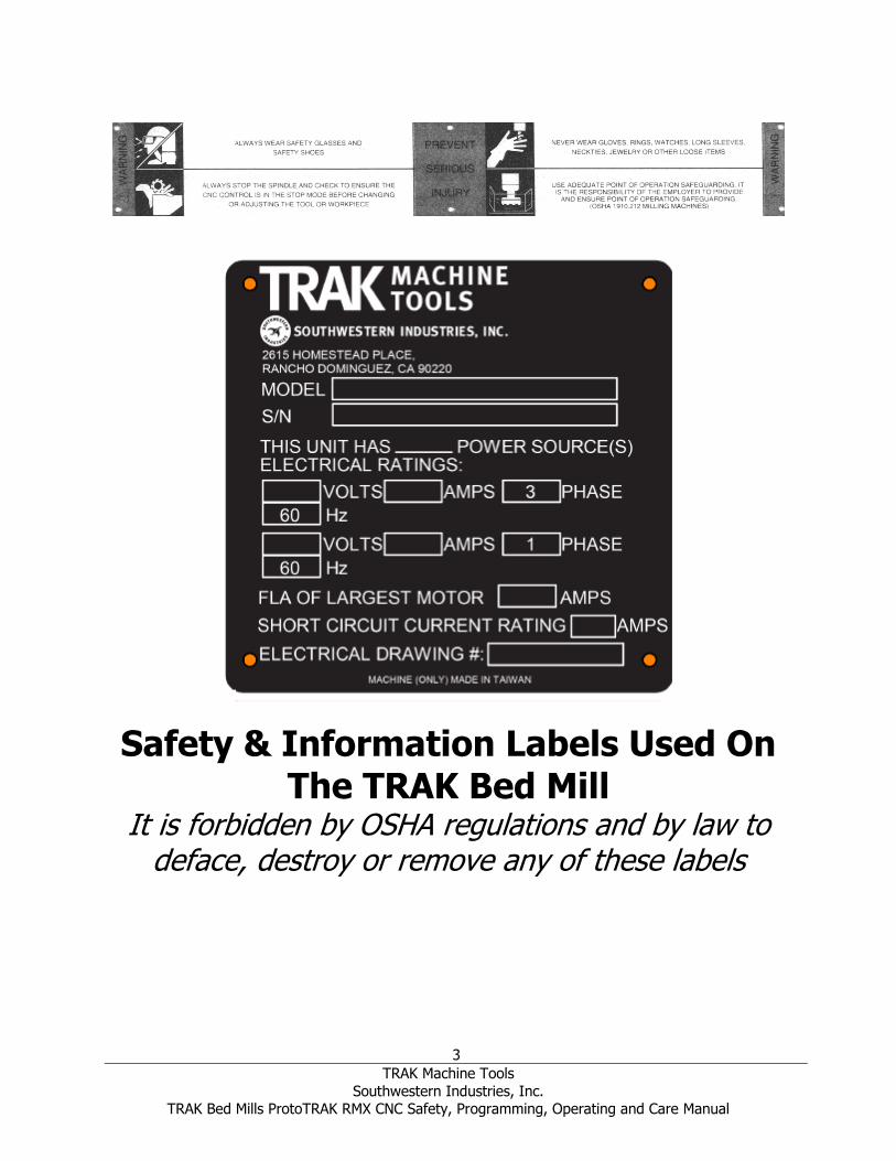
Safety & Information Labels Used On The TRAK Bed Mill
It is forbidden by OSHA regulations and by law to deface, destroy or remove any of these labels

4
TRAK Machine Tools
Southwestern Industries, Inc. TRAK Bed Mills ProtoTRAK RMX CNC Safety, Programming, Operating and Care Manual
220 VOLTS
Safety & Information Labels Used On The TRAK Bed Mill
It is forbidden by OSHA regulations and by law to deface, destroy or remove any of these labels
5
TRAK Machine Tools
Southwestern Industries, Inc. TRAK Bed Mills ProtoTRAK RMX CNC Safety, Programming, Operating and Care Manual
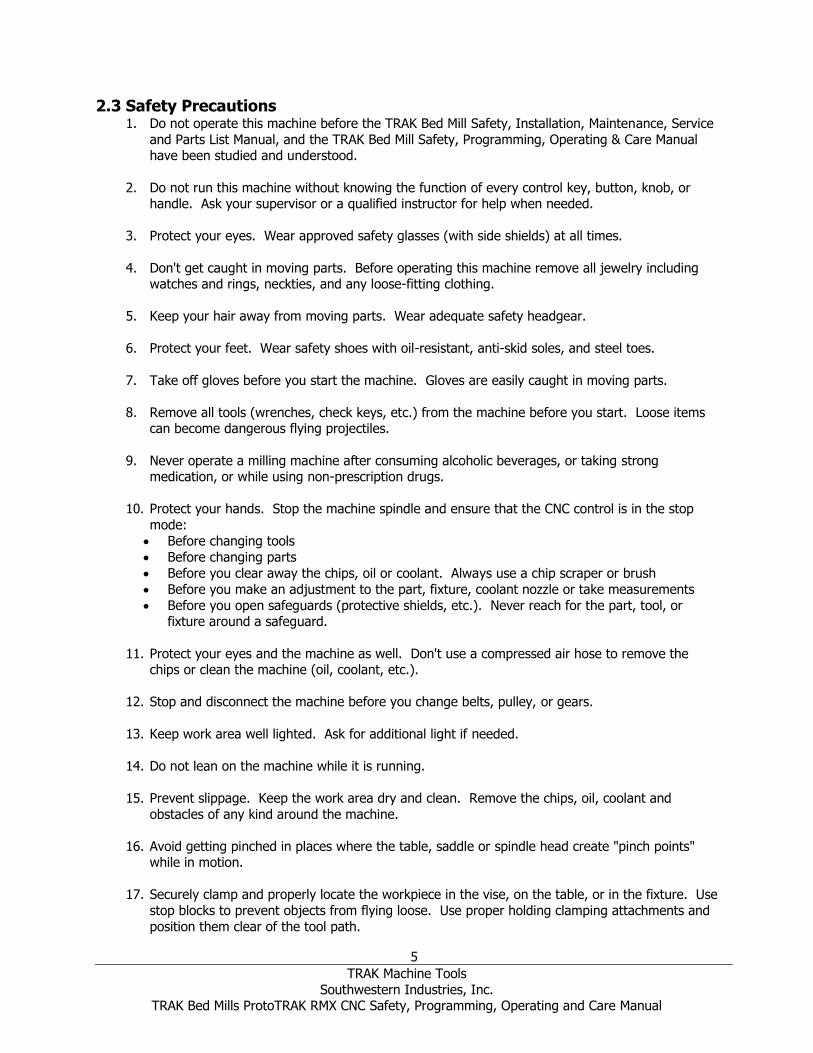
2.3 Safety Precautions 1. Do not operate this machine before the TRAK Bed Mill Safety, Installation, Maintenance, Service
and Parts List Manual, and the TRAK Bed Mill Safety, Programming, Operating & Care Manual have been studied and understood.
2. Do not run this machine without knowing the function of every control key, button, knob, or handle. Ask your supervisor or a qualified instructor for help when needed.
3. Protect your eyes. Wear approved safety glasses (with side shields) at all times.
4. Don't get caught in moving parts. Before operating this machine remove all jewelry including watches and rings, neckties, and any loose-fitting clothing.
5. Keep your hair away from moving parts. Wear adequate safety headgear.
6. Protect your feet. Wear safety shoes with oil-resistant, anti-skid soles, and steel toes.
7. Take off gloves before you start the machine. Gloves are easily caught in moving parts.
8. Remove all tools (wrenches, check keys, etc.) from the machine before you start. Loose items can become dangerous flying projectiles.
9. Never operate a milling machine after consuming alcoholic beverages, or taking strong medication, or while using non-prescription drugs.
10. Protect your hands. Stop the machine spindle and ensure that the CNC control is in the stop
mode:
• Before changing tools
• Before changing parts
• Before you clear away the chips, oil or coolant. Always use a chip scraper or brush
• Before you make an adjustment to the part, fixture, coolant nozzle or take measurements
• Before you open safeguards (protective shields, etc.). Never reach for the part, tool, or fixture around a safeguard.
11. Protect your eyes and the machine as well. Don't use a compressed air hose to remove the chips or clean the machine (oil, coolant, etc.).
12. Stop and disconnect the machine before you change belts, pulley, or gears.
13. Keep work area well lighted. Ask for additional light if needed.
14. Do not lean on the machine while it is running.
15. Prevent slippage. Keep the work area dry and clean. Remove the chips, oil, coolant and
obstacles of any kind around the machine.
16. Avoid getting pinched in places where the table, saddle or spindle head create "pinch points" while in motion.
17. Securely clamp and properly locate the workpiece in the vise, on the table, or in the fixture. Use
stop blocks to prevent objects from flying loose. Use proper holding clamping attachments and
position them clear of the tool path.

6
TRAK Machine Tools
Southwestern Industries, Inc. TRAK Bed Mills ProtoTRAK RMX CNC Safety, Programming, Operating and Care Manual
18. Use correct cutting parameters (speed, feed, depth, and width of cut) in order to prevent tool
breakage.
19. Use proper cutting tools for the job. Pay attention to the rotation of the spindle: Left hand tool
for counterclockwise rotation of spindle, and right-hand tool for clockwise rotation of spindle.
20. Prevent damage to the workpiece or the cutting tool. Never start the machine (including the rotation of the spindle) if the tool is in contact with the part.
21. Check the direction (+ or -) of movement of the table when using the jog or power feed.
22. Don't use dull or damaged cutting tools. They break easily and become airborne. Inspect the sharpness of the edges, and the integrity of cutting tools and their holders. Use proper length
for the tool.
23. Large overhang on cutting tools when not required result in accidents and damaged parts.
24. Prevent fires. When machining certain materials (magnesium, etc.) the chips and dust are highly flammable. Obtain special instruction from your supervisor before machining these
materials.
25. Prevent fires. Keep flammable materials and fluids away from the machine and hot, flying chips.
26. When working in manual mode (not CNC) make sure the computer control is switched to DRO or OFF.
27. An optional interlocked table guard is available from Southwestern Industries if the use of the
table guard is deemed necessary by the user for his application.

7
TRAK Machine Tools
Southwestern Industries, Inc. TRAK Bed Mills ProtoTRAK RMX CNC Safety, Programming, Operating and Care Manual
3.0 Description 3.1 ProtoTRAK RMX Control Specifications The ProtoTRAK RMX CNC provides you with an extraordinary combination of power and ease of use.
Programming and operations are kept simple and at any moment you may select Help Screens or make
changes to the programming defaults using the Info Keys.
3.1.1 List of System Specifications Pendant Control Hardware
• 2 or 3-axis CNC, 3-axis DRO
• Real handwheels for manual operation
• 15.6” Touchscreen LCD
• Intel® 2.0 GHz processor
• 4 GB Ram
• At least 32 GB of mSATA SSD
• 5 USB connectors
• 2 Ethernet Ports (1 for user and 1 for motion control)
• Override of program Feedrate
• Override of spindle speed
• LED status lights built into run panel
• E-stop
• Spindle Control (FWD, REV, OFF)
• Feed STOP and GO
• Fine vs Course EHW resolution control
• Accessory button to control coolant or air and AUTO mode in RUN mode
• Power Reset Button to energize the servos
• Headphone jack for video sound (headphone supplied)
Computer Module Control Hardware
• 3 axis motor control – X, Y and Z axis
• 10 inputs
• 10 outputs
• Mill Indexer interface
Software Features – General Operation
• Clear, uncluttered screen display
• Fly out windows for instant access to features and information
• EPA (Enhanced ProtoTRAK Assistance) for system help
• Programming Defaults to simplify part programming
• Event Options to modify control behavior
• QWERTY touchscreen keyboard
• Calculator places data in program for you
• Prompted data inputs
• English language – no codes
• Soft keys - change within context
• Windows® operating system
• Selectable two or three-axis CNC
• Color graphics with adjustable views
• Gestures for pan, zoom, rotate
• Inch/mm selectable
• Convenient modes of operation
• Networking
8
TRAK Machine Tools
Southwestern Industries, Inc. TRAK Bed Mills ProtoTRAK RMX CNC Safety, Programming, Operating and Care Manual
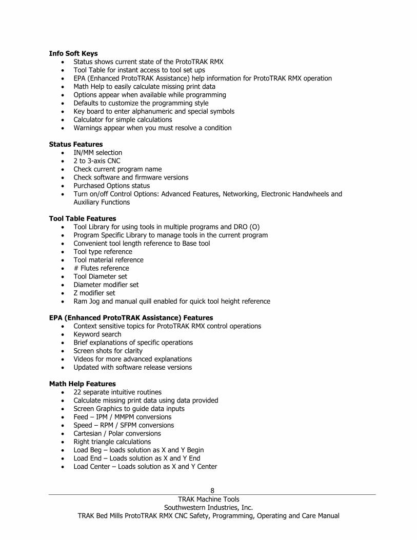
Info Soft Keys
• Status shows current state of the ProtoTRAK RMX
• Tool Table for instant access to tool set ups
• EPA (Enhanced ProtoTRAK Assistance) help information for ProtoTRAK RMX operation
• Math Help to easily calculate missing print data
• Options appear when available while programming
• Defaults to customize the programming style
• Key board to enter alphanumeric and special symbols
• Calculator for simple calculations
• Warnings appear when you must resolve a condition
Status Features
• IN/MM selection
• 2 to 3-axis CNC
• Check current program name
• Check software and firmware versions
• Purchased Options status
• Turn on/off Control Options: Advanced Features, Networking, Electronic Handwheels and Auxiliary Functions
Tool Table Features
• Tool Library for using tools in multiple programs and DRO (O)
• Program Specific Library to manage tools in the current program
• Convenient tool length reference to Base tool
• Tool type reference
• Tool material reference
• # Flutes reference
• Tool Diameter set
• Diameter modifier set
• Z modifier set
• Ram Jog and manual quill enabled for quick tool height reference
EPA (Enhanced ProtoTRAK Assistance) Features
• Context sensitive topics for ProtoTRAK RMX control operations • Keyword search
• Brief explanations of specific operations
• Screen shots for clarity
• Videos for more advanced explanations
• Updated with software release versions
Math Help Features
• 22 separate intuitive routines
• Calculate missing print data using data provided
• Screen Graphics to guide data inputs
• Feed – IPM / MMPM conversions
• Speed – RPM / SFPM conversions
• Cartesian / Polar conversions
• Right triangle calculations
• Load Beg – loads solution as X and Y Begin
• Load End – Loads solution as X and Y End
• Load Center – Loads solution as X and Y Center
9
TRAK Machine Tools
Southwestern Industries, Inc. TRAK Bed Mills ProtoTRAK RMX CNC Safety, Programming, Operating and Care Manual
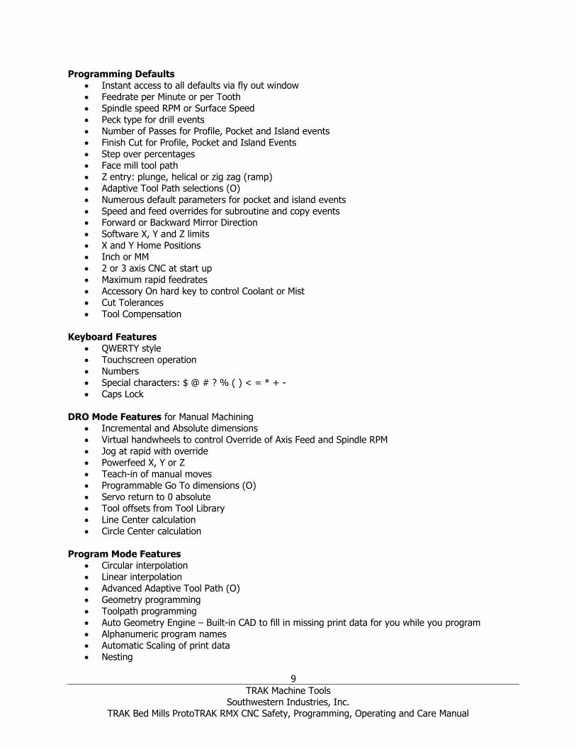
Programming Defaults
• Instant access to all defaults via fly out window
• Feedrate per Minute or per Tooth
• Spindle speed RPM or Surface Speed
• Peck type for drill events
• Number of Passes for Profile, Pocket and Island events
• Finish Cut for Profile, Pocket and Island Events
• Step over percentages
• Face mill tool path
• Z entry: plunge, helical or zig zag (ramp)
• Adaptive Tool Path selections (O)
• Numerous default parameters for pocket and island events
• Speed and feed overrides for subroutine and copy events • Forward or Backward Mirror Direction
• Software X, Y and Z limits
• X and Y Home Positions
• Inch or MM
• 2 or 3 axis CNC at start up
• Maximum rapid feedrates
• Accessory On hard key to control Coolant or Mist
• Cut Tolerances
• Tool Compensation
Keyboard Features
• QWERTY style
• Touchscreen operation
• Numbers
• Special characters: $ @ # ? % ( ) < = * + -
• Caps Lock
DRO Mode Features for Manual Machining
• Incremental and Absolute dimensions
• Virtual handwheels to control Override of Axis Feed and Spindle RPM
• Jog at rapid with override
• Powerfeed X, Y or Z
• Teach-in of manual moves
• Programmable Go To dimensions (O)
• Servo return to 0 absolute
• Tool offsets from Tool Library
• Line Center calculation
• Circle Center calculation
Program Mode Features
• Circular interpolation
• Linear interpolation
• Advanced Adaptive Tool Path (O)
• Geometry programming
• Toolpath programming
• Auto Geometry Engine – Built-in CAD to fill in missing print data for you while you program
• Alphanumeric program names
• Automatic Scaling of print data
• Nesting

10
TRAK Machine Tools
Southwestern Industries, Inc. TRAK Bed Mills ProtoTRAK RMX CNC Safety, Programming, Operating and Care Manual
• Multiple Fixtures (O)
• Incremental and absolute dimensions may even be mixed on a single point
• Automatic diameter cutter comp
• Look –graphics at all times
• List step – graphics with programmed events displayed
• Program data editing
• Part graphics update while programming
• Selectable display between size of drawing and number of events
• List Step graphics relate Events to Drawing
• Editing of programmed data
• Swipe to move through programmed Events
• Auxiliary functions: Coolant, Air/Mist, Pulse Indexer, Programmable Output signal (O)
Selectable within applicable Events:
• Z Safety plane
• Spindle Speed RPM or SFPM
• Feed rate per minute or tooth
• Event Comments on/off (O)
• Bottom Finish Cut
• Cutting method One Way or Zig-Zag
• Step-over %
• Machining Angle in XY (0 – 90 deg.)
• Drill Peck: Variable, Fixed, Chip Break
• Dwell Request
• Multiple Holes
• Z Entry Plunge, Zig-Zag or Helical
• Tool path Pattern: Offset, Parallel
• Tool path Pattern: Adaptive (O)
• Order of Passes: Depth or Region
• Insert Clipboard data
• Cut Tolerances
Canned Cycles (Event types):
• Position
• Drill / Bore / Tap
• Bolt Hole Drill / Bore / Tap
• Mill
• Arc
• Circular profile
• Rectangular profile
• Irregular Profile (with Auto Geometry Engine)
• Face Mill
• Circle pocket
• Rectangular pocket
• Irregular Pocket (with Auto Geometry Engine)
• Islands including Pocket and Island shapes
• Subroutine Repeat
• Subroutine Mirror
• Subroutine Rotation
• Copy (O)
• Copy Mirror (O)
• Copy Rotate (O)

11
TRAK Machine Tools
Southwestern Industries, Inc. TRAK Bed Mills ProtoTRAK RMX CNC Safety, Programming, Operating and Care Manual
• Copy Convert Drill to Tap (O)
• Helix
• Engrave (O)
• Engrave subroutines and copy (O)
• Thread Mill (O)
• Program pause
• Aux Event
Edit Mode Features
• Group Delete of Events
• Search Edit to make changes to multiple events
• Erase current program
• G-Code Editor (O)
• Clipboard to copy events for insertion elsewhere
Set-up Mode Features
• Toolpath graphics with selectable views
• Estimated Run Time clock
• Step forward and backward through of Toolpath graphics
• XYZ tool position locations displayed in Step through mode
• Verify Make Part – solid model graphics of programmed toolpath (O)
• Verify View Part – solid model of finished part
• Fixture offsets – convenient table for managing fixtures with DRO and Jog
• Ref Position – convenient table for setting Retract, Homes and software limits
• Service Codes for infrequent machine and control settings
Run Mode Features
• 3D CAM file run
• 3D G code file run
• Override of Programmed Axis Feed and Spindle Speed from 0 – 150%
• Virtual handwheels to control Override
• Tap override of Axis Feed and Spindle RPM
• Real time conversion of programmed RPM / SFM
• Real time conversion of programmed IPM / IPT
• Status display:
• Event #
• Fixture#
• Control system Ready
• Current Tool #
• Repeat #
• Countdown clock to next pause or tool change
• Event Comments
• Start at beginning
• Start at any Event
• Start at tool # for GCD programs
• Start at rough or finish pass
• Start at any finish cut for pockets and islands – XY, Z, XY & Z
• Show Absolute Dimensions during run
• Show Incremental Dimensions
• Show Tool Path – real time graphics with Tool icon
• Show Program
• TRAKing® - you control programmed X,Y and Z feeds with Electronic Handwheels(O)

12
TRAK Machine Tools
Southwestern Industries, Inc. TRAK Bed Mills ProtoTRAK RMX CNC Safety, Programming, Operating and Care Manual
• Chip Clear (O)
Program In/Out Mode features
• Program storage to USB device plugged into Control Pendant
• Program storage to Network via RJ45 Port
• Browse file locations
• Create New Folders
• CAM program converter
• Convert prior-generation ProtoTRAK programs to current (.PT10)
• Save Temp – saves all current programs, tools and other settings
• Open Temp – opens the data saved at last “Save Temp”
• Rename programs
• Cut, Copy, Delete, Paste of program(s)
• Look - Graphics preview without opening files
Advanced Features Option
• Adaptive Pocket Roughing
• Verify Make Part – solid model graphics of programmed toolpath
• Multiple Fixtures
• Event Comments
• G-code editor
• Thread Mill event
• Engrave Event
• Copy Repeat
• Copy Mirror
• Copy Rotate
• Copy Convert Drill to Tap
• Tool Library for using tools in multiple programs and DRO
• Chip Clear
• Rest Material
Auxiliary Functions Option
• Enables programming and control of:
• Coolant
• Air/Mist (for Fog Buster® or other air-driven coolant systems)
• Pulse Indexer
• Programmable Output signal
DXF File Converter Option
• Import and convert CAD data into ProtoTRAK programs
• DXF or DWG files
• Chaining
• Automatic Gap Closing
• Layer control
• Part alignment
• Feature analysis (circle/arc radius and position)
• Simple CAD construction/editing tools
• DXF-output capability
• Easy, prompted process you can do right at the machine
Parasolid File Converter Option
• Import and convert 3D CAD data into ProtoTRAK programs

13
TRAK Machine Tools
Southwestern Industries, Inc. TRAK Bed Mills ProtoTRAK RMX CNC Safety, Programming, Operating and Care Manual
• X_T files
• X, Y & Z dimensions are transferred into program events
• 2D and 3D views of part
• Add or remove geometry
• Chaining
• Part alignment
• Feature analysis (circle/arc radius and position)
• Simple CAD construction/editing tools
• Easy, prompted process you can do right at the machine
TRAKing® / Electronic Handwheels Option
• Standard on the DPM RX5 and DPM RX7
• TRAKing® of programs during program run
• Go To Dimensions in DRO Mode
• Scalable Fine/Course handwheel resolution
Offline Programming Option
• ProtoTRAK RMX user interface for Windows PC
• Program parts and simulate CNC Run
• Modify files from current and former ProtoTRAK models
3.2 ProtoTRAK RMX Options You may purchase software options with the original control purchase or later. If you purchased them
with your original order, they should come pre-installed from our factory. You can easily tell if you have an option activated on your control by pressing the Status Key. You can also see all the available options
by referring to Service Code 318 (see below).
To purchase Software Options, call our Sales Support Team at 800-421-6875 for pricing and to place your
order. Before you install the option, we recommend that you first assure that you are running the most recent version of the ProtoTRAK RMX.
Once you purchase the option, the Sales Support Rep will give you an Activation Code.
1. Go to the Set-up Mode
2. Select Serv Codes 3. Enter 318, Inc Set or Abs Set
4. Tap the option you want to activate from the list. 5. When prompted, enter the Activation Code.
3.2.1 Advanced Features In order to make the ProtoTRAK RMX easier for a basic user, we have segmented some of the more
complex features into an Advanced Features Option. Advanced Features, once installed, may be turned off or on in the Status Fly Out window.
3.2.2 TRAKing® / Electronic Handwheels Electronic Handwheels are required for TRAKing®, manual Go To, and Fine / Course handwheel
resolution. They replace the direct manual control of the ball screw with an encoder that sends a signal to the computer, which then commands the appropriate response from the axis motor. Electronic
Handwheels are active only in DRO Mode, Set up Mode to set tools and reference locations and Run
Mode for TRAKing® and Chip Clear. Otherwise, the machine will not respond to the movement of the handwheel.
You may easily turn the Electronic Handwheels on or off through the Status Information Screen.

14
TRAK Machine Tools
Southwestern Industries, Inc. TRAK Bed Mills ProtoTRAK RMX CNC Safety, Programming, Operating and Care Manual
3.2.3 DXF File Converter Option The DXF File Converter Option gives you powerful capability for quickly and easily translating DXF and
DWG files into ProtoTRAK RMX programs. If you work with CAD drawings, we highly recommend the DXF file converter.
The DXF File Converter Option has its own manual which is shipped with the software. You may also view a copy of the manual on our web site at www.trakmt.com.
3.2.4 Parasolid File Converter Option The Parasolid File Converter Option gives you powerful capability for quickly and easily translating
Parasolid files (X_T) into ProtoTRAK RMX programs. If you work with 3D Solid Model CAD drawings, we highly recommend the Parasolid file converter.
The Parasolid Option has its own manual which is shipped with the software. You may also view a copy
of the manual on our web site at www.trakmt.com.

15
TRAK Machine Tools
Southwestern Industries, Inc. TRAK Bed Mills ProtoTRAK RMX CNC Safety, Programming, Operating and Care Manual
3.2.5 Verify Option Part Verify allows you to see a solid model rendition of your programmed part as well as the programmed
toolpath. It is very useful to prove out a program and prevent mistakes.
3.3 Display Pendant 3.3.1 Front
Figure 3.2.1 The front of the ProtoTRAK RMX Control Pendant
Keyboard Hard Keys X, Y, Z: selects axis for subsequent commands
INC SET: loads incremental dimensions and general data ABS SET: loads absolute dimensions and general data
0-9, +/-, . : inputs numeric data with floating point format. Data is automatically + unless +/- key is
pressed. All input data is automatically rounded to the system's resolution RESTORE: clears an entry, aborts a keying procedure
BACK: Moves back within the screen or the DIL when there isn’t a better way to do it. * KEY – Not used at this time.
** KEY – Not used at this time.

16
TRAK Machine Tools
Southwestern Industries, Inc. TRAK Bed Mills ProtoTRAK RMX CNC Safety, Programming, Operating and Care Manual
Feed Keys: GO: initiates motion in Run. The green LED on the GO key will be lit when the servomotors are moving
the machine or when the program run has been initiated by the GO key. STOP: halts motion during Run. The red LED on the STOP key will be lit when the servos motors are not
moving the machine.
Spindle Keys:
REV: runs the spindle in reverse at programmed speed with any override. OFF: Turns spindle off and servo brakes to a stop.
FWD: runs spindle in the forward direction at programmed spindle speed with any override.
EHW FINE/COURSE:
Selects the resolution for the Optional Electronic Handwheels. C: moves the table at 0.800” per revolution for X,
moves the saddle at 0.800” per revolution for Y
F: moves the table at 0.200” per revolution for X,
moves the saddle at 0.200” per revolution for Y
ACCESSORY: When the switch is in the ON position, the flood coolant pump (or spray coolant) will come on and stay on during machining operations. It will not turn off during tool changes. Note – Spray coolant only works via the accessory button if you purchase the auxiliary function option. In the Auto mode, the coolant pump or spray coolant will be controlled as programmed by the Optional Auxiliary
functions. To get to the Auto operation, press and hold the Accessory key. If neither light is on, the
coolant pump or spray coolant will not operate. The coolant and air/mist will turn off at tool changes automatically. The user does not need to program this functionality.
POWER / RESET: the LED on indicates there is power to the servo motors. After starting the
ProtoTRAK, Press and hold this key until the white LED comes on RMX to initiate. This button will need
to be pressed any time the control gets into a critical fault condition. An example of this would be if the user presses the Emergency Stop button.
Keyboard Soft Keys
Once the ProtoTRAK RMX pendant has booted up, the soft keys are enabled and operated by the
touchscreen.
Fly Out Windows Touching one of the INFO Soft Keys initiates another window to open (or “fly out”). When one of these
windows is active, the associated INFO Soft Key will be yellow. In order to put the window away, or switch to another Fly Out Window, press the INFO Soft Key again.
Warnings are also presented in a Fly Out Window. When a Warning appears, you must press the Clear soft key to dismiss the warning.
17
TRAK Machine Tools
Southwestern Industries, Inc. TRAK Bed Mills ProtoTRAK RMX CNC Safety, Programming, Operating and Care Manual
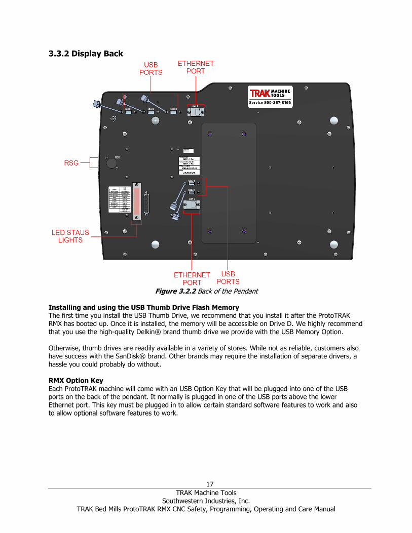
3.3.2 Display Back
Figure 3.2.2 Back of the Pendant
Installing and using the USB Thumb Drive Flash Memory The first time you install the USB Thumb Drive, we recommend that you install it after the ProtoTRAK
RMX has booted up. Once it is installed, the memory will be accessible on Drive D. We highly recommend
that you use the high-quality Delkin® brand thumb drive we provide with the USB Memory Option.
Otherwise, thumb drives are readily available in a variety of stores. While not as reliable, customers also have success with the SanDisk® brand. Other brands may require the installation of separate drivers, a
hassle you could probably do without.
RMX Option Key
Each ProtoTRAK machine will come with an USB Option Key that will be plugged into one of the USB ports on the back of the pendant. It normally is plugged in one of the USB ports above the lower
Ethernet port. This key must be plugged in to allow certain standard software features to work and also to allow optional software features to work.

18
TRAK Machine Tools
Southwestern Industries, Inc. TRAK Bed Mills ProtoTRAK RMX CNC Safety, Programming, Operating and Care Manual
3.4 Machine Specifications
Figure 3.4.1 DPMRX2 Front View

19
TRAK Machine Tools
Southwestern Industries, Inc. TRAK Bed Mills ProtoTRAK RMX CNC Safety, Programming, Operating and Care Manual
Figure 3.4.2 DPMRX2 Back View

20
TRAK Machine Tools
Southwestern Industries, Inc. TRAK Bed Mills ProtoTRAK RMX CNC Safety, Programming, Operating and Care Manual
Figure 3.4.3 DPMRX3 Front View
21
TRAK Machine Tools
Southwestern Industries, Inc. TRAK Bed Mills ProtoTRAK RMX CNC Safety, Programming, Operating and Care Manual
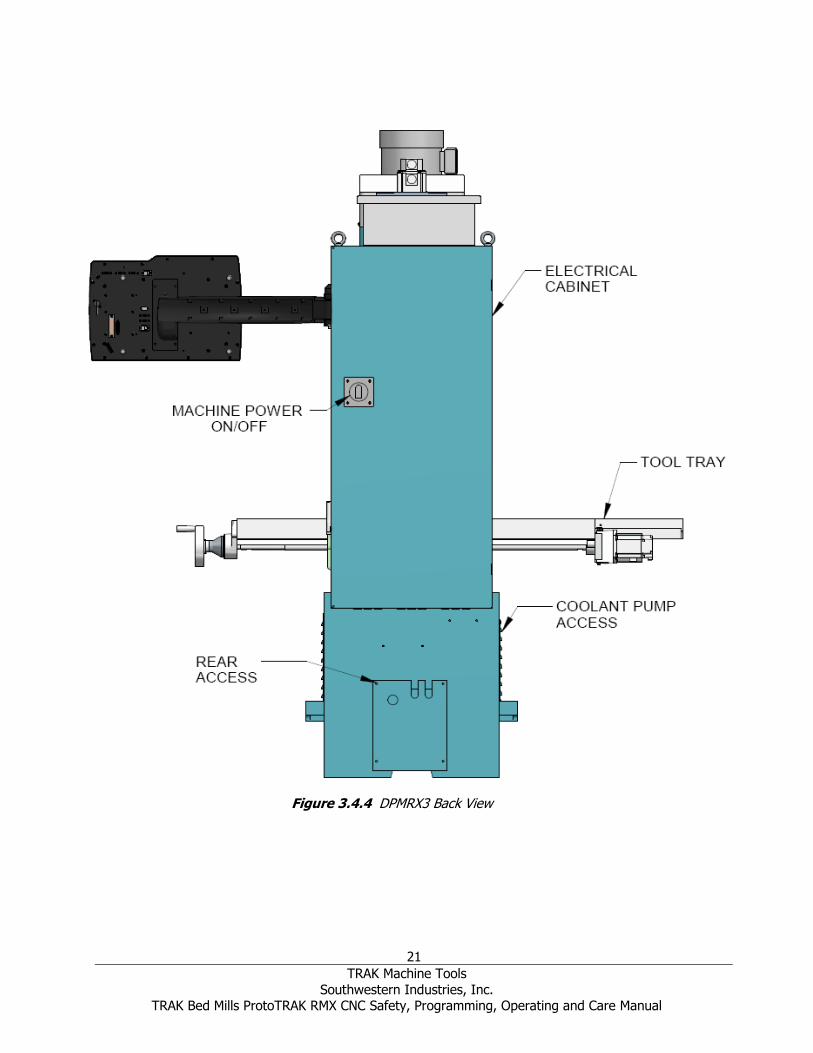
Figure 3.4.4 DPMRX3 Back View

22
TRAK Machine Tools
Southwestern Industries, Inc. TRAK Bed Mills ProtoTRAK RMX CNC Safety, Programming, Operating and Care Manual
Figure 3.4.5 DPMRX5 Front View

23
TRAK Machine Tools
Southwestern Industries, Inc. TRAK Bed Mills ProtoTRAK RMX CNC Safety, Programming, Operating and Care Manual
Figure 3.4.6 DPMRX5 Back View

24
TRAK Machine Tools
Southwestern Industries, Inc. TRAK Bed Mills ProtoTRAK RMX CNC Safety, Programming, Operating and Care Manual
Figure 3.4.7 DPMRX7 Front View

25
TRAK Machine Tools
Southwestern Industries, Inc. TRAK Bed Mills ProtoTRAK RMX CNC Safety, Programming, Operating and Care Manual
Figure 3.4.8 DPMRX7 Back View

26
TRAK Machine Tools
Southwestern Industries, Inc. TRAK Bed Mills ProtoTRAK RMX CNC Safety, Programming, Operating and Care Manual
MODEL NAME DPMRX2 DPMRX3 DPMRX5 DPMRX7
Table Size 49” x 9” 50” x 10” 50” x 12” 76” x 14”
T-Slots (number x width x pitch) 3 x .63” x 2.5”
3 x .63" x 2.48"
3 x .63" x 2.52"
4 x 16mm x 63.5 mm
Travel (X, Y, Z axis)* 31.75” x 16
x 25.5
31.5 x 17 x
25.81"
40 x 20 x
25.81”
60” x 23” x
24.25”
Quill Diameter 3 3/8” 3 15/16" 4.56” Maximum Quill Travel 5” 5.5” Spindle Taper R8 40 Taper Spindle Speed Range 40-600, 300-5000 Spindle Center to Column Face 18.5” 20.5” 20.5” 24” Spindle Motor Power 3 HP 5 HP 7.5 HP Power requirements (volts, phase,
current) 200-
240V;3P; 27A
200-240V;3P; 35A 200-240V;3P;
42A
Maximum Weight of Workpiece 1320 lbs. 1760 lbs. 2200 lbs. Height of table from bottom of bed 36.75” 36.75” 40” 38.75” Max spindle nose to table 25.5” 25.81” 24.25” Min height 86.625” 87.5" 87.5” 87.875” Max height 98.75” 100.5” 102” 105” Width of machine including table 71.25” 73.5” 94.13” 110” Length with electric box door closed 73.31” 76.63” 82.5” 94.5” Overall width incl full table traverse 102.53” 102.25” 131.06” 168.5” Overall length with electrical door open 93.88” 96.63" 103" 119” Footprint of Machine 23.13” x
40.5” 24” x 43.31”
24” x 48.4” 42.52” x 63”
Weight net / shipping lbs. 3200 / 3500 4100 /
4400 4400/ 4700 7480/7700
Rapid traverse X, Y, Z 250 ipm on X, Y and Z with Mechanical
Handwheels 400 ipm on X and Y
250 ipm on Z on EHW
machines
400 ipm on X and Y
250 ipm on Z
400 IPM on X and Y
250 IPM on Z
Coolant Capacity 10 gallons 15 gallons
Maximum Work Capacities in Mild Steel: Drilling max capacity 1” diameter Milling max capacity 3 inch³/min 5 inch³/min 7 inch3 / min
Tapping max capacity 3 /4 - 10 1-8” 1-8” * Model DPM RX2 only, installation of the TRAKing®/Electronic Handwheel option reduces X travel to
30.5”

27
TRAK Machine Tools
Southwestern Industries, Inc. TRAK Bed Mills ProtoTRAK RMX CNC Safety, Programming, Operating and Care Manual
3.5 Optional Equipment 3.5.1 Electronic Handwheels Electronic handwheels are standard on Models DRMRX5 and DPMRX7.
When ordered as part of the TRAKing/Electronic Handwheels Option (see Section 3.2.2) the electronic handwheels replace the standard mechanical handwheels for table and saddle traverse. The electronic
handwheels will operate when the ProtoTRAK RMX CNC is in a Mode where the machinist controls the motion of the table and saddle. This includes the DRO Mode, the Set-Up Mode and the TRAKing
operation in the Run Mode. The electronic handwheels will not operate during other functions, such as
edit or program in/out mode.
Handwheel resolution is determined by the F/C key on the display. Fine feed moves 0.200 inches per revolution, Course feed moves 0.800 inches per revolution.
3.5.2 Position Encoders The ProtoTRAK RMX CNC may be configured to run either with or without independent position encoders
for X and Y travel. Optional encoders are glass scales, each with 0.0002” underlying resolution.
3.5.3 Auxiliary Functions Auxiliary functions are controlled through the ProtoTRAK RMX CNC either in the program or with the accessory key on the front panel. The Auxiliary functions consist of the following:
• Coolant
• Air/MIST (for Fog Buster® or other air-driven coolant systems)
• Pulse Indexer
• Programmable Output signal
3.5.4 Table Guard The Table guard option provides an enclosed workspace mounted on the table. The sliding door is
switched to prevent operation of the CNC Run with the door open. While it will aid in the control of chips and coolant, it is not a fully waterproof enclosure.
3.5.5 Power Draw Bar A CAT 40 manual draw bar comes standard with the machine. A power draw bar option may be ordered.
The draw bar included in the option may be CAT or NMTB/NST.
An NMTB/NST type of draw bar is the appropriate length to fit tool holders that have a threaded tang on the top. The CAT type is longer to thread into CNC tool holders that have the tool changer grip, or
retention knob removed.
3.5.6 Remote Stop Go Switch For the convenience of operation while running the program, a Remote Stop/Go switch may be purchased. This switch is on a ten-foot cable and operates like the FEED Stop and Go keys on the
display.
3.5.7 Work Light An optional LED work light is available. It mounts to the left side (facing) of the column and plugs into
the computer module found in the electrical cabinet.
3.5.8 Coolant Pump The optional coolant pump is mounted in the back of the machine column. It is plugged into the electrical
cabinet and may be configured to operate as commanded by the auxiliary functions, or with the
Accessory ON button on the run panel.

28
TRAK Machine Tools
Southwestern Industries, Inc. TRAK Bed Mills ProtoTRAK RMX CNC Safety, Programming, Operating and Care Manual
3.5.9 Spray Coolant The Fog Buster® spray coolant option consists of a one-gallon holding tank, nozzle, air lines and an air
regulator for attaching compressed air. Coolant flow is adjusted by a needle valve at the sprayer head. Air flow is adjusted at the air pressure regulator with gage. Once flows are set, sprayer operation is
controlled by an air toggle switch or by interface with the optional Auxiliary Functions.
3.5.10 Limit Switches There are optional limit switches for the ram, saddle and table travel. When the limit switch is triggered,
it will decelerate the three axis servo motors to a stop.
3.5.11 Chip Pan/Splash Shield The Chip Pan/Splash Shield option consists of a chip pan mounted to the bed and splash shields mounted
to the right and left of the columns. Because of its bulk and weight, we recommend this option as
available factory-installed on the machine. It is very costly to ship on its own.
3.5.12 30-Taper Spindle For the DPM RX2 only, the standard R8 spindle may be replaced by a 30-taper spindle.
3.5.13 Vise A 6” vise from Kurt is available. We supply their DX6 mode. The vise kit comes with all the necessary
hardware to fasten it to your table.
3.5.14 Tooling Measurement Cart Not available for the DPM RX2. The Tooling Measurement Cart option consists of the Tooling Cart, Preset Tool, and Plate. The Tooling Measurement Cart helps set tool offsets in the tool table without touching
tools off the part. This is very handy when the machine has Electronic Hand Wheels and the chances of
damaging the part are high.
To use, set a base tool using Tooling Cart, and then for all other tools load it in the tooling cart read the value from the measurement scale and enter the absolute value as tool offset for that tool in tool table.
3.6 Lubrication System The way and ballscrew lubrication pump is wired to operate when the spindle is running. It also turns on
each time you turn on your machine to lubricate the axis before movement.
Factory Default Values
Interval Time – 60 min. Discharge Time – 15 sec
Discharge Pressure – Approximately 100 – 150psi
To adjust the amount of Discharge Pressure displayed on the lube pump gauge, loosen the jam nut and turn the adjustment screw located on the top right side of the lube pump while the lube pump is
activated. To activate the lube pump turn spindle on and press the Feed for continuous pumping and RST
for a single programmed pump.

29
TRAK Machine Tools
Southwestern Industries, Inc. TRAK Bed Mills ProtoTRAK RMX CNC Safety, Programming, Operating and Care Manual
CAUTION!
Failure to properly lubricate the mill will result in the premature failure of bearings and sliding surfaces.
The settings for the lube pump can be viewed and adjusted in Service Codes. Set Up Mode
Serv Codes E. Lube Pump Setup
Enter: 300 to choose between Manual and Automatic pump discharge
301 to set the cycle time (length of time between automatic discharges) 302 to set the amount of time of the automatic discharge
3.7 Electrical Cabinet The TRAK bed mills run on 200 to 240-volt 3 phase power. Shops with 415 to 480-volt incoming power
will require an optional step down transformer.
3.8 Integrated Ram and Quill Encoders A glass scale for the Quill operation is standard. Ram motion is measured by an encoder on the ram servo motor. The feedback from these encoders is integrated and displayed in the Z-axis digital readout
as one dimension
3.9 Servo Motors On the DPMRX2, DPMRX3 and DPMRX5, the servo motors on table, saddle are 750-watt brushless motors. The motor driving the ram/head is a 1000-watt brushless motor. The DPMRX7 uses 1000-Watt
motors on all 3 axes. The underlying resolution of the motors encoders depends on the ballscrew pitch and pulley ratio between the motor and ballscrew. This means the resolution will fall somewhere between
these 2 numbers - 0.0000019” and 0.0000030”
3.10 Reference (Base) Pin Each TRAK DPM is shipped with a 3/8” shank pin that is meant to make tool setting more convenient. You will find the pin in the Hardware Kit that accompanies the machine. The idea is for you to use this
pin and one of your tool holders to make a Base Reference Tool. That way, you can use the tool as your
Base Tool when you set up a new Z Offset on a tool.
We recommend that you keep the pin in the tool holder as a permanent part of your toolbox. You will find that that time you save and the peace of mind you get from having this secure reference is well
worth the dedication of a tool holder.

30
TRAK Machine Tools
Southwestern Industries, Inc. TRAK Bed Mills ProtoTRAK RMX CNC Safety, Programming, Operating and Care Manual
4.0 Basic Operation The TRAK DPM RX Bed Mills have been designed to give you unprecedented power in a CNC user experience that is natural and easy to use. This section will walk you through some basics of using the
ProtoTRAK RMX CNC.
4.1 Powering Up the System To turn on power to the entire machine and control system, rotate the power switch on the Electrical Cabinet to the On position.
The control will go through its boot up sequence. When it is finished, the following screen will appear.
Figure 4.1 The ProtoTRAK RMX will display this screen after it boots up.
To begin using the ProtoTRAK RMX CNC, first do the following:
Tap the Check System soft key.
Press the POWER Reset hard key and hold it for a few seconds until the white LED comes on.
4.2 Shutting Down the ProtoTRAK RMX CNC Important: The system must be turned off properly or you may lose unsaved data such as
programs or certain machine configurations. The SHUT DOWN soft key will initiate the process of shutting down safely. When the screen goes blank, turn the power switch at the
back of the electrical cabinet to the Off position.
In order to reach the SHUT DOWN soft key, first close any Fly Out Windows that are open. We also
recommend that you complete any prompted activity, such as programming an Event. Press the BACK hard key repeatedly until you get to the screen shown in Figure 4.1 above.

31
TRAK Machine Tools
Southwestern Industries, Inc. TRAK Bed Mills ProtoTRAK RMX CNC Safety, Programming, Operating and Care Manual
The ProtoTRAK control should be shut off at a minimum every few days. Failure to reboot may cause the control to run slowly. For example, the INFO screens may move in and out slowly. This is a sign the
control should be restarted. Take advantage of the SAVE TEMP feature prior to shut down as mentioned in the note below.
Note: You can save your current positions, tool information and program using the Save Temp feature in the Program In/Out mode.
4.3 Operator Run Keys 4.3.1 Feed The Feed Keys control the Go or Stop of programmed toolpath in the Run Mode. When running a
program in the Run Mode, you will be prompted for when to start the feed by pressing the GO button.
WARNING!
Pressing the GO button will initiate automatic machine motion!
4.3.2 Spindle Control The Spindle Forward/Off/Reverse is controlled through the Spindle hard keys just below the screen on the ProtoTRAK RMX control pendant. Spindle RPM is controlled through inputs in the DRO and Program
Modes.
To set the spindle RPM Range adjust the Spindle Range Lever on the upper right side of the head to High
or Low.
The spindle will not operate unless the ProtoTRAK RMX CNC is in the DRO or Run Modes.
4.3.3 EHW Fine/Coarse These buttons are used for machines that have Electronic Handwheels.
F or Fine:
- in DRO Mode – 0.200” per handwheel revolution - in Run Mode with TRAKing®
C or Coarse:
- in DRO Mode – 0.800” per handwheel revolution
- in Run Mode with TRAKing®
4.3.4 Accessory When the switch is in the On position, the flood coolant pump or spray coolant will come on and stay on
during machining operations.
In the Auto mode, the coolant pump or spray coolant will be controlled as programmed by the Optional Auxiliary functions. To get to the Auto operation, press and hold the Accessory key.
If neither light is on, the coolant pump or spray coolant will not operate.
4.3.5 Power / Reset Push and hold for a few seconds to initialize power to the X, Y and Z servo and motors. This is required after start up, after an Emergency stop or any critical fault.
32
TRAK Machine Tools
Southwestern Industries, Inc. TRAK Bed Mills ProtoTRAK RMX CNC Safety, Programming, Operating and Care Manual
4.4 Manual Operation of the Ram, Table and Saddle. When the Electronic Handwheels are installed, TRAK DPM RX may be used manually while in the DRO
Mode. Manual positioning and jog are active in other situations when needed, such as when setting tools.
When not in the DRO Mode, moving the Electronic Handwheel will not result in movement of the
machine.
4.5 Emergency Stop Press the button to shut off power to the spindle motor and axis motors. Rotate the switch to release. You may also want to press in the Emergency Stop at the end of the day if you would like to leave the
machine on but prevent the operation of the coolant pump or the Electronic Handwheels.
You must reset the power after each Emergency stop by pressing and holding the Power/Reset hard key.
4.6 Switching Between Two and Three-Axis Operation You may use the TRAK DPM RX as a two or three-axis CNC. To switch, tap the Status soft key and tap the box labeled AXIS MODE. See Section 6 for more information about the Status and other Info keys.
4.7 Data Input Keys Data Input keys (hard keys) are used to input numeric date and set as an Absolute or Incremental
reference.
4.8 Modes The Modes soft keys are always active. With the ProtoTRAK RMX it is always possible to switch freely between Modes once you close any Fly Out window.
As you move into and out of a Mode, the operations will almost always be where you left them the last
time you went out.
This manual will deal with each Mode thoroughly in the Sections following.
4.9 Gestures The touchscreen is operated with the following gestures:
Tap – Tap is used to select an item such as an Info Key. To Tap, lightly touch the screen with one finger. Double Tap – In Program In/Out mode, double tapping will open a file or folder.
Swipe – Swipe is used to move from one screen to another, for example you move forward and back through Events in the Program Mode with swipes. To Swipe, touch the screen with one finger and move
rapidly in the direction you want to move.
Pan – Pan is used to move content, such as a part drawing, around the screen. To Pan, touch the screen with one finger and move slowly in any direction.
Spread / Pinch – These gestures are used to zoom in or out of a drawing. Use your thumb and finger. Touch and Hold – Touch and hold works much like the right click of a mouse to initiate a pop up menu
for selections, when one is available. Touch the screen item and hold for 2 seconds. Drag – Drag is used to move some of the information windows to more convenient location on the
screen. Touch the window header or title area and drag it to where you want.
Rotate – Rotate is used to rotate a drawing or a solid model. Touch the screen with 2 fingers and twist to rotate the part along and axis projecting out of the screen. Move your 2 fingers to the right to rotate
around a vertical line on the screen. Move your 2 fingers to the left to rotate around a horizontal line on the screen. Move your 2 fingers CW or CCW on the screen to rotate around a point.

33
TRAK Machine Tools
Southwestern Industries, Inc. TRAK Bed Mills ProtoTRAK RMX CNC Safety, Programming, Operating and Care Manual
5.0 Definitions, Terms & Concepts 5.1 ProtoTRAK RMX CNC Axis Conventions
X Axis: positive X-axis motion is defined as the table moving to the left when facing the mill.
Consequently, measurement to the right is positive on the workpiece.
Y Axis: positive Y-axis motion is defined as the table moving toward you. Measurement toward the machine (away from you) is positive on the workpiece.
Z Axis: positive Z-axis motion is defined as moving the head up. Measurement up is also positive on the workpiece.
The Z RAPID dimension is the position at which Z will stop rapid traversing and switch to its programmed Z feedrate. Z motion will continue until Z End depth has been reached.
5.2 Part Geometry & Tool Path Programming The ProtoTRAK RMX CNC gives you ultimate flexibility in programming. Programs that are entered through the
ProtoTRAK RMX CNC system can be entered as either Part Geometry or Tool Path.
Part Geometry programming is the popular programming style of the ProtoTRAK family of products. This
is done by defining the final geometry of the part, and the ProtoTRAK RMX CNC has the job of figuring out the tool path from the part dimensions and the tool set-up information. This is a great benefit
compared to regular CNC because it doesn't force the programmer to do the difficult job of defining tool
path. A consequence of part geometry programming is that the following are not allowed:
• connection of an incline plane and another event
• connection of two events that lie in different planes
Using Geometry Programming, it is impossible for the ProtoTRAK RMX CNC to calculate a tool path for these
cases without creating a problem: in cutting the geometry desired in the first event, the tool ends up out of position for the next event. Resolving the difference in tool position where the first event ends and the next
event begins means either the CNC calculates and makes an unprogrammed move, or it retracts the tool out
and then back into the part.
Figure 5.1 ProtoTRAK RMX CNC conventions

34
TRAK Machine Tools
Southwestern Industries, Inc. TRAK Bed Mills ProtoTRAK RMX CNC Safety, Programming, Operating and Care Manual
These cases are not encountered often, but when they are you have the option of using Tool Path programming. In Tool Path programming you define the events the same way, but all inputs are treated as tool center. It is
your job to calculate and program the tool path.
Programs generated by CAD/CAM systems are always generated as Tool Path programs and are run as such even
if the Advanced Features Option has is not active on the ProtoTRAK RMX CNC.
5.3 Planes and Vertical Planes A plane is any flat surface. If that surface lies flat on the table, it is the XY plane. That is, if you move your finger along that surface or plane, you are moving in the X and/or Y direction, but not in Z (or at
least not until you pick your finger up). If you tilted that surface (think of it as a piece of paper) straight
up so that it faces the front of the machine, it would be in the XZ plane. If you tilted it up so that it faced left or right, it would be in the YZ plane.
A vertical plane is any plane (or surface) tipped up on its edge on the table (see below).
Unlike most CNC controls, the ProtoTRAK RMX CNC can machine arcs in any vertical plane rather than
just XZ or YZ.
5.4 Absolute & Incremental Reference The ProtoTRAK RMX CNC may be programmed and operated in either (or in a combination) of absolute
or incremental dimensions. An absolute reference from which all absolute dimensions are measured (in
DRO and program operation) can be set at any point on or even off the workpiece.
To help understand the difference between absolute and incremental position, consider the following example:
Figure 5.3 Vertical Planes

35
TRAK Machine Tools
Southwestern Industries, Inc. TRAK Bed Mills ProtoTRAK RMX CNC Safety, Programming, Operating and Care Manual
5.5 Referenced & Non-Referenced Data Data is always loaded into the ProtoTRAK RMX CNC by using the INC SET or ABS SET key. X, Y, Z positions are referenced data. In entering any X, Y, or Z position data, you must note whether it is an
incremental or absolute dimension and enter it accordingly. All other information (non-referenced data),
such as tool diameter, feedrate, etc. is not a position and may, therefore, be loaded with either the INC SET or ABS SET key. This manual uses the term SET when either INC SET or ABS SET may be used
interchangeably.
5.6 Incremental Reference Position in Programming When X, Y, Z RAPID and Z data for the beginning position of any event are input as incremental data, this increment must be measured from some known point in the previous event. Following are the
positions for each event type from which the incremental moves are made in the subsequent event:
Position: X, Y and Z programmed
Drill: X, Y, Z RAPID, and Z END programmed
Bolt Hole: X CENTER, Y CENTER, Z RAPID and Z END programmed
Mill: X END, Y END, Z RAPID and Z END programmed
Arc: X END, Y END, Z RAPID and Z END programmed
Circle (POCKET or FRAME): X CENTER, Y CENTER, Z RAPID and Z END programmed
Rectangle or Irregular (POCKET or PROFILE): X1 and Y1 corner, Z RAPID and Z END
programmed
Helix: The X END, Y END, Z RAPID, and Z END programmed.
Sub: The reference position as defined for the specific events above for the event prior to the
first event that was repeated.
A.G.E. PROFILE: The appropriate reference position as defined for the specific events above for the last event that is programmed. A.G.E. Profile Programming requires the Advanced
Features Option.
For example, if an ARC event followed a MILL event, a 2.0 inch incremental X BEG would mean that in
the X direction the beginning of the ARC event is 2.0 inches from the end of the MILL event.
Figure 5.4 Each point has both an absolute and an incremental reference in the X axis. The ProtoTRAK RMX CNC allows you to program using either.
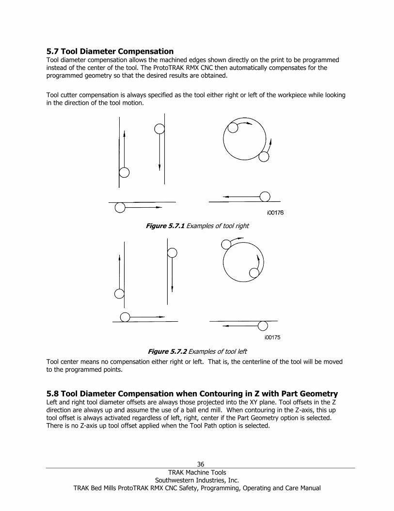
36
TRAK Machine Tools
Southwestern Industries, Inc. TRAK Bed Mills ProtoTRAK RMX CNC Safety, Programming, Operating and Care Manual
5.7 Tool Diameter Compensation Tool diameter compensation allows the machined edges shown directly on the print to be programmed
instead of the center of the tool. The ProtoTRAK RMX CNC then automatically compensates for the programmed geometry so that the desired results are obtained.
Tool cutter compensation is always specified as the tool either right or left of the workpiece while looking
in the direction of the tool motion.
Tool center means no compensation either right or left. That is, the centerline of the tool will be moved
to the programmed points.
5.8 Tool Diameter Compensation when Contouring in Z with Part Geometry Left and right tool diameter offsets are always those projected into the XY plane. Tool offsets in the Z
direction are always up and assume the use of a ball end mill. When contouring in the Z-axis, this up
tool offset is always activated regardless of left, right, center if the Part Geometry option is selected. There is no Z-axis up tool offset applied when the Tool Path option is selected.
Figure 5.7.1 Examples of tool right
Figure 5.7.2 Examples of tool left

37
TRAK Machine Tools
Southwestern Industries, Inc. TRAK Bed Mills ProtoTRAK RMX CNC Safety, Programming, Operating and Care Manual
Special attention must always be paid to tool offsets when machining with a ball end mill. The reason for this is that the tool diameter changes in the bottom part (that portion equal to the tool radius) of the
tool.
The tool is always positioned at the beginning of a milling operation so that the correct point on the ball
end of the tool is tangent to the beginning point, and offset perpendicular to the machined edge by the
radius of the tool. Consider the example below of milling a ramp in the XZ plane from point B to point C.
Note how the tool at the beginning point (point B) starts below (in the Z direction) point B so that it can
actually touch this point. If this were not true, a cusp would remain to the left of point B.
Now consider a similar example milling from A to B to C in the XZ plane.
Figure 5.8.2 In order to respect the lines defined by the programmed points, the ball end mill never touches point B. Tool starts centered over A offset up by the tool Radius R. It moves right until it is tangent to both AB and BC. Then moves to point C in the first example.
Note the Tool at B does not drop below the AB line and, therefore, never touches point B. As a result, a
fillet is formed at point B equal to the tool radius.
This second example of continuous machining from one cut (AB) to another (BC) with full cutter
compensation between requires the two cuts to be made with events which are connective (see Section 5.9 or 5.10 for a more complete discussion of this requirement).
5.9 Connective Events Connective events occur between two milling events (either Mill or Arc) when the X, Y, and Z ending
points of the first event are in the same location as the X, Y, and Z starting points of the next event. In addition, the tool offset and tool number of both events must be the same. And both events must lie in
the XY plane or the same vertical plane (see Section 5.2).
Figure 5.8.1 Ball end mill position with respect to program points. Tool starts so end mill is tangent to BC. R from center of tool is perpendicular to BC
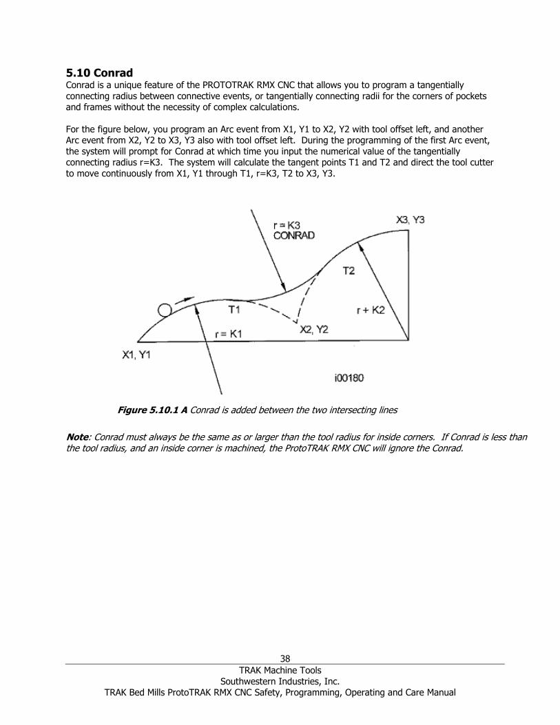
38
TRAK Machine Tools
Southwestern Industries, Inc. TRAK Bed Mills ProtoTRAK RMX CNC Safety, Programming, Operating and Care Manual
5.10 Conrad Conrad is a unique feature of the PROTOTRAK RMX CNC that allows you to program a tangentially
connecting radius between connective events, or tangentially connecting radii for the corners of pockets and frames without the necessity of complex calculations.
For the figure below, you program an Arc event from X1, Y1 to X2, Y2 with tool offset left, and another Arc event from X2, Y2 to X3, Y3 also with tool offset left. During the programming of the first Arc event,
the system will prompt for Conrad at which time you input the numerical value of the tangentially connecting radius r=K3. The system will calculate the tangent points T1 and T2 and direct the tool cutter
to move continuously from X1, Y1 through T1, r=K3, T2 to X3, Y3.
Note: Conrad must always be the same as or larger than the tool radius for inside corners. If Conrad is less than the tool radius, and an inside corner is machined, the ProtoTRAK RMX CNC will ignore the Conrad.
Figure 5.10.1 A Conrad is added between the two intersecting lines
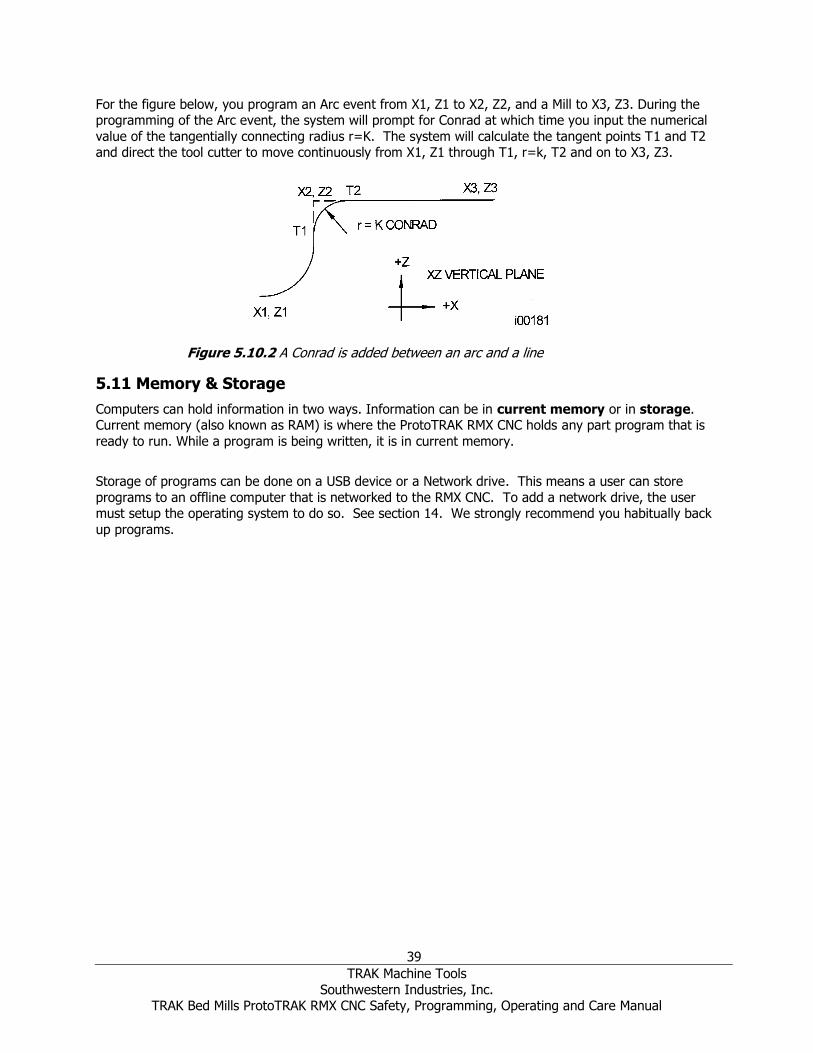
39
TRAK Machine Tools
Southwestern Industries, Inc. TRAK Bed Mills ProtoTRAK RMX CNC Safety, Programming, Operating and Care Manual
For the figure below, you program an Arc event from X1, Z1 to X2, Z2, and a Mill to X3, Z3. During the programming of the Arc event, the system will prompt for Conrad at which time you input the numerical
value of the tangentially connecting radius r=K. The system will calculate the tangent points T1 and T2 and direct the tool cutter to move continuously from X1, Z1 through T1, r=k, T2 and on to X3, Z3.
5.11 Memory & Storage
Computers can hold information in two ways. Information can be in current memory or in storage. Current memory (also known as RAM) is where the ProtoTRAK RMX CNC holds any part program that is
ready to run. While a program is being written, it is in current memory.
Storage of programs can be done on a USB device or a Network drive. This means a user can store
programs to an offline computer that is networked to the RMX CNC. To add a network drive, the user must setup the operating system to do so. See section 14. We strongly recommend you habitually back
up programs.
Figure 5.10.2 A Conrad is added between an arc and a line

40
TRAK Machine Tools
Southwestern Industries, Inc. TRAK Bed Mills ProtoTRAK RMX CNC Safety, Programming, Operating and Care Manual
6.0 Info Keys Info keys on the left side of the screen enable you to:
• Configure your ProtoTRAK RMX to your preferences
• Make changes to system defaults
• Look up information
• Access advanced capability
Info Keys are always available; while you are doing any operation of the ProtoTRAK RMX you may tap an Info key.
Fly Out Windows When you tap an Info key, the key will turn yellow and the associated fly out window will appear over the
window you had been using. When you are finished with the window, tap the key again to close it.
Figure 6.0a The Option key opens a Fly Out Window over the event programming to give you instant
access to relevant choices Once you open a Fly Out Window, you must close it by tapping the associated Info Key.
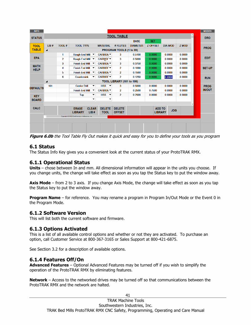
41
TRAK Machine Tools
Southwestern Industries, Inc. TRAK Bed Mills ProtoTRAK RMX CNC Safety, Programming, Operating and Care Manual
Figure 6.0b the Tool Table Fly Out makes it quick and easy for you to define your tools as you program
6.1 Status The Status Info Key gives you a convenient look at the current status of your ProtoTRAK RMX.
6.1.1 Operational Status Units – chose between In and mm. All dimensional information will appear in the units you choose. If you change units, the change will take effect as soon as you tap the Status key to put the window away.
Axis Mode – from 2 to 3 axis. If you change Axis Mode, the change will take effect as soon as you tap the Status key to put the window away.
Program Name – for reference. You may rename a program in Program In/Out Mode or the Event 0 in
the Program Mode.
6.1.2 Software Version This will list both the current software and firmware.
6.1.3 Options Activated This is a list of all available control options and whether or not they are activated. To purchase an option, call Customer Service at 800-367-3165 or Sales Support at 800-421-6875.
See Section 3.2 for a description of available options.
6.1.4 Features Off/On Advanced Features – Optional Advanced Features may be turned off if you wish to simplify the
operation of the ProtoTRAK RMX by eliminating features.
Network – Access to the networked drives may be turned off so that communications between the
ProtoTRAK RMX and the network are halted.

42
TRAK Machine Tools
Southwestern Industries, Inc. TRAK Bed Mills ProtoTRAK RMX CNC Safety, Programming, Operating and Care Manual
Electronic Handwheels – The optional (standard on the DPM RX5 and DPM RX7) Electronic Handwheels may be turned off to assure the machine doesn’t inadvertently move.
Note: When turned on, the Electronic Handwheels move the table, saddle and ram only during DRO Mode and TRAKing® in run mode. Auxiliary Functions – the AUX event may be turned off if you wish to simplify the operation of the
ProtoTRAK RMX.
6.2 Tool Table The Tool Table is divided into three sections (including the optional Tool Library):
Base Tool This is the status of the Base or reference tool – Set or Not Set. See below for a description of the Base
Reference Tool.
Figure 6.2.1a The Tool Table as it appears without the Advanced Features Option activated.
Program Tools These are the tools that you have entered into the events of your current program. Up to 100 tools may
be entered from 1 – 99.
As long as the tool number is in one of your events, it will automatically appear in this part of the screen.
See below for how to set up the tool. You may set up the tool at any time while you are preparing the program, including opening the Tool Table window as you are programming while the tool is on your
mind. If you forget to enter diameter or other essential information before running, the ProtoTRAK RMX will present you with an error message. To help, the info that is required before run is highlighted in
orange not if entered and it turns green when entered.

43
TRAK Machine Tools
Southwestern Industries, Inc. TRAK Bed Mills ProtoTRAK RMX CNC Safety, Programming, Operating and Care Manual
Tool Offsets and Mods in Program Tools are not saved when a current program is closed, erased or if the control is powered off. To save this information, see Save/Open Temp in the Program In/Out Mode for
saving a temporary file.
Tool Library (optional)
When the Advanced Features Option is activated, there will be a Tool Library section in the Tool Table.
The Tool Library can be a convenient way to save tool information and use the information to cut down on time in doing programming and set up. All the information, including the Offsets and Mods, are saved
in the Tool Library. You may set up the tools in the Tool Library separately from a program by entering tool information directly into the Tool Library or you may transfer information from Program Tools as you
go. Be sure to fully understand the Tool Library procedures to avoid using tools with incorrect or
incompatible offsets so you don’t crash a tool!
To input information directly into the Tool Library, simply tap in any of the columns of the empty row and enter information.
To transfer tool information that is already in a Program Tool, simply tap on the Program Tool, Tool # and tap ADD TO LIBRARY.
Tool Library tools may be identified by a number from 101 – 199. We do this to distinguish them from
the Program Tools which are numbered from 1 – 99.
Figure 6.2.1b The Tool Table with the Advanced Features Option activated. See Section 6.2.4 below for using the Tools from the Tool Library. Tool Table Column Headings
LIB# - Used only in the Tool Library section. You assign numbers to the tools in the Tool Library by tapping this field. In order to distinguish Tool Library from tool numbers you assign during programming,
the Tool Library tools must be a number from 101 – 199. It is not mandatory to assign a Library
Number, but it may help as a cross reference when you assign the Library tool to a Program Tool. If you want to use the library tool in DRO, then a library tool number is required.
44
TRAK Machine Tools
Southwestern Industries, Inc. TRAK Bed Mills ProtoTRAK RMX CNC Safety, Programming, Operating and Care Manual
Tool # - the tool number you assigned in the current program, from 1 – 99. These tools are the Program
Tools.
Tool Type - the type of tool chosen from the drop-down list if you elect to do so.
Material - selects the tool material from the drop-down list if you elect to do so.
# Flutes - specifies the number of flutes for the cutter. This is elective unless you use Feed per Tooth.
Diameter - the tool diameter. This is mandatory in order for the ProtoTRAK RMX to calculate the tool
path with offsets.
Z Offset - the difference between this tool and the Base Tool. You must set this tool to run the
program. The field will be orange and there will be a line instead of a number until the tool is set.
Dia Mod - allows for small adjustments e.g. for reground tools; this is elective.
Z Mod - allows for small adjustments in Z Offset; this is elective.
6.2.1 The Base Tool For your convenience, we have supplied a 3/8-inch drill shank with a rounded tip. If you insert the shank into a tool holder and never remove it, this can serve as your Base Tool. Referencing all tool offsets from
this Base Tool gives you the ability to use the same tool in several programs without resetting offsets. We also suggest that you establish a point you will use to touch off every time. This simple habit will
make tool setting quick, easy and secure.
Each time the ProtoTRAK RMX is powered down, the base tool reference will be lost.
6.2.2 Setting Z Offsets There are two different methods for setting your Z offsets:
Method 1: Setting Z Offsets can simply be a matter of first setting the Base Tool and then each tool. You can tell if a
tool is not set because the box will be orange and there will be dash instead of a number. To Set the Base Tool:
1. Put your Base Tool in the spindle.
2. Tap the Z Offset box in the Base Tool part of the Tool Table screen. 3. Touch off your Base Tool. We recommend that you use a touch-off point that you will be able to
use for all tools, now and in the future. If you mix up touch off points, you will crash a tool. 4. Press Enter.
Set the other tools Program or Tool Library:
1. Put the tool in the spindle. 2. Tap the Z Offset box for the tool.
3. Touch off the tool to the same place that you touched off the Base Tool. 4. Press SET
5. Repeat for all tools that you want to set or reset.
Note: Just because the field offset field is green and there is a number instead of a dash, this is NOT a guarantee that the offset is correct. If you want to start over to be sure, tap the value and tap the DELETE OFFSET key and redo the offset with the procedure above.
45
TRAK Machine Tools
Southwestern Industries, Inc. TRAK Bed Mills ProtoTRAK RMX CNC Safety, Programming, Operating and Care Manual
Method 2: (Added in 2.0.0 software version) You can use our optional Tool Measurement Device to measure your tool offsets. See section 3.5.14.
1. In the Tool Table screen, do not enter a value for the BASE. It should remain orange and read NOT SET.
2. Put your Base Tool in your tool measurement holder.
3. Set your tool measuring device to 0. 4. Use the measuring device to get each tool’s offset relative to the base tool.
5. Manually enter the tool offset into the tool table under Z OFFSET, exactly as it read from the measurement device.
6.2.3 Using Library Tools While Programming The Flyout Windows of the ProtoTRAK RMX makes programming your tools easier than ever. At any
time, tap the Tool Table key and the window will open over the mode window you are working in. Having a Tool Library at hand makes it even easier.
To use the Library Tools, simply do the following:
1. While programming, enter a number for your Program Tool from 1 – 99.
This will create an entry in the Program Tools area of the Tool Table for each unique tool number. The entry will appear as soon as you finish all the prompts for the event.
2. Tap the TOOL TABLE Info key. The Tool Table will open. 3. In the Tool Library section of the Tool Table, tap the Tool # Field in the row of the Library Tool you
want to use.
4. Press Enter. The information for the tool in the Tool Library will copy to the Program Tool. If the Library Tool had a LIB #, that number will appear for reference next to the Program Tool #.
That’s it!
Note: We do not allow you to enter the Library Tool # into the Tool prompt while programming an event. We do this as a precaution. Tool Library Z Offsets are stored in the control, but that doesn’t mean they are correct. Programs written at different times, on different ProtoTRAKs or on the Offline Software may have offsets stored that are not correct for the machine and tool on which they will run. To prevent errors, we make it a deliberate action for you to relate the Library Tool to the Program Tool.
This will give you the chance to decide whether you want to trust the values or not. It is an extra step,
albeit a small one, but well worth it to avoid what could be an expensive crash.
6.2.4 Soft keys in the Tool Table ERASE LIBRARY (O) – To erase all the Library Tool information at once. CLEAR LIB# (O) - To erase the Library Tool # reference from the Program Tool. First tap the Program
Tool #, and then CLEAR LIB#. DELETE TOOL (O) – deletes the data for a Library Tool. Tap anywhere on row first, then tap DELETE
TOOL. DELETE OFFSET – Deletes the offset for the tool. Tap anywhere on the row first, then tap DELETE
OFFSET.
ADD TO LIBRARY (O) – Copies the Program Tool information to the Tool Library. JOG – Turns on the servo motors so you can jog the ram to position for doing the Z offset.
Note: The jog feature always defaults to the positive direction.
(O) – These soft keys pertain to the Tool Library. The Advanced Features Option must be activated for the Tool Library to be available. If the keys are greyed out, the Advanced Features Option is not
activated.

46
TRAK Machine Tools
Southwestern Industries, Inc. TRAK Bed Mills ProtoTRAK RMX CNC Safety, Programming, Operating and Care Manual
6.3 EPA The EPA (Enhanced ProtoTRAK Assistance) key will give you quick access to a collection of short tutorials
that provide help for using the ProtoTRAK RMX CNC. While these tutorials are useful for resolving questions or jogging the memory, they are not intended to substitute for the user manual or for product
training.
Figure 6.3 The EPA Screen
6.3.1 EPA Index The EPA Index will display the tutorials available depending on either the current operation or your
selection in the Search Text box.
For example, if you are in the Program Mode, when you press the EPA key, the EPA Index will display the
topics most likely to be of interest for Program Mode operations. For example, say you are doing a part program using the AGE (Auto Geometry Engine™) and you forget the meaning of the Line Angle prompt.
By pressing the EPA Info key, the EPA Index will appear. Instead of listing all the topics, a shortened list of only those topics likely to be of interest for that operation will appear so you will be able to quickly
choose a tutorial with the information you need.
EPA Topics are arranged in Groups:
A. General – overall operation of the ProtoTRAK RMX B. Information key
C. DRO Mode
D. Program Events E. Other Program Features
F. Edit Mode G. Set-up Mode
H. Run Mode I. Program In/Out
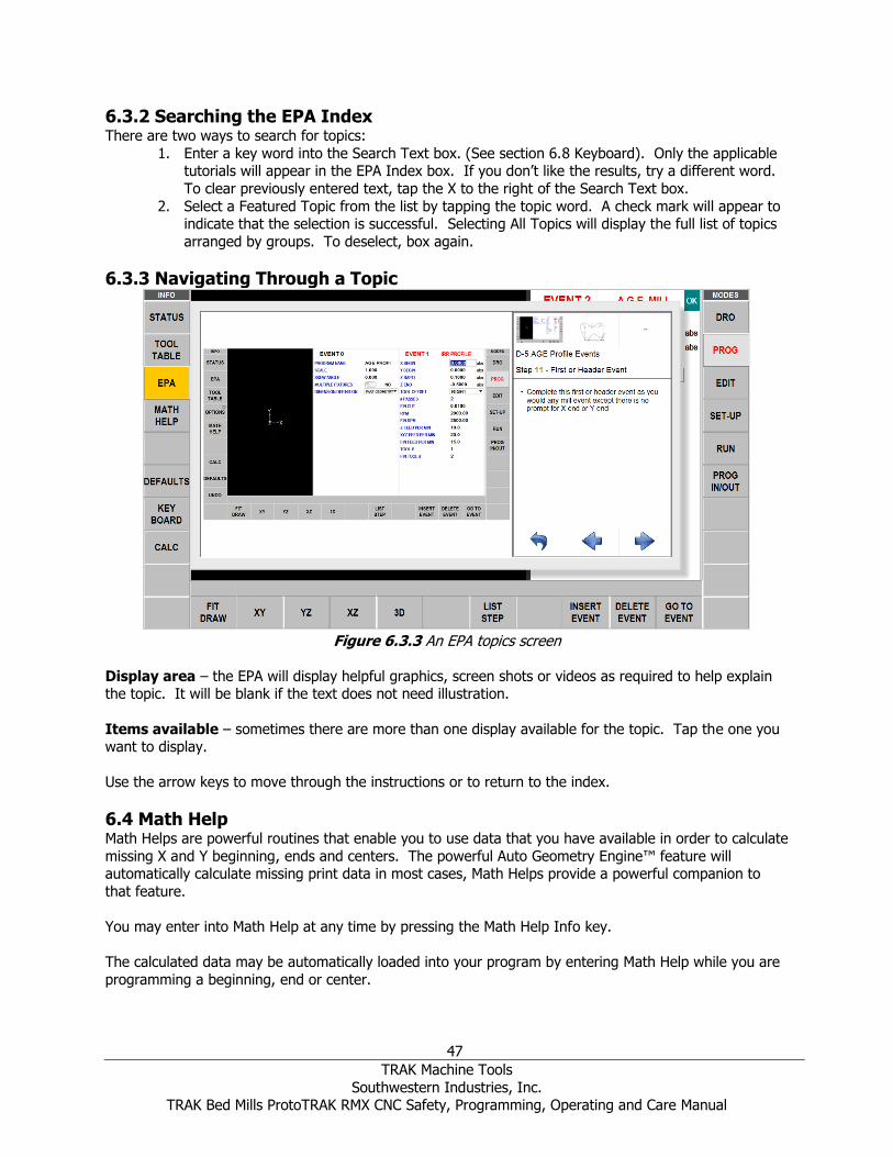
47
TRAK Machine Tools
Southwestern Industries, Inc. TRAK Bed Mills ProtoTRAK RMX CNC Safety, Programming, Operating and Care Manual
6.3.2 Searching the EPA Index There are two ways to search for topics:
1. Enter a key word into the Search Text box. (See section 6.8 Keyboard). Only the applicable tutorials will appear in the EPA Index box. If you don’t like the results, try a different word.
To clear previously entered text, tap the X to the right of the Search Text box.
2. Select a Featured Topic from the list by tapping the topic word. A check mark will appear to indicate that the selection is successful. Selecting All Topics will display the full list of topics
arranged by groups. To deselect, box again.
6.3.3 Navigating Through a Topic
Figure 6.3.3 An EPA topics screen
Display area – the EPA will display helpful graphics, screen shots or videos as required to help explain the topic. It will be blank if the text does not need illustration.
Items available – sometimes there are more than one display available for the topic. Tap the one you want to display.
Use the arrow keys to move through the instructions or to return to the index.
6.4 Math Help Math Helps are powerful routines that enable you to use data that you have available in order to calculate
missing X and Y beginning, ends and centers. The powerful Auto Geometry Engine™ feature will automatically calculate missing print data in most cases, Math Helps provide a powerful companion to
that feature.
You may enter into Math Help at any time by pressing the Math Help Info key.
The calculated data may be automatically loaded into your program by entering Math Help while you are
programming a beginning, end or center.
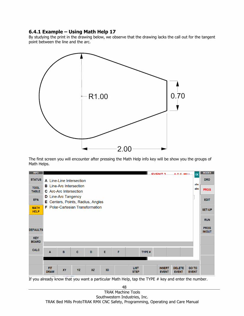
48
TRAK Machine Tools
Southwestern Industries, Inc. TRAK Bed Mills ProtoTRAK RMX CNC Safety, Programming, Operating and Care Manual
6.4.1 Example – Using Math Help 17 By studying the print in the drawing below, we observe that the drawing lacks the call out for the tangent
point between the line and the arc.
The first screen you will encounter after pressing the Math Help info key will be show you the groups of
Math Helps.
If you already know that you want a particular Math Help, tap the TYPE # key and enter the number.

49
TRAK Machine Tools
Southwestern Industries, Inc. TRAK Bed Mills ProtoTRAK RMX CNC Safety, Programming, Operating and Care Manual
In the example above we see that we want to know a point tangent to the line and arc on the drawing.
We select Group D Line-Arc Tangency by tapping the D key. Then we get the following choices:
Further study of the print reveals that we have the information most suitable for Math Help 17. We
select 17 by tapping the 17 key.
Enter the known print data as prompted on the data input line. Unlike the event programming, you must
enter the data on the data input line near the bottom of the screen. You cannot type the data directly into the list of data as you can in other places in the ProtoTRAK RMX. Use the DATA UP and DATA DOWN
keys to move through the list of data.
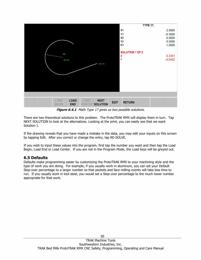
50
TRAK Machine Tools
Southwestern Industries, Inc. TRAK Bed Mills ProtoTRAK RMX CNC Safety, Programming, Operating and Care Manual
Figure 6.4.1 Math Type 17 gives us two possible solutions.
There are two theoretical solutions to this problem. The ProtoTRAK RMX will display them in turn. Tap NEXT SOLUTION to look at the alternatives. Looking at the print, you can easily see that we want
Solution 1.
If the drawing reveals that you have made a mistake in the data, you may edit your inputs on this screen
by tapping Edit. After you correct or change the entry, tap RE-SOLVE.
If you wish to input these values into the program, first tap the number you want and then tap the Load Begin, Load End or Load Center. If you are not in the Program Mode, the Load keys will be greyed out.
6.5 Defaults Defaults make programming easier by customizing the ProtoTRAK RMX to your machining style and the
type of work you are doing. For example, if you usually work in aluminum, you can set your Default Step-over percentage to a larger number so that pockets and face milling events will take less time to
run. If you usually work in tool steel, you would set a Step-over percentage to the much lower number appropriate for that work.

51
TRAK Machine Tools
Southwestern Industries, Inc. TRAK Bed Mills ProtoTRAK RMX CNC Safety, Programming, Operating and Care Manual
Figure 6.5 The Defaults Flyout Window.
6.5.1 Default Entries and What They Mean The following are the Default values that you may enter. The number corresponds to the number on the Defaults Flyout Window.
1. Feed Moves
Feed per Min – the Feedrate in Inch per minute or mm per minute.
Feed per Tooth – the Feedrate in inch or mm per tooth. The number of flutes must be defined for the tool in the Tool Table.
Math Help Type 30 will calculate IPM from the RPM, inch/tooth and number of teeth values you enter.
2. Spindle Speed Values RPM – Spindle speed in Revolutions per Minute
SFM or SMM - Surface Speed in Surface Feet per Minute or Surface Meters per Minute, which is
the speed of the outside Diameter of the tool.
Math Help Type 31 will convert an RPM value to SFM or SMM.
3. Peck Type on Drill and Bolt Hole events
Variable – progressively less each peck with full retract out of hole on each peck Fixed – same depth each peck with full retract out of hole on each peck
Chip break – retracts 0.020” between pecks. The pecks are the same as Fixed.
4. Profile, Pocket and Island Events
Number of Passes – the total Z cut divided evenly by this number. Finish cut in X / Y – the amount of wall material for the finish cut.
5. Step over percentage for Pocket and Island Events.
Step over percentage is the percentage of the tool diameter overlap as successive material is removed.

52
TRAK Machine Tools
Southwestern Industries, Inc. TRAK Bed Mills ProtoTRAK RMX CNC Safety, Programming, Operating and Care Manual
Step over percentage – Offset and parallel tool path – this step over percentage should balance the speed of the cut, working the tool properly, and the fact that the cutter will be loaded up
more on the initial cut where it will be taking a full width of cut, and when it is in a corner.
Step Over Percentage – Offset & Parallel Tool Path – Z Finish Cut – This helps the user define a
separate step over percentage for Z floor using offset & parallel tool path.
Step over percentage – Adaptive tool path (Advanced Features Option). Adaptive tool path is a complex software routine to achieve all cutting at a constant chip load. This enables you to
determine the chip load by the combination of other settings and the ProtoTRAK RMX will automatically calculate the tool path needed to obtain the finished part using that chip load.
Step Over Percentage – Adaptive Tool Path – Z Finish Cut – This helps user define a separate step over percentage for Z floor using adaptive tool path
6. Face Mill Event
The Face Mill event will cut a rectangular area you define by opposite corners. The toolpath for the Face
Mill Event should start from the X BEG/Y BEG corner and cut in the X +/- direction. It always starts off the area you define and machines the top of the part using the Step Over Percentage and the Cutting
Method you define in the Defaults. User can select the cutting order.
Step over percentage – The percentage of tool diameter overlap as successive material is removed.
Cutting Method: One Way - all machining is in one direction with rapid positioning in between. This enables you to
have all climb or conventional cutting for the entire event. Zig Zag – the machining is in a back-and-forth pattern, with no rapid positioning between
changes of direction. This has the effect of alternate climb and conventional cutting.
Z Finish cut – while programming the event, you will only see the prompt, and the default value
set here, when the Bottom Finish Cut is set to ‘Yes’ in Options.
Number of Passes/Depth per Pass – Toggle whether to prompt for # of passes or depth per pass.
Depth per Pass – The depth amount for each pass.
7. Pocket and Island Events All the following Defaults are applied to the powerful Pocket and Island Events.
Cutting Direction:
1 – CW – Clockwise (conventional cutting)
2 – CCW – Counterclockwise (climb cutting)
Z Entry method:
• Plunge – Z goes straight down at the Z Feedrate programmed.
• Helical – the X, Y and Z are automatically programmed to feed into the part in a helical motion.
• Zig Zag – the Z feeds in a back-and-forth motion.
Tool path pattern:
• Offset - Starts in a logical place depending on the part geometry and takes successive passes based on the Step over percentage.

53
TRAK Machine Tools
Southwestern Industries, Inc. TRAK Bed Mills ProtoTRAK RMX CNC Safety, Programming, Operating and Care Manual
• Parallel – Starts in a logical place and will move in parallel lines depending on the part
geometry. Moves back and forth in successive passes. In Machining Angle below, you can enter in an angle for the parallel moves if the part feature is not aligned to the X
axis.
• Adaptive (Advanced Features Option) – Complex software routine that maintains a constant chip load as it is cutting.
Adaptive Tool Path allows you to machine much faster than other tool paths. With other types of tool path, you must limit your feed rate and step over percentages to those cuts where the tool will be loaded
the most. A common example of an area with the greatest chip load is the corner of a pocket. That means that the rest of the tool path is cutting at feeds much lower than the cutter could take.
Figure 6.5.1 (7) Offset tool path on the left, Adaptive on the right.
Adaptive Machining is powerful software that calculates a tool path to keep the chip load constant. You
can set step over percentages and feedrates more aggressively and it is the job of Adaptive Tool Path to move along a toolpath that won’t overload the tool.
Cutting Method:
• One Way – all machining is in one direction with rapid positioning in between. This
enables you to have all climb or conventional cutting for the entire event.
• Zig Zag – the machining is in a back-and-forth pattern, with no rapid positioning between changes of direction. This has the effect of alternate climb and conventional cutting.
Tool Path Pattern – Z Finish Cut: Separate tool path pattern for Z floor
Z Entry Method – Z Finish Cut: Define Z entry method for Z floor
Cutting Method – Z Finish Cut: Define Cutting method for Z Floor
54
TRAK Machine Tools
Southwestern Industries, Inc. TRAK Bed Mills ProtoTRAK RMX CNC Safety, Programming, Operating and Care Manual
Z Finish Cut – While programming the event, you will only see the prompt, and the default value set here, when the Bottom Finish Cut is set to ‘Yes’ in Options.
Helical Entry Pitch – Input the pitch of the Helix used when starting a pocket.
Zig Zag Entry Angle – Input the angle of the back-and-forth motion used in starting a pocket.
Helical Entry Pitch – Z Finish Cut: Define Helical Entry Pitch for Z floor
Zig Zag Entry Angle – Z Finish Cut: Define Zig Zag Entry Angle for Z floor
Machining Angle – This is only needed when Toolpath Pattern (above) is set to Parallel. It is
useful when the part or the pocket is not aligned with the X axis. The Machining Angle allows you to have a toolpath that better suits the part.
Machining Angle in XY – Z Finish Cut – Define Machining Angle in XY for Z floor.
Order of Passes – This is the strategy for when the pocket cannot be completed in a complete pass without picking up the tool. For example, a roughing tool is used that cannot fit in the entire
pocket in one continuous path. You have these choices:
• Depth – Completes each depth for all regions before moving to the next depth. In other words, completes each pass for each region.
• Region – Completes all passes in each region before picking up the tool. In other words,
the part is machined to final depth in each region before starting the next region.
Roughing Link for Rapid – This works with the Adaptive Toolpath Pattern. When optimizing tool
load, the toolpath is not always contiguous, sometimes the tool needs to move from where it is in to a different section. Those moves between sections are called links. As a default, the
ProtoTRAK RMX will handle links in this way:
• For a rectangular pocket it will lift the tool to Z rapid and move at rapid to the next
section and rapid down to 0.020” above pass depth and then feed to the final depth.
• For an irregular pocket, it will lift the tool to Z Rapid (or the Z Safety Plane), then move
at rapid to the next section and rapid down to 0.020” above pass depth and then feed to the final depth.
If you do not care that the tool stays into the cut between sections on the rough cut, you would enter a small value into this prompt. If the links are large, the part may be machined more
quickly by having a rapid move between sections. The next prompt will allow you to preserve your finish at the bottom of the cut.
Note: In Figure 6.5.1 (7) above, the link length is set to a small value, hence the many rapid moves.
Bottom Z Finish link length for Rapid – This default works with Adaptive Toolpath Pattern and is applied when the Bottom Z Finish Cut is set to ON in Options. You may want to minimize the
tool marks that occur when the tool lifts from the cut and then reenters. To keep the cutter
down into the part, enter a value here that is big enough to include your largest Link length.
Minimum Curvature Radius – This value works with the Adaptive Tool Pattern. In order to keep the load constant on the tool, the Adaptive Toolpath often moves along a series of arcs. The
Adaptive Toolpath will try to fit into any section where the tool fits. This could result in the
toolpath whittling away at a narrow area that would be better left for a finishing tool of a smaller radius. The Minimum Curvature Radius allows you to set a minimum radius of the arcs to
preserve more Rest area for a smaller tool.

55
TRAK Machine Tools
Southwestern Industries, Inc. TRAK Bed Mills ProtoTRAK RMX CNC Safety, Programming, Operating and Care Manual
Minimum Curvature Radius – Z Finish Cut: Define Minimum Curvature Radius for Z floor.
Note: Rest area is simply the material that is left over from the rough cut, that is, the “rest” of the material. Apparently, someone got a patent on the use of the word “residual”.
Cut Tolerances are the tolerances that are used when calculating a toolpath. Depending on the complexity of the geometry the calculated toolpath that the machine will follow could deviate by
these amounts. These are not machine tolerances.
These tolerances are applied to Parallel and Adaptive toolpaths. For Offset toolpaths the typical
accuracy of the calculations should be ~1e-6. For most parts such as circles, rectangles and non-complex geometry there should be little to no deviation and the calculated toolpath is extremely
accurate. All Semi-Finish and Finish passes should have the same ~1e-6 accuracy when
calculating the toolpaths.
ROUGH CUT TOLERANCE – WITH FINISH CUT – This is the amount of deviation that is allowed
from the calculated roughing toolpath. The roughing toolpath is the programmed part minus the finish cut amount minus the cut tolerance. A larger tolerance allows the ProtoTRAK RMX control
to calculate the tool path faster, but with the possibility of having larger scallops that would be
cleaned up automatically with the Semi-Finish pass. Lowering this value will increase the time to calculate the tool path but also may allow a tool to fit into tighter areas and allow the rough tool
to remove more material before the REST tool comes in to finish the remaining material. Depending on the shape and complexity of the part, the rough cut dimension could vary from the
programmed dimension minus the finish cut amount to the programmed dimension minus the finish cut amount minus 2 times the cut tolerance. You are guaranteed that the rough cut will
never enter the finish cut material.
ROUGH CUT TOLERANCE – WITH NO FINISH CUT – The concept is the same as above, but a smaller tolerance should be entered since this value is only applied when you are machining a
pocket or island with no finish cut. This ensures the pocket will be machined accurate to within
this tolerance.
REST CUT TOLERANCE – Machining REST material is the same as the ROUGH CUT TOLERANCE –
WITH FINISH CUT. Since you will use the same tool for removing REST material as for finish cuts, this setting allows you to machine faster until the toolpath transitions to the Finish Cut.
8. Circle Pocket Event
Tool Path Patterns:
• Offset
• Spiral (Under the Z entry method, Helical will not work for spiral tool path.)
Tool Path Patterns – Z Finish Cut: Define Tool Pattern for Z floor in Circle Pockets.
9. Engrave Event – XY Reference
Engrave from XY position set as the center or lower left reference point.
10. Subroutine and Copy Events
These defaults are handy for people who use subroutines events in standard ways. For example, using subroutines to repeat programmed events for Finish Cuts. You will be able to override the default value
at the subroutine prompts.
Percent speed – origin event(s) Spindle Speed times this value.
Percent feed – origin event(s) Feedrate times this value.

56
TRAK Machine Tools
Southwestern Industries, Inc. TRAK Bed Mills ProtoTRAK RMX CNC Safety, Programming, Operating and Care Manual
Mirror direction:
• Forward – the toolpath will be mirrored and therefore will be the opposite of the toolpath of the origin event(s).
• Backward – the toolpath will not be mirrored and will maintain the same climb or
conventional direction as the origin event(s).
11. Reference Positions
Limits – Allow you to set default software limits that are relative to the X, Y and Z Absolute values you set. The ProtoTRAK RMX will not go past these limits.
Home position – In Run Mode, the ProtoTRAK RMX will return to these positions. These numbers are relative to the Absolute 0 set in DRO Mode.
12. Units Inch/mm
Setting the default will have the ProtoTRAK RMX operate in that unit each time it is turned on.
Note: You may change your current operations from one unit to the other with the Status Info key.
13. Start up in 2 or 3 Axis Mode This default determines how the ProtoTRAK RMX starts after being powered down. You can change this
in the Status info key.
14. Maximum Rapid Feedrates
If you do not want the maximum of 400 inches per minute you can set the maximum here. Note – the Z axis runs at 250 ipm.
15. Accessory On Button
This will determine what the Accessory Button will control. You may have both hooked up to the
ProtoTRAK RMX and move from one to the other. Coolant – signal to coolant
Mist – signal to mister
16. Tool Compensation
• Center – no tool compensation, the tool will move along the programmed toolpath
• Right – the tool moves to the right of the programmed toolpath, offset by the radius of
the tool diameter set in the Tool Table.
• Left – the tool moves to the left of the programmed toolpath, offset by the radius of the tool diameter set in the Tool Table
Note: see Section 5.7 for a nice illustration of Tool Diameter Compensation.
17. Z Safety Plane Default value for Z safety plane can be set here and for each event you can turn the Z safety
plane ON/OFF and it will use the value from defaults.
18. Show Supported File Types Only
Can be turned ON/OFF. When turned OFF, the user can see all file types in PROG IN/OUT, select the file, and open it as any file type supported by ProtoTRAK.
6.5.2 Working with Defaults As you are programming, press INC SET or ABS SET to accept the default value, or simply enter another
value and press SET.
Whatever you choose as a default can be easily changed in defaults or overridden event by event with
the prompt or in the Options Flyout window.
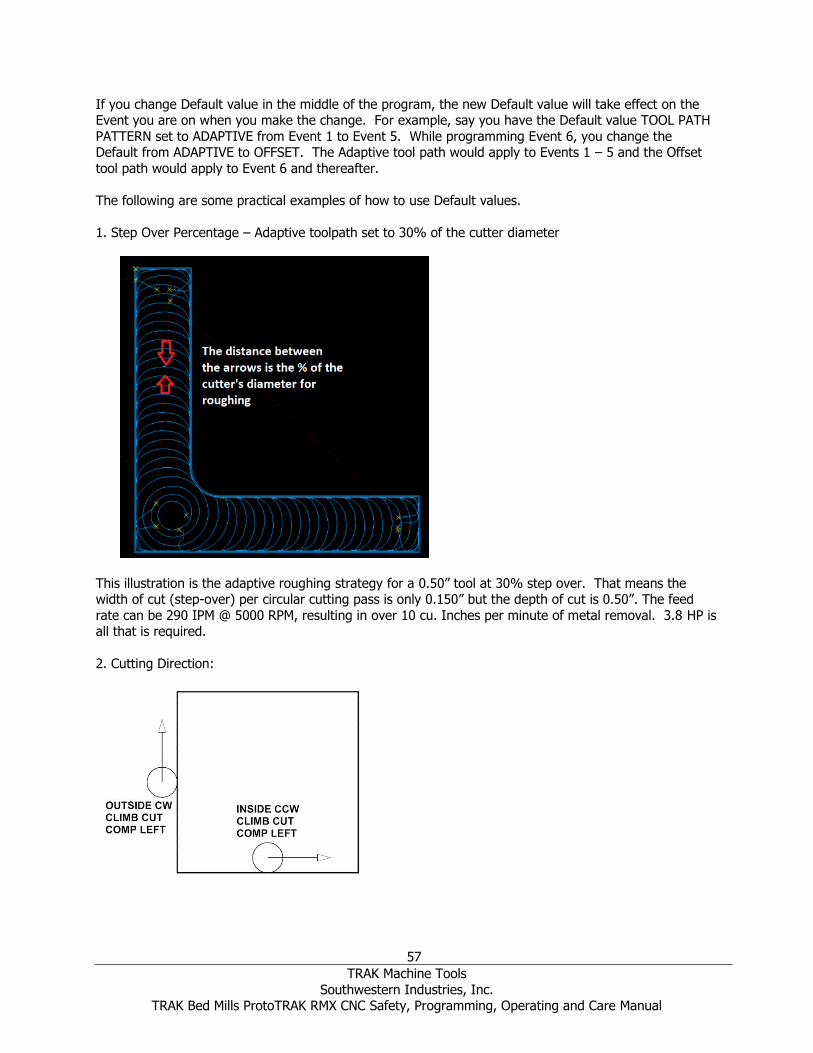
57
TRAK Machine Tools
Southwestern Industries, Inc. TRAK Bed Mills ProtoTRAK RMX CNC Safety, Programming, Operating and Care Manual
If you change Default value in the middle of the program, the new Default value will take effect on the Event you are on when you make the change. For example, say you have the Default value TOOL PATH
PATTERN set to ADAPTIVE from Event 1 to Event 5. While programming Event 6, you change the Default from ADAPTIVE to OFFSET. The Adaptive tool path would apply to Events 1 – 5 and the Offset
tool path would apply to Event 6 and thereafter.
The following are some practical examples of how to use Default values.
1. Step Over Percentage – Adaptive toolpath set to 30% of the cutter diameter
This illustration is the adaptive roughing strategy for a 0.50” tool at 30% step over. That means the width of cut (step-over) per circular cutting pass is only 0.150” but the depth of cut is 0.50”. The feed
rate can be 290 IPM @ 5000 RPM, resulting in over 10 cu. Inches per minute of metal removal. 3.8 HP is all that is required.
2. Cutting Direction:

58
TRAK Machine Tools
Southwestern Industries, Inc. TRAK Bed Mills ProtoTRAK RMX CNC Safety, Programming, Operating and Care Manual
Pockets: Set to 1- CW to conventional cut
Set to 2- CCW to climb cut
Profiles:
Set to 1- CW to climb cut Set to 2- CCW to conventional cut
3. Z Entry Method - Helical
By setting your Z entry type to helical, you can often get to the Z cutting depth faster. For instance, a 0.50” cutter in aluminum using a helix entry, with a pitch of 0.040, can run at 2500 RPM and a feed of
126 IPM. This can be done with the same tool you use to rough with so there is no tool change required.
4. Default Toolpath Pattern - Adaptive

59
TRAK Machine Tools
Southwestern Industries, Inc. TRAK Bed Mills ProtoTRAK RMX CNC Safety, Programming, Operating and Care Manual
Adaptive roughing is the fastest method of stock removal, with the least amount of wear and tear on both the tool and the machine. Notice the sweeping arc movements. This cutting strategy is extremely
efficient.
5. Default adaptive cutting pattern set to Zig-Zag
This picture illustrates Adaptive Zig Zag roughing strategy. By combining climb and conventional cutting,
the tool will stay down and in the cut and require fewer moves to reposition.
6. Helical Pitch Entry
The helical entry pitch has a strong bearing on how fast you can feed your tool down to the required Z
depth. The smaller the pitch, the faster the feedrate. We recommend you start with a 0.040 pitch for softer materials and half of that for harder materials.
7. Order of Passes
By Depth:

60
TRAK Machine Tools
Southwestern Industries, Inc. TRAK Bed Mills ProtoTRAK RMX CNC Safety, Programming, Operating and Care Manual
All roughing and rest cuts are made a one Z level before proceeding to the next Z level, as shown in this illustration. Notice how the tool moves to all 5 regions at each Z depth. This makes a total of 14 rapid
moves.
By Region:
All Z roughing and rest cuts are made in one Z region before proceeding to the next region, as shown in
this illustration. This strategy makes a total of only 5 rapid moves. There is minimum of traverse-wasting time. Notice cuts 1,2 and 3 are all in the same corner. The other corners are the same.
8. Minimum Curvature Radius
Above is a part cut with the standard minimum curvature radius of 0.10, utilizing a 0.50” cutter.
Notice the areas circled. The cutter could not fit the toolpath between the pocket and the island.
This leaves a large amount of stock that the tool will have to cut through at full depth and full width of cut. At high feeds, this may damage the cutter.

61
TRAK Machine Tools
Southwestern Industries, Inc. TRAK Bed Mills ProtoTRAK RMX CNC Safety, Programming, Operating and Care Manual
Below the minimum curvature radius was changed from 0.10 to 0.010. The toolpath can now fit between the pocket and the island. This slight adjustment allows the use of the larger 0.50” cutter to do the
heavy machining you would want to accomplish with the largest cutter diameter possible. Your maximum feed rate will have to decrease but the cycle time will be faster overall.
6.5.3 User Profiles Each user can set and save their individual default profiles. Service Code 600 allows you to edit and
manage User Profiles by using the ADD PROFILE, DELETE PROFILE, and RESET PROFILE buttons or
selecting a user profile to change the user name.
Figure 6.5.3 Service Code 600 – Manage User Profiles Window

62
TRAK Machine Tools
Southwestern Industries, Inc. TRAK Bed Mills ProtoTRAK RMX CNC Safety, Programming, Operating and Care Manual
6.6 Options The Options Info Key is active when you are in the Program Mode and you have choices for how you
program a particular event. If it is not active, the space will be blank. Options give you additional choices for programming events and also allow you to override the default programming style. For example, if
you have set the default Drilling to Variable Peck and you wish to change that to Fixed for this particular
event, you can quickly do that in Options.
Figure 6.6 Options enables you to override the defaults on the fly
You set your overall programming style in the Defaults Info Key (Section 6.5 above), but change them on
the fly in Options if you wish. If you find yourself frequently changing a default value, we highly
recommend that you change the value in the Defaults Info Key.
Note: Changing a Default does not change a current program. For a changed Default value to appear in a program, the program must be opened or started after the change.
6.6.1 Programming Variables Found in Options The options key is active when there are options for what is active in the window you are working in. In
programming, the Options that appear when you tap the Options Info key depend on the event type.
Z Safety Plane
The Z Safety Plane is a setting to insure that every tool will not accidently contact fixtures that stick up above the part. It is the distance from the part’s Z Absolute Zero to the bottom of every tool in the
spindle. When the Z Safety Plane is set to ON, a prompt will appear for entering the Z Safety plane value.
During program Run, the tool will move from Z Retract to Z Rapid for the first event. Between events, it will move to Z Safety Plane (instead of Z rapid) prior to an X, Y move.

63
TRAK Machine Tools
Southwestern Industries, Inc. TRAK Bed Mills ProtoTRAK RMX CNC Safety, Programming, Operating and Care Manual
Spindle Speed RPM – spindle speed for the event in Revolutions per Minute
Surface Speed – Spindle Speed for the event in Surface Feet per Minute, which is the speed of the outside Diameter of the tool.
You may use Math Help Type 31 to convert an RPM value to SFM.
Event Comments Turn this on in order to get the prompt to enter comments you wish to appear during program Run.
Peck Type
Override the default peck for the Drill event:
• Variable – progressively less each peck
• Fixed – same depth each peck
• Chip break – retracts 0020” between pecks
Chip break is the same as fixed but with a 0.020 retract between pecks
Feed Rate
Overrides the default feed rate setting for the event:
Feed per minute in inches or mm per minute Feed per tooth.
Dwell Request
Add a Dwell Time prompt to the Drill and Bore events measured in seconds. The dwell improves the finish on the floor of the hole.
Z Finish Cut Tool User can choose to use Rough Tool or Finish Tool for Z finish cut.
Bottom Finish Cut
Turn this on to add a Z Finish Cut prompt in the Face Mill, Pocket or Island event. If a Z Finish Cut
default was entered in the Defaults it will appear in the prompt.
Cutting Method Overrides the default cutting method for the event. The Cutting Method is explained in Section 6.5.
Step Over Percentage
Overrides the default step over percentage for the event. Step over percentage is explained in Section
6.5.
Machining Angle in XY Sets the angle the cutter will remove material from a pocket or island. 0⁰ means it will rough along the X
axis, 90⁰ degrees means it will rough along the Y axis. You can select any angle between 0 and 90⁰.
Z Entry Method
Overrides the default Z entry method for the event. Z Entry Method is explained in Section 6.5.
Tool Path Pattern Overrides the default tool path pattern for the event. Tool Path Pattern is explained in Section 6.5.
Tool Path Pattern – Z Finish Cut User can have different tool path pattern for Z Floor especially for Pockets and Islands.

64
TRAK Machine Tools
Southwestern Industries, Inc. TRAK Bed Mills ProtoTRAK RMX CNC Safety, Programming, Operating and Care Manual
Order of Passes Overrides the default order of passes for the event. Order of Passes is explained in Section 6.5.
Start Location
When using adaptive tool paths, you can turn on Start Location prompts that allow the user to program
where the tool enters the workpiece. Turning this option on, adds an X START and Y START prompt within your event.
6.7 Keyboard Tapping the KEYBOARD Info key will bring up the alphanumeric keyboard. Rather than being a Fly out
window, the keyboard is a separate window that can be dragged around the screen for convenience. After the keyboard is opened, tap the field in which you want to type text or numbers. CAPS LOCK button
key option is available. What you type must be set into memory using the Enter key (which is taken as an Abs Set entry). You may use the Abs Set and Inc Set keys on the keyboard as well as the hard keys.
Move the Keyboard by touching and holding the translucent bar at the top and dragging it to the desired
position. Close the keyboard by taping the X on the upper right corner or by pressing the KEYBOARD info
key again.
6.8 Calculator The CALC info key will open a new window with a calculator. Rather than being a Fly out window, the calculator is a separate window that can be moved around the screen. Open the scientific calculator by
clicking on the CALC header bar. When a numeric input is required while programming, the Inc Set and Abs Set will set the calculated value into the field that is being programmed.
Move the Calculator by touching and holding the translucent bar at the top and dragging it to the desired
position. Close the Calculator by tapping the X on the upper right corner or by pressing the CALC INFO
key again.

65
TRAK Machine Tools
Southwestern Industries, Inc. TRAK Bed Mills ProtoTRAK RMX CNC Safety, Programming, Operating and Care Manual
7.0 DRO Mode The ProtoTRAK RMX CNC operates in DRO Mode as a 3-axis digital readout. In addition to the large, easy-to-read dimensions, you have access to powerful capability that will make your manual work more
productive than ever.
7.1 Status Bar in DRO Mode The status bar in DRO mode displays 3 field boxes as shown in the figure below.
Figure 7.1 Status Bar in DRO Mode
Status Bar Box #1: Currently not being used.
Status Bar Box #2: Tool # label Status Bar Box #3: Displays information on the tool in the spindle. This information will change based
on the manual tool and library tool.
7.2 DRO Functions Once you press the DRO Mode key, you will encounter the following screen:
Inch to MM
To convert Inch to MM or MM to Inch tap the Status Info key and in Units at Start Up select Inch or MM. When you tap the Status key again the dimensions will be in the units you selected.
Selecting Dimension Reference
You may display your X, Y and Z dimensions in Incremental or Absolute for each axis. You may have a mixture of Absolute and incrementally dimensioned data.
66
TRAK Machine Tools
Southwestern Industries, Inc. TRAK Bed Mills ProtoTRAK RMX CNC Safety, Programming, Operating and Care Manual
To select between Absolute or Incremental Dimensions tap the ABS/INC label. The label and dimensions will toggle between Absolute and Incremental.
Resetting Dimensions
To reset, or zero out, Incremental Dimensions press the X, Y or Z hardkey and then the INC SET
hardkey. The incremental dimension for that axis will be set to 0 (zero). Note, whenever you change your Absolute number, whether you reset or preset, you will reset (zero out) the Incremental Dimension.
To reset, or zero out, Absolute Dimensions press the X, Y or Z hardkey and then the ABS SET hardkey.
The Absolute dimension for that axis will be set to 0 (zero). Please note that resetting the ABS Dimension will also reset the Incremental Dimension for that axis.
Presetting Dimensions You can also enter preset dimensions in order to establish a reference from the current X, Y and Z
position to some other point.
To preset an Incremental Dimension, press the X, Y or Z hardkey to select the axis. Enter the dimensional
value and press INC SET. The incremental preset will have no effect on the Absolute dimension.
To preset an Absolute Dimension, press the X, Y or Z hardkey to select the axis. Enter the dimensional value and press ABS SET. Presetting an Absolute dimension will also reset (zero out) the Incremental
dimension for that axis.
7.3 Apply Tool Library Data to DRO Operations (Advanced Features Option) The ProtoTRAK RMX enables you to apply the tool offsets from your tool Library while you are working manually. This will save you from touching off tools that have already been set.
Note: You may access the Tool Library at any time by pressing the Tool Table info key.
1. Tap the TOOL # soft key. 2. Enter the desired Library number. The tool library number must be between 101 and 199.
3. The Z dimension will reflect the new Absolute dimension of the tool you entered. The Tool # at the top of the screen will display the tool number entered.
4. If you enter a tool # that doesn’t exist in the Tool Library, no offset will be applied to the Z
position.

67
TRAK Machine Tools
Southwestern Industries, Inc. TRAK Bed Mills ProtoTRAK RMX CNC Safety, Programming, Operating and Care Manual
7.4 Spindle RPM
Figure 7.4 The Spindle Speed control in the DRO Mode.
7.4.1 Setting Spindle Speed and Values To Set Spindle Speed tap either RPM or SFM Spindle Speed box, enter the value up to the maximum and then press SET. The maximum RPM/SFM is set at the factory for the maximum rating of your machine
model. The box highlighted in red indicates at which speed it will run and whether the program is run
using RPM or SFM. In RUN Mode, the red outlined box toggles between RPM and SFM based on the spindle speed and values set in the program events.
7.4.2 Overriding Spindle Speed You may override the set Spindle Speed from 0% of set up to 150%.
To override do one of the following:
• For fine adjustment, tap the up or down Fine Override arrow keys
• Tap one of the set % values around the graphical dial, for example, 75%.
• Drag your finger in a circular motion along the diameter of the graphical dial as if you were
physically turning it. If you move your finger out to a larger radius, you will notice that this still allows adjustment of the feedrate. It gives the user a finer control of the feedrate
Note: As you “turn” the dial with your finger, the dial will “stick” to 100%. To resume turning, briefly lift your finger and put it back down. We put in this slight sticking at 100% so that you can move your attention away from the screen while ramping the override up or down.
As you apply overrides, the Spindle Speed and the Override % will update to the new values.

68
TRAK Machine Tools
Southwestern Industries, Inc. TRAK Bed Mills ProtoTRAK RMX CNC Safety, Programming, Operating and Care Manual
7.5 Feedrates in the DRO Mode You can set and override in order to do Power Feed, Go To or one of the other powered operations in
DRO Mode.
Figure 7.5 The Feedrate control in the DRO Mode
7.5.1 Setting Feedrate and Units To Set Feedrate tap the Feedrate box, enter the value and the press SET.
To change the Values between IPM (Inch or mm per minute) and IPT (Inch or mm per tooth) at Start up, tap Defaults and then Feed Moves.
7.5.2 Overriding Feedrates You may override the set Spindle Speed from 0% of set up to 150%.
To override do one of the following:
• For fine adjustment, tap the up or down Fine Override arrow keys
• Tap one of the set % values around the graphical dial, for example, 75%.
• Drag your finger in a circular motion along the diameter of the graphical dial as if you were
physically turning it.
Note: If you lift your finger while turning, the dial will “stick” to 100%. To resume turning, lift your finger again first then it will respond when being dragged. We put in this slight sticking so that you can move your attention away from the screen while ramping the override up or down.
As you apply overrides, the Spindle Speed and the Override % will update to the new values.
7.6 Power Feed The servomotors can be used as a power feed for the table, saddle or quill, or all three simultaneously.
a. Press the POWER FEED soft key.
b. A message box will appear that shows the power feed dimensions. All power feed moves are
entered as incremental moves from the current position to the next position.

69
TRAK Machine Tools
Southwestern Industries, Inc. TRAK Bed Mills ProtoTRAK RMX CNC Safety, Programming, Operating and Care Manual
c. Enter a position by pressing the axis key, the distance to go and the +/- key (if needed). Input the entry by pressing INC SET. For example, if you wanted to make a power feed move of 2.00" of
the table in the negative direction, you would enter: X, 2, +/-, INC SET. d. Do this for each axis you want to feed simultaneously. The message box will display what you’ve
entered.
e. Initiate the power feed move by pressing GO. f. The default Feed Rate is 10 IPM. Enter a new number in the feedrate box. While the machine is
moving use the Feed Override to adjust it. g. Press STOP to halt power feed. Press GO to resume.
h. Press RETURN soft key to return to manual DRO operation.
7.7 Go To (TRAKing/Electronic Handwheels Option) The Go To function in the DRO mode allows you to set an Absolute dimension in X or Y at which you want the machine to stop moving when you are cranking manually. For example, if you wanted to
machine manually to 2.000” Absolute, you would input: Go To, X, 2, ABS SET. While the Go To window is displayed, the ProtoTRAK RMX will not let you pass that 2.000" dimension you set.
a. Press the GO TO soft key.
b. Enter the axis, X or Y or both in turn. c. Input the dimension(s).
d. Press Abs Set. e. Crank the handwheel. Motion will stop at the entered dimension even if you continue to crank the
handwheel.
7.8 Return to Absolute Zero At any time during manual DRO operation you may automatically move the table to your Absolute zero
location in X and Y by pressing the RETURN ABS 0 soft key. When you do, the message window will read "Ready to Begin: Press Go when Ready”.
Make sure your tool is clear and press the GO key. The servos will turn on, move the ram to Z retract then move the table at rapid speed to your X and Y absolute zero position, and then turn off. You will be
at zero and in manual DRO operation. When you are in 2-axis CNC operation, only the X and Y will move, the ram will not.
7.9 Center The ProtoTRAK RMX will calculate the centers of lines and circles for you.
1. Press CENTER.
2. Select Line Center or Circle Center.
3. Follow the prompts in the message box on the screen.
The ProtoTRAK RMX will calculate the center from the information you’ve given it and display this calculation in the message box. If you desire, the control will feed at 100 IPM to the center location it
calculated.
7.10 Jog The servomotors can be used to jog the table, saddle and ram.
1. Press the JOG soft key. A flashing message will appear saying "CAUTION: JOG KEYS ARE ACTIVE".
2. To jog, press the X, Y or Z hard keys. Warning: Motion will occur!
3. To stop jogging, release the key.

70
TRAK Machine Tools
Southwestern Industries, Inc. TRAK Bed Mills ProtoTRAK RMX CNC Safety, Programming, Operating and Care Manual
4. The default feed is the maximum of 400 IPM for the X and Y axis and 250 ipm for the Z axis or the number you entered in Defaults.
5. Press the +/- hard key to reverse direction. When the number in the Feed rate box is negative, this indicates the minus direction.
6. Use the Feed Override functions to jog at a different speed.
7.11 Teach Teach gives you the ability to create a program by manually mimicking the moves you wish for the CNC to make. It can be a useful way of entering a few manual moves for operations like clearing out excess
material or remembering a few hole locations.
The process of using Teach is in two parts. The first part takes place in the DRO Mode. This is where you
start the Teach program, establish the program events and enter the X and Y dimensions. The second part is in the Program Mode. This is where you complete the Teach events that you began in the DRO
Mode by entering the rest of the data. Once the data is entered, the Teach events become just like the other events that make up a program.
Entering Teach Data From the DRO Mode, press Teach. On the top of the screen, you will see an event counter.
The event counter shows the event for which data is being entered. You may teach in position, drill and
mill events only.
On the first Teach screen, the soft keys are:
Posn: a position move. For two-axis programming, the POSN and DRILL events are combined. Drill: a drill or bore.
Mill Begin: the beginning of a straight line or MILL event.
End Teach: ends the teaching process and returns you to the main DRO screen. If you press the POSN or DRILL key, the event counter will go up by one and the screen remains the
same. If you press the MILL BEGIN key, the event counter stays on the same number. That is because you have given the beginning point of the line but not yet the end. The soft key selections will change to:
Mill End: the last point of the Mill event. Press this to end the Mill event and select a POSN, DRILL or new MILL event.
Mill Cont: the last point of the current Mill event, but the beginning of the next Mill event. You may
enter successive Mill events by pressing the MILL CONT key. Pressing either of the above soft keys will cause the event counter to increase by one.
At any time, you may exit the Teach and return to the DRO screen.
Converting Teach Data to a Program When you enter Teach, you are actually programming events. If there is already a program in current
memory, Teaching will add events to the end of the program. If there is not already a program in current memory, Teaching will start a new program. For example, if you already had a program in current
memory that had 10 events, when you press Teach, the event counter will say EVENT 11. If there was no program, the event counter will say EVENT 1.
So far, you have entered dimensions, but the ProtoTRAK RMX will need a little more information before you can make parts. The events you have defined with their X and Y dimensions are finished in the
Program Mode.

71
TRAK Machine Tools
Southwestern Industries, Inc. TRAK Bed Mills ProtoTRAK RMX CNC Safety, Programming, Operating and Care Manual
8.0 Program Mode Part 1: Getting Started and Some General Info 8.1 Programming Overview The ProtoTRAK RMX CNC makes programming easy by allowing you to program the actual part geometry
as defined by the print.
The basic strategy is to first fill in the initial program information in the Program Header screen and then
program the features of the part by selecting the soft key event types (geometry) and then fill in the prompts one-by-one.
Enter the Program Mode by tapping the PROG Mode key. If you exit the Program Mode, the same screen displayed when you exit will be there when you return.
The ProtoTRAK RMX CNC will allow only one program in current memory. To write a new program, you
must first erase the one in current memory (you may want to first store the program for use in the future). If there is already a program in current memory, entering the Program mode will allow you to
edit or add to that program.
To open a previously stored program, see Program In/out mode.
8.2 Info Keys The ProtoTRAK RMX gives you extraordinary power and control over how your part is machined. As you
are programming, you may use the Info Keys at any time:
Status – Quick check of Program Name and other information.
Tool Table – Check tool reference information or set up your tools as you program. EPA – quick reference information on relevant topics to get you past some uncertainty about how to do
something. Math Help – Convenient routines to help you calculate missing print data. Answers may be loaded
directly into the program event. Defaults – change the programming style that you have defined on the fly to fit the current work. Any
changes to Defaults will take place for the next event you select.
Options – Override Defaults or initiate additional capability that you may need on a particular event. If you find yourself frequently overriding a Default, you may want to consider changing the Default itself.
Keyboard – Alphanumeric text and symbols for you to use to name the program or to enter in Engrave events (Advanced Features Option).
Calculator – Basic calculator for quick math. Answers may be directly loaded into the event.
When you are finished with the Info Key, simply tap the key again to put the window away. Close the
Keyboard and Calculator by tapping the X on the upper right corner of their window.
8.3 Program Header (Event 0) Screen The first screen you see when you enter the Program Mode is the Program Header Screen.
The program name and general programming options you choose in the Program Header Screen will be summarized in the program as "Event 0".

72
TRAK Machine Tools
Southwestern Industries, Inc. TRAK Bed Mills ProtoTRAK RMX CNC Safety, Programming, Operating and Care Manual
Figure 8.3 The Program Header screen (event 0) with the Keyboard open for entering the part number.
Program Name: data is entered using the keyboard or the Data Input hard keys. Press either SET after entering. Program names may be any length, but only 40 characters will be displayed in the field of the
program name and up to 35 characters will be displayed in the Program Name field in the Status screen.
Scale: Allows a scale factor between .1 and 10. An input of 5 means the part will be 5 times as big as
the programmed dimensions. A value of 1.0000 is assumed if nothing is input.
Multiple Fixtures: Asks you if you wish to turn on the multiple fixtures offset. Answering Yes will cause
a prompt to appear at each event asking which fixture the event was referenced from. See below for more explanation of how to use Multiple Fixtures. Multiple Fixtures is an Advanced Feature.
Dimension Definition: The ProtoTRAK RMX CNC gives you a choice in programming either tool path or
geometry. Part Geometry programming allows you to define the geometry for your part and then the CNC does the difficult job of calculating tool path for you automatically. This is a great benefit for most
parts most of the time because it means that the CNC is doing the hard work of determining tool
position.
One restriction to part geometry programming is that for events to be connective, they must lay on the same plane (see Section 5.3 for a definition of planes). For this reason, the ProtoTRAK RMX CNC gives
you the option of entering your own tool path. If you wish to program the part by defining tool path
yourself, you may choose the TOOL PATH. Otherwise, Part Geometry programming is assumed. Tool Path operates under the same rules as standard RS274.
A program must be entirely written in Part Geometry or Tool Path programming, you cannot combine the
two methods in one program.
Input Z End for Verify (Verify Option): This prompt will appear only if you have the Verify option and
you are writing a 2-axis part program. If you select Yes you will be prompted for Z End information in each event. This is needed to show the depth for each event on the solid model of the part you program.

73
TRAK Machine Tools
Southwestern Industries, Inc. TRAK Bed Mills ProtoTRAK RMX CNC Safety, Programming, Operating and Care Manual
Go to Begin: Takes you from the Header Screen to the first event of the program. You may also simply swipe to the left.
Go to End: Takes you from the Header Screen to the last event of the program.
Go to Event: Will prompt you to enter an event number, then takes you to that event when you press SET.
8.4 Starting to Program To start programming, select Go To Begin or simply swipe the screen to the right to launch Event 1. At
any time you may move between the header and between events by swiping.
When an event is selected, all the prompts that need to be input will be shown on the right side of the
screen. The first prompt will be highlighted. Input the dimension or data requested and press INC SET or ABS SET. For X, Y or Z dimension data it is very important to properly select INC SET or ABS SET. For
all other data either SET will do.
When all data for an event has been entered, the entire event will be shifted to the left side of the screen if shown and the message box will ask you to select the next event.
8.5 Part Drawing While Programming As you program, your inputs will be used to make a drawing of the part to show you what you’ve
programmed so far. You may display one or two events by swiping the right edge of the border of the
drawing and the drawing will automatically resize to the amount of screen left to it.
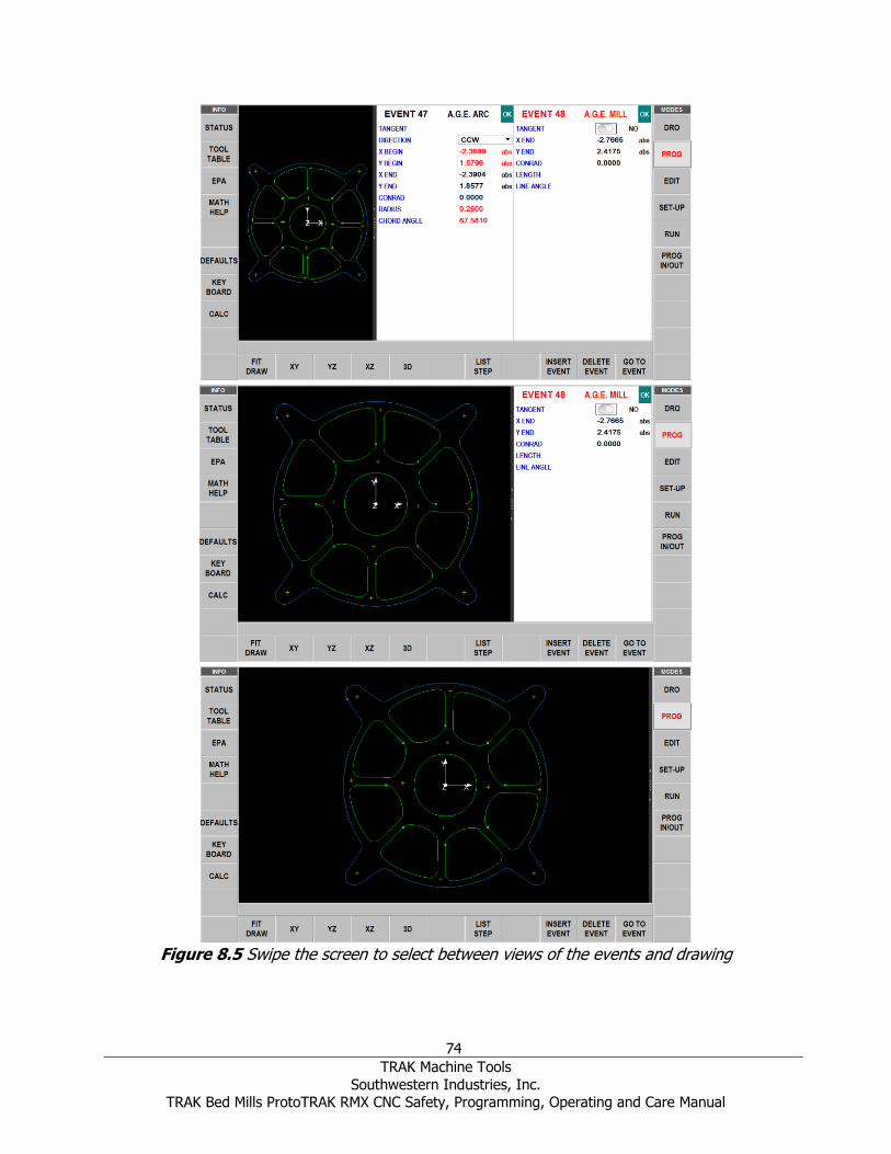
74
TRAK Machine Tools
Southwestern Industries, Inc. TRAK Bed Mills ProtoTRAK RMX CNC Safety, Programming, Operating and Care Manual
Figure 8.5 Swipe the screen to select between views of the events and drawing

75
TRAK Machine Tools
Southwestern Industries, Inc. TRAK Bed Mills ProtoTRAK RMX CNC Safety, Programming, Operating and Care Manual
8.6 Soft Keys within the Event Program Events will be described in the next section.
Once an event geometry is selected, the following Soft Keys will appear.
Figure 8.6 Soft Keys within an event.
Fit Draw: Resize the drawing to fit the screen after you have zoomed or pinched it.
XY: XY Plane view of part YZ: YZ plane view of part
XZ: XZ plane view of part 3D: 3D view of part
LIST STEP: Launches a process to show the part geometry as related to the Event type and number.
INSERT EVENT: Use this to insert a new event into the program. This new event will take the place of the one that was on the right side of the screen when you pressed the INSERT EVENT key. That
previous event, and all the events that follow, increase their event number by one. For example, if you started with a program of four events, if you were to press the INSERT EVENT key while Event 3 was on
the right side of the screen, the previous Event 3 would become Event 4 and the previous Event 4 would
become Event 5. If you insert a Subroutine event, the event numbers will increase by one as when you insert another kind of event. If you insert a copy event, the event numbers will increase by the number
of events that are copied.
DELETE EVENT: Deletes the event on the right side of the screen.
GO TO EVENT: Jumps you to the event you input.
When the LIST STEP key is selected, a list of the Event numbers and types appear on the right side of
the screen and additional Soft Keys appear at the bottom:
STEP FWD: Each key press moves you up in event number. As this occurs, the drawing will highlight
the geometry in the event by turning to purple and the event number will appear in the upper left of the drawing screen.
STEP BACK: Moves backward through the drawing.
START AT EVENT: Jumps you to the Event number in the drawing that you input.
RETURN: Takes you back to the previous soft key selections and screen view.
8.7 Z Rapid and Safety Plane Many events will give you the option of turning on and programming a Z Safety Plane. The Z Safety Plane is a dimension in Z Absolute that you define. It is there to allow you to program a Z move needed to
clear an obstruction.
For example, say you had Mill event as Event 1 and a Pocket event as Event 2, and on the part there is a
clamp between the end of Event 1 and the beginning of Event 2. The normal toolpath at the end of Event
1 would be:

76
TRAK Machine Tools
Southwestern Industries, Inc. TRAK Bed Mills ProtoTRAK RMX CNC Safety, Programming, Operating and Care Manual
Z moves to the higher of Z rapid for Event 1 and Event 2 XY moves at rapid to the beginning of Event 2.
Z moves to Z rapid of Event 2, then to XYZ beginning of Event 2
This direct path between events would cause the tool to hit the clamp. In order to avoid this, you could
enter a Z Safety plane within event 1. The toolpath would then be:
Z moves to the Z Safety Plane set in event 1 before going to Event 2 XY moves at rapid to the beginning of Event 2.
Z moves to Z rapid of Event 2, then to XYZ beginning of Event 2
8.8 Editing Data while Programming In addition to the List Step view, The ProtoTRAK RMX CNC allows you to move easily though your program by swiping the events back and forth. Previously programmed prompts and events may be
easily edited. With your event on the right side of the screen, tap the data that you wish to change or replace. Simply enter the desired data and press INC SET or ABS SET. The ProtoTRAK RMX will adjust
the program and update the drawing.
8.9 Finish Cuts When applicable for the event geometry, a Finish Cut prompt will appear. You can use finish (rest tool)
on Z finish cut for pockets and islands. If a value is entered, the prompts for Finish Feedrate, Finish RPM and Finish Tool # will remain. If a 0 is entered, indicating no finish cut, those prompts will disappear.
When a finish cut is programmed, the ProtoTRAK RMX will first rough out the material, leaving the
amount of material specified in the Finish Cut prompt. This material will be machined at the programmed
Finish Feedrate and RPM and with the programmed Finish tool.
A default value for finish cuts for Pockets, Profiles and Islands may be set in the Defaults Info Key.
8.10 Programming in 2 vs 3-Axis The ProtoTRAK RMX may be programmed in either 2 or 3 axis. Each program must be entirely in either 2 or 3-axis. When programming in 2 axis, the prompts for Z will not appear.
You can change your Mode between 2 and 3 axis with the Status Info key. When you change, the screen
will revert to the Start Up screen.
8.11 Using Multiple Fixtures (Advanced Features Option) When you want to use multiple fixtures, set the Multiple Fixtures setting in the Program Header screen to Yes.
You may run your program using up to six fixtures with the first fixture being the base fixture. A fixture is a location on your machine with a defined offset from your absolute 0. When you program an event to
have a fixture, it will treat the offset as if it were absolute zero shift. The programmed X, Y and Z absolute dimensions are relative to the absolute reference for the specified fixture.
For example, say you had two vises on the table. On the first vise, you established the lower left jaw as the absolute 0. At the same time, you measured the distance between the absolute zero you just
established and the lower left jaw of the other vise. You entered that measurement as an offset from your base vise (the first one) and the other vise, which is Fixture #2. Any events that you programmed
using Fixture #2 would treat the lower left corner of that second vise like the absolute 0 for the X, Y and
Z dimensions in the events.
77
TRAK Machine Tools
Southwestern Industries, Inc. TRAK Bed Mills ProtoTRAK RMX CNC Safety, Programming, Operating and Care Manual
Fixture offsets are handy for combining different programs together to run at the same time or to make multiple parts by repeating the events with different fixtures.
The fixture offsets are entered in the Set-up mode. There is a base fixture, called fixture number one.
We recommend that Event #1 in your program uses fixture number one. It doesn’t have to; we just
believe it is clearer that way.
8.11.1 Fixtures and Running the Program To run the program, first go to the DRO mode and set absolute 0 at the base fixture, Fixture #1.
In the Run mode, the SHOW ABS displays the absolute position relative to the fixture in the event being run, that is, the absolute dimension that was programmed.
8.11.2 Editing Fixtures With the Multiple Fixtures feature turned to YES, you may edit the fixture number in the Program Mode
event by event. You may also use the Search Edit feature in the Edit Mode to change fixture numbers. See Section 12.3 for setting up fixture offsets.

78
TRAK Machine Tools
Southwestern Industries, Inc. TRAK Bed Mills ProtoTRAK RMX CNC Safety, Programming, Operating and Care Manual
9.0 Program Mode Part 2: Program Events Events are fully defined pieces of geometry. By programming events, you tell the ProtoTRAK RMX CNC what geometry you want to end up with; it figures the tool path for you from your answers to the
prompts and the tool information you give it in the Set-Up Mode.
In the ProtoTRAK RMX, defining your event is made even easier by the interaction of the Defaults you
may set to define your programming style and the Options that enable you to change defaults or have additional functions.
Please see section 6.5 for information about Defaults and 6.6 for information about Options.
9.1 Prompts Found in Events The following is a description of the Prompts you’ll encounter after selecting an Event. Only the prompts
appropriate to the event you select will appear.
# Holes: The number of holes in the bolt hole pattern
# Passes: The number of cycles to machine to the final depth spaced equally from Z Rapid to Z End
(hint: keep Z Rapid small).
# PECKS: The default is displayed either Variable, Fixed or Chip Break. You may override the default by
choosing the Options Info key.
# Repeats: The number of times the programmed events are repeated in the Subroutine events.
# Rest Passes: The number of cycles to machine to the final depth in the rest (residual) material with
the finish tool.
% Feed: The percentage of the feeds in the programmed events to apply to the Subroutine events.
% RPM: The percentage of RPM in the programmed events to apply to the Subroutine events.
Angle: The angle from the positive X axes (that is, 3 o'clock); positive angle is measured
counterclockwise from 0.000 to 359.999 degrees, negative angles measured clockwise.
Conrad: The dimension of a tangential radius to the next event (that must lie in the same plane for part
geometry programming). May also be the corner radii of a rectangular pocket.
Direction: The clockwise or counterclockwise direction of the arc as viewed looking down for an arc in
the XY plane, looking from the front for a vertical plane, or looking from the right for a vertical YZ plane
FEED PER MIN: The Feedrate in Inch per minute or mm per minute
FEED PER TOOTH: The Feedrate in inch or mm per tooth. The number of flutes must be defined for the
tool in the Tool Table
FIN CUT: The width of the finish cut. If 0 is input there will be no finish cut. You will not receive this or
the other Finish prompts if the TOOL OFFSET is Tool Center.
FIN FEED PER MIN: The finish cut milling feedrate in in/min from .1 to 400 (250 for Z), or mm/min
from 5 to 10160 (6350 for Z)
FIN FEED PER TOOTH: The Finish cut feedrate in inch or mm per tooth. The number of flutes must be
defined for the tool in the Tool Table
FIN RPM: The spindle RPM for the finish cut.
FIN SURFACE SPEED: Finish Surface Speed in Surface Feet per Minute, which is the speed of the
outside Diameter of the tool

79
TRAK Machine Tools
Southwestern Industries, Inc. TRAK Bed Mills ProtoTRAK RMX CNC Safety, Programming, Operating and Care Manual
FIN TOOL #: Tool number you assign for the Finish Cut.
First Event #: The event number of the first programmed event for the subroutine.
Last Event #: The event number of the last programmed event of the subroutine.
Mirror Axis: The selection of the axis or axes to be mirrored (input X or Y or XY, SET) in the Subroutine
Mirror Events.
Pitch: The distance from one thread to the next in inches or mm. It is equal to one divided by the
number of threads per inch. For example, the pitch for a 1/4-20 screw is 1 / 20 = .05 inches
Radius: The finish radius of the arc circle or the bolt hole pattern
RPM / SFM: The default is displayed either RPM or SFM. You may override the default be choosing the
Options Info key.
Spindle Speed is programmed as either RPM or Surface Feed.
Tool #: The tool number you assign. SET without a number will use the tool number of the previous
event.
Tool Offset: The selection of the tool offset to right, offset to left or tool center (no offset) relative to
the programmed edge and direction of tool cutter movement and as projected in the XY plane
X Begin: The X dimension to the beginning of the mill or arc cut
X Center: The X dimension to the center of the arc or bolt hole pattern; incremental is from X End
X End: The X dimension to the end of the cut; incremental is from X Begin
X: The X dimension to the hole
X1: The X dimension to the first diagonal point of a rectangle.
X3: The X dimension to the opposite diagonal point of a rectangle.
XYZ FEED PER MIN: The milling feedrate in inches or mm per minute
XYZ FEED PER TOOTH: The XYZ milling feed rate per tooth in inches or mm. This is the chip thickness.
Y Begin: The Y dimension to the beginning of the cut
Y Center: The Y dimension to the center of the arc or bolt holt pattern; incremental is from Y End
Y END: The Y dimension to the end of the cut; incremental is from Y Begin
Y: The Y dimension to the hole
Y1: The Y dimension to the first diagonal point of a rectangle.
Y3: The Y dimension to the opposite diagonal point of a rectangle.
Z Begin: The Z dimension to the beginning of the cut
Z Center: The Z dimension to the center of the arc; incremental is from Z End.
Z End: The Z dimension to the end of the cut; incremental is Z Begin
Z FEED PER MIN: The drilling or vertical milling feed rate in inch or mm per minute
Z FEED PER TOOTH: The Z direction milling feed rate per tooth in inches or mm. This is the chip
thickness.
Z Rapid: The Z dimension at which the Z stops rapid and begins to feed at the programmed Z feed rate.

80
TRAK Machine Tools
Southwestern Industries, Inc. TRAK Bed Mills ProtoTRAK RMX CNC Safety, Programming, Operating and Care Manual
9.2 Event Types 9.2.1 POSN: Position Events This event type positions the table and quill at a specified position. The positioning is always at rapid
speed (modified by feedrate override) and in the most direct path possible from the previous location.
9.2.2 DRILL TAP Event This will drill, bore or tap a hole in the XY location that you enter.
Press the DRILL TAP soft key.
Drill, Bore, Tap, Helix: selects whether the hole is to be drilled, bored, tapped or machined in a Helix.
Drill This positions the table to the specified X and Y position, moves the HEAD at rapid to the Z RAPID
location, feeds to the Z END location, and rapids back to Z RAPID.
Bore
This positions the table to the specified X and Y position, moves the HEAD at rapid to the Z RAPID location, feeds to the Z END location, and feeds back.
Tap
This positions the table to the specified X and Y position, moves the HEAD at rapid to the Z RAPID
location, coordinates the spindle and feeds from Z rapid to the Z END location, and feeds back. Tap events allow you to tap holes using a floating tapping head. The feedrate of the thread will be calculated
from the pitch and RPM entered. The RPM range that the ProtoTRAK RX can tap for low gear is 40 to 200 RPM and for high gear is 300 to 1000 RPM.
• Prompt in the Tap Event – PITCH: The distance from one thread to the next in inches or mm. It
is equal to one divided by the number of threads per inch. For example, the pitch for a 1/4-20
screw is 1 20 = .05 inches
Tapping Notes and Recommendations • Harder materials will require slower speeds and tap size may also be limited. For example, the
TRAK Bed Mill may not be capable of tapping a 5/8-11 thread in inconel.
• Make sure your tap is not dull. Dull taps will require more torque to cut and may not cut threads to specification.
• Cutting oil will play a large role in determining the size of tap you can use in a given material. In
the tables above, cutting oil was used for the results shown for the DPM RX2, RX3 and RX5.
Coolant delivered by the optional spray coolant system was used for the results shown for the RX7. • A common problem with tapping is having adequate float in the tension and compression stroke.
The holder should float up and down with minimal force applied to the holder. Also make sure
your holder does not stick in tension (holder pulls down) or compression (holder pulls up). This will stop the tap from getting to the correct position programmed and may also break your tap.
• Always set your Z rapid higher than the tension stroke of your holder. This will save your tap if the
holder does get stuck in the tension stroke between holes.
• Make sure your tap is running true in the holder.
• Most tapping problems are due to a dull tap or a holder that is not floating and is stuck in a certain position.

81
TRAK Machine Tools
Southwestern Industries, Inc. TRAK Bed Mills ProtoTRAK RMX CNC Safety, Programming, Operating and Care Manual
Helical This positions the cutter at the hole Diameter (offset by cutter diameter) at Z Rapid. From there the
cutter moves in a helical motion in X, Y and Z feeding at the Pitch entered until it reaches Z End. At Z End, the cutter will move in X and Y to clean up the bottom of the hole. To finish, the cutter will feed to
the center of the hole and then move at rapid feedrate out of the hole.
Additional Prompts in Helix:
• Pitch – Input in inches (mm) 1 divided by the number of X, Y, Z revolutions per inch (mm). For
example, if you wanted 20 revolutions per inch you would enter .05 (1 ÷20).
• Diameter – Diameter of the hole.
Please see the tables below for our recommended tapping RPM for your model of machine.
A – aluminum only
AS – aluminum and steel
DPMRX2 Tap Size vs
RPM 40 100 200 300 500 750 1000
4-40 AS AS AS AS A
8-32 AS AS AS AS AS A
¼ - 20 AS AS AS AS AS AS A
3/8 -16 AS AS AS AS AS AS A
½ -13 AS AS AS AS AS A
5/8 - 11 AS AS A A A
¾-10 AS AS A A
1-8 A A
Interpolate speeds for tap sizes in between the ones noted in the table
DPMRX3 and DPMRX5 Tap Size vs
RPM 40 100 200 300 500 750 1000
4-40 AS AS AS AS A
8-32 AS AS AS AS AS A
¼ - 20 AS AS AS AS AS AS A
3/8 -16 AS AS AS AS AS AS A
½ -13 AS AS AS AS AS A
5/8 - 11 AS AS A A A
¾-10 AS AS A A
1-8 AS AS A
Interpolate speeds for tap sizes in between the ones noted in the table

82
TRAK Machine Tools
Southwestern Industries, Inc. TRAK Bed Mills ProtoTRAK RMX CNC Safety, Programming, Operating and Care Manual
DPMRX7 Tap Size vs
RPM
200 400 600 800 1000
4-40 AS AS A
8-32 AS AS AS A
¼ - 20 AS AS AS AS A
3/8 -16 AS AS AS AS A
½ -13 AS AS AS A
5/8 - 11 AS AS A
¾-10 A A
Interpolate speeds for tap sizes in between the ones noted in the table
9.2.3 Bolt Hole This will drill, bore or tap a series of holes evenly spaced around a center you define.
Bolt Hole Drill
This positions the table to the specified X and Y position, moves the HEAD at rapid to the Z RAPID location, feeds to the Z END location, and rapids back to Z RAPID.
Bolt Hole Bore This positions the table to the specified X and Y position, moves the HEAD at rapid to the Z RAPID
location, feeds to the Z END location, and feeds back.
Bolt Hole Tap This positions the table to the specified X and Y position, moves the HEAD at rapid to the Z RAPID
location, coordinates the spindle and feed at Z Begin, feeds to the Z END location, and feeds back.
Helical
This positions the cutter at the hole Diameter (offset by cutter diameter) at Z Rapid. From there the cutter moves in a helical motion in X, Y and Z feeding at the Pitch entered until it reaches Z End. At Z
End, the cutter will move in X and Y to clean up the bottom of the hole. To finish, the cutter will feed to
the center of the hole and then move at rapid feedrate out of the hole.
Additional Prompts in Helix:
• Pitch – Input in inches (mm) 1 divided by the number of X, Y, Z revolutions per inch (mm). For
example, if you wanted 20 revolutions per inch you would enter .05 (1 ÷20).
• Diameter – Diameter of the hole.
See the section above for more information about tapping on TRAK DPMRX Milling Machines.
9.2.4 Mill This event allows you to mill in a straight line from any one XYZ point to another, including at a diagonal in space. It may be programmed with a CONRAD if it is connective with the next event (this next event
must lie in the same plane as the Mill event).

83
TRAK Machine Tools
Southwestern Industries, Inc. TRAK Bed Mills ProtoTRAK RMX CNC Safety, Programming, Operating and Care Manual
9.2.5 Arc This event allows you to mill with circular contouring any arc (fraction of a circle) that lies in the XY plane
or a vertical plane. Vertical plane arcs are also limited to those that are entirely concave or convex (in other words, if you think of the arc lying on the surface of the earth, then it can't cross the equator).
In ARC events when X Center, Y Center, and Z Center are programmed incrementally, they are referenced from X End, Y End, and Z End respectively. An ARC event may be programmed with a
CONRAD if it is connective with the next event (this next event must lie in the same plane as the Arc event).
Note: When an arc is 180, there are several paths that all have the same beginning, ending, and center locations. To illustrate, Imagine that if you were on the earth's equator and you wanted to get to the other side of the earth you could go clockwise or counterclockwise around the equator, or you could go up over the north pole, or down under the south pole. The ProtoTRAK RMX CNC will automatically assume that all 180 arcs that have the same beginning, ending and center dimensions for Z, lie in the XY plane. If you want a 180 arc in a vertical plane, you must program two 90 arcs or some equivalent.
9.2.6 PROFILE Events These events allow you to mill around the outside or inside of a circular or rectangular frame or an
irregular profile. The irregular profile may be closed or open. All profiles are limited to the XY plane. When the irregular profile event is started the ProtoTRAK RMX CNC will automatically initiate the powerful
Auto Geometry Engine. See Section 10.0 for more information about programming with A.G.E.
Finish cuts and the number of passes are automatically programmed for Profile events if these values are
set in the Default Info key. Finish Cuts are only programmed when the Tool Right or Tool Left positions are selected.
Circle Profile
Press the CIRCLE soft key if you wish to mill a circular frame.
Rectangular Profile
Press the RECTANGLE soft key if you wish to mill a rectangular frame with or without corner radii (all
corners are 90 right angles).
Irregular Profile Press the IRREG PROFILE soft key if you wish to mill a profile other than a rectangle or circle. The
Irregular Profile event initiates the powerful Auto Geometry Engine to define a shape made up of straight
lines (Mills) and arcs. See section 10 for more information about programming with the powerful AGE feature.
The Irregular Profile is a series of events that are programmed to machine continuously. The first event
of the series will be called an IRR PROFILE and it will define the beginning point of the profile and other
machining information that applies to the entire profile.
When the initial Irregular Profile screen is complete, the rest of the profile is programmed using A.G.E. Mill and A.G.E. Arc events. Programming with the Auto Geometry Engine is explained in Section 10.0.
9.2.7 Face Mill The Face Mill event will cut a rectangular area you define by opposite corners. The toolpath for the Face
Mill Event should start from the X BEG/Y BEG corner and cut in the X +/- direction. It always starts off the area you define and machines the top of the part using the Step Over Percentage and the Cutting
Method you define in the Defaults. User can select the cutting order.

84
TRAK Machine Tools
Southwestern Industries, Inc. TRAK Bed Mills ProtoTRAK RMX CNC Safety, Programming, Operating and Care Manual
9.2.8 Pocket Events This event selection gives you a choice between, circle pocket, rectangular pocket and irregular pocket
within the XY plane.
Pockets include machining the circumference, as well as all the material inside the circumference of the
programmed shape. If a finished cut is programmed, it will be made at the completion of the final pass. The cutter will arc in and arc out of the finish cut and position itself the finish cut dimension away from
the part before moving the tool out of the part.
See Section 6.5.4 for the Defaults that you can set for Pocket Events.
Circle Pocket
The Circle Pocket will machine the circumference defined and the material on the inside. You may place Islands inside a circle pocket. Two tool path pattern options available under circle pocket are:
• Offset
• Spiral (Under the Z entry method, Helical will not work for spiral tool path.)
Rectangular Pocket The rectangular Pocket will mill a rectangular shape with all corners 90-degree right angles and the sides
parallel to the X and Y axes and the material on the inside. You may place Islands inside a rectangular
pocket.
Irregular Pocket The Irregular Pocket event gives you the powerful Auto Geometry Engine to define a shape made up of
straight lines (Mills) and arcs.
The first screen in an irregular pocket event will define the beginning point and some of its general
parameters. The last event of the irregular pocket must end at the same point as defined in the first event. A Conrad may be added to the last event of an Irregular Pocket and it will be inserted between the
end of the last event and the beginning of the first event.

85
TRAK Machine Tools
Southwestern Industries, Inc. TRAK Bed Mills ProtoTRAK RMX CNC Safety, Programming, Operating and Care Manual
9.2.9 Islands Events Island Events are programmed by first selecting Pocket and then Island.
An island is a shape that is left standing when the surrounding material is removed. The ProtoTRAK gives
you the ability to machine almost any shape as an island within a pocket. You may place Islands inside an
irregular pocket event.
Figure 9.2.9 Islands of any shape may be programmed within a pocket.
This powerful feature gives you an easy way to do complicated shapes. In order to organize it properly,
the ProtoTRAK RMX guides you through a sequence that helps keep things clear as you go.
First, from the Select an Event screen, you select POCKET. Next, select ISLAND.
Next, you will program the Pocket in which the island will sit.
Once the Pocket is defined, you will have a choice of Island shapes:
CIRCLE ISLAND – The circumference defined.
RECTANGULAR ISLAND – A rectangular shape with all corners 90-degree right angles and the sides parallel to the X and Y axes.
IRREGULAR ISLAND – Initiates the powerful Auto Geometry Engine for you to define a shape made up
of straight line and arcs.
END ISLAND – Tells the ProtoTRAK that you have no more islands to place inside the pocket. You can
use finish (rest tool) on Z finish cut for pockets and islands.

86
TRAK Machine Tools
Southwestern Industries, Inc. TRAK Bed Mills ProtoTRAK RMX CNC Safety, Programming, Operating and Care Manual
9.2.10 Subroutine Events The Subroutine Events are used for manipulating previously programmed geometry within the XY plane.
The Subroutine Event is divided into three options: Repeat, Mirror, and Rotate.
Repeat and Rotate may be connective. As long as the rules of connectivity are satisfied you may add subsequent events.
REPEAT allows you to repeat an event or a group of events up to 99 times with an offset in X and/or Y
and/or Z. This can be useful for drilling a series of evenly spaced holes, duplicating some machined
shapes, or even repeating an entire program with an offset for a second fixture.
Repeat events may be "nested." That is, you can repeat a repeat event, of a repeat event, of some programmed event(s). One new tool number may be assigned for each Repeat Event.
MIRROR (Advanced Features Option) is used for parts that have symmetrical patterns or mirror image
patterns. In addition to specifying the events to be repeated, you must also indicate the axis or axes (X
or Y or XY are allowed) that the reflection is mirrored across. In addition, you must specify the offset from absolute zero to the line of reflection. You may not mirror another mirror event, or mirror a rotate
event. Consider the figure below:
FIGURE 9.2.10a Holes 1-4 are mirrored across the Y axis to 5-8, respectively, about a line X OFFSET from X=absolute 0
CUTTING ORDER: Forward – the toolpath is from the first event to the last event. Backward – the toolpath is from the last event to the first event.
ROTATE is used for polar rotation of parts that have a rotational symmetry around some point in the XY plane. In addition to specifying the events to be repeated, you must also indicate the absolute X and Y
position of the center of rotation, the angle of rotation (measured counterclockwise as positive; and clockwise as negative), and the number of times the specified events are to be rotated and repeated.
You may not rotate another rotate event, however you can rotate a mirror event. Consider the figure
below:
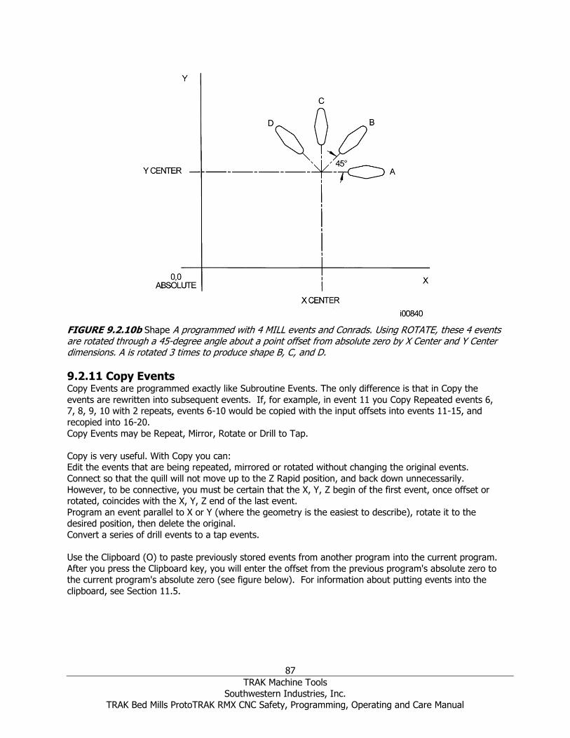
87
TRAK Machine Tools
Southwestern Industries, Inc. TRAK Bed Mills ProtoTRAK RMX CNC Safety, Programming, Operating and Care Manual
FIGURE 9.2.10b Shape A programmed with 4 MILL events and Conrads. Using ROTATE, these 4 events are rotated through a 45-degree angle about a point offset from absolute zero by X Center and Y Center dimensions. A is rotated 3 times to produce shape B, C, and D.
9.2.11 Copy Events Copy Events are programmed exactly like Subroutine Events. The only difference is that in Copy the
events are rewritten into subsequent events. If, for example, in event 11 you Copy Repeated events 6, 7, 8, 9, 10 with 2 repeats, events 6-10 would be copied with the input offsets into events 11-15, and
recopied into 16-20.
Copy Events may be Repeat, Mirror, Rotate or Drill to Tap.
Copy is very useful. With Copy you can: Edit the events that are being repeated, mirrored or rotated without changing the original events.
Connect so that the quill will not move up to the Z Rapid position, and back down unnecessarily.
However, to be connective, you must be certain that the X, Y, Z begin of the first event, once offset or rotated, coincides with the X, Y, Z end of the last event.
Program an event parallel to X or Y (where the geometry is the easiest to describe), rotate it to the desired position, then delete the original.
Convert a series of drill events to a tap events.
Use the Clipboard (O) to paste previously stored events from another program into the current program.
After you press the Clipboard key, you will enter the offset from the previous program's absolute zero to the current program's absolute zero (see figure below). For information about putting events into the
clipboard, see Section 11.5.

88
TRAK Machine Tools
Southwestern Industries, Inc. TRAK Bed Mills ProtoTRAK RMX CNC Safety, Programming, Operating and Care Manual
Figure 9.2.11 In the above example, the offset that puts the group of holes in the desired location is X=-1.50 and Y=-1.00.
9.2.12 Helix Event The Helix event will allow you to precisely define a helical tool path.
Notes: There is a separate Thread Mill Event for thread milling.
You may quickly and easily program your cutter to enter Pockets and clear off events in a helical move. Simply set the Default Z Entry Method to Helical.

89
TRAK Machine Tools
Southwestern Industries, Inc. TRAK Bed Mills ProtoTRAK RMX CNC Safety, Programming, Operating and Care Manual
9.2.13 Engrave The Engrave Event allows you to machine numbers, letters and special characters as part of a part
program.
When programming with the Engrave Event, the ProtoTRAK will construct a box to contain the text you
define. This box may be referenced by the location of its lower left corner, or by its center. In addition, the box may be presented in a radius or mirrored.
Prompts in the Engrave Event:
• X and Y begin: Define the lower left corner (for the Horizontal orientation) or the center of the
box of text (for the Vertical or Radial Orientation).
• Z end: The Z dimension at which the Z stops rapid and begins to feed at the programmed Z
feedrate.
• Height: The height of each letter or number.
• Text: Tap the Keyboard Info Key and enter the text you want to engrave and press SET.
• Z FEED PER MIN: The milling feed rate in inch or mm per minute
• XYZ FEED PER MIN: The milling feedrate in inches or mm per minute
• XYZ FEED PER TOOTH: The XYZ milling feed rate per tooth in inches
Additional functions in Engrave are enabled by tapping the Options Info Key.

90
TRAK Machine Tools
Southwestern Industries, Inc. TRAK Bed Mills ProtoTRAK RMX CNC Safety, Programming, Operating and Care Manual
Options Unique to the Engrave Event:
• XY Reference: Will use the values you enter to define the lower left corner of the text box or its center.
• Orientation: The text box may be Horizontal (like the text in this manual), Vertical (up and
down) or Radial (around the axis you input).

91
TRAK Machine Tools
Southwestern Industries, Inc. TRAK Bed Mills ProtoTRAK RMX CNC Safety, Programming, Operating and Care Manual
• Angle: Will work with either the Horizontal or Vertical Orientation.
• Mirror: Will Mirror the text about the X, Y or XY Axis defined by the X and Y inputs. The mirrored text will replace the original text and occupy the same place on the part.
Additional Prompts When Radius Orientation is Selected:
• Radius: The radius value you enter will apply with the center being the X and Y inputs and the
bottom of the text box.
• Radius Angle: The angle from 3 o’clock to the beginning of the text box.

92
TRAK Machine Tools
Southwestern Industries, Inc. TRAK Bed Mills ProtoTRAK RMX CNC Safety, Programming, Operating and Care Manual
9.2.14 Thread Mill Event Thread Mill event enables you to easily program an ID or OD thread.
Figure 9.2.14 Thread prompts
93
TRAK Machine Tools
Southwestern Industries, Inc. TRAK Bed Mills ProtoTRAK RMX CNC Safety, Programming, Operating and Care Manual
Special prompts in the Thread mill event:
• Z BEGIN: The Z dimension where the threading pass begins
• Z END: The Z bottom of the thread
• PITCH: The distance from one thread to the next in inches or mm. It is equal to one divided by the number of threads per inch. For example, the pitch for a 1/4-20 screw is 1 / 20 = .05 inches
• MAJOR DIA: The largest diameter of the thread (the root for an ID thread, the crest for an OD
thread)
• MINOR DIA: The smallest diameter of the thread (the root for an OD thread, the crest for an ID thread)
• SIDE: Inside for an ID thread, outside for an OD thread.
• ANGLE: The angle the tool feeds into the beginning depth, where the thread begins
• DIRECTION: Clockwise or counterclockwise
• # PASSES: The number of passes to cut the thread to its final depth
9.2.15 Aux Events Aux Functions allow you to control:
Coolant Air (usually for spray mist)
Pulse to interface to a programmable indexer
Auxiliary Output that is used to interface to some secondary device.
For example, if you wish to have the coolant start when a milling event starts and then turn off at the end, simply insert an Aux event with Coolant On before the milling event and then another with Coolant
Off afterwards.
The Accessory button on the Operator Run Keys must be in AUTO for coolant and air to work in your
program.
Note: The coolant and air will turn off automatically at all tool changes and then back on automatically when the program is resumed.
9.2.16 Pause The purpose of the Pause Event is to allow you to program a stop condition within the program. The
effect of this event is to stop the program run, turn off the spindle (if you choose, you could leave it on)
and move the head to the Z rapid location with the X and Y position corresponding to the end of the previous event.
Pause events are useful if you want to stop the program to make a measurement, change a fixture, etc.
Note: In general, you should avoid programming a PAUSE event between two connective events. The Pause event will cause the events to NOT be connective. To program a Pause Event press the PAUSE soft key. Because there is no input required, simply press
SET to load and the event counter will advance by one and the Select Event screen will reappear. You can also choose to leave the spindle on. The default is to turn it off.
In run, restart the spindle and press the GO key after a pause to continue.

94
TRAK Machine Tools
Southwestern Industries, Inc. TRAK Bed Mills ProtoTRAK RMX CNC Safety, Programming, Operating and Care Manual
9.3 Finishing Teach Events
Teach events are either POSN, DRILL or MILL events that are originated in the DRO Mode (see Section
7.10).
The Teach events that are started in the DRO Mode must be finished in the Program Mode before
running. Teach events are of these different types:
TEACH POSN: for two-axis operation, the Position and Drill event types are combined. TEACH DRILL: this may also be made into a bore or tap event.
TEACH MILL: a straight line that specifies the beginning and the end. When TEACH MILL events are
defined using the CONT MILL softkey, the prompts for information that cannot change will be suppressed.
When a Teach event is unfinished, the words NOT OK will appear next to the event type. Once the
prompts are completed, the words NOT OK and Teach will disappear. The event will become a normal MILL, DRILL, or POSN event.

95
TRAK Machine Tools
Southwestern Industries, Inc. TRAK Bed Mills ProtoTRAK RMX CNC Safety, Programming, Operating and Care Manual
10.0 Program Mode Part 3: Irregular Profiles, Pockets and Islands The powerful Auto Geometry Engine® (A.G.E.) When you program an Irregular Pocket or an Irregular Profile the Auto Geometry Engine® (A.G.E.) is
automatically started.
The A.G.E. is powerful software that works behind the easy-to-use geometry programming of the
ProtoTRAK RMX CNC. It is treated in its own section because it works differently than the other event types.
Unlike other events, the A.G.E. allows you to:
• Enter the data you know, and skip the prompts you don’t.
• Use different types of data (like angles) that may be available from the print.
• Enter guesses for the X and Y ends and centers not available on the print.
With the A.G.E., you can easily overcome limitations in the data the print provides without having to spend time in laborious calculations.
10.1 Starting the A.G.E. The A.G.E. is started automatically when you enter the Irregular Pocket or Irregular Profile event. The
first set of prompts you encounter will be the header information. Complete this first event as you would for any mill event except there is no prompt for X or Y end.
The second event that defines the end point of the first line or arc in the profile must have a known X end and Y end (and X Center and Y Center) dimensions. If that is not available on the print, you may be
able to enter a ramp on line to the first point. The beginning of this first line would be the point entered in the header (first) event.
Figure 9.1 Once the header event is complete, you will choose between A.G.E. Mills (as above) or A.G.E.
Arcs.
With the header event complete, you’ll define the pocket or profile with a series of Mills and Arcs:
A.G.E. Mill: A straight line from one X Y point to another. A.G.E. Arc: Any part of a circle.

96
TRAK Machine Tools
Southwestern Industries, Inc. TRAK Bed Mills ProtoTRAK RMX CNC Safety, Programming, Operating and Care Manual
End A.G.E.: Ends the A.G.E. programming for the Irregular Pocket or Irregular Profile. Abort A.G.E.: Aborts all A.G.E. events. The data for all the events is lost.
10.2 Prompts in A.G.E. Mill Programming Tangent: This refers to the tangency of the mill to the previous event (Section 10.10).
X END: The X dimension to the end of the mill cut; incremental is X Begin
Y END: The Y dimension to the end of the mill cut; incremental is Y Begin
CONRAD: The dimension of a tangential radius to the next event
LENGTH: The length of the mill from beginning to end.
LINE ANGLE: The angle of this mill line (moving from begin to end) measured counterclockwise from
the positive X axis (that is 3 o’clock) (Section 10.10).
GUESS: This softkey will appear when the prompt is on X or Y dimensioned data. Press the Guess key
before you press INC SET or ABS SET to enter the data as a guess (Section 10.8).
10.3 Prompts in A.G.E. Arc Programming TANGENT: This refers to the tangency of the mill to the previous event (Section 10.10).
DIRECTION: The clockwise or counterclockwise direction of the arc
X END: The X dimension to the end of the arc cut; incremental is from X Begin
Y END: The Y dimension to the end of the arc cut; incremental is from Y Begin
X CENTER: The X dimension to the center of the arc; incremental is from X End
Y CENTER: The Y dimension to the center of the arc; incremental is from Y End
CONRAD: The dimension of a tangential radius to the next event
RADIUS: The radius of the arc
CHORD ANGLE: The angle spanned by the arc (Section 10.11).
GUESS: This softkey will appear when the prompt is on X or Y dimensioned data. Press the Guess key before you press INC SET or ABS SET to enter the data as a guess (Section 10.8).
10.4 Skipping Over Prompts In the Auto Geometry Engine®, events don’t have to be complete before you can go to the next one.
You can skip the data you don’t know by tapping the next prompt. You may also simply swipe the event
to the left and get started on the next one.
You should always select whether or not the next event is tangent to the previous event (Section 10.10).
10.5 OK/NOT OK Each A.G.E. event has a flag that tells you if it has been fully defined. Sometimes data from later events is needed to define previous events. To the immediate right of the event type, the words OK or NOT OK
appear, depending on whether that particular event is defined.
Once the OK flag appears for the event, you do not need to enter more information. Swipe to the next event.
When the A.G.E. has sufficient data, it will calculate the data needed to fully define the previously NOT OK events. All data calculated by the A.G.E. is shown in red.

97
TRAK Machine Tools
Southwestern Industries, Inc. TRAK Bed Mills ProtoTRAK RMX CNC Safety, Programming, Operating and Care Manual
10.6 Ending A.G.E. Any time all the events are of an Irregular Profile are OK, the A.G.E. may be ended.
If you are programming an Irregular Pocket, there is an additional requirement that must be satisfied
before the A.G.E. may be ended: the X and Y end point of the last event must be the same as the X and
Y beginning point of the first event so that the pocket is closed. Otherwise, the ProtoTRAK RMX CNC cannot program the tool path to clear the pocket.
The Irregular Profile has no such restriction since profiles may be open or closed.
Once the A.G.E. is ended, the Irregular Pocket or Irregular Profile event is complete and you may then choose from all the programming canned cycles from the Select an Event screen.
10.7 Reopening A.G.E. To reopen the A.G.E. Profile or Pocket, simply use the BACK hard key or swipe to get one of the A.G.E.
events on the right side of the screen. You may insert other A.G.E. Mill and A.G.E. Arc events.
10.8 Guessing Ends and Centers Whenever you are missing X or Y Ends or Centers, you should generally enter a guess. That is because
when the AGE computes X and Y positions it occasionally finds more than one solution. The purpose of
guessing is to help AGE decide the correct solution.
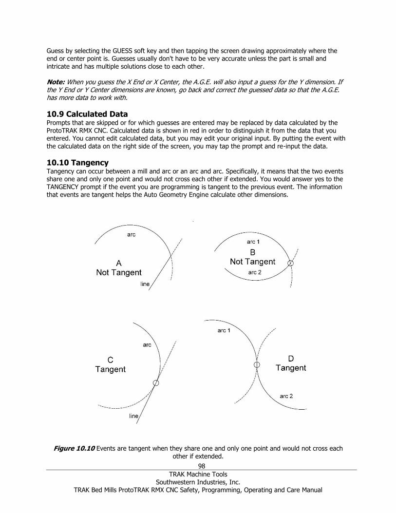
98
TRAK Machine Tools
Southwestern Industries, Inc. TRAK Bed Mills ProtoTRAK RMX CNC Safety, Programming, Operating and Care Manual
Guess by selecting the GUESS soft key and then tapping the screen drawing approximately where the end or center point is. Guesses usually don't have to be very accurate unless the part is small and
intricate and has multiple solutions close to each other.
Note: When you guess the X End or X Center, the A.G.E. will also input a guess for the Y dimension. If the Y End or Y Center dimensions are known, go back and correct the guessed data so that the A.G.E. has more data to work with.
10.9 Calculated Data Prompts that are skipped or for which guesses are entered may be replaced by data calculated by the
ProtoTRAK RMX CNC. Calculated data is shown in red in order to distinguish it from the data that you entered. You cannot edit calculated data, but you may edit your original input. By putting the event with
the calculated data on the right side of the screen, you may tap the prompt and re-input the data.
10.10 Tangency Tangency can occur between a mill and arc or an arc and arc. Specifically, it means that the two events share one and only one point and would not cross each other if extended. You would answer yes to the
TANGENCY prompt if the event you are programming is tangent to the previous event. The information that events are tangent helps the Auto Geometry Engine calculate other dimensions.
Figure 10.10 Events are tangent when they share one and only one point and would not cross each
other if extended.

99
TRAK Machine Tools
Southwestern Industries, Inc. TRAK Bed Mills ProtoTRAK RMX CNC Safety, Programming, Operating and Care Manual
Refer to Figure 10.10
- A line and an arc or 2 arcs are not tangent if you extend the lines past where they meet and they cross each other. A and B are not tangent.
- A line and an arc or 2 arcs are tangent if you extend the lines past where they meet and they do not cross each other. C and D are tangent
10.11 Line Angle The Line Angle prompt can be a powerful aid to the A.G.E. in helping you with incomplete print data.
Figure 10.11a Line Angles are referenced from an imaginary line at 3:00.
To measure the angle of an angled line, imagine another line that starts at the beginning of the angled line and extends in the positive X direction or 3:00 o'clock. The line angle is the angle between the
imaginary and angled lines always measured positive in the counter-clockwise direction.
In the drawing all lines to be machined from A to B or C or D or E or F and are measured from the
imaginary dashed line that starts at A (the beginning) and goes in the positive X direction or 3:00 o'clock. The line angles are shown in the drawing.

100
TRAK Machine Tools
Southwestern Industries, Inc. TRAK Bed Mills ProtoTRAK RMX CNC Safety, Programming, Operating and Care Manual
Figure 10.11b The imaginary line is drawn from the beginning of the angled line to be machined.
The imaginary positive X or 3:00 o'clock line must always be drawn from the beginning of the angled line to be machined. Referring to Figure 10.10b above, when machining from A to B, the angle of the line is
45° measured from the imaginary line at A. But when machining from B to A, the angle of the same line is 225° (180° + 45°) because B is the starting point and the imaginary line must be drawn from there.
10.12 Chord Angle
Figure 10.12 The chord angle is measured counter-clockwise.
The chord angle is the angle that is measured counter clockwise as positive from the beginning to the
end points.

101
TRAK Machine Tools
Southwestern Industries, Inc. TRAK Bed Mills ProtoTRAK RMX CNC Safety, Programming, Operating and Care Manual
10.13 Sample A.G.E. program
Consider this profile made up of 9 lines and arcs
Notice what is not known: Intersection of lines 3 and 4
Intersection of lines 5 and 6 Intersection of arcs 7 and 8
Center of arc 8
Intersection of arcs 8 and 9 Intersection of arc 9 and line 10

102
TRAK Machine Tools
Southwestern Industries, Inc. TRAK Bed Mills ProtoTRAK RMX CNC Safety, Programming, Operating and Care Manual
Event 1 The first programmed event is known as the Header. In this sample, this will be Event 1. To begin the
A.G.E. you must start by programming the Header and a mill or arc that is fully known, that is, all the needed dimensions are there. The 2” line segment (2) starting at 0,0 is fully known, so this is where we’ll
start.
Complete this first or header event as you would any mill event except there is no prompt for X end or Y end.
Event 2
Select AGE Mill Input X end (2.0) and Y end (0) as shown on the screen
There is no CONRAD to the next event
Note the OK label next to the event line

103
TRAK Machine Tools
Southwestern Industries, Inc. TRAK Bed Mills ProtoTRAK RMX CNC Safety, Programming, Operating and Care Manual
Event 3 Select AGE MILL
The line in event 3 is not tangent to the line in event 2 (no 2 straight lines can be tangent to each other) X end and Y end are not known. Tap Guess and select the screen above and to the right of Line 1 for
each dimension.
Line angle is 45° measured from an imaginary positive X line from the beginning of Line 2 The line length is not known, skip.
Note NOT OK label. We have input everything we know so swipe to the next event
Event 4
Select AGE MILL
The line in event 4 is not tangent to the line in event 3. X end is known (8.0) and Y end is known (0)
The line angle is 330° measured from an imaginary position X line from the beginning of Line 3 in a counter-clockwise direction
Note this event as well as the previous event are now OK

104
TRAK Machine Tools
Southwestern Industries, Inc. TRAK Bed Mills ProtoTRAK RMX CNC Safety, Programming, Operating and Care Manual
Event 5 Select AGE MILL
X end for line 5 is known (9.0) but Y end is not known. Tap Guess and tap the screen approximately where the Y end is
The 2.5 length is known
Note the event is OK
Event 6
Select AGE MILL The line in event 6 is not tangent to the line in event 5.
X end (9.0) is known and the 5.0 Y end is known
Note the event is OK
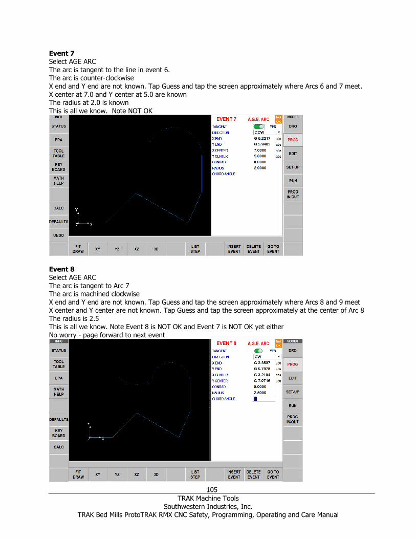
105
TRAK Machine Tools
Southwestern Industries, Inc. TRAK Bed Mills ProtoTRAK RMX CNC Safety, Programming, Operating and Care Manual
Event 7 Select AGE ARC
The arc is tangent to the line in event 6. The arc is counter-clockwise
X end and Y end are not known. Tap Guess and tap the screen approximately where Arcs 6 and 7 meet.
X center at 7.0 and Y center at 5.0 are known The radius at 2.0 is known
This is all we know. Note NOT OK
Event 8
Select AGE ARC
The arc is tangent to Arc 7 The arc is machined clockwise
X end and Y end are not known. Tap Guess and tap the screen approximately where Arcs 8 and 9 meet X center and Y center are not known. Tap Guess and tap the screen approximately at the center of Arc 8
The radius is 2.5 This is all we know. Note Event 8 is NOT OK and Event 7 is NOT OK yet either
No worry - page forward to next event

106
TRAK Machine Tools
Southwestern Industries, Inc. TRAK Bed Mills ProtoTRAK RMX CNC Safety, Programming, Operating and Care Manual
Event 9 Select AGE ARC
The arc is tangent to Arc 8 The arc is machined counter-clockwise
X end and Y end are not known. Tap Guess and tap approximately where Arc 9 and Line 10 meet
The arc center is known: X center 0 ABS and Y center 5 ABS The radius is 2.0
Note Event 9 is NOT OK but now Events 7 and 8 can be fully calculated and are OK Page forward to next event
Event 10
Select AGE MILL
Line 10 is tangent to Arc 9 X end at 0.0 and Y end at 0.0 are known
Note Event 10 is OK as well as Event 9 The entire profile has now been programmed
Page forward and tap END AGE

107
TRAK Machine Tools
Southwestern Industries, Inc. TRAK Bed Mills ProtoTRAK RMX CNC Safety, Programming, Operating and Care Manual
11.0 Edit Mode Within Program Mode, you can recall and re-input data event by event. In contrast, the Edit Mode contains powerful routines for more extensive program changes.
The changes you make in the Edit Mode affect only the program in current memory. In order to preserve
the changes, you must store the program again under the same name in the In/Out Mode.
11.1 Delete Events Rather than delete one event at a time in Program Mode, you may delete a group of events in the Edit
Mode.
In Edit Mode, press Delete Events.
The Data Input Line will prompt for the first event and then the last event to be deleted. Input the event
numbers and press SET. The remaining events will be renumbered.
11.2 Search Edit Selecting Search Edit opens the powerful Spreadsheet Editing function of the ProtoTRAK RMX. Spreadsheet Editing allows you to view program data in a table. From there you can make global changes
to the program by selecting which event prompts you want to view, sort or edit. This is particularly useful if you are working with a large program and you need to make changes to many events.
When you press the SEARCH EDIT soft key, the screen will load a table that contains data for the entire
program sorted by event number. The first view will show events 1 – 17. Use the Page and Data soft
keys, swipe the screen or tap the scroll bar to see other events.
Figure 11.2 The Search Edit key launches powerful Spreadsheet Editing.
Each row in the spreadsheet represents the data for the event number shown in the first column on the left. The event number and event type are always displayed in the first two columns, but the other data
displayed on the table can be changed.

108
TRAK Machine Tools
Southwestern Industries, Inc. TRAK Bed Mills ProtoTRAK RMX CNC Safety, Programming, Operating and Care Manual
Soft Keys in Search Edit: PAGE FWD: pages forward through the table.
PAGE BACK: pages backwards through the table. DATA TOP: highlights the data in the first row current sort
DATA BOTTOM: highlights the data in the last row of the current sort
GO TO EVENT: highlights the data in the row of the corresponding event. CHANGE ALL: enables you to make global changes of data, described below.
Note: the EV# (event number) and (event) TYPE may not be edited in Search Edit so the highlighter will not go there.
11.2.1 Selecting Data to be Displayed on the Search Edit Table In order to change the data selected in the table, tap the Options info key. You can choose which data to
display and the order of the columns by opening or closing the slide bar. Tap Reset to clear all the selections. Tap Options to close and the newly selected prompts will show in the table.
Figure 11.2.1 The Options Info key in search edit enables you to pick the fields to display.
11.2.2 Sorting Data Data may be sorted by any of the data types displayed in the column head. Red letters show which
column is used for sorting the data.
Simply tap the heading of the column to sort its data in ascending order (smallest first) and tap again to
change to descending order. The secondary sort will always be Event #.
11.2.3 Making Changes to Data To edit a single entry tap the entry, input the change and press INC SET or ABS SET.
To edit a group of identical entries:
1. Sort on the entry prompt by tapping the column head. You may sort on any value that gets the data
you want to change together.
2. Tap on the first data value you want to change (the highest on the list). 3. Tap Change All.
4. All data values that are the same and below the one you tapped will be highlighted.
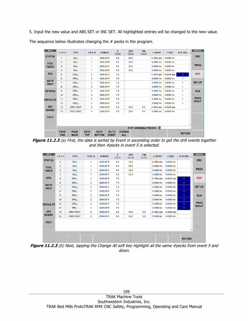
109
TRAK Machine Tools
Southwestern Industries, Inc. TRAK Bed Mills ProtoTRAK RMX CNC Safety, Programming, Operating and Care Manual
5. Input the new value and ABS SET or INC SET. All highlighted entries will be changed to the new value.
The sequence below illustrates changing the # pecks in the program.
Figure 11.2.3 (a) First, the data is sorted by Event in ascending order to get the drill events together
and then #pecks in event 5 is selected.
Figure 11.2.3 (b) Next, tapping the Change All soft key highlight all the same #pecks from event 5 and
down.

110
TRAK Machine Tools
Southwestern Industries, Inc. TRAK Bed Mills ProtoTRAK RMX CNC Safety, Programming, Operating and Care Manual
Figure 11.2.3 (c) Finally, the # pecks was changed to 2 in all the events from event 5 and down by
pressing 2, SET.
11.3 Erase Program Use the ERASE PROG soft key to erase the program from the current memory. Erasing the program from
current memory will not affect any programs that are stored.
If you have made changes to the program and wish to save this modified program, you will need to store
it. See Section 14.4.
11.4 G-Code Editor The G-Code Editor allows the edit of G-Code programs that are opened as .GCD files. Once edited, the program may be re-saved as .GCD files. ProtoTRAK Geometry-style programs may not be saved as .GCD
files.
When you enter the G-Code Editor, the G-Code program is displayed starting at the first Block Number.
Use the scroll bar to move up and down through the program. Search allows you to launch a simple find-and-replace routine to aid in editing large G-Code files.
Click in the Find What box and enter the item you want to find. Click on the Find Next box and the G-
Code Editor will locate the next occurrence of that item. Use Match Whole Word to limit the search to the
entire word. For example, if you want to find G2, but not G20 or G22, select Match Whole Word Only.
To make changes to Find What items, type what you want to have into the Replace With box. You can replace items one at a time by clicking first the Find Next box then the Replace With box for as many
changes as you want to make. You can replace every item in the program with a single click of the
Replace All box.
Return closes the G-Code Editor and returns the screen to the Edit Mode.
Note: If you use the USB Thumb Drive to store a G-code (.gcd) program file, you must leave the Thumb Drive plugged into the USB port the entire time the program is in current memory. If you unplug the thumb drive with the program still in current memory, the ProtoTRAK will display an error message.

111
TRAK Machine Tools
Southwestern Industries, Inc. TRAK Bed Mills ProtoTRAK RMX CNC Safety, Programming, Operating and Care Manual
11.5 Clipboard (Advanced Feature) The Clipboard feature is a way to copy events in one program in order to put them into a different
program. It is a two-part process that takes place in two different Modes. First, in the Edit Mode, the desired events are copied, or placed on the Clipboard, from the source program. Then the events are
inserted into the destination program in the Program Mode.
When you press the Clipboard key from the Edit Mode, you start the process that copies the
events that you want to put into a different program than the one in current memory.
Before you do that, you should write a program or open the program file that has the events you
want to copy. This is called the source program.
Inspect the events you want to copy. Make sure that the dimensioned data uses Absolute references in the first event to be copied and in all events where it will be important.
Incremental references may be used, but keep in mind where the Incremental reference will be made from. See the section on Incremental Reference Position in this manual.
In addition, you may want to modify this program in order to get all the events you want together. For example, if you want to copy events 2-5 and 7-12, you may want to modify the
program to delete events 1 and 6 first. That way, you can copy the all the events as they are now numbered from 1 to 10. Remember that you can modify this program just for this purpose
and it will not affect the original program unless you save it with the modifications in the Program
In/Out Mode.
When the source program is ready, press the CLIPBOARD softkey. A message will appear that says "Copy Events onto Clipboard" and the Data Input Line will read "From Event". Enter the
number of the first event that you want copied and press SET.
The Data Input Line will read "To Event". Enter the number of the last event you want copied
and press SET.
The group of events that you have specified is now on the clipboard and will remain there until you replace it with something else by going through the same procedure. When power is turned off to the
CNC the clipboard information will also be lost.
The events on the clipboard are inserted into a program in the Program Mode.

112
TRAK Machine Tools
Southwestern Industries, Inc. TRAK Bed Mills ProtoTRAK RMX CNC Safety, Programming, Operating and Care Manual
12.0 Set-Up Mode
12.1 Tool Path When the TOOL PATH soft key is pressed, the program is processed and the tool path graphics are
displayed. Large programs will take longer to process.
At the completion of running Tool Path, a time will appear in the upper left-hand corner of the screen
with the estimated time to run the program.
Since tool changes are manual, no time is allocated for the time required to change tools.
Most programming errors that would prevent the program from running are detected when the tool path
graphics are selected. The displayed graphic is automatically sized to fit the screen and an icon that represents the X, Y and Z orientation is placed at the program's absolute 0 reference point. The path
shown on the screen represents the center of the tool. • Position and drill events are drawn in yellow.
• Rapid moves are in red. • Programmed feeds are in blue.
Figure 12.0 The ProtoTRAK RMX processes the program and then displays the tool path. When the drawing is displayed you may spread or pinch to zoom in or out. You may also pan up, down
or sideways.
Soft Keys in Tool Path
FIT DRAW: Will re-draw, automatically sizing to fit the screen (necessary only if an adjustment changed the drawing from its initial sizing).
STEP FWD: Each press of the STEP FWD button shows the next tool move. To complete the drawing automatically, press FIT DRAW.
Tap STEP to move through the path one move at a time. The move you are on will be shown in purple.
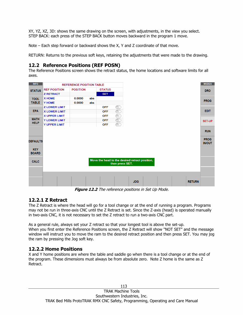
113
TRAK Machine Tools
Southwestern Industries, Inc. TRAK Bed Mills ProtoTRAK RMX CNC Safety, Programming, Operating and Care Manual
XY, YZ, XZ, 3D: shows the same drawing on the screen, with adjustments, in the view you select. STEP BACK: each press of the STEP BACK button moves backward in the program 1 move.
Note – Each step forward or backward shows the X, Y and Z coordinate of that move.
RETURN: Returns to the previous soft keys, retaining the adjustments that were made to the drawing.
12.2 Reference Positions (REF POSN) The Reference Positions screen shows the retract status, the home locations and software limits for all
axes.
Figure 12.2 The reference positions in Set Up Mode.
12.2.1 Z Retract The Z Retract is where the head will go for a tool change or at the end of running a program. Programs may not be run in three-axis CNC until the Z Retract is set. Since the Z-axis (head) is operated manually
in two-axis CNC, it is not necessary to set the Z retract to run a two-axis CNC part.
As a general rule, always set your Z retract so that your longest tool is above the set-up.
When you first enter the Reference Positions screen, the Z Retract will show "NOT SET" and the message window will instruct you to move the ram to the desired retract position and then press SET. You may jog
the ram by pressing the Jog soft key.
12.2.2 Home Positions X and Y home positions are where the table and saddle go when there is a tool change or at the end of the program. These dimensions must always be from absolute zero. Note Z home is the same as Z
Retract.

114
TRAK Machine Tools
Southwestern Industries, Inc. TRAK Bed Mills ProtoTRAK RMX CNC Safety, Programming, Operating and Care Manual
12.2.3 Limit Positions X and Y limit positions (one for plus direction, one for minus) will stop the program if they are exceeded
during run. Note that pressing the LIMIT ON/OFF soft key will turn the prompted limit off, or back on to its input value. If the limits are turned on, your program and home positions must fit within the limits you
define. If you turn on the limits and leave them at the default of 0 Absolute, the program will not run.
12.3 Fixture Offsets Fixture offsets are entered in the Set-Up Mode.
Setting up fixtures is easy. First, establish your base by setting your X, Y and Z absolute zero. You can
do this in the DRO Mode, but the X, Y and Z Absolute position dimensions are also on this screen for your reference. Fixture #1 is always the base.
Once you set your absolute zero on the base, it is a simple a matter of entering the distance from the
base to up to five other fixture locations. You can do this one of two ways. By entering the numbers with
the keypad or by positioning to the next fixture, tapping the offset value, and then pressing ABS SET.
The ERASE TABLE button is used to erase all fixture offsets from the table.
12.4 Verify Part (Advanced Features Option) Verify Part is used to see a solid graphical representation of the tools making the part. There is no better way to see how your tool and part will interact than to see the solid model and tool represented in Verify.
Of course, you must define the diameter of your tool along with your type of tool (finish end mill, ball end mill, drill, etc.) you are using when setting up your tools in tool setup. This allows you to draw the
correct shape for the tools you are cutting with.
Press VERIFY PART and the following soft keys will show:
DEFINE STOCK: If you wish to input dimensions of your rectangular stock relative to the programmed
absolute zero.
You don’t necessarily have to define the stock because Verify will automatically calculate and define the
stock based on the G code generated to run the program. The Z top and bottom value Verify calculates will be based off of the largest Z positive and negative value that is in the program. This means if you
program a drill to go through the part it will make this value the Z bottom value.
By using Define Stock you can put in the actual stock size and therefore get a more accurate picture of
the interaction between the tool and the part.
Note – The stock size you end up with is saved with your program.
AUTO: Will have Verify recalculate the stock for you.
ENLARGE STOCK: Each time you press this soft key, it increases stock by .1 inch.
Press MAKE PART and the display shows your stock material.
The status line shows whether simulation is on or off, the speed of the verification, the status of STOP or
GO and the tool number for the tool that is being simulated. The speed can be adjusted from single stop
all the way to a value of 20. The default speed is set to 1. Press the speed up or down buttons to adjust your speed. When on the single step speed, pressing GO will step the tool through each step of the
program.

115
TRAK Machine Tools
Southwestern Industries, Inc. TRAK Bed Mills ProtoTRAK RMX CNC Safety, Programming, Operating and Care Manual
The first 4 soft keys are used to adjust the part view and can be tapped before the simulation or during the simulation when the tool is cutting the part.
VERIFY PART will launch the solid graphic part verification routine as shown below. A Yellow progress bar
will appear as the simulation of the tool path takes place. After the tool path simulation finishes, the part
will be drawn as it will appear after machining. SHOW PART: Will skip the tool path simulation and show the finished part.
SPEED UP and SPEED DOWN: adjusts the speed of the tool path simulation. STOP: Stops the tool path simulation
EXIT: Exits the verification and returns you to the DEFINE STOCK page.
Verify in 2 Axis
When using VERIFY software in 2 axis mode on 3 axis products, Verify will set the stock size in Define Stock to 0 since there is no Z information in your program. By default, we will make the part 1” thick
when showing the material. Manually enter Z information in Define Stock to get a good representation of the part.
12.5 Run Strategy Run Strategy is a soft key which allows the user to select the run strategy when making the same part
multiple times using fixtures. The Default Run Strategy is Run part by part. The user can select either Tool by Tool or Part by Part.
Figure 12.5 ProtoTRAK RMX displaying run strategy soft keys with Tool by Tool run strategy set.
12.6 Pictures and Notes Pictures and Notes are useful features available in Setup mode that help the user include pictures of their
setup with PART program so when they run this part at a later date, they can remember how to set up the fixture and part.

116
TRAK Machine Tools
Southwestern Industries, Inc. TRAK Bed Mills ProtoTRAK RMX CNC Safety, Programming, Operating and Care Manual
12.6.1 Pictures To save pictures with the program, go to SETUP mode, select the PICTURES soft key and choose pictures
that you want to add. You can add up to 10 pictures for any given program. Once the pictures have been added, you can view the pictures to any given part using the PREVIOUS and NEXT button. Once the last
picture is viewed and you select NEXT, the first picture is displayed.
Figure 12.5.1 Example of a Picture
12.6.2 Notes The Notes function allows the user to include notes for themselves related to the program within the program for future reference. User has ability to have short and large notes. The software provides 4
pages for notes in which the first page has 9 short boxes for notes plus 1 large box. The following pages have 1 large box each for notes.

117
TRAK Machine Tools
Southwestern Industries, Inc. TRAK Bed Mills ProtoTRAK RMX CNC Safety, Programming, Operating and Care Manual
Figure 12.5.2 Example of Notes Function
12.7 Service Codes These are special codes that may be entered into the ProtoTRAK RMX CNC to call up routines used in
installation, setting of preferences, machine checkout and service.
WARNING!
Before using service codes, be aware that some of the routines are very powerful and may change important system settings. Some of the routines cause the servos to come on and move at rapid speed.
The Service Codes are divided into logical categories. The table below summarizes the more important
ones. See the service manual for more information on using Service Codes.
12.7.1 Software Code Description Comment
33 Software, Firmware and PLC versions
Displays current software versions and system settings.
141 Load configuration file from USB
thumb drive
To load configuration files from a USB thumb drive to the
RX control.
142 Save configuration file to USB
thumb drive
To save the configuration files for reloading later. When
a computer replacement is necessary, saving the settings
to a thumb drive for reloading them later is highly desirable.
316 Update Software Runs the routine that copies new software from a USB thumb drive device to the ProtoTRAK system. Use this
routine to install new ProtoTRAK software.
318 Converter and Software Options Displays which software options are turned on. Options in bold letters mean the option is active.

118
TRAK Machine Tools
Southwestern Industries, Inc. TRAK Bed Mills ProtoTRAK RMX CNC Safety, Programming, Operating and Care Manual
12.7.2 Machine Set-Up Code Description Comment
11 Hysterisis Measures the backlash between motor encoders and
glass scales.
122 Axis Calibration Using Offset This is a scale factor (one per axis) that is defined as the
length of the part programmed divided by the physical dimension of the actual part measured. It is less than 1
for a part that was cut too big and greater than 1 for a part that was cut too small.
123 Calibration Mode Use to calibrate the RMX control with a standard. Note –
when you have glass scale option, we calibrate both the motor and glass scale at the same time.
128 Backlash Calibration Constant Use to load backlash compensation for each axis.
304 Toggle Sensor/Glass Scale On or Off
Turn on or off
308 Reverse EHW Direction Change direction of Electronic Hand Wheel on X axis or Y
axis
311 Run Machine With Spindle Off Allows the user to run a program on the machine with
the spindle off. This normally would be something a
service technician might want to do more so than a user.
312 Toggle Limit Switches On or Off Turns limit switches on or off
321 Reverse Y Position Sensor Reverse the direction of the glass scale
322 Reverse X Position Sensor Reverse the direction of the glass scale
325 Reverse Quill Position Sensor Reverse the quill sensor or glass scale.
338 Toggle Limit Switches from 1 to 2
input
Tells software which style limit switch is present.
400 Update Foreign Language MLS File Used to update the software language table. Please contact your distributor for available languages and for
more information.
510 Spindle Setup and Calibration Allow for calibration of the spindle
530 Set Pendant and Machine Serial
Numbers
Service code to record pendant , computer module and
machine serial numbers. A warning will be given to user until this requirement is met.
540 Disable File Based Write Filter This service code must be used when changes need to
make to the operating system. When networking the control or loading drivers, this service code must be run.
550 Glass Scale Gain Adjustment This service code allows adjustment to the gains used for
the scales on the machine. Use only when you see instability in a given axis.
12.6.3 Diagnostic Codes Code Description Comment
1 Program, Configuration File, Log
Back up
The following service code captures all important data
from the RX machine. This includes the users program,
configuration files, message log, fault log etc. This is meant to be used to help us solve problems that may
pertain to our software. This file can then be emailed to our service department.
54 Continuous Run Mode Cycles through the program in current memory.
81 Program Panel Keyboard Test Gives a tone feedback to a button push and highlights the button.

119
TRAK Machine Tools
Southwestern Industries, Inc. TRAK Bed Mills ProtoTRAK RMX CNC Safety, Programming, Operating and Care Manual
Code Description Comment
131 Manual DRO Turns off servos so you can check encoders. Shows motor encoders and glass scale counts and direction of
counts.
132 Electronic Handwheel Test Test the EHW signals
314 Toggle Test Indicator (Debug
Lights)
Turns on diagnostic lights to help troubleshoot certain
problems. Add more info
319 Message Log Logs the machine as it runs. It captures all key presses, error messages and data as the machine runs. It is saved
automatically with service code 1.
320 Fault Log A log that captures all faults and error messages.
326 Look Up Message Allows user to displays safety flashing messages, master messages and slave error messages on screen. Often used by translators converting English language to some other language.
327 Display Memory Check Displays memory availability of various devices
521 Check Control IO (input/output) Application used to check all machine input and outputs. 522 Diagnostic Charting Tool Allow user to launch Diagnostic Charting Tool
12.6.4 Operator Defaults/Options Code Description Comment
79 Turn On/Off Beeper Turn the beeper on or off
143 Spindle Stays on at Tool Change Allows the spindle to stay on at a tool change.
328 EPA On/Off Turns the EPA feature on or off
600 Manage User Profiles Allows each user to save, delete, or reset individual default user profiles.
12.6.5 Lube Pump Codes Code Description Comment
300 Lube Pump Switch Discharge Allows the user to manual discharge the lube pump
301 Set Lube Pump Cycle Time Sets the time in minutes between pumping cycles
302 Set Lube Pump Discharge Time Sets the time in seconds for how long to pump for each
cycle.

120
TRAK Machine Tools
Southwestern Industries, Inc. TRAK Bed Mills ProtoTRAK RMX CNC Safety, Programming, Operating and Care Manual
13.0 Run Mode
13.1 Run Mode Screen
Items on the Run Screen:
Status Bar: The Status Bar in Run mode displays 14 field boxes as shown in the figure below.
Figure 13.1 Status Bar displayed while in Run Mode
Status Bar Box #1: Event Label Status Bar Box #2: Event Value
Status Bar Box #3: Event Name Status Bar Box #4: Tool # Label
Status Bar Box #5: Tool loaded in spindle Status Bar Box #6: Placeholder
Status Bar Box #7: Fixture Label
Status Bar Box #8: Fixture value Status Bar Box #9: Repeat Label
Status Bar Box #10: Repeat value Status Bar Box #11: Placeholder
Status Bar Box #12: Run Label
Status Bar Box #13: Total Run Time Status Bar Box #14: Event Comments
Event counter: this will be the current event number and event type.
Repeat: if a repeat event is in the event counter, this will show which repeat number, for example, if you program a drill with 5 repeats, this will show which repeat of the event that is being machined.
Tool #: the current tool number to load when prompted
Fixture: the fixture where machining will begin

121
TRAK Machine Tools
Southwestern Industries, Inc. TRAK Bed Mills ProtoTRAK RMX CNC Safety, Programming, Operating and Care Manual
Run: Shows RUN or TRAKing when in TRAKing mode. The box to the right shows the runtime clock. This does not count the time for a manual tool change. You must first run tool path in setup mode.
13.2 Starting to Run Before running a part, you must establish the position relationship between the part and spindle. That is,
you need to identify where the part is on the table relative to the tool or spindle centerline.
This is done by using an edge finder or dial indicator to move the table so that the part program absolute
zero is under the spindle centerline. ABS SET this position as absolute zero in the DRO mode. In addition, load the tool for Event 1 and position it at Z absolute zero. If this is impossible, position the tool
some known distance above absolute zero and ABS SET this dimension.
The program may be started in two ways:
START: Begins the program at Event 1 and assumes that the absolute zero that was last set in the DRO
mode corresponds to the part program zero. That is, if you were in the DRO mode and you moved the table to X=0 ABS, and Y=0 ABS the part program zero would be directly under the quill centerline.
START EVENT #: Allows you to start in the middle of a program. When appropriate, you will be prompted to identify the repeat number you wish to begin or select between beginning at the Rough,
Rest or Finish Tool. In addition to this, you can start at a certain pass # or at the XY, Z or XY and Z finish
cut.
13.3 Program Run
SHOW ABS: the absolute X, Y, Z positions as the part is run.
SHOW INC: the incremental (or distance to go within the event) X, Y, Z positions as the part is run.
SHOW PATH: the tool path graphics as the part is run.
SHOW PROG: the programmed data for the event being run, and the next event as the part is run.
The run procedure is very simple. Follow the instructions in the green message box and proceed by
pressing the GO key.
At the beginning of a program or once the STOP hard key is pressed, additional softkeys will be
available:
TRAKing: tap this softkey to control the X, Y and Z programmed motion with the table or saddle
handwheel. The TRAKing/Electronic Handwheels Option must be active for this function.
CNC Run – tap this softkey to start the CNC run

122
TRAK Machine Tools
Southwestern Industries, Inc. TRAK Bed Mills ProtoTRAK RMX CNC Safety, Programming, Operating and Care Manual
13.4 TRAKing/ Electronic Handwheel Option
The TRAKing / Electronic Handwheel feature is optional for models DPM RX2 and RX3. It is standard on
DPM RX5 and RX7.
TRAKing is a special kind of CNC run. When you tap the TRAKing soft key, the programmed head, table and saddle motion are controlled by turning the table or saddle electronic handwheel. Moving the X or Y
handwheel in the clockwise direction moves forward through the program; moving counterclockwise moves backward through the program. The spindle must be on in order to TRAK once the head reaches
the programmed Z Rapid position. To TRAK slowly, use the Y handwheel. To TRAK quickly, use the X
handwheel.
TRAKing comes in handy whenever you are a little unsure about any aspect of your program or set-up.
For example, on the first run of a part - instead of pressing GO and holding your hand on the stop button, use TRAKing to bring the tool to the part while you watch the DRO. Once assured that everything
is all right, press STOP and get into CNC run.
13.4.1 TRAKing in Two-Axis CNC
When running the ProtoTRAK RMX as a two-axis CNC, TRAKing works with the manual operation of the Z or head. The tool may be put in position when the messages "Set Z" or "Check Z" appear.
13.5 Program Run Messages
While in the Run Mode, clear instructions and prompts from the RMX CNC will tell you exactly what to do
to run the program. These messages will appear in a green box in the middle of the screen.
When a tool change is required, the tool information entered in the Tool Table will appear in the green
box.
Any Event Comments you entered during programming will appear in the box directly above the XYZ Dimension readouts. The Event Comments feature is part of the Advanced Features Option.

123
TRAK Machine Tools
Southwestern Industries, Inc. TRAK Bed Mills ProtoTRAK RMX CNC Safety, Programming, Operating and Care Manual
Once the program starts, a Run Time Clock will appear near the top of the screen. This clock displays the time remaining until the end of the program or the next tool change, and will count down as the
program is run. Note: the program must first be viewed as Tool Path in the Set Up Mode to initialize the Run Time Clock. Otherwise it will show 0.00.
13.6 Stop
At any time, the program may be halted by pressing the STOP key. This freezes the program at that
point. You may choose to continue running the program by tapping the CNC RUN softkey or pressing the GO key. You may also run the program by using the Electronic Handwheels on the table or saddle by
tapping the TRAKing softkey.
13.7 Chip Clear
Whether or not you are using CNC Run or the (optional) TRAKing, you will have the Chip Clear option available once the running commences. Chip Clear is a handy way to interrupt the cutting and move the
tool up and out of the part. You may also move the X & Y axis to a desirable location by using jog or
turning the handwheels. You may stop the spindle if desired. When you are ready, tap RESUME and the tool will move back where it left off when you tapped CHIP CLEAR. X&Y will move to the previous
location first, and then Z will come down to where you left off. When you hit the RESUME button, you can using CNC RUN or TRAKing to move back down into the part.
13.8 Feedrate and Speed Overrides
In program Run Mode, the programmed XYZ axis feeds as well as the rapid speeds may be adjusted.
Likewise, the programmed spindle speed may be adjusted.
See Sections 7.3 and 7.4 for using the Graphical Spindle and Feed Rate Override.

124
TRAK Machine Tools
Southwestern Industries, Inc. TRAK Bed Mills ProtoTRAK RMX CNC Safety, Programming, Operating and Care Manual
14.0 Program In/Out The Program In/Out Mode is where you work with those programs you want to store, or receive from others.
Figure 14.0 The Program In/Out screen showing a few of the programs used to test the ProtoTRAK RMX before release.
14.1 Getting to Files and Directories
Figure 14.1 Tap in the Look In box to see the available drives. Above, the file path is also shown for the highlighted program.
When you tap into the Look In box, the ProtoTRAK RMX will give you a view of the available drives.
Tapping on the drive you want will expose its file structure in the main part of the screen. To open a drive, simply tap on the drive you want. Double tap the folder name or tap the Open soft key to open
folders.
The Name box will display the name of the program in current memory until you highlight another folder
or program.
125
TRAK Machine Tools
Southwestern Industries, Inc. TRAK Bed Mills ProtoTRAK RMX CNC Safety, Programming, Operating and Care Manual
The Types box will show which file types are displayed. If you purchased optional Converters, you will see the appropriate file type extension listed when you tap in the Types box. For example, if a DXF
Converter is installed on the ProtoTRAK RMX, you will see the .DXF and .DWG extensions.
Thumb drives and Network locations are assigned to Drives D, E, F, etc. as you add them.
Note: Although you may view the contents, the ProtoTRAK RMX will not allow programs to be saved to the C Drive. You must use either a USB Thumb drive or Network to save and retrieve saved programs.
14.2 Saving a Program To save a program you have written or edited, we recommend you do the following steps in order:
- In PROG IN/OUT – Open the folder in which you want to save the program. - The Program Name defined in the PROG mode will automatically be in the Name bar. When you press
SAVE FILE, that file will be saved and should appear in the open folder. - Otherwise, you can click on the text box next to Name, and use the keyboard to type in your program
name.
If you want to save a copy of the file under a different name, simply tap in the Name bar and the Key
Board will automatically launch. Erase the old name and then enter the new name. Close the Key Board and tap SAVE FILE.
14.3 Opening a Saved Program To open a program, navigate to the one you want and then tap on it to highlight. Then either double tap
on the file name or tap the OPEN soft key.
The ProtoTRAK RMX will only keep one program in current memory at a time so you will be reminded
that opening a new program will overwrite the one in current memory.
Tip: If you made changes to the program in current memory, save it again before opening another one.
When the new program is loaded into current memory, the ProtoTRAK display will revert to the startup
screen.
The LOOK ON soft key will show you an XY line drawing of the program as you highlight them. If the program is large, the ProtoTRAK RMX may take a moment to display the drawing.
14.4 Temp Files Temp files enable you to preserve the set up information for the part you are working on, in addition to
the program. This is handy in case you would like to shut down the ProtoTRAK without losing the offsets, reference position and other information you need to run the program. You may also want to use Save
Temp periodically as you are working if you are worried about losing power. It is three taps from
programming to Save Temp and then back to where you were in the program.
All programs, tools and position info will be saved at the moment you tap Save Temp. Tapping Save Temp over-writes all data from previous Save Temp.
Tap Open Temp to restore all the information to the ProtoTRAK RMX.
Tip: After Open Temp, it is wise to check X, Y, Z ABS zero in case something moved!

126
TRAK Machine Tools
Southwestern Industries, Inc. TRAK Bed Mills ProtoTRAK RMX CNC Safety, Programming, Operating and Care Manual
14.5 Deleting a Program or Folder To delete a program or folder, press (not tap) and hold file name or folder in the data section until you
see the highlighted circle, when you pick up your finger you will see the drop-down box. Press DELETE. You will be warned before deleting.
Note: to delete the program from current memory, go to Edit Mode, Erase Prog.
14.6 Renaming a Program or Folder To rename a program or folder from Program In/Out, first navigate to the item you would like to rename.
Tap and highlight the Name box.
You will first need to erase the current name. Tap the Keyboard info key to launch the keyboard. Once
it appears, tap into the Name box again so that what you do on the keyboard will be shown in the Name
box.
Press Rename. The name of the file or folder will change. The old name will disappear (that is, you do
not create a copy with a new name, leaving the old name as it was previously saved.)
14.7 Create a New Folder To create a new folder, first highlight the drive or folder in which you want to have the new folder.
Launch the Keyboard by tapping the Keyboard info soft key. Then tap into the Name box. If there is a
name already there, use the backspace of the keyboard to erase the name. The item with that name will
not be affected.
Use the keyboard to write the name of the new folder. Press Create Folder and a new folder with the
name in the Name box will appear.
14.8 Copy or Cut a File or Folder To copy a file or folder, first navigate to the drive and double tap the folder where the program you want
to copy is located.
Press (not tap) and hold file name or folder in the data section until you see the highlighted circle, when you pick up your finger you will see the drop down box.

127
TRAK Machine Tools
Southwestern Industries, Inc. TRAK Bed Mills ProtoTRAK RMX CNC Safety, Programming, Operating and Care Manual
Figure 14.8 Pressing and holding the file name will bring up the box as shown above. Tap Copy to copy the item. Tap Cut to have the item deleted from the original location.
To place the copied item in a new location first navigate to the location where you want the copy to go.
Press and hold this drive, folder name or screen within the folder as above and select Paste.
If you selected Copy originally, the file or folder will not be deleted from the first location. If you selected
Cut, it will be deleted from the first location.
14.9 Backing Up Programs You may do a backup using the procedure above. When you tap the Select All soft key, all the files and folders visible on the screen will be selected. By pressing Copy, you may place these files into a new
location all at the same time.
Note: If you select a large number of files, the ProtoTRAK RMX may need a moment to perform the copy and paste.
14.10 Look On Press the Look On button to enable a preview window on the left hand side of the screen. This will
dynamically show you a top view of the program that is highlighted on the right hand side of the screen.
Press the Look Off button to disable the preview window.
14.11 File Extensions Programs you write on the ProtoTRAK RMX will automatically receive the file extension .PT10. The following is a list of other program types and what will happen if you open them.
Extension Description Notes
.PT10 ProtoTRAK RX series RMX files created and files converted and then saved.
.PT4 ProtoTRAK S, V, SX, TX series Some feature incompatibility.
.MX2 ProtoTRAK MX, AGE, M 2-axis series Some feature incompatibility.
.MX3 ProtoTRAK MX, AGE, M 3-axis series Some feature incompatibility.
.GCD G-code Program Will run as a G-code file
.CAM G-code to be converted to ProtoTRAK format
.DXF A DXF File Optional DXF converter will launch when the file is opened.
.DWG An AutoCad DWG drawing file Optional DXF converter will launch when the file
is opened.

128
TRAK Machine Tools
Southwestern Industries, Inc. TRAK Bed Mills ProtoTRAK RMX CNC Safety, Programming, Operating and Care Manual
Extension Description Notes
.PTG Pictures & Notes feature w/ GCD files
Only available through Advanced Features with Verify.
.X_T A Parasolid File Optional Parasolid Converter will launch when the file is opened.
14.12 Supported G-Codes for CAM Converter Open a G code file as a CAM file in order to convert it into an event program. Doing so will gain the
advantage of being able to edit the program easier, such as using our Search Edit feature.
G
Code Description Acceptable Format Notes
G00 Position at maximum feedrate G00 X0.0 Y0.0 Z0.0
G01 Linear Interpolation G01 X0.0 Y0.0 Z-1. F15. F = Feedrate
G02 Circular Interpolation (Clockwise)
G02 X1. Y2. Z0. I0. J2. K0.
I, J, & K define the X, Y, & Z centerpoints
respectively, incremental from the starting point of
the arc.
G03 Circular Interpolation (Counter-clockwise)
G03 X2. Y0. Z0. I2. J0. K0.
G06 Helix (Clockwise) G06 X0. Y0. Z0. I1. J0. K0. D2.0
K defines the center
point in Z of the first revolution of the helix.
D defines the # of revolutions.
G07 Helix (Counter-clockwise) G07 X0. Y0. Z0. I1. J0. K0. D2.0
G20 Input in Inch G20
G21 Input in Metric G21
G40 Cutter compensation cancel G40
G41 Cutter compensation left G41
G42 Cutter compensation right G42
G54 Fixture offset 1 (Base offset) G54 Note that this only calls
out which fixture # is being used. Fixture
Offsets (much like tool
offsets) are defined conversationally at our
control.
G55 Fixture offset 2 G55
G56 Fixture offset 3 G56
G57 Fixture offset 4 G57
G58 Fixture offset 5 G58
G59 Fixture offset 6 G59
G73 Peck Drilling Cycle – Chip Break Peck
G73 X0. Y0. Z-1. R.1 Q.125 F15.
Q = depth of peck
Chip break retract
distance = 0.020”
G80 Canned Cycle Cancel G80
G81 Drilling Cycle G81 X0. Y0. Z-1. R.1 F15. Z = final depth R = rapid position
G82 Drilling Cycle, Dwell at Bottom G82 X0. Y0. Z-1. R.1 P500 F15. P = dwell time in
milliseconds
G83 Peck Drilling G83 X0. Y0. Z-1. R.1 Q.125 F15. Q = depth of peck
G84 Tapping Cycle G84 X0. Y0. Z-2. R.1 S300 F15. S defines RPM
Pitch = F / S

129
TRAK Machine Tools
Southwestern Industries, Inc. TRAK Bed Mills ProtoTRAK RMX CNC Safety, Programming, Operating and Care Manual
G Code
Description Acceptable Format Notes
G85 Boring Cycle G85 X0. Y0. Z-1 R.1 F15.
G89 Boring Cycle, Dwell at Bottom G89 X0. Y0. Z-1 R.1 P800 F15. P = dwell time in milliseconds
G90 Absolute Programming G90
G91 Incremental Programming G91
M00 Pause / Program Stop M00 (Set Z)
The comment within the
parenthesis will be displayed in a green
message box.
M05 Spindle Off M05
M06 Tool Change T1 M06
M07 Mister On M07
M08 Coolant On M08
M09 Coolant Off M09
M21 Indexer Pulse - beginning of
event M21
M38 Mister Off M38
M51 Auxiliary Output On M51
M53 Auxiliary Output Off M53
14.13 Supported G-Codes for GCD Programs Open a G code program as a GCD file in order to run the program as is. The advantage here is being able
to run much larger files.
G Code
Description Acceptable Format Notes
G00 Position at maximum feedrate G00 X0.0 Y0.0 Z0.0
G01 Linear Interpolation G01 X0.0 Y0.0 Z-1. F15. F = Feedrate in Inches
per minute
G02 Circular Interpolation
(Clockwise) G02 X1. Y2. Z0. I0. J2. K0.
I, J, & K define the X, Y,
& Z centerpoints respectively, incremental
from the starting point
of the arc. G03
Circular Interpolation (Counter-clockwise)
G03 X2. Y0. Z0. I2. J0. K0.
G06 Helix (Clockwise) G06 X0. Y0. Z0. I1. J0. K0. D2.0 K defines the center
point in Z of the first
revolution. D defines the # of
revolutions.
G07 Helix (Counter-clockwise) G07 X0. Y0. Z0. I1. J0. K0. D2.0
G17 Select XY Plane G17 G17 - G19 only apply to
G2 and G3. G18 Select XZ Plane G18
G19 Select YZ Plane G19
G20 Input in Inch G20
G21 Input in Metric G21
G40 Cutter compensation cancel G40
G41 Cutter compensation left G41
G42 Cutter compensation right G42
G54 Fixture offset 1 (Base Offset) G54
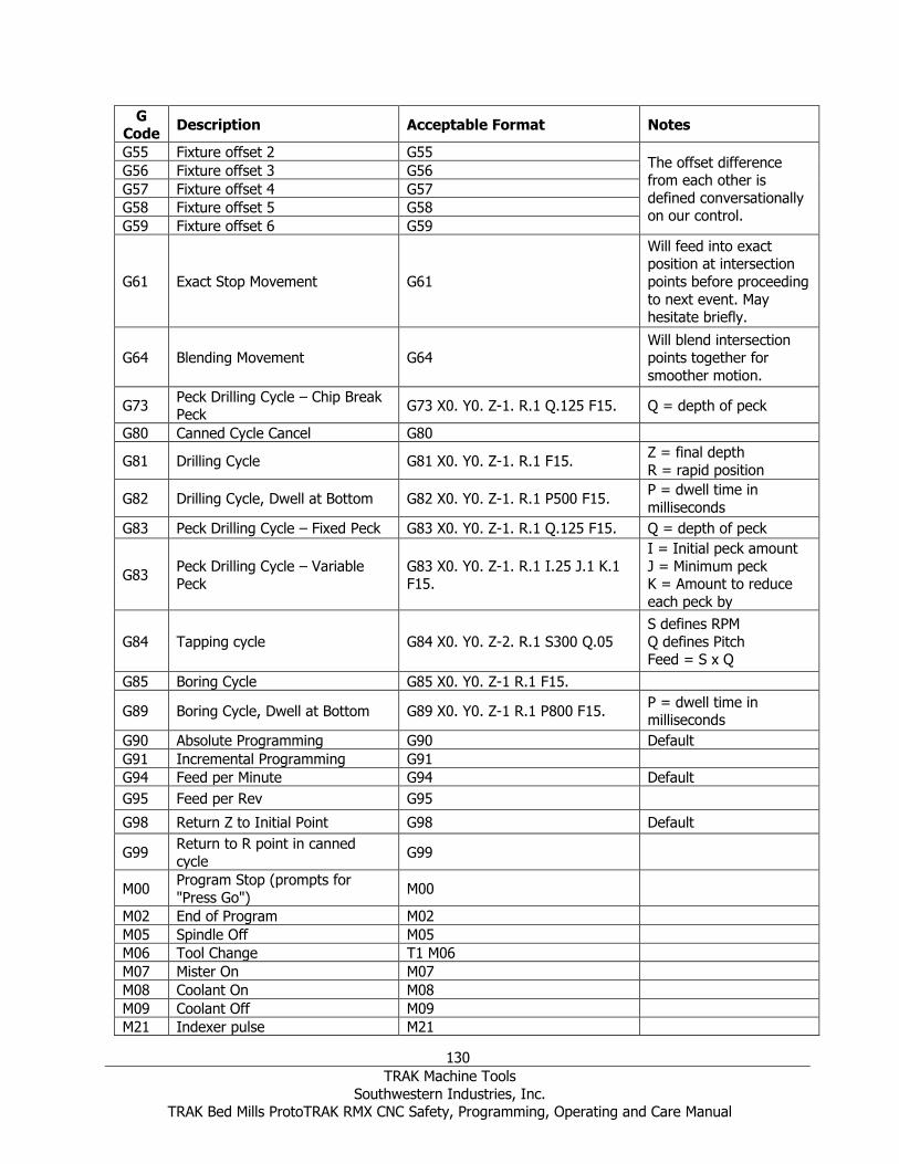
130
TRAK Machine Tools
Southwestern Industries, Inc. TRAK Bed Mills ProtoTRAK RMX CNC Safety, Programming, Operating and Care Manual
G Code
Description Acceptable Format Notes
G55 Fixture offset 2 G55 The offset difference from each other is
defined conversationally on our control.
G56 Fixture offset 3 G56
G57 Fixture offset 4 G57
G58 Fixture offset 5 G58
G59 Fixture offset 6 G59
G61 Exact Stop Movement G61
Will feed into exact position at intersection
points before proceeding
to next event. May hesitate briefly.
G64 Blending Movement G64 Will blend intersection points together for
smoother motion.
G73 Peck Drilling Cycle – Chip Break Peck
G73 X0. Y0. Z-1. R.1 Q.125 F15. Q = depth of peck
G80 Canned Cycle Cancel G80
G81 Drilling Cycle G81 X0. Y0. Z-1. R.1 F15. Z = final depth
R = rapid position
G82 Drilling Cycle, Dwell at Bottom G82 X0. Y0. Z-1. R.1 P500 F15. P = dwell time in
milliseconds
G83 Peck Drilling Cycle – Fixed Peck G83 X0. Y0. Z-1. R.1 Q.125 F15. Q = depth of peck
G83 Peck Drilling Cycle – Variable Peck
G83 X0. Y0. Z-1. R.1 I.25 J.1 K.1 F15.
I = Initial peck amount
J = Minimum peck K = Amount to reduce
each peck by
G84 Tapping cycle G84 X0. Y0. Z-2. R.1 S300 Q.05
S defines RPM
Q defines Pitch Feed = S x Q
G85 Boring Cycle G85 X0. Y0. Z-1 R.1 F15.
G89 Boring Cycle, Dwell at Bottom G89 X0. Y0. Z-1 R.1 P800 F15. P = dwell time in milliseconds
G90 Absolute Programming G90 Default
G91 Incremental Programming G91
G94 Feed per Minute G94 Default
G95 Feed per Rev G95
G98 Return Z to Initial Point G98 Default
G99 Return to R point in canned
cycle G99
M00 Program Stop (prompts for
"Press Go") M00
M02 End of Program M02
M05 Spindle Off M05
M06 Tool Change T1 M06
M07 Mister On M07
M08 Coolant On M08
M09 Coolant Off M09
M21 Indexer pulse M21

131
TRAK Machine Tools
Southwestern Industries, Inc. TRAK Bed Mills ProtoTRAK RMX CNC Safety, Programming, Operating and Care Manual
G Code
Description Acceptable Format Notes
M30 Program End M30
M38 Mister Off M38 This is new.
M51 Auxiliary Output On M51
M53 Auxiliary Output Off M53
14.14 Networking Prior to networking your control, you’ll need to turn off the File Based Write Filter temporarily. In order to
do this you’ll need to perform the following steps.
14.14.1.1 Press Mode, Setup, Service Code, input 540 and press ABS Set. When the following
screen comes up, press Yes.
14.14.1.2 The machine will reboot and bring you to the Windows desktop. Here you’ll make
your changes, then once your changes are made, click Finished as shown below to reboot (Note,
if you fail to click finish and reboot, you’ll return to this screen. The RX software will not open up automatically on this screen)
14.14.1 Networking – Windows 7 Networking Requirements: • Setting up the RMX/RLX on a Workgroup for Windows 7
• Straight thru CAT 5 / Ethernet Cable
• Mouse & Keyboard plugged into the RX controller

132
TRAK Machine Tools
Southwestern Industries, Inc. TRAK Bed Mills ProtoTRAK RMX CNC Safety, Programming, Operating and Care Manual
• Local Admin rights to the PC
• Obtain a DSL Cable router with DHCP Services
• All clicking on the mouse will be done with left button (left click) unless specified to right click
Basic Peer to Peer Network Utilizing Workgroup 1. In order to establish a Workgroup Network in Windows 7, the computer and control must
have the same workgroup name in order to be able to communicate with each other.
You’ll need to check the Workgroup name on your PC and if you wish to, modify the
name as well and then adjust it on the RX side to match in order to be able to network
the two together. To do this, perform the following steps:
a. On your keyboard, press the Windows Logo Key to bring up the Start Menu, locate
and right click Computer, then click Properties
b. Scroll down and locate Computer name, domain, and workgroup settings. Click
Change Settings
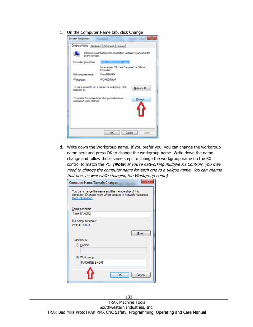
133
TRAK Machine Tools
Southwestern Industries, Inc. TRAK Bed Mills ProtoTRAK RMX CNC Safety, Programming, Operating and Care Manual
c. On the Computer Name tab, click Change
d. Write down the Workgroup name. If you prefer you, you can change the workgroup
name here and press OK to change the workgroup name. Write down the name
change and follow these same steps to change the workgroup name on the RX
control to match the PC. (Note: If you’re networking multiple RX Controls, you may
need to change the computer name for each one to a unique name. You can change
that here as well while changing the Workgroup name)

134
TRAK Machine Tools
Southwestern Industries, Inc. TRAK Bed Mills ProtoTRAK RMX CNC Safety, Programming, Operating and Care Manual
2. (Optional) - Secure Network Setup. In order to do a secure network setup requiring a
user name and password login, you’ll need to create a user account on your PC that can
be utilized on the RX control for secure access to a shared folder on your computer. You
may also use an existing user account on the PC but it must have a password associated
with it. To create a user account, do the following:
a. On your PC, click Start and then click Control Panel
b. Under User Accounts, click Add or remove user accounts
c. Click Create a new account

135
TRAK Machine Tools
Southwestern Industries, Inc. TRAK Bed Mills ProtoTRAK RMX CNC Safety, Programming, Operating and Care Manual
d. Input the user account name and select the user account type (Standard or
Administrator) and click Create Account.
e. Once the account is created, click on the account you’ve created
f. Click Create a password
g. Create a strong password that you can easily remember and input a hint as to what
your password would be to remind you in case you forget, then click Create
Password.
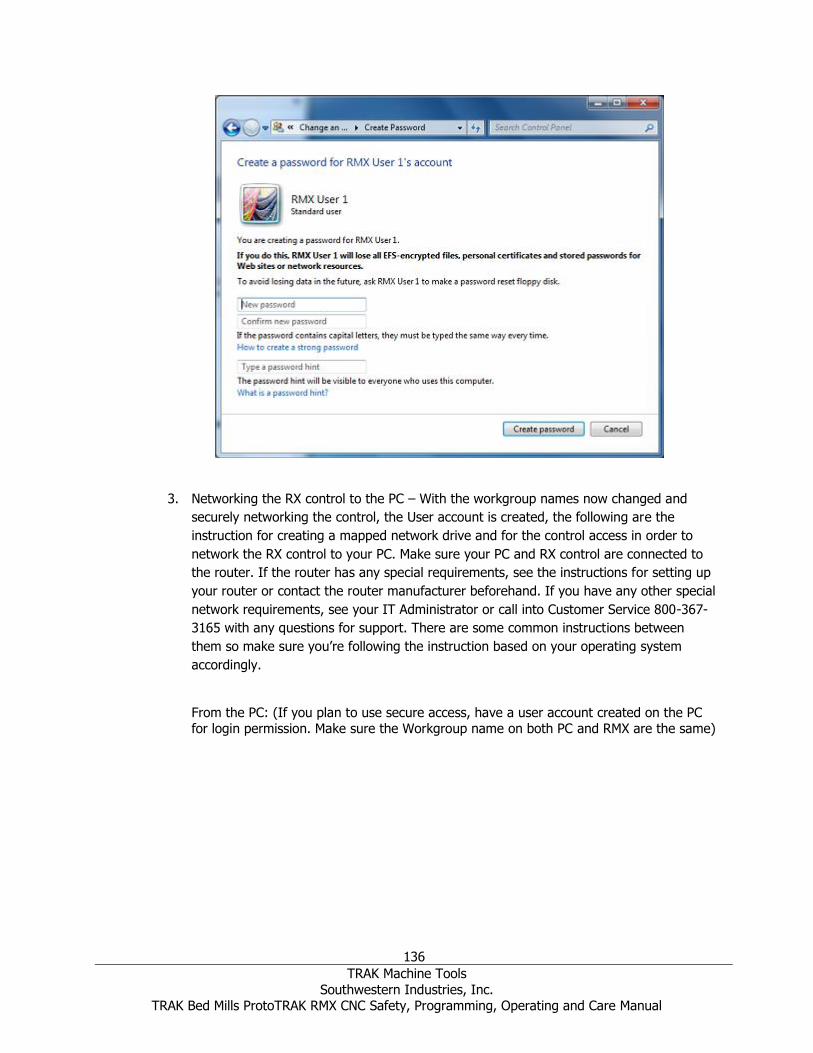
136
TRAK Machine Tools
Southwestern Industries, Inc. TRAK Bed Mills ProtoTRAK RMX CNC Safety, Programming, Operating and Care Manual
3. Networking the RX control to the PC – With the workgroup names now changed and
securely networking the control, the User account is created, the following are the
instruction for creating a mapped network drive and for the control access in order to
network the RX control to your PC. Make sure your PC and RX control are connected to
the router. If the router has any special requirements, see the instructions for setting up
your router or contact the router manufacturer beforehand. If you have any other special
network requirements, see your IT Administrator or call into Customer Service 800-367-
3165 with any questions for support. There are some common instructions between
them so make sure you’re following the instruction based on your operating system
accordingly.
From the PC: (If you plan to use secure access, have a user account created on the PC for login permission. Make sure the Workgroup name on both PC and RMX are the same)

137
TRAK Machine Tools
Southwestern Industries, Inc. TRAK Bed Mills ProtoTRAK RMX CNC Safety, Programming, Operating and Care Manual
a. Press the Windows Start button on your keyboard and click Control Panel
b. Click Network and Internet
c. Click Network and Sharing Center, then Change advanced sharing settings
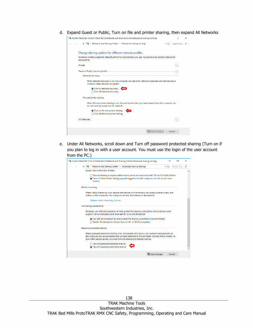
138
TRAK Machine Tools
Southwestern Industries, Inc. TRAK Bed Mills ProtoTRAK RMX CNC Safety, Programming, Operating and Care Manual
d. Expand Guest or Public, Turn on file and printer sharing, then expand All Networks
e. Under All Networks, scroll down and Turn off password protected sharing (Turn on if
you plan to log in with a user account. You must use the login of the user account
from the PC.)
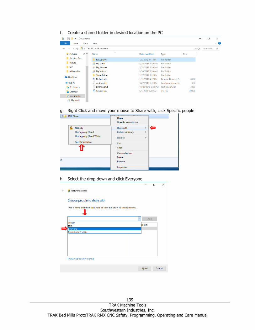
139
TRAK Machine Tools
Southwestern Industries, Inc. TRAK Bed Mills ProtoTRAK RMX CNC Safety, Programming, Operating and Care Manual
f. Create a shared folder in desired location on the PC
g. Right Click and move your mouse to Share with, click Specific people
h. Select the drop down and click Everyone

140
TRAK Machine Tools
Southwestern Industries, Inc. TRAK Bed Mills ProtoTRAK RMX CNC Safety, Programming, Operating and Care Manual
i. Change Permission Level to Read/Write, then click Share
j. On the RMX, press the Windows Start key and click My Computer

141
TRAK Machine Tools
Southwestern Industries, Inc. TRAK Bed Mills ProtoTRAK RMX CNC Safety, Programming, Operating and Care Manual
k. Click on Map Network Drive
l. Click the Drive drop down menu and select a drive letter. Click Browse
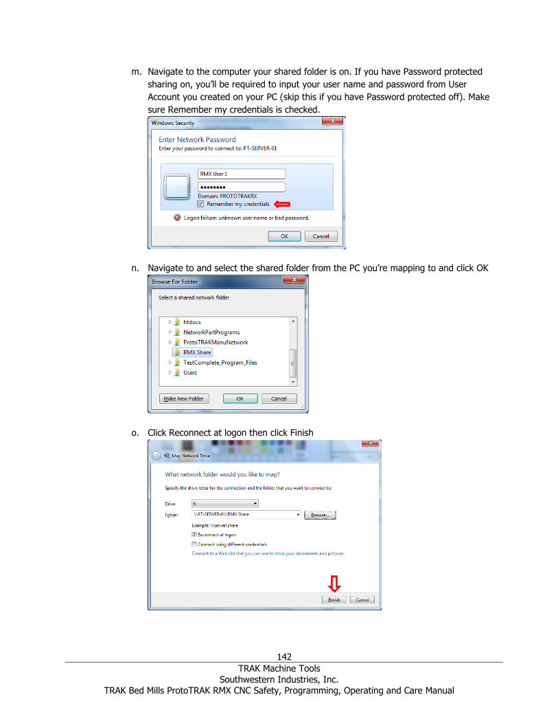
142
TRAK Machine Tools
Southwestern Industries, Inc. TRAK Bed Mills ProtoTRAK RMX CNC Safety, Programming, Operating and Care Manual
m. Navigate to the computer your shared folder is on. If you have Password protected
sharing on, you’ll be required to input your user name and password from User
Account you created on your PC (skip this if you have Password protected off). Make
sure Remember my credentials is checked.
n. Navigate to and select the shared folder from the PC you’re mapping to and click OK
o. Click Reconnect at logon then click Finish
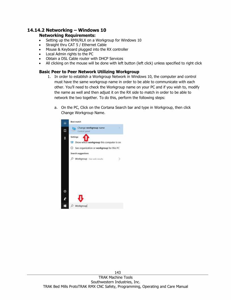
143
TRAK Machine Tools
Southwestern Industries, Inc. TRAK Bed Mills ProtoTRAK RMX CNC Safety, Programming, Operating and Care Manual
14.14.2 Networking – Windows 10 Networking Requirements: • Setting up the RMX/RLX on a Workgroup for Windows 10
• Straight thru CAT 5 / Ethernet Cable
• Mouse & Keyboard plugged into the RX controller
• Local Admin rights to the PC
• Obtain a DSL Cable router with DHCP Services
• All clicking on the mouse will be done with left button (left click) unless specified to right click
Basic Peer to Peer Network Utilizing Workgroup 1. In order to establish a Workgroup Network in Windows 10, the computer and control
must have the same workgroup name in order to be able to communicate with each
other. You’ll need to check the Workgroup name on your PC and if you wish to, modify
the name as well and then adjust it on the RX side to match in order to be able to
network the two together. To do this, perform the following steps:
a. On the PC, Click on the Cortana Search bar and type in Workgroup, then click
Change Workgroup Name.

144
TRAK Machine Tools
Southwestern Industries, Inc. TRAK Bed Mills ProtoTRAK RMX CNC Safety, Programming, Operating and Care Manual
b. In the area highlighted, you can view the Workgroup names.
c. If you wish to change it, click Change. Under Workgroup, change the workgroup
name in the text box and click OK
d. Follow steps 1-4 in the previous section 1.2.1 on the RX control to change the
Workgroup name to match the Windows 10 workgroup name.

145
TRAK Machine Tools
Southwestern Industries, Inc. TRAK Bed Mills ProtoTRAK RMX CNC Safety, Programming, Operating and Care Manual
2. (Optional) - Secure Network Setup. In order to do a secure network setup requiring a
user name and password login, you’ll need to create a user account on your PC that can
be utilized on the RX control for secure access to a shared folder on your computer. You
may also use an existing user account on the PC but it must have a password associated
with it. To create a user account, do the following:
a. Click in the Cortana Search Bar and type in: User Accounts, then click Add, Edit, or
Remove other people
b. Click Add someone else to this PC

146
TRAK Machine Tools
Southwestern Industries, Inc. TRAK Bed Mills ProtoTRAK RMX CNC Safety, Programming, Operating and Care Manual
c. Then type in a desired user name, a strong password that you can remember, and a
password hint that will remind you of what that password is in case the password is
forgotten and click Next.
3. Networking the RX control to the PC – With the workgroup names now changed and
securely networking the control, the User account is created, the following are the
instruction for creating a mapped network drive and for the control access in order to network the RX control to your PC. Make sure your PC and RX control are connected
to the router. If the router has any special requirements, see the instructions for setting up your router or contact the router manufacturer beforehand. If you have
any other special network requirements, see your IT Administrator or call into Customer Service 800-367-3165 with any questions for support. There are some
common instructions between them so make sure you’re following the instruction
based on your operating system accordingly.
From the PC: (If you plan to use secure access, have a user account created on the PC
for login permission. Make sure the Workgroup name on both PC and RMX are the same)

147
TRAK Machine Tools
Southwestern Industries, Inc. TRAK Bed Mills ProtoTRAK RMX CNC Safety, Programming, Operating and Care Manual
a. Press the Windows Start button on your keyboard and go to Settings
b. Click Network and Internet
c. Click Sharing options

148
TRAK Machine Tools
Southwestern Industries, Inc. TRAK Bed Mills ProtoTRAK RMX CNC Safety, Programming, Operating and Care Manual
d. Expand Guest or Public, Turn on file and printer sharing, then expand All Networks
e. Under All Networks, scroll down and Turn off password protected sharing (Turn on if
you plan to log in with a user account. You must use the login of the user account
from the PC.)
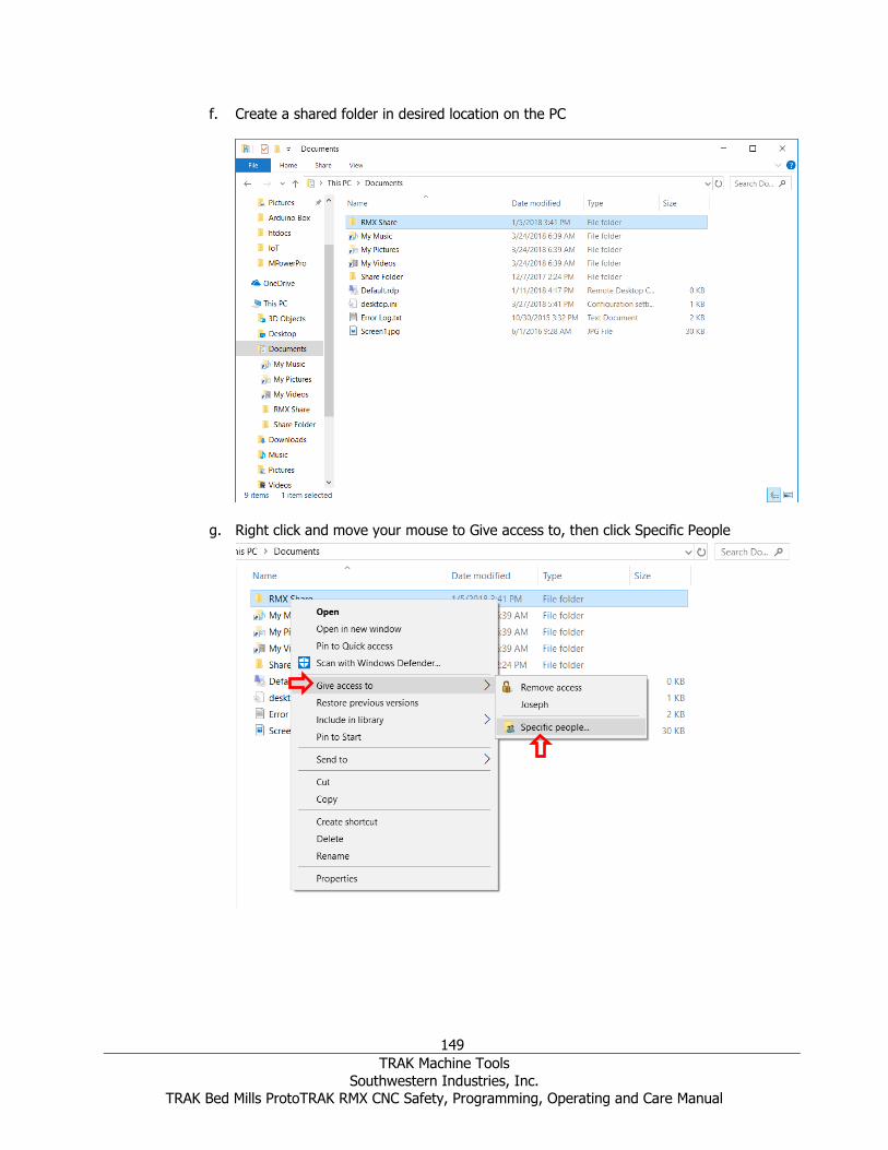
149
TRAK Machine Tools
Southwestern Industries, Inc. TRAK Bed Mills ProtoTRAK RMX CNC Safety, Programming, Operating and Care Manual
f. Create a shared folder in desired location on the PC
g. Right click and move your mouse to Give access to, then click Specific People
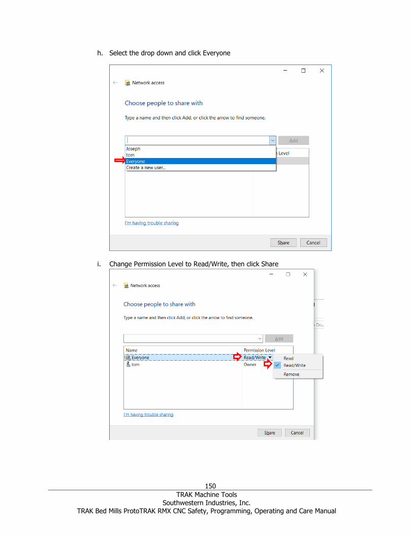
150
TRAK Machine Tools
Southwestern Industries, Inc. TRAK Bed Mills ProtoTRAK RMX CNC Safety, Programming, Operating and Care Manual
h. Select the drop down and click Everyone
i. Change Permission Level to Read/Write, then click Share

151
TRAK Machine Tools
Southwestern Industries, Inc. TRAK Bed Mills ProtoTRAK RMX CNC Safety, Programming, Operating and Care Manual
j. On the RMX, press the Windows Start key and click My Computer
k. Click on Map Network Drive

152
TRAK Machine Tools
Southwestern Industries, Inc. TRAK Bed Mills ProtoTRAK RMX CNC Safety, Programming, Operating and Care Manual
l. Click the Drive drop down menu and select a drive letter. Click Browse
m. Navigate to the computer your shared folder is on. If you have Password protected
sharing on, you’ll be required to input your user name and password from User
Account you created on your PC (skip this if you have Password protected off). Make
sure Remember my credentials is checked.
n. Navigate to and select the shared folder from the PC you’re mapping to and click OK
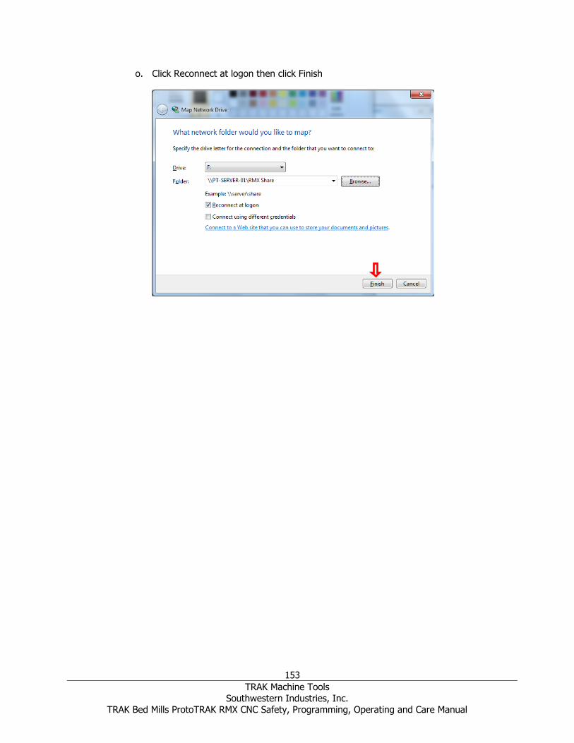
153
TRAK Machine Tools
Southwestern Industries, Inc. TRAK Bed Mills ProtoTRAK RMX CNC Safety, Programming, Operating and Care Manual
o. Click Reconnect at logon then click Finish

154
TRAK Machine Tools
Southwestern Industries, Inc. TRAK Bed Mills ProtoTRAK RMX CNC Safety, Programming, Operating and Care Manual
TRAK Machine Tools Southwestern Industries, Inc
TRAK Warranty Policy Warranty TRAK products are warranted to the original purchaser to be free from defects in workmanship and materials for the following periods:
Product Warranty Period
Materials Factory Labor
New TRAK/ProtoTRAK 1 Year 1 Year
Any EXCHANGE Unit 90 Days 90 Days
The warranty period starts on the date of the invoice to the original purchaser from Southwestern Industries, Inc. (SWI) or their authorized distributor.
If a product, subsystem or component proves to be defective in workmanship and fails within the
warranty period, it will be repaired or exchanged at our option for a properly functioning unit in
similar or better condition. Such repairs or exchanges will be made FOB Factory/Los Angeles or the location of our nearest factory representative or authorized distributor.
Warranty Disclaimers
• This warranty is expressly in lieu of any other warranties, express or implied, including any implied warranty of merchantability or fitness for a particular purpose, and of any
other obligations or liability on the part of SWI (or any producing entity, if different).
• Warranty repairs/exchanges do not cover incidental costs such as installation, labor,
freight, etc.
• SWI is not responsible for consequential damages from use or misuse of any of its
products.
• TRAK products are precision mechanical/electromechanical/electronic systems and must
be given the reasonable care that these types of products require. Evidence that the product does not receive adequate Preventative Maintenance may invalidate the
warranty. Excessive chips built up around ballscrews and way surfaces is an example of
this evidence.
• Accidental damage, beyond the control of SWI, is not covered by the warranty. Thus, the
warranty does not apply if a product has been abused, dropped, hit or disassembled.
• Improper installation by or at the direction of the customer in such a way that the
product consequently fails, is considered to be beyond the control of the manufacturer
and outside the scope of the warranty.
• Warranty does not cover wear items that are consumed under normal use of the product.
These items include, but are not limited to: windows, bellows, wipers, filters, drawbars
and belts.
F10302 | Rev: 020620
Related Documents


