Preface Preface Training is an important part of the professional development of an Industry professional. The feel of the environment in the industry poses as elixir for the aspirant and arms him with the ideas of how the works are done there. This training report contains the knowledge gained & self perceptions while my training period at National Capital Power Station, Dadri (G. B. Nagar) during summer break. In this report I have included the brief profile of NTPC Limited and its role in Indian power sector, with details of its managerial set up and its achievements and goals in near future. Addition to this, I have included the information of several of their projects running throughout the country. There had been a special section about the information about the NCPS- Dadri Project, after which follows a brief description of the thermal and gas production units of project. Since the field of study was assigned was Control & Instrumentation (Operation and Maintenance department) there is a section that tells about the role of C & I in working of power plant. A special introduction explaining working procedures and introducing laboratories cum workshops has been included as felt relevant and essential organ of all the control and instrumentation evident every where in the power plant. Lastly, the summary of the training has been given, that includes my innovations and thinking for all that observed here during the period and how much the training has proved helpful to me in understanding industrial code for work. 1

Welcome message from author
This document is posted to help you gain knowledge. Please leave a comment to let me know what you think about it! Share it to your friends and learn new things together.
Transcript

PrefacePrefaceTraining is an important part of the professional development of an Industry professional. The feel of the environment in the industry poses as elixir for the aspirant and arms him with the ideas of how the works are done there. This training report contains the knowledge gained & self perceptions while my training period at National Capital Power Station, Dadri (G. B. Nagar) during summer break.
In this report I have included the brief profile of NTPC Limited and its role in Indian power sector, with details of its managerial set up and its achievements and goals in near future. Addition to this, I have included the information of several of their projects running throughout the country.
There had been a special section about the information about the NCPS- Dadri Project, after which follows a brief description of the thermal and gas production units of project. Since the field of study was assigned was Control & Instrumentation (Operation and Maintenance department) there is a section that tells about the role of C & I in working of power plant. A special introduction explaining working procedures and introducing laboratories cum workshops has been included as felt relevant and essential organ of all the control and instrumentation evident every where in the power plant.
Lastly, the summary of the training has been given, that includes my innovations and thinking for all that observed here during the period and how much the training has proved helpful to me in understanding industrial code for work.
1

AcknowledgementAcknowledgementWe have a view in our minds that getting training in a public sector organization is equal to doing nothing or simply killing your time, but after completing my industrial training at NCPS- Dadri, I have a contradicting view, may be those people who said these things might not have the interest that is the requirements for getting something out of that what you perceive. But one thing is obvious that this all would have been a distant dream if the support from various peoples is subtracted from it.
Sequentially, I would come upon thanking Mr. S.K.Shrotri, AHP and Mr. Ram Parkash, AHP, NTPC Dadri, who were my insurer at NTPC, for there consensuses and guidance to me. And next I would heartily acknowledge all the officials that took time out of their precious time to volunteer for the cause that trainees have the introduction of the plant and its various sections.
I offer my sincerest thanks and deep sense of gratitude to Mr. S.K. DAS (Sr. SUPDT., O&M-Th.) and Mr. SANJAY KUMAR (SUPDT. C&I). I also thank the instructors that took our class who let us knew about the essential gas and thermal plants respectively. Now here is the acknowledgement of all those people who helped us by telling us our on site queries irrespective of the risk that may have priced much more that our benefit, a few names that I remember are Mr. B.K. Singh, Mr. Tajinder Gupta who made us realize the translucent pictures in our mind related to the various processes and parts in the plant. The Final Thanks is for the organization i.e. NTPC Limited which has facilitated this training program.
2
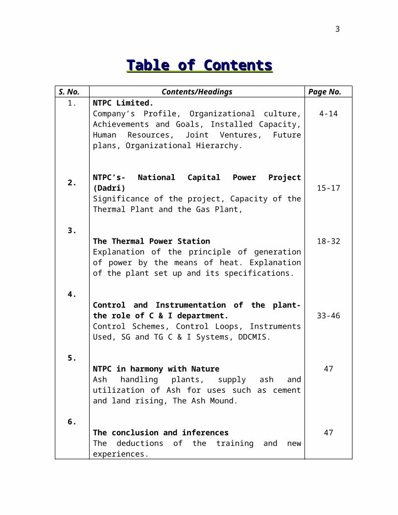
Table of ContentsTable of Contents
S. No. Contents/Headings Page No.1.
2.
3.
4.
5.
6.
NTPC Limited.Company’s Profile, Organizational culture, Achievements and Goals, Installed Capacity, Human Resources, Joint Ventures, Future plans, Organizational Hierarchy.
NTPC’s- National Capital Power Project (Dadri)Significance of the project, Capacity of the Thermal Plant and the Gas Plant,
The Thermal Power StationExplanation of the principle of generation of power by the means of heat. Explanation of the plant set up and its specifications.
Control and Instrumentation of the plant- the role of C & I department.Control Schemes, Control Loops, Instruments Used, SG and TG C & I Systems, DDCMIS.
NTPC in harmony with NatureAsh handling plants, supply ash and utilization of Ash for uses such as cement and land rising, The Ash Mound.
The conclusion and inferencesThe deductions of the training and new experiences.
4-14
15-17
18-32
33-46
47
47
3
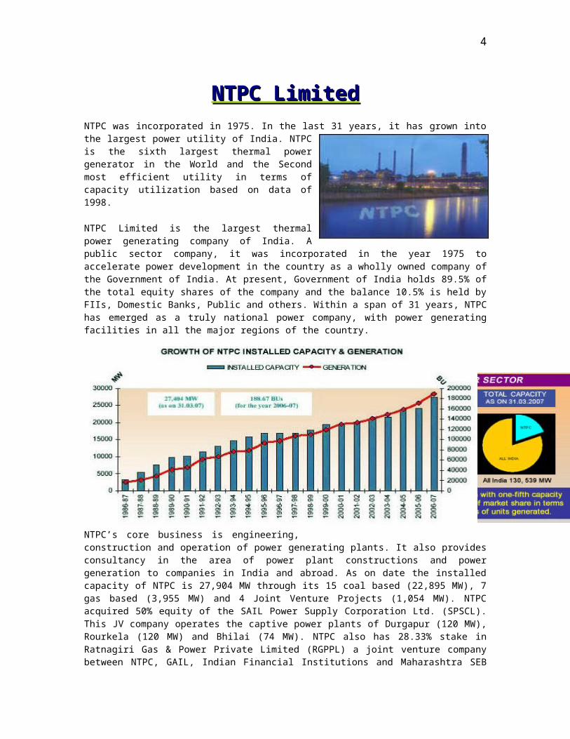
NTPC LimitedNTPC LimitedNTPC was incorporated in 1975. In the last 31 years, it has grown into the largest power utility of India. NTPC is the sixth largest thermal power generator in the World and the Second most efficient utility in terms of capacity utilization based on data of 1998.
NTPC Limited is the largest thermal power generating company of India. A public sector company, it was incorporated in the year 1975 to accelerate power development in the country as a wholly owned company of the Government of India. At present, Government of India holds 89.5% of the total equity shares of the company and the balance 10.5% is held by FIIs, Domestic Banks, Public and others. Within a span of 31 years, NTPC has emerged as a truly national power company, with power generating facilities in all the major regions of the country.
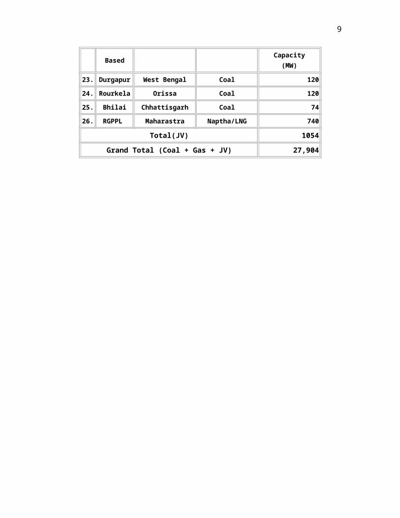
NTPC’s core business is engineering, construction and operation of power generating plants. It also provides consultancy in the area of power plant constructions and power generation to companies in India and abroad. As on date the installed capacity of NTPC is 27,904 MW through its 15 coal based (22,895 MW), 7 gas based (3,955 MW) and 4 Joint Venture Projects (1,054 MW). NTPC acquired 50% equity of the SAIL Power Supply Corporation Ltd. (SPSCL). This JV company operates the captive power plants of Durgapur (120 MW), Rourkela (120 MW) and Bhilai (74 MW). NTPC also has 28.33% stake in Ratnagiri Gas & Power Private Limited (RGPPL) a joint venture company between NTPC, GAIL, Indian Financial Institutions and Maharashtra SEB Holding Co. Ltd. The present capacity of Ratnagiri Gas & Power Private Limited (RGPPL) is 740 MW.
NTPC’s share on 31 Mar 2007 in the total installed capacity of the country was 20.18% and it contributed 28.50% of the total power generation of the country during 2006-07.
4
NTPC has set new benchmarks for the power industry both in the area of power plant construction and operations. It is providing power at the cheapest average tariff in the country. With its experience and expertise in the power sector, NTPC is extending consultancy services to various organizations in the power business.
NTPC is committed to the environment, generating power at minimal environmental cost and preserving the ecology in the vicinity of the plants. NTPC has undertaken massive afforestation in the vicinity of its plants. Plantations have increased forest area and reduced barren land. The massive afforestation by NTPC in and around its Ramagundam Power station (2600 MW) has contributed reducing the temperature in the areas by about 3°c. NTPC has also taken proactive steps for ash utilization. In 1991, it set up Ash Utilization Division to manage efficient use of the ash produced at its coal stations. This quality of ash produced is ideal for use in cement, concrete, cellular concrete, building material.
A "Centre for Power Efficiency and Environment Protection (CENPEEP)" has been established in NTPC with the assistance of United States Agency for International Development (USAID). Cenpeep is efficiency oriented, eco-friendly and eco-nurturing initiative - a symbol of NTPC's concern towards environmental protection and continued commitment to sustainable power development in India.
As a responsible corporate citizen, NTPC is making constant efforts to improve the socio-economic status of the people affected by its projects. Through its Rehabilitation and Resettlement programmes, the company endeavors to improve the overall socio-economic status of Project Affected Persons.
NTPC was among the first Public Sector Enterprises to enter into a Memorandum of Understanding (MOU) with the Government in 1987-88. NTPC has been Placed under the 'Excellent category' (the best category) every year since the MOU system became operative.
Recognizing its excellent performance and vast potential, Government of the India has identified NTPC as one of the jewels of Public Sector ‘Navratnas’- a potential global giant. Inspired by its glorious past and vibrant present, NTPC is well on its way to realize its vision of being “A world class integrated power major, powering India’s growth, with increasing global presence”.
5

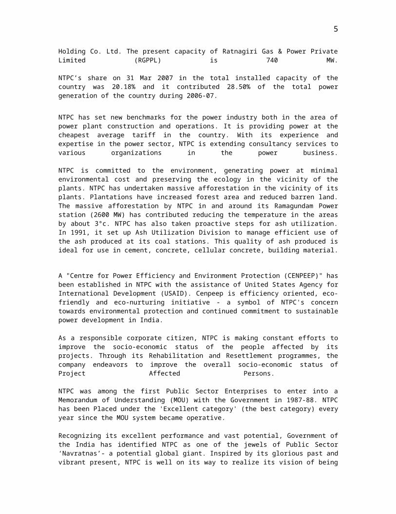
Installed Capacity
AN OVERVIEW
Projects No. of Projects Commissioned
Capacity(MW)
NTPC OWNED
COAL 15 22,895
GAS/LIQ. FUEL 07 3,955
TOTAL 22 26,850
OWNED BY JVCs
Coal 3 314*
Gas/LIQ. FUEL 1 740**
GRAND TOTAL 26 27,904
* Captive Power Plant under JVs with SAIL** Power Plant under JV with GAIL, FIs & MSEB
PROJECT PROFILE
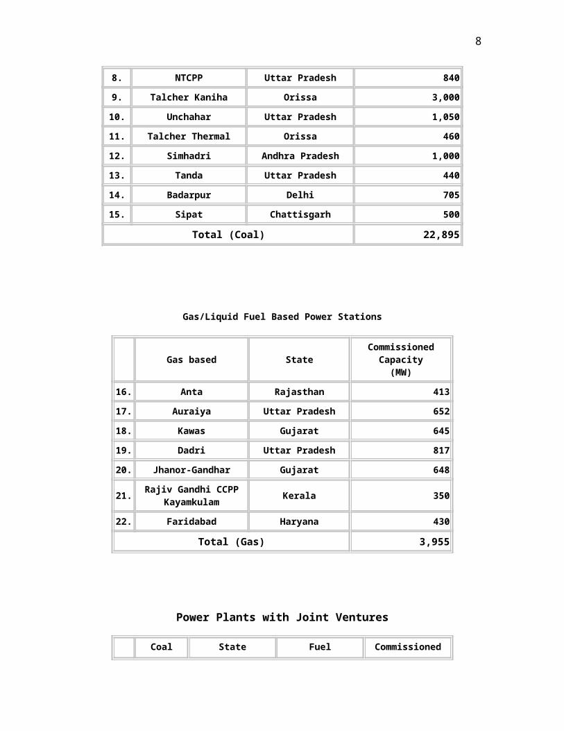
Coal Based Power Stations
Coal based State Commissioned
Capacity(MW)
1. Singrauli Uttar Pradesh 2,000
2. Korba Chattisgarh 2,100
3. Ramagundam Andhra Pradesh 2,600
4. Farakka West Bengal 1,600
5. Vindhyachal Madhya Pradesh 3,260
6. Rihand Uttar Pradesh 2,000
7. Kahalgaon Bihar 1,340
8. NTCPP Uttar Pradesh 840
9. Talcher Kaniha Orissa 3,000
10. Unchahar Uttar Pradesh 1,050
11. Talcher Thermal Orissa 460
6
12. Simhadri Andhra Pradesh 1,000
13. Tanda Uttar Pradesh 440
14. Badarpur Delhi 705
15. Sipat Chattisgarh 500
Total (Coal) 22,895
Gas/Liquid Fuel Based Power Stations
Gas based State Commissioned
Capacity(MW)
16. Anta Rajasthan 413
17. Auraiya Uttar Pradesh 652
18. Kawas Gujarat 645
19. Dadri Uttar Pradesh 817
20. Jhanor-Gandhar Gujarat 648
21. Rajiv Gandhi CCPP Kayamkulam
Kerala 350
22. Faridabad Haryana 430
Total (Gas) 3,955
Power Plants with Joint Ventures
Coal
Based State Fuel
Commissioned Capacity
(MW)
23. Durgapur West Bengal Coal 120
24. Rourkela Orissa Coal 120
25. Bhilai Chhattisgarh Coal 74
26. RGPPL Maharastra Naptha/LNG 740
Total(JV) 1054
7
Grand Total (Coal + Gas + JV) 27,904
8
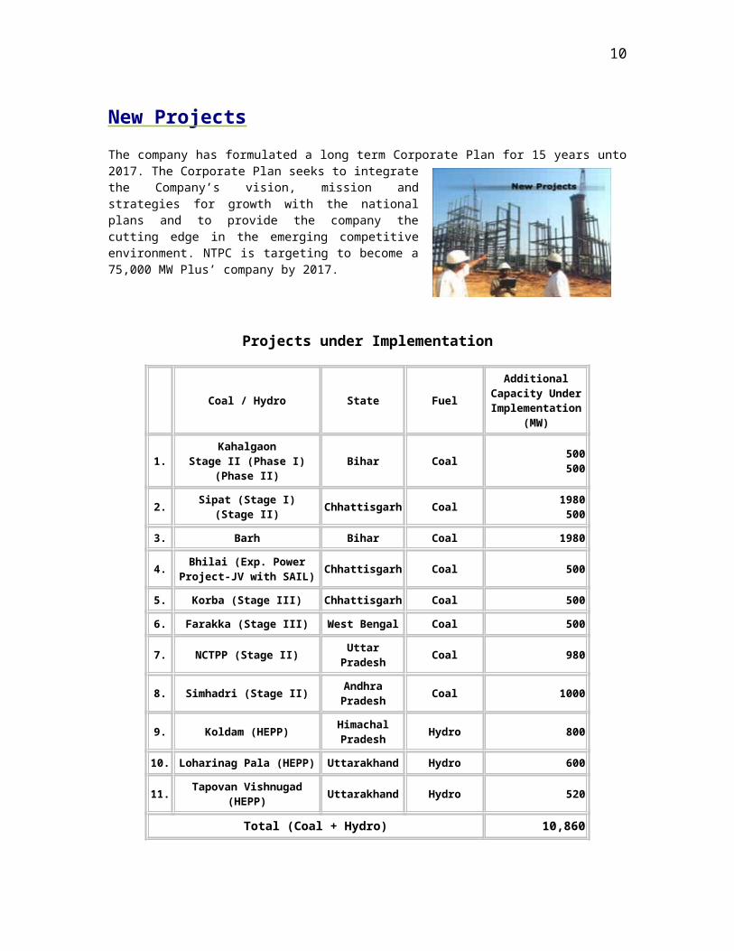
New Projects
The company has formulated a long term Corporate Plan for 15 years unto 2017. The Corporate Plan seeks to integrate the Company’s vision, mission and strategies for growth with the national plans and to provide the company the cutting edge in the emerging competitive environment. NTPC is targeting to become a 75,000 MW Plus’ company by 2017.
Projects under Implementation
Coal / Hydro State Fuel
Additional Capacity Under Implementation
(MW)
1. Kahalgaon
Stage II (Phase I) (Phase II)
Bihar Coal500500
2. Sipat (Stage I) (Stage
II)Chhattisgar
hCoal
1980500
3. Barh Bihar Coal 1980
4. Bhilai (Exp. Power
Project-JV with SAIL)Chhattisgar
hCoal 500
5. Korba (Stage III)Chhattisgar
hCoal 500
6. Farakka (Stage III) West Bengal Coal 500
7. NCTPP (Stage II)Uttar
PradeshCoal 980
8. Simhadri (Stage II)Andhra Pradesh
Coal 1000
9. Koldam (HEPP)Himachal Pradesh
Hydro 800
10. Loharinag Pala (HEPP) Uttarakhand Hydro 600
11. Tapovan Vishnugad
(HEPP)Uttarakhand Hydro 520
Total (Coal + Hydro) 10,860
9
Powering India's Growth: Through people
NTPC believes in achieving organizational excellence through Human Resources and follows "People First" approach to leverage the potential of its 23,500 employees to fulfill its business plans. Human Resources Function has formulated an integrated HR strategy which rests on four building blocks of HR viz. Competence building, Commitment building, Culture building and Systems building. All HR initiatives are undertaken within this broad framework to actualize the HR Vision of "enabling the employees to be a family of committed world class professionals making NTPC a learning organization.
To induct talent and groom them into a dedicated cadre of power professionals "Executive Trainee" Scheme was introduced in the year 1977 for recruitment in the disciplines of Mechanical, Electrical, Civil, Control & Instrumentation and now encompasses Computer Science, Chemistry, HR and Finance disciplines also. Besides a comprehensive one year training comprising theoretical inputs as well as on-the-job training, the new recruits are also attached with senior executives under a systematic and formal 'Mentoring System' of the company to integrate them into the Culture of the company.
As part of post employment training and development opportunities, a systematic Training plan has been formulated for ensuring minimum seven man days training per employee per year and includes level-wise planned intervention designed to groom people for assuming positions of higher responsibility, as well as specific need-based interventions based on scientific Training Needs Analysis. NTPC has set up 15 project training centers, 2 simulator training centers and an apex institute namely 'Power Management Institute' (PMI). While the project training centers (Employee Development Centers) have specialized in imparting technical skills and knowledge, PMI places emphasis on management development. Besides opportunities for long term education are also provided through tie ups with reputed Institutions like IIT, Delhi, (M.Tech in Power Generation Technology), MDI, Gurgaon (Executive MBA programme), BITS, Pilani (B.Tech) etc.
In order to realize the HR Vision of making NTPC a learning Organization by providing opportunities to continually learn new capabilities a number of initiatives have been taken. NTPC Open Competition for Executive Talent (NOCET) is organized every year in which teams of executives compete annually through oral and written presentation on a topical theme. Similarly "Professional Circles" have been formed department-wise where Executives of the department meet every fortnight to share their knowledge and experiences and discuss topical issues. In order to tap the latent talent among non executives and make use of their potential for creativity and innovation, Quality Circles have been set up in various units/offices in NTPC. Besides a management journal called "Horizon" is published quarterly to enable employees to share their ideas and experiences across the organization.
Demonstrating its high concern for people, NTPC has developed strong employee welfare, health & well-being and social security systems leading to high level of commitment. NTPC offers best quality-of-life through beautiful townships with all amenities such as educational, medical and recreational opportunities for employees and their family members. The motivation to perform and excel is further enhanced through a comprehensive NTPC Rewards and Recognition system.
10

In order to institutionalize a strong Culture based on Values a number of initiatives are taken to actualize the Vision and Core Values (BCOMIT) across the company. A culture of celebrating achievements and a strong focus on performance are a way of life in NTPC.
NTPC has institutionalized "Development Centers" in the company to systematically diagnose the current and potential competency requirements of the employees with the objective of enhancing their development in a planned manner. These Centers give a good insight to the employees about their strengths and weaknesses, the gaps in their competencies which they can bridge through suitable support from company. Due to innovative people management practices there is a high level of pride and commitment amongst employees as reflected in the various external surveys including “Great Places to Work for in India” in which NTPC was rated third Great Place to work for in the country in 2005.
JOINT VENTURE PARTNERS
NTPC, with a rich experience of engineering, constructing and operating over 26,000 MW of thermal generating capacity, is the largest and one of the most efficient power companies in India, having operations that match the global standards.
NTPC has identified Joint Ventures, strategic alliances as well as acquisitions and diversifications as viable and desired options for its business development.
NTPC looks for opportunity to create such joint ventures and strategic alliances, in the entire value chain of the power business. NTPC as a partner endows the Joint Venture Alliances with a winning edge. Acquisitions and Diversifications in the areas related to the core business not only ensure growth but also add to the robustness of the company. Diversification is carried out either directly or through subsidiaries/JVs.
ACQUISITION
Business development through Acquisition serves both NTPC's own commercial interest as well as the interest of the Indian economy
Taking over being a part of the acquisition process, is also an opportunity for NTPC to add to its power generation capacity through minimal investment and very low gestation period. NTPC has, over the years, acquired the following three power stations belonging to other utilities/SEBs and has turned around each of them using its corporate abilities.
POWER STATIONS TAKEN OVER YEAR ORIGINAL OWNER
11
2x210 MW Feroze Gandhi Unchahar Thermal Power Station
1991 UP RajyaVidyut Utpadan Nigam of Uttar Pradesh
4x60 MW + 2x110 MW Talcher Thermal Power Station
1995 Orissa State Electricity Board
4x110 MW Tanda Thermal Power Station
2000 UP State Electricity Board
705MW Badarpur Thermal Power Station
2006 Central Electricity Authority
DIVERSIFICATION
To broad-base the business and also to ensure growth, diversification in the areas related to NTPC's core business of power generation such as Hydro power, Distribution, Trading, Coal mining, LNG etc. have been identified as priority areas.
A. NUCLEAR POWER GENERATION
In line with its Corporate Plan, NTPC exploring forays into the field of Nuclear Power Generation. NTPC is now planning to set up Nuclear Power Projects of about 2000MW by the year 2017.
B. VERTICAL (BACKWARD) INTEGRATION - COAL MINING AND LNG BUSINESS:
COAL MINING: The policy changes in coal sector provide an opportunity to NTPC to enter captive coal mining business. Production is expected by 2007 in one coal block already allotted in 2004 (Pakri Barwadih in the state of Jharkhand). Six more blocks (~40MTPA) have been allotted to NTPC, including two in JV with CIL.
12
Growth Plans
Over the last three decades, NTPC has spearheaded development of thermal power generation in the Indian power sector. In this process, it has built a strong portfolio of coal and gas/liquid fuel based generation capacities. The company has made initial forays in the area of hydropower development and plans to have a significant share of hydro power in its future generation portfolio. Although NTPC is also offering technical services, both in domestic and international markets, through its Consultancy Wing, the generation business would continue to be the single largest revenue generator for NTPC.
The Indian power sector is witnessing several changes in the business and regulatory environment. The legal and policy framework has changed substantially with the enactment of the Electricity Act 2003. In the foreseeable future, India faces formidable challenges in meeting its energy needs. Recently, a draft integrated energy policy has been issued, which addresses all aspects including energy security, access, availability, affordability, pricing, efficiency and environment. To meet the twin objectives of ensuring availability of electricity to consumers at competitive rates, as well as attract large private investments in the sector, a new Tariff policy has also been issued. The power sector thus offers a mixed bag of challenges and opportunities to players and NTPC would continue to review its business strategy and portfolio in light of these changes.
Growth of the Generation Business
Developing and operating world-class power stations is NTPC’s core competence. Its scale of operation, financial strength and large experience serve to provide an advantage over competitors. To meet the objective of making available reliable and quality power at competitive prices, NTPC would continue to speedily implement projects and introduce state-of-art technologies.
Total capacity portfolio
India’s generation capacity can be expected to grow from the current levels of about 120 GW to about 225-250 GW by 2017. NTPC currently accounts for about 20% of the country’s installed capacity and almost 60% of the total installed capacity in the Central sector in the country. Going forward, in its target to remain the largest generating utility of India, NTPC would endeavor to maintain or improve its share of India’s generating capacity. Towards this end, NTPC would target to build an overall capacity portfolio of over 66,000 MW by 2017.
Fuel / Energy mix for capacity addition
Currently, coal has a dominant share in the power generation capacities in India. This is also reflected in the high share of coal-based capacities in NTPC’s current portfolio. With high uncertainties involved in Domestic gas/ LNG, both in terms of availability
13

and prices, NTPC would continue to set up large pit-head coal based projects, including few integrated coal cum power projects. To reduce the dependence on fossil fuels, there is a need to push for renewable sources of power in the sector. NTPC would avail of opportunities to add hydropower to its portfolio subject to competitive tariffs. A first step in this direction has already been taken with the investment in Koldam Hydro Power Project. NTPC would continue to closely monitor developments on nuclear front also and be open to setting up around 2000 MW of Nuclear power generation capacity, possibly through a Joint Venture. As a leader in power generation, NTPC would also consider other energy sources such as biomass, cogeneration, fuel cells, etc for future development thereby reducing the dependence on thermal fuels.
While a decision on the fuel/energy mix for NTPC in the future would be largely governed by their relative tariff-competitiveness, the fuel mix in 2017 may be different from the existing portfolio, though not very significantly.
Diversification along the Value Chain
NTPC has achieved the distinction of being the largest thermal generating company in India. In the past, this focus was adequate as the industry was highly regulated with limited diversification opportunities. Over last few years, the country has been facing acute shortages, both in coal and gas, severely affecting optimum utilization of its power stations and these shortages are likely to continue in future as well. This is in spite of the fact that India is one of the largest producers of coal in the World. To safeguard its competitive advantage in power generation business, NTPC has moved ahead in diversifying its portfolio to emerge as an integrated power major, with presence across entire energy value chain. In fact, to symbolize this change, NTPC has taken on a new identity and a new name “NTPC Limited”. NTPC has recently diversified into coal mining business primarily to secure its fuel requirements and support its aggressive capacity addition program. In addition, NTPC is also giving thrust on diversification in the areas of power trading and distribution. Diversification would also allow NTPC to offer new growth opportunities to its employees while leveraging their skills to capitalize on new opportunities in the sector.
Establishing a Global Presence
To become a truly global company serving global markets, it is essential for NTPC to establish its brand equity in overseas markets. NTPC would continue to focus on offering Engineering & Project Management Services, Operations & Maintenance services, and Renovation & Modernization services in the international market.
Establishing a successful services brand would be a precursor to taking higher investment decisions in different markets. Going forward, NTPC would continue to evaluate various options for strengthening its presence in global markets including setting up power generation capacity, acquisition of gas blocks etc.
Circa 2017: NTPC’s corporate profile
14

By the year 2017, NTPC would have successfully diversified its generation mix, diversified across the power value chain and entered overseas markets. As a result NTPC would have altered its profile significantly. Elements of the revised profile that NTPC would seek to achieve are:
Amongst top five market capitalization in the Indian market An Indian MNC with presence in many countries Diversified utility with multiple businesses Setting benchmarks in project construction and plant availability & efficiency Preferred employer Have a strong research and technology base Loyal customer base in both bulk and retail supply A leading corporate citizen with a keen focus on executing its social
responsibility
15
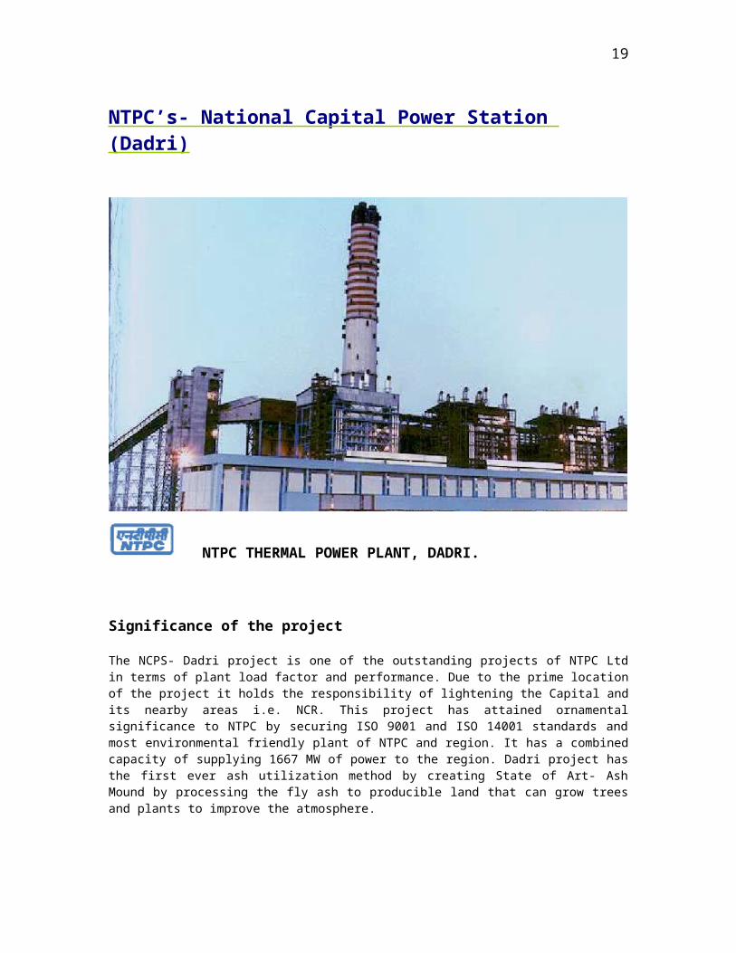
NTPC’s- National Capital Power Station (Dadri)
NTPC THERMAL POWER PLANT, DADRI.
Significance of the project
The NCPS- Dadri project is one of the outstanding projects of NTPC Ltd in terms of plant load factor and performance. Due to the prime location of the project it holds the responsibility of lightening the Capital and its nearby areas i.e. NCR. This project has attained ornamental significance to NTPC by securing ISO 9001 and ISO 14001 standards and most environmental friendly plant of NTPC and region. It has a combined capacity of supplying 1667 MW of power to the region. Dadri project has the first ever ash utilization method by creating State of Art- Ash Mound by processing the fly ash to producible land that can grow trees and plants to improve the atmosphere.
16
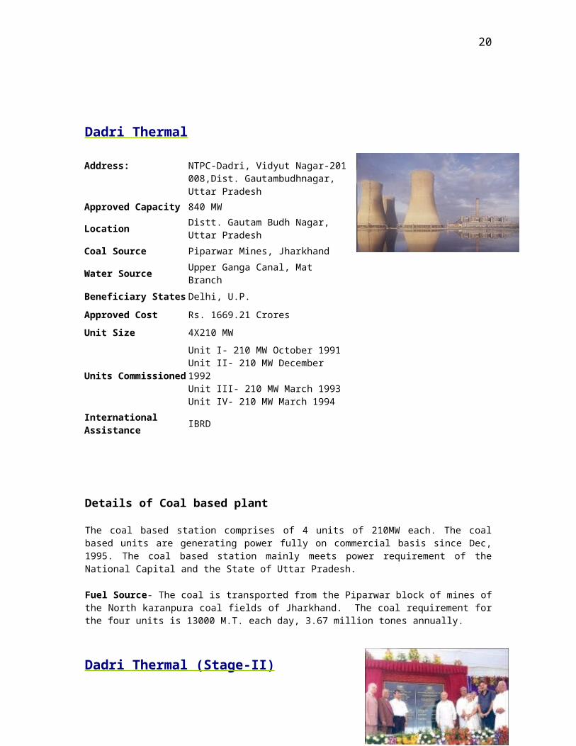
Dadri Thermal
Details of Coal based plant
The coal based station comprises of 4 units of 210MW each. The coal based units are generating power fully on commercial basis since Dec, 1995. The coal based station mainly meets power requirement of the National Capital and the State of Uttar Pradesh.
Fuel Source- The coal is transported from the Piparwar block of mines of the North karanpura coal fields of Jharkhand. The coal requirement for the four units is 13000 M.T. each day, 3.67 million tones annually.
Dadri Thermal (Stage-II)
The foundation stone for additional 980 MW i.e. 2 units of 490 MW each at NTPC’s National Capital Thermal Power Project was laid on 15th June, 2007 by Shri Sushilkumar Shinde, Hon. Union Minister of Power. With the installation of stage II (980MW) the total installed capacity of Dadri Project shall increase to 2673 MW. The additional capacity shall be built with an investment of Rs. 5,135 crore in time for the Commonwealth Games.
Address: NTPC-Dadri, Vidyut Nagar-201 008,Dist. Gautambudhnagar, Uttar Pradesh
Approved Capacity 840 MW
LocationDistt. Gautam Budh Nagar, Uttar Pradesh
Coal Source Piparwar Mines, Jharkhand
Water Source Upper Ganga Canal, Mat Branch
Beneficiary States Delhi, U.P.
Approved Cost Rs. 1669.21 Crores
Unit Size 4X210 MW
Units Commissioned
Unit I- 210 MW October 1991Unit II- 210 MW December 1992Unit III- 210 MW March 1993Unit IV- 210 MW March 1994
International Assistance
IBRD
17
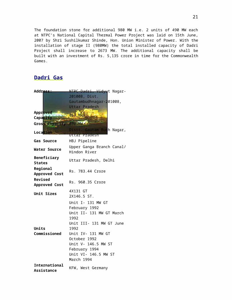
Dadri Gas
Details of Gas based plant
This plant is country’s largest has based station. The modules are fully under commercial operation since April 1997.
Gas station has two modules; each module consists of four gas turbines of 130.19 MW each within one waste heat recovery boiler and two steam turbines of 154.51 MW capacities.
Address: NTPC-Dadri, Vidyut Nagar-201008, Dist. Gautambudhnagar-201008, Uttar Pradesh
Approved Capacity 817 MW
Gross Capacity 830 MW
LocationDistt. Gautam Budh Nagar, Uttar Pradesh
Gas Source HBJ Pipeline
Water SourceUpper Ganga Branch Canal/ Hindon River
Beneficiary States Uttar Pradesh, Delhi
Regional Approved Cost
Rs. 783.44 Crore
Revised Approved Cost
Rs. 960.35 Crore
Unit Sizes4X131 GT2X146.5 ST.
Units Commissioned
Unit I- 131 MW GT February 1992Unit II- 131 MW GT March 1992Unit III- 131 MW GT June 1992Unit IV- 131 MW GT October 1992Unit V- 146.5 MW ST February 1994Unit VI- 146.5 MW ST March 1994
International Assistance
KFW, West Germany
18
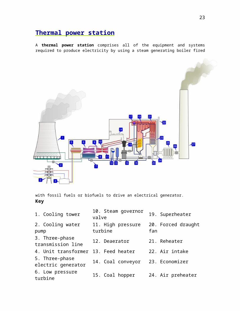
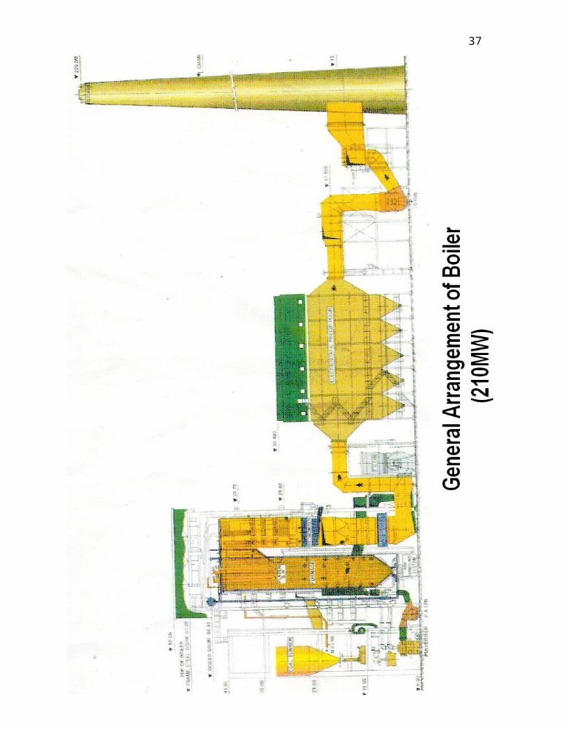
Thermal power station
A thermal power station comprises all of the equipment and systems required to produce electricity by using a steam generating boiler fired with fossil fuels or biofuels to drive an electrical generator.
Key
1. Cooling tower 10. Steam governor valve 19. Superheater2. Cooling water pump 11. High pressure turbine 20. Forced draught fan3. Three-phase transmission line
12. Deaerator 21. Reheater
4. Unit transformer 13. Feed heater 22. Air intake5. Three-phase electric generator
14. Coal conveyor 23. Economizer
6. Low pressure turbine 15. Coal hopper 24. Air preheater7. Boiler feed pump 16. Pulverized fuel mill 25. Precipitator8. Condenser 17. Boiler drum 26. Induced draught fan9. Intermediate pressure turbine
18. Ash hopper 27. Chimney stack
19
Description
A coal-fired thermal power station.
Coal is conveyed (14) from an external stack and ground to a very fine powder by large metal spheres in the pulverised fuel mill (16). There it is mixed with preheated air (24) driven by the forced draught fan (20). The hot air-fuel mixture is forced at high pressure into the boiler where it rapidly ignites. Water of a high purity flows vertically up the tube-lined walls of the boiler, where it turns into steam, and is passed to the boiler drum, where steam is separated from any remaining water. The steam passes through a manifold in the roof of the drum into the pendant superheater (19) where its temperature and pressure increase rapidly to around 200 bar and 570°C, sufficient to make the tube walls glow a dull red. The steam is piped to the high pressure turbine (11), the first of a three-stage turbine process. A steam governor valve (10) allows for both manual control of the turbine and automatic set-point following. The steam is exhausted from the high pressure turbine, and reduced in both pressure and temperature, is returned to the boiler reheater (23). The reheated steam is then passed to the intermediate pressure turbine (9), and from there passed directly to the low pressure turbine set (6). The exiting steam, now a little above its boiling point, is brought into thermal contact with cold water (pumped in from the cooling tower) in the condensor (8), where it condenses rapidly back into water, creating near vacuum-like conditions inside the condensor chest. The condensed water is then passed by a feed pump (7) through a deaerator (12), and pre-warmed, first in a feed heater (13) powered by steam drawn from the high pressure set, and then in the economiser (23), before being returned to the boiler drum. The cooling water from the condensor is sprayed inside a cooling tower (1), creating a highly visible plume of water vapor, before being pumped back to the condensor (8) in cooling water cycle.
The three turbine sets are coupled on the same shaft as the three-phase electrical generator (5) which generates an intermediate level voltage (typically 20-25 kV). This is stepped up by the unit transformer (4) to a voltage more suitable for transmission (typically 250-500 kV) and is sent out onto the three-phase transmission system (3).
Exhaust gas from the boiler is drawn by the induced draft fan (26) through an electrostatic precipitator (25) and is then vented through the chimney stack (27).
20
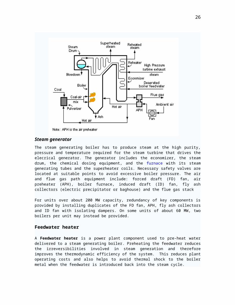
Steam generator
The steam generating boiler has to produce steam at the high purity, pressure and temperature required for the steam turbine that drives the elecrical generator. The generator includes the economizer, the steam drum, the chemical dosing equipment, and the furnace with its steam generating tubes and the superheater coils. Necessary safety valves are located at suitable points to avoid excessive boiler pressure. The air and flue gas path equipment include: forced draft (FD) fan, air preheater (APH), boiler furnace, induced draft (ID) fan, fly ash collectors (electric precipitator or baghouse) and the flue gas stack
For units over about 200 MW capacity, redundancy of key components is provided by installing duplicates of the FD fan, APH, fly ash collectors and ID fan with isolating dampers. On some units of about 60 MW, two boilers per unit may instead be provided.
Feedwater heater
A Feedwater heater is a power plant component used to pre-heat water delivered to a steam generating boiler. Preheating the feedwater reduces the irreversibilities involved in steam generation and therefore improves the thermodynamic efficiency of the system. This reduces plant operating costs and also helps to avoid thermal shock to the boiler metal when the feedwater is introduced back into the steam cycle.
In a steam power plant (usually modeled as a modified Rankine cycle), feedwater heaters allow the feedwater to be brought up to the saturation temperature very gradually. This minimizes the inevitable irreversibilites associated with heat transfer to the working fluid (water).
21

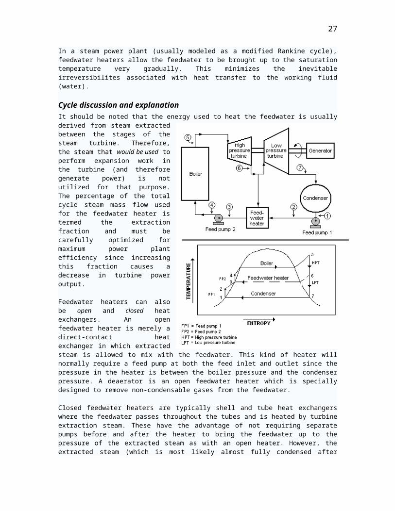
Cycle discussion and explanationIt should be noted that the energy used to heat the feedwater is usually derived from steam extracted between the stages of the steam turbine. Therefore, the steam that would be used to perform expansion work in the turbine (and therefore generate power) is not utilized for that purpose. The percentage of the total cycle steam mass flow used for the feedwater heater is termed the extraction fraction and must be carefully optimized for maximum power plant efficiency since increasing this fraction causes a decrease in turbine power output.
Feedwater heaters can also be open and closed heat exchangers. An open feedwater heater is merely a direct-contact heat exchanger in which extracted steam is allowed to mix with the feedwater. This kind of heater will normally require a feed pump at both the feed inlet and outlet since the pressure in the heater is between the boiler pressure and the condenser pressure. A deaerator is an open feedwater heater which is specially designed to remove non-condensable gases from the feedwater.
Closed feedwater heaters are typically shell and tube heat exchangers where the feedwater passes throughout the tubes and is heated by turbine extraction steam. These have the advantage of not requiring separate pumps before and after the heater to bring the feedwater up to the pressure of the extracted steam as with an open heater. However, the extracted steam (which is most likely almost fully condensed after heating the feedwater) must then be throttled to the condenser pressure, an isenthalpic process that results in some entropy gain.
Many power plants incorporate a number of feedwater heaters and may use both open and closed components.
In the case of a conventional steam-electric power plant utilizing a drum boiler, the surface condenser removes the latent heat of vaporization from the steam as it changes states from vapor to liquid. The heat content (btu) in the steam is referred to as Enthalpy. The condensate pump then pumps the condensate water through a feedwater heater. The feedwater heating equipment then raises the temperature of the water by utilizing extraction steam from various stages of the turbine.
22
Preheating the feedwater reduces the irreversibilities involved in steam generation and therefore improves the thermodynamic efficiency of the system. This reduces plant operating costs and also helps to avoid thermal shock to the boiler metal when the feedwater is introduced back into the steam cycle.
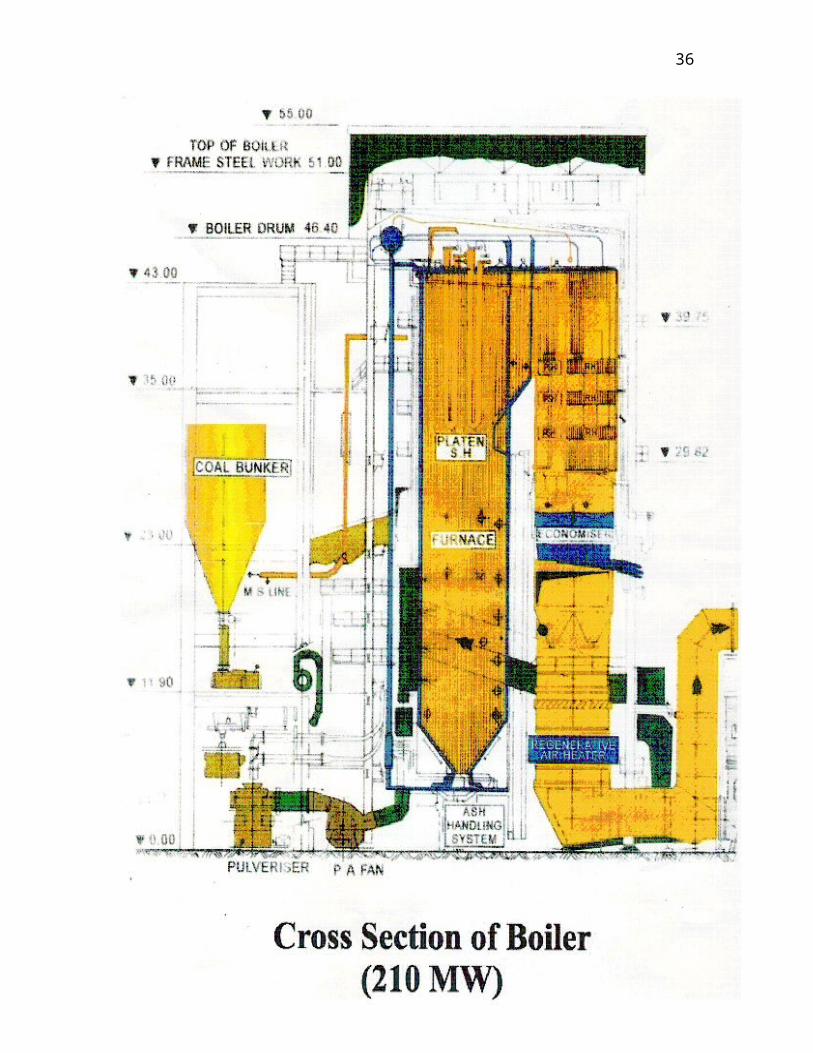
Boiler
Once this water is again inside the boiler or steam generator, the process of adding the latent heat of vaporization or Enthalpy is underway. The boiler transfers energy to the water by the chemical reaction of burning some type of fuel. The water enters the boiler through a section in the convection pass called the economizer. From the economizer it passes to the steam drum. Once the water enters the steam drum it goes down the downcomers to the lower inlet waterwall headers. From the inlet headers the water rises through the waterwalls and is eventually turned into steam due to the heat being generated by the burners located on the front and rear waterwalls (typically). As the water is turned into steam/vapor in the waterwalls, the steam/vapor once again enters the steam drum. The steam/vapor is passed through a series of steam and water separators and then dryers inside the steam drum. The steam separators and dryers remove the water droplets from the steam and the cycle through the waterwalls is repeated. This process is known as natural circulation.
Superheater
As the steam is conditioned by the drying equipment inside the drum, it is piped from the upper drum area into an elaborate set up of tubing in different areas of the boiler. The areas known as superheater and reheater. The steam vapor picks up energy and its temperature is now superheated above the saturation temperature. The superheated steam is then piped through the main steam lines to the valves of the high pressure turbine.
Fuel preparation system
In coal-fired power stations, the raw feed coal from the coal storage area is first crushed into small pieces and then conveyed to the coal feed hoppers at the boilers. The coal is next pulverized into a very fine powder. The pulverizers may be ball mills, rotating drum grinders, or other types of grinders.
Some power stations burn fuel oil rather than coal. The oil must kept warm (above its pour point) in the fuel oil storage tanks to prevent the oil from congealing and becoming unpumpable. The oil is usually heated to about 100°C before being pumped through the furnace fuel oil spray nozzles.
Boilers in some power stations use processed natural gas as their main fuel. Other power stations may use processed natural gas as auxiliary fuel in the event that their main fuel supply (coal or oil) is interrupted. In such cases, separate gas burners are provided on the boiler furnaces.
Fuel firing system and igniter system
From the pulverized coal bin, coal is blown by hot air through the furnace coal burners at an angle which imparts a swirling motion to the powdered coal to enhance
23
mixing of the coal powder with the incoming preheated combustion air and thus to enhance the combustion.
To provide sufficient combustion temperature in the furnace before igniting the powdered coal, the furnace temperature is raised by first burning some light fuel oil or processed natural gas (by using auxiliary burners and igniters provide for that purpose).
Air path
External fans are provided to give sufficient air for combustion. The forced draft fan takes air from the atmosphere and, first warming it in the air preheater for better combustion, injects it via the air nozzles on the furnace wall.
The induced draft fan assists the FD fan by drawing out combustible gases from the furnace, maintaining a slightly negative pressure in the furnace to avoid backfiring through any opening. At the furnace outlet, and before the furnace gases are handled by the ID fan, fine dust carried by the outlet gases is removed to avoid atmospheric pollution. This is an environmental limitation prescribed by law, and additionally minimizes erosion of the ID fan.
Steam turbine-driven electric generatorA turbo generator is a turbine directly connected to an electric generator for the generation of electric power.
The steam turbine-driven generators have auxiliary systems enabling them to work satisfactorily and safely. The steam turbine generator being rotating equipment generally has a heavy, large diameter shaft. The shaft therefore requires not only supports but also has to be kept in position while running. To minimise the frictional resistance to the rotation, the shaft has a number of bearings. The bearing shells, in which the shaft rotates, are lined with a low friction material like Babbitt metal. Oil lubrication is provided to further reduce the friction between shaft and bearing surface and to limit the heat generated.
Barring gear
Barring gear is the term used for the mechanism provided for rotation of the turbine generator shaft at a very low speed (about one revolution per minute) after unit stoppages for any reason. Once the unit is "tripped" (i.e., the turbine steam inlet valve is closed), the turbine starts slowing or "coasting down". When it stops completely, there is a tendency for the turbine shaft to deflect or bend if allowed to remain in one position too long. This deflection is because the heat inside the turbine casing tends to concentrate in the top half of the casing, thus making the top half portion of the shaft hotter than the bottom half. The shaft therefore warps or bends by millionths of inches, only detectable by monitoring eccentricity meters.
But this small amount of shaft deflection would be enough to cause vibrations and damage the entire steam turbine generator unit when the it is restarted. Therefore, the shaft is not permitted to come to a complete stop by a mechanism known as "turning gear" or "barring gear" that automatically takes over to rotate the unit at a preset low speed.
24

If the unit is shut down for major maintenance, then the barring gear must be kept in service until the temperatures of the casings and bearings are sufficiently low.
Condenser
Surface condenser is the commonly used term for a shell and tube heat exchanger installed on the exhaust steam from a steam turbine in thermal power stations.
Steam-electric power plants utilize a surface condenser cooled by water circulating through tubes. The steam which was used to turn the turbine is exhausted into the condenser. The steam is therefore condensed as it comes in contact with the cool tubes full of circulating water. This condensed steam is withdrawn from the bottom of the surface condenser. The condensed steam is now water, commonly referred to as condensate water.
These condensers are heat exchangers which convert steam from its gaseous to its liquid state at a pressure below atmospheric pressure. Where water is in short supply, an air-cooled condenser is often used. An air-cooled condenser is however significantly more expensive and cannot achieve as low a steam turbine exhaust pressure as a surface condenser and is therefore less efficient.
In thermal power plants, the primary purpose of a surface condenser is to condense the exhaust steam from a steam turbine to obtain maximum efficiency and also to convert the turbine exhaust steam into pure water (referred to as steam condensate) so that it may be reused in the steam generator or boiler as boiler feed water.
The steam turbine itself is a device to convert the heat in steam to mechanical power. The difference between the heat of steam per unit weight at the inlet to the turbine and the heat of steam per unit weight at the outlet to the turbine represents the heat which is converted to mechanical power. Therefore, the more the conversion of heat per pound or kilogram of steam to mechanical power in the turbine, the better is its efficiency. By condensing the exhaust steam of a turbine at a pressure below atmospheric pressure, the steam pressure drop between the inlet and exhaust of the turbine is increased, which increases the amount heat available for conversion to mechanical power. Most of the heat liberated due to condensation of the exhaust steam is carried away by the cooling medium (water or air) used by the surface condenser.
The condenser generally uses either circulating cooling water from a cooling tower or once-through water from a river, lake or ocean
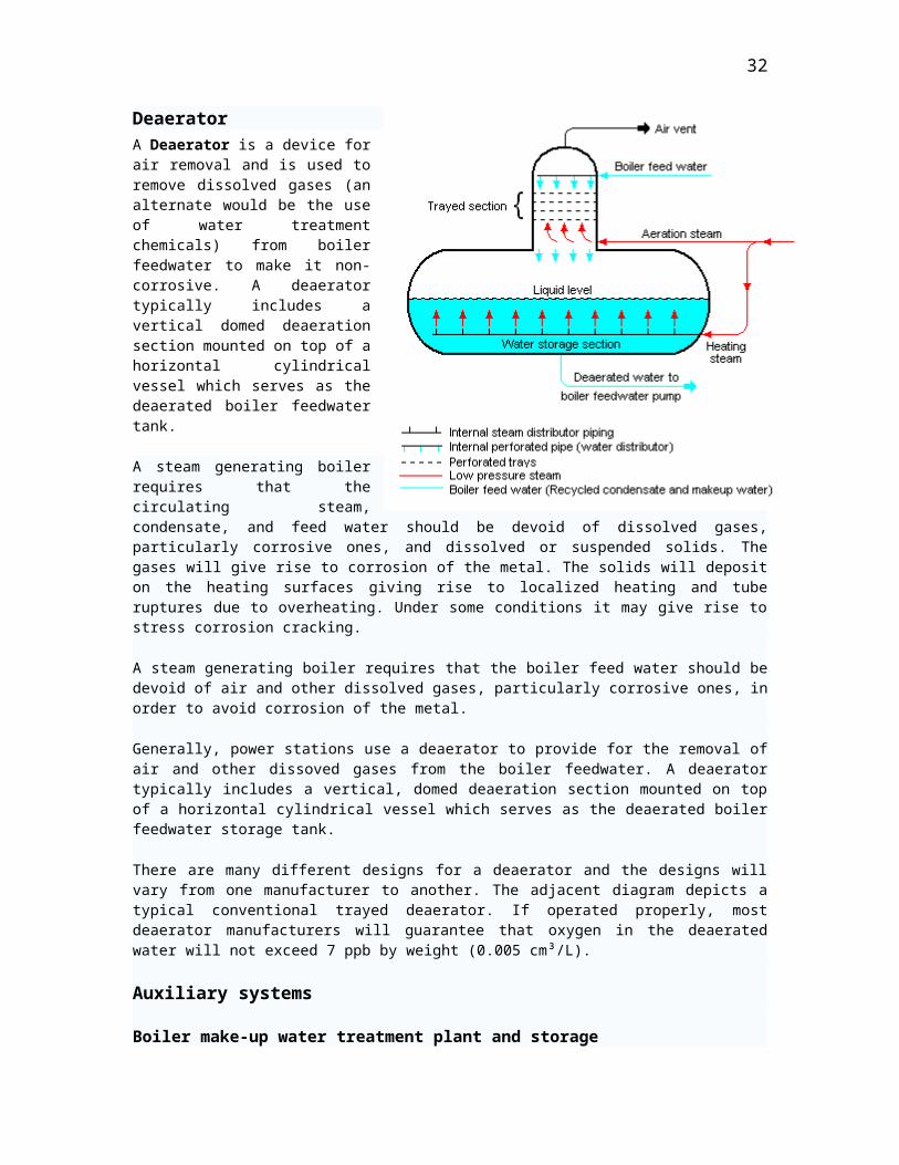
DeaeratorA Deaerator is a device for air removal and is used to remove dissolved gases (an alternate would be the use of water treatment chemicals) from boiler feedwater to make it non-corrosive. A deaerator typically includes a vertical domed
25
deaeration section mounted on top of a horizontal cylindrical vessel which serves as the deaerated boiler feedwater tank.
A steam generating boiler requires that the circulating steam, condensate, and feed water should be devoid of dissolved gases, particularly corrosive ones, and dissolved or suspended solids. The gases will give rise to corrosion of the metal. The solids will deposit on the heating surfaces giving rise to localized heating and tube ruptures due to overheating. Under some conditions it may give rise to stress corrosion cracking.
A steam generating boiler requires that the boiler feed water should be devoid of air and other dissolved gases, particularly corrosive ones, in order to avoid corrosion of the metal.
Generally, power stations use a deaerator to provide for the removal of air and other dissoved gases from the boiler feedwater. A deaerator typically includes a vertical, domed deaeration section mounted on top of a horizontal cylindrical vessel which serves as the deaerated boiler feedwater storage tank.
There are many different designs for a deaerator and the designs will vary from one manufacturer to another. The adjacent diagram depicts a typical conventional trayed deaerator. If operated properly, most deaerator manufacturers will guarantee that oxygen in the deaerated water will not exceed 7 ppb by weight (0.005 cm³/L).
Auxiliary systems
Boiler make-up water treatment plant and storage
Since there is continuous withdrawal of steam and continuous return of condensate to the boiler, losses due to blow-down and leakages have to be made up for so as to maintain the desired water level in the boiler steam drum. For this, continuous make-up water is added to the boiler water system. The impurities in the raw water input to the plant generally consist of calcium and magnesium salts which impart hardness to the water. Hardness in the make-up water to the boiler will form deposits on the tube water surfaces which will lead to overheating and failure of the tubes. Thus, the salts have to be removed from the water and that is done by a water demineralising treatment plant (DM). A DM plant generally consists of cation, anion and mixed bed exchangers. The final water from this process consists essentially of hydrogen ions and hydroxide ions which is the chemical composition of pure water. The DM water, being very pure, becomes highly corrosive once it absorbs oxygen from the atmosphere because of its very high affinity for oxygen absorption.
The capacity of the DM plant is dictated by the type and quantity of salts in the raw water input. However, some storage is essential as the DM plant may be down for maintenance. For this purpose, a storage tank is installed from which DM water is continuously withdrawn for boiler make-up. The storage tank for DM water is made from materials not affected by corrosive water, such as PVC. The piping and valves are generally of stainless steel. Sometimes, a steam blanketing arrangement or stainless steel doughnut float is provided on top of the water in the tank to avoid contact with atmospheric air. DM water make-up is generally added at the steam space of the condenser (i.e., the vacuum side). This arrangement not only sprays the water but also DM water gets deaerated, with the dissolved gases being removed by the ejector of the condenser itself.
26
Fly ash collection
Fly ash is captured and removed from the flue gas by electrostatic precipitators or fabric bag filters (or sometimes both) located at the outlet of the furnace and before the induced draft fan. The fly ash is periodically removed from the collection hoppers below the precipitators or bag filters. Generally, the fly ash is pneumatically transported to storage silos for subsequent transport by trucks or railroad cars.
Bottom ash collection and disposal
At the bottom of every boiler, a hopper has been provided for collection of the bottom ash from the bottom of the furnace. This hopper is always filled with water to quench the ash and clinkers falling down from the furnace. Some arrangement is included to crush the clinkers and for conveying the crushed clinkers and bottom ash to a storage site.
Oil system
An auxiliary oil system pump is used to supply oil at the start-up of the steam turbine generator. It supplies the hydraulic oil system required for steam turbine's main inlet steam stop valve, the governing control valves, the bearing and seal oil systems, the relevant hydraulic relays and other mechanisms.
At a preset speed of the turbine during start-ups, a pump driven by the turbine main shaft takes over the functions of the auxiliary system.
Generator heat dissipation
The electricity generation coupled to the turbine shaft requires cooling to dissipate the heat that it generates. While small units may be cooled by air drawn through filters at the inlet, larger units generally require special cooling arrangements. Hydrogen gas cooling, in an oil-sealed casing, is used because it has the highest known heat transfer coefficient of any gas and for its low viscosity which reduces windage losses. This system requires special handling during start-up, with air in the chamber first displaced by carbon dioxide before filling with hydrogen. This ensures that the highly flammable hydrogen does not mix with oxygen in the air.
The hydrogen pressure inside the casing is maintained slightly higher than atmospheric pressure to avoid outside air ingress. The hydrogen must be sealed against outward leakage where the shaft emerges from the casing. Mechanical seals around the shaft are installed with a very small annular gap to avoid rubbing between the shaft and the mechanical seals. To avoid gas leakage from the annular gap, seal oil provided in a way such that part of the oil flows to inside and part to outside of the casing to prevent the hydrogen gas leakage to atmosphere.
The generator also contain water ducts for further cooling. Since the generator coils are at a potential of about 22–kV and water is conductive, an insulating barrier such as Teflon is used to interconnect the water line and the generator HV windings. Demineralized water of low conductivity and without impurities is used.
Generator high voltage system
27
The generator voltage is normally 11 kV in smaller units and in bigger units it would be about 22 kV. Probably this is limited by the insulation media available and the construction methodology limitations available today. The generator HV leads are normally of large section aluminum channels because of very high current as against cables used in smaller machines. They are enclosed in aluminum bus ducts (with good grounding), live channels being supported on suitable insulators inside. Further the generator HV channels (leads) are directly connected to suitably designed step-up transformers for connecting to a transmission yard high voltage substation, of the order of 110 kV or 220 kV for further transmission by grid. The HV generator channels generally being of long run and also subjected to heat and cold, necessary suitable expansion joints are also provided.
The necessary protection and metering devices are incorporated on the HV leads of generator. Thus the steam turbine generator and the transformer form one unit. In smaller units, generating normally at 11 kV, a breaker is provided to connect it to a common 11 kV bus system in a cubicle normally located indoors.
Other systems
Monitoring and alarm system
All of the major plant components and systems require pre-checking for start-up during the first start or after a shut-down for any reason whatsoever. The safety aspects and the normal procedures have to be looked into at all stages of operation. Manual intervention is also unavoidable; however, much the system is made automatic. In view of this necessary protection, monitoring with alarms for out of limit parameters, and auto and manual control equipment are provided on the operator consoles, both on the mechanical and electrical equipment.
Battery supplied emergency lighting and communication
Central battery system consisting of lead acid cell units to make up 240 V DC, sometimes in two individual stacks with its own battery charging unit, inverter to get 230 V AC, and auto-stepless changeover in case station supply of 230 V AC fails. The batteries are installed in separate rooms (battery rooms) with exhaust fans and all round coated with acid-proof paint.
The essential equipment supplied by this battery system are: control and relay equipment, communication and emergency lighting, and turbine lube oil pumps. This control equipment is installed in separate rooms with monitoring on the operators’ console. This is essential for smooth and damageless shutdown of the units.
28
29
30
Transport of coal fuel to site and to storage
Coal Handling Plant (CHP)
Coal handling Plant is the unit that deals with the procurement of the raw coal and its transference to the hoppers in the Thermal Feeding unit.
Most thermal stations use coal as the main fuel. Raw coal is transported from collieries to a power station site by railway wagons only. Generally coal wagons are sent as a full railway rake. Coal Approaches to the Coal handling plant in special carrying wagons of Indian Railways of types- BOB-R (Bottom Open Bogey-Rapid discharge) and BOX-N which are unloaded here in offside area by using various techniques for each wagon types (Wagon Tippler for BOX-N types and Track Hoppers for BOB-R types).
The coal received at site by wagons may be of different sizes. They are unloaded at site by rotary dumpers or side tilt dumpers to tip over conveyor belts below. They are generally carried direct to the crusher house for crushing the coal to about ¾ inch (6 mm) size and then by belt conveyors to storage yard. Normally this crushed coal is stored with compaction by bulldozers, as compacting of highly volatile coal avoids spontaneous ignition. Hence this arrangement is generally adopted.
The crushed coal from storage or after crushing direct is conveyed to top of boilers by means of belt conveyor system. At the top of boilers a horizontal conveyor with distributing arrangement for feeding to any boiler bunker will feed the coal to the required boiler bunkers generally which ever boiler is in operation. This is to avoid long hours of storage in boiler bunkers to avoid spontaneous ignition at that point.
CHP also deals with the stocking of initiating fuel oils- that are LDO and HFO (Light Diesel Oil and Heavy Fuel Oil) these are supplied to the station by the use of pumps located in CHP area.
31
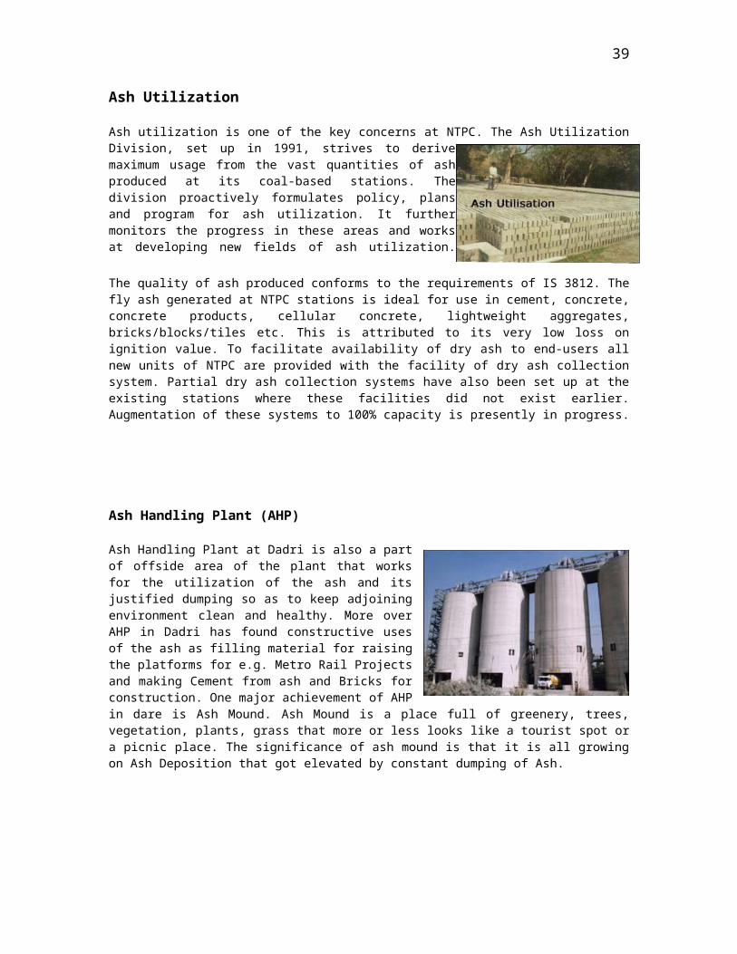
Ash Utilization
Ash utilization is one of the key concerns at NTPC. The Ash Utilization Division, set up in 1991, strives to derive maximum usage from the vast quantities of ash produced at its coal-based stations. The division proactively formulates policy, plans and program for ash utilization. It further monitors the progress in these areas and works at developing new fields of ash utilization.
The quality of ash produced conforms to the requirements of IS 3812. The fly ash generated at NTPC stations is ideal for use in cement, concrete, concrete products, cellular concrete, lightweight aggregates, bricks/blocks/tiles etc. This is attributed to its very low loss on ignition value. To facilitate availability of dry ash to end-users all new units of NTPC are provided with the facility of dry ash collection system. Partial dry ash collection systems have also been set up at the existing stations where these facilities did not exist earlier. Augmentation of these systems to 100% capacity is presently in progress.
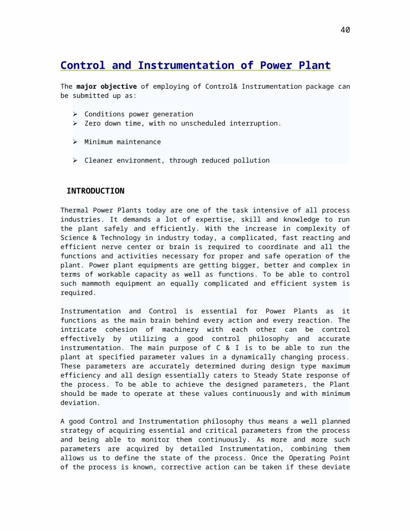
Ash Handling Plant (AHP)
Ash Handling Plant at Dadri is also a part of offside area of the plant that works for the utilization of the ash and its justified dumping so as to keep adjoining environment clean and healthy. More over AHP in Dadri has found constructive uses of the ash as filling material for raising the platforms for e.g. Metro Rail Projects and making Cement from ash and Bricks for construction. One major achievement of AHP in dare is Ash Mound. Ash Mound is a place full of greenery, trees, vegetation, plants, grass that more or less looks like a tourist spot or a picnic place. The significance of ash mound is that it is all growing on Ash Deposition that got elevated by constant dumping of Ash.
32
Control and Instrumentation of Power Plant
The major objective of employing of Control& Instrumentation package can be submitted up as:
Conditions power generation Zero down time, with no unscheduled interruption.
Minimum maintenance
Cleaner environment, through reduced pollution
INTRODUCTION
Thermal Power Plants today are one of the task intensive of all process industries. It demands a lot of expertise, skill and knowledge to run the plant safely and efficiently. With the increase in complexity of Science & Technology in industry today, a complicated, fast reacting and efficient nerve center or brain is required to coordinate and all the functions and activities necessary for proper and safe operation of the plant. Power plant equipments are getting bigger, better and complex in terms of workable capacity as well as functions. To be able to control such mammoth equipment an equally complicated and efficient system is required.
Instrumentation and Control is essential for Power Plants as it functions as the main brain behind every action and every reaction. The intricate cohesion of machinery with each other can be control effectively by utilizing a good control philosophy and accurate instrumentation. The main purpose of C & I is to be able to run the plant at specified parameter values in a dynamically changing process. These parameters are accurately determined during design type maximum efficiency and all design essentially caters to Steady State response of the process. To be able to achieve the designed parameters, the Plant should be made to operate at these values continuously and with minimum deviation.
A good Control and Instrumentation philosophy thus means a well planned strategy of acquiring essential and critical parameters from the process and being able to monitor them continuously. As more and more such parameters are acquired by detailed Instrumentation, combining them allows us to define the state of the process. Once the Operating Point of the process is known, corrective action can be taken if these deviate from the designed values. Deviations in any parameters are then corrected by Control Logic so as to minimize their effect.
Thus a complete C&I scheme would include the following—
Signal Acquisition through sensors and transducers Signal Processing via Electronic Cards and continuous monitoring of
parameters.
Failsafe and efficient Control Scheme
33
Output to Final Control Element to control the process or equipment
34
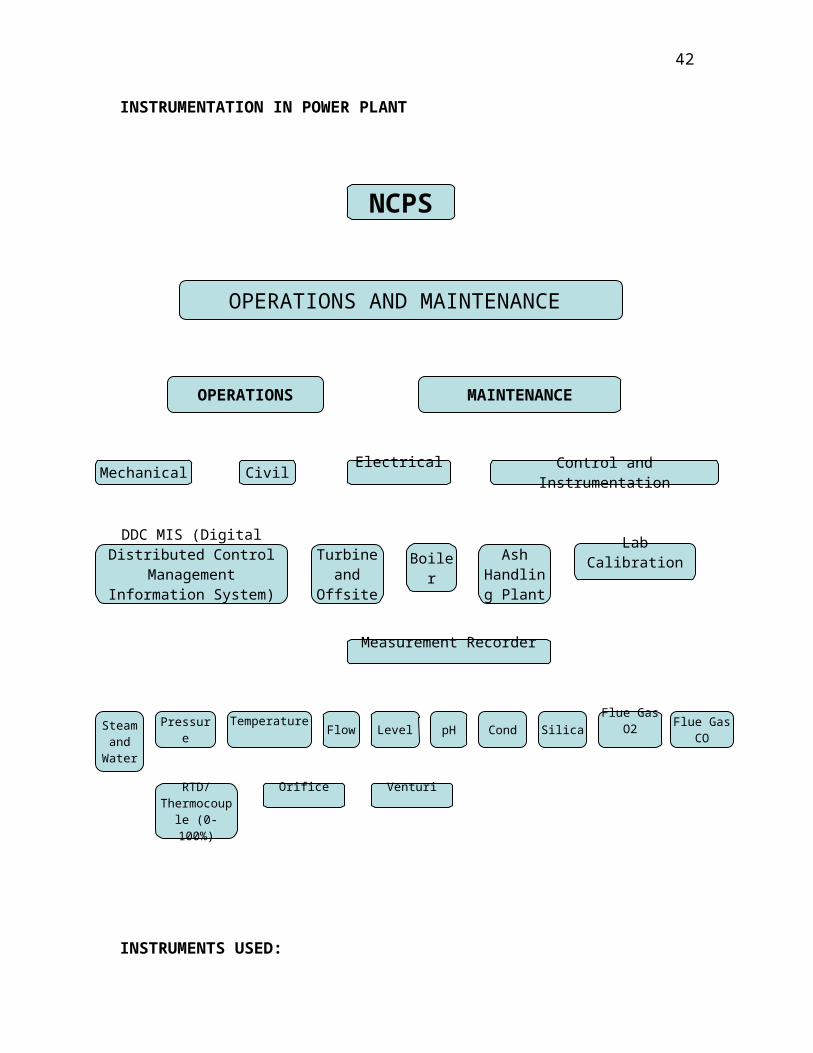
NCPS
OPERATIONS AND MAINTENANCE
OPERATIONS MAINTENANCE
Mechanical CivilElectrical
Control and Instrumentation
DDC MIS (Digital Distributed Control
Management Information System)
Turbine and
Offsite
BoilerAsh
Handling Plant
Lab Calibration
Measurement Recorder
Steam and
Water
PressureTemperature
CondLevel pHFlow SilicaFlue Gas
O2 Flue Gas CO
RTD/Thermocouple (0-100%)
Orifice Venturi
INSTRUMENTATION IN POWER PLANT
INSTRUMENTS USED:
35
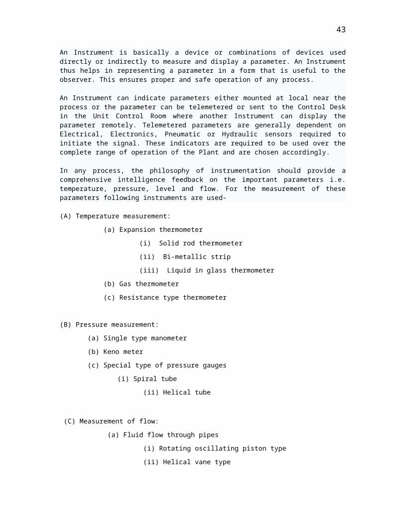
An Instrument is basically a device or combinations of devices used directly or indirectly to measure and display a parameter. An Instrument thus helps in representing a parameter in a form that is useful to the observer. This ensures proper and safe operation of any process.
An Instrument can indicate parameters either mounted at local near the process or the parameter can be telemetered or sent to the Control Desk in the Unit Control Room where another Instrument can display the parameter remotely. Telemetered parameters are generally dependent on Electrical, Electronics, Pneumatic or Hydraulic sensors required to initiate the signal. These indicators are required to be used over the complete range of operation of the Plant and are chosen accordingly.
In any process, the philosophy of instrumentation should provide a comprehensive intelligence feedback on the important parameters i.e. temperature, pressure, level and flow. For the measurement of these parameters following instruments are used-
(A) Temperature measurement:
(a) Expansion thermometer
(i) Solid rod thermometer
(ii) Bi-metallic strip
(iii) Liquid in glass thermometer
(b) Gas thermometer
(c) Resistance type thermometer
(B) Pressure measurement:
(a) Single type manometer
(b) Keno meter
(c) Special type of pressure gauges
(i) Spiral tube
(ii) Helical tube
(C) Measurement of flow:
(a) Fluid flow through pipes
(i) Rotating oscillating piston type
(ii) Helical vane type
(iii) Turbine type
(iv) Combination meter
(b) Fluid flow through open channel
(i) The weir
(ii) Venturi flumes
(iii) Pressure difference flow meter
(c) Variable aperture type flow meter
36
(d) Electromagnetic flow meter
(e) Primary elements
(i) Orifice plate
(ii) Flow nozzle
(iii) Pitot tube
(f) Secondary elements
(i) Low difference head flow meter- Bell type
(ii) Medium and high difference head flow meter-
Mercury manometer and Bellows flow meter
(D) Measurement of level:
(a) Pressure operated types
(b) Burden pressure gauge
(i) Mercury manometer
(ii) Diaphragm type
(c) Sealed capsule type
(d) Air purge system
37
Major C & I systems included under main plant packages i.e.
SG and TG
The SG/TG C&I systems are based on state of the art microprocessor technique with CRT/KBD operations facilities. Operations through backup conventional devices are also possible. These C&I systems are procured under the respective main plant package i.e. SG/TG packages.
The SG-C&I system:-
The SG-C&I systems include the following microprocessor based system:-1. FSSS for purging, automatic firing, flame monitoring, sequential
starter and shutdown of mills etc.2. In dry air damper control system3. Auxiliary PRDS control system
Each of these functional blocks is provided as independent system. All these functional blocks are connected together through redundant system bus to achieve integrated CRT/KBD operation and monitoring. For this purpose, two control CRTs and one number dot matrix printer are provided for SG-C&I system operation. Provision is also made to connect the SG-C&I system bus with DDCMIS bus for monitoring of the SG-C&I system through DDCMIS CRT/KBDs. However, all the interlocking and protection inputs are hardwired to DDCMIS from SG-C&I system.
In addition to the above microprocessors based system, the following systems are also provided:-
1. Soot blower CS2. Coal feeder control3. Control of electrometric safety valve4. Furnace temperature probes
The TG-C&I system:-
The TG-C&I system includes the following functional blocks:-
1. EHG control system2. Automatic turbine run up system3. HP-IP bypass control system4. Turbine stress control system5. Automatic turbine testing system6. Turbine protection system7. Turbine supervisory instrumentation8. Generator auxiliaries control system
Each of these functional blocks is provided as independent system. All these functional blocks except TSI are connected together through redundant system bus to achieve integrated CRT/KBD operation and monitoring. For this purpose, 2 number control CRT’s & 1 number dot matrix printer for TG –C&I system and 1 CRT each for TSI and TSCS, monitoring are provided. Provision is also made to connect the TG-C&I system bus with DDCMIS system bus for monitoring of the TG-C&I system through
38
DDCMIS CRT/KBDs. However, all the interlocking and protection inputs are hardwired to DDCMIS from TG-C&I system.
SWAS
Recognizing the importance of water chemistry in power plant operations a comprehensive steam and water analysis system is provided. This system includes a sample conditioning system for temperature and pressure reduction and conditioning of various sample streams and necessary analyzer for online analysis of parameters like conductivity, pH, dissolved oxygen, residual hydrazine, silica etc. all critical points in condensate feed water and steam cycle. The SWAS has 3 panels namely sample conditioning panel, analyzer panel and recorder panel which are physically separate from each other. This system helps the plant chemistry in making the necessary adjustment in water treatment system so as to avoid deposits/accumulations in heat exchanger tubes, corrosion of power cycle equipments and damage due to carry over.
39
Major control loops in thermal power stations:
Automatic Closed Loop controls are extensively used in Thermal Power Plants, whose complex processes require tight control over the dynamic parameters. Some important control loops are mentioned below:
(i) Coordinate Master Control – Coordinates the Master controls of both Boiler
& Turbine.
(ii) Boiler Master Control – Master controller for all the Boiler controllers.
(iii)Turbine Master Control – Master controller for all Turbine controllers.
(iv) Firing Rate Control – Controls feed rate of coal to boiler.
(v) Furnace Draft Control – Controls the furnace pressure by Fan air-flow
control.
(vi) SH/RH temperature Control – Controls the exit steam temperatures of
SH & RH.
(vii) Feed water Controller – Controls the feed water entry to Drum and thus
its level.
(viii) Pulveriser Temperature Control – Controls the exit temperature of coal-
air mixture.
(ix) Pulveriser Air Flow Control – Controls the total air flow through the
Pulveriser.
(x) Heater Level Controls – Controls the drip level of heaters including
Deaerator.
40

CONTROL SCHEME
The Control Scheme is necessary to take corrective action whenever the parameters cross the desired values. This is essential because otherwise the plant will drift into an unstable region, which is not desirable. To maintain the operation point of different processes in the desired zone, a failsafe and accurate controller is a necessity.
Control systems are classified according to the control action of the controller, which is the quantity responsible for activating the system to produce an output.
(1) Open Loop Control System or ON/OFF Control (also known as Binary Control) - An open loop control system is defined as one in which the control action is independent of the output. Here, the controller output is not generated from the inputs to the controller. It is a logically generated output as per the combined effects of some or all the inputs, which thus define the state of the system. This type of control is implemented when the control is desired to achieve two preset states-either ON or OFF. The controller output is fed to the final control element, which in this case is equipment like a pump or a motor. This type of control is useful to implement Interlock and Protection schemes of the different plant equipment. Interlocks and Protection schemes are necessary in a process where high potential for danger exists and safety of the equipment is a primary concern.
(2) Close Loop Control System (also known as Analog Control) - A Close Loop System is one in which the control action is dependent on the output. Here the process parameter is continuously acquired from the field and works as a feedback for the controller output. This type of control scheme is used when continuous or modulating control of a process is required .This allows the process parameter to be continuously controlled from CLOSED (0% output) to OPEN (100% output) and any value in between. A suitable transducer acquires the measured variable (MV) from the process and the signal is sent to the controller. Here the signal is compared with the set point defined by the process operator and an error signal is generated as a result of the comparison. The error signal is then is the reflection of the deviation that needs to be corrected. Appropriate control logic is act on this error signal to generate a controller output. This is fed to the Final Control Element, which in this case would normally be a Control value.
41
TYPES OF CLOSED LOOP CONTOLS
The Closed Loop Control of a dynamically changing system is difficult and extremely complex. Control schemes have been developed from first principles wherein the simplest case were considered and then refined to generate more complex schemes. The control scheme utilizes the basic mathematical concept of gain and generated error to eliminate the lags in the process.
Controllers or any physical instrument have some inherent properties, which hamper there efficient working. Controllers are designed to accommodate and counter the effect of these inherent physical properties which are:
(1) Dead band –the small change in input which in insensitive to the controller due to inertia.
(2) Process Lag- time lag for the rapidly changing input to arrive at the instrument.
(3) Measuring Lag- time lag for the instrument to sense this input change.(4) Transmission Lag- time taken to transmit the signal for processing and
control.
The three basic types of control schemes are:
a. Proportional Control (P action) - The simplest control scheme where the controller output is proportional to the error generated between the measured value and the desired set point. Thus, mathematically we say that V=G , where V is the expected output corresponding to change in input. G is the gain or the proportionality constant. Thus for any input change, the output changes by G . However due to the inherent dead band, the output can never attain the exact desired output. An error called the offset thus always remains between the desired output and the actual output. To eliminate this offset error, another control scheme was introduced.
b. Integral Control (I action) - Integral action acts on the output by increasing it as the error remains. Thus, as long as the offset remains, the controllers
output increases so as to nullify it. Mathematically, V = .The output
V Depends on the duration of the offset error and is the integral time
constant and determines the time duration required for the control output to attain the desired output without offset. More the duration, more is the Integral output. This method is quite adequate to eliminate slow offset errors. However if the input changes very quickly, as is normally the case with pressure and flow parameters. This scheme then fails to react quickly to control the parameters within the margins available. Thus a fast acting response is also needed and has been incorporated in the next scheme.
c. Derivative Control (D action) - Derivative action is used to detect and respond
to fast changing input signal. Mathematically, V = , where is
Derivative time constant and determines the response of the output to the rate of change of the input.
d. Higher systems of Control such as State Variable Approach and Fuzzy Logic Control schemes are also operational and useful.
Obviously to attain the best control philosophy that suits the process dynamics, a judicious mix between the various options needs to be done. Popular types of controllers used in power plants use-
42
PI Control : V = + G + ; = Integral time const.
PID Control: V = + G + + . ; =Derivative time const.
Time response for PID controller is the best as it takes the least time to stabilize or recover from a step change in input. The purely P controller is next best and the PI takes the most time to recover from the input changes. Fast changing process will demand a fast controller with Derivative action incorporated into it. A slow process will accommodate a slower controller. A balance must thus be made between the importance or weights of these three control actions with regard to the process requirements.
A sample control loop demonstrating both Closed and Open Loop control is as shown below-
43
c (t)
ω (t)

Fig: Control Philosophy showing both Open and Closed Loop Control Schemes. FCE is the Final Control Element and can be a Control Valve. Equipment is a processes unit like Pump or a Fan.
Controller
Transducer
Equipment
FCE
44
DDCMIS (Distributed Digital Control Monitoring & Information System)
The DDCMIS are the state of art microprocessor based latest technology. These are closed and open loop system man machine interface and other important features.
INTRODUCTION
The DDCMIS employs state of art microprocessor and is based on latest proven technology. It performs the function of sequence and modulating controls, plant start up/shut down in all regimes of plant operation including emergency conditions.
The DDCMIS consists of closed loop control system. Open loop control system,
man machine interface system and plant information and measurement system, sequence of events recording system (SERS) and slave clock system functional blocks.
BASIC FEATURES OF DDCMIS
Seven numbers of color CRT’s are connected to MMIPIS functional block, for control system operation, plant monitoring and information functions and alarm monitoring functions .Each of the color CRT’s is 100% interchangeable (any control/monitoring /alarming function for any part of the plant can be performed from any color CRT) and provides complete control, monitoring, supervisory and display functions for the control system variables and control system status. The display includes all control related displays, bar graph displays, group display system alarms and real time trend display.
These displays are available on control CRT’s for the measurement signals as well.
The system is configured so as to enable efficient plant operation in all modes of operation viz. start up, normal operation, shut down etc. through control CRT’s and key boards. The monitoring/ supervision functions are design as on line system which process, display and store information to provide the operator , either automatically or on demand , relevant information of complete plant. The monitoring / supervision functions include performance calculations, displays, logs, alarm monitoring and retrieval. Two color graphic printers, one line and three dot matrix printers are provided for logs, reports and alarms. In addition to these, one magnetic cartridge tape unit for historical storage and retrieval systems and two nos. of 6 pin microprocessor based trend recorders for trending of points are provided. 100% hot redundant controllers are employed both for CLCS and OLCS. Hard ware for CLCS and OLCS are separate and independent of each other.
The OLCS, for the major equipment like boiler, turbine, generator auxiliaries, and power operated valves and dampers etc. is designed to give max. degree of protection while maintaining sufficient simplicity to ensure reliability, maintainability and min of nuisance shut down .In case of failure of system bus of CRT and KBD, the manual operation of about 10% of total drives i.e. drives through back up push buttons. The unit provided through backup push buttons .The basic important protections of the drives is available at all times even on the failure of OLCS controllers .The system is based on the design aspect that it would continue to
45
operate without any loss of any function or safety features in case of failure of single device/ component.
The change in system configuration, twining constants and similar engineering and maintenance functions are not allowed of view, these functions are allowed only from engineers/ programmers console in CER under lock and key operation. Separate consoles are provided for programming/modification in MMIPIS and control system along with respective peripherals.
A separate stand alone microprocessor based system is provided for sequence of events monitoring functions to enable analysis of tripping. The system monitors the SOE inputs with the resolution of 1ms. The SERs have its own dedicated dot matrix printers for printing reports. The system is also provided with its dedicated historical storage and retrieval system to store all the SER logs and reports.
One PC-AT is provided with erasable optical disk and drives interfaced with system bus for all line storage of plant data. Necessary hardware and software is provided to achieve data transfer in requisite format.
One master and slave clock system is also provided to ensure uniform timing through out the unit and plant. The master clock is time synchronized with DDCMIS and SERS.
46
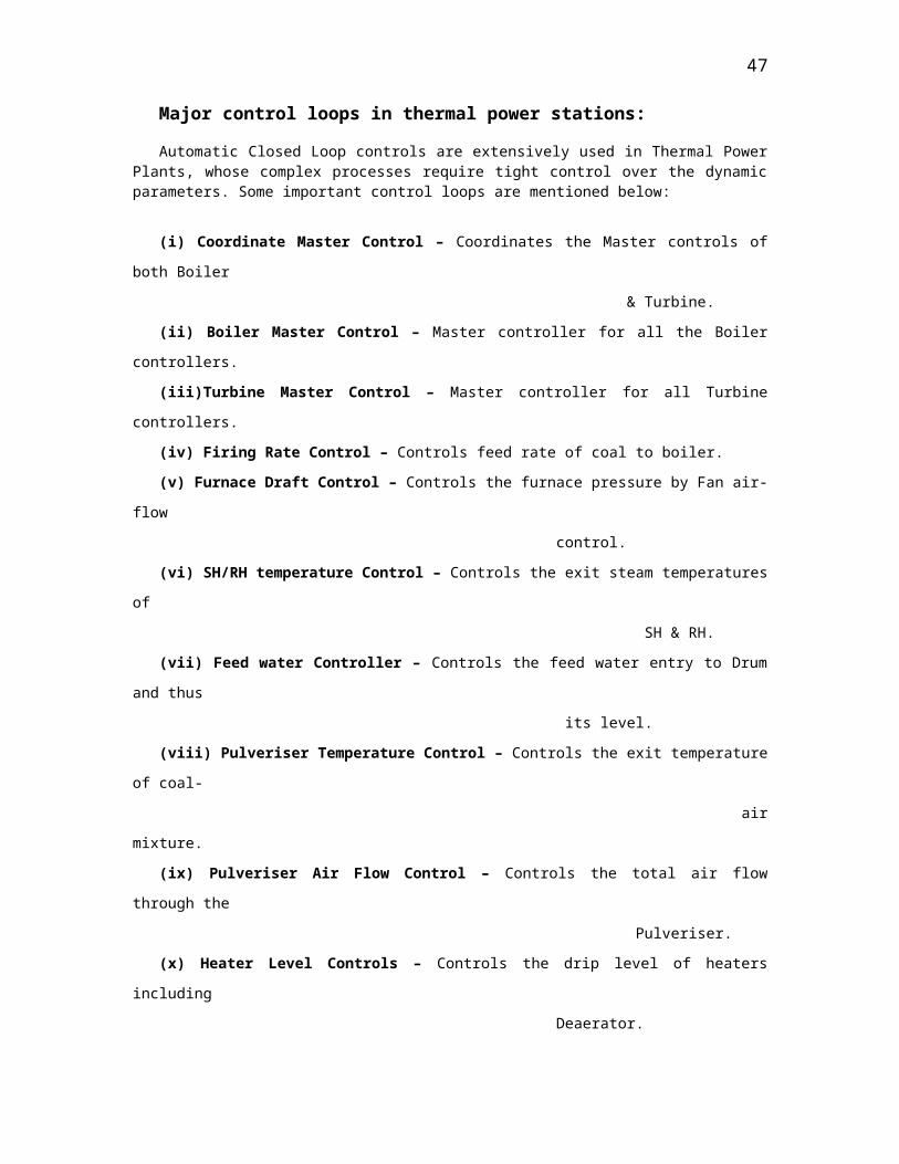
ADVANTAGES OF AUTOMATIC CONTROL SYSTEM
1. Process parameters are kept close to the desired values.
2. Combustion efficiency is increased resulting in better fuel economics,
reduction in Boiler fouling, less atmospheric pollution and lesser carbon
residues in ash.
3. Lowers metal fatigue of boiler tubes as temp. are kept stable.
4. Increased safety of man and machine
5. Operator mal-operations due to the tedious nature of the job are reduced.
DISADVANTAGES OF AUTOMATIC CONTROL LOOPS
1. Equipment should be more reliable and failsafe.
2. Desire values may need to be changed due to process behavior for proper
optimization.
3. Process and measurement time lags may hamper proper functioning of the
loop.
4. The instrumentation and electronics will require periodic maintenance and
cost increase.
RECENT TRENDS
Control schemes implemented on Analog devices like transistors have been
replaced with better and more efficient controllers using digital technology. Microprocessors are being used nowadays to digitize the input analog signal, use appropriate control logic and reconvert the digital output into a corresponding analog signal. The concept of Distributed Digital Control (DDC) has already gained importance due to its fast and accurate modular design and control philosophy. Programmable Logic Controllers (PLC’s) are used extensively for smaller processes and small loops. Better Plant monitoring is being done by utilizing the power of the computer. Application specific packages are being written for the power plants, which will help them produce better and more efficient power. Better monitoring of all process and equipment is also possible using this software. Detailed analysis of thermal stresses and life assessment studies can now be done swiftly and accurately with historic data, if required. Communication via networks and display units like CRT’s enable better operator interface and understanding. Integrated and On-line Information Systems are now available that can do various in-depth analysis and display the same to the operator for necessary guidance and is very useful for management decision-making.
47

NTPC (Dadri) - In Harmony with Nature
NTPC- Dadri has attained ISO Standards 9001 that deals with efficient working and 14001 that certify an organization for its environment friendly activities.
At NCPP, they are functioning in harmony with the environment and the vicinity of the plant the harmful fly ash and smoke discharge is pre treated in ESP and discharged in the atmosphere through a 220 m long chimney. Ash handling plant and Ash mound are the perfect examples that NCPP is working with the nature and caring it with excess of plantation and afforestation drives in the vicinity of the plant and all over the area.
The Conclusion and Inferences
The visit to the Plant of the organization has put forth many things that I not have ever thought of. The training was helpful and was a great experience of how the works are done actually and professionalism that was observed practically was another precious experience that has great value.
Of many things inferred from the visit to the NCPP Dadri is discipline in the organization and following the perfect conduct and their advantages on the field were worth great value. I got to know about the differences in the practices that are performed in the laboratory and that are performed in the industry and the importance of precision in Industry, where it has relevance and where it does not have.
The final words are for the organization from top to bottom wherever it has supported me in getting this worth experiences and knowledge.
----XXX [END] XXX----
48
Related Documents