TRAINING MODULES FOR WATERWORKS PERSONNEL Special Knowledge 2.3 e Maintenance and repair of pumps 2^2.0.8,33 u.

Welcome message from author
This document is posted to help you gain knowledge. Please leave a comment to let me know what you think about it! Share it to your friends and learn new things together.
Transcript
TRAINING MODULESFOR
WATERWORKS PERSONNEL
Special Knowledge2.3 e
Maintenance and repair of pumps
2^2.0.8,33 u.

Training modules for waterworks personnelin developing countries
ForewordEven the greatest optimists are no longer sure that the goals of the UN "International DrinkingWater Supply and Sanitation Decade", set in 1977 in Mar del Plata, can be achieved by 1990.High population growth in the Third World combined with stagnating financial and personnelresources have led to modifications to the strategies in cooperation with developing coun-tries. A reorientation process has commenced which can be characterized by the followingcatchwords:- use of appropriate, simple and - if possible - low-cost technologies,- lowering of excessively high water-supply and disposal standards,- priority to optimal operation and maintenance, rather than new investments,- emphasis on institution-building and human resources development.Our training modules are an effort to translate the last two strategies into practice. Experiencehas shown that a standardized training system for waterworks personnel in developingcountries does not meet our partners' varying individual needs. But to prepare specificdocuments for each new project or compile them anew from existing materials on hand can-not be justified from the economic viewpoint. We have therefore opted for a flexi ble system oftraining modules which can be combined to suit the situation and needs of the target groupin each case, and thus put existing personnel in a position to optimally maintain and operatethe plant.The modules will primarily be used as guidelines and basic training aids by GTZ staff andGTZ consultants in institution-building and operation and maintenance projects. In themedium term, however, they could be used by local instructors, trainers, plant managersand operating personnel in their daily work, as check lists and working instructions.45 modules are presently available, each covering subject-specific knowledge and skillsrequired in individual areas of waterworks operations, preventive maintenance and repair.Different combinations of modules will be required for classroom work, exercises, and prac-tical application, to suit in each case the type of project, size of plant and the previous qualifi-cations and practical experience of potential users.Practical day-to-day use will of course generate hints on how to supplement or modify thetexts. In other words: this edition is by no means a finalized version. We hope to receive yourcritical comments on the modules so that they can be optimized over the course of time.Our grateful thanks are due to
Prof. Dr.-lng. H.P. HaugandIng.-Grad. H. Hack
for their committed coordination work and also to the following co-authorsfor preparing the modules:
Dipl.-lng. Beyene Wolde GabrielIng.-Grad. K. H. EngelIng.-Grad. H. HackIng.-Grad. H. HauserDipl.-lng. H. R. JolowiczK. Ph. Muller-OswaldIng.-Grad. B. RollmannDipl.-lng. K. SchnabelDr. W. Schneider
It is my sincere wish that these training modules will be put to successful use and will thussupport world-wide efforts in improving water supply and raising living standards.
Dr. Ing. Klaus ErbelHead of DivisionHydraulic Engineering,Water Resources DevelopmentEschborn, May 1987
Training modules for waterworks personnelin developing countries
Module2 . 3e
Page
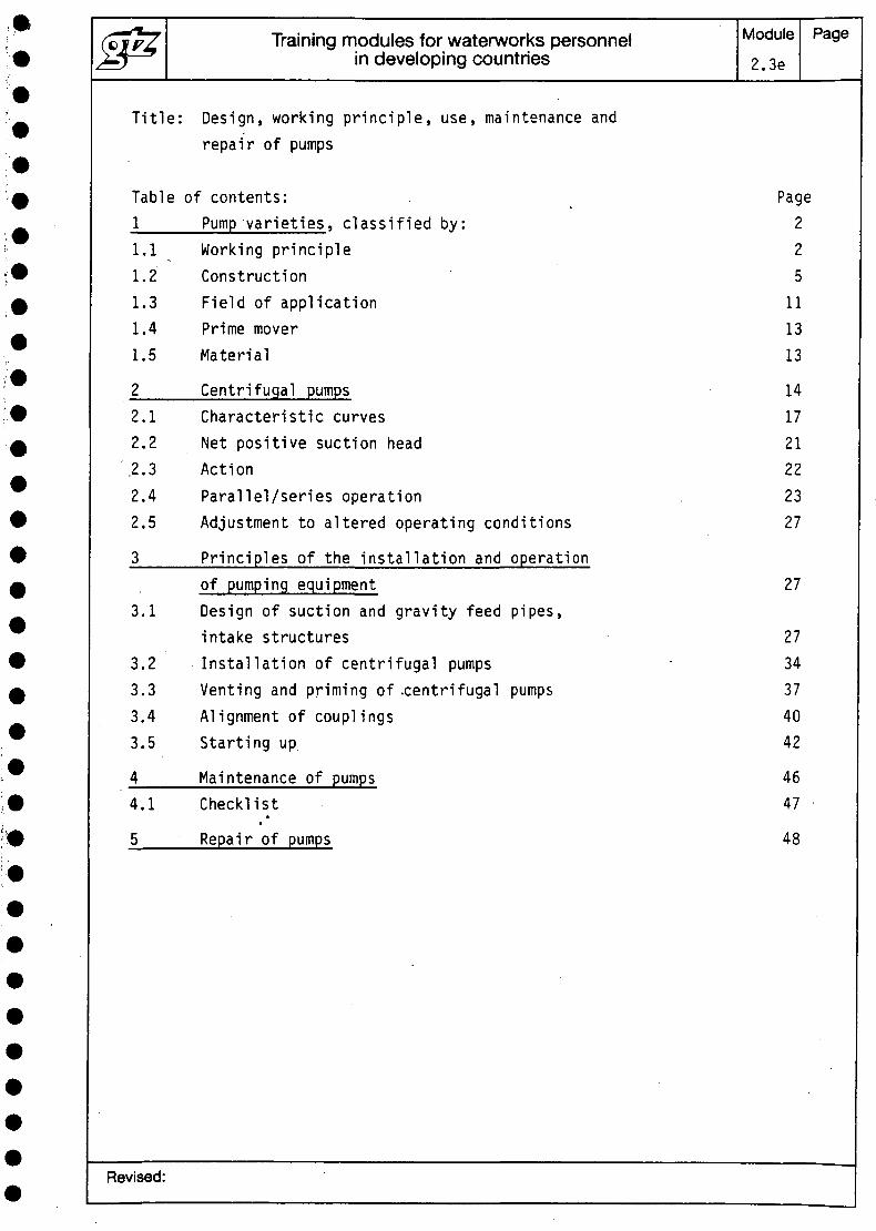
Title: Design, working principle, use, maintenance andrepair of pumps
Table of contents:J.____Pump varieties, classified by:1.1 Working principle1.2 Construction1.3 Field of application1.4 Prime mover1.5 Material
2______Centrifugal pumps2.1 Characteristic curves2.2 Net positive suction head.2.3 Action2.4 Parallel/series operation2.5 Adjustment to altered operating conditions
3____Principles of the installation and operationof pumping equipment
3.1 Design of suction and gravity feed pipes,intake structures
3.2 Installation of centrifugal pumps3.3 Venting and priming of -centrifugal pumps3.4 Alignment of couplings3.5 Starting up
4____Maintenance of pumps4.1 Checklist
5 Repair of pumps
Page225
111313
141721222327
27
2734374042
4647
48
Revised:
Training modules for waterworks personnelin developing countries
Module2.3e
Page2
1 Pump varieties
There is no universally valid system of nomenclature forpumps, since a wide range of different criteria are usedto describe and name them. The following outline cantherefore cover only those aspects which are most oftenused to classify the different types of pumps. In this way,pumps may be distinguished according to their ...
1.1 Working principle:
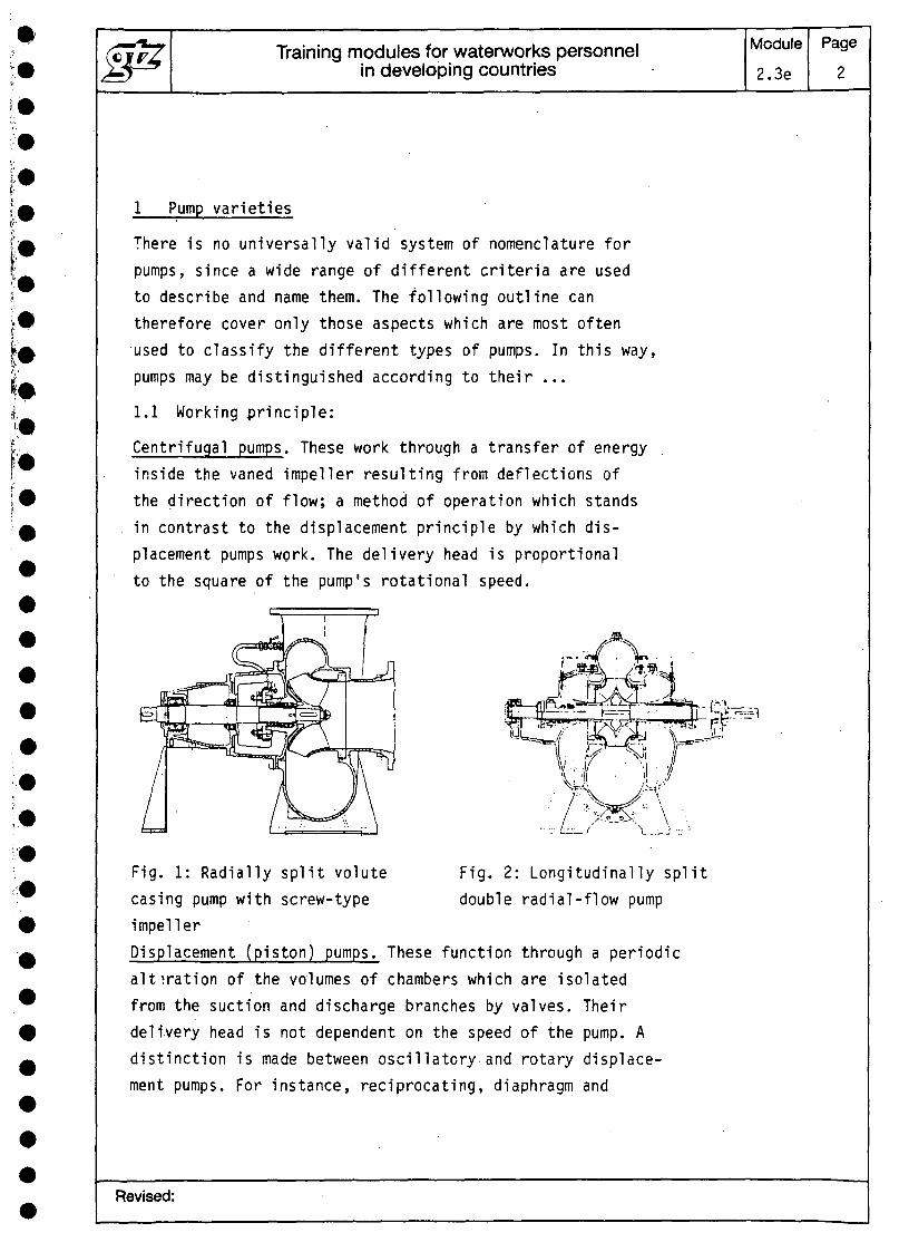
Centrifugal pumps. These work through a transfer of energyinside the vaned impeller resulting from deflections ofthe direction of flow; a method of operation which standsin contrast to the displacement principle by which dis-placement pumps work. The delivery head is proportionalto the square of the pump's rotational speed.
Fig. 2: Longitudinally splitdouble radial-flow pump
Fig. 1: Radially split volutecasing pump with screw-typeimpellerDisplacement (piston) pumps. These function through a periodicalteration of the volumes of chambers which are isolatedfrom the suction and discharge branches by valves. Theirdelivery head is not dependent on the speed of the pump. Adistinction is made between oscillatory and rotary displace-ment pumps. For instance, reciprocating, diaphragm and
Revised:
Training modules for waterworks personnelin developing countries
Module2.3e
Page3
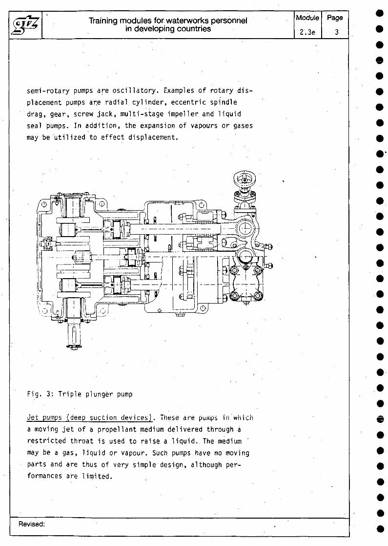
semi-rotary pumps are oscillatory. Examples of rotary dis-placement pumps ar,e radial cylinder, eccentric spindledrag, gear, screw jack, multi-stage impeller and liquidseal pumps. In addition, the expansion of vapours or gasesmay be utilized to effect displacement.
Fig. 3: Triple plunger pump
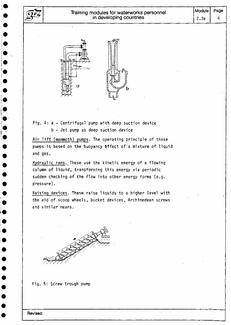
•Jet pumps (deep suction devices). These are pumps in whicha moving jet of a propellent medium delivered through arestricted throat is used to raise a liquid. The mediummay be a gas, liquid or vapour. Such pumps.have no movingparts and are thus of very simple design, although per-formances are limited.
Revised:
Training modules for waterworks personnelin developing countries
Module2.3e
Page4
Fig. 4: a - Centrifugal pump with deep suction deviceb - Jet pump as deep suction device
Air lift (mammoth) pumps. The operating principle of thesepumps is based on the buoyancy effect of a mixture of liquidand gas.
Hydraulic rams. These use the kinetic energy of a flowingcolumn of liquid, transforming this energy via periodicsudden checking of the flow into other energy forms (e.g.pressure).
Raising devices. These raise liquids to a higher level withthe aid of scoop wheels, bucket devices, Archimedean screwsand similar means.
Fig. 5: Screw trough pump
Revised:
Training modules for waterworks personnelin developing countries
Module2.3e.
Page5
Electro-magnetic pumps. This type functions as a resultof the direct action of a magnetic' field on a ferromagneticmedium. Use of such pumps is thus limited to the pumpingof liquid metals, so that they play virtually no part inwater-supply systems. .
1.2 Construction: . ~ '
The fundamentally different working principles of thevarieties of pumps described above clearly dictate quitedifferent constructions. When pumps are designated on thebasis of some aspect of their construction, this is onlyto distinguish a variant within.one of the main categories.The following comments are limited to describing variationsin the design of centrifugal pumps, since these"are thechief pumps used in water-supply systems.
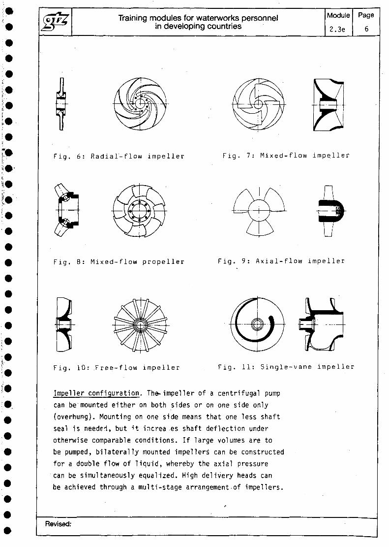
Impeller design. Depending on the specific rotational speedof a centrifugal pump, its impeller may be constructed forradial flow, semi-axial (mixed) flow (also known as a helicalor screw impeller) or axial flow (propeller-type). Radialand semi-axial impellers may have open passages (withoutcovering plates) or closed passages (with covering plates).•Propellers may be cast all in one piece with their hubs,or the blades may be fixed adjustably to the hub for bettercorrection of the characteristic curve, or they may, forcontrol purposes, be adjustable in operation. The bladesof the propeller do not have to be at rig^t angles to thepump's centre of rotation, especially if the propelleris used, whilst retaining its control advantages, forgreater delivery heads and the medium therefore flows throughit with radial velocity components. ' . '
There are, further, special impellers which are used in.the pumping of certain media - e.g. single-vane, double-and triple-passage, free-flow and peripheral impellers.
Revised:
Training modules for waterworks personnelin developing countries
Module
2.3e
Page
6
Fig. 6: Rad ia l - f l ow impeller Fig. 7: M i x e d - f l o w impeller
Fig. 8: M i xed - f l ow propeller Fig. 9: A x i a l - f l o w impeller
Fig. 10: .F ree - f l ow impeller Fig. 11: Single-vane impeller
Impeller configuration. The-impeller of a centrifugal pumpcan be mounted either on both sides or on one side only(overhung). Mounting on one side means that one less shaftseal is needed, but H increa es shaft deflection underotherwise comparable conditions. If large volumes are tobe pumped, bilaterally mounted impellers' can be constructedfor a double flow of liquid, whereby the axial pressurecan be simultaneously equalized. High delivery heads canbe achieved through a multi-stage arrangement.of impellers.
Revised:
Training modules for waterworks personnelin developing countries
Module2.3e
Page7
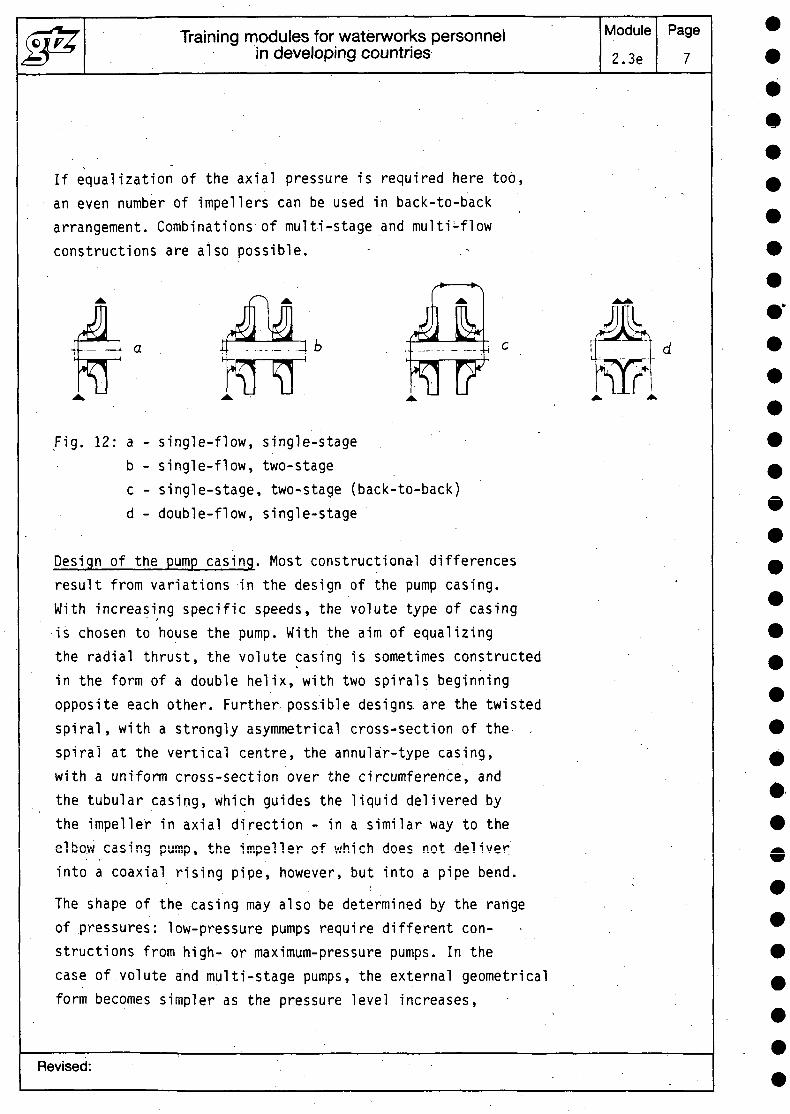
If equalization of the axial pressure is required here too,an even number of impellers can be used in back-to-backarrangement. Combinations of multi-stage and multi-flowconstructions are also possible.
I
k
Fig. 12: a - single-flow, single-stageb - single-flow, two-stagec - single-stage, two-stage (back-to-back)d - double-flow, single-stage
Design of the pump casing. Most constructiona-1 differencesresult from variations in the design of the pump casing.With increasing specific speeds, the volute type of casingis chosen to house the pump. With the aim of equalizingthe radial thrust, the volute casing is sometimes constructedin the form of a double helix, with two spirals beginningopposite each other. Further, possible designs, are the twistedspiral, with a strongly asymmetrical cross-section of the ,spiral at the vertical centre, the annular-type casing,with a uniform cross-section over the circumference, andthe tubular casing, which guides the liquid delivered bythe impeller in axial direction - in a similar way to theslbo.w casing pump, the impeller of which does not deliverinto a coaxial rising pipe, however, but into a pipe bend.
The shape of the casing may also be determined by the rangeof pressures: low-pressure pumps require different con-structions from high- or maximum-pressure pumps. In thecase of volute and multi-stage pumps, the external geometricalform becomes simpler as the pressure level increases,
Revised:
J^ Training modules for waterworks personnelin developing countries
Module
2.3e
Page
8
approaching cylindrical, conical or spherical designs. Theadvantages of these constructions - i.e. reduction of stress,ease of installation - are more or less concomitant witha loss of efficiency or of capacity of the casing - thusalso with higher costs.
Further variations in the construction of the pump casingarise from its separation into two parts horizontally orvertically, at right angles or parallel to the shaft -which are nearly always practised for greater convenienceof installation and servicing.
Finally, the position of the suction and delivery connectionson the pump also has an effect on the design of its casing.The axial intake - i.e. the suction branch - of single-stagevolute pumps is, for instance, a particular characteristicof this type of pump - in contrast with inline pumps, whereintake and delivery are located opposite each o-ther, orrefinery pumps with both connections on the top. Where thepump shaft is mounted on one side only, even its alternativemounting in a bearing flange or bearing block is sometimestaken as a distinguishing feature.
In segmented pumps, the casing sections are designatedaccording to their function - i.e. suction casing, stagecasing, several of which may be lined up in series, anddelivery casing. When assembled, the casings, includingthe anchor bars which hold the suction casing, stage casingsand delivery casing together as an airtight unit, are oftensurrounded by a jacket made of sheet metal to give the pump itsexternal form. In the case of hot-water pumps, the jacket containsthe insulating materials (glass fibres, high-gloss foil etc.)
If the casing joint is in the same plane as the shaft, e.g incentrifugal pumps with horizontal shaft the casing consistsof a lower section, which contains the suction and deliveryconnections and the pump feet, and a simpler upper section.
Revised:
Training modules for waterworks personnelin developing countries
Module
2.3e
Page
9
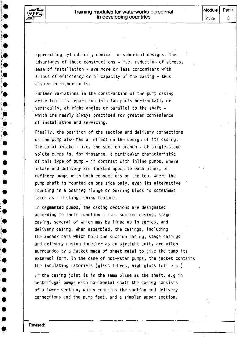
Both sections are provided with a flange at the joint, whichextends right round the casing, including the two stuffing-box housings, and which is used to fasten the two partsof the casing together, with the aid of many screws, sothat it is' completely air- and water-tight.
In longitudinally divided pumps with a vertical shaft, theimpeller often runs in a submerged bearing, so that thesecond shaft packing is not required. The two casing sectionsin this case are called the 'back section - this containsthe suction and delivery connections and the pump foot -and the front section.
Fig. 13: Simple vo lute casing
w i t h axia l suc t ion b ranch
Fig. 14:..Inline casing
Fig. 15: Hor i zon ta l l y d iv ided
cas ingFig. 16: Mul t i -s tage
segmen ted pump
Revised:
Training modules for waterworks personnelin developing countries
Module2.3e
Page10
Methods of installation. Methods of installation vary quitewidely. A basic distinction is made between centrifugalpumps with a horizontal shaft and those with a verticalshaft. Pumps with a vertical shaft may be installed in wetor dry surroundings. Centrifugal pumps which can be completelyimmersed are also known as submersible pumps - most'pumpswith tubular casings, for instance, come under this heading.Centrifugal pumps with their shafts positioned at an angleare occasionally found in pumping stations for pumpjnglarge quantities of water at low heads.
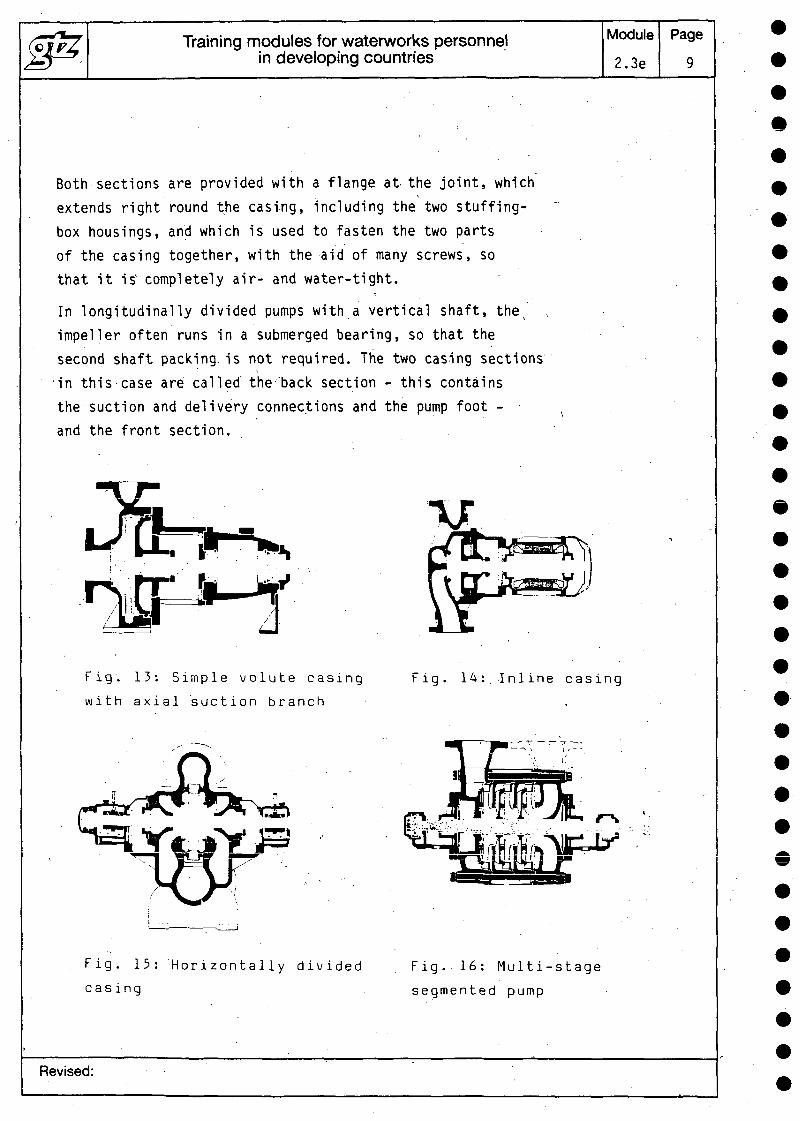
A second characteristic which varies to some extent is themethod of mounting the centrifugal pump on its foundation.It may rest on its own feet, or it may be flanged onto theprime mover in the form of a self-contained unit. The con-nection between the casings of pump and prime mover, e.g.in the case of flanged motors or motor lanterns, providesfurther distinguishing features, as also does the designof the base plate (one for pump and prime mover together,or separate bases for 'motor and pump).
Finally, in contrast with permanent methods of installation,pumps may also be mounted on wheels or skids, or be providedwith a carrying handle.
Fig. 17: Horizontal, dry installationa - pump and motor mounted separately on foundation
blocksb - pump and motor mounted separately on base platesc - pump and motor mounted on a common base plate
Revised:
Training modules for waterworks personnelin developing countries
Module2.3e
Page11
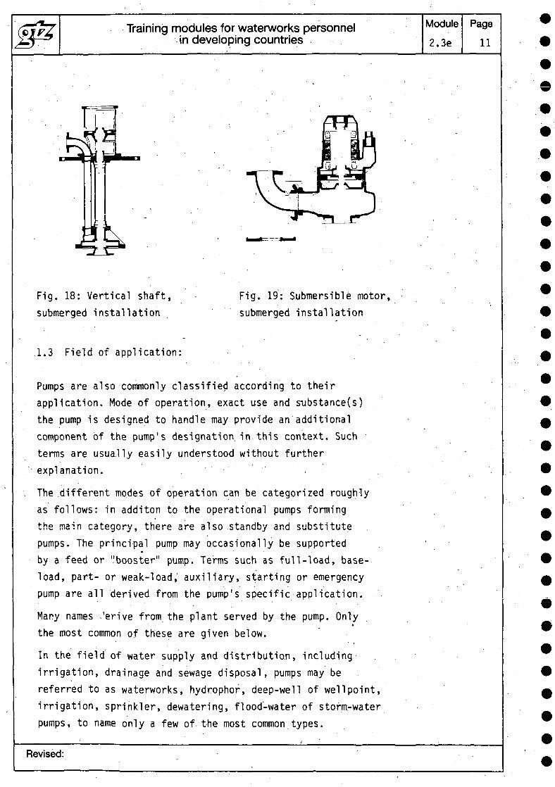
Fig. 18: Vertical shaft,submerged installation
Fig. 19: Submersible motor,submerged installation
1.3 Field of application:
Pumps are also commonly classified according to theirapplication. Mode of operation, exact use and STjbstance(s)the pump is designed to handle may provide an additionalcomponent of the pump's designation, in this context. Suchterms are usually easily understood without furtherexplanation. . ,
The .different modes of operation can be categorized roughlyas follows: in additon to the operational pumps formingthe main category, there are also standby and substitutepumps. The principal pump may occasionally be supported
• - ' -
by a feed or "booster" pump. Terms such as full-load, base-load, part- or weak-load, auxiliary, starting or emergencypump are all derived from the pump's specific application.
Many names -'erive from the plant served by the pump. Onlythe most common of these are given below.
In the field of water supply and distribution, includingirrigation, drainage and sewage disposal, pumps may bereferred to as waterworks, hydrophor, deep-well of well point,irrigation, sprinkler, dewatering, flood-water of storm-waterpumps, to name only a few of the most common types.
Revised:
Training modules for waterworks personnelin developing countries
Module2.3e
Page12
In power stations and heating installations, the pumps usedwill be known as boiler-water feed, condensed-steam, reactor,stored-water (these can often operate both as pumps andas turbines), or heating-water circulating pumps.
In the chemical and petro-chemical' industries: chemical,pipeline, refinery, process, inline, loading, mixing andreturn-flow pumps.
In marine engineering: ship's pumps, oil pumps for loadingand unloading tankers, ballast and bilge pumps and dockpumps for filling and draining docks.
Other applications require: trench drainage pumps, dredging,fire-control, injection, jetting, scavenging, petrol andvent/vacuum pumps.
The designation of a pump is also often derived from themedium it is designed to handle.
Most pumps transport fluids the main component of whichis water: pure-water, drinking-water, hot- and cold-waterpumps, cooling-water, sea-water and brine pumps, condensateand feed-water pumps; sewage and faeces pumps, liquid manure,sludge and solids-handling (non-chokeable) pumps, celluloseand wood-pulp pumps.
Named after other fluids are oil pumps (heating oil, lubri-cating oil, hot oil), fuel pumps, heat-transfer oil pumps,coolant, liquid gas, grease, acid, lye, beverage, fish,beet, fruit and concrete pumps.
Revised:
Training modules for waterworks personnelin developing countries
Module
2.3e
Page
13
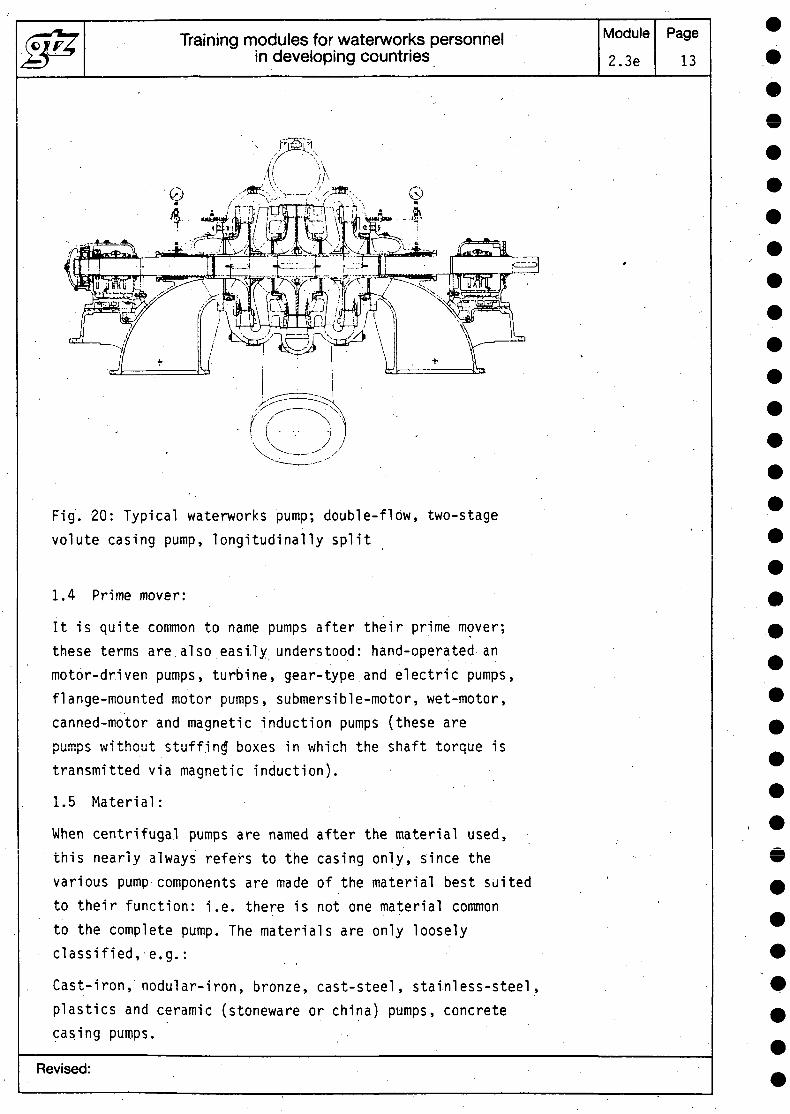
Fig. 20: Typical waterworks pump; double-flow, two-stagevolute casing pump, longitudinally split
1.4 Prime mover:
It is quite common to name pumps after their prime mover;these terms are also easily understood: hand-operated anmotor-driven pumps, turbine, gear-type and electric pumps,flange-mounted motor pumps, submersible-motor, wet-motor,canned-motor and magnetic induction pumps (these arepumps without stuffing* boxes in which the shaft torque istransmitted via magnetic induction).
1.5 Material: ,
When centrifugal pumps are named after the material used,this nearly always refers to the casing only, since thevarious pump components are made of the material best suitedto their function: i.e. there is not one material commonto the complete pump. The materials are only looselyclassified, e.g.:
Cast-iron, nodular-iron, bronze, cast-steel, stainless-steel,plastics and ceramic (stoneware or .china) pumps, concretecasing pumps.
Revised:
Training modules for waterworks personnelin developing countries
Module2.3e
Page14
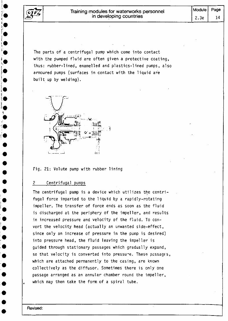
The parts of a centrifugal pump which come into contactwith the pumped fluid are often given a protective coating,thus: rubber-lined, enamelled and plastics-lined pumps, alsoarmoured pumps (surfaces in contact with the liquid arebuilt up by welding).
Fig. 21: Volute pump with rubber lining
Centrifugal pumps
The centrifugal pump is a device which utilizes the centri-fugal force imparted to the liquid by a rapidly-rotatingimpeller. The transfer of force ends as soon as the fluidis discharged at the periphery of the impeller, and resultsin increased pressure and velocity of the fluid. To con-vert the velocity head (actually an unwanted side-effect,since only an increase of pressure in the pump is desired)into pressure head, the fluid leaving the impeller isguided through stationary passages which gradually expand,so that velocity is converted into pressure. These passages,which are attached permanently to the casing, are knowncollectively as the diffusor. Sometimes there is only onepassage arranged as an annular chamber round the impeller,which may then take the form of a spiral tube.
Revised:
Training modules for waterworks personnelin developing countries
Module2.3e
Page15
•The most important component of a centrifugal pump is theimpeller. In most centrifugal pumps, the fluid enters theimpeller near the centre of rotation and discharges fromit with a radial motion at its periphery, This is the mostcommon arrangement because the centrifugal forces then resultin a continuous increase in pressure in the direction ofmotion. .
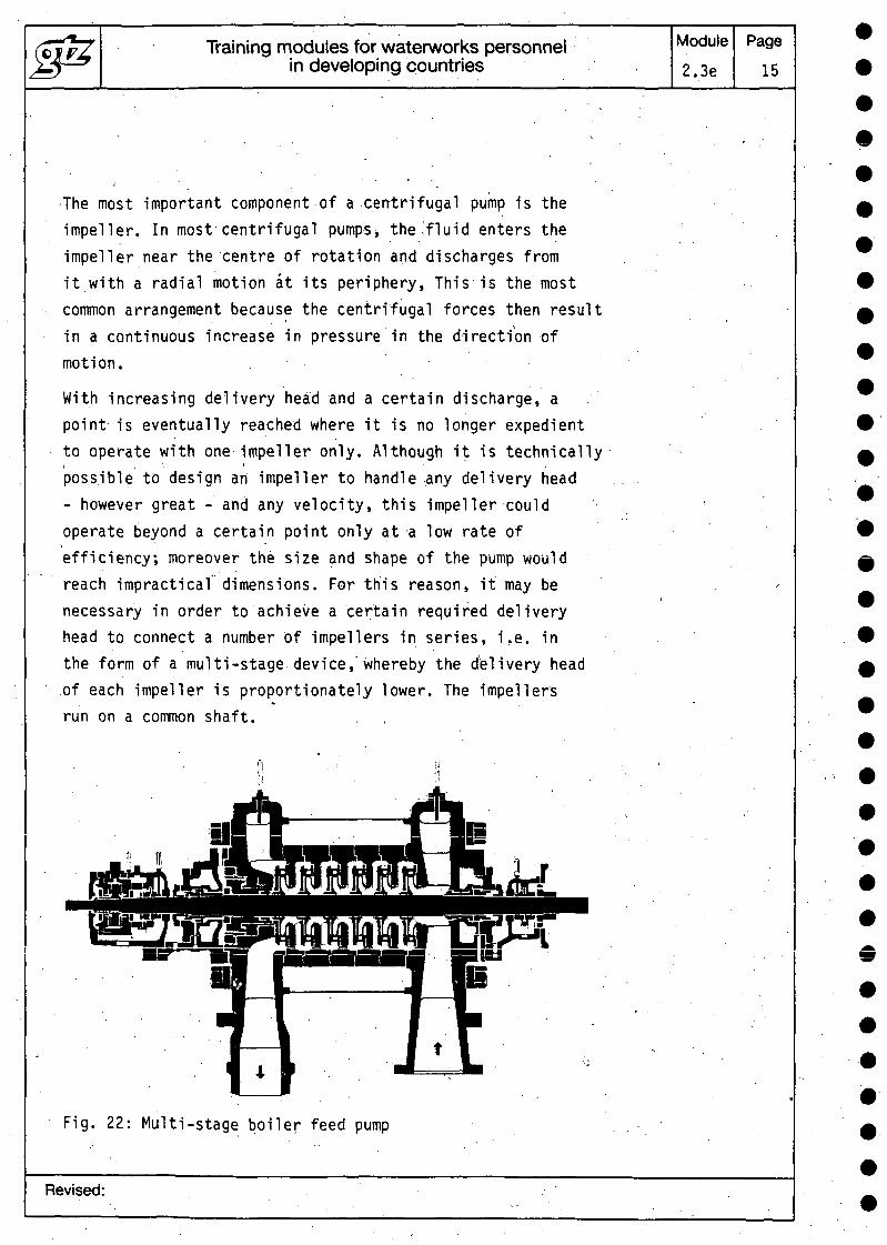
With increasing delivery head and a certain discharge, apoint is eventually reached where it is no longer expedientto operate with one impeller only. Although it is technicallyi * • .possible to design an impeller to handle any delivery head- however great - and any velocity, this impeller couldoperate beyond a certain point only at a low rate ofefficiency; moreover the size and shape of the pump wouldreach impractical dimensions. For this reason, it may benecessary in order to achieve a certain required deliveryhead to connect a number of impellers in series, i.e. inthe form of a multi-stage device,'whereby the delivery headof each impeller is proportionately lower. The impellersrun on a common shaft. . ,
Fig. 22: Multi-stage boiler feed pump
Revised:
Training modules for waterworks personnelin developing countries
Module2.3e
Page16
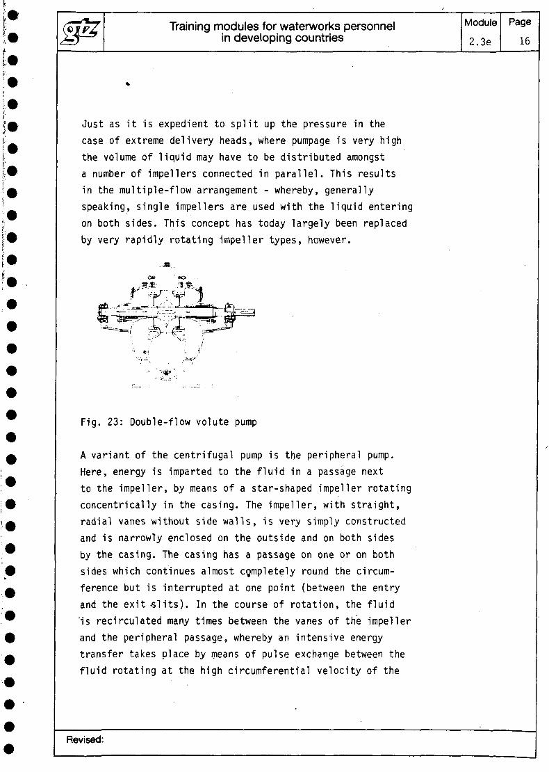
Just as it is expedient to split up the pressure in thecase of extreme delivery heads, where pumpage is very highthe volume of liquid may have to be distributed amongsta number of impellers connected in parallel. This resultsin the multiple-flow arrangement - whereby, generallyspeaking, single impellers are used with the liquid enteringon both sides. This concept has today largely been replacedby very rapidly rotating impeller types, however.
-•<*•
Fig. 23: Double-flow volute pump
A variant of the centrifugal pump is the peripheral pump.Here, energy is imparted to the fluid in a passage nextto the impeller, by means of a star-shaped impeller rotatingconcentrically in the casing. The impeller, with straight,radial vanes without side walls, is very simply constructedand is narrowly enclosed on the outside and on both sidesby the casing. The casing has a passage on one or on bothsides which continues almost cgmpletely round the circum-ference but is interrupted at one point (between the entryand the exit-slits). In the course of rotation, the fluid'is recirculated many times between the vanes of the impellerand the peripheral passage, whereby an intensive energytransfer takes place by means of pulse exchange between thefluid rotating at the high circumferential velocity of the
Revised:
Training modules for waterworks personnelin developing countries
Module2.3e
Page' 17
impeller and the fluid flowing at a lower speed throughthe peripheral passage. This pulse exchange is repeatedmany times over at the impeller's periphery.and resultsin an extremely high delivery head, which may be 5 to 15times higher than that of radial-flow impellers of the samesize rotating at the same velocity.
In addition to this extremely high delivery head - whichcan be increased still further by using peripheral pumpsin multi-stage arrangement - this type of pump has the ad-vantage of being self-priming. As in liquid seal pumps,the water remaining in the pump casing forms, with rotatingimpeller, a ring of water with a free surface if air isdrawn into the peripheral pump through the suction branch. ,This liquid seal would circulate concentrically and there-fore ineffectively in the casing if the passage were notinterrupted at one point on the circumference. At this point,the inner radius of the ring is smaller due to the dis-placement effect, so that the empty spaces filled with airbetween the radial vanes of the impeller are also reducedand the peripheral pump thus acts as a compressor on thedisplacement principle, in the same way as a liquid sealpump.
2.1 Characteristic curves
In the case of a centrifugal pump being driven at a con-stant speed, the delivery head H, power consumption P -and thus also the degree of efficiency - and the requiredNPSH are all functions of the capacity Q. These relation-ships are shown by characteristic curves.
Revised:
Training modules for waterworks personnelin developing countries
Module
2.3e
Page
18
0 30 tf
ID a n » ln,CPH ao
1 2 3 « 3 < 1 L/S • « 11 O 13 u C
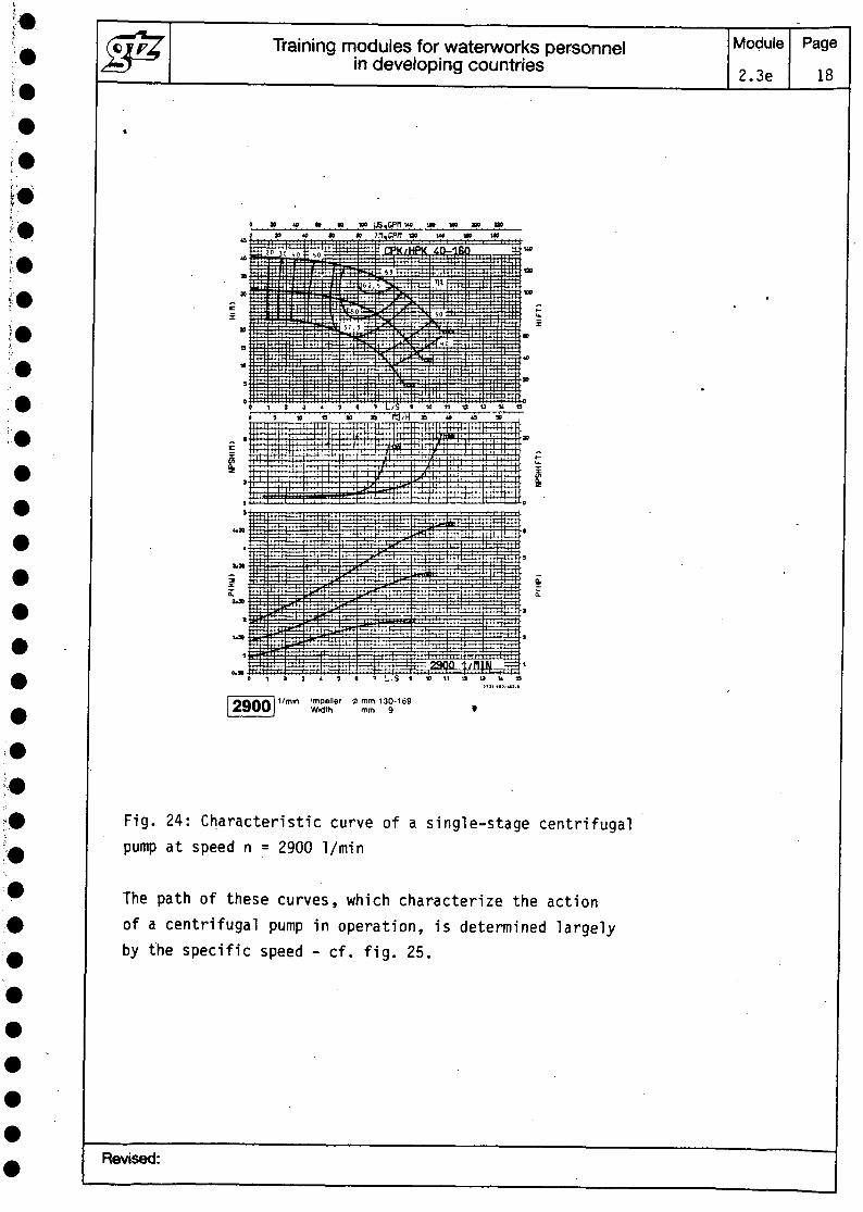
1/min impeller 2 mm 130-169Width mm 9
Fig. 24: Characteristic curve of a single-stage centrifugalpump at speed n = 2900 1/min
The path of these curves, which characterize the actionof a centrifugal pump in operation, is determined largelyby the specific speed - cf. fig. 25.
Revised:
Training modules for waterworks personnelin developing countries
Module
2.3e
Page19
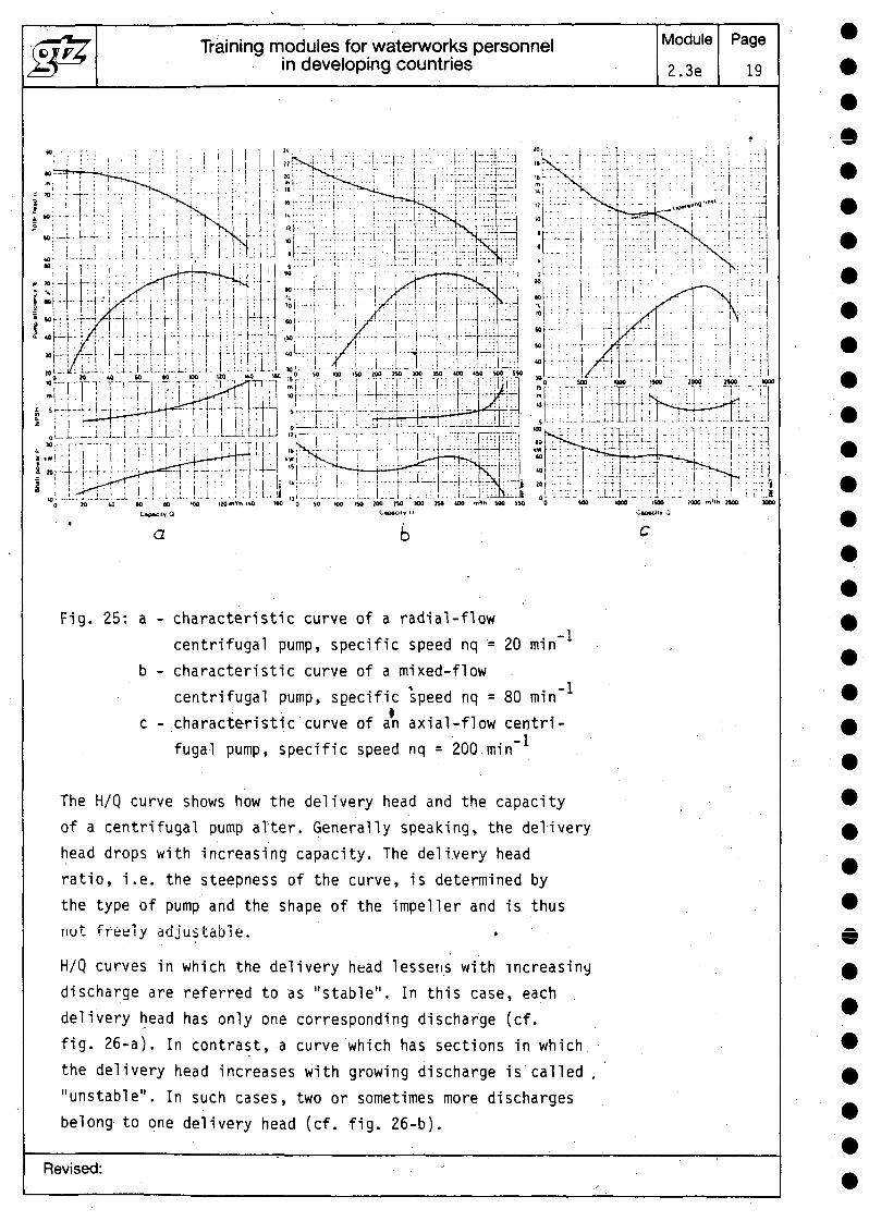
Fig. 25: a - characteristic curve of a radial-flowcentrifugal pump, specific speed nq = 20 min~
b - characteristic curve of a mixed-flowcentrifugal pump, specific speed nq = 80 min~
c - characteristic curve of an axial-flow centri-fugal pump, specific speed nq = 200.min~
The H/Q curve shows how the delivery head and the capacityof a centrifugal pump alter. Generally speaking, the deliveryhead drops with increasing capacity. The delivery headratio, i.e. the steepness of the curve, is determined bythe type of pump and the shape of the impeller and is thusnot freely adjustable. .
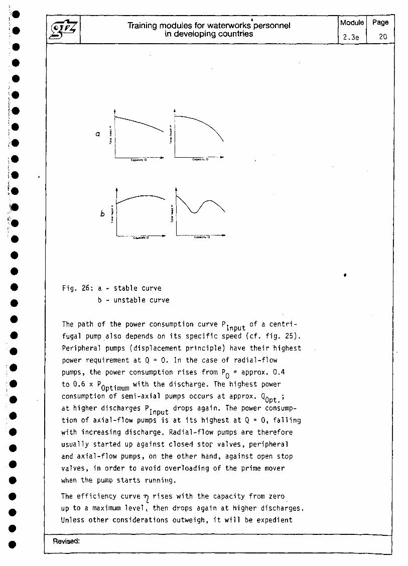
H/Q curves in which the delivery head lessens with increasingdischarge are referred to as "stable". In this case, eachdelivery head has only one corresponding discharge (cf.fig. 26-a). In contrast, a curve which has sections in whichthe delivery head increases with growing discharge is called ."unstable". In such cases, two or sometimes more dischargesbelong to one delivery head (cf. fig. 26-b).
Revised:
Training modules for waterworks personnelin developing countries
Module
2.3e
Page20
b \
Fig. 26: a - stable curveb - unstable curve
The path of the power consumption curve PjnDUt °* a centri-fugal pump also depends on its specific speed (cf. fig. 25).Peripheral pumps (displacement principle) have their highestpower requirement at Q = 0. In the case of radial-flowpumps, the power consumption rises from PQ = approx. 0.4to 0.6 x PQntimum with the discharge. The highest powerconsumption of semi-axial pumps occurs at approx. Q . ;at higher discharges P* . drops again. The power consump-tion of axial-flow pumps is at its highest at Q = 0, fallingwith increasing discharge. Radial-flow pumps are thereforeusually started up against closed stop valves, peripheraland axial-flow pumps, on the other hand, against open stopvalves, in order to avoid overloading of the prime moverwhen the pump starts running.
The efficiency curve T» rises with the capacity from zeroup to a maximum level, then drops again at higher discharges.Unless other considerations outweigh, it will be expedient
Revised:
Training modules for waterworks personnelin developing countries
Module
2.3e
Page
21
to select the pump which has its highest efficiency Q .near the rated capacity QN> i.e. QN = QQ t ,The path of the curve of the required NPSH, NPSH , is
I Ct| •
also largely dependent on the specific speed. • •
2.2 NPSH (net positive suction head)
The NPSH is an important factor in .the analysis of thesuction action of a centrifugal pump, i.e. it allows anassessment of the relative likelihood of cavitation occurringto be made.
Cavitation is the occurrence of cavities or hollow spaces,resulting from the formation of gas bubbles, in a liquidin motion, followed by their sudden dispersal. If, in aflowing liquid, the static pressure drops to the vapourpressure belonging to the. liquid's temperature, e.g. dueto an increase in the absolute flow velocity or to a changein the geodetic head, gas bubbles form in the interior ofthe liquid at this point. They are transported along bythe flowing liquid and collapse suddenly when the staticpressure is again higher, than the vapour pressure. Thiscollapse occurs at high speed in the form of an implosion.At the start of the implosion, an indentation forms, incavities nearer to the walls on the side farthest fromthe wall, and in cavities nearer to the centre of the flowingliquid on,the side where the pressure is highest. As theindentation grows, a "micro-jet" of liquid forms, whichthen bursts the deformed bubbles into two or more parts.Where cavities are adhering to a wall or are near to one,this micro-jet then hits the surface of the wall at highspeed, causing considerable damage to it. These, pressureimpacts are to be seen as the mechanical cause of cavitationerosion, whereby chemical aggression may add to the effect.On examination, the eroded areas can be seen to have apitted, sponge-like structure.
Revised:
Training modules for waterworks personnelin developing countries
Module
2.3e
Page22
In centrifugal pumps, cavitation may be caused especiallyby local drops in pressure in the entrance to the impeller,due to the higher flow velocity at this point. Even beforecavitation occurs, the gas bubbles both lead to a drop indelivery head and efficiency and also, through their suddencollapse, cause the pump to run unevenly and noisily. Toavoid, or at least reduce, the risk of cavitation in centri-fugal pumps, static pressure must be in excess of thevapour pressure of the liquid at the entrance to the impeller.This difference between the absolute static pressure andthe vapour pressure, plus the dynamic losses inside thepump, are determined on a test stand and given in the pumpcharacteristic. Thus the NPSH of a pump indicates to
i GQ •what minimum extent the total pressure head in the planeof reference for the NPSH value, usually the impeller entryside, must be greater than the vapour pressure of the liquidin order to guarantee fault-free running of the pump atthe rated velocity, rated discharge and with the liquidon which the calculations were based.
2.3 Action
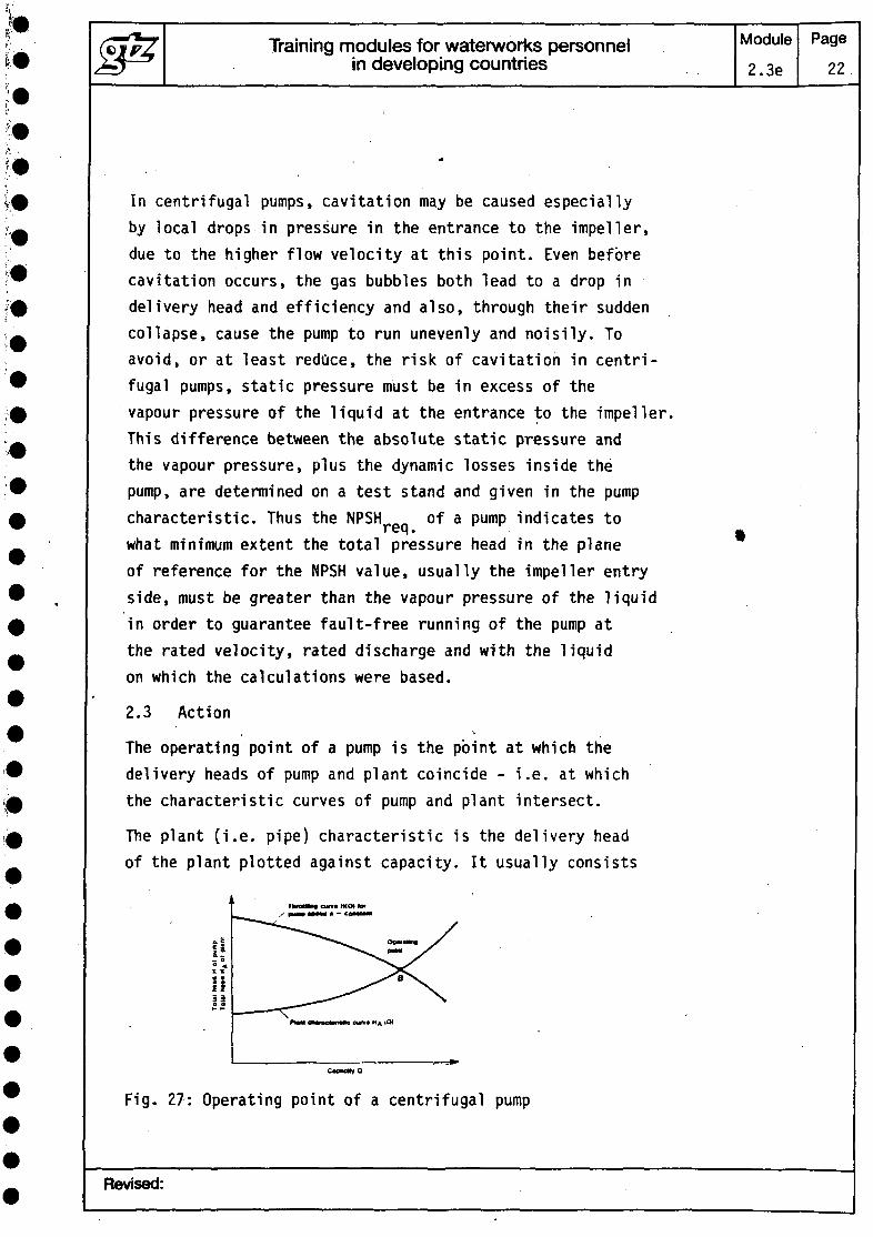
The operating point of a pump is the point at which thedelivery heads of pump and plant coincide - i.e. at whichthe characteristic curves of pump and plant intersect.
The plant (i.e. pipe) characteristic is the delivery headof the plant plotted against capacity. It usually consists
Ifnii
NA(Ol
Fig. 27: Operating point of a centrifugal pump
Revised:
Training modules for waterworks personnelin developing countries
Module
2.3e
Page
23
of one part which is independent of discharge, the statichead (the vertical distance between the water level on thesuction side and on the delivery side) and another partwhich increases in proportion with the square of the dischargevolume, the dynamic head - friction losses in the pipes.In special cases (e.g. circulating plants), the static headmay equal zero.
The point of intersection thus gives the volume of liquidbeing pumped through the plant and the corresponding valuesfor power consumption, efficiency and the required NPSHof the pump.
Generally speaking, the design and dimensioning of a pumpdepend plUmarily on discharge; the .delivery head of theplant (= delivery head of the pump) is then calculated onthe basis of the given conditions.
2.4 Operation in parallel/in series
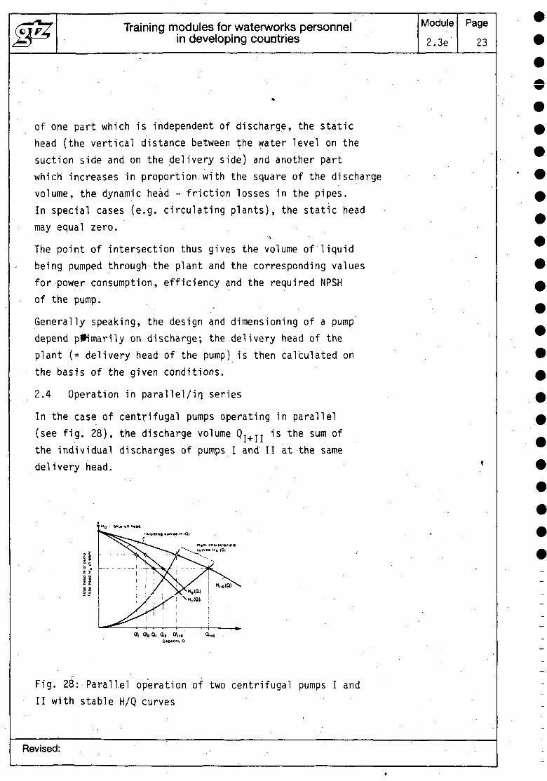
In the case of centrifugal pumps operating in parallel(see fig. 28), the discharge volume QT+TT is the sum ofthe individual discharges of pumps I and II at the samedelivery head.
Fig. 28: Parallel operation of two centrifugal pumps I andII with stable H/Q curves
Revised:
Training modules for waterworks personnelin developing countries
Module
2.3e
Page24
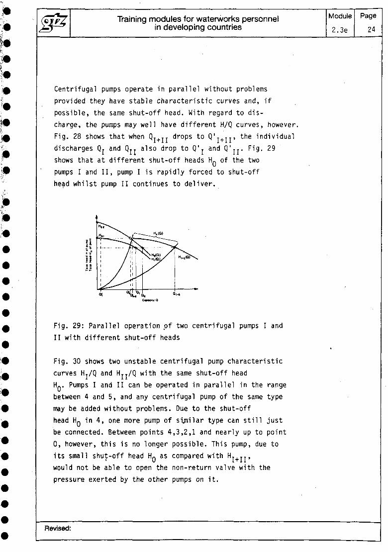
Centrifugal pumps operate in parallel without problemsprovided they have stable characteristic curves and, ifpossible, the same shut-off head. With regard to dis-charge, the pumps may well have different H/Q curves, however.Fig. 28 shows that when QT+TT drops to Q'T+TT» the individualdischarges Q, and Q,, also drop to Q'r and Q'jj. Fig. 29shows that at different shut-off heads HO of the twopumps I and II, pump I is rapidly forced to shut-offhead whilst pump II continues to deliver.
Fig. 29: Parallel operation of two centrifugal pumps I andII with different shut-off heads
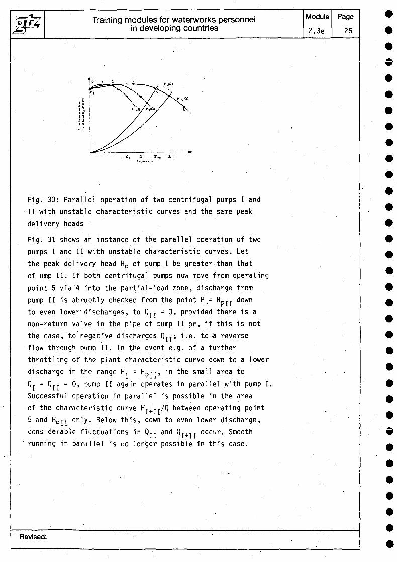
Fig. 30 shows two unstable centrifugal pump characteristiccurves H./Q and Hjj/Q with the same shut-off headHO. Pumps I and II can be operated in parallel in the rangebetween 4 and 5, and any centrifugal pump of the same typemay be added without problems. Due to the shut-offhead HQ in 4, one more pump of similar type can still justbe connected. Between points 4,3,2,1 and nearly up to point0, however, this is no longer possible. This pump, due toits small shut-off head HQ as compared with H,+JJ,would not be able to open the non-return valve with thepressure exerted by the other pumps on it.
Revised:
Training modules for waterworks personnelin developing countries
Module2.3e
Page25
H.(0)
Fig. 30: Parallel operation of two centrifugal pumps I andII with unstable characteristic curves and the same peakdelivery heads
Fig. 31 shows an instance of the parallel operation of twopumps I and II with unstable characteristic curves. Letthe peak delivery head Hp of pump I be greater,than thatof ump II. If both centrifugal pumps now move from operatingpoint 5 via~4 into the partial-load zone, discharge frompump II is abruptly checked from the point H.= HpII downto even lower discharges, to QTT = 0, provided there is anon-return valve in the pipe of pump II or, if this is notthe case, to negative discharges Q T Ti i.e. to a reverseflow through pump II. In the event e.g. of a furtherthrottling of the plant characteristic curve down to a lowerdischarge in the range HT = Hprr, in the small area toQj = QJJ = 0, pump II again operates in parallel with pump I.Successful operation in parallel is possible in the areaof the characteristic curve HT+JT/Q between operating point5 and HpTT only. Below this, down to even lower discharge,considerable fluctuations in QTT and QT+TT occur. Smoothrunning in parallel is no longer possible in this case.
Revised:
Training modules for waterworks personnelin developing countries
Module
2.3e
Page
26
H.K»
I!!i
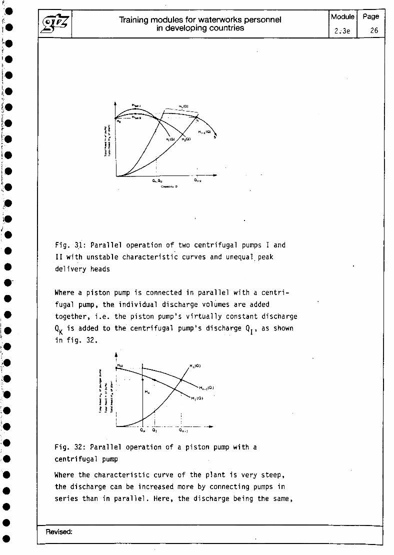
Fig. 31: Parallel operation of two centrifugal pumps I andII with unstable characteristic curves and unequal, peakdelivery heads
Where a piston pump is connected in parallel with a centri-fugal pump, the individual discharge volumes are addedtogether, i.e. the piston pump's virtually constant dischargeQK is added to the centrifugal pump's discharge Q,, as shownin fig. 32.
HA(Q)
Fig. 32: Parallel operation of a piston pump with acentrifugal pump
Where the characteristic curve of the plant is very steep,the discharge can be increased more by connecting pumps inseries than in parallel. Here, the discharge being the same,
Revised:
Training modules for waterworks personnelin developing countries
Module2.3e
Page27
the delivery heads are added together. The same principleis utilized in multi-stage centrifugal pumps.
2.5 Adjustment to altered operation conditions
If a different capacity from that resulting as under 2.4is required in the plant, there are various possible waysof moving the operating point. These methods are based eitheron an alteration of the plant characteristic curve H./Q,. e.g.
by throttling . , 'by introducing a bypass . .
or on an alteration of the pump characteristic curve H/Q, e.g.
by adjusting the speedby altering the diameter of the impellerby adjusting the angle of a grid in front of the impellerby producing an initial spin directly in front of the im-peller by means of a directed bypass flowby adjusting the impeller vanesby blocking the impeller flow by means of a certaincavitation volumeby sharpening the ends of the vanes.
3 Principles of the installation and operation ofpumping equipment
3.1 Design of suction and gravity feed pipes,intake structures
Suction pipes must always be laid horizontally or elsesloping steadily upwards to the pump, in order to avoidaccumulations of gas or air. The pipes must be completely 'water-tight and it should be possible to'release the airfrom them without difficulty. If conical connecting piecesare necessary, these should be of non-concentric design.Gravity feed pipes should be laid either horizontally orsloping steadily downwards to the pump.
Revised:
Training modules for waterworks personnelin developing countries
Module
2.3e
Page
28
Sudden alterations of cross-section and sharp bends shouldbe avoided. Poorly-designed suction or feed pipes (e.g.where there are bends on several planes directly beforethe pump's suction nozzle) can have a considerably detri-mental effect on the pump's performance.
In the case of double-flow pumps, care must be taken toensure that admission to both sides of the impeller is ofequal volume. There must therefore be a straight pipe runat least 2 x DN long between a necessary bend and the pump'ssuction nozzle, to balance the flow.
If several pumps of the same type are connected to a common/
suction or feed pipe, it must be ensured, through appropriatedesign, that flow conditions are-the same before each pump.
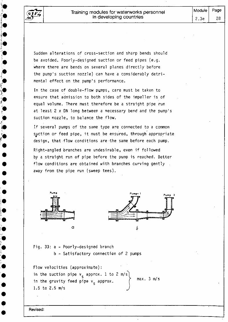
Right-angled branches are undesirable, even if followedby a straight run of pipe before the pump is reached. Betterflow conditions are obtained with branches curving gently .away from the pipe run (sweep tees).
Pump Pump'* 1 Pump 2
Fig. 33: a - Poorly-designed branchb - Satisfactory connection of 2 pumps
Flow velocities (approximate):in the suction pipe v approx. 1 to 2 m/sin the gravity feed pipe v approx.1.5 to 2.5 m/s
max. 3 m/s
Revised:
Training modules for waterworks personnelin developing countries
Module2.32
Page
29
Stop valves in the suction or feed pipe must remain fullyopen during operation and may not be used for controlpurposes.
Stop valves in the suction pipe are best installed witha horizontal spindle or a spindle projecting verticallydownwards, to avoid the formation of air pockets In thespindle hood.
The spindle of the stop valve should further be sufficientlywell sealed to reliably prevent the admission of air.
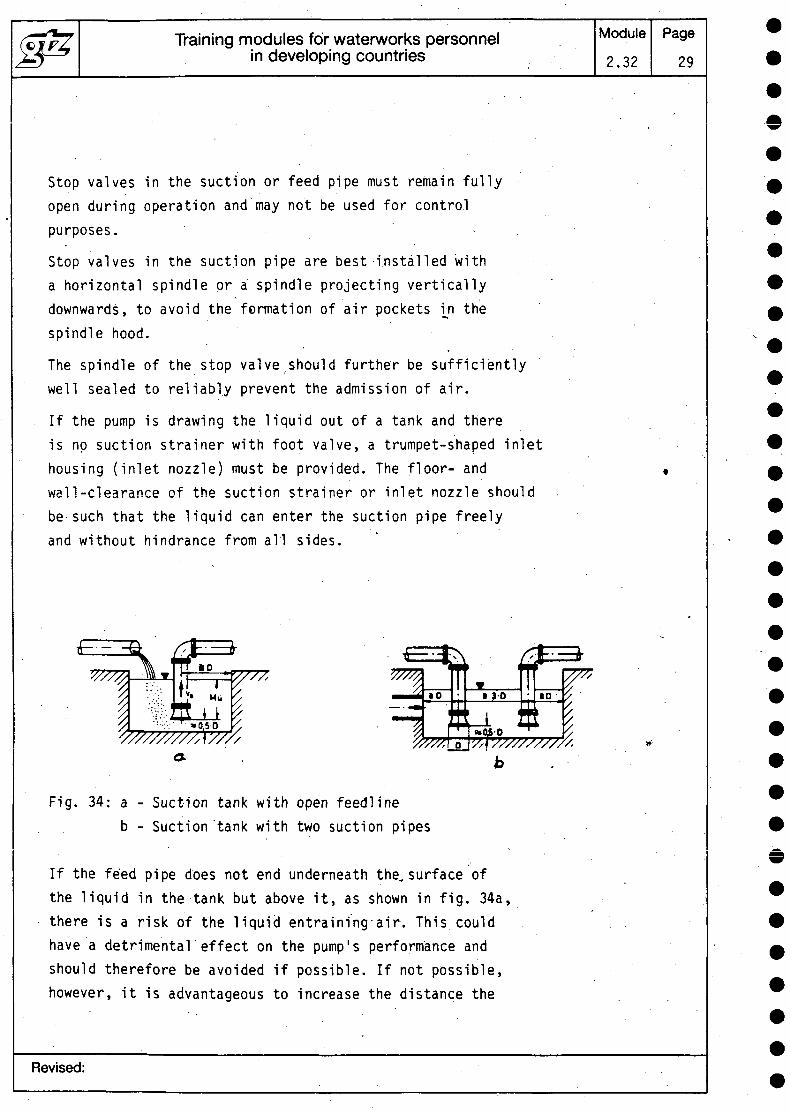
If the pump is drawing the liquid out of a tank and thereis no suction strainer with foot valve, a trumpet-shaped inlethousing (inlet nozzle) must be provided. The floor- andwall-clearance of the suction strainer or inlet nozzle shouldbe such that the liquid can enter the suction pipe freelyand without hindrance from all sides.
Fig. 34: a - Suction tank with open feedlineb - Suction'tank with two suction pipes
If the feed pipe does not end underneath the. surface ofthe liquid in the tank but above it, as shown in fig. 34a,there is a risk of the liquid entraining-air. This couldhave a detrimental effect on the pump's performance andshould therefore be avoided if possible. If not possible,however, it is advantageous to increase the distance the
Revised:
Training modules for waterworks personnelin developing countries
Module
2..3e
Page
30
liquid travels between its point of entry and the suctionopening, either by installing bulkheads or selecting arelatively large minimum cover of water, so that the aircan escape again - this may involve higher constructioncosts, however. At a flow velocity v of approx. 2 m/s,for instance, a minimum cover of approx. 1.3 m is necessary.
The intake chamber of a vertically installed centrifugalpump should be designed so that a continuous flow of liquidto the pump can be guaranteed for every operational stateand whatever the level in the chamber. This is especiallyimportant in the case of specifically fast-running pumps(mixed-flow and axial/propeller), since these are more affectedby an uneven flow of liquid than radial-flow pumps.
Smooth operation of the pump is achieved when the flow ofliquid to the.pump's impeller has low spin and a uniformspeed-profile over the complete cross-section of the intakenozzle. In addition, the formation at lowest levels of theliquid of air-drawing vortices in the intake chamber mustbe avoided. If these conditions are not met, a drop in thepump's discharge and efficiency must be expected. Underparticularly unfavourable conditions, damage resulting fromvibration or cavitation may occur.
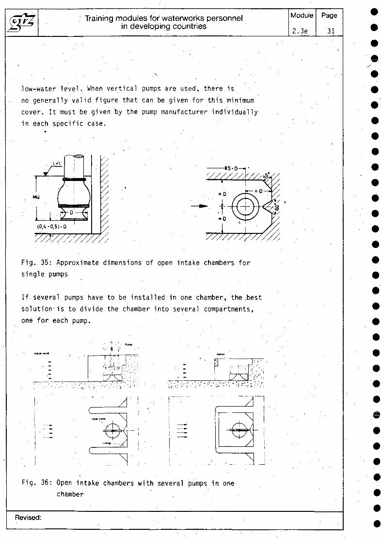
Open intake chambers. Fig. 35 gives recommendations on theprinciple dimensions of tanks where only one pump is tobe installed. These must be taken as approximate figures -only. The channel should have a uniform cross-section forat least 5 x D before the pump. The flow velocity in theintake channel should not exceed 0.5 m/s. The referencequantity D is equivalent to the outside diameter of theinlet casing of a vertical mixed-flow or axial-flow impellerpump.
The minimum cover is measured as the distance between thelower edge of the inlet casing and the lowest possible
Revised:
Training modules for waterworks personnelin developing countries
Module
2.3e
Page
31
low-water level. When vertical pumps are used, there isno generally va l id figure that can be given for this minimumcover. It must be given by the pump manufacturer individuallyin each specific case.
(0,4-0,5)-0
Fig. 35: Approximate dimensions of open intake chambers forsingle pumps
If several pumps have to be installed in one chamber, the .bestsolution'is to divide the chamber into several compartments,one for each pump.
'A
Fig. 36: Open intake chambers with several pumps in onechamber
Revised:
Training modules for waterworks personnelin developing countries
Module2.3e
Page32
If this arrangement is not possible, bulkheads (baffles)must be provided or else certain minimum clearances betweenthe inlet casings observed. The measures taken in each caseshould always first be discussed with the pump manufacturer.
Common mistakes in the design of intake chambers:
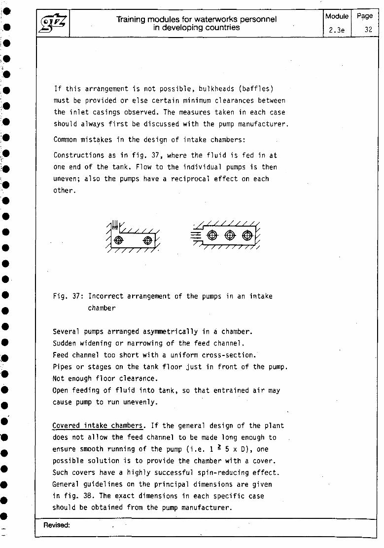
Constructions as in fig. 37, where the fluid is fed in atone end of the tank. Flow to the individual pumps is thenuneven; also the pumps have a reciprocal effect on eachother.
Fig. 37: Incorrect arrangement of the pumps in an intakechamber
Several pumps arranged asymmetrically in a chamber.Sudden widening or narrowing of the feed channel.Feed channel too short with a uniform cross-section.Pipes or stages on the tank floor just in front of the pump.Not enough floor clearance.Open feeding of fluid into tank, so that entrained air maycause pump to run unevenly.
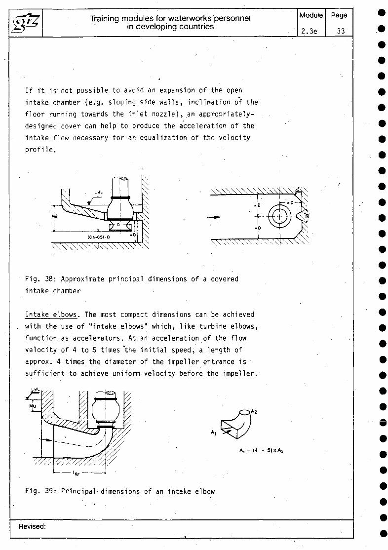
Covered intake chambers. If the general design of the plantdoes not allow the feed channel to be made long enough toensure smooth running of the pump (i.e. 1 - 5 x 0 ) , onepossible solution is to provide the chamber with a cover.Such covers have a highly successful spin-reducing effect.General guidelines on the principal dimensions are givenin fig. 38. The exact dimensions in each specific caseshould be obtained from the pump manufacturer.
Revised:
Training modules for waterworks personnelin developing countries
Module
2.3e
Page
33
If it is not possible to avoid an expansion of the openintake chamber (e.g. sloping side walls, inclination of thefloor running towards the inlet nozzle), an appropriately-designed cover can help to produce the acceleration of theintake flow necessary for an equalization of the velocityprofile.
Fig. 38: Approximate principal dimensions of a coveredintake chamber
Intake elbows. The most compact dimensions can be achievedwith the use of "intake elbows" which, like turbine elbows,function as accelerators. At an acceleration of the flowvelocity of 4 to 5 times *the initial speed, a length ofapprox. 4 times the diameter of the impeller entrance issufficient to achieve uniform velocity before the impeller.-
A, = (4 - 5)xA,
Fig. 39: Principal dimensions of an intake elbow
Revised:
Training modules for waterworks personnelin developing countries
Module
2.3e
Page
34
The cross-sectional area of the entry into the elbow (A,)should be large enough (and thus the admission velocityof the liquid low enough) to prevent air funnels formingand air being sucked in.
However, it is advisable to carry out a cost/benefit analysisfor each separate case, to determine whether the higherconstruction costs of this alternative, as compared withan intake chamber, are justified.
3.2 Installation of centrifugal pumps
Generally speaking, the installation of a centrifugal pumpcovers mounting of the pumping unit (pump plus prime mover)at its point of application, together with all the connect-ing pipework necessary for its functioning. The unit mustbe installed in such a way that all external forces canreliably be carried by the foundation, columns, frame,bases, or even the pipes.
Depending on the type of pump and often also on the fieldof application, installation will fall, into one of thefollowing categories: installation on or without a foundation,dry or submerged, indoor or outdoor.
Where pumps are installed on a foundation, a further dis-tinction must be made between pumps with horizontal andwith vertical shaft. Decisive for safe and reliable runningof the pump are the foundation's strength and vibrationalproperties (high-frequency/low-frequency). A general dis-tinction can be made between concrete foundations on whicha base common to centrifugal pump and prime mover is mounted;and concrete or steel console foundations mounted on specialelements which provide optimum vibration insulation. Suchelements include e.g. cork mats, rubber or spring components.Each machine is attached separately to the console by itsown base or frame.
Revised:
Training modules for waterworks personnelin developing countries
Module2.3e
Page35
Horizontal pumps and their prime movers, with the exceptionof block pumps, are supplied mounted together on one base.Larger units, and sometimes also gear driven/feed pump unitshave bases which are constructed in several sections. Thebases are then mounted on the foundation and the spacesbetween them filled in with, a sealing compound, e.g. cementmortar. The foundation screws must not be tightened untilthe compound has set. This procedure gives the bases thenecessary strength to resist any undesired deformation underloading, e.g. due to pipe expansion forces. The next stepis to align the couplings of the separate parts of the unitby inserting adjustment plates underneath the feet of themachines on the base. There follows stress-free connection
. \of the pipes to the pump, installation of accessories,lubricating devices, filters etc. The process of installingthe pump ends with an alignment check.
Vertical pumps and their prime movers are installed by asimilar procedure. The coupling does not have to be aligned,however, if pump and drive are directly connected by meansof a drive lantern. In such cases the pump is fixed to thefoundation by means of a base flange only. The drive lanternthen determines the exact position of the drive.
Installation without a foundation is the rule wherever theweight of the machines and the anticipated stresses fromthe pipes are low, or wherever the pump has to'remain mobile.
Submersible-motor pumps, most inline pumps and .glandlesspumps, especially circulating pumps, are installed withouta foundation. Larger un'its are occasionally provided withan additional simple column foundation.
Mobile pumps, e.g. fire-fighting or mobile pipeline pumps,are fixed either directly or together with their basesto the frame (wheel- or skid-mounted). This constructionrequires the connected pipes to be flexible. Where largerunits are mounted in this way, the bases must be rigid enoughto keep distortions down to an acceptable level.
Revised:
Training modules for waterworks personnelin developing countries
Module2.3e
Page36
Portable pumps (e..g. for use in gardens or for pumping waterout of cellars), are always constructed as self-containedunits, needing no adjustment of the coupling. Since suchpumps are always relatively small and connected to flexiblehoses rather than to rigid pipework, no foundations arenecessary. The pump can be stood on any firm, level surface.
Bases without a foundation are sometimes necessary in thecase of acid pumps, to allow any aggressive fluid whichmay have leaked under the base to be removed.
In the case of vertical pumps in particular, a distinctionis made between submerged (wet) applications and dry in-stallation.
The main advantage of a submerged installation lies in thelower installation and construction costs. The pump isdirectly immersed in the liquid to be pumped - e.g.submersible-borehole and most tubular-casing pumps. Tubular-casing pumps can be installed either with the weight ofpump and motor together supported by one floor of the con-struction or by different floors; also the delivery pipemay be laid above or below the floor of the pump house.
If it is necessary to inspect the pump - e.g. the seals -regularly from the outside, dry installation must be chosen.
The advantage of dry installation is that the pump chambercan then also be used for other purposes as well - e.g. theerection of other machines. This is e.g. the rule for themost common types of vertical ship's pumps. These are in-stalled either in a standing arrangement, with the pumpfoot mounted on a steel frame in the floor of the engine-room (with pump and motor casing connected by a drive lantern),•or in a wall-mounted construction, where the motor lanternis mounted on one of the engine-room walls. Dry instal-lation is also the rule in the case of volute pumps usedin other applications - e.g. for sewage pumping or in thepetrochemical industry, also in the case of some othertubular-casing pumps.
Revised:
Training modules for waterworks personnelin developing countries
Module
2.3e
Page
37
Installation in the open, i.e. without the protection ofa building or roof, requires certain other conditions besidesthose already given to be met. Climatic features such asrain" (protection against corrosion, motors protectedagainst spray), solar radiation (unilateral heat expansion,overheating of the drive unit), frost, flying sand, windforces etc. have to be taken into account. Because conditionsvary so widely, there are no stanardized rules for theoutdoor installation of pumps.
3.3 Venting and priming of centrifugal pumps
The suction pipe of non-self-priming pumps and the pumpitself must be filled with fluid before starting up. Ifthe impeller or suction impeller is not surrounded by waterwhen the pump is not running, it is expedient to provide a 'foot or non-return valve below the lowest level of theliquid. In this arrangement, which is restricted to lownominal diameters only, the foot valve, pump casing, pipes:and other fittings must be dimensioned with an additionalsafety margin over and above the highest, static pressureload. The reason-for this is that the foot or non-returnvalve may suddenly be pulled closed by a return flow whenthe pump is switched off, so that pressure surges (waterhammer) may occur..For this reason another non-return valveis often provided in the discharge pipe, to protect thepump. This arrangement only functions smoothly if the valveon the discharge side closes before that on the suctionside.
Centrifugal pumps are considered to be self-priming if theyare suitable for pumping liquids, gases and mixtures ofliquids and gases. They must be able to extract air fromthe pump suction pipe without the aid of additionalexternal extraction devices.
Pumps which are not self-priming and where the installationof a foot or non-return valve in the suction pipe is not
Revised:
Training modules for waterworks personnelin developing countries
Module
2.3e
Page
38
possible are filled before the pump is started by an ex-traction of the air from the suction pipe and the pump.Borehole pumps are provided with a foot valve in spite oftheir submersion provided the shaft is mounted in water-lubricated rubber bearings and - where the pump is installedat a greater depth - provided some bearings are above thesurface of the water. These bearings also need water duringthe starting-up phase. The foot valve keeps all bearingsconstantly surrounded by water.
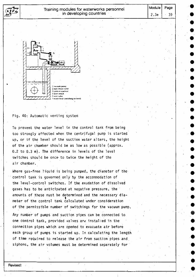
In general, centrifugal pumps have to be filled with liquidprior to working. In plants where the liquid runs to thepump by gravity, care must be taken to ensure that thepump casing is adequately vented. The situation isdifferent in plants with a geodetic suction lift. Unlikedisplacement pumps, standard-type centrifugal pumps canproduce only a very low negative pressure if they are notfilled with liquid. This means that they are not alwaysable to vent their suction pipe without help. In suctionoperation, therefore, special measures must be taken beforestarting the pump to extract the air from pump and suctionpipe. Centrifugal pumps installed above the water-levelon the suction side are filled with the aid of venting equip-ment. In the case of an automatic venting system, the pipeto be vented is connected to the control tank by means ofa pipe sloping steadily upwards. This contains two level-control switches which switch the vacuum pump on and, off.To vent the pump casing and if necessary the discharge pipeup to the non-return valve, these chambers are connectedto the air chamber of the control tank through intermediateswitching of an air-relief valve. A double-acting ball checkvalve both maintains the vacuum after the venting pump hasbeen switched off and also prevents water from overflowinginto it if the control system should fail. The switch-onlevel in the control tank should be approx. 0.3 m abovethe highest level in the system to be vented.
Revised:
Training modules for waterworks personnelin developing countries
Module
2'.3e
Page
39
cuum pump2 nun-return valve3 control reservoir4 level switch5 veni valve^ wuter tevel (switching c
Fig. 40: Automatic venting system
To prevent the water level in the control tank from beingtoo strongly affected when the centrifugal pump is startedup, or if the level of the suction water alters, the heightof the air chamber should be as low as possible (approx.0.2 to 0.3 m). The difference in levels of the levelswitches should be once- to twice the height of theair chamber.
Where gas-free liquid is being pumped, the diameter of thecontrol tank is governed only by the accommodation ofthe level-control switches. If the exudation of dissolvedgases has to be anticipated at negative pressure, theamounts of these must be determined and the necessary dia-meter of the control tank calculated under considerationof the permissible number of switchings for the vacuum pump.
Any number of pumps and suction pipes can be connected toone control tank, provided valves are inst.al led in theconnection pipes which are opened to evacuate air beforeeach group of pumps is started up. In calculating the lengthof time required to release the air from suction pipes andsiphons, the air volumes must be determined separately for
Revised:
Training modules for waterworks personnelin developing countries
Module2.3e
Page40
the rising and for the horizontal sections of the pipe andthen added together.
3.4 Alignment of couplings
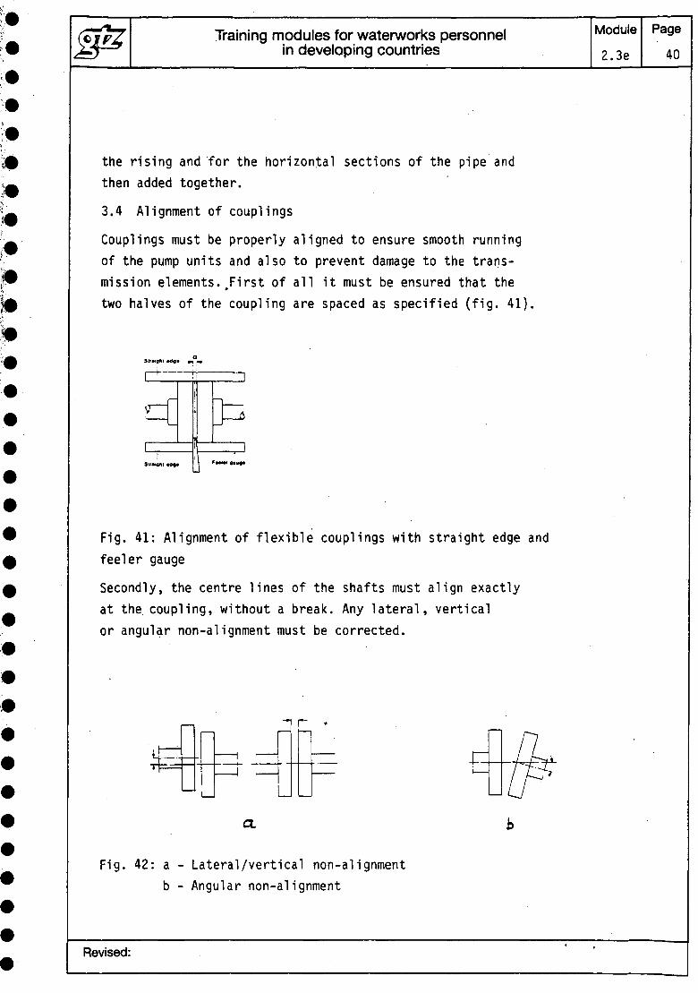
Couplings must be properly aligned to ensure smooth runningof the pump units and also to prevent damage to the trans-mission elements..First of all it must be ensured that thetwo halves of the coupling are spaced as specified (fig. 41)
Str*i0ftl Ma* +1 r+
Fig. 41: Alignment of flexible couplings with straight edge andfeeler gauge
Secondly, the centre lines of the shafts must align exactlyat the coupling, without a break. Any lateral, verticalor angular non-alignment must be corrected.
U
r
a.
Fig. 42: a - Lateral/vertical non-alignmentb - Angular non-alignment
Revised:
Training modules for waterworks personnelin developing countries
Module2.3e
Page41
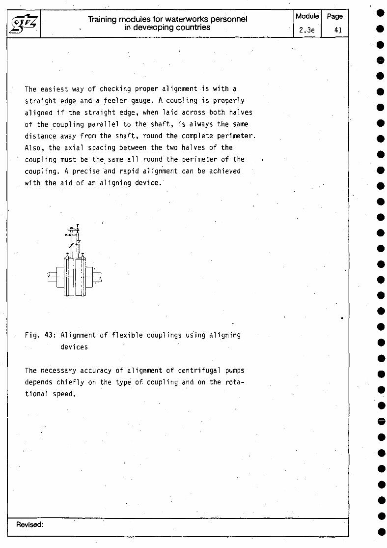
The easiest way of checking proper alignment is with astraight edge and a feeler gauge. A coupling is properlyaligned if the straight edge, when laid across both halvesof the coupling parallel to the shaft, is always the samedistance away from the shaft, round the complete perimeter.Also, the axial spacing between the two halves of thecoupling must be the same all round the perimeter of thecoupling. A precise and rapid alignment can be achievedwith the aid of an aligning device.
ALdtH Jyi
V—
Li
Fig. 43: Alignment of flexible couplings using aligningdevices
The necessary accuracy of alignment of centrifugal pumpsdepends chiefly on the type of coupling and on the rota-tional speed.
Revised:
Training modules for waterworks personnelin developing countries
Module2.3e
Page42
When aligning couplings of hot-water pumps, the specialinstructions given by the manufacturer because of the pos-sibility of thermal distortions must be followed with care.
After alignment of the coupling, it is advisable to fastenpump and prime mover to the base or foundation to preventthe machines from altering their position in operation.
3.5 Starting up
The process of starting up a machine assembly consistingof electric motor and pump - e.g. centrifugal pump - isaffected by the following factors:
1. Type of electric motor: D.C. motors have good startingproperties and seldom cause problems in this phase.Asynchronous motors with slip-ring rotors whichare started up with starting resistors are also problem-free. Asynchronous motors with squirrel-cage rotors havevarious starting torque characteristics, depending ondesign and type of rotor, and always require adjustmentto the specific application.
2. Type of pump: piston pumps (displacement pumps) necessitatehigh breakaway torques. Radial-flow centrifugal pumpsrequire a relatively low torque. The counter-torque-i.e. the torque developed by the pump which opposes themotor torque - increases, however, with the square ofthe rotational speed. The extent of the counter-torquedepends on whether the pump is started up with open orclosed throttle.
3. Type of switching on and type of current: with directswitching to a "rigid grid", the full starting and run-uptorque is available. Starting current is approx. 4.5to 6 times the rated current. With direct switching toa "flexible grid", the mains voltage drops under theeffect of the switching-on current consumed. The torquecurve of the motor falls in an approximately quadratic
Revised:
Training modules for waterworks personnelin developing countries
Module2.3e
Page43
ratio .to the drop in voltage. After run-up, the mainsvoltage recovers its full potential as soon as the currenttaken up by the motor has dropped back to the ratedvalue.
The starting torque Tp is the torque required by the pumpduring starting'to maintain .the speed achieved. It climbsfrom zero at standstill up to the rated torque.In contrast, the torque T taken up during starting viaathe coupling is primarily dependent on the motor. Thisdriving torque is higher than the starting torque untilthe rated torque is reached. The difference between thetwo torques serves to accelerate all rotating masses inthe complete machine assembly.
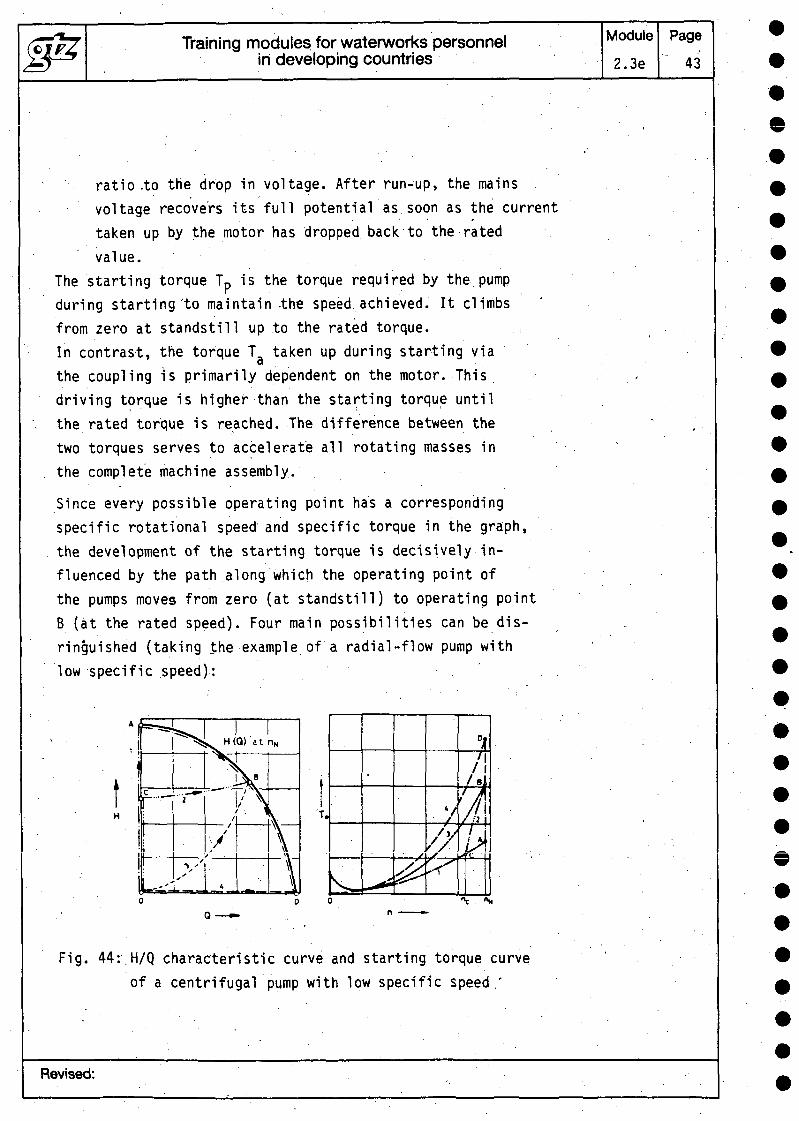
Since every possible operating point has a correspondingspecific rotational speed and specific torque in the graph,the development of the starting torque is decisively in-fluenced by the path along which the operating point ofthe pumps moves from zero (at standstill) to operating pointB (at the rated speed). Four main possibilities can be dis-ringuished (taking the example of a radial-flow pump withlow specific speed):
Fig. 44:.H/Q characteristic curve and starting torque curveof a centrifugal pump with low specific speed.'
Revised:
Training modules for waterworks personnelin developing countries
Module2.3e
Page44
1. Starting up with stop valve closed, opening of stop valveafter rated speed has been reached (curve 0-A-B). In thesection 0-A, the hydraulic torque of the pump increasesquadratically with the speed. This torque is increased throughthe superposition of the frictional torque of bearings andshaft seals, which represents a relatively large part ofthe starting torque at low speeds. At n = 0, frictionaltorque is particularly high due to the static friction,also known as the breakaway troque. Normally it makes upapprox. 5 to 10 % of the rated torque. In the case of overhung-mounted pumps with a high feed pressure, it_may also reachthe magnitude of the rated torque.
In section A-B, the starting torque rises or falls - nowat approximately constant speed - depending on the pump'*spower intake. Peripheral and axial-flow pumps, where atQ = 0 the power requirement, and so also the starting torque,are greater than at the operating point, will thereforenot be started up by this method.
2. Starting up with open stop valve against a purely staticdelivery head exerted against a non-return valve(curve 0-C-B): here the development of the starting torqueup to point C is the same as with a closed stop valve, sincethe non-return valve cannot be opened by the pumppressure (thereby beginning delivery) before this point.The further development of the torque curve is determinedby plotting intermediate curves for the section C-B forvarious speeds and calculating the torque from the powerinput.
3. Starting up with open stop valve against a purely dynamicdelivery head of the plant (curve 0-B): this path resultsonly if the pipe is very short. The starting torque Tpincreases - apart from the frictional torque - quadraticallywith the speed from zero up to the rated torque. If thepipe is very long, however, the time required to accelerate
Revised:
Training modules for waterworks personnelin developing countries
Module2.3e
Page45
the water mass is much longer than the starting-up timeof the pump. The water mass at rest then functions as aclosed stop valve and the development of the starting torqueis more similar to that in case 1.
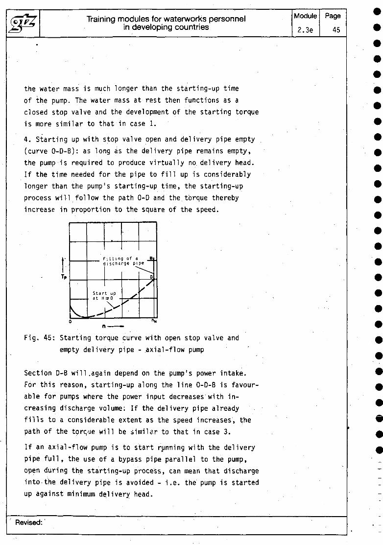
4. Starting up with stop valve open and delivery pipe empty(curve 0-D-B): as long as the delivery pipe remains empty,the pump is required to produce virtually no, delivery head.If the time needed for the pipe to fill up is considerablylonger than the pump's starting-up time, the starting-upprocess will follow the path 0-D and the torque therebyincrease in proportion to the square of the speed.
F i 1 1 ing of adischarge pipe
Start upat Har 0
Fig. 45: Starting torque curve with open stop valve andempty delivery pipe - axial-flow pump
Section D-B will.again depend on the pump's power intake.For this reason, starting-up along the line 0-D-B is favour-able for pumps where the power input decreases with in-creasing discharge volume: If the delivery pipe alreadyfills to a considerable extent as the speed increases, thepath of the torque will be similar to that in case 3.
If an axial-flow pump is to start running with the deliverypipe full, the use of a bypass pipe parallel to the pump,open during the starting-up process, can mean that dischargeinto the delivery pipe is avoided - i.e. the pump is startedup against minimum delivery head.
Revised:
Training modules for waterworks personnelin developing countries
Module
2.3e
Page46
When starting peripheral pumps in plants with an emptydelivery pipe, the stop valve should not be completely opened,so that discharge is restricted and cavitation in the pumpavoided.
4___Maintenance of pumps
Pumps must be inspected and serviced at certain set intervals.The operating instructions for each pump give exact main-tenance schedules, including the type and extent of thework to be carried out. Sometimes service contracts aredrawn up for certain pieces of equipment.
Regular maintenance of pumps and motors prolongs their servicelife and saves costs in the long run.
External servicing of pumps and prime movers: the machinesmust be cleaned externally at regular intervals. Note thatpumps and motors may on no account be cleaned with a waterjet (i.e. hosed down). Any rust should be removed and theaffected area treated. Uncoated parts should be coated witha preservative grease.
Maintenance of bearings: bearings should be serviced regu-larly. Since lubricants are consumed with varying rapidity,these must either be topped up or renewed (oil change,topping-up or complete renewal of grease). The intervalsbetween lubrication and the type and grade of lubricantto use are given in the operating instructions.
Maintenance of-shaft seals: this depends on the type ofseal. In the case of packed stuffing boxes, it must beremembered that these should always drip slightly inoperation. Packed stuffing boxes which seal completelycause damage to the sealing elements - shaft, shaft sleeves.In this case, the nuts of the stuffing-box screws shouldbe loosened until the stuffing box drips slightly. The sameis true of metal, sleeve and plastic packings.
Revised:
Training modules for waterworks personnelin developing countries
Module
2.3e
Page
47
In the case of mechanical (floating ring) seals, leakagesare usually not externally visible. Separate servicing isnot necessary. If comparatively extensive leakages occur,the sealing elements should be replaced. Further detailsare given in the operating instructions.
Other maintenance work: .
Checking to see that centrifugal pump and prime mover arerunning smoothly; where appropriate tightening of the V-belt.
Checking engine performance with regard to power consumption.
Inspection of the coupling alignment.
Inspection of the flexible transmission elements for wear(coupling plate, coupling bolts, coupling buffers).
Checking the supply of flushing and sealing water.
Inspection of pressure-relieving equipment (balancing disc,high-pressure pumps) where appropriate.
Checking functioning of the automatic grease'guns and greasepipes, lubricant pumps.
4.1 Checklist .
This list is intended as a general guide only and does notclaim to cover all eventualities:- Check to see that pump-and prime mover are running smoothly.- Check performance data, measuring and entering current
consumption.- Check oil or grease supply (bearings). .- Inspect shaft seal (packed stuffing box, mechanical seal.,
shaft sealing rings).- In the case of packed stuffing boxes, re-pack if necessary.
Mechanical seals: replace carbon ring seal and rotatingslide ring if necessary. -
Revised:
Training modules for waterworks personnelin developing countries
Module
2.3e
Page
48
- Inspect alignment of coupling.
- Check flexible transmission elements for wear (couplingplate, bolts, buffers).
- Check stop and non-return valves for correct functioning.
- Check outside of equipment for corrosion, interior pumpparts for erosion and cavitation.
- Carry out a trial run after servicing.
- Determine spare parts requirement and order whereappropriate.
- Check supply of flushing and sealing water.
- Check installed solenoid valves, filters, screens etc.
- Check pressure-relieving equipment for wear.
- Inspect electric control devices.
- Check functioning of automatic grease guns and pipes.
- Look for wear through hand-hole cover.
- Measure rotor clearance.
- Check throttle slit.
5 Repair of pumps
The following list is intended to help in recognizing anddealing with any faults which may occur. It chiefly coversproblems with centrifugal pumps.
Table 1: Fault - Cause - Remedy
Fault
Pump discharge too low
Prime mover overloaded
Pump discharge pressure too high
Key 'to cause/remedy
1, 2, 3, 4, 5, 6, 7,8, 9, 10, 11, 18, 28
12, 13, 14, 15, 20, 27, 28
15
Revised:
Training modules for waterworks personnelin developing countries
Module
2.3e
Page
49
Bearing temperature too high 22, 23, 24, 25, 26
Pump leaking " 16, 29
Too much leakage from shaft seals 17, 18, 19, 20, 21, 22,23, 33
Pump running unevenly 3, 6, 11,- 12, 22, 23,25, 30, 31, 32
Undue increase of temperaturein the pump 3, 6, 32
See below for list-of causes and remedies.
Cause/remedy
1. Pump delivering against excessive pressure.- Open stop valve wider until operating point is adjusted.
2. Counter-pressure too high.- Install a larger impeller (consult manufacturer first).- Increase speed (turbine, internal combustion engine, gear-
box mechanism).
3. Pump or pipe not fully vented/not primed.- Vent or fill.
4. Feed pipe or impeller blocked- Remove deposits/foreign matter from interior- of pumpand/or pipe.
5. Formation of air-pockets in 'the pipe.- Alter pipe lay-out.- Install air-relief valve.- Inspect screens, suction strainer.-
6. NPSH of the plant (feed) too low.- Check level of the liquid and correct if necessary.- Open stop valve in the feed pipe fully. .- Possibly alter feed pipe if resistances in it are too high,
Revised:
Training modules for waterworks personnelin developing countries
Module
2.3e
Page
50
7. Suction lift too high.- Clean suction strainer and suction pipe.- Correct level of liquid.- Alter design of the suction pipe.
8. Air being drawn in at the stuffing box.- Clean sealing liquid channel, if necessary introduce other
sealing liquid or increase its pressure.- Replace shaft seal.
9. Wrong rotational direction.- Change over 2 phases of the current (alternating current).Observe indicator of pressure-gauge (higher pressure =correct rotational direction).
10. Speed too low.- Increase rotational speed.- Increase voltage.- This problem may also be solved by installing an impeller
with a larger diameter (consult manufacturer).
11. Interior parts worn.- Replace worn, parts.
12. Counter-pressure of the pump is lower than that specifiedor calculated when designing the plant.
- Adjust operating point precisely by means of the stopvalve in the delivery pipe.
- If overloading is constant, possibly trim the impeller(consult manufacturer first).
13. Liquid has a higher density or viscosity than wasassumed when designing the plant.
- Cons.ult the manufacturer and re-dimension the equipment.
14. Gland too tight or not straight.- Adjust.
15. Speed too high.- Reduce speed (turbine, internal combustion engine etc.).- Consult manufacturer - diameter of impeller may have tobe altered.
Revised:
Training modules for waterworks personnelin developing countries
Module
2.3e
Page
51
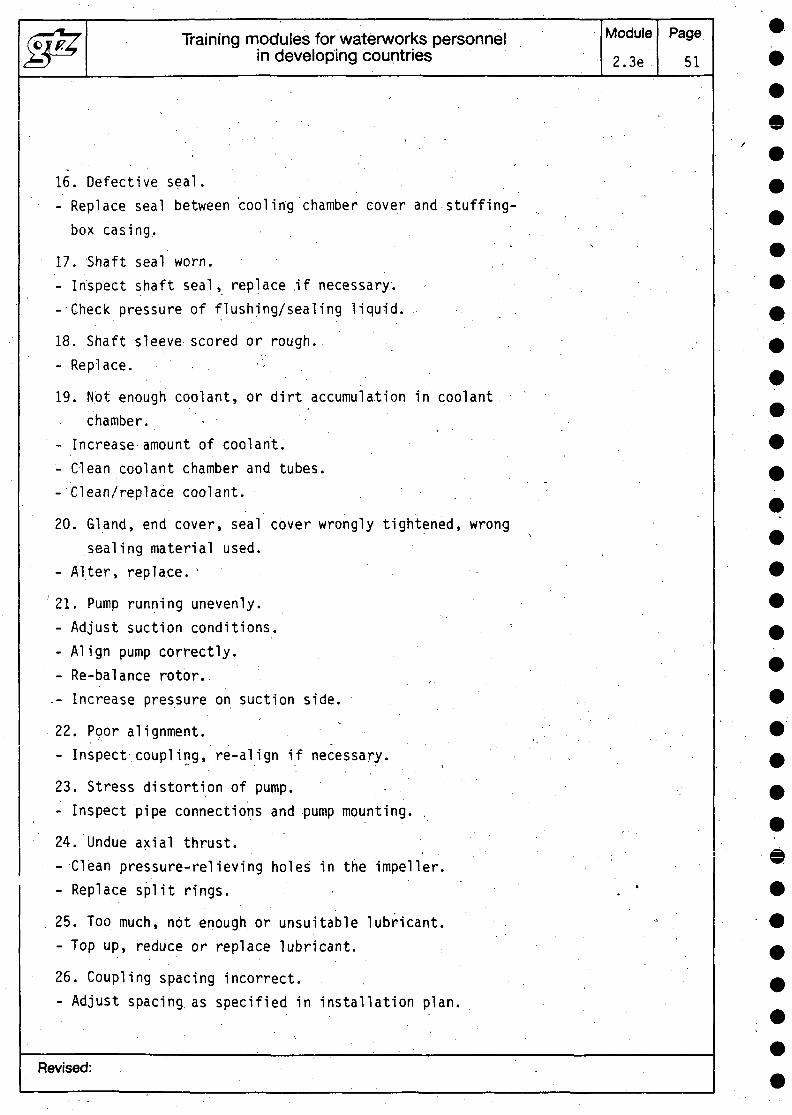
16. Defective seal.- Replace seal between cooling chamber cover and stuffing-
box casing.
17. Shaft seal worn.- Inspect shaft seal, replace .if necessary.- Check pressure of flushing/sealing liquid.
18. Shaft sleeve scored or rough.- Replace. • - .
19. Not enough coolant, or dirt accumulation in coolantchamber. -
- Increase amount of coolant.- Clean coolant chamber and tubes.-'Clean/replace coolant. . . .
20. Gland, end cover, seal cover wrongly tightened, wrongsealing material used.
- Alter, replace. '
21. Pump running unevenly.- Adjust suction conditions.- Align pump correctly.- Re-balance rotor..- Increase pressure on suction side.
22. Poor alignment.- Inspect coupling, re-align if necessary.
f- • • . ^
23. Stress distortion of pump. •- Inspect pipe connections and pump mounting. .
24. Undue axial thrust.- Clean pressure-relieving holes in the impeller.- Replace split rings. •
25. Too much, not enough or unsuitable lubricant.- Top up, reduce or replace lubricant.
26. Coupling spacing incorrect.- Adjust spacing as specified in installation plan.
Revised:
Training modules for waterworks personnelin developing countries
Module
2.3e 52
27. Operating voltage too low.
28. Running on two phases.- Replace faulty fuse.- Inspect lead connections.
29. Connecting screws too loose.- Tighten.- Replace washers.
30. Rotor running out of true.- Clean rotor.- Rebalance.
31. Damaged bearing.- Replace.
32. Insufficient discharge.- Increase minimum discharge.
33. Fault in the feed of circulation liquid.- Increase free cross-section.
Further details are given in the operating instructionsprovided by the pump manufacturer.
The components%bf a single-stage, horizontal volute pumpwith e.g. radial-flow impeller are shown in the drawingbelow.
Revised:
Training modules for waterworks personnelin developing countries
Module
2.3e
Page
53
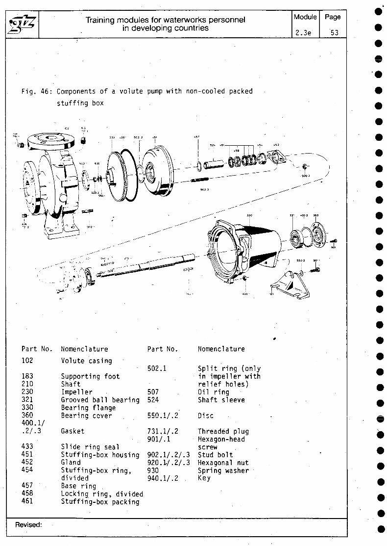
Fig. 46: Components of a volute pump with non-cooled packedstuffing box
Part No.102
183210230321330360400. I/.2/.3
433451452454
457458461
NomenclatureVolute casing
Supporting footShaftImpellerGrooved ball bearingBearing flange
Gasket
SI ide ring sealStuffing-box housingGlandStuffing-box ring,
. dividedBase ringLocking ring, dividedStuffing-box packing
Part No
502.1
507524
550.1/.2
731.I/.2901/.1
902.1/.2/.3920.L/.2/.3930940.I/.2 .
Nomenclature
Split ring (onlyin impeller withrelief holes)Oil ringShaft sleeve
Disc
Threaded plugHexagon-headscrewStud boltHexagonal nutSpring washerKey
Revised:
(OF/7. Training modules for waterworks personnelin developing countries
Module Page
Fig. 34: Mu = Mln. cover
Fig. 35: Lowest water level
Fig. 38: Lowest water level
Fig. 39: Lowest water level
Fig. 44: H/Q at nN
Fig. 45: Filling of discharge pipeStarting up at H = 0
Minimum cover
Minimum cover
Revised:
Deutsche Gesellschaft fur Technische Zusammenarbeit (GTZ) GmbHDag-Hammarskiold-Weg 1+2 D 6236 Eschbom t Telefon (061961 79-O Telex 407 501-0 gttd
The government-owned GTZ operates in the field of TechnicalCooperation. Some 4,500 German experts are working together withpartners from some 100 countries in Africa, Asia and Latin America inprojects covering practically every sector of agriculture, forestry, economicdevelopment, social services and institutional and physical infrastructure.- The GTZ is commissioned to do this work by the Government of theFederal Republic of Germany and by other national and internationalorganizations.
GTZ activities encompass:
- appraisal, technical planning, control and supervision of technicalcooperation projects commissioned by the Government of the FederalRepublic of Germany or by other authorities
- advisory services to other • agencies implementing developmentprojects
- the recruitment selection, briefing and assignment of expert personneland assuring their welfare and technical backstopping during theirperiod of assignment
- provision of materials and equipment for projects, planning work,selection, purchasing and shipment to the developing countries
- management of all financial obligations to the partnercountry.
The series "Sonderpublikattonen der GTZ" includes more than 190publications. A list detailing the subjects covered can be obtained from theGTZ-Unit 02: Press and Public Relations, or from the TZ-Verlagsgesell-schaft mbH, Postfach 36, D 6101 RoBdorf 1, Federal Republic of Germany.
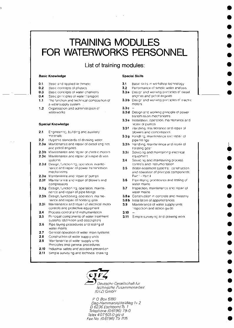
TRAINING MODULESFOR WATERWORKS PERSONNEL
List of training modules:Basic Knowledge
0.1 Basic and applied arithmetic0.2 Basic concepts of physics0.3 Basic concepts of water chemistry0.4 Basic principles of water transport1.1 The function and technical composition of
a watersupply system1-.2 Organisation and administration of
Special Skills
3.1 Basic skills in workshop technology3.2 Performance of simple water analysis3.3a Design and working principles of diesel
engines and petrol engines3.3b Design and working principles of electric
motors3.3 c -
waterworks 3.3d
3.3 eSpecial Knowledge
2.1
2.22.3 a
2.3 b2.3c
2.3d
2.3 e2.3f
2.3 g
2.3 h
2.3 i
2.42.5
2.6
2.72.82.9
2.102.11
Engineering, puildmg and auxiliarymaterialsHygienic standards of drinking waterMaintenance and repair of diesel enginesand petrol enginesMaintenance and repair ol electric motorsMaintenance and repair of simple drivensystemsDesign, functioning, operation, mainte-nance and repair of power transmissionmechanismsMaintenance and repair of pumpsMaintenance and repair ol blowers andcompressorsDesign, functioning, operation, mainte-nance and repair of pipe fittingsDesign, functioning, operation, mainte-nance and repair of hoisting gearMaintenance and repair of electrical motorcontrols and protective equipmentProcess control and InstrumentationPrincipal components ol water-treatmentsystems (definition and description)Pipe laying procedures and testing ofwater mamsGeneral operation of water mam systemsConstruction of water supply unitsMaintenance of water supply unitsPrinciples and general proceduresIndustrial safety and accident preventionSimple surveying and technical arawmg
3.3 f
3.3 g
3.3 h
3.3 i
3.4
3.5
3.6
3.7
3.8 a3.8 b3.9
3.103.11
Design and working principle of powertransmission mechanismsInstallation, operation, maintenance andrepair of pumpsHandling, maintenance and repair ofplowers and compressorsHandling, maintenance and repair ofpipe fitt ingsHandling, maintenance and repair ofhoisting gearServicing and maintaining electricalequipmentServicing and maintaining processcontrols and instrumentationWater-treatment systems: constructionand operation of principal components:Part I - Part IIPipe-laying procedures and testing ofwater mamsInspection, maintenance and repair ofwater mamsConstruction in concrete and masonryInstallation of appurtenancesMaintenance of water supply unitsInspection and action guide-Simple surveying and drawing work
Deutsche Cesellschaft furTechnische Zusammenarbeit
IGTZ) GmbH
P 0. Box 5180Dag-Hammarskjold-Weg 1+ 2
D6236Eschborn/Ts. 1Telephone (06196) 79-0
Telex 4 07 501-0 gtzdFax No.-(06196J 79-1115
Related Documents