Manual Release 1 Training Manual M580 Quick Start M580 Quick Start Version 1.0

Welcome message from author
This document is posted to help you gain knowledge. Please leave a comment to let me know what you think about it! Share it to your friends and learn new things together.
Transcript
Manual Release 1
Training Manual
M580 Quick Start
M580 Quick Start Version 1.0
September 2015 Edition for M580 Quick Start v1.0
Manual Release 1
ii M580 Quick Start v1.0 September 2015
DISCLAIMER
Schneider Electric makes no representations or warranties with respect to this manual and, to the maximum extent permitted by law,
expressly limits its liability for breach of any warranty that may be implied to the replacement of this manual with another. Furthermore,
Schneider Electric reserves the right to revise this publication at any time without incurring an obligation to notify any person of the revision.
The information provided in this documentation contains general descriptions and/or technical characteristics of the performance of the products contained herein. This documentation is not intended as a substitute for and is not to be used for determining suitability or reliability
of these products for specific user applications. It is the duty of any such user or integrator to perform the appropriate and complete risk
analysis, evaluation and testing of the products with respect to the relevant specific application or use thereof. Neither Schneider Electric nor any of its affiliates or subsidiaries shall be responsible or liable for misuse of the information that is contained herein. If you have any
suggestions for improvements or amendments or have found errors in this publication, please notify us.
All pertinent state, regional, and local safety regulations must be observed when installing and using this product. For reasons of safety and to help ensure compliance with documented system data, only the manufacturer should perform repairs to components.
When devices are used for applications with technical safety requirements, the relevant instructions must be followed.
Failure to use Schneider Electric software or approved software with our hardware products may result in injury, harm, or improper operating results.
Failure to observe this information can result in injury or equipment damage.
© 2013 Schneider Electric. All rights reserved.
The contents of this manual are proprietary to Schneider Electric and all rights, including copyright, are reserved by Schneider Electric. No
part of this document may be reproduced in any form or by any means, electronic or mechanical, including photocopying, without express
written permission of Schneider Electric.
Quick Start Training Manual
INTRODUCTION AND LEGAL NOTICE
Your purchase of this official Quick Start Training Manual entitles you to undertake the Quick Start training course.
Satisfactory completion of the course evaluation is mandatory for you to obtain a Schneider Electric certificate of completion of the training
course.
Schneider Electric will not accept any liability for action taken in reliance on this training manual.
TRADEMARKS
Schneider Electric has made every effort to supply trademark information about company names, products and services mentioned in this
manual. Trademarks shown below were derived from various sources.
Microsoft Windows, Windows XP, Windows Vista, Windows 7, Windows 8, Microsoft Office and Microsoft Excel are either registered
trademarks or trademarks of Microsoft® Corporation in the United States and/or other countries.
General Notice:
Some product names used in this manual are used for identification purposes only and may be trademarks of their respective companies.
Validity Note
The present documentation is intended for qualified technical personnel responsible for the implementation, operation and maintenance of
the products described. It contains information necessary for the proper use of the products.
About Us
Members of Schneider Electric’s team of Instructional Designers have tertiary qualifications in Education, Educational Course Development
and are also experienced Instructors. Currently, the team is supporting a range of Schneider Electric courses in multiple languages and
multiple software environments.
Authors
Sebastien ARRIBE

M580 Quick Start Manual Release 1 iii
Safety Information
Important
Information PLEASE NOTE
Read these instructions carefully, and look at the equipment to become familiar
with the device before trying to install, operate, or maintain it. The following
special messages may appear throughout this documentation or on the equipment
to warn of potential hazards or to call attention to information that clarifies or
simplifies a procedure.
The addition of this symbol to a "Danger" or "Warning" safety label indicates that an electrical hazard exists which will result in personal injury if the instructions are not followed.
This is the safety alert symbol. It is used to alert you to potential personal injury hazards. Obey all safety alert messages that follow this symbol to avoid possible injury or death.
DANGER
DANGER indicates an imminently hazardous situation which, if not avoided, will result in death or serious injury.
WARNING
WARNING indicates a potentially hazardous situation which, if not avoided, could result in death or serious injury.
CAUTION
CAUTION indicates a potentially hazardous situation which, if not avoided, could result in minor or moderate injury.
NOTICE
NOTICE is used to address practices not related to physical injury.

iv M580 Quick Start September 2015
Safety Information (cont.)
Important
Information
(cont.)
PLEASE NOTE
Electrical equipment should be installed, operated, serviced, and maintained only
by qualified personnel. No responsibility is assumed by Schneider Electric for any
consequences arising out of the use of this material.
A qualified person is one who has skills and knowledge related to the construction
and operation of electrical equipment and its installation, and has received safety
training to recognize and avoid the hazards involved.
M580 Quick Start Manual Release 1 v
Safety Information (cont.)
Before you
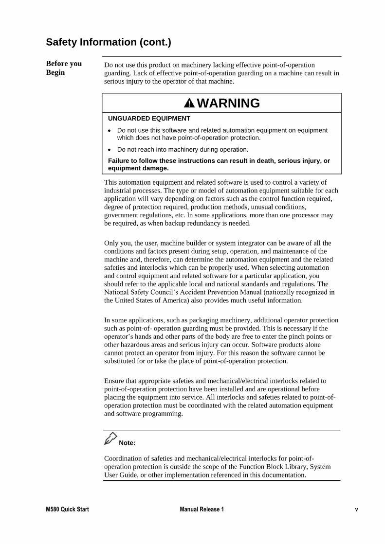
Begin Do not use this product on machinery lacking effective point-of-operation
guarding. Lack of effective point-of-operation guarding on a machine can result in
serious injury to the operator of that machine.
WARNING
UNGUARDED EQUIPMENT
Do not use this software and related automation equipment on equipment which does not have point-of-operation protection.
Do not reach into machinery during operation.
Failure to follow these instructions can result in death, serious injury, or equipment damage.
This automation equipment and related software is used to control a variety of
industrial processes. The type or model of automation equipment suitable for each
application will vary depending on factors such as the control function required,
degree of protection required, production methods, unusual conditions,
government regulations, etc. In some applications, more than one processor may
be required, as when backup redundancy is needed.
Only you, the user, machine builder or system integrator can be aware of all the
conditions and factors present during setup, operation, and maintenance of the
machine and, therefore, can determine the automation equipment and the related
safeties and interlocks which can be properly used. When selecting automation
and control equipment and related software for a particular application, you
should refer to the applicable local and national standards and regulations. The
National Safety Council’s Accident Prevention Manual (nationally recognized in
the United States of America) also provides much useful information.
In some applications, such as packaging machinery, additional operator protection
such as point-of- operation guarding must be provided. This is necessary if the
operator’s hands and other parts of the body are free to enter the pinch points or
other hazardous areas and serious injury can occur. Software products alone
cannot protect an operator from injury. For this reason the software cannot be
substituted for or take the place of point-of-operation protection.
Ensure that appropriate safeties and mechanical/electrical interlocks related to
point-of-operation protection have been installed and are operational before
placing the equipment into service. All interlocks and safeties related to point-of-
operation protection must be coordinated with the related automation equipment
and software programming.
Note:
Coordination of safeties and mechanical/electrical interlocks for point-of-
operation protection is outside the scope of the Function Block Library, System
User Guide, or other implementation referenced in this documentation.
vi M580 Quick Start September 2015
Safety Information (cont.)
Start-up and
Test Before using electrical control and automation equipment for regular operation
after installation, the system should be given a start-up test by qualified personnel
to verify correct operation of the equipment. It is important that arrangements for
such a check be made and that enough time is allowed to perform complete and
satisfactory testing.
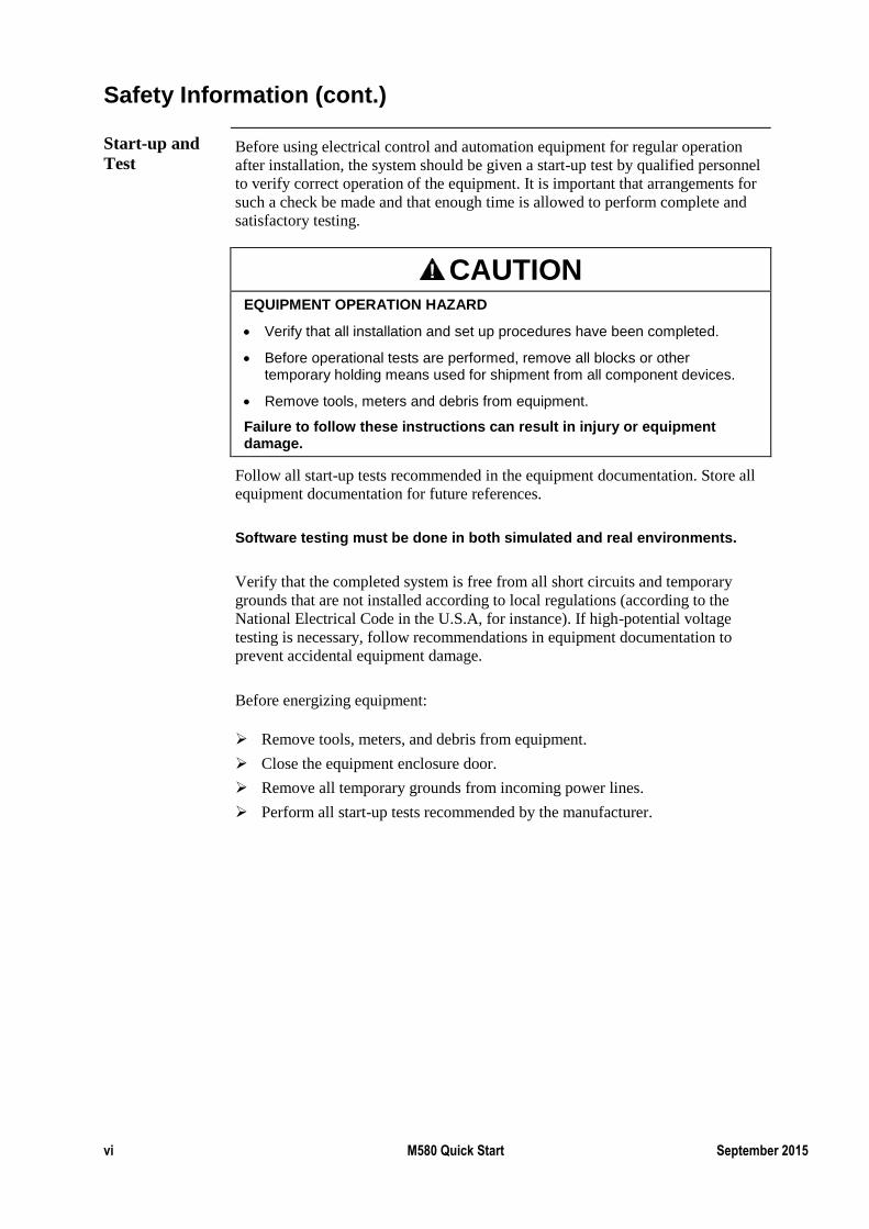
CAUTION
EQUIPMENT OPERATION HAZARD
Verify that all installation and set up procedures have been completed.
Before operational tests are performed, remove all blocks or other temporary holding means used for shipment from all component devices.
Remove tools, meters and debris from equipment.
Failure to follow these instructions can result in injury or equipment damage.
Follow all start-up tests recommended in the equipment documentation. Store all
equipment documentation for future references.
Software testing must be done in both simulated and real environments.
Verify that the completed system is free from all short circuits and temporary
grounds that are not installed according to local regulations (according to the
National Electrical Code in the U.S.A, for instance). If high-potential voltage
testing is necessary, follow recommendations in equipment documentation to
prevent accidental equipment damage.
Before energizing equipment:
Remove tools, meters, and debris from equipment.
Close the equipment enclosure door.
Remove all temporary grounds from incoming power lines.
Perform all start-up tests recommended by the manufacturer.
M580 Quick Start Manual Release 1 vii
Safety Information (cont.)
Operation and
Adjustments The following precautions are from the NEMA Standards Publication ICS 7.1-
1995 (English version prevails):
Regardless of the care exercised in the design and manufacture of equipment
or in the selection and ratings of components, there are hazards that can be
encountered if such equipment is improperly operated.
It is sometimes possible to misadjust the equipment and thus produce
unsatisfactory or unsafe operation. Always use the manufacturer’s instructions
as a guide for functional adjustments. Personnel who have access to these
adjustments should be familiar with the equipment manufacturer’s instructions
and the machinery used with the electrical equipment.
Only those operational adjustments actually required by the operator should
be accessible to the operator. Access to other controls should be restricted to
prevent unauthorized changes in operating characteristics.

viii M580 Quick Start September 2015
Before the Course Begins
Scope of this
Training
Manual
This training manual is a supplement to the authorised training. In order to make
proper use of the software students should also refer to the documentation that has
been provided with the product such as the Help Files, User Guides or Knowledge
Base.
The graphics displaying screen captures were taken using the Windows® 7
operating system. If students are running a different version of Windows then
screen images may differ slightly from those shown in the training manual.
Some screen captures may have been taken from beta versions of the software and
may vary slightly from release screen captures.
M580 Quick Start Manual Release 1 ix
Conventions Used in this Manual
Objectives These are the skills to be achieved by the end of each chapter. An overview
providing a brief synopsis of the topic begins each section. Often, examples are
given to illustrate the conceptual overview.
Example -
The configuration environment consists of several toolbars, browser windows and
programming editors. This chapter introduces the user to the configuration
environment using an example project with pre-defined elements.
Exercises After a concept is explained students will be given exercises that practice the
skills just learned. These exercises begin by explaining the general concept of
each exercise and then step-by-step procedures are listed to guide students
through each exercise.
Example -
Paste an object from a library onto a test page called Utility.
Run the Milk_Upgrade project then trigger and view some alarms.
i. Use the following template settings:
User Input Whenever information is to be typed into a field or dialog box it will be written in
this font:
KETTLE_TEMP/25
Note that some exercises will show a fragment of information already typed into a
Unity Pro screen and then ask students to add extra lines of configuration. In this
instance, the previously entered material will be given to the student as light grey
italic text.
KETTLE_TEMP/25
OVEN_TEMP/5
x M580 Quick Start September 2015
Conventions Used in this Manual (cont.)
Hints & Tips This heading will provide students with useful or helpful information that will
make configuring the project easier.
Example -
Hints & Tips:
To go to the next field, use the mouse cursor or press the TAB key.
Note A note will refer to a feature which may not be obvious at first glance but
something that should always be kept in mind.
Example -
Note:
Any events named GLOBAL are enabled automatically when events are enabled.
Menus and
Menu Options Text separated by the double arrow symbol “»” indicates that students are to
select a menu.
Example -
File » New…
Open a menu “File” then select the menu option “New…”
Horizontal and
Vertical Tabs Text written this way indicates the Horizontal then the (Vertical) tab is to be
selected.
Example -
Appearance (General)
M580 Quick Start Manual Release 1 xi
Conventions Used in this Manual (cont.)
See Also Text written in this way indicates further references about the current topic.
Example -
See Also:
For further information about Templates, see Quick Start Help - Using Page
Templates.
Further
Training This heading describes topics that are covered in more advanced courses.
Example -
Further Training:
Trend Table Maths is a topic in the Customisation and Design Course.

xii M580 Quick Start September 2015
M580 Quick Start Manual Release 1 xiii
Course Overview
What is Quick
Start? Quick Start is “hands on” oriented training that presents how to configure the
common features of the M580.The training focuses on configuration, thus PLC
programming is not taught in this course.
The training is divided into three chapters:
1. The first chapter will show how to create a basic configuration with local
I/O.
2. The second chapter allows training on bigger architectures. As M580’s
have numerous types of I/O and modules, most of the training can be run
in simulation mode. However, in case the exercises are required with
Equipment this chapter is designed in such a way that allows for the use
of Equipment.
The last chapter refers to the most advanced features of the M580, as these are
more complex to implement, this chapter will only describe the features and not
implement them.
Course
Objectives By the completion of this training course the student will be able to:
Connect Unity Pro to an M580 through USB and an Ethernet (RJ45) cable
Describe the different types of I/O
Configure local I/O
Change the security features of the M580
Describe the use of the M580 Ethernet ports
Configure a DTM device
Configure a Remote I/O drop
Configure a local Premium I/O drop, extending a local M580 drop
Configure a NOC
Configure a basic M580 Hot Standby (HSBY) architecture
Describe other features of the M580
xiv M580 Quick Start September 2015
Course Overview (cont.)
Target
Audience Quick Start is designed for anyone having basic PLC programming skills and
willing to discover the M580 features.
This includes people with no experience with the M580, people migrating from
Premium/Quantum to the M580 as well as staff familiar with the M580 that want
a “How to” guide.
Prerequisite
Knowledge The only prerequisite knowledge is to be familiar with PLC programming through
Unity Pro v8.1 or later.
Further Training:
For those not familiar with Unity Pro, the free eLearning “Unity Pro - Click and
Start” will provide all the knowledge required to go through M580 Quick Start:
Link to Click and Start eLearning.
Equipment A computer with a valid version of Unity Pro v8.0 or later (This includes demo
versions).
Most exercises of this training can be carried out in Unity Pro’s
SimulationMode. Nevertheless, the Equipment required to perform the training
in Standard Mode is listed at the beginning of each exercise.

M580 Quick Start Manual Release 1 xv
Course Overview (cont.)
Support If support or additional information about any concepts or products in the course
is required, students should ask the Instructor who will either address the question
or obtain additional technical assistance as required.

M580 Quick Start Manual Release 1 xvii
Table of Contents
CHAPTER 1: M580 BASICS ......................................................................................... 1-1
Overview .................................................................................................................... 1-1
Different Types of M580 I/O ..................................................................................... 1-2 M580 Embedded Ethernet Ports ................................................................................ 1-7 Connect to the M580 .................................................................................................. 1-9 Exercise - Connect to the Simulation Mode............................................................. 1-10 Exercise - Connect Through USB ............................................................................ 1-11
Exercise - Configure the Embedded Ethernet Ports ................................................. 1-16 Local I/O .................................................................................................................. 1-22
Exercise - Configure Local I/O ................................................................................ 1-23 Cyber Security .......................................................................................................... 1-31 Exercise – Cyber Security ........................................................................................ 1-35 Summary .................................................................................................................. 1-36
Overview .................................................................................................................... 1-1
CHAPTER 2: ADVANCED ARCHITECTURE CONFIGURATION..................................... 2-1
Overview .................................................................................................................... 2-2 DIO ............................................................................................................................. 2-3 Exercise - Install a DTM in Unity Pro ....................................................................... 2-4 Exercise - Configure an Altivar Drive ....................................................................... 2-7 Summary .................................................................................................................. 2-16
NOC ......................................................................................................................... 2-17 Exercise - Configure an Altivar Drive (cont.) .......................................................... 2-19
Summary .................................................................................................................. 2-20 M580 Isolated Device Networks .............................................................................. 2-21 BME NOC Web Services ......................................................................................... 2-39
Remote I/O (RIO)..................................................................................................... 2-56 Summary .................................................................................................................. 2-67
Exercise - Premium I/O ............................................................................................ 2-69 Summary .................................................................................................................. 2-73
M580 Hot Standby (HSBY) ..................................................................................... 2-74 Exercise – HSBY ..................................................................................................... 2-80 Summary .................................................................................................................. 2-82 Advanced Cyber Security......................................................................................... 2-83 Exercise - Password Management (cont.) ................................................................ 2-89
Integrity Checking .................................................................................................... 2-91 Summary .................................................................................................................. 2-95
xviii SoMachine Basic Version 1.10 September 2015
CHAPTER 3: MAKE THE MOST OF THE M580! .......................................................... 3-1
Overview .................................................................................................................... 3-1 SD Card ...................................................................................................................... 3-2 Weighing Module Overview ...................................................................................... 3-4 Web Pages .................................................................................................................. 3-6
Summary .................................................................................................................... 3-9
APPENDIX A: APPENDIX .............................................................................................. A-1
Answers to Questions ................................................................................................ A-1 M580 Basics .............................................................................................................. A-2 Device I/O ................................................................................................................. A-3
NOC .......................................................................................................................... A-4 Remote I/O ................................................................................................................ A-5 Premium I/O .............................................................................................................. A-6
M580 Hot Standby .................................................................................................... A-7 Advanced Cyber Security.......................................................................................... A-8 Make the Most of the M580!..................................................................................... A-9
Overview
This part of the training covers the basic features of the M580:
An introduction to the different types of I/O.
Two types of M580 CPU:
1. Part Number Series **20
2. Part Number Series **40
The different types of I/O available between these CPU’s
Connection via Ethernet
Connection via USB
Configuring a local I/O device
Cyber Security features of the M580.
At the end of this chapter the student will be able to configure a basic M580
architecture.
Chapter 1: M580 Basics
Introduction
1-2 M580 Quick Start 1.0 September 2015
Different Types of M580 I/O
M580’s have three types of I/O.
By the end of this section the student will be able to:
Describe the three types of I/O
In Automation architecture, the heart of a system is a PAC. Information coming
from the field (sensors, push buttons, etc.) and commands sent to the devices
(motor control, variable speed drive references, etc.) are often linked to the PAC
via digital or analogue inputs and outputs. These inputs and outputs are physically
connected through wiring between field devices and input and output modules.
These modules can be located in different positions: Locally, Remotely, or
Distributed.
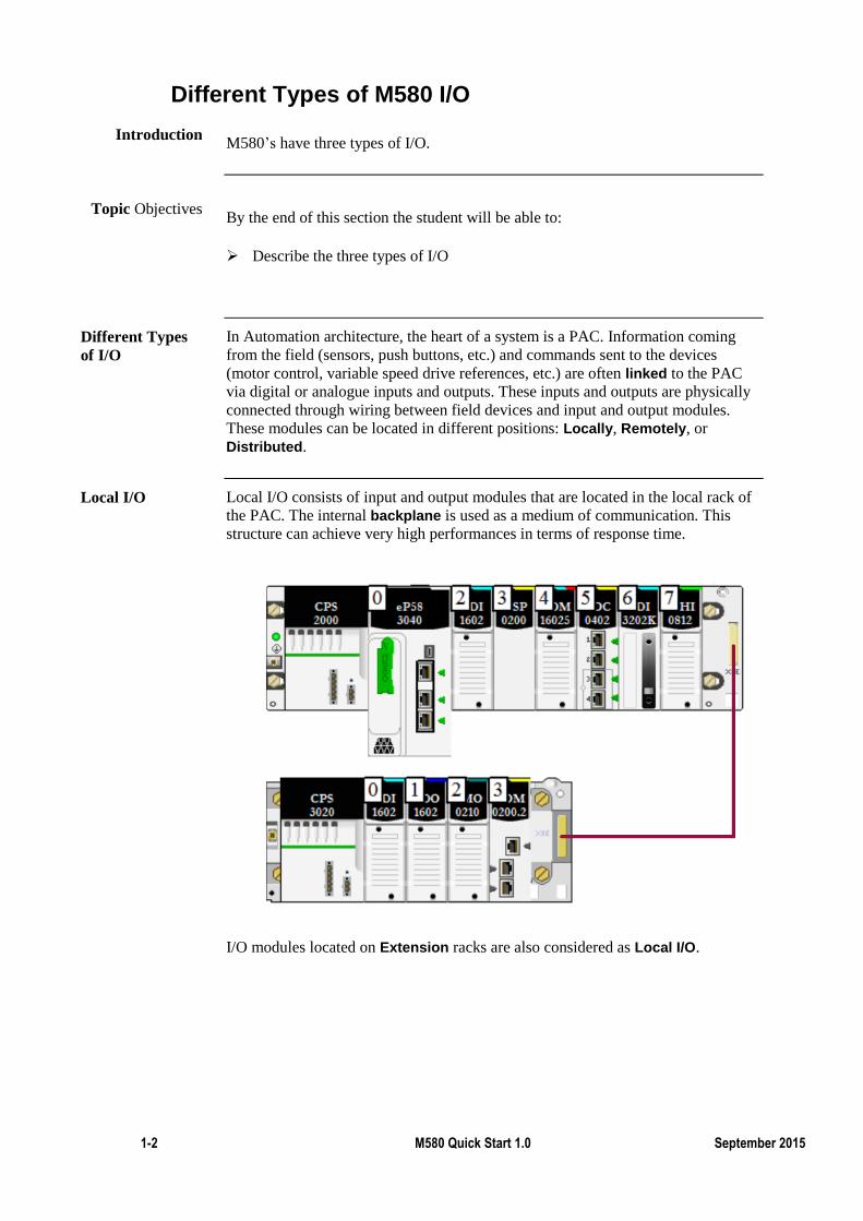
Local I/O consists of input and output modules that are located in the local rack of
the PAC. The internal backplane is used as a medium of communication. This
structure can achieve very high performances in terms of response time.
I/O modules located on Extension racks are also considered as Local I/O.
Introduction
Topic Objectives
Different Types
of I/O
Local I/O
M580 Quick Start Manual Release 1 1-3
Different Types of M580 I/O (cont.)
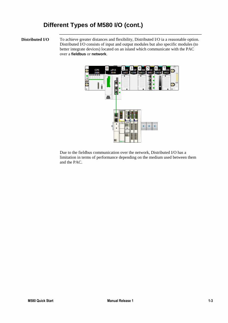
To achieve greater distances and flexibility, Distributed I/O ia a reasonable option.
Distributed I/O consists of input and output modules but also specific modules (to
better integrate devices) located on an island which communicate with the PAC
over a fieldbus or network.
Due to the fieldbus communication over the network, Distributed I/O has a
limitation in terms of performance depending on the medium used between them
and the PAC.
Distributed I/O
1-4 M580 Quick Start 1.0 September 2015
M580 Remote I/O
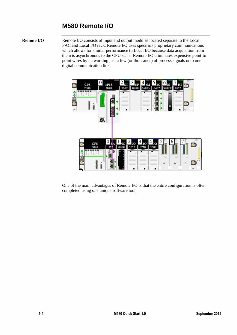
Remote I/O consists of input and output modules located separate to the Local
PAC and Local I/O rack. Remote I/O uses specific / proprietary communications
which allows for similar performance to Local I/O because data acquisition from
them is asynchronous to the CPU scan. Remote I/O eliminates expensive point-to-
point wires by networking just a few (or thousands) of process signals onto one
digital communication link.
One of the main advantages of Remote I/O is that the entire configuration is often
completed using one unique software tool.
Remote I/O
M580 Quick Start Manual Release 1 1-5
M580 Remote I/O (cont.)
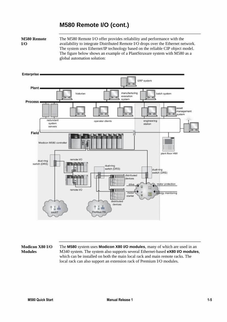
The M580 Remote I/O offer provides reliability and performance with the
availability to integrate Distributed Remote I/O drops over the Ethernet network.
The system uses Ethernet/IP technology based on the reliable CIP object model.
The figure below shows an example of a PlantStruxure system with M580 as a
global automation solution:
The M580 system uses Modicon X80 I/O modules, many of which are used in an
M340 system. The system also supports several Ethernet-based eX80 I/O modules,
which can be installed on both the main local rack and main remote racks. The
local rack can also support an extension rack of Premium I/O modules.
M580 Remote
I/O
Modicon X80 I/O
Modules
1-6 M580 Quick Start 1.0 September 2015
Exercise - Recognise the Different Types of I/O
By the completion of this exercise the student will be able to:
Identify the different types of I/O
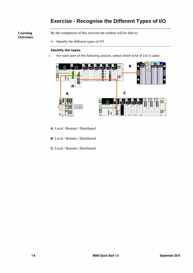
Identify the types.
i. For each part of the following picture, select which kind of I/O is used:
A: Local / Remote / Distributed
B: Local / Remote / Distributed
C: Local / Remote / Distributed
Learning
Outcomes
M580 Quick Start Manual Release 1 1-7
M580 Embedded Ethernet Ports
In the previous topic the different types of I/O were explained.
The M580 has 3 ports which, depending on the part number, allows for different
types of I/O.
Thus this chapter will present the different ports of the M580, and which of these
ports can be used for Remote I/O (RIO) or Distributed I/O (DIO).
By the end of this section the student will be able to:
Identify the different ports of the M580
Describe their roles depending on the part number
First let’s look at the M580 ports.
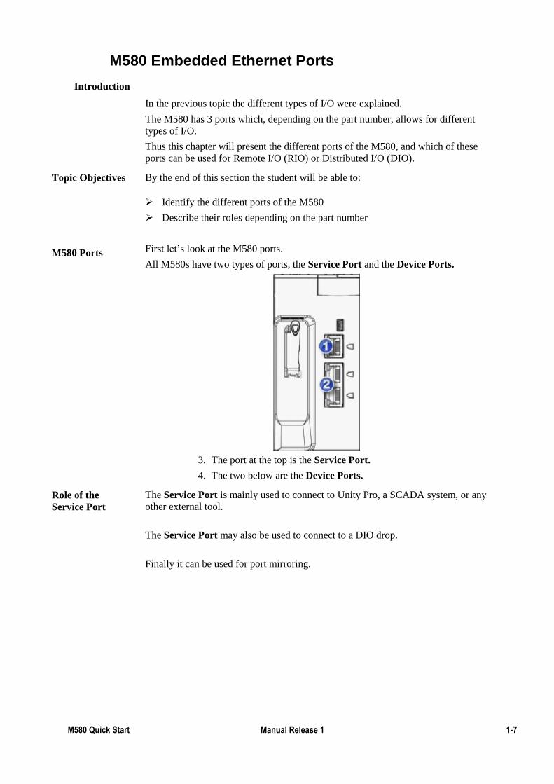
All M580s have two types of ports, the Service Port and the Device Ports.
3. The port at the top is the Service Port.
4. The two below are the Device Ports.
The Service Port is mainly used to connect to Unity Pro, a SCADA system, or any
other external tool.
The Service Port may also be used to connect to a DIO drop.
Finally it can be used for port mirroring.
Introduction
Topic Objectives
M580 Ports
Role of the
Service Port
1-8 M580 Quick Start 1.0 September 2015
M580 Embedded Ethernet Ports (cont.)
This is where there is a big difference between the 2 types of CPU.
If the CPU’s type is **20 then the Device Ports are used to connect DIO drops. A
DIO drop can be composed of almost any device including non Schneider-Electric
devices.
If the CPU’s type is **40 then the Device Ports are used to connect RIO drops.
In both cases the supported architectures are wired star or ring.
Role of the
Device Port
M580 Quick Start Manual Release 1 1-9
Connect to the M580
We now know which port we can use to connect to the M580.
In this chapter the user will learn how to connect to the M580, via Simulation
Mode, USB and of course Ethernet.
Connecting to the PLC will allow the project to be downloaded to the PLC and
provide relevant information for troubleshooting.
Remember that unless specified, exercises can be done through both Simulation
Mode or connected directly to a PLC (provided that the student has the required
Equipment
By the end of this section the student will be able to:
Connect to a simulator
Connect to a PLC via USB
Connect to a PLC via Ethernet
Monitor the PLC status
Introduction
Topic Objectives
1-10 M580 Quick Start 1.0 September 2015
Exercise - Connect to the Simulation Mode
By the completion of this exercise the student will:
Connect to an emulated M580
None
Start Unity Pro
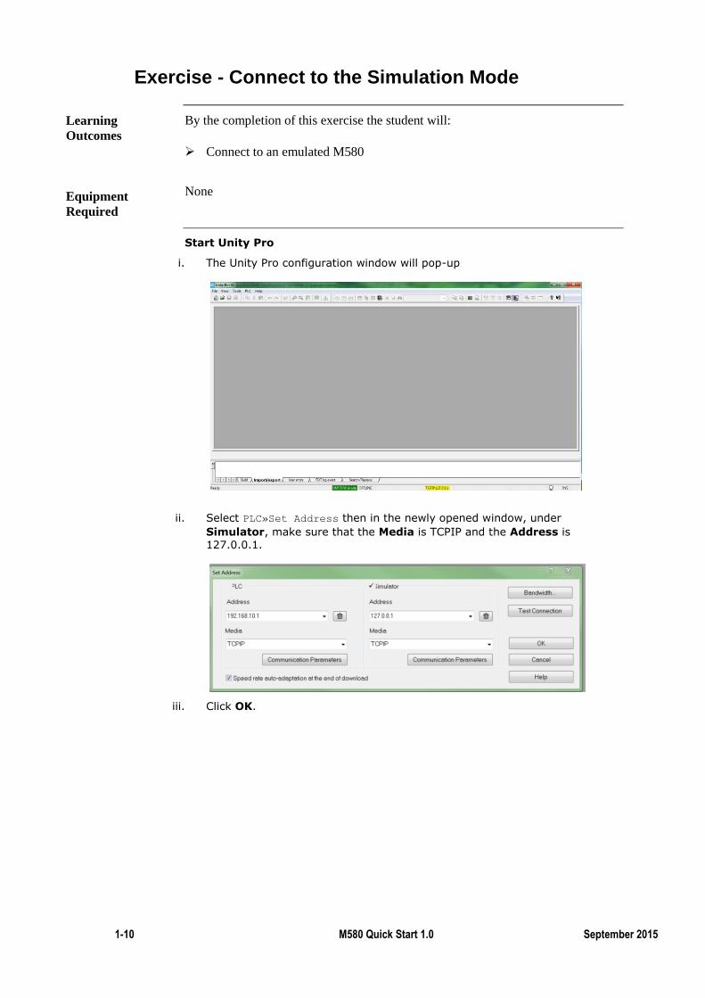
i. The Unity Pro configuration window will pop-up
ii. Select PLC»Set Address then in the newly opened window, under
Simulator, make sure that the Media is TCPIP and the Address is 127.0.0.1.
iii. Click OK.
Learning
Outcomes
Equipment
Required
M580 Quick Start Manual Release 1 1-11
Exercise - Connect to the Simulation Mode (cont.)
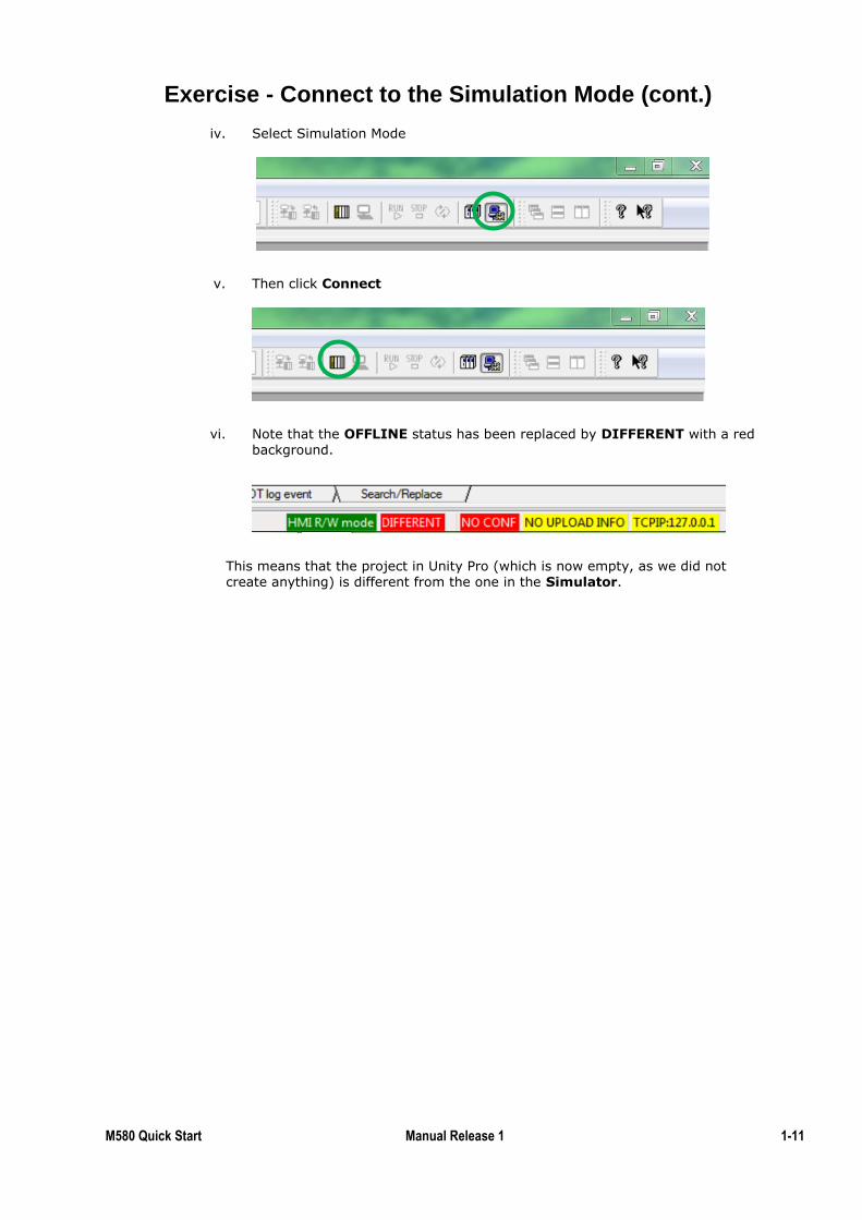
iv. Select Simulation Mode
v. Then click Connect
vi. Note that the OFFLINE status has been replaced by DIFFERENT with a red background.
This means that the project in Unity Pro (which is now empty, as we did not create anything) is different from the one in the Simulator.
1-12 M580 Quick Start 1.0 September 2015
Exercise - Connect Through USB
By the completion of this exercise the student will:
Install M580 USB drivers
Test the USB connection
Connect to an M580 via USB
To complete this exercise on a PLC, the student will need
One M580 PLC (any CPU)
A BMX or BME rack
A compatible power supply
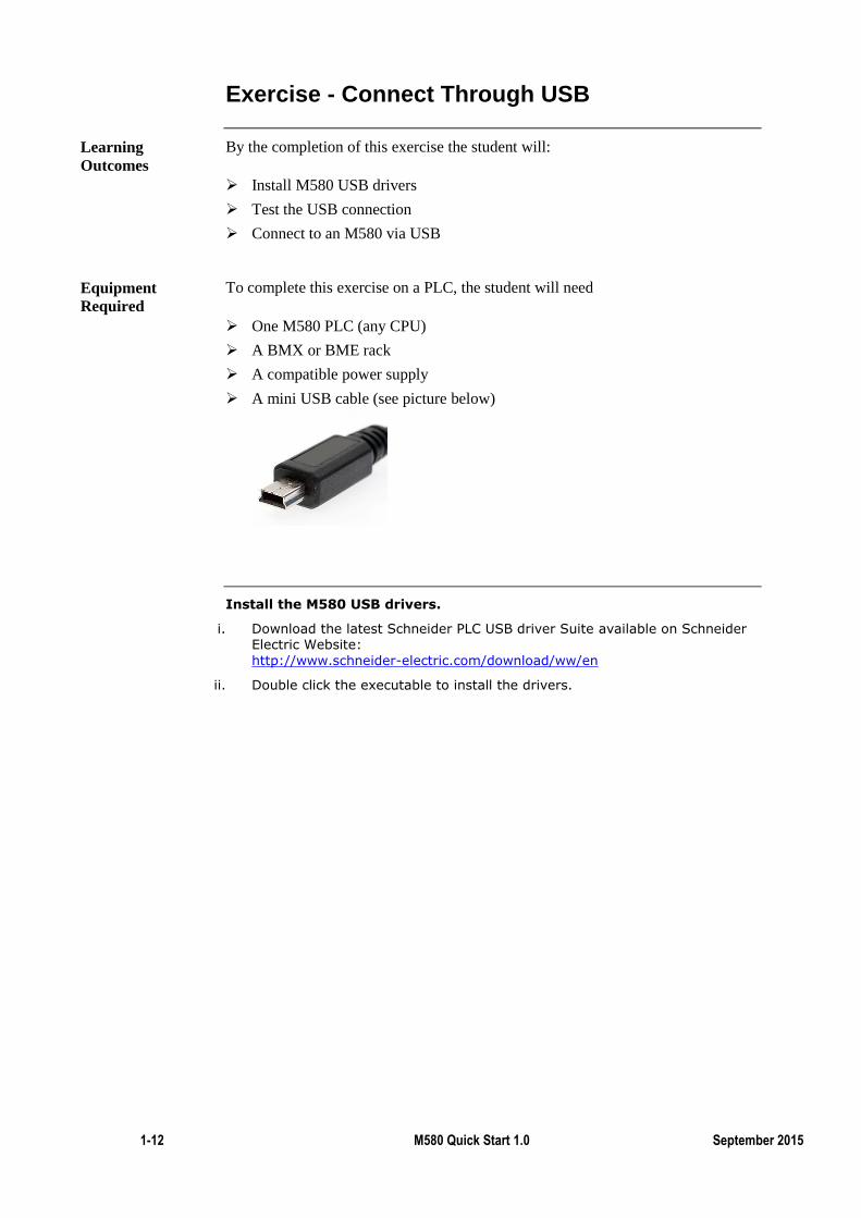
A mini USB cable (see picture below)
Install the M580 USB drivers.
i. Download the latest Schneider PLC USB driver Suite available on Schneider Electric Website:
http://www.schneider-electric.com/download/ww/en
ii. Double click the executable to install the drivers.
Learning
Outcomes
Equipment
Required
M580 Quick Start Manual Release 1 1-13
Exercise - Connect Through USB (cont.)
Test the USB connection
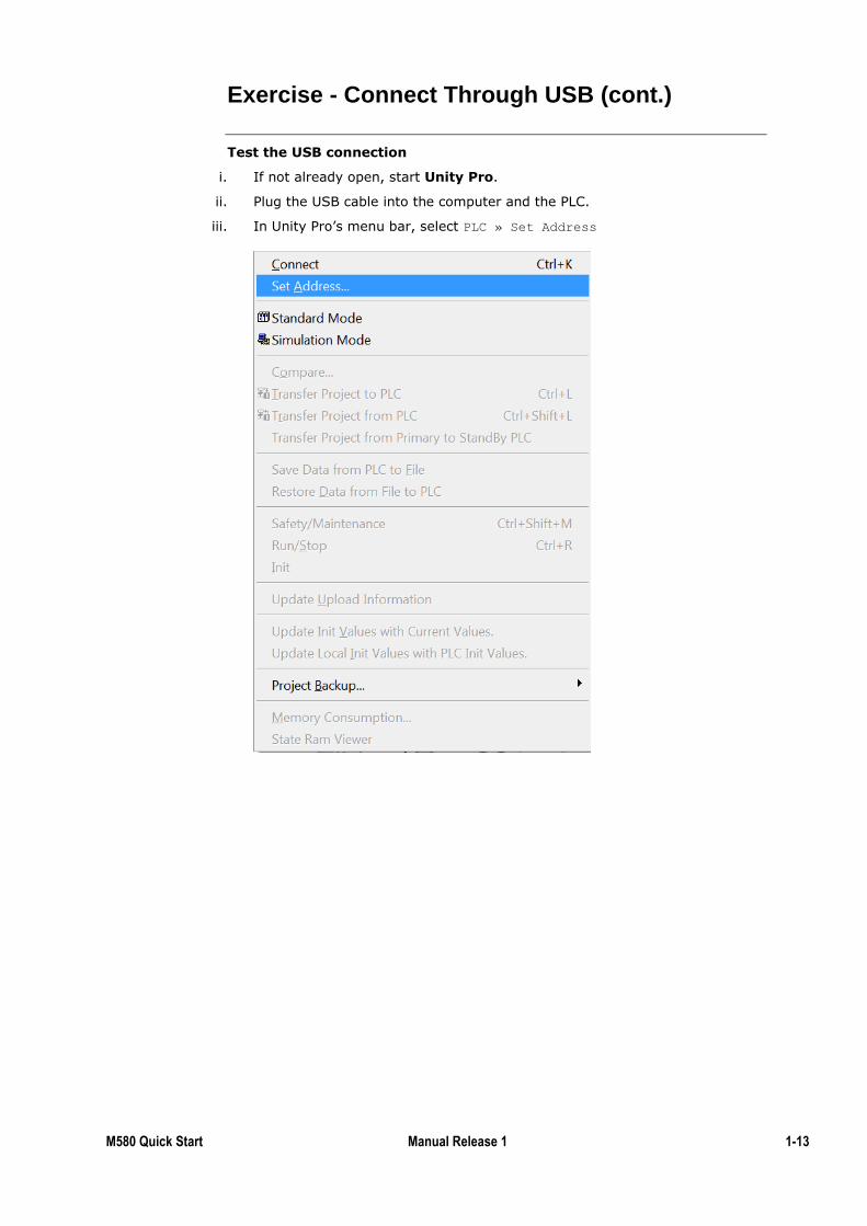
i. If not already open, start Unity Pro.
ii. Plug the USB cable into the computer and the PLC.
iii. In Unity Pro’s menu bar, select PLC » Set Address
1-14 M580 Quick Start 1.0 September 2015
Exercise - Connect Through USB (cont.)
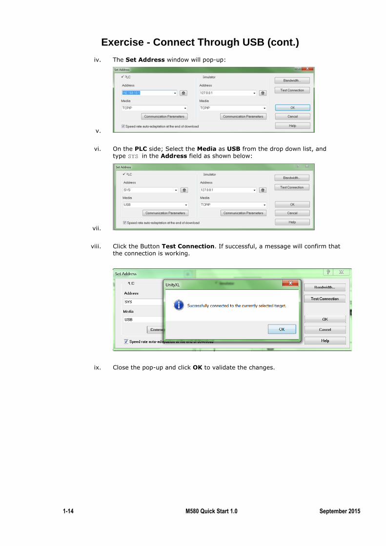
iv. The Set Address window will pop-up:
v.
vi. On the PLC side; Select the Media as USB from the drop down list, and
type SYS in the Address field as shown below:
vii.
viii. Click the Button Test Connection. If successful, a message will confirm that
the connection is working.
ix. Close the pop-up and click OK to validate the changes.
M580 Quick Start Manual Release 1 1-15
Exercise - Connect Through USB (cont.)
Connect to the PLC
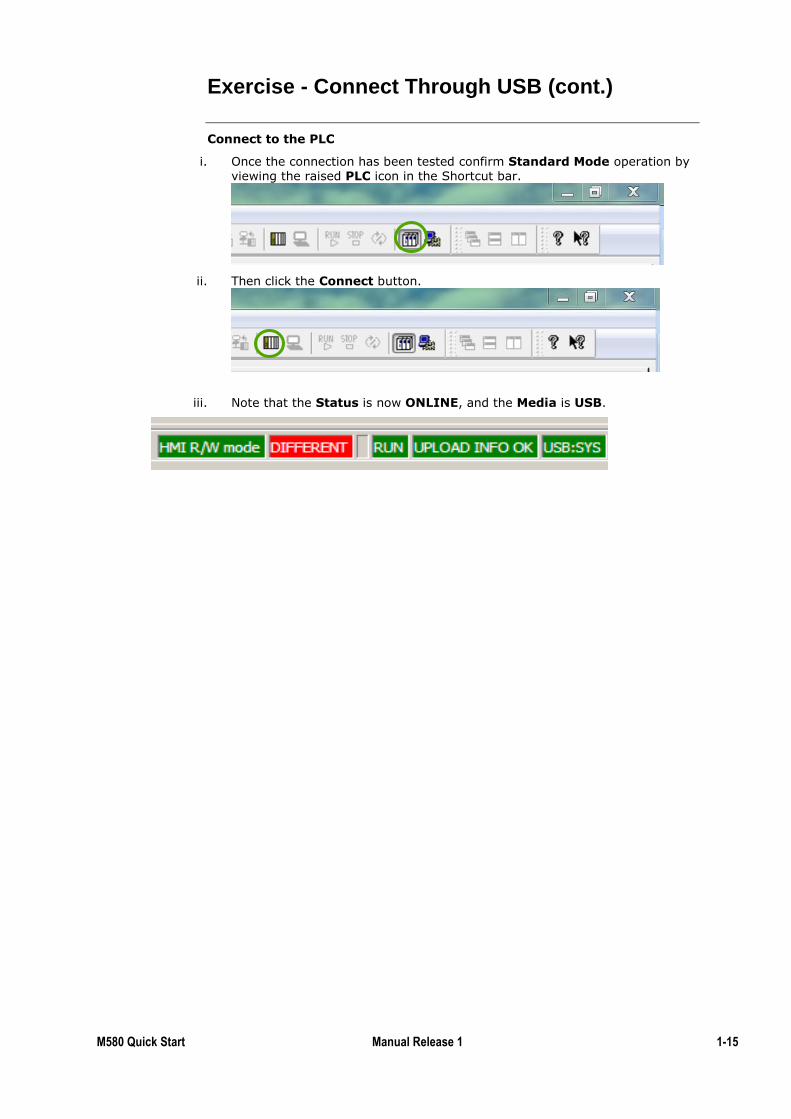
i. Once the connection has been tested confirm Standard Mode operation by viewing the raised PLC icon in the Shortcut bar.
ii. Then click the Connect button.
iii. Note that the Status is now ONLINE, and the Media is USB.
1-16 M580 Quick Start 1.0 September 2015
Exercise - Configure the Embedded Ethernet Ports
By the completion of this exercise the student will:
Be able to configure the embedded Ethernet ports of the M580 CPU
Use the default DDT to display data from the M580 CPU
Create a new project.
i. If not already open, start Unity Pro
ii. Select File » New.
iii. Select any M580 CPU / rack then click OK.
Configure the IP addresses.
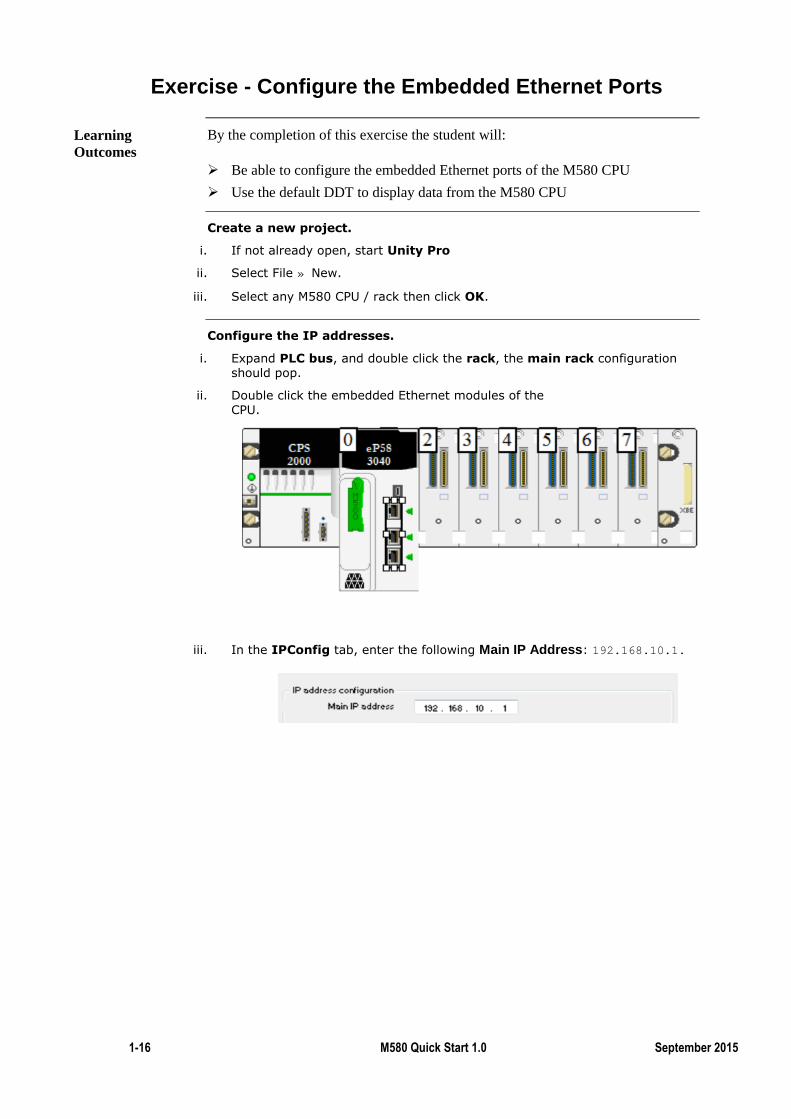
i. Expand PLC bus, and double click the rack, the main rack configuration should pop.
ii. Double click the embedded Ethernet modules of the CPU.
iii. In the IPConfig tab, enter the following Main IP Address: 192.168.10.1.
Learning
Outcomes
M580 Quick Start Manual Release 1 1-17
Exercise - Configure the Embedded Ethernet Ports (cont.)
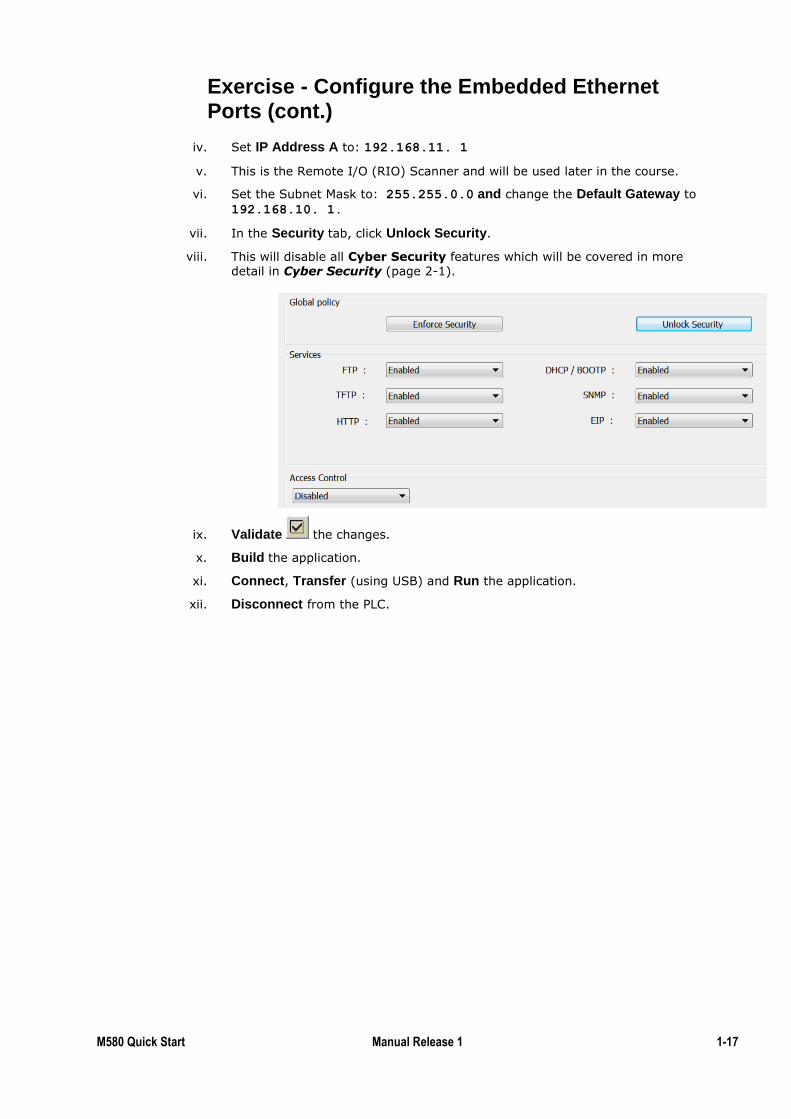
iv. Set IP Address A to: 192.168.11. 1
v. This is the Remote I/O (RIO) Scanner and will be used later in the course.
vi. Set the Subnet Mask to: 255.255.0.0 and change the Default Gateway to
192.168.10. 1.
vii. In the Security tab, click Unlock Security.
viii. This will disable all Cyber Security features which will be covered in more detail in Cyber Security (page 2-1).
ix. Validate the changes.
x. Build the application.
xi. Connect, Transfer (using USB) and Run the application.
xii. Disconnect from the PLC.
1-18 M580 Quick Start 1.0 September 2015
Exercise - Configure the Embedded Ethernet Ports (cont.)
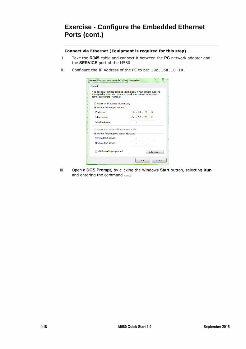
Connect via Ethernet (Equipment is required for this step)
i. Take the RJ45 cable and connect it between the PC network adaptor and
the SERVICE port of the M580.
ii. Configure the IP Address of the PC to be: 192.168.10.10.
iii. Open a DOS Prompt, by clicking the Windows Start button, selecting Run
and entering the command cmd.
M580 Quick Start Manual Release 1 1-19
Exercise - Configure the Embedded Ethernet Ports (cont.)
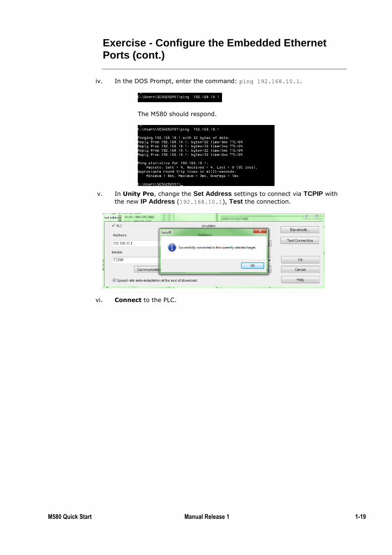
iv. In the DOS Prompt, enter the command: ping 192.168.10.1.
The M580 should respond.
v. In Unity Pro, change the Set Address settings to connect via TCPIP with
the new IP Address (192.168.10.1), Test the connection.
vi. Connect to the PLC.
1-20 M580 Quick Start 1.0 September 2015
Exercise - View the M580 State from Unity Pro
By the completion of this exercise the student will:
Be able to monitor the M580 CPU from Unity Pro
Connect to the PLC.
i. Via USB, Ethernet or Simulation Mode.
View data from the Device DDT.
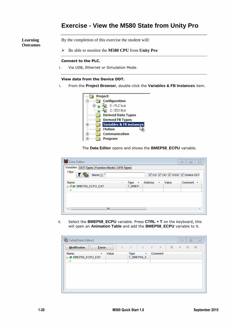
i. From the Project Browser, double-click the Variables & FB Instances item.
The Data Editor opens and shows the BMEP58_ECPU variable.
ii. Select the BMEP58_ECPU variable. Press CTRL + T on the keyboard, this
will open an Animation Table and add the BMEP58_ECPU variable to it.
Learning
Outcomes
M580 Quick Start Manual Release 1 1-21
Exercise - View the M580 State from Unity Pro (cont.)
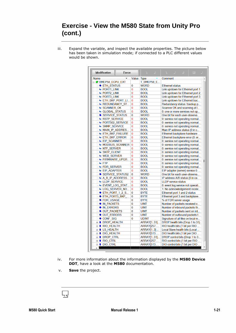
iii. Expand the variable, and inspect the available properties. The picture below has been taken in simulation mode; if connected to a PLC different values
would be shown.
iv. For more information about the information displayed by the M580 Device DDT, have a look at the M580 documentation.
v. Save the project.
1-22 M580 Quick Start 1.0 September 2015
Local I/O
This chapter provides information on how to create a new Project, connect to the
PLC and download the Project to the PLC. This Project will include Local I/O.
Local I/O modules are on the same rack as the M580.
They are the most basic type of I/O and the easiest to configure.
To simplify I/O mapping most of the M580 I/O modules are configured via a
Device DDT.
Introduction
M580 Quick Start Manual Release 1 1-23
Exercise - Configure Local I/O
By the completion of this exercise the student will:
Create a new M580 application
Configure a local I/O
Name and use a Device DDT variable
Check the status of the local I/O drop
To complete this exercise on a PLC the student will need
One M580 PLC (any CPU)
A compatible rack and power supply
A DDO1602
Create a new Project
i. Using the Windows Start Menu open Unity Pro:
Start » All Programs » Schneider Electric » So Collaborative » Unity Pro » Unity Pro XL
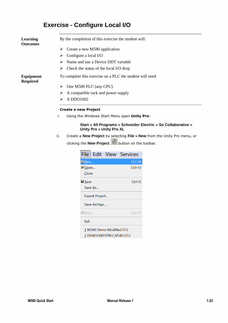
ii. Create a New Project by selecting File » New from the Unity Pro menu, or
clicking the New Project button on the toolbar.
Learning
Outcomes
Equipment
Required
1-24 M580 Quick Start 1.0 September 2015
Exercise - Configure a Local I/O (cont.)
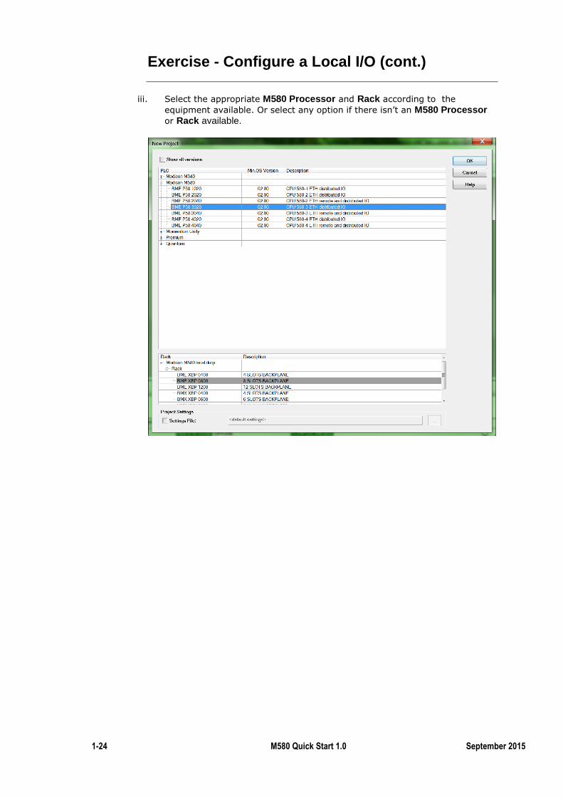
iii. Select the appropriate M580 Processor and Rack according to the
equipment available. Or select any option if there isn’t an M580 Processor or Rack available.
M580 Quick Start Manual Release 1 1-25
Exercise - Configure a Local I/O (cont.)
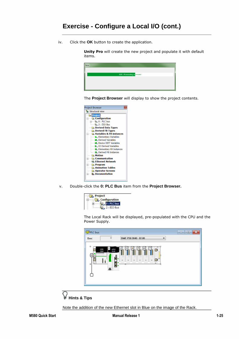
iv. Click the OK button to create the application.
Unity Pro will create the new project and populate it with default items.
The Project Browser will display to show the project contents.
v. Double-click the 0: PLC Bus item from the Project Browser.
The Local Rack will be displayed, pre-populated with the CPU and the
Power Supply.
Hints & Tips
Note the addition of the new Ethernet slot in Blue on the image of the Rack.
1-26 M580 Quick Start 1.0 September 2015
Exercise - Configure a Local I/O (cont.)
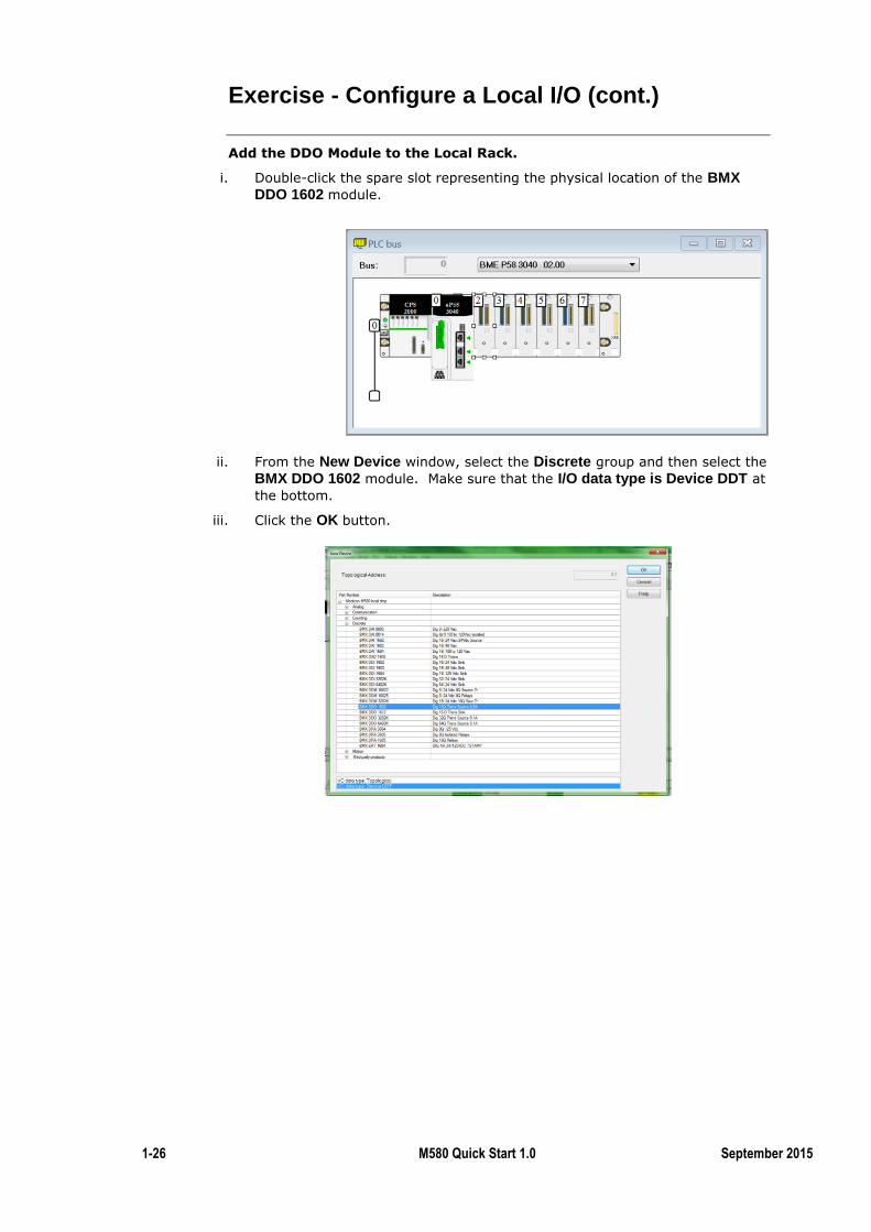
Add the DDO Module to the Local Rack.
i. Double-click the spare slot representing the physical location of the BMX DDO 1602 module.
ii. From the New Device window, select the Discrete group and then select the
BMX DDO 1602 module. Make sure that the I/O data type is Device DDT at
the bottom.
iii. Click the OK button.
M580 Quick Start Manual Release 1 1-27
Exercise - Configure a Local I/O (cont.)
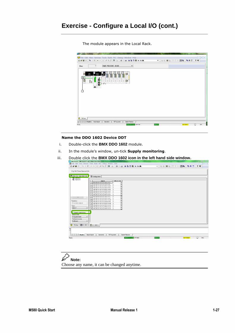
The module appears in the Local Rack.
Name the DDO 1602 Device DDT
i. Double-click the BMX DDO 1602 module.
ii. In the module’s window, un-tick Supply monitoring.
iii. Double click the BMX DDO 1602 icon in the left hand side window.
Note:
Choose any name, it can be changed anytime.
1-28 M580 Quick Start 1.0 September 2015
Exercise - Configure a Local I/O (cont.)
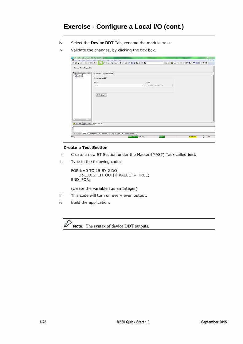
iv. Select the Device DDT Tab, rename the module Obi1.
v. Validate the changes, by clicking the tick box.
Create a Test Section
i. Create a new ST Section under the Master (MAST) Task called test.
ii. Type in the following code:
FOR i:=0 TO 15 BY 2 DO Obi1.DIS_CH_OUT[i].VALUE := TRUE; END_FOR; (create the variable i as an Integer)
iii. This code will turn on every even output.
iv. Build the application.
Note: The syntax of device DDT outputs.
M580 Quick Start Manual Release 1 1-29
Exercise - Configure a Local I/O (cont.)
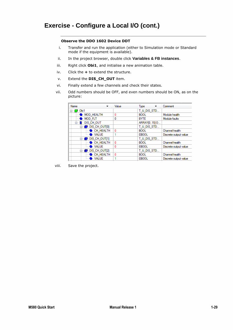
Observe the DDO 1602 Device DDT
i. Transfer and run the application (either to Simulation mode or Standard mode if the equipment is available).
ii. In the project browser, double click Variables & FB instances.
iii. Right click Obi1, and initialise a new animation table.
iv. Click the + to extend the structure.
v. Extend the DIS_CH_OUT item.
vi. Finally extend a few channels and check their states.
vii. Odd numbers should be OFF, and even numbers should be ON, as on the
picture:
viii. Save the project.
1-30 M580 Quick Start 1.0 September 2015
Exercise - Configure a Local I/O (cont.)
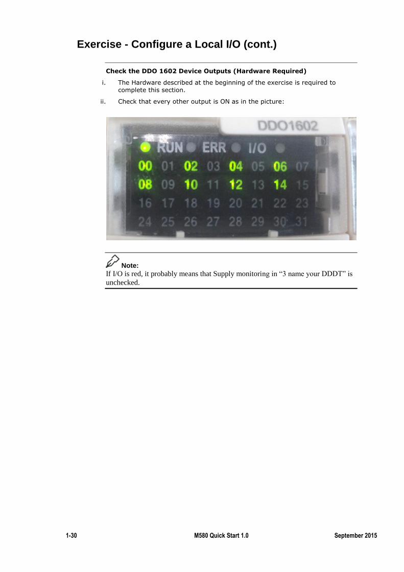
Check the DDO 1602 Device Outputs (Hardware Required)
i. The Hardware described at the beginning of the exercise is required to complete this section.
ii. Check that every other output is ON as in the picture:
Note:
If I/O is red, it probably means that Supply monitoring in “3 name your DDDT” is
unchecked.
M580 Quick Start Manual Release 1 1-31
Cyber Security
The project is now properly running in the PLC (or Simulator). This chapter
explains how to make sure that someone will not disrupt its normal functioning via
a Cyber Attack; such as Stuxnet?
The M580 is one of the first PLC with enabled security features that make it a
harder target for cyber attacks.
This exercise explains how to enable these features and how they will affect the
architecture.
Further Training:
1) To make the system even more secure; refer to the cyber security topic in the
second chapter.
2) The Schneider Electric document; Cyber Security for Automation Systems(Unity
Pro v8.0)
By the end of this chapter the student will be able to:
Identify Cyber Security measures within the M580.
Deploy Cyber Security measures in M580 architecture.
Introduction
Topic Objectives
1-32 M580 Quick Start 1.0 September 2015
Cyber Security (cont.)
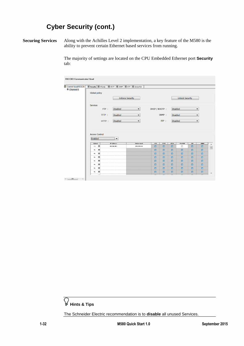
Along with the Achilles Level 2 implementation, a key feature of the M580 is the
ability to prevent certain Ethernet based services from running.
The majority of settings are located on the CPU Embedded Ethernet port Security
tab:
Hints & Tips
The Schneider Electric recommendation is to disable all unused Services.
Securing Services
M580 Quick Start Manual Release 1 1-33
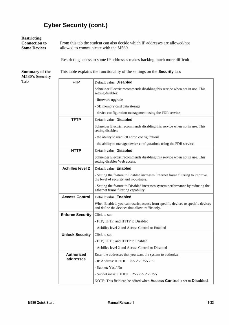
Cyber Security (cont.)
From this tab the student can also decide which IP addresses are allowed/not
allowed to communicate with the M580.
Restricting access to some IP addresses makes hacking much more difficult.
This table explains the functionality of the settings on the Security tab:
FTP Default value: Disabled
Schneider Electric recommends disabling this service when not in use. This
setting disables:
- firmware upgrade
- SD memory card data storage
- device configuration management using the FDR service
TFTP Default value: Disabled
Schneider Electric recommends disabling this service when not in use. This
setting disables:
- the ability to read RIO drop configurations
- the ability to manage device configurations using the FDR service
HTTP Default value: Disabled
Schneider Electric recommends disabling this service when not in use. This
setting disables Web access.
Achilles level 2 Default value: Enabled
- Setting the feature to Enabled increases Ethernet frame filtering to improve
the level of security and robustness.
- Setting the feature to Disabled increases system performance by reducing the
Ethernet frame filtering capability.
Access Control Default value: Enabled
When Enabled, you can restrict access from specific devices to specific devices
and define the devices that allow traffic only.
Enforce Security Click to set:
- FTP, TFTP, and HTTP to Disabled
- Achilles level 2 and Access Control to Enabled
Unlock Security Click to set:
- FTP, TFTP, and HTTP to Enabled
- Achilles level 2 and Access Control to Disabled
Authorized addresses
Enter the addresses that you want the system to authorize:
- IP Address: 0.0.0.0 ... 255.255.255.255
- Subnet: Yes / No
- Subnet mask: 0.0.0.0 ... 255.255.255.255
NOTE: This field can be edited when Access Control is set to Disabled.
Restricting
Connection to
Some Devices
Summary of the
M580’s Security
Tab
1-34 M580 Quick Start 1.0 September 2015
Cyber Security (cont.)
Note:
1) Be very careful when activating the security features, especially IP restriction
because the PLC can become inaccessible: by IP, SD card and USB! In that case
the PLC is useless. Thus be careful experimenting with these features at the same
time.
2) It is advised that all protocols are disabled and Achilles 2 Cyber Security is
enabled when a project is started. Unity Pro will then request protocols to be
activated when they are required. Only the features the project requires are
therefore enabled, which improves Cyber Security. Once the configuration is
working access to specific IP addresses can then also be restricted.
Quite often NOCs are connected to a SCADA system, making them indirectly
connected to an internet network and away from cyber attacks.
Note:
To avoid intrusion from the NOC a new secured NOC module will be released
soon. It will include Cyber Security features similar to the ones of the M580.
Cyber Secured
NOC
M580 Quick Start Manual Release 1 1-35
Exercise – Cyber Security
By the completion of this exercise the student will:
Activate the Achilles level 2 feature
Enable/disable services
To complete this exercise on a PLC the student will need
One M580 PLC (any CPU)
A BMX or BME rack
A compatible power supply
A micro USB cable or an RJ45 cable
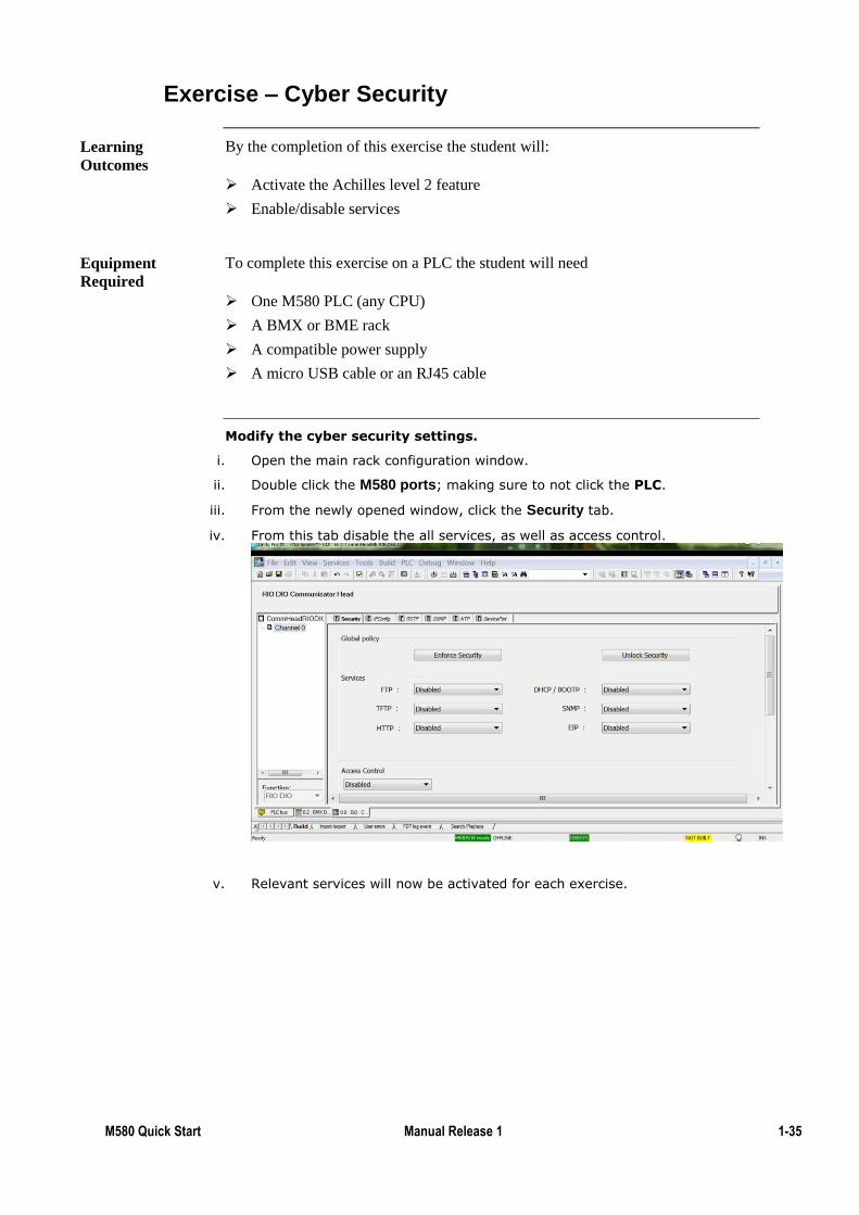
Modify the cyber security settings.
i. Open the main rack configuration window.
ii. Double click the M580 ports; making sure to not click the PLC.
iii. From the newly opened window, click the Security tab.
iv. From this tab disable the all services, as well as access control.
v. Relevant services will now be activated for each exercise.
Learning
Outcomes
Equipment
Required

1-36 M580 Quick Start 1.0 September 2015
Summary
In this chapter the following topics have been covered:
The different types of IO
The M580 Ethernet ports
Connect to the M580
Configure a local I/O device
Device DDT
Cyber security
The following questions will help to check understanding of the topics covered in
this chapter:
What are the three types of I/O? Which ones are faster to configure?
_______________
_______________
_______________
What are the purposes of the SERVICE port?
What is the advantage of Device DDT over topological addressing?
What is the purpose of observing the M580 Device DDT?
How to access the security parameters of the M580?
To ensure higher cyber security; which services should be disabled?
Summary
Questions
M580 Quick Start Manual Release 1 2-1
Overview
The basics to design an architecture have now been carried out.
In this chapter we will reuse what we have previously learned to design more
sophisticated M580 architectures, including the following:
RIO
DIO.
Hot Standby
Migration paths from:
Premium I/O
Quantum PLC with X80 I/O (same case as RIO)
As well as configuration of NOCs and advanced security features.
This section is modular which means that you can carry out the exercises in any
order, as long as the prerequisites are followed (represented by arrows).
See the chart below for more information:
Note:
Kindly note that the RIO exercise is similar to migration from a Quantum PLC
with X80 modules to a M580 PLC with X80 modules.
You can click the different items to jump directly to the topic.
Chapter 2: Advanced Architecture Configuration
Introduction
2-2 M580 Quick Start 1.0 September 2015
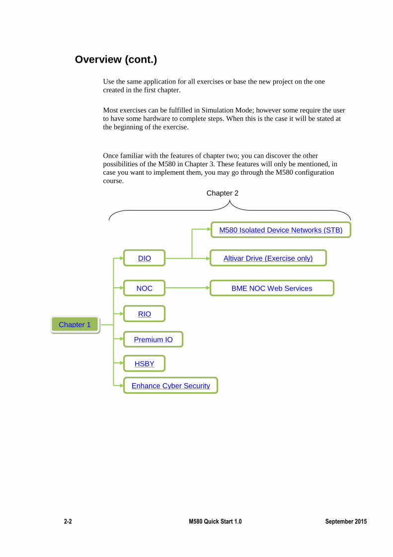
Overview (cont.)
Use the same application for all exercises or base the new project on the one
created in the first chapter.
Most exercises can be fulfilled in Simulation Mode; however some require the user
to have some hardware to complete steps. When this is the case it will be stated at
the beginning of the exercise.
Once familiar with the features of chapter two; you can discover the other
possibilities of the M580 in Chapter 3. These features will only be mentioned, in
case you want to implement them, you may go through the M580 configuration
course.
Chapter 1
HSBY
NOC
RIO
DIO
Basics
Premium IO
Altivar Drive (Exercise only)
Chapter 2
Enhance Cyber Security
BME NOC Web Services
M580 Isolated Device Networks (STB)
M580 Quick Start Manual Release 1 2-3
DIO
Device Type Manager (DTM) through Ethernet allows DIO drop integration with
almost any device to the architecture.
Configuring a DTM device is done in two steps:
Installing the DTM in Unity Pro common to all FDT/DTM devices
Configuration of the device through Unity Pro’s DTM window specific to
each device.
As a generic configuration for all devices cannot be provided DTM configuration is
illustrated through one of the most advanced examples of device integration: The
integration of an Altivar drive through Unity Pro.
By the end of this section the student will be able to:
Install and add a DTM in Unity Pro
Configure the basic settings of an Altivar drive
Test the communication with an Altivar drive
Introduction
Topic Objectives
2-4 M580 Quick Start 1.0 September 2015
Exercise - Install a DTM in Unity Pro
By the completion of this exercise the student will:
Install a DTM library in Unity Pro
Add a DTM device in a Unity Pro project
This exercise is purely software based, so the student will only need Unity Pro v8.0
or later version, and an internet connection.
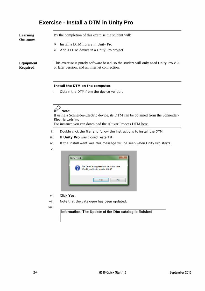
Install the DTM on the computer.
i. Obtain the DTM from the device vendor.
Note:
If using a Schneider-Electric device, its DTM can be obtained from the Schneider-
Electric website.
For instance you can download the Altivar Process DTM here.
ii. Double click the file, and follow the instructions to install the DTM.
iii. If Unity Pro was closed restart it.
iv. If the install went well this message will be seen when Unity Pro starts.
v.
vi. Click Yes.
vii. Note that the catalogue has been updated:
viii.
Learning
Outcomes
Equipment
Required
M580 Quick Start Manual Release 1 2-5
Exercise - Install a DTM in Unity Pro (cont.)
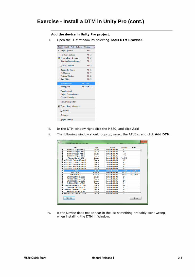
Add the device in Unity Pro project.
i. Open the DTM window by selecting Tools DTM Browser.
ii. In the DTM window right click the M580, and click Add
iii. The following window should pop-up, select the ATV6xx and click Add DTM.
iv. If the Device does not appear in the list something probably went wrong
when installing the DTM in Window.
2-6 M580 Quick Start 1.0 September 2015
Exercise - Install a DTM in Unity Pro (cont.)
Note:
The following points may be different if a different device is being configured.
v. In the case of the Altivar drive select which protocol will be used between the M580 and the drive
vi. For this exercise select Modbus over TCP.
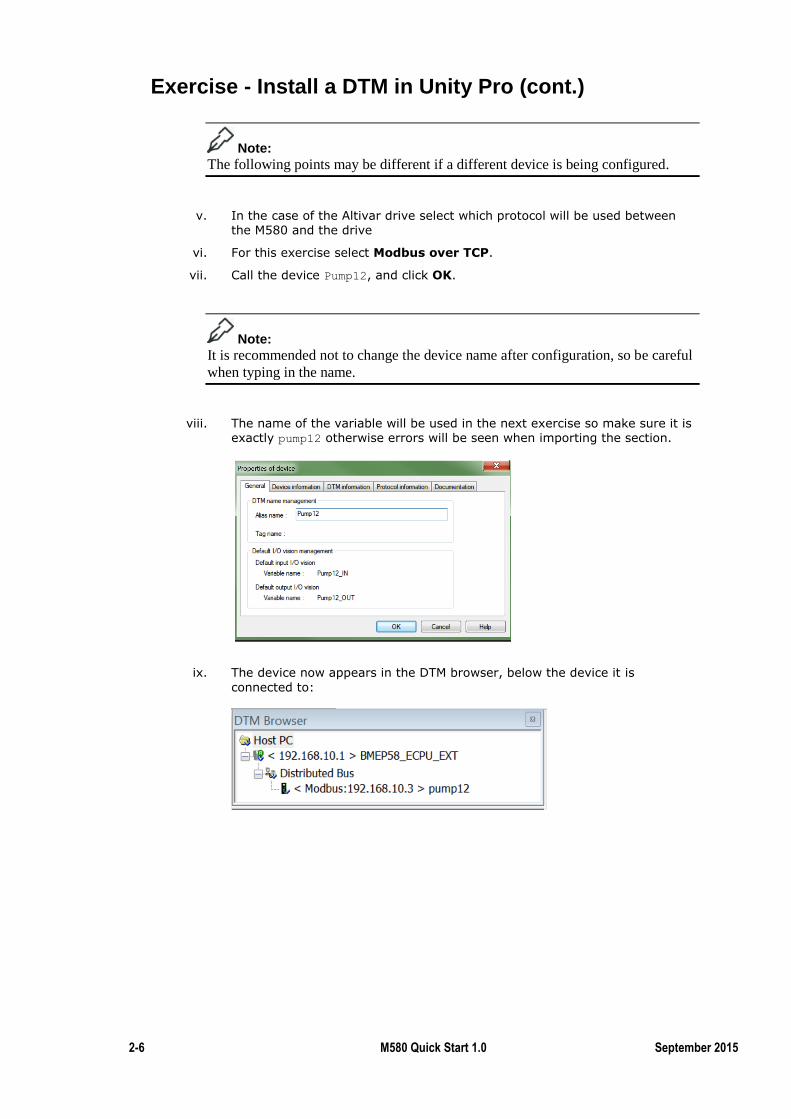
vii. Call the device Pump12, and click OK.
Note:
It is recommended not to change the device name after configuration, so be careful
when typing in the name.
viii. The name of the variable will be used in the next exercise so make sure it is exactly pump12 otherwise errors will be seen when importing the section.
ix. The device now appears in the DTM browser, below the device it is
connected to:
M580 Quick Start Manual Release 1 2-7
Exercise - Configure an Altivar Drive
The DTM is now installed in Unity Pro.
This means that the specific parameters of the device now need now need to be
configured through Unity Pro.
The configuration of this drive will take less than 30 minutes, which is much
shorter than the usual time to configure a drive.
By the completion of this exercise the student will:
Configure an Altivar drive
Test the functioning of an Altivar drive
To complete this exercise on a PLC the student will need
One M580 PLC (any CPU)
A compatible rack and power supply
An Altivar drive
An Ethernet cable
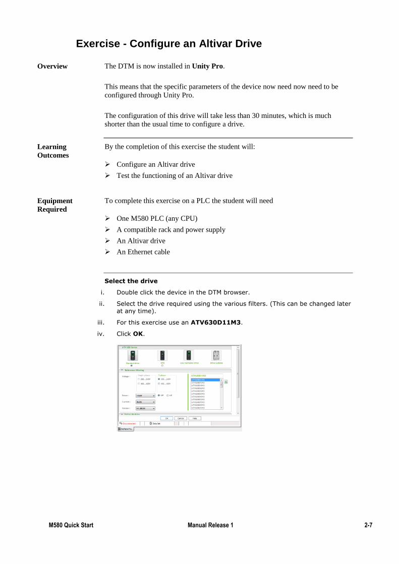
Select the drive
i. Double click the device in the DTM browser.
ii. Select the drive required using the various filters. (This can be changed later at any time).
iii. For this exercise use an ATV630D11M3.
iv. Click OK.
Overview
Learning
Outcomes
Equipment
Required
2-8 M580 Quick Start 1.0 September 2015
Exercise - Configure an Altivar Drive (cont.)
Create the DFB controlling the drive
i. Double click the drive in the DTM window.
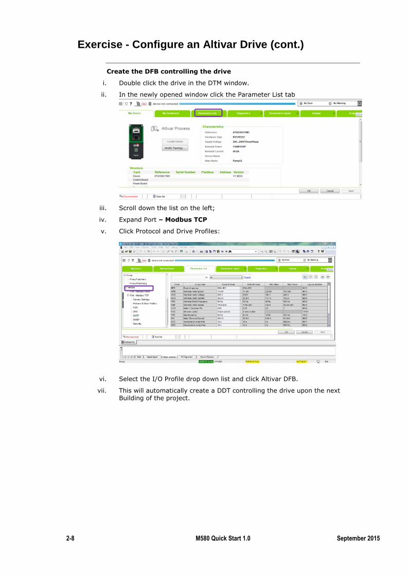
ii. In the newly opened window click the Parameter List tab
iii. Scroll down the list on the left;
iv. Expand Port – Modbus TCP
v. Click Protocol and Drive Profiles:
vi. Select the I/O Profile drop down list and click Altivar DFB.
vii. This will automatically create a DDT controlling the drive upon the next
Building of the project.
M580 Quick Start Manual Release 1 2-9
Exercise - Configure an Altivar Drive (cont.)
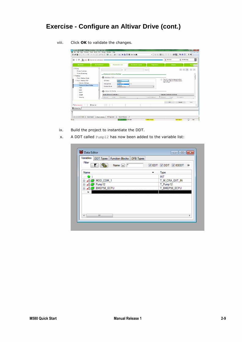
viii. Click OK to validate the changes.
ix. Build the project to instantiate the DDT.
x. A DDT called Pump12 has now been added to the variable list:
2-10 M580 Quick Start 1.0 September 2015
Exercise - Configure an Altivar Drive (cont.)
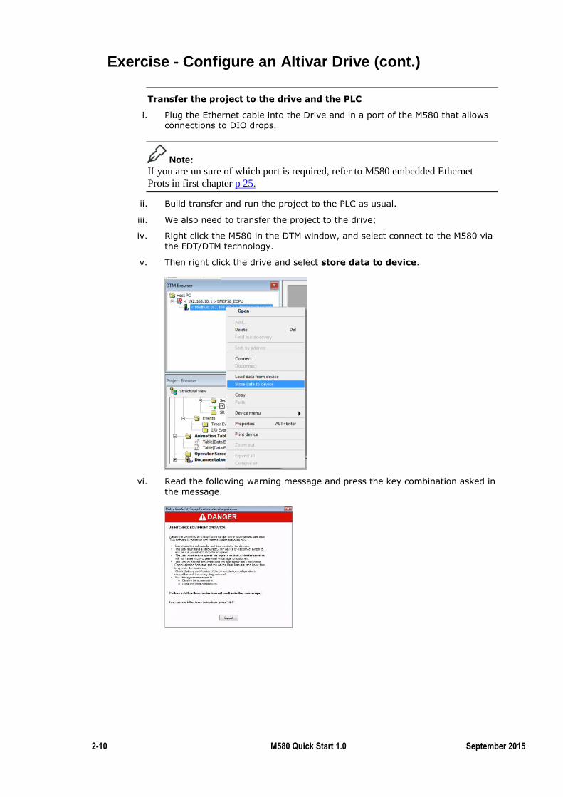
Transfer the project to the drive and the PLC
i. Plug the Ethernet cable into the Drive and in a port of the M580 that allows connections to DIO drops.
Note:
If you are un sure of which port is required, refer to M580 embedded Ethernet
Prots in first chapter p 25.
ii. Build transfer and run the project to the PLC as usual.
iii. We also need to transfer the project to the drive;
iv. Right click the M580 in the DTM window, and select connect to the M580 via the FDT/DTM technology.
v. Then right click the drive and select store data to device.
vi. Read the following warning message and press the key combination asked in the message.
M580 Quick Start Manual Release 1 2-11
Exercise - Configure an Altivar Drive (cont.)
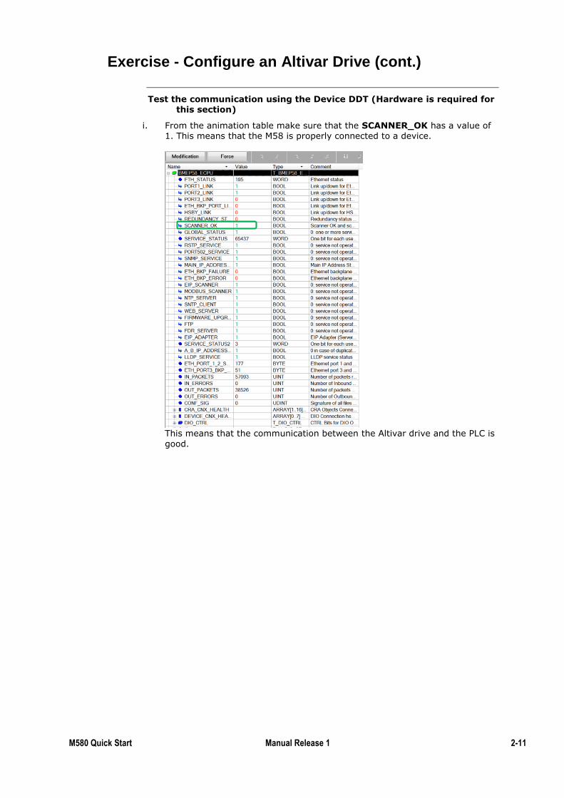
Test the communication using the Device DDT (Hardware is required for this section)
i. From the animation table make sure that the SCANNER_OK has a value of 1. This means that the M58 is properly connected to a device.
This means that the communication between the Altivar drive and the PLC is
good.
2-12 M580 Quick Start 1.0 September 2015
Exercise - Configure an Altivar Drive (cont.)
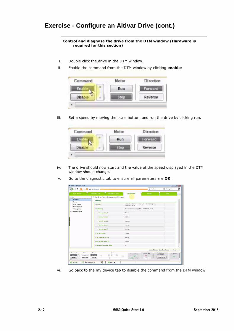
Control and diagnose the drive from the DTM window (Hardware is required for this section)
i. Double click the drive in the DTM window.
ii. Enable the command from the DTM window by clicking enable:
iii. Set a speed by moving the scale button, and run the drive by clicking run.
iv. The drive should now start and the value of the speed displayed in the DTM window should change.
v. Go to the diagnostic tab to ensure all parameters are OK.
vi. Go back to the my device tab to disable the command from the DTM window
M580 Quick Start Manual Release 1 2-13
Exercise - Configure an Altivar Drive (cont.)
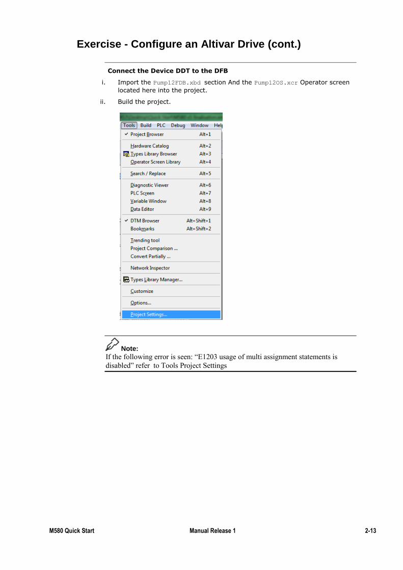
Connect the Device DDT to the DFB
i. Import the Pump12FDB.xbd section And the Pump12OS.xcr Operator screen
located here into the project.
ii. Build the project.
Note:
If the following error is seen: “E1203 usage of multi assignment statements is
disabled” refer to Tools Project Settings
2-14 M580 Quick Start 1.0 September 2015
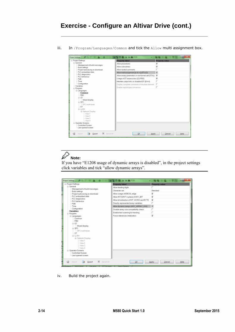
Exercise - Configure an Altivar Drive (cont.)
iii. In /Program/Languages/Common and tick the Allow multi assignment box.
Note:
If you have “E1208 usage of dynamic arrays is disabled”, in the project settings
click variables and tick “allow dynamic arrays”.
iv. Build the project again.
M580 Quick Start Manual Release 1 2-15
Exercise - Configure an Altivar Drive (cont.)
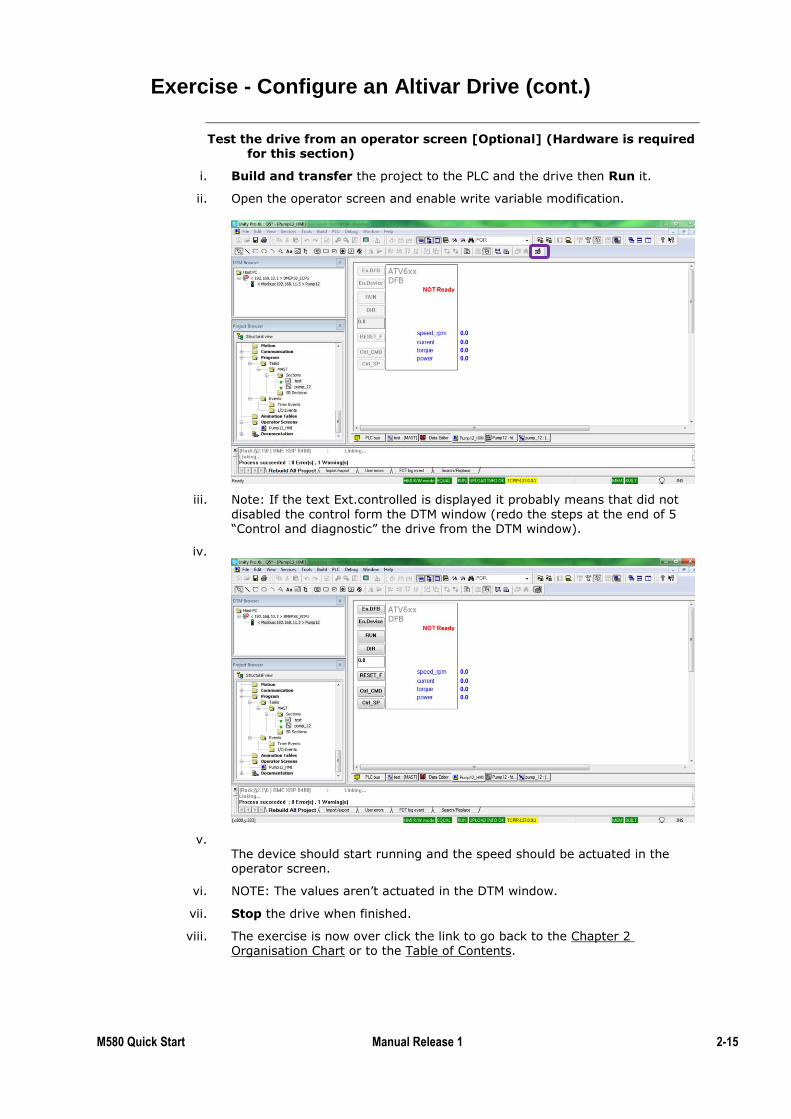
Test the drive from an operator screen [Optional] (Hardware is required for this section)
i. Build and transfer the project to the PLC and the drive then Run it.
ii. Open the operator screen and enable write variable modification.
iii. Note: If the text Ext.controlled is displayed it probably means that did not
disabled the control form the DTM window (redo the steps at the end of 5 “Control and diagnostic” the drive from the DTM window).
iv.
v. The device should start running and the speed should be actuated in the operator screen.
vi. NOTE: The values aren’t actuated in the DTM window.
vii. Stop the drive when finished.
viii. The exercise is now over click the link to go back to the Chapter 2 Organisation Chart or to the Table of Contents.
2-16 M580 Quick Start 1.0 September 2015
Summary
In this chapter the following topics have been covered:
Installing a DTM in Windows
How to add a DTM in Unity Pro
Configuring an Altivar drive through Unity Pro
Testing an Altivar Drive through Unity Pro
The following questions will help to check understanding of the topics covered in
this chapter:
What kind of device can be included in a DIO drop?
What is the main advantage of device integration? (You can take the Altivar
drive as an example)
Summary
Questions
M580 Quick Start Manual Release 1 2-17
NOC
The first chapter explained the use of the different ports of the M580: Connecting
to RIO or DIO drops or to a third party client such as a SCADA or Unity Pro.
A NOC’s role is quite similar: Connected to DIO drops or a SCADA. Doing so,
will extend the number of drops connected to the M580 rack, as well as freeing
bandwidth and CPU usage for the M580.
This chapter will explain how to configure a NOC; Once the NOC is configured a
DIO drop will be connected to it, as per the DIO chapter, or connect it to the
SCADA system.
By the end of this section the student will be able to:
Configure an NOC both for SCADA applications or to connect to DIO drops
Introduction
Topic Objectives
2-18 M580 Quick Start 1.0 September 2015
Exercise - Distributed Devices via a NOC
By the completion of this exercise the student will be able to:
Implement an isolated distributed device network using the BME NOC 0311
module
Integrate a distributed device using Modbus/TCP
Monitor and control the health of a device via the available DDTs.
This exercise requires the Advantys software.
To complete this exercise on a PLC the following equipment is required:
One NOC 0311
One M580
One compatible rack
One compatible power supply
STB Modules
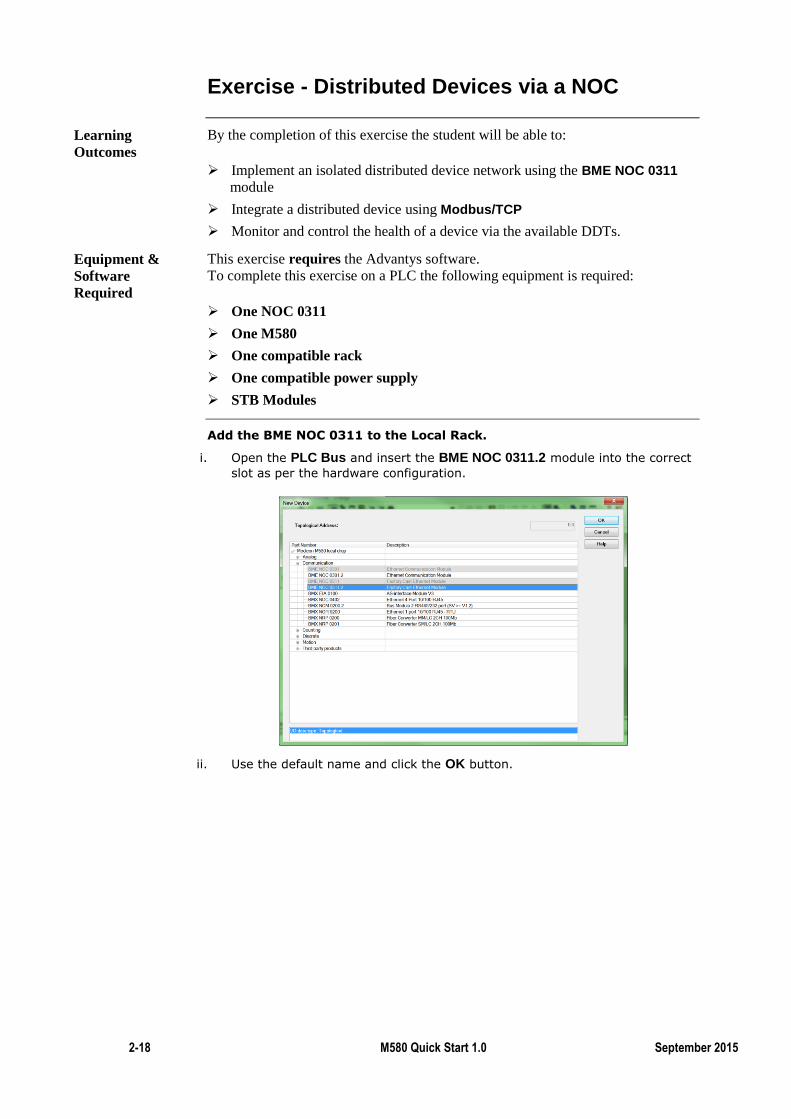
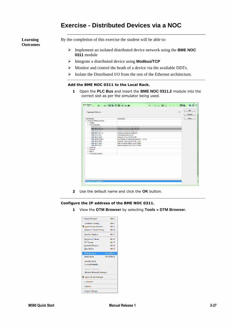
Add the BME NOC 0311 to the Local Rack.
i. Open the PLC Bus and insert the BME NOC 0311.2 module into the correct
slot as per the hardware configuration.
ii. Use the default name and click the OK button.
Learning
Outcomes
Equipment &
Software
Required
M580 Quick Start Manual Release 1 2-19
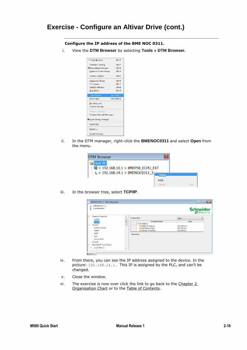
Exercise - Configure an Altivar Drive (cont.)
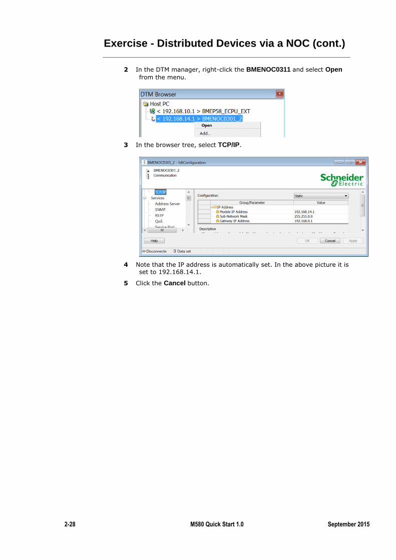
Configure the IP address of the BME NOC 0311.
i. View the DTM Browser by selecting Tools » DTM Browser.
ii. In the DTM manager, right-click the BMENOC0311 and select Open from
the menu.
iii. In the browser tree, select TCP/IP.
iv. From there, you can see the IP address assigned to the device. In the picture: 192.168.14.1. This IP is assigned by the PLC, and can’t be
changed.
v. Close the window.
vi. The exercise is now over click the link to go back to the Chapter 2 Organisation Chart or to the Table of Contents.
2-20 M580 Quick Start 1.0 September 2015
Summary
In this chapter the following topics have been covered:
How to add a NOC in Unity Pro
Configuring a NOC
The following questions will help to check understanding of the topics covered in
this chapter:
What are the possible roles of a NOC?
Summary
Questions
M580 Quick Start Manual Release 1 2-21
M580 Isolated Device Networks
Distributed I/O can be combined with RIO on a single network to reduce wiring
and installation costs. However, with a large amount of DIO, this can impact
performance of both the RIO and DIO networks.
A solution is to isolate the Distributed I/O onto a separate network. This chapter
details the techniques for this and how to use the BME NOC to achieve network
isolation.
By the completion of this topic you will be able to:
Understand the difference between combined and isolated Device Networks
Investigate possible network architectures
Configure an Isolated Device Network using the BME NOC 0311
Use the BME NOC 0311 Web Services
Configure a FactoryCast Web page
This Part Covers the Following Topics:
Device Networks ........................................................................ 2-22
BME NOC 03*1 ......................................................................... 2-24
BME NOC Web Services ........................................................... 2-38
FactoryCast ................................................................................. 2-42
Introduction
Topic Objectives
2-22 M580 Quick Start 1.0 September 2015
Device Networks
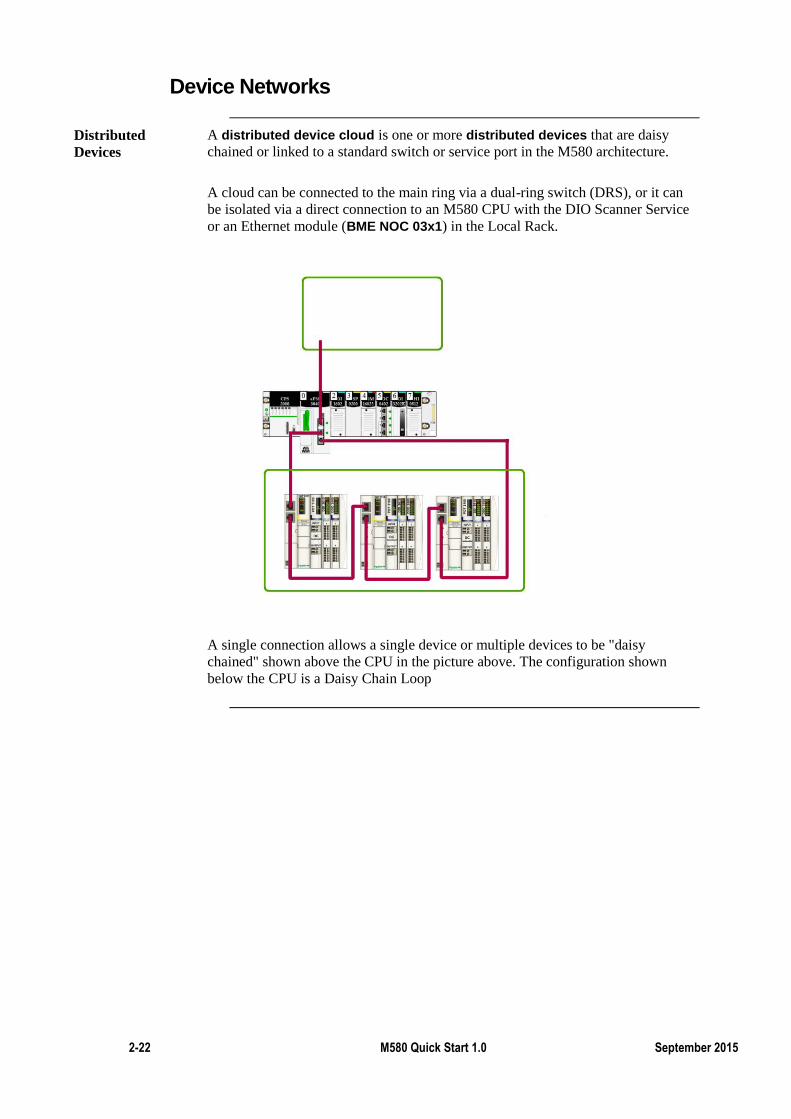
A distributed device cloud is one or more distributed devices that are daisy
chained or linked to a standard switch or service port in the M580 architecture.
A cloud can be connected to the main ring via a dual-ring switch (DRS), or it can
be isolated via a direct connection to an M580 CPU with the DIO Scanner Service
or an Ethernet module (BME NOC 03x1) in the Local Rack.
A single connection allows a single device or multiple devices to be "daisy
chained" shown above the CPU in the picture above. The configuration shown
below the CPU is a Daisy Chain Loop
Distributed
Devices

M580 Quick Start Manual Release 1 2-23
Isolated Device Networks
The second way to integrate distributed devices is to separate them from the
M580 Ethernet Remote I/O network. This allows for optimum utilisation of
resources. Daisy chain loops are supported.
We will not learn how to do this in this training.
Isolated
Distributed
Device Network
2-24 M580 Quick Start 1.0 September 2015
BME NOC 03*1
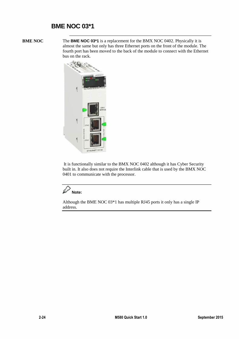
The BME NOC 03*1 is a replacement for the BMX NOC 0402. Physically it is
almost the same but only has three Ethernet ports on the front of the module. The
fourth port has been moved to the back of the module to connect with the Ethernet
bus on the rack.
It is functionally similar to the BMX NOC 0402 although it has Cyber Security
built in. It also does not require the Interlink cable that is used by the BMX NOC
0401 to communicate with the processor.
Note:
Although the BME NOC 03*1 has multiple RJ45 ports it only has a single IP
address.
BME NOC
M580 Quick Start Manual Release 1 2-25
BME NOC 03*1 (cont.)
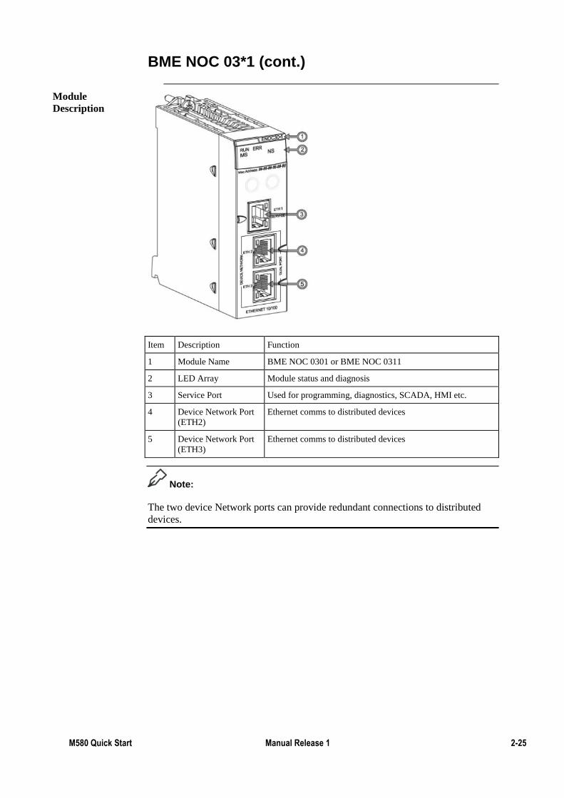
Item Description Function
1 Module Name BME NOC 0301 or BME NOC 0311
2 LED Array Module status and diagnosis
3 Service Port Used for programming, diagnostics, SCADA, HMI etc.
4 Device Network Port
(ETH2)
Ethernet comms to distributed devices
5 Device Network Port
(ETH3)
Ethernet comms to distributed devices
Note:
The two device Network ports can provide redundant connections to distributed
devices.
Module
Description
2-26 M580 Quick Start 1.0 September 2015
BME NOC 03*1 (cont.)
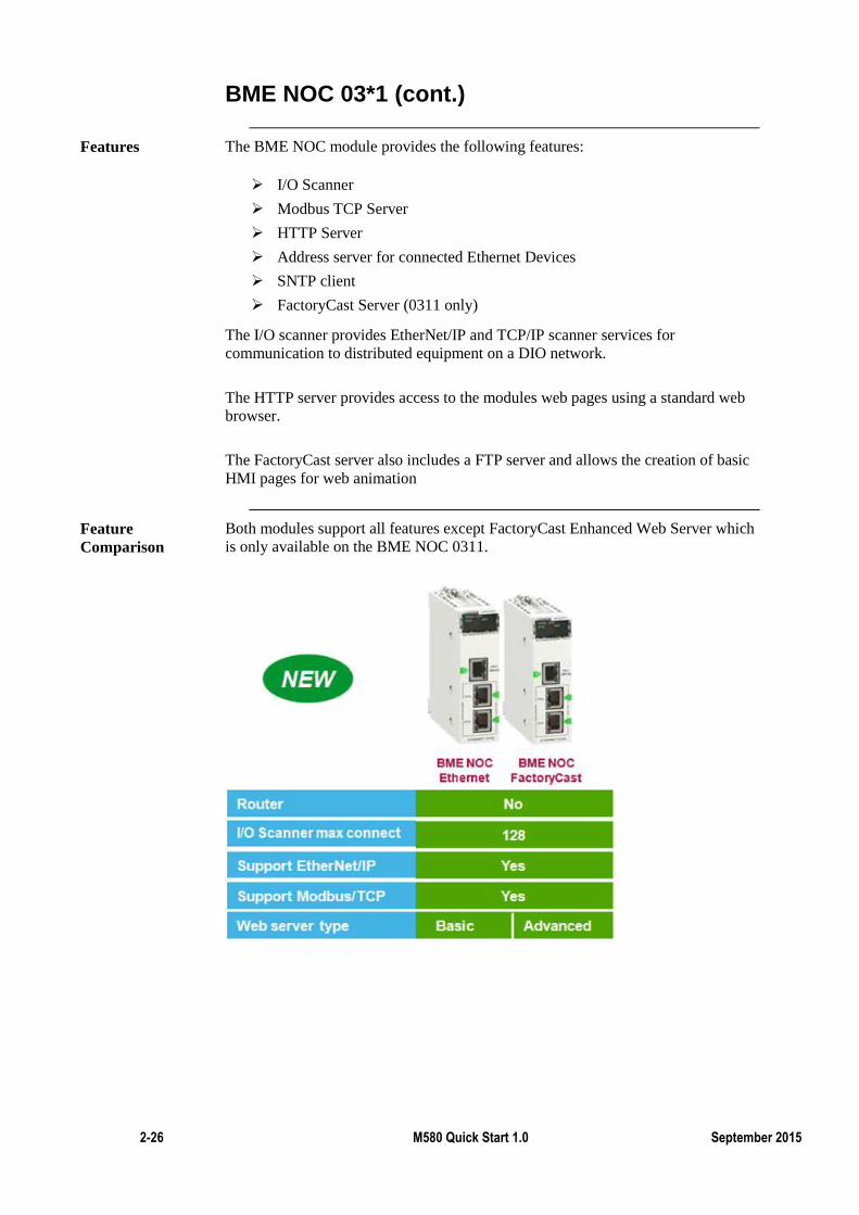
The BME NOC module provides the following features:
I/O Scanner
Modbus TCP Server
HTTP Server
Address server for connected Ethernet Devices
SNTP client
FactoryCast Server (0311 only)
The I/O scanner provides EtherNet/IP and TCP/IP scanner services for
communication to distributed equipment on a DIO network.
The HTTP server provides access to the modules web pages using a standard web
browser.
The FactoryCast server also includes a FTP server and allows the creation of basic
HMI pages for web animation
Both modules support all features except FactoryCast Enhanced Web Server which
is only available on the BME NOC 0311.
Features
Feature
Comparison
M580 Quick Start Manual Release 1 2-27
Exercise - Distributed Devices via a NOC
By the completion of this exercise the student will be able to:
Implement an isolated distributed device network using the BME NOC
0311 module
Integrate a distributed device using Modbus/TCP
Monitor and control the heath of a device via the available DDTs.
Isolate the Distributed I/O from the rest of the Ethernet architecture.
Add the BME NOC 0311 to the Local Rack.
1 Open the PLC Bus and insert the BME NOC 0311.2 module into the
correct slot as per the simulator being used.
2 Use the default name and click the OK button.
Configure the IP address of the BME NOC 0311.
1 View the DTM Browser by selecting Tools » DTM Browser.
Learning
Outcomes
2-28 M580 Quick Start 1.0 September 2015
Exercise - Distributed Devices via a NOC (cont.)
2 In the DTM manager, right-click the BMENOC0311 and select Open from the menu.
3 In the browser tree, select TCP/IP.
4 Note that the IP address is automatically set. In the above picture it is
set to 192.168.14.1.
5 Click the Cancel button.
M580 Quick Start Manual Release 1 2-29
Exercise - Distributed Devices via a NOC (cont.)
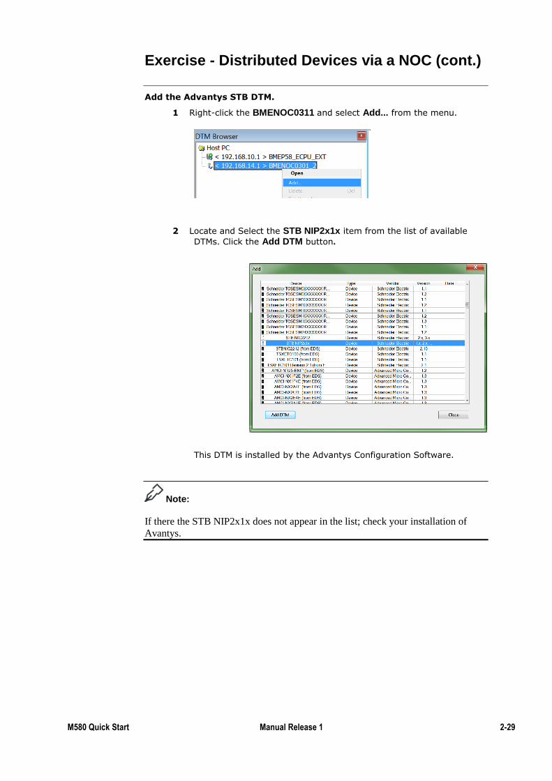
Add the Advantys STB DTM.
1 Right-click the BMENOC0311 and select Add... from the menu.
2 Locate and Select the STB NIP2x1x item from the list of available
DTMs. Click the Add DTM button.
This DTM is installed by the Advantys Configuration Software.
Note:
If there the STB NIP2x1x does not appear in the list; check your installation of
Avantys.
2-30 M580 Quick Start 1.0 September 2015
Exercise - Distributed Devices via a NOC (cont.)
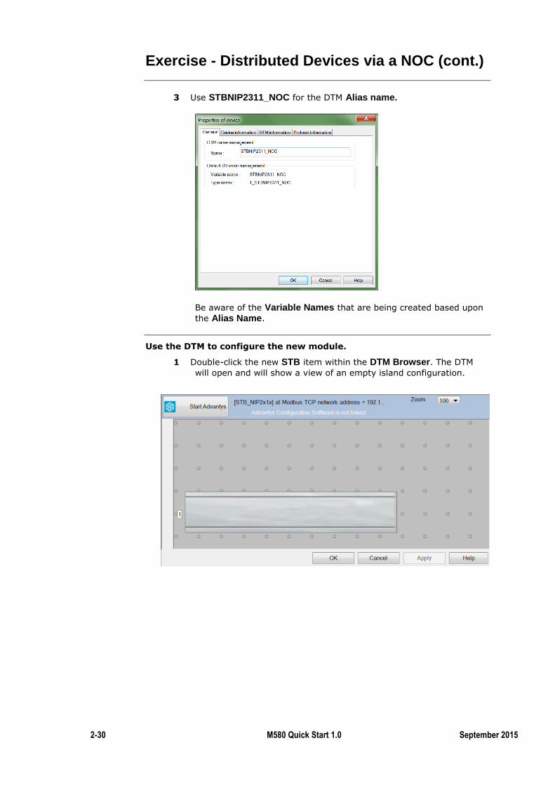
3 Use STBNIP2311_NOC for the DTM Alias name.
Be aware of the Variable Names that are being created based upon
the Alias Name.
Use the DTM to configure the new module.
1 Double-click the new STB item within the DTM Browser. The DTM
will open and will show a view of an empty island configuration.
M580 Quick Start Manual Release 1 2-31
Exercise - Distributed Devices via a NOC (cont.)
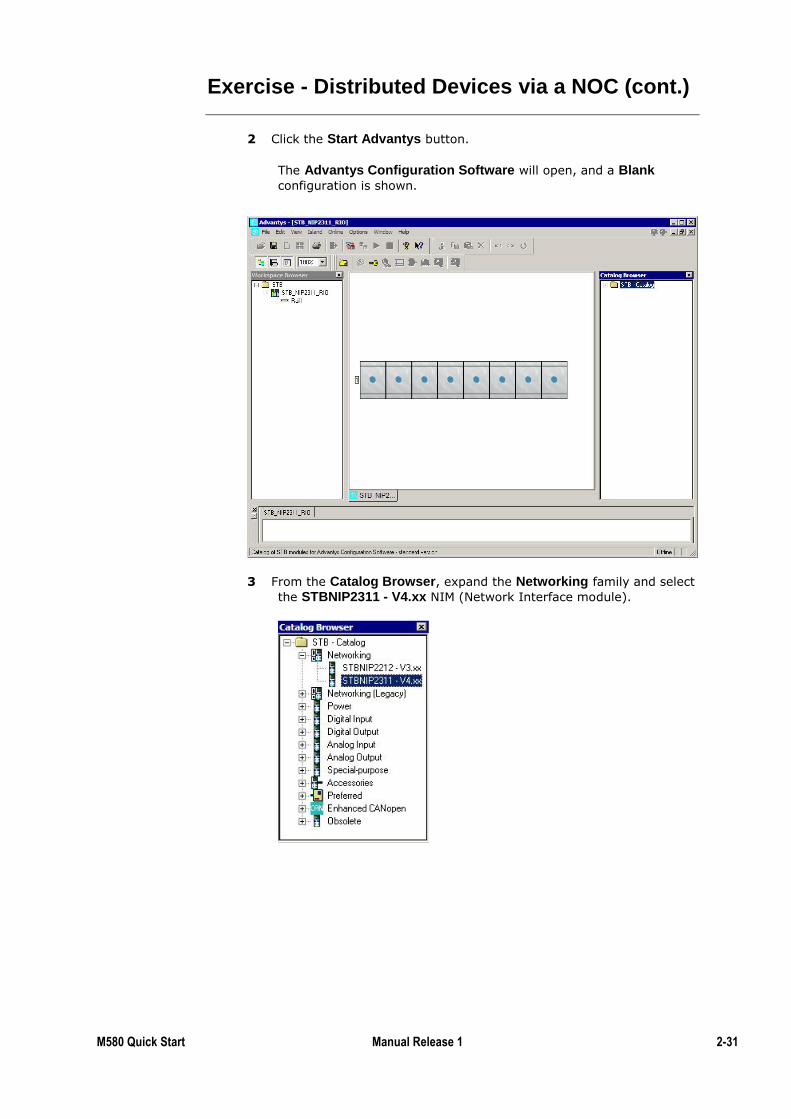
2 Click the Start Advantys button.
The Advantys Configuration Software will open, and a Blank
configuration is shown.
3 From the Catalog Browser, expand the Networking family and select
the STBNIP2311 - V4.xx NIM (Network Interface module).
2-32 M580 Quick Start 1.0 September 2015
Exercise - Distributed Devices via a NOC (cont.)
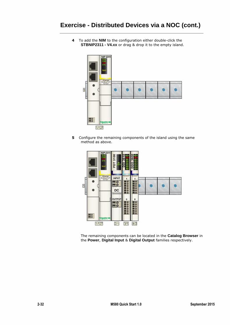
4 To add the NIM to the configuration either double-click the
STBNIP2311 - V4.xx or drag & drop it to the empty island.
5 Configure the remaining components of the island using the same
method as above.
The remaining components can be located in the Catalog Browser in
the Power, Digital Input & Digital Output families respectively.
M580 Quick Start Manual Release 1 2-33
Exercise - Distributed Devices via a NOC (cont.)
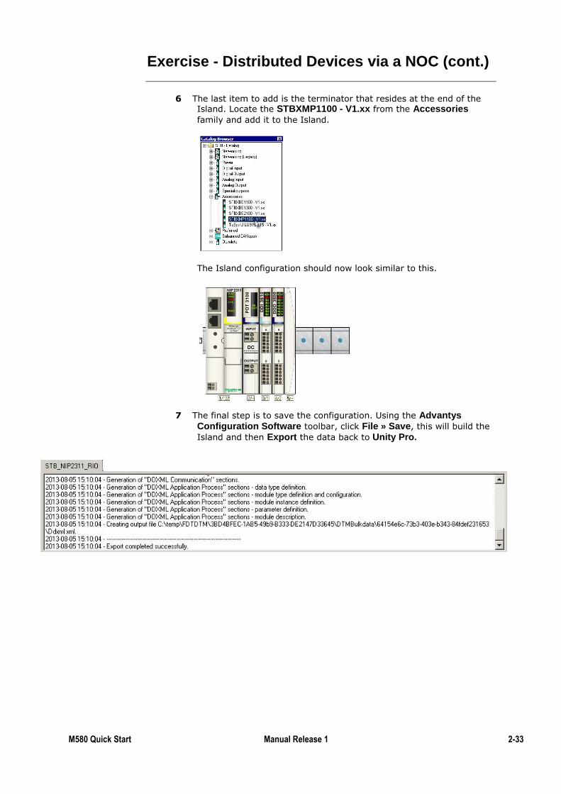
6 The last item to add is the terminator that resides at the end of the Island. Locate the STBXMP1100 - V1.xx from the Accessories
family and add it to the Island.
The Island configuration should now look similar to this.
7 The final step is to save the configuration. Using the Advantys Configuration Software toolbar, click File » Save, this will build the
Island and then Export the data back to Unity Pro.
2-34 M580 Quick Start 1.0 September 2015
Exercise - Distributed Devices via a NOC (cont.)
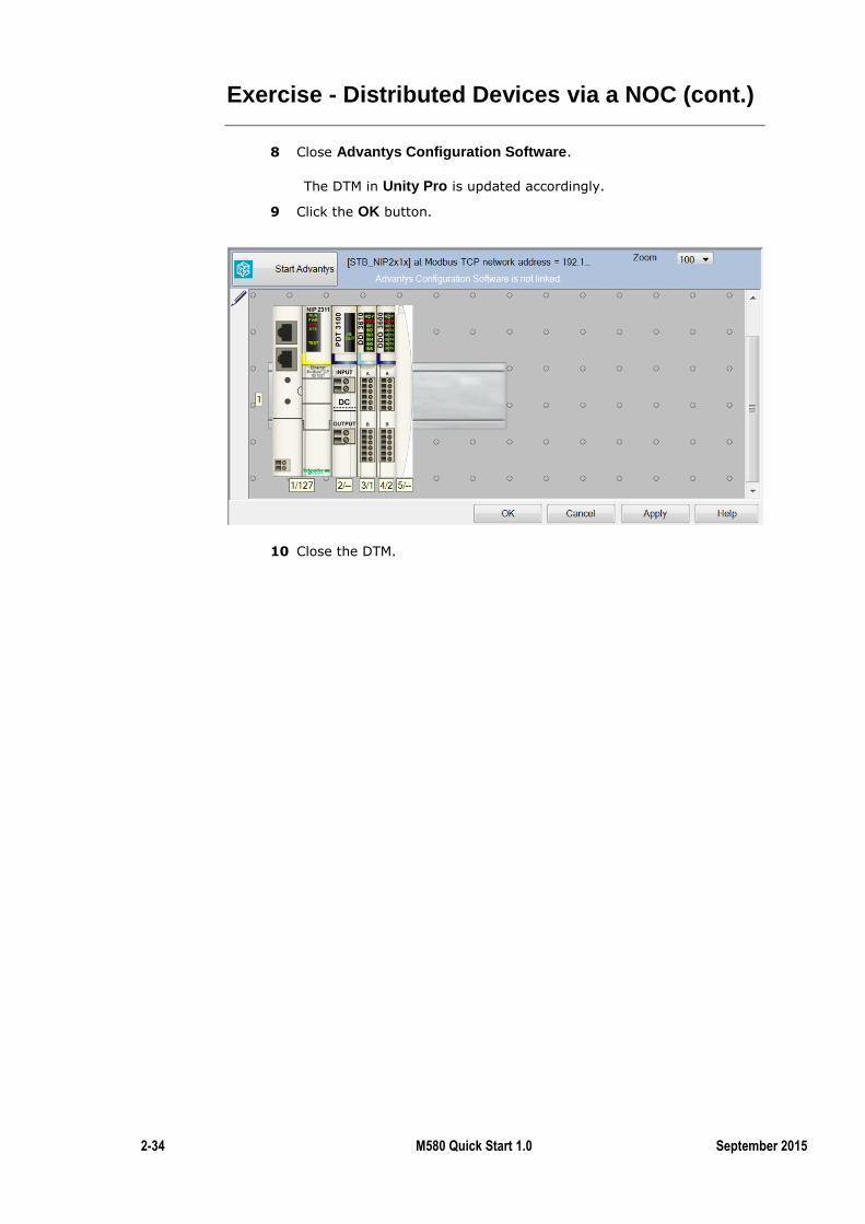
8 Close Advantys Configuration Software.
The DTM in Unity Pro is updated accordingly.
9 Click the OK button.
10 Close the DTM.
M580 Quick Start Manual Release 1 2-35
Exercise - Distributed Devices via a NOC (cont.)
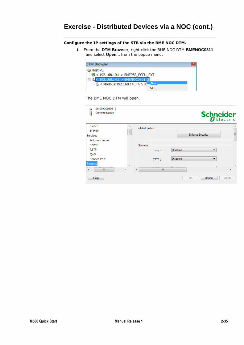
Configure the IP settings of the STB via the BME NOC DTM.
1 From the DTM Browser, right click the BME NOC DTM BMENOC0311
and select Open... from the popup menu.
The BME NOC DTM will open.
2-36 M580 Quick Start 1.0 September 2015
Exercise - Distributed Devices via a NOC (cont.)
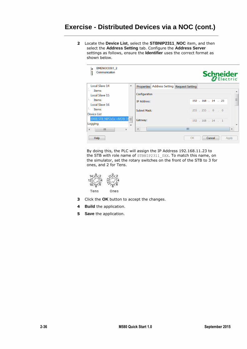
2 Locate the Device List, select the STBNIP2311_NOC item, and then
select the Address Setting tab. Configure the Address Server settings as follows, ensure the Identifier uses the correct format as
shown below.
By doing this, the PLC will assign the IP Address 192.168.11.23 to the STB with role name of STBNIP2311_0XX. To match this name, on
the simulator, set the rotary switches on the front of the STB to 3 for ones, and 2 for Tens.
3 Click the OK button to accept the changes.
4 Build the application.
5 Save the application.

M580 Quick Start Manual Release 1 2-37
Exercise - Distributed Devices via a NOC (cont.)
Auto-configure the Advantys STB Island
1 Power cycle the Advantys STB island, so it will take into account the new rotary switches configuration.
2 Open the front door of the Network Interface Module (NIM).
3 Using a screw driver, press and hold the RST button for 3 seconds to
reset the Island to its factory settings. (This action has nothing to do
with the IP Address: It is just to reset the modules configuration).
4 When the reset is done, both PWR and RUN LEDs should be steady
on.
Test the Distributed Device.
Connect, Transfer and RUN the application.
5 Use a Red patch cable to connect the Device port of the NOC to one
of the available Ethernet ports on the STBNIP2311.
6 Open the Data Editor, select the STBNIP2311_NOC variable and add
it to an Animation Table.
2-38 M580 Quick Start 1.0 September 2015
Exercise - Distributed Devices via a NOC (cont.)
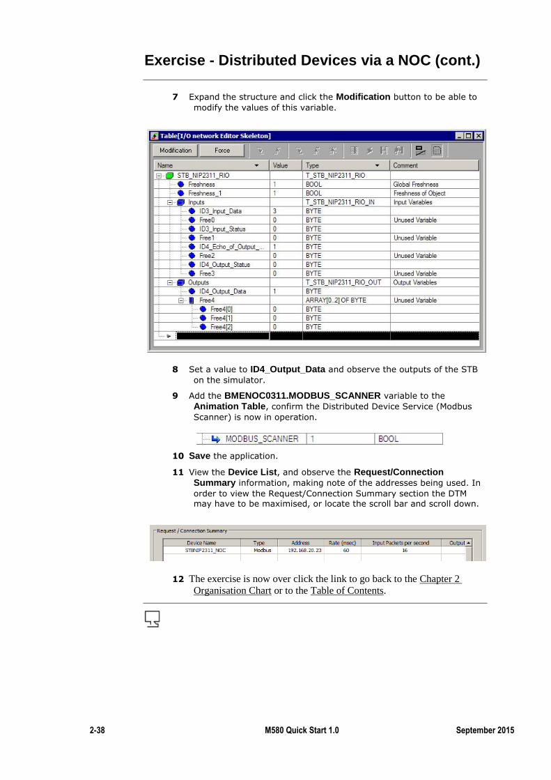
7 Expand the structure and click the Modification button to be able to
modify the values of this variable.
8 Set a value to ID4_Output_Data and observe the outputs of the STB
on the simulator.
9 Add the BMENOC0311.MODBUS_SCANNER variable to the Animation Table, confirm the Distributed Device Service (Modbus
Scanner) is now in operation.
10 Save the application.
11 View the Device List, and observe the Request/Connection Summary information, making note of the addresses being used. In
order to view the Request/Connection Summary section the DTM may have to be maximised, or locate the scroll bar and scroll down.
12 The exercise is now over click the link to go back to the Chapter 2
Organisation Chart or to the Table of Contents.
M580 Quick Start Manual Release 1 2-39
BME NOC Web Services
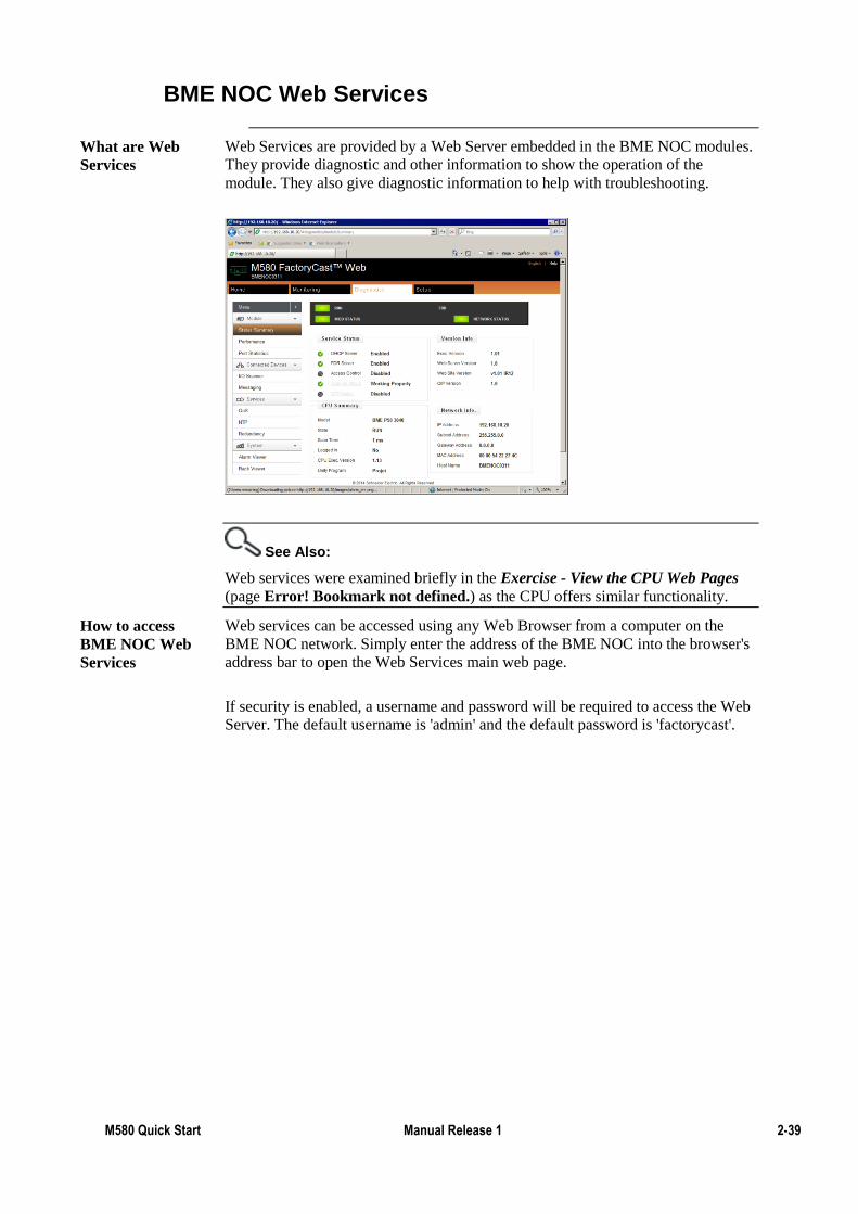
Web Services are provided by a Web Server embedded in the BME NOC modules.
They provide diagnostic and other information to show the operation of the
module. They also give diagnostic information to help with troubleshooting.
See Also:
Web services were examined briefly in the Exercise - View the CPU Web Pages
(page Error! Bookmark not defined.) as the CPU offers similar functionality.
Web services can be accessed using any Web Browser from a computer on the
BME NOC network. Simply enter the address of the BME NOC into the browser's
address bar to open the Web Services main web page.
If security is enabled, a username and password will be required to access the Web
Server. The default username is 'admin' and the default password is 'factorycast'.
What are Web
Services
How to access
BME NOC Web
Services
2-40 M580 Quick Start 1.0 September 2015
BME NOC Web Services (cont.)
The Diagnostic Viewer offers several pages of diagnostic information for the BME
NOC. These includes the following:
Module Status
Performance
Port Status
I/O Scanner
Redundancy Status
Alarm Viewer
Rack Viewer
These pages can assist with fault-finding the module or device network. The other
pages that are available can assist with more detailed network troubleshooting.
Diagnostics
Viewer
M580 Quick Start Manual Release 1 2-41
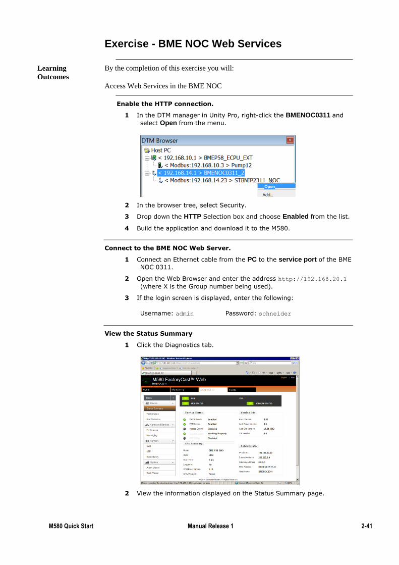
Exercise - BME NOC Web Services
By the completion of this exercise you will:
Access Web Services in the BME NOC
Enable the HTTP connection.
1 In the DTM manager in Unity Pro, right-click the BMENOC0311 and
select Open from the menu.
2 In the browser tree, select Security.
3 Drop down the HTTP Selection box and choose Enabled from the list.
4 Build the application and download it to the M580.
Connect to the BME NOC Web Server.
1 Connect an Ethernet cable from the PC to the service port of the BME
NOC 0311.
2 Open the Web Browser and enter the address http://192.168.20.1
(where X is the Group number being used).
3 If the login screen is displayed, enter the following:
Username: admin Password: schneider
View the Status Summary
1 Click the Diagnostics tab.
2 View the information displayed on the Status Summary page.
Learning
Outcomes
2-42 M580 Quick Start 1.0 September 2015
FactoryCast
FactoryCast is a Web server included with the BME NOC 0311. It provides the
following features:
Custom Web Pages to create a user defined interface to the module
Rack Viewer providing a graphical representation of the configured ePAC system
including all modules and I/O status
ePAC Program Viewer giving a view of the ePAC program code with animated
variable states
Trend Viewer for graphical visualisation of variables
Customisable Dashboard with widgets to provide an efficient view of process data
Configuration is via a built-in designer which is part of the Web Interface. Logos
and colours can be configured to provide easy brand labelling.
What is
FactoryCast?
M580 Quick Start Manual Release 1 2-43
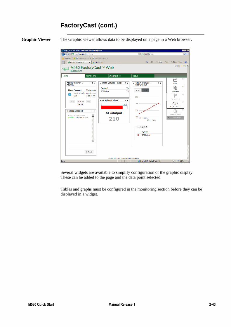
FactoryCast (cont.)
The Graphic viewer allows data to be displayed on a page in a Web browser.
Several widgets are available to simplify configuration of the graphic display.
These can be added to the page and the data point selected.
Tables and graphs must be configured in the monitoring section before they can be
displayed in a widget.
Graphic Viewer
2-44 M580 Quick Start 1.0 September 2015
Exercise - FactoryCast Graphic Display
By the completion of this exercise you will:
Access FactoryCast in the BME NOC
Explore the FactoryCast Data Display features
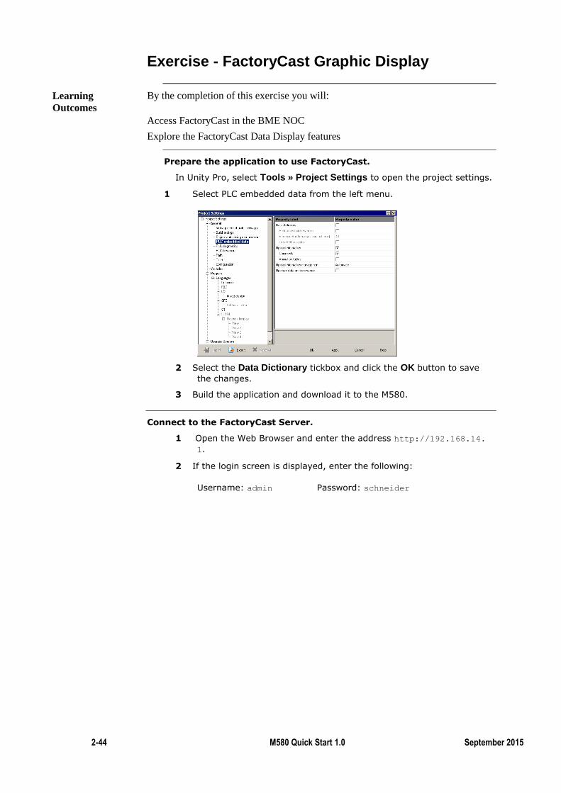
Prepare the application to use FactoryCast.
In Unity Pro, select Tools » Project Settings to open the project settings.
1 Select PLC embedded data from the left menu.
2 Select the Data Dictionary tickbox and click the OK button to save
the changes.
3 Build the application and download it to the M580.
Connect to the FactoryCast Server.
1 Open the Web Browser and enter the address http://192.168.14.
1.
2 If the login screen is displayed, enter the following:
Username: admin Password: schneider
Learning
Outcomes
M580 Quick Start Manual Release 1 2-45
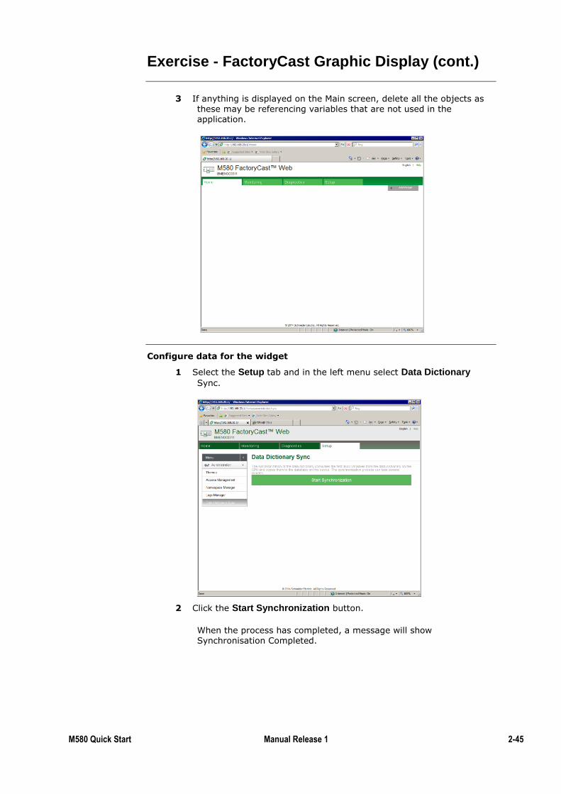
Exercise - FactoryCast Graphic Display (cont.)
3 If anything is displayed on the Main screen, delete all the objects as these may be referencing variables that are not used in the application.
Configure data for the widget
1 Select the Setup tab and in the left menu select Data Dictionary
Sync.
2 Click the Start Synchronization button.
When the process has completed, a message will show Synchronisation Completed.
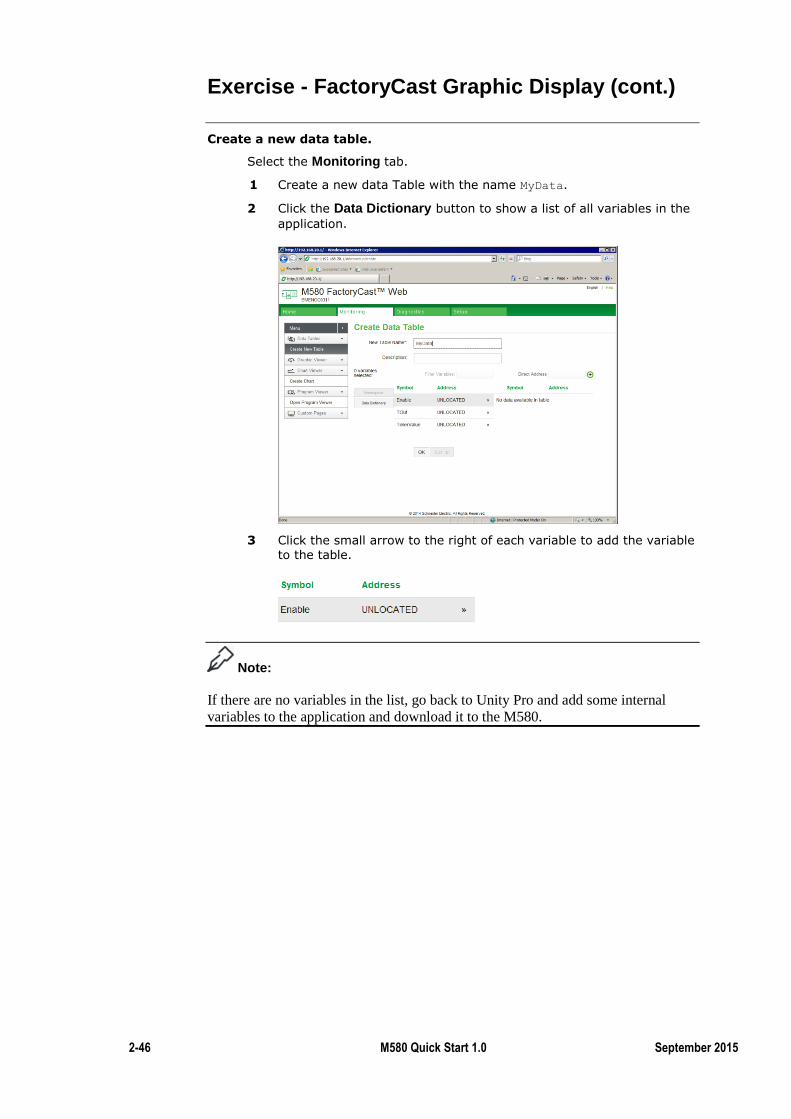
2-46 M580 Quick Start 1.0 September 2015
Exercise - FactoryCast Graphic Display (cont.)
Create a new data table.
Select the Monitoring tab.
1 Create a new data Table with the name MyData.
2 Click the Data Dictionary button to show a list of all variables in the
application.
3 Click the small arrow to the right of each variable to add the variable
to the table.
Note:
If there are no variables in the list, go back to Unity Pro and add some internal
variables to the application and download it to the M580.
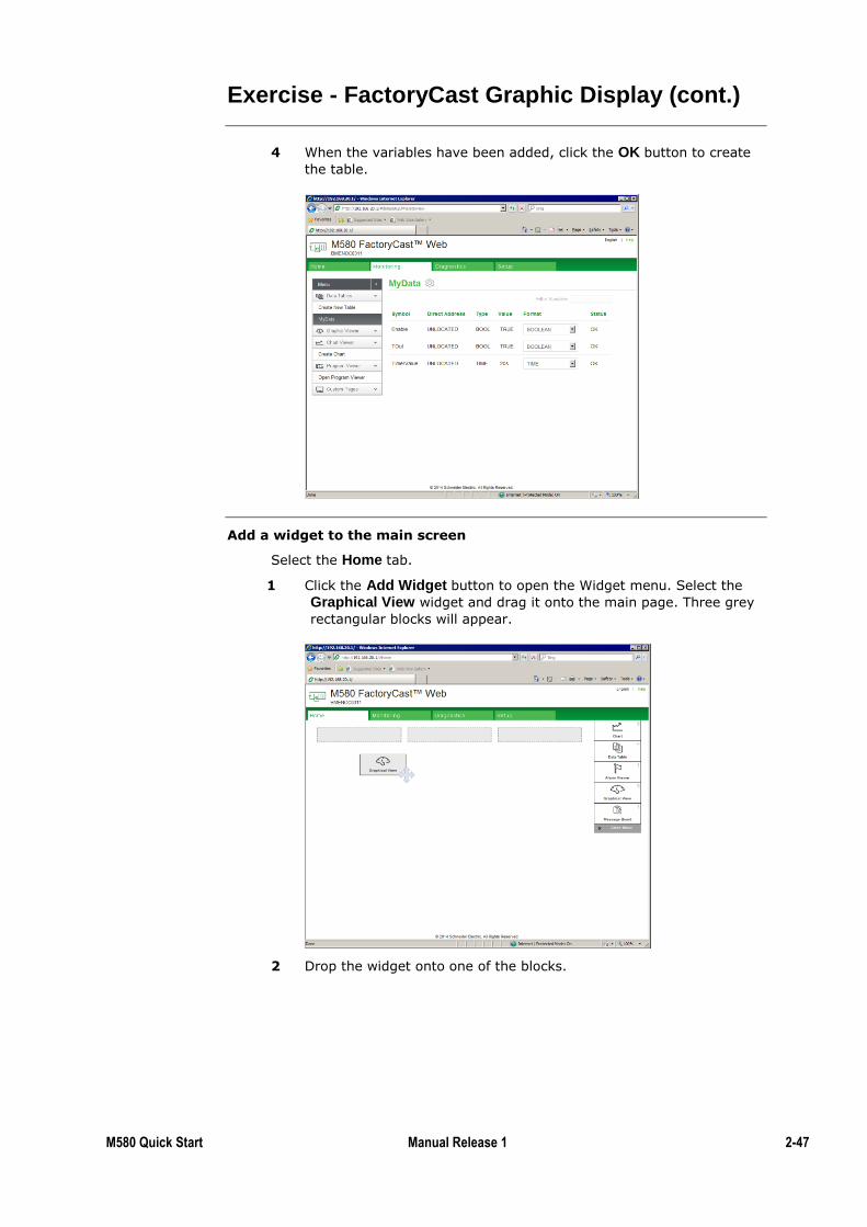
M580 Quick Start Manual Release 1 2-47
Exercise - FactoryCast Graphic Display (cont.)
4 When the variables have been added, click the OK button to create
the table.
Add a widget to the main screen
Select the Home tab.
1 Click the Add Widget button to open the Widget menu. Select the
Graphical View widget and drag it onto the main page. Three grey
rectangular blocks will appear.
2 Drop the widget onto one of the blocks.
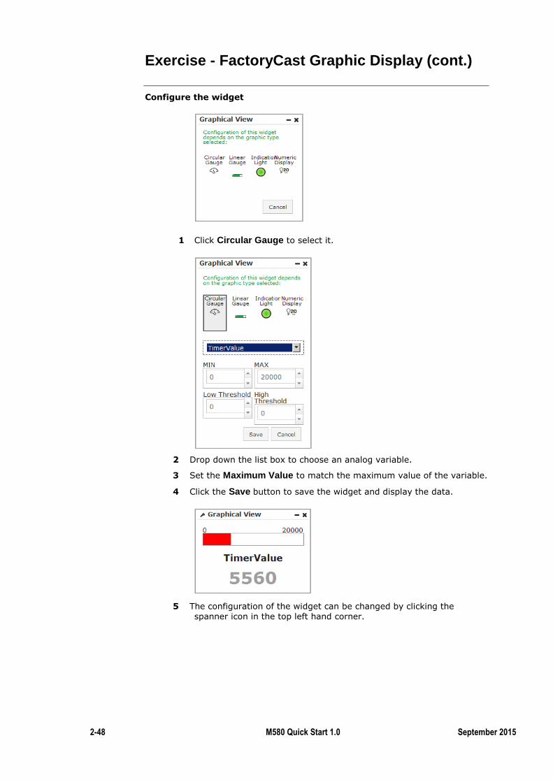
2-48 M580 Quick Start 1.0 September 2015
Exercise - FactoryCast Graphic Display (cont.)
Configure the widget
1 Click Circular Gauge to select it.
2 Drop down the list box to choose an analog variable.
3 Set the Maximum Value to match the maximum value of the variable.
4 Click the Save button to save the widget and display the data.
5 The configuration of the widget can be changed by clicking the spanner icon in the top left hand corner.
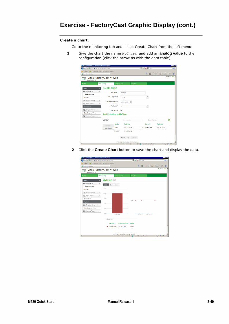
M580 Quick Start Manual Release 1 2-49
Exercise - FactoryCast Graphic Display (cont.)
Create a chart.
Go to the monitoring tab and select Create Chart from the left menu.
1 Give the chart the name MyChart and add an analog value to the
configuration (click the arrow as with the data table).
2 Click the Create Chart button to save the chart and display the data.

2-50 M580 Quick Start 1.0 September 2015
Exercise - FactoryCast Graphic Display (cont.)
Add the chart to the home page.
1 Go to the Home tab and drag a Chart widget onto the page. Select
MyChart and click the Save button to display the data.
2 Modify the analog value in Unity Pro and observe the changes on the Web page.
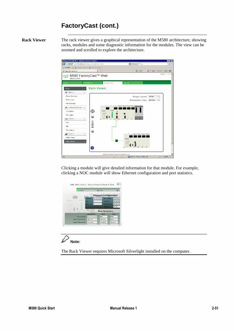
M580 Quick Start Manual Release 1 2-51
FactoryCast (cont.)
The rack viewer gives a graphical representation of the M580 architecture, showing
racks, modules and some diagnostic information for the modules. The view can be
zoomed and scrolled to explore the architecture.
Clicking a module will give detailed information for that module. For example,
clicking a NOC module will show Ethernet configuration and port statistics.
Note:
The Rack Viewer requires Microsoft Silverlight installed on the computer.
Rack Viewer
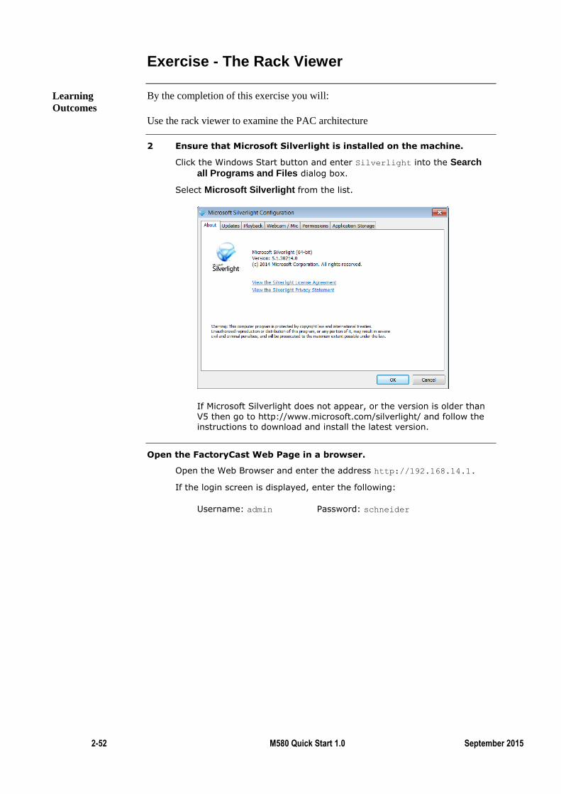
2-52 M580 Quick Start 1.0 September 2015
Exercise - The Rack Viewer
By the completion of this exercise you will:
Use the rack viewer to examine the PAC architecture
2 Ensure that Microsoft Silverlight is installed on the machine.
Click the Windows Start button and enter Silverlight into the Search
all Programs and Files dialog box.
Select Microsoft Silverlight from the list.
If Microsoft Silverlight does not appear, or the version is older than
V5 then go to http://www.microsoft.com/silverlight/ and follow the instructions to download and install the latest version.
Open the FactoryCast Web Page in a browser.
Open the Web Browser and enter the address http://192.168.14.1.
If the login screen is displayed, enter the following:
Username: admin Password: schneider
Learning
Outcomes
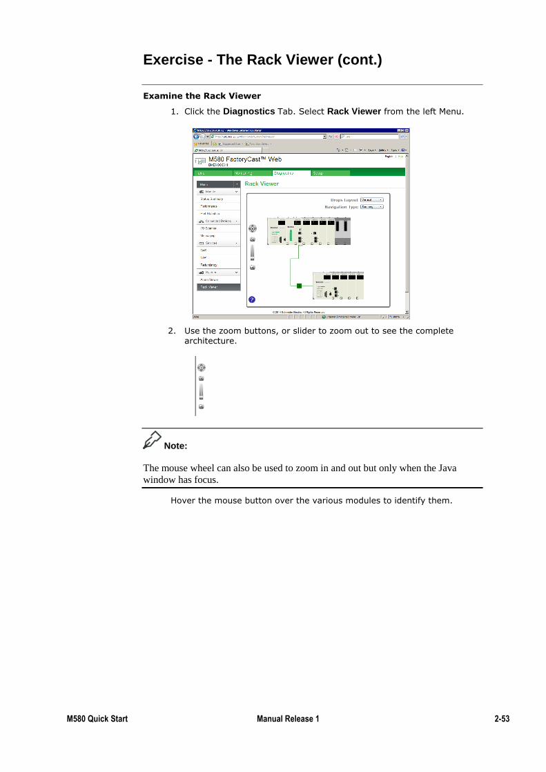
M580 Quick Start Manual Release 1 2-53
Exercise - The Rack Viewer (cont.)
Examine the Rack Viewer
1. Click the Diagnostics Tab. Select Rack Viewer from the left Menu.
2. Use the zoom buttons, or slider to zoom out to see the complete architecture.
Note:
The mouse wheel can also be used to zoom in and out but only when the Java
window has focus.
Hover the mouse button over the various modules to identify them.
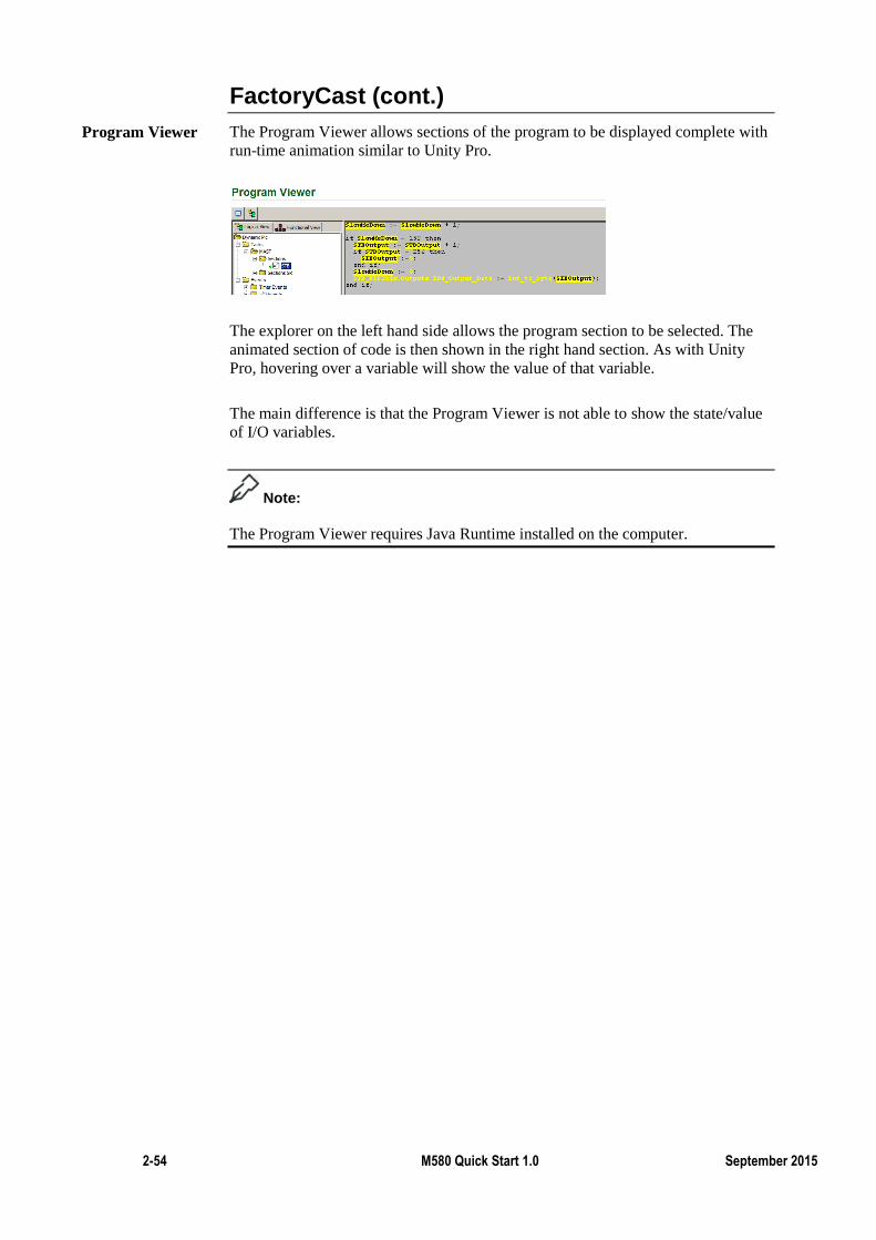
2-54 M580 Quick Start 1.0 September 2015
FactoryCast (cont.)
The Program Viewer allows sections of the program to be displayed complete with
run-time animation similar to Unity Pro.
The explorer on the left hand side allows the program section to be selected. The
animated section of code is then shown in the right hand section. As with Unity
Pro, hovering over a variable will show the value of that variable.
The main difference is that the Program Viewer is not able to show the state/value
of I/O variables.
Note:
The Program Viewer requires Java Runtime installed on the computer.
Program Viewer
M580 Quick Start Manual Release 1 2-55
Summary
In this chapter the following topics have been covered:
Device Networks
Isolated Device Networks
BME NOC 03*1
BME NOC Web Services
FactoryCast
The following questions will help to check understanding of the topics covered in
this chapter:
What are the possible roles of a NOC?
How many BME NOC modules make up the offer?
Which BME NOC modules support Factorycast?
Summary
Questions
2-56 M580 Quick Start 1.0 September 2015
Remote I/O (RIO)
The first chapter explained how to configure local I/O.
This chapter will show that configuring an RIO drop is quite similar to a local.
This makes the configuration of RIO much easier than DIO drops.
Other advantages of RIO over DIO are:
The rapidity of communication between the devices and the M580
The possibility to use FDR (Fast Device Replacement)
The use of RSTP
See the M580 Configuration Course for more details in these features.
The main limitation of RIO is that only some X80 modules support it.
If you have a Quantum PLC with X80 modules, you can configure these modules
as an M580 RIO drop.
By the end of this section the student will be able to:
Configure a RIO drop
Introduction
Topic Objectives
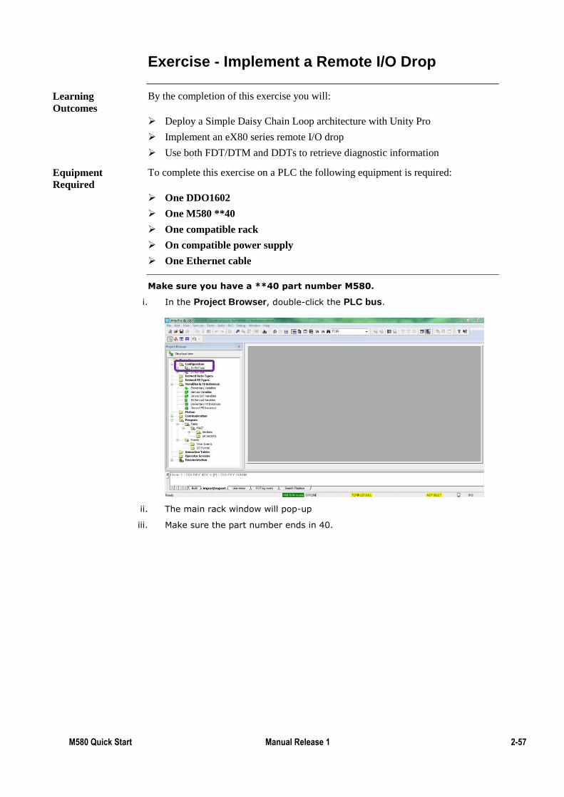
M580 Quick Start Manual Release 1 2-57
Exercise - Implement a Remote I/O Drop
By the completion of this exercise you will:
Deploy a Simple Daisy Chain Loop architecture with Unity Pro
Implement an eX80 series remote I/O drop
Use both FDT/DTM and DDTs to retrieve diagnostic information
To complete this exercise on a PLC the following equipment is required:
One DDO1602
One M580 **40
One compatible rack
On compatible power supply
One Ethernet cable
Make sure you have a **40 part number M580.
i. In the Project Browser, double-click the PLC bus.
ii. The main rack window will pop-up
iii. Make sure the part number ends in 40.
Learning
Outcomes
Equipment
Required
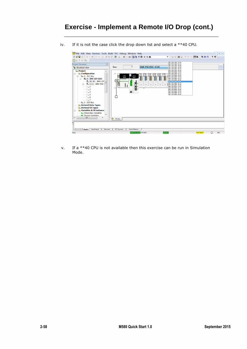
2-58 M580 Quick Start 1.0 September 2015
Exercise - Implement a Remote I/O Drop (cont.)
iv. If it is not the case click the drop down list and select a **40 CPU.
v. If a **40 CPU is not available then this exercise can be run in Simulation Mode.
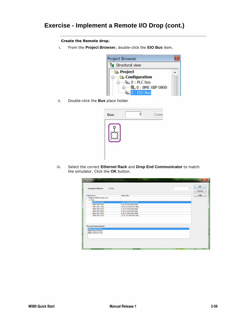
M580 Quick Start Manual Release 1 2-59
Exercise - Implement a Remote I/O Drop (cont.)
Create the Remote drop.
i. From the Project Browser, double-click the EIO Bus item.
ii. Double-click the Bus place holder
iii. Select the correct Ethernet Rack and Drop End Communicator to match
the simulator. Click the OK button.
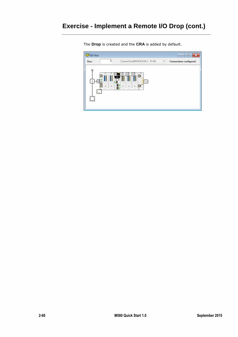
2-60 M580 Quick Start 1.0 September 2015
Exercise - Implement a Remote I/O Drop (cont.)
The Drop is created and the CRA is added by default.
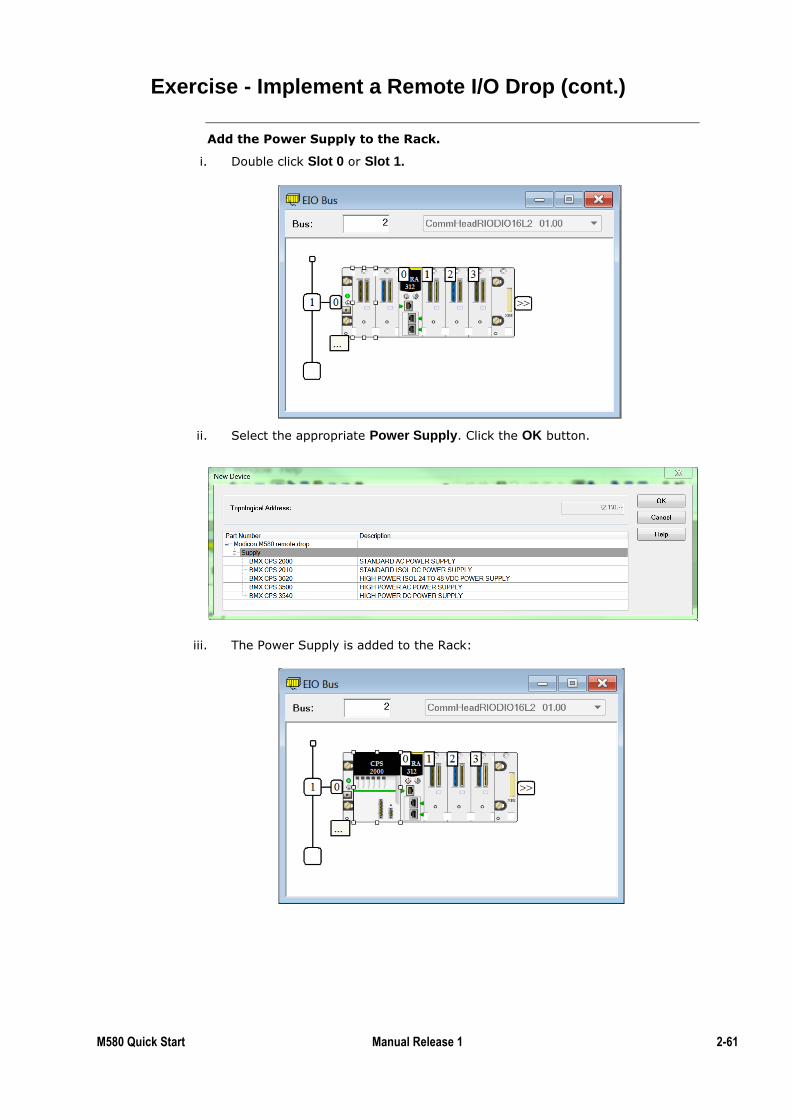
M580 Quick Start Manual Release 1 2-61
Exercise - Implement a Remote I/O Drop (cont.)
Add the Power Supply to the Rack.
i. Double click Slot 0 or Slot 1.
ii. Select the appropriate Power Supply. Click the OK button.
iii. The Power Supply is added to the Rack:
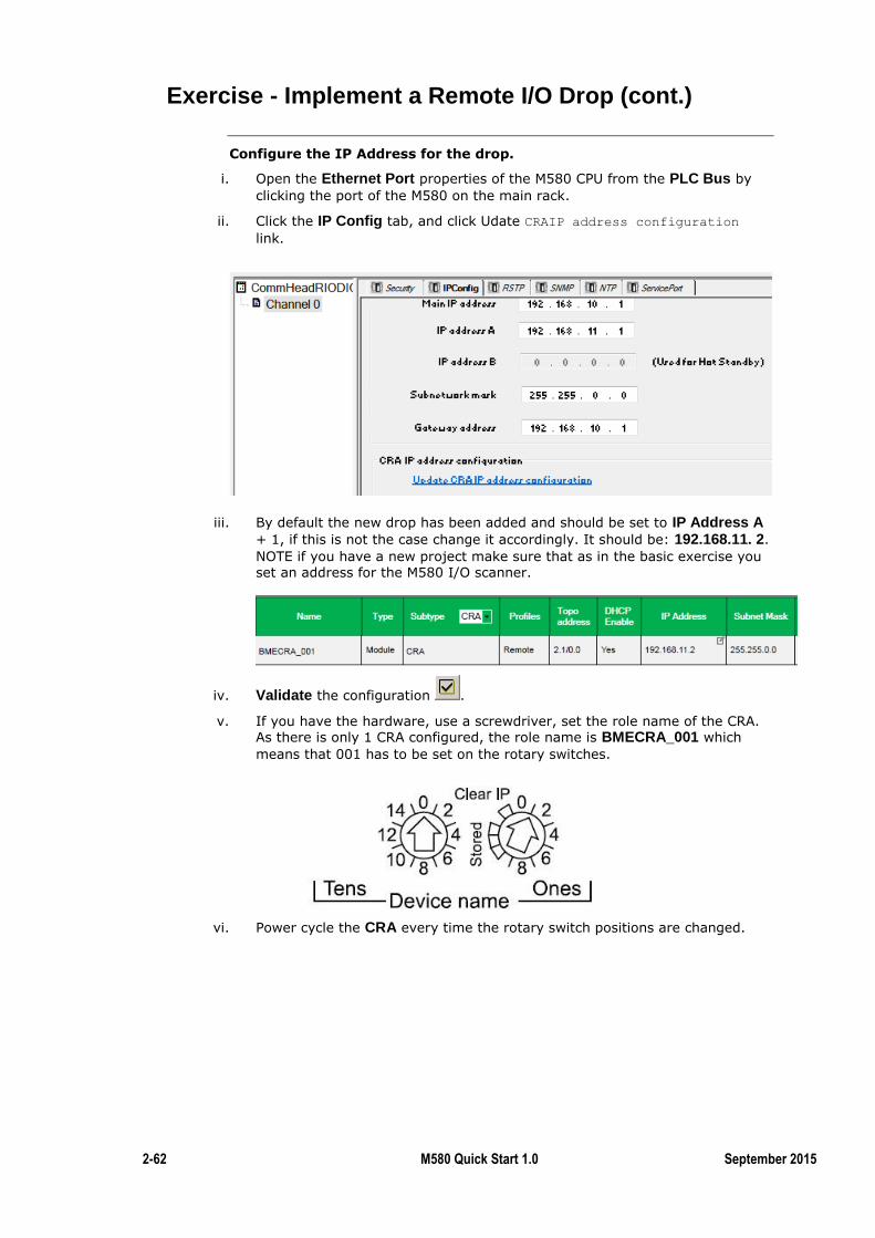
2-62 M580 Quick Start 1.0 September 2015
Exercise - Implement a Remote I/O Drop (cont.)
Configure the IP Address for the drop.
i. Open the Ethernet Port properties of the M580 CPU from the PLC Bus by
clicking the port of the M580 on the main rack.
ii. Click the IP Config tab, and click Udate CRAIP address configuration
link.
iii. By default the new drop has been added and should be set to IP Address A + 1, if this is not the case change it accordingly. It should be: 192.168.11. 2.
NOTE if you have a new project make sure that as in the basic exercise you set an address for the M580 I/O scanner.
iv. Validate the configuration .
v. If you have the hardware, use a screwdriver, set the role name of the CRA. As there is only 1 CRA configured, the role name is BMECRA_001 which
means that 001 has to be set on the rotary switches.
vi. Power cycle the CRA every time the rotary switch positions are changed.
M580 Quick Start Manual Release 1 2-63
Exercise - Implement a Remote I/O Drop (cont.)
Add the DDO1602.
i. Add a DDO1602 in the Remote rack.
Note:
This time Device DDT is automatically chosen as the type of I/O cannot be
selected NOTE: This time Device DDT is automatically chosen as the type of I/O
cannot be selected.
ii. Change the device name to Obi2 and un-tick the Supply Monitoring box.
iii. Open the test ST section created in the basic exercise,or create a new one if you started a new project.
iv. Type in this code: FOR i:=0 TO 15 BY 2 DO
Obi2.DIS_CH_OUT[i].VALUE := TRUE;
END_FOR;
Note:
Note the difference in the name of the device between this code and the code used
in the basic exercise.
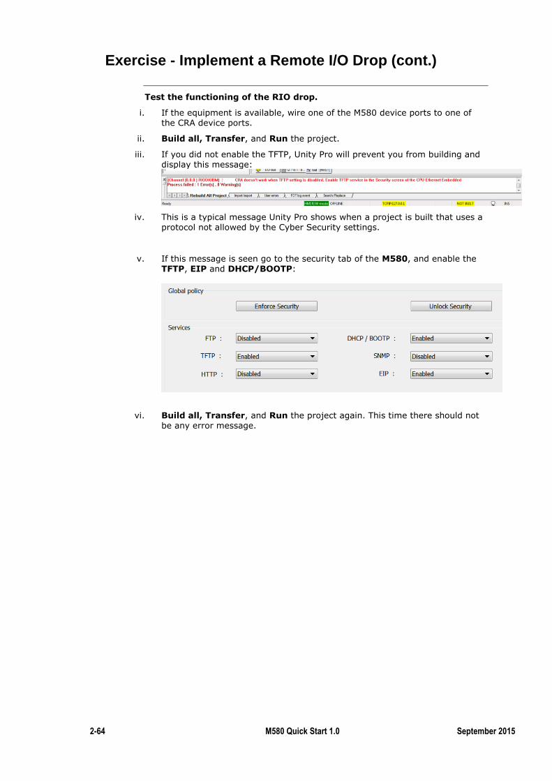
2-64 M580 Quick Start 1.0 September 2015
Exercise - Implement a Remote I/O Drop (cont.)
Test the functioning of the RIO drop.
i. If the equipment is available, wire one of the M580 device ports to one of the CRA device ports.
ii. Build all, Transfer, and Run the project.
iii. If you did not enable the TFTP, Unity Pro will prevent you from building and display this message:
iv. This is a typical message Unity Pro shows when a project is built that uses a
protocol not allowed by the Cyber Security settings.
v. If this message is seen go to the security tab of the M580, and enable the TFTP, EIP and DHCP/BOOTP:
vi. Build all, Transfer, and Run the project again. This time there should not
be any error message.
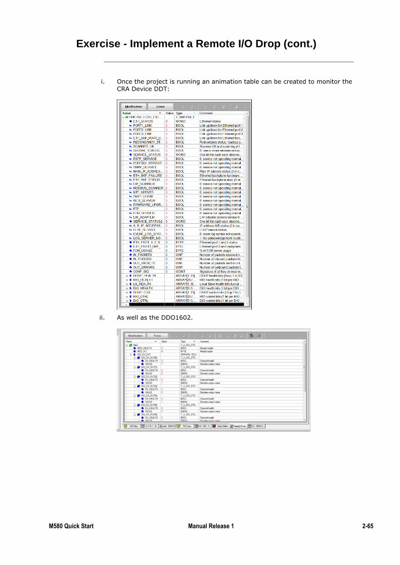
M580 Quick Start Manual Release 1 2-65
Exercise - Implement a Remote I/O Drop (cont.)
i. Once the project is running an animation table can be created to monitor the CRA Device DDT:
ii. As well as the DDO1602.
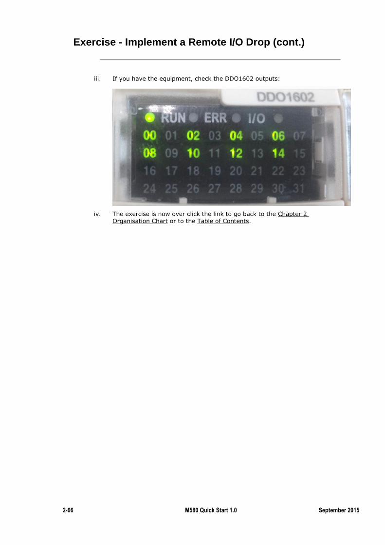
2-66 M580 Quick Start 1.0 September 2015
Exercise - Implement a Remote I/O Drop (cont.)
iii. If you have the equipment, check the DDO1602 outputs:
iv. The exercise is now over click the link to go back to the Chapter 2 Organisation Chart or to the Table of Contents.
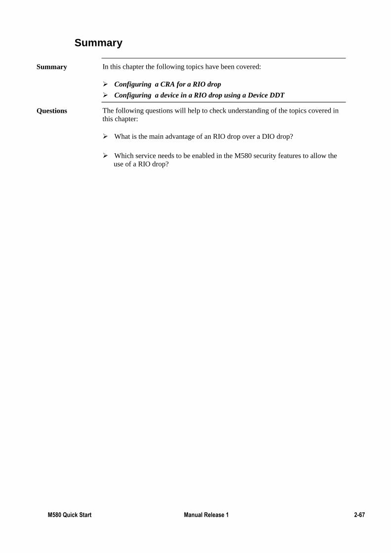
M580 Quick Start Manual Release 1 2-67
Summary
In this chapter the following topics have been covered:
Configuring a CRA for a RIO drop
Configuring a device in a RIO drop using a Device DDT
The following questions will help to check understanding of the topics covered in
this chapter:
What is the main advantage of an RIO drop over a DIO drop?
Which service needs to be enabled in the M580 security features to allow the
use of a RIO drop?
Summary
Questions
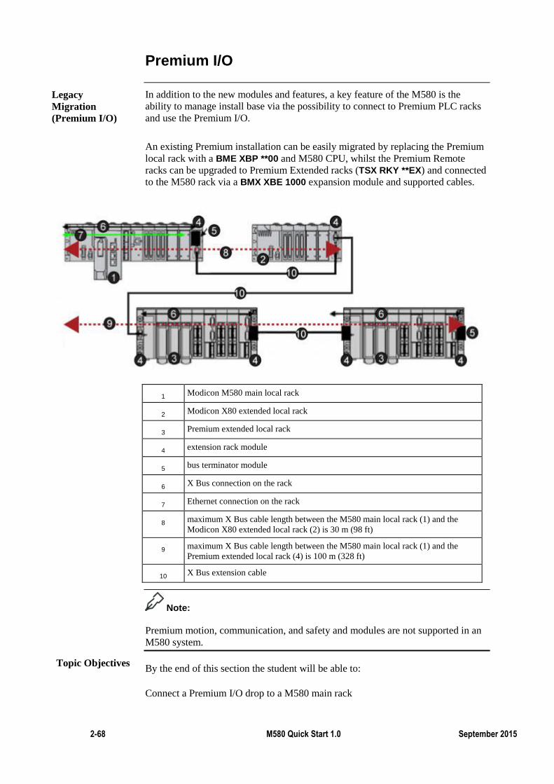
2-68 M580 Quick Start 1.0 September 2015
Premium I/O
In addition to the new modules and features, a key feature of the M580 is the
ability to manage install base via the possibility to connect to Premium PLC racks
and use the Premium I/O.
An existing Premium installation can be easily migrated by replacing the Premium
local rack with a BME XBP **00 and M580 CPU, whilst the Premium Remote
racks can be upgraded to Premium Extended racks (TSX RKY **EX) and connected
to the M580 rack via a BMX XBE 1000 expansion module and supported cables.
1 Modicon M580 main local rack
2 Modicon X80 extended local rack
3 Premium extended local rack
4 extension rack module
5 bus terminator module
6 X Bus connection on the rack
7 Ethernet connection on the rack
8 maximum X Bus cable length between the M580 main local rack (1) and the
Modicon X80 extended local rack (2) is 30 m (98 ft)
9 maximum X Bus cable length between the M580 main local rack (1) and the
Premium extended local rack (4) is 100 m (328 ft)
10 X Bus extension cable
Note:
Premium motion, communication, and safety and modules are not supported in an
M580 system.
By the end of this section the student will be able to:
Connect a Premium I/O drop to a M580 main rack
Legacy
Migration
(Premium I/O)
Topic Objectives
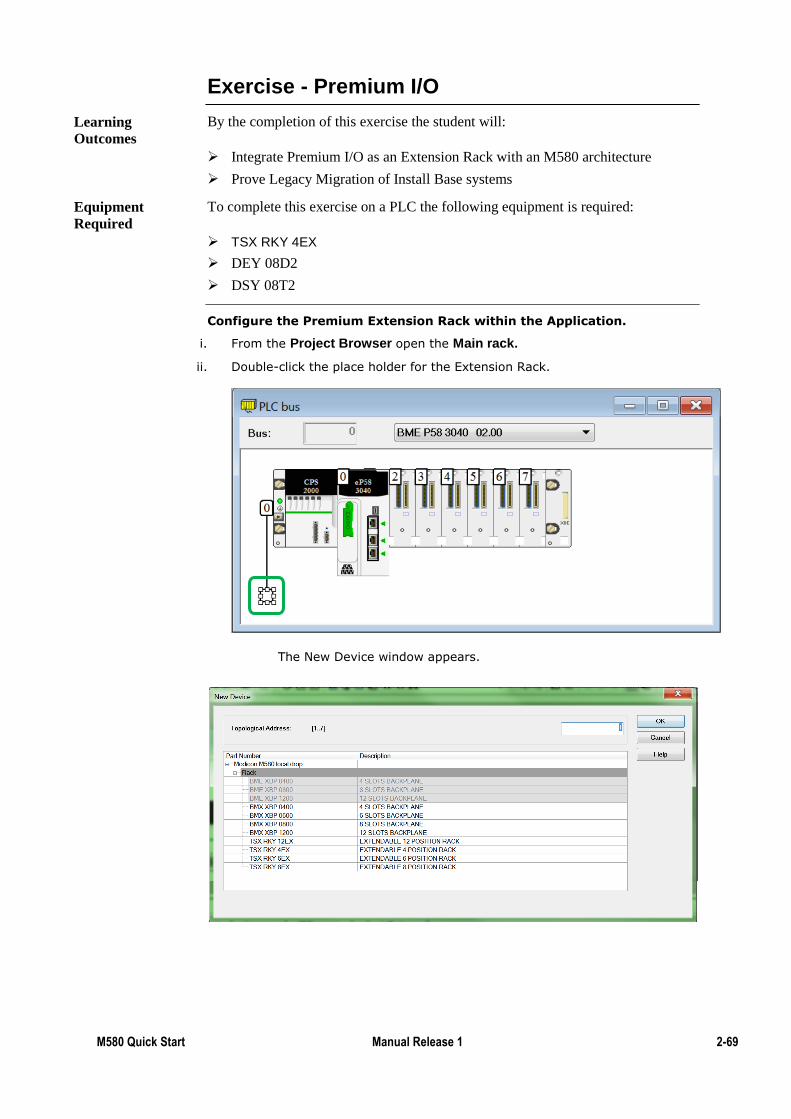
M580 Quick Start Manual Release 1 2-69
Exercise - Premium I/O
By the completion of this exercise the student will:
Integrate Premium I/O as an Extension Rack with an M580 architecture
Prove Legacy Migration of Install Base systems
To complete this exercise on a PLC the following equipment is required:
TSX RKY 4EX
DEY 08D2
DSY 08T2
Configure the Premium Extension Rack within the Application.
i. From the Project Browser open the Main rack.
ii. Double-click the place holder for the Extension Rack.
The New Device window appears.
Learning
Outcomes
Equipment
Required
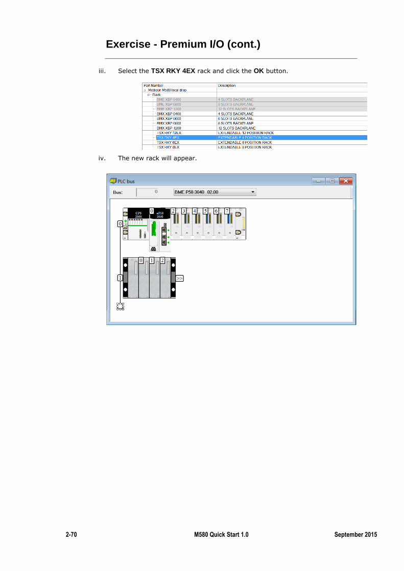
2-70 M580 Quick Start 1.0 September 2015
Exercise - Premium I/O (cont.)
iii. Select the TSX RKY 4EX rack and click the OK button.
iv. The new rack will appear.
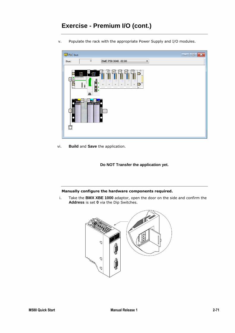
M580 Quick Start Manual Release 1 2-71
Exercise - Premium I/O (cont.)
v. Populate the rack with the appropriate Power Supply and I/O modules.
vi. Build and Save the application.
Do NOT Transfer the application yet.
Manually configure the hardware components required.
i. Take the BMX XBE 1000 adaptor, open the door on the side and confirm the
Address is set 0 via the Dip Switches.
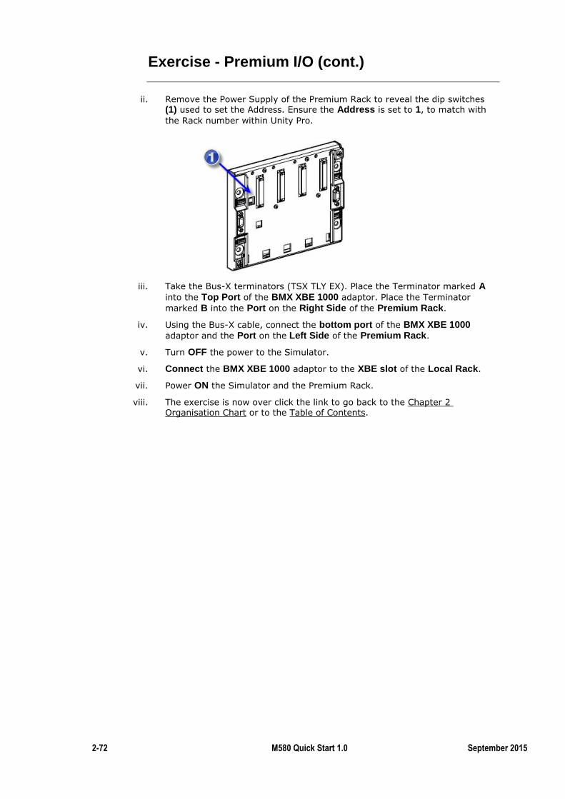
2-72 M580 Quick Start 1.0 September 2015
Exercise - Premium I/O (cont.)
ii. Remove the Power Supply of the Premium Rack to reveal the dip switches (1) used to set the Address. Ensure the Address is set to 1, to match with
the Rack number within Unity Pro.
iii. Take the Bus-X terminators (TSX TLY EX). Place the Terminator marked A into the Top Port of the BMX XBE 1000 adaptor. Place the Terminator
marked B into the Port on the Right Side of the Premium Rack.
iv. Using the Bus-X cable, connect the bottom port of the BMX XBE 1000
adaptor and the Port on the Left Side of the Premium Rack.
v. Turn OFF the power to the Simulator.
vi. Connect the BMX XBE 1000 adaptor to the XBE slot of the Local Rack.
vii. Power ON the Simulator and the Premium Rack.
viii. The exercise is now over click the link to go back to the Chapter 2 Organisation Chart or to the Table of Contents.

M580 Quick Start Manual Release 1 2-73
Summary
In this chapter the following topics have been covered:
Integrating Premium I/O modules in a M580
The following questions will help to check understanding of the topics covered in
this chapter:
Which type of I/O is a PIO drop: local I/O RIO or DIO?
What type of cables do you need to connect the main rack to the PIO drop?
Summary
Questions

2-74 M580 Quick Start 1.0 September 2015
M580 Hot Standby (HSBY)
Just as Premium PLCs, M580s come with a Hot Standby offer to ensure high
reliability of systems.
This chapter covers the basic configuration of M580 architectures. For more
information, follow the M580 HSBY configuration course.
By the end of this section the student will be able to:
Configure a basic Hot Standby M580 architecture
Test this architecture
Introduction
Topic Objectives
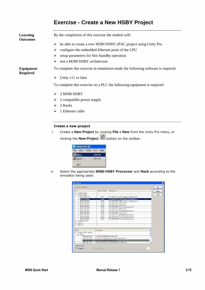
M580 Quick Start Manual Release 1 2-75
Exercise - Create a New HSBY Project
By the completion of this exercise the student will:
be able to create a new M580 HSBY ePAC project using Unity Pro
configure the embedded Ethernet ports of the CPU
setup parameters for Hot Standby operation
test a M580 HSBY architecture
To complete this exercise in simulation mode the following software is required:
Unity v11 or later
To complete this exercise on a PLC the following equipment is required:
2 M580 HSBY
2 compatible power supply
2 Racks
1 Ethernet cable
Create a new project
i. Create a New Project by clicking File » New from the Unity Pro menu, or
clicking the New Project button on the toolbar:
ii. Select the appropriate M580 HSBY Processor and Rack according to the
simulator being used:
Learning
Outcomes
Equipment
Required
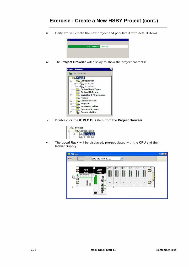
2-76 M580 Quick Start 1.0 September 2015
Exercise - Create a New HSBY Project (cont.)
iii. Unity Pro will create the new project and populate it with default items:
iv. The Project Browser will display to show the project contents:
v. Double click the 0: PLC Bus item from the Project Browser:
vi. The Local Rack will be displayed, pre-populated with the CPU and the
Power Supply:
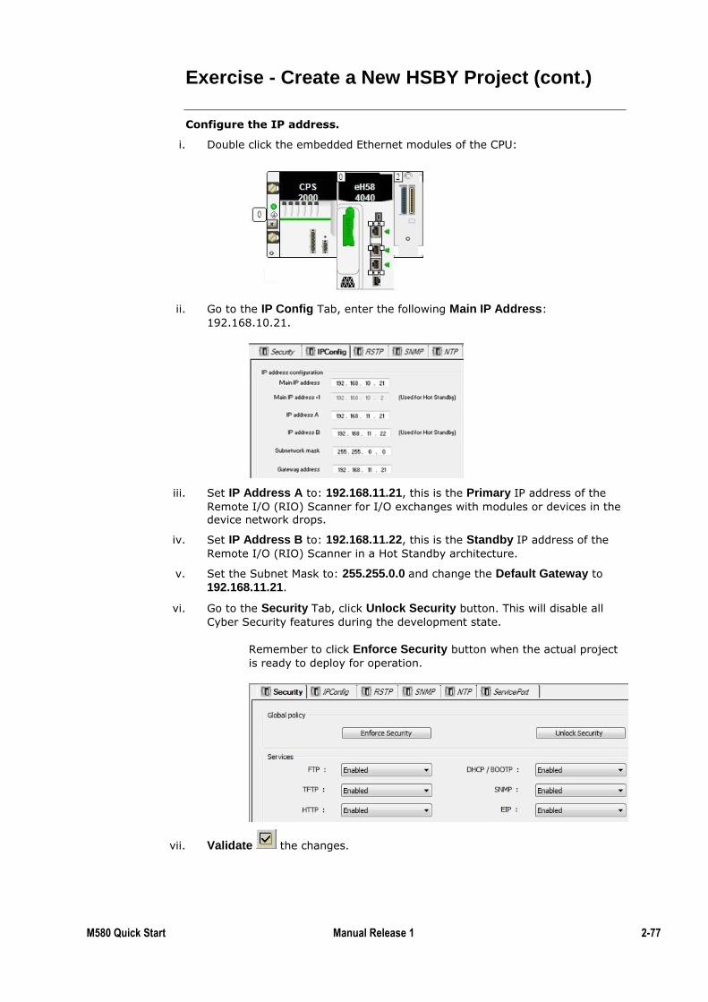
M580 Quick Start Manual Release 1 2-77
Exercise - Create a New HSBY Project (cont.)
Configure the IP address.
i. Double click the embedded Ethernet modules of the CPU:
ii. Go to the IP Config Tab, enter the following Main IP Address:
192.168.10.21.
iii. Set IP Address A to: 192.168.11.21, this is the Primary IP address of the
Remote I/O (RIO) Scanner for I/O exchanges with modules or devices in the device network drops.
iv. Set IP Address B to: 192.168.11.22, this is the Standby IP address of the
Remote I/O (RIO) Scanner in a Hot Standby architecture.
v. Set the Subnet Mask to: 255.255.0.0 and change the Default Gateway to
192.168.11.21.
vi. Go to the Security Tab, click Unlock Security button. This will disable all
Cyber Security features during the development state.
Remember to click Enforce Security button when the actual project
is ready to deploy for operation.
vii. Validate the changes.
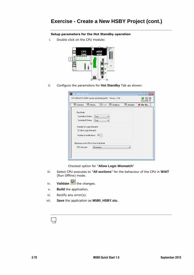
2-78 M580 Quick Start 1.0 September 2015
Exercise - Create a New HSBY Project (cont.)
Setup parameters for the Hot Standby operation
i. Double click on the CPU module:
ii. Configure the parameters for Hot Standby Tab as shown:
Checked option for "Allow Logic Mismatch"
iii. Select CPU executes to "All sections" for the behaviour of the CPU in WAIT (Run Offline) mode.
iv. Validate the changes.
v. Build the application.
vi. Rectify any error(s).
vii. Save the application as M580_HSBY.stu.
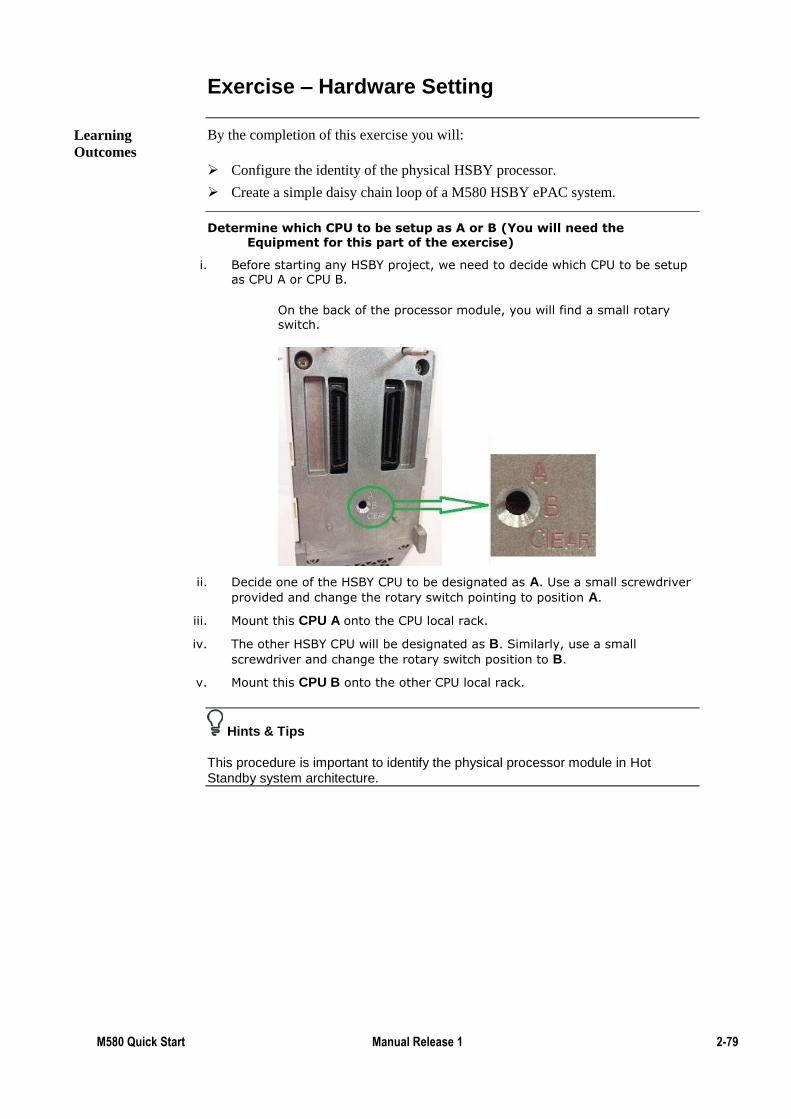
M580 Quick Start Manual Release 1 2-79
Exercise – Hardware Setting
By the completion of this exercise you will:
Configure the identity of the physical HSBY processor.
Create a simple daisy chain loop of a M580 HSBY ePAC system.
Determine which CPU to be setup as A or B (You will need the Equipment for this part of the exercise)
i. Before starting any HSBY project, we need to decide which CPU to be setup as CPU A or CPU B.
On the back of the processor module, you will find a small rotary
switch.
ii. Decide one of the HSBY CPU to be designated as A. Use a small screwdriver
provided and change the rotary switch pointing to position A.
iii. Mount this CPU A onto the CPU local rack.
iv. The other HSBY CPU will be designated as B. Similarly, use a small
screwdriver and change the rotary switch position to B.
v. Mount this CPU B onto the other CPU local rack.
Hints & Tips
This procedure is important to identify the physical processor module in Hot Standby system architecture.
Learning
Outcomes
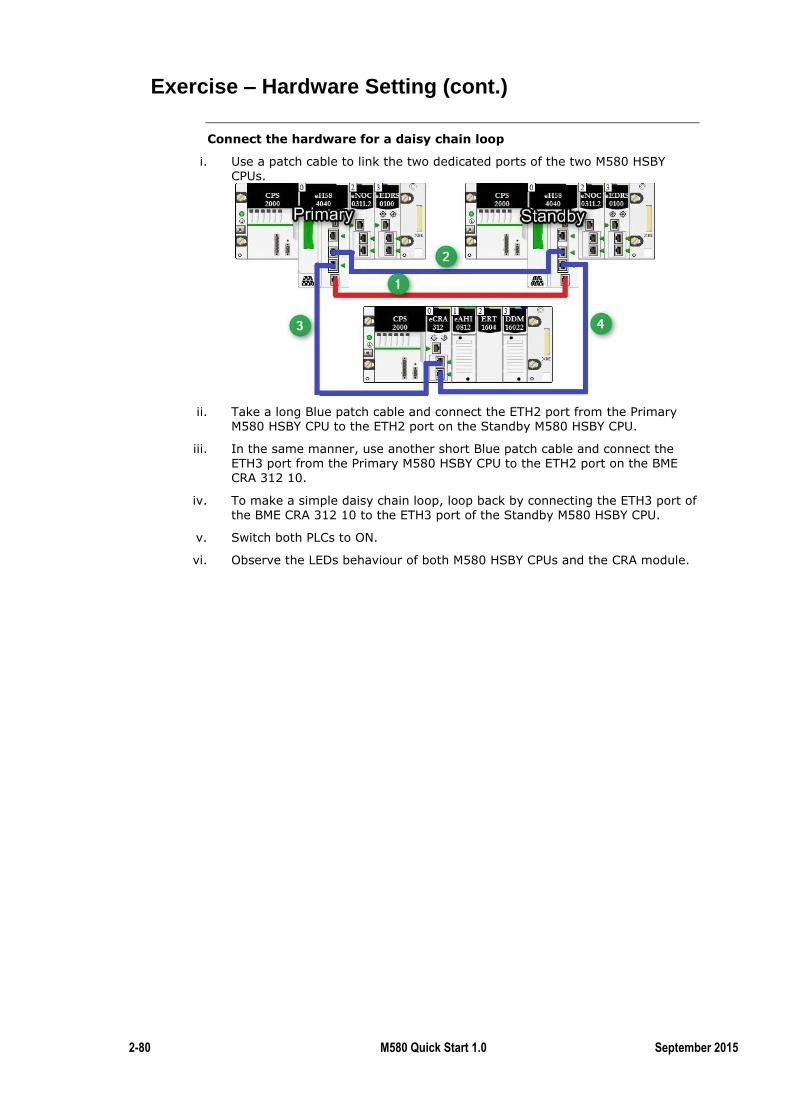
2-80 M580 Quick Start 1.0 September 2015
Exercise – Hardware Setting (cont.)
Connect the hardware for a daisy chain loop
i. Use a patch cable to link the two dedicated ports of the two M580 HSBY CPUs.
ii. Take a long Blue patch cable and connect the ETH2 port from the Primary M580 HSBY CPU to the ETH2 port on the Standby M580 HSBY CPU.
iii. In the same manner, use another short Blue patch cable and connect the ETH3 port from the Primary M580 HSBY CPU to the ETH2 port on the BME CRA 312 10.
iv. To make a simple daisy chain loop, loop back by connecting the ETH3 port of the BME CRA 312 10 to the ETH3 port of the Standby M580 HSBY CPU.
v. Switch both PLCs to ON.
vi. Observe the LEDs behaviour of both M580 HSBY CPUs and the CRA module.
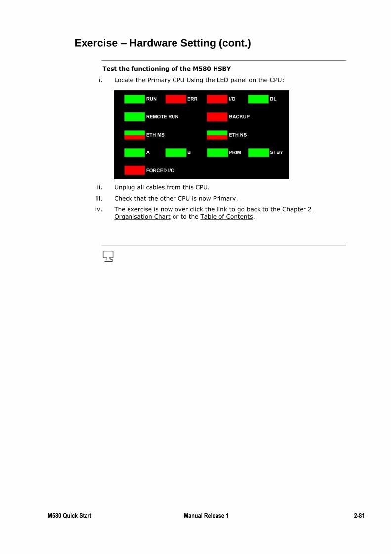
M580 Quick Start Manual Release 1 2-81
Exercise – Hardware Setting (cont.)
Test the functioning of the M580 HSBY
i. Locate the Primary CPU Using the LED panel on the CPU:
ii. Unplug all cables from this CPU.
iii. Check that the other CPU is now Primary.
iv. The exercise is now over click the link to go back to the Chapter 2
Organisation Chart or to the Table of Contents.
2-82 M580 Quick Start 1.0 September 2015
Summary
In this chapter the following topics have been covered:
Configuring a Basic Hot Standby architecture in Unity Pro
How to set a PLC as A or B
Wiring a Hot Standby architecture
The following questions will help to check understanding of the topics covered in
this chapter:
Which version of Unity Pro do you need to configure a Hot Standby
architecture?
How can you check if the PLC is A or B and primary or secondary?
Summary
Questions

M580 Quick Start Manual Release 1 2-83
Advanced Cyber Security
The first chapter explained the very important Cyber Security feature of the M580;
the activation/deactivation of its services.
In this topic we will discover more Cyber Security features such as:
Password management
Integrity Checks
Memory and Run/Stop Protect
IP address restrictions
By the end of this chapter the student will be able to:
Deploy advanced Cyber Security measures in M580 architecture.
Introduction
Chapter Objectives
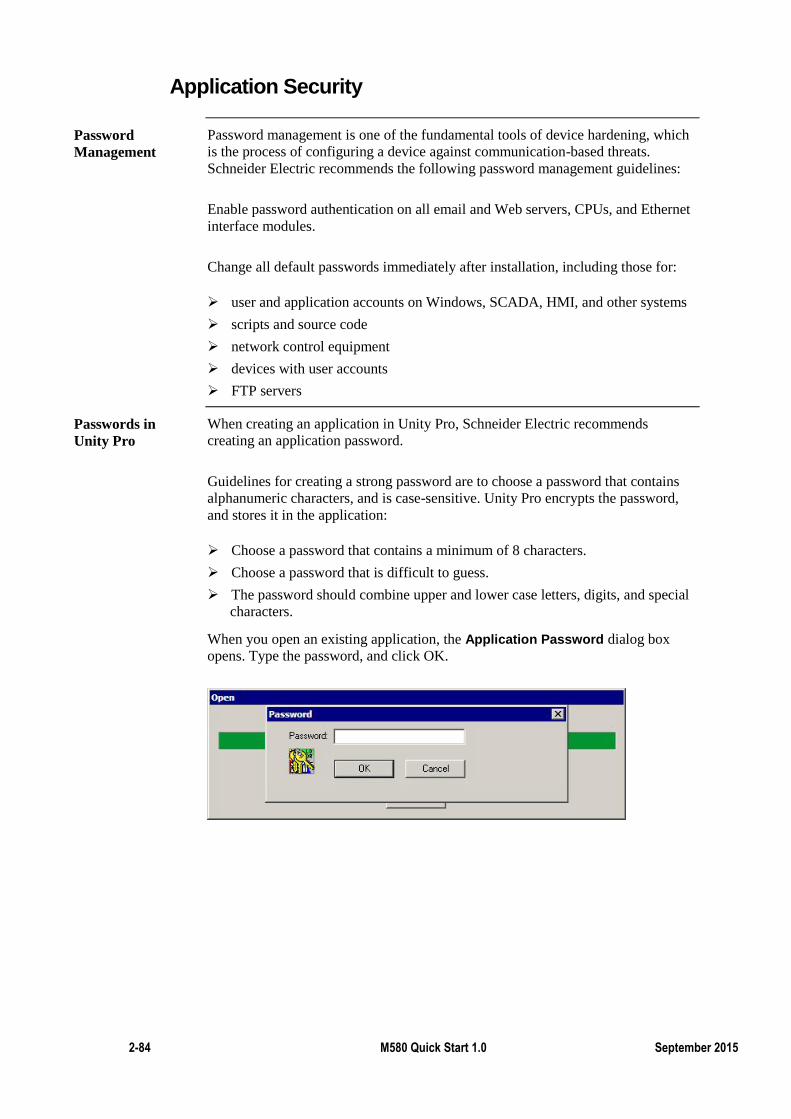
2-84 M580 Quick Start 1.0 September 2015
Application Security
Password management is one of the fundamental tools of device hardening, which
is the process of configuring a device against communication-based threats.
Schneider Electric recommends the following password management guidelines:
Enable password authentication on all email and Web servers, CPUs, and Ethernet
interface modules.
Change all default passwords immediately after installation, including those for:
user and application accounts on Windows, SCADA, HMI, and other systems
scripts and source code
network control equipment
devices with user accounts
FTP servers
When creating an application in Unity Pro, Schneider Electric recommends
creating an application password.
Guidelines for creating a strong password are to choose a password that contains
alphanumeric characters, and is case-sensitive. Unity Pro encrypts the password,
and stores it in the application:
Choose a password that contains a minimum of 8 characters.
Choose a password that is difficult to guess.
The password should combine upper and lower case letters, digits, and special
characters.
When you open an existing application, the Application Password dialog box
opens. Type the password, and click OK.
Password
Management
Passwords in
Unity Pro
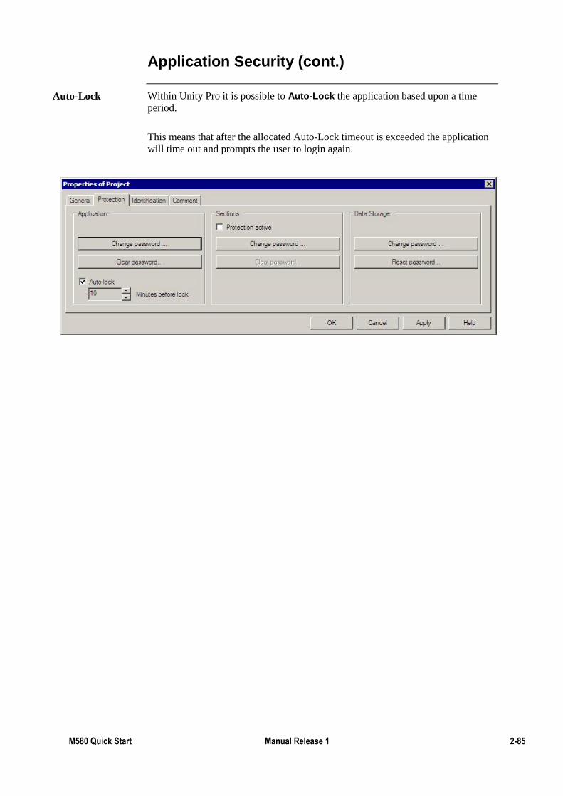
M580 Quick Start Manual Release 1 2-85
Application Security (cont.)
Within Unity Pro it is possible to Auto-Lock the application based upon a time
period.
This means that after the allocated Auto-Lock timeout is exceeded the application
will time out and prompts the user to login again.
Auto-Lock
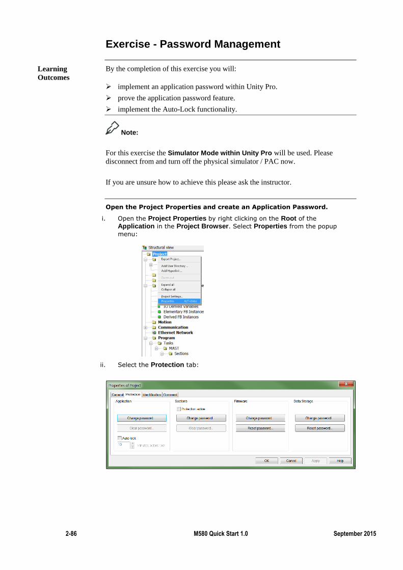
2-86 M580 Quick Start 1.0 September 2015
Exercise - Password Management
By the completion of this exercise you will:
implement an application password within Unity Pro.
prove the application password feature.
implement the Auto-Lock functionality.
Note:
For this exercise the Simulator Mode within Unity Pro will be used. Please
disconnect from and turn off the physical simulator / PAC now.
If you are unsure how to achieve this please ask the instructor.
Open the Project Properties and create an Application Password.
i. Open the Project Properties by right clicking on the Root of the
Application in the Project Browser. Select Properties from the popup
menu:
ii. Select the Protection tab:
Learning
Outcomes
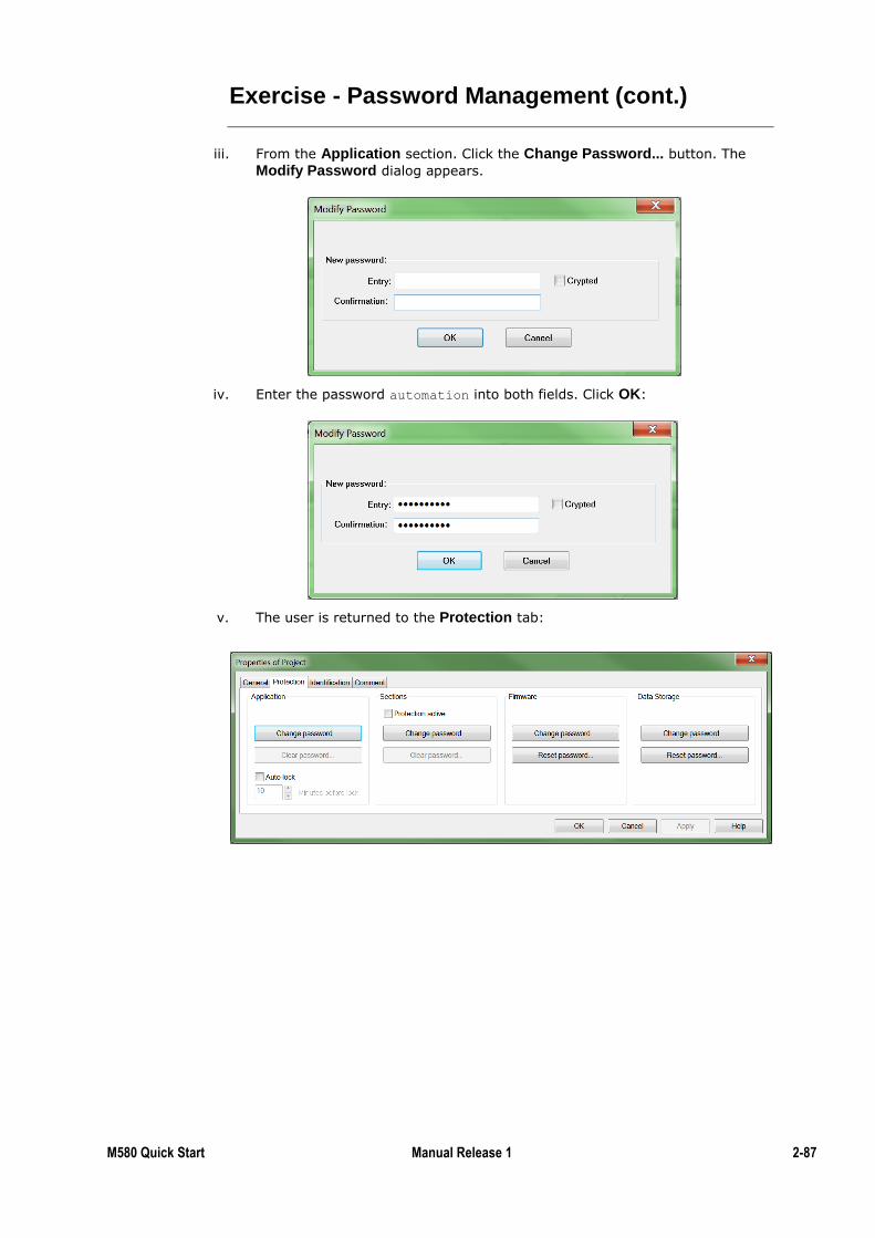
M580 Quick Start Manual Release 1 2-87
Exercise - Password Management (cont.)
iii. From the Application section. Click the Change Password... button. The
Modify Password dialog appears.
iv. Enter the password automation into both fields. Click OK:
v. The user is returned to the Protection tab:
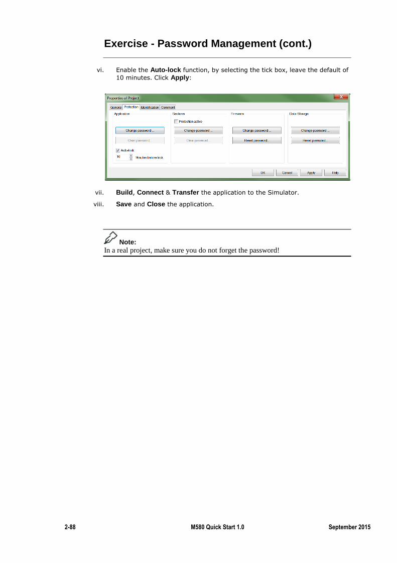
2-88 M580 Quick Start 1.0 September 2015
Exercise - Password Management (cont.)
vi. Enable the Auto-lock function, by selecting the tick box, leave the default of
10 minutes. Click Apply:
vii. Build, Connect & Transfer the application to the Simulator.
viii. Save and Close the application.
Note:
In a real project, make sure you do not forget the password!
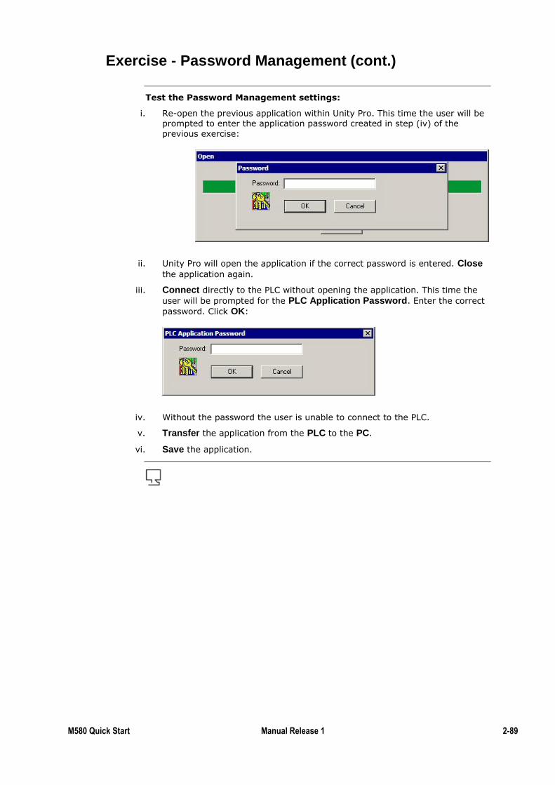
M580 Quick Start Manual Release 1 2-89
Exercise - Password Management (cont.)
Test the Password Management settings:
i. Re-open the previous application within Unity Pro. This time the user will be prompted to enter the application password created in step (iv) of the previous exercise:
ii. Unity Pro will open the application if the correct password is entered. Close
the application again.
iii. Connect directly to the PLC without opening the application. This time the
user will be prompted for the PLC Application Password. Enter the correct
password. Click OK:
iv. Without the password the user is unable to connect to the PLC.
v. Transfer the application from the PLC to the PC.
vi. Save the application.
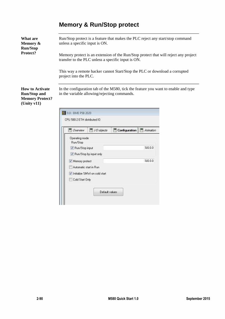
2-90 M580 Quick Start 1.0 September 2015
Memory & Run/Stop protect
Run/Stop protect is a feature that makes the PLC reject any start/stop command
unless a specific input is ON.
Memory protect is an extension of the Run/Stop protect that will reject any project
transfer to the PLC unless a specific input is ON.
This way a remote hacker cannot Start/Stop the PLC or download a corrupted
project into the PLC.
In the configuration tab of the M580, tick the feature you want to enable and type
in the variable allowing/rejecting commands.
What are
Memory &
Run/Stop
Protect?
How to Activate
Run/Stop and
Memory Protect?
(Unity v11)
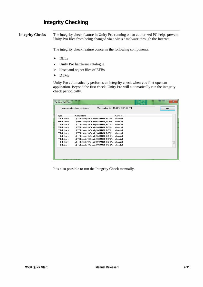
M580 Quick Start Manual Release 1 2-91
Integrity Checking
The integrity check feature in Unity Pro running on an authorized PC helps prevent
Unity Pro files from being changed via a virus / malware through the Internet.
The integrity check feature concerns the following components:
DLLs
Unity Pro hardware catalogue
libset and object files of EFBs
DTMs
Unity Pro automatically performs an integrity check when you first open an
application. Beyond the first check, Unity Pro will automatically run the integrity
check periodically.
It is also possible to run the Integrity Check manually.
Integrity Checks
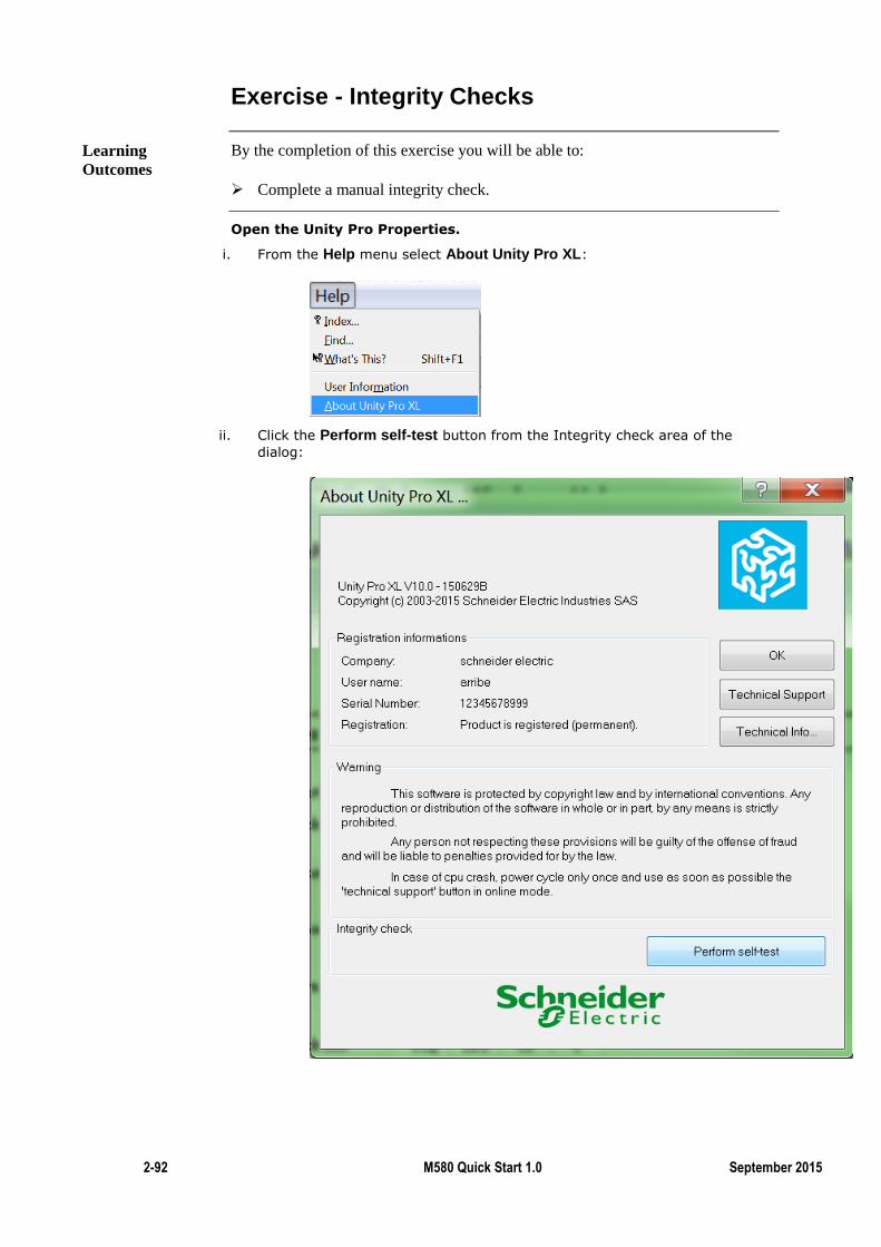
2-92 M580 Quick Start 1.0 September 2015
Exercise - Integrity Checks
By the completion of this exercise you will be able to:
Complete a manual integrity check.
Open the Unity Pro Properties.
i. From the Help menu select About Unity Pro XL:
ii. Click the Perform self-test button from the Integrity check area of the
dialog:
Learning
Outcomes
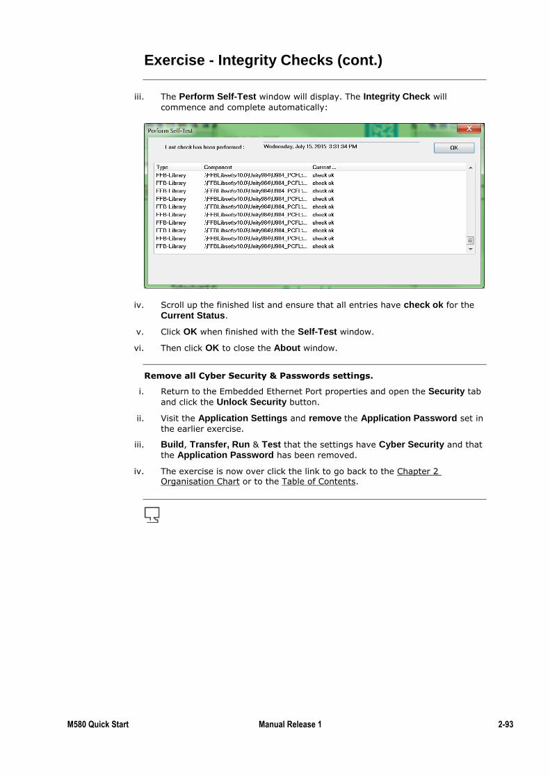
M580 Quick Start Manual Release 1 2-93
Exercise - Integrity Checks (cont.)
iii. The Perform Self-Test window will display. The Integrity Check will
commence and complete automatically:
iv. Scroll up the finished list and ensure that all entries have check ok for the
Current Status.
v. Click OK when finished with the Self-Test window.
vi. Then click OK to close the About window.
Remove all Cyber Security & Passwords settings.
i. Return to the Embedded Ethernet Port properties and open the Security tab
and click the Unlock Security button.
ii. Visit the Application Settings and remove the Application Password set in
the earlier exercise.
iii. Build, Transfer, Run & Test that the settings have Cyber Security and that
the Application Password has been removed.
iv. The exercise is now over click the link to go back to the Chapter 2 Organisation Chart or to the Table of Contents.
2-94 M580 Quick Start 1.0 September 2015
Access Control
Access control is a feature that allows the user to set which IP addresses are allow
to communicate with the device (PLC or cyber secured NOC), communication
from any other IP will be rejected by the device.
In Unity Pro v11 this feature will be combined with the restriction of the features
allowing IP addresses to communicate with device via specific protocols only.
As with most of the M580 cyber security features, this feature is located in the
Security tab of the M580. From there type in the list of authorised IP addresses,
then enable access control and download the program to the PLC.
Note:
Be careful if you usually download the projects to the PLC via Ethernet cable to
add the IP address of the computer in allowed IP addresses, and remember the PC
IP address.
If you usually transfer the project via other media, make sure that the service is
enabled before downloading the project to the PLC!
Introduction
How to enable it?
M580 Quick Start Manual Release 1 2-95
Summary
In this chapter the following topics have been covered:
Setting a password to restrict the download of a project to the PLC
Performing integrity checks
Setting the memory protect and run/stop protect features
Restricting the access to the PLC to some IP addresses
The following questions will help to check understanding of the topics covered in
this chapter:
How does the memory protect and run/stop protect features work?
When are the integrity check performed?
Summary
Questions


Overview
The previous chapters have explained only the most common features of the M580.
This chapter highlights expanded features which increase the possibilities of the
M580.
These features include:
The use of a SD card
Local extension racks
Embedded web pages
The SCAIME weighing module
The HART module
Time-stamping
Further Training:
In case you want to implement these features we suggest you to go through the
M580 in-class training.
Chapter 3: Make the Most of the M580!
Introduction
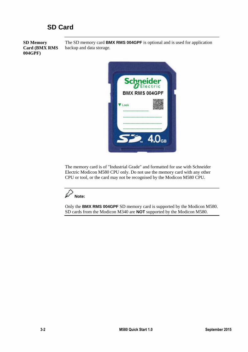
3-2 M580 Quick Start 1.0 September 2015
SD Card
The SD memory card BMX RMS 004GPF is optional and is used for application
backup and data storage.
The memory card is of "Industrial Grade" and formatted for use with Schneider
Electric Modicon M580 CPU only. Do not use the memory card with any other
CPU or tool, or the card may not be recognised by the Modicon M580 CPU.
Note:
Only the BMX RMS 004GPF SD memory card is supported by the Modicon M580.
SD cards from the Modicon M340 are NOT supported by the Modicon M580.
SD Memory
Card (BMX RMS
004GPF)
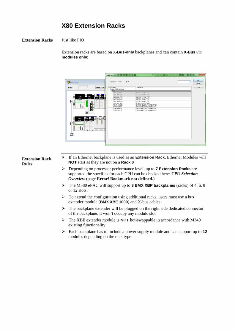
X80 Extension Racks
Just like PIO
Extension racks are based on X-Bus-only backplanes and can contain X-Bus I/O
modules only:
If an Ethernet backplane is used as an Extension Rack, Ethernet Modules will
NOT start as they are not on a Rack 0
Depending on processor performance level, up to 7 Extension Racks are
supported the specifics for each CPU can be checked here: CPU Selection
Overview (page Error! Bookmark not defined.)
The M580 ePAC will support up to 8 BMX XBP backplanes (racks) of 4, 6, 8
or 12 slots
To extend the configuration using additional racks, users must use a bus
extender module (BMX XBE 1000) and X-bus cables
The backplane extender will be plugged on the right side dedicated connector
of the backplane. It won’t occupy any module slot
The XBE extender module is NOT hot-swappable in accordance with M340
existing functionality
Each backplane has to include a power supply module and can support up to 12
modules depending on the rack type
Extension Racks
Extension Rack
Rules
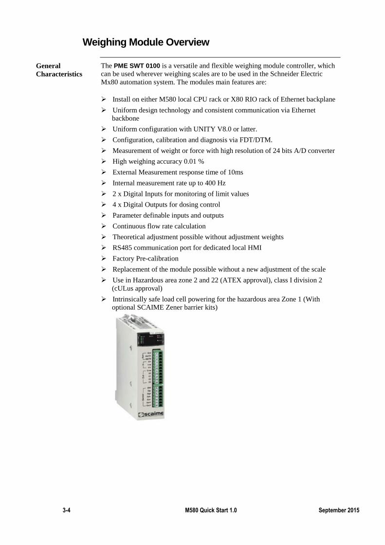
3-4 M580 Quick Start 1.0 September 2015
Weighing Module Overview
The PME SWT 0100 is a versatile and flexible weighing module controller, which
can be used wherever weighing scales are to be used in the Schneider Electric
Mx80 automation system. The modules main features are:
Install on either M580 local CPU rack or X80 RIO rack of Ethernet backplane
Uniform design technology and consistent communication via Ethernet
backbone
Uniform configuration with UNITY V8.0 or latter.
Configuration, calibration and diagnosis via FDT/DTM.
Measurement of weight or force with high resolution of 24 bits A/D converter
High weighing accuracy 0.01 %
External Measurement response time of 10ms
Internal measurement rate up to 400 Hz
2 x Digital Inputs for monitoring of limit values
4 x Digital Outputs for dosing control
Parameter definable inputs and outputs
Continuous flow rate calculation
Theoretical adjustment possible without adjustment weights
RS485 communication port for dedicated local HMI
Factory Pre-calibration
Replacement of the module possible without a new adjustment of the scale
Use in Hazardous area zone 2 and 22 (ATEX approval), class I division 2
(cULus approval)
Intrinsically safe load cell powering for the hazardous area Zone 1 (With
optional SCAIME Zener barrier kits)
General
Characteristics
HART with the M580
The X80 HART module takes the role of HART multiplexer, facilitating the
transmission of HART field instrument data as follows:
The multiplexer provides one-to-many communications between:
A HART master device, for example, asset management software resident on a PC,
and Multiple HART slave devices (for example, HART field instruments)
The multiplexer provides HART instrument data to a PLC master.
The HART I/O data of AHI & AHO modules is accessed and managed by the
AMS software. The following AMS software packages are supported:
Emerson AMS suit
FieldCare
PACTware
In addition to the AMS software, the HART I/O data of the BME AHI 0812 &
BME AHO 0412 modules can also be accessed by the I/O mapping function found
in the device DTMs.
The X80 HART interface modules support the mapping of HART instrument input
and output data items to the HART multiplexer process image. The data items
enabled in I/O mapping function can be dynamically controlled by the program
logic.
HART
Multiplexer
Function
I/O Mapping
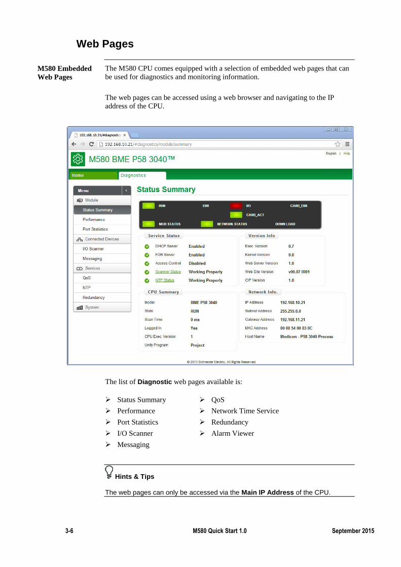
3-6 M580 Quick Start 1.0 September 2015
Web Pages
The M580 CPU comes equipped with a selection of embedded web pages that can
be used for diagnostics and monitoring information.
The web pages can be accessed using a web browser and navigating to the IP
address of the CPU.
The list of Diagnostic web pages available is:
Status Summary QoS
Performance Network Time Service
Port Statistics Redundancy
I/O Scanner Alarm Viewer
Messaging
Hints & Tips
The web pages can only be accessed via the Main IP Address of the CPU.
M580 Embedded
Web Pages
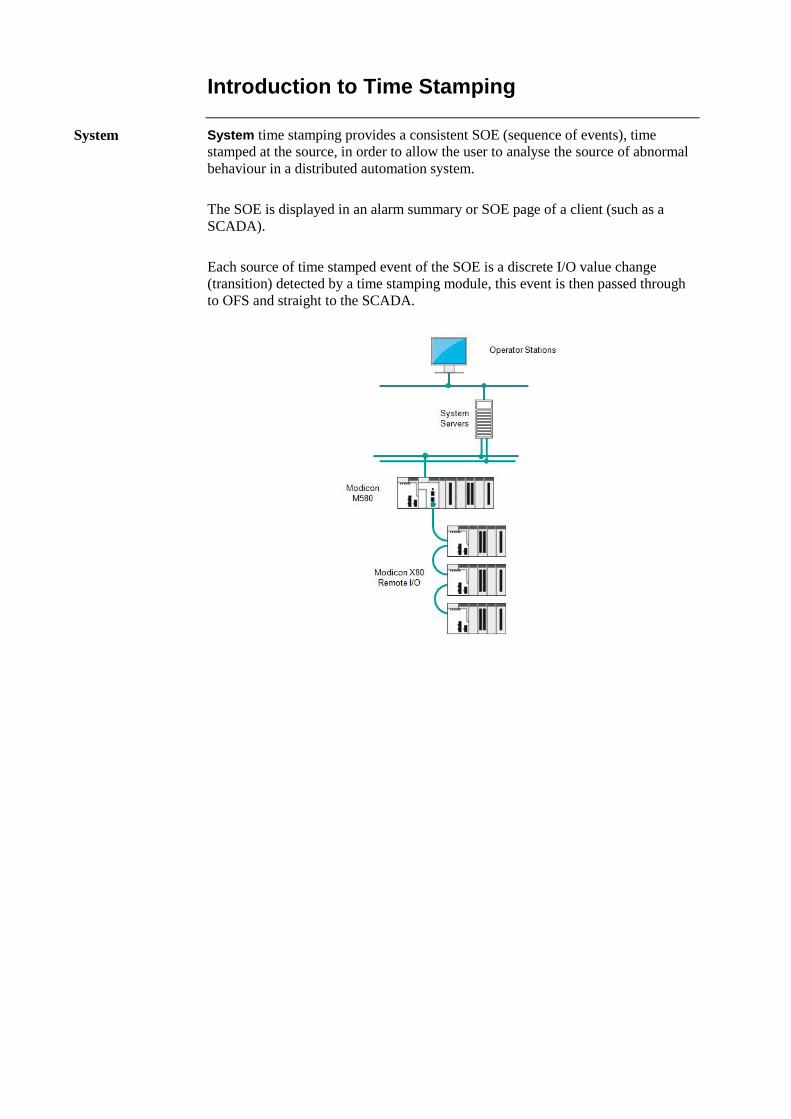
Introduction to Time Stamping
System time stamping provides a consistent SOE (sequence of events), time
stamped at the source, in order to allow the user to analyse the source of abnormal
behaviour in a distributed automation system.
The SOE is displayed in an alarm summary or SOE page of a client (such as a
SCADA).
Each source of time stamped event of the SOE is a discrete I/O value change
(transition) detected by a time stamping module, this event is then passed through
to OFS and straight to the SCADA.
System
3-8 M580 Quick Start 1.0 September 2015
Introduction to Time Stamping (cont.)
There are many benefits of system time stamping:
removes the need for PLC programming.
Direct communication between the time stamping modules and the client.
If the time stamping modules are in a Modicon X80 Remote I/O drop, the PLC
communication bandwidth is not used.
Consistency of data (I/O values) between the process (time stamping
modules) and the client (SCADA).
Time quality information associated with each time stamped event.
No loss of events in normal operating conditions:
A buffer is available to store the events in each time stamping module. The
event storage is stopped when the buffer is full.
Rising and falling edges transitions are stored for each discrete I/O.
Where available, Hot Standby configurations on the PLC and/or redundant
SCADA are managed.
Benefits
Summary
In this chapter the following topics have been covered:
Using a SD card with M580
Local extension racks
Monitor a M580 for its embedded web pages
The SCAIME weighing module
The HART module
Time stamping
The following questions will help to check understanding of the topics covered in
this chapter:
What are the two purposes of using an SD card with the M580?
What is the role of the M580 web pages?
Summary
Questions

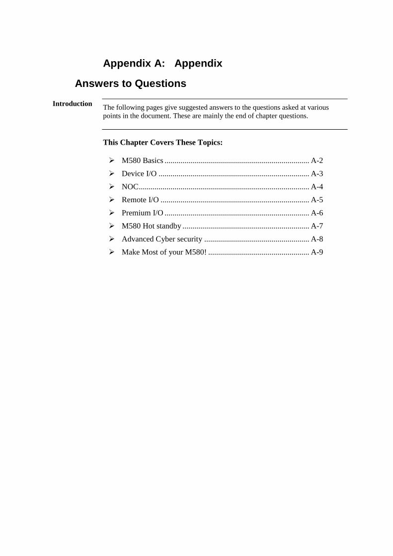
Answers to Questions
The following pages give suggested answers to the questions asked at various
points in the document. These are mainly the end of chapter questions.
This Chapter Covers These Topics:
M580 Basics ......................................................................... A-2
Device I/O ............................................................................ A-3
NOC ...................................................................................... A-4
Remote I/O ........................................................................... A-5
Premium I/O ......................................................................... A-6
M580 Hot standby ................................................................ A-7
Advanced Cyber security ..................................................... A-8
Make Most of your M580! ................................................... A-9
Appendix A: Appendix
Introduction
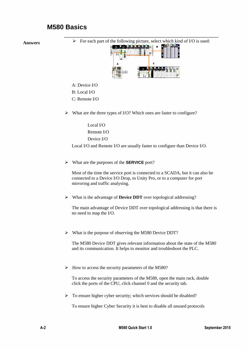
A-2 M580 Quick Start 1.0 September 2015
M580 Basics
For each part of the following picture, select which kind of I/O is used:
A: Device I/O
B: Local I/O
C: Remote I/O
What are the three types of I/O? Which ones are faster to configure?
Local I/O
Remote I/O
Device I/O
Local I/O and Remote I/O are usually faster to configure than Device I/O.
What are the purposes of the SERVICE port?
Most of the time the service port is connected to a SCADA, but it can also be
connected to a Device I/O Drop, to Unity Pro, or to a computer for port
mirroring and traffic analysing.
What is the advantage of Device DDT over topological addressing?
The main advantage of Device DDT over topological addressing is that there is
no need to map the I/O.
What is the purpose of observing the M580 Device DDT?
The M580 Device DDT gives relevant information about the state of the M580
and its communication. It helps to monitor and troubleshoot the PLC.
How to access the security parameters of the M580?
To access the security parameters of the M580, open the main rack, double
click the ports of the CPU, click channel 0 and the security tab.
To ensure higher cyber security; which services should be disabled?
To ensure higher Cyber Security it is best to disable all unused protocols
Answers
Device I/O
What kind of device can be included in a DIO drop?
It is possible to connect any DTM device to a DIO drop, including non
Schneider-Electric devices.
What is the main advantage of device integration? (You can take the Altviar
drive as an example)
Device integration makes integration of devices easier by configuring and
testing them from single software.
Answers
A-4 M580 Quick Start 1.0 September 2015
NOC
What are the possible roles of a NOC?
A NOC has the same use as the service port of M580; it can be used to connect
a drop to a SCADA or to connect DIO drops.
In both cases, using a NOC instead of connecting directly to the M580 reduces
the resources used by the M580.
Which BME NOC modules support FactoryCast?
The 0311 support FactoryCast.
Answers

Remote I/O
What is the main advantage of an RIO drop over a DIO drop?
Remote I/O drops are usually much faster to configure than Device I/O drops.
Which service needs to be enabled in the M580 security features to allow the
use of a RIO drop?
TFTP needs to be enabled in order to being able to build a project with a RIO
drop.
Answers

A-6 M580 Quick Start 1.0 September 2015
Premium I/O
Which type of I/O is a Premium I/O drop: local I/O RIO or DIO?
A Premium I/O drop is considered as a local drop.
What type of cables do you need to connect the main rack to the PIO drop?
To connect a PIO drop to the M580 main rack, you will need X-bus cables.
Answers

M580 Hot Standby
Which version of Unity Pro do you need to configure Hot Standby
architecture?
HSBY architectures are configured via Unity Pro v11 or later versions.
How can you check if the PLC is A or B and primary or secondary?
To check if the PLC is A or B and Primary or Secondary you can either look
the M580's LED panel, or check the M580 Device DDT.
Answers

A-8 M580 Quick Start 1.0 September 2015
Advanced Cyber Security
How does the memory protect and run/stop protect features work?
Run/Stop protect is a feature that makes the PLC reject any start/stop command
unless a specific input is ON.
When are the integrity check performed?
Unity Pro automatically performs an integrity check when you first open an
application. Beyond the first check, Unity Pro will automatically run the
integrity check periodically.
Answers

Make the Most of the M580!
What are the two purposes of using an SD card with the M580?
The SD memory card is optional and is used for application backup and data
storage.
What is the role of the M580 web pages?
Embedded web pages are used for diagnostics and monitoring information.
Answers
Related Documents