Trailer 4500kg or Less Inspection Methods and Standards Reference Manual September 2020 The information contained in this document is confidential and proprietary to the Government of Newfoundland and Labrador. Unauthorized distribution or use of this document or the information contained herein is strictly prohibited.

Welcome message from author
This document is posted to help you gain knowledge. Please leave a comment to let me know what you think about it! Share it to your friends and learn new things together.
Transcript
Trailer 4500kg or Less Inspection Methods and Standards
Reference Manual
September 2020 The information contained in this document is confidential and proprietary to the Government of Newfoundland and Labrador. Unauthorized distribution or use of this document or the information contained herein is strictly prohibited.
Copyright and Disclaimer
Government of Newfoundland and Labrador reserves the right to make changes to the information contained in this publication without prior notice. Official Inspection Stations will be notified in all cases where any such changes have taken place.
© Queen’s Printer
Table of Contents
Introduction 1
Instructions for Authorized Inspection Mechanic Conducting Inspections 2
Inspection Method 2
Inspection Outcome Based on Current Condition 2
Inspection Report 2
Workplace Safety 3
Informational Notes 3
Terminology 4
Application 4
Definitions 4
Categorization of fluid leaks 6
Illustrations and Diagrams Used in the Manual 6
Measurements and Tolerances 7
Defective conditions of Hoses, Tubing and Lines 9
Section 1 – Suspension 10
1. Suspension and Frame Attachments 10
2. Axle Attaching and Tracking Components 11
3. Spring and Spring Attachment 12
5. Strut / Shock Absorber 14
Section 2 – Brake Systems 15
1. General 15
2. Hydraulic System Components 15
3. Electric Brake System 18
4. Drum Brake System Components 19
5. Disc Brake System Components 22
Section 3 – Lamps 24
1. Required Lamps 24
2. Reflex Reflector 27
Section 4 – Electrical System 32
1. Wiring 32
2. Trailer Cord (output to towed vehicle) 33
Section 5 – Body 34
1. Cargo Body 34
2. Cargo Doors 36
3. Device or Equipment attached or Mounted to the Vehicle 36
4. Fender / Mudguard 38

Section 6 – Tire and Wheel 39
1. Tire-Tread Depth 39
2. Tire Tread Condition 39
3. Tire Sidewall 40
4. Tire Inflation Pressure 41
5. Wheel Hub 42
6. Wheel Bearing 43
7. Wheel / Rim (General) 44
8. Wheel Fasteners (Nuts, Bolts and Studs) 45
Section 7 – Coupling Devices 46
1. Hitch Assembly, Structure and Attaching Components 46
2. Coupling Devices 47
3. Hitch Components 47
4. Fifth Wheel Hitch 48
Page 1 Trailer 4500kg or less Inspection Methods and Standards
Note: All inspection procedures are visual unless additional inspection procedures are indicated. Conditions shown in this manner are defined conditions. The definitions can be found in the introduction section.
Introduction
As partners in road safety, licensed Official Inspection Station appointee’s and Authorized Inspection Mechanics must carefully review and apply the vehicle inspection standards contained in the Official Inspection Station Manual, prescribed in the Official Inspection Station Regulations, under the Highway Traffic Act. This Standard applies to trailers less than 4500kg requiring the issuance of an Official Inspection Station Certificate. The purpose of the inspection is to ensure that the vehicle meets a minimum safety standard at the time of inspection. A determination must be made as to whether the condition of the vehicle at the time of the inspection conforms to the requirements outlined in this manual.
All items listed in this Standard must be inspected in accordance with the specific outlined procedures. An Official Inspection Station Vehicle Inspection Certificate is a legal declaration that the vehicle was inspected in accordance with the standards prescribed in the Official Inspection Station Manual and met all of the requirements at the time of the inspection.

Page 2 Trailer 4500kg or less Inspection Methods and Standards
Note: All inspection procedures are visual unless additional inspection procedures are indicated. Conditions shown in this manner are defined conditions. The definitions can be found in the introduction section.
Instructions for Authorized Inspection Mechanics Conducting Inspections
Inspection Methods
The inspection of vehicle components and systems conducted to determine compliance with the Official Inspection Station Manual consists mainly of visual inspection activities in Sections 1-7.
An inspection will also involve testing, removal and/or disassembly of components, measurements and other actions in certain cases. Whenever an item requires more than a visual inspection, additional procedures are specifically provided. These are displayed with the heading “Additional Inspection Procedure(s):” appearing before the text describing the necessary steps.
Inspection Outcome Based on Current Vehicle Condition
A pass or fail outcome of a vehicle inspection is based on the condition of the vehicle at the time of the inspection. The determination does not involve a prediction about a vehicle’s condition in the future.
Inspection Report
For each inspection, the authorized inspection mechanic must complete an inspection report. This report must be provided to the customer.
The following items are noted in the Manual as recordable items and must be included on the inspection report.
Tire Tread Depth
Disc Brakes - Rotor Thickness - Pad (Friction) Material Thickness of Inner and Outer Brake Pad
Brake Drum System - Brake Shoe Lining Thickness - Brake Drum Diameter

Page 3 Trailer 4500kg or less Inspection Methods and Standards
Note: All inspection procedures are visual unless additional inspection procedures are indicated. Conditions shown in this manner are defined conditions. The definitions can be found in the introduction section.
Additional details on the type of information that must be recorded can be found in the respective sections contained in the manual.
Workplace Safety
Some of the inspection procedures described in this manual require the use of tools and equipment, and may involve safety hazards. It is assumed that the individual performing inspections according to this manual is fully familiar with all relevant workplace safety requirements and protocols.
No specific safety warnings are provided within this document. All relevant and appropriate safety precautions are the responsibility of the authorized inspection mechanic and the workplace where the inspection is conducted.
Informational Notes
In many cases, additional information is provided to clarify the inspection procedure or assist in consistent interpretation of the manual. These are displayed with the heading “Note:” appearing before the text.

Page 4 Trailer 4500kg or less Inspection Methods and Standards
Note: All inspection procedures are visual unless additional inspection procedures are indicated. Conditions shown in this manner are defined conditions. The definitions can be found in the introduction section.
Terminology
Application
Various terms and acronyms are used throughout this manual. These terms have specific and consistent meanings as they relate to conducting safety inspections and identifying defective conditions. The purpose of defining these terms is to support consistent interpretation and application of the language used. The terms that are defined below are highlighted whenever they appear in each section to remind the reader that the condition is one of those that is specifically defined. This reminder also appears in the footer of each page of this document.
Definitions
The meaning of each of the terms, for the purposes of conducting inspections according to this manual, is as follows:
“abnormally worn” – means unusual, excessive or exceptional wear of a vehicle component, indicative of the presence of some deterioration or defect in that component, or in a related part of a vehicle. This term is used selectively in this manual for a component or system where some wear is normal, and does not directly have any effect on vehicle safety. It is expected that the authorized inspection mechanic knows the amount of wear, and the type of wear, that is typical (normal) based on the age and operation of the vehicle and based on the standards as prescribed by the vehicle manufacturer and or industry standard.
“broken” – means burst, cracked, crushed or damaged.
“CMVSS” – means Canada Motor Vehicle Safety Standards (CMVSS) and their supporting Technical Standards Documents. These are Canadian safety standards for vehicles that were developed and are updated by Transport Canada.
“crazed” – a network of fine cracks in the surface
“damaged” – means any unintended condition, or condition caused by means other than normal use, that is likely to impair normal function.
“industry standard” – means installation, modification or repair methods described in industry-accepted standards or recommended practices published by Mitchell Repair Information Company, ALLDATA, the Society of Automotive Engineers (SAE), I-CAR, Canadian Standards Association (CSA) and other similar documents from similar organizations.

Page 5 Trailer 4500kg or less Inspection Methods and Standards
Note: All inspection procedures are visual unless additional inspection procedures are indicated. Conditions shown in this manner are defined conditions. The definitions can be found in the introduction section.
“inoperative” – means a vehicle component or system that does not operate the way it was originally intended to or the way the vehicle manufacturer intended it to operate.
“insecure” – means (a) a component is becoming detached due to deterioration of the means of attachment, or (b) the means of attachment is unable to withstand normal vehicle operation or is not at least equivalent to the OEM standard means of attachment.
“loose” – means that an item is detached, or no longer fully attached, due to improper installation, failure or deterioration of one or more means of attachment.
“missing” – means that an item is absent (such as “removed” or ”detached”) that is ordinarily present on the vehicle, was present on the vehicle when the vehicle was manufactured, or is required for normal and safe vehicle operation. “manufacturer” – means the manufacturer of the vehicle, the manufacturer of a major vehicle component or system, or manufacturer of aftermarket parts that are direct replacements for OEM parts.
“OEM” – means” original equipment manufacturer” and refers to the “brand name” manufacturer of the vehicle.
“OEM standard” – means the manufacturing methods, component and assembly quality levels, and performance levels set by the manufacturer of a vehicle or vehicle component to ensure a vehicle is able to perform safely as intended. It includes component quality, performance levels, repair methods, durability, safety and the service methods outlined in the warranty and service literature provided for the use and maintenance of a vehicle. Parts supplied by OEM, and established aftermarket manufacturers of parts intended for direct replacement of OEM parts, are generally considered to meet OEM standard
“operate as intended” – means the manner in which a vehicle component or system ordinarily operates, operated when the vehicle was manufactured, or is required to operate for normal and safe vehicle operation
“reject if” – means a condition if present at the time of inspection or after repairs that results in a failed inspection.

Page 6 Trailer 4500kg or less Inspection Methods and Standards
Note: All inspection procedures are visual unless additional inspection procedures are indicated. Conditions shown in this manner are defined conditions. The definitions can be found in the introduction section.
Categorization of Fluid (Liquid) Leaks
Every reference to a fluid (or liquid) leak listed as a reject condition is categorized with respect to the level of severity of the leak: level 1, level 2 or level 3. Each category is defined below. A vehicle with a leak that meets the defined level, or leaking more severely than this level, will cause the vehicle to fail inspection.
“level 1 leak” – means seepage of fluid that is not great enough to form drops.
“level 2 leak” – means seepage of fluid that is great enough to form drops, but not great enough to cause the drops to fall during inspection.
“level 3 leak” – means seepage of fluid that forms drops that fall during inspection
Illustrations and Diagrams Used in the Manual
In an effort to improve the consistency and uniformity of the inspection process, a series of diagrams and illustrations is used in this version of the Manual. When a diagram or illustration is in conflict with a legislated or regulatory requirement, the latter prevails.

Page 7 Trailer 4500kg or less Inspection Methods and Standards
Note: All inspection procedures are visual unless additional inspection procedures are indicated. Conditions shown in this manner are defined conditions. The definitions can be found in the introduction section.
Measurements and Tolerances
Many of the inspection items and reject conditions involve measurements of mass or weight, pressure and distance. To achieve consistent application of each criterion that involves such a measurement, it is necessary to address the degree of precision associated with such measurements. In determining the appropriate level of precision or tolerance, it is also necessary to consider the measuring tools that will be commonly used to make each of these measurements.
The level of precision associated with any measurement is defined by the tolerance stipulated for it. Tolerance is expressed as a plus or minus (+/-) value. The actual window of precision is double the value of the tolerance. For example, 50 mm (+/- 1 mm), means a value of 49 to 51 mm. The measurement tolerance of 1 mm renders a measurement precision of within 2 mm.
Given the similarities in the measurements that appear most frequently in this Manual, standard tolerances are given for most of these measurements. The standard tolerances that are listed below apply in all cases where no additional tolerance is provided. In cases where the standard tolerance does not apply, the tolerance for that criterion is provided adjacent to the measurement. Whenever a tolerance is provided adjacent to a measurement, the tolerance stipulated with the measurement is to be used in place of the standard tolerance listed below.
Measurements of distance are the most common in this Standard, and also have a significant variance in terms of the range of distance that is used. Four different standard tolerance values are used for distance.
Pressure Metric (SI) pressure value = kilopascals (kPa), Imperial (American) pressure value = pounds per square inch or pounds/inch2 (psi) Conversion Factors: 1 kPa = 0.145 psi, 6.9 kPa = 1 psi
Standard tolerance for all pressure values: +/- 5 kPa (0.5 psi)
Distance Metric (SI) distance value: millimetre (mm) Imperial (American) distance value: inch (in.) Conversion Factors: 1 mm = 0.039 in., 1 in. = 25.4 mm Standard tolerance for distance value ranges
Page 8 Trailer 4500kg or less Inspection Methods and Standards
Note: All inspection procedures are visual unless additional inspection procedures are indicated. Conditions shown in this manner are defined conditions. The definitions can be found in the introduction section.
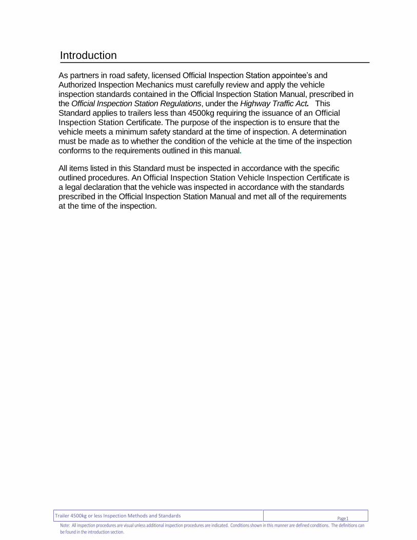
Tolerances for distance measurements vary based on the type and precision of the criterion as follows:
1. Large distance measurements of greater than 25 mm: tolerance is +/- 5 mm (accuracy is to the nearest 10 mm)
2. Short distance measurements of 1 to 25 mm, where the distance value is expressed as a whole mm: tolerance is +/- 0.5 mm (accuracy is to the nearest 1 mm)
3. Precise short distance measurements of 1.0 to 25.0 mm, where the distance value is expressed as one-tenth of a mm: tolerance is +/- 0.05 mm (accuracy is to the nearest 0.1 mm)
4. Micro distance measurements of less than 1 mm: tolerance is +/- 0.005 mm (accuracy is to the nearest 0.01 mm)
For the purpose of these tolerances, the following equivalent values are used:
Comparable Measurement Tolerances
Tolerance in metric measurements
Tolerance in imperial measurements
± 5 mm ± 0.125 (1/8) in.
± 0.5 mm ± 0.02 in.
± 0.05 mm ± 0.002 in.
± 0.005 mm ± 0.0005 in.
Metric / Imperial Conversions
25.4 mm = 1.0 in. 10.0 mm = 0.394 in.
0.0254 mm = 0.001 in.

Page 9 Trailer 4500kg or less Inspection Methods and Standards
Note: All inspection procedures are visual unless additional inspection procedures are indicated. Conditions shown in this manner are defined conditions. The definitions can be found in the introduction section.
Identification of Defective Conditions of the Types of Hose, Tubing and Lines Used on Vehicles
Diagram Characteristics Defective Condition
Type 1 – Copper, steel or plastic tubing used for liquid or vapour. Made of a single layer of material.
Wear or damage is visible on the outside.
Type 2 – Plastic (usually nylon) tubing commonly used in air- brake systems. Uses no reinforcement ply. Inner core and outer cover are usually different colour.
Inner core becomes visible from the outside, as shown by colour change.
Type 3 - Plastic (usually nylon) tubing commonly used in air- brake systems. Uses reinforcement ply. Inner and outer core are different colour. (Note: Type 2 and 3 may appear identical externally.)
Reinforcement ply or inner core is visible from the outside, as shown by colour change.
Type 4 – Stainless steel braided (or otherwise) outer cover with inner layer of tubing.
Wear or damage visible on the outer cover.
Type 5 – Synthetic rubber hose with inner reinforcement ply.
Wear or damage exposing the reinforcement ply.
Type 6 – Synthetic rubber hose with multiple reinforcement plies.
Wear or damage exposing the outer reinforcement ply.
Type 7 – Flexible hose with one or more reinforcement plies that may be fabric or steel, and an outer protective layer.
Wear or damage through the outer protective layer and outer cover, exposing a reinforcement ply.

Page 10 Trailer 4500kg or less Inspection Methods and Standards
Note: All inspection procedures are visual unless additional inspection procedures are indicated. Conditions shown in this manner are defined conditions. The definitions can be found in the introduction section.
Section 1 - Suspension
1. Suspension and Frame Attachments
Item and Method of Inspection: Reject if:
Note: This section applies to all types of suspension.
Manufacturer welding of components is a normal part of many manufacturing processes, and is distinct from welding to modify or repair a part.
Additional Inspection Procedure(s):
Raise the vehicle as necessary to access the suspension components.
a) vehicle ride height
Additional Inspection Procedure(s): Check ride height while vehicle is unloaded, parked on a flat level surface and with tires inflated to specified pressure. The allowable variation in ride height from left to right is based on a ground-to-vehicle measurement.
a) - one side of the vehicle is more than 25
mm, higher or lower than the other when measured at the tire centerline
b) frame bracket, mounting bracket and hanger
b) - broken, cracked, damaged, loose, or
missing - perforated due to corrosion or
deterioration - welded or repaired in a way that does
not meet OEM standard or Industry Standard
c) mounting fasteners c) - broken, cracked, loose or missing
d) tire interference d) - the condition of the suspension system
allows a tire to contact any part of the vehicle frame or body
Section 1 – Suspension

Page 11 Trailer 4500kg or less Inspection Methods and Standards
Note: All inspection procedures are visual unless additional inspection procedures are indicated. Conditions shown in this manner are defined conditions. The definitions can be found in the introduction section.
Section 1 - Suspension
Item and Method of Inspection: Reject if:
e) suspension travel e) - there is no or very limited suspension
travel due to a binding or seized suspension component, or due to improper stiffness or specification of suspension (which is either topped or bottomed out)
2. Axles, Axle Attaching and Tracking Components
Item and Method of Inspection: Reject if:
Note: This section applies to all types of suspension.
a) axle a)
- bent or welded
a) axle attachment, axle saddle a) - bent, broken, cracked, loose or missing - axle has shifted from its normal position
b) bushing (rubber or composite material) b) - missing, loose or shifted out of place - wear or damage permits suspension
component to shift out of position
c) stabilizer / anti-sway bar, ball and socket or link
c) - bent, broken, missing
- welded or repaired in a way that does not meet OEM standard
- Level 2 leak

Page 12 Trailer 4500kg or less Inspection Methods and Standards
Note: All inspection procedures are visual unless additional inspection procedures are indicated. Conditions shown in this manner are defined conditions. The definitions can be found in the introduction section.
Section 1 - Suspension
Item and Method of Inspection: Reject if:
d) arm, rod, strut / shock suspension, control arm
d) - bent, broken, cracked, loose, missing,
or worn out - perforated due to corrosion or
deterioration - welded or repaired in a way that does
not meet OEM standard - wear or damage permits axle or wheel
to shift out of position or required orientation
- binding strut bearings/mounts prevent free rotation of steering wheel
- Level 2 leak
3. Spring and Spring Attachment
Item and Method of Inspection: Reject if:
a) leaf spring a) - any spring leaf is broken, missing ,
worn more than 3 mm, cracked or shifted out of place
- any spring leaf is worn more than 3 mm in the hanger contact area or where leaves are in contact with each other
- leaf is shifted and contacting another vehicle part
b) composite spring
Note: Some change in the appearance of a composite spring, described as “fuzzing” / frayed is normal as the spring ages.
b) - worn more than 3 mm in load bearing
area - broken, crack of any length visible on
both sides of a spring, splintered or not the same type on each side of the vehicle.

Page 13 Trailer 4500kg or less Inspection Methods and Standards
Note: All inspection procedures are visual unless additional inspection procedures are indicated. Conditions shown in this manner are defined conditions. The definitions can be found in the introduction section.
Section 1 - Suspension
Item and Method of Inspection: Reject if:
c) shackle, pin, bushing c) - broken, missing, loose or pin seized - shifted out of normal position - fastener loose or missing - vertical movement of a spring or
shackle against a spring pin exceeds OEM standard or if not available; wear exceeds limit below
- for pin size up to 25 mm, wear limit is 2.0 mm
- for pin size greater than 25 mm, wear limit is 3.0 mm
d) U-bolt and hardware (centre bolt, fasteners, saddles or shackles)
d) - missing, loose or shifted out of normal
position - welded or repaired in a way that does
not meet OEM standard
e) spring contact area of hanger (slipper)
Note: Wear plates are permitted by some manufacturers in the spring contact (slipper) area of fabricated hangers.
e) - repaired by welding (except installation
of wear plates) - spring-load bearing area is worn more
than 3 mm
f) coil spring f) - broken or shifted out of normal position - spacer is fitted between coils
g) torsion bar g) - broken, cracked or missing
- repaired by welding
h) rubber load cushion h) - rubber block or vertical pin is broken,
loose, missing or split
Page 14 Trailer 4500kg or less Inspection Methods and Standards
Note: All inspection procedures are visual unless additional inspection procedures are indicated. Conditions shown in this manner are defined conditions. The definitions can be found in the introduction section.
Section 1 - Suspension
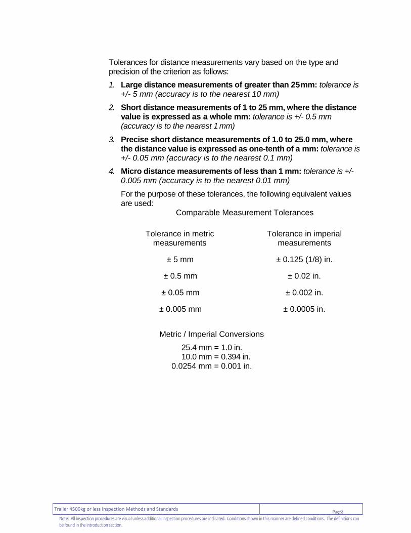
4. Strut / Shock Absorber
Item and Method of Inspection: Reject if:
Additional Inspection Procedure(s): Check shock absorbers by rapidly lowering and raising the vehicle.
a) operation a) - vehicle oscillates more than two cycles
after release
b) condition b) - damaged, disconnected or missing - Level 2 leak
c) mount and hardware c) - broken, loose, binding or missing

Page 15 Trailer 4500kg or less Inspection Methods and Standards
Note: All inspection procedures are visual unless additional inspection procedures are indicated. Conditions shown in this manner are defined conditions. The definitions can be found in the introduction section.
Section 2 - Brakes
Additional Inspection Procedure(s): Inspecting Internal Brake Components
1. Disassembly of Wheels and Drums for Inspection Internal brake components must be inspected at every inspection. Disassembly or removal of wheels, and/or brake parts, is required to facilitate full inspection of all components.
2. Required Measurement of Brake Components Brake inspections require certain components to be measured. These measurements are required to be recorded on the inspection report. The items that must be measured for each type of brake are as follows:
2.1 Drum Brake Systems For drum brakes, the brake-shoe lining thickness and brake-drum diameter must be measured at every inspection.
2.2 Disc Brake Systems For disc brakes, the rotor thickness and pad friction material thickness of the inner and outer brake pad must be measured and recorded at every inspection. Friction-material thickness can be determined by measuring the friction material itself, or by measuring the combined thickness of the friction material and pad backing plate, then deducting the thickness of the backing plate. Always record the thickness of the friction material only.
Section 2 – Brake Systems

Page 16 Trailer 4500kg or less Inspection Methods and Standards
Note: All inspection procedures are visual unless additional inspection procedures are indicated. Conditions shown in this manner are defined conditions. The definitions can be found in the introduction section.
Section 2 - Brakes
1. General
Item and Method of Inspection: Reject if:
a) brake system a) A component of the brake system is missing or has been disabled
2. Hydraulic System Components
Item and Method of Inspection: Reject if:
a) metal line and fittings
Additional Inspection Procedure(s): Inspect lines and fittings for leaks after brakes are applied with a heavy force on the brake pedal similar to what would be used in an emergency stop.
Note:
Surface rust and corrosion is normal on metal lines and fittings, and is not cause for rejection.
a) - heavy rust, corrosion or scaling is
present on any metal line or fitting that reduces or increases the thickness or compromises the structural integrity of the material
- level 1 leak - chafing, cracked, flattened or restricting
section - insecure mounting causing line to shift
out of its normal position - repaired by welding or soldering - repaired using material or method that
does not meet OEM standard - connections between brake system
components are not a flared type fitting or does not meet OEM standard
- component does not meet OEM standard

Page 17 Trailer 4500kg or less Inspection Methods and Standards
Note: All inspection procedures are visual unless additional inspection procedures are indicated. Conditions shown in this manner are defined conditions. The definitions can be found in the introduction section.
Section 2 - Brakes
Item and Method of Inspection: Reject if:
b) flexible line / hose
Additional Inspection Procedure(s):
Inspect flexible hoses after brakes are applied with a heavy force on the brake pedal similar to what would be used in an emergency stop.
b) - bulged or swells under pressure,
flattened, twisted, restricted section or insecure mounting
- outer composite material is cracked or chafed exposing an inner layer as shown in hose and tube condition chart in introduction or located so as to rub against any component.
- component does not meet OEM standard
- level 1 leak
c) master cylinder / surge tank
c) - damaged or insecure mounting - fluid is contaminated - level 1 leak
- fluid level is below indicated minimum level or, if not indicated, more than 13 mm from top
- filler cap is damaged, loose or missing, vent holes are plugged or gasket is missing or swollen
d) auxiliary or work brake (line-lock device)
Note:
Line-lock devices block brake fluid from returning to the master cylinder as a means of holding a vehicle stationary. Improperly installed they can interfere with normal service brake operation.
d) - any device is installed that interferes with normal service brake operation
Page 18 Trailer 4500kg or less Inspection Methods and Standards
Note: All inspection procedures are visual unless additional inspection procedures are indicated. Conditions shown in this manner are defined conditions. The definitions can be found in the introduction section.
Section 2 - Brakes
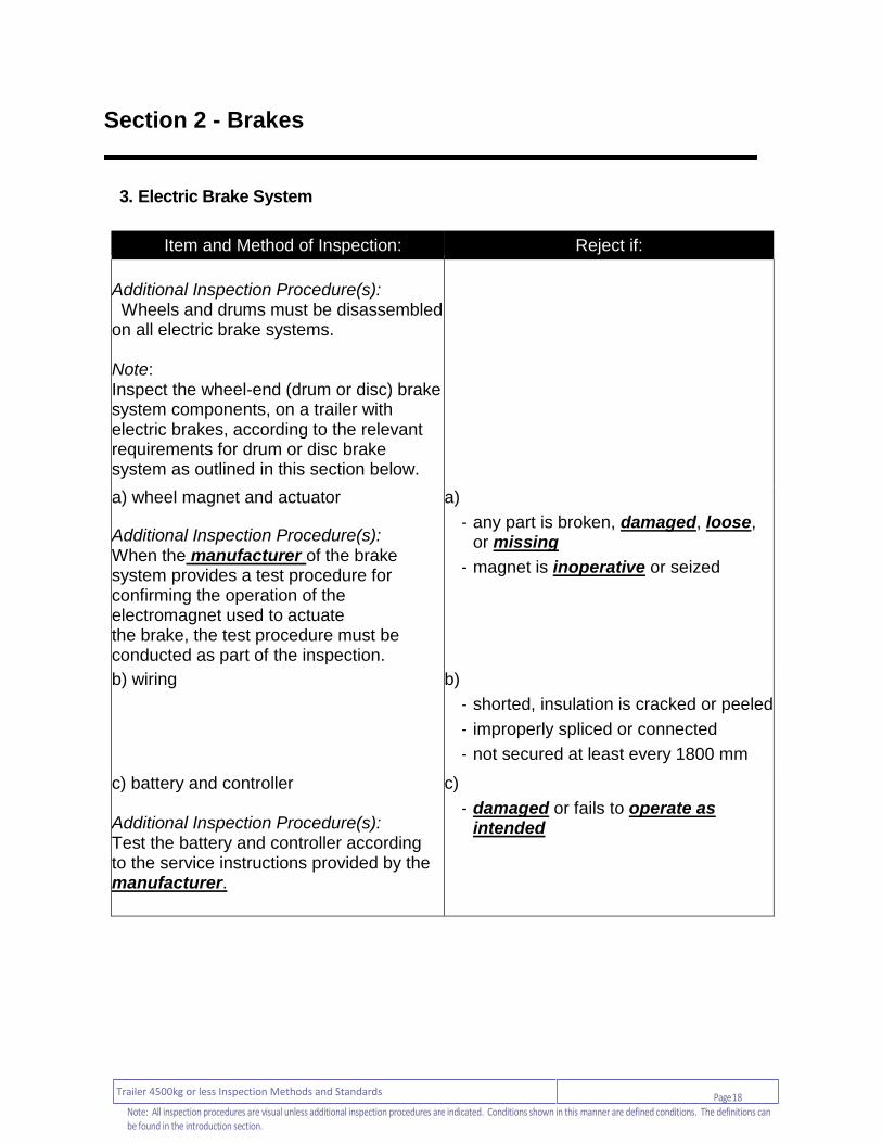
3. Electric Brake System
Item and Method of Inspection: Reject if:
Additional Inspection Procedure(s): Wheels and drums must be disassembled on all electric brake systems. Note: Inspect the wheel-end (drum or disc) brake system components, on a trailer with electric brakes, according to the relevant requirements for drum or disc brake system as outlined in this section below.
a) wheel magnet and actuator
Additional Inspection Procedure(s): When the manufacturer of the brake system provides a test procedure for confirming the operation of the electromagnet used to actuate the brake, the test procedure must be conducted as part of the inspection.
a)
- any part is broken, damaged, loose, or missing
- magnet is inoperative or seized
b) wiring
b)
- shorted, insulation is cracked or peeled
- improperly spliced or connected
- not secured at least every 1800 mm
c) battery and controller Additional Inspection Procedure(s): Test the battery and controller according to the service instructions provided by the manufacturer.
c)
- damaged or fails to operate as intended

Page 19 Trailer 4500kg or less Inspection Methods and Standards
Note: All inspection procedures are visual unless additional inspection procedures are indicated. Conditions shown in this manner are defined conditions. The definitions can be found in the introduction section.
Section 2 - Brakes
4. Drum Brake System Components
Item and Method of Inspection: Reject if:
Additional Inspection Procedure(s): Inspection requires removal of the drum and also other components as necessary to inspect all components as detailed below.
a) brake shoe lining condition a) - lining material is broken, contaminated or
cracked - signs of “rust-jacking” (friction material
lifting due to rust build-up, shoe-table deformation, friction material separating from backing material)
- lining protrudes outside of drum - lining loose or separating from shoe - shim is used between lining and shoe - shoe or lining is installed incorrectly (such
as primary and secondary shoes reversed)
b) brake shoe lining thickness
Additional Inspection Procedure(s):
Lining thickness must be measured at each inspection, and the measurement must be recorded on the inspection report.
b) - bonded brake-shoe lining thickness is less
than the minimum specified by the manufacturer or when no specification is available 1.6 mm (2/32 in) where the lining is thinnest
Note: Lining thickness measurements are taken above a rivet or shoe at the most worn location.
- riveted brake-shoe lining thickness is less than the minimum specified by the manufacturer or when no specification is available 1.6 mm (2/32 in) above rivet

Page 20 Trailer 4500kg or less Inspection Methods and Standards
Note: All inspection procedures are visual unless additional inspection procedures are indicated. Conditions shown in this manner are defined conditions. The definitions can be found in the introduction section.
Section 2 - Brakes
Item and Method of Inspection: Reject if:
c) brake drum condition
Note: Heat checks and some surface cracks on the friction surface are normal. Heat checking is identified by a number of short, fine, hairline cracks on the braking surface.
c) - crack, groove or worn area is deeper
than the drum wear limit - surface cracks or heat checks extend
completely across the brake surface. - any external crack is present - friction surface is abnormally worn
d) brake drum diameter (wear)
Additional Inspection Procedure(s):
Brake drum diameter must be measured and recorded on the inspection report. See Introduction to Section 3 for details.
d) - measured drum diameter exceeds limit
indicated on the brake drum or, if not available, OEM standard or industry standard
e) self-adjuster mechanism e) - broken, incorrect thread direction,
inoperative, missing or seized
f) adjusters (manual) f)
- broken, inoperative, missing or seized
g) anchor pin / bracket and return spring
g) - abnormally worn, bent, broken, loose or
missing - spring stretched
h) backing plate h) - bent, damaged or loose - shoe contact area is grooved or worn in a
manner that restricts free movement of shoes
i) axle and spindle i) - cracked or damaged

Page 21 Trailer 4500kg or less Inspection Methods and Standards
Note: All inspection procedures are visual unless additional inspection procedures are indicated. Conditions shown in this manner are defined conditions. The definitions can be found in the introduction section.
Section 2 - Brakes
Item and Method of Inspection: Reject if:
j) wheel cylinder j)
- inoperative or seized, damaged, loose or insecure mounting
- level 1 leak - dust seal is cracked or split, missing,
damaged or deteriorated
k) wheel seal k) - level 2 leak
6. Disc Brake System Components
Item and Method of Inspection: Reject if:
Additional Inspection Procedure(s):
When an inspection reveals evidence of a defect or abnormal condition, brake components must be disassembled to the point necessary to verify defect.
Refer to the instructions in the Introduction to Section 3 to determine what measurements are required to be taken and recorded.
a) - broken, pitted, damaged or cracks on
surface extending to the outer edge; broken or cracked cooling fins; or mechanical damage that may be attributable to abnormal wear on friction surfaces
- any surface crack, groove or worn area is deeper than the wear limit
- crack extends from the friction surface through to the cooling vent
- contact pattern of the pad on solid rotor material (not rusted) is less than 75% of the radial width around the entire rotor, on one side
a) disc (rotor) condition
Note: Lateral run-out and parallelism needs to be checked only where there is evidence of a problem (for example, severe brake pedal pulsation upon brake application).
Heat checks and some surface cracks on the friction surface are normal.
Heat checks are identified by a number of short, fine hairline cracks on the braking surface.
Page 22 Trailer 4500kg or less Inspection Methods and Standards
Note: All inspection procedures are visual unless additional inspection procedures are indicated. Conditions shown in this manner are defined conditions. The definitions can be found in the introduction section.
Section 2 - Brakes
Item and Method of Inspection: Reject if:
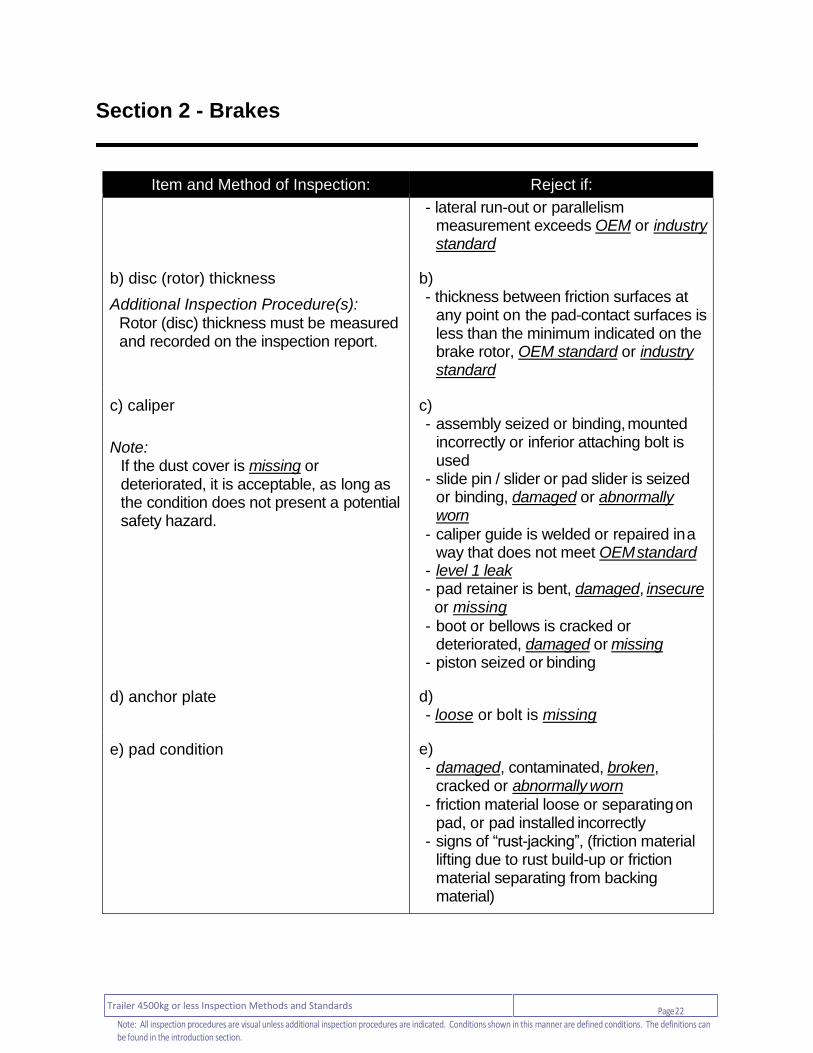
- lateral run-out or parallelism measurement exceeds OEM or industry standard
b) disc (rotor) thickness
Additional Inspection Procedure(s): Rotor (disc) thickness must be measured and recorded on the inspection report.
b) - thickness between friction surfaces at
any point on the pad-contact surfaces is less than the minimum indicated on the brake rotor, OEM standard or industry standard
c) caliper
Note:
If the dust cover is missing or deteriorated, it is acceptable, as long as the condition does not present a potential safety hazard.
c) - assembly seized or binding, mounted
incorrectly or inferior attaching bolt is used
- slide pin / slider or pad slider is seized or binding, damaged or abnormally worn
- caliper guide is welded or repaired in a way that does not meet OEM standard
- level 1 leak - pad retainer is bent, damaged, insecure
or missing
- boot or bellows is cracked or deteriorated, damaged or missing
- piston seized or binding
d) anchor plate d) - loose or bolt is missing
e) pad condition e) - damaged, contaminated, broken,
cracked or abnormally worn - friction material loose or separating on
pad, or pad installed incorrectly - signs of “rust-jacking”, (friction material
lifting due to rust build-up or friction material separating from backing material)

Page 23 Trailer 4500kg or less Inspection Methods and Standards
Note: All inspection procedures are visual unless additional inspection procedures are indicated. Conditions shown in this manner are defined conditions. The definitions can be found in the introduction section.
Section 2 - Brakes
Item and Method of Inspection: Reject if:
f) pad (friction material) thickness
Additional Inspection Procedure(s):
Pad (friction material) thickness of both inboard and outboard pad must be measured and must be recorded on the inspection report.
Note: Pad (friction material) thickness can be determined by measuring the friction material itself or by measuring the combined thickness of the friction material and pad backing plate, then deducting the thickness of the backing plate. Record the thickness of the friction material on service brakes only.
f) - measured friction-material thickness is
less than manufacturer specification. If limit is not available:
bonded friction-material thickness is less than 1.6 mm
riveted friction-material thickness is less than 3.2 mm (4/32 in) without pads removed
riveted friction-material thickness is less than 1.6 mm (2/32 in) above the rivet head with pads removed
- difference between inboard and outboard friction-material thickness is greater than manufacturer specification. If limit is not available: difference is greater than 3.2 mm (4/32 in)
g) clearance between pads and rotor
(caliper adjustment) g) - does not meet manufacturer’s
specifications
Page 24 Trailer 4500kg or less Inspection Methods and Standards
Note: All inspection procedures are visual unless additional inspection procedures are indicated. Conditions shown in this manner are defined conditions. The definitions can be found in the introduction section.
Section 3 - Lamps
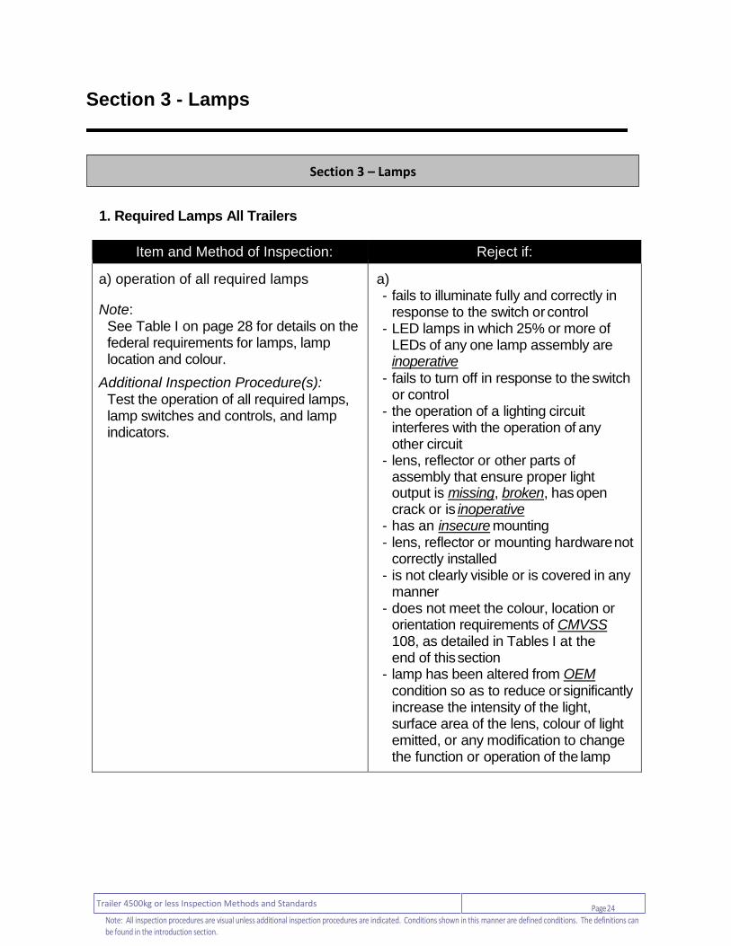
1. Required Lamps All Trailers
Item and Method of Inspection: Reject if:
a) operation of all required lamps
Note: See Table I on page 28 for details on the federal requirements for lamps, lamp location and colour.
Additional Inspection Procedure(s):
Test the operation of all required lamps, lamp switches and controls, and lamp indicators.
a) - fails to illuminate fully and correctly in
response to the switch or control - LED lamps in which 25% or more of
LEDs of any one lamp assembly are inoperative
- fails to turn off in response to the switch or control
- the operation of a lighting circuit interferes with the operation of any other circuit
- lens, reflector or other parts of assembly that ensure proper light output is missing, broken, has open crack or is inoperative
- has an insecure mounting - lens, reflector or mounting hardware not
correctly installed - is not clearly visible or is covered in any
manner - does not meet the colour, location or
orientation requirements of CMVSS 108, as detailed in Tables I at the end of this section
- lamp has been altered from OEM condition so as to reduce or significantly increase the intensity of the light, surface area of the lens, colour of light emitted, or any modification to change the function or operation of the lamp
Section 3 – Lamps

Page 25 Trailer 4500kg or less Inspection Methods and Standards
Note: All inspection procedures are visual unless additional inspection procedures are indicated. Conditions shown in this manner are defined conditions. The definitions can be found in the introduction section.
Section 3 - Lamps
Item and Method of Inspection: Reject if:
b) tail lamps
Note:
Trailers less than 762mm (30 inches) wide only require 1 red light mounted at or near the centre.
b) - vehicle modification or installation of
lamp causes tail lamp to be higher or lower than permitted by Table I
- the tail lamps fail to meet any of the following requirements:
minimum of 2 lamps facing the rear, located at rear of vehicle and as far apart as practical, red in colour
illuminate correctly when operated by headlamp control
c) stop (brake) lamps
Note:
Trailers less than 762mm (30 inches) wide only require 1 red light mounted at or near the center.
c) - the stop lamps fail to meet any of
the following requirements:
minimum of 2 lamps facing the rear, located at rear of vehicle and as far apart as practical, red in colour
illuminate correctly when service brakes are applied
d) turn-signal lamps d) - turn-signal lamps fail to meet any of the
following requirements:
minimum of 2 facing the rear, as far apart as practical, amber or red in colour
illuminate correctly when operated by turn signal control
e) licence-plate lamp e) - not white, fails to illuminate licence plate
when operated by headlamp control - lamp not shielded from projecting light
rearward.
Page 26 Trailer 4500kg or less Inspection Methods and Standards
Note: All inspection procedures are visual unless additional inspection procedures are indicated. Conditions shown in this manner are defined conditions. The definitions can be found in the introduction section.
Section 3 - Lamps
Item and Method of Inspection: Reject if:
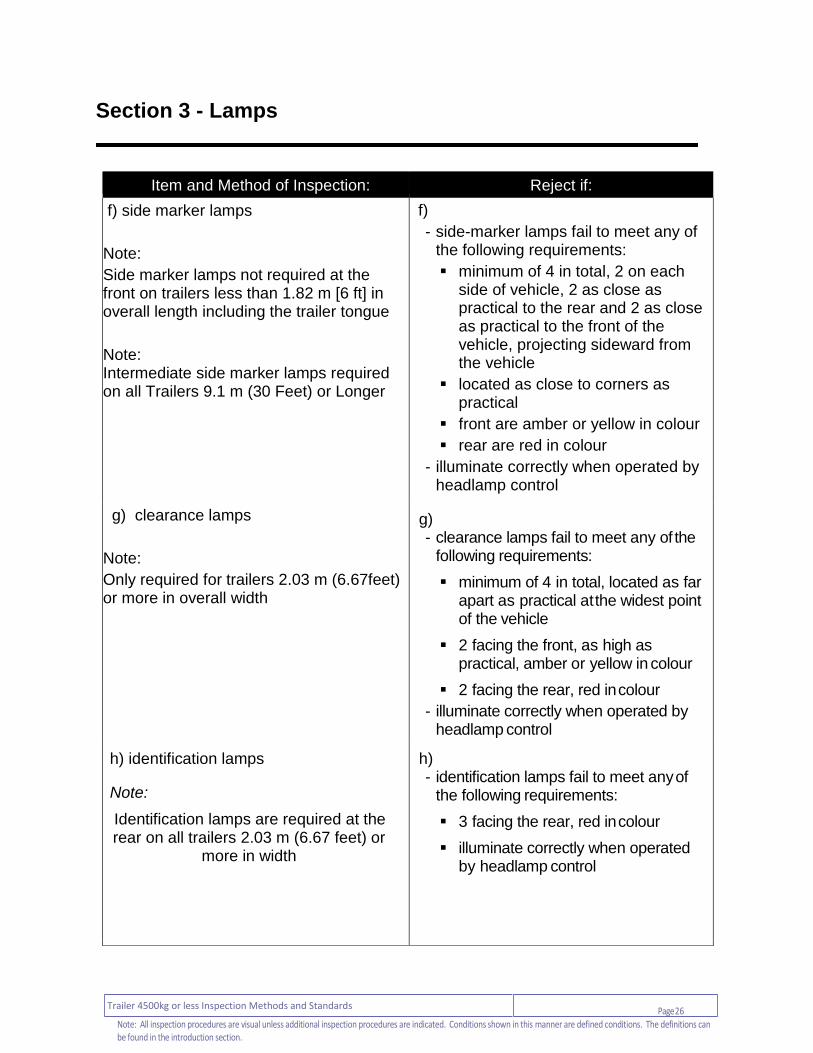
f) side marker lamps
Note:
Side marker lamps not required at the front on trailers less than 1.82 m [6 ft] in overall length including the trailer tongue
Note: Intermediate side marker lamps required on all Trailers 9.1 m (30 Feet) or Longer
f)
- side-marker lamps fail to meet any of the following requirements:
minimum of 4 in total, 2 on each side of vehicle, 2 as close as practical to the rear and 2 as close as practical to the front of the vehicle, projecting sideward from the vehicle
located as close to corners as practical
front are amber or yellow in colour
rear are red in colour
- illuminate correctly when operated by headlamp control
g) clearance lamps
Note:
Only required for trailers 2.03 m (6.67feet) or more in overall width
g) - clearance lamps fail to meet any of the
following requirements:
minimum of 4 in total, located as far apart as practical at the widest point of the vehicle
2 facing the front, as high as practical, amber or yellow in colour
2 facing the rear, red in colour
- illuminate correctly when operated by headlamp control
h) identification lamps
Note:
Identification lamps are required at the rear on all trailers 2.03 m (6.67 feet) or
more in width
h) - identification lamps fail to meet any of
the following requirements:
3 facing the rear, red in colour
illuminate correctly when operated by headlamp control
Page 27 Trailer 4500kg or less Inspection Methods and Standards
Note: All inspection procedures are visual unless additional inspection procedures are indicated. Conditions shown in this manner are defined conditions. The definitions can be found in the introduction section.
Section 3 - Lamps
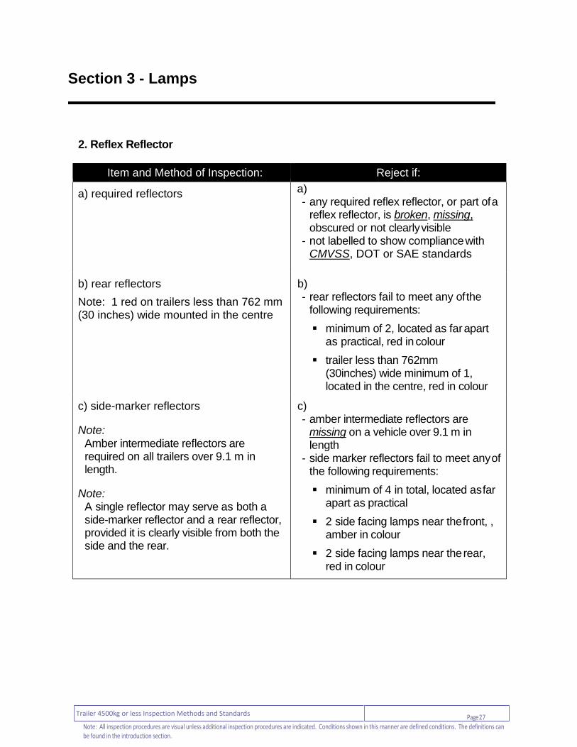
2. Reflex Reflector
Item and Method of Inspection: Reject if:
a) required reflectors
a) - any required reflex reflector, or part of a
reflex reflector, is broken, missing, obscured or not clearly visible
- not labelled to show compliance with CMVSS, DOT or SAE standards
b) rear reflectors
Note: 1 red on trailers less than 762 mm (30 inches) wide mounted in the centre
b) - rear reflectors fail to meet any of the
following requirements:
minimum of 2, located as far apart as practical, red in colour
trailer less than 762mm (30inches) wide minimum of 1, located in the centre, red in colour
c) side-marker reflectors
Note:
Amber intermediate reflectors are required on all trailers over 9.1 m in length.
Note: A single reflector may serve as both a side-marker reflector and a rear reflector, provided it is clearly visible from both the side and the rear.
c) - amber intermediate reflectors are
missing on a vehicle over 9.1 m in length
- side marker reflectors fail to meet any of the following requirements:
minimum of 4 in total, located as far apart as practical
2 side facing lamps near the front, , amber in colour
2 side facing lamps near the rear, red in colour

Page 28 Trailer 4500kg or less Inspection Methods and Standards
Note: All inspection procedures are visual unless additional inspection procedures are indicated. Conditions shown in this manner are defined conditions. The definitions can be found in the introduction section.
Section 3 - Lamps
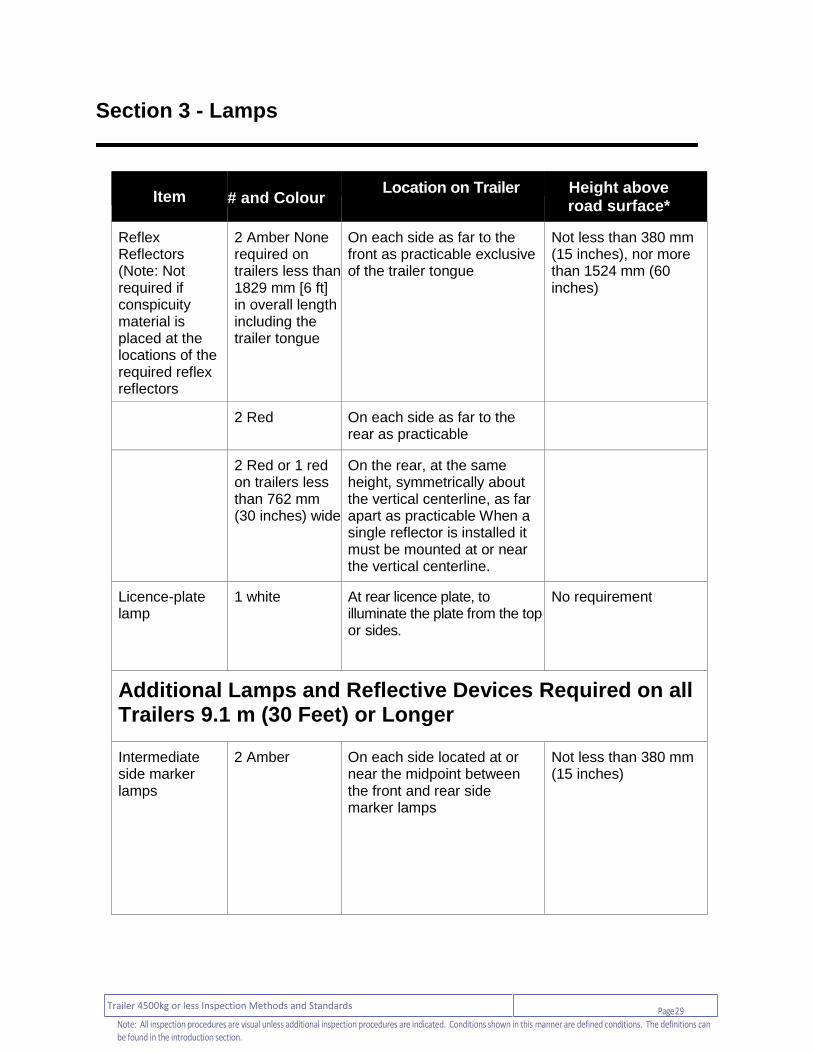
Table I: Required Trailer Lighting Equipment All Trailers
Item
# and Colour Location on Trailer Height above
road surface*
Turn Signal Lamps
2 Red or amber On the rear, at the same height, symmetrically about the vertical centerline, as far apart as practicable
Not less than 380 mm (15 inches), nor more than 2108 mm (83 inches)
Taillamps 2 red or 1 red on trailers less than 762 mm (30 inches) wide
On the rear, 1 on each side of the vertical centerline, at the same height, and as far apart as practicable. When a single lamp is installed it must be mounted at or near the vertical centerline
Not less than 380 mm (15 in.) or more than 1,829 mm (72 in.)
Stop lamps 2 red or 1 red on trailers less than 762 mm (30 inches) wide
On the rear, 1 on each side of the vertical centerline at the same height, and as far apart as practicable. When a single lamp is installed it must be mounted at or near the vertical centerline
Not less than 380 mm (15 in.) or more than 1,829 mm (72 in.)
Side Marker Lamps
2 Amber None required on trailers less than 1829 mm [6 ft] in overall length including the trailer tongue
On each side as far to the front as practicable exclusive of the trailer tongue
Not less than 380 mm (15 inches)
2 Red On each side as far to the rear as practicable
Not less than 380 mm (15 inches). Not more than 1524 mm (60 inches) on trailers 2032 mm or more in overall width
Page 29 Trailer 4500kg or less Inspection Methods and Standards
Note: All inspection procedures are visual unless additional inspection procedures are indicated. Conditions shown in this manner are defined conditions. The definitions can be found in the introduction section.
Section 3 - Lamps
Item
# and Colour Location on Trailer Height above
road surface*
Reflex Reflectors (Note: Not required if conspicuity material is placed at the locations of the required reflex reflectors
2 Amber None required on trailers less than 1829 mm [6 ft] in overall length including the trailer tongue
On each side as far to the front as practicable exclusive of the trailer tongue
Not less than 380 mm (15 inches), nor more than 1524 mm (60 inches)
2 Red On each side as far to the rear as practicable
2 Red or 1 red on trailers less than 762 mm (30 inches) wide
On the rear, at the same height, symmetrically about the vertical centerline, as far apart as practicable When a single reflector is installed it must be mounted at or near the vertical centerline.
Licence-plate lamp
1 white At rear licence plate, to illuminate the plate from the top or sides.
No requirement
Additional Lamps and Reflective Devices Required on all Trailers 9.1 m (30 Feet) or Longer
Intermediate side marker lamps
2 Amber On each side located at or near the midpoint between the front and rear side marker lamps
Not less than 380 mm (15 inches)
Page 30 Trailer 4500kg or less Inspection Methods and Standards
Note: All inspection procedures are visual unless additional inspection procedures are indicated. Conditions shown in this manner are defined conditions. The definitions can be found in the introduction section.
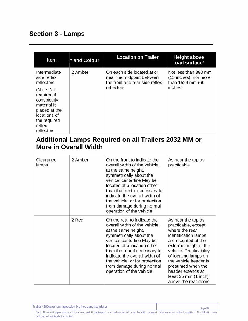
Section 3 - Lamps
Item
# and Colour Location on Trailer Height above
road surface*
Intermediate side reflex reflectors
(Note: Not required if conspicuity material is placed at the locations of the required reflex reflectors
2 Amber On each side located at or near the midpoint between the front and rear side reflex reflectors
Not less than 380 mm (15 inches), nor more than 1524 mm (60 inches)
Additional Lamps Required on all Trailers 2032 MM or More in Overall Width
Clearance lamps
2 Amber On the front to indicate the overall width of the vehicle, at the same height, symmetrically about the vertical centerline May be located at a location other than the front if necessary to indicate the overall width of the vehicle, or for protection from damage during normal operation of the vehicle
As near the top as practicable
2 Red On the rear to indicate the overall width of the vehicle, at the same height, symmetrically about the vertical centerline May be located at a location other than the rear if necessary to indicate the overall width of the vehicle, or for protection from damage during normal operation of the vehicle
As near the top as practicable, except where the rear identification lamps are mounted at the extreme height of the vehicle. Practicability of locating lamps on the vehicle header is presumed when the header extends at least 25 mm (1 inch) above the rear doors

Page 31 Trailer 4500kg or less Inspection Methods and Standards
Note: All inspection procedures are visual unless additional inspection procedures are indicated. Conditions shown in this manner are defined conditions. The definitions can be found in the introduction section.
Section 3 - Lamps
Item
# and Colour Location on Trailer Height above
road surface*
2 Amber to front and red to rear
On a boat trailer the requirement for front and rear clearance lamps may be met by installation at or near the midpoint on each side of a dual facing lamp so as to indicate the extreme width. May be located at a location other than the front and the rear if necessary to indicate the overall width of the vehicle, or for protection from damage during normal operation of the vehicle
As near the top as practicable
Identification lamps
3 Red On the rear, at the same height, as close as practicable to the vertical centerline, with lamp centers spaced not less than 152 mm (6 inches) or more than 305 mm (12 inches) apart
As near the top as practicable. Practicability of locating lamps on the vehicle header is presumed when the header extends at least 25 mm (1 inch) above the rear doors
Page 32 Trailer 4500kg or less Inspection Methods and Standards
Note: All inspection procedures are visual unless additional inspection procedures are indicated. Conditions shown in this manner are defined conditions. The definitions can be found in the introduction section.
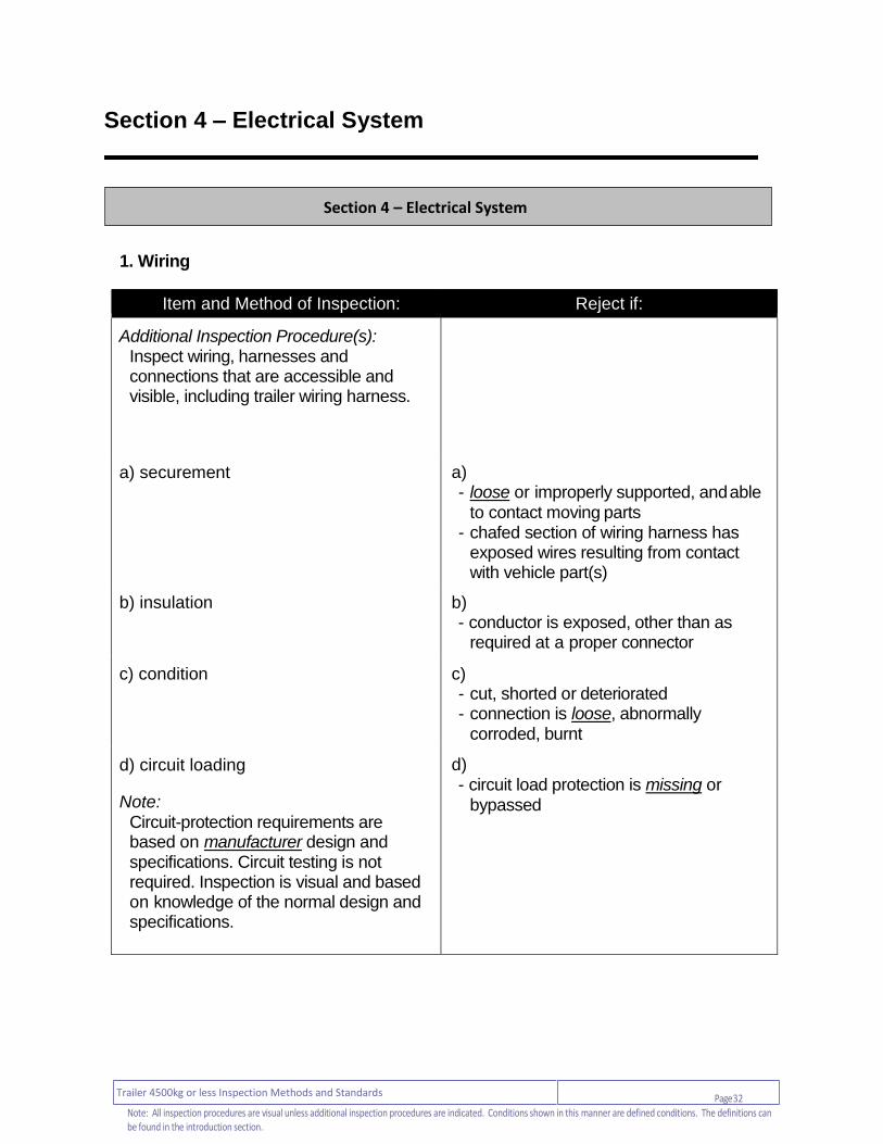
Section 4 – Electrical System
1. Wiring
Item and Method of Inspection: Reject if:
Additional Inspection Procedure(s): Inspect wiring, harnesses and connections that are accessible and visible, including trailer wiring harness.
a) securement a) - loose or improperly supported, and able
to contact moving parts - chafed section of wiring harness has
exposed wires resulting from contact with vehicle part(s)
b) insulation b) - conductor is exposed, other than as
required at a proper connector
c) condition c) - cut, shorted or deteriorated - connection is loose, abnormally
corroded, burnt
d) circuit loading
Note: Circuit-protection requirements are based on manufacturer design and specifications. Circuit testing is not required. Inspection is visual and based on knowledge of the normal design and
specifications.
d) - circuit load protection is missing or
bypassed
Section 4 – Electrical System

Page 33 Trailer 4500kg or less Inspection Methods and Standards
Note: All inspection procedures are visual unless additional inspection procedures are indicated. Conditions shown in this manner are defined conditions. The definitions can be found in the introduction section.
Section 4 – Electrical System
2. Trailer Cord (output to towed vehicle)
Item and Method of Inspection: Reject if:
a) insulation a) - conductor is exposed, other than as
required at a proper connector
b) connection
Note:
A trailer cord must be repaired only by using industry standard methods.
c) - cracked - ends split - improper repair or connection

Page 34 Trailer 4500kg or less Inspection Methods and Standards
Note: All inspection procedures are visual unless additional inspection procedures are indicated. Conditions shown in this manner are defined conditions. The definitions can be found in the introduction section.
Section 5 –Body
1. Cargo Body
Item and Method of Inspection: Reject if:
Additional Inspection Procedure(s): Where any sheet metal, structural item or fastener is suspected of being loose or perforated by corrosion, determine the integrity of the suspect item or area.
Note: Minor surface rust and corrosion is normal.
a) - any section has exposed sharp edge, is
torn or protrudes out in a manner that could be hazardous to driver, passenger, pedestrian or cyclist
- panel is insecure or loose - rivet is loose, missing - welded or repaired in a way that does
not meet OEM standard or industry standard
a) sheet metal
b) floor and deck
b) - has any condition that allows a person or
cargo to fall through - has a hole larger than 200 mm across
the longest dimension - welded or repaired in a way that does
not meet OEM standard or industry standard
Section 5 – Body

Page 35 Trailer 4500kg or less Inspection Methods and Standards
Note: All inspection procedures are visual unless additional inspection procedures are indicated. Conditions shown in this manner are defined conditions. The definitions can be found in the introduction section.
Section 5 –Body
Item and Method of Inspection: Reject if:
c) frame and sub-frame
c) - bulge caused by corrosion - stress crack at side rail or rub-rail - rivet is loose, missing, dimpled by
corrosion - bent, broken, cracked, kinked, welded or
repaired in a way that does not meet OEM standard or industry standard
- perforated or weakened by corrosion
d) cross member d) - bent, broken, collapsed, cracked ,
kinked, torn or missing - perforated or weakened by corrosion
e) inner or outer side rail and body long sills
e) - bulge caused by corrosion - rivet is loose, missing, dimpled by
corrosion - bent, broken, cracked or insecure - welded or repaired in a way that does
not meet OEM standard or industry standard
f) tailgate
f) - broken, loose or insecure
g) body-to-frame attachment
Note:
Includes body-to-frame attachments such as u-bolts, pivot hinge, cheek-plate mounts, flex-mount hardware, body clamps and j-bars.
g) - bent, broken, cracked, loose or missing - spacer or insulator is abnormally worn,
crushed, dislodged or missing
Page 36 Trailer 4500kg or less Inspection Methods and Standards
Note: All inspection procedures are visual unless additional inspection procedures are indicated. Conditions shown in this manner are defined conditions. The definitions can be found in the introduction section.
Section 5 –Body
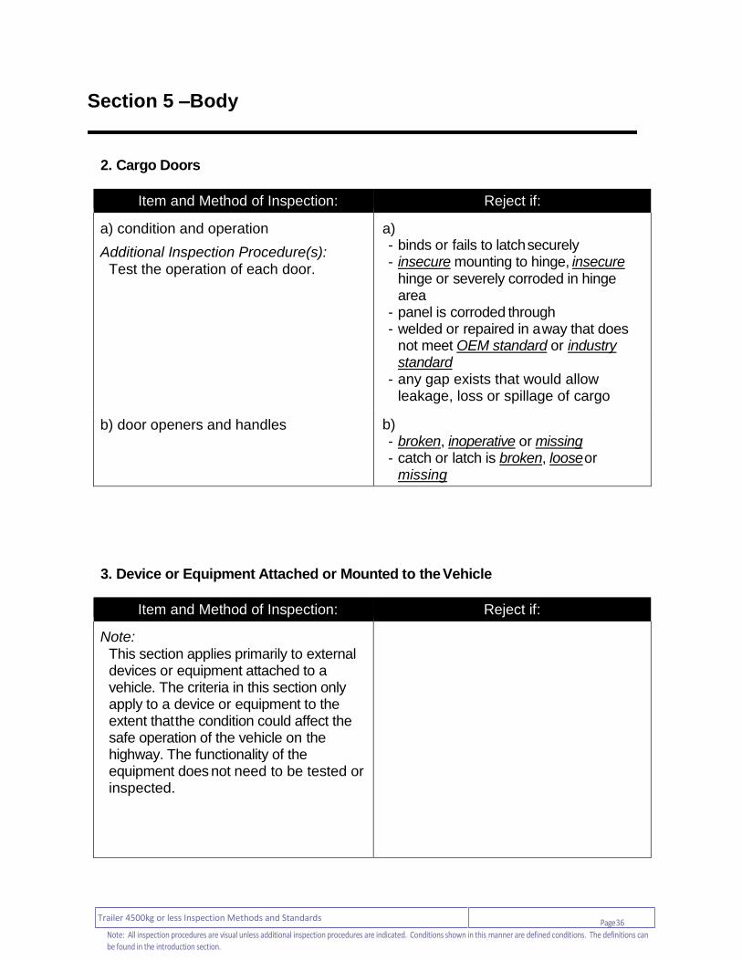
2. Cargo Doors
Item and Method of Inspection: Reject if:
a) condition and operation
Additional Inspection Procedure(s): Test the operation of each door.
a) - binds or fails to latch securely - insecure mounting to hinge, insecure
hinge or severely corroded in hinge area
- panel is corroded through - welded or repaired in a way that does
not meet OEM standard or industry standard
- any gap exists that would allow leakage, loss or spillage of cargo
b) door openers and handles
b) - broken, inoperative or missing - catch or latch is broken, loose or
missing
3. Device or Equipment Attached or Mounted to the Vehicle
Item and Method of Inspection: Reject if:
Note: This section applies primarily to external devices or equipment attached to a vehicle. The criteria in this section only apply to a device or equipment to the extent that the condition could affect the safe operation of the vehicle on the highway. The functionality of the equipment does not need to be tested or inspected.
Page 37 Trailer 4500kg or less Inspection Methods and Standards
Note: All inspection procedures are visual unless additional inspection procedures are indicated. Conditions shown in this manner are defined conditions. The definitions can be found in the introduction section.
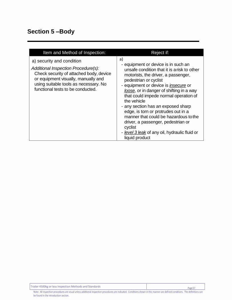
Section 5 –Body
Item and Method of Inspection: Reject if:
a) security and condition
Additional Inspection Procedure(s): Check security of attached body, device or equipment visually, manually and using suitable tools as necessary. No functional tests to be conducted.
a) - equipment or device is in such an
unsafe condition that it is a risk to other motorists, the driver, a passenger, pedestrian or cyclist
- equipment or device is insecure or loose, or in danger of shifting in a way that could impede normal operation of the vehicle
- any section has an exposed sharp edge, is torn or protrudes out in a manner that could be hazardous to the driver, a passenger, pedestrian or cyclist
- level 3 leak of any oil, hydraulic fluid or liquid product

Page 38 Trailer 4500kg or less Inspection Methods and Standards
Note: All inspection procedures are visual unless additional inspection procedures are indicated. Conditions shown in this manner are defined conditions. The definitions can be found in the introduction section.
Section 5 –Body
4. Fender / Mudguard
Item and Method of Inspection: Reject if:
Note: A mudguard is required surrounding every wheel, where the full width of the tire is not enclosed by a body element, such as a fender.
a) - fender or mudguard is broken, has
insecure mounting, is loose or missing
- fender or mudguard has a hole, tear or opening larger than 100 mm across the longest dimension
- top of the mudguard does not reach up to the top of the tires or a body element
- where the full width of a tire is not enclosed by a body element, such as a fender the mudguard does not extend down at least as far as the wheel’s horizontal centre line
- mudguard does not cover the full width of a tire surrounding the portion of the tire which is not enclosed by a body element or fender
a) condition and location
Page 39 Trailer 4500kg or less Inspection Methods and Standards
Note: All inspection procedures are visual unless additional inspection procedures are indicated. Conditions shown in this manner are defined conditions. The definitions can be found in the introduction section.
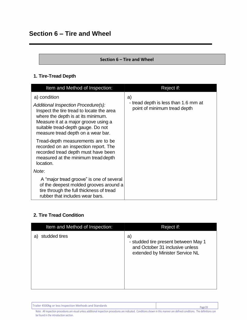
Section 6 – Tire and Wheel
1. Tire-Tread Depth
Item and Method of Inspection: Reject if:
a) condition
Additional Inspection Procedure(s): Inspect the tire tread to locate the area where the depth is at its minimum. Measure it at a major groove using a suitable tread-depth gauge. Do not measure tread depth on a wear bar.
Tread-depth measurements are to be recorded on an inspection report. The recorded tread depth must have been measured at the minimum tread depth location.
Note:
A “major tread groove” is one of several of the deepest molded grooves around a tire through the full thickness of tread rubber that includes wear bars.
a) - tread depth is less than 1.6 mm at
point of minimum tread depth
2. Tire Tread Condition
Item and Method of Inspection: Reject if:
a) studded tires
a) - studded tire present between May 1
and October 31 inclusive unless extended by Minister Service NL
Section 6 – Tire and Wheel

Page 40 Trailer 4500kg or less Inspection Methods and Standards
Note: All inspection procedures are visual unless additional inspection procedures are indicated. Conditions shown in this manner are defined conditions. The definitions can be found in the introduction section.
Section 6 – Tire and Wheel
Item and Method of Inspection: Reject if:
b) tread condition b) - cut or crack greater than 25 mm long
that extends deeper than a major tread groove
- cut or crack extends into body cord, or any body cord is exposed
- any piece of original tire tread is missing, and the longest dimension across the missing section is greater than 25 mm
c) re-grooving c)
- non regroovable tire has been re-grooved
3. Tire Sidewall
Item and Method of Inspection: Reject if:
a) matching and application
Note:
Nominal tire size is based on the size designation and marking provided by the tire manufacturer
Tire size and load capacity requirements of the vehicle manufacturer can be located on the Tire Placard label, Federal Compliance label or other reference.
a) - nominal tire size is different between
the left and right tires at the front or rear of the vehicle.
- wheel / rim size does not match tire size according to tire manufacturer’s specifications
- required tire is missing - radial tire is mixed with non-radial
anywhere on vehicle - any tire is labelled ”Not for Highway
Use,” or in any way that indicates the tire is not intended for on-road use
- tire has a lower load rating / capacity than specified by the vehicle manufacturer
- tire is sufficiently oversized / undersized as to contact any vehicle component which may affect the safe operation of the vehicle
- tire is over or undersized outside of manufacturers specifications

Page 41 Trailer 4500kg or less Inspection Methods and Standards
Note: All inspection procedures are visual unless additional inspection procedures are indicated. Conditions shown in this manner are defined conditions. The definitions can be found in the introduction section.
Section 6 – Tire and Wheel
Item and Method of Inspection: Reject if:
b) condition b) - ply separation is evident or body cords
are exposed - bulge in sidewall more than 10 mm high - casing is broken or distorted - presence of plug-type repair, or rubber-
coated or cured-rubber plug is used in the sidewall
- UV degradation damage more than 3 mm deep
4. Tire Inflation Pressure
Item and Method of Inspection: Reject if:
Additional Inspection Procedure(s): Measure tire inflation pressure using a suitable gauge.
a) inflation pressure
Note: Recommended tire inflation pressure is based on data provided by the vehicle manufacturer Ensure pressure is as required by OEM
a) - leaking tire will not maintain a constant
air pressure
b) valve stem b) - cracked, damaged, leaking or
inaccessible - prevents measurement of tire pressure - prevents inflation or deflation of tire

Page 42 Trailer 4500kg or less Inspection Methods and Standards
Note: All inspection procedures are visual unless additional inspection procedures are indicated. Conditions shown in this manner are defined conditions. The definitions can be found in the introduction section.
Section 6 – Tire and Wheel
5. Wheel Hub
Item and Method of Inspection: Reject if:
a) condition
Note: Bearing fit in the hub is checked only when disassembled.
a) - repaired by welding - bent, broken, cracked, damaged or
distorted - bearing cup is loose in hub bore
b) stud hole b) - any stud hole is enlarged or damaged
in a way that prevents proper fitting and retention of studs
c) wheel seal c) - level 2 leak of oil from lubricated hub - seal is allowing grease to be lost from
hub - seal is out of position
d) lubricant (oil lubricated) d) - lubricant level is below
indicated minimum - lubricant is contaminated - level 2 leak from hub or hub cap
e) lubricant (grease lubricated) e) - grease is leaking from hub - hub cap is cracked, loose or missing
f) hub / spindle fasteners (nuts, bolts, studs)
f) - any fastener is bent, broken, otherwise
damaged or missing - there is evidence of a loose or
ineffective fastener

Page 43 Trailer 4500kg or less Inspection Methods and Standards
Note: All inspection procedures are visual unless additional inspection procedures are indicated. Conditions shown in this manner are defined conditions. The definitions can be found in the introduction section.
Section 6 – Tire and Wheel
6. Wheel Bearing
Item and Method of Inspection: Reject if:
Additional Inspection Procedure(s): Check wheel bearing with axle raised sufficiently to rotate the wheel and hub assembly. Rotate the wheel by hand to check for bearing roughness or binding. Check wheel bearing end-play / adjustment by pushing wheel assembly or hub inward and outward parallel to axle centerline. Confirm end-play / adjustment with dial gauge if necessary.
a) end play / adjustment a) - does not meet OEM standard, industry
standard, or when specification is not provided, is less than 0.02 mm, or more than 0.13 mm
b) bearing condition b) - binding or roughness detected while
rotating the bearing
c) locking device c)
- bearing adjustment locking device is missing, not engaged or inoperative

Page 44 Trailer 4500kg or less Inspection Methods and Standards
Note: All inspection procedures are visual unless additional inspection procedures are indicated. Conditions shown in this manner are defined conditions. The definitions can be found in the introduction section.
Section 6 – Tire and Wheel
7. Wheel / Rim General
Item and Method of Inspection: Reject if:
a) condition
Note:
A Spacer is a solid piece of material intended to offset the wheel outboard. It has holes in it through which the studs pass without engaging the spacer.
An Adapter is a spacer that is attached to the hub with fasteners. The wheel is attached to the adapter by nuts on
a) - wheel / rim is damaged, broken, bent,
cracked or distorted - wheel / rim has been welded or
repaired in a way that does not meet industry standard
- there is less than 3 mm clearance between butt ends of the lock ring on a multi-piece wheel / rim
- incompatible wheel or component is
studs mounted in the adapter. used on a wheel system - spacer has been used between any
wheel and hub - adapter is damaged, has damaged
fasteners, fasteners of inadequate length, inappropriate material or incorrect grade of stud, nut or bolt
- wheel is installed incorrectly - there is evidence of damage or
deterioration, foreign material, excessive or uncured paint on a hub, drum or wheel-mounting face
b) matching b) - wheel / rim size does not match tire size
c) bead lock c) - loose or missing fastener

Page 45 Trailer 4500kg or less Inspection Methods and Standards
Note: All inspection procedures are visual unless additional inspection procedures are indicated. Conditions shown in this manner are defined conditions. The definitions can be found in the introduction section.
Section 6 – Tire and Wheel
8. Wheel Fasteners (Nuts, Bolts and Studs)
Item and Method of Inspection: Reject if:
a) installation a) - incorrect fastener type, thread direction
or style is installed - any nut is not fully engaged with the
stud or bolt - incompatible wheel or component is
used on a wheel system - wheel is installed incorrectly
b) condition b) - any fastener is bent, broken, otherwise
damaged or missing - there is evidence of a loose or
ineffective fastener

Page 46 Trailer 4500kg or less Inspection Methods and Standards
Note: All inspection procedures are visual unless additional inspection procedures are indicated. Conditions shown in this manner are defined conditions. The definitions can be found in the introduction section.
Section 7 – Coupling Devices
1. Hitch Assembly, Structure and Attaching Components
Item and Method of Inspection: Reject if:
Note:
This applies to all types of hitching systems.
Some rust and corrosion on the outer surface of exposed metal parts is normal. When an excessive amount of rust or corrosion is present and has reduced the thickness of the remaining metal structural resulting in structural deterioration.
Only the hardware that is installed on the vehicle requires inspection.
a) - part is bent, broken or cracked - weld is broken or cracked - welded or repaired in a way that does
not meet OEM standard or industry standard
- fastener is ineffective, loose or missing
- perforated by corrosion or abnormally deteriorated anchor point for secondary attachment (safety chain / cable) is broken, excessively worn or otherwise deteriorated
- hitch is not properly attached to chassis frame as specified by the manufacturer
a) hitch assembly, receiver, drawbar or draw beam, supporting structure and attachment to vehicle chassis
Section 7 – Coupling Devices

Page 47 Trailer 4500kg or less Inspection Methods and Standards
Note: All inspection procedures are visual unless additional inspection procedures are indicated. Conditions shown in this manner are defined conditions. The definitions can be found in the introduction section.
Section 7 – Coupling Devices
1. Coupling Devices
Item and Method of Inspection: Reject if:
a) adjustment, condition and operation of latches, locks, pins and other coupling devices
Additional Inspection Procedure(s):
Test the operation of the coupler according to the manufacturer service instructions.
a) - fails to operate as intended welded or
repaired in a way that does not meet manufacturer standard
- excessively worn
2. Hitch Components
Item and Method of Inspection: Reject if:
a) ball, neck and stem of ball-type hitch a) - loose, bent or cracked - ball is worn more than 3.0 mm from
original dimension 3.0 mm = 0.12 in.
b) cast or forged part of pintle hook b) - has been repaired by welding - material is worn more than 5 mm from
original dimension

Page 48 Trailer 4500kg or less Inspection Methods and Standards
Note: All inspection procedures are visual unless additional inspection procedures are indicated. Conditions shown in this manner are defined conditions. The definitions can be found in the introduction section.
Section 7 – Coupling Devices
3. Fifth-Wheel Hitch
Item and Method of Inspection: Reject if:
a) coupler plate
Additional Inspection Procedure(s): Check the condition and flatness of the coupler plate using a tool specifically intended for that purpose.
a) - cracked, broken, loose, warped or
worn so that the area in contact with the lower fifth wheel is less than 75% of the surface of the coupler
- bent upward or downward more than specified by manufacturer
- lubricant is contaminated with an abrasive material
- coupler’s attachment or a structural member is corroded, damaged or in a condition that the plate or kingpin is weakened
- mounting bolt or rivet is broken, corroded, loose or missing (also refer to Section 8, Body, item 5. Frame, Rails and Mounts)
- bulge is present in attaching and mating surface due to corrosion
- rivet is dimpled due to corrosion - rivet area bulged due to corrosion
b) fifth wheel couple plate b) - broken, cracked, damaged, distorted or
welded, or repaired in a way that does not meet manufacturer standard
- surface is worn beyond manufacturer specified limit
- lubricant is abnormally contaminated (for example, sand or gravel)
- not properly lubricated (unless equipped with manufacturer-supplied, no-lube, top-plate coupling surface)

Page 49 Trailer 4500kg or less Inspection Methods and Standards
Note: All inspection procedures are visual unless additional inspection procedures are indicated. Conditions shown in this manner are defined conditions. The definitions can be found in the introduction section.
Section 7 – Coupling Devices
Item and Method of Inspection: Reject if:
c) latching mechanism
Additional Inspection Procedure(s): Test the operation of the latch and wear in the fifth-wheel assembly, using a test device specifically designed for that purpose.
c) - broken, cracked or inoperative - stiffness or seizing of the latch
mechanism is felt - free play, slack or wear is beyond manufacturer specified limit
- improperly adjusted - modified or improperly repaired - release handle is bent, modified or has
anything attached to it
d) lower-coupler pivot (”fifth-wheel saddle”)
Additional Inspection Procedure(s): Check for wear according to manufacturer service instructions.
d) - wear exceeds manufacturer
specification
e) slider assembly and locking mechanism e) - broken, cracked, damaged or
inoperative
- fore / aft movement of fifth wheel in slider exceeds manufacturer specification
- fails to lock securely - slider stop is missing or insecure
Related Documents