Traffic Signal Troubleshooting Charles DeVitis Upper Merion Township Traffic Signal Supervisor December 6 th 2018

Welcome message from author
This document is posted to help you gain knowledge. Please leave a comment to let me know what you think about it! Share it to your friends and learn new things together.
Transcript

Traffic Signal Troubleshooting
Charles DeVitis Upper Merion TownshipTraffic Signal Supervisor December 6th 2018

What does the Signal Tech really need to know.
ControllersConflict Monitors Battery Back Up SystemsFiber OpticsNetworking and SwitchesAdaptive Systems Central SystemsPreemptionLoad SwitchesBIU’sPower SuppliesAnd Many More

O1 R
O1 Y
O1 G+24VDC
2 1
34
56
78
910
Chassis Ground
Logic Ground
A InputR
B Input Y
C Input G
No Connection
120VAC
A Output
B Output
C Output
+24VDC
AC Common12 11
Three Circuit Loadswitch
Traffic Controller
CMU
8
10
7
12 11
Load
Circuit#2
Load
Circuit#1#2 #1
AC (-)Chassis
9 Ground
AC (+)
Flasher
Mercury Relay
Circuit Breaker
AC
(-
) GN
D
AC
(+)
Neutral Bus Bar
FlasherControl
Flash Transfer Relay
R F Y G R F Y G
Simplified Controller Cabinet Wiring Diagram

Default CU TS 2
Channel Mapping

NEMA SIGNAL PHASING
Ring 1 1 2 3 4
Ring 2 5 6 7 8
Ring 1 1 2 3 4
Ring 2 5 6 7 8
Ring 1 1 2 3 4
Ring 2 5 6 7 8
Sequential Phases in a Ring are not permitted to be on at same time. In Ring One Phases 1,2,3 and 4 should not be programmed to be on at same time.Same applies to Ring Two for Phases 5,6,7 and 8
Phases that are permitted to be on at same time will be one from Ring One and the Phase below it in Ring Two or on the diagonal and not crossing the Barrier.Usually Phases 2+6 are Main Street and Phases 4+8 are side street. Phases 1+5 are Main streets turn Lanes and Phases 3+7 are side streets turn lanes.
Here is an example of how the turns lanes are defined.Phase 2 turning phase is Phase 5, as you can see the turn lanes are diagonal from the parent phase.

NEMA SIGNAL PHASING 16 Channels
Ring 1 1 2 3 4
Ring 2 5 6 7 8
Ring 3 9 10 11 12
Ring 4 13 14 15 16
Ring 3 9 10 11 12
Ring 4 13 14 15 16
Now we previously learned about a 2 ring NEMA Phasing, the same will apply if we add a 3rd and 4th ring to the cabinet. Seen mainly in TS 2 Cabinets. If used for Vehicle Phasing. Ped and Overlap we will handle a little differently
Ring Three consist of the following:Phases 9 through 12 are for Pedestrian Movements
Ring Four consist of the following:Phases 13 through 16 are for Overlaps A through D
Again we carry over what we learned on permissive phases from Rings 1 and 2. Can not cross the Barrier and sequential phases can not be on at same time.

Parent Phase 2 6 4 8
R3 Child Phases 9 11 10 12R4 Child Phases 13 15 14 16
Parent Phase 2 6 4 8
Ped 9 11 10 12OVL 13 15 14 16
Now I will confuse everyone because with Rings 3 and 4 they are slightly different and I will use a new diagram to explain.
Phases 2,4,6 and 8 are Parent Phases from Rings 1 and 2 and this diagram shows their Child Phases.
In this Example we show you the new permissive pairs of rings 3 and 4's Child Phases and how they are associated with the Parent phases of rings 1 and 2.Phase 2 vehicle + Phase 9 ped + Phase 13 overlap APhase 6 vehicle + Phase 11 ped + Phase 15 overlap CPhase 4 vehicle + Phase 10 ped + Phase 14 overlap BPhase 8 vehicle + Phase 12 ped + Phase 16 overlap D

CONFLICT
RED FAIL
CVM/WATCHDOG
24V-2 & 24V-1
CLEARANCE FAIL
PORT 1 FAIL
DIG/PGM CARD
FIELD CHECK
FAIL DUAL
INDICATION
Monitor Cheat Sheet & Trouble Shooting Guide
Signal Indication Burned Out Shorted or Open
Field Wiring Output side of load Switch
shorted Bad transfer Flash relay
Bad Load Switch, EPAC, BIU in TS2
Controller found the fault, Police Flash Switch,TS2 Check Frame Faults
This is a NON Latching Fault (can be set to latching)
The signal will return to normal operation when 24 vdc is restored Power
Supply in TS2
Controller in TS1
Main Power under 90 Volts AC
If running on Generator bad output powerMin Yellow and Red
Time was cut short for Yellow or Red Clearance times
Controller programming
Preemption programming an overlap for right turn signal
TS 2 only faults SDLC Cables, BIU, Controller
Program card ajar, Monitor Broke
In combination with Conflict helps determine exact signal indication fault
2 different Signal indications on at the same time same phaseLoad Switch Field WiresTS 1 (conflict monitor) Green and Yellow Light bulb on at same time TS 2
ONLY a RED out will trigger this with FIELD CHECK Status enabled Bad
transfer Flash relay
LOCAL FLASH Police door Epac incorrect Time of Day
KNOWN GENERATOR PROBLEMS
If output power is too high or too low the signal will go in and out of flash
If the frequency of the generators sine wave shifts above or below +/- 2 Hertz The MMU and
Conflict Monitor will keep the signal in flash
RED ENABLE or RED FAIL will be the fault on MMU and RE RE will be on if
using the LCD conflict monitors TS-1
Have the police bring out another generator and write down the number on the generator so we can have it removed
from service

Monitor Cheat Sheet & Trouble Shooting Guide
TROUBLE SHOOTING COMPLAINTS from Others/Police CHECK
POLICE DOOR SWITCHES FIRST
Make sure the FLASH SWITCH is in its proper position
Signal in Flash but I also see the green lit
CHECK Mercury Relay then Flash Transfer relays
TS 2 ONLY
PLEASE CHECK THE ALARM PAGES Screens 9-4 & 9-8 & 9-3
USE ECOM SOFTWARE OR EPAC SCREEN 9 – 8 check the MMU ALARM REPORT
This will be able to rule out NON LATCHING FAULTS example loss of 24vdc
START UP FLASH w/PREEMPT
Bad BIU or preempt input
First check screen 1-8 enter frame 138 check bits 22 & 23
Second same as above but check frame 139 check bits 24 thru 27 if a “1” is present the BIU or Preempt card is causing
the problem
If replacing the BIU or turning off the Preemption card does not work check that there is no ramp or
firehouse or rail road preemption causing this problem remove wires from backboard or unplug “D” connector
LAST replace Controller
TS 2 DIAG FLASH – NO EXIT A series of repetitive faults that require you to power down and recycle power to the
signal. These faults happen 3 times in a 24 hour period.
This is caused by a FRAME FAULT check the equipment that is attached to the SDLC cables FRAME FAULTS 128
thru 131 are all related to the MMU
FRAME FAULTS 138 thru 141 are all related to the TERMINAL & FACILITIES BIU’s FRAME
FAULTS 148 thru 155 are all related to the Detector racks or Camera Processor
In the Seimens Epac Book on page 111 is the Diagnostics section and will explain in detail Also in the book
on page 101 is the LOCAL ALARMS explained
TS 1
Active status of the intersection
Active status of the ABC connectors output
These 2 screens will show you what color R, Y, G is on for its corresponding phase
When STOP TIME is on because of a fault you can now narrow down what signal colors are giving you a conflict
or dual indication
Additional info on a TS 2 cabinet not covered in this manual but covered in
our other Trouble shooting seminar

Monitor Cheat Sheet & Trouble Shooting Guide
ON ALL TIMING COMPLAINTS check in this order
TIME OF DAY remember MILITARY TIME is used DETECTORS &
CAMERAS for faults or miss aligned camera
Check Locking Non Locking
Put the phase into MAX RECALL if NO CALL is being generated VERY RARE
Check next paragraph for help on changing vehicle recalls
PHASE DATA make sure it corresponds to the Signal Permit Density times
Pedestrian times Vehicle and Ped Recalls
Phases 2 and 6 are usually are set for MIN RECALL
All other phases are set at No recall unless loop is broken then Max Recall Broken
Pedestrian Button MIN RECALL NEVER MAX RECALL
Max Recall messes up volume density
Protected Turns Phases
Have a dedicated 3 Section head for this movement We want
LOCKING memory
Protected Permissive Turn Phases
Have a 5 section head dedicated for this movement example Phases 1+6
We want NON-LOCKING memory Example the TURNING movement usually phases 1 or 5 and 3 + 7
Side Streets Phases 4 & 8
Non Locking Memory unless Signal plan calls for Locking
No Recalls should be under these phases unless Signal Plan calls for a recall

A logical thought process
7 Step Isolation Procedure
1. Observe intersection operation
2. Identify the problem or problems
3. Determine the general areas that could create the observed symptoms
4. Make tests or take steps to isolate the actual area causing the problem
5. Make tests to determine the device that is causing the problem
6. Replace the defective device or otherwise correct the problem
7. After corrective measures are completed, thoroughly observe intersection
operation to ensure that all problems have been corrected.

Define the Problem
and Conditions
Flashing
Intersection
Conflict MonitorController
Write Down
Information
Dual Indication
Two or More Indications
Detected on the Same
Channel
Field Cabinet
Check Field Wiring
Yes Reset Monitor with
CAUTION
N
Isolate Phase at the
Field Terminals
Temporarily Load
the Field Terminals
o
Look for a Common
Point Where Two
Indications Meet
Check Field Terminals
For Contact Between
Field Outputs
Check Load Switch
for the Phase
Check Controller
Outputs on that Phase Replace Load Switch
Not
SureMove Load Switch to a
Different Location
YesNo
Check for Bad Relay
Contact
OK Duel
Outputs
Check for Debris on
Back Side of Panel
Replace Relay
Replace Controller Yes
YesOK
Remove
Bad
Contacts
Check Cannon Plugs
for Debris
Clean
OK
Check for Proper
Signal OperationYes
Yes 13-17

Flashing
Intersection
Conflict MonitorController
Write Down
Information
Conflict
Voltage Detected
Concurrently (>450m sec.)
on any conflicting channels
Remember the
wiring diagram
Is the monitor card
programmed?
Isolate the conflicting
channels / phases at
the field terminalsYes
Program the monitor
card
No
Temporarily load
the field terminals
Reset monitor with
CAUTION
Field
Yes
Cabinet
No
Check Field Wiring Look for loose wires in the
cabinet making contact on
the field terminals
Things to check:
Shorted wires, open
neutrals, burned out
signal lamps
Move load switch to a
different locationCheck for
conflicting
controller outputs
NoSur
Check loadswitches for a
conflicting outputs
t
e
No
Replace load switch
Yes
Replace ControllerYes
Yes
Check for bad relay
contacts
No
Replace Relay YesYes
No
Check for debris on
the back side of the
panel
Check cannon plugs
for debris
No
Remove
Clean
Check for Proper
Signal OperationYes
Define the Problem
and Conditions
13-20

Display Real- Time
Status
Why guess when you can know?
• Real time status shows all signal states, field terminal voltages, and cabinet control voltages.
• Current fault type and fault status is displayed with time and date stamp.
• Channels involved in the fault are
directly indicated.
View a display that graphically displays signal On/Off states as well as the RMS voltage at each field terminal and at the AC Line input. It
is like having a 48+ channel digital voltmeter connected to the cabinet 24 hours a day, 365 days a year. When a fault is detected the real-
time status is latched as a snap-shot of the cabinet status at the time the fault was detected. The fault type is displayed with the time and
date of the event. Channels involved with the fault are also directly identified.
ECom Signal SoftwareFor use with Eberle Design brand of Conflict Monitors

MMU acts like 48 individualVolt meters on every signal output
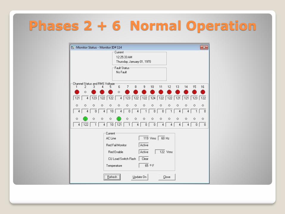
Phases 2 + 6 Normal Operation


Where do Signal Technicians receive
training ?
New Jersey Section of the IMSA
Passed down training within the
Department
Local Signal Suppliers

Troubleshooting Tips
Always remember, in a TS 2 facility, the CU and the MMU share responsibility in looking for problems, and either may initiate a flash condition if one is detected.
The following three steps will usually provide enough information to diagnose most problems in a previously working facility
Look at the Alarms log
◦ Look at the MMU fault log
◦ Look at the Ring Status for Rings 1 & 2
If you are physically at the facility, the indicator LEDS on the MMU and BIUs frequently provide convenient information.
The CU exerts control over the MMU using the CVM line (Controller Fault Monitor Output). Therefore, the MMU will usually not latch into a fault state for a serious problems first detected by the CU.

Troubleshooting TipsExample CU ScreensSTOPTIME
RING 1 RING 2 PHS..12345678 90123456
YEL 4 YEL 4 O/N .O...O.. ........
GAP OUT GAP OUT VEH CCCCCCCC ........
PED RRRRRRRR ........
H/O ........ OOOOOOOO
LOCK OUT -
MAX OUT MAX OUT STOPTIME – 1/2
Ring status Ring 1 and Ring 2
If the facility is in relay flash, but the load switch
LEDs are lit and not flashing, then the MMU has
most likely detected a problem before the CU
and is holding the CU in stop time. The MMU
may, or may not, be latched at this point,
depending on what the problem was. The CU
logs should have information about the nature
of the problem.

Troubleshooting TipsExample CU ScreensTS 2 DIAG FLSH – NO XIT
EPAC RING TIMERS SEQ: 00 F-PRIOR MENU
RING 1 RING 2 PHS..12345678 90123456
MGRN 11 MGRN 11 O/N ...O...O ........
WALK 3 WALK 3 VEH CCCCCCC. ........
PED RRR.RRR. ........
H/O ........ OOOOOOOO
PASS 4 PASS 2 TS2 DIAG FLSH - NO XIT
MAX1 31 MAX1 31
Ring status Ring 1 and Ring 2
The controller has detected either a non-
recoverable TS 2 error, or has had three
occurrences of a fault for an individual T&F BIU.
This will require a CU reset either by power
cycling, or using the 3, 5, 9 screen. The MMU
may, or may not, be latched, depending on the
specific problem.
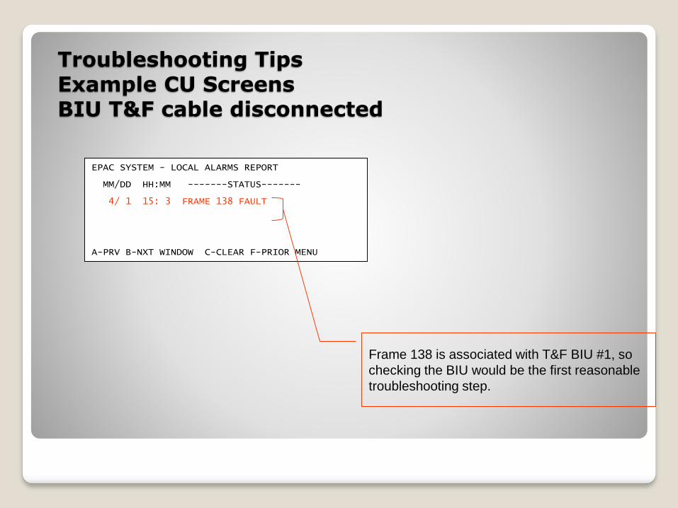
Troubleshooting TipsExample CU ScreensBIU T&F cable disconnected
EPAC SYSTEM - LOCAL ALARMS REPORT
MM/DD HH:MM -------STATUS-------
4/ 1 15: 3 FRAME 138 FAULT
A-PRV B-NXT WINDOW C-CLEAR F-PRIOR MENU
Frame 138 is associated with T&F BIU #1, so
checking the BIU would be the first reasonable
troubleshooting step.

Troubleshooting TipsExample CU Screens
CU SDLC cable disconnected
Cable disconnected from CU
EPAC SYSTEM - LOCAL ALARMS REPORT
MM/DD HH:MM -------STATUS-------
4/ 1 15:12 FRAME 139 FAULT
4/ 1 15:12 FRAME 128 FAULT
4/ 1 15:12 DIAG: RESP FRAME FAIL
4/ 1 15:12 FRAME 129 FAULT
4/ 1 15:12 DIAG: RESP FRAME FAIL
4/ 1 15:12 FRAME 138 FAULT
4/ 1 15:12 FRAME 148 FAULT
4/ 1 15:12 FRAME 149 FAULT
4/ 1 15:12 FRAME 150 FAULT
4/ 1 15:12 FRAME 151 FAULT
4/ 1 15:12 FRAME 131 FAULT
4/ 1 15:12 DIAG: RESP FRAME FAIL
4/ 1 15:12 FRAME 152 FAULT
4/ 1 15:12 FRAME 153 FAULT
A-PRV B-NXT WINDOW C-CLEAR F-PRIOR MENU
A failure of this magnitude usually
indicates an electrical problem with the
SDLC bus, or a problem with the CU itself.

The New Tool for the Signal Technician

Managed Network Switch
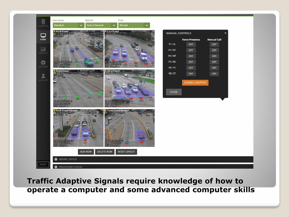
Traffic Adaptive Signals require knowledge of how to operate a computer and some advanced computer skills
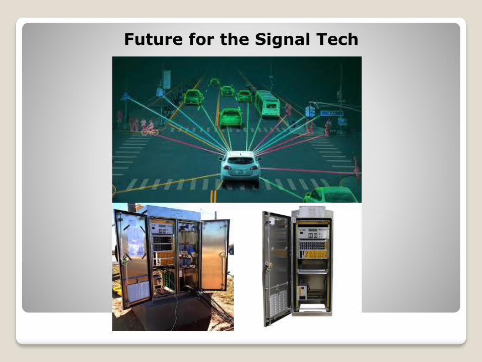
Future for the Signal Tech

Complex signal repair

The End
Related Documents


