SAFETY WARNING Only qualified personnel should install and service the equipment.The installation, starting up, and servicing of heating, ventilating, and air- conditioning equipment can be hazardous and requires specific knowledge and training. Improperly installed, adjusted or altered equipment by an unqualified person could result in death or serious injury.When working on the equipment, observe all precautions in the literature and on the tags, stickers, and labels that are attached to the equipment. Tracer™ LonTalk® Communication Interface for ReliaTel™ Controls for light and large commercial units with a ReliaTel™ control platform Programming Guide BAYLTCI002* 3 to 10Tons Packaged Rooftop units with ReliaTel™ Communications Module, 6 to 25Tons Split System units with ReliaTel™ Communications Module BAYLTCI003* 12.5 to 25Tons Packaged Rooftop units with ReliaTel™ Communications Module, 27.5 to 50Tons Packaged Rooftop units with ReliaTel™ Communications Module BAYLTCI004* 27.5 to 50TonsVariable AirVolume (VAV) Packaged Rooftop Air Conditioners (YC,TC, TE) with ReliaTel™ Communications Module RT-SVP09A-EN November 2013

Welcome message from author
This document is posted to help you gain knowledge. Please leave a comment to let me know what you think about it! Share it to your friends and learn new things together.
Transcript

SAFETY WARNINGOnly qualified personnel should install and service the equipment.The installation, starting up, and servicing of heating, ventilating, and air-
conditioning equipment can be hazardous and requires specific knowledge and training. Improperly installed, adjusted or altered equipment
by an unqualified person could result in death or serious injury.When working on the equipment, observe all precautions in the literature and
on the tags, stickers, and labels that are attached to the equipment.
Tracer™ LonTalk® Communication Interface
for ReliaTel™ Controls for light and large commercial unitswith a ReliaTel™ control platform
Programming Guide
BAYLTCI002* 3 to 10 Tons Packaged Rooftop units with ReliaTel™ Communications Module,6 to 25 Tons Split System units with ReliaTel™ Communications Module
BAYLTCI003* 12.5 to 25 Tons Packaged Rooftop units with ReliaTel™ Communications Module,27.5 to 50 Tons Packaged Rooftop units with ReliaTel™ Communications Module
BAYLTCI004* 27.5 to 50 Tons Variable Air Volume (VAV) Packaged Rooftop Air Conditioners (YC, TC,TE) with ReliaTel™ Communications Module
RT-SVP09A-ENNovember 2013

© 2013Trane All rights reserved RT-SVP09A-EN
Warnings, Cautions and Notices
Warnings, Cautions and Notices. Note thatwarnings,cautions and notices appear at appropriate intervalsthroughout this manual. Warnings are provided to alertinstalling contractors to potential hazards that could resultin death or personal injury. Cautions are designed to alertpersonnel to hazardous situations that could result inpersonal injury, while notices indicate a situation thatcould result in equipment or property-damage-onlyaccidents.
Your personal safety and the proper operation of thismachine depend upon the strict observance of theseprecautions.
Read this manual thoroughly before operating or servicingthis unit.
Important
Environmental Concerns!
Scientific research has shown that certain man-madechemicals can affect the earth’s naturally occurringstratospheric ozone layer when released to theatmosphere. In particular, several of the identifiedchemicals that may affect the ozone layer are refrigerantsthat contain Chlorine, Fluorine and Carbon (CFCs) andthose containing Hydrogen, Chlorine, Fluorine andCarbon (HCFCs). Not all refrigerants containing thesecompounds have the same potential impact to theenvironment.Trane advocates the responsible handling ofall refrigerants-including industry replacements for CFCssuch as HCFCs and HFCs.
Responsible Refrigerant Practices!
Trane believes that responsible refrigerant practices areimportant to the environment, our customers, and the airconditioning industry. All technicians who handlerefrigerants must be certified.The Federal Clean Air Act(Section 608) sets forth the requirements for handling,reclaiming, recovering and recycling of certainrefrigerants and the equipment that is used in theseservice procedures. In addition, some states ormunicipalities may have additional requirements that
must also be adhered to for responsible management ofrefrigerants. Know the applicable laws and follow them.
ATTENTION: Warnings, Cautions, and Notices appear atappropriate sections throughout this literature. Readthese carefully:
WARNINGIndicates a potentially hazardoussituation which, if not avoided, couldresult in death or serious injury.
CAUTIONsIndicates a potentially hazardoussituation which, if not avoided, couldresult in minor or moderate injury. Itcould also be used to alert againstunsafe practices.
NOTICE:Indicates a situation that could result inequipment or property-damage onlyaccidents.
WARNING
Proper Field Wiring and GroundingRequired!
All field wiring MUST be performed by qualifiedpersonnel. Improperly installed and grounded fieldwiring poses FIRE and ELECTROCUTION hazards.Toavoid these hazards, you MUST follow requirements forfield wiring installation and grounding as described inNEC and your local/state electrical codes. Failure tofollow code could result in death or serious injury.
WARNING
Personal Protective Equipment (PPE)Required!
Installing/servicing this unit could result in exposure toelectrical, mechanical and chemical hazards.
• Before installing/servicing this unit, technicians
MUST put on all Personal Protective Equipment (PPE)
recommended for the work being undertaken.
ALWAYS refer to appropriate MSDS sheets and OSHA
guidelines for proper PPE.
• When working with or around hazardous chemicals,
ALWAYS refer to the appropriate MSDS sheets and
OSHA guidelines for information on allowable
personal exposure levels, proper respiratory
protection and handling recommendations.
• If there is a risk of arc or flash, technicians MUST put
on all Personal Protective Equipment (PPE) in
accordance with NFPA 70E or other country-specific
requirements for arc flash protection, PRIOR to
servicing the unit.
Failure to follow recommendations could result in deathor serious injury.

Table of Contents
Warnings, Cautions and Notices . . . . . . . . . . 2
Table of Contents . . . . . . . . . . . . . . . . . . . . . . . . 3
Overview . . . . . . . . . . . . . . . . . . . . . . . . . . . . . . . 6
Specifications and Dimensions . . . . . . . . . . . 7
LonMark™ Product Details . . . . . . . . . . . . . . . 8
Supporting Units . . . . . . . . . . . . . . . . . . . . . . . . 9
Communication Link and Setup . . . . . . . . . . 10
LonTalk® Communication Link Wiring Re-quirements . . . . . . . . . . . . . . . . . . . . . . . . . . 10
Setup . . . . . . . . . . . . . . . . . . . . . . . . . . . . . . . 10
Human Interface Setup . . . . . . . . . . . . . . 10
Device Addressing . . . . . . . . . . . . . . . . . . 10
Network Variable Summary for Space Com-fort Control (SCC) and Discharge Air Control(DAC) . . . . . . . . . . . . . . . . . . . . . . . . . . . . . 10
Network Variable Input Definitions . . . . . . . 15
Application Mode Input: nviApplicMode . 15
Auxiliary Heat Enable Input: nviAuxHeatEn-able . . . . . . . . . . . . . . . . . . . . . . . . . . . . . . . . . 15
Building Static Pressure Setpoint Input:nviBldgStaticSP . . . . . . . . . . . . . . . . . . . . . . 16
Building Static Pressure Input: nviBldgStat-Press . . . . . . . . . . . . . . . . . . . . . . . . . . . . . . . . 16
Compressor Enable Input:nviComprEnable . . . . . . . . . . . . . . . . . . . . . . 16
Discharge Air Cooling Setpoint Input: nviDA-ClSP . . . . . . . . . . . . . . . . . . . . . . . . . . . . . . . . 17
Discharge Air Heating Setpoint Input: nvi-DAHtSP . . . . . . . . . . . . . . . . . . . . . . . . . . . . . 17
Discharge Air Reheat Setpoint Input: nvi-DAReheatSP . . . . . . . . . . . . . . . . . . . . . . . . . 17
Duct Static Pressure Setpoint Input: nviDuct-StaticSP . . . . . . . . . . . . . . . . . . . . . . . . . . . . . 17
Economizer Enable Input: nviEconEnable 17
Emergency Override Input:nviEmergOverride . . . . . . . . . . . . . . . . . . . . 17
Fan Mode Command Input: . . . . . . . . . . . . 18
Heat/Cool Mode Input: nviHeatCool . . . . . 18
Minimum Outdoor Air Flow Setpoint Input:nviMinOAFlowSP . . . . . . . . . . . . . . . . . . . . . 18
Outdoor Air Minimum Position Input: nviO-AMinPos . . . . . . . . . . . . . . . . . . . . . . . . . . . . 18
Occupancy Override Input:nviOccManCmd . . . . . . . . . . . . . . . . . . . . . . .19
Occupancy Scheduler Input:nviOccSchedule . . . . . . . . . . . . . . . . . . . . . . .19
Occupancy Sensor Input: nviOccSensor . .20
Outdoor Air Humidity Input:nviOutdoorRH . . . . . . . . . . . . . . . . . . . . . . . . .20
Outdoor Air Temperature Input: nviOutdoor-Temp . . . . . . . . . . . . . . . . . . . . . . . . . . . . . . . .20
Primary Cool Enable Input:nviPriCoolEnable . . . . . . . . . . . . . . . . . . . . . .21
Primary Heat Enable Input:nviPriHeatEnable . . . . . . . . . . . . . . . . . . . . . .21
Service Test Command: . . . . . . . . . . . . . . . .21
Status Request Input: nviRequest . . . . . . . .22
Temperature Setpoint Input (Absolute): nvi-Setpoint . . . . . . . . . . . . . . . . . . . . . . . . . . . . . .23
Setpoint Offset Input: nviSetptOffset . . . . .23
Space CO2 Sensor Input: nviSpaceCO2(nviSpaceIAQ) . . . . . . . . . . . . . . . . . . . . . . . . .23
Space Dehumidification Setpoint Input:nviSpaceDehumSP . . . . . . . . . . . . . . . . . . . .23
Space Humidity Input: nviSpaceRH . . . . . .24
Space Temperature Input: nviSpaceTemp 24
Device Control Input . . . . . . . . . . . . . . . . . . .24
Description Type bytes Invalid Value Tracer™SCC uses Tracer™ DAC uses . . . . . . . . . .24
Field Override Input . . . . . . . . . . . . . . . . . . . .24
Comm5 Command . . . . . . . . . . . . . . . . . . . .24
Network Variable Output Definitions . . . . . .25
Alarm Message Text Output: nvoAlarmMes-sage . . . . . . . . . . . . . . . . . . . . . . . . . . . . . . . . .25
Application Mode Output: nvoApplicMode 25
Building Static Pressure Output: nvoBldgStat-Press . . . . . . . . . . . . . . . . . . . . . . . . . . . . . . . . .25
Discharge Air Reheat Setpoint Output, nvo-DAReheatSP . . . . . . . . . . . . . . . . . . . . . . . . . .26
Dehumidification Status Output, nvoDehu-midifier . . . . . . . . . . . . . . . . . . . . . . . . . . . . . .26
Discharge Air Temperature Output, nvoDis-chAirTemp . . . . . . . . . . . . . . . . . . . . . . . . . . .26
Duct Static Pressure Output, nvoDuctStat-Press . . . . . . . . . . . . . . . . . . . . . . . . . . . . . . . . .27
RT-SVP09A-EN 3

Table of Contents
Economizer Enabled Output,nvoEconEnabled . . . . . . . . . . . . . . . . . . . . . 27
Effective Discharge Air Temperature SetpointOutput, nvoEffDATempSP . . . . . . . . . . . . . 27
Effective Duct Static Pressure Setpoint Out-put, nvoEffDuctStatSP . . . . . . . . . . . . . . . . . 28
Effective Occupancy Output,nvoEffectOccup . . . . . . . . . . . . . . . . . . . . . . 28
Effective Setpoint Output, nvoEffectSetpt 28
Effective Space Dehumidification SetpointOutput, nvoEffSpaceDHSP . . . . . . . . . . . . . 29
Exhaust Fan Status Output,nvoExhFanStatus . . . . . . . . . . . . . . . . . . . . . 29
Fan Speed Output, nvoFanSpeed . . . . . . . 30
Effective Heat/Cool Output, nvoHeatCool 30
Mixed Air Temperature Output,nvoMATemp . . . . . . . . . . . . . . . . . . . . . . . . . 31
Mixed Air Temperature Output, nvoMixedAir-Temp . . . . . . . . . . . . . . . . . . . . . . . . . . . . . . . 31
Outdoor Air Damper Output,nvoOADamper . . . . . . . . . . . . . . . . . . . . . . . 31
Outdoor Airflow Output, nvoOAFlow . . . . 31
Absolute Power Consumption . . . . . . . . . . 32
Outdoor Air Humidity Output,nvoOutdoorRH . . . . . . . . . . . . . . . . . . . . . . . 32
Outdoor Air Temperature Output, nvoOut-doorTemp . . . . . . . . . . . . . . . . . . . . . . . . . . . 32
Return Air Temperature Output,nvoRATemp . . . . . . . . . . . . . . . . . . . . . . . . . 32
Service Test Status . . . . . . . . . . . . . . . . . . . 33
Local Setpoint Output, nvoSetpoint . . . . . 33
Space CO2 Sensor Output, nvoSpaceCO2 33
Space Humidity Output, nvoSpaceRH . . . 33
Effective Space Temperature Output, nvo-SpaceTemp . . . . . . . . . . . . . . . . . . . . . . . . . . 34
Status Request Output, nvoStatus . . . . . . 34
Supply Fan Status Output,nvoSupFanStatus . . . . . . . . . . . . . . . . . . . . . 35
Terminal Load Output, nvoTerminalLoad 36
Unit Status Output, nvoUnitStatus . . . . . . 36
Device Status Output . . . . . . . . . . . . . . . . . . 37
Comm5 Status Output . . . . . . . . . . . . . . . . . 37
Configuration . . . . . . . . . . . . . . . . . . . . . . . . . . 38
Configuration Property Definitions . . . . . . . 40
Building Static Pressure Setpoint, nciBldg-StaticSP . . . . . . . . . . . . . . . . . . . . . . . . . . . . . .40
Local Bypass Time, nciBypassTime . . . . . .40
Discharge Air Cooling Setpoint, nciDAClSP 40
Discharge Air Heating Setpoint,nciDAHtSP . . . . . . . . . . . . . . . . . . . . . . . . . . . .40
Discharge Air Reheat Setpoint, nciDAReheat-SP . . . . . . . . . . . . . . . . . . . . . . . . . . . . . . . . . . .40
Daytime Warm Up Initiate Setpoint, nciDay-time . . . . . . . . . . . . . . . . . . . . . . . . . . . . . . . . .40
Daytime Warm Up Termination Setpoint, nci-DaytimeTerm . . . . . . . . . . . . . . . . . . . . . . . . .41
Device Build Version Number, nciDevBuild-Num . . . . . . . . . . . . . . . . . . . . . . . . . . . . . . . . .41
Device Major Version Number,nciDevMajVer . . . . . . . . . . . . . . . . . . . . . . . . .41
Device Config Choices . . . . . . . . . . . . . . . . .41
Device Minor Version Number,nciDevMinVer . . . . . . . . . . . . . . . . . . . . . . . . .41
Duct Static Pressure Setpoint,nciDuctStatSP . . . . . . . . . . . . . . . . . . . . . . . . .41
Econ and Ventilation Type . . . . . . . . . . . . . .41
Exhaust Enable Position, nciExhaustConfig 42
Exhaust Enable Position, nciExhStartPos .42
Exhaust AND/OR Return Fan/Damper Identifi-er . . . . . . . . . . . . . . . . . . . . . . . . . . . . . . . . . . . .42
Fan Configuration Input . . . . . . . . . . . . . . . .42
HVAC Unit Type Identifier, nciHvacType . .42
Location Label, nciLocation . . . . . . . . . . . . .43
Minimum Outdoor Airflow Setpoint, nciMinO-AFlowSP . . . . . . . . . . . . . . . . . . . . . . . . . . . . .43
Minimum Send Time, nciMinOutTm . . . . .43
Module Software Version . . . . . . . . . . . . . . .43
Outdoor Airflow Calibration,nciOAFlowCalib . . . . . . . . . . . . . . . . . . . . . . .43
Outdoor Air Damper Minimum Position, nciO-AMinPos . . . . . . . . . . . . . . . . . . . . . . . . . . . . .43
Receive Heartbeat, nciRcvHrtBt . . . . . . . . . .44
Occupancy Temperature Setpoints, nciSet-points . . . . . . . . . . . . . . . . . . . . . . . . . . . . . . . .44
Send Heartbeat, nciSndHrtBt . . . . . . . . . . . .44
Space CO2 Limit, nciSpaceCO2Lim . . . . . .45
Device Personality . . . . . . . . . . . . . . . . . . . . .45
Preheat Type Identifier . . . . . . . . . . . . . . . . .45
4 RT-SVP09A-EN

Table of Contents
Space CO2 Low Limit . . . . . . . . . . . . . . . . . 45
Occupancy Temp Setpoint . . . . . . . . . . . . . 45
Reheat Type Identifier . . . . . . . . . . . . . . . . . 45
Valid Range . . . . . . . . . . . . . . . . . . . . . . . . 45
Space Dehumidification Setpoint, nciSpace-DehumSP . . . . . . . . . . . . . . . . . . . . . . . . . . . . 45
Space Humidity Setpoint,nciSpaceRHSetpt . . . . . . . . . . . . . . . . . . . . . 46
Supply Fan Type Identifier . . . . . . . . . . . . . 46
Operation Modes and General Information 47
Operation Modes . . . . . . . . . . . . . . . . . . . . . 47
Temperature Control Modes . . . . . . . . . . 47
Occupancy Modes . . . . . . . . . . . . . . . . . . 47
Timed Override Control Mode . . . . . . . . 50
Emergency Override Mode . . . . . . . . . . . 50
Setpoint Operation Mode . . . . . . . . . . . . 50
Input Duct Static Pressure . . . . . . . . . . . . 50
Morning or Daytime Warm-Up . . . . . . . . 50
Discharge Air Temperature Control . . . . 50
Mixed Air and Outdoor Air Temperature In-puts . . . . . . . . . . . . . . . . . . . . . . . . . . . . . . 51
General Information . . . . . . . . . . . . . . . . . . 51
Location Identifier . . . . . . . . . . . . . . . . . . 51
Power-up Sequence . . . . . . . . . . . . . . . . . 51
Peer-to-peer Communication . . . . . . . . . 51
Troubleshooting . . . . . . . . . . . . . . . . . . . . . . . . 52
LED Activity . . . . . . . . . . . . . . . . . . . . . . . . . . 52
Red Service LED . . . . . . . . . . . . . . . . . . . . 52
Green Status LED . . . . . . . . . . . . . . . . . . . 52
Yellow Comm LED . . . . . . . . . . . . . . . . . . 52
Yellow IPC RXA (Receives)/IPC TXA (Trans-mits) LED . . . . . . . . . . . . . . . . . . . . . . . . . . 52
Service Test and Input Requirements . . . . 52
Service Test . . . . . . . . . . . . . . . . . . . . . . . 52
Required Inputs for Unit Operation . . . . 52
Diagnostics . . . . . . . . . . . . . . . . . . . . . . . . . . 53
General Notes . . . . . . . . . . . . . . . . . . . . . . 53
Translating Multiple Diagnostics . . . . . . 53
Resetting Diagnostics . . . . . . . . . . . . . . . . 53
Appendix . . . . . . . . . . . . . . . . . . . . . . . . . . . . . . 54
General Notes forTable 74, p. 58. . . . . . . . 57
Glossary . . . . . . . . . . . . . . . . . . . . . . . . . . . . . . . .69
RT-SVP09A-EN 5

6 RT-SVP09A-EN
Overview
The LonTalk® Communications Interface for ReliaTel™(LCI-R) unitary systems provides a communicationinterface between a LonTalk® network and a unit controlsystem.The LCI-R uses an FTT-10A free-topologytransceiver, which allows star, bus, and loop wiringarchitectures.
The interface can operate in any of the following ways:
• In stand-alone mode
• In peer-to-peer mode with one or more units
• On aTracer™ Summit or third-party buildingautomation system (BAS)
In addition, it is available as a factory-installed option or afield-installed kit.The features and functions described inthis manual apply to either option.
Note: Some unit features or functions described may notbe available on all products or are defined by themanufacturer according to the LonMark™specification. In addition, they are not available toa third-partybuilding automationsystem or servicetool. (Refer to Table 1, p. 8) Certain networkvariables may requireadditional optionalmodules.Refer to the section, “,” p. 10 and other appropriateproduct literature for more information.
This programming guide provides the followinginformation:
• Specifications and controller board
• LonMark product details
• Supporting units/software and configuration
• Communication link and setup
• Network variable input/output definitions
• Configuration property definitions
• Configuration and configuration definitions
• Operation modes and general information
• Troubleshooting
• Appendix
• Glossary
Important: The LCI-R is not polarity sensitive.Thisinterface should be installed by a qualifiedtechnician who is properly trained andexperienced with LonTalk® networks.
RT-SVP09A-EN 7
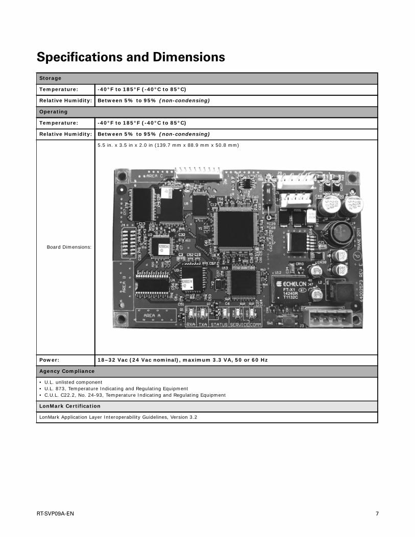
Specifications and Dimensions
Storage
Temperature: -40°F to 185°F (-40°C to 85°C)
Relative Humidity: Between 5% to 95% (non-condensing)
Operating
Temperature: -40°F to 185°F (-40°C to 85°C)
Relative Humidity: Between 5% to 95% (non-condensing)
Board Dimensions:
5.5 in. x 3.5 in x 2.0 in (139.7 mm x 88.9 mm x 50.8 mm)
Power: 18–32 Vac (24 Vac nominal), maximum 3.3 VA, 50 or 60 Hz
Agency Compliance
• U.L. unlisted component• U.L. 873, Temperature Indicating and Regulating Equipment• C.U.L. C22.2, No. 24-93, Temperature Indicating and Regulating Equipment
LonMark Certification
LonMark Application Layer Interoperability Guidelines, Version 3.2

8 RT-SVP09A-EN
LonMark™ Product Details
Table 1. LonMark™ product details
Manufacturer: Trane
Product Data Sheet: • RT-PRG001-EN (Rooftop)
Device Class: Discharge Air Controller
CommunicationChannel: TP/FT-10 (ANSI/EIA-709.3)
Usage: Commercial
LonMark Version: Version 3.4
Supported LonMarkObjects:
• 0000; Node Object• 8500; Space Comfort Controller• 8610; Discharge Air Controller• 8 0002A 560a 03 04 05• 3.4 @0, 8500, 8610 Tracer™ LCI-R• 80002A560A030405.XIFNote: Network Variables that are applicable to both supported profiles (SCC and DAC) may be listed twice in the XIF, but only
one will be active, based on unit configuration. To determine which variable is active for a particular profile, refer to the variable self-doc string (third line for each variable in the XIF).
For example:VAR nviOccSchedule 113 0 0 0 (113 represents the network variable index for this device) 0 1 63 0 2 1 0 1 0 0 0 0 0"@2|1;nviOccSchedule (2 represents the DAC object and 1 represents the DAC profile index 1)
VAR nviOccSchedule 114 0 0 0 (114 represents the network variable index for this device) 0 1 63 0 2 1 0 1 0 0 0 0 0"@1|5;nviOccSchedule (1 represents the SCC object and 5 represents the SCC profile index 5)
Note: For more details on information contained in this table, refer to www.lonmark.org

RT-SVP09A-EN 9
Supporting Units
Figure 1 through Figure 4 illustrate the supporting unitsfor the LCI-R.
Figure 1. Voyager™ 12.5 to 25 tons
Figure 2. Voyager™ Commercial 27.5 to 50 tons
Figure 3. Odyssey™ 6 to 25 tons
Figure 4. Precedent™ 3 to 10 tons

Communication Link and Setup
TheTracer™ LCI-R controller communicates using theLonTalk® protocol.Typically, a communication link isapplied between unit controllers and a BAS. However, acommunication link can be made by means of the Rover™service tool or by peer-to-peer communication acrosscontrollers when a building automation system is notpresent.
The LonTalk® communication protocol allows peer-to-peer communications between controllers. Acommunicated variable input (such as a setpoint, spacetemperature, or outdoor air temperature) has priority overa locally wired input to the controller. For example, if theLCI-R controller has a wired outdoor air temperaturesensor, andTracer™ Summit or another LonTalk®controller sends it a communicated outdoor airtemperature, the communicated value is used by the LCI-R controller. If a communicated input value is lost, the LCI-R controller reverts to using the locally wired sensor input.
Note: Observe polarity for LonTalk® communicationlinks.
The controller provides four terminals for the LonTalk®communication link connections, as follows:
• Two terminals for communication to the board
• Two terminals for communication from the board tothe next unit (daisy chain)
LonTalk® Communication Link
Wiring Requirements
The LonTalk® communication link is used for connectionto a LonTalk® building network.The communication linkwiring is dependent on the network architecture.
Note: For proper wiring recommendations, refer to theLonWorks FTT-10A FreeTopologyTransceiverUser's Guide at www.echelon.com. ForTraneBAS installations, refer to the Comm5 WiringInstallation (BAS-SVN01) for wiringrecommendations.
Setup
Human Interface Setup
The unit must be changed from LOCAL to BAS/NETWORK (remote) control in the human interfaceSetup menu.To change to BAS/NETWORK:
1. Press the Setup menu button on the human interfaceand then press Next.
2. When the next screen displays, press the + button untilthe unit control is set to BAS/NETWORK.
3. Press Enter.
Device Addressing
LonTalk® devices are given a unique Neuron ID address(such as 00-01-64-1C-2B-00) by the manufacturer. EachLCI-R controller can be identified by its unique Neuron IDand this ID is located on a label of each controller.TheNeuron ID is also displayed when communication isestablished usingTracer™ Summit or Rover service tool.
Network Variable Summary for SpaceComfort Control (SCC) and Discharge AirControl (DAC)
Table 2, p. 11 throughTable 9, p. 14 provide informationabout nodes, input/output variables, and configurationproperties. For more details, refer to www.lonmark.org.
10 RT-SVP09A-EN
Communication Link and Setup
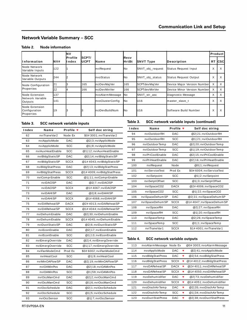
Network Variable Summary – SCC
Table 2. Node information
Information NV#
NV Profile Index
SCPT/UCPT Name
Recv HrtBt SNVT Type Description
Product
RT CSC
Node Network Variable Inputs 122 1 nviRequest No SNVT_obj_request Status Request Input X X
Node Network Variable Outputs 244 2 nvoStatus No SNVT_obj_status Status Request Output X X
Node Configuration Properties
21 3 165 nciDevMajVer 165 SCPTdevMajVer Device Major Version Number X X
22 4 166 nciDevMinVer 166 SCPTdevMinVer Device Minor Version Number X X
Node Extension Network Variable Outputs
137 nvoAlarmMessage No SNVT_str_asc Diagnostic Message X X
141 nvoClusterConfig No U16 master_slave_t X X
Node Extension Configuration Properties
19 3 3 nciDevBuildNum No U16 Software Build Number X X
Table 3. SCC network variable inputs
Index Name Profile ♥ Self doc string
62 nviTraneVar2 Node Ex $0#3001;nviTraneVar2
63 nviApplicMode DAC @2|3;nviApplicMode
64 nviApplicMode SCC @1|8;nviApplicMode
65 nviAuxHeatEnable SCC @1|12;nviAuxHeatEnable
66 nviBldgStaticSP DAC @2|14;nviBldgStaticSP
67 nviBldgStaticSP SCCX @1#4043;nviBldgStaticSP
68 nviBldgStatPress DAC @2|13;nviBldgStatPress
69 nviBldgStatPress SCCX @1#4009;nviBldgStatPress
70 nviComprEnable SCC @1|11;nviComprEnable
71 nviDAClSP DAC @2|7;nviDAClSP
72 nviDAClSP SCCX @1#4067;nviDAClSP
73 nviDAHtSP DAC @2|8;nviDAHtSP
74 nviDAHtSP SCCX @1#4068;nviDAHtSP
75 nviDAReheatSP DACX @2#4013;nviDAReheatSP
76 nviDAReheatSP SCCX @1#4044;nviDAReheatSP
77 nviDehumEnable DAC @2|30;nviDehumEnable
78 nviDehumEnable SCCX @1#4045;nviDehumEnable
79 nviDuctStaticSP DAC @2|6;nviDuctStaticSP
80 nviEconEnable DAC @2|17;nviEconEnable
81 nviEconEnable SCC @1|13;nviEconEnable
82 nviEmergOverride DAC @2|4;nviEmergOverride
83 nviEmergOverride SCC @1|17;nviEmergOverride
84 nviFanModeCmd Prod Ex $0#6002;nviFanModeCmd
85 nviHeatCool SCC @1|9;nviHeatCool
86 nviMinOAFlowSP DAC @2|19;nviMinOAFlowSP
87 nviOAMinPos DAC @2|18;nviOAMinPos
88 nviOAMinPos SCC @1|59;nviOAMinPos
89 nviOccManCmd DAC @2|2;nviOccManCmd
90 nviOccManCmd SCC @1|6;nviOccManCmd
91 nviOccSchedule DAC @2|1;nviOccSchedule
92 nviOccSchedule SCC @1|5;nviOccSchedule
93 nviOccSensor SCC @1|7;nviOccSensor
94 nviOutdoorRH DAC @2|21;nviOutdoorRH
95 nviOutdoorRH SCC @1|21;nviOutdoorRH
96 nviOutdoorTemp DAC @2|20;nviOutdoorTemp
97 nviOutdoorTemp SCC @1|19;nviOutdoorTemp
98 nviPriCoolEnable DAC @2|15;nviPriCoolEnable
99 nviPriHeatEnable DAC @2|16;nviPriHeatEnable
100 nviRequest Node @0|1;nviRequest
101 nviServiceTest Prod Ex $0#6004;nviServiceTest
102 nviSetpoint SCC @1|2;nviSetpoint
103 nviSetptOffset SCC @1|3;nviSetptOffset
104 nviSpaceCO2 DACX @2#4006;nviSpaceCO2
105 nviSpaceCO2 SCC @1|22;nviSpaceCO2
106 nviSpaceDehumSP DAC @2|31;nviSpaceDehumSP
107 nviSpaceDehumSP SCCX @1#4047;nviSpaceDehumSP
108 nviSpaceRH DAC @2|27;nviSpaceRH
109 nviSpaceRH SCC @1|20;nviSpaceRH
110 nviSpaceTemp DAC @2|26;nviSpaceTemp
111 nviSpaceTemp SCC @1|1;nviSpaceTemp
112 nviTraneVar1 SCCX $1#4001;nviTraneVar1
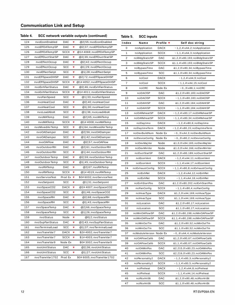
Table 4. SCC network variable outputs
113 nvoAlarmMessage Node Ex @0#3003;nvoAlarmMessage
114 nvoApplicMode DAC ♥ @2|41;nvoApplicMode
115 nvoBldgStatPress DAC ♥ @2|54;nvoBldgStatPress
116 nvoBldgStatPress SCCX ♥ @1#4012;nvoBldgStatPress
117 nvoDAReheatSP DACX ♥ @2#4011;nvoDAReheatSP
118 nvoDAReheatSP SCCX ♥ @1#4050;nvoDAReheatSP
119 nvoDehumidifier DAC ♥ @2|73;nvoDehumidifier
120 nvoDehumidifier SCCX ♥ @1#4051;nvoDehumidifier
121 nvoDischAirTemp DAC ♥ @2|35;nvoDischAirTemp
122 nvoDischAirTemp SCC ♥ @1|34;nvoDischAirTemp
123 nvoDuctStatPress DAC ♥ @2|38;nvoDuctStatPress
Table 3. SCC network variable inputs (continued)
Index Name Profile ♥ Self doc string
RT-SVP09A-EN 11
Communication Link and Setup
124 nvoEconEnabled DAC ♥ @2|55;nvoEconEnabled
125 nvoEffDATempSP DAC ♥ @2|37;nvoEffDATempSP
126 nvoEffDATempSP SCCX ♥ @1#4069;nvoEffDATempSP
127 nvoEffDuctStatSP DAC ♥ @2|39;nvoEffDuctStatSP
128 nvoEffectOccup DAC ♥ @2|42;nvoEffectOccup
129 nvoEffectOccup SCC ♥ @1|29;nvoEffectOccup
130 nvoEffectSetpt SCC ♥ @1|28;nvoEffectSetpt
131 nvoEffSpaceDHSP DAC ♥ @2|72;nvoEffSpaceDHSP
132 nvoEffSpaceDHSP SCCX ♥ @1#4052;nvoEffSpaceDHSP
133 nvoExhFanStatus DAC ♥ @2|46;nvoExhFanStatus
134 nvoExhFanStatus SCCX ♥ @1#4011;nvoExhFanStatus
135 nvoFanSpeed SCC ♥ @1|33;nvoFanSpeed
136 nvoHeatCool DAC ♥ @2|40;nvoHeatCool
137 nvoHeatCool SCC ♥ @1|30;nvoHeatCool
138 nvoLoadAbsK SCC ♥ @1|36;nvoLoadAbsK
139 nvoMATemp DAC ♥ @2|65;nvoMATemp
140 nvoMATemp SCCX ♥ @1#4008;nvoMATemp
141 nvoMixedAirTemp SCC ♥ @1|64;nvoMixedAirTemp
142 nvoOADamper DAC ♥ @2|56;nvoOADamper
143 nvoOADamper SCC ♥ @1|42;nvoOADamper
144 nvoOAFlow DAC ♥ @2|57;nvoOAFlow
145 nvoOutdoorRH DAC ♥ @2|61;nvoOutdoorRH
146 nvoOutdoorRH SCC ♥ @1|44;nvoOutdoorRH
147 nvoOutdoorTemp DAC ♥ @2|59;nvoOutdoorTemp
148 nvoOutdoorTemp SCC ♥ @1|45;nvoOutdoorTemp
149 nvoRATemp DAC ♥ @2|67;nvoRATemp
150 nvoRATemp SCCX ♥ @1#4019;nvoRATemp
151 nvoServiceTest Prod Ex ♥ $0#6032;nvoServiceTest
152 nvoSetpoint SCC ♥ @1|31;nvoSetpoint
153 nvoSpaceCO2 DACX ♥ @2#4007;nvoSpaceCO2
154 nvoSpaceCO2 SCC ♥ @1|46;nvoSpaceCO2
155 nvoSpaceRH DAC ♥ @2|68;nvoSpaceRH
156 nvoSpaceRH SCC ♥ @1|43;nvoSpaceRH
157 nvoSpaceTemp DAC ♥ @2|66;nvoSpaceTemp
158 nvoSpaceTemp SCC ♥ @1|26;nvoSpaceTemp
159 nvoStatus Node ♥ @0|2;nvoStatus
160 nvoSupFanStatus DAC ♥ @2|43;nvoSupFanStatus
161 nvoTerminalLoad SCC ♥ @1|37;nvoTerminalLoad
162 nvoTraneVar7 DACX ♥ $2#4002;nvoTraneVar7
163 nvoTraneVar7 SCCX ♥ $1#4003;nvoTraneVar7
164 nvoTraneVar9 Node Ex $0#3002;nvoTraneVar9
165 nvoUnitStatus DAC ♥ @2|36;nvoUnitStatus
166 nvoUnitStatus SCC ♥ @1|27;nvoUnitStatus
167 nvoTraneVar1702 Prod Ex $0#6005;nvoTraneVar1702
Table 4. SCC network variable outputs (continued) Table 5. SCC inputs
Index Name Profile ♥ Self doc string
0 nciApplication DACX ~1,2,4\xA4,2;nciApplication
1 nciApplication SCCX ~1,1,4\xA4,3;nciApplication
2 nciBldgStaticSP DAC &1,2,0\x80,193;nciBldgStaticSP
3 nciBldgStaticSP SCCX &1,1,4\x80,193;nciBldgStaticSP
4 nciBypassTime DAC &1,2,0\x80,34;nciBypassTime
5 nciBypassTime SCC &1,1,0\x80,34;nciBypassTime
6 nciCool DACX ~1,2,4\xA4,9;nciCool
7 nciCool SCCX ~1,1,4\xA4,15;nciCool
8 nciCRC Node Ex ~0,,3\x88,1;nciCRC
9 nciDAClSP DAC &1,2,0\x80,183;nciDAClSP
10 nciDAClSP SCCX ~1,1,0\x80,183;nciDAClSP
11 nciDAHtSP DAC &1,2,0\x80,184;nciDAHtSP
12 nciDAHtSP SCCX ~1,1,0\x80,184;nciDAHtSP
13 nciDAReheatSP DACX ~1,2,4\x80,17;nciDAReheatSP
14 nciDAReheatSP SCCX ~1,1,4\x80,34;nciDAReheatSP
15 nciDaytime DACX ~1,2,4\x80,6;nciDaytime
16 nciDaytimeTerm DACX ~1,2,4\x80,15;nciDaytimeTerm
17 nciDevBuildNum Node Ex ~0,,3\xA4,3;nciDevBuildNum
18 nciDeviceConfig Node Ex ~0,,3\x80,2;nciDeviceConfig
19 nciDevMajVer Node &1,0,0\x84,165;nciDevMajVer
20 nciDevMinVer Node &1,0,0\xA4,166;nciDevMinVer
21 nciDuctStatSP DAC &1,2,0\x80,189;nciDuctStatSP
22 nciEconVent DACX ~1,2,4\xA4,11;nciEconVent
23 nciEconVent SCCX ~1,1,4\xA4,17;nciEconVent
24 nciExhaustConfig SCCX ~1,1,4\x80,8;nciExhaustConfig
25 nciExhRet DACX ~1,2,4\xA4,12;nciExhRet
26 nciExhRet SCCX ~1,1,4\xA4,18;nciExhRet
27 nciExhStartPos DAC &1,2,0\x80,202;nciExhStartPos
28 nciFanConfig SCCX ~1,1,4\x80,4;nciFanConfig
29 nciHvacType DACX &1,2,0\xA4,169;nciHvacType
30 nciHvacType SCC &1,1,0\xA4,169;nciHvacType
31 nciLocation DAC &1,2,0\x80,17;nciLocation
32 nciLocation SCC &1,1,0\x80,17;nciLocation
33 nciMinOAFlowSP DAC &1,2,0\x80,198;nciMinOAFlowSP
34 nciMinOAFlowSP SCCX &1,1,4\x80,198;nciMinOAFlowSP
35 nciMinOutTm DAC &1,2,0\x80,52;nciMinOutTm
36 nciMinOutTm SCC &1,1,0\x80,52;nciMinOutTm
37 nciModuleVersion Node Ex ~0,,6\xA4,4;nciModuleVersion
38 nciOAFlowCalib DAC &1,2,0\x80,67;nciOAFlowCalib
39 nciOAFlowCalib SCCX &1,1,4\x80,67;nciOAFlowCalib
40 nciOAMinPos DAC &2,215,0\x80,23;nciOAMinPos
41 nciOAMinPos SCC &2,216,0\x80,23;nciOAMinPos
42 nciPersonality2 DACX ~1,2,4\x80,3;nciPersonality2
43 nciPersonality2 SCCX ~1,1,4\x80,5;nciPersonality2
44 nciPreheat DACX ~1,2,4\xA4,8;nciPreheat
45 nciPreheat SCCX ~1,1,4\xA4,14;nciPreheat
46 nciRcvHrtBt DAC &1,2,0\x80,48;nciRcvHrtBt
47 nciRcvHrtBt SCC &1,1,0\x80,48;nciRcvHrtBt
12 RT-SVP09A-EN

Communication Link and Setup
Network Variable Summary– DAC
48 nciReheat DACX ~1,2,4\xA4,10;nciReheat
49 nciReheat SCCX ~1,1,4\xA4,16;nciReheat
50 nciSetpoints DAC &1,2,0\x80,60;nciSetpoints
51 nciSetpoints SCC &1,1,0\x80,60;nciSetpoints
52 nciSndHrtBt DAC &1,2,0\x80,49;nciSndHrtBt
53 nciSndHrtBt SCC &1,1,0\x80,49;nciSndHrtBt
54 nciSpaceCO2Lim DACX &1,2,4\x80,42;nciSpaceCO2Lim
55 nciSpaceCO2Lim SCC &1,1,0\x80,42;nciSpaceCO2Lim
56 nciSpaceCO2LowLm DACX ~1,2,4\x80,18;nciSpaceCO2LowL
m
57 nciSpaceCO2LowLm SCCX ~1,1,4\x80,29;nciSpaceCO2LowL
m
58 nciSpaceDehumSP DAC &1,2,0\x80,36;nciSpaceDehumSP
59 nciSpaceRHSetpt SCC &1,1,0\x80,36;nciSpaceRHSetpt
60 nciSupplyFan DACX ~1,2,4\xA4,7;nciSupplyFan
61 nciSupplyFan SCCX ~1,1,4\xA4,13;nciSupplyFan
Table 5. SCC inputs (continued)
Index Name Profile ♥ Self doc string
Table 6. DAC extension network variable inputs
NV#Recv HrtBt SNVT Type Description
Product
Name RT CSC
93 nviDAReheatSP Yes SNVT_temp_p Discharge Air Reheat Setpoint X
126 nviSpaceCO2 Yes SNVT_ppm Space CO2 Sensor Input X
Table 7. DAC extension network variable outputs
NV#Send HrtBt SNVT Type Description
Product
Name RT CSC
247 nvoTerminalLoad Yes SNVT_lev_percent Terminal Load output X X
206 nvoLocalDSPress Yes SNVT_press_p Local Duct Static Pressure Output X X
236 nvoSpaceCO2 Yes SNVT_ppm Space CO2 Sensor Output X X
173 nvoEnterWaterTmp Yes SNVT_temp_p Entering Water Temperature Output X
155 nvoDAReheatSP Yes SNVT_temp_p Discharge Air Reheat Setpoint
217 nvoOADewpoint Yes SNVT_temp_p Outdoor Air Dewpoint
175 nvoEREABPDamper Yes SNVT_lev_percent Energy Recovery Exhaust Air Bypass Damper Position Output X
177 nvoERFrostAvoid Yes SNVT_switch Energy Recovery Frost Avoidance State X
179 nvoERLvgExhTemp Yes SNVT_temp_p Energy Recovery Leaving Exhaust Temp Output X
181 nvoEROABPDamper Yes SNVT_lev_percent Energy Recovery Outside Air Bypass Damper Position Output X
183 nvoERPreheat Yes SNVT_switch Energy Recovery Preheat On/Off Control Output X
185 nvoERStatus Yes SNVT_switch Energy Recovery Status Output X
200 nvoHeatSecondary Yes SNVT_lev_percent Secondary Heat Output X
Table 8. Product extension network variable outputs
NV#Recv HrtBt Description
Product
Name RT CSC
210 nvoMasterSlave1 Yes Master Slave Output #1 (bound on cluster slaves) X
211 nvoMasterSlave2 Yes Master Slave Output #2 (bound on cluster slaves) X
RT-SVP09A-EN 13

Communication Link and Setup
Table 9. DAC extension configuration properties
NV#
SCPT/UCPT Index SNVT Type Description
Product
Name RT CSC
38 nciHvacType 169 SNVT_hvac_type HVAC Unit Type Identifier X X
17 nciDaytime 6 SNVT_Temp_p Daytime Warm-up Initiate Setpoint X X
18 nciDaytimeTerm 15 SNVT_Temp_p Daytime Warm-up Terminate Setpoint X X
15 nciDAReheatSP 17 SNVT_Temp_p Discharge Air Reheat Setpoint X
29 nciERFrostAvoidSP 20 SNVT_Temp_p Energy Recovery Frost Avoidance Setpoint X
67 nciSpaceCO2Lim 42 SNVT_ppm Space CO2 High Limit Setpoint X X
14 RT-SVP09A-EN

Network Variable Input Definitions
The network variable input definitions in this section arelisted alphabetically by the nviName, such asnviApplicMode.When an nvi is invalid, the unit will decideproper operation based on its local inputs.
Application Mode Input:
nviApplicMode
Network Input: SNVT_hvac_mode
nviApplicMode (SCC and DAC profile)
Used to coordinate the controller with any supervisorycontroller.The default value is adopted at power-up and inthe event of not receiving an update within the specifiedreceive heartbeat time. Refer to the tables in the“Appendix,” p. 54 for details about Application ModeInput. Default service type = unacknowledged.
ReliaTel products will only use HVAC_AUTO, HVAC_HEAT,HVAC_MRNG_WRMUP, HVAC_COOL,HVAC_NIGHT_PURGE, HVAC_PRE_COOL, HVAC_OFF,HVAC_EMERG_HEAT, HVAC_FAN_ONLY and HVAC_NUL.HVAC_NUL is treated the same as HVAC_AUTO.EMERG_HEAT is treated the same as HVAC_AUTO for nonheat pump products. All other enumerations are definedas HVAC_AUTO for ReliaTel™ products.
For the HVAC_FAN_ONLY enumeration, heating andcooling are locked out and will overridenviAuxHeatEnable, nviComprEnable, nviPriCoolEnable,and nviPriHeatEnable. HVAC_DEHUMIDIFICATION (14) isnot supported in nviApplicMode by IntelliPak productsbecause dehumidification is activated only by setpointsand space conditions.The unit should be unoccupiedbefore sending the HVAC_MRNG_WRMUP,HVAC_NIGHT_PURGE, or HVAC_PRE_COOL.
Auxiliary Heat Enable Input:
nviAuxHeatEnable
Network Input: SNVT_switch
nviAuxHeatEnable (SCC profile; refer to
“Primary Heat Enable Input:
nviPriHeatEnable” )
A structure used by space temp controllers to enable ordisable or limit any type of mechanical heat on the heatoutput. A discharge air controller uses nviPriHeatEnable.An invalid value is adopted at power-up and in the event of
not receiving an update within the specified receiveheartbeat time. Default service type = unacknowledged.
For ReliaTel™ products, the action initiated by this inputdepends upon what type of heater (gas, electric, or heatpump) is present and the number of heat stages. For heatpumps, nviAuxHeatEnable only controls auxiliary heat(not compressors), whether it comes on first or not.nviAuxHeatEnable is overridden if nviApplicMode =HVAC_NIGHT_PURGE, HVAC_PRE_COOL, orHVAC_FAN_ONLY (or nviApplicMode = HVAC_AUTO orHVAC_NUL and nviHeatCool = HVAC_NIGHT_PURGE,HVAC_PRE_COOL, or HVAC_FAN_ONLY) which disablesheating.
Table 10. Application mode input valid ranges
Type RT/CSC Ranges Invalid Values
U08
0 = HVAC_AUTO1 = HVAC_HEAT2 = HVAC_MRNG_WRMUP3 = HVAC_COOL4 = HVAC_NIGHT_PURGE5 = HVAC_PRE_COOL6 = HVAC_OFF7 = HVAC_TEST (HVAC_AUTO)8 = HVAC_EMERG_HEAT (HVAC_AUTO)9 = HVAC_FAN_ONLY10 = HVAC_FREE_COOL (HVAC_AUTO)11 = HVAC_ICE (HVAC_AUTO)12 = HVAC_MAX_HEAT (HVAC_AUTO)13 = HVAC_ECONOMIZING (HVAC_AUTO)14 = HVAC_DEHUMIDIFICATION (HVAC_AUTO)15 = HVAC_CALIBRATE (HVAC_AUTO)16 to 255 = HVAC_NUL
0xFF = HVAC_NUL
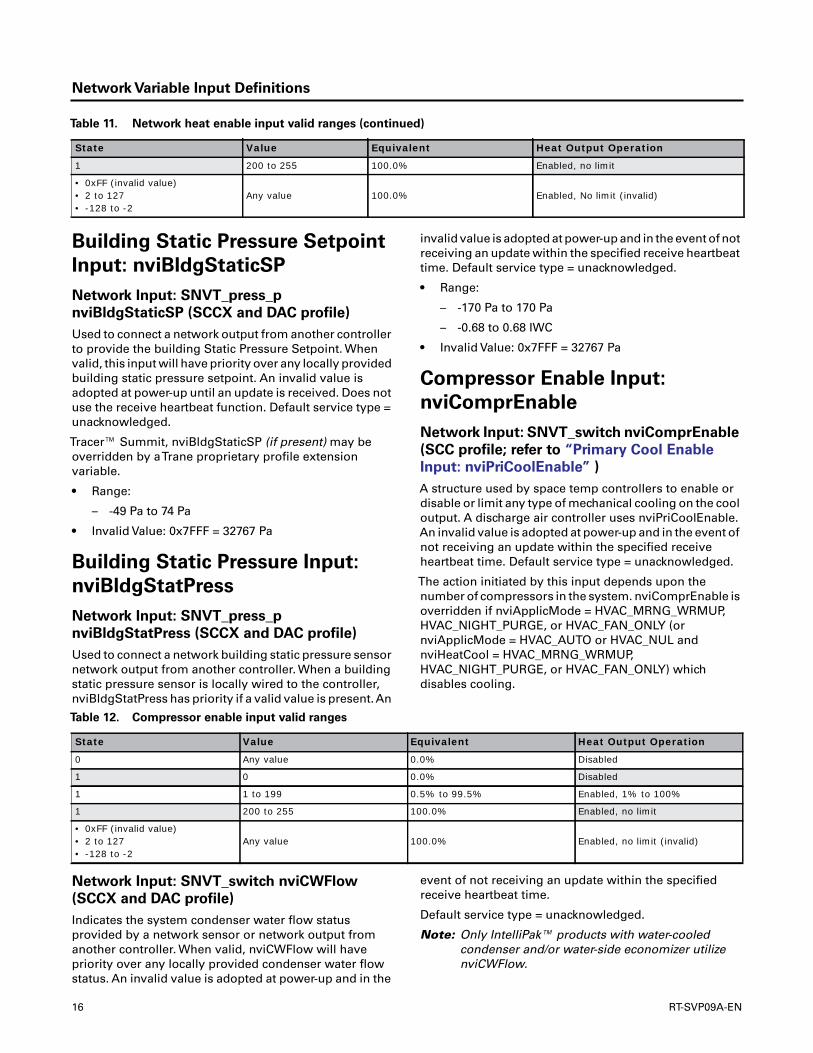
Table 11. Network heat enable input valid ranges
State Value Equivalent Heat Output Operation
0 Any value 0.0% Disabled
1 0 0.0% Disabled
1 1 to 199 0.5% to 99.5% Enabled, 1% to 100%
RT-SVP09A-EN 15
Network Variable Input Definitions
Building Static Pressure Setpoint
Input: nviBldgStaticSP
Network Input: SNVT_press_p
nviBldgStaticSP (SCCX and DAC profile)
Used to connect a network output from another controllerto provide the building Static Pressure Setpoint. Whenvalid, this input will have priority over any locally providedbuilding static pressure setpoint. An invalid value isadopted at power-up until an update is received. Does notuse the receive heartbeat function. Default service type =unacknowledged.
Tracer™ Summit, nviBldgStaticSP (if present) may beoverridden by aTrane proprietary profile extensionvariable.
• Range:
– -49 Pa to 74 Pa
• Invalid Value: 0x7FFF = 32767 Pa
Building Static Pressure Input:
nviBldgStatPress
Network Input: SNVT_press_p
nviBldgStatPress (SCCX and DAC profile)
Used to connect a network building static pressure sensornetwork output from another controller. When a buildingstatic pressure sensor is locally wired to the controller,nviBldgStatPress has priority if a valid value is present.An
invalid value is adopted at power-up and in the event of notreceiving an update within the specified receive heartbeattime. Default service type = unacknowledged.
• Range:
– -170 Pa to 170 Pa
– -0.68 to 0.68 IWC
• Invalid Value: 0x7FFF = 32767 Pa
Compressor Enable Input:
nviComprEnable
Network Input: SNVT_switch nviComprEnable
(SCC profile; refer to “Primary Cool Enable
Input: nviPriCoolEnable” )
A structure used by space temp controllers to enable ordisable or limit any type of mechanical cooling on the cooloutput. A discharge air controller uses nviPriCoolEnable.An invalid value is adopted at power-up and in the event ofnot receiving an update within the specified receiveheartbeat time. Default service type = unacknowledged.
The action initiated by this input depends upon thenumber of compressors in the system. nviComprEnable isoverridden if nviApplicMode = HVAC_MRNG_WRMUP,HVAC_NIGHT_PURGE, or HVAC_FAN_ONLY (ornviApplicMode = HVAC_AUTO or HVAC_NUL andnviHeatCool = HVAC_MRNG_WRMUP,HVAC_NIGHT_PURGE, or HVAC_FAN_ONLY) whichdisables cooling.
Network Input: SNVT_switch nviCWFlow
(SCCX and DAC profile)
Indicates the system condenser water flow statusprovided by a network sensor or network output fromanother controller. When valid, nviCWFlow will havepriority over any locally provided condenser water flowstatus. An invalid value is adopted at power-up and in the
event of not receiving an update within the specifiedreceive heartbeat time.
Default service type = unacknowledged.
Note: Only IntelliPak™ products with water-cooledcondenser and/or water-side economizer utilizenviCWFlow.
1 200 to 255 100.0% Enabled, no limit
• 0xFF (invalid value)• 2 to 127• -128 to -2
Any value 100.0% Enabled, No limit (invalid)
Table 11. Network heat enable input valid ranges (continued)
State Value Equivalent Heat Output Operation
Table 12. Compressor enable input valid ranges
State Value Equivalent Heat Output Operation
0 Any value 0.0% Disabled
1 0 0.0% Disabled
1 1 to 199 0.5% to 99.5% Enabled, 1% to 100%
1 200 to 255 100.0% Enabled, no limit
• 0xFF (invalid value)• 2 to 127• -128 to -2
Any value 100.0% Enabled, no limit (invalid)
16 RT-SVP09A-EN

Network Variable Input Definitions
Discharge Air Cooling Setpoint
Input: nviDAClSP
Network Input: SNVT_temp_p nviDAClSP
(DAC profile)
Used to set the discharge air cooling setpoint of thecontroller.An invalid value is adopted at power-up until anupdate is received. Does not use the receive heartbeatfunction. Default service type = unacknowledged.
• Range: 4.44 °C to 26.67 °C (40 °F to 80 °F)
• Invalid Value: 0x7FFF = 327.67°C
Discharge Air Heating Setpoint
Input: nviDAHtSP
Network Input: SNVT_temp_p nviDAHtSP
(DAC profile)
This input network variable is used to set the discharge airreheat setpoint. Default service type = unacknowledged.
• Range: 10 °C to 70 °C (50 °F to 158 °F)
• Default: 0x7FFF = 327.67°C
• Invalid Value: 0x7FFF = 327.67°C
Discharge Air Reheat Setpoint
Input: nviDAReheatSP
Network Input: SNVT_temp_p nviDAReheatSP
(SCCX and DACX profile)
This input network variable is used to set the discharge airreheat setpoint. Default service type = unacknowledged.Only IntelliPak Rooftop products with a modulatingdehumidification option utilize nviDAReheatSP.
• Range: 18.44°C to 26.66°C (65°F to 80°F)
• Default: 0x7FFF = 327.67°C
• Invalid Value: 0x7FFF = 327.67°C
Duct Static Pressure Setpoint
Input: nviDuctStaticSP
Network Input: SNVT_press_p
nviDuctStaticSP (DAC profile)
Used to set the duct static pressure setpoint of thecontroller.An invalid value is adopted at power-up until anupdate is received. Does not use the receive heartbeatfunction. Default service type = unacknowledged.
• Range:
– 0 Pa to 625 Pa (0.0 to 2.5 IWC)
• Default: 0x7FFF = 32,767 Pa
• Invalid Value: 0x7FFF = 32,767 Pa
Used to enable the dehumidification function in thecontroller. It is typically set by a supervisory node. Defaultvalue will be adopted at power-up and in case of notreceiving an update within the specified receive heartbeattime. Default service type = unacknowledged.
ReliaTel™ products with a dehumidification option utilizenviDehumEnable and only to enable/disabledehumidification. Enabling dehumidification does notforce the unit to actively dehumidify, sincedehumidification is activated by setpoint and spaceconditions.
Economizer Enable Input:
nviEconEnable
Network input: SNVT_switch nviEconEnable
(SCC and DAC profile)
A structure used to enable and disable economizeroperation. An invalid value is adopted at power-up and inthe event of not receiving an update within the specifiedreceive heartbeat time. Default service type =unacknowledged.
Emergency Override Input:
nviEmergOverride
Network Input: SNVT_hvac_emerg
nviEmergOverride (SCC and DAC profile)
Used to command the device into different emergencymodes. an invalid value is adopted at power-up until anupdate is received. Does not use the receive heartbeatfunction. Default service type = unacknowledged.
Type Range Invalid Value
U08 0 = EMERG_NORMAL: Normal operation
Table 13. Economizer enable input valid ranges
State Value Humidification Meaning
0 Any value Disabled No economizing.
1 0 Disabled No economizing.
1 1 to 255 Enabled Economizing in the first stage of cooling.
• 0xFF (invalid value)• 2 to 127• -128 to -2
00 (invalid value) Auto (invalid) Unit controller decision as to whether economizing is possible.
RT-SVP09A-EN 17
Network Variable Input Definitions
1 = EMERG_PRESSURIZE: Start the PRESSURIZEoperation
2 = EMERG_DEPRESSURIZE: Start the DEPRESSURIZEoperation
3 = EMERG_PURGE: Start the PURGE operation
4 = EMERG_SHUTDOWN: SHUTDOWN all unit functions
5 = EMERG_FIRE: Input from fire pull box/system.SHUTDOWN all unit functions
6 to 255 = EMERG_NUL: Invalid mode (same asEMERG_NORMAL) 0 = EMERG_NORMAL
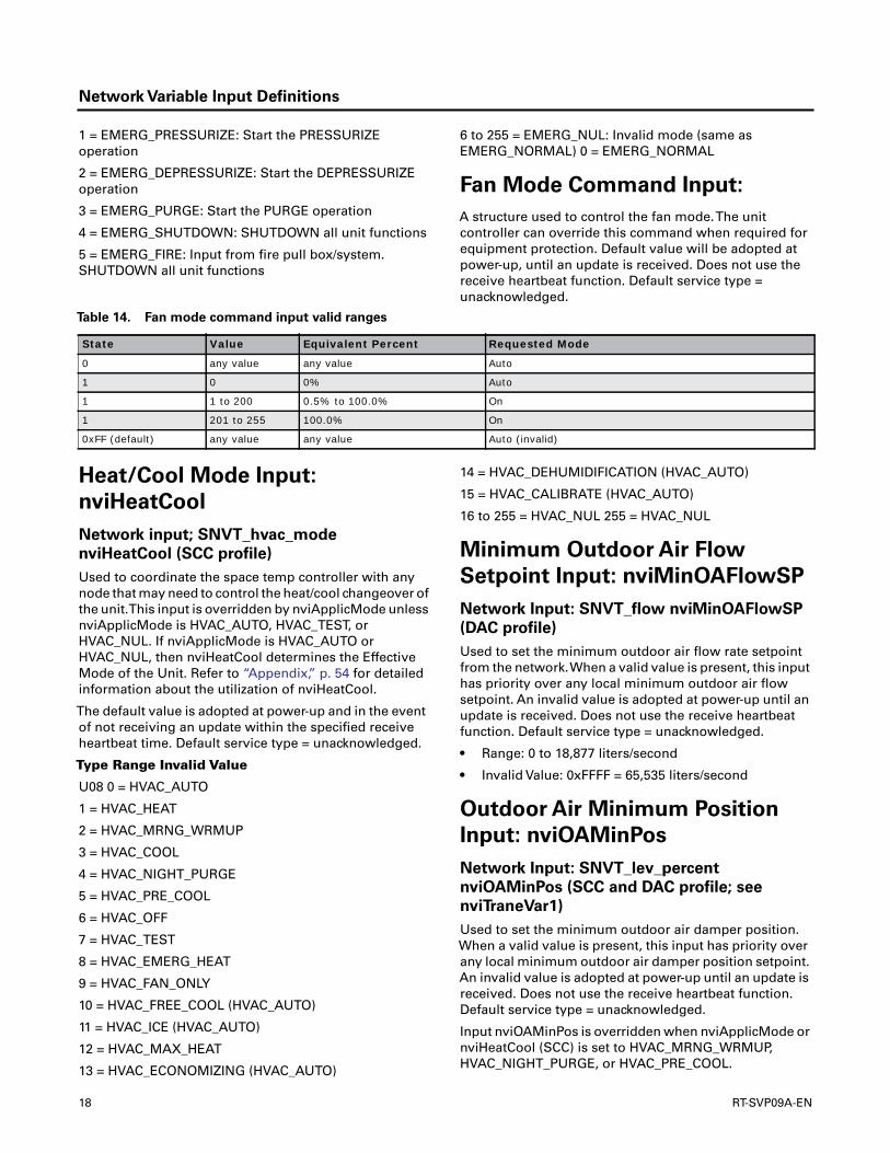
Fan Mode Command Input:
A structure used to control the fan mode.The unitcontroller can override this command when required forequipment protection. Default value will be adopted atpower-up, until an update is received. Does not use thereceive heartbeat function. Default service type =unacknowledged.
Heat/Cool Mode Input:
nviHeatCool
Network input; SNVT_hvac_mode
nviHeatCool (SCC profile)
Used to coordinate the space temp controller with anynode that may need to control the heat/cool changeover ofthe unit.This input is overridden by nviApplicMode unlessnviApplicMode is HVAC_AUTO, HVAC_TEST, orHVAC_NUL. If nviApplicMode is HVAC_AUTO orHVAC_NUL, then nviHeatCool determines the EffectiveMode of the Unit. Refer to “Appendix,” p. 54 for detailedinformation about the utilization of nviHeatCool.
The default value is adopted at power-up and in the eventof not receiving an update within the specified receiveheartbeat time. Default service type = unacknowledged.
Type Range Invalid Value
U08 0 = HVAC_AUTO
1 = HVAC_HEAT
2 = HVAC_MRNG_WRMUP
3 = HVAC_COOL
4 = HVAC_NIGHT_PURGE
5 = HVAC_PRE_COOL
6 = HVAC_OFF
7 = HVAC_TEST
8 = HVAC_EMERG_HEAT
9 = HVAC_FAN_ONLY
10 = HVAC_FREE_COOL (HVAC_AUTO)
11 = HVAC_ICE (HVAC_AUTO)
12 = HVAC_MAX_HEAT
13 = HVAC_ECONOMIZING (HVAC_AUTO)
14 = HVAC_DEHUMIDIFICATION (HVAC_AUTO)
15 = HVAC_CALIBRATE (HVAC_AUTO)
16 to 255 = HVAC_NUL 255 = HVAC_NUL
Minimum Outdoor Air Flow
Setpoint Input: nviMinOAFlowSP
Network Input: SNVT_flow nviMinOAFlowSP
(DAC profile)
Used to set the minimum outdoor air flow rate setpointfrom the network.When a valid value is present, this inputhas priority over any local minimum outdoor air flowsetpoint. An invalid value is adopted at power-up until anupdate is received. Does not use the receive heartbeatfunction. Default service type = unacknowledged.
• Range: 0 to 18,877 liters/second
• Invalid Value: 0xFFFF = 65,535 liters/second
Outdoor Air Minimum Position
Input: nviOAMinPos
Network Input: SNVT_lev_percent
nviOAMinPos (SCC and DAC profile; see
nviTraneVar1)
Used to set the minimum outdoor air damper position.When a valid value is present, this input has priority overany local minimum outdoor air damper position setpoint.An invalid value is adopted at power-up until an update isreceived. Does not use the receive heartbeat function.Default service type = unacknowledged.
Input nviOAMinPos is overridden when nviApplicMode ornviHeatCool (SCC) is set to HVAC_MRNG_WRMUP,HVAC_NIGHT_PURGE, or HVAC_PRE_COOL.
Table 14. Fan mode command input valid ranges
State Value Equivalent Percent Requested Mode
0 any value any value Auto
1 0 0% Auto
1 1 to 200 0.5% to 100.0% On
1 201 to 255 100.0% On
0xFF (default) any value any value Auto (invalid)
18 RT-SVP09A-EN
Network Variable Input Definitions
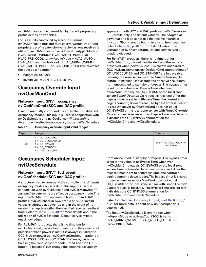
nviOAMinPos can be overridden byTrane® proprietaryprofile extension variables.
For SCC units controlled byTracer™ Summit,nviOAMinPos (if present) may be overwritten by aTraneproprietary profile extension variable (last one received isutilized.) nviOAMinPos is overridden if nviApplicMode =HVAC_MRNG_WRMUP, HVAC_NIGHT_PURGE, orHVAC_PRE_COOL (or nviApplicMode = HVAC_AUTO orHVAC_NUL and nviHeatCool = HVAC_MRNG_WRMUP,HVAC_NIGHT_PURGE, or HVAC_PRE_COOL) which closesthe outside air damper.
• Range: 0% to 100%
• Invalid Value: 0x7FFF = +163.835%
Occupancy Override Input:
nviOccManCmd
Network Input: SNVT_occupancy
nviOccManCmd (SCC and DAC profile)
Used to manually command the controller into differentoccupancy modes.This input is used in conjunction withnviOccSchedule and nviOccSensor (if installed) todetermine the effective occupancy mode. nviOccSchedule
appears in both SCC and DAC profiles, nviOccSensor inSCC profile only.The default value will be adopted atpower-up and it does not use the receive heartbeatfunction. Should not be bound to a send heartbeat nvo.Refer to Table 69, p. 48 for more details about theutilization of nviOccManCmd. Default service type =unacknowledged.
For ReliaTel™ products, there is no time-out fornviOccManCmd, it is not heartbeated, and the value is notpreserved when power is lost (it is always initialized toOCC_NUL on power-up.) nviOccManCmd enumerations ofOC_UNOCCUPIED and OC_STANDBY are bypassable.Pressing the zone sensor moduleTimed Override Onbutton (if installed) can change the effective occupancyfrom unoccupied to standby or bypass.The bypass timeris set to the value in nciBypassTime whenevernviOccManCmd equals OC_BYPASS or the local zonesensorTimed Override On request is received. After thebypass timer is set to nciBypassTime, the controllerbegins counting down to zero.The bypass timer is clearedto zero whenever nviOccManCmd does not equalOC_BYPASS or the local zone sensor withTimed OverrideCancel request is received. If nciBypassTime is set to zero,it disables the OC_BYPASS enumeration fornviOccManCmd and nviOccSchedule.
Occupancy Scheduler Input:
nviOccSchedule
Network Input: SNVT_tod_event
nviOccSchedule (SCC and DAC profile)
A structure used to command the controller into differentoccupancy modes on schedule.This input is used inconjunction with nviOccSensor and nviOccManCmd (ifinstalled) to determine the effective occupancy mode.Theinput nviOccManCmd appears in both SCC and DACprofiles, nviOccSensor in SCC profile only. An invalidvalues is adopted at power-up and in the event of notreceiving an update within the specified receive heartbeattime. Refer to Table 69, p. 48 for more details about theutilization of nviOccSchedule. Default service type =unacknowledged.
For ReliaTel™ products, there is no time-out fornviOccManCmd, it is not heartbeated, and the value is notpreserved when power is lost (it is always initialized toOCC_NUL on power-up.) nviOccManCmd enumerations ofOC_UNOCCUPIED and OC_STANDBY are bypassable.Pressing the zone sensor moduleTimed Override Onbutton (if installed) can change the effective occupancy
from unoccupied to standby or bypass.The bypass timeris set to the value in nciBypassTime whenevernviOccManCmd equals OC_BYPASS or the local zonesensorTimed Override On request is received. After thebypass timer is set to nciBypassTime, the controllerbegins counting down to zero.The bypass timer is clearedto zero whenever nviOccManCmd does not equalOC_BYPASS or the local zone sensor withTimed OverrideCancel request is received. If nciBypassTime is set to zero,it disables the OC_BYPASS enumeration fornviOccManCmd and nviOccSchedule.
Refer to“Effective Occupancy Output, nvoEffectOccup,”p. 28 for more details about how unit occupancy isdetermined.
The input nviOccSchedule is overridden whennviApplicMode or nviHeatCool (SCC) is set toHVAC_MRNG_WRMUP, HVAC_NIGHT_PURGE, orHVAC_PRE_COOL.
Table 15. Occupancy override input valid ranges
Type Ranges Default
U08
0 = OC_OCCUPIED1 = OC_UNOCCUPIED2 = OC_BYPASS3 = OC_STANDBY4 to 255 = OC_NUL
255 = OC_NUL (value not available)
RT-SVP09A-EN 19
Network Variable Input Definitions
Occupancy Sensor Input:
nviOccSensor
Network Input: SNVT_occupancy
nviOccSensor (SCC profile)
Used to indicate the presence of occupants in thecontrolled space.This input is used in conjunction withnviOccSchedule and nviOccManCmd (if installed) todetermine the effective occupancy mode. Invalid value willbe adopted at power-up and in case of not receiving anupdate within the specified receive heartbeat time. Referto Table 69, p. 48 for more details about the utilization ofnviOccSensor. Default service type = unacknowledged.
For ReliaTel™ products, there is no time-out fornviOccManCmd, it is not heartbeated, and the value is notpreserved when power is lost (it is always initialized toOCC_NUL on power-up.) nviOccManCmd enumerations ofOC_UNOCCUPIED and OC_STANDBY are bypassable.Pressing the zone sensor moduleTimed Override On
button (if installed) can change the effective occupancyfrom unoccupied to standby or bypass.The bypass timeris set to the value in nciBypassTime whenevernviOccManCmd equals OC_BYPASS or the local zonesensorTimed Override On request is received. After thebypass timer is set to nciBypassTime, the controllerbegins counting down to zero.The bypass timer is clearedto zero whenever nviOccManCmd does not equalOC_BYPASS or the local zone sensor withTimed OverrideCancel request is received. If nciBypassTime is set to zero,it disables the OC_BYPASS enumeration fornviOccManCmd and nviOccSchedule.
Refer to “Effective Occupancy Output, nvoEffectOccup,”p. 28 for more details about how unit occupancy isdetermined.
The input nviOccSensor is overridden whennviApplicMode or nviHeatCool (SCC) is set to
HVAC_MRNG_WRMUP, HVAC_NIGHT_PURGE, orHVAC_PRE_COOL.
Outdoor Air Humidity Input:
nviOutdoorRH
Network Input: SNVT_lev_percent
nviOutdoorRH (SCC and DAC profile)
The outdoor air humidity in percent.Typically provided byeither a network sensor or a supervisory controller.Whenan outdoor air humidity sensor is locally wired to thecontroller, the nviOutdoorRH has priority if a valid value ispresent.An invalid value is adopted at power-up and in theevent of not receiving an update within the specifiedreceive heartbeat time. Default service type =unacknowledged.
For IntelliPak™ products, the outdoor air humidity input islimited to between 10 - 90%.
• Range: 0% to100%
• Invalid Value: 0x7FFF = 163.835%
Outdoor AirTemperature Input:
nviOutdoorTemp
network input SNVT_temp_p
nviOutdoorTemp (SCC and DAC profile)
The outdoor air dry bulb temperature is provided by eithera network outdoor air temperature sensor or anothercontroller. When an outdoor air temperature sensor islocally wired to the controller, the nviOutdoorTemp haspriority if a valid value is present. An invalid value isadopted at power-up and in the event of not receiving anupdate within the specified receive heartbeat time. Defaultservice type = unacknowledged.
• Range: -40.0 °C to 70.0 °C, -40.0 °F to 158.0 °F
• Invalid Value: 0x7FFF = 327.67°C
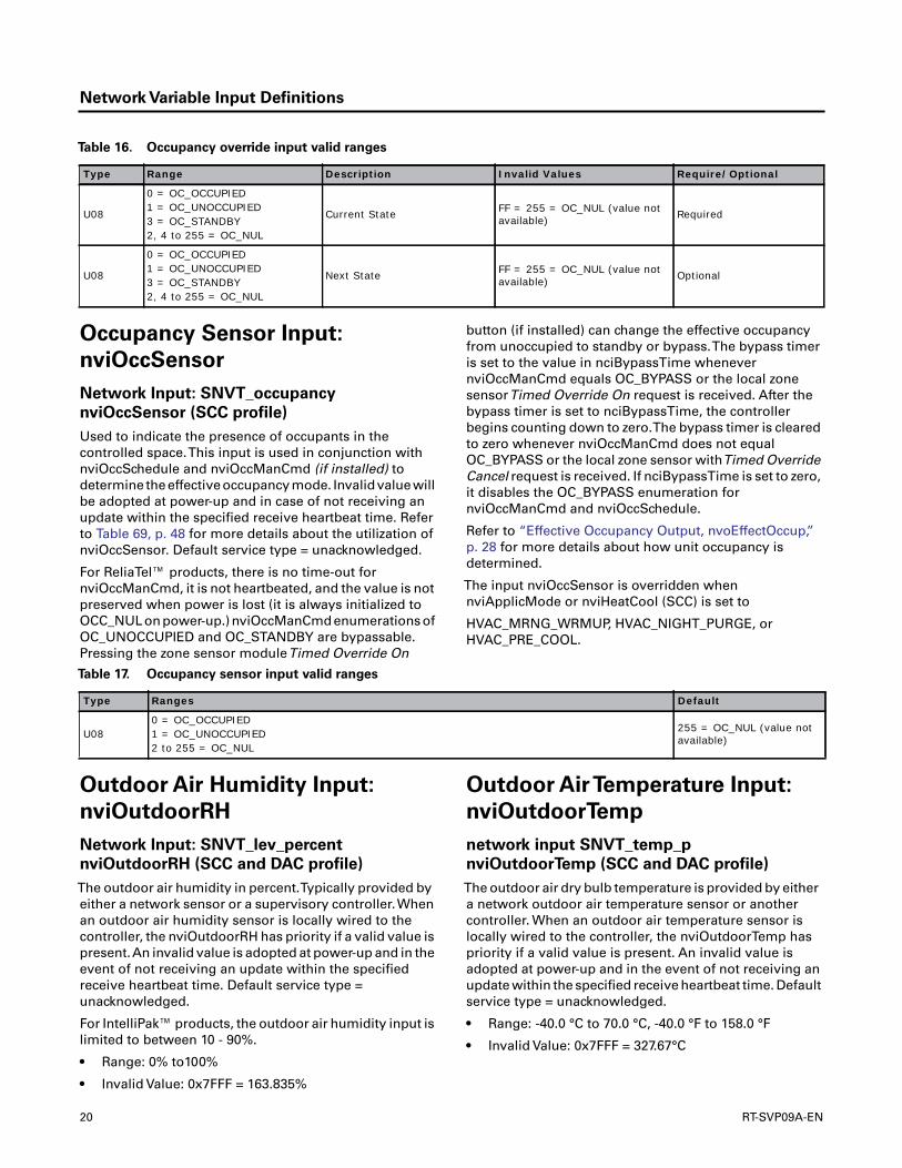
Table 16. Occupancy override input valid ranges
Type Range Description Invalid Values Require/Optional
U08
0 = OC_OCCUPIED1 = OC_UNOCCUPIED3 = OC_STANDBY2, 4 to 255 = OC_NUL
Current State FF = 255 = OC_NUL (value not available) Required
U08
0 = OC_OCCUPIED1 = OC_UNOCCUPIED3 = OC_STANDBY2, 4 to 255 = OC_NUL
Next State FF = 255 = OC_NUL (value not available) Optional
Table 17. Occupancy sensor input valid ranges
Type Ranges Default
U080 = OC_OCCUPIED1 = OC_UNOCCUPIED2 to 255 = OC_NUL
255 = OC_NUL (value not available)
20 RT-SVP09A-EN

Network Variable Input Definitions
Primary Cool Enable Input:
nviPriCoolEnable
network input SNVT_switch nviPriCoolEnable
(DAC profile; refer to “Compressor Enable
Input: nviComprEnable” )
A structure used by a discharge air controller to enable ordisable or limit mechanical cooling on the cool output. A
space temp controller uses nviComprEnable. An invalidvalue is adopted at power-up and in the event of notreceiving an update within the specified receive heartbeattime. Default service type = unacknowledged.
Primary Heat Enable Input:
nviPriHeatEnable
Network Input: SNVT_switch
nviPriHeatEnable (DAC profile; refer to
“Auxiliary Heat Enable Input:
nviAuxHeatEnable” )
A structure used by a discharge air controller to enable ordisable or limit mechanical heat on the heat output. Aspace temp controller uses nviAuxHeatEnable.The default
value is adopted at power-up and in the event of notreceiving an update within the specified receive heartbeattime. Default service type = unacknowledged.
For all ReliaTel™ products, the action initiated by this inputdepends upon what type of heater (gas, electric, or heatpump) is present and the number of heat stages. For heatpumps, nviPriHeatEnable only controls auxiliary heat (notcompressors), whether it comes on first or not.nviPriHeatEnable is overridden if nviApplicMode =HVAC_NIGHT_PURGE, HVAC_PRE_COOL, orHVAC_FAN_ONLY which disables heating.
ServiceTest Command:
Command the unit to step through service test. It istypically set by a service tool. Default value will be adoptedat power-up and in case of not receiving an update withinthe specified receive heartbeat time. Default service type =unacknowledged.
Each time nviServiceTest is enabled, the unit transitions tothe next service test mode and performs a differentfunction.After nvoServiceTest reflects the next service testmode, nviServiceTest reverts to disabled. OncenviServiceTest exceeds the last service test step mode, theunit will reset and leave service test. An internal unit“ServiceTestTimer” (not configurable and not
communicated) will be reset to 60 minutes each timenviServiceTest transitions from disabled to enabled. If thetimer counts down to zero, the unit will reset and leaveservice test mode.
Table 18. Primary cool enable input valid ranges
State Value Equivalent Percent Cool Output Operation
0 Any value 0.0% Disabled
1 0 0.0% Disabled
1 1 to 199 0.5% to 99.5% Enabled; 1% to 100%
1 200 to 255 100.0% Enabled; no limit
• 0xFF (invalid value)• 2 to 127• -128 to -2
00 (invalid value) 100.0% Enabled; no limit (invalid)
Table 19. Primary heat enable input valid ranges
State Value Equivalent Percent Cool Output Operation
0 Any value 0.0% Disabled
1 0 0.0% Disabled
1 1 to 199 0.5% to 99.5% Enabled; 1% to 100%
1 200 to 255 100.0% Enabled; no limit
• 0xFF (invalid value)• 2 to 127• -128 to -2
Any value 100.0% Enabled; no limit (invalid)
RT-SVP09A-EN 21

Network Variable Input Definitions
Status Request Input: nviRequest
Network Input: SNVT_obj_request nviRequest
(node profile)
Provides the mechanism to request a particular mode fora particular object within a node. An invalid value is
adopted at power-up or until an update is received. Doesnot use the receive heartbeat function. Responses are setvia nvoStatus. Default service type = unacknowledged.
Table 20. Primary heat enable input valid ranges and object request field enumeration definitions
Type Range Description Invalid Value Bytes Valid Meaning
U16 0 to 65535 Object ID 65535 2
• 0• 1• 2• 3 to 65535
• Node object• SCC object• DAC object• Invalid
U08 Enum 0 to 255 Object request 255 1 See below See below
Length 3
Enum Object Request Mode Meaning Controller Interpretation
0 RQ_NORMAL Enable object and remove override. Report object status.
1 RQ_DISABLED(a) Disable object. Ignore object request, invalid request.
2 RQ_UDATE_STATUS Just report object status. Report object status.
3 RQ_SELF_TEST Perform object self-test. Ignore object request, invalid request.
4 RQ_UPDATE_ALARM Update alarm status. Ignore object request, invalid request.
5 RQ_REPORT_MASK Report status bit mask. Report status bit mask.
6 RQ_OVERRIDE Override object. Ignore object request, invalid request.
7 RQ_ENABLE Enable object. Ignore object request, invalid request.
8 RQ_RMV_OVERRIDE Remove object override. Ignore object request, invalid request.
9 RQ_CLEAR_STATUS Clear object status. Report object status.
10 RQ_CLEAR_ALARM Clear object alarm. Clear diagnostic alarm.
11 RQ_ALARM_NOTIFY_ENABLE Enable alarm notification. Ignore object request, invalid request.
12 RQ_ALARM_NOTIFY_DISABLE Disable alarm notification. Ignore object request, invalid request.
13 RQ_MANUAL_CTRL Enable object for manual control. Ignore object request, invalid request.
14 RQ_REMOTE_CTRL Enable object for remote control. Ignore object request, invalid request.
15 RQ_PROGRAM Enable programming of special configuration properties. Ignore object request, invalid request.
16 RQ_CLEAR_RESET Clear reset notification flag. Ignore object request, invalid request.
17 RQ_RESET Execute reset sequence of object. Ignore object request, invalid request.
18 to 255 RQ_NUL Value not available. Ignore object request, invalid request.
(a) Highlighted entries under Object Request Mode column are not supported by the controller. Instead, these entries will generate an nvoStatus trans-mission with the Invalid_Request bit set.
Table 21. Node object behavior in response to object request
Request Code Node Object Behavior
Normal The Request does not change the state of the object. The Status of the object is sent via nvoStatus. See nciApplication for a description of how to determine the unit type and which profile is supported.
Update statusStatus of the node object is sent via nvoStatus. The status bits of the node object (with the exception of invalid_request and invalid_id) are defined to be the inclusive OR of the status bits of all the other objects in the node, SCC and DAC in this case.
Report maskSend a mask of supported status bits via nvoStatus. A one bit in the mask means that the node may set the corresponding bit in nvoStatus when the condition defined for that bit occurs. A zero means that the bit will never be set by the node.
Clear status No status bits cleared. Status of the object is sent via nvoStatus.
Clear alarm Clears most latching diagnostics. Re-sends automatically resetting diagnostics if no latching diagnostics are present.
NUL Ignore object request.
22 RT-SVP09A-EN

Network Variable Input Definitions
Temperature Setpoint Input
(Absolute): nviSetpoint
Network Input: SNVT_temp_p nviSetpoint
(SCC profile)
Used to allow the space setpoints for the occupied andstandby modes to be changed. If nviSetpoint,nviSetptOffSet and/or nviSetptShift are used together, theresult on the effective setpoints is additive.The defaultvalue is adopted at power-up until an update is received.Does not use the receive heartbeat function. Defaultservice type = unacknowledged.
Refer to Table 76, p. 63 for more details about theutilization of nviSetpoint by IntelliPak products.
• Range: 10°C to 35°C (50°F to 95°F)
• Default: 0x7FFF = 327.67°C
• Invalid Value: 0x7FFF = 327.67°C
Setpoint Offset Input:
nviSetptOffset
Network Input: SNVT_temp_p nviSetptOffset
(SCC profile)
Used to shift the effective occupied and standbytemperature setpoints.All occupied and standby setpointswill be shifted upward (+) or downward (-) by the value ofnviSetptOffset. If nviSetpoint, nviSetptOffSet, and/ornviSetptShift are used together, the result on the effectivesetpoints is additive.
An invalid value is adopted at power-up and in the event ofnot receiving an update within the specified receiveheartbeat time. Default service type = unacknowledged.
Refer to Table 76, p. 63 for more details about theutilization of nviSetptOffset by IntelliPak products.
• Range: -10°C to +10°C (-18°F to 18°F)
• Invalid Value: 0x7FFF = 327.67°C (Default)
Space CO2 Sensor Input:
nviSpaceCO2 (nviSpaceIAQ)
Network Input: SNVT_ppm nviSpaceCO2 (SCC
and DACX profile)
Used to measure the space CO2 in PPM.The unit can alsohave a locally wired CO2 sensor. When a local space CO2value is available to the controller, the nviSpaceCO2 haspriority, if a valid value is present.The default value isadopted at power-up and in the event of not receiving anupdate within the specified receive heartbeat time. Defaultservice type = unacknowledged.
• Range: 0 to 2,000 PPM
• Default: 0xFFFF = 65,535 PPM
• Invalid Value: 0xFFFF = 65,535 PPM
Space Dehumidification Setpoint
Input: nviSpaceDehumSP
Network Input: SNVT_lev_percent
nviSpaceDehumSP (SCCX and DAC profile)
Used to connect a network space dehumidificationsetpoint or network output from another controller.Whena local space dehumidification setpoint is available to thecontroller, the nviSpaceDehumSP has priority if a validvalue is present. An invalid value is adopted at power-upuntil an update is received. Does not use the receiveheartbeat function. Default service type =unacknowledged.
Only ReliaTel™ products with the dehumidification optionutilize nviSpaceDehumSP.
• 40% to 65%
• 0x7FFF = 163.835%
Table 22. SCC/DAC object behavior in response to object request
Request Code Node Object Behavior
NormalThe Request does not change the state of the object. The Status of the object is sent via nvoStatus. The out-of-service object sets the out-of-service and disabled bits. See nciApplication for a description of how to determine the unit type and which profile is supported.
Update status Status of the object is sent via nvoStatus. The out-of-service object sets the out-of-service and disabled bits.
Report maskSend a mask of supported status bits via nvoStatus. A one bit in the mask means that the node may set the corresponding bit in nvoStatus when the condition defined for that bit occurs. A zero means that the bit will never be set by the node. The out-of-service object sets the out-of-service and disabled bits.
Clear status No status cleared. Status of the object is sent via nvoStatus. The out-of-service object sets the out-of-service and disabled bits.
Clear alarm Clears most latching diagnostics. Re-sends automatically resetting diagnostics if no latching diagnostics are present.
NUL Ignore object request.
RT-SVP09A-EN 23

Network Variable Input Definitions
Space Humidity Input:
nviSpaceRH
Network Input: SNVT_lev_percent
nviSpaceRH (SCC and DAC profile)
Used to connect a network return air or space relativehumidity sensor or network output from anothercontroller. When a return air or space relative humiditysensor is locally wired to the controller, the nviSpaceRHhas priority, if a valid value is present. An invalid value isadopted at power-up and in the event of not receiving anupdate within the specified receive heartbeat time. Defaultservice type = unacknowledged.
• Range: 0% to 100%
• Default: 0x7FFF = 163.835%
• Invalid Value: 0x7FFF = 163.835%
SpaceTemperature Input:
nviSpaceTemp
Network Input: SNVT_temp_p nviSpaceTemp
(SCC and DAC profile)
Used to connect a network space temperature sensor ornetwork output from another controller. If nviSpaceTemphas a valid value, it will have priority over a locally wiredspace temperature sensor. An invalid value is adopted atpower-up and in the event of not receiving an updatewithin the specified receive heartbeat time. Default servicetype = unacknowledged.
• Range: -40.0°C to 65.55°C, -40.0°F to 149.9°F
• Invalid Value: 0x7FFF = 327.67°C
Device Control Input
A structure used by a space temp controller to set theoccupied OA damper minimum position setpoint. Adischarge air controller uses nviMinOAFlowSP,nviOAMinPos, and nviBldgStaticSP. Default service type =unacknowledged.
For SCC units, nviTraneVar1.OAMinPosSetpoint may beoverwritten by nviOAMinPos andnviTraneVar1.BldgStaticSetpoint may be overwritten bynviBldgStaticSP (last received is utilized.)OAMinPosSetpoint is overridden when nviApplicMode ornviHeatCool (SCC) is set to HVAC_MRNG_WRMUP,HVAC_NIGHT_PURGE, or HVAC_PRE_COOL.
DescriptionType bytes Invalid ValueTracer™ SCC usesTracer™ DAC uses
Output Request 1 SNVT_switch 2 0x00FF
Output Request 2 SNVT_switch 2 0x00FF
OA Flow Setpoint SNVT_flow 2 0xFFFF SCCX nviTraneVar1DAC nviMinOAFlowSP
OA Min Pos Setpoint SNVT_lev_percent 2 0x7FFF SCCXnviTraneVar1 DAC nviOAMinPos
Flow Multiplier SNVT_multiplier 2 0x0000
Heat Enable SNVT_switch 2 0x00FF
Cool Enable SNVT_switch 2 0x00FF
Bldg Static Setpoint SNVT_press_p 2 0x7FFF SCCXnviTraneVar1 DAC nviBldgStaticSP
Boost SNVT_switch 2 0x00FF
Energy Limit SNVT_switch 2 0x00FF
Total Length 20
Field Override Input
This input network variable is used to perform service test.The use of this network variable supersedes normalcontrol of the outputs.This variable is designed to be sentby Rover. With the use of this variable the controllercontinues to react to any/all diagnostics, both hardwiredand logical, just as it does during normal operation.Invalidvalue will be adopted at power-up or until an update isreceived. Does not use the receive heartbeat function.Default service type = unacknowledged.
This variable is functionally the same as installing aresistor on theTest input on the controller with oneprimary distinction.The communication ofnviTraneVar1401 is based on a communicatedenumeration to define the test step. It is the responsibilityof the sender (i.e. Rover) to send the test steps in theproper sequence.
Note: When this variable is being sent to the controller,nviApplicMode should be sent at the same time with anenumerated value representing “TEST” (enumeration 7 =HVAC_TEST). As a result, the controller will reflect a unitstatus ofTEST in the variable nvoUnitStatus.
A manual override timer expiration is used to cancel theoverride request.This timer is set to 60 minutes at the startof manual test, and reset to 60 minutes each time manualtest is advanced to the next step.
All minimum output timers (compressor on/off minimumtimers, fan off delays, etc.) are IGNORED during thisoutput override (as well as during the ServiceTest).
Comm5 Command
This network variable isTrane proprietary and should notshow up in any literature. Used to return a status for aComm 5 command. Note that no status is returned whena node is unlocked.The Comm 5 Status command typefield will be the same as the Comm 5 Command type fieldexcept for the asynchronous Comm 5 Status enumeration.Kirk Johnson defined this network variable.
24 RT-SVP09A-EN
Network Variable Output Definitions
The network variable output definitions in this section arelisted alphabetically by the nvoName. For examplenvoAlarmMessage.
Alarm MessageText Output:
nvoAlarmMessage
Network Output: SNVT_str_asc
nvoAlarmMessage (node extension profile)
Used to communicate the diagnostics in the controller asthey occur.The alarm message code format is displayedas, s_nnnnnnnnnnnnnnnnnnnnnnnnnnnnn, with aSpace between the s and the first ASCII character.Thefollowing explains this alarm message coding:
• s; indicates diagnostic severity with five types ofdiagnostics:
– P= normal, last reset resulted from a power up
– 0= normal, last reset was not from power up
– 1= informational message (handle at nextscheduled routine maintenance)
– 2= service required (handle at normal rates duringnormal working hours)
– 3= critical alarm (handle now, cost is no object)
• n; represents 29 ASCII characters that displays adeciphered message.The last n must be null (0x00),can be 29 characters or less.
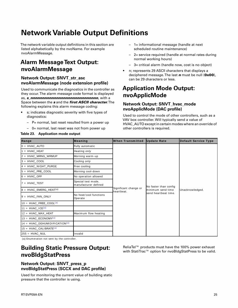
Application Mode Output:
nvoApplicMode
Network Output: SNVT_hvac_mode
nvoApplicMode (DAC profile)
Used to control the mode of other controllers, such as aVAV box controller. Will typically send a value ofHVAC_AUTO except in certain modes where an override ofother controllers is required.
Building Static Pressure Output:
nvoBldgStatPress
Network Output: SNVT_press_p
nvoBldgStatPress (SCCX and DAC profile)
Used for monitoring the current value of building staticpressure that the controller is using.
ReliaTel™ products must have the 100% power exhaustwith StatiTrac™ option for nvoBldgStatPress to be valid.
Table 23. Application mode output
Range Meaning When Transmitted Update Rate Default Service Type
0 = HVAC_AUTO Fully automatic
Significant change or heartbeat.
No faster than config minimum send time send heartbeat time.
Unacknowledged.
1 = HVAC_HEAT Heating only
2 = HVAC_MRNG_WRMUP Morning warm-up
3 = HVAC_COOL Cooling only
4 = HVAC_NIGHT_PURGE Free cooling
5 = HVAC_PRE_COOL Morning cool-down
6 = HVAC_OFF No operation allowed
7 = HVAC_TEST Special test mode, manufacturer defined
8 = HVAC_EMERG_HEAT(a)
9 = HVAC_FAN_ONLY No heat/cool functions Operate
10 = HVAC_FREE_COOL(a)
11 = HVAC_ICE(a)
12 = HVAC_MAX_HEAT Maximum flow heating
13 = HVAC_ECONOMY(a)
14 = HVAC_DEHUMIDIFICATION(a)
15 = HVAC_CALIBRATE(a)
255 = HVAC_NUL Invalid
(a) Enumeration not sent by the controller.
RT-SVP09A-EN 25
Network Variable Output Definitions
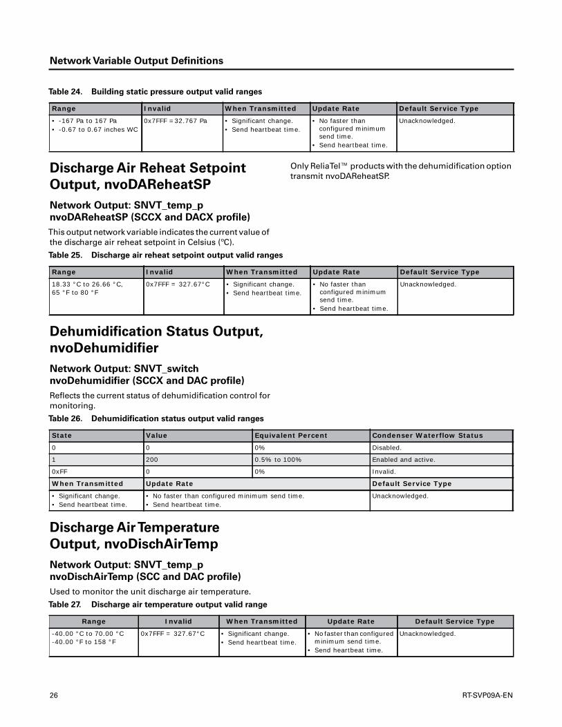
Discharge Air Reheat Setpoint
Output, nvoDAReheatSP
Network Output: SNVT_temp_p
nvoDAReheatSP (SCCX and DACX profile)
This output network variable indicates the current value ofthe discharge air reheat setpoint in Celsius (ºC).
Only ReliaTel™ products with the dehumidification optiontransmit nvoDAReheatSP.
Dehumidification Status Output,
nvoDehumidifier
Network Output: SNVT_switch
nvoDehumidifier (SCCX and DAC profile)
Reflects the current status of dehumidification control formonitoring.
Discharge AirTemperature
Output, nvoDischAirTemp
Network Output: SNVT_temp_p
nvoDischAirTemp (SCC and DAC profile)
Used to monitor the unit discharge air temperature.
Table 24. Building static pressure output valid ranges
Range Invalid When Transmitted Update Rate Default Service Type
• -167 Pa to 167 Pa• -0.67 to 0.67 inches WC
0x7FFF =32.767 Pa • Significant change.• Send heartbeat time.
• No faster than configured minimum send time.
• Send heartbeat time.
Unacknowledged.
Table 25. Discharge air reheat setpoint output valid ranges
Range Invalid When Transmitted Update Rate Default Service Type
18.33 °C to 26.66 °C, 65 °F to 80 °F
0x7FFF = 327.67°C • Significant change.• Send heartbeat time.
• No faster than configured minimum send time.
• Send heartbeat time.
Unacknowledged.
Table 26. Dehumidification status output valid ranges
State Value Equivalent Percent Condenser Waterflow Status
0 0 0% Disabled.
1 200 0.5% to 100% Enabled and active.
0xFF 0 0% Invalid.
When Transmitted Update Rate Default Service Type
• Significant change.• Send heartbeat time.
• No faster than configured minimum send time.• Send heartbeat time.
Unacknowledged.
Table 27. Discharge air temperature output valid range
Range Invalid When Transmitted Update Rate Default Service Type
-40.00 °C to 70.00 °C-40.00 °F to 158 °F
0x7FFF = 327.67°C • Significant change.• Send heartbeat time.
• No faster than configured minimum send time.
• Send heartbeat time.
Unacknowledged.
26 RT-SVP09A-EN
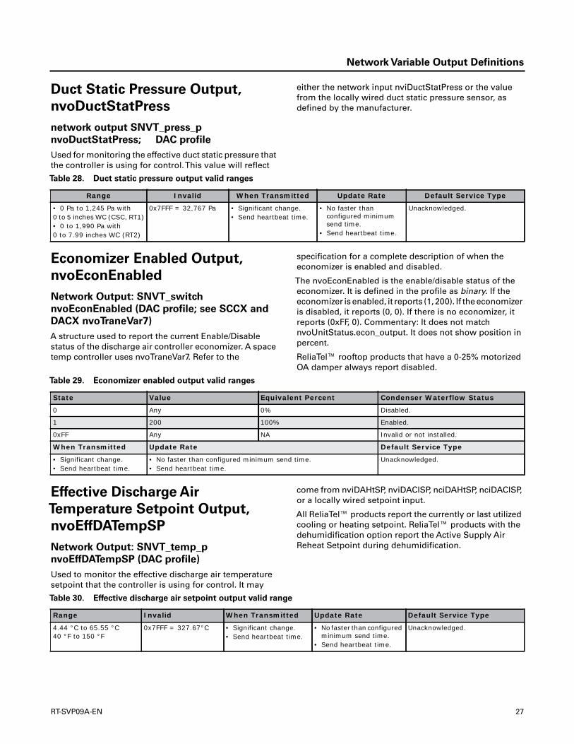
Network Variable Output Definitions
Duct Static Pressure Output,
nvoDuctStatPress
network output SNVT_press_p
nvoDuctStatPress; DAC profile
Used for monitoring the effective duct static pressure thatthe controller is using for control.This value will reflect
either the network input nviDuctStatPress or the valuefrom the locally wired duct static pressure sensor, asdefined by the manufacturer.
Economizer Enabled Output,
nvoEconEnabled
Network Output: SNVT_switch
nvoEconEnabled (DAC profile; see SCCX and
DACX nvoTraneVar7)
A structure used to report the current Enable/Disablestatus of the discharge air controller economizer. A spacetemp controller uses nvoTraneVar7. Refer to the
specification for a complete description of when theeconomizer is enabled and disabled.
The nvoEconEnabled is the enable/disable status of theeconomizer. It is defined in the profile as binary. If theeconomizer is enabled, it reports (1, 200). If the economizeris disabled, it reports (0, 0). If there is no economizer, itreports (0xFF, 0). Commentary: It does not matchnvoUnitStatus.econ_output. It does not show position inpercent.
ReliaTel™ rooftop products that have a 0-25% motorizedOA damper always report disabled.
Effective Discharge Air
Temperature Setpoint Output,
nvoEffDATempSP
Network Output: SNVT_temp_p
nvoEffDATempSP (DAC profile)
Used to monitor the effective discharge air temperaturesetpoint that the controller is using for control. It may
come from nviDAHtSP, nviDAClSP, nciDAHtSP, nciDAClSP,or a locally wired setpoint input.
All ReliaTel™ products report the currently or last utilizedcooling or heating setpoint. ReliaTel™ products with thedehumidification option report the Active Supply AirReheat Setpoint during dehumidification.
Table 28. Duct static pressure output valid ranges
Range Invalid When Transmitted Update Rate Default Service Type
• 0 Pa to 1,245 Pa with0 to 5 inches WC (CSC, RT1)• 0 to 1,990 Pa with0 to 7.99 inches WC (RT2)
0x7FFF = 32,767 Pa • Significant change.• Send heartbeat time.
• No faster than configured minimum send time.
• Send heartbeat time.
Unacknowledged.
Table 29. Economizer enabled output valid ranges
State Value Equivalent Percent Condenser Waterflow Status
0 Any 0% Disabled.
1 200 100% Enabled.
0xFF Any NA Invalid or not installed.
When Transmitted Update Rate Default Service Type
• Significant change.• Send heartbeat time.
• No faster than configured minimum send time.• Send heartbeat time.
Unacknowledged.
Table 30. Effective discharge air setpoint output valid range
Range Invalid When Transmitted Update Rate Default Service Type
4.44 °C to 65.55 °C40 °F to 150 °F
0x7FFF = 327.67°C • Significant change.• Send heartbeat time.
• No faster than configured minimum send time.
• Send heartbeat time.
Unacknowledged.
RT-SVP09A-EN 27

Network Variable Output Definitions
Effective Duct Static Pressure
Setpoint Output,
nvoEffDuctStatSP
Network Output: SNVT_press_p
nvoEffDuctStatSP (DAC profile)
Used to monitor the effective duct static pressure setpointthat the controller is using for control.This value may
come from nviDuctStaticSP, nciDuctStatSP, or a locallywired setpoint input.
Effective Occupancy Output,
nvoEffectOccup
Network Output: SNVT_occupancy
nvoEffectOccup (SCC and DAC profile)
Used to indicate the current occupancy of the controller.This information is typically reported to a supervisorycontroller, or provided to another controller to coordinatethe operation of multiple units.The occupancy mode isdetermined by a combination of optional input networkvariables and logic in the controller, as defined by thecontroller manufacturer.The network variables which canimpact the occupancy state of the controller are;nviOccManCmd (SCC/DAC), nviOccSchedule (SCC/DAC),and nviOccSensor (only SCC).The unit is always in one ofthe four possible occupancy states. Refer to Table 69, p. 48for more details about the utilization of nvoEffectOccup.
For ReliaTel™ products, there is no time-out fornviOccManCmd, it is not heartbeated, and the value is notpreserved when power is lost (it is always initialized to
OCC_NUL on power-up.) nviOccManCmd enumerations ofOC_UNOCCUPIED and OC_STANDBY are bypassable.Pressing the zone sensor moduleTimed Override Onbutton (if installed) for less than 8 seconds can change theeffective occupancy from unoccupied or standby tobypass.The bypass timer is set to the value innciBypassTime whenever nviOccManCmd equalsOC_BYPASS or the local zone sensorTimed Override Onrequest is received. After the bypass timer is set tonciBypassTime, the controller begins counting down tozero.The bypass timer is cleared to zero whenevernviOccManCmd does not equal OC_BYPASS or the localzone sensor withTimed Override Cancel request isreceived. If nciBypassTime is set to zero, it disables theOC_BYPASS enumeration for nviOccManCmd andnviOccSchedule. If nciBypassTime is set to zero, it does notdisable theTOV Request orTOV Cancel Request innvoTraneVar7. Pressing the zone sensor moduleTimedOverride On button for more than 8 seconds will cause theLCI-R controller to broadcast a Service Pin Message(Neuron ID and Program ID.)
Effective Setpoint Output,
nvoEffectSetpt
Network Output: SNVT_temp_p
nvoEffectSetpt (SCC profile)
Used to monitor the effective space temperature setpointwhich may depend on nciSetpoints, nvoEffectOccup,nviSetpoint, nviSetpointOffset, nviSetptShift,
nciPersonality2, nvoHeatCool, and any local setpointadjustment. For example, if the occupancy state isunoccupied and the heat/cool state is heat, then theeffective setpoint would be equal to the unoccupiedheating setpoint defined in nciSetpoints.
Table 31. Effective duct static pressure setpoint output valid ranges
Range Invalid When Transmitted Update Rate Default Service Type
0 Pa to 622 Pa, 0.0 to 2.5 IWC
0x7FFF = 32,767% • Significant change.• Send heartbeat time.
• No faster than configured minimum send time.
• Send heartbeat time.
Unacknowledged.
Table 32. Effective occupancy output valid ranges
Range Invalid When Transmitted Update Rate Default Service Type
0 = OC_OCCUPIED Always valid. • Significant change.• Send heartbeat time.
• No faster than configured minimum send time.
• Send heartbeat time.
Unacknowledged.
1 = OC_UNOCCUPIED
2 = OC_BYPASS
3 = OC_STANDBT
4 to 255 not used
28 RT-SVP09A-EN

Network Variable Output Definitions
Refer to Table 76, p. 63 for more details.
Effective Space Dehumidification
Setpoint Output,
nvoEffSpaceDHSP
Network Output: SNVT_lev_percent
nvoEffSpaceDHSP (SCCX and DAC profile)
Reflects the effective Space High Limit Humidity Setpointfor monitoring.
Exhaust Fan Status Output,
nvoExhFanStatus
Network Output: SNVT_switch
nvoExhFanStatus (SCCX and DAC profile; see
SCCX and DACX nvoTraneVar7)
A structure used to report the current status of the exhaustfan.
For ReliaTel™ units that do not have StatiTrac™ installed,when State is 1, Value will always be 0% or 100%.
Table 33. Effective setpoint output valid range
Range Invalid When Transmitted Update Rate Default Service Type
10.00°C to 32.33°C(50°F to 90°F)
0x7FFF • Significant change.• Send heartbeat time.
• No faster than configured minimum send time.
• send heartbeat time.
Unacknowledged.
Table 34. Effective space dehumidification setpoint output valid range
Range Invalid When Transmitted Update Rate Default Service Type
40% to 65% 0x7FFF = 163.835% (not present)
• Significant change.• Send heartbeat time.
• No faster than configured minimum send time.
• Send heartbeat time.
Unacknowledged.
Table 35. Exhaust fan status control output valid ranges
State Value Equivalent Percent Requested Fan State Requested Fan Capacity
0 0 NA OFF NA
1 0 0.0% OFF NA
1 1-199 0.5% to 99.5% ON 0.5% to 99.5%
1 200 100% ON 100%
0xFF 0 NA Invalid. Invalid.
When Transmitted Update Rate Default Service Type
• Significant change.• Send heartbeat
time.
• No faster than configured minimum send time.• Send heartbeat time.
Unacknowledged.
RT-SVP09A-EN 29

Network Variable Output Definitions
Fan Speed Output, nvoFanSpeed
Network Output: SNVT_switch nvoFanSpeed
(SCC profile; refer to “Supply Fan Status
Output, nvoSupFanStatus,” p. 35)
A structure used by a space temp controller to report thecurrent supply fan speed. A discharge air controller usesnvoSupFanOnOff and nvoSupFanStatus.
Effective Heat/Cool Output,
nvoHeatCool
Network Output: SNVT_hvac_mode
nvoHeatCool (SCC and DAC profile)
Used to indicate the current heat/cool mode of thecontroller.Typically reported to a supervisory controller or
another controller. May be used to coordinate theoperation of multiple units.
Table 36. Fan speed output valid ranges
State Value Equivalent Percent Requested Fan State Requested Fan Capacity
0 NA NA OFF NA
1 0 0.0% OFF 0%
1 200 100% ON High or 100%.
0xFF NA NA Invalid. Invalid.
When Transmitted Update Rate Default Service Type
• Significant change.• Send heartbeat
time.
• No faster than configured minimum send time.• Send heartbeat time.
Unacknowledged.
Table 37. Effective heat/cool output
Range Invalid When Transmitted Update Rate Default Service Type
0 = HVAC_AUTO
Always invalid. Significant change or heartbeat.
No faster than config minimum send time send heartbeat time.
Unacknowledged.
1 = HVAC_HEAT
2 = HVAC_MRNG_WRMUP
3 = HVAC_COOL
4 = HVAC_NIGHT_PURGE
5 = HVAC_PRE_COOL
6 = HVAC_OFF
7 = HVAC_TEST
8 = HVAC_EMERG_HEAT(a)
9 = HVAC_FAN_ONLY
10 = HVAC_FREE_COOL(a)
11 = HVAC_ICE(a)
12 = HVAC_MAX_HEAT
13 = HVAC_ECONOMY(a)
14 = HVAC_DEHUMIDIFICATION(a)
15 = HVAC_CALIBRATE(a)
0xFF = HVAC_NUL
(a) Enumeration item not sent by the controller.
30 RT-SVP09A-EN

Network Variable Output Definitions
Mixed AirTemperature Output,
nvoMATemp
Network Output: SNVT_temp_p nvoMATemp
(SCCX and DAC profile; refer to nvoTraneVar7
and “Mixed AirTemperature Output,
nvoMixedAirTemp” )
Used to monitor the mixed air temp being used by thecontroller. Also reported as part of the nvoTraneVar7structure.
Mixed AirTemperature Output,
nvoMixedAirTemp
Network Output: SNVT_temp_p
nvoMixedAirTemp (SCC profile; refer to
nvoTraneVar7 and “Mixed AirTemperature
Output, nvoMATemp” )
Used to monitor the mixed air temp being used by thecontroller. Also reported as part of the nvoTraneVar7structure.
Outdoor Air Damper Output,
nvoOADamper
Network Output: SNVT_lev_percent
nvoOADamper (SCC and DAC profile)
Reflects the current position of the outdoor air damper (ifhard wired) or as a request to a remote outdoor airdamper.
Outdoor Airflow Output,
nvoOAFlow
Network Output: SNVT_flow nvoOAFlow
(DAC profile)
Indicates the current value of the outdoor Airflow formonitoring.This value will reflect the network inputnviOAFlow (if valid) or the value from a locally wired airflow sensor. Only IntelliPak products with a VentilationControl Module (VCM) transmit nvoOAFlow.
Table 38. Mixed air temperature output valid range
Range Invalid When Transmitted Update Rate Default Service Type
-40.00 °C to 65.55 °C, -40.00 °F to 150.0 °F
0x7FFF = 327.67°C • Significant change.• Send heartbeat time.
• No faster than configured minimum send time.
• Send heartbeat time.
Unacknowledged.
Table 39. Mixed air temperature output valid ranges
Range Invalid When Transmitted Update Rate Default Service Type
40.00 °C to 65.55 °C, -40.00 °F to 150.0 °F
0x7FFF = 327.67°C • Significant change.• Send heartbeat time.
• No faster than configured minimum send time.
• Send heartbeat time.
Unacknowledged.
Table 40. Outdoor air damper output valid range
Range Invalid When Transmitted Update Rate Default Service Type
0% to 100.0% 0x7FFF = 163.835% (not present)
• Significant change.• Send heartbeat time.
• No faster than configured minimum send time.
• Send heartbeat time.
Unacknowledged.
RT-SVP09A-EN 31

Network Variable Output Definitions
Absolute Power Consumption
Used to indicate the current power consumption of theunit. Since this value is unsigned, theTerminal Loadoutput (nvoTerminalLoad) must be used to determine ifthe power consumption is currently being used for heatingor cooling.The determination of this value ismanufacturer-defined, based on the type of unit and itsapplication. A manufacturer can choose to provide eithernvoLoadAbs or nvoLoadAbsK (or both), based on therange required for the application.
nvoLoadAbsK is calculated usingnciApplication.CoolingSourceSize andnciApplication.HeatingSourceSize, which must beconfigured by an external service tool.The default for both
is zero, so if it is not modified, nvoLoadAbsK will reportzero.
Range: 0.0 to 200.0 kilowatts
Outdoor Air Humidity Output,
nvoOutdoorRH
Network Output: SNVT_lev_percent
nvoOutdoorRH (SCC and DAC profile)
Indicates the current value of the outdoor air relativehumidity for monitoring.This value will reflect thenetwork input nviOutdoorRH (if valid) or the value from alocally wired sensor.
Outdoor AirTemperature Output,
nvoOutdoorTemp
Network Output: SNVT_temp_p
nvoOutdoorTemp (SCC and DAC profile)
Used to monitor the outdoor air temperature being usedby the controller.This value will reflect the network input
nviOutdoorTemp (if valid) or the value from a locally wiredsensor.
Return AirTemperature Output,
nvoRATemp
Network Output: SNVT_temp_p nvoRATemp
(SCCX and DAC profile)
Indicates the current value of the return air temperature formonitoring.This value will reflect the network inputnviRATemp (if valid) or the value from a locally wiredsensor.
Table 41. Outdoor airflow output valid range
Range Invalid When Transmitted Update Rate Default Service Type
0 to 30,677 liters/sec0 to 65,000 cfm
0xFFFF = 65,535 liters/sec
• Significant change.• Send heartbeat time.
• No faster than configured minimum send time.
• Send heartbeat time.
Unacknowledged.
Table 42. Outdoor air humidity output valid range
Range Invalid When Transmitted Update Rate Default Service Type
10% to 90.0% 0x7FFF = 163.835% (not present)
• Significant change.• Send heartbeat time.
• No faster than configured minimum send time.
• Send heartbeat time.
Unacknowledged.
Table 43. Outdoor air temperature output valid range
Range Invalid When Transmitted Update Rate Default Service Type
-40.00 °C to 70.00 °C,-40.00 °F to 158.00 °F
0x7FFF = 327.67 °C • Significant change.• Send heartbeat time.
• No faster than configured minimum send time.
• Send heartbeat time.
Unacknowledged.
32 RT-SVP09A-EN

Network Variable Output Definitions
ServiceTest Status
Indicates the current ServiceTest state.
Local Setpoint Output,
nvoSetpoint
Network Output: SNVT_temp_p nvoSetpoint
(SCC profile)
Used to monitor the locally wired space temperaturesetpoint. If this setpoint is not locally wired, the output willsend the invalid value.
Refer to Table 76, p. 63 for more details.
Space CO2 Sensor Output,
nvoSpaceCO2
Network Output: SNVT_ppm nvoSpaceCO2
(SCC and DACX profile)
Used to indicate the space CO2 concentration in ppm froma locally wired CO2 sensor.
Only ReliaTel™ products with Demand ControlledVentilation enabled will transmit nvoSpaceCO2.
Space Humidity Output,
nvoSpaceRH
Network Output: SNVT_lev_percent
nvoSpaceRH (SCC and DAC profile)
Indicates the current value of the space relative humidityfor monitoring.This value will reflect the network input
nviSpaceRH (if valid) or the value from a locally wiredsensor.
If nviSpaceRH is invalid, ReliaTel™ products will transmitvalid values for nvoSpaceRH even if Dehumidification/Reheat Option or air-side economizer with comparativeenthalpy is installed or not. It both options are installed,the space humidity sensor used with dehumidification isreported.
Table 44. Return air temperature output valid range
Range Invalid When Transmitted Update Rate Default Service Type
0.00 °C to 98.33 °C, 32.00 °F to 209.00 °F
0x7FFF = 327.67 °C • Significant change.• Send heartbeat time.
• No faster than configured minimum send time.
• Send heartbeat time.
Unacknowledged.
Table 45. Local setpoint output valid range
Range Invalid When Transmitted Update Rate Default Service Type
10 °C to 29.4 °C, 50 °F to 90 °F
0x7FFF = 327.67 °C • Significant change.• Send heartbeat time.
• No faster than configured minimum send time.
• Send heartbeat time.
Unacknowledged.
Table 46. Space CO2 sensor output valid range
Range Invalid When Transmitted Update Rate Default Service Type
0 to 2,000 ppm 0x7FFF = 65,535 • Significant change.• Send heartbeat time.
• No faster than configured minimum send time.
• Send heartbeat time.
Unacknowledged.
Table 47. Space humidity output valid range
Range Invalid When Transmitted Update Rate Default Service Type
0% to 100.0% 0x7FFF = 163.835% (not present)
• Significant change.• Send heartbeat time.
• No faster than configured minimum send time.
• Send heartbeat time.
Unacknowledged.
RT-SVP09A-EN 33

Network Variable Output Definitions
Effective SpaceTemperature
Output, nvoSpaceTemp
Network Output: SNVT_temp_p
nvoSpaceTemp (SCC and DAC profile)
Used to monitor the effective space temperature that thecontroller is using. If input nviSpaceTemp has a valid
value, this output will echo the value of the input. If a validvalue for nviSpaceTemp does not exist, the locally wiredsensor value is used. However, if neither value is available,the output will send the invalid value.
Status Request Output,
nvoStatus
Network Output: SNVT_obj_status nvoStatus
(Node profile)
This nvo output is a list of bit fields that indicate the statusof the objects in the node. Sent in response to nviRequestor poll or heartbeat. Poll does not update nvoStatus, andas an example, the user will not see a change in the alarmbit. Only nviRequest and heartbeat update nvoStatus.
WhenTransmitted
Output nvoStatus is transmitted whenever a request isreceived on the nviRequest input and as one of the nvo
with heartbeat.The node object status is sent during thefirst heartbeat nvoStatus transmission.Then, either theSCC object status or the DAC object status is sent duringthe second heartbeat nvoStatus transmission (dependingon which profile is being used) and the cycle repeats.
Update Rule
The application must update the status such that a poll ofthe status following the request returns a reasonablevalue.
• Update Rate: send heartbeat time
• Default ServiceType: acknowledged
Table 48. Effective space temperature output valid range
Range Invalid When Transmitted Update Rate Default Service Type
-40 °C to 65.5 °C, -40 °F to 150 °F
0x7FFF = 327.67 °F • Significant change.• Send heartbeat time.
• No faster than configured minimum send time.
• Send heartbeat time.
Unacknowledged.
Table 49. Status request output structure definitions, 6 bytes
Type Description Report Mask Byte Bit Meaning
U16 Object_ID NA 0, 1 NA
• Node object• SCC object• DAC object• 3 to 65,535 = Undefined object
Bit Invalid_ID 0 2 7A status of invalid_id is reported whenever an nviRequest is received for an object id that is not implemented in the node. Invalid_id is mandatory and is always present and is not set in the report mask.
Bit Invalid_Request 0 2 6A status of invalid_request is reported whenever an nviRequest is received for an non-implemented function. Invalid_request is mandatory and is always present and is not set in the report mask.
Bit Disabled 1 2 5
A status of disabled is reported if a valid object request code is received for the disabled object. The node object is never disabled. The SCC object is disabled when the LCI unit type is FAU, CSC DAC, or RT DAC. The DAC object is disabled when the LCI unit type is CSC SCC or RT SCC. See nciApplication for details on how the LCI unit type and supported profile is determined.The disabled and the out-of-service bits are always both set at the same time in the IntelliPak unit.
Bit Out_Of_Limits 0 2 4 Object exceeded alarm limits.
Bit Open_Circuit 0 2 3 Open circuit detected.
Bit Out_Of_Service 1 2 2
A status of out-of-service is reported if a valid object request code is received for the out_of_service object. The node object is never out-of-service. The SCC object is out-of-service when the LCI unit type is FAU, CSC DAC, or RT DAC. The DAC object is out-of-service when the LCI unit type is CSC SCC or RT SCC. See nciApplication for details on how the LCI unit type and supported profile is determined.
Bit Mechanical_Fault 0 2 1 Mechanical fault detected.
Bit Feedback_Failrure 0 20 Feedback signals not received.
34 RT-SVP09A-EN
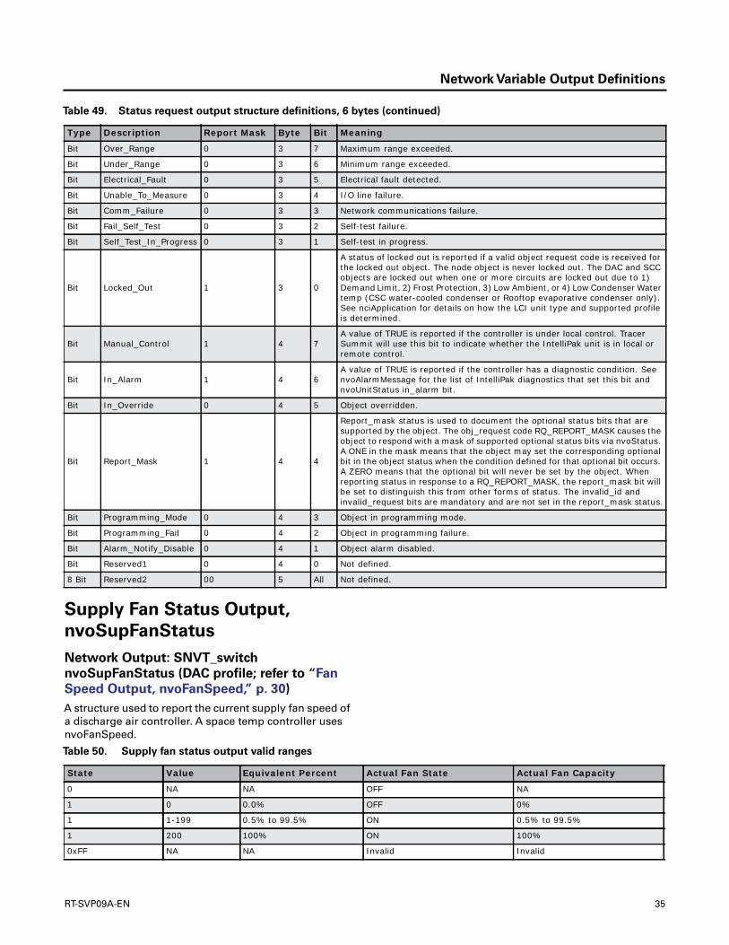
Network Variable Output Definitions
Supply Fan Status Output,
nvoSupFanStatus
Network Output: SNVT_switch
nvoSupFanStatus (DAC profile; refer to “Fan
Speed Output, nvoFanSpeed,” p. 30)
A structure used to report the current supply fan speed ofa discharge air controller. A space temp controller usesnvoFanSpeed.
Bit Over_Range 0 3 7 Maximum range exceeded.
Bit Under_Range 0 3 6 Minimum range exceeded.
Bit Electrical_Fault 0 3 5 Electrical fault detected.
Bit Unable_To_Measure 0 3 4 I/O line failure.
Bit Comm_Failure 0 3 3 Network communications failure.
Bit Fail_Self_Test 0 3 2 Self-test failure.
Bit Self_Test_In_Progress 0 3 1 Self-test in progress.
Bit Locked_Out 1 3 0
A status of locked out is reported if a valid object request code is received for the locked out object. The node object is never locked out. The DAC and SCC objects are locked out when one or more circuits are locked out due to 1) Demand Limit, 2) Frost Protection, 3) Low Ambient, or 4) Low Condenser Water temp (CSC water-cooled condenser or Rooftop evaporative condenser only). See nciApplication for details on how the LCI unit type and supported profile is determined.
Bit Manual_Control 1 4 7A value of TRUE is reported if the controller is under local control. Tracer Summit will use this bit to indicate whether the IntelliPak unit is in local or remote control.
Bit In_Alarm 1 4 6A value of TRUE is reported if the controller has a diagnostic condition. See nvoAlarmMessage for the list of IntelliPak diagnostics that set this bit and nvoUnitStatus in_alarm bit.
Bit In_Override 0 4 5 Object overridden.
Bit Report_Mask 1 4 4
Report_mask status is used to document the optional status bits that are supported by the object. The obj_request code RQ_REPORT_MASK causes the object to respond with a mask of supported optional status bits via nvoStatus. A ONE in the mask means that the object may set the corresponding optional bit in the object status when the condition defined for that optional bit occurs. A ZERO means that the optional bit will never be set by the object. When reporting status in response to a RQ_REPORT_MASK, the report_mask bit will be set to distinguish this from other forms of status. The invalid_id and invalid_request bits are mandatory and are not set in the report_mask status.
Bit Programming_Mode 0 4 3 Object in programming mode.
Bit Programming_Fail 0 4 2 Object in programming failure.
Bit Alarm_Notify_Disable 0 4 1 Object alarm disabled.
Bit Reserved1 0 4 0 Not defined.
8 Bit Reserved2 00 5 All Not defined.
Table 49. Status request output structure definitions, 6 bytes (continued)
Type Description Report Mask Byte Bit Meaning
Table 50. Supply fan status output valid ranges
State Value Equivalent Percent Actual Fan State Actual Fan Capacity
0 NA NA OFF NA
1 0 0.0% OFF 0%
1 1-199 0.5% to 99.5% ON 0.5% to 99.5%
1 200 100% ON 100%
0xFF NA NA Invalid Invalid
RT-SVP09A-EN 35

Network Variable Output Definitions
Terminal Load Output,
nvoTerminalLoad
Network Output: SNVT_lev_percent
nvoTerminalLoad (SCC and DACX profile)
Indicates the current heat/cool energy demand of the unit.Positive values indicate that cooling energy is required (or
in use) by the controller, while negative values indicatethat heating energy is required (or in use) by the controller.The actual determination of the value of nvoTerminalLoadis manufacturer-defined. One method is to typically reportthe output of the heating/cooling control algorithm.Another method is to report only the heating/coolingenergy required from a central source, such as a waterloop or air handling unit.
Unit Status Output,
nvoUnitStatus
Network Output: SNVT_hvac_status
nvoUnitStatus (SCC and DAC profile)
A structure used to report controller status.
For ReliaTel™ products, the electric heat capacity reportedin the “heat_output_primary” field is divided equallybetween the number of stages available.This may or maynot reflect the actual capacity step for a given stage.Thiswas done because of the number of variations in capacitysteps due to model number variations, line voltage,wiring, and sizes/number of heater elements. For heatpumps, heat_output_primary always reports compressorsand heat_output_secondary always reports auxiliary heat,
whether auxiliary heat comes on first or not. UnlikenvoEconEnabled, nvoUnitStatus.econ_output showspercent open (like HYPERLINK \l "nvoOADamper"nvoOADamper.) nvoEconEnabled is the enable/disablestatus of the economizer and is defined in the profile as"binary" (does not show percent.) If the economizer isenabled, it reports (1, 200). If the economizer is disabled, itreports (0, 0). If there is no economizer, it reports (0xFF, 0).
Unlike nvoEconEnabled, nvoUnitStatus.econ_outputshows percent open. Output nvoEconEnabled is theenable/disable status of the economizer and is defined inthe profile as binary (does not show percent). If theeconomizer is enabled, it reports (1, 200). If the economizeris disabled, it reports (0, 0). If there is no economizer, itreports (0xFF, 0). IntelliPak Rooftop products with a 0-25%motorized OA damper always report disabled.
When Transmitted Update Rate Default Service Type
• Significant change.• Send heartbeat
time.
• No faster than configured minimum send time.
• Send heartbeat time.
Unacknowledged.
Table 50. Supply fan status output valid ranges (continued)
State Value Equivalent Percent Actual Fan State Actual Fan Capacity
Table 51. Terminal load output valid range
Range Invalid When Transmitted Update Rate Default Service Type
-100-0% to 100.0 heating to cooling
Always invalid. Significant change. No faster than configured minimum send time.
Unacknowledged.
Table 52. Unit status output valid ranges
Type Range Description Bytes Meaning
SNVT_hvac_mode 0 = HVAC_AUTO(a)
1 = HVAC_HEAT2 = HVAC_MRNG_WRMUP3 = HVAC_COOL4 = HVAC_NIGHT_PURGE5 = HVAC_PRE_COOL6 = HVAC_OFF7 = HVAC_TEST8 = HVAC_EMERG_HEAT(a)
9 = HVAC_FAN_ONLY10 = HVAC_FREE_COOL(a)
11 = HVAC_ICE12 = HVAC_MAX_HEAT13 = HVAC_ECONOMY(a)
14 = HVAC_DEHUMID15 = HVAC_CALIBRATE(a)
0xFF = HVAC_NUL
Mode (nvoHeatCool) 1 This field reports the same value as nvoHeatCool.
SNVT_lev_percent 0% to 100%, 0x7FFF = invalid
Heat_Output_Primary 2 Status position of heat output.
36 RT-SVP09A-EN
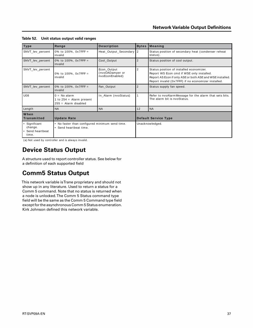
Network Variable Output Definitions
Device Status Output
A structure used to report controller status. See below fora definition of each supported field
Comm5 Status Output
This network variable isTrane proprietary and should notshow up in any literature. Used to return a status for aComm 5 command. Note that no status is returned whena node is unlocked.The Comm 5 Status command typefield will be the same as the Comm 5 Command type fieldexcept for the asynchronous Comm 5 Status enumeration.Kirk Johnson defined this network variable.
SNVT_lev_percent 0% to 100%, 0x7FFF = invalid
Heat_Output_Secondary 2 Status position of secondary heat (condenser reheat status).
SNVT_lev_percent 0% to 100%, 0x7FFF = invalid
Cool_Output 2 Status position of cool output.
SNVT_lev_percent0% to 100%, 0x7FFF = invalid
Econ_Output (nvoOADamper or nvoEconEnabled)
2 Status position of installed economizer.Report WS Econ cmd if WSE only installed.Report AS Econ if only ASE or both ASE and WSE installed. Report invalid (0x7FFF) if no economizer installed.
SNVT_lev_percent 0% to 100%, 0x7FFF = invalid
Fan_Output 2 Status supply fan speed.
U08 0 = No alarm1 to 254 = Alarm present255 = Alarm disabled
In_Alarm (nvoStatus) 1 Refer to nvoAlarmMessage for the alarm that sets bits. The alarm bit is nvoStatus.
Length NA NA 12 NA
When Transmitted Update Rate Default Service Type
• Significant change.
• Send heartbeat time.
• No faster than configured minimum send time.• Send heartbeat time.
Unacknowledged.
(a) Not used by controller and is always invalid.
Table 52. Unit status output valid ranges
Type Range Description Bytes Meaning
RT-SVP09A-EN 37

Configuration
TheTracer™ LCI-R is factory configured andcommissioned with fixed sequences of operation. All ofthe configuration parameters are predefined and loadedbased upon the configuration of the unit. Some as-builtconfiguration parameters are adjustable at the humaninterface. BothTracer™ Summit systems and theTrane
Rover ServiceTool allow access to these parameters tomake adjustments to controller operation.
The configuration parameters in theTracer™ LCI-R matchthe unit type with the control mode, cooling and heatingsources, and outdoor air damper.The control modeselects the desired unit operation. Refer to Table 53.
Table 53. Tracer™ LCI-R unit type configuration parameters
Control Mode Temperature Control
• Constant-volume• Constant-volume • VAV
• Space temperature• Discharge air• Discharge air
Table 54. Heating and cooling source
Cooling Source Heat Source Heat Type Outdoor Air Damper
None Gas Staged None
Hydronic Electric Modulating Outdoor air damper
DX coil Hot water
Steam
Table 55. Outdoor air damper
Parameter Valid range Default Value
Occupied outdoor damper minimum position 0 to 100% 15%
Occupied standby damper minimum position 0 to 100% 15%
Economizer enable temperature (dry bulb) 50°F to 140°F (10°C to 60°C) 75°F (23.9°C)
Table 56. Exhaust fan or damper
Parameter Valid Range Default Value
Exhaust fan enable setpoint (Note 1) 0 to 100% 25%
Note: The exhaust fan is energized when the outdoor air damper is equal to or greater than the exhaust fan enable setpoint. The exhaust fan is turned off when the outdoor air damper is less than the exhaust fan enable setpoint.
Table 57. Local zone sensor switch
Parameter Valid Range Default Value
Local fan/system switch Enable or disable Disable
Table 58. Space temperature setpoints
Default Setpoint Valid Range Default Value
Occupied heating setpoint 50°F to 90°F (10°C to 32.22°C) 71°F (21.67°C)
Occupied cooling setpoint 50°F to 90°F (10°C to 32.22°C) 74°F (23.33°C)
Occupied standby heating setpoint 50°F to 90°F (10°C to 32.22°C) 67°F (19.44°C)
Occupied standby cooling setpoint 50°F to 90°F (10°C to 32.22°C) 78°F (25.56°C)
Unoccupied heating setpoint 50°F to 90°F (10°C to 32.22°C) 60°F (15.56°C)
Unoccupied cooling setpoint 50°F to 90°F (10°C to 32.22°C) 85°F (29.44°C)
Heating setpoint low limit(a) 40°F to 115°F (4.44°C to 46.11°C) 40°F (4.44°C)
Cooling setpoint low limit 40°F to 115°F (4.44°C to 46.11°C) 40°F (4.44°C)
Heating setpoint high limit 40°F to 115°F (4.44°C to 46.11°C) 104°F (40°C)
38 RT-SVP09A-EN
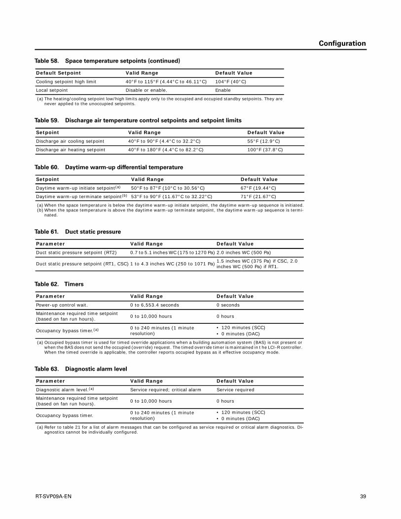
Configuration
Cooling setpoint high limit 40°F to 115°F (4.44°C to 46.11°C) 104°F (40°C)
Local setpoint Disable or enable. Enable
(a) The heating/cooling setpoint low/high limits apply only to the occupied and occupied standby setpoints. They are never applied to the unoccupied setpoints.
Table 58. Space temperature setpoints (continued)
Default Setpoint Valid Range Default Value
Table 59. Discharge air temperature control setpoints and setpoint limits
Setpoint Valid Range Default Value
Discharge air cooling setpoint 40°F to 90°F (4.4°C to 32.2°C) 55°F (12.9°C)
Discharge air heating setpoint 40°F to 180°F (4.4°C to 82.2°C) 100°F (37.8°C)
Table 60. Daytime warm-up differential temperature
Setpoint Valid Range Default Value
Daytime warm-up initiate setpoint(a) 50°F to 87°F (10°C to 30.56°C) 67°F (19.44°C)
Daytime warm-up terminate setpoint(b) 53°F to 90°F (11.67°C to 32.22°C) 71°F (21.67°C)
(a) When the space temperature is below the daytime warm-up initiate setpoint, the daytime warm-up sequence is initiated.(b) When the space temperature is above the daytime warm-up terminate setpoint, the daytime warm-up sequence is termi-
nated.
Table 61. Duct static pressure
Parameter Valid Range Default Value
Duct static pressure setpoint (RT2) 0.7 to 5.1 inches WC (175 to 1270 Pa) 2.0 inches WC (500 Pa)
Duct static pressure setpoint (RT1, CSC) 1 to 4.3 inches WC (250 to 1071 Pa) 1.5 inches WC (375 Pa) if CSC, 2.0 inches WC (500 Pa) if RT1.
Table 62. Timers
Parameter Valid Range Default Value
Power-up control wait. 0 to 6,553.4 seconds 0 seconds
Maintenance required time setpoint (based on fan run hours). 0 to 10,000 hours 0 hours
Occupancy bypass timer.(a) 0 to 240 minutes (1 minute resolution)
• 120 minutes (SCC)• 0 minutes (DAC)
(a) Occupied bypass timer is used for timed override applications when a building automation system (BAS) is not present or when the BAS does not send the occupied (override) request. The timed override timer is maintained in t he LCI-R controller. When the timed override is applicable, the controller reports occupied bypass as it effective occupancy mode.
Table 63. Diagnostic alarm level
Parameter Valid Range Default Value
Diagnostic alarm level.(a) Service required; critical alarm Service required
Maintenance required time setpoint (based on fan run hours). 0 to 10,000 hours 0 hours
Occupancy bypass timer. 0 to 240 minutes (1 minute resolution)
• 120 minutes (SCC)• 0 minutes (DAC)
(a) Refer to table 21 for a list of alarm messages that can be configured as service required or critical alarm diagnostics. Di-agnostics cannot be individually configured.
RT-SVP09A-EN 39
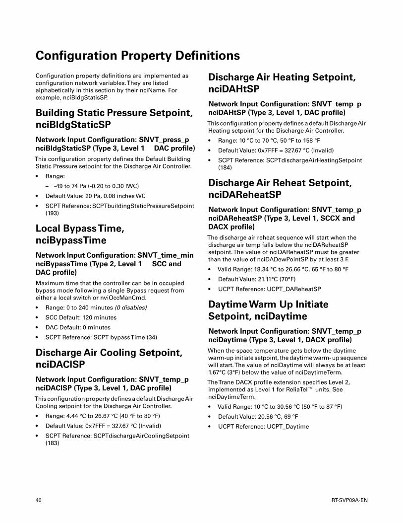
Configuration Property Definitions
Configuration property definitions are implemented asconfiguration network variables.They are listedalphabetically in this section by their nciName. Forexample, nciBldgStatisSP.
Building Static Pressure Setpoint,
nciBldgStaticSP
Network Input Configuration: SNVT_press_p
nciBldgStaticSP (Type 3, Level 1 DAC profile)
This configuration property defines the Default BuildingStatic Pressure setpoint for the Discharge Air Controller.
• Range:
– -49 to 74 Pa (-0.20 to 0.30 IWC)
• Default Value: 20 Pa, 0.08 inches WC
• SCPT Reference: SCPTbuildingStaticPressureSetpoint(193)
Local BypassTime,
nciBypassTime
Network Input Configuration: SNVT_time_min
nciBypassTime (Type 2, Level 1 SCC and
DAC profile)
Maximum time that the controller can be in occupiedbypass mode following a single Bypass request fromeither a local switch or nviOccManCmd.
• Range: 0 to 240 minutes (0 disables)
• SCC Default: 120 minutes
• DAC Default: 0 minutes
• SCPT Reference: SCPT bypassTime (34)
Discharge Air Cooling Setpoint,
nciDAClSP
Network Input Configuration: SNVT_temp_p
nciDAClSP (Type 3, Level 1, DAC profile)
This configuration property defines a default DischargeAirCooling setpoint for the Discharge Air Controller.
• Range: 4.44 °C to 26.67 °C (40 °F to 80 °F)
• Default Value: 0x7FFF = 327.67 °C (Invalid)
• SCPT Reference: SCPTdischargeAirCoolingSetpoint(183)
Discharge Air Heating Setpoint,
nciDAHtSP
Network Input Configuration: SNVT_temp_p
nciDAHtSP (Type 3, Level 1, DAC profile)
This configuration property defines a default DischargeAirHeating setpoint for the Discharge Air Controller.
• Range: 10 °C to 70 °C, 50 °F to 158 °F
• Default Value: 0x7FFF = 327.67 °C (Invalid)
• SCPT Reference: SCPTdischargeAirHeatingSetpoint(184)
Discharge Air Reheat Setpoint,
nciDAReheatSP
Network Input Configuration: SNVT_temp_p
nciDAReheatSP (Type 3, Level 1, SCCX and
DACX profile)
The discharge air reheat sequence will start when thedischarge air temp falls below the nciDAReheatSPsetpoint.The value of nciDAReheatSP must be greaterthan the value of nciDADewPointSP by at least 3 F.
• Valid Range: 18.34 °C to 26.66 °C, 65 °F to 80 °F
• Default Value: 21.11°C (70°F)
• UCPT Reference: UCPT_DAReheatSP
Daytime Warm Up Initiate
Setpoint, nciDaytime
Network Input Configuration: SNVT_temp_p
nciDaytime (Type 3, Level 1, DACX profile)
When the space temperature gets below the daytimewarm-up initiate setpoint, the daytime warm- up sequencewill start.The value of nciDaytime will always be at least1.67°C (3°F) below the value of nciDaytimeTerm.
TheTrane DACX profile extension specifies Level 2,implemented as Level 1 for ReliaTel™ units. SeenciDaytimeTerm.
• Valid Range: 10 °C to 30.56 °C (50 °F to 87 °F)
• Default Value: 20.56 °C, 69 °F
• UCPT Reference: UCPT_Daytime
40 RT-SVP09A-EN

Configuration Property Definitions
Daytime Warm UpTermination
Setpoint, nciDaytimeTerm
Network Input Configuration: SNVT_temp_p
nciDaytimeTerm (Type 3, Level 1, DACX profile)
When the space temperature gets above the daytimewarm-up termination setpoint, the daytime warm-upsequence will end.The value of nciDaytimeTerm willalways be at least 1.67ºC (3ºF) above the value ofnciDaytime.
• Valid Range: 4.44°C, 10°C to 30.56°C, 40°F, 50°F to 87°F
• Default Value: 20.56 °C, 69 °F
• UCPT Reference: UCPT_DaytimeTerm
Device Build Version Number,
nciDevBuildNum
Network Input Configuration: unsigned int
nciDevBuildNum (Type 1, Level 1, Node Ex
profile)
This configuration property defines the build versionnumber for the device and is read-only. It cannot bewritten.
• SCPT: UCPTdevBuildNum
• SCPT Index: U16
• Valid Range: 0 - 65536
• Default Value: 2
Device Major Version Number,
nciDevMajVer
Network Input Configuration: unsigned short
nciDevMajVer (Type 1, Level 1, Node profile)
This configuration property defines the major versionnumber for the device and is read-only. It cannot bewritten.This number stays in sync with the SPID.Thisnumber is the same for all nodes with the same SPID.
• SCPT: UCPTdevMajVer
• SCPT Index: 165
• Valid Range: 0 - 255
• Default Value: 6
Device Config Choices
A structure used to define theTrane Node Object. Not allof the fields in this structure are defined. One two bitenumeration field is defined and it is used to configure theTrane alarm level on diagnostics that support alarm levelconfiguration. Diagnostics that support alarm levelconfiguration are treated as a group and not individually.
This does not change the controllers reaction to adiagnostic, only the ASCII string in nvoAlarmMessage.
Device Minor Version Number,
nciDevMinVer
Network Input Configuration: unsigned short
nciDevMinVer (Type 1, Level 1, Node profile)
This configuration property defines the minor versionnumber for the device and is read-only. It cannot bewritten. It matches the application software part numberextension.
• Valid Range: 0 - 255
• Default Value: 0
• SCPT: UCPTdevMinVer
• SCPT Index: 166
Duct Static Pressure Setpoint,
nciDuctStatSP
Network Input Configuration: SNVT_press_p
nciDuctStatSP (Type 3, Level 1, DAC profile)
This configuration property defines a default Duct StaticPressure setpoint for the Discharge Air Controller.
• Range:
– 0 Pa to 625 Pa, 0.0 to 2.5 IWC
– Default: 375 Pa, 1.5 IWC
• SCPT Reference: SCPTductStaticPressureSetpoint(189)
Econ and VentilationType
This configuration property is not used by the controllerfor any purpose. It is used to identify the type ofeconomizer or ventilation system that is being controlled.The EconomizerVentilationType can be polled by a tool oran operator interface device, to help the user identify thetype of equipment.
UCPT Reference, UCPT_OA_type
Valid RangeThe following economizer or ventilationsystems can be selected.
Table 64. enumerations and descriptions
enum Description
0 none or not supported (default)
1 2 position ventilation
2 airside (modulating) economizer
3 2 position ventilation and waterside economizer
4 waterside economizer
5 airside and waterside economizer
6 TRAQ damper/sensor
RT-SVP09A-EN 41

Configuration Property Definitions
Note: Highlighted enumerations are not used by thecontroller.This configuration property is initiallyloaded with the correct value and no furtherupdates are made by the controller. Its value isignored by the controller and has no effect on itsoperation. It cannot be written, but can be polled.
Exhaust Enable Position,
nciExhaustConfig
Network Input Configuration:
SNVT_lev_percent nciExhaustConfig (Type 3,
Level 1, SCCX profile; refer to “Exhaust Enable
Position, nciExhStartPos” )
Defines the exhaust enable outdoor air damper positionsetpoint for a space temp controller. A discharge aircontroller uses nciExhStartPos.
IntelliPak products ignore values greater than 100% (101%does not disable exhaust)
• Typical Range: 0% to 101%, 101% disables
• Default Value: 25%
• UCPT Reference: UCPT_exhaust_cfg
Exhaust Enable Position,
nciExhStartPos
Network Input Configuration:
SNVT_lev_percent nciExhStartPos (Type 3,
Level 1, DAC profile; refer to “Exhaust Enable
Position, nciExhaustConfig” )
Defines the exhaust enable outdoor air damper positionsetpoint for a discharge air controller. A space tempcontroller uses nciExhaustConfig
IntelliPak products ignore values greater than 100% (101%does not disable exhaust)
• Range: 0% to 101% (101% disables)
• Default Value: 25%
• SCPT Reference: SCPTexhaustEnablePosition (202)
Exhaust AND/OR Return Fan/
Damper Identifier
This configuration property is not used by the controllerfor any purpose. It is used to identify the type of exhaustor return system that is being controlled.The Exhaust and/or Return Fan/DamperType can be polled by a tool or anoperator interface device, to help the user identify the typeof equipment.
For ReliaTel™ products with modulating exhaust, amodulating damper enumeration is always reportedbecause the same analog output is used to control eithera modulating damper or a VFD and the controls were notdesigned to differentiate between the two. If aneconomizer is installed, an exhaust fan output is present,but there is not enough configuration information todetermine if an exhaust fan is installed. Generally,Precedent products do not have an exhaust fan.The usercan change this with a service tool (Rover), if desired.Changing this variable affects HYPERLINK \l"nvoExhFanStatus" nvoExhFanStatus.
If an economizer is not installed, then nciExhRet reportsnone, and the user cannot modify. If an economizer isinstalled and power exhaust is not installed, the user mayselect none or 1 speed exhaust fan. If an economizer andpower exhaust are installed, then nciExhRet reports 1speed exhaust fan with modulating exaust damper andthe user cannot modify.
Fan Configuration Input
This configuration variable is a structure used to define thefan configuration. Separate configuration exists for thesupply fan during heating and the supply fan duringcooling.
HVAC UnitType Identifier,
nciHvacType
Network Input Configuration:
SNVT_hvac_type nciHvacType (Type 1, Level
255, SCC and DACX profile)
This configuration property is not used by the controllerfor any purpose. It is used to identify the type of HVAC unitthat is being controlled. Although the HVAC UnitType canbe read via the network, typically, it should not bechanged.The configuration property SCPThvacTypeshould be declared using the device_specific_flg so that itcan be protected by the network configuration tool toavoid inadvertent modification in the field by the installer.In addition, the use of device_specific_flg allows devices tohave a common *.XIF file, where the only networkinterface difference is the value of this configurationproperty. If it is changed, the user must verify theapplication for the selected HVAC UnitType.
7 airside economizer and TRAQ damper/sensor
8 TRAQ damper/sensor and waterside economizer
9 airside economizer, TRAQ damper/sensor and waterside economizer
10 to 255 None
Table 64. enumerations and descriptions (continued)
enum Description
42 RT-SVP09A-EN
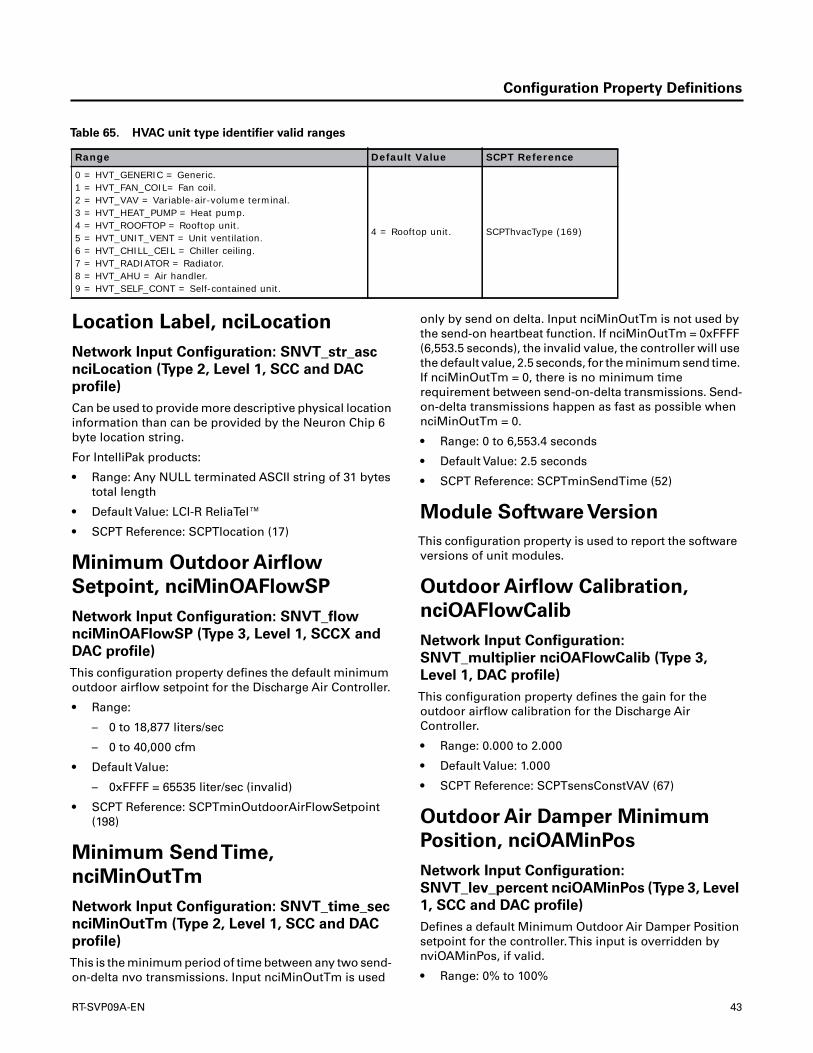
Configuration Property Definitions
Location Label, nciLocation
Network Input Configuration: SNVT_str_asc
nciLocation (Type 2, Level 1, SCC and DAC
profile)
Can be used to provide more descriptive physical locationinformation than can be provided by the Neuron Chip 6byte location string.
For IntelliPak products:
• Range: Any NULL terminated ASCII string of 31 bytestotal length
• Default Value: LCI-R ReliaTel™
• SCPT Reference: SCPTlocation (17)
Minimum Outdoor Airflow
Setpoint, nciMinOAFlowSP
Network Input Configuration: SNVT_flow
nciMinOAFlowSP (Type 3, Level 1, SCCX and
DAC profile)
This configuration property defines the default minimumoutdoor airflow setpoint for the Discharge Air Controller.
• Range:
– 0 to 18,877 liters/sec
– 0 to 40,000 cfm
• Default Value:
– 0xFFFF = 65535 liter/sec (invalid)
• SCPT Reference: SCPTminOutdoorAirFlowSetpoint(198)
Minimum SendTime,
nciMinOutTm
Network Input Configuration: SNVT_time_sec
nciMinOutTm (Type 2, Level 1, SCC and DAC
profile)
This is the minimum period of time between any two send-on-delta nvo transmissions. Input nciMinOutTm is used
only by send on delta. Input nciMinOutTm is not used bythe send-on heartbeat function. If nciMinOutTm = 0xFFFF(6,553.5 seconds), the invalid value, the controller will usethe default value, 2.5 seconds, for the minimum send time.If nciMinOutTm = 0, there is no minimum timerequirement between send-on-delta transmissions. Send-on-delta transmissions happen as fast as possible whennciMinOutTm = 0.
• Range: 0 to 6,553.4 seconds
• Default Value: 2.5 seconds
• SCPT Reference: SCPTminSendTime (52)
Module Software Version
This configuration property is used to report the softwareversions of unit modules.
Outdoor Airflow Calibration,
nciOAFlowCalib
Network Input Configuration:
SNVT_multiplier nciOAFlowCalib (Type 3,
Level 1, DAC profile)
This configuration property defines the gain for theoutdoor airflow calibration for the Discharge AirController.
• Range: 0.000 to 2.000
• Default Value: 1.000
• SCPT Reference: SCPTsensConstVAV (67)
Outdoor Air Damper Minimum
Position, nciOAMinPos
Network Input Configuration:
SNVT_lev_percent nciOAMinPos (Type 3, Level
1, SCC and DAC profile)
Defines a default Minimum Outdoor Air Damper Positionsetpoint for the controller.This input is overridden bynviOAMinPos, if valid.
• Range: 0% to 100%
Table 65. HVAC unit type identifier valid ranges
Range Default Value SCPT Reference
0 = HVT_GENERIC = Generic.1 = HVT_FAN_COIL= Fan coil.2 = HVT_VAV = Variable-air-volume terminal.3 = HVT_HEAT_PUMP = Heat pump.4 = HVT_ROOFTOP = Rooftop unit.5 = HVT_UNIT_VENT = Unit ventilation.6 = HVT_CHILL_CEIL = Chiller ceiling.7 = HVT_RADIATOR = Radiator.8 = HVT_AHU = Air handler.9 = HVT_SELF_CONT = Self-contained unit.
4 = Rooftop unit. SCPThvacType (169)
RT-SVP09A-EN 43
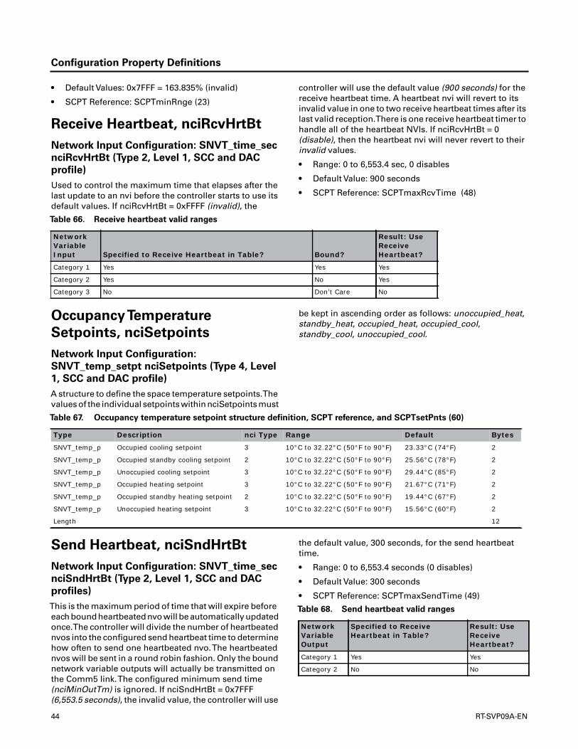
Configuration Property Definitions
• Default Values: 0x7FFF = 163.835% (invalid)
• SCPT Reference: SCPTminRnge (23)
Receive Heartbeat, nciRcvHrtBt
Network Input Configuration: SNVT_time_sec
nciRcvHrtBt (Type 2, Level 1, SCC and DAC
profile)
Used to control the maximum time that elapses after thelast update to an nvi before the controller starts to use itsdefault values. If nciRcvHrtBt = 0xFFFF (invalid), the
controller will use the default value (900 seconds) for thereceive heartbeat time. A heartbeat nvi will revert to itsinvalid value in one to two receive heartbeat times after itslast valid reception.There is one receive heartbeat timer tohandle all of the heartbeat NVIs. If nciRcvHrtBt = 0(disable), then the heartbeat nvi will never revert to theirinvalid values.
• Range: 0 to 6,553.4 sec, 0 disables
• Default Value: 900 seconds
• SCPT Reference: SCPTmaxRcvTime (48)
OccupancyTemperature
Setpoints, nciSetpoints
Network Input Configuration:
SNVT_temp_setpt nciSetpoints (Type 4, Level
1, SCC and DAC profile)
A structure to define the space temperature setpoints.Thevalues of the individual setpoints within nciSetpoints must
be kept in ascending order as follows: unoccupied_heat,standby_heat, occupied_heat, occupied_cool,standby_cool, unoccupied_cool.
Send Heartbeat, nciSndHrtBt
Network Input Configuration: SNVT_time_sec
nciSndHrtBt (Type 2, Level 1, SCC and DAC
profiles)
This is the maximum period of time that will expire beforeeach bound heartbeated nvo will be automatically updatedonce.The controller will divide the number of heartbeatednvos into the configured send heartbeat time to determinehow often to send one heartbeated nvo.The heartbeatednvos will be sent in a round robin fashion. Only the boundnetwork variable outputs will actually be transmitted onthe Comm5 link.The configured minimum send time(nciMinOutTm) is ignored. If nciSndHrtBt = 0x7FFF(6,553.5 seconds), the invalid value, the controller will use
the default value, 300 seconds, for the send heartbeattime.
• Range: 0 to 6,553.4 seconds (0 disables)
• Default Value: 300 seconds
• SCPT Reference: SCPTmaxSendTime (49)
Table 66. Receive heartbeat valid ranges
Network Variable Input Specified to Receive Heartbeat in Table? Bound?
Result: Use Receive Heartbeat?
Category 1 Yes Yes Yes
Category 2 Yes No Yes
Category 3 No Don’t Care No
Table 67. Occupancy temperature setpoint structure definition, SCPT reference, and SCPTsetPnts (60)
Type Description nci Type Range Default Bytes
SNVT_temp_p Occupied cooling setpoint 3 10°C to 32.22°C (50°F to 90°F) 23.33°C (74°F) 2
SNVT_temp_p Occupied standby cooling setpoint 2 10°C to 32.22°C (50°F to 90°F) 25.56°C (78°F) 2
SNVT_temp_p Unoccupied cooling setpoint 3 10°C to 32.22°C (50°F to 90°F) 29.44°C (85°F) 2
SNVT_temp_p Occupied heating setpoint 3 10°C to 32.22°C (50°F to 90°F) 21.67°C (71°F) 2
SNVT_temp_p Occupied standby heating setpoint 2 10°C to 32.22°C (50°F to 90°F) 19.44°C (67°F) 2
SNVT_temp_p Unoccupied heating setpoint 3 10°C to 32.22°C (50°F to 90°F) 15.56°C (60°F) 2
Length 12
Table 68. Send heartbeat valid ranges
Network Variable Output
Specified to Receive Heartbeat in Table?
Result: Use Receive Heartbeat?
Category 1 Yes Yes
Category 2 No No
44 RT-SVP09A-EN
Configuration Property Definitions
Space CO2 Limit,
nciSpaceCO2Lim
Network Input Configuration: SNVT_ppm
nciSpaceCO2Lim (Type 3, Level 1, SCC profile)
Defines a high limit CO2 setpoint for the controlled space.The controller ventilation functions, in response to thislimit, are manufacturer defined.
For ReliaTel™ products that provide a Demand ControlVentilation function, nciSpaceCO2Lim correlates to theDefault Design Minimum CO2 Setpoint, which defines theCO2 level which opens theTRAQ dampers to the DesignMinimum OA Flow Setpoint (for units withTRAQs) oropens the OA Damper to the Design Minimum OA DamperSetpoint (for units withoutTRAQs.)
Except for zero, which disables DCV, nciSpaceCO2Limcannot be set lower than 500 ppm, or lower thannciSpaceCO2LowLm + 100 ppm or greater than 2000 ppm.
• Range: 150 to 2,000 ppm (0 disables)
• Default Value: 1,000 ppm
• SCPT Reference: SCPTlimitCO2 (42)
Device Personality
A structure to define the general application.
For ReliaTel™ products, the language identifier controlsthe language of the string returned in nvoAlarmMessage.
PreheatType Identifier
This configuration property is not used by the controllerfor any purpose. It is used to identify the type of primaryheat that is being controlled.The PreheatType can bepolled by a tool or an operator interface device, to help theuser identify the type of equipment.
For ReliaTel™ heat pump products, modulating electric,modulating gas and modulating hydronic heat can beconfigured as the first stage of heat. In theseconfigurations, DX heating is considered secondary heat.
Space CO2 Low Limit
Defines a low limit CO2 setpoint for the controlled space.The controller ventilation functions, in response to thislimit, are manufacturer defined.
For ReliaTel™ products, withTRAQ sensors, that providea CO2 Reset function, nciSpaceCO2LowLm correlates tothe CO2 Reset Start setpoint, which defines the CO2 levelwhich provides no reset (increase) to the Minimum OACFM setpoint.
For ReliaTel™ products that provide a Demand ControlVentilation function, nciSpaceCO2LowLmcorrelates to theDefault DCV Minimum CO2 Setpoint, which defines theCO2 level which closes theTRAQ dampers to the DCV
Minimum OA Flow Setpoint (for units withTRAQs) orcloses the OA Damper to the DCV Minimum OA DamperSetpoint (for units withoutTRAQs.)
nciSpaceCO2LowLm can not be set lower than 300 ppm,or greater than nciSpaceCO2Lim - 100 ppm or greater than1900 ppm.
• Range: 50 to 1900 ppm
• Default Value: 800 ppm
• SCPT Reference: SCPTlimitCO2 (42)
OccupancyTemp Setpoint
A structure to define the space temperature setpoints.Thevalues of the individual setpoints within nciSetpoints mustbe kept in ascending order as follows: unoccupied_heat £standby_heat £ occupied_heat £ occupied_cool £standby_cool £ unoccupied_cool.
See HYPERLINK \l "nvoEffectSetpt" nvoEffectSetpt forSCC implementation details.
ReheatType Identifier
This configuration property is not used by the controllerfor any purpose. It is used to identify the type of secondaryheat that is being controlled.The ReheatType can bepolled by a tool or an operator interface device, to help theuser identify the type of equipment.
For ReliaTel™ heat pump products, modulating electric,modulating gas and modulating hydronic heat can beconfigured as the first stage of heat. In theseconfigurations, DX heating is considered secondary heat.
Valid Range
The following reheat types can be selected. Enumerationsless than 128 are upstream of the supply fan, drawthrough. Enumerations greater than 128 are down streamof the supply fan, blow through.
Space Dehumidification Setpoint,
nciSpaceDehumSP
Network Input Configuration:
SNVT_lev_percent nciSpaceDehumSP (Type 3,
Level 1, DAC profile; see nciSpaceRHSetpt)
This configuration property defines the default spacedehumidification setpoint for the Discharge Air Controller.
• Range: 40% to 65% (RT)
• Default Value: 60%
• SCPT Reference: SCPThumSetpt (36)
RT-SVP09A-EN 45
Configuration Property Definitions
Space Humidity Setpoint,
nciSpaceRHSetpt
Network Input Configuration:
SNVT_lev_percent nciSpaceRHSetpt (Type 3,
Level 1, SCC profile; see nciSpaceDehumSP)
This configuration property defines a high humiditysetpoint for the controlled space.The controllerdehumidification functions, in response to this limit, aredefined by the manufacturer.
• Range: 40 to 65%
• Default Value: 60%
• SCPT Reference: SCPThumSetpt (36)
Supply FanType Identifier
This configuration property is not used by the controllerfor any purpose. It is used to identify the type of supply fanthat is being controlled.The Supply FanType can be polledby a tool or an operator interface device, to help the useridentify the type of equipment.
46 RT-SVP09A-EN

Operation Modes and General Information
This section provides operation modes and generalinformation about theTracer™ LCI-R.
Operation Modes
Temperature Control Modes
TheTracer™ LCI-R can be configured to operate in thefollowing temperature control modes:
• Constant-volume (CV) space temperature control(SCC)
• Constant-volume (CV) discharge air temperaturecontrol (DAC)
• Variable-air-volume (VAV) discharge air temperaturecontrol (DAC)
Constant-Volume SpaceTemperature Control
(Cascade Control) (SCC)
For this type of control, theTracer™ LCI-R requires both aspace-temperature and discharge-air-temperature sensor.In this control mode, the controller compares the spacetemperature to the space heat/cool setpoint to generate adischarge air temperature setpoint.The controllermodulates its heating or cooling outputs to control thedischarge air temperature to the discharge air temperaturesetpoint.This calculated discharge air temperaturesetpoint is the desired discharge air temperature (supplyair temperature) that the unit must deliver to maintainspace temperature at the space heating or coolingsetpoint.
The space temperature can be hard wired to the RTRMmodule ZoneTemp input (only 10 kW thermistor) or can becommunicated to the controller using LonTalk®. Similarly,cooling and/or heating setpoint(s) can be provided by ahard wired zone sensor, a night setback panel, a LonTalk®communicated value, or by using the stored defaultsetpoints in the controller.
The discharge air temperature must be a hard wiredanalog input to the RTRM module (only 10 kW thermistor).
Constant-Volume Discharge AirTemperature
Control (DAC)
For this type of control, theTracer™ LCI-R requires only adischarge air sensor (only 10 kW thermistor) to operate.This control mode modulates the heating or coolingoutputs to maintain the discharge air temperature at thedischarge air temperature setpoint.
Variable-Air-Volume (VAV) Discharge Air
Control (DAC)
For this type of control, theTracer™ LCI-R maintains adischarge air temperature according to the cool/heatdischarge air setpoint, and duct static pressure at the ductstatic pressure setpoint.The controller maintains duct
static pressure by modulating the supply fan inlet guidevanes (IGV) or the variable frequency drive (VFD).
Occupancy Modes
Active heating and cooling setpoints are affected by theoccupancy mode of the controller.The controlleroccupancy mode is determined by either a hard wiredinput (such as a zone sensor, night setback panel, orchangeover switch) or by a communicated request (suchas from a system-level controller or another peercontroller).
A stand-alone controller uses the binary input to switchbetween occupied and unoccupied. For peer-to-peerapplications, refer to the section, “Peer-to-peerCommunication,” p. 51.
Valid Occupancy Modes
The valid occupancy modes of theTracer™ LCI-R are:
Occupied
Normal operating mode for occupied spaces or daytimeoperation.
Unoccupied
Normal operating mode for unoccupied spaces ornighttime operation.
Occupied Standby
Constant-volume mode used to reduce the heating andcooling demands during the occupied hours when thespace is vacant or unoccupied. For example, the controllermay use occupied standby mode for a classroom while thestudents are out of the room.
Occupied Bypass
The mode used for timed override conditions. Forexample, if the controller is in unoccupied mode andsomeone presses the ON button on the zone sensor ornight setback panel, the controller is placed in occupiedbypass mode for 120 minutes (adjustable) or untilsomeone presses the Cancel button on the zone sensor.
Determining the Occupancy Mode
The occupancy of the controller is determined byevaluating the combination of three potentialcommunicating inputs, as well as the hard wiredoccupancy input and the occupied bypass timer.Thefollowing three communicating inputs affect the controlleroccupancy mode. Maximum flexibility is provided byhaving all three of these inputs; however, the number thatyou use varies with the application and the featuresavailable in your building automation system. Refer toTable 69, p. 48.
RT-SVP09A-EN 47
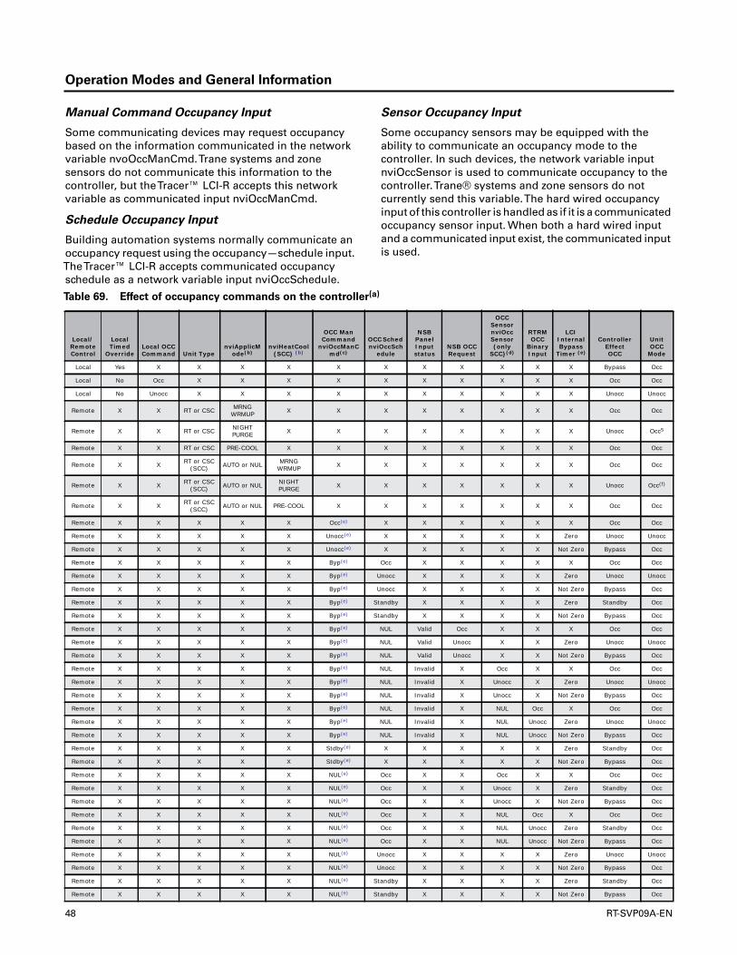
Operation Modes and General Information
Manual Command Occupancy Input
Some communicating devices may request occupancybased on the information communicated in the networkvariable nvoOccManCmd.Trane systems and zonesensors do not communicate this information to thecontroller, but theTracer™ LCI-R accepts this networkvariable as communicated input nviOccManCmd.
Schedule Occupancy Input
Building automation systems normally communicate anoccupancy request using the occupancy—schedule input.TheTracer™ LCI-R accepts communicated occupancyschedule as a network variable input nviOccSchedule.
Sensor Occupancy Input
Some occupancy sensors may be equipped with theability to communicate an occupancy mode to thecontroller. In such devices, the network variable inputnviOccSensor is used to communicate occupancy to thecontroller.Trane® systems and zone sensors do notcurrently send this variable.The hard wired occupancyinput of this controller is handled as if it is a communicatedoccupancy sensor input. When both a hard wired inputand a communicated input exist, the communicated inputis used.
Table 69. Effect of occupancy commands on the controller(a)
Local/Remote Control
Local Timed
OverrideLocal OCCCommand Unit Type
nviApplicMode(b)
nviHeatCool (SCC) (b)
OCC Man Command
nviOccManCmd(c)
OCC Sched nviOccSch
edule
NSB Panel Input status
NSB OCC Request
OCC Sensor nviOccSensor (only
SCC)(d)
RTRMOCC
Binary Input
LCI Internal Bypass
Timer (e)
Controller EffectOCC
Unit OCC
Mode
Local Yes X X X X X X X X X X X Bypass Occ
Local No Occ X X X X X X X X X X Occ Occ
Local No Unocc X X X X X X X X X X Unocc Unocc
Remote X X RT or CSC MRNG WRMUP X X X X X X X X Occ Occ
Remote X X RT or CSC NIGHT PURGE X X X X X X X X Unocc Occ5
Remote X X RT or CSC PRE-COOL X X X X X X X X Occ Occ
Remote X X RT or CSC (SCC) AUTO or NUL MRNG
WRMUP X X X X X X X Occ Occ
Remote X X RT or CSC (SCC) AUTO or NUL NIGHT
PURGE X X X X X X X Unocc Occ(f)
Remote X X RT or CSC (SCC) AUTO or NUL PRE-COOL X X X X X X X Occ Occ
Remote X X X X X Occ(e) X X X X X X Occ Occ
Remote X X X X X Unocc(e) X X X X X Zero Unocc Unocc
Remote X X X X X Unocc(e) X X X X X Not Zero Bypass Occ
Remote X X X X X Byp(e) Occ X X X X X Occ Occ
Remote X X X X X Byp(e) Unocc X X X X Zero Unocc Unocc
Remote X X X X X Byp(e) Unocc X X X X Not Zero Bypass Occ
Remote X X X X X Byp(e) Standby X X X X Zero Standby Occ
Remote X X X X X Byp(e) Standby X X X X Not Zero Bypass Occ
Remote X X X X X Byp(e) NUL Valid Occ X X X Occ Occ
Remote X X X X X Byp(e) NUL Valid Unocc X X Zero Unocc Unocc
Remote X X X X X Byp(e) NUL Valid Unocc X X Not Zero Bypass Occ
Remote X X X X X Byp(e) NUL Invalid X Occ X X Occ Occ
Remote X X X X X Byp(e) NUL Invalid X Unocc X Zero Unocc Unocc
Remote X X X X X Byp(e) NUL Invalid X Unocc X Not Zero Bypass Occ
Remote X X X X X Byp(e) NUL Invalid X NUL Occ X Occ Occ
Remote X X X X X Byp(e) NUL Invalid X NUL Unocc Zero Unocc Unocc
Remote X X X X X Byp(e) NUL Invalid X NUL Unocc Not Zero Bypass Occ
Remote X X X X X Stdby(e) X X X X X Zero Standby Occ
Remote X X X X X Stdby(e) X X X X X Not Zero Bypass Occ
Remote X X X X X NUL(e) Occ X X Occ X X Occ Occ
Remote X X X X X NUL(e) Occ X X Unocc X Zero Standby Occ
Remote X X X X X NUL(e) Occ X X Unocc X Not Zero Bypass Occ
Remote X X X X X NUL(e) Occ X X NUL Occ X Occ Occ
Remote X X X X X NUL(e) Occ X X NUL Unocc Zero Standby Occ
Remote X X X X X NUL(e) Occ X X NUL Unocc Not Zero Bypass Occ
Remote X X X X X NUL(e) Unocc X X X X Zero Unocc Unocc
Remote X X X X X NUL(e) Unocc X X X X Not Zero Bypass Occ
Remote X X X X X NUL(e) Standby X X X X Zero Standby Occ
Remote X X X X X NUL(e) Standby X X X X Not Zero Bypass Occ
48 RT-SVP09A-EN

Operation Modes and General Information
Remote X X X X X NUL(e) NUL Valid Occ Occ X X Occ Occ
Remote X X X X X NUL(e) NUL Valid Occ Unocc X Zero Standby Occ
Remote X X X X X NUL(e) NUL Valid Occ Unocc X Not Zero Bypass Occ
Remote X X X X X NUL(e) NUL Valid Occ NUL Occ X Occ Occ
Remote X X X X X NUL(e) NUL Valid Occ NUL Unocc Zero Standby Occ
Remote X X X X X NUL(e) NUL Valid Occ NUL Unocc Not Zero Bypass Occ
Remote X X X X X NUL(e) NUL Valid Unocc X X Zero Unocc Unocc
Remote X X X X X NUL(e) NUL Valid Unocc X X Not Zero Bypass Occ
Remote X X X X X NUL(e) NUL Invalid X Occ X X Occ Occ
Remote X X X X X NUL(e) NUL Invalid X Unocc X Zero Unocc Unocc
Remote X X X X X NUL(e) NUL Invalid X Unocc X Not Zero Bypass Occ
Remote X X X X X NUL(e) NUL Invalid X NUL Occ X Occ Occ
Remote X X X X X NUL(e) NUL Invalid X NUL Unocc Zero Unocc Unocc
Remote X X X X X NUL(e) NUL Invalid X NUL Unocc Not Zero Bypass Occ
(a) X in any of the table fields denotes any state.(b) If nviApplicMode or nviHeatCool equals HVAC_MRNG_WRMUP, HVAC_NIGHT_PURGE, or HVAC_PRE_COOL, each has higher priority than
nviOccManCmd, nviOccSchedule, nviOccSensor or any local unit occupancy input. This is because the unit must be in occupied mode to perform the desired functions (such as space pressure control).
(c) There is no time out for nviOccManCmd. It is not heartbeated. The value of nviOccManCmd is lost when power is lost, nviOccManCmd = NUL when power returns. The nviOccManCmd enumerations of unoccupied and standby can be bypassed. Pushing the zone sensor module timed override ON button can change the effective occupancy from unoccupied or standby to bypass.
(d) The nviOccSensor is only SCC. The DAC profile uses the NUL rows in this column.(e) The bypass timer is set to the value in nciBypassTime every time one of the following occurs:
1) Receive nviOccManCmd = bypass2) Receive timed override ON request from the local zone sensor moduleAfter the bypass timer is set to nciBypassTime, it counts down to zero. The bypass timer is cleared to zero every time one of the following occurs:1) Receive nviOccManCmd = occupied, unoccupied, standby, NUL, or undefined2) Receive timed override CANCEL request from the local zone sensor moduleTo disable the network bypass timer, set nciBypassTime to zero. This disables the nviOccManCmd and nviOccSchedule OC_BYPASS enumeration. This does not disable the local bypass timer that is used by the zone sensor with timed override button, which is hard-coded to be three hours. However, if nciBypassTime is set to zero and either nviOccManCmd or nviOccSchedule are set to OC_BYPASS, the local zone sensor timed override button is disabled. If nciBypassTime is set to zero, it does not disable the TOV Request or TOV Cancel Request in nvoTraneVar7.
(f) When nviApplicMode = HVAC_NIGHT_PURGE, nviOccSchedule, and nviOccSensor are ignored, nvoEffectOccup reports OC_UNOCCUPIED, and the human interface reports occupied. This was necessary because all Intellipak DAC products must be in occupied mode to do discharge air control with duct static pressure control.
Table 69. Effect of occupancy commands on the controller(a) (continued)
Local/Remote Control
Local Timed
OverrideLocal OCCCommand Unit Type
nviApplicMode(b)
nviHeatCool (SCC) (b)
OCC Man Command
nviOccManCmd(c)
OCC Sched nviOccSch
edule
NSB Panel Input status
NSB OCC Request
OCC Sensor nviOccSensor (only
SCC)(d)
RTRMOCC
Binary Input
LCI Internal Bypass
Timer (e)
Controller EffectOCC
Unit OCC
Mode
RT-SVP09A-EN 49
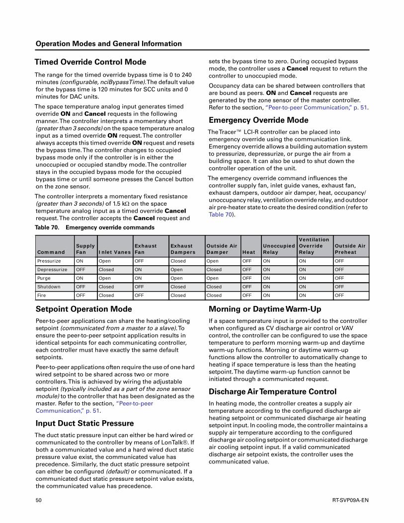
Operation Modes and General Information
Timed Override Control Mode
The range for the timed override bypass time is 0 to 240minutes (configurable, nciBypassTime).The default valuefor the bypass time is 120 minutes for SCC units and 0minutes for DAC units.
The space temperature analog input generates timedoverride ON and Cancel requests in the followingmanner.The controller interprets a momentary short(greater than 3 seconds) on the space temperature analoginput as a timed override ON request.The controlleralways accepts this timed override ON request and resetsthe bypass time.The controller changes to occupiedbypass mode only if the controller is in either theunoccupied or occupied standby mode.The controllerstays in the occupied bypass mode for the occupiedbypass time or until someone presses the Cancel buttonon the zone sensor.
The controller interprets a momentary fixed resistance(greater than 3 seconds) of 1.5 k on the spacetemperature analog input as a timed override Cancelrequest.The controller accepts the Cancel request and
sets the bypass time to zero. During occupied bypassmode, the controller uses a Cancel request to return thecontroller to unoccupied mode.
Occupancy data can be shared between controllers thatare bound as peers. ON and Cancel requests aregenerated by the zone sensor of the master controller.Refer to the section, “Peer-to-peer Communication,” p. 51.
Emergency Override Mode
TheTracer™ LCI-R controller can be placed intoemergency override using the communication link.Emergency override allows a building automation systemto pressurize, depressurize, or purge the air from abuilding space. It can also be used to shut down thecontroller operation of the unit.
The emergency override command influences thecontroller supply fan, inlet guide vanes, exhaust fan,exhaust dampers, outdoor air damper, heat, occupancy/unoccupancy relay, ventilation override relay, and outdoorair pre-heater state to create the desired condition (refer toTable 70).
Setpoint Operation Mode
Peer-to-peer applications can share the heating/coolingsetpoint (communicated from a master to a slave).Toensure the peer-to-peer setpoint application results inidentical setpoints for each communicating controller,each controller must have exactly the same defaultsetpoints.
Peer-to-peer applications often require the use of one hardwired setpoint to be shared across two or morecontrollers.This is achieved by wiring the adjustablesetpoint (typically included as a part of the zone sensormodule) to the controller that has been designated as themaster. Refer to the section, “Peer-to-peerCommunication,” p. 51.
Input Duct Static Pressure
The duct static pressure input can either be hard wired orcommunicated to the controller by means of LonTalk®. Ifboth a communicated value and a hard wired duct staticpressure value exist, the communicated value hasprecedence. Similarly, the duct static pressure setpointcan either be configured (default) or communicated. If acommunicated duct static pressure setpoint value exists,the communicated value has precedence.
Morning or Daytime Warm-Up
If a space temperature input is provided to the controllerwhen configured as CV discharge air control or VAVcontrol, the controller can be configured to use the spacetemperature to perform morning warm-up and daytimewarm-up functions. Morning or daytime warm-upfunctions allow the controller to automatically change toheating if space temperature is less than the heatingsetpoint.The daytime warm-up function cannot beinitiated through a communicated request.
Discharge AirTemperature Control
In heating mode, the controller creates a supply airtemperature according to the configured discharge airheating setpoint or communicated discharge air heatingsetpoint input. In cooling mode, the controller maintains asupply air temperature according to the configureddischarge air cooling setpoint or communicated dischargeair cooling setpoint input. If a valid communicateddischarge air setpoint exists, the controller uses thecommunicated value.
Table 70. Emergency override commands
CommandSupply Fan Inlet Vanes
Exhaust Fan
Exhaust Dampers
Outside Air Damper Heat
Unoccupied Relay
Ventilation Override Relay
Outside Air Preheat
Pressurize ON Open OFF Closed Open OFF ON ON OFF
Depressurize OFF Closed ON Open Closed OFF ON ON OFF
Purge ON Open ON Open Open OFF ON ON OFF
Shutdown OFF Closed OFF Closed Closed OFF ON ON OFF
Fire OFF Closed OFF Closed Closed OFF ON ON OFF
50 RT-SVP09A-EN

Operation Modes and General Information
Mixed Air and Outdoor AirTemperatureInputs
Temperature inputs such as mixed air temperature oroutdoor air temperature aid the ability of the LCI-R tomaintain comfort and protect the unit.
General Information
This section provides general information about thefollowing:
• Location identifier
• Power-up sequence
• Peer-to-peer communication
Location Identifier
TheTracer™ LCI-R includes unit configuration for alocation identifier.The maximum length of the locationidentifier is 30 characters.The identifier can be modifiedfor easy identification of the unit based on its physicallocation.
Power-up Sequence
When 24 Vac power is initially applied to theTracer™ LCI-R and the unit controller, the following sequence occurs(refer to the section, “LED Activity,” p. 52):
• Red Service LED and green Status LED blinkintermittently.
• Internal unit communications begins (TXA and RXALEDs blink).
• Green Status LED turns on solid.
• Unit will remain in local (stand-alone) control untilLonTalk® control data is received.
• Power-up control wait feature is applied.The controllerwaits 300 seconds to allow ample time for thecommunicated control data to arrive. If after 300seconds, the controller has not received anycommunicated control data, the unit assumes local(stand-alone) operation.
• Normal operation begins.
A service test cannot be initiated until the power-upsequence has completed. Refer to the section, “ServiceTest,” p. 52.
Peer-to-peer Communication
Tracer™ LCI-R controllers allow peer-to-peer (or master/slave) data communication. Data such as spacetemperature, setpoint, and occupancy can be shared froma master control to a peer control with or without thepresence of aTracer™ Summit system (refer to Figure 5).
For peer-to-peer applications, the controllers must bebound as peers using the Rover service tool. Refer to theRover service tool product literature for more information.Figure 5. Peer-to-peer communication
RT-SVP09A-EN 51
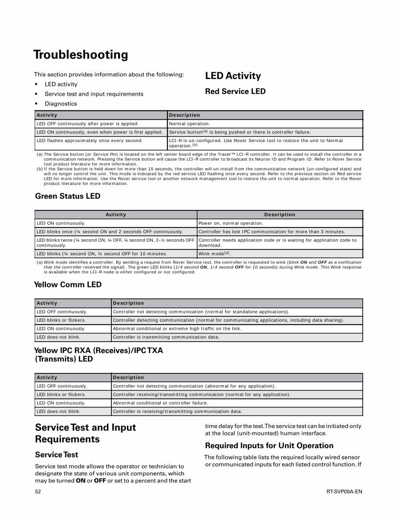
Troubleshooting
This section provides information about the following:
• LED activity
• Service test and input requirements
• Diagnostics
LED Activity
Red Service LED
Green Status LED
Yellow Comm LED
Yellow IPC RXA (Receives)/IPCTXA(Transmits) LED
ServiceTest and Input
Requirements
ServiceTest
Service test mode allows the operator or technician todesignate the state of various unit components, whichmay be turned ON or OFF or set to a percent and the start
time delay for the test.The service test can be initiated onlyat the local (unit-mounted) human interface.
Required Inputs for Unit Operation
The following table lists the required locally wired sensoror communicated inputs for each listed control function. If
Activity Description
LED OFF continuously after power is applied. Normal operation.
LED ON continuously, even when power is first applied. Service button(a) is being pushed or there is controller failure.
LED flashes approximately once every second. LCI-R is un-configured. Use Rover Service tool to restore the unit to Normal operation.(b)
(a) The Service button (or Service Pin) is located on the left center board edge of the Tracer™ LCI-R controller. It can be used to install the controller in a communication network. Pressing the Service button will cause the LCI-R controller to broadcast its Neuron ID and Program ID. Refer to Rover Service tool product literature for more information.
(b) If the Service button is held down for more than 15 seconds, the controller will un-install from the communication network (un-configured state) and will no longer control the unit. This mode is indicated by the red service LED flashing once every second. Refer to the previous section on Red service LED for more information. Use the Rover service tool or another network management tool to restore the unit to normal operation. Refer to the Rover product literature for more information.
Activity Description
LED ON continuously. Power on, normal operation.
LED blinks once (¼ second ON and 2 seconds OFF continuously. Controller has lost IPC communication for more than 3 minutes.
LED blinks twice (¼ second ON, ¼ OFF, ¼ second ON, 2-½ seconds OFF continuously.
Controller needs application code or is waiting for application code to download.
LED blinks (¼ second ON, ¼ second OFF for 10 minutes. Wink mode(a).
(a) Wink mode identifies a controller. By sending a request from Rover Service tool, the controller is requested to wink (blink ON and OFF as a notification that the controller received the signal). The green LED blinks (1/4 second ON, 1/4 second OFF for 10 seconds) during Wink mode. This Wink response is available when the LCI-R node is either configured or not configured.
Activity Description
LED OFF continuously. Controller not detecting communication (normal for standalone applications).
LED blinks or flickers. Controller detecting communication (normal for communicating applications, including data sharing).
LED ON continuously. Abnormal conditional or extreme high traffic on the link.
LED does not blink. Controller is transmitting communication data.
Activity Description
LED OFF continuously. Controller not detecting communication (abnormal for any application).
LED blinks or flickers. Controller receiving/transmitting communication (normal for any application).
LED ON continuously. Abnormal conditional or controller failure.
LED does not blink. Controller is receiving/transmitting communication data.
52 RT-SVP09A-EN
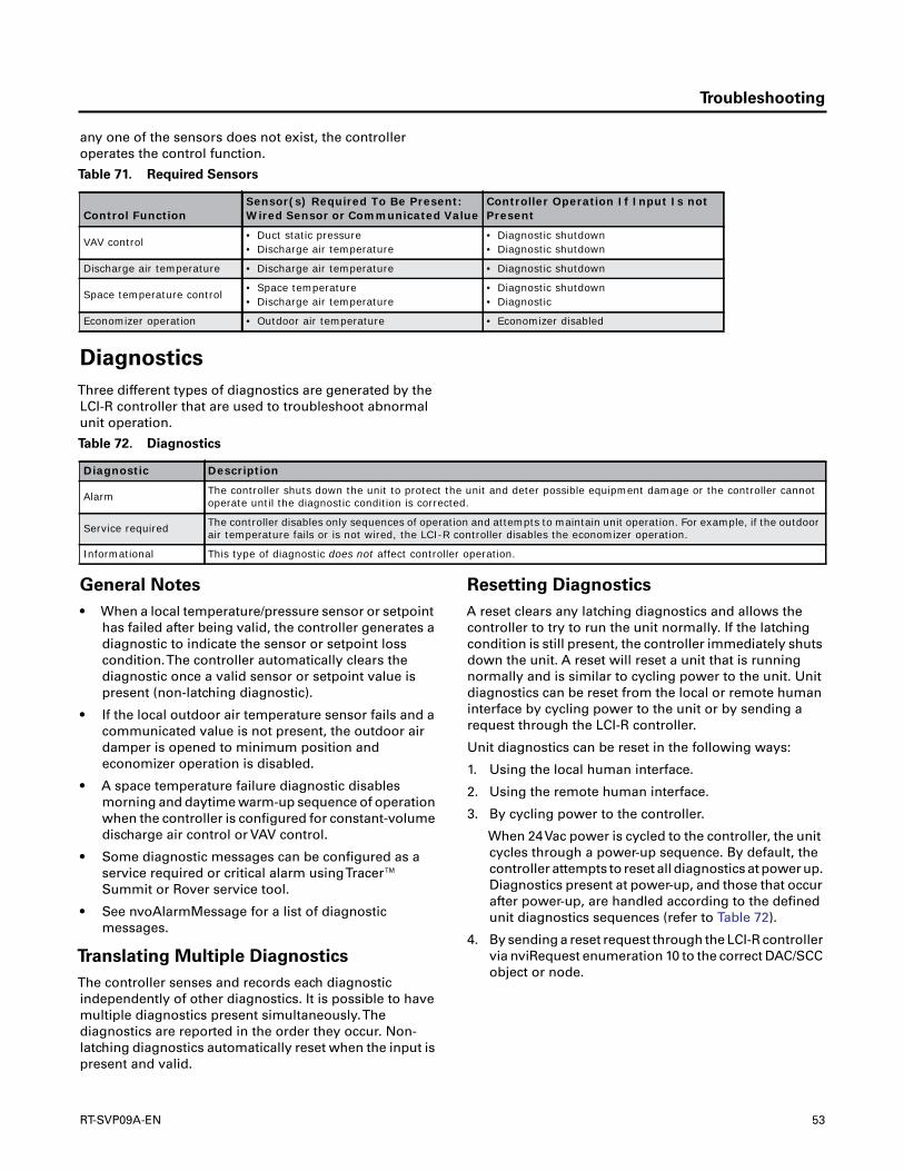
Troubleshooting
any one of the sensors does not exist, the controlleroperates the control function.
Diagnostics
Three different types of diagnostics are generated by theLCI-R controller that are used to troubleshoot abnormalunit operation.
General Notes
• When a local temperature/pressure sensor or setpointhas failed after being valid, the controller generates adiagnostic to indicate the sensor or setpoint losscondition.The controller automatically clears thediagnostic once a valid sensor or setpoint value ispresent (non-latching diagnostic).
• If the local outdoor air temperature sensor fails and acommunicated value is not present, the outdoor airdamper is opened to minimum position andeconomizer operation is disabled.
• A space temperature failure diagnostic disablesmorning and daytime warm-up sequence of operationwhen the controller is configured for constant-volumedischarge air control or VAV control.
• Some diagnostic messages can be configured as aservice required or critical alarm usingTracer™Summit or Rover service tool.
• See nvoAlarmMessage for a list of diagnosticmessages.
Translating Multiple Diagnostics
The controller senses and records each diagnosticindependently of other diagnostics. It is possible to havemultiple diagnostics present simultaneously.Thediagnostics are reported in the order they occur. Non-latching diagnostics automatically reset when the input ispresent and valid.
Resetting Diagnostics
A reset clears any latching diagnostics and allows thecontroller to try to run the unit normally. If the latchingcondition is still present, the controller immediately shutsdown the unit. A reset will reset a unit that is runningnormally and is similar to cycling power to the unit. Unitdiagnostics can be reset from the local or remote humaninterface by cycling power to the unit or by sending arequest through the LCI-R controller.
Unit diagnostics can be reset in the following ways:
1. Using the local human interface.
2. Using the remote human interface.
3. By cycling power to the controller.
When 24Vac power is cycled to the controller, the unitcycles through a power-up sequence. By default, thecontroller attempts to reset all diagnostics at power up.Diagnostics present at power-up, and those that occurafter power-up, are handled according to the definedunit diagnostics sequences (refer to Table 72).
4. By sending a reset request through the LCI-R controllervia nviRequest enumeration 10 to the correct DAC/SCCobject or node.
Table 71. Required Sensors
Control FunctionSensor(s) Required To Be Present: Wired Sensor or Communicated Value
Controller Operation If Input Is not Present
VAV control• Duct static pressure• Discharge air temperature
• Diagnostic shutdown• Diagnostic shutdown
Discharge air temperature • Discharge air temperature • Diagnostic shutdown
Space temperature control• Space temperature• Discharge air temperature
• Diagnostic shutdown• Diagnostic
Economizer operation • Outdoor air temperature • Economizer disabled
Table 72. Diagnostics
Diagnostic Description
Alarm The controller shuts down the unit to protect the unit and deter possible equipment damage or the controller cannot operate until the diagnostic condition is corrected.
Service required The controller disables only sequences of operation and attempts to maintain unit operation. For example, if the outdoor air temperature fails or is not wired, the LCI-R controller disables the economizer operation.
Informational This type of diagnostic does not affect controller operation.
RT-SVP09A-EN 53

Appendix
Refer to the following tables about the following:
• Effects of modes on unit operation
• Determining heat/cool mode, fan request, and runrequest
• Arbitration logic
Table 73. Effect of application mode and heat/cool mode on unit operation(a)
Input Output
VA
V B
ox C
md
Pla
tfor
m I
D
Un
it_
Sta
te
Mai
n S
tate
Pri
mar
y C
ontr
ol S
tate
nvi
Ap
plic
Mod
e (S
CC
/D
AC
)
nvi
Hea
tCoo
l (S
CC
)
Su
pp
ly F
an S
tatu
s
Gas
Hea
t Ty
pe
Dry
ing
Mod
e
Hea
t Ty
pe
Sys
tem
Con
trol
Hea
t/C
ool M
ode
nvo
Hea
tCoo
ln
voU
nit
Sta
tus.
mod
e(D
AC
/S
CC
)
nvo
Ap
plic
Mod
e(o
nly
DA
C)
Un
it O
per
atio
n(b
)1
Open X X X X X X X X X XVAV with IGV or VAV w/o
IGVX HVAC_MAX_HEAT HVAC_MAX_HEAT
Fan EnabledHeat Enabled
Cooling EnabledDamper Enabled
X X Reset X X X X X X X X X X HVAC_OFF HVAC_AUTO
Fan DisabledHeating Disabled Cool-
ing DisabledDamper Disabled
X X Check config X X X X X X X X X X HVAC_NUL HVAC_AUTO
Fan DisabledHeating Disabled Cool-
ing DisabledDamper Disabled
X X Emerg stop X X X X X X X X X X HVAC_OFF HVAC_AUTO
Fan DisabledHeating Disabled Cool-
ing DisabledDamper Disabled
X X Mfg override X X X X X X X X X X HVAC_TEST HVAC_AUTO
Fan DisabledHeating Disabled Cool-
ing DisabledDamper Disabled
X X Main Reset X X X X X X X X X HVAC_OFF HVAC_AUTO
Fan DisabledHeating Disabled Cool-
ing DisabledDamper Disabled
X X Main Unused X X X X X X X X X HVAC_NUL HVAC_NUL
Fan DisabledHeating Disabled Cool-
ing DisabledDamper Disabled
X X Main Service test X X X X X X X X X HVAC_MAX_HEAT HVAC_MAX_HEAT Dependent on test
Configuration
X X MainVentila-
tion over-ride
X X X Not requested X X X X X HVAC_OFF HVAC_AUTO
Fan EnabledHeat Enabled
Cooling EnabledDamper Enabled
X X MainVentila-
tion over-ride
X X X X Staged X GasVAV with IGV or VAV w/o
IGVHeat HVAC_MAX_HEAT HVAC_MAX_HEAT
Fan EnabledHeat Enabled
Cooling EnabledDamper Enabled
X X MainVentila-
tion over-ride
X X X X Staged X Gas CV Heat HVAC_HEAT not applicable
Fan EnabledHeat Enabled
Cooling EnabledDamper Enabled
X X MainVentila-
tion over-ride
X X X X Modu-lated X Gas X Heat HVAC_HEAT HVAC_HEAT
Fan EnabledHeat Enabled
Cooling EnabledDamper Enabled
X X MainVentila-
tion over-ride
X X X X X X ElectricVAV with IGV
orVAV w/o IGV
Heat HVAC_MAX_HEAT HVAC_MAX_HEAT
Fan EnabledHeat Enabled
Cooling EnabledDamper Enabled
X X MainVentila-
tion over-ride
X X X X X X Electric 1=CV Heat HVAC_HEAT not applicable
Fan EnabledHeat Enabled
Cooling EnabledDamper Enabled
X X MainVentila-
tion over-ride
X X X X X X
Hydronicexternal heat or
heat pump
X Heat HVAC_HEAT HVAC_HEAT
Fan EnabledHeat Enabled
Cooling EnabledDamper Enabled
54 RT-SVP09A-EN
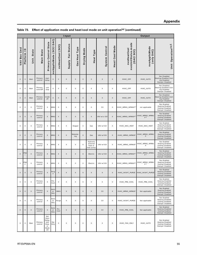
Appendix
X X Main Primary control
start delay X X X X X X X X HVAC_OFF HVAC_AUTO
Fan DisabledHeating Disabled Cool-
ing DisabledDamper Disabled
X X Main Primary controlP
unit stop X X X X X X X X HVAC_OFF HVAC_AUTO
Fan DisabledHeating Disabled Cool-
ing DisabledDamper Disabled
X X Main Primary control
mode off X X X X X X X X HVAC_OFF HVAC_AUTO
Fan DisabledHeating Disabled Cool-
ing DisabledDamper Disabled
X X X Primary control X MWU X X X X X CV X HVAC_MRNG_WRMUP 2 not applicable
Fan EnabledHeating EnabledCooling DisabledDamper Disabled
X X X Primary control X MWU X X X X X VAV w/o IGV X HVAC_MRNG_WRMUP 2 HVAC_MRNG_WRMU
P 2
Fan EnabledHeating EnabledCooling DisabledDamper Disabled
X X X Primary control X MWU X X Staged X Gas VAV w/IGV X HVAC_MAX_HEAT HVAC_MAX_HEAT
Fan EnabledHeating EnabledCooling DisabledDamper Disabled
X X X Primary control X MWU X X Modulat-
ing X Gas VAV w/IGV X HVAC_MRNG_WRMUP HVAC_MRNG_WRMUP
Fan EnabledHeating EnabledCooling DisabledDamper Disabled
X X X Primary control X MWU X X X X
Hydronicexternal heat or
heat pump
VAV w/IGV X HVAC_MRNG_WRMUP HVAC_MRNG_WRMUP
Fan EnabledHeating EnabledCooling DisabledDamper Disabled
X IPak I X Primary
control X MWU X X X X Electric VAV w/IGV X HVAC_MRNG_WRMUP 1 HVAC_MRNG_WRMUP 1
Fan EnabledHeating EnabledCooling DisabledDamper Disabled
X IPak II X Primary
control X MWU X X X X Electric VAV w/IGV X HVAC_MRNG_WRMUP 1 HVAC_MRNG_WRMUP 1
Fan EnabledHeating EnabledCooling DisabledDamper Disabled
X X X Primary control X Purg
e X X X X X X X HVAC_NIGHT_PURGE HVAC_NIGHT_PURGE
Fan EnabledHeating DisabledCooling DisabledDamper Disabled
X X X Primary control X Pre-
Cool X X X X X X X HVAC_PRE_COOL HVAC_PRE_COOL
Fan EnabledHeating DisabledCooling EnabledDamper Disabled
X X X Primary control X
Auto or
NULMWU X X X X CV X HVAC_MRNG_WRMUP Not applicable
Fan EnabledHeating EnabledCooling DisabledDamper Disabled
X X X Primary control X
Auto or
NULPurge X X X X CV X HVAC_NIGHT_PURGE Not applicable
Fan EnabledHeating DisabledCooling DisabledDamper Disabled
X X X Primary control X
Auto or
NUL
Pre-Cool X X X X CV X HVAC_PRE_COOL Not applicable
Fan EnabledHeating DisabledCooling EnabledDamper Disabled
X X Main Primary control
Not Start Delay, Unit Stop,
or Mode Off
Fan Only X X X X X X X HVAC_FAN_ONLY HVAC_AUTO
Fan EnabledHeating DisabledCooling DisabledDamper Disabled
Table 73. Effect of application mode and heat/cool mode on unit operation(a) (continued)
Input Output
VA
V B
ox C
md
Pla
tfor
m I
D
Un
it_
Sta
te
Mai
n S
tate
Pri
mar
y C
ontr
ol S
tate
nvi
Ap
plic
Mod
e (S
CC
/D
AC
)
nvi
Hea
tCoo
l (S
CC
)
Su
pp
ly F
an S
tatu
s
Gas
Hea
t Ty
pe
Dry
ing
Mod
e
Hea
t Ty
pe
Sys
tem
Con
trol
Hea
t/C
ool M
ode
nvo
Hea
tCoo
ln
voU
nit
Sta
tus.
mod
e(D
AC
/S
CC
)
nvo
Ap
plic
Mod
e(o
nly
DA
C)
Un
it O
per
atio
n(b
)1
RT-SVP09A-EN 55

Appendix
X X Main Primary control
Not Start Delay, Unit Stop,
or Mode Off
Auto or
NUL
Fan only X X X X X X HVAC_FAN_ONLY Not applicable
Fan EnabledHeating DisabledCooling DisabledDamper Disabled
X X Main Primary control mwu X X X X X X CV X HVAC_MRNG_WRMUP Not applicable
Fan Enabled Heating EnabledCooling DisabledDamper Disabled
X X Main Primary control mwu X X X X X X VAV w/IGV or
VAV w/o IGV X HVAC_MRNG_WRMUP Not applicable
Fan Enabled Heating EnabledCooling DisabledDamper Disabled
X X Main Primary control dwu X X X X X X VAV w/IGV or
VAV w/o IGV X HVAC_MAX_HEAT HVAC_MAX_HEAT
Fan EnabledHeating EnabledCooling DisabledDamper Enabled
X X Main Primary control
sys-tem diag
X X X X X X X X HVAC_OFF HVAC_AUTO
Fan DisabledHeating DisabledCooling DisabledDamper Disabled
X X Main Primary control
Unoc-cupied X X Not
requested X X X X X HVAC_OFF HVAC_AUTO
Fan DisabledHeating DisabledCooling DisabledDamper Disabled
X X Main Primary control
Unoc-cupied X X X X Drying X CV X HVAC_DEHUMID HVAC_DEHUMID
Fan EnabledHeating EnabledCooling EnabledDamper Enabled
X X Main Primary control
Unoc-cupied X X X X X X CV Heat HVAC_HEAT Not applicable
Fan EnabledHeating EnabledCooling EnabledDamper Enabled
X X Main Primary control
Unoc-cupied X X X X X X CV Cool HVAC_COOL Not applicable
Fan EnabledHeating EnabledCooling EnabledDamper Enabled
X X Main Primary control
Unoc-cupied X X X X X X VAV w/IGV or
VAV w/o IGV X HVAC_MAX_HEAT HVAC_MAX_HEAT
Fan EnabledHeating EnabledCooling EnabledDamper Enabled
X X Main Primary control
VAV Occu-pied
X X X X Drying X X X HVAC_MAX_HEAT HVAC_MAX_HEAT
Fan EnabledHeating EnabledCooling EnabledDamper Enabled
X X Main Primary control
VAV Occu-pied
X X X staged X Gas X Heat HVAC_MAX_HEAT HVAC_MAX_HEAT
Fan EnabledHeating EnabledCooling EnabledDamper Enabled
X X Main Primary control
VAV Occu-pied
X X X modu-lated X Gas X Heat HVAC_HEAT HVAC_HEAT
Fan EnabledHeating EnabledCooling EnabledDamper Enabled
X X Main Primary control
VAV Occu-pied
X X X X X Electric X Heat HVAC_MAX_HEAT HVAC_MAX_HEAT
Fan EnabledHeating EnabledCooling EnabledDamper Enabled
X X Main Primary control
VAV Occu-pied
X X X X X
hydronicexternal heat or
heat pump
X Heat HVAC_HEAT HVAC_HEAT
Fan EnabledHeating EnabledCooling EnabledDamper Enabled
X X Main Primary control
VAV Ooccu-pied
X X X X X X X Cool HVAC_COOL HVAC_COOL
Fan EnabledHeating EnabledCooling EnabledDamper Enabled
Table 73. Effect of application mode and heat/cool mode on unit operation(a) (continued)
Input Output
VA
V B
ox C
md
Pla
tfor
m I
D
Un
it_
Sta
te
Mai
n S
tate
Pri
mar
y C
ontr
ol S
tate
nvi
Ap
plic
Mod
e (S
CC
/D
AC
)
nvi
Hea
tCoo
l (S
CC
)
Su
pp
ly F
an S
tatu
s
Gas
Hea
t Ty
pe
Dry
ing
Mod
e
Hea
t Ty
pe
Sys
tem
Con
trol
Hea
t/C
ool M
ode
nvo
Hea
tCoo
ln
voU
nit
Sta
tus.
mod
e(D
AC
/S
CC
)
nvo
Ap
plic
Mod
e(o
nly
DA
C)
Un
it O
per
atio
n(b
)1
56 RT-SVP09A-EN
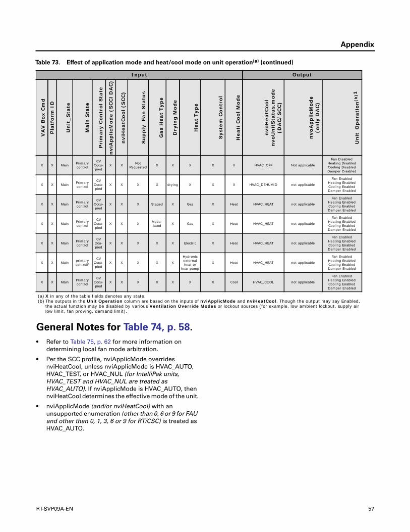
Appendix
General Notes for Table 74, p. 58.
• Refer to Table 75, p. 62 for more information ondetermining local fan mode arbitration.
• Per the SCC profile, nviApplicMode overridesnviHeatCool, unless nviApplicMode is HVAC_AUTO,HVAC_TEST, or HVAC_NUL (for IntelliPak units,HVAC_TEST and HVAC_NUL are treated asHVAC_AUTO). If nviApplicMode is HVAC_AUTO, thennviHeatCool determines the effective mode of the unit.
• nviApplicMode (and/or nviHeatCool) with anunsupported enumeration (other than 0, 6 or 9 for FAUand other than 0, 1, 3, 6 or 9 for RT/CSC) is treated asHVAC_AUTO.
X X Main Primary control
CV Occu-pied
X X Not Requested X X X X X HVAC_OFF Not applicable
Fan DisabledHeating DisabledCooling DisabledDamper Disabled
X X Main Primary control
CV Occu-pied
X X X X drying X X X HVAC_DEHUMID not applicable
Fan EnabledHeating EnabledCooling EnabledDamper Enabled
X X Main Primary control
CV Occu-pied
X X X Staged X Gas X Heat HVAC_HEAT not applicable
Fan EnabledHeating EnabledCooling EnabledDamper Enabled
X X Main Primary control
CV Occu-pied
X X X Modu-lated X Gas X Heat HVAC_HEAT not applicable
Fan EnabledHeating EnabledCooling EnabledDamper Enabled
X X Main Primary control
CV Ocu-pied
X X X X X Electric X Heat HVAC_HEAT not applicable
Fan EnabledHeating EnabledCooling EnabledDamper Enabled
X X Main primary controlP
CV Occu-pied
X X X X X
Hydronicexternal heat or
heat pump
X Heat HVAC_HEAT not applicable
Fan EnabledHeating EnabledCooling EnabledDamper Enabled
X X Main Primary control
CV Occu-pied
X X X X X X X Cool HVAC_COOL not applicable
Fan EnabledHeating EnabledCooling EnabledDamper Enabled
(a) X in any of the table fields denotes any state.(b) The outputs in the Unit Operation column are based on the inputs of nviApplicMode and nviHeatCool. Though the output may say Enabled,
the actual function may be disabled by various Ventilation Override Modes or lockout sources (for example, low ambient lockout, supply air low limit, fan proving, demand limit).
Table 73. Effect of application mode and heat/cool mode on unit operation(a) (continued)
Input Output
VA
V B
ox C
md
Pla
tfor
m I
D
Un
it_
Sta
te
Mai
n S
tate
Pri
mar
y C
ontr
ol S
tate
nvi
Ap
plic
Mod
e (S
CC
/D
AC
)
nvi
Hea
tCoo
l (S
CC
)
Su
pp
ly F
an S
tatu
s
Gas
Hea
t Ty
pe
Dry
ing
Mod
e
Hea
t Ty
pe
Sys
tem
Con
trol
Hea
t/C
ool M
ode
nvo
Hea
tCoo
ln
voU
nit
Sta
tus.
mod
e(D
AC
/S
CC
)
nvo
Ap
plic
Mod
e(o
nly
DA
C)
Un
it O
per
atio
n(b
)1
RT-SVP09A-EN 57
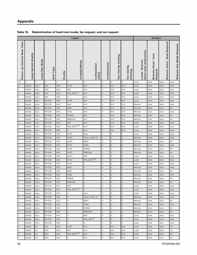
Appendix
Table 74. Determination of heat/cool mode, fan request, and run request
Input Output
Pow
er u
p C
ontr
ol W
ait
Tim
e
Loca
l Sw
itch
En
able
Loca
l Fan
Mod
e
Un
it T
ype
Pro
file
nvi
Ap
plic
Mod
e
nvi
Hea
tCoo
l(S
CC
)
nvo
Hea
tCoo
l
Fan
Con
fig
Coo
ling
Fan
Con
fig
Hea
tin
g
Loca
l/ R
emot
eH
eat/
Coo
l Arb
itra
tion
Rem
ote
Hea
t/ C
ool
Req
ues
t
Rem
ote
Au
to/
Sto
p R
equ
est
Rem
ote
Fan
Mod
e R
equ
est
>0 X X X X X X X X X Local Heat Stop Auto
0 Enable Auto FAU DAC AUTO N/A X N/A N/A Local Heat Auto Auto
0 Enable Auto FAU DAC OFF N/A X N/A N/A Local Heat Stop Auto
0 Enable Auto FAU DAC FAN_ONLY(a) N/A X N/A N/A Local Heat Auto Auto
0 Enable Auto FAU DAC X N/A X N/A N/A Local Heat Auto Auto
0 Enable Auto RT/CSC DAC AUTO N/A X N/A N/A Local Heat Auto Auto
0 Enable Auto RT/CSC DAC Heat N/A X N/A N/A Remote Heat Auto Auto
0 Enable Auto RT/CSC DAC MWU N/A X N/A N/A Remote Heat Auto On
0 Enable Auto RT/CSC DAC COOL N/A X N/A N/A Remote Cool Auto Auto
0 Enable Auto RT/CSC DAC PURGE N/A X N/A N/A Remote Cool Auto On
0 Enable Auto RT/CSC DAC PRECOOL N/A X N/A N/A Remote Cool Auto On
0 Enable Auto RT/CSC DAC OFF N/A X N/A N/A Local Heat Stop Auto
0 Enable Auto RT/CSC DAC FAN_ONLY(a) N/A X N/A N/A Local Heat Auto Auto
0 Enable Auto RT/CSC DAC X N/A X N/A N/A Local Heat Auto Auto
0 Enable Auto RT/CSC SCC AUTO Auto X X X Local Heat Auto Auto
0 Enable Auto RT/CSC SCC AUTO Heat or MAX HT X X X Remote Heat Auto Auto
0 Enable Auto RT/CSC SCC AUTO MWU X X X Remote Heat Auto On
0 Enable Auto RT/CSC SCC AUTO COOL X X X Remote Cool Auto Auto
0 Enable Auto RT/CSC SCC AUTO PURGE X X X Remote Cool Auto On
0 Enable Auto RT/CSC SCC AUTO PRECOOL X X X Remote Cool Auto On
0 Enable Auto RT/CSC SCC AUTO OFF X X X Local Heat Stop Auto
0 Enable Auto RT/CSC SCC AUTO FAN_ONLY(a) X X X Local Heat Auto Auto
0 Enable Auto RT/CSC SCC AUTO X X X X Local Heat Auto Auto
0 Enable Auto RT/CSC SCC HEAT X X X X Remote Heat Auto Auto
0 Enable Auto RT/CSC SCC MWU X X X X Remote Heat Auto On
0 Enable Auto RT/CSC SCC COOL X X X X Remote Cool Auto Auto
0 Enable Auto RT/CSC SCC PURGE X X X X Remote Cool Auto On
0 Enable Auto RT/CSC SCC PRECOOL X X X X Remote Cool Auto On
0 Enable Auto RT/CSC SCC OFF X X X X Local Heat Stop Auto
0 Enable Auto RT/CSC SCC FAN_ONLY(a) X X X X Local Heat Auto Auto
0 Enable Auto RT/CSC SCC X Auto X X X Local Heat Auto Auto
0 Enable Auto RT/CSC SCC X Heat or MAX HT X X X Remote Heat Auto Auto
0 Enable Auto RT/CSC SCC X MWU X X X Remote Heat Auto On
0 Enable Auto RT/CSC SCC X COOL X X X Remote Cool Auto Auto
0 Enable Auto RT/CSC SCC X PURGE X X X Remote Cool Auto On
0 Enable Auto RT/CSC SCC X PRECOOL X X X Remote Cool Auto On
0 Enable Auto RT/CSC SCC X OFF X X X Local Heat Stop Auto
0 Enable Auto RT/CSC SCC X FAN_ONLY4 X X X Local Heat Auto Auto
0 Enable Auto RT/CSC SCC X X X X X Local Heat Auto Auto
0 Enable On FAU DAC AUTO N/A X N/A N/A Local Heat Auto On
0 Enable On FAU DAC OFF N/A X N/A N/A Local Heat Stop On
0 Enable On FAU DAC FAN_ONLY(a) N/A X N/A N/A Local Heat Auto On
0 Enable On FAU DAC X N/A X N/A N/A Local Heat Auto On
58 RT-SVP09A-EN

Appendix
0 Enable On RT/CSC SCC AUTO AUTO X X X Local Heat Auto On
0 Enable On RT/CSC SCC AUTO Heat or MAX HT X X X Remote Heat Auto On
0 Enable On RT/CSC SCC AUTO MWU X X X Remote Heat Auto On
0 Enable On RT/CSC SCC AUTO COOL X X X Remote Cool Auto On
0 Enable On RT/CSC SCC AUTO PURGE X X X Remote Cool Auto On
0 Enable On RT/CSC SCC AUTO PRECOOL X X X Remote Cool Auto On
0 Enable On RT/CSC SCC AUTO OFF X X X Local Heat Stop On
0 Enable On RT/CSC SCC AUTO FAN_ONLY(a) X X X Local Heat Auto On
0 Enable On RT/CSC SCC AUTO X X X X Local Heat Auto On
0 Enable On RT/CSC SCC Heat X X X X Remote Heat Auto On
0 Enable On RT/CSC SCC MWU X X X X Remote Heat Auto On
0 Enable On RT/CSC SCC COOL X X X X Remote Cool Auto On
0 Enable On RT/CSC SCC PURGE X X X X Remote Cool Auto On
0 Enable On RT/CSC SCC PRECOOL X X X X Remote Cool Auto On
0 Enable On RT/CSC SCC OFF X X X X Local Heat Stop On
0 Enable On RT/CSC SCC FAN_ONLY(a) X X X X Local Heat Auto On
0 Enable On RT/CSC SCC X X X X X Local Heat Auto On
0 Disable X FAU DAC AUTO N/A X N/A N/A Local Heat Auto Auto
0 Disable X FAU DAC OFF N/A X N/A N/A Local Heat Stop Auto
0 Disable X FAU DAC FAN_ONLY(a) N/A X N/A N/A Local Heat Auto Auto
0 Disable X FAU DAC X N/A X N/A N/A Local Heat Auto Auto
0 Disable X RT/CSC DAC AUTO N/A X N/A N/A Local Heat Auto Auto
0 Disable X RT/CSC DAC HEAT N/A X N/A N/A Remote Heat Auto Auto
0 Disable X RT/CSC DAC MWU N/A X N/A N/A Remote Heat Auto On
0 Disable X RT/CSC DAC COOL N/A X N/A N/A Remote Cool Auto Auto
0 Disable X RT/CSC DAC PURGE N/A X N/A N/A Remote Cool Auto On
0 Disable X RT/CSC DAC PRECOOL N/A X N/A N/A Remote Cool Auto On
0 Disable X RT/CSC DAC OFF N/A X N/A N/A Local Heat Stop Auto
0 Disable X RT/CSC DAC FAN_ONLY(a) N/A X N/A N/A Local Heat Auto Auto
0 Disable X RT/CSC DAC X N/A X N/A N/A Local Heat Auto Auto
0 Disable X RT/CSC SCC AUTO AUTO Heat orMWU orMax HT
X Cycling Local Heat Auto Auto
0 Disable X RT/CSC SCC AUTO AUTO Heat orMWU orMax HT
X Cont Local Heat Auto OnOn
0 Disable X RT/CSC SCC AUTO AUTO Cool Cycling X local Heat Auto Auto
0 Disable X RT/CSC SCC AUTO AUTO Cool Cont X Local Heat Auto On
0 Disable X RT/CSC SCC AUTO AUTO purge X X Remote Cool Auto On
0 Disable X RT/CSC SCC AUTO AUTO Precool X X Remote Cool Auto On
0 Disable X RT/CSC SCC AUTO AUTO Off ortest ornul
X X Local Heat Auto Auto
0 Disable X RT/CSC SCC AUTO AUTO FAN_ONLY(a) X X Local Heat Auto Auto
0 Disable X RT/CSC SCC AUTO Heat or MAX HT X X Cycling Remote Heat Auto Auto
Table 74. Determination of heat/cool mode, fan request, and run request (continued)
Input Output
Pow
er u
p C
ontr
ol W
ait
Tim
e
Loca
l Sw
itch
En
able
Loca
l Fan
Mod
e
Un
it T
ype
Pro
file
nvi
Ap
plic
Mod
e
nvi
Hea
tCoo
l(S
CC
)
nvo
Hea
tCoo
l
Fan
Con
fig
Coo
ling
Fan
Con
fig
Hea
tin
g
Loca
l/ R
emot
eH
eat/
Coo
l Arb
itra
tion
Rem
ote
Hea
t/ C
ool
Req
ues
t
Rem
ote
Au
to/
Sto
p R
equ
est
Rem
ote
Fan
Mod
e R
equ
est
RT-SVP09A-EN 59

Appendix
0 Disable X RT/CSC SCC AUTO Heat or MAX HT X X Cont Remote Heat Auto On
0 Disable X RT/CSC SCC AUTO MWU X X X Remote Heat Auto On
0 Disable X RT/CSC SCC AUTO COOL X Cycling X Remote Cool Auto Auto
0 Disable X RT/CSC SCC AUTO COOL X Cont X Remote Cool Auto On
0 Disable X RT/CSC SCC AUTO PURGE X X X Remote Cool Auto On
0 Disable X RT/CSC SCC AUTO PRECOOL X X X Remote Cool Auto On
0 Disable X RT/CSC SCC AUTO OFF X X X Local Heat Stop Auto
0 Disable X RT/CSC SCC AUTO FAN_ONLY(a) Heat orMWU orMax HT
X Cycling Local Heat Auto Auto
0 Disable X RT/CSC SCC AUTO FAN_ONLY(a) Heat orMWU orMax HT
X Cont Local Heat Auto On
0 Disable X RT/CSC SCC AUTO FAN_ONLY(a) Cool Cycling X Local Heat Auto Auto
0 Disable X RT/CSC SCC AUTO FAN_ONLY(a) Cool Cont X Local Heat Auto On
0 Disable X RT/CSC SCC AUTO FAN_ONLY(a) Purge X X Remote Cool Auto On
0 Disable X RT/CSC SCC AUTO FAN_ONLY(a) Precool X X Remote Cool Auto On
0 Disable X RT/CSC SCC AUTO FAN_ONLY(a) Off ortest ornul
X X Local Heat Auto Auto
0 Disable X RT/CSC SCC AUTO FAN_ONLY(a) Fan only X X Local Heat Auto Auto
0 Disable X RT/CSC SCC AUTO X Heat orMWU orMax HT
X Cycling Local Heat Auto Auto
0 Disable X RT/CSC SCC AUTO X Heat orMWU orMax HT
X Cont Local Heat Auto On
0 Disable X RT/CSC SCC AUTO X Cool Cycling X Local Heat Auto Auto
0 Disable X RT/CSC SCC AUTO X Cool Cont X Local Heat Auto On
0 Disable X RT/CSC SCC AUTO X Purge X X Remote Cool Auto On
0 Disable X RT/CSC SCC AUTO X Precool X X Remote Cool Auto On
0 Disable X RT/CSC SCC AUTO X Off ortest ornul
X X Local Heat Auto Auto
0 Disable X RT/CSC SCC AUTO X Fan only X X Local Heat Auto Auto
0 Disable X RT/CSC SCC HEAT X X X Cycling Remote Heat Auto Auto
0 Disable X RT/CSC SCC HEAT X X X Cont Remote Heat Auto On
0 Disable X RT/CSC SCC MWU X X X X Remote Heat Auto On
0 Disable X RT/CSC SCC COOL X X Cycling X Remote Cool Auto Auto
0 Disable X RT/CSC SCC COOL X X Cont X Remote Cool Auto On
0 Disable X RT/CSC SCC PURGE X X X X Remote Cool Auto On
0 Disable X RT/CSC SCC PRECOOL X X X X Remote Cool Auto On
0 Disable X RT/CSC SCC OFF X X X X Local Heat Stop Auto
0 Disable X RT/CSC SCC FAN_ONLY(a) X Heat orMWU orMax HT
X Cycling Local Heat Auto Auto
0 Disable X RT/CSC SCC FAN_ONLY(a) X Heat orMWU orMax HT
X Cont Local Heat Auto On
0 Disable X RT/CSC SCC FAN_ONLY(a) X Cool Cycling X Local Heat Auto Auto
Table 74. Determination of heat/cool mode, fan request, and run request (continued)
Input Output
Pow
er u
p C
ontr
ol W
ait
Tim
e
Loca
l Sw
itch
En
able
Loca
l Fan
Mod
e
Un
it T
ype
Pro
file
nvi
Ap
plic
Mod
e
nvi
Hea
tCoo
l(S
CC
)
nvo
Hea
tCoo
l
Fan
Con
fig
Coo
ling
Fan
Con
fig
Hea
tin
g
Loca
l/ R
emot
eH
eat/
Coo
l Arb
itra
tion
Rem
ote
Hea
t/ C
ool
Req
ues
t
Rem
ote
Au
to/
Sto
p R
equ
est
Rem
ote
Fan
Mod
e R
equ
est
60 RT-SVP09A-EN

Appendix
0 Disable X RT/CSC SCC FAN_ONLY(a) X Cool Cont X Local Heat Auto On
0 Disable X RT/CSC SCC FAN_ONLY(a) X Purge X X Remote Cool Auto On
0 Disable X RT/CSC SCC FAN_ONLY(a) X Precool X X Remote Cool Auto On
0 Disable X RT/CSC SCC FAN_ONLY(a) X Off ortest ornul
X X Local Heat Auto Auto
0 Disable X RT/CSC SCC FAN_ONLY(a) X Fan only X X Local Heat Auto Auto
0 Disable X RT/CSC SCC X AUTO Heat orMWU orMax HT
X Cycling Local Heat Auto Auto
0 Disable X RT/CSC SCC X AUTO Heat orMWU orMax HT
X Cont Local Heat Auto On
0 Disable X RT/CSC SCC X AUTO Cool Cycling X Local Heat Auto Auto
0 Disable X RT/CSC SCC X AUTO Cool Cont X Local Heat Auto On
0 Disable X RT/CSC SCC X AUTO Purge X X Remote Cool Auto On
0 Disable X RT/CSC SCC X AUTO Precool X X Remote Cool Auto On
0 Disable X RT/CSC SCC X AUTO Off ortest ornul
X X Local Heat Auto Auto
0 Disable X RT/CSC SCC X AUTO Fan only X X Local Heat Auto Auto
0 Disable X RT/CSC SCC X Heat or MAX HT X X Cycling Remote Heat Auto Auto
0 Disable X RT/CSC SCC X Heat or MAX HT X X Conti Remote Heat Auto On
0 Disable X RT/CSC SCC X MWU X X X Remote Heat Auto On
0 Disable X RT/CSC SCC X COOL X cycling X Remote Cool Auto Auto
0 Disable X RT/CSC SCC X COOL X Cont X Remote Cool Auto On
0 disable X RT/CSC SCC X PURGE X X X Remote Cool Auto On
0 Disable X RT/CSC SCC X PRECOOL X X X Remote Cool Auto On
0 Disable X RT/CSC SCC X OFF X X X Local Heat Stop Auto
0 Disable X RT/CSC SCC X FAN_ONLY(a) Heat orMWU orMax HT
X Cycling Local Heat Auto Auto
0 Disable X RT/CSC SCC X FAN_ONLY(a) Heat orMWU orMax HT
X Cont Local Heat Auto On
0 Disable X RT/CSC SCC X FAN_ONLY(a) Cool Cycling X Local Heat Auto Auto
0 Disable X RT/CSC SCC X FAN_ONLY(a) Cool Cont X Local Heat Auto On
0 Disable X RT/CSC SCC X FAN_ONLY(a) Purge X X Remote Cool Auto On
0 Disable X RT/CSC SCC X FAN_ONLY(a) Precool X X Remote Cool Auto On
0 Disable X RT/CSC SCC X FAN_ONLY(a) Off ortest ornul
X X Local Heat Auto Auto
0 Disable X RT/CSC SCC X FAN_ONLY(a) Fan only X X Local Heat Auto Auto
0 Disable X RT/CSC SCC X X Heat orMWU orMax HT
X Cycling Local Heat Auto Auto
0 Disable X RT/CSC SCC X X Heat orMWU orMax HT
X Cont Local Heat Auto On
0 Disable X RT/CSC SCC X X Cool Cycling X Local Heat Auto Auto
0 Disable X RT/CSC SCC X X Cool Cont X Local Heat Auto On
Table 74. Determination of heat/cool mode, fan request, and run request (continued)
Input Output
Pow
er u
p C
ontr
ol W
ait
Tim
e
Loca
l Sw
itch
En
able
Loca
l Fan
Mod
e
Un
it T
ype
Pro
file
nvi
Ap
plic
Mod
e
nvi
Hea
tCoo
l(S
CC
)
nvo
Hea
tCoo
l
Fan
Con
fig
Coo
ling
Fan
Con
fig
Hea
tin
g
Loca
l/ R
emot
eH
eat/
Coo
l Arb
itra
tion
Rem
ote
Hea
t/ C
ool
Req
ues
t
Rem
ote
Au
to/
Sto
p R
equ
est
Rem
ote
Fan
Mod
e R
equ
est
RT-SVP09A-EN 61
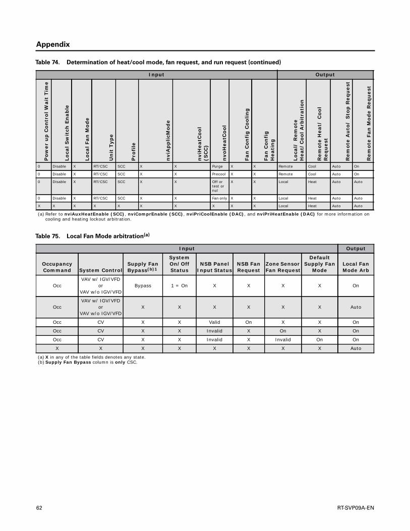
Appendix
0 Disable X RT/CSC SCC X X Purge X X Remote Cool Auto On
0 Disable X RT/CSC SCC X X Precool X X Remote Cool Auto On
0 Disable X RT/CSC SCC X X Off ortest ornul
X X Local Heat Auto Auto
0 Disable X RT/CSC SCC X X Fan only X X Local Heat Auto Auto
X X X X X X X X X X Local Heat Auto Auto
(a) Refer to nviAuxHeatEnable (SCC), nviComprEnable (SCC), nviPriCoolEnable (DAC), and nviPriHeatEnable (DAC) for more information on cooling and heating lockout arbitration.
Table 74. Determination of heat/cool mode, fan request, and run request (continued)
Input Output
Pow
er u
p C
ontr
ol W
ait
Tim
e
Loca
l Sw
itch
En
able
Loca
l Fan
Mod
e
Un
it T
ype
Pro
file
nvi
Ap
plic
Mod
e
nvi
Hea
tCoo
l(S
CC
)
nvo
Hea
tCoo
l
Fan
Con
fig
Coo
ling
Fan
Con
fig
Hea
tin
g
Loca
l/ R
emot
eH
eat/
Coo
l Arb
itra
tion
Rem
ote
Hea
t/ C
ool
Req
ues
t
Rem
ote
Au
to/
Sto
p R
equ
est
Rem
ote
Fan
Mod
e R
equ
est
Table 75. Local Fan Mode arbitration(a)
Input Output
OccupancyCommand System Control
Supply Fan Bypass(b)1
System On/OffStatus
NSB PanelInput Status
NSB FanRequest
Zone Sensor Fan Request
Default Supply Fan
ModeLocal Fan Mode Arb
OccVAV w/ IGV/VFD
orVAV w/o IGV/VFD
Bypass 1 = On X X X X On
OccVAV w/ IGV/VFD
orVAV w/o IGV/VFD
X X X X X X Auto
Occ CV X X Valid On X X On
Occ CV X X Invalid X On X On
Occ CV X X Invalid X Invalid On On
X X X X X X X X Auto
(a) X in any of the table fields denotes any state.(b) Supply Fan Bypass column is only CSC.
62 RT-SVP09A-EN

Appendix
Table 76. SCC Space Setpoint arbitration
1. Local Setpoint Arbitration From IPC Bus
Default Occ Zone Cooling Setpoint Source Based on Default OCC Zone Cooling Setpoint Source
Default Occ Zone Heating Setpoint Source localOccCool = RTM Cooling Setpoint
Default Unocc Zone Cooling Setpoint Source localOccCool = =NSB Occ Zone Colling Setpoint
Default Unocc Zone Heating Setpoint Source localOccCool = Default Occ Zone Cooling Setpoint
RTM Cooling Setpoint localOccCool = GBAS 0–5V Occ Zone Cooling Setpoint
RTM Heating Setpoint localOccCool = GBAS 0–10V Occ Zone Cooling Setpoint
NSB Occ Zone Cooling Setpoint(a)
(a) NSB Occ Zone Cooling Setpoint and NSB Occ Zone Heating Setpoint are not internally communicated by the RTM. Instead, use Default Occ Zone Cooling Setpoint and Default Occ Zone Heating setpoint.
Based on Default Unocc Zone Cooling Setpoint Source
NSB Occ Zone Heating Setpoint localUnoccCool = RTM Cooling Setpoint
NSB Unocc Zone Cooling Setpoint localUnoccCool = NSB Unocc Zone Cooling Setpoint
NSB Unocc Zone Heating Setpoint localUnoccCool = Default Unocc Zone Cooling Setpoint
Default Occ Zone Cooling Setpoint localUnoccCool = GBAS 0–5V Unocc Zone Cooling Setpoint
Default Occ Zone Heating Setpoint localUnoccCool = GBAS 0–10V Unocc Zone Cooling Setpoint
Default Unocc Zone Cooling Setpoint Based on Default Occ Zone Heating Setpoint Source
Default Unocc Zone Heating Setpoint localOccHeat = RTM Heating Setpoint
GBAS 0–5V Occ Zone Cooling Setpoint localOccHeat = NSB Occ Zone Heating Setpoint
GBAS 0–5V Unocc Zone Cooling Setpoint localOccHeat = Default Occ Zone Heating Setpoint
GBAS 0–5V Occ Zone Heating Setpoint localOccHeat = GBAS 0–5V Occ Zone Heating Setpoint
GBAS 0–5V Unocc Zone Heating Setpoint localOccHeat = =GBAS 0–10V Occ Zone Heating Setpoint
GBAS 0–10V Occ Zone Cooling Setpoint Based on Default Unocc Zone Heating Setpoint Source
GBAS 0–10V Occ Zone Heating Setpoint localUnoccHeat = RTM Heating Setpoint
GBAS 0–10V Unocc Zone Cooling Setpoint localUnoccHeat = NSB Unocc Zone Heating Setpoint
GBAS 0–10V Unocc Zone Heating Setpoint localUnoccHeat = Default Unocc Zone Heating Setpoint
localUnoccHeat = GBAS 0–5V Unocc Zone Heating Setpoint
locaUnoccHeat = GBAS 0–10V Unocc Zone Heating Setpoint
2. Calibrate a Valid Local Setpoint (localcal)
nciSensor1Cal; -10°F to 10°F (±5.56°C) localOccCoolCal = localOcccool + nciSensor1Cal
localUnoccCoolCal = localUnoccColl + nciSensor1Cal
localOccHeatCal = localOccHeat + nciSensor1Cal
localUnoccHeatCal = localUnoccHeat + nciSensor1Cal
Based on nvoEffOccupancy Unit Heat/Cool Status
nvoSetpoint = localOccCoolCal OR localOccCoolCal = localOccCool
nvoSetpoint = localUnoccCoolCal OR locaUnoccCoolCal = localUnoccCool
nvoSetpoint = localOccHeatCal OR localOccHeatCal = localOccHeat
nvoSetpoint = locaUnoccHeatCal localUnoccHeatCal = lcaoUnoccHeat
3. Check If OK to Use Valid Local Setpoint
nciPersonality2 (local setpoint en/dis) If nciPersonality2.boolean.local_setpoint = enable
setpointSource = local ELSE
setpointSource = none
RT-SVP09A-EN 63
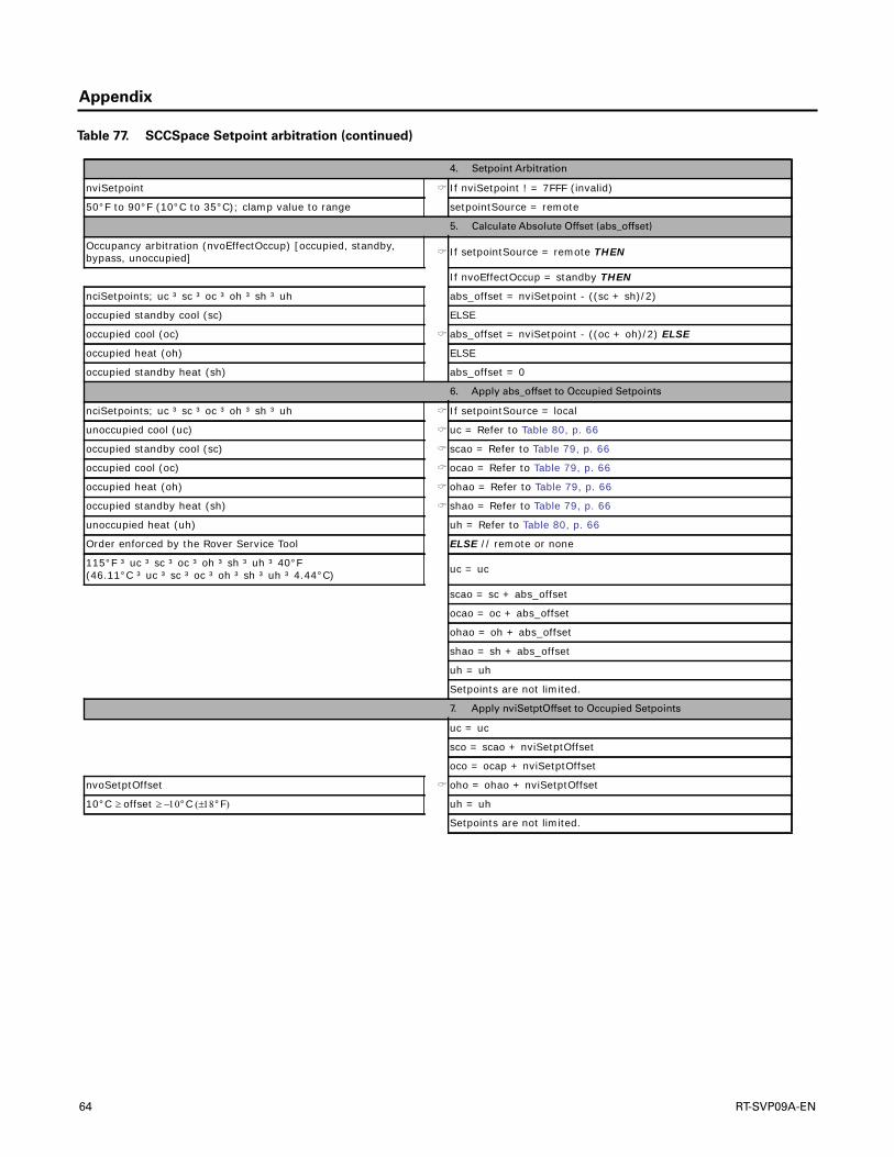
Appendix
Table 77. SCCSpace Setpoint arbitration (continued)
4. Setpoint Arbitration
nviSetpoint If nviSetpoint ! = 7FFF (invalid)
50°F to 90°F (10°C to 35°C); clamp value to range setpointSource = remote
5. Calculate Absolute Offset (abs_offset)
Occupancy arbitration (nvoEffectOccup) [occupied, standby, bypass, unoccupied] If setpointSource = remote THEN
If nvoEffectOccup = standby THEN
nciSetpoints; uc ³ sc ³ oc ³ oh ³ sh ³ uh abs_offset = nviSetpoint - ((sc + sh)/2)
occupied standby cool (sc) ELSE
occupied cool (oc) abs_offset = nviSetpoint - ((oc + oh)/2) ELSE
occupied heat (oh) ELSE
occupied standby heat (sh) abs_offset = 0
6. Apply abs_offset to Occupied Setpoints
nciSetpoints; uc ³ sc ³ oc ³ oh ³ sh ³ uh If setpointSource = local
unoccupied cool (uc) uc = Refer to Table 80, p. 66
occupied standby cool (sc) scao = Refer to Table 79, p. 66
occupied cool (oc) ocao = Refer to Table 79, p. 66
occupied heat (oh) ohao = Refer to Table 79, p. 66
occupied standby heat (sh) shao = Refer to Table 79, p. 66
unoccupied heat (uh) uh = Refer to Table 80, p. 66
Order enforced by the Rover Service Tool ELSE // remote or none
115°F ³ uc ³ sc ³ oc ³ oh ³ sh ³ uh ³ 40°F(46.11°C ³ uc ³ sc ³ oc ³ oh ³ sh ³ uh ³ 4.44°C) uc = uc
scao = sc + abs_offset
ocao = oc + abs_offset
ohao = oh + abs_offset
shao = sh + abs_offset
uh = uh
Setpoints are not limited.
7. Apply nviSetptOffset to Occupied Setpoints
uc = uc
sco = scao + nviSetptOffset
oco = ocap + nviSetptOffset
nvoSetptOffset oho = ohao + nviSetptOffset
10°C offset °C°F uh = uh
Setpoints are not limited.
64 RT-SVP09A-EN

Appendix
Table 78. SCCSpace Setpoint arbitration (continued)
8. Apply nviSetptShift to All Setpoints
nviSetptShift
10°C uc_shift °C°F ucs = uc + uc_shift
10°C sc_shift °C°F scs = sco + sc_shift
10°C oc_shift °C°F ocs + oco + oc_shift
10°C oh_shift °C°F ohs = oho + oh_shift
10°C sh_shift °C°F shs = sho + sh_shift
10°C uh_shift °C°F uhs = uh + uh_shift
Setpoints are not limited.
9. Limit Occupied Setpoints
nciPersonality2 ucs = ucs
cool setpoint high limit (csphl) csphl scl cspll
cool setpoint low limit (cspll) csphl ocl cspll
heat setpoint high limit (hsphl) hsphl ohl hspll
heat setpoint low limit (hspll) hsphl shl hspll
115°F range °F°C to 4.44°C) uhs = uhs
10. Six (6) Active Space Setpoints
ucs = active unoccupied cool setpoint
sca = active standby cool setpoint
oca = active occupied cool setpoint
oha = active occupied heat setpoint
sha = active standby heat setpoint
uha = active unoccupied heat setpoint
11. DeterminingTwo (2) Active Setpoints
acsp = active cool setpoint
ahsp = active heat setpoint
Occupancy arbitration (nvoEffectOccup) [occupied, standby, bypass, unoccupied] If nvoEffectOccup = occupied or bypass THEN
acsp = oca
ahsp = oha ELSE
If nvoEffectOccup = standby THEN
LCI-R reports remote setpoints to RTM controller. acsp = sca
Remote Occ Unocc Zone Cooling Setpoint = acsp ahsp = sha ELSE
Unoccupied
Remote Occ Unocc Zone Heating Setpoint = ahsp acsp = uca
ahsp = uha
12. Determining One (1) Active_Space_Setpoint
Zone demand arbitration (zd) = nvoHeatCool If zd = cool THEN
active_space_setpoint = acsp ELSE
zd ! = cool
nvoEffectSetpt_active_space_setpoint active_space_setpoint = ahsp
RT-SVP09A-EN 65
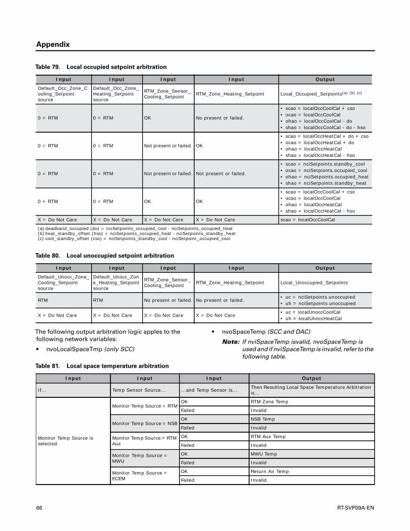
Appendix
The following output arbitration logic apples to thefollowing network variables:
• nvoLocalSpaceTmp (only SCC)
• nvoSpaceTemp (SCC and DAC)
Note: If nviSpaceTemp isvalid, nvoSpaceTemp isused and if nviSpaceTemp is invalid, refer to thefollowing table.
Table 79. Local occupied setpoint arbitration
Input Input Input Input Output
Default_Occ_Zone_Cooling_Setpoint source
Default_Occ_Zone_Heating_Setpoint source
RTM_Zone_Sensor_Cooling_Setpoint RTM_Zone_Heating_Setpoint Local_Occupied_Setpoints(a) (b) (c)
0 = RTM 0 = RTM OK No present or failed.
• scao = localOccCoolCal + cso• ocao = localOccCoolCal• ohao = localOccCoolCal - do• shao = localOccCoolCal - do - hso
0 = RTM 0 = RTM Not present or failed. OK
• scao = localOccHeatCal + do + cso• ocao = localOccHeatCal + do• ohao = localOccHeatCal• shao = localOccHeatCal - hso
0 = RTM 0 = RTM Not present or failed. Not present or failed.
• scao = nciSetpoints.standby_cool• ocao = nciSetpionts.occupied_cool• ohao = nciSetpoints.occupied_heat• shao = nciSetpoints.standby_heat
0 = RTM 0 = RTM OK OK
• scao = localOccCoolCal + cso• ocao = localOccCoolCal• ohao = localOccHeatCal• shao = localOccHeatCal - hso
X = Do Not Care X = Do Not Care X = Do Not Care X = Do Not Care scao = localOccCoolCal
(a) deadband_occupied (do) = nciSetpoints_occupied_cool - nciSetpoints_occupied_heat(b) heat_standby_offset (hso) = nciSetpoints_occupied_heat - nciSetpoints_standby_heat(c) cool_standby_offset (cso) = nciSetpoints_standby_cool - nciSetpoint_occupied_cool
Table 80. Local unoccupied setpoint arbitration
Input Input Input Input Output
Default_Unocc_Zone_Cooling_Setpoint source
Default_Unocc_Zone_Heating_Setpoint source
RTM_Zone_Sensor_Cooling_Setpoint RTM_Zone_Heating_Setpoint Local_Unoccupied_Setpoints
RTM RTM No present or failed. No present or failed.• uc = nciSetpoints.unoccupied• uh = nciSetpoints.unoccupied
X = Do Not Care X = Do Not Care X = Do Not Care X = Do Not Care• uc = localUnoccCoolCal• uh = localUnoccHeatCal
Table 81. Local space temperature arbitration
Input Input Input Output
If... Temp Sensor Source... ...and Temp Sensor is... Then Resulting Local Space Temperature Arbitration is...
Monitor Temp Source is selected.
Monitor Temp Source = RTMOK RTM Zone Temp
Failed Invalid
Monitor Temp Source = NSBOK NSB Temp
Failed Invalid
Monitor Temp Source = RTM Aux
OK RTM Aux Temp
Failed Invalid
Monitor Temp Source = MWU
OK MWU Temp
Failed Invalid
Monitor Temp Source = ECEM
OK Return Air Temp
Failed Invalid
66 RT-SVP09A-EN
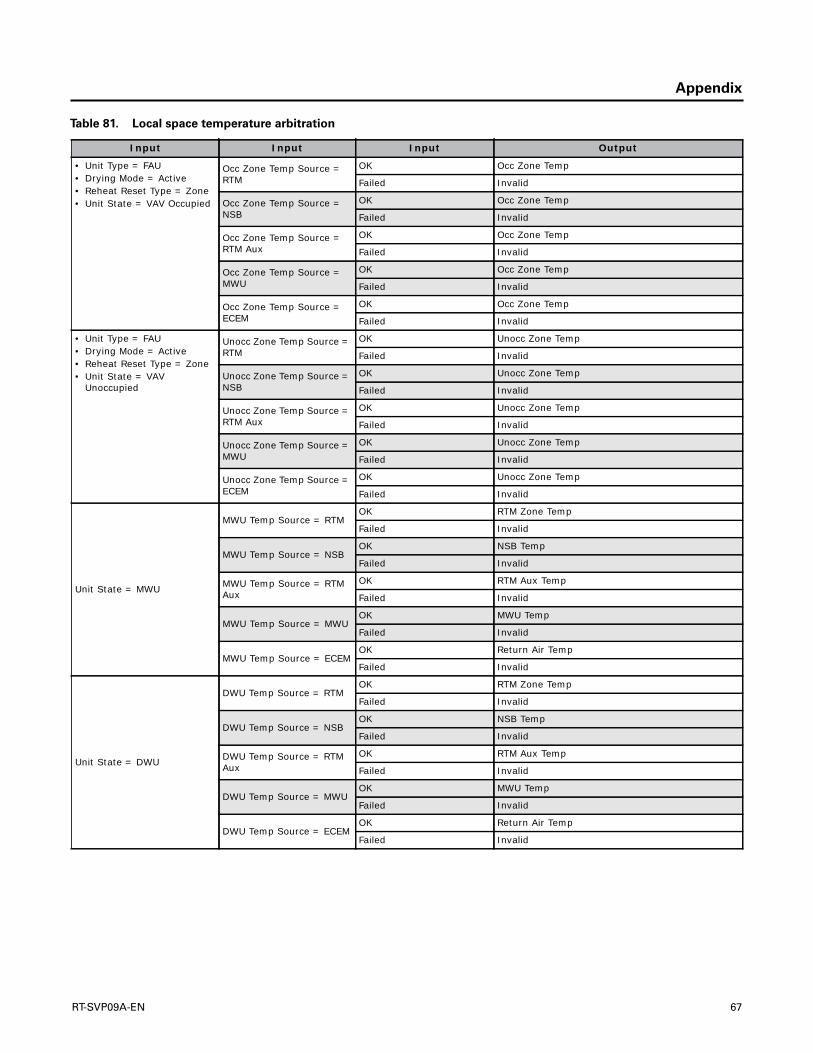
Appendix
• Unit Type = FAU• Drying Mode = Active• Reheat Reset Type = Zone• Unit State = VAV Occupied
Occ Zone Temp Source = RTM
OK Occ Zone Temp
Failed Invalid
Occ Zone Temp Source = NSB
OK Occ Zone Temp
Failed Invalid
Occ Zone Temp Source = RTM Aux
OK Occ Zone Temp
Failed Invalid
Occ Zone Temp Source = MWU
OK Occ Zone Temp
Failed Invalid
Occ Zone Temp Source = ECEM
OK Occ Zone Temp
Failed Invalid
• Unit Type = FAU• Drying Mode = Active• Reheat Reset Type = Zone• Unit State = VAV
Unoccupied
Unocc Zone Temp Source = RTM
OK Unocc Zone Temp
Failed Invalid
Unocc Zone Temp Source = NSB
OK Unocc Zone Temp
Failed Invalid
Unocc Zone Temp Source = RTM Aux
OK Unocc Zone Temp
Failed Invalid
Unocc Zone Temp Source = MWU
OK Unocc Zone Temp
Failed Invalid
Unocc Zone Temp Source = ECEM
OK Unocc Zone Temp
Failed Invalid
Unit State = MWU
MWU Temp Source = RTMOK RTM Zone Temp
Failed Invalid
MWU Temp Source = NSBOK NSB Temp
Failed Invalid
MWU Temp Source = RTM Aux
OK RTM Aux Temp
Failed Invalid
MWU Temp Source = MWUOK MWU Temp
Failed Invalid
MWU Temp Source = ECEMOK Return Air Temp
Failed Invalid
Unit State = DWU
DWU Temp Source = RTMOK RTM Zone Temp
Failed Invalid
DWU Temp Source = NSBOK NSB Temp
Failed Invalid
DWU Temp Source = RTM Aux
OK RTM Aux Temp
Failed Invalid
DWU Temp Source = MWUOK MWU Temp
Failed Invalid
DWU Temp Source = ECEMOK Return Air Temp
Failed Invalid
Table 81. Local space temperature arbitration
Input Input Input Output
RT-SVP09A-EN 67

Appendix
Unit State = Unoccupied
Unocc Zone Temp Source = RTM
OK RTM Zone Temp
Failed Invalid
Unocc Zone Temp Source = NSB
OK NSB Temp
Failed Invalid
Unocc Zone Temp Source = RTM Aux
OK RTM Aux Temp
Failed Invalid
Unocc Zone Temp Source = MWU
OK MWU Temp
Failed Invalid
Unocc Zone Temp Source = ECEM
OK Return Air Temp
Failed Invalid
• Unit Control = VAV• Active Cool Reset = Zone• Active Heat Reset Type =
Outdoor Air or Zone
Zone Reset Temp Source = RTM
OK RTM Zone Temp
Failed Invalid
Zone Reset Temp Source = NSB
OK NSB Temp
Failed Invalid
Zone Reset Temp Source = RTM Aux
OK RTM Aux Temp
Failed Invalid
Zone Reset Temp Source = MWU
OK MWU Temp
Failed Invalid
Zone Reset Temp Source = ECEM
OK Return Air Temp
Failed Invalid
Unit Control = CV
Occ Zone Temp Source = RTM
OK RTM Zone Temp
Failed Invalid
Occ Zone Temp Source = NSB
OK NSB Temp
Failed Invalid
Occ Zone Temp Source = RTM Aux
OK RTM Aux Temp
Failed Invalid
Occ Zone Temp Source = MWU
OK MWU Temp
Failed Invalid
Occ Zone Temp Source = ECEM
OK Return Air Temp
Failed Invalid
Table 81. Local space temperature arbitration
Input Input Input Output
68 RT-SVP09A-EN

Glossary
AActive Setpoint
The setpoint that is currently being used for control.Occupied/unoccupied heating/cooling setpoints areselected according to unit mode and occupied/unoccupied switching functions.
BBAS
Building Automation System.
CCSC
Commercial Self-contained.
CV
Constant Volume.
DDAC
Discharge Air Controller (LonMark™ profile).
DACX
Discharge Air Controller Extension (Trane®).
Daytime Warm-up
Applies to VAV units. Refers to a zone warm-up cycle thatoccurs when the zone temperature falls to apredetermined value.
Deadband
As applied to discharge air temperature control, this refersto a range of temperature equally spaced above andbelow the discharge air temperature control point inwhich the control algorithm is satisfied. There is noadjustment of machine capacity within the deadband.
EECEM
Exhaust/comparative enthalpy module.
Emergency Stop input
RTM binary input. Can be used for emergency shutdownof the unit by field-installed contacts. A diagnostic isproduced when this input is open.
Enthalpy
A measure of the heat content or total heat, includingboth sensible and latent heat, measured in Joules (J) orBritish thermal units (Btu).
HHI
Human Interface.
HrtBt
Heartbeat.
IIGV
Inlet Guide Vanes.
I/O
Input/output.
IPC
Interprocessor Communications.
IWC
Inches Water Column.
MMCM
Multiple Circuit Compressor Module.
Minimum Position
Also known as economizer minimum position.
MWU
Morning Warm-up.
NNSB
Night setback which applies to the control of heating andcooling operation of a rooftop unit during unoccupiedmode.
NV
Network Variable.
nvi
Network Variable Input.
nvo
Network Variable Output.
OOA
Outdoor Air.
OA Reset
A function that resets (modifies) the Supply AirTemperature Cooling (or Heating) Setpoint based on theoutside air temperature.
RT-SVP09A-EN 69

Glossary
PPa
Pascals
Purge
A function which causes zone air to be purged andreplaced by outside air.
RReference Enthalpy
An outdoor enthalpy value above which economizing isdisabled.
RA
Return Air.
Remote Human Interface (Remote HI)
A human interface module design to be mountedremotely from the unit. There are some functionaldifferences between a machine and remote HI.
RT
Rooftop systems and rooftop air handlers.
RT1
IntelliPak I rooftop units manufactured before March2009.
RT2
All IntelliPak II units and IntelliPak I+ units manufacturedafter March 2009.
RTM
Rooftop Module– contains I/Os for most air-handlingfunctions.
SSCC
Space Comfort Controller (LonMark profile).
SCCX
Space Comfort Controller Extension (Trane®).
SCM
Single Circuit Compressor Module.
SCPT
Standard Configuration Property Type.
SNVT
Standard Network Variable Type.
SPID
Standard Program Identification.
StatiTrac™
Trane trademark for control of space pressurization.
SA
Supply Air.
UUCPT
User-defined configuration property type.
VVAV
Variable-air-volume.
VCM
Ventilation Control Module.
VOM
Ventilation Override Module.
XXIF
External Interface File.
ZZone Reset
A function that resets (modifies) the supply airtemperature cooling (or heating) setpoint based on thezone temperature.
70 RT-SVP09A-EN


The manufacturer optimizes the performance of homes and buildings around the world. A business of Ingersoll Rand,the leader in creating and sustaining safe, comfortable and energy efficient environments,the manufacturer offers abroad portfolio of advanced controls and HVAC systems, comprehensive building services, and parts. For moreinformation, visit www.IRCO.com.
The manufacturer has a policy of continuous product and product data improvement and reserves the right to change design and specifications without notice.
We are committed to using environmentally
conscious print practices that reduce waste.
© 2013Trane All rights reserved
RT-SVP09A-EN 19 Nov 2013
(NEW)
Related Documents