Technical Report MySQL Database on NetApp ONTAP Best Practices Anup Bharti, NetApp October 2018 | TR-4722 Abstract MySQL and its variants, including MariaDB and Percona, are widely used for many enterprise applications. These applications range from global social networking sites and massive e-commerce systems to SMB hosting systems containing thousands of database instances. This document describes the configuration requirements and provides guidance on tuning and storage configuration for deploying MySQL on NetApp ® ONTAP ® data management software. To determine whether the environment, configurations, and versions specified in this report support your environment, consult the Interoperability Matrix Tool (IMT).

Welcome message from author
This document is posted to help you gain knowledge. Please leave a comment to let me know what you think about it! Share it to your friends and learn new things together.
Transcript

Technical Report
MySQL Database on NetApp ONTAP Best Practices
Anup Bharti, NetApp
October 2018 | TR-4722
Abstract
MySQL and its variants, including MariaDB and Percona, are widely used for many
enterprise applications. These applications range from global social networking sites and
massive e-commerce systems to SMB hosting systems containing thousands of database
instances. This document describes the configuration requirements and provides guidance
on tuning and storage configuration for deploying MySQL on NetApp® ONTAP® data
management software.
To determine whether the environment, configurations, and versions specified in this report
support your environment, consult the Interoperability Matrix Tool (IMT).
2 MySQL Database on NetApp ONTAP © 2018 NetApp, Inc. All rights reserved. © 2016 NetApp, Inc. All rights reserved.
TABLE OF CONTENTS
1 Introduction ........................................................................................................................................... 5
2 NetApp ONTAP ..................................................................................................................................... 5
2.1 ONTAP with AFF and FAS Controllers ...........................................................................................................5
2.2 NPS for Cloud .................................................................................................................................................6
2.3 ONTAP Select .................................................................................................................................................6
2.4 Cloud Volumes ................................................................................................................................................7
3 ONTAP Features ................................................................................................................................... 7
4 ONTAP Configuration........................................................................................................................... 8
4.1 RAID Level ......................................................................................................................................................8
4.2 Capacity Levels ...............................................................................................................................................9
4.3 Read_realloc ................................................................................................................................................. 10
5 Storage Virtual Machines and Logical Interfaces ........................................................................... 10
5.1 SVMs ............................................................................................................................................................ 11
5.2 LIF ................................................................................................................................................................. 11
5.3 NFS LIF Design ............................................................................................................................................ 12
5.4 SAN LIF Design ............................................................................................................................................ 14
6 Additional ONTAP Considerations ................................................................................................... 15
6.1 LUN Considerations ...................................................................................................................................... 15
6.2 Cluster Operations—Takeover and Switchover ............................................................................................ 17
6.3 MetroCluster and Multiple Aggregates .......................................................................................................... 18
6.4 NVFAIL ......................................................................................................................................................... 18
6.5 Overcommitting RAM .................................................................................................................................... 19
6.6 Ethernet Flow Control ................................................................................................................................... 19
6.7 Jumbo Frames .............................................................................................................................................. 19
6.8 TCP Parameters ........................................................................................................................................... 20
7 ONTAP QoS ......................................................................................................................................... 20
7.1 IOPS QoS ..................................................................................................................................................... 20
7.2 Bandwidth QoS ............................................................................................................................................. 21
7.3 Guaranteed QoS ........................................................................................................................................... 21
8 ONTAP Efficiency ............................................................................................................................... 21
8.1 Compression ................................................................................................................................................. 21
8.2 Alignment ...................................................................................................................................................... 22
3 MySQL Database on NetApp ONTAP © 2018 NetApp, Inc. All rights reserved. © 2016 NetApp, Inc. All rights reserved.
8.3 Inline Data Compaction ................................................................................................................................. 23
8.4 Deduplication ................................................................................................................................................ 23
8.5 Thin Provisioning .......................................................................................................................................... 23
9 Native Data Protection ....................................................................................................................... 24
9.1 Recovery Time Objective .............................................................................................................................. 24
9.2 Recovery Point Objective .............................................................................................................................. 24
9.3 NetApp Snapshot Technology ...................................................................................................................... 24
9.4 NetApp SnapRestore Technology ................................................................................................................. 25
9.5 Data Replication and Disaster Recovery ...................................................................................................... 26
10 Linux Configuration............................................................................................................................ 27
10.1 Slot Tables .................................................................................................................................................... 27
10.2 Security-Enhanced Linux .............................................................................................................................. 28
10.3 I/O Schedulers .............................................................................................................................................. 28
10.4 Multipathing ................................................................................................................................................... 28
10.5 Open File Limits ............................................................................................................................................ 29
11 Database and Virtualization ............................................................................................................... 29
11.1 Containers..................................................................................................................................................... 29
11.2 Storage Presentation .................................................................................................................................... 30
11.3 Para Virtualized Drivers ................................................................................................................................ 31
12 MySQL ................................................................................................................................................. 31
12.1 Why MySQL? ................................................................................................................................................ 31
12.2 MySQL File Structure .................................................................................................................................... 32
12.3 MySQL Configuration .................................................................................................................................... 35
13 Deployment Methods ......................................................................................................................... 38
13.1 MySQL over NAS .......................................................................................................................................... 39
13.2 MySQL over SAN .......................................................................................................................................... 40
14 Performance Benchmarking .............................................................................................................. 41
14.1 SysBench ...................................................................................................................................................... 41
14.2 MySQL Slap .................................................................................................................................................. 41
15 Performance Results .......................................................................................................................... 41
15.1 Testing Considerations ................................................................................................................................. 42
4 MySQL Database on NetApp ONTAP © 2018 NetApp, Inc. All rights reserved. © 2016 NetApp, Inc. All rights reserved.
Appendix A: my.cnf Parameters ............................................................................................................. 45
Where to Find Additional Information .................................................................................................... 45
Version History ......................................................................................................................................... 46
LIST OF TABLES
Table 1) MySQL configuration parameters. .................................................................................................................. 35
Table 2) Lab setup. ...................................................................................................................................................... 42
Table 3) Test results on NFS. ....................................................................................................................................... 43
Table 4) Test results on NFS with compression and deduplication. ............................................................................. 43
Table 5) Test results on iSCSI. ..................................................................................................................................... 44
Table 6) Test results on iSCSI with compression and deduplication. ........................................................................... 44
LIST OF FIGURES
Figure 1) RAID DP offers protection and efficiency. .......................................................................................................9
Figure 2) InnoDB engine architecture. .......................................................................................................................... 33
Figure 3) MySQL file system structure. ........................................................................................................................ 34
Figure 4) MySQL configuration parameters used for benchmark tests. ....................................................................... 45
5 MySQL Database on NetApp ONTAP © 2018 NetApp, Inc. All rights reserved. © 2016 NetApp, Inc. All rights reserved.
1 Introduction
NetApp® ONTAP® is powerful data-management software with native capabilities that include inline
compression, nondisruptive hardware upgrades, and the ability to import a LUN from a foreign storage
array. Up to 24 nodes can be clustered together, simultaneously serving data through NFS, CIFS, iSCSI,
FC, and FC over Ethernet (FCoE) protocols. In addition, NetApp Snapshot™ technology is the basis for
creating tens of thousands of online backups and fully operational database clones.
In addition to the rich feature set of ONTAP, there are many user requirements, including database size,
performance requirements, and data protection needs. Known deployments of NetApp storage include
everything from a virtualized environment of approximately 6,000 databases to single databases
approaching the 1PB mark.
MySQL, including its derivatives such as MariaDB, is one of the most popular open-source databases
across the globe. MySQL provides ultimate platform flexibility to enterprises that need more features and
functions for their database servers, at a lower cost than proprietary closed-source databases. Enterprise
features include an extensible, pluggable architecture, native high availability, and exceptionally simple
management. Setting up the MySQL database server takes just 15 minutes from software download to
installation. Recent MySQL versions also support many advanced features commonly found in NoSQL
databases.
Enterprises using MySQL face several challenges when their data grows exponentially, and data
management becomes difficult. This document details the best practices to follow for successful
deployment of MySQL on ONTAP. These practices range from tuning options to data protection to proper
use of efficiency features such as compression and compaction.
Note: This guide assumes that you have a basic understanding of the technology and operation of ONTAP software and the MySQL database.
2 NetApp ONTAP
For maximum performance and control of data, NetApp ONTAP remains the leading solution. It is the
standard storage solution that thousands of customers have relied on for more than 20 years. ONTAP
delivers solutions for any environment, ranging from mission-critical database deployments to instant
restore scenarios.
ONTAP software is the foundation for advanced data protection and management. However, ONTAP is
only the software portion of the solution. There are several hardware environments to choose from:
• ONTAP on NetApp AFF and FAS
• NetApp Private Storage for Cloud (NPS for Cloud)
• ONTAP Select
• NetApp Cloud Volumes ONTAP
Some hardware options offer better performance, others offer lower costs, and some run within
hyperscale clouds. The core functions of ONTAP are unchanged, with multiple replication options
available to bind different ONTAP systems into a single solution. As a result, data protection and disaster
recovery strategies can be built on real-world needs, such as performance requirements, capital
expenditure (capex), or operational expenditure (opex) considerations, and overall cloud strategy. The
underlying storage technology runs anywhere in any environment.
2.1 ONTAP with AFF and FAS Controllers
For maximum performance and control of data, ONTAP on a physical AFF or FAS controller remains the
leading solution. ONTAP delivers solutions for any environment, ranging from three mission-critical
databases to 60,000-database service provider deployments, instant restores of petabyte-scale

6 MySQL Database on NetApp ONTAP © 2018 NetApp, Inc. All rights reserved. © 2016 NetApp, Inc. All rights reserved.
databases, and database as a service (DBaaS) environments involving hundreds of clones of a single
database.
2.2 NPS for Cloud
NetApp introduced the NPS option to address the needs of data-intensive workloads in the public cloud.
Although many public cloud storage options exist, most of them have limitations in terms of performance,
control, or scale. For database workloads, the primary limitations are as follows:
• Many public cloud storage options do not scale to the IOPS levels required by modern database workloads in terms of cost, efficiency, or manageability.
• Even when the raw IOPS capabilities of a public cloud provider meet requirements, the I/O latencies are frequently unacceptable for database workloads. This limitation has become more prevalent as databases have migrated to all-flash storage arrays, and businesses have begun to measure latency in terms of microseconds, not milliseconds.
• Although public cloud storage availability is good overall, it does not yet meet the demands of most mission-critical environments.
• Public cloud storage services have backup and recovery capabilities, but in general, they cannot meet the zero recovery point objective (RPO) and near-zero recovery time objective (RTO) requirements of most databases. Data protection requires true instant backup and recovery based on Snapshot copies, not streaming backup and recovery to and from elsewhere in a cloud.
• Hybrid cloud environments must move data between on-premises and cloud storage systems, mandating a common foundation for storage management.
• Many governments have strict data sovereignty laws that prohibit relocating data outside national borders.
NPS systems deliver maximum storage performance, control, and flexibility to public cloud providers,
including Amazon Web Services (AWS), Microsoft Azure, and IBM SoftLayer. This capability is delivered
by AFF and FAS systems, including NetApp MetroCluster™ options, in data centers connected directly to
public clouds. The full power of the hyperscaler compute layer can be used without the limitations of
hyperscaler storage. Furthermore, NPS enables cloud-independent and multicloud architectures because
the data, such as application binaries, databases, database backups, and archives, remains wholly within
the NPS system. There is no need to expend time, bandwidth, or money moving data between cloud
providers.
Notably, some NetApp customers have used the NPS model on their own initiative. In many locations,
high-speed access to one of the hyperscaler providers is readily available to customer data center
facilities. Elsewhere, customers use colocation facilities that are already capable of providing high-speed
access to hyperscaler cloud providers. These facilities have led to the use of AWS, Azure, and SoftLayer
as essentially on-demand, consumption-based sources of virtualized servers. In some cases, nothing has
changed about the customers’ day-to-day operations. They simply use the hyperscaler services as a
more powerful, flexible, and cost-efficient replacement for their traditional virtualization infrastructure.
Options are also available for NPS as a service (NPSaaS). Often the demands of database environments
are substantial enough to warrant purchasing an NPS system at a colocation facility. However, some
customers prefer to use both cloud servers and cloud storage as an operational expenditure rather than a
capital expenditure. In these cases, they want to use storage resources purely as an as-needed, on-
demand service. Several providers now offer NPS as a service for such customers.
2.3 ONTAP Select
ONTAP Select runs on a customer’s own virtualization infrastructure and delivers ONTAP intelligence and
Data Fabric connectivity to the drives inside white box hardware. ONTAP Select allows ONTAP and guest
operating systems to share physical hardware as a highly converged infrastructure. The best practices for
running MySQL on ONTAP are not affected.
7 MySQL Database on NetApp ONTAP © 2018 NetApp, Inc. All rights reserved. © 2016 NetApp, Inc. All rights reserved.
An ONTAP Select environment does not match the peak performance of a high-end AFF system, but
most databases do not require 300K IOPS. Typical databases require only about 5K to 10K IOPS, a
target that ONTAP Select can meet. Furthermore, most databases are limited more by storage latency
than storage IOPS, a problem that you can address by deploying ONTAP Select on solid-state drives
(SSDs).
2.4 Cloud Volumes
NetApp introduced Cloud Volumes to meet the advanced performance and management requirements in
hyperscaler clouds, including AWS, Azure, and Google Cloud Platform. The Cloud Volumes solution is
available in two forms: NetApp Cloud Volumes ONTAP and NetApp Cloud Volumes Service.
Cloud Volumes ONTAP
Cloud Volumes ONTAP is similar to ONTAP Select, except that it runs in a hyperscaler cloud
environment, bringing intelligence and Data Fabric connectivity to hyperscaler storage volumes. The best
practices for running MySQL on ONTAP are not affected. The primary considerations are performance
and, to a lesser extent, cost.
Cloud Volumes ONTAP is partially limited by the performance of the underlying volumes managed by the
cloud provider. The result is more manageable storage, and, in some cases, the caching capability of
Cloud Volumes ONTAP offers a performance improvement. However, there are always some IOPS and
latency limitations due to the reliance on the public cloud provider. These limitations do not make
database performance unacceptable, but the performance ceiling is simply lower than the performance of
a physical AFF system. Furthermore, the performance of storage volumes offered by the cloud providers
that are used by Cloud Volumes ONTAP are continuously improving.
Cloud Volumes Service
NetApp Cloud Volumes Service is storage served by physical storage systems running ONTAP,
delivering the best possible performance in the public cloud with enterprise-class availability and data
protection. Storage is available on demand with pay-as-you-go and prepaid billing options. Many of the
advanced features of ONTAP are available through hyperscaler portals, with more options becoming
available all the time.
3 ONTAP Features
Some NetApp ONTAP features include:
• Flexible response to changing business requirements:
− Accelerate SAN and NAS workloads with flash.
− Scale to 24 nodes, and upgrade and service with zero downtime.
− Connect easily to the cloud.
• Delivery of uptime, security, and cost efficiency:
− Continuous availability.
− Proven storage efficiency with built-in encryption.
− Simplified management and deep application integration.
• Flexible, scalable storage; designed for business-critical and consolidated environments that require:
− Rich data management.
− Enterprise-grade capabilities.
− Scalability for SAN and NAS workloads.
• Backups based on Snapshot technology:
8 MySQL Database on NetApp ONTAP © 2018 NetApp, Inc. All rights reserved. © 2016 NetApp, Inc. All rights reserved.
− Use volume-based Snapshot technology to create entire volume backups.
− Take advantage of very fast, crash-consistent Snapshot copy backups.
• Use of the NetApp Snap Creator® framework along with user-maintained scripts to custom-design your database backup solution.
• Recovery based on Snapshot copies:
− Use volume-based NetApp SnapRestore® (VBSR) technology to restore your volume.
− Perform instant recovery to an earlier point in time (PiT).
− Use single-file SnapRestore if needed.
• Checksums and data integrity:
− Data integrity is protected by use of checksums at multiple levels.
− TCP layer rejects the packet data and requests retransmission if data inconsistency occurs at a network level.
− Checksum errors can be detected and corrected.
− RAID rebuild takes care of data integrity.
− Data integrity is also maintained at the MySQL level through checksum at the InnoDB page level.
4 ONTAP Configuration
This section presents best practices for basic NetApp ONTAP configuration.
These best practices don’t apply to large-scale MySQL deployments (200+ databases), which require a
special architecture and design. Even small changes in data protection requirements can significantly
affect storage design. For detailed configuration information, see TR-4591: Database Data Protection:
Backup, Recovery, Replication, and DR. For comprehensive assistance with design, contact NetApp
sales.
4.1 RAID Level
Disk redundancy is an important factor in decisions about storage layout for controllers. There are
different RAID levels that measure disk redundancy; for example, RAID 4, RAID 3, RAID 5, RAID 6,
NetApp RAID DP®, or NetApp RAID-TEC™.
With traditional single-parity RAID (RAID 3, 4, or 5) or even RAID 1 (mirroring), the entire volume and all
its data is lost if a second drive fails or has an uncreatable bit error while another drive in the RAID group
rebuilds. Most RAID implementations also have a drawback that affects write operations. Completion of a
write operation on other RAID implementations requires multiple disk reads to regenerate the parity data,
a process commonly called the RAID penalty.
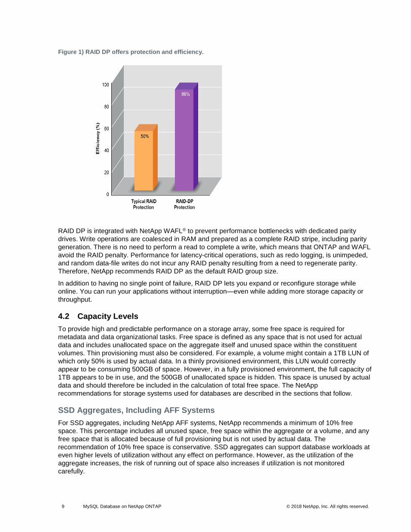
However, NetApp RAID DP, a high-performance dual-parity version of RAID 6, protects against double
disk failure, as shown in Figure 1. It provides higher availability than RAID 1 (mirroring), RAID 0+1
(striping and mirroring), and RAID 5 and incurs no performance penalty.
9 MySQL Database on NetApp ONTAP © 2018 NetApp, Inc. All rights reserved. © 2016 NetApp, Inc. All rights reserved.
Figure 1) RAID DP offers protection and efficiency.
RAID DP is integrated with NetApp WAFL® to prevent performance bottlenecks with dedicated parity
drives. Write operations are coalesced in RAM and prepared as a complete RAID stripe, including parity
generation. There is no need to perform a read to complete a write, which means that ONTAP and WAFL
avoid the RAID penalty. Performance for latency-critical operations, such as redo logging, is unimpeded,
and random data-file writes do not incur any RAID penalty resulting from a need to regenerate parity.
Therefore, NetApp recommends RAID DP as the default RAID group size.
In addition to having no single point of failure, RAID DP lets you expand or reconfigure storage while
online. You can run your applications without interruption—even while adding more storage capacity or
throughput.
4.2 Capacity Levels
To provide high and predictable performance on a storage array, some free space is required for
metadata and data organizational tasks. Free space is defined as any space that is not used for actual
data and includes unallocated space on the aggregate itself and unused space within the constituent
volumes. Thin provisioning must also be considered. For example, a volume might contain a 1TB LUN of
which only 50% is used by actual data. In a thinly provisioned environment, this LUN would correctly
appear to be consuming 500GB of space. However, in a fully provisioned environment, the full capacity of
1TB appears to be in use, and the 500GB of unallocated space is hidden. This space is unused by actual
data and should therefore be included in the calculation of total free space. The NetApp
recommendations for storage systems used for databases are described in the sections that follow.
SSD Aggregates, Including AFF Systems
For SSD aggregates, including NetApp AFF systems, NetApp recommends a minimum of 10% free
space. This percentage includes all unused space, free space within the aggregate or a volume, and any
free space that is allocated because of full provisioning but is not used by actual data. The
recommendation of 10% free space is conservative. SSD aggregates can support database workloads at
even higher levels of utilization without any effect on performance. However, as the utilization of the
aggregate increases, the risk of running out of space also increases if utilization is not monitored
carefully.
10 MySQL Database on NetApp ONTAP © 2018 NetApp, Inc. All rights reserved. © 2016 NetApp, Inc. All rights reserved.
HDD Aggregates, Including Flash Pool Aggregates
For HDD aggregates, including NetApp Flash Pool™ aggregates, NetApp recommends a minimum of 15%
free space. This percentage includes all unused space, free space within the aggregate or a volume, and
any free space that is allocated because of full provisioning but is not used by actual data. There should
be no measurable performance effect when utilization is less than 85%. As utilization approaches 90%,
some reduction in performance might become noticeable for certain workloads. As utilization reaches
95%, most database workloads experience a degradation in performance.
4.3 Read_realloc
Most write activity to the MySQL data file consists of random overwrites. As these overwrites occur, the
changed data is placed on a new physical location within the storage system. This action has no effect on
random I/O, which is typically the most performance-critical I/O type. However, it can affect sequential I/O
throughput because the storage system is forced to perform more physical disk I/O operations to
assemble the response to a multiblock read request and to perform read-ahead.
On an AFF system, the additional I/O operations are not significant. But on an array with spinning media,
including Flash Pool aggregates, the additional drive head movement results in increased latency, which
lowers throughput. Enabling the read_realloc option on a volume results in real-time optimization of
the file system layout. When the data on a WAFL volume is poorly allocated, the bulk of the work required
to address the problem is read activity. After the block reads are complete, writing the data back to disk in
a single contiguous RAID stripe is a low-cost operation. The read_realloc option enables this process
in a way that does not affect overall performance.
For example, suppose a full table scan is being performed, meaning that a data file is being read
sequentially. If read_realloc detects blocks that were suboptimally organized on the disk, 90% of the
work to address the problem is already complete. The blocks are already in RAM on the storage system;
therefore, after servicing the read request from the database server, read_realloc performs the next
step and writes them back to disk in an optimized format. The next time a full table scan is performed, the
data is optimized. In the long term, the use of the read_realloc option creates a constant data cleanup
process that optimizes the layout of the data files on a disk.
There are two read_realloc methods: general and space optimized. The general setting optimizes
block layout for both the live file system and the blocks contained in a Snapshot copy. This approach can
result in increased space consumption when Snapshot copies are present, but it offers improved
performance during sequential reads on the live file system, Snapshot copies, and clones. If the space-
optimized approach is used, the blocks contained in Snapshot copies are not reorganized. These
parameters can be changed at any time; however, read_realloc should not be enabled across the
entire environment at once because the additional work required could affect performance. Enabling it on
one or two data-file–containing volumes per day is a safer approach.
NetApp recommends following best practices for the read_realloc option:
• Set read_realloc on volumes that contain the data files, and then monitor the space consumption.
Enabling this option is unnecessary on volumes that contain an archive log, control file, or other data file, but doing so should not cause problems.
• If the Snapshot copies appear to cause excess space consumption, change the setting to space optimized.
As previously stated, read_realloc is not applicable to AFF systems.
5 Storage Virtual Machines and Logical Interfaces
As with other aspects of database architecture, the best options for storage virtual machine (SVM) and
logical interface (LIF) designs depend heavily on scaling requirements and business needs.
11 MySQL Database on NetApp ONTAP © 2018 NetApp, Inc. All rights reserved. © 2016 NetApp, Inc. All rights reserved.
This section provides an overview of key management principles of NetApp ONTAP data management
software. For more comprehensive documentation, see the Network Management Guide for the version
of ONTAP you are using.
5.1 SVMs
SVMs are the basic functional unit of storage, so it is useful to compare an SVM to a guest on a VMware
ESXi server. When first installed, ESXi has no preconfigured capabilities, such as hosting a guest
operating system or supporting an end-user application. It is an empty container until a virtual machine
(VM) is defined. ONTAP data management software is similar. When first installed, ONTAP has no data-
serving capabilities, and an SVM must be defined. It is the SVM personality that defines the data
services.
Some customers operate one primary SVM for most of their day-to-day requirements but then create a
small number of SVMs for special needs, including the following situations:
• An SVM for a critical business database managed by a specialist team.
• An SVM for a development group that has been granted administrative control to manage its own storage independently.
• An SVM for sensitive business data, such as human resources or financial reporting data, for which the administrative team must be limited.
Note: In a multitenant environment, each tenant’s data can be given a dedicated SVM. The recommended limit for SVMs is approximately 125 per cluster node, but in general the LIF maximums are reached before the SVM limit is reached. There is a point at which a multitenant environment is best separated into network segments rather into isolated, dedicated SVMs.
5.2 LIF
From a functional perspective, LIFs can be divided into the following groups:
• Cluster and node management LIFs. LIFs used to manage the storage cluster.
• SVM management LIFs. Interfaces that permit access to an SVM through the ONTAP API (known as NetApp Manageability SDK) for functions such as Snapshot copy creation or volume resizing. Products such as NetApp SnapManager® for Oracle (SMO) must have access to an SVM management LIF.
• Data LIFs. Interfaces that carry FC, iSCSI, NFS, or CIFS data.
Note: A data LIF used for NFS traffic can also be used for management. To do so, change the firewall policy from data to management or another policy that allows HTTP, HTTPS, or SSH. This change can simplify network configuration by avoiding the configuration of each host for access to both the NFS data LIF and a separate management LIF. You cannot configure an interface for both iSCSI and management traffic, even though both use an IP protocol. A separate management LIF is required in iSCSI environments.
For detailed information about LIF types, see the ONTAP Network Management Guide.
Consider the following primary topics when building a LIF strategy:
• Performance. Is the network bandwidth sufficient?
• Resiliency. Are there any single points of failure in the design?
• Manageability. Can the network be scaled nondisruptively?
These topics apply to the end-to-end solution, from the host through the switches to the storage system.

12 MySQL Database on NetApp ONTAP © 2018 NetApp, Inc. All rights reserved. © 2016 NetApp, Inc. All rights reserved.
5.3 NFS LIF Design
In contrast to SAN protocols, NFSv3 and NFSv4 have a limited ability to define multiple paths to data.
The parallel NFS (pNFS) extensions to NFSv4.1 address this limitation.
Performance and Resiliency
Although measuring SAN LIF performance is primarily a matter of calculating the total bandwidth from all
primary paths, determining NFS LIF performance requires a closer look at the exact network
configuration. For example, two 10Gb ports can be configured as raw physical ports, or they can be
configured as a Link Aggregation Control Protocol (LACP) interface group. If they are configured as an
interface group, multiple load-balancing policies are available that work differently depending on whether
traffic is switched or routed. Finally, Direct NFS (DNFS) offers load-balancing configurations that do not
exist in any currently operating system NFS clients.
Unlike SAN protocols, NFS file systems require resiliency at the protocol layer. For example, a LUN is
always configured with multipathing enabled, meaning that multiple redundant channels are available to
the storage system, each of which uses the FC protocol. An NFS file system, on the other hand, depends
on the availability of a single TCP/IP channel that can be protected at the physical layer only. This
arrangement is why options such as port failover and LACP port aggregation exist.
In an NFS environment, both performance and resiliency are provided at the network protocol layer. As a
result, both topics are intertwined and must be discussed together.
Bind LIFs to Port Groups
To bind a LIF to a port group, associate the LIF IP address with a group of physical ports. The primary
method for aggregating physical ports together is LACP. The fault-tolerance capability of LACP is fairly
simple; each port in an LACP group is monitored and is removed from the port group if a malfunction
occurs. There are, however, many misconceptions about how LACP works with respect to performance:
• LACP does not require the configuration on the switch to match the endpoint. For example, ONTAP can be configured with IP-based load balancing, whereas a switch can use MAC-based load balancing.
• Each endpoint using an LACP connection can independently choose the packet transmission port, but it cannot choose the port used for receipt. Therefore, traffic from ONTAP to a particular destination is tied to a particular port, and the return traffic could arrive on a different interface. This does not cause problems, however.
• LACP does not evenly distribute traffic all the time. In a large environment with many NFS clients, the result is typically even use of all ports in an LACP aggregation. However, any one NFS file system in the environment is limited to the bandwidth of only one port, not the entire aggregation.
• Although round-robin LACP policies are available on ONTAP, these policies do not address the connection from a switch to a host. For example, a configuration with a four-port LACP trunk on a host and a four-port LACP trunk on ONTAP is still only able to read a file system using a single port. Although ONTAP can transmit data through all four ports, no switch technologies are currently available that send from the switch to the host through all four ports. Only one is used.
The most common approach in larger environments consisting of many database hosts is to build an
LACP aggregate of an appropriate number of 10Gb interfaces by using IP load balancing. This approach
enables ONTAP to deliver even use of all ports, as long as enough clients exist. Load balancing breaks
down when there are fewer clients in the configuration, because LACP trunking does not dynamically
redistribute load.
When a connection is established, traffic in a particular direction is placed on only one port. For example,
a database performing a full table scan against an NFS file system connected through a four-port LACP
trunk reads data though only one network interface card (NIC). If only three database servers are in such

13 MySQL Database on NetApp ONTAP © 2018 NetApp, Inc. All rights reserved. © 2016 NetApp, Inc. All rights reserved.
an environment, it is possible that all three are reading from the same port, while the other three ports are
idle.
Bind LIFs to Physical Ports
Binding a LIF to a physical port results in more granular control over network configuration because a
given IP address on an ONTAP system is associated with only one network port at a time. Resiliency is
then accomplished through the configuration of failover groups and failover policies.
Failover Policies and Failover Groups
The behavior of LIFs during network disruption is controlled by failover policies and failover groups.
Configuration options have changed with the different versions of ONTAP. Consult the ONTAP Network
Management Guide for specific details for the version of ONTAP being deployed.
Follow these general practices for Data ONTAP 8.2 and earlier:
1. Configure a failover group to be user defined.
2. Populate the failover group with ports on the storage failover (SFO) partner controller so that the LIFs follow the aggregates during an SFO. This configuration avoids the creation of indirect traffic.
3. Use failover ports with performance characteristics that match the original LIF. For example, a LIF on a single physical 10Gb port should include a failover group with a single 10Gb port. A four-port LACP LIF should fail over to another four-port LACP LIF.
4. Set the failover policy to priority.
Data ONTAP 8.3 allows management of LIF failover based on broadcast domains. Therefore, an
administrator can define all the ports that have access to a given subnet and allow Data ONTAP to select
an appropriate failover LIF. Some customers can use this approach, but it has limitations in a high-speed
database storage network environment because of the lack of predictability. For example, an environment
can include both 1Gb ports for routine file system access and 10Gb ports for data file I/O. If both types of
ports exist in the same broadcast domain, LIF failover can result in moving data file I/O from a 10Gb port
to a 1Gb port.
NetApp recommends using the Data ONTAP 8.2 approach, defining which ports can be used for LIF
failover. In summary, consider the following practices:
1. Configure a failover group as user defined.
2. Populate the failover group with ports on the SFO partner controller so that the LIFs follow the aggregates during an SFO. This approach avoids creating indirect traffic.
3. Use failover ports with matching performance characteristics to the original LIF. For example, a LIF on a single physical 10Gb port should include a failover group with a single 10Gb port. A four-port LACP LIF should fail over to another four-port LACP LIF. These ports would be a subset of the ports defined in the broadcast domain.
4. Set the failover policy to SFO partner only. Doing so makes sure that the LIF follows the aggregate during failover.
Auto-Revert
Set the auto-revert parameter as desired. Most customers prefer to set this parameter to true to
have the LIF revert to its home port. However, in some cases, customers have set this parameter to
false so that they can investigate an unexpected failover before returning a LIF to its home port.
LIF-to-Volume Ratio
A common misconception is that there must be a 1:1 relationship between volumes and NFS LIFs.
Although this configuration is required for moving a volume anywhere in a cluster without creating

14 MySQL Database on NetApp ONTAP © 2018 NetApp, Inc. All rights reserved. © 2016 NetApp, Inc. All rights reserved.
additional interconnect traffic, it is categorically not a requirement. Intercluster traffic must be considered,
but the mere presence of intercluster traffic does not create problems. Many of the published benchmarks
created for ONTAP include predominantly indirect I/O.
For example, a database project containing a relatively small number of performance-critical databases
that only requires a total of 40 volumes might warrant a 1:1 volume to LIF strategy. This arrangement
would require 40 IP addresses. Any volume could then be moved anywhere in the cluster along with the
associated LIF, and traffic would always be direct, minimizing every source of latency even at
microsecond levels.
As a counterexample, a 1:1 relationship between customers and LIFs might make a large hosted
environment easier to manage. Over time, you might need to migrate a volume to a different node, which
would cause some indirect traffic. However, you shouldn’t be able to detect the performance effect unless
the network ports on the interconnect switch are saturating. If necessary, establish a new LIF on
additional nodes and update the host at the next maintenance window to remove indirect traffic from the
configuration.
5.4 SAN LIF Design
LIF design in a SAN environment is relatively simple for one reason: multipathing. All modern SAN
implementations allow a client to access data over multiple network paths and select the best path or
paths for access. As a result, performance with respect to LIF design is simpler to address because SAN
clients automatically load-balance I/O across the best available paths. If a path becomes unavailable, the
client automatically selects a different path. The resulting simplicity of design makes SAN LIFs more
manageable. This does not mean that a SAN environment is always more easily managed, because
there are many other aspects of SAN storage that are much more complicated than NFS. It simply means
that SAN LIF design is easier.
Performance
The most important consideration with LIF performance in a SAN environment is bandwidth. For example,
a four-node ONTAP cluster with two 16Gb FC ports per node allows up to 32Gb of bandwidth from each
node. I/O is automatically balanced between ports, and all I/O is directed down the most optimal path.
Resiliency
SAN LIFs do not fail over. If a SAN LIF fails, the client’s multipathing ability detects the loss of a path and
redirects I/O to a different LIF.
Manageability
LIF migration is a much more common task in an NFS environment, because LIF migration is often
associated with relocating volumes around the cluster. There is no need to migrate a LIF in a SAN
environment when volumes are relocated. After the volume move has completed, ONTAP sends a
notification to the SAN about a change in paths, and the SAN clients automatically reoptimize. LIF
migration with SAN is primarily associated with major physical hardware changes. For example, if a
nondisruptive upgrade of the controllers is required, a SAN LIF is migrated to the new hardware. If an FC
port is found to be faulty, a LIF can be migrated to an unused port.
Design Recommendations
NetApp makes the following primary recommendations:
• Do not create more paths than are required. Too many paths make overall management more complicated and can cause problems with path failover on some hosts. Furthermore, some hosts have unexpected path limitations for configurations such as SAN booting.

15 MySQL Database on NetApp ONTAP © 2018 NetApp, Inc. All rights reserved. © 2016 NetApp, Inc. All rights reserved.
• Few LUNs should require more than four paths to storage. The value of having more than two nodes advertising paths to LUNs is limited because the aggregate hosting a LUN is inaccessible if the node that owns the LUN and its high-availability (HA) partner fail. Creating paths on nodes other than the primary HA pair is not helpful in such a situation.
• You can manage the number of visible LUN paths by selecting which ports are included in FC zones. However, it is usually easier to include all potential target points in the FC zone and control LUN visibility at the ONTAP level.
• In Data ONTAP 8.3 and later, the selective LUN-mapping feature is the default. With selective LUN mapping, any new LUN is automatically advertised from the node that owns the underlying aggregate and the node’s HA partner. With this arrangement, you don’t need to create port sets or configure zoning to limit port accessibility. Each LUN is available on the minimum number of nodes required for optimal performance and resiliency.
• If you must migrate a LUN outside the two controllers, you can add the additional nodes with the LUN-mapping add-reporting-nodes command so that the LUNs are advertised on the new
nodes. Doing so creates additional SAN paths to the LUNs for LUN migration. However, the host must perform a discovery operation to use the new paths.
• Do not be overly concerned about indirect traffic. It is best to avoid indirect traffic in an I/O-intensive environment for which every microsecond of latency is critical, but the visible performance effect is negligible for typical workloads.
• An FC zone should never contain more than one initiator. Such an arrangement might appear to work initially, but crosstalk between initiators eventually interferes with performance and stability.
Note: In general, multitarget zones are regarded as safe, although in rare circumstances the behavior of FC target ports from different vendors has caused problems. For example, avoid including the target ports from both a NetApp and an EMC storage array in the same zone. In addition, placing a NetApp storage system and a tape device in the same zone is even more likely to cause problems.
6 Additional ONTAP Considerations
The additional points described in this section must be considered while deploying a database solution on
NetApp ONTAP.
6.1 LUN Considerations
LUN Misalignment Warnings
Database logging normally generates unaligned I/O that can cause misleading warnings about misaligned
LUNs on ONTAP. The reason is that most databases perform a sequential write of the log file with writes
of varying size. A log write operation that does not align to 4KB boundaries does not ordinarily cause
performance problems, because the next log write operation completes the block. The result is that
ONTAP is able to process almost all writes as complete 4KB blocks, even though the data in some 4KB
blocks was written in two separate operations.
LUN Sizing
A LUN is a virtualized object on ONTAP that exists across all the spindles in the hosting aggregate. As a
result, the LUN’s performance is unaffected by its size, because the LUN draws on the full potential of the
aggregate no matter which size is chosen.
NetApp discourages the practice of establishing a universal standard LUN size, because doing so can
complicate manageability. For example, a standard LUN size of 100GB might work well when a database
is in the range of 1TB to 2TB, but a database 20TB in size would require 200 LUNs. This means that
16 MySQL Database on NetApp ONTAP © 2018 NetApp, Inc. All rights reserved. © 2016 NetApp, Inc. All rights reserved.
server reboot times are longer, and there are more objects to manage in the various UIs. Using fewer,
larger LUNs avoids such problems.
Notes:
• The LUN count is more important than the LUN size.
• LUN size is mostly controlled by LUN count requirements.
Avoid creating more LUNs than required.
LUN Resizing and LVM-Based Resizing
When a SAN-based file system has reached its capacity limit, there are two options for increasing the
space available:
• Increase the size of the LUNs.
• Add a LUN to an existing volume group and expand the contained logical volumes.
Both options are supportable, but increasing a LUN size is usually more difficult and can be risky. Here
are some of the considerations:
• LUNs created by ONTAP can be increased to approximately 10 times their original size. The limitation is based on the inherent structure of disk geometry. There are sometimes options to increase further, but this increase can involve partition table changes that require advanced understanding of disk configuration at the host level.
• NetApp recommends that you shut down the database before attempting to resize a LUN, and to create Snapshot copies as a fallback measure. Although this recommendation is not a requirement, there is some risk of disruption and user error when rediscovering the newly enlarged LUNs at the host OS level.
• NetApp SnapDrive® for Windows offers an exception to LUN resizing complications. SnapDrive for Windows provides a safe and nondisruptive method of increasing LUN sizes.
Although LUN resizing is an option to increase capacity, it is usually better to use a logical volume
manager (LVM). One of the principal reasons LVMs exist is to avoid the need for a LUN resize. With an
LVM, multiple LUNs are bonded together into a virtual pool of storage. The logical volumes carved out of
this disk pool are managed by the LVM and can be resized easily. An LVM also avoids hotspots on a
particular disk by distributing a given logical volume across all available LUNs. You can usually perform
transparent migration by using the volume manager to relocate the underlying extents of a logical volume
to new LUNs.
For these reasons, NetApp discourages a strategy involving resizing LUNs and encourages an LVM
approach.
LUN Count
Unlike the LUN size, the LUN count does affect performance. Database performance is affected by the
capability to perform parallel I/O through the SCSI layer. As a result, two LUNs offer better performance
than a single LUN. Using a logical volume manager, such as Veritas Volume Manager (VxVM) or Linux
LVM2, is the simplest method to increase parallelism.
NetApp customers have experienced minimal benefit from increasing the number of LUNs beyond eight,
although testing of 100% SSD environments with very heavy random I/O has demonstrated further
improvement up to 64 LUNs. NetApp recommends building a volume group with an extent size that
enables the even distribution of I/O. For example, a 1TB volume group composed of 10 100GB LUNs and
an extent size of 100MB would yield 10,000 extents in total (1,000 extents per LUN). The resulting I/O on
a database placed on this 1TB volume group should be evenly distributed across all 10 LUNs.
Distributing a logical volume across extents is not the same as striping, although the concept is similar.
17 MySQL Database on NetApp ONTAP © 2018 NetApp, Inc. All rights reserved. © 2016 NetApp, Inc. All rights reserved.
Logical volume managers break up LUNs into relatively large extents in order to make data management
simpler. Larger extents are preferred because they deliver better efficiency of read-ahead operations. For
example, an LVM2 extent of 64MB allows storage array read-ahead to assist transferring a full 64MB of
data before the LVM moves to the next extent. Smaller extents mean that read-ahead must reset more
often as read operations move from extent to extent.
The more important random I/O should still be evenly distributed across LUNs, even with a large extent
size, unless the database has extremely concentrated I/O.
In contrast to distributed extents, true striping should be avoided. Striping mostly targeted relatively slow
spinning disk technology. For example, if an application was known to read in 1MB chunks, a stripe set
could be created with eight LUNs with a stripe width of 128KB. As a result, a 1MB operation could be
executed as eight simultaneous 128KB I/O operations on each LUN. This technique is rarely beneficial
with a modern database and storage system. Furthermore, incorrect tuning of a striped volume group
decreases performance.
Most databases are limited by random I/O performance, not sequential performance If a data file exists
across many extents, a large amount of I/O can be randomized across the extents. This arrangement
means that all LUNs in the volume group are used evenly, and no individual LUN limits performance.
NetApp recommends the following:
• In general, four to eight LUNs are sufficient to support data file I/O. Fewer than four LUNs might limit performance because of limitations in host SCSI implementations.
• Do not use fine-grained striping. Instead, enable an LVM policy that distributes data across large extents on each LUN to ensure that each data file is spread across all available LUNs.
6.2 Cluster Operations—Takeover and Switchover
You must understand the storage takeover and switchover function to make sure that database
operations are not disrupted by these operations:
• Under normal conditions, incoming writes to a controller are synchronously mirrored to its partner. In a NetApp MetroCluster environment, writes are also mirrored to a remote controller. Until a write is stored in nonvolatile media in all locations, it is not acknowledged to the host application.
• The media storing the write data is called NVMEM. It is sometimes referred to as NVRAM, and it can be thought of as a write cache, although it functions as a journal. In a normal operation, the data from NVMEM is not read; it is used only to protect data if software or hardware fails. When data is written to disk, the data is transferred from the RAM in the system, not from NVMEM.
• During a takeover operation, one node in an HA pair takes over the operations from its partner. A switchover is essentially the same, but it applies to MetroCluster configurations in which a remote node takes over the functions of a local node.
During routine maintenance operations, a storage takeover or switchover operation should be
transparent, other than for a potential brief pause in database operations as the network paths change.
Networking can be complicated, and it is easy to make errors, so NetApp strongly recommends testing
takeover and switchover operations thoroughly with a database before putting a storage system into
production. Doing so is the only way to be sure that all network paths are configured correctly. In a SAN
environment, carefully check the output of the sanlun lun show -p command to make sure that all
expected primary and secondary paths are available.
Take care when issuing a forced takeover or switchover. Forcing a change to storage configuration with
these options means that the state of the controller that owns the disks is disregarded and the alternative
node forcibly takes control of the disks. Incorrect forcing of a takeover can result in data loss or
corruption, because a forced takeover or switchover can discard the contents of NVMEM. After the
takeover or switchover is complete, the loss of that data means that the data stored on disk might revert
to a slightly older state from the point of view of the database.
18 MySQL Database on NetApp ONTAP © 2018 NetApp, Inc. All rights reserved. © 2016 NetApp, Inc. All rights reserved.
A forced takeover with a normal HA pair is rarely required. In almost all failure scenarios, a node shuts
down and informs the partner so that an automatic failover takes place. There are some edge cases,
such as a rolling failure in which the interconnect between nodes is lost and then one controller is lost, so
a forced takeover is required. In such a situation, the mirroring between nodes is lost before the controller
failure, which means that the surviving controller no longer has a copy of the writes in progress. The
takeover then needs to be forced, which means that data potentially is lost.
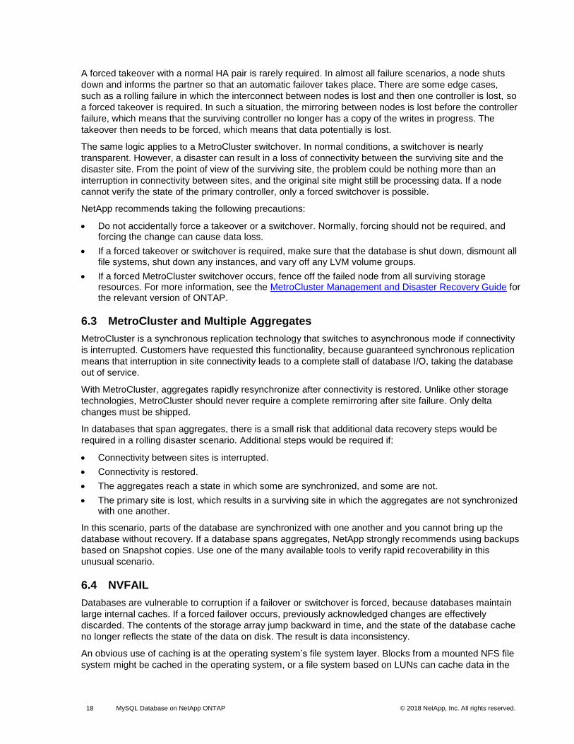
The same logic applies to a MetroCluster switchover. In normal conditions, a switchover is nearly
transparent. However, a disaster can result in a loss of connectivity between the surviving site and the
disaster site. From the point of view of the surviving site, the problem could be nothing more than an
interruption in connectivity between sites, and the original site might still be processing data. If a node
cannot verify the state of the primary controller, only a forced switchover is possible.
NetApp recommends taking the following precautions:
• Do not accidentally force a takeover or a switchover. Normally, forcing should not be required, and forcing the change can cause data loss.
• If a forced takeover or switchover is required, make sure that the database is shut down, dismount all file systems, shut down any instances, and vary off any LVM volume groups.
• If a forced MetroCluster switchover occurs, fence off the failed node from all surviving storage resources. For more information, see the MetroCluster Management and Disaster Recovery Guide for the relevant version of ONTAP.
6.3 MetroCluster and Multiple Aggregates
MetroCluster is a synchronous replication technology that switches to asynchronous mode if connectivity
is interrupted. Customers have requested this functionality, because guaranteed synchronous replication
means that interruption in site connectivity leads to a complete stall of database I/O, taking the database
out of service.
With MetroCluster, aggregates rapidly resynchronize after connectivity is restored. Unlike other storage
technologies, MetroCluster should never require a complete remirroring after site failure. Only delta
changes must be shipped.
In databases that span aggregates, there is a small risk that additional data recovery steps would be
required in a rolling disaster scenario. Additional steps would be required if:
• Connectivity between sites is interrupted.
• Connectivity is restored.
• The aggregates reach a state in which some are synchronized, and some are not.
• The primary site is lost, which results in a surviving site in which the aggregates are not synchronized with one another.
In this scenario, parts of the database are synchronized with one another and you cannot bring up the
database without recovery. If a database spans aggregates, NetApp strongly recommends using backups
based on Snapshot copies. Use one of the many available tools to verify rapid recoverability in this
unusual scenario.
6.4 NVFAIL
Databases are vulnerable to corruption if a failover or switchover is forced, because databases maintain
large internal caches. If a forced failover occurs, previously acknowledged changes are effectively
discarded. The contents of the storage array jump backward in time, and the state of the database cache
no longer reflects the state of the data on disk. The result is data inconsistency.
An obvious use of caching is at the operating system’s file system layer. Blocks from a mounted NFS file
system might be cached in the operating system, or a file system based on LUNs can cache data in the

19 MySQL Database on NetApp ONTAP © 2018 NetApp, Inc. All rights reserved. © 2016 NetApp, Inc. All rights reserved.
operating system buffer cache. A failure of NVRAM or a forced takeover in these situations could result in
file system corruption.
ONTAP systems protect databases and operating systems from this scenario with NVFAIL and its
associated parameters.
6.5 Overcommitting RAM
Overcommitting RAM means configuring more virtualized RAM on various hosts than exists on the
physical hardware. Doing so can cause unexpected performance problems. When virtualizing a
database, the underlying blocks of the database cache must not be swapped out to disk by the
hypervisor, or performance becomes highly unstable.
6.6 Ethernet Flow Control
Ethernet flow control allows a client to request that a sender temporarily stop data transmission—usually
because the receiver cannot process incoming data quickly enough. At one time, requesting that a sender
cease transmission was less disruptive than having a receiver discard packets because buffers were full.
This is no longer the case with the TCP stacks used in operating systems today. In fact, flow control
causes more problems than it solves.
Performance problems caused by Ethernet flow control have been increasing in recent years. This is
because Ethernet flow control operates at the physical layer. If a network configuration permits any
database server to send an Ethernet flow control request to a storage system, I/O pauses for all
connected clients. Because more clients are served by a single storage controller, the likelihood of these
clients sending flow control requests increases. The problem has occurred frequently at customer sites
with extensive operating system virtualization.
A NIC on a NetApp system should not receive flow-control requests. The method used to achieve this
result varies according to the network switch manufacturer. Usually, you can set flow control on an
Ethernet switch to receive desired or receive on, which means that a flow control request is not
forwarded to the storage controller. If the network connection on the storage controller doesn’t allow flow-
control disabling, configure the clients to never send flow control requests. Change to either the NIC
configuration on the database server itself or the switch ports to which the database server is connected.
NetApp Best Practice
Make sure that NetApp storage controllers do not receive Ethernet flow-control packets. If possible, set
the switch ports to which the controller is attached; however, some switch hardware has limitations that
might require client-side changes instead.
6.7 Jumbo Frames
The use of jumbo frames can improve performance somewhat in 1Gb networks by reducing CPU and
network overhead, but the benefit usually isn’t significant. Even so, NetApp recommends implementing
jumbo frames when possible, to realize potential performance benefits and to future-proof the solution.
In 10Gb networks, using jumbo frames is almost mandatory. Without jumbo frames, most 10Gb
implementations reach a packets-per-second limit before they reach the 10Gb mark. Using jumbo frames
improves efficiency in TCP/IP processing, because it allows the database server, NICs, and the storage
system to process fewer larger packets. The performance improvement varies from NIC to NIC, but it is
significant.
Many people erroneously believe that in jumbo-frame implementations, all connected devices must
support jumbo frames and that the maximum transmission unit (MTU) size must match end to end.
Instead, the two network endpoints negotiate the highest mutually acceptable frame size when
20 MySQL Database on NetApp ONTAP © 2018 NetApp, Inc. All rights reserved. © 2016 NetApp, Inc. All rights reserved.
establishing a connection. In a typical environment, a network switch is set to an MTU size of 9216, the
NetApp controller is set to 9000, and the clients are set to a mix of 9000 and 1514. Clients that can
support an MTU of 9000 can use jumbo frames, and clients that can support only 1514 can negotiate a
lower value.
Problems with this arrangement are rare in a completely switched environment. However, take care in a
routed environment that no intermediate router is forced to fragment jumbo frames.
NetApp recommends the following best practices:
• With 1GbE, Jumbo frames are desirable but not required.
• With 10GbE, Jumbo frames are required for maximum performance.
6.8 TCP Parameters
Three settings are frequently misconfigured: TCP timestamps, selective acknowledgment (SACK), and
TCP window scaling. Many out-of-date Internet documents recommend disabling these parameters to
improve performance. There was some merit to this recommendation many years ago when CPU
capabilities were much lower and it was advantageous to reduce TCP processing overhead whenever
possible.
However, with modern operating systems, disabling any of these TCP features rarely results in any
detectable benefit, and might damage performance. Performance damage is especially likely in
virtualized networking environments, because these features are required for efficient handling of packet
loss and changes in network quality.
NetApp recommends the following best practices:
• Enable TCP timestamps, SACK, and TCP window scaling on the host.
7 ONTAP QoS
The increased adoption of all-flash storage has also resulted in consolidation of database workloads.
Storage arrays relying on spinning media tended to support only a limited number of databases because
of the limited IOPS capabilities of older drive technology. One or two highly active databases would
saturate the underlying disks long before the storage controllers reached their limits. This situation has
changed. A performance capability of a relatively small number of SSDs can saturate even the most
powerful storage controllers. You can use the full capabilities of the controllers without the fear of sudden
performance collapse as spinning media latency spikes.
For example, a simple two-node HA AFF8080 system can service about 400K random IOPS before
latency climbs above 1 millisecond. Less than 1% of databases would be expected to reach such levels,
and allowing an AFF8080 to manage just 10K IOPS would be wasteful.
There are three types of quality of service (QoS) in NetApp ONTAP: IOPS, bandwidth, and guaranteed.
QoS controls can be applied to SVMs, volumes, LUNs, and files.
7.1 IOPS QoS
An IOPS QoS control is based on the total IOPS of a given resource, but there are several aspects of
IOPS QoS that might not be intuitive. Some customers have been puzzled by the apparent increase in
latency when an IOPS threshold is reached. This IOPS QoS is the only viable method of limiting IOPS.
Logically, it functions like a token system. For example, if a volume containing data files has a 10K IOPS
limit, each I/O operation that arrives must first receive a token to continue processing. As long as no more
than 10K tokens are consumed in a second, no delays are present.

21 MySQL Database on NetApp ONTAP © 2018 NetApp, Inc. All rights reserved. © 2016 NetApp, Inc. All rights reserved.
7.2 Bandwidth QoS
Not all I/O sizes are the same. Databases might perform a large number of fully random block reads,
which would result in the IOPS threshold being reached. But databases might also perform a full table
scan operation, which would consist of few large block reads, consuming a lot of bandwidth, but relatively
few IOPS.
7.3 Guaranteed QoS
Many customers seek a solution that includes guaranteed QoS, which is more difficult than it seems and
potentially wasteful. For example, placing 10 databases with a 10K IOPS guarantee would require a
system to be sized such that all 10 databases could simultaneously run at 10K IOPS, for a total of 100K.
This scenario is highly unlikely, but if it is required, the best option is to guarantee performance through
the sizing effort.
For example, each NetApp AFF8080 HA pair could constitute a 400K IOPS building block. The total
guaranteed IOPS of all hosted databases should not add up to more than 400K IOPS. Furthermore, to
prevent a database from consuming more than its allotted IOPS capability, it should have the standard
QoS applied as a limit.
8 ONTAP Efficiency
Storage efficiency enables you to store the maximum amount of data within the smallest possible space
and at the lowest possible cost. The NetApp storage efficiency technologies described in this section can
help you realize maximum space savings.
8.1 Compression
Before all-flash storage systems were available, database compression was of limited value, because
most databases required a large number of spindles to provide acceptable performance. Storage systems
contained much more capacity than required as a side effect of the large number of drives. The scenario
has changed with the rise of solid-state storage. You no longer need to vastly overprovision the drive
count purely to obtain good performance. You can match the drive space in a storage system to actual
capacity needs.
The increased IOPS capability of SSDs almost always yields cost savings compared to spinning drives,
but compression can achieve further savings by increasing the effective capacity of solid-state media.
Compression is available in MySQL, but it creates a load on the database server CPUs, which can
damage performance. A better option is to offload the compression work to the storage system.
Adaptive Compression
Adaptive compression has been thoroughly tested with database workloads with no observed effect on
performance, even in an all-flash environment in which latency is measured in microseconds. In initial
testing, some customers have reported a performance increase with the use of compression.
NetApp ONTAP manages physical blocks in 4KB units. Therefore, the maximum possible compression
ratio with adaptive compression alone is 2:1 with a database using an 8KB block. Early testing with real
customer data has shown compression ratios approaching this level, but results vary according to the
type of data stored.
The simplest approach for using compression is enabling adaptive compression for all database volumes.
As stated previously, adaptive compression is suitable for all I/O patterns. Note the following exceptions:
• If a volume is not thin provisioned, do not enable compression; it provides no benefit.
• If a large number of binary logs are retained, moving them to a volume using secondary compression improves storage efficiency.

22 MySQL Database on NetApp ONTAP © 2018 NetApp, Inc. All rights reserved. © 2016 NetApp, Inc. All rights reserved.
• Some databases have high redo logging (transaction logs) rates. Redo logs are comparatively small and are constantly overwritten, so any space savings from compression is negligible. This data should be moved to a volume without compression.
• If data files contain a significant amount of uncompressible data—for example, when compression is already enabled, or encryption is used—place this data on volumes without compression.
Secondary Compression
Secondary compression uses a larger block size that is fixed at 32KB. This feature allows ONTAP to
compress data beyond 2:1, but secondary compression is primarily designed for data at rest or data that
is written sequentially and requires maximum compression.
NetApp recommends secondary compression for datasets that include large amounts of unchanging
data, such as binary logs, logical or physical backups, or exported data. These types of files are written
sequentially and not updated. This point does not mean that adaptive compression is discouraged.
However, if the volume of data being stored is large, then secondary compression delivers better savings
when compared to adaptive compression.
Caution
Secondary compression and deduplication should not be used together with flat-file backups. Small
changes to the backed-up data will affect the 32KB compression window. If the window shifts, the
resulting compressed data will differ across the entire file. Deduplication occurs after compression,
which means the deduplication engine will see each compressed backup differently. If deduplication of
backups is required, don’t use secondary compression. Adaptive compression is preferable, because it
works at a smaller block size and does not disrupt deduplication efficiency. For similar reasons, host-
side compression also interferes with deduplication efficiency.
8.2 Alignment
Adaptive compression in a database environment requires some consideration of compression block
alignment. Compression block is a concern only for data that is subject to random overwrites of specific
blocks. This approach is similar in concept to overall file system alignment.
For example, an 8KB write to a data file is compressed only if it aligns with an 8KB boundary in the file
system itself. This point means that the write operation must fall within the first 8KB of the file, the second
8KB of the file, and so forth. Data such as backups or binary logs consists of sequentially written
operations that span multiple blocks, all of which are compressed. There is no need to consider
alignment. The only I/O pattern of concern is the random overwrites of data files.
Alignment on an NFS Volume
With NFS, data files are aligned. Each block of the data file is aligned with respect to the start of the file.
Alignment on SAN (LUN)
SAN environments require data to be aligned to an 8KB boundary for optimum compression. There are
two aspects of alignment for SAN: the LUN and the file system. The LUN must be configured as either a
whole-disk device (no partition) or with a partition that aligns to an 8KB boundary.
The simplest approach is to use the whole-disk device, and skip creating any partitions. The file system is
then aligned to the start of the LUN itself, and alignment is correct.

23 MySQL Database on NetApp ONTAP © 2018 NetApp, Inc. All rights reserved. © 2016 NetApp, Inc. All rights reserved.
8.3 Inline Data Compaction
Inline data compaction, introduced in ONTAP 9, improves compression efficiency. As stated previously,
adaptive compression alone can provide at best 2:1 savings, because it is limited to storing an 8K I/O in a
4K WAFL block. Compression methods such as secondary compression use a larger block size and
deliver better efficiency but are not suitable for data that is subject to small block overwrites.
Decompressing 32KB units of data, updating an 8KB portion, recompressing, and writing back to disk
creates overhead.
Inline data compaction works by allowing multiple logical blocks to be stored within physical blocks. For
example, a database with highly compressible data such as text or partially full blocks can compress from
8KB to 1KB. Without compaction, that 1KB of data would still occupy an entire 4KB block. Inline data
compaction allows that 1KB of compressed data to be stored in just 1KB of physical space alongside
other compressed data. It is not a compression technology; it is simply a more efficient way of allocating
space on disk and therefore should not create any detectable performance impact.
The degree of savings varies. In general, data that is already compressed or encrypted cannot be further
compressed, so such datasets do not benefit from compaction. The best way to evaluate potential
savings is to use the NetApp Space Saving Estimation Tool (SSET) available on the NetApp Field Portal
or through your NetApp representative.
8.4 Deduplication
Data deduplication cuts storage requirements by reducing redundancies in primary, backup, and archival
data. Inline deduplication of zeros speeds up database performance by 20% to 30%. Further
improvements to inline deduplication in ONTAP 9 provide additional efficiency by extending elimination of
duplicate data to blocks in memory and SSDs.
8.5 Thin Provisioning
Efficiency features are forms of thin provisioning. For example, a 100GB LUN occupying a 100GB volume
might compress down to 50GB. There are no actual savings realized yet, because the volume is still
100GB. The volume must first be reduced in size, so the space saved can be used elsewhere on the
system. If later changes to the 100GB LUN result in the data becoming less compressible, the LUN grows
and the volume could fill up.
NetApp strongly recommends thin provisioning, because it can simplify management while delivering a
substantial improvement in usable capacity with associated cost savings. The reason is simple: Database
environments frequently include a lot of empty space, a large number of volumes and LUNs, and
compressible data. Thick provisioning results in reserving space on storage for volumes and LUNs in
case they someday become full and contain 100% uncompressible data. This scenario is unlikely. Thin
provisioning allows that space to be reclaimed and used elsewhere and allows capacity management to
be based on the storage system itself rather than many smaller volumes and LUNs.
Some customers prefer to use thick provisioning, either for specific workloads or according to established
operational practices.
Caution
If a volume is thick provisioned, take care to completely disable all efficiency features for that volume,
including decompression and removal of deduplication, by using the sis undo command. The volume
should not appear in volume efficiency show output. If it does, the volume is still partially
configured for efficiency features. The result is overwriting, which increases the chance that
configuration oversights cause the volume to unexpectedly run out of space, resulting in database I/O
errors.
24 MySQL Database on NetApp ONTAP © 2018 NetApp, Inc. All rights reserved. © 2016 NetApp, Inc. All rights reserved.
9 Native Data Protection
The most mission-critical data is usually found in databases. Any enterprise without its data becomes
paralyzed and cannot run its business. This data must be protected. However, data protection is more
than just ensuring a usable backup—it involves performing the backups quickly and reliably as well as
storing backups safely. The other side of data protection is data recovery. When data is inaccessible, the
enterprise is affected and might be inoperative until data is restored. This process must be quick and
reliable. Finally, most databases must be protected against disasters, which means maintaining a replica
of the database. The replica must be sufficiently up-to-date, and making the replica a fully operational
database must be quick and simple.
A database data protection architecture should be defined by business requirements. These requirements
include factors such as the speed of recovery, the maximum permissible data loss, and backup retention
needs. The data protection plan must also consider various regulatory requirements for data retention
and restoration. Finally, consider different data recovery scenarios, ranging from the typical recovery
resulting from user or application errors up to disaster recovery scenarios that include the complete loss
of a site. Small changes in data protection and recovery policies can significantly affect the overall
architecture of storage, backup, and recovery. It is critical to define and document standards before
starting design work to avoid complicating a data protection architecture. The following two sections
describe two objectives of data protection to consider in your backup or recover strategy: RTO and RPO.
9.1 Recovery Time Objective
The recovery time objective (RTO) defines the maximum time allowed for the recovery of a service. For
example, a human resources database might have an RTO of 24 hours because, although losing access
to this data for a day would be inconvenient, the business can still operate. In contrast, a database
supporting the general ledger of a bank would have an RTO measured in minutes or even seconds. An
RTO of zero is not possible, because there must be a way to differentiate between an actual service
outage and a routine event such as a lost network packet. However, a near-zero RTO is a typical
requirement.
9.2 Recovery Point Objective
The recovery point objective (RPO) defines the maximum tolerable data loss. In a database context, the
RPO is usually a question of how much uncommitted data can be lost in a specific situation. In a typical
recovery scenario in which a database is damaged by a product bug or user error, the RPO should be
zero—there should be no data loss. The recovery procedure involves restoring an earlier copy of the
database files and then replaying the log files to bring the database state up to the desired PiT. The log
files required for this operation should already be backed up.
In unusual scenarios, log data might be lost. For example, an accidental or malicious rm -rf * of
database files could result in the deletion of all data. The only option would be to restore from backup,
including log files, and some data would inevitably be lost. The only option to improve the RPO in a
traditional backup environment would be to perform repeated backups of the log data. This option is
limited, however, because of the constant data movement and the difficulty maintaining a backup system
as a constantly running service. One of the benefits of advanced storage systems is the ability to protect
data from accidental or malicious damage to files and thus deliver a better RPO without data movement.
9.3 NetApp Snapshot Technology
The foundation of NetApp ONTAP data protection software is NetApp Snapshot technology. The key
values are as follows:
• Simplicity. A Snapshot copy is a read-only copy of a data container’s contents at a specific PiT.
• Efficiency. Snapshot copies require no space at the moment of creation. Space is only consumed when data is changed.

25 MySQL Database on NetApp ONTAP © 2018 NetApp, Inc. All rights reserved. © 2016 NetApp, Inc. All rights reserved.
• Manageability. A backup strategy based on Snapshot copies is easy to configure and manage, because Snapshot copies are a native part of the storage operating system. If the storage system is powered on, it is ready to create backups.
• Scalability. Up to 255 backups of a single container of files and LUNs can be preserved. For complex datasets, multiple containers of data can be protected by a single, consistent set of Snapshot copies.
• No performance impact. Performance is unaffected, whether a volume contains 250 Snapshot copies or none.
As a result, protecting a database running on ONTAP is simple and highly scalable. Database backups do not require movement of data. Therefore, a backup strategy should be customized to the needs of the business rather than the limitations of network transfer rates, large number of tape drives, or disk staging areas.
To implement the data protection strategy with MySQL, it is important to design the storage layout
accordingly. NetApp recommends that you create two volumes for MySQL:
• A volume to store all your data files, index files, and tablespace
• A volume to store all your logs (mainly redo logs and binary logs)
For detailed information about this recommendation, see section 12, “MySQL.”
You can create point-in-time recovery (PITR) consistent backups by completing the following steps:
1. Quiesce the I/O to stop MySQL writing on disk by running the FLUSH TABLES WITH READ LOCK
command.
2. Create the Snapshot copy of both volumes.
3. Unquiesce the I/O to allow MySQL transactions by running the UNLOCK TABLES command.
Integrate these steps in the shell script for your daily and weekly backup solutions. NetApp Snapshot
technology backs up terabytes and petabytes in a matter of seconds. This feature is helpful for the
MySQL ecosystem where the traditional approach (logical or hot backup) of creating backups takes
longer and uses more network and disk bandwidth.
9.4 NetApp SnapRestore Technology
Rapid data restoration in ONTAP from a Snapshot copy is delivered by NetApp SnapRestore technology.
SnapRestore enables instantaneous restoration of Snapshot data. The reason SnapRestore works so
quickly and efficiently is that a Snapshot copy is essentially a parallel read-only view of the contents of a
volume at a specific PiT. The active blocks are the real blocks that can be changed, whereas the
Snapshot copy is a read-only view into the state of the blocks that constitute the files and LUNs at the
time the Snapshot copy was created. ONTAP permits read-only access to Snapshot data, but the data
can be reactivated with SnapRestore. The Snapshot copy is reenabled as a read/write view of the data,
returning the data to its prior state. SnapRestore can operate at the volume or file level. The technology is
essentially the same with a few minor differences in behavior. The key values are as follows:
• Individual files or LUNs can be restored in seconds, whether it is a 2TB LUN or a 4KB file.
• An entire container (a NetApp FlexVol® volume) of LUNs and files can be restored in seconds, whether it is 10GB or 100TB of data.
When a critical database is down, critical business operations are down. Tapes can break, and even
restore operations from disk-based backups can be slow to transfer across the network. SnapRestore
prevents these problems by delivering near instantaneous restoration of databases. Even petabyte-scale
databases can be completely restored with just a few minutes of effort.
With a two-volume approach and SnapRestore technology, it is easy to restore any backup size. Select
the target data and log volumes to restore. The restore is an exact PiT, because all the logs (binary and
transaction logs) are stored on the log volume. You can perform PITR by completing the following steps:
26 MySQL Database on NetApp ONTAP © 2018 NetApp, Inc. All rights reserved. © 2016 NetApp, Inc. All rights reserved.
1. Stop the MySQL application.
2. Restore the volumes with SnapRestore technology.
3. Start the MySQL application.
After MySQL restarts, it automatically recovers by checking the transaction logs (IB logs).
Note: Manual recovery is not required for MySQL to bring the database back up. Database recovery depends on the size of the IB log file. The larger the size of the file, the longer the recovery time. For more information, see section 12.2, “MySQL File Structure.”
Snapshot and SnapRestore technologies are most useful when database refresh is required on dev/test
systems. Most of the time the development and QA teams provide production data for their work. It is
quite easy to restore daily backups on dev and QA systems with NetApp Snapshot, SnapRestore, and
FlexClone® technologies. Also, you can restore the deleted rows or dropped tables from the Snapshot
copy.
To recover deleted rows or dropped tables from the backup, complete the following steps:
1. Take a FlexClone volume from the Snapshot copy.
2. Split the FlexClone volume from its parent volume.
3. Attach the volume to another MySQL instance.
4. Restore individual rows or tables from the MySQL instance.
9.5 Data Replication and Disaster Recovery
Nearly every database requires data replication. At the most basic level, replication can mean a copy on
tape stored off site or database-level replication to a standby database. Disaster recovery refers to the
use of those replica copies to bring a service online if a catastrophic loss of service occurs. ONTAP offers
multiple replication options to address various requirements natively within the storage array, covering a
complete spectrum of needs. These options can range from simple replication of backups to a remote site
up to a synchronous, fully automated solution that delivers disaster recovery and HA in the same
platform.
The primary ONTAP replication technologies applicable to databases are the NetApp SnapMirror® and
NetApp SyncMirror® technologies. These products are not add-ons but are fully integrated into ONTAP
and activated by the simple addition of a license key. Storage-level replication is not the only option,
either. Database-level replication, MySQL native replication, global transaction identifier (GTID) semi-sync
replication, InnoDB clusters, and Percona XtraDB Cluster (PXC) can also be used as data protection
strategies.
The right choice depends on the specific replication, recovery, and retention requirements.
ONTAP SnapMirror
SnapMirror is the NetApp asynchronous replication solution, ideally suited for protecting large,
complicated, and dynamic datasets such as databases and their associated applications. Its key values
are as follows:
• Manageability. SnapMirror is easy to configure and manage because it is a native part of the storage software. No add-on products are required. Replication relationships can be established in minutes and can be managed directly on the storage system.
• Simplicity. Replication is based on FlexVol volumes, which are containers of LUNs or files that are replicated as a single consistent group.
• Efficiency. After the initial replication relationship is established, only changes are replicated. Efficiency features such as deduplication and compression are preserved, further reducing the amount of data that must be transferred to a remote site.
27 MySQL Database on NetApp ONTAP © 2018 NetApp, Inc. All rights reserved. © 2016 NetApp, Inc. All rights reserved.
• Flexibility. Mirrors can be temporarily broken to allow testing of disaster recovery procedures, and then the mirroring can be easily reestablished with no need for a complete remirroring. Only the changed data must be applied to bring the mirrors back into sync. Mirroring can also be reversed to allow a rapid resync after the disaster concludes and the original site is back in service. Finally, read/write clones of replicated data are available for testing and development.
ONTAP SyncMirror
SyncMirror provides an additional layer of synchronous data mirroring in ONTAP. At the simplest layer,
SyncMirror creates two complete sets of RAID-protected data in two different locations. They can be in
adjoining rooms within a data center, or they can be located many kilometers apart.
SyncMirror is fully integrated with ONTAP and operates just above the RAID level. Therefore, all the usual
ONTAP features, such as Snapshot copies, SnapRestore, and FlexClone technology, work seamlessly.
NetApp MetroCluster manages ONTAP controllers by using SyncMirror technology. The primary purpose
of MetroCluster is to provide HA access to synchronously mirrored data in various failure scenarios.
The key values of data protection with MetroCluster and SyncMirror are as follows:
• In normal operations, SyncMirror delivers synchronous mirroring across locations. A write operation is not acknowledged until it is present on nonvolatile media on both sites.
• If connectivity between sites fails, SyncMirror automatically switches into asynchronous mode to keep the primary site serving data until connectivity is restored. Then it delivers rapid resynchronization by efficiently updating the changes that have accumulated on the primary site. Full reinitialization is not required.
SnapMirror is also fully compatible with systems based on SyncMirror. For example, a primary database
might be running on a MetroCluster cluster spread across two geographic sites. This database can also
replicate backups to a third site as long-term archives or for the creation of clones in a DevOps
environment.
For more information about database protection, see TR-4591: Database Data Protection: Backup,
Recovery, and DR.
10 Linux Configuration
10.1 Slot Tables
NFS performance on Linux depends on a parameter called tcp_slot_table_entries. This parameter
regulates the number of outstanding NFS operations that are permitted on a Linux operating system.
The default value in most 2.6-derived kernels, which includes RH5 and OL5, is 16. However, this default
frequently causes performance problems. The opposite problem occurs on newer kernels in which the
tcp_slot_table_entries value is uncapped and can cause storage problems by flooding the system
with excessive requests. The solution is to set this value statically. Use a value of 128 for any Linux
operating system using NetApp NFS storage with a MySQL database. To set this value in Red Hat
Enterprise Linux 6.2 and earlier, place the following entry in /etc/sysctl.conf:
# sysctl -a | grep tcp.*.slot_table sunrpc.tcp_max_slot_table_entries = 128
sunrpc.tcp_slot_table_entries = 128
# sysctl -a | grep tcp.*.slot_table sunrpc.tcp_max_slot_table_entries = 128
sunrpc.tcp_slot_table_entries = 128
In addition, there is a bug in most Linux distributions using 2.6 kernels. The startup process reads the
contents of /etc/sysctl.conf before the NFS client is loaded. As a result, when the NFS client is
eventually loaded, it takes the default value of 16. To avoid this problem, edit /etc/init.d/netfs to
call /sbin/sysctl -p in the first line of the script so that tcp_slot_table_entries is set to 128
28 MySQL Database on NetApp ONTAP © 2018 NetApp, Inc. All rights reserved. © 2016 NetApp, Inc. All rights reserved.
before NFS mounts any file systems. To set this value in Red Hat Enterprise Linux 6.3 and later, apply
the following modification in the RPC configuration file:
echo "options sunrpc udp_slot_table_entries=64 tcp_slot_table_entries=128
tcp_max_slot_table_entries=128" >> /etc/modprobe.d/sunrpc.conf
10.2 Security-Enhanced Linux
Security-Enhanced Linux (SELinux) is a Linux kernel security model that provides a mechanism for
supporting access control security policies. The SELinux architecture supports the enforcement of many
kinds of mandatory access control policies. This enforcement applies to users, daemons, files, and
directories.
The /etc/selinux/config configuration file controls whether SELinux is enabled or disabled. The
SELinux variable can be set to disabled, permissive, or enforcing mode. The disabled option completely
disables the SELinux kernel and application code, leaving the system running without any SELinux
protection. The permissive option enables the SELinux code but causes it to operate in a mode where
policy-denied accesses are permitted but audited. The enforcing option enables the SELinux code and
causes it to enforce and audit access denials. Permissive mode can yield a different set of denials than
enforcing mode. Enforcing mode prevents an operation from proceeding past the first denial, and some
application code will fall back to a less privileged mode of operation if denied access.
Most deployments observed errors while mounting an NFS file system on a Linux host or while starting
the MySQL daemon. Some common errors are shown here:
Error message: not found; Error message: access denied;
Error message: Permission denied; Cannot mount / access an NFS volume or file system; Error
Message: Cannot find home Directory
[Warning] Can't create test file /mysqlvol/test/mysql/testmysql.lower-test
[Note] /usr/sbin/mysqld (mysqld 5.7.22-log) starting as process 5683 ...
[Warning] Can't create test file /mysqlvol/test/mysql/testmysql.lower-test
[Warning] Can't create test file /mysqlvol/test/mysql/testmysql.lower-test
[ERROR] Could not open file '/mysqlvol/test/mysql/mysql-error.log' for error logging: Permission
denied
You can resolve these errors by correcting the SELinux configuration files and making sure that the
export options on NetApp ONTAP are configured correctly. For relevant troubleshooting information, see
the steps in the NetApp Knowledgebase.
10.3 I/O Schedulers
The Linux kernel allows low-level control over the way that I/O to block devices is scheduled. The defaults
on various distributions of Linux vary considerably. MySQL recommends that you use NoOps or a
deadline I/O scheduler with native asynchronous I/O (AIO) on Linux. In general, NetApp customers and
internal testing show better results with NoOps.
MySQL’s InnoDB storage engine uses the asynchronous I/O subsystem (native AIO) on Linux to perform
read-ahead and write requests for data file pages. This behavior is controlled by the
innodb_use_native_aio configuration option, which is enabled by default. With native AIO, the type of
I/O scheduler has greater influence on I/O performance. Conduct benchmarks to determine which I/O
scheduler provides the best results for your workload and environment.
See the relevant Linux and MySQL documentation for instructions on configuring the I/O scheduler.
10.4 Multipathing
Some customers have encountered crashes during network disruption because the multipath daemon
was not running on their system. On more recent versions of Linux, the installation process of the
operating system and the multipathing daemon might leave these operating systems vulnerable to this

29 MySQL Database on NetApp ONTAP © 2018 NetApp, Inc. All rights reserved. © 2016 NetApp, Inc. All rights reserved.
problem. The packages are installed correctly, but they are not configured for automatic startup after a
reboot.
You can verify the state of the multipath daemon by running the systemctl command. If the status is
not active, the daemon is not running.
[root@jfs0 ~]# systemctl status multipathd.service
multipathd.service - Device-Mapper Multipath Device Controller
Loaded: loaded (/usr/lib/systemd/system/multipathd.service; enabled; vendor preset: enabled)
Active: active (running) since Mon 2018-06-25 13:05:05 EDT; 1 months 21 days ago
Process: 583 ExecStart=/sbin/multipathd (code=exited, status=0/SUCCESS)
Process: 579 ExecStartPre=/sbin/multipath -A (code=exited, status=0/SUCCESS)
Process: 557 ExecStartPre=/sbin/modprobe dm-multipath (code=exited, status=0/SUCCESS)
Main PID: 589 (multipathd)
CGroup: /system.slice/multipathd.service
└─589 /sbin/multipathd
10.5 Open File Limits
To run, the MySQL server needs file descriptors. It uses them to open new connections, store tables in
the cache, create temporary tables to resolve complicated queries, and access persistent ones. If
mysqld is not able to open new files when needed, it can stop functioning correctly. A common symptom
of this issue is error 24, “Too many open files.” The number of file descriptors mysqld can open
simultaneously is defined by the open_files_limit option set in the configuration file
(/etc/my.cnf). But open_files_limit also depends on the limits of the operating system. This
dependency makes setting the variable more complicated.
MySQL cannot set its open_files_limit option higher than what is specified under ulimit 'open
files'. Therefore, you need to explicitly set these limits at the operating system level to allow MySQL to
open files as needed. There are two ways to check the file limit in Linux:
• The ulimit command quickly gives you a detailed description of the parameters being allowed or
locked. The changes made by running this command are not permanent and will erase after a system reboot.
• Changes to the /etc/security/limit.conf file are permanent and are not affected by a system
reboot.
Make sure to change both the hard and soft limits for user mysql. The following excerpts are from the
configuration:
mysql hard nofile 65535
mysql soft nofile 65353
In parallel, update the same configuration in my.cnf to fully use the open file limits.
11 Database and Virtualization
Virtualization of databases with VMware ESXi, Oracle Virtual Machine (OVM), or Kernel-Based Virtual
Machine (KVM) is an increasingly common choice for NetApp customers who choose virtualization for
even their most mission-critical databases.
11.1 Containers
Containerization of MySQL databases is becoming more prevalent. Low-level container management is
almost always performed through Docker. Container management platforms such as OpenShift and
Kubernetes make management of large container environments even simpler. The benefits of
containerization include lower costs, because there is no need to license a hypervisor. Also, containers
allow multiple databases to run isolated from one another while sharing the same underlying kernel and
operating system. Containers can be provisioned in microseconds.

30 MySQL Database on NetApp ONTAP © 2018 NetApp, Inc. All rights reserved. © 2016 NetApp, Inc. All rights reserved.
NetApp offers the Trident driver to provide advanced management capabilities of storage. For example,
Trident allows a container created in Kubernetes to automatically provision its storage on the appropriate
tier, apply export policies, set NetApp Snapshot policies, and even clone one container to another. For
additional information, see Trident Storage Orchestrator for Containers.
11.2 Storage Presentation
Customers considering virtualization of their databases should base their storage decisions on their
business needs. Although this statement applies to all IT decisions, it is especially important for
virtualization, because the size and scope of projects vary considerably.
Regarding storage presentation, a storage resource should be managed directly by the VM guest.
Therefore, use one of the following storage configurations:
• iSCSI LUNs managed by the iSCSI initiator on the VM, not the hypervisor
• NFS file systems mounted by the VM, not a Virtual Machine Disk (VMDK)
• FC raw device mappings (RDMs) when the VM guest manages the file system
As a general rule, avoid using datastores for database files. There are many reasons for this
recommendation:
• Transparency. When a VM owns its file systems, it is easier for a database administrator (DBA) or a system administrator to identify the source of the file systems for their data.
• Performance. Testing has shown that channeling all I/O through a hypervisor datastore affects performance.
• Manageability. When a VM owns its file systems, the use or nonuse of a hypervisor layer affects manageability. The same procedures for provisioning, monitoring, data protection, and so on can be used across the entire estate, including virtualized and nonvirtualized environments.
• Stability and troubleshooting. When a VM owns its file systems, delivering good, stable performance and troubleshooting problems are much simpler because the entire storage stack is present on the VM. The hypervisor’s only role is to transport FC or IP frames. When a datastore is included in a configuration, it complicates the configuration by introducing another set of timeouts, parameters, log files, and potential bugs.
• Portability. When a VM owns its file systems, the process of moving a database environment becomes much simpler. File systems can be easily moved between virtualized and nonvirtualized guests.
• Vendor lock-in. After data is placed in a datastore, using a different hypervisor or removing the data from the virtualized environment entirely becomes very difficult.
• Snapshot enablement. In some cases, backups in a virtualized environment can become a problem because of the relatively limited bandwidth. For example, a four-port 10GbE trunk might be sufficient to support day-to-day performance needs of many virtualized databases. However, such a trunk would be insufficient to perform backups using Oracle Recovery Manager (RMAN) or other backup products that require streaming a full-sized copy of the data.
Using VM-owned file systems makes it easier to take advantage of Snapshot-based backups and restores. A VM-owned file system offloads the work of performing backups onto the storage system. There is no need to overbuild the hypervisor configuration purely to support the bandwidth and CPU requirements in the backup window.
Note: For optimum performance and manageability, NetApp recommends that you avoid placing database data on a datastore. Use guest-owned file systems such as NFS, or use iSCSI file systems managed by the guest or by RDMs.

31 MySQL Database on NetApp ONTAP © 2018 NetApp, Inc. All rights reserved. © 2016 NetApp, Inc. All rights reserved.
11.3 Para Virtualized Drivers
For optimum performance, using Para virtualized network drivers is critical. When a datastore is used, a
Para virtualized SCSI driver is required. A Para virtualized device driver allows a guest to integrate more
deeply into the hypervisor, as opposed to an emulated driver in which the hypervisor spends more CPU
time mimicking the behavior of physical hardware.
The performance of most databases is limited by storage. Therefore, the extra latency introduced by a
network or SCSI driver is particularly noticeable. NetApp Support has encountered many performance
complaints that customers resolved by installing Para virtualized drivers. During one customer proof of
concept, databases showed better performance under ESXi than with the same hardware running as
bare metal. The tests were very I/O intensive, and the performance difference was attributed to the use of
the ESXi Para virtualized network drivers.
Note: NetApp recommends that you use Para virtualized network drivers and SCSI drivers.
12 MySQL
MySQL Standard Edition enables you to deliver high-performance and scalable OLTP applications. It
provides the ease of use that has made MySQL famous along with industrial-strength performance and
reliability. MySQL Standard Edition includes InnoDB, making it a fully integrated, transaction-safe ACID-
compliant database. In addition, MySQL replication allows you to deliver high-performance, scalable
applications.
12.1 Why MySQL?
MySQL is the world’s most popular database because it has native-rich features. Some of the features
are as follows:
• Lower TCO. MySQL is a powerful, free, open-source database management system that has been available for years. It is very stable. It has community support that helps maintain, debug, and add new features. If a web application requires more than a database, or requires load-balancing or sharding, you can easily set up database instances with only hardware costs, rather than commercial databases that require a single license for each instance.
• Reliability, performance, and ease of use. One of MySQL’s hallmarks is exceptional performance and scalability, which is why so many web-based businesses use it. MySQL uses several key strengths to deliver fast performance. Because competition is always a mouse click (or screen touch) away, rapid responses to customer inquiries and activities are paramount. The database serving web-based applications needs to provide extreme performance for both read (simple and complex queries) and write operations.
• Database development, design, and administration. MySQL Workbench provides an integrated development, design, and administration environment to make developers and DBAs more productive. Different developers look for different features in a database, and MySQL offers a range of features. It can run adequately on both a laptop and a desktop. It can easily adapt to the environment, ensuring that it does not collide with existing web servers or applications.
• Comprehensive transactional support. MySQL is one of the most robust transactional database engines available. It is the solution for full data integrity, offering features such as complete atomic, consistent, isolated, durable transaction support; multiversion transaction support; and unrestricted row-level locking. It provides instant deadlock identification through server-enforced referential integrity.
• Data security. MySQL is globally renowned for being the most secure and reliable database management system used in popular web applications such as WordPress, Drupal, Joomla, Facebook, Google, and Twitter. The data security and support for transactional processing that accompany the recent version of MySQL can benefit any business, especially e-commerce businesses that involve frequent money transfers.

32 MySQL Database on NetApp ONTAP © 2018 NetApp, Inc. All rights reserved. © 2016 NetApp, Inc. All rights reserved.
• Pluggable architecture. The MySQL pluggable storage engine architecture enables a database professional to select a specialized storage engine for a particular application need without having to manage application coding requirements. The MySQL server architecture isolates the application programmer and DBA from all the low-level implementation details at the storage level, providing a consistent and easy application model and API. Although there are different capabilities across different storage engines, the application is shielded from these differences.
MySQL’s efficient and modular architecture provides huge benefits if you want to target a particular
application need—such as data warehousing, transaction processing, or HA situations—while using
interfaces and services that are independent of any one storage engine.
Before designing your storage solution for deploying MySQL on NetApp ONTAP, you should understand
the MySQL architecture. The pluggable architecture divides work between MySQL common code (parser,
optimizer) and the storage engine. The default storage engine for MySQL, InnoDB, is ACID compatible
and is used mostly for OLTP workloads. Its features include:
• ACID transactions
• Row-level locking
• Foreign key constraints
• Automatic crash recovery
• Table compression (read/write)
• Spatial data types (no spatial indexes)
12.2 MySQL File Structure
InnoDB acts as the middle layer between disk storage and the MySQL server—it stores the data to disk.
Figure 2 shows how InnoDB interacts with storage.
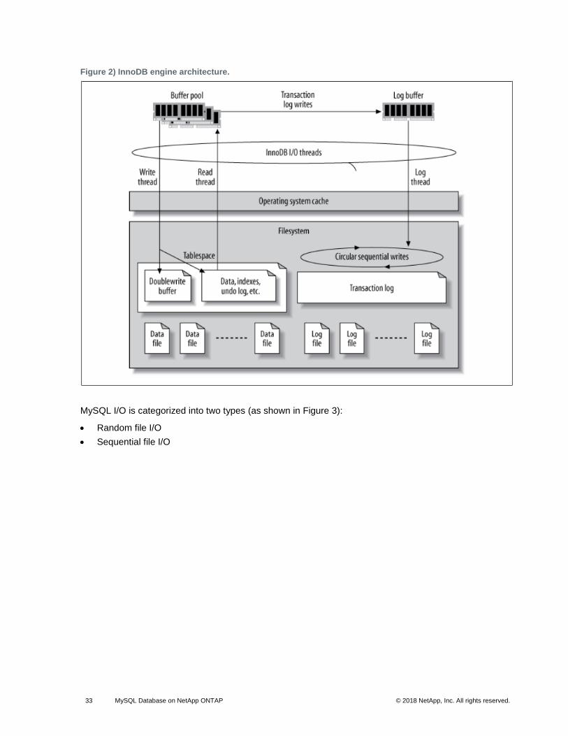
33 MySQL Database on NetApp ONTAP © 2018 NetApp, Inc. All rights reserved. © 2016 NetApp, Inc. All rights reserved.
Figure 2) InnoDB engine architecture.
MySQL I/O is categorized into two types (as shown in Figure 3):
• Random file I/O
• Sequential file I/O

34 MySQL Database on NetApp ONTAP © 2018 NetApp, Inc. All rights reserved. © 2016 NetApp, Inc. All rights reserved.
Figure 3) MySQL file system structure.
Data files are randomly read and overwritten, which results in high IOPS levels. Therefore, SSD storage
is recommended.
Note: A battery-backed write cache is also very effective on SSD.
Redo log files and binary log files are transactional logs. They are sequentially written, so you can get
good performance on HDD with the write cache. A sequential disk read happens on recovery, but it rarely
causes a performance problem, because log file size is usually smaller than data files, and sequential
reads are faster than random reads (occurring on data files).
The double-write buffer is a special feature of InnoDB. InnoDB first writes flushed pages to the double-
write buffer, and then writes the pages to their correct positions on the data files. This process prevents
page corruption. Without the double-write buffer, the page might become corrupted if a power failure
occurs during the write-to-disks process. Because writing to the double-write buffer is sequential, it is
highly optimized for HDDs. Sequential reads occur on recovery.
Because ONTAP NVRAM already provides write protection, double-write buffering is not required.
MySQL has a parameter, skip_innodb_doublewrite, to disable the double-write buffer. This feature
can substantially improve performance.
The insert buffer is also a special feature of InnoDB. If nonunique secondary index blocks are not in
memory, InnoDB inserts entries into the insert buffer to avoid random disk I/O operations. Periodically, the
insert buffer is merged into the secondary index trees in the database. The insert buffer reduces the
number of disk I/O operations by merging I/O requests to the same block; random I/O operations can be
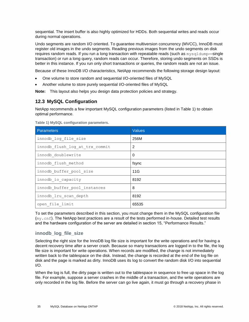
35 MySQL Database on NetApp ONTAP © 2018 NetApp, Inc. All rights reserved. © 2016 NetApp, Inc. All rights reserved.
sequential. The insert buffer is also highly optimized for HDDs. Both sequential writes and reads occur
during normal operations.
Undo segments are random I/O oriented. To guarantee multiversion concurrency (MVCC), InnoDB must
register old images in the undo segments. Reading previous images from the undo segments on disk
requires random reads. If you run a long transaction with repeatable reads (such as mysqldump—single
transaction) or run a long query, random reads can occur. Therefore, storing undo segments on SSDs is
better in this instance. If you run only short transactions or queries, the random reads are not an issue.
Because of these InnoDB I/O characteristics, NetApp recommends the following storage design layout:
• One volume to store random and sequential I/O-oriented files of MySQL
• Another volume to store purely sequential I/O-oriented files of MySQL
Note: This layout also helps you design data protection policies and strategy.
12.3 MySQL Configuration
NetApp recommends a few important MySQL configuration parameters (listed in Table 1) to obtain
optimal performance.
Table 1) MySQL configuration parameters.
Parameters Values
innodb_log_file_size 256M
innodb_flush_log_at_trx_commit 2
innodb_doublewrite 0
innodb_flush_method fsync
innodb_buffer_pool_size 11G
innodb_io_capacity 8192
innodb_buffer_pool_instances 8
innodb_lru_scan_depth 8192
open_file_limit 65535
To set the parameters described in this section, you must change them in the MySQL configuration file
(my.cnf). The NetApp best practices are a result of the tests performed in-house. Detailed test results
and the hardware configuration of the server are detailed in section 15, “Performance Results.”
innodb_log_file_size
Selecting the right size for the InnoDB log file size is important for the write operations and for having a
decent recovery time after a server crash. Because so many transactions are logged in to the file, the log
file size is important for write operations. When records are modified, the change is not immediately
written back to the tablespace on the disk. Instead, the change is recorded at the end of the log file on
disk and the page is marked as dirty. InnoDB uses its log to convert the random disk I/O into sequential
I/O.
When the log is full, the dirty page is written out to the tablespace in sequence to free up space in the log
file. For example, suppose a server crashes in the middle of a transaction, and the write operations are
only recorded in the log file. Before the server can go live again, it must go through a recovery phase in

36 MySQL Database on NetApp ONTAP © 2018 NetApp, Inc. All rights reserved. © 2016 NetApp, Inc. All rights reserved.
which the changes recorded in the log file are replayed. The more entries that are in the log file, the
longer it takes for the server to recover.
In this example, the log file size affects both the recovery time and the write performance. When choosing
the right number for the log file size, balance the recovery time against write performance. Typically,
anything between 128M and 512M is a good value.
innodb_flush_log_at_trx_commit
When there is a change to the data, the change is not immediately written to the disk. Instead, the data is
recorded in a log buffer, which is a portion of memory that InnoDB allocates to buffer changes that are
recorded in the log file. InnoDB flushes the buffer to the log file on disk when a transaction is committed,
when the buffer gets full, or once per second, whichever event happens first. The configuration variable
that controls this process is innodb_flush_log_at_trx_commit. The value options include:
• 0: When you set innodb_flush_log_trx_at_commit=0, InnoDB writes the modified data (in the
InnoDB buffer pool) to the log file (ib_logfile) and flushes the log file (write to disk) every second.
However, it does not do anything when the transaction is committed. If there is a power failure or system crash, none of the unflushed data is recoverable because it is not written to either the log file or stored disk.
• 1: When you set innodb_flush_log_trx_commit=1, InnoDB writes the log buffer to the
transaction log and flushes to durable storage for every transaction. For example, for all transaction commits, InnoDB writes to the log and then writes to disk. Slower disk storage negatively affects performance; for example, the number of InnoDB transactions per second is reduced.
• 2: When you set innodb_flush_log_trx_commit=2, InnoDB writes the log buffer to the log file at
every commit; however, it doesn’t write data to disk. InnoDB flushes data once every second. Even if there is a power failure or system crash, option 2 data is available in the log file and is recoverable.
If performance is the main goal, set the value to 2. Since InnoDB writes to disk once per second, not for
every transaction commit, performance improves dramatically. If a power failure or crash occurs, data can
be recovered from the transaction log.
If data safety is the main goal, set the value to 1 so that for every transaction commit, InnoDB flushes to
disk. However, performance might be affected.
Note: For optimal performance from MySQL on ONTAP, set the value of this parameter to 2.
innodb_doublewrite
When this parameter is enabled (the default), InnoDB stores all data twice: first to the double-write buffer
and then to the actual data files. You can turn off this parameter with --skip-innodb_doublewrite for
benchmarks or when you’re more concerned with top performance than data integrity or possible failures.
InnoDB uses a file flush technique called double-write. Before it writes pages to the data files, InnoDB
writes them to a contiguous area called the double-write buffer. After the write and the flush to the double-
write buffer are complete, InnoDB writes the pages to their proper positions in the data file. If the
operating system or a mysqld process crashes during a page write, InnoDB can later find a good copy of
the page from the double-write buffer during crash recovery.
Best Practice
NetApp recommends disabling the double-write buffer, because it’s an area in common tablespace and
is already stored on ONTAP software. ONTAP NVRAM serves the same function.
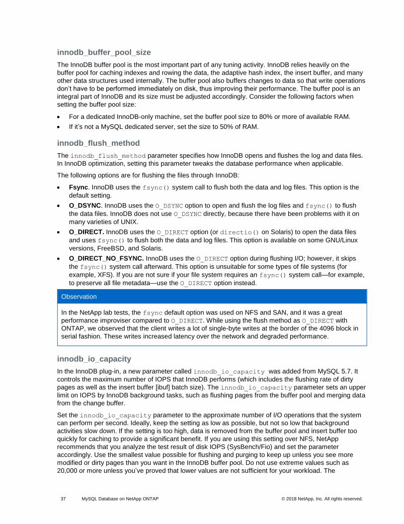
37 MySQL Database on NetApp ONTAP © 2018 NetApp, Inc. All rights reserved. © 2016 NetApp, Inc. All rights reserved.
innodb_buffer_pool_size
The InnoDB buffer pool is the most important part of any tuning activity. InnoDB relies heavily on the
buffer pool for caching indexes and rowing the data, the adaptive hash index, the insert buffer, and many
other data structures used internally. The buffer pool also buffers changes to data so that write operations
don’t have to be performed immediately on disk, thus improving their performance. The buffer pool is an
integral part of InnoDB and its size must be adjusted accordingly. Consider the following factors when
setting the buffer pool size:
• For a dedicated InnoDB-only machine, set the buffer pool size to 80% or more of available RAM.
• If it’s not a MySQL dedicated server, set the size to 50% of RAM.
innodb_flush_method
The innodb_flush_method parameter specifies how InnoDB opens and flushes the log and data files.
In InnoDB optimization, setting this parameter tweaks the database performance when applicable.
The following options are for flushing the files through InnoDB:
• Fsync. InnoDB uses the fsync() system call to flush both the data and log files. This option is the
default setting.
• O_DSYNC. InnoDB uses the O_DSYNC option to open and flush the log files and fsync() to flush
the data files. InnoDB does not use O_DSYNC directly, because there have been problems with it on
many varieties of UNIX.
• O_DIRECT. InnoDB uses the O_DIRECT option (or directio() on Solaris) to open the data files
and uses fsync() to flush both the data and log files. This option is available on some GNU/Linux
versions, FreeBSD, and Solaris.
• O_DIRECT_NO_FSYNC. InnoDB uses the O_DIRECT option during flushing I/O; however, it skips
the fsync() system call afterward. This option is unsuitable for some types of file systems (for
example, XFS). If you are not sure if your file system requires an fsync() system call—for example,
to preserve all file metadata—use the O_DIRECT option instead.
Observation
In the NetApp lab tests, the fsync default option was used on NFS and SAN, and it was a great
performance improviser compared to O_DIRECT. While using the flush method as O_DIRECT with
ONTAP, we observed that the client writes a lot of single-byte writes at the border of the 4096 block in
serial fashion. These writes increased latency over the network and degraded performance.
innodb_io_capacity
In the InnoDB plug-in, a new parameter called innodb_io_capacity was added from MySQL 5.7. It
controls the maximum number of IOPS that InnoDB performs (which includes the flushing rate of dirty
pages as well as the insert buffer [ibuf] batch size). The innodb_io_capacity parameter sets an upper
limit on IOPS by InnoDB background tasks, such as flushing pages from the buffer pool and merging data
from the change buffer.
Set the innodb_io_capacity parameter to the approximate number of I/O operations that the system
can perform per second. Ideally, keep the setting as low as possible, but not so low that background
activities slow down. If the setting is too high, data is removed from the buffer pool and insert buffer too
quickly for caching to provide a significant benefit. If you are using this setting over NFS, NetApp
recommends that you analyze the test result of disk IOPS (SysBench/Fio) and set the parameter
accordingly. Use the smallest value possible for flushing and purging to keep up unless you see more
modified or dirty pages than you want in the InnoDB buffer pool. Do not use extreme values such as
20,000 or more unless you’ve proved that lower values are not sufficient for your workload. The

38 MySQL Database on NetApp ONTAP © 2018 NetApp, Inc. All rights reserved. © 2016 NetApp, Inc. All rights reserved.
Innodb_IO_capacity parameter regulates flushing rates and related disk I/O. You can seriously harm
performance by setting this parameter or the innodb_io_capacity_max parameter too high and
wasting disk I/O operations with premature flushing.
innodb_lru_scan_depth
The innodb_lru_scan_depth parameter influences the algorithms and heuristics of the flush
operation for the InnoDB buffer pool. This parameter is primarily of interest to performance experts tuning
I/O-intensive workloads. For each buffer pool instance, this parameter specifies how far down in the least
recently used (LRU) page list the page cleaner thread should continue scanning, looking for dirty pages to
flush. This background operation is performed once per second.
You can adjust the value up or down to minimize the number of free pages. Don’t set the value much
higher than needed, because the scans can have a significant performance cost. Also, consider adjusting
this parameter when changing the number of buffer pool instances, because innodb_lru_scan_depth
*innodb_buffer_pool_instances defines the amount of work performed by the page cleaner thread
each second.
A setting smaller than the default is suitable for most workloads. Consider increasing the value only if you
have spare I/O capacity under a typical workload. Conversely, if a write-intensive workload saturates your
I/O capacity, decrease the value, especially if you have a large buffer pool.
open_file_limits
The open_file_limits parameter determines the number of files that the operating system permits
mysqld to open. The value of this parameter at run time is the real value permitted by the system and
might be different from the value you specify at server startup. The value is 0 on systems where MySQL
cannot change the number of open files. The effective open_files_limit value is based on the value
that is specified at the system startup (if any) and the values of max_connections and
table_open_cache by using these formulas:
• 10 + max_connections + (table_open_cache x 2)
• max_connections x 5
• Operating system limit if positive
• If the operating system limit is infinity: open_files_limit value is specified at startup; 5,000 if
none
The server attempts to obtain the number of file descriptors using the maximum of these four values. If
that many descriptors cannot be obtained, the server attempts to obtain as many as the system will
permit.
13 Deployment Methods
There are different ways of accessing your data stored on disk. If it’s a local disk, you can directly access
the data over the cable. However, if the data is stored over a network, you must choose a protocol to fit
your requirements. Storage protocols are broadly categorized into the following two parts:
• NAS protocols
• SAN protocols
A NAS unit is a single storage device that operates on files. It includes a dedicated hardware device that
connects to a LAN, usually through an Ethernet connection. This NAS server authenticates clients and
manages file operations in much the same manner as traditional file servers, through well-established
network protocols. NAS uses file-based protocols such as NFS (popular on UNIX systems) or SMB (used
with Microsoft Windows systems) to copy the blocks and files over a network.
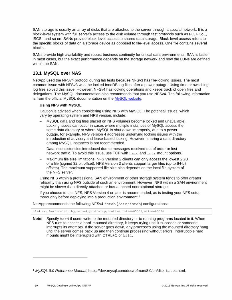
39 MySQL Database on NetApp ONTAP © 2018 NetApp, Inc. All rights reserved. © 2016 NetApp, Inc. All rights reserved.
SAN storage is usually an array of disks that are attached to the server through a special network. It is a
block-level system with full server’s access to the disk volume through fast protocols such as FC, FCoE,
iSCSI, and so on. SANs provide block-level access to shared data storage. Block-level access refers to
the specific blocks of data on a storage device as opposed to file-level access. One file contains several
blocks.
SANs provide high availability and robust business continuity for critical data environments. SAN is faster
in most cases, but the exact performance depends on the storage network and how the LUNs are defined
within the SAN.
13.1 MySQL over NAS
NetApp used the NFSv4 protocol during lab tests because NFSv3 has file-locking issues. The most
common issue with NFSv3 was the locked InnoDB log files after a power outage. Using time or switching
log files solved this issue. However, NFSv4 has locking operations and keeps track of open files and
delegations. The MySQL documentation also recommends that you use NFSv4. The following information
is from the official MySQL documentation on the MySQL website.
Using NFS with MySQL
Caution is advised when considering using NFS with MySQL. The potential issues, which vary by operating system and NFS version, include:
− MySQL data and log files placed on NFS volumes become locked and unavailable. Locking issues can occur in cases where multiple instances of MySQL access the same data directory or where MySQL is shut down improperly, due to a power outage, for example. NFS version 4 addresses underlying locking issues with the introduction of advisory and lease-based locking. However, sharing a data directory among MySQL instances is not recommended.
− Data inconsistencies introduced due to messages received out of order or lost network traffic. To avoid this issue, use TCP with hard and intr mount options.
− Maximum file size limitations. NFS Version 2 clients can only access the lowest 2GB of a file (signed 32 bit offset). NFS Version 3 clients support larger files (up to 64-bit offsets). The maximum supported file size also depends on the local file system of the NFS server.
Using NFS within a professional SAN environment or other storage system tends to offer greater reliability than using NFS outside of such an environment. However, NFS within a SAN environment might be slower than directly-attached or bus-attached nonrotational storage.
If you choose to use NFS, NFS Version 4 or later is recommended, as is testing your NFS setup thoroughly before deploying into a production environment.1
NetApp recommends the following NFSv4 fstab (/etc/fstab) configurations:
nfs4 rw, hard,nointr,bg,vers=4,proto=tcp,noatime,rsize=65536,wsize=65536
Note: Specify hard if users write to the mounted directory or to running programs located in it. When NFS tries to access a hard-mounted directory, it keeps trying until it succeeds or someone interrupts its attempts. If the server goes down, any processes using the mounted directory hang until the server comes back up and then continue processing without errors. Interruptible hard mounts might be interrupted with CTRL+C or kill.
1 MySQL 8.0 Reference Manual, https://dev.mysql.com/doc/refman/8.0/en/disk-issues.html.

40 MySQL Database on NetApp ONTAP © 2018 NetApp, Inc. All rights reserved. © 2016 NetApp, Inc. All rights reserved.
Specify nointr if users might damage critical data by manually interrupting an NFS request. It is better for the system to hang while the server is down than risk losing data between the client and the server.
13.2 MySQL over SAN
There are two options to configure MySQL with SAN using the previously described two-volume model.
Smaller databases can be placed on a pair of standard LUNs as long as the I/O and capacity demands
are within the limits of a single LUN file system. For example, a database that requires approximately 2K
random IOPS can be hosted on a single file system on a single LUN. Likewise, a database that is only
100GB in size would fit on a single LUN without creating a management problem.
Larger databases require multiple LUNs. For example, a database that requires 100K IOPS would most
likely need at least eight LUNs. A single LUN would become a bottleneck because of the inadequate
number of SCSI channels to disk. A 10TB database would similarly be difficult to manage on a single
10TB LUN. Logical volume managers are designed to bond the performance and capacity capabilities of
multiple LUNs together to improve performance and manageability.
In both cases, a pair of NetApp ONTAP volumes should be sufficient. With a simple configuration, the
data file LUN would be placed in a dedicated volume, as would the log LUN. With a logical volume
manager configuration, all the LUNs in the data file volume group would be in a dedicated volume, and
the LUNs of the log volume group would be in a second dedicated volume.
NetApp recommends two file systems for MySQL deployments on SAN:
• The first file system stores all MySQL data including tablespace, data, and index.
• The second file system stores all logs (binary logs, slow logs, and transaction logs).
There are multiple reasons for separating data in this manner, including:
• The I/O patterns of data files and log files differ. Separating them would allow more options with QoS controls.
• Optimal use of Snapshot technology requires the ability to independently restore the data files. Comingling data files with log files interferes with data file restoration.
• NetApp SnapMirror technology can be used to provide a simple, low-RPO disaster recovery capability for a database; however, it requires different replication schedules for the data files and logs.
Note: Use this basic two-volume layout to future-proof the solution so that all ONTAP features can be used if needed.
NetApp also recommends that you format your drive with the ext4 file system because of the following
features:
• Extended approach to block management features used in the journaling file system (JFS) and delayed allocation features of the extended file system (XFS).
• Ext4 permits file systems of up to 1 exbibyte (2^60 bytes) and files of up to 16 tebibytes (16 * 2^40 bytes). In contrast, the ext3 file system supports only a maximum file system size of 16TB and a maximum file size of 2TB.
• In ext4 file systems, multiblock allocation (mballoc) allocates multiple blocks for a file in a single
operation, instead of allocating them one by one, as in ext3. This configuration reduces the overhead of calling the block allocator several times, and it optimizes the allocation of memory.
• Although XFS is the default for many Linux distributions, it manages metadata differently and is not suitable for some MySQL configurations.
NetApp recommends using 4k block size options with the mkfs utility to align with existing block LUN
size.
mkfs.ext4 -b 4096

41 MySQL Database on NetApp ONTAP © 2018 NetApp, Inc. All rights reserved. © 2016 NetApp, Inc. All rights reserved.
NetApp LUNs store data in 4KB physical blocks, which yields eight 512-byte logical blocks.
If you do not set up the same block size, I/O will not be aligned with physical blocks correctly and could
write in two different disks in a RAID group, resulting in latency.
It is important that you align I/O for smooth read/write operations. However, when the I/O begins at a
logical block that is not at the start of a physical block, the I/O is misaligned. I/O operations are aligned
only when they begin at a logical block—the first logical block in a physical block.
14 Performance Benchmarking
Most MySQL deployments undergo a performance benchmarking stage before going to the production. It
is always a best practice to complete performance benchmarking of the system. Here are some of the
important metrics to benchmark:
• Throughput
• Transactions/queries per second (TPS/QPS)
• Latency
This section describes tools that have been used to measure these metrics in the MySQL ecosystem.
14.1 SysBench
SysBench is a benchmark suite that allows you to quickly get an impression of system performance,
which is important if you plan to run a database under intensive load. SysBench supports testing CPU,
memory, file I/O, mutex performance, and even MySQL benchmarking. You can select the SysBench File
I/O Workload option to measure the disk throughput. It also comes with a set of database workload Lua
scripts (read/write, write only, and read only) to measure QPS/TPS metrics of MySQL. The tool also helps
you measure the average latency of the queries. In summary, you can simulate different kinds of
workloads as needed. For more information, refer to the Linux man page for the SysBench tool.
14.2 MySQL Slap
MySQL includes a diagnostic tool called mysqlslap; it’s been available since version 5.1.4. It is a
benchmarking tool that can help DBAs and developers load-test their database servers. The mysqlslap
tool can emulate a large number of client connections to the database server at the same time. The load-
testing parameters are fully configurable, and the results from different test runs can be used to fine-tune
the database design or hardware resources. This tool runs in the following three stages:
1. Create schema, table, and, optionally, any stored programs or data to use for the test. This stage uses a single client connection.
2. Run the load test. This stage can use many client connections.
3. Clean up (disconnect, drop table if specified). This stage uses a single client connection.
A query that consumes too many database resources might be the result of designing tables incorrectly,
selecting the wrong table type, or creating an inefficient query. When a query eats up a lot of database
resources, it can negatively affect other application components. By using mysqlslap to stress-test a
server in a nonpublic environment, you will discover these errors sooner, which prevents a database
failure after your application goes live. To learn more, review the tool options on the MySQL site.
15 Performance Results
This section describes the tests and validations performed in the NetApp labs. All the parameters
suggested in section 10, “Linux Configuration,” and section 12, “MySQL,” were tested in the NetApp lab.
We used the SysBench utility to perform basic benchmarking of the disk and MySQL. The test results

42 MySQL Database on NetApp ONTAP © 2018 NetApp, Inc. All rights reserved. © 2016 NetApp, Inc. All rights reserved.
provide a basic idea of the tests performed and the numbers achieved. Actual results can vary depending
on the server configuration and the parameters configured. Test results covered the benchmarking
performed for NFS and iSCSI protocol.
15.1 Testing Considerations
Accurate testing of database storage performance is a complicated task. It requires not just an
understanding of IOPS and throughput, but also an understanding of the difference between foreground
and background I/O operations, the impact of latency on the database, and numerous operating system
and network settings that affect storage performance. In addition, there are nonstorage database tasks to
consider. There is a point where optimizing storage performance yields no useful benefits, because
storage performance is no longer a limiting factor for performance.
Most database customers now select an all-flash array, which creates some additional considerations. As
an example, consider performance testing on a two-node NetApp AFF8080 system:
• With a 75/25 read/write ratio, two AFF8080 nodes can deliver over 300K random database IOPS before latency even crosses the 1ms mark. This far exceeds the current performance demands of most databases, so it is difficult to predict the expected improvement. Storage would be largely erased as a bottleneck.
• Network bandwidth is an increasingly common source of performance limitations. For example, spinning disk solutions are often bottlenecks for database performance, because the I/O latency is very high. When latency limitations are removed by an all-flash array, the barrier frequently shifts to the network. This situation is especially notable with virtualized environments and blade systems where the true network connectivity is difficult to visualize. This limitation can complicate performance testing if the storage system itself cannot be fully utilized because of bandwidth limitations.
• In general, comparing the performance of an all-flash array with an array containing spinning disks is not possible because of the dramatically improved latency of all-flash arrays. Test results are typically not meaningful.
• Comparing peak IOPS performance with an all-flash array is frequently not a useful test, because databases are not limited by storage I/O. For example, assume that one array can sustain 500K random IOPS, whereas another can sustain 300K. The difference is irrelevant in the real world if a database is spending 99% of its time on CPU processing. The workloads never use the full capabilities of the storage array. In contrast, peak IOPS capabilities might be critical in a consolidation platform in which the storage array is expected to be loaded to its peak capabilities.
• Always consider latency as well as IOPS in any storage test. Many storage arrays in the market make claims of extreme levels of IOPS, but the latency renders those IOPS useless at such levels. The typical target with all-flash arrays is the 1ms mark. A better approach to testing is not to measure the maximum possible IOPS, but to determine how many IOPS a storage array can sustain before average latency is greater than 1ms.
Table 2 describes the test lab environment.
Table 2) Lab setup.
Lab Details
Server details Intel Xeon CPU E5-2630 0 @ 2.30GHz (4Core); 15GB RAM
Operating system Red Hat Enterprise Linux 7.3 (64-bit)
Storage Hybrid FAS8060; two volumes (data and logs)
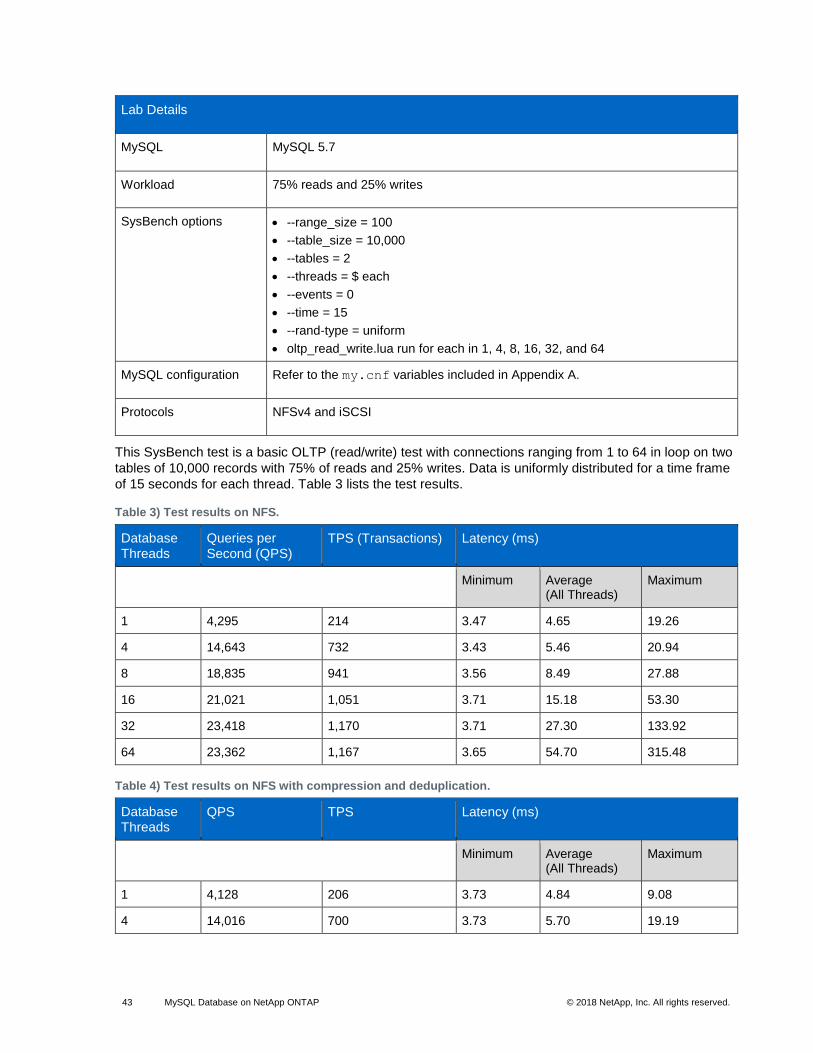
43 MySQL Database on NetApp ONTAP © 2018 NetApp, Inc. All rights reserved. © 2016 NetApp, Inc. All rights reserved.
Lab Details
MySQL MySQL 5.7
Workload 75% reads and 25% writes
SysBench options • --range_size = 100
• --table_size = 10,000
• --tables = 2
• --threads = $ each
• --events = 0
• --time = 15
• --rand-type = uniform
• oltp_read_write.lua run for each in 1, 4, 8, 16, 32, and 64
MySQL configuration Refer to the my.cnf variables included in Appendix A.
Protocols NFSv4 and iSCSI
This SysBench test is a basic OLTP (read/write) test with connections ranging from 1 to 64 in loop on two
tables of 10,000 records with 75% of reads and 25% writes. Data is uniformly distributed for a time frame
of 15 seconds for each thread. Table 3 lists the test results.
Table 3) Test results on NFS.
Database Threads
Queries per Second (QPS)
TPS (Transactions) Latency (ms)
Minimum Average (All Threads)
Maximum
1 4,295 214 3.47 4.65 19.26
4 14,643 732 3.43 5.46 20.94
8 18,835 941 3.56 8.49 27.88
16 21,021 1,051 3.71 15.18 53.30
32 23,418 1,170 3.71 27.30 133.92
64 23,362 1,167 3.65 54.70 315.48
Table 4) Test results on NFS with compression and deduplication.
Database Threads
QPS TPS Latency (ms)
Minimum Average (All Threads)
Maximum
1 4,128 206 3.73 4.84 9.08
4 14,016 700 3.73 5.70 19.19
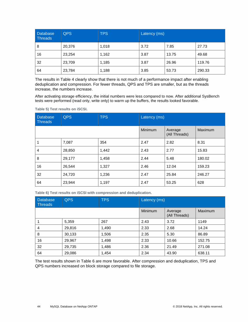
44 MySQL Database on NetApp ONTAP © 2018 NetApp, Inc. All rights reserved. © 2016 NetApp, Inc. All rights reserved.
Database Threads
QPS TPS Latency (ms)
8 20,376 1,018 3.72 7.85 27.73
16 23,254 1,162 3.87 13.75 49.68
32 23,709 1,185 3.87 26.96 119.76
64 23,784 1,188 3.85 53.73 290.33
The results in Table 4 clearly show that there is not much of a performance impact after enabling
deduplication and compression. For fewer threads, QPS and TPS are smaller, but as the threads
increase, the numbers increase.
After activating storage efficiency, the initial numbers were less compared to now. After additional SysBench tests were performed (read only, write only) to warm up the buffers, the results looked favorable.
Table 5) Test results on iSCSI.
Database Threads
QPS TPS Latency (ms)
Minimum Average (All Threads)
Maximum
1 7,087 354 2.47 2.82 8.31
4 28,850 1,442 2.43 2.77 15.83
8 29,177 1,458 2.44 5.48 180.02
16 26,544 1,327 2.46 12.04 159.23
32 24,720 1,236 2.47 25.84 246.27
64 23,944 1,197 2.47 53.25 628
Table 6) Test results on iSCSI with compression and deduplication.
Database Threads
QPS TPS Latency (ms)
Minimum Average (All Threads)
Maximum
1 5,359 267 2.43 3.72 1149
4 29,816 1,490 2.33 2.68 14.24
8 30,133 1,506 2.35 5.30 86.89
16 29,967 1,498 2.33 10.66 152.75
32 29,735 1,486 2.36 21.49 271.08
64 29,086 1,454 2.34 43.90 638.11
The test results shown in Table 6 are more favorable. After compression and deduplication, TPS and
QPS numbers increased on block storage compared to file storage.
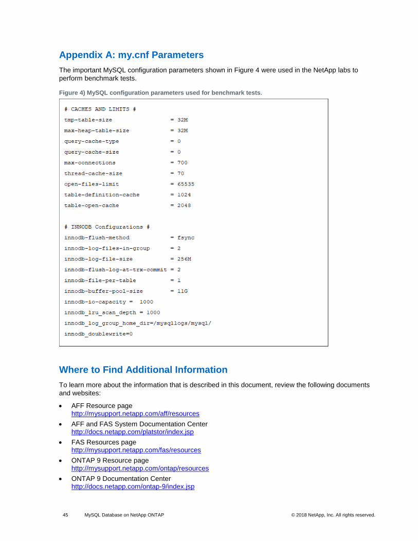
45 MySQL Database on NetApp ONTAP © 2018 NetApp, Inc. All rights reserved. © 2016 NetApp, Inc. All rights reserved.
Appendix A: my.cnf Parameters
The important MySQL configuration parameters shown in Figure 4 were used in the NetApp labs to
perform benchmark tests.
Figure 4) MySQL configuration parameters used for benchmark tests.
Where to Find Additional Information
To learn more about the information that is described in this document, review the following documents
and websites:
• AFF Resource page http://mysupport.netapp.com/aff/resources
• AFF and FAS System Documentation Center http://docs.netapp.com/platstor/index.jsp
• FAS Resources page http://mysupport.netapp.com/fas/resources
• ONTAP 9 Resource page http://mysupport.netapp.com/ontap/resources
• ONTAP 9 Documentation Center http://docs.netapp.com/ontap-9/index.jsp

46 MySQL Database on NetApp ONTAP © 2018 NetApp, Inc. All rights reserved. © 2016 NetApp, Inc. All rights reserved.
• NetApp Product Documentation http://docs.netapp.com
Version History
Version Date Document Version History
Version 1.0 October 2018 Initial release

47 MySQL Database on NetApp ONTAP © 2018 NetApp, Inc. All rights reserved. © 2016 NetApp, Inc. All rights reserved.
Refer to the Interoperability Matrix Tool (IMT) on the NetApp Support site to validate that the exact product and feature versions described in this document are supported for your specific environment. The NetApp IMT defines the product components and versions that can be used to construct configurations that are supported by NetApp. Specific results depend on each customer’s installation in accordance with published specifications.
Copyright Information
Copyright © 2018 NetApp, Inc. All Rights Reserved. Printed in the U.S. No part of this document covered by copyright may be reproduced in any form or by any means—graphic, electronic, or mechanical, including photocopying, recording, taping, or storage in an electronic retrieval system—without prior written permission of the copyright owner.
Software derived from copyrighted NetApp material is subject to the following license and disclaimer:
THIS SOFTWARE IS PROVIDED BY NETAPP “AS IS” AND WITHOUT ANY EXPRESS OR IMPLIED WARRANTIES, INCLUDING, BUT NOT LIMITED TO, THE IMPLIED WARRANTIES OF MERCHANTABILITY AND FITNESS FOR A PARTICULAR PURPOSE, WHICH ARE HEREBY DISCLAIMED. IN NO EVENT SHALL NETAPP BE LIABLE FOR ANY DIRECT, INDIRECT, INCIDENTAL, SPECIAL, EXEMPLARY, OR CONSEQUENTIAL DAMAGES (INCLUDING, BUT NOT LIMITED TO, PROCUREMENT OF SUBSTITUTE GOODS OR SERVICES; LOSS OF USE, DATA, OR PROFITS; OR BUSINESS INTERRUPTION) HOWEVER CAUSED AND ON ANY THEORY OF LIABILITY, WHETHER IN CONTRACT, STRICT LIABILITY, OR TORT (INCLUDING NEGLIGENCE OR OTHERWISE) ARISING IN ANY WAY OUT OF THE USE OF THIS SOFTWARE, EVEN IF ADVISED OF THE POSSIBILITY OF SUCH DAMAGE.
NetApp reserves the right to change any products described herein at any time, and without notice. NetApp assumes no responsibility or liability arising from the use of products described herein, except as expressly agreed to in writing by NetApp. The use or purchase of this product does not convey a license under any patent rights, trademark rights, or any other intellectual property rights of NetApp.
The product described in this manual may be protected by one or more U.S. patents, foreign patents, or pending applications.
Data contained herein pertains to a commercial item (as defined in FAR 2.101) and is proprietary to NetApp, Inc. The U.S. Government has a non-exclusive, non-transferrable, non-sublicensable, worldwide, limited irrevocable license to use the Data only in connection with and in support of the U.S. Government contract under which the Data was delivered. Except as provided herein, the Data may not be used, disclosed, reproduced, modified, performed, or displayed without the prior written approval of NetApp, Inc. United States Government license rights for the Department of Defense are limited to those rights identified in DFARS clause 252.227-7015(b).
Trademark Information
NETAPP, the NETAPP logo, and the marks listed at http://www.netapp.com/TM are trademarks of NetApp, Inc. Other company and product names may be trademarks of their respective owners.
TR-4722-1018
Related Documents