Fronius prints on elemental chlorine free paper (ECF) sourced from certified sustainable forests (FSC). / Perfect Charging / Perfect Welding / Solar Energy TPS 270i C EN Operating instructions MIG/MAG power source 42,0426,0206,EN 015-17112020

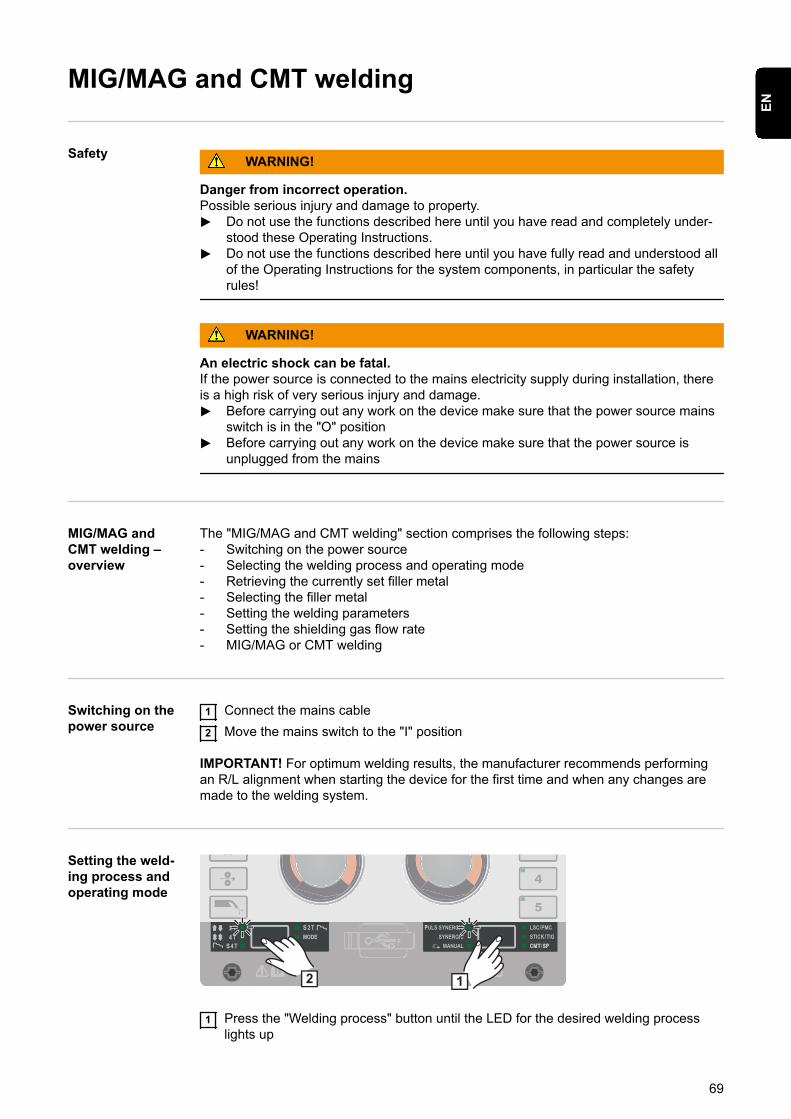
Welcome message from author
This document is posted to help you gain knowledge. Please leave a comment to let me know what you think about it! Share it to your friends and learn new things together.
Transcript

Fronius prints on elemental chlorine free paper (ECF) sourced from certified sustainable forests (FSC).
/ Perfect Charging / Perfect Welding / Solar Energy
TPS 270i CEN
Operating instructions
MIG/MAG power source
42,0426,0206,EN 015-17112020

ContentsSafety rules 7
Explanation of safety notices 7General 7Proper use 7Environmental conditions 8Obligations of the operator 8Obligations of personnel 8Mains connection 8Residual current protective device 9Protecting yourself and others 9Noise emission values 9Danger from toxic gases and vapours 10Danger from flying sparks 10Risks from mains current and welding current 11Meandering welding currents 12EMC Device Classifications 12EMC measures 12EMF measures 13Specific hazards 13Requirement for the shielding gas 14Danger from shielding gas cylinders 14Danger from escaping shielding gas 15Safety measures at the installation location and during transport 15Safety measures in normal operation 15Commissioning, maintenance and repair 16Safety inspection 16Disposal 17Safety symbols 17Data protection 17Copyright 17
General information 19
General 21Device concept 21Functional principle 21Application areas 21Warning notices on the device 22Description of Warning Notices on the Device 24
Welding packages, welding characteristics and welding processes 26General 26Welding characteristics 26Summary of MIG/MAG pulse synergic welding 28Summary of MIG/MAG standard synergic welding 28Summary of the PMC process 29Summary of the LSC process 29Summary of SynchroPulse welding 29Summary of the CMT process 30
System components 31General 31Overview 31Options 31
Controls, connections and mechanical components 33
Control panel 35General 35Safety 35Control panel 35Displaying plain text for parameters 40
F1/F2 special function parameters, Favourites button 41
3
EN

F1 and F2 special function parameters 41The Favourites button 42
Connections, switches and mechanical components 45Connections, switches and mechanical components 45
Installation and commissioning 47
Minimum equipment needed for welding task 49General 49MIG/MAG gas-cooled welding 49MIG/MAG water-cooled welding 49Manual CMT welding 49TIG DC welding 49MMA welding 49
Before installation and commissioning 50Safety 50Proper use 50Setup regulations 50Mains connection 50Generator-powered operation 51Information on system components 51
Connecting the mains cable 52Safety 52General 52Stipulated mains cables 52Connecting the mains cable - general 53
Start-up 55Safety 55General 55Connecting the gas cylinder 55Establishing a ground earth connection 56Connecting the welding torch 56Inserting/replacing feed rollers 57Inserting the wirespool 58Inserting the basket-type spool 59Feeding in the wire electrode 60Setting the contact pressure 61Adjusting the brake 63Design of the brake 63Performing R/L alignment 64
Welding 65
MIG/MAG modes 67General 67Symbols and their explanations 672-step mode 684-step mode 68Special 4-step mode 68Special 2-step mode 68
MIG/MAG and CMT welding 69Safety 69MIG/MAG and CMT welding – overview 69Switching on the power source 69Setting the welding process and operating mode 69Retrieving the currently set filler metal 70Selecting the filler metal 70Setting the welding parameters 72Setting the shielding gas flow rate 72MIG/MAG or CMT welding 73
MIG/MAG and CMT welding parameters 74Welding parameters for MIG/MAG pulse synergic welding, for CMT welding and PMC welding 74Welding parameters for MIG/MAG standard synergic welding and LSC welding 75
4

Welding parameters for MIG/MAG standard manual welding 77Explanation of footnotes 78
EasyJob mode 79General 79EasyJob mode 79
Spot welding 80Spot welding 80
TIG welding 82Safety 82Preparations 82TIG welding 82Igniting the arc 84Finishing welding 84
MMA welding 85Safety 85Preparations 85MMA welding 85Welding parameters for manual metal arc welding 87
Setup settings 89
Setup menu - overview 91Entering/exiting the Setup menu 91Setup menu - overview 92
Process parameters 93Process parameters for start of welding/end of welding 93Process parameters for Gas-Setup 94Process parameters for process control 95Penetration stabilizer 95Arc length stabilizer 97Combination of penetration stabilizer and arc length stabilizer 99Process parameters for spot welding 100Process parameters for monitoring and components 100Process parameters for electrode setup 101Process parameters for TIG setup 104Process parameters for SynchroPulse 105Process parameters for Process Mix 107R/L alignment 109
Settings 111General remarks 111Overview 111Setting the units 111Setting the standards 112Setting the display brightness 112Displaying replaced characteristics 112Setting F1 and F2 special function parameters via the Setup menu 112Setting the Favourites button via the Setup menu 113Retrieving system data 113Setting the interior lighting 114Restoring the factory settings 115Resetting the password for the power source website 115Retrieving device information 115Setting the special display for JobMaster 115Setting the mode for spot welding 116
Setting the language 117Setting the language 117
Keylock 118Keylock 118
SmartManager - The power source website 119
SmartManager - The power source website 121General remarks 121
5
EN
Calling up the power source website 121Changing password / logging off 121Settings 122Language selection 122Fronius 122
Overview 123Overview 123Expand all groups / Reduce all groups 123Save as XML-file 123
Update 124Update 124Searching for an update file (performing the update) 124Fronius WeldConnect 126
Screenshot 127Screenshot 127
Backup & Restore 128General remarks 128Backup & Restore 128Automatic backup 129
Function Packages 130Function Packages 130Welding Packages 130Special characteristics 130Options 130Installing a function package 130
Synergic lines overview 131Characteristics overview 131Show /hide filter 131
Troubleshooting and maintenance 133
The Error menu 135The Error menu 135
Troubleshooting 136General 136Safety 136Power source - troubleshooting 136
Care, maintenance and disposal 140General 140Safety 140At every start-up 140If necessary 140Every 2 months 140Every 6 months 140Updating firmware 140Disposal 141
Technical data 143
Average consumption values during welding 145Average wire electrode consumption during MIG/MAG welding 145Average shielding gas consumption during MIG/MAG welding 145Average shielding gas consumption during TIG welding 145
Technical data 146Explanation of the term "duty cycle" 146Special voltages 146TPS 270i C 147TPS 270i C /nc 148TPS 270i C /MV/nc 149TPS 270i C /S/nc 151Overview with critical raw materials, year of production of the device 152
6
Safety rules
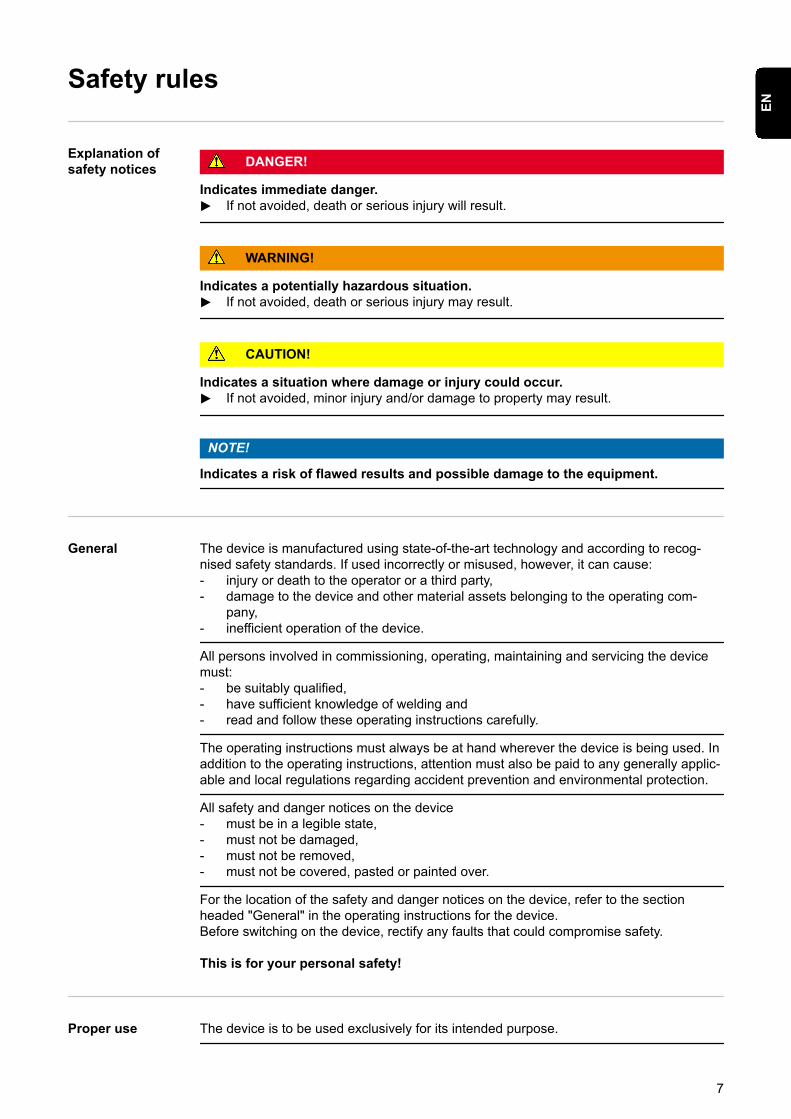
Explanation ofsafety notices DANGER!
Indicates immediate danger.▶ If not avoided, death or serious injury will result.
WARNING!
Indicates a potentially hazardous situation.▶ If not avoided, death or serious injury may result.
CAUTION!
Indicates a situation where damage or injury could occur.▶ If not avoided, minor injury and/or damage to property may result.
NOTE!
Indicates a risk of flawed results and possible damage to the equipment.
General The device is manufactured using state-of-the-art technology and according to recog-nised safety standards. If used incorrectly or misused, however, it can cause:- injury or death to the operator or a third party,- damage to the device and other material assets belonging to the operating com-
pany,- inefficient operation of the device.
All persons involved in commissioning, operating, maintaining and servicing the devicemust:- be suitably qualified,- have sufficient knowledge of welding and- read and follow these operating instructions carefully.
The operating instructions must always be at hand wherever the device is being used. Inaddition to the operating instructions, attention must also be paid to any generally applic-able and local regulations regarding accident prevention and environmental protection.
All safety and danger notices on the device- must be in a legible state,- must not be damaged,- must not be removed,- must not be covered, pasted or painted over.
For the location of the safety and danger notices on the device, refer to the sectionheaded "General" in the operating instructions for the device.Before switching on the device, rectify any faults that could compromise safety.
This is for your personal safety!
Proper use The device is to be used exclusively for its intended purpose.
7
EN
The device is intended solely for the welding processes specified on the rating plate.Any use above and beyond this purpose is deemed improper. The manufacturer shall notbe held liable for any damage arising from such usage.
Proper use includes:- carefully reading and following all the instructions given in the operating instructions- studying and obeying all safety and danger notices carefully- performing all stipulated inspection and maintenance work.
Never use the device for the following purposes:- Thawing out pipes- Charging batteries- Starting engines
The device is designed for use in industry and the workshop. The manufacturer acceptsno responsibility for any damage caused through use in a domestic setting.
The manufacturer likewise accepts no liability for inadequate or incorrect results.
Environmentalconditions
Operation or storage of the device outside the stipulated area will be deemed as not inaccordance with the intended purpose. The manufacturer shall not be held liable for anydamage arising from such usage.
Ambient temperature range:- during operation: -10 °C to + 40 °C (14 °F to 104 °F)- during transport and storage: -20 °C to +55 °C (-4 °F to 131 °F)
Relative humidity:- up to 50% at 40 °C (104 °F)- up to 90% at 20 °C (68 °F)
The surrounding air must be free from dust, acids, corrosive gases or substances, etc.Can be used at altitudes of up to 2000 m (6561 ft. 8.16 in.)
Obligations of theoperator
The operator must only allow persons to work with the device who:- are familiar with the fundamental instructions regarding safety at work and accident
prevention and have been instructed in how to use the device- have read and understood these operating instructions, especially the section
"safety rules", and have confirmed as much with their signatures- are trained to produce the required results.
Checks must be carried out at regular intervals to ensure that operators are working in asafety-conscious manner.
Obligations ofpersonnel
Before using the device, all persons instructed to do so undertake:- to observe the basic instructions regarding safety at work and accident prevention- to read these operating instructions, especially the "Safety rules" section and sign to
confirm that they have understood them and will follow them.
Before leaving the workplace, ensure that people or property cannot come to any harmin your absence.
Mains connection Devices with a higher rating may affect the energy quality of the mains due to their cur-rent consumption.
8
This may affect a number device types in terms of:- Connection restrictions- Criteria with regard to the maximum permissible mains impedance *)- Criteria with regard to the minimum short-circuit power requirement *)
*) at the interface with the public gridsee "Technical data"
In this case, the plant operator or the person using the device should check whether thedevice may be connected, where appropriate by discussing the matter with the powersupply company.
IMPORTANT! Ensure that the mains connection is earthed properly
Residual currentprotective device
Local regulations and national guidelines may require a residual current protectivedevice when connecting equipment to the public grid.The type of residual current protective device recommended by the manufacturer for theequipment is indicated in the technical data.
Protecting your-self and others
Anyone working with the device exposes themselves to numerous risks, e.g.- flying sparks and hot pieces of metal- Arc radiation, which can damage eyes and skin- Hazardous electromagnetic fields, which can endanger the lives of those using car-
diac pacemakers- Risk of electrocution from mains current and welding current- Greater noise pollution- Harmful welding fumes and gases
Suitable protective clothing must be worn when working with the device. The protectiveclothing must have the following properties:- Flame-resistant- Insulating and dry- Covers the whole body, is undamaged and in good condition- Safety helmet- Trousers with no turn-ups
Protective clothing refers to a variety of different items. Operators should:- Protect eyes and face from UV rays, heat and sparks using a protective visor and
regulation filter- Wear regulation protective goggles with side protection behind the protective visor- Wear stout footwear that provides insulation even in wet conditions- Protect the hands with suitable gloves (electrically insulated and providing protection
against heat)- Wear ear protection to reduce the harmful effects of noise and to prevent injury
Keep all persons, especially children, out of the working area while any devices are inoperation or welding is in progress. If, however, there are people in the vicinity:- Make them aware of all the dangers (risk of dazzling by the arc, injury from flying
sparks, harmful welding fumes, noise, possible risks from mains current and weldingcurrent, etc.)
- Provide suitable protective equipment- Alternatively, erect suitable safety screens/curtains.
Noise emissionvalues
The device generates a maximum sound power level of <80 dB(A) (ref. 1pW) when idlingand in the cooling phase following operation at the maximum permissible operating pointunder maximum rated load conditions according to EN 60974-1.
9
EN
It is not possible to provide a workplace-related emission value during welding (or cut-ting) as this is influenced by both the process and the environment. All manner of differ-ent welding parameters come into play, including the welding process (MIG/MAG, TIGwelding), the type of power selected (DC or AC), the power range, the type of weldmetal, the resonance characteristics of the workpiece, the workplace environment, etc.
Danger fromtoxic gases andvapours
The fumes produced during welding contain harmful gases and vapours.
Welding fumes contain substances that cause cancer, as stated in Monograph 118 of theInternational Agency for Research on Cancer.
Use at-source extraction and a room extraction system.If necessary, use a welding torch with an integrated extraction device.
Keep your face away from welding fumes and gases.
Fumes and hazardous gases- must not be breathed in- must be extracted from the working area using appropriate methods.
Ensure an adequate supply of fresh air. Ensure that there is a ventilation rate of at least20 m³ per hour at all times.
Otherwise, a welding helmet with an air supply must be worn.
If there is any doubt about whether the extraction capacity is sufficient, the measuredtoxic emission values should be compared with the permissible limit values.
The following components are responsible, amongst other things, for the degree of tox-icity of welding fumes:- Metals used for the workpiece- Electrodes- Coatings- Cleaners, degreasers, etc.- Welding process used
The relevant material safety data sheets and manufacturer's specifications for the listedcomponents should therefore be studied carefully.
Recommendations for trade fair scenarios, risk management measures and for identify-ing working conditions can be found on the European Welding Association website underHealth & Safety (https://european-welding.org).
Flammable vapours (e.g. solvent fumes) should be kept away from the arc's radiationarea.
Close the shielding gas cylinder valve or main gas supply if no welding is taking place.
Danger from fly-ing sparks
Flying sparks may cause fires or explosions.
Never weld close to flammable materials.
Flammable materials must be at least 11 metres (36 ft. 1.07 in.) away from the arc, oralternatively covered with an approved cover.
A suitable, tested fire extinguisher must be available and ready for use.
Sparks and pieces of hot metal may also get into adjacent areas through small gaps oropenings. Take appropriate precautions to prevent any danger of injury or fire.
10
Welding must not be performed in areas that are subject to fire or explosion or nearsealed tanks, vessels or pipes unless these have been prepared in accordance with therelevant national and international standards.
Do not carry out welding on containers that are being or have been used to store gases,propellants, mineral oils or similar products. Residues pose an explosive hazard.
Risks from mainscurrent and weld-ing current
An electric shock is potentially life threatening and can be fatal.
Do not touch live parts either inside or outside the device.
During MIG/MAG welding and TIG welding, the welding wire, the wirespool, the feedrollers and all pieces of metal that are in contact with the welding wire are live.
Always set the wirefeeder up on a sufficiently insulated surface or use a suitable, insu-lated wirefeeder holder.
Make sure that you and others are protected with an adequately insulated, dry base orcover for the earth or ground potential. This base or cover must extend over the entirearea between the body and the earth or ground potential.
All cables and leads must be secured, undamaged, insulated and adequately dimen-sioned. Replace loose connections and scorched, damaged, or inadequately dimen-sioned cables and leads immediately.Use the handle to ensure the power connections are tight before every use.In the case of power cables with a bayonet connector, rotate the power cable around thelongitudinal axis by at least 180° and pretension.
Do not wrap cables or leads around the body or parts of the body.
The electrode (rod electrode, tungsten electrode, welding wire, etc.) must- never be immersed in liquid for cooling- Never touch the electrode when the power source is switched on.
Double the open circuit voltage of a power source can occur between the welding elec-trodes of two power sources. Touching the potentials of both electrodes at the same timemay be fatal under certain circumstances.
Arrange for the mains cable to be checked regularly by a qualified electrician to ensurethe ground conductor is functioning properly.
Protection class I devices require a mains supply with ground conductor and a connectorsystem with ground conductor contact for proper operation.
Operation of the device on a mains supply without ground conductor and on a socketwithout ground conductor contact is only permitted if all national regulations for protectiveseparation are observed.Otherwise, this is considered gross negligence. The manufacturer shall not be held liablefor any damage arising from such usage.
If necessary, provide adequate earthing for the workpiece.
Switch off unused devices.
Wear a safety harness if working at height.
Before working on the device, switch it off and pull out the mains plug.
Attach a clearly legible and easy-to-understand warning sign to the device to preventanyone from plugging the mains plug back in and switching it on again.
After opening the device:- Discharge all live components- Ensure that all components in the device are de-energised.
11
EN
If work on live parts is required, appoint a second person to switch off the main switch atthe right moment.
Meandering weld-ing currents
If the following instructions are ignored, meandering welding currents can develop withthe following consequences:- Fire hazard- Overheating of parts connected to the workpiece- Irreparable damage to ground conductors- Damage to device and other electrical equipment
Ensure that the workpiece is held securely by the workpiece clamp.
Attach the workpiece clamp as close as possible to the area that is to be welded.
Position the device with sufficient insulation against electrically conductive environments,e.g. Insulation against conductive floor or insulation to conductive racks.
If distribution boards, twin-head mounts, etc., are being used, note the following: Theelectrode of the welding torch / electrode holder that is not used is also live. Make surethat the welding torch / electrode holder that is not used is kept sufficiently insulated.
In the case of automated MIG/MAG applications, ensure that only an insulated wire elec-trode is routed from the welding wire drum, large wirefeeder spool or wirespool to thewirefeeder.
EMC Device Clas-sifications
Devices in emission class A:- Are only designed for use in industrial settings- Can cause line-bound and radiated interference in other areas
Devices in emission class B:- Satisfy the emissions criteria for residential and industrial areas. This is also true for
residential areas in which the energy is supplied from the public low-voltage mains.
EMC device classification as per the rating plate or technical data.
EMC measures In certain cases, even though a device complies with the standard limit values for emis-sions, it may affect the application area for which it was designed (e.g. when there issensitive equipment at the same location, or if the site where the device is installed isclose to either radio or television receivers).If this is the case, then the operator is obliged to take appropriate action to rectify thesituation.
Check and evaluate the immunity to interference of nearby devices according to nationaland international regulations. Examples of equipment that may be susceptible to interfer-ence from the device include:- Safety devices- Power, signal and data transfer lines- IT and telecommunications devices- Measuring and calibrating devices
Supporting measures for avoidance of EMC problems:1. Mains supply
- If electromagnetic interference arises despite correct mains connection, addi-tional measures are necessary (e.g. use a suitable line filter).
12
2. Welding power leads- must be kept as short as possible- must run close together (to avoid EMF problems)- must be kept well apart from other leads
3. Equipotential bonding4. Earthing of the workpiece
- If necessary, establish an earth connection using suitable capacitors.5. Shielding, if necessary
- Shield off other nearby devices- Shield off entire welding installation
EMF measures Electromagnetic fields may pose as yet unknown risks to health:- effects on the health of others in the vicinity, e.g. wearers of pacemakers and hear-
ing aids- wearers of pacemakers must seek advice from their doctor before approaching the
device or any welding that is in progress- for safety reasons, keep distances between the welding cables and the welder's
head/torso as large as possible- do not carry welding cables and hosepacks over the shoulders or wind them around
any part of the body
Specific hazards Keep hands, hair, clothing and tools away from moving parts. For example:- Fans- Cogs- Rollers- Shafts- Wirespools and welding wires
Do not reach into the rotating cogs of the wire drive or into rotating drive components.
Covers and side panels may only be opened/removed while maintenance or repair workis being carried out.
During operation- Ensure that all covers are closed and all side panels are fitted properly.- Keep all covers and side panels closed.
The welding wire emerging from the welding torch poses a high risk of injury (piercing ofthe hand, injuries to the face and eyes, etc.).
Therefore always keep the welding torch away from the body (devices with wire-feedunit) and wear suitable protective goggles.
Never touch the workpiece during or after welding - risk of burns.
Slag can jump off cooling workpieces. The specified protective equipment must thereforealso be worn when reworking workpieces, and steps must be taken to ensure that otherpeople are also adequately protected.
Welding torches and other parts with a high operating temperature must be allowed tocool down before handling.
Special provisions apply in areas at risk of fire or explosion - observe relevantnational and international regulations.
Power sources for work in areas with increased electric risk (e.g. near boilers) must carrythe "Safety" sign. However, the power source must not be located in such areas.
Risk of scalding from escaping coolant. Switch off cooling unit before disconnectingcoolant flow or return lines.
13
EN
Observe the information on the coolant safety data sheet when handling coolant. Thecoolant safety data sheet may be obtained from your service centre or downloaded fromthe manufacturer's website.
Use only suitable load-carrying equipment supplied by the manufacturer when transport-ing devices by crane.- Hook chains and/or ropes onto all suspension points provided on the load-carrying
equipment.- Chains and ropes must be at the smallest angle possible to the vertical.- Remove gas cylinder and wire-feed unit (MIG/MAG and TIG devices).
If the wire-feed unit is attached to a crane holder during welding, always use a suitable,insulated wirefeeder hoisting attachment (MIG/MAG and TIG devices).
If the device has a carrying strap or handle, this is intended solely for carrying by hand.The carrying strap is not to be used if transporting with a crane, counterbalanced lift truckor other mechanical hoist.
All lifting accessories (straps, handles, chains, etc.) used in connection with the device orits components must be tested regularly (e.g. for mechanical damage, corrosion orchanges caused by other environmental factors).The testing interval and scope of testing must comply with applicable national standardsand directives as a minimum.
Odourless and colourless shielding gas may escape unnoticed if an adapter is used forthe shielding gas connection. Prior to assembly, seal the device-side thread of theadapter for the shielding gas connection using suitable Teflon tape.
Requirement forthe shielding gas
Especially with ring lines, contaminated shielding gas can cause damage to equipmentand reduce welding quality.Meet the following requirements regarding shielding gas quality:- Solid particle size < 40 µm- Pressure condensation point < -20 °C- Max. oil content < 25 mg/m³
Use filters if necessary.
Danger fromshielding gas cyl-inders
Shielding gas cylinders contain gas under pressure and can explode if damaged. As theshielding gas cylinders are part of the welding equipment, they must be handled with thegreatest of care.
Protect shielding gas cylinders containing compressed gas from excessive heat, mech-anical impact, slag, naked flames, sparks and arcs.
Mount the shielding gas cylinders vertically and secure according to instructions to pre-vent them falling over.
Keep the shielding gas cylinders well away from any welding or other electrical circuits.
Never hang a welding torch on a shielding gas cylinder.
Never touch a shielding gas cylinder with an electrode.
Risk of explosion - never attempt to weld a pressurised shielding gas cylinder.
Only use shielding gas cylinders suitable for the application in hand, along with the cor-rect and appropriate accessories (regulator, hoses and fittings). Only use shielding gascylinders and accessories that are in good condition.
Turn your face to one side when opening the valve of a shielding gas cylinder.
14
Close the shielding gas cylinder valve if no welding is taking place.
If the shielding gas cylinder is not connected, leave the valve cap in place on the cylin-der.
The manufacturer's instructions must be observed as well as applicable national andinternational regulations for shielding gas cylinders and accessories.
Danger fromescaping shield-ing gas
Risk of suffocation from the uncontrolled escape of shielding gas
Shielding gas is colourless and odourless and, in the event of a leak, can displace theoxygen in the ambient air.- Ensure an adequate supply of fresh air with a ventilation rate of at least 20 m³/hour.- Observe safety and maintenance instructions on the shielding gas cylinder or the
main gas supply.- Close the shielding gas cylinder valve or main gas supply if no welding is taking
place.- Check the shielding gas cylinder or main gas supply for uncontrolled gas leakage
before every start-up.
Safety measuresat the installationlocation and dur-ing transport
A device toppling over could easily kill someone. Place the device on a solid, level sur-face such that it remains stable- The maximum permissible tilt angle is 10°.
Special regulations apply in rooms at risk of fire or explosion- Observe relevant national and international regulations.
Use internal directives and checks to ensure that the workplace environment is alwaysclean and clearly laid out.
Only set up and operate the device in accordance with the degree of protection shownon the rating plate.
When setting up the device, ensure there is an all-round clearance of 0.5 m (1 ft. 7.69in.) to ensure that cooling air can flow in and out freely.
When transporting the device, observe the relevant national and local guidelines andaccident prevention regulations. This applies especially to guidelines regarding the risksarising during transport.
Do not lift or transport operational devices. Switch off devices before transport or lifting.
Before transporting the device, allow coolant to drain completely and detach the follow-ing components:- Wirefeeder- Wirespool- Shielding gas cylinder
After transporting the device, the device must be visually inspected for damage beforecommissioning. Any damage must be repaired by trained service technicians beforecommissioning the device.
Safety measuresin normal opera-tion
Only operate the device when all safety devices are fully functional. If the safety devicesare not fully functional, there is a risk of- injury or death to the operator or a third party- damage to the device and other material assets belonging to the operator- inefficient operation of the device
15
EN
Any safety devices that are not functioning properly must be repaired before switching onthe device.
Never bypass or disable safety devices.
Before switching on the device, ensure that no one is likely to be endangered.
Check the device at least once a week for obvious damage and proper functioning ofsafety devices.
Always fasten the shielding gas cylinder securely and remove it beforehand if the deviceis to be transported by crane.
Only the manufacturer's original coolant is suitable for use with our devices due to itsproperties (electrical conductibility, anti-freeze agent, material compatibility, flammability,etc.).
Only use suitable original coolant from the manufacturer.
Do not mix the manufacturer's original coolant with other coolants.
Only connect the manufacturer's system components to the cooling circuit.
The manufacturer accepts no liability for damage resulting from use of other systemcomponents or a different coolant. In addition, all warranty claims will be forfeited.
Cooling Liquid FCL 10/20 does not ignite. The ethanol-based coolant can ignite undercertain conditions. Transport the coolant only in its original, sealed containers and keepwell away from any sources of ignition.
Used coolant must be disposed of properly in accordance with the relevant national andinternational regulations. The coolant safety data sheet may be obtained from your ser-vice centre or downloaded from the manufacturer's website.
Check the coolant level before starting to weld, while the system is still cool.
Commissioning,maintenance andrepair
It is impossible to guarantee that bought-in parts are designed and manufactured to meetthe demands made of them, or that they satisfy safety requirements.- Use only original spare and wearing parts (also applies to standard parts).- Do not carry out any modifications, alterations, etc. to the device without the manu-
facturer's consent.- Components that are not in perfect condition must be replaced immediately.- When ordering, please give the exact designation and part number as shown in the
spare parts list, as well as the serial number of your device.
The housing screws provide the ground conductor connection for earthing the housingparts.Only use original housing screws in the correct number and tightened to the specifiedtorque.
Safety inspection The manufacturer recommends that a safety inspection of the device is performed atleast once every 12 months.
The manufacturer recommends that the power source be calibrated during the same 12-month period.
A safety inspection should be carried out by a qualified electrician- after any changes are made- after any additional parts are installed, or after any conversions- after repair, care and maintenance has been carried out- at least every twelve months.
16
For safety inspections, follow the appropriate national and international standards anddirectives.
Further details on safety inspection and calibration can be obtained from your servicecentre. They will provide you on request with any documents you may require.
Disposal Do not dispose of this device with normal domestic waste! To comply with the EuropeanDirective on Waste Electrical and Electronic Equipment and its implementation asnational law, electrical equipment that has reached the end of its life must be collectedseparately and returned to an approved recycling facility. Any device that you no longerrequire must either be returned to your dealer or given to one of the approved collectionand recycling facilities in your area. Ignoring this European Directive may have poten-tially adverse affects on the environment and your health!
Safety symbols Devices with the CE mark satisfy the essential requirements of the low-voltage and elec-tromagnetic compatibility directives (e.g. relevant product standards of the EN 60 974series).
Fronius International GmbH hereby declares that the device is compliant with Directive2014/53/EU. The full text on the EU Declaration of Conformity can be found at the follow-ing address: http://www.fronius.com
Devices marked with the CSA test mark satisfy the requirements of the relevant stand-ards for Canada and the USA.
Data protection The user is responsible for the safekeeping of any changes made to the factory settings.The manufacturer accepts no liability for any deleted personal settings.
Copyright Copyright of these operating instructions remains with the manufacturer.
The text and illustrations are all technically correct at the time of printing. We reserve theright to make changes. The contents of the operating instructions shall not provide thebasis for any claims whatsoever on the part of the purchaser. If you have any sugges-tions for improvement, or can point out any mistakes that you have found in the instruc-tions, we will be most grateful for your comments.
17
EN

18

General information
19

20
General
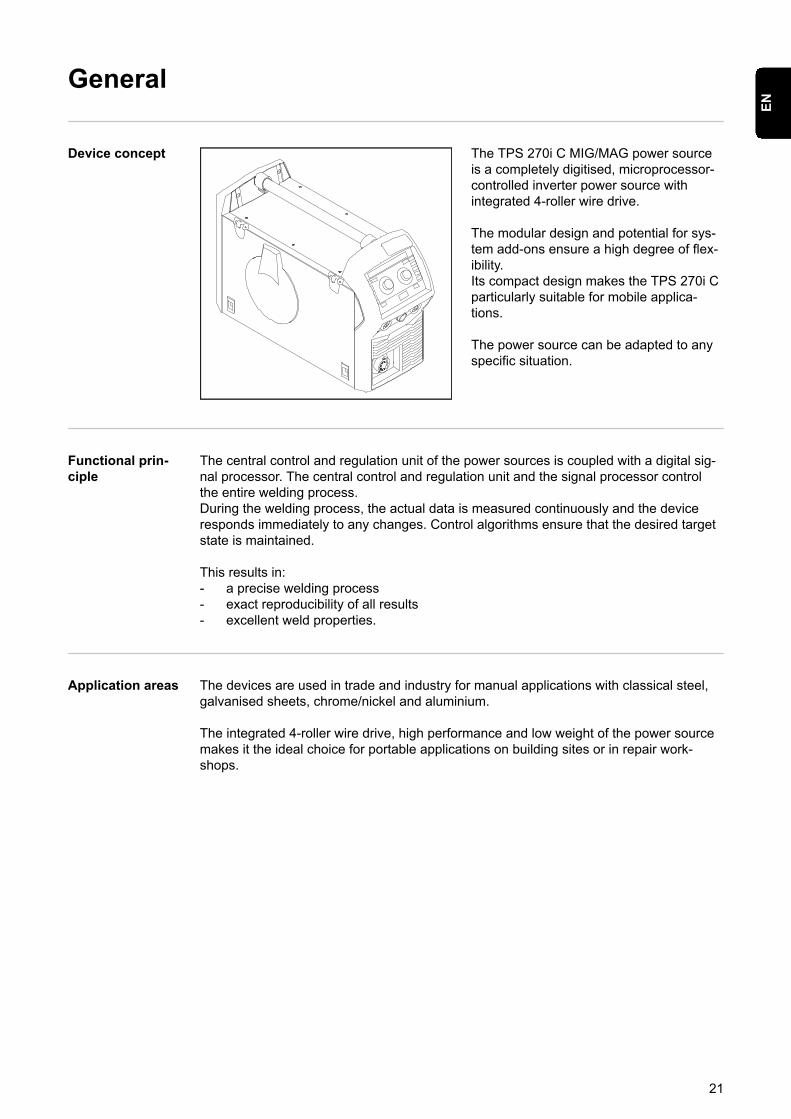
Device concept The TPS 270i C MIG/MAG power sourceis a completely digitised, microprocessor-controlled inverter power source withintegrated 4-roller wire drive.
The modular design and potential for sys-tem add-ons ensure a high degree of flex-ibility.Its compact design makes the TPS 270i Cparticularly suitable for mobile applica-tions.
The power source can be adapted to anyspecific situation.
Functional prin-ciple
The central control and regulation unit of the power sources is coupled with a digital sig-nal processor. The central control and regulation unit and the signal processor controlthe entire welding process.During the welding process, the actual data is measured continuously and the deviceresponds immediately to any changes. Control algorithms ensure that the desired targetstate is maintained.
This results in:- a precise welding process- exact reproducibility of all results- excellent weld properties.
Application areas The devices are used in trade and industry for manual applications with classical steel,galvanised sheets, chrome/nickel and aluminium.
The integrated 4-roller wire drive, high performance and low weight of the power sourcemakes it the ideal choice for portable applications on building sites or in repair work-shops.
21
EN
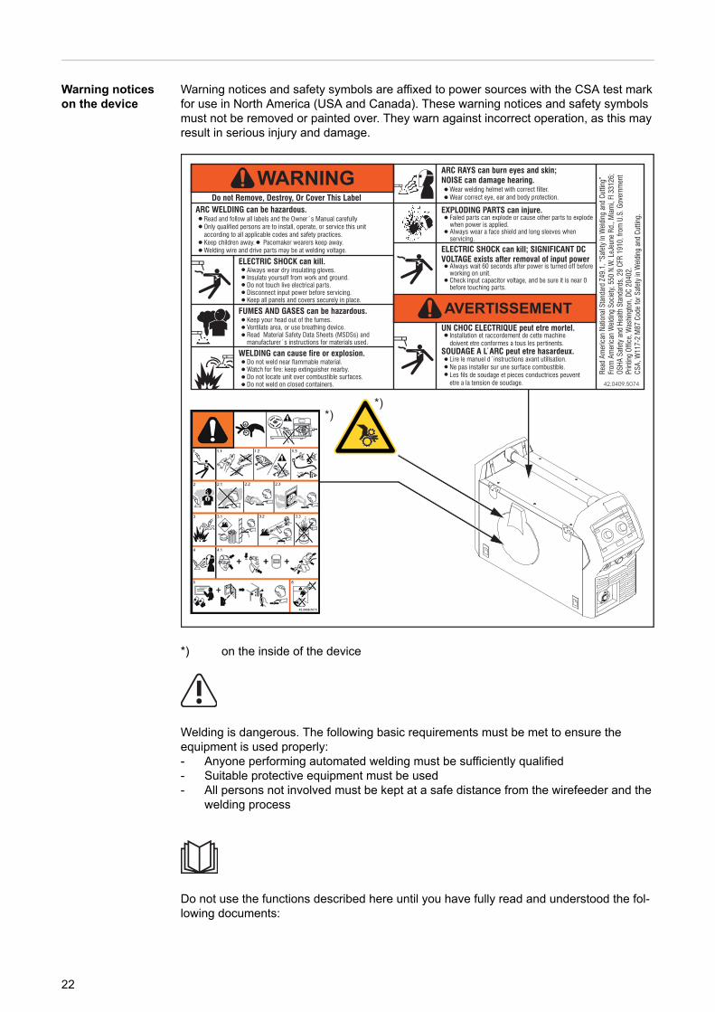
Warning noticeson the device
Warning notices and safety symbols are affixed to power sources with the CSA test markfor use in North America (USA and Canada). These warning notices and safety symbolsmust not be removed or painted over. They warn against incorrect operation, as this mayresult in serious injury and damage.
*)*)
*) on the inside of the device
Welding is dangerous. The following basic requirements must be met to ensure theequipment is used properly:- Anyone performing automated welding must be sufficiently qualified- Suitable protective equipment must be used- All persons not involved must be kept at a safe distance from the wirefeeder and the
welding process
Do not use the functions described here until you have fully read and understood the fol-lowing documents:
22
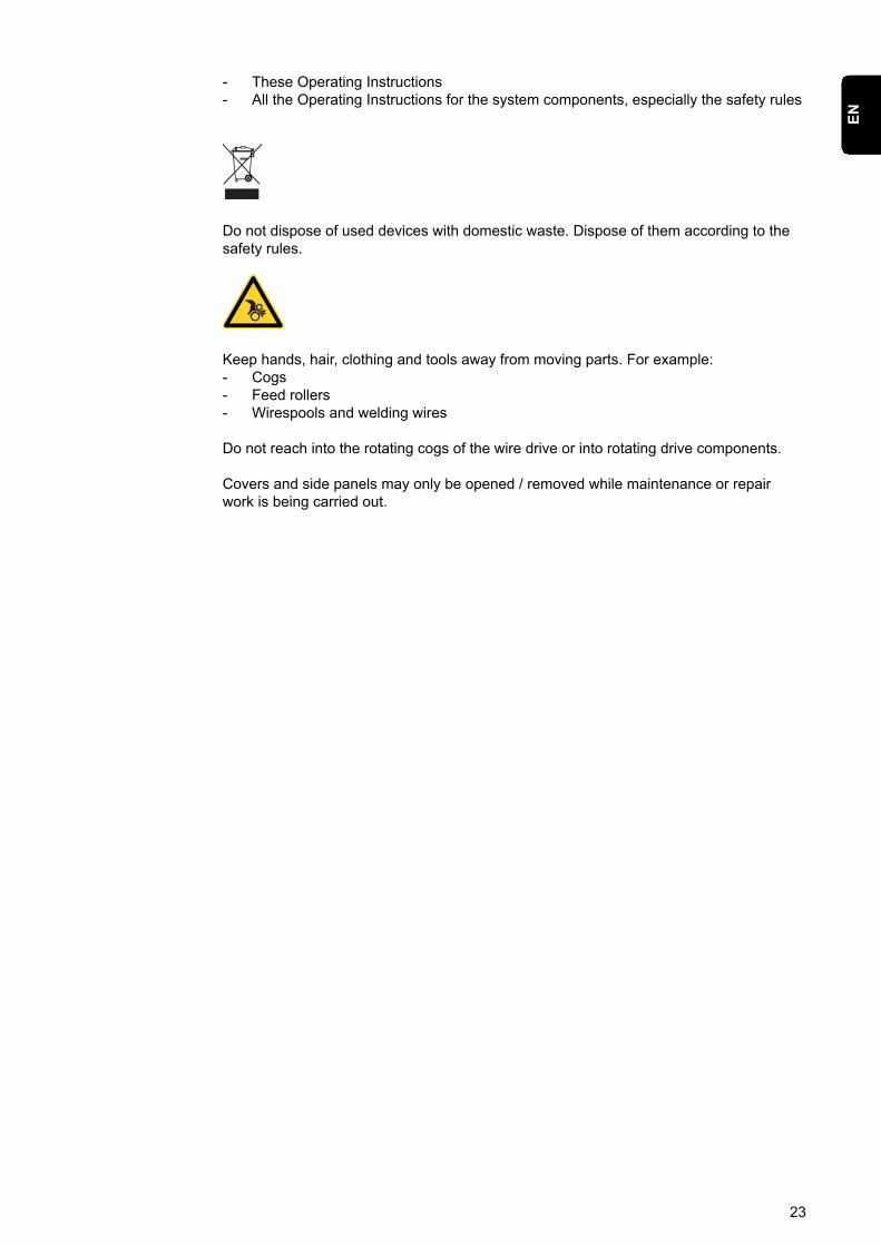
- These Operating Instructions- All the Operating Instructions for the system components, especially the safety rules
Do not dispose of used devices with domestic waste. Dispose of them according to thesafety rules.
Keep hands, hair, clothing and tools away from moving parts. For example:- Cogs- Feed rollers- Wirespools and welding wires
Do not reach into the rotating cogs of the wire drive or into rotating drive components.
Covers and side panels may only be opened / removed while maintenance or repairwork is being carried out.
23
EN

Description ofWarning Noticeson the Device
On certain device versions, warning notices are attached to the device.
The arrangement of the symbols may vary.
A B
. Warning! Watch Out!There are possible hazards as shown by the symbols.
A Drive rolls can injure fingers.
B Welding wire and drive parts are at welding voltage during operationKeep hands and metal objects away.
1. Electric shock can kill.
1.1 Wear dry insulating gloves. Do not touch electrode with bare hand. Do not wearwet or damaged gloves.
1.2 Protect yourself from electric shock by insulating yourself from work and ground.
1.3 Disconnect input plug or power before working on machine
2. Breathing welding fumes can be hazardous to your health.
2.1 Keep your head out of the fumes.
2.2 Use forced ventilation or local exhaust to remove the fumes.
2.3 Use ventilating fan to remove fumes.
24
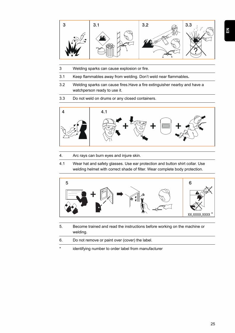
3 Welding sparks can cause explosion or fire.
3.1 Keep flammables away from welding. Don’t weld near flammables.
3.2 Welding sparks can cause fires.Have a fire extinguisher nearby and have awatchperson ready to use it.
3.3 Do not weld on drums or any closed containers.
4. Arc rays can burn eyes and injure skin.
4.1 Wear hat and safety glasses. Use ear protection and button shirt collar. Usewelding helmet with correct shade of filter. Wear complete body protection.
xx,xxxx,xxxx *
5. Become trained and read the instructions before working on the machine orwelding.
6. Do not remove or paint over (cover) the label.
* identifying number to order label from manufacturer
25
EN
Welding packages, welding characteristics andwelding processes
General Various welding packages, welding characteristics and welding processes are availablewith TPSi power sources that enable a wide range of materials to be effectively welded.
Welding charac-teristics
Depending on the welding process and shielding gas mix, various process-optimisedwelding characteristics are available when selecting the filler metal.
Examples of welding characteristics:- MIG/MAG 3700 PMC Steel 1,0mm M21 - arc blow *- MIG/MAG 3450 PMC Steel 1,0mm M21 - dynamic *- MIG/MAG 3044 Pulse AlMg5 1.2 mm I1 - universal *- MIG/MAG 2684 Standard Steel 0.9 mm M22 - root *
The additional designation (*) next to the welding process provides information about thespecial properties and use of the welding characteristic.The description of the characteristics is set out as follows:
DesignationWelding processProperties
arc blowPMCCharacteristic with improved arc break properties by deflecting the external magneticfields
brazeCMT, LSC, PMCCharacteristics for brazing processes (high brazing speed, reliable wetting and good flowof braze material)
braze+CMTOptimised characteristics for brazing processes with special "Braze+" gas nozzle (narrowgas nozzle opening, high shielding gas flow rate)
claddingCMT, LSC, PMCCharacteristic for cladding with low penetration, low dilution and wide weld seam flow forimproved wetting
dynamicCMT, PMC, Pulse, StandardCharacteristics for high welding speeds with concentrated arc
flanged edgeCMTCharacteristics for flange welds with frequency and energy yield adjustments;the edge is fully covered with the weld seam but not melted down
galvanizedCMT, LSC, PMC, Pulse, StandardCharacteristics for galvanised sheet surfaces (low zinc pore risk, reduced zinc meltingloss)
26
galvannealedPMCCharacteristics for iron/zinc-coated sheet surfaces
gap-bridgingCMT, PMCCharacteristics with very low heat input for optimum gap-bridging ability
Hot spotCMTCharacteristics with hot start sequence, specially for plug welds and MIG/MAG spot weldjoints
mix ** PMC
Also required: Pulse and PMC welding packages
Characteristics with process switch between pulsed and dip transfer arcSpecially for welding vertical-up seams with cyclic change between a hot and cold sup-porting process phase.
mix ** / ***CMT
Also required: CMT drive unit WF 60i Robacta Drive CMT, Pulse, Standard and CMTwelding packages
Characteristics with process switch between pulsed and CMT, where the CMT process isinitiated by wire movement reversal.
mix drive ***PMC
Also required: PushPull drive unit WF 25i Robacta Drive or WF 60i Robacta Drive CMT,Pulse and PMC welding packages
Characteristics with process switch between pulsed and dip transfer arc, where the diptransfer arc is initiated by wire movement reversal.
multi arcPMCCharacteristics for components being welded by several arcs each influencing the other
PCS **PMCPulse Controlled Spray Arc - Direct transition from the concentrated pulsed arc to a shortspray arc. The advantages of pulsed and standard arcs combined in a single character-istic
pipePMCCharacteristic for pipe applications and positional welding on narrow gap applications
retroCMT, Pulse, PMC, StandardCharacteristics with the properties of the TransPuls Synergic (TPS) predecessor series
ripple drive ***PMC
Also required:CMT drive unit WF 60i Robacta Drive CMT
27
EN

Characteristics that behave like interval mode for clear weld rippling, especially with alu-minium
rootCMT, LSC, StandardCharacteristics for root passes with powerful arc
seam trackPMC, PulseCharacteristics with increased seam-tracking signal, especially for use with several weld-ing torches on one component.
TIMEPMCCharacteristics for welding with long stick out and TIME shielding gases(T.I.M.E. = Transferred Ionized Molten Energy)
universalCMT, PMC, Pulse, StandardCharacteristics for conventional welding tasks in renowned Fronius quality
WAAMCMTCharacteristics with reduced heat input and greater stability at a higher deposition ratefor welding bead onto bead in adaptive structures
weld+CMTCharacteristics for welding with short stick out and Braze+ gas nozzle (gas nozzle withsmall opening and high flow velocity)
** Mixed process characteristics*** Welding characteristics with special properties provided by additional hardware
Summary ofMIG/MAG pulsesynergic welding
MIG/MAG pulse synergic
MIG/MAG pulse synergic welding is a pulsed-arc process with controlled material trans-fer.In the base current phase, the energy supply is reduced to such an extent that the arc isonly just stable and the surface of the workpiece is preheated. In the pulsing currentphase, a precise current pulse ensures the targeted detachment of a droplet of weldingmaterial.This principle guarantees a low-spatter weld and precise working across the entire powerrange, as unwelcome short circuits with simultaneous droplet explosion and uncontrolledwelding spatter are virtually eliminated.
Summary ofMIG/MAG stand-ard synergicwelding
MIG/MAG standard synergic
The MIG/MAG standard synergic welding process is a MIG/MAG welding process acrossthe entire power range of the power source with the following arc types:
Short circuit arcDroplet transfer takes place during a short circuit in the lower power range.
Intermediate arcThe droplet increases in size on the end of the wire electrode and is transferred in themid-power range during the short circuit.
28

Spray arcA short circuit-free transfer of material in the high power range.
Summary of thePMC process
PMC = Pulse Multi Control
PMC is a pulsed arc welding process with high-speed data processing, precise recordingof the process status and improved droplet detachment. Faster welding possible with astable arc and even fusion penetration.
Summary of theLSC process
LSC = Low Spatter Control
LSC is a new, low-spatter dip transfer arc process.The current is reduced before break-ing the short-circuit bridge; re-ignition takes place at significantly lower welding currentvalues.
Summary of Syn-chroPulse weld-ing
SynchroPulse is available for all processes (standard/pulsed/LSC/PMC).Due to the cyclical change of welding power between two operating points, Syn-chroPulse achieves a flaking seam appearance and non-continuous heat input.
29
EN
Summary of theCMT process
CMT = Cold Metal Transfer
A special CMT drive unit is required for the CMT process.
The reversing wire movement in the CMT process results in a droplet detachment withimproved dip transfer arc properties.The advantages of the CMT process are as follows- Low heat input- Less spattering- Reduced emissions- High process stability
The CMT process is suitable for:- Joint welding, cladding and brazing – particularly in the case of high requirements in
terms of heat input and process stability- Welding on light-gauge sheet with minimal distortion- Special connections, such as copper, zinc, and steel/aluminium
NOTE!
A CMT reference book is available complete with typical applications; seeISBN 978-3-8111-6879-4.
30
System components
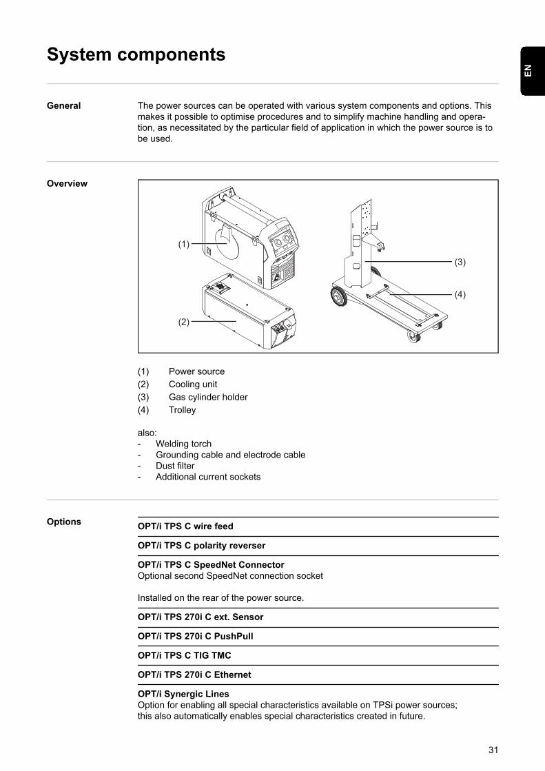
General The power sources can be operated with various system components and options. Thismakes it possible to optimise procedures and to simplify machine handling and opera-tion, as necessitated by the particular field of application in which the power source is tobe used.
Overview
(1)
(2)
(3)
(4)
(1) Power source(2) Cooling unit(3) Gas cylinder holder(4) Trolley
also:- Welding torch- Grounding cable and electrode cable- Dust filter- Additional current sockets
Options OPT/i TPS C wire feed
OPT/i TPS C polarity reverser
OPT/i TPS C SpeedNet ConnectorOptional second SpeedNet connection socket
Installed on the rear of the power source.
OPT/i TPS 270i C ext. Sensor
OPT/i TPS 270i C PushPull
OPT/i TPS C TIG TMC
OPT/i TPS 270i C Ethernet
OPT/i Synergic LinesOption for enabling all special characteristics available on TPSi power sources;this also automatically enables special characteristics created in future.
31
EN

OPT/i GUN TriggerOption for special functions in conjunction with the torch trigger
32

Controls, connections and mechan-ical components
33

34
Control panel
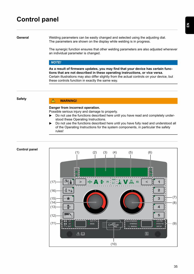
General Welding parameters can be easily changed and selected using the adjusting dial.The parameters are shown on the display while welding is in progress.
The synergic function ensures that other welding parameters are also adjusted wheneveran individual parameter is changed.
NOTE!
As a result of firmware updates, you may find that your device has certain func-tions that are not described in these operating instructions, or vice versa.Certain illustrations may also differ slightly from the actual controls on your device, butthese controls function in exactly the same way.
Safety WARNING!
Danger from incorrect operation.Possible serious injury and damage to property.▶ Do not use the functions described here until you have read and completely under-
stood these Operating Instructions.▶ Do not use the functions described here until you have fully read and understood all
of the Operating Instructions for the system components, in particular the safetyrules!
Control panel(1) (2) (3) (4) (5) (6)
(7)
(10)
(8)
(9)
(17)
(16)
(15)(14)(13)
(12)
(11)
35
EN
No. Function
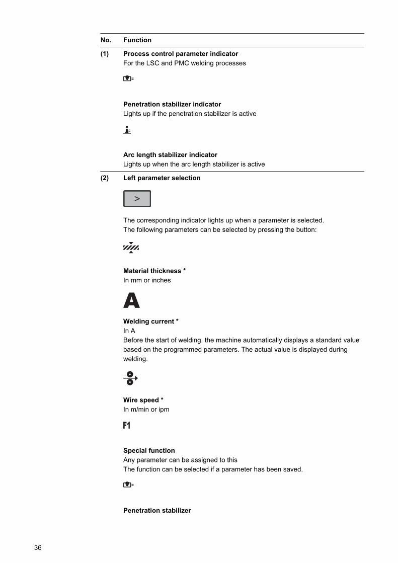
(1) Process control parameter indicatorFor the LSC and PMC welding processes
Penetration stabilizer indicatorLights up if the penetration stabilizer is active
Arc length stabilizer indicatorLights up when the arc length stabilizer is active
(2) Left parameter selection
The corresponding indicator lights up when a parameter is selected.The following parameters can be selected by pressing the button:
Material thickness *In mm or inches
Welding current *In ABefore the start of welding, the machine automatically displays a standard valuebased on the programmed parameters. The actual value is displayed duringwelding.
Wire speed *In m/min or ipm
Special functionAny parameter can be assigned to thisThe function can be selected if a parameter has been saved.
Penetration stabilizer
36
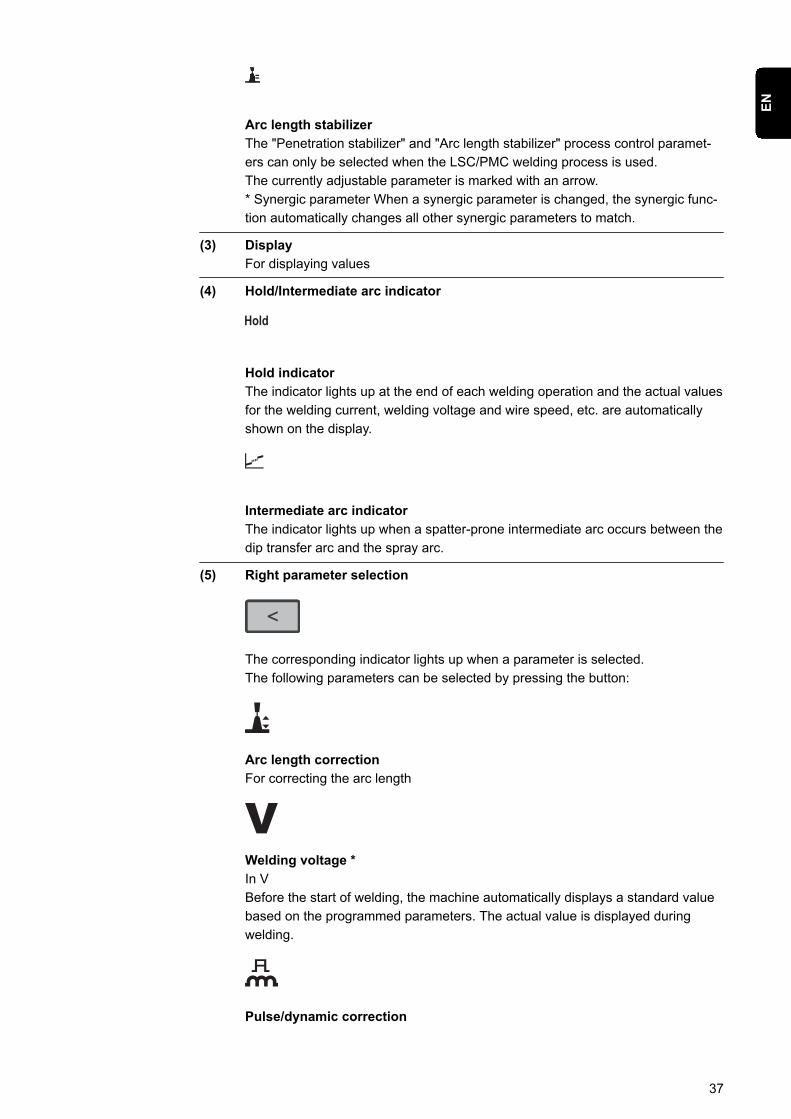
Arc length stabilizerThe "Penetration stabilizer" and "Arc length stabilizer" process control paramet-ers can only be selected when the LSC/PMC welding process is used.The currently adjustable parameter is marked with an arrow.* Synergic parameter When a synergic parameter is changed, the synergic func-tion automatically changes all other synergic parameters to match.
(3) DisplayFor displaying values
(4) Hold/Intermediate arc indicator
Hold indicatorThe indicator lights up at the end of each welding operation and the actual valuesfor the welding current, welding voltage and wire speed, etc. are automaticallyshown on the display.
Intermediate arc indicatorThe indicator lights up when a spatter-prone intermediate arc occurs between thedip transfer arc and the spray arc.
(5) Right parameter selection
The corresponding indicator lights up when a parameter is selected.The following parameters can be selected by pressing the button:
Arc length correctionFor correcting the arc length
Welding voltage *In VBefore the start of welding, the machine automatically displays a standard valuebased on the programmed parameters. The actual value is displayed duringwelding.
Pulse/dynamic correction
37
EN
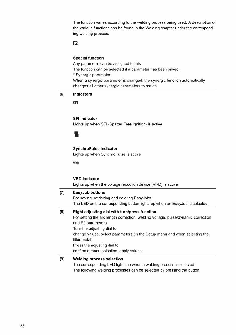
The function varies according to the welding process being used. A description ofthe various functions can be found in the Welding chapter under the correspond-ing welding process.
Special functionAny parameter can be assigned to thisThe function can be selected if a parameter has been saved.* Synergic parameterWhen a synergic parameter is changed, the synergic function automaticallychanges all other synergic parameters to match.
(6) Indicators
SFI indicatorLights up when SFI (Spatter Free Ignition) is active
SynchroPulse indicatorLights up when SynchroPulse is active
VRD indicatorLights up when the voltage reduction device (VRD) is active
(7) EasyJob buttonsFor saving, retrieving and deleting EasyJobsThe LED on the corresponding button lights up when an EasyJob is selected.
(8) Right adjusting dial with turn/press functionFor setting the arc length correction, welding voltage, pulse/dynamic correctionand F2 parametersTurn the adjusting dial to:change values, select parameters (in the Setup menu and when selecting thefiller metal)Press the adjusting dial to:confirm a menu selection, apply values
(9) Welding process selectionThe corresponding LED lights up when a welding process is selected.The following welding processes can be selected by pressing the button:
38
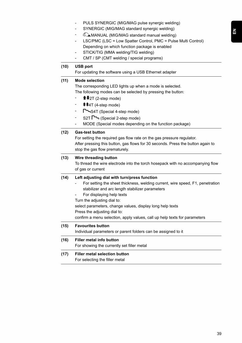
- PULS SYNERGIC (MIG/MAG pulse synergic welding)- SYNERGIC (MIG/MAG standard synergic welding)- MANUAL (MIG/MAG standard manual welding)- LSC/PMC (LSC = Low Spatter Control, PMC = Pulse Multi Control)
Depending on which function package is enabled- STICK/TIG (MMA welding/TIG welding)- CMT / SP (CMT welding / special programs)
(10) USB portFor updating the software using a USB Ethernet adapter
(11) Mode selectionThe corresponding LED lights up when a mode is selected.The following modes can be selected by pressing the button:- 2T (2-step mode)- 4T (4-step mode)- S4T (Special 4-step mode)- S2T (Special 2-step mode)- MODE (Special modes depending on the function package)
(12) Gas-test buttonFor setting the required gas flow rate on the gas pressure regulator.After pressing this button, gas flows for 30 seconds. Press the button again tostop the gas flow prematurely.
(13) Wire threading buttonTo thread the wire electrode into the torch hosepack with no accompanying flowof gas or current
(14) Left adjusting dial with turn/press function- For setting the sheet thickness, welding current, wire speed, F1, penetration
stabilizer and arc length stabilizer parameters- For displaying help textsTurn the adjusting dial to:select parameters, change values, display long help textsPress the adjusting dial to:confirm a menu selection, apply values, call up help texts for parameters
(15) Favourites buttonIndividual parameters or parent folders can be assigned to it
(16) Filler metal info buttonFor showing the currently set filler metal
(17) Filler metal selection buttonFor selecting the filler metal
39
EN
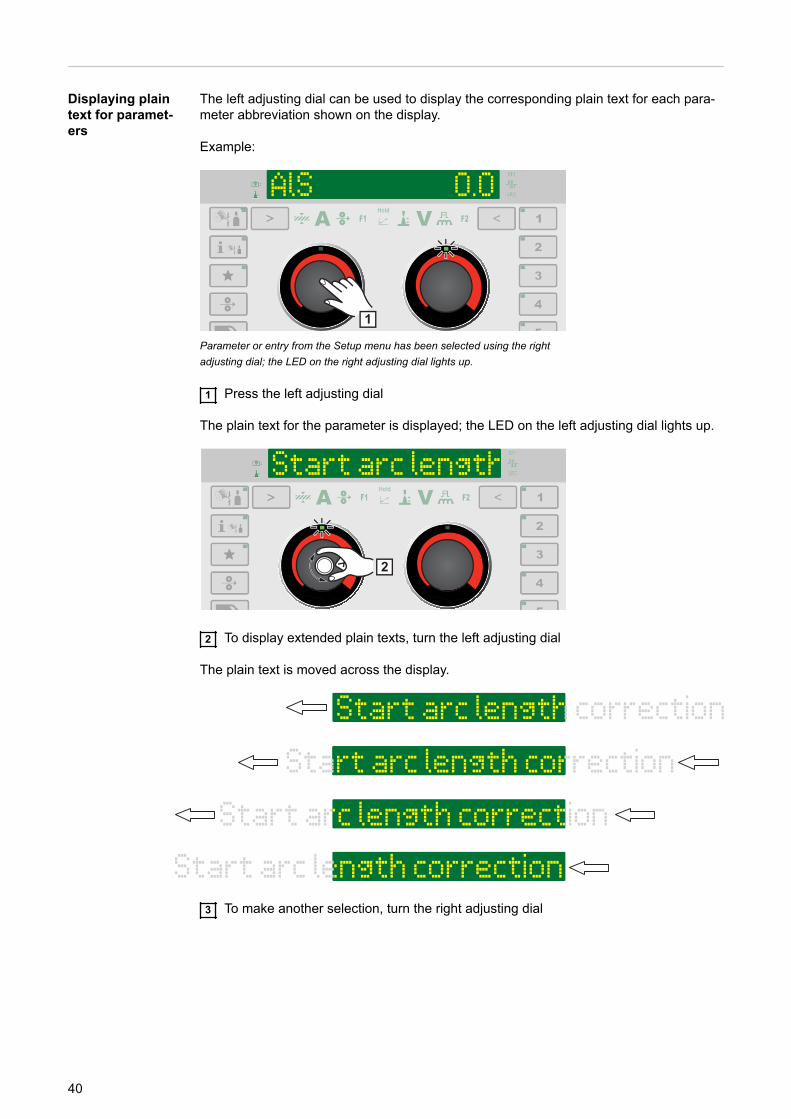
Displaying plaintext for paramet-ers
The left adjusting dial can be used to display the corresponding plain text for each para-meter abbreviation shown on the display.
Example:
1
Parameter or entry from the Setup menu has been selected using the rightadjusting dial; the LED on the right adjusting dial lights up.
1 Press the left adjusting dial
The plain text for the parameter is displayed; the LED on the left adjusting dial lights up.
2
2 To display extended plain texts, turn the left adjusting dial
The plain text is moved across the display.
3 To make another selection, turn the right adjusting dial
40

F1/F2 special function parameters, Favourites but-ton
F1 and F2 specialfunction paramet-ers
Setting F1 and F2 special function parameters
I-S [%] 150
~ 3 sec. 2 2
~ 3 sec.
1
Example: the selected parameter I-S is assigned to F1
1 Select the desired parameter in the Setup menu
Further information on the Setup menu can be found from page 89
2 To assign the selected parameter to F1 or F2, press the parameter selection buttonfor approx. 3 seconds:F1 ... left parameter selectionF2 ... right parameter selection
F1/F2 flashes while the parameter selection button is pressed.
As soon as the parameter is saved, the indicator for the corresponding special functionparameter lights up.F1 (for example) and a tick is shown next to the parameter:
The selected parameter is now stored under F1.
If a parameter cannot be assigned to the F1 or F2 special function parameters, afterapprox. 5 seconds F1 (for example) and X is displayed:
This deletes an existing stored parameter.
Retrieving F1 and F2 special function parameters
I-S [%] 0.0
1 1
~ 3 sec.
41
EN
1 Press the parameter selection button until F1 or F2 lights up:F1 ... left parameter selectionF2 ... right parameter selection
The stored parameter is shown first, then the currently set value of the parameter.
150 0.0
2 2
2 Change the value of the parameter by turning the adjusting dial:F1 ... left adjusting dialF2 ... right adjusting dial
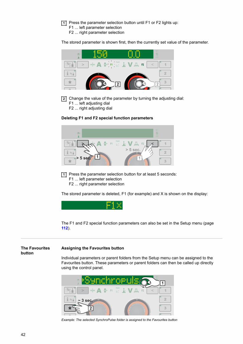
Deleting F1 and F2 special function parameters
> 5 sec. 1 1
> 5 sec.
1 Press the parameter selection button for at least 5 seconds:F1 ... left parameter selectionF2 ... right parameter selection
The stored parameter is deleted, F1 (for example) and X is shown on the display:
The F1 and F2 special function parameters can also be set in the Setup menu (page112).
The Favouritesbutton
Assigning the Favourites button
Individual parameters or parent folders from the Setup menu can be assigned to theFavourites button. These parameters or parent folders can then be called up directlyusing the control panel.
~ 3 sec.
1
2
Example: The selected SynchroPulse folder is assigned to the Favourites button
42

1 Select the desired parameter or the desired parent folder in the Setup menu
Further information on the Setup menu can be found from page 89
2 To assign the selected parameter or folder to the Favourites button, press theFavourites button for approx. 3 seconds
Next to the parameter or folder and a tick are shown:
The selected parameter or folder is now assigned to the Favourites button.
Retrieving favourites
Parameters or folders stored under the Favourites button can be retrieved in any setting,except for when the Setup menu is active.Ongoing selection processes or called up jobs are cancelled when favourites areretrieved.
< 3 sec.
1
1 Briefly press the "Favourites" button (< 3 seconds)
The LED on the Favourites button lights up and the stored parameter or folder is shownon the display.
2 To end retrieval of the favourite, briefly press the Favourites button again (< 3seconds)
The LED on the Favourites button goes out and the display switches to the welding para-meters.
Deleting favourites
> 5 sec.
1
1 Press the Favourites button for at least 5 seconds:
The stored parameter or folder is deleted and and X are shown on the display:
43
EN

The Favourites button can also be assigned in the Setup menu (page 113).
44
Connections, switches and mechanical compon-ents
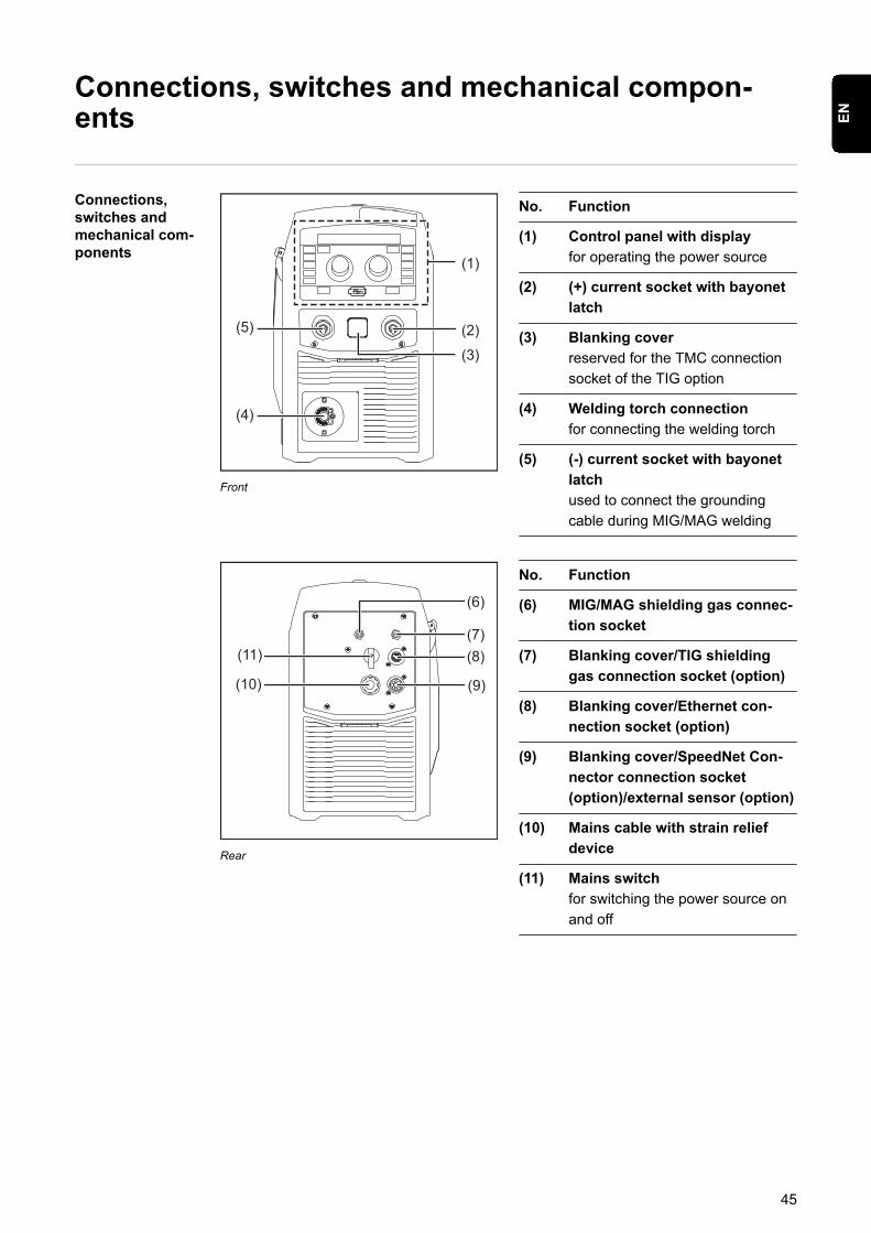
Connections,switches andmechanical com-ponents
(1)
(2)(3)
(4)
(5)
Front
No. Function
(1) Control panel with displayfor operating the power source
(2) (+) current socket with bayonetlatch
(3) Blanking coverreserved for the TMC connectionsocket of the TIG option
(4) Welding torch connectionfor connecting the welding torch
(5) (-) current socket with bayonetlatchused to connect the groundingcable during MIG/MAG welding
(11)
(6)
(7)
(10)
(8)
(9)
Rear
No. Function
(6) MIG/MAG shielding gas connec-tion socket
(7) Blanking cover/TIG shieldinggas connection socket (option)
(8) Blanking cover/Ethernet con-nection socket (option)
(9) Blanking cover/SpeedNet Con-nector connection socket(option)/external sensor (option)
(10) Mains cable with strain reliefdevice
(11) Mains switchfor switching the power source onand off
45
EN
(13)
(12)
Side view
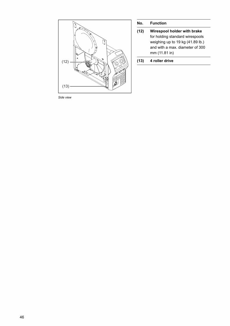
No. Function
(12) Wirespool holder with brakefor holding standard wirespoolsweighing up to 19 kg (41.89 lb.)and with a max. diameter of 300mm (11.81 in)
(13) 4 roller drive
46

Installation and commissioning
47

48
Minimum equipment needed for welding task
General Depending on which welding process you intend to use, a certain minimum equipmentlevel will be needed in order to work with the power source.The welding processes and the minimum equipment levels required for the welding taskare then described.
MIG/MAG gas-cooled welding
- Power source- Grounding (earthing) cable- MIG/MAG welding torch, gas-cooled- Shielding gas supply- Wire electrode
MIG/MAG water-cooled welding
- Power source- Cooling unit- Grounding (earthing) cable- MIG/MAG welding torch, water-cooled- Shielding gas supply- Wire electrode
Manual CMTwelding
- Power source- Standard, Pulse and CMT welding packages enabled on the power source- Grounding cable- PullMig CMT welding torch incl. CMT drive unit and CMT wire buffer
IMPORTANT! For water-cooled CMT applications, a cooling unit is also required!
- OPT/i PushPull- CMT interconnecting hosepack- Wire electrode- Gas connection (shielding gas supply)
TIG DC welding - Power source- Grounding (earthing) cable- TIG gas-valve torch- Gas connection (shielding gas supply)- Filler metal (depending on the application)
MMA welding - Power source- Grounding (earthing) cable- Electrode holder with welding cable- Rod electrodes
49
EN
Before installation and commissioning
Safety WARNING!
Danger from incorrect operation.Possible serious injury and damage to property.▶ Do not use the functions described here until you have read and completely under-
stood these Operating Instructions.▶ Do not use the functions described here until you have fully read and understood all
of the Operating Instructions for the system components, in particular the safetyrules!
Proper use The power source may only be used for MIG/MAG, MMA and TIG welding. Any useabove and beyond this purpose is deemed improper. The manufacturer shall not be heldliable for any damage arising from such usage.
Proper use also includes:- following all the information in the operating instructions- carrying out all the specified inspection and servicing work
Setup regulations The device is tested to IP 23 protection, meaning:- protection against penetration by solid foreign bodies with diameters > 12.5 mm
(0.49 in.)- protection against direct sprays of water at any angle up to 60° from the vertical
The device can be set up and operated outdoors in accordance with IP23. Avoid directwetting (e.g. from rain).
WARNING!
If one of these devices topples over or falls it could cause serious or even fatalinjury.▶ Place devices, upright consoles and trolleys on a solid, level surface in such a way
that they remain stable.
The venting duct is a very important safety feature. When choosing the installation loca-tion, ensure that the cooling air can enter and exit unhindered through the air ducts onthe front and back of the device. Any electroconductive metallic dust (e.g. from grindingwork) must not be allowed to get sucked into the device.
Mains connection - The devices are designed for the mains voltage specified on the rating plate.- Devices with a nominal voltage of 3 x 575 V must be operated on three-phase sys-
tems with earthed star point.- If your version of the appliance does not come with mains cables and mains plugs
ready-fitted, these must be fitted by a qualified person in accordance with nationalstandards.
- The fuse protection for the mains lead is indicated in the technical data.
50
CAUTION!
An inadequately dimensioned electrical installation can cause serious damage.▶ The mains lead and its fuse protection must be dimensioned to suit the local power
supply.The technical data shown on the rating plate applies.
Generator-powered opera-tion
The power source is generator-compatible.
The maximum apparent power S1max of the power source must be known in order toselect the correct generator output.The maximum apparent power S1max of the power source is calculated as follows:
3-phase devices: S1max = I1max x U1 x √3
Single-phase devices: S1max = I1max x U1
See device rating plate or technical data for I1max and U1 values
The generator apparent power SGEN needed is calculated using the following rule ofthumb:
SGEN = S1max x 1.35
A smaller generator may be used when not welding at full power.
IMPORTANT! The generator apparent power SGEN must always be higher than the max-imum apparent power S1max of the power source.
When using single-phase devices with a 3-phase generator, note that the specified gen-erator apparent power is often only available as a whole across all three phases of thegenerator. If necessary, obtain further information on the single-phase power of the gen-erator from the generator manufacturer.
NOTE!
The voltage delivered by the generator must never exceed the upper or lower lim-its of the mains voltage tolerance range.Details of the mains voltage tolerance can be found in the "Technical data" section.
Information onsystem compon-ents
The steps and activities described below include references to various system compon-ents, including:- Trolley- Welding torch- etc.
For more detailed information about installing and connecting the system components,please refer to the appropriate operating instructions.
51
EN
Connecting the mains cable
Safety WARNING!
Danger due to work that has been carried out incorrectly.This can result in serious injury and damage to property.▶ The work described below must only be carried out by trained and qualified person-
nel.▶ Observe national standards and directives.
CAUTION!
Danger due to improperly prepared mains cable.This can cause short circuits and damage.▶ Fit ferrules to all phase conductors and the ground conductor of the stripped mains
cable.
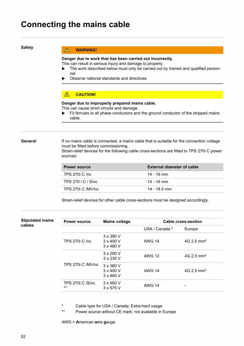
General If no mains cable is connected, a mains cable that is suitable for the connection voltagemust be fitted before commissioning.Strain-relief devices for the following cable cross-sections are fitted to TPS 270i C powersources:
Power source External diameter of cable
TPS 270i C /nc 14 - 16 mm
TPS 270 i C / S/nc 14 - 16 mm
TPS 270i C /MV/nc 14 - 18.5 mm
Strain-relief devices for other cable cross-sections must be designed accordingly.
Stipulated mainscables
Power source Mains voltage Cable cross-section
USA / Canada * Europe
TPS 270i C /nc3 x 380 V3 x 400 V3 x 460 V
AWG 14 4G 2.5 mm²
TPS 270i C /MV/nc
3 x 200 V3 x 230 V AWG 12 4G 2.5 mm²
3 x 380 V3 x 400 V3 x 460 V
AWG 14 4G 2.5 mm²
TPS 270i C /S/nc**
3 x 460 V3 x 575 V AWG 14 -
* Cable type for USA / Canada: Extra-hard usage** Power source without CE mark; not available in Europe
AWG = American wire gauge
52
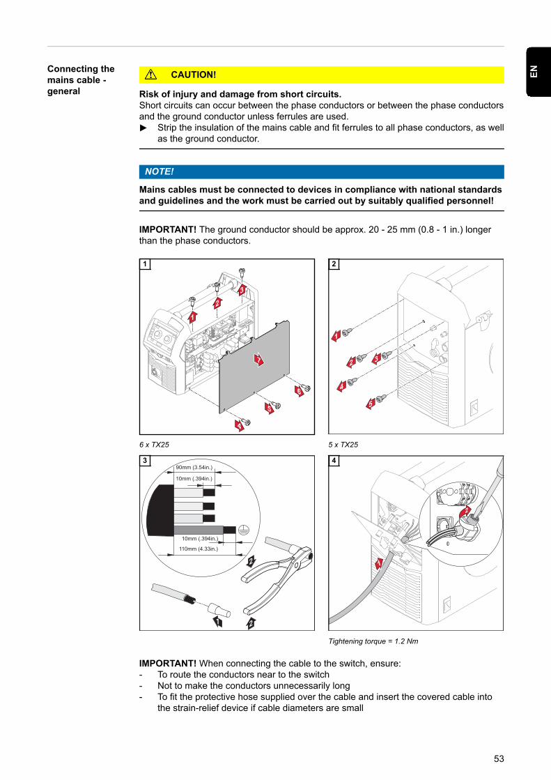
Connecting themains cable -general
CAUTION!
Risk of injury and damage from short circuits.Short circuits can occur between the phase conductors or between the phase conductorsand the ground conductor unless ferrules are used.▶ Strip the insulation of the mains cable and fit ferrules to all phase conductors, as well
as the ground conductor.
NOTE!
Mains cables must be connected to devices in compliance with national standardsand guidelines and the work must be carried out by suitably qualified personnel!
IMPORTANT! The ground conductor should be approx. 20 - 25 mm (0.8 - 1 in.) longerthan the phase conductors.
6 x TX25
1
5 x TX25
2
3
Tightening torque = 1.2 Nm
4
IMPORTANT! When connecting the cable to the switch, ensure:- To route the conductors near to the switch- Not to make the conductors unnecessarily long- To fit the protective hose supplied over the cable and insert the covered cable into
the strain-relief device if cable diameters are small
53
EN
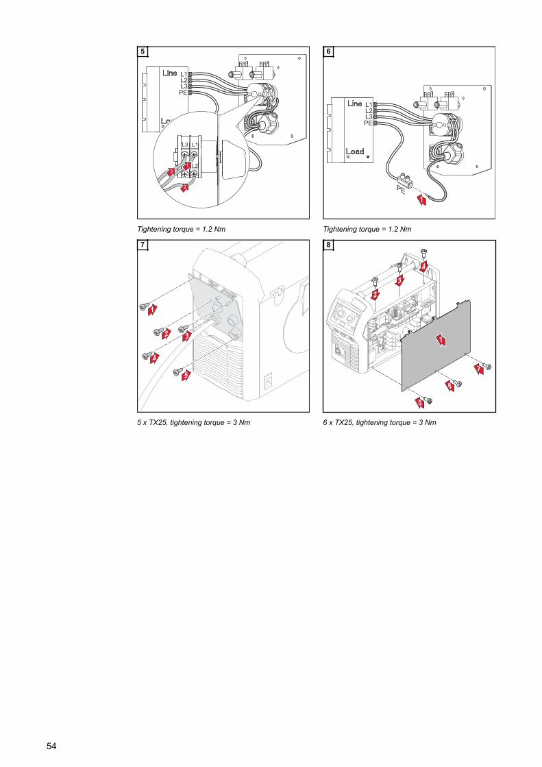
Tightening torque = 1.2 Nm
5
Tightening torque = 1.2 Nm
6
5 x TX25, tightening torque = 3 Nm
7
6 x TX25, tightening torque = 3 Nm
8
54
Start-up
Safety WARNING!
An electric shock can be fatal.If the power source is connected to the mains electricity supply during installation, thereis a high risk of very serious injury and damage.▶ Before carrying out any work on the device make sure that the power source mains
switch is in the "O" position▶ Before carrying out any work on the device make sure that the power source is
unplugged from the mains
WARNING!
Danger from electrical current due to electrically conductive dust in the device.This can result in serious injury and damage to property.▶ Only operate the device with an air filter fitted. The air filter is a very important safety
device for adhering to the IP 23 protection class.
General Commissioning the power source is described with reference to a manual gas-cooledMIG/MAG application.
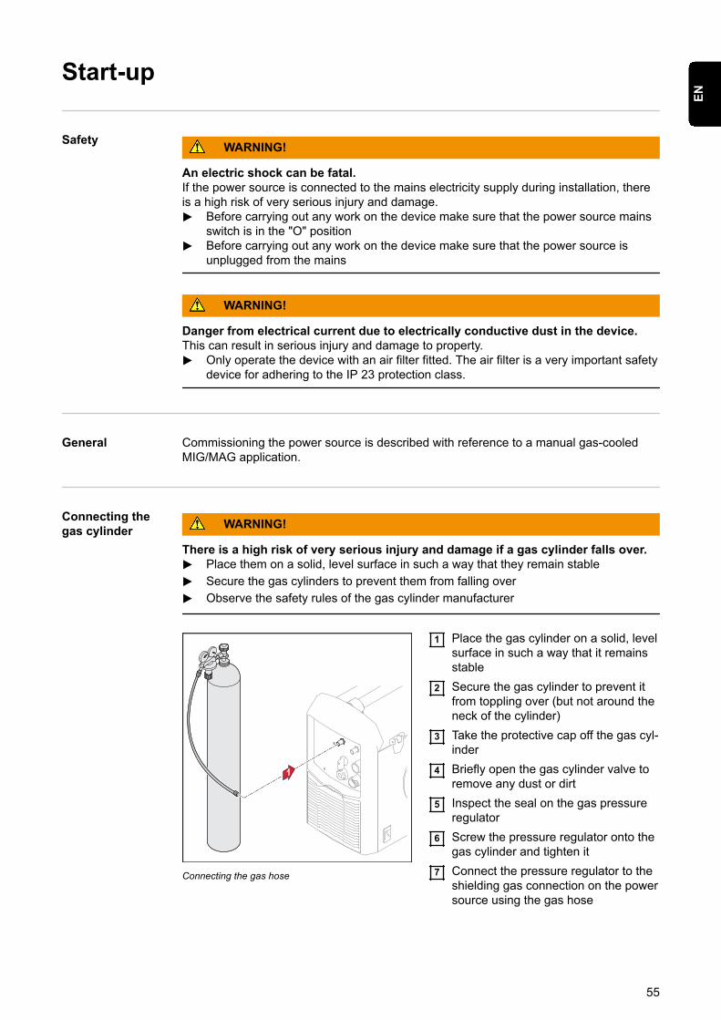
Connecting thegas cylinder WARNING!
There is a high risk of very serious injury and damage if a gas cylinder falls over.▶ Place them on a solid, level surface in such a way that they remain stable
▶ Secure the gas cylinders to prevent them from falling over
▶ Observe the safety rules of the gas cylinder manufacturer
Connecting the gas hose
1 Place the gas cylinder on a solid, levelsurface in such a way that it remainsstable
2 Secure the gas cylinder to prevent itfrom toppling over (but not around theneck of the cylinder)
3 Take the protective cap off the gas cyl-inder
4 Briefly open the gas cylinder valve toremove any dust or dirt
5 Inspect the seal on the gas pressureregulator
6 Screw the pressure regulator onto thegas cylinder and tighten it
7 Connect the pressure regulator to theshielding gas connection on the powersource using the gas hose
55
EN
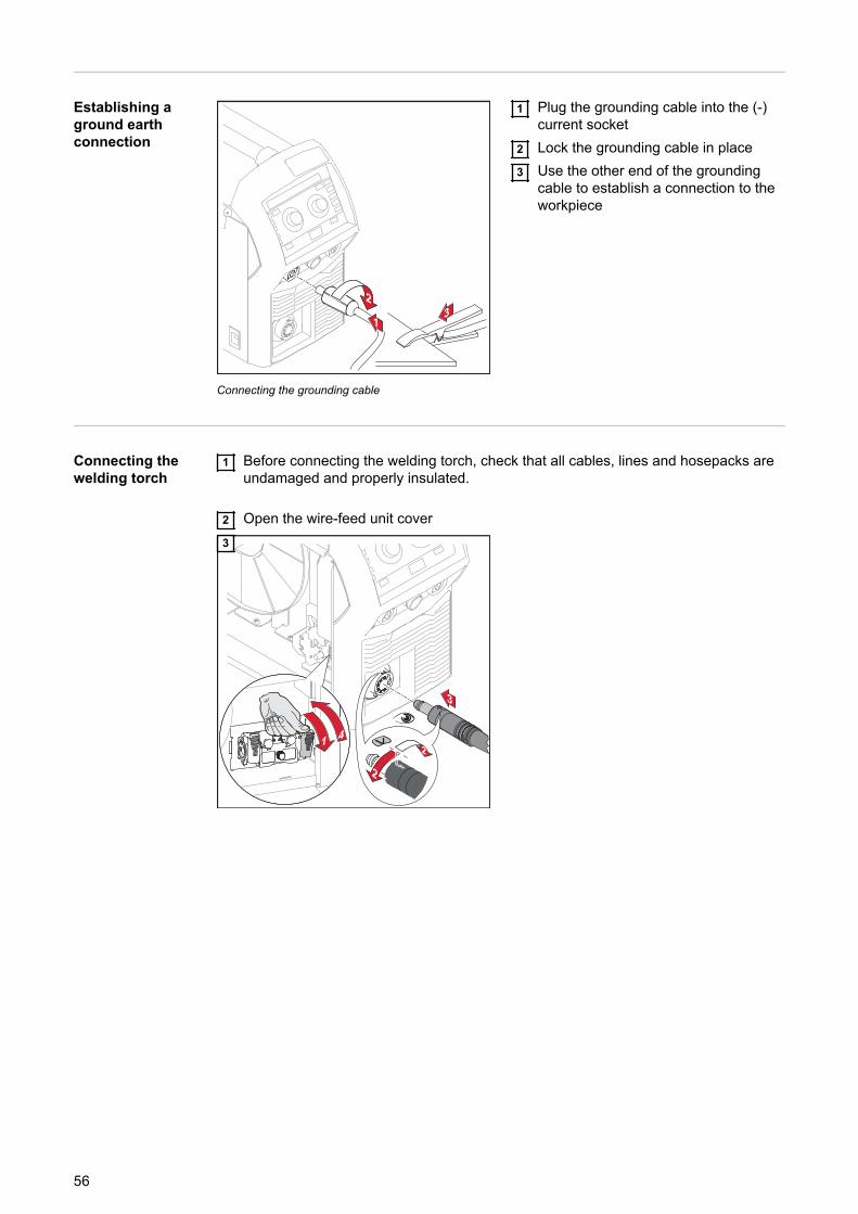
Establishing aground earthconnection
Connecting the grounding cable
1 Plug the grounding cable into the (-)current socket
2 Lock the grounding cable in place3 Use the other end of the grounding
cable to establish a connection to theworkpiece
Connecting thewelding torch
1 Before connecting the welding torch, check that all cables, lines and hosepacks areundamaged and properly insulated.
2 Open the wire-feed unit cover
2
2
3
4
3
56
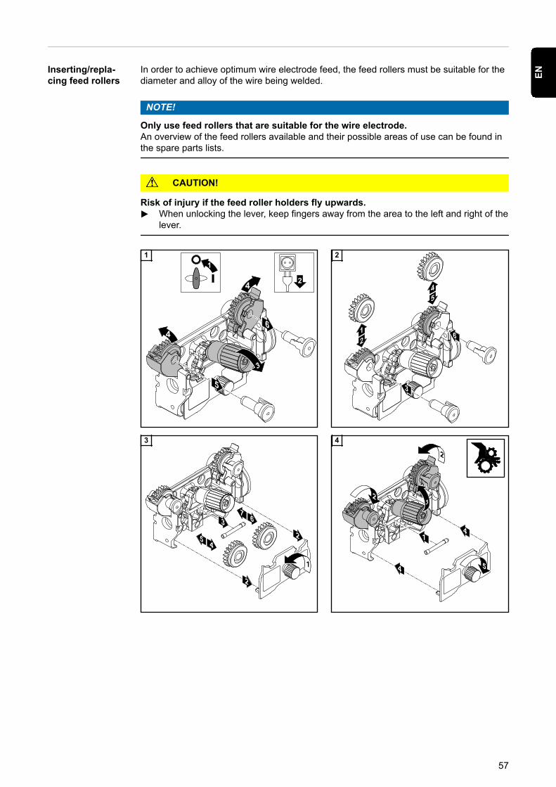
Inserting/repla-cing feed rollers
In order to achieve optimum wire electrode feed, the feed rollers must be suitable for thediameter and alloy of the wire being welded.
NOTE!
Only use feed rollers that are suitable for the wire electrode.An overview of the feed rollers available and their possible areas of use can be found inthe spare parts lists.
CAUTION!
Risk of injury if the feed roller holders fly upwards.▶ When unlocking the lever, keep fingers away from the area to the left and right of the
lever.
1 2
3 4
57
EN
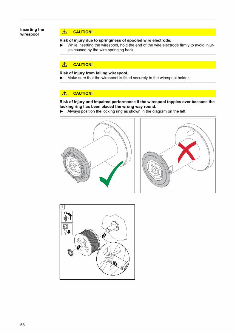
Inserting thewirespool CAUTION!
Risk of injury due to springiness of spooled wire electrode.▶ While inserting the wirespool, hold the end of the wire electrode firmly to avoid injur-
ies caused by the wire springing back.
CAUTION!
Risk of injury from falling wirespool.▶ Make sure that the wirespool is fitted securely to the wirespool holder.
CAUTION!
Risk of injury and impaired performance if the wirespool topples over because thelocking ring has been placed the wrong way round.▶ Always position the locking ring as shown in the diagram on the left.
1
58
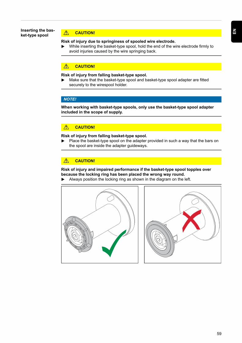
Inserting the bas-ket-type spool CAUTION!
Risk of injury due to springiness of spooled wire electrode.▶ While inserting the basket-type spool, hold the end of the wire electrode firmly to
avoid injuries caused by the wire springing back.
CAUTION!
Risk of injury from falling basket-type spool.▶ Make sure that the basket-type spool and basket-type spool adapter are fitted
securely to the wirespool holder.
NOTE!
When working with basket-type spools, only use the basket-type spool adapterincluded in the scope of supply.
CAUTION!
Risk of injury from falling basket-type spool.▶ Place the basket-type spool on the adapter provided in such a way that the bars on
the spool are inside the adapter guideways.
CAUTION!
Risk of injury and impaired performance if the basket-type spool topples overbecause the locking ring has been placed the wrong way round.▶ Always position the locking ring as shown in the diagram on the left.
59
EN
1 2
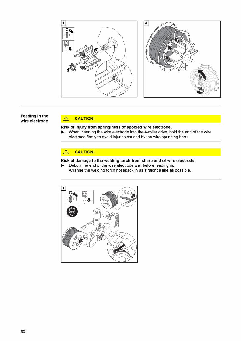
Feeding in thewire electrode CAUTION!
Risk of injury from springiness of spooled wire electrode.▶ When inserting the wire electrode into the 4-roller drive, hold the end of the wire
electrode firmly to avoid injuries caused by the wire springing back.
CAUTION!
Risk of damage to the welding torch from sharp end of wire electrode.▶ Deburr the end of the wire electrode well before feeding in.
Arrange the welding torch hosepack in as straight a line as possible.
1
60
2
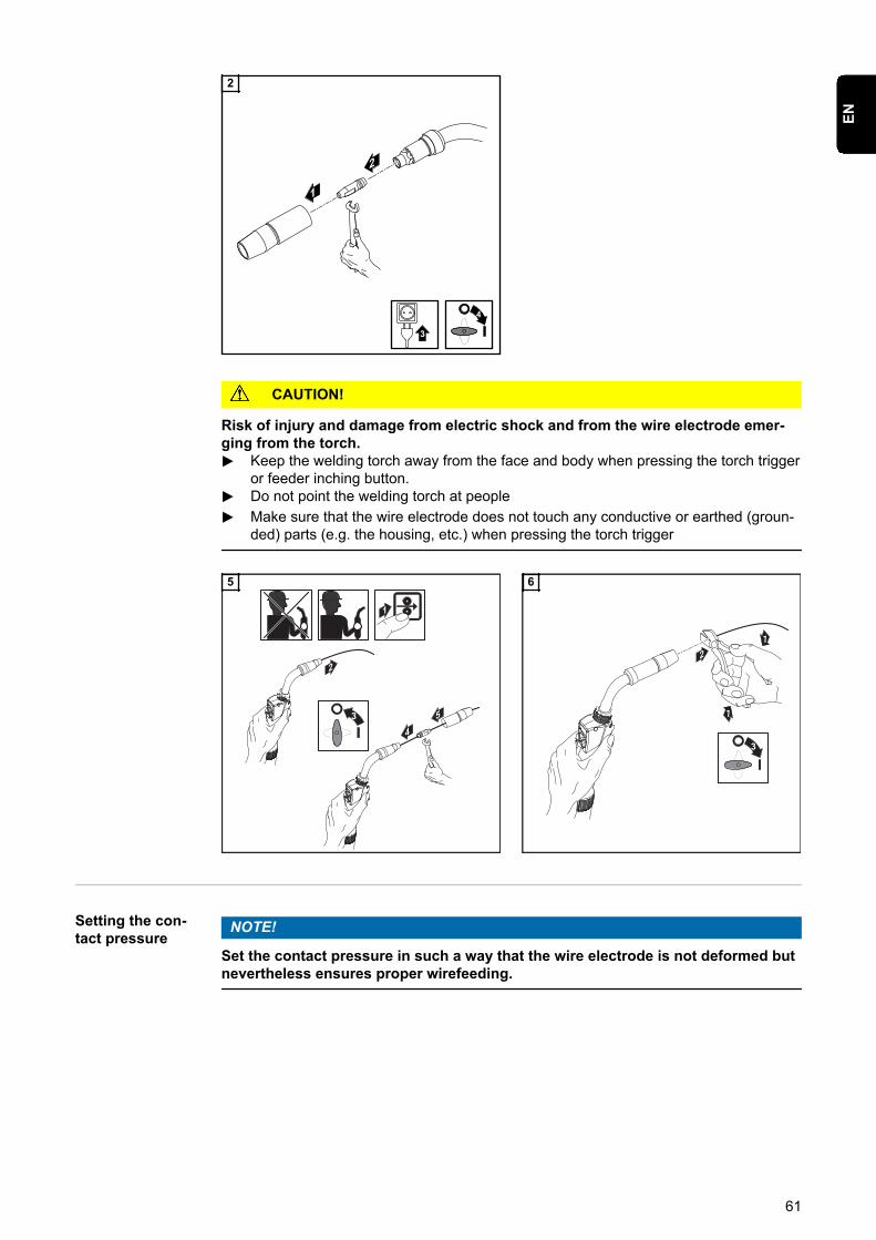
CAUTION!
Risk of injury and damage from electric shock and from the wire electrode emer-ging from the torch.▶ Keep the welding torch away from the face and body when pressing the torch trigger
or feeder inching button.▶ Do not point the welding torch at people
▶ Make sure that the wire electrode does not touch any conductive or earthed (groun-ded) parts (e.g. the housing, etc.) when pressing the torch trigger
1
2
4
53
5
1
1
2
3
6
Setting the con-tact pressure
NOTE!
Set the contact pressure in such a way that the wire electrode is not deformed butnevertheless ensures proper wirefeeding.
61
EN

1 Contact pressure standard values forU-groove rollers
Steel:4 - 5
CrNi4 - 5
Tubular cored electrodes2 - 3
62
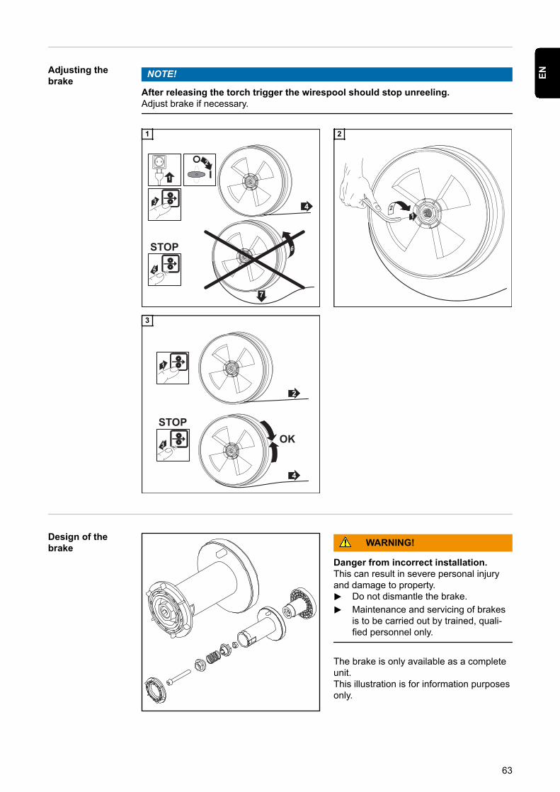
Adjusting thebrake
NOTE!
After releasing the torch trigger the wirespool should stop unreeling.Adjust brake if necessary.
43
STOP 6
7
5
1
2
1
21
2
2
1
4
STOPOK
3
3
Design of thebrake WARNING!
Danger from incorrect installation.This can result in severe personal injuryand damage to property.▶ Do not dismantle the brake.
▶ Maintenance and servicing of brakesis to be carried out by trained, quali-fied personnel only.
The brake is only available as a completeunit.This illustration is for information purposesonly.
63
EN

Performing R/Lalignment
IMPORTANT! For optimum welding results, the manufacturer recommends performingan R/L alignment when starting the device for the first time and when any changes aremade to the welding system.
64

Welding
65

66
MIG/MAG modes
General WARNING!
Danger from incorrect operation.Possible serious injury and damage to property.▶ Do not use the functions described here until you have read and completely under-
stood these Operating Instructions.▶ Do not use the functions described here until you have fully read and understood all
of the Operating Instructions for the system components, in particular the safetyrules!
See the Setup menu for information on settings, setting range and units of measurementfor the available parameters.
Symbols andtheir explana-tions
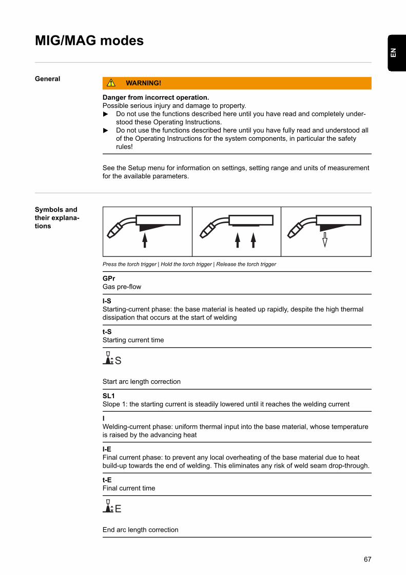
Press the torch trigger | Hold the torch trigger | Release the torch trigger
GPrGas pre-flow
I-SStarting-current phase: the base material is heated up rapidly, despite the high thermaldissipation that occurs at the start of welding
t-SStarting current time
S
Start arc length correction
SL1Slope 1: the starting current is steadily lowered until it reaches the welding current
IWelding-current phase: uniform thermal input into the base material, whose temperatureis raised by the advancing heat
I-EFinal current phase: to prevent any local overheating of the base material due to heatbuild-up towards the end of welding. This eliminates any risk of weld seam drop-through.
t-EFinal current time
E
End arc length correction
67
EN
SL2Slope 2: the welding current is steadily lowered until it reaches the final current
GPoGas post-flow
A detailed explanation of the parameters can be found in the section headed "Processparameters"
2-step mode
t
I
+
I
GPr GPo
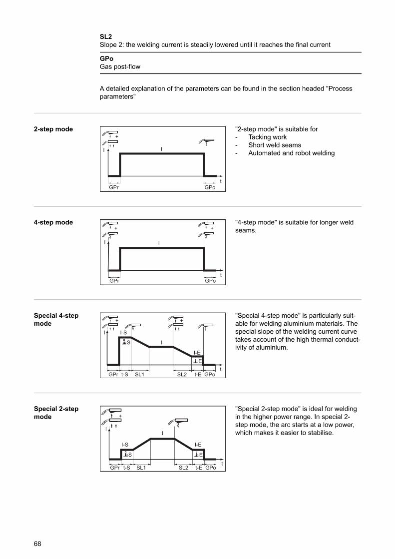
"2-step mode" is suitable for- Tacking work- Short weld seams- Automated and robot welding
4-step mode
t
I
+
I
GPr GPo
+"4-step mode" is suitable for longer weldseams.
Special 4-stepmode
I
t
I
GPr GPo
I-E
SL1t-S
I-S
SL2
+ +
S
E
t-E
"Special 4-step mode" is particularly suit-able for welding aluminium materials. Thespecial slope of the welding current curvetakes account of the high thermal conduct-ivity of aluminium.
Special 2-stepmode
I
I-S I-E
+
I
S E
GPr GPoSL1 SL2t
t-S t-E
"Special 2-step mode" is ideal for weldingin the higher power range. In special 2-step mode, the arc starts at a low power,which makes it easier to stabilise.
68
MIG/MAG and CMT welding
Safety WARNING!
Danger from incorrect operation.Possible serious injury and damage to property.▶ Do not use the functions described here until you have read and completely under-
stood these Operating Instructions.▶ Do not use the functions described here until you have fully read and understood all
of the Operating Instructions for the system components, in particular the safetyrules!
WARNING!
An electric shock can be fatal.If the power source is connected to the mains electricity supply during installation, thereis a high risk of very serious injury and damage.▶ Before carrying out any work on the device make sure that the power source mains
switch is in the "O" position▶ Before carrying out any work on the device make sure that the power source is
unplugged from the mains
MIG/MAG andCMT welding –overview
The "MIG/MAG and CMT welding" section comprises the following steps:- Switching on the power source- Selecting the welding process and operating mode- Retrieving the currently set filler metal- Selecting the filler metal- Setting the welding parameters- Setting the shielding gas flow rate- MIG/MAG or CMT welding
Switching on thepower source
1 Connect the mains cable2 Move the mains switch to the "I" position
IMPORTANT! For optimum welding results, the manufacturer recommends performingan R/L alignment when starting the device for the first time and when any changes aremade to the welding system.
Setting the weld-ing process andoperating mode
12
1 Press the "Welding process" button until the LED for the desired welding processlights up
69
EN
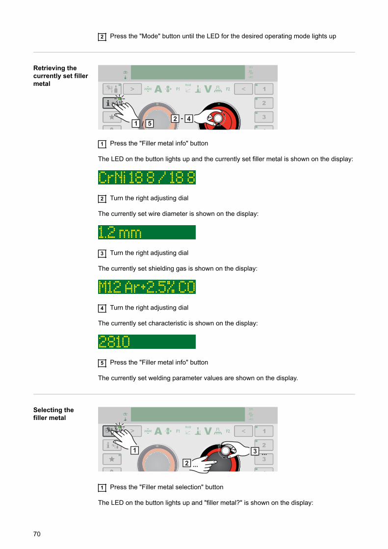
2 Press the "Mode" button until the LED for the desired operating mode lights up
Retrieving thecurrently set fillermetal
142 -
5/
1 Press the "Filler metal info" button
The LED on the button lights up and the currently set filler metal is shown on the display:
2 Turn the right adjusting dial
The currently set wire diameter is shown on the display:
3 Turn the right adjusting dial
The currently set shielding gas is shown on the display:
4 Turn the right adjusting dial
The currently set characteristic is shown on the display:
5 Press the "Filler metal info" button
The currently set welding parameter values are shown on the display.
Selecting thefiller metal
1
2
3 ...
...
1 Press the "Filler metal selection" button
The LED on the button lights up and "filler metal?" is shown on the display:
70

2 Press the right adjusting dial
The first available filler metal is displayed:
3 Select the desired filler metal by turning the right adjusting dial4 Press the right adjusting dial
"diameter?" is shown on the display: *
5 Press the right adjusting dial
The first available wire diameter is displayed:
6 Select the desired wire diameter by turning the right adjusting dial7 Press the right adjusting dial
"gas?" is shown on the display: *
8 Press the right adjusting dial
The first available shielding gas is displayed:
9 Select the desired shielding gas by turning the right adjusting dial10 Press the right adjusting dial
If available, the first available characteristic is displayed: *
11 Select the desired characteristic by turning the right adjusting dial12 Press the right adjusting dial
A prompt to apply the new filler metal is displayed: *
13 Press the right adjusting dial
The set filler metal is saved.
71
EN
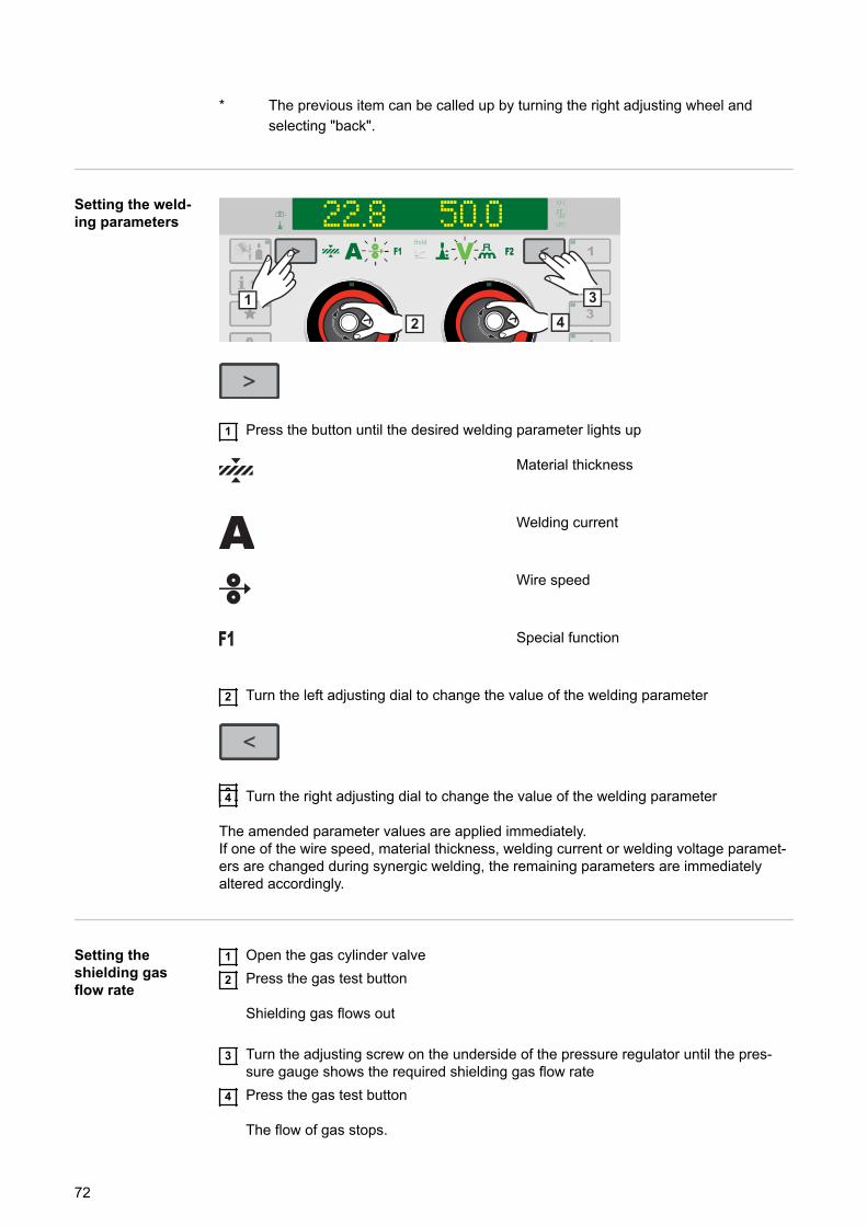
* The previous item can be called up by turning the right adjusting wheel andselecting "back".
Setting the weld-ing parameters 22.8 5O.O
12
34
1 Press the button until the desired welding parameter lights up
Material thickness
Welding current
Wire speed
Special function
2 Turn the left adjusting dial to change the value of the welding parameter
34 Turn the right adjusting dial to change the value of the welding parameter
The amended parameter values are applied immediately.If one of the wire speed, material thickness, welding current or welding voltage paramet-ers are changed during synergic welding, the remaining parameters are immediatelyaltered accordingly.
Setting theshielding gasflow rate
1 Open the gas cylinder valve2 Press the gas test button
Shielding gas flows out
3 Turn the adjusting screw on the underside of the pressure regulator until the pres-sure gauge shows the required shielding gas flow rate
4 Press the gas test button
The flow of gas stops.
72
MIG/MAG or CMTwelding CAUTION!
Risk of injury and damage from electric shock and from the wire electrode emer-ging from the torch.When pressing the torch trigger:▶ keep the torch away from your face and body
▶ do not point the welding torch at people
▶ make sure that the wire electrode does not touch any electrically conducting orearthed (grounded) parts, such as the housing, etc.
1 Press the torch trigger and start welding
Whenever welding ends, the actual values for the welding current, welding voltage andwire speed are stored, and HOLD appears on the display.
NOTE!
It is not always possible to change parameters that have been set on a systemcomponent control panel (e.g. remote control) on the power source control panel.
73
EN
MIG/MAG and CMT welding parameters
Welding paramet-ers for MIG/MAGpulse synergicwelding, for CMTwelding and PMCwelding
The following welding parameters can be set and displayed for MIG/MAG pulse synergicwelding, CMT welding and PMC welding:
using the left adjusting dial:
Material thickness1)
Setting range: 0.1 - 30.0 mm 2) / 0.004 - 1.18 in. 2)
Welding current1)
in A
Setting range: depends on the welding process and welding program selected
Before the start of welding, the machine automatically displays a standard value basedon the programmed parameters. The actual value is displayed during welding.
Wire speed1)
Setting range: 0.5 - 25 m/min 2) / 20 - 980 ipm. 2)
Special functionany parameter can be assigned to this (see page 41)
The function can be selected if a parameter has been saved.
Penetration stabilizer4) (see page 95)
Setting range: 0 - 10 m/min / 0 - 393.7 ipmFactory setting: 0
Arc length stabilizer4) (see page 97)
Setting range: 0 - 5Factory setting: 0
74
using the right adjusting dial:
Arc length correctionfor correcting the arc length;
Setting range: -10 - +10Factory setting: 0
- .... shorter arc length0 ... neutral arc length+ ... longer arc length
Welding voltage1)
in V
Setting range: depends on the welding process and welding program selected
Before the start of welding, the machine automatically displays a standard value basedon the programmed parameters. The actual value is displayed during welding.
Pulse/dynamic correctionfor correcting the pulsing energy of a pulsed arc
Setting range: -10 - +10Factory setting: 0
- ... lower droplet detachment force0 ... neutral droplet detachment force+ ... increased droplet detachment force
Special functionany parameter can be assigned to this (see page 41)
The function can be selected if a parameter has been saved.
Welding paramet-ers for MIG/MAGstandard syner-gic welding andLSC welding
The following welding parameters can be set and displayed for MIG/MAG standard syn-ergic welding and LSC welding:
using the left adjusting dial:
Material thickness1)
75
EN
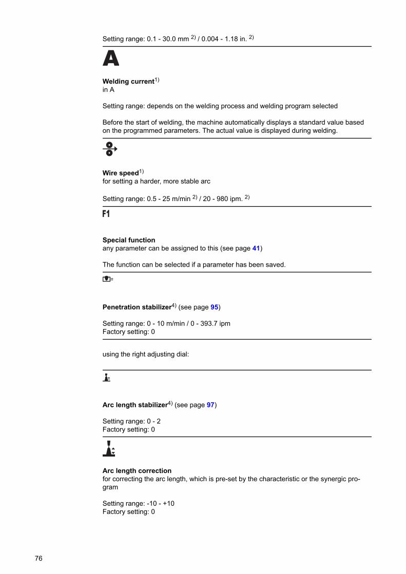
Setting range: 0.1 - 30.0 mm 2) / 0.004 - 1.18 in. 2)
Welding current1)
in A
Setting range: depends on the welding process and welding program selected
Before the start of welding, the machine automatically displays a standard value basedon the programmed parameters. The actual value is displayed during welding.
Wire speed1)
for setting a harder, more stable arc
Setting range: 0.5 - 25 m/min 2) / 20 - 980 ipm. 2)
Special functionany parameter can be assigned to this (see page 41)
The function can be selected if a parameter has been saved.
Penetration stabilizer4) (see page 95)
Setting range: 0 - 10 m/min / 0 - 393.7 ipmFactory setting: 0
using the right adjusting dial:
Arc length stabilizer4) (see page 97)
Setting range: 0 - 2Factory setting: 0
Arc length correctionfor correcting the arc length, which is pre-set by the characteristic or the synergic pro-gram
Setting range: -10 - +10Factory setting: 0
76
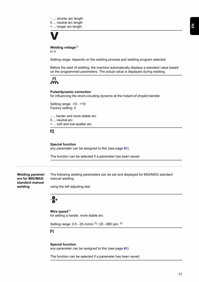
- .... shorter arc length0 ... neutral arc length+ ... longer arc length
Welding voltage1)
in V
Setting range: depends on the welding process and welding program selected
Before the start of welding, the machine automatically displays a standard value basedon the programmed parameters. The actual value is displayed during welding.
Pulse/dynamic correctionfor influencing the short-circuiting dynamic at the instant of droplet transfer
Setting range: -10 - +10Factory setting: 0
- ... harder and more stable arc0 ... neutral arc+ ... soft and low-spatter arc
Special functionany parameter can be assigned to this (see page 41)
The function can be selected if a parameter has been saved.
Welding paramet-ers for MIG/MAGstandard manualwelding
The following welding parameters can be set and displayed for MIG/MAG standardmanual welding:
using the left adjusting dial:
Wire speed1)
for setting a harder, more stable arc
Setting range: 0.5 - 25 m/min 2) / 20 - 980 ipm. 2)
Special functionany parameter can be assigned to this (see page 41)
The function can be selected if a parameter has been saved.
77
EN
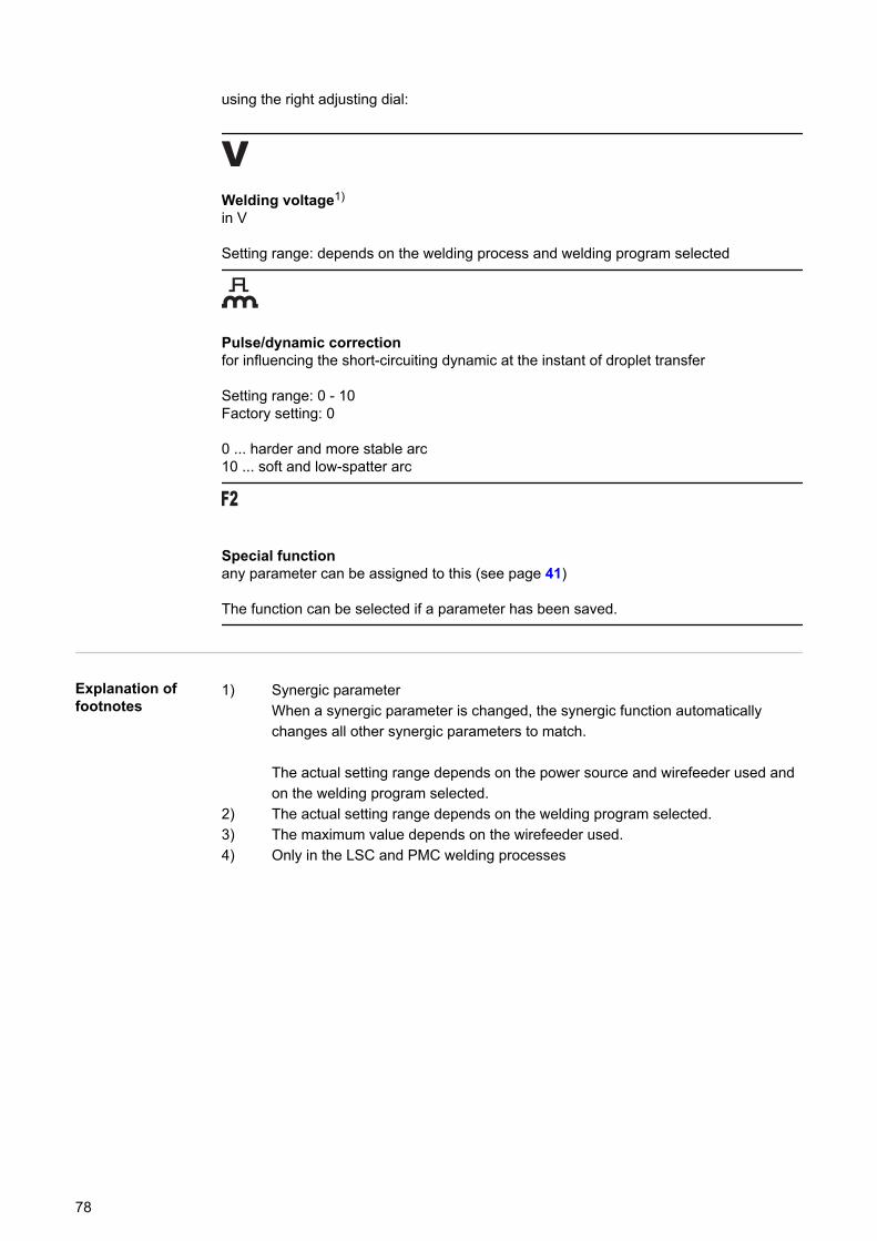
using the right adjusting dial:
Welding voltage1)
in V
Setting range: depends on the welding process and welding program selected
Pulse/dynamic correctionfor influencing the short-circuiting dynamic at the instant of droplet transfer
Setting range: 0 - 10Factory setting: 0
0 ... harder and more stable arc10 ... soft and low-spatter arc
Special functionany parameter can be assigned to this (see page 41)
The function can be selected if a parameter has been saved.
Explanation offootnotes
1) Synergic parameterWhen a synergic parameter is changed, the synergic function automaticallychanges all other synergic parameters to match.
The actual setting range depends on the power source and wirefeeder used andon the welding program selected.
2) The actual setting range depends on the welding program selected.3) The maximum value depends on the wirefeeder used.4) Only in the LSC and PMC welding processes
78
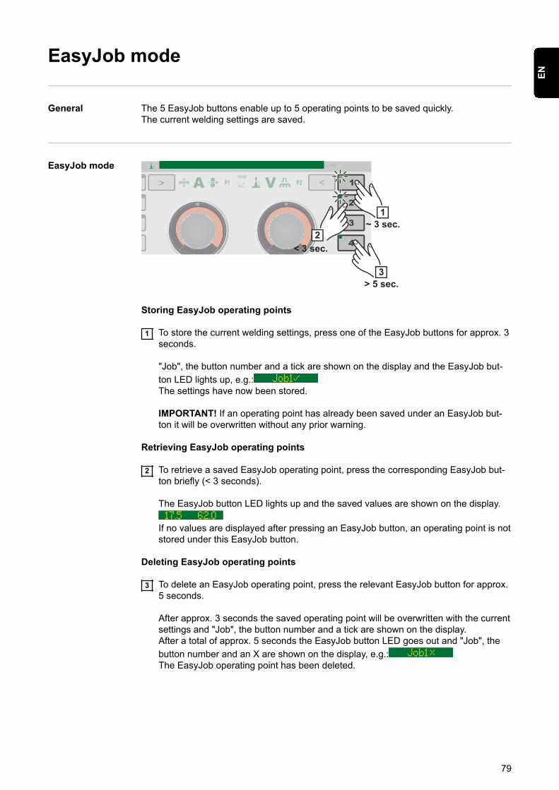
EasyJob mode
General The 5 EasyJob buttons enable up to 5 operating points to be saved quickly.The current welding settings are saved.
EasyJob mode
1~ 3 sec.
2< 3 sec.
3> 5 sec.
Storing EasyJob operating points
1 To store the current welding settings, press one of the EasyJob buttons for approx. 3seconds.
"Job", the button number and a tick are shown on the display and the EasyJob but-ton LED lights up, e.g.:The settings have now been stored.
IMPORTANT! If an operating point has already been saved under an EasyJob but-ton it will be overwritten without any prior warning.
Retrieving EasyJob operating points
2 To retrieve a saved EasyJob operating point, press the corresponding EasyJob but-ton briefly (< 3 seconds).
The EasyJob button LED lights up and the saved values are shown on the display.
If no values are displayed after pressing an EasyJob button, an operating point is notstored under this EasyJob button.
Deleting EasyJob operating points
3 To delete an EasyJob operating point, press the relevant EasyJob button for approx.5 seconds.
After approx. 3 seconds the saved operating point will be overwritten with the currentsettings and "Job", the button number and a tick are shown on the display.After a total of approx. 5 seconds the EasyJob button LED goes out and "Job", thebutton number and an X are shown on the display, e.g.:The EasyJob operating point has been deleted.
79
EN
Spot welding
Spot welding Spot welding can be carried out in the following welding processes:PULSE SYNERGIC | SYNERGIC | MANUAL | LSC/PMC | SP (CMT)
1 Select the desired welding process by pressing the "Welding process" button2 Select the MODE by pressing the "Mode" button
"Spot" appears briefly on the display.
3 Setup menu / Process parameters / Spot welding4 Press the right adjusting dial
The SPt (spot welding time) parameter is shown.
5 Enter the desired value for the spot welding time: press and turn the right adjustingdial
Setting range: 0.1 - 10.0 sFactory setting: 1.0 s
6 Confirm the value by pressing the right adjusting dial
NOTE!
4-step mode is assigned as standard for spot welding.Press the torch trigger - Spot welding process runs until the end of the spot welding time- Press again to stop the spot welding time prematurely▶ The spot welding setting can be changed to 2-step in the Setup menu under Set-
tings / System / SPm(more information on 2-step and 4-step mode for spot welding starts on page 116)
7 Select the filler metal, wire diameter and shielding gas8 Open the gas cylinder valve9 Set the shielding gas flow rate
CAUTION!
Risk of injury and damage from electric shock and from the wire electrode emer-ging from the torch.When pressing the torch trigger:▶ Keep the welding torch away from your face and body
▶ Wear suitable protective goggles
▶ Do not point the welding torch at people
▶ Make sure that the wire electrode does not touch any conductive or earthed parts(e.g. housing, etc.)
10 Spot welding
Procedure for producing a welding spot:
1 Hold the welding torch vertical2 Press and release the torch trigger3 Keep the torch in the same position
80

4 Wait for the gas post-flow time5 Lift the torch off the workpiece
NOTE!
Pre-set start of welding and end of welding parameters are also active for spotwelding.▶ A start of welding / end of welding action for spot welding can be stored in the Setup
menu under Process parameters / Start/End.▶ If the final current time is active, the end of welding is not after the pre-set spot weld-
ing time, but only once the pre-set slope and final current times have ended.
81
EN
TIG welding
Safety WARNING!
Danger from incorrect operation.Possible serious injury and damage to property.▶ Do not use the functions described here until you have read and completely under-
stood these Operating Instructions.▶ Do not use the functions described here until you have fully read and understood all
of the Operating Instructions for the system components, in particular the safetyrules!
WARNING!
An electric shock can be fatal.If the power source is connected to the mains electricity supply during installation, thereis a high risk of very serious injury and damage.▶ Before carrying out any work on the device make sure that the power source mains
switch is in the "O" position▶ Before carrying out any work on the device make sure that the power source is
unplugged from the mains
Preparations 1 Move the mains switch to the "O" position2 Disconnect the mains plug3 Remove the MIG/MAG welding torch4 Disconnect the grounding (earthing) cable from the (-) current socket5 Plug the grounding (earthing) cable into the 2nd (+) current socket and twist to fasten
it6 Use the other end of the grounding (earthing) cable to establish a connection to the
workpiece7 Plug the bayonet current plug on the TIG gas-valve torch into the (-) current socket
and twist it clockwise to fasten it8 Screw the pressure regulator onto the (argon) gas cylinder and tighten it9 Connect the gas hose of the TIG gas-valve torch to the pressure regulator
10 Plug in the mains plug
TIG welding CAUTION!
Risk of injury and damage from electric shock.As soon as the mains switch is in the "I" position, the tungsten electrode of the weldingtorch is live.▶ Make sure that the tungsten electrode does not touch any persons or electrically
conductive or earthed parts (e.g. housing, etc.)
1 Move the mains switch to the "I" position
82
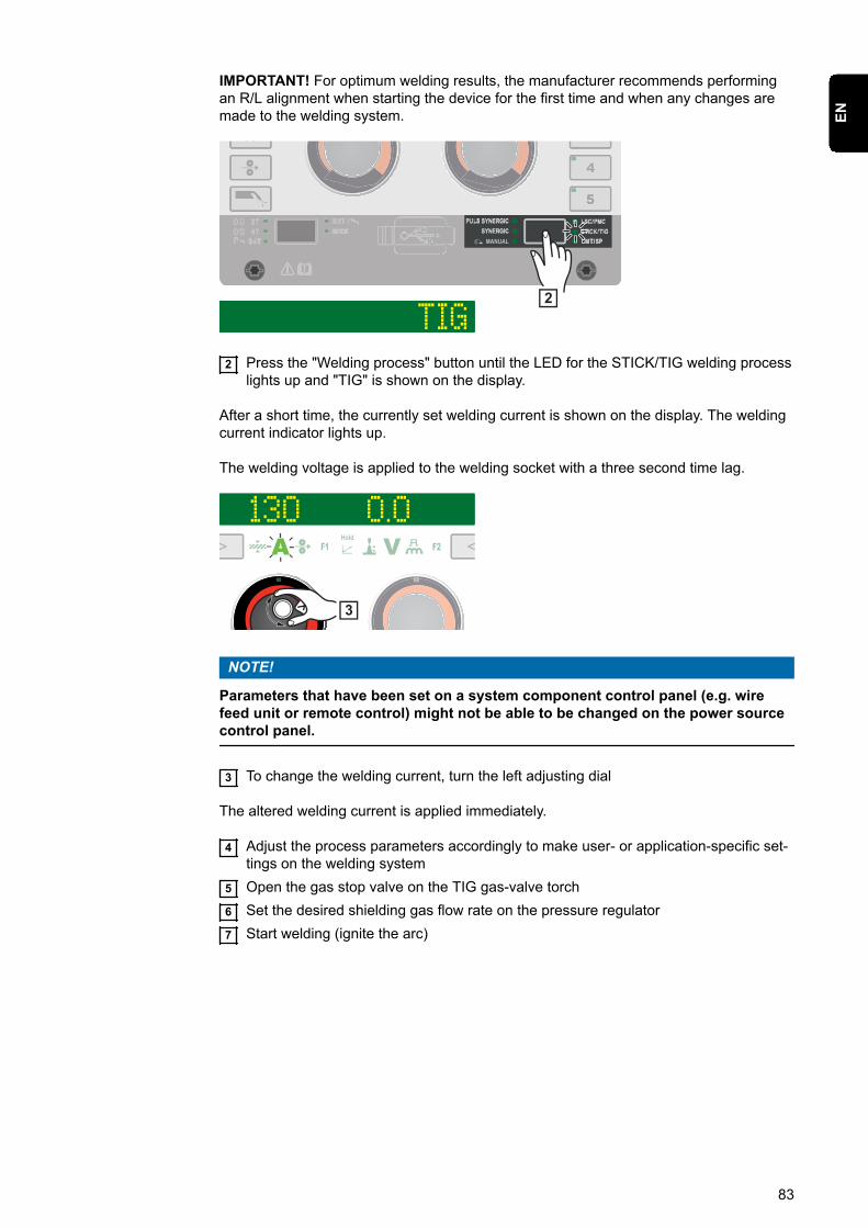
IMPORTANT! For optimum welding results, the manufacturer recommends performingan R/L alignment when starting the device for the first time and when any changes aremade to the welding system.
2
2 Press the "Welding process" button until the LED for the STICK/TIG welding processlights up and "TIG" is shown on the display.
After a short time, the currently set welding current is shown on the display. The weldingcurrent indicator lights up.
The welding voltage is applied to the welding socket with a three second time lag.
3
NOTE!
Parameters that have been set on a system component control panel (e.g. wirefeed unit or remote control) might not be able to be changed on the power sourcecontrol panel.
3 To change the welding current, turn the left adjusting dial
The altered welding current is applied immediately.
4 Adjust the process parameters accordingly to make user- or application-specific set-tings on the welding system
5 Open the gas stop valve on the TIG gas-valve torch6 Set the desired shielding gas flow rate on the pressure regulator7 Start welding (ignite the arc)
83
EN
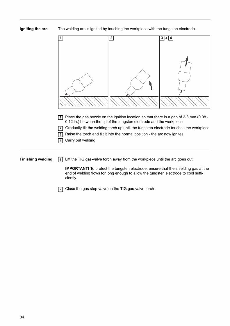
Igniting the arc The welding arc is ignited by touching the workpiece with the tungsten electrode.
1 2 3 4+
1 Place the gas nozzle on the ignition location so that there is a gap of 2-3 mm (0.08 -0.12 in.) between the tip of the tungsten electrode and the workpiece
2 Gradually tilt the welding torch up until the tungsten electrode touches the workpiece3 Raise the torch and tilt it into the normal position - the arc now ignites4 Carry out welding
Finishing welding 1 Lift the TIG gas-valve torch away from the workpiece until the arc goes out.
IMPORTANT! To protect the tungsten electrode, ensure that the shielding gas at theend of welding flows for long enough to allow the tungsten electrode to cool suffi-ciently.
2 Close the gas stop valve on the TIG gas-valve torch
84
MMA welding
Safety WARNING!
Danger from incorrect operation.Possible serious injury and damage to property.▶ Do not use the functions described here until you have read and completely under-
stood these Operating Instructions.▶ Do not use the functions described here until you have fully read and understood all
of the Operating Instructions for the system components, in particular the safetyrules!
WARNING!
An electric shock can be fatal.If the power source is connected to the mains electricity supply during installation, thereis a high risk of very serious injury and damage.▶ Before carrying out any work on the device make sure that the power source mains
switch is in the "O" position▶ Before carrying out any work on the device make sure that the power source is
unplugged from the mains
Preparations 1 Move the mains switch to the "O" position2 Disconnect the mains plug3 Remove the MIG/MAG welding torch
NOTE!
Check the rod electrode packaging or labelling to determine whether the rodelectrodes are for positive pole or negative pole welding.
4 Plug the grounding (earthing) cable into either the (-) or the (+) current socketdepending on the type of electrode, and twist to fasten it
5 Use the other end of the grounding (earthing) cable to establish a connection to theworkpiece
6 Plug the bayonet current plug of the electrode holder cable into the free currentsocket with the opposite polarity, according to the type of electrode, and twist itclockwise to latch it in place
7 Plug in the mains plug
MMA welding CAUTION!
Risk of injury and damage from electric shock.As soon as the mains switch is in the "I" position, the rod electrode in the electrodeholder is live.▶ Make sure that the rod electrode does not touch any persons or electrically conduct-
ive or earthed parts (e.g. housing, etc.)
1 Move the mains switch to the "I" position
85
EN
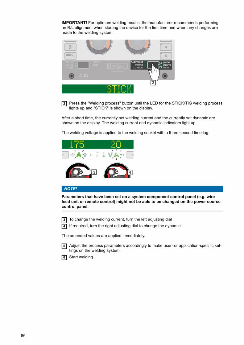
IMPORTANT! For optimum welding results, the manufacturer recommends performingan R/L alignment when starting the device for the first time and when any changes aremade to the welding system.
STICK2
2 Press the "Welding process" button until the LED for the STICK/TIG welding processlights up and "STICK" is shown on the display.
After a short time, the currently set welding current and the currently set dynamic areshown on the display. The welding current and dynamic indicators light up.
The welding voltage is applied to the welding socket with a three second time lag.
175 20
43
NOTE!
Parameters that have been set on a system component control panel (e.g. wirefeed unit or remote control) might not be able to be changed on the power sourcecontrol panel.
3 To change the welding current, turn the left adjusting dial4 If required, turn the right adjusting dial to change the dynamic
The amended values are applied immediately.
5 Adjust the process parameters accordingly to make user- or application-specific set-tings on the welding system
6 Start welding
86
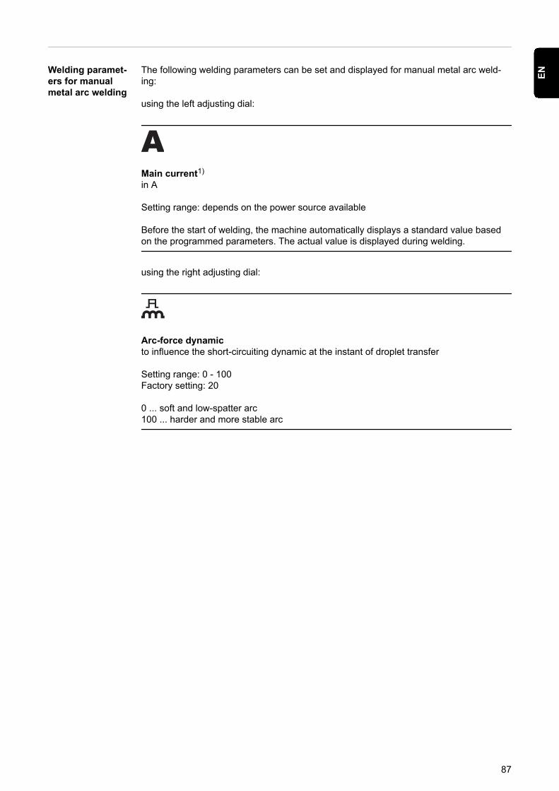
Welding paramet-ers for manualmetal arc welding
The following welding parameters can be set and displayed for manual metal arc weld-ing:
using the left adjusting dial:
Main current1)
in A
Setting range: depends on the power source available
Before the start of welding, the machine automatically displays a standard value basedon the programmed parameters. The actual value is displayed during welding.
using the right adjusting dial:
Arc-force dynamicto influence the short-circuiting dynamic at the instant of droplet transfer
Setting range: 0 - 100Factory setting: 20
0 ... soft and low-spatter arc100 ... harder and more stable arc
87
EN

88

Setup settings
89

90
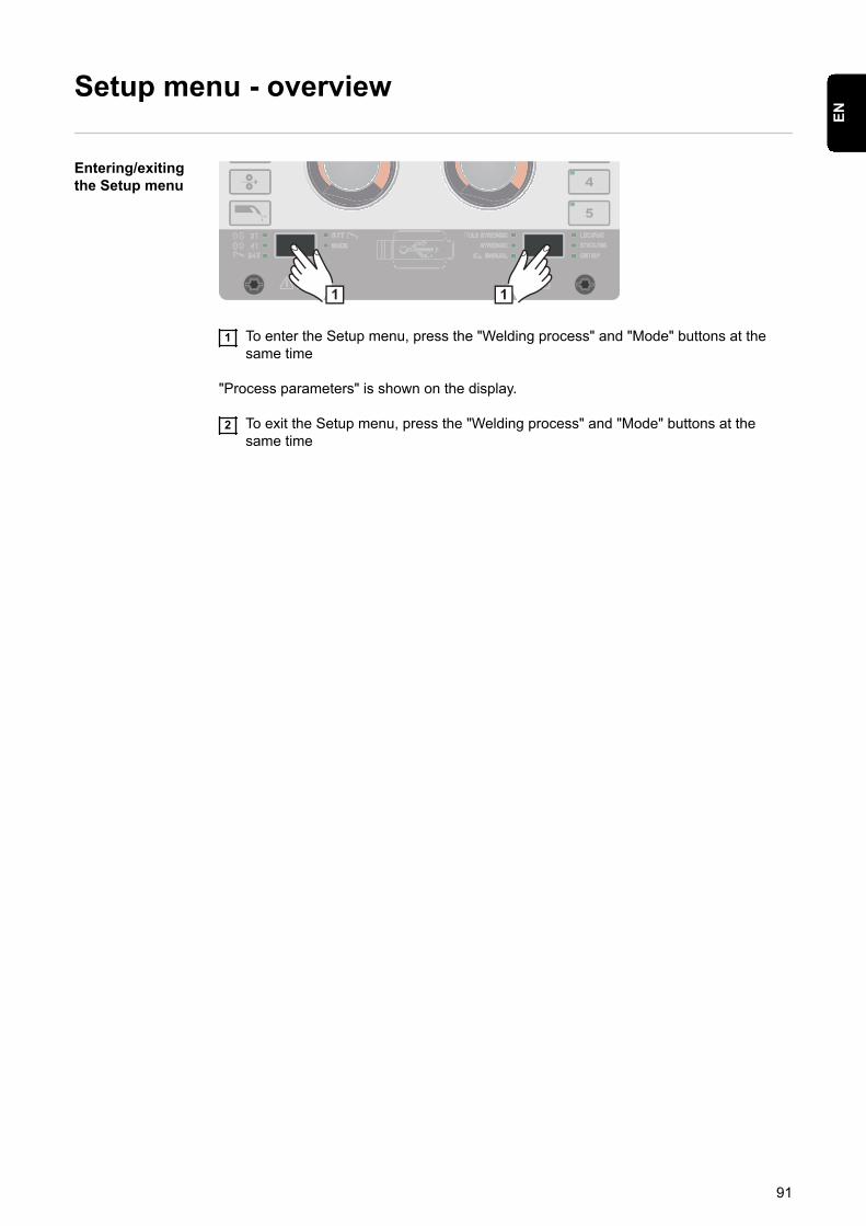
Setup menu - overview
Entering/exitingthe Setup menu
1 1
1 To enter the Setup menu, press the "Welding process" and "Mode" buttons at thesame time
"Process parameters" is shown on the display.
2 To exit the Setup menu, press the "Welding process" and "Mode" buttons at thesame time
91
EN
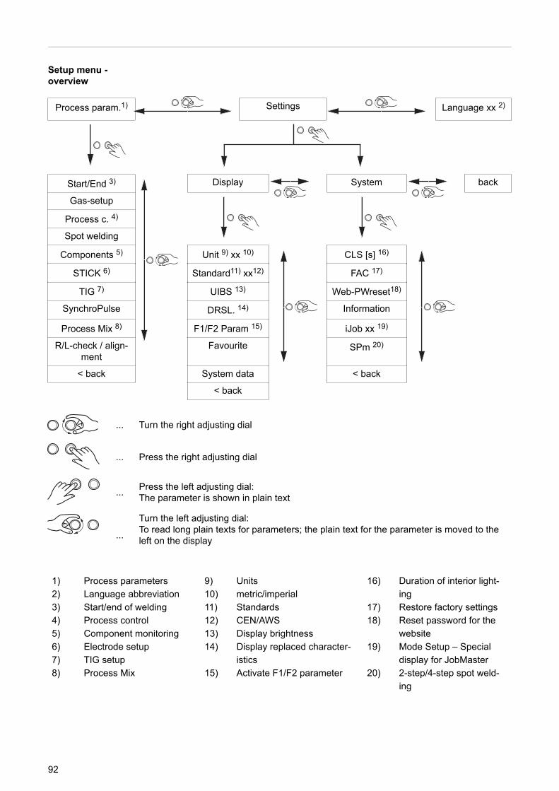
Setup menu -overview
Process param.1) Settings Language xx 2)
Start/End 3)
Display System back
Gas-setup
Process c. 4)
Spot welding
Components 5) Unit 9) xx 10) CLS [s] 16)
STICK 6) Standard11) xx12) FAC 17)
TIG 7) UIBS 13) Web-PWreset18)
SynchroPulse DRSL. 14) Information
Process Mix 8) F1/F2 Param 15) iJob xx 19)
R/L-check / align-ment
Favourite SPm 20)
< back System data < back
< back
... Turn the right adjusting dial
... Press the right adjusting dial
... Press the left adjusting dial:The parameter is shown in plain text
...
Turn the left adjusting dial:To read long plain texts for parameters; the plain text for the parameter is moved to theleft on the display
1) Process parameters2) Language abbreviation3) Start/end of welding4) Process control5) Component monitoring6) Electrode setup7) TIG setup8) Process Mix
9) Units10) metric/imperial11) Standards12) CEN/AWS13) Display brightness14) Display replaced character-
istics15) Activate F1/F2 parameter
16) Duration of interior light-ing
17) Restore factory settings18) Reset password for the
website19) Mode Setup – Special
display for JobMaster20) 2-step/4-step spot weld-
ing
92
Process parameters
Process paramet-ers for start ofwelding/end ofwelding
The following process parameters can be set and displayed for the start and end of weld-ing:
I-SStarting currentFor setting the starting current for MIG/MAG welding (e.g. aluminium welding start-up)
Setting range: 0 - 200% (of welding current)Factory setting: 135%
AlSStart arc length correctionFor correcting the arc length at the start of welding
Setting range: -10 - +10% (of welding voltage)Factory setting: 0
- .... shorter arc length0 ... neutral arc length+ ... longer arc length
t-SStarting current timeFor setting the length of time the starting current is to be active
Setting range: off / 0.1 - 10.0 sFactory setting: off
SL1Slope 1For setting the time during which the starting current is decreased or increased to thewelding current
Setting range: 0 - 9.9 sFactory setting: 1 s
SL2Slope 2For setting the time during which the welding current is decreased or increased to thefinal current.
Setting range: 0 - 9.9 sFactory setting: 1 s
I-EFinal currentFor setting the final current so thata) heat build-up towards the end of welding is prevented andb) the end-crater can be filled when welding aluminium
Setting range: 0 - 200% (of welding current)Factory setting: 50
AlEEnd arc length correctionFor correcting the arc length at the end of welding
93
EN
Setting range: -10 - +10% (of welding voltage)Factory setting: 0
- .... shorter arc length0 ... neutral arc length+ ... longer arc length
t-EFinal current timeFor setting the length of time for which the final current is to be active
Setting range: off / 0.1 - 10.0 sFactory setting: off
SFIto activate/deactivate the SFI function (Spatter Free Ignition of the arc)
Setting range: off / onFactory setting: off
SFI-HSSFI HotStartFor setting a HotStart time in conjunction with SFI ignition
During SFI ignition, a spray arc phase occurs within the set HotStart time. This increasesthe heat input irrespective of the mode, thus ensuring deeper penetration right from thevery start of welding.
Setting range: off / 0.01 - 2.00 sFactory setting: off
W-rWire retractFor setting the wire withdrawal value (= composite value based on backward movementof wire and a time).The wire withdrawal depends on the features of the welding torch.
Setting range: 0.0 - 10.0Factory setting: 0.0
IgCIgnition current (manual mode)For setting the ignition current for MIG/MAG standard manual welding
Setting range: 100 - 450 AFactory setting: 450
W-r (man.)Wire retract (manual mode)For setting the wire withdrawal value (= composite value based on backward movementof wire and a time) for MIG/MAG standard manual welding.The wire withdrawal depends on the features of the welding torch.
Setting range: 0.0 - 10.0Factory setting: 0.0
Process paramet-ers for Gas-Setup
The following process parameters can be set and displayed for Gas-Setup:
94
GPrGas pre-flowFor setting the gas flow time before the arc is ignited
Setting range: 0 - 9.9 sFactory setting: 0.1 s
GPoGas post-flowFor setting the gas flow time after the arc has gone out
Setting range: 0 - 9.9 sFactory setting: 0.5 s
GCVGas set valueFor specifying the gas set value in l/min
GCFGas factorFor setting the gas correction factor
Setting range: aut, 0.90 - 20.0Factory setting: aut
Process paramet-ers for processcontrol
The following process parameters can be set and displayed for the process control:- PSt - penetration stabilizer- AlSt - arc length stabilizer
Penetration stabilizer and arc length stabilizer can also be set in combination with oneanother.
Penetration sta-bilizer
The penetration stabilizer is used to set the max. permitted change in the wire speed toensure that the welding current and hence the penetration is kept stable or constant withvariable stick out.
The penetration stabilizer parameter is only available when the WP PMC (Welding Pro-cess Pulse Multi Control) or WP LSC (Welding Process Low Spatter Control) option hasbeen enabled on the power source.
0 - 10.0 m/min (ipm)Factory setting: 0 m/min
0The penetration stabilizer is not activated.The wire speed remains constant.
0.1 - 10.0The penetration stabilizer is activated.The welding current remains constant.
95
EN
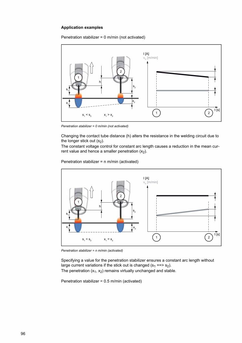
Application examples
Penetration stabilizer = 0 m/min (not activated)
I [A]vD [m/min]
1
2
1 2
h
s1
s2
x1x2
t [s]s1 < s2 x1 > x2
Penetration stabilizer = 0 m/min (not activated)
Changing the contact tube distance (h) alters the resistance in the welding circuit due tothe longer stick out (s2).The constant voltage control for constant arc length causes a reduction in the mean cur-rent value and hence a smaller penetration (x2).
Penetration stabilizer = n m/min (activated)
I [A]vD [m/min]
1
2
1 2
h
s1
s2
x1 x2
t [s]s1 < s2 x1 = x2
Penetration stabilizer = n m/min (activated)
Specifying a value for the penetration stabilizer ensures a constant arc length withoutlarge current variations if the stick out is changed (s1 ==> s2).The penetration (x1, x2) remains virtually unchanged and stable.
Penetration stabilizer = 0.5 m/min (activated)
96
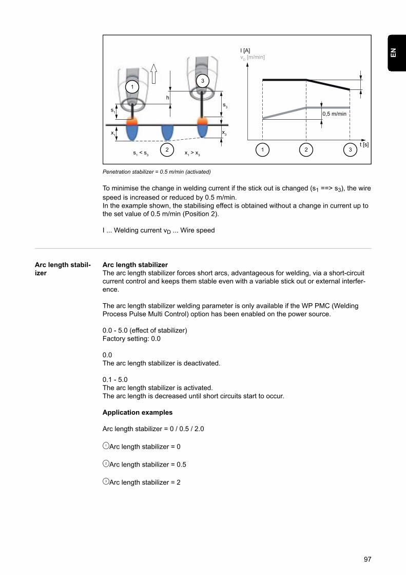
I [A]vD [m/min]
13
1 2 3
h
s1
s3
x1x3
t [s]s1 < s3 x1 > x3
2
0,5 m/min
Penetration stabilizer = 0.5 m/min (activated)
To minimise the change in welding current if the stick out is changed (s1 ==> s3), the wirespeed is increased or reduced by 0.5 m/min.In the example shown, the stabilising effect is obtained without a change in current up tothe set value of 0.5 m/min (Position 2).
I ... Welding current vD ... Wire speed
Arc length stabil-izer
Arc length stabilizerThe arc length stabilizer forces short arcs, advantageous for welding, via a short-circuitcurrent control and keeps them stable even with a variable stick out or external interfer-ence.
The arc length stabilizer welding parameter is only available if the WP PMC (WeldingProcess Pulse Multi Control) option has been enabled on the power source.
0.0 - 5.0 (effect of stabilizer)Factory setting: 0.0
0.0The arc length stabilizer is deactivated.
0.1 - 5.0The arc length stabilizer is activated.The arc length is decreased until short circuits start to occur.
Application examples
Arc length stabilizer = 0 / 0.5 / 2.0
1 Arc length stabilizer = 0
2 Arc length stabilizer = 0.5
3 Arc length stabilizer = 2
97
EN
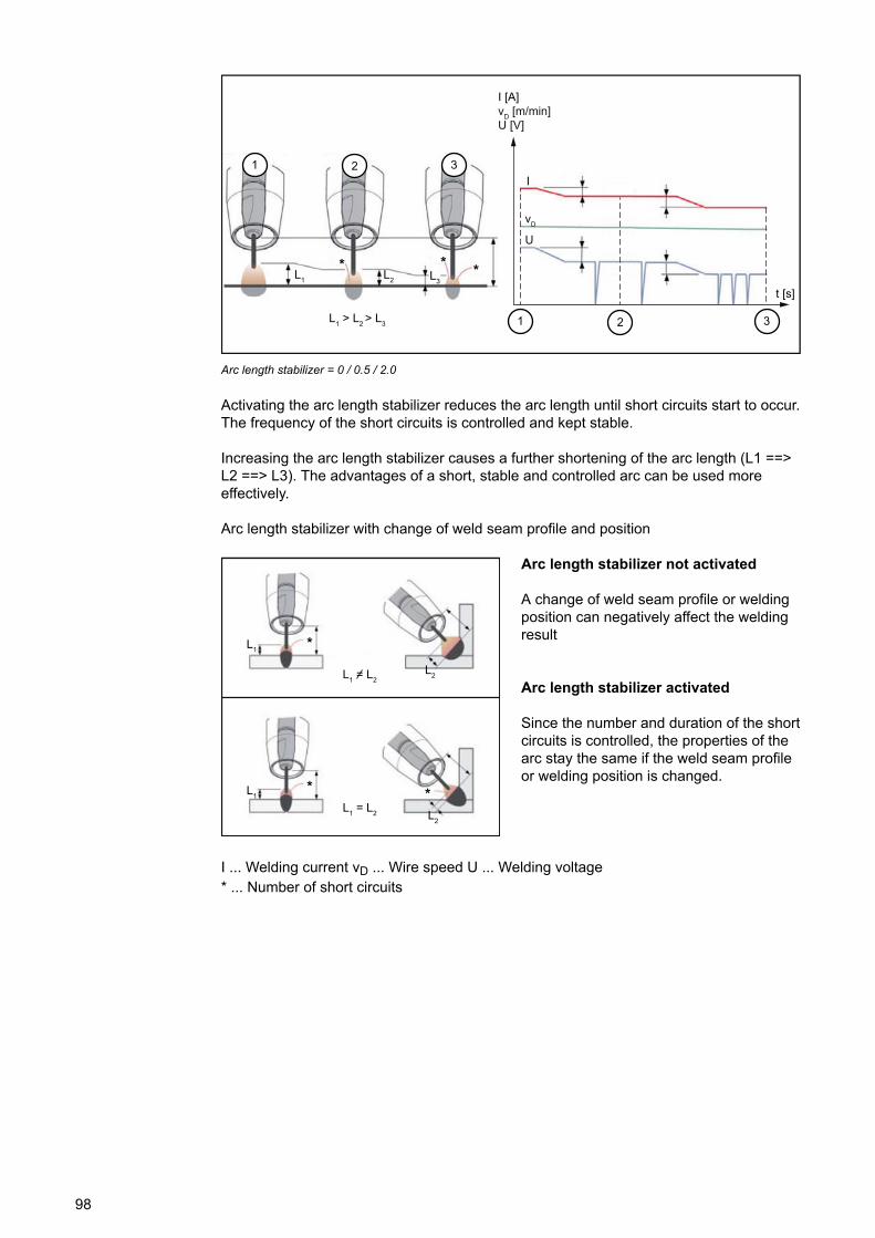
I [A]vD [m/min]U [V]
t [s]
L1 > L2 > L3
1 2 3
1 2 3
I
vD
U
L1 L2 L3
* * *
Arc length stabilizer = 0 / 0.5 / 2.0
Activating the arc length stabilizer reduces the arc length until short circuits start to occur.The frequency of the short circuits is controlled and kept stable.
Increasing the arc length stabilizer causes a further shortening of the arc length (L1 ==>L2 ==> L3). The advantages of a short, stable and controlled arc can be used moreeffectively.
Arc length stabilizer with change of weld seam profile and position
L1 = L2
L1
L2
*
* *L1
L2
L1 = L2
Arc length stabilizer not activated
A change of weld seam profile or weldingposition can negatively affect the weldingresult
Arc length stabilizer activated
Since the number and duration of the shortcircuits is controlled, the properties of thearc stay the same if the weld seam profileor welding position is changed.
I ... Welding current vD ... Wire speed U ... Welding voltage* ... Number of short circuits
98
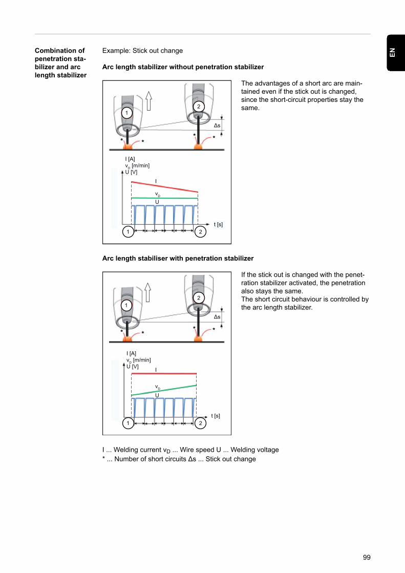
Combination ofpenetration sta-bilizer and arclength stabilizer
Example: Stick out change
Arc length stabilizer without penetration stabilizer
Δs
I [A]vD [m/min]U [V]
t [s]
12
1 2
I
vD
U
****
The advantages of a short arc are main-tained even if the stick out is changed,since the short-circuit properties stay thesame.
Arc length stabiliser with penetration stabilizer
Δs
I [A]vD [m/min]U [V]
t [s]
12
1 2
I
vD
U
****
If the stick out is changed with the penet-ration stabilizer activated, the penetrationalso stays the same.The short circuit behaviour is controlled bythe arc length stabilizer.
I ... Welding current vD ... Wire speed U ... Welding voltage* ... Number of short circuits Δs ... Stick out change
99
EN
Process paramet-ers for spot weld-ing
SPtSpot welding time
0.1 - 10.0 sFactory setting: 1.0 s
Process paramet-ers for monitor-ing and compon-ents
The following process parameters can be set and displayed for the system componentsof a welding system:
C-CCooling unit modeTo determine whether a cooling unit is to be switched on or off, or operated automatically
Setting range: eco / auto / on / off (depending on the cooling unit)Factory setting: auto
C-tDelay time flow sensorFor setting the time from when the flow sensor responds until a warning message is out-put
Setting range: 5 - 25 sFactory setting: 10 s
CFUCooler flow warning limit
Setting range: off, 0.75 - 0.95 l/minFactory setting: off
FdiFeeder inching speedin m/min (ipm)For setting the wire speed at which the wire electrode is threaded into the torch hosep-ack
Setting range:min. - max. (depending on the wirefeeder)Factory setting: 10.0 m/min
itoIgnition time-outLength of wire that is fed before the safety cut-out trips
Setting range: off / 5 - 100 mm (0.2 - 3.94 in.)Factory setting: off
The ignition time-out process parameter is a safety function. The length of wire that is fedbefore the safety cut-out trips may differ from the pre-set wire length, particularly whenthe wire is being fed at fast wire speeds.
How it works:Once the torch trigger is pressed, gas pre-flow begins immediately. Wirefeeding thenbegins, followed by ignition. If no current starts flowing before the specified length of wirehas been fed, the power source cuts out automatically.To try again, press the torch trigger again.
100
GSLLower gas flow rate limit
Setting range: 0.5 - 30.0 l/minFactory setting: 7.0 l/min
GStMaximum duration of gas flow deviation
Setting range: off, 0.1 - 10.0 sFactory setting: 2.0 s
GSFGas factor sensordependent on the shielding gas used(only in conjunction with the OPT/i gas controller option)
Setting range: auto, 0.90 - 20.0Factory setting: auto(the correction factor is automatically set for standard gases from the Fronius weldingdatabase)
Process paramet-ers for electrodesetup
The following process parameters can be set and displayed for manual metal arc weld-ing (STICK):
I-SStarting currentFor setting the starting current
Setting range: 0 - 200%Factory setting: 150%
HtiStarting current timeFor setting the length of time for which the starting current is to be active
Setting range: 0.0 - 2.0 sFactory setting: 0.5 s
ElnCharacteristicFor selecting the electrode characteristic
Setting range: I-constant / 0.1 - 20.0 A/V / P-constantFactory setting: I-constant
101
EN
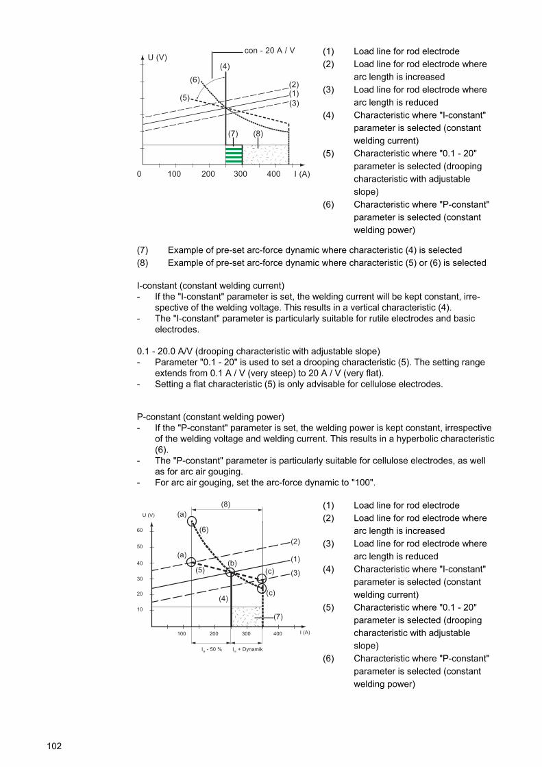
0040 200100 300 I (A)
U (V)con - 20 A / V
(4)
(5)
(6)
(7) (8)
(1)(2)
(3)
(1) Load line for rod electrode(2) Load line for rod electrode where
arc length is increased(3) Load line for rod electrode where
arc length is reduced(4) Characteristic where "I-constant"
parameter is selected (constantwelding current)
(5) Characteristic where "0.1 - 20"parameter is selected (droopingcharacteristic with adjustableslope)
(6) Characteristic where "P-constant"parameter is selected (constantwelding power)
(7) Example of pre-set arc-force dynamic where characteristic (4) is selected(8) Example of pre-set arc-force dynamic where characteristic (5) or (6) is selected
I-constant (constant welding current)- If the "I-constant" parameter is set, the welding current will be kept constant, irre-
spective of the welding voltage. This results in a vertical characteristic (4).- The "I-constant" parameter is particularly suitable for rutile electrodes and basic
electrodes.
0.1 - 20.0 A/V (drooping characteristic with adjustable slope)- Parameter "0.1 - 20" is used to set a drooping characteristic (5). The setting range
extends from 0.1 A / V (very steep) to 20 A / V (very flat).- Setting a flat characteristic (5) is only advisable for cellulose electrodes.
P-constant (constant welding power)- If the "P-constant" parameter is set, the welding power is kept constant, irrespective
of the welding voltage and welding current. This results in a hyperbolic characteristic(6).
- The "P-constant" parameter is particularly suitable for cellulose electrodes, as wellas for arc air gouging.
- For arc air gouging, set the arc-force dynamic to "100".
10
20
30
40
50
60
U (V)
004003001 200 I (A)
IH + DynamikIH - 50 %
(8)
(2)
(1)
(3)
(7)
(c)
(c)(b)
(a)
(a)
(6)
(5)
(4)
(1) Load line for rod electrode(2) Load line for rod electrode where
arc length is increased(3) Load line for rod electrode where
arc length is reduced(4) Characteristic where "I-constant"
parameter is selected (constantwelding current)
(5) Characteristic where "0.1 - 20"parameter is selected (droopingcharacteristic with adjustableslope)
(6) Characteristic where "P-constant"parameter is selected (constantwelding power)
102
(8) Example of pre-set arc-force dynamic where characteristic (5) or (6) is selected(9) Possible change in the current where characteristic (5) or (6) is selected, as a
function of the welding voltage (arc length)
(a) Operating point where arc length is long(b) Operating point where welding current IH is set(c) Operating point where arc length is short
The characteristics (4), (5) and (6) shown here apply when using a rod electrode whosecharacteristic corresponds - at a given arc length - to the load line (1).
Depending on what welding current (I) has been set, the point of intersection (operatingpoint) of characteristics (4), (5) and (6) will be displaced along the load line (1). The oper-ating point provides information on the actual welding voltage and the actual welding cur-rent.
Where the welding current (IH) is permanently set, the operating point may migrate alongthe characteristics (4), (5) and (6) according to the welding voltage at a given moment.The welding voltage U is dependent upon the arc length.
If the arc length changes (e.g. in accordance with the load line (2)) the resulting operat-ing point will be the point where the corresponding characteristic (4), (5) or (6) intersectswith the load line (2).
Applies to characteristics (5) and (6): Depending upon the welding voltage (arc length),the welding current (I) will also become either smaller or larger, even though the valueset for IH remains the same.
AstAnti-stickTo activate/deactivate the anti-stick function
Setting range: off / onFactory setting: on
As the arc becomes shorter, the welding voltage may drop so far that the rod electrodewill tend to stick. This may also cause the rod electrode to burn out.
The anti-stick function prevents the electrode from burning out. If the rod electrodebegins to stick, the power source switches the welding current off after 1.5 seconds. Afterthe rod electrode has been lifted off the workpiece, the welding process can be continuedwithout any problems.
UcoBreak voltageFor setting a voltage, at which the welding process can be ended by slightly lifting therod electrode.
Setting range: 20.0 - 90.0 VFactory setting: 90.0 V
The arc length depends on the welding voltage. To end the welding process, it is usuallynecessary to significantly lift the rod electrode away from the workpiece. With the break-voltage parameter, the welding voltage can be limited to a value that makes it possible toend the welding operation simply by lifting the rod electrode slightly.
IMPORTANT! If, during welding, you often find that the welding operation is ended unin-tentionally, increase the value of the break voltage.
103
EN
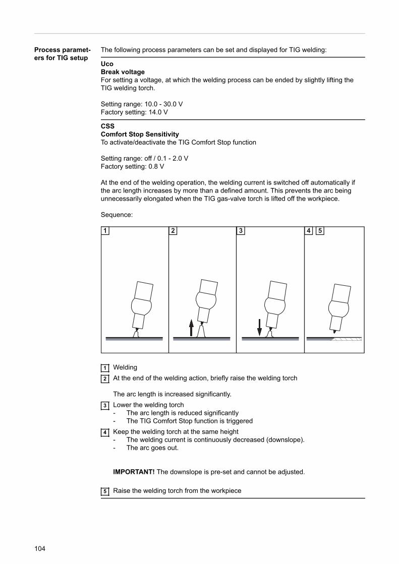
Process paramet-ers for TIG setup
The following process parameters can be set and displayed for TIG welding:
UcoBreak voltageFor setting a voltage, at which the welding process can be ended by slightly lifting theTIG welding torch.
Setting range: 10.0 - 30.0 VFactory setting: 14.0 V
CSSComfort Stop SensitivityTo activate/deactivate the TIG Comfort Stop function
Setting range: off / 0.1 - 2.0 VFactory setting: 0.8 V
At the end of the welding operation, the welding current is switched off automatically ifthe arc length increases by more than a defined amount. This prevents the arc beingunnecessarily elongated when the TIG gas-valve torch is lifted off the workpiece.
Sequence:
1 2 3 4 5
1 Welding2 At the end of the welding action, briefly raise the welding torch
The arc length is increased significantly.3 Lower the welding torch
- The arc length is reduced significantly- The TIG Comfort Stop function is triggered
4 Keep the welding torch at the same height- The welding current is continuously decreased (downslope).- The arc goes out.
IMPORTANT! The downslope is pre-set and cannot be adjusted.
5 Raise the welding torch from the workpiece
104
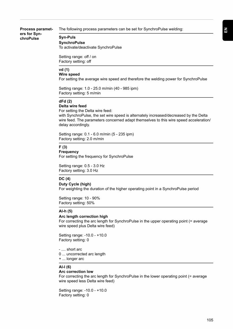
Process paramet-ers for Syn-chroPulse
The following process parameters can be set for SynchroPulse welding:
Syn-PulsSynchroPulseTo activate/deactivate SynchroPulse
Setting range: off / onFactory setting: off
vd (1)Wire speedFor setting the average wire speed and therefore the welding power for SynchroPulse
Setting range: 1.0 - 25.0 m/min (40 - 985 ipm)Factory setting: 5 m/min
dFd (2)Delta wire feedFor setting the Delta wire feed:with SynchroPulse, the set wire speed is alternately increased/decreased by the Deltawire feed. The parameters concerned adapt themselves to this wire speed acceleration/delay accordingly.
Setting range: 0.1 - 6.0 m/min (5 - 235 ipm)Factory setting: 2.0 m/min
F (3)FrequencyFor setting the frequency for SynchroPulse
Setting range: 0.5 - 3.0 HzFactory setting: 3.0 Hz
DC (4)Duty Cycle (high)For weighting the duration of the higher operating point in a SynchroPulse period
Setting range: 10 - 90%Factory setting: 50%
Al-h (5)Arc length correction highFor correcting the arc length for SynchroPulse in the upper operating point (= averagewire speed plus Delta wire feed)
Setting range: -10.0 - +10.0Factory setting: 0
- .... short arc0 ... uncorrected arc length+ ... longer arc
Al-l (6)Arc correction lowFor correcting the arc length for SynchroPulse in the lower operating point (= averagewire speed less Delta wire feed)
Setting range: -10.0 - +10.0Factory setting: 0
105
EN
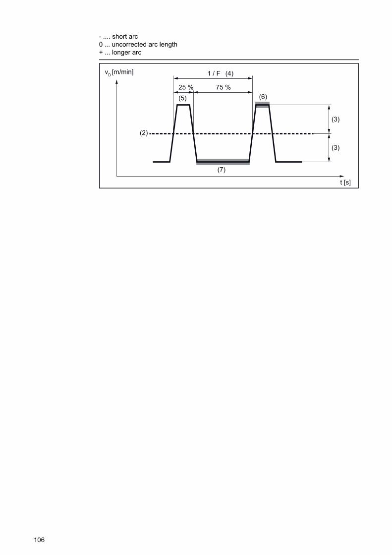
- .... short arc0 ... uncorrected arc length+ ... longer arc
(2)
(3)
(3)
(4)
(5) (6)
(7)
25 %
vD [m/min]
75 %
t [s]
1 / F
106
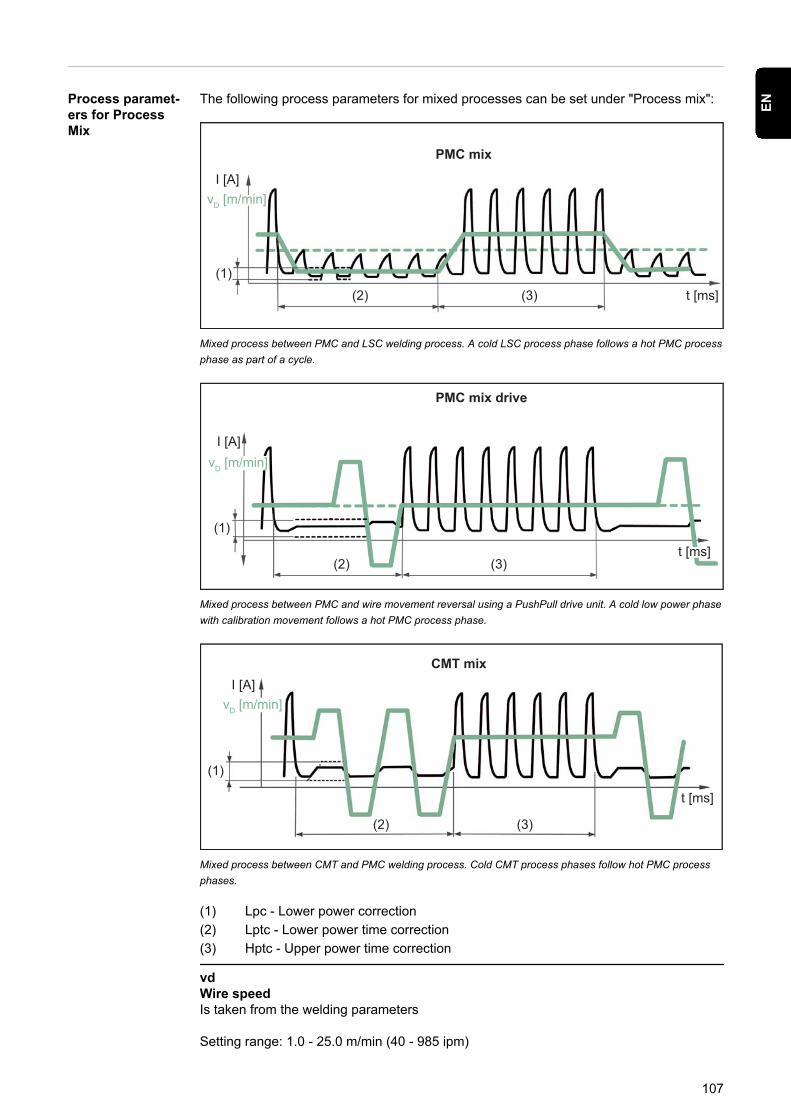
Process paramet-ers for ProcessMix
The following process parameters for mixed processes can be set under "Process mix":
(1)(2) (3) t [ms]
I [A]
PMC mix
vD [m/min]
Mixed process between PMC and LSC welding process. A cold LSC process phase follows a hot PMC processphase as part of a cycle.
(1)
(2) (3)
I [A]
PMC mix drive
vD [m/min]
t [ms]
Mixed process between PMC and wire movement reversal using a PushPull drive unit. A cold low power phasewith calibration movement follows a hot PMC process phase.
(1)
(2) (3)
t [ms]
I [A]CMT mix
vD [m/min]
Mixed process between CMT and PMC welding process. Cold CMT process phases follow hot PMC processphases.
(1) Lpc - Lower power correction(2) Lptc - Lower power time correction(3) Hptc - Upper power time correction
vdWire speedIs taken from the welding parameters
Setting range: 1.0 - 25.0 m/min (40 - 985 ipm)
107
EN
The wire speed value can also be specified or changed in the Process mix parameters.
AlcArc length correctionIs taken from the welding parameters
Setting range: -10.0 - +10.0
The arc length correction value can also be specified or changed in the Process mixparameters.
For CMT mix:
Positive correction:increase in the pulsed voltage for the PMC phaselonger reverse movement in the CMT phase (increases arc length)
Negative correction:reduction in the pulsed voltage for the PMC phaseshorter reverse movement in the CMT phase (reduces arc length)
PDcPulse/dynamic correctionIs taken from the welding parameters
Setting range: -10.0 - +10.0
The pulse/dynamic correction value can also be specified or changed in the Process mixparameters.
For CMT mix:
Positive correction:increase in the pulse energy (pulse current height, pulse current width)Reduction in the pulse frequency in the PMC phase
Negative correction:reduction in the pulse energy (pulse current height, pulse current width)Increase in the pulse frequency in the PMC phase
Hptc (3)Upper power time correctionTo set the duration of the hot process phase in a mixed process
Setting range: -10.0 - +10.0Factory setting: 0
Lptc (2)Lower power time correctionTo set the duration of the cold process phase in a mixed process
Setting range: -10.0 - +10.0Factory setting: 0.0
Upper and lower power time correction is used to define the relationship between hotand cold process phases.
If the lower power time correction is increased, the process frequency reduces and theLSC process phase becomes longer.
If the lower power time correction is reduced, the process frequency increases and theLSC process phase becomes shorter.
108
Lpc (1)Lower power correctionTo set the energy input in the cold process phase in a mixed process
Setting range: -10.0 - +10.0Factory setting: 0
If the lower power correction is increased, this results in a higher wire speed and there-fore higher energy yield in the cold LSC process phase.
R/L alignment Align the welding circuit resistance (R) and welding circuit inductivity (L) if one of the fol-lowing components of the welding system is changed:- Torch hosepacks- Return lead cables, welding power-leads- Welding torches, electrode holders- Push-pull units
Prerequisites for R/L alignment:
The welding system must be complete: closed welding loop with torch and torch hosep-ack, wirefeeders, return lead cable, interconnecting hosepacks.
Performing R/L alignment:
1 Select Setup menu / Process param. / R/L-check / alignment2 Press the right adjusting dial
The current welding circuit inductivity values in µH and welding circuit resistance valuesin mOhm are displayed.
3 Press the right adjusting dial (or press the torch trigger)
"Connect earth" is shown on the display.
4 Establish a safe ground earth connection
IMPORTANT! Contact between the earthing clamp and workpiece must be estab-lished on a cleaned area of the workpiece.
5 Press the right adjusting dial (or press the torch trigger)
"Remove nozzle" is shown on the display.
6 Remove the gas nozzle from the welding torch7 Press the right adjusting dial (or press the torch trigger)
"Contact workp." is shown on the display.
8 Place the contact tip of the welding torch flush against the workpiece surface9 Press the torch trigger
(or press the right adjusting dial)
After a successful measurement, the current values are displayed.
10 Select "Finish" by turning the right adjusting dial11 Press the right adjusting dial
109
EN

12 To exit the Setup menu, press the "Welding process" and "Mode" buttons at thesame time
110
Settings
General remarks NOTE!
As a result of firmware updates, you may find that there are functions available onyour unit that are not described in these operating instructions or vice versa.Certain illustrations may also differ slightly from the actual control elements on yourdevice. However, these controls function in exactly the same way.
WARNING!
Operating the equipment incorrectly can cause serious injury and damage.▶ Do not use the functions described until you have thoroughly read and understood
these operating instructions▶ Do not use the functions described until you have thoroughly read and understood
all the operating instructions for the system components, especially the safety rules
Overview The settings contain the following options:
Under "View"- Units- Standards- UIBS (display brightness)- DRSL (display replaced characteristics)- Setting F1 and F2 special function parameters- Setting the parameters for the Favourites button- System data
Under "System"- Interior lighting setup- Restore factory settings- Resetting the password for the power source website- Information- Special display for JobMaster- Spot welding mode
Setting the units 1 Select Setup menu / Settings / View / Unit2 Press the right adjusting dial
The first of the available units is displayed.
3 Select the desired unit by turning the right adjusting dial:- metric (mm, kg, etc.)- imperial (in., lbs., etc.)
4 Press the right adjusting dial to apply the units5 To exit the Setup menu, press the "Welding process" and "Mode" buttons at the
same time
111
EN
Setting the stand-ards
1 Select Setup menu / Settings / View / Standard2 Press the right adjusting dial
The first of the available standards is displayed.
3 Select the desired standard by turning the right adjusting dial:- CEN
Name of filler metal according to European standards(e.g. AlMg 5, CuSi3, Steel, etc.)
- AWSName of filler metal according to the American Welding Society Standard(e.g. ER 5356, ER CuSi-A, ER 70 S-6, etc.)
4 Press the right adjusting dial to set the standard5 To exit the Setup menu, press the "Welding process" and "Mode" buttons at the
same time
Setting the dis-play brightness
1 Select Setup menu / Settings / View / UIBS
UIBS = User interface brightness settings
2 Press the right adjusting dial
The value for the display brightness is shown.
3 Select the desired display brightness by turning the right adjusting dial (1 - 4)4 Press the right adjusting dial to apply the value5 To exit the Setup menu, press the "Welding process" and "Mode" buttons at the
same time
Displayingreplaced charac-teristics
1 Select setup menu / Settings / View / DRSL
DRSL = Display replaced synergic lines
2 Press the right adjusting dial3 Select "on" by turning the right adjusting dial4 Press the right adjusting dial to activate the function5 To exit the Setup menu, press the "Welding process" and "Mode" buttons at the
same time
Setting F1 and F2special functionparameters viathe Setup menu
1 Select Setup menu / Settings / View / F1/F2 Param.2 Press the right adjusting dial
The parameters currently stored under F1 and F2 are displayed.If no parameters are stored, the first possible parameter is displayed.
3 Select the desired parameter by turning the right adjusting dial4 Press the right adjusting dial
112
5 Turn the right adjusting dial to determine under which special function the parametershould be stored:- ... the parameter is not assigned to a special function/a stored parameter is deletedF1 ... parameter is stored under special function F1F2 ... parameter is stored under special function F2
6 Press the right adjusting dial to confirm the selection7 To exit the Setup menu, press the "Welding process" and "Mode" buttons at the
same time
Setting theFavourites buttonvia the Setupmenu
1 Select Setup menu / Settings / View / Favourite2 Press the right adjusting dial
The list of parent folders and parameters is displayed.If a parameter or a folder is currently stored under the Favourites button, this is indicatedwith at the end of the display.
3 Select the desired parameter or folder by turning the right adjusting dial4 Press the right adjusting dial5 Turn the right adjusting dial to determine whether the parameter or folder should be
stored under the Favourites button:- ... parameter or folder is not stored
... parameter or folder is stored6 Press the right adjusting dial to confirm the selection
The stored parameter or folder is indicated with at the end of the display.
7 To exit the Setup menu, press the "Welding process" and "Mode" buttons at thesame time
Retrieving sys-tem data
1 Select Setup menu / Settings / View / System data2 Press the right adjusting dial
The first available system data value is displayed.
3 Select the desired system data value by turning the right adjusting dial4 To exit the Setup menu, press the "Welding process" and "Mode" buttons at the
same time
The following system data can be displayed:
IPCurrent arc power in kW
The arc power is the product of welding current and welding voltage and is used to cal-culate the electrical energy input:
E = IP / vs
E Electrical energy input in kJ/cmIP Arc power in kWvs Welding speed in cm/s
113
EN

IECurrent arc energy in kJ
The arc energy is the sum total of the arc power and calculates the heat input of the weldseam most recently produced.If the weld seam length is known the electrical energy input can be calculated:
E = IE / L
E Electrical energy input in kJ/cmIE Arc energy in kJL Length of the weld seam in cm
The arc energy is preferably used during manual welding.
I-M1Current motor current in A, wirefeeder 1(wirefeeder next to the arc)
I-M2Current motor current in A, wirefeeder 2(e.g. the rear wirefeeder in a push-pull system)
I-M3Current motor current in A, wirefeeder 3(e.g. an unreeling wirefeeder in a push-pull system with unreeling wirefeeder)
CFICurrent flow rate in l/min on the cooling unit(with built-in OPT/i CU flow temperature sensor option)
Error output if flow rate < 0.7 l/min
CU-tCurrent coolant temperature in °C on the cooling unit(with built-in OPT/i CU flow temperature sensor option)
Error output if coolant temperature > 70 °C(measured during coolant return)
I-tArc time in h
DC-tTotal power source operating hours in h
GconTotal gas consumption in l
Setting theinterior lighting
1 Select Setup menu / Settings / System / CLS2 Press the right adjusting dial3 Select the desired duration by turning the right adjusting dial:
off ... interior lighting switched off1 - 60 ... interior lighting is switched on for the duration enteredon ... interior lighting is switched on permanently
4 Press the right adjusting dial5 To exit the Setup menu, press the "Welding process" and "Mode" buttons at the
same time
114
Restoring thefactory settings
1 Select Setup menu / Settings / System / FAC2 Press the right adjusting dial3 Turn the right adjusting dial to select "Yes", thereby restoring the power source to the
factory settings4 Press the right adjusting dial
The process parameters and machine default values are immediately reset to the factorysettings without any further warning.
5 To exit the Setup menu, press the "Welding process" and "Mode" buttons at thesame time
Resetting thepassword for thepower sourcewebsite
1 Select Setup menu / Settings / System / Web-PWreset2 Press the right adjusting dial3 Turn the right adjusting dial to select "Yes", thereby resetting the password for the
power source:User name = adminPassword = admin
4 Press the right adjusting dial
The password is immediately reset to the factory settings without any further warning.
5 To exit the Setup menu, press the "Welding process" and "Mode" buttons at thesame time
Retrieving deviceinformation
1 Select Setup menu / Settings / System / Information2 Press the right adjusting dial
The first item of available information is displayed.
3 Select the desired information by turning the right adjusting dialSerial numberImage versionIP addressMAC address
4 Press the right adjusting dial to display the information5 To exit the Setup menu, press the "Welding process" and "Mode" buttons at the
same time
Setting the spe-cial display forJobMaster
1 Select Setup menu / Settings / System / iJob2 Press the right adjusting dial3 Activate or deactivate the function by turning the right adjusting dial:
off ... the special display for JobMaster is deactivatedon ... the special display for JobMaster is activated
4 Press the right adjusting dial5 To exit the Setup menu, press the "Welding process" and "Mode" buttons at the
same time
115
EN

The following can now be set and carried out on the JobMaster welding torch:- Mode- SynchroPulse- Gas test
Setting the modefor spot welding
1 Select Setup menu / Settings / System / SPm2 Press the adjusting dial
3 Turn the adjusting dial and select the desired mode for spot welding
2-step = spot welding in 2-step mode:The spot welding process runs for as long as the torch trigger is kept pressed andends no later than at the expiry of the spot welding time.Releasing the torch trigger stops the spot welding process before the spot weldingtime expires
4-step = spot welding in 4-step mode:The spot welding process starts once the torch trigger is pressed and ends no laterthan at the expiry of the spot welding time.Press the torch trigger again to stop the spot welding process before the spot weld-ing time expires.
4 Press the right adjusting dial5 To exit the Setup menu, press the "Welding process" and "Mode" buttons at the
same time
More information on spot welding:- Page 80 (spot welding in general)- Page 100 (spot welding time)
116

Setting the language
Setting the lan-guage
1 Access the Setup menu2 Select the language3 Press the right adjusting dial
The language abbreviation of the currently set language is highlighted on the display.
4 Select the desired language by turning the right adjusting dial
The following languages can be selected:
cs Czechda Danishde Germanen Englishes Spanishet Estonianfr Frenchhr Croatianhu Hungarianit Italianlt Lithuanianlv Latvian
nl Dutchno Norwegianpl Polishpt Portuguese (Brazil)ro Romanianru Russiansk Slovaksl Sloveniansr Serbiansv Swedishtr Turkishuk Ukrainian
5 Press the right adjusting dial to apply the language6 To exit the Setup menu, press the "Welding process" and "Mode" buttons at the
same time
117
EN
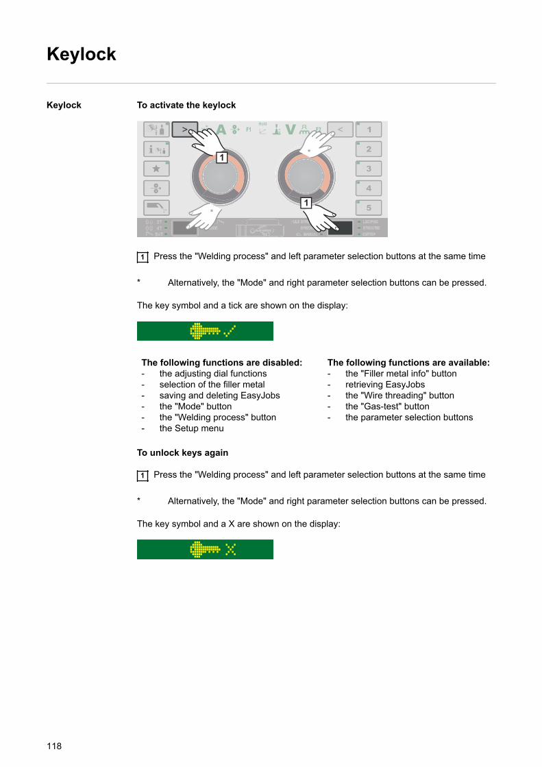
Keylock
Keylock To activate the keylock
1
1*
*
1 Press the "Welding process" and left parameter selection buttons at the same time
* Alternatively, the "Mode" and right parameter selection buttons can be pressed.
The key symbol and a tick are shown on the display:
The following functions are disabled:- the adjusting dial functions- selection of the filler metal- saving and deleting EasyJobs- the "Mode" button- the "Welding process" button- the Setup menu
The following functions are available:- the "Filler metal info" button- retrieving EasyJobs- the "Wire threading" button- the "Gas-test" button- the parameter selection buttons
To unlock keys again
1 Press the "Welding process" and left parameter selection buttons at the same time
* Alternatively, the "Mode" and right parameter selection buttons can be pressed.
The key symbol and a X are shown on the display:
118

SmartManager - The power sourcewebsite
119

120
SmartManager - The power source website
General remarks The power source has its own website: SmartManager.As soon as the power source is connected to a computer with the help of a networkcable, or is integrated into a network, the power source's SmartManager can be retrievedusing the power source's IP address.At least IE 10 or a similar modern browser is required to access SmartManager.
The entries displayed on SmartManager may vary depending on system configuration,software upgrades and available options.
Examples of entries displayed:
- Actual system data- Documentation- Job data- Power source configuration- Backup & Restore- User management- Signal visualisation
- Overview- Update- Function packages- Characteristics overview- Screenshot- Robot interface *
* Depending on the available robot interface, the name of the interface will be dis-played as an entry on the website.
Calling up thepower sourcewebsite
1 Setup menu / Settings / System / Information ==> note the IP address of the powersource (IP)
2 Enter the IP address in the browser search field3 Enter user name and password
Factory setting:User name = adminPassword = admin
The power source website is displayed.
Changing pass-word / logging off
By clicking this symbol- the user password can be changed- you can log out of SmartManager
Changing the password for the SmartManager:
1 Enter the old password2 Enter the new password3 Repeat the new password4 Click on "Save"
121
EN
Settings
Clicking on this symbol expands the display of characteristics, material specificationsand certain welding parameters for the power source's SmartManager.
The settings depend on which user is currently logged on.
Language selec-tion
The languages available for SmartManager can be displayed by clicking on the languageabbreviation.
The language that is currently set is highlighted in white.
To change the language, click on the one you would like.
Fronius
A click on the Fronius logo opens the homepage of Fronius: www.fronius.com.
122
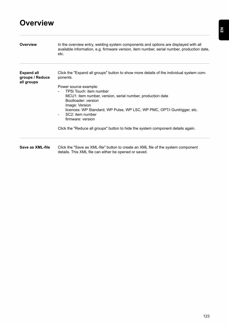
Overview
Overview In the overview entry, welding system components and options are displayed with allavailable information, e.g. firmware version, item number, serial number, production date,etc.
Expand allgroups / Reduceall groups
Click the "Expand all groups" button to show more details of the individual system com-ponents.
Power source example:- TPSi Touch: item number
MCU1: item number, version, serial number, production dateBootloader: versionimage: Versionlicences: WP Standard, WP Pulse, WP LSC, WP PMC, OPT/i Guntrigger, etc.
- SC2: item numberfirmware: version
Click the "Reduce all groups" button to hide the system component details again.
Save as XML-file Click the "Save as XML-file" button to create an XML file of the system componentdetails. This XML file can either be opened or saved.
123
EN
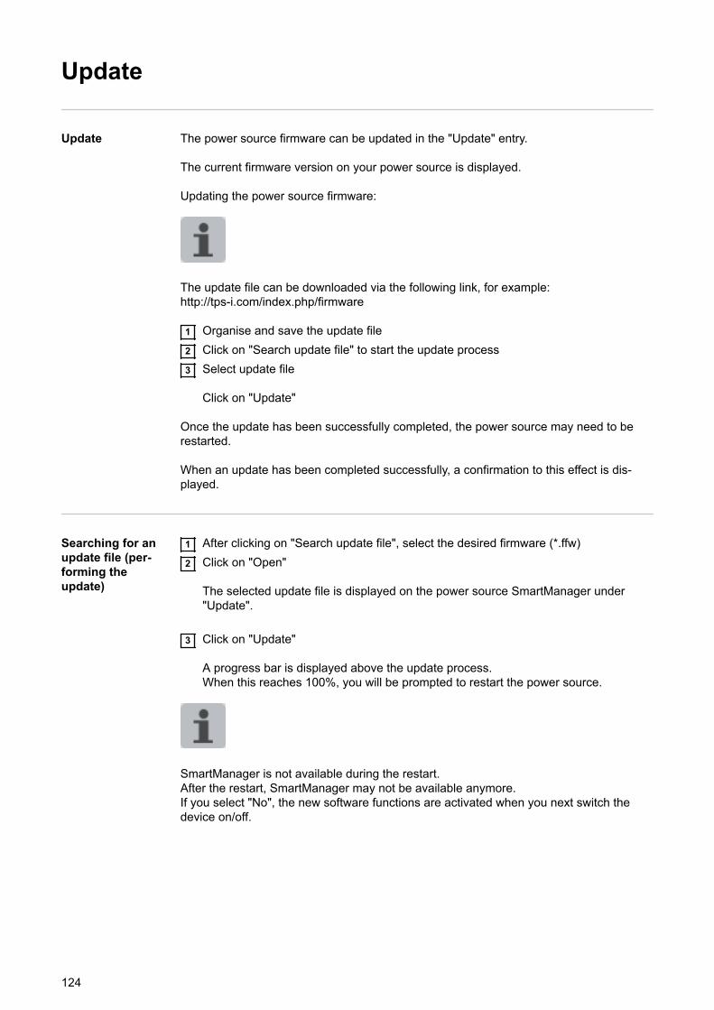
Update
Update The power source firmware can be updated in the "Update" entry.
The current firmware version on your power source is displayed.
Updating the power source firmware:
The update file can be downloaded via the following link, for example:http://tps-i.com/index.php/firmware
1 Organise and save the update file2 Click on "Search update file" to start the update process3 Select update file
Click on "Update"
Once the update has been successfully completed, the power source may need to berestarted.
When an update has been completed successfully, a confirmation to this effect is dis-played.
Searching for anupdate file (per-forming theupdate)
1 After clicking on "Search update file", select the desired firmware (*.ffw)2 Click on "Open"
The selected update file is displayed on the power source SmartManager under"Update".
3 Click on "Update"
A progress bar is displayed above the update process.When this reaches 100%, you will be prompted to restart the power source.
SmartManager is not available during the restart.After the restart, SmartManager may not be available anymore.If you select "No", the new software functions are activated when you next switch thedevice on/off.
124

4 To restart the power source, click on "Yes"
The power source restarts; the display goes black for a short time.The Fronius logo is shown on the power source display during the restart.
Once the update has been completed successfully, confirmation and the current firm-ware version are displayed.Finally, log back on to SmartManager.
125
EN

Fronius Weld-Connect
The mobile application Fronius WeldConnect can also be called up in the "Update" entry.Fronius WeldConnect helps welders, design engineers and work schedulers to estimatevarious welding parameters.
Fronius WeldConnect
Fronius WeldConnect is available in the following forms:- WeldConnect online (direct link)- As an Android app- As an Apple/IOS app
The welding parameters established in the mobile app can be transferred as weldingjobs to the power source via WLAN (you will need to enter the IP address).
126

Screenshot
Screenshot In the Screenshot entry, a digital image of the power source display can be created atany time, irrespective of the navigation or set values.
1 Click on "Create screenshot" to capture a screenshot of the display
A screenshot of the currently displayed settings is created.
Different functions are available for saving the screenshot depending on the browserused; the display may vary.
127
EN

Backup & Restore
General remarks In the backup & restore entry
- all welding system data can be saved as a backup (e.g. current parameter settings,jobs, user characteristics, defaults, etc.),
- any backups will be restored to the welding system
- You can select which data you would like to be backed up automatically.
Backup &Restore
Starting backup
1 Click on "Start backup" to save a backup of the welding system data
The data is saved in a selected location in the default format MCU1-YYYYMMDDH-Hmm.fbc.
YYYY = YearMM = MonthDD = DayHH = Hourmm = Minute
The date and time correspond to the power source settings.
Searching for a restore file
1 Click on "Search restore file" to transfer an available backup to the power source2 Select the file and click on "Open"
The selected backup file is displayed on the power source SmartManager under"Restore".
3 Click on "Start recovery"
Once the data has been successfully restored, a confirmation to this effect is dis-played.
128

Automaticbackup
1 Enter data for automatic backup
- Interval settingsInterval: daily / weekly / monthlyat: Time (hh:mm)
- Backup targetProtocol: SFTB / SMBServer, port, storage location, domain/user, password
- Proxy settingsServer, port, user, password
2 Save changes3 Trigger automatic backup
129
EN
Function Packages
Function Pack-ages
In the Function Packages entry, the function packages, special characteristics, options,etc., present on the power source are displayed.New function packages can also be uploaded.
Welding Pack-ages
Under Welding Packages, the welding packages present on the power source are dis-played with their respective item numbers, e.g.:- WP Standard, (MIG/MAG standard synergic welding)- WP Pulse (MIG/MAG pulse synergic welding)- WP LSC (Low Spatter Control, low-spatter dip transfer arc process)- WP PMC (Pulse Multi Control, enhanced pulsed arc welding process)
Possible upgrades:- WP CMT- etc.
Special charac-teristics
Under special characteristics, the available special characteristics present on the powersource are displayed with their respective item numbers, e.g.:- PMC - AlMg4,5Mn(Zr) - I3 Ar...- etc.
Options The options available on the power source are displayed under "Options" with theirrespective item numbers and possible upgrades, e.g.:
Options- OPT/i GUN Trigger- etc.
Possible upgrades- OPT/i Jobs- OPT/i Interface Designer ...- etc.
Installing a func-tion package
1 Organise and save a function package2 Click on "Search function package file"3 Select the desired function package file (*.xml)4 Click on "Open"
The selected function package file is displayed on the power source SmartManagerunder "Install function package".
5 Click on "Install function package"
Once the function package has been successfully installed, a confirmation to thiseffect is displayed.
130
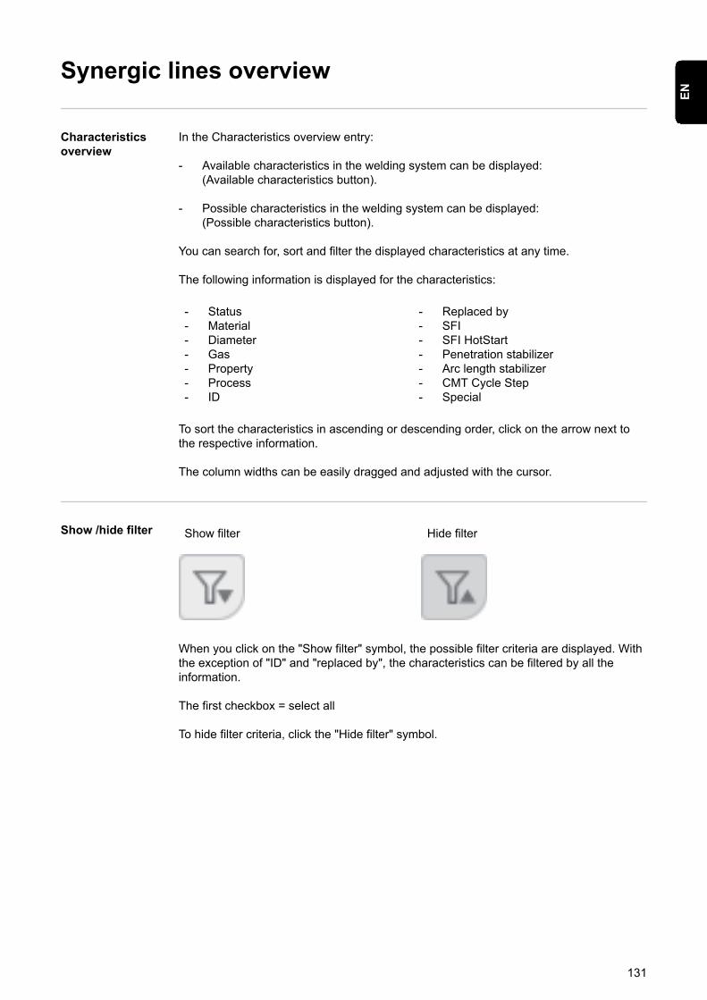
Synergic lines overview
Characteristicsoverview
In the Characteristics overview entry:
- Available characteristics in the welding system can be displayed:(Available characteristics button).
- Possible characteristics in the welding system can be displayed:(Possible characteristics button).
You can search for, sort and filter the displayed characteristics at any time.
The following information is displayed for the characteristics:
- Status- Material- Diameter- Gas- Property- Process- ID
- Replaced by- SFI- SFI HotStart- Penetration stabilizer- Arc length stabilizer- CMT Cycle Step- Special
To sort the characteristics in ascending or descending order, click on the arrow next tothe respective information.
The column widths can be easily dragged and adjusted with the cursor.
Show /hide filter Show filter Hide filter
When you click on the "Show filter" symbol, the possible filter criteria are displayed. Withthe exception of "ID" and "replaced by", the characteristics can be filtered by all theinformation.
The first checkbox = select all
To hide filter criteria, click the "Hide filter" symbol.
131
EN

132

Troubleshooting and maintenance
133

134

The Error menu
The Error menu Notifications, warnings and errors are shown on the display with the corresponding num-ber.
If an error occurs, the Error menu is always in the foreground.
Pressing the right adjusting dial opens the Error menu on "confirm".
Pressing the right adjusting dial a second time confirms the error; the Error menu closes.
By turning the right adjusting dial you can navigate between "Cause", "Solution" and"Hide".If you select "Cause" or "Solution", the corresponding description is displayed when theright adjusting dial is pressed.Turn the left or right adjusting dial to scroll through the displayed text.Pressing the right adjusting dial takes you back to the Error menu.
If you select "Hide", the Error menu closes, however, the error will not be reset. The topright LED flashes on the display to show that there is a hidden, not reset error. The errorcan now be called up as the first entry in the Setup menu.To enter the Setup menu, press the "Welding process" and "Mode" buttons at the sametime.
135
EN
Troubleshooting
General The power sources are equipped with an intelligent safety system, meaning it has beenpossible to dispense with nearly all fuses. After a possible malfunction has beenremedied, the power source can be used again as normal.
Possible malfunctions, warning notices or status codes are shown on the display as plaintext dialogues.
Safety WARNING!
An electric shock can be fatal.Before opening the device▶ Turn the mains switch to the "O" position
▶ Unplug the device from the mains
▶ Ensure the device cannot be switched back on
▶ Using a suitable measuring instrument, check to make sure that electrically chargedcomponents (e.g. capacitors) have been discharged
WARNING!
An inadequate ground conductor connection can cause serious injury or damage.The housing screws provide a suitable ground conductor connection for earthing thehousing.▶ The housing screws must NOT be replaced by any other screws that do not provide
a reliable ground conductor connection.
Power source -troubleshooting
Power source does not functionMains switch is on, but indicators are not lit up
There is a break in the mains lead; the mains plug is not plugged inCheck the mains lead, ensure that the mains plug is plugged in
Mains socket or mains plug faultyReplace faulty parts
Mains fuse protectionChange the mains fuse
Short circuit on the 24 V supply of SpeedNet connection socket or externalsensorUnplug connected components
Cause:Remedy:
Cause:Remedy:
Cause:Remedy:
Cause:
Remedy:
136
No welding currentMains switch is on, overtemperature is displayed
Overload; the duty cycle has been exceededCheck duty cycle
Thermostatic automatic circuit breaker has been trippedWait until the power source automatically comes back on after the end ofthe cooling phase
Limited supply of cooling airEnsure accessibility to cooling air ducts
The fan in the power source is faultyContact After-Sales Service
Cause:Remedy:
Cause:Remedy:
Cause:Remedy:
Cause:Remedy:
No welding currentMains switch is ON and indicators are lit up
Grounding (earthing) connection is incorrectCheck the grounding (earthing) connection for correct polarity
There is a break in the power cable in the welding torchReplace the welding torch
Cause:Remedy:
Cause:Remedy:
Nothing happens when the torch trigger is pressedPower source mains switch is ON and indicators are lit up
Only for welding torches with an external control plug: the control plug is notplugged inPlug in the control plug
Welding torch or welding torch control line is faultyReplace the welding torch
Cause:
Remedy:
Cause:Remedy:
No protective gas shieldAll other functions are OK
Gas cylinder is emptyChange the gas cylinder
The gas pressure regulator is faultyReplace the gas pressure regulator
Gas hose is not fitted or is damagedFit or change the gas hose
Welding torch is faultyChange the welding torch
Gas solenoid valve is faultyContact After-Sales Service
Cause:Remedy:
Cause:Remedy:
Cause:Remedy:
Cause:Remedy:
Cause:Remedy:
137
EN
Poor weld propertiesIncorrect welding parametersCheck the settings
Poor ground earth connectionEnsure good contact to workpiece
Inadequate or no protective gas shieldCheck the pressure regulator, gas hose, gas solenoid valve, torch gas con-nection, etc.
Welding torch is leakingChange the welding torch
Wrong contact tip, or contact tip is worn outReplace the contact tip
Wrong wire alloy or wrong wire diameterCheck the wire electrode that has been inserted
Wrong wire alloy or wrong wire diameterCheck weldability of the base material
The shielding gas is not suitable for this wire alloyUse the correct shielding gas
Cause:Remedy:
Cause:Remedy:
Cause:Remedy:
Cause:Remedy:
Cause:Remedy:
Cause:Remedy:
Cause:Remedy:
Cause:Remedy:
Irregular wire feed speedBraking force has been set too highLoosen the brake
Hole in the contact tip is too narrowUse a suitable contact tip
Faulty inner liner in welding torchCheck the inner liner for kinks, dirt, etc. and replace if necessary
The feed rollers are not suitable for the wire electrode being usedUse suitable feed rollers
Feed rollers have the wrong contact pressureOptimise the contact pressure
Cause:Remedy:
Cause:Remedy:
Cause:Remedy:
Cause:Remedy:
Cause:Remedy:
Wirefeed problemswhen using long hosepacks
Incorrect arrangement of hosepackArrange the hosepack in as straight a line as possible, avoid tight bends
Cause:Remedy:
138

Welding torch becomes very hotThe specification of the welding torch is inadequateObserve the duty cycle and loading limits
Only on water-cooled systems: Inadequate coolant flowCheck coolant level, coolant flow, for coolant contamination, etc. For furtherinformation refer to the cooling unit operating instructions.
Cause:Remedy:
Cause:Remedy:
139
EN
Care, maintenance and disposal
General Under normal operating conditions, the power source requires only a minimum of careand maintenance. However, it is vital to observe some important points to ensure thewelding system remains in a usable condition for many years.
Safety WARNING!
An electric shock can be fatal.Before opening the device▶ Turn the mains switch to the "O" position
▶ Unplug the device from the mains
▶ Ensure the device cannot be switched back on
▶ Using a suitable measuring instrument, check to make sure that electrically chargedcomponents (e.g. capacitors) have been discharged
At every start-up - Check mains plug, mains cable, welding torch, interconnecting hosepack andgrounding (earthing) connection for damage
- Check whether the all-round clearance of 0.5 m (1 ft. 8 in.) is kept to ensure that thecooling air can easily flow and escape.
NOTE!
Air inlets and outlets must never be covered, not even partially.
If necessary If a lot of dust has accumulated:- Remove the fin element on the rear of the housing- Detach the air filter located behind and clean
Every 2 months - If present: clean air filter
Every 6 months CAUTION!
Danger of damage to electronic components.▶ Do not bring the air nozzle too close to electronic components.
- Open the device- Clean out the device interior using dry compressed air at reduced pressure- If a lot of dust has accumulated, clean the cooling air ducts
Updating firm-ware
IMPORTANT! To update the firmware you need a PC or laptop that is connected to thepower source via an Ethernet network.
140

1 Get latest firmware (e.g. from the Fronius Download Center)File format: official_tpsi_x.x.x-xxxx.ffw
2 Establish Ethernet connection between PC/laptop and power source3 Open the power source SmartManager (see page 121)4 Transfer the firmware to the power source (see page 124)
Disposal Dispose of in accordance with the applicable national and local regulations.
141
EN

142

Technical data
143

144
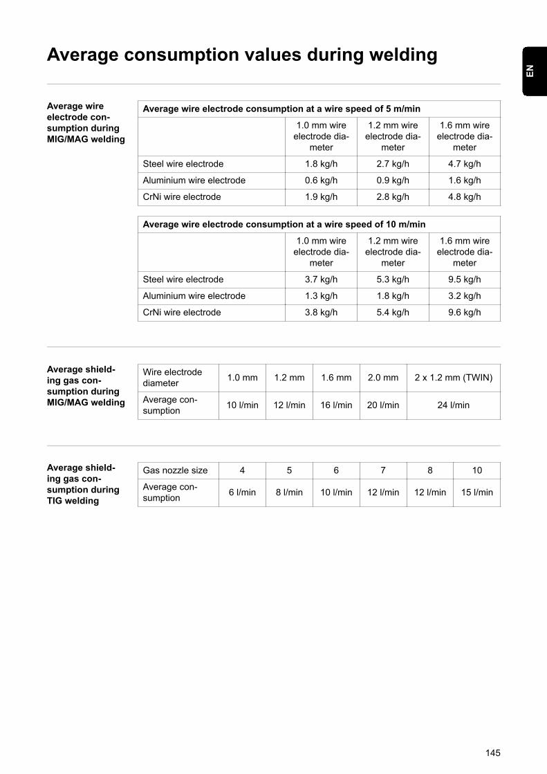
Average consumption values during welding
Average wireelectrode con-sumption duringMIG/MAG welding
Average wire electrode consumption at a wire speed of 5 m/min
1.0 mm wireelectrode dia-
meter
1.2 mm wireelectrode dia-
meter
1.6 mm wireelectrode dia-
meter
Steel wire electrode 1.8 kg/h 2.7 kg/h 4.7 kg/h
Aluminium wire electrode 0.6 kg/h 0.9 kg/h 1.6 kg/h
CrNi wire electrode 1.9 kg/h 2.8 kg/h 4.8 kg/h
Average wire electrode consumption at a wire speed of 10 m/min
1.0 mm wireelectrode dia-
meter
1.2 mm wireelectrode dia-
meter
1.6 mm wireelectrode dia-
meter
Steel wire electrode 3.7 kg/h 5.3 kg/h 9.5 kg/h
Aluminium wire electrode 1.3 kg/h 1.8 kg/h 3.2 kg/h
CrNi wire electrode 3.8 kg/h 5.4 kg/h 9.6 kg/h
Average shield-ing gas con-sumption duringMIG/MAG welding
Wire electrodediameter 1.0 mm 1.2 mm 1.6 mm 2.0 mm 2 x 1.2 mm (TWIN)
Average con-sumption 10 l/min 12 l/min 16 l/min 20 l/min 24 l/min
Average shield-ing gas con-sumption duringTIG welding
Gas nozzle size 4 5 6 7 8 10
Average con-sumption 6 l/min 8 l/min 10 l/min 12 l/min 12 l/min 15 l/min
145
EN
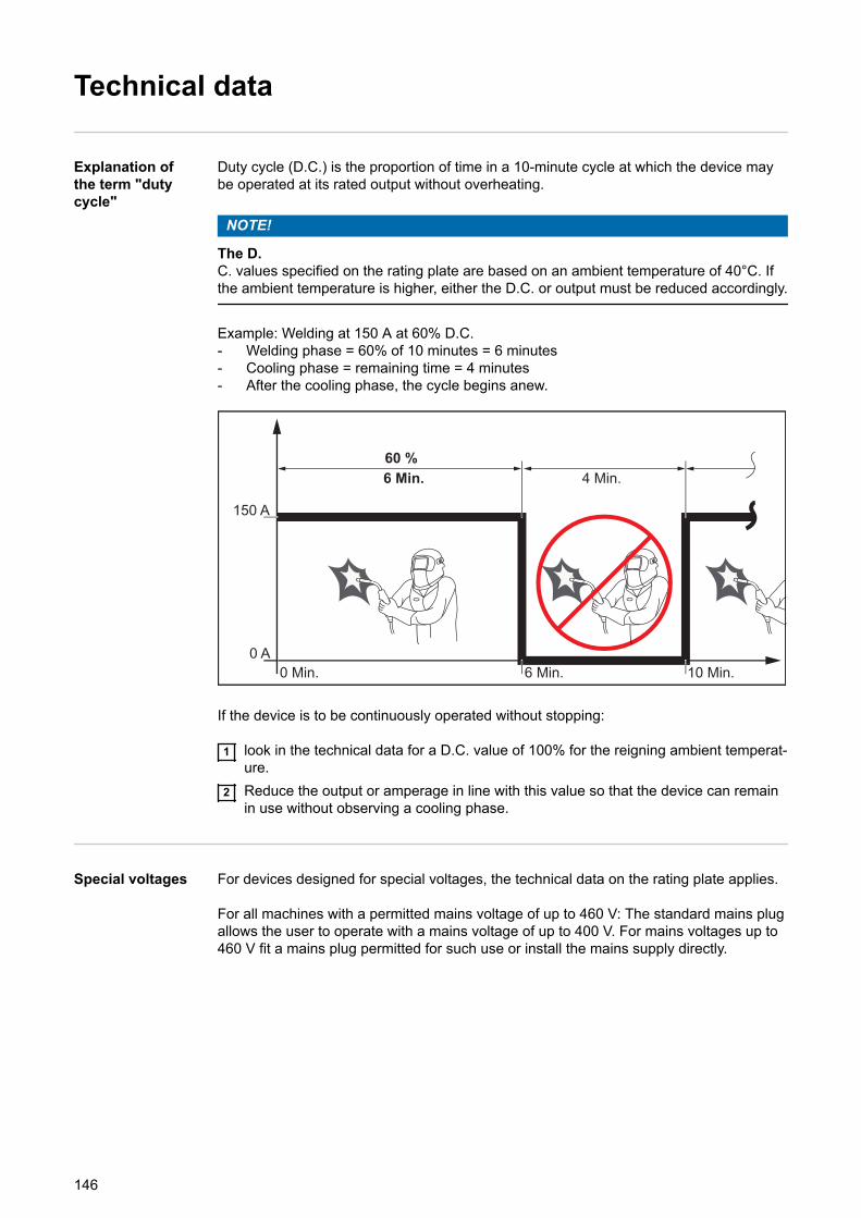
Technical data
Explanation ofthe term "dutycycle"
Duty cycle (D.C.) is the proportion of time in a 10-minute cycle at which the device maybe operated at its rated output without overheating.
NOTE!
The D.C. values specified on the rating plate are based on an ambient temperature of 40°C. Ifthe ambient temperature is higher, either the D.C. or output must be reduced accordingly.
Example: Welding at 150 A at 60% D.C.- Welding phase = 60% of 10 minutes = 6 minutes- Cooling phase = remaining time = 4 minutes- After the cooling phase, the cycle begins anew.
10 Min.6 Min.
150 A
0 Min.0 A
4 Min.6 Min.60 %
If the device is to be continuously operated without stopping:
1 look in the technical data for a D.C. value of 100% for the reigning ambient temperat-ure.
2 Reduce the output or amperage in line with this value so that the device can remainin use without observing a cooling phase.
Special voltages For devices designed for special voltages, the technical data on the rating plate applies.
For all machines with a permitted mains voltage of up to 460 V: The standard mains plugallows the user to operate with a mains voltage of up to 400 V. For mains voltages up to460 V fit a mains plug permitted for such use or install the mains supply directly.
146
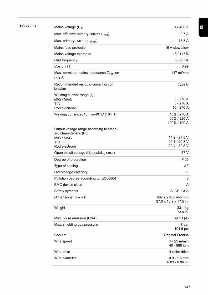
TPS 270i C Mains voltage (U1) 3 x 400 V
Max. effective primary current (I1eff) 9.7 A
Max. primary current (I1max) 15.3 A
Mains fuse protection 16 A slow-blow
Mains voltage tolerance -15 / +15%
Grid frequency 50/60 Hz
Cos phi (1) 0.99
Max. permitted mains impedance Zmax onPCC1)
117 mOhm
Recommended residual-current circuitbreaker
Type B
Welding current range (I2)MIG / MAGTIGRod electrode
3 - 270 A3 - 270 A
10 - 270 A
Welding current at 10 min/40 °C (104 °F) 40% / 270 A60% / 220 A
100% / 190 A
Output voltage range according to stand-ard characteristic (U2)MIG / MAGTIGRod electrode
14.2 - 27.5 V14.1 - 20.8 V20.4 - 30.8 V
Open circuit voltage (U0 peak/U0 r.m.s) 57 V
Degree of protection IP 23
Type of cooling AF
Overvoltage category III
Pollution degree according to IEC60664 3
EMC device class A
Safety symbols S, CE, CSA
Dimensions l x w x h 687 x 276 x 445 mm27.0 x 10.9 x 17.5 in.
Weight 33.1 kg73.0 lb.
Max. noise emission (LWA) 69 dB (A)
Max. shielding gas pressure 7 bar101.5 psi
Coolant Original Fronius
Wire speed 1 - 25 m/min40 - 980 ipm
Wire drive 4-roller drive
Wire diameter 0.8 - 1.6 mm0.03 - 0.06 in.
147
EN
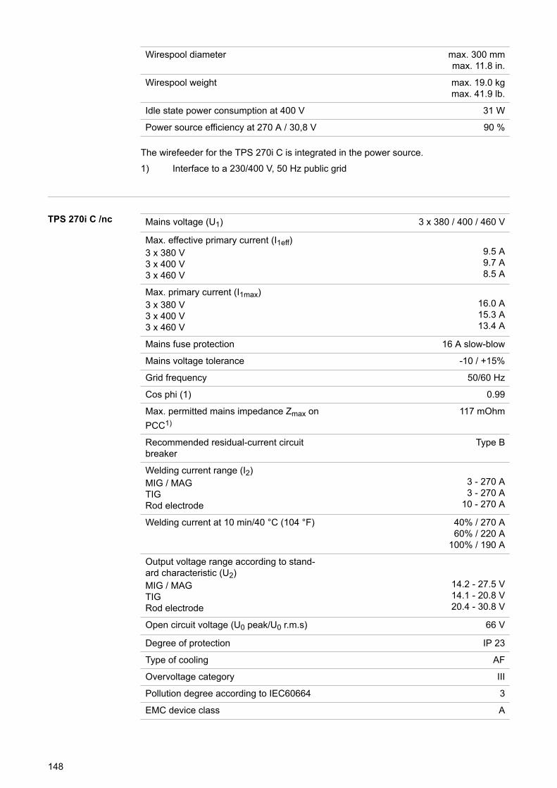
Wirespool diameter max. 300 mmmax. 11.8 in.
Wirespool weight max. 19.0 kgmax. 41.9 lb.
Idle state power consumption at 400 V 31 W
Power source efficiency at 270 A / 30,8 V 90 %
The wirefeeder for the TPS 270i C is integrated in the power source.1) Interface to a 230/400 V, 50 Hz public grid
TPS 270i C /nc Mains voltage (U1) 3 x 380 / 400 / 460 V
Max. effective primary current (I1eff)3 x 380 V3 x 400 V3 x 460 V
9.5 A9.7 A8.5 A
Max. primary current (I1max)3 x 380 V3 x 400 V3 x 460 V
16.0 A15.3 A13.4 A
Mains fuse protection 16 A slow-blow
Mains voltage tolerance -10 / +15%
Grid frequency 50/60 Hz
Cos phi (1) 0.99
Max. permitted mains impedance Zmax onPCC1)
117 mOhm
Recommended residual-current circuitbreaker
Type B
Welding current range (I2)MIG / MAGTIGRod electrode
3 - 270 A3 - 270 A
10 - 270 A
Welding current at 10 min/40 °C (104 °F) 40% / 270 A60% / 220 A
100% / 190 A
Output voltage range according to stand-ard characteristic (U2)MIG / MAGTIGRod electrode
14.2 - 27.5 V14.1 - 20.8 V20.4 - 30.8 V
Open circuit voltage (U0 peak/U0 r.m.s) 66 V
Degree of protection IP 23
Type of cooling AF
Overvoltage category III
Pollution degree according to IEC60664 3
EMC device class A
148
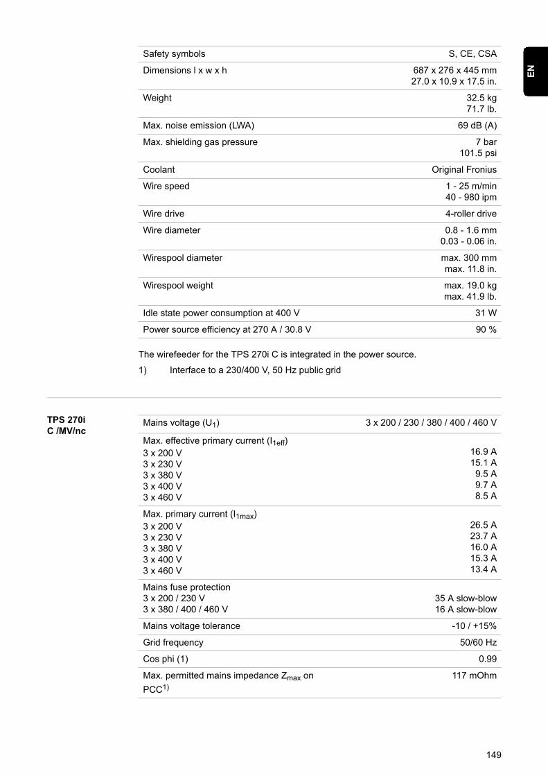
Safety symbols S, CE, CSA
Dimensions l x w x h 687 x 276 x 445 mm27.0 x 10.9 x 17.5 in.
Weight 32.5 kg71.7 lb.
Max. noise emission (LWA) 69 dB (A)
Max. shielding gas pressure 7 bar101.5 psi
Coolant Original Fronius
Wire speed 1 - 25 m/min40 - 980 ipm
Wire drive 4-roller drive
Wire diameter 0.8 - 1.6 mm0.03 - 0.06 in.
Wirespool diameter max. 300 mmmax. 11.8 in.
Wirespool weight max. 19.0 kgmax. 41.9 lb.
Idle state power consumption at 400 V 31 W
Power source efficiency at 270 A / 30.8 V 90 %
The wirefeeder for the TPS 270i C is integrated in the power source.1) Interface to a 230/400 V, 50 Hz public grid
TPS 270iC /MV/nc
Mains voltage (U1) 3 x 200 / 230 / 380 / 400 / 460 V
Max. effective primary current (I1eff)3 x 200 V3 x 230 V3 x 380 V3 x 400 V3 x 460 V
16.9 A15.1 A9.5 A9.7 A8.5 A
Max. primary current (I1max)3 x 200 V3 x 230 V3 x 380 V3 x 400 V3 x 460 V
26.5 A23.7 A16.0 A15.3 A13.4 A
Mains fuse protection3 x 200 / 230 V3 x 380 / 400 / 460 V
35 A slow-blow16 A slow-blow
Mains voltage tolerance -10 / +15%
Grid frequency 50/60 Hz
Cos phi (1) 0.99
Max. permitted mains impedance Zmax onPCC1)
117 mOhm
149
EN
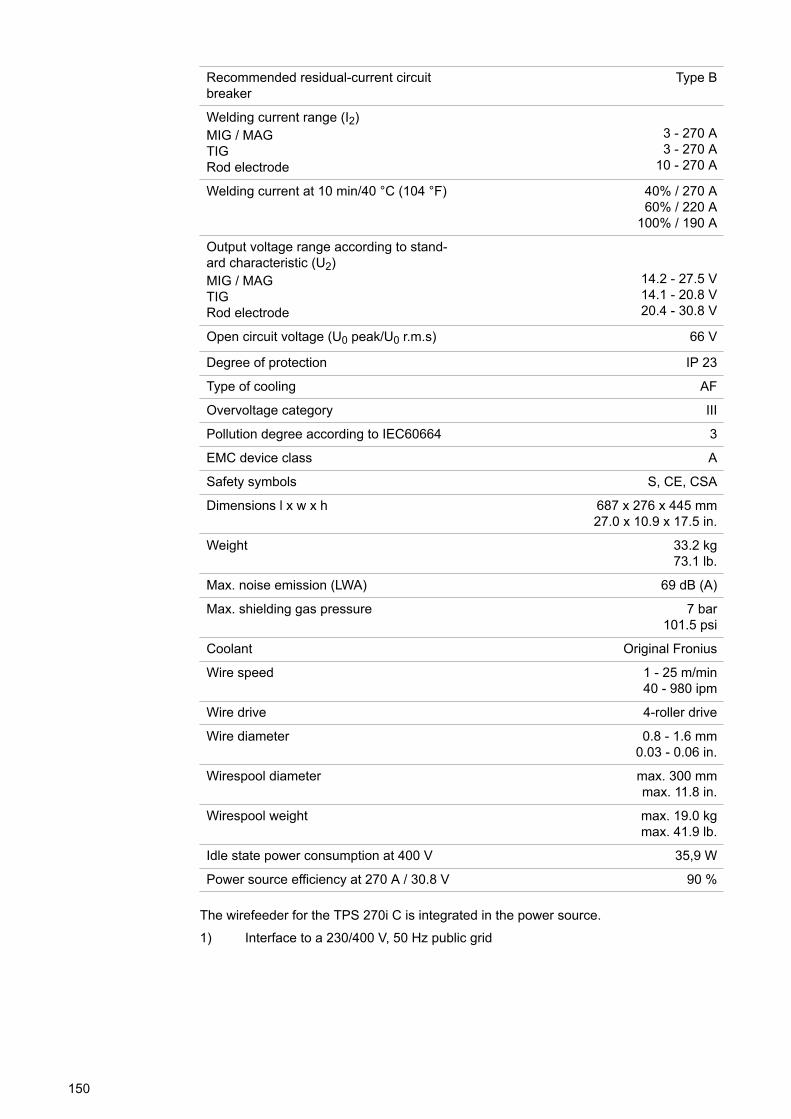
Recommended residual-current circuitbreaker
Type B
Welding current range (I2)MIG / MAGTIGRod electrode
3 - 270 A3 - 270 A
10 - 270 A
Welding current at 10 min/40 °C (104 °F) 40% / 270 A60% / 220 A
100% / 190 A
Output voltage range according to stand-ard characteristic (U2)MIG / MAGTIGRod electrode
14.2 - 27.5 V14.1 - 20.8 V20.4 - 30.8 V
Open circuit voltage (U0 peak/U0 r.m.s) 66 V
Degree of protection IP 23
Type of cooling AF
Overvoltage category III
Pollution degree according to IEC60664 3
EMC device class A
Safety symbols S, CE, CSA
Dimensions l x w x h 687 x 276 x 445 mm27.0 x 10.9 x 17.5 in.
Weight 33.2 kg73.1 lb.
Max. noise emission (LWA) 69 dB (A)
Max. shielding gas pressure 7 bar101.5 psi
Coolant Original Fronius
Wire speed 1 - 25 m/min40 - 980 ipm
Wire drive 4-roller drive
Wire diameter 0.8 - 1.6 mm0.03 - 0.06 in.
Wirespool diameter max. 300 mmmax. 11.8 in.
Wirespool weight max. 19.0 kgmax. 41.9 lb.
Idle state power consumption at 400 V 35,9 W
Power source efficiency at 270 A / 30.8 V 90 %
The wirefeeder for the TPS 270i C is integrated in the power source.1) Interface to a 230/400 V, 50 Hz public grid
150
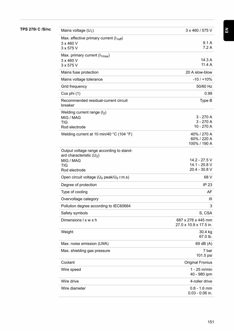
TPS 270i C /S/nc Mains voltage (U1) 3 x 460 / 575 V
Max. effective primary current (I1eff)3 x 460 V3 x 575 V
9.1 A7.2 A
Max. primary current (I1max)3 x 460 V3 x 575 V
14.3 A11.4 A
Mains fuse protection 20 A slow-blow
Mains voltage tolerance -10 / +10%
Grid frequency 50/60 Hz
Cos phi (1) 0.99
Recommended residual-current circuitbreaker
Type B
Welding current range (I2)MIG / MAGTIGRod electrode
3 - 270 A3 - 270 A
10 - 270 A
Welding current at 10 min/40 °C (104 °F) 40% / 270 A60% / 220 A
100% / 190 A
Output voltage range according to stand-ard characteristic (U2)MIG / MAGTIGRod electrode
14.2 - 27.5 V14.1 - 20.8 V20.4 - 30.8 V
Open circuit voltage (U0 peak/U0 r.m.s) 68 V
Degree of protection IP 23
Type of cooling AF
Overvoltage category III
Pollution degree according to IEC60664 3
Safety symbols S, CSA
Dimensions l x w x h 687 x 276 x 445 mm27.0 x 10.9 x 17.5 in.
Weight 30.4 kg67.0 lb.
Max. noise emission (LWA) 69 dB (A)
Max. shielding gas pressure 7 bar101.5 psi
Coolant Original Fronius
Wire speed 1 - 25 m/min40 - 980 ipm
Wire drive 4-roller drive
Wire diameter 0.8 - 1.6 mm0.03 - 0.06 in.
151
EN

Wirespool diameter max. 300 mmmax. 11.8 in.
Wirespool weight max. 19.0 kg / max. 41.9 lb.
The wirefeeder for the TPS 270i C is integrated in the power source.
Overview withcritical rawmaterials, year ofproduction of thedevice
Overview with critical raw materials:An overview of which critical raw materials are contained in this device can be found atthe following Internet address.www.fronius.com/en/about-fronius/sustainability.
To calculate the year of production of the device:- Each device is provided with a serial number- The serial number consists of 8 digits - for example 28020099- The first two digits give the number from which the year of production of the device
can be calculated- This figure minus 11 gives the year of production
• For example: Serial number = 28020065, calculation of the year of production =28 - 11 = 17, year of production = 2017
152

153
EN

154

155
EN

FRONIUS INTERNATIONAL GMBHFroniusstraße 1
A-4643 PettenbachAUSTRIA
Under www.fronius.com/contact you will find the addressesof all Fronius Sales & Service Partners and locations.
Related Documents