TP208-13 APPENDIX A PART 572E (50 th Male) DUMMY PERFORMANCE CALIBRATION TEST PROCEDURE

Welcome message from author
This document is posted to help you gain knowledge. Please leave a comment to let me know what you think about it! Share it to your friends and learn new things together.
Transcript

TP208-13 APPENDIX A
PART 572E (50th Male) DUMMY PERFORMANCE CALIBRATION TEST PROCEDURE

TP208-13 APPENDIX A
PART 572 SUBPART E DUMMY PERFORMANCE CALIBRATION TEST PROCEDURE
TABLE OF CONTENTS PAGE
1. PURPOSE AND APPLICATION ...............................................................................................A-1 2. GENERAL REQUIREMENTS ................................................................................................... A-1 3. SECURITY ........................................................................................................................... A-3 4. GOOD HOUSEKEEPING ......................................................................................................... A-3 5. TEST SCHEDULING AND MONITORING................................................................................ A-3 6. TEST DATA DISPOSITION ...................................................................................................... A-3 7. GOVERNMENT FURNISHED PROPERTY (GFP) ................................................................... A-4 8. CALIBRATION AND TEST INSTRUMENTATION.................................................................... A-4 9. PHOTOGRAPHY ...................................................................................................................... A-5 10. DEFINITIONS ........................................................................................................................... A-5 11. PRETEST REQUIREMENTS.................................................................................................... A-6 11.1 TRANSDUCER REQUIREMENTS.................................................................... A-6 11.2 OTHER TRANSDUCER CONDITIONS............................................................. A-7
11.3 THORAX IMPACTOR PROBE .......................................................................... A-8 11.4 KNEE IMPACTOR PROBE ............................................................................... A-8 11.5 GENERAL TEST CONDITIONS...................................................................... A-11
12. CALIBRATION TEST EXECUTION ........................................................................................ A-11 13. POST TEST REQUIREMENTS .............................................................................................. A-11 14. REPORTS ......................................................................................................................... A-11 14.1 APPARENT TEST FAILURE........................................................................... A-11 14.2 FINAL PERFORMANCE CALIBRATION REPORTS ...................................... A-12 15. DATA SHEETS ....................................................................................................................... A-15 A1 DUMMY DAMAGE CHECKLIST ..................................................................... A-15 A2 EXTERNAL MEASUREMENTS ...................................................................... A-17 A3 HEAD DROP TEST ......................................................................................... A-24 A4 NECK FLEXION TEST .................................................................................... A-28 A5 NECK EXTENSION TEST............................................................................... A-31 A6 THORAX IMPACT TEST................................................................................. A-38 A7 LEFT KNEE IMPACT TEST ............................................................................ A-43 A8 RIGHT KNEE IMPACT TEST.......................................................................... A-45 A9 HIP JOINT-FEMUR FLEXION TEST............................................................... A-48 A10 INSTRUMENTATION CALIBRATION INFORMATION ................................... A-54

TP208-13
ILLUSTRATIONS PAGE
1A. PART 572E TEST DUMMY................................................................................................. A-2 2A. SIGN CONVENTION........................................................................................................... A-9 3A. EXTERNAL DIMENSIONS SPECIFICATIONS................................................................. A-21 4A. EXTERNAL DIMENSIONS TEST SETUP -- FRONT VIEW ............................................. A-22 5A. EXTERNAL DIMENSIONS TEST SETUP -- SIDE VIEW ................................................. A-23 6A. HEAD DROP TEST SPECIFICATION .............................................................................. A-26 7A. HEAD DROP TEST SETUP.............................................................................................. A-27 8A. NECK PENDULUM SPECIFICATIONS ............................................................................ A-34 9A. NECK FLEXION TESTSETUP SPECIFICATIONS........................................................... A-35 10A. NECK EXTENSION TEST SETUP SPECIFICATIONS .................................................... A-36 11A. ROTATION TRANSDUCER ASSEMBLY ......................................................................... A-37 12A. THORAX IMPACT TEST SPECIFICATIONS.................................................................... A-41 13A. THORAX HYSTERESIS.................................................................................................... A-42 14A. KNEE IMPACT SETUP TEST SPECIFICATIONS............................................................ A-47 15A. PELVIC BONE STABILIZER INSERT .............................................................................. A-50 16A. PELVIS UPPER SUPPORT DEVICE................................................................................ A-50 17A. HIP JOINT TEST FIXTURE ASSEMBLY .......................................................................... A-51 18A. HIP JOINT TEST FIXTURE AND TORSO ASSEMBLY, FRONT VIEW ........................... A-52 19A. HIP JOINT TEST FIXTURE AND TORSO ASSEMBLY, SIDE VIEW ............................... A-53
TABLES 1A. SIGN CONVENTION FOR HYBRID III TRANSDUCER OUTPUTS ................................. A-10

TP208-13 A 1
1. PURPOSE AND APPLICATION
The purpose of this laboratory procedure is to provide dummy users (independent testing laboratories under contract with the Office of Vehicle Safety Compliance) with standard test procedures for performing receiving-inspection and performance calibration tests on the Part 572, Subpart E dummy so that repetitive and correlative test results can be obtained. The following tests have been developed to establish a uniform calibration procedure for all users as the means of verifying the performance of the dummy.
A. EXTERNAL DIMENSIONS B. HEAD DROP TEST (572.32) C. NECK FLEXION TEST (572.33) D. NECK EXTENSION TEST (572.33) E. THORAX IMPACT TEST (572.34) F. FEMUR IMPACT TESTS (572.35) G. HIP JOINT-FEMUR FLEXION (572.35)
This laboratory procedure for the calibration of Part 572, Subpart E dummies must be used by National Highway Traffic Safety Administration (NHTSA) contract laboratories performing FMVSS 208 testing for the Office of Vehicle Safety Compliance (OVSC).
2. GENERAL REQUIREMENTS
The Code of Federal Regulations (49CFR), Parts 571 and 572, was amended to adopt the Hybrid III, 50th Percentile Dummy as the means of determining a vehicle's conformance to the performance requirements of FMVSS 208. Each Part 572, Subpart E dummy used in a compliance test must meet the specifications and performance criteria of Part 572 before and after each vehicle test in order to be an acceptable compliance test tool.
The Part 572, Subpart E Hybrid III 50th Percentile Dummy consists of components and assemblies specified in the drawing and specifications package which is available from Reprographics Technologies, 9000 Virginia Manor, Beltsville, MD 20705, telephone - (301) 419-5069.
TP208-13 A 2
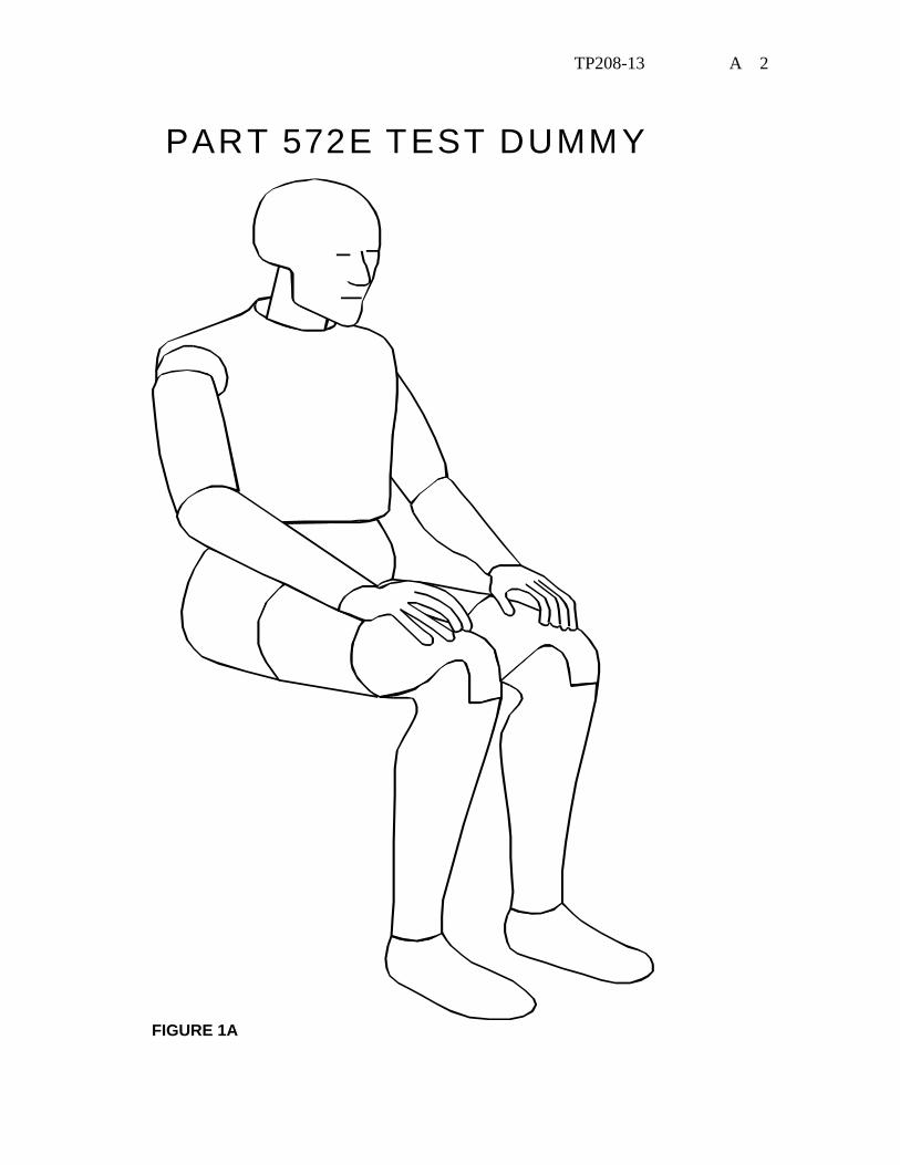
PART 572E TEST DUMMY
FIGURE 1A

TP208-13 A 3
3. SECURITY All NHTSA Part 572, Subpart E test dummies delivered to the contract
laboratory as Government Furnished Property (GFP) will be stored in a safe and secure area such as the dummy calibration laboratory. The contractor is financially responsible for any acts of theft and/or vandalism which occur during the storage of GFP. Any security problems shall be reported by telephone to the Industrial Property Manager (IPM), Office of Contracts and Procurement, within two working days after the incident. A letter containing specific details of the security problem will be sent to the IPM (with copy to the COTR) within 48 hours.
The contractor is responsible for maintaining the NHTSA test dummies in good working order, and shall protect and segregate the data that evolves from conducting Part 572, Subpart E dummy calibration tests before and after each vehicle crash usage.
No Information concerning the Part 572E dummy calibration data shall be released to anyone except the COTR, unless specifically authorized by the COTR or the COTR's Branch or Division Chief.
NOTE: No Individuals, other than contractor personnel directly involved in the dummy calibration test program, shall be allowed to witness dummy calibration tests unless specifically authorized by the COTR.
4. GOOD HOUSEKEEPING
Contractors shall maintain the entire dummy calibration laboratory, test fixtures, and instrumentation in a neat, clean, and painted condition with test instruments arranged in an orderly manner consistent with good test laboratory housekeeping practices.
5. TEST SCHEDULING AND MONITORING
The Part 572, Subpart E dummies are being calibrated as test tools to be used in a vehicle test to determine compliance with the requirements of FMVSS 208. The schedule for these performance calibration tests must be correlated with that of the vehicle tests. All testing shall be coordinated to allow monitoring by the COTR.
6. TEST DATA DISPOSITION
The contractor shall make all dummy calibration data available to the COTR for review and analysis as required. All calibration test data for each particular Part 572, Subpart E dummy will be sent to the COTR with each test report.

TP208-13 A 4
All backup data sheets, strip charts, recordings, plots, technicians notes, etc. shall be either sent to the COTR or destroyed at the conclusion of each delivery order, purchase order, etc.
7. GOVERNMENT FURNISHED PROPERTY (GFP)
P572 test dummies will be furnished to the contract laboratory by the OVSC. The dummies shall be stored in an upright sitting position with the weight supported by the internal structure of the pelvis. The dummies head shall be held upright without supporting the weight of the dummy by using an eyebolt that can be secured in the top of the head. These dummies shall be stored in a secured room that is kept between 55ºF and 85ºF. The contractor will check dummy components for damage after each crash test and complete a dummy damage checklist (Section 15, Data Sheets) that will be included with the posttest dummy calibration. The COTR will be kept informed of the dummies condition in order that replacement parts can be provided. The contractor shall calibrate the dummies before and verify the calibration after every crash test.
8. CALIBRATION AND TEST INSTRUMENTATION
Before the contractor initiates the dummy performance calibration test program, a test instrumentation calibration system must be implemented and maintained in accordance with established calibration practices. The calibration system shall be set up and maintained as follows:
A. Standards for calibrating the measuring and test equipment shall be
stored and used under appropriate environmental conditions to assure their accuracy and stability.
B. All measuring instruments and standards shall be calibrated by the
contractor, or a commercial facility, against a higher order standard at periodic intervals not exceeding 12 months for instruments and 12 months for calibration standards. Records, showing the calibration traceability to the National Institute of Standards and Technology (NIST), shall be maintained for all measuring and test equipment.
C. All measuring and test equipment and measuring standards shall
be labeled with the following information: (1) Date of calibration (2) Date of next scheduled calibration

TP208-13 A 5
(3) Name of the technician who calibrated the equipment D. The contractor shall provide a written calibration procedure that
includes, as a minimum, the following information for all measurement and test equipment.
(1) Type of equipment, manufacturer, model number, etc. (2) Measurement range (3) Accuracy (4) Calibration interval (5) Type of standard used to calibrate the equipment (calibration
traceability of the standard must be evident)
(6) The actual procedures and forms used to perform calibrations.
E. The contractor shall keep records of calibrations for all test
instrumentation in a manner that assures the maintenance of established calibration schedules. All such records shall be readily available for inspection when requested by the COTR. The calibration system will need the written acceptance of the COTR before testing begins.
F. Test equipment shall receive a calibration check immediately prior
to and after each test. This check shall be recorded by the test technician(s) and submitted with the final report.
G. Anthropomorphic test devices shall be calibrated before and after
each test. These calibrations shall be submitted with the final report.
9. PHOTOGRAPHIC DOCUMENTATION
Provide still photographs (8 x 10 inch glossy color prints properly focused for clear images) of posttest calibration damage resulting from the vehicle crash test.
10. DEFINITIONS NONE
TP208-13 A 6
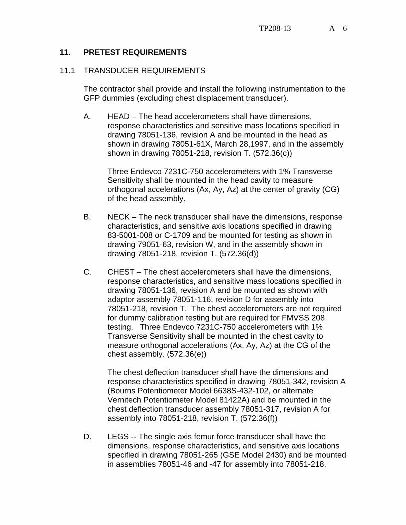
11. PRETEST REQUIREMENTS 11.1 TRANSDUCER REQUIREMENTS
The contractor shall provide and install the following instrumentation to the GFP dummies (excluding chest displacement transducer).
A. HEAD – The head accelerometers shall have dimensions,
response characteristics and sensitive mass locations specified in drawing 78051-136, revision A and be mounted in the head as shown in drawing 78051-61X, March 28,1997, and in the assembly shown in drawing 78051-218, revision T. (572.36(c))
Three Endevco 7231C-750 accelerometers with 1% Transverse
Sensitivity shall be mounted in the head cavity to measure orthogonal accelerations (Ax, Ay, Az) at the center of gravity (CG) of the head assembly.
B. NECK – The neck transducer shall have the dimensions, response
characteristics, and sensitive axis locations specified in drawing 83-5001-008 or C-1709 and be mounted for testing as shown in drawing 79051-63, revision W, and in the assembly shown in drawing 78051-218, revision T. (572.36(d))
C. CHEST – The chest accelerometers shall have the dimensions,
response characteristics, and sensitive mass locations specified in drawing 78051-136, revision A and be mounted as shown with adaptor assembly 78051-116, revision D for assembly into 78051-218, revision T. The chest accelerometers are not required for dummy calibration testing but are required for FMVSS 208 testing. Three Endevco 7231C-750 accelerometers with 1% Transverse Sensitivity shall be mounted in the chest cavity to measure orthogonal accelerations (Ax, Ay, Az) at the CG of the chest assembly. (572.36(e))
The chest deflection transducer shall have the dimensions and
response characteristics specified in drawing 78051-342, revision A (Bourns Potentiometer Model 6638S-432-102, or alternate Vernitech Potentiometer Model 81422A) and be mounted in the chest deflection transducer assembly 78051-317, revision A for assembly into 78051-218, revision T. (572.36(f))
D. LEGS -- The single axis femur force transducer shall have the
dimensions, response characteristics, and sensitive axis locations specified in drawing 78051-265 (GSE Model 2430) and be mounted in assemblies 78051-46 and -47 for assembly into 78051-218,

TP208-13 A 7
revision T. The femur transducers are not required for calibration of the dummy but are required for FMVSS 208 testing. (572.36(h))
E. TEST FIXTURE – The neck pendulum, thorax and knee probe
accelerometers shall have the dimensions and characteristics of Endevco Model 7231C. (572.36(g))
11.2 OTHER TRANSDUCER CONDITIONS
A. TRANSDUCER MOUNTS The mountings for sensing devices shall have no resonance frequency within range of 3 times the frequency range of the applicable channel class. (572.36(k)
B. The sign convention for outputs of transducers mounted within the
Hybrid III that measure head and chest accelerations, chest deflection and femur loads are located in Figure 2A. For other transducers see SAE J1733DEC94 (Appendix F). (572.36(j) & (572.31(a)(5))
C. TRANSDUCER OUTPUT FILTERING
The outputs of acceleration and force-sensing devices installed in the dummy and in the test apparatus specified by this part are recorded with individual data channels. Each data channel will be comprised of a sensor, signal conditioner, data acquisition device, and all interconnecting cables, and must conform to the requirements of SAE Recommended Practice J211/1 MAR95, "Instrumentation for Impact Test," with channel classes as follows: (572.36(i))
(1) Head acceleration – Class 1000 (572.36(i)(1))
(2) Neck force – Class 1000 (572.36(i)(2)) (For calculation of the moment about the occipital condyle, use filter class 600 for the neck force)
(3) Neck moments – Class 600 (572.36(i)(3)) (4) Neck pendulum acceleration – Class 60 (572.36(i)(4)) (5) Neck rotation transducers - Class 60 (6) Thorax and thorax pendulum acceleration – Class 180
(572.36(i)(5)) (7) Thorax deflection - Class 180 (572.36(i)(6)) (8) Knee pendulum acceleration – Class 600(572.36(i)(7)) (9) Femur force – Class 600 (572.36(i)(8)) (10) Hip flexion – Class 60
All filter classes should be of the "phaseless" type to be compatible with the "time" dependent test parameters.
TP208-13 A 8
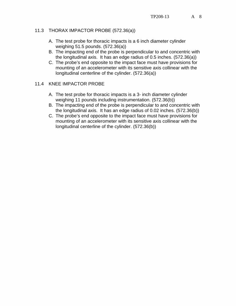
11.3 THORAX IMPACTOR PROBE (572.36(a))
A. The test probe for thoracic impacts is a 6 inch diameter cylinder weighing 51.5 pounds. (572.36(a))
B. The impacting end of the probe is perpendicular to and concentric with the longitudinal axis. It has an edge radius of 0.5 inches. (572.36(a))
C. The probe’s end opposite to the impact face must have provisions for mounting of an accelerometer with its sensitive axis collinear with the longitudinal centerline of the cylinder. (572.36(a))
11.4 KNEE IMPACTOR PROBE
A. The test probe for thoracic impacts is a 3- inch diameter cylinder weighing 11 pounds including instrumentation. (572.36(b))
B. The impacting end of the probe is perpendicular to and concentric with the longitudinal axis. It has an edge radius of 0.02 inches. (572.36(b))
C. The probe’s end opposite to the impact face must have provisions for mounting of an accelerometer with its sensitive axis collinear with the longitudinal centerline of the cylinder. (572.36(b))

TP208-13 A 9
TABLE 1A
SIGN CONVENTIONS FORPART 572 SUBPART E TEST DUMMIES
POSSIBLE AR
-AZ
-AX
-AY+AX
+AY
+AZ
C.G.TARGET
LEFT FEMURLOAD CELL(FL )
RIGHT FEMURLOAD CELL(FR )
-AX-AZ+AY
-AY+AX
+AZ
3 UNIAXIAL ACCELEROMETERSLOCATED AT THE C.G. OF THEHEAD ASSEMBLY
3 UNIAXIAL ACCELEROMETERSLOCATED AT THE C.G. OF THECHEST ASSEMBLY
+ FR
+ FL (Tension)
+ FR
+ FL (Tension)
AR = A2X + A2
Y + A2Z Gs
FIGURE 2A

TP208-13 A 10
SIGN CONVENTION FOR HYBRID III TRANSDUCER OUTPUTS
BODY SEGMENT — MEASURED FORCE
POSITIVE OUTPUT DIRECTION
NECK FX SHEAR FY SHEAR FZ AXIAL MX MOMENT (ROLL) MY MOMENT (PITCH) MZ MOMENT (YAW)
HEAD REARWARD OR CHEST FORWARD HEAD LEFTWARD, CHEST RIGHTWARD HEAD UPWARD, CHEST DOWNWARD LEFT EAR TOWARD LEFT SHOULDER CHIN TOWARD STERNUM CHIN TOWARD LEFT SHOULDER
FEMUR FX SHEAR FY SHEAR FZ AXIAL MX MOMENT (ROLL) MY MOMENT (PITCH) MZ MOMENT (YAW)
KNEE UPWARD, UPPER FEMUR DOWNWARD KNEE RIGHTWARD, UPPER FEMUR LEFTWARD KNEE FORWARD (TENSION), PELVIS REARWARD KNEE LEFTWARD, HOLD UPPER FEMUR IN PLACE KNEE UPWARD, HOLD UPPER FEMUR IN PLACE KNEE ROTATED CCW WHEN FACING FRONT OF DUMMY
KNEE CLEVIS - FZ AXIAL TIBIA DOWNWARD (TENSION), FEMUR UPWARD
UPPER TIBIA MX MOMENT MY MOMENT
ANKLE LEFTWARD, HOLD KNEE IN PLACE ANKLE FORWARD, BOTTOM OF KNEE CLEVIS REARWARD
LOWER TIBIA FX SHEAR FY SHEAR FZ AXIAL MX MOMENT MY MOMENT
ANKLE FORWARD, KNEE REARWARD ANKLE RIGHTWARD, KNEE LEFTWARD ANKLE DOWNWARD (TENSION), KNEE UPWARD ANKLE LEFTWARD, HOLD KNEE IN PLACE ANKLE FORWARD, BOTTOM OF KNEE CLEVIS REARWARD
CHEST DISPLACEMENT CHEST COMPRESSED - NEGATIVE
KNEE SHEAR DISPLACEMENT PUSH ON FRONT OF TIBIA - NEGATIVE
NOTE: DIRECTIONS ARE DEFINED IN RELATION TO A SEATED DUMMY
TP208-13 A 11
11. PRETEST REQUIREMENTS....Continued 11.5 GENERAL TEST CONDITIONS A. Surfaces of dummy components are not painted unless otherwise
specified. (572.36(n)) B. Dummy performance tests of the same component, segment,
assembly, or fully assembled dummy are separated in time by a period of not less than 30 minutes unless otherwise specified. (572.36(m))
C. Dummy performance tests are conducted at any temperature from
69ºF to 72ºF unless otherwise specified and at any relative humidity from 10% to 70% after exposure of the dummy to these conditions for a period of not less than 4 hours.
D. Dummy limb joints are set at 1 g, barely restraining the weight of
the limb when it is extended horizontally. The force required to move a limb segment does not exceed 2 gs throughout the range of limb motion. (572.36(l))
E. Dummies will be clothed for the thorax calibration tests with the
exception of the shoes being removed. 12. CALIBRATION TEST EXECUTION Complete the Data Sheets in section 15. 13. POST TEST REQUIREMENTS
The contractor shall verify all instrumentation and check data sheets and photographs. Make sure data is recorded in all data blocks on every performance calibration test data sheet.
14. REPORTS 14.1 APPARENT NONCONFORMANCE
During the post test calibration, any indication of apparent nonconformance to the requirements of Regulation P572 shall be communicated by telephone to the COTR within 24 hours with written notification mailed within 48 hours (Saturdays and Sundays excluded). Written notification shall be submitted with a copy of the particular test data sheet(s) and preliminary data plot(s).
TP208-13 A 12
In the event of an apparent nonconformance, a post test calibration check of some critically sensitive test equipment and instrumentation may be required for verification of accuracy. The necessity for the calibration shall be at the COTR's discretion and shall be performed without additional costs to the OVSC.
14.2 FINAL PERFORMANCE CALIBRATION REPORTS 14.2.1 COPIES
A report containing the pre-test calibration and post test calibration verification data for each Part 572,Subpart E dummy used in the vehicle compliance test shall be submitted with the FMVSS 208 final test report for the vehicle tested.
Contractors are required to PROOF READ all Final Test Reports before submittal to the COTR. The OVSC will not act as a report quality control office for contractors. Reports containing a significant number of errors will be returned to the contractor for correction, and a "hold" will be placed on invoice payment for the particular test.
14.2.2 REQUIREMENTS
Performance calibration report Table of Contents shall include the following:
A. Section 1 — Purpose of Calibration Test B. Section 2 — Calibration Data Summary C. Section 3 — Test Data D. Section 4 — Test Equipment List and Calibration Information E. Section 5 — Photographs (if applicable)
The test data for each dummy will be presented in separate sections. Each section shall contain a title page, test results summary and the test data. The title page shall include the dummy's serial number and the manufacturer's name. It will also indicate whether the calibration data is pre or post test. The test results sheets will provide a summary of each test and describe any damage, failures and/or corrective action taken. The test data shall include the pass/fail data sheets, the time histories for each data channel used to determine the pass or fail status, and instrumentation calibration data sheets.

TP208-13 A 13
14.2.3 FIRST PAGE
FRONT COVER
A heavy paperback cover (or transparency) shall be provided for the protection of the final report. The information required on the cover is as follows:
A. Final Report Title And Subtitle such as
DUMMY PERFORMANCE CALIBRATION IN SUPPORT OF
VEHICLE SAFETY COMPLIANCE TESTING FOR OCCUPANT CRASH PROTECTION
B. Contractor's Name and Address such as
ABC TESTING LABORATORIES, INC.
405 Main Street Detroit, Michigan 48070
NOTE: DOT SYMBOL WILL BE PLACED BETWEEN ITEMS B AND C C. Date of Final Performance Calibration Report completion D. The sponsoring agency's name and address as follows
U. S. DEPARTMENT OF TRANSPORTATION National Highway Traffic Safety Administration
Enforcement Office of Vehicle Safety Compliance
400 Seventh Street, SW Room 6111 (NVS-220) Washington, DC 20590

TP208-13 A 14
15. Data Sheets DATA SHEET A1
DUMMY DAMAGE CHECKLIST (50th Male) Dummy Serial Number _____________ Test Date _____________ Technician ___________________________ This check sheet is completed as part of the post test calibration verification. __ Perform general cleaning.
Dummy Item Inspect for Comments Damaged OK Outer skin Gashes, rips, cracks Head Ballast secure General appearance Neck Broken or cracked
rubber
Upper neck bracket firmly attached to the lower neck bracket
Looseness at the condyle joint
Nodding blocks cracked or out of position
Spine Broken or cracks in rubber.
Ribs Broken or bent ribs Broken or bent rib
supports
Damping material separated or cracked
Rubber bumpers in place
Chest Displacement Assembly
Bent shaft
Slider arm riding in track
Transducer leads
Torn cables

TP208-13 A 15
Dummy Item Inspect for Comments Damaged OK Accelerometer Mountings
Head mounting secure
Chest mounting secure
Knees Skin condition Insert (do not
remove)
Casting Limbs Normal movement
and adjustment
Knee Sliders Wires intact Rubber returned to
“at rest” position
Pelvis Broken Other
If upon visual examination, damage is apparent in any of these areas, the appropriate engineer or engineering technician is to be consulted for a decision on repair or replacement of parts. Repair or Replacement approved by: _____________________________ ______________ Signature Date Describe the repair or replacement of parts: Checked by __________________________________ _______________ Signature Date
TP208-13 A 16
DATA SHEET A2 EXTERNAL MEASUREMENTS (50th Male) (Procedures for Disassembly, Inspection
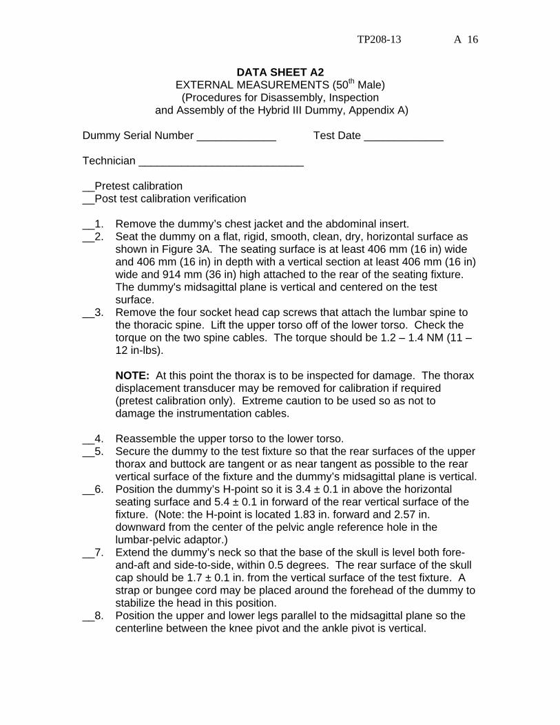
and Assembly of the Hybrid III Dummy, Appendix A) Dummy Serial Number _____________ Test Date _____________ Technician ___________________________ __Pretest calibration __Post test calibration verification __1. Remove the dummy’s chest jacket and the abdominal insert. __2. Seat the dummy on a flat, rigid, smooth, clean, dry, horizontal surface as
shown in Figure 3A. The seating surface is at least 406 mm (16 in) wide and 406 mm (16 in) in depth with a vertical section at least 406 mm (16 in) wide and 914 mm (36 in) high attached to the rear of the seating fixture. The dummy's midsagittal plane is vertical and centered on the test surface.
__3. Remove the four socket head cap screws that attach the lumbar spine to the thoracic spine. Lift the upper torso off of the lower torso. Check the torque on the two spine cables. The torque should be 1.2 – 1.4 NM (11 – 12 in-lbs).
NOTE: At this point the thorax is to be inspected for damage. The thorax displacement transducer may be removed for calibration if required (pretest calibration only). Extreme caution to be used so as not to damage the instrumentation cables.
__4. Reassemble the upper torso to the lower torso. __5. Secure the dummy to the test fixture so that the rear surfaces of the upper
thorax and buttock are tangent or as near tangent as possible to the rear vertical surface of the fixture and the dummy’s midsagittal plane is vertical.
__6. Position the dummy’s H-point so it is 3.4 ± 0.1 in above the horizontal seating surface and 5.4 ± 0.1 in forward of the rear vertical surface of the fixture. (Note: the H-point is located 1.83 in. forward and 2.57 in. downward from the center of the pelvic angle reference hole in the lumbar-pelvic adaptor.)
__7. Extend the dummy’s neck so that the base of the skull is level both fore-and-aft and side-to-side, within 0.5 degrees. The rear surface of the skull cap should be 1.7 ± 0.1 in. from the vertical surface of the test fixture. A strap or bungee cord may be placed around the forehead of the dummy to stabilize the head in this position.
__8. Position the upper and lower legs parallel to the midsagittal plane so the centerline between the knee pivot and the ankle pivot is vertical.
TP208-13 A 17
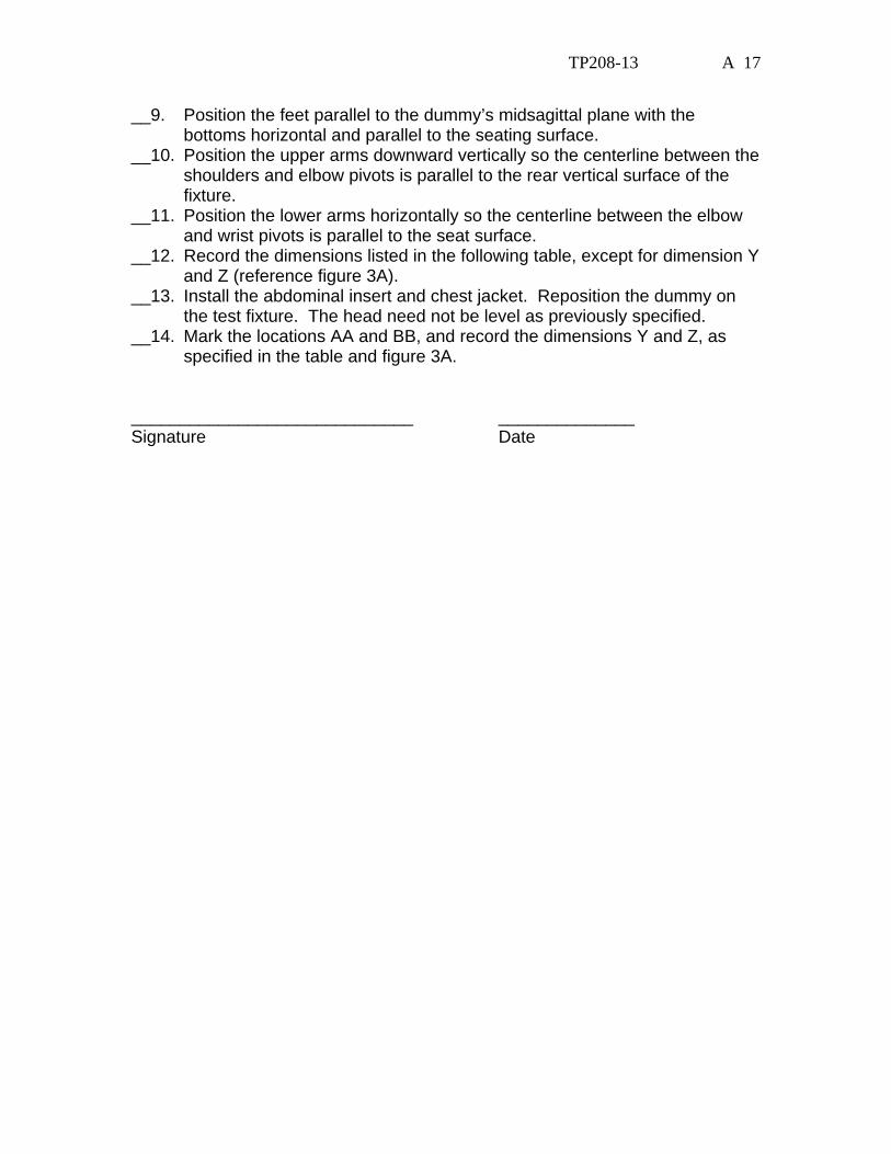
__9. Position the feet parallel to the dummy’s midsagittal plane with the bottoms horizontal and parallel to the seating surface.
__10. Position the upper arms downward vertically so the centerline between the shoulders and elbow pivots is parallel to the rear vertical surface of the fixture.
__11. Position the lower arms horizontally so the centerline between the elbow and wrist pivots is parallel to the seat surface.
__12. Record the dimensions listed in the following table, except for dimension Y and Z (reference figure 3A).
__13. Install the abdominal insert and chest jacket. Reposition the dummy on the test fixture. The head need not be level as previously specified.
__14. Mark the locations AA and BB, and record the dimensions Y and Z, as specified in the table and figure 3A.
_____________________________ ______________ Signature Date
TP208-13 A 18
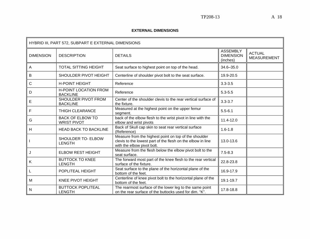
EXTERNAL DIMENSIONS
HYBRID III, PART 572, SUBPART E EXTERNAL DIMENSIONS
DIMENSION DESCRIPTION DETAILS ASSEMBLY DIMENSION (inches)
ACTUAL MEASUREMENT
A TOTAL SITTING HEIGHT Seat surface to highest point on top of the head. 34.6–35.0
B SHOULDER PIVOT HEIGHT Centerline of shoulder pivot bolt to the seat surface. 19.9-20.5
C H-POINT HEIGHT Reference 3.3-3.5
D H-POINT LOCATION FROM BACKLINE Reference 5.3-5.5
E SHOULDER PIVOT FROM BACKLINE
Center of the shoulder clevis to the rear vertical surface of the fixture. 3.3-3.7
F THIGH CLEARANCE Measured at the highest point on the upper femur segment. 5.5-6.1
G BACK OF ELBOW TO WRIST PIVOT
back of the elbow flesh to the wrist pivot in line with the elbow and wrist pivots 11.4-12.0
H HEAD BACK TO BACKLINE Back of Skull cap skin to seat rear vertical surface (Reference) 1.6-1.8
I SHOULDER TO- ELBOW LENGTH
Measure from the highest point on top of the shoulder clevis to the lowest part of the flesh on the elbow in line with the elbow pivot bolt.
13.0-13.6
J ELBOW REST HEIGHT Measure from the flesh below the elbow pivot bolt to the seat surface. 7.5-8.3
K BUTTOCK TO KNEE LENGTH
The forward most part of the knee flesh to the rear vertical surface of the fixture. 22.8-23.8
L POPLITEAL HEIGHT Seat surface to the plane of the horizontal plane of the bottom of the feet. 16.9-17.9
M KNEE PIVOT HEIGHT Centerline of knee pivot bolt to the horizontal plane of the bottom of the feet. 19.1-19.7
N BUTTOCK POPLITEAL LENGTH
The rearmost surface of the lower leg to the same point on the rear surface of the buttocks used for dim. “K”. 17.8-18.8
TP208-13 A 19
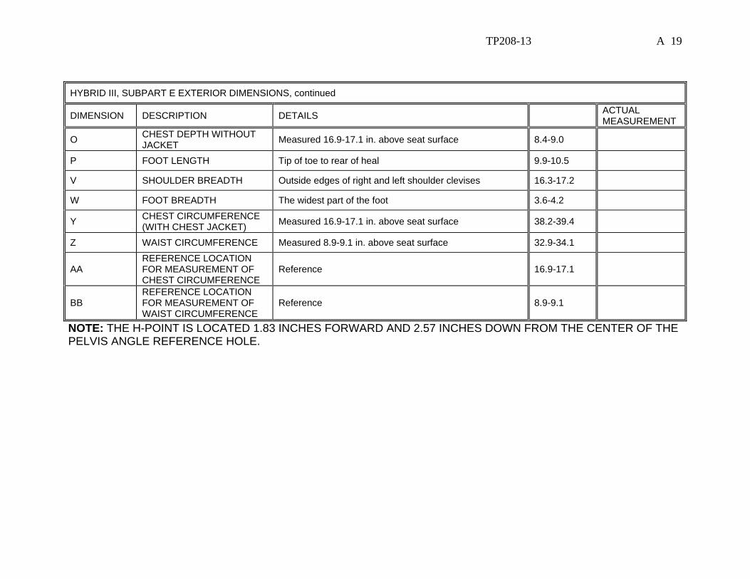
HYBRID III, SUBPART E EXTERIOR DIMENSIONS, continued
DIMENSION DESCRIPTION DETAILS ACTUAL MEASUREMENT
O CHEST DEPTH WITHOUT JACKET Measured 16.9-17.1 in. above seat surface 8.4-9.0
P FOOT LENGTH Tip of toe to rear of heal 9.9-10.5
V SHOULDER BREADTH Outside edges of right and left shoulder clevises 16.3-17.2
W FOOT BREADTH The widest part of the foot 3.6-4.2
Y CHEST CIRCUMFERENCE (WITH CHEST JACKET) Measured 16.9-17.1 in. above seat surface 38.2-39.4
Z WAIST CIRCUMFERENCE Measured 8.9-9.1 in. above seat surface 32.9-34.1
AA REFERENCE LOCATION FOR MEASUREMENT OF CHEST CIRCUMFERENCE
Reference 16.9-17.1
BB REFERENCE LOCATION FOR MEASUREMENT OF WAIST CIRCUMFERENCE
Reference 8.9-9.1
NOTE: THE H-POINT IS LOCATED 1.83 INCHES FORWARD AND 2.57 INCHES DOWN FROM THE CENTER OF THE PELVIS ANGLE REFERENCE HOLE.

TP208-13 A 20
EXTERNAL DIMENSIONSSPECIFICATIONS
SIDE VIEWFRONT VIEW
NOTE: Figure is referenced to the erect seated position. The curved lumbardoes not allow the Hybrid III to be positioned in a perfect erect attitude. (REF: S572.31(A)(6))
Z-AXIS
Y-AXISX-AXIS
Y-AXIS
BAA
BB
V
H
A
L
P
K
N
D
C
G
E
O
Y
Z
W Z-AXIS
KNEEPIVOTBOLT
WRISTPIVOTBOLT I
I
J
1.7" ± 0.1" REF.
H-POINT F
X-AXIS M

TP208-13 A 21
EXTERNAL DIMENSIONS TEST SETUP
FIGURE 4A

TP208-13 A 22
EXTERNAL DIMENSIONS TEST SETUP
FIGURE 5A

TP208-13 A 23
DATA SHEET A3 HEAD DROP TEST (572.32) (50th Male)
Dummy Serial Number _____________ Test Date _____________ Technician ___________________________ __Pretest calibration __Post test calibration verification Test attempt no. ____ (when successive head drops are necessary) __1. It has been at least 3 hours since the last head drop. (572.32(c)(5)) __ N/A, ONLY one head drop performed __2. The head assembly consists of the complete head (78051-61X), the neck
transducer structural replacement (78051-383X), and three (3) accelerometers. (572.32(b))
__3. Torque the skull cap screws to 160 lbf-in. __4. Accelerometers and their respective mounts are smooth and clean. __6. The data acquisition system, including transducers, conforms to the requirements
of SAE Recommended Practice J211/1 MAR95. (572.35(i)) __7. The head assembly soaked at a temperature between 18.9oC (66ºF) and 25.6oC
(78ºF) and at a relative humidity from 10% to 70% for a period of at least four (4) hours prior to a test. (572.32(c)(1))
Record the maximum temperature ______ Record the minimum temperature ______ Record the maximum humidity ______ Record the minimum humidity ______ __8. Visually inspect the head skin for cracks, cuts, abrasions, etc. Repair or replace
the head skin if the damaged area is more than superficial. Note: If the damage resulted from the vehicle crash test in which the dummy was an occupant, the damaged area is to be documented with photography and the post test calibration verification testing completed before any replacement or repairs are made.
Record findings and actions: _________________________________________ ________________________________________________________________ ________________________________________________________________ ________________________________________________________________ ________________________________________________________________ __9. Clean the impact surface of the skin and the impact surface of the fixture with
isopropyl alcohol, 1,1,1 trichloroethane or equivalent prior to the test. (572.32(c)(2))
TP208-13 A 24
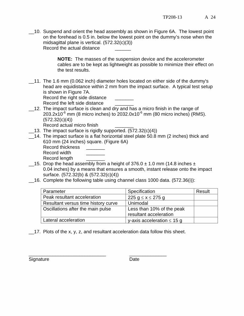
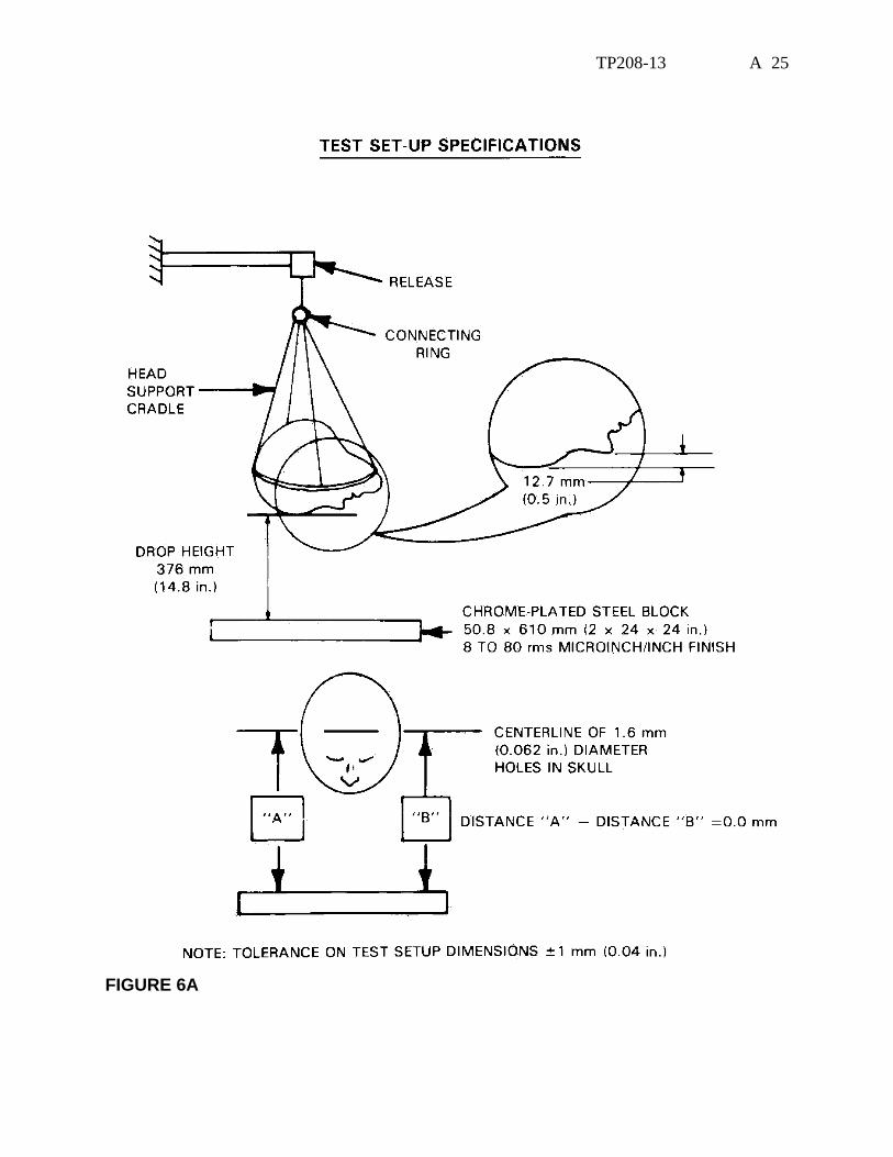
__10. Suspend and orient the head assembly as shown in Figure 6A. The lowest point on the forehead is 0.5 in. below the lowest point on the dummy’s nose when the midsagittal plane is vertical. (572.32(c)(3))
Record the actual distance ______
NOTE: The masses of the suspension device and the accelerometer cables are to be kept as lightweight as possible to minimize their effect on the test results.
__11. The 1.6 mm (0.062 inch) diameter holes located on either side of the dummy's
head are equidistance within 2 mm from the impact surface. A typical test setup is shown in Figure 7A.
Record the right side distance _______ Record the left side distance _______ __12. The impact surface is clean and dry and has a micro finish in the range of
203.2x10⁻⁶ mm (8 micro inches) to 2032.0x10-6 mm (80 micro inches) (RMS). (572.32(c)(4))
Record actual micro finish _______ __13. The impact surface is rigidly supported. (572.32(c)(4)) __14. The impact surface is a flat horizontal steel plate 50.8 mm (2 inches) thick and
610 mm (24 inches) square. (Figure 6A) Record thickness _______ Record width _______ Record length _______ __15. Drop the head assembly from a height of 376.0 ± 1.0 mm (14.8 inches ±
0.04 inches) by a means that ensures a smooth, instant release onto the impact surface. (572.32(b) & (572.32(c)(4))
__16. Complete the following table using channel class 1000 data. (572.36(i)):
Parameter Specification Result Peak resultant acceleration 225 g ≤ x ≤ 275 g Resultant versus time history curve Unimodal Oscillations after the main pulse Less than 10% of the peak
resultant acceleration
Lateral acceleration y-axis acceleration ≤ 15 g __17. Plots of the x, y, z, and resultant acceleration data follow this sheet. _____________________________ ______________ Signature Date
TP208-13 A 25
FIGURE 6A

TP208-13 A 26
HEAD DROP TEST SETUP
FIGURE 7A
DATA SHEET A4
TP208-13 A 27
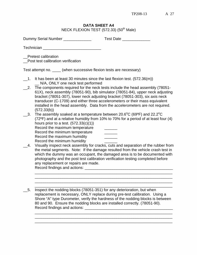
DATA SHEET A4 NECK FLEXION TEST (572.33) (50th Male)
Dummy Serial Number _____________ Test Date _____________ Technician ___________________________ __Pretest calibration __Post test calibration verification Test attempt no. ____ (when successive flexion tests are necessary) __1. It has been at least 30 minutes since the last flexion test. (572.36(m)) __ N/A, ONLY one neck test performed __2. The components required for the neck tests include the head assembly (78051-
61X), neck assembly (78051-90), bib simulator (78051-84), upper neck adjusting bracket (78051-307), lower neck adjusting bracket (78051-303), six axis neck transducer (C-1709) and either three accelerometers or their mass equivalent installed in the head assembly. Data from the accelerometers are not required. (572.33(b))
__3. The assembly soaked at a temperature between 20.6oC (69ºF) and 22.2oC (72ºF) and at a relative humidity from 10% to 70% for a period of at least four (4) hours prior to a test. (572.33(c)(1))
Record the maximum temperature ______ Record the minimum temperature ______ Record the maximum humidity ______ Record the minimum humidity ______ __4. Visually inspect neck assembly for cracks, cuts and separation of the rubber from
the metal segments. Note: If the damage resulted from the vehicle crash test in which the dummy was an occupant, the damaged area is to be documented with photography and the post test calibration verification testing completed before any replacement or repairs are made.
Record findings and actions: _________________________________________ ________________________________________________________________ ________________________________________________________________ ________________________________________________________________ ________________________________________________________________ __5. Inspect the nodding blocks (78051-351) for any deterioration, but when
replacement is necessary, ONLY replace during pre-test calibration. Using a Shore “A” type Durometer, verify the hardness of the nodding blocks is between 80 and 90. Ensure the nodding blocks are installed correctly. (78051-90).
Record findings and actions: _________________________________________ ________________________________________________________________ ________________________________________________________________ ________________________________________________________________
TP208-13 A 28
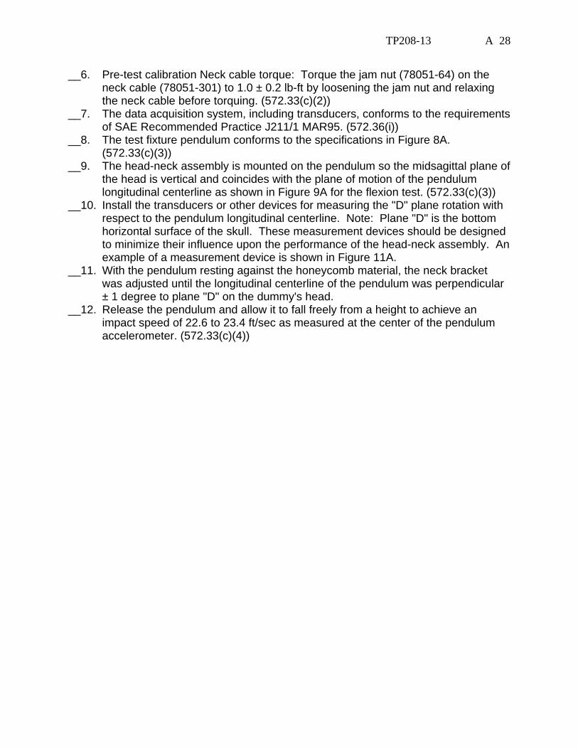
__6. Pre-test calibration Neck cable torque: Torque the jam nut (78051-64) on the neck cable (78051-301) to 1.0 ± 0.2 lb-ft by loosening the jam nut and relaxing the neck cable before torquing. (572.33(c)(2))
__7. The data acquisition system, including transducers, conforms to the requirements of SAE Recommended Practice J211/1 MAR95. (572.36(i))
__8. The test fixture pendulum conforms to the specifications in Figure 8A. (572.33(c)(3))
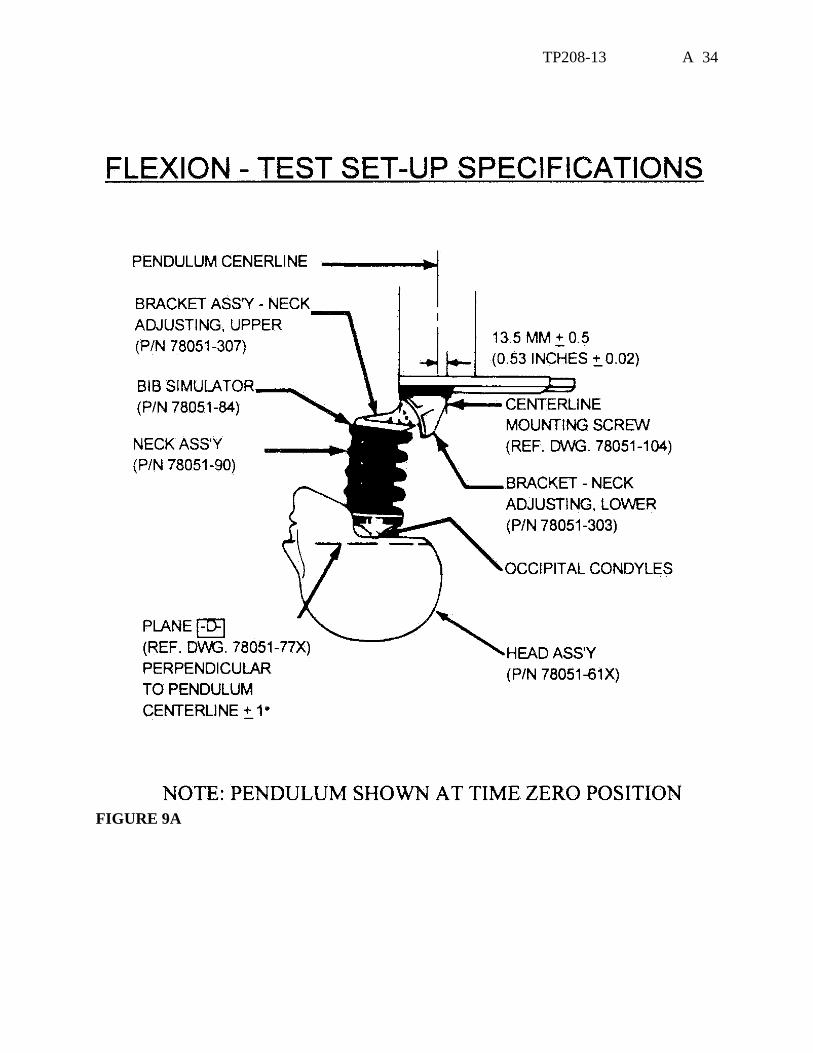
__9. The head-neck assembly is mounted on the pendulum so the midsagittal plane of the head is vertical and coincides with the plane of motion of the pendulum longitudinal centerline as shown in Figure 9A for the flexion test. (572.33(c)(3))
__10. Install the transducers or other devices for measuring the "D" plane rotation with respect to the pendulum longitudinal centerline. Note: Plane "D" is the bottom horizontal surface of the skull. These measurement devices should be designed to minimize their influence upon the performance of the head-neck assembly. An example of a measurement device is shown in Figure 11A.
__11. With the pendulum resting against the honeycomb material, the neck bracket was adjusted until the longitudinal centerline of the pendulum was perpendicular ± 1 degree to plane "D" on the dummy's head.
__12. Release the pendulum and allow it to fall freely from a height to achieve an impact speed of 22.6 to 23.4 ft/sec as measured at the center of the pendulum accelerometer. (572.33(c)(4))

TP208-13 A 29
__13. Complete the following table: Neck Flexion Test Results (572.33(b)(1) & (572.33(c)(4) Parameter Specification Result Pendulum impact speed 22.6 ft/sec ≤ speed ≤ 23.4 ft/sec
@ 10ms 22.5 ≤ g ≤ 27.5 @ 20 ms 17.6 ≤ g ≤ 22.6 @30ms 12.5 ≤ g ≤ 18.5
Pendulum Deceleration Versus Time Pulse Above 30 ms 29 g maximum First Pendulum Decay to 5g 34 ms ≤ time ≤ 42 ms
64o ≤ max. rotation ≤ 78o Plane D Rotation 57 ms ≤ time of max. rotation ≤ 64 ms
Time for Plane D Rotation to Cross 0o During First Rebound
113 ms ≤ time ≤ 128 ms
65 lbf-ft ≤ moment ≤ 80 lbf-ft Maximum Moment 47 ms ≤ time of max. moment ≤ 58 ms
Time of first decay to 0 lbf-ft Positive Moment Decay** (Flexion)
97 ms ≤ time ≤ 107ms
*Moment about the occipital condyle = My – (0.058 ft x Fx) (572.33(b)(1)(ii)) My = Moment in lbf-ft measured by the transducer Fx = Force, in lbf measured by the transducer
**Time zero is defined as the time of initial contact between the pendulum striker plate and the honeycomb material. (572.133(b)(3)
__14. Plots of pendulum acceleration, y-axis moment, x-axis force, y-axis moment
about the occipital condyle, and D plane rotation follows this sheet. _____________________________ ______________ Signature Date
TP208-13 A 30
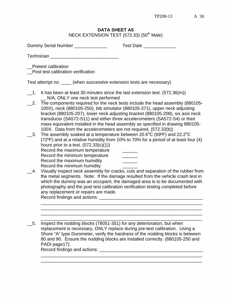
DATA SHEET A5 NECK EXTENSION TEST (572.33) (50th Male)
Dummy Serial Number _____________ Test Date _____________ Technician ___________________________ __Pretest calibration __Post test calibration verification Test attempt no. ____ (when successive extension tests are necessary) __1. It has been at least 30 minutes since the last extension test. (572.36(m)) __ N/A, ONLY one neck test performed __2. The components required for the neck tests include the head assembly (880105-
100X), neck (880105-250), bib simulator (880105-371), upper neck adjusting bracket (880105-207), lower neck adjusting bracket (880105-208), six axis neck transducer (SA572-S11) and either three accelerometers (SA572-S4) or their mass equivalent installed in the head assembly as specified in drawing 880105-100X. Data from the accelerometers are not required. (572.33(b))
__3. The assembly soaked at a temperature between 20.6oC (69ºF) and 22.2oC (72ºF) and at a relative humidity from 10% to 70% for a period of at least four (4) hours prior to a test. (572.33(c)(1))
Record the maximum temperature ______ Record the minimum temperature ______ Record the maximum humidity ______ Record the minimum humidity ______ __4. Visually inspect neck assembly for cracks, cuts and separation of the rubber from
the metal segments. Note: If the damage resulted from the vehicle crash test in which the dummy was an occupant, the damaged area is to be documented with photography and the post test calibration verification testing completed before any replacement or repairs are made.
Record findings and actions: _________________________________________ ________________________________________________________________ ________________________________________________________________ ________________________________________________________________ ________________________________________________________________ __5. Inspect the nodding blocks (78051-351) for any deterioration, but when
replacement is necessary, ONLY replace during pre-test calibration. Using a Shore “A” type Durometer, verify the hardness of the nodding blocks is between 80 and 90. Ensure the nodding blocks are installed correctly. (880105-250 and PADI page17).
Record findings and actions: _________________________________________ ________________________________________________________________ ________________________________________________________________
TP208-13 A 31
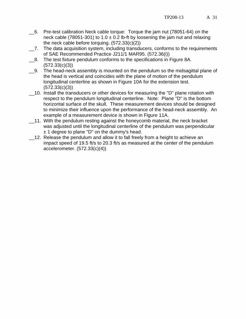
__6. Pre-test calibration Neck cable torque: Torque the jam nut (78051-64) on the neck cable (78051-301) to 1.0 ± 0.2 lb-ft by loosening the jam nut and relaxing the neck cable before torquing. (572.33(c)(2))
__7. The data acquisition system, including transducers, conforms to the requirements of SAE Recommended Practice J211/1 MAR95. (572.36(i))
__8. The test fixture pendulum conforms to the specifications in Figure 8A. (572.33(c)(3))
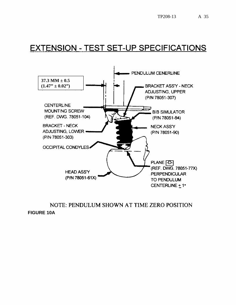
__9. The head-neck assembly is mounted on the pendulum so the midsagittal plane of the head is vertical and coincides with the plane of motion of the pendulum longitudinal centerline as shown in Figure 10A for the extension test. (572.33(c)(3))
__10. Install the transducers or other devices for measuring the "D" plane rotation with respect to the pendulum longitudinal centerline. Note: Plane "D" is the bottom horizontal surface of the skull. These measurement devices should be designed to minimize their influence upon the performance of the head-neck assembly. An example of a measurement device is shown in Figure 11A.
__11. With the pendulum resting against the honeycomb material, the neck bracket was adjusted until the longitudinal centerline of the pendulum was perpendicular ± 1 degree to plane "D" on the dummy's head.
__12. Release the pendulum and allow it to fall freely from a height to achieve an impact speed of 19.5 ft/s to 20.3 ft/s as measured at the center of the pendulum accelerometer. (572.33(c)(4))

TP208-13 A 32
__13. Complete the following table: Neck Extension Test Results (572.33(b)(2) & (572.33(c)(4)) Parameter Specification Result Pendulum impact speed 19.5 ft/sec ≤ speed ≤ 20.3 ft/sec
@ 10ms 17.2 ≤ g ≤ 21.2 @ 20 ms 14 ≤ g ≤ 19 @30ms 11.0 ≤ g ≤ 16.0
Pendulum Deceleration versus time pulse Above 30
ms 22 g maximum
First Pendulum Decay to 5g 38 ms ≤ time ≤ 46 ms 81o ≤ max. rotation ≤ 106o Plane D Rotation 72 ms ≤ time of max. rotation ≤ 82 ms
Time for Plane D Rotation to Cross 0o During First Rebound
147 ms ≤ time ≤ 174 ms
-59 lbf-ft ≤ moment ≤ -39 lbf-ft Maximum Moment 65 ms ≤ time ≤ 79 ms
Time of first decay to 0 lbf-ft Negative Moment Decay** (Extension)
120 ms ≤ time ≤ 148 ms
*Moment about the occipital condyle = My – (0.01778 m x Fx) (572.133(b)(1)(ii) My = Moment in Nm measured by the transducer Fx = Force, in N measured by the transducer
**Time zero is defined as the time of initial contact between the pendulum striker plate and the honeycomb material. (572.133(b)(3)
__14. Plots of pendulum acceleration, y-axis moment, x-axis force, y-axis moment
about the occipital condyle, and D plane rotation follows this sheet. _____________________________ ______________ Signature Date

TP208-13 A 33
FIGURE 8A
TP208-13 A 34
FIGURE 9A
TP208-13 A 35
37.3 MM ± 0.5 (1.47” ± 0.02”)
FIGURE 10A

TP208-13 A 36
ROTATION TRANSDUCER ASSEMBLY
FIGURE 11A
TP208-13 A 37
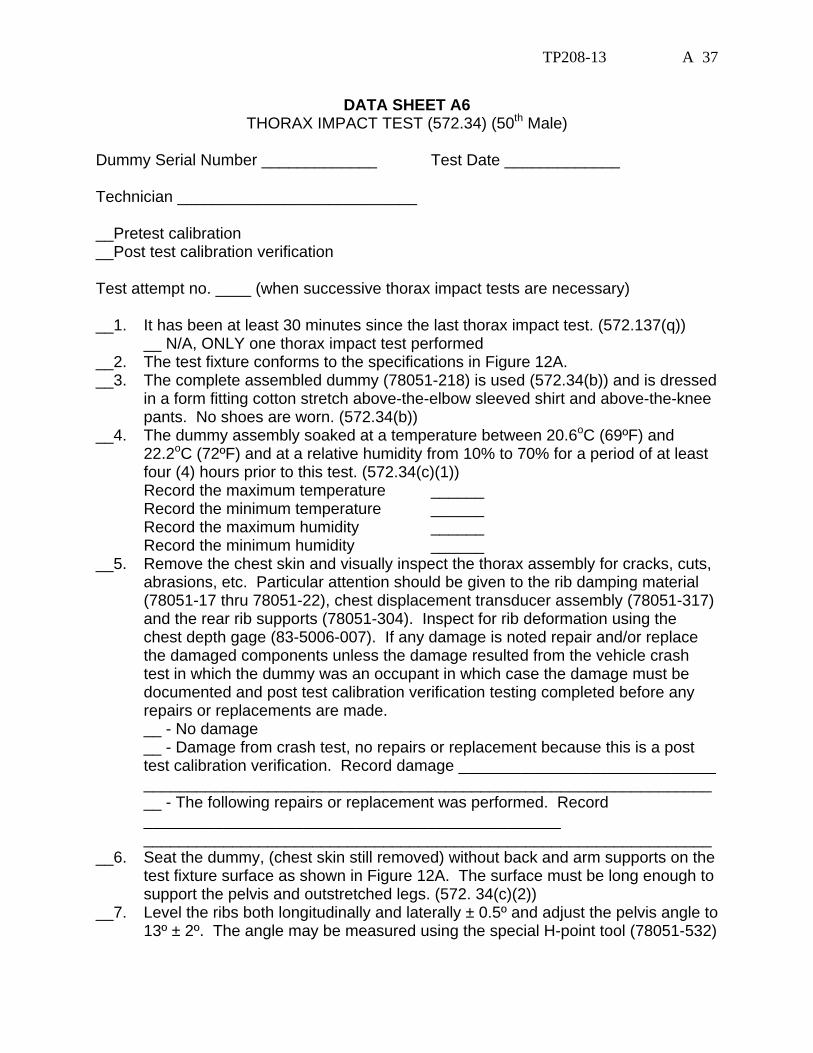
DATA SHEET A6 THORAX IMPACT TEST (572.34) (50th Male)
Dummy Serial Number _____________ Test Date _____________ Technician ___________________________ __Pretest calibration __Post test calibration verification Test attempt no. ____ (when successive thorax impact tests are necessary) __1. It has been at least 30 minutes since the last thorax impact test. (572.137(q)) __ N/A, ONLY one thorax impact test performed __2. The test fixture conforms to the specifications in Figure 12A. __3. The complete assembled dummy (78051-218) is used (572.34(b)) and is dressed
in a form fitting cotton stretch above-the-elbow sleeved shirt and above-the-knee pants. No shoes are worn. (572.34(b))
__4. The dummy assembly soaked at a temperature between 20.6oC (69ºF) and 22.2oC (72ºF) and at a relative humidity from 10% to 70% for a period of at least four (4) hours prior to this test. (572.34(c)(1))
Record the maximum temperature ______ Record the minimum temperature ______ Record the maximum humidity ______ Record the minimum humidity ______ __5. Remove the chest skin and visually inspect the thorax assembly for cracks, cuts,
abrasions, etc. Particular attention should be given to the rib damping material (78051-17 thru 78051-22), chest displacement transducer assembly (78051-317) and the rear rib supports (78051-304). Inspect for rib deformation using the chest depth gage (83-5006-007). If any damage is noted repair and/or replace the damaged components unless the damage resulted from the vehicle crash test in which the dummy was an occupant in which case the damage must be documented and post test calibration verification testing completed before any repairs or replacements are made.
__ - No damage __ - Damage from crash test, no repairs or replacement because this is a post
test calibration verification. Record damage _____________________________ ________________________________________________________________ __ - The following repairs or replacement was performed. Record
_______________________________________________ ________________________________________________________________ __6. Seat the dummy, (chest skin still removed) without back and arm supports on the
test fixture surface as shown in Figure 12A. The surface must be long enough to support the pelvis and outstretched legs. (572. 34(c)(2))
__7. Level the ribs both longitudinally and laterally ± 0.5º and adjust the pelvis angle to 13º ± 2º. The angle may be measured using the special H-point tool (78051-532)

TP208-13 A 38
that inserts into the pelvic structure and extends outward beyond the pelvic skin surface or by using the surface of the pelvic adaptor block. (572.34(c)(2)
__8. The midsagittal plane of the dummy is vertical within ± 1º. (572.134(c)(3)) __9. The longitudinal centerline of the test probe is centered within ±2.5 mm of the
midsagittal plane of the dummy and is 12.7 mm ± 1mm below the horizontal peripheral centerline of the No. 3 rib and is within 0.5º of a horizontal line in the dummy's midsagittal plane. (572.34(c)(4))
__10. Align the adjustable neck bracket index marks to the "zero" position. (Figure 12A) __11. Record locations such as the rear surfaces of the thoracic spine and the lower
neck bracket reference with respect to locations such as the rear surfaces of the thoracic spine and the lower neck bracket. These reference measurements are necessary to ensure the dummy is in the same position after the chest skin is installed. The reference locations must be accessible after installation of the chest skin. It may be necessary to leave the chest skin zipper unfastened until the references are checked and fasten it just prior to the test.
__12. Install the chest skin and reposition the dummy as described in the preceding paragraph using the reference measurements recorded.
__13. Place the arm assemblies horizontal ± 2º and parallel to the midsagittal plane. The arms are held in place by tightening the adjustment nut that holds the arm yoke to the clavicle assembly.
__14. The data acquisition system, including transducers, must conform to the requirements of SAE Recommended Practice J211/1 MAR95 Class 180.
__15. Impact the anterior surface of the thorax with the test probe so the longitudinal centerline of the probe is within 2º of a horizontal line in the dummy's midsagittal plane at the moment of impact. (572.34(c)(5)) The velocity of the test probe at the time of impact is 22 f/s ± 0.4 f/s. (572.34(b)) The probe is guided so there is no significant lateral, vertical or rotational movement during the impact. (572.34(c)(6)

TP208-13 A 39
__16. Complete the following table: Thorax Impact Results (572.34(b))
Parameter* Specification Result Test Probe Speed 21.6 f/s ≤ speed ≤ 22.4 f/s Chest Compression 2.5 in. ≤ compression ≤ 2.86 in. Peak resistance force** 1160 lb ≤ peak force ≤ 1325 lb Internal Hysteresis*** 69% ≤ hysteresis ≤ 85%
*Time zero is defined as the time of initial contact between the test probe and the chest skin.
**Force = impactor mass x acceleration (572.34(b)) ***Area under loading curve minus the area under the unloading curve divided by
the area under the loading curve. __17. Plots of chest compression, pendulum acceleration, pendulum speed, and force,
follow this sheet. _____________________________ ______________ Signature Date

TP208-13 A 40
FIGURE 12A

TP208-13 A 41
0.00 0.67 1.33 2.00 2.67 3.33 4.000
600
1200
1800
2400
CHEST DISPLACEMENT, inches
PART 572E HYBRID III THORAX CALIBRATION - HYSTERESIS
2.50" Minimum
2.86" Maximum
1325 lbs1160 lbs
FIGURE 13A

TP208-13 A 42
DATA SHEET A7 LEFT KNEE IMPACT TEST (572.35) (50th Male)
Dummy Serial Number _____________ Test Date _____________ Technician ___________________________ __Pretest calibration __Post test calibration verification Test attempt no. ____ (when successive knee impact tests are necessary) __1. It has been at least 30 minutes since the last knee impact test. (572.36(m)) __ N/A, ONLY one knee impact test performed __2. The test fixture conforms to the specifications in Figure 14A. __3. The leg assembly (86-5001-001) with the upper leg assembly (78051-46)
removed, and the load cell simulator (78051-319) is used. (572.35(b)(2)) __4. The knee assembly soaked at a temperature between 18.9oC (66ºF) and 25.6oC
(78ºF) and at a relative humidity from 10% to 70% for a period of at least four (4) hours prior to this test. (572.35(b)(2)(ii))
Record the maximum temperature ______ Record the minimum temperature ______ Record the maximum humidity ______ Record the minimum humidity ______ __5. Mount the test specimen and secure it to the rigid test fixture. (572.35(b)(2)(iii))
(Figure 14A) __6. No parts of the foot or tibia contact any exterior surface. (572.35(b)(2)(iii)) __7. Align the test probe so that at contact the longitudinal centerline of the probe is
collinear within 2 degrees with the longitudinal centerline of the femur load cell simulator except it is within 0.5 degrees horizontally. (572.35(b)(2)(iv)&(vi))
__8. The probe is guided so there is no significant lateral, vertical or rotational movement during the impact with the knee. (572.35(b)(2)(v))
__9. The data acquisition system, including transducers, must conform to the requirements of SAE Recommended Practice J211/1 MAR95 (572.136(m)) Class 600.
__10. Contact the knee with the test probe at a speed between 6.8 ft/s and 7.0 ft/s. (572.35(b))
__11. Complete the following table: Knee Impact Results (572.35(b)(1)
Parameter Specification Result Probe speed 6.8 ft/s ≤ speed ≤ 7.0 ft/s Peak resistance force* 1060 lb ≤ force ≤ 1300 lb
*Force = impactor mass x deceleration (572.35(b)(1))

TP208-13 A 43
__12. Plots of pendulum acceleration, pendulum speed, and force, follow this sheet. Time zero is defined as the time of contact between the test probe and the knee. (572.3(b)(2)(vii))
_____________________________ ______________ Signature Date
TP208-13 A 44
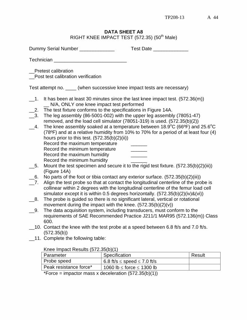
DATA SHEET A8 RIGHT KNEE IMPACT TEST (572.35) (50th Male)
Dummy Serial Number _____________ Test Date _____________ Technician ___________________________ __Pretest calibration __Post test calibration verification Test attempt no. ____ (when successive knee impact tests are necessary) __1. It has been at least 30 minutes since the last knee impact test. (572.36(m)) __ N/A, ONLY one knee impact test performed __2. The test fixture conforms to the specifications in Figure 14A. __3. The leg assembly (86-5001-002) with the upper leg assembly (78051-47)
removed, and the load cell simulator (78051-319) is used. (572.35(b)(2)) __4. The knee assembly soaked at a temperature between 18.9oC (66ºF) and 25.6oC
(78ºF) and at a relative humidity from 10% to 70% for a period of at least four (4) hours prior to this test. (572.35(b)(2)(ii))
Record the maximum temperature ______ Record the minimum temperature ______ Record the maximum humidity ______ Record the minimum humidity ______ __5. Mount the test specimen and secure it to the rigid test fixture. (572.35(b)(2)(iii))
(Figure 14A) __6. No parts of the foot or tibia contact any exterior surface. (572.35(b)(2)(iii)) __7. Align the test probe so that at contact the longitudinal centerline of the probe is
collinear within 2 degrees with the longitudinal centerline of the femur load cell simulator except it is within 0.5 degrees horizontally. (572.35(b)(2)(iv)&(vi))
__8. The probe is guided so there is no significant lateral, vertical or rotational movement during the impact with the knee. (572.35(b)(2)(v))
__9. The data acquisition system, including transducers, must conform to the requirements of SAE Recommended Practice J211/1 MAR95 (572.136(m)) Class 600.
__10. Contact the knee with the test probe at a speed between 6.8 ft/s and 7.0 ft/s. (572.35(b))
__11. Complete the following table: Knee Impact Results (572.35(b)(1)
Parameter Specification Result Probe speed 6.8 ft/s ≤ speed ≤ 7.0 ft/s Peak resistance force* 1060 lb ≤ force ≤ 1300 lb
*Force = impactor mass x deceleration (572.35(b)(1))

TP208-13 A 45
__12. Plots of pendulum acceleration, pendulum speed, and force, follow this sheet. Time zero is defined as the time of contact between the test probe and the knee. (572.3(b)(2)(vii))
_____________________________ ______________ Signature Date

TP208-13 A 46
FIGURE14A
TP208-13 A 47
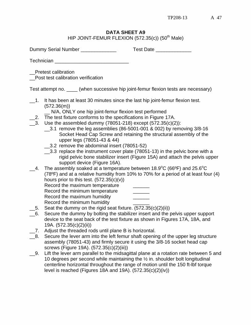
DATA SHEET A9 HIP JOINT-FEMUR FLEXION (572.35(c)) (50th Male)
Dummy Serial Number _____________ Test Date _____________ Technician ___________________________ __Pretest calibration __Post test calibration verification Test attempt no. ____ (when successive hip joint-femur flexion tests are necessary) __1. It has been at least 30 minutes since the last hip joint-femur flexion test.
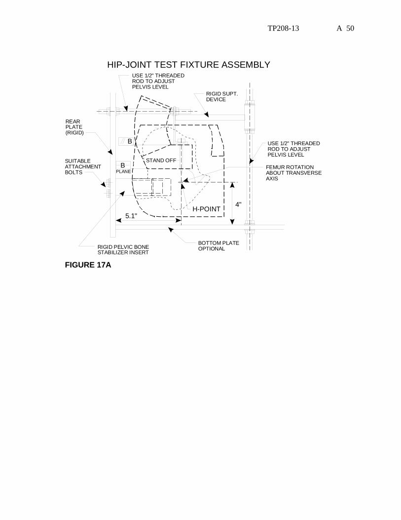
(572.36(m)) __ N/A, ONLY one hip joint-femur flexion test performed __2. The test fixture conforms to the specifications in Figure 17A. __3. Use the assembled dummy (78051-218) except (572.35(c)(2)):
__3.1 remove the leg assemblies (86-5001-001 & 002) by removing 3/8-16 Socket Head Cap Screw and retaining the structural assembly of the upper legs (78051-43 & 44)
__3.2 remove the abdominal insert (78051-52) __3.3 replace the instrument cover plate (78051-13) in the pelvic bone with a
rigid pelvic bone stabilizer insert (Figure 15A) and attach the pelvis upper support device (Figure 16A).
__4. The assembly soaked at a temperature between 18.9oC (66ºF) and 25.6oC (78ºF) and at a relative humidity from 10% to 70% for a period of at least four (4) hours prior to this test. (572.35(c)(v))
Record the maximum temperature ______ Record the minimum temperature ______ Record the maximum humidity ______ Record the minimum humidity ______ __5. Seat the dummy on the rigid seat fixture. (572.35(c)(2)(ii)) __6. Secure the dummy by bolting the stabilizer insert and the pelvis upper support
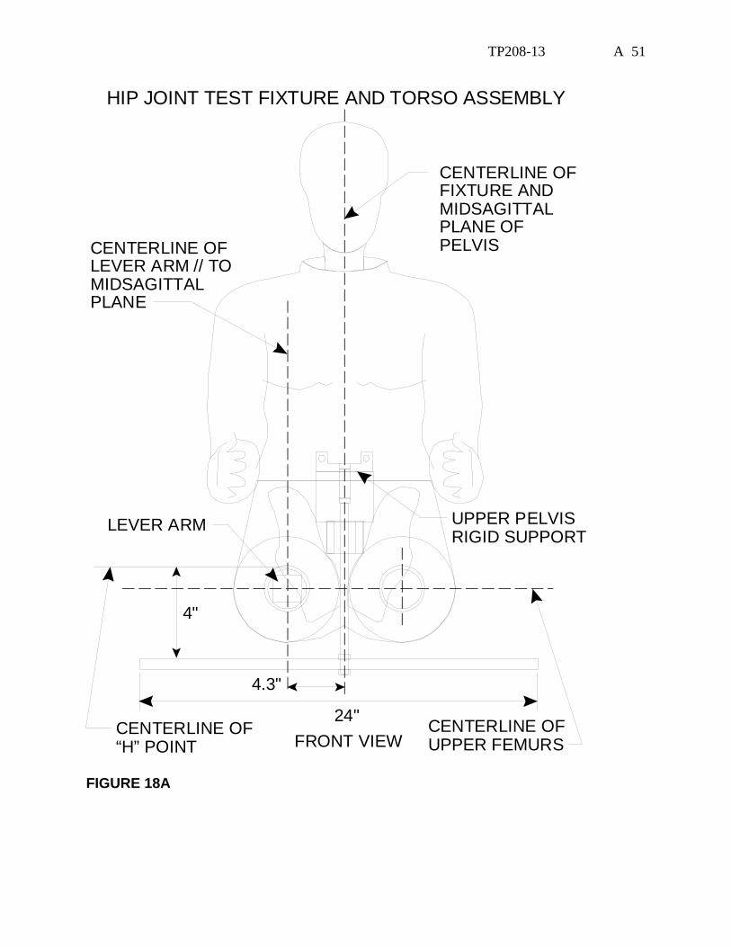
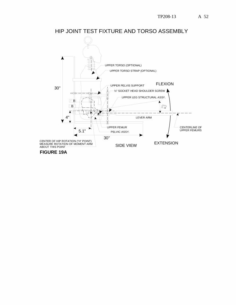
device to the seat back of the test fixture as shown in Figures 17A, 18A, and 19A. (572.35(c)(2)(ii))
__7. Adjust the threaded rods until plane B is horizontal. __8. Secure the lever arm into the left femur shaft opening of the upper leg structure
assembly (78051-43) and firmly secure it using the 3/8-16 socket head cap screws (Figure 19A). (572.35(c)(2)(iii))
__9. Lift the lever arm parallel to the midsagittal plane at a rotation rate between 5 and 10 degrees per second while maintaining the ½ in. shoulder bolt longitudinal centerline horizontal throughout the range of motion until the 150 ft-lbf torque level is reached (Figures 18A and 19A). (572.35(c)(2)(iv))
TP208-13 A 48
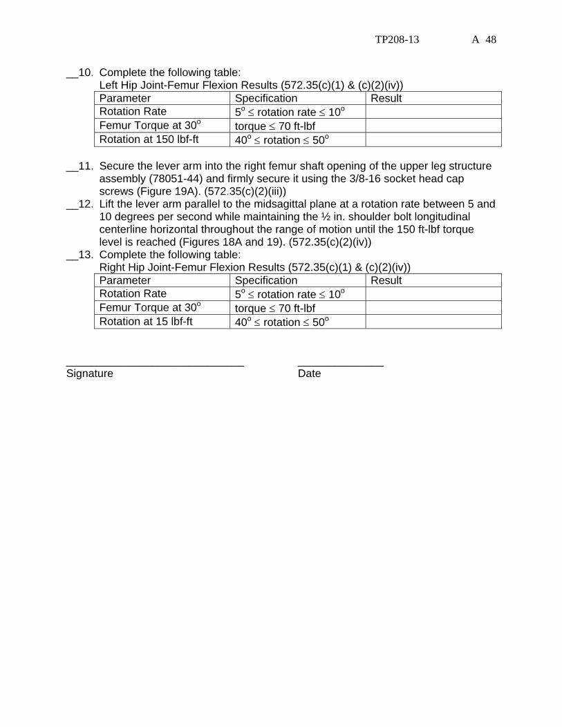
__10. Complete the following table: Left Hip Joint-Femur Flexion Results (572.35(c)(1) & (c)(2)(iv))
Parameter Specification Result Rotation Rate 5o ≤ rotation rate ≤ 10o Femur Torque at 30o torque ≤ 70 ft-lbf Rotation at 150 lbf-ft 40o ≤ rotation ≤ 50o
__11. Secure the lever arm into the right femur shaft opening of the upper leg structure
assembly (78051-44) and firmly secure it using the 3/8-16 socket head cap screws (Figure 19A). (572.35(c)(2)(iii))
__12. Lift the lever arm parallel to the midsagittal plane at a rotation rate between 5 and 10 degrees per second while maintaining the ½ in. shoulder bolt longitudinal centerline horizontal throughout the range of motion until the 150 ft-lbf torque level is reached (Figures 18A and 19). (572.35(c)(2)(iv))
__13. Complete the following table: Right Hip Joint-Femur Flexion Results (572.35(c)(1) & (c)(2)(iv))
Parameter Specification Result Rotation Rate 5o ≤ rotation rate ≤ 10o Femur Torque at 30o torque ≤ 70 ft-lbf Rotation at 15 lbf-ft 40o ≤ rotation ≤ 50o
_____________________________ ______________ Signature Date

TP208-13 A 49
PELVIC BONE STABLIZER INSERTTAP FOR SUITABLEATTACHMENT BOLTSPER FIGURE 25
INSERT INTO PELVISINSTRUMENT CAVITYOF PART #78051-59
2.50"
1.75"
4.25" 1.25"
3.31"2.94"
1.87"
2.15"
0.152"
1.75"
1.75"
0.183"
MATERIAL: Aluminum or Steel 0.20" DIA. HOLES THROUGH 4 PLACES
NOTE: HOLE LOCATIONSMATCHING INSTRUMENTCAVITY COVER #78051-13
FIGURE 15A
PELVIS UPPER SUPPORT DEVICE
NOTCH TO CLEAR HYBRID III CHEST POT ASSY.
HOLE SPACING ABOUT THE MIDSAGITTAL CENTERLINE TO MATCH MOUNTING HOLES OF MOUNT PELVIC ADAPTOR #78051-53
1/2" HOLES SUITABLE SPACED TO MATCH WITH HOLES IN REAR PLANE OF FIGURE 25
7.75"
8.93"
2"
4.125"
45 MIDSAGITTAL CENTERLINE
HOLE TO CLEAR 1/2" SHAFT
MATERIAL: CRS Steel
STANDOFF (2 Reqd)
3/8"-16 TAP X 1: DEEP 0.125"
2.50" THREAD 3/8"-16 X 0.750 LONG
FIGURE 16A
TP208-13 A 50
B
B
HIP-JOINT TEST FIXTURE ASSEMBLY
RIGID SUPT.DEVICE
FEMUR ROTATIONABOUT TRANSVERSEAXIS
SUITABLEATTACHMENTBOLTS
REARPLATE(RIGID)
H-POINT5.1"
4"
BOTTOM PLATEOPTIONALRIGID PELVIC BONE
STABILIZER INSERT
USE 1/2" THREADEDROD TO ADJUSTPELVIS LEVEL
USE 1/2" THREADEDROD TO ADJUSTPELVIS LEVEL
PLANE
STAND OFF
FIGURE 17A
TP208-13 A 51
HIP JOINT TEST FIXTURE AND TORSO ASSEMBLY
FRONT VIEW
CENTERLINE OFFIXTURE ANDMIDSAGITTALPLANE OFPELVISCENTERLINE OF
LEVER ARM // TOMIDSAGITTALPLANE
UPPER PELVISRIGID SUPPORT
LEVER ARM
CENTERLINE OF“H” POINT
CENTERLINE OFUPPER FEMURS
24"
4.3"
4"
FIGURE 18A
TP208-13 A 52
HIP JOINT TEST FIXTURE AND TORSO ASSEMBLY
SIDE VIEW
FLEXION
EXTENSION
1
UPPER TORSO (OPTIONAL)
UPPER PELVIS SUPPORT
UPPER FEMUR
30"
30"
5.1"
4"
UPPER TORSO STRAP (OPTIONAL)
CENTERLINE OFUPPER FEMURS
UPPER LEG STRUCTURAL ASSY.
PELVIC ASSY.
BB
LEVER ARM
CENTER OF HIP ROTATION (”H” POINT)MEASURE ROTATION OF MOMENT ARMABOUT THIS POINT
½” SOCKET HEAD SHOULDER SCREW
FIGURE 19A
TP208-13 A 53
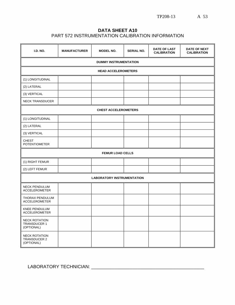
DATA SHEET A10 PART 572 INSTRUMENTATION CALIBRATION INFORMATION
I.D. NO. MANUFACTURER MODEL NO. SERIAL NO. DATE OF LAST CALIBRATION
DATE OF NEXT CALIBRATION
DUMMY INSTRUMENTATION
HEAD ACCELEROMETERS
(1) LONGITUDINAL
(2) LATERAL
(3) VERTICAL
NECK TRANSDUCER
CHEST ACCELEROMETERS
(1) LONGITUDINAL
(2) LATERAL
(3) VERTICAL
CHEST POTENTIOMETER
FEMUR LOAD CELLS
(1) RIGHT FEMUR
(2) LEFT FEMUR
LABORATORY INSTRUMENTATION
NECK PENDULUM ACCELEROMETER
THORAX PENDULUM ACCELEROMETER
KNEE PENDULUM ACCELEROMETER
NECK ROTATION TRANSDUCER 1 (OPTIONAL)
NECK ROTATION TRANSDUCER 2 (OPTIONAL)
LABORATORY TECHNICIAN: ____________________________________________
Related Documents