∗ The titles given inside the components are the names of the terminals (terminal codes) and are not treated as being abbreviations. AVENSIS (EWD526E) 17 ABBREVIATIONS D ABBREVIATIONS The following abbreviations are used in this manual. A/C = Air Conditioner A/T = Automatic Transaxle ABS = Anti–Lock Brake System CIS = Commonwealth of Independent States DLC3 = Data Link Connector 3 EC = Electrochromic ECT = Electronic Control Transmission ECU = Electronic Control Unit EFI = Electronic Fuel Injection EGR = Exhaust Gas Recirculation EPS = Electric Power Steering ESA = Electronic Spark Advance EVAP = Evaporative Emission HID = High Intensity Discharge INT = Intermittent ISC = Idle Speed Control J/B = Junction Block L/B = Liftback Type LH = Left–Hand LHD = Left–Hand Drive M/T = Manual Transaxle PTC = Positive Temperature Coefficient R/B = Relay Block RH = Right–Hand RHD = Right–Hand Drive S/D = Sedan Type SRS = Supplemental Restraint System SW = Switch TEMP. = Temperature TRC = Traction Control VRV = Vacuum Regulating Valve VSC = Vehicle Stability Control VSV = Vacuum Switching Valve VVT = Variable Valve Timing VVT–i = Variable Valve Timing–intelligent W/G = Wagon Type w/ = With w/o = Without

Toyota Avensis 2003-2007 Electrical Wiring - All
Apr 08, 2016
600+ pages with elecrtical diagrams
Welcome message from author
This document is posted to help you gain knowledge. Please leave a comment to let me know what you think about it! Share it to your friends and learn new things together.
Transcript

∗ The titles given inside the components are the names of the terminals (terminal codes) and are not treated as beingabbreviations.
AVENSIS (EWD526E)
17
ABBREVIATIONS D
ABBREVIATIONS
The following abbreviations are used in this manual.
A/C = Air ConditionerA/T = Automatic TransaxleABS = Anti–Lock Brake SystemCIS = Commonwealth of Independent StatesDLC3 = Data Link Connector 3EC = ElectrochromicECT = Electronic Control TransmissionECU = Electronic Control UnitEFI = Electronic Fuel InjectionEGR = Exhaust Gas RecirculationEPS = Electric Power SteeringESA = Electronic Spark AdvanceEVAP = Evaporative EmissionHID = High Intensity DischargeINT = IntermittentISC = Idle Speed ControlJ/B = Junction BlockL/B = Liftback TypeLH = Left–HandLHD = Left–Hand DriveM/T = Manual TransaxlePTC = Positive Temperature CoefficientR/B = Relay BlockRH = Right–HandRHD = Right–Hand DriveS/D = Sedan TypeSRS = Supplemental Restraint SystemSW = SwitchTEMP. = TemperatureTRC = Traction ControlVRV = Vacuum Regulating ValveVSC = Vehicle Stability ControlVSV = Vacuum Switching ValveVVT = Variable Valve TimingVVT–i = Variable Valve Timing–intelligentW/G = Wagon Typew/ = Withw/o = Without

AVE
NS
IS (E
WD
526E)
640
M O
VE
RA
LL
EL
EC
TR
ICA
L W
IRIN
G D
IAG
RA
M
1 2 3 4
21 AVENSIS
3
ACC
IG1
IG2
ST2
AM1 1
64 AM2
44
11
2 2
1
IL Behind theCombinationMeter
Brake
AB
S
17 IE1
EA
40A A
BS
25A A
BS
P o w e r S o u rc e A B S
W–B
W–B
W–B
R–Y
P R–Y
LR
R–W
B–W
B–W
B–R
RL
18 3 2
12 22 1 4
EBDW WA GND2 GND1
IG1 +BS +BM
EngineCompartmentRight
C10 (A ), C
11 (B )
I13
S 2
B–R
∗ 1 : Gasoline∗ 2 : 1CD–FTV
Com
bination Meter
Ignition SW
Skid Control ECU with Actuator
Com
bination Meter
System
<42–11>
FL MAIN3. 0W
Battery
120A A
LT (∗3 )100A
ALT (∗4 )
1
W
DH
25A A
M1
DN1DH5
2
1
3
5
DA9
7. 5A E
CU
–IG
IG1 R
elay
IJLeft Kick Panel
B–G
B–G
G–R
B–G
G–Y
W–B
W
(∗2 )B
–L
(∗1 )
140A A
LT
B
3
(∗2 )
2
1
3
4D
4B
1
2
3
(∗1 )
(∗2 )B
–L
ED1
(∗2 )
(∗2 )
1
(∗1 )
1
DB18
22 IE1
R–W
R–W
R–W
18 IE1
2 B 22 B
17 A 9 A 4 B
W–B
R–Y
1 IP1
IE41(RHD)
(LHD)
1
30A A
M2
1A1
4A1
B–G
B–G
(∗1 )
(∗1 )
B(∗2 )
3 (∗2 )B
(∗1 )
(∗1 )
(∗1 )
(∗1 )
1
11
1 1
2 2
40A A
BS
25A A
BS
RL (∗2 )
(∗2 )
1B1
LR(∗2 )
(∗2 )
B(∗2)
G–R G–Y
B–R
(Cont. next page)
2
B–W
A B (RHD)
C A (LHD)JunctionC
onnector
J 8 (A ), J26 (B )
A B (RHD)
C A (LHD)
C B (RHD)
G A (LHD)
C B (RHD)
G A (LHD)
JunctionC
onnector
J10 (A ), J20 (B )
IK Behind theCombinationMeter
AJ15JunctionConnector
W–B (LH
D ∗2 )
(RH
D)
∗ 3 : 1AZ–FE∗ 4 : 1ZZ–FE, 3ZZ–FE
10A IG
N
DA18
2 DH
B–R
A
A
A
AJ16JunctionConnector
J17JunctionConnector
P
W–B
(LHD
)
W–B
(RH
D)
IO Instrument PanelReinforcement RH
W–B
(LHD
∗1 )
AVE
NS
IS (E
WD
526E)
641 M
5 6 7 8
21 AVENSIS (Cont' d)
A B S
S 2Skid Control ECU with Actuator
VP
2 IE2
W
13
TS
14
B–W
PKB
B–W
1
22
1 2
1
2
1
W–L
W–G
2 IB1 1 IB1 10 IE2 11 IE2
VPGRBWR–L
L–Y
25 11
5 6 10 9 7 17 19 8
FL+ FL– FR+ FR– RL+ RL– RR+ RR–
TC D/G
GR
A 4
A 5
A32
A33
G–W
L–W
20 23
STP SP1
Stop Light S
W<
17–1>
Com
bination Meter
<42–4>
AB
S S
peed Sensor
Front LH
AB
S S
peed Sensor
Front RH
AB
S S
peed Sensor
Rear LH
AB
S S
peed Sensor
Rear R
H
1 IE2
21
G
PN
G
DiodeD 2
R
W–L
(A/T )
(A/T )
Neutral S
tart SW
<11–11>
<12–10>
2
3 1
1 IM1 10 IM1VP
G(A
/T )(A
/T )
DLC
3<
6–14><
7–13><
8–15>
DLC
3<
6–15><
7–15><
8–16>
DB3 DC2
DC4 DM8
A/C
Control A
ssembly
<47–5>
<48–8>
<49–7>
B–W
Multi–D
isplay<
39–6>B
–W
1
ParkingBrake SW
P 4
B–W
∗ 5 : Navigation System (Map Type)
(∗5 )

AVE
NS
IS (E
WD
526E)
676
M O
VE
RA
LL
EL
EC
TR
ICA
L W
IRIN
G D
IAG
RA
M
1 2 3 4
47 AVENSIS (Cont. next page)
B–G
B–G
FL MAIN3. 0W
Battery
120A A
LT (∗3 )100A
ALT (∗4 )
1
40A H
TR
1B1
2
1
B–W
7. 5A E
CU
–B 2
63
ACC
IG1AM1 1
I13Ignition SW
1 DH
25A A
M1
DN1DH5
2
1
3
5
DA9
10A H
TR
IG1 R
elay
DC6
IJLeft Kick Panel
W–R
3
5
2
1
4
DP
DF DADF
HTRRelay
L
L
B–G
B–G
B–G
G–Y
R–W
W–B
W–B
W–B
L–B
GR
–R
B
3
+B
L–B
4
VM
B–W
1 2
GND SI
A15(A), A16(B)A/C Control Assembly
L–B
W–B
IK Behind theCombination Meter
B 5B
lower M
otorC
ontroller
R–W
2
GR
–R
CE6
CE2
CC10
CF7
R–W
W–R
IG +B
R–W
W–R
P o w e r S o u rc e A ir C o n d itio n e r (A u to m a tic A /C ) a n dP o w e r H e a te r (H o t G a s T y p e A u to m a tic A /C )
4A 4C 4D
4B
1
2
12 B 24 B
17 B 5 B
HR BLW
R
BR–W(LHD)
G–R
1
1 1
(∗1 )(∗1 )
(∗1 )
(∗1 )
A
JunctionConnector
J15
CB1
CJ9
R–W
2 IK2
3 IK2
1
RR
R
8 A
SOL+
∗ 2 : 1CD–FTV w/ Power Heater (Hot Gas Type)
∗ 1 : Gasoline
2
3424
B
B
140A A
LT
W W
3 33
3
1
2
(∗2 )
(∗2 )
(∗2 )
(∗2 )
1
30A D
CC
1A1
2
1
B–W
5 IP1
IE44(RHD)
(LHD)
B–W
1 ED1
B–L
(∗2 ) (∗1 )
B–L
(∗2 )
2
1
1
6
C 3
(LHD
)
H A H A
F B
H A
(LHD
)
(LHD
)(LH
D)R–W
(LHD)
AR–W(RHD)
JunctionConnector
J26(A), J27(B)
R–W
R–W
R–W
R–W
R–W
R–W
(RH
D)
(RHD)
(RH
D ∗2 )
(RH
D)
(RH
D)
(RHD)
R–W
(RH
D)
IE218
IE111
CK12
IL Behind theCombination Meter
2 6
2
3
1
R–Y
R–B
R–W
R–W
R–W
G–Y
W–B
C 4
IG
E IN
P 5
11 B
HOTGASIN
G–Y
(LHD
∗2 )
2
1
M
Blow
er Motor
B 4
F B
R–W
(RH
D)
MGV
R–Y
7 A
DB5
H A
(RH
D ∗2 )
R–W
(LHD
∗2 )
R–W
(RH
D ∗2 )
(∗2 )
(∗2 )
(∗2 )
(∗2 )
(∗2 )(∗2 )
(∗2 )
∗ 3 : 1AZ–FSE, 1AZ–FE∗ 4 : 1ZZ–FE, 3ZZ–FE
1 IJ2 2 IJ2
LW
–B
4 IJ2IJ23
R
L–B
A
AJunctionC
onnector
J16
W–B
(∗2 )
Com
pressor Assem
bly
CondenserAssembly
Pow
er Heater S
W
AVE
NS
IS (E
WD
526E)
677 M
5 6 7 8
47 AVENSIS (Cont' d)
A ir C o n d itio n e r (A u to m a tic A /C ) a n d P o w e r H e a te r (H o t G a s T y p e A u to m a tic A /C )
G
2
1
SG–5
A17A
/C R
oom Tem
p. S
ensor
GR
TR
6 B 22 B
13 B
GND
W–B
CG3
CA6
RightKickPanel
IP
W–B
W–R
FAN
NO
. 3 Relay
<44–3>
<45–2>
<46–3>
CFAN
2
(LHD
)
(LHD
)
A18A/C Solar Sensor
PP
(RH
D)
(LHD
) 2
R(R
HD
)
(RH
D)
5
W
IQ1
W(R
HD
)
(RH
D)
Y
17
IQ1
LL
IQ1
Y
4
(RH
D)
(RH
D)
(RHD)2 1 3 4 5
FACEPT DEFVZGND
TSP
B21
IF11
2 3
IF1
9 BA
TSD
LGLG
B–W
Parking B
rake SW
<20–6>
<21–6>
MAXHOT
MAXCOOLPTVZGND
MAXHOT
MAXCOOLPTVZGND
(RH
D)
(LHD
)
(LHD
)IQ1 3
V
R–W(LHD)
R
1
MM
3
IQ1
OO
S5–4
B15
IF13
A25Air Vent Mode Control Servo Motor
7 B
PRE
17 IE2
L–W
G–W
IE28
SG
B18
2
L–W
G–W
13
B–W
B
W–G
PBKIG
A
(RH
D)
V(R
HD
)
TESG–4
B10A16
1
19
A19A
/C Therm
istor
A 3
2
1
6 A
3 5 42
14 A
Y–R
2 B
Y–B
GR B P–L
A23
8 B 11 A 12 A
Air Mix Control Servo Motor(Driver Side)
A
AMDHTPD AMDCS5–2SG–2
3 A 4 A 13
1
B A 1 B 20 B 1 A 2 A
16 B
S5
7
5
IE2
B–W
SG–1 S5–1 AMPCTPP AMPH
A15
Air Mix Control Servo Motor(Front Passenger Side)
A24
WYVRP
45321
REC
B
FRS
19
2
P–B
1
R–Y
Air Inlet C
ontrolS
ervo Motor
A21
SG–3 S5–3 AODTPM AOF
B14
5
L–B
43
LG–B
GR
–R
21
BR
–W
G–W
(LHD)
A/C Control AssemblyA15(A), A16(B)
M
R–W(RHD)A
(LHD
)
W–B
IK Behind theCombination Meter
JunctionConnector
J15A
(LHD
)
(RH
D)
W–B
(RH
D)
+
REC FRS
DE
F I/UP
Fuse<
36–3>
RDEFIN
4 B
PBLT
3 B
MPX+
10 A
MPX–
20 A
Multiplex C
omm
unicationS
ystem<
1–15><
2–11>
G–W
W–B
(RH
D)
A
A
JunctionConnector
J17
∗ 1 : Gasoline
(∗1 )A/C Pressure Sensor

AVE
NS
IS (E
WD
526E)
678
M O
VE
RA
LL
EL
EC
TR
ICA
L W
IRIN
G D
IAG
RA
M
1 2 3 4
48 AVENSIS
P o w e r S o u rc e A ir C o n d itio n e r (M a n u a l A /C ) a n d P o w e r H e a te r (H o t G a s T y p e M a n u a l A /C )
6 B5 B
RL–B
3 IJ1 2 IJ1
M2 M1
(Cont. next page)
BW B–G
B–G
FL MAIN3. 0W
Battery
120A A
LT(1A
Z–FE)
100A A
LT(1ZZ–FE
, 3ZZ–FE)
1
40A H
TR
1B1
2
1
B–W
7. 5A E
CU
–B 2
6
3
ACC
IG1AM1 1
I13Ignition SW
1 DH
25A A
M1
DN1DH5
2
1
3
5
DA9
10A H
TR
IG1 R
elay
DC6
IJLeft Kick Panel
W–R
3
5
2
1
4
DP
DF DADF
HTR
Relay
L
L
B–G
B–G
G–R
B–G
G–Y
R–W
W–B
3
W–B
W–B
W
4 2 34
2
(∗2 )B
–L
(∗1 )
L–B
GR
–R
140A A
LT
B
3
(∗2 )
2
1
3
4A 4C 4D
4B
1
2
3
G–R
(∗1 )
∗ 2 : 1CD–FTV
(∗2 )B
–L
B–W
(LHD)
(RHD)5 IP1
IE44
1
B–W
1
2
1 1A
30A D
CC
(∗2 )
(∗2 )
(∗2 )
∗ 1 : Gasoline
1
1
(∗1 )
(∗1 )
1
(∗1 )
2
1
M BlowerMotor
B 4
4 B
L
HI
L
L
2 B
GR
–R
C1
4 CK
5 CE
CA1
HRIN
GR
–R
A353 B
GR
–R
C2
7 CG
2
1
1 ED1
IK ∗4
GND
J15JunctionConnector
1 B
W–B
W–B
A
6
1
W–B
4 IJ11 IJ1
L
1 3 2 4
HI M2 M1 LO
(LHD
)
W–B
(RH
D)
(RH
D)
(LHD
)
(LHD
)
(LHD
)
C C CC
(RH
D)
(RH
D)
(RH
D)
GR
–R
GR
–R
GR
–R
(RH
D)
GR
–R
Junction ConnectorJ28
(∗3 )
J16
R–W
R–B
R–Y
1
2
A
11 IE1
18 IE2
(∗3 )(∗3 )
14 A
MGV
DB
R–W
5
(LHD
∗3 )
R–W
GR–R
(LHD ∗3)
(LHD)
(LHD
)G
R–R
R–W(RHD ∗3)
C 4
(RH
D)
R–W
A/C Control AssemblyA13(A), A14(B)
A
B
C
D
E
F
G
W–B
R–W(RHD)
R–W(LHD)
W–R
W–B(RHD)
W–B(LHD)
W–B
Blower SW A/C Amplifier
JunctionConnector
(∗3 )
(∗3)
(LHD
)
BlowerResistor
B 6
RL–B
B–W
W–B
∗ 4 : Behind the Combination Meter
Behind theCombination Meter
IL
A
W–B
(∗3 )
∗ 3 : 1CD–FTV Power Heater (Hot Gas Type)
Condenser A
ssembly
AVE
NS
IS (E
WD
526E)
679 M
5 6 7 8
48 AVENSIS (Cont' d)
A ir C o n d itio n e r (M a n u a l A /C ) a n d P o w e r H e a te r (H o t G a s T y p e M a n u a l A /C )
IK22
17
W–R
2 A11 A 10 A1 A
1 2
3
R–W
W–R
R–Y
P–B
R–W
R–W
2CF7
IG REC FRS +B
(LHD)
+
FRSREC
A21A
ir Inlet Control
Servo M
otor
C 3
IK23
GND
W–B
3 CG
6 CA
A40
1
R
R–W
1 CB
6 CE2 CE
12 CK
W–B
W–B
IPRight Kick Panel
CC10R
–W
2
1
39 A31 A
W–G
B
TE SG–4
B–W
A/C
Thermistor
G–W
L–W
A 3
PRESGS5
L–W
G–W
B–W
21
RPTC1(SIG1)
A28
23 A
G–W
BR
–W
GR
–R
LG–B
L–B
3
A32A38
FAN
NO
. 3 Relay
<44–3>
<45–2>
<46–3>
W–R
A
37 A 6 A 33 A 12 A 13 A
1 2 3 4 5
F
7
SG–3 S5–3 TPM AOD AOF
CFAN
A/C Amplifier
GND VZ PT DEF FACE
M
25 A
Parking B
rake SW
<20–6>
<21–6>
B–W
PBKIG
17 IE2IE287 IE2
Multiplex C
omm
unicationS
ystem<
1–15><
2–11>
29 A
MPX–MPX+
A9
Air Vent Mode Control Servo MotorA25
A19
CG9
IK Behind theCombination Meter
J17JunctionConnector
W–B
A
(LHD
)
(LHD
)
(LHD
)
(RH
D)
A
W–B
(RH
D)
A
R
SOL+
H AH A
F B
H A
JunctionConnector
J26(A), J27(B)
R–W
R–W
R–W
R–W
(RH
D)
(RH
D)
(RH
D)
(RH
D)
(LHD
)
Y–B
Y–R
GR B P–L
5 A 36 A 34 A 16 A 15 A
1 2 3 4 5
S5–2 SG–2 TP AMC AMH
VZ GND PT MAXCOOL
MAXHOT
M
Air Mix Control Servo MotorA22
(∗3 )W
–B
G–Y
R–W
3
62
(LHD
∗3 )
IG
E IN
P 5
(∗3 )
(LHD
∗3 )
H A
R–W
(RH
D ∗3 )
22 A
HOTGASIN
R–W
CJ9R–W
(LHD ∗3)
F B
R–W
(RH
D ∗3 )
(LHD
)
R–W
(RH
D)
R–W
R–W(RHD)
(∗5 )E
ngine EC
U (M
/T )<
8–7>
B–W
ALT(EFII)
A26
(∗5 )A
lternator<
3–3>
W–L
PTC1(PTC)
A20
(∗5 )H
TR1 R
elay<
43–4>
R–W
PTC2(PTCL)
A19
(∗5 )H
TR2 R
elay<
43–4>
R–Y
HRLY
A30
(∗5 )H
–LP R
elay<
1–8><
13–1>
G
ER–W
D
(RHD ∗3)
C
B
W–B
A
R–W(RHD)
R–W(LHD)
W–R
W–B(RHD)
W–B(LHD)
A/C Control AssemblyA13(A), A14(B)
24 A
PBLT
4 A
RDEFIN
DE
F I/UP
Fuse<
36–3>
∗ 6 : Except 1AZ–FE∗ 5 : Power Heater (Electrical Type)
∗ 1 : Gasoline∗ 3 : 1CD–FTV Power Heater (Hot Gas Type)
(RHD)R–W
G–W
(∗1 )
(∗3)
(∗6 )
(LHD
)
J15JunctionConnector
A
A
W–B
(RH
D)
Com
pressor Assem
bly
A/C Pressure Sensor
Pow
er Heater S
W

AVE
NS
IS (E
WD
526E)
662
M O
VE
RA
LL
EL
EC
TR
ICA
L W
IRIN
G D
IAG
RA
M
1 2 3 4
37 AVENSIS
140A A
LT
120A A
LT (∗5 )100A
ALT (∗6 )
3 4B1
3 4D1
DN1
DH1
3
ACC
IG1AM1 1
25AAM1
2
1
3
5
DH5
DA9
2
1
3
5
B–G
BW B–G
G–R
G–Y
Battery
FL MAIN3. 0W
(∗3)
(∗4 )
11
22
(∗3 )
(∗4 )
1 ED1
(∗4 )B
–L
IG1 R
elay
SE
AT H
TR R
elay
IJLeftKickPanel
W–B
W–B
DK11
R–W
W–B
DK6
W–B
6
7
I15
P o w e r S o u rc e A u to m a tic G la re –R e s is ta n t E C M irro r
S e a t H e a te r
DA33
IPRight KickPanel
A
20A S
–HTR
DM5
E AG A
A BG BB
DM16
BRUnder the LeftCenter Pillar
E A F A
A B H B
G A
G B
LG
R–G
L–B
LG–B
LG LG
L–B
R–B
L–B B
B–O
L–B
LG–B
L–B B
B–O
11 IM2
(∗2 )
(∗2 )
(∗2 )
(∗1 )
(∗1 )
(∗1 )
(∗2 )
(∗2 )
(∗2 )
(∗1 )
(∗1 )(∗1 )
(∗1 )
(∗1 )
(∗1 )
(∗1 )
66 1
41 4 2 4 1 5 4 3 2
BVUnder the RightCenter Pillar
HA
FB
J37(A), J38(B)
HA
FB
J35(A), J36(B)
B A
C B
BS Lower BackPanel Left
C
C
S16 S16 S17 S17
L–B
W–BW–BW–BW–B
W–B
W–B
L–B
W–B
W–B
W–B
W–B
(∗1) (∗1)
(∗2 )
(∗1) (∗1)
(∗2 )
∗ 1 : w/ Power Seat∗ 2 : w/o Power Seat∗ 3 : Gasoline∗ 4 : 1CD–FTV
L–B(∗2)
L–B(∗2)
R–L
RYYBY GB
B B
SeatHeaterSquab
Seat HeaterCushion
Seat Heater Controller
3
17 IC2
1 B4 A3 A 2 B5 A
RVL SWL SWR RVRE
W–B
10A H
TR10A
GA
UG
E1
F A
H B
RLG
(∗1 )(∗1 )
5
2 A
IG
R–L
Seat Heater SWS 7(A), S 8(B)
LG–BLG(∗2)(∗2)
B B–O(∗2)(∗2)
Junction Connector
J32Junction C
onnectorJ30 (A ), J31 (B )
L–B L–B
R
1
G YB
RRYYBB B
SeatHeaterSquab
Seat HeaterCushion
Seat Heater Controller
Ignition SWI13
B RYY
Y RG
B
SeatHeaterSquab
Seat HeaterCushion
Seat Heater Controller
B
R Y G
Seat Heater Controller
Seat HeaterCushion
SeatHeaterSquab
B
B
Y Y RB
Seat Heater LH Seat Heater LH Seat Heater RH Seat Heater RH
Junction ConnectorJunction Connector
Junction Connector
J35 (A ), J36 (B )
Junction Connector
J37 (A ), J38 (B )
InnerMirror
∗ 5 : 1AZ–FSE, 1AZ–FE∗ 6 : 1ZZ–FE, 3ZZ–FE
JunctionC
onnector
J17
A
W–B

AVE
NS
IS (E
WD
526E)
630
M O
VE
RA
LL
EL
EC
TR
ICA
L W
IRIN
G D
IAG
RA
M
1 2 3 4
18 AVENSIS
1
120A A
LT (∗3 )100A
ALT (∗4 )
2
3
1 4D
25AAM1
3
ACC
IG1AM1 1
DH1DH5 DN1
2
1
3
5
7. 5AGAUGE2
27
IG1Relay
DA
B–G
B
Battery
FL MAIN3. 0W
9 DA
Left Kick PanelIJ
1 B
2 A
3 A
2 B
(A/T)
(M/T)
(A/T)
(M/T)
R–W
R–W
W–B
5 IK1
R–Y
(∗10 )R
–B(∗3 M
/T )
R–Y
R–Y
(LHD
∗5 )
(∗9 )
P o w e r S o u rc e B a c k – U p L ig h t
R–W
B–G
2
1
140A A
LT
3
W
∗ 1 : Gasoline∗ 2 : 1CD–FTV∗ 3 : 1AZ–FSE, 1AZ–FE∗ 4 : 1ZZ–FE, 3ZZ–FE∗ 5 : w/ Multi–Display
G–R
4B1
B–G
(∗1 )
(∗2 )
(∗1 )
(∗2 )
(∗1 )
I13
(∗2 )B
–L
CD1
CA8
C
C
C
8 IC2
B
B
BS Lower BackPanel Left
Lower Back PanelCenter (S/D, L/B)
BT
B
R–B
R–B
W–B
(RH
D ∗7, R
HD
L/B, R
HD
W/G
)
(LHD
∗7, LHD
L/B, LH
D W
/G)
R–B
R–B
(∗6)
(∗6)
1 C (W/G)
2 B (L/B)
6 A (S/D)
6 C (W/G)
6 B (L/B)
2 A (S/D)
2 A (S/D)
5 B (L/B)
4 C (W/G)
6 A (S/D)
3 B (L/B)
3 C (W/G)
1 IK1
G–Y
W–B
W–B
N 1 (A )
B 1 (B )
∗ 6 : S/D w/o Rear Fog∗ 7 : S/D w/ Rear Fog
R–W
R–Y
(∗4 LHD
S/D
M/T ∗8 )
R–Y
(∗9 )
R–Y
(∗9 )
1 ED1
(∗2 )B
–L
J 5
J32
R14(A), (B), (C)R13(A), (B), (C)
Back–U
p
Back–U
p
(∗6 )R
–B
G–R
A A A A
C B
Navigation E
CU
<39–6>
Option C
onnector(N
avigation EC
U)<
50–3>R
–Y(R
HD
∗5 )
R–Y
(RH
D)
J22 (A ), J23 (B )
R–Y
(RH
D)
R–Y(RHD)
Back–U
p Light SW
Ignition SW
Junction Connector
Junction Connector
JunctionC
onnector
Neutral S
tart SW
Rear CombinationLight LH
Rear CombinationLight RH
∗ 9 : LHD Except ∗4 LHD S/D M/T ∗8
Lower Back PanelRight (W/G)
R–Y(∗4 LHD S/D M/T ∗8)
∗10 : Except ∗3 M/T
∗ 8 : w/o Winter Package w/o Moon Roof, w/o Rear Power Window, w/o Headlight Cleaner, w/o Front Fog Light, w/o Daytime Running Light or w/o Multi–Display

AVE
NS
IS (E
WD
526E)
592
M O
VE
RA
LL
EL
EC
TR
ICA
L W
IRIN
G D
IAG
RA
M
1 2 3 4
3 AVENSIS
B–G
4B1
120A A
LT (∗9 )100A
ALT (∗7 )
1
2
7. 5A A
LT–S
1
2
4D1 14E1
B
B–G
B–G
3
ACC
IG1
IG2
ST2
AM1 1
AM2
G–R G–Y
Battery
FL MAIN3. 0W
R–W
1 IK2
W–B
2 A
R–W
BB
C h a rg in gP o w e r S o u rc e
∗ 1 : Gasoline∗ 2 : 1CD–FTV∗ 3 : Power Heater (Electrical Type)∗ 4 : Power Heater (Combustion Type)
G–R
3
140A A
LT
1
2
3
W
B
B1
IG1 R
elay
B–G(∗1)
9 DA18 DB
Ignition SWI13
B B–L
B–G
(∗1 )
B(∗2 )
1 A3 A 4 A
M S LB+(∗1)B (∗2)
IG
Y
(∗2)
(∗1 )
(∗1 )
1 ED1
B–L
B–L(∗2)
Y
A11(A), A12(B)
2
1
3
5
Alternator
4A1 1A1
B–G(∗1)
(∗1 )
3
3
(∗2 )(∗2 )
B(∗2 )
B
B
(∗2 )
(∗2 )
DN1 DH5
J10 (A ), J20 (B )Junction C
onnector
R–W
5 EE1
EA15 (∗1)
(∗2)
7. 5A E
CU
–IG
Pow
er Heater
Assem
bly<43–3>
Y(∗4 )
(∗3 )B
–LA
/C C
ontrolA
ssembly<
48–8><
49–8>
B–L
Engine E
CU
(M/T )
<8–8>
(∗2 )(∗2 )
13 IK2
B–W
(∗3 )
25A A
M1
DH1
G–Y
30A A
M2
1
2
1
1 IP1
IE41
B–R
B–R
B–R
(LHD)
(RHD)
5 5
5 5
1B
1 A
7 IK1
BB
B–R
B–Y
W–B
B–R
3 2
5 1
2
1
6
6
B A
B B C B
A A
C B
6
9
P
N
A A
N 1
Neutral
Start S
W
J12 (A ), J13 (B )JunctionC
onnectorB
–Y
B–Y
B–Y
B–W
B–Y
B–Y
B–YB–W
B–Y5
7. 5A S
T
(A/T )
(M/T )
(M/T )
(A/T )
Engine E
CU
(M/T )
<5–11>
<6–11>
<7–7>
Engine and E
CT E
CU
(A/T )
<5–11>
<6–11>
<7–7>
(∗1 )
(∗2 )E
ngine EC
U (M
/T )<
8–7>
ST R
elay
S ta r tin g
S 4(A), S 5(B)Starter
B–R
4
C B (RHD)
G A (LHD)
G A (LHD)
C B (RHD)
B L
∗ 5 : 1AZ–FSE, 1CD–FTV∗ 6 : 1AZ–FE, 1ZZ–FE, 3ZZ–FE∗ 7 : 1ZZ–FE, 3ZZ–FE
IJLeft Kick Panel
DJ2
W–B
(∗5 )
20 A
23 A
18 B
21 A (∗2)
29 A (∗6)
29 B (∗8)
21 C (∗8)
28 B (1AZ–FE)
27 A (∗7)
9 IK1
Y(∗6 )Y(∗6 )
9 D (∗2)
RL
MPX1 MPX2
Multiplex C
omm
unicationS
ystem<
1–15><
2–11>
Engine and E
CT
EC
U (A
/T )
E 9 (A ), E10 (B ), E11 (C
), E12 (D)
Engine E
CU
(M/T )
∗ 8 : 1AZ–FSE∗ 9 : 1AZ–FSE, 1AZ–FE
(∗5 )

AVE
NS
IS (E
WD
526E)
651 M
3 421
∗ 1 : Gasoline∗ 2 : 1CD–FTV
C ig a re tte L ig h te rP o w e r S o u rc e R e a r W ip e r a n d W a s h e r
29 AVENSIS
3
ACC
IG1AM1
2
1
1 DH
25AAM1
DN1
DH5
DD7
2 IC2
L–R
2
1
M
1 BG1 5 BE2
(L/B)
(W/G
)(W
/G)
(L/B)
LLL L
ILBehind theCombinationMeter
A
DB11
15ACIG
DH3
G
G–YR
G
W
W
B–G
B–G
LL–B
L–BL
L–B
PW
–B
(∗1 )
(∗2 )
(W/G
)
(L/B)
(W/G
)
10 4
3
3
1
23
Battery
W–B
FL MAIN3. 0W
Washer
OFF
INT
ON
Washer +ON (∗5)
G
3 BF2
BD24
4 BF2
BD25(L/B)
(W/G)
(L/B)
(W/G)
IP
WR+1R C1R E
LS C1
Right KickPanel
W–B
1 4D
4B1
120A A
LT (∗3 )100A
ALT (∗4 )
1
2
3
3
2
1
B
140A A
LT
JunctionConnector
L–R 11 IC1 2 IC1
4 BE2 2 BG1
L–B LL
(L/B)
(∗1 )
(∗2 )
1 ED1
B–L
(∗2 )
Ignition SWI13
J 5(A), J28(B)
Combination SWC13
R20
JunctionConnector
J17
CigaretteLighter
C 7
Rear W
iper andW
asher SW
BE13 6 BG1
LL–R
L–RL
(W/G
)
(L/B)
(L/B)
(W/G
)
1
5 BF1
BD13 (L/B)
(W/G)
+B
L–R
Rear W
asherM
otor
R 3
L–R
2
W–B
R
A B
A A
A B (RHD)
A A (LHD)
A A (LHD)
A B (RHD)
L–R
∗ 5 : w/ Auto Wiper System
W–B
A
IL Behind theCombinationMeter
JunctionConnector
J16
W–B
(RH
D)
(LHD
)(LH
D)
(RH
D)
M
+1+BSWiper Relay
2
1
3
5
20A R
R W
IP
DA9
IJ Left KickPanel
W–B
L–R
IG1Relay
9 IO1
IE39 (LHD)
(RHD)
IO144
IE3(RHD)(LHD)
IO∗8
W–B
(∗7 )
(∗6 )
(∗6 )
∗ 3 : 1AZ–FSE, 1AZ–FE∗ 4 : 1ZZ–FE, 3ZZ–FE
∗ 6 : LHD 1CD–FTV, RHD∗ 7 : LHD Except 1CD–FTV∗ 8 : Instrument Panel Reinforcement RH
W–B(∗7)
A A
Rear Wiper Motor and Relay

AVE
NS
IS (E
WD
526E)
668
M O
VE
RA
LL
EL
EC
TR
ICA
L W
IRIN
G D
IAG
RA
M
1 2 3 4
42 AVENSIS (Cont. next page)
6
16 IE1
A
P o w e r S o u rc e C o m b in a tio n M e te r
L–W
W–R
L–W
GR
–RE
ngine and EC
T EC
U (A
/T )<
5–17><
6–13><
7–11>
∗ 3 : 1AZ–FSE, 1AZ–FE∗ 2 : 1CD–FTV∗ 1 : Gasoline
Speedom
eter
Tachometer
Fuel
Temp.
Door
OUTSIDETEMP. ODO/TRIP
20 B
∗ 6 : w/ Moon Roof
5 B
W–B
3 B19 B
Skid C
ontrol EC
Uw
ith Actuator
<20–6>
<21–5>
Engine E
CU
(M/T )
<5–17>
<6–13>
<7–11>
<8–13>
C10(A), C11(B)
6
7. 5A D
OM
E
2
6
1
W–R
B–R
∗ 7 : w/ Navigation System (Map Type)
Combination Meter7. 5A R
AD
NO
. 1
DH3
DB4
GG2
F C
H B
GR
GR
BW
B–G
FL MAIN3. 0W
Battery
120A A
LT (∗3 )100A
ALT (∗4 )
B–W
3
ACC
IG1AM1 1
I13Ignition SW
1 DH
25A A
M1
DN1DH5
2
1
3
5
DA9
10A G
AU
GE
1
IG1 R
elay
DB7
IJLeft Kick Panel
B–G
G–R
B–G
G–Y
R–W
W–B
3
(∗2 )B
–L
(∗1 )
140A A
LT
B(∗2 )
2
1
3
4D
4B
1
2
3
G–R
(∗1 )
(∗2 )B
–L
ED1
1
B–W
1
2
1 1A
30A D
CC
(∗2 )
(∗2 )
1
1
5 IP1
IE44 (LHD)
(RHD)
B–W
4 IG2
ST2
6AM2
CA7
CD6
R–W
21 B
R–W
IPRightKickPanel
CK6
CA6
W–B
18 B
B–R
G–Y
H C H C
F B F
H C
B F
H C
B
V–W
Headlight B
eam Level
Control E
CU
<24–3>
V–W
Moon R
oof Control
Relay and M
otor<
32–3>
V–W
Multi–D
isplay<
39–6>(∗7 )
(∗6 )
(w/ H
ID)
V–W
V–W
Navigation E
CU
<39–6>
(∗5 )
Engine and E
CT E
CU
(A/T )
<5–12>
<6–11>
<7–10>
V–W
V–W
EP
S E
CU
<23–4>
(∗8 )
Engine E
CU
(M/T )
<5–12>
<6–11>
<7–10>
<8–12>
1
(∗1 )
1 4A
(∗1 )B
–G
2
1
B–R
1
30A A
M2
1 IP1
IE41(RHD)
(LHD)
B–R
B–R
Option C
onnector(N
avigation EC
U)<
50–3>
A/T SHIFT (A/T)CLOCK
CPU
∗ 5 : w/ Multi–Display
∗ 4 : 1ZZ–FE, 3ZZ–FE ∗ 8 : w/ EPS
2 A
GR
F CF C
H B
F A (LHD)
JunctionConnector
J10(A), J11(B), J26(C)
(RHD)
(LHD
)
W–R
W–R
(RH
D)
F A (LHD)
H D (RHD)
(LHD)
(RHD)
Junction Connector
J 8 (A ), J 9 (B ), J20 (C), J21 (D
)
V–W
F D (RHD)F DF D
H A H A H A H A (LHD)
Junction Connector
J10 (A ), J11 (B ), J20 (C), J21 (D
)
(RHD)
(LHD)
ILBehind theCombinationMeter
IKBehind theCombinationMeter
A
JunctionConnector
J15 W–B
W–B(LHD)
(RHD)
AVE
NS
IS (E
WD
526E)
669 M
5 6 7 8
42 AVENSIS (Cont' d) (Cont. next page)
C o m b in a tio n M e te r
Near the Starter
Buzzer
EI
BR
4 IK1
A
Y–G
16
2
1
Y–G
BR
E 7
BR
Engine O
ilLevel S
ensor
Fuel
Turn Signal andHazard WarningLight System<15–2><15–3>
W–B
Illumination
System
<19–4>
Tail
Turn LH
Turn RH
AB–R
17 A
1 B 13 B14 B
Oil Level
2
Y–R
BR
Y–R
1
1 A
15 IK2
F14Fuel Filter W
arning SW
AVC–LANI/F
4 AA3
G–Y
G
Multi–D
isplay<
39–6><
40–3>
(∗2 )(∗2 )
(∗2 )
(∗2) (∗2)
3
2
G–W
BR
–W
5 A 10 A
BR
–W
G–W
F25
15 IC1 6 IC115 IE1
1
2
WW–R
IE14
11 A 12 A
W–R
W
A 1A
/C A
mbient
Temp. S
ensor
IOInstrument PanelReinforcement RH
(∗2 )(∗2 )
(∗2 )
A/T O
IL TEM
P
Charge
EC
T SN
OW
Seat B
elt Glow
CR
UIS
E
13 A A14
BEANI/F
Multiplex
Com
munication
System
<1–15>
<2–10>
<2–11>
A15
(∗9 )
Illumination
AB–R
CPU
C10(A), C11(B)Combination Meter
∗ 5 : w/ Multi–Display
(∗5 )
(∗5 )
Taillight System
<14–2>
∗ 2 : 1CD–FTV
Behind theCombination Meter
IK
W–B
AJ15JunctionConnector
(RH
D)
(LHD
)
∗ 9 : w/ Theft Deterrent
∗ 1 : Gasoline
(∗2 )(∗2 )
(∗2 )
W–B
(LHD
∗1 )
W–B
(RH
D)
A
A
A
AJ16JunctionConnector
J17JunctionConnector
Behind theCombination Meter
IL
W–B
(LHD
∗2 )
Fuel Sender
AVE
NS
IS (E
WD
526E)
670
M O
VE
RA
LL
EL
EC
TR
ICA
L W
IRIN
G D
IAG
RA
M
9 10 11 12
42 AVENSIS (Cont' d)
10AIGN
C o m b in a tio n M e te r
B–R B–W
SR
S
Brake
AB
S
Check E
ngine
ECEngine Compartment Left
2
C
19 IK2
R–WR–W
W–B
Y–BR
–W
Y–B
R–W
R–W
B–W
SR
S S
ystem<
22–4>
Engine C
ontrol System
<5–5>
<6–7>
<7–5>
<8–4>
(∗2)
(∗1 )
C
1 1
VS
C S
ystem<
20–10>
Oil P
ressure
∗ 2 : 1CD–FTV∗ 1 : Gasoline
1
9 A 4 B9 B 2 B
19 IE1
(∗2)
11 B
TRC
OFF
Slip
VS
C17 B15 B16 B
VSC System<20–10>
Rear Fog
AB
S S
ystem<
21–3>
8 A8 B
Rear Fog
Light System
<16–2>
22 B
(∗2 )
C10(A), C11(B)
Front Fog
7 AFront FogLight S
ystem<
16–2>
O 2
CB 3
J 2
V 2
J 8 (A ), J26 (B )
Brake Fluid Level
Warning S
W
Combination Meter
JunctionConnector
JunctionC
onnector
Oil P
ressure SW
VacuumSW
DH2 DA18
AC
BA
P/S
6 B
EP
S S
ystem<
23–2>
Filter
Beam
Level
Headlight B
eam Level C
ontrolS
ystem<
24–3>
10 B A
Multiplex C
omm
unicationS
ystem<
1–14>
High B
eam
6
12 B
Headlight S
ystem<
13–4>
(w/ V
SC
)
(w/ V
SC
)
(w/ V
SC
)
A
C A
A B
(LHD)
(RHD)
(LHD)
(RHD)
Multiplex C
omm
unicationS
ystem<
1–14>H
eadlight System
<13–4>
(w/ H
ID)

556
AVENSIS (EWD526E)
K CONNECTOR LIST
1 2
GrayA 1
21
BlackA 2
1 2 3
BlackA 3
1 2
A 4
1 2
A 5
54321
BlackA 6
21
3 4
GrayA 7
1 2
3 4
GrayA 8
1 2
YellowA 9
1 2
YellowA10
21
3 4
BlackA11
1
(Except 1CD–FTV)A12
1
(1CD–FTV)A12
4
22
3
21 24
1
2623
62
27
7
28
8
30
10
31
11
32
12
33
13
35
15
36
16
37
17
38
18
29
95
25 34
14
39
19
40
20
A13
1 2
4 5
3
6
A14
1 2 3 4 5 6 7 8 9 10
11 12 13 14 15 16 17 18 19 20
A15
21
13 14
3
15
4
16
5
17
6
18
7
19
8
20
9
21
10
22
11
23
12
24
A16
21
BlackA17
1 2 3
BlackA18
21
A19
1 2 34 5 6
BlackA20
1 2 3
BlackA21
54321
BlackA22
54321
BlackA23
54321
BlackA24
54321
BlackA25
AVENSIS (EWD526E)
557
K
171819161415 20
1 2 3 4
5 6 7 8 9 101112
13
A B
YellowA26
242523 26222021 2827
1 2 3 4 5 6
7 8 9 1011121314151617
1819
A B
YellowA27
171819161415 20
1 2 3 4
5 6 7 8 9 101112
13
A B
YellowA28
1 2 3 4
YellowA29
1 2 3 4
YellowA30
1
A31
12
A32
12
A33
1 2
GrayB 1
1 2 3
BlackB 2
1 2
BlackB 3
1
2
B 4
1 2 3 4
BlackB 5
1 2
3 4
BlackB 6
2
3 4
1
(L/B)B 7
2
3 4
1
(W/G) BlueB 7
2 1
B 8
1 23 4
GrayB 9
23 41
B10
1 2
BlackC 1
1 2
BlackC 2
1 2
GrayC 3
1 2
C 4
1 2
BlackC 5
1 2
(*1) GrayC 6
1 2
(1CD–FTV) BlackC 6
1 2
(1ZZ–FE, 3ZZ–FE) BlackC 6
23 41
BlackC 7
35
1 2X
C 8
1 2
C 9
9
18
8
1716
76
1514
54
1312
32
11
1
10
BlueC10
*1 : 1AZ–FSE, 1AZ–FE

558
AVENSIS (EWD526E)
K CONNECTOR LIST
11
2221
109
2019
87
1817
65
1615
43
1413
1 2
12
C11
1 2 4 7 8
9 10 1112131415 16 17
5 63
C12
1 2 3 4 5 6 7 8 9
10 11 12 131415 16 17 18
BlackC13
7 8
1 2
12
4 5 6
9 1110
3
C14
21
YellowC15
21
YellowC16
21
BlackC17
21
BlackC18
1 2 34 5 6
BlackD 1
1 2 3
D 2
1 2
BlackD 3
1 2
(Except 1CD–FTV)D 4
1 2 3
(1CD–FTV)D 4
16 15 14 13 12 11 10 9
8 7 6 5 4 3 2 1
D 5
54321
D 6
1 2
D 7
1 2
D 8
1
D 9
1
D10
1
D11
1
D12
1 2 3 4
5 6 7 8 9 10
D13
1 2 3 4
5 6 7 8 9 10
D14
1 2 3 4
5 6 7 8 9 10
D15
1 2 3 4
5 6 7 8 9 10
D16
21
13 14
3
15
4
16
5
17
6
18
7
19
8
20
9
21
10
22
11
23
12
24
D17
1 2 3 4
5 6 7 8 9 10
D18
1 2 3 4
5 6 7 8 9 10
D19
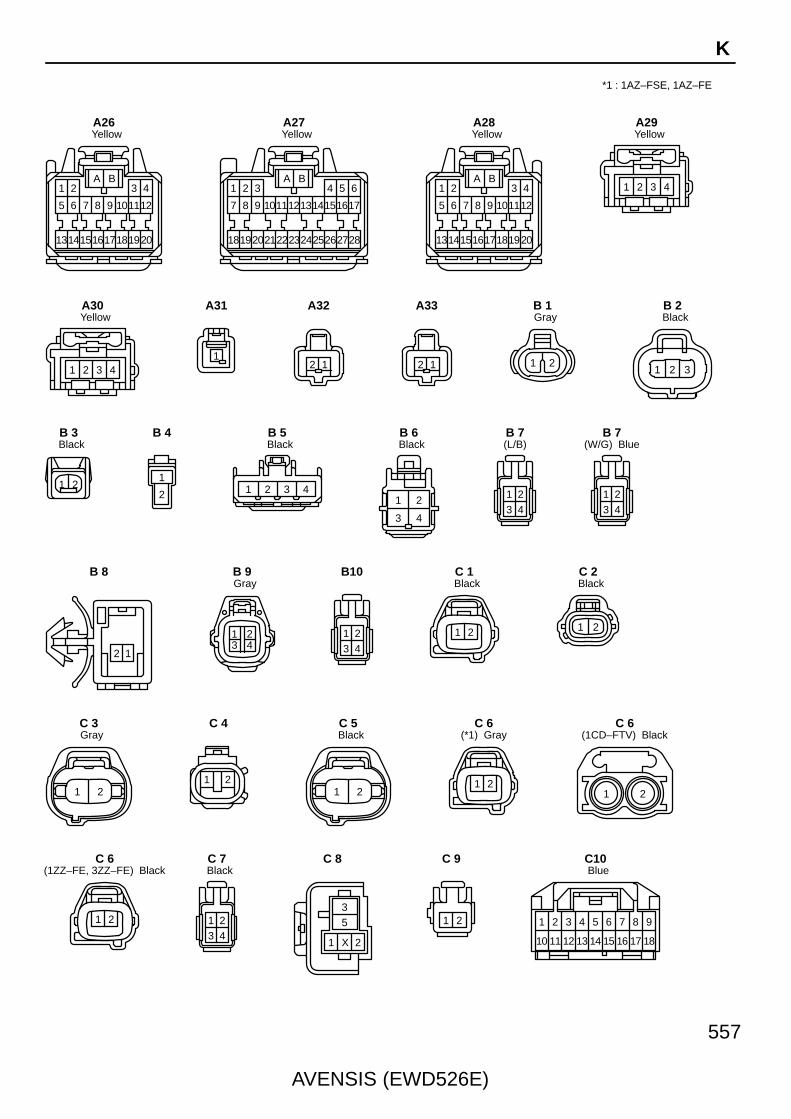
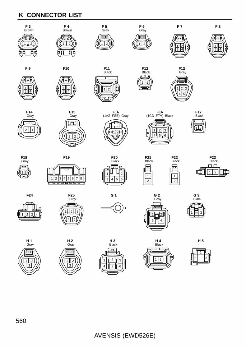
AVENSIS (EWD526E)
559
K
1 2 3 4
5 6 7 8 9 10
D20
1 2 3 4
5 6 7 8 9 10
D21
1 2 3 4 5
6 7 8 9 10
GrayE 1
21
(Except 1AZ–FE) GrayE 2
21
(1AZ–FE) GrayE 2
1 2 34 5 6
BlackE 3
1 2 3 4 5 6 7 8
BlackE 4
1 2 3 4 5
(1AZ–FSE) BlackE 5
87654321
(1CD–FTV) Dark GrayE 5
13 2
BlackE 6
1 2
GrayE 7
1 2 3 4
BlackE 8
1
17
292827 3126
1918
98
20
10
21
30
11
76
13 14 15 16
22 23 24
12
432 5
25
E 9
16
3231 3528
2017
9 10
34
11
65
13 14 15
23 24 26
12
321 4
27
29
18
7
30
19
8
21 22 25
33
E10
1
17
29 3228
1918
98
20
10
21
31
11
76
13 14 15 16
22 23 26
12
432 5
27
30
24 25
E11
1
19
333231 3528
2320
118 12
34
13
76
15 16 17 18
24 25 26
14
432 5
27
29
21
9
30
22
10
E12
1
17
29 3428
1918
98
20
10
21
33
11
76
13 14 15 16
22 23 26
12
432 5
2724 25
30 31 32
E13
2
1
GrayE14
1 2 3 4 5 6
7 8 9 10 11 12
E15
1 2
BlackF 1
1 2
BlackF 2
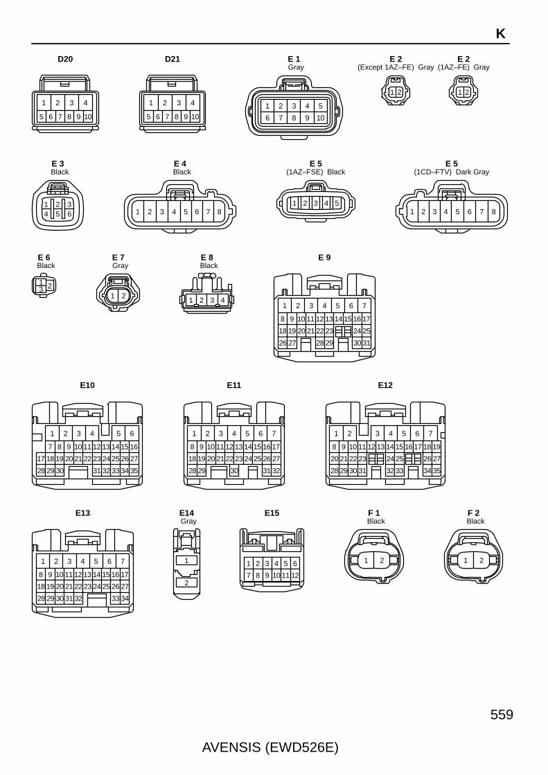
560
AVENSIS (EWD526E)
K CONNECTOR LIST
1 2
BrownF 3
1 2
BrownF 4
1 2
GrayF 5
1 2
GrayF 6
1 23 4
F 7
1 23 4
F 8
1 23 4
F 9
1 23 4
F10
1 2
BlackF11
12
BlackF12
1 2 3
4 5
GrayF13
12
GrayF14
21
GrayF15
1 23
(1AZ–FSE) GrayF16
1 2 3
654
(1CD–FTV) BlackF16
1 2
BlackF17
21
GrayF18
2 3 4 5 6 7 81
F19
1 2
3 4 5 6
BlackF20
21
BlackF21
21
BlackF22
21
BlackF23
1 2 3 4
F24
1 2 3
4 5
GrayF25
1
G 1
1 2
3 4
GrayG 2
1 2
BlackG 3
213
GrayH 1
213
GrayH 2
1
4 5
2 3
6
BlackH 3
1 2
BlackH 4
1
2 3
H 5

AVENSIS (EWD526E)
561
K
1
2 3
H 6
21
3 4
(1AZ–FSE) GrayH 7
1 2
3 4
(1ZZ–FE, 3ZZ–FE) GrayH 7
21
3 4
BlackH 8
1 2
3 4
GrayH 9
21
3 4
BlackH10
1
BlackH11
1
BlackH12
1 2
5
3 4
6 7 8 9 10
BlackH13
21
13 14
3
15
4
16
5
17
6
18
7
19
8
20
9
21
10
22
11
23
12
24
H14
1 2 3 4 5
H15
1 2 3 4
BlackH16
1 23 4
GrayH17
1 2 3
BlackH18
1 2 3
BlackH19
12
(L/B)H20
12
(S/D) GrayH20
1 2
(W/G) BlackH20
1 2 3 4
BlackI 1
1 2 3 4
GrayI 2
1 2 3 4
BlackI 3
1 2 3 4
GrayI 4
1 2
(Except 1AZ–FSE) BlackI 5
1 2
(1AZ–FSE) BlackI 5
1 2
(Except 1AZ–FSE) GrayI 6
1 2
(1AZ–FSE) GrayI 6
1 2
(Except 1AZ–FSE) BlackI 7
1 2
(1AZ–FSE) BlackI 7
1 2
(Except 1AZ–FSE) GrayI 8
1 2
(1AZ–FSE) GrayI 8
1 2
GrayI 9
1 2 3
BlackI10
1 2 3 4 5 6 7
BlackI11
1 2 3 4 5 6 7
BlackI12
1 2
4 5
3
6
I13

562
AVENSIS (EWD526E)
K CONNECTOR LIST
E
HH
ED
HH
DC
GG
CC
GF
BB
FF
A A
F
E
HH
ED
HH
DC
GG
CC
GF
BB
FF
A A
F
C
FF
CC
FF
CB
EE
BB
EE
BA
DD
A A
D
C
FF
CC
FF
CB
EE
BB
EE
BA
DD
A A
D
A A A A AA A A A A A A A
A A A A AA A A A A A A A
A B B C CA A B D D D C CA A B B C C
D D D E E E
A A B B C C
D D D E E E
E
HH
ED
HH
DC
GG
CC
GF
BB
FF
A A
F
E
HH
ED
HH
DC
GG
CC
GF
BB
FF
A A
F
E
HH
ED
HH
DC
GG
CC
GF
BB
FF
A A
F
E
HH
ED
HH
DC
GG
CC
GF
BB
FF
A A
F
E
HH
ED
HH
DC
GG
CC
GF
BB
FF
A A
F
A A B B C C
D D D E E E
BBAAAC C C D D D B
11
2221
109
2019
87
1817
65
1615
43
1413
1 2
12
I14
1 2 3 4 5 76
BlackI15
1 2 3 4
I16
CCBAAA A B B B C C
GrayJ 1
BlackJ 2
A A B B C C
D D D E E E
J 3 J 4
A B B C CA A B D D D C C
J 5
E
HH
ED
HH
DC
GG
CC
GF
BB
FF
A A
F
J 6 J 7 Black
J 8
BlackJ 9
GrayJ10
GrayJ11
J12 J13 J14
A A
A A A A
J15
J16 J17 J18
J19 J20 J21

AVENSIS (EWD526E)
563
K
A B C D E E
F F F F G H
A A B C D E
F G H H H H
A B C D E E
F F F F G H
A A B C D E
F G H H H H
A A A A A A
B B B C C C
A A A A A A
B B B C C C
A B B C CA A B D D D C CA A A A A A
B B B C C C
A A A A A A
B B B C C C
C
EE
CC
EE
CC
EE
BB
ED
BA
DD
A A
D
A B B C CA A B D D D C CE
HH
ED
HH
DC
GG
CC
GF
BB
FF
A A
F
E
HH
ED
HH
DC
GG
CC
GF
BB
FF
A A
F
A A B B C C
D D E E F F
A A B B C C
D D E E F F
A A B B C C
D D E E F F
A A B B C C
D D E E F F
J22 J23 J24 J25
J26 J27 J28
J29 J30 J31 J32
J33 J34 J35 J36
J37 J38
1 2
BlackK 1
1 2
BlackK 2
21
YellowK 3
1 2
BlackL 1
1 2
BlackL 2
1 32
BlackL 3
2 1
L 4
1 2
L 5
1 2
L 6

564
AVENSIS (EWD526E)
K CONNECTOR LIST
*5 : Power Heater (Hot Gas Type)
1 2 3 4 5
L 7
21 3 4 5 6 7 8 9 101112 13
14 15 16171819 2021222324 25
(*2)M 1
1 2 3 4 5 6 7 8 9
10 11 12 13 14 15 16 17 18
(*3)M 1
109876
54321
(*2)M 2
1 2 3
4 5 6
(*3)M 2
1
M 3
2 1
3 67 45
M 4
2 1
3 67 45
M 5
1 2 3 4 5
6 7 8 9 10
GrayM 6
23 41
M 7
1 2 3 4 5
6 7 8 9
GrayN 1
1 2
GrayN 2
1 2 3 4 5 6 7 8 9
10 11 12 13 14 15 16 17 18
N 3
109876
54321
N 4
8765431 2
N 5
1 2
N 6
1 2
N 7
1 2
N 8
32
1
BlackO 1
1
GrayO 2
1 2 3 4
5 6 7 8
BlackP 1
1
BlackP 2
1 2
GrayP 3
1
BlackP 4
1 2
3 4 5 6
(*4) GrayP 5
1 2
3 4 5 6
(*5)P 5
1
2
BlackP 6
2 31
P 7
1 2 3 4
P 8
1
5
2
6
3
7
4
8
P 9
1
5
2
6
3
7
4
8
P10
*2 : w/ Navigation System (Map Type)*3 : w/o Navigation System (Map Type)
*4 : Power Heater (Combustion Type)

AVENSIS (EWD526E)
565
K
1
5
2
6
3
7
4
8
P11
654321
GrayP12
654321
GrayP13
654321
GrayP14
654321
GrayP15
21
YellowP16
21
YellowP17
1 2 3 4
5 6 7 8 9 10
BlackP18
1 2 3 4
5 6 7 8 9 10
BlackP19
1 2
P20
1 2
BlackP21
1 2
P22
1 2
BlueP23
1 2
P24
1 2
BlueP25
21
GrayR 1
21
BlackR 2
1 2
RedR 3
1 2 3 4
5 6 7 8 9 10
R 4
1 2
3 4 5 6
R 5
7 8
1 2
12
4 5 6
9 1110
3
R 6
1 2 3 4 5 6 7 8 9 10
11 12 13 14 15 16 17 18 19 20
R 7 R 8
35
1 2X
R 9
1 2 3 4 5 6 7 8 9 10
R10
54321
R11
3 2 1
BlackR12
1 2 3 4 5 6 7
(Except W/G) BlackR13
1 2 3 4 5 6
(W/G)R13
35
1 2X

566
AVENSIS (EWD526E)
K CONNECTOR LIST
*6 : 1AZ–FE, 1ZZ–FE, 3ZZ–FE
1 2 3 4 5 6 7
(Except W/G) BlackR14
1 2 3 4 5 6
(W/G)R14
2
1
BlackR15
2
1
BlackR16
1 2
R17
1
(L/B)R18
1
(S/D, W/G)R18
1
(L/B)R19
1
(S/D)R19
1
(W/G)R19
1 32
BlackR20
30 3317
1
322642
16412524
403915 2322
383721
2
203635
191831 34
3 4 5 6 7 8 9 10
14132928
11 1227
BlackS 1
17 181
212 3 4
16 19 20 22 23 24 25 26151413121110985 76
BlackS 2
1 2
GrayS 3
1
BlackS 4
1
(*1)S 5
1
(1CD–FTV)S 5
1
(1ZZ–FE, 3ZZ–FE)S 5
1 2
GrayS 6
54321
BlackS 7
21
BlackS 8
7 8
1 2
12
4 5 6
9 1110
3
S 9
1 2
3 4 5 6
BlackS10
123456
BlackS11
1 2 3 45 6 7
BlackS12
1
3
2
4
(*6) BlackS13
*1 : 1AZ–FSE, 1AZ–FE

AVENSIS (EWD526E)
567
K
1
3
2
4
(*7)S13
1 2 3 4
(*8) YellowS14
21
(*9) YellowS14
21
(*9) YellowS15
1 2
3 4 5 6
(w/ Power Seat) GrayS16
1 2 3 4
(w/o Power Seat)S16
1 2
3 4 5 6
(w/ Power Seat) GrayS17
1 2
YellowS18
1 2
YellowS19
1 2 3 4 5 6
BlackT 1
1 2 3
BlackT 2
1 2
BlackT 4
1 2 3
BlackT 5
4
22
3
21 24
1
2623
62
27
7
28
8
30
10
31
11
32
12
33
13
35
15
36
16
37
17
38
18
29
95
25 34
14
39
19
40
20
T 6
7
1413
65
1211
43
109
21
8
T 8
1 2
5
3 4
6 7 8 9 10
BlackT 9
1 2 34 5 6 7 8
BlackT10
54321
T11
21
T13
21
BlackT14
1 2 3
BlackT15
1 2 3 4
T16
1 2 3 4
T18
1 2 3 4
T19
1 2
BlackU 1
1 2 3
BlackV 1
*7 : 1AZ–FSE, 1CD–FTV*8 : w/ Curtain Shield Airbag*9 : w/o Curtain Shield Airbag
1 2 3 4
(*8) YellowS15
1 2 3 4
(w/o Power Seat)S17
1 2
GrayT 3
8765431 2
T 7
8765431 2
T12
1 2 3 4
T17
1
BlackV 2

568
AVENSIS (EWD526E)
K CONNECTOR LIST
1 2
3
BlackV 3
1 2
BlackV 4
1 2
BlueV 5
1 2
BrownV 6
21
V 9
1 2
W 1
16
19
151312
23 24
10
22
14
18 21
11
20
1
17
9
2 3 4 5 6 7 8
BlackW 2
1 2 3 4 5 6 7 8 9
10 11 12 13 14 15 16 17 18
Z 2
9 8 7 6 5 4 3 2 1
18 17 16 15 14 13 12 11 10
Z 1
1 2
BlackV 7
21
V 8
432
1
BlackY 1

AVENSIS (EWD526E)
569
Memo

AVE
NS
IS (E
WD
526E)
594
M O
VE
RA
LL
EL
EC
TR
ICA
L W
IRIN
G D
IAG
RA
M
3 421
(Cont. next page)5 AVENSIS
B
P o w e r S o u rc e
G–R
AB
3
5
1
2
4 4
44
INJ R
elayB
–RB
VB–Y
V
KB
JB–R
LB–W
1AM1 IG1
ACC
3
G–R
IG2 R
elay
2
B–WE
DB–W
2
1 5
3
B–W
18 DA
W–B
B–R
B
W–B
B–W
4 4
4 4
1
2
3
5
I13Ignition SW
(RHD)
(LHD)
B–R
1 IE4
IP11
AM2 6
ST2
IG24
7. 5A E
FI NO
. 2
B–W
1
2
4
13 EA1
B–W
DL16
4
1
30A A
M2
1
2
1A1
2 DH
10A IG
N
B–W
B
W–B
W–B
B–Y
B–Y
Engine Compartment Left EC
44
44
1
2
5
3
4A11 4B
1
2
1 1
120A A
LT
15A IG
2
2
4D1 1
B–G
2
20A E
FI
B–G
B–G
Battery
FL MAIN3. 0W
B–R B
1
G–Y
9
5 1
G–R
DN
G–Y
B–G
W–B
GGR
1
10A TH
RO
TTLE
1
DH
FR–W
GR
DA
IG1 R
elay
G–R
1 DH
25A A
M1
R–W
7 DB
10A G
AU
GE
1
IJLeft Kick Panel
7
B–W
W–B
DA
7. 5A O
BD
2
W–B
10A E
FI NO
. 1
1
2
4
7 EA1
B
B–Y B–Y
B–R
B–R
IV
HB–Y
B–R
B–W
1
2
30A D
CC
1
(RHD)
(LHD)
B–W
4 IE4
IP15
1
2
7. 5A D
OM
E
6
6
CW–RW–R
EFI R
elay
4 IE2
AVE
NS
IS (E
WD
526E)
595 M
5 6 7 8
5 AVENSIS (Cont' d) (Cont. next page)
∗ 1 : LHD M/T∗ 2 : RHD M/T∗ 3 : Shielded
E n g in e C o n tro l (1 A Z – F S E )
HB–Y
BR
BR
BR
B–WE
AB
LB–W
JB–R
KB
B
AB
W–B
W–B
B
W
BR
E1
C1
W–B
ME01
C4
W–B
E02
E6
W–B
E01
E7
W–B
E03
C7
Intake Side ofCylinder Block
EE
G–R
(∗3)
(∗3)
Left side ofthe CylinderHead
EF
W
W
A11
+BM
G–Y
B6
BR
W–B
2
IE4
3
B
IR13R–W
V
IREL
20
B–W
(RHD)
(LHD)
BR Under the LeftCenter Pillar
G–Y
L–B
5
4
2
M
W–B
10 A
FC
G–Y
IB1
FuelPump
F25
G–Y
6
1
IC3
3
Circuit O
peningR
elay
5
B–R
A1
+B
B–R
IP1
8 AA3
10
MRELBATT
GR
B–Y
2
GR
B–Y
IE1
B–W
B–W
C 8
IE1
(∗1 )
R–WF
B–R
I
35
V
E
B–W
B–W
D
+B2
2
2 A
B–R
GGR
(LHD
)
G–W
G–W
IE214
CPU
B95 BA13 A14
B21 22 B
BEAN I/F
C A
B–W
B–W
R–W
W–B
Right Kick PanelIP
6 CK
6 CA
W–B
C10 (A ), C
11 (B )C
ombination M
eter
CR
UIS
E
Check E
ngine
8 CE7 CA
6 CD
Stop Light S
WS13
ST1–
B12
4 IR1
3
4
ACAC
DE
B–W
B–W
B–W
IGSW
A9
W
Engine and ECT ECU (A/T)E 9(A), E10(B), E11(C), E12(D), E13(E)
Engine ECU (M/T)
5 IE2
G–R
BR
BB
B–W
B–W
(RH
D)
(LHD
)
(LHD
)
(RH
D)
(LHD
)
G–W
G–W
(RH
D)
(∗1 )R
–W
IR159 IE2
(∗1 )
LG–B
LG–B
IE215
ClutchStart SW
C 9
D
B10
6 IR1
1
2
R–W
C
(∗1 )
(∗2 )
(∗1 )LG
–B
C
(∗1 )LG
–B
JunctionC
onnector
J14
R–W
CW
BRD
1
Stop Light
System
<17–2>
BR
CW–R
B20
BH
CF
MultiplexCommunication System<1–15><2–11>
F A (LHD)
F C
Junction Connector
J10 (A ), J11 (B ), J26 (C)
(RHD)
(LHD)
W–R
(LHD
)
W–R
(RH
D)
R–W
(∗2 )
(∗2 )R
–W
C B (LHD)
E D (RHD)
A C (RHD)A C
Junction Connector
J 8 (A ), J 9 (B ), J26 (C), J27 (D
)
B–W
R–W
(∗2 )
(LHD
)
(LHD)
B–W
(RH
D)
B–W(RHD)
D
(∗2 )LG
–B
D
(∗2 )LG
–B
JunctionC
onnector
J19
D B D B
D A
D A D A (LHD)
D B (RHD)
(RHD)
(LHD)
JunctionC
onnector
J14 (A ), J28 (B )
7 IO1
IE37 (LHD)
(RHD)
Under the LeftCenter Pillar
BQ
W–B
AVE
NS
IS (E
WD
526E)
596
M O
VE
RA
LL
EL
EC
TR
ICA
L W
IRIN
G D
IAG
RA
M
9 10 11 12
5 AVENSIS (Cont' d) (Cont. next page)
E n g in e C o n tro l (1 A Z – F S E )
Engine ECU (M/T)
E 9(A), E10(B), E11(C), E12(D), E13(E)Engine and ECT ECU (A/T)
Injector No. 3I 6Injector No. 2
E 4(A), E 5(B)
BR
Charging S
ystem<
3–4>
21 C
RL
A
IJFIJT# 4IJT# 3IJT# 2IJT# 1
R
B–WC
AB
B–W
B
E
A
I 8Injector No. 4
I 5Injector No. 1
Com
bination Meter
<42–3>
17 B
V–W
SPD
FAN
NO
. 2 Relay<
44–4>
Airbag S
ensor Assem
bly<
22–8>
F/PS
LG–B
ST Fuse (M
/T )<
3–3>
Diode (Fan )<
44–4>
A14
Transponder KeyComputer<9–4>
27 B
GR
IMI
26 B
W
IMOTRC+
A25
TRC–
G L
A31
Skid C
ontrol EC
Uw
ith Actuator<
20–7>
FAN
NO
. 1 Relay<
44–4>
4 A
W
FAN
I 7
Stop Light S
W<
17–2>
19 B
G–W
STP
Neutral S
tart SW
(A/T )
<3–3>
17 E
B–Y
STA
1
21
2
G
NE+
C25
GR
NE–
C24
(∗3 )
R
R
RW
G2+
C27
(∗3 )
TAIL Fuse
<14–2>
ELS
G
A12
B5B3B2B1B4
Ignition Coil and IgniterNo. 1, No. 2, No. 3 or No. 4<4–3><4–4>
24 E
W–R
IGF1
11 E
L–Y
IGT4
10 E
LG–B
IGT3
9 E
P
IGT2
8 E
R–W
IGT1
R–B
IJF1
E25
W–L
# 4
E4
R–W
# 3
E3
W–R
# 2
E2
G–W
# 1
E1
∗ 3 : Shielded
21122112
INJ# 3COM2INJ# 2INJ# 4COM1INJ# 1VBGND
B
A8A7
L
P L L
B–W
A21 A A6
BR
Y BR
BR
B–R
A34 A A5
E
D BBD
AEAE
J12(A), J13(B)JunctionConnector
BR
EOM
A15
BR
Cam
shaftP
osition Sensor
C 1
C 6
Crankshaft
Position S
ensor
BR
(∗3 )
(∗3 )
BB
BBR
CW
BRD
29 B
MPX2
18 B
MPX1
Multiplex C
omm
unicationS
ystem<
1–15><
2–11>
ENG+
Y(LH
D)
W(R
HD
)
A24
ENG–
B
A30
NEO
Y–B
A17
Electronic Driver Unit
AVE
NS
IS (E
WD
526E)
597 M
13 14 15 16
5 AVENSIS (Cont' d) (Cont. next page)
E n g in e C o n tro l (1 A Z – F S E )
Engine and ECT ECU (A/T)E 9(A), E10(B), E11(C), E12(D), E13(E)
Engine ECU (M/T)
D
HT2B
L–B
BR
H10
H 9
Heated O
xygen Sensor
(Bank 2 S
ensor 1 )
Heated O
xygen Sensor
(Bank 2 S
ensor 2 )
AD
BE
ADAD
Heated O
xygen Sensor
(Bank 1 S
ensor 2 )
BR
BR
R–W
1
W
2
BR
BR
HTOX
+BE1
H 8
B–WC
BA
GNDVCC
VOUT
BR
R–W
22
1 3
BR
R–W
1264
5 3 3 1
R–W
BRBR
BR
R–W
BR
R–W
BR
L–W
21 E
VTA1
Y–G
23 E
PR
G–W
33 E
PIM
(∗3 )
17 C
GE01
W
2 C
M–
B
3 C
M+
B–R
31 E
VTA2
H 7
Heated O
xygen Sensor
(Bank 1 S
ensor 1 )
R–W
18 E
VC
BR
28 E
E2
2
1
B–W
19 E
THW
HTOX
+BE1
E1OX
+BHT
E1OX
+BHT
B–WB–WB–W B–W B–W
B–W
BR
13
24
R L
HT2A
D4
OX2A
D23
(∗3 )
B–W
BR
13
24
B Y
HT1A
D5
OX1A
D22
(∗3 )
B–W
L–B
43
21
R G
O2B–
C31
OX2B
D29
(∗3 )
B–WP
43
21
B W
O1B–
C26
OX1B
D21
(∗3 )
(∗3 )
2
B
KNK1
D1
G
FP–
D3
1
2
R
FP+
D6
(∗3 )
BR
Y–B
OC1–
C15
1
2
W–G
OC1+
C16
Knock S
ensorK 1
Spill V
alveS 3
Cam
shaft Timing O
ilC
ontrol Valve
C 2
EKNK
D
BR
33
P
HT1B
D25
BR
BR
B–W
BBR
T 1Throttle Control Motorand Position Sensor Fuel P
ressureS
ensor
F16
V 1V
acuum S
ensor
B 2
E 2E
FI Water Tem
p. Sensor
R–W
BR
PB
E26
Y
9 EA1EA110EA111
3 R–WY
1 BR
2
BR
∗ 3 : Shielded
BE
BR
JunctionConnector
J12(A), J13(B)
BBR
CB–W
DBR
EBR
AB
VOUT
VCC GND
Accel Position SensorA20
IG21
VPA1EP1
G
5
G
22 A
VPA
Y
3
IG26
Y
28 A
EPA
10 C
PSW
G
1
VCPA
A26
B
6
B
EPA2
A29
Y
7 IG2
1
Y
VPA2
A23
W
2
W
VCP2
A27
B
2 IG2
4
B
VCP1 EP2 VPA2 VCP2
3 IG2IG25
(LHD)
(LHD
)
51 4 3 2 6 (RHD)
(LHD
)
B(R
HD
)
(LHD
)(LH
D)
W(R
HD
)
(LHD
)(LH
D)
Y(R
HD
)
(LHD
)(LH
D)
G(R
HD
)
(LHD
)(LH
D)
B(R
HD
)
(LHD
)(LH
D)
Y(R
HD
)P 2
Brake Booster Pressure Sensor
Pow
er Steering O
il Pressure S
W
PIM E2 VC
AVE
NS
IS (E
WD
526E)
598
M O
VE
RA
LL
EL
EC
TR
ICA
L W
IRIN
G D
IAG
RA
M
17 18 19 20
5 AVENSIS (Cont' d)
E n g in e C o n tro l (1 A Z – F S E )
51
BR
B–W
E2
29 E
EVG
G
2
E2G
+B
VG
3
L–Y
VG
E3020 E
THA
GR
4
THA
B–W
2
1
L–B
SCV
E5
B–W
B–W
2
1
W–G
EVP1
E34
VS
V (E
VA
P)
V 5
VS
V (Intake A
irC
ontrol Valve )
V 6
A 6A
ir Flow M
eter
BRBR
B–W
B
BR
BR
IK214
Left Side of theCylinder Head
EF
DLC3
GR
–R
BA
CDCD
GR
–R
GR
–R
Com
binationM
eter<42–4>
9
TAC
TACH
BAT
BR
SG
16
5
A5
4
CG
W–B
D 5
IO InstrumentPanelReinforcementRH
A
W–B
15
WFSE
G
19 A
WFSE
G
BR
RES/ACC
CANCEL
CRUISE
SET/COAST
2
3
ECC
W
CCS
CCS
B24
Com
bination SW
C14C
ruise Control S
W
Engine and ECT ECU (A/T)E 9(A), E10(B), E11(C), E12(D), E13(E)
Engine ECU (M/T)
BBR
CB–W
DBR
EBR
AB
C ru is e C o n tro l (1 A Z – F S E )
JunctionConnector
J16
E A E A (LHD)
B D (RHD)
(RHD)
(LHD)
W–B
IP RightKickPanel
W–B
W–B
CB3
CA6
(LHD
)
(RH
D)
(RH
D)
(RH
D)
(LHD
)
Junction Connector
J 8 (A ), J 9 (B ), J26 (C), J27 (D
)
DD8
IE2
15 DL10 DD
Integration Relay
<1–5>
<2–5>
DB
(RH
D)
W–L
TC
A20
W–G
SIL
A18
(RH
D)
(LHD)
W–G
W
(RH
D)
W
Multi–D
isplay<
39–6>
W–L
W–L
13
TC
Junction Connector
B C
(LHD
)
D B
W–L
W–L
J 8 (A ), J 9 (B ), J20 (C), J21 (D
)
W–L
(LHD)
(RHD)
DB9
W–G
W–G
7
SIL
Junction Connector
G C G C
G B
W–G
J 8 (A ), J 9 (B ), J26 (C), J27 (D
)
G A G A
B A B A (LHD)
D D (RHD)D D
(RHD)G D
1730 DA3 DC
DL1
W–L
W–G
Skid Control ECUwith Actuator<20–11>
W–L
W–L
W–G
Airbag SensorAssembly<22–8>
WW
12
TS
Junction Connector
D C
(LHD
)
(LHD
)
J 8 (A ), J20 (C), J21 (D
)
W
12
(RHD)
Skid Control ECUwith Actuator<20–11>
D A D A (LHD)
B D (RHD)
∗ 4 : w/ Navigation System (Map Type)
(∗4 )(RHD)G C
G A (LHD)
W–G
Transponder Key
Com
puter<9–4>
A

AVE
NS
IS (E
WD
526E)
608
M O
VE
RA
LL
EL
EC
TR
ICA
L W
IRIN
G D
IAG
RA
M
1 2 3 4
8 AVENSIS (Cont. next page)
3
4
ACC
IG1
IG2
ST2
AM1 1
6AM2
I13
(LHD)
(RHD)
W
3
2
1
140A A
LT
3
30A A
M2
20A E
FI
2
1
2
1
11
B–R
2
1
3
5
1 1
1 1
EFI M
AIN
Relay
EC
10 EE1
B–W
W–B
A
B
Battery
FL MAIN3. 0W
5
3
1
2
IG1 R
elay
25A A
M1
10A G
AU
GE
1
10A IG
N
B
KB–W
B–W
2 IE1
GR
GR
B–Y
GR
B–Y
B–Y
G–R
R–W
B–W
C
D
E
J
G–Y
B–R
G–Y
W–B
E n g in e C o n tro l (1 C D – F T V )P o w e r S o u rc e
1 DN
Ignition SW
3
B
1A1
1 IP1
IE41
G–R
1 ED1
B–L
DH2
DA18
B–R
B–W
DH5DH1 DB7
DA9
B–L
R–W
B–Y
IJLeft Kick Panel
3
5
1
2
1
ED
U R
elay
1
1 1
EE17
R–B
YG
B–W
B–W
B–W Y
4 IE2
LG
R–W(LHD)
CD6
CA7 CE8
7. 5A O
BD
2
7 DA
B
Check E
ngine
CR
UIS
E
W–B
CA6
CK6
IP Right Kick Panel
W–B
R–W
G
IY
WH
BEAN I/F
21 B
5 B 9 B
CPU
30A D
CC
2
1
1
B–W
(LHD)
(RHD)4 IE4
IP15
7. 5A D
OM
E
2
1
6
6
B–W
20 B
F C
H B
Junction Connector
J10 (A ), J11 (B ), J26 (C)
W–R
W–R
B–R
A13 A14
MultiplexCommunicationSystem<1–15><2–11>
Glow
W–R
(LHD
)
F A (LHD)
F C (RHD)
W–R
(RH
D)
FR–W(RHD)
22 B
80A G
LOW
1
2
3
B
1
2
3
4
B
G 2
1
BRB
Near theStarter
EI
G lo w P lu g
GlowPlugRelay
Engine Compartment Left
Glow PlugG 1
B–W
Combination MeterC10(A), C11(B)
R
BR
AVE
NS
IS (E
WD
526E)
609 M
5 6 7 8
8 AVENSIS (Cont' d) (Cont. next page)
∗ 1 : Power Heater (Electrical Type)E n g in e C o n tro l (1 C D – F T V )
B–W
B–W
RB
Y
IREL
A
G
10
2
(RHD)
LG–B
(LHD)R–WR–W
R–W(RHD)
9
1
ClutchStart SW
(RHD)LG–B
(LHD)
C 9
(LHD)
R–W
(RHD)LG–B
(LHD)LG–B
6IR1
IR1
IE215
10
D
IE2
B
YI
L
5
H
28
W
8
R–W
BR
E2
D
+B
B–W
9
RL
IK1
Alternator
<3–3>
BR
B–W
9 A
IGSW
B–W
E D
C A C A
A
C
D
E
J
B
B–W
B–Y
GR
R–W(LHD)
KB–W
B–W(LHD)
G–W
(RHD)
4
3
20IE1
IR13
B–W(RHD)
12 B
ST1–
14IE2
IR14
G–W(LHD)
G–W(RHD)
B–W
(LHD)
(LHD)
G–W(RHD)
8 A
MREL
2 B
BATT
(LHD)
12 A
W
W
6 4 3 1
15 D
LU+A
14 D
LU–A
13 D
LU+B
12 D
LU–B
B G Y L
5 2D 1
B–W
B–W
10 D
VN
W
1
2
B–W
V 4
5 4 2
24 C
VG
32 C
EVG
31 D
THA
G L–Y
G–R
B–W
3
BR
1
A 6
19 D
THW
B–W
2 EC1
W
1
2
L
1 EC1
BR
E 2
18 D
VC
R–W
B–W
3 2
1
T 5
28 C
PIM
B–W
R–W
W–R
Transponder Key C
omputer
<9–4>
BR
BRB–WB–WB–WB–W
B–Y
GR
R–W
E 9(A), E10(B), E12(C), E13(D)
AB
11 B
PTC1
B–L
14 A
GREL
19 B
STP
G–W
8 D
ALT
29 B
IMO
W
30 B
IMI
GR
C
1
Stop Light S
W<
17–2>
A
10 IK1
RR
A/C
Control A
ssembly
<48–8>
<49–8>
PIM
E2
VC
GD
Air Flow
Meter
Diesel ThrottleControl Motor
EFI W
ater Temp.
Sensor
Engine ECU (M/T)
Turbo Pressure
SensorV
RV
(EG
R)
1
2 I 9
20 D
THIA
GR
BR
1
2 F18
29 D
THF
LB
R
BRBR
2 D
PCV+
LG–R
1
2 S 6
LG
1 D
PCV–
LG
BRB
CR–W
Fuel Temp. S
ensor
Intake Air Tem
p. Sensor
Suction C
ontrolV
alve
S3
B2
S4 S2
B1
S1
6 4 3 1
6 C
EG+A
5 C
EG–A
4 C
EG+B
3 C
EG–B
G Y–G
R–L
G–B
2 5 E 3
B–W
B–W
B–W
7 A
STA
B–Y
ST Fuse
<3–3>
AC
GB–W
(∗1 )
FR–W(RHD)
2
1
Stop LightSystem<17–2>
S13S
topLight S
W
C B (LHD)
E D (RHD)
A C A C (RHD)
Junction Connector
J 8 (A ), J 9 (B ), J26 (C), J27 (D
)
+B E2
E2G THAVG
(LHD
)
B–W
(RH
D)
Charging S
ystem<
3–4>
7 IO1
IE37 (LHD)
(RHD)
B–Y
EGR ValveControl Motor
AVE
NS
IS (E
WD
526E)
610
M O
VE
RA
LL
EL
EC
TR
ICA
L W
IRIN
G D
IAG
RA
M
9 10 11 12
8 AVENSIS (Cont' d) (Cont. next page)
Skid C
ontrol EC
Uw
ith Actuator<
20–7>
(w/ V
SC
)
(w/ V
SC
)
(w/ V
SC
)
(w/ V
SC
)
17 A
Y–B
NEOENG–
B
A3024 A
Y
ENG+
33 D
PCR2
P–B
P–B
A 31 A
G
6
2 EB1
2
5 IG2
25
PR2PR
5
EB1
IG2IG2
5
B
Multiplex C
omm
unicationS
ystem<
1–15><
2–11>
PP
PCR1
D26
TRC+
L
(w/ V
SC
)
TRC–
1 C
E2S
BR
R–W
BR
3 EB1
6 EB1
6
3
E2S
VCE2
VCS
1
AB
1
26 A
VCPA
B
6
B G
5
22 A
VPA
G
3
28 A
EPA
Y
4
B W
2
23 A
VPA2
W
1
A20
20 A
MPX1
3 A
FAN
WFA
N N
O. 1 R
elay<46–4>
21 A
MPX2
17 B
SP1
V–W
Com
binationM
eter<42–3>
4
EB14
EB11
R–W
BR
R–W
VCS
C2
Fuel PressureSensor
F16
R–W
E 9(A), E10(B), E12(C), E13(D)
G
VPA2 EP2VCP2
Y
EP1
Y
VPA1VCP1
Accel Position Sensor
Engine ECU (M/T)
IG27 IG22 IG23
27 A
VCP2
29 A
EPA2
Y
FAN
NO
. 2 Relay<
46–4>
# 4
5 B
IJT# 4
D
W–L
21
2
1
4 A
INJ# 1
WB
–R
I 5Injector No. 1
5 A
COM1
B–R
2
1
3 A
INJ# 4
BB
–R
I 8Injector No. 4
2
1
2 A
INJ# 2
YL
I 6Injector No. 2
6 A
COM2
L
2
1
1 A
INJ# 3
VL
I 7Injector No. 3
# 3
2 B
IJT# 3
D
R–W
22
# 2
3 B
IJT# 2
D
W–R
23
# 1
6 B
IJT# 1
D
G–W
24
PRD
4 B
PRD
D
R–L
32
INJF
7 B
IJF
D
R–B
25
EA11 EA12
W
1
2
7 A
COM3
BB
8
P 3
B
PRV
W
(Shielded )
1 B
GND
E 4(A), E 5(B)
8 A
BATTERY
G
D
G
(Shielded)
W–B
(Shielded)
(Shielded)
E n g in e C o n tro l (1 C D – F T V )
A
C
B
D
B
R–WC
BRB
(LHD
)
(LHD
)(LH
D)
(LHD
)(LH
D)
(LHD
)
(LHD
)
(LHD
)(LH
D)
(LHD
)
(LHD
)(LH
D)
(LHD)4 5 1 6 2 3 (RHD)
Y(R
HD
)
W(R
HD
)
(RH
D)
BY(R
HD
)
(RH
D)
G
(RH
D)
B
Pressure D
ischarge Valve
Electronic Driver Unit
AVE
NS
IS (E
WD
526E)
611 M
13 14 15 16
8 AVENSIS (Cont' d)
(Shielded)
W–B
4
CG
IL
AE AE E A
Behind theCombination Meter
A
JunctionConnector
J16
Junction Connector
J 8 (A ), J 9 (B ), J26 (C), J27 (D
)
27 D
NE+
G
1
2 C 6
34 D
NE–
R
31 C
G–
L
2
1 C 1
23 C
G1
P
16
BAT
5 A
TACH
GR
–R
18 A
SIL
W–G
11 A
TC
W–L
TAC
9 5
GR
–R
SG
Com
binationM
eter<42–4>
B
D 5
BR
BR
B
(Shielded )
(Shielded )
GR
–R
Cam
shaft Position
Sensor
Crankshaft
Position S
ensor
DLC3
D CD C
A B
E B
BR
BR
BE
AD D A
BR
BR
Cruise C
ontrol SW
(Shielded)
24 B
CCS
W
2
SET/COAST
CRUISE
CANCEL
RES/ACC
Com
bination SW
C14
E BB
RBD
W–B
JunctionC
onnector
J12 (A ), J13 (B ) D
15 A
EOM
BR
BR
(Shielded)
A
C
B
D(Shielded)
B
W–B
W–B
E01
D7
E02
D6
2
1
11 D
THOP
P–L
W–B
T 3Throttle P
osition SW
BR
BR
E1
C7
EINear the Starter
C ru is e C o n tro l (1 C D – F T V )E n g in e C o n tro l (1 C D – F T V )
W–B
E A (LHD)E A
B D (RHD)
(RHD)
(LHD)
(LHD
)
(∗2 )
(∗2 )
CCS
∗ 3 : w/ Navigation System (Map Type)
IP Right KickPanel
CB3
CA6
W–B
(LHD
)
W–B
(RH
D)
W–B
(RH
D)
W–B
(RH
D)
W
15
WFSE
WFSE
A19
W–L
W–L
13
TC
Junction Connector
B C
D B
W–L
J 8 (A ), J 9 (B ), J20 (C), J21 (D
)
W–L
W–G
W–G
7
SIL
G C G C
G B
W–G
G A G A
B A B A (LHD)
D D (RHD)D D
(RHD)G D
(Shielded)
(Shielded)
DB9DB17DA30DC3
W–G
(LHD)
IntegrationR
elay<
1–5><
2–5>
DD8 DD10 DL15 DL1
W–L
W–G
Skid Control ECUwith Actuator<20–11><21–6>
W–L
W–L
W–G
Airbag SensorAssembly<22–8>
(RH
D)
(LHD
)
W–L
(RH
D)
Multi–D
isplay<
39–6>
(RHD)
(LHD)
(RH
D)
WW
12
TS
Junction Connector
D C
J 8 (A ), J20 (C), J21 (D
)
W
(RHD)
D A D A (LHD)
B D (RHD)
(LHD
)
12 IE2
(LHD
)W
Skid Control ECUwith Actuator<20–11><21–6>
W
∗ 2 : w/ Cruise Control
(∗3 )
Engine ECU (M/T)E 9(A), E10(B), E12(C), E13(D)
3
ECC
(RHD)G C
G A (LHD)
W–G
TransponderK
ey Com
puter<
9–4>
Junction Connector
J 8 (A ), J 9 (B ), J26 (C), J27 (D
)
A
W–B
(LHD
)

AVE
NS
IS (E
WD
526E)
618
M O
VE
RA
LL
EL
EC
TR
ICA
L W
IRIN
G D
IAG
RA
M
1 2 3 4
11 AVENSIS (Cont. next page)
P o w e r S o u rc e E C T a n d A /T In d ic a to r (1 A Z – F E )
4B1 4A1
120A A
LT
(LHD)
4D1
1A1
30A A
M2
1
20A E
FI
1
1 IP1
IE41
3
4
ACC
IG1
IG2
ST2
AM1 1
6AM2
30A D
CC
(RHD)
1
5 IP1
IE44
6
EFI R
elay
DH1
25A A
M1
IG1 R
elay
2
1
3
5
5 DH DN1
DA9
IJ Left Kick Panel
10A G
AU
GE
1
DB7
7. 5A G
AU
GE
2
DA27
CA8
CD1
1 IK1
5
3
1
2
4
R–W
4
4 4
R–W
EC Engine Compartment Left
4
10A E
FI NO
. 1
4
R–W
12 EA1
2
A/T SHIFTCLOCK
2 2 2 2
1 1 1 1
BEAN I/F
1
CD6
CG1
21 B 20 B 14 A 13 A
5 B
Multiplex
Com
munication
System
<1–15>
<2–11>
Battery
G–R
B–R
G–Y
B–R
B–Y
B–G
B–G
B–G
B–W
B–R
B–W
B–R
B–Y
GR
G–R
G–Y
B–G
R–W
R–W
B–R
B–R
R–W
W–R
R–W
W–R
W–BB
–W
B–W
W–B
W–B
FL MAIN3. 0W
B–R
J10 (A ), J11 (B ), J26 (C
)
I13
C10(A), C11(B)
B
A
C
D
E
B–Y
GR
B–R
CPU
7. 5A D
OM
E
6
W–R
CA7
FR–W
R–W
1
2
GW–B
B–Y
F C F C
H B
F A (LHD)
(RHD)
(LHD
)
W–R
(RH
D)
Combination Meter
Ignition SW
Junction Connector
AVE
NS
IS (E
WD
526E)
619 M
5 6 7 8
11 AVENSIS (Cont' d) (Cont. next page)
∗ 1 : Europe
GW–B W–B
CK
1 A
2 IE1
8 A 3 A
B–W
DH2
10AIGN
DA18
B
A
C
D
E
R–W
B–R
B–Y
GR
B–R
8 IK1
B–W
9 A
C A
C A
+B MREL BATT IGSW
B–R
GR
B–Y
B–R
GR
B–Y
A
E 9(A), E10(B), E12(C), E13(D)
1
2
C9 181935 C27 C B21
T 4
17 B D 21 D 19 D
Engine C
ontrol System
<6–11>
Engine C
ontrol System
<6–8>
<6–9>
STA STP SPD VC VTA1
B–O B
THW
THOE2 SLT+ SLT– DSL SL2+ SL2– SL1+ S4
6 1 2 7 3 4 9 5 8
28 D 30 D 17 D 16 D 11 C 17 C C16 19 C 13 C
E2 THO SLT+ SLT– DSL SL2+ SL2– SL1+ S4
BR V P–L
P L–B R R–B
Y L
F
E 1
27 A
1
2
WW
KD
(∗1 )
W–B
(∗1 )
K 2
A22 A 20 B
IK Behind theCombination Meter
A
3
5 72 1
T 7
LR B
W–B
CA6
CJ6
IP Right Kick Panel
W–B
J15
R–W
J 8 (A )
R–W
(∗1 )W
–B
(∗1 )
IG12
SFTDSFTU SPT1 NT+ NT–
B–R
A23A29
MPX2 MPX1
Multiplex C
omm
unicationS
ystem<
1–15><
2–11>
6
E C T a n d A /T In d ic a to r (1 A Z – F E )
1 IG1
NC–NC+
LG–B
LG
C 5
C26 C34
2
1
Y–B
SL1–
C18
10
SL1–
RBWBRYGGOOO
IG
SSFTU SFTDE A A
E B
J26 (A ), J27 (B )
B–W
B–W
(RH
D)
(RH
D)
(LHD
)(LH
D)
Counter G
ear Speed S
ensor
ECT Solenoid
Engine and ECT ECU (A/T)
JunctionC
onnector
JunctionConnector
Junction Connector
Kick D
own S
W
TransmissionControl SW
Turbine Speed S
ensor
7 IO1
IE37 (LHD)
(RHD)
A
A
W–B
(RH
D)
W–B
(LHD
)
J17JunctionConnector
AVE
NS
IS (E
WD
526E)
620
M O
VE
RA
LL
EL
EC
TR
ICA
L W
IRIN
G D
IAG
RA
M
9 10 11 12
11 AVENSIS (Cont' d)
E C T a n d A /T In d ic a to r (1 A Z – F E )
A
(RH
D)
RD
B
LG–B
R–Y
EOM
Left Side of theCylinder Head
15
A A
B10 11 B
E02E01E04E05
W–B
W–B
W–B
W–B
D6C4
EFIntake Side ofCylinder Block
EE
D7C3
(∗2 )
(∗2 )
W–B
BR
LG–B
(LHD)
BR
7 C
BR
E1
A
D B
E A
J12 (A ), J13 (B )
LG–B
R–Y
7 5
IK2
2 1
3
DL NL
10
RL PL
A
9 IK2 5 IK1 20 IK2
RB
J 5
(RH
D)
N 1
A
R–W
LG–B
LG–B
R R–Y
W–L
R–Y
W–L
R–Y
B
R–W
(RHD) R
W–L
R
Diode
<21–5>
22 B
N
R A
W–L
W–L
P
B21
(LHD)AD
(RHD)BD
D B
D A (LHD)AD
(RHD)BD
A
A B
A A
R
J18(A), J29(B)
(LHD)
E 9(A), E10(B), E12(C), E13(D)
(LHD
)
(LHD
)
(LHD)
LG–B
CC
J14C
C
(LHD)
A A
C B
J22 (A ), J23 (B )
R–Y(RHD)
R–Y(RHD)
∗ 2 : Unleaded Gasoline
R
Engine and ECT ECU (A/T)
JunctionConnector
Junction Connector
JunctionConnector
JunctionConnector
Junction Connector
Neutral Start SW

AVE
NS
IS (E
WD
526E)
614
M O
VE
RA
LL
EL
EC
TR
ICA
L W
IRIN
G D
IAG
RA
M
1 2 3 4
10 AVENSIS (Cont. next page)
P o w e r S o u rc e E C T a n d A /T In d ic a to r (1 A Z – F S E )
4B1 4A1
120A A
LT
(LHD)
4D1
1A1
30A A
M2
1
20A E
FI
1
1 IP1
IE41
3
4
ACC
IG1
IG2
ST2
AM1 1
6AM2
30A D
CC
(RHD)
1
5 IP1
IE44
6
EFI R
elay
6
DH1
25A A
M1
IG1 R
elay
2
1
3
5
5 DH DN1
DA9
IJ Left Kick Panel
10A G
AU
GE
1
DB7
7. 5A G
AU
GE
2
DA27
CA8
CD1
1 IK1
5
3
1
2
4
R–W
4
4 4
R–W
EC Engine Compartment Left
4
10A E
FI NO
. 1
4
R–W
2
A/T SHIFTCLOCK
2 2 2 2
1 1 1 1
BEAN I/F
1
CD6
CG1
21 B 20 B 14 A 13 A
5 B
Multiplex
Com
munication
System
<1–15>
<2–11>
Battery
G–R
B–R
G–Y
B–R
B–Y
B–G
B–G
B–G
B–W
B–R
B–W
W–R
B–R
B–Y
GR
G–R
G–Y
B–G
R–W
R–W
B–R
B–R
R–W
W–R
R–W
W–R
W–BB
–W
B–W
W–B
W–B
FL MAIN3. 0W
B–R
J10 (A ), J11 (B ), J26 (C
)
I13
C10(A), C11(B)
C
A
D
E
F
B–Y
GR
B–R
CPU
7. 5A E
CU
–B 2
6
W–R
CA7
25 22
E IGH
GR–WR
–W
DB16
CD3
CC10
W–R
W–R
23
B
B
2
1 1
2
MultiplexCommunicationSystem<1–15><2–11>
11 A22 A
MPX2 MPX1
I14(A)
IW–B
7. 5A D
OM
E
DA14
SNOW
8
B
B–Y
(LHD)
(RHD)
10A TH
RO
TTLE
1
2
1
G–R
G–RB
3 IP1
IE42
F C F C
H B
F A (LHD)
(RHD)
(RH
D)
W–R
(LHD
)
IntegrationRelay
Combination Meter
Ignition SW
Junction Connector
EC
T SN
OW
AVE
NS
IS (E
WD
526E)
615 M
5 6 7 8
10 AVENSIS (Cont' d) (Cont. next page)
IW–B W–B
7
B–R
+B2
A2
BD
AD
(RHD)BD
(LHD)AD
(LHD)AD
(RHD)BD
J26 (A ), J27 (B )
1 A
2 IE1
8 A 3 A
B–W
DH2
10AIGN
DA18
B
A
D
E
F
R–W
G–R
B–Y
GR
B–R
B–W
9 A
+B MREL BATT IGSW
B–R
GR
B–Y
B–R
GR
B–Y
A
7 E 4 C
EE Intake Side ofCylinder Block
EF Left Side of theCylinder Head
6 E 15 A
W–B
W–B
W–B
BR
E 9(A), E10(B), E11(C), E12(D), E13(E)E01 E02 ME01EOM
J14 (A ), J28 (B )
21
C
C
(LHD
)
(RH
D)
(RH
D)
B–W
(LHD
)
B–W
BE
AA
G–R
G–Y
+BM
B6
IE25
G
30 B
1
2
WW
KD
(LHD
)
W–B
(LHD
)
K 2
B22 B 20 B
IK Behind theCombination Meter
A
3
5 72 1
T 7
LR B
W–B
CJ6
4
IP Right Kick Panel
W–B
W–B
J15
BBH
R–W
J 8
R–W
(LHD
)W
–B
(LHD
)
IG28
SFTDSFTU SPT1
B18B29
MPX2 MPX1
Multiplex C
omm
unicationS
ystem<
1–15><
2–11>
E C T a n d A /T In d ic a to r (1 A Z – F S E )
C
CB–R B–R
W–B
E03
1 C
BR
E1
AE
BD
BR
J12 (A ), J13 (B )
BR
SLT+THO SLT– DSL SL2+ SL2– SL1+ SL1– S4
1 2 7
E31
3 4 9 5 10 8
32 D 13 D 12 D 11 D 17 D 16 D D19 18 D 10 D
THO SLT+ SLT–
193E21 C 2 C E 17 B
Engine Control System<5–11><5–12><5–14><5–15>
STPVTA1 VTA2 M+ M– THW
DSL SL2+ SL2– SL1+ SL1– S4
V P–L
P L–B R R–B
Y Y–B L
E 1
G
BR
E2
E28
OO
SPD
E18E17
STA VC
B19
G Y BR W B R
4 IG2
E2
6
O
1
E 8
11 CF
8 CH
(LHD)
(RHD) CK6 CA6
ECT Solenoid
EC
T Pattern S
elect SW
Engine and ECT ECU (A/T)
JunctionC
onnector
Junction Connector
JunctionC
onnector
JunctionConnector
JunctionC
onnector
Kick D
own S
W
TransmissionControl SW
SFTDSFTU SE
IG
7 IO1
IE37 (LHD)
(RHD)
W–B
A
A
(RH
D)
W–B
(LHD
)
JunctionC
onnector
J17
AVE
NS
IS (E
WD
526E)
616
M O
VE
RA
LL
EL
EC
TR
ICA
L W
IRIN
G D
IAG
RA
M
9 10 11 12
10 AVENSIS (Cont' d)
(RHD)BD
A710 B 11 B 6 A
R
LG–B
R–Y
W–L
D N R P
7 5
IK2
2 1
3
DL NL
10
RL PL
A
9 IK2 5 IK1 20 IK2
RB
N 1
(LHD)AC
R–W
LG–B
R R–Y
W–L
R–Y
R–W
E C T a n d A /T In d ic a to r (1 A Z – F S E )
NC+NC–
LG
LG–B
C 5
D34 D26
1
2
NT–NT+
B
B–O
T 4
D27 D35
2
1C A (LHD)
D B (RHD)
J 5
J14 (A ), J19 (B )
LG–B
E 9(A), E10(B), E11(C), E12(D), E13(E)
(LHD
)(LH
D)
A A
C B
J22 (A ), J23 (B )
R–Y
(RH
D)
R–Y
(RH
D)
Counter G
ear Speed
Sensor
Engine and ECT ECU (A/T)
JunctionConnector
JunctionC
onnector
JunctionC
onnector
Neutral Start SW
Turbine Speed S
ensor
C
C

AVE
NS
IS (E
WD
526E)
622
M O
VE
RA
LL
EL
EC
TR
ICA
L W
IRIN
G D
IAG
RA
M
1 2 3 4
12 AVENSIS (Cont. next page)
P o w e r S o u rc e E C T a n d A /T In d ic a to r (1 Z Z – F E )
4B1 4A1
100A A
LT
(LHD)
4D1
1A1
30A A
M2
1
20A E
FI
1
1 IP1
IE41
3
4
ACC
IG1
IG2
ST2
AM1 1
6AM2
30A D
CC
(RHD)
1
5 IP1
IE44
6
EFI R
elay
6
DH1
25A A
M1
IG1 R
elay
2
1
3
5
5 DH DN1
DA9
IJ Left Kick Panel
10A G
AU
GE
1
DB7
7. 5A G
AU
GE
2
DA27
CA8
CD1
1 IK1
5
3
1
2
4
R–W
4
4 4
R–W
EC Engine Compartment Left
4
10A E
FI NO
. 1
4
R–W
12 EA1
2
A/T SHIFTCLOCK
2 2 2 2
1 1 1 1
BEAN I/F
1
CD6
CG1
21 B 20 B 14 A 13 A
5 B
Multiplex
Com
munication
System
<1–15>
<2–11>
Battery
G–R
B–R
G–Y
B–R
B–Y
B–G
B–G
B–G
B–W
B–R
B–W
W–R
B–R
B–Y
GR
G–R
G–Y
B–G
R–W
R–W
B–R
B–R
R–W
W–R
R–W
W–R
W–BB
–W
B–W
W–B
W–B
FL MAIN3. 0W
B–R
J10 (A ), J11 (B ), J26 (C
)
I13
C10(A), C11(B)
B
A
C
D
E
B–Y
GR
B–R
CPU
7. 5A E
CU
–B 2
6
W–R
CA7
25 22
E IGG
FR–W
R–W
DB16
CD3
CC10
W–R
W–R
23
B
B
2
1 1
2
MultiplexCommunicationSystem<1–15><2–11>
11 A22 A
MPX2 MPX1
I14(A)
HW–B
7. 5A D
OM
E
DA14
SNOW
8
B
B–Y
F C F C
H B
F A (LHD)
(RHD)
(LHD
)
W–R
(RH
D)
IntegrationRelay
Combination Meter
Ignition SW
Junction Connector
EC
T SN
OW
AVE
NS
IS (E
WD
526E)
623 M
5 6 7 8
12 AVENSIS (Cont' d) (Cont. next page)
HW–B W–B
1 A
2 IE1
8 A 3 A
B–W
DH2
10AIGN
DA18
B
A
C
D
E
R–W
B–R
B–Y
GR
B–R
8 IK1
B–W
9 A
C A
C A
+B MREL BATT IGSW
B–R
GR
B–Y
B–R
GR
B–Y
A
5 C 7 D
EH Left Side of theCylinder Head
EG Left Side of theCylinder Head
7 C 6 D
W–B
BR
W–B
W–B
E 9(A), E10(B), E12(C), E13(D)E03 E1 E01 E02
1
2
C9 181935 C27 C B30
T 4
17 B D 21 D 19 D
Engine Control System<7–7><7–8><7–10>
STA STP SPD VC VTA
B–O B
THW
OTE2 SLT+ SLT– S1 S2 SL SB ST
6 1 3 8 5 10 4 7 2
28 D 30 D 17 D 16 D 15 C 14 C C13 19 C 12 C
E2 THO SLT+ SLT– S1 S2 SL SB ST
BR V P–L
P P–L
P R L
R–B
F
E 1
12 B
1
2
WW
KD
(LHD
)
W–B
(LHD
)
K 2
B1110 B 22 B 21 BB23 B 8 B
IK Behind theCombination Meter
A
3
5 72 1
T 7
LR B
W–B
CJ6
4
IP Right Kick Panel
W–B
W–B
J15
BBG
R–W
R–Y
(LHD
)
LG–B R
W–L
J 8 (A )
D R N P
D
C
E
F
R–W
R–Y(LHD)
LG–B
R
W–L
(LHD
)W
–B
(LHD
)
IG12
SFTDSFTU SPT NT+ NT–
B–R
A23A29
MPX2 MPX1
Multiplex C
omm
unicationS
ystem<
1–15><
2–11>
E C T a n d A /T In d ic a to r (1 Z Z – F E )
1 IG1
A A
E B
J26 (A ), J27 (B )
(LHD
)(LH
D)
B–W
B–W
(RH
D)
(RH
D)
R–YB
A A
C B
J22 (A ), J23 (B )
R–Y
(RH
D)
R–Y
(RH
D)
(RHD)
R–Y
(RH
D)
YVLGBWGRGOO
1
E 8
11 CF
8 CH CK6 CA6
(LHD)
(RHD)
ECT Solenoid
EC
T Pattern S
elect SW
Engine and ECT ECU (A/T)
Junction Connector
JunctionConnector
Junction Connector
JunctionC
onnector
Kick D
own S
W
Transmission Control SW
Turbine Speed S
ensor
E
IG
SSFTU SFTD7 IO1
IE37 (LHD)
(RHD)
A
A
W–B
(RH
D)
W–B
(LHD
)
J17JunctionConnector
AVE
NS
IS (E
WD
526E)
624
M O
VE
RA
LL
EL
EC
TR
ICA
L W
IRIN
G D
IAG
RA
M
9 10 11 12
12 AVENSIS (Cont' d)
E C T a n d A /T In d ic a to r (1 Z Z – F E )
7 5
IK2
2 1
3
DL NL
10
RL PL
C
A
9 IK2 5 IK1 20 IK2
RB
J 5
J18(A), J29(B)
N 1
D
C
E
F
C
R–W
R–Y(LHD)
LG–B
R
W–L
LG–B
R R–Y
W–L
R–Y
W–L
R–Y(LHD)
R
R
W–L
R–W
LG–B
R
W–L
R
Diode
<21–5>
BR–Y
(RHD)
R–Y(RHD)
(LHD
)
A B
A A
D B (RHD)
D A (LHD)
A B
A A
A A
A B
D A
D B
D A (LHD)
D B (RHD)
JunctionConnector
Junction Connector
Neutral Start SW

AVE
NS
IS (E
WD
526E)
600
M O
VE
RA
LL
EL
EC
TR
ICA
L W
IRIN
G D
IAG
RA
M
1 2 3 4
6 AVENSIS (Cont. next page)
A
P o w e r S o u rc e
B
B–W(LHD)C
DR–B
J
1
BB–R
FL MAIN3. 0W
Battery
B–G
B–G
20A E
FI
2
B–G
11 4D
2
15A IG
2
120A A
LT
11
2
1
4B1 1 4A
3
5
2
1
4 4
4 4
12
ECEngine Compartment Left
B–Y
B–Y
B–R
W–B
W–B
EFIRelay
EA1
B–W
B–R
GR
10A IG
N
DH2
1 1A
2
1
30A A
M2
1
4
10A E
FI NO
. 1
16 DL
B–W
EA113
4
22
1
B–W
B–W
7. 5A E
FI NO
. 2
4
1
4 IG2
ST2
6AM2
1 IP1
IE41
B–R
(LHD)
(RHD)
Ignition SWI13
5
3
2
1
44
44
R–B
W–B
B–R
W–B
DA18
B–W
B–W
3
ACC
IG1AM1 1
IG2 R
elayB
8 EA1
R–B
W–B
B–G
G–Y
DNDH
DA
1
2
5
3
G–R
1 DH
25A A
M1
R–W
7 DB
10A G
AU
GE
1
IG1 R
elay
G–R
5 1
9
G–Y
IJLeft Kick Panel
B–W
W–B
B–Y
B
7 DA
7. 5A O
BD
2
W–B
CE8
CA7
(M/T)R–W
A/F R
elay
GR
WW–B
B–R
4 4
4 4
1
2
5
3
1
20A A
/F
1
2
B–R
IB–R
GR
2 EA1 1 EA1
WWW(∗1 )
(∗1 )
(∗1 )
(∗1 )
(∗1 )
(∗1 )(∗1 )
(∗1 )
(∗1 )
∗ 1 : Unleaded Gasoline
KW(∗1)
LW(∗1)
R–WE
FB–Y
GRG
HB–W
R–W(M/T)
BB–W
(RHD)
B–R
(RH
D)
B–W
(LHD
) (M/T )
AVE
NS
IS (E
WD
526E)
601 M
5 6 7 8
6 AVENSIS (Cont' d) (Cont. next page)
E n g in e C o n tro l (1 A Z – F E ) ∗ 1 : Unleaded Gasoline∗ 2 : Shielded
J 8(A)JunctionConnector
(M/T) (M/T)R–W
IK14 IK1
L–RL(∗1 )
BR
(∗1 )
ADAD
BR
BR
(∗1 )
(∗1 )
10
GRG
IB–R
(∗2 )
(∗1)
(∗1 )
(∗1 )
HT1B
H 8
Heated O
xygen Sensor
(Bank 1 S
ensor 2 )L
4
21
3 4
21 C
OX1B
B
32 D
O1B–
B–W
WB
–W
(∗1 )
B
B–W
(∗1 )
Junction ConnectorJ12(A), J13(B)
Engine ECU (M/T)
A
Check E
ngine
C29
BR
OX2B
R
B–W
R–B
BA
(∗2 )
31 D
O2B–
G
22
B–R
I 8Injector No. 4
I 7Injector No. 3
I 6Injector No. 2
I 5Injector No. 1
WY
# 4
D4
# 3
D3
# 2
D2
# 1
D1
B
2
1
2
1
2
1
2
1
R–B
R–B
R–B
R–B
R–B R–B
B–W
(∗1 )
B
B–W
W
9
Com
bination Meter
C11
BR
C
BR
B–W
G–R
L–YG
BR
BR
A 6A
ir Flow M
eter
E 2E
FI Water Tem
p. Sensor
E2
D28
C
R–B
B–W(LHD)
D
1
2
THA
4
E2
BR
5
+B
VG
3
1
B–R
(∗1 )
Engine and ECT ECU (A/T)E 9(A), E10(B), E12(C), E13(D)
2
E2G
24 C
VG EVG
C32 20 D
THA THW
D19
(∗1 )
(∗1 )
1
(∗1 )
(∗1 )
3C
HT2B
(∗1 )
W
H10
HA1A
A 7A
ir Fuel Ratio S
ensor(B
ank 1 Sensor 1 )
L
6
21
3 4
23 C
A1A+
W
31 C
A1A–
BW
(∗1 )
C
L
A2A–
C30
G
A2A+
C22
43
1
(∗1 )
B–W
IGSW
A9
B–W
W
A11
J
BA
CLSW
10 B
9 IE2
2
1
15 IE2
KW(∗1)
W(∗1)L
ER–W
B–YF
C
(∗1 )
A
C A
43
2
5
Y
Air Fuel R
atio Sensor
(Bank 2 S
ensor 1 )
(∗2 )
(∗1 )
L–R
2
A 8
HA2A
(∗1 )
(∗1 )
LG–B
R–W
LG–B
J14
B
H
BR
B–W
(∗2 )
(M/T )
(M/T )
(M/T )
C 9
C 8
B–W
B–W
I10IS
C V
alve
B–R
2
G–R
RSD
C
EF Left Side of theCylinder Head
7 C
E1
BR
W–B
10
IE1
B–Y
GR
1
2
B–Y
GR
BATTMREL
3 AA8
B–R
3
IK18
B–R
+B
1 A
B–R
Circuit O
pening Relay
IC36
G–Y
F25FuelPump
B–W
IB1
JunctionC
onnector
(M/T )
LG–B
C
C
B–R
B–R
B–W
VS
V (E
VA
P)
V 5
(∗1)
2
1
W–G
PRG
D12
G–Y
FC
A10
W–B
M
4
5
L–B
G–Y
Under the LeftCenter Pillar
BR
10
5
3
1
2
BB–W
Clutch S
tart SW
A A A A
E B
Junction Connector
J26 (A ), J27 (B )
(LHD
)
(LHD
)
(LHD
)
(RHD)
(LHD
)
B–W
B–W
B–W
(RH
D)
(RH
D)
(RH
D)
B–W
(RH
D)
7 IO1
IE37 (LHD)
(RHD)
Under the LeftCenter Pillar
BQ
W–B
HT +B
AF+ AF–
HT +B
AF+ AF–
HT +B
OX E1
+B HT
OX E1
+B GND
DUTY
Heated O
xygen Sensor
(Bank 2 S
ensor 2 )
AVE
NS
IS (E
WD
526E)
602
M O
VE
RA
LL
EL
EC
TR
ICA
L W
IRIN
G D
IAG
RA
M
9 10 11 12
6 AVENSIS (Cont' d)
∗ 1 : Unleaded Gasoline∗ 2 : Shielded
∗ 4 : w/ Engine Immobiliser System∗ 3 : Leaded GasolineE n g in e C o n tro l (1 A Z – F E )
(∗3)
(∗3 )
(∗3)
(∗3 )
(∗3 )
2 C
(∗2 )
D A
E BE B
BRBR
BR
BR
Engine ECU (M/T)
B
MPX2
23
Multiplex C
omm
unicationS
ystem<
1–15><
2–11>
B
Diode (Fan )<
44–4>
GR
IMO
26
TAIL Fuse
<14–2>
Engine and ECT ECU (A/T)E 9(A), E10(B), E12(C), E13(D)
BD
AE
Ignition Coil and IgniterNo. 1, No. 2, No. 3 or No. 4<4–3><4–4>
R–W P
LG–B
L–Y
W–R
IGF1
D13
IGT4
D11
IGT3
D10
IGT2
D9
IGT1
D8
G
A A
ELS
A12
BA
(∗1 )
(∗1 )(∗1 )
W–B
W–B
W–B
W–B
C 2
Cam
shaft Timing O
ilC
ontrol Valve
C 6
Crankshaft
Position S
ensor
C 1
Cam
shaftP
osition Sensor
Pow
er Steering
Oil P
ressure SW
P 2
K 1K
nock Sensor
W
A
EOM
BR
J12(A), J13(B)
(∗1 )
Junction Connector
10
G
PSW
3
BR
E2
2
VCVTA
13
L–W
R–W
BR
T 2Throttle P
ositionS
ensor
R–W
VC
D18
VTA1
D21
EE Intake Side ofCylinder Block
W–B
E04
4 CD6
E02
W–B
W–B
E01
7 D C3
E05
W–B
EA1
W–G
Y–B
2
1
OC1+
D15
OC1–
D14
23
1
(∗2 )
(∗2 )
R G
NE+
D27
1
2
W RR
NE–
D34
1
2
G2+
D26
R–W
32 D
VAF
P
Variable R
esistor
D
V 3
P
R–W
(∗2 )
2
KNK1
B
C1 15
EA1
(∗2 )
AE
Transponder Key C
omputer
<9–4>
B
IMI
W
27
(∗4 )
MPX1
9 EA1
2 3
VCC
EKNK
EF Left Side of theCylinder Head
1
(∗2 )
E
(∗4 )
A
D B
29
BR
VAF
1
E2
BR
(∗3 )
7 A
FAN
WFA
N N
O. 1 R
elay<44–4>
Com
bination Meter
<42–3>
V–W
SPD
B17 9 C
STA
B–Y
ST Fuse (M
/T )<
3–3>
FAN
NO
. 2 Relay<
44–4>
Neutral S
tart SW
(A/T )
<3–3>
Stop Light S
W<
17–2>G
–W
STP
B19A14
F/PS
LG–B
Charging S
ystem<
3–4>
RL
28 B
Airbag S
ensorA
ssembly<
22–8>
(∗1 )
(∗1 )
AB
BRB
(Cont. next page)
AVE
NS
IS (E
WD
526E)
603 M
13 14 15 16
6 AVENSIS (Cont' d)
(∗5 )
J16
DLC3
GR
–R
BA
CDCD
GR
–R
GR
–R
Com
binationM
eter<42–4>
TACH
TAC
GR
–R
BR
SG
9
5
Junction Connector
J 8 (A ), J 9 (B ), J26 (C), J27 (D
)
A5
4
CGW
–B
D 5
IOInstrument PanelReinforcement RH
A
W–B
15
WFSE
G
19 A
WFSE
G
E A (LHD)AE
B D (RHD)
(RHD)
(LHD)
W–B
IP RightKickPanel
W–B
CB3
CA6
(RH
D)
(LHD
)(LH
D)
(RH
D)
16
B
BAT
W–L
E n g in e C o n tro l (1 A Z – F E )
J 8 (A )Junction C
onnectorAD
AD
∗ 5 : w/ Navigation System (Map Type)
BBR
BA
E 9(A), E10(B), E12(C), E13(D)Engine and ECT ECU (A/T)Engine ECU (M/T)
(LHD
)
W–L
DD8
IE2
15 DL10 DD
Integration Relay
<1–5>
<2–5>
DB
(RH
D)
W–L
TC
A20
W–G
SIL
A18
(LHD)
W–G
WW
Multi–D
isplay<
39–6>
W–L
W–L
13
TC
Junction Connector
(LHD
)
D B
W–L
W–L
J 8 (A ), J 9 (B )
DB9
W–G
W–G
7
SIL
Junction Connector
G C G C
G B
W–G
J 8 (A ), J 9 (B ), J26 (C), J27 (D
)
G A G A
B A B A
(RHD)
(LHD
)(RHD)G D
1730 DA3 DC
DL1
W–L
W–G
Skid Control ECUwith Actuator<21–6>
W–L
W–L
W–G
Airbag SensorAssembly<22–8>
W W
12
TS
(RH
D)
(LHD
)
12
Skid C
ontrol EC
Uw
ith Actuator
<21–6>
(LHD
)
(RH
D)
W–B
W–G
(LHD
)W
–L
W–G
(LHD)AG
CG (RHD)
W–G
W–G
Transponder Key
Com
puter<9–4>
(∗4 )
∗ 4 : w/ Engine Immobiliser System
(∗4 )
JunctionConnector
A
(LHD
)W
–B

AVE
NS
IS (E
WD
526E)
594
M O
VE
RA
LL
EL
EC
TR
ICA
L W
IRIN
G D
IAG
RA
M
3 421
(Cont. next page)5 AVENSIS
B
P o w e r S o u rc e
G–R
AB
3
5
1
2
4 4
44
INJ R
elayB
–RB
VB–Y
V
KB
JB–R
LB–W
1AM1 IG1
ACC
3
G–R
IG2 R
elay
2
B–WE
DB–W
2
1 5
3
B–W
18 DA
W–B
B–R
B
W–B
B–W
4 4
4 4
1
2
3
5
I13Ignition SW
(RHD)
(LHD)
B–R
1 IE4
IP11
AM2 6
ST2
IG24
7. 5A E
FI NO
. 2
B–W
1
2
4
13 EA1
B–W
DL16
4
1
30A A
M2
1
2
1A1
2 DH
10A IG
N
B–W
B
W–B
W–B
B–Y
B–Y
Engine Compartment Left EC
44
44
1
2
5
3
4A11 4B
1
2
1 1
120A A
LT
15A IG
2
2
4D1 1
B–G
2
20A E
FI
B–G
B–G
Battery
FL MAIN3. 0W
B–R B
1
G–Y
9
5 1
G–R
DN
G–Y
B–G
W–B
GGR
1
10A TH
RO
TTLE
1
DH
FR–W
GR
DA
IG1 R
elay
G–R
1 DH
25A A
M1
R–W
7 DB
10A G
AU
GE
1
IJLeft Kick Panel
7
B–W
W–B
DA
7. 5A O
BD
2
W–B
10A E
FI NO
. 1
1
2
4
7 EA1
B
B–Y B–Y
B–R
B–R
IV
HB–Y
B–R
B–W
1
2
30A D
CC
1
(RHD)
(LHD)
B–W
4 IE4
IP15
1
2
7. 5A D
OM
E
6
6
CW–RW–R
EFI R
elay
4 IE2
AVE
NS
IS (E
WD
526E)
595 M
5 6 7 8
5 AVENSIS (Cont' d) (Cont. next page)
∗ 1 : LHD M/T∗ 2 : RHD M/T∗ 3 : Shielded
E n g in e C o n tro l (1 A Z – F S E )
HB–Y
BR
BR
BR
B–WE
AB
LB–W
JB–R
KB
B
AB
W–B
W–B
B
W
BR
E1
C1
W–B
ME01
C4
W–B
E02
E6
W–B
E01
E7
W–B
E03
C7
Intake Side ofCylinder Block
EE
G–R
(∗3)
(∗3)
Left side ofthe CylinderHead
EF
W
W
A11
+BM
G–Y
B6
BR
W–B
2
IE4
3
B
IR13R–W
V
IREL
20
B–W
(RHD)
(LHD)
BR Under the LeftCenter Pillar
G–Y
L–B
5
4
2
M
W–B
10 A
FC
G–Y
IB1
FuelPump
F25
G–Y
6
1
IC3
3
Circuit O
peningR
elay
5
B–R
A1
+B
B–R
IP1
8 AA3
10
MRELBATT
GR
B–Y
2
GR
B–Y
IE1
B–W
B–W
C 8
IE1
(∗1 )
R–WF
B–R
I
35
V
E
B–W
B–W
D
+B2
2
2 A
B–R
GGR
(LHD
)
G–W
G–W
IE214
CPU
B95 BA13 A14
B21 22 B
BEAN I/F
C A
B–W
B–W
R–W
W–B
Right Kick PanelIP
6 CK
6 CA
W–B
C10 (A ), C
11 (B )C
ombination M
eter
CR
UIS
E
Check E
ngine
8 CE7 CA
6 CD
Stop Light S
WS13
ST1–
B12
4 IR1
3
4
ACAC
DE
B–W
B–W
B–W
IGSW
A9
W
Engine and ECT ECU (A/T)E 9(A), E10(B), E11(C), E12(D), E13(E)
Engine ECU (M/T)
5 IE2
G–R
BR
BB
B–W
B–W
(RH
D)
(LHD
)
(LHD
)
(RH
D)
(LHD
)
G–W
G–W
(RH
D)
(∗1 )R
–W
IR159 IE2
(∗1 )
LG–B
LG–B
IE215
ClutchStart SW
C 9
D
B10
6 IR1
1
2
R–W
C
(∗1 )
(∗2 )
(∗1 )LG
–B
C
(∗1 )LG
–B
JunctionC
onnector
J14
R–W
CW
BRD
1
Stop Light
System
<17–2>
BR
CW–R
B20
BH
CF
MultiplexCommunication System<1–15><2–11>
F A (LHD)
F C
Junction Connector
J10 (A ), J11 (B ), J26 (C)
(RHD)
(LHD)
W–R
(LHD
)
W–R
(RH
D)
R–W
(∗2 )
(∗2 )R
–W
C B (LHD)
E D (RHD)
A C (RHD)A C
Junction Connector
J 8 (A ), J 9 (B ), J26 (C), J27 (D
)
B–W
R–W
(∗2 )
(LHD
)
(LHD)
B–W
(RH
D)
B–W(RHD)
D
(∗2 )LG
–B
D
(∗2 )LG
–B
JunctionC
onnector
J19
D B D B
D A
D A D A (LHD)
D B (RHD)
(RHD)
(LHD)
JunctionC
onnector
J14 (A ), J28 (B )
7 IO1
IE37 (LHD)
(RHD)
Under the LeftCenter Pillar
BQ
W–B
AVE
NS
IS (E
WD
526E)
596
M O
VE
RA
LL
EL
EC
TR
ICA
L W
IRIN
G D
IAG
RA
M
9 10 11 12
5 AVENSIS (Cont' d) (Cont. next page)
E n g in e C o n tro l (1 A Z – F S E )
Engine ECU (M/T)
E 9(A), E10(B), E11(C), E12(D), E13(E)Engine and ECT ECU (A/T)
Injector No. 3I 6Injector No. 2
E 4(A), E 5(B)
BR
Charging S
ystem<
3–4>
21 C
RL
A
IJFIJT# 4IJT# 3IJT# 2IJT# 1
R
B–WC
AB
B–W
B
E
A
I 8Injector No. 4
I 5Injector No. 1
Com
bination Meter
<42–3>
17 B
V–W
SPD
FAN
NO
. 2 Relay<
44–4>
Airbag S
ensor Assem
bly<
22–8>
F/PS
LG–B
ST Fuse (M
/T )<
3–3>
Diode (Fan )<
44–4>
A14
Transponder KeyComputer<9–4>
27 B
GR
IMI
26 B
W
IMOTRC+
A25
TRC–
G L
A31
Skid C
ontrol EC
Uw
ith Actuator<
20–7>
FAN
NO
. 1 Relay<
44–4>
4 A
W
FAN
I 7
Stop Light S
W<
17–2>
19 B
G–W
STP
Neutral S
tart SW
(A/T )
<3–3>
17 E
B–Y
STA
1
21
2
G
NE+
C25
GR
NE–
C24
(∗3 )
R
R
RW
G2+
C27
(∗3 )
TAIL Fuse
<14–2>
ELS
G
A12
B5B3B2B1B4
Ignition Coil and IgniterNo. 1, No. 2, No. 3 or No. 4<4–3><4–4>
24 E
W–R
IGF1
11 E
L–Y
IGT4
10 E
LG–B
IGT3
9 E
P
IGT2
8 E
R–W
IGT1
R–B
IJF1
E25
W–L
# 4
E4
R–W
# 3
E3
W–R
# 2
E2
G–W
# 1
E1
∗ 3 : Shielded
21122112
INJ# 3COM2INJ# 2INJ# 4COM1INJ# 1VBGND
B
A8A7
L
P L L
B–W
A21 A A6
BR
Y BR
BR
B–R
A34 A A5
E
D BBD
AEAE
J12(A), J13(B)JunctionConnector
BR
EOM
A15
BR
Cam
shaftP
osition Sensor
C 1
C 6
Crankshaft
Position S
ensor
BR
(∗3 )
(∗3 )
BB
BBR
CW
BRD
29 B
MPX2
18 B
MPX1
Multiplex C
omm
unicationS
ystem<
1–15><
2–11>
ENG+
Y(LH
D)
W(R
HD
)
A24
ENG–
B
A30
NEO
Y–B
A17
Electronic Driver Unit
AVE
NS
IS (E
WD
526E)
597 M
13 14 15 16
5 AVENSIS (Cont' d) (Cont. next page)
E n g in e C o n tro l (1 A Z – F S E )
Engine and ECT ECU (A/T)E 9(A), E10(B), E11(C), E12(D), E13(E)
Engine ECU (M/T)
D
HT2B
L–B
BR
H10
H 9
Heated O
xygen Sensor
(Bank 2 S
ensor 1 )
Heated O
xygen Sensor
(Bank 2 S
ensor 2 )
AD
BE
ADAD
Heated O
xygen Sensor
(Bank 1 S
ensor 2 )
BR
BR
R–W
1
W
2
BR
BR
HTOX
+BE1
H 8
B–WC
BA
GNDVCC
VOUT
BR
R–W
22
1 3
BR
R–W
1264
5 3 3 1
R–W
BRBR
BR
R–W
BR
R–W
BR
L–W
21 E
VTA1
Y–G
23 E
PR
G–W
33 E
PIM
(∗3 )
17 C
GE01
W
2 C
M–
B
3 C
M+
B–R
31 E
VTA2
H 7
Heated O
xygen Sensor
(Bank 1 S
ensor 1 )
R–W
18 E
VC
BR
28 E
E2
2
1
B–W
19 E
THW
HTOX
+BE1
E1OX
+BHT
E1OX
+BHT
B–WB–WB–W B–W B–W
B–W
BR
13
24
R L
HT2A
D4
OX2A
D23
(∗3 )
B–W
BR
13
24
B Y
HT1A
D5
OX1A
D22
(∗3 )
B–W
L–B
43
21
R G
O2B–
C31
OX2B
D29
(∗3 )
B–WP
43
21
B W
O1B–
C26
OX1B
D21
(∗3 )
(∗3 )
2
B
KNK1
D1
G
FP–
D3
1
2
R
FP+
D6
(∗3 )
BR
Y–B
OC1–
C15
1
2
W–G
OC1+
C16
Knock S
ensorK 1
Spill V
alveS 3
Cam
shaft Timing O
ilC
ontrol Valve
C 2
EKNK
D
BR
33
P
HT1B
D25
BR
BR
B–W
BBR
T 1Throttle Control Motorand Position Sensor Fuel P
ressureS
ensor
F16
V 1V
acuum S
ensor
B 2
E 2E
FI Water Tem
p. Sensor
R–W
BR
PB
E26
Y
9 EA1EA110EA111
3 R–WY
1 BR
2
BR
∗ 3 : Shielded
BE
BR
JunctionConnector
J12(A), J13(B)
BBR
CB–W
DBR
EBR
AB
VOUT
VCC GND
Accel Position SensorA20
IG21
VPA1EP1
G
5
G
22 A
VPA
Y
3
IG26
Y
28 A
EPA
10 C
PSW
G
1
VCPA
A26
B
6
B
EPA2
A29
Y
7 IG2
1
Y
VPA2
A23
W
2
W
VCP2
A27
B
2 IG2
4
B
VCP1 EP2 VPA2 VCP2
3 IG2IG25
(LHD)
(LHD
)
51 4 3 2 6 (RHD)
(LHD
)
B(R
HD
)
(LHD
)(LH
D)
W(R
HD
)
(LHD
)(LH
D)
Y(R
HD
)
(LHD
)(LH
D)
G(R
HD
)
(LHD
)(LH
D)
B(R
HD
)
(LHD
)(LH
D)
Y(R
HD
)P 2
Brake Booster Pressure Sensor
Pow
er Steering O
il Pressure S
W
PIM E2 VC
AVE
NS
IS (E
WD
526E)
598
M O
VE
RA
LL
EL
EC
TR
ICA
L W
IRIN
G D
IAG
RA
M
17 18 19 20
5 AVENSIS (Cont' d)
E n g in e C o n tro l (1 A Z – F S E )
51
BR
B–W
E2
29 E
EVG
G
2
E2G
+B
VG
3
L–Y
VG
E3020 E
THA
GR
4
THA
B–W
2
1
L–B
SCV
E5
B–W
B–W
2
1
W–G
EVP1
E34
VS
V (E
VA
P)
V 5
VS
V (Intake A
irC
ontrol Valve )
V 6
A 6A
ir Flow M
eter
BRBR
B–W
B
BR
BR
IK214
Left Side of theCylinder Head
EF
DLC3
GR
–R
BA
CDCD
GR
–R
GR
–R
Com
binationM
eter<42–4>
9
TAC
TACH
BAT
BR
SG
16
5
A5
4
CG
W–B
D 5
IO InstrumentPanelReinforcementRH
A
W–B
15
WFSE
G
19 A
WFSE
G
BR
RES/ACC
CANCEL
CRUISE
SET/COAST
2
3
ECC
W
CCS
CCS
B24
Com
bination SW
C14C
ruise Control S
W
Engine and ECT ECU (A/T)E 9(A), E10(B), E11(C), E12(D), E13(E)
Engine ECU (M/T)
BBR
CB–W
DBR
EBR
AB
C ru is e C o n tro l (1 A Z – F S E )
JunctionConnector
J16
E A E A (LHD)
B D (RHD)
(RHD)
(LHD)
W–B
IP RightKickPanel
W–B
W–B
CB3
CA6
(LHD
)
(RH
D)
(RH
D)
(RH
D)
(LHD
)
Junction Connector
J 8 (A ), J 9 (B ), J26 (C), J27 (D
)
DD8
IE2
15 DL10 DD
Integration Relay
<1–5>
<2–5>
DB
(RH
D)
W–L
TC
A20
W–G
SIL
A18
(RH
D)
(LHD)
W–G
W
(RH
D)
W
Multi–D
isplay<
39–6>
W–L
W–L
13
TC
Junction Connector
B C
(LHD
)
D B
W–L
W–L
J 8 (A ), J 9 (B ), J20 (C), J21 (D
)
W–L
(LHD)
(RHD)
DB9
W–G
W–G
7
SIL
Junction Connector
G C G C
G B
W–G
J 8 (A ), J 9 (B ), J26 (C), J27 (D
)
G A G A
B A B A (LHD)
D D (RHD)D D
(RHD)G D
1730 DA3 DC
DL1
W–L
W–G
Skid Control ECUwith Actuator<20–11>
W–L
W–L
W–G
Airbag SensorAssembly<22–8>
WW
12
TS
Junction Connector
D C
(LHD
)
(LHD
)
J 8 (A ), J20 (C), J21 (D
)
W
12
(RHD)
Skid Control ECUwith Actuator<20–11>
D A D A (LHD)
B D (RHD)
∗ 4 : w/ Navigation System (Map Type)
(∗4 )(RHD)G C
G A (LHD)
W–G
Transponder Key
Com
puter<9–4>
A

AVE
NS
IS (E
WD
526E)
608
M O
VE
RA
LL
EL
EC
TR
ICA
L W
IRIN
G D
IAG
RA
M
1 2 3 4
8 AVENSIS (Cont. next page)
3
4
ACC
IG1
IG2
ST2
AM1 1
6AM2
I13
(LHD)
(RHD)
W
3
2
1
140A A
LT
3
30A A
M2
20A E
FI
2
1
2
1
11
B–R
2
1
3
5
1 1
1 1
EFI M
AIN
Relay
EC
10 EE1
B–W
W–B
A
B
Battery
FL MAIN3. 0W
5
3
1
2
IG1 R
elay
25A A
M1
10A G
AU
GE
1
10A IG
N
B
KB–W
B–W
2 IE1
GR
GR
B–Y
GR
B–Y
B–Y
G–R
R–W
B–W
C
D
E
J
G–Y
B–R
G–Y
W–B
E n g in e C o n tro l (1 C D – F T V )P o w e r S o u rc e
1 DN
Ignition SW
3
B
1A1
1 IP1
IE41
G–R
1 ED1
B–L
DH2
DA18
B–R
B–W
DH5DH1 DB7
DA9
B–L
R–W
B–Y
IJLeft Kick Panel
3
5
1
2
1
ED
U R
elay
1
1 1
EE17
R–B
YG
B–W
B–W
B–W Y
4 IE2
LG
R–W(LHD)
CD6
CA7 CE8
7. 5A O
BD
2
7 DA
B
Check E
ngine
CR
UIS
E
W–B
CA6
CK6
IP Right Kick Panel
W–B
R–W
G
IY
WH
BEAN I/F
21 B
5 B 9 B
CPU
30A D
CC
2
1
1
B–W
(LHD)
(RHD)4 IE4
IP15
7. 5A D
OM
E
2
1
6
6
B–W
20 B
F C
H B
Junction Connector
J10 (A ), J11 (B ), J26 (C)
W–R
W–R
B–R
A13 A14
MultiplexCommunicationSystem<1–15><2–11>
Glow
W–R
(LHD
)
F A (LHD)
F C (RHD)
W–R
(RH
D)
FR–W(RHD)
22 B
80A G
LOW
1
2
3
B
1
2
3
4
B
G 2
1
BRB
Near theStarter
EI
G lo w P lu g
GlowPlugRelay
Engine Compartment Left
Glow PlugG 1
B–W
Combination MeterC10(A), C11(B)
R
BR
AVE
NS
IS (E
WD
526E)
609 M
5 6 7 8
8 AVENSIS (Cont' d) (Cont. next page)
∗ 1 : Power Heater (Electrical Type)E n g in e C o n tro l (1 C D – F T V )
B–W
B–W
RB
Y
IREL
A
G
10
2
(RHD)
LG–B
(LHD)R–WR–W
R–W(RHD)
9
1
ClutchStart SW
(RHD)LG–B
(LHD)
C 9
(LHD)
R–W
(RHD)LG–B
(LHD)LG–B
6IR1
IR1
IE215
10
D
IE2
B
YI
L
5
H
28
W
8
R–W
BR
E2
D
+B
B–W
9
RL
IK1
Alternator
<3–3>
BR
B–W
9 A
IGSW
B–W
E D
C A C A
A
C
D
E
J
B
B–W
B–Y
GR
R–W(LHD)
KB–W
B–W(LHD)
G–W
(RHD)
4
3
20IE1
IR13
B–W(RHD)
12 B
ST1–
14IE2
IR14
G–W(LHD)
G–W(RHD)
B–W
(LHD)
(LHD)
G–W(RHD)
8 A
MREL
2 B
BATT
(LHD)
12 A
W
W
6 4 3 1
15 D
LU+A
14 D
LU–A
13 D
LU+B
12 D
LU–B
B G Y L
5 2D 1
B–W
B–W
10 D
VN
W
1
2
B–W
V 4
5 4 2
24 C
VG
32 C
EVG
31 D
THA
G L–Y
G–R
B–W
3
BR
1
A 6
19 D
THW
B–W
2 EC1
W
1
2
L
1 EC1
BR
E 2
18 D
VC
R–W
B–W
3 2
1
T 5
28 C
PIM
B–W
R–W
W–R
Transponder Key C
omputer
<9–4>
BR
BRB–WB–WB–WB–W
B–Y
GR
R–W
E 9(A), E10(B), E12(C), E13(D)
AB
11 B
PTC1
B–L
14 A
GREL
19 B
STP
G–W
8 D
ALT
29 B
IMO
W
30 B
IMI
GR
C
1
Stop Light S
W<
17–2>
A
10 IK1
RR
A/C
Control A
ssembly
<48–8>
<49–8>
PIM
E2
VC
GD
Air Flow
Meter
Diesel ThrottleControl Motor
EFI W
ater Temp.
Sensor
Engine ECU (M/T)
Turbo Pressure
SensorV
RV
(EG
R)
1
2 I 9
20 D
THIA
GR
BR
1
2 F18
29 D
THF
LB
R
BRBR
2 D
PCV+
LG–R
1
2 S 6
LG
1 D
PCV–
LG
BRB
CR–W
Fuel Temp. S
ensor
Intake Air Tem
p. Sensor
Suction C
ontrolV
alve
S3
B2
S4 S2
B1
S1
6 4 3 1
6 C
EG+A
5 C
EG–A
4 C
EG+B
3 C
EG–B
G Y–G
R–L
G–B
2 5 E 3
B–W
B–W
B–W
7 A
STA
B–Y
ST Fuse
<3–3>
AC
GB–W
(∗1 )
FR–W(RHD)
2
1
Stop LightSystem<17–2>
S13S
topLight S
W
C B (LHD)
E D (RHD)
A C A C (RHD)
Junction Connector
J 8 (A ), J 9 (B ), J26 (C), J27 (D
)
+B E2
E2G THAVG
(LHD
)
B–W
(RH
D)
Charging S
ystem<
3–4>
7 IO1
IE37 (LHD)
(RHD)
B–Y
EGR ValveControl Motor
AVE
NS
IS (E
WD
526E)
610
M O
VE
RA
LL
EL
EC
TR
ICA
L W
IRIN
G D
IAG
RA
M
9 10 11 12
8 AVENSIS (Cont' d) (Cont. next page)
Skid C
ontrol EC
Uw
ith Actuator<
20–7>
(w/ V
SC
)
(w/ V
SC
)
(w/ V
SC
)
(w/ V
SC
)
17 A
Y–B
NEOENG–
B
A3024 A
Y
ENG+
33 D
PCR2
P–B
P–B
A 31 A
G
6
2 EB1
2
5 IG2
25
PR2PR
5
EB1
IG2IG2
5
B
Multiplex C
omm
unicationS
ystem<
1–15><
2–11>
PP
PCR1
D26
TRC+
L
(w/ V
SC
)
TRC–
1 C
E2S
BR
R–W
BR
3 EB1
6 EB1
6
3
E2S
VCE2
VCS
1
AB
1
26 A
VCPA
B
6
B G
5
22 A
VPA
G
3
28 A
EPA
Y
4
B W
2
23 A
VPA2
W
1
A20
20 A
MPX1
3 A
FAN
WFA
N N
O. 1 R
elay<46–4>
21 A
MPX2
17 B
SP1
V–W
Com
binationM
eter<42–3>
4
EB14
EB11
R–W
BR
R–W
VCS
C2
Fuel PressureSensor
F16
R–W
E 9(A), E10(B), E12(C), E13(D)
G
VPA2 EP2VCP2
Y
EP1
Y
VPA1VCP1
Accel Position Sensor
Engine ECU (M/T)
IG27 IG22 IG23
27 A
VCP2
29 A
EPA2
Y
FAN
NO
. 2 Relay<
46–4>
# 4
5 B
IJT# 4
D
W–L
21
2
1
4 A
INJ# 1
WB
–R
I 5Injector No. 1
5 A
COM1
B–R
2
1
3 A
INJ# 4
BB
–R
I 8Injector No. 4
2
1
2 A
INJ# 2
YL
I 6Injector No. 2
6 A
COM2
L
2
1
1 A
INJ# 3
VL
I 7Injector No. 3
# 3
2 B
IJT# 3
D
R–W
22
# 2
3 B
IJT# 2
D
W–R
23
# 1
6 B
IJT# 1
D
G–W
24
PRD
4 B
PRD
D
R–L
32
INJF
7 B
IJF
D
R–B
25
EA11 EA12
W
1
2
7 A
COM3
BB
8
P 3
B
PRV
W
(Shielded )
1 B
GND
E 4(A), E 5(B)
8 A
BATTERY
G
D
G
(Shielded)
W–B
(Shielded)
(Shielded)
E n g in e C o n tro l (1 C D – F T V )
A
C
B
D
B
R–WC
BRB
(LHD
)
(LHD
)(LH
D)
(LHD
)(LH
D)
(LHD
)
(LHD
)
(LHD
)(LH
D)
(LHD
)
(LHD
)(LH
D)
(LHD)4 5 1 6 2 3 (RHD)
Y(R
HD
)
W(R
HD
)
(RH
D)
BY(R
HD
)
(RH
D)
G
(RH
D)
B
Pressure D
ischarge Valve
Electronic Driver Unit
AVE
NS
IS (E
WD
526E)
611 M
13 14 15 16
8 AVENSIS (Cont' d)
(Shielded)
W–B
4
CG
IL
AE AE E A
Behind theCombination Meter
A
JunctionConnector
J16
Junction Connector
J 8 (A ), J 9 (B ), J26 (C), J27 (D
)
27 D
NE+
G
1
2 C 6
34 D
NE–
R
31 C
G–
L
2
1 C 1
23 C
G1
P
16
BAT
5 A
TACH
GR
–R
18 A
SIL
W–G
11 A
TC
W–L
TAC
9 5
GR
–R
SG
Com
binationM
eter<42–4>
B
D 5
BR
BR
B
(Shielded )
(Shielded )
GR
–R
Cam
shaft Position
Sensor
Crankshaft
Position S
ensor
DLC3
D CD C
A B
E B
BR
BR
BE
AD D A
BR
BR
Cruise C
ontrol SW
(Shielded)
24 B
CCS
W
2
SET/COAST
CRUISE
CANCEL
RES/ACC
Com
bination SW
C14
E BB
RBD
W–B
JunctionC
onnector
J12 (A ), J13 (B ) D
15 A
EOM
BR
BR
(Shielded)
A
C
B
D(Shielded)
B
W–B
W–B
E01
D7
E02
D6
2
1
11 D
THOP
P–L
W–B
T 3Throttle P
osition SW
BR
BR
E1
C7
EINear the Starter
C ru is e C o n tro l (1 C D – F T V )E n g in e C o n tro l (1 C D – F T V )
W–B
E A (LHD)E A
B D (RHD)
(RHD)
(LHD)
(LHD
)
(∗2 )
(∗2 )
CCS
∗ 3 : w/ Navigation System (Map Type)
IP Right KickPanel
CB3
CA6
W–B
(LHD
)
W–B
(RH
D)
W–B
(RH
D)
W–B
(RH
D)
W
15
WFSE
WFSE
A19
W–L
W–L
13
TC
Junction Connector
B C
D B
W–L
J 8 (A ), J 9 (B ), J20 (C), J21 (D
)
W–L
W–G
W–G
7
SIL
G C G C
G B
W–G
G A G A
B A B A (LHD)
D D (RHD)D D
(RHD)G D
(Shielded)
(Shielded)
DB9DB17DA30DC3
W–G
(LHD)
IntegrationR
elay<
1–5><
2–5>
DD8 DD10 DL15 DL1
W–L
W–G
Skid Control ECUwith Actuator<20–11><21–6>
W–L
W–L
W–G
Airbag SensorAssembly<22–8>
(RH
D)
(LHD
)
W–L
(RH
D)
Multi–D
isplay<
39–6>
(RHD)
(LHD)
(RH
D)
WW
12
TS
Junction Connector
D C
J 8 (A ), J20 (C), J21 (D
)
W
(RHD)
D A D A (LHD)
B D (RHD)
(LHD
)
12 IE2
(LHD
)W
Skid Control ECUwith Actuator<20–11><21–6>
W
∗ 2 : w/ Cruise Control
(∗3 )
Engine ECU (M/T)E 9(A), E10(B), E12(C), E13(D)
3
ECC
(RHD)G C
G A (LHD)
W–G
TransponderK
ey Com
puter<
9–4>
Junction Connector
J 8 (A ), J 9 (B ), J26 (C), J27 (D
)
A
W–B
(LHD
)

AVE
NS
IS (E
WD
526E)
604
M O
VE
RA
LL
EL
EC
TR
ICA
L W
IRIN
G D
IAG
RA
M
1 2 3 4
7 AVENSIS
2
1 1
100A A
LT
15A IG
2
2
4D1 1
B–G
Battery
FL MAIN3. 0W
4B1
20A E
FI
1
2
1
3
5
2
1
4 4
4 4
A
2
1
3
5
5
4
M
ECEngine Compartment Left
10 A
BR
B–Y
B–R
W–B
L–B
W–B
B–Y
B
FC
BATT
P o w e r S o u rc e E n g in e C o n tro l (1 Z Z – F E , 3 Z Z – F E )
EFIRelay
12 EA1
3 A
R–B
B–R
W–B
GR
B–R
(Cont. next page)
8 A
MREL
GR
10A IG
N
B–R
F25
Under the LeftCenter Pillar
E 9(A), E10(B), E12(C), E13(D)
E
D
B
B–W
B–R
Engine and ECT ECU (A/T)Engine ECU (M/T)
Fuel Pump
6 IC3
10 IB1
Circuit O
pening Relay
C 8
G–Y
G–Y
B–W
B–W
A1
+B
B–R
8 IK1
B–R
13 EA1
B–W
B–R
DH2
DA18
2 IE1
GR
B–Y
B–Y
B–Y
10A E
FI NO
. 1
4
4
2
17. 5A E
FI NO
. 2
2
4
1
B–W
B–W
B–W
B–W
1
30A A
M2
1
2
1A14A1
B–G
B–G
B–R B
4 IG2
ST2
6AM2
1 IP1
IE41
B–R
B–R
(LHD)
(RHD)
Ignition SWI13
5
3
2
1
4 4
4 4
R–B
W–B
IG2Relay
B–R
B
W–B
DL16
B–R
B–R
7. 5A O
BD
2
DA7
B
1 DN
B–W
B–WC
B–W
7 IO1
IE37 (LHD)
(RHD)
BQ Under the LeftCenter Pillar
W–B
AVE
NS
IS (E
WD
526E)
605 M
5 6 7 8
7 AVENSIS (Cont' d) (Cont. next page)
R–B R–B
1
2
1
2
1
2
1
2
9 A
Y W
B–W
B
IGSW
Check
Engine
9
22
2 D 3 D 4 D
# 20 # 30 # 40
Left Side of theCylinder Head
EH
E1
BR
C
W–B
7 D 6 D
W–B
7
11 A
R–B
R–B
R–B
R–B
W
W–B
E01 E02
W
R–B
R–B
EA18
5 C
W–B
E03
C11
I 5 I 6 I 7 I 8
Com
bination Meter
Injector No. 1
Injector No. 2
Injector No. 3
Injector No. 4
27
# 10
D1
B–R
Left Side of theCylinder Head
EG
B
IMI
B
IMO
26
BR
9
B–Y
10
3BR
B–W
A
E
B
DB–R
P
LG–B
Airbag S
ensor Assem
bly<
22–8>
B19 A14
STP F/PS
Stop Light S
W<
17–2>G
–W
A7
FAN
Diode (Fan )
<45–3>
W
E 2
23 C4 C
1
2
24 C 32 C 20 D 21 D18 D19 D
L–W
B–W
BR
B–W
G–R
L–YG
B–R
BR
1 5 2 4
3131423
OX
9
HT1AVTA OX1A
HT
(∗1 )
VG
Ignition Coil and
Igniter No. 1, N
o. 2, No. 3
or No. 4<
4–3><
4–4>
EVG THA THW
BR
VC
R–W
IGF
BR
D
BR
23
W–R
L–Y
11 D
IGT4IGT3
D10
LG–B
ST Fuse (M
/T )<
3–3>
D
IGT2
R–W
IGT1
8C
STA
D
E 9(A), E10(B), E12(C), E13(D)
A 6
23
B–R
1
2
5 D 12 D
1
G–R
W–G
B–W
B–R
Neutral S
tart SW
(A/T )
<3–3>
RSO EVP1
B–R
15 D
2
1
14 D
Y–B
W–G
OCV+ OCV–
C 2
V 5
I10
B–W
BR
H 7
BR
B–WIK1
B
BBR
B–W
D
+B
T 2
(∗1)
B–W
13 A
ELS2
G
Transponder Key C
omputer
<9–4>
W GR
AB
∗ 1 : Shielded
2
Y
TAIL Fuse
<14–2>
E1
C
Air Flow
Meter
Cam
shaft Timing O
ilC
ontrol Valve
EFI W
ater Temp. S
ensor
Engine and ECT ECU (A/T)Engine ECU (M/T)
Heated O
xygenS
ensor(B
ank 1 Sensor 1 )
ISC
Valve
E2
BR
ThrottlePositionSensor
VS
V (E
VA
P)
D28
FAN
NO
. 2 Relay
<45–3>
IH2
1IH2
IK218
B–W
BR–B
CB–W
E n g in e C o n tro l (1 Z Z – F E , 3 Z Z – F E )
B–WB–W
B–R
A C A C
E D
C A (LHD)C AC A
B–W
B–W
B–W
(LHD
)
(RH
D)
(RHD)
(RHD)
(LHD
)B
–W
E2G
+B
THA
E2
VG
Junction Connector
J 8 (A ), J26 (C), J27 (D
)
GND VISC
DUTY
AVE
NS
IS (E
WD
526E)
606
M O
VE
RA
LL
EL
EC
TR
ICA
L W
IRIN
G D
IAG
RA
M
9 10 11 12
7 AVENSIS (Cont' d)
B
R
Multiplex C
omm
unicationS
ystem<
1–15><
2–11>
MPX1
(∗1 )
(∗1 )
AD34
NE–
Crankshaft
Position S
ensor
EB12
Heated O
xygenS
ensor(B
ank 1 Sensor 2 )
A
C
B
W
1
2
1
D26 B17
SPD
V–W
5 A
E A E A
D B
Left Side ofthe Cylinder Head
BDBE
AEAD
EH
2
1 C
R W
GR
–RG
R–R
B
G2
B
(∗1 )
D
BR
BR
(∗1 )
MPX2
A
9
16
29
BR
FKN+
TACH
TAC
BAT
W
2
A
(∗1 )
Com
bination Meter
<42–3>C
6
NE+
G
D
B
B
R
27 D
1
2
C 1
D 5
FKN–
K 1
BR
BR
B–W
J12(A), J13(B)
E 9(A), E10(B), E12(C), E13(D)
D
∗ 1 : Shielded
EB1
P
C214 B
1
B–W
24
1 3
B
HT1B OX1B
(∗1)
C
HT OX
+BE1
Cam
shaftP
osition Sensor
DLC3
Engine and ECT ECU (A/T)Engine ECU (M/T)
JunctionConnector
23
Knock S
ensor A
(∗1 )
H17
R (∗1 )
7 IK2
(∗1 )
B
4 IH22 IH2
BR
(∗1 )
A27
RL
Charging S
ystem<
3–4>
D C D C
A B A B
C29
EMPS
GR
GR
GR
–R
6
EP
S E
CU
<23–4>
IK2
GR
–RC
ombination
Meter<
42–4>
19 A
15
WFSE
WFSE
G
(∗1 )
E n g in e C o n tro l (1 Z Z – F E , 3 Z Z – F E )
W–L
TC
A20
W–G
SIL
A18
E A (LHD)E A
B D B D (RHD)
(LHD)
(RHD)
Junction Connector
J 8 (A ), J 9 (B ), J26 (C), J27 (D
)
A
B
C
D
E
F
(∗1)
(∗1)
W–L
(∗1)
W–G
(∗1)
(Cont. next page)
AVE
NS
IS (E
WD
526E)
607 M
13 14 15 16
7 AVENSIS (Cont' d)
EP
S E
CU
<23–4>
(LHD)BB
CD
EP
S E
CU
<23–4>
(∗1)
D
BR
Left Side of theCylinder Head
EG
14 IK2
IO Instrument PanelReinforcement RH
AW
–L(R
HD
)
W–B
BR
W–B
BR
D B
45
(LHD)
(RHD)CB
CGSG
J16JunctionConnector
(∗1)
DG (RHD)
W–G
BG (LHD)
EP
S E
CU
<23–4>
B
C
(LHD
)(LH
D)
IP Right KickPanel
W–B
W–B
(RH
D)
(RH
D)
F
CB3
E
CA6
W–B
(RH
D)
W–L
DD8
IE2
15 DL10 DD
IntegrationR
elay<1–5>
<2–5>
DB
(RH
D)
(LHD
)
(∗1)
(RHD)
W–G
W
(RH
D)
W
Multi–D
isplay<
39–6>
W–L
W–L
13
TC
Junction Connector
B C
(LHD
)
D B
W–L
W–L
J 8 (A ), J 9 (B ), J20 (C), J21 (D
)
W–L
W–G
DB9
W–G
W–G
7
SIL
Junction Connector
G C G C
G B
W–G
J 8 (A ), J 9 (B ), J26 (C), J27 (D
)
G A G A (LHD) B A B A (LHD)
D D (RHD)D DG D
1730 DA3 DC
DL1
W–L
W–G
Skid C
ontrol EC
Uw
ith Actuator
<21–6>
W–L
W–L
W–G
Airbag S
ensorA
ssembly
<22–8>
WW
12
TS
Junction Connector
D C
(LHD
)
(LHD
)
J 8 (A ), J 9 (B ), J20 (C), J21 (D
)
W12
(RHD)
Skid Control ECUwith Actuator<21–6>
D A D A (LHD)
B D (RHD)W
(RH
D)
(LHD
)W
W(RHD)
(∗1)A
DLC3D 5
∗ 2 : Navigation System (Map Type)E n g in e C o n tro l (1 Z Z – F E , 3 Z Z – F E ) ∗ 1 : Shielded
G C
G A
Transponder Key
Com
puter<9–4>
W–G
(∗2 )
W–B
(LHD
)
A

AVE
NS
IS (E
WD
526E)
612
M O
VE
RA
LL
EL
EC
TR
ICA
L W
IRIN
G D
IAG
RA
M
1 2 3 4
9 AVENSIS
FL MAIN3. 0W
Battery
7. 5A E
CU
–B 1
6
+B
W–R
P o w e r S o u rc e E n g in e Im m o b ilis e r S y s te m
GND
∗ 2 : 1CD–FTV∗ 1 : Gasoline
W
3
(∗2 )
1
50A A
M1 N
O. 1
1B1
2
1
W
2 IP1
IE51(RHD)
(LHD)
(∗2 )
2
1
B–R
B–R
1
(∗1 )
1
(∗2 )
(∗1 )
1
4B
4A
1A
3
(∗2 )
3
B
B–G
B–G
B
1
30A A
M2
DA
Ignition SW
1 IE4
IP11 (RHD)
(LHD)
B–R
I13
B–R
1
IG2
ST2
64 AM2
10A IG
N
2 DH
4
1
2
140A A
LT
14
12
IG
B–W
Transponder Key ComputerT 8
13
AGND
GR
–R
12L–R
TXCT CODE
Y–G
11 8
Y–B
VC5
7
GND TXCT
5 4
CODE VC5
1
Transponder Key AmplifierI12
D
W–G
9
Security Indicator Light
8
3
IND
B
W–B
CI5
CA6
IPRight Kick Panel
8
W–B
CH9
Y
KSW
10
Unlock W
arning SW
<1–20>
<2–17>
Door C
ourtesy SW
Front LH<
1–19>R
CTY
4 7
EFII
W GR
EFIO
6
Engine and E
CT E
CU
(A/T )
<5–11>
<6–11>
<7–7>
Engine E
CU
(M/T )
<5–11>
<6–11>
<7–7>
<8–8>
2
6A1
2
4
120A A
LT (∗3 )100A
ALT (∗4 )
1
2 50A A
M1 N
O. 1
1
Door C
ourtesy SW
Front RH
<2–16>
1 (LHD)(RHD)
1(LHD)(RHD)
F19
IL Behind theCombination Meter
A
(RH
D)
W–B
(LHD
)
J16A
(LHD
)W–B(LHD)
W–B(RHD)
W–R
W
(∗1 )W
DLC
3<5–19>
<6–15>
<7–13>
<8–15>
7
V(∗5 )Theft D
eterrent EC
U<
2–8>
JunctionConnector
∗ 5 : w/ Theft Deterrent
∗ 3 : 1AZ–FSE, 1AZ–FE∗ 4 : 1ZZ–FE, 3ZZ–FE
A
W–B
(RH
D)
W(∗1)
E
IMBSEC

AVE
NS
IS (E
WD
526E)
645 M
1 2 3 4
23 AVENSIS
P o w e r S o u rc e E P S
1 1A
DH5
2
1
5
3
7. 5A E
CU
–IG
IG1 R
elay
G–Y
B–G
Battery
FL MAIN3. 0W
9 DA
IJ
W–B
2
50A E
MP
S
1
1
DB18
IMBehind theCombinationMeter
R–W
Com
bination Meter
<42–4>
1
30A A
M2
B–R
1
2
DH2
10A IG
N
DA18
B–W
P/S
R
25A A
M1
DH1
G–R
M Torque Sensor
EP
S M
otor
B–W
A B
C A
4B1
4A1
B–G
B–R
4D1
100A A
LT
Ignition SWI13
Com
bination Meter
C10 (A ), C
11 (B )
22 B
6 B17 A
1 IP1
IE41 (LHD)
(RHD)
E14(A), E15(B)
AM2
AM1
ACC
IG1
IG2
ST2
3
4
1
6
DN1
B–G
B–G
G–Y
5 B 2 A
W–G
W–L
W
3 2
5 1
EMPSRelay
1 1
1 1
R
R
1 A 3 B 8 B6 B 2 B 4 B 11 B
9 B
5 IE1
C C
G B
R–W
GR
W–R
L
R–W
W–R
W–B
V–W
B–W
WL SPD PGND
PIG RLY IDUPIG SIL TC TS
B–R
1
2
B12
GR
–R
TACH
Engine and E
CT
EC
U (A
/T )<7–11>
Engine E
CU
(M/T )
<7–11>
DLC
3<
7–14>
DLC
3<
7–14>
DLC
3<
7–15>
G A (LHD)
C D (RHD)
(RHD)
(LHD)
JunctionConnector
J10(A), J11(B), J20(C), J21(D)
Left Kick Panel
A B (RHD)
C A (LHD)
JunctionConnector
J 8(A), J26(B)(RHD)
(LHD)
G–R
A
A
IO Instrument PanelReinforcement RH
J16
W–B
(LHD
)
IK Behind theCombinationMeter
AJ15JunctionConnector
W–B
(RH
D)
A
A
JunctionConnector
J17JunctionConnector
W–B
(LHD
)
W–B
(RH
D)
B–R
EPS ECU
TRQGTRQ2TRQ1TRQVM2M1

AVE
NS
IS (E
WD
526E)
628
M O
VE
RA
LL
EL
EC
TR
ICA
L W
IRIN
G D
IAG
RA
M
1 2 3 4
16 AVENSIS
IJLeft KickPanel
5
1
2
3
5
5
5 5
15AFR FOG
OFF
FR FOGRelay
P o w e r S o u rc e R e a r F o g L ig h t
FR RR
Front (∗4)
Rear (∗6)
EF
Rear (∗3)
Fog LightS
W
IPRight KickPanel
1
120A A
LT (∗7 )100A
ALT (∗8 )
2
1 4B
B–G
Battery
FL MAIN3. 0W
4D1
W
3
B
3
2
140A A
LT
1
B–G
(∗1 )
(∗2 )(∗2 )
(∗1 )
C12
11 12
10
F ro n t F o g L ig h t
Combination SW
1 ED1
DN1
B–L
B–L
(∗2 )
Rear Fog
Front Fog
7 A 8 A
5 B
C10 (A ), C
11 (B )
W–B
G
R–W
Com
bination Meter
DA9
DA16
W–B
ECEngineCompartmentLeft
2
1
2
1
EB EngineCompartmentRight
W–B
W–B
GG
F 3
F 4
Front FogLight LH
Front FogLight R
H
AA
BC
A A
J 3(A), J 4(B)
G
6 CA
W–B
W–B
6 CK
BSLower BackPanel Left
BT Lower Back PanelCenter (S/D, H/B)
W–B
R14(A), (B), (C)
(RH
D ∗5 )
R–W
W–B
6 A (S/D)
3 B (L/B)
3 C (W/G)
5 C (W/G)
7 B (L/B)
3 A (S/D)
R13(A), (B), (C)
(LHD
∗5 )R
–W
2 A (S/D)
5 B (L/B)
4 C (W/G)
2 C (W/G)
1 B (L/B)
5 A (S/D)
3
5
2
1
R 8
13 IC2
W–R
7. 5ARR FOG
10 DA
11 IC2
R–Y
DA24
1
2
5
3
10ATAILTAIL
Relay
DM4
A A
3 IC2
C C
C B
J30
A
GG
G
R–Y
5 IC3R
–W
W–R
R–W
W–B
G(∗4 )
G(∗4 )
G G
Taillight System<14–1>
∗ 1 : Gasoline∗ 2 : 1CD–FTV∗ 3 : w/ Front Fog Light and Rear Fog Light
G
G–Y
G–Y
R–Y
R–YJunction
Connector
JunctionConnector
Rear CombinationLight LH
Rear CombinationLight RH
Fog
Fog
(∗5)
(∗5 )
(∗4 )
(∗4 )
(∗5)
∗ 4 : w/ Front Fog Light∗ 5 : w/ Rear Fog Light∗ 6 : w/ Rear Fog Light w/o Front Fog Light
C A (LHD)
C D (RHD)
(RHD)
(LHD)
Junction Connector
J10 (A ), J11 (B ), J26 (C), J27 (D
)
(∗5 )
(∗4 )
(∗5 )
(LHD
)(LH
D)
CG6
W–B(RHD)
(LHD
∗5 )
(RH
D ∗5 )
(∗4 )
Lower Back PanelRight (W/G)
Rear FogLight Relay
∗ 7 : 1AZ–FSE, 1AZ–FE∗ 8 : 1ZZ–FE, 3ZZ–FE
(∗5)
(∗5 )(∗5)
(∗5)
(∗5 )
(∗4 )(∗4 )
(∗4 )(∗4 )
(∗4 )(∗4 )
(∗4 )
(∗4 )

AVE
NS
IS (E
WD
526E)
660
M O
VE
RA
LL
EL
EC
TR
ICA
L W
IRIN
G D
IAG
RA
M
1 2 3 4
35 AVENSIS
W
B–G
FL MAIN3. 0W
Battery
120A A
LT(1A
Z–FSE
, 1AZ–FE
)100A
ALT
(1ZZ–FE, 3ZZ–FE
)
1
50A A
M1 N
O. 1
1B1
2
1
W
20A FR
DIC
63
ACC
IG1AM1 1
I13Ignition SW
1 DH
25A A
M1
DN1DH5
2
1
3
5
DA9
10A G
AU
GE
1
IG1 R
elay
DB7
IJLeft Kick Panel
R–W
W
B–G
G–R
B–G
G–Y
R–W
W–B
P o w e r S o u rc e F ro n t W in d o w D e ic e r
4 4D
4B
1
250A A
M1 N
O. 1
G–R
∗ 3 : w/ Mirror Heater
1
1
(∗1 )(∗1 )
(∗1 )
2 IP1
IE51 (LHD)
(RHD)
∗ 2 : 1CD–FTV∗ 1 : Gasoline
B
140A A
LT
W W
33
3
1
2
(∗2 )
(∗2 )
(∗2 )
1 ED1
B–L
(∗2 )
(∗1 )
B–L
(∗2 ) 2
1
3
5
5 5
5 5
FR D
EIC
ER
Relay
CH4CF5
CA7
LR
–W
R–W
R–W
R–W
2 6
IG D
6A1
1
2
(∗2 )
W(∗2 )
F20
12 IE3
D
D
EDLeft Side of theSuspension Tower
BB
W–B
W–B
W–B
B
R–W
2
1
B–Y
10A M
IR H
TR
6
B
6
1
2
12 IA1
5
4
9 IA1
IJLeftKickPanel
B–Y
B–Y
W–B
W–B
12 IL1
5
4
IL19
IPRightKickPanel
B–Y
B–Y
W–B
W–B
B(∗3)
JunctionConnector
J18(A), J29(B)
Mirror H
eater LHM
4
Mirror H
eater RH
M 5
M ir ro r H e a te r
∗ 4 : w/ Front Window Deicer∗ 5 : LHD w/ FR DEICER Relay w/o Front Window Deicer
1
2
Front Window
Deicer
F12
(∗4)
∗ 6 : RHD w/ FR DEICER Relay
(∗4 )(∗4 )
(∗4 )
4W
–BW
–BCJ
Right Kick Panel IP
6 CA
3
E
6 B5 B
5 A 6 A
JunctionC
onnector
J 2
Short C
onnectorS10 (A ), S11 (B )
L(∗5)
G–W(∗5)
G–W
(∗5 )R
ear Window
Defogger S
W<
36–3>
Rear W
indowD
efogger Relay
<36–4>
Rear W
indowD
efogger SW
<36–4>
G–W
G–W
(∗6 )
(∗6 )
(∗4 )(∗4 )
B B (RHD)
E A (LHD)
B B
E A
B B (RHD)
E A (LHD)
Front Wiper Deicer SW

AVE
NS
IS (E
WD
526E)
649 M
1 2 3 4
27 AVENSIS
Battery
FL MAIN3. 0W
120A A
LT (∗3 )100A
ALT (∗4 )
B–G
3
ACC
IG1AM1 1
Ignition SWI13
DH1
25A A
M1
2
1
3
5
DN1 DH5
DA9
DL17
IG1 R
elay
DA26
25A W
IP
1
2
M
5 3 1
2 5
EDLeft Side of theSuspension Tower
A
IL ∗9
P o w e r S o u rc e F ro n t W ip e r a n d W a s h e r (w / A u to W ip e r S y s te m )
B–G
G–R
B–G
G–Y
G–Y
L–R
L–R
W–L
L–R
B–R
R–W
GG
R–W
B–R
W–B
W–B
W–B
(∗5 )
1
2
MM
S+2+1
EB
OFF
MIST
HI
LO
AUTO
+B +1 +2 +S AUTO
Front Wiper S
W
E
16178 211
FrontW
asher SW
On
Off
WF EWC
13C
ombination S
W
Left Kick Panel IJ
W–B
W–B
(RHD)
(LHD)2 4 (RHD)
1 4 3 (LHD)
12 ID1 13 ID1 3 ID1
R12Rain Sensor
RS–SIGNAL VCC RS GND
3 1 2
17 2 19 23
RSI SP SG+S
LG
P–B V
LG
P–B V
IK∗9
W–B
F11Front W
asher Motor
J15JunctionConnector
1513
L–R
L–R
R–W
L–Y
WO
W–L
W–B
(∗5 )
∗ 1 : Gasoline∗ 2 : 1CD–FTV
8 1 16 119 4
W 2Wiper Relay
+2 +B +1 F2F1 WF
E
22
∗ 7 : w/ Headlight Cleaner w/ HID∗ 8 : Except ∗7
140A A
LT
BW
3
3
1
2
4D1
4B1
1 ED1
(∗2 )(∗2 )
(∗1 )(∗1 )
(∗1 )B
–L(∗2 )
B–L
(∗2 )
B
A
JunctionC
onnector
J14
7
B–R
Front Wiper M
otorF13
W–L
WF
12
B
B
JunctionC
onnector
J 2
W–L
W–L
(∗7)
(∗7)
(∗8 )
W–B
D
D
JunctionC
onnector
J 2L–R
DL18
L–R
WF EWEAUTO+S+2 +B
12 14
GR
–R
LG–B
20 24
VR1 VR2
VR1 VR2+1
A
BB
A
R–W(LHD)
(LHD
)
(LHD
)
(LHD
)
(LHD
)
A A A A
C B
A B
C A C A
L–R
L–R
R–W
R–WL–R
(RH
D)
R–W
L–R(R
HD
)
R–W
(RH
D)
(RHD)
(LHD)
(RHD)
(RHD)
(LHD
)
(RHD)
L–R(R
HD
)
JunctionConnector
J14
JunctionC
onnector
J24 (A ), J25 (B )JunctionC
onnector
J24 (A ), J25 (B )L–R
(RH
D)
∗ 3 : 1AZ–FSE, 1AZ–FE∗ 4 : 1ZZ–FE, 3ZZ–FE∗ 5 : LHD 1CD–FTV, RHD∗ 6 : LHD Except 1CD–FTV
8 IO1
IE38
3 IO1
IE33
10 IO1
IE310 (LHD)
(RHD)
W–L
1 IO1
IE31 (LHD)
(RHD)
IO ∗10
W–B
(∗6 )
W–B
(∗6 )
∗ 9 : Behind the Combination Meter∗10 : Instrument Panel Reinforcement RH
C
C
L–R
JunctionConnector
J 1

AVE
NS
IS (E
WD
526E)
650
M O
VE
RA
LL
EL
EC
TR
ICA
L W
IRIN
G D
IAG
RA
M
3 421
28 AVENSIS
HI
On
INT
1
4
EBED
5
611
2
16
7
8
17
54 3 1 25 14 3 2
W–L
R–W
B–R
L–Y(LHD) G (RHD)
R–W
B–R
G
W–B W
–B
L–R
W–B
W–B
W–L
RR
–Y
∗ 1 : Gasoline
∗ 7 : w/ Headlight Cleaner w/ HID
Com
bination SW
<13–2>
LOBattery
OFF
FL MAIN3. 0W
WF
EW
+S+1
+2+B
(RHD)
P o w e r S o u rc e F ro n t W ip e r a n d W a s h e r (w /o A u to W ip e r S y s te m ) H e a d lig h t C le a n e r(w / H ID )
(LHD)
Wiper R
elay
INT2
B1
INT1
∗9
∗ 2 : 1CD–FTV
4
1 IE1
R
EngineCompartmentRight
3
R–Y
2
B–W
1
2
M
D
D
W–B
1
L–R
H 3
Headlight
Cleaner S
W
H16
HDLO E H
PBFRWA IG
Headlight C
leanerM
otor
H 4
W–L
Junction Connector
J 2
CC
Front Wiper M
otorF13
B–G
(∗1 )
4B1
120AALT (∗3)100AALT (∗4)
1
2
4D1
30A H
–LP C
LN(∗1 )B
–G
1
2
4
3
140AALT
1
2
3
30A H
/CLN
(∗2 )W
1
2
1
1B1
3
(∗2 )W
1 ED1
(∗2 )L
B–L
(∗2 )
B(∗2)
3
ACC
IG1AM1 1 C
JunctionConnector
J 1
C13
Ignition SWI13
DH1
25A A
M1
2
1
3
5 25A W
IP
IG1 R
elay
DN1 DH5 DL17 DL18
DA9
IJLeft Kick Panel
W–B
W–B
B–G(∗1)
B–L(∗2)
G–R
G–Y
L–R
L–R
L(∗1 )
L(∗1 )
L(∗2 )
W–L
(∗7 )
W–L
(∗8 )
W–B
L–R
Integration Relay
<1–7>
Front Wiper SW
Combination SW
L–R
26 DA
B
1
2
M
FrontW
asher Motor
F11
(∗7)
B
JunctionConnector
J 2
B W–L(∗7)
L–R
L–R
L–R
L–R
Off
MIS
T
FrontWasherSW
Com
bination SW
<1–12>
<13–1>
M
BS+1+2E
∗ 8 : Except ∗7
∗ 3 : 1AZ–FSE, 1AZ–FE∗ 4 : 1ZZ–FE, 3ZZ–FE∗ 5 : Behind the Combination Meter (LHD 1CD–FTV, RHD)∗ 6 : Instrument Panel Reinforcement RH (LHD Except 1CD–FTV)
∗ 9 : Left Side of the Suspension Tower
IL : ∗5IO : ∗6
IO111
IE3(RHD)(LHD)
IO11010
IE3
IO188
IE3
IO133
IE3(RHD)(LHD)
Headlight C
leaner Control R
elay

AVE
NS
IS (E
WD
526E)
648
M O
VE
RA
LL
EL
EC
TR
ICA
L W
IRIN
G D
IAG
RA
M
1 2 3 4
26 AVENSIS
1
2
1A1
25A F–H
TR
1
2
1
L
G–Y3
ACC
IG1AM1 1G–R
FL MAIN3. 0W
Battery
DHI13
2
1
2
3
5
2
ECEngine CompartmentLeft
R–L
L
F–HTR
Relay
2
1 EE1
1
2
L–RL–R
W–B
F15
F u e l H e a te rP o w e r S o u rc e
1
2
15A H
OR
N
1
W
2
1
3
5
2 2
2 2
1
1
20 IE1
IE113
C14
GG
G–W
HORNRelay
(LHD)
(RHD)
W
H11
Horn S
W(LH
D)
3
140A A
LT
1
2
3
B
B
(∗2)
(∗2)
(∗2 )
H o rn
Com
bination SW
Fuel Heater
Horn LH
Ignition SW
W–B
EI Near the Starter
DL10
7. 5A E
CU
–IG
2
1
5
3
IG1 R
elay
5 DH
9 DA
W–B
IJLeft Kick Panel
1H12Horn RH
G–W
3
1 DN
25A A
M1
WB
–L
1 ED1
4B1
B–G
B–G
(∗1 )
(∗1 )
W
G–R
B–L
R–L
G–Y
(∗2 )(∗2 )
4A1
(∗1 )B
–G
120A A
LT (∗3 )100A
ALT (∗4 )
1
2
1
2 50A A
M1 N
O. 1
4
W(∗1 )
2 IP1
IE51
W
3
(∗2 )
50A A
M1 N
O. 1
2
1
1
W(∗2 )
1B1
(LHD)
(RHD)
W
F u e l L id O p e n e r
6A1
10AFUEL OPN
6
IA212
12 IL2
2
3
18 IC2
1
2
M
C
C
B A
C B
BS Lower BackPanel Left
L–BL–B
L–RL–R
L–RW
–B
W–B
W–B
W–B
F24
(RHD)
(LHD)
(RHD)
(LHD)
F23
13 IA2
IL213
J30(A), J31(B)
1
2
J32
W
JunctionConnector
Fuel LidOpenerMotor
Fuel LidOpener SW
D B
B A
G
GG
(RHD)
(RHD)
(∗5 )Theft D
eterrent EC
U<
2–8>
JunctionConnector
∗ 3 : 1AZ–FSE, 1AZ–FE∗ 4 : 1ZZ–FE, 3ZZ–FE∗ 5 : w/ Theft Deterrent
∗ 2 : 1CD–FTV∗ 1 : Gasoline
AB
JunctionConnector
J26(A), J27(B)

010BH–01
A54988
N·m (kgf·cm, ft·lbf) : Specified torque Non–reusable part
Camshaft Timing Tube Assy
Camshaft Drive Gear
Seal Washer
Camshaft Setting Oil Seal
No. 2 Camshaft,No. 4 Camshaft Sub–assy
Wave Washer
Camshaft Driven Main Gear
Snap Ring
Camshaft Timing GearBolt Washer
Screw Plug78 (790, 58)
15 (150, 11)
7.5 (80, 66 in.·lbf)
Camshaft Sub Gear
Camshaft,No. 3 Camshaft Sub–assy
OVERHAUL
–INTRODUCTION HOW TO USE THIS MANUAL (1ZZ–FE/3ZZ–FE)01–1
1ZZ–FE,3ZZ–FE ENGINE REPAIR MANUAL(RM923E)
HOW TO USE THIS MANUAL (1ZZ–FE/3ZZ–FE)GENERAL INFORMATION1. GENERAL DESCRIPTION(a) This manual is made in accordance with SAE J2008.(b) Generally repair operations can be separated in the following 3 main processes:
1. Diagnosis2. Removing and Installing, Replacing, Disassembling, Installing and Checking, Adjusting3. Final Inspection
(c) This manual explains ”Removing and Installing, Replacing, Disassembling, Installing and Checking,Adjusting”, but ”Final Inspection” is omitted.
(d) The following essential operations are not written in this manual, however these operations must bedone in the practical situation.(1) Operation with a jack or lift(2) Cleaning of a removed part when necessary(3) Visual check
2. INDEX(a) An alphabetical INDEX is provided as a section on the end of the book to guide you to the item to be
repaired.3. PREPARATION(a) Use of special service tools (SST) and special service materials (SSM) may be required, depending
on the repairing condition. Be sure to use SST and SSM when they are required and follow the workingprocedure properly. A list of SST and SSM is in the Preparation section of this manual.
4. REPAIR PROCEDURES(a) Component drawing is placed as the section or title when necessary.(b) Illustrations of the parts catalog are placed as the ”disassembled parts drawing” so that it enables you
to understand the fitting condition of the components.(c) Non–reusable parts, grease applied parts, precoated parts and tightening torque are specified in the
components drawing.Example:

Illustration:what to do and where
Task heading: what to do
Detailed text:how to do taskSet part No. Component part No.
A59974
01–2–INTRODUCTION HOW TO USE THIS MANUAL (1ZZ–FE/3ZZ–FE)
1ZZ–FE,3ZZ–FE ENGINE REPAIR MANUAL(RM923E)
(d) Tightening torque, oil applying position, and non–reusable parts are described as important points inthe procedure.
NOTICE:There are cases where such information can only be indicated by an illustration. In that case, all theinformation such as torque, oil, etc. are described in the illustration.(e) Installing procedure of operation items is performed in the reverse order of the removing, and only the
important points are described.(f) Only items with points are described in the procedure, and the operational portion and content are
placed using an illustration. In the explanations, details of the operational method, standard value andnotice are placed.
(g) There may be a case where the illustrations of similar models are used. In that case the details maybe different from the actual vehicle.
(h) The procedures are presented in a step–by–step format:(1) The illustration shows what to do and where to do it.(2) The task heading tells what to do.(3) The detailed text tells how to perform the task and gives other information such as specifications
and warnings.Example:
HINT:This format provides an experienced technician with a FAST TRACK to the necessary information. The taskheading can be read at a glance when necessary, and the text below provides detailed information. Impor-tant specifications and warnings always stand out in bold type.
5. SERVICE SPECIFICATIONS(a) Specifications are presented in bold type throughout the manual. You never have to leave the proce-
dure to look up your specifications. The specifications are also found in the Service Specifications sec-tion for a quick reference.
6. TERMS DEFINITIONCAUTION Indicate the possibility of injury to you or other people.
NOTICE Indicate the possibility of damage to the components being repaired.
HINT Provide additional information to help you perform the repair efficiently.

–INTRODUCTION HOW TO USE THIS MANUAL (1ZZ–FE/3ZZ–FE)01–3
1ZZ–FE,3ZZ–FE ENGINE REPAIR MANUAL(RM923E)
7. SI UNIT(a) The UNITS given in this manual are primarily expressed according to the SI UNIT (International Sys-
tem of Unit), and alternately expressed in the metric system and in the English System.Example:Torque: 30 N m (310 kgf cm, 22 ft lbf)

18
AVENSIS (EWD526E)
E GLOSSARY OF TERMS AND SYMBOLS
BATTERYStores chemical energy andconverts it into electrical energy.Provides DC current for the auto’svarious electrical circuits.
GROUNDThe point at which wiring attaches tothe Body, thereby providing a returnpath for an electrical circuit; without aground, current cannot flow.
CAPACITOR (Condenser)A small holding unit for temporarystorage of electrical voltage.
HEADLIGHTSCurrent flow causes a headlightfilament to heat up and emit light. Aheadlight may have either a single(1) filament or a double (2) filament
1. SINGLE FILAMENT
CIGARETTE LIGHTERAn electric resistance heatingelement.
2. DOUBLE FILAMENT
CIRCUIT BREAKERBasically a reusable fuse, a circuitbreaker will heat and open if toomuch current flows through it.Some units automatically reset whencool, others must be manually reset.
HORNAn electric device which sounds aloud audible signal.
DIODEA semiconductor which allowscurrent flow in only one direction.
IGNITION COILConverts low–voltage DC currentinto high–voltage ignition current forfiring the spark plugs.
DIODE, ZENERA diode which allows current flow in onedirection but blocks reverse flow only upto a specific voltage. Above that potential,it passes the excess voltage. This acts asa simple voltage regulator.
LIGHTCurrent flow through a filamentcauses the filament to heat up andemit light.
PHOTODIODEThe photodiode is a semiconductorwhich controls the current flowaccording to the amount of light.
LED (LIGHT EMITTING DIODE)Upon current flow, these diodes emitlight without producing the heat of acomparable light.
DISTRIBUTOR, IIAChannels high–voltage current fromthe ignition coil to the individualspark plugs.
METER, ANALOGCurrent flow activates a magneticcoil which causes a needle to move,thereby providing a relative displayagainst a background calibration.
FUSEA thin metal strip which burns throughwhen too much current flows through it,thereby stopping current flow andprotecting a circuit from damage.
FUSIBLE LINK
METER, DIGITALCurrent flow activates one or manyLED’s, LCD’s, or fluorescentdisplays, which provide a relative ordigital display.
FUEL
A heavy–gauge wire placed in highamperage circuits which burns through onoverloads, thereby protecting the circuit.The numbers indicate the crosssectionsurface area of the wires.
(for Medium Current Fuse)
(for High Current Fuse or Fusible Link)
MOTORA power unit which convertselectrical energy into mechanicalenergy, especially rotary motion.
M

AVENSIS (EWD526E)
19
E
RELAYBasically, an electrically operatedswitch which may be normallyclosed (1) or open (2).Current flow through a small coilcreates a magnetic field which eitheropens or closes an attached switch.
1. NORMALLY CLOSED
2. NORMALLY OPEN
SWITCH, MANUALOpens and closes
SPEAKERAn electromechanical device whichcreates sound waves from currentflow.
RELAY, DOUBLE THROWA relay which passes currentthrough one set of contacts or theother.
circuits, therebystopping (1) orallowing (2) currentflow.
1. NORMALLY OPEN
2. NORMALLY CLOSED
RESISTORAn electrical component with a fixedresistance, placed in a circuit toreduce voltage to a specific value.
SWITCH, DOUBLE THROWA switch which continuously passescurrent through one set of contactsor the other.
RESISTOR, TAPPEDA resistor which supplies two ormore different non adjustableresistance values.
SWITCH, IGNITIONA key operated switch with severalpositions which allows variouscircuits, particularly the primaryignition circuit, to becomeoperational.
RESISTOR, VARIABLE or RHEOSTATA controllable resistor with a variablerate of resistance.Also called a potentiometer orrheostat.
SENSOR (Thermistor)A resistor which varies its resistancewith temperature.
SWITCH, WIPER PARKAutomatically returns wipers to thestop position when the wiper switchis turned off.
(Reed Switch Type)
SENSOR, SPEEDUses magnetic impulses to openand close a switch to create a signalfor activation of other components.
TRANSISTORA solidstate device typically used asan electronic relay; stops or passescurrent depending on the voltageapplied at ”base”.
SHORT PINUsed to provide an unbrokenconnection within a junction block.
WIRESWires are always drawn asstraight lines on wiringdiagrams.Crossed wires (1) without ablack dot at the junction are
(1) NOT CONNECTED
SOLENOIDAn electromagnetic coil which formsa magnetic field when current flows,to move a plunger, etc.
black dot at the junction arenot joined;crossed wires (2) with ablack dot or octagonal ( )mark at the junction arespliced (joined)connections.
(2) SPLICED

AVE
NS
IS (E
WD
526E)
608
M O
VE
RA
LL
EL
EC
TR
ICA
L W
IRIN
G D
IAG
RA
M
1 2 3 4
8 AVENSIS (Cont. next page)
3
4
ACC
IG1
IG2
ST2
AM1 1
6AM2
I13
(LHD)
(RHD)
W
3
2
1
140A A
LT
3
30A A
M2
20A E
FI
2
1
2
1
11
B–R
2
1
3
5
1 1
1 1
EFI M
AIN
Relay
EC
10 EE1
B–W
W–B
A
B
Battery
FL MAIN3. 0W
5
3
1
2
IG1 R
elay
25A A
M1
10A G
AU
GE
1
10A IG
N
B
KB–W
B–W
2 IE1
GR
GR
B–Y
GR
B–Y
B–Y
G–R
R–W
B–W
C
D
E
J
G–Y
B–R
G–Y
W–B
E n g in e C o n tro l (1 C D – F T V )P o w e r S o u rc e
1 DN
Ignition SW
3
B
1A1
1 IP1
IE41
G–R
1 ED1
B–L
DH2
DA18
B–R
B–W
DH5DH1 DB7
DA9
B–L
R–W
B–Y
IJLeft Kick Panel
3
5
1
2
1
ED
U R
elay
1
1 1
EE17
R–B
YG
B–W
B–W
B–W Y
4 IE2
LG
R–W(LHD)
CD6
CA7 CE8
7. 5A O
BD
2
7 DA
B
Check E
ngine
CR
UIS
E
W–B
CA6
CK6
IP Right Kick Panel
W–B
R–W
G
IY
WH
BEAN I/F
21 B
5 B 9 B
CPU
30A D
CC
2
1
1
B–W
(LHD)
(RHD)4 IE4
IP15
7. 5A D
OM
E
2
1
6
6
B–W
20 B
F C
H B
Junction Connector
J10 (A ), J11 (B ), J26 (C)
W–R
W–R
B–R
A13 A14
MultiplexCommunicationSystem<1–15><2–11>
Glow
W–R
(LHD
)
F A (LHD)
F C (RHD)
W–R
(RH
D)
FR–W(RHD)
22 B
80A G
LOW
1
2
3
B
1
2
3
4
B
G 2
1
BRB
Near theStarter
EI
G lo w P lu g
GlowPlugRelay
Engine Compartment Left
Glow PlugG 1
B–W
Combination MeterC10(A), C11(B)
R
BR
AVE
NS
IS (E
WD
526E)
609 M
5 6 7 8
8 AVENSIS (Cont' d) (Cont. next page)
∗ 1 : Power Heater (Electrical Type)E n g in e C o n tro l (1 C D – F T V )
B–W
B–W
RB
Y
IREL
A
G
10
2
(RHD)
LG–B
(LHD)R–WR–W
R–W(RHD)
9
1
ClutchStart SW
(RHD)LG–B
(LHD)
C 9
(LHD)
R–W
(RHD)LG–B
(LHD)LG–B
6IR1
IR1
IE215
10
D
IE2
B
YI
L
5
H
28
W
8
R–W
BR
E2
D
+B
B–W
9
RL
IK1
Alternator
<3–3>
BR
B–W
9 A
IGSW
B–W
E D
C A C A
A
C
D
E
J
B
B–W
B–Y
GR
R–W(LHD)
KB–W
B–W(LHD)
G–W
(RHD)
4
3
20IE1
IR13
B–W(RHD)
12 B
ST1–
14IE2
IR14
G–W(LHD)
G–W(RHD)
B–W
(LHD)
(LHD)
G–W(RHD)
8 A
MREL
2 B
BATT
(LHD)
12 A
W
W
6 4 3 1
15 D
LU+A
14 D
LU–A
13 D
LU+B
12 D
LU–B
B G Y L
5 2D 1
B–W
B–W
10 D
VN
W
1
2
B–W
V 4
5 4 2
24 C
VG
32 C
EVG
31 D
THA
G L–Y
G–R
B–W
3
BR
1
A 6
19 D
THW
B–W
2 EC1
W
1
2
L
1 EC1
BR
E 2
18 D
VC
R–W
B–W
3 2
1
T 5
28 C
PIM
B–W
R–W
W–R
Transponder Key C
omputer
<9–4>
BR
BRB–WB–WB–WB–W
B–Y
GR
R–W
E 9(A), E10(B), E12(C), E13(D)
AB
11 B
PTC1
B–L
14 A
GREL
19 B
STP
G–W
8 D
ALT
29 B
IMO
W
30 B
IMI
GR
C
1
Stop Light S
W<
17–2>
A
10 IK1
RR
A/C
Control A
ssembly
<48–8>
<49–8>
PIM
E2
VC
GD
Air Flow
Meter
Diesel ThrottleControl Motor
EFI W
ater Temp.
Sensor
Engine ECU (M/T)
Turbo Pressure
SensorV
RV
(EG
R)
1
2 I 9
20 D
THIA
GR
BR
1
2 F18
29 D
THF
LB
R
BRBR
2 D
PCV+
LG–R
1
2 S 6
LG
1 D
PCV–
LG
BRB
CR–W
Fuel Temp. S
ensor
Intake Air Tem
p. Sensor
Suction C
ontrolV
alve
S3
B2
S4 S2
B1
S1
6 4 3 1
6 C
EG+A
5 C
EG–A
4 C
EG+B
3 C
EG–B
G Y–G
R–L
G–B
2 5 E 3
B–W
B–W
B–W
7 A
STA
B–Y
ST Fuse
<3–3>
AC
GB–W
(∗1 )
FR–W(RHD)
2
1
Stop LightSystem<17–2>
S13S
topLight S
W
C B (LHD)
E D (RHD)
A C A C (RHD)
Junction Connector
J 8 (A ), J 9 (B ), J26 (C), J27 (D
)
+B E2
E2G THAVG
(LHD
)
B–W
(RH
D)
Charging S
ystem<
3–4>
7 IO1
IE37 (LHD)
(RHD)
B–Y
EGR ValveControl Motor
AVE
NS
IS (E
WD
526E)
610
M O
VE
RA
LL
EL
EC
TR
ICA
L W
IRIN
G D
IAG
RA
M
9 10 11 12
8 AVENSIS (Cont' d) (Cont. next page)
Skid C
ontrol EC
Uw
ith Actuator<
20–7>
(w/ V
SC
)
(w/ V
SC
)
(w/ V
SC
)
(w/ V
SC
)
17 A
Y–B
NEOENG–
B
A3024 A
Y
ENG+
33 D
PCR2
P–B
P–B
A 31 A
G
6
2 EB1
2
5 IG2
25
PR2PR
5
EB1
IG2IG2
5
B
Multiplex C
omm
unicationS
ystem<
1–15><
2–11>
PP
PCR1
D26
TRC+
L
(w/ V
SC
)
TRC–
1 C
E2S
BR
R–W
BR
3 EB1
6 EB1
6
3
E2S
VCE2
VCS
1
AB
1
26 A
VCPA
B
6
B G
5
22 A
VPA
G
3
28 A
EPA
Y
4
B W
2
23 A
VPA2
W
1
A20
20 A
MPX1
3 A
FAN
WFA
N N
O. 1 R
elay<46–4>
21 A
MPX2
17 B
SP1
V–W
Com
binationM
eter<42–3>
4
EB14
EB11
R–W
BR
R–W
VCS
C2
Fuel PressureSensor
F16
R–W
E 9(A), E10(B), E12(C), E13(D)
G
VPA2 EP2VCP2
Y
EP1
Y
VPA1VCP1
Accel Position Sensor
Engine ECU (M/T)
IG27 IG22 IG23
27 A
VCP2
29 A
EPA2
Y
FAN
NO
. 2 Relay<
46–4>
# 4
5 B
IJT# 4
D
W–L
21
2
1
4 A
INJ# 1
WB
–R
I 5Injector No. 1
5 A
COM1
B–R
2
1
3 A
INJ# 4
BB
–R
I 8Injector No. 4
2
1
2 A
INJ# 2
YL
I 6Injector No. 2
6 A
COM2
L
2
1
1 A
INJ# 3
VL
I 7Injector No. 3
# 3
2 B
IJT# 3
D
R–W
22
# 2
3 B
IJT# 2
D
W–R
23
# 1
6 B
IJT# 1
D
G–W
24
PRD
4 B
PRD
D
R–L
32
INJF
7 B
IJF
D
R–B
25
EA11 EA12
W
1
2
7 A
COM3
BB
8
P 3
B
PRV
W
(Shielded )
1 B
GND
E 4(A), E 5(B)
8 A
BATTERY
G
D
G
(Shielded)
W–B
(Shielded)
(Shielded)
E n g in e C o n tro l (1 C D – F T V )
A
C
B
D
B
R–WC
BRB
(LHD
)
(LHD
)(LH
D)
(LHD
)(LH
D)
(LHD
)
(LHD
)
(LHD
)(LH
D)
(LHD
)
(LHD
)(LH
D)
(LHD)4 5 1 6 2 3 (RHD)
Y(R
HD
)
W(R
HD
)
(RH
D)
BY(R
HD
)
(RH
D)
G
(RH
D)
B
Pressure D
ischarge Valve
Electronic Driver Unit
AVE
NS
IS (E
WD
526E)
611 M
13 14 15 16
8 AVENSIS (Cont' d)
(Shielded)
W–B
4
CG
IL
AE AE E A
Behind theCombination Meter
A
JunctionConnector
J16
Junction Connector
J 8 (A ), J 9 (B ), J26 (C), J27 (D
)
27 D
NE+
G
1
2 C 6
34 D
NE–
R
31 C
G–
L
2
1 C 1
23 C
G1
P
16
BAT
5 A
TACH
GR
–R
18 A
SIL
W–G
11 A
TC
W–L
TAC
9 5
GR
–R
SG
Com
binationM
eter<42–4>
B
D 5
BR
BR
B
(Shielded )
(Shielded )
GR
–R
Cam
shaft Position
Sensor
Crankshaft
Position S
ensor
DLC3
D CD C
A B
E B
BR
BR
BE
AD D A
BR
BR
Cruise C
ontrol SW
(Shielded)
24 B
CCS
W
2
SET/COAST
CRUISE
CANCEL
RES/ACC
Com
bination SW
C14
E BB
RBD
W–B
JunctionC
onnector
J12 (A ), J13 (B ) D
15 A
EOM
BR
BR
(Shielded)
A
C
B
D(Shielded)
B
W–B
W–B
E01
D7
E02
D6
2
1
11 D
THOP
P–L
W–B
T 3Throttle P
osition SW
BR
BR
E1
C7
EINear the Starter
C ru is e C o n tro l (1 C D – F T V )E n g in e C o n tro l (1 C D – F T V )
W–B
E A (LHD)E A
B D (RHD)
(RHD)
(LHD)
(LHD
)
(∗2 )
(∗2 )
CCS
∗ 3 : w/ Navigation System (Map Type)
IP Right KickPanel
CB3
CA6
W–B
(LHD
)
W–B
(RH
D)
W–B
(RH
D)
W–B
(RH
D)
W
15
WFSE
WFSE
A19
W–L
W–L
13
TC
Junction Connector
B C
D B
W–L
J 8 (A ), J 9 (B ), J20 (C), J21 (D
)
W–L
W–G
W–G
7
SIL
G C G C
G B
W–G
G A G A
B A B A (LHD)
D D (RHD)D D
(RHD)G D
(Shielded)
(Shielded)
DB9DB17DA30DC3
W–G
(LHD)
IntegrationR
elay<
1–5><
2–5>
DD8 DD10 DL15 DL1
W–L
W–G
Skid Control ECUwith Actuator<20–11><21–6>
W–L
W–L
W–G
Airbag SensorAssembly<22–8>
(RH
D)
(LHD
)
W–L
(RH
D)
Multi–D
isplay<
39–6>
(RHD)
(LHD)
(RH
D)
WW
12
TS
Junction Connector
D C
J 8 (A ), J20 (C), J21 (D
)
W
(RHD)
D A D A (LHD)
B D (RHD)
(LHD
)
12 IE2
(LHD
)W
Skid Control ECUwith Actuator<20–11><21–6>
W
∗ 2 : w/ Cruise Control
(∗3 )
Engine ECU (M/T)E 9(A), E10(B), E12(C), E13(D)
3
ECC
(RHD)G C
G A (LHD)
W–G
TransponderK
ey Com
puter<
9–4>
Junction Connector
J 8 (A ), J 9 (B ), J26 (C), J27 (D
)
A
W–B
(LHD
)

530
AVENSIS (EWD526E)
I GROUND POINT
ElectronicDriver Unit
DLC3
Engine andECT ECU (A/T)
Ignition Coil andIgniter No. 1
Ignition Coil andIgniter No. 2
Ignition Coil andIgniter No. 3
Ignition Coil andIgniter No. 4
Combination SW
DLC3
Engine andECT ECU (A/T)
ISC Valve
E 4
E 4
E 4
EF
IK214
W–B
W–B
W–B
W–B
W–BW
BR BR
W–B
W–B
W–B
(SG)
(ME01)
(E02)
(E01)
(E03)
(E1)
EE
W–B
W–B
W–B
BR
BR
BR
(E02)
(E01)
(E04)
(E05)
EE
W–B
W–B
W–B
W–B
(Unleaded Gasoline)
(Unleaded Gasoline)
W–B
EF
BR
W–B
BR
BR
(E1)
AE
BD
BD
BE
BE
J12(A), J13(B)
BR BR
BR
BR
D
BE
EB
B
DA
BE
J12(A), J13(B)
BR
BR
BR
W–B
W–B
W–B
(1AZ–FSE)
(1AZ–FSE)
(1AZ–FE)
(1AZ–FE)
(SG)
Junction Connector
Junction Connector
Engine ECU (M/T)
Engine ECU (M/T)
BR(EOM)
Ignition Coil andIgniter No. 1
Ignition Coil andIgniter No. 2
Ignition Coil andIgniter No. 3
Ignition Coil andIgniter No. 4
E 4
E 4
W–B
W–B
W–B
W–B
W–B
(EOM)BR
E 5 : LHDE 4 : RHD
E 3 : LHDI 3 : RHD
AVENSIS (EWD526E)
531
I
Engine andECT ECU (A/T)
Ignition Coil andIgniter No. 1
Ignition Coil andIgniter No. 2
Ignition Coil andIgniter No. 3
Ignition Coil andIgniter No. 4
DLC3
ISC Valve
Engine Oil LevelSensor
Fuel FilterWarning SW
Fuel Heater
Engine ECU(M/T)
DLC3
Combination SW
Glow Plug Relay
HTR1 Relay
HTR2 Relay
ThrottlePosition SW
ElectronicDriver Unit
E 4
E 4
W–B
W–B
W–B
W–B
W–B
EH
BR
W–B
EG
IK214
W–B
W–B
BR
W–B
BR
(E02)
(E01)
(SG)
3
3 I 3 I 3
I 3
I 3
I 3
EI
BR
BR
BR
BR
BR
W–B
BR
BR
W–B
W–B
W–B
W–B
BR(E1)
(E02)
(E01)
(E1)
(E03)
(1ZZ–FE, 3ZZ–FE)
(1ZZ–FE, 3ZZ–FE)
W–B
A
BE
E DB
DB
BE
J12(A), J13(B)
BR
BR
BR
BE BR
(EOM)
(SG)
BR
W–B
W–B
W–B
(1CD–FTV)
Engine ECU(M/T)
Junction Connector
Engine ECU(M/T)
532
AVENSIS (EWD526E)
I GROUND POINT
Water Temp. SW(Radiator Fan)
Headlight CleanerControl Relay
Headlight CleanerControl Motor
Headlight ControlECU RH
Headlight RH (Low)
Front Turn SignalLight RH
Front Side TurnSignal Light RH
Front ClearanceLight RH
Front Fog Light RH
Skid ControlECU withActuator
Headlight Beam LevelControl Actuator LH
Front Side TurnSignal Light LH
Front Turn SignalLight LH
Engine HoodCourtesy SW
Brake Fluid LevelWarning SW
EFI Relay
IG2 Relay
Headlight LH (High)
A/F Relay
Front ClearanceLight LH
Front Fog Light LH
F–HTR Relay
Fuel Pump
EPS ECU
Headlight RH (High)
Front Window Deicer
Front Wiper Motor
Headlight ControlECU LH
Headlight LH (Low)
Power HeaterAssembly
FAN NO. 2 Relay
Radiator Fan Motor
Radiator FanResistor
E 1
E 1
E 1
E 1
E 1
E 1
E 2
E 2
E 2
E 2
E 2
W–B
W–B
EB EA
4
4
W–B
W–B
W–B
W–B
(w/ HID)
W–B
(w/o HID)
(w/o HID)
W–B
(∗1)
W–B
W–B
W–B
W–B
W–B
W–B
W–B
W–B
W–B
W–B
W–B
W–B
W–B
W–B
W–B
(w/o HID)
W–B(GND1)
(GND2)
4
2
E 2
E 2
E 2
W–B
(∗1)
W–B
W–B
W–B
W–B
W–B
D D
A A
EC ED
E 2
W–B
J 2
D
A
W–B
(w/ HID)
W–B
(w/o HID)
W–B
W–B
W–B
W–B
W–B
W–B
W–B
W–B
1 E 2
E 2
W–B
W–B
(1AZ–FSE, 1AZ–FE)
W–B
(1ZZ–FE, 3ZZ–FE)
W–B
∗ 1 : w/ Daytime Running Light
IM
W–B
W–B
JunctionConnector
W–B
W–B
W–B
E 2
W–B
W–B
E 2
W–B
W–B
W–B
W–B
W–B
E 1
W–B
E 1
W–B
W–B EFI MAIN Relay1E 2
W–B
W–B
AVENSIS (EWD526E)
533
I
License Plate Light LH
License Plate Light RH
Back DoorCourtesy SW
High MountedStop Light
Fuel Lid Opener Motor
Seat Heater SW
Seat Heater LH
Fuel Pump
Power Seat Control SW(Front Passenger' s Seat)
Power Seat ControlSW (Driver' s Seat)
Door UnlockDetection SWRear LH
Seat Heater LH
Power WindowControl SW Rear LH
Power Window MotorRear LH
Door UnlockDetection SWRear RH
Power Window ControlSW Rear RH
Power Window MotorRear RH
Power Seat Control SW(Front Passenger' s Seat)
Power Seat Control SW(Driver' s Seat)
Seat Heater RH
Buckle SW (FrontPassenger' s Side)
Theft Warning Siren
Seat Heater RH
(ACT–)
(E)
AA
BW
W–B
W–B
W–B
W–B
W–B
W–B
W–B
W–B
(S/D)
AH
BF
BF
BF
BF
J35(A), J36(B)
Lumbar SupportControl SW
(E1)
(E2)
B 2
B 2
BA110
BQ
W–B(RHD)
W–B(LHD)
W–B(LHD)
W–B(LHD)
W–B
W–B
W–B
W–B
W–B
W–B
BR
W–B
W–B
W–B
(Gasoline)
W–B
(w/o Power Seat)
(E1)
(E2)
Lumbar SupportControl SW
J37(A), J38(B)
AH
BF
BF
BF
BF
BV BU
B 8
B 8
BC110
W–B
W–B
W–B
W–B
W–B
W–B
W–B
W–B
W–B
W–B
(RHD)
W–B
(RHD)
W–B
(RHD)
W–B
(LHD)
W–B
W–B
W–B
J33(A), J34(B)
BA
BA
BA
BA
BA
AA
(LHD)
B
( S/D
)
W–B
W–B
Luggage CompartmentDoor Lock Motor
Luggage CompartmentDoor Opener SW
License PlateLight RH
License PlateLight LH
Rear CombinationLight LH
Rear CombinationLight RH
BC BC
AB ABAB
BC
BSBT
W–B
W–B
(S/D)
(S/D)
W–B
W–B
(S/D)
W–B
(S/D)
W–B
W–B 4 BF1
2 BD1
BG13 BE12
BX
(L/B)(W/G)
W–B
( W/G
)
W–B
( L/B
)
W–B
( L/B
)
W–B
( W/G
)
W–B
( L/B
, W
/G)
J30(A), J31(B)JunctionConnector
JunctionConnector
JunctionConnector
Back DoorLock Motor
Double LockPosition SWRear LH
Occupant DetectionSensor Double Lock
Position SWRear RH
High MountedStop LightBG1
4 L
(W/G)
W–B(L/B)
W–B
(W/G)
Rear Window Defogger
W–B
Back Door Opener SWW–B
Buckle SW (FrontPassenger' s Side)Occupant DetectionSensor
W–B
C
W–B
C
C
C C
JunctionConnector
J32
W–B
Luggage CompartmentLight SW
(L/B, W/G)
(L/B, W/G)
W–B
W–B
( L/B
, W/G
)
(w/ Power Seat)
(w/ Power Seat)
(w/ Power Seat)
Junction Connector
534
AVENSIS (EWD526E)
I GROUND POINT
Combination Meter
Front WiperDeicer SW
Remote ControlMirror SW
Door Control Receiver
Front Passenger' sSeat Belt WarningLight
Transponder KeyComputer
TRC Off SW
Kick Down SW
(E)
(ILL–)
Headlight Cleaner SW
Headlight Beam LevelControl SW
(TL)
(ILL–)
Glove Box Light
Headlight Beam LevelControl ECU
Wiper Relay
(TL)
(ILL–)
Multi–Display
Blower MotorController
A/C ControlAssembly
Mirror Heater RH
Power Window MotorFront RH
Power Window ControlSW (FrontPassenger Side)
Multi–Display
Navigation ECU
Multi–Display
A/C ControlAssembly
A/C ControlAssembly
TransmissionControl SW
Shift LockControl ECU
Remote Controller(Navigation)
Cigarette Lighter
Power Outlet
SEAT HTR Relay
(E)
(ILL–)
(E)
(E)
(ILL–)
(ILL–)
(GND1)
ECT PatternSelect SW
Hazard SW
CK6
CJ4
CJ5
6CI
CD8
9CH
CI5
10CJ
CJ11
CG4
5CG
CH10
CG3
CJ6
CF11
CF12
CG9
CI2
CE11
CH3
CH8
CD9
CE10
IJ14
IG24
IG11
(∗2)(∗3)
CA6
Power Heater SW
B 7IL19
IP
IK
(E)
(ILL–)
DA33
II12
A
A
A
A
A
A
A
A A
A
A
A
A
W–B
W–BW–B
W–B
W–B
W–B
W–B
W–B
W–B
W–B
W–B
W–B
W–B
W–B
W–B
W–B
W–B
W–B
W–B
W–B
W–B
W–B
W–B W–B W–B
W–B
W–B
W–B
W–B
W–B
W–B
W–B
W–B
W–B
W–B
W–B W–B
W–B
W–B
W–B
W–B
W–B
W–B
W–B
W–B
W–B
(∗5)
(Except ∗5)
(∗4)
(∗6)
(∗6)
(∗6)
W–B
W–B
J15
J17
∗ 1 : w/ Daytime Running Light∗ 2 : 1AZ–FSE∗ 3 : Except 1AZ–FSE
(∗5)
(Except ∗5)
Blower ResistorW–B
(LHD)
∗ 4 : w/ Multi–Display w/o Navigation System (Map Type)
Junction Connector
JunctionConnector
∗ 6 : w/ Navigation System (Map Type)
Rear Window DefoggerSWSecurity IndicatorLight
CF13 W–B
(SNSE) NavigationECU
Cigarette LighterIllumination
(GND)
∗ 5 : Automatic A/C
(GND)
(GND)
(GND)
IJ24 W–B
(∗5)
(∗7)
(∗7)
∗ 7 : Power Heater (Combustion Type)∗ 8 : 1CD–FTV Power Heater (Hot Gas Type)
AVENSIS (EWD526E)
535
I
Interior Light
Personal Light
Vanity Light RH
Vanity Light LH
Moon Roof Control SW
Inner Mirror
Moon Roof ControlRelay and Motor
P/POINT Relay
Noise Filter (RearWindow Defogger No. 1)
HTR Relay
Door Key Lock andUnlock SW(Driver' s Side)
Power Window MotorFront LH
Power WindowMaster SW
Mirror Heater LH
(EL)
Combination SW
Radio and Player
Integration Relay
IG1 Relay
Airbag SensorAssembly
CombinationSW
ST Relay
Combination Meter
Unlock Warning SW
Turn Signal FlasherRelay
Combination SW
Combination Meter
DLC3
Power Heater SW
B 5
B 5
B 5
B 5
B 5
BB12
5 DA21
DK6
(E1)
(E2)
(EF)
5
DD4
DD3
DA16
DA9
DP1
DF4
B 1
B 1
B 1
IA19
IJ
IN
DJ2
W–B
W–B
W–B
W–B
W–B
W–B
W–B W–B
W–B
W–B
W–B
W–B
W–B
W–B
W–B
W–B
W–B
W–B
W–B
W–B
W–B
W–B
W–B
W–B
W–B
BR
W–B
W–B
W–B
W–B
W–B
W–B
W–B
W–B
W–B
W–B
W–B
W–B
W–B
W–B
W–B
A
A
A
A
A
A
A
A
A
W–B
(TB)
(CG)
(E)
(ILL–)
Combination SW
J16
(LHD)
(LHD)
(LHD)
IL : LHD 1CD–FTVIO : LHD Gasoline
JunctionConnector
Door Unlock DetectionSW (Driver' s Side)
(∗1)
Door LockControl SW
(∗8)
(∗8)
536
AVENSIS (EWD526E)
I GROUND POINT
CombinationSW
Combination Meter
Remote ControlMirror SW
Theft Deterrent ECU
ECT PatternSelect SW
Headlight Beam LevelControl ECU
Combination SW
Unlock Warning SW
NavigationECU
Multi–Display
NavigationECU
Multi–Display
Combination SW
Combination SW
Radio and Player
Front Passenger' sSeat BeltWarning Light
Hazard SW
Transponder KeyComputer
Power Heater SW
Cigarette Lighter
TRC Off SW
CG6
CK6
CD8
CG9
CF13
CK7
CG4
CG5
CH10
W–B
W–B
W–B
W–B
W–B
W–B
W–B
W–B
W–B
(∗6)
(∗6)
(∗6)
W–B
(∗4)
(E)
CH8
CH9
CB3
CI5
W–B
W–B
W–B
W–B
CA6
CD9
CI2
CF11
W–B
W–B
W–B(TB)
(CG)
(E)
(ILL–)
DLC3
Headlight Beam LevelControl SW
Turn Signal FlasherRelay
A A
A
A
A
A
A
A
A
(E)
(ILL–)
(E)
(ILL–)
J16
W–B
W–B
W–B
W–B
W–B
W–B
W–B
W–B
IL IN
W–B
W–B
W–B
W–B
(EL)
(SNSE)
(ILL–)
(GND1)
∗ 6 : w/ Navigation System (Map Type)
Door Key Lock andUnlock SW(Driver' s Side)
Power Window MotorFront RH
Mirror Heater RH
Power WindowMaster SW
B 7
B 7
B 7
IL19
IP
W–B
W–B
W–B
W–B
W–B
W–B
W–B
W–B
(∗10)
(∗10)
(∗9)
W–B
W–B
W–B
(RHD)
W–B
(RHD)(RHD)
Door Key Lock andUnlock SW(Driver' s Side)Door UnlockDetection SW(Driver' s Side)
Junction Connector
∗ 9 : w/o Double Locking∗10 : w/ Double Locking
Rear Window DefoggerSWSecurity IndicatorLight
Cigarette LighterIllumination
Door UnlockDetection SW(Driver' s Side)Double LockPosition SW(Driver' s Side)
(EF)
(GND)
(GND)
AW–B(TL)
(ILL–)
∗ 4 : w/ Multi–Display w/o Navigation System (Map Type)
Headlight Cleaner SWW–B5
CD
Door LockControl SW
∗ 5 : Automatic A/C
AVENSIS (EWD526E)
537
I
Vanity Light LH
Moon Roof Control SW
Inner Mirror
Theft WarningUltrasonic Sensor
Noise Filter (RearWindow Defogger No. 1)
HTR Relay
Moon Roof ControlRelay and Motor
P/POINT Relay
Airbag SensorAssembly
ST Relay
Integration Relay
IG1 Relay
B 5
B 5
B 5
B 5
BB12
W–B
W–B
W–B
W–B
W–B
W–B
5 DA21
DD4
DK6
W–B
W–B
DD3
5 DJ2W–B
DA9
W–B
W–B
(E1)
(E2)
IJ
DF4
IA19W–B
(RHD)
DP1 W–B
Multi–DisplayJ15
(∗5)
(Except ∗5)
W–B
W–B
W–B
W–B
W–B
IK
A
A
AA
A
(RHD)
Blower MotorController
A/C ControlAssembly
Wiper Relay
Door Control Receiver
Power Window MotorFront LH
Power Window ControlSW (Front PassengerSide)
Mirror Heater LH
Door UnlockDetection SW(Front Passenger' s Side)
B 1
B 1
B 1
W–B
W–B
W–B
W–B
W–B
Interior Light
Personal Light
W–B
W–B
W–B
Vanity Light RH
W–B
W–B
Power Outlet
A/C ControlAssembly
A/C ControlAssembly
Glove Box Light
TransmissionControl SW
Shift Lock ControlECU
Remote Controller(Navigation)
Combination Meter
Blower ResistorA
A
4IJ1
A
A
A
A
A
A
A
W–B
W–B
W–B
W–B
W–B
W–B
W–B
W–B
A
W–B
(∗5)
(Except ∗5)
(E)
(ILL–)
II12W–B W–B
J17
W–B
W–B
W–B
W–B
W–B
W–B
W–B
W–B
Junc
tion
Con
nect
or
Junction Connector
(GND)
Double LockPosition SW(Front Passenger' s Side)
IJ24W–B
(∗5)
W–B
A
(GND)

AVE
NS
IS (E
WD
526E)
646
M O
VE
RA
LL
EL
EC
TR
ICA
L W
IRIN
G D
IAG
RA
M
1 2 3 4
24 AVENSIS
DH2
DA18
12 IE1B
–W L P
G–Y
L–W
P–L
P–L
L–W
G–Y
PL
B–W
B–W L
G–W
B–W
L
G–W
B
1 4 14 23 3 13 22
2 3 1 2 3 1
2 5 202411
SHB SHRR SHG
2 3
Battery
Com
bination Meter
<42–3>
P o w e r S o u rc e H e a d lig h t B e a m L e v e l C o n tro l (w / H ID )
WNG E1 SBR SHR SGR
IG LH2 LH1 LH3 RH2 RH1 RH3
FL MAIN3. 0W
Beam
Level
B–W
B–W
3
1
2
3
2
1
3
5
IP Right Kick Panel
3
4
ACC
IG1
IG2
ST2
AM1 1
6AM2
DH1 DN1 DH5 DA27
IG1 R
elay
DA9
IJ Left Kick Panel
1A1
30A A
M2
1
LG
W–B
H 1
Height Control Sensor(Rear)
H19
Headlight Beam Level Control ECUH14
Com
bination Meter
C11
Ignition SWI13
H 2
8 IM1 7 IM1 6 IM1
G–Y
B–R
B–R
R–W
G–Y
B–G
W–B
G–R
B–R
W B–G
R–W
W–B
H–LP
Relay
<1–7>
<13–2>
1
140A A
LT
Headlight Beam LevelControl Actuator LH
Headlight Beam LevelControl Actuator RH
10
22
(∗1 )
B–L
(∗2 )
10AIGN
1 IP1
IE41 (LHD)
(RHD)
CA8
CK5
R–W
V–W
12
SPDRR
–YHDLP
10
1
W–G
W–R
W
W–G
W–R
W
H18
15 6 21
SHB SHFR SHG
2 3
SBF SHF SGF
CA6
CE10
1 ED1
2
1
120A A
LT (∗3 )100A
ALT (∗4 )
B–G
(∗1 )
(∗2 )
4B1
4D1 4A13
B–L
(∗2 )(∗2 )
2
1
(∗1 )
B–R
G–R
B–G
(∗1 )
7. 5AGAUGE2
25AAM1
B(∗2 )
W–B
W–B
5 IH14 IH13 IH1
Height Control Sensor(Front)
∗ 1 : Gasoline∗ 2 : 1CD–FTV
A B (RHD)
C A (LHD)
C A (LHD)
A B (RHD)JunctionC
onnector
J 8 (A ), J26 (B )CI2
(LHD
)
W–B
(RH
D)
7 IO2
IE67
1 IO2
IE61
6 IO2
IE66
8 IO2
IE68
2 IO2
IE62 (LHD)
(RHD)
∗ 3 : 1AZ–FSE, 1AZ–FE∗ 4 : 1ZZ–FE, 3ZZ–FE

AVE
NS
IS (E
WD
526E)
647 M
1 2 3 4
25 AVENSIS
(∗1 )
(∗2)
3
140A A
LT
1
2
3
B
Battery
FL MAIN3. 0W
1 4D
2
1
120A A
LT (∗3 )100A
ALT (∗4 )
1 4B
B–G
2
1
3
5
10ATAILTAIL
Relay
W B–G
B–G
B–L
2
3
1
3
EC Engine Compartment Left
2 1
IPRight Kick Panel
H 1
H 2
H15
P–L
G–Y
G
W–B
GG
W–B
G–Y
G–Y
(∗5 )G
–R(∗6 )
P–L
P–L
G–Y
G–YW
–B
W–B
W–B
G
4 2
1 5
B–L
(∗2 )(∗2 )
(∗1 )
∗ 1 : Gasoline∗ 2 : 1CD–FTV
(∗2)
(∗1)
H e a d lig h t B e a m L e v e l C o n tro l (w /o H ID )P o w e r S o u rc e
Headlight B
eam Level
Control A
ctuator LH
Headlight B
eam Level
Control A
ctuator RH
Headlight B
eam Level
Control S
W
CA6
12 IE1
A
AA
DL8 DM4
G
C A C A
A B
IC23
A
A
GG
DN1
1 ED1
Junction ConnectorJ 3(A), J 4(B)
JunctionConnector
J 1
JunctionConnector
J30
JunctionC
onnector
J10 (A ), J26 (B )
(∗2 )B
11 CE
5 CI
(LHD)
(RHD)
C B (RHD)
C A (LHD)
C A (LHD)
C B (RHD)
Taillight System<14–1>
∗ 5 : Except RHD 1CD–FTV∗ 6 : RHD 1CD–FTV
∗ 3 : 1AZ–FSE, 1AZ–FE∗ 4 : 1ZZ–FE, 3ZZ–FE

AVE
NS
IS (E
WD
526E)
650
M O
VE
RA
LL
EL
EC
TR
ICA
L W
IRIN
G D
IAG
RA
M
3 421
28 AVENSIS
HI
On
INT
1
4
EBED
5
611
2
16
7
8
17
54 3 1 25 14 3 2
W–L
R–W
B–R
L–Y(LHD) G (RHD)
R–W
B–R
G
W–B W
–B
L–R
W–B
W–B
W–L
RR
–Y
∗ 1 : Gasoline
∗ 7 : w/ Headlight Cleaner w/ HID
Com
bination SW
<13–2>
LOBattery
OFF
FL MAIN3. 0W
WF
EW
+S+1
+2+B
(RHD)
P o w e r S o u rc e F ro n t W ip e r a n d W a s h e r (w /o A u to W ip e r S y s te m ) H e a d lig h t C le a n e r(w / H ID )
(LHD)
Wiper R
elay
INT2
B1
INT1
∗9
∗ 2 : 1CD–FTV
4
1 IE1
R
EngineCompartmentRight
3
R–Y
2
B–W
1
2
M
D
D
W–B
1
L–R
H 3
Headlight
Cleaner S
W
H16
HDLO E H
PBFRWA IG
Headlight C
leanerM
otor
H 4
W–L
Junction Connector
J 2
CC
Front Wiper M
otorF13
B–G
(∗1 )
4B1
120AALT (∗3)100AALT (∗4)
1
2
4D1
30A H
–LP C
LN(∗1 )B
–G
1
2
4
3
140AALT
1
2
3
30A H
/CLN
(∗2 )W
1
2
1
1B1
3
(∗2 )W
1 ED1
(∗2 )L
B–L
(∗2 )
B(∗2)
3
ACC
IG1AM1 1 C
JunctionConnector
J 1
C13
Ignition SWI13
DH1
25A A
M1
2
1
3
5 25A W
IP
IG1 R
elay
DN1 DH5 DL17 DL18
DA9
IJLeft Kick Panel
W–B
W–B
B–G(∗1)
B–L(∗2)
G–R
G–Y
L–R
L–R
L(∗1 )
L(∗1 )
L(∗2 )
W–L
(∗7 )
W–L
(∗8 )
W–B
L–R
Integration Relay
<1–7>
Front Wiper SW
Combination SW
L–R
26 DA
B
1
2
M
FrontW
asher Motor
F11
(∗7)
B
JunctionConnector
J 2
B W–L(∗7)
L–R
L–R
L–R
L–R
Off
MIS
T
FrontWasherSW
Com
bination SW
<1–12>
<13–1>
M
BS+1+2E
∗ 8 : Except ∗7
∗ 3 : 1AZ–FSE, 1AZ–FE∗ 4 : 1ZZ–FE, 3ZZ–FE∗ 5 : Behind the Combination Meter (LHD 1CD–FTV, RHD)∗ 6 : Instrument Panel Reinforcement RH (LHD Except 1CD–FTV)
∗ 9 : Left Side of the Suspension Tower
IL : ∗5IO : ∗6
IO111
IE3(RHD)(LHD)
IO11010
IE3
IO188
IE3
IO133
IE3(RHD)(LHD)
Headlight C
leaner Control R
elay

AVE
NS
IS (E
WD
526E)
652
M O
VE
RA
LL
EL
EC
TR
ICA
L W
IRIN
G D
IAG
RA
M
1 2 3 4
30 AVENSIS
1
3
DH
9
IG1 R
elay
DA
ED11
W (∗1 )
2
30A H
/CLN
3
140A A
LT
1
2
3
I13
1
1
1
DH1
Battery
FL MAIN3. 0W
5
2
1AM1 IG1
ACC
3
25AAM1
5
B–G
DN
1 4D
2
1
120A A
LT (∗3 )100A
ALT (∗4 )
1 4B
L–R
W–B
2 30A H
–LP C
LN
1
4
L
1 IE1
1
2
M
EB Engine Compartment RightIJ
W–B
H 4
H 3
H16
3 2
1 4 5
4
1
LRR
R–Y
W–B B
–WW
–BW
–B
W–B
H e a d lig h t C le a n e r (w /o H ID )P o w e r S o u rc e
∗ 1 : Gasoline∗ 2 : 1CD–FTV
Combination SW<13–2>
1 1B
(∗2 )
3
(∗2 )W (∗1 )
G–Y
G–R
DA19
15AP
/PO
INT
5P
/PO
INT
Relay
5
5
5
A
IKLeft Kick Panel
(∗1 )B
–G
(∗2 )B
–L
3 2
5 1
W–B
J17
W–L
GR
F C
H B
Behind theCombination Meter
3 DH
4 DB
GR
G
2 G
C
C
W–R
W–B
L–R
W–L
J 8(A), J 9(B), J20(C), J21(D)
J 1
L
G–R
(∗2 )L
(∗2 )B
–L
DL17
25A W
IP
L–R
7. 5AR
AD
NO
. 1
(∗1 )
(∗2 )
(∗2 )B (∗1 )
B–G
P o w e r O u tle t
Integration Relay<1–7>
AF
DH
(LHD)
(RHD)
(LHD)
(RHD)
HeadlightCleaner Motor
Headlight
Cleaner S
W
Ignition SW
JunctionConnector
Junction Connector
JunctionConnector
21 DA
W–B
∗ 3 : 1AZ–FSE, 1AZ–FE∗ 4 : 1ZZ–FE, 3ZZ–FE
1 II1
1
2
2 II1
W–R
W–B
Pow
er Outlet
P 6A
IP Right Kick Panel
AJ15JunctionConnector
W–B
W–B
(RH
D)
(LHD
)
W–B
Headlight Cleaner Control Relay

AVE
NS
IS (E
WD
526E)
625 M
1 2 3 4
13 AVENSIS
B–G
4B1
1
40A M
AIN
FL MAIN3. 0W
Battery
3
2
(∗1 )
1
16
W–L
H e a d lig h t (w /o D a y tim e R u n n in g L ig h t)P o w e r S o u rc e
OFF
Tail
Head
Flash
Low
High
EL T H HL HU
Dim
mer S
WLightC
ontrolS
W
Com
bination SW
2
15AH
–LP LH
15AH
–LP R
H
2
2 2
2
10AH
–LP H
I LH
10AH
–LP H
I RH
2 2
1
22
3 3
2
EC EngineCompartmentLeft
EB EngineCompartmentRight
222
1 11 1
R–W
(w/ H
ID)
R (w
/o HID
)R
–W(w
/ HID
) R
(w/o H
ID)
R–W
R–WW
–B
W–B
W–B
W–B
R
R–B
R–Y
R–L
W–R
H 6H
5
W–R
C10 (A ), C
11 (B )
High B
eam
H–LP
Relay
2 2
2
1
5
3
2 2
W–L
R–Y
W–L
W–R
Com
bination Meter
Headlight
LH (H
igh )
Headlight R
H (H
igh )
1A1
IOInstrument PanelReinforcement RH
W–B
12 B
6 A
EB
DA
DA
DA
B A B A
B B B B
2
1
R–L
R–L
R–L
R–L
F 7H
eadlight Control E
CU
LH
F 9H
eadlight Control E
CU
RH
A
A J 3(A), J 4(B)JunctionConnector
J 2JunctionConnector
RRW
–B
W–B
W–B
W–B
R–Y
(w/ HID)
R–Y
A/C
Control A
ssembly
<48–8>
<49–8>
(w/o HID)
(∗3 )
(w/ H
ID)
(w/ H
ID)
(w/o H
ID)
R–W
(w/ H
ID)
(w/o H
ID)
(w/ H
ID)
22
11
(w/o H
ID)
(w/ H
ID)
(w/ H
ID)
(w/o H
ID)
E A E A
D B D B
Headlight C
leanerR
elay<28–4>
R–Y
13
R–Y
R–Y
(∗5 )
J 3(A), J 4(B)JunctionConnector
C A C A
C B C B
R–Y
R–Y
(∗6 )
(∗6 )
JunctionC
onnectorR
–Y
R–Y
(LHD
∗7 )
(LHD
w/ H
ID)
Headlight C
leaner SW
<28–4>
<30–4>
Headlight B
eam Level
Control E
CU
<24–3>
7
W–R
3 4A1
B(∗2 )
B–G
(∗1 )
(∗7 w/ H
ID)
R–Y(∗6)
(w/o HID)
(w/o H
ID)
R–L
(w/o HID)R–L
B(∗2 )
BD
R–Y
(∗3 )
JunctionConnector
J 3(A), J 4(B)
HF
8
E
E
E
E J 6 (A ), J 7 (B )
R–Y
R–Y
(∗8 )
(∗8 )
Headlight C
leaner SW
<28–4>
Headlight B
eam Level
Control E
CU
<24–3>
(∗8 )
(∗8 )
R–Y
R–Y
J29
R–Y(∗8)
R–Y(∗8)
R–Y(∗6)
Headlight R
H (Low
)F10
Headlight LH
(Low)
F 8
∗ 1 : Gasoline∗ 2 : 1CD–FTV∗ 3 : Power Heater (Electrical Type)
∗ 5 : LHD General, RHD w/o HID∗ 6 : LHD Except General∗ 7 : w/ Headlight Cleaner∗ 8 : RHD w/ HID
R–W
C12
JunctionC
onnector
IL Behind theCombination Meter
W–B
(∗4 )
(∗9 )
∗ 9 : LHD Except 1CD–FTV
∗ 4 : LHD 1CD–FTV, RHD
ED EngineCompartmentLeft
W–B
EA EngineCompartmentRight
W–B

AVE
NS
IS (E
WD
526E)
680
M O
VE
RA
LL
EL
EC
TR
ICA
L W
IRIN
G D
IAG
RA
M
1 2 3 4
49 AVENSIS
P o w e r S o u rc e H e a te r
6 B5 B
RL–B
3 IJ1 2 IJ1
M2 M1
(Cont. next page)
BW B–G
B–G
FL MAIN3. 0W
Battery
120A A
LT(1A
Z–FE)
100A A
LT(1ZZ–FE
, 3ZZ–FE)
1
40A H
TR
1B1
2
1
B–W
7. 5A E
CU
–B 2
6
3
ACC
IG1AM1 1
I13Ignition SW
1 DH
25A A
M1
DN1DH5
2
1
3
5
DA9
10A H
TR
IG1 R
elay
DC6
IJLeft Kick Panel
W–R
3
5
2
1
4
DP
DF DADF
HTR
Relay
L
L
B–G
B–G
G–R
B–G
G–Y
R–W
W–B
3
W–B
W–B
W
4 2 34
2
(∗2 )B
–L
(∗1 )
L–B
GR
–R
140A A
LT
B
3
(∗2 )
2
1
3
4A 4C 4D
4B
1
2
3
G–R
(∗1 )
∗ 2 : 1CD–FTV
(∗2 )B
–L
B–W
(LHD)
(RHD)5 IP1
IE44
1
B–W
1
2
1 1A
30A D
CC
(∗2 )
(∗2 )
(∗2 )
∗ 1 : Gasoline
1
1
(∗1 )
(∗1 )
1
(∗1 )
2
1
M BlowerMotor
B 4
4 B
L
HI
L
L
2 B
GR
–R
C1
4 CK
5 CE
CA1
HRIN
GR
–R
A353 B
GR
–R
C2
7 CG
2
1
1 ED1
IKBehind the Combination Meter
GND
J15JunctionConnector
1 B
W–B
W–B
A
6
1
W–B
4 IJ11 IJ1
L
1 3 2 4
HI M2 M1 LO
(LHD
)
W–B
(RH
D)
(RH
D)
(LHD
)
(LHD
)
(LHD
)
C C CC
(RH
D)
(RH
D)
(RH
D)
GR
–R
GR
–R
GR
–R
(RH
D)
GR
–R
Junction ConnectorJ28
GR–R(LHD)
(LHD
)G
R–R
(RH
D)
R–W
A/C Control AssemblyA13(A), A14(B)
A
B
C
D
E
R–W(RHD)
R–W(LHD)
W–R
W–B(RHD)
W–B(LHD)
Blower SW Heater Amplifier
(LHD
)
BlowerResistor
B 6
RL–B
B–W
W–B
AVE
NS
IS (E
WD
526E)
681 M
5 6 7 8
49 AVENSIS (Cont' d)
H e a te r
W–R
2 A11 A 10 A1 A
1 2
3
W–R
R–Y
P–B
R–W
R–W
CF7
IG REC FRS +B
+
FRSREC
A21A
ir Inlet Control
Servo M
otor
GND
W–B
3 CG
6 CA
A40
1 CB
6 CE2 CE
W–B
W–B
IPRight Kick Panel
CC10
R–W
RPTC1(SIG1)
A28
23 A
G–W
BR
–W
GR
–R
LG–B
L–B
FAN
NO
. 3 Relay
<44–3>
<45–2>
<46–3>
W–R
37 A 6 A 33 A 12 A 13 A
1 2 3 4 5
D
SG–3 S5–3 TPM AOD AOF
CFAN
Heater Amplifier
GND VZ PT DEF FACE
M
25 A
Parking B
rake SW
<20–6>
<21–6>
B–W
PBKIG
Multiplex C
omm
unicationS
ystem<
1–15><
2–11>
29 A
MPX–MPX+
A9
Air Vent Mode Control Servo MotorA25
CG9
IK Behind theCombination Meter
J17JunctionConnector
W–B
A
(LHD
)
(LHD
)
(LHD
)
(RH
D)
A
W–B
(RH
D)
R–W
(RH
D)
(LHD
)
Y–B
Y–R
GR B P–L
5 A 36 A 34 A 16 A 15 A
1 2 3 4 5
S5–2 SG–2 TP AMC AMH
VZ GND PT MAXCOOL
MAXHOT
M
Air Mix Control Servo MotorA22
(LHD
)
R–W
(RH
D)
R–W(RHD)
(∗3 )E
ngine EC
U (M
/T )<
8–7>
B–W
ALT(EFII)
A26
(∗3 )A
lternator<
3–3>
W–L
PTC1(PTC)
A20
(∗3 )H
TR1 R
elay<
43–4>
R–W
PTC2(PTCL)
A19
(∗3 )H
TR2 R
elay<
43–4>
R–Y
HRLY
A30
(∗3 )H
–LP R
elay<
1–8><
13–1>
E
C
B
A
R–W(RHD)
R–W(LHD)
W–R
W–B(RHD)
W–B(LHD)
A/C Control AssemblyA13(A), A14(B)
24 A
PBLT
4 A
RDEFIN
DE
F I/UP
Fuse<
36–3>
∗ 4 : Except 1AZ–FE∗ 3 : Power Heater (Electrical Type)∗ 1 : Gasoline
G–W
(∗1 )
(∗4 )
R–W
(LHD
)
H
H
HJunctionC
onnector
J26 R–W(RHD)
J15JunctionConnector
A
A
W–B
(RH
D)

AVE
NS
IS (E
WD
526E)
648
M O
VE
RA
LL
EL
EC
TR
ICA
L W
IRIN
G D
IAG
RA
M
1 2 3 4
26 AVENSIS
1
2
1A1
25A F–H
TR
1
2
1
L
G–Y3
ACC
IG1AM1 1G–R
FL MAIN3. 0W
Battery
DHI13
2
1
2
3
5
2
ECEngine CompartmentLeft
R–L
L
F–HTR
Relay
2
1 EE1
1
2
L–RL–R
W–B
F15
F u e l H e a te rP o w e r S o u rc e
1
2
15A H
OR
N
1
W
2
1
3
5
2 2
2 2
1
1
20 IE1
IE113
C14
GG
G–W
HORNRelay
(LHD)
(RHD)
W
H11
Horn S
W(LH
D)
3
140A A
LT
1
2
3
B
B
(∗2)
(∗2)
(∗2 )
H o rn
Com
bination SW
Fuel Heater
Horn LH
Ignition SW
W–B
EI Near the Starter
DL10
7. 5A E
CU
–IG
2
1
5
3
IG1 R
elay
5 DH
9 DA
W–B
IJLeft Kick Panel
1H12Horn RH
G–W
3
1 DN
25A A
M1
WB
–L
1 ED1
4B1
B–G
B–G
(∗1 )
(∗1 )
W
G–R
B–L
R–L
G–Y
(∗2 )(∗2 )
4A1
(∗1 )B
–G
120A A
LT (∗3 )100A
ALT (∗4 )
1
2
1
2 50A A
M1 N
O. 1
4
W(∗1 )
2 IP1
IE51
W
3
(∗2 )
50A A
M1 N
O. 1
2
1
1
W(∗2 )
1B1
(LHD)
(RHD)
W
F u e l L id O p e n e r
6A1
10AFUEL OPN
6
IA212
12 IL2
2
3
18 IC2
1
2
M
C
C
B A
C B
BS Lower BackPanel Left
L–BL–B
L–RL–R
L–RW
–B
W–B
W–B
W–B
F24
(RHD)
(LHD)
(RHD)
(LHD)
F23
13 IA2
IL213
J30(A), J31(B)
1
2
J32
W
JunctionConnector
Fuel LidOpenerMotor
Fuel LidOpener SW
D B
B A
G
GG
(RHD)
(RHD)
(∗5 )Theft D
eterrent EC
U<
2–8>
JunctionConnector
∗ 3 : 1AZ–FSE, 1AZ–FE∗ 4 : 1ZZ–FE, 3ZZ–FE∗ 5 : w/ Theft Deterrent
∗ 2 : 1CD–FTV∗ 1 : Gasoline
AB
JunctionConnector
J26(A), J27(B)

AVENSIS (EWD526E)
3
HOW TO USE THIS MANUAL B
This manual provides information on the electrical circuits installed on vehicles bydividing them into a circuit for each system.
The actual wiring of each system circuit is shown from the point where the powersource is received from the battery as far as each ground point. (All circuitdiagrams are shown with the switches in the OFF position.)
When troubleshooting any problem, first understand the operation of the circuitwhere the problem was detected (see System Circuit section), the power sourcesupplying power to that circuit (see Power Source section), and the ground points(see Ground Point section). See the System Outline to understand the circuitoperation.
When the circuit operation is understood, begin troubleshooting of the problemcircuit to isolate the cause. Use Relay Location and Electrical Wiring Routingsections to find each part, junction block and wiring harness connectors, wiringharness and wiring harness connectors, splice points, and ground points of eachsystem circuit. Internal wiring for each junction block is also provided for betterunderstanding of connection within a junction block.Wiring related to each system is indicated in each system circuit by arrows(from__, to__). When overall connections are required, see the Overall ElectricalWiring Diagram at the end of this manual.

[A]
[B]
[H]
[D]
[F]
[E]
[ I ]
[L]
[M]
[J]
[K]
[G][C]
1
2
IB
IB
3
4
47
2 1 11
13
4
1
2
6
3
1
2
B18
BL
R LG
R
B18G R
3
4
Rea
r C
ombi
natio
n Li
ght R
HR
7
Rea
r C
ombi
natio
n Li
ght L
HR
6
High MountedStop Light
H17
Light Failure Sensor
Stop Light SW
ABS ECU
S 6
CombinationMeter
C 7
BV11 W B
(Shielded)
BV11
I 5G W
IB2
IB1
IE114
BO
50
8L 4
15ASTOP
7.5AGAUGE
From Power Source System (See Page 66)
Stop Light
GR
WB
WB
WB
WB
GB
YG
RL
R
GR
WR
GW
WB
GW
W/G
)
( S/D
)L
L
( ( S/D
)
Sto
p
Sto
p
Rea
r Li
ghts
4
AVENSIS (EWD526E)
B HOW TO USE THIS MANUAL
∗ The system shown here is an EXAMPLE ONLY. It is different to the actualcircuit shown in the SYSTEM CIRCUITS SECTION.

AVENSIS (EWD526E)
5
B
[A] : System Title
[B] : Indicates a Relay Block. No shading is used andonly the Relay Block No. is shown to distinguish itfrom the J/BExample: Indicates Relay Block No.1
[C] : ( ) is used to indicate different wiring andconnector, etc. when the vehicle model, enginetype, or specification is different.
[D] : Indicates related system.
[E] : Indicates the wiring harness and wiring harnessconnector. The wiring harness with male terminal isshown with arrows ( ).Outside numerals are pin numbers.
Female Male ( )
The first letter of the code for each wiring harnessand wiring harness connector(s) indicates thecomponent’s location, e.g, ”E” for the EngineCompartment, ”I” for the Instrument Panel andSurrounding area, and ”B” for the Body andSurrounding area.
When more than one code has the first and secondletters in common, followed by numbers (e.g, IH1,IH2), this indicates the same type of wiring harnessand wiring harness connector.
[F] : Represents a part (all parts are shown in sky blue).The code is the same as the code used in partsposition.
[G] : Junction Block (The number in the circle is the J/BNo. and the connector code is shown beside it).Junction Blocks are shaded to clearly separatethem from other parts.
3C indicates thatit is insideJunction BlockNo.3
Example:
[H] : Indicates the wiring color.
Wire colors are indicated by an alphabetical code.
B = Black W = White BR = Brown
L = Blue V = Violet SB = Sky Blue
R = Red G = Green LG = Light Green
P = Pink Y = Yellow GR = Gray
O = Orange
The first letter indicates the basic wire color and thesecond letter indicates the color of the stripe.
Example: L – Y
L(Blue)
Y(Yellow)
[I] : Indicates a wiring Splice Point (Codes are ”E” for theEngine Room, ”I” for the Instrument Panel, and ”B”for the Body).
The Location of splice Point I 5 is indicated by theshaded section.
[J] : Indicates a shielded cable.
[K] : Indicates the pin number of the connector.The numbering system is different for female andmale connectors.
Example: Numbered in orderfrom upper left tolower right
Numbered in orderfrom upper right tolower left
Female Male
[L] : Indicates a ground point.
The first letter of the code for each ground point(s)indicates the component’s location, e.g, ”E” for theEngine Compartment, ”I” for the Instrument Paneland Surrounding area, and ”B” for the Body andSurrounding area.
[M] : Page No.

[N]
[O]
[P]
[Q]
[R]
[S]
[T]
[U]
6
AVENSIS (EWD526E)
B HOW TO USE THIS MANUAL
Current is applied at all times through the STOP fuse to TERMINAL 2 of the stop light SW.When the ignition SW is turned on, current flows from the GAUGE fuse to TERMINAL 8 of the light failure sensor, and also flowsthrough the rear lights warning light to TERMINAL 4 of the light failure sensor.
Stop Light Disconnection WarningWhen the ignition SW is turned on and the brake pedal is pressed (Stop light SW on), if the stop light circuit is open, the currentflowing from TERMINAL 7 of the light failure sensor to TERMINALS 1, 2 changes, so the light failure sensor detects thedisconnection and the warning circuit of the light failure sensor is activated.As a result, the current flows from TERMINAL 4 of the light failure sensor to TERMINAL 11 to GROUND and turns the rear lightswarning light on. By pressing the brake pedal, the current flowing to TERMINAL 8 of the light failure sensor keeps the warningcircuit on and holds the warning light on until the ignition SW is turned off.
S6 Stop Light SW2–1 : Closed with the brake pedal depressed
L4 Light Failure Sensor1, 2, 7–Ground : Approx. 12 volts with the stop light SW on
4, 8–Ground : Approx. 12 volts with the ignition SW at ON position11–Ground : Always continuity
: Parts Location
Code See Page Code See Page Code See Page
C7 34 L4 36 R7 37
H17 36 R6 37 S6 35
: Relay Blocks
Code See Page Relay Blocks (Relay Block Location)
1 18 R/B No.1 (Instrument Panel Brace LH)
: Junction Block and Wire Harness Connector
Code See Page Junction Block and Wire Harness (Connector Location)
IB 20 Instrument Panel Wire and Instrument Panel J/B (Lower Finish Panel)
3C 22 Instrument Panel Wire and J/B No.3 (Instrument Panel Brace LH)
: Connector Joining Wire Harness and Wire Harness
Code See Page Joining Wire Harness and Wire Harness (Connector Location)
IE1 42 Floor Wire and Instrument Panel Wire (Left Kick Panel)
BV1 50 Luggage Room Wire and Floor Wire (Luggage Room Left)
: Ground Points
Code See Page Ground Points Location
BL 50 Under the Left Center Pillar
BO 50 Back Panel Center
: Splice Points
Code See Page Wire Harness with Splice Points Code See Page Wire Harness with Splice Points
I5 44 Cowl Wire B18 50 Luggage Room Wire
System Outline
Service Hints

AVENSIS (EWD526E)
7
B
[N] : Explains the system outline.
[O] : Indicates values or explains the function for reference during troubleshooting.
[P] : Indicates the reference page showing the position on the vehicle of the parts in the system circuit.
Example : Part ”L4” (Light Failure Sensor) is on page 36 of the manual.∗ The letter in the code is from the first letter of the part, and the number indicates its order in parts
starting with that letter.Example : L 4
ÁÁ
Parts is 4th in orderLight Failure Sensor
[Q] : Indicates the reference page showing the position on the vehicle of Relay Block Connectors in the system circuit.
Example : Connector ”1” is described on page 18 of this manual and is installed on the left side of the instrumentpanel.
[R] : Indicates the reference page showing the position on the vehicle of J/B and Wire Harness in the system circuit.
Example : Connector ”3C” connects the Instrument Panel Wire and J/B No.3. It is described on page 22 of thismanual, and is installed on the instrument panel left side.
[S] : Indicates the reference page describing the wiring harness and wiring harness connector (the female wiringharness is shown first, followed by the male wiring harness).
Example : Connector ”IE1” connects the floor wire (female) and Instrument panel wire (male). It is described onpage 42 of this manual, and is installed on the left side kick panel.
[T] : Indicates the reference page showing the position of the ground points on the vehicle.
Example : Ground point ”BO” is described on page 50 of this manual and is installed on the back panel center.
[U] : Indicates the reference page showing the position of the splice points on the vehicle.
Example : Splice point ”I5” is on the Cowl Wire Harness and is described on page 44 of this manual.

8
AVENSIS (EWD526E)
B HOW TO USE THIS MANUAL
The ground points circuit diagram shows the connections from all major parts to the respective ground points. Whentroubleshooting a faulty ground point, checking the system circuits which use a common ground may help you identifythe problem ground quickly. The relationship between ground points ( EA , IB and IC shown below) can also bechecked this way.
5
5
5
5
4
4
4
4
4BA15
IB18
EA2
ID115
IC33
IA12
E 3
W–B
W–B
W–B
W–B
W–B
W–B
W–B
W–B
W–B W–B
W–B
W–B W–B
W–B
W–B W–B W–B
W–B
W–B
W–B
W–B
W–B
W–B
W–B
W–B W–B W–B
W–B
BR
W–B
BR BR
W–B
W–BW–B
W–B
W–B
W–B
W–BW–B W–B
W–B
W–B
W–B
W–B
W–B
BR
W–B
BRBR
BR
W–B(4A–GZE)
W–BW–B
I 2
I 2
B 5I 5
I 5
I 5
B 5
B 5
B 5
I 5
I 5
I 3I 3
E 3
E 3
E 3
E 2
E 4
E 5
E 4
E 5
E 6E 4
E 4
B 4
EA
I 4
B 4
B 4
I 4 I 8
IB IC
4
4
3E5
3E6
3G13
3F3
3D1
3B7
W–B
W–B
W–BW–B
W–B
W–B
W–B
W–B
W–B
W–B
W–B
W–B
W–B
W–B
W–B
I 6
I 6
I 23C7
10
A
A
A
A
A
A
JunctionConnector
J 1
W–B
W–B
W–B
W–B
BR
W–B
W–B
W–B
W–B
W–B
W–B
I GROUND POINT
FAN MAIN Relay
FAN MAIN Relay
A/C Relay No.2
A/C Relay No.3
Radiator Fan Motor
Headlight Cleaner Relay
Headlight LH
Headlight RH
Front Fog Light LH
Brake Fluid Level SW
Front Fog Light RHFront Turn Signal Light RH
Front Clearance Light RH
Front Turn Signal Light LH
Front Clearance Light LH
Door Lock Control SW
Door Courtesy SW RH
Door Lock Motor RH
Door Lock Control Relay
Blower Resistor
Idle–Up SW
A/C Amplifier
Radio and Player
HEATER Relay
Auto Antenna Motor
A/C Control Assembly
Blower Motor
Blower SW
Parking Brake SW
Combination Meter
Combination SW
Cruise Control ECU
Remote Control Mirror SW
Turn Signal Flasher
Defogger SW
Unlock Warning SW
Power Window Master SW
Power Window ControlRelay
Door Courtesy SW LH
Door Lock Control SW
Door Lock Motor LH
Fuel Control SW
Woofer Speaker Amplifier
Combination Meter
Combination Meter
Fuel Sender
Cigarette Lighter
O/D Main SW
Clock
Combination SW
∗ The system shown here is an EXAMPLE ONLY. It is different to the actual circuit shown in the SYSTEM CIRCUITS SECTION.

AVENSIS (EWD526E)
9
B
The ”Current Flow Chart” section, describes which parts each power source (fuses, fusible links, and circuit breakers)transmits current to. In the Power Source circuit diagram, the conditions when battery power is supplied to each systemare explained. Since all System Circuit diagrams start from the power source, the power source system must be fullyunderstood.
AC
C
S 2
6
6 5
2
2
2
Battery 30A AM2
Starter
Short Pin
100A ALT
Fusible Link Block
60A ABS
10A ECU–B
7.5A DOME
15A EFI
10A HAZARD
20A RADIO NO.1
10A HORN
20A
10A
Fuse Page
214230112122
194187180166210
ABS
Cigarette LighterCombination Meter
Key Reminder and Seat Belt WarningLight Auto Turn OffTheft Deterrent and Door Lock Control
ABS and Traction ControlCruise ControlElectronically Controlled TransmissionMultiplex Communication System
STOP
System
DOMEHeadlightInterior Light
3 EA2 1 EA1
E 6
E 7
E 7
2
2
22
2
2
2
2
INJECTION Relay
STARTER Relay
B
B
B
B–O 1
1
2
2
3
4
3
4
W–B
W–B
B–W
B–W
E 7
E 7
B
B
W 1.25B FL MAIN
50A MAIN
7.5A AM2
15A HAZ–RADIO
2
2
2
2
2
W
W
EB1
EB1
7
6W–R
I 2 I 2
I 2
W W
W
W
W
1
1
1
1
40A DOOR LOCK CB
7.5A DOME
1 W–L
R
1
1
2
4 3
1
11
1
1 1
1
G
G
W–R
15A TAIL
20A DEFOGB–Y
8 4
3 2
Ignition SWI 8
B–Y1 1
P–L
Battery
15A RAD CIG
2
TAILRelay
Power Source
J POWER SOURCE (Current Flow Chart)
Engine Room R/B (See Page 20)
2
WW
BB
BB
B
W–R
WW
W
G–WA
M2
AM
1
IG2
IG1
W
W
The chart below shows the route by which current flows from the battery to each electrical source(Fusible Link, Circuit Breaker, Fuse, etc.) and other parts.
∗ The system shown here is an EXAMPLE ONLY. It is different to the actual circuit shown in the SYSTEM CIRCUITS SECTION.

Black
[D]
K CONNECTOR LIST
J4 K1 K2 L1
L2 L3 L4 M1 M2 M3
M4 N1 N2 O1 O2
Dark Gray
Gray
Dark GrayBlackGrayGray
A B BA A B C C C
D DD D
AA
AA
AAA A 1
1 2 1 2
1 12 1
2
1 2 36 7 8 9 101112
4 5
71 23 45 6 8
4321
1 2 3 2 3 48 9 105 6
17
1 2 1 1
[A]
[C]
[B]J3
1 2 1 2
6 7 8
1 2A
A
A
AA AA B BA A B C C C
D DD D
I14 I15 I16 J1 J2Dark Gray Gray Black
10
AVENSIS (EWD526E)
B HOW TO USE THIS MANUAL
[A] : Indicates connector to be connected to a part. (The numeral indicates the pin No.)
[B] : Junction ConnectorIndicates a connector which is connected to a short terminal.
Junction Connector
Short TerminalSame Color
Junction connector in this manual include a short terminal which isconnected to a number of wire harnesses. Always performinspection with the short terminal installed. (When installing thewire harnesses, the harnesses can be connected to any positionwithin the short terminal grouping. Accordingly, in other vehicles,the same position in the short terminal may be connected to a wireharness from a different part.)Wire harness sharing the same short terminal grouping have thesame color.
[C] : Parts CodeThe first letter of the code is taken from the first letter of part, and the numbers indicates its order in parts whichstart with the same letter.
[D] : Connector ColorConnectors not indicated are milky white in color.

A 1
L PART NUMBER OF CONNECTORS
A/C Ambient Temp. Sensor
Code
90980–11070
Part Number
D 4 Diode (Courtesy)
Code
90980–11608
A 2 A/C Condenser Fan Motor 90980–11237 D 5 Diode (Interior Light) 90980–10962
A 3 A/C Condenser Fan Relay 90980–10940 D 6 Diode (Moon Roof) 90980–11608
A 4 A/C Condenser Fan Resistor 90980–10928
90980–11271
D 7 Door Lock Control Relay 90980–10848
A 5 A/C Magnetic Clutch
90980–11413
D 8 Door Lock Control SW LH90980–11148
A 6 A/T Oil Temp. Sensor
90980–11151
D 9 Door Lock Control SW RH
A 7 ABS Actuator
90980–11009
Door Courtesy SW LH90980–11097
A 8 ABS Actuator
90980–10941
Door Courtesy SW RH
A 9 ABS Speed Sensor Front LH
90980–11002
Door Courtesy SW Front LH
ABS Speed Sensor Front RH
90980–11856
Door Courtesy SW Front RH90980–11156
Airbag Sensor Front LH Door Courtesy SW Rear LH
Airbag Sensor Front RH Door Courtesy SW Rear RH
A10
A11
A12
A13 Airbag Squib 90980–11194 Door Key Lock and Unlock SW LH90980–11170
90980–11070
D10
D11
D12
D13
D14
D15
D16
D17 Door Key Lock and Unlock SW RH
Part NumberPart NamePart Name
[A] [B] [C]
AVENSIS (EWD526E)
11
B
[A] : Part Code
[B] : Part Name
[C] : Part NumberToyota Part Number are indicated.
Not all of the above part numbers of the connector are established for the supply.

AVE
NS
IS (E
WD
526E)
593 M
1 2 3 4
4 AVENSIS
IG24 AM2 6
ST2
1A1
30AAM2
1
FL MAIN3. 0W
Battery
B–G
B–R
B–R
1
+B
IGT IGF GND
1
3 2 4P
W–R
W–B
+B
IGT IGF GND
1
3 2 4
R–W
W–R
W–B
+B
IGT IGF GND
1
3 2 4
LG–B
W–R
W–B
+B
IGT IGF GND
1
3 2 4
L–Y
W–R
W–B
R–B
R–B
R–B
R–B
B–R
R–B B–R
R–B
W–RW–R
W–R
W–B
P o w e r S o u rc e Ig n it io n ∗ 1 : 1AZ–FSE, 1AZ–FE∗ 2 : 1ZZ–FE, 3ZZ–FE
EC Engine Compartment Left
1 IP1
IE41
4B1
1 4A
15AIG2
1
2
1
3
5
4 4
4 4
DL16
10AIGN
DH
2 2
1 1
2
8 EA1
Noise Filter
(Ignition )
N 2
Ignition Coil andIgniter No. 4
I 4Ignition Coil andIgniter No. 3
I 3Ignition Coil andIgniter No. 2
I 2Ignition Coil andIgniter No. 1
I 1R–B
W–B
B–G
B–R
B
(LHD)
(RHD)
B–R
IG2Relay
W–BW–B
R–B
R–B
R–B
Engine and ECT ECU (A/T)<5–9><6–11><7–8>Engine ECU (M/T)<5–9><6–11><7–8>
EHLeft Side of theCylinder Head
EFLeft Side of theCylinder Head
(∗2 )W
–B(∗2 )
W–B
(∗1 )
W–B
(∗1 )
Ignition SWI13

AVE
NS
IS (E
WD
526E)
632
M O
VE
RA
LL
EL
EC
TR
ICA
L W
IRIN
G D
IAG
RA
M
1 2 3 4
19 AVENSIS
C10 (A ), C
11 (B )
P o w e r S o u rc e Illu m in a tio n
Illumination
CA5
13
TRLY INTB
G
TOUT
(∗3 )
T
Taillight System
<14–1>
Integration Relay
DJ9 DJ6
1415
DB12
12
8 CI
4
1
P 5
G
5 B17 A
IL Behind theCombinationMeter
A
W–B
J16
A
(Cont. next page)
∗ 3 : w/ Daytime Running Light∗ 4 : 1CD–FTV Power Heater (Hot Gas Type)
Behind theCombination Meter
IK
AJ17
(RH
D)
W–B
(RH
D)
W–B
(RH
D)
W–B
(LHD
)
W–R
20 B
2
7. 5A D
OM
E
6
W–R
1
6
(RH
D)
7
W–R
(LHD
)
(RHD)
(LHD)4 IE4
IP15
1
1
(∗2 )
(∗2 )
30A D
CC
1A1
2
1
1
ED1
B–L
(∗2 )
(∗1 )
G–R
3
B–G
2
1
4B
4D
(∗1 )
3
1
2
(∗2 )
4A
B
140A A
LT
(∗1 )
B–L
(∗2 )
(∗1 )
3
W–B
R–W
G–Y
B–G
G–R
B–G
1
Left Kick Panel IJ
7 DB
IG1 R
elay
10A G
AU
GE
1
9 DA
5
3
1
2
5 DH 1 DN
25A A
M1
DH1
I13
1AM1 IG1
ACC
3
B–W
120A A
LT (1AZ–FS
E, 1A
Z–FE)
100A A
LT (1ZZ–FE, 3ZZ–FE
)
Battery
FL MAIN3. 0W
B–G
W B
B–W
CA
CD6
R–W
21 B
R–W
G–Y
1
W–R
F CF C
H B
F A
2
1
3
5 7. 5A P
AN
EL
TAIL R
elay
DB19
(∗3 )G
G(w
/o Daytim
e Running Light )
G
B14
G–W(∗3)
BW–B(RHD)
10A TA
IL
DM4
G
A
A
3 IC2
GG
J30
(LHD)AC
CC (RHD)J10 (A ), J11 (B ), J26 (C)
AC
CC
G G
W–BD
∗ 2 : 1CD–FTV∗ 1 : Gasoline
CW–B(RHD)
Com
bination Meter
Ignition SW
Junction Connector
JunctionConnector
JunctionConnector
JunctionC
onnector
(∗3 )
A AA
CPU
Tail
A
A
JunctionConnector
J15
A
W–B
W–B
(LHD
∗2, RH
D)
InstrumentPanelReinforcementRH
IO
W–B
(LHD
∗1 )
Pow
er Heater S
W
25
E
(∗4 )(∗4 )
AVE
NS
IS (E
WD
526E)
633 M
5 6 7 8
19 AVENSIS (Cont' d)
I llu m in a tio n
W–BW–B
(RHD w/ VSC)
(RHD)W–B
W–B(RHD)
E
D
C
B
A
B
2CA11
6
A13 (A ), A16 (B )
G
CA
CJCK8
G(∗9 )
2
1
W–B
6 CK
H16
H15
3
(∗9 )W
–B
W–B
D
1 CJ
9 CD
G
5
G 3
Right Kick Panel
3
2
G
∗11 : Automatic A/C
IP
∗10 : Except Automatic A/C
23 B (∗11)
(∗10)A21
40 A (∗10)
13 B (∗11)
W–B
(RHD)
(LHD)
W–B
(w/ V
SC
)
G
CH1
2
7
T 9
W–B
CJ11
3 CJ
GW
–B(LH
D w
/ VS
C)
M 1
∗ 8 : w/ Front Window Deicer
∗ 5 : w/ Navigation System (Map Type)∗ 6 : w/o Navigation System (Map Type) ∗ 9 : w/ Headlight Cleaner∗ 7 : w/ Headlight Beam Level Control w/o HID
(∗8 )
CJ5
8 CJ
GW
–B(∗8 )
W–B
G
CI3
8 CH
18
4
W–B
G
CH2
9 CH
A
(LHD
)
W–B
(RH
D)
(∗7 )(∗7 )
2 CI
5 CD
11 CE
5 CI
4 CG
10 CH
(∗5)
(∗6)
(LHD
)
(LHD
)
(RHD)(LHD)
(LHD)(RHD)
5
W–B
(RH
D w
/ VS
C)
W–B(RHD)
1
4
F20
F19
8
9
H13
(RH
D)
W–B
(RH
D)
(Cont. next page)
C
CG3
W–B
(RH
D)
(LHD
)W
–B
ILL+
GND
W–B(RHD)
ILL+
GND
ILL+
E
A/C
Control A
ssembly
Rear W
indow D
efogger SW
Glove B
ox Light
Hazard S
W
Headlight B
eam Level C
ontrol SW
Headlight C
leaner SW
Multi–D
isplay
TRC
Off S
W
GW
–B
M 1
TAIL
ILL–
Multi–D
isplay
2
13
(∗5 )
(∗6 )(∗6 )
(∗5 )
10
8
Front Wiper D
eicer SW
AVE
NS
IS (E
WD
526E)
634
M O
VE
RA
LL
EL
EC
TR
ICA
L W
IRIN
G D
IAG
RA
M
9 10 11 12
19 AVENSIS (Cont' d)
I llu m in a tio n
(RHD)W–B
A
B
C
D
E
W–B(RHD w/ VSC)
(RHD)W–B
(∗14 )
72
3
4 CD
H A H A
F B F BF B
C14 6
(∗12 )
F B
P 8
1
3
R 4
10
7 ID1 IC18
DA9
DK6
IJLeft KickPanel
BS Lower Back Panel Left
BC
AB
C
C
J 8(A), J 9(B)
W–B
Behind theCombination Meter
IK
W–B
W–B
W–B
W–B
W–B
W–B
GGG
GG
GG
J32
J30(A), J31(B)
(∗12 )
(LHD
∗13 )
A
∗12 : Power Heater (Combustion Type)∗13 : w/ Steering SW
G
W–B
Right Kick PanelIP
G
A
J17
W–B
G
CF1CH7CI4
BR
(LHD
)W
–B(R
HD
)
Instrument PanelReinforcement Center
IN
G
CA12
2
3
A A
C 7
GW
–B
Behind theCombination Meter
IL
A
J16
W–B
(RH
D w
/ VS
C)
W–B
(RH
D)
W–B
(RH
D)
CH9
CF12 (LHD)
(RHD)
(LHD
)(LH
D ∗14 )
(LHD
)
(∗15 )(∗15 )
(∗15 )(∗15 )
(∗15 )
E
E E E
G
G(R
HD
∗13 )
G(R
HD
∗14 )(R
HD
)
J19
G(RHD)
(LHD
)
∗14 : A/T Except 1AZ–FE∗15 : w/ Seat Heater
W–B
(RH
D)
E 8 4
8
T 7
R11
1
4
P 5
1
5
S 7
A A A
ILL+
GND
Cigarette Lighter
Illumination
EC
T Pattern
Select S
W
Junction Connector
JunctionConnector
JunctionConnector
JunctionConnector
JunctionConnector
JunctionConnector
Rem
ote Controller (N
avigation )
Personal Light
Radio and P
layer
Seat H
eater SW
Transmission C
ontrol SW
Com
bination SW
10
Radio and P
layerS
ystem<
41–2>
EAU
ILL+
W–B
(RH
D)
4
1
ILL
GND
A
(RH
D)
W–B
A
JunctionConnector
J15
W–B
W–B
(RHD)
(LHD
)A
Pow
er Heater S
W

2
AVENSIS (EWD526E)
A INTRODUCTION
This manual consists of the following 13 sections:
No. Section Description
INDEX Index of the contents of this manual.A
INTRODUCTION Brief explanation of each section.
B HOW TO USE THISMANUAL Instructions on how to use this manual.
C TROUBLE–SHOOTING Describes the basic inspection procedures for electrical circuits.
D ABBREVIATIONS Defines the abbreviations used in this manual.
EGLOSSARY OFTERMS ANDSYMBOLS
Defines the symbols and functions of major parts.
F RELAY LOCATIONS Shows position of the Electronic Control Unit, Relays, Relay Block, etc.This section is closely related to the system circuit.
G ELECTRICALWIRING ROUTING
Describes position of Parts Connectors, Splice points, Ground points, etc.This section is closely related to the system circuit.
INDEX Index of the system circuits.
HSYSTEM CIRCUITS
Electrical circuits of each system are shown from the power supply through groundpoints. Wiring connections and their positions are shown and classified by codeaccording to the connection method. (Refer to the section, ”How to use this manual”).The ”System Outline” and ”Service Hints” useful for troubleshooting are also containedin this section.
I GROUND POINT Shows ground positions of all parts described in this manual.
J POWER SOURCE(Current Flow Chart) Describes power distribution from the power supply to various electrical loads.
K CONNECTOR LIST Describes the form of the connectors for the parts appeared in this book.This section is closely related to the system circuit.
L PART NUMBER OFCONNECTORS Indicates the part number of the connectors used in this manual.
MOVERALLELECTRICALWIRING DIAGRAM
Provides circuit diagrams showing the circuit connections.

AVE
NS
IS (E
WD
526E)
660
M O
VE
RA
LL
EL
EC
TR
ICA
L W
IRIN
G D
IAG
RA
M
1 2 3 4
35 AVENSIS
W
B–G
FL MAIN3. 0W
Battery
120A A
LT(1A
Z–FSE
, 1AZ–FE
)100A
ALT
(1ZZ–FE, 3ZZ–FE
)
1
50A A
M1 N
O. 1
1B1
2
1
W
20A FR
DIC
63
ACC
IG1AM1 1
I13Ignition SW
1 DH
25A A
M1
DN1DH5
2
1
3
5
DA9
10A G
AU
GE
1
IG1 R
elay
DB7
IJLeft Kick Panel
R–W
W
B–G
G–R
B–G
G–Y
R–W
W–B
P o w e r S o u rc e F ro n t W in d o w D e ic e r
4 4D
4B
1
250A A
M1 N
O. 1
G–R
∗ 3 : w/ Mirror Heater
1
1
(∗1 )(∗1 )
(∗1 )
2 IP1
IE51 (LHD)
(RHD)
∗ 2 : 1CD–FTV∗ 1 : Gasoline
B
140A A
LT
W W
33
3
1
2
(∗2 )
(∗2 )
(∗2 )
1 ED1
B–L
(∗2 )
(∗1 )
B–L
(∗2 ) 2
1
3
5
5 5
5 5
FR D
EIC
ER
Relay
CH4CF5
CA7
LR
–W
R–W
R–W
R–W
2 6
IG D
6A1
1
2
(∗2 )
W(∗2 )
F20
12 IE3
D
D
EDLeft Side of theSuspension Tower
BB
W–B
W–B
W–B
B
R–W
2
1
B–Y
10A M
IR H
TR
6
B
6
1
2
12 IA1
5
4
9 IA1
IJLeftKickPanel
B–Y
B–Y
W–B
W–B
12 IL1
5
4
IL19
IPRightKickPanel
B–Y
B–Y
W–B
W–B
B(∗3)
JunctionConnector
J18(A), J29(B)
Mirror H
eater LHM
4
Mirror H
eater RH
M 5
M ir ro r H e a te r
∗ 4 : w/ Front Window Deicer∗ 5 : LHD w/ FR DEICER Relay w/o Front Window Deicer
1
2
Front Window
Deicer
F12
(∗4)
∗ 6 : RHD w/ FR DEICER Relay
(∗4 )(∗4 )
(∗4 )
4W
–BW
–BCJ
Right Kick Panel IP
6 CA
3
E
6 B5 B
5 A 6 A
JunctionC
onnector
J 2
Short C
onnectorS10 (A ), S11 (B )
L(∗5)
G–W(∗5)
G–W
(∗5 )R
ear Window
Defogger S
W<
36–3>
Rear W
indowD
efogger Relay
<36–4>
Rear W
indowD
efogger SW
<36–4>
G–W
G–W
(∗6 )
(∗6 )
(∗4 )(∗4 )
B B (RHD)
E A (LHD)
B B
E A
B B (RHD)
E A (LHD)
Front Wiper Deicer SW

AVE
NS
IS (E
WD
526E)
654
M O
VE
RA
LL
EL
EC
TR
ICA
L W
IRIN
G D
IAG
RA
M
1 2 3 4
32 AVENSIS
3
IG1 R
elay
W
(∗1 )
(∗2)
G–R
3
1
2
3
I13
B
1
Battery
FL MAIN3. 0W
5
2
1AM1 IG1
ACC
3
B–G
1 4D
2
1
120A A
LT (∗3 )100A
ALT (∗4 )
1 4B
B–G
W–B
10A G
AU
GE
1
25A A
M1
25A D
OO
R
DH1 DH5
DN1
DA9 DA5
G–Y ∗ 1 : Gasoline
∗ 2 : 1CD–FTV
P o w e r S o u rc e M o o n R o o f
IJ Left Kick Panel
(∗1 )
W–B
140A A
LT
(∗2 )
7. 5A R
AD
NO
. 1
2 G
3 DH
G
25 20
22 1 21
E P/W
IG B ACC
9
DC9
PCTY
17
DB13
DCTY
19
DA8
KSW
Multiplex C
omm
unication System
<1–19>
<1–20>
<2–16>
<2–17>
B
B–L(∗2)
DG
L–W
20A S
/RO
OF
1
10
L–W
6 BB1
L–W
1 ID1
L–W
5 BB1
3
BB
6 ID1
J 8 (A ), J26 (B )
ID12
V–W
V–W
8
4 BB1 BB12
5 W–B
W–B
GG
1
1 BB1 BB13
6
RR
Com
binationM
eter<42–3>
W–B
B
V–W
1 3
W–B
2 M 7
M 6
DK
W–B
6
W–B
7 DB
R–W
A
8
E
W–B
W–B
J17
R–W
1
IG
G–W
7
STP
Stop Light S
W<
17–2>
CA7
CF4
R–W
Shift LockSolenoid
SLS+ SLS–
S 9
S h ift L o c k
Integration Relay
E B (RHD)
A A (LHD)
A A (LHD)
E B (RHD)
E
CLSOPN
Open Close
ED11
M
+B
SPDPWS SO SC
CPU
Ignition SW
Junction Connector
JunctionConnector
Moon Roof Control Relay and Motor
Moon Roof Control SW
Shift Lock ControlECU
∗ 3 : 1AZ–FSE, 1AZ–FE∗ 4 : 1ZZ–FE, 3ZZ–FE
Behind theCombinationMeter
A
IKIP Right KickPanel
AJ15JunctionConnector
W–B
W–B
(RH
D)
(LHD
)
GND

AVE
NS
IS (E
WD
526E)
666
M O
VE
RA
LL
EL
EC
TR
ICA
L W
IRIN
G D
IAG
RA
M
1 2 3 4
40 AVENSIS
3 4B1
140AALT
120A ALT(∗3)100A ALT(∗4)
3 4D13 4A1
3
ACC
IG1AM1
2
1
2
1
3
5
DH5 DN1DH1
25AAM1
1 ED1
1
30ADCC
1A1
10AGAUGE1
DB7DA9
IJLeft Kick Panel
CA7
CF3
DH3 DB4
7. 5ARADNO. 1
F C
H B
6 6
CE4
CB9
15A R
AD
NO
. 2
CA6
CH10
IPRight Kick Panel
P o w e r S o u rc e M u lti– D is p la y (w /o N a v ig a tio n S y s te m M a p T y p e )
B
B–G
B–G
B–G
WBB
–W
WB
–L
G–R
W–B
W–B
R–W R
–W G G–Y
W–B
W–R
L–Y
GR
GR L–Y
B–W
G
G–Y
B–W
9
IG TX1– TX1+ GNDST1
ACC +B
DISP
2 2
1 1
(∗2 )
(∗1 )(∗1 )
(∗1 )
(∗2 )
(∗2 )
(∗2 )(∗2 )
Battery
FL MAIN3. 0W
B–G
(∗1 )
B–L (∗2 )
IG1Relay
I13
J 8 (A ), J 9 (B ), J20 (C)
1
2
5 IP1
IE44 (LHD)
(RHD)
2
1
R–W
W–B
∗ 1 : Gasoline∗ 2 : 1CD–FTV
M 1(A), M 2(B), M 3(C)
G
Com
bination Meter
<42–5>
1 A 9 A
2 A 13 A 4 A 8 A7 A
F A (LHD)
F C (RHD)
(LHD
)
GR
(RH
D)
E A
E B
(LHD
)(LH
D)
L–Y(R
HD
)L–Y
(RH
D)
L–Y(LHD)
G
DTX+
G–Y
DTX–
L
SG
B
BRQ
P
TX3+
LG
TX3–
2 B 5 B 4 B 1 B 6 A 15 A
Option Connector(Navigation ECU)<50–2>
J24 (A ), J25 (B )
Ignition SW
Junction Connector
Junction Connector
Multi–Display
∗ 3 : 1AZ–FSE, 1AZ–FE∗ 4 : 1ZZ–FE, 3ZZ–FE
A
W–B
IK Behind the Combination Meter
W–B
GND
C1
J15JunctionConnector
Com
bination SW
C14
EAU
10
Radio and PlayerSystem<41–2>

AVE
NS
IS (E
WD
526E)
586
M O
VE
RA
LL
EL
EC
TR
ICA
L W
IRIN
G D
IAG
RA
M
1 2 3 4
2 AVENSIS (Cont. next page)
B–G
4B1
4D1
1AM1 IG1
ACC
3
2
1
3
5
10A G
AU
GE
1
IJ Left Kick Panel
140A A
LT
120A A
LT (1AZ–FS
E, 1A
Z–FE)
100A A
LT (1ZZ–FE, 3ZZ–FE
)
W–B
W–B
G–Y
B–G
(∗1 )
G–R
B–G
FL MAIN3. 0W
Battery
IG1Relay
1
2
3
3
W
1
2
1 ED1
(∗1 )
B–G(∗1)
B–L
B–L (∗2 )
(∗2 )(∗2 )
(∗1 )
I13
DH1 DH5 DN1
DA9
6
W–R
25A A
M1
7. 5A E
CU
–B 2
25
E
M u ltip le x C o m m u n ic a tio n S y s te m (R H D )P o w e r S o u rc e
∗ 1 : Gasoline∗ 2 : 1CD–FTV
4A11A13
30A D
CC
1
1
2
B–W
BB
B–G(∗1)
(∗2 )
(∗2 )
5 IP1
B–W
B–W
22
IG
23
B
I14(A)
1
25A D
OO
R
B
21
ACC
7. 5A R
AD
NO
. 1
DH3
2
G
G
W–R
DB16
DK6
W–B
6
6
W–R
7. 5A D
OM
E
1
2
1
2
1
2
5
3TAIL R
elay
DB4
GR
DB7
R–W
AW–R
∗ 3 : w/ Wireless Door Lock
R–W
W–R
W–B
GR
E
F
C
B
13
TRLY
(∗3)
Integration Relay
Ignition SW
CC10 CD3
CI7 CF9
W–R
W–R
(∗4 )
(∗3 )W
–R
W–R
W–R(∗4)D
∗ 4 : w/ Theft Deterrent
W–BG
W–B
AVE
NS
IS (E
WD
526E)
587 M
5 6 7 8
2 AVENSIS (Cont' d) (Cont. next page)
M u ltip le x C o m m u n ic a tio n S y s te m (R H D )
W–R
P–L
(∗3)
IK Behind theCombination Meter
GROUND
AJ15
E
F
W–B
B
IC27
(∗3 )G
–Y
L–W(∗3 )
W–B
IC216
23
1
(∗3 )
(∗3 )
16 A A7
PRG RDA
L–W
G–Y
Moon R
oof System
<32–2>
Pow
er Window
System
<34–3>
P/W
20
GRC
Airbag S
ensor Assem
bly<
22–11>L–R
DA5
EC
T and A/T Indicator S
ystem<
10–2><
12–2>
SNOW
8
DA14
W–R
R–W
W–G
IC31
21 A
W–G
OBD2
15 A
LG
FRLY
Turn Signal Flasher R
elay<
15–3>
9 A
L–R
BKL
IC212
DLC
3<
5–19><
6–15><
7–14><
8–15>
AW–R
I14(A)
∗ 3 : w/ Wireless Door Lock
(∗3 )
∗ 4 : w/ Theft Deterrent
PRG RDA
Integration Relay
+B
JunctionConnector
IND
25
V
E
29
W–B
W–B
L–RL–R
1
3
Engine Compartment LeftEC
+B1 IG
2 10
IO15
34
DSWH
R–W
W–R
(∗4 )(∗4 )
11 IM1
CTLS
L–R
ID18ID19ID119
IOUT
L–B
S+B
(∗4 )
(∗4 )
L–W
LG–B
SSW1SOFF
LG–B
S+B
L–W
L–B
IOUT
SOU–
1
L
SOU+
5
P
SIN+
8
W
SIN–
4
(Shielded )
132426673
GND
2
(∗4 )
W–B
2112
MIN+ MIN– MOU– MOU+
T12
T14 T13
(∗4 )
27
W–B
Under the RightCenter Pillar
BV
L–R
12 IM1
W–R
W–R
(∗4 )P
–L
31
MPX
T152
31
CONT+B
GND
T 6
E 6
(∗4 W/G
)
(∗4 W/G
)
(∗4 W/G
)
(∗4 W/G
)
Security Indicator
Light<9–2>
L–W
LG–B
Engine H
oodC
ourtesy SW
(∗4 )
Theft Deterrent E
CU
Theft WarningSiren
(∗4 )
(∗4 )
(∗4 )(∗4 )
(∗4 )
(∗4 )
(∗4 )
(∗4 )
(∗4 )
(∗4 )
(∗4 )
(∗4 )
(∗4 )
(∗4 )
DW–R(∗4)
KSW
12
Y(∗4 )
HORN
5
GH
OR
N R
elay<
26–2>(∗4 )
(∗4)
A
Door C
ontrol Receiver
D 6
W–R
5
(∗3 )
B
R–WC
R–WD
GRE
W–RG
W–BF
YH
(∗4)
(∗4)
(∗4)
W–BI
(∗4)W–B
GAW–B
W–B
W–B W–B
Theft WarningUltrasonicSensor Rear LH
Theft WarningUltrasonicSensor Rear RH
Theft WarningUltrasonic Sensor
AVE
NS
IS (E
WD
526E)
588
M O
VE
RA
LL
EL
EC
TR
ICA
L W
IRIN
G D
IAG
RA
M
9 10 11 12
2 AVENSIS (Cont' d) (Cont. next page)
M u ltip le x C o m m u n ic a tio n S y s te m (R H D )
6 CD
15
(∗4 )
AJ20 (A ), J21 (B )
GR
GR
AF
BH
C10(A), C11(B)
W–R
20 B2 A
GR
5 B
W–B
R–W
21 B
Right Kick PanelIP
CK6
CA6
W–B
Door
BEANI/F
14 A
22 A 11 A
1 IC1 10 IC1
PP–B
P–B
P
MPX1MPX2
13 A
P
MPX+
MPX–
9 A
10 B
20 B
29 A
P–B
(∗5)
CPU
(∗6)A13 (A ), A15 (B ), A16 (C)
MPX1
MPX2
18 B
23 A
21 A
29 A (∗7)
(∗2)
(1AZ–FSE)
(∗7)
E 9 (A ), E10 (B )
29 B (1AZ–FSE)
20 A (∗2)
P
P–L
A/C
Control A
ssembly
Combination Meter
Engine and E
CT E
CU
(A/T )
Engine E
CU
(M/T )
Junction Connector
HY
∗ 5 : Except Automatic A/C
71 CK
7 CA
R–W
R–W
FW–B
GW–R
EGR
DR–W
CR–W
B
A
(∗4)
P–L
W–R
(∗4)
(∗4)
(∗4)
CD
(∗6)
(∗5)
L–R
C3
A
Buzzer
(∗8 )(∗8 )
(∗8 )
R–W
1
3
L–R
(∗8 )
(∗8 )W
–B
3
Seat B
elt
W–B
(∗8 )
24
PBLT1
A
ILBehind theCombination Meter
W–B
(∗8 )
J16JunctionConnector
R–W
5Front Passenger' s Seat BeltWarning Light
F19
8 IC3
G–Y
C
C
W–B
Lower BackPanel Left
BS
B A
C B
W–B
W–B
JunctionC
onnector
J32JunctionC
onnector
J30 (A ), J31 (B )
G–Y
(∗8 )(∗8 )(∗8 )
(∗8 )
2
EY
CW–B
DW–R
AW–R(∗4)
(∗4)
BW–R
∗ 2 : 1CD–FTV∗ 7 : 1AZ–FE, 1ZZ–FE, 3ZZ–FE∗ 4 : w/ Theft Deterrent∗ 8 : Except 1AZ–FE
(∗8 )
(∗8)
(∗8)
∗ 6 : Automatic A/C
(∗4)W–B
I
CG9
B10
A
B–PBEW PBEW E
IG
Integration RelayI14(A)
Buckle S
W (Front P
assenger's S
ide )O
ccupant Detection S
ensor
AVE
NS
IS (E
WD
526E)
589 M
13 14 15 16
2 AVENSIS (Cont' d) (Cont. next page)
M u ltip le x C o m m u n ic a tio n S y s te m (R H D )
(∗4 )
W–R
BH
W–RW
–R
W–R
F A
ID14
H B
F A
W–B
W–B
W–B
W–B
W–G
W–R
W–G
1 DA
(∗9)B2
(∗10)A2
(∗10)A6
(∗9)B6
I11 (A ), I12 (B )
J26(A), J27(B)
W–G
LP
6
7 DK
P 8
F
V 9
W–R
V 8
2
1 R17
I14(A)
A
1
2
1
2
4
D 7
W–R
W–R
R
1
2
IA110
IC214
IA111
R
R
D 9
1
CI11
W–R
R–Y
ILL–
ILL+
C
W–R
W–R
W–R
W–R
W–BW–B
F
W–R
∗ 9 : w/ Engine Immobiliser System∗10 : w/o Engine Immobiliser System
W–B
(L/B, W
/G)
(S/D
)(S
/D)
A
W–R
R–Y
R–Y
LGCY
A1
R–Y
W–R
A
AJ32
1
R–Y
(S/D)
L 52
D 3
A
RW
–R
2
1
RW
–R
IC25
R
W–R
W–B
W–R
ID111
D 8
W–R
W–R
R
1
2
IL110
IL111
R
PCTY
9
2 DB
W–G
2 DK
R
R
R
W–G
W–G
W–G
R
DCTY
17
13 DB
RCTY
16
CK
9 DC 12 DM 13 DM
IM19 18 IM1
4 IC2
R
D10
1
W–G
D11
1
W–G
D12
1Transponder Key C
omputer
<9–4>
(∗9 )R
CI9 CI10
CE3 CH6
CA1CE5CG7
BR–Y
(L/B, W/G)
3
4
2
(S/D
)
(L/B, W
/G)
2
34
I16
Integration Relay
Diode
Door C
ourtesyLight LH
Door C
ourtesyLight R
H
Door C
ourtesy SW
Front LH
Door C
ourtesy SW
Front RH
Door C
ourtesy SW
Rear LH
Door C
ourtesy SW
Rear R
H
Ignition Key C
ylinder Light
JunctionConnector
JunctionConnector
(S/D)
Rear Interior Light
Luggage Com
partment
Light
Personal Light
Vanity Light LH
Vanity Light R
H
AY(∗4)
EY
C
DW–R
AW–R(∗4)
(∗4)
BW–R
∗ 4 : w/ Theft Deterrent
Interior Light
AVE
NS
IS (E
WD
526E)
590
M O
VE
RA
LL
EL
EC
TR
ICA
L W
IRIN
G D
IAG
RA
M
17 18 19 20
2 AVENSIS (Cont' d) (Cont. next page)
M u ltip le x C o m m u n ic a tio n S y s te m (R H D ) ∗11 : w/o Double Locking∗ 9 : w/ Engine Immobiliser System∗ 8 : Except 1AZ–FE
∗12 : w/ Double Locking
A D A
F B F B
13 CF
CA6
Right Kick Panel IP
W–B
DA8
19
KSW
Y
1
2U 1
W–B
D
(∗4 )
Transponder Key C
omputer
<9–4>
Y (∗9 )YY Y
J22 (A ), J23 (B )
YY (∗8 )
(∗8 )
(1AZ–FE
)
B10 (∗12)
D14(B)
(∗11)
(∗12)
(∗12 )(∗12 )
(∗12 )(∗12 )
(∗12 )(∗12 )
(∗12)
(L/B, W/G)R–Y
B
B
L(∗12)
C
B
AW(∗12)
B3
WW
IL18
B4
LL
IL14
B
3 IC1
DLPD
B
A6
A8
B8
A6
B6
A5
B5
A7
B7
Junction Connector U
nlock Warning S
W
I14(A)
A
BDCY
R–Y
(L/B, W
/G)
8 BD2
BF22
BG25BE28
2
1
(L/B, W
/G)
R–Y
BA
IL19
J32JunctionConnector
AA
BS
BC
W–B
W–B
J30 (A ), J31 (B )
(S/D
)(S
/D)
AB
1
2
L–B(S
/D)
L 4
W–B
(S/D
)
AB
L(S
/D)
(S/D
)
L(S/D)
12
(L/B)
(W/G)
R–Y
R–Y
R–Y
R–Y
(L/B)
(L/B)
(W/G
)(W
/G)
W–B
(L/B, W
/G)
A
A
(L/B, W
/G)
A
R–Y
(L/B, W
/G)
(L/B, W
/G)
(L/B, W
/G)
(L/B, W
/G)
J33 (A ), J34 (B )
B 7
B 8
(W/G
)(W
/G)
(L/B)
(L/B)
(W/G
)(W
/G)
(L/B)
(L/B)
W–B
W–B
L–B
LLW
–B
L–BLL
LLL
(W/G)
(L/B)
(W/G)
(L/B)
10 A
DM3
4
BDSULACT
L–B(L/B
, W/G
)
7 BD2
BF26
6 BD2
BF25
BG24 BG23BE27 BE26
M
4
3
2
1
A B A B
Lower BackPanel Left
BXRight Side ofthe Back Door
L1 UL1
1011
(∗11)
4 IL2 3 IL22 IL2 1 IL2 18 IL2
4 A A5 3 A
7
W–B
13
8 5
(S/D)
W–B
L–B
L–Y L LGLGLL–R
DA29 DA
L2 UL2 LSWD
BR
–W
G–W
BR
–W
G–W
Unlock
Lock
D13(A)
L
IC116
W–B
W–B
LG
D17
IPRight Kick Panel
L–R
17 IC1 7 IC1
R–Y
CR–Y(S/D)
W–B
W–B
(∗12)
Integration Relay
Back D
oor Opener S
W
Back D
oor Courtesy S
WB
ack Door Lock M
otor
Door Key Lock and Unlock SW(Driver' s Side)Door Lock Control Motor(Driver' s Side)Door Unlock Detection SW(Driver' s Side)
Door Key Lock and Unlock SW(Driver' s Side)Door Lock Control Motor(Driver' s Side)Door Unlock Detection SW(Driver' s Side)Double Lock Motor(Driver' s Side)Double Lock Position SW(Driver' s Side)
JunctionC
onnectorJunctionC
onnector
Luggage Com
partment
Door O
pener SW
Door Lock C
ontrol SW
L 3
M
3
12
Y(∗4)A
∗ 4 : w/ Theft Deterrent
BG13BE12
2 BD1
BF14
W–B
W–B
W–B
W–B
W–B
(L/B)
(W/G
)(W
/G)
(L/B)
(L/B, W
/G)
(L/B)
(W/G)
Luggage Com
partment D
oor Lock Motor
Luggage Com
partment Light S
W
AVE
NS
IS (E
WD
526E)
591 M
21 22 23 24
2 AVENSIS (Cont' d)
M u ltip le x C o m m u n ic a tio n S y s te m (R H D )
1 B
I14(A)
D15(A)
CB2
7 IL1 2 IL1
2 BA1 11 BA12 BC1 11 BC1
DM7 DM6
7 CJ CC8 CC7 11 CK
L–R
L–B
L–R
L–B
L–R
L–B
L–R
L–B
L–R
L–B
L–R
L–B
10 DB
D18(A)
20 DB
D20(A)
4 CA
L–B
L–R
L–R
∗12 : w/ Double Locking
17 IM2
L–B
1 IM2
∗11 : w/o Double Locking
(∗12)
(∗12 )
1 A (∗11)
2 B
4 A
2 B
4 A A1
B14 B
4 A
3 B
1 A
AG
GA
GA
GB
GB
17 IL2
BB
9 B
J20(A), J21(B)
4 BC1 9 BC1
B
LG–B
B
LG–B
LG–B
B
17 IM1 16 IM1
5 B
9
9 B
DB8
7
LSWP
LG–B
17 IA2 18 IA2
B
LG–B
LG–B
B
4 BA1
LG–B
6 B 8 B
DA20
BA1
B
LG–B
LG–B
B
9 B 5 B
DM10
12 IC1
B
5 CB CK3CE1CI1
CA2CD2CJ1210 CA5 CH6 CF
6 BC1 16 BC1
L W
L WWL
2 IM2 11 IM2
2 B 1 B
4 IA1 8 IA1
L WWL
2 B 1 B
L W
6 BA1
LL
4 B
4 IC3
L
16 BA1
WW
3 B
10 IC3
W
WL
DJ9
15
ACTR
DJ6
14
ACTS
L W
B B
B
6 B (∗12)B10
W–B
W–B
5 B (∗12)B7
W–B
W–B
Under the RightCenter Pillar
BU
W–B
W–B
10 BC1
10 B (∗12)B6
W–B
W–B
BA110
W–B
W–B
BQUnder the RightCenter Left
IA19
W–B
W–B
IJLeft Kick Panel
A
B(∗12)
C
B
W(∗12)
L(∗12)
(∗12)
(∗12 )
(∗12)
(∗12)
(∗12 )
(∗12)
(∗11)
(∗12)
(∗11)
(∗12 )(∗12 )
(∗12 )(∗12 )
(∗12 )
(∗12 )
(∗12 )(∗12 )
(∗12 )(∗12 )
(∗12 )
(∗12 )
(∗12 )
(∗12 )(∗12 )
(∗12 )(∗12 )
(∗12 )
(∗12 )
(∗12 )
(∗12 )
(∗12 )(∗12 )
(∗12 )(∗12 )
(∗12 )
(∗12 )
(∗12 )
(∗12 )(∗12 )
(∗12 )
(∗12 )(∗12 )
(∗12 )
(∗12 )
(∗12 )
(∗12 )
(∗12 )(∗12 )
(∗12 )(∗12 )
(∗12 )
(∗12 )(∗12 )
(∗12 )(∗12 )
(∗12 )
(∗12 )(∗12 )
(∗12 )
D13(A)
D14(B) D19(B)D16(B)D21(B)
Integration Relay
Door Key Lock and Unlock SW (Driver' s Side)Door Lock Control Motor (Driver' s Side)Door Unlock Detection SW (Driver' s Side)
Door Key Lock and Unlock SW (Driver' s Side)Door Lock Control Motor (Driver' s Side)Door Unlock Detection SW (Driver' s Side)Double Lock Motor (Driver' s Side)Double Lock Position SW (Driver' s Side)
Door Lock Control Motor(Front Passenger' s Side)
Door Lock Control Motor(Front Passenger' s Side)Door Unlock Detection SW(Front Passenger' s Side)Double Lock Motor(Front Passenger' s Side)Double Lock Position SW(Front Passenger' s Side)
Door Lock MotorRear LH
Door Lock MotorRear LH
Double Lock MotorRear LHDouble Lock PositionSW Rear LH
Door Lock MotorRear RH
Door Lock MotorRear RH
Double Lock MotorRear RHDouble Lock PositionSW Rear RH
JunctionConnector
L–R
A1
B3
A4
B4
ACT–ACT+
32
L–B
L–R
L–B
L–R
4 DJ1 DJ
IA12IA17
L–B
(∗12)
(∗11)
Door UnlockDetection SW Rear RH
Door Unlock DetectionSW Rear LH
Under the RightCenter Pillar
BV
W–B

AVE
NS
IS (E
WD
526E)
586
M O
VE
RA
LL
EL
EC
TR
ICA
L W
IRIN
G D
IAG
RA
M
1 2 3 4
2 AVENSIS (Cont. next page)
B–G
4B1
4D1
1AM1 IG1
ACC
3
2
1
3
5
10A G
AU
GE
1
IJ Left Kick Panel
140A A
LT
120A A
LT (1AZ–FS
E, 1A
Z–FE)
100A A
LT (1ZZ–FE, 3ZZ–FE
)
W–B
W–B
G–Y
B–G
(∗1 )
G–R
B–G
FL MAIN3. 0W
Battery
IG1Relay
1
2
3
3
W
1
2
1 ED1
(∗1 )
B–G(∗1)
B–L
B–L (∗2 )
(∗2 )(∗2 )
(∗1 )
I13
DH1 DH5 DN1
DA9
6
W–R
25A A
M1
7. 5A E
CU
–B 2
25
E
M u ltip le x C o m m u n ic a tio n S y s te m (R H D )P o w e r S o u rc e
∗ 1 : Gasoline∗ 2 : 1CD–FTV
4A11A13
30A D
CC
1
1
2
B–W
BB
B–G(∗1)
(∗2 )
(∗2 )
5 IP1
B–W
B–W
22
IG
23
B
I14(A)
1
25A D
OO
R
B
21
ACC
7. 5A R
AD
NO
. 1
DH3
2
G
G
W–R
DB16
DK6
W–B
6
6
W–R
7. 5A D
OM
E
1
2
1
2
1
2
5
3TAIL R
elay
DB4
GR
DB7
R–W
AW–R
∗ 3 : w/ Wireless Door Lock
R–W
W–R
W–B
GR
E
F
C
B
13
TRLY
(∗3)
Integration Relay
Ignition SW
CC10 CD3
CI7 CF9
W–R
W–R
(∗4 )
(∗3 )W
–R
W–R
W–R(∗4)D
∗ 4 : w/ Theft Deterrent
W–BG
W–B
AVE
NS
IS (E
WD
526E)
587 M
5 6 7 8
2 AVENSIS (Cont' d) (Cont. next page)
M u ltip le x C o m m u n ic a tio n S y s te m (R H D )
W–R
P–L
(∗3)
IK Behind theCombination Meter
GROUND
AJ15
E
F
W–B
B
IC27
(∗3 )G
–Y
L–W(∗3 )
W–B
IC216
23
1
(∗3 )
(∗3 )
16 A A7
PRG RDA
L–W
G–Y
Moon R
oof System
<32–2>
Pow
er Window
System
<34–3>
P/W
20
GRC
Airbag S
ensor Assem
bly<
22–11>L–R
DA5
EC
T and A/T Indicator S
ystem<
10–2><
12–2>
SNOW
8
DA14
W–R
R–W
W–G
IC31
21 A
W–G
OBD2
15 A
LG
FRLY
Turn Signal Flasher R
elay<
15–3>
9 A
L–R
BKL
IC212
DLC
3<
5–19><
6–15><
7–14><
8–15>
AW–R
I14(A)
∗ 3 : w/ Wireless Door Lock
(∗3 )
∗ 4 : w/ Theft Deterrent
PRG RDA
Integration Relay
+B
JunctionConnector
IND
25
V
E
29
W–B
W–B
L–RL–R
1
3
Engine Compartment LeftEC
+B1 IG
2 10
IO15
34
DSWH
R–W
W–R
(∗4 )(∗4 )
11 IM1
CTLS
L–R
ID18ID19ID119
IOUT
L–B
S+B
(∗4 )
(∗4 )
L–W
LG–B
SSW1SOFF
LG–B
S+B
L–W
L–B
IOUT
SOU–
1
L
SOU+
5
P
SIN+
8
W
SIN–
4
(Shielded )
132426673
GND
2
(∗4 )
W–B
2112
MIN+ MIN– MOU– MOU+
T12
T14 T13
(∗4 )
27
W–B
Under the RightCenter Pillar
BV
L–R
12 IM1
W–R
W–R
(∗4 )P
–L
31
MPX
T152
31
CONT+B
GND
T 6
E 6
(∗4 W/G
)
(∗4 W/G
)
(∗4 W/G
)
(∗4 W/G
)
Security Indicator
Light<9–2>
L–W
LG–B
Engine H
oodC
ourtesy SW
(∗4 )
Theft Deterrent E
CU
Theft WarningSiren
(∗4 )
(∗4 )
(∗4 )(∗4 )
(∗4 )
(∗4 )
(∗4 )
(∗4 )
(∗4 )
(∗4 )
(∗4 )
(∗4 )
(∗4 )
(∗4 )
DW–R(∗4)
KSW
12
Y(∗4 )
HORN
5
GH
OR
N R
elay<
26–2>(∗4 )
(∗4)
A
Door C
ontrol Receiver
D 6
W–R
5
(∗3 )
B
R–WC
R–WD
GRE
W–RG
W–BF
YH
(∗4)
(∗4)
(∗4)
W–BI
(∗4)W–B
GAW–B
W–B
W–B W–B
Theft WarningUltrasonicSensor Rear LH
Theft WarningUltrasonicSensor Rear RH
Theft WarningUltrasonic Sensor
AVE
NS
IS (E
WD
526E)
588
M O
VE
RA
LL
EL
EC
TR
ICA
L W
IRIN
G D
IAG
RA
M
9 10 11 12
2 AVENSIS (Cont' d) (Cont. next page)
M u ltip le x C o m m u n ic a tio n S y s te m (R H D )
6 CD
15
(∗4 )
AJ20 (A ), J21 (B )
GR
GR
AF
BH
C10(A), C11(B)
W–R
20 B2 A
GR
5 B
W–B
R–W
21 B
Right Kick PanelIP
CK6
CA6
W–B
Door
BEANI/F
14 A
22 A 11 A
1 IC1 10 IC1
PP–B
P–B
P
MPX1MPX2
13 A
P
MPX+
MPX–
9 A
10 B
20 B
29 A
P–B
(∗5)
CPU
(∗6)A13 (A ), A15 (B ), A16 (C)
MPX1
MPX2
18 B
23 A
21 A
29 A (∗7)
(∗2)
(1AZ–FSE)
(∗7)
E 9 (A ), E10 (B )
29 B (1AZ–FSE)
20 A (∗2)
P
P–L
A/C
Control A
ssembly
Combination Meter
Engine and E
CT E
CU
(A/T )
Engine E
CU
(M/T )
Junction Connector
HY
∗ 5 : Except Automatic A/C
71 CK
7 CA
R–W
R–W
FW–B
GW–R
EGR
DR–W
CR–W
B
A
(∗4)
P–L
W–R
(∗4)
(∗4)
(∗4)
CD
(∗6)
(∗5)
L–R
C3
A
Buzzer
(∗8 )(∗8 )
(∗8 )
R–W
1
3
L–R
(∗8 )
(∗8 )W
–B
3
Seat B
elt
W–B
(∗8 )
24
PBLT1
A
ILBehind theCombination Meter
W–B
(∗8 )
J16JunctionConnector
R–W
5Front Passenger' s Seat BeltWarning Light
F19
8 IC3
G–Y
C
C
W–B
Lower BackPanel Left
BS
B A
C B
W–B
W–B
JunctionC
onnector
J32JunctionC
onnector
J30 (A ), J31 (B )
G–Y
(∗8 )(∗8 )(∗8 )
(∗8 )
2
EY
CW–B
DW–R
AW–R(∗4)
(∗4)
BW–R
∗ 2 : 1CD–FTV∗ 7 : 1AZ–FE, 1ZZ–FE, 3ZZ–FE∗ 4 : w/ Theft Deterrent∗ 8 : Except 1AZ–FE
(∗8 )
(∗8)
(∗8)
∗ 6 : Automatic A/C
(∗4)W–B
I
CG9
B10
A
B–PBEW PBEW E
IG
Integration RelayI14(A)
Buckle S
W (Front P
assenger's S
ide )O
ccupant Detection S
ensor
AVE
NS
IS (E
WD
526E)
589 M
13 14 15 16
2 AVENSIS (Cont' d) (Cont. next page)
M u ltip le x C o m m u n ic a tio n S y s te m (R H D )
(∗4 )
W–R
BH
W–RW
–R
W–R
F A
ID14
H B
F A
W–B
W–B
W–B
W–B
W–G
W–R
W–G
1 DA
(∗9)B2
(∗10)A2
(∗10)A6
(∗9)B6
I11 (A ), I12 (B )
J26(A), J27(B)
W–G
LP
6
7 DK
P 8
F
V 9
W–R
V 8
2
1 R17
I14(A)
A
1
2
1
2
4
D 7
W–R
W–R
R
1
2
IA110
IC214
IA111
R
R
D 9
1
CI11
W–R
R–Y
ILL–
ILL+
C
W–R
W–R
W–R
W–R
W–BW–B
F
W–R
∗ 9 : w/ Engine Immobiliser System∗10 : w/o Engine Immobiliser System
W–B
(L/B, W
/G)
(S/D
)(S
/D)
A
W–R
R–Y
R–Y
LGCY
A1
R–Y
W–R
A
AJ32
1
R–Y
(S/D)
L 52
D 3
A
RW
–R
2
1
RW
–R
IC25
R
W–R
W–B
W–R
ID111
D 8
W–R
W–R
R
1
2
IL110
IL111
R
PCTY
9
2 DB
W–G
2 DK
R
R
R
W–G
W–G
W–G
R
DCTY
17
13 DB
RCTY
16
CK
9 DC 12 DM 13 DM
IM19 18 IM1
4 IC2
R
D10
1
W–G
D11
1
W–G
D12
1Transponder Key C
omputer
<9–4>
(∗9 )R
CI9 CI10
CE3 CH6
CA1CE5CG7
BR–Y
(L/B, W/G)
3
4
2
(S/D
)
(L/B, W
/G)
2
34
I16
Integration Relay
Diode
Door C
ourtesyLight LH
Door C
ourtesyLight R
H
Door C
ourtesy SW
Front LH
Door C
ourtesy SW
Front RH
Door C
ourtesy SW
Rear LH
Door C
ourtesy SW
Rear R
H
Ignition Key C
ylinder Light
JunctionConnector
JunctionConnector
(S/D)
Rear Interior Light
Luggage Com
partment
Light
Personal Light
Vanity Light LH
Vanity Light R
H
AY(∗4)
EY
C
DW–R
AW–R(∗4)
(∗4)
BW–R
∗ 4 : w/ Theft Deterrent
Interior Light
AVE
NS
IS (E
WD
526E)
590
M O
VE
RA
LL
EL
EC
TR
ICA
L W
IRIN
G D
IAG
RA
M
17 18 19 20
2 AVENSIS (Cont' d) (Cont. next page)
M u ltip le x C o m m u n ic a tio n S y s te m (R H D ) ∗11 : w/o Double Locking∗ 9 : w/ Engine Immobiliser System∗ 8 : Except 1AZ–FE
∗12 : w/ Double Locking
A D A
F B F B
13 CF
CA6
Right Kick Panel IP
W–B
DA8
19
KSW
Y
1
2U 1
W–B
D
(∗4 )
Transponder Key C
omputer
<9–4>
Y (∗9 )YY Y
J22 (A ), J23 (B )
YY (∗8 )
(∗8 )
(1AZ–FE
)
B10 (∗12)
D14(B)
(∗11)
(∗12)
(∗12 )(∗12 )
(∗12 )(∗12 )
(∗12 )(∗12 )
(∗12)
(L/B, W/G)R–Y
B
B
L(∗12)
C
B
AW(∗12)
B3
WW
IL18
B4
LL
IL14
B
3 IC1
DLPD
B
A6
A8
B8
A6
B6
A5
B5
A7
B7
Junction Connector U
nlock Warning S
W
I14(A)
A
BDCY
R–Y
(L/B, W
/G)
8 BD2
BF22
BG25BE28
2
1
(L/B, W
/G)
R–Y
BA
IL19
J32JunctionConnector
AA
BS
BC
W–B
W–B
J30 (A ), J31 (B )
(S/D
)(S
/D)
AB
1
2
L–B(S
/D)
L 4
W–B
(S/D
)
AB
L(S
/D)
(S/D
)
L(S/D)
12
(L/B)
(W/G)
R–Y
R–Y
R–Y
R–Y
(L/B)
(L/B)
(W/G
)(W
/G)
W–B
(L/B, W
/G)
A
A
(L/B, W
/G)
A
R–Y
(L/B, W
/G)
(L/B, W
/G)
(L/B, W
/G)
(L/B, W
/G)
J33 (A ), J34 (B )
B 7
B 8
(W/G
)(W
/G)
(L/B)
(L/B)
(W/G
)(W
/G)
(L/B)
(L/B)
W–B
W–B
L–B
LLW
–B
L–BLL
LLL
(W/G)
(L/B)
(W/G)
(L/B)
10 A
DM3
4
BDSULACT
L–B(L/B
, W/G
)
7 BD2
BF26
6 BD2
BF25
BG24 BG23BE27 BE26
M
4
3
2
1
A B A B
Lower BackPanel Left
BXRight Side ofthe Back Door
L1 UL1
1011
(∗11)
4 IL2 3 IL22 IL2 1 IL2 18 IL2
4 A A5 3 A
7
W–B
13
8 5
(S/D)
W–B
L–B
L–Y L LGLGLL–R
DA29 DA
L2 UL2 LSWD
BR
–W
G–W
BR
–W
G–W
Unlock
Lock
D13(A)
L
IC116
W–B
W–B
LG
D17
IPRight Kick Panel
L–R
17 IC1 7 IC1
R–Y
CR–Y(S/D)
W–B
W–B
(∗12)
Integration Relay
Back D
oor Opener S
W
Back D
oor Courtesy S
WB
ack Door Lock M
otor
Door Key Lock and Unlock SW(Driver' s Side)Door Lock Control Motor(Driver' s Side)Door Unlock Detection SW(Driver' s Side)
Door Key Lock and Unlock SW(Driver' s Side)Door Lock Control Motor(Driver' s Side)Door Unlock Detection SW(Driver' s Side)Double Lock Motor(Driver' s Side)Double Lock Position SW(Driver' s Side)
JunctionC
onnectorJunctionC
onnector
Luggage Com
partment
Door O
pener SW
Door Lock C
ontrol SW
L 3
M
3
12
Y(∗4)A
∗ 4 : w/ Theft Deterrent
BG13BE12
2 BD1
BF14
W–B
W–B
W–B
W–B
W–B
(L/B)
(W/G
)(W
/G)
(L/B)
(L/B, W
/G)
(L/B)
(W/G)
Luggage Com
partment D
oor Lock Motor
Luggage Com
partment Light S
W
AVE
NS
IS (E
WD
526E)
591 M
21 22 23 24
2 AVENSIS (Cont' d)
M u ltip le x C o m m u n ic a tio n S y s te m (R H D )
1 B
I14(A)
D15(A)
CB2
7 IL1 2 IL1
2 BA1 11 BA12 BC1 11 BC1
DM7 DM6
7 CJ CC8 CC7 11 CK
L–R
L–B
L–R
L–B
L–R
L–B
L–R
L–B
L–R
L–B
L–R
L–B
10 DB
D18(A)
20 DB
D20(A)
4 CA
L–B
L–R
L–R
∗12 : w/ Double Locking
17 IM2
L–B
1 IM2
∗11 : w/o Double Locking
(∗12)
(∗12 )
1 A (∗11)
2 B
4 A
2 B
4 A A1
B14 B
4 A
3 B
1 A
AG
GA
GA
GB
GB
17 IL2
BB
9 B
J20(A), J21(B)
4 BC1 9 BC1
B
LG–B
B
LG–B
LG–B
B
17 IM1 16 IM1
5 B
9
9 B
DB8
7
LSWP
LG–B
17 IA2 18 IA2
B
LG–B
LG–B
B
4 BA1
LG–B
6 B 8 B
DA20
BA1
B
LG–B
LG–B
B
9 B 5 B
DM10
12 IC1
B
5 CB CK3CE1CI1
CA2CD2CJ1210 CA5 CH6 CF
6 BC1 16 BC1
L W
L WWL
2 IM2 11 IM2
2 B 1 B
4 IA1 8 IA1
L WWL
2 B 1 B
L W
6 BA1
LL
4 B
4 IC3
L
16 BA1
WW
3 B
10 IC3
W
WL
DJ9
15
ACTR
DJ6
14
ACTS
L W
B B
B
6 B (∗12)B10
W–B
W–B
5 B (∗12)B7
W–B
W–B
Under the RightCenter Pillar
BU
W–B
W–B
10 BC1
10 B (∗12)B6
W–B
W–B
BA110
W–B
W–B
BQUnder the RightCenter Left
IA19
W–B
W–B
IJLeft Kick Panel
A
B(∗12)
C
B
W(∗12)
L(∗12)
(∗12)
(∗12 )
(∗12)
(∗12)
(∗12 )
(∗12)
(∗11)
(∗12)
(∗11)
(∗12 )(∗12 )
(∗12 )(∗12 )
(∗12 )
(∗12 )
(∗12 )(∗12 )
(∗12 )(∗12 )
(∗12 )
(∗12 )
(∗12 )
(∗12 )(∗12 )
(∗12 )(∗12 )
(∗12 )
(∗12 )
(∗12 )
(∗12 )
(∗12 )(∗12 )
(∗12 )(∗12 )
(∗12 )
(∗12 )
(∗12 )
(∗12 )(∗12 )
(∗12 )
(∗12 )(∗12 )
(∗12 )
(∗12 )
(∗12 )
(∗12 )
(∗12 )(∗12 )
(∗12 )(∗12 )
(∗12 )
(∗12 )(∗12 )
(∗12 )(∗12 )
(∗12 )
(∗12 )(∗12 )
(∗12 )
D13(A)
D14(B) D19(B)D16(B)D21(B)
Integration Relay
Door Key Lock and Unlock SW (Driver' s Side)Door Lock Control Motor (Driver' s Side)Door Unlock Detection SW (Driver' s Side)
Door Key Lock and Unlock SW (Driver' s Side)Door Lock Control Motor (Driver' s Side)Door Unlock Detection SW (Driver' s Side)Double Lock Motor (Driver' s Side)Double Lock Position SW (Driver' s Side)
Door Lock Control Motor(Front Passenger' s Side)
Door Lock Control Motor(Front Passenger' s Side)Door Unlock Detection SW(Front Passenger' s Side)Double Lock Motor(Front Passenger' s Side)Double Lock Position SW(Front Passenger' s Side)
Door Lock MotorRear LH
Door Lock MotorRear LH
Double Lock MotorRear LHDouble Lock PositionSW Rear LH
Door Lock MotorRear RH
Door Lock MotorRear RH
Double Lock MotorRear RHDouble Lock PositionSW Rear RH
JunctionConnector
L–R
A1
B3
A4
B4
ACT–ACT+
32
L–B
L–R
L–B
L–R
4 DJ1 DJ
IA12IA17
L–B
(∗12)
(∗11)
Door UnlockDetection SW Rear RH
Door Unlock DetectionSW Rear LH
Under the RightCenter Pillar
BV
W–B
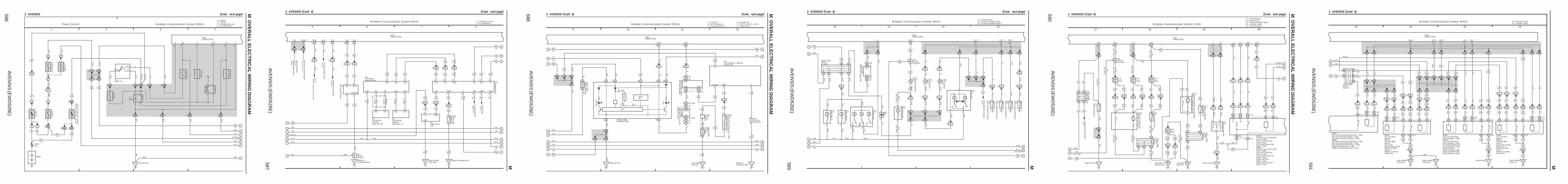
AVE
NS
IS (E
WD
526E)
664
M O
VE
RA
LL
EL
EC
TR
ICA
L W
IRIN
G D
IAG
RA
M
1 2 3 4
39 AVENSIS
3 4B1
140A A
LT
120A A
LT (∗3 )100A
ALT (∗4 )
3 4D13 4A1
3
2
1
2
1
3
5
DH5 DN1DH1
25AAM1
1 ED1
1
30A D
CC
1A1
10A G
AU
GE
1
DB7DA9
IJ Left Kick Panel
DH3
7. 5A R
AD
NO
. 1
6
15A R
AD
NO
. 2
P o w e r S o u rc e N a v ig a tio n S y s te m (M a p T y p e )
B
B–G
B–G
B–G
WBB
–W
WB
–L
G–R
W–B
W–B
R–W
G
G–Y
B–W
2 2
1 1
(∗2 )
(∗1 )(∗1 )
(∗1 )
(∗2 )
(∗2 )
(∗2 )(∗2 )
Battery
FL MAIN3. 0W
B–G
(∗1 )
B–L (∗2 )
IG1Relay
1
2
5 IP1
IE44 (LHD)
(RHD)
2
1
∗ 1 : Gasoline∗ 2 : 1CD–FTV
A1
+B1
4
ACC
IG1
IG2
ST2
AM1
5
AM2
30A A
M2
2
1
1
1 IP1
IE41
B–R
B–R
G–R
B–R
(LHD)
(RHD)
I13 6
7. 5A S
T
2
1
B–Y
DB4
6
6
B–W
CB10CE4
CB9
14 A
ACC
B
C
E
GR
L–Y
GR
L–Y
GR
R–W
L–Y
GR
B–W
L–Y
CF3
CA7
R–W
G
(Cont. next page)
3 A 15 A
IG ST1
B–WR–W
H D
F A F A F A
BH
F C F C F C
(LHD)
(RHD)
(LHD)
(RHD)
GR
GR
GR
GR
Junction Connector
J 8 (A ), J 9 (B ), J20 (C), J21 (D
)
(LHD
)
(LHD
)(LH
D)
GR
GR
(RHD)
(RHD)
AGR
(RHD)
(LHD)
GR
(RH
D)
D
(LHD)
(LHD
)
(LHD
)
(LHD
)
L–Y(RHD)
G–Y
E A
E B E B
L–Y(R
HD
)
L–Y
L–Y
L–Y(RHD)
(RHD)
(RH
D)
JunctionC
onnector
J24 (A ), J25 (B )
Multi–DisplayM 1(A), M 2(B), M 3(C)
Ignition SW
∗ 3 : 1AZ–FSE, 1AZ–FE∗ 4 : 1ZZ–FE, 3ZZ–FE
AVE
NS
IS (E
WD
526E)
665 M
5 6 7 8
39 AVENSIS (Cont' d)
N a v ig a tio n S y s te m (M a p T y p e )
(RHD)
(RHD)
MIC–
MIC+
A
18
TX3–
IP
R
GND2GND1
A
1
MIC–+B
A
L–Y
GR
ACC
9
Neutral S
tart SW
(A/T )<
18–3>B
ack–Up Light S
W(M
/T )<18–3>
ID1
A1
R(LH
D)
W(R
HD
)
G–Y
12
5 C
5
IK
CG
Behind theCombination Meter
10 CH
6 C
BR
B
A
CK
245
W–B
W–B
W–B
W–B
ID1
4
A
A17
GND
W–B
W–B
R B W
A5
SPD
V–W
Com
bination Meter
<42–3>
A14
REV
R–Y
(Shielded )
W
(Shielded )
A2
AUO+
P (LH
D)
LG(R
HD
)
A11
AUO–
V(LH
D)
L (RH
D)
AUI+Tw
eeter LH (LH
D)
<41–4>
A5
GTX+
P
A18
GTX–
LG
Radio and P
layer<
41–4>
A17
PKB
B–W
Parking B
rake SW
<20–6>
<21–6>
Com
bination Meter
<42–3>
A4
SPD
V–W
A 24
Com
bination Meter
<42–5>
A
TX3+
B6
VG
B8
SYNC
B3
B
B7
G
B2
R
B1
VR
6 B
VG
8 B
SYNC
3 B
B
W–B
SNSE
7 B
G
Radio and P
layer<
41–3><
41–4>
7 C
2 B
R
AUI–
1 B
VR
Right Kick Panel IP
YRGBW
(Shielded )
(Shielded )
Right KickPanel
10 B
TX–
5 B
TX+
B10
CTX–
B5
CTX+
VLG
18
DLC
3<
5–19><
6–15><
7–14><
8–15>
A16
TC
W–L
A22
SGD1
A10
RE1
2 3
ACC
SGND TX
7
1
GND
W–B
R
(Shielded )
(Shielded )
C 10
CA
17
25
LG(LH
D)
R (R
HD
)
5
3
BRB
B
R
C
E
MIC+
6 CA
C
G
B–W
9 IC2
J17
16 ID1
MACC
GR
L–Y
SGNDGR
14 ID1
MACC
GR
AGR
Tweeter R
H (R
HD
)<
41–3>
(LHD)
(LHD
)
(LHD
)
DL–Y
(LHD)
L–Y(R
HD
)
CF
W–B
13
(LHD
)
(RH
D)
Multi–DisplayM 1(A), M 2(B), M 3(C)
Navigation ECUN 3(A), N 4(B), N 5(C)
T11Telephone MicrophoneAmplifier
JunctionConnector
J15
Rem
ote Controller
(Navigation )
R11
JunctionConnector
A
AW–B
W–B
(RHD)
(RHD)
W–B
(LHD
)W
–B(LH
D)

AVE
NS
IS (E
WD
526E)
682
M O
VE
RA
LL
EL
EC
TR
ICA
L W
IRIN
G D
IAG
RA
M
1 2 3 4
50 AVENSIS
3 4B1
140AALT
120A ALT(∗3)100A ALT(∗4)
3 4D13 4A1
3
ACC
IG1AM1
2
DH1
25AAM1
1 ED1
1
30ADCC
1A1
DH3
7. 5ARADNO. 1
F B
6 6
CE4
CB10
15A R
AD
NO
. 2
P o w e r S o u rc e O p tio n C o n n e c to r (N a v ig a tio n S y s te m T u rn b y T u rn T y p e )
B
B–G
B–G
B–G
WBB
–W
B–L
GR L–Y
B–W
2 2
1 1
(∗2 )
(∗1 )(∗1 )
(∗1 )
(∗2 )
(∗2 )
(∗2 )
Battery
FL MAIN3. 0W
I13
1
2
5 IP1
IE44 (LHD)
(RHD)
2
1
∗ 1 : Gasoline∗ 2 : 1CD–FTV
Z 1(A), Z 2(B)
G
L–Y
GR
G–Y L B P LG
18 B 11 B9 B 2 B
W
R
G
6 CA
W–B
CF10
IP Right Kick Panel
W–B
F A
E A
E B
(LHD
)
L–Y(R
HD
)L–Y
(RH
D)
L–Y(LHD)
(LHD
)
Multi–Display<40–3><40–4>
F B
F A (LHD)
(LHD)
(RHD)
(RHD)
J 8(A), J20(B)DB4
GR
DN1
G–R
B–W
V–W
Com
bination Meter
<42–3>
Neutral S
tart SW
(A/T )<
18–3>R
–YB
ack–Up Light S
W(M
/T )<18–3>
J24 (A ), J25 (B )
V(LH
D)
L (RH
D)
LG
P (LH
D)
LG(R
HD
)
R
Tweeter LH
(LHD
)<
41–4>
Radio and P
layer<
41–3><
41–4>
Tweeter R
H (R
HD
)<
41–3>
10 A 1 A
6 A 15 A 13 A 16 A 5 A 14 A 3 A 12 A 18 A 9 A 11 A2 A17 A
Ignition SW
JunctionConnector
JunctionC
onnector
∗ 3 : 1AZ–FSE, 1AZ–FE∗ 4 : 1ZZ–FE, 3ZZ–FE
Option Connector (Navigation ECU)

L PART NUMBER OF CONNECTORS
Code Part Name Part Number Code Part Name Part Number
AVENSIS (EWD526E)
Note: Not all of the above part numbers of the connector are established for the supply.
570
A 1 A/C Ambient Temp. Sensor 90980–11030
A 2 A/C Condenser Fan Motor 90980–10928
A 3 A/C Pressure Sensor 90980–10845
A 4 ABS Speed Sensor Front LH
A 5 ABS Speed Sensor Front RH90980–11003
A 6 Air Flow Meter 90980–11317
A 7 Air Fuel Ratio Sensor (Bank 1 Sensor 1) 90980–11178
A 8 Air Fuel Ratio Sensor (Bank 2 Sensor 1) 90980–10869
A 9 Airbag Sensor Front LH
A10 Airbag Sensor Front RH90980–11856
A11 Alternator 90980–11964
Alternator (Except 1CD–FTV) 90980–09212A12
Alternator (1CD–FTV) 90980–09213
A13 A/C Control Assembly 90980–12169
A14 A/C Control Assembly 90980–11778
A15 A/C Control Assembly 90980–12259
A16 A/C Control Assembly 90980–12200
A17 A/C Room Temp. Sensor 90980–11918
A18 A/C Solar Sensor 90980–11987
A19 A/C Thermistor 90980–11918
A20 Accel Position Sensor 90980–11144
A21 Air Inlet Control Servo Motor 90980–11987
A22 Air Mix Control Servo Motor
A23 Air Mix Control Servo Motor (Driver Side)
A24Air Mix Control Servo Motor (FrontPassenger Side)
90980–11909
A25 Air Vent Mode Control Servo Motor
A26 Airbag Sensor Assembly 82824–50160
A27 Airbag Sensor Assembly 90980–11872
A28 Airbag Sensor Assembly 82824–50150
A29Airbag Squib (Front Passenger AirbagAssembly) 90980–12160
A30 Airbag Squib (Steering Wheel Pad)
A31 Antenna Amplifier 90980–10870
A32 ABS Speed Sensor Rear LH
A33 ABS Speed Sensor Rear RH90980–11060
B 1 Back–Up Light SW 90980–10576
B 2 Brake Booster Pressure Sensor 90980–10845
B 3 Brake Fluid Level Warning SW 90080–98001
B 4 Blower Motor 90980–10214
B 5 Blower Motor Controller 90980–11676
B 6 Blower Resistor 90980–11136
Back Door Courtesy SWB 7
Back Door Lock Motor90980–10795
B 8 Back Door Opener SW 90980–11967
B 9 Buckle SW (Driver’s Side) 90980–10942
Buckle SW (Front Passenger’s Side)B10
Occupant Detection Sensor90980–10795
C 1 Camshaft Position Sensor 90980–10947
C 2 Camshaft Timing Oil Control Valve 90980–11162
C 3 Compressor Assembly 90980–11156
C 4 Condenser Assembly 90980–11003
C 5 Counter Gear Speed Sensor 90980–11156
Crankshaft Position Sensor (1AZ–FSE,1AZ–FE) 90980–10947
C 6 Crankshaft Position Sensor (1CD–FTV) 90980–12028
Crankshaft Position Sensor (1ZZ–FE,3ZZ–FE) 90980–10947
Cigarette LighterC 7
Cigarette Lighter Illumination90980–10795
C 8 Circuit Opening Relay 82660–05020
C 9 Clutch Start SW 90980–10825
C10 Combination Meter 90980–11913
C11 Combination Meter 90980–11915
C12 Combination SW 90980–11672
C13 Combination SW 90980–11594
C14 Combination SW 90980–12183
C15 Curtain Shield Airbag Sensor LH
C16 Curtain Shield Airbag Sensor RH90980–12352
C17 Curtain Shield Airbag Squib LH
C18 Curtain Shield Airbag Squib RH90980–12219
D 1 Diesel Throttle Control Motor 90980–11144
D 2 Diode 90980–11071
D 3 Diode 90980–10962
Diode (Fan) (Except 1CD–FTV) 90980–11608D 4
Diode (Fan) (1CD–FTV) 90980–11071
D 5 DLC3 90980–11665
D 6 Door Control Receiver 90980–11909
D 7 Door Courtesy Light LH
D 8 Door Courtesy Light RH90980–11148
D 9 Door Courtesy SW Front LH
D10 Door Courtesy SW Front RH
D11 Door Courtesy SW Rear LH90980–10871
D12 Door Courtesy SW Rear RH
Door Key Lock and Unlock SW (Driver’sSide)
D13Door Lock Control Motor (Driver’s Side)
90980–12226
Door Unlock Detection SW (Driver’s Side)

L
Code Part Name Part Number Code Part Name Part Number
AVENSIS (EWD526E)
571
Door Key Lock and Unlock SW (Driver’sSide)
Door Lock Control Motor (Driver’s Side)D14
Door Unlock Detection SW (Driver’s Side)
Double Lock Motor (Driver’s Side)
Double Lock Position SW (Driver’s Side)
D15Door Lock Control Motor (FrontPassenger’s Side) 90980–12226Door Lock Control Motor (FrontPassenger’s Side)
Door Unlock Detection SW (FrontPassenger’s Side)
D16Double Lock Motor (Front Passenger’sSide)
Double Lock Position SW (FrontPassenger’s Side)
Door Lock Control SWD17
Power Window Master SW90980–12200
D18 Door Lock Motor Rear LH
Door Lock Motor Rear LH
Door Unlock Detection SW Rear LHD19
Double Lock Motor Rear LH
Double Lock Position SW Rear LH
D20 Door Lock Motor Rear RH90980–12226
Door Lock Motor Rear RH
Door Unlock Detection SW Rear RHD21
Double Lock Motor Rear RH
Double Lock Position SW Rear RH
E 1 ECT Solenoid 90980–11658
EFI Water Temp. Sensor (Except 1AZ–FE) 90980–10737E 2
EFI Water Temp. Sensor (1AZ–FE) 90980–10735
E 3 EGR Valve Control Motor 90980–11144
E 4 Electronic Driver Unit 90980–11592
Electronic Driver Unit (1AZ–FSE) 90980–11024E 5
Electronic Driver Unit (1CD–FTV) 90980–11593
E 6 Engine Hood Courtesy SW 90980–10554
E 7 Engine Oil Level Sensor 90980–11235
E 8 ECT Pattern Select SW 90980–11013
Engine and ECT ECU (A/T)E 9
Engine ECU (M/T)90980–12142
Engine and ECT ECU (A/T)E10
Engine ECU (M/T)90980–12146
Engine and ECT ECU (A/T)E11
Engine ECU (M/T)90980–12143
Engine and ECT ECU (A/T)E12
Engine ECU (M/T)90980–12145
Engine and ECT ECU (A/T)E13
Engine ECU (M/T)90980–12144
E14 EPS ECU 90980–12300
E15 EPS ECU 90980–12290
F 1 Front Clearance Light LH
F 2 Front Clearance Light RH90980–11149
F 3 Front Fog Light LH
F 4 Front Fog Light RH90980–11660
F 5 Front Side Turn Signal Light LH
F 6 Front Side Turn Signal Light RH90980–11162
Front Turn Signal Light LHF 7
Headlight Control ECU LH
Front Turn Signal Light LHF 8
Headlight LH (Low)
Front Turn Signal Light RH90980–10942
F 9Headlight Control ECU RH
Front Turn Signal Light RHF10
Headlight RH (Low)
F11 Front Washer Motor 90080–98117
F12 Front Window Deicer 90980–11155
F13 Front Wiper Motor 90980–11599
F14 Fuel Filter Warning SW 90980–11002
F15 Fuel Heater 90980–10928
Fuel Pressure Sensor (1AZ–FSE) 90980–11451F16
Fuel Pressure Sensor (1CD–FTV) 90980–11194
F17 Fuel Pump 90080–98001
F18 Fuel Temp. Sensor 90980–10737
Front Passenger’s Seat Belt Warning Light
F19 Rear Window Defogger SW 90980–11989
Security Indicator Light
F20 Front Wiper Deicer SW 90980–10797
F21 Front Door Speaker LH
F22 Front Door Speaker RH90080–98157
F23 Fuel Lid Opener Motor 90080–98313
F24 Fuel Lid Opener SW 90980–11013
Fuel PumpF25
Fuel Sender90980–11077
G 1 Glow Plug 99141–13006
G 2 Glow Plug Relay 90980–11569
G 3 Glove Box Light 90980–11098
H 1 Headlight Beam Level Control Actuator LH
H 2 Headlight Beam Level Control Actuator RH90980–11016
H 3 Headlight Cleaner Control Relay 90980–10939
H 4 Headlight Cleaner Motor 90080–98116
H 5 Headlight LH (High)
H 6 Headlight RH (High)90980–11314

L PART NUMBER OF CONNECTORS
Code Part Name Part Number Code Part Name Part Number
AVENSIS (EWD526E)
Note: Not all of the above part numbers of the connector are established for the supply.
572
Heated Oxygen Sensor (Bank 1 Sensor 1)(1AZ–FSE) 90980–11028
H 7Heated Oxygen Sensor (Bank 1 Sensor 1)(1ZZ–FE, 3ZZ–FE) 90980–10869
H 8 Heated Oxygen Sensor (Bank 1 Sensor 2) 90980–11028
H 9 Heated Oxygen Sensor (Bank 2 Sensor 1) 90980–10869
H10 Heated Oxygen Sensor (Bank 2 Sensor 2) 90980–11028
H11 Horn LH
H12 Horn RH90980–10619
H13 Hazard SW 90980–10801
H14 Headlight Beam Level Control ECU 90980–12200
H15 Headlight Beam Level Control SW 90980–10789
H16 Headlight Cleaner SW 90980–10601
H17 Heated Oxygen Sensor (Bank 1 Sensor 2) 90980–11930
H18 Height Control Sensor (Front)
H19 Height Control Sensor (Rear)90980–11860
High Mounted Stop Light (L/B) 90980–10320
H20 High Mounted Stop Light (S/D) 90980–WB002
High Mounted Stop Light (W/G) 90980–11148
I 1 Ignition Coil and Igniter No.1
I 2 Ignition Coil and Igniter No.2
I 3 Ignition Coil and Igniter No.390980–11885
I 4 Ignition Coil and Igniter No.4
Injector No.1 (Except 1AZ–FSE) 90980–11875I 5
Injector No.1 (1AZ–FSE) 90980–12117
Injector No.2 (Except 1AZ–FSE) 90980–11875I 6
Injector No.2 (1AZ–FSE) 90980–12117
Injector No.3 (Except 1AZ–FSE) 90980–11875I 7
Injector No.3 (1AZ–FSE) 90980–12117
Injector No.4 (Except 1AZ–FSE) 90980–11875I 8
Injector No.4 (1AZ–FSE) 90980–12117
I 9 Intake Air Temp. Sensor 90980–11025
I10 ISC Valve 90980–11145
I11 Ignition Key Cylinder Light
Ignition Key Cylinder Light 90980–12092I12
Transponder Key Amplifier
I13 Ignition SW 90980–11778
I14 Integration Relay 90980–11915
I15 Inner Mirror 90980–11794
I16 Interior Light 90980–11950
J 1 Junction Connector
J 2 Junction Connector90980–10803
J 3 Junction Connector
J 4 Junction Connector90980–11661
J 5 Junction Connector 90980–11542
J 6 Junction Connector
J 7 Junction Connector90980–11915
J 8 Junction Connector
J 9 Junction Connector
J10 Junction Connector90980–11915
J11 Junction Connector
J12 Junction Connector
J13 Junction Connector90980–11661
J14 Junction Connector 90980–11542
J15 Junction Connector 90980–10976
J16 Junction Connector
J17 Junction Connector90980–11542
J18 Junction Connector
J19 Junction Connector
J20 Junction Connector90980–11915
J21 Junction Connector
J22 Junction Connector
J23 Junction Connector
J24 Junction Connector90980–11661
J25 Junction Connector
J26 Junction Connector
J27 Junction Connector90980–11915
J28 Junction Connector 90980–11542
J29 Junction Connector 90980–11915
J30 Junction Connector
J31 Junction Connector90980–11661
J32 Junction Connector 90980–11542
J33 Junction Connector
J34 Junction Connector
J35 Junction Connector
J36 Junction Connector90980–11661
J37 Junction Connector
J38 Junction Connector
K 1 Knock Sensor 90980–11875
K 2 Kick Down SW 90980–11156
K 3 Knee Airbag Squib 90980–12253
L 1 License Plate Light LH
L 2 License Plate Light RH90080–98001
Luggage Compartment Door Lock MotorL 3
Luggage Compartment Light SW90980–10908
L 4 Luggage Compartment Door Opener SW 90980–11967
L 5 Luggage Compartment Light 90980–11148
L 6 Lumbar Support Control Motor 90980–10825
L 7 Lumbar Support Control SW 90980–10789
Multi–Display (w/ Navigation System (MapType)) 90980–11877
M 1Multi–Display (w/o Navigation System (MapType)) 90980–11973

L
Code Part Name Part Number Code Part Name Part Number
AVENSIS (EWD526E)
573
Multi–Display (w/ Navigation System (MapType)) 90980–11923
M 2Multi–Display (w/o Navigation System (MapType)) 90980–12209
M 3 Multi–Display 90980–10871
Mirror Heater LHM 4
Remote Control Mirror LH
Mirror Heater RH90980–12059
M 5Remote Control Mirror RH
M 6 Moon Roof Control Relay and Motor 82824–05030
M 7 Moon Roof Control SW 90980–10795
N 1 Neutral Start SW 90980–11784
N 2 Noise Filter (Ignition) 90980–10843
N 3 Navigation ECU 90980–11973
N 4 Navigation ECU 90980–11923
N 5 Navigation ECU 90980–12221
N 6 Noise Filter (Rear Window Defogger No.1)
N 7 Noise Filter (Rear Window Defogger No.2) 90980–10825
N 8 Noise Filter (Stop Light)
O 1 Oil Pressure Sensor 90080–98200
O 2 Oil Pressure SW 90980–11363
P 1 Power Heater Assembly 90980–10897
P 2 Power Steering Oil Pressure SW 90980–11428
P 3 Pressure Discharge Valve 90980–11285
P 4 Parking Brake SW 90980–10871
P 5 Power Heater SW 90980–10996
P 6 Power Outlet 90080–98182
P 7 PTC Heater 90980–11685
P 8 Personal Light 90980–11950
P 9Power Window Control SW (FrontPassenger Side)
P10 Power Window Control SW Rear LH90980–12113
P11 Power Window Control SW Rear RH
P12 Power Window Motor Front LH
P13 Power Window Motor Front RH
P14 Power Window Motor Rear LH90080–98276
P15 Power Window Motor Rear RH
P16 Pretensioner LH
P17 Pretensioner RH90980–12253
P18 Power Seat Control SW (Driver’s Seat)
P19Power Seat Control SW (Front Passenger’sSeat)
90980–10997
P20Power Seat Motor (Driver’s Seat FrontVertical Control)
P21Power Seat Motor (Driver’s Seat LifterControl) 90980–10825
P22Power Seat Motor (Driver’s Seat RecliningControl)
P23Power Seat Motor (Driver’s Seat SlideControl)
P24Power Seat Motor (Front Passenger’s SeatReclining Control) 90980–10825
P25Power Seat Motor (Front Passenger’s SeatSlide Control)
R 1 Radiator Fan Motor
R 2 Radiator Fan Resistor90980–10928
R 3 Rear Washer Motor 90080–98117
R 4 Radio and Player 90980–10997
R 5 Radio and Player 90980–10996
R 6 Radio and Player 90980–12183
R 7 Radio and Player 90980–12259
R 8 Rear Fog Light Relay 82660–05010
R 9 Rear Window Defogger Relay 82660–05020
R10 Remote Control Mirror SW 90980–11657
R11 Remote Controller (Navigation) 90980–11909
R12 Rain Sensor 90080–98309
Rear Combination Light LH (Except W/G) 90080–98175R13
Rear Combination Light LH (W/G) 90980–10964
Rear Combination Light RH (Except W/G) 90080–98175R14
Rear Combination Light RH (W/G) 90980–10964
R15 Rear Door Speaker LH
R16 Rear Door Speaker RH90080–98157
R17 Rear Interior Light 90980–11148
Rear Window Defogger (L/B) 90980–11258R18
Rear Window Defogger (S/D, W/G) 90980–11259
Rear Window Defogger (L/B) 90980–11258
R19 Rear Window Defogger (S/D) 90980–10786
Rear Window Defogger (W/G) 90980–11259
R20 Rear Wiper Motor and Relay 90980–10908
S 1 Skid Control ECU with Actuator 90080–98278
S 2 Skid Control ECU with Actuator 90980–WB001
S 3 Spill Valve 90980–12117
S 4 Starter 90980–11400
Starter (1AZ–FSE, 1AZ–FE) 90980–09506
S 5 Starter (1CD–FTV) 90980–09507
Starter (1ZZ–FE, 3ZZ–FE) 90980–09463
S 6 Suction Control Valve 90980–11285
S 7 Seat Heater SW 90980–11909
S 8 Seat Heater SW 90980–11918
S 9 Shift Lock Control ECU 90980–12183
S10 Short Connector 90980–10797
S11 Short Connector 90980–10796
S12 Steering Sensor 90080–98241
S13 Stop Light SW 90980–11118

L PART NUMBER OF CONNECTORS
Code Part Name Part Number Code Part Name Part Number
AVENSIS (EWD526E)
Note: Not all of the above part numbers of the connector are established for the supply.
574
Side Airbag Sensor LH (w/ Curtain ShieldAirbag) 90980–12225
S14Side Airbag Sensor LH (w/o Curtain ShieldAirbag) 90980–12352
Side Airbag Sensor RH (w/ Curtain ShieldAirbag) 90980–12225
S15Side Airbag Sensor RH (w/o Curtain ShieldAirbag) 90980–12352
Seat Heater LH (w/ Power Seat) 90980–10797S16
Seat Heater LH (w/o Power Seat) 90980–11090
Seat Heater RH (w/ Power Seat) 90980–10797S17
Seat Heater RH (w/o Power Seat) 90980–11090
S18 Side Airbag Squib LH
S19 Side Airbag Squib RH90980–11864
T 1 Throttle Control Motor and Position Sensor 90980–11858
T 2 Throttle Position Sensor 90980–11261
T 3 Throttle Position SW 90980–11038
T 4 Turbine Speed Sensor 90980–11156
T 5 Turbo Pressure Sensor 90980–10845
T 6 Theft Deterrent ECU 90980–12169
T 7 Transmission Control SW 90980–12221
T 8 Transponder Key Computer 90980–11911
T 9 TRC Off SW 90980–10801
T10 Turn Signal Flasher Relay 90980–10799
T11 Telephone Microphone Amplifier 90980–11909
T12 Theft Warning Ultrasonic Sensor 90980–12221
T13 Theft Warning Ultrasonic Sensor Rear LH
T14 Theft Warning Ultrasonic Sensor Rear RH90980–11918
T15 Theft Warning Siren 90980–11349
T16 Tweeter Front LH
T17 Tweeter Front RH
T18 Tweeter Rear LH90980–12304
T19 Tweeter Rear RH
U 1 Unlock Warning SW 90980–10860
V 1 Vacuum Sensor 90980–10845
V 2 Vacuum SW 90980–11252
V 3 Variable Resistor 90980–10902
V 4 VRV (EGR) 90980–11162
V 5 VSV (EVAP) 90980–10572
V 6 VSV (Intake Air Control Valve) 90980–11149
V 7 VSC Warning Buzzer 90980–10906
V 8 Vanity Light LH
V 9 Vanity Light RH90980–11918
W 1 Water Temp. SW (Radiator Fan) 90980–11235
W 2 Wiper Relay 90080–98318
Y 1 Yaw Rate Sensor 90080–98249
Z 1 Option Connector (Navigation ECU) 82824–30240
Z 2 Option Connector (Navigation ECU) 90980–11973

L
Code Part Name Part Number Code Part Name Part Number
AVENSIS (EWD526E)
575

AVE
NS
IS (E
WD
526E)
671 M
1 2 3 4
43 AVENSIS
B
3
140A A
LT
1
2
31
25A P
WR
HTR
1
2
W W
FL MAIN3. 0W
Battery
25AAM1
DH
I13Ignition SW
1 DH5 DN1
2
1
3
5
10AHTR
DC6DA9
12 IE6
2
1
M
ECEngine Compartment Left
8 3 2 1
6
3
5
IJLeft Kick Panel IK
W–B
L
W–B
G–Y
YW
G–Y
Y
G–Y
W–B
B–L
G–R
J15
P 1
P 5
F17
IG1 R
elay
P o w e r H e a te r (C o m b u s tio n T y p e )P o w e r S o u rc e
Fuel Pum
p
JunctionConnector
A
2 W–B
Alternator
<3–3>
A
A
W–B
JunctionC
onnector
J 2
1A1 3
3 3
G–Y
Behind the Combination Meter
3 33 3
5 2
3 1
3 3 3 3
50A H
TR2
50A H
TR1
HTR
1 Relay
HTR
2 Relay
2 5
1 3
A/C Control Assembly<48–8><49–8>
3 1AM1
ACC
IG1
CB1
CK12
R–W
B
EINear the Starter
5 IK2 16 IK2
B–R B
R–W
B–R
W–L
B
R–W
W–L
BR WBRB
BR
1 2
W
PTC HeaterP 7
1 ED1
B–L
R–W
W–B
1
22
1
P o w e r H e a te r(E le c tr ic a l T y p e )
3 EE1BR
INE
IG
–F/PSWALT+L
+
PTC2PTC1
Power Heater Assembly
Pow
er Heater S
W
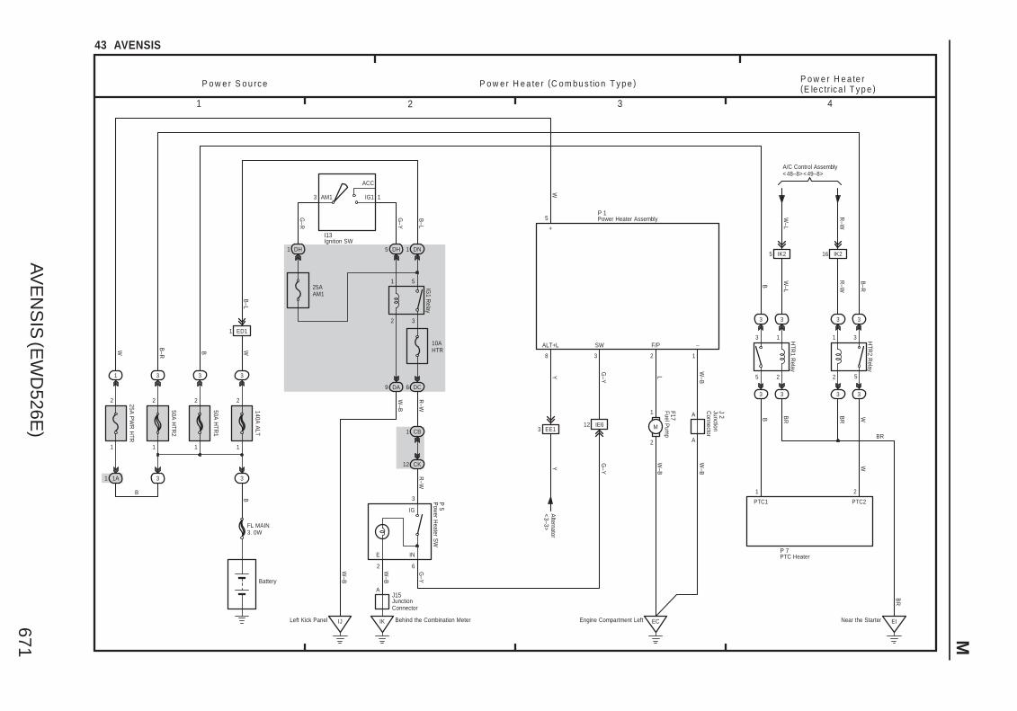

AVE
NS
IS (E
WD
526E)
676
M O
VE
RA
LL
EL
EC
TR
ICA
L W
IRIN
G D
IAG
RA
M
1 2 3 4
47 AVENSIS (Cont. next page)
B–G
B–G
FL MAIN3. 0W
Battery
120A A
LT (∗3 )100A
ALT (∗4 )
1
40A H
TR
1B1
2
1
B–W
7. 5A E
CU
–B 2
63
ACC
IG1AM1 1
I13Ignition SW
1 DH
25A A
M1
DN1DH5
2
1
3
5
DA9
10A H
TR
IG1 R
elay
DC6
IJLeft Kick Panel
W–R
3
5
2
1
4
DP
DF DADF
HTRRelay
L
L
B–G
B–G
B–G
G–Y
R–W
W–B
W–B
W–B
L–B
GR
–R
B
3
+B
L–B
4
VM
B–W
1 2
GND SI
A15(A), A16(B)A/C Control Assembly
L–B
W–B
IK Behind theCombination Meter
B 5B
lower M
otorC
ontroller
R–W
2
GR
–R
CE6
CE2
CC10
CF7
R–W
W–R
IG +B
R–W
W–R
P o w e r S o u rc e A ir C o n d itio n e r (A u to m a tic A /C ) a n dP o w e r H e a te r (H o t G a s T y p e A u to m a tic A /C )
4A 4C 4D
4B
1
2
12 B 24 B
17 B 5 B
HR BLW
R
BR–W(LHD)
G–R
1
1 1
(∗1 )(∗1 )
(∗1 )
(∗1 )
A
JunctionConnector
J15
CB1
CJ9
R–W
2 IK2
3 IK2
1
RR
R
8 A
SOL+
∗ 2 : 1CD–FTV w/ Power Heater (Hot Gas Type)
∗ 1 : Gasoline
2
3424
B
B
140A A
LT
W W
3 33
3
1
2
(∗2 )
(∗2 )
(∗2 )
(∗2 )
1
30A D
CC
1A1
2
1
B–W
5 IP1
IE44(RHD)
(LHD)
B–W
1 ED1
B–L
(∗2 ) (∗1 )
B–L
(∗2 )
2
1
1
6
C 3
(LHD
)
H A H A
F B
H A
(LHD
)
(LHD
)(LH
D)R–W
(LHD)
AR–W(RHD)
JunctionConnector
J26(A), J27(B)
R–W
R–W
R–W
R–W
R–W
R–W
(RH
D)
(RHD)
(RH
D ∗2 )
(RH
D)
(RH
D)
(RHD)
R–W
(RH
D)
IE218
IE111
CK12
IL Behind theCombination Meter
2 6
2
3
1
R–Y
R–B
R–W
R–W
R–W
G–Y
W–B
C 4
IG
E IN
P 5
11 B
HOTGASIN
G–Y
(LHD
∗2 )
2
1
M
Blow
er Motor
B 4
F B
R–W
(RH
D)
MGV
R–Y
7 A
DB5
H A
(RH
D ∗2 )
R–W
(LHD
∗2 )
R–W
(RH
D ∗2 )
(∗2 )
(∗2 )
(∗2 )
(∗2 )
(∗2 )(∗2 )
(∗2 )
∗ 3 : 1AZ–FSE, 1AZ–FE∗ 4 : 1ZZ–FE, 3ZZ–FE
1 IJ2 2 IJ2
LW
–B
4 IJ2IJ23
R
L–B
A
AJunctionC
onnector
J16
W–B
(∗2 )
Com
pressor Assem
bly
CondenserAssembly
Pow
er Heater S
W
AVE
NS
IS (E
WD
526E)
677 M
5 6 7 8
47 AVENSIS (Cont' d)
A ir C o n d itio n e r (A u to m a tic A /C ) a n d P o w e r H e a te r (H o t G a s T y p e A u to m a tic A /C )
G
2
1
SG–5
A17A
/C R
oom Tem
p. S
ensor
GR
TR
6 B 22 B
13 B
GND
W–B
CG3
CA6
RightKickPanel
IP
W–B
W–R
FAN
NO
. 3 Relay
<44–3>
<45–2>
<46–3>
CFAN
2
(LHD
)
(LHD
)
A18A/C Solar Sensor
PP
(RH
D)
(LHD
) 2
R(R
HD
)
(RH
D)
5
W
IQ1
W(R
HD
)
(RH
D)
Y
17
IQ1
LL
IQ1
Y
4
(RH
D)
(RH
D)
(RHD)2 1 3 4 5
FACEPT DEFVZGND
TSP
B21
IF11
2 3
IF1
9 BA
TSD
LGLG
B–W
Parking B
rake SW
<20–6>
<21–6>
MAXHOT
MAXCOOLPTVZGND
MAXHOT
MAXCOOLPTVZGND
(RH
D)
(LHD
)
(LHD
)IQ1 3
V
R–W(LHD)
R
1
MM
3
IQ1
OO
S5–4
B15
IF13
A25Air Vent Mode Control Servo Motor
7 B
PRE
17 IE2
L–W
G–W
IE28
SG
B18
2
L–W
G–W
13
B–W
B
W–G
PBKIG
A
(RH
D)
V(R
HD
)
TESG–4
B10A16
1
19
A19A
/C Therm
istor
A 3
2
1
6 A
3 5 42
14 A
Y–R
2 B
Y–B
GR B P–L
A23
8 B 11 A 12 A
Air Mix Control Servo Motor(Driver Side)
A
AMDHTPD AMDCS5–2SG–2
3 A 4 A 13
1
B A 1 B 20 B 1 A 2 A
16 B
S5
7
5
IE2
B–W
SG–1 S5–1 AMPCTPP AMPH
A15
Air Mix Control Servo Motor(Front Passenger Side)
A24
WYVRP
45321
REC
B
FRS
19
2
P–B
1
R–Y
Air Inlet C
ontrolS
ervo Motor
A21
SG–3 S5–3 AODTPM AOF
B14
5
L–B
43
LG–B
GR
–R
21
BR
–W
G–W
(LHD)
A/C Control AssemblyA15(A), A16(B)
M
R–W(RHD)A
(LHD
)
W–B
IK Behind theCombination Meter
JunctionConnector
J15A
(LHD
)
(RH
D)
W–B
(RH
D)
+
REC FRS
DE
F I/UP
Fuse<
36–3>
RDEFIN
4 B
PBLT
3 B
MPX+
10 A
MPX–
20 A
Multiplex C
omm
unicationS
ystem<
1–15><
2–11>
G–W
W–B
(RH
D)
A
A
JunctionConnector
J17
∗ 1 : Gasoline
(∗1 )A/C Pressure Sensor

AVE
NS
IS (E
WD
526E)
678
M O
VE
RA
LL
EL
EC
TR
ICA
L W
IRIN
G D
IAG
RA
M
1 2 3 4
48 AVENSIS
P o w e r S o u rc e A ir C o n d itio n e r (M a n u a l A /C ) a n d P o w e r H e a te r (H o t G a s T y p e M a n u a l A /C )
6 B5 B
RL–B
3 IJ1 2 IJ1
M2 M1
(Cont. next page)
BW B–G
B–G
FL MAIN3. 0W
Battery
120A A
LT(1A
Z–FE)
100A A
LT(1ZZ–FE
, 3ZZ–FE)
1
40A H
TR
1B1
2
1
B–W
7. 5A E
CU
–B 2
6
3
ACC
IG1AM1 1
I13Ignition SW
1 DH
25A A
M1
DN1DH5
2
1
3
5
DA9
10A H
TR
IG1 R
elay
DC6
IJLeft Kick Panel
W–R
3
5
2
1
4
DP
DF DADF
HTR
Relay
L
L
B–G
B–G
G–R
B–G
G–Y
R–W
W–B
3
W–B
W–B
W
4 2 34
2
(∗2 )B
–L
(∗1 )
L–B
GR
–R
140A A
LT
B
3
(∗2 )
2
1
3
4A 4C 4D
4B
1
2
3
G–R
(∗1 )
∗ 2 : 1CD–FTV
(∗2 )B
–L
B–W
(LHD)
(RHD)5 IP1
IE44
1
B–W
1
2
1 1A
30A D
CC
(∗2 )
(∗2 )
(∗2 )
∗ 1 : Gasoline
1
1
(∗1 )
(∗1 )
1
(∗1 )
2
1
M BlowerMotor
B 4
4 B
L
HI
L
L
2 B
GR
–R
C1
4 CK
5 CE
CA1
HRIN
GR
–R
A353 B
GR
–R
C2
7 CG
2
1
1 ED1
IK ∗4
GND
J15JunctionConnector
1 B
W–B
W–B
A
6
1
W–B
4 IJ11 IJ1
L
1 3 2 4
HI M2 M1 LO
(LHD
)
W–B
(RH
D)
(RH
D)
(LHD
)
(LHD
)
(LHD
)
C C CC
(RH
D)
(RH
D)
(RH
D)
GR
–R
GR
–R
GR
–R
(RH
D)
GR
–R
Junction ConnectorJ28
(∗3 )
J16
R–W
R–B
R–Y
1
2
A
11 IE1
18 IE2
(∗3 )(∗3 )
14 A
MGV
DB
R–W
5
(LHD
∗3 )
R–W
GR–R
(LHD ∗3)
(LHD)
(LHD
)G
R–R
R–W(RHD ∗3)
C 4
(RH
D)
R–W
A/C Control AssemblyA13(A), A14(B)
A
B
C
D
E
F
G
W–B
R–W(RHD)
R–W(LHD)
W–R
W–B(RHD)
W–B(LHD)
W–B
Blower SW A/C Amplifier
JunctionConnector
(∗3 )
(∗3)
(LHD
)
BlowerResistor
B 6
RL–B
B–W
W–B
∗ 4 : Behind the Combination Meter
Behind theCombination Meter
IL
A
W–B
(∗3 )
∗ 3 : 1CD–FTV Power Heater (Hot Gas Type)
Condenser A
ssembly
AVE
NS
IS (E
WD
526E)
679 M
5 6 7 8
48 AVENSIS (Cont' d)
A ir C o n d itio n e r (M a n u a l A /C ) a n d P o w e r H e a te r (H o t G a s T y p e M a n u a l A /C )
IK22
17
W–R
2 A11 A 10 A1 A
1 2
3
R–W
W–R
R–Y
P–B
R–W
R–W
2CF7
IG REC FRS +B
(LHD)
+
FRSREC
A21A
ir Inlet Control
Servo M
otor
C 3
IK23
GND
W–B
3 CG
6 CA
A40
1
R
R–W
1 CB
6 CE2 CE
12 CK
W–B
W–B
IPRight Kick Panel
CC10R
–W
2
1
39 A31 A
W–G
B
TE SG–4
B–W
A/C
Thermistor
G–W
L–W
A 3
PRESGS5
L–W
G–W
B–W
21
RPTC1(SIG1)
A28
23 A
G–W
BR
–W
GR
–R
LG–B
L–B
3
A32A38
FAN
NO
. 3 Relay
<44–3>
<45–2>
<46–3>
W–R
A
37 A 6 A 33 A 12 A 13 A
1 2 3 4 5
F
7
SG–3 S5–3 TPM AOD AOF
CFAN
A/C Amplifier
GND VZ PT DEF FACE
M
25 A
Parking B
rake SW
<20–6>
<21–6>
B–W
PBKIG
17 IE2IE287 IE2
Multiplex C
omm
unicationS
ystem<
1–15><
2–11>
29 A
MPX–MPX+
A9
Air Vent Mode Control Servo MotorA25
A19
CG9
IK Behind theCombination Meter
J17JunctionConnector
W–B
A
(LHD
)
(LHD
)
(LHD
)
(RH
D)
A
W–B
(RH
D)
A
R
SOL+
H AH A
F B
H A
JunctionConnector
J26(A), J27(B)
R–W
R–W
R–W
R–W
(RH
D)
(RH
D)
(RH
D)
(RH
D)
(LHD
)
Y–B
Y–R
GR B P–L
5 A 36 A 34 A 16 A 15 A
1 2 3 4 5
S5–2 SG–2 TP AMC AMH
VZ GND PT MAXCOOL
MAXHOT
M
Air Mix Control Servo MotorA22
(∗3 )W
–B
G–Y
R–W
3
62
(LHD
∗3 )
IG
E IN
P 5
(∗3 )
(LHD
∗3 )
H A
R–W
(RH
D ∗3 )
22 A
HOTGASIN
R–W
CJ9R–W
(LHD ∗3)
F B
R–W
(RH
D ∗3 )
(LHD
)
R–W
(RH
D)
R–W
R–W(RHD)
(∗5 )E
ngine EC
U (M
/T )<
8–7>
B–W
ALT(EFII)
A26
(∗5 )A
lternator<
3–3>
W–L
PTC1(PTC)
A20
(∗5 )H
TR1 R
elay<
43–4>
R–W
PTC2(PTCL)
A19
(∗5 )H
TR2 R
elay<
43–4>
R–Y
HRLY
A30
(∗5 )H
–LP R
elay<
1–8><
13–1>
G
ER–W
D
(RHD ∗3)
C
B
W–B
A
R–W(RHD)
R–W(LHD)
W–R
W–B(RHD)
W–B(LHD)
A/C Control AssemblyA13(A), A14(B)
24 A
PBLT
4 A
RDEFIN
DE
F I/UP
Fuse<
36–3>
∗ 6 : Except 1AZ–FE∗ 5 : Power Heater (Electrical Type)
∗ 1 : Gasoline∗ 3 : 1CD–FTV Power Heater (Hot Gas Type)
(RHD)R–W
G–W
(∗1 )
(∗3)
(∗6 )
(LHD
)
J15JunctionConnector
A
A
W–B
(RH
D)
Com
pressor Assem
bly
A/C Pressure Sensor
Pow
er Heater S
W

AVE
NS
IS (E
WD
526E)
652
M O
VE
RA
LL
EL
EC
TR
ICA
L W
IRIN
G D
IAG
RA
M
1 2 3 4
30 AVENSIS
1
3
DH
9
IG1 R
elay
DA
ED11
W (∗1 )
2
30A H
/CLN
3
140A A
LT
1
2
3
I13
1
1
1
DH1
Battery
FL MAIN3. 0W
5
2
1AM1 IG1
ACC
3
25AAM1
5
B–G
DN
1 4D
2
1
120A A
LT (∗3 )100A
ALT (∗4 )
1 4B
L–R
W–B
2 30A H
–LP C
LN
1
4
L
1 IE1
1
2
M
EB Engine Compartment RightIJ
W–B
H 4
H 3
H16
3 2
1 4 5
4
1
LRR
R–Y
W–B B
–WW
–BW
–B
W–B
H e a d lig h t C le a n e r (w /o H ID )P o w e r S o u rc e
∗ 1 : Gasoline∗ 2 : 1CD–FTV
Combination SW<13–2>
1 1B
(∗2 )
3
(∗2 )W (∗1 )
G–Y
G–R
DA19
15AP
/PO
INT
5P
/PO
INT
Relay
5
5
5
A
IKLeft Kick Panel
(∗1 )B
–G
(∗2 )B
–L
3 2
5 1
W–B
J17
W–L
GR
F C
H B
Behind theCombination Meter
3 DH
4 DB
GR
G
2 G
C
C
W–R
W–B
L–R
W–L
J 8(A), J 9(B), J20(C), J21(D)
J 1
L
G–R
(∗2 )L
(∗2 )B
–L
DL17
25A W
IP
L–R
7. 5AR
AD
NO
. 1
(∗1 )
(∗2 )
(∗2 )B (∗1 )
B–G
P o w e r O u tle t
Integration Relay<1–7>
AF
DH
(LHD)
(RHD)
(LHD)
(RHD)
HeadlightCleaner Motor
Headlight
Cleaner S
W
Ignition SW
JunctionConnector
Junction Connector
JunctionConnector
21 DA
W–B
∗ 3 : 1AZ–FSE, 1AZ–FE∗ 4 : 1ZZ–FE, 3ZZ–FE
1 II1
1
2
2 II1
W–R
W–B
Pow
er Outlet
P 6A
IP Right Kick Panel
AJ15JunctionConnector
W–B
W–B
(RH
D)
(LHD
)
W–B
Headlight Cleaner Control Relay

AVE
NS
IS (E
WD
526E)
663 M
1 2 3 4
38 AVENSIS
120A A
LT (∗3 )100A
ALT (∗4 )
6A1
30APWR SEAT
2
1
6
BV Under the RightCenter Pillar
1
4 9
L
6
L–B
2
1
M
3 2
Power Seat Control SW(Front Passenger' s Seat)
P19
P24
Battery
FL MAIN3. 0W
B–G
R–L (LH
D)
Y–R
(RH
D)
W
W
W–B Y
–R
Y–B
W–B
P o w e r S e a tP o w e r S o u rc e
1
2
4
4B
Slide Reclining
E SLDR RCLF RCLR
B
Front
Rear
Front
Rear
2
2
M
Pow
er Seat M
otor(Front P
assenger's S
eat S
lide Control )
P25
(LHD
)
BRUnder the LeftCenter Pillar
W–B
(RH
D)
Under the RightCenter Pillar
Pow
er Seat M
otor(Front P
assenger's S
eat R
eclining Control )
1
140A A
LT
2
3
3
50A A
M1 N
O. 1
1
50A A
M1 N
O. 1
2
2
1
1
1
1B1
2 IP1
IE51
WW
(LHD)
(RHD)
Pow
er Seat M
otor(D
river's S
eat R
eclining Control )
Pow
er Seat M
otor(D
river's S
eat Lifter C
ontrol )
W–B
Y–R
Front
Y–B
W–B
Y–R
(LHD
)R
–L (RH
D)
BR Under the LeftCenter Pillar
1
4
P23
P21
Pow
er Seat M
otor(D
river's S
eat Front V
ertical Control )
P20
9
L
6
L–B
10
L–Y
5
L–R
7
Y–G
8
Y
M
2
1
3 2
B
Power Seat Control SW (Driver' s Seat)P18
P22
SlideFrontVertical Lifter Reclining
E SLDR FDWN LDWN RCLF RCLR
Dow
n
Rear
Dow
n
Up
Front
Rear
Up
1
1
M
Pow
er Seat M
otor(D
river's S
eat S
lide Control ) 1
1
M
1
2
M
(RHD)1 (LHD)
(LHD
)
BV
W–B
(RH
D)
(LHD)4 9 6 5 10 8 7 3 2 (RHD)
DN1
30APWR SEAT
2
1
DM2
B–L
A C
E BE B
A A (LHD)
E D (RHD)E D
L–O(LH
D)
(RHD)
(LHD)
F D
H A
F B (LHD)
H C (RHD)
(LHD)
(RHD)F D
F B
F D
F B
JunctionC
onnector
J35 (A ), J36 (B ), J37 (C
), J38 (D)
JunctionC
onnector
J35 (A ), J36 (B ). J37 (C
), J38 (D)
1
22
2
2
2(RHD)(LHD)
(LHD)(RHD)
(RHD)(LHD)
(LHD)(RHD)
(RHD)(LHD)
(LHD)(RHD)
M
1
1
W–B
1
R–B
4
L 6
2
2
(RHD)(LHD)
(LHD)(RHD)
B(∗2 )
(∗1 )
L 7
2 5
3
W–B
R–G
34D1
1 ED1
10 IM2
L–O
L–O(LH
D)
L–O(RHD)
F D
H A
H C (LHD)
F B (RHD)
(LHD)
(RHD)
JunctionC
onnector
J35 (A ), J36 (B ), J37 (C
), J38 (D)
A C
E B
E D (LHD)
A A (RHD)
(LHD)
(RHD)
JunctionC
onnector
J35 (A ), J36 (B ), J37 (C
), J38 (D)
1
1(RHD)(LHD)
(LHD)(RHD)
∗ 1 : Gasoline∗ 2 : 1CD–FTV
W
B–G
(∗1 )
(∗1 )
(∗2 )
(∗2)
W
(∗2 )
(∗2 )
B–G(∗1)
Y–R(LHD)R–L(RHD)
B
H R E2 E1
FUPSLDF LUP SLDF
L–O(R
HD
)
L–O(R
HD
)
Lumbar S
upportC
ontrol SW
Lumbar S
upportC
ontrol Motor
∗ 3 : 1AZ–FSE, 1AZ–FE∗ 4 : 1ZZ–FE, 3ZZ–FE

546
AVENSIS (EWD526E)
J POWER SOURCE (Current Flow Chart)
Driver Side J/B (See Page 30)Fuse System Page
7.5A ECU–IG
ABS
Charging
EPS
Fuel Heater
Radiator Fan and Condenser Fan (1AZ–FSE, 1AZ–FE)
Radiator Fan and Condenser Fan (1CD–FTV)
Radiator Fan (1ZZ–FE, 3ZZ–FE)
VSC
348
126
364
446
496
500
498
338
7.5A GAUGE2
ABS
Back–Up Light
ECT and A/T Indicator (1AZ–FE)
ECT and A/T Indicator (1AZ–FSE)
ECT and A/T Indicator (1ZZ–FE)
Headlight Beam Level Control (w/ HID)
Navigation System (Map Type)
Turn Signal and Hazard Warning Light
348
254
306
298
314
276
472
244
7.5A OBD2
Engine Control (1AZ–FE)
Engine Control (1AZ–FSE)
Engine Control (1CD–FTV)
Engine Control (1ZZ–FE, 3ZZ–FE)
148
134
174
162
7.5A PANEL
Headlight (w/ Daytime Running Light)
Illumination
Key Reminder and Light Reminder
Multiplex Communication System (LHD)
222
256
290
192
7.5A RAD NO.1
Combination Meter
Door Lock Control (RHD) and Theft Deterrent
Headlight (w/ Daytime Running Light)
Interior Light (LHD)
Interior Light (RHD)
Moon Roof
Multi–Display (w/o Navigation System Map Type)
Multiplex Communication System (LHD)
Multiplex Communication System (RHD)
Navigation System (Map Type)
Power Outlet
Power Window (LHD)
Power Window (RHD)
Radio and Player
Remote Control Mirror
488
374
222
264
270
436
480
192
206
472
452
412
418
484
462
7.5A RR FOG Rear Fog Light 236
∗ These are the page numbers of the first page on which the related system is shown.

AVENSIS (EWD526E)
547
J
Fuse System Page
10A GAUGE1
ABS
Air Conditioner (Automatic A/C) and Power Heater (Hot Gas Type Automatic A/C)
Air Conditioner (Manual A/C) and Power Heater (Hot Gas Type Manual A/C)
Automatic Glare–Resistant EC Mirror
Charging
Combination Meter
Cruise Control (1AZ–FSE)
Cruise Control (1CD–FTV)
Door Lock Control (RHD) and Theft Deterrent
ECT and A/T Indicator (1AZ–FE)
ECT and A/T Indicator (1AZ–FSE)
ECT and A/T Indicator (1ZZ–FE)
Engine Control (1AZ–FE)
Engine Control (1AZ–FSE)
Engine Control (1CD–FTV)
Engine Control (1ZZ–FE, 3ZZ–FE)
EPS
Front Window Deicer
Headlight Beam Level Control (w/ HID)
Headlight Cleaner (w/ HID)
Headlight Cleaner (w/o HID)
Headlight (w/ Daytime Running Light)
Illumination
Interior Light (LHD)
Interior Light (RHD)
Key Reminder and Light Reminder
Mirror Heater
Moon Roof
Multi–Display (w/o Navigation System Map Type)
Multiplex Communication System (LHD)
Multiplex Communication System (RHD)
Navigation System (Map Type)
Power Window (LHD)
Power Window (RHD)
Rear Window Defogger
Seat Belt Warning
Shift Lock
SRS
VSC
348
502
510
448
126
488
322
330
374
306
298
314
148
134
174
162
364
454
276
284
288
222
256
264
270
290
460
436
480
192
206
472
412
418
456
294
440
355
338
10A HTR
Air Conditioner (Automatic A/C) and Power Heater (Hot Gas Type Automatic A/C)
Air Conditioner (Manual A/C) and Power Heater (Hot Gas Type Manual A/C)
502
510
∗ These are the page numbers of the first page on which the related system is shown.

548
AVENSIS (EWD526E)
J POWER SOURCE (Current Flow Chart)
Fuse System Page
10A HTR
Heater
Power Heater (Combustion Type)
Power Heater (Electrical Type)
Seat Heater
518
528
524
468
10A IGN
ABS
Combination Meter
Cruise Control (1AZ–FSE)
Cruise Control (1CD–FTV)
ECT and A/T Indicator (1AZ–FE)
ECT and A/T Indicator (1AZ–FSE)
ECT and A/T Indicator (1ZZ–FE)
Engine Control (1AZ–FE)
Engine Control (1AZ–FSE)
Engine Control (1CD–FTV)
Engine Control (1ZZ–FE, 3ZZ–FE)
Engine Immobiliser System
EPS
Headlight Beam Level Control (w/ HID)
Ignition
Seat Belt Warning
SRS
VSC
348
488
322
330
306
298
314
148
134
174
162
188
364
276
130
294
355
338
10A TAIL
Combination Meter
Cruise Control (1AZ–FSE)
Engine Control (1AZ–FE)
Engine Control (1AZ–FSE)
Engine Control (1ZZ–FE, 3ZZ–FE)
Front Fog Light
Headlight Beam Level Control (w/o HID)
Illumination
Key Reminder and Light Reminder
Rear Fog Light
Taillight
488
322
148
134
162
232
280
256
290
236
240
15A CIG Cigarette Lighter 450
15A FR FOG Front Fog Light 232
15A P/POINT Power Outlet 452
15A STOP
ABS
Cruise Control (1AZ–FSE)
Cruise Control (1CD–FTV)
ECT and A/T Indicator (1AZ–FE)
ECT and A/T Indicator (1AZ–FSE)
ECT and A/T Indicator (1ZZ–FE)
Engine Control (1AZ–FE)
Engine Control (1AZ–FSE)
348
322
330
306
298
314
148
134
∗ These are the page numbers of the first page on which the related system is shown.

AVENSIS (EWD526E)
549
J
Fuse System Page
15A STOP
Engine Control (1CD–FTV)
Engine Control (1ZZ–FE, 3ZZ–FE)
Shift Lock
Stop Light
VSC
174
162
440
250
338
20A RR WIP Rear Wiper and Washer 432
20A S–HTR Seat Heater 468
20A S/ROOF Moon Roof 436
25A DOOR
Door Lock Control (LHD)
Door Lock Control (RHD) and Theft Deterrent
Double Locking
Headlight (w/ Daytime Running Light)
Interior Light (LHD)
Interior Light (RHD)
Key Reminder and Light Reminder
Moon Roof
Multiplex Communication System (LHD)
Multiplex Communication System (RHD)
Power Window (LHD)
Power Window (RHD)
Wireless Door Lock Control (LHD)
Wireless Door Lock Control (RHD)
368
374
404
222
264
270
290
436
192
206
412
418
388
396
25A WIP
Front Wiper and Washer (w/ Auto Wiper System)
Front Wiper and Washer (w/o Auto Wiper System)
Headlight Cleaner (w/ HID)
Headlight Cleaner (w/o HID)
424
428
284
288
30A PWR SEAT Power Seat 464
Engine Room R/B No.1 (1CD–FTV) (See Page 25)Fuse System Page
7.5A ALT–S Charging 126
10A HAZARD Turn Signal and Hazard Warning Light 244
15A HORN
Door Lock Control (RHD) and Theft Deterrent
Horn
Multiplex Communication System (RHD)
374
442
206
15A IG2 Ignition 130
20A EFICruise Control (1CD–FTV)
Engine Control (1CD–FTV)
330
174
25A ABS (w/o VSC) ABS 348
25A F–HTR Fuel Heater 446
25A PWR HTR Power Heater (Combustion Type) 528
25A VSC (w/ VSC) VSC 338
30A AM2 Starting 124
∗ These are the page numbers of the first page on which the related system is shown.

550
AVENSIS (EWD526E)
J POWER SOURCE (Current Flow Chart)
Fuse System Page
30A CDS Radiator Fan and Condenser Fan (1CD–FTV) 500
30A H/CLNHeadlight Cleaner (w/ HID)
Headlight Cleaner (w/o HID)
284
288
30A RR DEF Rear Window Defogger 456
40A ABS (w/o VSC) ABS 348
40A HTR
Air Conditioner (Automatic A/C) and Power Heater (Hot Gas Type Automatic A/C)
Air Conditioner (Manual A/C) and Power Heater (Hot Gas Type Manual A/C)
Heater
Power Heater (Electrical Type)
502
510
518
524
40A MAIN
Headlight Beam Level Control (w/ HID)
Headlight Cleaner (w/ HID)
Headlight Cleaner (w/o HID)
Headlight (w/ Daytime Running Light)
Headlight (w/o Daytime Running Light)
Multiplex Communication System (LHD)
Power Heater (Electrical Type)
276
284
288
222
228
192
524
40A RDI Radiator Fan and Condenser Fan (1CD–FTV) 500
50A VSC (w/ VSC) VSC 338
Engine Room R/B No.1 (Gasoline) (See Page 24)Fuse System Page
7.5A ALT–S Charging 126
10A HAZARD Turn Signal and Hazard Warning Light 244
10A THROTTLEECT and A/T Indicator (1AZ–FSE)
Engine Control (1AZ–FSE)
298
134
15A HORN
Door Lock Control (RHD) and Theft Deterrent
Horn
Multiplex Communication System (RHD)
374
442
206
15A IG2
Engine Control (1AZ–FE)
Engine Control (1AZ–FSE)
Engine Control (1ZZ–FE, 3ZZ–FE)
Ignition
148
134
162
130
20A A/F Engine Control (1AZ–FE) 148
20A EFI
ECT and A/T Indicator (1AZ–FE)
ECT and A/T Indicator (1AZ–FSE)
ECT and A/T Indicator (1ZZ–FE)
Engine Control (1AZ–FE)
Engine Control (1AZ–FSE)
Engine Control (1ZZ–FE, 3ZZ–FE)
306
298
314
148
134
162
30A AM2 Starting 124
30A CDS Radiator Fan and Condenser Fan (1AZ–FSE, 1AZ–FE) 496
∗ These are the page numbers of the first page on which the related system is shown.

AVENSIS (EWD526E)
551
J
Fuse System Page
30A H/CLNHeadlight Cleaner (w/ HID)
Headlight Cleaner (w/o HID)
284
288
30A RDI (1AZ–FSE, 1AZ–FE)
Radiator Fan and Condenser Fan (1AZ–FSE, 1AZ–FE) 496
30A RR DEF Rear Window Defogger 456
40A HTR
Air Conditioner (Automatic A/C) and Power Heater (Hot Gas Type Automatic A/C)
Air Conditioner (Manual A/C) and Power Heater (Hot Gas Type Manual A/C)
Heater
502
510
518
40A MAIN
Headlight Beam Level Control (w/ HID)
Headlight Cleaner (w/ HID)
Headlight Cleaner (w/o HID)
Headlight (w/ Daytime Running Light)
Headlight (w/o Daytime Running Light)
Multiplex Communication System (LHD)
276
284
288
222
228
192
40A RDI (1ZZ–FE, 3ZZ–FE) Radiator Fan (1ZZ–FE, 3ZZ–FE) 498
50A EMPS EPS 364
Engine Room R/B No.2 (See Page 26)Fuse System Page
10A H–LP HI LH
Headlight (w/ Daytime Running Light)
Headlight (w/o Daytime Running Light)
Multiplex Communication System (LHD)
222
228
192
10A H–LP HI RH
Combination Meter
Headlight (w/ Daytime Running Light)
Headlight (w/o Daytime Running Light)
Multiplex Communication System (LHD)
488
222
228
192
15A H–LP LH
Headlight (w/ Daytime Running Light)
Headlight (w/o Daytime Running Light)
Multiplex Communication System (LHD)
222
228
192
15A H–LP RH
Combination Meter
Headlight (w/ Daytime Running Light)
Headlight (w/o Daytime Running Light)
Multiplex Communication System (LHD)
488
222
228
192
Engine Room R/B No.3 (See Page 26)Fuse System Page
50A HTR1 Power Heater (Electrical Type) 524
50A HTR2 Power Heater (Electrical Type) 524
80A GLOW Engine Control (1CD–FTV) 174
140A ALT
Charging
Front Fog Light
Headlight Beam Level Control (w/o HID)
Headlight (w/ Daytime Running Light)
126
232
280
222
∗ These are the page numbers of the first page on which the related system is shown.

552
AVENSIS (EWD526E)
J POWER SOURCE (Current Flow Chart)
Fuse System Page
140A ALT
Illumination
Key Reminder and Light Reminder
Multiplex Communication System (LHD)
Multiplex Communication System (RHD)
Rear Fog Light
Seat Heater
Taillight
256
290
192
206
236
468
240
Engine Room R/B No.4 (See Page 27)Fuse System Page
7.5A EFI NO.2
Engine Control (1AZ–FE)
Engine Control (1AZ–FSE)
Engine Control (1ZZ–FE, 3ZZ–FE)
148
134
162
10A EFI NO.1
Cruise Control (1AZ–FSE)
ECT and A/T Indicator (1AZ–FE)
ECT and A/T Indicator (1AZ–FSE)
ECT and A/T Indicator (1ZZ–FE)
Engine Control (1AZ–FE)
Engine Control (1AZ–FSE)
Engine Control (1ZZ–FE, 3ZZ–FE)
322
306
298
314
148
134
162
25A ABS (w/o VSC) ABS 348
25A VSC (w/ VSC) VSC 338
30A H–LP CLNHeadlight Cleaner (w/ HID)
Headlight Cleaner (w/o HID)
284
288
40A ABS (w/o VSC) ABS 348
50A VSC (w/ VSC) VSC 338
100A ALT (1ZZ–FE, 3ZZ–FE)
Charging
Front Fog Light
Headlight Beam Level Control (w/o HID)
Headlight (w/ Daytime Running Light)
Illumination
Key Reminder and Light Reminder
Multiplex Communication System (LHD)
Multiplex Communication System (RHD)
Rear Fog Light
Seat Heater
Taillight
126
232
280
222
256
290
192
206
236
468
240
120A ALT (1AZ–FSE, 1AZ–FE)
Charging
Front Fog Light
Headlight Beam Level Control (w/o HID)
Headlight (w/ Daytime Running Light)
Illumination
Key Reminder and Light Reminder
Multiplex Communication System (LHD)
126
232
280
222
256
290
192
∗ These are the page numbers of the first page on which the related system is shown.

AVENSIS (EWD526E)
553
J
Fuse System Page
120A ALT (1AZ–FSE, 1AZ–FE)
Multiplex Communication System (RHD)
Rear Fog Light
Seat Heater
Taillight
206
236
468
240
Fuse Block (See Page 29)Fuse System Page
7.5A DEF I/UP
Air Conditioner (Automatic A/C) and Power Heater (Hot Gas Type Automatic A/C)
Air Conditioner (Manual A/C) and Power Heater (Hot Gas Type Manual A/C)
Heater
Rear Window Defogger
502
510
518
456
7.5A DOME
ABS
Air Conditioner (Automatic A/C) and Power Heater (Hot Gas Type Automatic A/C)
Air Conditioner (Manual A/C) and Power Heater (Hot Gas Type Manual A/C)
Charging
Combination Meter
Cruise Control (1AZ–FSE)
Cruise Control (1CD–FTV)
Door Lock Control (RHD) and Theft Deterrent
Double Locking
ECT and A/T Indicator (1AZ–FE)
ECT and A/T Indicator (1AZ–FSE)
ECT and A/T Indicator (1ZZ–FE)
Engine Control (1AZ–FE)
Engine Control (1AZ–FSE)
Engine Control (1CD–FTV)
Engine Control (1ZZ–FE, 3ZZ–FE)
EPS
Headlight Beam Level Control (w/ HID)
Headlight (w/ Daytime Running Light)
Illumination
Interior Light (LHD)
Interior Light (RHD)
Key Reminder and Light Reminder
Moon Roof
Multi–Display (w/o Navigation System Map Type)
Multiplex Communication System (LHD)
Multiplex Communication System (RHD)
Navigation System (Map Type)
Seat Belt Warning
SRS
348
502
510
126
488
322
330
374
404
306
298
314
148
134
174
162
364
276
222
256
264
270
290
436
480
192
206
472
294
355
∗ These are the page numbers of the first page on which the related system is shown.

554
AVENSIS (EWD526E)
J POWER SOURCE (Current Flow Chart)
Fuse System Page
7.5A DOMEVSC
Wireless Door Lock Control (RHD)
338
396
7.5A ECU–B 1 Engine Immobiliser System 188
7.5A ECU–B 2
Air Conditioner (Automatic A/C) and Power Heater (Hot Gas TypeAutomatic A/C)
Air Conditioner (Manual A/C) and Power Heater (Hot Gas TypeManual A/C)
Door Lock Control (LHD)
Door Lock Control (RHD) and Theft Deterrent
Double Locking
ECT and A/T Indicator (1AZ–FSE)
ECT and A/T Indicator (1ZZ–FE)
Headlight Cleaner (w/ HID)
Headlight Cleaner (w/o HID)
Headlight (w/ Daytime Running Light)
Heater
Interior Light (LHD)
Interior Light (RHD)
Key Reminder and Light Reminder
Multiplex Communication System (LHD)
Multiplex Communication System (RHD)
Power Heater (Electrical Type)
Power Window (LHD)
Power Window (RHD)
Wireless Door Lock Control (LHD)
Wireless Door Lock Control (RHD)
502
510
368
374
404
298
314
284
288
222
518
264
270
290
192
206
524
412
418
388
396
7.5A ST
Cruise Control (1AZ–FSE)
Cruise Control (1CD–FTV)
ECT and A/T Indicator (1AZ–FE)
ECT and A/T Indicator (1AZ–FSE)
ECT and A/T Indicator (1ZZ–FE)
Engine Control (1AZ–FE)
Engine Control (1AZ–FSE)
Engine Control (1CD–FTV)
Engine Control (1ZZ–FE, 3ZZ–FE)
Navigation System (Map Type)
Starting
322
330
306
298
314
148
134
174
162
472
124
10A FUEL OPN Fuel Lid Opener 444
10A MIR HTR Mirror Heater 460
15A RAD NO.2
Multi–Display (w/o Navigation System Map Type)
Navigation System (Map Type)
Radio and Player
480
472
484
20A D–FR P/WPower Window (LHD)
Power Window (RHD)
412
418
∗ These are the page numbers of the first page on which the related system is shown.

AVENSIS (EWD526E)
555
J
Fuse System Page
20A D–RR P/WPower Window (LHD)
Power Window (RHD)
412
418
20A FR DICFront Window Deicer
Mirror Heater
454
460
20A P–FR P/WPower Window (LHD)
Power Window (RHD)
412
418
20A P–RR P/WPower Window (LHD)
Power Window (RHD)
412
418
30A PWR SEAT Power Seat 464
∗ These are the page numbers of the first page on which the related system is shown.

544
AVENSIS (EWD526E)
J POWER SOURCE (Current Flow Chart)
4
Code or LocationParts
Electrical Source
7.5A DRL
Starter S1
Location
Example
The chart below shows the route by which current flows from the battery to each electrical source(Fusible Link, Circuit Breaker, Fuse, etc.) and other Parts.
Battery
I13
25A PWR HTR
30A H-LP CLN
50A VSC (*7)
25A VSC (*7)(*1)
(*1) (*1)
(*1)
(*1)
(*2)
(*1)
(*2)
(*2)(*2)
(*1)
(*2)
40A ABS (*8)
25A ABS (*8)
50A AM1 NO.1
50A AM1 NO.1
80A GLOW
50A HTR1
50A HTR2
40A HTR
30A RDI (*5)
40A RDI (*2, *6)
30A CDS
50A VSC (*2 *7)
25A VSC (*2 *7)
40A ABS (*2 *8)
25A ABS (*2 *8)
30A H/CLN (*2)
30A RR DEF
EFI Relay(Point Side)
Ignition SW(AM2)
H-LP Relay(Point Side)
7.5A ECU-B 2
7.5A DOME
15A RAD NO.2
20A A/F
10A THROTTLE
15A HORN
10A HAZARD
7.5A ALT-S
15A IG2
25A F-HTR
30A RR DEF
50A EMPS
120A ALT (*5)
100A ALT (*6)
FL MAIN 3.0W
140A ALT
20A EFI
30A AM2
40A MAIN
30A DCC
1
4
3
1
1
1
1
4
4
1
3
1
1
4
2
6
AVENSIS (EWD526E)
545
J
R9
I13
30A PWR SEAT
10A FUEL OPN
7.5A ECU-B 1
20A D-FR P/W
20A D-RR P/W
20A P-FR P/W
20A P-RR P/W
20A FR DIC FR DEICER Relay 10A MIR HTR
15A CIG
7.5A RAD NO.1
10A GAUGE1
7.5A GAUGE2
25A WIP
20A RR WIP
10A HTR
7.5A ECU-IG
30A PWR SEAT
7.5A RR FOG
20A S/ROOF
15A STOP
15A P/POINT
15A FR FOG
7.5A OBD2
25A DOOR
* 1:Gasoline* 2:1CD-FTV* 3:w/ Daytime Running Light* 4:w/o Daytime Running Light* 5:1AZ-FSE, 1AZ-FE* 6:1ZZ-FE, 3ZZ-FE* 7:w/ VSC* 8:w/o VSC
Ignition SW
(Point Side)
(AM1)
20A S-HTR
10A TAIL
7.5A PANEL
25A AM1
SEAT HTR Relay
IG1 Relay
TAIL Relay
(Point Side)
(Point Side)
(Point Side)
Rear WindowDefogger Relay
10A EFI NO.1
DIM Relay(Point Side)
10A H-LP HI RH
10A H-LP HI LH
15A H-LP RH
15A H-LP LH
7.5A ST
10A IGN
7.5A DEF I/UP
7.5A EFI NO.2
(*1)
(*2)
(*1)
(*3)
(*4)
(*3)
(*1)
6
6
7
7
7
7
7
7
7
7
7
4
2 2
2
6
6
65
7
1 : Engine Room R/B No.1 (See Page 24 (*1) or 25 (*2))
2 : Engine Room R/B No.2 (See Page 26)
3 : Engine Room R/B No.3 (See Page 26)
4 : Engine Room R/B No.4 (See Page 27)
5 : Driver Side R/B (See Page 28)
6 : Fuse Block (See Page 29)
7 : Driver Side J/B (See Page 30)
[LOCATION]

AVE
NS
IS (E
WD
526E)
580
M O
VE
RA
LL
EL
EC
TR
ICA
L W
IRIN
G D
IAG
RA
M
1 2 3 4
1 AVENSIS (Cont. next page)
B–G
4B1
1
4D1
1AM1 IG1
ACC
3
2
1
3
5
10A G
AU
GE
1
IJ Left Kick Panel
140A A
LT
120A A
LT (1AZ–FS
E, 1A
Z–FE)
100A A
LT (1ZZ–FE, 3ZZ–FE
)
40A M
AIN
W–B
W–B
G–Y
B–G
(∗1 )
G–R
B–G
FL MAIN3. 0W
Battery
IG1Relay
1
2
3
2
3
W
1
2
1 ED1
(∗1 )
B–G(∗1)
B–L
B–L (∗2 )
(∗2 )(∗2 )
(∗1 )
I13
DH1 DH5 DN1
1
DA9
6
W–R
25A A
M1
7. 5A E
CU
–B 2
25
E
W–L
M u lt ip le x C o m m u n ic a tio n S y s te m (L H D )P o w e r S o u rc e
∗ 1 : Gasoline∗ 2 : 1CD–FTV
Ignition SW
4A11A13
30A D
CC
1
1
2
B–W
BB
B–G(∗1)
(∗2 )
(∗2 )
4 IE4
B–W
B–W
22
IG
23
B
Integration RelayI14(A)
1
25A D
OO
R
B
21
ACC
7. 5A R
AD
NO
. 1
DH3
2
G
G
CD3
10 CC
W–R
W–R
DB16
W–R
CF9
(∗4 )
DK6
W–B
6
6
W–R
7. 5A D
OM
E
1
2
1
2
1
2
5
3TAIL R
elay
15
INTB
7. 5A P
AN
EL
DB19
DJ9
G–W
∗ 3 : w/ Daytime Running Light
(∗3 )
(∗3 )
DB4
GR
DB7
R–W
B
AW–R(∗4)
W–L(∗3)
∗ 4 : w/ Wireless Door Lock
R–W
W–R
W–B
GR
E
F
D
C
13
TRLY
IO Instrument PanelReinforcement RH
IL Behind theCombination Meter
W–BW–B(∗1)(∗2)
AVE
NS
IS (E
WD
526E)
581 M
5 6 7 8
1 AVENSIS (Cont' d) (Cont. next page)
DIM
M u ltip le x C o m m u n ic a tio n S y s te m (L H D )
R–Y
Headlight C
leanerS
W<
28–4><
30–4>
H–LP
Relay
2 2
2
1
5
3
2 2
W–L
R–Y
W–L
14 A
R–L
Headlight B
eam Level
Control E
CU
<24–3>
15 IC2
2 A
R–Y
HRLY
R–Y
E A
D B
JunctionC
onnector
J 3 (A ), J 4 (B )
12
T
Taillight System
<14–1>
W–RC AC A
C B
C A
R–Y
R–Y
(∗6 )
(∗3 ∗5 )
JunctionConnector
J 6(A), J 7(B)
D 6
Door C
ontrolR
eceiver
IC27
(∗4 )G
–Y
L–W(∗4 )
W–B
IC216
23
1
(∗4 )
(∗4 )
16 A A7
PRG RDA
L–W
G–Y
14
TOUT
20
P/W
Moon R
oof System
<32–2>
Pow
er Window
System
<33–3>
DB12 DA5
EC
T and A/T Indicator S
ystem<
10–2><
12–2>
SNOW
8
DA14
W–G
IC31
21 A
W–G
OBD2
15 A
LG
FRLY
Turn Signal Flasher R
elay<
15–3>
9 A
L–R
BKL
IC212Illumination S
ystem<
19–3>
DJ6
DIM
Relay
2 2
1
2
5
3
2 2
6 IB1
W–R
W–R
R–L
R–B
R–Y
(∗3 )
(∗3 )
(∗8 )
(∗3 )
(∗3 )
(∗3 )
(∗3 )(∗3 )
(∗3 )
(∗3 )
(∗3)
(∗3 )
(∗3 )
Integration RelayI14(A)
C
D
E
F
R–W
GR
W–B
W–R
W–R(∗4)
W–L(∗3)A
B
W–RB
AR–B
(∗3)
(∗3)
GRD
F
C
EW–B
R–W
W–R
L–RA
irbag Sensor A
ssembly
<22–11>
W–BG
∗ 6 : ∗3 w/ HID∗ 5 : w/ Headlight Cleaner∗ 4 : w/ Wireless Door Lock
(∗3 )W
–R
R–Y
D B
(∗3 )
A/C ControlAssembly<48–8><49–8>
∗ 3 : w/ Daytime Running Light
∗ 8 : ∗3 Power Heater (Electrical Type)
(∗4)
(∗4 )
DLC
3<
5–19><
6–15><
7–14><
8–15>
GROUND
PRG RDA
(∗3 )
(∗3 )
(A/T )
W–R
5
+B
(∗4 )
AVE
NS
IS (E
WD
526E)
582
M O
VE
RA
LL
EL
EC
TR
ICA
L W
IRIN
G D
IAG
RA
M
9 10 11 12
1 AVENSIS (Cont' d) (Cont. next page)
M u ltip le x C o m m u n ic a tio n S y s te m (L H D )
OFF
DA
13 A18
H
HUHLHTEL
Low
Head
High
Dim
mer S
W
Tail
R–Y
R–Y
W–B
Flash
(∗7 )
LightC
ontrol SW
28
GR
W–R
(∗3 )
(∗3 )
2
1
(∗3 )
R
2
15AH–LP LH
15AH–LP RH
2
2 2
(∗3 )
(∗3 )
(∗3 )(∗3 )
(∗3 )(∗3 )
(∗3 ) (∗3)
2
10AH–LPHI LH
10AH–LPHI RH
2 2
2
3 3
2
EC Engine Compartment Left EB
2
(∗3 )
22
1 11 1
R–B
R–W
W–B
W–B
W–B
W–B
W–B
W–B
R R–B
R–Y
R–L
R–L
H 6
H 5
Headlight LH
(High )
Headlight R
H (H
igh )
R–L
W–B
ILBehind theCombination Meter
BA
AEAE
R–Y
R–Y
R–Y
(∗6 )
(∗6 )
(∗6 )
IE110
(∗3 )
(∗3 )(∗3 )
(∗2 ∗3 )
(∗3 )
R–Y
Headlight C
leanerR
elay<28–4>
(∗6 )
Junction Connector
J 6 (A ), J 7 (B )
3 IC3
R–Y
HF
6 A
R–W
9 IC3
R–W
HU
BE
AD AD
Engine Compartment Right
Headlight C
ontrol EC
U LH
F 7
(∗7 )
(∗6 )(∗6 )
(∗7 )
A
A
2
1
R–B
W–B
Headlight C
ontrol EC
U R
HF 9
(∗7 )
(∗6 )(∗6 )
(∗7 )
(∗3)
(∗3)W–B
W–B
W–B
JunctionConnector
J 2
GW–B
FW–B
Integration RelayI14(A)
R–W(∗3)B
W–B
A
C
E
D
GR
W–R
R–W(∗3)A
R–B
W–R
D
B
F
C
EW–B
R–W
W–R
(∗3)
∗ 7 : ∗3 w/o HID∗ 6 : ∗3 w/ HID
∗ 3 : w/ Daytime Running Light
(∗4) (∗4)
∗ 4 : w/ Wireless Door Lock
1
2
Headlight LH
(Low)
F 8 2
1
Headlight R
H (Low
)F10
HF
16
13 7 8
Combination SWC12
J 8 (A ), J 9 (B )Junction C
onnectorG
RG
R
AF
BH
Junction Connector
J 3 (A ), J 4 (B )
∗ 1 : Gasoline∗ 2 : 1CD–FTV
IO Instrument PanelReinforcement RH
(∗1 ∗3 )W
–B
EngineCompartmentRight
EA
W–B
EDEngineCompartmentLeft
W–B
AVE
NS
IS (E
WD
526E)
583 M
13 14 15 16
1 AVENSIS (Cont' d) (Cont. next page)
M u ltip le x C o m m u n ic a tio n S y s te m (L H D )
(∗3 )
FW–B W–B
8 CD
2
1
2
1
Integration RelayI14(A)
2
4
3
Vanity Light LH
V 8
Vanity Light R
HV 9
Personal Light
P 8
DK7
6
LP
W–G
Ignition Key
Cylinder Light
I11 (A ), I12 (B )
6 B (∗9)
6 A (∗10)
2 A (∗10)
2 B (∗9)
DA1
W–G
W–G
W–B
W–B
W–B
W–B
BH
AF
BHBH
4 ID1
AF
W–R
W–R
W–R
W–R
W–R
W–R
W–R
W–R
W–R
AW–R
W–BB
BR–W(∗3)
W–R
R–W
DW–B
A
E
CGR
W–R
20 B2 A
GR
5 B
W–B
7 CD
CD6
R–W
21 B
R–W
Right Kick PanelIP
CK6
CA6
W–B
Door
BEANI/F
14 A
22 A 11 A
1 IC1
10 IC1
PP–B
P–B
P
MPX1MPX2
13 A
P
MPX+
MPX–
9 A
10 B
20 B
29 A
P–B
(∗12)
CPU
(∗13)
(∗12)
(∗13)
A/C
Control A
ssembly
A13 (A ), A15 (B ), A16 (C)
MPX1
MPX2
18 B
23 A
21 A
29 A (∗11)
(∗2)
(1AZ–FSE)
(∗11)
Engine E
CU
(M/T )
Engine and E
CT E
CU
(A/T )
E 9 (A ), E10 (B )
29 B (1AZ–FSE)
20 A (∗2)
P
W–R
A6
(∗3 )H
igh Beam
W–B
W–B
W–B
(∗4) (∗4)
ILL+
ILL–
W–R
Seat B
elt
(∗15)
7
(∗14 )G
–Y
IM114
(∗14 )W
–BG
–Y
Under the RightCenter Pillar
BV
W–B
F19Front Passenger' s Seat BeltWarning Light4
R–W
(∗14 )
8
B10
6
(∗14 )
L–R
3
1
(∗15 )B
uzzer
(∗14 )
(∗14 )
Combination MeterC10(A), C11(B)
12 B
R–W
PBLT
24 A
3 C
L–R
7 CA
R–W(∗14)
∗13 : Automatic A/C
∗ 9 : w/ Engine Immobiliser System
∗12 : Except Automatic A/C
∗ 2 : 1CD–FTV
∗11 : 1AZ–FE, 1ZZ–FE, 3ZZ–FE∗10 : w/o Engine Immobiliser System
∗ 3 : w/ Daytime Running Light∗ 4 : w/ Wireless Door Lock
∗14 : Except 1AZ–FE∗15 : Except 1AZ–FE, Latin America, Argentina, CIS
(∗14 )
(∗15 )
CH9
W–B
(∗14 )
BU Under the RightCenter Pillar
W–B
Junction Connector
J10 (A ), J11 (B )
CW–B(∗3)
IG
E PBEW B–PBEW
Buckle S
W (Front P
assenger's S
ide )O
ccupant Detection S
ensor
AVE
NS
IS (E
WD
526E)
584
M O
VE
RA
LL
EL
EC
TR
ICA
L W
IRIN
G D
IAG
RA
M
17 18 19 20
1 AVENSIS (Cont' d) (Cont. next page)
M u ltip le x C o m m u n ic a tio n S y s te m (L H D )
Y(∗9 )
1Door C
ourtesy SW
Rear R
H
D12
W–G
1Door C
ourtesy SW
Rear LH
D11
W–G
1Door C
ourtesy SW
Front RH
D10
R
1Door C
ourtesy SW
Front LH
D 9
R
IC24
IM11814 IC2 9 IM1
DM13DM12DC9
BD
ABAB
16
RCTY
DB13
17
DCTY
R
W–G
W–G
W–G
R
R
R
DK2
W–G
JunctionC
onnector
J10 (A ), J11 (B )
I16
DB2
9
PCTY
R
11 IL1
10 IL1
2
1
AF
BH
AFAF
RW
–RW
–R
D 8
R
11 IA1
10 IA1
2
1
RW
–RW
–R
D 7
BR–Y(S/D)
11 ID1
W–R
W–B
W–R
W–R
4 3
2
JunctionConnector
J 6(A), J 7(B)
R
5 IC2
W–R
BH
B
1
2
W–R
BD
iodeD
3
Integration RelayI14(A)
AW–R
W–BB
2
L 5LuggageC
ompartm
ent Light
(S/D)
1
J32JunctionConnector
A
A
W–R
R–Y
1 A
LGCY
R–Y
R–Y
R–Y
A
(S/D
)(S
/D)
(∗16 )
Instrument PanelReinforcement RH
IO
W–B
A
DA6DA8
19
KSW
Y Y
1
2
Transponder Key C
omputer
<9–4>
JunctionConnector
J16
Unlock W
arning SW
U 1
W–B
Y
∗16 : L/B, W/G
Transponder Key C
omputer
<9–4>
(∗9 )R
D B
R–Y(∗16)A
2
1
(∗16 )W
–R
R17
Rear Interior Light
(S/D
)
∗ 9 : w/ Engine Immobiliser System
CW–B(∗3)
AW–B(∗3)
∗ 3 : w/ Daytime Running Light∗ 2 : 1CD–FTV∗ 1 : Gasoline
W–B
ILBehind theCombination Meter
A
(∗1 )
(∗2 )
Door C
ourtesyLight LH
Door C
ourtesyLight R
H
Interior Light
AVE
NS
IS (E
WD
526E)
585 M
21 22 23 24
1 AVENSIS (Cont' d)
M u ltip le x C o m m u n ic a tio n S y s te m (L H D )
IM2
IC17
1
IC117
L–B
IM217
L–Y(S
/D)
L–R(∗16 )
Left Kick PanelIJ
∗16 : L/B, W/G
L–R
LG
W–B
W–B
16 IC1
L–R
L–B
L
D13
Lock
Unlock
CA4
G–W
BR
–W
G–W
BR
–W
D20
ACT–ACT+LSWDUL2L2
DB20
Door Lock MotorRear LH
Door Lock MotorRear RH
32
DA
D18
29 DA DB10
L–R L LG
L–B
L–R
L–B
L–RL–B
L–R
L–B
L–R
LGLL–R
L–B
L–R
L–B
L–R
L–B
L–R
L–B
L–R
W–B
58 141414148109
13
W–B
7
7
CK117 CC8 CCCJ7
6 DM7 DM4 DJ1 DJ
A35 AA4
BC111BC12IL12IL17BA111BA12IA12IA17IA218IA21IA22IA23IA24
2 CB
D15
11 10
UL1L1
Right Side ofthe Back Door
BX Lower BackPanel Left
BABA
2
3
4
M
6 BE27 BE23 BG24 BG2
5 BF2
BD26
6 BF2
BD27
(∗16 )L–B
LACT BDSU
4
3 DM
A10
(L/B)
(W/G)
(L/B)
(W/G)
LL L
L L L–B
W–B
L L
L–B
W–B
W–B
W–B
(L/B)
(L/B)
(W/G
)(W
/G)
(L/B)
(L/B)
(W/G
)(W
/G)
B 8
Back D
oor Courtesy S
WB 7
(∗16 )
(∗16 )
(∗16 )
(∗16 )
(∗16 )
R–Y
A
BR–Y(S/D)
Integration RelayI14(A)
(∗16 )
A
A
(∗16 )W
–B
(W/G
)(W
/G)
(L/B)
(L/B)
R–Y
R–Y
R–Y
R–Y
(W/G)
(L/B)
12 A
BDCY
R–Y
(∗16 )
8 BD2
BF22
BG25BE28
2
1
(∗16 )R
–Y
BA
W–B
(∗16 )IA19
J32JunctionConnector
AA
BS
BC
W–B
W–B
(S/D
)(S
/D)
AB
1
2
L–B(S
/D)
Luggage Com
partment D
oor Opener S
WL 4
W–B
(S/D
)
AB
L(S
/D)
L 3
M
L(S/D)
L–B(S/D)
R–Y(∗16)A
R–Y
(S/D
)
Back D
oor Lock Motor
JunctionConnector
J30(A), J31(B)
3
12
1
Door Lock C
ontrol SW
D17
Junction Connector
J33 (A ), J34 (B )
3 BG12 BE1
4 BF1
BD12
W–B
W–B
W–B
W–B
W–B
(L/B)
(W/G
)(W
/G)
(L/B)
(∗16 )
(L/B)
(W/G)
Luggage Com
partment D
oor Lock Motor
Luggage Com
partment Light S
W
Back D
oor Opener S
W
Door LockControl Motor(Front Passenger' s Side)
Door Key Lock and Unlock SW(Driver' s Side)
Door Unlock Detection SW(Driver' s Side)
Door Lock Control Motor(Driver' s Side)

AVE
NS
IS (E
WD
526E)
658
M O
VE
RA
LL
EL
EC
TR
ICA
L W
IRIN
G D
IAG
RA
M
1 2 3 4
34 AVENSIS (Cont. next page)
3
IG1 R
elayB–L
ED11
W
(∗2 )
(∗3)
G–R
3
1
2
3
I13
B
1
Battery
FL MAIN3. 0W
5
2
1AM1 IG1
ACC
3
B–G
1 4D
2
1
120A A
LT(1A
Z–FSE
, 1AZ–FE
)100A
ALT
(1ZZ–FE, 3ZZ–FE
)
1 4B
B–G
W–B
10A G
AU
GE
1
25A A
M1
25A D
OO
R
DH1 DH5
DN1 6
DA9 DA5
5 2 1
3 IL1
A
B
D17
3 14 2 4
PW FRA FRU FRD
L–B(∗1)
L–W(∗1)
W W–L
W–R
L–Y
L–W
L–B
G–Y
BB
∗ 2 : Gasoline∗ 3 : 1CD–FTV
P o w e r S o u rc e P o w e r W in d o w (R H D )
IJ Left Kick Panel
(∗2 )
W–B
IL19
7
E
W–B
W–B
W–B
L
∗ 1 : w/ Rear Power Window
(∗1 )
(∗1 )
5 IL1
6
L L
4
W–B
P13
2 50A A
M1 N
O. 1
(∗2 )
1
4
W
20A P
–FR P
/W
20A D
–FR P
/W
1
2
1
22
1
6
20A D
–RR
P/W
2
20A P
–RR
P/W
6
1
6
6A1
W
140A A
LT
2 50A A
M1 N
O. 1
(∗3 )
1
1
W
31B1
(∗3)W
(∗3 )(∗3 )
2 IP1
W B–L
(∗3 )
7. 5A R
AD
NO
. 1
2 G
3 DH
G
20
22 1 21
P/W
IG B ACC
9
DC9
PCTY
17
DB13
DCTY
19
DA8
KSW
Multiplex C
omm
unication System
<2–16>
<2–17>
B
CL–Y
(∗4 )
E A
A B
B
B
J26(A), J27(B)
B
(∗5)
(∗4)
(∗4 )
(∗5 )
∗ 4 : w/ Moon Roof∗ 5 : w/o Moon Roof
Integration Relay
IP Right Kick Panel
Ignition SW
Junction Connector
Power Window Master SW
25
E
Pow
er Window
Motor Front R
H
AVE
NS
IS (E
WD
526E)
659 M
5 6 7 8
34 AVENSIS (Cont' d)
P o w e r W in d o w (R H D )
IC3
IL2 98 IL2
8
11 IA2
4
10 9
FLU FLD
2
G–Y
G–W
L–RW
–B
G–W
G–Y
P 9
8 IA2 9 IA2
IL210 11 IL2
IM2
10 IA2
5 IA1
4
11
G–Y
23
612
G–W
5
361
L–R
W–B
FLA
L–Y
L–RG
–W
G–Y
L–BL–B
WL
L–B
L–B
G–W
G–Y
L–B
P12
L–Y
(∗1 )
L–R 8IM12
(∗1 )
A
B
BC11
22 18
(∗1 )
19
BA11
44
BC118
4
BC13 BC112 BC18
IC15 IC113
5
IC114
2 1
IC14
6
IM1
L–B(∗1)
L–W(∗1)
5
38 1 6 5 2
(∗1 )
1
(∗1 )
6
(∗1)
(∗1 )
(∗1 )
W–B
IL26
(∗1 )
W–B
(∗1 )
IL25
Under the RightCenter Pillar
(∗1 )
W–B
IL27
(∗1 )L–B
(∗1 )
IL220
RRD
(∗1 )
RRU
IL219
(∗1 )
RRA
(∗1 )
IL221
RLD
(∗1 )
RLU
(∗1 )
RLA(∗1 )
(∗1 )
(∗1 )
(∗1 )(∗1 )
BQ Under the LeftCenter Pillar
16
BA110
17
10 BC1
BU
15
L–W
(∗1 )
G–Y
(∗1 )
G
(∗1 )
R
(∗1 )
R–YL
L
R–Y
R
L–W
BA1
G–Y
18
G
R
LL
(∗1 )L–R
L–R
R–Y
(∗1 )
R–Y
BA1
R
3
L
R–Y
R
L–W
L L–W
(∗1 )
L–RR–Y
L–W
BA1
G–Y
12
G
W–B
W–B
W–B
(∗1 )
W–B
R
W–B
(∗1 )
L–R
BA1
G
8
G–Y
L–WL–W
G–Y
G(∗1 )
L–W
G–R
(∗1 )
G
L–R
L–B
(∗1 )
L–B
D17
P10 P14 P11 P15
(∗1 )
(∗1 )
(∗1 )
(∗1 )
(∗1 )
(∗1 )
∗ 6 : w/o Rear Power Window
(∗1 )
(∗1 )
(∗1 )
(∗1 )
(∗1 )
(∗1 )
(∗1 )
WL AUTO UP DOWN
E
(∗1 )
(∗1)(∗1 )
(∗1 )(∗1 )
(∗1)
(∗1 )
CL–Y
L–W(∗1) 4 IM1 3 IM1
IJ Left KickPanel
IA19
W–B
W–B
(∗1 )
WL UP DOWN
E
AUTO
1 6
WL AUTO UP DOWN
E
38
CB9
CE4
L–R
CB8 CB10
(∗1 )L–R
(∗1 )L–R
(∗1 )
Power Window Control SW(Front Passenger Side)
Power Window ControlSW Rear LH
Power Window Control SWRear RH
Power Window Master SW
4
∗ 1 : w/ Rear Power Window
L–R(∗6 )
L–R(∗6)
Under the RightCenter Pillar
BR Under the LeftCenter Pillar
BV
W–BW–B
Power Window Motor Rear LH Power Window Motor Rear RHPower Window Motor Front LH

010BI–01
Z11554
Seal Lock Adhesive
01–4–INTRODUCTION REPAIR INSTRUCTION (1NZ–FE/2NZ–FE)
1ZZ–FE,3ZZ–FE ENGINE REPAIR MANUAL(RM923E)
REPAIR INSTRUCTION (1NZ–FE/2NZ–FE)PRECAUTION1. TO PREVENT FROM ENTERING FOREIGN SUBSTANCES.(a) When foreign substances such as dust, grain of sand or metallic dust enter inside of engine, it often
causes functional failure of the engine.(1) Precaution before disassembly.
Remove adequately all sand and mud adhere to the outside of engine.(2) Precaution at reassembly.
Protect disassembled parts from dust by using vinyl sheet to cover.2. TO PREVENT SCRATCHES ON THE PARTS.(a) The existence of scratches on the contact and revolving surfaces often causes oil leak and seisure.
(1) Precautions at disassembly and reassembly. When disassemble the contact surface of the parts, use plastic hummer striking lightly. (Do
not pry out by screwdriver). When fix the parts to the vise, do not directly catch it in the vise. Fix the parts through alumi-
num bar.3. TO CLEAN AND WASH THE PARTS.(a) Each parts needs to be well cleaned, washed, and dried by air, and apply specified oil before reas-
sembly.(1) Cleaning and washing by alkaline solvent is prohibited:
Parts made of aluminum and rubber. (ex. cylinder head cover gasket etc.)(2) Cleaning and washing by flushing oil (ex. kerosene, white gasoline etc.) is prohibited:
Parts made of rubber. (ex. cylinder head cover gasket etc.)4. POSITION AND DIRECTION OF EACH PARTS.(a) Each parts needs to be reassembled as the same position and direction as it disassembled.
(1) Precautions at disassembly and reassembly. Follow the directions when the manual designates to mark the matchmark and/or direction
mark. Disassembled parts needs to be put in order as disassembled, not to change position and/
or direction. Follow the directions when the manual instructs the position and direction.
5. INSTALL ENGINE ASSEMBLY TO OVERHAUL STAND WHEN OVERHAUL THE ENGINE.6. PUT THE DISASSEMBLED PARTS IN ORDER AS THEY DISASSEMBLED.7. APPLY ENGINE OIL TO THE SLIDING AND ROTATING SURFACES.8. NON–REUSABLE PARTS SUCH AS GASKET AND SEAL NEEDS TO BE CHANGED TO THE NEW
PARTS.9. BASIC REPAIR HINT
(a) Precoated Parts:(1) Precoated parts are bolts, nuts, etc. that are coated
with a seal lock adhesive at the factory.(2) If a precoated part is retightened, loosened or
caused to move in any way, it must be recoated withthe specified adhesive.
(3) When reusing precoated parts, clean off the oldadhesive and dry with compressed air. Then applythe specified seal lock adhesive to the bolt, nut orthreads.

L1 L2
D02612
L2L1
D01201
L2L1
D01202
–INTRODUCTION REPAIR INSTRUCTION (1NZ–FE/2NZ–FE)01–5
1ZZ–FE,3ZZ–FE ENGINE REPAIR MANUAL(RM923E)
NOTICE:Do the torque checking with the lower limit value of the torque tolerance.
(4) Depending on the seal lock agent to apply, there may be a case where it is necessary to leaveit for a specified time until it hardens.
(b) Gaskets:When necessary, use a sealer on gaskets to prevent leaks.
(c) Bolts, Nuts and Screws:Carefully observe all specifications for bolt tightening torques. Always use a torque wrench.
(d) Torque When Using Extension Tool with Torque Wrench:(1) In case of tightening by extending the entire length
of the torque wrench combined with SST or tool, ifyou tighten until the reading of the torque wrenchreached the specified torque value, the actualtorque becomes excessive.
(2) In this text, only the specified torque is described.In case of using SST or extension tool, find the read-ing of the torque wrench by the formula.
(3) Formula T’=T x L2/(L1 + L2)T’ Reading of torque wrench Nm kgfcm ftlbf
T Torque Nm kgfcm ftlbf
L1 Length of SST or tool (cm)
L2 Length of torque wrench (cm)
10. REMOVAL AND INSTALLATION OF FUEL CONTROL PARTS(a) Place for Removing and Installing Fuel System Parts:
(1) Place with good air ventilation and without anything flammable such as welder, grinder, drill, elec-tric motor or stove in the surroundings.
(2) Never work in a place like a pit or nearby pit as there is a possibility that vaporized fuel fills thoseplaces.
(b) Removing and Installing of Fuel System Parts:(1) Prepare a fire extinguisher before starting the operation.(2) For prevention of the static electricity, install a ground on the fuel changer, vehicle and fuel tank,
and do not spray much water so as to prevent slipping.

D01563
D25081
Flat Spring Clamp
Clamp Track
01–6–INTRODUCTION REPAIR INSTRUCTION (1NZ–FE/2NZ–FE)
1ZZ–FE,3ZZ–FE ENGINE REPAIR MANUAL(RM923E)
(3) Never use any electric equipment like an electric motor or a working light as they may causespark or high temperature.
(4) Never use an iron hammer as it may cause spark.(5) Dispose the shop lag separately from any fuel deposit.
11. REMOVAL AND INSTALLATION OF ENGINE INTAKEPARTS
(a) If any metal tip is mixed in the inlet pass, that may give abad effect to the engine and turbo charger.
(b) When removing and installing of the inlet system parts,close the opening of the removed inlet system parts andthe engine with a clean shop lag or gum tape.
(c) When installing the inlet system parts, check that there isno mixing of a metal tip.
12. HANDLING OF HOSE CLAMPS(a) Before removing the hose, check the depth of inserting
portion and the clamp position to restore it surely.(b) Change a deformed or dented into a new one.(c) In case of reusing the hose, install the clamp on the hose
where it has a clamp track.(d) For a flat spring type clamp, make it adjust by adding force
to the arrow mark direction after the installation.

AVE
NS
IS (E
WD
526E)
673 M
1 2 3 4
45 AVENSIS
P o w e r S o u rc e R a d ia to r F a n (1 Z Z – F E , 3 Z Z – F E )
1
100A A
LT
2
1 4B
25A A
M1
3 1
2
1
5
3
7. 5A E
CU
–IGIG
1 Relay
G–Y
B–G
B–G
Battery
FL MAIN3. 0W
Left Kick PanelIJ
W–B
2
40A R
DI
1
1
2
1
3
5
1
1
1
1
FANNO. 3Relay
1
2
M
2
1
5
3
4
1 1
1 1
1
B
B
1
2
EC
R–L
W–R
L
B
W–B
WW
W–R
R–L
W–R
W
W–B
W–B
W–B
FANNO. 2Relay
L
R–LACC
IG1AM1
1DN
14D
G–R
W–R I13
R 1
R 2
Engine Compartment Left
Ignition SW
RadiatorFan Motor
Radiator Fan R
esistorDA9
DH1
4C1
B–G
1B1
DL10DH5 DL11
A/C
Control A
ssembly
<47–5>
<48–8>
<49–7>
16 IE2
W–R
6 IE2
R–L
JunctionConnector
J 1
2
1
W–R
W
D 4
Engine and ECT ECU(A/T)<7–8>
B
Engine ECU (M/T)<7–8>
W–R
Diode(Fan)

AVE
NS
IS (E
WD
526E)
672
M O
VE
RA
LL
EL
EC
TR
ICA
L W
IRIN
G D
IAG
RA
M
1 2 3 4
44 AVENSIS
P o w e r S o u rc e R a d ia to r F a n a n d C o n d e n s e r F a n (1 A Z – F S E , 1 A Z – F E )
1
120A A
LT
2
1 4B
4C1
1 1B
25A A
M1
3 1
2
1
5
3
7. 5A E
CU
–IGIG
1 Relay
G–Y
B–G
B–G
B–G
Battery
FL MAIN3. 0W
Left Kick PanelIJ
W–B
2
30A R
DI
1
1
2
1
5
3
1
1
1
1
FANNO. 1Relay
1
2
M
2
1
5
3
4
1 1
1 1
1
B
B
6 IE2
EC
R–L
B
B
W–B
WW
W–R
L
W
W
W–B
FANNO. 2Relay
W–R
Engine and E
CT E
CU
(A/T )
<5–12>
<6–11>
R–L
ACC
IG1AM1
1DN
14D
G–RL
I13
11 DL5 DH
9 DA
R 1
J 1
Engine E
CU
(M/T )
<5–12>
<6–11>
Engine CompartmentLeft
Ignition SW
JunctionConnector
RadiatorFan Motor
2
1
3
5
1
1
1
1
FANNO. 3Relay
W–R
L
R–L
W–R
BB
2
1
M
2
1
A 2A/C CondenserFan Motor
B
B
16 IE2
W–R
A/C
Control A
ssembly
<47–5>
<48–8>
<49–7>
W–R
W
W–R D 4
10 DL
W–B
1
2
30A C
DS
1
W–R
R–L
DH1
R–L
L
Diode(Fan)

AVE
NS
IS (E
WD
526E)
674
M O
VE
RA
LL
EL
EC
TR
ICA
L W
IRIN
G D
IAG
RA
M
1 2 3 4
46 AVENSIS
P o w e r S o u rc e R a d ia to r F a n a n d C o n d e n s e r F a n (1 C D – F T V )
1
140A A
LT
2
3
3 1
DH5
2
1
5
3
7. 5A E
CU
–IGIG
1 Relay
G–Y
W
B
Battery
FL MAIN3. 0W
9 DA
Left Kick PanelIJ
W–B
2
40A R
DI
1
1C
DL11
2
1
3
5
1
1
1
1
FANNO. 1Relay
1
2
M
2
1
5
3
4
2 2
2 2
B
ECEngine Compartment Left
2
B
3
R–L
W–R
B
W–R
W
W–B
L
W
W–B
W–B
W
FANNO. 2Relay
B
ACC
IG1AM1
1DN3
G–R
L
1
2
30A C
DS
1
W–R
2
1
3
5
1
1
1
1
FANNO. 3Relay
R–L
W–R
B
W
M
1
2
W–R
W–BB
W–B
L
1
B–LED1
1
1B1
3
W
25A A
M1
DH1
Ignition SWI13
DL10
R–L
RadiatorFan Motor
R 1 A/C CondenserFan Motor
A 2
W
R–L
D 4
16 IE2
W–R
1
2
EBEngine Compartment Right
W–B
W 1
B
W
6 IE2
Engine E
CU
(M/T )
<8–10>
W
JunctionConnector
J 1
A/C
Control A
ssembly
<47–5>
<48–8>
<49–7>
R–L
W–R
1
2
B
L
W–B
Diode (Fan )
Water Tem
p. SW
(Radiator Fan )

AVE
NS
IS (E
WD
526E)
667 M
1 2 3
41 AVENSIS
P o w e r S o u rc e R a d io a n d P la y e r
4
1
120A A
LT(1A
Z–FSE
, 1AZ–FE
)100A
ALT
(1ZZ–FE, 3ZZ–FE
)
2
1 4A
4D1
1 DN
25A A
M1
B–G
7. 5A R
AD
NO
. 1
Battery
FL MAIN3. 0W
(∗1 )
(∗2 )B
3
3
2
140A A
LT
1
B–G
(∗1 )
I13
1 ED1
(∗2 )W
(∗2 )B
–L
AU1 AU2
SW2SW1
12 11
W–R
PLG
(∗8 )
GND
∗ 8 : w/ Steering SW
∗ 2 : 1CD–FTV∗ 1 : Gasoline
15AR
AD
NO
. 2
2
1
L–Y
4 A
+B
6
7 D 8 D 6 D
R 4(A), R 5(B), R 6(C), R 7(D)
C14
∗ 3 : w/ Navigation System (Map Type)
3
ACC
IG1AM1
2
IN
BR
(LHD
)W
–B(R
HD
)B
R(LH
D)
W–B
(RH
D)
GND
7 A
BA17 17 BA1
2 B 6 B
RL+ RL–
B Y
B Y
1 IC2 10 IC2
B Y
1 2
6 IA1
1 2
1 A 5 A
FR+ FR–
LG L
LG L
P V
1 2
2 A 6 A
FL+ FL–
P V
P V
LG L
1 2
IA11IL16IL11
DB4
DH3
3
DH1
5 IP1
IE44
6
1A
30A D
CC
1
B–W
(LHD)
(RHD)
B B–G
B–W
1
CE4
CB8
L–Y
GR
EAU
10
21
WR
IM218IM29
WR
WR
RR–RR+
B3B1
BC1717 BC1
B Y WR
4 2 4 2
3 1 3 1
C
TX–
10
LGP
TX+
C9
ACC
3 A
Multi–Display<39–6>
Instrument PanelReinforcement Center
∗ 4 : RHD, LHD w/o Multi–Display
(∗3 )
(∗3 )(∗4 )
(∗4 )
4 2
3 1
4
3 1
2T17
T16
(∗8 )
(∗8 )
GR
G–R
4B1
(∗2) (∗1)
L–Y
G
T19 T18
F21F22
∗ 5 : LHD, RHD w/o Multi–Display∗ 6 : LHD w/ Multi–Display∗ 7 : RHD w/ Multi–Display
∗ 9 : w/ Multi–Display w/o Navigation System (Map Type)∗10 : RHD 1CD–FTV w/o Multi–Display∗11 : RHD Except 1CD–FTV w/o Multi–Display
F B (RHD)
F A (LHD)
F B (RHD)
F A (LHD)
J 8 (A ), J20 (B )
(∗10 )
(LHD
)(LH
D)
L–Y(LH
D)
L–Y(∗10 )
E
E
L–Y(∗11 )
L–YL–Y(∗11 )
(∗11 )
J24
(∗5 )
(∗5 )
ANT+
1
B
8 A
R16 R15
A31AntennaAmplifier
Front DoorSpeaker LH
Front DoorSpeaker RH
Ignition SW
Junction Connector
Junction Connector
Radio and Player
Rear Door Speaker LHRear Door Speaker RH
Com
bination SW
Tweeter
Front LH
Tweeter
Front RH
Tweeter Rear LHTweeter Rear RH
(–)OUT(+)OUT(–)OUT(+)OUT
(+)IN (–)IN (+)IN (–)IN
R (∗3)LG(∗9)
W(∗3)R(∗9)
LG
L
(∗7)
(∗7)
(∗7)
(∗7)
Option C
onnector(N
avigation EC
U)<
50–4>
Navigation E
CU
<39–7>
R
LG
Option C
onnector(N
avigation EC
U)<
50–4>
Navigation E
CU
<39–7>
(∗6)
P
(∗6)
(∗6)
(∗6)V
(+)OUT
(+)IN
(–)OUT
(–)IN
(+)OUT
(+)IN
(–)OUT
(–)IN
2
1

AVE
NS
IS (E
WD
526E)
628
M O
VE
RA
LL
EL
EC
TR
ICA
L W
IRIN
G D
IAG
RA
M
1 2 3 4
16 AVENSIS
IJLeft KickPanel
5
1
2
3
5
5
5 5
15AFR FOG
OFF
FR FOGRelay
P o w e r S o u rc e R e a r F o g L ig h t
FR RR
Front (∗4)
Rear (∗6)
EF
Rear (∗3)
Fog LightS
W
IPRight KickPanel
1
120A A
LT (∗7 )100A
ALT (∗8 )
2
1 4B
B–G
Battery
FL MAIN3. 0W
4D1
W
3
B
3
2
140A A
LT
1
B–G
(∗1 )
(∗2 )(∗2 )
(∗1 )
C12
11 12
10
F ro n t F o g L ig h t
Combination SW
1 ED1
DN1
B–L
B–L
(∗2 )
Rear Fog
Front Fog
7 A 8 A
5 B
C10 (A ), C
11 (B )
W–B
G
R–W
Com
bination Meter
DA9
DA16
W–B
ECEngineCompartmentLeft
2
1
2
1
EB EngineCompartmentRight
W–B
W–B
GG
F 3
F 4
Front FogLight LH
Front FogLight R
H
AA
BC
A A
J 3(A), J 4(B)
G
6 CA
W–B
W–B
6 CK
BSLower BackPanel Left
BT Lower Back PanelCenter (S/D, H/B)
W–B
R14(A), (B), (C)
(RH
D ∗5 )
R–W
W–B
6 A (S/D)
3 B (L/B)
3 C (W/G)
5 C (W/G)
7 B (L/B)
3 A (S/D)
R13(A), (B), (C)
(LHD
∗5 )R
–W
2 A (S/D)
5 B (L/B)
4 C (W/G)
2 C (W/G)
1 B (L/B)
5 A (S/D)
3
5
2
1
R 8
13 IC2
W–R
7. 5ARR FOG
10 DA
11 IC2
R–Y
DA24
1
2
5
3
10ATAILTAIL
Relay
DM4
A A
3 IC2
C C
C B
J30
A
GG
G
R–Y
5 IC3R
–W
W–R
R–W
W–B
G(∗4 )
G(∗4 )
G G
Taillight System<14–1>
∗ 1 : Gasoline∗ 2 : 1CD–FTV∗ 3 : w/ Front Fog Light and Rear Fog Light
G
G–Y
G–Y
R–Y
R–YJunction
Connector
JunctionConnector
Rear CombinationLight LH
Rear CombinationLight RH
Fog
Fog
(∗5)
(∗5 )
(∗4 )
(∗4 )
(∗5)
∗ 4 : w/ Front Fog Light∗ 5 : w/ Rear Fog Light∗ 6 : w/ Rear Fog Light w/o Front Fog Light
C A (LHD)
C D (RHD)
(RHD)
(LHD)
Junction Connector
J10 (A ), J11 (B ), J26 (C), J27 (D
)
(∗5 )
(∗4 )
(∗5 )
(LHD
)(LH
D)
CG6
W–B(RHD)
(LHD
∗5 )
(RH
D ∗5 )
(∗4 )
Lower Back PanelRight (W/G)
Rear FogLight Relay
∗ 7 : 1AZ–FSE, 1AZ–FE∗ 8 : 1ZZ–FE, 3ZZ–FE
(∗5)
(∗5 )(∗5)
(∗5)
(∗5 )
(∗4 )(∗4 )
(∗4 )(∗4 )
(∗4 )(∗4 )
(∗4 )
(∗4 )

AVE
NS
IS (E
WD
526E)
661 M
1 2 3 4
36 AVENSIS
5
3
1
2
B
W B–G
B–G
FL MAIN3. 0W
Battery
120A A
LT(1A
Z–FSE
, 1AZ–FE
)100A
ALT
(1ZZ–FE, 3ZZ–FE
)
1
30A R
R D
EF
1B1
2
1
3
ACC
IG1
R–W
AM1 1
I13Ignition SW
1 DH
25A A
M1
DN1DH5
2
1
3
5
DA9
10A G
AU
GE
1
IG1 R
elay
DC5
IJLeft Kick Panel
W
9
B–G
G–R
B–G
G–Y
R–W
W–B
W–B
W–B
W
(∗2 )B
–L
(∗1 )
140A A
LT
B
3
(∗2 )
2
1
3
P o w e r S o u rc e R e a r W in d o w D e fo g g e r
4D
CH
4B
1
2
3
G–R
(∗1 )
∗ 3 : w/o FR DEICER Relay
(∗2 )B
–L
ED11
Right Kick Panel IP
6 CA
(∗2 )
(∗2 )
∗ 2 : 1CD–FTV∗ 1 : Gasoline
1
1
(∗1 )
(∗1 )
18
R–W
CD7
CA7
7 DB
G–W
R–W
R–W
56
8
IC37
G–W
BB
BX Right Side ofthe Back Door
FR DEICER Relay<35–3>
BW
–B
BG15
IC1
R–W
1 A
1 B
BE14
BD14 6 BF1
BBB B
B
R18 (A ), R
19 (B )R
ear Window
Defogger
(L/B)
(W/G
)(W
/G)
(W/G
)(W
/G)
(L/B)
(L/B)
Right Quarter Panel BW
BB
B(S
/D)
(S/D
)(S
/D)
1 N 7
B(L/B
, W/G
)
B B
7 IB1
1
2
W
W W
W–B
1 DP
G
G
9 IC1
G–W
G–W
G
G–W
JunctionConnector
J 6
Short C
onnector<
35–3>(∗6 )
∗ 4 : LHD w/ FR DEICER Relay
∗ 6 : ∗4 w/o Front Window Deicer∗ 5 : RHD w/ FR DEICER Relay
G–W
2
6
7. 5A D
EF I/U
P
B
6
BG
–W(∗1 )
(∗1 )(∗1 )
1
A/C
Control A
ssembly
<47–6>
<48–8>
<49–7>
(∗4)
(∗3 )
(∗4)
W
G–W
4C1DF4
W–B
1 A
1 B
Rear W
indow D
efoggerR
18 (A ), R19 (B )
Rear W
indowD
efogger Relay
R 9
G–W(∗5)
(∗5 )
(∗5 )
(RHD)43 (LHD)
(LHD)1 (RHD)
IL Behind theCombinationMeter
(LHD
)(LH
D)
W–B
(RH
D)
Rear W
indow D
efogger SW
F19
W–B
(RH
D)
A
AJ16JunctionConnector
Noise Filter
N 6
W–B(L/B)
(L/B)
(L/B)
(L/B)
(L/B)
(S/D
)
(S/D
)
Rear WindowDefogger
E
DEF IG
Noise Filter (R
ear Window
Defogger N
o. 2 )
Noise Filter
(Rear W
indow D
efogger No. 1 )

AVE
NS
IS (E
WD
526E)
651 M
3 421
∗ 1 : Gasoline∗ 2 : 1CD–FTV
C ig a re tte L ig h te rP o w e r S o u rc e R e a r W ip e r a n d W a s h e r
29 AVENSIS
3
ACC
IG1AM1
2
1
1 DH
25AAM1
DN1
DH5
DD7
2 IC2
L–R
2
1
M
1 BG1 5 BE2
(L/B)
(W/G
)(W
/G)
(L/B)
LLL L
ILBehind theCombinationMeter
A
DB11
15ACIG
DH3
G
G–YR
G
W
W
B–G
B–G
LL–B
L–BL
L–B
PW
–B
(∗1 )
(∗2 )
(W/G
)
(L/B)
(W/G
)
10 4
3
3
1
23
Battery
W–B
FL MAIN3. 0W
Washer
OFF
INT
ON
Washer +ON (∗5)
G
3 BF2
BD24
4 BF2
BD25(L/B)
(W/G)
(L/B)
(W/G)
IP
WR+1R C1R E
LS C1
Right KickPanel
W–B
1 4D
4B1
120A A
LT (∗3 )100A
ALT (∗4 )
1
2
3
3
2
1
B
140A A
LT
JunctionConnector
L–R 11 IC1 2 IC1
4 BE2 2 BG1
L–B LL
(L/B)
(∗1 )
(∗2 )
1 ED1
B–L
(∗2 )
Ignition SWI13
J 5(A), J28(B)
Combination SWC13
R20
JunctionConnector
J17
CigaretteLighter
C 7
Rear W
iper andW
asher SW
BE13 6 BG1
LL–R
L–RL
(W/G
)
(L/B)
(L/B)
(W/G
)
1
5 BF1
BD13 (L/B)
(W/G)
+B
L–R
Rear W
asherM
otor
R 3
L–R
2
W–B
R
A B
A A
A B (RHD)
A A (LHD)
A A (LHD)
A B (RHD)
L–R
∗ 5 : w/ Auto Wiper System
W–B
A
IL Behind theCombinationMeter
JunctionConnector
J16
W–B
(RH
D)
(LHD
)(LH
D)
(RH
D)
M
+1+BSWiper Relay
2
1
3
5
20A R
R W
IP
DA9
IJ Left KickPanel
W–B
L–R
IG1Relay
9 IO1
IE39 (LHD)
(RHD)
IO144
IE3(RHD)(LHD)
IO∗8
W–B
(∗7 )
(∗6 )
(∗6 )
∗ 3 : 1AZ–FSE, 1AZ–FE∗ 4 : 1ZZ–FE, 3ZZ–FE
∗ 6 : LHD 1CD–FTV, RHD∗ 7 : LHD Except 1CD–FTV∗ 8 : Instrument Panel Reinforcement RH
W–B(∗7)
A A
Rear Wiper Motor and Relay
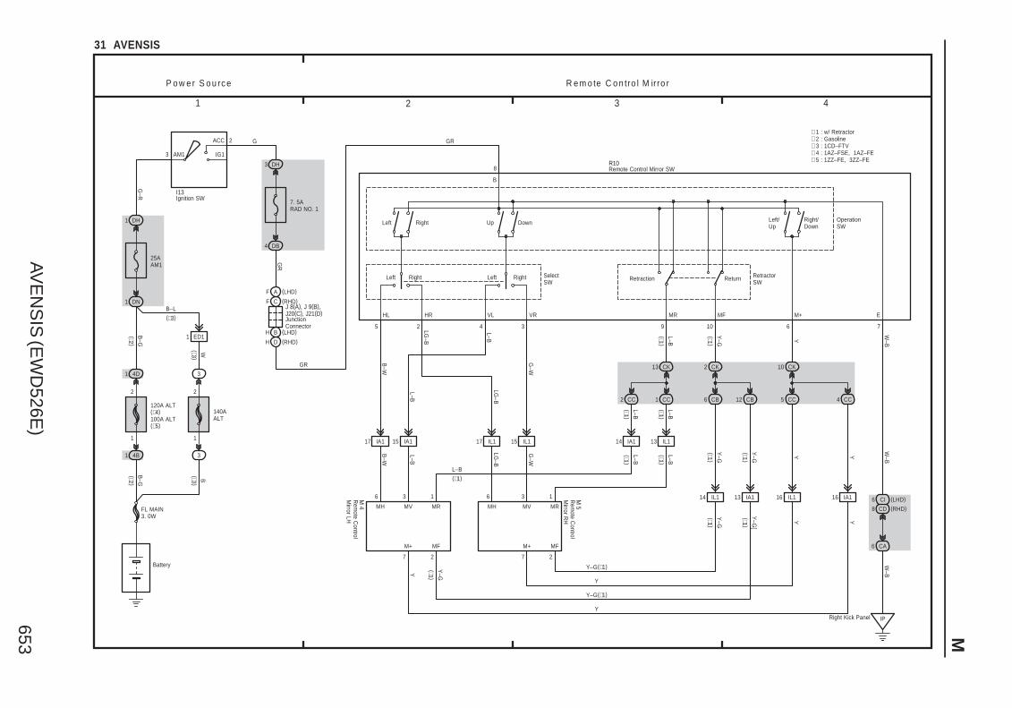
AVE
NS
IS (E
WD
526E)
653 M
1 2 3 4
31 AVENSIS
B–G
4B1
120A ALT(∗4)100A ALT(∗5)
1
2
4D1
DN1
25AAM1
DH1
3
ACC
IG1AM1
2 G
G–R
Battery
FL MAIN3. 0W
DH3
7. 5ARAD NO. 1
RightLeftRightLeft
DownUpRightLeft
8
B
5 2 4 3 6 7
HL HR VL VR M+ E
L–B
9
(∗1 )
L–B
B–W
LG–B
G–W
L–B
L–B
6 3 1 6 3 1
77 2 2
IPRight Kick Panel
Y–G
(∗1 )
W–B
Y–G
(∗1 )
Y
G–W
B–W
LG–B
L–B
10
W–B
CA6
W–B
Y
Y–G Y
Y–G(∗1)
Y
Y–G(∗1)
Y
(∗1 )
GR
(∗1 )
(∗1 )
R e m o te C o n tro l M irro rP o w e r S o u rc e
∗ 2 : Gasoline∗ 3 : 1CD–FTV
DB4
GR
Retraction Return
OperationSW
RetractorSW
SelectSW
Y–G
(∗1 )
Y
Y–G
[
Y(∗1 )
Y–GY (∗1 )
L–B(∗1)
LG–B
L–B
MR MF
MH MV MR
M+ MF
MVMH MR
MFM+
∗ 1 : w/ Retractor
Remote Control Mirror SWR10
Ignition SWI13
(∗2 )B
–G(∗2 )
B
3
140AALT
1
2
3
(∗3 )
1 ED1
W(∗3 )
F C
H B
GR
16 IA113 IA1 16 IL114 IL1
13 IL114 IA115 IL117 IL115 IA117 IA1
CK13 CK2 CK10
CC1 CB6 CC5CB12 CC4CC2
L–B(∗1 )
(∗1 )L–B
M 4
M 5
B–L(∗3)
Rem
ote Control
Mirror LH
Rem
ote Control
Mirror R
H
F A (LHD)
H D (RHD)
JunctionConnector
J 8(A), J 9(B), J20(C), J21(D)
(LHD)
(RHD)
6 CI
8 CD
(LHD)
(RHD)
Right/Down
Left/Up
∗ 4 : 1AZ–FSE, 1AZ–FE∗ 5 : 1ZZ–FE, 3ZZ–FE

AVE
NS
IS (E
WD
526E)
662
M O
VE
RA
LL
EL
EC
TR
ICA
L W
IRIN
G D
IAG
RA
M
1 2 3 4
37 AVENSIS
140A A
LT
120A A
LT (∗5 )100A
ALT (∗6 )
3 4B1
3 4D1
DN1
DH1
3
ACC
IG1AM1 1
25AAM1
2
1
3
5
DH5
DA9
2
1
3
5
B–G
BW B–G
G–R
G–Y
Battery
FL MAIN3. 0W
(∗3)
(∗4 )
11
22
(∗3 )
(∗4 )
1 ED1
(∗4 )B
–L
IG1 R
elay
SE
AT H
TR R
elay
IJLeftKickPanel
W–B
W–B
DK11
R–W
W–B
DK6
W–B
6
7
I15
P o w e r S o u rc e A u to m a tic G la re –R e s is ta n t E C M irro r
S e a t H e a te r
DA33
IPRight KickPanel
A
20A S
–HTR
DM5
E AG A
A BG BB
DM16
BRUnder the LeftCenter Pillar
E A F A
A B H B
G A
G B
LG
R–G
L–B
LG–B
LG LG
L–B
R–B
L–B B
B–O
L–B
LG–B
L–B B
B–O
11 IM2
(∗2 )
(∗2 )
(∗2 )
(∗1 )
(∗1 )
(∗1 )
(∗2 )
(∗2 )
(∗2 )
(∗1 )
(∗1 )(∗1 )
(∗1 )
(∗1 )
(∗1 )
(∗1 )
66 1
41 4 2 4 1 5 4 3 2
BVUnder the RightCenter Pillar
HA
FB
J37(A), J38(B)
HA
FB
J35(A), J36(B)
B A
C B
BS Lower BackPanel Left
C
C
S16 S16 S17 S17
L–B
W–BW–BW–BW–B
W–B
W–B
L–B
W–B
W–B
W–B
W–B
(∗1) (∗1)
(∗2 )
(∗1) (∗1)
(∗2 )
∗ 1 : w/ Power Seat∗ 2 : w/o Power Seat∗ 3 : Gasoline∗ 4 : 1CD–FTV
L–B(∗2)
L–B(∗2)
R–L
RYYBY GB
B B
SeatHeaterSquab
Seat HeaterCushion
Seat Heater Controller
3
17 IC2
1 B4 A3 A 2 B5 A
RVL SWL SWR RVRE
W–B
10A H
TR10A
GA
UG
E1
F A
H B
RLG
(∗1 )(∗1 )
5
2 A
IG
R–L
Seat Heater SWS 7(A), S 8(B)
LG–BLG(∗2)(∗2)
B B–O(∗2)(∗2)
Junction Connector
J32Junction C
onnectorJ30 (A ), J31 (B )
L–B L–B
R
1
G YB
RRYYBB B
SeatHeaterSquab
Seat HeaterCushion
Seat Heater Controller
Ignition SWI13
B RYY
Y RG
B
SeatHeaterSquab
Seat HeaterCushion
Seat Heater Controller
B
R Y G
Seat Heater Controller
Seat HeaterCushion
SeatHeaterSquab
B
B
Y Y RB
Seat Heater LH Seat Heater LH Seat Heater RH Seat Heater RH
Junction ConnectorJunction Connector
Junction Connector
J35 (A ), J36 (B )
Junction Connector
J37 (A ), J38 (B )
InnerMirror
∗ 5 : 1AZ–FSE, 1AZ–FE∗ 6 : 1ZZ–FE, 3ZZ–FE
JunctionC
onnector
J17
A
W–B

AVE
NS
IS (E
WD
526E)
654
M O
VE
RA
LL
EL
EC
TR
ICA
L W
IRIN
G D
IAG
RA
M
1 2 3 4
32 AVENSIS
3
IG1 R
elay
W
(∗1 )
(∗2)
G–R
3
1
2
3
I13
B
1
Battery
FL MAIN3. 0W
5
2
1AM1 IG1
ACC
3
B–G
1 4D
2
1
120A A
LT (∗3 )100A
ALT (∗4 )
1 4B
B–G
W–B
10A G
AU
GE
1
25A A
M1
25A D
OO
R
DH1 DH5
DN1
DA9 DA5
G–Y ∗ 1 : Gasoline
∗ 2 : 1CD–FTV
P o w e r S o u rc e M o o n R o o f
IJ Left Kick Panel
(∗1 )
W–B
140A A
LT
(∗2 )
7. 5A R
AD
NO
. 1
2 G
3 DH
G
25 20
22 1 21
E P/W
IG B ACC
9
DC9
PCTY
17
DB13
DCTY
19
DA8
KSW
Multiplex C
omm
unication System
<1–19>
<1–20>
<2–16>
<2–17>
B
B–L(∗2)
DG
L–W
20A S
/RO
OF
1
10
L–W
6 BB1
L–W
1 ID1
L–W
5 BB1
3
BB
6 ID1
J 8 (A ), J26 (B )
ID12
V–W
V–W
8
4 BB1 BB12
5 W–B
W–B
GG
1
1 BB1 BB13
6
RR
Com
binationM
eter<42–3>
W–B
B
V–W
1 3
W–B
2 M 7
M 6
DK
W–B
6
W–B
7 DB
R–W
A
8
E
W–B
W–B
J17
R–W
1
IG
G–W
7
STP
Stop Light S
W<
17–2>
CA7
CF4
R–W
Shift LockSolenoid
SLS+ SLS–
S 9
S h ift L o c k
Integration Relay
E B (RHD)
A A (LHD)
A A (LHD)
E B (RHD)
E
CLSOPN
Open Close
ED11
M
+B
SPDPWS SO SC
CPU
Ignition SW
Junction Connector
JunctionConnector
Moon Roof Control Relay and Motor
Moon Roof Control SW
Shift Lock ControlECU
∗ 3 : 1AZ–FSE, 1AZ–FE∗ 4 : 1ZZ–FE, 3ZZ–FE
Behind theCombinationMeter
A
IKIP Right KickPanel
AJ15JunctionConnector
W–B
W–B
(RH
D)
(LHD
)
GND

AVE
NS
IS (E
WD
526E)
642
M O
VE
RA
LL
EL
EC
TR
ICA
L W
IRIN
G D
IAG
RA
M
1 2 3 4
22 AVENSIS (Cont. next page)
P o w e r S o u rc e S R S
SRS
AM24 6
ST2
IG2
1
B–R
I13
B–R
(LHD)
(RHD)1 IP1
IE41
Ignition SW
30A A
M2
2
1
FL MAIN3. 0W
Battery
B
B–G
B–G
B
3
(∗2 )
3
1A
4A
4B
1
(∗1 )
(∗2 )
1
(∗1 )
1
B–W
22 B
17 A
∗ 2 : 1CD–FTV∗ 1 : Gasoline
C10(A), C11(B)Combination Meter
W–R
20 B
5 B
W–B
7 CA
CD6
R–W
21 B
Right Kick Panel IP
CK6
CA6
W–B
BEANI/F
14 A
CPU
13 A
Multiplex C
omm
unicationS
ystem<
1–15><
2–11>
F C
H B
CF
F A (LHD)
W–R
(RH
D)
(LHD
)W
–R
(RHD)
Junction Connector
J10 (A ), J11 (B ), J26 (C)
W–R
8 B
B–Y
120A A
LT(1A
Z–FSE
, 1AZ–FE
)100A
ALT
(1ZZ–FE, 3ZZ–FE
)
3
ACC
IG1AM1 1
1 DH
25A A
M1
DN1DH5
2
1
3
5
DA9
10A G
AU
GE
1
IG1 R
elay
IJLeft Kick Panel
B–G
G–R
B–G
G–Y
W–B
W
(∗2 )B
–L
(∗1 )
140A A
LT
2
1
4D
1
2
3
G–R
(∗2 )B
–L
ED11
(∗2 )
1
(∗1 )
R–W
7 DB
R–W
6
2
1
7. 5A D
OM
E
6
1
2
30A D
CC
4 IE4
IP15
B–W
1
B–W
G–Y
B–W
B–R
A
B
C
B–R
B–W
B–Y
A
A
IL Behind theCombinationMeter
J16
W–B
(LHD
∗2 )
IK Behind theCombinationMeter
AJ15JunctionConnector
W–B
(RH
D)
A
A
JunctionConnector
J17JunctionConnector
W–B
(LHD
)
IO Instrument PanelReinforcement RH
W–B
(LHD
∗1 )
W–B
(RH
D)
AVE
NS
IS (E
WD
526E)
643 M
5 6 7 8
22 AVENSIS (Cont' d) (Cont. next page)
5 B
IG2
3 B
LA
B–Y
DD6
DA12
13 B
D–
2
14 B
D+
1
16 B
D2+
4
17 B
D2–
3
Y Y–B
Y–G
Y–R
10 B
P+
11 B
P–
Y–R
Y–G
8 B
P2+
7 B
P2–
Y Y–B
15 B
SL+
2
26 B
SL–
1
W–R
BR
W–R
Y–R
(∗4 )B
R (∗5 )
9 B
SR+
2
20 B
SR–
1
G R
G R
PL+
1
PL–
2
Y–B Y
8 A 7 A
PR+
1
PR–
2
Y–B Y
9 C 10 C
IJ Left Kick Panel
W–B
A30Airbag Squib(Steering Wheel Pad)
A 9Airbag SensorFront LH
A10Airbag SensorFront RH
P16PretensionerLH
P17PretensionerRH
S R S
Airbag Squib(Front Passenger Airbag Assembly)
A29
DD5
DH2
B–W
10A IG
N
DA9
B–R
DD4 DD3
28 B
E2E1
B27
W–B
W–B
SIL
B12
TC
B19
W–L
W–G
LG–B
LG–B
DA11
9
23 B
DD
GSW2
Engine E
CU
(M/T )
<5–11>
<6–11>
<7–8>
Engine and E
CT E
CU
(A/T )
<5–11>
<6–11>
<7–8>
(∗1 )(∗1 )
1 2 3 4
1 IN1 2 IN1
Y–B
12 C
DK+
(∗3 )
Y–R
11 C
DK–
(∗3 )
1 2
Knee Airbag SquibK 3
Y–B
(∗3 )
Y–R
(∗3 )
DA18
A B (RHD)
C A (LHD)
C A (LHD)
A B (RHD)
B–W
B–W
SL+ SL– SR+ SR–
A
B
C
B–R
B–W
B–Y
∗ 5 : Except LHD 1CD–FTV
∗ 3 : w/ Knee Airbag∗ 1 : Gasoline
∗ 4 : LHD 1CD–FTV
Airbag Sensor AssemblyA26(A), A27(B), A28(C)
DLC
3<
5–18><
6–14><
7–13><
8–14>
Junction ConnectorJ 8(A), J26(B)
3 IO3
IE73
4 IO3
IE74
1 IO3
IE71
2 IO3
IE72 (LHD)
(RHD)
AVE
NS
IS (E
WD
526E)
644
M O
VE
RA
LL
EL
EC
TR
ICA
L W
IRIN
G D
IAG
RA
M
9 10 11 12
22 AVENSIS (Cont' d)
S R S
A
(∗6)GR–R
(∗6)
BCL–
3 C (RHD)
DD2
1 A
BCL+
L–R
A26(A), A27(B), A28(C)Airbag Sensor Assembly
4 A
1 B (∗7)
3 A (∗6)
9 A
ICL+
1
10 A
ICL–
2
Y–V
Y–R
C17Curtain ShieldAirbag SquibLH
L–B
16 A
BBL+
18 A
BBL–
GR
–L
LG–B
S14(A), (B)Side AirbagSensor LH
12 A
SFL+
1
11 A
SFL–
2
Y–R
Y–G
S18Side AirbagSquib LH
BBL+BCL+
BBL–BCL–
3 A (∗6)
Curtain Shield AirbagSensor RH
A4
2 B
C16
1 B
8 C
ICR+
Y–V
1
7 C
ICR–
Y–R
2
17 C
BBR+
GR
BBR+BCR+
15 C
BBR–
P
BBR–BCR–
5 C
SFR+
Y–R
1
6 C
SFR–
Y–G
2(∗7)
S15(A), (B)Side AirbagSensor RH
C18Curtain ShieldAirbag Squib RH
S19Side AirbagSquib RH
1
3
DB
14 C
19 A
LBE+RBE+
G–Y
1 C
4 A
LSP+RSP+
L–B
2 C
3 A
LSP–(LHD)RSP–(RHD)
GR
–B
1 2
GR
–B
L–B
G–Y
(LHD)
(RHD)
W–B
B 9Buckle SW(Driver' s Side)
2
(∗6 )
(∗6 )
2
(∗6 )
(∗6 )
4 B
GSW1DBEW
L–RIntegration R
elay<
1–6><
2–5>
4 2
LBE–(LHD)RBE–(RHD)
W–B
Seat P
ositionA
irbag Sensor
14
(LHD)A2
B2
∗ 7 : w/o Curtain Shield Airbag
A
BCR+ BCR–
A121
L
LG
(∗6)
(∗6)
C15
(∗6)(∗7)
(∗6)(∗7)
∗ 6 : w/ Curtain Shield Airbag
Buckle S
W
Curtain Shield Airbag Sensor LH

AVE
NS
IS (E
WD
526E)
592
M O
VE
RA
LL
EL
EC
TR
ICA
L W
IRIN
G D
IAG
RA
M
1 2 3 4
3 AVENSIS
B–G
4B1
120A A
LT (∗9 )100A
ALT (∗7 )
1
2
7. 5A A
LT–S
1
2
4D1 14E1
B
B–G
B–G
3
ACC
IG1
IG2
ST2
AM1 1
AM2
G–R G–Y
Battery
FL MAIN3. 0W
R–W
1 IK2
W–B
2 A
R–W
BB
C h a rg in gP o w e r S o u rc e
∗ 1 : Gasoline∗ 2 : 1CD–FTV∗ 3 : Power Heater (Electrical Type)∗ 4 : Power Heater (Combustion Type)
G–R
3
140A A
LT
1
2
3
W
B
B1
IG1 R
elay
B–G(∗1)
9 DA18 DB
Ignition SWI13
B B–L
B–G
(∗1 )
B(∗2 )
1 A3 A 4 A
M S LB+(∗1)B (∗2)
IG
Y
(∗2)
(∗1 )
(∗1 )
1 ED1
B–L
B–L(∗2)
Y
A11(A), A12(B)
2
1
3
5
Alternator
4A1 1A1
B–G(∗1)
(∗1 )
3
3
(∗2 )(∗2 )
B(∗2 )
B
B
(∗2 )
(∗2 )
DN1 DH5
J10 (A ), J20 (B )Junction C
onnector
R–W
5 EE1
EA15 (∗1)
(∗2)
7. 5A E
CU
–IG
Pow
er Heater
Assem
bly<43–3>
Y(∗4 )
(∗3 )B
–LA
/C C
ontrolA
ssembly<
48–8><
49–8>
B–L
Engine E
CU
(M/T )
<8–8>
(∗2 )(∗2 )
13 IK2
B–W
(∗3 )
25A A
M1
DH1
G–Y
30A A
M2
1
2
1
1 IP1
IE41
B–R
B–R
B–R
(LHD)
(RHD)
5 5
5 5
1B
1 A
7 IK1
BB
B–R
B–Y
W–B
B–R
3 2
5 1
2
1
6
6
B A
B B C B
A A
C B
6
9
P
N
A A
N 1
Neutral
Start S
W
J12 (A ), J13 (B )JunctionC
onnectorB
–Y
B–Y
B–Y
B–W
B–Y
B–Y
B–YB–W
B–Y5
7. 5A S
T
(A/T )
(M/T )
(M/T )
(A/T )
Engine E
CU
(M/T )
<5–11>
<6–11>
<7–7>
Engine and E
CT E
CU
(A/T )
<5–11>
<6–11>
<7–7>
(∗1 )
(∗2 )E
ngine EC
U (M
/T )<
8–7>
ST R
elay
S ta r tin g
S 4(A), S 5(B)Starter
B–R
4
C B (RHD)
G A (LHD)
G A (LHD)
C B (RHD)
B L
∗ 5 : 1AZ–FSE, 1CD–FTV∗ 6 : 1AZ–FE, 1ZZ–FE, 3ZZ–FE∗ 7 : 1ZZ–FE, 3ZZ–FE
IJLeft Kick Panel
DJ2
W–B
(∗5 )
20 A
23 A
18 B
21 A (∗2)
29 A (∗6)
29 B (∗8)
21 C (∗8)
28 B (1AZ–FE)
27 A (∗7)
9 IK1
Y(∗6 )Y(∗6 )
9 D (∗2)
RL
MPX1 MPX2
Multiplex C
omm
unicationS
ystem<
1–15><
2–11>
Engine and E
CT
EC
U (A
/T )
E 9 (A ), E10 (B ), E11 (C
), E12 (D)
Engine E
CU
(M/T )
∗ 8 : 1AZ–FSE∗ 9 : 1AZ–FSE, 1AZ–FE
(∗5 )

AVE
NS
IS (E
WD
526E)
629 M
1 2 3 4
17 AVENSIS
B
1
2
DN1
15ASTOP
DA22
R–W
2 IR1
R–W
R–W
(RH
D)
(RH
D)
(LHD
)
1
2
G–W
(RH
D)
1 IR1
G–W
(RH
D)
6 IE3
G–W
G–W
(LHD)
(LHD)
G–W
G–W
S to p L ig h tP o w e r S o u rc e
Battery
FL MAIN3. 0W
Engine and E
CT E
CU
(A/T )
<5–12>
<6–11>
<7–8>
Shift Lock C
ontrol EC
U<
32–4>
3
1
2
3
140A A
LT
120A A
LT (∗3 )100A
ALT (∗4 )
B–G
(∗1 )
B–G(∗1)
(∗2 )
S13
G–W
Skid C
ontrol EC
U w
ith Actuator
<20–6>
<21–5>
∗ 1 : Gasoline∗ 2 : 1CD–FTV
Engine E
CU
(M/T )
<5–12>
<6–11>
<7–8>
<8–8>
Stop Light SW
4B1
4D1
WB
–L
1 ED1
11 IE3
R–W
(LHD
)
DA2
DC10DB1DL2
BSLower BackPanel Left
BT Lower Back PanelCenter (S/D, L/B)
6 C (W/G)
4 B (L/B)
1 A (S/D)
2 A (S/D)
5 B (L/B)
4 C (W/G)
W–B
R13(A), (B), (C) R14(A), (B), (C)
(W/G)C3
(L/B)B3
(S/D)A6
(S/D)A7
(L/B)B4
(W/G)C1
W–B
G–W
G–W
B B B B
C AC AC A
B A
C B
W–B
W–B
C
C
1
2
W–B
G–W(S/D)
G–W
J30(A), J31(B)
JunctionConnector
J32
JunctionConnector
High M
ountedS
top Light
H20
J30(A), J31(B)JunctionConnector
BX Right Side ofthe Back Door
A A
A B
4 BG1
2
1
W–B(W/G)
L(W/G)
G–W
(L/B)
1 BE1
L(L/B
)
3 BF1
BD11
G–W
(L/B, W
/G)
1
G–W(L/B, W/G)
Noise Filter(Stop Light)
N 8
JunctionConnector
J33(A), J34(B)
High M
ountedS
top Light
H20
G–W
(L/B, W
/G)
G–W
(W/G
)
W–B
(L/B)
(W/G)
W–B
W–B
(L/B)
(∗2 )(∗2 )
(S/D
)(S
/D)
(S/D
)
Rear CombinationLight LH
Rear CombinationLight RH
Stop
Stop
(L/B, W
/G)
∗ 3 : 1AZ–FSE, 1AZ–FE∗ 4 : 1ZZ–FE, 3ZZ–FE
Lower Back PanelRight (W/G)
2 BE13 BG1
4 BF1
BD12
W–B
W–B
(W/G
)
(L/B)
W–B
W–B
(W/G
)
(L/B)
DM1
W–B
W–B(L/B, W/G)
(L/B, W
/G)
(L/B)
(W/G)

AVE
NS
IS (E
WD
526E)
626
M O
VE
RA
LL
EL
EC
TR
ICA
L W
IRIN
G D
IAG
RA
M
1 2 3 4
14 AVENSIS
B–G
DN1
2
1
3
5
13
Tail
OFF
Head
T H ELLight Control
SW
14
16
120A A
LT (∗5 )100A
ALT (∗6 )
10ATAIL
TAILRelay
DL8 DL9
2
1
F 1
EC EngineCompartmentLeft
GW
–B
2
1
F 2
EB EngineCompartmentRight
GW
–B
R
B–G
B–G
IL
W–B
FL MAIN3. 0W
Battery
TRLY
T
P o w e r S o u rc e T a illig h t
∗ 1 : w/ Daytime Running Light∗ 2 : w/o Daytime Running Light
4D
4B
2
1
A A
A B A BA B A BBA
2
1
L 1
GW
–B
2
1
GW
–B(S
/D)
BS Lower BackPanel Left
J31(B)
2
1 L 1
GW
–B
2
1 L 2
GW
–B
BX Right Side ofthe Back Door
W–B
J34(B)
B A
C B C B
J33(A), J34(B)
3 BE26 BG2
1 BF2
BD23
GG
GG
(W/G
)
(L/B)
(L/B)
(W/G
)
(L/B)
(W/G)
G(∗7 )
GW
–B
R13 (A ), (B ), (C
)
Lower BackPanel Center
BT
GW
–B
R14 (A ), (B ), (C
)
L 2
(S/D
)
W–B
W–B
J30(A), J31(B)
DM4
G
A
AJ 1
G
DB12
IntegrationR
elay
(∗1 )
(∗3 )
1
1DA23
R(∗2 )
(∗3 )
B
140A A
LT
(∗4 )W
3
3
2
1
(∗4 )
1 ED1
B–L
(∗3)
(∗4)
Behind theCombinationMeter
∗ 3 : Gasoline∗ 4 : 1CD–FTV∗ 5 : 1AZ–FSE, 1AZ–FE∗ 6 : 1ZZ–FE, 3ZZ–FE
12
∗ 7 : L/B, W/G
G (∗7 )
(∗7 )(∗7 )
(∗7 )
(∗7 )
Tail
5 C (W/G)
6 B (L/B)
4 A (S/D)
4 C (W/G)
5 B (L/B)
2 A (S/D)
3 C (W/G)
3 B (L/B)
6 A (S/D)
2 C (W/G)
2 B (L/B)
4 A (S/D)
Tail
(S/D
)
(S/D
)
(S/D)
C BC B
A B A B
A B
C B
JunctionConnector
J15A
W–B
IK
Tail
17 A
14 B
Behind theCombinationMeter
C12
C10 (A ), C
11 (B )
JunctionConnector
J16A
W–B
(RH
D)
(LHD
)
C C
(RHD)
C A
(LHD)
C A (LHD)
C C (RHD)
A A
J10 (A ), J11 (B ), J26 (C
), J27 (D)
G
3 IC2
G GG
Com
bination Meter
Com
bination SW
Front Clearance Light LH
Front Clearance Light R
H
JunctionConnector
JunctionC
onnector
JunctionConnector
JunctionConnector
JunctionConnector
JunctionConnector
License Plate Light LH
License Plate
Light LH
License Plate
Light RH
License Plate Light R
H
Rear C
ombination Light LH
Rear C
ombination Light R
H
C D
C B
G(∗3 )G
Engine and E
CT E
CU
(A/T )
<5–10>
<6–11>
<7–7>
Engine E
CU
(M/T )
<5–10>
<6–11>
<7–7>
IOInstrument PanelReinforcement RH
W–B
(LHD
∗3 )
(LHD
∗4, RH
D)
A
A
W–B
(RH
D)
JunctionConnector
J17
A
W–B
W–B
(LHD ∗3)
(LHD ∗4)

To Ignition SWIG Terminal
Fuse
VoltmeterSW 1
Relay
SW 2 Solenoid
[A]
[B]
[C]
Ohmmeter
SW
Ohmmeter
Diode
Digital Type Analog Type
12
AVENSIS (EWD526E)
C TROUBLESHOOTING
VOLTAGE CHECK
(a) Establish conditions in which voltage is present at the checkpoint.
Example:[A] – Ignition SW on[B] – Ignition SW and SW 1 on[C] – Ignition SW, SW 1 and Relay on (SW 2 off)
(b) Using a voltmeter, connect the negative lead to a good groundpoint or negative battery terminal, and the positive lead to theconnector or component terminal.This check can be done with a test light instead of a voltmeter.
CONTINUITY AND RESISTANCE CHECK
(a) Disconnect the battery terminal or wire so there is no voltagebetween the check points.
(b) Contact the two leads of an ohmmeter to each of the checkpoints.
If the circuit has diodes, reverse the two leads and checkagain.When contacting the negative lead to the diode positive sideand the positive lead to the negative side, there should becontinuity.When contacting the two leads in reverse, there should be nocontinuity.
(c) Use a volt/ohmmeter with high impedance (10 kΩ/Vminimum) for troubleshooting of the electrical circuit.

To Ignition SWIG Terminal
Test Light
RelayLight
SW 2 Solenoid
Disconnect
Short [A]
DisconnectDisconnect
SW 1
Fuse Case
Short [B]
Short [C]
Pull Up
Press Down Press Down
Pull Up
AVENSIS (EWD526E)
13
C
FINDING A SHORT CIRCUIT
(a) Remove the blown fuse and disconnect all loads of the fuse.
(b) Connect a test light in place of the fuse.
(c) Establish conditions in which the test light comes on.
Example:[A] – Ignition SW on[B] – Ignition SW and SW 1 on[C] – Ignition SW, SW 1 and Relay on (Connect the
Relay) and SW 2 off (or Disconnect SW 2)
(d) Disconnect and reconnect the connectors while watching thetest light.The short lies between the connector where the test lightstays lit and the connector where the light goes out.
(e) Find the exact location of the short by lightly shaking theproblem wire along the body.
CAUTION:(a) Do not open the cover or the case of the ECU unless
absolutely necessary. (If the IC terminals are touched,the IC may be destroyed by static electricity.)
(b) When replacing the internal mechanism (ECU part) ofthe digital meter, be careful that no part of your body orclothing comes in contact with the terminals of leadsfrom the IC, etc. of the replacement part (spare part).
DISCONNECTION OF MALE AND FEMALECONNECTORS
To pull apart the connectors, pull on the connector itself, notthe wire harness.
HINT : Check to see what kind of connector you aredisconnecting before pulling apart.

(mm)
Reference:
ToolUpExample:(Case 1)
Terminal Retainer
Terminal Retainer
[Retainer at Full Lock Position]
[Retainer at Temporary Lock Position]
StopperTerminalRetainer
SecondaryLocking Device
Example:(Case 2)
14
AVENSIS (EWD526E)
C TROUBLESHOOTING
HOW TO REPLACE TERMINAL(with terminal retainer or secondary locking device)
1. PREPARE THE SPECIAL TOOL
HINT : To remove the terminal from the connector, pleaseconstruct and use the special tool or like object shown onthe left.
2. DISCONNECT CONNECTOR
3. DISENGAGE THE SECONDARY LOCKING DEVICE OR
TERMINAL RETAINER.
(a) Locking device must be disengaged before the terminallocking clip can be released and the terminal removed fromthe connector.
(b) Use a special tool or the terminal pick to unlock the secondarylocking device or terminal retainer.
NOTICE:Do not remove the terminal retainer from connector body.
[A] For Non–Waterproof Type Connector
HINT : The needle insertion position varies according to the
connector’s shape (number of terminals etc.), so
check the position before inserting it.
”Case 1”
Raise the terminal retainer up to the temporary lock
position.
”Case 2”
Open the secondary locking device.

ToolTab
Tab
TerminalRetainer
Access Hole( Mark)
Tool
Tool
[Female]
Example:
[Male]
(Case 1)
[Male] [Female]
Retainerat Full Lock Position
Retainerat Temporary Lock Position
Terminal Retainer
[Male] Press Down [Female]Press Down
ToolTool
Example:(Case 2)
AVENSIS (EWD526E)
15
C
[B] For Waterproof Type Connector
HINT : Terminal retainer color is differentaccording to connector body.
Example:Terminal Retainer : Connector BodyBlack or White : GrayBlack or White : Dark GrayGray or White : Black
”Case 1”Type where terminal retainer is pulledup to the temporary lock position (PullType).
Insert the special tool into the terminalretainer access hole (Mark) and pullthe terminal retainer up to thetemporary lock position.
HINT : The needle insertion position variesaccording to the connector ’s shape(Number of terminals etc.), so checkthe position before inserting it.
”Case 2”Type which cannot be pulled as far asPower Lock insert the tool straight intothe access hole of terminal retainer asshown.

Retainer atFull Lock Position
[Male] [Female]
Retainer atTemporary Lock Position
Locking Lug
Tool
16
AVENSIS (EWD526E)
C TROUBLESHOOTING
Push the terminal retainer down to the temporary lock position.
(c) Release the locking lug from terminal and pull the terminal outfrom rear.
4. INSTALL TERMINAL TO CONNECTOR
(a) Insert the terminal.
HINT:1. Make sure the terminal is positioned correctly.2. Insert the terminal until the locking lug locks firmly.3. Insert the terminal with terminal retainer in the temporary lock
position.
(b) Push the secondary locking device or terminal retainer in tothe full lock position.
5. CONNECT CONNECTOR

AVE
NS
IS (E
WD
526E)
627 M
1 2 3 4
15 AVENSIS
1A1
10A H
AZA
RD
1
3
ACC
IG1AM1 1
Ignition SWI13
DH1
25A A
M1
2
1
3
5
DN1 DH5 27 DA
7. 5A G
AU
GE
2
IG1 R
elay
DA9
IJLeft Kick Panel
8 CA
6 CC
1 4
Turn Signal Flasher RelayT10
D D
D A
8
4
1
DL3DM17
BS
W–B
Rear C
ombination
Light LH
R13 (A ), (B ), (C
)
EC EngineCompartmentLeft
5 DL
EB
DM11
Rear C
ombination
Light RH
R14 (A ), (B ), (C
)
EngineCompartmentRight
3 2 5 6 7
3 CH
6 CA
P o w e r S o u rc e T u rn S ig n a l a n d H a z a rd W a rn in g L ig h t
Battery
FL MAIN3. 0W
B–L
B–G
B–G
W
G–R
R–W
G–Y
B–G
G–R
R–W
W–B
W–B
R–W
WW LG
LG
LG
IG +B EHW
LL LR EL ER GND Hazard S
WH
13
G–Y
W–B
G–W
W–B
W–B
W–B
W–B
G–YG
–Y
W–B
W–B
G–Y
G–W
∗ 2 : 1CD–FTV∗ 1 : Gasoline
4B
1
2
D A
Turn
Turn
LH
Off
RH
1 3
Turn SW
Turn LH
Turn RH
2
W–B
1
2
Front Side Turn
Signal Light LH
F 5
W–B
G–W
G–W
W–B
W–B
1
2
W–B
G–Y
W–B
1
4D14A1
(∗1 )
(∗2 )
(∗1 )
6 IC2
LG
Integration Relay<1–6><2–5>
IP∗7IOBTLower Back PanelCenter (S/D, L/B)
A AA
Front Turn Signal
Light RH
F 9 (A ), F10 (B )
Front Side Turn
Signal Light R
H
F 6
DL6
3 B (∗6)
3 A (∗5)
3 B (∗6)
3 A (∗5)
4 A (∗5)
4 B (∗6)
4 A (∗5)
4 B (∗6)
DL4
DB6 DB15
1 B 13 B
17 A
BB
D
B D
D
G–W
G–Y
33
1
3
2
140A A
LT
B(∗2 )
B(∗2)
(∗1 )
G–Y
1 ED1
B–G
(∗1 )
B–L
(∗2 )W(∗2 )
Front Turn Signal Light LH
F 7 (A ), F 8 (B )
G–Y
G–W
4 C (W/G)
5 B (L/B)
5 A (S/D)
G–W
3 C (W/G)
3 B (L/B)
3 A (S/D)
6 A (S/D)
3 B (L/B)
3 C (W/G)
2 A (S/D)
5 B (L/B)
4 C (W/G)
W–B
W–B
InstrumentPanelReinforcementRH
∗ 5 : w/ HID∗ 6 : w/o HID
W–B
120A A
LT (∗3 )100A
ALT (∗4 )
1
2
Lower BackPanel Left
B B (LHD)
F C F C (RHD)
(RHD)
(LHD)
JunctionConnector
J10(A), J11(B), J24(C), J25(D)
TL TB TRF A F A
D B
(LHD
)
(LHD
)(LH
D)
(LHD
)
(LHD
)
(LHD
)
E AA
E BJunctionConnector
J22(A), J23(B)
JunctionConnector
J 5JunctionConnector
J 5
G–W
(RH
D)
G–W
(RH
D)
G–Y
(RH
D)
G–Y
(RH
D)
G–Y
(RH
D)
G–W
(RH
D)
EC
ombination S
WC
12
W–B
A
IK∗8
W–B
(LHD)(RH
D)
JunctionConnector
J15
(LHD
)
(LHD
)(LH
D)
(LHD
)
(LHD
)
A
IL∗8
W–B
(RH
D)
W–B
(RH
D)
JunctionConnector
J16
CD9
CF11
W–B
(RH
D)
W–B
(RH
D)
JunctionC
onnector
J16
2 IO1
IE32 (LHD)
(RHD)
Lower Back PanelRight (W/G)
∗ 7 : Right Kick Panel∗ 8 : Behind the Combination Meter
∗ 4 : 1ZZ–FE, 3ZZ–FE∗ 3 : 1AZ–FSE, 1AZ–FE
A
A
W–B
(LHD
∗1 )
W–B
(LHD
∗2 )
Com
bination Meter
C10 (A ), C
11 (B )
A
A
JunctionConnector
J17
W–B(RHD)

AVE
NS
IS (E
WD
526E)
636
M O
VE
RA
LL
EL
EC
TR
ICA
L W
IRIN
G D
IAG
RA
M
3 421
20 AVENSIS
EAEngine Compartment Right
2 112
W–B
10 6 41 24 21 22
14
R–W
L–Y
R–L
W B
W BR–L
L–Y
W–B
W–B
P o w e r S o u rc e V S C
FR–FR+FL–FL+GND1
IG1
GND2
(Cont. next page)
AM24 6
1AM1
ST2
IG2
IG1
ACC
3
44
1 1
2 2
1
25A V
SC
50A V
SC
RL
B–R
LR
I13
B–R
(LHD)
(RHD)1 IP1
IE411
(∗1 )
(∗1 )
(∗2 )
(∗2 )
R L
50A V
SC
25A V
SC
22
11
1 1
(∗1 )
(∗1 )
Ignition SW
(∗1 )
R–W
DB18
1
4A1
30A A
M2
1
1B
FL MAIN3. 0W
Battery
120A A
LT
1
W
DH
25A A
M1
DN1DH5
2
1
3
5
DA9
7. 5A E
CU
–IG
IG1 R
elay
IJLeft Kick Panel
B–G
B–G
G–R
B–G
G–Y
W–B
W
(∗2 )B
–L
(∗1 )
140A A
LT
B
3
(∗2 )
2
1
3
1A
4D
4B
1
2
1
3
(∗1 )
(∗2 )B
–L
ED1
(∗2 )
(∗2 )
1
(∗1 )
1
B–G
(∗2 )
B(∗2 )
3 B
RL(∗2 )
(∗2 )
B(∗2)
G–R G–Y
B–R
5
+BS
9
+BM
22 IE1
Skid Control ECU with ActuatorS 1
C C C C
G B
AB–R
Junction Connector
J10 (A ), J11 (B ), J20 (C), J21 (D
)
R–W
R–W
R–WR
–W
ABS Speed SensorFront RH
A 5ABS Speed SensorFront LH
A 4
∗ 2 : 1CD–FTV∗ 1 : 1AZ–FSE
2
IE13
B–Y
BZ
B–Y
15
2
1
Buzzer
VS
C W
arningB
uzzer
V 7
G A G A (LHD)
C D (RHD)
(LHD)
(RHD)
R–W
R–W
DB7
10A G
AU
GE
1
CA7
CD6
BR–W
R–W
AVE
NS
IS (E
WD
526E)
637 M
5 6 7 8
20 AVENSIS (Cont' d)
1 3
2 4
16 30
W–G
W–L
YGND YIGA
7 1
5 6
W–G
W–L
W–G
W–L
WB
B W
29 13
SS2 SS1
(Shielded )
27
VCM PMC
11
GR
12
E2
Y–G
Y–R
Engine E
CU
(M/T )
<5–10>
<8–11>
Y–BBY
NEO
32
G
7
ENG–ENG+
818
TRC+
L
TRC–
19
V S C
123
Engine and E
CT E
CU
(A/T )<
5–10>
Y–BB
W(∗3 )
Y(∗4 )
G L
13 IE2
IE86 13 IE8
IE23
7 IE8
IE215
14 IE8
IE214
5 IE8
IE113
Oil Pressure SensorO 1
Steering
Sensor
S12
Yaw
Rate
Sensor
Y 1
AB–R
Skid Control ECU with ActuatorS 1
C B C B
B A A A
D B E B
WB
(Shielded )
C
W–G
W–L
B
W B
BBBB
ADAD AB AA
(Shielded)
(Shielded )
(Shielded )
Junction ConnectorJ 6(A), J 7(B)
IK Behind theCombination Meter
A
JunctionConnector
J15
W–B
IM11 IM110
IE211
ABS Speed SensorRear RH
A33ABS Speed SensorRear LH
IE210
1 2
IB11
1 2
IB12
23 40 38 39
R G P V
R G P V
P V
A32
RR–RR+RL–RL+
PKB
31
2 IE2
B–W
STPSP1
L–W
Stop Light S
W<
17–1>G
–W
35 37
B–W C
ombination M
eter<
42–4>
(LHD)
(RHD)
(Cont. next page)
IE114
CSW
42
G–Y
6
9
G–Y
W–B
Right Kick Panel IP
CA6
CJ10
W–B
T 9TR
C O
ffS
W
W–B
IL Behind theCombination Meter
(RH
D)
(LHD
)(LH
D)
∗ 4 : Except RHD 1AZ–FSE∗ 3 : RHD 1AZ–FSE
1 IE8 2 IE8 9 IE8 10 IE8 3 IE8
JunctionConnector
J18
W(LH
D)
(LHD
)
(LHD
)
(LHD
)
(LHD
)
(LHD
)
(LHD
)
(LHD
)
(LHD
)
(LHD
)
(LHD
)
(LHD
)(LH
D)
(LHD
)
(LHD
)
(LHD
)
(LHD)
DB3 DC4 DM8DC2
1
B–W
B–W
B–W
Parking B
rake SW
P 4 A/C
Control A
ssembly
<47–5>
<48–8>
<49–7>
Multi–D
isplay<
39–6>
AB–R
GND UBAT GND 12V
CANL CANHCANHIGH
CANLOW
B BB–W B–W
∗ 5 : w/ Navigation System (Map Type)
(∗5 )
A
A
W–B(RHD)
J16JunctionConnector
AVE
NS
IS (E
WD
526E)
638
M O
VE
RA
LL
EL
EC
TR
ICA
L W
IRIN
G D
IAG
RA
M
9 10 11 12
20 AVENSIS (Cont' d)
V S C
W–G
W–L
W
26
6 IE1
17 28
D/G TSTC
W–B
VSCW
W–R
34 4
LG
IND WT
LG–B
2
B–W
36
R–Y
WA
22 B
9 A16 B 15 B 17 B
AB
S
P
2
20
EBDW
Brake
4 B B
Combination MeterSystem<42–11>
Combination MeterC10(A), C11(B)
(LHD
∗1 )
TRC
OFF
Slip
VS
C
8 IE1 7 IE1 17 IE1 18 IE1
W–R
LG
LG–B
R–Y
P
IO213 IO212 IO211 IO111
IO Instrument PanelReinforcement RH
IO112
10A IG
N
B–W
2 DH
18 DA
A B (RHD)
C A (LHD)
A B (RHD)
C A (LHD)
J 8 (A ), J26 (B )Junction C
onnector
B–W
W–B(RHD)
17 A
J17JunctionConnector
W–B
ILBehind theCombinationMeter
J16JunctionConnector
(LHD
∗2 )
W–B(LHD)
1 3
2 4
16 30
W–G
W–L
YGND YIGA
1 7
65
W–L
W–G
W–G
W–L
WB
B W B
29 13
SS2 SS1
(Shielded ) S
teeringS
ensor
S12
Yaw
Rate
Sensor
Y 1
CFB B
WB
(Shielded )
B
BB
AA
W–G
W–L
W
CF FC B F
(Shielded )
(Shielded )
Junction ConnectorJ19 Behind the
CombinationMeter
IK
A
J15JunctionC
onnector
W–B
B
CAC A
A B
W–L
W–L
W–G
J22 (A ), J23 (B )JunctionC
onnector
JunctionC
onnector
J22 (A ), J23 (B )
W–G
(RH
D)
(RH
D)
(RH
D)
(RH
D)
(RH
D)
(RH
D)
(RH
D)
(RH
D)
(RH
D)
(RHD)
(RHD)
(RH
D)
(RH
D)
(RH
D)
(RH
D)
(RH
D)
(RH
D)
(RHD)
(RH
D)
(RH
D)
(RH
D)
B–R
Skid Control ECU with ActuatorS 1
A
B
21 B
R–WR–W
GND UBAT GND 12V
CANL CANHCANLOW
CANHIGH
DLC
3<
5–18><
8–15>
DLC
3<
5–19><
8–16>
∗ 2 : 1CD–FTV∗ 1 : 1AZ–FSE
A
A
A
A
(LHD
)W
–B
(RH
D)
W–B
(RH
D)
W–B
A
Related Documents