EM·' EN'GINE MECHANICAIL DIESEl E NlIGINE D'IAGINOSIS •.••• , .. , .. "., , .... ID IESEL E LEGTRI>CAL. SYSTEM DIAGNOSIS ••••• EN.'GINE TUNE-UP ." , .. , .. " .. , .. , ". COMPRESSION CH ECK .. " .•..••.. , ...• , •• " ••• TIM ING B,ElT " , .. , .. , .. , .. " ,. C'ompol'1ents ••••...... " ....•.••.••.. , . , ... Removal of Timing Belt ..... ., ••..•......... lnspectlon f Components ........•.. , . lnstellatlun [If Timing Be-Hl " .. , .. , .. , .. "., .. ,. · CYlIN DER HEAD· ••••••••..... " .. ,'•.•.• , ••.•• ,. Components , .. , .. , , , , ". Remov-al of Cylinder Head ,.. ,.. ,.. , ...•..•.• Disassembly of CyUnd{!r He-ad ..... ,." •• ,., •• lnscecticn, Cieanin g and Repaiir of Cylinde r Head ompcnents •.............. " ••.•... Rep o laceme n1 of Ca m shaft 0 i I SeaI ....••••••• Installation (If CyUnder Head " .•••. < • , , • , •••• CYLIN DEA BLOCK , .. " .. "." •. Co:rnpotlents ., •••.... , ..... ".. ".. ". ,... ,..•• DiSassembl'y 01 Cyminder Bllock Page EM~2 EM-l1 EM-14~ EM·19 EM-20 EM-20 EM-20 .EM'-.24 EM-lIS EM·31 EM~31 EM-32 .EM-35 EM~36 EM~44 EM-45 EM~-4Ei EM-50 EM·50 'EM-51 lnspectionot Cylinder Bloc!k ." ......•.•• ,.... EM-55 lDis.assembly of Pi lston and Connectilllg Rod Assembly , , ".,..... EM-56 Iinspection or Piston and Connecting Rod ASl:H3rmbly " .•.. , , , .. ,..... EM-·51 Re' p~a cem en ilt of Connectiing Rod Bush·ing .. ,.. EM-60 Inspection and R.epatr of Crankshaft ,..... IEM~61 ~oritlg of CyUnden'i •• , • ....... , ,....... EM-62 Rep,Walcement of Crankshaft Oil SoHalls ........• EM·63 A.ssembly of Platen and Connecting Rod Assembly ., ..... , .... '.' .... , . .. a • • • • E M -64 InS1allatl em of era III kshafi. P lstn nan d Connecting Rod Assemblly ., " ,. EM·6S Assemb~y of Cylilru;ler Block .. , ,., .. ', .. , EM ·6:'1

Welcome message from author
This document is posted to help you gain knowledge. Please leave a comment to let me know what you think about it! Share it to your friends and learn new things together.
Transcript

8/4/2019 Toyota 2L Engine Mechanical
http://slidepdf.com/reader/full/toyota-2l-engine-mechanical 1/68
EM·'
EN'GINE MECHANICAIL
DIESEl ENlIGINE D'IAGINOSIS •.••• , .. , .. "., ,....
ID IESEL E LEGTRI>CAL. SYSTEM DIAGNOSIS •••••
EN.'GINE TUNE-UP ." , .. , .. " .. , .. , ".
COMPRESSION CH ECK .. " .•..••.. , ...• , •• " •••
TIM ING B,E l T " , .. , .. , .. , .. " ,.
C'ompol'1ents ••••...... " ....•.••.••.. , .. , ...
Removal of Timing Belt ..... ., ••..•.........
lnspectlon of Components ........•.. , .
lnstellatlun [If Timing Be-Hl " .. , .. , .. , .. "., .. ,.
·CYlIN DER HEAD· ••••••••..... " .. ,' •.•.• , ••.•• ,.
Components , .. , .. , , , , ".
Remov-al of Cylinder Head , .. , .. , .. , ...•..•.•
Disassembly of CyUnd{!r He-ad ..... ,." •• ,., ••
lnscecticn, Cieaning and Repaiir of Cylinder
Head Compcnents •.............. " ••.•...
Rep o laceme n1 of Camshaft 0 iI SeaI ....•••••••
Installation (If CyUnder Head " .•••. < • , , • , ••••
CYLIN DEA BLOCK , .. " .. "." •.
Co:rnpotlents ., •••.... , ..... " .. " .. " . , ... , ..••
DiSassembl'y 01 Cyminder Bllock
Page
EM~2
EM-l1
EM-14~
EM·19
EM-20
EM-20
EM-20
.EM'-.24
EM-lIS
EM·31
EM~31
EM-32
.EM-35
EM~36
EM~44
EM-45
EM~-4Ei
EM-50
EM·50
'EM-51
lnspectionot Cylinder Bloc!k ." ......•.•• ,.... EM-55
lDis.assembly of Pilston and ConnectilllgRod Assembly , , ".,..... EM-56
Iinspection o r Piston and Connecting Rod
ASl:H3rmbly " .•.. , , , .. ,..... EM-·51
Re'p~acemenilt of Connectiing Rod Bush·ing .. ,.. EM-60
Inspection and R.epatr of Crankshaft ,..... IEM~61
~oritlg of CyUnden'i •• , •....... , ,....... EM-62
Rep,Walcement of Crankshaft Oil SoHalls ........• EM·63
A.ssembly of Platen and Connecting
Rod Assembly ., ..... , .... '.' .... , . .. a • • • • EM -64
InS1allatl em of eraIII
kshafi. P lstn nan dConnecting Rod Assemblly ., " ,. EM·6S
Assemb~y of Cylilru;ler Block .. , ,., .. ', .. , EM ·6:'1
8/4/2019 Toyota 2L Engine Mechanical
http://slidepdf.com/reader/full/toyota-2l-engine-mechanical 2/68
EM-·2 ENG INE M ECHAIN ICAl - Diesel ErI_9illtl Dlagllosis
DIESEL ENGINE DI·AG'NOS.1IS
1. GENEHAL
Diesel engine problems are LJ5uaillycaused by the engine or fuel system. The injection pump is very rarely
the cause of 'fuel systemprdb~ems.
Before beginning Fuel system tests, ' first cheek tha t the eng ine compression, valve tilTling and othermajor svsterns are wi'lhin specttication:
The following fuel system dlaqnosls procedures are applicable to . Toyota 1C , 1C~T, 2C. L, 2L and .2L-Tengines equipped wIth 'the distributor tvpe injection pump-
2. PRELIM IN.ARY CHECKS
{a) Becfore perfofming fuel 'sys'hml checks, ·check, that the engine is in goo-d running condition. I'f
necessary. Hn3·1check the compression, ·timing and major components or systems.
(b) Checkthe air filter and clean or replace as n~@ded.
(d Check thai thereis swfficleh't fuel III th€! terrk.
(d) Check if the-fuel. is contaminated with ·gosollns or other fmeiign elements. O·nIIYgood-qu~lity diesel
ruel should be used. .
(e ) Bleed air from the system by pLlrnping the primjng; pump 30 - 40 limes.
tf} Check for water in the fuel Pliler and fuel tank and drain as necessary.
(gl If the engine will not crank or if it cranks slowly. first troubleshoot the electr ical system.

8/4/2019 Toyota 2L Engine Mechanical
http://slidepdf.com/reader/full/toyota-2l-engine-mechanical 3/68
ENGINE MIECHANICAl- Di@sal Engine Dis_grrosis.
PRECAUTION
1. Tha basic trnubleshnotinq procedures for the diesel engin0 (valve clearance, compression, hearings,valves. pistons, etc.) are the same checks you would make fora qasoline engine.
2. The repair of aninjection pump require's considerable skill and use of a special test bench.
ENGINE WILL NOT CRANK
(IPossible C.ause) ~Check Procedure and.Conec1i.on Method)
LOOSE OR COR .ROOEDBATTERY CABLES
t--------i Check cables from batterv to starter and maken e ce ssa ry re oa i rs ,
Check alternatcr OU tput and the drive belt
R eUtlir a s tlI(!!·cess~ry.
D lS -C .HARG IE 'D BATTERY
\3. 1NOPERATNE STARTER \ r - - - - - - - - - - l Check for batterv voltage at starter terminals
30 and 50,If Okay .. see STARTING: SYSTEM, page {ST ~·15
or 16) for repair procedure.
EN.GINIE CRANKS SLQWL V-WILL NOT START
NOTE: Minimum urankinq speed: Cold M IT 100 rpmA/T 110 rpm
Hot 150 rpm
(Ched< Procedure ~.ndCorrection M~thQ(U
1. LOOSE 'OR C:OFl.RODED
BATTERY CABLES
1 2 . DISCHARGED BATTERY Refer to lternsj and 2 Of ENGINE WILL NOT
CRANK_
1 3 . IMPROPER EN GI N IE OIL Check engine oil,If improper visccsitv, drain arid refill with oil of
vi ;'lC·031ity rec 0 rnm e nd e d· by m ertu f~ctl.!i ' r i i : r~
EM-3
8/4/2019 Toyota 2L Engine Mechanical
http://slidepdf.com/reader/full/toyota-2l-engine-mechanical 4/68
EM-4
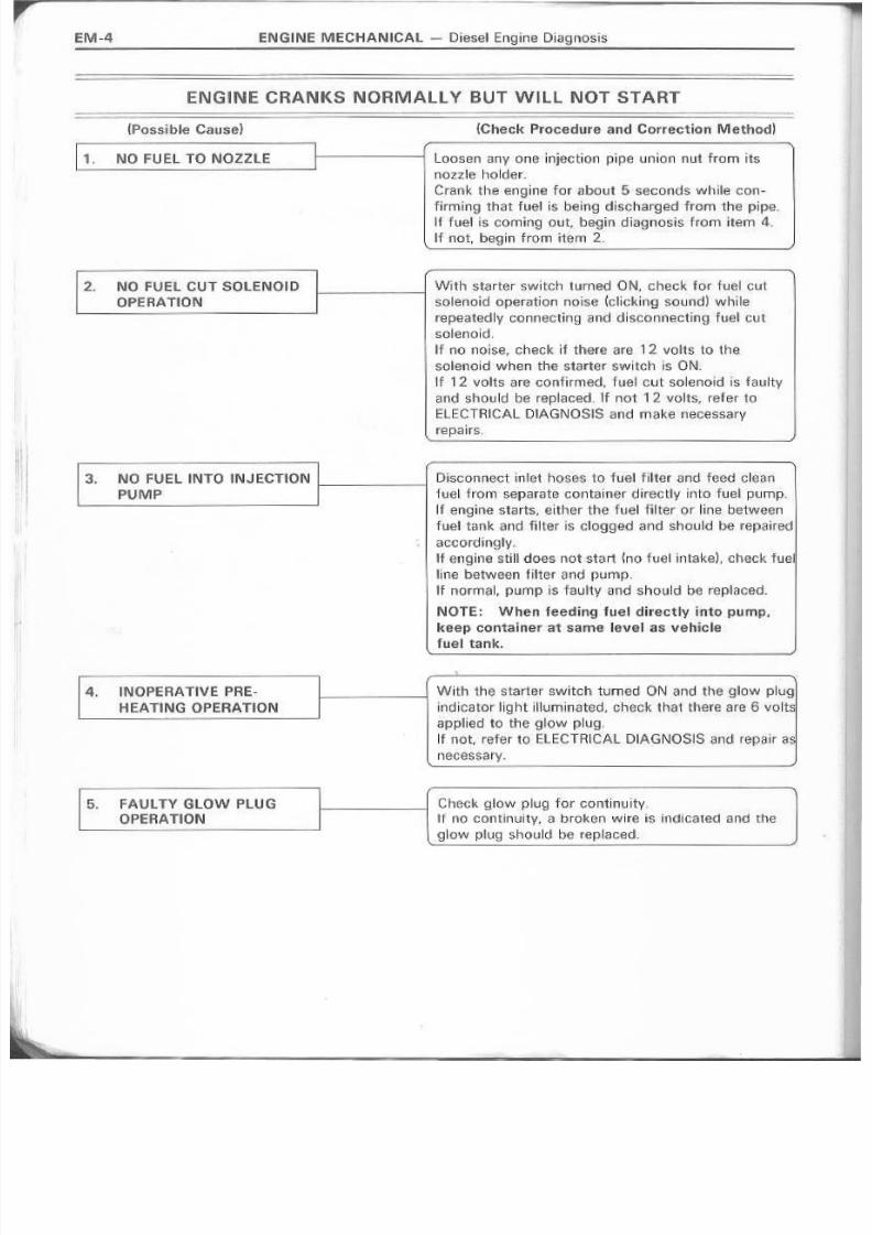
ENGINE CRANKS NORMA.LLY BUT W~lL N,OT'START
(Passible Cause) (Check Procedure and Corr,ectro,n M,ethodl
1, NO fU EL TO NOZZLE 1-------1 Loosen any onelnjectton pipe unlon nut from itsI--------~------' nozzle holder:
Crank the eng,ine for a bou t 5 seconds while con-
firming that fuel is' bei,flg discharped from the pipe.lit 'fuel is co:rning .out, begin diagnosis from i'tem 4.
If not, b~gin trorn item 2,
2 ,. N O FUEL CUT saLENOID
OPERATION
I---------i With starter switch turned ON, checkfor tu¢1 cutsolenoid operation noise (eli,eking sound) while
repeatedly Gonn@Ctur1g and discnnnectlnq fuel cut
solenoid,
IT no noise, check if there are 1 2 volts 'to th esolenoid when the starter switch is 'ON,~f 12 volts are confirmed" ruel cut solenoid is faulty
and should 'be replaced, H not 1 2 volts, refer to
ElECTRICAL. D!AGNOSIS and mal~e necesservrepairs,
NO.c 'FUEL INTO tNJECTlON I I - _ _ ~ _ _ I P~sGonneGt ~nlet hoses 1. 0 fuel fllter :<)mdfeed cleen
PUlM P . fue ~fro rrr sap ara te cnn te irter d irec Uy into fue~pump.
If anq l l1e sta rts, ~Lth e r the fu e l fi Iter 0 r li n .e b etw e s 11
fuel tank and filter is clogged and should be repaired
accordingN·!'Fengine '"St:il~does not .stsrt ~riO fuel intake)" check fue l
llne between filter and PW'11p.
H normal, pump is faultvano should be replaced.
NOTE: W'hen feeding fuel directly into PUffilp •.
r<,eepcarrtalner at same level·as vehicle
fuel tank.
~.
,
1-------1 With the starter switch turned ON and the HI,ow plug
indicator light illuminated, check that there are 6 volts
appliad to the glow plug,
If not, refer 10 ELECnUCAL DIAGNOSIS and repair a s
n e c e s s a rv.
4. IN,OP'ERAT'IVE PRE-
HIEATING OPERATION
Check glow plug. for continuity,
If t10 eontrnuitv, a broken wlr.e is In{':llcalec1 and the.gkow plug should be, replaced.
FAULTY GLOW PlU G
O PE R.A T lO N .
8/4/2019 Toyota 2L Engine Mechanical
http://slidepdf.com/reader/full/toyota-2l-engine-mechanical 5/68
Check for loose unions cr 'cracks.
If lie'aking, tighten to standard torque or, it necessary.replace pipe~s~.
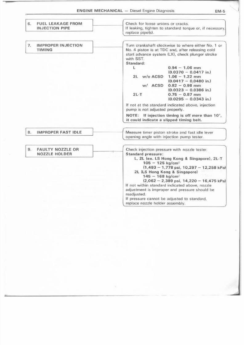
6. FUEL LEAKAGE FROM
IN'J'ECTION P.P'E
Turn crankShaft clockwise to whare either No, 1 Or
NQ. 4- piston is at TOe and, after 'releasing cold
start advance system (LX), check plunger stroke
with SST .
5tafldard~
L 0.94- 1.06"mm
(0.0370 - 0.0417 h'l.)
2L wio ACSD 1.06 - 1.22 mrn(0.0417 - 0:0480 in.)
wI ACSD 0.82 - 0,98 mm
(0.032.3- 0.0386 in.]
2,L-T 0.75- 0.87 mm
(0,,0295 - 0.0343 in.)
If not at the standard indicated above, injection
pump is not .adju~tedproperly.
NOTE: If injection 'timing is off more than 10°,
it Gould indicate a slipped timing belt,
1. 1M PROPER INJ·ECTION
TIMING
l B . IMPROPER FAST IDLE -i Measure timer piston strokaanc fast idle lever
opernin~an,gl.e with injection pump tester.
a . FAULTY NOZZLE OR
NOZZL.E HOLDER
Check, ln lectron p,I'essure with r l "OZZ~ 'tester,
Standard plreSSLlirEi!;
t. . 2L (ex. rs Hongl Kong '& SingaporeL 2l- T
105 - 125 kglcrnz . .
(1.,4~3 ._ 'I r778 psi, 10,2.97 - l'2,258 kPa)
2L ~LSHong Kong & 'S~ngaporel145 - 16:8 kgjC:IT'!~
(2,062 -2.389 psi. 14,2.2.0 - 16.-475 kPa)
kf not within standard indicated above, nozzle
.adjustment is improper and pressure should be
readjusted,
If pressure cannc] be adjusted to standard,
. replace riOtzle holder sssembtv.
'EM-S
8/4/2019 Toyota 2L Engine Mechanical
http://slidepdf.com/reader/full/toyota-2l-engine-mechanical 6/68
EM-6 EN G INE M ECHAN ICAl ~ Die sel'l Engine Di<lgnosirs
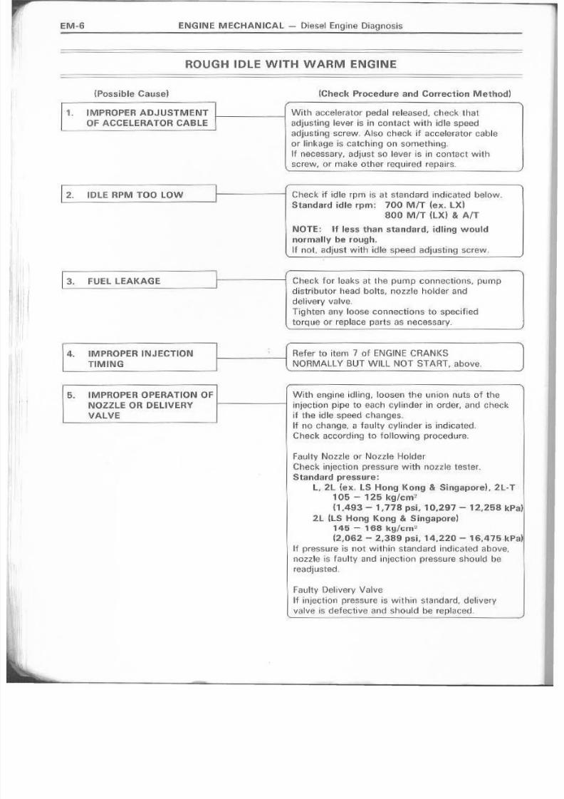
ROUGH IDLE WITH WARM ENGINE
(Possible Cause) jChe·cI{ Procedure and Correction Method)
1. IMPROPER ADJ USTMENT
OF ACCELERATOR CABl.EI----~_ With accelera tor pedal released. check 'that
adjr'llsti,ng lever is in contact with idle speed
.adjLJstitng screw. Also check i ' f , acoelerator cableor linkage IS catching on sornettnnq.
'I'Fnecesaerv, adjust so lever is ill contact with
screw, or make ether required repa irs ..
1 2 . ID L E R PM liD O lOWI
Check' if idII1l rpm is at standard bn~:HGated below-
St.andard idle rpm: 700 MIT (ex,. LXl
Sa o. M IT (LX) & 'A n
NOTE: If less than standard, idling would
normally be r·ough.
If not, adjust with idle speed 'i3idjustirng screw,
I
Check for Ieaksat the pump connections, pump
distributor head bo lts" no zz le holder a.nd
delivery valve,
Tlqhten a ny loose connections to specified
torque or replace parts as necessarv.
1 3 . FU EL L EA KA GE !I--------iI
R~fer to item 7 of ENGINE CRANKS
NORMAlLV BUT WILL NOT STA'RT, above,
4 . IM PR O PER IN J EC T IO Ii\l
T'MING
5. IMPROPI: ROPE RATION 0 F Wi til eng ln e ~d~ ijn g. 'Ioosen th e un ion nuts of theNOZZLE OR DELIVERY 1------1 injection pipe to each cvllnder in order. and check
VALVE i' f the idle speed changes. .
If no ehange, a faulty cylinder is indicated ..
Check according to foLlowing procedure.
Fau~tvNozzl.s Or Not!2le Holder'Check injection pressure with nozzle tester.Stand ard pre 55ure :
L" 2L (ex, lS Hong Kong'& Si_ngaporeL 2L·T
105 - 125 kg/em' .
(1,493- 1,778 psi" 10.297- 12,25& kPa,)
2L ItS Hong Kong & Singaporel
145 - 166 kg/l:an~
~2.,062- 2.389 psi. 1,4,220- 1£.475.I~Pa)
If pressure u s not wHhin standard indicated above,
nozzle is 'Faulty and inJect ion pressure should be
reedlusted.
Faultv 'Dei ivery Va l vs
If injection pressure is within standard, delivery
valve IS defective and should be replaced,

8/4/2019 Toyota 2L Engine Mechanical
http://slidepdf.com/reader/full/toyota-2l-engine-mechanical 7/68
ENG.IN E M ECHANIICAL - Diesel Engine Diag rrosis
'6. N!O FUEL INTO IINJECTION 1------1 Refel' to item 3 of ENGINE CRANKS NORMALLY
PUMP BUT W'llL NOT 'START, above.
ENGIIINE SU DDENL Y STOPS
(Possfb le Cau 5e) (Check Proce dure and Correct ion Me tho d j
1. ENG,lINEWILL NOT RE-START
I----~---l Check toSE!1}f !!!ng,ine re-starts according to
prescribed procedure.If not. refer to ENG INE CRANKS NORMALLY BUT
, WilL NOT 5T A R T. above, and repalr ·as necessary_
1 2 . ROUGH IDLE 1--------1 IIFid le is n ot s.ta bIE fl,refer to ROUGH IDLE and repair'-------------- aocord:ing~.y.
~ __ ~~ __J
NOTE: No operation noise from the 'fuel cut
so leno·id rna v be· due to 100s e elec tr ica I
eormectlerrs, so check connectors before
prac eoedin 9 with fu rther repa irs,
Refer to ENGINE CRANKS NORMALLY BUT WilL
NOT START, above, end check accordinqlv.
3 MALFUNICTION OF FUEL
C UT SO LEN O ID
4. NO FUEL INTO INJECnON l.-__ -----::-----1
PUMP
R@fer to item 3 of ENGINE CRANKS NOHMA1L YBUT WILL NOT START, above:
LACK OF POWER
NOTE:
1. First cheelc that air eIea Iller lis Irrot Clogg ad all d eng ine not ave rheati ng.
2. Not ..appUcabh~~if customer desires outpu1 power 'higher than speelfled for that vehicle.
For accuracy. adjust with a chaasls dynamo.
lP'ossible Gause) (Check Procedure 'and Correctkm Method)
Witi:l.<Iccelel'ator fully depressed, check that
adluMingi lever is in contact with maxlmum spaed ,
01djus'l: ill gl S~r~w.If n ot, adjust accordi l1gry.
1 . 1M P 'ROPER _ ACCELERATORCABLE AIlJ U'STM ENT
Start engine, depress acceler:8Itar pedal to floorand check that no-load maxlrnum rpm is within
standard.I f n .o tt , 6 d1 j u ~ .t twith max , lmum sp~ed adjlustillg sc:rew.
2 _ INSUFFICIENT NO-LOAD
MAXIMUM RPM
EM-7

8/4/2019 Toyota 2L Engine Mechanical
http://slidepdf.com/reader/full/toyota-2l-engine-mechanical 8/68
EM-8 ENGINE M ECHAN ICAL- Diese~ Eng,i l1e Diagnos. i :s
----,
3,. INTERCHANGED I- ~~(N10TE.: Ov-e:rflow screw is marked "OUT" andOVERFLOW SCRiEW lOUT) las an inner jet. They must l1Iot be interchanged.
A.ND INLET (NO MARK)
fiTTING
1 4 . FUEL LEAKAGE
6. IMp·FlOPER I.NJEGTIO!NI
TIMING
1. F,AULTV NOZZLE OR
NOZZLE HOLDER
I RMer··to item 3 of ROLJGIFIIDLE WITH WARM
ENGINE.
Disconnect inlet hose fro'rn fu~'l finer and feed
c lean h . J e l c lire c1 1Y lc m o th e pump.~f eng i rnE ! . cQnd· it ian imprQv i3$ ,. f U ' E : ! 1 filter , is c l' ogged
and should b~ repla.;:ed.
NOTE : When fe ed ~ng'fue I dilfefltl v i rsto PUll'!P,Ikeep container at same leve'l as vehicle ' fue!1
tank,
If no increase In 8r1ghlJt!l ccndstlon after replacing
fue~ftlter, check pfim~~'~lpump or perform otherneeessa r : ' f repa irs.
RHfer ·to item 7 of ENGINE. CRANtKS NORMAL LY
BUT W IL ,L NOT STAAT_
Re:rer tb item 9 o'f ENG~NE CRANKS NORMALLY
BUT WilL NOT srAfrt
EKe ESS ·IVE EX HAUST S MO K IE
NOTiE:
1 , CIheC'k th atill ii- r:~eaner is n01 c In99 ed..2. Check w.ith uustumer whetber aU consumption has beeneXGessiv:e.
(PO 55.tO l{l C a u s-e )
1. 1M PROPER IN J ECTION
T~MIIM.G
1 2 . CLOGGED ,FUEL FU.TER ~-----------i
I
'FlEif ief to item 7 o:f ENG INE CRANKs NORMALLY
BUT WilL. No.T START
NOTE : Black smoh:e zn d leates adva nee dtim i1119
while white smiokeindicates retarded tiMing.Adjus1ments should be made .accordingly.
Referc to item 5· of LACK Or- POWER.
NOTE: AI!;hi,gh rpm ~2rOOO- 3.0001, a clo99ledf i.lter' t8nds· to m ak e 1heex h ; ; 1 . 1 , 1 st smo ke white.

8/4/2019 Toyota 2L Engine Mechanical
http://slidepdf.com/reader/full/toyota-2l-engine-mechanical 9/68
EN G IN IE . M EC HAN IU ::A L - Diese l Engin,e Diagnosls
1--_----1'[ Refer to item 9 ot ENGINE CRANKS NORMALLYBUT WILL NOT START.
3. FAULTV NOZZLE (lR
NOZZLE HO LDER
NOTE; Exc,essive exhaust smol"e ~s.often
eaused by noul,e pressm:e being 100 low.
EXCE.8,s,1VE FU IELCO NSUMiPTIO N
NOTE: Check whetherolutoh sUpPling. brakes grab.bingl, tires. 'w rongl size -or a , i i r filtef clogged.
(Check Pmceduni!and Correction Method)
Refer to item . : ? of R'OUG'H IDLE WrlH WARM
E N G I N E .
I "1. fU EL LE,AK AGEII
1 2 . mu: RPM TOO HU3H 1-------1 ,Af te1r sufficiently warm ing up eillgine, cheek that
L-_---------~- idle. rpm is as specified beJow.
Idh~ rpm: 700 MIT h~x. DO800 M!T (LX) & A/T
U'net, adjust wi-thidle speed adjusting screw,
r; .TN_·_OO.- .· .O~L.· ,.H-_AIG_.D .H...MAX~MUM RPM I I - - - - - ~ - - itart-engIne, depress a eea iera ro r peda l to f loorL . and Gh.~c.kthat no-load maximum rpm is within
sttlnciard,
Ne-load m axim um rpm :L, 2L {ex..lS Hong I(ong & , S j ,ngapC i IfE ! . Ausf ta lh !1
LV & LN56) & 2iL-T 4,900
2L (LS Hong Kong .& S o irig i;llpore, Auslra I iaLY & LN56) 4,500
Ilf not, 3u1uS1 with maximum spe.ed. adjusting screw,
Refer f o item 7 of EN.GIINEGHANKS NORMALLY
BUT WILL NOT .5TART. .4. IMPRO PER IN ,JEG TIO !N
TIMING
Rehw to item H nf ENGINE CRANKS NORMALLY
BUT WILL N . O · T START.5, FAULTV NOZZLE OR
NOZZLE HOLDER
E,NGINE NO ISEW HEN WARM
(Clanking, Nolse with Excessiv'e Vi bratlon)
'(Check Proeedureand CorrtllcUon Metho~l
CIl.~C k c o olla nt te rn p e r,1 lu re wit h coo 13nt
te m pe ra tu re -g a ug e --If not suff Id'~rrtl y wa rrn, the rmo stat is : fa uHy anoshould O!:lrep1lac,ed,
1. COOLANT lfEMPiERATU RE
TOO LOW
EM·9
j

8/4/2019 Toyota 2L Engine Mechanical
http://slidepdf.com/reader/full/toyota-2l-engine-mechanical 10/68
EM-1I0
2, IM'P'ROPER 11~.uEC::TION
TIMING
J.. FAULTY NOZ·ZLE OR
NOZZLE HOLDER
NOTE (ex. w/ACSO):
Refer 10 i"tam 7 . o f ENGliNE CR AN KS N OR MA LLY
BUT WilL NOT START.
('Possible Cause)
BIN DING ACCELERATOR
UNKAGE
Refer to item 9 of ENGINE CRANKS NORMALLY
. BUT WILL NOT ST ART
ENGilNE WilL NOT RETURN TO ID'lE
Check. that idle adjusting kncb is returned.
iCheck Procedure and Correcti·o'!1 Method}
1------1 Operate (;!djl.l8ting lever on 'top of injection pump
and check. jf engltle retLJrI1S to ldle,
If 50, accelerator cable is . bindIng Of maladjusted
and should be repaired accordingly ..
If engine does not return 'to idle, injection pump i s "faulty ' and should be replaced,
ENG INE WI LL NOT SHUT OFF WI.TH KEY.
(Pos,sib1e C~use)
IMPROPER FUEL CUT
SOLENOm OPERATION
(Checl( Procedure and. Correc1ion Me1hod~
I------i Dlscorinect connector 011 top of fuel cut solenoid Elndcheck if engine stops;
If so, starter switch is i . f : ' luhy and should be !repairedas necessary or rep 1 aced. -~fellgil)9 does not stop, either 'F1JelCUl t solenoidis fa.ulty or there is interference by fOf ' la ign partlcles,R e,p al r as ne e€)ssa ry .
8/4/2019 Toyota 2L Engine Mechanical
http://slidepdf.com/reader/full/toyota-2l-engine-mechanical 11/68
EM·"
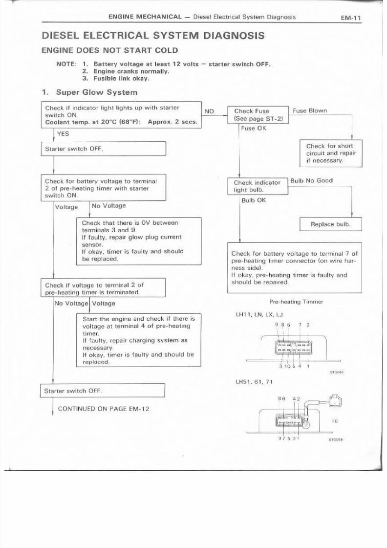
DIESEL ELECTRI,CAL SYSTE.M DIAGNOSIS
ENGINE DOES NOT STAR.T GOLD
NOTE; 1. Ba'U;ery vo Itag e at lea st 1 2 V " Its ~·S"talrter swite hOFF.
,2. Engfne cranks normally.3. FU5ib~elink okay.
1. Sup.er G;ow System
Check if indicator light lights up with "Starter
Bwitch ON,Coolanl temp. at 20°.G (68°(=j: ,Approx. 2s,.;;cs.
YES
Starter sWi,tch OF F ,
Check for battery vQ!tage toterminal2 o'J pre-heatlnq 'timer with S!tarte'f
switch ON ,
Voltage NO"Voltage
Check that there I S OV betweenterminals 3 and g,
I I f ' t<l£uLty,repair glow p .~ug current
sensor,
If okaJY, 'timer is faulty and should
'b e re ;tlla eM ,
Check if voltane to terminal 2 ofpre-he·6ting timer is tsrrnlnated,
No Voltage Vo:ltagi3
Start the enginei:lm:J check if there is
vo I ta g~ stterrn insl 4, of prfl!~h m a t l · o g .
timer,I~fEl,Il'ty~ repair Ghar,gingsyslem as
F1ec.essary,
If ok",V, timer is faulty arid should t r i l l ·
rePI~?'~~.: .
Start13r switch OFF,
CONTINUED 'oN PAGE EM~ 12
Fuse Blownheck Fuse
(Se,e pag€! ST-2)
I Fus~ OK
INO
.Check 'for shan
circuit and repa~r
i 'f necess·.1lry,
Check indicator ~.6u'lb No Goodiight bulb.
Bulb. OK
R ep la ce bl,J~ b_
Check.. for battery voltag.e to terminal 7 of
pre- he.ating timer connector ~on wire har-
ness sjdeL
If okay, pre-heMing, timer is faulty andshould be .~~paln::d,
Pire ·, h ea t i ng · T iminer
lHt 1, UI, j , LX,.U
7 .~
I
..~TQo1>'l!~.
LH51,61,7l
1 D .
,
~ n s a \ STOO.~

8/4/2019 Toyota 2L Engine Mechanical
http://slidepdf.com/reader/full/toyota-2l-engine-mechanical 12/68
l~
EM-12 ENG INE MECHANICAL - Dt@sel,Eleotric,al S'ystem Diagnosis
CON T~N U ED FHOM PAGE EM -l1
Places starter swltch a t ON and
check for vo!Jtage to glow p ~ L . J g
a few seconds later,
Thereafter, voltage should drop
about 1a.~------~--------~~
I Pre-heatinq Duration is Quite
1 D i" f: fe re n t T h an That Above
ex. LX ] L : X
1,0 -
. No Voltage
F-_--___l... ~-- , No Continuity r------~----~--------------~__Check glow plug for contlnultv. - Glow p~ug'faultyaind should be replaced_
Contlnuitv
No Voltag,e
at A H
-3D -ro HJ :);D ~o m-2.0 0 .20 4() (~r.'
" "J I J ~ m r .f I r: u I~ r ~ ~ : = :' '' :_ _ :I _ ~ f: _ 1_ - -- = .= r ~ n :l ~ :
Timer is faulty and should be replaeed,
Disc 0nnect water tempera tu re sensa r (le.Jt rearof €!1J9Iine)and check if pre-heatinq duration is
abo u t 1 5.0 se ep nds O f, if -C O rinector isdirectly groun(Jedr pre-haatinc duration ~s
about 3 seco nd s.
I f 0k av, wsts r tem pera ture sen sor I s . 'f au I ty a .nd
should be replaced.
If not. 'l~rner is' faulty and 'should be- replaced.A Her completion of pre-heating,
check for voltage at terminal8 1O l g a i r f ' 1 when starter .switeh is
placed-at ST.
Vo1 tageT
Starter switch OfF.
Place starter switch at ON and
check if current 'f low to . terrninat8 of tlmer ls.in accordance with
coolant temperature
Isee 9 fa ph a bovs) ;
I INo. 1/2 Voltage
Them.after
I
Timer is faulty and sncutc be. replaced.
Glow plug okay.
Check-for battery vol'tage at pos.itiv€' sl(Je of glow
p~ug current sensor (Int,ake manifold Side:),
If 0ka If j rep lace sense r.
If no veltaqe, No. lglow pilug r.eilay is faulty and
should be replaced.
(For component inspection, see pag:€'s ST-4 and
ST-5),
Check fQF battery v,oltag€i to plus side of resistor
{Inlal\e rnenlfold side;).If okay; replace resistor.
IF no voltage, No . .2 ,glow pl.og relay is hwlty
and should be replaced ..

8/4/2019 Toyota 2L Engine Mechanical
http://slidepdf.com/reader/full/toyota-2l-engine-mechanical 13/68
ENGINE MECHANICAL.- Die,selEI~ctriGaJ System DlJ3gnosi$ EM-13
2.. Fuel Cut Solen'oid
W~Ul s ta r te r cSW i ·tci1 tu rned ON, ehec Ii; to Ii '
fuel cutsolsneld operation tlIois.!3'(di.ck~f1g
;Si0und ) wh i Ie repea ted IV GQ n n ac tln 9 a n d
disco ~ 1 flecti ng i fu e II cut soleno id,
No Noise
I - Fuse[Hown Check Tefr short cir.cuhCheck F u s: ~ \S e e p s·g e S T -2 JI---------------~... . c J ' ' , ' , '_
ano r e p : < : J . ir ~s n ecasse ry ,
Apply baUBfY voI.tQ .g .e (1 2 No!S '€ ' Check wire;;: h arn ess fromvotts] dir~Gt,ly to ~;:ole,no~dII-----------------~ fUSB A {S e e p ag !a S 'T -.2 }
and che.{>k for noise. to fuel CUlt solenoid.
No NOise
R ep l ac e fu el Gut soller!oj d.
8/4/2019 Toyota 2L Engine Mechanical
http://slidepdf.com/reader/full/toyota-2l-engine-mechanical 14/68
EM··14
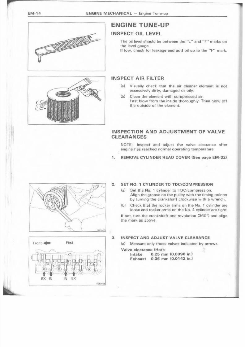
ENG ' N E TU_NE-UP
I.NSPECT OIL LEVEL
The oil1evel should be between the "L" and '''F'' marks 01 1
the level gauge_.
If low, ohecl< for le~l~og.e and add oil up to tile ~'F" marie
e:NGiNE MECHANICAL - Eng'ine Tune-up
Front,. Fir~t
EX IN IN EX
INSPECT AIR FILTER
{a~ Visual11v check that the air cleaner element IS not
excessively dirty r -damaged or oily,
(bl CI'ean the element witt1 compressed air,
First blow from the inside thoroughly, Then 'blow 6ffthe outside of the element.
~NSPECTION AND A'DJUSTMENT OF VALVECLEARANCES
NOTE; lnspect arid .a,djLJst the valve c learence after
engine i18Sreached normal operatiflg temperature.
1, REMOVE CytlN DER HEAD COVER. (See page EM -32)
2 . SET NO.1 CYLINDER TO TOC/COMPRESSiON
~a} Set the 'No, 1 cvllnder to TDC/compres.sion,
Align the groove on the pulley with thstiming pointer
by turninq the crarrkshaft clockwirse with a wrench,
(bJ Check that the rocker arms on the No, T cvlinder meloe ss a nd rocker arms on the N o_ '4·cylinder are ti,ght.
'If not. turn the ctanlrsh:aft one revolution (360°) and align
th€ mark as above,
3 _ .NSPECT AND AOJ UST VAL VE. CLEARANCE
(a) Measl~re only those valves indicated by arrows.
Valve clearance a-lot):
lntake 0.25 mrn (0.'009-8in.l
Exhaust 0.36 mm lO.O'l42 in.!
8/4/2019 Toyota 2L Engine Mechanical
http://slidepdf.com/reader/full/toyota-2l-engine-mechanical 15/68
ENGINE MECHANICAL- Engine Tune-LIp EM·15
Second
EM01 05
\'/I
Ii
I
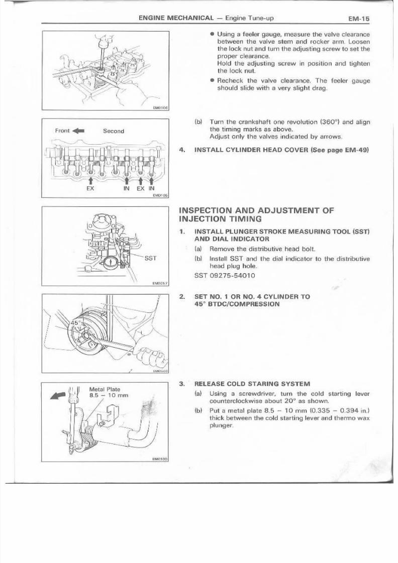
• Using a feeler ~auge, measure the valve clearance
between tha v~lve stem 'and rocker arm, Loosen
the lock nut and turn the adjusting screw to set theproper cleeranee,
Hold ths adjusting screw in position and tighten
the lock nut.
• Recheck the valve clearance, The feeler ,gauge
shou Id 8 1 ide with a very s~ight drag.
(b) Turn the crankshaft one revolution (3600) and ,align
the tirn iilg marks as above.
,Adj u s t a n lv the va IV8:S i r'ldic ated by arrows.
4. INST.A.LL CYLI NDER HEAOCOVER (See paiSe EM·49)
INSPECTI 0 NAND ,ADJ USTM ENli OFINJ.ECTI:ONTtMING
1. INSTALL PLUNGER STROK.E MEASURING TOOL (SST: I
AND DIAL INDICAiOH
~a) 'Remove the di5trib~tive. head bolt.
(b) lnstall SST· and the dial indicator to the distributive
head plug hole.
SST 09-275-54010
.2 . S.ET N'O. 11OR NO.4 CYlilN PER TO46
D
BT'DC/COMPRESSION'
3. RELEASE COLD STARING SYSTEM
(a) Usi FIg a screwdrlver, tu rn the co Id sta rting Iever
counterclockwise about 20D as shown.
(b) Put a.metal pilate 8.5 - 10 mm (0,3.35 -0.394 in.!
thick between the Gold starting lever ami thermo wax
plunger,

8/4/2019 Toyota 2L Engine Mechanical
http://slidepdf.com/reader/full/toyota-2l-engine-mechanical 16/68
EM-'6 ENG!INE MECH.ANIICAL _- Engille Tuns-up
4. 1NSPECTAND ADJUST INJIECTION TIMING
(a l Set the dl.~1gauge a t z ero mm (0 ln.l.
~bl' Recheck to see' that the d lal Hauge rsmai nsat zero
mrn (0 in.], whl, le rotating, the cr,ankshaft pu l l, ey s li gh t-ly to the left and I[,g hi.
(c) Slowly rotate the crartkshatt pulley until No. 'i " or No.4 cylinder iset TDC/comf:Jn lSsion.
{d)' Me,asur,etile plun'ger stroke.
Plu ng er stroke:
L 0..94 - 1..06 rnrn jO.,0370 - 0..0.417 inJ2l w/o ACSID 1.06 - 1.22 mm
(0.0417 - 0.0480 inJ
wI A.CSD 0.B2 - 0.,98·mm
(0 0.0 .32 3 - 0 ..0 38 6 in.)2L- T 0.75 - 0.87 ! 1 1 1 i 1 1 (0..0295 - 0.0343 in.)
te,) Loosen the: foul' injectlion PIpe union nuts and fuelinlet pipe union nut at the injection pump side.
(f) l.oe 59n the fo ur injection PtJ IIIP mount ing bolts andtwo nuts.
'(g ) A d ju st the p lu ng e r stroke by sl.ig'htlv tilting file injeG·-
tlon pump body.
If the stroksis less than .specifigati·on, tiltthe pump towardengine.
If 9 mater than spec i fie atlon 'I i ~tthe pump away fro men,gine.
(h) Tig htsn 'the injection pump mmmting bolts and nuts.
TO'r .Ql Ie :
"801'5. 185 1<9-cm (13 ft-.b, 18 N'm)
Nuts 210 .Ieg-'em (15ft-lb, 21 Nom)
Recheck the plunqer stroke',
Tighten th e linjection pipe union nuts and fuel inllEltpipe unlo n nut.
Torque:
Injection pipe 250 k'g=cm{1a ft-Ib" 2,5N·mlInh~tp;pe 23(i~.g~om
(17ft-lb.
23N'm~
•
5. R'EMOVE METAL PLATE FROM COLD STARTINGLEVER ' .
6. REMOVE SST AND DIAL IN,o!'CATOR
ta l Remove SST and the d'ial indica tor .
SST 09275-54010
(b) Install the distribution heac bolt with a new gasket
Torque the bolts.
Torque: 170 kg-em ~12 'ft-lb,,17 N'ml
7. ,S,TART ENGINE AND CHECK FOR 'LEAKS

8/4/2019 Toyota 2L Engine Mechanical
http://slidepdf.com/reader/full/toyota-2l-engine-mechanical 17/68
ENGINE; MECHANICAL ~ Engrn~ Tune-up
ldls SpeedtAdjusting ScrewI
INSPECTION AND ADJUSTMENT OF
IDLE AND MAXIMUM SPEEDS
1. mNITiAL CONDITIONS:
{a ) .Ai r clea 1 1 e r installed
(b~ En 'g~ne C dolant norma I ope ra ti 1 1 1 9 te rn p era tu re
(c) Aecessorles switched off
{d} Transmission in neutral
2 INSPECT AND ADJ UST IIDLE SPEED
~a ) C nBC k t ha t the illd j ust in 9 1la ve r to UG has ·t he idle speedacljlist ing screw when th e accelerator ped E l i is
released.
If not, adjust the accelerator linl~~~e,
(b) In is ta II a tac hamate, to !~~eng ine,
{d Start the engine,
( c O Check the ii'dIe speed.
Idie .speed': '']QO rp m MIT (ex. LX)
,800 rpm M)T (D O & . Ali
(·e) Adjust the idi,e.speed,
• D iscon nect 'th e a c cs l fi rater I i nkage .
• Loosen 'the lock nut 0 f the .idle speed 8 dj UIsting
screw.
• Adjust the idle speed by turning the IDLE SPE'ED
ADJUSTING SCREW.
• Secu re Iy tig hten the lee k 1 1 lit.
• Carmsct the accelerator lifukag.e.
• Afte.r adjustment, adjust the accsler ator linkage_
3., I:NSPECT A.ND ADJUST MAXIMUM S.PEED
~a} Check that 'the adjusting lever touches the maximum
speed adIl.iIs.ting screw when the accelerator pedal isdepressed all the way.
If not, adju;;:t the stop. bolt of the accelerator pedal.

8/4/2019 Toyota 2L Engine Mechanical
http://slidepdf.com/reader/full/toyota-2l-engine-mechanical 18/68
EM-1B ENGINE. MECHANICAL - Engine Tune-up
{b} Insta II 9, ta Ghometer to the. 'eng ine.
( c . ) Start the engine,
(d) Depress the accelerator peda l a ll the way_
(e) Check the maxlmum speed.
M~.ximum speed:
k, 2L lex. LS Hong Kong & . Singap(H€!; Australia
lY& .
lN56)&
2L-T 4,900rpm
2L l.lS Hongi Kong & Singapore, Australia
l Y & LN56} 4,:500 rpm
m Adjust the maximum speed.
• Disconnect the accelerator linkage-
• Usill.9 SST, loosen 'the lock nut of the maximum
speed apjusting screw.
SST09275-54020
• Acljust the maximum speed by the MAXIMUMSPEE D ADJUST IN G SC REW _
NOTE: Ad h . J st at ielile speed. T h&n , r a l i see ngine speedand recheck the maximum soeed.
• Using SST, securely ti.ghten the lock nut.
SST09275-54020
• Connect thE! accelerator l inkage.
• A iter adjustment, adjust the stop bolt aT tha
accelerator pedal.
CH Eel< AND .ADJU STM ENT OFi NTAKEAIR VOL.UMe (LS, tX71 MIT)
1 , . INITIAL. CONmTIO'NS;
(a) Air cleaner installed
{bl Eng ine coolant normal operating temperature.
h . : : } Accessories switched off
(d} Transmissicn in neutral
{e) 900 meters or less above sea level,(f) intake air volume valve fully closed,
2. CHI;,CK AIND ADJUST INTAKE A.R VOLUME
o(a) Install a.vacuum g8u 'g ,e to the lntaks mani'folct
(b) S ta rt the eng ine.
(c ) Check the lntake rnarnfuld vacuum.
Vacuum: 11[} - 150 rnmHg
(4.33 - 5.91 i n. ,Hg • . 1,4.1 - :20.0 kPa)
(d). Adjust the' vacuum by kH;l~en~ngile lock nut 'and
turniflH theiNT AKE A,~RCONST'RfCTOR ADJUSTING
SCREW.
Intake Air Constrictor _
Adjusting s<;n~w. ,rV\acuum- -r-l~../ I , }IGauge~ ~'
~""

8/4/2019 Toyota 2L Engine Mechanical
http://slidepdf.com/reader/full/toyota-2l-engine-mechanical 19/68
ENG IN,EM ECHli\N ICAL- Compression Chack
NOTE~ If there is lack of power; excessive oil or fuel con-
surnptlen, measure the~ylillder compresslcn pressure.
1. WARM UP ENGINE
.2, DISC01NNECT fUEL cur SOLENOID WIIRE
CO 'NN IE :CTOR
3, REMOVE FOU RG LOW PLUGS
(S@epa~geEM-21l
CAUTION: Make· sure tth~ load win:! is notgumnded.
4. IINST A.Ll aSTTO GLOW PLUG MOUNTI NG 1010.E
SST 09992-00023
.5 . M.EASURE CYUN.oIE R COMPRESSION iPRESSU RE
fa} Conn:eGt a comprassjcn gauge (SSTj to SST.
SST 09.992-00023
~b) While cranki ! " l o g t h(5 en9 ins with thesta rtsr, meat ure
the comp're 's6idrJ pressure.
NOlE: A. lways . us€ a fully charged bat tery so tha t atleast
2 : S.o rpm ea rr he re a G hed,
(c) RepElatste.p.s (al and (b) tor each cvlinder.
Compressicm prassure:
==-"-r L. ,2l-T 30.0 ikglcm2~427 psl, 2,942 kPa) ~~
zt, ~2,Okg!o.m'l (455 psi, 3,138 kPa)
Minim um pre s;sUl'e
'20.0 ~g/Gm'~ (284 pS'i , 1 . .,961 klPa)
Differenc €I D€ftwtl en eae h ·cyIinder:
LEtSS "lila n 5.0 kg! 0 rri~ (7" ps'j, 490 'lePa)
~d) IF the ·cylind~r corrrpresslorr in one Or more cylindar~
is low, pour a Iunall~ amount of engine oi~ inlo UIe
:cyi inder 1 h rou g h t h fl 9 I( lw pi ug h ola a nd repea'tstep:;;'
( 0 ; 1 ) and~b). for the ~:iylinder wIth ~ow compression.
• Hadd~liIg oil helps :thE;!co.mp res qion,. Ci1;;lf'lGOS are~hat ttl€ piston rirrqs end/or cYlin~eF bore are wornOr dam[llg~,L . . .
II! If pressure stays low, a "'alive may be stid·dng O
.$.~Etfingimprop~r~v, orttrere may be ieak:gl9€l' past
the gasket.
8/4/2019 Toyota 2L Engine Mechanical
http://slidepdf.com/reader/full/toyota-2l-engine-mechanical 20/68
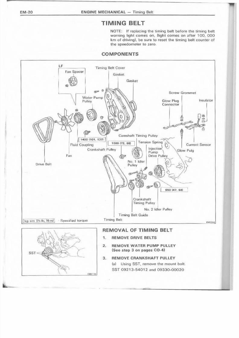
'EM-20 EN,GlNE MECHANICAL ,~ Tirnlnq Belt
TIMrNG BELTNOTE: If ropiacing the timing belt before the timing belt
warning light comes o!il,(I~ght comes on after 100, 000km of driving}, besure to reset the< tim.in'g belt counter of
, -
the speedometer to zero,
COMPONENTS
L FTiming Belt' Cover
Gasket
Sc raw G ro rnmet
Glow P'lug,
Connec,tor
!Fan
Drive Belt
N o_ 2 . I dle r P ull ey
Timing Belt Guide
,
r r : : : , kc , : 9 _m (ft.lb. N'ml \ . hp!,}Gified toreve Timing, Belt
l l ~ ~ ~ - = = ~ = = = = ~ ~ ~_~ ~ ~ ~ ~ ~ ~ _ _~~~'~~4
3. REMOVE CRANKSHAFT PU LLEY
(a) Using, SST, remove the mount bolt,
SST 09213-54-01 2 . and 09330-00020
R'EMOV A I L . 0 F TI M ING BELT
1" REMOVE DR 'IV i! BEL T 'S;
2. IREMOVEWATER PUMP PULLEY
(See S o tep' 3 on pag as; CO~4)

8/4/2019 Toyota 2L Engine Mechanical
http://slidepdf.com/reader/full/toyota-2l-engine-mechanical 21/68
ENGINE MEOHAN ICAL- Timing Be~t EM-21
(b) Using SST, remove the pulley.
SST 09213-60.017
4, REMOVE TIIMING BELT COVER
Remove the twelve holts and bsh eave t" with the two
g.aske'ts,
5... REfi./10VE TIMING BELT GU IDE
6; REMOVE C URR'I:NT SEN SORAN D FOU A . GLOW
PLUGS
tao) Hem ove the fa u r 5crew gmmmats .•
(b} Remove the four glow P~Mgconnecting nuts.
~G } [futa pa (UrI. ix; LN)]Remo r\!! e . th e nu t, pi a te wa rsher, ! I n s u Ia torss and c tlr-rent sensor.
(dJ Removt:) theg 10w plug connactcr,
~el Hflmove t h i e to II J r gl'ow plug s ..
7. SET NO.1 CYUNDEH TO TDe/COMPRESSION
Usin g . .a crankshat t pulleV mount bQlt,aHgfll 'Ule TDC f fi< 11 r
of the earns n aft tim ing pu'l iey with the top end. 'of the
:cyliirldier head.
:?"
1<"'01-1' /

8/4/2019 Toyota 2L Engine Mechanical
http://slidepdf.com/reader/full/toyota-2l-engine-mechanical 22/68
E N G lN E MECHA'N~CAl - -nmin'g Bel t
~ e , .REMOVE TIMING BELT
NOTE: If reusing the timing belt, draw a direction arrow
on the belt On direction Of eng ine revolution), 'and placernatchmarks 011the puil.eys and timillg bslt, .
fa) U:;:;ing needle-nosed pliers, remove the tensionS . p f H 1 g "
~b) Loosen the two NQ. 1 idler pu~IBy mount bolts.
tc} IRemove th€ timing belt.
9,. REM OVE NO . 1 IO lE 'R PU lLEV
'Remave the two mount bolts, plate washers: and idlerpulley,
10. REMOVE CAMSHAFT TtMI NG PU LLEV
Using SST, remove' the mount bolt.
SST 09278-54011

8/4/2019 Toyota 2L Engine Mechanical
http://slidepdf.com/reader/full/toyota-2l-engine-mechanical 23/68
EN.GINEM.ECHANIICAl ~. Timing Belt ! : .M-
'-, I 'I t '", r- ',.
, : . , . < : : ~ 'f~ " . . '~, -
(j" ~
S$T
111. RIEMOVE iNS~;CTION· PU.MP DmVE. PULLEY
{a~ Us i( 1 9 SST, remov.e 'the m 0 u tH nut.
SST 0.9278-5401 1
{b } Using SST, remove the. pump drive pulley.
SST 09213-5.00'1 7
/I
i
12. REMOVIE;: NO. : 2 . IDLER IPULLE¥
R€irnci.v:€!.thG rnourtt boltarrd No. . 2idl~r pulley.
i,.
13.. REMOVE CRANKSHAFT TIMING PULL.IEY
Us}ng SST, ftlrIlOV€ ·the. tr~I~:st\aft timh~g puHey_
SST 09213-6Q017
/"". / ' - - - . ~---SST , .. ' .... -------
.... /~-- . . . .
. .~ I
",,: ~ ~~ I ....
!

8/4/2019 Toyota 2L Engine Mechanical
http://slidepdf.com/reader/full/toyota-2l-engine-mechanical 24/68
ENGINE MECHANICAL - Timit"l:g Belt
INSPECTIONI OF COMPONENTS
1. INSPECT TIMING BEt T
CAUTION:1. Do not bend, twist 01' turn the belt lnslde out,
2. Do not allow the belt to come into GO ntact with
oil, water or steam.
3. Do not utUi2e belt tension when installing orremovin.9 the set bolt of the camsbart timing
p'ulley.
'If there are defects as. shown ln the: figures, check ·the
followif-lg paints and replace the timing belt " if necessarv.
{a) Premature parting
• Check fer proper lnstallatlon .
• Check 'the ,timing GOVer gasket for damage , endcheck Fer correct instsilatlon.
~b~ If tile belt teethare crackeo o r d~ma.ged, check to
see if the camshaft, water pump 0 1 1 " pil pum.p is
lcclesd.
~ ' C l If thi5re is notlceabte wear or cracks em the. belt face.
G.h~ck to see i f there are nicks Oil 'one side O f the idlerpu'lley lock;
{ e I ) If there is wear QI delma'ge on only one side of the
belt, check the beH guide '(Ind the alignment or eachpuHey,

8/4/2019 Toyota 2L Engine Mechanical
http://slidepdf.com/reader/full/toyota-2l-engine-mechanical 25/68
1~39,7-4D,7 min
EM! 133
~e} If th €rclllis no ticea ble weaf 0n the belt teeth, check the-
timing cover .gaske!t for dam.age and check for cor-reetgaskst irrstallatic«, Check for foreign rnatertals
On the: pulley teeth,
.2.. ~NSPECT IOLER P'UILlEYS
Check "the tllrlnung smoothness; of 'the 'liming ben kH~rlPu~leys_
Ilf neeessa r y , replac~ fh e id lor puHI!i'y,
3. INSP'ECT TENSION SPRI.NG
( < ; ) ) Check th~ 'fr,ee length - O f 'the spring,
Free leng th:
39.7 - 40. '1 rum ~1.563 - 1.80.2 in.}
(Ib Check the te nslen of the spring ,a'~ the spec if iMinstalled lenglh_
I I nstall edr re n slo n :4·.0 1(9 (8.,B lb. 39 N) at 52 mm (2.05 in.)
If not .5pee ifi ed , rep l see the s'p ring,_
INSTALLATIO N 0 F TI MilNG BElTISee p,age E,M~20)
1. IINSTA,iLL CRANKSHAFT' 111MIN G PULIlI:Y
(a) A I tg r ! th e tim if lg pu IIe y set key wirth the key 9 roo ve 'O f
theUm:ing pullay.
(b) U!;iing SST i'lnd a ti l amm er, d ri;ve in timing pull ey .
SST 09214~.60010
2. INSTALL N'(};2 IlllERPUL'LEY
Torque.: 4000'I.(g~(lm (29 ft"lb,3JJ N·rnl

8/4/2019 Toyota 2L Engine Mechanical
http://slidepdf.com/reader/full/toyota-2l-engine-mechanical 26/68
EM·26 ENGJNE MECHANICAt - Timil1Q Belt
[M0131
F,M01t9
3" l'NISTAlL INJ ECTION PUMP DR'IVE PULLEY
( G I ) Align the drive pulley setlkey with the key groove o f
the drive pulley.
(b,) Using, SST, Install the drlvs puHey with the mount
nut, Torque tile mount nut
Torque: 650 l<gl~cm(47ft-lb. 64 N·m)
SST 09278~54<OT 1
CAUTION: Do n01 use an im,pact wrench,
- -- -
I;MClr3B l
4, INSoTALL C,AMSHAFTTIIMING PULl.EY
{aj Align the timing pul'ley knock pin with the pin hole af
tha timillg pulley,
(b) Using SST; Install the timing pulley witn the mount
bolt and ptete washer. Torque the mount bolt.
Torque: 1.000 kg-em (72 it-lb. 98 N·m)
SST 09278-54011
5. liNSTALl NO" 'I IDLER PULLEY
~a} Tarnporari lv install th e idler p~!lley with th-e two
mount bolts 'and plate washers.
(b) Sw~ngthe idler pulley toward the lett,
6. SET' NO. 1 CVUN DiER TO TDe/COM PRESSION
Aligllthe t~mbng a nd drive puiIBYiJ. at each position.
CAUnON: The engi,neshould be Gold.

8/4/2019 Toyota 2L Engine Mechanical
http://slidepdf.com/reader/full/toyota-2l-engine-mechanical 27/68
ENGIN E M ECHAN ICAL - Timing Belt
7. I NST ALL TIM ING BE:LT
If using new timing be'li:
.(_s) Install the tirrHri_g belt tothe camshaft timing p'l,Jiney.
CAllIT'ION: Be sure the ti:ming belt iss~curely
mesihed and. flot loos€!:.
Ib} Align the IDimingmarks of the pump drive Plllieyandell pump body. .
(c) InstaH the trming belt to tl,e pump drivl~ pullav.
C_At:lTION: Be sure the timing belt is securelv
meshed and not loose.
(d) lil$tal~ the timing belt to Ul~ No . .2 idler pu.lleyarrd
cran ksh a'ftti m ing. p'.uHey.
CAUTION,: Be' sure the belt is, not twisted air tOO
tight.
If reu'sing timh~.g 'beR;
AJ~gn 'Ul€ points rnerked d;ui'lng removal and installthe tim-
Lng belt with the' arrow po.jnting ~nthe directicn o·fengin.erevolution,
EM~112 13MB1 '16

8/4/2019 Toyota 2L Engine Mechanical
http://slidepdf.com/reader/full/toyota-2l-engine-mechanical 28/68
B. IINSTAU. TENSION SIPR1NG
CAU'TION; LOo~a\!!1I 1 ; rha mount bolts to whe,re the tim"
ing beh idme pulliey llightly moves wi1h tension spring
fon~e.
EM-28 ENG INEMECHAN ICAl - Tlrnlnq Beli
1O.TORQUE NO. 1 ~DLE.R PULLI:Y MOUNT BOLTS
Tor'que: 195 I(g~cm (1,4 f1-lb, 19 N'm)
_1 CAUTION: WhUe 1ightenill'lg the mount bol1s. do notmove the idlrer pulley bracket.
9. CH EeK. POSITION OF TI MING A.IND DRIVE PU LlEVS
~a.) Place a crankshaft puUey mount bolt on the crank-
shaft.
(b} Usl ! ' 1 r 9 1 a w rene 1 " 1 , tum the cranks haft pu'lley mcuot
bolt 2 revclutions from TDe to TDe.
CAU1iI.ON. : Always turn the crankshaft clockwise.
(c) C hac k th at eae h pulley a 1 . 1 9ns wit h ibe marks,
If the marKS do not align, ramovs the timing belt enc
reinstall it

8/4/2019 Toyota 2L Engine Mechanical
http://slidepdf.com/reader/full/toyota-2l-engine-mechanical 29/68
ENGINE IMECHANIICAl.- T!rn~r'I lg Belt EM-29
/
11. INSTALL FOUR GLOW PLUGS AND CU RIFIENTSENSOR
(.a} linstall and torque the fourg low plugs_
Torque: 13-0 kg~cm (,9 it-Ib, 13, N·m)
(b ) P li3Jc~ thl;! g .IDW piugcQllnectot on 'the glow plugis,
(c} [E,urope (LH, LX. LNnIn-stall th e c urrent sensor with the lnsulatores, platewasher. and nut
~d) Insta II the' fO ;U f g!ow p~u9 co nnect ing fHJtS.
(e) InstaHtile fourscrew grommets,
12. INST A.LL TIMI:ING IBELT GUmE
AI igrl the set k.eyon th e 0ranks haft wilt h the keygrDovs 0f
the belt 9u~dean d s I r i d e it itl,
j
13. INSTALL. TIMING BELT COVER
{a l Ins tall the gas kets 'to the. bel t (lOVB.L
{b) lnstall the belt cover with the twelve bol,s,
14.. INST ALL CRANKSHAFT PUlLiEY
~a l A l.ign th e pUlley sat key w it h .t he l~ ~Yg iro bv e of the-
pullev,
{bl' L J ; E i 1 i g SST and a 11[:1nrner, drive in th€i pl..Ill,ey,
SST 09223,-63010

8/4/2019 Toyota 2L Engine Mechanical
http://slidepdf.com/reader/full/toyota-2l-engine-mechanical 30/68
(el U$.ing SST, install the mount bott arid torque it .
Torque: L400 kg~cm 1101ft~lb. 137 N·mi
SST 092l3~5"40 12 and 093-30-00'Cl20.
15;. 'INSTALL WATER 'PUMP PULLEY
(See step 4D!1 pa g,e CO- G,)
ENGINE. MECHAN~CAL - Tirning, Be'lt
-- -/"
"L" ~----
Ale Compressor Ptlll~y
P', B ...~ater Pump Pulley
I "'-t..\.
b£"'-..-1~6s~"mpp",!"~,-\{ _ _ w'"
AlternatorPLl~le.V' CfElnksh~ft Pulley 81;.1":)I,i;
16. ~NSTALL DRIVE BELTS
Driv-e belt defloGtioll t i l t 10 kg (22. lb, 9.8 N) mrn {in.)
Used
-..,_..__ - '. I I
---------12:~ cenditlcnPo 5 itic n '-.."--~ ___
New
( Watl!l"r pump- "I". Alte rn a to r .'
7-10 10-14
(0,2.8 - 0,39) [0.3.9 - 0.551-+------1
'13 - '17 17- 23
{C ).51 - 0 ,67 ) (0 .,6,7 - 0.91)- - - I - - - - - - - - - - - ~
8-10 10-14{O.31 - O.3m (0 ..39 - OJ;!5)
A
c
{ C ranksha ft- \
;" A i C compressor ...
(C,·anks. l .1af t- "1
" PS pump ,.'
NOTE. ;• . . N ®w bett" refers. to a bel l. w hich has ne:ver be en IIse d.
• "Used belt" refers to a Qelt which has been used 0[1 a
running eng ihefor 5 minutea or mere.

8/4/2019 Toyota 2L Engine Mechanical
http://slidepdf.com/reader/full/toyota-2l-engine-mechanical 31/68
ENG tNE MECHANICAL- Cylinder Head EM-31
CYLINDER HEAD
COMPONEiNTS
Heat Insul;:'!tor
Exhaust Manifold
II..
r Gasket
/ /r l
/ -
r-----·Seal Washer
\--- Cyrjnder Head Cover
~~~~;;~~;;~iitY----GaSke'l
• Gasketlntaka Manifold
'. C8i rnshaftOil Seal
Cams.h~ft 0 iISe<: ll R~ ta iner
U- i Eng ii i~.H~riger
,-2-.5-0-(-11-1,5~~
[~ Ift.~b" N - m n : T~ghteningtorque
• Non-reusable part

8/4/2019 Toyota 2L Engine Mechanical
http://slidepdf.com/reader/full/toyota-2l-engine-mechanical 32/68
EM·32 ·ENG INE M ECHAN ICAL. - Cylinder Heac
4. REMOVE CYLINDER HEAD GOVIER
~al ' Remova the two b0!1ts heIdiIi9 tne head C,OVE!r" to the
belt cover.
{b·~ Remove the three cap nuts, seal wasne~s, head coverand.qasket,
6. IREMOVE TIM ING BELT(See steps 1 to 8 on p.i:I.yesEM-2.0 to 22)
6. REMOVE C.A.MSHA-FT TIM.NG PULL'EYb- ~- __ ~_-_~E ..... : : : : . . ( ) : . . = ' ' 1 9 - (See step '10 Oil 'P·age EM-221 '
7. DISCONNECT ACCELERATOR CONNE.CTING RODFRO M A C.C ELERA TO R L IN K
R I: M OV AL O .F CY L I N D ER. HEAD
1. IREMOVE FOUR INJECTION PIPESlSee step 1 on page HlI~7 i'
2. REMOVE FOUA INJECTION NO.ZZLES
(See steps 2, 3 on p·ages FU-7. :81
3. IREMOVE FUEL INLET P:IPEtSee step 10 on page FU-14)
8. HE.MOVE ~NTAKE MANU; :O<LO AND ILH E.NGI:NE
HA'NGER
Remove the six" bolts, tw o nuts. U-I engine hanger arrdin ta ke m an ifo Id a rH;i 'gB,s'ket
9. REMOVE WA T 'E R O U TliET ASSE.M'BLY
Removt5· the two bolts. wster out~et assembly and gjjJsket
8/4/2019 Toyota 2L Engine Mechanical
http://slidepdf.com/reader/full/toyota-2l-engine-mechanical 33/68
ENGI NE M ECHIlI.NIC.AL - Cylind,er Head EM·33
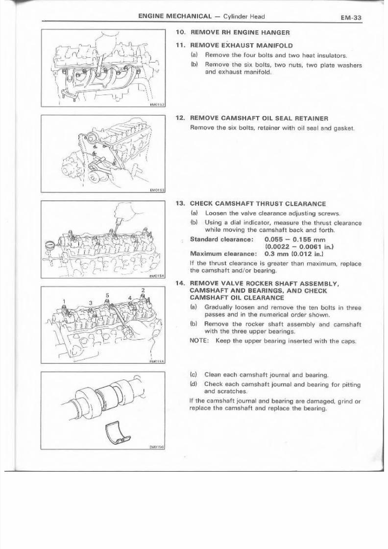
10" REMQVERHENGIN ~ HANGER
11. REMOVE EXHAUST MANIFOLD
(.al Remove th e fQyr 00 tis a nd two he.a t ineul a t or s.
(b) R(;!move the slx bolts" 'twon uts, lWG plate VIi;;:l sJwrs
and exhaust man~fald,
12" REMOVE CAMSHAFT 01 L SEAL RET AIINl I :A
Remove the sb;:botts, retainer with oll seal and g~sket..
13.•. CHECK CAMSHAFT THRUST CLE:A.FI.ANCE·
~6} Loosen the valve clearance adjustLng screws,
{b) Usinge l d~a~'mdlcator, measure th e. thrust c lea ra nc e
w'l"~i.lemmt~f1g the camshaft back. and forth"
Standard clearance: O.O~5- 0.155 mm
~O.O:022 - o .omn in,)
lMaximun1cllearance: 0.3 mm (0.012 in.)
If tha thrust G~e~r6nceiisgreatert'harn maximum, replace
thl:) ca m sha ft and ! or be,l;Iring ,
'14. REMOVE VAIL ViE ROCKER SHAIFT A~SEM.BL v,CAMSHAFT AND BEARI NlGS, AN D CHECK
OAMSHAFT 01 L C L E A R A N C E
[s;} Grad ua IIy 1 1 6 osen and rem ove the ten bolts in ttl fee
pa s s e s a n d ~ nth e 11u m eri c a I' 0 rder sh own.
{b) Remove the rcu ;;:ke r shaft assemblyandoamshaft'with the three upper bj1Nlrin~s."
N01E~. Keep the upper beadn!;Jl:nsi@ftad wlththe caps.
~G } Clean each camshaft journal ' an d bea rit l'Q.
(d) Check each camshaf t journal and b,etJr:ing for pitting·;!!r.lld .seratches,
Ihhe. carnehaf't jo.umaland b : e a r ! F 1 l g are d?im.aged, gr ind or
r®P ~ G leel th e ca rns h aft~nd replace the bearl ng.
8/4/2019 Toyota 2L Engine Mechanical
http://slidepdf.com/reader/full/toyota-2l-engine-mechanical 34/68
EM-34
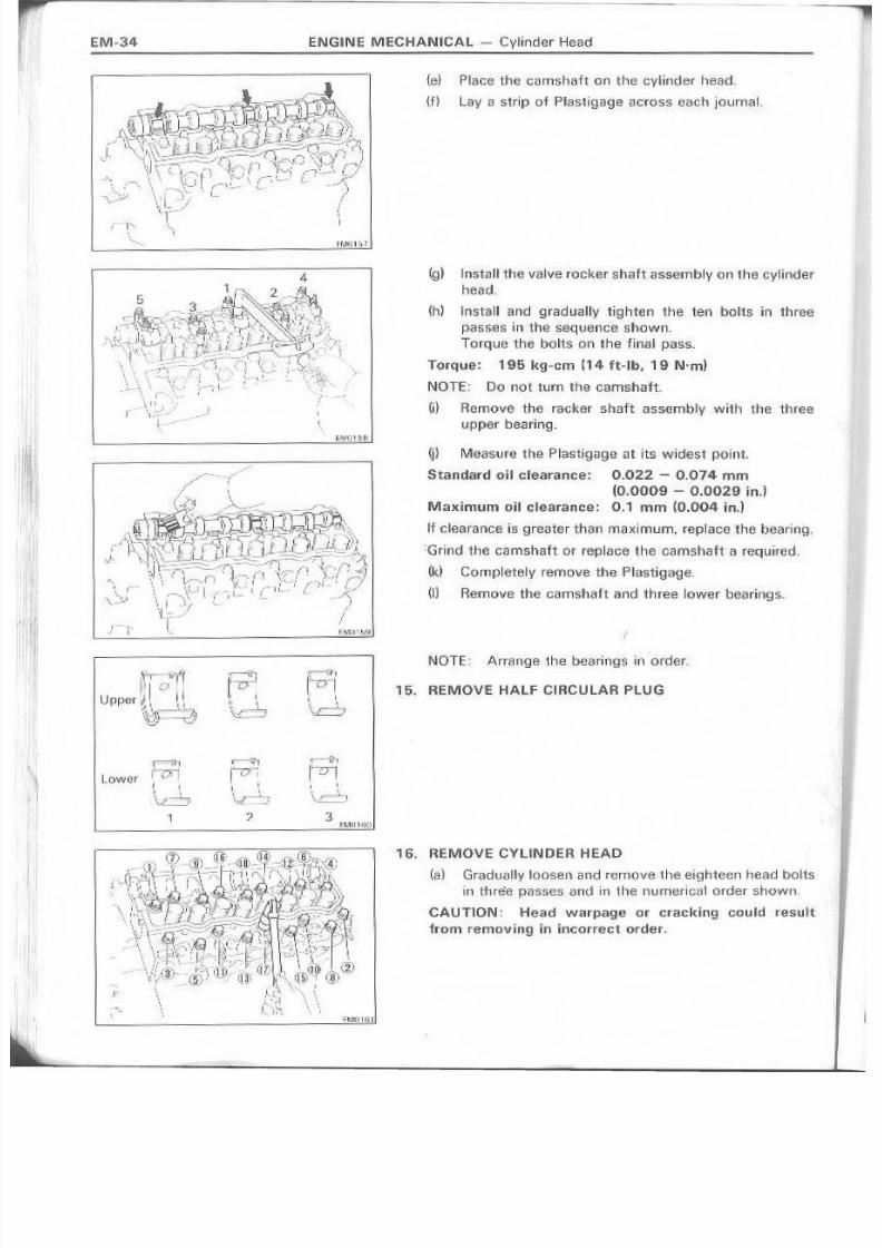
{e } P!lacethe qarn.s'haf 't on the cyiinde~ head.
t'F}~ay a strip of Pli ' i ist igage across each journal.
(g) Install the valve rocker shaft assembly on the cylinderhead ,
(Ii) Iinstall and gradually .t'ighten the ten bolts in three-
passes in the sequence shown .Torque the bolts on the final pass.
Torque: 1,915kg~cm ~14 <ft~lb, 19 N'm)
NOTE~ Do not turn the camshaft.
(i) Hernove the racket shaft assembly with ' the threeupper bearing.
'~) Mea SUre th e IPI asti gag'9 ati ts widest point
Standard oil clearance: 0,.02,2 - 0.014 mm
(0.0009 - 0'.0029 ln.]
Maximum oil clearance: 0.1 mrn '10.004 ln.l
lfclearenca is tira8ter than maximum, replace .rhe bear inq ,
~Grlnd the camsha-ft 61'replace the 'camshaft a required"
(k) Completely remove the P~astlgagl5,
W Remove the camshaft and three lower bearings.
N O TE ; A rra nge the. bearings i n order.
15. REMOVE HALF CIRC'UL.AR PLUG
,-Vi,
1 ' " " C T i1I. ,~~.,
, t : ; i l. I
" I
' : . . . . . ~ . : : ' : - - . _ ,
16. REMOVE CYL'INOER HEAD
( . a ) Gradually IOOSEiI1 a nd remove th e e-i .ght@sn head bolts
ill Ltu'6fl passes anti ill th e numerical order shown,
CAUTION: Head warpage or cracking could result
from removing in Ineorrectorder.
1 3

8/4/2019 Toyota 2L Engine Mechanical
http://slidepdf.com/reader/full/toyota-2l-engine-mechanical 35/68
EN G fN E MECH A N iC A L - C ylinder H ea d EM·35
3 ·4
[b} lift the cylinder head from the dowels on the cylinder
block and ' place the he13d ' on wooden blocks 01113
bench,
NOTE: If the cvllnder head is . difficult 'to lift off, pry witha screwdriver between the cylinder head and bl'otksaliences,
(ei Remove: the .cylil1der head gasket
CAUTIO,N: Bec,areful nat to damage, the cvrrndethead and blooksutface on thecyliltder and head
gasket sides.,
DJ'SASSEMBL V OF CYLlNDE.R H.EAD('See pag,e',t:M-31)
1. A EMO VE VA LVES
(a) Using SST. re-move the keBpets., is.pring r¢tailler .and
spring.
SST 09;202~43013
(b) RemQve the valve. oil &ea~and spr.ing se~t.
NOTE: An'1.'!ngehe dlsessembled part-sin order.
2 . . REMOVE eOM'B.US:TfON CHAM .BERS
Drive out the combustion oharnbers arrd/or shim.
NOTE: Arrange the disassembled parts in order.
8/4/2019 Toyota 2L Engine Mechanical
http://slidepdf.com/reader/full/toyota-2l-engine-mechanical 36/68
EM~36 ENG'INE MECHANICAL - Cylinder Head
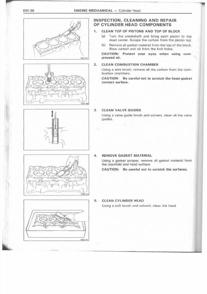
INSPECTION, ,CLEANING AND, REPAiROF CYL IN DER ' H EAD COMPONENTS
1. CLEAN TOP OF PISTONS AN,n TOP Of BLOCK
ta} T\Jrnt;he .crankshatt and brinq eaoh piston to top
dea d center ..Sera pe th e carbo n fro m th-e pis ton top.
(b) Remove ail g.asket mat~.ri ja:1from the top of the block
Blowcarbon and oil from the bolt ho,l-es.
CAUTION: Protect your e;{es when usiJ19 com-
EM0161. pressed air.._ ~ ~~
2. CLEAN COMBUSTION CHAMBER
Using a wire brush, remove all the carbon from the com-
bustion chambers.
CAUnON: Be carefiUllno1 to scratch the head gaskef
contact surface.
3, CL'EAN VALVE G'UtOES
Using a v'alveguide brush and 'solvent, dean all the valveg,uides; .
4. 'R EMOVI:G .o .,SK ET MATER~.A .L
Usingl a .ga,skBt scraper, remove all' gasket material from
the manifold and head surface.
CAUTION: Be careful nut to scratch thesurfaces.
5. CLEAN CYUN D'ER HEAD
Using a s-oft brush and solvent. cle-an 'the head,

8/4/2019 Toyota 2L Engine Mechanical
http://slidepdf.com/reader/full/toyota-2l-engine-mechanical 37/68
ENG IN E M ECHAN ICAl - Cylind:er Head EM·37
6. INSP'ECT CYLINDER HEAD FOR FLATNESS
Using s precision straight edge and teeter galJ'ge, measure
the surfaces contacting the cylinder block arid manifolds
f or we rpa ge~
M~,xim.umwarpaUf;!.: 0.2 mrn (0..008, ln.!
I~fwarpa~ge is 9rester than maximum. n~pl2lce the cVlinderhead.
7. INSPECT CYU NIDER HEAD FOR CRACI(S
LJsing, a dye penetrant, check. the combustion chamber,
inu< i1keand .exhaust ports, head s,urhlce_· and the top o 'f the
head klr cracks.
If a crack is found. replace the, cylinder head ,
8, CLEAN VALVES
~ E 1 ) Using , i ; ! gaskett i ,crap\5I" chip any carbon from the
valve: head ..
~b) U S i ' r 1 g a wire brush, thoroughly clean the valve,
I~~I[M01?'1
~1O'72
"..,l.l1'1'3
~~--'~,."
)

8/4/2019 Toyota 2L Engine Mechanical
http://slidepdf.com/reader/full/toyota-2l-engine-mechanical 38/68
ENGINE ME,CHAN ICAl - Cytill'loer Head
9. INSPECT VALVE, STEM AND GUIDE
la) US'lnga d~a~ind~cator, measure tl18 inside diameter of
the valve guide,
Guide inside di,ameter: 8·,51 - 8.53 mm
(0.3350 - 0.3358 in.)
OJ) Using, a micrometer, measure the diameter of 'the
valve stem.
Stem. diameler.~
Intake 8.473 - 8.489 mm. (0.3336 - 0.3342 in.)
'Exhaust 8.454- 8.47.0 1 1 1 m
(0.3328, - 0.3335 in,,)
(d Subtract .the valve stem measurement from the valve
9uid~ measurement,Standard stem oHclearance:
Intake 0.021 - 0.051 mm(0,,0008,- 0.0022 inJ
Exhaust 0.040 - 0.076 mm(0.0016 ~ 0.0030 in.!
M,a;dmum stem 0 ' 1 1 clearance,:
Intake 0.10 mm (0.00:39in.)
Exhaust 0.12 1ll!11 (0.0047 i,n.)
If the clearance is greater than the above values, re-place
the valve and guide,
10. I F "';U:CESSARY. REPLACE. VALVE GiUIDE
fa} Using SST, and a hammer, -drive out the vallve-guide.
SST 0920 t -6001 f
(b) Using dial in¢litator, measure the 'ValVI';! guide bote of
th e ty lin d e r M a'c L
8/4/2019 Toyota 2L Engine Mechanical
http://slidepdf.com/reader/full/toyota-2l-engine-mechanical 39/68
ENGINE MECHANrCAIL- ()lintli3:r Head EM~39
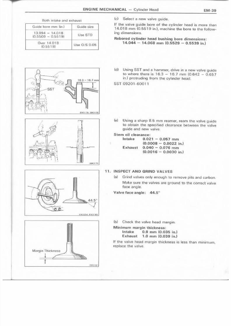
{c) Select a new valvegllJide.
I -f the .v :a lve guide bore of the cylinder head is more thanHk(J"i8 mm ( 'b,551 9 ~nJ;machtne the bore to the follow-ing dimensions.
Aebored cylinder head bushing Daf.e dtmenslons:14..044 - 14.068 rnm m.5529 - 0.·55,39 in.)
(d} U8ing SSLand a hemmer, drive in Q new vallve;guid.e
to wh'€n~ there is. 16,3- 16,7 rnrn (0,642 ~ (1657
in J protl'uding f rom the: oylin d : er h € ia d ,
S ST c l9 .2 0 1 -6"0 0 ,'1
(e) U\:iing a sharp' R5 mm reamer; ream the valve guide
1 ' ' 0 obtein th B spedfied. c l s ara n c e b€tween' the Itaiv egll~ide. and new valv'L!l,
Stem oil elearanee:Intake 0.021 - 0 ..057 rnrn
(O .OOOB - 0 .002 2 in.)EXhaust 0.040 .~. 0.076 rnm
(0.'0016' - 0.003.0 in.]
1 " 1 " . I NSPECT AND GRIN 0 VALVES
(a ) Grlnd vtll_\jes cnlv enough to remove plts.and carbon.
Ma:J ,; .esu re the ' va lves are :g rouno to th e c orre ct vableface i:lng,le,
Valve face fli1'Iule: 44.So
(b) C heck ttl';:: [email protected] head m.arg~n,·
M lnlmurn m3rgih 1:hic!lit!rH;!SS:
Intake 0.9 mill (O,035 in.]
Exhaust 1.0 mm ~.O.039 in.)
If the va lve h ea d m i: l'rg ~ F i1l l iCknezs-s , is less tha n m in im u m ,r.~pIQt.,e<thevalve.
1 lL '994 - 1 ~t,O 1S(0.5509 - [U).619~ Use STD
Over 14.01 8(0,S519)
Use 01$ 0.05.. I

8/4/2019 Toyota 2L Engine Mechanical
http://slidepdf.com/reader/full/toyota-2l-engine-mechanical 40/68
"
E.M-40 ENGINE MECHA N ICA L - Cylinder Head
lI
Length1 -
E f . , 2 2EO
(c} C heo k th III v iJ .lv e a ve ra 'll le n g t h.
S1andard overall length:In1ake 122.95 mm ~.4,8405 h1!JExhal(!st 122.75 mm (4·,,8327 in..)
Minimum overall lengl th:
Iintake 122.45 mm (4.8209·in,J~xhaust 12.2.25 mm 14.8130 jn.~
.' ,
- '1 \
'J
(d) r f the valvastern tip i s worn. rel~~d.ac:e the 'tip with
grinder or rep~acethe vaive,
CAUTION:. DO'not grind Qf1 more than the m,inimufT
,amO'IJll il t .
12. INSPECT AND C.LEAN VALVS SEATS
(a) US!Iig' a 45" cutter, resurface the valve seats. RemQvonly eMiJgh metal to clean the seats-
(b) Cheek the valve se.ating positlo.1],
Apply a thin coat of prussian blue {or white lead) tothe valve 'face. lnstall the valve, While applying lighpressure to the v.alve, rotate the viii~veagainst theseat .
(el Check the val ve f sea and seat to r the foUow iing:
• ~ 'f blue appears 3,60° around the valvatace, the
valve is concentric. If not, replace the valve..
• If blul!! appears 360n around the valve seat the
9uqde and seat EirIE:or ' l:~nlr ~c, I r no t, re~urf ace 'thes e a t
• Check 'that the seat contact is on the middle of thevalv~ f..acewith the foHowing width:1.2 - 1.6·mm jO.047 - 0.063 in.)
If not corre ct the valve seat as fo 110W 5:
~1) If the sea ti '19 i s too h~gh 0n the va Ive fMIl, use
30° and ' 1 $ < : > cutters to correct the 'ssat,

8/4/2019 Toyota 2L Engine Mechanical
http://slidepdf.com/reader/full/toyota-2l-engine-mechanical 41/68
ENGINE MECHAN OC :AL - Gyander H e a : d E M - 4 1
(2) IfseatiAg ls too low on the valve face" use 65
and 45° cutters to correct the, seat.
(d) Hand-lap the valve' and valve ssat with abrasive compound.
13. INSPECT VALVE: SPR.INGS
~a) Using a steel square, measure the squarsness of thva~ve sprl n g ' 5 . ,
Maximum squersness: 2..0 mm (0.079 in.)
If .squareness is, greater than maximum" replacs the, valspring,
{b} Using Gali l~l 'en",measure the free length Df thie' valspring,
Free length: 47.98 mm (1.8890 ln.l
If not as specified, replace .the valve spring,
(c} U sing a sprl ngl la s te r, me as ure the te ns iQn of thvalve spring at 'the specified installed :Iength.
Installed tension:'29.2 kg {64.4 Ib, 286 INI at 39.3 mm (1.5.47 lin.)
If not as specified, replace the valve spring',
\'
. ~ V ' · ' ( ~ \1 \ 1 ] ' - - 1 , \
\ I I \ h ' , . . .~ " \ 1
8/4/2019 Toyota 2L Engine Mechanical
http://slidepdf.com/reader/full/toyota-2l-engine-mechanical 42/68
ENG1NE MEeHAN ICAL - Cylinder Head
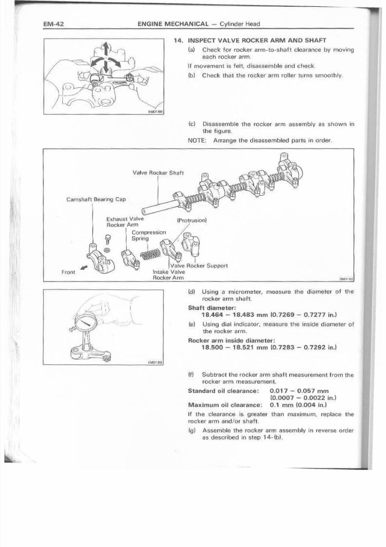
14. IN.sP'ECT VALVE ROCK;ER ARM AND SHAFT
{a} Check for rocker arrn-to-shatt clearance by movingeach rocker arm.
1'[movement is felt disassemble and check,
~b) Check that the reeker a'rm roller turns srnoothly,
{el Disassemble tha rocker arm assembly aashown inthe fi~ure,
NOTE: Anange the disassembled parts, irr order.
Valve Rocke~Shaft
I
Camshaft Bearing Cap
E){halist Val,\I,e (Protrusion)Rocker Arm /
Compression '.~_o._"."Spring - .; .~ \ d
l Ij.·' \ ) i_ '.' ." > ,.\ ... ", -
Valv\';!Rooker Support
Intake V~lveBooker ArmFront
(d) Using -8 micrometer, measure the diameter of the-
rocker arm sbart.
Shaft -tUameter:18.464 - 18.483 mm (O,.72S·9- 0.7217 in.)
~e} U~;in9dial indicater, measure the inside diameter ofthe rockerarm,
Roc'ker arm inside diameter;
18.500 - 18.5,21 rom (0'.7283 - 0.7292 ln.]
( f ) ' Subtract the rocker arm shaft measurement from therocker arm measurement,
Standard oil clearance: 0.017 - 0.,.0.57 mm(0:0007- 0..0'0.22In.l
Maximum on clearance; 0.,1mm (0.004 in.)
i ' fthe olea ra n ce is. greater than m ~ S 1 x im u r n , reple oe the
rocker arm and/or shaft.
(g) Assemble the !'Ock.er armassembly in reverse order
as described in step 14-(b).

8/4/2019 Toyota 2L Engine Mechanical
http://slidepdf.com/reader/full/toyota-2l-engine-mechanical 43/68
ENIGTNE.MECHANICAL - Cylinder He:ad~ , j ~ ~ - - - - - - - - - - - - - - - - - - - - - - - - - - - - - - - - - - ~ ~ ~ ~ - - - - - - - - - - ~ - - - - ~ ~ ~ ~ ~ ~ ·{ ~I
~ ~ ~ - • .. > : -•-:;-• • • .< - - . ~ 3 . , ' ' " ' '(;l\Wl91
1.6. INSPECT CAMSHAfT
{a d PlacG the camshaft on V-'b.locks and, uSing a dial
indicator, measure the cilrc.le runout at the centerjournal,
M;;l:ldmumcircle runnut: 0.1 mrn (0.039 ill.)
If the G ii rchil run Qut is g re.ater than m ax~mum, rapiaC~ theC'8I1il!3 1 1 , ; l ft.
~b} Using a rrucrernater, rneasurethe cam lobe he~ght
Min imUmc am lobe he~gt1t:
Intall!:e L. 2L 46.76 rnm U .8409, ln.l
.2l~T 46.2'9 mr:n (1.8224 ln.]
E;I(haust 47.2.5 mm (1.860.211'1,)
If the cam lobe height is less than rninlrnurn, I'GplaGe thecamshaft.
(0 ) Us~ng a micrometer, measure the journal di·amete·r.
JOl,.llrnaI d lame ter: 34.9&9 - ~34.985 rnm
(1.3767 .~.1.3774 in.~
If Ute' Q~lcl e . a ranee eve 1 " 1 when new t i G ' < : ; i rilngsate use.d,IS
grei!ter than spE;lcif~ed, regrind or r!;u.)laie the eamstratt,
16. IF NECESSA.RY, GRIND AND HONE CAMSHAFT
JOURNAL
Grind < 3 1 l ! d hone the [ournals to the undersiaed finisheddiameter,
~rls ta II new ]0 Urrl a il bea rin g s,
Bea.r~ng.size OJ/S 0.125, 0.250)
Journam finishe.d diameter:U/S 00.125 ·34.8·44·~.34.860 mm
~1.3718·~ 1.3724 inJ
U/SO.Z50 .34.719 -3.4.735 mm
~1,3669- 1.:3'675ln.l
17.INSpIECT I.NTAKE ANID EX.'HAUST MANIFOLDS
Usfng.~lpn·.eci;s~onstrai:glit ~dg'eandf'€teler g·aug:e,measure'thl~ ,smrac(;j-.scMtacting the cylinder head for -w.i;lrp~ge_
Maximum rTIJanifoldswarpage: 0.4 mm W.01G i in.)
If warpage is greater than maximum, repl.~cethe manifoldl .< .

8/4/2019 Toyota 2L Engine Mechanical
http://slidepdf.com/reader/full/toyota-2l-engine-mechanical 44/68
EM-44 EN Gi,N E. MECHAN tCA L - Cylinder Head
/" --,
,
./'~-... ~~~.. !f J_ - c : : _ : s . : . ! S '
~
SST
Cu t Posit iQ ! ,, !
t t " t u
REPLACEMENT OIFCAMSHAFT OIL a,EAL
NOTE: There are two methods ot oil seal replacement.
RE'PLACE CAMSHAFT ou, SEAL
If c:amshaft oil seal retainer is removed 'from cylinderhead:
(a) Using a :screwdriver and hammer. qriveoutthe oils e a l
(b) Using SST and a hammer, drive- in anew oil seal untilits surface i.s flush with the 0 1 ' 1 seal retainer edge-
SST 092 '4~60010
(el ' App 1 '1MP 9 re a se to the oll. seal
If carruj,h:dto,ii'! sea I retal net' is lnsta Ued. to, cy Iinderhead:
{a} Using a knife, cut off the oil seal lip,
(b) Usingl a screwdriver .. pry out the oil seal,
CAUTION:, Be careful not to, d~m.age the cams haft.Tape, the scr,ewdrivel".
(c} Apply MP grease to a new oi'l seal.
!d) Usingl SST and a hammer. drive in the oil seal until its5 ,u r ia c :e is fIIush w~th o~1seal retainer edge-
SST09214~60010
8/4/2019 Toyota 2L Engine Mechanical
http://slidepdf.com/reader/full/toyota-2l-engine-mechanical 45/68
ENG INE MECHANICAL _, Cylinder Head
,
,,,,
ASSE M l B LY OF -CV L liN D E .R HEAD
(-SeE!page EM·3'f~
NOTE:
'R Thowughly dean all parts. 10' be essernbled .
• Before im.talling the pans, apply n.ew engina oil t~ all
5 1 iding and retati fig surfaces •
• Replo;lce all ga$k~ts, O-rings and oil seals. with newparts,
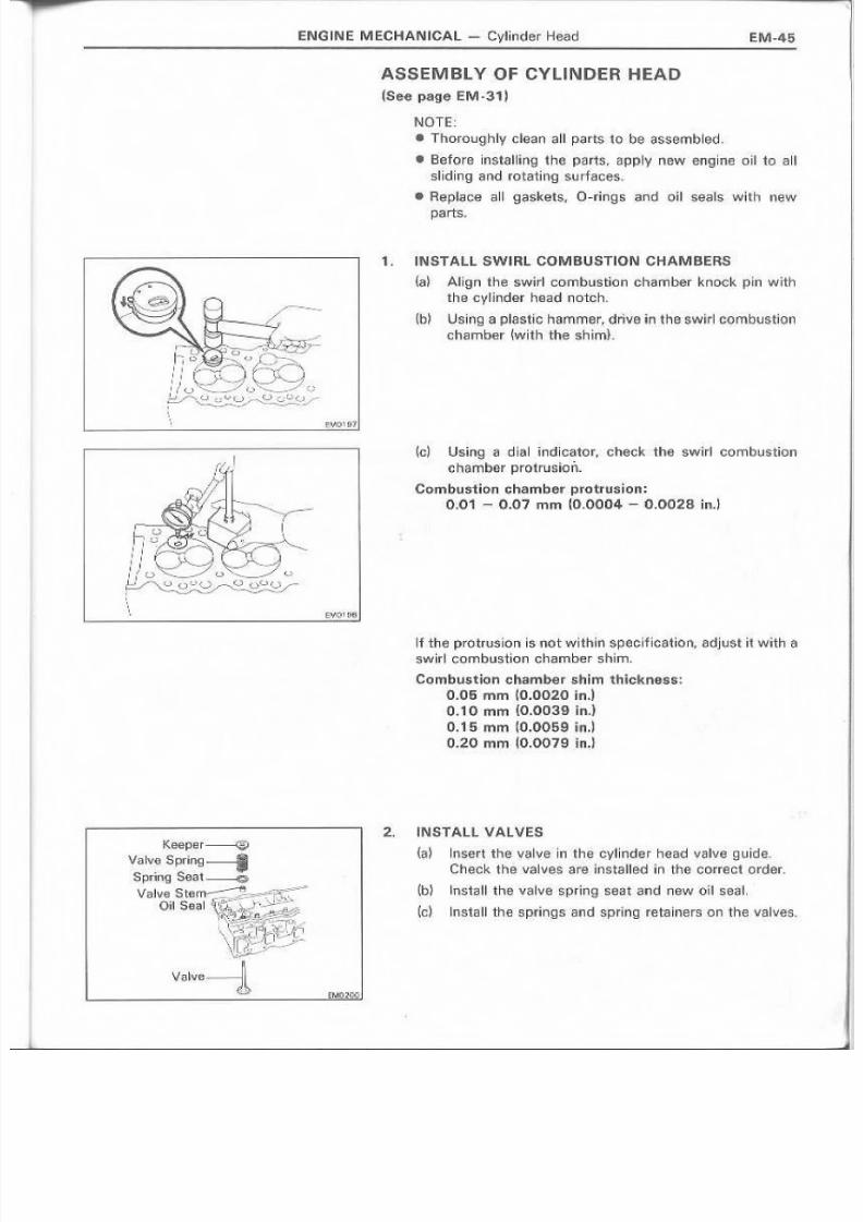
11. INST.AlL SWIIRL COMIBUS.TION CHAM BERS
{a~ Align the 8w~rl combustion chamber knock pin with
tha G y l.illder haadn etch,
(Ib) LJshlg a piastk: hammer, drive inths swirl combustion
(lh~mber {with the sh~m}-
k: l Using a alial tndlcetor, check. the' swirll cornousncncharnbe« protruslcn,
Combustion chamber prctnrelen:0;01 - OJ]"? mm {O.OOU4 ~ 0'.0028 in.l
If the pfo,tmsIOT1 Is-not within specificetien, adjust it witnas . w ir I ecrnb ustio n cha mber' shl rn, .
Comblllst:io!1 chamber shim 'thkkness:(1.005mmiO;002cO ln.]
0.10 mm (0.003,9 il'l.J
0.15 mm W·.0059 lin,'1
0:-20 ru m (O.0079in.1
2 . INSTALL VAL VES
{ i ; I ~ ~ lnsert the: V.,I\I~ in th@ e,ylinder head valve guide.
Check t n e v a Ive $ a re. l n s ta Ue o in the correc t .0 rder,
(b) linstrrfll the valvE: spring S®1H and newouseal.
(a ) Iinstall th e sprin ,95 r a n d s p w i rl9 retalners 0r! th e va Ilie's.

8/4/2019 Toyota 2L Engine Mechanical
http://slidepdf.com/reader/full/toyota-2l-engine-mechanical 46/68
EM-46
{d} US~llg SST. compress the valve. sprin"9filTld place the
two keepers around the valve stern.
SST 092.02A3013
IENG.NE MECHANICAL ~ Cylinder Head
, /J
;
Fronl
U pp er {e ;.;, N , o_ 1Cllmsrnaft Be:aring)
and LOW'€ r r Be-ari.ng
Uppmt Bearing{No.1 CamshaftBeari!1gl
(6 ) Using g l p~astrc hammer. ligbt'ly tap the stem to
assure proper fit.
I.N STA L L A T I ON OIF CV II N D ER HEAD,
~.see 'Il'S.g e 'EM<~ 1)
1. INSTALL CYUNDER HEA'D
' ( i f l ) Install a nsw cylinder head g a si< ;,e t a n d th e head onthe Gy~irider block.
{b) Apply a Ught coat QTeng~ne oi'l on th$ thr-Mds and
under the head of bolts.
!d Inst ,al l grapually and t ighten the 'eHghte'EHl head boasin three passes and, in ·nUJ sequence shown. Torque
the bolts on the final pass..
Torque: 1.200 kg-ern l87 H"lb. 1,18 N'm)
2. INSTALL CAMSHA'FT 'aEARIN GS. CAMSHAfT AN 'D
VA.LV!: HOCKER SHAFT ASSEMBLY
(a) Install the upper be'arings to the camshaft bearing
caps.
{b}lnstalll the fowBr bearings to 'the cvlinder head,
(c ) PI,ace the camshaft in the cylinder head,

8/4/2019 Toyota 2L Engine Mechanical
http://slidepdf.com/reader/full/toyota-2l-engine-mechanical 47/68
ENGIIN E M E,CHA.N.ICAL- Cylinder Head EM-47
{d} Tum the crankshaft to lowerths pistons.
{e) Instal17the varlve rocker shatt ,assembly On the cylir]der
head,
{f ) Gn'~du;;iHy fnst!;ldl a nd 'llg hten HH;! : ten bolts in three
p i 3 sse sin the sequen ce shown,
Torque the bolts on the final pass.
Torque: 195 k91~orn (14 ·ft-Ib, 1i9 N.nil)
3·. INSTALL C.AMSH:AFT Oil SEAL AETAI NEFI
Install a newga,sk!!it and the. retairner withthe s~')ifbolts
To rq ue t h € 001:t8.
Torque: 18S Ie.g-em (13 ft-!Ib, 18 N"m)
4. INSTAill EXHAUST MANifOLD
( , id Install ~ fl,ew 9 a is ke:t and the exh a ust m anift;d!CI with
.the six bolts, two plate washers and nuts, TO~QlJe,he
bolts and nuts.
Torque: l, 2.L 400k9~Gm t2.9fH~b~39 N'rrd
2l ~T 530 I~g~C'.m (38 H·llb, :5.2N'm)
~q ) Install the twolnsulators with thefour bolts. Torque
th e bolts,
Torque :120 kg~G'm U l ft- Ib, 12 N -rn]
5. INSTALL RH ENGINIE HANGER
Torque: 380 !<g~CITl . ~27'ft~lb, 37 N'm~
I ,
i ,
, I
I EM(!'!.~~
6. INSTALL WAfER OUTLET ASSEMBLY
Instflilia new g8slket and ·ttle watter outlet assembly with
th e -tw 0 no tts , T orq ue th e b0 lts,
Torque: 195 kg-em ~'14U-lb,'.9 N'mt
7. INSTALL INTAKE MANIFOLD A.ND LH iENGINE
HANGER
Insta II ' r : ! IlfllW ga.sket, inta ke 01 ani to~d.and LHe ngine ha ngewit hthe '5 ,1 ,x bo It s' : an d 'tw o nuts,
Torque: 240 h::U-GITI (17 U-Ilb,. 24 N'~n)
B. CON'NIECT ACCELERATOR CONINfCTl'NG ROD
9. IN€iT ALLfOU R INJECTION NOZZLES
(See steps 3, 4 on page .FU-12J
10 ... INS.TAlL FUEL INLET PIPE~S.ee pa-ge FU~47)
8/4/2019 Toyota 2L Engine Mechanical
http://slidepdf.com/reader/full/toyota-2l-engine-mechanical 48/68
11. INSTAL'L fOU F I: 'IN.JECTION P~PES
(See page FU~12~
12, INSTALL G.AMSHAFT l]M ING PULL~Y
(See' page EM-l6I
13. ~NSl'AlL TI'MINGBEL T(Se-e s,te'p,s ,6 to16 011 .pages' 'EM-261:J] 3Q)
E,~NG~NEMECHANICAL - Cylinder H~ad'
First
Second
[M0105
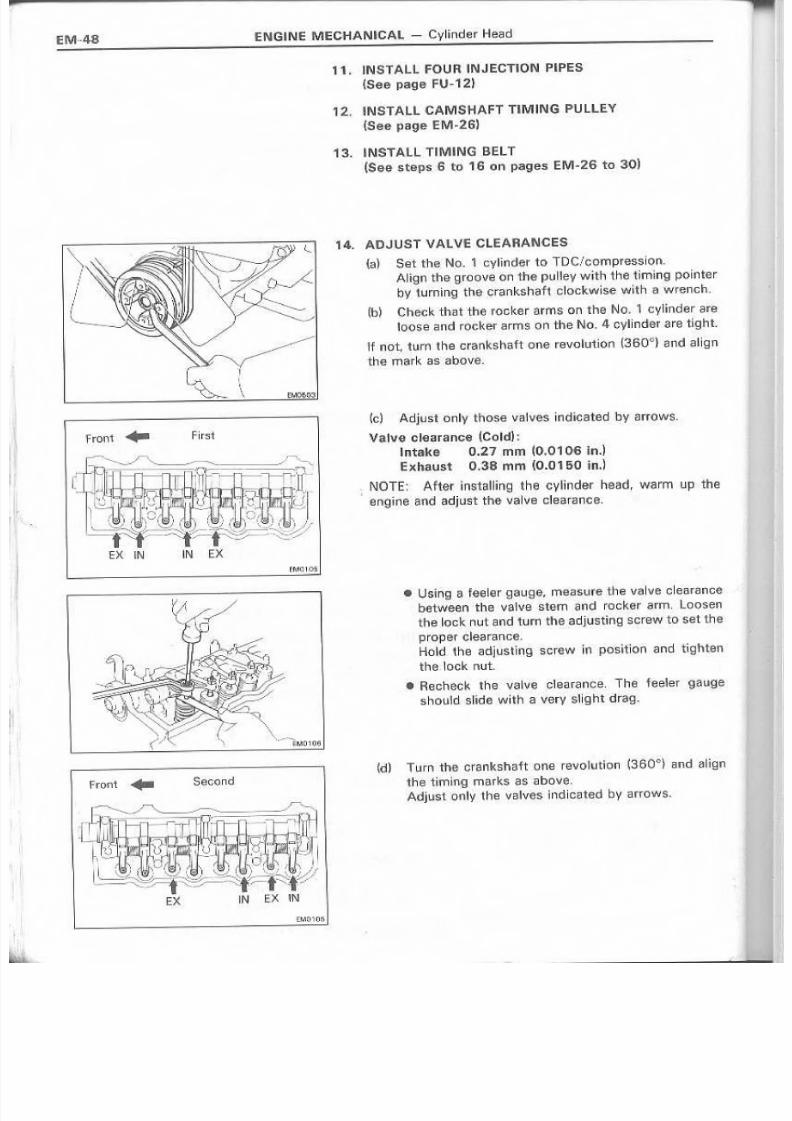
'14.. ADJUST VALVE CLEARA. I \UJ· .ES
{a) Set the No.1 cylinder to TDC/cromp'ress"ion,
Afig n th e groove 0r! th e p ulle y wh'h the- t~imin 9 po in te r
by 'ill! r'n i n9 the era n ks haft c Iockw i,se w~th it! wrench.
(b) Check thatthe rocker arms emthe No.1 cvlinder areleo 5eand rocker arms on the No..4 cylim:ler are tLg.ht,
'If not, tu rt"I th e m~nk$.h attone ravclut [0n '(3'60 d } ,8nd alig n
the mark as above.
(c ) Adj~s •. 0 n Iy th ose v·aJve .s: i lid icated by II rro WS,
Va'ive elearareea tCold);
~ntak,eO.27 rnm {O.0106 InJE,xhau~t 0.38 mrn (0.0150 in.}
I NOTE: AUerins;talling the cyiiinder head, warm up the
eng in ill and aqJu stthe v alv e ela aea IIc e.
• U ~~ r1 lga feeh~Tgaug : e , fTI'9cE1SUl"e' t~W!valv€: clesranca
betwe,en 'the vel ve stem Q n d ree ke r arm, to osen
the ~oGkt1lutsnd turn the .adjuMinig SQr~Wto set the
proper clearance. .Hoidthe adjusting 'screw In pcsltinn arid t~ghten
t h € .1ock nut.
.• Hecnec k the vo:j~\fe c~ara nee, T h efe·e!erQ aug e
shou1d slida with a\/ery s!i.ght drag.
(d) T urnthe crsnksh aft one revolution (350 Q}snd a Ilgn
the t~m~ngmarks as!;Ibave,Ad ju~ t "bn~v t he · v t: l. lv es1rldiG,~t~d by arrows.

8/4/2019 Toyota 2L Engine Mechanical
http://slidepdf.com/reader/full/toyota-2l-engine-mechanical 49/68
'~E .N lC iUN EIMEC HAN UO AL -C ylinde r Head EM·49
15. liNSTALL. HALF C~RCULAH PLUG·
~.a} Ap ply se a I Pac k.ifig black ~Part No. 08 B2 (3 ~OdO80) or
equlvalent to the half circular plug.
(b) Install th e ~1.alfc l fC U lar plug to the cy lind III r n earL
1G. INIS1'ALL CVl.IN DER HEAD COVEIR
ta) Apply seel P?cKing ·black.(p~rt No. 08B.216~iOOO.80} oraqui.val1ent to the camSihaft oil saal retainer. cyli100er
head end ha~·fciin::ular plug .as shown,
(b,) insti!! II a 9 as ket to the Iiiead cover,
'{9} inst'll~1he head c:overwith the thre.e. ~n;l61washers and
cHip nuts.
{dO InstaU the remaining two timjrl9 ,gear cover mountbollts.
\'.

8/4/2019 Toyota 2L Engine Mechanical
http://slidepdf.com/reader/full/toyota-2l-engine-mechanical 50/68
IEM·50 ENIGIINE MECHANICAL Cyliind.;lr Block
CYLINDER BLOCK
COMIPONENTS
PistonRing (No, 1Compressioni---'
PistonRing (Oil)~----Pistoil Ring (No, 2 Compression)
o--Piiston PinPiston .-------------=--r®Snap Ring ---------
- \p RodBushing
II-----~Conneding Rod
Crankshaft~OilJel
. , 1 0 i I Check Va,lve
I 260 t19•.261 I
.,}----. Gasket
---Ol Pari
Ikij~c.m ('fl-llb, N :m ) I : Specifled torque
• Non - reusobl e part
8/4/2019 Toyota 2L Engine Mechanical
http://slidepdf.com/reader/full/toyota-2l-engine-mechanical 51/68
ENGINe MECHANICAL - Cyl!~r!der Block
_ _ _ - - - _ - - - - -
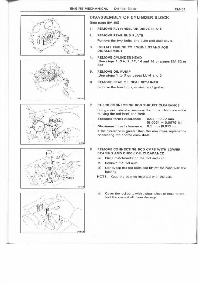
D ISASSEM tBl V OF CVLI NDER BLOCK
(Se€! page EM "50)
1. REMOVE FLYWHEl!:l OR DRIVE PLATE
2. REMOVE REAR -=N D IPU \ TE
Rerl10ve the two bctts, end pl-at"e iElno dust cover,
,3 , INSTAll ENGI.NE TO ENG INE STAND FORDISABSEI\II SL¥
4. REMOVE CYLIIN DER HEAD
JS,eesteps 1, 3 to 1, 1.2, 14 and 16 on pages.E.M-32 1035) .
:5, REMOVE D.IL P UM P
(See steps 1 1 to 7 on p@:9,esLU~4 and 5l
6. REMOVE R~AR OIL SEAL RET/tIN ER
Remove the four bo lt s, r et a :i ne l' and gasket,
7. CHECK CONlNE.CTIIN.6. ROD THRUST CLEARANCE
Using a dial indinator. measure the. thrust clearance whllemoving the rod back and forth,
Standard tht us tc:le.ara nee:: O.as .~ 0..:2 0 mm
~O.0031 - 0.0079 ln.l
Maximum thrust clearance: 0.3 rum (0.012 inJ
If the cleeranee is 9 r&8 ter than the maxlrnum, replace thecan nec:tiJng ro d Q nd/cr cran ks ha1lt"
8. REMQVE- CONN ECTING ROD CAPS WITH LOWER
BEARIING .AIN.D CHECK Oil C l i EARANCE
(a) Pia oe match marks 0n the rod a rid cap,
( I ; l . ) Rernove the. rod nuts-
[e) UghUy tap 'the rod bolts and lift off the caps l/IJittl thet;lH~ring.
NOTE:. Keep th.€ be~rirng ilriSerWai With th€·C.,p,
(d~ Co:v~rthe.rod bolts with Q short piece of hose to pro-
teet the crankshaft frorndamaqe.

8/4/2019 Toyota 2L Engine Mechanical
http://slidepdf.com/reader/full/toyota-2l-engine-mechanical 52/68
ENG'INE MECHANICAL - :Cylinder Block
(e~ C·rea"each crank pin and beairing,
m Check e~ch crank pin and beating for pitting andscratches,
If the crank ·pinand bearing are dC!maged, grind or replace
the I;:rankshaft an·d replace the baaril1g,
',2 Dr 3
/h.~.
'\\\,
Brown., Bla·ck o r Blue
EMJ~t"\.
(g} la.y·a strip of Plro;llstig,a.geacross the crank pin.
(h) Install the ro d caps {See' pagr€! EM-67)
Torque: 600 k~-cm (43 ft~lb. 59 N·m)
NOTE~ Do not turn the crankshaft.
m Hernov~ the rod cap,
m Measun'l: the PI~i"st:i9age at lts widest point
Standard oil clearance: 00.036,- 0.064 mm(0.00014 .~ 0.0025 tn.l
Maximum oil: etearance: 0.1 mm ("0,,004 in.)
'If the cleaeance 1S gr,eater than maximum, rep1i;1ce the
b~arin9, Grind the crank pins or replace the crenksheft as
required ..
NOTE: There six different ·standard bearinqs, distin-
guished numertcally (1, 2 and 3} and by color (b-rown,
black and b~ue),
For 2 L~T e.ng.ine s, rep ~ace be a ri09 with one h 0 1 \ 1 ing l~he
'Samenumberas marked on 'the bearinqoap. Far Land 2L
engines f replace. wilh o ne having .. the eolor with corres-
ponds. to the number on tbe bearil1g cao, i. e., 1 withbrown. 2 with black, 3 with blue.
tid Completely remove the PI; ;H~t igag.@.

8/4/2019 Toyota 2L Engine Mechanical
http://slidepdf.com/reader/full/toyota-2l-engine-mechanical 53/68
ENG IN E M ECH,ANICAL - Cylinder Block EM-53
9. PUSH OUT PISTON, AND COINNECTING RODASSEMBLY WITH UPP'ER BEARING
(a) Remove 1 3 1 1 the carbon from the piston ring, ridge,
(b} Cover the rod bolts, (See, page EM~!J1)
(d P ush o ut the piston and rod assembly with the bear-ilng through the top 'of the 'cvllncer block"
NOTE:
IIKeep the bearing inserted with the rod •
.. Arrange the piston and r o o assernblvln order,
10" CHECK CRANr(SHAFT THRUST CLEARANCE
Using a :di~a~lnoir.rator, measure the thrust clearance while
p ry~ng, th e cr~rrks h a 'l't be ck and fa nh wi tha screwd rivsr,
Standard thrust clearance: 0.04 - 0.25 mm~O.0016- 0.0098 i n . . , )
Maximum thrust clearance: 0.3 mm 10.012 in.)
If the clearance: is greater than maximum, replace 'ththrust washers as. a set,
11. REMOVE MAIN BEARliNiG CAlPS WITH LOW'ER
eElA.RI:NG AJ'lJO C'HECK' Oil CLEARANCE
{a} loosen rha bolts until the threads no longer mesh.
{b ~ G ra5ping' th e bot ts to g .e th er, pul] 0 ff b ea ri'n g c s p,
NOTE: Keep the bearing inserted with the caps,
(c l Lift out the crankshaft.
~d} C lea n each [ournal .and bt'!!Minid.
~e} Check eaph journal and bearinq for pining a ndscratch e$ :.
If the jou:mal and beari .ng are darn.!jged. grind Or replacethe crankshaft and replace the bearing"
MOUN T G P .AVI-\TT CO l' rG E O F TA,FJ:'I
L I B R A R Y
8/4/2019 Toyota 2L Engine Mechanical
http://slidepdf.com/reader/full/toyota-2l-engine-mechanical 54/68
EM·54 ENGINE MECHANICAL- Cyli1nder Block
~.2. 0.r3~- '.' '. l .. ;
\ : & : . y.
o Br,QWfI. Bla~k or muc:
2 - ~Of Black.!, o r :3 lo r Slue)
Front ..
·0
NQ, 1
LowerO
'1
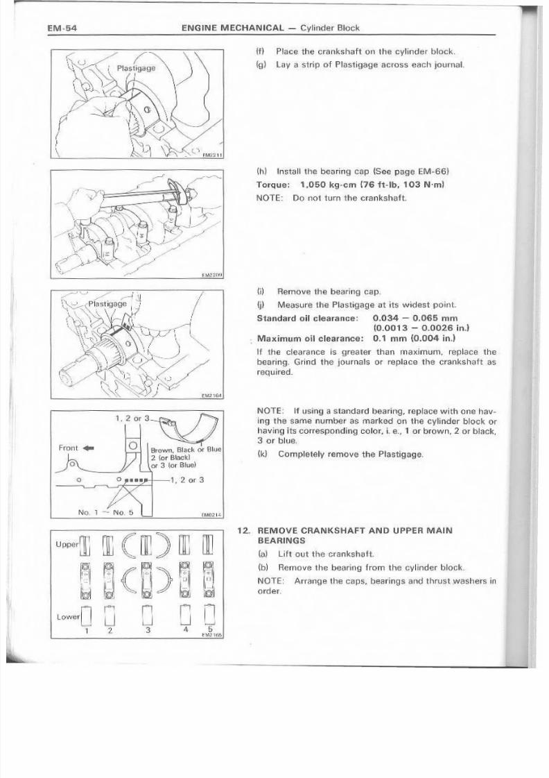
m P~ace thecrankshaft 011 the ovlinder block.
I ( g ' } Lay a strip of Plasti.gage across each journal.
(h) II'1I.st31~he bearing C?iP (Sas pa.g~ EM~B6}
Torque: 1,050 kg-em ·176n·llb, 103 N'm'
NOTE: Do I'O( turn the crankshaft.
m Remove the bearing cap.
0) M~asure the Plast,igage'at its widest point.
Standard oil cNe,arance; 0.034 - 0.065 mrn
to .O'D13 - Q.0026 in.lMa ximU'rn · o n clearance: 0.1 men (0.004 inJ
If the clearance is . grea,tel ' than maximum, reptaee the
bearing. Grind the journals or replace the crankshaft as
rsqulred.
NOTE; ~fuSing a standard bearing. replace with one hav-
ing 'the same number as marked on the' cylinder block Or
havin:g its correspondlnq color, i- e. , 1 o r brown, 2 or black,
3 or blue.
(k} Cornpletelv remove the Plasti,gage.
12. REMOVE CRANKSHAFT AN D UPPER MAl N
BEARINGS
(a) lin outthe-crankshaft.
(b) Remove the b6<i!r~ng from the 'cyllnder block,
NOTE: Arranqe the caps, besrlng,!j a n d , 'thrust )Nesh{:m~,n
o r d e L

8/4/2019 Toyota 2L Engine Mechanical
http://slidepdf.com/reader/full/toyota-2l-engine-mechanical 55/68
E:NGINE: MI::CHANICAl - CylInder Block EM-55
' 1 1 " : 3 . . RI:MOV:I:. OIL CH ECK VALVES AN 0 01 L. JETS
I NSPEGTI ON OIF CY U N.DE R BLOCK
1 ,REMOVEGAS'KET MAl"E.RIAl
Usi n9 ag ssket SClCl per. remove all gasket meteria I 'From
the cylinder bloek surface.
2. ClEA.N CYLI N.DER BLOCK
Usi[ l 'g a soff brus h ,s nd .soIyent, cl aan th e b U ode
3. IINSPECT TOP OF cvu NDER BLOCK
LJSirl'g~1precislon .straight edge and fe~l~r gauge, rneasure,the surlacas contacting the cylinder head gaske.tfor war-
page ..
Maximum warRage~ 0.2 mOl (0.008 in.]
~fw;i'lrp,age I.S,~rea'terthan maximum, rep.~ace~M ~vlinder
o'iock,
4. ~NSPEC'r CVLilN DERS'
V is u a lly c he ck th e eyli n ds r fN \len i c 131s c ra te hes,
If deep scratehas t1n~present, rebore allfour Gylil id fWS ..
o--
EMH23

8/4/2019 Toyota 2L Engine Mechanical
http://slidepdf.com/reader/full/toyota-2l-engine-mechanical 56/68
EN (nN E M ECH A N IC A L - Cylinder Block
E B : : D Thrust
.. .' Dir~c.lon
~ .\ A xia lDirection
~ A rL 15 mm.1---....1 1 0 _5 9 < , rd
E l ' \MiddJe
C j, 15 rnm~~'-----+T(0_5.9 ird
/I,
5.. INSPECT CVUNDER BORES
Using a cylinder gauge, measure the cylinder bore ·at posi-
tiorrs A , Band C in the thrust and axia', directions.
Sta.ndard diameter
CyHnder bo re rnrn (in.)P l st o rl s iz e
L 2l, 2L· T
90.000 - 90,030 9'2,000 - 9'2.030(3.543 3 ~. ; 3 . .5445) (3.6220 - 3_6232)
90.500 - 90.;53.0 I 92.500 - 92.530{3.56 30'- 3 , 1 3 6421 (~.tl'417 - 3.6429)
S'fD
DiS 0.50.
mm ~inJylinde·r- bore1----
L~-------F----
STI) so .z s ~J,&524)~ - - ~ - - - - - r - - - - -
Q/S 0.50 90_73 f3$720)- ~ ~
2 L . 2 L - T
92.23 (3.63111
9 <2 .7 3 ~3 -6 50 S .J
If the diameter is.g r€!.ater than maximum of the ST'D size,
rebore a~1four cylinders.
If the di:~meter is g :rea t€ ll " than rnaxirnurn of the O/S 0.50,
r e 'p l a .G o e l t h e cyl~inder block.. .
6 . R EMOVE; C Y U N D ER R ID G E
1 " 1 the wear i,s less than 0:.2 mm (OJ006 ln.), use a ridge
reamer to rrm.c'hin€l '~hE!piston ri,ng ridge at the fop of the
cylinder;
DISASSEMBLY Q'F P'ISTON ANDCO NN EC 'T IN G RO D A SSEM BLY
,. C H EC K F IT BETW EEN P'STON AND PtN
Try to move the pi$ton bauk and forth on 'the piston pin.
If any' movement is felt, replace the piston and pin.
2. REMOVE PISTON RINGS
Us.ing a piSt_O.il ring expander, removethe piston rings,
Keep the rings .separats for .Iillii'l.chcylinder.
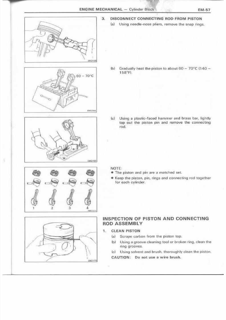
8/4/2019 Toyota 2L Engine Mechanical
http://slidepdf.com/reader/full/toyota-2l-engine-mechanical 57/68
ENG IN E M ECHAN U::A l -
3. DI:SCONNECT CONNECTING ROD FROMIPISTON
(6 ) Using needle-nose pli:€Js. remove the snap rinqs,
{b} Gr"O;Jdus.llyeat the platen to about. '<60- 70"'C ~.140 -158,on
\1\
E 1 V < 7 1 6 B I
(c} Usi ng a pia stic- faced hamm !1 l rand brass bar, HghtlytaP 0ut the piston Pln and remave the {JQnnectlnq
rod,
NOTE:
• Th€l piston and pin are a rnMened set.
• KeG !p the p iston , p in , .r in.gs end conneetlnq re d to ge the r
'For ee c h cy I l i f ! der .
INSPECTION 0 IF PISTONI A'N D CONNECTI NGROD ASSEMBLY
t. CLEAN I PISTON
{ E l i ) S.cr~pllicarbon fromthe piston top,
{b~ Using '0 gro ove olea r1lng too lor b roken ring, clean the
c -, ri ng 9move s;
\\1 , \ . (c) .USh19 solvent and brush, 1i.horough~y clean the ptstorr.I 'I CA UTIO'N: Do noli: use a wi're brush.EM2 '1 '!O
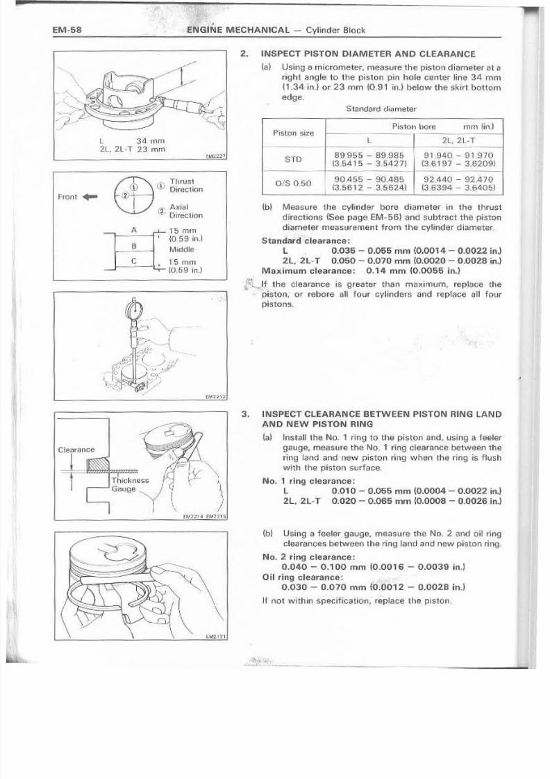
8/4/2019 Toyota 2L Engine Mechanical
http://slidepdf.com/reader/full/toyota-2l-engine-mechanical 58/68
2. INSPECT P1STON DIAMETER A.ND CLEA.R.ANCE
( . a } Using a micrometer, measure the piston diameter at aright angle to tine piston pin hole center ~ i n G l 34 rnrn
{1:34 ird or 23 mrn {O.·9.,inJ below the skirt bottom
edge.
L 34 rnrn2L, 2l·T 23.· rnrn
Front ...
T Thrust~V [:lJir.et tnQn
[ " 2 ; A~ ia l .,,- Direction
ili
5mrn
{O .59....l l . . ) .Mijddh,
1. 5 rnrn- ~O,59ln.l
Standard d i : o ; l metar
O iS 00.50
P isto n . s i . z f . l Piston bore rnm ( ] ; P e d1--------
l 2L,2Vr-1----
8·9.955- 89.985 9 1.9400 - 9".970{3,541 5 - 3.542 7) ~3,61'97 - 3,82.09}
TD
90,455- SOABSI (3,5612 - 3.5624J
92.44(l" - 92,410
( .3,6 394 - $.6.iJ-0 5)
{iJ) Measure the cylinder bore diameter in the thrust
dlrsctions {See page EM-,56)ano subtract the· piston
diameter meesurernent hom the cylinder diameter.
Starul3fd· clearance:L 0.035 - 0.055 rom (O.0014 - 0.00:22 in.)
2L,2L- T 0.050 ~ 0.070 mm.(0.0020 - 0.0028 in.)Max.imumGle·arsnce: 0.14 mm lO ,OQSS in.)
, d ' * t . . . J t the clearance ~sgreater than maxlmum. replace the"'·'piston,: O T reb-ore E 1 1 1 four ey.li ilders and replace all four
pistons.
3. iNSPECT CLEAR.ANCE BETWEEN, P'ISTON RiING, LAN D
A.ND NEW PISTON RING
(a) Install the N.o. 1 ring to the piston s.nd, lIsing . a te ele r
.gauge, measure the No..1 ring clearance between the
ring Ia nd a nd new pi sto n ring w h e ti l the fill 9 is f~ts.h·
with the piston surface,
No. 1 ring clearance:
L 0.010 - 0.055 mm (0.0004 - 0.0022 in.)
2L, ·2L.-T 0.0.20 - 0.065 mm ~O.{)008 - 0.0026 in.~
~bl Using a feeier gauge, measure the No.2 a,nd oil r~t1g
clearances between the ri·!lg land" and new piston ri,ng.
No, 2 ring c:'eatance:0.040- 0.' 00 rnm(O.OO 16 :- 0.0039 in.'
Oil rJng olearanee: ..>
0.030 - 0.070 rnen (O "; (iO ·'2 ~ 0.0028 inJ
If not within specification. replace the piston.
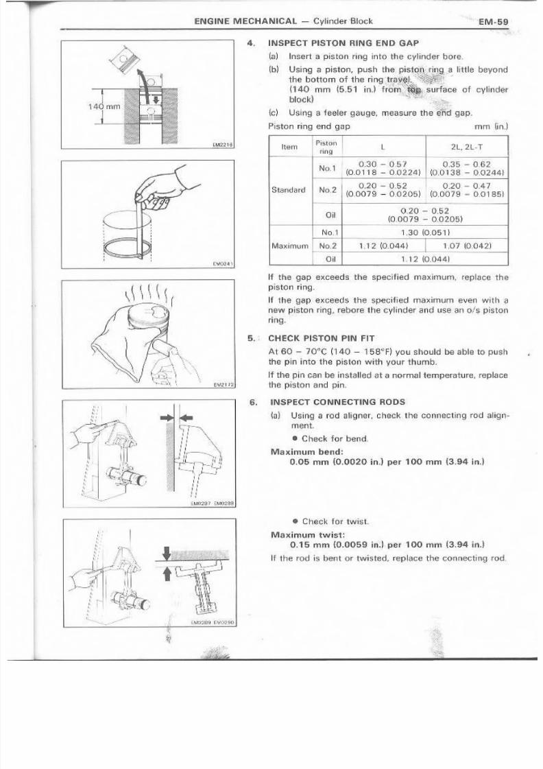
8/4/2019 Toyota 2L Engine Mechanical
http://slidepdf.com/reader/full/toyota-2l-engine-mechanical 59/68
ENGIIN E MECHANICAL - Cyl.inder 'B!1ock EM·59
4, INSP'ECT PISTON R lNG I END GAP
(a) Insert a piston rillg into the cylinder bore.
~b) Usiing O il piston, push the p ils* . r , _ r~ little beyolldthe bottom of the ding 'tr;a,·. ' . 1 ' ' :
{140. mm ~5.51 inJ frHr.%~·· : , ,surface of cylinder
blo ckl . "\i:~ _
'(d U Iii ing a ,' feel 'El f 9 a u ge , rn B a' s u ra th e' '$ 'jf d' g a p.
Piston ring €Ina gap mrr;, (in,
IPiston Irm.g
tem 2L.2L-T
N ', 0,30 -'0,5:7 0,35 - 0.62
1 _ ' _ 0 . _ ' ' - + - 1 _ ( 0 _ ' 0 _ ' ' _ ' _ 8 _ " _ - _ 0 _ . _ . 0 _ 2 . _ 2 _ 4 _ ) 1 (9,0138 - ,O_0244}
O ,Z 'O - '0 .52 0.20. - 0.47(0.007 9 - 0_0.205) ( 0 , 0 0 7 9 ' - 0_01 85]
O .2
1.1 1 2 (0.044) 1,07 (0_042)
1,12 \0,0441,
0,20 - 0,5.2(0,0079- 0.0205)
I------~~---~--------c
1.3.0 (O.05·'-to,1
Max~mum NQ,2
Oil
If the gap exceeds the speclfiad maxlrnurn, re:plac€! the
piston ring.
If the gap· exceeds the specified maximum E!"IEtnwith ~
new piston Ir.ilflg,. rebore theevllnder a nd use 'an o/s pis tonring. .
5.. CHECK PISTON PIN FIT
At 60 - 70< !C n 40 - 158tlF) YDU should be able to push
the pin into the piston with your thumb,
If the pin can be installed at a normal temperature, replace
the piston and pin,
6. INSPECli CONN ECl"ING ROns
~,a)' Using a rod allqner, check. the Connecting rod allqri-
merit.
• C heck for bend,
Malx.imum bend:
0".05 mm (O.OOZO in.l per 100 mm (3.94 in.]
• Check for tw~st-
Maximum twist:0.15 rnm (0.0059 ln.l per 100 mrn (3,.'94 in.l
If the rod is bent 01 " twisted, replac€! the connectinq rod.

8/4/2019 Toyota 2L Engine Mechanical
http://slidepdf.com/reader/full/toyota-2l-engine-mechanical 60/68
ENGINE MECHAN ICAL - Cy"lnder Blo 'c;:1<
t;M2'174"
3.
{b} M e a s _ w l ! 1 ' e thG oil ¢learaVlce b~1we,Bn the r o d bushing
and pistcn cln .
• Using an lnsJde dial indicator, measure the insidediameter of the rod bushing .
• Using 1 3 , micrometer, measure the diarrreter o,f thepiston pin.
e Subtract the, piston pin diameter hom the rod
bushing inside diameter.
Stam1ard on cle;~lifance: 0.004 ~ 0.012 mm{O.0002 - 0,00005 il1.~
Maximum oil clearance: 0'.05 mm (0.0020 in.)
If the oil ctaerance is greater than rnaxirrrum, replace therod bushing.
R EP lA C E,M EN T O F CON N EC TIN G HO DBUSH.ING
1 . R EMOVE RO D 'BU SH IN G
Using SST and a press. press out the bu.sh ing ,
SST 009222-4001 'I
2. I'NSTA,LL N.EW ROD BUSHING
ta} A.llg,11he oil IriOIBS Qf the bush ing and connecting red,
(b), Using SST and a press,' press in the bushing,
SST 09222-40011
HONE ROD BUSHING ,AND, CHECK PISTON P'tN FIT liNCON,NECTING ROD
is!) Using a pin hQle grinder, hone the bushif,g and checkthat the: oil claaranoa is wiJhrn standard speclfication,
Standard oil clearance: 0,004 - 0.0'1,2 mm
(0.0002- 0.0005 w n . 1
(.b) Check rhe pis.ton pin fit at normal room temperatura,
Coat the piston pill witl1 engijne oil and push it intothe roo with your thumb.
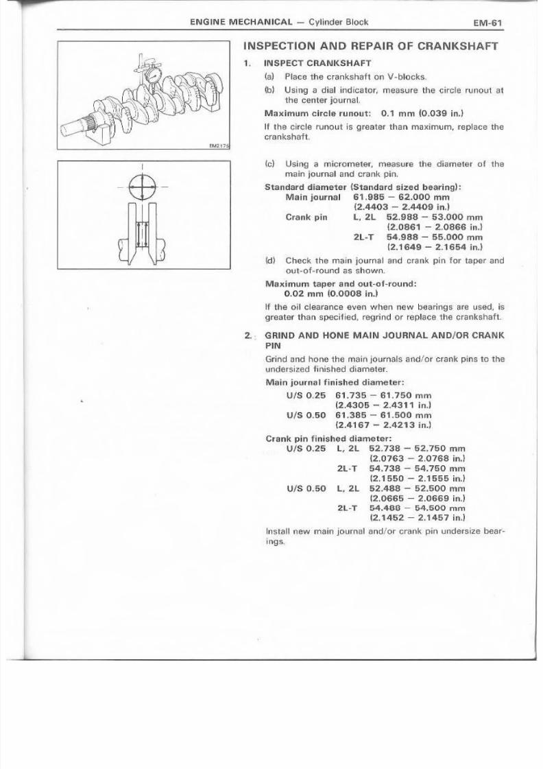
8/4/2019 Toyota 2L Engine Mechanical
http://slidepdf.com/reader/full/toyota-2l-engine-mechanical 61/68
I:NG.INE MECHANICAL - Cylinder Block EM-61
I
-$-
INS,PECTION AND REPAIR OF CRANI{SHAFT
1., INSPECT CRANKSHAFT
(8 ) Placethe crankshaft on V-blocks.
~b) Using a dia~ indicator, I11S.1lSLlre- the circle runout atthe center jouma~, ' .
Maximum elrela runnut: 0 . 1 ' 1 mm (0.039 in.)
I f the circle runout is, gre-ater than maximum, replace thee ra n k sh aft
(c) Using a micrometer, measure th e diameter ,o f the
main Journal and crank pin,
Standard ,~iame1i:er'(Standard sized bearing I , :Ma,in j:ournal 61.986 - 62.000 mm
(2.440·3 - ,2.4409inJ
Crank pin L. 2l 52..988- 53.000 mm
(2.'0861 - 2.086:6 ln.)2L-T 5,4.968 ~. 56.000 mm
12.1649 - 2.1654 inJ
!d} Check the main journal and crank pin for taper andcut-e F~roul!d as shown,
Max.imurn taper and out-ef-reund:
0.02 mm (0.0008 ln.]
' If t il le oil cie'i;lrapce even when new bear-ing s sre used , !S
greater than specified, regrind or replace -,he cr~nk5haft.
2. GRIND AND HONE MAl N JO 'U !RNAL AN D-/OR CRAiN,KPIN
Grin,cIand hOIl€: the main journals and/or c.l 'ank puns to theundelrsiz!ild finished 'dlarneter.
Main jcurnal finish~d diiametet:
UI!80 ..25 61.736 - 61.750 mm
(2.4305- 2,,4311 ln.]
U/S, 0 ..50 61..386 - 61.500 r n m(2.4167 - 2.4213 ~ nJ
Cran!k pin frnished diameter:U/S 0.25 L, .2L, 52,738 - 52.750 mm
(2.0763 - 2.0768 in.)2L·T 54,738 = 54.750 mm
12.1550 - 2.'1555 ln.]
U/S 0.50 L, 2l 5,2.488 - 52.500 mm~2.06'65- 2.0669 in,)
2L-T ,54.48,8- 54.5,00 romt2..1452 - ~.1457 ln.l
Instal'l new rnaln jOLJma ,1 and/Or crank pin undersize bear-lnqs,
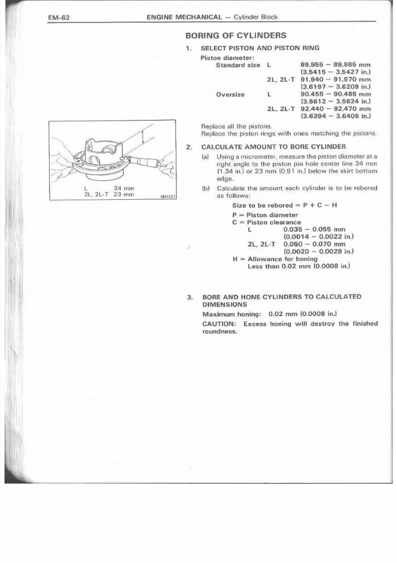
8/4/2019 Toyota 2L Engine Mechanical
http://slidepdf.com/reader/full/toyota-2l-engine-mechanical 62/68
BORING OF CY·UNDERS
EM-t:i2 ENGI NE MECHANICAL ~. Cylinder Block
t 34 rnrn2L, zt.T 13 mrn
1. SELECT PISTON AND PISTON RING
Piston diameter:
Standardsi.ze L
2L, 2L- T
89.955 - 89.985 mm(:3.541·5 .~. 3.5421 in,)
91.940 - 91.970 rnm
(3.6197 - 3J:i,209 ln.l
90~455- 90.485 mm13.5612 - 3.5624 in.l92..440 - 92.470 mrnt3.6394 - 3.6405 illl.)
Oversize L
2L.2L-T
Aepl.aG~ '@IIthe pistons.
R·epia ce the pj s t o 1 1 rings with ones rna teh in 9 the pisto n
2. CALCULATE AMOUNT TO BOHE CYLIINDE:R
( a ) Us.ing;;;lirnictornater, measure the piston diameter a
" igd l tang l€ to the piston PhF l hole center line 34 rn{, .34 inJ or 23. mm W.91 in.) b.elow the skirt bottoedge ..
(bl Calculate the arnount each cylinder I,sto be rebcrsastcltows:
Size to be rebored = P +C - H
P '"""Pis.ton diameter
C =P~stonclearance
t, 0,035- 0.055:mrn(0.0014 - 0.002·2 in.)
.2L, 2L~T 0.050 >= 0.070 mrn
(0.0020 - 0.0028 ln.lH =Allowance for honlin·g
Less than 0.02 mill (0.0008 bd
3. eOR,EAND HONE cvu NDERS TO CALCliLATED
IlIMENSJONiS
Maximum honing: 0.02 mrn ( O . O O C H 3 . in.}
CAUTlONI: EXC;E!.ss honing will destroy the finish
roundness.

8/4/2019 Toyota 2L Engine Mechanical
http://slidepdf.com/reader/full/toyota-2l-engine-mechanical 63/68
EN mN E M ECH A N ICAL- Cylinder Block EM·53
REPLACE M ENT OF CRAN KS HAFT 01L SEALS
Cl:.I'tPosition
~~
NOTE: There are two rnetnods 0" oil sea t replacement.
1. REPLACE CReANKSHAFT FRONT OIL SEAL
If nll pump body is removed from cylinder block:
(a) UIiing a screwdrlver and hammer; a r r i V e out tile oil
seal ,
{b} IJsin9c' SST and a hammer .. drive in a new ell seal.to
the de:pth of 0_5 mm (0,020 in,) from the oili pump
body edge,
SST OH214-600 10
Ie ) Apply MP gr4;:N;lseo the ail seal.
If oll pump body is, ,nstalledto cylinder block:
{a l Usingl a k nif e', Gut off the oil sea! lip.
(b) Using a .screwdriver, ~ : ) l F y put the ell seal.
CAUTION: Be carefut not to d.ama'ge the erarrkshatt,
Tape the serewdrlver,
(c~ Apply MP gl'-ease 'to a new oil seal.
(d) Using SST and a hammer, drive in the nil seal to a
depth 'of 0,5 mm (0,020 ln.l from the o i , l pump body
edge.
SST 0'921.4-60010
2. REPLACE CRANKS'HAFT REAR Oil SEAL
11 tear oil11sea l retainer is rarnoved frorn cylinde'r bku: :k. :
{a } Using a screwdriver and narnrner , drive out the oil
seaL
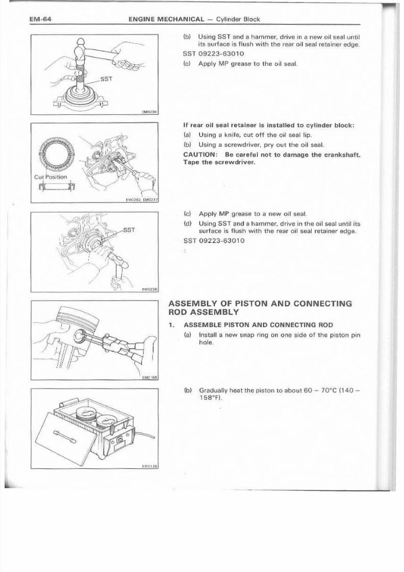
8/4/2019 Toyota 2L Engine Mechanical
http://slidepdf.com/reader/full/toyota-2l-engine-mechanical 64/68
ENGINE MECHANICAL ~ Cylif1der Block
C\ :dP os i~ ipn
~:~
\.
\, EM 1" 16 B _
~bl Usilng SST and a hammer, drive in a new o il seal uilt~1its surface is Husb with the rear oil seal re ta in er e dg e,
SST 09223-63010
{ c l A pply M P 9reas'e' to tha oil-seal.
If rear nll seai retaii i1er is, instaUed to cyHnder bloe'I(:
(a) Using a knife, aut off the: oil seal, Hp.
(b) Using a screwdnvar. p l F Y out the oil seal,
CAUTtDN: 'Be careful not to damaqe the crankshaft ..
Tape ttle screwdriver.
~ C ; ) A pplY ' M P gr:ea s,e to a newoMse~L
(d) UsIng, SST a nd ,8 hammer , drive in the ,oil ! ; l o B E I ' I until its
sur face is fh,J.!;ihwith the rear oil seal retainer edge.
SST 09223'-630100
,ASS'EM BL Y 0 F PISTON A,N 0 ,CONN ECTI NG
ROiDASSEMBLY
1. ASSEMBLE PISTON,AND CONNECT'NG ROO
(a} lnstall 1 :1 new snap ring 01 1 one side of the pis.toll p~n
hole.
{b} 'GraduaHy heat the piston, 'to about 60 - JODe ('40 -
1 6 S : < > F ) ,
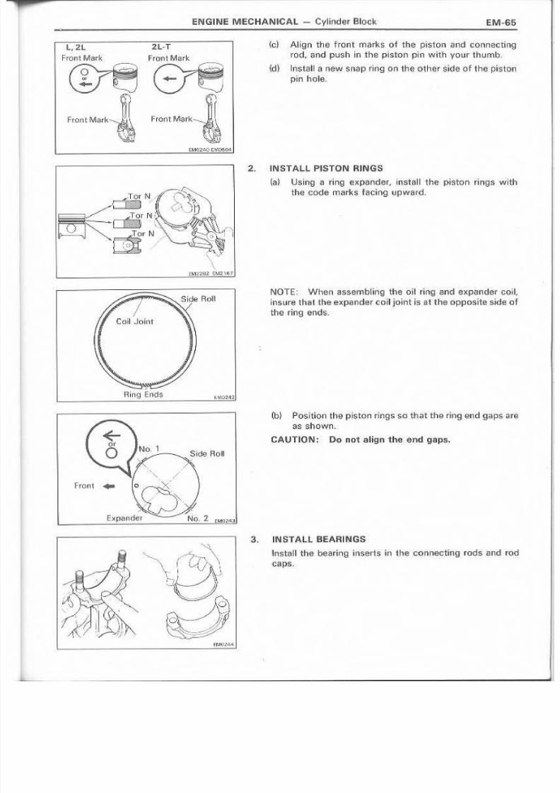
8/4/2019 Toyota 2L Engine Mechanical
http://slidepdf.com/reader/full/toyota-2l-engine-mechanical 65/68
.EN.GINE. MEC!HANIC:A.L- Cylinder Block
F ro nt M awk
L,2L .2.L.T
Frofit Mar~ Front Mark
~
r .,. ", v
\\<M;l""282 EM~ 'lo·, J
·r
Ringr:nds
h:;} Ailgn the front marks of tlhe piston and COM9cting
rod, <lindpush in .th e piston pin W_ith y"Our thumb,
{d } Insta II a !'lew sn.ap r.~ngo n th e ot tl e r sjd e ()'~ the: phrton
pin hole.
2., INS,TAlL PISTON RINGiS
(a) U.sing , < ' 1 ring l;!)I;p·~nder, install thG: piston rings with
the. · j ; :Ode marks tacing u.pwEI'r{L
NOTE.: Wh€r1 rrHlsembling. the ell ring and expander coil,
Insure that the expander eoll jointIs at theepposite side ofthe ringl€lntl!il,
(b) Po s l t lo n the p isto n dn9550 tha t the dng end 9aps~.re,
as shown.
CA,UTIOINl: Do not align the· ,e'nd gaps.
INSTALL BEA.FUNGS
!rl!lsta II the beatri ngi nserts i~thl ~;rCIOnnacting rods .a nd rod
caps,
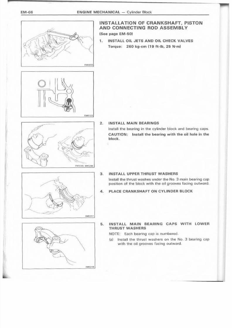
8/4/2019 Toyota 2L Engine Mechanical
http://slidepdf.com/reader/full/toyota-2l-engine-mechanical 66/68
ENG i NE M EC .H AN IC A,L - Cyl ind,er Block
.0 I ~ \ _ ;- \.0.
q2. INSTALL MAIN BE ;A ,R INGS
Install the bearinq in the, cylinde'[ block and bearing, caps.
CAUTION: Install.the bearing wlith the oil hole in the
bloc.k.
3, IN,·STAll UPPER THRUST WASHERS
lnstall the thrust washes under the N C L 3 main b-Baringcapposition o f the tl~O Gk with ' th,e eilg,roQve:s facing outward,
4. PLACECRANKSHAFT ON CYLINDER BLOCK
5. INSTA,lL MAIN BEARING CAPS WITH LOWER
THRUST WASHEIRS
NOTE: EaChbearing cap Is numbered.
{al Install the thrust washers on the No. 3 bearing capwith the o'il ~roov-es facing outward.

8/4/2019 Toyota 2L Engine Mechanical
http://slidepdf.com/reader/full/toyota-2l-engine-mechanical 67/68
ENGINE M ECHIANICAL- Cylind.rilr Block EM~6
Ex.No.3 Beari!llg G~p No, 3 Bel;lrin.gCap {b) lnatall the tH~arir)9 caps in their proper location.
(c) Apply a light coating of enqlne oil on the threads and
heads under of the cap holts,
{d} InsM11and ti.ghten the cap bolls tn two or threepasses, Sind in the sequence shown.
Torque: 1,050 kq-nm (76 ft-Ib, 103N'm)
{ej Check that the crankshaft turns smoothly.
(f ) Check the crankshaft thrust clearanee.
(Sa,a pagB EM~53)
6. INSTALL PISTON AND CON NECTING ROO
ASSEMBLY
{a) Cover 'th e ro d bolts withQ short pi~:cElOf hose to proted tha crankshaft kOf1l damage ' ,
(b} Us·ing a r~ng compressor, push the correcuv nurn-
bared piston and rod assernblv into each Gylinde
with the 'front merk of the piston fffcing forward,
7. IINSTALL C ON N E C T I N G ROD CAPS
(a) Match the numbered cap' with the numbered rod.
(b) Install the rod caps with the front mark facing for
ward.
W!0:150
F ro nt M ark
~I
~j- f\'.
' 1 1 ~ .
Front f\ilark- J I (1\
~I

8/4/2019 Toyota 2L Engine Mechanical
http://slidepdf.com/reader/full/toyota-2l-engine-mechanical 68/68
k:.} Apply a ~~!;Intcoat of the engiif l lei oil on the threads andunder the rod nuts. .
(d} Install, ,Sindtighten the rod nuts altematatv in two orthree pa·5se~.
Torque: 600 I(g~(lm(43 fHb, 59 N'm)
(8 ) Check that the crankshaft turns smoothly.
m C hec k th e rod th w st ole a ra n ce ,(See page EM~5~)
EM~68 ENGJNE MECHANI,CAL - .cylinder Block
ASSEMBLY OF CYLINDER. BLOCK
(See page EM~50)
1. INSTALl R'EAROIL SEAL RETAINER
Install 8 new ga.sket and the retainer with· the four bolts,T orq u e: tile holts,
Terque :130 kg-em '(9f't-lb, 13 N·m)
2 . INS,TALL O IL 'PU M P'
(Se'l! s.teps ~ to 7 on pages IL.U-6,7)
3. INSTALL CYlIND,ER HEADISee ,steps 1 to 3, 5, 10 to 14 !;lInd 16on p'ages EM~4·
1(49)
4. REMOVE E.NGIINf STAND
5. IINST ALL REAR E.ND PLATE
l'nst!!}'11 a dust :seal and the end plate with the two bolts.
Torque the bolts.
Terque: 1120 keg-em (9 fl·lib" 12 N·,m)
6. INSTALL FL V'W HiE EL O R DRIVE P'LATE
Torque: 1,250 kg-em (90 f1~I.b,123 N·m)
Related Documents