Reprint 27-Feb-2007 Copyright © 2007 DVCon and Doulos Ltd. All Rights Reserved 1 February 22, 2007 Towards a Practical Design Methodology with SystemVerilog Interfaces and Modports Jonathan Bromley Senior Consultant Doulos, Ringwood, UK [email protected] Notes This paper was presented at DVCon 2007 (see www.dvcon.org) where it was judged by delegates to be joint Best Paper. The full text of the paper is available in the DVCon Proceedings, and on the Doulos website www.doulos.com. The other joint winner was: FEV’s Greatest Bloopers: False Positives in Formal Equivalence Erik Seligman, Joonyoung Kim Digital Enterprise Group, Intel Corporation, Hillsboro, OR

Welcome message from author
This document is posted to help you gain knowledge. Please leave a comment to let me know what you think about it! Share it to your friends and learn new things together.
Transcript
Reprint 27-Feb-2007 Copyright © 2007 DVCon and Doulos Ltd. All Rights Reserved 1
February 22, 2007
Towards a Practical Design Methodologywith SystemVerilog Interfaces and Modports
Jonathan Bromley
Senior Consultant
Doulos, Ringwood, UK
Notes
This paper was presented at DVCon 2007 (see www.dvcon.org) where it wasjudged by delegates to be joint Best Paper. The full text of the paper is availablein the DVCon Proceedings, and on the Doulos website www.doulos.com.
The other joint winner was:
FEV’s Greatest Bloopers: False Positives in Formal Equivalence
Erik Seligman, Joonyoung KimDigital Enterprise Group, Intel Corporation, Hillsboro, OR

Towards a Practical Design Methodology with SystemVerilog Interfaces and Modports DVCon 2007
2 Copyright © 2007 DVCon and Doulos Ltd. All Rights Reserved Reprint 27-Feb-2007
Multi-level bus architecture
Many of today's FPGA and ASIC designs use interconnect schemes such asAMBA (published by ARM Ltd) or other standards.
Bus fabric Unlike traditional rack-and-cards systems, an on-chip system is likely to usemany different forms of interconnect – our example shows the high-performanceAXI and AHB buses co-existing with the much simpler, lower-performance APB.Furthermore, point-to-point connection is usually preferable to shared (multi-drop) interconnect. It is therefore usually necessary to have one or more busswitching and bridge blocks, shown here as a "Bus fabric" module. Suchmodules are often quite complex, and need extensive customisation to suit thenumber and type of subsystems in each individual application.
The use of bus fabric modules typically leads to multiple instances of a giveninterconnect structure at the top level of the design. In our example we have twoinstances of the AXI bus, and two instances of APB.

Reprint 27-Feb-2007 Copyright © 2007 DVCon and Doulos Ltd. All Rights Reserved 3
Multi-level bus architecture
Enclosing top-level module
Peripheral
Bus fabric
Peripheral
APB
CPU DMA Memory
PeripheralPeripheral
AX
I
AH
B
AX
I
APB
Notes
Towards a Practical Design Methodology with SystemVerilog Interfaces and Modports DVCon 2007
4 Copyright © 2007 DVCon and Doulos Ltd. All Rights Reserved Reprint 27-Feb-2007
The need for encapsulated interconnect
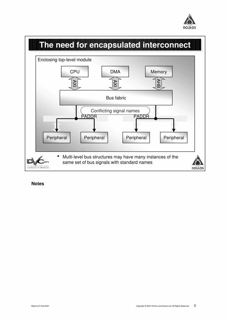
Because there are two APB buses at the same level of hierarchy, we have aproblem when we come to create the wiring. The standard name for theaddress bus in APB is PADDR, but we can't use that name for two separatesignals! In a traditional system we would be obliged to invent two differentnames for the two PADDR signals – and, of course, do the same over and overagain for all the other signals too.
Perhaps you use scripts, or a graphical design entry tool, to do all this tiresometop-level wiring, in which case the signals will probably get unfathomable namessuch as PADDR_1 and PADDR_2. Alternatively you may do it manually, which isunpleasantly laborious and error-prone. Neither solution seems ideal.
We could solve this problem elegantly if we had some way to encapsulate thewhole of an APB (or any other) interconnect in a single structure. As we will seein the next few pages, SystemVerilog's interface construct provides just suchan encapsulation.
Reprint 27-Feb-2007 Copyright © 2007 DVCon and Doulos Ltd. All Rights Reserved 5
Enclosing top-level module
The need for encapsulated interconnect
• Multi-level bus structures may have many instances of thesame set of bus signals with standard names
Peripheral
Bus fabric
Peripheral
CPU DMA Memory
PeripheralPeripheral
AX
I
AH
B
AX
I
Conflicting signal namesConflicting signal namesPADDR PADDR
Notes
Towards a Practical Design Methodology with SystemVerilog Interfaces and Modports DVCon 2007
6 Copyright © 2007 DVCon and Doulos Ltd. All Rights Reserved Reprint 27-Feb-2007
Data structures are not enough
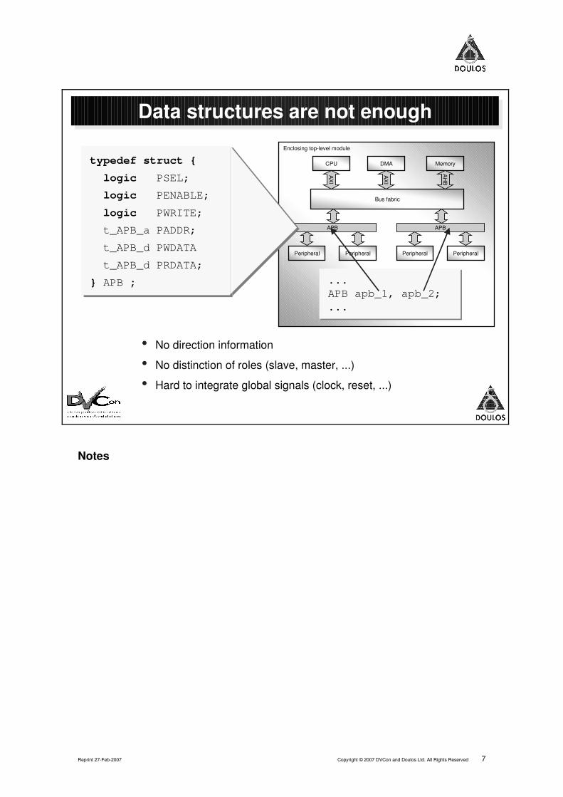
First, though, we'll look at an alternative possibility. SystemVerilog also offersthe struct feature, allowing users to define a data type that contains acollection of distinct data items. Our example shows the definition of a new datatype APB that can be used as a "cookie cutter" to create new variables, each ofwhich represents the complete set of signals needed for the APB interconnect.
However, if you try to use this mechanism you will find exactly the samedifficulties that VHDL users have suffered for many years when trying to use theRECORD construct to do such things:
• it is impossible to specify input or output directions individually for thevarious components of the record, which is very troublesome;
• a module wishing to connect to such a structure must simply connect to allof it – there is no way to distinguish the various different roles, such asmaster or slave, that different modules may have;
• signals whose scope extends outside the bus itself, such as clock and reset,cannot be conveniently integrated into this arrangement.
These are exactly the problems that SystemVerilog interfaces were designedto solve, as we'll see on the next page.
Reprint 27-Feb-2007 Copyright © 2007 DVCon and Doulos Ltd. All Rights Reserved 7
Data structures are not enough
• No direction information
• No distinction of roles (slave, master, ...)
• Hard to integrate global signals (clock, reset, ...)
typedef struct {
logic PSEL;
logic PENABLE;
logic PWRITE;
t_APB_a PADDR;
t_APB_d PWDATA
t_APB_d PRDATA;
} APB ;
typedef struct {
logic PSEL;
logic PENABLE;
logic PWRITE;
t_APB_a PADDR;
t_APB_d PWDATA
t_APB_d PRDATA;
} APB ;
Enclosing top-level module
Peripheral
Bus fabric
Peripheral
APB
CPU DMA Memory
PeripheralPeripheral
AX
I
AH
B
AX
IAPB
...APB apb_1, apb_2;...
...APB apb_1, apb_2;...
Notes

Towards a Practical Design Methodology with SystemVerilog Interfaces and Modports DVCon 2007
8 Copyright © 2007 DVCon and Doulos Ltd. All Rights Reserved Reprint 27-Feb-2007
Interface captures interconnect
Here we see the simplest way to use an interface to capture a structured setof interconnect. The interface is defined in much the same way as a module;indeed, the writer is strongly of the opinion that interfaces and modules are verynearly the same!
Interface contentsThe interface contains declarations of nets or (as here) variables that representthe various signals that form the interconnect. Note that we can use the signal'sstandard data-sheet names, since there will be no conflict with signals of thesame name elsewhere in the design.
PortsThe interface can also have ports; here we have used a port to bring in a globalclock signal, making it visible by its standard name PCLK within the interfaceitself.
Instantiating the interfaceNow that we have defined the interface, we can instantiate it in just the sameway as we could instantiate a module. Note how we have wired the same globalclock signal PCLK to both instances of the interface.
Because we have used interfaces to capture the interconnect, the top-levelenclosing module is now much cleaner and easier to understand than it wouldbe if each interface were represented as a collection of separate signals.

Reprint 27-Feb-2007 Copyright © 2007 DVCon and Doulos Ltd. All Rights Reserved 9
Interface captures interconnect
• Global signals ported into the interface
• Each interface instance provides a new set of bus signals
• Enclosing module is now much cleaner
interface APB (
input bit PCLK );
logic PSEL;
logic PENABLE;
logic PWRITE;
t_APB_a PADDR;
t_APB_d PWDATA
t_APB_d PRDATA;
endinterface
interface APB (
input bit PCLK );
logic PSEL;
logic PENABLE;
logic PWRITE;
t_APB_a PADDR;
t_APB_d PWDATA
t_APB_d PRDATA;
endinterface
Enclosing top-level module
Peripheral
Bus fabric
Peripheral
APB
CPU DMA Memory
PeripheralPeripheral
AX
I
AH
B
AX
IAPB
bit PCLK;APB apb_1(PCLK);APB apb_2(PCLK);
bit PCLK;APB apb_1(PCLK);APB apb_2(PCLK);
Notes
Towards a Practical Design Methodology with SystemVerilog Interfaces and Modports DVCon 2007
10 Copyright © 2007 DVCon and Doulos Ltd. All Rights Reserved Reprint 27-Feb-2007
Porting the interface into a module
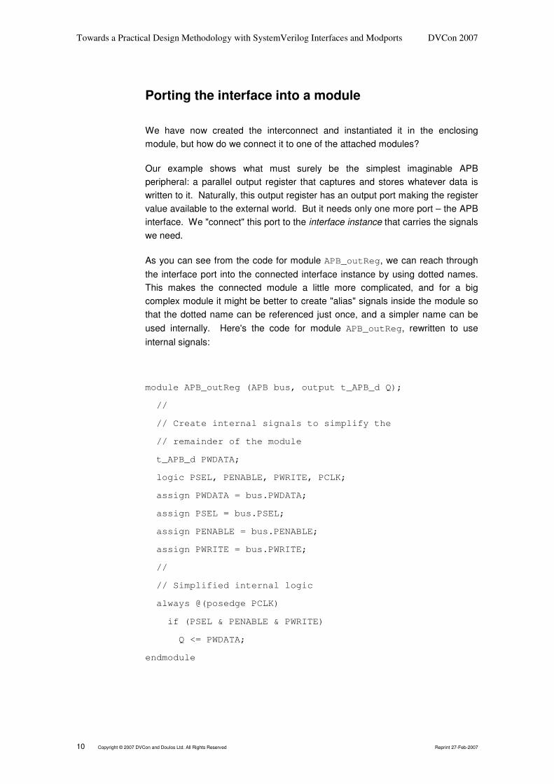
We have now created the interconnect and instantiated it in the enclosingmodule, but how do we connect it to one of the attached modules?
Our example shows what must surely be the simplest imaginable APBperipheral: a parallel output register that captures and stores whatever data iswritten to it. Naturally, this output register has an output port making the registervalue available to the external world. But it needs only one more port – the APBinterface. We "connect" this port to the interface instance that carries the signalswe need.
As you can see from the code for module APB_outReg, we can reach throughthe interface port into the connected interface instance by using dotted names.This makes the connected module a little more complicated, and for a bigcomplex module it might be better to create "alias" signals inside the module sothat the dotted name can be referenced just once, and a simpler name can beused internally. Here's the code for module APB_outReg, rewritten to useinternal signals:
module APB_outReg (APB bus, output t_APB_d Q);
//
// Create internal signals to simplify the
// remainder of the module
t_APB_d PWDATA;
logic PSEL, PENABLE, PWRITE, PCLK;
assign PWDATA = bus.PWDATA;
assign PSEL = bus.PSEL;
assign PENABLE = bus.PENABLE;
assign PWRITE = bus.PWRITE;
//
// Simplified internal logic
always @(posedge PCLK)
if (PSEL & PENABLE & PWRITE)
Q <= PWDATA;
endmodule
Reprint 27-Feb-2007 Copyright © 2007 DVCon and Doulos Ltd. All Rights Reserved 11
Porting the interface into a module
• Port of interface type makes all interface contents visible
• Access usinginterface_port_name.interface_contents
Enclosing top-level module
Peripheral
Bus fabric
Peripheral
APB
CPU DMA Memory
PeripheralPeripheral
AX
I
AH
B
AX
I APB
module APB_outReg (
APB bus,
output t_APB_d Q );
always @(posedge bus.PCLK)
if (bus.PSEL & bus.PENABLE & bus.PWRITE)
Q <= bus.PWDATA;
endmodule
module APB_outReg (
APB bus,
output t_APB_d Q );
always @(posedge bus.PCLK)
if (bus.PSEL & bus.PENABLE & bus.PWRITE)
Q <= bus.PWDATA;
endmodule
t_APB_d Out;APB_outReg lamp_reg ( .bus(apb_2), .Q(Out) );
t_APB_d Out;APB_outReg lamp_reg ( .bus(apb_2), .Q(Out) );
Notes

Towards a Practical Design Methodology with SystemVerilog Interfaces and Modports DVCon 2007
12 Copyright © 2007 DVCon and Doulos Ltd. All Rights Reserved Reprint 27-Feb-2007
Modports reflect client roles
We have used ports on an interface to solve the problem of integrating globalsignals with the interconnect, but we also need to deal with two other issues: thedistinction of various client rôles, and establishing the dataflow direction for eachsignal individually. Using the modport construct elegantly solves both theseproblems.
In any interface, we can declare one or more modport specifying a view of theinterface that one client rôle should see. The modport details the names ofinterface signals that are available to the client, and the directions of each signalfrom the point of view of the connected module. In our example, we have madeall interface signals available to both the master and slave clients. However, ifwe prefer we can also make some signals invisible to certain clients, simply byomitting those signals from the modport list.
A client module can then choose to connect to the appropriate modport, ratherthan the whole interface.

Reprint 27-Feb-2007 Copyright © 2007 DVCon and Doulos Ltd. All Rights Reserved 13
Modports reflect client roles
Enclosing top-level module
Peripheral
Bus fabric
Peripheral
APB
CPU DMA Memory
PeripheralPeripheral
AX
I
AH
B
AX
IAPB
interface APB ( input bit PCLK );
logic PSEL, PENABLE, PWRITE; t_APB_a PADDR; t_APB_d PWDATA, PRDATA;
modport Master ( input PCLK, output PSEL, PENABLE, PWRITE, PADDR, PWDATA, input PRDATA );
modport Slave ( input PCLK, input PSEL, PENABLE, PWRITE, PADDR, PWDATA, output PRDATA );
endinterface
interface APB ( input bit PCLK );
logic PSEL, PENABLE, PWRITE; t_APB_a PADDR; t_APB_d PWDATA, PRDATA;
modport Master ( input PCLK, output PSEL, PENABLE, PWRITE, PADDR, PWDATA, input PRDATA );
modport Slave ( input PCLK, input PSEL, PENABLE, PWRITE, PADDR, PWDATA, output PRDATA );
endinterface
• Directions are relative to the connected (client) module
• Modports also can restrict visibility(some roles don't need to see all contents of interface)
Notes
Towards a Practical Design Methodology with SystemVerilog Interfaces and Modports DVCon 2007
14 Copyright © 2007 DVCon and Doulos Ltd. All Rights Reserved Reprint 27-Feb-2007
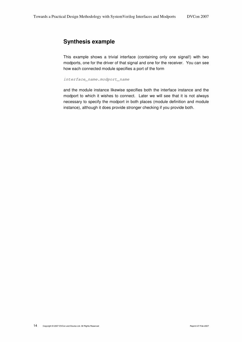
Synthesis example
This example shows a trivial interface (containing only one signal!) with twomodports, one for the driver of that signal and one for the receiver. You can seehow each connected module specifies a port of the form
interface_name.modport_name
and the module instance likewise specifies both the interface instance and themodport to which it wishes to connect. Later we will see that it is not alwaysnecessary to specify the modport in both places (module definition and moduleinstance), although it does provide stronger checking if you provide both.

Reprint 27-Feb-2007 Copyright © 2007 DVCon and Doulos Ltd. All Rights Reserved 15
module Top; Itf inst_Itf(); Master inst_M(inst_Itf.M); Slave inst_S(inst_Itf.S);endmodule
module Top; Itf inst_Itf(); Master inst_M(inst_Itf.M); Slave inst_S(inst_Itf.S);endmodule
Synthesis example
interface Itf; logic L;
modport M(output L); modport S(input L);endinterface
interface Itf; logic L;
modport M(output L); modport S(input L);endinterface
module Master( Itf.M iM
);
always ... iM.L <= 1'b0;
...
endmodule
module Master( Itf.M iM
);
always ...
iM.L <= 1'b0;
...
endmodule
module Slave( Itf.S iS
);
always @(iS.L) ...
endmodule
module Slave( Itf.S iS
);
always @(iS.L)
...
endmodule
inst_M inst_Sinst_Itf
Notes

Towards a Practical Design Methodology with SystemVerilog Interfaces and Modports DVCon 2007
16 Copyright © 2007 DVCon and Doulos Ltd. All Rights Reserved Reprint 27-Feb-2007
Synthesis results
Interfaces and modports are synthesisable!
This slide shows the netlist that would result from synthesis of the previouspage's example. The details might differ slightly between different synthesistools, but the general principles are exactly as shown here.
First, the synthesis tool flattens or "explodes" the interface instance so that all itscontents are declared directly in the enclosing module. Naturally, that will entailsome renaming of the interface contents – especially if there is more than oneinstance of the same interface.
Next, the synthesis tool must rewrite each connected module's port list so that itexpects to connect to a set of distinct signals, rather than an interface ormodport. All the connected module instantiations must then be rewritten tomatch.
Finally, the synthesis tool patches-up all references to interface signals withinthe connected modules so that instead they reference the newly created ports.
At the time of writing (February 2007) not all synthesis tools yet support this, butsupport is growing fast and already there are examples of both FPGA and ASICsynthesis tools that have the necessary SystemVerilog capability.
It's not all good news…It's clear that straighforward use of interfaces for point-to-point interconnection isconvenient and practical. However, on the next few pages we will investigatesome common problems that cannot be solved quite so easily.

Reprint 27-Feb-2007 Copyright © 2007 DVCon and Doulos Ltd. All Rights Reserved 17
module Top; logic inst_Itf_L; Master inst_M(inst_Itf_L); Slave inst_S(inst_Itf_L);endmodule
module Top; logic inst_Itf_L; Master inst_M(inst_Itf_L); Slave inst_S(inst_Itf_L);endmodule
Synthesis results
• Interface instance contentsare "exploded" into theenclosing module
module Master( output logic Itf_L
);
always ... Itf_L <= 1'b0;
...
endmodule
module Master( output logic Itf_L
);
always ...
Itf_L <= 1'b0;
...
endmodule
module Slave( input logic Itf_L
);
always @(Itf_L) ...
endmodule
module Slave( input logic Itf_L
);
always @(Itf_L)
...
endmodule
inst_M inst_S
Notes

Towards a Practical Design Methodology with SystemVerilog Interfaces and Modports DVCon 2007
18 Copyright © 2007 DVCon and Doulos Ltd. All Rights Reserved Reprint 27-Feb-2007
Multiple drivers on a bus
Like many interconnect schemes, APB is designed to link one master to multipleslaves. For signals going from master to slave, this is straightforward; themaster drives a signal, and multiple slaves receive it. For signals going theother way, though, things are more troublesome. In our APB example only onesignal is driven by slaves: the read data signal PRDATA. For any bus read cycle,just one slave is selected (typically by address decoding) and only that slaveshould drive PRDATA. How can we arrange this if we use an interface?
Three-state driversAll slaves' PRDATA outputs are connected to a common net in the interface.Only the selected slave drives the PRDATA net. Other, deselected slaves placethe high-impedance value 'bZ on the net.
This approach works correctly both for synthesis and for simulation, but itrepresents a hardware modelling style that is completely inappropriate formodern on-chip architectures. Some synthesis tools can automatically re-mapthis structure to a multiplexer, but this is not guaranteed and we cannotrecommend this style for routine use.
Multiplexer or AND-OR logicAlternatively, each slave can have its own PRDATA signal. These varioussignals can then be multiplexed on to the master's common PRDATA, using thesame address decode that was used to select the slaves. Alternatively,deselected slaves can drive their outputs to zero, and all the outputs can then beORed together to create the correct readback value.
This approach is perfect for hardware, but requires that we create distinctPRDATA signals for each individual slave. As we will see later, this is difficult toarrange using interfaces and modports.
Selective deposit to a variableFor simulation, the most natural and most elegant approach is for the selectedslave to write to a variable PRDATA in the interface, and for all deselected slavessimply to refrain from writing to that variable. Verilog's "last-write-wins"behaviour then ensures that the required value appears on PRDATA.
This approach works well in simulation, but is not synthesisable because thesynthesis tool cannot resolve the effect of multiple processes writing to the samevariable. Consequently it can't be used for real hardware design.
We believe this to be the most significant difficulty relating to the use ofinterfaces in synthesisable design.

Reprint 27-Feb-2007 Copyright © 2007 DVCon and Doulos Ltd. All Rights Reserved 19
SlavemoduleSlave
moduleMastermoduleMastermodule
SlavemoduleSlave
module
Multiple drivers on a bus
PCLK,PSEL etc.
PRDATA
APB interfaceinstance
APB interfaceinstance
• Multiple drivers on net: OK forsynthesis, bad for hardware
• Multiple deposits to variable:OK for modelling, notsynthesisable
Tri-state bus? Multiplexer? Wire-OR?Tri-state bus? Multiplexer? Wire-OR?
APB.Master modportAPB.Master modport
APB.Slavemodports
APB.Slavemodports
Notes
Towards a Practical Design Methodology with SystemVerilog Interfaces and Modports DVCon 2007
20 Copyright © 2007 DVCon and Doulos Ltd. All Rights Reserved Reprint 27-Feb-2007
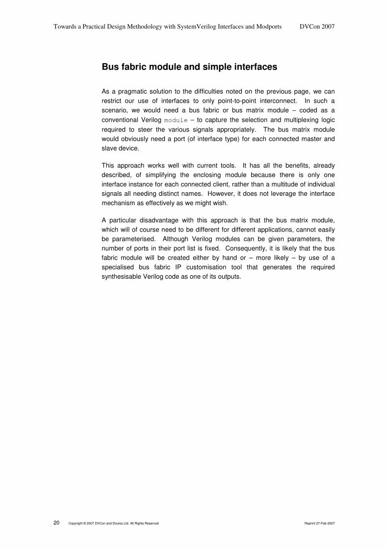
Bus fabric module and simple interfaces
As a pragmatic solution to the difficulties noted on the previous page, we canrestrict our use of interfaces to only point-to-point interconnect. In such ascenario, we would need a bus fabric or bus matrix module – coded as aconventional Verilog module – to capture the selection and multiplexing logicrequired to steer the various signals appropriately. The bus matrix modulewould obviously need a port (of interface type) for each connected master andslave device.
This approach works well with current tools. It has all the benefits, alreadydescribed, of simplifying the enclosing module because there is only oneinterface instance for each connected client, rather than a multitude of individualsignals all needing distinct names. However, it does not leverage the interfacemechanism as effectively as we might wish.
A particular disadvantage with this approach is that the bus matrix module,which will of course need to be different for different applications, cannot easilybe parameterised. Although Verilog modules can be given parameters, thenumber of ports in their port list is fixed. Consequently, it is likely that the busfabric module will be created either by hand or – more likely – by use of aspecialised bus fabric IP customisation tool that generates the requiredsynthesisable Verilog code as one of its outputs.
Reprint 27-Feb-2007 Copyright © 2007 DVCon and Doulos Ltd. All Rights Reserved 21
Bus fabricmodule
Bus fabricmodule
SlavemoduleSlave
module
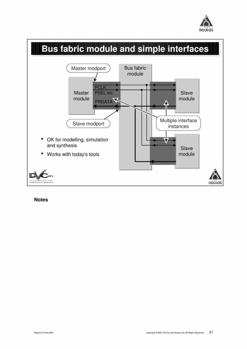
Bus fabric module and simple interfaces
MastermoduleMastermodule
PCLK,PSEL etc.
PRDATA
Master modportMaster modport
• OK for modelling, simulationand synthesis
• Works with today's toolsSlave
moduleSlave
module
Multiple interfaceinstances
Multiple interfaceinstancesSlave modportSlave modport
Notes
Towards a Practical Design Methodology with SystemVerilog Interfaces and Modports DVCon 2007
22 Copyright © 2007 DVCon and Doulos Ltd. All Rights Reserved Reprint 27-Feb-2007
Interface architecture challenges
If we wish to exploit the power of interfaces more fully, we must solve theproblem of multiple client modports and multiple drivers on interface signals.
Each slave must connect to a distinct modport, because each slave has adistinct identity and occupies a specific address range. However, this conflictswith the obvious need for every slave interface to look identical; they should allpresent the same set of APB slave signals. Clearly, this gives us a problem ofnaming.
Furthermore, the bus fabric interface must now accept some responsibility foraddress decoding. We must choose whether this decoding is done centrally, bythe interface itself, or by each individual slave performing a matching operationon the address value.
Address ranges, number of masters and slaves, and other features of the wholebus-based system should ideally be parameterisable.
Finally we must solve the problem of multiple drivers on a signal, as describedearlier – although, as we will see, this problem is very closely related to theproblem of modport signal naming.
Reprint 27-Feb-2007 Copyright © 2007 DVCon and Doulos Ltd. All Rights Reserved 23
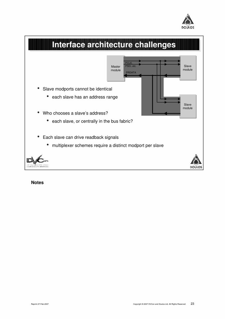
Interface architecture challenges
• Slave modports cannot be identical
• each slave has an address range
• Who chooses a slave’s address?
• each slave, or centrally in the bus fabric?
• Each slave can drive readback signals
• multiplexer schemes require a distinct modport per slave
SlavemoduleSlave
moduleMastermoduleMastermodule
SlavemoduleSlave
module
PCLK,PSEL etc.
PRDATA
Notes
Towards a Practical Design Methodology with SystemVerilog Interfaces and Modports DVCon 2007
24 Copyright © 2007 DVCon and Doulos Ltd. All Rights Reserved Reprint 27-Feb-2007
Modport expressions
The SystemVerilog language standard (IEEE Std.1800-2005) already provides asolution to many of the difficulties we have described, with its modportexpression construct. This diagram shows a very simple use of modportexpressions.
The interface contains a vector signal V[1:0]. We imagine that the mastermodule needs to see the full vector, but each slave should drive only one bit ofthe vector. This can be done by passing a parameter – the bit number – intoeach slave; but this is not ideal, because it means that the slaves need to beaware of the internal structure of the interface. Ideally, each slave should seeonly the single-bit output that it requires; and, of course, it would be best it bothslaves see exactly the same set of connections.
Modport expressions enable all this by renaming a signal as it goes through themodport. The modport expression
output .L(V[0])
says that the module connected to the modport should see a signal called L, butthat signal should in fact be implemented by signal V[0] inside the interfaceitself.
Now we have two different modports, but each of them presents exactly thesame appearance to its connected module.
But there is some bad news:
No current SystemVerilog tools support modport expressions!

Reprint 27-Feb-2007 Copyright © 2007 DVCon and Doulos Ltd. All Rights Reserved 25
module Top; Itf2 inst_Itf2(); Master inst_M(inst_Itf2.M); Slave0 inst_S0(inst_Itf2.S0); Slave1 inst_S1(inst_Itf2.S1);endmodule
module Top; Itf2 inst_Itf2(); Master inst_M(inst_Itf2.M); Slave0 inst_S0(inst_Itf2.S0); Slave1 inst_S1(inst_Itf2.S1);endmodule
Modport expressions
interface Itf2; logic [1:0] V;
modport M(input V);
modport S0 ( output .L(V[0]) );
modport S1 ( output .L(V[1]) );
endinterface
interface Itf2; logic [1:0] V;
modport M(input V);
modport S0 ( output .L(V[0]) );
modport S1 ( output .L(V[1]) );
endinterface
module Master(
Itf2.M iM
);
always @(iM.V) ...
module Master(
Itf2.M iM
);
always @(iM.V) ...
module Slave0(
Itf2.S0 iS
);
always ...
iS.L <= ...
module Slave0(
Itf2.S0 iS
);
always ...
iS.L <= ...
inst_M inst_S0inst_Itf2
module Slave1( Itf2.S1 iS
);
always ...
iS.L <= ...
module Slave1( Itf2.S1 iS
);
always ...
iS.L <= ...
inst_S1
Identical namesIdentical names
• Rename signalsacross a modport
Notes
Towards a Practical Design Methodology with SystemVerilog Interfaces and Modports DVCon 2007
26 Copyright © 2007 DVCon and Doulos Ltd. All Rights Reserved Reprint 27-Feb-2007
Specialised modports
Here's the idea from the previous page, worked through in a more practicalexample. Let's suppose that we want to connect a UART device to our APBsystem. The UART device has already been designed to expect an APBinterface. Note that the module definition for APB_UART doesn't specify anymodport in its port list, but we do specify the modport when we instantiate it. Inthis way we don't need to make the module unnecessarily specialised. Themodule instance is specialised (for address range, etc) by being connected to asuitable modport on the APB_sys interface instance.
Likewise, our APB_UART module expects to see the standard signal name PSELfor its bus select signal, but we wish to specify a particular decoded signalUART_PSEL within the interface. A modport expression provides this renaming,and also provides the UART with a much narrower (4-bit) part of the address,since it only occupies a 16-word address range.
Decoding logic in the interfaceInterfaces can contain always blocks and continuous assign statements,allowing them to contain significant functionality. Here we have used acontinuous assign statement, together with SystemVerilog's convenient newwild-equality test ==?, to create an address decoder.
Note Currently, interfaces are not permitted to contain module instances; but this islikely to change in future revisions of the SystemVerilog standard, making it eveneasier to incorporate non-trivial functionality inside an interface.

Reprint 27-Feb-2007 Copyright © 2007 DVCon and Doulos Ltd. All Rights Reserved 27
interface APB_sys ( input bit PCLK );
logic PSEL; t_APB_a PADDR; ... wire UART_PSEL = PSEL & (PADDR ==? 'hACOFFEE?) ;
modport mp_M ( input PCLK, output PSEL, PADDR, ... );
modport mp_UART ( input PCLK, input .PSEL(UART_PSEL), .PADDR(PADDR[3:0]), ... );
...
interface APB_sys ( input bit PCLK );
logic PSEL; t_APB_a PADDR; ... wire UART_PSEL = PSEL & (PADDR ==? 'hACOFFEE?) ;
modport mp_M ( input PCLK, output PSEL, PADDR, ... );
modport mp_UART ( input PCLK, input .PSEL(UART_PSEL), .PADDR(PADDR[3:0]), ... );
...
module Top; bit clk; APB_sys apb ( clk ); Master inst_M( apb.mp_M, ... ); APB_UART inst_U( apb.mp_UART, ... ); ...
module Top; bit clk; APB_sys apb ( clk ); Master inst_M( apb.mp_M, ... ); APB_UART inst_U( apb.mp_UART, ... ); ...
Specialised modports
module APB_UART ( APB_sys bus, ... ); always ... if (bus.PSEL) ...
module APB_UART ( APB_sys bus, ... ); always ... if (bus.PSEL) ...
modport notspecified heremodport not
specified here
instantiation chooses modportinstantiation chooses modport
address decoding built into bus fabricaddress decoding built into bus fabric
specialised modportspecialised modport
Notes

Towards a Practical Design Methodology with SystemVerilog Interfaces and Modports DVCon 2007
28 Copyright © 2007 DVCon and Doulos Ltd. All Rights Reserved Reprint 27-Feb-2007
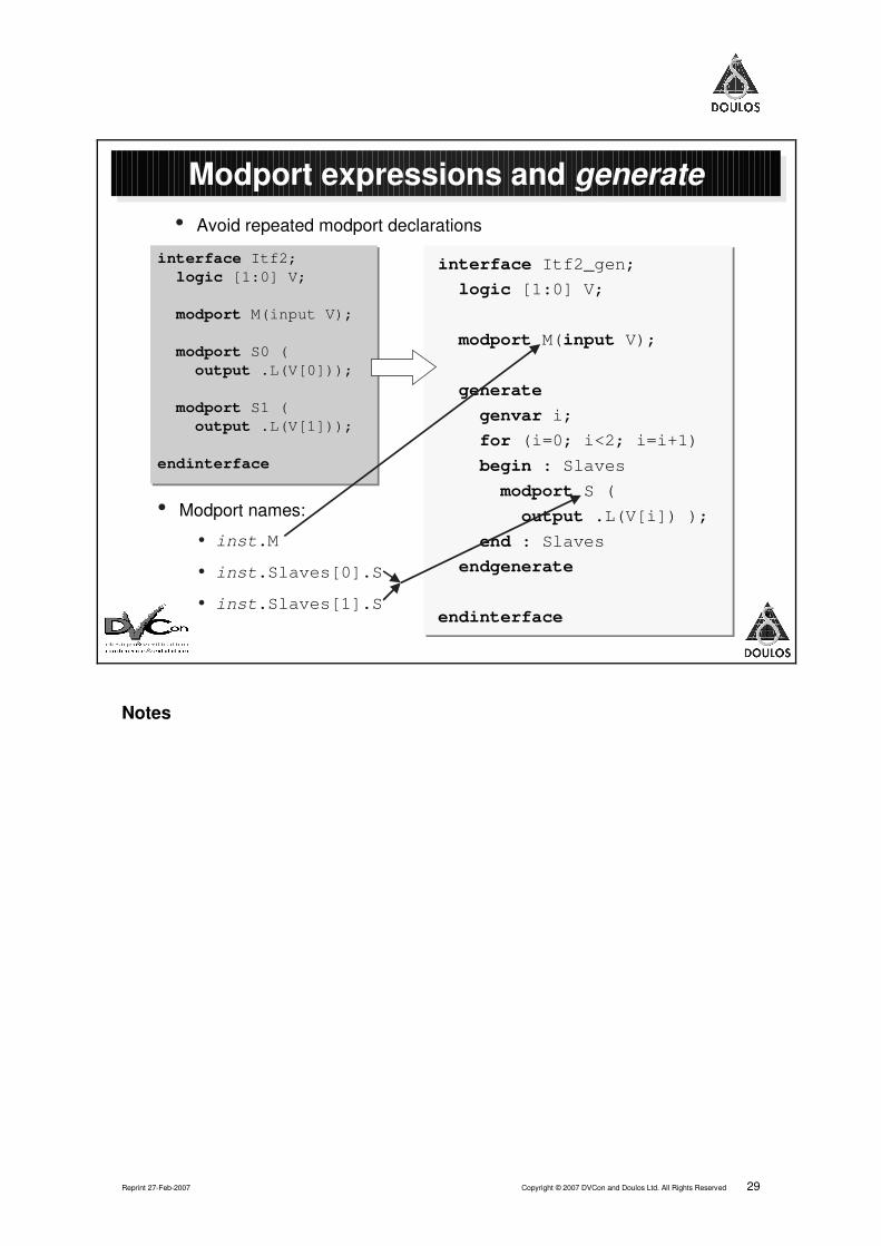
Modport expressions and generate
The previous page showed modport expressions being used to create aspecialised modport that nevertheless has the standard signal names from thepoint of view of a connected module. Using the generate construct we can goeven further, and allow extensive parameterisation of the interface; modportscan be created in a generate construct.
We have kept the example very simple, but you can easily see how this idea canbe combined with the use of parameters to make very flexible interfaces thathave a configurable number of modports.
There is a little difficulty about the names of these generated modports, becausethe generate construct creates a new scope. The slide shows how thegenerated modports' names are determined. On the next page we will see howto make use of these strangely-named modports.
But there is some bad news:
No current SystemVerilog tools support modports inside a generate construct!
Reprint 27-Feb-2007 Copyright © 2007 DVCon and Doulos Ltd. All Rights Reserved 29
Modport expressions and generate
interface Itf2; logic [1:0] V;
modport M(input V);
modport S0 ( output .L(V[0]));
modport S1 ( output .L(V[1]));
endinterface
interface Itf2; logic [1:0] V;
modport M(input V);
modport S0 ( output .L(V[0]));
modport S1 ( output .L(V[1]));
endinterface
• Avoid repeated modport declarations
interface Itf2_gen; logic [1:0] V;
modport M(input V);
generate genvar i;
for (i=0; i<2; i=i+1)
begin : Slaves
modport S (
output .L(V[i]) ); end : Slaves
endgenerate
endinterface
interface Itf2_gen; logic [1:0] V;
modport M(input V);
generate
genvar i; for (i=0; i<2; i=i+1)
begin : Slaves
modport S (
output .L(V[i]) );
end : Slaves
endgenerate
endinterface
• Modport names:
• inst.M
• inst.Slaves[0].S
• inst.Slaves[1].S
Notes

Towards a Practical Design Methodology with SystemVerilog Interfaces and Modports DVCon 2007
30 Copyright © 2007 DVCon and Doulos Ltd. All Rights Reserved Reprint 27-Feb-2007
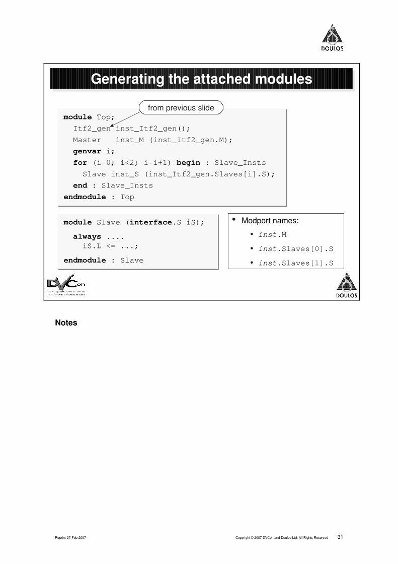
Generating the attached modules
The modules that we will use to connect to the generated modports use aconvenient trick: by specifying a port of type interface.modport_name the
module is saying "I can connect to a modport called modport_name, no matterwhat interface it is in".
We can use another generate loop to construct a collection of connectedmodules, with the genvar iterator participating in the selection of modport foreach module. Once again, this arrangement could easily be parameterised.
Reprint 27-Feb-2007 Copyright © 2007 DVCon and Doulos Ltd. All Rights Reserved 31
Generating the attached modules
• Modport names:
• inst.M
• inst.Slaves[0].S
• inst.Slaves[1].S
module Top;
Itf2_gen inst_Itf2_gen();
Master inst_M (inst_Itf2_gen.M);
genvar i;
for (i=0; i<2; i=i+1) begin : Slave_Insts
Slave inst_S (inst_Itf2_gen.Slaves[i].S);
end : Slave_Insts
endmodule : Top
module Top;
Itf2_gen inst_Itf2_gen();
Master inst_M (inst_Itf2_gen.M);
genvar i;
for (i=0; i<2; i=i+1) begin : Slave_Insts
Slave inst_S (inst_Itf2_gen.Slaves[i].S);
end : Slave_Insts
endmodule : Top
module Slave (interface.S iS);
always .... iS.L <= ...;
endmodule : Slave
module Slave (interface.S iS);
always .... iS.L <= ...;
endmodule : Slave
from previous slidefrom previous slide
Notes

Towards a Practical Design Methodology with SystemVerilog Interfaces and Modports DVCon 2007
32 Copyright © 2007 DVCon and Doulos Ltd. All Rights Reserved Reprint 27-Feb-2007
Address decoding in attached module
The previous few pages have suggested that modports can be specialised bylogic in the interface itself.
It is also possible to perform address decoding, and other specialisations, insidethe connected module. Of course, the module then needs to reflect the resultsof this decoding back into the interface, where it could be used to control amultiplexer for multi-source readback signals such as PRDATA. This is anattractive idea because it suggests that we could make a completely generic busfabric interface, and specialise it by connecting an appropriate set ofparameterised modules.
The example opposite works as it stands, but does not really do all we want.We would prefer to have a completely un-specialised – generic – interface; buthow would that interface gain the correct number and kind of modports? It iseasy to connect any number of modules to the same modport – we discuss thatin more detail on the next page – but then all the modules see exactly the sameset of signals, which doesn't help us with the problem of multi-source signals.
The SystemVerilog language does not provide a clear set of answers to theseproblems, and the author hopes that some enhancements could be made in thefuture to provide modports that in some way can be configured by the modulesthat connect to them.
Meanwhile, we must add a parameter to the interface to specify how manymodports it must have. Clearly this mechanism will not work until we have toolsupport for modport expressions and modports in a generate construct.

Reprint 27-Feb-2007 Copyright © 2007 DVCon and Doulos Ltd. All Rights Reserved 33
Address decoding in attached module
• Requires modport expressions!
module APB_slave ( #(My_Adrs = 24'hDEAD??) ( APB.slave_mp bus, ... );
assign bus.active = (bus.PADDR ==? My_Adrs);
module APB_slave ( #(My_Adrs = 24'hDEAD??) ( APB.slave_mp bus, ... );
assign bus.active = (bus.PADDR ==? My_Adrs);
address range set byparameter on moduleaddress range set byparameter on module
extra connection to interfaceextra connection to interface decoding logicdecoding logic
interface APB #(N_slaves = 1) ( ... );
logic [N_slaves-1:0] decodes; ... genvar i; for (i=0; i<N_slaves; i++) begin : gen_slave_mp modport slave_mp ( output .active(decodes[i]), ... ); end
interface APB #(N_slaves = 1) ( ... );
logic [N_slaves-1:0] decodes; ... genvar i; for (i=0; i<N_slaves; i++) begin : gen_slave_mp modport slave_mp ( output .active(decodes[i]), ... ); end
which slave is active?which slave is active?
Notes
Towards a Practical Design Methodology with SystemVerilog Interfaces and Modports DVCon 2007
34 Copyright © 2007 DVCon and Doulos Ltd. All Rights Reserved Reprint 27-Feb-2007
Singleton modports
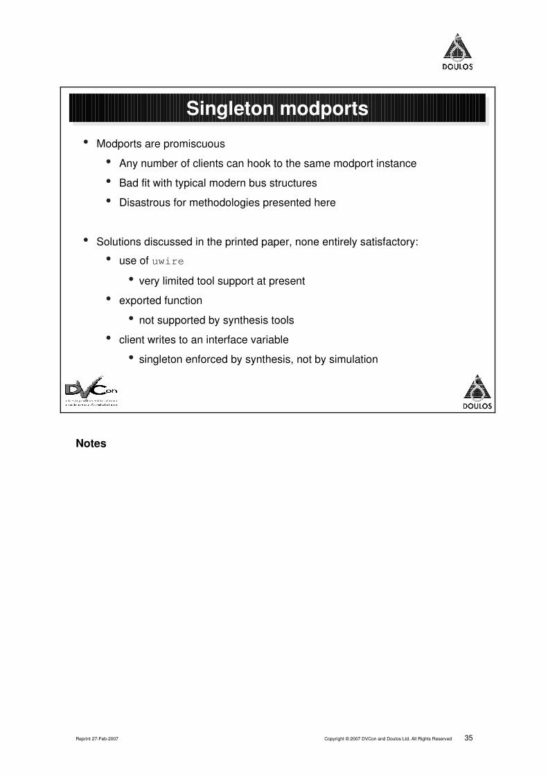
Because of the problems of address decode specialisation and multi-sourcesignals, the approaches presented in the previous few pages are easily broken ifa user inadvertently connects more than one module to the same modport. Theauthor believes that SystemVerilog could benefit from an enhancement allowinga modport to be specified as a singleton, so that at most one module canconnect to it.
The author has had interesting discussions with a colleague who pointed outthat in standard Verilog you would naturally expect to be able to connect anynumber of modules to a single wire, and consequently we should expect thesame of modports. The author's opinion is that modports offer a much morestructured connection scheme than does a wire, and therefore the singletonproperty is valuable. You, gentle reader, must make up your own mind!
In the printed paper, several possible workarounds are discussed; none is totallysatisfactory. During the DVCon conference, Don Mills offered another approachbased on the fact that SystemVerilog permits only one continuous assignment toany variable; the author plans to investigate this in more detail and publish theresults in due course on the Doulos website.
Reprint 27-Feb-2007 Copyright © 2007 DVCon and Doulos Ltd. All Rights Reserved 35
Singleton modports
• Modports are promiscuous
• Any number of clients can hook to the same modport instance
• Bad fit with typical modern bus structures
• Disastrous for methodologies presented here
• Solutions discussed in the printed paper, none entirely satisfactory:
• use of uwire
• very limited tool support at present
• exported function
• not supported by synthesis tools
• client writes to an interface variable
• singleton enforced by synthesis, not by simulation
Notes
Towards a Practical Design Methodology with SystemVerilog Interfaces and Modports DVCon 2007
36 Copyright © 2007 DVCon and Doulos Ltd. All Rights Reserved Reprint 27-Feb-2007
Conclusions
Interfaces are valuable both for modelling and for synthesis using today's tools.The approach suggested on page 20 (bus fabric module with point-to-pointinterfaces) offers a good way to exploit many of their advantages withoutstretching the capabilities of current tools.
Meanwhile, the author hopes that this paper will provide food for thought both forusers and for tool vendors; in particular he looks forward to the availability ofmodport expressions and generated modports in practice.
The lack of support for singleton modports in the SystemVerilog languagerestricts users' ability to build truly robust configurable designs using interfaces.There is further work to do in this area, and such work may perhaps lead tofuture enhancements of the language.
Questions? If you have further questions on this paper, please feel free to email the authorat the address on the front page; he will always endeavour to respond promptly.
AcknowledgementsThe author would like to thank his colleagues for their consistently insightfulsupport, and also the following people for their special contributions:
• Bruce Mathewson of ARM Ltd who brought the "bus fabric module"technique to my attention;
• Cliff Cummings of Sunburst Design Inc., for his careful review of the originalpaper and his enthusiastic encouragement;
• Don Mills of Microchip Technology, Inc for his useful insight concerningsingleton modports.

Reprint 27-Feb-2007 Copyright © 2007 DVCon and Doulos Ltd. All Rights Reserved 37
Conclusions
• Interfaces are synthesizable!
• Interfaces are useful today for point-to-point and multi-drop buses
• Lack of tool support for modport expressions is a disappointment
• They offer great opportunities for bus fabric modelling
• Lack of language support for singleton modports is unfortunate
Questions?Questions?
Notes

Towards a Practical Design Methodology with SystemVerilog Interfaces and Modports DVCon 2007
38 Copyright © 2007 DVCon and Doulos Ltd. All Rights Reserved Reprint 27-Feb-2007
Related Documents


