Towards A More Efficient Quadrotor Configuration Scott Driessens and Paul E. I. Pounds † Abstract— The small rotor sizes of quadrotors and multi- rotors makes them intrinsically less energy efficient than a traditional helicopter with a large single rotor. However, the quadrotor configuration’s innate simplicity and inexpensive construction recommends its use in many aerial robotics appli- cations. We present a four-rotor configuration that merges the simplicity of a quadrotor with the energy efficiency of a heli- copter, while improving manoeuvering rotor bandwidth. This class of aircraft, called a ‘Y4’ or ‘triangular quadrotor’, consists of a single fixed-pitch main rotor with three smaller rotors on booms that provide both counter-torque and manoeuvering control. Our analysis indicates that a Y4 may provide a 20 per cent reduction in hovering power required, compared with a similarly sized conventional quadrotor. Using a matched pair of quadrotor/triangular quadrotor aircraft, our preliminary experiments show that the test-bed Y4 used 15 per cent less power, without optimisation. We present a dynamic model and demonstrate experimentally that the aircraft can be stabilised in flight with PID control. I. I NTRODUCTION Unmanned Aerial Vehicles (UAVs) have stepped out of the realm of academic research and military operations and are rapidly becoming useful in civilian applications. Advances in integrated avionics have driven the cost and complexity of UAVs down, and into the hands of commercial users. There is increasing demand for reliable UAV platforms that can carry large equipment payloads, and have longer flight times and range — particularly for indoor applications. The utility of hovering UAV systems is bounded by available power sources, and the efficiency of transferring that energy to the air via rotors. This restricts the achievable payload, flight time and speed performance, typically to payloads of less than 1 kg or flight times of less than 20 min- utes for vehicles small enough to fly through doorways and around human spaces [1]. Increasing available energy stores correspondingly requires heavier (and thus larger) aircraft that would not fit in small spaces. The energy density of power sources improves slowly — thus, we focus on improving energetic performance of aircraft but maximising the power efficiency of lifting systems. The power a rotorcraft requires to hover scales with the mass being lifted and the area of the rotor [2, p 63]. For this reason, skycranes and cargo helicopters have particularly large diameter rotors [3] or multiple rotors [4] to reduce disc-loading. In contrast, the smaller rotors employed by quadrotors and multirotors are more energy intensive [5]. However a trade-off of helicopters lies in the complex † Corresponding author. This work was supported by the University of Queensland. Scott Driessens is a Bachelor of Engineering graduate and Paul Pounds is a Lecturer in Mechatronics of the University of Queensland, Brisbane, Australia. {firstname.lastname}@uq.edu.au Fig. 1: ‘Y4’ Triangular Quadrotor Configuration. rotorhead mechanics, which are maintenance intensive — quadrotors, conversely, are simple and robust. Our approach is to combine the energetic benefits of a helicopter’s single large rotor with the simplicity of a quadrotor. This is achieved by employing a single large main rotor with three smaller manoeuvering rotors. The small rotors are canted to provide counter-torque like the tail- rotor of a traditional helicopter. By placing the manoeuvering rotors beneath the main rotor, the largest rotor disc area may be realised for a given maximum footprint diameter. Furthermore, the low rotational inertias of the smaller rotors increase the available attitude control bandwidth, but at the cost of increased gyroscopics of the larger rotor [6]. We call this configuration a ‘triangular quadrotor’ or ‘Y4’. Similar multirotor arrangements have been previously developed with an eye towards increasing payload. The SkySapience Hovermast [7] employs a single larger central rotor with smaller outboard rotors, as does the CLQ16 Aerial Platform [8]. These designs are aimed at increasing lift by employing rotors matched to a chemical fuel drive system; they rely on the drag torque of co-linear outboard rotors to provide counter-torque. Their use of numerous outboard rotors (four or more), which require a larger footprint for a given main rotor diameter, reduces the expected achievable efficiency compared with the proposed configuration. To test the anticipated performance improvement of the tri- angular quadrotor, we developed a matched quadrotor and Y4 pair. These aircraft are of identical gross mass, motor mass, footprint diameter, flight controllers, batteries and central airframe. They differ only in the number of boom arms, and the rotor-motor-speed controller combinations being tested. By comparing their performance directly, we can assess the relative merits of the proposed approach. In this paper we describe the improved rotor configuration for hovering multi-rotor robots and compare its energetics to 2013 IEEE/RSJ International Conference on Intelligent Robots and Systems (IROS) November 3-7, 2013. Tokyo, Japan 978-1-4673-6357-0/13/$31.00 ©2013 IEEE 1386

Welcome message from author
This document is posted to help you gain knowledge. Please leave a comment to let me know what you think about it! Share it to your friends and learn new things together.
Transcript

Towards A More Efficient Quadrotor Configuration
Scott Driessens and Paul E. I. Pounds†
Abstract— The small rotor sizes of quadrotors and multi-rotors makes them intrinsically less energy efficient than atraditional helicopter with a large single rotor. However, thequadrotor configuration’s innate simplicity and inexpensiveconstruction recommends its use in many aerial robotics appli-cations. We present a four-rotor configuration that merges thesimplicity of a quadrotor with the energy efficiency of a heli-copter, while improving manoeuvering rotor bandwidth. Thisclass of aircraft, called a ‘Y4’ or ‘triangular quadrotor’, consistsof a single fixed-pitch main rotor with three smaller rotorson booms that provide both counter-torque and manoeuveringcontrol. Our analysis indicates that a Y4 may provide a 20 percent reduction in hovering power required, compared with asimilarly sized conventional quadrotor. Using a matched pairof quadrotor/triangular quadrotor aircraft, our preliminaryexperiments show that the test-bed Y4 used 15 per cent lesspower, without optimisation. We present a dynamic model anddemonstrate experimentally that the aircraft can be stabilisedin flight with PID control.
I. INTRODUCTION
Unmanned Aerial Vehicles (UAVs) have stepped out of therealm of academic research and military operations and arerapidly becoming useful in civilian applications. Advances inintegrated avionics have driven the cost and complexity ofUAVs down, and into the hands of commercial users. Thereis increasing demand for reliable UAV platforms that cancarry large equipment payloads, and have longer flight timesand range — particularly for indoor applications.
The utility of hovering UAV systems is bounded byavailable power sources, and the efficiency of transferringthat energy to the air via rotors. This restricts the achievablepayload, flight time and speed performance, typically topayloads of less than 1 kg or flight times of less than 20 min-utes for vehicles small enough to fly through doorwaysand around human spaces [1]. Increasing available energystores correspondingly requires heavier (and thus larger)aircraft that would not fit in small spaces. The energy densityof power sources improves slowly — thus, we focus onimproving energetic performance of aircraft but maximisingthe power efficiency of lifting systems.
The power a rotorcraft requires to hover scales with themass being lifted and the area of the rotor [2, p 63]. Forthis reason, skycranes and cargo helicopters have particularlylarge diameter rotors [3] or multiple rotors [4] to reducedisc-loading. In contrast, the smaller rotors employed byquadrotors and multirotors are more energy intensive [5].However a trade-off of helicopters lies in the complex
† Corresponding author. This work was supported by the University ofQueensland. Scott Driessens is a Bachelor of Engineering graduate andPaul Pounds is a Lecturer in Mechatronics of the University of Queensland,Brisbane, Australia. [email protected]
Fig. 1: ‘Y4’ Triangular Quadrotor Configuration.
rotorhead mechanics, which are maintenance intensive —quadrotors, conversely, are simple and robust.
Our approach is to combine the energetic benefits ofa helicopter’s single large rotor with the simplicity of aquadrotor. This is achieved by employing a single large mainrotor with three smaller manoeuvering rotors. The smallrotors are canted to provide counter-torque like the tail-rotor of a traditional helicopter. By placing the manoeuveringrotors beneath the main rotor, the largest rotor disc areamay be realised for a given maximum footprint diameter.Furthermore, the low rotational inertias of the smaller rotorsincrease the available attitude control bandwidth, but at thecost of increased gyroscopics of the larger rotor [6]. We callthis configuration a ‘triangular quadrotor’ or ‘Y4’.
Similar multirotor arrangements have been previouslydeveloped with an eye towards increasing payload. TheSkySapience Hovermast [7] employs a single larger centralrotor with smaller outboard rotors, as does the CLQ16 AerialPlatform [8]. These designs are aimed at increasing lift byemploying rotors matched to a chemical fuel drive system;they rely on the drag torque of co-linear outboard rotorsto provide counter-torque. Their use of numerous outboardrotors (four or more), which require a larger footprint for agiven main rotor diameter, reduces the expected achievableefficiency compared with the proposed configuration.
To test the anticipated performance improvement of the tri-angular quadrotor, we developed a matched quadrotor and Y4pair. These aircraft are of identical gross mass, motor mass,footprint diameter, flight controllers, batteries and centralairframe. They differ only in the number of boom arms, andthe rotor-motor-speed controller combinations being tested.By comparing their performance directly, we can assess therelative merits of the proposed approach.
In this paper we describe the improved rotor configurationfor hovering multi-rotor robots and compare its energetics to
2013 IEEE/RSJ International Conference onIntelligent Robots and Systems (IROS)November 3-7, 2013. Tokyo, Japan
978-1-4673-6357-0/13/$31.00 ©2013 IEEE 1386

Fig. 2: Triangular Quadrotor Manoeuvering Controls. Arrow sizes indicaterelative rotor velocities (white arrows are constant).
a ‘matched pair’ conventional quadrotor. In Section III weanalyse the theoretical performance of rotor configurationsfor flight indoors, and consider the effect of rotor size andgyroscopics on control bandwidth. In Section IV we presenta comparative dynamic model and control schema for the Y4configuration with respect to a standard quadrotor. Section Vpresents preliminary power experiments. A brief conclusioncompletes the paper.
II. THE TRIANGULAR QUADROTOR
The proposed configuration is a hybrid between traditionalhelicopters and quadrotors. The configuration uses a singlelarge fixed-pitch rotor at the centre of the craft to providethe majority of lift. Three smaller rotors spaced aroundthe central point on booms, each slightly canted sidewaysat a fixed angle, provide lateral thrust (see Fig. 1). Likethe traditional helicopter, the boom-mounted rotors provideactive counter-torque; like a quadrotor, the rotors providecontrol torques. Unlike a quadrotor, these three smallerdevices are not intended to provide significant lifting thrust.
The manoeuvering moment produced by the counter-torque rotors is derived from their vertical thrust component.Control torques are applied much like standard quadrotors— the speed of one rotor is increased while the othertwo is decreased. This maintains the total counter-torqueproduced in the plane, whilst producing an asymmetry inthe vertical thrust components (see Fig. 2). This causesthe rotorcraft to pitch or roll in the air in an identicalfashion to standard quadrotors. Yaw control is derived akinto traditional helicopters — the combined counter-torque ofthe boom-mounted rotors is increased or decreased to affectazimuthal rotation.
As a rotorcraft with four fixed-pitch rotors, the Y4 con-figuration technically remains a quadrotor and preserves itsmechanical simplicity, while also delivering the full area oflifting surface provided by a helicopter. The counter-torquerotors can be mounted outboard of the main rotor or aboveor below it. Outboard motors provide more effective torquefor lower thrust (but with longer boom arms), while under orover mounted rotors allow the design to be made maximally
compact. Furthermore, the counter-torque rotors all spin thesame direction, reducing the limitation of requiring matchedforward and contra-rotating pairs and increasing flexibilitywhen designing with commercial off-the-shelf parts.
III. ROTOR ENERGETICS AND INERTIA
There are two broad areas of interest in the performance ofquadrotors: energetic performance and control performance.Energetics determines the achievable flight time, range andpayload weight an aircraft can carry, while control de-termines its ability to manoeuver and reject disturbances.This paper predominantly considers the energetics of thetriangular quadrotor configuration, but a control model is alsopresented with references to conventional quadrotor design.
A. Quadrotors vs Traditional Helicopter
From momentum theory, the power required by a rotor,P , is linked to the desired thrust [9, p22]:
P =T 3/2
√2ρA
(1)
where T is the hover thrust, ρ is the density of air, and A isthe rotor disc area. For a traditional helicopter, T is weightforce of the aircraft and the effective area of the rotor will bethe region swept by the rotor disc, less the region obscuredby the fuselage and tail boom. A traditional helicopter alsopays a 5 to 30 per cent power overhead for its tail rotorto provide counter-torque that offsets the drag torque of themain rotor [10].
In contrast, for a quadrotor, the thrust force on eachrotor is one quarter of the whole. For a given footprintdiameter, the area of the rotors is that of four discs inscribedin the bounding circle. However, interactions of the bladevortices generated by rotors require greater spacing betweenthem; a rule of thumb is
√2 times rotor radius [11], [12].
Consequently, there is substantially less lifting area availableto a conventional quadrotor than a helicopter1.
Consider a traditional helicopter and a quadrotor, withequal mass, each designed to fit within a unit diametercircular footprint. Assume both have equal fuselage cross-section, such that the entirety of the fuselage exists outsideof the quadrotor rotor discs — which are spaced to avoidvortex interaction (see Fig. 3) — but which negates an equalarea under the helicopter rotor. The effective rotor disc areaavailable to the helicopter will be 0.732 units2; the total rotordisc area available to the quadrotor will be 0.428 units2.
Consequently, from (1), the total lifting power requiredby the quadrotor will be 1.31 times that of the traditionalhelicopter — almost a third more. Adding 15 per centparasitic power overhead required for a traditional tailrotor,the power saved is approximately 25 per cent. Thus, aquadrotor may be expected to fly only 80 per cent as faror as long as a traditional helicopter UAV.
1Not all rotorcraft follow this rule; some tandem helicopters spacetheir rotors closer, or even overlapping, at the expense of higher powerrequirements [2, p 108]
1387
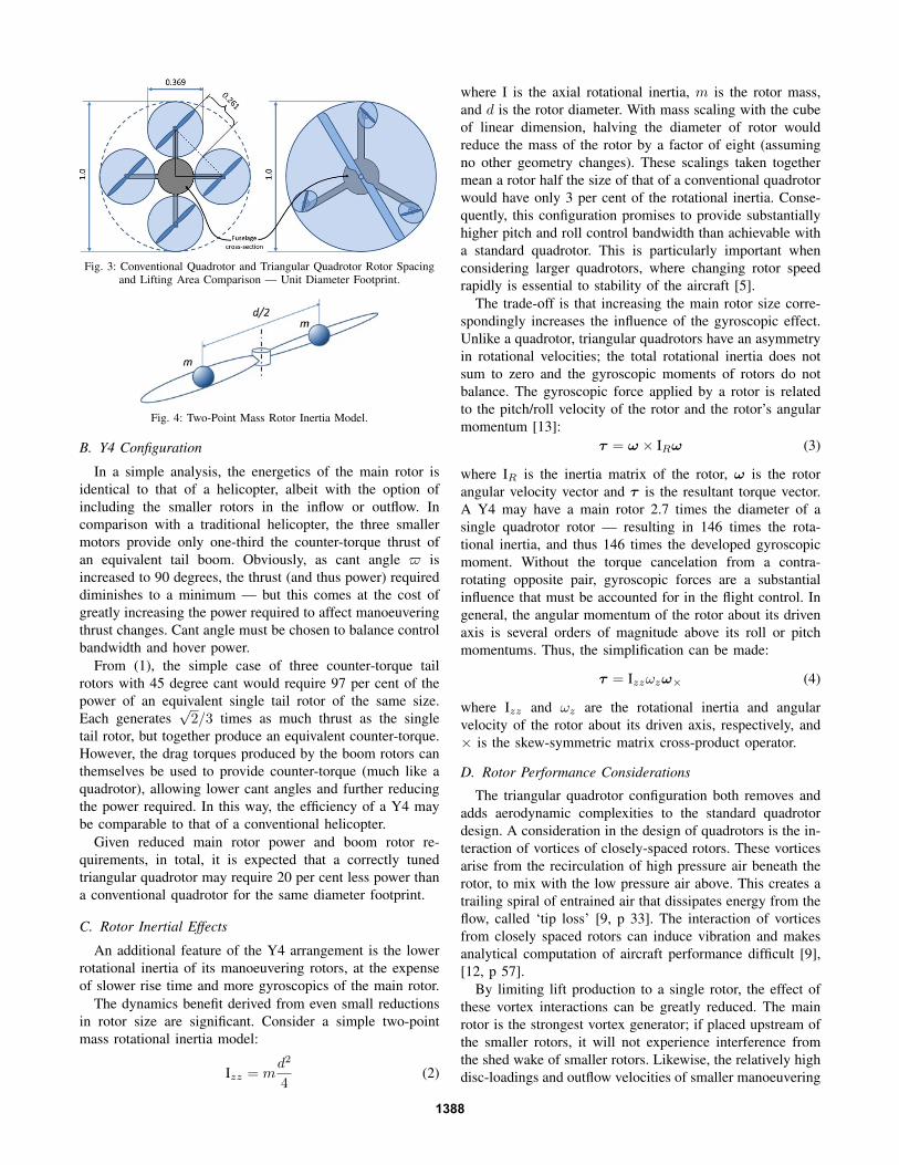
Fig. 3: Conventional Quadrotor and Triangular Quadrotor Rotor Spacingand Lifting Area Comparison — Unit Diameter Footprint.
Fig. 4: Two-Point Mass Rotor Inertia Model.
B. Y4 Configuration
In a simple analysis, the energetics of the main rotor isidentical to that of a helicopter, albeit with the option ofincluding the smaller rotors in the inflow or outflow. Incomparison with a traditional helicopter, the three smallermotors provide only one-third the counter-torque thrust ofan equivalent tail boom. Obviously, as cant angle $ isincreased to 90 degrees, the thrust (and thus power) requireddiminishes to a minimum — but this comes at the cost ofgreatly increasing the power required to affect manoeuveringthrust changes. Cant angle must be chosen to balance controlbandwidth and hover power.
From (1), the simple case of three counter-torque tailrotors with 45 degree cant would require 97 per cent of thepower of an equivalent single tail rotor of the same size.Each generates
√2/3 times as much thrust as the single
tail rotor, but together produce an equivalent counter-torque.However, the drag torques produced by the boom rotors canthemselves be used to provide counter-torque (much like aquadrotor), allowing lower cant angles and further reducingthe power required. In this way, the efficiency of a Y4 maybe comparable to that of a conventional helicopter.
Given reduced main rotor power and boom rotor re-quirements, in total, it is expected that a correctly tunedtriangular quadrotor may require 20 per cent less power thana conventional quadrotor for the same diameter footprint.
C. Rotor Inertial Effects
An additional feature of the Y4 arrangement is the lowerrotational inertia of its manoeuvering rotors, at the expenseof slower rise time and more gyroscopics of the main rotor.
The dynamics benefit derived from even small reductionsin rotor size are significant. Consider a simple two-pointmass rotational inertia model:
Izz = md2
4(2)
where I is the axial rotational inertia, m is the rotor mass,and d is the rotor diameter. With mass scaling with the cubeof linear dimension, halving the diameter of rotor wouldreduce the mass of the rotor by a factor of eight (assumingno other geometry changes). These scalings taken togethermean a rotor half the size of that of a conventional quadrotorwould have only 3 per cent of the rotational inertia. Conse-quently, this configuration promises to provide substantiallyhigher pitch and roll control bandwidth than achievable witha standard quadrotor. This is particularly important whenconsidering larger quadrotors, where changing rotor speedrapidly is essential to stability of the aircraft [5].
The trade-off is that increasing the main rotor size corre-spondingly increases the influence of the gyroscopic effect.Unlike a quadrotor, triangular quadrotors have an asymmetryin rotational velocities; the total rotational inertia does notsum to zero and the gyroscopic moments of rotors do notbalance. The gyroscopic force applied by a rotor is relatedto the pitch/roll velocity of the rotor and the rotor’s angularmomentum [13]:
τ = ω × IRω (3)
where IR is the inertia matrix of the rotor, ω is the rotorangular velocity vector and τ is the resultant torque vector.A Y4 may have a main rotor 2.7 times the diameter of asingle quadrotor rotor — resulting in 146 times the rota-tional inertia, and thus 146 times the developed gyroscopicmoment. Without the torque cancelation from a contra-rotating opposite pair, gyroscopic forces are a substantialinfluence that must be accounted for in the flight control. Ingeneral, the angular momentum of the rotor about its drivenaxis is several orders of magnitude above its roll or pitchmomentums. Thus, the simplification can be made:
τ = Izzωzω× (4)
where Izz and ωz are the rotational inertia and angularvelocity of the rotor about its driven axis, respectively, and× is the skew-symmetric matrix cross-product operator.
D. Rotor Performance Considerations
The triangular quadrotor configuration both removes andadds aerodynamic complexities to the standard quadrotordesign. A consideration in the design of quadrotors is the in-teraction of vortices of closely-spaced rotors. These vorticesarise from the recirculation of high pressure air beneath therotor, to mix with the low pressure air above. This creates atrailing spiral of entrained air that dissipates energy from theflow, called ‘tip loss’ [9, p 33]. The interaction of vorticesfrom closely spaced rotors can induce vibration and makesanalytical computation of aircraft performance difficult [9],[12, p 57].
By limiting lift production to a single rotor, the effect ofthese vortex interactions can be greatly reduced. The mainrotor is the strongest vortex generator; if placed upstream ofthe smaller rotors, it will not experience interference fromthe shed wake of smaller rotors. Likewise, the relatively highdisc-loadings and outflow velocities of smaller manoeuvering
1388

rotors reduce the influence of a non-uniform shed vortexsheet in the outflow of a large rotor. Placing these smallerrotors around the vena contracta of the main rotor wouldfurther insulate them still, but require substantial verticalspacing [2, p 101].
IV. DYNAMIC MODELING AND CONTROL
With two key exceptions, the flight control and stabili-sation of a Y4 quadrotor is identical to that of a standardquadrotor. Both types of aircraft can be considered as rigidbody systems with rotors acting as force-torque generators.We first present a model for a standard quadrotor, and thendescribe how that of the triangular quadrotor differs.
A. A Standard Quadrotor ModelA common quadrotor dynamic model expressed in the
body-fixed frame is [14]2:
ξ = Rv (5)mv = −mΩ×v +mgR′e3 + Te3 (6)R = RΩ× (7)
IΩ = −Ω×IΩ + Γ (8)
where ξ is the vehicle position, R is the attitude rotationmatrix, v is the body velocity, Ω is the rigid body rotationalvelocity vector, m and I are the mass and rotational inertiamatrix of the flyer, g is acceleration due to gravity and Tand Γ are the total rotor thrust and torque vectors.
The thrust and torque of each individual rotor is modeledusing the Blade Element Method thrust and torque equations[9, p 17]. For the ith rotor:
Ti =1
4CT ρA(dωi)
2 (9)
Qi =1
8CQρAd
3ωi|ωi| (10)
Pi =1
8CQρA(dωi)
3 (11)
where Ti, Qi and Pi are the thrust, drag torque and power ofthe rotor, respectively, ρ is the density of air (taken as 1.184kg/m3), A is the planform area of the rotor disc, d is the rotordiameter, and ωi is the axial rotational velocity of the rotor.Here CT and CQ are rotor non-dimensionalised thrust anddrag coefficients, properties that relate the rotational velocityof the rotor to the thrust and torque produced; the torquecoefficient also relates the power required by the rotor at agiven speed. In equation 11, ω is multiplied by its magnitudeto preserve the sign of rotation for counter-rotating rotors.
In these equations, only the rotor velocity is non-constant— they can be simplified to Ti = αω2
i and Qi = κω2i .
Thus, the force-torque mapping of a standard quadrotor canbe summarised by a single matrix relating rotor speed toforces [15]:
TΓ1
Γ2
Γ3
=
α α α α0 −rα 0 rαrα 0 −rα 0κ −κ κ −κ
ω1
2
ω22
ω32
ω42
(12)
2These dynamics can be likewise expressed in the inertial frame [15].
where are rotors are indexed 1–4, clockwise, starting at thefront, and r is the boom arm distance from the centre ofgravity to each rotor centre.
B. Triangular Quadrotor Adaptation
With reference to the above model, the changes made forthe triangular quadrotor are small. Firstly, the rigid bodyangular velocity dynamics must explicitly incorporate theunbalanced gyroscopic contribution τi of each of the rotorsaccording to (4).
IΩ = −Ω×IΩ +∑
τ + Γ (13)
The gyroscopic torques are almost entirely concentrated inthe main rotor — we explicitly ignore the contribution ofthe smaller rotor gyroscopics. Also explicitly ignored are thesmall side forces produced by the boom rotors; T considersonly vertical force contributions.
Secondly, the force-torque mappings of the rotors are quitedifferent and are dependent on $:TΓ1
Γ2
Γ3
=
αC$ αC$ αC$ αM
0 −√32 rαC$
√32 rαC$ 0
rαC$ − 12rαC$ − 1
2rαC$ 0rαS$ rαS$ rαS$ −κM
ω1
2
ω22
ω32
ωM2
(14)
where α and κ and αM and κM are the boom rotor and mainrotor proportional thrust and drag coefficients, respectively.The shorthands Sx and Cx stand for sin(x) and cos(x),respectively.
C. Controllability and Stabilisation
It is well-known that quadrotors perform well in hoverunder linear PID control [16]. The control mapping matricesof quadrotors given in (12) is full rank and invertible, as isthe case for triangular quadrotors in (14), given non-singularboom rotor cant angles (0 < $ < π/2). This allows for fullindependent control of roll, pitch and yaw torques and thrust.The control structure of a Y4 could therefore be expected tobe very similar to that of a standard quadrotor, barring theeffect of the main rotor gyroscopics.
Conveniently, the variables on which the gyroscopic forcesdepend — rotor inertia, rotor velocity and roll-pitch rate— are constant physical parameters easily measured offline,or aircraft states sensed online by most flight controllers.This, combined with a well-understood gyroscopic model,recommends a feedback linearisation approach to stabilisingtriangular quadrotors.
A proposed simple control law takes the form of amodified linear PID control with gyroscopic correction:
Γ =
(kp + ki
1
s+ kds
)φθψ
−ωM IMzz
0 s 0−s 0 00 0 0
φθψ
(15)
where φ, θ and ψ are the roll, pitch and yaw angles of thecraft, and kp, ki and kd are control gains identical to thoseof a standard quadrotor of the same size and weight.
1389

An additional advantage of the triangular configuration isimproved yaw performance. The value of κ for a standardquadrotor is typically very small, and the near cancellationof rotor drag forces in hover results in low yaw controlauthority. In contrast, the magnitude of rα cos$ for the Y4are larger and work together, rather than cancel; they mayprovide as similar degree of yaw control as a conventionalhelicopter.
V. EXPERIMENTS
We have undertaken preliminary analysis of the pre-dictions of the energetic and control performance of thetriangular quadrotor configuration. The large number ofvariables involved in the design of a quadrotor of eitherconfiguration makes a direct comparison difficult. To explorethe relative merits of the proposed design, two quadrotorswere constructed to be as similar as possible, within thelimits of their differing rotor configurations — a standard‘control’3 quadrotor and Y4 testbed. These were then testedin static tests to compare their thrust performance and energyconsumption. The triangular quadrotor was also flown toascertain the stability of simple PID flight control. Detailedcomparative control response tests of the triangular quadrotorand standard quadrotor are ongoing, and not presented in thispaper.
A. Comparative Test-Beds
To make as meaningful a comparison as possible betweentwo dissimilar aircraft, both vehicles must be structured alongcommon lines where possible. Both aircraft are designed tobe small sub-kilogram vehicles with 30 per cent thrust mar-gin and fit through a conventional doorway (50 cm diameter).The two test-bed aircraft were specifically designed to keepthe following common parameters identical:• 850 g gross mass• 480 mm footprint diameter• 300 g actuator mass• Chassis hub and arm units• Battery type and capacity• Flight controller
Aside from the motor and rotor size and placement beingtested, the following design parameters were unavoidablydifferent:• Rotor geometry• Motor manufacturers• Electronic speed controller model
Of these non-idealities, the greatest scope for miscomparisonlies in the inability to find performance-matched rotors in thevarious sizes needed. To ameliorate this potential problem,we elected to use a stock rotor tuned for the standard quadro-tor configuration and choose an off-the-shelf variable-pitchconventional rotor for the Y4. The variable-pitch rotor wasthen adjusted to optimise thrust performance. In this way, the‘control’ will derive the most benefit from rotors matched
3Used in the sense of ‘experimental control’ — an unmodified baseline.
Fig. 5: Y4 Triangular Quadrotor and ‘Control’ Standard Quadrotor.
to its aerodynamic requirements, while the performance ofthe Y4 will be conservative. However, it was not possibleto obtain a 250-series rotor with 480 mm rotor diameter;the closest match available was 460 mm. Thus, the controlquadrotor will have a small relative power (approximately9 per cent) advantage due to greater lift area.
The standard quadrotor and Y4 test-beds use identicalmanufacturers for their manoeuvering thruster motors. Theseparts were chosen to provide suitable rotor power whilemaintaining the actuator mass-fraction of the vehicle. Thesame manufacturer was used to reduce potential variationintroduced by different fabrication technology from differentmakers. However, this could not be maintained for the mainrotor of the Y4, as no manufacturer could be found thatproduced both fast, small motors for flight control and alsolarge motors with low flux-linkage coefficient4. Thus, themain rotor motor is of a slightly different design. For similarreasons, it was not possible to entirely use motor controllersthe same manufacturer. However, it is expected that variationin the performance of electronic speed controllers will besmall.
A mass-budget breakdown for the two aircraft is given inTable I.
B. Test-Bed Power Performance
The expected power requirements of the aircraft can bepredicted using (10–11). The non-dimensionalised coeffi-cients for each rotor were determined empirically using afixed thrust test rig (see Fig. 6), and are given in Table II— rotor velocity in hover conditions is denoted ω0 andhover power is P0. A sample static thrust test comparingthe low-end performance of the standard quadrotor rotorsand the Y4 main rotor, both powered by 3-cell LithiumPolymer packs.Current was measured with a Watts-up meterand thrust was measured with a digital scale. These testsindicate that the Y4’s lift rotor produces greater lift thrustper Amp, at the low end of the rotor performance range.
The hover power requirement for the Y4 boom motors isbased on a 30 degree rotor cant; this was determined throughtrial and error to provide good manoeuvering authoritybut also effective low-power counter-torque. In hover, it isexpected that the Y4 will use 77.6 W, while the standardquadrotor test-bed will require 92.8 W of continuous power— almost 20 per cent more.
4Also referred to as the motor’s ‘KV’ — RPM per volt
1390
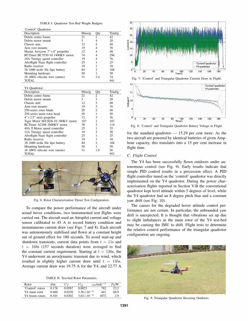
TABLE I: Quadrotor Test-Bed Weight Budgets.
‘Control’ QuadrotorDescription Mass/g Qty Total/gDelrin centre frame 21 2 42Delrin motor mount 5 4 20Chassis arm 12 4 48Arm root mounts 19 4 76Master Airscrew 7”×4” propeller 12 4 48RCTimer BC3530-10 1400KV motor 74 4 29618A Turnigy speed controller 19 4 76Afroflight Naze flight controller 25 1 25Radio receiver 18 1 183S 1000 mAh 30c lipo battery 84 2 168Mounting hardware 50 1 5018 AWG silicone wire (metre) 31 2.4 74TOTAL 941
Y4 QuadrotorDescription Mass/g Qty Total/gDelrin centre frame 21 2 42Delrin motor mount 5 3 20Chassis arm 12 3 48Arm root mounts 19 3 76250-series rotor blade 20 2 40250-series main rotor head 50 1 504”×2.5” mini propeller 12 3 36Tiger Motor MT2826-10 380KV motor 187 1 187RCTimer A2208 2600KV motor 38 3 11440A T-Motor speed controller 35 1 3512A Turnigy speed controller 10 3 30Afroflight Naze flight controller 25 1 25Radio receiver 18 1 183S 1000 mAh 30c lipo battery 84 2 168Mounting hardware 50 1 5018 AWG silicone wire (metre) 31 1.8 56TOTAL 953
Fig. 6: Rotor Characterisation Thrust Test Configuration.
To compare the power performance of the aircraft underactual hover conditions, two instrumented test flights werecarried out. The aircraft used an Attopilot current and voltagesensor calibrated to 45 A to record battery condition andinstantaneous current draw (see Figs. 7 and 8). Each aircraftwas autonomously stabilised and flown at a constant heightout of ground effect for 180 seconds. To avoid start-up andshutdown transients, current data points from t = 11s andt = 168s (157 seconds duration) were averaged to findthe constant current requirement. Starting at t = 130s, theY4 underwent an aerodynamic transient due to wind, whichresulted in slightly higher current draw until t = 135s.Average current draw was 19.75 A for the Y4, and 22.77 A
TABLE II: Test-bed Rotor Parameters.
Rotor d/m CT CQ ω0/rads−1 P0/W‘Control’ rotors 0.178 0.0587 0.0023 782 23.2Y4 main rotor 0.460 0.0230 3.36×10⁻⁴ 441 68.9Y4 boom rotors 0.101 0.0302 3.62×10⁻⁴ 1872 2.9
Fig. 7: ‘Control’ and Triangular Quadrotor Current Draw in Flight.
Fig. 8: ‘Control’ and Triangular Quadrotor Battery Voltage in Flight.
for the standard quadrotor — 15.29 per cent more. As thetwo aircraft are powered by identical batteries of given Amp-hour capacity, this translates into a 15 per cent increase inflight time.
C. Flight Control
The Y4 has been successfully flown outdoors under au-tonomous control (see Fig. 9). Early results indicate thatsimple PID control results in a precession effect. A PIDflight controller tuned on the ‘control’ quadrotor was directlyimplemented on the Y4 quadrotor. During the power char-acterisation flights reported in Section V-B the conventionalquadrotor kept level attitude within 5 degrees of level, whilethe Y4 quadrotor had an 8 degree pitch bias and a constantyaw drift (see Fig. 10).
The causes for the degraded hover attitude control per-formance are not certain. In particular, the unbounded yawdrift is unexpected. It is thought that vibrations set up dueto slight imbalances in the main rotor of the Y4 test-bedmay be causing the IMU to drift. Flight tests to determinethe relative control performance of the triangular quadrotorconfiguration are ongoing.
Fig. 9: Triangular Quadrotor Hovering Outdoors.
1391

Fig. 10: Quadrotor Outdoor Flight Roll, Pitch and Yaw Angles.
VI. NON-IDEALITIES AND FUTURE WORK
Despite the 15 per cent power improvement in flightperformance, the analytical figures suggest that more gainscan be realised. Non-idealities identified include features par-ticular to the development test-bed, and unmodeled aspects ofthe aeromechanics. Reducing these effects will allow a bettercomparison to be drawn between the two configurations, andalso lead to better Y4 efficiency:• Foremost, the Y4 uses a smaller main rotor footprint
than the ‘control’. This can be fixed by fabricatinglonger rotor blades that precisely match the standardquadrotor.
• Better rotor balancing and vibration isolation for themain rotor will clarify whether the degraded attitudecontrol performance of the Y4 is related to the rotorconfiguration or a side-effect.
• The stock boom rotors and 250-series rotor assemblyof the Y4 can be replaced with custom rotors correctlyoptimised for their flow regimes, such as hyperbolictwist and chord, to maximise lift efficiency and reduceparasitic drag [1].
• It is not known whether interference effects may bearising in the boom rotors due to their location in themain rotor outflow. This can be tested by changingthe inter-rotor spacing and comparing efficiency andattitude control performance.
• Tests must be undertaken to measure and compare therelative attitude control performance of the two test-beds, and the response bandwidth of the Y4 given itsmain rotor gyroscopics.
With these improvements, it is expected that the relativeperformance of the Y4 compared to the ‘control’ will im-prove to be closer to the analytical prediction.
VII. CONCLUSION
We have proposed a configuration of a four-rotor aerialrobot — a quadrotor — that is substantially different from thestandard quadrotor configuration. This approach employs atriangular configuration of manoeuvering rotors with a singlelarge lifting rotor at the centre. It has been shown analyticallythis the large central rotor of the triangular quadrotor config-uration offers up to 25 per cent power improvement over the
smaller rotors of a standard quadrotor with the same footprintdiameter (comparable to the benchmark power efficiency ofa conventional helicopter). The smaller manoeuvering rotorsof the Y4 also have the potential to provide faster responsetimes and higher control bandwidth at the expense of strongergyroscopics of the main rotor.
Using a matched-pair of standard and Y4 quadrotor test-beds, we found that the Y4 could deliver a 15 per centpower improvement in autonomous hover power tests, evenwith a slight disadvantage in main rotor size and withoutaerodynamic rotor optimisation. The triangular quadrotorwas able to be stabilised using simple PID flight control, butwith degraded attitude tracking performance and unboundedyaw drift. Future work will examine the control issues withthe current Y4 test-bed and attempt to resolve non-idealitiesin the design and this is expected to lead to further gainsover the conventional quadrotor configuration.
VIII. ACKNOWLEDGMENTS
The authors would like to thank Dan Bersak for his helpfuldiscussion related to this work.
REFERENCES
[1] P. Pounds, R. Mahony and P. Corke, “Design of a Static Thrusterfor Micro Air Vehicle Rotorcraft”, Journal of Aerospace Engineering,Vol. 22, No. 1, pp. 85-94, 2009.
[2] J. G. Leishman, Principles of Helicopter Aerodynamics, 2nd Ed.,Cambridge University Press, New York, 2006.
[3] Aviastar, “Kellett-Hughes XH-17 ‘Flying Crane”’, http://www.aviastar.org/helicopters_eng/mcdonnel_crane.php(2013).
[4] Army.mil, “Chinook Factfile”, http://www.army.mil/factfiles/equipment/aircraft/chinook.html (2013).
[5] P. Pounds and R. Mahony, “Small-Scale Aeroelastic Rotor Simula-tion, Design and Fabrication”, In Proc. Australasian Conference onRobotics and Automation, 2005.
[6] P. Pounds, R. Mahony and P. Corke, “System Identification andControl of an Aerobot Drive System”, In Proc. Information, Decisionand Control, 2007.
[7] SkySapience, “Hovermast,” http://skysapience.com/products/the-hovermast (2012).
[8] A. Zaitsevsky, “Method of controlling a helicopter with six ormore rotors”, http://lamat.me/patents/LT2012007-en.pdf (2012).
[9] R. Prouty, Helicopter Performance, Stability, and Control, KriegerPublishing Company, 2002.
[10] P. Cantrell, “Helicopter Aviation”, http://www.copters.com/aero/torque.html (2013).
[11] S. Green, “Design of an X-4 Flyer”, Australian National UniversityDept. Engineering Honours Thesis, 2003.
[12] D.A. Griffiths and J. G. Leishman, “Dual-rotor interference and groundeffects using a free-vortex wake model”, In Proc. 58th Annual Forumand Technology Display of the American Helicopter Assoc., 2002.
[13] N. Guenard, T. Hamel and V. Moreau, “Dynamic Modeling andIntuitive Control Strategy for an ‘X4-Flyer”. In Proc. InternationalConference on Control and Automation, 2005.
[14] P. Pounds, R. Mahony, P. Hynes and J. Roberts, “Design of a Four-Rotor Aerial Robot”, In Proc. of Australasian Conference on Roboticsand Automation, 2002.
[15] T. Hamel, R. Mahony, R. Lozano and J. Ostrowski, “Dynamic Mod-elling and Configuration Stabilization for an X4-Flyer”, In Proc. 15thTriennial World Congress of the International Federation of AutomaticControl, 2002.
[16] S. Bouabdallah, A. Noth and R. Siegwart, “PID vs LQ Control Tech-niques Applied to an Indoor Micro Quadrotor”, In Proc. IEEE/RSJInternational Conference on Intelligent Robots and Systems, 2004.
1392
Related Documents