© 2013 IEEE. Personal use of this material is permitted. Permission from IEEE must be obtained for all other uses, in any current or future media, including reprinting/republishing this material for advertising or promotional purposes, creating new collective works, for resale or redistribution to servers or lists, or reuse of any copyrighted component of this work in other works. Digital Object Identifier (DOI): 10.1109/MIE.2013.2252958 IEEE Industrial Electronics Magazine, Vol. 7, No. 2, pp. 17-26, June 2013. Toward Reliable Power Electronics: Challenges, Design Tools, and Opportunities Huai Wang Marco Liserre Frede Blaabjerg Suggested Citation H. Wang, M. Liserre, and F. Blaabjerg, "Toward reliable power electronics: challenges, design tools, and opportunities," IEEE Industrial Electronics Magazine, vol. 7, no. 2, pp. 17-26, Jun. 2013.

Welcome message from author
This document is posted to help you gain knowledge. Please leave a comment to let me know what you think about it! Share it to your friends and learn new things together.
Transcript
© 2013 IEEE. Personal use of this material is permitted. Permission from IEEE must be obtained for all other uses, in any current or future media, including reprinting/republishing this material for advertising or promotional purposes, creating new collective works, for resale or redistribution to servers or lists, or reuse of any copyrighted component of this work in other works. Digital Object Identifier (DOI): 10.1109/MIE.2013.2252958 IEEE Industrial Electronics Magazine, Vol. 7, No. 2, pp. 17-26, June 2013.
Toward Reliable Power Electronics: Challenges, Design Tools, and Opportunities
Huai Wang Marco Liserre Frede Blaabjerg Suggested Citation
H. Wang, M. Liserre, and F. Blaabjerg, "Toward reliable power electronics: challenges, design tools, and opportunities," IEEE Industrial Electronics Magazine, vol. 7, no. 2, pp. 17-26, Jun. 2013.
Toward Reliable Power Electronics
Huai Wang, Member, IEEE, Marco Liserre, Fellow, IEEE, Frede Blaabjerg, Fellow, IEEE
I. Introduction
A new era of power electronics was created with the invention of Thyristor in 1957.
Since then, the evolution of modern power electronics has witnessed its full potential and fast
expanding in the applications of generation, transmission, distribution and end-user
consumption of electrical power. Performance of power electronic systems, especially in
terms of efficiency and power density, has been continuously improved by taking advantage
of the intensive research and advancement in circuit topologies, control schemes,
semiconductors, passive components, digital signal processors and system integration
technologies.
In recent years, automotive and aerospatiale industries have brought stringent
reliability constraints also on power electronic systems because of safety requirements. Also
industrial and energy sector are following the same trend and more and more efforts are
devoted to better power electronic systems to account for reliability with cost-effective and
sustainable solutions. Figure 1 shows the product drivers and research trends for more
cost-effective and reliable power electronic systems. Better understanding on reliability of
power electronic components, converters and systems will alleviate the challenges posed in
both reliability critical applications and cost sensitive applications. Figure 2 describes a
general optimization curve to define the reliability specification of a product in terms of
achieving minimum life cycle cost, in which the impact of reliability on customer satisfaction
and brand value are not taken into account. The cost to correct the deficiencies in the design
phase is progressively increased as the product development proceeds. High failure rate
during the field operation will also cause high maintenance cost.
1
Reliability of power electronics involves multiple disciplines. It is similar with
power electronics itself, which also involves a combination of technologies. In 1974,
William E. Newell defined the scope of power electronics based on three of the major
disciplines of electrical engineering shown in Figure 3(a). Almost four decades later, from
the authors’ perspective, the scope of reliability of power electronics is defined in Figure
3(b). It covers the following three major aspects: analytical analysis to understand the
nature of why and how power electronic products fail; design for reliability process to build
in reliability and sufficient robustness in power electronic products during each development
process; accelerated testing and condition monitoring to perform robustness validation and
ensure reliable field operation. A university-industry collaborated center named of Center
of Reliable Power Electronics (CORPE) at Aalborg University, Denmark, is making efforts to
promote the move toward reliable power electronics and extend the scope of power
electronics that has been defined since 1974.
The aim of this article is to give a brief description of the reliability of power
electronics and review the state-of-the-art research on more reliable power electronics.
Challenges, design tools and opportunities for achieving more reliable power electronics are
discussed in the following three sections, respectively.
II. Reliability Challenges in Power Electronics
Reliability is defined as the ability of an item to perform required function under
stated conditions for a certain period of time, which is often measured by probability of
failure, frequency of failure, or in terms of availability [1]. The essence of reliability
engineering is to prevent the creation of failures. The reliability challenges in power
electronics could be considered from different perspectives, such as the trends for high power
density products, emerging high temperature applications and reliability-critical applications
as illustrated in Fig. 1, increasing electrical and electronic complexity, resource-consuming
2
verification testing and so on. The authors here discuss the challenges from experiences in
the field operations and shortcomings of the general practice applied in reliability research on
power electronics.
Field experiences reveal that power electronic converters are usually one of the most
critical parts in terms of failure rate, lifetime and maintenance cost. Various examples in the
wind power and photovoltaic systems have been discussed in [2].
Industries have advanced the development of reliability engineering from traditional
testing for reliability to Design for Reliability (DFR) [3]. DFR is the process conducted
during the design phase of a component or system that ensures them to be able to achieve the
required level of reliability. It aims to understand and fix the reliability problems up-front in
the design process. Accordingly, many efforts have been devoted to considerations into the
reliability aspect performance of power electronic components [4]-[5], converters [6]-[8] and
systems [9]-[10]. However, the reliability research in the area of power electronics has the
following limitations:
Lack of systematic DFR approach specific for design of power electronic systems. The
DFR approach studied in reliability engineering is too broad in focus [3]. Power
electronic systems have their own challenges and new opportunities in improving the
reliability, which is worthwhile to be investigated. Moreover, design tools, except for
the reliability prediction, are rarely applied in state-of-the-art research on reliability of
power electronic systems.
Over reliance on calculated value of Mean-Time-To-Failure (MTTF) or
Mean-Time-Between-Failures (MTBF) and bathtub curve [11]. Bathtub curve
divides the operation of a device or system into three distinct time periods. Although
it is approximately consistent with some practical cases, the assumptions of “random”
failure and constant failure rate during the useful life period are misleading [11] and
3
the true root causes of different failure modes are not identified. The fundamental
assumptions of MTTF or MTBF are constant failure rate and no wear out. Therefore,
the calculated values may have high degree of inaccuracy if wear out occurs within the
time. Moreover, MTTF represents the time when 63.2% of the items (under constant
failure rate condition) would fail and varies with operation conditions and testing
methods [12].
Over reliance on handbook-based models and statistics. Military handbook
MIL-HDBK-217F [13] is widely used to predict the failure rate of power electronic
components [7]-[8]. However, temperature cycling, failure rate change with material,
combined environments, supplier variations (e.g. technology and quality) are not
considered. Moreover, as failure details are not collected and addressed, the
handbook method could not give designers insight into the root cause of a failure and
the inspiration for reliability enhancement. Statistics is a necessary basis to deal
with the effects of uncertainty and variability on reliability. However, as the
variation is often a function of time and operating condition, statistics itself is not
sufficient to interpret the reliability data without judgment of the assumptions and
non-statistical factors (e.g. modification of designs, new components, etc.).
III. Reliability Design Tools for Power Electronics
Figure 4 presents a DFR procedure applicable to power electronics design. The
procedure integrates multiple state-of-the-art design tools and designs reliability into each
development process (i.e. concept, design, validation, production and release) of power
electronic products, especially in the design phase. The design of power electronic
converters are mission profile (i.e. a representation of all of the relevant operation and
environmental conditions throughout the full life cycle [14]) based by taking into account large
parametric variations (e.g. temperature ranges, solar irradiance variations, wind speed
4
fluctuations, load changes, manufacturing process, etc.). Several design examples have been
discussed in [15]-[17]. It should be noted that the reliability design of power electronic
systems should consider both hardware and control algorithms. The reliability issues of
different Maximum Power Point Tracking (MPPT) algorithms and implementations for
photovoltaic (PV) inverters are discussed in [10].
It is not the intention of the authors to cover each block diagram shown in Figure 4 in
this article, which has been presented in [2]. Important concepts and design tools are
discussed as follows. A study case on a 2.3 MW wind power converter is also presented to
demonstrate part of the DFR procedure.
A. Physics-of-Failure (PoF) Approach
A paradigm shift in reliability research on power electronics is going on from today’s
handbook based methods to more physics based approaches, which could provide better
understanding of failure causes and design deficiencies, so as to find solutions to improve the
reliability rather than obtaining analytical numbers only. Physics-of-Failure (PoF) approach
is a methodology based on root-cause failure mechanism analysis and the impact of materials,
defects and stresses on product reliability [18]. Failures can be generally classified into two
types caused by overstress and wear out, respectively. Overstress failure arises as a result of
a single load (e.g. over voltage) while wear out failure arises because of cumulative damage
related to the load (e.g. temperature cycling). Compared to empirical failure analysis based
on historical data, the PoF approach requires the knowledge of deterministic science (i.e.
materials, physics and chemistry) and probabilistic variation theory (i.e. statistics). The
analysis involves the mission profile of the component, type of failure mechanism and the
associated physical-statistical model.
B. Load-Strength Analysis
5
The root-cause of failures is load-strength interference. A component fails when the
applied load L (application stress demand) exceeds the design strength S (component stress
capability). The load L here refers to a kind of stress (e.g. voltage, cyclic load, temperature,
etc.) and strength S refers to any resisting physical property (e.g. harness, melting point,
adhesion, etc.) [3]. Figure 5 presents a typical load-strength interference evolving with time.
For most power electronic components, neither load nor strength is fixed, but allocated within
a certain interval which can be presented by a specific probability density function (e.g.
normal distribution). Moreover, the strength of a material or device could be easily
degraded with time. The probability of failure can be obtained by analyzing the overlap
area between the distributions of load and strength, which is based on well-defined and
in-depth understanding of mission profile and component physics.
Since the variations of load and strength cannot be avoided, it is important to perform
robust design and analysis to minimize the effects of variations and uncontrollable factors.
Safety factors/derating, worse case analysis, Six Sigma design, statistical Design of
Experiments (DOE) and Taguchi design approach are the widely applied methods to deal
with variations. It is worthwhile to mention that the Taguchi design approach tests the effect
of variability of both control factors and noise factors (i.e. uncontrollable ones) and uses
signal-to-noise ratios to determine the best combination of parameters, which is different
from the worst case analysis and other methods. Detailed description and comparison of
those methods are well discussed in [19].
C. Reliability Prediction Toolbox
Reliability prediction is an important tool to quantify the lifetime, failure rate and
design robustness based on various source of data and prediction models. Figure 6
presents a generic prediction procedure based on the PoF approach. The toolbox includes
statistical models and lifetime models and various sources of available data (e.g.
6
manufacturer testing data, simulation data and field data, etc.) for the reliability prediction of
individual components and the whole system. The statistical models are well presented in
[3]. The lifetime models for failure mechanisms induced by various types of single or
combined stressors (e.g. voltage, current, temperature, temperature cycling and humidity) are
discussed in [20]-[21]. Temperature and its cycling are the major stressors that affect the
reliability performance, which could be more significant with the trend for high power
density and high temperature power electronic systems. In [2], two models presenting the
impact of temperature and temperature cycling on lifetime are illustrated in detail.
Constant parameters in the lifetime models can be estimated according to the
available testing data. Therefore, the reliability of each critical individual component is
predicted by considering each of its associated critical failure mechanism. To map the
component level reliability prediction to the system level, the system modeling method
Reliability Block Diagram (RBD), Fault-Tree Analysis (FTA) or state-space analysis (e.g.
Markov analysis) is applied as discussed in detail in [9].
D. Study Case on a Wind Power Converter
To demonstrate the DFR approach, a simplified study case on a 2.3 MW wind power
converter is discussed here. The selected circuit topology is a Two-Level Back-to-Back
(2L-BTB) configuration composed of two Pulse-Width-Modulated (PWM)
Voltage-Source-Converters (VSCs). A technical advantage of the 2L-BTB solution is the
relatively simple structure and few components, which contributes to a well-proven robust
and reliable performance. IGBT modules in the converter are focused in this case study as
an example. Other components that could also be reliability critical are not covered here.
Figure 7 presents the procedure to predict the lifetime of the IGBT modules for a given wind
speed profile application. The main steps are illustrated as follows:
Wind speed profile and converter specifications. For illustration purpose, a wind
7
speed profile during a half hour shown in Figure 7 is analyzed. The switching
frequency of the converter is 1950 Hz and DC bus voltage is 1.1 kV. Two kinds of
selections for the IGBT modules used in the grid side converter are analyzed. The
selection I is two 1.6 kA / 1.7 kV 125ºC IGBT in parallel and the selection II is one
2.4 kA / 1.7 kV 150ºC IGBT.
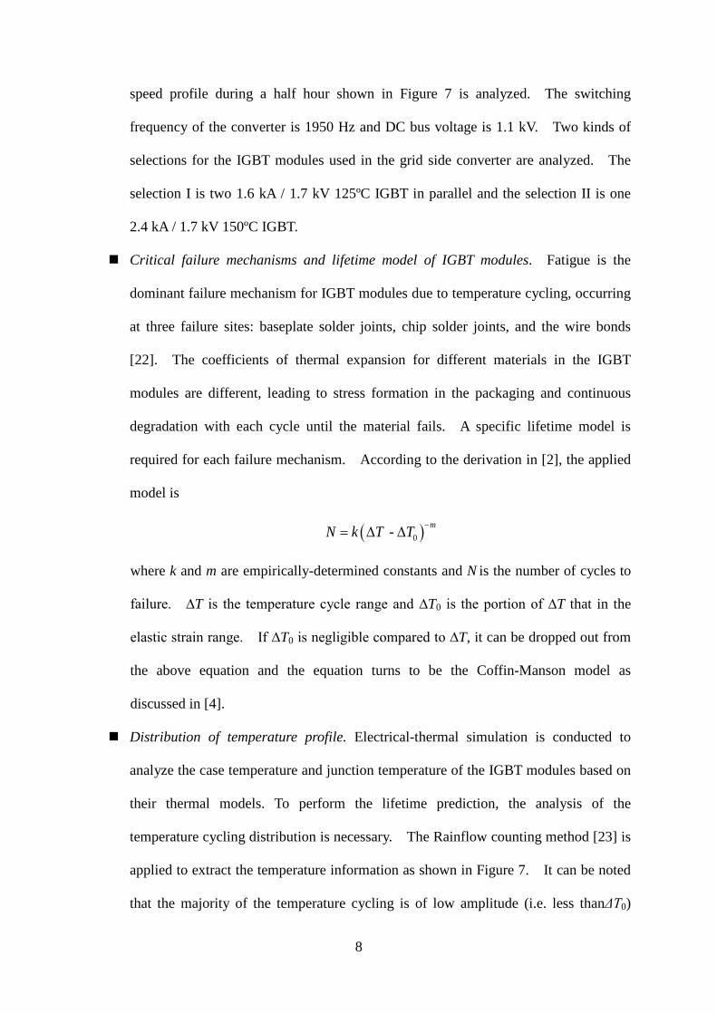
Critical failure mechanisms and lifetime model of IGBT modules. Fatigue is the
dominant failure mechanism for IGBT modules due to temperature cycling, occurring
at three failure sites: baseplate solder joints, chip solder joints, and the wire bonds
[22]. The coefficients of thermal expansion for different materials in the IGBT
modules are different, leading to stress formation in the packaging and continuous
degradation with each cycle until the material fails. A specific lifetime model is
required for each failure mechanism. According to the derivation in [2], the applied
model is
( )0 - -= ∆ ∆ mN k T T
where k and m are empirically-determined constants and N is the number of cycles to
failure. ∆T is the temperature cycle range and ∆T0 is the portion of ∆T that in the
elastic strain range. If ∆T0 is negligible compared to ∆T, it can be dropped out from
the above equation and the equation turns to be the Coffin-Manson model as
discussed in [4].
Distribution of temperature profile. Electrical-thermal simulation is conducted to
analyze the case temperature and junction temperature of the IGBT modules based on
their thermal models. To perform the lifetime prediction, the analysis of the
temperature cycling distribution is necessary. The Rainflow counting method [23] is
applied to extract the temperature information as shown in Figure 7. It can be noted
that the majority of the temperature cycling is of low amplitude (i.e. less thanΔT0)
8
which then has negligible impact on the lifetime.
Parameter estimation of lifetime models. The parameters in the above applied
lifetime model are estimated respectively for baseplate solder joints, chip solder
joints, and the wire bonds based on the lifetime testing data described in [22].
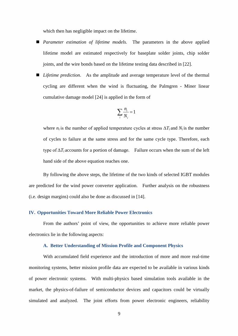
Lifetime prediction. As the amplitude and average temperature level of the thermal
cycling are different when the wind is fluctuating, the Palmgren - Miner linear
cumulative damage model [24] is applied in the form of
1=∑ i
i i
nN
where ni is the number of applied temperature cycles at stress ΔTi and Ni is the number
of cycles to failure at the same stress and for the same cycle type. Therefore, each
type of ΔTi accounts for a portion of damage. Failure occurs when the sum of the left
hand side of the above equation reaches one.
By following the above steps, the lifetime of the two kinds of selected IGBT modules
are predicted for the wind power converter application. Further analysis on the robustness
(i.e. design margins) could also be done as discussed in [14].
IV. Opportunities Toward More Reliable Power Electronics
From the authors’ point of view, the opportunities to achieve more reliable power
electronics lie in the following aspects:
A. Better Understanding of Mission Profile and Component Physics
With accumulated field experience and the introduction of more and more real-time
monitoring systems, better mission profile data are expected to be available in various kinds
of power electronic systems. With multi-physics based simulation tools available in the
market, the physics-of-failure of semiconductor devices and capacitors could be virtually
simulated and analyzed. The joint efforts from power electronic engineers, reliability
9
engineers and physics scientists will enable better understandings of both the components and
the specific conditions they are exposed to.
B. Better Design, Testing and Monitoring Methods
The following methods could be applied to improve the reliability during design,
testing and operation of power electronic systems.
Smart derating of power electronic components and load management.
Investigation into the relationship between failure rate and design margin could
provide a smart derating guideline of power electronic components in terms of the
compromise between cost and reliability as shown in Figure 8(a). It avoids either
over engineering design or lack of robustness margin. Similar concept could be
applied to the output power derating at the converter level or system level.
Fault tolerant design. The design involves redundancy design, fault isolation, fault
detection and on-line repair. In the event of a hardware failure, the redundant unit
will be activated to replace the failed one during the repair interval. The repair of the
failure is on-line and the system operation could be maintained. Fault tolerant
design is widely applied in reliability critical applications to improve system level
reliability as shown in Figure 8(b). Certain types of multi-level inverters and matrix
converters could also have inherent fault tolerant capability without additional
hardware circuitry [9].
Highly Accelerated Limit Testing (HALT). It is a kind of qualitative testing method
to find design deficiencies and extend design robustness margins with the minimum
required number of testing units (typically 4 or 8) in minimum time (typically a week)
[3]. The basic concept of HALT is illustrated in Figure 8(c). The stresses applied
to the testing units are well beyond normal mission profile to find the weak links in
the product design.
10
Diagnosis, prognosis and condition monitoring. These are effective ways for fault
detection or health monitoring to enhance the reliability of power converters which
are under operation [25]. The condition monitoring provides the real-time operating
characteristics of the systems by monitoring specific parameters (e.g. voltage, current,
impedance, etc.) of power electronic components. For example, impedance
characteristics analysis based on Electrochemical Impedance Spectroscopy (EIS) has
been used to monitoring the condition of batteries [26]. To implement EIS, it is
necessary to use spread spectrum signals (e.g. Pseudo Random Binary Signals
(PRBS) [26]-[27]) to excite the system and observe the corresponding response. By
applying prognosis or condition monitoring to power electronic systems, proactive
maintenance work could be planned to avoid failures that would occur. Figure 8(d)
shows an example of a condition monitoring system for wind turbine power
converters.
Reactive power control and thermal optimized modulation. Thermal loading of
switching devices in power electronic converters can be improved by reactive power
control and modified modulation schemes as discussed in [28]-[29]. The power
losses and therefore the thermal stresses on switching devices are reduced.
C. Better Power Electronic Components
Application of more reliable and cost-effective active components and passive
components is another key aspect to improve the reliability of power electronic converters
and systems. With the advances in semiconductor materials, packaging technologies and
film capacitor technologies, the reliability of active switching devices and passive
components is expected to be improved.
Concluding Remarks
More and more efforts have been devoted to alleviate the challenges in reliability
11
critical applications and in reduction of life cycle cost of power electronic systems. A new
paradigm shift is going on from handbook based calculations to more physics based
approaches. This article defines the scope of reliability of power electronics from three
aspects of analytical physics, design for reliability and verification and monitoring. A
state-of-the-art design procedure based on mission profile knowledge, physics-of-failure
approach and design for reliability is presented. The major opportunities toward more
reliable power electronics are addressed. Joint efforts from engineers and scientists in the
multiple disciplines are required to fulfill the defined scope and promote the paradigm shift in
reliability research.
Callout 1
Center of Reliable Power Electronics (CORPE)
CORPE is a strategic research center between the industry and universities, led by
Aalborg University, Denmark. It aims to design more reliable and more efficient power
electronic systems for use in power generation, distribution and consumption.
The center addresses better understanding of how reliability of power electronic
devices and systems is influenced by different stress factors such as temperature, overvoltage
and current, overload and environment. Further, the center will develop device and system
models that will enable simulation and design of power electronic systems very close to the
limits of the devices and enable designed reliability. The knowledge will also be used online
during operation to predict lifetime and enable smart derating of the equipment still in
operation and ensure longer lifetime. The goals will be:
Power electronic systems will be more reliable
More efficient systems
More competitive (price) by reducing maintenance and operation costs
12
Callout 2
Examples of Field Failures in Power Electronic Systems
One example is in the wind turbine application. In wind power generation system,
power electronic converters are dominantly applied for regulating the fluctuating input power
and maximizing the electrical energy harvested from the wind [S1]. In [S2], the operation
of around 350 onshore wind turbines associated with 35,000 downtime events has been
recorded from 10-minute average SCADA (supervisory control and data acquisition ) data,
fault and alarm logs, work orders and service reports, and operation and maintenance (O&M)
contractor reports. It shows that the power electronic frequency converters cause 13% of
the failure rate and 18.4% of the downtime of the monitored wind turbines.
Another example is in the photovoltaic (PV) application. In PV system, PV inverters
are used for efficiently converting the dc voltage for ac applications or integration of the
output energy into electrical grids [S3]. Leading manufacturers nowadays could provide PV
modules with over 20 years of warranty. However, the number is around 5 years for PV
inverters on average in 2012 [S4]. Therefore, even though inverters account only for 10-20%
of the initial system cost, they may need to be replaced 3-5 times over the life of a PV system,
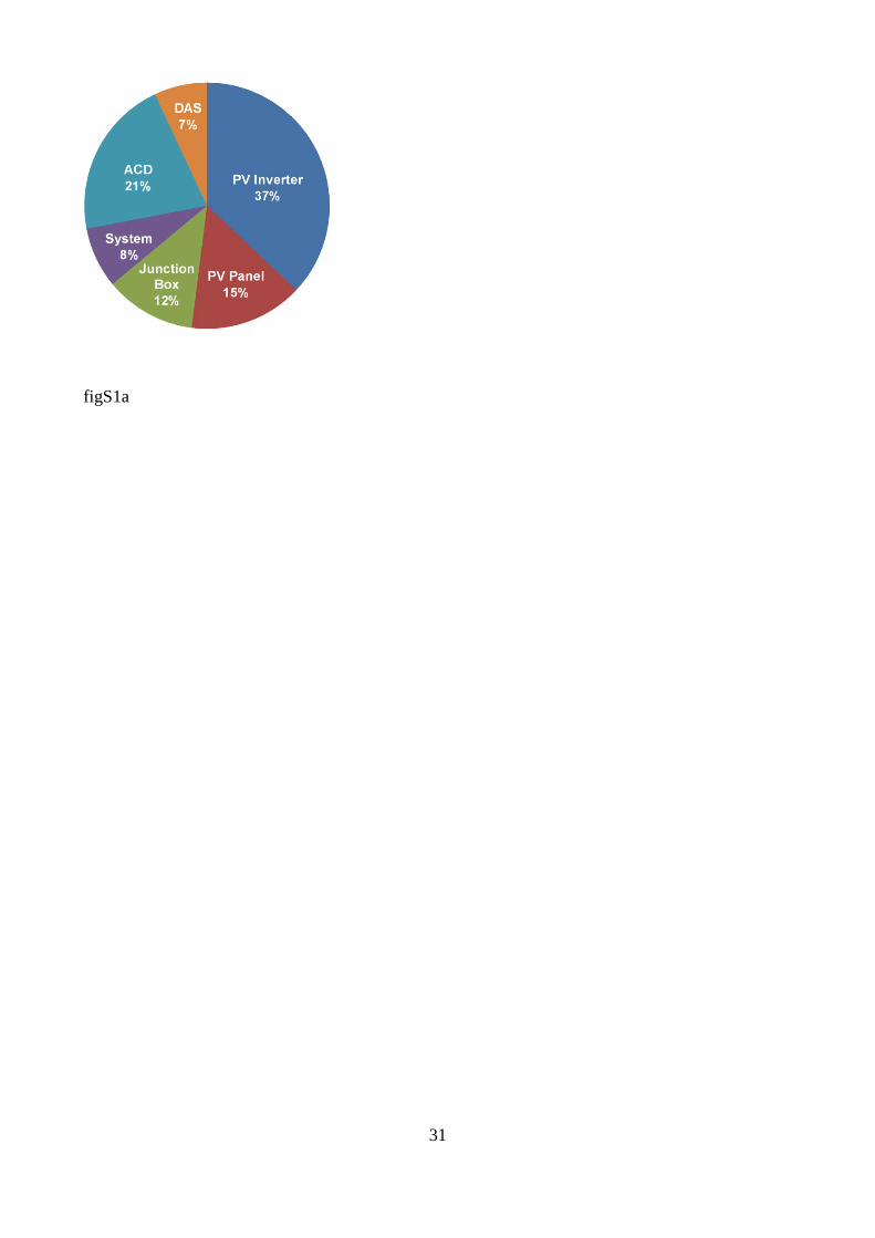
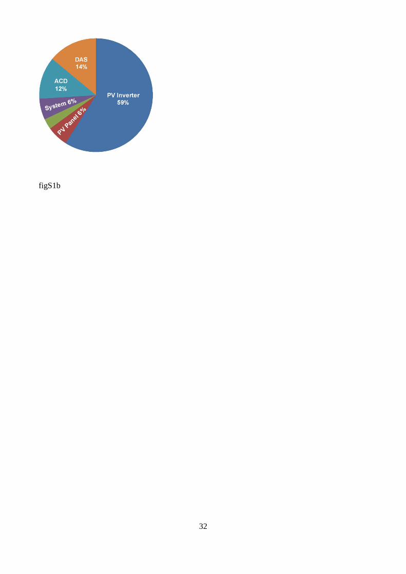
introducing additional investment [S5]. According to the field experiences during 2000 –
2005 in a large utility-scale PV generation plant studied in [S6], the PV inverters are
responsible for 37% of the unscheduled maintenance and 59% of the associated cost as shown
in Figure S1.
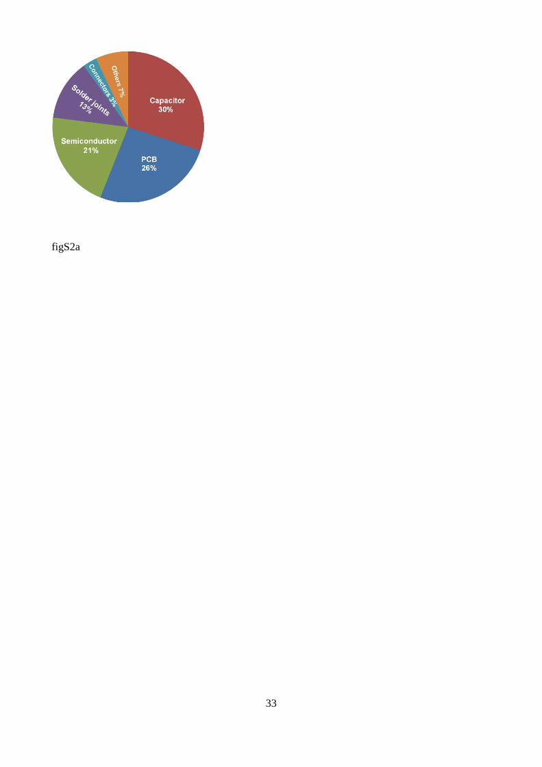
On the component level, semiconductor switching devices (e.g. Insulated Gate Bipolar
Transistor, IGBT) and capacitors are the two types of reliability critical components. Figure
S2 (a) represents a survey in [S7] showing the failure distribution among power electronic
components. It can be noted that capacitors and semiconductors are the most vulnerable
power electronic components, which is also verified by another survey conducted in [S8]. It
13
should be noted that the lifetime of electrolytic capacitors depends on both the rated lifetime at
nominal conditions and the actual experienced stresses in the field operation. Long lifetime
could be achieved with large design margin in terms of voltage, ripple current and temperature,
such as the cases shown in [S9]-[S10]. Therefore, there may be controversial views on the
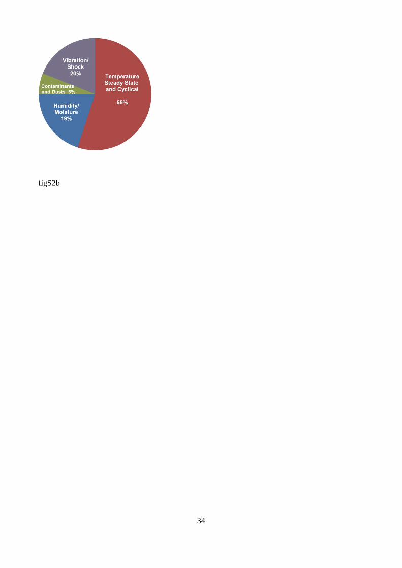
application of electrolytic capacitors in PV inverters as discussed in [S11]. Temperature,
vibration and humidity are the three major of the stressors that directly or indirectly induce
the failures of power electronic components. The US Air Force Avionics Integrity Program
(AVIP) has conducted investigation into the failure sources of electronic equipment in 1980s
and reached the conclusion shown in [S12] and represented in Figure S2 (b), indicating that
temperature is the most dominant stressor.
References
[S1] F. Blaabjerg, M. Liserre, and K. Ma, “Power electronics converters for wind turbine
systems,” IEEE Transactions on Industry Applications, vol.48, no.2, pp.708-719,
Mar-Apr. 2012.
[S2] Reliawind, Report on wind turbine reliability profiles – field data reliability analysis,
2011, online available: http://www.reliawind.eu/files/file-inline/110502_Reliawind_
Deliverable_D.1.3ReliabilityProfilesResults.pdf.
[S3] S. B. Kjaer, J. K. Pedersen, and F. Blaabjerg, “A review of single-phase grid
connected inverters for photovoltaic modules,” IEEE Transactions on Industry
Applications, vol. 41, no. 5, pp. 1292-1306, Sep. 2005.
[S4] M. Schmela, “PHOTON: Inverter survey 2012 stats,” Presentation at the PHOTON’s
3rd PV Inverter Conference, San Francisco, Feb., 2012.
[S5] T. McMahon, G. Jorgensen, and R. Hulstrom, “Module 30 year life: what does it
mean and is it predictable/achievable?” in Proc. of National Center for Photovoltaics
Program Review Meeting, Denver, pp. 16-19, Apr. 2000.
14
[S6] L. M. Moore and H. N. Post, “Five years of operating experience at a large,
utility-scale photovoltaic generating plant,” Journal of Progress in Photovoltaics:
Research and Applications, vol. 16, no. 3, pp. 249-259, 2008.
[S7] E. Wolfgang, “Examples for failures in power electronics systems,” presentation at
ECPE Tutorial on Reliability of Power Electronic Systems, Nuremberg, Germany,
Apr. 2007.
[S8] S. Yang, A. T. Bryant, P. A. Mawby, D. Xiang, L. Ran, and P. Tavner, “An
industry-based survey of reliability in power electronic converters,” IEEE
Transactions on Industry Applications, vol. 47, no. 3, pp. 1441- 1451, May/Jun.,2011.
[S9] J. S. Shaffer, “Evaluation of electrolytic capacitor application in Enphase
microinverters,” Online available: http://enphase.com/wp-uploads/enphase.com/2011/
03/Electrolytic_Capacitor_Expert_Report.pdf.
[S10] M. Fornage, “Reliability study of electrolytic capacitors in a micro-inverter,” Online
available: http://enphase.com/downloads/ElectolyticCapacitorLife092908.pdf.
[S11] G. Petrone, G. Spagnuolo, and M. Vitelli, “Distributed maximum power point
tracking: challenges and commercial solutions,” Automatika, vol. 53, no. 2, pp.
128-141, 2012.
[S12] ZVEL, Handbook for robustness validation of automotive electrical/electronic
modules, Jun. 2008.
15
References
[1] IEEE Standard Framework for the Reliability Prediction of Hardware, IEEE Std. 1413, IEEE,
2009, New York.
[2] H. Wang, K. Ma, and F. Blaabjerg, “Design for reliability of power electronic systems,” in
Proc. of IEEE Industrial Electronics Society Annual Conference (IECON), pp. 33-44, 2012.
[3] P. O'Connor and A. Kleyner, Practical reliability engineering, the 5th edition, John Wiley &
Sons, ch.2, ch. 4 and ch. 7, 2012, ISBN: 978-0-470-97982-2.
[4] C. Busca, R. Teodorescu, F. Blaabjerg, S. Munk-Nielsen, L. Helle, T. Abeyasekera, and P.
Rodriguez, “An overview of the reliability prediction related aspects of high power IGBTs
in wind power applications,” Journal of Microelectronics Reliability, vol. 51, no. 9-11, pp.
1903-1907, 2011.
[5] A. Testa, S. De Caro, and S. Russo, “A reliability model for power MOSFETs working in
avalanche mode based on an experimental temperature distribution analysis,” IEEE
Transactions on Power Electronics, vol. 27, no.6, pp. 3093-3100, Jun. 2012.
[6] E. Koutroulis and F. Blaabjerg, “Design optimization of transformer-less grid-connected PV
inverters including reliability,” IEEE Transactions on Power Electronics, vol. 28, no. 1, pp.
325-335, Jan. 2013.
[7] C. Rodriguez and G. A. J. Amaratunga, “Long-lifetime power inverter for photovoltaic AC
modules,” IEEE Transactions on Industrial Electronics, vol. 55, no. 7, pp. 2593-2601, Jul.
2008.
[8] F. Chan and H. Calleja, “Reliability estimation of three single-phase topologies in
grid-connected PV systems,” IEEE Transactions on Industrial Electronics, vol. 58, no. 7,
pp. 2683-2689, Jul., 2011.
[9] Y. Song and B. Wang, “Survey on reliability of power electronic systems,” IEEE
Transactions on Power Electronics, vol. 28, no. 1, pp. 591-604, Jan. 2013.
16
[10] G. Petrone, G. Spagnuolo, R. Teodorescu, M. Veerachary, and M. Vitelli, “Reliability issues
in photovoltaic power processing systems,” IEEE Transactions on Industrial Electronics,
vol.55, no.7, pp. 2569-2580, Jul. 2008.
[11] G. A. Klutke, Peter C. Kiessler, and M. A. Wortman, “A critical look at the Bathtub curve,”
IEEE Transactions on Reliability, vol. 52, no. 1, pp. 125-129, Mar., 2003.
[12] M. Krasich, “How to estimate and use MTTF/MTBF would the real MTBF please stand
up?” in Proc. of IEEE Annual Reliability and Maintenance Symposium, pp.353-359, 2009.
[13] Military Handbook: Reliability prediction of electronic equipment, MIL-HDBK-217F, Dec.
2, 1991.
[14] ZVEL, Handbook for robustness validation of automotive electrical/electronic modules, Jun.
2008.
[15] G. Adinolfi, N. Femia, G. Petrone, G. Spagnuolo, and M. Vitelli, “Design of dc/dc
converters for DMPPT PV applications based on the concept of energetic efficiency,”
Transactions of the ASME: Journal of Solar Energy Engineering, vol. 132, May 2010.
[16] S. Aldaco, H. Calleja, F. Chan, and H. Grajales, “Effect of the mission profile on the
reliability of a power converter aimed at photovoltaic applications - a case study,” IEEE
Transactions on Power Electronics, vol. 28, no. 6, pp. 2998-3007, Jun., 2013.
[17] J. Biela, S. Waffler, and J. W. Kolar, “Mission profile optimized modularization of hybrid
vehicle DC/DC converter systems,” in Proceedings of IEEE International Power
Electronics and Motion Control Conference, pp. 1390-1396, 2009.
[18] M. Pecht and A. Dasgupta, “Physics-of-failure: an approach to reliable product
development,” in Proc. of International Integrated Reliability Workshop, pp. 1-4, 1995.
[19] A. Coppola, “Creating robust designs,” DOD Reliability Analysis Center: Selected Topics in
Assurance Related Technology (START), Online available: http://www.theriac.org/pdfs/starts
heets/rbd.pdf.
17
[20] JEP122C, Failure mechanisms and models for semiconductor devices, JEDC Solid State
Technology Association, Mar. 2006.
[21] ZVEL, How to measure lifetime for robustness validation-step by step, Nov. 2012.
[22] ABB Application Note, Load-cycling capability of HiPakTM IGBT modules, 2012.
[23] ASTM International, E1049-85 (2005) Standard practices for cycle counting in fatigue
analysis, 2005.
[24] Miner, M. A., “Cumulative damage in fatigue,” Journal of Applied Mechanics, no. 12,
A159-A164, 1945.
[25] S. Yang, D. Xiang, A. Bryant, P. Mawby, L. Ran, and P. Tavner, “Condition monitoring for
device reliability in power electronic converters: a review,” IEEE Transactions on Power
Electronics, vol. 25, no. 11, pp. 2734-2752, Nov., 2010.
[26] R. Al-Nazer, V. Cattin, M. Montaru, and P. Granjon, “Broadband identification of battery
electrical impedance for HEV,” in Proceedings of Research & Innovation for Transport
Systems of the Future (RITF 2012), Nov. 2012.
[27] B. Miao, R. Zane, and D. Maksimović, “System identification of power converters with
digital control through cross-correlation methods,” IEEE Transactions on Power
Electronics, vol. 20, no. 5, pp. 1093-1099, Sep., 2005.
[28] K. Ma, M. Liserre, F. Blaabjerg, “Reactive power influence on the thermal cycling of
multi-MW wind power inverter” accepted to IEEE Transactions on Industry Applications.
[29] K. Ma, F. Blaabjerg, M. Liserre, “Thermal analysis of multilevel grid side converters for 10
MW wind turbines under low voltage ride through” accepted to IEEE Transactions on
Industry Applications.
18
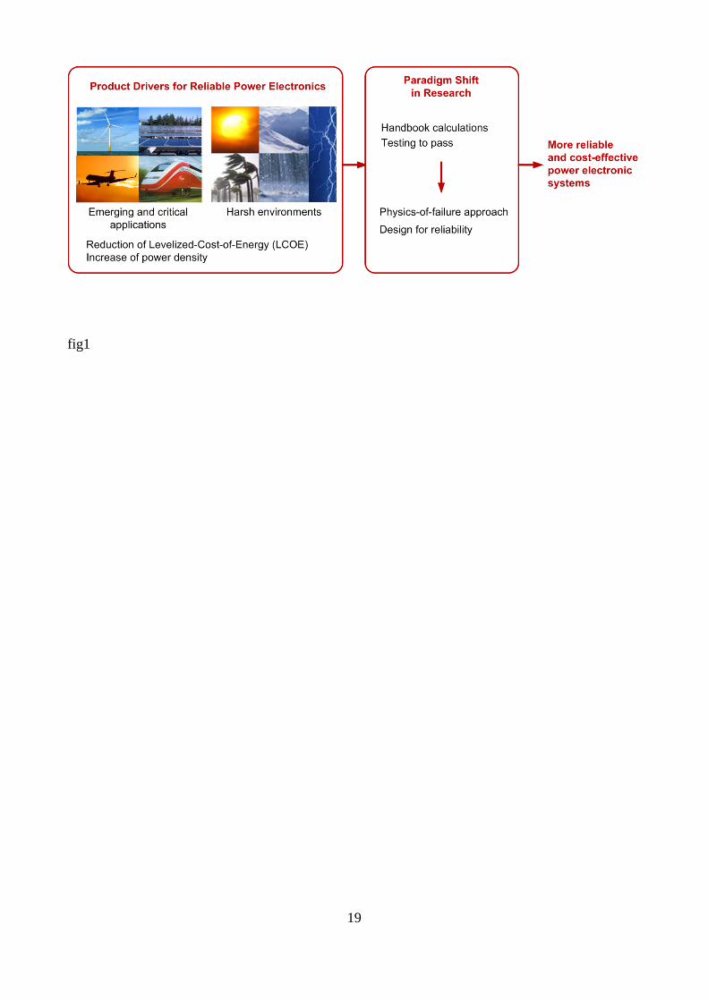
fig1
19
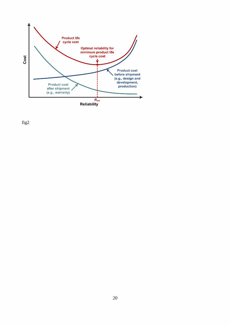
fig2
20
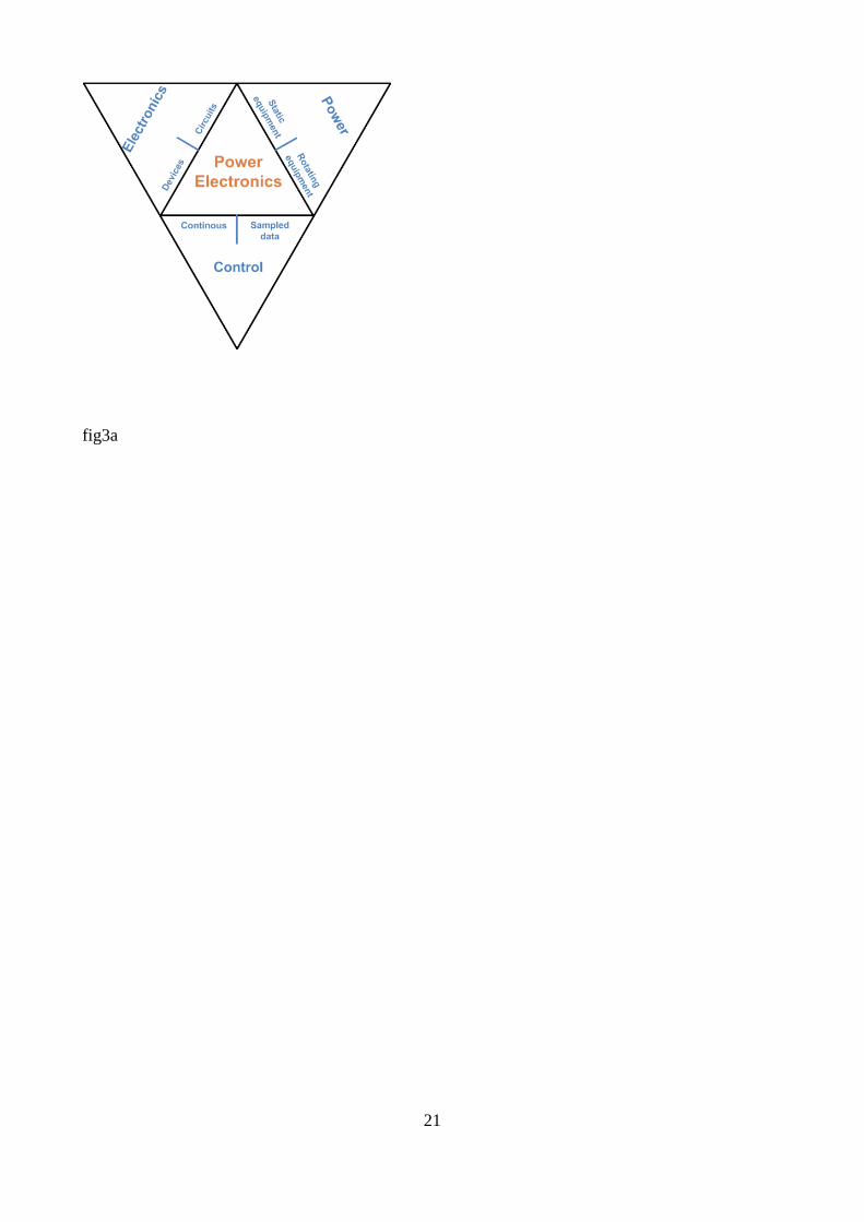
fig3a
21
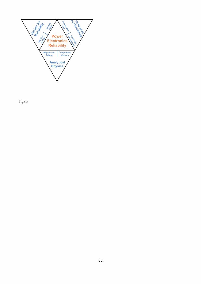
fig3b
22
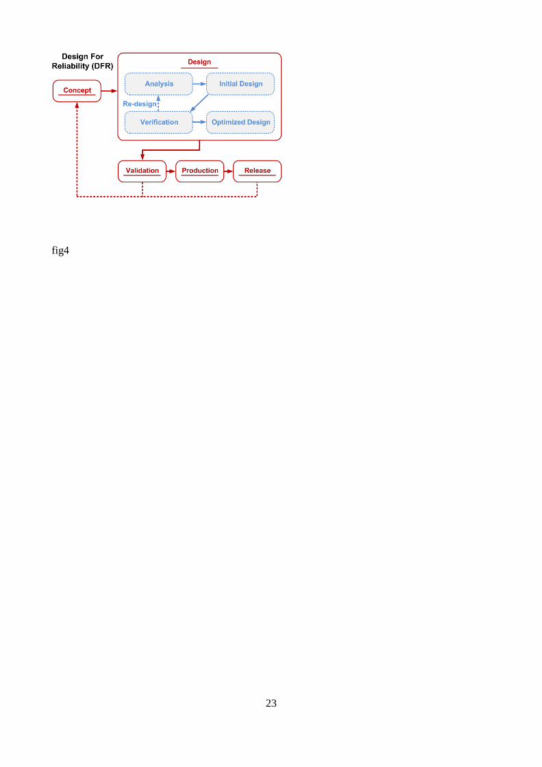
fig4
23
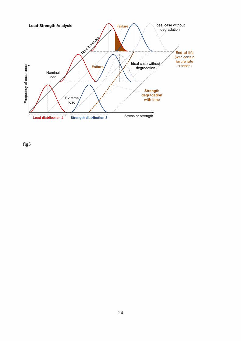
fig5
24
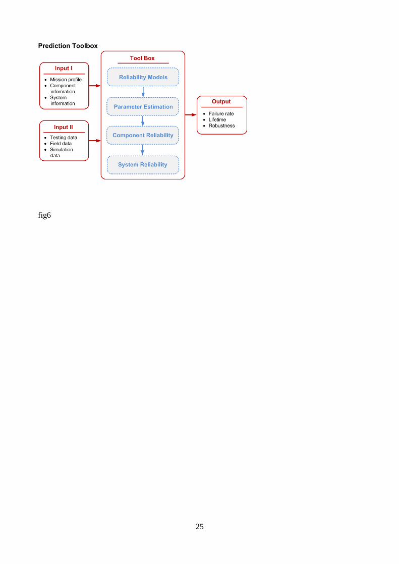
fig6
25
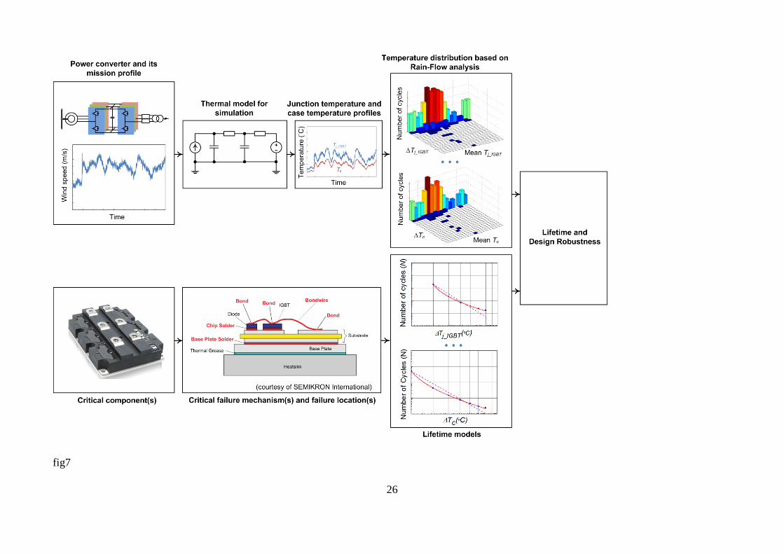
fig7
26
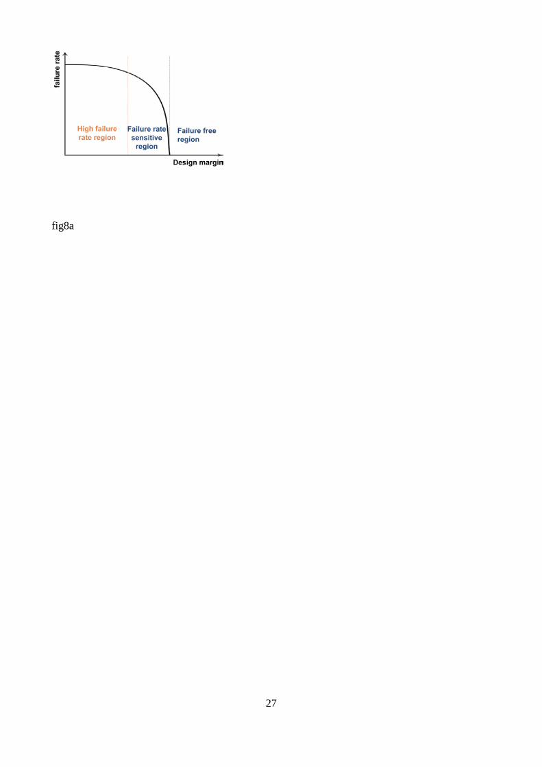
fig8a
27
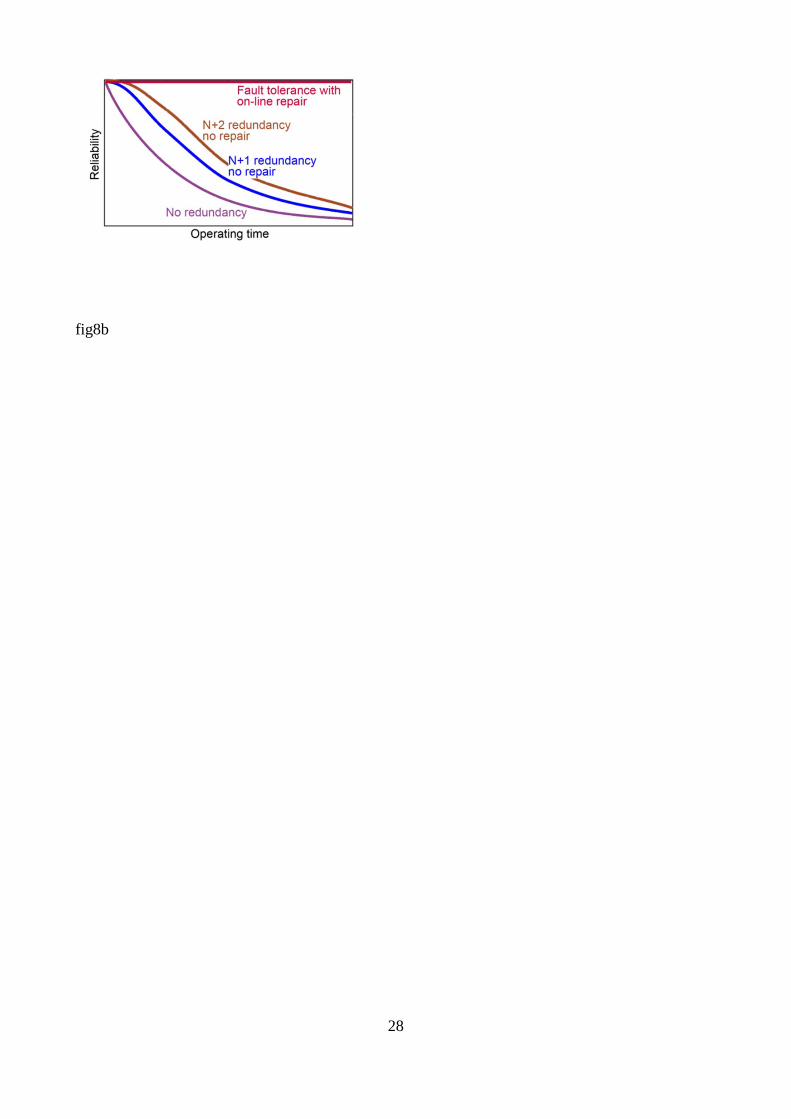
fig8b
28
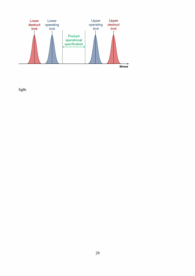
fig8c
29
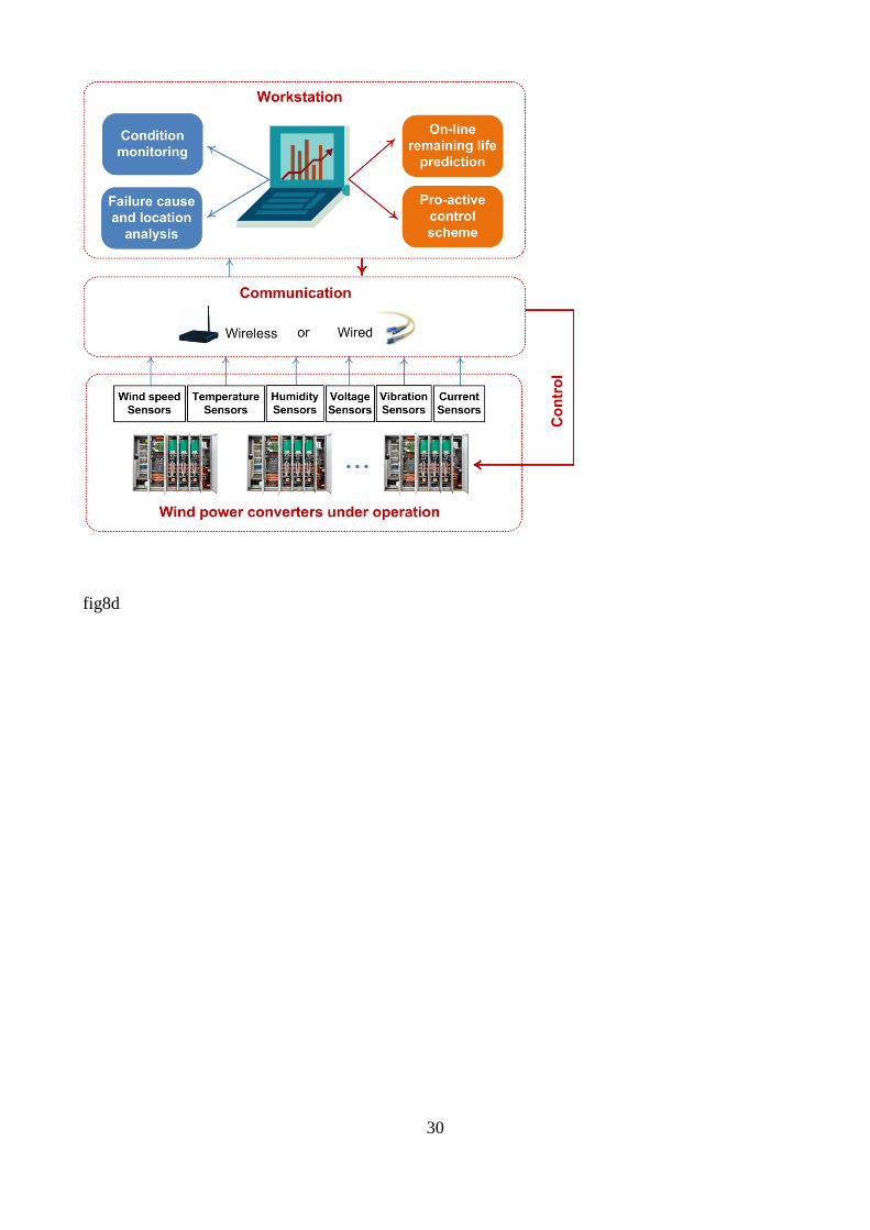
fig8d
30
figS1a
31
figS1b
32
figS2a
33
figS2b
34
Related Documents


![[Ebook].[Electronics].[Current Sensing Solutions for Power Supply Designers].pdf](https://static.cupdf.com/doc/110x72/55cf9d2a550346d033ac7ea3/ebookelectronicscurrent-sensing-solutions-for-power-supply-designerspdf.jpg)


