Toward polarized antiprotons: Machine development for spin-filtering experiments at COSY C. Weidemann, 1, 2, * F. Rathmann, 2 H.J. Stein, 2 B. Lorentz, 2 Z. Bagdasarian, 2, 3 L. Barion, 1 S. Barsov, 4 U. Bechstedt, 2 S. Bertelli, 1 D. Chiladze, 2, 3 G. Ciullo, 1 M. Contalbrigo, 1 S. Dymov, 5 R. Engels, 2 M. Gaisser, 2 R. Gebel, 2 P. Goslawski, 6 K. Grigoriev, 2, 4 G. Guidoboni, 1 A. Kacharava, 2 V. Kamerdzhiev, 2 A. Khoukaz, 6 A. Kulikov, 5 A. Lehrach, 2, 7 P. Lenisa, 1 N. Lomidze, 3 G. Macharashvili, 2, 5 R. Maier, 2 S. Martin, 8 D. Mchedlishvili, 3 H.O. Meyer, 9 S. Merzliakov, 2, 5 M. Mielke, 6 M. Mikirtychiants, 2, 4 S. Mikirtychiants, 2, 4 A. Nass, 2 N.N. Nikolaev, 2, 10 D. Oellers, 1, 2 M. Papenbrock, 6 A. Pesce, 1 D. Prasuhn, 2 M. Retzlaff, 2 R. Schleichert, 2 D. Schr¨ oer, 6 H. Seyfarth, 2 H. Soltner, 11 M. Statera, 1 E. Steffens, 12 H. Stockhorst, 2 H. Str¨ oher, 2 M. Tabidze, 3 G. Tagliente, 13 P. Th¨ orngren Engblom, 1, 14 S. Trusov, 15, 16 Yu. Valdau, 4, 17 A. Vasiliev, 4 and P. W¨ ustner 18 1 Universit´ a di Ferrara and INFN, 44122 Ferrara, Italy 2 Institut f¨ ur Kernphysik, Forschungszentrum J¨ ulich, 52425 J¨ ulich, Germany 3 High Energy Physics Institute, Tbilisi State University, 0186 Tbilisi, Georgia 4 High Energy Physics Department, St. Petersburg Nuclear Physics Institute, 188350 Gatchina, Russia 5 Laboratory of Nuclear Problems, Joint Institute for Nuclear Research, 141980 Dubna, Russia 6 Institut f¨ ur Kernphysik, Universit¨at M¨ unster, 48149 M¨ unster, Germany 7 III. Physikalisches Institut B, RWTH Aachen University, 52056 Aachen, Germany 8 UGS Gerlinde Schulteis and Partner GbR, 08428 Langenbernsdorf, Germany 9 Physics Department, Indiana University, Bloomington, IN 47405, USA 10 L.D. Landau Institute for Theoretical Physics, 142432 Chernogolovka, Russia 11 Zentralinstitut f¨ ur Engineering und Technologie (ZEA-1), Forschungszentrum J¨ ulich, 52425 J¨ ulich, Germany 12 Physikalisches Institut II, Universit¨ at Erlangen-N¨ urnberg, 91058 Erlangen, Germany 13 INFN, Sezione di Bari, 70126 Bari, Italy 14 Department of Physics, Royal Institute of Technology, SE-10691, Stockholm, Sweden 15 Institut f¨ ur Kern- und Hadronenphysik, Forschungszentrum Rossendorf, 01314 Dresden, Germany 16 Skobeltsyn Institute of Nuclear Physics, Lomonosov Moscow State University, 119991 Moscow, Russia 17 Helmholtz-Institut f¨ ur Strahlen- und Kernphysik, Universit¨at Bonn, 53115 Bonn, Germany 18 Zentralinstitut f¨ ur Systeme der Elektronik (ZEA-2), Forschungszentrum J¨ ulich, 52425 J¨ ulich, Germany The paper describes the commissioning of the experimental equipment and the machine studies required for the first spin-filtering experiment with protons at a beam kinetic energy of 49.3 MeV in COSY. The implementation of a low-β insertion made it possible to achieve beam lifetimes of τ b = 8000 s in the presence of a dense polarized hydrogen storage-cell target of areal density dt = (5.5 ± 0.2) × 10 13 atoms/cm 2 . The developed techniques can be directly applied to antiproton machines and allow for the determination of the spin-dependent ¯ pp cross sections via spin filtering. I. INTRODUCTION Already in 1968 it was realized that by means of a spin filter using an internal polarized hydrogen target, polar- ized high-energy proton beams could be produced at the 30 GeV ISR 1 at CERN [1]. Since more efficient methods to provide polarized beams had already been invented, the idea of using a spin filter was revisited only in 1982 to polarize antiprotons at LEAR 2 of CERN [2]. At the 1985 workshop at Bodega Bay, CA, USA, a number of dif- ferent techniques were discussed to provide stored beams of antiprotons [3]. Among them spin filtering was rated practical and promising. Spin filtering and related mechanisms leading to a po- larization build-up in a stored beam were discussed in * [email protected]; Corresponding author 1 Intersecting Storage Ring 2 Low-Energy Antiproton-cooler Ring great detail at the Daresbury workshop in 2007 [4], and in a WE–Heraeus seminar in 2008 at Bad Honnef, Ger- many [5]. In the framework of the FILTEX collabo- ration, polarization build-up in an initially unpolarized beam was observed for the first time using 23 MeV pro- tons stored in the TSR 3 at Heidelberg, interacting with polarized hydrogen atoms in a storage-cell target [6]. (A detailed description of the experimental effort is given in [7–9], up-to-date results are summarized in [10].) The renewed interest in experiments with polarized an- tiprotons aims at the production of a polarized antipro- ton beam at the HESR 4 [11] of FAIR 5 [12] at Darm- stadt, Germany. In 2003, a Letter of Intent for a variety of spin-physics experiments with polarized antiprotons 3 Test Storage Ring 4 High Energy Storage Ring 5 Facility for Antiproton and Ion Research, http://www. fair-center.de arXiv:1407.6724v1 [physics.acc-ph] 24 Jul 2014

Welcome message from author
This document is posted to help you gain knowledge. Please leave a comment to let me know what you think about it! Share it to your friends and learn new things together.
Transcript

Toward polarized antiprotons: Machine development forspin-filtering experiments at COSY
C. Weidemann,1, 2, ∗ F. Rathmann,2 H.J. Stein,2 B. Lorentz,2 Z. Bagdasarian,2, 3 L. Barion,1 S. Barsov,4
U. Bechstedt,2 S. Bertelli,1 D. Chiladze,2, 3 G. Ciullo,1 M. Contalbrigo,1 S. Dymov,5 R. Engels,2 M. Gaisser,2
R. Gebel,2 P. Goslawski,6 K. Grigoriev,2, 4 G. Guidoboni,1 A. Kacharava,2 V. Kamerdzhiev,2 A. Khoukaz,6
A. Kulikov,5 A. Lehrach,2, 7 P. Lenisa,1 N. Lomidze,3 G. Macharashvili,2, 5 R. Maier,2 S. Martin,8 D. Mchedlishvili,3
H.O. Meyer,9 S. Merzliakov,2, 5 M. Mielke,6 M. Mikirtychiants,2, 4 S. Mikirtychiants,2, 4 A. Nass,2
N.N. Nikolaev,2, 10 D. Oellers,1, 2 M. Papenbrock,6 A. Pesce,1 D. Prasuhn,2 M. Retzlaff,2 R. Schleichert,2
D. Schroer,6 H. Seyfarth,2 H. Soltner,11 M. Statera,1 E. Steffens,12 H. Stockhorst,2 H. Stroher,2 M. Tabidze,3
G. Tagliente,13 P. Thorngren Engblom,1, 14 S. Trusov,15, 16 Yu. Valdau,4, 17 A. Vasiliev,4 and P. Wustner18
1Universita di Ferrara and INFN, 44122 Ferrara, Italy2Institut fur Kernphysik, Forschungszentrum Julich, 52425 Julich, Germany
3High Energy Physics Institute, Tbilisi State University, 0186 Tbilisi, Georgia4High Energy Physics Department, St. Petersburg Nuclear Physics Institute, 188350 Gatchina, Russia
5Laboratory of Nuclear Problems, Joint Institute for Nuclear Research, 141980 Dubna, Russia6Institut fur Kernphysik, Universitat Munster, 48149 Munster, Germany
7III. Physikalisches Institut B, RWTH Aachen University, 52056 Aachen, Germany8UGS Gerlinde Schulteis and Partner GbR, 08428 Langenbernsdorf, Germany
9Physics Department, Indiana University, Bloomington, IN 47405, USA10L.D. Landau Institute for Theoretical Physics, 142432 Chernogolovka, Russia
11Zentralinstitut fur Engineering und Technologie (ZEA-1),Forschungszentrum Julich, 52425 Julich, Germany
12Physikalisches Institut II, Universitat Erlangen-Nurnberg, 91058 Erlangen, Germany13INFN, Sezione di Bari, 70126 Bari, Italy
14Department of Physics, Royal Institute of Technology, SE-10691, Stockholm, Sweden15Institut fur Kern- und Hadronenphysik, Forschungszentrum Rossendorf, 01314 Dresden, Germany
16Skobeltsyn Institute of Nuclear Physics, Lomonosov Moscow State University, 119991 Moscow, Russia17Helmholtz-Institut fur Strahlen- und Kernphysik, Universitat Bonn, 53115 Bonn, Germany
18Zentralinstitut fur Systeme der Elektronik (ZEA-2),Forschungszentrum Julich, 52425 Julich, Germany
The paper describes the commissioning of the experimental equipment and the machine studiesrequired for the first spin-filtering experiment with protons at a beam kinetic energy of 49.3 MeVin COSY. The implementation of a low-β insertion made it possible to achieve beam lifetimesof τb = 8000 s in the presence of a dense polarized hydrogen storage-cell target of areal densitydt = (5.5± 0.2)× 1013atoms/cm2. The developed techniques can be directly applied to antiprotonmachines and allow for the determination of the spin-dependent pp cross sections via spin filtering.
I. INTRODUCTION
Already in 1968 it was realized that by means of a spinfilter using an internal polarized hydrogen target, polar-ized high-energy proton beams could be produced at the30 GeV ISR1 at CERN [1]. Since more efficient methodsto provide polarized beams had already been invented,the idea of using a spin filter was revisited only in 1982to polarize antiprotons at LEAR2 of CERN [2]. At the1985 workshop at Bodega Bay, CA, USA, a number of dif-ferent techniques were discussed to provide stored beamsof antiprotons [3]. Among them spin filtering was ratedpractical and promising.
Spin filtering and related mechanisms leading to a po-larization build-up in a stored beam were discussed in
∗ [email protected]; Corresponding author1 Intersecting Storage Ring2 Low-Energy Antiproton-cooler Ring
great detail at the Daresbury workshop in 2007 [4], andin a WE–Heraeus seminar in 2008 at Bad Honnef, Ger-many [5]. In the framework of the FILTEX collabo-ration, polarization build-up in an initially unpolarizedbeam was observed for the first time using 23 MeV pro-tons stored in the TSR3 at Heidelberg, interacting withpolarized hydrogen atoms in a storage-cell target [6]. (Adetailed description of the experimental effort is givenin [7–9], up-to-date results are summarized in [10].)
The renewed interest in experiments with polarized an-tiprotons aims at the production of a polarized antipro-ton beam at the HESR4 [11] of FAIR5 [12] at Darm-stadt, Germany. In 2003, a Letter of Intent for a varietyof spin-physics experiments with polarized antiprotons
3 Test Storage Ring4 High Energy Storage Ring5 Facility for Antiproton and Ion Research, http://www.
fair-center.de
arX
iv:1
407.
6724
v1 [
phys
ics.
acc-
ph]
24
Jul 2
014
2
was proposed by the PAX6 collaboration [13]. In 2005the PAX collaboration submitted a technical proposal tothe QCD program committee of FAIR, suggesting as anupgrade for HESR a double-polarized antiproton-protoncollider to study, among other subjects, the transversitydistribution of the proton [14, 15].
Polarizing a stored beam by spin-flip in ~e−p (or ~e+p)scattering [16] presents an advantage, because contraryto spin filtering, beam particles are not lost. Triggeredby the PAX proposal, the theory of spin-flip interactionswas radically revised, leading to negligibly small crosssections for proton-electron scattering [17–20]. In a re-cent experiment performed at COSY7[21], the e−~p spin-flip cross sections were indeed shown to be too small toallow for the efficient production of polarized antiprotonsbased on e+p interactions [10, 22].
Polarizing antiprotons by spin filtering, using the spin-dependent part of the nucleon-nucleon interaction, re-mains the only viable method, up to now experimentallyconfirmed for a stored beam of protons and a polarizedhydrogen gas target [6, 7]. Theoretical considerationsfor beams of antiprotons have meanwhile been extended
from p ~H interactions [23, 24] to p ~D [25] and p3 ~He [26].In order to complement the Heidelberg TSR spin-
filtering experiment by a second measurement, and tocommission the experimental setup for the proposed ppexperiment at the AD8 of CERN [27], a spin-filteringexperiment was performed in 2011 at COSY. The exper-iment confirmed that only pp scattering contributes tothe polarization build-up [28]. At a beam kinetic energyof T = 49.3 MeV, slightly above the COSY injection en-ergy of T = 45 MeV, precise ~pd analyzing power data forthe beam polarization measurement are available [29].
The spin-filtering method exploits the spin-dependenceof the total hadronic cross section [30],
σtot = σ0 ± σ1 ·Q , (1)
where σ0 is the spin-independent, σ1 the spin-dependentpart, and Q is the nuclear polarization of the target. Thepositive (negative) signs denote parallel (antiparallel) ori-entation of the spins of beam and target protons.
The number of beam protons with spin orientation par-allel (antiparallel) to that of the target spins is denotedby N↑ (N↓). One can safely neglect the numerically mi-nuscule spin-flip cross section. Then the decrease of thetotal number of beam particles as function of time fromthe initial values N↑(t = 0) = N↓(t = 0) = Ntot(t = 0)/2is described by
Ntot(t) = N↑(t) +N↓(t)
= Ntot(0) · exp
(− t
τb
)· cosh
(t
τ1
), (2)
6 Polarized Antiproton eXperiments, http://collaborations.
fz-juelich.de/ikp/pax/7 COoler SYnchrotron and storage ring8 Antiproton Decelerator
where
τb = (fdtσb)−1 and τ1 = (Qdtfσ1)−1 . (3)
Here dt is the areal target gas density and f the rev-olution frequency determined by the beam momentumand the ring circumference. Furthermore, σb = σ0 + σC
combines σ0 and single Coulomb scattering σC in thetarget, the latter for scattering angles larger than the ac-ceptance angle Θacc of the machine. For single Coulombscattering and small values of Θacc, the beam lifetimeτb ∝ σ−1
C ∝ Θ2acc ∝ β−1 (see Sec. II B). Therefore the
betatron function (or β-function) at the target should besmall in order to achieve a long beam lifetime.
The polarization build-up in the stored, circulatingbeam is given by
P (t) =N↑(t)−N↓(t)N↑(t) +N↓(t)
= tanh
(t
τ1
). (4)
It depends on the spin-dependent removal of particles.The effective removal cross section in Eq. (1) dependson the machine acceptance, σ1 = σ1(Θ > Θacc), andconsequently so does the achievable beam polarization,as illustrated, e.g., in Fig. 15 of Ref. [24].
In the present paper, the development effort, includinga variety of measurements is described, necessary to pre-pare the COSY storage ring and the experimental equip-ment for the spin-filtering experiments [28, 31]. The pa-per is organized as follows:
• Section II presents the essential components of theCOSY ring, in particular its lattice and the electroncooler (II A), followed by the requirements to thelow-β insertion at the position of the polarized gastarget, and its realization (II B).
• Section III describes the internal polarized hydro-gen storage-cell target (III A), the coil system toproduce the magnetic holding field at the storagecell (III B), and the vacuum system around the po-larized target (III C).
• In Sec. IV the equipment employed for beam diag-nosis is described, comprising beam current trans-former, H0 monitor, ionization profile monitor,beam-position monitor, movable frame system foracceptance measurements, and beam-polarimetersetup.
• Section V describes the betatron tune mapping(Sec. V A), and orbit adjustment (Sec. V B) to pro-vide long beam lifetime for the spin-filtering exper-iments.
• Section VI highlights the commissioning of the low-β insertion, including the determination of the β-function at the target.
• Section VII presents the measurements of the beamwidths (VII A) at the location of the internal target,

3
the beam emittance (VII B), and the determinationof the machine acceptance and the acceptance angleat the target position (VII C).
• In Sec. VIII the efforts are described to optimizethe beam lifetime by means of closed orbit cor-rection and tune adjustment. Space-charge ef-fects (VIII A) and vacuum considerations are dis-cussed as well (VIII B).
• In Sec. IX it is explained how the beam was setup for the experiments (IX A) and how a typi-cal measurement cycle looked like (IX B). In ad-dition, the measurement of the beam polarizationlifetime (IX C) and the efficiency of the RF spinflipper are described (IX D).
• Section X summarizes the main results.
II. COSY ACCELERATOR AND STORAGERING
The synchrotron and storage ring COSY acceleratesand stores unpolarized and polarized proton or deuteronbeams in the momentum range between 0.3 GeV/c and3.65 GeV/c. COSY has a racetrack design with two 180
arc sections connected by 40 m long straight sections. Itis operated as cooler storage ring with internal targets(ANKE9, WASA10, PAX6) or with an extracted beam(see Fig. 1, bottom panel). Beam cooling, i.e., reduc-ing the momentum spread of the beam and shrinking thetransverse equilibrium phase space, is realized by electroncooling up to proton-beam momenta of 0.6 GeV/c [32],and by stochastic cooling for proton momenta above1.5 GeV/c [33].
Polarized proton and deuteron beams are routinelydelivered to experiments over the whole momentumrange [34]. Polarized beams from the ion source are pre-accelerated in the cyclotron JULIC [35], injected andaccelerated in COSY without significant loss of polar-ization. Imperfection and intrinsic depolarization reso-nances are overcome by well-established procedures [36–38]. When the polarization lifetime is by orders of mag-nitude longer than the spin filtering periods required,it becomes feasible to polarize an originally unpolarizedbeam by filtering, as was confirmed in a dedicated exper-iment [28], described in Sec. IX.
A. COSY lattice and electron cooler
The COSY lattice is designed to provide flexibility withrespect to ion-optical settings [39] in order to fulfill the
9 Apparatus for Studies of Nucleon and Kaon Ejectiles, http:
//collaborations.fz-juelich.de/ikp/anke/10 Wide Angle Shower Apparatus, http://collaborations.
fz-juelich.de/ikp/wasa/
FIG. 1. Bottom panel: Floor plan of the COSY facility. The24 dipole magnets are given in red, the quadrupole magnetsin blue except those around the PAX target point (PAX-TP)and the 100 keV electron cooler which are given in green. Thequadrupole magnets of COSY are combined into quadrupolefamilies, each consisting of four magnets with a common cur-rent supply. There are eight families for the telescopic straightsections (QT1 to QT8, middle panel) and six for the arcs(QU1 to QU6, top panel). The PAX quadrupoles of the low-β insertion at the PAX-TP are combined to an outer pair(PAX1) and an inner pair (PAX2).
requirements for internal and external experiments. Eachof the arcs is composed of three mirror-symmetric unitcells (U) consisting of four dipole magnets (O), two hor-izontally focusing (F) and two horizontally defocusingquadrupole magnets (D). Each of the six unit cells hasa DOFO-OFOD structure (see Fig. 1, top panel). Thetwo inner (and outer) quadrupole magnets of each unitcell are connected to the inner (and outer) pair of theopposite unit cell located in the other arc, thereby sixquadrupole families arise (QU1 to QU6). A symmetricoperation of all unit cells leads to a sixfold symmetry ofthe β-functions [40].
The straight sections are composed of two mirror-

4
TABLE I. Main parameters of the COSY accelerator and stor-age ring [21].
COSYcircumference 183.47 mparticles (un-)polarized p and dtype of injection H−, D− stripping injectioncurrent at source exit polarized: 15 µA
unpolarized: 100− 200 µAmomentum range 0.3− 3.65 GeV/cbetatron tune range 3.55− 3.7 in both planesphase-space cooling electron and stochasticbeam position monitors 31 (horizontal and vertical)steerers 23 (horizontal), 21 (vertical)
straight sections
length: 40 m4× 4 quadrupole magnets4 sextupole magnetsbeam pipe diameter: 0.15 m
arc sections
length: 52 m3× 4 dipole magnets3× 4 quadrupole magnets5 sextupole magnetsbeam pipe in dipole magnets:height: 0.06 m, width: 0.15 m
symmetric telescopic (T) arrangements with twoquadrupole triplets, each consisting of four quadrupoles,either operated in FDDF or DFFD mode. Thereby, a 2πphase advance and 1:1 imaging over the complete straightsection is achieved, decoupling to first order the arcs fromthe straight sections [39], and providing three possiblelocations per straight section for internal target exper-iments with adjustable β-functions in the center of thetriplets. Figure 2 (top panel) shows the horizontal (x)and vertical (y) β-functions, βx and βy, and the disper-sion D for a typical setting of COSY used at injection.The basic parameters of COSY are listed in Table I.
The straight sections can be made free of dispersion bybreaking the sixfold symmetry with a specific setting ofthe six arc quadrupole families (see Fig. 2, bottom panel).This dispersion-freeD = 0 setting is advantageous for theoperation of the storage-cell target, therefore it has beenchosen during the spin-filtering experiments. A non-zerodispersion causes a displacement of a particle with a rel-ative momentum deviation ∆p
p from the reference orbit,
and the deviation from the ideal orbit is given by [41]
x(s)total = xref(s) +D(s) · ∆p
p, (5)
where s is the position along the reference orbit ands = 0 is located at the beginning of the straight section,where the PAX-TP is located.
The COSY electron cooler (see Fig. 1) is used to com-pensate multiple small-angle Coulomb scattering and en-ergy loss in the target and the residual gas in the machine.It provided stable beam emittance and beam energy dur-ing the spin-filtering experiment. It was designed for elec-
s (m)0 20 40 60 80 100 120 140 160 180
(m
), D
(m
)β
10
5
0
5
10
15
20
25
30
35
yβ
D
xβ
TargetTelescope
CoolerTelescope
Arc Arc
s (m)0 20 40 60 80 100 120 140 160 180
(m
), D
(m
)β
5
0
5
10
15
20
25
30
35
yβ
D
xβ
Target
Telescope
Cooler
Telescope
Arc Arc
FIG. 2. Top panel: Optical functions (βx, βy) and dispersionD along COSY for a standard setting (D 6= 0). In each ofthe arcs a symmetric behavior due to the three unit cells ineach section is noticeable. Bottom panel: β-functions anddispersion for the D = 0 setting through the telescopes. ThePAX target is located in the center of the target telescope.
tron energies up to 100 keV, thus enabling phase-spacecooling up to a proton-beam kinetic energy of 183.6 MeV[42]. Its main parameters are listed in Table II. Two shortsolenoids located in the 8 m long drift region in front andbehind the electron cooler (see Fig. 7 of Ref. [43]) and op-erated with reversed polarity to that in the drift solenoidcompensate phase-space coupling and avoid spin rota-tion in the case of polarized beams. The field strengthsare adjusted such that
∫B · dl over the cooler magnets
and the compensating solenoids equals zero. The maindrift solenoid was typically operated at magnetic fieldsof B = 50− 80 mT.
Beams of small emittance, as produced by electroncooling, tend to develop coherent betatron oscillationswhich lead to beam loss [42]. The transverse feedbacksystem of COSY [44, 45] was used to avoid these insta-bilities.

5
TABLE II. Parameters of the electron cooler at COSY [42].
Electron Coolerelectron energy 20− 100 keVtypical electron beam current 0.25 Amagnetic field strength 50− 150 mTlength of drift solenoid 2.00 mbending radius in the toroids 0.60 meffective length of cooling 1.50 meffective length of solenoidal field 3.20 meffective length of compensation 0.5 msolenoidsdiameter of COSY beam tube 0.15 mdiameter of electron beam 0.025 mtypical β-functions at the e-cooler βx = 6 m, βy = 20 mdiagnosis H0 profile monitor
and count rate
B. Low-β insertion
In a storage ring, the geometrical machine accep-tance11 [41] is defined by
Ax,y =
(a2x,y
βx,y
)min
, (6)
and the acceptance angle Θacc [46], by
1
Θ2acc
=1
2Θ2x
+1
2Θ2y
with1
Θ2x,y
=βx,yAx,y
, (7)
where a is the free aperture along the ring. At the kineticenergy of Tp = 49.3 MeV of the spin-filtering experiment,the beam lifetime (Eq. (3)) is dominated by the Coulombscattering loss on the target gas and the residual gasin the ring; the hadronic losses amount to about 10%of the total loss cross section σb (see Sec. VIII B). TheCoulomb-loss cross section can be derived by integrationof the differential Rutherford cross section, for scatteringangles larger than Θacc [47],
σC =
Θmax∫Θacc
2π∫0
dσ
dΩdφ sin ΘdΘ = 4π
Z2gasZ
2i r
2i
β4Lγ
2L
· 1
Θ2acc
. (8)
Zgas and Zi are the atomic numbers of the target (orresidual) gas and the ion beam, respectively, βL and γL
are the relativistic Lorentz factors, and ri = reme/mi isthe classical ion radius. The beam lifetime due to singleCoulomb scattering,
τb ≈ τC =1
σCdtf=
β4Lγ
2L
4πZ2gasZ
2i r
2i
· Θ2acc
dt · f∝ 1
dt · β, (9)
11 Throughout this paper µm is used as unit of machine acceptanceand beam emittance, equivalent to mm mrad.
(m)0
β0 0.1 0.2 0.3 0.4 0.5 0.6 0.7 0.8 0.9 1
m)
µA
(
0
10
20
30
40
50
60
FIG. 3. Machine acceptance A(β0) using Eq. (11) for a storagecell with diameter d = 9.6 mm and length l = 400 mm asfunction of β0 at the target center. A reaches a maximum forβ0 = l/2 = 0.2 m.
is inversely proportional to the β-function and the gasdensity. Therefore, especially the β-functions at thePAX-TP should be made small, because of the high den-sities.
It turns out that for a given target-gas cell an optimalvalue for the β-function at the cell center exists. Theβ-function in a symmetric drift space is described by
β(s′) = β0 +s′2
β0, (10)
where s′ is the distance from the cell center, and β0 is theβ-function at the center. The machine acceptance for astorage cell of diameter d and length l as function of β0
is therefore given by
A(β0) =(d/2)
2
β0 +
(l/2
)2
β0
, (11)
and A(β0) reaches a maximum for β0 = l/2. A storagecell of d = 9.6 mm and l = 400 mm is used to max-imize the target areal density in the experiment (seeSec. III A). For the specified cell the maximum accep-tance is A(β0 = 0.2 m) ≈ 58 m (see Fig. 3). The stan-dard COSY lattice (D 6= 0) provides geometrical ac-ceptances of about Ax ≈ (75 mm)2/25 m = 225 µm andAy ≈ (30 mm)2/20 m = 45 µm (see Fig. 2 and Table I),thus with the smallest β-functions of about 3 m, the givenstorage cell would restrict the machine acceptance toA(β0 = 3 m) ≈ 8 µm.
To obtain the required small β-functions, a low-β in-sertion consisting of four additional quadrupole magnets(blue in Fig. 4), formerly used at CELSIUS [48], was in-stalled in the drift space in front and behind the target.The quadrupole magnets are arranged in a doublet struc-ture (DF-FD), where the D and F magnets are powered

6
1
3
4
5
6
2
2
FIG. 4. View of the PAX installation at COSY from the ring interior (the beam coming from the left). 1: COSY quadrupolemagnet, 2: two of the four PAX quadrupoles (formerly used at CELSIUS [48]), forming the low-β insertion by doublet focusing(DF-FD), 3: Atomic Beam Source (ABS), 4: support system, 5: flange supporting rail system, 6: PAX target chamber housingthe storage cell. The Breit-Rabi polarimeter (BRP) and the Target-Gas Analyzer (TGA) are mounted towards the outside ofthe ring. The horizontal distance between the inner faces of the two COSY quadrupole magnets is 3.75 m, the height of thebeam-tube center from the ground is 1.80 m.
by separate power supplies. When the doublets are oper-ated, the four regular COSY quadrupole families in thisstraight section are reduced in strength to maintain itstelescopic nature. Thus the other magnets in the machinedo not require any readjustment.
Precise positioning of the beam inside the storage cellwas provided by horizontal and vertical steerer coils,which were mounted because of space restrictions on theyokes of the adjacent quadrupole magnets up- and down-stream of the low-β insertion.
Based on the COSY lattice using the standard magnetsettings, a calculation of the optical functions was car-ried out with the MAD12 program, version 8 [49]. Theresults, obtained with the PAX magnets switched ONand OFF, are shown in Fig. 5, indicating that βx and βyat the target point can be reduced by more than one or-der of magnitude, with minimal values of βx,y ≈ 0.3 m.The commissioning of the low-β section, including themeasurement of βx and βy, is described in Sec. VI.
12 Methodical Accelerator Design
Reduced β-functions at the target, however, are ac-companied by increased ones up- and downstream, reach-ing values of about 33 m (see Fig. 5, bottom panel).Therefore, excellent vacuum conditions have to be main-tained also in these regions to avoid adversely affectingthe beam lifetime.
III. POLARIZED TARGET
A. Polarized atomic beam source and storage cell
The polarized internal target (PIT) consists of theatomic beam source (ABS), which was developed for theTSR spin-filtering experiment [9, 50], later on used in theHERMES experiment at DESY [51, 52], and now modi-fied for spin-filtering at COSY, a storage cell [53], a so-called Breit-Rabi polarimeter (BRP) [54], and a TargetGas Analyzer (TGA) [55]. H0 atoms in a single hyperfine-state are prepared in the ABS and injected into a thin-walled storage cell. A fraction of the gas diffuses fromthe cell through a side tube into the diagnostic system,where the BRP determines the atomic polarization and

7
s (m)0 5 10 15 20 25 30 35 40
(m
)β
0
5
10
15
20
25
30
35
yβ
xβ
s(m)0 5 10 15 20 25 30 35 40
(m
)β
0
5
10
15
20
25
30
35
yβ
xβ
FIG. 5. Model calculation of the β-functions for the standardCOSY setting (D 6= 0) with PAX magnets switched OFF(top panel) and ON (bottom panel), indicating that minimalvalues of βx,y ≈ 0.3 m can be reached at the target point ats = 19.87 m. s = 0 is located at the beginning of the targetstraight section
the TGA the relative fraction of atoms and molecules. Amagnetic guide-field system defines the quantization axisfor the target polarization, which can be oriented alongthe x (outward), y (up), or s (along beam) direction, orany superposition thereof (see Sec. III B).
The gas load into the target chamber and the neigh-boring sections causes beam losses due to the interactionof beam particles with the residual gas. A dedicatedpumping system, described in Sec. III C, was developedto minimize these losses.
The storage cell (see Fig. 6, label 1) increases the dwelltime of the polarized atomic gas in the interaction regionwith the beam and enhances the areal target density com-pared to a free atomic jet by about two orders in mag-nitude. The cell was made from aluminum and coatedwith Teflon13 to reduce depolarization and recombina-
13 Teflon (Polytetrafluoroethylene) coating was done by the com-pany Rhenotherm, Kunststoffbeschichtungs GmbH, Kempen,Germany, http://www.rhenotherm.de/
7
3
2
6
1
4
5
FIG. 6. Section view of the PAX target chamber. The labelsdenote the storage cell (1) with feeding tube to the ABS (ver-tical), and extraction tube to the BRP (to the backside), flowlimiters (2) of 19 mm diameter and 80 mm length, jalousie (3)to protect the cell from heat radiation during activation of theNEG pumps (4), COSY beam (5), guide field compensationcoils (6), and magnetic guide field coils (7).
tion [56]. Under the assumption of linear decrease of thegas density from the center to the open ends the arealtarget-gas density is given by
dt =1
2· l · ICtot
, (12)
where I [s−1] is the intensity of the injected beam fromthe ABS, l [cm] the total length of the storage tube andCtot the total conductance of the storage cell. The con-ductance [`/s] of a circular tube of diameter di [cm] andlength li [cm] can be written as [57]
Ci = 3.81
√T
M· d3
i
li + 1.33 · di, (13)
where T [K] is the temperature and M [u] the molarmass.
The total conductance Ctot of the storage cell isgiven by the sum of all conductances with respect tothe cell center. For a storage-cell tube (l = 400 mm,d = 9.6 mm), a feeding tube from the ABS (l = 100 mm,d = 9.6 mm), and the extraction tube to the target po-larimeter (l = 380 mm, d = 9.6 mm), the conductance ofthe storage cell yields Ctot = 2 ·C 1
2 cell +Cfeed +Cextract =
12.15 `/s. With an intensity from the ABS injected intothe feeding tube of I = 3.3 · 1016 s−1 [51], an areal den-sity of dt = 5.45 · 1013 cm−2 is expected. During thespin-filtering experiment, in good agreement with the es-timate given above, a target density of [28]
dt = (5.5± 0.2) · 1013 cm−2, (14)
8
s’ (mm)800 600 400 200 0 200 400 600 800
(m
T)
yB
2
1.5
1
0.5
0
0.5
1
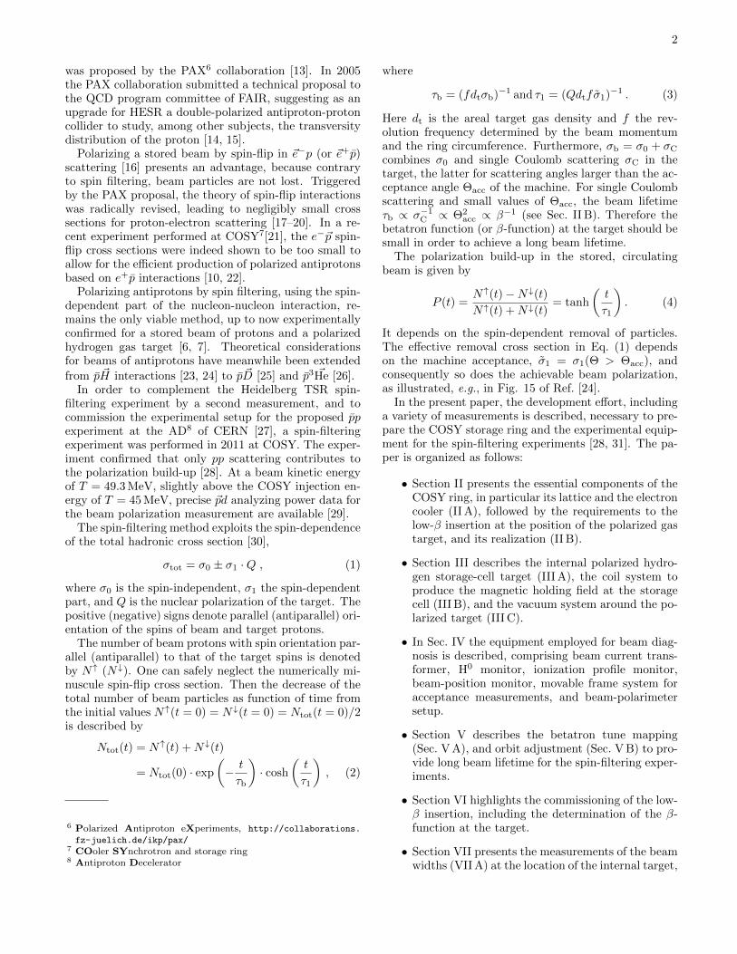
FIG. 7. Calculated vertical magnetic flux density By alongs′-direction for the coil configuration of Fig. 6. In the targetcell region (s′ = −200 mm to +200 mm), indicated by thevertical dashed bars, the magnetic field is about 1 mT.
was deduced from the shift of the orbit frequency of thecoasting beam caused by the energy loss in the target gas(see Sec. IV B) [8, 58].
B. Holding field coil system
The operation of the polarized target requires a coilsystem providing guide fields of about 1 mT [59] in orderto define the orientation of the target polarization andallowing to reverse it in short sequence. The polarizationof the gas atoms is known to be fully reversed withinabout 10 ms after switching the polarity of the magneticfield (see Fig. 11 of [60]). A system of coils, providingfields in transverse (x, y) and longitudinal (s) directions,was installed on the target chamber (see Fig. 6).
Additional coils installed on the up- and downstreamends of the target chamber (see Fig. 6) made sure that thehorizontal and sideways field integrals
∫Bx,yds vanish
(see Fig. 7), thereby avoiding that the beam positions inthe rest of the machine are affected. Holding field andcompensation coils require only a single power supply.
A measurement of the magnetic field By in the cen-ter of the target chamber using a Hall probe yieldedBy↓ = −1.08± 0.03 mT and By↑ = 1.10±0.03 mT, point-ing down- and upward, respectively. This result is ingood agreement with the calculated magnetic field of 1.0to 1.1 mT inside the storage cell based on the coil geom-etry shown in Fig. 6, using the Amperes14 program.
The vertical magnetic guide field causes a deflectionof the proton beam in horizontal direction. Accord-
14 Integrated Engineering Software (IES), Winnipeg, Manitoba,Canada, http://www.integratedsoft.com
s (m)
0 20 40 60 80 100 120 140 160 180
x (
mm
)∆
1.5
1
0.5
0
0.5
1
1.5
Target
Telescope
Cooler
Telescope
Arc Arc
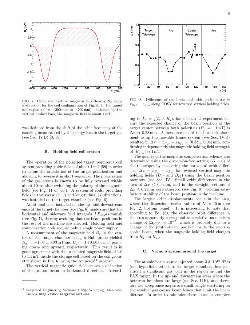
FIG. 8. Difference of the horizontal orbit position ∆x =xBy↑ − xBy↓ along COSY for reversed vertical holding fields.
ing to ~Fx = q(~vs × ~By), for a beam at experiment en-ergy the expected change of the beam position at thetarget center between both polarities (By = ±1mT) is∆x ≈ 0.28 mm. A measurement of the beam displace-ment using the movable frame system (see Sec. IV D)resulted in ∆x = xBy↑ − xBy↓ = (0.33 ± 0.04) mm, con-firming independently the magnetic holding field strengthof |By↑,↓| ≈ 1 mT.
The quality of the magnetic compensation scheme wasdetermined using the dispersion-free setting (D = 0) ofthe telescopes by measuring the horizontal orbit differ-ence ∆x = xBy↑ − xBy↓ for reversed vertical magneticholding fields (By↑ and By↓) using the beam positionmonitors (see Sec. IV). Small orbit differences in thearcs of ∆x ≤ 0.9 mm, and in the straight sections of∆x ≤ 0.2 mm were observed (see Fig. 8), yielding satis-factory stability of the beam position in the machine.
The largest orbit displacements occur in the arcs,where the dispersion reaches values of D ≈ 15 m (seeFig. 2, bottom panel). It is interesting to note thataccording to Eq. (5), the observed orbit difference inthe arcs apparently correspond to a relative momentumchange of |∆p/p| ≈ 10−5, which is probably due to achange of the proton-beam position inside the electroncooler beam, when the magnetic holding field changesfrom By↑ to By↓.
C. Vacuum system around the target
The atomic beam source injected about 3.3 · 1016 H0/s(one hyperfine state) into the target chamber, thus gen-erated a significant gas load in the region around thePAX target. In the up- and downstream areas where thebetatron functions are large (see Sec. II B), and there-fore the acceptance angles are small, single scattering onthe residual gas causes beam losses that limit the beamlifetime. In order to minimize these losses, a complex

9
vacuum system was installed. It consists of
1. ten NEG cartridges15 installed below the targetchamber, providing a nominal pumping speed of10× 1900 `/s for H2 (see Fig. 6),
2. NEG coating of the beam pipes up- and down-stream of the target region with a nominal pumpingspeed of 2× 5000 `/s [61].,
3. flow limiters with an inner diameter of 19 mm anda length of 80 mm (see Fig. 6) installed at the en-trance and exit of the target chamber in order tominimize the gas flow from the target into the ad-jacent sections without a restriction of the machineacceptance, and
4. one turbo pump16 with a nominal pumping speed of1200 `/s for H2 installed below the target chamber,primarily used during the activation of the NEGpumps.
The NEG coating and the NEG cartridges were acti-vated by heating up to 230 C and 450 C, respectively,making use of the possibility that the entire low-β sec-tion is made bakeable. Assuming a gas flow of about3.3 · 1016 H0/s, during operation of the target, approxi-mately one activation per week is required. A jalousiewith mirror plates is mounted above the NEG cartridgesin order to minimize the heat radiation into the targetchamber during activation. The jalousie is closed duringheating and opened for pumping. In addition, fast clos-ing valves 17 were installed at the up- and downstreamends of the target chamber, which are capable to seal thesection off the rest of the ring during bake-out, or in caseof a sudden vacuum break.
The vacuum system enabled a base pressure of2 · 10−10 mbar in the target chamber and less than10−11 mbar in the adjacent sections when the polarizedtarget is switched off. During operation of the polarizedtarget the pressure never exceeded about 10−7 mbar inthe target chamber and 10−9 mbar in the adjacent NEG-coated vacuum tubes.
IV. BEAM DIAGNOSTIC TOOLS
Various beam diagnostics systems, available at COSY,were used to perform the studies described in this paper.
15 SAES getter pump GP 500 MK5, a type of vacuum pumpmanufactured by SAES GETTERS (DEUTSCHLAND) GmbH,Cologne, Germany, [http://www.saesgetters.com], sorbs activegases with a nonevaporable getter (NEG) material (Zr-V-Fe al-loy).
16 HiPace 1800, Pfeiffer Vacuum GmbH, Asslar, Germany, http:
//www.pfeiffer-vacuum.de/17 VAT fast closing valve, series 750: DN-100-CF, VAT Deutschland
GmbH, Grasbrunn, Germany, http://www.vatvalve.com/
A. Beam current transformer
A beam current transformer (BCT) measures the cur-rent of the circulating ion beam. The BCT electronics isbased on the DCCT principle (DC current transformer)[62] and can be set to deliver 1 V or alternatively 0.1 Voutput signal for 1 mA of beam current. The BCT signalforms the basis for the measurement of the beam life-time, which was determined from a continuous record ofthe beam current as function of time, fitted by an expo-nential.
B. Beam position monitors
The beam position monitors (BPM) at COSY are ofthe electrostatic type. Each BPM consists of two pairs ofelectrodes, providing sensitivity along the x and y direc-tion. The electrodes, diagonally cut from a cylindrical orrectangular stainless steel tube, are matched to the sizeof the beam tubes in the straight and arc sections (seeTable I) [63].
A bunch of charged particles passing through the de-vice induces a voltage change that depends on the dis-tance of the beam to the electrodes. The voltage dif-ference at both electrodes ∆ = U1 − U2, divided by thevoltage sum
∑= U1 + U2 determines the beam posi-
tion. A Fourier analysis of ∆ as function of time al-lows one to extract the transverse Fourier componentsof the beam spectrum, which are used to determine thebetatron tunes Qx and Qy (described in more detail inSec. V A).
The sum signal∑
recorded with an unbunched beamwas used to determine the longitudinal Fourier compo-nents of the beam spectrum, from which the revolutionfrequency f and the momentum spread ∆p were ob-tained.
The beam-energy loss, caused by the interaction of thebeam with the residual gas in the machine and the targetgas, leads to a change of the revolution frequency per unitof time, and is used to determine the target density (seeEq. (7) of Ref. [58]).
C. Stripline unit
The stripline unit of COSY uses four electrodesmounted azimuthally at 45 with respect to the x andy direction to excite coherent betatron oscillations [64].The unit is powered with a frequency-swept sine wavevoltage. The coherent betatron oscillations of the beamas function of the exciting frequency are recorded with aBPM, and Fourier-analyzed to yield the fractional beta-tron tune, as described in Sec. V A.
10
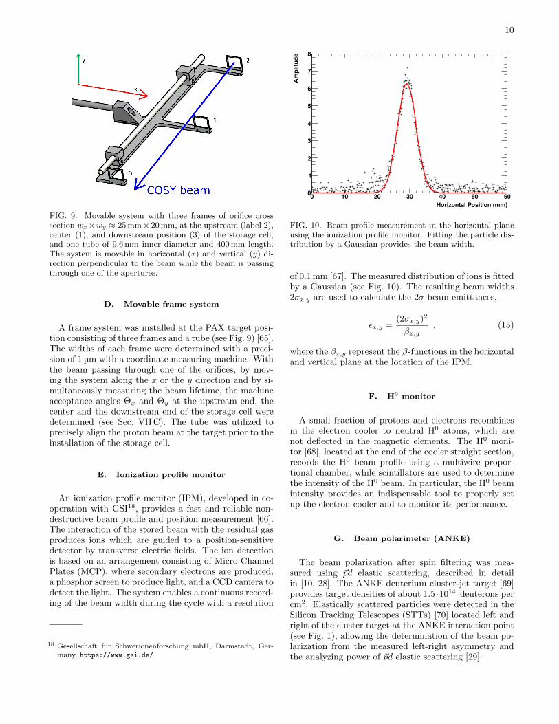
FIG. 9. Movable system with three frames of orifice crosssection wx×wy ≈ 25 mm× 20 mm, at the upstream (label 2),center (1), and downstream position (3) of the storage cell,and one tube of 9.6 mm inner diameter and 400 mm length.The system is movable in horizontal (x) and vertical (y) di-rection perpendicular to the beam while the beam is passingthrough one of the apertures.
D. Movable frame system
A frame system was installed at the PAX target posi-tion consisting of three frames and a tube (see Fig. 9) [65].The widths of each frame were determined with a preci-sion of 1 µm with a coordinate measuring machine. Withthe beam passing through one of the orifices, by mov-ing the system along the x or the y direction and by si-multaneously measuring the beam lifetime, the machineacceptance angles Θx and Θy at the upstream end, thecenter and the downstream end of the storage cell weredetermined (see Sec. VII C). The tube was utilized toprecisely align the proton beam at the target prior to theinstallation of the storage cell.
E. Ionization profile monitor
An ionization profile monitor (IPM), developed in co-operation with GSI18, provides a fast and reliable non-destructive beam profile and position measurement [66].The interaction of the stored beam with the residual gasproduces ions which are guided to a position-sensitivedetector by transverse electric fields. The ion detectionis based on an arrangement consisting of Micro ChannelPlates (MCP), where secondary electrons are produced,a phosphor screen to produce light, and a CCD camera todetect the light. The system enables a continuous record-ing of the beam width during the cycle with a resolution
18 Gesellschaft fur Schwerionenforschung mbH, Darmstadt, Ger-many, https://www.gsi.de/
Horizontal Position (mm)
0 10 20 30 40 50 60
Am
plitu
de
0
1
2
3
4
5
6
7
8
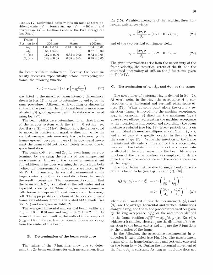
FIG. 10. Beam profile measurement in the horizontal planeusing the ionization profile monitor. Fitting the particle dis-tribution by a Gaussian provides the beam width.
of 0.1 mm [67]. The measured distribution of ions is fittedby a Gaussian (see Fig. 10). The resulting beam widths2σx,y are used to calculate the 2σ beam emittances,
εx,y =(2σx,y)2
βx,y, (15)
where the βx,y represent the β-functions in the horizontaland vertical plane at the location of the IPM.
F. H0 monitor
A small fraction of protons and electrons recombinesin the electron cooler to neutral H0 atoms, which arenot deflected in the magnetic elements. The H0 moni-tor [68], located at the end of the cooler straight section,records the H0 beam profile using a multiwire propor-tional chamber, while scintillators are used to determinethe intensity of the H0 beam. In particular, the H0 beamintensity provides an indispensable tool to properly setup the electron cooler and to monitor its performance.
G. Beam polarimeter (ANKE)
The beam polarization after spin filtering was mea-sured using ~pd elastic scattering, described in detailin [10, 28]. The ANKE deuterium cluster-jet target [69]provides target densities of about 1.5 ·1014 deuterons percm2. Elastically scattered particles were detected in theSilicon Tracking Telescopes (STTs) [70] located left andright of the cluster target at the ANKE interaction point(see Fig. 1), allowing the determination of the beam po-larization from the measured left-right asymmetry andthe analyzing power of ~pd elastic scattering [29].

11
V. BETATRON TUNE AND ORBITADJUSTMENT
Before the actual commissioning of the low-β sectioncould be approached, suitable betatron tune settings andcorrections to the machine orbit had to be carried out,in order to provide good starting conditions for furtheroptimization of the machine with respect to the beamlifetime (Sec. V A).
In the following section in particular the mapping ofthe betatron tunes under different conditions, and thecoupling of the horizontal and vertical phase-space arediscussed. The implemented closed orbit correction pro-cedures aimed at a reduction of the local acceptance lim-itations in the machine in order to optimize the beamlifetime (Sec. V B).
A. Betatron tune mapping
The particles circulating in COSY with frequency fperform betatron oscillations in the horizontal (x) andvertical (y) plane which are induced by the focusingstrength of the quadrupole magnets in the ring. To firstorder the betatron motion constitutes a sinusoidal wavewith frequency fβx,y = f · Qx,y, where Qx,y denotes thebetatron tunes (or working point), i.e., the number ofbetatron oscillations per turn, given by
Qx,y =∆ψx,y
2π=
1
2π
∮ds
βx,y(s). (16)
Here ∆ψx,y = ψx,y(s+ C)− ψx,y(s) is the phase changeper revolution, and C the ring circumference.
At COSY, in order to analyze the betatron tune of themachine, a network analyzer is used to induce coherenttransverse betatron oscillations of the beam by power-ing the stripline unit (see Sec. IV C) with a frequency-swept sine wave voltage, covering the frequency range ofa sideband. These oscillations are detected by a position-sensitive pickup and the output signals are analyzed witha spectrum analyzer. The resulting spectrum consists ofa series of lower (−) and upper (+) betatron sidebandsat each revolution harmonic n with center frequencies of
f− = (n− qx,y)f and f+ = (n+ qx,y)f , (17)
where f denotes the average revolution frequency. Sincethe betatron motion is sampled by the pickup once perturn, the measured spectrum provides only informa-tion about the fractional tune qx,y = frac(Qx,y), whereQx,y = int(Qx,y) + qx,y. The fractional tune is deducedfrom the peak value of both sideband frequencies, andthe revolution frequency is found by adding them. In-serting the resulting value for f into Eq. (17) yields qxand qy.
Because of the symmetry in a synchrotron like COSY,the magnetic structure after each full turn merges into
xQ3.553.59
3.633.67
3.71
yQ
3.55
3.59
3.63
3.67
3.71
(s)
τ
0
500
1000
1500
2000
2500
3000
0
500
1000
1500
2000
2500
3000
FIG. 11. Beam lifetime as a function of the working point(Qx, Qy). While the beam lifetime increases with decreas-ing distance to the difference tune Qx = Qy (dashed line),∆Qsplit = 0, however, is not reachable because of coupling.
itself. Consequently, the forces on the beam recur pe-riodically, and therefore, the betatron tunes should beirrational numbers in order to avoid betatron resonancesthat can lead to an expansion of the beam or even tobeam loss. The resonance condition is given by
mQx ± nQy = l m, n, l ∈ N. (18)
In order to increase the beam lifetime a search for theoptimal betatron tunes was performed for several ma-chine settings, and to this end, different tune combi-nations (Qx, Qy) were investigated. In this procedure,called tune-mapping, the currents in the quadrupolemagnet families QU1-3-5 and QU2-4-6 were varied in therange of ±3%, while the beam lifetime was determinedfrom an exponential fit to the beam current using theBCT signal (see Sec. IV A).
The betatron tune scans, carried out with D 6= 0 set-ting of COSY, showed a large variation in the beam life-time by a factor six in a rather small region of beta-tron tunes (see Fig. 11). Maximum beam lifetimes wereobserved close to the standard COSY working point ofQx = 3.58 and Qy = 3.62. This is in good agreementwith tracking calculations carried out for COSY usingMAD-X [49]. The impact of the third and sixth ordermachine resonances on the beam lifetime is clearly visi-ble, as shown in Fig. 12.
An early investigation of the COSY beam lifetime asfunction of the betatron tunes (Qx, Qy) had confirmedthat the beam lifetime increased with decreasing tunesplit ∆Qsplit = Qx − Qy (see Fig. 11), as mentionedin [71]. Coupling between the horizontal and vertical be-tatron oscillations leads to a rotation of the eigenvectorsof the transverse oscillations, thus the difference reso-nance ∆Qsplit = 0 cannot be reached. Betatron motionscan be coupled through solenoidal and skew-quadrupolefields. The latter arise for instance from quadrupole rolls

12
xQ3.56 3.58 3.6 3.62 3.64 3.66 3.68 3.7
yQ
3.56
3.58
3.6
3.62
3.64
3.66
3.68
3.7
0
500
1000
1500
2000
2500
3000 order 2
order 3
order 6
FIG. 12. Beam lifetime [s] as a function of the betatron tunesQx and Qy. Shown here again are the data from Fig. 11,together with additional data points (in red) in the regionclose to Qx = Qy (low coupling), which were reached by anadjustment of sextupole magnets. The dashed lines corre-spond to |∆Qsplit| = 0.014. Sum and difference resonancesof the second, third and sixth order are shown, representingthe strongest multipole components of dipole and quadrupolemagnets in the machine.
and feed-downs from higher-order multipoles caused byan off-axis beam orbit [72]. The observed tune split∆Qsplit = 0.014 (shown in Fig. 12) cannot be attributedto phase-space coupling induced by the main and the twocompensation solenoids of the electron cooler, becausethey were operated in compensation mode (see Sec. II A).
Applying additional corrections, using the COSY sex-tupole magnets of proper polarity, led to a reduced cou-pling and yielded ∆Qsplit ≈ 0.006 (see red data pointsin Fig. 12). This indicated that the coupling mightoriginate from sextupole components in the fields of thedipole magnets which affect the beam in an off-axis po-sition. This conclusion was confirmed in later measure-ments, performed to commission the low-β insertion (seeFig. 15), which showed that a comparably small ∆Qsplit
could be reached without sextupole corrections by ap-plying instead a closed orbit correction. An indepen-dent measurement at COSY with a 232.8 MeV deuteronbeam [73] arrived at the same conclusion. Startingwith a distorted orbit at the acceptance limit yielded∆Qsplit = 0.011, and by applying a careful closed orbitcorrection, the coupling was decreased by about a factorof four to ∆Qsplit = 0.003.
The achieved tune splits correspond to a small linearcoupling in the machine, which is neglected in later con-siderations.
B. Closed orbit correction
Due to misalignment or field errors of magnets, the realorbit in a machine deviates from the ideal one. In regionswhere the β-functions are large, these deviations lead tolocal restrictions of the machine aperture, and thus re-duce the lifetime of the beam. A closed orbit correctionscheme, based on the orbit response matrix (ORM), wasimplemented to increase the machine acceptance and toimprove the beam lifetime [74, 75]. In addition, the or-bit correction allows one to specify boundary conditionssuch as the beam position at the target or the electroncooler.
The entries Rus,i of the ORM reflect changes of the orbit
deviation u(s) (u = x or y) measured with a BPM at aposition s in the ring, which is caused by a change in thedeflection strength Θu(i) of a correction-dipole magnetat a position i affecting the beam in horizontal (u = x)or vertical (u = y) direction. For x or y these quantitiesare connected by the relation
u(s) = Rus,i ·Θu(i), (19)
where
Rus,i =
√βu,iβu,s ·
cos(πQu − ψu,s→i)2sin(πQu)
(20)
depends on the transverse tune Qu, on the β-function atbeam position monitors and correction-dipole magnets,and on the phase advance between the positions s and i,denoted by ψu,s→i. The ORM can either be calculatedfor the beam optics of the ring or measured. Here, thelatter method was applied. When M horizontal (x) andvertical (y) BPMs and Nx and Ny correcting elementsare installed, then Eq. (19) is replaced by
~u = Ru · ~Θu, (21)
where ~Θu is a vector of Nx or Ny components, ~u is avector of M components, and Ru is a M×Nx or M×Ny
matrix with the calculated elements Rus,i.
For M ≥ Nx, Ny, which was fulfilled in the presentstudies, the horizontal and vertical closed orbit correc-tions were derived by variation of the Θu(i) kick angles to
find the minimum quadratic residual | Ru · ~Θu−~u |2 [74–76]. This method was used in the present studies. An-other possibility uses the inversion of the ORM, where
the appropriate settings are calculated from ~Θu = R−1~u.This method is usually faster, though it should be notedthat an inversion of the matrix R is not always possible.
The closed orbit correction procedure for COSY wastested for the first time in January of 2009 within theframework of a PAX beam time and was further opti-mized since then with the aim to achieve longer beamlifetimes at injection energy. The measurement of theORM made use of up to Ny = 17 vertical orbit correc-tion dipole magnets for the measurement of the verticalORM. 20 horizontal orbit correction dipole magnets, two

13
s (m)0 20 40 60 80 100 120 140 160 180
x (
mm
)∆
20
10
0
10
20
30
40Target
TelescopeCooler
TelescopeArc Arc
uncorrected
1st iteration
2nd iteration
s (m)0 20 40 60 80 100 120 140 160 180
y (
mm
)∆
6
4
2
0
2
4
6
TargetTelescope
CoolerTelescopeArc Arc
uncorrected
1st iteration
2nd iteration
FIG. 13. Effect of horizontal (top) and vertical (bot-tom) closed orbit correction for COSY at injection energy(Tp = 45 MeV). The initial vertical orbit deviations are ingeneral smaller than the horizontal ones.
horizontal back-leg windings at the ANKE dipole mag-nets, and both compensation dipole magnets next to theelectron cooler toroid magnets were used for the determi-nation of the horizontal ORM, i.e., Nx = 24. Dependingon their availability, up to M = 31 beam position mon-itors were employed. The above required M ≥ Nx, Ny
was always fulfilled. Phase-space coupling was neglectedin these measurements. The beam was deflected in bothtransverse planes by changing the current of a particu-lar correction dipole magnet by about 5%. The orbitchanges at the BPMs, normalized to the variation of thecurrent correspond to the entries of the ORM. In spite ofthe longer computation time a χ2 minimization was used
to determine the correction angle kicks ~Θu(i).A typical example of a closed orbit correction with two
iterations is displayed in Fig. 13. The vertical COSY or-bit usually shows smaller deviations than the horizontalone. For the horizontal orbit correction, the initial de-viations of up to 35 mm could be decreased to less than10 mm. Closed-orbit corrections, carried out more re-cently in 2011, exhibit deviations of less than 3 mm.
PAX quadrupole current (A)
0 20 40 60 80 100 120 140 160 180 200
CO
SY
qu
ad
rup
ole
cu
rre
nt
(A)
0
5
10
15
20
25
30
35
40
45
50
(m
) β
0
0.5
1
1.5
2
2.5
3
3.5
4
4.5
5
calculatedx
β calculated
yβ
QT1QT2QT3QT4
FIG. 14. Currents in the COSY quadrupoles and the betatronamplitudes vs current of the PAX low-β quadrupoles. Withincreasing strength of the low-β magnets the betatron ampli-tudes βx (in blue) and βy (in red)(right scale) decrease. Thecurrents in the COSY quadrupoles (QT1-QT4) were reducedto keep the tune constant, using a D 6= 0 setting.
VI. COMMISSIONING OF LOW-β INSERTION
Prior to the polarization build-up measurements, thelow-β insertion (see Sec. II B) was commissioned in adedicated beam time. The aim was to achieve betatronamplitudes at the target center of about βx,y ≈ 0.3 mwithout significant reduction of the beam lifetime. MADcalculations [49] verified that the PAX low-β quadrupoleshave to provide 10 to 40 times larger focusing strengthsthan the regular COSY quadrupole magnets in order toachieve the required small β-functions at the target. Hor-izontal or vertical displacements of the beam in the stronglow-β magnets would cause large orbit excursions alongthe ring. Therefore, a careful closed orbit correction (seeSec. V B) and selection of a reasonable working point (seeSec. V A) were carried out prior to the commissioning toavoid beam losses when the low-β quadrupole magnetsare operated.
The goal to operate the low-β insertion while main-taining the telescopic features of the straight section wasaccomplished using as a starting point a regular COSYoptics setting at Tp = 45 MeV, with dispersion D 6= 0and low-β section switched off. Subsequently, the fieldsof the low-β quadrupole magnets were increased stepwisein strength, while those of the COSY quadrupoles in thesame straight section were reduced in strength such thatthe betatron tunes remained constant. Figure 14 displaysthe current in the COSY quadrupole families QT1-QT4vs the current in the PAX low-β magnets found in thisprocess. The MAD model was used to calculate the β-function at the center point of the insertion (see Fig. 14,right scale). The strengths of the low-β PAX quadrupolemagnets were reduced in the calculation by an empiri-cal value of 4% to achieve stable solutions in the lattice

14
)2k (1/m3.65 3.7 3.75 3.8 3.85 3.9 3.95 4
Q
3.57
3.58
3.59
3.6
3.61
3.62
3.63
3.64
3.65
3.66
x Q
y Q
0.0013± = 0.0084 split
Q∆
)2k (1/m3.66 3.68 3.7 3.72 3.74 3.76 3.78 3.8
Q
3.56
3.58
3.6
3.62
3.64
3.66
3.68
x Q
y Q
0.0017± = 0.0087 split
Q∆
FIG. 15. Betatron tunes Qx (horizontal) and Qy (vertical) asfunction of the focusing strength kx,y for the inner (top panel)and outer (bottom panel) pair of the PAX low-β quadrupoles.The data were fitted with a hyperbola, and the slopes ofthe asymptotes |∆Qx,y/∆k| were used to determine the β-functions. ∆Qsplit is a measure of coupling in the machine.
calculations.
In order to verify the validity of the lattice model, theβ-functions at the PAX quadrupoles were experimen-tally determined by changing the quadrupole strengthand measuring the tune change of the machine. The
quadrupole focusing strength k = 1Bρ
∂By
∂x = 1Bρ
∂Bx
∂y is
given by the magnetic rigidity Bρ = 0.977 Tm for thechosen kinetic energy of Tp = 45 MeV and the magnetic
field gradient. The latter is expressed by∂By
∂x = ∂Bx
∂y =
g · I, where g = 0.0197 Tm−1A−1 denotes the current-specific gradient and I is the operating current. The fourPAX quadrupole magnets are powered pairwise. There-fore, the tunes are measured either as a function of thefocusing strength, i.e., the operating current of the in-ner pair (PAX2, Fig. 15) or of the outer pair (PAX1).The current of the inner pair was modified in steps of1 A from 181.4 A to 199.4 A, corresponding to the rangek = 3.658 m−2 to k = 4.021 m−2. The values for the
outer pair are steps of 0.5 A from 181.7 A to 188.2 A, cor-responding to the range k = 3.664 m−2 to k = 3.795 m−2.
In Fig. 15 the measured tunes Qx and Qy are displayedas function of the quadrupole strength of the outer pair(PAX1, bottom panel) and the inner pair (PAX2, toppanel). According to Ref. [77], the functional form ofQx,y(k) is described by a hyperbola. The hyperbolic fitsalso yield the tune split of ∆Qsplit = 0.0085 ± 0.0010,obtained from a weighted average using the outer andthe inner quadrupole pair. This constitutes an indepen-dent evidence for the presence of slight coupling in themachine, as discussed already in Sec. V A. The crossingpoints of the asymptotes at Q = 3.611 for the inner pairand Q = 3.613 for the outer pair agree within the errorof Qsplit as it has to be.
The ion-optics matrix formalism for a change of thequadrupole focusing strength ∆k yields a tune shift [41,78]
∆Qx,y =1
4π
s0+l∫s0
∆kβx,y(s)ds , (22)
where βx,y(s) is the position-dependent β-function andl is the effective length of the field of the quadrupolemagnet. For small ∆k, βx,y(s) can be replaced by βx,y,which yields
βx,y =4π
l
∣∣∣∣∆Qx,y∆k
∣∣∣∣ . (23)
The absolute value takes into account that the β-functionhas to be positive, remembering that a quadrupole fo-cuses in one plane (∆Qx,y > 0 for ∆k > 0) and defocusesin the other plane (∆Qy,x < 0 for ∆k > 0). To deter-
mine the average values βx and βy in the magnets of theinner and outer pair with the use of Eq. 23, the values of| ∆Q/∆k | are the absolute values of the four slopes ofthe asymptotes of the hyperbolas of Fig. 15. The effectivelength of a single PAX quadrupole magnet, measured as0.442 m, for each of the pairs yields l = 0.884 m. The re-sulting βx and βy are shown in Fig. 16 together with theresult of the model calculation which yields a reasonableagreement (see Table III) with the measured data andβx = 0.31 m and βy = 0.46 m at the center of the target.From a comparison of measured and calculated betatronfunctions an uncertainty of about 10% is estimated forthe β-functions obtained from the MAD model.
TABLE III. Measured and calculated betatron functions βxand βy from the MAD model at the position of the PAXquadrupole magnets (outer pair: PAX1, inner pair: PAX2).The calculated β-functions at the target center are given incolumn six.
Measurement Model calculationPAX1 PAX2 PAX1 PAX2 center
βx (m) 2.31 ± 0.13 2.80 ± 0.04 2.11 2.71 0.31βy (m) 12.41 ± 1.01 3.31 ± 0.05 12.99 2.74 0.46

15
s(m)17 18 19 20 21 22
(m
)β
1
10y
β
xβ
1 2 3 4
FD F D FF
FIG. 16. Model calculation of the β-functions at the PAX-TPand measured values of βx and βy at the magnet positions.In blue the four new PAX quadrupole magnets are indicated.Magnet 1 and 4 form the defocusing (D) pair (PAX1) andmagnets 2 and 3 the focusing (F) pair (PAX2), where eachpair is operated with a single power supply. In addition thestorage cell and the beam direction are shown.
VII. BEAM SIZE, BEAM EMITTANCE,MACHINE ACCEPTANCE, AND TARGET
ACCEPTANCE ANGLE
The polarization build-up cross section σ1 depends onthe acceptance angle Θacc at the target location, as ex-plained in Sec. I. Therefore, in order to determine σ1, it isnecessary to measure Θacc. The measurement made useof the fact that when an object is placed at a distancesmaller than the maximum allowed extension of the localphase-space ellipse, the machine acceptance is reduced,and therefore the beam lifetime as well [65, 79].
In the subsequent section, we first describe the deter-mination of the beam width at the target, since it mayhave some bearing on the machine acceptance extractedfrom a measurement with the scraper system, describedin Sec. IV D. The actual acceptance measurements, in-cluding the determination of Θacc and a discussion ofpossible systematic errors, are described in Sec. VII C.
A. Measurement of the beam widths at the target
The beam widths along the PAX target were de-termined by moving each the three rectangular frames(shown in Fig. 9) with constant speed through the protonbeam. The decrease of the beam current was recordedwith the BCT (see Sec. IV A). A typical result of such a
Position (mm)
3 2 1 0 1 2 3
Beam
In
ten
sit
y (
mA
)
0
0.05
0.1
0.15
0.2
0.25
0.3
0.35
0.4
0.45
σ
FIG. 17. Measured beam intensity as function of frame po-sition obtained by moving the frame through the beam. Theresulting beam profile (black points) constitutes half of aninverted Gaussian from which σ as a measure of the beamwidth is obtained by fitting using Eq. (27) (dashed blueline). The beam intensity with frame in nominal positionof I0 = 0.35 mA corresponds to about 4.67 · 109 protons atinjection energy.
frame scan is shown in Fig. 17. The remaining beam in-tensity as function of the frame position is obtained fromconverting the measured time into the distance from thestart position, using the constant velocity of the framemovement of
vx = vy = (1.65± 0.02) mm/s. (24)
The measured beam profile constitutes half of an in-verted Gaussian when the beam itself has a Gaussianprofile [80]. Assuming no coupling in the machine (seeSec. V A), a scraper moving along x (or y) direction re-moves only those particles from the (x, x′) (or (y, y′))phase space for which the betatron amplitudes are largerthan the distance from the beam center to the edge ofthe scraper (see Fig. 1 of Ref. [65]).
A cooled and stored beam exhibits a two-dimensionalGaussian distribution in transverse phase space wherethe density distribution of the betatron amplitude ρβ ine.g., the (x, x′) plane [80, 81] is given by
ρβ(x) =I0σ2x
· x · exp
(− x2
2σ2x
). (25)
The measured beam intensity as a function of frame po-sition can be written as [65],
Iframe(x) =
x−µx∫0
ρβ(x) · dx
= I0
[1− exp
(− (x− µx)2
2σ2x
)]. (26)
Here I0 is the beam intensity with the frame in nom-inal position, µx is the beam center, and σx describes
16
TABLE IV. Determined beam widths (in mm) at three po-sitions, center (s′ = 0 mm) and up- (s′ = −200 mm) anddownstream (s′ = +200 mm) ends of the PAX storage cell(see Fig. 9).
Frame 2 1 3Position (s′) −200 mm 0 mm +200 mm
2σx 1.04± 0.02 0.91± 0.04 1.04± 0.012σy 0.66± 0.02 − 0.67± 0.02βx (m) 0.62± 0.06 0.55± 0.06 0.62± 0.06βy (m) 0.48± 0.05 0.38± 0.04 0.48± 0.05
the beam width in x-direction. Because the beam in-tensity decreases exponentially before intercepting theframe, the following function
I(x) = Iframe(x) · exp(− xτb · vx
)(27)
was fitted to the measured beam intensity dependence,shown in Fig. 17, in order to determine σx and σy by thesame procedure. Although with coupling or dispersionat the frame position, the functional form is more com-plicated [82], good agreement with the data was achievedusing Eq. (27).
The beam widths were determined for all three framesof the scraper system with the D = 0 setting (seeSec. II A) at Tp = 45 MeV. Horizontally, the frames couldbe moved in positive and negative direction, while thevertical measurements were only feasible by moving theframes upward, because in case of the downward move-ment the beam could not be completely removed due tospace limitation.
The beam width 2σx and 2σy for each frame were de-termined by averaging the results of two independentmeasurements. In case of the horizontal measurement2σx additionally includes averaging the results from bothx-direction measurements. The results are listed in Ta-ble IV. Unfortunately, the vertical measurement at thetarget center (s′ = 0 mm) showed distortions that madethe result inconsistent. The measurements confirm thatthe beam width 2σx is smallest at the cell center and asexpected, knowing the β-functions, increases symmetri-cally toward the up- and downstream ends of the storagecell. The appropriate β-functions at the location of eachframe were obtained from the validated MAD model (seeSec. VI) and are given in Table IV.
The averaged horizontal and vertical beam widths are2σx = 1.03 ± 0.01 mm and 2σy = 0.67 ± 0.02 mm. Interms of these beam widths, the walls of the storage cell(rcell = 4.8 mm) are at least ten standard deviations awayfrom the center of the beam.
B. Determination of the beam emittance
The values of the β-functions allow one to deter-mine the 2σ beam emittance for each measurement from
Eq. (15). Weighted averaging of the resulting three hor-izontal emittances yields
εx =(2σx)2
βx= (1.71± 0.17) µm , (28)
and of the two vertical emittances yields
εy =(2σy)2
βy= (0.92± 0.15) µm . (29)
The given uncertainties arise from the uncertainty of theframe velocity, the statistical errors of the fit, and theestimated uncertainty of 10% on the β-functions, givenin Table IV.
C. Determination of Ax, Ay, and Θacc at the target
The acceptance of a storage ring is defined in Eq. (6).At every point in the ring, the acceptance Ax,y cor-responds to a (horizontal and vertical) phase-space el-lipse [72]. When at some point along the orbit, a re-striction (frame) is moved into the machine acceptance,e.g., in horizontal (x) direction, the maximum (x, x′)phase-space ellipse, representing the machine acceptanceat that location, is intercepted, and accordingly the beamlifetime is reduced (see Fig. 18). Every particle orbits onan individual phase-space ellipses in (x, x′) and (y, y′),and all ellipses at a specific location in the ring havethe same shape [76]. While the insertion of the framepresents initially only a limitation of the x coordinate,because of the betatron motion, also the x′ coordinateis affected. Therefore, measuring the beam lifetime asfunction of the frame position was employed to deter-mine the machine acceptance and the acceptance angleat the target.
The total beam lifetime due to single Coulomb scat-tering is found to be (see Eqs. (9) and (7)) [46],
τ ′b(Ax, Ay) = c ·Θ2acc = 2c ·
(1
Θ2x
+1
Θ2y
)−1
= 2c ·(〈βx〉Ax
+〈βy〉Ay
)−1
, (30)
where c is a constant during the measurement, 〈βx〉 and〈βy〉 are the average horizontal and vertical β-functionsalong the ring, and the x- and y-acceptance is either givenby the ring acceptance Aring
x,y or the acceptance defined
by the frame position Aframex,y = a2
x,y/βx,y (see Eq. (6)),whichever is smaller. Here ax,y are the distances of the re-striction to the beam center and βx,y are the β-functionsat the location of the frame.
In the following, the acceptance measurement in x-direction is exemplified (see Fig. 19). The measurementbegins with the frame horizontally and vertically centeredon the beam (x = 0). During the horizontal movement ofthe frame Ay is constant. As long as the frame does not

17
x (mm)4 3 2 1 0 1 2 3 4
x’ (m
rad
)
10
8
6
4
2
0
2
4
6
8
10
machine acceptance
frame edge
FIG. 18. Horizontal phase-space distribution at the PAX tar-get position from a Monte-Carlo simulation. A typical ma-chine acceptance at COSY (Ax = 20 µm, Ay = 15 µm) isindicated by the large ellipse. Moving a frame into the ma-chine acceptance decreases both x and x′, thus reduces thebeam lifetime, and allows one to determine Ax and Θx.
limit the machine acceptance (|x| ≤ |x2|), the beam life-time is not affected (part III in Fig. 19). When the framemoves into the machine acceptance (|x2| ≤ |x| ≤ |x1|),Ax and therefore the beam lifetime become smaller (partsII and IV). Reaching a position of |x| ≥ |x1| the mea-sured beam lifetime vanishes (parts I and V). Theoreti-cally, the beam lifetime should vanish to zero, when theframe reaches the center of the beam, corresponding to aposition of |x| = wx/2, where wx is the measured framewidth (see Sec. IV D).
Based on these considerations the following fit func-tion, using Eq. (30), is formulated,
τb(x) =
0
τ ′b(Aframex , Aring
y )
τ ′b(Aringx , Aring
y )
τ ′b(Aframex , Aring
y )
0
if x ≤ −x1 I
if −x1 ≤ x ≤ −x2 II
if −x2 ≤ x ≤ x2 III
if x2 ≤ x ≤ x1 IV
if x ≥ x1 V
(31)where Aring
y , x1, and x2 are fit parameters. The ma-chine acceptance is determined from the distance be-tween x2 and the beam center by
Ax =(wx/2− x2)2
βx. (32)
The offset of the beam with respect to the center of theframe can be determined with a typical uncertainty of0.1 mm. For clarity, the offset parameter has been omit-ted in Eq. (31), but is taken into account in the actualfitting function.
Monte-Carlo simulations of an acceptance measure-ment using realistic phase-space distributions at the PAX
position of frame center
beam
lif
eti
me (
a.u
.)
1x 1x2x 2x0
I VII IVIII
2 x2
xw
xw
FIG. 19. Schematic illustration of the beam lifetime as func-tion of the position of the frame during an acceptance mea-surement. As long as the frame is outside the machine accep-tance (part III), the beam lifetime is unchanged. When theframe limits the acceptance the beam lifetime drops (partsII and IV) according to Eq. (31), and when it intercepts thebeam itself, the beam lifetime vanishes (parts I and V). Theacceptance is then defined by the frame width wx and theposition where the frame enters the machine acceptance x2.
target position showed good agreement between simu-lated data and the fit function (Eq. (31)) for typical beamsizes at the target (see Sec. VII A).
The acceptance measurements with the movable framesystem (see Sec. IV D, Fig. 9) were carried out for allfour edges of each of the three rectangular frames. Mov-ing each frame individually into the machine accep-tance, while recording the beam lifetime, allowed oneto determine the machine acceptance angles at the en-trance of the storage cell (s′ = −200 mm), at the center(s′ = 0 mm), and at the exit (s′ = +200 mm). A mea-surement carried out in the presence of the ANKE clustertarget (see Sec. IV G) showed good agreement of the re-sulting acceptances.
The acquired dataset enabled a precise determinationof the machine acceptance, the acceptance angle in hor-izontal and vertical direction, and of the total accep-tance angle Θacc (Eq. 7) at the target. During themeasurements the beam intensity was in the range of(7.5− 10) · 109 circulating unpolarized cooled protons atinjection energy of 45 MeV, with the PAX low-β sectionswitched on and the initial beam lifetime of about 3700 s.
During injection the frame was horizontally and verti-cally centered on the beam. After injection and cooling,the frame was moved in horizontal (vertical) directionand the resulting beam lifetime was recorded. An ex-ample of a measurement with frame 1, located at thetarget center, is shown in Fig. 20. The uncertainties ofthe beam lifetimes τb are of the order of 100 s, chosen toyield reduced χ2 of approximately unity for the fits.
All fits indicate that the beam lifetime actually van-ishes before the frame edge intercepts the beam center.

18
x position (mm)10 5 0 5 10
(s)
bτ
0
500
1000
1500
2000
2500
3000
3500
4000
4500
xw
xδxδ
y position (mm)10 5 0 5 10
(s)
bτ
0
500
1000
1500
2000
2500
3000
3500
4000
4500
yw
yδ yδ
FIG. 20. Recorded beam lifetime as function of the horizontal (x, left panel) and vertical (y, right) position of frame 1 (PAXtarget center), and fit of τb(x) using Eq. (31). The fits indicate, that the observed widths at the base (τb = 0) were smallerthan the corresponding frame widths (wx, wy), where the discrepancies δx = 1.0± 0.1 mm and δy = 0.5± 0.1 mm.
TABLE V. Acceptance measurements with the movable frame system, listing the acceptances Ax and Ay, the acceptance anglesΘx and Θy, and Θacc, using Eqs. (6), (7), and the β-functions given in Table IV. One measurement with frame 1 was carriedout with the cluster target switched on. The weighted averages are given in the bottom row. Results were rounded to onedecimal place, while for calculation and averaging three decimal places were used.
Pos (m) Frame Ax(µm) Ay(µm) Θx(mrad) Θy(mrad) Θacc(mrad)−0.2 2 27.1± 4.0 16.8± 3.2 6.6± 0.6 5.9± 0.6 6.2± 0.4
0.0 1 49.7± 10.3 14.1± 6.0 9.5± 1.1 6.1± 1.3 7.3± 1.20.2 3 31.5± 4.7 19.6± 3.7 7.1± 0.6 6.4± 0.7 6.7± 0.50.0 1 (target on) 33.0± 5.1 12.4± 3.1 7.8± 0.7 5.7± 0.8 6.5± 0.6
Average 31.2± 2.5 15.7± 1.8 7.3± 0.3 6.0± 0.4 6.45 ± 0.27
This is equivalent to stating that the observed width atthe base (τb = 0) is smaller than the frame width (seeSec. IV D), thus |x1| + δx = wx/2 and |y1| + δy = wy/2(see Fig. 20), where the discrepancy δx (δy) is of theorder of 1.0 ± 0.1 mm (0.5 ± 0.1 mm). Possibly, smallbeam oscillations of unknown origin are responsible forthis observation. It should be noted that the approachof measuring the machine acceptance with a rectangularframe is sensitive to such effects, while this is not thecase for a single-sided scraper measurement. Therefore,in the latter case, the machine acceptance might be un-derestimated.
The results for Ax, Ay, Θx, Θy, and Θacc using Eqs. (6)and (7) are listed in Table V. The total acceptance angleat the target position amounts to
Θacc = (6.45± 0.27) mrad . (33)
The given uncertainty includes the error of the fit as wellas an estimated 10% uncertainty of the β-functions.
The determined horizontal and vertical machine accep-tances of Ax = 31.2 ± 2.5 µm and Ay = 15.7 ± 1.8 µm(see Table V) are significantly smaller than the sim-ple geometrical acceptances estimated from the standardCOSY lattice and the dimensions of the beam pipe (see
Sec. II B). This is the case, because the beam lifetime islikewise impaired by dynamic effects through processesthat act on long time scales, caused by nonlinear externalfields [83]. Therefore, by the presented method one deter-mines the relevant machine acceptance for spin-filteringexperiments.
VIII. BEAM LIFETIME OPTIMIZATION
This section describes further machine investigationscarried out at COSY aiming at an enlargement of thebeam lifetime toward τb ≈ 10000 s, necessary to de-termine the spin-dependent cross section σ1 of the po-larization build-up during a few weeks of beam time.The starting point of the optimization is marked by abeam lifetime of τb = 800 s, reached in 2007 for an elec-tron cooled proton beam at injection energy without tar-get [68].
Different processes contribute to the beam lifetime,such as betatron resonances, the Coulomb interactionwith the residual gas and the target, intrabeam scat-tering, and hadronic interactions. Particle loss due tobetatron resonances can be minimized by the choice ofa suitable working point, also required for the commis-
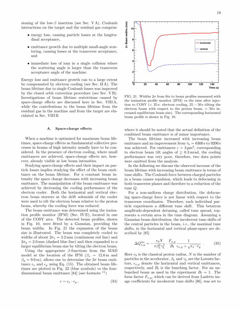
19
sioning of the low-β insertion (see Sec. V A). Coulombinteractions on the target and the residual gas comprise
• energy loss, causing particle losses at the longitu-dinal acceptance,
• emittance growth due to multiple small-angle scat-tering, causing losses at the transverse acceptance,and
• immediate loss of ions in a single collision wherethe scattering angle is larger than the transverseacceptance angle of the machine.
Energy loss and emittance growth can to a large extentbe compensated by electron cooling (see Sec. II A). Thebeam lifetime due to single Coulomb losses was improvedby the closed orbit correction procedure (see Sec. V B).Investigations of beam lifetime restrictions caused byspace-charge effects are discussed here in Sec. VIII A,while the contributions to the beam lifetime from theresidual gas in the machine and from the target are elu-cidated in Sec. VIII B.
A. Space-charge effects
When a machine is optimized for maximum beam life-times, space-charge effects as fundamental collective pro-cesses in beams of high intensity usually have to be con-sidered. In the presence of electron cooling, where smallemittances are achieved, space-charge effects are, how-ever, already visible at low beam intensities.
Studying space-charge effects and their impact on par-ticle losses implies studying the effect of the beam emit-tance on the beam lifetime. For a constant beam in-tensity the space charge decreases with increasing beamemittance. The manipulation of the beam emittance wasachieved by decreasing the cooling performance of theelectron cooler. Both the horizontal and vertical elec-tron beam steerers at the drift solenoids of the coolerwere used to tilt the electron beam relative to the protonbeam, whereby the cooling force was reduced.
The beam emittance was determined using the ioniza-tion profile monitor (IPM) (Sec. IV E), located in oneof the COSY arcs. The detected beam profiles, shownin Fig. 10, were fitted by a Gaussian, providing thebeam widths. In Fig. 21 the expansion of the beamsize is illustrated. The beam was completely cooled towidths of about 2σx = 3.2 mm (continuous red line) and2σy = 2.0 mm (dashed blue line) and then expanded to alarger equilibrium beam size by tilting the electron beam.
Using the appropriate β-functions from the MADmodel at the location of the IPM (βx = 12.6 m andβy = 9.6 m), allows one to determine the 2σ beam emit-tance εx and εy using Eq. (15). The obtained beam life-times are plotted in Fig. 22 (blue symbols) vs the four-dimensional beam emittance [84] (see footnote 11)
ε = εx · εy , (34)
Time (s)
0 20 40 60 80 100 120 140
Beam
wid
ths (
mm
)σ
2
0
2
4
6
8
10
horizontal
vertical
FIG. 21. Widths 2σ from fits to beam profiles measured withthe ionization profile monitor (IPM) vs the time after injec-tion to COSY (< 25 s: electron cooling, 25 − 50 s tilting theelectron beam with respect to the proton beam, > 50 s in-creased equilibrium beam size). The corresponding horizontalbeam profile is shown in Fig. 10.
where it should be noted that the actual definition of thecombined beam emittance is of minor importance.
The beam lifetime increased with increasing beamemittance and an improvement from τb = 6300 s to 9200 swas achieved. For emittances ε > 3 µm2, correspondingto electron beam tilt angles of ≥ 0.3 mrad, the coolingperformance was very poor, therefore, two data pointswere omitted from the analysis.
In the following we discuss the observed increase of thebeam lifetime with increasing beam emittance in terms oftune shifts. The Coulomb force between charged particlesin a beam causes repulsion, which leads to defocusing inboth transverse planes and therefore to a reduction of thetune Q.
For a non-uniform charge distribution, the defocus-ing space-charge force is not linear with respect to thetransverse coordinates. Therefore, each individual par-ticle experiences a different tune shift. This betatronamplitude-dependent detuning, called tune spread, rep-resents a certain area in the tune diagram. Assuming aGaussian beam distribution, the incoherent tune shifts ofthe central particles in the beam, i.e., the maximal tuneshifts, in the horizontal and vertical phase-space are de-scribed by [85]
∆Qincx,y = − r0N
πβ2Lγ
3L
· Fx,yBf
1
εx,y +√εx · εy
. (35)
Here r0 is the classical proton radius, N is the number ofparticles in the accelerator, βL and γL are the Lorentz fac-tors, εx,y denote the horizontal and vertical emittances,respectively, and Bf is the bunching factor. For an un-bunched beam as used in the experiment Bf = 1. Theform factor Fx,y, which can be derived from Lasletts im-age coefficients for incoherent tune shifts [86], was set to
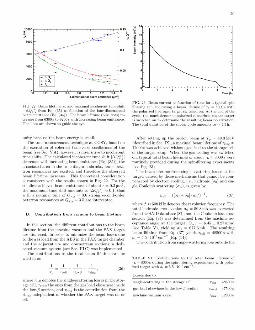
20
)2mµ4dimensional beam emittance (
0 0.2 0.4 0.6 0.8 1 1.2 1.4
(s
)
bτ
0
2000
4000
6000
8000
10000
inc
Q∆
0
0.05
0.1
0.15
x Q∆
y Q∆
bτ
FIG. 22. Beam lifetime τb and maximal incoherent tune shift−∆Qinc
x,y from Eq. (35) as function of the four-dimensionalbeam emittance (Eq. (34)). The beam lifetime (blue dots) in-creases from 6300 s to 9200 s with increasing beam emittance.The lines are shown to guide the eye.
unity because the beam energy is small.The tune measurement technique at COSY, based on
the excitation of coherent transverse oscillations of thebeam (see Sec. V A), however, is insensitive to incoherenttune shifts. The calculated incoherent tune shift |∆Qinc
x,y|decreases with increasing beam emittance (Eq. (35)), theassociated area in the tune diagram shrinks, fewer beta-tron resonances are excited, and therefore the observedbeam lifetime increases. This theoretical considerationis consistent with the results shown in Fig. 22. For thesmallest achieved beam emittances of about ε = 0.2 µm2,the maximum tune shift amounts to |∆Qinc
x,y| ≈ 0.1, thuswith a nominal tune of Qx,y = 3.6 strong second-orderbetatron resonances at Qx,y = 3.5 are intercepted.
B. Contributions from vacuum to beam lifetime
In this section, the different contributions to the beamlifetime from the machine vacuum and the PAX targetare discussed. In order to minimize the beam losses dueto the gas load from the ABS in the PAX target chamberand the adjacent up- and downstream sections, a dedi-cated vacuum system (see Sec. III C) was implemented.
The contributions to the total beam lifetime can bewritten as
1
τb=
1
τcell+
1
τlowβ+
1
τring, (36)
where τcell denotes the single-scattering losses in the stor-age cell, τlowβ the ones from the gas load elsewhere insidethe low-β section, and τring is the contribution from thering, independent of whether the PAX target was on oroff.
Time (h)
0 1 2 3 4 5 6
p)
9B
eam
in
ten
sit
y (
10
0
2
4
6
8
10
12
14
FIG. 23. Beam current as function of time for a typical spinfiltering run, indicating a beam lifetime of τb = 8000 s withthe polarized hydrogen target switched on. At the end of thecycle, the much denser unpolarized deuterium cluster targetis switched on to determine the resulting beam polarization.The total duration of the shown cycle amounts to ≈ 5.5 h.
After setting up the proton beam at Tp = 49.3 MeV(described in Sec. IX), a maximal beam lifetime of τring ≈12000 s was achieved without gas feed to the storage cellof the target setup. When the gas feeding was switchedon, typical total beam lifetimes of about τb ≈ 8000 s wereroutinely provided during the spin-filtering experiments(see Fig. 23).
The beam lifetime from single-scattering losses at thetarget, caused by those mechanisms that cannot be com-pensated by electron cooling, i.e., hadronic (σ0) and sin-gle Coulomb scattering (σC), is given by
τcell = ([σC + σ0] · dtf)−1, (37)
where f ≈ 508 kHz denotes the revolution frequency. Thetotal hadronic cross section σ0 = 59.8 mb was extractedfrom the SAID database [87], and the Coulomb loss crosssection (Eq. (8)) was determined from the machine ac-ceptance angle at the target, Θacc = 6.45 ± 0.27 mrad(see Table V), yielding σC = 677.6 mb. The resultingbeam lifetime from Eq. (37) yields τcell = 48500 s withdt = 5.5 · 1013 cm−2 (Eq. (14)).
The contribution from single-scattering loss outside the
TABLE VI. Contributions to the total beam lifetime ofτb = 8000 s during the spin-filtering experiments with polar-ized target with dt = 5.5 · 1013 cm−2.
Losses due to
single-scattering in the storage cell τcell 48500 s
gas load elsewhere in the low-β section τlowβ 47500 s
machine vacuum alone τring 12000 s

21
cell in the low-β section, determined from Eq. (36), yieldsτlowβ = (τb
−1 − τ−1ring − τcell
−1)−1 = 47500 s. The threecontributions to the total beam lifetime are summarizedin Table VI. The results show that the total beam lifetimeat COSY is dominated by the machine alone, whereas thetarget region contributes by only one third.
IX. SPIN FILTERING AT 49.3 MEV
The goal of the machine development was to providea routine to set up COSY for the spin-filtering experi-ments. This routine (see Sec. IX A) and the measure-ment cycles (see Sec. IX B) are described below. Majorrequirements for the experiment were beam intensities ofabout 1 · 1010 protons and long beam and polarizationlifetimes. Dedicated cycles were set up to measure thebeam polarization lifetime (see Sec. IX C), and the effi-ciency of the RF spin flipper (see Sec. IX D) that enablesthe application of the cross-ratio method [88] within eachcycle by reversing the beam polarization.
A. Setting up the beam
Based on the investigations described above, the fol-lowing sequence of steps was applied to provide longbeam and polarization lifetimes together with high beamintensities.
1. Setting up injection for protons at Tp = 45 MeVwith standard COSY optics.
2. Setting up electron cooling, including the trans-verse feedback system.
3. First closed orbit correction.
4. Switching on of the low-β section by increasingthe current in the low-β quadrupoles and simulta-neously decreasing the current in the quadrupolesof the target telescope, while keeping the machinetunes constant (see Sec. VI).
5. Optimization of injection and electron cooling withthe low-β section switched on.
6. Setting up stacking injection to increase the beamintensity.
7. Second closed orbit correction.
8. Setting up acceleration to Tp = 49.3 MeV with elec-tron beam switched off.
9. Setting up electron cooling without feedback withreduced electron current (Ie = 50 mA) for optimalbeam lifetime.
10. Change of machine optics to dispersion D = 0 set-ting.
11. Third closed orbit correction.
12. Tune adjustment (using only QU1, QU5 and QU2,QU6, Fig. 1, to keep D = 0) to provide optimalbeam lifetime without transverse feedback.
13. Adjustment of electron beam angle with respect tothe proton beam to further optimize the beam life-time (see Sec. VIII A).
Concerning step 9, it should be noted that it provedmore effective to operate the transverse feedback systemof the electron cooler (see Sec. II A) rather at injectionenergy than at the experiment energy of 49.3 MeV. Theexcitation of coherent betatron oscillations in the beam,due to the missing transverse feedback at experiment en-ergy, was avoided by selecting a different working point(Qx = 3.62 and Qy = 3.64), and by a reduction of theelectron current.
B. Measurement cycle
After the beam was set up as described in Sec. IX A, adedicated spin-filtering cycle was implemented, accordingto the sequence shown in Fig. 24. The relevant figure ofmerit can be expressed as FOM = P 2(t) · I(t) [89] whichled to the conclusion to use filtering periods of 1.5 and2 beam lifetimes to yield smallest overall uncertaintiesfor the spin-dependent cross sections [16], at the sametime providing the time dependence of the polarizationbuild-up. A cycle with no filtering but otherwise identi-cal settings as in the spin filtering process was setup forsystematic studies.
The spin-filtering cycles were composed of three parts:
1. Beam preparation (56 s)An unpolarized proton beam was injected at abeam energy of Tp = 45 MeV, electron cooled(Ie = 150 mA), and subsequently accelerated toTp = 49.3 MeV.
2. Spin-filtering (tfilter = 0 s, 12000 s, and 16000 s)Polarized hydrogen atoms were injected into thestorage cell at the PAX interaction point. Theholding field coils, orienting the target polariza-tion, were powered on in either +y (up) or −y(down) orientation for the duration of the spin-filtering period. Three different spin-filtering peri-ods were used: tfilter = 12000 s and tfilter = 16000 s,corresponding to about 1.5 and 2 times the mea-sured beam lifetime, for systematic reasons mea-surements with tfilter = 0 s were taken as well.
3. Beam polarimetry (2500 s)At the end of the spin-filtering period, the PAXpolarized target was switched off, the ANKE deu-terium cluster target was switched on, and the dataacquisition for the determination of the beam po-larization was started (Sec. IV G). The current of
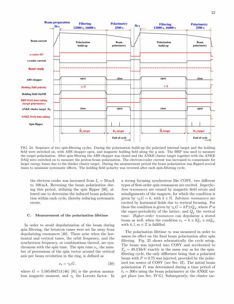
22
Polarization
build-up Beam
polarimetry
ABS chopper
Holding field polarity
Holding field On/Off
BRP DAQ data taking
(target polarimetry)
Beam ready
D2ANKE cluster target
ANKE DAQ data taking
targetD 2
Beam current
Spin flipper
e-cooler current
e-cooler HV
y+
Beam preparation
12000 s, 16000 s56 s
open close
openclose
H target1
End of cycle
Polarization
build-up Beam
polarimetry
targetD 2
12000 s, 16000 s 2500 s
open close
openclose
H target1
End of cycle
y-
Filtering Polarimetry Filtering Polarimetry2500 s56 s
FIG. 24. Sequence of two spin-filtering cycles. During the polarization build-up the polarized internal target and the holdingfield were switched on, with ABS chopper open, and magnetic holding field along the y axis. The BRP was used to measurethe target polarization. After spin filtering the ABS chopper was closed and the ANKE cluster target together with the ANKEDAQ were switched on to measure the proton-beam polarization. The electron-cooler current was increased to compensate forlarger energy losses due to the thicker cluster target. During the measurement period the beam polarization was flipped severaltimes to minimize systematic effects. The holding field polarity was reversed after each spin-filtering cycle.
the electron cooler was increased from Ie = 50 mAto 100 mA. Reversing the beam polarization dur-ing this period, utilizing the spin flipper [90], al-lowed one to determine the induced beam polariza-tion within each cycle, thereby reducing systematicerrors.
C. Measurement of the polarization lifetime
In order to avoid depolarization of the beam duringspin filtering, the betatron tunes were set far away fromdepolarizing resonances [40]. These arise when the hor-izontal and vertical tunes, the orbit frequency, and thesynchrotron frequency, or combinations thereof, are syn-chronous with the spin tune. The spin tune νs, the num-ber of precessions of the spin vector around the verticalaxis per beam revolution in the ring, is defined as
νs = γLG , (38)
where G = 5.585 694713 (46) [91] is the proton anoma-lous magnetic moment, and γL the Lorentz factor. In
a strong focusing synchrotron like COSY, two differenttypes of first-order spin resonances are excited. Imperfec-tion resonances are caused by magnetic field errors andmisalignments of the magnets, for which the condition isgiven by γLG = k, with k ∈ N. Intrinsic resonances areexcited by horizontal fields due to vertical focusing. Forthese the condition is given by γLG = kP±Qy, where P isthe super-periodicity of the lattice, and Qy the verticaltune. Higher-order resonances can depolarize a storedbeam as well, when the condition νs = k ± lQx ±mQy,with k, l,m ∈ Z is fulfilled.
The polarisation lifetime τP was measured in order toassess its effect on the final beam polarization after spinfiltering. Fig. 25 shows schematically the cycle setup.The beam was injected into COSY and accelerated toTp = 49.3 MeV exactly in the same way as for the spin-filtering cycle, the only difference being that a polarizedbeam with P ≈ 0.75 was injected, provided by the polar-ized ion source of COSY (see Sec. II). The initial beampolarization Pi was determined during a time period oft1 = 300 s using the beam polarimeter at the ANKE tar-get place (see Sec. IV G). Subsequently, the cluster tar-

23
Time (s)
0 2000 4000 6000
p)
8B
eam
in
ten
sit
y (
10
Beam
po
lari
zati
on
CT ONCluster Target OFFON
fP
iP
FIG. 25. Measurement cycle to determine the beam polar-ization lifetime. The beam polarization (red) is measuredbefore (Pi) and after (Pf) a waiting period of 5000 s. Duringthe measurement, the deuterium cluster target (CT) of theANKE polarimeter is switched on causing a faster decrease ofthe beam intensity (black).
get was switched off for t2 = 5000 s in order to minimizebeam losses. The measurement of the final polarizationPf lasted for t3 = 940 s. The durations of the measure-ment periods were optimized to yield the smallest rela-tive errors in τP and to reach equal statistical errors ofthe beam polarization during both sequences. The beampolarization lifetime was determined by evaluating
τP =−∆t
ln(PfPi
) , (39)
where the initial and the final beam polarizations wereaveraged over the measurement periods t1 and t3, re-spectively. Taking these measurement periods into ac-count, the time difference between both polarizationmeasurements is given by ∆t = t2 + t′1 + t′3 = 5496 s,where t′1 and t′3 account for the exponential decrease ofthe event rate within each measurement period. WithPi = 0.746 ± 0.003 and Pf = 0.731 ± 0.003 [92], the de-termination of the polarization lifetime yielded
τP = (2.7± 0.8) · 105 s . (40)
Therefore, the polarization losses during the spin-filteringexperiments with filter times of tfilter = 12000 s and16000 s did not exceed 6%.
D. Efficiency of RF spin flipper
During the polarization measurement period at theend of each filtering cycle, the beam polarization wasflipped several times to enable the determination of thebeam polarization within each cycle using the cross-ratio
Time (s)
0 100 200 300 400
p)
8B
eam
in
ten
sit
y (
10
Beam
po
lari
zati
on
CT ON CT OFF CT ON
SF OFF SF ON SF OFF
FIG. 26. Measurement cycle to determine the spin-flip (SF)efficiency. The beam polarization (red) is measured before(Pi) and after (Pf) nflip = 99 spin flips. While these areexecuted, the deuterium cluster target (CT) of the ANKEpolarimeter is switched off.
method [88], whereby systematic errors are cancelled tofirst order.
The spin flips were generated using a so-calledFroissart-Stora frequency sweep induced with an RFsolenoid [90, 93]. The RF frequency was swept over theprecession frequency of the proton spin and flips the spinresonantly at the frequency fRF = f0 · (γLG± k), whichyielded for k = −4, fRF = 0.9615 MHz. The frequencyramp from 0.9605 MHz to 0.9625 MHz was carried out in2.5 s, therefore the effect on the duty cycle was negligible.
The spin flip efficiency,
εflip = exp
ln(PfPi
)nflip
, (41)
where Pi,f are the initial and final polarizations, was de-termined in order to be able to correct for polarizationlosses and to adjust the number of flips nflip within themeasurement period. The dedicated cycle to determinethe spin-flip efficiency, shown schematically in Fig. 26,yielded the smallest relative error in εflip. It begins withthe injection and acceleration of a polarized proton beamto Tp = 49.3 MeV, followed by a polarization measure-ment lasting for about 50 s. Subsequently, the clustertarget was switched off and nflip = 99 spin flips were per-formed within a time period of 300 s. Finally, the beampolarization was measured again for about 100 s.
The measurements of εflip during the experimentphase, each lasting for about two hours, yielded
εflip = 0.9872± 0.0001 . (42)
During the initial spin-filtering measurements the num-ber of spin flips was two. Thus, the polarization loss dueto the spin-flipper never exceeded 3%.

24
X. CONCLUSION
In this paper we present the machine development forthe spin-filtering experiments carried out at COSY [28].The prime objective was to provide a long beam life-time in the presence of a polarized hydrogen gas target.To this end a dedicated low-β section consisting of twoquadrupole doublets was implemented at the PAX tar-get place. The optimization of the beam lifetime includedthe search for optimal working points, closed orbit cor-rections, optimization of electron cooling, and the mini-mization of the β-functions at the PAX target.
The low-β insertion lead to β-functions of (βx, βy) =(0.31± 0.03 m, 0.46± 0.05 m) at the center of the polar-ized storage cell target, presenting a reduction of abouta factor of ten compared to the situation before. Hence,single Coulomb scattering as the dominating loss mech-anism for cooled beams was reduced by the same factor.In addition, this allowed us to use a narrow storage cell ofdiameter d = 9.6 mm and length l = 400 mm with a arealtarget-gas density of dt = (5.5± 0.2) · 1013atoms/cm2.
Special care of the vacuum conditions in and aroundthe target chamber was taken through the installation ofa sophisticated pumping system together with flow lim-iters at the entrance and exit of the chamber. The beamlifetime caused by the target region with an injected gasflow of 3.3 ·1016 H/s contributed by only one third to thetotal beam lifetime of τb = 8000 s, while the contributionof the machine itself was twice as large.
The machine acceptances, the beam widths andthe machine acceptance angle at the target were de-termined using a dedicated movable frame system,yielding Ax = (31.2± 2.5) µm, Ay = (15.7± 1.8) µm,(2σx, 2σy) = (1.03± 0.01 mm, 0.67± 0.02 mm), andΘacc = (6.45± 0.27) mrad. With the achieved β-functions, the horizontal and vertical 2σ beam emittanceswere εx = (1.71± 0.17) µm and εy = (0.92± 0.15) µm.
In order to improve the systematics of the spin-filteringexperiment, an RF spin flipper was utilized to reversethe polarization of the stored beam after spin filtering.
The spin-flip efficiency determined in dedicated cyclesamounted to εflip = 0.9872 ± 0.0001, and the polariza-tion loss due to the spin-flipper never exceeded 3%. Inaddition, the polarization lifetime was determined in ded-icated cycles, yielding τP = (2.7±0.8) ·105 s, thus for thespin-filtering experiments at COSY with spin-filteringtimes of tfilter = 12000 s and 16000 s, the polarizationloss due to a finite polarization lifetime did not exceed6%.
The interplay of the investigations presented in thispaper fulfilled the demanding beam conditions for thefirst spin-filtering experiment at COSY. The presentedresults comprise a recipe about how to set up a beamfor spin-filtering experiments in a storage ring, directlyapplicable for the anticipated spin-filtering studies withantiprotons at the AD of CERN [27].
ACKNOWLEDGMENTS
We are grateful to the COSY crew for the continuoussupport over several years and especially for providinggood working conditions during experiments. We wouldlike to acknowledge the invaluable help by the workshopsand personnel of the Institut fur Kernphysik (in par-ticular J. Sarkadi), by the Zentralinstitut fur Systemeder Elektronik (ZEA-2) and Zentralinstitut fur Engineer-ing und Technologie (ZEA-1) of the ForschungszentrumJulich (especially H. Jagdfeld and H. Straatmann), andby the workshop of the University of Ferrara (in partic-ular V. Carassiti)
Our thanks also go to the colleagues from CERN(P. Chiggiato, J. Hansen, P. C. Pinto, and I. Wevers)for the test measurements and discussions concerning thevacuum design and the NEG coating.
The present work is supported by the ERC AdvancedGrant POLPBAR (Grant Agreement 246980), the EUgrants of the Projects I3HP2 and I3HP3 (Grant Agree-ments 227431 and 283286), the COSY-FFE program(41853505-FAIR-009), and the Swedish Research Council(Dnos. 624-2009-224 and 624-2010-5135).
[1] P. L. Csonka, Nucl. Instrum. Meth. 63, 247 (1968).[2] K. Kilian and D. Mohl, Ettore Majorana Int. Sci. Ser.
Phys. Sci. 17, 701 (1984).[3] Proc. of the Workshop on Polarized Antiprotons, Bodega
Bay, 1985; eds. A. D. Krisch, A. M. T. Lin and O. Cham-berlain, AIP Conf. Proc. 145 (1986).
[4] Proc. of the International Workshop ”Polarized antipro-ton beams - how?”, Daresbury, UK, 2007; eds. D. P. Bar-ber, N. Buttimore, S. Chattopadhyay, G. Court and E.Steffens, AIP Conf. Proc. 1008 (2008).
[5] The program of the 409. WE-Heraeus seminar, includ-ing all talks is available from http://www.fe.infn.it/
heraeus/.[6] F. Rathmann et al., Phys. Rev. Lett. 71, 1379 (1993).
[7] F. Rathmann, Ph.D. thesis, Philips-Universitat Marburg,1994.
[8] K. Zapfe et al., Nucl. Instrum. Meth. A368, 293 (1996).[9] K. Zapfe et al., Rev. Sci. Instrum. 66, 28 (1995).
[10] D. Oellers et al., Phys. Lett. B674, 269 (2009).[11] A. Lehrach, O. Boine-Frankenheim, F. Hinterberger,
R. Maier, and D. Prasuhn, Nucl. Instrum. Meth. A561,289 (2006).
[12] H.H. Gutbrod et al. (Eds.), FAIR Baseline Tech-nical Report, ISBN 3-9811298-0-6 (2006), availablefrom http://www.fair-center.de/fileadmin/fair/
publications_FAIR/FAIR_BTR_1.pdf.[13] P. Lenisa and F. Rathmann (PAX Collaboration),
“Antiproton-Proton Scattering Experiments with Po-

25
larization (Letter of Intent),” (2003), available fromhttp://collaborations.fz-juelich.de/ikp/pax/
documents/proposals.shtml.[14] V. Barone et al. (PAX Collaboration), “Antiproton-
Proton Scattering Experiments with Polarization (Tech-nical proposal),” (2005), available from http://arxiv.
org/pdf/hep-ex/0505054.pdf.[15] F. Bradamante et al., (2005), arXiv:physics/0511252
[physics].[16] F. Rathmann et al., Phys. Rev. Lett. 94, 014801 (2005).[17] A. Milstein and V. Strakhovenko, Phys. Rev. E72,
066503 (2005).[18] N. Nikolaev and F. Pavlov, in Proceedings of the 17th In-
ternational Spin Physics Symposium (SPIN 2006), (Ky-oto, 2006, Vol. 915 (AIP, New York, 2007) p. 932) hep-ph/0601184 [hep-ph].
[19] N. Nikolaev and F. Pavlov, AIP Conf. Proc. 1008, 34(2008).
[20] A. Milstein, S. Salnikov, and V. Strakhovenko, Nucl.Instrum. Meth. B266, 3453 (2008), 0802.3766.
[21] R. Maier, Nucl. Instrum. Meth. A390, 1 (1997).[22] D. Oellers et al., Nucl. Instrum. Meth. A 759, 6 (2014).[23] V. F. Dmitriev, A. I. Milstein, and S. G. Salnikov, Phys.
Lett. B690, 427 (2010).[24] D. Zhou and R. G. E. Timmermans, Phys. Rev. C87,
054005 (2013).[25] Y. N. Uzikov and J. Haidenbauer, Phys. Rev. C 87,
054003 (2013).[26] Y. N. Uzikov, J. Haidenbauer, and B. A. Prmantayeva,
Phys. Rev. C 84, 054011 (2011).[27] P. Lenisa and F. Rathmann (PAX Collaboration), “Mea-
surement of the Spin Dependence of the pp interactionat the AD ring ,” (2009), available from http://arxiv.
org/abs/0904.2325.[28] W. Augustyniak et al., Phys. Lett. B718, 64 (2012).[29] N. S. P. King et al., Phys. Lett. B69, 151 (1977).[30] J. Bystricky, F. Lehar, and P. Winternitz, J. Phys.
(France) 39, 1 (1978).[31] C. Weidemann, Ph.D. thesis, University Cologne,
2011, available from http://collaborations.
fz-juelich.de/ikp/pax/public_files/theses/
thesisCh.Weidemann.pdf.[32] D. Prasuhn et al., in Proceedings of the Workshop on
Beam Cooling and Related Topics, Montreux, 1993,CERN Report 94-03, 317-321 (1994).
[33] D. Prasuhn et al., Nucl. Instrum. Meth. A441, 167(2000).
[34] P. D. Eversheim et al., in Proceedings of the Int. Symp.on High Energy Spin Physics SPIN 1996, Amsterdam,Netherlands, World Scientific Singapore (1997), p. 306.
[35] L. Aldea et al., in Proceedings of the 9th Int. Conf. onCyclotrons and their applications, Caen, France, 1981,edited by G. Gendreau, les Editions de Physique, Paris(1982), p. 103.
[36] H. Stockhorst, ”Polarized proton and deuteron beams atCOSY” (2004), available from http://arxiv.org/abs/
physics/0411148.[37] B. Lorentz et al., J. Phys. Conf. Ser. 295, 012146 (2011).[38] A. Lehrach et al., AIP Conf. Proc. 667, 30 (2003).[39] K. Bongardt et al., Conf. Proc. C8903201, 1379 (1989).[40] A. Lehrach et al., Nucl. Instrum. Meth. A439, 26 (2000).[41] K. Wille, The Physics of Particle Accelerators (Oxford
University Press, 2001).[42] H. J. Stein et al., (2011), arXiv:1101.5963 [physics.acc-
ph].[43] H. Soltner, H. Stein, V. Kamerdzhiev, J. de Villiers,
J. Conradie, and J. Dietrich, Applied Superconductivity,IEEE Transactions on 24, 1 (2014).
[44] V. Kamerdzhiev, Ph.D. thesis, Dortmund University(2003), available from https://eldorado.tu-dortmund.
de/bitstream/2003/2322/1/Kamerdzhievunt.pdf.[45] V. Kamerdzhiev et al., Nucl. Instrum. Meth. A532, 285
(2004).[46] N. Madsen, S. Maury, and D. Mohl, Nucl. Instrum.
Meth. A441, 54 (2000).[47] H. Poth, Phys. Rept. 196, 135 (1990).[48] C. Ekstrom et al., Phys. Scripta T22, 256 (1988).[49] H. Grote and F. C. Iselin, “The MAD program (methodi-
cal accelerator design) version 8.4: User’s reference man-ual ,” (1991), available from http://mad.web.cern.ch/
mad/.[50] F. Stock et al., Nucl. Instrum. Meth. A343, 334 (1994).[51] A. Nass et al., Nucl. Instrum. Meth. A 505, 633 (2003).[52] A. Airapetian et al. (HERMES Collaboration), Nucl. In-
strum. Meth. A540, 68 (2005).[53] G. Ciullo et al., J. Phys. Conf. Ser. 295, 012150 (2011).[54] C. Baumgarten et al. (HERMES Target Group), Nucl.
Instrum. Meth. A482, 606 (2002).[55] C. Baumgarten et al., Nucl. Instrum. Meth. A508, 268
(2003).[56] J. Price and W. Haeberli, Nucl. Instrum. Meth. A349,
321 (1994).[57] A. Roth, Vacuum Technology (Elsevier Science Pub-
lisher, Amsterdam, 1990) 3rd edition.[58] H. J. Stein et al., Phys. Rev. ST Accel. Beams 11, 052801
(2008).[59] E. Steffens and W. Haeberli, Reports on Progress in
Physics 66, 1887 (2003).[60] F. Rathmann et al., Phys. Rev. C58, 658 (1998).[61] P. Chiggiato and P. C. Pinto, Thin Solid Films 515, 382
(2006).[62] K. Unser, IEEE Trans. Nucl. Sci. 28, 2344 (1981).[63] R. Maier et al., Conf. Proc. C900612, 800 (1990).[64] J. Dietrich and I. Mohos, in Proceedings of the 8th Work-
shop on Beam Instrumentation, BIW’98, Stanford, USA,1998, edited by R.O. Hettel, Stanford (1998), p. 454.
[65] K. Grigoryev et al., Nucl. Instrum. Meth. A599, 130(2009).
[66] C. Bohme, in Proceedings of the 9th European Work-shop on Beam Diagnostics and Instrumentation for Par-ticle Accelerators (DIPAC09), Basel, Switzerland, 2009,edited by J. Chrin, M. Marx, V.R.W. Schaa, V. Schlott(Villigen, PSI, 2009), 185 p.
[67] P. Forck, Conf. Proc. C100523, TUZMH01 (2010).[68] H. J. Stein, IKP Annual Report (2004), available
from http://donald.cc.kfa-juelich.de/wochenplan/
publications/AR2004/documents/AR2004_Articles.
pdf.[69] A. Khoukaz et al., The European Physical Journal D 5,
275 (1999).[70] R. Schleichert et al., IEEE Trans. Nucl. Sci. 50, 301
(2003).[71] R. Cappi, E. Metral, and D. Mohl, in Proceedings,
18th International Conference, HEACC 2001, Tsukuba,Japan, 2001, CERN-PS-2001-010-AE.
[72] S. Y. Lee, Accelerator Physics (Second Edition) (WorldScientific Publishing Co. Pte. Ltd., Singapore, 2004).
[73] A. Lehrach, F. Rathmann, and J. Pretz (JEDI Collabo-

26
ration), “Search for Permanent Electric Dipole Momentsat COSY ,” (2012), COSY proposal #216, availablefrom http://collaborations.fz-juelich.de/ikp/
jedi/public_files/proposals/EDM-COSY-Proposal_
cover_02.05.2012.pdf.[74] R. Talman, in Frontiers of Particle Beams; Observation,
Diagnosis and Correction, Lecture Notes in Physics, Vol.343, edited by M. Month and S. Turner (Springer BerlinHeidelberg, 1989) pp. 4–45.
[75] D. Welsch, Ph.D. thesis, Rheinische Friedrich-Wilhelms-Universitat Bonn (2009), available at http://hss.ulb.
uni-bonn.de/2010/2082/2082.pdf.[76] A. Chao and M. Tigner, Handbook of Accelerator Physics
and Engineering (3rd printing) (World Scientific Publish-ing Co. Pte. Ltd., Singapore, 2006).
[77] P. Bryant, A simple theory for weak betatron coupling,in CERN Accelerator School, Geneva, 207 (1994).
[78] E. Courant and H. Snyder, Annals Phys. 3, 1 (1958).[79] M. Ross et al., Nucl. Instrum. Meth. A326, 424 (1993).[80] K. Potter, Beam profiles, CERN Accelerator School, Gif-
sur-Yvette, Paris, 1984, Yellow Report CERN 85-19, 301-317 (1984).
[81] F. Hinterberger and D. Prasuhn, Nucl. Instrum. Meth.A279, 413 (1989).
[82] A. Jansson et al., Tevatron beam study report, avail-able from http://beamdocs.fnal.gov/AD/DocDB/0003/
000393/002/Scraping%20Report.pdf (2003).[83] G. Guignard, The general theory of all sum and differ-
ence resonances in a three-dimensional magnetic field ina synchrotron (CERN, Geneva, 1976) CERN-76-06.
[84] J. Buon, Conf. Proc. C930517, 469 (1993).[85] K. Schindl, Space Charge, CERN Accelerator School,
Zeuthen, Germany, September 15-26, 305 (2003).[86] L. Laslett, in Proceedings of Summer Study on Storage
Rings, Accelerators and Experimentation at Super High-Energies, Brookhaven, USA, 1963, edited by J.W. Bitt-ner (Upton, N.Y., BNL, 1963), p. 324; eConf C630610,324 (1963).
[87] SAID, Nucleon–nucleon scattering database, Center forNuclear Studies, Department of Physics, George Wash-ington University, USA.
[88] R. C. Hanna, in Proceedings of the 2nd Interna-tional Symposium on Polarization Phenomena, Karls-ruhe, 1965, (Birkhaeuser, Basel 1966), p. 280.
[89] G. G. Ohlsen and P. W. Keaton, Nucl. Instrum. Meth.109, 41 (1973).
[90] V. S. Morozov et al., Phys. Rev. ST Accel. Beams 7,024002 (2004).
[91] NIST database, available from http://physics.nist.
gov/cgi-bin/cuu/Value?gp.[92] Z. Bagdasarian, Master thesis, Ivane Javakhishvili
Tbilisi State University, 2012, available fromhttp://collaborations.fz-juelich.de/ikp/pax/
public_files/theses/thesisZ.Bagdasarian.pdf.[93] M. Froissart and R. Stora, Nucl. Instrum. Meth. 7, 297
(1960).
Related Documents