Toward engineering functional organ modules by additive manufacturing This content has been downloaded from IOPscience. Please scroll down to see the full text. Download details: IP Address: 110.77.221.43 This content was downloaded on 04/10/2013 at 15:15 Please note that terms and conditions apply. 2012 Biofabrication 4 022001 (http://iopscience.iop.org/1758-5090/4/2/022001) View the table of contents for this issue, or go to the journal homepage for more Home Search Collections Journals About Contact us My IOPscience

Welcome message from author
This document is posted to help you gain knowledge. Please leave a comment to let me know what you think about it! Share it to your friends and learn new things together.
Transcript

Toward engineering functional organ modules by additive manufacturing
This content has been downloaded from IOPscience. Please scroll down to see the full text.
Download details:
IP Address: 110.77.221.43
This content was downloaded on 04/10/2013 at 15:15
Please note that terms and conditions apply.
2012 Biofabrication 4 022001
(http://iopscience.iop.org/1758-5090/4/2/022001)
View the table of contents for this issue, or go to the journal homepage for more
Home Search Collections Journals About Contact us My IOPscience
IOP PUBLISHING BIOFABRICATION
Biofabrication 4 (2012) 022001 (12pp) doi:10.1088/1758-5082/4/2/022001
TOPICAL REVIEW
Toward engineering functional organmodules by additive manufacturingFrancoise Marga1, Karoly Jakab1, Chirag Khatiwala2,Benjamin Shepherd2, Scott Dorfman2, Bradley Hubbard3,Stephen Colbert3 and Gabor Forgacs1,2,4,5,6
1 Department of Physics and Astronomy, University of Missouri, Columbia, MO 65211, USA2 Organovo, Inc., 5871 Oberlin Drive, San Diego, CA 92121, USA3 Department of Plastic Surgery, University of Missouri, Columbia, MO 65211, USA4 Department of Biomedical Engineering, University of Missouri, Columbia, MO 65211, USA5 The Shipley Center for Innovation, Clarkson University, Potsdam, NY 13699, USA
E-mail: [email protected]
Received 7 December 2011Accepted for publication 17 January 2012Published 12 March 2012Online at stacks.iop.org/BF/4/022001
AbstractTissue engineering is emerging as a possible alternative to methods aimed at alleviating thegrowing demand for replacement tissues and organs. A major pillar of most tissue engineeringapproaches is the scaffold, a biocompatible network of synthetic or natural polymers, whichserves as an extracellular matrix mimic for cells. When the scaffold is seeded with cells it issupposed to provide the appropriate biomechanical and biochemical conditions for cellproliferation and eventual tissue formation. Numerous approaches have been used to fabricatescaffolds with ever-growing complexity. Recently, novel approaches have been pursued that donot rely on artificial scaffolds. The most promising ones utilize matrices of decellularizedorgans or methods based on multicellular self-assembly, such as sheet-based andbioprinting-based technologies. We briefly overview some of the scaffold-free approaches anddetail one that employs biological self-assembly and bioprinting. We describe the technologyand its specific applications to engineer vascular and nerve grafts.
(Some figures may appear in colour only in the online journal)
Abbreviations
ECM extracellular matrixCVD cardiovascular diseaseHASMC human aortic smooth muscle cellHAEC human aortic endothelial cellHDFb human dermal fibroblastID inner diameterDAH differential adhesion hypothesisSC Schwann cellsPLGA polylactic glycolic acid
6 Author to whom any correspondence should be addressed.
BMSC bone marrow stem cellMSC mesenchymal stem cell
1. Introduction
The classical tissue engineering paradigm [1] is to seed andgrow cells in biocompatible matrix materials—scaffolds—designed to direct cell differentiation and functional assemblyinto three-dimensional tissues [2]. To mimic the in vivo milieu,the developing tissue is cultured in a bioreactor providingthe necessary molecular and physical signals [3], followedby implantation into the host, where further maturation andintegration are anticipated.
1758-5082/12/022001+12$33.00 1 © 2012 IOP Publishing Ltd Printed in the UK & the USA
Biofabrication 4 (2012) 022001 Topical Review
Scaffolds have been fabricated from both synthetic andnatural polymers and used to engineer tissue grafts of greatvariety (e.g. skin, cartilage, bone, blood vessels, skeletalmuscle, bladder, trachea, myocardium [4–8]). To be usefulfor tissue engineering, these polymers must be biodegradable,have an architecture compatible with cell type, size, nutrienttransport to maintain viability and growth. They have to beengineered to assure that their degradation rate matches the rateat which cells within them deposit their own cell and tissue-specific extracellular matrix (ECM). Scaffolds often need tocontain soluble clues (e.g. growth factors, morphogens) and areassembled to slowly release them [9, 10] or shaped accordingto the geometry of the desired construct [11, 12]. Despite theselimiting conditions, scaffold-based tissue engineering has ledto some spectacular clinically relevant results [11, 13–18]. Dueto the many challenges for scaffolds, alternative approacheshave appeared recently. One is based on decellularized nativeECMs, and the other exploits the innate properties of cells toproduce their own ECM (i.e. scaffold-free tissue engineering).
The use of the decellularized, tissue-specific ECMeliminates a number of difficulties associated with scaffold-based tissue engineering [19–21]. The method is based onremoving the cellular and nuclear content of xenogenicor homogenic organs and reseeding the resulting tissue orthe organ-specific ECM with the recipient’s cells [22–30].This approach has led to spectacular results in tissue andfull organ reconstruction, such as cardiovascular repair [31],readily available vascular grafts for hemodialysis access [32],complete bioartificial heart [33], vascularized liver organoid[34] and clinical restoration of dysfunctional airway [35].To ensure that no immunogenic reaction is triggered by thedecellularized ECM, it is vital to remove all cellular material.The efficiency of removal depends on the origin of the tissue ororgan. Thus the specific chemical and enzymatic methods ofdecellularization must be selected with great care [20, 31].Furthermore, when the decellularized matrices of complexheterogeneous organs (e.g. heart) are repopulated with variouscell types it is not obvious how to determine their ratio.
Fully biological tissue engineering is free of exogenousscaffolds. Instead, it is based on cellular self-assembly thatrelies, among others, on the ability of cells to develop theirown tissue-specific ECM. In one approach, sheets of cells areengineered and cultured until they develop the ECM. Sheetswrapped into tubes have been used to build fully biologicalnerve grafts [36] and autologous vascular grafts [37, 38] withpromising functional results in early human clinical trials[38–40]. Combining sheets gives rise to three-dimensionaltissues with complex architecture [41], which can be usedfor cell-based therapy [42].
Another self-assembly-based approach detailed in thiswork is based on the recognition that ‘nature knows best’.Here, a multicellular assembly, with composition dictatedby the tissue or organoid to be engineered, is prepared inan initial configuration compatible with the topology of thattissue or organ. It then self-assembles through morphogeneticprocesses akin to those in early development, into thedesired three-dimensional structure [43]. In the technologydiscussed here, the initial configuration of the multicellular
system is prepared by the automated deposition of bioinkparticles (conveniently prepared multicellular aggregates) anda biocompatible temporary support, using specialized deliverydevices [44, 45].
Several types of delivery methods exist for such solidfree-form fabrication of cellular constructs: inkjet bioprinters(desktop inkjet printers redesigned and enabled to deliver cellsalso in the vertical direction) [46–50], direct cell writing usingpneumatically powered nozzle systems [51] or laser guidance[52–54] and mechanical extruders [55, 56].
Fully biological, self-assembly-based tissue engineering,in particular when combined with additive manufacturingmethods, has the potential to deliver constructs that resemblemost their in vivo counterparts both architecturally andfunctionally. The disadvantage of the method is that thedevelopment of the natural ECM is time consuming and in vitroself-assembly may differ from that under fully physiologicalconditions. Finally, as with all tissue engineering approaches,the regulatory hurdles will be substantial.
Below we overview a particular scaffold-free, self-assembly-based approach that utilizes bioprinting, and discusstwo specific applications: the engineering of vascular and nervegrafts.
2. Self-assembly-based tissue engineering bybioprinting
The major components of the print-based tissue engineeringtechnology detailed below are the bioink, the temporarysupport structure and the bioprinter.
2.1. Bioink
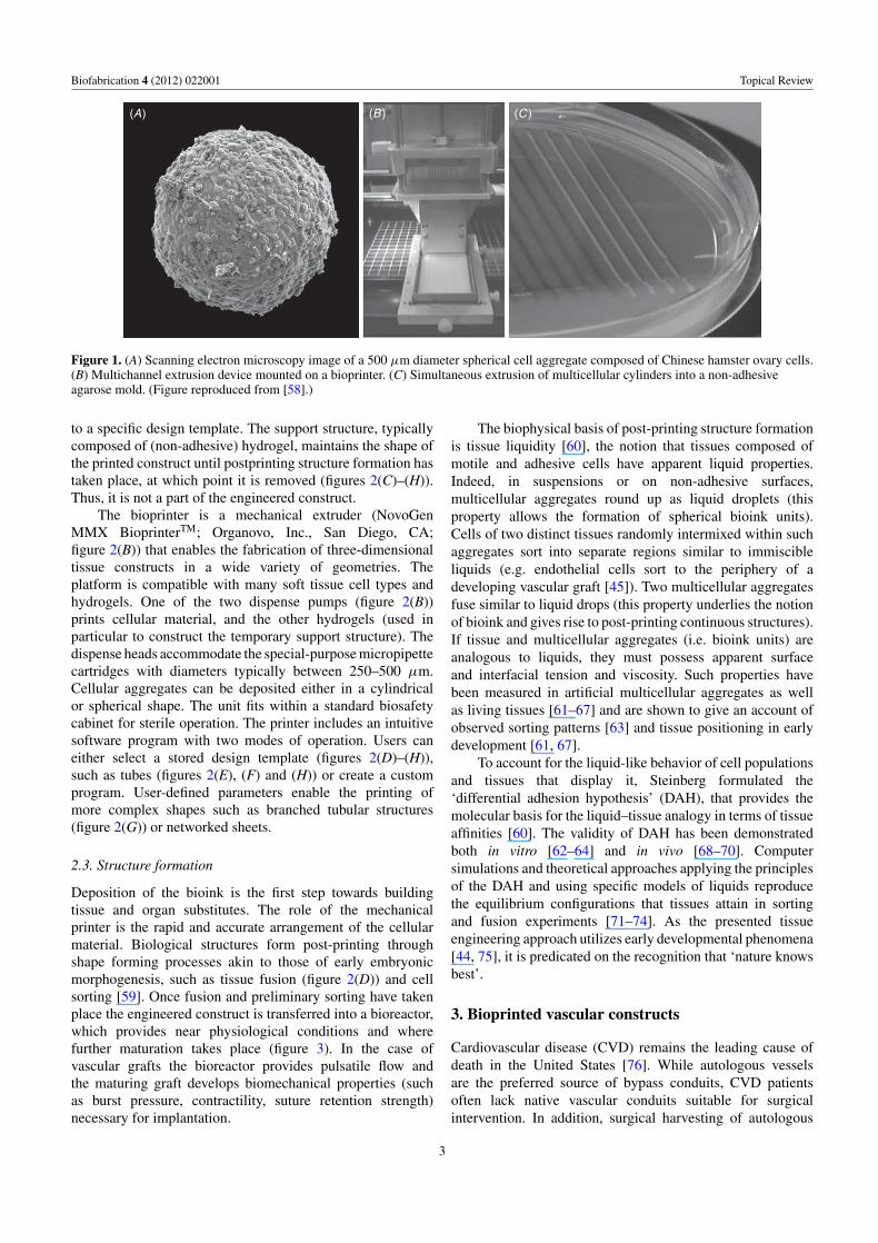
The bioink particles are multicellular aggregates (spheroids orcylinders) composed of cell types consistent with the tissueor organ structure to be printed. These can be prepared inmultiple ways [57]. As for printing ideally they have tobe of consistent size, we have developed a specific methodof preparation (for details see [58]). Cells are culturedunder usual conditions in a cell-type specific medium inPetri dishes or standard culture flasks, transferred to 10 mltissue culture flasks, incubated and centrifuged. Resultingpellets are aspirated into special-purpose micropipettes, 250–500 μm in diameter, incubated to re-establish cell–celladhesive contacts and extruded. For spherical bioink, extrudedcylinders are cut into equal fragments that are let to round upovernight on a gyratory shaker. Depending on the diameterof the micropipette, this procedure provides spheroids of adefined size and cell number (typically several thousand cells;figure 1(A)). For cylindrical bioink, cylinders are extrudedby the bioprinter into specifically prepared cell-inert hydrogelmolds (figures 1(B) and (C)) for overnight maturation. Thespherical or cylindrical bioink units are finally aspirated intomicropipettes, which serve as printer cartridges (figure 2(A)).
2.2. Support structure and bioprinter
Cartridges are loaded into the printer (figure 2(B)), whichdeposits the bioink particles and support structure according
2
Biofabrication 4 (2012) 022001 Topical Review
(A) (B ) (C )
Figure 1. (A) Scanning electron microscopy image of a 500 μm diameter spherical cell aggregate composed of Chinese hamster ovary cells.(B) Multichannel extrusion device mounted on a bioprinter. (C) Simultaneous extrusion of multicellular cylinders into a non-adhesiveagarose mold. (Figure reproduced from [58].)
to a specific design template. The support structure, typicallycomposed of (non-adhesive) hydrogel, maintains the shape ofthe printed construct until postprinting structure formation hastaken place, at which point it is removed (figures 2(C)–(H)).Thus, it is not a part of the engineered construct.
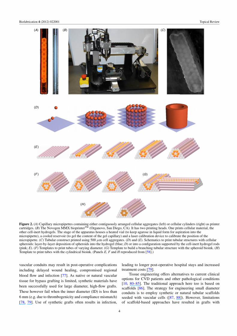
The bioprinter is a mechanical extruder (NovoGenMMX BioprinterTM; Organovo, Inc., San Diego, CA;figure 2(B)) that enables the fabrication of three-dimensionaltissue constructs in a wide variety of geometries. Theplatform is compatible with many soft tissue cell types andhydrogels. One of the two dispense pumps (figure 2(B))prints cellular material, and the other hydrogels (used inparticular to construct the temporary support structure). Thedispense heads accommodate the special-purpose micropipettecartridges with diameters typically between 250–500 μm.Cellular aggregates can be deposited either in a cylindricalor spherical shape. The unit fits within a standard biosafetycabinet for sterile operation. The printer includes an intuitivesoftware program with two modes of operation. Users caneither select a stored design template (figures 2(D)–(H)),such as tubes (figures 2(E), (F) and (H)) or create a customprogram. User-defined parameters enable the printing ofmore complex shapes such as branched tubular structures(figure 2(G)) or networked sheets.
2.3. Structure formation
Deposition of the bioink is the first step towards buildingtissue and organ substitutes. The role of the mechanicalprinter is the rapid and accurate arrangement of the cellularmaterial. Biological structures form post-printing throughshape forming processes akin to those of early embryonicmorphogenesis, such as tissue fusion (figure 2(D)) and cellsorting [59]. Once fusion and preliminary sorting have takenplace the engineered construct is transferred into a bioreactor,which provides near physiological conditions and wherefurther maturation takes place (figure 3). In the case ofvascular grafts the bioreactor provides pulsatile flow andthe maturing graft develops biomechanical properties (suchas burst pressure, contractility, suture retention strength)necessary for implantation.
The biophysical basis of post-printing structure formationis tissue liquidity [60], the notion that tissues composed ofmotile and adhesive cells have apparent liquid properties.Indeed, in suspensions or on non-adhesive surfaces,multicellular aggregates round up as liquid droplets (thisproperty allows the formation of spherical bioink units).Cells of two distinct tissues randomly intermixed within suchaggregates sort into separate regions similar to immiscibleliquids (e.g. endothelial cells sort to the periphery of adeveloping vascular graft [45]). Two multicellular aggregatesfuse similar to liquid drops (this property underlies the notionof bioink and gives rise to post-printing continuous structures).If tissue and multicellular aggregates (i.e. bioink units) areanalogous to liquids, they must possess apparent surfaceand interfacial tension and viscosity. Such properties havebeen measured in artificial multicellular aggregates as wellas living tissues [61–67] and are shown to give an account ofobserved sorting patterns [63] and tissue positioning in earlydevelopment [61, 67].
To account for the liquid-like behavior of cell populationsand tissues that display it, Steinberg formulated the‘differential adhesion hypothesis’ (DAH), that provides themolecular basis for the liquid–tissue analogy in terms of tissueaffinities [60]. The validity of DAH has been demonstratedboth in vitro [62–64] and in vivo [68–70]. Computersimulations and theoretical approaches applying the principlesof the DAH and using specific models of liquids reproducethe equilibrium configurations that tissues attain in sortingand fusion experiments [71–74]. As the presented tissueengineering approach utilizes early developmental phenomena[44, 75], it is predicated on the recognition that ‘nature knowsbest’.
3. Bioprinted vascular constructs
Cardiovascular disease (CVD) remains the leading cause ofdeath in the United States [76]. While autologous vesselsare the preferred source of bypass conduits, CVD patientsoften lack native vascular conduits suitable for surgicalintervention. In addition, surgical harvesting of autologous
3
Biofabrication 4 (2012) 022001 Topical Review
(A)
(D )
(E )
(F )
(H )
(G)
(B) (C)
Figure 2. (A) Capillary micropipettes containing either contiguously arranged cellular aggregates (left) or cellular cylinders (right) as printercartridges. (B) The Novogen MMX bioprinterTM (Organovo, San Diego, CA). It has two printing heads. One prints cellular material, theother cell-inert hydrogels. The stage of the apparatus houses a heated vial (to keep agarose in liquid form for aspiration into themicropipette), a cooled reservoir (to gel the content of the gel capillary) and a laser calibration device to calibrate the position of themicropipette. (C) Tubular construct printed using 500 μm cell aggregates. (D) and (E). Schematics to print tubular structures with cellularspheroids: layer-by-layer deposition of spheroids into the hydrogel (blue; D) or into a configuration supported by the cell-inert hydrogel rods(pink; E). (F) Templates to print tubes of varying diameter. (G) Template to build a branching tubular structure with the spheroid bioink. (H)Template to print tubes with the cylindrical bioink. (Panels E, F and H reproduced from [58].)
vascular conduits may result in post-operative complicationsincluding delayed wound healing, compromised regionalblood flow and infection [77]. As native or natural vasculartissue for bypass grafting is limited, synthetic materials havebeen successfully used for large diameter, high-flow grafts.These however fail when the inner diameter (ID) is less than6 mm (e.g. due to thrombogenicity and compliance mismatch)[78, 79]. Use of synthetic grafts often results in infection,
leading to longer post-operative hospital stays and increasedtreatment costs [79].
Tissue engineering offers alternatives to current clinicaloptions for CVD patients and other pathological conditions[10, 80–85]. The traditional approach here too is based onscaffolds [86]. The strategy for engineering small diameterconduits is to employ synthetic or natural tubular scaffoldsseeded with vascular cells ([87, 88]). However, limitationsof scaffold-based approaches have resulted in grafts with
4
Biofabrication 4 (2012) 022001 Topical Review
(A)
(B )
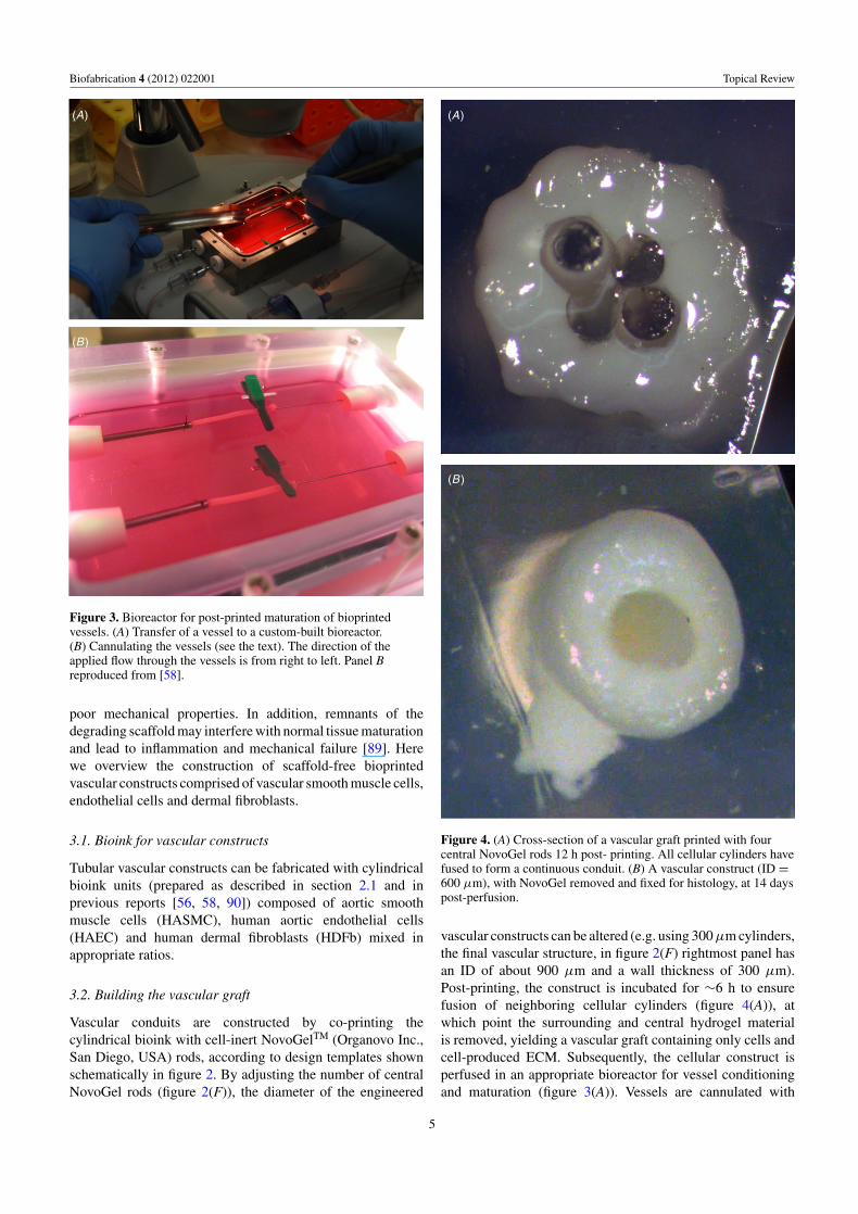
Figure 3. Bioreactor for post-printed maturation of bioprintedvessels. (A) Transfer of a vessel to a custom-built bioreactor.(B) Cannulating the vessels (see the text). The direction of theapplied flow through the vessels is from right to left. Panel Breproduced from [58].
poor mechanical properties. In addition, remnants of thedegrading scaffold may interfere with normal tissue maturationand lead to inflammation and mechanical failure [89]. Herewe overview the construction of scaffold-free bioprintedvascular constructs comprised of vascular smooth muscle cells,endothelial cells and dermal fibroblasts.
3.1. Bioink for vascular constructs
Tubular vascular constructs can be fabricated with cylindricalbioink units (prepared as described in section 2.1 and inprevious reports [56, 58, 90]) composed of aortic smoothmuscle cells (HASMC), human aortic endothelial cells(HAEC) and human dermal fibroblasts (HDFb) mixed inappropriate ratios.
3.2. Building the vascular graft
Vascular conduits are constructed by co-printing thecylindrical bioink with cell-inert NovoGelTM (Organovo Inc.,San Diego, USA) rods, according to design templates shownschematically in figure 2. By adjusting the number of centralNovoGel rods (figure 2(F)), the diameter of the engineered
(A)
(B )
Figure 4. (A) Cross-section of a vascular graft printed with fourcentral NovoGel rods 12 h post- printing. All cellular cylinders havefused to form a continuous conduit. (B) A vascular construct (ID =600 μm), with NovoGel removed and fixed for histology, at 14 dayspost-perfusion.
vascular constructs can be altered (e.g. using 300 μm cylinders,the final vascular structure, in figure 2(F) rightmost panel hasan ID of about 900 μm and a wall thickness of 300 μm).Post-printing, the construct is incubated for ∼6 h to ensurefusion of neighboring cellular cylinders (figure 4(A)), atwhich point the surrounding and central hydrogel materialis removed, yielding a vascular graft containing only cells andcell-produced ECM. Subsequently, the cellular construct isperfused in an appropriate bioreactor for vessel conditioningand maturation (figure 3(A)). Vessels are cannulated with
5
Biofabrication 4 (2012) 022001 Topical Review
(A)
(B )
(C )
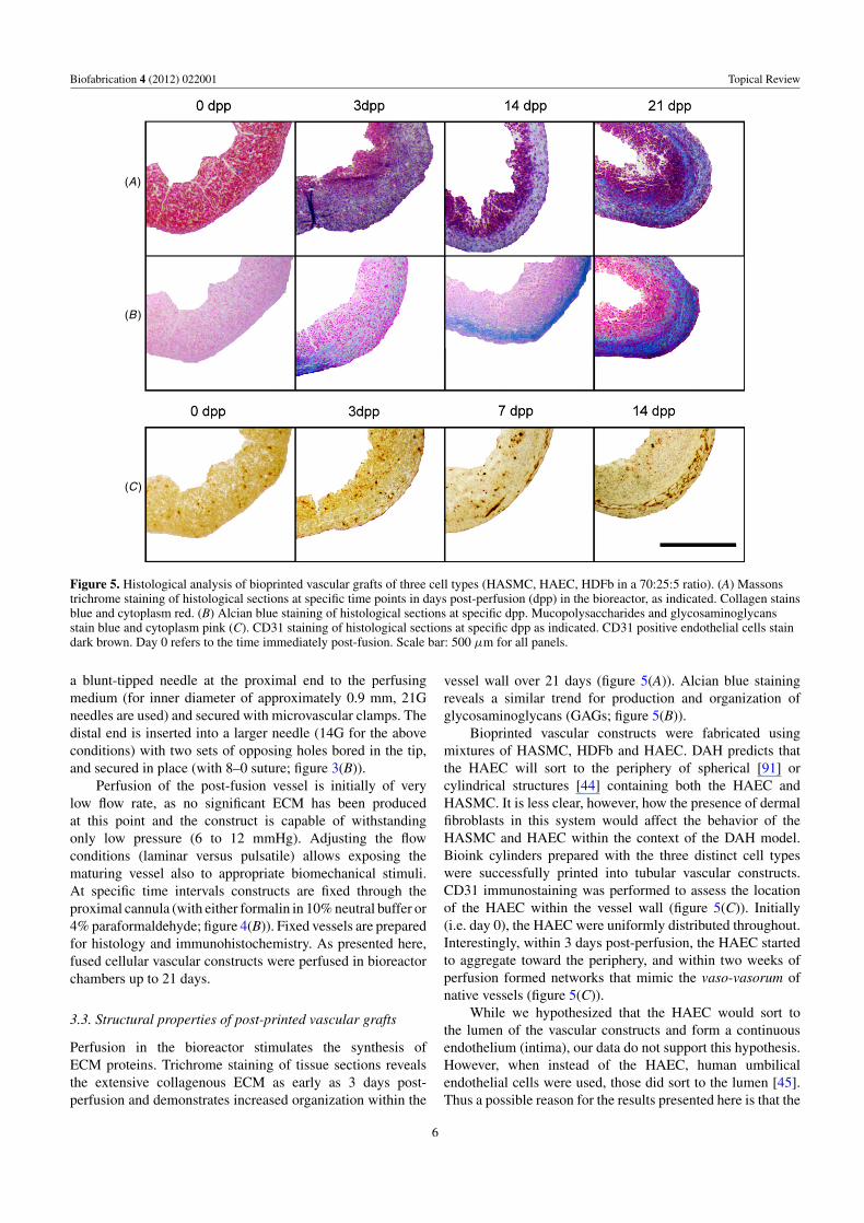
Figure 5. Histological analysis of bioprinted vascular grafts of three cell types (HASMC, HAEC, HDFb in a 70:25:5 ratio). (A) Massonstrichrome staining of histological sections at specific time points in days post-perfusion (dpp) in the bioreactor, as indicated. Collagen stainsblue and cytoplasm red. (B) Alcian blue staining of histological sections at specific dpp. Mucopolysaccharides and glycosaminoglycansstain blue and cytoplasm pink (C). CD31 staining of histological sections at specific dpp as indicated. CD31 positive endothelial cells staindark brown. Day 0 refers to the time immediately post-fusion. Scale bar: 500 μm for all panels.
a blunt-tipped needle at the proximal end to the perfusingmedium (for inner diameter of approximately 0.9 mm, 21Gneedles are used) and secured with microvascular clamps. Thedistal end is inserted into a larger needle (14G for the aboveconditions) with two sets of opposing holes bored in the tip,and secured in place (with 8–0 suture; figure 3(B)).
Perfusion of the post-fusion vessel is initially of verylow flow rate, as no significant ECM has been producedat this point and the construct is capable of withstandingonly low pressure (6 to 12 mmHg). Adjusting the flowconditions (laminar versus pulsatile) allows exposing thematuring vessel also to appropriate biomechanical stimuli.At specific time intervals constructs are fixed through theproximal cannula (with either formalin in 10% neutral buffer or4% paraformaldehyde; figure 4(B)). Fixed vessels are preparedfor histology and immunohistochemistry. As presented here,fused cellular vascular constructs were perfused in bioreactorchambers up to 21 days.
3.3. Structural properties of post-printed vascular grafts
Perfusion in the bioreactor stimulates the synthesis ofECM proteins. Trichrome staining of tissue sections revealsthe extensive collagenous ECM as early as 3 days post-perfusion and demonstrates increased organization within the
vessel wall over 21 days (figure 5(A)). Alcian blue stainingreveals a similar trend for production and organization ofglycosaminoglycans (GAGs; figure 5(B)).
Bioprinted vascular constructs were fabricated usingmixtures of HASMC, HDFb and HAEC. DAH predicts thatthe HAEC will sort to the periphery of spherical [91] orcylindrical structures [44] containing both the HAEC andHASMC. It is less clear, however, how the presence of dermalfibroblasts in this system would affect the behavior of theHASMC and HAEC within the context of the DAH model.Bioink cylinders prepared with the three distinct cell typeswere successfully printed into tubular vascular constructs.CD31 immunostaining was performed to assess the locationof the HAEC within the vessel wall (figure 5(C)). Initially(i.e. day 0), the HAEC were uniformly distributed throughout.Interestingly, within 3 days post-perfusion, the HAEC startedto aggregate toward the periphery, and within two weeks ofperfusion formed networks that mimic the vaso-vasorum ofnative vessels (figure 5(C)).
While we hypothesized that the HAEC would sort tothe lumen of the vascular constructs and form a continuousendothelium (intima), our data do not support this hypothesis.However, when instead of the HAEC, human umbilicalendothelial cells were used, those did sort to the lumen [45].Thus a possible reason for the results presented here is that the
6
Biofabrication 4 (2012) 022001 Topical Review
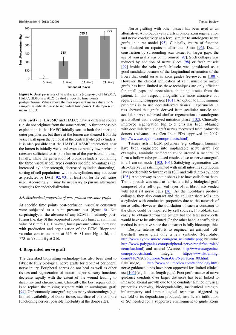
Figure 6. Burst pressures of vascular grafts (composed of HASMC,HAEC, HDFb in a 70:25:5 ratio) at specific time pointspost-perfusion. Values above the bars represent mean values for Nsamples as indicated next to individual time points. Data representmean ± SD.
cells used (i.e. HASMC and HAEC) have a different source(i.e. do not originate from the same patient). A further possibleexplanation is that HAEC initially sort to both the inner andouter peripheries, but those at the lumen are sheared from thevessel wall upon the removal of the central hydrogel cylinders.It is also possible that the HAEC–HASMC interaction nearthe lumen is initially weak and even extremely low perfusionrates are sufficient to strip the lumen of the provisional intima.Finally, while the generation of bioink cylinders, containingthe three vascular cell types confers specific advantages (i.e.increased cylinder strength, decreased cylinder shortening),sorting of cell populations within the cylinders may not occuras predicted by DAH [92, 93], at least not for the cell ratiosused. Accordingly, it may be necessary to pursue alternativestrategies for endothelialization.
3.4. Mechanical properties of post-printed vascular grafts
At specific time points post-perfusion, vascular constructswere subjected to a burst pressure test (figure 6). Notsurprisingly, in the absence of any ECM immediately post-fusion (i.e. day 0) the bioprinted constructs burst at a minimalvalue of 6 mm Hg. However, burst pressure values increasedwith production and organization of the ECM. Bioprintedvascular constructs burst at 315 ± 81 mm Hg at 3d, and773 ± 78 mm Hg at 21d.
4. Bioprinted nerve graft
The described bioprinting technology has also been used tofabricate fully biological nerve grafts for repair of peripheralnerve injury. Peripheral nerves do not heal as well as othertissues and regeneration of motor and/or sensory functionsdecrease rapidly with the extent of the wound leading todisability and chronic pain. Clinically, the best repair optionis to replace the missing segment with an autologous graft[94]. Unfortunately, autografting has many shortcomings (e.g.limited availability of donor tissue, sacrifice of one or morefunctioning nerves, possible morbidity at the donor site).
Nerve grafting with other tissues has been used as analternative. Autologous vein grafts promote axon regenerationand nerve conductivity at a level similar to autologous nervegrafts in a rat model [95]. Clinically, return of functionwas obtained on repairs smaller than 3 cm [96]. Due toconstriction by surrounding scar tissue, for larger gaps, theuse of vein grafts was compromised [97]. Such collapse wasreduced by addition of nerve slices [98] or fresh muscle[99] inside the vein graft. Muscle was considered as agood candidate because of the longitudinal orientation of thefibers that could serve as axon guides (reviewed in [100]).However, the clinical application of vein, muscle or mixedgrafts has been limited as these techniques are only efficientfor small gaps and necessitate obtaining tissues from thepatient. In this respect, allografts are more attractive butrequire immunosuppression [101]. An option to limit immuneproblems is to use decellularized tissues. Experiments inrats showed that grafts derived from acellular muscle andacellular nerve achieved similar regeneration to autologousgrafts albeit with a delayed initiation phase [102]. Clinically,improved regeneration (up to 5 cm) has been obtainedwith decellularized allograft nerves recovered from cadavericdonors (Advance, AxoGen Inc.; FDA approved in 2007;http://www.axogeninc.com/products.html).
Tissues rich in ECM polymers (e.g. collagen, laminin)have been engineered into implantable nerve graft. Forexamples, amniotic membrane rolled around a mandrel toform a hollow tube produced results close to nerve autograftin a 1 cm rat model [103, 104]. Satisfying regeneration wasalso observed in rats implanted with small intestine submucosalayer seeded with Schwann cells (SC) and rolled into a cylinder[105]. Another way to obtain sheets is to have cells form them.This approach was used to fabricate a fully biological graftcomposed of a self-organized layer of rat fibroblasts seededwith fetal rat nerve cells [36]. As the fibroblasts producecollagen, they also contract and the cellular sheet rolls intoa cylinder with conductive properties due to the network ofnerve cells. However, the translation of such a construct tothe clinic could be impaired by cell sources. Fibroblasts caneasily be obtained from the patient but the fetal nerve cellswould have to be substituted. On the other hand, a scaffoldlessmethod is attractive since the construct is fully biocompatible.
Despite intense efforts to engineer an artificial ‘off-the-shelf’ nerve graft only a few synthetic (Neurotube,http://www.synovismicro.com/gem_neurotube.php; Neurolachttp://www.polyganics.com/peripheral-nerve-repair/neurolac/neurolac.html) and natural (Avance, http://www.axogeninc.com/products.html; Integra, http://www.ilstraining.com/NTC%20Solutions/NeuraGen/NeuraGen_00.html;SaluBridge, http://www.salumedica.com/technology.htm)nerve guidance tubes have been approved for limited clinicaluse [106] (e.g. limited length gaps). Poor performance of nerveguidance conduits over larger distances has been linked toimpaired axonal growth due to the conduits’ limited physicalproperties (porosity, biodegradability, mechanical strength,inflammatory and immunological responses triggered byscaffold or its degradation products), insufficient infiltrationof SC needed for a supportive environment to guide axons
7
Biofabrication 4 (2012) 022001 Topical Review
and the lack of longitudinally oriented structural featuresmimicking endoneural architecture.
A tissue-engineered nerve graft, superior to autologousnerve grafts, has still to be built. Strategies to engineersuch a graft should incorporate physical, molecular andbiological elements [107]. The addition of supportive cells,in particular SC, into the lumen of the nerve guidance tubeis a must and should be combined with any topographic ormolecular improvement [108]. Since SC are hard to isolateand culture, alternative cell types have been considered (e.g.olfactory ensheathing cells [109], hair follicle stem cells[110], bone marrow stem cells [111]). Different options havebeen followed to enhance the topographic suitability of nerveguidance tubes. With the development of microfabricationtechniques microtopographical patterns were created usingsynthetic materials. These are systematically being studiedand modified to optimize for SC behavior (e.g. adhesion) andoriented neurite progression [112]. In particular, nanofibershad their physical parameters (diameter, porosity) tailoredfor use as nerve guidance tubes with luminal topographyfavorable to nerve regeneration [113, 114]. Some naturalfibers such as spider silk have also been employed intonerve guidance tube [115]. Another strategy to enhance nerveguidance tube potential is to fill it with hydrogels (e.g. agarose,collagen, chitosan, hyaluronic acid, keratin) in association withECM components (e.g. laminin, fibronectin, proteoglycans)and neurotrophic factors (e.g. nerve growth factor, fibroblastgrowth factor) to create a growth permissive environmentfor cells to add [116]. In what follows, we outline how thedescribed bioprinting technology can be applied to fabricatefully biological nerve grafts and circumvent a number of issuesdiscussed above.
4.1. Design and bioink
We designed a scaffold-free nerve graft guided by thefollowing considerations: (i) the choice of a rat sciatic nerveinjury model for implantation; (ii) the creation of a multi-lumen pattern to increase the luminal surface area availablefor support cells to favor axon regeneration; (iii) the cell typeto support axon regeneration and to be suitable for cylindricalbioink preparation. Furthermore, the graft needed to have adiameter comparable to that of a rat sciatic nerve (∼2 mm)and be at least 1 cm long to fill the gap. Instructed by earlierresults [117] 500 μm cylindrical bioink units were used (fortheir preparation see section 2.1).
As the density of supporting cells is a critical factor foraxon regeneration [108], to establish proof of concept, initiallya tube composed exclusively of SC was considered. Such tubewas impossible to build because due to the lack of sufficientSC cell–cell adhesion, the cylindrical bioink particles werenot sufficiently strong for printing. Hair follicles-derived stemcells and bone marrow stem cells (BMSC) have successfullybeen used as a source of support cells for nerve regenerationand trans-differentiation into SC [110, 118]. We observedthat BMSC form adequate cylindrical bioink units. BMSChave also been shown to possess anti-inflammatory propertiesbeneficial for tissue regeneration. Additionally, mesenchymal
stem cells, a subcellular fraction of BMSC, can differentiateinto Schwann-like cells when co-cultured with SC [119]. Thuswe employed BMSC to prepare the bioink.
4.2. Building the graft
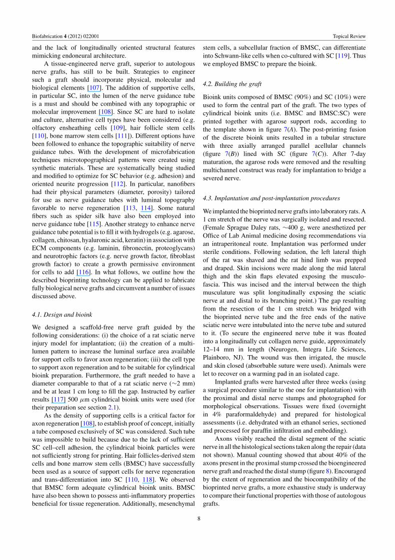
Bioink units composed of BMSC (90%) and SC (10%) wereused to form the central part of the graft. The two types ofcylindrical bioink units (i.e. BMSC and BMSC:SC) wereprinted together with agarose support rods, according tothe template shown in figure 7(A). The post-printing fusionof the discrete bioink units resulted in a tubular structurewith three axially arranged parallel acellular channels(figure 7(B)) lined with SC (figure 7(C)). After 7-daymaturation, the agarose rods were removed and the resultingmultichannel construct was ready for implantation to bridge asevered nerve.
4.3. Implantation and post-implantation procedures
We implanted the bioprinted nerve grafts into laboratory rats. A1 cm stretch of the nerve was surgically isolated and resected.(Female Sprague Daley rats, ∼400 g, were anesthetized perOffice of Lab Animal medicine dosing recommendations viaan intraperitoneal route. Implantation was performed understerile conditions. Following sedation, the left lateral thighof the rat was shaved and the rat hind limb was preppedand draped. Skin incisions were made along the mid lateralthigh and the skin flaps elevated exposing the musculo-fascia. This was incised and the interval between the thighmusculature was split longitudinally exposing the sciaticnerve at and distal to its branching point.) The gap resultingfrom the resection of the 1 cm stretch was bridged withthe bioprinted nerve tube and the free ends of the nativesciatic nerve were intubulated into the nerve tube and suturedto it. (To secure the engineered nerve tube it was floatedinto a longitudinally cut collagen nerve guide, approximately12–14 mm in length (Neurogen, Integra Life Sciences,Plainboro, NJ). The wound was then irrigated, the muscleand skin closed (absorbable suture were used). Animals werelet to recover on a warming pad in an isolated cage.
Implanted grafts were harvested after three weeks (usinga surgical procedure similar to the one for implantation) withthe proximal and distal nerve stumps and photographed formorphological observations. Tissues were fixed (overnightin 4% paraformaldehyde) and prepared for histologicalassessments (i.e. dehydrated with an ethanol series, sectionedand processed for paraffin infiltration and embedding).
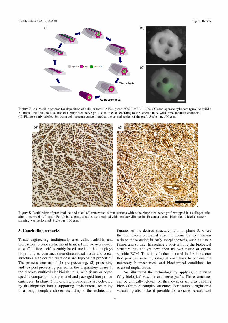
Axons visibly reached the distal segment of the sciaticnerve in all the histological sections taken along the repair (datanot shown). Manual counting showed that about 40% of theaxons present in the proximal stump crossed the bioengineerednerve graft and reached the distal stump (figure 8). Encouragedby the extent of regeneration and the biocompatibility of thebioprinted nerve grafts, a more exhaustive study is underwayto compare their functional properties with those of autologousgrafts.
8
Biofabrication 4 (2012) 022001 Topical Review
(B )
(C )
(A)
Figure 7. (A) Possible scheme for deposition of cellular (red: BMSC, green: 90% BMSC + 10% SC) and agarose cylinders (gray) to build a3-lumen tube. (B) Cross-section of a bioprinted nerve graft, constructed according to the scheme in A, with three acellular channels.(C) Fluorescently labeled Schwann cells (green) concentrated at the central region of the graft. Scale bar: 500 μm.
(A) (B )
Figure 8. Partial view of proximal (A) and distal (B) transverse, 4 mm sections within the bioprinted nerve graft wrapped in a collagen tubeafter three weeks of repair. For global aspect, sections were stained with hematoxylin–eosin. To detect axons (black dots), Bielschowskystaining was performed. Scale bar: 100 μm.
5. Concluding remarks
Tissue engineering traditionally uses cells, scaffolds andbioreactors to build replacement tissues. Here we overvieweda scaffold-free, self-assembly-based method that employsbioprinting to construct three-dimensional tissue and organstructures with desired functional and topological properties.The process consists of (1) pre-processing, (2) processingand (3) post-processing phases. In the preparatory phase 1,the discrete multicellular bioink units, with tissue or organspecific composition are prepared and packaged into printercartridges. In phase 2 the discrete bioink units are deliveredby the bioprinter into a supporting environment, accordingto a design template chosen according to the architectural
features of the desired structure. It is in phase 3, wherethe continuous biological structure forms by mechanismsakin to those acting in early morphogenesis, such as tissuefusion and sorting. Immediately post-printing the biologicalstructure has not yet developed its own tissue or organ-specific ECM. Thus it is further matured in the bioreactorthat provides near-physiological conditions to achieve thenecessary biomechanical and biochemical conditions foreventual implantation.
We illustrated the technology by applying it to buildfully biological vascular and nerve grafts. These structurescan be clinically relevant on their own, or serve as buildingblocks for more complex structures. For example, engineeredvascular grafts make it possible to fabricate vascularized
9
Biofabrication 4 (2012) 022001 Topical Review
tissues, a major challenge for tissue and organ engineeringat present. Due to its versatility it is to be expected that thetechnology will have many other applications. Besides obviousones, such as resource for three-dimensional tissue cultureor providing truly three-dimensional biological constructsfor basic research in developmental biology, it is likely tobe employed by the pharmaceutical industry. Rapidly andreproducibly prepared three-dimensional functional biologicalconstructs of specific topology, built of human cells, couldserve as tissue intermediates between animal and humanclinical trials for drug testing. Such application may leadto significant savings in the ubiquitously high cost of drugdevelopment.
Acknowledgments
This research was partially supported by NSF (grantEF0256854) and by the University of Missouri ResearchBoard.
References
[1] Lanza R P, Langer R S and Vacanti J 2007 Principles ofTissue Engineering (Burlington, MA: Elsevier)
[2] Hollander A P and Hatton P V (ed) 2010 BiopolymerMethods in Tissue Engineering (Totowa, NJ: HumanaPress)
[3] Kasper C, Van Griensven M and Portner R (ed) 2009Bioreactor Systems for Tissue Engineering (Berlin:Springer)
[4] Grayson W L, Chao P H, Marolt D, Kaplan D Land Vunjak-Novakovic G 2008 Engineeringcustom-designed osteochondral tissue grafts TrendsBiotechnol. 26 181–9
[5] Mikos A G et al 2006 Engineering complex tissues TissueEng. 12 3307–39
[6] Radisic M et al 2004 Functional assembly of engineeredmyocardium by electrical stimulation of cardiac myocytescultured on scaffolds Proc. Natl Acad. Sci. USA101 18129–34
[7] Tandon N et al 2009 Electrical stimulation systems forcardiac tissue engineering Nature Protoc. 4 155–73
[8] Vunjak-Novakovic G, Altman G, Horan R and Kaplan D L2004 Tissue engineering of ligaments Annu. Rev. Biomed.Eng. 6 131–56
[9] Fischbach C and Mooney D J 2007 Polymers for pro- andanti-angiogenic therapy Biomaterials 28 2069–76
[10] Griffith L and Naughton G 2002 Tissue engineering—currentchallenges and expanding opportunities Science295 1009–14
[11] Atala A, Bauer S B, Soker S, Yoo J J and Retik A B 2006Tissue-engineered autologous bladders for patientsneeding cystoplasty Lancet 367 1241–6
[12] Niklason L E et al 1999 Functional arteries grown in vitroScience 284 489–93
[13] Hibino N et al 2010 Late-term results of tissue-engineeredvascular grafts in humans J. Thorac. Cardiovasc. Surg.139 431–6
[14] Matsumura G et al 2006 Evaluation of tissue-engineeredvascular autografts Tissue Eng. 12 3075–83
[15] Oberpenning F, Meng J, Yoo J J and Atala A 1999 De novoreconstitution of a functional mammalian urinary bladderby tissue engineering Nature Biotechnol. 17 149–55
[16] Raya-Rivera A et al 2011 Tissue-engineered autologousurethras for patients who need reconstruction: anobservational study Lancet 377 1175–82
[17] Shin’Oka T, Imai Y and Ikada Y 2001 Transplantation of atissue-engineered pulmonary artery N. Eng. J. Med.344 532–3
[18] Shin’oka T et al 2005 Midterm clinical result oftissue-engineered vascular autografts seeded withautologous bone marrow cells J. Thorac. Cardiovasc.Surg. 129 1330–8
[19] Badylak S F 2002 The extracellular matrix as a scaffold fortissue reconstruction Semin. Cell. Dev. Biol. 13 377–83
[20] Gilbert T W, Sellaro T L and Badylak S F 2006Decellularization of tissues and organs Biomaterials27 3675–83
[21] Hoshiba T, Lu H, Kawazoe N and Chen G 2010Decellularized matrices for tissue engineering ExpertOpin. Biol. Ther. 10 1717–28
[22] Baiguera S et al 2010 Tissue engineered human tracheas forin vivo implantation Biomaterials 31 8931–8
[23] Dahl S L M, Koh J, Prabhakar V and Niklason L E 2003Decellularized native and engineered arterial scaffolds fortransplantation Cell Transplant. 12 659–66
[24] Gui L, Muto A, Chan S A, Breuer C K and Niklason L E2009 Development of decellularized human umbilicalarteries as small-diameter vascular grafts Tissue Eng. A15 2665–76
[25] Murase Y et al 2006 Evaluation of compliance and stiffnessof decellularized tissues as scaffolds for tissue-engineeredsmall caliber vascular grafts using intravascular ultrasoundASAIO J. 52 450–5
[26] Petersen T H, Calle E A, Colehour M B and Niklason L E2011 Matrix composition and mechanics of decellularizedlung scaffolds Cells Tissues Organs in press
[27] Ponce Marquez S et al 2009 Decellularization of bovinecorneas for tissue engineering applications Acta Biomater.5 1839–47
[28] Prasertsung I, Kanokpanont S, Bunaprasert T, Thanakit Vand Damrongsakkul S 2008 Development of acellulardermis from porcine skin using periodic pressurizedtechnique J. Biomed. Mater. Res. B 85 210–9
[29] Ross E A et al 2009 Embryonic stem cells proliferate anddifferentiate when seeded into kidney scaffolds J. Am. Soc.Nephrol. 20 2338–47
[30] Zeltinger J, Landeen L K, Alexander H G, Kidd I Dand Sibanda B 2001 Development and characterization oftissue-engineered aortic valves Tissue Eng. 7 9–22
[31] Godier-Furnemont A F et al 2011 Composite scaffoldprovides a cell delivery platform for cardiovascular repairProc. Natl Acad. Sci. USA 108 7974–9
[32] Dahl S L et al 2011 Readily available tissue-engineeredvascular grafts Sci. Transl. Med. 3 68ra69
[33] Ott H C et al 2008 Perfusion-decellularized matrix: usingnature’s platform to engineer a bioartificial heart NatureMed. 14 213–21
[34] Baptista P M et al 2011 The use of whole organdecellularization for the generation of a vascularized liverorganoid Hepatology 53 604–17
[35] Macchiarini P et al 2008 Clinical transplantation of atissue-engineered airway Lancet 372 2023–30
[36] Baltich J, Hatch-Vallier L, Adams A M, Arruda E Mand Larkin L M 2010 Development of a scaffoldlessthree-dimensional engineered nerve using anerve-fibroblast co-culture In Vitro Cell. Dev. Biol. Anim.46 438–44
[37] L’Heureux N et al 2006 Human tissue-engineered bloodvessels for adult arterial revascularization Nature Med.12 361–5
10
Biofabrication 4 (2012) 022001 Topical Review
[38] L’Heureux N et al 2007 Technology insight: the evolution oftissue-engineered vascular grafts—from research toclinical practice Nature Clin. Pract. Cardiovasc. Med.4 389–95
[39] L’Heureux N, McAllister T N and de la Fuente L M 2007Tissue-engineered blood vessel for adult arterialrevascularization N. Eng. J. Med. 357 1451–3
[40] McAllister T N et al 2009 Effectiveness of haemodialysisaccess with an autologous tissue-engineered vasculargraft: a multicentre cohort study Lancet 373 1440–6
[41] Tsuda Y et al 2007 Cellular control of tissue architecturesusing a three-dimensional tissue fabrication techniqueBiomaterials 28 4939–46
[42] Hannachi I, Yamato M and Okano T 2009 Cell sheettechnology and cell patterning for biofabricationBiofabrication 1 022002
[43] Jakab K, Neagu A, Mironov V, Markwald R R and Forgacs G2004 Engineering biological structures of prescribedshaped using self-assembling multicellular systems Proc.Natl Acad. Sci. USA 101 2864–9
[44] Jakab K et al 2010 Tissue engineering by self-assembly andbio-printing of living cells Biofabrication 2 022001
[45] Mironov V, Boland T, Trusk T, Forgacs G and Markwald R R2003 Organ printing: computer-aided jet-based 3D tissueengineering Trends Biotechnol. 21 157–61
[46] Boland T, Xu T, Damon B and Cui X 2006 Application ofinkjet printing to tissue engineering Biotechnol. J. 1 910–7
[47] Campbell P G and Weiss L E 2007 Tissue engineering withthe aid of inkjet printers Expert Opin. Biol. Ther. 7 1123–7
[48] Cui X, Dean D, Ruggeri Z M and Boland T 2010 Celldamage evaluation of thermal inkjet printed Chinesehamster ovary cells Biotechnol. Bioeng. 106 963–9
[49] Nakamura M et al 2005 Biocompatible inkjet printingtechnique for designed seeding of individual living cellsTissue Eng. 11 1658–66
[50] Roth E A et al 2004 Inkjet printing for high-throughput cellpatterning Biomaterials 25 3707–15
[51] Chang R, Nam J and Sun W 2008 Effects of dispensingpressure and nozzle diameter on cell survival from solidfreeform fabrication-based direct cell writing Tissue Eng.A 14 41–8
[52] Barron J A, Bradley R R, Kim H, Spargo B Jand Chrisey D B 2004 Application of laser printing tomammalian cells Thin Solid Films 453–454 383–7
[53] Catros S et al 2011 Laser-assisted bioprinting for creatingon-demand patterns of human osteoprogenitor cells andnano-hydroxyapatite Biofabrication 3 025001
[54] Odde D J and Renn M J 1999 Laser-guided direct writing forapplications in biotechnology Trends Biotechnol. 17 385–9
[55] Cohen D L, Malone E, Lipson H and Bonassar L J 2006Direct freeform fabrication of seeded hydrogels inarbitrary geometries Tissue Eng. 12 1325–35
[56] Jakab K, Damon B, Neagu A, Kachurin A and Forgacs G2006 Three-dimensional tissue constructs built bybioprinting Biorheology 43 509–13
[57] Lin R Z and Chang H Y 2008 Recent advances inthree-dimensional multicellular spheroid culture forbiomedical research Biotechnol. J. 3 1172–84
[58] Norotte C, Marga F S, Niklason L E and Forgacs G 2009Scaffold-free vascular tissue engineering using bioprintingBiomaterials 30 5910–7
[59] Perez-Pomares J M and Foty R A 2006 Tissue fusion and cellsorting in embryonic development and disease: biomedicalimplications Bioessays 28 809–21
[60] Steinberg M S 1963 Reconstruction of tissues by dissociatedcells. Some morphogenetic tissue movements and thesorting out of embryonic cells may have a commonexplanation Science 141 401–8
[61] Damon B J, Mezentseva N V, Kumaratilake J S, Forgacs Gand Newman S A 2008 Limb bud and flank mesodermhave distinct ‘physical phenotypes’ that may contribute tolimb budding Dev. Biol. 321 319–30
[62] Forgacs G, Foty R A, Shafrir Y and Steinberg M S 1998Viscoelastic properties of living embryonic tissues: aquantitative study Biophys. J. 74 2227–34
[63] Foty R A, Pfleger C M, Forgacs G and Steinberg M S 1996Surface tensions of embryonic tissues predict their mutualenvelopment behavior Development 122 1611–20
[64] Hegedus B, Marga F, Jakab K, Sharpe-Timms K Land Forgacs G 2006 The interplay of cell-cell andcell-matrix interactions in the invasive properties of braintumors Biophys. J. 91 2708–16
[65] Jakab K et al 2008 Relating cell and tissue mechanics:implications and applications Dev. Dyn. 237 2438–49
[66] Norotte C, Marga F, Neagu A, Kosztin I and Forgacs G 2008Experimental evaluation of apparent tissue surface tensionbased on the exact solution of the Laplace equationEurophys. Lett. 81 46003
[67] Schotz E et al 2008 Quantitative differences in tissue surfacetension influence zebrafish germ layer positioning HFSP2 42–56
[68] Godt D and Tepass U 1998 Drosophila oocyte localization ismediated by differential cadherin- based adhesion Nature395 387–91
[69] Gonzalez-Reyes A and St Johnston D 1998 Patterning of thefollicle cell epithelium along the anterior-posterior axisduring Drosophila oogenesis Development 125 2837–46
[70] Hayashi T and Carthew R W 2004 Surface mechanicsmediate pattern formation in the developing retina Nature431 647–52
[71] Glazier J A and Graner F 1993 Simulation of the differentialadhesion driven rearrangement of biological cells Phys.Rev. E 47 2128–54
[72] Gordon R, Goel N S, Steinberg M S and Wiseman L L 1972A rheological mechanism sufficient to explain the kineticsof cell sorting J. Theor. Biol. 37 43–73
[73] Marmottant P et al 2009 The role of fluctuations and stresson the effective viscosity of cell aggregates Proc. NatlAcad. Sci. USA 106 17271–5
[74] Mombach J C, Glazier J A, Raphael R C and Zajac M 1995Quantitative comparison between differential adhesionmodels and cell sorting in the presence and absence offluctuations Phys. Rev. Lett. 75 2244–7
[75] Forgacs G and Newman S 2005 Biological Physics of theDeveloping Embryo (Cambridge: Cambridge UniversityPress)
[76] Thom T et al 2006 Heart disease and stroke statistics—2006update: a report from the American Heart AssociationStatistics Committee and Stroke Statistics SubcommitteeCirculation 113 e85–151
[77] Fowler V G Jr et al 2005 Clinical predictors of majorinfections after cardiac surgery Circulation 112 I358–65
[78] Edelman E R 1999 Vascular tissue engineering: designerarteries Circ. Res. 85 1115–7
[79] Niklason L E and Langer R S 1997 Advances in tissueengineering of blood vessels and other tissues Transpl.Immunol. 5 303–6
[80] Bonassar L J and Vacanti C A 1998 Tissue engineering: thefirst decade and beyond J. Cell. Biochem. Suppl.30–31 297–303
[81] Khademhosseini A, Langer R, Borenstein J and Vacanti J P2006 Microscale technologies for tissue engineering andbiology Proc. Natl Acad. Sci. USA 103 2480–7
[82] Langer R 2000 Biomaterials in drug delivery and tissueengineering: one laboratory’s experience Acc. Chem. Res.33 94–101
11
Biofabrication 4 (2012) 022001 Topical Review
[83] Langer R and Vacanti J P 1993 Tissue engineering Science260 920–6
[84] Lysaght M J, Nguy N A and Sullivan K 1998 An economicsurvey of the emerging tissue engineering industry TissueEng. 4 231–8
[85] Vacanti J P, Langer R, Upton J and Marler J J 1998Transplantation of cells in matrices for tissue regenerationAdv. Drug Deliv. Rev. 33 165–82
[86] Mironov V et al 2006 Cardiovascular tissue engineering: I.Perfusion bioreactors: a review J. Long Term Eff. Med.Implants 16 111–30
[87] Isenberg B C, Williams C and Tranquillo R T 2006Small-diameter artificial arteries engineered in vitro Circ.Res. 98 25–35
[88] Kakisis J D, Liapis C D, Breuer C and Sumpio B E 2005Artificial blood vessel: the Holy Grail of peripheralvascular surgery J. Vasc. Surg. 41 349–54
[89] Dahl S L, Rhim C, Song Y C and Niklason L E 2007Mechanical properties and compositions of tissueengineered and native arteries Ann. Biomed. Eng.35 348–55
[90] Jakab K et al 2008 Tissue engineering by self-assembly ofcells printed into topologically defined structures TissueEng. A 14 413–21
[91] Korff T, Kimmina S, Martiny-Baron G and Augustin H G2001 Blood vessel maturation in a three-dimensionalspheroidal coculture model: direct contact with smoothmuscle cells regulates endothelial cell quiescence andabrogates VEGF responsiveness FASEB J. 15 447–57
[92] Krieg M et al 2008 Tensile forces govern germ-layerorganization in zebrafish Nature Cell. Biol. 10 429–36
[93] Manning M L, Foty R A, Steinberg M S and Schoetz E M2010 Coaction of intercellular adhesion and corticaltension specifies tissue surface tension Proc. Natl Acad.Sci. USA 107 12517–22
[94] Millesi H 1968 On the problem of overbridging defects of theperipheral nerves Wien. Med. Wochenschr. 118 182–7
[95] Chiu D T et al 1988 Comparative electrophysiologicevaluation of nerve grafts and autogenous vein grafts asnerve conduits: an experimental study J. Reconstr.Microsurg. 4 303–9
[96] Chiu D T and Strauch B 1990 A prospective clinicalevaluation of autogenous vein grafts used as a nerveconduit for distal sensory nerve defects of 3 cm or lessPlast. Reconstr. Surg. 86 928–34
[97] Tang J B, Shi D and Zhou H 1995 Vein conduits for repair ofnerves with a prolonged gap or in unfavourable conditions:an analysis of three failed cases Microsurgery 16 133–7
[98] Tang J B, Gu Y Q and Song Y S 1993 Repair of digital nervedefect with autogenous vein graft during flexor tendonsurgery in zone 2 J. Hand. Surg. Br. 18 449–53
[99] Battiston B, Tos P, Cushway T R and Geuna S 2000 Nerverepair by means of vein filled with muscle grafts: I.Clinical results Microsurgery 20 32–6
[100] Meek M F, Varejao A S and Geuna S 2004 Use of skeletalmuscle tissue in peripheral nerve repair: review of theliterature Tissue Eng. 10 1027–36
[101] Moore A M, Ray W Z, Chenard K E, Tung Tand Mackinnon S E 2009 Nerve allotransplantation as itpertains to composite tissue transplantation Hand4 239–44
[102] Kerns J M, Danielsen N, Zhao Q, Lundborg G and Kanje M2003 A comparison of peripheral nerve regeneration in
acellular muscle and nerve autografts Scand. J. Plast.Reconstr. Surg. Hand. Surg. 37 193–200
[103] Mohammad J, Shenaq J, Rabinovsky E and Shenaq S 2000Modulation of peripheral nerve regeneration: atissue-engineering approach. The role of amnion tubenerve conduit across a 1 centimeter nerve gap Plast.Reconstr. Surg. 105 660–6
[104] O’Neill A C et al 2009 Preparation and integration of humanamnion nerve conduits using a light-activated techniquePlast. Reconstr. Surg. 124 428–37
[105] Hadlock T A, Sundback C A, Hunter D A, Vacanti J Pand Cheney M L 2001 A new artificial nerve graftcontaining rolled Schwann cell monolayers Microsurgery21 96–101
[106] Meek M F and Coert J H 2008 US Food and DrugAdministration/Conformit Europe-approved absorbablenerve conduits for clinical repair of peripheral and cranialnerves Ann. Plast. Surg. 60 110–6
[107] de Ruiter G C, Malessy M J, Yaszemski M J, Windebank A Jand Spinner R J 2009 Designing ideal conduits forperipheral nerve repair Neurosurg. Focus 26 E5
[108] Guenard V, Kleitman N, Morrissey T K, Bunge R Pand Aebischer P 1992 Syngeneic Schwann cells derivedfrom adult nerves seeded in semipermeable guidancechannels enhance peripheral nerve regenerationJ. Neurosci. 12 3310–20
[109] Radtke C et al 2009 Transplantation of olfactory ensheathingcells enhances peripheral nerve regeneration aftermicrosurgical nerve repair Brain Res. 1254 10–7
[110] Hoffman R M 2006 The pluripotency of hair follicle stemcells Cell Cycle 5 232–3
[111] Wang D et al 2008 Bridging small-gap peripheral nervedefects using acellular nerve allograft implanted withautologous bone marrow stromal cells in primates BrainRes. 1188 44–53
[112] Hoffman-Kim D, Mitchel J A and Bellamkonda R V 2010Topography, cell response, and nerve regeneration Annu.Rev. Biomed. Eng. 12 203–31
[113] Cunha C, Panseri S and Antonini S 2011 Emergingnanotechnology approaches in tissue engineering forperipheral nerve regeneration Nanomedicine 7 50–9
[114] Kim Y T, Haftel V K, Kumar S and Bellamkonda R V 2008The role of aligned polymer fiber-based constructs in thebridging of long peripheral nerve gaps Biomaterials29 3117–27
[115] Allmeling C et al 2008 Spider silk fibres in artificial nerveconstructs promote peripheral nerve regeneration CellProlif. 41 408–20
[116] Steed M B, Mukhatyar V, Valmikinathan Cand Bellamkonda R V 2011 Advances in bioengineeredconduits for peripheral nerve regeneration Atlas OralMaxillofac. Surg. Clin. North Am. 19 119–30
[117] Hadlock T, Sundback C, Hunter D, Cheney Mand Vacanti J P 2000 A polymer foam conduit seeded withSchwann cells promotes guided peripheral nerveregeneration Tissue Eng. 6 119–27
[118] Yamakawa T et al 2007 Nerve regeneration promoted in atube with vascularity containing bone marrow-derivedcells Cell Transplant. 16 811–22
[119] Krampera M et al 2007 Induction of neural-likedifferentiation in human mesenchymal stem cells derivedfrom bone marrow, fat, spleen and thymus Bone40 382–90
12
Related Documents