TotalPac ® 3 Dry pipe system 1 of 14 FM-076D-0-85G (Optional) DESCRIPTION This TOTALPAC ® 3 integrated fire protection system by FireFlex Systems Inc. consists of a dry pipe system trim totally pre- assembled, pre-wired and factory tested. All electrical and mechanical components of the system are contained in one single unit TOTALPAC ® 3 dry pipe systems are built around the Viking trim using dry pipe valves model F-1. All the valves are rated up to a maximum of 175 psi WWP (1207 kPa) max. and are available in the following diameters: 4" (100 mm) 6" (150 mm) Standard features • cULus Listed & FM Approved as an assembled unit • Factory assembled, programmed and tested under ISO-9001 standards • Prewired to a terminal block • Easy and compact installation • Viking conventional trim rated at 175 psi (1207 kPa) • Galvanized trim piping • Serial number for easy reference • Corrosion resistant cabinet with flush type handle and lock • No open drain cup inside the unit • numerous modular options to meet the most demanding jobsite requirements • Four styles of modular air supply options • Inlet & outlet hydrostatic test ports • User-friendly standardized operation & installation manual • Free interactive simulator

Welcome message from author
This document is posted to help you gain knowledge. Please leave a comment to let me know what you think about it! Share it to your friends and learn new things together.
Transcript

TotalPac®3 Dry pipe system
1 of 14 FM-076D-0-85G
(Optional)
DESCRIPTION
This TOTALPAC®3 integrated fire protection system by FireFlex Systems Inc. consists of a dry pipe system trim totally pre-assembled, pre-wired and factory tested. All electrical and mechanical components of the system are contained in one single unit
TOTALPAC®3 dry pipe systems are built around the Viking trim using dry pipe valves model F-1.
All the valves are rated up to a maximum of 175 psi WWP (1207 kPa) max. and are available in the following diameters:
4" (100 mm) 6" (150 mm)
Standard features
• cULus Listed & FM Approved as an assembled unit
• Factory assembled, programmed and tested under ISO-9001 standards
• Prewired to a terminal block
• Easy and compact installation
• Viking conventional trim rated at 175 psi (1207 kPa)
• Galvanized trim piping
• Serial number for easy reference
• Corrosion resistant cabinet with flush type handle and lock
• No open drain cup inside the unit
• numerous modular options to meet the most demanding jobsite requirements
• Four styles of modular air supply options
• Inlet & outlet hydrostatic test ports
• User-friendly standardized operation & installation manual
• Free interactive simulator
TotalPac®3 Dry pipe system
FM-076D-0-85G 2 of 14
Cabinet
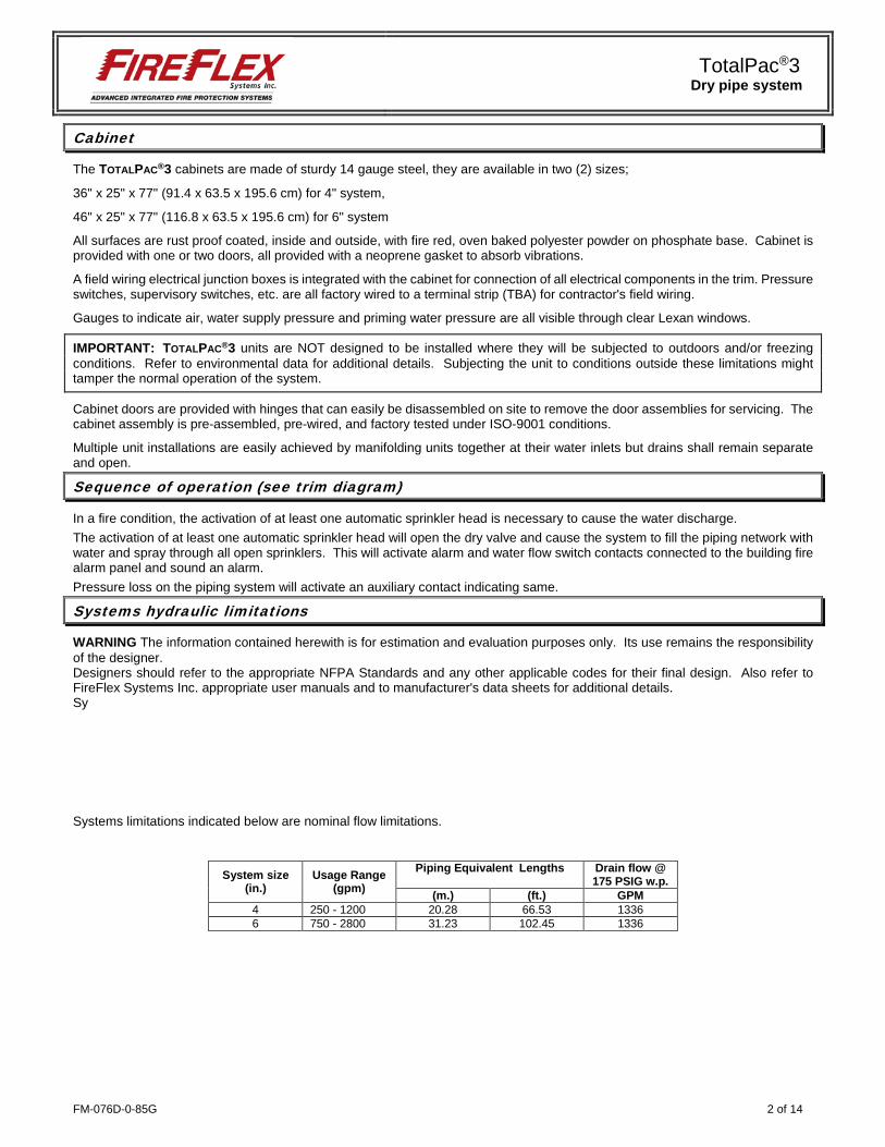
The TOTALPAC®3 cabinets are made of sturdy 14 gauge steel, they are available in two (2) sizes;
36" x 25" x 77" (91.4 x 63.5 x 195.6 cm) for 4" system,
46" x 25" x 77" (116.8 x 63.5 x 195.6 cm) for 6" system
All surfaces are rust proof coated, inside and outside, with fire red, oven baked polyester powder on phosphate base. Cabinet is provided with one or two doors, all provided with a neoprene gasket to absorb vibrations.
A field wiring electrical junction boxes is integrated with the cabinet for connection of all electrical components in the trim. Pressure switches, supervisory switches, etc. are all factory wired to a terminal strip (TBA) for contractor's field wiring.
Gauges to indicate air, water supply pressure and priming water pressure are all visible through clear Lexan windows.
IMPORTANT: TOTALPAC®3 units are NOT designed to be installed where they will be subjected to outdoors and/or freezing conditions. Refer to environmental data for additional details. Subjecting the unit to conditions outside these limitations might tamper the normal operation of the system.
Cabinet doors are provided with hinges that can easily be disassembled on site to remove the door assemblies for servicing. The cabinet assembly is pre-assembled, pre-wired, and factory tested under ISO-9001 conditions.
Multiple unit installations are easily achieved by manifolding units together at their water inlets but drains shall remain separate and open.
Sequence of operation (see trim diagram)
In a fire condition, the activation of at least one automatic sprinkler head is necessary to cause the water discharge. The activation of at least one automatic sprinkler head will open the dry valve and cause the system to fill the piping network with water and spray through all open sprinklers. This will activate alarm and water flow switch contacts connected to the building fire alarm panel and sound an alarm. Pressure loss on the piping system will activate an auxiliary contact indicating same.
Systems hydraulic limitations
WARNING The information contained herewith is for estimation and evaluation purposes only. Its use remains the responsibility of the designer. Designers should refer to the appropriate NFPA Standards and any other applicable codes for their final design. Also refer to FireFlex Systems Inc. appropriate user manuals and to manufacturer's data sheets for additional details. Sy
Systems limitations indicated below are nominal flow limitations.
System size (in.)
Usage Range (gpm)
Piping Equivalent Lengths Drain flow @ 175 PSIG w.p.
(m.) (ft.) GPM 4 250 - 1200 20.28 66.53 1336 6 750 - 2800 31.23 102.45 1336
TotalPac®3 Dry pipe system
3 of 14 FM-076D-0-85G
Standard equipment
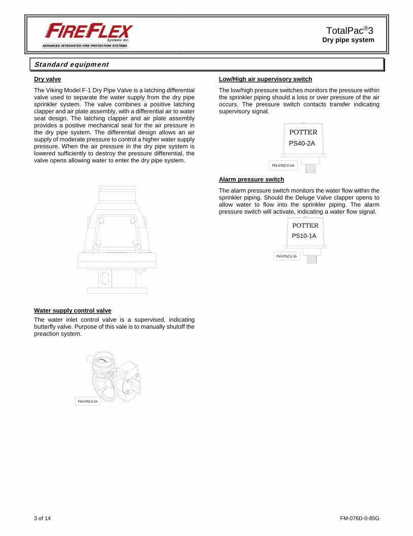
Dry valve
The Viking Model F-1 Dry Pipe Valve is a latching differential valve used to separate the water supply from the dry pipe sprinkler system. The valve combines a positive latching clapper and air plate assembly, with a differential air to water seat design. The latching clapper and air plate assembly provides a positive mechanical seal for the air pressure in the dry pipe system. The differential design allows an air supply of moderate pressure to control a higher water supply pressure. When the air pressure in the dry pipe system is lowered sufficiently to destroy the pressure differential, the valve opens allowing water to enter the dry pipe system.
Water supply control valve The water inlet control valve is a supervised, indicating butterfly valve. Purpose of this vale is to manually shutoff the preaction system.
Low/High air supervisory switch
The low/high pressure switches monitors the pressure within the sprinkler piping should a loss or over pressure of the air occurs. The pressure switch contacts transfer indicating supervisory signal.
Alarm pressure switch
The alarm pressure switch monitors the water flow within the sprinkler piping. Should the Deluge Valve clapper opens to allow water to flow into the sprinkler piping. The alarm pressure switch will activate, indicating a water flow signal.
POTTERPS40-2A
POTTERPS10-1A

TotalPac®3 Dry pipe system
FM-076D-0-85G 4 of 14
Optional mechanical equipment
Semi and full flanged option When required by the user, TOTALPAC®3 units can be provided in either a semi-flanged of full flanged configuration. The semi flanged option provides flanged fittings only on the water inlet pipe (side needs to be specified at the time of order) and on the system riser outlet. The drain manifold is then provided with a threaded end that also needs to have its side specified (left or right). The rest of the fittings are the same as usual with the main components being provided in the standard grooved -grooved configuration. The full flanged option is the same as above but goes a step further with the main components being also provided with a flanged-flanged configuration. When provided, the face of the flanges will always be situated 6 inches from the outside face of the mounting base or cabinet surface.
Anti-column device option The model LD-1 anti-column device is an optional trim component designed for use with preaction sprinkler systems. The anti-column device automatically prevents an unwanted water column from establishing within the system riser. On preaction sprinkler systems the anti-column device prevents water from columning downstream of the easy riser check valve.
OSHPD option Pre-approved construction, under OSP-0341-10, using specific components.
FM-061H-0-155B
Threaded end
Flanged fitting outside cabinet(when provided)
Field Connectionto Open Drain(specify side)
Field connectionto Water Supply
(specify side)Flanged fitting outside cabinet(when provided)
From Sprinkler Riser
FM-061H-0-146ATo Drain Collector

TotalPac®3 Dry pipe system
5 of 14 FM-076D-0-85G
Air supply
Direct air compressor (Style “A”)
Used only for the sprinkler piping network of the dry pipe system. Air supply style "A" includes the air compressor mounted inside the TOTALPAC®3 cabinets with its supervisory trim and options. Compressors are of the tankless, oiless piston type and are factory piped to the sprinkler system riser, all within the TOTALPAC®3 cabinets.
Compressors are available in four (4) sizes: 1/6HP 1/2HP 1/3HP 1HP
Table 1
Maximum Air Pressure Setting Water Pressure Minimum Maximum
PSI kPa PSI kPa PSI kPa 50 345 15 103 25 172 75 517 20 138 30 207
100 690 25 172 35 241 150 1034 35 241 50 310 175 1207 45 310 60 345
Compressor Service Factor Amp (S.F.A) rating Compressor
Size (HP) 115Vac / 60Hz 230Vac / 60Hz 220Vac / 50Hz
1/6 5.0 Amp. 2.5 Amp. 1.3 Amp. 1/3 7.4 Amp. 3.7 Amp. 2.5 Amp. 1/2 10.0 Amp. 5.0 Amp. 4.0 Amp. 1 18.0 Amp. 9.0 Amp. 6.0 Amp.
115 / 230 Vac – 60Hz air compressor selection Table:
H.P CFM
@ 40 PSI
System capacity to fill system to 40 PSI
in 30 minutes *
1/6 1.33 125 gal. 1/3 2.61 250 gal. 1/2 4.06 365 gal. 1 7.40 615 gal.
220 / 240 Vac – 50Hz air compressor selection Table:
H.P LPM @
40 PSI
System capacity to fill system to 40 PSI
in 30 minutes *
1/6 35.4 390 L 1/3 68 750 L 1/2 4.06 1140 L 1 7.40 1965 L
* Air pressure shall be adjusted as per Table 1
WARNING The information contained herewith is for estimation and evaluation purposes only. Its use remains the responsibility of the designer.
FM-061H-0-118C
1
CONTRACTOR'SHYDROSTATIC TEST PORT(system side)
2 TO DRAIN COLLECTOR
TO SPRINKLER RISER
Copper tubing
This section replacedby Dehydrator option A(when used)
TO OPTIONAL ACCELERATOR(plugged when not used)
3TO PNEUMATIC ACTUATOR(plugged when not used)
E4(plugged withSureFire trim)
Pressure relief valve
TotalPac®3 Dry pipe system
FM-076D-0-85G 6 of 14
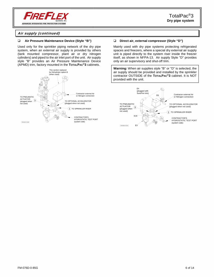
Air supply (continued)
Air Pressure Maintenance Device (Style “B”)
Used only for the sprinkler piping network of the dry pipe system, when an external air supply is provided by others (tank mounted compressor, plant air or dry nitrogen cylinders) and piped to the air inlet port of the unit. Air supply style "B" provides an Air Pressure Maintenance Device (APMD) trim, factory mounted in the TOTALPAC®3 cabinets.
Direct air, external compressor (Style “D”)
Mainly used with dry pipe systems protecting refrigerated spaces and freezers, where a special dry external air supply unit is piped directly to the system riser inside the freezer itself, as shown in NFPA-13. Air supply Style "D" provides only an air supervisory and shut-off trim.
Warning: When air supplies style "B" or "D" is selected, the air supply should be provided and installed by the sprinkler contractor OUTSIDE of the TOTALPAC®3 cabinet. It is NOT provided with the unit.
FM-061H-0-119B
1
CONTRACTOR'SHYDROSTATIC TEST PORT(system side)
TO SPRINKLER RISER
TO OPTIONAL ACCELERATOR(plugged when not used)
This section replacedby Dehydrator option B(when used)
Contractor external Airor Nitrogen connection
3TO PNEUMATICACTUATOR(plugged whennot used)
1 TO SPRINKLER RISER
E4(plugged withSureFire trim)
FM-061H-0-121A
CONTRACTOR'SHYDROSTATIC TEST PORT(system side)
E16
E3
TO OPTIONAL ACCELERATOR(plugged when not used)
Contractor external Airor Nitrogen connection
E6
3TO PNEUMATICACTUATOR(plugged whennot used)
TotalPac®3 Dry pipe system
7 of 14 FM-076D-0-85G
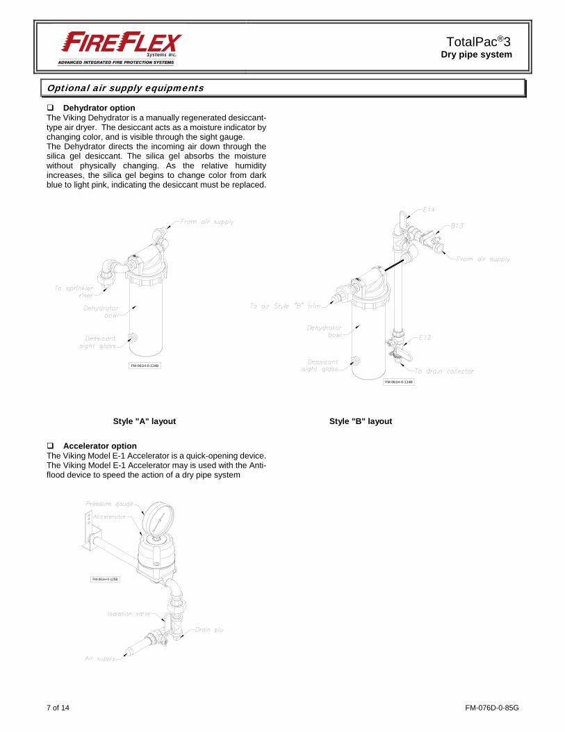
Optional air supply equipments
Dehydrator option The Viking Dehydrator is a manually regenerated desiccant-type air dryer. The desiccant acts as a moisture indicator by changing color, and is visible through the sight gauge. The Dehydrator directs the incoming air down through the silica gel desiccant. The silica gel absorbs the moisture without physically changing. As the relative humidity increases, the silica gel begins to change color from dark blue to light pink, indicating the desiccant must be replaced.
Style "A" layout Style "B" layout
Accelerator option The Viking Model E-1 Accelerator is a quick-opening device. The Viking Model E-1 Accelerator may is used with the Anti-flood device to speed the action of a dry pipe system
FM-061H-0-124B
FM-061H-0-124B
FM-061H-0-125B

TotalPac®3 Dry pipe system
FM-076D-0-85G 8 of 14
Details & field wiring diagrams
Cabinet with main components - Configuration shown with air style "A"
FM-061H-0-175B
Junction boxTBA & TBB
Dry Valve
Riser Outlet toSprinklers Network
Cable Entry
Water SupplyControl Valve
Drain Outlet(either side)
Water Inlet(either side)
Optional Air Compressor
Optional Air CompressorIsolating Switch

TotalPac®3 Dry pipe system
9 of 14 FM-076D-0-85G
Trim diagram
Trim Components: A1 Dry valve B1 Priming / water level test valve B3 1/16" Restricted orifice B5 Alarm test valve B6 N/A B7 Drip check valve B8 Drain check valve B11 Air supply pressure gauge & valve B12 Water supply pressure gauge & valve B13 Check valve B15 7/32" Restricted orifice
C1 Alarm pressure switch C2 Connection to water motor gong (strainer supplied
by contractor) C3 Hydraulic alarm cut-off valve D1 Water supply control valve D3 Main drain valve E4 Air supervisory pressure switch
B7
C2
A
B
To AcceleratorOption
To AcceleratorOption
E4
B11
FM-061H-0-115C
FIELD CONNECTIONTO OPEN DRAIN
(on both sides)
FIELD CONNECTIONTO WATER SUPPLY
(on both sides)
FIELD CONNECTION TOSPRINKLER PIPING NETWORK
B1
TotalPac Base(shown without enclosure)
CONTRACTOR'SHYDROSTATIC TEST PORT(water supply side)
1To Air Supply System Trim
C3
C1
B5
B8
B13
B3
2To Air Supply System Trim
CONTRACTOR'SHYDROSTATICTEST PORT(system side)
A1
D1
B12
D3
1 inch connectionfor sprinkler
B15

TotalPac®3 Dry pipe system
FM-076D-0-85G 10 of 14
Field wiring diagrams:
FM-061H-0-98A
1
TBA 2 3 4 5 6 7 8 9 10 11 12 13 14 15 16
WA
TER
FLO
WW
ATE
R F
LOW
SW
ITC
H
EO
L
EO
L
LOW
AIR
PR
ES
SU
RE
SW
ITC
H(s
ee ta
ble
belo
w fo
r set
tings
)LO
W A
IR P
RE
SS
UR
E
EO
L
MA
IN V
ALV
E S
UP
V S
WIT
CH
MA
IN V
ALV
E
1234
TBBLINENEUTRALGROUND
120VAC, 60Hz 220VAC, 50Hz
AIR COMPRESSOR2HP MAX
WIRING OF AIR COMPRESSOR POWER SOURCE(WITH AIR OPTION "A" ONLY)
1
TBC 2 3
C NO
NC
MA
IN V
ALV
EContacts provided forconnection to the building'scentral Fire Alarm Panel.
LOS ANGELES OPTION
CHICAGO OPTION
NOTE:
All devices are shown in their normal supervisory state.
NOTES:
Use dry contacts with power limited circuits only.
Contacts are rated:Pressure switches: 2A, 30VDC 10A, 125/250VACSupervisory switches: 0.5A, 125VDC 0.25A, 250VDC 5A, 1/6HP, 125/250VAC
Refer to Local Electrical Codes for wiring size.EOL devices (not included) must be compatible with the Release Control Panel used.
All devices are factory wired.
MA
IN V
ALV
E S
UP
V S
WIT
CH
EO
L
HIG
H A
IR P
RE
SS
UR
E S
WIT
CH
(see
tabl
e be
low
for s
ettin
gs)
HIG
H A
IR P
RE
SS
UR
E

TotalPac®3 Dry pipe system
11 of 14 FM-076D-0-85G
Dimensions
Figure 1 – Cabinet dimensions:
System
Size A B C D E F G H J K L M N P Q R S T U 4" 4" 4" 2" 36¾" 25" 77" 4" 10" 11½" 13¾" 3¾" 2½" 2" 12" 11½" 48½" 53" 42" 39¾"
6" 6" 6" 2" 46" 25" 77" 4" 11" 11½" 13¾" 3¾" 5½" 2" 17¾" 11½" 59½" 65¼" N/A 50"
Notes: Dimensions are nominal and may vary ±¼".
U
D
F
E
P
H
K
L
ØA
ØC
FM-061H-0-129A
WATER INLETSCH.40 GROOVED OUTLET
DRAIN - SCH.40 GROOVED OUTLET
SPR
INKL
ER R
ISER
SC
H.4
0 G
RO
OVE
D O
UTL
ET
OPTIONALSHUT-OFF VALVE
J
R
S
M M
T
SPR
INKL
ER R
ISER
SC
H.4
0 G
RO
OVE
D O
UTL
ET
Q
OPTIONAL FIRE DEP'TCONNECTION OUTLET(DRILLED ONLY WHENORDERED)
G
N N
TBB TBA & TBC
CO
NTR
OL
PAN
EL
CONTROLPANEL
(except for RemoteControlled Unit)
TBA, TBB & TBC
ØB
SYSTEMS WEIGHTS Cabinets without control panel
System Description Weight (lbs) Weight (Kg) 4" Dry pipe cabinet unit 710 322 6" Dry pipe cabinet unit 995 451
TotalPac®3 Dry pipe system
FM-076D-0-85G 12 of 14
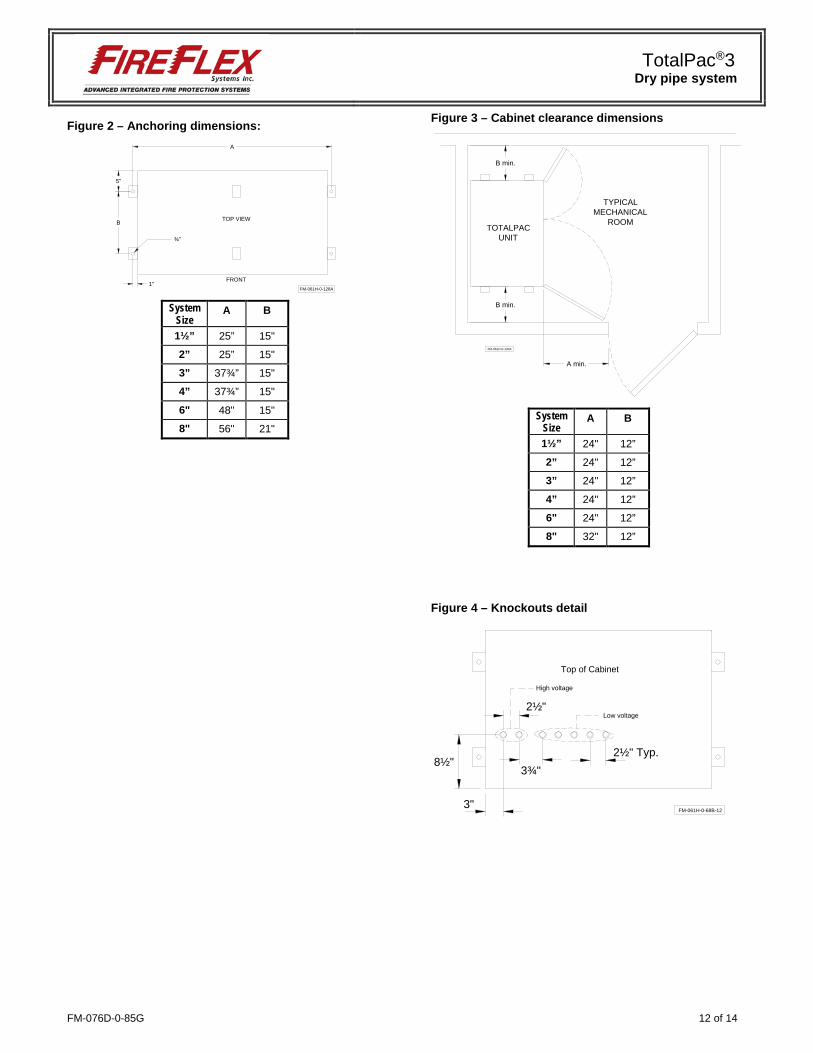
Figure 2 – Anchoring dimensions:
System
Size A B
1½” 25” 15"
2” 25” 15"
3” 37¾” 15"
4” 37¾” 15"
6" 48" 15"
8" 56" 21"
Figure 3 – Cabinet clearance dimensions
System
Size A B
1½” 24" 12”
2” 24" 12”
3” 24" 12”
4” 24" 12”
6" 24" 12”
8" 32" 12”
Figure 4 – Knockouts detail
5"
FM-061H-0-128A
A
FRONT
TOP VIEW
¾"
1"
B
A min.
B min.
TYPICALMECHANICAL
ROOM
FM-061H-0-130A
B min.
TOTALPACUNIT
3"
8½"
Top of Cabinet
FM-061H-0-68B-12
2½" Typ.3¾"
2½"
High voltage
Low voltage
TotalPac®3 Dry pipe system
13 of 14 FM-076D-0-85G
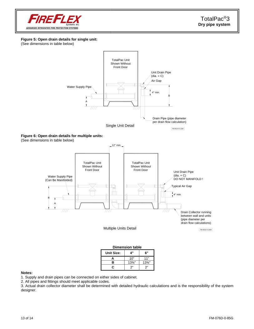
Figure 5: Open drain details for single unit: (See dimensions in table below)
Figure 6: Open drain details for multiple units: (See dimensions in table below)
Dimension table Unit Size: 4" 6"
A 10" 11" B 13¾" 13¾" C 2" 2"
Notes: 1. Supply and drain pipes can be connected on either sides of cabinet. 2. All pipes and fittings should meet applicable codes. 3. Actual drain collector diameter shall be determined with detailed hydraulic calculations and is the responsibility of the system designer.
Air Gap
Water Supply Pipe
Unit Drain Pipe(dia. = C)
FM-061H-0-139A
A
B4'' min.
Drain Pipe (pipe diameterper drain flow calculation)
Single Unit Detail
TotalPac UnitShown Without
Front Door
FM-061H-0-140A
Drain Collector runningbetween wall and units(pipe diameter perdrain flow calculations)
Multiple Units Detail
A
B
Water Supply Pipe(Can Be Manifolded)
TotalPac UnitShown Without
Front Door
TotalPac UnitShown Without
Front Door
12'' min.
Typical Air Gap
Unit Drain Pipe(dia. = C)DO NOT MANIFOLD !
4'' min.

FM-076D-0-85G 14 of 14
1935, Lionel-Bertrand Blvd.
Boisbriand QC Canada J7H 1N8 Tel.: 450-437-3473 • Fax: 450-437-1930
Toll Free: 866-347-3353 Email: [email protected] • Web: www.fireflex.com
Related Documents