PRINTED IN JAPAN TOSHIBA Potable Printer B-EP2DL SERIES Document No. EO18-33024 Original Sep., 2008 (Revised ) Maintenance Manual

Welcome message from author
This document is posted to help you gain knowledge. Please leave a comment to let me know what you think about it! Share it to your friends and learn new things together.
Transcript

PRINTED IN JAPAN
TOSHIBA Potable Printer
B-EP2DL SERIES
Document No. EO18-33024 Original Sep., 2008 (Revised )
Maintenance Manual

WARNING! Follow all manual instructions. Failure to do so could create safety hazards such as fire or electrocution.
NOTE: Failure to follow manual instructions or any unauthorized modification, substitution orchange to this product will void the limited product warranty.

EO18-33024 (Revision Date: Mar. 17, 2009)
CAUTION! 1. This manual may not be copied in whole or in part without prior written permission of TOSHIBA
TEC. 2. The contents of this manual may be changed without notification.
Copyright © 2008 by TOSHIBA TEC CORPORATION All Rights Reserved 570 Ohito, Izunokuni-shi, Shizuoka-ken, JAPAN
TABLE OF CONTENTS
Page
1. UNPACKING .............................................................................................................. 1- 1 1.1 Procedure ........................................................................................................................1- 1 1.2 Checks.............................................................................................................................1- 1 2. MAJOR UNIT REPLACEMENT.................................................................................. 2- 1
2.1 Replacing the CPU PC Board .........................................................................................2- 1 2.2 Replacing the LCD Unit ...................................................................................................2- 8 2.3 Replacing the Peel-off Roller...........................................................................................2- 9 2.4 Replacing the Peel-off Sensor.......................................................................................2- 10 2.5 Replacing the Stepping Motor .......................................................................................2- 12 2.6 Replacing the Drive PC Board.......................................................................................2- 14 2.7 Replacing the Battery Terminal .....................................................................................2- 16 2.8 Replacing the Print Head...............................................................................................2- 17 2.9 Replacing the Cover Open Switch and Media Sensor (Lower) .....................................2- 19 2.10 Replacing the Media Sensor (Upper) ............................................................................2- 22 2.11 Replacing the Platen Ass’y............................................................................................2- 24 3. TROUBLESHOOTING................................................................................................ 3- 1

1. UNPACKING EO18-33024
1.1 Procedure
1- 1
1. UNPACKING 1.1 Procedure 1) Open the carton. 2) Unpack the accessories from the carton. 3) Unpack the printer. NOTE: Keep the carton and pad for future transportation of the printer.
1.2 Checks 1) Check for damage or scratches on the machine. 2) Confirm that none of the accessories are missing.

2. MAJOR UNIT REPLACEMENT EO18-33024
2.1 Replacing the CPU PC Board
2-1
2. MAJOR UNIT REPLACEMENT WARNING!
1. Disconnect the power cord before installing the main parts. 2. Be careful not to injure your fingers when replacing the main parts.
CAUTION! 1. Since a lot of small moulded parts are used in this printer, care must be taken not to damage or lose
them. 2. Be careful not to damage the print head while removing and reassembling. 3. In the United States, used lithium ion batteries should be returned to the store where you bought the
machine. (USA only) 4. LITHIUM ION BATTERYDISPOSE OF PROPERLY Caution: Do not handle damaged or leaking lithium ion battery. 5. Before handling the main parts, be sure to discharge static electricity in human body through other
metals. Failure to do this may damage the CPU PC board, print head, etc..
NOTES: 1. Before replacing the main parts, print out the maintenance counter values and the parameter values and keep
the printout. (Refer to Section 4.2 Diagnostics Test in the System Mode Manual.) After replacing, restore the setting according to the printout.
2. Use precision screwdrivers for replacing the precision components which are installed into the printer. 2.1 Replacing the CPU PC Board 1) Turn off the printer. 2) Slide the Battery Lever in the direction of the arrow, and remove the Battery Pack from the printer. 3) Remove the four Tapping Screws from the Bottom Cover.
Battery Lever
Battery Pack
T-3x10 Screw
T-3x10 Screw

2. MAJOR UNIT REPLACEMENT EO18-33024
2.1 Replacing the CPU PC Board
2-2
4) Press the Top Cover Open Button to open the Top Cover. 5) Remove the Left Side Cover in the direction of the arrow. 6) Remove the Right Side Cover and the Front Cover in the direction of the arrow, respectively.
NOTE: The Gears shown in the picture below are not secured and are easily removed. Be carefulnot to drop and break or lose them.
Top Cover Top Cover Open Button
Left Side Cover
Gear
Right Side Cover
Front Cover

2. MAJOR UNIT REPLACEMENT EO18-33024
2.1 Replacing the CPU PC Board
2-3
7) Remove the Front Cover. 6) Disconnect all Connectors and FPC Cable from the CPU PC Board. NOTE: Before disconnecting the FPC Cable, release the Connector Lock. 7) Disconnect the Earth Terminal from the Drive PC Board.
Front Cover
CPU PC Board
FPC Cable
Connector Lock CPU PC Board
Drive PC Board
Earth Terminal

2. MAJOR UNIT REPLACEMENT EO18-33024
2.1 Replacing the CPU PC Board
2-4
8) Open the Hooks, then remove the CPU PC Board from the Front Cover. 9) Remove the screw, then remove the Earth Terminal. 10) Replace the CPU PC Board with a new one, then reassemble in the reverse order of removal.
Hook
CPU PC Board
T-2x5 Screw
Earth Terminal

2. MAJOR UNIT REPLACEMENT EO18-33024
2.1 Replacing the CPU PC Board
2-5
11) Close the front cover. 12) Mount the left side cover to the printer while fitting the tabs on the left side cover into the slots of the printer
enclosure. Fit the tabs A to C into the slots A’ to C’.
Front Cover
NOTES: 1. Make sure that the pins on the both sides of the front cover are fit in position, as shown in the
pictures below. 2. Do not reassemble the Front Cover while the Top Cover Open Button is pressed. Doing so may
cause the Top Cover not to open.
Pin
Top Cover Open Button
Good No Good
Tab ATab CTab B
A’
B’
C’

2. MAJOR UNIT REPLACEMENT EO18-33024
2.1 Replacing the CPU PC Board
2-6
13) Mount the right side cover to the printer while fitting the tabs on the right side cover into the slots of the
printer enclosure. Fit the tabs A to C into the slots A’ to C’.
NOTE: It is easy to mount the left side cover if you fit the tabs from the LCD side in order, then secure the bottomside. Be careful not to catch the cable by the cover while reassembling.
NOTE: It is easy to mount the right side cover if you fit the tabs from the LCD side in order, then secure thebottom side. Be careful not to catch the cable by the cover while reassembling.
Right Side Cover
Left Side Cover
Tab ATab B Tab C
A’
B’
C’

2. MAJOR UNIT REPLACEMENT EO18-33024 (Revision Date: Dec. 16, 2008)
2.1 Replacing the CPU PC Board
2-7
NOTES: 1. After replacing the CPU PC Board, refer to the Setting Operation Manual or System Mode Manual and
perform the following operations. 1. Perform a RAM clear. 2. Perform the sensor adjustment. 2. After replacing the CPU PC Board, perform an LED check in the system mode and make sure the LED
lights properly. If the LED does not light properly, this may result from the disconnection of the harness from the CPU PC board, the unset battery, or the run-down battery, etc. Make sure the connection of the cables and the battery status. When they are correct, the LED failure may result from the initial failure of the CPU PC board and replace the CPU PC board with a correct one. Regarding the procedures for the LED check, refer to Section 4.2.3 in the System Mode Manual.
2. MAJOR UNIT REPLACEMENT EO18-33024 (Revision Date: Dec. 16, 2008)
2.2 Replacing the LCD Unit
2-8
2.2 Replacing the LCD Unit 1) Remove the Right Cover, Left Cover, Front Cover and CPU PC Board. (Refer to Section 2.1 Replacing the
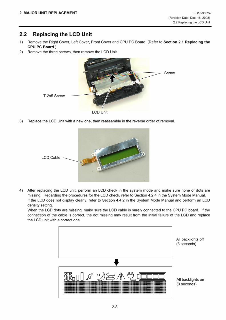
CPU PC Board.) 2) Remove the three screws, then remove the LCD Unit. 3) Replace the LCD Unit with a new one, then reassemble in the reverse order of removal. 4) After replacing the LCD unit, perform an LCD check in the system mode and make sure none of dots are
missing. Regarding the procedures for the LCD check, refer to Section 4.2.4 in the System Mode Manual. If the LCD does not display clearly, refer to Section 4.4.2 in the System Mode Manual and perform an LCD density setting. When the LCD dots are missing, make sure the LCD cable is surely connected to the CPU PC board. If the connection of the cable is correct, the dot missing may result from the initial failure of the LCD and replace the LCD unit with a correct one.
T-2x5 Screw
Screw
LCD Unit
All backlights off (3 seconds)
All backlights on (3 seconds)
LCD Cable

2. MAJOR UNIT REPLACEMENT EO18-33024
2.3 Replacing the Peel-off Roller
2-9
2.3 Replacing the Peel-off Roller 1) Remove the Right Cover, Left Cover and Front Cover. (Refer to Section 2.1 Replacing the CPU PC
Board.) 2) Remove the two Roller Clips with a straight slot screwdriver, then remove the Peel-off Roller Ass’y. 3) Remove the two Peel-off Rollers and the two Roller Clips from the Roller Shaft. 4) Replace the Peel-off Roller with a new one, then reassemble in the reverse order of removal.
Roller Clip
Straight Slot Screwdriver Peel-off Roller
Roller Clip Peel-off Roller
Roller Shaft
NOTE: Be careful of the orientation of the Roller Clips as shown in the picture below when reassemblingthe Peel-off Rollers.
Roller Clip
Roller Clip
2. MAJOR UNIT REPLACEMENT EO18-33024 (Revision Date: Mar. 17, 2009)
2.4 Replacing the Peel-off Sensor
2-10
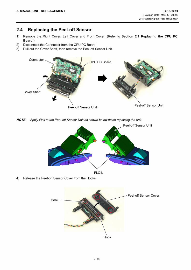
2.4 Replacing the Peel-off Sensor 1) Remove the Right Cover, Left Cover and Front Cover. (Refer to Section 2.1 Replacing the CPU PC
Board.) 2) Disconnect the Connector from the CPU PC Board. 3) Pull out the Cover Shaft, then remove the Peel-off Sensor Unit. NOTE: Apply Floil to the Peel-off Sensor Unit as shown below when replacing the unit. 4) Release the Peel-off Sensor Cover from the Hooks.
Cover Shaft
Peel-off Sensor Unit Peel-off Sensor Unit
ConnectorCPU PC Board
FLOIL
Peel-off Sensor Unit
Hook
Hook Peel-off Sensor Cover
2. MAJOR UNIT REPLACEMENT EO18-33024
2.4 Replacing the Peel-off Sensor
2-11
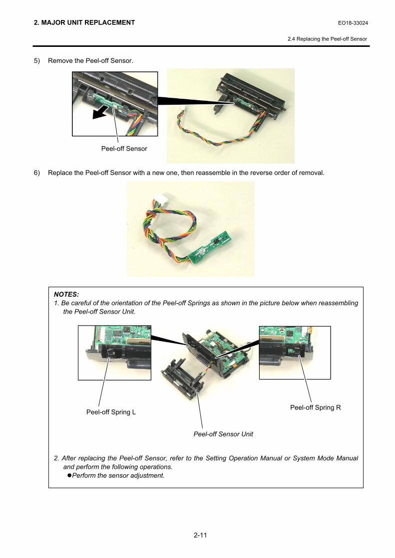
5) Remove the Peel-off Sensor.
6) Replace the Peel-off Sensor with a new one, then reassemble in the reverse order of removal.
Peel-off Sensor
NOTES: 1. Be careful of the orientation of the Peel-off Springs as shown in the picture below when reassembling
the Peel-off Sensor Unit. 2. After replacing the Peel-off Sensor, refer to the Setting Operation Manual or System Mode Manual
and perform the following operations. Perform the sensor adjustment.
Peel-off Spring L
Peel-off Sensor Unit
Peel-off Spring R

2. MAJOR UNIT REPLACEMENT EO18-33024 (Revision Date: Mar. 17, 2009)
2.7 Replacing the Stepping Motor
2-12
2.5 Replacing the Stepping Motor 1) Remove the Right Cover, Left Cover and Front Cover. (Refer to Section 2.1 Replacing the CPU PC
Board.) 2) Remove the two Gears. 3) Remove the two screws. NOTE: When replacing the gear, apply a small amount of Floil (8mm3) to each Gear Stud with a toothpick, etc.
by drawing a line around the part as shown below.
Stepping Motor
SMW-2x6 Screw
Gear
Gear Stud (2 places)
Gear Stud
FLOIL
2. MAJOR UNIT REPLACEMENT EO18-33024
2.7 Replacing the Stepping Motor
2-13
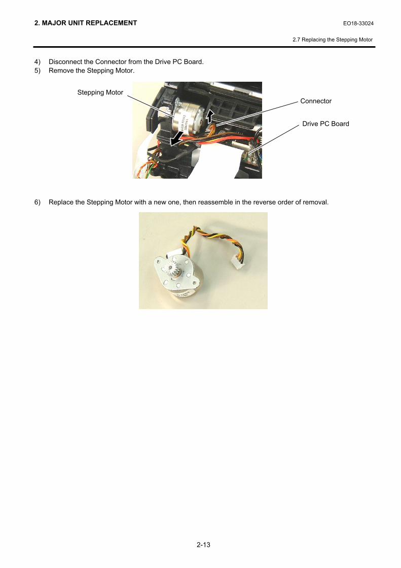
4) Disconnect the Connector from the Drive PC Board. 5) Remove the Stepping Motor.
6) Replace the Stepping Motor with a new one, then reassemble in the reverse order of removal.
Stepping Motor
Drive PC Board
Connector
2. MAJOR UNIT REPLACEMENT EO18-33024
2.5 Replacing the Drive PC Board
2-14
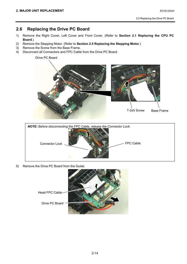
2.6 Replacing the Drive PC Board 1) Remove the Right Cover, Left Cover and Front Cover. (Refer to Section 2.1 Replacing the CPU PC
Board.) 2) Remove the Stepping Motor. (Refer to Section 2.5 Replacing the Stepping Motor.) 3) Remove the Screw from the Base Frame. 4) Disconnect all Connectors and FPC Cable from the Drive PC Board. 5) Remove the Drive PC Board from the Guide.
Drive PC Board
Head FPC Cable
NOTE: Before disconnecting the FPC Cable, release the Connector Lock.
Connector Lock FPC Cable
Base Frame T-2x5 Screw
Drive PC Board

2. MAJOR UNIT REPLACEMENT EO18-33024
2.5 Replacing the Drive PC Board
2-15
6) Replace the Drive PC Board with a new one, then reassemble in the reverse order of removal.

2. MAJOR UNIT REPLACEMENT EO18-33024
2.6 Replacing the Battery Terminal
2-16
2.7 Replacing the Battery Terminal 1) Remove the Right Cover, Left Cover and Front Cover. (Refer to Section 2.1 Replacing the CPU PC
Board.) 2) Remove the Stepping Motor. (Refer to Section 2.5 Replacing the Stepping Motor.) 3) Remove the Drive PC Board. (Refer to Section 2.6 Replacing the Drive PC Board.) 4) Hold down the Hook and remove the Battery Terminal upward. 5) Replace the Battery Terminal with a new one, then reassemble in the reverse order of removal.
Hook
Battery Terminal
Battery Terminal
NOTE: Reassemble the battery terminal so that the tubes areplaced on the battery case.
Tube
Battery Case

2. MAJOR UNIT REPLACEMENT EO18-33024
2.9 Replacing the Cover Open Switch and Media Sensor (Lower)
2-17
2.8 Replacing the Print Head 1) Remove the Right Cover, Left Cover and Front Cover. (Refer to Section 2.1 Replacing the CPU PC
Board.) 2) Release the Hooks, then remove the Media Sensor Holder Ass’y upward. 3) Remove the E-Ring. 4) Remove the Shaft.
Media Sensor Holder Ass’y
Print Head
E-Ring
Shaft
CAUTION! 1. Before handling the print head, be sure to discharge static electricity in human body through other
metals. Failure to do this may damage the print head element. 2. Never touch the print head element directly by hands or hard objects. Doing so will damage the
element, causing a dot missing and a print failure.
Media Sensor Holder Ass’y
Hook
Shaft

2. MAJOR UNIT REPLACEMENT EO18-33024 (Reviosion Date: Dec. 16, 2008)
2.9 Replacing the Cover Open Switch and Media Sensor (Lower)
2-18
5) Disconnect the Head FPC from the Print Head Connector. 6) Remove the Print Head Ass’y. 7) Disconnect the Head FPC Cable from the Drive PC Board Connector. 8) Replace the Print Head and Head FPC Cable with a new one, then reassemble in the reverse order of
removal.
Head FPC CableDrive PC Board
Print Head Connector
Head FPC
NOTES: 1. After replacing the Print Head, refer to the Setting Operation Manual or System Mode Manual and
perform the following operations. Perform a RAM clear.
2. After replacing the Print Head, perform the print head broken element check and make sure none ofthe elements are broken. (Refer to Section 4.2.2 in the System Mode Manual.)
Also perform a test print and make sure the print quality is correct. (Refer to Section 4.6 in the SystemMode Manual.) If the print tone is dark or light, perform the print tone fine adjustment. (Refer toSection 4.5.4 in the System Mode Manual.) If the media is smudged, this may result from thesmudged print head. In the case, refer to the Owner’s Manual and clean the print head.
2. MAJOR UNIT REPLACEMENT EO18-33024
2.9 Replacing the Cover Open Switch and Media Sensor (Lower)
2-19
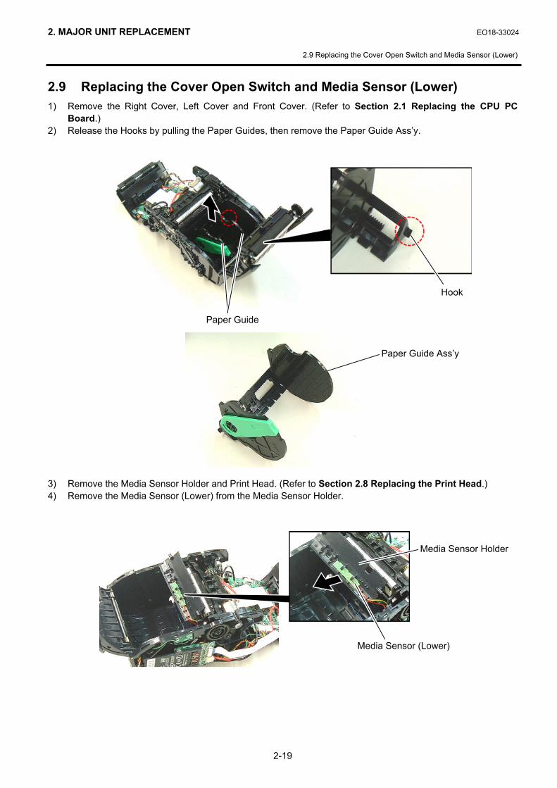
2.9 Replacing the Cover Open Switch and Media Sensor (Lower) 1) Remove the Right Cover, Left Cover and Front Cover. (Refer to Section 2.1 Replacing the CPU PC
Board.) 2) Release the Hooks by pulling the Paper Guides, then remove the Paper Guide Ass’y. 3) Remove the Media Sensor Holder and Print Head. (Refer to Section 2.8 Replacing the Print Head.) 4) Remove the Media Sensor (Lower) from the Media Sensor Holder.
Hook
Paper Guide
Media Sensor (Lower)
Media Sensor Holder
Paper Guide Ass’y
2. MAJOR UNIT REPLACEMENT EO18-33024 (Revision Date: Dec. 16, 2008)
2.9 Replacing the Cover Open Switch and Media Sensor (Lower)
2-20
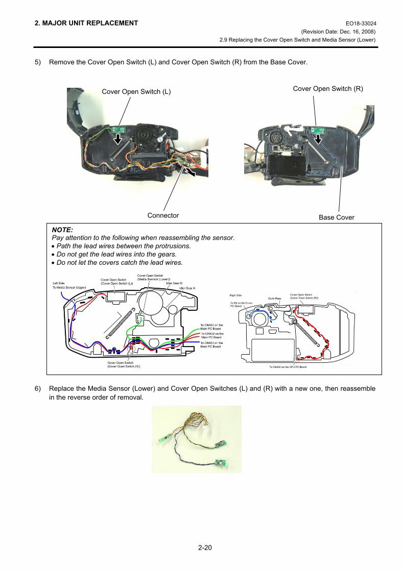
5) Remove the Cover Open Switch (L) and Cover Open Switch (R) from the Base Cover.
6) Replace the Media Sensor (Lower) and Cover Open Switches (L) and (R) with a new one, then reassemble
in the reverse order of removal.
Cover Open Switch (L) Cover Open Switch (R)
Connector Base Cover
NOTE: Pay attention to the following when reassembling the sensor. • Path the lead wires between the protrusions. • Do not get the lead wires into the gears. • Do not let the covers catch the lead wires.

2. MAJOR UNIT REPLACEMENT EO18-33024 (Revision Date: Dec. 16, 2008)
2.9 Replacing the Cover Open Switch and Media Sensor (Lower)
2-21
NOTES: 1. After replacing the Media Sensor, refer to the Setting Operation Manual or System Mode Manual and
perform the following operations. 1. Perform a RAM clear. 2. Perform the sensor adjustment.
2. After replacing the Media Sensor, perform an operation check for the cover open switch as follows. When the top cover is fully opened, make sure “Cover Open” is displayed on the LCD. When either side of the top cover is opened, make sure “Cover Open” is displayed on the LCD. When the top cover is fully closed, make sure the print operation is performed correctly. If the cover open switch does not operate correctly, this may result from the wrong connection of the
sensor connector, poor contact of the cable, etc. Make sure the sensor connector is surely connectedto CN402 on the CPU PC board and the cable is not broken.

2. MAJOR UNIT REPLACEMENT EO18-33024
2.10 Replacing the Media Sensor (Upper)
2-22
2.10 Replacing the Media Sensor (Upper) 1) Remove the Right Cover, Left Cover and Front Cover. (Refer to Section 2.1 Replacing the CPU PC
Board.) 2) Release the Hooks, then remove the Outlet Paper Guide Ass’y. 3) Remove the Media Sensor (Upper). 4) Disconnect the cables from the Main PC Board.
Hook Outlet Paper Guide Ass’y
Screw
Hook
Media Sensor (Upper)
Main PC Board
Connector

2. MAJOR UNIT REPLACEMENT EO18-33024
2.10 Replacing the Media Sensor (Upper)
2-23
5) Replace the Media Sensor (Upper) with a new one, then reassemble in the reverse order of removal.
NOTE: After replacing the Media Sensor, refer to the Setting Operation Manual or System Mode Manual andperform the following operations.
1. Perform a RAM clear. 2. Perform the sensor adjustment.

2. MAJOR UNIT REPLACEMENT EO18-33024 (Revision Date: Dec. 16, 2008)
2.10 Replacing the Platen Ass’y
2-24
2.11 Replacing the Platen Ass’y 1) Remove the Upper Sensor Cover. (Refer to Section 2.9 Replacing the Media Sensor (Upper).) 2) Release the Hooks, then remove the Platen Ass’y. 3) Replace the Platen Ass’y with a new one, then reassemble in the reverse order of removal.
Hook
Platen Ass’y
Hook
NOTES: 1. After replacing the Platen, refer to the Setting Operation Manual or System Mode Manual and perform
the following operations. Perform a RAM clear.
2. Perform a test print and make sure printing is even. (Refer to Section 4.6 in the System Mode Manual.)If the printing is uneven, make sure the platen ass’y is surely fixed with the hooks.

3. TROUBLESHOOTING EO18-33024
3. TROUBLESHOOTING
3- 1
3. TROUBLESHOOTING Problems Cause Solution
The printer is not turned on.
1. The battery is not loaded correctly.2. The battery terminal is
disconnected from the soldering part.
3. CPU PC board ass'y failure or Drive PC board ass'y failure
1. Re-load the battery correctly. 2. Replace the battery terminal. 3. Replace the CPU PC board ass'y or
the Drive PC board ass'y.
The printer does not print media. (The status indicator blinks in red.)
1. The media roll is not loaded correctly.
2. The media cover is not closed completely.
3. The media is jammed in the printer.
4. The print head FPC harness or the print head element is broken.
5. The print head temperature reached the upper limit of the operating temperature.
6. Flash ROM write error or erase error occurred.
7. There is insufficient area in the flash ROM.
8. The print mode is not selected
correctly.
1. Re-load the media roll correctly. 2. Close the media cover completely. 3. Remove the jammed media and re-
load the media roll correctly. 4. Replace the print head FPC harness
or the print head ass'y. 5. Open the media cover and allow the
print head to cool. . 6 . Open the media cover and close it
again. Replace the CPU PC board ass'y.
7. Open the media cover and close it again. Erase the data.
8. Open the media cover and close it again.
Send the correct print mode from the PC or handy terminal.
The printer does not print media. (The status indicator Blinks in green or orange.)
1. A communication error occurred.
1. Check that the interface cable is connected firmly. Check the communication parameters.
The printer does not print media. (The status indicator lights in red.)
1. The battery voltage is low.
1. Turn off the printer and replace the battery with a fully charged one.
The printer does not print media. (The status indicator lights in orange.)
1. The battery is nearly end.
1. Replace the battery with a fully charged one as soon as possible.
The [FEED] button does not function.
1. The [FEED] button is depressed incompletely.
1. Press the [FEED] button more strongly. Replace the CPU PC board ass'y or Drive PC Board.

3. TROUBLESHOOTING EO18-33024
3. TROUBLESHOOTING
3- 2
Problems Cause Solution
The printer does not print labels one by one in the strip mode or specified number of labels in the batch mode.
1. The sensors are not adjusted properly.
2. The sensors are not installed properly.
3. The sensors are dirty. 4. The sensors are disconnected
from the CPU PC board ass'y.
1. Re-adjust the sensors. 2. Re-install the sensors. 3. Clean the sensors. 4. Connect the sensors to the CPU PC
board ass'y.
A cover open error occurs after closing the media cover.
1. Either side of the media cover is unlocked.
2. The media cover switch failure
1. Close the media cover until both sides of the cover click in position.
2. Replace the media cover switch.
The printer does not print by radio communication.
1. Interface PC board ass'y failure 2. CPU PC board ass'y failure 3. Interface PC board ass'y is
disconnected from the CPU PC board ass'y.
4. The FPC cable for the interface PC board is broken.
1. Replace the interface PC board ass'y.2. Replace the CPU PC board ass'y. 3. Connect the interface PC board ass'y
with the CPU PC board ass'y completely.
4. Replace the FPC cable for the interface PC board.
Poor print quality
1. The print head is dirty. 2. Unspecified media is used.
1. Clean the print head. 2. Change the media to the specified
one.
The print start position is not detected.
1. The sensor is not adjusted properly.
2. The sensor is not installed properly.
3. The sensor or the sensor filter is dirty.
4. The sensor is disconnected from the CPU PC board ass'y.
1. Re-adjust the sensor. 2. Re-install the sensor. 3. Clean the sensor and sensor filter. 4. Connect the sensor to the CPU PC
board ass'y completely.
The power switch does not perform.
1. Power switch failure or CPU PC board ass'y failure
1. Replace the power switch or the CPU PC board ass'y.
Print tone is uneven.
1. The print head is dirty. 2. The print head failure 3. The platen failure
1. Clean the print head. 2 Replace the print head ass'y. 3. Replace the platen.
A print error occurs in the feed direction.
1. Failure in the motor idler gear, platen idler gear, idler gear, or platen gear
2. Print head failure 3. Platen failure
1. Replace the motor idler gear, platen idler gear, idler gear, or platen gear.
2. Replace the print head ass'y. 3. Replace the platen.
Related Documents