Torque motor manual

Welcome message from author
This document is posted to help you gain knowledge. Please leave a comment to let me know what you think about it! Share it to your friends and learn new things together.
Transcript

To rq u e m o to r m a n u a l

Torq
ue m
otor
man
ual -
ver
. 2.1
2 ©2020 Tecnotion BV - All rights reserved - The contents of this document are subject to change without prior notice.
TABLE OF CONTENTS
1. BEFORE YOU START 4
1.1 About this manual 41.2 Intended use 41.3 Use of symbols 41.4 Important notice 41.5 Safety warnings 41.6 Certification 6
1.6.1 CE Certification
1.6.2 Restriction of Hazardous Substances (RoHS)
1.7 Overview applicable standards 6
2. OVERVIEW & SPECIFICATIONS 7
2.1 Introduction of the motor 72.2 Motor family and series 72.3 Specifications 72.4 Basic components 8
2.4.1 Rotor
2.4.2 Stator
2.4.3 QTL torque motor kit fixation brackets
2.5 Additional components 9
3. MOTOR CONFIGURATION 10
3.1 Safety 103.2 Properties 103.3 Housing requirements 113.4 Mounting 11
3.4.1 Stator
3.4.2 Rotor
3.5 Electrical interface 153.5.1 Cable specifications & protective earth
3.5.2 Wiring schemes
3.6 Temperature sensors 183.6.1 PTC characteristic
3.6.2 KTY characteristic
3.7 Accessories 203.7.1 Digital Hall module
3.7.2 Configuration
4. INSTALLATION 24
4.1 Safety 244.2 Introduction 244.3 Before you start 25
4.3.1 Cleaning
4.3.2 Axial attraction
4.3.3 Radial attraction
4.4 Mounting options 304.4.1 Stator clamping
4.4.2 Stator bonding
4.4.3 Rotor clamping QTR series
4.4.4 Rotor bonding QTR series
4.4.5 Mounting QTL series
4.5 Installation of stator and rotor QTR series 324.5.1 Rotor in stator installation
4.5.2 Stator over rotor installation
4.5.3 Installation of the QTL 210 & 290 motor assembly
4.5.4 Installation of the QTL 230 & 310 motor assembly
4.5.5 Final check
4.6 Electrical connections 354.6.1 General remarks
4.6.2 Powerlines
4.6.3 Protective earth
4.6.4 Polarization test
4.6.5 Temperature sensor cable wiring
4.6.6 EMC performance

Torq
ue m
otor
man
ual -
ver
. 2.1
3 ©2020 Tecnotion BV - All rights reserved - The contents of this document are subject to change without prior notice.
4.7 Deinstallation 354.8 Additional components 36
4.8.1 Digital Hall module
4.9 Coupling torque motors 36
5. OPERATION 37
5.1 Pre-commissioning 375.2 Configuring 375.3 Testing 375.4 Operational conditions 38
6. TRANSPORT, STORAGE & DISMANTLING 39
6.1 General safety rules for transport, storage & dismantling 396.2 Transport & packaging 396.3 Storage and transportation 40
APPENDIX - TABLE OF CONTENTS
APPENDIX A 42
Overview - QTR 65 - 17/25/34/60 42Overview - QTR 78 - 17/25/34/60 43Overview - QTR 105 - 17/25/34/60 44Dimensions - QTR 105 - 17/25/34/60 45Overview - QTR 133 - 17/25/34/60 46Dimensions - QTR 133 - 17/25/34/60 47Overview - QTR 160 - 17/25/34/60 48Dimensions - QTR 160 - 17/25/34/60 49Dimensions - QTL 210 - 65/85/105 50Dimensions - QTL 230 - 65/85/105 51Dimensions - QTL 290 - 65/85/105 52
Dimensions - QTL 310 - 65/85/105 53
APPENDIX B 54
QTR 65- digital Hall module 54QTR 78- digital Hall module 55QTR 105 - digital Hall module 56QTR 133 - digital Hall module 57QTR 160 - digital Hall module 58
APPENDIX C 59
Material overview 59
APPENDIX D 60
IATA strayfield threshold 60
APPENDIX E 61
CE certification 61
APPENDIX F 62
T/n graphs 65/78 62T/n graphs 105/133/160 N winding 63T/n graphs 105/133/160 N winding 64T/n graphs 105/133/160 Y&Z winding 65T/n graphs 105/133/160 Y&Z winding 66T/n graphs QTL 210/230 N winding 67T/n graphs QTL 290/310 N winding 68
GLOSSARY 69

Torq
ue m
otor
man
ual -
ver
. 2.1
4Before you start©2020 Tecnotion BV - All rights reserved - The contents of this document are subject to change without prior notice.
1. BEFORE YOU START
This is the manual for your Tecnotion motor. Please read this manual very carefully. The information provided is important for a safe and warranted installation and operation of the motor. Be sure to have this manual at hand when installing or working with the motor.
1.1 About this manual
This manual describes the use of a Tecnotion torque motor system. These motors can be applied in numerous application devices. This manual is intended for technicians who construct a machine that includes a torque motor system. It will give insight what aspects to consider for the design and installation for a torque motor.
1.2 Intended use
A torque motor system is a permanent-magnet direct drive motor that rotates along an axis. It is intended to be used wherever a rotary movement is required. Only use this torque motor system as intended, every other use is not-intended use and therefore not warranted.
1.3 Use of symbols
This symbol describes a tip to inform the user.
This symbol is a non-safety related important notice that the user should be aware of.
These symbols warn about safety information that should be respected.
1.4 Important notice
Tecnotion declines all responsibility in case of accident or damage due to negligence or lack of observance of the instructions described in this manual. Tecnotion also declines all responsibility in case of accident or damage in conditions that differ from those indicated in the manual; Tecnotion also declines all responsibility for damage caused by improper use of the motor.
Handle the components of the motor with care, packed as well as unpacked.
Do not expose the magnets to temperatures higher than 70° C. The magnets may be demagnetized at higher temperatures.
Do not expose the stator to temperatures above 100 no curing° C. The filler material or wiring may be damaged.
Unpack the motor and check its integrity. If there is any irregularity, contact the dealer or Tecnotion, signaling the nature of the defects. Make a note of the serial number. This facilitates the correspondence with the supplier.
1.5 Safety warnings
Use of magnets
The used magnets show large attraction forces on all ferromagnetic objects such as iron. These forces cannot be controlled by hand. They may cause serious jamming danger. Do not bring any soft magnetic objects (iron) nearer than 25 cm of the magnetic side of the magnets of the rotor.

Torq
ue m
otor
man
ual -
ver
. 2.1
5Before you start©2020 Tecnotion BV - All rights reserved - The contents of this document are subject to change without prior notice.
Provide sufficient radial and axial centering and guidance to prevent collision during installation.
Be sure that the stator and rotor are fixed into your machine before removing the magnetic field protection plates. The stator and rotor will attract each other during installation. These forces cannot be controlled by hand. Put the magnetic field protection plates on again before dismounting them.
Magnetic sensitive objects like banking cards, pacemakers or other magnetic information carriers may be damaged if they are brought within 1 m of the magnets (plates or rotor).
If at any time and in any situation there is any doubt about the safety of the motor, do not use it and contact your supplier.
Mechanical safety
The motor is used as a part of a machine. The user has to take care that the machine as a whole fulfils all CE requirements.
The motor is powered by a servo amplifier. In case of a power disruption or fatal error this may automatically result in a free run out of the motor. Make mechanical precautions to prevent damage on the motor or your machine in the case of such an event.
The magnets can detach from the rotor when the motor is operated above its allowed maximum rotational speed. This can cause personal injury or damage to the motor and the entire application. This speed varies per motor type. Please set the correct maximum speed for the installed torque motor. Refer to appendix G for maximum mechanical speed.
Earthing
Before installing the motor, make sure that the supply mains are grounded and operate in conformity with the regulations in force.
Make sure that there is an effective protective earth. Make sure that there is no voltage at the wire terminals before connecting.
An earth connection does not work on non-conducting mounting surfaces like granite. In these cases the protective earth must be established by an earthing wire.
Maintenance
Before carrying out checks or doing any maintenance, clear the system by disconnecting the voltage. Be sure that there is no possibility of accidental connections.
The components can be damaged when cleaned with a non-prescribed cleaning agent. Use only isopropanol as a cleaning agent.
Adhesives and activators can damage the stator and rotor.
UV blacklight can cause irreversible damage to the eyes and other tissue when exposed. When using a UV blacklight installation wear appropriate protective clothing and glasses.
The motor contains permanent magnets that produce a magnetic stray field. For transport safety please check chapter 6 for information on transport.

Torq
ue m
otor
man
ual -
ver
. 2.1
6Before you start©2020 Tecnotion BV - All rights reserved - The contents of this document are subject to change without prior notice.
1.6 Certification
All information about certifications can be found in this chapter. The decla-ration of conformity or compliance can be found in appendix F.
1.6.1 CE CertificationTecnotion B.V. declares that all torque motors mentioned in this installation manual are manufactured in accordance with European directive 2006/95/EC and in conformity with the following standards, see Table 1.
Table 1: Applicable standards
Standard Name of standard
EN 60034-1: 2010 Rotating Electrical Machines, Part 1: Rating and performance.
EN 60204-1: 2010 Safety of machinery - Electrical equipment of machines, Part 1: General requirements
1.6.2 Restriction of Hazardous Substances (RoHS)Tecnotion B.V. declares to be compliant with the RoHS-guideline. Therefore Tecnotion ensures that all products are free from lead, cadmium, mercury, hexavalent chromium, polybrominated biphenyls or polybrominated diphenyl ethers.
1.7 Overview applicable standards
The table below gives an overview of applicable standards per motor type.
Table 2: Applicable standards per motortype
Series CE RoHS
QTR 65 Yes Yes
QTR 78 Yes Yes
QTR 105 Yes Yes
QTR 133 Yes Yes
QTR 160 Yes Yes
QTR digital Hall module Yes Yes
QTL 210 Yes Yes
QTL 230 Yes Yes
QTL 290 Yes Yes
QTL 310 Yes Yes
Torq
ue m
otor
man
ual -
ver
. 2.1
7overview & specifications©2020 Tecnotion BV - All rights reserved - The contents of this document are subject to change without prior notice.
2. OVERVIEW & SPECIFICATIONS
This chapter gives an overview of the motor and its components and speci-fications.
2.1 Introduction of the motor
Tecnotion torque motors are so called frameless torque motors. They can be applied in numerous application devices. For a fully functional torque motor system the user needs to provide additional components like an:
axis, bearing system, encoder and controller system.
In paragraph 2.4 & 2.5 more information can be found on the basic and additional components.
2.2 Motor family and series
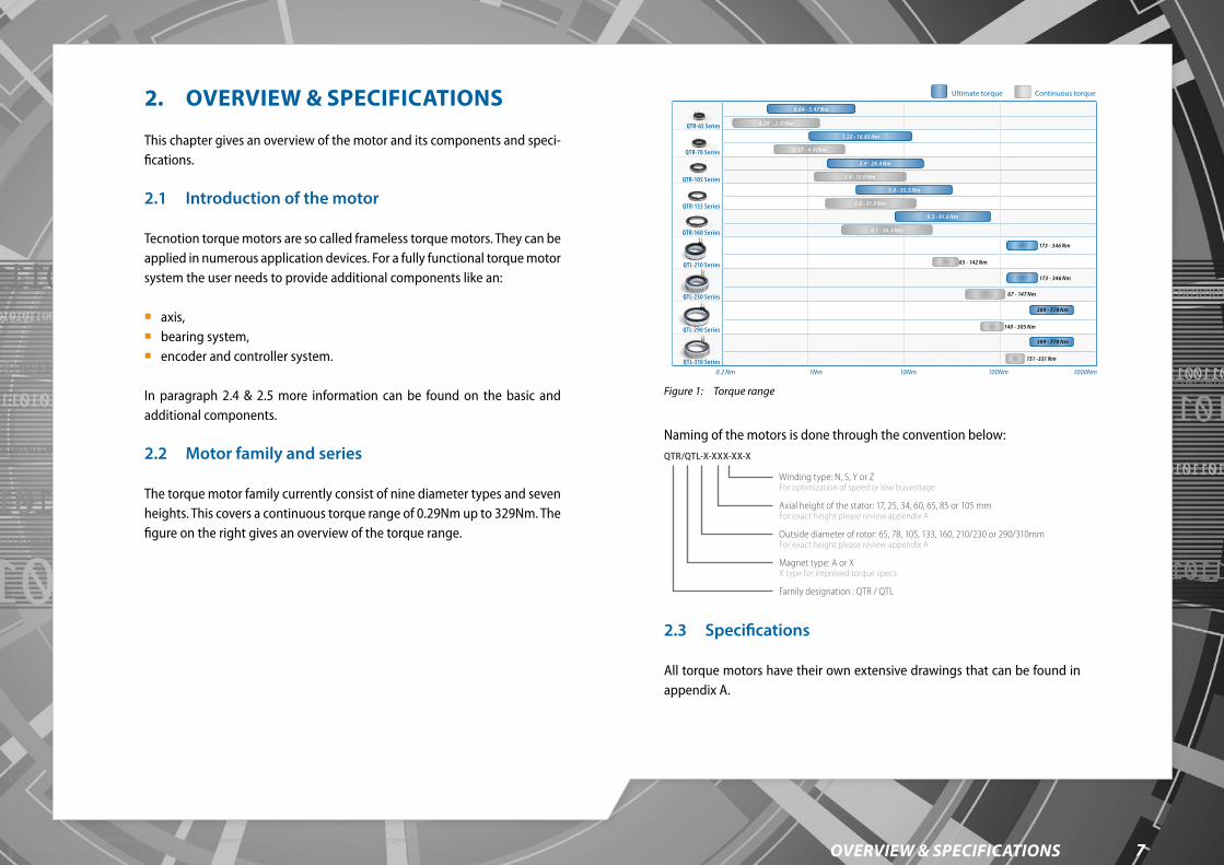
The torque motor family currently consist of nine diameter types and seven heights. This covers a continuous torque range of 0.29Nm up to 329Nm. The figure on the right gives an overview of the torque range.
10Nm1Nm 100Nm 1000Nm
2.6 - 21.9 Nm
5.6 - 55.5 Nm
1.4 - 12.0 Nm
0.57 - 4.41Nm
0.29 ..2.31Nm
9.3 - 91.6 Nm
173 - 346 Nm
389 - 778 Nm
389 - 778 Nm
4.1 - 36.3 Nm
65 - 142 Nm
67 - 147 Nm
140 - 305 Nm
151 -331 Nm
2.9 - 28.4 Nm
1.22 - 10.85 Nm
0.64 - 5.47 Nm
0.2 Nm
QTR-78 Series
QTR-105 Series
QTR-133 Series
QTR-160 Series
QTL-210 Series
QTL-230 Series
QTL-290 Series
QTL-310 Series
QTR-65 Series
Ultimate torque Continuous torque
173 - 346 Nm
Figure 1: Torque range
Naming of the motors is done through the convention below:QTR/QTL-X-XXX-XX-X
Winding type: N, S, Y or ZFor optimization of speed or low busvoltage
Axial height of the stator: 17, 25, 34, 60, 65, 85 or 105 mmFor exact height please review appendix A
Outside diameter of rotor: 65, 78, 105, 133, 160, 210/230 or 290/310mmFor exact height please review appendix A
Magnet type: A or XX type for improved torque specs
Family designation : QTR / QTL
2.3 Specifications
All torque motors have their own extensive drawings that can be found in appendix A.

Torq
ue m
otor
man
ual -
ver
. 2.1
8overview & specifications©2020 Tecnotion BV - All rights reserved - The contents of this document are subject to change without prior notice.
2.4 Basic components
A Tecnotion QTR torque motor kit consists of a rotor containing the magnets and a stator containing the coils. The bigger torque motors are provided with a temperature sensor. A QTL torque motor has optionally a ring with cooling channels wrapped around the stator and four brackets and spacers to fix the rotor and stator in place. In case of the water-cooled motor there are a total of four brackets. Additionally it has integrated temperature sen-sors. See Figure 2.
Figure 2: Basic components QTL motor kit
The voltage rating of 300, 600 or 680 Vdc varies per torque motor. Should another cable exit type or voltage rating be required please contact your local Tecnotion representative to explore the possibilities. Common methods of construction of the stator into an application are clamping or bonding. The torque motor lamination stack surface is made of bare steel and is prone to corrosion. When the lamination stack surface is not pro-tected it will show corrosion, this however will not affect performance.
2.4.1 RotorThe rotor, containing the magnets, is usually the moving part of the torque motor. The rotor can be fastened into an application by means of bonding, clamping, or bolting, depending on the motor type. The rotor of QTL motor can be fastened into an application by means of bolting.
Magnetic field protection ringThe rotor an be supplied with a magnetic field neutralizing protection ring (QTR-65, QTR-78 and QTL series don’t have a protection ring), see Figure 3. It functions as a shield for the magnetic forces. With the ring installed the rotor can be handled safely.
TECN
OTIO
N
A2
654321
10987654321
h
g
f
e
d
c
b
a
h
g
f
e
d
c
b
a
C T
ECN
OTI
ON
BV
writ
ten
cons
ent o
f the
cop
yrig
ht o
wne
r.or
in p
art i
s pr
ohib
ited
with
out t
heAl
l rig
hts
rese
rved
. Rep
rodu
ctio
n in
who
leC
TEC
NO
TIO
N B
V
toes
tem
min
g va
n de
aut
eurs
rech
theb
bend
e.ni
et to
eges
taan
dan
met
sch
rifte
lijke
of o
penb
aarm
akin
g, g
ehee
l of g
edee
ltelijk
, is
Alle
rech
ten
voor
beho
uden
. Ver
veel
voud
igin
g
HOEK
ANGLE
MAAT
DIMENSION
TOLERANTIES TENZIJ ANDERS VERMELDTOLERANCE UNLESS OTHERWISE STATED
UN-D 603
A
A
AANTALQUANT.
ORDERNO./ORDERNR.
PATTERN NO./MODELNR.AANTALQUANT.
SAMENSTELLINGSNR.ASSEMBLY NO.
STUKITEM
BL.SH.SH.
BL.VERV.SUPERS.
AIN UMR
UN-D 28
mm
EENH.UNIT
BEHAND
ELING
TREATM
ENTMA
TERIAA
LMA
TERIALROUGHNESS
RUWHEIDALGEMENE
GENERAL
SCHAALSCALE
EUROP.PROJ.
EIGENDOM VANPROPERTY OF
NAMENAAM
CONTR.CHECK TECNOTION BV ALMEL0 - NEDERLAND
Stator
Rotor
Protectionring
Stator
Rotor
Protection ring
Figure 3: Protection ring
2.4.2 StatorThe stator comes in different diameters and heights. It has a separate power and temperature sensor cable both with a length of 0.5 m. The cable exit can, depending on the motor type, be in axial or radial direction (see Figure 4). The QTL torque motor has a separate power and temperature sensor

Torq
ue m
otor
man
ual -
ver
. 2.1
9overview & specifications©2020 Tecnotion BV - All rights reserved - The contents of this document are subject to change without prior notice.
cable both with a length of 2 m. The stator can be fastened into an applica-tion by means of bolting, bonding, crimping and/or clamping depending on the motor type.
2.4.3 QTL torque motor kit fixation bracketsThe stator and rotor are locked together using fixation brackets, see Figure 2. The function of the fixation brackets is to keep the stator and rotor locked in place to ensure safety during transport and installation.
Figure 4: QTR motor with axial exit
2.5 Additional components
To construct a complete motion system, additional components are required. These components are not included when buying a Tecnotion torque motor. Please review the following minimum required compo-nents for setting up a complete motion system:
Power supply with sufficient power and voltage rating. Cables and connectors for connecting the torque motor to the drive
system. Amplifier and servo drive system. Bearing system, with sufficient stiffness and appropriate friction force. Mechanical infrastructure for containing the rotor and stator and to
accommodate heat transfer.
Optional:
Ruler disc and/or encoder system and/or Tecnotion digital Hall module. Braking mechanism.
Digital Hall moduleThe digital Hall module (see below) can be used to determine the electrical position of the rotor. The module is a replacement for a ‘wake-and-shake’ of the motor. It means that the module only functions when the QTR stator is not powered. This module cannot commutate over the entire speed- and load bandwidth.

Torq
ue m
otor
man
ual -
ver
. 2.1
10Motor configuration©2020 Tecnotion BV - All rights reserved - The contents of this document are subject to change without prior notice.
3. MOTOR CONFIGURATION
This chapter gives information for designing an application driven by a Tecnotion torque motor. Please take notice of the advice, tips and warnings in this chapter to make sure the torque motor performs in the best possible way.
3.1 Safety
Use of magnets
The used magnets show large attraction forces on all ferromagnetic objects such as iron. These forces cannot be controlled by hand. They may cause serious jamming danger. Do not bring any soft magnetic objects (iron) nearer than 25 cm of the magnetic side of the magnets of the rotor.
Provide sufficient radial and axial centering and guidance to prevent collision during installation.
Be sure that the stator and rotor are fixed into your machine before removing the magnetic field protection plates. The stator and rotor will attract each other during installation. These forces cannot be controlled by hand. Put the magnetic field protection plates or fixation brackets on again before dismounting them.
Magnetic sensitive objects like banking cards, pacemakers or other magnetic information carriers may be damaged if they are brought within 1 m of the magnets (plates or rotor).
If at any time and in any situation there is any doubt about the safety of the motor, do not use it and contact your supplier.
Mechanical safety
The motor is used as a part of a machine. The user has to take care that the machine as a whole fulfils all CE requirements.
Be sure your machine as a whole meets the requirements of all applicable electrical standards, such as the EN 60204 standard.
The motor is powered by a servo amplifier. In case of a power disruption or fatal error this may automatically result in a free run out of the motor. Make mechanical precautions to prevent damage on the motor or your machine in the case of such an event.
The magnets can detach from the rotor when the motor is operated above its allowed maximum rotational speed. This can cause personal injury or damage to the motor and the entire application. This speed varies per motor type. Please set the correct maximum speed for the installed torque motor. Refer to appendix G for maximum mechanical speed.
3.2 Properties
The relevant properties concerning configuration of a torque motor are described below.
CorrosionThe Tecnotion torque motor lamination stack surface is made of bare steel and is prone to corrosion. When the lamination stack surface is not pro-tected it will show corrosion, this however will not affect performance.
CoolingIn order to achieve rated performance, the stator needs to be mounted in a cooled housing. The full lamination stack needs to be in contact with a 20°C surface. Insufficient cooling will have an effect on the motor's continuous torque.

Torq
ue m
otor
man
ual -
ver
. 2.1
11Motor configuration©2020 Tecnotion BV - All rights reserved - The contents of this document are subject to change without prior notice.
Air gapThe correct air gap will be ensured by installing the Tecnotion torque motor according the instructions in this manual.
Thermal conductionTecnotion torque motors dissipate heat through the lamination stack. Most heat dissipates through the larger stack surface, though the lamination stack shoulders also have an important function. Proper clamping of the shoulders helps dissipate the heat. Cooling is needed when the motor is operated at continuous or stall torque.
For smaller motors (17 mm and 25 mm height) shoulder clamping can be sufficient (see Figure 5). For larger motors it is needed for the motor to lose its heat through the lamination stack. This can be done by a cooled housing or heat sink.
For catalogue performance the lamination stack surface needs to be in full contact with a body or heat sink kept at a maximum of 20°C. When only the shoulders of the lamination stack are in contact with a cooling/clamping surface, the available continuous torque is affected. The available continu-ous torque can be reduced by up to 75%. This reduction is affected by the motor size, clamping force and various changes in the environment.
TECN
OTIO
N
A2
654321
10987654321
h
g
f
e
d
c
b
a
h
g
f
e
d
c
b
a
C T
ECN
OTI
ON
BV
writ
ten
cons
ent o
f the
cop
yrig
ht o
wne
r.or
in p
art i
s pr
ohib
ited
with
out t
heAl
l rig
hts
rese
rved
. Rep
rodu
ctio
n in
who
leC
TEC
NO
TIO
N B
V
toes
tem
min
g va
n de
aut
eurs
rech
theb
bend
e.ni
et to
eges
taan
dan
met
sch
rifte
lijke
of o
penb
aarm
akin
g, g
ehee
l of g
edee
ltelijk
, is
Alle
rech
ten
voor
beho
uden
. Ver
veel
voud
igin
g
HOEK
ANGLE
MAAT
DIMENSION
TOLERANTIES TENZIJ ANDERS VERMELDTOLERANCE UNLESS OTHERWISE STATED
UN-D 603
A
A
AANTALQUANT.
ORDERNO./ORDERNR.
PATTERN NO./MODELNR.AANTALQUANT.
SAMENSTELLINGSNR.ASSEMBLY NO.
STUKITEM
BL.SH.SH.
BL.VERV.SUPERS.
AIN UMR
UN-D 28
mm
EENH.UNIT
BEHAND
ELING
TREATM
ENTMA
TERIAA
LMA
TERIALROUGHNESS
RUWHEIDALGEMENE
GENERAL
SCHAALSCALE
EUROP.PROJ.
EIGENDOM VANPROPERTY OF
NAMENAAM
CONTR.CHECK TECNOTION BV ALMEL0 - NEDERLAND
Figure 5: Cooling surface indicated in orange
3.3 Housing requirements
Pay attention to the different housing/connection requirements for the var-ious torque series. When clamping the stator all specifications apply. When a bonding-connection is used, the angularity does not apply. Always use the correct concentricity and centering of the rotor in the stator. Centering of the stator is done on the lamination stack. Rotor centering can be done on the inside of the rotor.
3.4 Mounting
There are a number of factors to consider when mounting a torque motor. Most importantly the method of mounting of the stator can affect perfor-mance. A tradeoff has to be made between thermal conduction, cost of infrastructure (housing) and ease of (de)installation.
When designing a mounting/housing, these questions can help:
Does the application use a high continuous load (that requires good thermal conductivity) or short peak loads (with sufficient downtime for cooling)?
What clamping force or shear strength is to be expected to keep the stator in place?
Is a quick (de)installation of the motor required?
3.4.1 Stator
Do not clamp the stator on the black polyurethane casting, this can damage the coils.
Do not center the stator on the black polyurethane casting.

Torq
ue m
otor
man
ual -
ver
. 2.1
12Motor configuration©2020 Tecnotion BV - All rights reserved - The contents of this document are subject to change without prior notice.
To ensure a good connection when mounting a stator, pay attention to the proper alignment, sufficient clamping force/tightening torque and heat extraction. Thermal properties are affected by the mounting method, either by variation in the contact surface or by additional thermal resistances (adhesives).
A
A
B
B
SECTION A-A
SECTION B-B
Figure 6: Heat extraction in orange
QTL 230 and QTL 310 cooling ringIt is necessary to check if the substances present in and around the intended application do not react with any part of the motor, in particular the NBR O-rings sealing the cooling ring (see Figure 7) as this could lead to a leakage of the cooling medium possibly resulting in diminished performance, short-circuiting, corrosion and/or contamination of the application. It is the
responsibility of the user to design the housing in such a way that it is leak-proof and compatible with the intended application.
Alle
rechte
n v
oorb
ehouden. V
erv
eelv
oudig
ing
of openbaarm
akin
g, geheel of gedeeltelij
k, is
nie
t to
egesta
an d
an m
et schriftelij
ke
toeste
mm
ing v
an d
e a
ute
urs
rechth
ebbende.
C T
EC
NO
TIO
N B
V
All
rights
reserv
ed. R
epro
duction in w
hole
or
in p
art
is p
rohib
ited w
ithout th
e
written c
onsent of th
e c
opyright ow
ner.
C T
EC
NO
TIO
N B
V
1 2 3 4 5 6 7
1 2 3 4 5 6 7 8 9 10
f
d
c
b
a
g
f
e e
d
c
b
a
TE
CN
OT
ION
0,2mm
3,2
1
A1
HOEK
ANGLE
MAAT
DIMENSION
TOLERANTIES TENZIJ ANDERS VERMELD
TOLERANCE UNLESS OTHERWISE STATED
UN-D 603
A
A
AANTALQUANT.
ORDERNO./ORDERNR.
PATTERN NO./MODELNR.
VERV.SUPERS.
AIN UMR
UN-D 28
mm
EENH.UNIT
BEHA
NDEL
ING
TREA
TMEN
TMA
TERI
AAL
MATE
RIALROUGHNESS
RUWHEIDALGEMENE
GENERAL
SCHAALSCALE
EUROP.PROJ.
EIGENDOM VANPROPERTY OF
NAMENAAM
TECNOTION BV ALMEL0 - NEDERLAND
1:2 Error: No reference
Error: No referenceCreated :
0,5°AANTALQUANT.
SAMENSTELLINGSNR.ASSEMBLY NO.
STUKITEM
SHEET 1 OF 1
Error: No reference Error: No reference
2345
Remove all sharp burrs and sharp edges. Dimensions after surface treatment.
Error: No reference
Error: No reference
Error: No reference Error: No reference Error: No reference
7-11-2018
WATERCOOLING IN- AND OUTLETCOOLING CHANNELS
O-RING
ROTOR
STATOR
HOUSING EXAMPLE
SENSOR CABLE
POWER CABLE
Figure 7: Material overview of QTL 230 and QTL 310 with O-rings
3.4.2 RotorThe main objective when mounting the rotor is proper positioning – axial and radial – of the motor. Other than positioning the rotor, the proper clamping/bonding/bolting force needs to be considered. The steel of the rotor compared to the stator lamination stack allows for higher clamp forces.
Mounting a rotor requires a strong and rigid axle. Take into consideration that heat dissipation trough the axle will be minimal. Tecnotion recom-mends two options when mounting a QTR rotor. The rotor can either be mounted by clamping it axially or by bonding (see Figure 8), or by bolting in case of a QTL rotor.

Torq
ue m
otor
man
ual -
ver
. 2.1
13Motor configuration©2020 Tecnotion BV - All rights reserved - The contents of this document are subject to change without prior notice.
TECN
OTIO
N
A2
654321
10987654321
h
g
f
e
d
c
b
a
h
g
f
e
d
c
b
a
C T
ECN
OTI
ON
BV
writ
ten
cons
ent o
f the
cop
yrig
ht o
wne
r.or
in p
art i
s pr
ohib
ited
with
out t
heAl
l rig
hts
rese
rved
. Rep
rodu
ctio
n in
who
leC
TEC
NO
TIO
N B
V
toes
tem
min
g va
n de
aut
eurs
rech
theb
bend
e.ni
et to
eges
taan
dan
met
sch
rifte
lijke
of o
penb
aarm
akin
g, g
ehee
l of g
edee
ltelijk
, is
Alle
rech
ten
voor
beho
uden
. Ver
veel
voud
igin
g
HOEK
ANGLE
MAAT
DIMENSION
TOLERANTIES TENZIJ ANDERS VERMELDTOLERANCE UNLESS OTHERWISE STATED
UN-D 603
A
A
AANTALQUANT.
ORDERNO./ORDERNR.
PATTERN NO./MODELNR.AANTALQUANT.
SAMENSTELLINGSNR.ASSEMBLY NO.
STUKITEM
BL.SH.SH.
BL.VERV.SUPERS.
AIN UMR
UN-D 28
mm
EENH.UNIT
BEHAND
ELING
TREATM
ENTMA
TERIAA
LMA
TERIALROUGHNESS
RUWHEIDALGEMENE
GENERAL
SCHAALSCALE
EUROP.PROJ.
EIGENDOM VANPROPERTY OF
NAMENAAM
CONTR.CHECK TECNOTION BV ALMEL0 - NEDERLAND
Figure 8: Bonding surface (left), clamping surface (right)
QTR 65 and QTR 78 housing specificationThe following specifications apply when designing a housing for a Tecnotion QTR 65 or QTR 78 stator. The stator's main contact area is the lamination stack. The lamination stack is used both for cooling and clamping/bonding purposes. The stator requires a housing with specifications according to Figure 9 and Table 3. SECTION B-B
Alig
n0.3u0
.2
Axle diameter h8
Housing diameter H8
Mini
mum
dept
h
a 0,1 B
a 0,3 B
n 0,1 B
n 0,1 BB
Maximum axle diameter
Figure 9: QTR 65 and QTR 78 housing requirement tolerances for mounting/centering purposes
Pay attention to the angularity and parallelism when installing a Tecnotion QTR stator.
Table 3: Housing specification QTR 65 and QTR 78
MotorQTR 65- 17/25 series
QTR 65- 34/60 series
QTR 78- 17/25 series
QTR 78- 34/60 series
AlignmentAxial alignment of the rotor in stator must be within 0,3 mm +/- 0,2 mm
Minimum depth 5.5 mm 7.5 mm 5.5 mm 7.5 mm
Housing diameter 65 mm H8 78 mm H8
Axle diameter 17 mm h8 29 mm h8
Max. axle diameter 23 mm 35 mm
QTR 1xx housing specificationWhen mounting a QTR 105, QTR 133 or QTR 160 stator different tolerances apply. See the specifications according to Figure 10 and Table 4. When the housing meets the tolerances described, the torque motor will perform best.
TECN
OTIO
N
A2
654321
10987654321
h
g
f
e
d
c
b
a
h
g
f
e
d
c
b
a
C T
ECN
OTI
ON
BV
writ
ten
cons
ent o
f the
cop
yrig
ht o
wne
r.or
in p
art i
s pr
ohib
ited
with
out t
heAl
l rig
hts
rese
rved
. Rep
rodu
ctio
n in
who
leC
TEC
NO
TIO
N B
V
toes
tem
min
g va
n de
aut
eurs
rech
theb
bend
e.ni
et to
eges
taan
dan
met
sch
rifte
lijke
of o
penb
aarm
akin
g, g
ehee
l of g
edee
ltelijk
, is
Alle
rech
ten
voor
beho
uden
. Ver
veel
voud
igin
g
HOEK
ANGLE
MAAT
DIMENSION
TOLERANTIES TENZIJ ANDERS VERMELDTOLERANCE UNLESS OTHERWISE STATED
UN-D 603
A
A
AANTALQUANT.
ORDERNO./ORDERNR.
PATTERN NO./MODELNR.AANTALQUANT.
SAMENSTELLINGSNR.ASSEMBLY NO.
STUKITEM
BL.SH.SH.
BL.VERV.SUPERS.
AIN UMR
UN-D 28
mm
EENH.UNIT
BEHAND
ELING
TREATM
ENTMA
TERIAA
LMA
TERIALROUGHNESS
RUWHEIDALGEMENE
GENERAL
SCHAALSCALE
EUROP.PROJ.
EIGENDOM VANPROPERTY OF
NAMENAAM
CONTR.CHECK TECNOTION BV ALMEL0 - NEDERLAND
AA
SECTION A-A
IDr h7
ODs H9
Alig
nmen
t0.3u0
.4
Mini
mum
dept
h
a 0,2 A
BB
SECTION B-B
Alig
n0.3u0
.2
IDrotor h8
ODstator H8
Mini
mum
dept
h
a 0,1 B
a 0,3 B
n 0,1 B
n 0,1 B
A
B
SECTION A-A
Axle diameter h7
Maximum axle diameter
Housing diameter H9
Alig
nmen
t0.3u0
.4
Mini
mum
dept
h
a 0,2 A
A
Figure 10: QTR 1xx housing requirement tolerances for mounting/centering purposes

Torq
ue m
otor
man
ual -
ver
. 2.1
14Motor configuration©2020 Tecnotion BV - All rights reserved - The contents of this document are subject to change without prior notice.
When using a digital Hall module: Tecnotion advices to bond rather than clamp the stator.
Table 4: Housing specification QTR 105, QTR 133 and QTR 160
MotorQTR 105-17/25
QTR 105-34
QTR 105-60
QTR 133-17/25
QTR 133-34
QTR 133-60
QTR 160 17/25
QTR 160-34
QTR 160-60
Alignment Axial alignment of the rotor in stator must be within 0.3 mm +/- 0.4 mm
Minimum depth
4.5 mm
5.0 mm
5.5 mm
4.5 mm
5.0 mm
5.5 mm
4.5 mm
5.0 mm
5.5 mm
Housing diameter
105 mm H9 133 mm H9 160 mm H9
Axle diameter
56 mm h7 84 mm h7 111 mm h7
Max. axle diameter
62 mm 91 mm 118 mm
Beware of the maximum temperature when curing the bonding material.For the stator, no curing above 100°C. Risk of damaging the stator.For the rotor, no curing above 70°C. Above 70°C, risk of demagnatizing the magnets.
QTL series housing specificationIn order to design the most suitable housing for a particular application the dimensions of the stator and rotor are given below. The stator of the water cooled motors and rotor have bolting holes for fastening it to the applica-tion. This method is advised. The stator of the non-water cooled motors do not have bolting holes, therefore fixing the motor to the housing should be done by bonding, crimping or tangential clamping. Axial clamping is not advised because the lamination stack can be damaged due to compression. The requirements to fixate the motor within the housing are dependent on the application and the intended movement profile. The non-water cooled QTL motors are very similar to the QTR series and the same methods of fixa-
tion, with the exception of axial clamping, can be applied. When designing the housing of a water cooled motor it is important to take into consider-ation that the O-ring needs to maintain a seal at all times. Always use the correct concentricity and centering of the rotor in the stator. Centering of the stator is done on the rotor ring, not the filler material. Rotor centering can be done on the inside of the rotor ring. See the specifications according to Figure 11 and Table 5.
Alle
rechte
n v
oorb
ehouden. V
erv
eelv
oudig
ing
of openbaarm
akin
g, geheel of gedeeltelij
k, is
nie
t to
egesta
an d
an m
et schriftelij
ke
toeste
mm
ing v
an d
e a
ute
urs
rechth
ebbende.
C T
EC
NO
TIO
N B
V
All
rights
reserv
ed. R
epro
duction in w
hole
or
in p
art
is p
rohib
ited w
ithout th
e
written c
onsent of th
e c
opyright ow
ner.
C T
EC
NO
TIO
N B
V
1 2 3 4 5 6 7
1 2 3 4 5 6 7 8 9 10
f
d
c
b
a
g
f
e e
d
c
b
a
Available
mtemmink
1.6
Drawing
TOLERANCE ACCORDING TO:ISO 2768-1(m) and ISO 2768-2 (K) UNLESS OTHERWISE STATED
QUANT.ORDER NR.
PATTERN NO.
QUANT.
Released
AIN UMR
UN-D 28
mm
UNIT
TREA
TMEN
TMA
TERI
ALROUGHNESS
GENERAL
SCALE
EUROP.PROJ.
PROPERTY OF
Name:
TECNOTION BV ALMEL0 - NEDERLAND
2:1mtemmink
2019-04-26
Created : 2019-04-25
2345
STATUS
ASSEMBLY NO.ITEM
HOUSING O H8
AXLE O h8
A
a O 0.1 A
MAXIMUM O AXLE
915
Alle
re
chte
n v
oorb
eho
ude
n.
Ve
rve
elv
oud
igin
g
of o
pe
nb
aarm
akin
g,
ge
he
el of
ged
ee
lte
lijk,
is
nie
t to
eg
esta
an d
an
met
sch
rifte
lijke
toe
ste
mm
ing
van
de
au
teu
rsre
ch
the
bb
en
de.
C T
EC
NO
TIO
N B
V
All
righ
ts r
ese
rve
d.
Rep
rodu
ctio
n in w
ho
le
or
in p
art
is p
roh
ibite
d w
ith
ou
t th
e
writt
en c
onsen
t o
f th
e c
op
yrig
ht
ow
ne
r.
C T
EC
NO
TIO
N B
V
1 2 3 4 5 6 7
1 2 3 4 5 6 7 8 9 10
f
d
c
b
a
g
f
e e
d
c
b
a
Available
mtemmink
1.6
Drawing
TOLERANCE ACCORDING TO:ISO 2768-1(m) and ISO 2768-2 (K) UNLESS OTHERWISE STATED
QUANT.ORDER NR.
PATTERN NO.
QUANT.
Released
AIN UMR
UN-D 28
mm
UNIT
TREA
TMEN
TMA
TERI
ALROUGHNESS
GENERAL
SCALE
EUROP.PROJ.
PROPERTY OF
Name:
TECNOTION BV ALMEL0 - NEDERLAND
2:1mtemmink
2019-04-26
Created : 2019-04-26
2345
STATUS
ASSEMBLY NO.ITEM
AXLE O h7
HOUSING O E8 A
MAXIMUM O AXLE
915
a O 0.1 A
Figure 11: QTL 210 and 290 (above) and 230 and 310 (below) housing requirement toler-ances for mounting/centering purposes

Torq
ue m
otor
man
ual -
ver
. 2.1
15Motor configuration©2020 Tecnotion BV - All rights reserved - The contents of this document are subject to change without prior notice.
Table 5: Housing specification QTL 210, QTL 230, QTL 290 and QTL 310
QTL 210 QTL 230 QTL 290 QTL 310
ID Housing 210 E8 230 H8 290 E8 310 H8
OD Rotor axle 140 h7 140 h8 220 h7 220 h8
Max. axle diameter 146 mm 226 mm
3.5 Electrical interface
Tecnotion torque motors come with various cable configurations. The main difference can be seen by:
QTR 65 and QTR 78 motors use 4 ‘flying leads’ for powering the motor. QTR 105, QTR 133 and QTR 160 motors have two cables, the larger one
being the power cable, the smaller being the temperature sensor cable. Both cables being shielded with braided metal.
The temperature sensor cable can be cut off if the sensor is not used.
QTR 65 and QTR 78 have no strain relief, provide proper strain relief in construction.
The cable exit differs for various Tecnotion torque motors (see Figure 12).
The 65 mm and 78 mm Tecnotion torque motors use flying lead power cables. These motors do not have a temperature sensor (cable).
Tecnotion torque motors of 105, 133 and 160 diameters with a 17, 25 or 34 mm height use a radial cable exit.
Tecnotion torque motors of 105, 133 and 160 diameters with a 60 mm height and all QTL motors use an axial cable exit.
QTR 1xx Y and Z have different cable exit dimensions.
TECN
OTIO
N
A2
654321
10987654321
h
g
f
e
d
c
b
a
h
g
f
e
d
c
b
a
C T
ECN
OTI
ON
BV
writ
ten
cons
ent o
f the
cop
yrig
ht o
wne
r.or
in p
art i
s pr
ohib
ited
with
out t
heAl
l rig
hts
rese
rved
. Rep
rodu
ctio
n in
who
leC
TEC
NO
TIO
N B
V
toes
tem
min
g va
n de
aut
eurs
rech
theb
bend
e.ni
et to
eges
taan
dan
met
sch
rifte
lijke
of o
penb
aarm
akin
g, g
ehee
l of g
edee
ltelijk
, is
Alle
rech
ten
voor
beho
uden
. Ver
veel
voud
igin
g
HOEK
ANGLE
MAAT
DIMENSION
TOLERANTIES TENZIJ ANDERS VERMELDTOLERANCE UNLESS OTHERWISE STATED
UN-D 603
A
A
AANTALQUANT.
ORDERNO./ORDERNR.
PATTERN NO./MODELNR.AANTALQUANT.
SAMENSTELLINGSNR.ASSEMBLY NO.
STUKITEM
BL.SH.SH.
BL.VERV.SUPERS.
AIN UMR
UN-D 28
mm
EENH.UNIT
BEHAND
ELING
TREATM
ENTMA
TERIAA
LMA
TERIALROUGHNESS
RUWHEIDALGEMENE
GENERAL
SCHAALSCALE
EUROP.PROJ.
EIGENDOM VANPROPERTY OF
NAMENAAM
CONTR.CHECK TECNOTION BV ALMEL0 - NEDERLAND
Figure 12: Axial flying lead (left), radial shielded cables (middle), axial shielded cables (right)
QTL torque motorThe QTL torque motor has two cables exiting the stator axially. The larger orange one being the power cable, the smaller green one being the tem-perature sensor cable. Both cables being shielded with braided metal.
3.5.1 Cable specifications & protective earthSee Table 6 for cable specifications and identification. If desired you can shorten these cables and provide them with appropriate connectors.

Torq
ue m
otor
man
ual -
ver
. 2.1
16Motor configuration©2020 Tecnotion BV - All rights reserved - The contents of this document are subject to change without prior notice.
Table 6: Cable specification and identification
MotorQTR 65QTR 78
QTR 105 NQTR 133 NQTR 160 N
QTR 105 Y/ZQTR 133 Y/ZQTR 160 Y/Z
QTL 210 NQTL230 NQTL 290 NQTL 310 N
Motor height All 17-25-34 60 All 17-25-34 All 65-85-105
Type of cable
4 flying leads (3 phases, 1 ground)
Shielded powerShielded sensor
Shielded power
Shielded sensor
Shielded power
Shielded sensor
Length 500 mm
Cable diameter in mm
2.06 6.5 9.5 4.5 6.6 4.5 10.6 6.4
Bending radius in mm
10.3 42.3 38.4 27 99 27 79.5 48
Rated voltage Vdc
600 320 600 n/s 320 n/s 680 30
Internally the motor’s protective earth wire is galvanically connected to the lamination stack. This wire must be connected to the protective earth con-nector of the servo amplifier.
Provide the motor system with protective earth lines to the amplifier that are as short as possible..
The details about the QTR 1xx sensor cable wire identification are shown in Table 7.
Table 7: Sensor cable wire identification QTR 1xx
Sensor cable (color) Connection to servo controller
PTC (white) PTC
PTC (brown) PTC
KTY21 (green) KTY83-122
KTY21 (yellow) KTY83-122
Shield Protective earth
3.5.2 Wiring schemes Below are the wiring schemes for the different torque motors.
QTR 65 & QTR 78
Servo amplifier
L1
L3 L2
L1
L2
L3
PEgreen/yellow
Torque motor
Frame
Figure 13: Wiring scheme for QTR 65 and QTR 78
Table 8: Power cables wire identification QTR 65 and QTR 78
Power cable 17/25/34/60 Connection to servo controller
3-phases
L1 black
3-phasesL2 red
L3 white
Protective earth green/yellow Protective earth

Torq
ue m
otor
man
ual -
ver
. 2.1
17Motor configuration©2020 Tecnotion BV - All rights reserved - The contents of this document are subject to change without prior notice.
QTR 1xx N+Y
Servo amplifier
L1
L3 L2
PTC
KTY
L1
L2
L3
PEgreen/yellow
white
brown
yellow
green
Torque motor
Frame
Figure 14: Wiring scheme for QTR 105, QTR 133 and QTR 160
Table 9: Power cables wire identification QTR 1xx N+Y
Powercable 17/25/34 60 Connection to servo controller
3-phases
L1 black black '1'
3-phasesL2 red black '2'
L3 white black '3'
Protective earth green/yellow Protective earth
Shield Protective earth
QTR 1xx Z
Servo amplifier
L1
L3
L2
PTC
KTY
L1
L2
L3
PEgreen/yellow
white
brown
yellow
green
Torque motor
Frame
Figure 15: Wiring scheme for torque Z windings
Table 10: Power cables wire identification QTR 1xx Z
Powercable 17/25/34 60 Connection to servo controller
3-phases
L1 black black '1'
3-phasesL2 red black '2'
L3 white black '3'
Protective earth green/yellow Protective earth
Shield Protective earth

Torq
ue m
otor
man
ual -
ver
. 2.1
18Motor configuration©2020 Tecnotion BV - All rights reserved - The contents of this document are subject to change without prior notice.
QTL series
Servo amplifier
L1
L3 L2
L1
L2
L3
PEgreen/yellow
Torque motor
Frame
+-
red
yellow
green
blue
PT1000
PT1000
PT1000
PTC
PTC
PTC
brown
black
Figure 16: Wiring scheme for QTL series
Table 11: Power cables designation QTL series
Phase Cable designation
L1 U/L1/C/L+
L2 V/L2
L3 W/L3/D/L-
PE GN/YE
Table 12: Sensor cable wire identification QTL series
Component Colour
PTC Brown
PTC Black
PT1000 (1) + Red
Not used Orange
PT1000 (2) + Green
PT1000 (3) + Yellow
PT1000 common - Blue
Not used Violet
3.6 Temperature sensors
Tecnotion can supply three types of temperature sensors with its torque motors:
PTC-sensors KTY-sensors PT1000
The PTC-sensor can be used as a cut-off sensor when the maximum tem-perature is exceeded. The KTY-sensor can be used for monitoring purposes as well.

Torq
ue m
otor
man
ual -
ver
. 2.1
19Motor configuration©2020 Tecnotion BV - All rights reserved - The contents of this document are subject to change without prior notice.
Tecnotion QTR 65 and QTR 78 torque motors do not use any temperature sensors.
Tecnotion QTR 105, QTR 133 and QTR 160 stators are equipped with two temperature sensors, one PTC-1k-type and one KTY83-122 type.
Tecnotion QTL 210, QTL 230, QTL 290 and QTL 310 stators are equipped with 3 x PTC 1kΩ in series and 3 x PT1000 in parallel.
In cases where long peak currents are demanded, the thermal response time of the stator is too long to ensure a proper overheating protection by the sensors. The temperature sensors can ensure a proper protection up to an I
rms of 45% of the ultimate current of the motor. This corresponds with a
temperature increase of 4.5°C/s. These long peak current conditions can occur for example during an accidental run or by taking a new axis in con-trol. In this case I2t protection is essential to prevent the stator from over-heating. In almost all controllers an I2t protection can be set in the software.
3.6.1 PTC characteristicThe PTC-1k type is a sensor which has a very sudden resistance rise near the critical temperature of the stator of 110°C. The PTC-1k type is almost a digi-tal indicator: temperature below vs. above critical temperature. Therefore it is very useful for signaling over temperature without requiring sensitive electronics.
It is not possible to obtain a direct temperature signal from this sensor. At room temperature the PTC has an electrical resistance <100 Ω. When the temperature rises to the critical temperature the resistance will increase rather uniformly up to 1000 Ω. Above this temperature the resistance increases exponentially. 1000 Ω is the switching resistance. The amplifier should immediately stop the power supply when this resistance is exceeded. In this way overheating and motor damage can be prevented.
T (°C)
R (Ω)
10 30 50 70 90 110 130 150 180101
102
103
104
105
106
107
Figure 17: Temperature dependence of the PTC-1k sensor
3.6.2 KTY characteristicThe KTY83-122 sensor has a rather stable and slow temperature coefficient as shown in Figure 18. The sensor can supply a temperature reading in the whole range. Therefore it is useful to monitor the coil temperature during tests and to decide whether the thermal margins are enough to guarantee error-free running of the machine under certain conditions.
Disadvantage of the sensor is that it requires sensitive and accurate elec-tronics to obtain a reliable reading. Please configure the sensor according to the wiring scheme in Figure 19 to attain a correct read out.

Torq
ue m
otor
man
ual -
ver
. 2.1
20Motor configuration©2020 Tecnotion BV - All rights reserved - The contents of this document are subject to change without prior notice.
Table 13: KTY83-122 characteristic values
T (°C) 20 25 30 40 50 60 70 80 90 100 110 120 130
RNOM
(Ω) 972 1010 1049 1130 1214 1301 1392 1487 1585 1687 1792 1900 2012
2000
1500
1000
5000 50 100
°C
Ω
RKTY
RMIN
RNOM
RMAX
T
R
Figure 18: Temperature dependence of the KTY83-122 sensor
12k
4k7 KTY
Usupply
Usignal
Figure 19: Wiring scheme for KTY83-122 sensor
0
2 0 0
4 0 0
6 0 0
8 0 0
1 0 0 0
1 2 0 0
1 4 0 0
1 6 0 0
0 2 0 4 0 6 0 8 0 1 0 0 1 2 0 1 4 0
Res
ista
nce
[Oh
m]
Temperature [°C]
PT1000 resistance graph
Figure 20: PT 1000 sensor characteristics
3.7 Accessories
3.7.1 Digital Hall moduleTecnotion QTR motors can be equipped with a digital Hall module for ‘wake and-shake’ functionality. (digital Hall module is not available for QTL series).Before the motor is switched on this digital Hall module can determine the position and direction of rotation of the rotor. For drawings of the digital Hall module see appendix B.
The QTR digital Hall modules can only be used as a wake-and-shake replace-ment. This means that the module only functions when the torque stator is not powered.

Torq
ue m
otor
man
ual -
ver
. 2.1
21Motor configuration©2020 Tecnotion BV - All rights reserved - The contents of this document are subject to change without prior notice.
3.7.2 Configuration
A filter needs to be placed on the output following scheme in Figure 15. Values for R and C may deviate as long as R*C (time constant) equals 47 ms.
When considering EMC it is best to use connectors with a metal (conducting) housing. The cable shield has to be connected to the connector housing.
Connecting the Hall module to the connector has to be done with ESD protection.
ADC input controller
Ground
DHM output
100μF
470Ω
Figure 21: Output filter
Tecnotion digital Hall modules are shipped with the screws used to install them. A Philips ph0 screwdriver is used to mount the module on the QTR stator. The digital Hall module requires a QTR stator with prepared mount-ing holes for the digital Hall module.
When the sensor is mounted it is not possible to insert or extract the rotor from the sensor side.
Table 14: General specifications
Type Value
Input voltage +5 ... 15 Vdc
Output signalSource type TTL, max 2.5mA, 5±0.5Vdc (3 signals)AquadB, max 2.5mA, 5±0.5Vdc (2 signals). (Not applicable for QTR0xx)
Cable Shielded 0.5m length
Cable diameter 4.7
EMC Conform EN61000-6-2 (Immunity)
RoHS Conform
Reach Conform
Table 15: Electrical interface
Color Function
White 0V
Brown +5 ... 15V
Grey Hall A1
Green Hall A2
Red Hall B
Yellow Hall C
QTR digital Hall timing and alignment
The timing diagrams are applicable when the rotor moves clockwise
Legend for TTL diagrams Legend for AquadB diagrams(not applicable for QTR 65 /78)
3
4.7O
R29
.6±0
.3R
40.9
±0.3
O 1.6Hole (2x)For 1.8x6 self tapping screw
37.5 (2x)
24°
6
60°
120°
Figure 22: Legend for the timing diagrams

Torq
ue m
otor
man
ual -
ver
. 2.1
22Motor configuration©2020 Tecnotion BV - All rights reserved - The contents of this document are subject to change without prior notice.
0 4 7 11 14 18 22 25 29 32Volta
ge
Degrees of rotation
DHM QTR 105
Hall A1
Hall B
Hall C
Hall A2
U 1-2
U 2-3
U 3-1
0 3 5 8 10 13 15 18 21 23Volta
ge
Degrees of rotation
DHM QTR 133
Hall A1
Hall B
Hall C
Hall A2
U 1-2
U 2-3
U 3-1
0 2 4 6 8 10 12 14 16 18Volta
ge
Degrees of rotation
DHM QTR 160
Hall A1
Hall B
Hall C
Hall A2
U 1-2
U 2-3
U 3-1
0 10 20 30 40 50 60 70 80 90Volta
ge
Degrees of Rotation
DHM QTR 65
Hall A
Hall B
Hall C
U 1-2
U 2-3
U 3-1
0 10 20 30 40 50 60Volta
ge
Degrees of Rotation
DHM QTR 78
Hall A
Hall B
Hall C
U 1-2
U 2-3
U 3-1
Figure 23: Timing diagram of QTR 65 series
0 4 7 11 14 18 22 25 29 32Volta
ge
Degrees of rotation
DHM QTR 105
Hall A1
Hall B
Hall C
Hall A2
U 1-2
U 2-3
U 3-1
0 3 5 8 10 13 15 18 21 23Volta
ge
Degrees of rotation
DHM QTR 133
Hall A1
Hall B
Hall C
Hall A2
U 1-2
U 2-3
U 3-1
0 2 4 6 8 10 12 14 16 18Volta
ge
Degrees of rotation
DHM QTR 160
Hall A1
Hall B
Hall C
Hall A2
U 1-2
U 2-3
U 3-1
0 10 20 30 40 50 60 70 80 90Volta
ge
Degrees of Rotation
DHM QTR 65
Hall A
Hall B
Hall C
U 1-2
U 2-3
U 3-1
0 10 20 30 40 50 60Volta
ge
Degrees of Rotation
DHM QTR 78
Hall A
Hall B
Hall C
U 1-2
U 2-3
U 3-1
Figure 24: Timing diagram of QTR 78 series
0 4 7 11 14 18 22 25 29 32Volta
ge
Degrees of rotation
DHM QTR 105
Hall A1
Hall B
Hall C
Hall A2
U 1-2
U 2-3
U 3-1
0 3 5 8 10 13 15 18 21 23Volta
ge
Degrees of rotation
DHM QTR 133
Hall A1
Hall B
Hall C
Hall A2
U 1-2
U 2-3
U 3-1
0 2 4 6 8 10 12 14 16 18Volta
ge
Degrees of rotation
DHM QTR 160
Hall A1
Hall B
Hall C
Hall A2
U 1-2
U 2-3
U 3-1
0 10 20 30 40 50 60 70 80 90Volta
ge
Degrees of Rotation
DHM QTR 65
Hall A
Hall B
Hall C
U 1-2
U 2-3
U 3-1
0 10 20 30 40 50 60Volta
ge
Degrees of Rotation
DHM QTR 78
Hall A
Hall B
Hall C
U 1-2
U 2-3
U 3-1
Figure 25: Timing diagram of QTR 105 series
0 4 7 11 14 18 22 25 29 32Volta
ge
Degrees of rotation
DHM QTR 105
Hall A1
Hall B
Hall C
Hall A2
U 1-2
U 2-3
U 3-1
0 3 5 8 10 13 15 18 21 23Volta
ge
Degrees of rotation
DHM QTR 133
Hall A1
Hall B
Hall C
Hall A2
U 1-2
U 2-3
U 3-1
0 2 4 6 8 10 12 14 16 18Volta
ge
Degrees of rotation
DHM QTR 160
Hall A1
Hall B
Hall C
Hall A2
U 1-2
U 2-3
U 3-1
0 10 20 30 40 50 60 70 80 90Volta
ge
Degrees of Rotation
DHM QTR 65
Hall A
Hall B
Hall C
U 1-2
U 2-3
U 3-1
0 10 20 30 40 50 60Volta
ge
Degrees of Rotation
DHM QTR 78
Hall A
Hall B
Hall C
U 1-2
U 2-3
U 3-1
Figure 26: Timing diagram of QTR 133 series

Torq
ue m
otor
man
ual -
ver
. 2.1
23Motor configuration©2020 Tecnotion BV - All rights reserved - The contents of this document are subject to change without prior notice.
0 4 7 11 14 18 22 25 29 32Volta
ge
Degrees of rotation
DHM QTR 105
Hall A1
Hall B
Hall C
Hall A2
U 1-2
U 2-3
U 3-1
0 3 5 8 10 13 15 18 21 23Volta
ge
Degrees of rotation
DHM QTR 133
Hall A1
Hall B
Hall C
Hall A2
U 1-2
U 2-3
U 3-1
0 2 4 6 8 10 12 14 16 18Volta
ge
Degrees of rotation
DHM QTR 160
Hall A1
Hall B
Hall C
Hall A2
U 1-2
U 2-3
U 3-1
0 10 20 30 40 50 60 70 80 90Volta
ge
Degrees of Rotation
DHM QTR 65
Hall A
Hall B
Hall C
U 1-2
U 2-3
U 3-1
0 10 20 30 40 50 60Volta
ge
Degrees of Rotation
DHM QTR 78
Hall A
Hall B
Hall C
U 1-2
U 2-3
U 3-1
Figure 27: Timing diagram of QTR 160 series

Torq
ue m
otor
man
ual -
ver
. 2.1
24installation©2020 Tecnotion BV - All rights reserved - The contents of this document are subject to change without prior notice.
4. INSTALLATION
Please follow the installation order in this manual. A different order may cause dangerous situations and damage due to uncontrolled magnetic attracion forces.
4.1 Safety
The rotor with the installed magnets show large attraction forces on all ferromagnetic objects such as iron. These forces cannot be controlled by hand. They may cause serious jamming danger. Do not bring any soft magnetic objects (iron) nearer than 25 cm of the magnetic side of the rotor. Do not remove the fixation brackets before the stator and rotor are installed (applies only for QTL motor kits).
Put the magnetic field neutralizing protection cover on the rotor again when dismounting them. This does not apply to QTR 65, QTR 78 motors and all QTL motors (are supplied without protection rings).
The stator and rotor will attract each other during installation. These forces cannot be controlled by hand. Provide sufficient radial and axial centering and guidance to prevent collision during installation.
Magnetic sensitive objects like banking cards, pacemakers or other magnetic information carriers may be damaged if they are brought within 1 m of the rotor.
A torque motor is powered by a servo amplifier. In case of a power disruption or fatal error this may automatically result in a free run out of the motor. Make mechanical precautions on the motor or your machine to prevent damage or personal injury in case of such an event.
When handling the motor it may be necessary to use a lifting aid. When lifting lugs are used, no radial forces may be applied when using the bolting holes of the motor.
Before starting any activity on the wiring, make sure that the mains are disconnected. Work carefully according the instructions belonging to the applied servo controller. Be sure your machine as a whole meets the requirements of all applicable electrical standards, such as the EN 60204 standard.
QTR 65 and QTR 78 have no strain relief, provide proper strain relief in construction.
Applies for QTL motors: Only remove the fixation brackets when indicated Remove the fixation brackets before operation Installation on ferro-magnetic material can cause acceleration of
the rotor plus statorPlease contact us if you are planning on separating the stator and rotor. Always use non-ferromagnetic tooling when installing and/or working on or near the QTL motor.
Beware of the maximum temperature when curing the bonding material.
For the stator, no curing above 100˚C. Risk of damaging the stator. For the rotor, no curing above 70˚C. Above 70˚C, risk of
demagnatizing the magnets.
4.2 Introduction
QTR 65, QTR 78 motors and all QTL motors come pre-assembled. The rotor is shipped inside the stator in the motor's packaging. The rotor and stator of the QTL are separated by a 1 mm thick non-ferromagnetic shim. This pack-age can be installed in the application directly or it can be disassembled before final installation.
Do not switch on the motor before proper installation and removal of the shim! And if applicable, the fixation brackets.

Torq
ue m
otor
man
ual -
ver
. 2.1
25installation©2020 Tecnotion BV - All rights reserved - The contents of this document are subject to change without prior notice.
For QTR 105, QTR 133 and QTR 160 motors the rotor and stator are separated in the packaging. Installation requires the removal of the magnetic protec-tion ring and insertion of the rotor in the stator. Because there is a consider-able amount of attraction force between rotor and stator special tooling and/or non-ferromagnetic shims are required.
4.3 Before you start
The magnets on the rotor are attracted by the ferromagnetic material in the lamination stack of the stator. This attraction is present in two directions, axial and radial. During installation specific tooling or system design is required to enable controlled and safe insertion of the rotor into the stator. Perform the installation checks below before installing the components.
Check axial attraction force and radial attraction force and size tooling accordingly.
Always use non-ferromagnetic tooling for the rotor assembly. Specific tooling is required for mounting the connectors to the power
and sensor cables. Please verify with your connector supplier what tooling is required.
Check the installation video on www.tecnotion.com
4.3.1 Cleaning
The stator and rotor can be damaged when cleaned with a non-prescribed cleaning agent. Use only isopropanol as a cleaning agent.
Oxidation on the lamination stack surface can be removed with Scotch-Brite.
For general, non-cleanroom applications, the rotor and stator do not need to be cleaned before installation or commissioning. For cleaning purposes Tecnotion prescribes isopropanol as cleaning agent for the stator and rotor.
4.3.2 Axial attractionThe rotor is attracted by the stator in axial direction. The forces are the larg-est when the rotor starts to enter the stator, see Figure 28. It is in equilibrium when the rotor is symmetrical between the lamination stacks. The axial forces for QTR 65, 78, 105, 133 and 160 are shown in Figure 29 through Figure 33.
Area where attraction force increases exponentially
A
B
D
D=0
Figure 28: Behaviour of axial attraction forces A- Attraction force increases exponentially B - Attraction forces are in equilibrium

Torq
ue m
otor
man
ual -
ver
. 2.1
26installation©2020 Tecnotion BV - All rights reserved - The contents of this document are subject to change without prior notice.
0
2
4
6
8
10
12
14
16
18
-100 -80 -60 -40 -20 0 20 40 60 80 100
Axia
l for
ce [N
]
D [mm]
65-17
65-25
65-34
65-60
0
5
10
15
20
25
-100 -80 -60 -40 -20 0 20 40 60 80 100
Axia
l for
ce [N
]
D [mm]
78-17
78-25
78-34
78-60
Figure 29: Axial forces QTR 65 series
0
2
4
6
8
10
12
14
16
18
-100 -80 -60 -40 -20 0 20 40 60 80 100
Axia
l for
ce [N
]
D [mm]
65-17
65-25
65-34
65-60
0
5
10
15
20
25
-100 -80 -60 -40 -20 0 20 40 60 80 100
Axia
l for
ce [N
]
D [mm]
78-17
78-25
78-34
78-60
Figure 30: Axial forces QTR 78 series
0
5
10
15
20
25
30
35
40
-100 -80 -60 -40 -20 0 20 40 60 80 100
Axia
l For
ce [N
]
D [mm]
105-17
105-25
105-34
105-60
Type
0
5
10
15
20
25
30
35
40
45
50
-100 -80 -60 -40 -20 0 20 40 60 80 100
Axia
l For
ce [N
]
D [mm]
133-17
133-25
133-34
133-60
Type
0
10
20
30
40
50
60
70
-100 -80 -60 -40 -20 0 20 40 60 80 100
Axia
l For
ce [N
]
D [mm]
160-17
160-25
160-34
160-60
Type
Figure 31: Axial forces QTR 105 series
0
5
10
15
20
25
30
35
40
-100 -80 -60 -40 -20 0 20 40 60 80 100
Axia
l For
ce [N
]
D [mm]
105-17
105-25
105-34
105-60
Type
0
5
10
15
20
25
30
35
40
45
50
-100 -80 -60 -40 -20 0 20 40 60 80 100
Axia
l For
ce [N
]
D [mm]
133-17
133-25
133-34
133-60
Type
0
10
20
30
40
50
60
70
-100 -80 -60 -40 -20 0 20 40 60 80 100
Axia
l For
ce [N
]
D [mm]
160-17
160-25
160-34
160-60
Type
Figure 32: Axial forces QTR 133 series

Torq
ue m
otor
man
ual -
ver
. 2.1
27installation©2020 Tecnotion BV - All rights reserved - The contents of this document are subject to change without prior notice.
0
5
10
15
20
25
30
35
40
-100 -80 -60 -40 -20 0 20 40 60 80 100
Axia
l For
ce [N
]
D [mm]
105-17
105-25
105-34
105-60
Type
0
5
10
15
20
25
30
35
40
45
50
-100 -80 -60 -40 -20 0 20 40 60 80 100
Axia
l For
ce [N
]
D [mm]
133-17
133-25
133-34
133-60
Type
0
10
20
30
40
50
60
70
-100 -80 -60 -40 -20 0 20 40 60 80 100
Axia
l For
ce [N
]
D [mm]
160-17
160-25
160-34
160-60
Type
Figure 33: Axial forces QTR 160 series
QTL motors axial attractionThe worst case axial attraction force is approximately 300 Newton for the QTL 210 and QTL 230 motors and 450 N for the QTL 290 and QTL 310 motors. See Figures 34 and 35. This force is reached shortly after the rotor enters the region of attraction. The QTL motors are delivered as a kit where the rotor is already placed within the stator. It is advised keep the rotor situated inside the stator due to the high axial attraction forces without taking special care to mitigate these forces.
0
50
100
150
200
250
300
350
0 20 40 60 80 100 120
Axia
l for
ce [N
]
D [mm]
Axial force QTL Series
QTL-210-65 and QTL-230-65
QTL-210-85 and QTL-230-85
QTL-210-105 and QTL-230-105
0
50
100
150
200
250
300
350
400
450
500
0 20 40 60 80 100 120
Axia
l for
ce [N
]
Axial force QTL Series
QTL-290-65 and QTL-310-65
QTL-290-85 and QTL-310-85
QTL-290-105 and QTL-310-105
D [mm]
Figure 34: Axial forces QTL 210 and QTL 230 series
0
50
100
150
200
250
300
350
0 20 40 60 80 100 120
Axia
l for
ce [N
]
D [mm]
Axial force QTL Series
QTL-210-65 and QTL-230-65
QTL-210-85 and QTL-230-85
QTL-210-105 and QTL-230-105
0
50
100
150
200
250
300
350
400
450
500
0 20 40 60 80 100 120
Axia
l for
ce [N
]
Axial force QTL Series
QTL-290-65 and QTL-310-65
QTL-290-85 and QTL-310-85
QTL-290-105 and QTL-310-105
D [mm]
Figure 35: Axial forces QTL 290 and QTL 310 series
4.3.3 Radial attractionThe rotor is attracted by the stator in radial direction. The attraction force is zero when the rotor is exactly concentrically mounted with respect to the stator. It is at its maximum when the rotor and stator are in contact with each other. Please review Figure 37 to Figure 44 for the radial attraction forces when axially positioned like Figure 36.

Torq
ue m
otor
man
ual -
ver
. 2.1
28installation©2020 Tecnotion BV - All rights reserved - The contents of this document are subject to change without prior notice.
D
D=0mm
A
B
QTR QTL 210/230 QTL 290/310
D 1.1 mm 1.4 mm 1.2 mm
Figure 36: Behaviour of radial attraction forces A - Radial forces in equilibrium B - Radial forces are maximal
0
20
40
60
80
100
120
140
-1,5 -1 -0,5 0 0,5 1 1,5
Radi
al fo
rce [
N]
D [mm]
65-17
65-25
65-34
65-60
Figure 37: Radial forces QTR 65 series
Figure 38: Radial forces QTR 78 series

Torq
ue m
otor
man
ual -
ver
. 2.1
29installation©2020 Tecnotion BV - All rights reserved - The contents of this document are subject to change without prior notice.
Figure 39: Radial forces QTR105 series
Figure 40: Radial forces QTR133 seriesRa
dial
forc
e [N]
D [mm]
0
100
200
300
400
500
600
700
800
900
1000
-1,5 -1 -0,5 0 0,5 1 1,5
160-17
160-25
160-34
160-60
Figure 41: Radial forces QTR160 series
0
500
1000
1500
2000
2500
3000
3500
4000
4500
0 0,2 0,4 0,6 0,8 1 1,2 1,4 1,6
Forc
e [N
]
Radial Force QTL Series
QTL-210-65 and QTL-230-65
QTL-210-85 and QTL-230-85
QTL-210-105 and QTL-230-105
0
500
1000
1500
2000
2500
3000
3500
4000
4500
5000
0 0,2 0,4 0,6 0,8 1 1,2 1,4
Forc
e [N
]Radial Force QTL Series
QTL-290-65 and QTL-310-65
QTL-290-85 and QTL-310-85
QTL-290-105 and QTL-310-105
D [mm]
D [mm]
Figure 42: Radial forces QTL 210 and QTL 230 series

Torq
ue m
otor
man
ual -
ver
. 2.1
30installation©2020 Tecnotion BV - All rights reserved - The contents of this document are subject to change without prior notice.
0
500
1000
1500
2000
2500
3000
3500
4000
4500
0 0,2 0,4 0,6 0,8 1 1,2 1,4 1,6
Forc
e [N
]
Radial Force QTL Series
QTL-210-65 and QTL-230-65
QTL-210-85 and QTL-230-85
QTL-210-105 and QTL-230-105
0
500
1000
1500
2000
2500
3000
3500
4000
4500
5000
0 0,2 0,4 0,6 0,8 1 1,2 1,4
Forc
e [N
]
Radial Force QTL Series
QTL-290-65 and QTL-310-65
QTL-290-85 and QTL-310-85
QTL-290-105 and QTL-310-105
D [mm]
D [mm]
Figure 43: Radial forces QTL 290 and QTL 310 series
4.4 Mounting options
Successfully mounting a torque motor requires the proper tooling. When mounted, the motor needs to be cooled and fixed in position properly. Cool-ing is needed especially in applications with high (continuous) workload.
Stators are centered and aligned via the lamination stack. Tecnotion rotors are centered and aligned on the inner diameter.
Rotors and stators can be clamped, bonded or bolted depending on the motor series, to the application following the procedures described in this chapter.
4.4.1 Stator clampingThe required clamping force is determined by the stator's outer diameter. The stators are calculated so that they keep the motor in place and optimize cooling. Some compressing effect can be expected for larger stack heights. This clamping force maximizes the contact area between motor and hous-ing, see Figure 44 and Table 16.
TECN
OTIO
N
A2
654321
10987654321
h
g
f
e
d
c
b
a
h
g
f
e
d
c
b
a
C T
ECN
OTI
ON
BV
writ
ten
cons
ent o
f the
cop
yrig
ht o
wne
r.or
in p
art i
s pr
ohib
ited
with
out t
heAl
l rig
hts
rese
rved
. Rep
rodu
ctio
n in
who
leC
TEC
NO
TIO
N B
V
toes
tem
min
g va
n de
aut
eurs
rech
theb
bend
e.ni
et to
eges
taan
dan
met
sch
rifte
lijke
of o
penb
aarm
akin
g, g
ehee
l of g
edee
ltelijk
, is
Alle
rech
ten
voor
beho
uden
. Ver
veel
voud
igin
g
HOEK
ANGLE
MAAT
DIMENSION
TOLERANTIES TENZIJ ANDERS VERMELDTOLERANCE UNLESS OTHERWISE STATED
UN-D 603
A
A
AANTALQUANT.
ORDERNO./ORDERNR.
PATTERN NO./MODELNR.AANTALQUANT.
SAMENSTELLINGSNR.ASSEMBLY NO.
STUKITEM
BL.SH.SH.
BL.VERV.SUPERS.
AIN UMR
UN-D 28
mm
EENH.UNIT
BEHAND
ELING
TREATM
ENTMA
TERIAA
LMA
TERIALROUGHNESS
RUWHEIDALGEMENE
GENERAL
SCHAALSCALE
EUROP.PROJ.
EIGENDOM VANPROPERTY OF
NAMENAAM
CONTR.CHECK TECNOTION BV ALMEL0 - NEDERLAND
A
A
SECTION A-A
Clamping ring
Stator
B
DETAIL B
Clamping surface
Figure 44: Example clamping ring
Clamping surface area and force are shown in Table 15.
Table 16: Stator clamping force requirement
Motor QTR 65 QTR 78 QTR 105 QTR 133 QTR 160
Clamping OD 65 78 105 133 160
Clamping ID 62 75 102 130 157
Clamping surface (mm^2) 250 301 407 517 623
Clamping force (N) 7000 7000 14000 14000 21000
These clamping forces are a recommendation when the motor is used to its ultimate torque. At low loads, the clamping force can be reduced. It is how-ever not recommended to install the motor with less than the required clamping force. The clamping force ensures good contact of the lamination stack and housing.
4.4.2 Stator bonding
Adhesives and activators can damage the stator and rotor. Only use adhesives that do not react with the motor materials. See appendix D (material properties).
When using a digital Hall module it’s better to bond a stator to the housing.

Torq
ue m
otor
man
ual -
ver
. 2.1
31installation©2020 Tecnotion BV - All rights reserved - The contents of this document are subject to change without prior notice.
Please consider that the adhesive used will have an effect on heat dissipa-tion. Any adhesive will add an extra temperature resistance. This will influ-ence cooling during operation, especially continuous performance is affected.
When using an adhesive to connect a Tecnotion stator to a housing, keep in mind the following variables:
Heat dissipation of the stator. Thermal conductivity of bonding material. Thickness of the bonding material. Shear strength of the bonding material. Centering of the rotor in the stator. No reactivity with polyutherane casting.
Ideally a bonding material with a minimal thickness and high thermal con-ductivity is used. Table 17 below shows the influence of typical bonding material thickness and thermal conductivity on the performance of the Tecnotion QTR motor.
Table 17: Adhesive conductivity
Motor QTR 65 QTR 78 QTR 105 QTR 133 QTR 160
Adhesive thickness (mm) 0.2
Low resistance adhesive(Tc % @ 0,6 W/(m*K))
95% 90% 85% 80% 80%
High resistancce(Tc % @ 0,1 W/(m*K))
75% 70% 70% 70% 70%
4.4.3 Rotor clamping QTR series
Do not clamp the rotor radially on its inner diameter or on the rotor magnets
If the rotor is to be clamped, the side surfaces of the rotor can be used. An example of a clamped rotor can be seen in Figure 45. The rotor is only designed to withstand axial clamping forces, not radial clamping forces.
TECN
OTIO
N
A2
654321
10987654321
h
g
f
e
d
c
b
a
h
g
f
e
d
c
b
a
C T
ECN
OTI
ON
BV
writ
ten
cons
ent o
f the
cop
yrig
ht o
wne
r.or
in p
art i
s pr
ohib
ited
with
out t
heAl
l rig
hts
rese
rved
. Rep
rodu
ctio
n in
who
leC
TEC
NO
TIO
N B
V
toes
tem
min
g va
n de
aut
eurs
rech
theb
bend
e.ni
et to
eges
taan
dan
met
sch
rifte
lijke
of o
penb
aarm
akin
g, g
ehee
l of g
edee
ltelijk
, is
Alle
rech
ten
voor
beho
uden
. Ver
veel
voud
igin
g
HOEK
ANGLE
MAAT
DIMENSION
TOLERANTIES TENZIJ ANDERS VERMELDTOLERANCE UNLESS OTHERWISE STATED
UN-D 603
A
A
AANTALQUANT.
ORDERNO./ORDERNR.
PATTERN NO./MODELNR.AANTALQUANT.
SAMENSTELLINGSNR.ASSEMBLY NO.
STUKITEM
BL.SH.SH.
BL.VERV.SUPERS.
AIN UMR
UN-D 28
mm
EENH.UNIT
BEHAND
ELING
TREATM
ENTMA
TERIAA
LMA
TERIALROUGHNESS
RUWHEIDALGEMENE
GENERAL
SCHAALSCALE
EUROP.PROJ.
EIGENDOM VANPROPERTY OF
NAMENAAM
CONTR.CHECK TECNOTION BV ALMEL0 - NEDERLAND
A
A SECTION A-A
Clamping ring
Hub
Rotor
Figure 45: Example clamping ring
The sides of the rotor are described by the maximum clamping diameter and inner diameter of the steel rotor. Table 18 below describes the size and surface per motor diameter.
Table 18: Rotor clamping requirement
Motor QTR 65 QTR 78 QTR 105 QTR 133 QTR 160
Rotor ID (mm) 17 29 56 84 111
Rotor OD (mm) 23 35 62 89 117
Surface area (mm^2) 213 327 634 784 1060
Rotor clamp force (N) 5000 5000 10000 10000 20000
4.4.4 Rotor bonding QTR seriesWhen bonding the rotor using an adhesive, this is best done using the inside surface of the rotor. The bonding surface for a Tecnotion QTR rotor is defined by the height and inner diameter of the rotor. Find the height and diameter in following Table 19.

Torq
ue m
otor
man
ual -
ver
. 2.1
32installation©2020 Tecnotion BV - All rights reserved - The contents of this document are subject to change without prior notice.
Table 19: Rotor bonding specifications
Motor QTR 65 QTR 78 QTR 105 QTR 133 QTR 160
Rotor ID (mm) 17 35 62 84 111
Stack height (mm)
Rotor height (mm)
Surface area (mm^2)
17 8,6 459.3 783.5 1513.0 2269.5 2999.0
25 16,6 886.6 1512.4 2920.4 4380.6 5788.7
34 24,6 1313.8 2241.2 4327.9 6491.8 8578.4
60 84,6 2595.6 4427.8 8550.2 12825.2 16947.6
Minimum shear force @ Tu (N/mm^2)
17 8,6 0.164 0.115 0.068 0.059 0.056
25 16,6 0.169 0.119 0.075 0.065 0.061
34 24,6 0.198 0.139 0.087 0.076 0.072
60 84,6 0.271 0.19 0.119 0.103 0.097
4.4.5 Mounting QTL series
Stator The stationary part of the assembly can be fastened to the stator by use of the bolting holes in the case of the water cooled motors or clamping and/or bonding in case of the non-water cooled motors. There are 12 bolting holes on each side of stator which are M5. The tightening torque of the bolts is 6 Nm. The bolt holes are a maximum of 10 mm deep. Please note that stain-less steel bolts are not strong enough with regards to the mentioned tight-ening torque. The tightening torque is determined according to bolts of steel 8.8.
Rotor The moving part of the assembly can be fastened to the rotor by use of the bolting holes. In case of the QTL 210 and QTL 230 these holes are M4 and are situated every 22.5° around the rotor. The QTL 290 and QTL 310 have holes that are M4 and are situated every 18° around the rotor. The tightening torque of the bolts is 3 Nm. The bolt holes are a maximum of 11 mm deep.
Please note that stainless steel bolts are not strong enough with regards to the mentioned tightening torque. The tightening torque is determined according to bolts of steel 8.8.
4.5 Installation of stator and rotor QTR series
Installation of stator and rotor is the process of bringing together the rotor and stator of a QTR motor. When bringing the rotor and stator together, the rotor magnets will start attracting the stator strongly. Installation should be done in compliance with the radial and axial attraction forces, see para-graphs "4.3.2 Axial attraction" & "4.3.3 Radial attraction"
All QTR 105, QTR 133 and QTR 160 motors require installation (or assembly) of the rotor and stator. These motors are shipped separately in one package/ box, see Figure 36. The rotor is covered by a protection ring.
TECN
OTIO
N
A2
654321
10987654321
h
g
f
e
d
c
b
a
h
g
f
e
d
c
b
a
C T
ECN
OTI
ON
BV
writ
ten
cons
ent o
f the
cop
yrig
ht o
wne
r.or
in p
art i
s pr
ohib
ited
with
out t
heAl
l rig
hts
rese
rved
. Rep
rodu
ctio
n in
who
leC
TEC
NO
TIO
N B
V
toes
tem
min
g va
n de
aut
eurs
rech
theb
bend
e.ni
et to
eges
taan
dan
met
sch
rifte
lijke
of o
penb
aarm
akin
g, g
ehee
l of g
edee
ltelijk
, is
Alle
rech
ten
voor
beho
uden
. Ver
veel
voud
igin
g
HOEK
ANGLE
MAAT
DIMENSION
TOLERANTIES TENZIJ ANDERS VERMELDTOLERANCE UNLESS OTHERWISE STATED
UN-D 603
A
A
AANTALQUANT.
ORDERNO./ORDERNR.
PATTERN NO./MODELNR.AANTALQUANT.
SAMENSTELLINGSNR.ASSEMBLY NO.
STUKITEM
BL.SH.SH.
BL.VERV.SUPERS.
AIN UMR
UN-D 28
mm
EENH.UNIT
BEHAND
ELING
TREATM
ENTMA
TERIAA
LMA
TERIALROUGHNESS
RUWHEIDALGEMENE
GENERAL
SCHAALSCALE
EUROP.PROJ.
EIGENDOM VANPROPERTY OF
NAMENAAM
CONTR.CHECK TECNOTION BV ALMEL0 - NEDERLAND
Stator
Rotor
Protectionring
Figure 46: Rotor and stator packaging of QTR 1xx
QTR 65 and QTR 78 motors are shipped with the rotor inside the stator, the two being separated by a plastic shim, see Figure 47.

Torq
ue m
otor
man
ual -
ver
. 2.1
33installation©2020 Tecnotion BV - All rights reserved - The contents of this document are subject to change without prior notice.
TECN
OTIO
N
A2
654321
10987654321
h
g
f
e
d
c
b
a
h
g
f
e
d
c
b
a
C T
ECN
OTI
ON
BV
writ
ten
cons
ent o
f the
cop
yrig
ht o
wne
r.or
in p
art i
s pr
ohib
ited
with
out t
heAl
l rig
hts
rese
rved
. Rep
rodu
ctio
n in
who
leC
TEC
NO
TIO
N B
V
toes
tem
min
g va
n de
aut
eurs
rech
theb
bend
e.ni
et to
eges
taan
dan
met
sch
rifte
lijke
of o
penb
aarm
akin
g, g
ehee
l of g
edee
ltelijk
, is
Alle
rech
ten
voor
beho
uden
. Ver
veel
voud
igin
g
HOEK
ANGLE
MAAT
DIMENSION
TOLERANTIES TENZIJ ANDERS VERMELDTOLERANCE UNLESS OTHERWISE STATED
UN-D 603
A
A
AANTALQUANT.
ORDERNO./ORDERNR.
PATTERN NO./MODELNR.AANTALQUANT.
SAMENSTELLINGSNR.ASSEMBLY NO.
STUKITEM
BL.SH.SH.
BL.VERV.SUPERS.
AIN UMR
UN-D 28
mm
EENH.UNIT
BEHAND
ELING
TREATM
ENTMA
TERIAA
LMA
TERIALROUGHNESS
RUWHEIDALGEMENE
GENERAL
SCHAALSCALE
EUROP.PROJ.
EIGENDOM VANPROPERTY OF
NAMENAAM
CONTR.CHECK TECNOTION BV ALMEL0 - NEDERLAND
Shim (1mm)
Rotor
Stator
Figure 47: Rotor and stator packaging of QTR 65 and QTR 78
These motors can be built in the application as they are. If required, the rotors can be pushed out of the stator. The required force can be found in paragraph "4.3.2 Axial attraction". After disassembly the rotor and stator can be put together using the descriptions in this chapter.
4.5.1 Rotor in stator installationInstalling a rotor inside a stator can be done using a custom installation tool and optionally a 1 mm thick shim. It is advised to properly fix the stator in its housing and fix the rotor to a hub. The hub should connect to a custom alignment tool stiff enough to withstand the axial and radial alignment forces. Follow the steps below for installation:
1. Mount the stator.2. Mount the rotor, by bonding or clamping it to a hub.3. Install an installation tool to the rotor hub and/or line the stator inner
suface with a shim.4. Carefully insert the rotor in the stator.5. Fixate the rotor to the axle/application.6. Remove any shim or tooling used during installation.
4.5.2 Stator over rotor installationInstalling a stator over a rotor can be done using a centering cone or an 1 mm thick shim. Follow the steps below for installation:
1. Mount the rotor.2. Mount the centering cone or the shim3. Carefully pull the stator over the rotor.4. Fixate the stator to the application.5. Remove any cone or shim used during installation.
TECN
OTIO
N
A2
654321
10987654321
h
g
f
e
d
c
b
a
h
g
f
e
d
c
b
a
C T
ECN
OTI
ON
BV
writ
ten
cons
ent o
f the
cop
yrig
ht o
wne
r.or
in p
art i
s pr
ohib
ited
with
out t
heAl
l rig
hts
rese
rved
. Rep
rodu
ctio
n in
who
leC
TEC
NO
TIO
N B
V
toes
tem
min
g va
n de
aut
eurs
rech
theb
bend
e.ni
et to
eges
taan
dan
met
sch
rifte
lijke
of o
penb
aarm
akin
g, g
ehee
l of g
edee
ltelijk
, is
Alle
rech
ten
voor
beho
uden
. Ver
veel
voud
igin
g
HOEK
ANGLE
MAAT
DIMENSION
TOLERANTIES TENZIJ ANDERS VERMELDTOLERANCE UNLESS OTHERWISE STATED
UN-D 603
A
A
AANTALQUANT.
ORDERNO./ORDERNR.
PATTERN NO./MODELNR.AANTALQUANT.
SAMENSTELLINGSNR.ASSEMBLY NO.
STUKITEM
BL.SH.SH.
BL.VERV.SUPERS.
AIN UMR
UN-D 28
mm
EENH.UNIT
BEHAND
ELING
TREATM
ENTMA
TERIAA
LMA
TERIALROUGHNESS
RUWHEIDALGEMENE
GENERAL
SCHAALSCALE
EUROP.PROJ.
EIGENDOM VANPROPERTY OF
NAMENAAM
CONTR.CHECK TECNOTION BV ALMEL0 - NEDERLAND
A
A
SECTION A-A
Rotor
Centering cone
Stator
Figure 48: Cone
Rotor
Shim (1 mm)
Stator
Figure 49: Shim
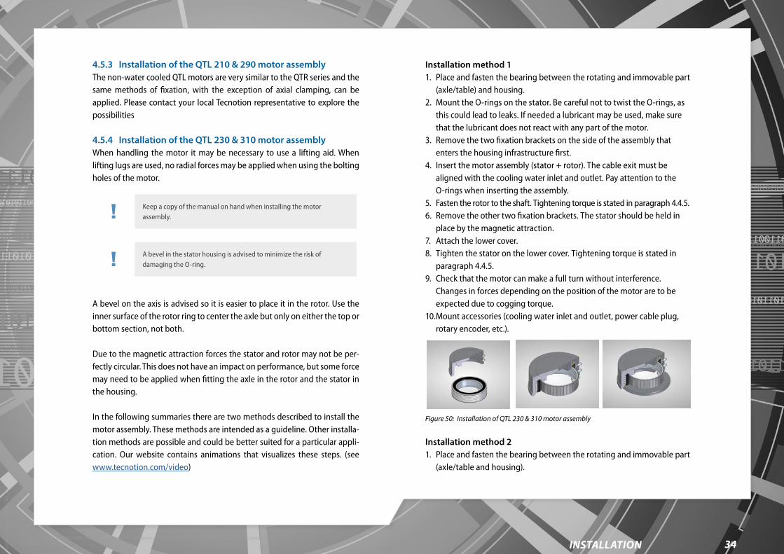
Torq
ue m
otor
man
ual -
ver
. 2.1
34installation©2020 Tecnotion BV - All rights reserved - The contents of this document are subject to change without prior notice.
4.5.3 Installation of the QTL 210 & 290 motor assemblyThe non-water cooled QTL motors are very similar to the QTR series and the same methods of fixation, with the exception of axial clamping, can be applied. Please contact your local Tecnotion representative to explore the possibilities
4.5.4 Installation of the QTL 230 & 310 motor assemblyWhen handling the motor it may be necessary to use a lifting aid. When lifting lugs are used, no radial forces may be applied when using the bolting holes of the motor.
Keep a copy of the manual on hand when installing the motor assembly.
A bevel in the stator housing is advised to minimize the risk of damaging the O-ring.
A bevel on the axis is advised so it is easier to place it in the rotor. Use the inner surface of the rotor ring to center the axle but only on either the top or bottom section, not both.
Due to the magnetic attraction forces the stator and rotor may not be per-fectly circular. This does not have an impact on performance, but some force may need to be applied when fitting the axle in the rotor and the stator in the housing.
In the following summaries there are two methods described to install the motor assembly. These methods are intended as a guideline. Other installa-tion methods are possible and could be better suited for a particular appli-cation. Our website contains animations that visualizes these steps. (see www.tecnotion.com/video)
Installation method 11. Place and fasten the bearing between the rotating and immovable part
(axle/table) and housing.2. Mount the O-rings on the stator. Be careful not to twist the O-rings, as
this could lead to leaks. If needed a lubricant may be used, make sure that the lubricant does not react with any part of the motor.
3. Remove the two fixation brackets on the side of the assembly that enters the housing infrastructure first.
4. Insert the motor assembly (stator + rotor). The cable exit must be aligned with the cooling water inlet and outlet. Pay attention to the O-rings when inserting the assembly.
5. Fasten the rotor to the shaft. Tightening torque is stated in paragraph 4.4.5.6. Remove the other two fixation brackets. The stator should be held in
place by the magnetic attraction.7. Attach the lower cover.8. Tighten the stator on the lower cover. Tightening torque is stated in
paragraph 4.4.5.9. Check that the motor can make a full turn without interference.
Changes in forces depending on the position of the motor are to be expected due to cogging torque.
10. Mount accessories (cooling water inlet and outlet, power cable plug, rotary encoder, etc.).
Figure 50: Installation of QTL 230 & 310 motor assembly
Installation method 21. Place and fasten the bearing between the rotating and immovable part
(axle/table and housing).

Torq
ue m
otor
man
ual -
ver
. 2.1
35installation©2020 Tecnotion BV - All rights reserved - The contents of this document are subject to change without prior notice.
2. Mount the O-rings on the stator. Be careful not to twist the O-rings, as this could lead to leaks. If needed a lubricant may be used, make sure that the lubricant does not react with any part of the motor.
3. Remove the two fixation brackets on the side of the assembly that enters the housing infrastructure first.
4. Fasten the rotor to the shaft. Tightening torque is stated in paragraph 4.4.5.
5. Attach the stator to the lower cover.6. Remove the spacer foils.7. Remove the other two fixation brackets. The stator should be held in
place by the magnetic attraction.8. Place and fasten the housing over the motor assembly (stator + rotor).
The cable exit must be aligned with the cooling water inlet and outlet. Pay attention to the O-rings when inserting the assembly.
9. Check that the motor can make a full turn without interference. Changes in forces depending on the position of the motor are to be expected due to cogging torque.
10. Mount accessories (cooling water inlet and outlet, power cable plug, rotary encoder, etc.).
Check our installation videos at www.tecnotion.com/video.
4.5.5 Final checkBefore starting any activity on the wiring, make sure that the mains are dis-connected. Work carefully according the instructions belonging to the applied servo controller. Be sure your machine as a whole meets the require-ments of all applicable electrical standards, such as the EN 60204 standard.
4.6 Electrical connections
4.6.1 General remarksBefore testing, make sure that the electrical and mechanical protection of the torque motor system is well configured.
4.6.2 PowerlinesThe power cable can be confectioned by the user to fit the servo drive.
4.6.3 Protective earthMake sure that there is an effective protective earth. Make sure that there is no voltage at the wire terminals before connecting.
4.6.4 Polarization test Testing the polarization is very important, a wrong polarization will result in an uncontrolled run out of the axis.
4.6.5 Temperature sensor cable wiring See paragraph "3.5.1 Cable specifications & protective earth." for all specs.
4.6.6 EMC performanceThe combination of a torque motor with a servo drive needs a proper shielded connection for optimal EMC performance. Therefore it is very important to connect the shielding of the shielded (EMC) motor cable corectly to the shielding point of the servo drive.
For optimal EMC performance place the metal (conducting) rotor bearings as close as possible near the rotor, to make high frequency electrical contact with the torque stator.
If the cable is not directly connected with the drive, proper connectors must be used to pass the EMC field well.
4.7 Deinstallation
Reposition the magnetic field neutralizing protection cover on the rotor again when dismounting them.

Torq
ue m
otor
man
ual -
ver
. 2.1
36installation©2020 Tecnotion BV - All rights reserved - The contents of this document are subject to change without prior notice.
If deinstallation is to be expected, save the magnetic protection ring and/or shims supplied with your Tecnotion QTR motor.
It is very important to refastened the fixation brackets (supplied with your QTL motor) on the stator and rotor before dismounting them!
In general the deinstallation order follows the reverse installation sequence as described in the installation order. This can vary however for each appli-cation design. Reposition the magnetic field neutralizing cover, if applica-ble, as soon as the rotor is removed from the stator.
4.8 Additional components
4.8.1 Digital Hall moduleSee paragraph "3.7 Accessories" for information on the digital Hall module. See appendices B and C for specifications of the digital Hall module
4.9 Coupling torque motors
Two or more torque motors can be coupled to operate together. Then the torques generated can be added together. Coupled torque motors can in principle be operated by one amplifier, provided that the maximum driver power output, is not reached. The torque motors are connected in parallel and the currents of both motors add up. It is not possible to mount motors in series with voltages adding up, because their wiring is not suitable.
Two or more motors of the same type can always be coupled. For example QTR-A-105-17N with QTR-A-105-17N. Motors of different types can only be coupled if their motor torque constants are equal.
For more information contact our application engineers at telephone number: +31 546 898 475 or [email protected].
Torq
ue m
otor
man
ual -
ver
. 2.1
37operation©2020 Tecnotion BV - All rights reserved - The contents of this document are subject to change without prior notice.
5. OPERATION
When you are convinced that your application’s torque motor system is installed in a proper way, both mechanically and electrically, you can put your motor system into operation.
5.1 Pre-commissioning
Before powering the system, please perform a final check on the items below:
1. Does the axis rotate free over the whole turn, without touching small mechanical parts like bolts or contaminations?
2. Does your system have an emergency stop?3. Is the temperature cable properly connected?4. Does the motor ruler combination have the right polarization?5. Has the power cable been connected properly?6. Operational conditions according to IEC 60721-3. For reference check
paragraph 5.4.
5.2 Configuring
Some input and output signals need to be configured by following the steps below:
1. The following motor items should be configured as parameter settings of the servo amplifier:
Maximum continuous current. Maximum peak current. Value of the coil self-inductance. Maximum speed (rpm). Presence/absence of an electromechanical motor brake.
Number of pole pairs. Switching resistance of PTC.
2. The following settings for the ruler system should be configured as parameters of the servo amplifier:
Type of interface of the ruler system. Resolution or period of the encoder.
3. These are the I/O parameters to be configured: Settings of the available digital inputs and outputs. For instance, pay
attention to the type of end switches if present. Settings of the available analog inputs and outputs.
4. Finally the controlling parameters must be configured. Current control settings. These settings depend on both motor and
amplifier. Speed control settings. Position control settings.
5.3 Testing
After the amplifier is powered up some input and output signals need to be examined by following the steps below:
1. Check the end switches, if present, by rotating the axis manually to the switch position. Simultaneously check whether the signal is detected by the amplifier.
2. Check the presence of the PTC signal.

Torq
ue m
otor
man
ual -
ver
. 2.1
38operation©2020 Tecnotion BV - All rights reserved - The contents of this document are subject to change without prior notice.
5.4 Operational conditions
Be aware that the motor and housing can become hot during operation. It is advised to use the temperature sensors to monitor the temperature during operation to prevent overheating.
The operational conditions of QTL motors are largely the same as the QTR motors. However, the cables of the QTL motor have an increased resistance to oils, acids and alkalis according to EN 50363-10-2.
The mentioned ambient conditions are for the primary product package contained in a secondary cardboard package. The primary package is intended for storage in warehouse and efficient packing in a secondary or tertiary package. The primary packaging itself is not suited as a transporta-tion package. See Table 20 for the operational conditions.
Table 20: Operational conditions
Climatic conditions
Operation 3K3
Low air pressure 99kPa (different from 3K3). Derating will occur
High air pressure 101kPa (different from 3K3)
Biological conditions
Operation 3B1
Chemically active substances
Operation 3C1
Mechanically active substances
Operation 3S1
Mechanical conditions
Operation 3M7

Torq
ue m
otor
man
ual -
ver
. 2.1
39transport, storage & disMantling©2020 Tecnotion BV - All rights reserved - The contents of this document are subject to change without prior notice.
6. TRANSPORT, STORAGE &
DISMANTLING
This chapter describes the requirements for transportation, storage and dis-mantling of the torque motors. This information needs to be taken into account together with the additional information in the main manual.
6.1 General safety rules for transport, storage & dismantling
QTR series Only handle the rotor with the magnetic field neutralizing protection
ring in place (QTR 65 & QTR 78 don’t have a protection ring). Only transport rotors and magnets in their original packaging. This
ensures the magnetic stray field is within safe limits and that no uncontrolled attraction of ferromagnetic materials can occur.
Do not throw away the magnetic field protection ring (QTR series) or fixation brackets (QTL series) as these are needed when de-installing the motor, they can be reused.
Magnetic sensitive objects like banking cards, pacemakers or other magnetic information carriers may be damaged if they are brought within 1 m of the magnets (plates or rotor).
The storage area for motor components needs to be clearly delimited with a warning sign: ‘Caution powerful magnets!’.
Only store motors in their original packaging.
QTL seriesThe QTL package is delivered with the rotor inside the stator locked together with fixation brackets.
Only transport and store the QTL in its original packaging together with the fixation brackets. This ensures the magnetic stray field is within safe
limits and that no uncontrolled attraction of ferromagnetic materials can occur.
Do not lift the stator by the cables . The QTL stator and rotor are heavy. A lifting aid is recommended when
handling the QTL, no radial forces may be applied when using the bolting holes of the motor.
Be cautious when handling the motor inside or outside of its packaging as it could tip over and cause serious injury.
Magnetic sensitive objects like banking cards, pacemakers or other magnetic information carriers may be damaged if they are brought within 1 m of the magnets (plates or rotor).
The storage area for motor components needs to be clearly delimited with a warning sign: ‘Caution powerful magnets!’.
Only store motors in their original packaging.
6.2 Transport & packaging
The rotor of the torque motor contains permanent magnets that produce a magnetic strayfield. For transport safety the following needs to be taken into account when transporting magnetized materials by air.
AirfreightWhen magnetic material is transported by air, the IATA airfreight packaging instruction 953 applies. Above a certain threshold value the relevant author-ity needs to be informed prior to shipping, see Table 21.
Table 21: Magnetic strayfield threshold value
Threshold Field strength Action
1 <5.25mG @2.1m of package No action required
2 >5.25mG @2.1m of package Notify relevant authority and label products / packages

Torq
ue m
otor
man
ual -
ver
. 2.1
40transport, storage & disMantling©2020 Tecnotion BV - All rights reserved - The contents of this document are subject to change without prior notice.
3 >5.25mG @4.6 m of package Relevant authority needs to authorize the shipment. Special measures need to be taken, e.g. extra packaging material / higher shipment cost.
Magnetic materials can, when transported in close proximity to each other, amplify their individual magnetic stray field strength. A single rotor can therefore have a stray field well below the safe field strength threshold, mul-tiple rotors could surpass this threshold. No action is required for any motor in the QTR or QTL product range when packed in their original packaging.
Other means of transportationFor all other means of transportation no additional measures need to be taken regarding magnetic stray field risks other than those regarding gen-eral health and safety.
PackagingTecnotion products have a primary package that sits directly around the product. Tecnotion primary product package is intended only as product packaging. It’s main function is to:
Pack the product and required documentation. Identify the product type and serial number. Inform about important safety advice if required. Inform about important transportation and storage advice. Safeguard product functionality during transportation and storage.
For transportation the product and primary package will be placed into a secondary package or even a tertiary package. (Usually a 800 × 1200 mm Euro-pallet). The type and size of this package depends on the size of the order to be shipped. Typically the remaining volume in the secondary and tertiary packages will be filled with Instapak.
6.3 Storage and transportation
To ensure the product quality Tecnotion advises the following storage con-ditions: according to IEC 60721-3-1 Storage, 60721-3-2 Transportation.
The primary package is intended for storage in a warehouse and efficient packing in a secondary or tertiary package. The primary packaging itself is not suited as a transportation package.
The mentioned ambient transportation conditions in Table 22 below are for the primary product package contained in a secondary cardboard package.
Table 22: Storage conditions
Climatic conditions
Long term storage 1K3
Storage temperature: -25°C to +55°C (different from 1K3)
Rate of change: 20°C/hour (different from 1K3)
Condensation None (different from 1K3)
Storage duration No limitation
Transportation 2K2
Biological conditions
Long term storage 1B1
Transportation 2B1
Chemically active substances
Long term storage 1C2
Transportation 2C1
Mechanical conditions
Long term storage 1M1
Transportation 2M2

Torq
ue m
otor
man
ual -
ver
. 2.1
41transport, storage & disMantling©2020 Tecnotion BV - All rights reserved - The contents of this document are subject to change without prior notice.
APPENDIX - TABLE OF CONTENTS
APPENDIX A 42
Overview - QTR 65 - 17/25/34/60 42Overview - QTR 78 - 17/25/34/60 43Overview - QTR 105 - 17/25/34/60 44Dimensions - QTR 105 - 17/25/34/60 45Overview - QTR 133 - 17/25/34/60 46Dimensions - QTR 133 - 17/25/34/60 47Overview - QTR 160 - 17/25/34/60 48Dimensions - QTR 160 - 17/25/34/60 49Dimensions - QTL 210 - 65/85/105 50Dimensions - QTL 230 - 65/85/105 51Dimensions - QTL 290 - 65/85/105 52Dimensions - QTL 310 - 65/85/105 53
APPENDIX B 54
QTR 65- digital Hall module 54QTR 78- digital Hall module 55QTR 105 - digital Hall module 56QTR 133 - digital Hall module 57QTR 160 - digital Hall module 58
APPENDIX C 59
Material overview 59
APPENDIX D 60
IATA strayfield threshold 60
APPENDIX E 61
CE certification 61
APPENDIX F 62
T/n graphs 65/78 62T/n graphs 105/133/160 N winding 63T/n graphs 105/133/160 N winding 64T/n graphs 105/133/160 Y&Z winding 65T/n graphs 105/133/160 Y&Z winding 66T/n graphs QTL 210/230 N winding 67T/n graphs QTL 290/310 N winding 68
GLOSSARY 69

Tecnotion | www.tecnotion.com | [email protected]
Torq
ue m
otor
man
ual -
ver
. 2.1
42©2020 Tecnotion BV - All rights reserved - The contents of this document are subject to change without prior notice.
appendiX a
APPENDIX A Overview - QTR 65 - 17/25/34/60

Tecnotion | www.tecnotion.com | [email protected]
Torq
ue m
otor
man
ual -
ver
. 2.1
43
O78
O75
Lead wires AWG 16 3+PE
120°
(3x)
QTR 78-17 QTR 78-25 QTR 78-34 QTR 78-60
18.5Max 26.5Max Max 35.5 62.5Max
8 16 24 48
O29
8.6 16.6 24.6 48.6
©2020 Tecnotion BV - All rights reserved - The contents of this document are subject to change without prior notice.
appendiX a
Overview - QTR 78 - 17/25/34/60APPENDIX A

Tecnotion | www.tecnotion.com | [email protected]
Torq
ue m
otor
man
ual -
ver
. 2.1
44
QTR-105-17 QTR-105-25 QTR-105-34 QTR-105-60
©2020 Tecnotion BV - All rights reserved - The contents of this document are subject to change without prior notice.
appendiX a
Overview - QTR 105 - 17/25/34/60APPENDIX A
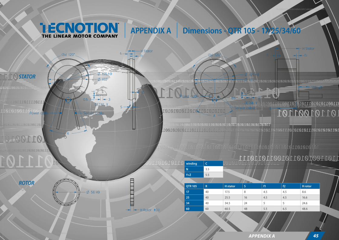
Tecnotion | www.tecnotion.com | [email protected]
Torq
ue m
otor
man
ual -
ver
. 2.1
45
STATOR
O 56 H9
H Rotor ±0.1
O 105 h9
O 102
X DETAIL X30.5
O
O
Power cable Sensor cable
12
S
C
)x3( °021
R
)x3( °021
Power cable
Sensor cable
Max 25
H Stator
S
A
Y DETAIL Y
30.5
ROTOR
105 h9102
H Stator
©2020 Tecnotion BV - All rights reserved - The contents of this document are subject to change without prior notice.
appendiX a
Dimensions - QTR 105 - 17/25/34/60
winding C
N 3.5
Y+Z 5.5
QTR 105 R H stator S f1 f2 H rotor
17 40 17.5 8 4.5 4.5 8.6
25 40 25.5 16 4.5 4.5 16.6
34 40 34.5 24 5 5 24.6
60 60 60.5 48 5.5 6.5 48.6
APPENDIX A

Tecnotion | www.tecnotion.com | [email protected]
Torq
ue m
otor
man
ual -
ver
. 2.1
46©2020 Tecnotion BV - All rights reserved - The contents of this document are subject to change without prior notice.
appendiX a
Overview - QTR 133 - 17/25/34/60APPENDIX A
QTR-133-17 QTR-133-25 QTR-133-34 QTR-133-60

Tecnotion | www.tecnotion.com | [email protected]
Torq
ue m
otor
man
ual -
ver
. 2.1
47
STATOR
R
Power cable Sensor cable
O 130
O 133 h9
X
DETAIL X30.5
H Stator
S
)x3( °021
O 130
O 133 h9
A
Power cable
Sensor cableY
DETAIL Y30,5
S
xaM 52
)x3( °021
STATOR
ROTOR
R
Power cable Sensor cable
O 130
O 133
X
DETAIL X30.5
S u0.5
Max 3.5
O 130
O 133
A
Power cable
Sensor cableY
DETAIL Y30,5
S u0.75
xaM 52
H Rotor ±0.1
O 84 H9
f1 f2
H Statorf1
f2
winding C
N 3.5
Y+Z 5.5
QTR 133 R H stator S f1 f2 H rotor
17 35 17.5 8 4.5 4.5 8.6
25 35 25.5 16 4.5 4.5 16.6
34 35 34.5 24 5 5 24.6
60 45 60.5 48 5.5 6.5 48.6
©2020 Tecnotion BV - All rights reserved - The contents of this document are subject to change without prior notice.
appendiX a
APPENDIX A Dimensions - QTR 133 - 17/25/34/60

Tecnotion | www.tecnotion.com | [email protected]
Torq
ue m
otor
man
ual -
ver
. 2.1
48
QTR-160-17 QTR-160-25 QTR-160-34 QTR-160-60
©2020 Tecnotion BV - All rights reserved - The contents of this document are subject to change without prior notice.
appendiX a
Overview - QTR 160 - 17/25/34/60APPENDIX A

Tecnotion | www.tecnotion.com | [email protected]
Torq
ue m
otor
man
ual -
ver
. 2.1
49
R
Power cable Sensor cable
O 157
O 160 h9
X
DETAIL X30.5 C
S
)x3( °021
A
Power cable
Sensor cable
O 157
O 160 h9
ADETAIL A
30.5
xaM 52
)x3( °021
O 111
R
Power cable Sensor cable
O 157
O 160
X
DETAIL X30.5 Max 3.5
S u0.5
A
Power cable
Sensor cable
O 157
O 160
ADETAIL A
30.5
S u0.75
xaM 52
O 111 H9
H Rotor ±0.1
STATOR
ROTOR
S
H Statorf1 f2
H Statorf1
f2
©2020 Tecnotion BV - All rights reserved - The contents of this document are subject to change without prior notice.
appendiX a
APPENDIX A Dimensions - QTR 160 - 17/25/34/60
winding C
N 3.5
Y+Z 5.5
QTR 160 R H stator S f1 f2 H rotor
17 25 17.5 8 4.5 4.5 8.6
25 25 25.5 16 4.5 4.5 16.6
34 25 34.5 24 5 5 24.6
60 35 60.5 48 5.5 6.5 48.6

Tecnotion | www.tecnotion.com | [email protected]
Torq
ue m
otor
man
ual -
ver
. 2.1
50©2020 Tecnotion BV - All rights reserved - The contents of this document are subject to change without prior notice.
appendiX a
APPENDIX A Dimensions - QTL 210 - 65/85/105
QTL-A-210- 65 85 105
41 61 81
22°
140O
148O
11°4 H7O (2x)
M4 `11 (32x)
15 15 15
210O
30°

Tecnotion | www.tecnotion.com | [email protected]
Torq
ue m
otor
man
ual -
ver
. 2.1
51©2020 Tecnotion BV - All rights reserved - The contents of this document are subject to change without prior notice.
appendiX a
APPENDIX A Dimensions - QTL 230 - 65/85/105
QTL-A-230- 65 85 105
41 61 81
36 36 36
230O
220O30°
M5 `10 (24x)
22°
140O
148O
11°4 H7O (2x)
M4 `11 (32x)

Tecnotion | www.tecnotion.com | [email protected]
Torq
ue m
otor
man
ual -
ver
. 2.1
52©2020 Tecnotion BV - All rights reserved - The contents of this document are subject to change without prior notice.
appendiX a
APPENDIX A Dimensions - QTL 290 - 65/85/105
QTL-A-290- 65 85 105
41 61 81
220O
228O
M4 `11 (40x)
18°
9°4 H7O (2x)
15 15 15
290O
30°

Tecnotion | www.tecnotion.com | [email protected]
Torq
ue m
otor
man
ual -
ver
. 2.1
53©2020 Tecnotion BV - All rights reserved - The contents of this document are subject to change without prior notice.
appendiX a
APPENDIX A Dimensions - QTL 310 - 65/85/105
QTL-A-310- 65 85 105310O
41 61 81
M5 `10 (24x)
30°
3636 36
300O
220O
228O
M4 `11 (40x)
18°
9°4 H7O (2x)

Tecnotion | www.tecnotion.com | [email protected]
Torq
ue m
otor
man
ual -
ver
. 2.1
54©2020 Tecnotion BV - All rights reserved - The contents of this document are subject to change without prior notice.
appendiX B
APPENDIX B QTR 65- digital Hall module

Tecnotion | www.tecnotion.com | [email protected]
Torq
ue m
otor
man
ual -
ver
. 2.1
55©2020 Tecnotion BV - All rights reserved - The contents of this document are subject to change without prior notice.
appendiX B
APPENDIX B QTR 78- digital Hall module

Tecnotion | www.tecnotion.com | [email protected]
Torq
ue m
otor
man
ual -
ver
. 2.1
56
3
4.7OR
29.6
±0.3
R40
.9±0
.3
O )x2(eloH 6.1For 1.8x8 self tapping screw
37.5 (2x)
24°
6
60°
120°
R29
.6±0
.3R
40.9
±0.3
OeloH 1For 1.8x6 self tapping screw
24°
120°
©2020 Tecnotion BV - All rights reserved - The contents of this document are subject to change without prior notice.
appendiX B
APPENDIX B QTR 105 - digital Hall module

Tecnotion | www.tecnotion.com | [email protected]
Torq
ue m
otor
man
ual -
ver
. 2.1
57
3
4.7O
60°
51 (2x)
120°
623
°R
43.1
±0.3
R54
.4±0
.3
15°
O )x2(eloH 6.1For 1.8x8 self tapping screw
4.7O
6
51 (2x)
120°
23°
R43
.1±0
.3R
54.4
±0.3
15°
O )x2(eloH 6.1For 1.8x6 self tapping screw
©2020 Tecnotion BV - All rights reserved - The contents of this document are subject to change without prior notice.
appendiX B
APPENDIX B QTR 133 - digital Hall module

Tecnotion | www.tecnotion.com | [email protected]
Torq
ue m
otor
man
ual -
ver
. 2.1
58
4.7O
R 56.7±0.3
R 68±0.
3
O )x2(eloH 6.1For 1.8x8 self tapping screw
12°
3
6
60°
80°
15°
64.6 (2x)
4.7O
R 56.7±0.3
R 68±0.
3
O )x2(eloH 6.1For 1.8x6 self tapping screw
12°
60°
80°
15°
64.6 (2x)
©2020 Tecnotion BV - All rights reserved - The contents of this document are subject to change without prior notice.
appendiX B
APPENDIX B QTR 160 - digital Hall module

Tecnotion | www.tecnotion.com | [email protected]
Torq
ue m
otor
man
ual -
ver
. 2.1
59©2020 Tecnotion BV - All rights reserved - The contents of this document are subject to change without prior notice.
appendiX c
MagnetsMaterial: NdFeBCoating: Epoxy
Cable clamp (enclosed in casting)Material: Steel(not applicable for QTR 65 and QTR 78)
Temperature sensor cable(not applicable for QTR 65 and QTR 78)
Power cable
Coil insulation
Temperature sensor KTY (enclosed in casting)
Type: KTY83-122(not applicable for QTR 65 and QTR 78)
Coil (enclosed in casting)Material: Copper
Rotor ringMaterial: Steel
Coating: Nickel
Lamination stackMaterial: Electrical sheet Fe
Coil castingMaterial: PU
Temperature sensor PTC (enclosed in casting)(not applicable for QTR 65 and QTR 78)
Material overviewAPPENDIX C

Tecnotion | www.tecnotion.com | [email protected]
Torq
ue m
otor
man
ual -
ver
. 2.1
60©2020 Tecnotion BV - All rights reserved - The contents of this document are subject to change without prior notice.
appendiX d
APPENDIX D IATA strayfield threshold
Product Product configuration Action
No action Notify relevant authority Authorisation by relevant authority required
QTR 65 series Single kit in original packaging x
Completely filled Euro-pallet of kits in original packaging (1200*800*1000mm)
x
Individual rotor x
QTR 78 series Single kit in original packaging x
Completely filled Euro-pallet of kit in original packaging (1200*800*1000mm)
x
Individual rotor x
QTR 105-133-160 series Single kit in original packaging x
Completely filled Euro-pallet of kit in original packaging (1200*800*1000mm)
x
Rotor with protection ring x
Rotor without protection ring x
QTL series Single kit in original packaging x
Completely filled Euro-pallet of kit in original packaging (1200*800*1000mm)
x
Products shipped in their original packaging do not need actions relevant to the IATA treshold

Tecnotion | www.tecnotion.com | [email protected]
Torq
ue m
otor
man
ual -
ver
. 2.1
61
For most recent version see our website: http://www.tecnotion.com/certifications.html
©2020 Tecnotion BV - All rights reserved - The contents of this document are subject to change without prior notice.
appendiX e
APPENDIX E CE certification
For most recent version see our website: http://www.tecnotion.com/certifications.html

Tecnotion | www.tecnotion.com | [email protected]
Torq
ue m
otor
man
ual -
ver
. 2.1
62©2020 Tecnotion BV - All rights reserved - The contents of this document are subject to change without prior notice.
appendiX f
APPENDIX F T/n graphs 65/78
MAXIMUM allowable speed for QTR-A 65 series motors is 28.000 rpm.MAXIMUM allowable speed for QTR-A 78 series motors is 23.000 rpm. If you plan a high speed application, please contact Tecnotion.
0
0,1
0,2
0,3
0,4
0,5
0,6
0,7
0,8
0 5000 10000 15000 20000 25000
Torq
ue [N
m]
Speed [rpm]
QTR-A-65-17N @ 100 °C
48 Vdc
160 Vdc
300 Vdc
600 Vdc
Tc
nmax mech
0
0,2
0,4
0,6
0,8
1
1,2
1,4
1,6
0 5000 10000 15000 20000 25000
Torq
ue [N
m]
Speed [rpm]
QTR-A-65-25N @ 100 °C
48 Vdc
160 Vdc
300 Vdc
600 Vdc
Tc
nmax mech
0
0,5
1
1,5
2
2,5
0 5000 10000 15000 20000 25000
Torq
ue [N
m]
Speed [rpm]
QTR-A-65-34Y @ 100 °C
48 Vdc
160 Vdc
300 Vdc
600 Vdc
Tc
nmax mech
0
1
2
3
4
5
6
0 5000 10000 15000 20000 25000
Torq
ue [N
m]
Speed [rpm]
QTR-A-65-60Y @ 100 °C
48 Vdc
160 Vdc
300 Vdc
600 Vdc
Tc
0
0,2
0,4
0,6
0,8
1
1,2
1,4
0 5000 10000 15000 20000
Torq
ue [N
m]
Speed [rpm]
QTR-A-78-17N @ 100 °C
48 Vdc
160 Vdc
300 Vdc
600 Vdc
Tc
nmax mech
0
0,5
1
1,5
2
2,5
3
3,5
0 5000 10000 15000 20000
Torq
ue [N
m]
Speed [rpm]
QTR-A-78-25Y @ 100 °C
48 Vdc
160 Vdc
300 Vdc
600 Vdc
Tc
nmax mech
0
0,5
1
1,5
2
2,5
3
3,5
4
4,5
5
0 5000 10000 15000 20000
Torq
ue [N
m]
Speed [rpm]
QTR-A-78-34Y @ 100 °C
48 Vdc
160 Vdc
300 Vdc
600 Vdc
Tc
nmax mech
0
2
4
6
8
10
12
0 2000 4000 6000 8000 10000 12000
Torq
ue [N
m]
Speed [rpm]
QTR-A-78-60Y @ 100 °C
48 Vdc
160 Vdc
300 Vdc
600 Vdc
Tc

Tecnotion | www.tecnotion.com | [email protected]
Torq
ue m
otor
man
ual -
ver
. 2.1
63©2020 Tecnotion BV - All rights reserved - The contents of this document are subject to change without prior notice.
appendiX f
APPENDIX F T/n graphs 105/133/160 N winding
0
1
2
3
4
5
6
0 1000 2000 3000 4000 5000 6000
Torq
ue [N
m]
Speed [rpm]
QTR-A-133-17N @ 100 °C
48 Vdc
160 Vdc
300 Vdc
Tc
0
2
4
6
8
10
12
14
0 500 1000 1500 2000 2500 3000
Torq
ue [N
m]
Speed [rpm]
QTR-A-133-25N @ 100 °C
48 Vdc
160 Vdc
300 Vdc
Tc
0
5
10
15
20
25
0 500 1000 1500
Torq
ue [N
m]
Speed [rpm]
QTR-A-133-34N @ 100 °C
48 Vdc
160 Vdc
300 Vdc
Tc
0
10
20
30
40
50
60
0 200 400 600 800 1000 1200
Torq
ue [N
m]
Speed [rpm]
QTR-A-133-60N @ 100 °C
48 Vdc
160 Vdc
300 Vdc
600 Vdc
Tc
0
1
2
3
4
5
6
7
0 1000 2000 3000 4000 5000
Torq
ue [N
m]
Speed [rpm]
QTR-A-105-25N @ 100 °C
48 Vdc
160 Vdc
300 Vdc
Tc
0
2
4
6
8
10
12
0 500 1000 1500 2000 2500 3000
Torq
ue [N
m]
Speed [rpm]
QTR-A-105-34N @ 100 °C
48 Vdc
160 Vdc
300 Vdc
Tc
0
5
10
15
20
25
30
0 500 1000 1500 2000 2500
Torq
ue [N
m]
Speed [rpm]
QTR-A-105-60N @ 100 °C
48 Vdc
160 Vdc
300 Vdc
600 Vdc
Tc
0
0,5
1
1,5
2
2,5
3
3,5
0 2000 4000 6000 8000 10000
Torq
ue [N
m]
Speed [rpm]
QTR-A-105-17N @ 100 °C
48 Vdc
160 Vdc
300 Vdc
Tc
0
1
2
3
4
5
6
7
8
9
10
0 500 1000 1500 2000 2500 3000 3500
Torq
ue [N
m]
Speed [rpm]
QTR-A-160-17N @ 100 °C
48 Vdc
160 Vdc
300 Vdc
Tc
0
5
10
15
20
25
0 500 1000 1500
Torq
ue [N
m]
Speed [rpm]
QTR-A-160-25N @ 100 °C
48 Vdc
160 Vdc
300 Vdc
Tc
0
5
10
15
20
25
30
35
40
0 200 400 600 800 1000
Torq
ue [N
m]
Speed [rpm]
QTR-A-160-34N @ 100 °C
48 Vdc
160 Vdc
300 Vdc
Tc
0
10
20
30
40
50
60
70
80
90
100
0 100 200 300 400 500 600 700 800
Torq
ue [N
m]
Speed [rpm]
QTR-A-160-60N @ 100 °C
48 Vdc
160 Vdc
300 Vdc
600 Vdc
Tc

Tecnotion | www.tecnotion.com | [email protected]
Torq
ue m
otor
man
ual -
ver
. 2.1
64©2020 Tecnotion BV - All rights reserved - The contents of this document are subject to change without prior notice.
appendiX f
APPENDIX F T/n graphs 105/133/160 N winding
MAXIMUM allowable speed for QTR-A 105 series motors is 16.500 rpm.
MAXIMUM allowable speed for QTR-A 133 series motors is 14.000 rpm.
MAXIMUM allowable speed for QTR-A 160 series motors is 12.000 rpm.
If you plan a high speed application, please contact Tecnotion.
0
1
2
3
4
5
6
0 1000 2000 3000 4000 5000 6000
Torq
ue [N
m]
Speed [rpm]
QTR-A-133-17N @ 100 °C
48 Vdc
160 Vdc
300 Vdc
Tc
0
2
4
6
8
10
12
14
0 500 1000 1500 2000 2500 3000
Torq
ue [N
m]
Speed [rpm]
QTR-A-133-25N @ 100 °C
48 Vdc
160 Vdc
300 Vdc
Tc
0
5
10
15
20
25
0 500 1000 1500
Torq
ue [N
m]
Speed [rpm]
QTR-A-133-34N @ 100 °C
48 Vdc
160 Vdc
300 Vdc
Tc
0
10
20
30
40
50
60
0 200 400 600 800 1000 1200
Torq
ue [N
m]
Speed [rpm]
QTR-A-133-60N @ 100 °C
48 Vdc
160 Vdc
300 Vdc
600 Vdc
Tc
0
1
2
3
4
5
6
7
0 1000 2000 3000 4000 5000
Torq
ue [N
m]
Speed [rpm]
QTR-A-105-25N @ 100 °C
48 Vdc
160 Vdc
300 Vdc
Tc
0
2
4
6
8
10
12
0 500 1000 1500 2000 2500 3000
Torq
ue [N
m]
Speed [rpm]
QTR-A-105-34N @ 100 °C
48 Vdc
160 Vdc
300 Vdc
Tc
0
5
10
15
20
25
30
0 500 1000 1500 2000 2500
Torq
ue [N
m]
Speed [rpm]
QTR-A-105-60N @ 100 °C
48 Vdc
160 Vdc
300 Vdc
600 Vdc
Tc
0
0,5
1
1,5
2
2,5
3
3,5
0 2000 4000 6000 8000 10000
Torq
ue [N
m]
Speed [rpm]
QTR-A-105-17N @ 100 °C
48 Vdc
160 Vdc
300 Vdc
Tc
0
1
2
3
4
5
6
7
8
9
10
0 500 1000 1500 2000 2500 3000 3500
Torq
ue [N
m]
Speed [rpm]
QTR-A-160-17N @ 100 °C
48 Vdc
160 Vdc
300 Vdc
Tc
0
5
10
15
20
25
0 500 1000 1500
Torq
ue [N
m]
Speed [rpm]
QTR-A-160-25N @ 100 °C
48 Vdc
160 Vdc
300 Vdc
Tc
0
5
10
15
20
25
30
35
40
0 200 400 600 800 1000
Torq
ue [N
m]
Speed [rpm]
QTR-A-160-34N @ 100 °C
48 Vdc
160 Vdc
300 Vdc
Tc
0
10
20
30
40
50
60
70
80
90
100
0 100 200 300 400 500 600 700 800
Torq
ue [N
m]
Speed [rpm]
QTR-A-160-60N @ 100 °C
48 Vdc
160 Vdc
300 Vdc
600 Vdc
Tc

Tecnotion | www.tecnotion.com | [email protected]
Torq
ue m
otor
man
ual -
ver
. 2.1
65©2020 Tecnotion BV - All rights reserved - The contents of this document are subject to change without prior notice.
appendiX f
APPENDIX F T/n graphs 105/133/160 Y&Z winding
0
0,5
1
1,5
2
2,5
3
3,5
0 5000 10000 15000 20000
Torq
ue [N
m]
Speed [rpm]
QTR-A-105-17Y @ 100 °C
48 Vdc
160 Vdc
300 Vdc
Tc
0
2
4
6
8
10
12
0 1000 2000 3000 4000 5000 6000
Torq
ue [N
m]
Speed [rpm]
QTR-A-105-34Y @ 100 °C
48 Vdc
160 Vdc
300 Vdc
Tc
0
1
2
3
4
5
6
7
8
0 2000 4000 6000 8000 10000
Torq
ue [N
m]
Speed [rpm]
QTR-A-105-25Y @ 100 °C
48 Vdc
160 Vdc
300 Vdc
Tc
0
0,5
1
1,5
2
2,5
3
3,5
0 5000 10000 15000 20000 25000 30000 35000
Torq
ue [N
m]
Speed [rpm]
QTR-A-105-17Z @ 100 °C
48 Vdc
160 Vdc
300 Vdc
Tc
0
1
2
3
4
5
6
7
0 5000 10000 15000
Torq
ue [N
m]
Speed [rpm]
QTR-A-105-25Z @ 100 °C
48 Vdc
160 Vdc
300 Vdc
Tc
0
2
4
6
8
10
12
0 2000 4000 6000 8000 10000 12000
Torq
ue [N
m]
Speed [rpm]
QTR-A-105-34Z @ 100 °C
48 Vdc
160 Vdc
300 Vdc
Tc
0
1
2
3
4
5
6
7
0 2000 4000 6000 8000 10000
Torq
ue [N
m]
Speed [rpm]
QTR-A-133-17Y @ 100 °C
48 Vdc
160 Vdc
300 Vdc
Tc
0
2
4
6
8
10
12
14
0 1000 2000 3000 4000 5000
Torq
ue [N
m]
Speed [rpm]
QTR-A-133-25Y @ 100 °C
48 Vdc
160 Vdc
300 Vdc
Tc
0
1
2
3
4
5
6
7
0 2000 4000 6000 8000 10000 12000 14000
Torq
ue [N
m]
Speed [rpm]
QTR-A-133-17Z @ 100 °C
48 Vdc
160 Vdc
300 Vdc
Tc
nmax mech
0
2
4
6
8
10
12
14
0 2000 4000 6000 8000
Torq
ue [N
m]
Speed [rpm]
QTR-A-133-25Z @ 100 °C
48 Vdc
160 Vdc
300 Vdc
Tc
0
5
10
15
20
25
0 1000 2000 3000 4000 5000 6000
Torq
ue [N
m]
Speed [rpm]
QTR-A-133-34Z @ 100 °C
48 Vdc
160 Vdc
300 Vdc
Tc
0
2
4
6
8
10
12
0 1000 2000 3000 4000 5000 6000
Torq
ue [N
m]
Speed [rpm]
QTR-A-160-17Y @ 100 °C
48 Vdc
160 Vdc
300 Vdc
Tc
0
5
10
15
20
25
0 500 1000 1500 2000 2500 3000
Torq
ue [N
m]
Speed [rpm]
QTR-A-160-25Y @ 100 °C
48 Vdc
160 Vdc
300 Vdc
Tc
0
2
4
6
8
10
12
0 2000 4000 6000 8000 10000
Torq
ue [N
m]
Speed [rpm]
QTR-A-160-17Z @ 100 °C
48 Vdc
160 Vdc
300 Vdc
Tc
0
5
10
15
20
25
0 1000 2000 3000 4000 5000
Torq
ue [N
m]
Speed [rpm]
QTR-A-160-25Z @ 100 °C
48 Vdc
160 Vdc
300 Vdc
Tc
0
5
10
15
20
25
30
35
40
0 500 1000 1500 2000 2500 3000 3500
Torq
ue [N
m]
Speed [rpm]
QTR-A-160-34Z @ 100 °C
48 Vdc
160 Vdc
300 Vdc
Tc

Tecnotion | www.tecnotion.com | [email protected]
Torq
ue m
otor
man
ual -
ver
. 2.1
66©2020 Tecnotion BV - All rights reserved - The contents of this document are subject to change without prior notice.
appendiX f
APPENDIX F T/n graphs 105/133/160 Y&Z winding
0
0,5
1
1,5
2
2,5
3
3,5
0 5000 10000 15000 20000
Torq
ue [N
m]
Speed [rpm]
QTR-A-105-17Y @ 100 °C
48 Vdc
160 Vdc
300 Vdc
Tc
0
2
4
6
8
10
12
0 1000 2000 3000 4000 5000 6000
Torq
ue [N
m]
Speed [rpm]
QTR-A-105-34Y @ 100 °C
48 Vdc
160 Vdc
300 Vdc
Tc
0
1
2
3
4
5
6
7
8
0 2000 4000 6000 8000 10000
Torq
ue [N
m]
Speed [rpm]
QTR-A-105-25Y @ 100 °C
48 Vdc
160 Vdc
300 Vdc
Tc
0
0,5
1
1,5
2
2,5
3
3,5
0 5000 10000 15000 20000 25000 30000 35000
Torq
ue [N
m]
Speed [rpm]
QTR-A-105-17Z @ 100 °C
48 Vdc
160 Vdc
300 Vdc
Tc
0
1
2
3
4
5
6
7
0 5000 10000 15000
Torq
ue [N
m]
Speed [rpm]
QTR-A-105-25Z @ 100 °C
48 Vdc
160 Vdc
300 Vdc
Tc
0
2
4
6
8
10
12
0 2000 4000 6000 8000 10000 12000
Torq
ue [N
m]
Speed [rpm]
QTR-A-105-34Z @ 100 °C
48 Vdc
160 Vdc
300 Vdc
Tc
0
1
2
3
4
5
6
7
0 2000 4000 6000 8000 10000
Torq
ue [N
m]
Speed [rpm]
QTR-A-133-17Y @ 100 °C
48 Vdc
160 Vdc
300 Vdc
Tc
0
2
4
6
8
10
12
14
0 1000 2000 3000 4000 5000
Torq
ue [N
m]
Speed [rpm]
QTR-A-133-25Y @ 100 °C
48 Vdc
160 Vdc
300 Vdc
Tc
0
1
2
3
4
5
6
7
0 2000 4000 6000 8000 10000 12000 14000
Torq
ue [N
m]
Speed [rpm]
QTR-A-133-17Z @ 100 °C
48 Vdc
160 Vdc
300 Vdc
Tc
nmax mech
0
2
4
6
8
10
12
14
0 2000 4000 6000 8000
Torq
ue [N
m]
Speed [rpm]
QTR-A-133-25Z @ 100 °C
48 Vdc
160 Vdc
300 Vdc
Tc
0
5
10
15
20
25
0 1000 2000 3000 4000 5000 6000
Torq
ue [N
m]
Speed [rpm]
QTR-A-133-34Z @ 100 °C
48 Vdc
160 Vdc
300 Vdc
Tc
0
2
4
6
8
10
12
0 1000 2000 3000 4000 5000 6000
Torq
ue [N
m]
Speed [rpm]
QTR-A-160-17Y @ 100 °C
48 Vdc
160 Vdc
300 Vdc
Tc
0
5
10
15
20
25
0 500 1000 1500 2000 2500 3000
Torq
ue [N
m]
Speed [rpm]
QTR-A-160-25Y @ 100 °C
48 Vdc
160 Vdc
300 Vdc
Tc
0
2
4
6
8
10
12
0 2000 4000 6000 8000 10000
Torq
ue [N
m]
Speed [rpm]
QTR-A-160-17Z @ 100 °C
48 Vdc
160 Vdc
300 Vdc
Tc
0
5
10
15
20
25
0 1000 2000 3000 4000 5000
Torq
ue [N
m]
Speed [rpm]
QTR-A-160-25Z @ 100 °C
48 Vdc
160 Vdc
300 Vdc
Tc
0
5
10
15
20
25
30
35
40
0 500 1000 1500 2000 2500 3000 3500
Torq
ue [N
m]
Speed [rpm]
QTR-A-160-34Z @ 100 °C
48 Vdc
160 Vdc
300 Vdc
Tc
MAXIMUM allowable speed for QTR-A 105 series motors is 16.500 rpm.
MAXIMUM allowable speed for QTR-A 133 series motors is 14.000 rpm.
MAXIMUM allowable speed for QTR-A 160 series motors is 12.000 rpm.
If you plan a high speed application, please contact Tecnotion.

Tecnotion | www.tecnotion.com | [email protected]
Torq
ue m
otor
man
ual -
ver
. 2.1
67©2020 Tecnotion BV - All rights reserved - The contents of this document are subject to change without prior notice.
appendiX f
APPENDIX F T/n graphs QTL 210/230 N winding
0
20
40
60
80
100
120
140
160
180
200
0 200 400 600 800
Torq
ue [N
m]
Speed [rpm]
QTL-210-65N @ 100 °C
160 Vdc
320 Vdc
680 Vdc
Tc
0
50
100
150
200
250
300
0 100 200 300 400 500
Torq
ue [N
m]
Speed [rpm]
QTL-210-85N @ 100 °C
160 Vdc
320 Vdc
680 Vdc
Tc
0
50
100
150
200
250
300
350
400
0 100 200 300 400
Torq
ue [N
m]
Speed [rpm]
QTL-210-105N @ 100 °C
160 Vdc
320 Vdc
680 Vdc
Tc
0
20
40
60
80
100
120
140
160
180
200
0 200 400 600 800
Torq
ue [N
m]
Speed [rpm]
QTL-230-65N @ 100 °C
160 Vdc
320 Vdc
680 Vdc
Tc
0
50
100
150
200
250
300
0 100 200 300 400 500
Torq
ue [N
m]
Speed [rpm]
QTL-230-85N @ 100 °C
160 Vdc
320 Vdc
680 Vdc
Tc
0
50
100
150
200
250
300
350
400
0 100 200 300 400
Torq
ue [N
m]
Speed [rpm]
QTL-230-105N @ 100 °C
160 Vdc
320 Vdc
680 Vdc
Tc
0
50
100
150
200
250
300
350
400
450
0 100 200 300
Torq
ue [N
m]
Speed [rpm]
QTL-290-65N @ 100 °C
160 Vdc
320 Vdc
680 Vdc
Tc
0
100
200
300
400
500
600
700
0 50 100 150 200 250
Torq
ue [N
m]
Speed [rpm]
QTL-290-85N @ 100 °C
160 Vdc
320 Vdc
680 Vdc
Tc
0
100
200
300
400
500
600
700
800
900
0 50 100 150
Torq
ue [N
m]
Speed [rpm]
QTL-290-105N @ 100 °C
160 Vdc
320 Vdc
680 Vdc
Tc
0
50
100
150
200
250
300
350
400
450
0 100 200 300
Torq
ue [N
m]
Speed [rpm]
QTL-310-65N @ 100 °C
160 Vdc
320 Vdc
680 Vdc
Tc
0
100
200
300
400
500
600
700
0 50 100 150 200 250
Torq
ue [N
m]
Speed [rpm]
QTL-310-85N @ 100 °C
160 Vdc
320 Vdc
680 Vdc
Tc
0
100
200
300
400
500
600
700
800
900
0 50 100 150
Torq
ue [N
m]
Speed [rpm]
QTL-310-105N @ 100 °C
160 Vdc
320 Vdc
680 Vdc
Tc

Tecnotion | www.tecnotion.com | [email protected]
Torq
ue m
otor
man
ual -
ver
. 2.1
68©2020 Tecnotion BV - All rights reserved - The contents of this document are subject to change without prior notice.
appendiX f
0
20
40
60
80
100
120
140
160
180
200
0 200 400 600 800
Torq
ue [N
m]
Speed [rpm]
QTL-210-65N @ 100 °C
160 Vdc
320 Vdc
680 Vdc
Tc
0
50
100
150
200
250
300
0 100 200 300 400 500
Torq
ue [N
m]
Speed [rpm]
QTL-210-85N @ 100 °C
160 Vdc
320 Vdc
680 Vdc
Tc
0
50
100
150
200
250
300
350
400
0 100 200 300 400
Torq
ue [N
m]
Speed [rpm]
QTL-210-105N @ 100 °C
160 Vdc
320 Vdc
680 Vdc
Tc
0
20
40
60
80
100
120
140
160
180
200
0 200 400 600 800
Torq
ue [N
m]
Speed [rpm]
QTL-230-65N @ 100 °C
160 Vdc
320 Vdc
680 Vdc
Tc
0
50
100
150
200
250
300
0 100 200 300 400 500
Torq
ue [N
m]
Speed [rpm]
QTL-230-85N @ 100 °C
160 Vdc
320 Vdc
680 Vdc
Tc
0
50
100
150
200
250
300
350
400
0 100 200 300 400
Torq
ue [N
m]
Speed [rpm]
QTL-230-105N @ 100 °C
160 Vdc
320 Vdc
680 Vdc
Tc
0
50
100
150
200
250
300
350
400
450
0 100 200 300
Torq
ue [N
m]
Speed [rpm]
QTL-290-65N @ 100 °C
160 Vdc
320 Vdc
680 Vdc
Tc
0
100
200
300
400
500
600
700
0 50 100 150 200 250
Torq
ue [N
m]
Speed [rpm]
QTL-290-85N @ 100 °C
160 Vdc
320 Vdc
680 Vdc
Tc
0
100
200
300
400
500
600
700
800
900
0 50 100 150
Torq
ue [N
m]
Speed [rpm]
QTL-290-105N @ 100 °C
160 Vdc
320 Vdc
680 Vdc
Tc
0
50
100
150
200
250
300
350
400
450
0 100 200 300
Torq
ue [N
m]
Speed [rpm]
QTL-310-65N @ 100 °C
160 Vdc
320 Vdc
680 Vdc
Tc
0
100
200
300
400
500
600
700
0 50 100 150 200 250
Torq
ue [N
m]
Speed [rpm]
QTL-310-85N @ 100 °C
160 Vdc
320 Vdc
680 Vdc
Tc
0
100
200
300
400
500
600
700
800
900
0 50 100 150
Torq
ue [N
m]
Speed [rpm]
QTL-310-105N @ 100 °C
160 Vdc
320 Vdc
680 Vdc
Tc
APPENDIX F T/n graphs QTL 290/310 N winding

Tecnotion | www.tecnotion.com | [email protected]
Torq
ue m
otor
man
ual -
ver
. 2.1
69
Glossary
©2020 Tecnotion BV - All rights reserved - The contents of this document are subject to change without prior notice.
glossary
AWG American Wire Gauge is a standard for wire thickness specification. The diameter “d” can be calculated with the AWG value “n”. d[mm]= 0.127[mm] x 92 ^((36-n)/39).
Back EMF Phase-Phaserms
Ke
V/krpm Back electromotive force. A torque motor, when operated, also acts as a generator. The Back EMF describes the coefficient between the generated voltage and the speed of the motor [V/krpm]. When the generated voltage is nearly equal to the bus voltage of the system the motor cannot run any faster.
Back EMF Phase-Phasepeak
Ke
V/krpm This value represents the maximum value of the Back EMF that is generated between the phases of the motor. It is obtained by multiplying the effective value of the Back EMF with √2.
Bending radius minimum Minimum bending radius for the cable when used in static configuration.
Cable mass all cables m g Mass of all cables for a length of 0.5m.
Coil induction per Phase I < 0.6 Ip L mH The induction value in [millihenry] of one phase of the motor. This value can be verified via the motor cables. But the double value will be measured because of the star point configuration of the motor, if applicable.
Coil resistance per Phase coils @ 25°C ex. cable
R Ohm The resistance value in [Ohm] of one phase of the motor. This value can be verified via the motor cables. But the double value will be measured because of the star point configuration of the motor, if applicable.
Continuous power loss coils @ 100°C Pc
W The maximum amount of power in [Watt] that is dissipated when the motor is operated at continuous force. The actual value can be lower as a result of variations in thermal resistance, coil temperature and winding resistance. The resistance per phase increases with the temperature according to Rph_ΔT= Rph*(1+α x ΔT). With α being the temperature coefficient for copper [1/K] and ΔT the temperature increase in [K] .
Continuous torque coils @ 100°C Tc
Nm At continuous torque the heat generated and the heat flowing to the environment are equal. Dissipation occurs purely via conduction, convection and radiation. The continuous torque is specified for a aluminium mounting surface which is kept at 20°C and a thermal resistance of 0.05 K/W.
Electrical time constant coils @ 25°C τe
ms The time after which the current reaches 63%(1-1/e) of the desired magnitude. This metric gives an indication of the reaction time of the motor.
KTY temperature sensor Ohm/K The temperature measurement sensor for the torque series, has a positive coefficient between temperature and resistance.
Lamination stack height Harm
mm Height of the lamination stack.
Magnets @ 25°C Temperature at which the specified force is rated. Permanent magnets have a negative temperature coefficient. At higher magnet temperatures the achievable force will be lower. Permanent magnets will demagnetise at a specific temperature and applied external magnetic loads. For Tecnotion torque motors this will occur around and above 70°C. At the specified 25°C this demagnetisation will not occur.
Maximum continuous current coils @ 100°C Ic
Arms
The maximum continuous current [A] the motor can be run at to achieve the continuous torque. When cooled by means of radiation, convection and conduction through a 20°C aluminium surface and a thermal resistance of 0.05 [K/W].
Parameter Remark Symbol Unit Definition
Glossary

Tecnotion | www.tecnotion.com | [email protected]
Torq
ue m
otor
man
ual -
ver
. 2.1
70©2020 Tecnotion BV - All rights reserved - The contents of this document are subject to change without prior notice.
glossary
Maximum speed @Tc Nmax
rpm The maximum speed the torque motor can achieve at continuous torque. The actual value depends on the bus voltage and required force. Please check the T/n diagrams in the Tecnotion simulation tool.
Maximum mechanical speed @Tc Nmax
rpm The maximum mechanical speed is the speed at which the rotor will start to break down, which means that the magnets will detach from the rotor ring. This speed is much higher than the maximum speed that can be obtained by powering the motor.
Motor constant coils @25°C Km
(Nm)² /W Ratio between torque in newton meter and dissipated heat in Watts [(Nm)²/W]. A higher value of the constant implies that the motor dissipates less heat for the generation of a certain amount of force. The value decreases at higher coil temperatures.
Motor height Hmotor
mm Height of the stator excluding the cable exit.
Motor torque constant Up to Ic Kt
Nm/A Ratio between torque in newton meter and RMS current [A].
Peak current magnet @ 25°C Ip
Arms The peak current [A] the motor can be run at to achieve the specified peak torque.
Peak torque coils @100°C TP
Nm The peak torque is the force generated by the motor just beyond the saturation point of the motor force constant. The coils will heat up with 6°C/s. The peak torque is determined by the tolerated material expansion due to an increased temperature of the coil. For torque motors this increase is at 6°C/s.
Poles Nmgn
nr Number of poles.
PTC temperature sensor Ohm/K The temperature sensor for the Torque series. This PTC-1k type sensor has a very sudden resistance rise near the critical stator temperature and can be used as a cut off sensor for protection against overheating of the stator. The PTC sensor has a positive coefficient between temperature and resistance.
Rotor ID IDR
mm The inner diameter of the rotor.
Rotor iInertia JR
Kg*m² Moment of inertia of the rotor.
Rotor mass MR
g Mass of the rotor.
Stator mass ex. cables Ms
g Mass of the stator excluding cable mass.
Stator OD ODs
mm The outer diameter of the stator.
Synchronous motor An electric motor that runs at a speed directly proportional to the frequency of the current used to operate it.
Temperature cut-off sensor A cut-off sensor is used to protect the motor from damage due to overheating. The sensor has a positive coefficient between temperature and resistance. Near 110°C the resistance increases exponentially. The sensor output can be used as input for the controller to shut off the current to prevent damage to the coils.
Temperature sensor Ohm/K A temperature sensor can be used for monitoring the coil temperature. Torque motors are fitted with KTY sensors.
Thermal resistance coils to mounting surface
Rth
K/W Defines how warm the coil unit will become as a result of the dissipation of power to the surface. Rtherm x dissipated power = [°C/W] x [Watt] = [C] temperature of the coil unit.
Glossary
Parameter Remark Symbol Unit Definition

Tecnotion | www.tecnotion.com | [email protected]
Torq
ue m
otor
man
ual -
ver
. 2.1
71©2020 Tecnotion BV - All rights reserved - The contents of this document are subject to change without prior notice.
glossary
Thermal time constant to maximum coil temperature
τth
s Time [sec] required for the coil windings to reach [1-1/e=63%] of their maximum temperature during continuous force.
Total mass ex. cables MT
g The total mass of the rotor and stator excluding cables.
Ultimate current magnet @ 70°C Iu
Arms The ultimate current [A] the motor can be run at to achieve the specified ultimate force. Do not exceed this current.
Ultimate torque @ 20°C/s increase
magnet @ 25°C Tu
Nm The torque generated by the motor beyond the saturation point in the non linear area of the motor torque constant. The value of the motor torque constant at ultimate torque is 26% less than the linear value. efficiency of transfer of current to force is lower and causes the coils to heat up faster. For ultimate torque the temperature increase is 20°C/s.
VacRMS The effective value of a sine shaped alternating current voltage.
Vdc The direct current bus voltage can be calculated from the AC supply voltage by multiplication Vdc=Vac rms x (√2).
Winding type The winding type determines balance between maximum speed, force, required current and bus voltage of the coil. N-type windings are optimised for normal currents and regular bus voltages.
Glossary
Parameter Remark Symbol Unit Definition

Tecnotion Headquarters
Twentepoort West 15
7609 RD Almelo
The Netherlands
Tel. +31 (0)546 536 300
Fax +31 (0)546 536 380
Tecnotion GmbH
Elsenheimerstraße 59
80687 München
Deutschland
Tel. +49 89 381537-400
Fax +49 89 381537-409
Tecnotion Sp. z o.o.
Ul. Ryżowa 49
02-495 Warszawa
Poland
Tel. +48 606 544 046
Tecnotion Rep. of Korea
Seoul Forest Halla Eco Valley
25, Ttukseom-ro 1-gil,
Seongdong-gu, Seoul
Zip-code: 04778 South Korea
Tel. +82 (0)10 4540 5599
Tecnotion USA
200 Broad Hollow Road -
Suite 207
Melville, NY, 11747
USA
Tel.+01 (631) 983-2833
Related Documents