i TORQUE AND SPEED CONTROL OF SINGLE PHASE INDUCTION MOTOR USING VARIABLE FREQUENCY DRIVES (VFD) A PROJECT REPORT Submitted by NAME REG NO. SABIYULLA R. (112012064293) in partial fulfillment for the award of the degree of BACHELOR OF TECHNOLOGY IN ELECTRICAL AND ELECTRONICS ENGINEERING PERIYAR NAGAR, VALLAM-613 403, THANJAVUR. MARCH 2015

Welcome message from author
This document is posted to help you gain knowledge. Please leave a comment to let me know what you think about it! Share it to your friends and learn new things together.
Transcript
i
TORQUE AND SPEED CONTROL OF SINGLE PHASE
INDUCTION MOTOR USING VARIABLE
FREQUENCY DRIVES (VFD)
A PROJECT REPORT
Submitted by
NAME REG NO.
SABIYULLA R. (112012064293)
in partial fulfillment for the award of the degree
of
BACHELOR OF TECHNOLOGY
IN
ELECTRICAL AND ELECTRONICS ENGINEERING
PERIYAR NAGAR, VALLAM-613 403, THANJAVUR.
MARCH 2015
ii
DEPARTMENT OF ELECTRICAL ANDELECTRONICS ENGINEERINGPeriyar Nagar, Vallam Thanjavur - 613 403, Tamil Nadu, IndiaPhone: +91 - 4362 - 264600 Fax: +91- 4362 - 264660Email: [email protected] Web: http://www. pmu.edu
BONAFIDE CERTIFICATE
Certified that this project report “Torque and Speed Control of Single Phase
Induction Motor Using Variable Frequency Drives (VFD)” is the bonafide work
of Sabiyulla .R (112012064293) who carried out the project work under my
supervision.
Signature :
Name : Dr. N. Muruganantham
Head of the Department
Prof. K. JayaKumar
Supervisor
Date :
Submitted for Periyar Maniammai University Project Viva-vice Examination held
on……………………..at University.
Signature :
Name :
Date :
External Examiner Internal Examiner

iii
ACKNOWLEDGEMENT
We are gifted to study in Periyar Maniammai University, Vallam a prestigious
institution. We express our great respect and gratitude to our mentor and social reformer
THANTHAI PERIYAR.
We would like to express our sincere thanks and gratitude to our Esteemed Chancellor
Dr. K. VEERAMANI for giving us an opportunity of being a part of this institution.
We would like to express our heartfelt thanks and respect to our Hon’ble Vice
Chancellor Dr. N. RAMCHANDRAN for encouraging and motivating us to do this project.
We also express our sincere thanks and respect to our Hon’ble Pro Vice- Chancellor
Dr. M. THAVAMANI for encouraging and motivating us to do this project.
We would like to express our immense gratitude to our respected Registrar(I/C)
Dr. T. P. MANI for providing us the necessities throughout the course of the project.
We take the immense pleasure in thanking our Head of the Department
Dr. N. MURUGANANTHAM who was behind in each and every activity and encouraging
in finishing this project successfully.
We take the immense pleasure in thanking our Project Co-ordinator and supervisor
Prof. K. JAYAKUMAR who was behind in each and every activity and extended good
support in finishing this project successfully.
Last But not Least, we also thank our department faculty members, Non-teaching
staffs, parents, family members and our dear friends for providing continuous guidance and
moral support throughout the study.
iv
ABSTRACT
There are several terms used to describe devices that control speed. Variable
frequency drive uses power electronics vary the frequency of input power to motor, thereby
controlling motor speed. AC motor drives are widely used to control the speed of pumps,
blower speeds, machine tool speeds, conyeyor systems speeds and others applications that
require variable speed with variable torque. A modern industrial power system may include
variable frequency drive (VFD) loads at several locations. The complete system consists of
an ac voltage input that is put through a diode bridge rectifier to produce a dc output which
across a shunt capacitor, this will, in turn, feed the PWM inverter. The PWM inverter is
controlled to produce a desired sinusoidal voltage at a particular frequency.
v
TABLE OF CONTENT
CHAPTERNO.
TITLE PAGENO.
ABSTRACT iv
LIST OF FIGURE viii
LIST OF TABLE x
LIST OF ABBREVIATION xi
1 COMPANY PROFILE 1
1.1 Oil and Natural Gas Corporation Limited an Over view 1
1.2 History 2
1.2.1 Foundation to 1961 2
1.3 India's Most Valuable Public Sector Enterprise 3
1.4 ONGC Represents India's Energy Security Through
its Pioneering Efforts 4
1.5 Competitive Strength 5
1.6 Perspective Plan 2030 (PP2030) 5
1.7 Sourcing Equity Oil Abroad 6
1.8 Frontiers of Technology 6
1.9 Best In Class Infrastructure And Facilities 7
1.10 The Road Ahead 7
1.11 Value-chain integration 7
1.12 Corporate Social Responsibility 8
1.13 Corporate Governance 8
1.14 Health, Safety & Environment 9
1.15 Human Resources 9
1.16 Drilling Operations 9
1.16.1 Introduction 9
1.16.2 Type of Drilling Rigs 10
1.16.2.1 Land Rigs 10
1.16.2.2 Marine Rigs Drilling Rigs
1.16.2.2.1 Floating Rigs
11
1.16.2.2.1.1 Semi Submersible 11
1.16.2.2.1.2 Platform 12
vi
1.16.2.2.1.3 Jack up 12
1.16.3 Rotary Drilling 12
1.16.3.1 Prime Movers 14
1.16.3.2 Hoisting Equipments 14
1.16.4 Oil Rig Motors Type 4903CX 14
1.16.4.1 Special Constructional Feature 16
1.16.4.1.1 Brush Gear 16
1.16.4.1.2 Armature 16
1.16.4.1.3 Armature Bearing Assembly 17
1.16.4.1.4 Special features 17
2 INDRODUCTION 18
2.1 Over View of The Project 18
2.2 Objective 19
3 PROPOSED SYSTEM AND EXPLAINATION 21
3.1 Introduction 21
3.2 Block Diagram 21
4 HARADWARE IMPLEMENTATION 22
4.1 POWER SUPPLY 22
4.1.1 Transformer 22
4.1.2 Rectifier 23
4.1.3 Single Diode Rectifier 24
4.1.4 Bridge Rectifier 24
4.1.5 Smoothing (filter) 25
4.1.6 Regulator 26
4.1.7 Pin diagram for 7805 26
4.1.8 Power supply circuit diagram 27
4.1.9 Circuit Description 27
4.2 KEYPAD 28
4.3 CRYSTAL DISPLAY 29
4.3.1 Functional Description of The Controller IC 30
4.3.2 Interfacing the Microprocessor/Controller 31
4.4 MICRO CONTROLLER 32
4.4.1 Features 32
vii
4.4.2Architecture of 80c51 33
4.4.3 Oscillator Characteristics 37
4.4.4 Idle Mode 38
4.4.5 Programming the Flash 39
4.4.6 Programming Interface 40
4.5 AUTOTRANSFORMER BASICS 40
4.5.1 Autotransformer Design 41
4.5.2 Autotransformer with Multiple Tapping Points 41
4.5.3 Autotransformer Terminal Markings 42
4.5.4 Disadvantages of an Autotransformer 43
4.5.5 The Variable Autotransformer 43
4.6 PWM BASED MOSFET DRIVER 45
4.6.1 Application 46
4.6.2 Voltage Regulation 47
4.6.3 Metal-Oxide-Semiconductor Field-Effect Transistor 47
4.6.4 PWM Based MOSFET Driver Circuit Diagram 48
4.6.5 Circuit Working Description 48
4.7 IR (U-SLOT) SPEED SENSOR 49
4.8 SINGLE PHASE INDUCTION MOTOR 50
4.8.1 Operating principle 51
4.8.2 Synchronous speed 52
4.8.3 Slip 53
4.8.4 Construction 53
4.8.5 Rotation reversal 54
4.8.6 Power factor 54
4.8.7 Efficiency 55
4.9 CIRCUIT DIAGRAM 55
5 CONCLUSION 58
5.1 Result 58
5.2 Conclusion 59
REFERENCE 60
ANNEXURE-I 62

viii
LIST OF FIGURES
FIGURENO.
NAME OF THE FIGURE PAGENO.
1 Type of drilling Rigs 10
2 Semi Submersible 11
3 Platform 12
4 Jack up 12
5 Rotary Drilling 13
6 Oil Rig Motors Type 4903CX 15
7 Armature 17
8 Block Diagram 21
9 Power supply 22
10 Transformer 23
11 single diode rectifier 24
12 Bridge rectifier 24
13 Smoothing (filter) 25
14 Pin diagram for 7805 26
15 Power supply diagram 27
16 Keypad 28
17 crystal Display 29
18 Architecture of 80c51 33
19 PIC 80C51 Pin diagram 34
20 Oscillator characteristics 38
21 Autotransformer Design 41
22 Autotransformer with Multiple Tapping Points 41
23 Autotransformer Terminal Markings 42
24 Autotransformer Terminal Markings 42
25 Variable Autotransformer 44
26 Variable Autotransformer circuit diagram 44
27 Pulse-width modulation output wave 45
28 Pulse-width modulation pulse 46
29 PWM Based MOSFET Driver Circuit Diagram 48
30 IR (U-SLOT) Speed Sensor 50

ix
31 Single Phase Induction Motor 51
32 Single Phase Induction Motor Construction 54
33 Variable frequency drives circuit Diagram 56
34 Torque and Speed Control of Single Phase Induction Motor Using
VFD
57
35 Graph of rotor Speed Versus Frequency 59
x
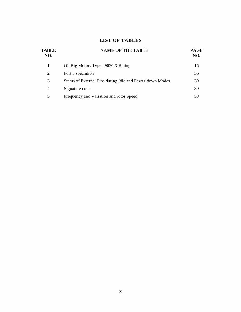
LIST OF TABLES
TABLENO.
NAME OF THE TABLE PAGENO.
1 Oil Rig Motors Type 4903CX Rating 15
2 Port 3 speciation 36
3 Status of External Pins during Idle and Power-down Modes 39
4 Signature code 39
5 Frequency and Variation and rotor Speed 58

xi
LIST OF ABBREVIATION
1 AC Alternative Current
2 ALE Application Link Enabling
3 ARM Asynchronous Response Module
4 AVR Automated Voltage Regulator
5 C Capacitor
6 CPU Central processing unit
7 DC Direct Current
8 DSR Data Terminal Ready
9 DTR Data Terminal Ready
10 GND Ground
11 HP Horsepower
12 HVAC high-voltage alternating current.
13 HZ Frequency
14 I Amps
15 IC Intragrated Circuit
16 IO Output Current
17 IP Primary Current
18 Is Secondary Current
19 LED Liquid Emitter Display
20 MOSFET metal–oxide–semiconductor field-effect transistor
21 MOVX Move Extended Memory
22 NC Normally Closed
23 NO Normally Open
24 NP Number of Turns on Primary Coil
25 Ns Number of Turns On secondary Coil
26 ONGC Oil and Natural Gas Corporation
27 PEROM Programmable and Erasable Read Only Memory
28 PEROM Programmable and Erasable Read Only Memory
29 PIC Pheripheral Interface Controller
30 PWM Pulse-width modulation
31 RAM Random Access Memory
32 RI Ring Indicator
xii
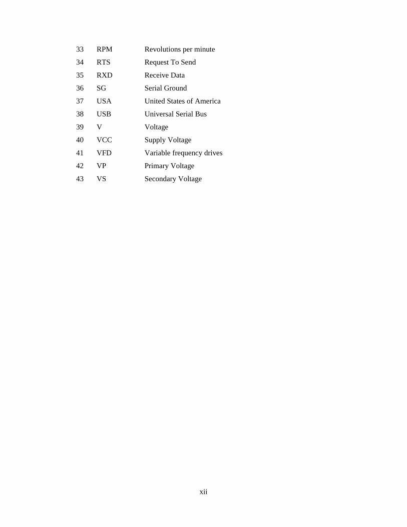
33 RPM Revolutions per minute
34 RTS Request To Send
35 RXD Receive Data
36 SG Serial Ground
37 USA United States of America
38 USB Universal Serial Bus
39 V Voltage
40 VCC Supply Voltage
41 VFD Variable frequency drives
42 VP Primary Voltage
43 VS Secondary Voltage

1
CHAPTER 1
COMPANY PROFILE
1.1 Oil and Natural Gas Corporation Limited (ONGC) an Over view
Oil and Natural Gas Corporation Limited (ONGC) is an Indian multinational oil and
gas company headquartered in Dehradun, India. It is a Public Sector Undertaking (PSU) of the
Government of India, under the administrative control of the Ministry of Petroleum and Natural
Gas. It is India's largest oil and gas exploration and production company. It produces around 69%
of India's crude oil (equivalent to around 30% of the country's total demand) and around 62% of its
natural gas.
On 31 March 2013, its market capitalisation was INR 2.6 trillion (US$48.98 billion),
making it India's second largest publicly traded company. In a government survey for FY 2011-12,
it was ranked as the largest profit making PSU in India. ONGC has been ranked 357th in the
Fortune Global 500 list of the world's biggest corporations for the year 2012. It is ranked 22nd
among the Top 250 Global Energy Companies by Platts.
ONGC was founded on 14 August 1956 by Government of India, which currently holds a
68.94% equity stake. It is involved in exploring for and exploiting hydrocarbons in 26 sedimentary
basins of India, and owns and operates over 11,000 kilometers of pipelines in the country. Its
international subsidiary ONGC Videsh currently has projects in 15 countries. ONGC has
discovered 6 of the 7 commercially-producing Indian Basins, in the last 50 years, adding over 7.1
billion tonnes of In-place Oil & Gas volume of hydrocarbons in Indian basins. Against a global
decline of production from matured fields, ONGC has maintained production from its brownfields
like Mumbai High, with the help of aggressive investments in various IOR (Improved Oil
Recovery) and EOR (Enhanced Oil Recovery) schemes. ONGC has many matured fields with a
current recovery factor of 25-33%.Its Reserve Replacement Ratio for between 2005 and 2013, has
been more than one. During FY 2012-13, ONGC had to share the highest ever under-recovery of
INR 494.2 million (an increase of INR 49.6 million over the previous financial year) towards the
under-recoveries of Oil Marketing Companies (IOC, BPCL and HPCL).

2
1.2 History
1.2.1 Foundation to 1961
Before the independence of India, the Assam Oil Company in the north-eastern and
Attock Oil company in north-western part of the undivided India were the only oil producing
companies, with minimal exploration input. The major part of Indian sedimentary basins was
deemed to be unfit for development of oil and gas resources.
After independence, the Central Government of India realized the importance of oil and gas for
rapid industrial development and its strategic role in defense. Consequently, while framing the
Industrial Policy Statement of 1948, the development of petroleum industry in the country was
considered to be of utmost necessity.
Until 1955, private oil companies mainly carried out exploration of hydrocarbon resources
of India. In Assam, the Assam Oil Company was producing oil at Digboi (discovered in 1889) and
Oil India Ltd. (a 50% joint venture between Government of India and Burmah Oil Company) was
engaged in developing two newly discovered large fields Naharkatiya and Moraan in Assam. In
West Bengal, the Indo-Stanvac Petroleum project (a joint venture between Government of India
and Standard Vacuum Oil Company of USA) was engaged in exploration work. The vast
sedimentary tract in other parts of India and adjoining offshore remained largely unexplored
In 1955, Government of India decided to develop the oil and natural gas resources in the
various regions of the country as part of the Public Sector development. With this objective, an Oil
and Natural Gas Directorate was set up towards the end of 1955, as a subordinate office under the
then Ministry of Natural Resources and Scientific Research. The department was constituted with a
nucleus of geoscientists from the Geological Survey of India.
A delegation under the leadership of the Minister of Natural Resources visited several
European countries to study the status of oil industry in those countries and to facilitate the training
of Indian professionals for exploring potential oil and gas reserves. Experts from Romania, the
Soviet Union, the United States and West Germany subsequently visited India and helped the
government with their expertise. Soviet experts later drew up a detailed plan for geological and
geophysical surveys and drilling operations to be carried out in the 2nd Five Year Plan (1956-61).
3
In April 1956, the Government of India adopted the Industrial Policy Resolution, which
placed Mineral Oil Industry among the schedule 'A' industries, the future development of which
was to be the sole and exclusive responsibility of the state. Soon, after the formation of the Oil and
Natural Gas Directorate, it became apparent that it would not be possible for the Directorate with
its limited financial and administrative powers as subordinate office of the Government, to function
efficiently. So in August, 1956, the Directorate was raised to the status of a commission with
enhanced powers, although it continued to be under the government. In October 1959, the
Commission was converted into a statutory body by an act of the Indian Parliament, which
enhanced powers of the commission further. The main funct1ions of the Oil and Natural Gas
Commission subject to the provisions of the Act, were "to plan, promote, organize and implement
programs for development of Petroleum Resources and the production and sale of petroleum and
petroleum products produced by it, and to perform such other functions as the Central Government
may, from time to time, assign to it ". The act further outlined the activities and steps to be taken by
ONGC in fulfilling its mandate. by vicky singh
1.3 India's Most Valuable Public Sector Enterprise
ONGC won Petrofed Oil & Gas Industry Awards 2011 in three categories - "Exploration &
Production: Company of the Year", "Project Management (above Rs. 2000 crore):
Company of the Year" and "Innovator of the Year: Team (Won by IOGPT)".
ONGC bagged Oil Industry Safety Directorate (OISD) awards for "Best Overall Safety
Performance of Oil and Gas Onshore Assets" and "Most Consistent Safety Performer
Award" (won by Rajahmundry Asset of ONGC) for the year 2011-12. In addition, JV
operation at Panna gas field between ONGC, BG and Reliance, operated by BG India won
the OISD award for "Best Production Platform – Pvt/JV Companies".
'Best Employer' award and 'Voice of Employee' award at the Aon Hewitt Best Employers –
India 2013 .
Golden Peacock Award for Corporate Social Responsibility for 2013. ONGC's structured
approach in delivering tailored CSR projects for communities around its operational areas
got it the coveted award.
Randstad Award-2013 for the Most Attractive Employer in the Energy Sector in India.
Gold Trophy of SCOPE Meritorious Award in the category of Corporate Social
Responsibility and Responsiveness for 2011-12.

4
'Best Enterprise Award' in the Maharatna and Navratna category at WIPS Award of
excellence held on February 11, 2014 at Kolkata. ONGC bagged this award third time in a
row.
ONGC's foreign operations arm OVL bagged the best PSU award in the oil and gas sector
at the Dainik Bhaskar India Pride Awards on December 19, 2013.
Human Resource Management Excellence Award in the Navratna and Maharatna category
at the PSE Excellence Awards 2013.
ABP 'Global CSR Excellence and Leadership Awards' 2013 - ONGC was the solitary
winner in the category of 'Best CSR Practices in the Areas of Health'.
1.4 ONGC Represents India's Energy Security Through its Pioneering Efforts
ONGC is the only fully–integrated petroleum company in India, operating along the entire
hydrocarbon value chain. It has single-handedly scripted India's hydrocarbon saga. Some
key pointers.
ONGC has discovered 6 out of the 7 producing basins in India.
It has 7.59 billion tonnes of In-place hydrocarbon reserves. It has to its credit more than 320
discoveries of oil and gas with Ultimate Reserves of 2.69 Billion Metric tonnes (BMT) of
Oil Plus Oil Equivalent Gas (O+OEG) from domestic acreages.
It has cumulatively produced 851 Million Metric Tonnes (MMT) of crude and 532 Billion
Cubic Meters (BCM) of Natural Gas, from 111 fields.
ONGC has won 121 out of a total 235 Blocks (more than 50%) in the 8 rounds of bidding,
under the New Exploration Licensing Policy (NELP) of the Indian Government.
ONGC's wholly-owned subsidiary ONGC Videsh Ltd. (OVL) is the biggest Indian
multinational, with 30 Oil & Gas projects (9 of them producing) in 15 countries.
Produces over 1.24 million barrels of oil equivalent per day, contributing over 64% of
India's domestic production. Of this, over 75% of crude oil produced is Light & Sweet.
The Company holds the largest share of hydrocarbon acreages in India (51% in PEL Areas
& 67% in ML Areas).
ONGC possesses about one tenth of the total Indian refining capacity.
ONGC has a well-integrated Hydrocarbon Value Chain structure with interests in LNG and
product transportation business as well.

5
A unique organization in world to have all operative offshore and onshore installations
(403) accredited with globally recognized certifications.
1.5 Competitive Strength
All crudes are sweet and most (76%) are light, with sulphur percentage ranging from 0.02-
0.10, API gravity range 26°-46° and hence attract a premium in the market.
Strong intellectual property base, information, knowledge, skills and experience
Maximum number of Exploration Licenses, including competitive NELP rounds. ONGC
has bagged 121 of the 235 Blocks (more than 50%) awarded in the 8 rounds of NELP.
ONGC owns and operates more than 26,600 kilometers of pipelines in India, including sub-
sea pipelines. No other company in India operates even 50 per cent of this route length.
1.6 Perspective Plan 2030 (PP2030)
PP2030 charts the roadmap for ONGC's growth over the next two decades. It aims to
double ONGC's production over the plan period with 4-5 per cent growth against the present
growth rate of 2 percent. In physical terms the aspirations under Perspective Plan 2030 aims for:
Production of 130 mmtoe of oil and oil equivalent gas (O + OEG) per year and accretion of
over 1,300 mmtoe of proven reserves.
Grow ONGC Videsh Limited (OVL) six fold to 60 mmtoe of international O+OEG
production per year by 2030.
More than 20 mmtoe of O+OEG production per year in India coming from new
unconventional sources such as shale gas, CBM, deepwater and HPHT (High Pressure &
High Temperature) reservoirs.
Over 6.5 GW power generation from nuclear, solar and wind and 9 MTPA of LNG.
Scaling up refining capacity to over 20 MMTPA and targeted investments to capture
downstream integration in petrochemicals.
6
1.7 Sourcing Equity Oil Abroad
ONGC Videsh, a Miniratna Schedule “A” Central Public Sector Enterprise (CPSE) of the
Government of India under the administrative control of the Ministry of Petroleum & Natural Gas
is the wholly owned subsidiary and overseas arm of Oil and Natural Gas Corporation Limited
(ONGC), the flagship national oil company (NOC) of India. The primary business of ONGC
Videsh is to prospect for oil and gas acreages outside India, including exploration, development and
production of oil and gas.
ONGC Videsh was incorporated as Hydrocarbons India Pvt. Ltd. on 5 March 1965 to carry
out exploration and development of the Rostam and Raksh oil fields in Iran and undertaking a
service contract in Iraq. The company was rechristened as ONGC Videsh Limited on 15th June,
1989 with the prime objective of marketing the expertise of ONGC abroad. The nineties saw the
Company engaged in limited exploration activities in Egypt, Yemen, Tunisia and Vietnam.
In its new avatar as ONGC Videsh, the company from mid-nineties re-oriented its focus on
acquiring quality overseas oil and gas assets. ONGC Videsh, which had one asset in year 2000,
gradually succeeded in competing with the best in the international arena and could conclude many
large transactions across the world in subsequent years. Presently, ONGC Videsh owns
Participating Interests in 33 oil and gas assets in 16 countries and contributes to 14.5% and 8% of
oil and natural gas production of India respectively. In terms of reserves and production, ONGC
Videsh is the second largest petroleum Company of India, next only to its parent ONGC.
ONGC Videsh’s oil and gas operations produced 8.36 MMT of oil and oil equivalent gas in
2013-14 as against 0.252 MMT of O+OEG in 2002-03. ONGC Videsh’s overseas cumulative
investment up to 31st March, 2014 has crossed USD 22 billion.
1.8 Frontiers of Technology
State-of-the-art seismic data acquisition, processing and interpretation facilities
Uses one of the Top Ten Virtual Reality Interpretation facilities in the world.
Alliances with Transocean, Schlumberger, Halliburton, Baker Hughes, IPR, Petrobras,
Norsk, ENI and Shell One of the biggest ERP implementations in the Asia.
7
1.9 Best in Class Infrastructure And Facilities
The Company operates with 27 Seismic crews, manages 250 onshore production
installations, 215 offshore installations, 77 drilling (plus 31 hired) and 57 work-over rigs (plus 25
hired), owns and operates more than 28,139 kilometers of pipeline in India, including 4,500
kilometers of sub-sea pipelines.
ONGC has adopted Best-in-class business practices for modernization, expansion and
integration of all Infocom systems.
1.10 The Road Ahead
ONGC looks forward to become an integrated energy provider, with:
New Discoveries and fast track development.
Equity Oil from Abroad.
Downstream Value Additions & Forward Integration.
Leveraging state-of-the art technology and global best practices.
New Sources of Energy.
Production from small and marginal fields.
ONGC has taken structured initiatives to tap unconventional energy sources through
unconventional gases like Coal Bed Methane (CBM), Underground Coal Gasification
(UCG), Shale Gas and Gas Hydrates, or unconventional energy sources like wind, solar etc.
"ONGC Energy Centre Trust", a dedicated centre created by ONGC for holistic research in
non-conventional energy sources, has taken up three projects viz., Thermo-chemical reactor
for Hydrogen, Geo-bio Reactors and Fuel Cells. ONGC has already commissioned a 50
MW Wind Farm in Gujarat and plan is afoot to set up another 100 MW Wind Farm in
Rajasthan. ONGC has also set up 3 Solar Thermal Engines at Solar Energy Centre, Ministry
of New and Renewable Energy (MNRE) campus at Gurgaon.
1.11 Value-chain integration
ONGC's purchase of majority stake in equity in the ailing Mangalore Refinery &
Petrochemicals Limited (MRPL), a stand-alone refinery of 9.69 MMT capacity in March 2003 is a
standout testimony of ONGC's integrated business model. Besides adding that desired comfort to

8
this Company in mitigating higher risk of E&P operation, this deal also set an example in the
Indian business history where a PSU has taken over a joint stock company and turned it around in a
record time of one year.
Moving ahead, ONGC has taken structured initiatives towards value-multiplier integration
projects like – Refinery, LNG, Petrochemicals, Power, SEZ, etc., to have presence in the entire
hydrocarbon value-chain.
1.12 Corporate Social Responsibility
In recognition of its role as a 'responsible leader', ONGC continues its quest to make
positive, tangible difference in the lives of the vulnerable and disadvantaged. With a business
paradigm that is based on an interconnected vision - of people's welfare, societal growth and
environmental conservation, ONGC in 2011-12 continued to cater to the developmental needs
across the following focus areas:
Education including vocational courses;
Health Care.
Entrepreneurship (self-help & livelihood generation) schemes.
Infrastructure support roads, bridges, Schools, hospitals in around our operational areas
Environment protection, ecological conservation, promotion.
Protection of heritage sites, UNESCO heritage monuments etc.
Promotion of artisans, craftsman, musicians, artists etc. for preservation of heritage, art &
culture.
Women's empowerment, girl child development, gender sensitive projects.
Water management including ground water recharge.
Initiatives for physically and mentally challenged.
Sponsorship of seminars, conferences, workshops etc. and Promoting sports/sports persons;
supporting agencies promoting sports / sports persons.
1.13 Corporate Governance
ONGC has taken structured initiatives towards Corporate Governance and its practices
which evolve around multi-layered checks and balances to ensure transparency. Apart from the
mandatory measures required to be implemented as a part of Corporate Governance, ONGC has
9
gone the extra mile in this regard and has implemented the Whistle Blower Policy, Annual Report
on working of the Audit & Ethics Committee, MCA Voluntary Guidelines on Corporate
Governance, Enterprise-wide Risk Management (ERM) framework.
1.14 Health, Safety & Environment
ONGC has implemented globally recognized QHSE management systems conforming to
requirements of ISO 9001, OHSAS 18001 and ISO 14001 at ONGC facilities and certified by
reputed certification agencies at all its operational units. Corporate guidelines on incident reporting,
investigation and monitoring of recommendations has been developed and implemented for
maintaining uniformity throughout the organization in line with international practice.
During 2011-12, 20% reduction in incidents achieved, 131 environmental clearance
(EC/TOR) obtained, 4 Lakh Ringal Bamboo Planted in Upper Himalayas, 25000 MT of oily waste
treated using Bioremediation, 412 installations certified with QHSE, 240 operational units audited
for HSE Performance, 130 employees trained on HUET, 14 HSE awareness programs completed.
Corporate Disaster Management Plan and guidelines have been developed for uniform
disaster management all across ONGC. ONGC has also developed Occupational Health physical
fitness criteria for employees deployed for offshore operations. Occupational Health module has
now been populated on SAP system.
1.15 Human Resources
ONGC has vast pool of skilled and talented professionals – the most valuable asset for the
company. 32,909 ONGCians (as on 31st March, 2012) dedicate themselves for the excellent
performance of the company. ONGC extends several welfare benefits to the employees and their
families by way of comprehensive medical care, education, housing and social security.
1.16 DRILLING OPERATIONS
1.16.1 Introduction
To prepare drilling programs; modified drilling program cost estimates including AFEs
(Authorization for Expenditure); bid specification for drilling contractor; drilling contracts.
10
There are various drilling contracts: daily rate, turnkey, footage rate, and incentive. To work with
geologist (on logging program), and other specialists such as directional engineers, mud engineer,
service and supply personnel.
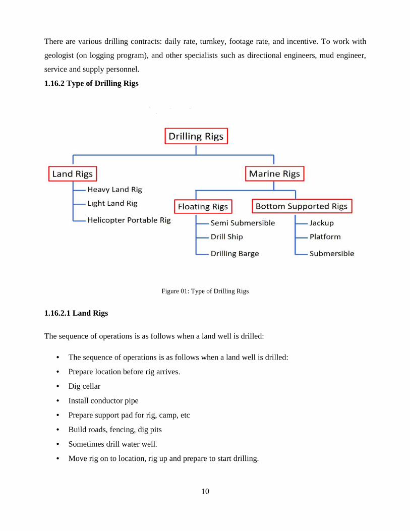
1.16.2 Type of Drilling Rigs
Figure 01: Type of Drilling Rigs
1.16.2.1 Land Rigs
The sequence of operations is as follows when a land well is drilled:
The sequence of operations is as follows when a land well is drilled:
Prepare location before rig arrives.
Dig cellar
Install conductor pipe
Prepare support pad for rig, camp, etc
Build roads, fencing, dig pits
Sometimes drill water well.
Move rig on to location, rig up and prepare to start drilling.
11
1.16.2.2 Marine Rigs Drilling Rigs
Two main types:
1. floating
2. bottom-supported unit
Floating unit include: semisubmersible (bottle-type, column stabilized), barge rig and drill
ship.
Bottom-supported unit include: submersible (posted barges, bottle-type submersibles, arctic
submersibles), jackups and platforms.
1.16.2.2.1 Floating Rigs
An oil platform, offshore platform, or (colloquially) oil rig is a large structure with facilities
to drill wells, to extract and process oil and natural gas, or to temporarily store product until it can
be brought to shore for refining and marketing. In many cases, the platform contains facilities to
house the workforce as well.
Depending on the circumstances, the platform may be fixed to the ocean floor, may consist
of an artificial island, or may float. Remote subsea wells may also be connected to a platform by
flow lines and by umbilical connections. These subsea solutions may consist of one or more subsea
wells, or of one or more manifold centres for multiple wells.
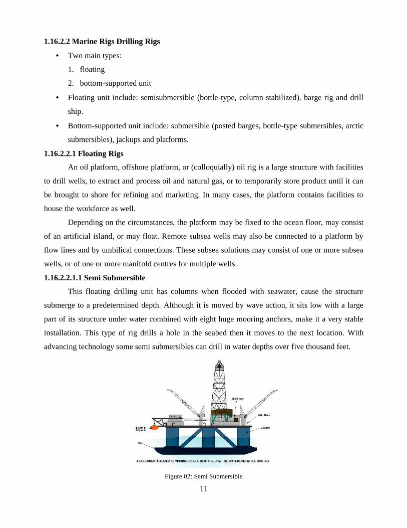
1.16.2.2.1.1 Semi Submersible
This floating drilling unit has columns when flooded with seawater, cause the structure
submerge to a predetermined depth. Although it is moved by wave action, it sits low with a large
part of its structure under water combined with eight huge mooring anchors, make it a very stable
installation. This type of rig drills a hole in the seabed then it moves to the next location. With
advancing technology some semi submersibles can drill in water depths over five thousand feet.
Figure 02: Semi Submersible

12
1.16.2.2.1.2 Platform
This immobile structure can be built from concrete or steel and rests on the seabed. When
oil or gas is located a platform may be constructed to drill further wells at that site and also to
produce the hydrocarbon.
Figure 03: Platform
1.16.2.2.1.3 Jack up
This is a mobile drilling rig, different from the semi submersible. Instead of floating over
its drilling location the Jackup has long leg structures, which it lowers to and into the seabed raising
the rig out of the water.The obvious limitation with this type of installation is the depth of water it
can operate in.The maximum being five hundred feet.
Figure 04: Jack up
1.16.3 Rotary Drilling
Rotary drilling uses a sharp, rotating drill bit to dig down through the Earth's crust.The spinning of
the drill bit allows for penetration of even the hardest rock. The actual mechanics of modern rigs
are quite complicated.In addition, technology advances so rapidly that new innovations are being
13
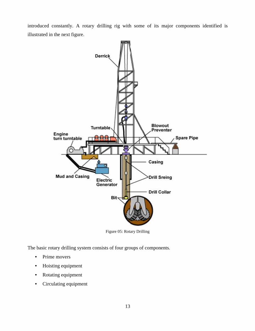
introduced constantly. A rotary drilling rig with some of its major components identified is
illustrated in the next figure.
Figure 05: Rotary Drilling
The basic rotary drilling system consists of four groups of components.
Prime movers
Hoisting equipment
Rotating equipment
Circulating equipment

14
1.16.3.1 Prime Movers
The prime movers in a rotary drilling rig are those pieces of equipment that provide the
power to the entire rig.
Recently, while diesel engines still compose the majority of power sources on rotary rigs,
other types of engines are also in use.
Some rotary rigs may use electricity directly from power lines. Most rotary rigs these days
require 1,000 to 3,000 horsepower, while shallow drilling rigs may require as little as
500 horsepower.
The energy from these prime movers is used to power the rotary equipment, the hoisting
equipment, and the circulating equipment.
1.16.3.2 Hoisting Equipments
The hoisting equipment on a rotary rig consists of the tools used to raise and lower whatever
other equipment may go into or come out of the well. The most visible part of the hoisting
equipment is the derrick, the tall tower-like structure that extends vertically from the well hole. The
hoisting system is made up of the drawworks, derrick, crown block, traveling block, hook and wire
rope. If a drill bit needs to be changed, either due to tear or a change in the subsurface rock, the
whole string of pipe must be raised to the surface. The hoisting equipment is used to raise all of this
equipment to the surface so that the drill bit may be replaced. Whenever the drillstem is suspended
by the traveling blockand drill line, the entire load rests on the derrick. The standard pyramid
derrick is a structure with four supporting legs resting on a square base.
In comparison, a mast is much more slender and may be thought of as sitting on one side of the rig
floor or work space.The derrick is erected on a substructure which supports the rig floor and rotary
table and provides work space for the equipment on the rig floor.
1.16.4 Oil Rig Motors Type 4903CX
1000 HP motor is a single shaft extension, heavy duty, direct current four pole separately excited
machines provide with inter poles and TIG welded, lap wound fully equalized armature coil
connections.

15
Figure 07: Oil Rig Motors Type 4903CX
Motor can be used to drive Draw Works/ Rotary/ Mud Pumps & Cement Pumps in both on shore &
off shore drilling environment.This design is especially developed for heavy duty drilling . These
motors are highly reliable machines with service proven record of efficient & dependable
performance.A wide variety of mechanical arrangements, accessories & configurations are
available to suit specific requirements.
Table 01: Oil Rig Motors Type 4903CX Rating
Rotating Mud
pump/Draw works
Shunt wound
4903 BX
900/1100HP
1050RPM
Shunt wound
4903 CX
1000/1250 HP
1050 RPM
Series/Shunt wound
4903 EX
1000 HP/1250 HP
1050 RPM
Armature current (A)
-Continuous 950 1050 1050
-Intermittent 1150* 1325* 1325*
Field current (A) 50.5/57 50.5/57 500
Max.Speed 2750 2750 2750
Insulating Class ‘H’ ‘H’ ‘H’
Cooling 2900 CFM at 210
MM WG
2900 CFM at 210
MM WG
2900 CFM at 210
MM WG
7.5 HP 7.5 HP 7.5 HP
Blower Blower Blower
Voltage (V) 750 750 750
Bearing Sealed Sealed Sealed
Weight incl. acc.(KG)-
Single shaft extension 3400 3400 3400

16
various application ratings of oil rig motors. interchangeability mounting dimensions & shaft height
are such that the motors is interchangeable with drilling motors commonly used in industry.
application flexibility full horse power rating for both cw & ccw shaft rotation.
1.16.4.1Special Constructional Feature
The main poles are built from sheet steel laminations riveted together whereas interpole is
machined from high permeability steel. The main field coils are with copper strap flat wound,
whereas the interpole coils are edge wound .Coils are insulated with Mica based class H insulation
system and are vacuum and pressure impregnated. The pole bolt heads are sealed with a compound
to prevent water entry. All internal electrical connections are effectively secured to prevent
movement and loosening in service.
1.16.4.1.1 Brush Gear
Split carbon brushes with rubber tops are used for better commutation. Brush holders are
secured to the magnet frame by micalex insulated pins. A PTFE insulator mounted on the support
pin provides a creepage surface that is very easy to clean. The radial distance of the brush holder
from the commutator and brush spring tensions can be adjusted .Arcing ring is provided to
minimize the damage in the event of flashover.
1.16.4.1.2 Armature
The varnished electrical sheet steel punchings. Shaft is machined from Nickel-Chromium-
Molybdenum steel to BS 970, grade EMN25V. Two rows of ventilating ducts are provided for
effective cooling. The commutator is made of silver bearing copper segments.
The coils are held down in the core slots with epoxy glass wedges. Res-I-glass tape is used to retain
the end windings. The armature is vacuum and pressure impregnated with high quality solventless
polyester varnish. The armature is dynamically balanced.
Figure 07: Armature

17
1.16.4.1.3 Armature Bearing Assembly
The armature is supported on two grease lubricated roller bearings.
The bearing on the commutator end acts as locating bearing while the pinion end
bearing takes care of any differentials between the armature and frame.
Both the bearing arrangement are fully sealed thereby necessitating lubrication only
once in about 3 years or so.
The sealed bearing arrangement also prevents bearing lubricants passing into the
machine or getting contaminated with gear lubricant or other foreign material.
1.16.4.1.4 Special features
230 Volts, 225 watts single phase space heater to control internal humidity.
Frame mounts cut-out switch to isolate the motor during servicing / repairs.
Plug-in type connections for power and control cables.
Bottom cable entry.
Pressurized enclosure for operation in hazardous area.
Standard drive hub, shrink fitted on tapered seating over shaft extension.
18
CHAPATER 2
INTRODUCTION
2.1 OVER VIEW OF THE PROJECT
Variable frequency drive (VFD) usage has increased dramatically in HVAC applications.
The VFDs are now commonly applied to air handlers, pumps and tower fans. A better
understanding of VFDs will lead to improved application and selection of both equipment and
HVAC systems. This paper is intended to provide basic a understanding of common VFD terms,
VFD operation and VFD benefits.
In addition to this paper will discuss some basic application guidelines regarding harmonic
distortion with respect to industry standards. A modern adjustable speed AC machine system is
equipped with an adjustable frequency drive that is a power electronic device for speed control of
an electric machine. It controls the speed of the electric machine by converting the fixed voltage
and frequency of the grid to adjustable values on the machine side.
There are many types of inverters, and they are classified according to number of phases,
use of power semiconductor devices, commutation principles, and output Waveforms. The new
standard has been greatly expanded and is now “recommended practices and requirements” rather
than just guidelines. Considerable input was received from the electric utilities and, as a result,
stringent limits have been placed on individual as well as total current harmonic distortion.
Considerable importance is given to the customer utility interface. The limits on voltage distortion
and line notching remain unchanged.
The most common solution employed for adjustable-speed drives (ASDs) is the voltage-
source-inverter (VSI)-fed induction motor. The inverter generates a pulse width modulation (PWM)
output voltage, presenting many advantages: high efficiency (up to 98%), low sensitivity to line
transients, open-circuit protection, constant high input power factor, multimode application
capability, small relative size, common bus regeneration, wide speed range, and excellent speed
regulation. In order to decrease the switching losses, fast switching devices like insulated gate
bipolar transistors (MOSFETs) are used.
As a consequence, MOSFET-based drives have smaller heat sinks, which make the whole
drive enclosure smaller, thus reducing overall cost. The combination of simpler, faster control
circuits and higher carrier frequencies allows higher performance drives with high starting torque
and especially good performance at low speeds. The developed hardware is tested on a three phase ,
19
230V , 50Hz induction motor. According to the requirement a program is written and is fed to the
Micro-Controller for necessary action.
The inverter output current is regulated by a sine wave reference, generated by PWM
technique, and the MOSFETs are triggered at constant delay angle. The waveforms are analyzed
and studies on digital display operator.
2.2 OBJECTIVE
Induction motors are fixed speed motors which are used in most industries because of its
reduced cost, reliability and rugged nature. In industrial applications which require variable speed,
the use of induction motor is limited as a result of low efficiency and high cost penalty associated
with the existing control techniques. The improvement and advancement in power electronics has
led to the production of ac motor drives known as a variable frequency drive (VFD), which are
now used to control the speed of induction motors at reduced production and maintenance cost with
increased efficiency. A variable-frequency drive (VFD) is a system for controlling the rotational
speed or torque of an alternating current (AC) electric motor by controlling the frequency of the
electric power supplied to the motor.
A variable frequency drive is a type of adjustable speed drive also referred to as AC drives,
adjustable frequency drives, frequency converters, micro drive or inverter drives. It controls the
speed of the electric machine by converting the frequency of the grid to adjustable values on the
machine side, thus allowing the electric motor to quickly and easily adjust its speed to the required
value. The two major functions of a variable frequency drive are to provide power conversion from
one frequency to another, and to enable control of the output frequency. Variable-frequency drives
are used in applications ranging from small appliances to the largest of mine mill drives and
compressors. They are also widely used in ventilation systems for large buildings, variable
frequency motors on fans which save energy by allowing the volume of air moved to match the
system demand. They are also used on pumps, conveyors and machine tools drives. Variable
frequency drives can be classified as;
• AC variable frequency drives
• Current source input variable frequency drives
• Pulse width modulated variable frequency drives
• Flux vector pulse width variable frequency drives.
20
CHAPTER 3
PROPOSED SYSTEM AND EXPLAINATION
3.1 INTRODUCTION
The speed of induction motor is directly proportional to the supply frequency and no. of poles of
motor. Variable speed drive by using frequency control method is commonly used to control and
change the speed of single phase induction motor. It can vary the desired speed by changing the
frequency using switching sequence of MOSFET. To get low cost,high performance speed control
circuit is design.
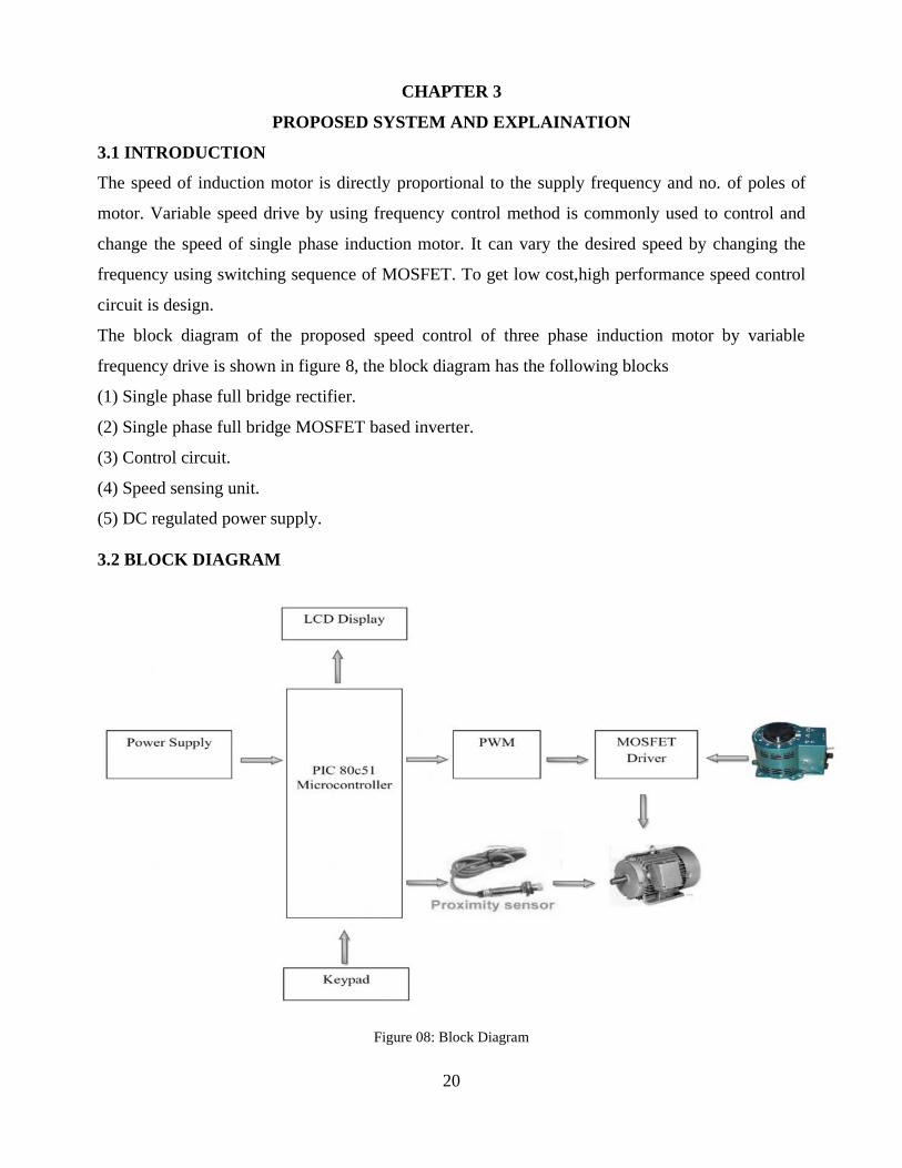
The block diagram of the proposed speed control of three phase induction motor by variable
frequency drive is shown in figure 8, the block diagram has the following blocks
(1) Single phase full bridge rectifier.
(2) Single phase full bridge MOSFET based inverter.
(3) Control circuit.
(4) Speed sensing unit.
(5) DC regulated power supply.
3.2 BLOCK DIAGRAM
Figure 08: Block Diagram
21
In This System we are using PIC microcontroller. It is the flash type microcontroller in
which we have already programmed. By using the software instruction we are generating PWM
wave in the PIC microcontroller. Then the PWM wave is given to PWM driver circuit. The PWM
driver circuit contains with MOSFET. The induction motor interface with MOSFET and speed
sensor Then PWM pulse is given to MOSFET driver circuit. MOSFET driver circuit is used to
control the ON OFF time of MOSFET according PWM pulse from PIC microcontroller. The
MOSFET is nothing but metal oxide field Effect Transistor. In this project we are using four set of
MOSFET is used. Through the driver circuit switching time between the MOSFET‘s is varied. At
the time of high portion in the PWM wave two MOSFET is switched ON and remaining OFF. At
the time of low portion of PWM wave another two MOSFET is switched ON, before two MOSFET
is switched OFF. Through this wave circuit AC voltage is generated. Then AC voltage is given to
step up transform in order to step up into 230V. So the output of the transformer is 230V AC. This
voltage and given to motor.
The Speed is monitored by the proximity sensor. It is the one type of transducer. It detects
the metals and generates the voltage pulse. We fixed the metal plate in the motor shaft. So
whenever the metal plate is crossed, the proximity sensor generates the pulse. The corresponding
pulse signal is given to microcontroller. Now the microcontrollers display the pulse rate or speed
will display on the LCD display which is equal to speed of the motor. Here the voltage is measured
by potential transformer then it will give to precession rectifier this rectifier convert 0 to 5v level.
Then this precession rectifier gave to ADC. The ADC nothing but analog to digital converter after
converting this voltage is given to microcontroller the microcontroller display the voltage in LCD
display. The speed we can set through keypad.
22
CHAPTER 4
HARADWARE IMPLEMENTATION
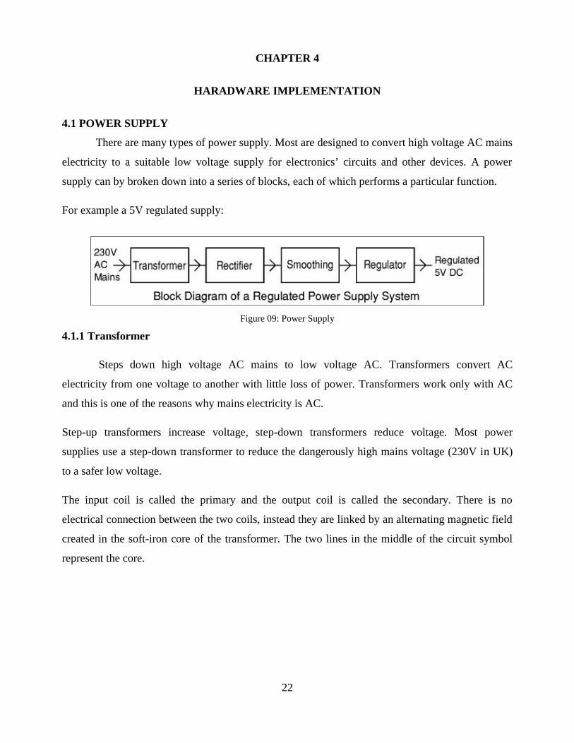
4.1 POWER SUPPLY
There are many types of power supply. Most are designed to convert high voltage AC mains
electricity to a suitable low voltage supply for electronics’ circuits and other devices. A power
supply can by broken down into a series of blocks, each of which performs a particular function.
For example a 5V regulated supply:
Figure 09: Power Supply
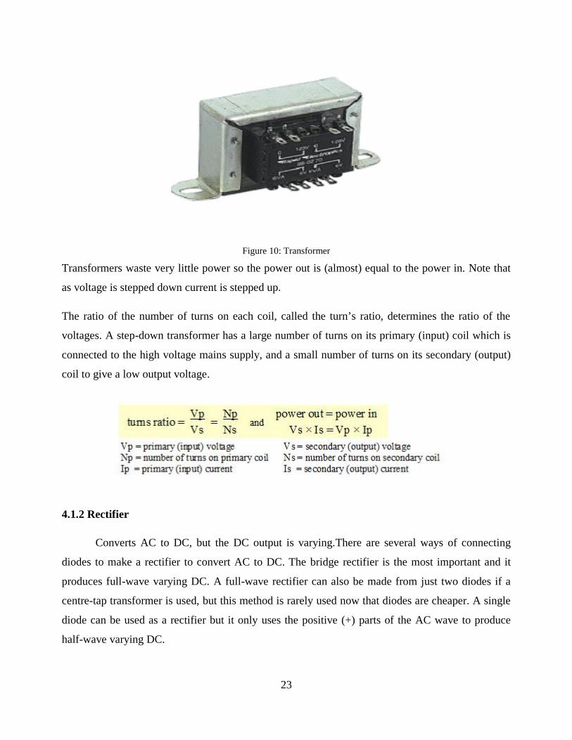
4.1.1 Transformer
Steps down high voltage AC mains to low voltage AC. Transformers convert AC
electricity from one voltage to another with little loss of power. Transformers work only with AC
and this is one of the reasons why mains electricity is AC.
Step-up transformers increase voltage, step-down transformers reduce voltage. Most power
supplies use a step-down transformer to reduce the dangerously high mains voltage (230V in UK)
to a safer low voltage.
The input coil is called the primary and the output coil is called the secondary. There is no
electrical connection between the two coils, instead they are linked by an alternating magnetic field
created in the soft-iron core of the transformer. The two lines in the middle of the circuit symbol
represent the core.
23
Figure 10: Transformer
Transformers waste very little power so the power out is (almost) equal to the power in. Note that
as voltage is stepped down current is stepped up.
The ratio of the number of turns on each coil, called the turn’s ratio, determines the ratio of the
voltages. A step-down transformer has a large number of turns on its primary (input) coil which is
connected to the high voltage mains supply, and a small number of turns on its secondary (output)
coil to give a low output voltage.
4.1.2 Rectifier
Converts AC to DC, but the DC output is varying.There are several ways of connecting
diodes to make a rectifier to convert AC to DC. The bridge rectifier is the most important and it
produces full-wave varying DC. A full-wave rectifier can also be made from just two diodes if a
centre-tap transformer is used, but this method is rarely used now that diodes are cheaper. A single
diode can be used as a rectifier but it only uses the positive (+) parts of the AC wave to produce
half-wave varying DC.
24
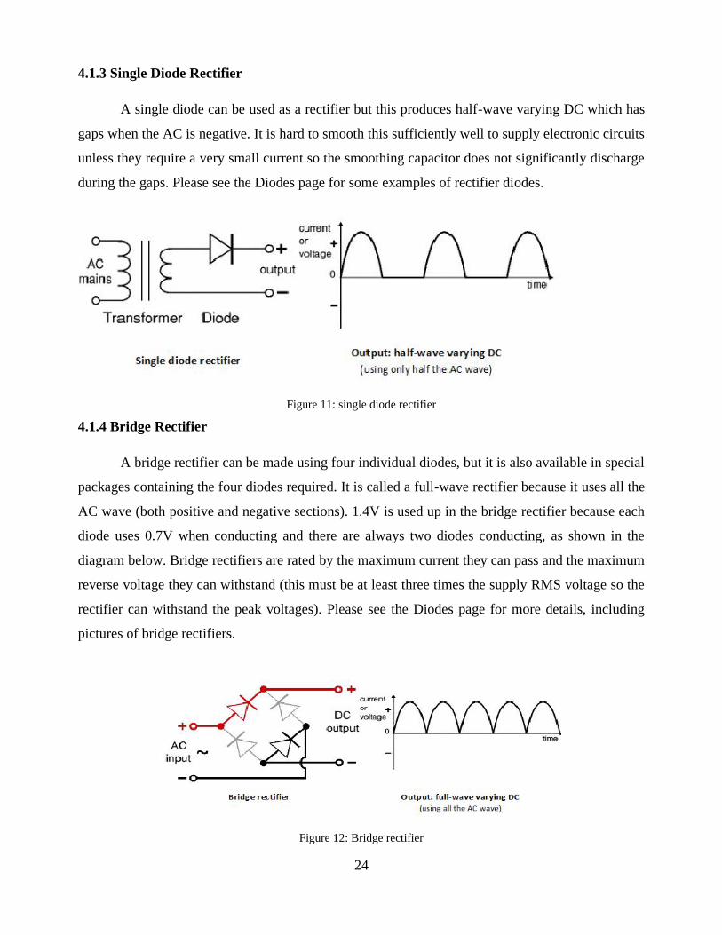
4.1.3 Single Diode Rectifier
A single diode can be used as a rectifier but this produces half-wave varying DC which has
gaps when the AC is negative. It is hard to smooth this sufficiently well to supply electronic circuits
unless they require a very small current so the smoothing capacitor does not significantly discharge
during the gaps. Please see the Diodes page for some examples of rectifier diodes.
Figure 11: single diode rectifier
4.1.4 Bridge Rectifier
A bridge rectifier can be made using four individual diodes, but it is also available in special
packages containing the four diodes required. It is called a full-wave rectifier because it uses all the
AC wave (both positive and negative sections). 1.4V is used up in the bridge rectifier because each
diode uses 0.7V when conducting and there are always two diodes conducting, as shown in the
diagram below. Bridge rectifiers are rated by the maximum current they can pass and the maximum
reverse voltage they can withstand (this must be at least three times the supply RMS voltage so the
rectifier can withstand the peak voltages). Please see the Diodes page for more details, including
pictures of bridge rectifiers.
Figure 12: Bridge rectifier
25
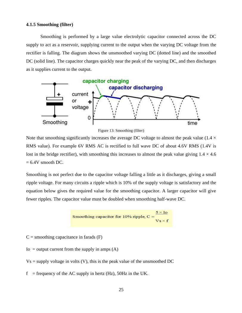
4.1.5 Smoothing (filter)
Smoothing is performed by a large value electrolytic capacitor connected across the DC
supply to act as a reservoir, supplying current to the output when the varying DC voltage from the
rectifier is falling. The diagram shows the unsmoothed varying DC (dotted line) and the smoothed
DC (solid line). The capacitor charges quickly near the peak of the varying DC, and then discharges
as it supplies current to the output.
Figure 13: Smoothing (filter)
Note that smoothing significantly increases the average DC voltage to almost the peak value (1.4 ×
RMS value). For example 6V RMS AC is rectified to full wave DC of about 4.6V RMS (1.4V is
lost in the bridge rectifier), with smoothing this increases to almost the peak value giving 1.4 × 4.6
= 6.4V smooth DC.
Smoothing is not perfect due to the capacitor voltage falling a little as it discharges, giving a small
ripple voltage. For many circuits a ripple which is 10% of the supply voltage is satisfactory and the
equation below gives the required value for the smoothing capacitor. A larger capacitor will give
fewer ripples. The capacitor value must be doubled when smoothing half-wave DC.
C = smoothing capacitance in farads (F)
Io = output current from the supply in amps (A)
Vs = supply voltage in volts (V), this is the peak value of the unsmoothed DC
f = frequency of the AC supply in hertz (Hz), 50Hz in the UK.
26
4.1.6 Regulator
Voltage regulator ICs are available with fixed (typically 5, 12 and 15V) or variable output
voltages. They are also rated by the maximum current they can pass. Negative VO. To make things
really simple let’s start with a simple power supply and it is also the one they usually give you in
your first electronics project. Well the reason is quite obvious because all electronics circuits
require a DC power supply to work. You really do plug in the wires of your electronic items in AC
mains supply but they do have AC to DC converters too provide DC to the circuits. All this is done
with a power supply in the right place.
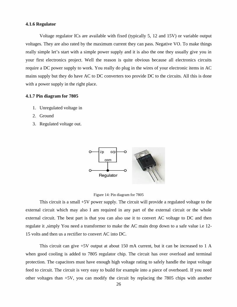
4.1.7 Pin diagram for 7805
1. Unregulated voltage in
2. Ground
3. Regulated voltage out.
Figure 14: Pin diagram for 7805
This circuit is a small +5V power supply. The circuit will provide a regulated voltage to the
external circuit which may also I am required in any part of the external circuit or the whole
external circuit. The best part is that you can also use it to convert AC voltage to DC and then
regulate it ,simply You need a transformer to make the AC main drop down to a safe value i.e 12-
15 volts and then us a rectifier to convert AC into DC.
This circuit can give +5V output at about 150 mA current, but it can be increased to 1 A
when good cooling is added to 7805 regulator chip. The circuit has over overload and terminal
protection. The capacitors must have enough high voltage rating to safely handle the input voltage
feed to circuit. The circuit is very easy to build for example into a piece of overboard. If you need
other voltages than +5V, you can modify the circuit by replacing the 7805 chips with another
27
regulator with different output voltage from regulator 78xx chip family. The last numbers in the
chip code tells the output voltage. Remember that the input voltage must be at least 3V greater than
regulator output voltage to otherwise the regulator does not work well. Don’t forget to check the
pin diagram before connecting the IC.
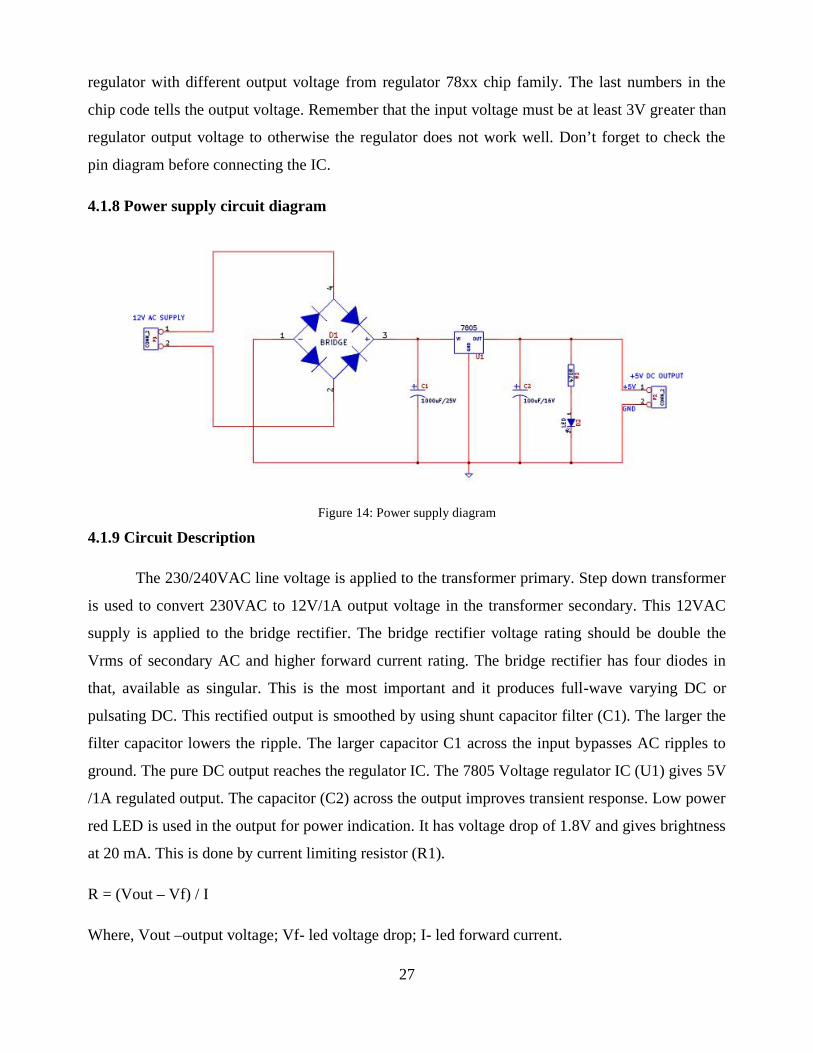
4.1.8 Power supply circuit diagram
Figure 14: Power supply diagram
4.1.9 Circuit Description
The 230/240VAC line voltage is applied to the transformer primary. Step down transformer
is used to convert 230VAC to 12V/1A output voltage in the transformer secondary. This 12VAC
supply is applied to the bridge rectifier. The bridge rectifier voltage rating should be double the
Vrms of secondary AC and higher forward current rating. The bridge rectifier has four diodes in
that, available as singular. This is the most important and it produces full-wave varying DC or
pulsating DC. This rectified output is smoothed by using shunt capacitor filter (C1). The larger the
filter capacitor lowers the ripple. The larger capacitor C1 across the input bypasses AC ripples to
ground. The pure DC output reaches the regulator IC. The 7805 Voltage regulator IC (U1) gives 5V
/1A regulated output. The capacitor (C2) across the output improves transient response. Low power
red LED is used in the output for power indication. It has voltage drop of 1.8V and gives brightness
at 20 mA. This is done by current limiting resistor (R1).
R = (Vout – Vf) / I
Where, Vout –output voltage; Vf- led voltage drop; I- led forward current.
28
From this we get R as 160E. We use the standard value of 220E. The higher value of limiting
resistor gives low brightness but longer life time. So, here 470E is used.
4.2 KEYPAD
A numeric keypad, or numpad for short, is the small, palm-sized, seventeen key section of a
computer keyboard, usually on the very far right. The numeric keypad features digits 0 to 9,
addition (+), subtraction (-), multiplication (*) and division (/) symbols, a decimal point (.) and
Num Lock and Enter keys. Laptop keyboards often do not have a numpad, but may provide
numpad input by holding a modifier key (typically lapelled "Fn") and operating keys on the
standard keyboard.
Particularly large laptops (typically those with a 17 inch screen or larger) may have space
for a real numpad, and many companies sell separate numpads which connect to the host laptop by
a USB connection.
Numeric keypads usually operate in two modes: when Num Lock is off, keys 8, 6, 2, 4 act
like an arrow keys and 7, 9, 3, 1 act like Home, PgUp, PgDn and End; when Num Lock is on, digits
keys produce corresponding digits. These, however, differ from the numeric keys at the top of the
keyboard in that, when combined with the Alt key on a PC, they are used to enter characters which
may not be otherwise available: for example, Alt-0169 produces the copyright symbol. These are
referred to as Alt codes.
On Apple Computer Macintosh computers, which lack a Num Lock key, the numeric
keypad always produces only numbers. The num lock key is replaced by the clear key.
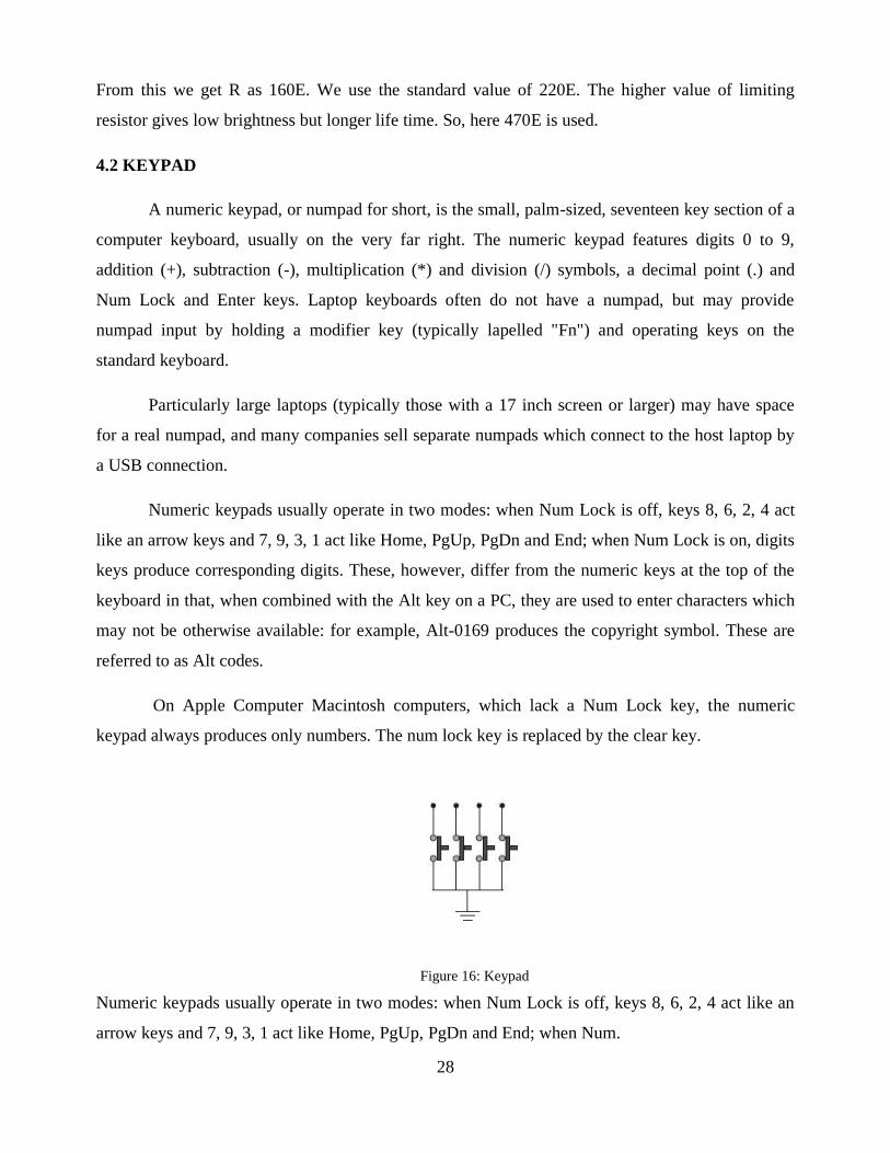
Figure 16: Keypad
Numeric keypads usually operate in two modes: when Num Lock is off, keys 8, 6, 2, 4 act like an
arrow keys and 7, 9, 3, 1 act like Home, PgUp, PgDn and End; when Num.
29
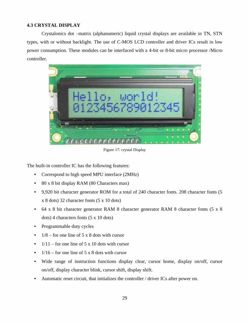
4.3 CRYSTAL DISPLAY
Crystalonics dot –matrix (alphanumeric) liquid crystal displays are available in TN, STN
types, with or without backlight. The use of C-MOS LCD controller and driver ICs result in low
power consumption. These modules can be interfaced with a 4-bit or 8-bit micro processor /Micro
controller.
Figure 17: crystal Display
The built-in controller IC has the following features:
Correspond to high speed MPU interface (2MHz)
80 x 8 bit display RAM (80 Characters max)
9,920 bit character generator ROM for a total of 240 character fonts. 208 character fonts (5
x 8 dots) 32 character fonts (5 x 10 dots)
64 x 8 bit character generator RAM 8 character generator RAM 8 character fonts (5 x 8
dots) 4 characters fonts (5 x 10 dots)
Programmable duty cycles
1/8 – for one line of 5 x 8 dots with cursor
1/11 – for one line of 5 x 10 dots with cursor
1/16 – for one line of 5 x 8 dots with cursor
Wide range of instruction functions display clear, cursor home, display on/off, cursor
on/off, display character blink, cursor shift, display shift.
Automatic reset circuit, that initializes the controller / driver ICs after power on.
30
4.3.1 Functional Description of The Controller IC
Registers
The controller IC has two 8 bit registers, an instruction register (IR) and a data register
(DR). The IR stores the instruction codes and address information for display data RAM (DD
RAM) and character generator RAM (CG RAM). The IR can be written, but not read by the MPU.
The DR temporally stores data to be written to /read from the DD RAM or CG RAM. The
data written to DR by the MPU, is automatically written to the DD RAM or CG RAM as an
internal operation.
When an address code is written to IR, the data is automatically transferred from the DD
RAM or CG RAM to the DR. data transfer between the MPU is then completed when the MPU
reads the DR. likewise, for the next MPU read of the DR, data in DD RAM or CG RAM at the
address is sent to the DR automatically. Similarly, for the MPU write of the DR, the next DD RAM
or CG RAM address is selected for the write operation.
Busy Flag
When the busy flag is1, the controller is in the internal operation mode, and the next
instruction will not be accepted.
When RS = 0 and R/W = 1, the busy flag is output to DB7.
The next instruction must be written after ensuring that the busy flag is 0.
Address Counter
The address counter allocates the address for the DD RAM and CG RAM read/write
operation when the instruction code for DD RAM address or CG RAM address setting, is input to
IR, the address code is transferred from IR to the address counter. After writing/reading the display
data to/from the DD RAM or CG RAM, the address counter increments/decrements by one the
address, as an internal operation. The data of the address counter is output to DB0 to DB6 while
R/W = 1 and RS = 0.
Display Data Ram (DD RAM)
The characters to be displayed are written into the display data RAM (DD RAM), in the
form of 8 bit character codes present in the character font table. The extended capacity of the DD
RAM is 80 x 8 bits i.e. 80 characters.
31
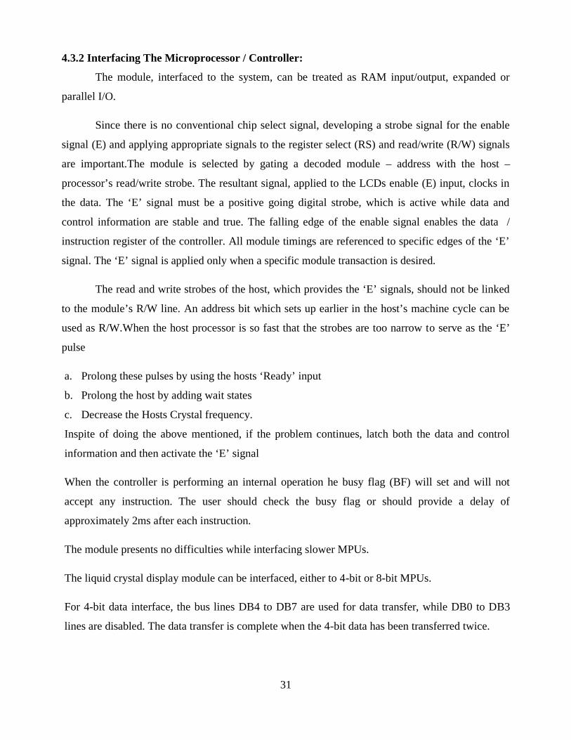
4.3.2 Interfacing The Microprocessor / Controller:
The module, interfaced to the system, can be treated as RAM input/output, expanded or
parallel I/O.
Since there is no conventional chip select signal, developing a strobe signal for the enable
signal (E) and applying appropriate signals to the register select (RS) and read/write (R/W) signals
are important.The module is selected by gating a decoded module – address with the host –
processor’s read/write strobe. The resultant signal, applied to the LCDs enable (E) input, clocks in
the data. The ‘E’ signal must be a positive going digital strobe, which is active while data and
control information are stable and true. The falling edge of the enable signal enables the data /
instruction register of the controller. All module timings are referenced to specific edges of the ‘E’
signal. The ‘E’ signal is applied only when a specific module transaction is desired.
The read and write strobes of the host, which provides the ‘E’ signals, should not be linked
to the module’s R/W line. An address bit which sets up earlier in the host’s machine cycle can be
used as R/W.When the host processor is so fast that the strobes are too narrow to serve as the ‘E’
pulse
a. Prolong these pulses by using the hosts ‘Ready’ input
b. Prolong the host by adding wait states
c. Decrease the Hosts Crystal frequency.
Inspite of doing the above mentioned, if the problem continues, latch both the data and control
information and then activate the ‘E’ signal
When the controller is performing an internal operation he busy flag (BF) will set and will not
accept any instruction. The user should check the busy flag or should provide a delay of
approximately 2ms after each instruction.
The module presents no difficulties while interfacing slower MPUs.
The liquid crystal display module can be interfaced, either to 4-bit or 8-bit MPUs.
For 4-bit data interface, the bus lines DB4 to DB7 are used for data transfer, while DB0 to DB3
lines are disabled. The data transfer is complete when the 4-bit data has been transferred twice.
32
The busy flag must be checked after the 4-bit data has been transferred twice. Two more 4-bit
operations then transfer the busy flag and address counter data.
For 8-bit data interface, all eight-bus lines (DB0 to DB7) are used.
4.4 MICRO CONTROLLER
The AT89C51 is a low-power, high-performance CMOS 8-bit microcomputer with 4K
bytes of Flash programmable and erasable read only memory (PEROM). The device is
manufactured using Atmel’s high-density non-volatile memory technology and is compatible with
the industry-standard MCS-51 instruction set and pin out. The on-chip Flash allows the program
memory to be reprogrammed in-system or by a conventional non-volatile memory programmer. By
combining a versatile 8-bit CPU with Flash on a monolithic chip, the Atmel AT89C51 is a
powerful microcomputer which provides a highly-flexible and cost-effective solution to many
embedded control applications.
4.4.1 Features
4K Bytes of In-System Reprogrammable Flash MemoryEndurance: 1,000 Write/Erase Cycles1
Fully Static Operation: 0 Hz to 24 MHz
Three-level Program Memory Lock
128 x 8-bit Internal RAM
32 Programmable I/O Lines
Two 16-bit Timer/Counters
Six Interrupt Sources
Programmable Serial Channel

33
4.4.2 Architecture of 80c51
The AT80C51is a high-performance static 80C51 design fabricated with Philips high-
density CMOS technology with operation from 2.7 V to 5.5 V. The 8xC51 and 8xC52 contain a
128 × 8 RAM and 256 × 8 RAM respectively, 32 I/O lines, three 16-bit counter/timers, a six-
source, four-priority level nested interrupt structure, a serial I/O port for either multi-processor
communications, I/O expansion or full duplex UART, and on-chip oscillator and clock circuits. In
addition, the device is a low power static design which offers a wide range of operating frequencies
down to zero. Two software selectable modes of power reduction—idle mode and power-down
mode are available. The idle mode freezes the CPU while allowing the RAM, timers, serial port,
and interrupt system to continue functioning. The power-down mode saves the RAM contents but
the oscillator, causing all other chip functions to be inoperative. Since the design is static, the clock
can be stopped without loss of user data and then the execution resumed from the point the clock
was stopped.
Figure 18: Architecture of 80c51
34
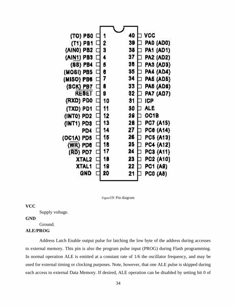
Figure19: Pin diagram
VCCSupply voltage.
GNDGround.
ALE/PROG
Address Latch Enable output pulse for latching the low byte of the address during accesses
to external memory. This pin is also the program pulse input (PROG) during Flash programming.
In normal operation ALE is emitted at a constant rate of 1/6 the oscillator frequency, and may be
used for external timing or clocking purposes. Note, however, that one ALE pulse is skipped during
each access to external Data Memory. If desired, ALE operation can be disabled by setting bit 0 of

35
SFR location 8EH. With the bit set, ALE is active only during a MOVX or MOVC instruction.
Otherwise, the pin is weakly pulled high. Setting the ALE-disable bit has no effect if the
microcontroller is in external execution mode.
Port 0Port 0 is an 8-bit open-drain bi-directional I/O port. As an output port, each pin can sink
eight TTL inputs. When 1s are written to port 0 pins, the pins can be used as high-impedance
inputs. Port 0 may also be configured to be the multiplexed low-order address/data bus during
accesses to external pro-gram and data memory. In this mode P0 has internal pull ups. Port 0 also
receives the code bytes during Flash programming, and outputs the code bytes during program
verification. External pull ups are required during program verification.
Port 1Port 1 is an 8-bit bi-directional I/O port with internal pull ups. The Port 1 output buffers can
sink/source four TTL inputs. When 1s are written to Port 1 pins they are pulled high by the internal
pull ups and can be used as inputs. As inputs, Port 1 pins that are externally being pulled low will
source current (IIL) because of the internal pull ups. Port 1 also receives the low-order address
bytes during Flash programming and verification.
Port 2Port 2 is an 8-bit bi-directional I/O port with internal pull ups. The Port 2 output buffers can
sink/source four TTL inputs. When 1s are written to Port 2 pins they are pulled high by the internal
pull ups and can be used as inputs. As inputs, Port 2 pins that are externally being pulled low will
source current (IIL) because of the internal pull ups. Port 2 emits the high-order address byte during
fetches from external program memory and during accesses to external data memory that use 16-bit
addresses (MOVX @ DPTR). In this application, it uses strong internal pull ups when emitting 1s.
During accesses to external data memory that use 8-bit addresses (MOVX @ RI), Port 2 emits the
contents of the P2 Special Function Register. Port 2 also receives the high-order address bits and
some control signals during Flash programming and verification.
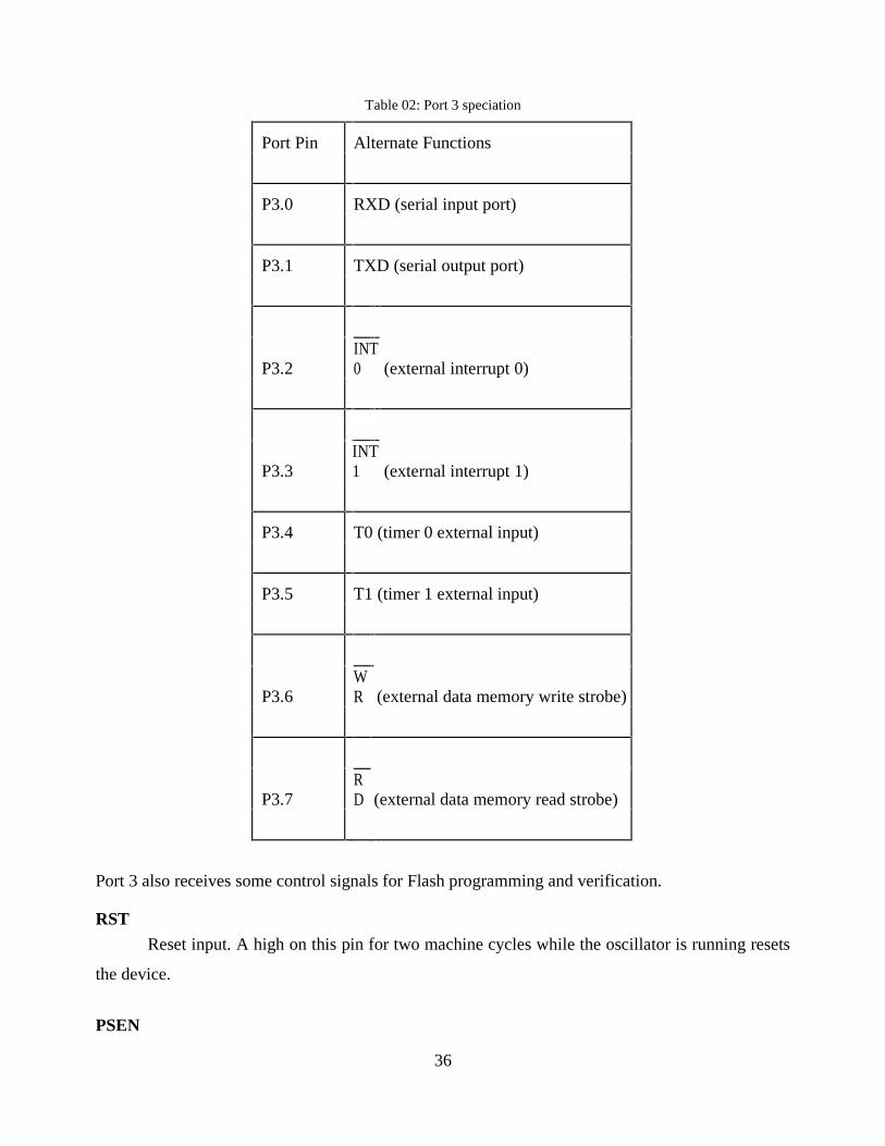
Port 3
Port 3 is an 8-bit bi-directional I/O port with internal pull ups. The Port 3 output buffers can
sink/source four TTL inputs. When 1s are written to Port 3 pins they are pulled high by the internal
pull ups and can be used as inputs. As inputs, Port 3 pins that are externally being pulled low will
source current (IIL) because of the pull ups.
Port 3 also serves the functions of various special features of the AT89C51 as listed below:
36
Table 02: Port 3 speciation
Port Pin Alternate Functions
P3.0 RXD (serial input port)
P3.1 TXD (serial output port)
P3.2 (external interrupt 0)INT0
P3.3 (external interrupt 1)INT1
P3.4 T0 (timer 0 external input)
P3.5 T1 (timer 1 external input)
P3.6 (external data memory write strobe)WR
P3.7 (external data memory read strobe)RD
Port 3 also receives some control signals for Flash programming and verification.
RST
Reset input. A high on this pin for two machine cycles while the oscillator is running resets
the device.
PSEN
37
Program Store Enable is the read strobe to external pro-gram memory.
When the AT89C51 is executing code from external pro-gram memory, PSEN is activated twice
each machine cycle, except that two PSEN activations are skipped during each access to external
data memory.
EA/VPP
External Access Enable. EA must be strapped to GND in order to enable the device to fetch
code from external pro-gram memory locations starting at 0000H up to FFFFH. Note, however,
that if lock bit 1 is programmed, EA will be internally latched on reset.
EA should be strapped to VCC for internal program executions. This pin also receives the 12-volt
programming enable volt-age (VPP) during Flash programming, for parts that require 12-volt VPP.
XTAL1
Input to the inverting oscillator amplifier and input to the internal clock operating circuit.
XTAL2
Output from the inverting oscillator amplifier.
4.4.3 Oscillator Characteristics
XTAL1 and XTAL2 are the input and output, respectively, of an inverting amplifier which
can be configured for use as an on-chip oscillator, as shown in Figure 1. Either a quartz crystal or
ceramic resonator may be used. To drive the device from an external clock source, XTAL2 should
be leftunconnected while XTAL1 is driven as shown in Figure 2. There are no requirements on the
duty cycle of the external clock signal, since the input to the internal clocking circuitry is through a
divide-by-two flip-flop, but minimum and maxi-mum voltage high and low time specifications
must be observed.

38
Figure 20: Oscillator characteristics
4.4.4 Idle Mode
In idle mode, the CPU puts itself to sleep while all the on-chip peripherals remain active.
The mode is invoked by software. The content of the on-chip RAM and all the special functions
registers remain unchanged during this mode. The idle mode can be terminated by any enabled
interrupt or by a hardware reset.
It should be noted that when idle is terminated by a hard ware reset, the device normally resumes
program execution, from where it left off, up to two machine cycles before the internal reset
algorithm takes control. On-chip hardware inhibits access to internal RAM in this event, but access
to the port pins is not inhibited.
To eliminate the possibility of an unexpected write to a port pin when Idle is terminated by
reset, the instruction following the one that invokes Idle should not be one that writes to a port pin
or to external memory.

39
Status of External Pins During Idle and Power-down Modes
Table 03: Status of External Pins during Idle and Power-down Modes
4.4.5 Programming the Flash
The AT89C51 is normally shipped with the on-chip Flash memory array in the erased
state (that is, contents = FFH) and ready to be programmed. The programming interface accepts
either a high-voltage (12-volt) or a low-voltage (VCC) program enable signal. The low-voltage
program-ming mode provides a convenient way to program the AT89C51 inside the user’s system,
while the high-voltage programming mode is compatible with conventional third-party Flash or
EPROM programmers.The AT89C51 is shipped with either the high-voltage or low-voltage
programming mode enabled. The respective top-side marking and device signature codes are listed
in the following table.
Table 04: Signature code
ModeProgramMemory ALE PSEN PORT0 PORT1 PORT2 PORT3
Idle Internal 1 1 Data Data Data Data
Idle External 1 1 Float Data Address Data
Power-down Internal 0 0 Data Data Data Data
Power-down External 0 0 Float Data Data Data

40
The AT89C51 code memory array is programmed byte-by-byte in either programming mode. To
program any non-blank byte in the on-chip Flash Memory, the entire memory must be erased using
the Chip Erase Mode.
4.4.6 Programming Interface
Every code byte in the Flash array can be written and the entire array can be erased by using
the appropriate combination of control signals. The write operation cycle is self-timed and once
initiated, will automatically time itself to completion. All major programming vendors offer
worldwide support for the Atmel microcontroller series. Please contact your local programming
vendor for the appropriate software revision.
4.5 AUTOTRANSFORMER BASICS
Unlike the previous voltage transformer which has two electrically isolated windings called:
the primary and the secondary, an Autotransformer has only one single voltage winding which is
common to both sides. This single winding is “tapped” at various points along its length to provide
a percentage of the primary voltage supply across its secondary load. Then the autotransformer has
the usual magnetic core but only has one winding, which is common to both the primary and
secondary circuits.
Therefore in an autotransformer the primary and secondary windings are linked together
both electrically and magnetically. The main advantage of this type of transformer design is that it
can be made a lot cheaper for the same VA rating, but the biggest disadvantage of an
autotransformer is that it does not have the primary/secondary winding isolation of a conventional
double wound transformer.
The section of winding designated as the primary part of the winding is connected to the AC
power source with the secondary being part of this primary winding. An autotransformer can also
be used to step the supply voltage up or down by reversing the connections. If the primary is the
total winding and is connected to a supply, and the secondary circuit is connected across only a
portion of the winding, then the secondary voltage is “stepped-down” as shown.
41
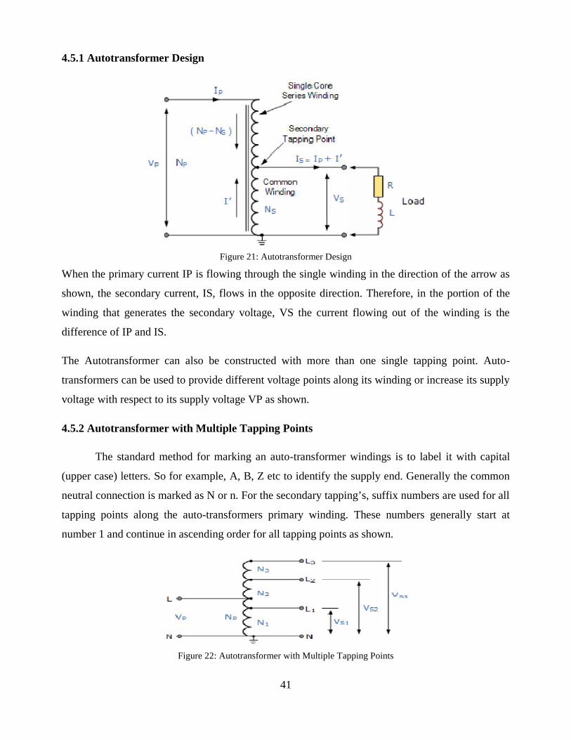
4.5.1 Autotransformer Design
Figure 21: Autotransformer Design
When the primary current IP is flowing through the single winding in the direction of the arrow as
shown, the secondary current, IS, flows in the opposite direction. Therefore, in the portion of the
winding that generates the secondary voltage, VS the current flowing out of the winding is the
difference of IP and IS.
The Autotransformer can also be constructed with more than one single tapping point. Auto-
transformers can be used to provide different voltage points along its winding or increase its supply
voltage with respect to its supply voltage VP as shown.
4.5.2 Autotransformer with Multiple Tapping Points
The standard method for marking an auto-transformer windings is to label it with capital
(upper case) letters. So for example, A, B, Z etc to identify the supply end. Generally the common
neutral connection is marked as N or n. For the secondary tapping’s, suffix numbers are used for all
tapping points along the auto-transformers primary winding. These numbers generally start at
number 1 and continue in ascending order for all tapping points as shown.
Figure 22: Autotransformer with Multiple Tapping Points
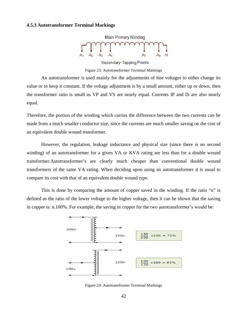
42
4.5.3 Autotransformer Terminal Markings
Figure 23: Autotransformer Terminal Markings
An autotransformer is used mainly for the adjustments of line voltages to either change its
value or to keep it constant. If the voltage adjustment is by a small amount, either up or down, then
the transformer ratio is small as VP and VS are nearly equal. Currents IP and IS are also nearly
equal.
Therefore, the portion of the winding which carries the difference between the two currents can be
made from a much smaller conductor size, since the currents are much smaller saving on the cost of
an equivalent double wound transformer.
However, the regulation, leakage inductance and physical size (since there is no second
winding) of an autotransformer for a given VA or KVA rating are less than for a double wound
transformer.Autotransformer’s are clearly much cheaper than conventional double wound
transformers of the same VA rating. When deciding upon using an autotransformer it is usual to
compare its cost with that of an equivalent double wound type.
This is done by comparing the amount of copper saved in the winding. If the ratio “n” is
defined as the ratio of the lower voltage to the higher voltage, then it can be shown that the saving
in copper is: n.100%. For example, the saving in copper for the two autotransformer’s would be:
Figure 24: Autotransformer Terminal Markings
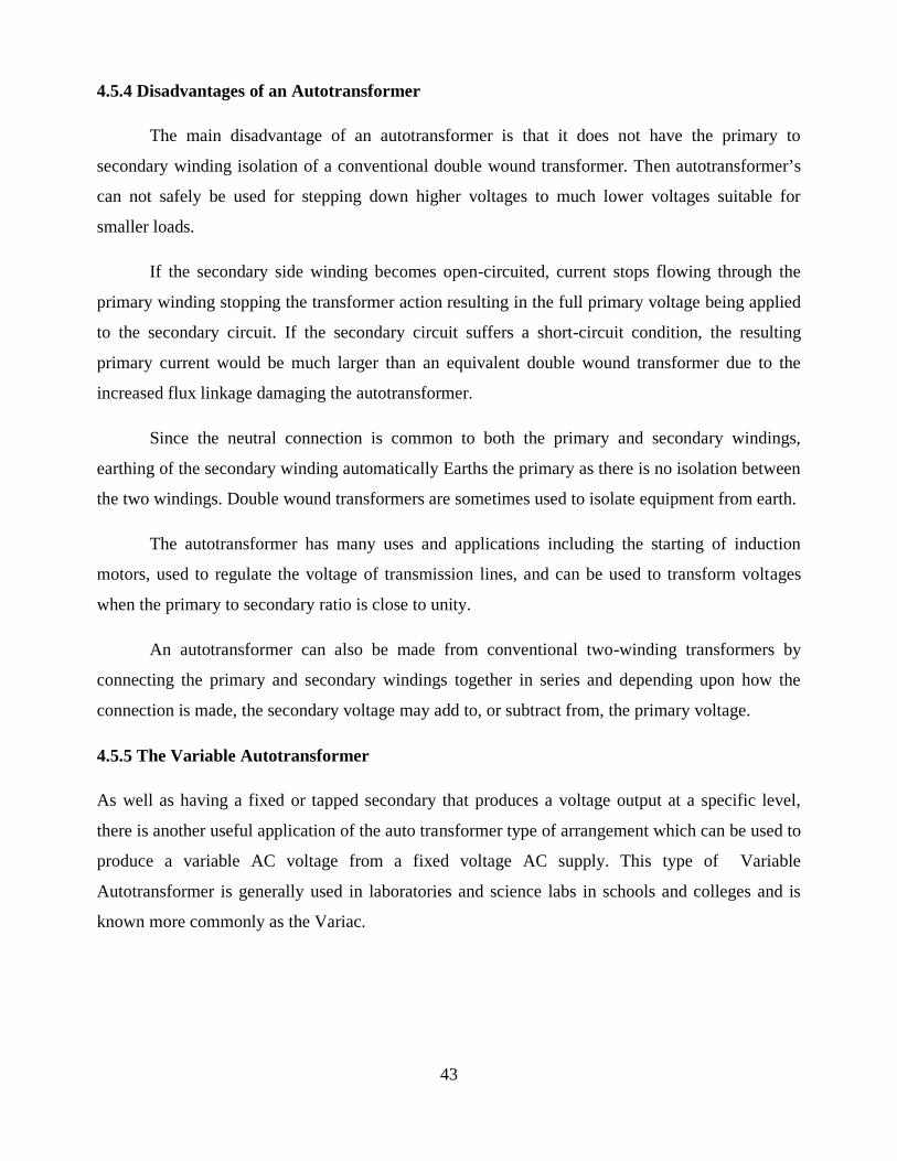
43
4.5.4 Disadvantages of an Autotransformer
The main disadvantage of an autotransformer is that it does not have the primary to
secondary winding isolation of a conventional double wound transformer. Then autotransformer’s
can not safely be used for stepping down higher voltages to much lower voltages suitable for
smaller loads.
If the secondary side winding becomes open-circuited, current stops flowing through the
primary winding stopping the transformer action resulting in the full primary voltage being applied
to the secondary circuit. If the secondary circuit suffers a short-circuit condition, the resulting
primary current would be much larger than an equivalent double wound transformer due to the
increased flux linkage damaging the autotransformer.
Since the neutral connection is common to both the primary and secondary windings,
earthing of the secondary winding automatically Earths the primary as there is no isolation between
the two windings. Double wound transformers are sometimes used to isolate equipment from earth.
The autotransformer has many uses and applications including the starting of induction
motors, used to regulate the voltage of transmission lines, and can be used to transform voltages
when the primary to secondary ratio is close to unity.
An autotransformer can also be made from conventional two-winding transformers by
connecting the primary and secondary windings together in series and depending upon how the
connection is made, the secondary voltage may add to, or subtract from, the primary voltage.
4.5.5 The Variable Autotransformer
As well as having a fixed or tapped secondary that produces a voltage output at a specific level,
there is another useful application of the auto transformer type of arrangement which can be used to
produce a variable AC voltage from a fixed voltage AC supply. This type of Variable
Autotransformer is generally used in laboratories and science labs in schools and colleges and is
known more commonly as the Variac.
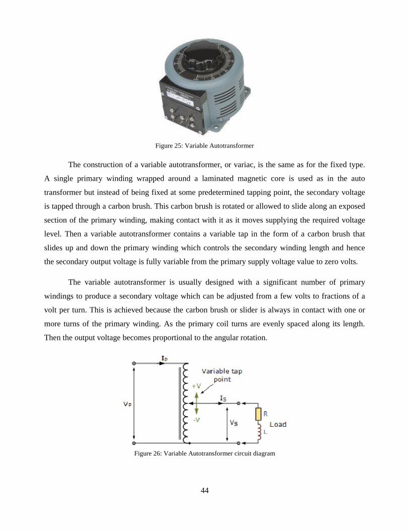
44
Figure 25: Variable Autotransformer
The construction of a variable autotransformer, or variac, is the same as for the fixed type.
A single primary winding wrapped around a laminated magnetic core is used as in the auto
transformer but instead of being fixed at some predetermined tapping point, the secondary voltage
is tapped through a carbon brush. This carbon brush is rotated or allowed to slide along an exposed
section of the primary winding, making contact with it as it moves supplying the required voltage
level. Then a variable autotransformer contains a variable tap in the form of a carbon brush that
slides up and down the primary winding which controls the secondary winding length and hence
the secondary output voltage is fully variable from the primary supply voltage value to zero volts.
The variable autotransformer is usually designed with a significant number of primary
windings to produce a secondary voltage which can be adjusted from a few volts to fractions of a
volt per turn. This is achieved because the carbon brush or slider is always in contact with one or
more turns of the primary winding. As the primary coil turns are evenly spaced along its length.
Then the output voltage becomes proportional to the angular rotation.
Figure 26: Variable Autotransformer circuit diagram
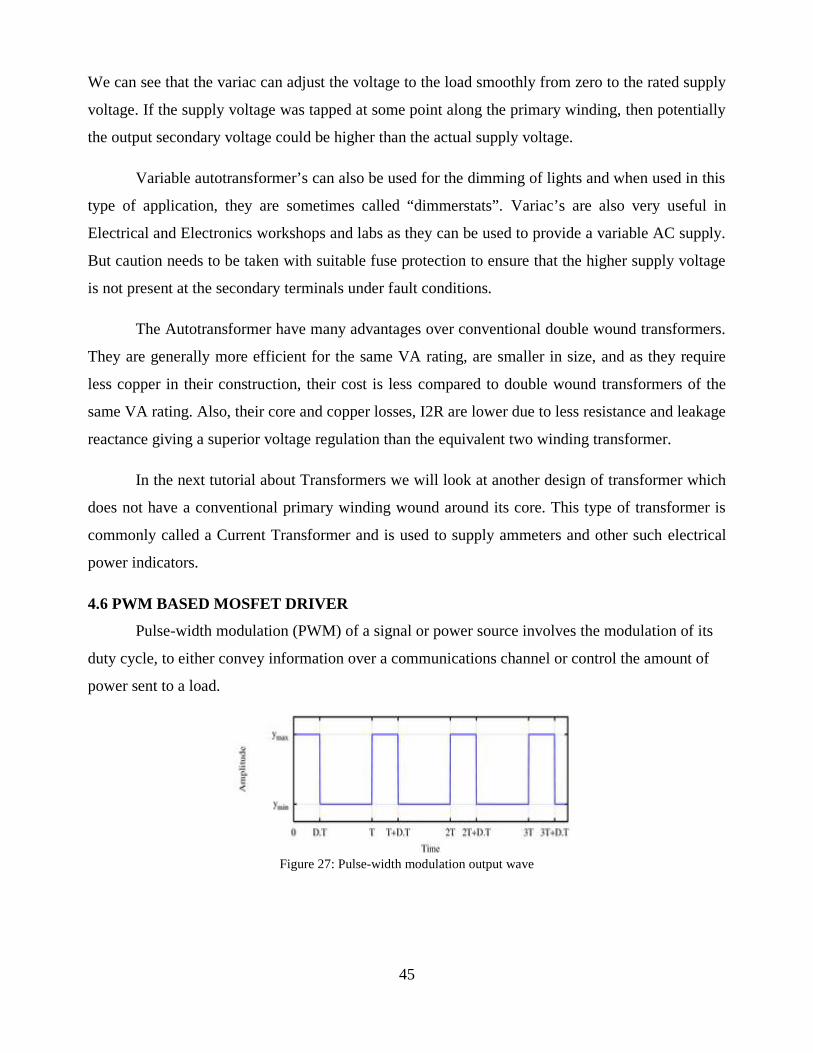
45
We can see that the variac can adjust the voltage to the load smoothly from zero to the rated supply
voltage. If the supply voltage was tapped at some point along the primary winding, then potentially
the output secondary voltage could be higher than the actual supply voltage.
Variable autotransformer’s can also be used for the dimming of lights and when used in this
type of application, they are sometimes called “dimmerstats”. Variac’s are also very useful in
Electrical and Electronics workshops and labs as they can be used to provide a variable AC supply.
But caution needs to be taken with suitable fuse protection to ensure that the higher supply voltage
is not present at the secondary terminals under fault conditions.
The Autotransformer have many advantages over conventional double wound transformers.
They are generally more efficient for the same VA rating, are smaller in size, and as they require
less copper in their construction, their cost is less compared to double wound transformers of the
same VA rating. Also, their core and copper losses, I2R are lower due to less resistance and leakage
reactance giving a superior voltage regulation than the equivalent two winding transformer.
In the next tutorial about Transformers we will look at another design of transformer which
does not have a conventional primary winding wound around its core. This type of transformer is
commonly called a Current Transformer and is used to supply ammeters and other such electrical
power indicators.
4.6 PWM BASED MOSFET DRIVER
Pulse-width modulation (PWM) of a signal or power source involves the modulation of its
duty cycle, to either convey information over a communications channel or control the amount of
power sent to a load.
Figure 27: Pulse-width modulation output wave
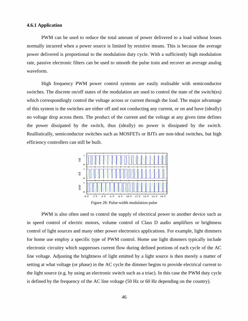
46
4.6.1 Application
PWM can be used to reduce the total amount of power delivered to a load without losses
normally incurred when a power source is limited by resistive means. This is because the average
power delivered is proportional to the modulation duty cycle. With a sufficiently high modulation
rate, passive electronic filters can be used to smooth the pulse train and recover an average analog
waveform.
High frequency PWM power control systems are easily realisable with semiconductor
switches. The discrete on/off states of the modulation are used to control the state of the switch(es)
which correspondingly control the voltage across or current through the load. The major advantage
of this system is the switches are either off and not conducting any current, or on and have (ideally)
no voltage drop across them. The product of the current and the voltage at any given time defines
the power dissipated by the switch, thus (ideally) no power is dissipated by the switch.
Reallistically, semiconductor switches such as MOSFETs or BJTs are non-ideal switches, but high
efficiency controllers can still be built.
Figure 28: Pulse-width modulation pulse
PWM is also often used to control the supply of electrical power to another device such as
in speed control of electric motors, volume control of Class D audio amplifiers or brightness
control of light sources and many other power electronics applications. For example, light dimmers
for home use employ a specific type of PWM control. Home use light dimmers typically include
electronic circuitry which suppresses current flow during defined portions of each cycle of the AC
line voltage. Adjusting the brightness of light emitted by a light source is then merely a matter of
setting at what voltage (or phase) in the AC cycle the dimmer begins to provide electrical current to
the light source (e.g. by using an electronic switch such as a triac). In this case the PWM duty cycle
is defined by the frequency of the AC line voltage (50 Hz or 60 Hz depending on the country).
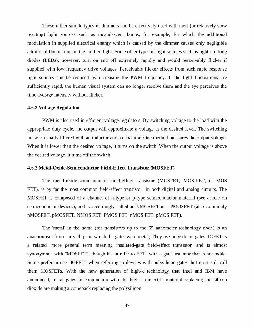
47
These rather simple types of dimmers can be effectively used with inert (or relatively slow
reacting) light sources such as incandescent lamps, for example, for which the additional
modulation in supplied electrical energy which is caused by the dimmer causes only negligible
additional fluctuations in the emitted light. Some other types of light sources such as light-emitting
diodes (LEDs), however, turn on and off extremely rapidly and would perceivably flicker if
supplied with low frequency drive voltages. Perceivable flicker effects from such rapid response
light sources can be reduced by increasing the PWM frequency. If the light fluctuations are
sufficiently rapid, the human visual system can no longer resolve them and the eye perceives the
time average intensity without flicker.
4.6.2 Voltage Regulation
PWM is also used in efficient voltage regulators. By switching voltage to the load with the
appropriate duty cycle, the output will approximate a voltage at the desired level. The switching
noise is usually filtered with an inductor and a capacitor. One method measures the output voltage.
When it is lower than the desired voltage, it turns on the switch. When the output voltage is above
the desired voltage, it turns off the switch.
4.6.3 Metal-Oxide-Semiconductor Field-Effect Transistor (MOSFET)
The metal-oxide-semiconductor field-effect transistor (MOSFET, MOS-FET, or MOS
FET), is by far the most common field-effect transistor in both digital and analog circuits. The
MOSFET is composed of a channel of n-type or p-type semiconductor material (see article on
semiconductor devices), and is accordingly called an NMOSFET or a PMOSFET (also commonly
nMOSFET, pMOSFET, NMOS FET, PMOS FET, nMOS FET, pMOS FET).
The 'metal' in the name (for transistors up to the 65 nanometer technology node) is an
anachronism from early chips in which the gates were metal; They use polysilicon gates. IGFET is
a related, more general term meaning insulated-gate field-effect transistor, and is almost
synonymous with "MOSFET", though it can refer to FETs with a gate insulator that is not oxide.
Some prefer to use "IGFET" when referring to devices with polysilicon gates, but most still call
them MOSFETs. With the new generation of high-k technology that Intel and IBM have
announced, metal gates in conjunction with the high-k dielectric material replacing the silicon
dioxide are making a comeback replacing the polysilicon.
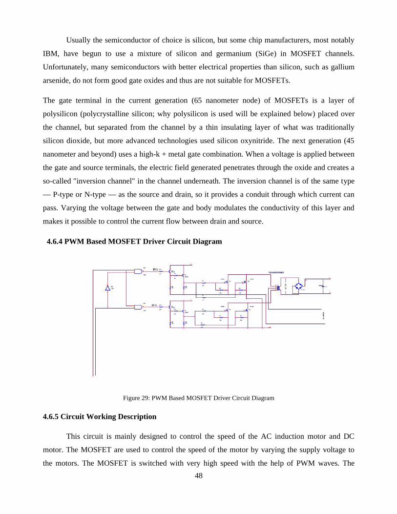
48
Usually the semiconductor of choice is silicon, but some chip manufacturers, most notably
IBM, have begun to use a mixture of silicon and germanium (SiGe) in MOSFET channels.
Unfortunately, many semiconductors with better electrical properties than silicon, such as gallium
arsenide, do not form good gate oxides and thus are not suitable for MOSFETs.
The gate terminal in the current generation (65 nanometer node) of MOSFETs is a layer of
polysilicon (polycrystalline silicon; why polysilicon is used will be explained below) placed over
the channel, but separated from the channel by a thin insulating layer of what was traditionally
silicon dioxide, but more advanced technologies used silicon oxynitride. The next generation (45
nanometer and beyond) uses a high-k + metal gate combination. When a voltage is applied between
the gate and source terminals, the electric field generated penetrates through the oxide and creates a
so-called "inversion channel" in the channel underneath. The inversion channel is of the same type
— P-type or N-type — as the source and drain, so it provides a conduit through which current can
pass. Varying the voltage between the gate and body modulates the conductivity of this layer and
makes it possible to control the current flow between drain and source.
4.6.4 PWM Based MOSFET Driver Circuit Diagram
Figure 29: PWM Based MOSFET Driver Circuit Diagram
4.6.5 Circuit Working Description
This circuit is mainly designed to control the speed of the AC induction motor and DC
motor. The MOSFET are used to control the speed of the motor by varying the supply voltage to
the motors. The MOSFET is switched with very high speed with the help of PWM waves. The
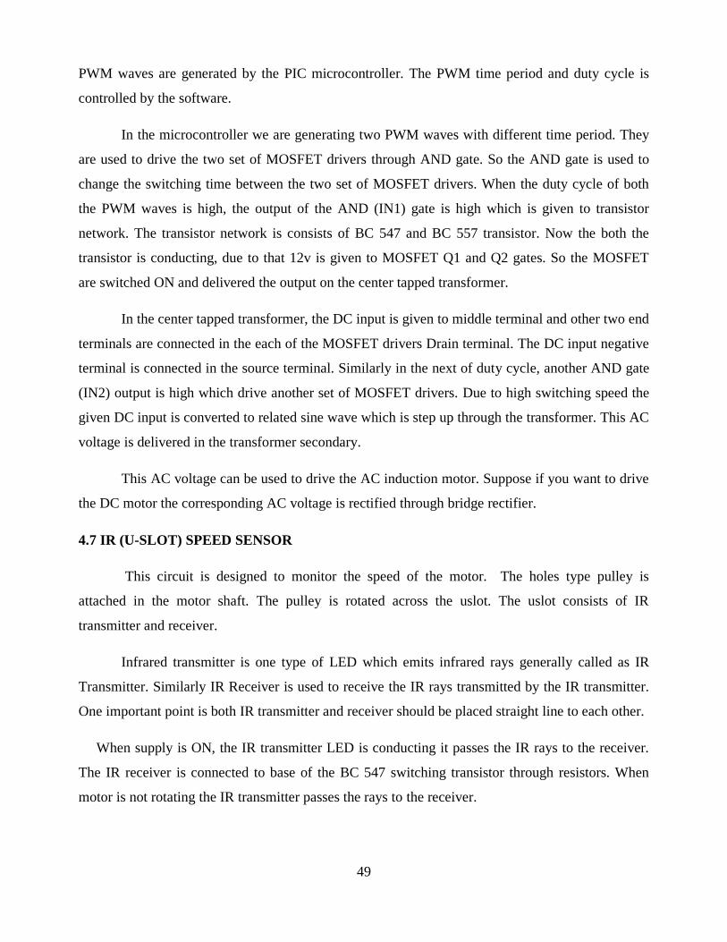
49
PWM waves are generated by the PIC microcontroller. The PWM time period and duty cycle is
controlled by the software.
In the microcontroller we are generating two PWM waves with different time period. They
are used to drive the two set of MOSFET drivers through AND gate. So the AND gate is used to
change the switching time between the two set of MOSFET drivers. When the duty cycle of both
the PWM waves is high, the output of the AND (IN1) gate is high which is given to transistor
network. The transistor network is consists of BC 547 and BC 557 transistor. Now the both the
transistor is conducting, due to that 12v is given to MOSFET Q1 and Q2 gates. So the MOSFET
are switched ON and delivered the output on the center tapped transformer.
In the center tapped transformer, the DC input is given to middle terminal and other two end
terminals are connected in the each of the MOSFET drivers Drain terminal. The DC input negative
terminal is connected in the source terminal. Similarly in the next of duty cycle, another AND gate
(IN2) output is high which drive another set of MOSFET drivers. Due to high switching speed the
given DC input is converted to related sine wave which is step up through the transformer. This AC
voltage is delivered in the transformer secondary.
This AC voltage can be used to drive the AC induction motor. Suppose if you want to drive
the DC motor the corresponding AC voltage is rectified through bridge rectifier.
4.7 IR (U-SLOT) SPEED SENSOR
This circuit is designed to monitor the speed of the motor. The holes type pulley is
attached in the motor shaft. The pulley is rotated across the uslot. The uslot consists of IR
transmitter and receiver.
Infrared transmitter is one type of LED which emits infrared rays generally called as IR
Transmitter. Similarly IR Receiver is used to receive the IR rays transmitted by the IR transmitter.
One important point is both IR transmitter and receiver should be placed straight line to each other.
When supply is ON, the IR transmitter LED is conducting it passes the IR rays to the receiver.
The IR receiver is connected to base of the BC 547 switching transistor through resistors. When
motor is not rotating the IR transmitter passes the rays to the receiver.
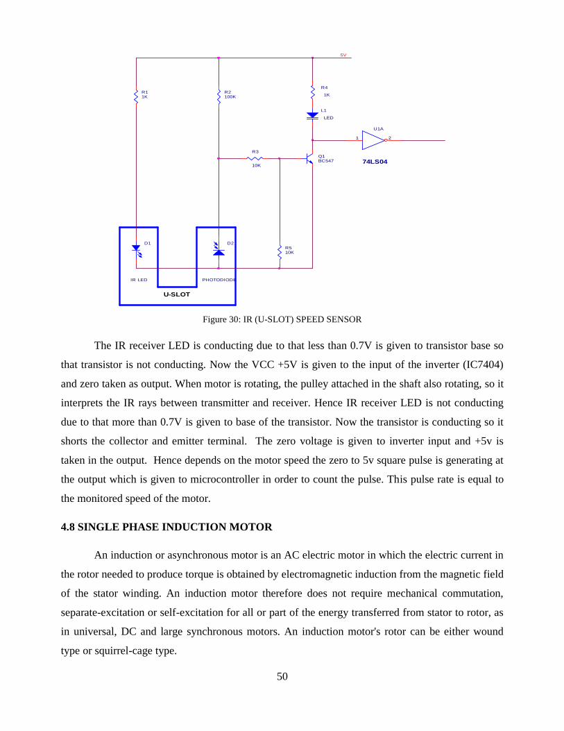
50
Figure 30: IR (U-SLOT) SPEED SENSOR
The IR receiver LED is conducting due to that less than 0.7V is given to transistor base so
that transistor is not conducting. Now the VCC +5V is given to the input of the inverter (IC7404)
and zero taken as output. When motor is rotating, the pulley attached in the shaft also rotating, so it
interprets the IR rays between transmitter and receiver. Hence IR receiver LED is not conducting
due to that more than 0.7V is given to base of the transistor. Now the transistor is conducting so it
shorts the collector and emitter terminal. The zero voltage is given to inverter input and +5v is
taken in the output. Hence depends on the motor speed the zero to 5v square pulse is generating at
the output which is given to microcontroller in order to count the pulse. This pulse rate is equal to
the monitored speed of the motor.
4.8 SINGLE PHASE INDUCTION MOTOR
An induction or asynchronous motor is an AC electric motor in which the electric current in
the rotor needed to produce torque is obtained by electromagnetic induction from the magnetic field
of the stator winding. An induction motor therefore does not require mechanical commutation,
separate-excitation or self-excitation for all or part of the energy transferred from stator to rotor, as
in universal, DC and large synchronous motors. An induction motor's rotor can be either wound
type or squirrel-cage type.
D1
IR LED
Q1BC547
R11K
U1A
74LS04
1 2
5V
R510K
R4
1K
L1
LED
R3
10K
R2100K
U-SLOT
D2
PHOTODIODE
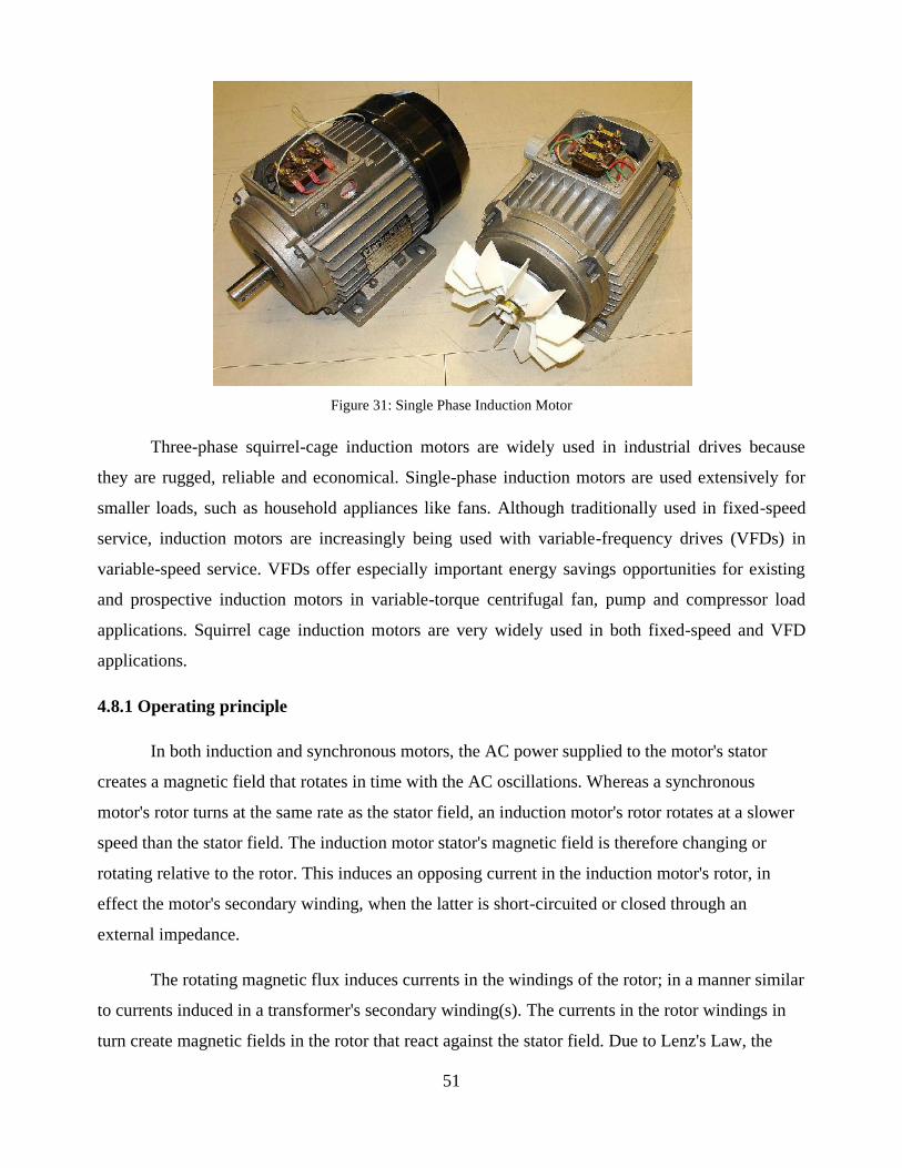
51
Figure 31: Single Phase Induction Motor
Three-phase squirrel-cage induction motors are widely used in industrial drives because
they are rugged, reliable and economical. Single-phase induction motors are used extensively for
smaller loads, such as household appliances like fans. Although traditionally used in fixed-speed
service, induction motors are increasingly being used with variable-frequency drives (VFDs) in
variable-speed service. VFDs offer especially important energy savings opportunities for existing
and prospective induction motors in variable-torque centrifugal fan, pump and compressor load
applications. Squirrel cage induction motors are very widely used in both fixed-speed and VFD
applications.
4.8.1 Operating principle
In both induction and synchronous motors, the AC power supplied to the motor's stator
creates a magnetic field that rotates in time with the AC oscillations. Whereas a synchronous
motor's rotor turns at the same rate as the stator field, an induction motor's rotor rotates at a slower
speed than the stator field. The induction motor stator's magnetic field is therefore changing or
rotating relative to the rotor. This induces an opposing current in the induction motor's rotor, in
effect the motor's secondary winding, when the latter is short-circuited or closed through an
external impedance.
The rotating magnetic flux induces currents in the windings of the rotor; in a manner similar
to currents induced in a transformer's secondary winding(s). The currents in the rotor windings in
turn create magnetic fields in the rotor that react against the stator field. Due to Lenz's Law, the
52
direction of the magnetic field created will be such as to oppose the change in current through the
rotor windings. The cause of induced current in the rotor windings is the rotating stator magnetic
field, so to oppose the change in rotor-winding currents the rotor will start to rotate in the direction
of the rotating stator magnetic field.
The rotor accelerates until the magnitude of induced rotor current and torque balances the
applied load. Since rotation at synchronous speed would result in no induced rotor current, an
induction motor always operates slower than synchronous speed. The difference, or "slip," between
actual and synchronous speed varies from about 0.5 to 5.0% for standard Design B torque curve
induction motors. The induction machine's essential character is that it is created solely by
induction instead of being separately excited as in synchronous or DC machines or being self-
magnetized as in permanent magnet motors. For rotor currents to be induced, the speed of the
physical rotor must be lower than that of the stator's rotating magnetic field (n_s), otherwise the
magnetic field would not be moving relative to the rotor conductors and no currents would be
induced. As the speed of the rotor drops below synchronous speed, the rotation rate of the magnetic
field in the rotor increases, inducing more current in the windings and creating more torque. The
ratio between the rotation rate of the magnetic field induced in the rotor and the rotation rate of the
stator's rotating field is called slip. Under load, the speed drops and the slip increases enough to
create sufficient torque to turn the load. For this reason, induction motors are sometimes referred to
as asynchronous motors. An induction motor can be used as an induction generator, or it can be
unrolled to form a linear induction motor which can directly generate linear motion.
4.8.2 Synchronous speed
An AC motor's synchronous speed, , is the rotation rate of the stator's magnetic field,
which is expressed in revolutions per minute as
(RPM),
where is the motor supply's frequency in hertz and is the number of magnetic poles. That is, for
a six-pole three-phase motor with three pole-pairs set 120° apart, equals 6 and equals 1,000
RPM and 1,200 RPM respectively for 50 Hz and 60 Hz supply systems.
53
4.8.3 Slip
Slip, S, is defined as the difference between synchronous speed and operating speed, at the
same frequency, expressed in rpm or in percent or ratio of synchronous speed.
where n Ns is stator electrical speed, n_Nr is rotor mechanical speed. Slip, which varies from zero
at synchronous speed and 1 when the rotor is at rest, determines the motor's torque. Since the short-
circuited rotor windings have small resistance, a small slip induces a large current in the rotor and
produces large torque. At full rated load, slip varies from more than 5% for small or special
purpose motors to less than 1% for large motors. These speed variations can cause load-sharing
problems when differently sized motors are mechanically connected. Various methods are available
to reduce slip, VFDs often offering the best solution.
4.8.4 Construction
The stator of an induction motor consists of poles carrying supply current to induce a
magnetic field that penetrates the rotor. To optimize the distribution of the magnetic field, the
windings are distributed in slots around the stator, with the magnetic field having the same number
of north and south poles. Induction motors are most commonly run on single-phase or three-phase
power, but two-phase motors exist; in theory, induction motors can have any number of phases.
Many single-phase motors having two windings can be viewed as two-phase motors, since a
capacitor is used to generate a second power phase 90° from the single-phase supply and feeds it to
the second motor winding. Single-phase motors require some mechanism to produce a rotating field
on startup. Cage induction motor rotor's conductor bars are typically skewed to reduce noise.
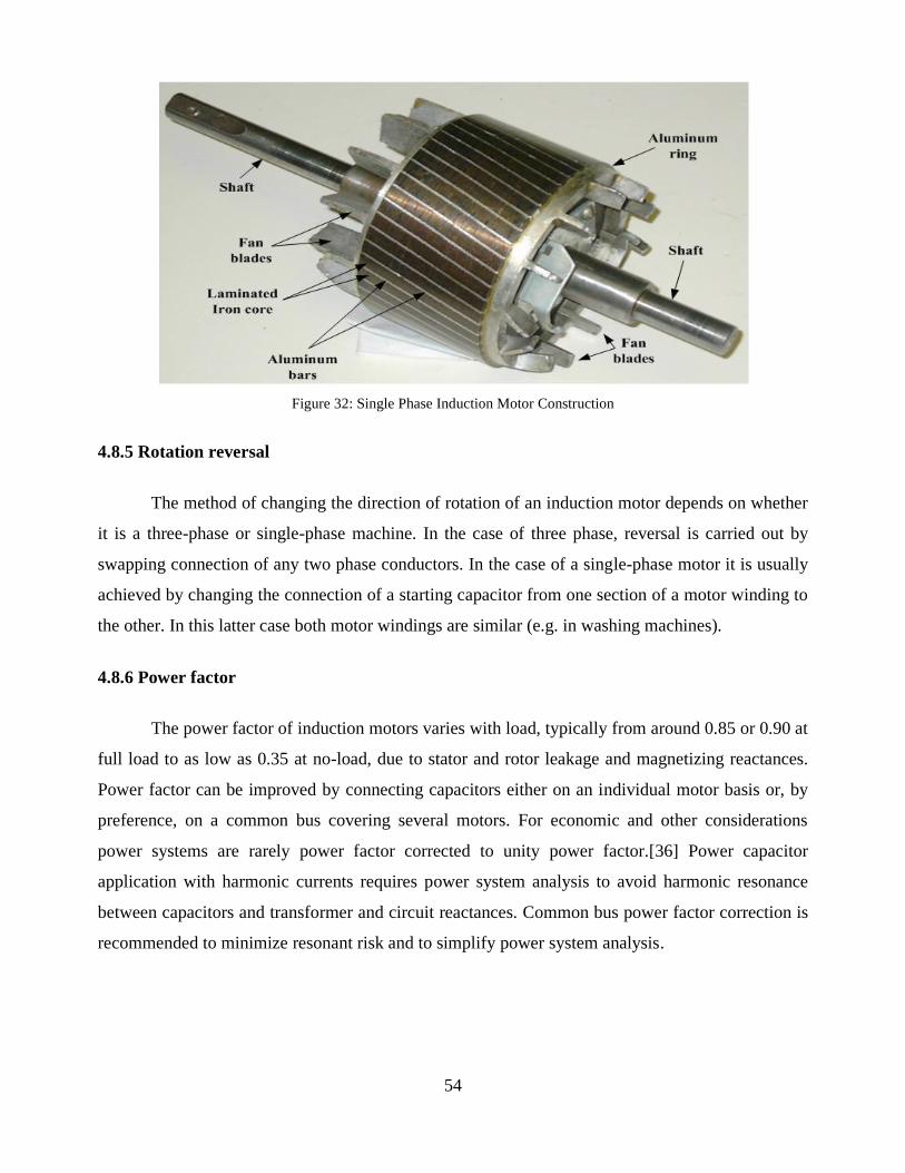
54
Figure 32: Single Phase Induction Motor Construction
4.8.5 Rotation reversal
The method of changing the direction of rotation of an induction motor depends on whether
it is a three-phase or single-phase machine. In the case of three phase, reversal is carried out by
swapping connection of any two phase conductors. In the case of a single-phase motor it is usually
achieved by changing the connection of a starting capacitor from one section of a motor winding to
the other. In this latter case both motor windings are similar (e.g. in washing machines).
4.8.6 Power factor
The power factor of induction motors varies with load, typically from around 0.85 or 0.90 at
full load to as low as 0.35 at no-load, due to stator and rotor leakage and magnetizing reactances.
Power factor can be improved by connecting capacitors either on an individual motor basis or, by
preference, on a common bus covering several motors. For economic and other considerations
power systems are rarely power factor corrected to unity power factor.[36] Power capacitor
application with harmonic currents requires power system analysis to avoid harmonic resonance
between capacitors and transformer and circuit reactances. Common bus power factor correction is
recommended to minimize resonant risk and to simplify power system analysis.
55
4.8.7 Efficiency
Full load motor efficiency varies from about 85 % to 97 %, related motor losses being broken down
roughly as follows:
Friction and windage, 5 % – 15 %
Iron or core losses, 15 % – 25 %
Stator losses, 25 % – 40 %
Rotor losses, 15 % – 25 %
Stray load losses, 10 % – 20 %
Various regulatory authorities in many countries have introduced and implemented legislation to
encourage the manufacture and use of higher efficiency electric motors. There is existing and
forthcoming legislation regarding the future mandatory use of premium-efficiency induction-type
motors in defined equipment.
4.9 CIRCUIT DIAGRAM
A full wave bridge rectifier converts single phase or three phase 50 Hz power from standardutility supply to either fixed or adjustable Dc voltage. Diode Bridge Rectifier One diagonal pair ofrectifier will allow power to pass through only when the voltage is positive. A second diagonal pairof rectifier will allow power to pass through only when the voltage is negative. So two diagnal pairof rectifiers are required for each phase of power.
Electric swithes-power transistor or thyristor switch the rectified DC on and off, and aproduce a current or voltage waveform at the desired new frequency. The final section of the VFDis referred to as an “inverter.” The inverter contains transistors that deliver power to the motor. The(MOSFET) is a common choice in modern VFDs.
The MOSFET can switch on and off several thousand times per second and precisely control thepower delivered to the motor. The IGBT uses a method named “pulse width modulation” (PWM) tosimulate a current sine wave at the desired frequency to the motor.
Motor speed (rpm) is dependent upon frequency. Varying the frequency output of the VFD controlsmotor speed: Speed (rpm) = frequency (hertz) x 120 / no. of poles.
An electronic circuit receives a feedback information from the driven motor and adjusts the outputvoltage or frequency to the selected values. Usually the output voltage is regulated to produce aconstant ratio of voltage to frequency (V/Hz). Controllers may incorporate many complex controlfunctions.
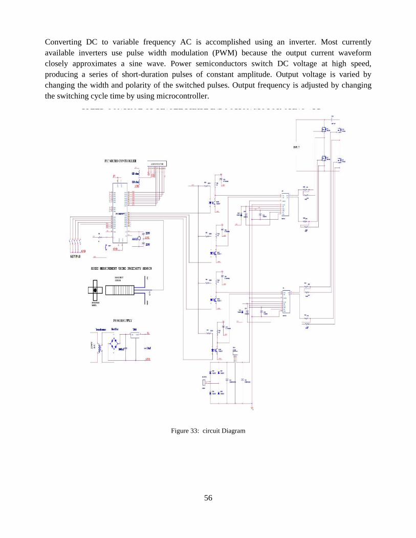
56
Converting DC to variable frequency AC is accomplished using an inverter. Most currentlyavailable inverters use pulse width modulation (PWM) because the output current waveformclosely approximates a sine wave. Power semiconductors switch DC voltage at high speed,producing a series of short-duration pulses of constant amplitude. Output voltage is varied bychanging the width and polarity of the switched pulses. Output frequency is adjusted by changingthe switching cycle time by using microcontroller.
Figure 33: circuit Diagram
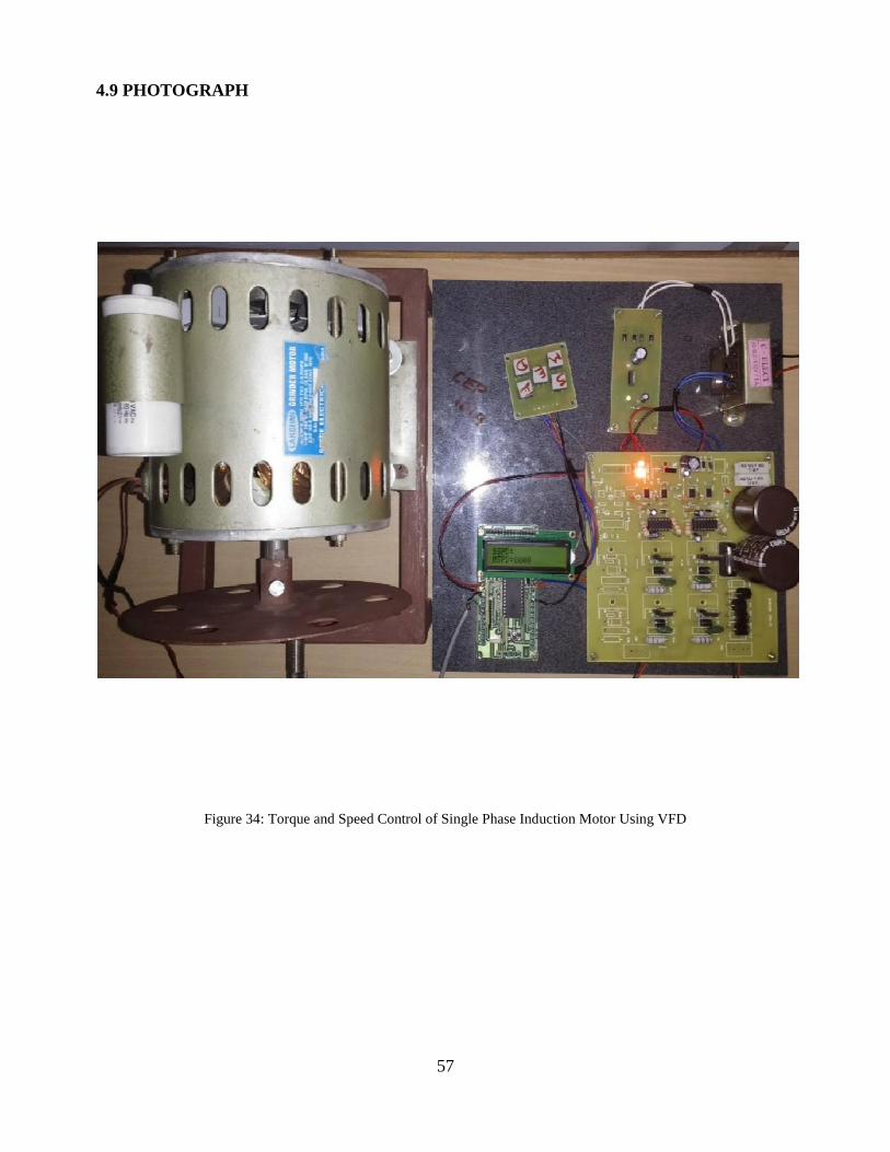
57
4.9 PHOTOGRAPH
Figure 34: Torque and Speed Control of Single Phase Induction Motor Using VFD
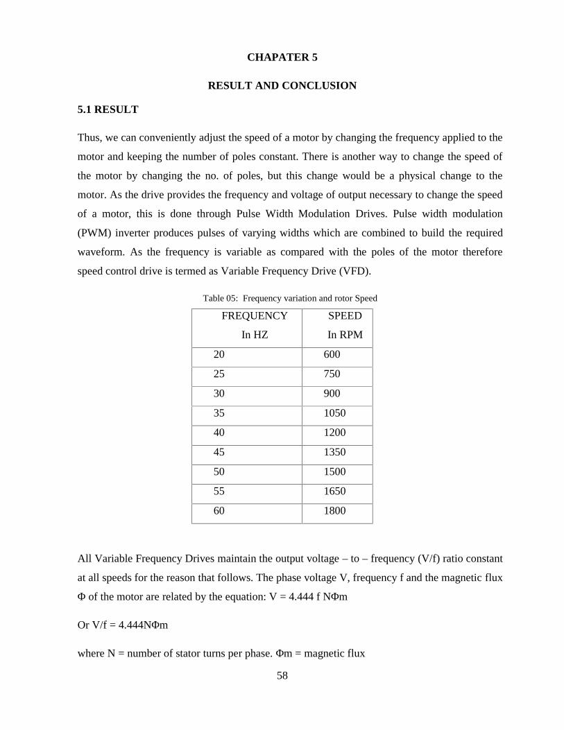
58
CHAPATER 5
RESULT AND CONCLUSION
5.1 RESULT
Thus, we can conveniently adjust the speed of a motor by changing the frequency applied to the
motor and keeping the number of poles constant. There is another way to change the speed of
the motor by changing the no. of poles, but this change would be a physical change to the
motor. As the drive provides the frequency and voltage of output necessary to change the speed
of a motor, this is done through Pulse Width Modulation Drives. Pulse width modulation
(PWM) inverter produces pulses of varying widths which are combined to build the required
waveform. As the frequency is variable as compared with the poles of the motor therefore
speed control drive is termed as Variable Frequency Drive (VFD).
Table 05: Frequency variation and rotor Speed
FREQUENCY
In HZ
SPEED
In RPM
20 600
25 750
30 900
35 1050
40 1200
45 1350
50 1500
55 1650
60 1800
All Variable Frequency Drives maintain the output voltage – to – frequency (V/f) ratio constant
at all speeds for the reason that follows. The phase voltage V, frequency f and the magnetic flux
Φ of the motor are related by the equation: V = 4.444 f NΦm
Or V/f = 4.444NΦm
where N = number of stator turns per phase. Φm = magnetic flux
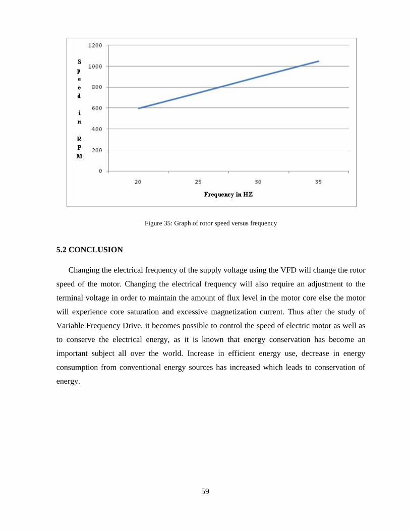
59
Figure 35: Graph of rotor speed versus frequency
5.2 CONCLUSION
Changing the electrical frequency of the supply voltage using the VFD will change the rotor
speed of the motor. Changing the electrical frequency will also require an adjustment to the
terminal voltage in order to maintain the amount of flux level in the motor core else the motor
will experience core saturation and excessive magnetization current. Thus after the study of
Variable Frequency Drive, it becomes possible to control the speed of electric motor as well as
to conserve the electrical energy, as it is known that energy conservation has become an
important subject all over the world. Increase in efficient energy use, decrease in energy
consumption from conventional energy sources has increased which leads to conservation of
energy.
60
REFERENCES
[1] Specification of Variable Frequency Drive Systems to Meet the New IEEE 519 Standard.
[2] Gopal K. Dubey, Fundamentals of Electrical Drives, Second Edition, Narosa Publishing House,
2007
[3] Jan-Erik Räsänen and Eric W Schreiber, “Using Variable Frequency Drives (VFD) to save
energy and reduce emissions in newbuilds and existing ships” White Paper – ABB Marine and
Cranes, 2012.
[4] Yasar Birbir, “Design and implementation of PLC-based monitoring control system for three-
phase induction motors fed by PWM supply” International Journal of Systems Applications,
Engineering & Development, Issue 3, Volume 2, pages 128-135, September 2008.
[5] Brian Shuman, “Building A Reliable VFD System” Belden Technical Support 1.800.
BELDEN.1 www.belden.com 2009.
[6] Thomas F Kaiser, Richard H Osman, Ralph O Dickau, “Analysis Guide for Variable Frequency
Drive Operated Centrifugal Pumps” Proceedings of The Twenty Fourth International Pump Users
Symposium, pages 81-106, 2008
[8] L. Xu, "Dynamical Model of and Integral-Cycle Controlled Single-Phase Induction Machine,"
IEEE Transactions on Energy Conversion, Vol. 7, No. 4, Dec. 1002, pp. 761-767.
[9] E.R. Collins and R.E. Ashley, "Operating Characteristics of Single-Phase Capacitor Motors
Driven from Variable Frequency Supplies," Proceedings of IEEE-IAS Conference, 1991, pp. 52-
57.
[10] M.F. Rahman and L. Zhong, "A Single/Two-Phase, Regenerative, Variable Speed, Induction
Motor Drive with Sinusoidal Input Current," Proceedings of IEEE Conference, 1995, pp. 584-590.\
[11] M.F. Rahman and L. Zhong, "A Variable Speed Single-Phase Induction Motor Drive using a
Smart Power Module,Proceedings of the 1996 IEE Power Electronics and Variable Speed Drives
Conference, 23-5 Sept. 1996, Conference Publication No. 429, pp. 407-412.

61
[12] Randall L. Foulke, Principles and Applications of Variable Frequency Drives NC AWNA.
WEA Spring Conference New Bern, North Carolina April, 2009.
[13] Ned Mohan, Tore M. Undaland and William P. Robbins Power electronics (converters,
application and design) third edition, John Wiley and sons INC.
[14] P.C. Sen Power electronics McGraw- Hill Education Private Limited, Second edition 2009.
[15] Theraja A. Text book of electrical technology 1997, S. Chand and Company LTD.
[16] R.K. Rajput Electric Machines (DC machines, AC machines and polyphase circuits) in S.I.
units Laxmi publications LTD, third edition, 2002.
[17] Stephen J. Chapman. Electric machinery fundamentals, third edition, McGraw- Hill
Companies INC.
[18] Jimmie J. Cathey Electric machines, analysis and design applying matlab. McGraw- Hill
Companies INC, 2001 edition.

62
ANNEXURE I
PROGRAM
#include <MEGA 16.H>
// ALPHANUMERIC LCD MODULE FUNCTIONS
VOID MAIN (VOID){
// DECLARE YOUR LOCAL VARAIABLES HERES
// INPUT/OUTPUT PORTS INITIALIZATION
// PORT A INITIAZATION
// FUNC7=IN FUNC6=IN FUNC5=IN FUNC4=IN FUNC3=IN FUN2=IN FUN1=IN
FUNC0=IN
// STATE7=T STATE6= T STATE5=T STATE4= T STATE3= T STATE2= T STATE1=T
STATE0=T
PORTA=0X00;
DDRA=0X00;
//PORT B INITIALIZATION
// FUNC7=OUT FUNC6=IN FUNC5=OUT FUNC4=OUT FUNC3=IN FUNC2=IN FUNC1=IN
FUNC0=IN
// STATE7=0 STATE6= T STATE5 =0 STATE4= 0 STATE3= T STATE2= T STATE1=T
STATE0=T
PORTB=0X00;
DDRB=0XB0;

63
//PORT C INITIALIZATION
// FUNC7=IN FUNC6=IN FUNC5=IN FUNC4=IN FUNC3=IN FUNC2=IN FUNC1=IN
FUNC0=IN
// STATE7=T STATE6= T STATE5 =T STATE4= T STATE3= T STATE2= T STATE1=T
STATE0=T
PORTC=0X00;
DDRC=0X00;
//PORT D INITIALIZATION
// FUNC7=OUT FUNC6=OUT FUNC5=OUT FUNC4=OUT FUNC3=OUT FUNC2=OUTFUNC1=OUT
FUNC0=OUT
// STATE7=0 STATE6= 0 STATE5 =0 STATE4= 0 STATE3= 0 STATE2= 0 STATE1=0
STATE0=T
PORTD=0X00;
DDRD=0XFF;
// TIMER/COUNTER 0 INITIALIZATION
// CLOCK SOURCE: SYSTEM CLOCK
// CLOCK VALUE: TIMER 0 STOPED
// MODE: NORMAL TOP=0XFF
//OCD OUTPUT: DISCONNECTED
TCCR0=0X00;
TCNT0=0X00;
0CR0=0X00;

64
// TIMER/COUNTER 1 INITIALIZATION
// CLOCK SOURCE: SYSTEM CLOCK
// CLOCK VALUE: TIMER 1 STOPPED
// MODE: NORMAL TOP=0XFFFF
// OC1A OUTPUT: DISCON.
// OC1B OUTPUT: DISCON.
// NOISE CANCELER: OFF
// INPUT CAPTURE ON FALLING EDGE
// TIMER1 OVERFLOW INTERRUPT: OFF
// INPUT CAPTURE INTERRUPT: OFF
// COMPARE A MATCH INTERRUPT: OFF
// COMPARE B MATCH INTERRUPT: OFF
TCCR1A=0X00;
TCCR1B=0X00;
TCNT1H=0X00;
TCNT1L=0X00;
OCR1AH=0X00;
OCR1AL=0X00;
OCR1BH=0X00;
OCR1BL=0X00;
// TIMER/CONTER 2 INITIALIZATION
// CLOCK SOURCE: SYSTEM CLOCK
// CLOCK VALUE: TIMER2 STOPPED
// MODE: NORMAL TOP=0XFF

65
// OC2 OUTPUT: DISCONNED
ASSR=0X00;
TCCR2=0X00;
TCNT2=0X00;
OCR2=0X00;
// EXTERNAL INTERRUPT (S) INTIALIZATION
// INT0: OFF
// INT1: OFF
// INT2: OFF
MCUCR=0X00;
MCUCSR=0X00;
// TIMER(S)/CONTER(S) INTERRUPT(S) INTIALIZATION
TIMSK=0X00;
// USART INTIALIZATION
// USSART DISABLE
UCSRD=0X00;
// ANALOG COMPARATOR INTIALIZATION
// ANALOG COMPARATOR: ON
// THE ANALOG COMPARATOR’S POSITIVE INPUT IS
// CONNECTED TO THE BANDGAP VOLTAGE REFERENCE
// THE ANALOG COMPARATOR’S NEGATIVE INPUT IS

66
// CONNECTED TO THE ADC MULTIPLEXER
// INTERRUPT ON FALLING OUTPUT EDGE
// ANALOG COMPARATOR INPUT CAPTURE BY TIMER/CONTER 1: ON
ACSR=0X4E;
AFIOR=0X0E;
// ADC INTIALIZATION
// ADC DISABLED
ADCSRA=0X00;
// SPI INTIALIZATION
// SPI DISABLED
SPCR=0X00;
// TWI INTIALIZATION
// TWI DISABLED
TWCR=0X00;
// GLOBAL ENABLE INTERRUPTS
#ASM (“SEL”)
DOUBLE POW, VTG, CT;
WHILE (1)
{
CHK ();
IF (DET)

67
MOTOR=OFF
}
}
Related Documents