Ali R. Yildiz 1 Department of Automotive Engineering, Uludag University, 16059 Bursa, Turkey e-mail: [email protected] Kazuhiro Saitou Department of Mechanical Engineering, University of Michigan, Ann Arbor, MI 48109 e-mail: [email protected] Topology Synthesis of Multicomponent Structural Assemblies in Continuum Domains This paper presents a new method for synthesizing structural assemblies directly from the design specifications, without going through the two-step process. Given an extended design domain with boundary and loading conditions, the method simultaneously opti- mizes the topology and geometry of an entire structure and the location and configuration of joints, considering structural performance, manufacturability, and assembleability. As a relaxation of our previous work utilizing a beam-based ground structure, this paper presents a new formulation in a continuum design domain, which enhances the ability to represent complex structural geometry observed in real-world products. A multiobjective genetic algorithm is used to obtain Pareto optimal solutions that exhibit trade-offs among stiffness, weight, manufacturability, and assembleability. Case studies with a cantilever and a simplified automotive floor frame under multiple loadings are examined to show the effectiveness of the proposed method. Representative designs are selected from the Pareto front and trade-offs among the multiple criteria are discussed. DOI: 10.1115/1.4003038 1 Introduction Most structural products such as automotive bodies have com- plex geometry to meet customer’s demand of high functionality, aesthetic appeal with enhanced structural stability, and reduced weight. Since manufacturing those products in one piece is either impossible or uneconomical, most structural products are assem- blies of components with simpler geometries. The conventional way to design structural assemblies is to design the overall geom- etry first and then decompose the geometry to determine the part boundary and joint locations. This two-step process, however, can lead to suboptimal design since the product geometry, even if optimized as one piece, would not be optimal after decomposition. This paper presents a method for synthesizing structural assem- blies directly from the design specifications without going through the two-step process. Given an extended design domain with boundary and loading conditions, the method simultaneously op- timizes the topology and geometry of an entire structure and the location and configuration of joints, considering structural perfor- mance, manufacturability, and assembleability. Previously, we presented a formulation where the extended design domain is given as a ground structure consisting of nonoverlapping beams 1. This paper presents a new, relaxed formulation in a continuum design domain, which enhances the ability to represent complex structural geometry observed in real-world products. The continuum design domain is discretized such that every other adjacent finite element is a thin strip. The topology and geometry of a structure are represented by the existence or ab- sence of a structural material at each regular element sandwich- ing a thin strip element. The location and configuration of joints are represented by the existence or absence of a weld material a material equivalent of weld joints at each thin element. The prob- lem is posed as a multiobjective optimization problem with re- spect to four objectives: stiffness, weight, manufacturability, and assembleability. Assuming the sheet metal structures joined by spot welds, the manufacturability of a component is calculated based on the overall component size and geometric complexity, and the assembleability of an overall structure is calculated based on the sum of the lengths of all joints. A multiobjective genetic algorithm coupled with finite element FE analysis is used to obtain Pareto optimal solutions. Case studies with a cantilever and a simplified automotive floor frame are presented. In each case study, several representative designs among the Pareto optimal solutions are examined for the trade-offs among the four objectives. Finally, the future prospects toward the auto- mated top-down synthesis of a structural assembly with realistic geometry are discussed. 2 Related Work 2.1 Single-Component Structural Topology Optimization. Structural topology optimization aims at optimizing both topology the way substructures are connected and geometry size and shape of substructures within a fixed design domain. Structural topology optimization can be classified to 1 the discrete element and 2 continuum approaches. In the discrete element approach pioneered by Dorn et al. 2, optimal structures can be found as a subset of a ground structure, a predefined exhaustive set of dis- crete elements e.g., trusses and beams in a given design domain Fig. 1a. In the continuum approach pioneered by Bendsøe and Kikuchi 3, optimal structures can be found as a distribution of materials and are void at each location in the continuum within a given design domain Fig. 1b. Since structures are represented as a collection of primitive structural members, the discrete ele- ment approach cannot represent complex structural geometry ob- served in real-world products. The continuum approach, on the other hand, does not have this limitation, with an expense of ad- ditional computational costs. The right figures in Figs. 1a and 1b illustrate this difference A comprehensive review of the work on the discrete element approach can be found in Refs. 5–7. A similar approach utilizing shape grammar is presented in Refs. 8,9. Gil and Andreu 10 conducted simultaneous shape and size optimization, and Peder- sen and Nielsen 11 solved problems with eigenfrequencies, dis- 1 Corresponding author. Contributed by the Design Theory and Methodology Committee of ASME for publication in the JOURNAL OF MECHANICAL DESIGN. Manuscript received August 19, 2009; final manuscript received November 5, 2010; published online January 6, 2011. Assoc. Editor: Jonathan Cagan. Journal of Mechanical Design JANUARY 2011, Vol. 133 / 011008-1 Copyright © 2011 by ASME Downloaded From: http://mechanicaldesign.asmedigitalcollection.asme.org/ on 10/17/2014 Terms of Use: http://asme.org/terms

Welcome message from author
This document is posted to help you gain knowledge. Please leave a comment to let me know what you think about it! Share it to your friends and learn new things together.
Transcript

1
pawibweblo
btbtlmpg�ds
ogsiamls
p22
J
Downloaded Fr
Ali R. Yildiz1
Department of Automotive Engineering,Uludag University,
16059 Bursa, Turkeye-mail: [email protected]
Kazuhiro SaitouDepartment of Mechanical Engineering,
University of Michigan,Ann Arbor, MI 48109
e-mail: [email protected]
Topology Synthesis ofMulticomponent StructuralAssemblies in ContinuumDomainsThis paper presents a new method for synthesizing structural assemblies directly from thedesign specifications, without going through the two-step process. Given an extendeddesign domain with boundary and loading conditions, the method simultaneously opti-mizes the topology and geometry of an entire structure and the location and configurationof joints, considering structural performance, manufacturability, and assembleability. Asa relaxation of our previous work utilizing a beam-based ground structure, this paperpresents a new formulation in a continuum design domain, which enhances the ability torepresent complex structural geometry observed in real-world products. A multiobjectivegenetic algorithm is used to obtain Pareto optimal solutions that exhibit trade-offs amongstiffness, weight, manufacturability, and assembleability. Case studies with a cantileverand a simplified automotive floor frame under multiple loadings are examined to showthe effectiveness of the proposed method. Representative designs are selected from thePareto front and trade-offs among the multiple criteria are discussed.�DOI: 10.1115/1.4003038�
IntroductionMost structural products such as automotive bodies have com-
lex geometry to meet customer’s demand of high functionality,esthetic appeal with enhanced structural stability, and reducedeight. Since manufacturing those products in one piece is either
mpossible or uneconomical, most structural products are assem-lies of components with simpler geometries. The conventionalay to design structural assemblies is to design the overall geom-
try first and then decompose the geometry to determine the partoundary and joint locations. This two-step process, however, canead to suboptimal design since the product geometry, even ifptimized as one piece, would not be optimal after decomposition.
This paper presents a method for synthesizing structural assem-lies directly from the design specifications without going throughhe two-step process. Given an extended design domain withoundary and loading conditions, the method simultaneously op-imizes the topology and geometry of an entire structure and theocation and configuration of joints, considering structural perfor-
ance, manufacturability, and assembleability. Previously, weresented a formulation where the extended design domain isiven as a ground structure consisting of nonoverlapping beams1�. This paper presents a new, relaxed formulation in a continuumesign domain, which enhances the ability to represent complextructural geometry observed in real-world products.
The continuum design domain is discretized such that everyther adjacent finite element is a thin strip. The topology andeometry of a structure are represented by the existence or ab-ence of a structural material at each �regular� element sandwich-ng a thin strip element. The location and configuration of jointsre represented by the existence or absence of a weld material �aaterial equivalent of weld joints� at each thin element. The prob-
em is posed as a multiobjective optimization problem with re-pect to four objectives: stiffness, weight, manufacturability, and
1Corresponding author.Contributed by the Design Theory and Methodology Committee of ASME for
ublication in the JOURNAL OF MECHANICAL DESIGN. Manuscript received August 19,009; final manuscript received November 5, 2010; published online January 6,
011. Assoc. Editor: Jonathan Cagan.ournal of Mechanical Design Copyright © 20
om: http://mechanicaldesign.asmedigitalcollection.asme.org/ on 10/17/201
assembleability. Assuming the sheet metal structures joined byspot welds, the manufacturability of a component is calculatedbased on the overall component size and geometric complexity,and the assembleability of an overall structure is calculated basedon the sum of the lengths of all joints. A multiobjective geneticalgorithm coupled with finite element �FE� analysis is used toobtain Pareto optimal solutions. Case studies with a cantilever anda simplified automotive floor frame are presented.
In each case study, several representative designs among thePareto optimal solutions are examined for the trade-offs amongthe four objectives. Finally, the future prospects toward the auto-mated top-down synthesis of a structural assembly with realisticgeometry are discussed.
2 Related Work
2.1 Single-Component Structural Topology Optimization.Structural topology optimization aims at optimizing both topology�the way substructures are connected� and geometry �size andshape of substructures� within a fixed design domain. Structuraltopology optimization can be classified to �1� the discrete elementand �2� continuum approaches. In the discrete element approachpioneered by Dorn et al. �2�, optimal structures can be found as asubset of a ground structure, a predefined exhaustive set of dis-crete elements �e.g., trusses and beams� in a given design domain�Fig. 1�a��. In the continuum approach pioneered by Bendsøe andKikuchi �3�, optimal structures can be found as a distribution ofmaterials and are void at each location in the continuum within agiven design domain �Fig. 1�b��. Since structures are representedas a collection of primitive structural members, the discrete ele-ment approach cannot represent complex structural geometry ob-served in real-world products. The continuum approach, on theother hand, does not have this limitation, with an expense of ad-ditional computational costs. The right figures in Figs. 1�a� and1�b� illustrate this difference
A comprehensive review of the work on the discrete elementapproach can be found in Refs. �5–7�. A similar approach utilizingshape grammar is presented in Refs. �8,9�. Gil and Andreu �10�conducted simultaneous shape and size optimization, and Peder-
sen and Nielsen �11� solved problems with eigenfrequencies, dis-JANUARY 2011, Vol. 133 / 011008-111 by ASME
4 Terms of Use: http://asme.org/terms
phpcps
Smmotg
ttttndvrm
aaesla
Fpa
Fob†
0
Downloaded Fr
lacements, and buckling constraints. The continuum approachas been applied to various design problems such as stiffnessroblems �12–17�, eigenfrequency problems �18,19�, automotiverashworthiness problems �20–25�, and reliability optimizationroblems �26,27�. These works, however, assume that the optimaltructures can always be manufactured in one piece.
2.2 Multicomponent Structural Topology Optimization.ince complex product geometry is often realized by assemblingultiple components with simpler geometries, the optimization ofulticomponent structural products based on product-level design
bjectives is of a significant engineering interest. Earlier attemptso this problem are the optimization of component topology andeometry within the predefined component boundaries �28–31�.
As illustrated in Fig. 2�a�, each component is optimized withinhe pre-predefined design domain, and joints are optimized withinhe overlaps among these domains. This work, therefore, assumeshe existence of components and joints as the given, rather thanhe outcome of optimization. In particular, an optimized compo-ent can have complex topology and geometry within each designomain. This assumption does not really makes sense since theery reason for having multiple components in a structure is toeduce the geometric complexity, so each component can beanufactured easier than the structure in one piece.To remedy this situation, a recent work addressed the problem
s the optimization of component boundaries �i.e., joint locationsnd configuration� and joint attributes in a given product geom-try, with the consideration of the manufacturability and as-embleability of each component �32,33�. These approaches areater relaxed to allow variable component sizing �34,35� and vari-ble product topologies �1�, which is the basis of the present work.
ig. 1 Two approaches for „single-component… structural to-ology optimization: „a… discrete element „ground structure…nd „b… continuum, adopted from Ref. †4‡
ig. 2 Two approaches for multicomponent structural topol-gy optimization †26–29‡: „a… with predefined componentoundaries and „b… without predefined component boundaries
1‡11008-2 / Vol. 133, JANUARY 2011
om: http://mechanicaldesign.asmedigitalcollection.asme.org/ on 10/17/201
In Ref. �1�, the design of components and joints are simulta-neously obtained as an outcome of optimization hence overcom-ing the above issues in Refs. �28–31�. The method in Ref. �1�,however, could not find practical applications since the resultingstructures are unrealistically simple due to its use of the discreteelement approach �Fig. 2�b��.
3 ApproachThe proposed method synthesizes multicomponent structures
within a continuum design domain, considering structural perfor-mance, manufacturability, and assembleability according to thefollowing procedure:
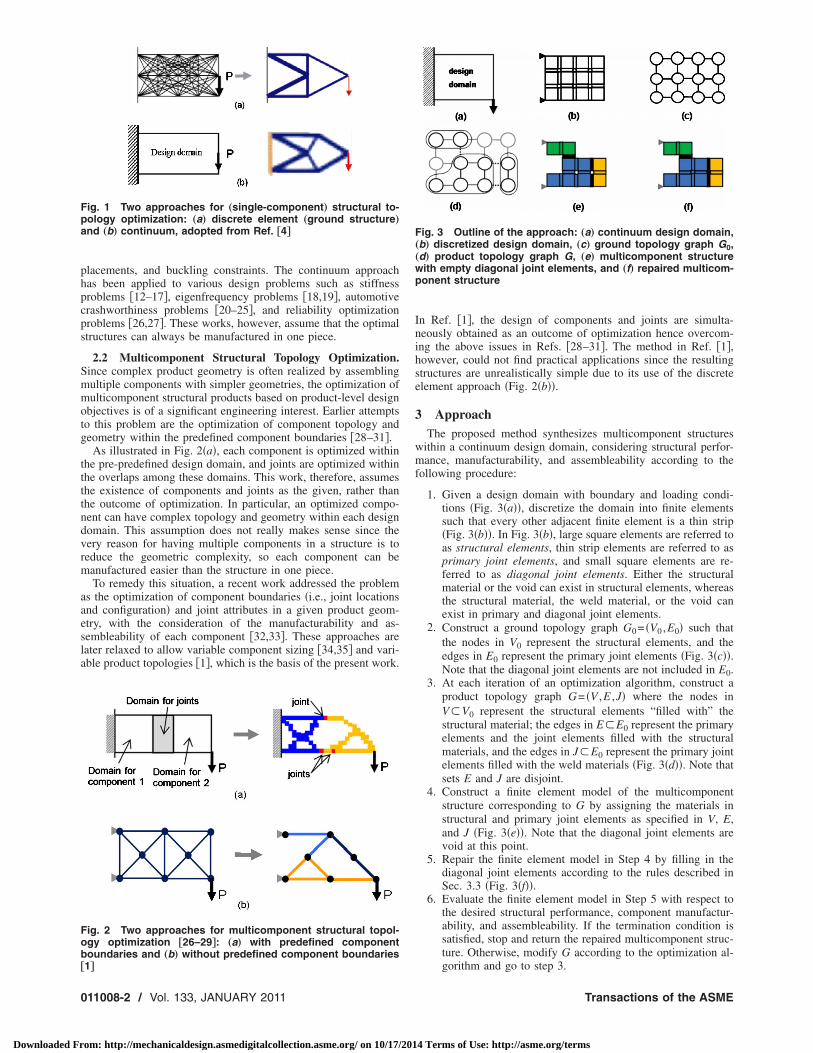
1. Given a design domain with boundary and loading condi-tions �Fig. 3�a��, discretize the domain into finite elementssuch that every other adjacent finite element is a thin strip�Fig. 3�b��. In Fig. 3�b�, large square elements are referred toas structural elements, thin strip elements are referred to asprimary joint elements, and small square elements are re-ferred to as diagonal joint elements. Either the structuralmaterial or the void can exist in structural elements, whereasthe structural material, the weld material, or the void canexist in primary and diagonal joint elements.
2. Construct a ground topology graph G0= �V0 ,E0� such thatthe nodes in V0 represent the structural elements, and theedges in E0 represent the primary joint elements �Fig. 3�c��.Note that the diagonal joint elements are not included in E0.
3. At each iteration of an optimization algorithm, construct aproduct topology graph G= �V ,E ,J� where the nodes inV�V0 represent the structural elements “filled with” thestructural material; the edges in E�E0 represent the primaryelements and the joint elements filled with the structuralmaterials, and the edges in J�E0 represent the primary jointelements filled with the weld materials �Fig. 3�d��. Note thatsets E and J are disjoint.
4. Construct a finite element model of the multicomponentstructure corresponding to G by assigning the materials instructural and primary joint elements as specified in V, E,and J �Fig. 3�e��. Note that the diagonal joint elements arevoid at this point.
5. Repair the finite element model in Step 4 by filling in thediagonal joint elements according to the rules described inSec. 3.3 �Fig. 3�f��.
6. Evaluate the finite element model in Step 5 with respect tothe desired structural performance, component manufactur-ability, and assembleability. If the termination condition issatisfied, stop and return the repaired multicomponent struc-ture. Otherwise, modify G according to the optimization al-
Fig. 3 Outline of the approach: „a… continuum design domain,„b… discretized design domain, „c… ground topology graph G0,„d… product topology graph G, „e… multicomponent structurewith empty diagonal joint elements, and „f… repaired multicom-ponent structure
gorithm and go to step 3.
Transactions of the ASME
4 Terms of Use: http://asme.org/terms
saen
w
F
F
Ipi
fitp
Fts
Fts
J
Downloaded Fr
3.1 Definition of Design Variables. In order to uniquelypecify a product topology graph G= �V ,E ,J�, two vectors x and yre defined as design variables. Structure vector x specifies thexistence of the structural material in each structural element �aode in the ground topology graph G0�
x = �x0,x1, . . . ,xi, . . . ,xn−2,xn−1� �1�
here n= �V0� and
xi = �1 if structural material exists in structral element i
0 otherwise�
or a given x, therefore, the node set V of G can be written as
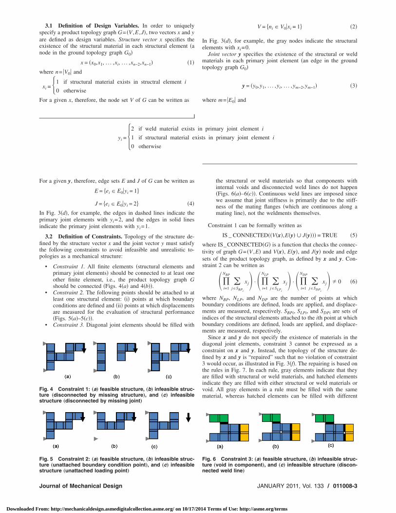
tructure „unattached loading point…
ournal of Mechanical Design
om: http://mechanicaldesign.asmedigitalcollection.asme.org/ on 10/17/201
V = �ni � V0�xi = 1 �2�
In Fig. 3�d�, for example, the gray nodes indicate the structuralelements with xi=0.
Joint vector y specifies the existence of the structural or weldmaterials in each primary joint element �an edge in the groundtopology graph G0�
y = �y0,y1, . . . ,yi, . . . ,ym−2,ym−1� �3�
where m= �E0� and
yi = 2 if weld material exists in primary joint element i
1 if structural material exists in primary joint element i
0 otherwise�
or a given y, therefore, edge sets E and J of G can be written as
E = �ei � E0�yi = 1
J = �ei � E0�yi = 2 �4�
n Fig. 3�d�, for example, the edges in dashed lines indicate therimary joint elements with yi=2, and the edges in solid linesndicate the primary joint elements with yi=1.
3.2 Definition of Constraints. Topology of the structure de-ned by the structure vector x and the joint vector y must satisfy
he following constraints to avoid infeasible and unrealistic to-ologies as a mechanical structure:
• Constraint 1. All finite elements �structural elements andprimary joint elements� should be connected to at least oneother finite element, i.e., the product topology graph Gshould be connected �Figs. 4�a� and 4�b��.
• Constraint 2. The following points should be attached to atleast one structural element: �i� points at which boundaryconditions are defined and �ii� points at which displacementsare measured for the evaluation of structural performance�Figs. 5�a�–5�c��.
• Constraint 3. Diagonal joint elements should be filled with
ig. 4 Constraint 1: „a… feasible structure, „b… infeasible struc-ure „disconnected by missing structure…, and „c… infeasibletructure „disconnected by missing joint…
ig. 5 Constraint 2: „a… feasible structure, „b… infeasible struc-ure „unattached boundary condition point…, and „c… infeasible
the structural or weld materials so that components withinternal voids and disconnected weld lines do not happen�Figs. 6�a�–6�c��. Continuous weld lines are imposed sincewe assume that joint stiffness is primarily due to the stiff-ness of the mating flanges �which are continuous along amating line�, not the weldments themselves.
Constraint 1 can be formally written as
IS _ CONNECTED��V�x�,E�y� � J�y��� = TRUE �5�
where IS_CONNECTED�G� is a function that checks the connec-tivity of graph G= �V ,E� and V�x�, E�y�, and J�y� node and edgesets of the product topology graph, as defined by x and y. Con-straint 2 can be written as
� i=1
NBP
�j�SBPi
xj� · � i=1
NLP
�j�SLPi
xj� · � i=1
NDP
�j�SDPi
xj� � 0 �6�
where NBP, NLP, and NDP are the number of points at whichboundary conditions are defined, loads are applied, and displace-ments are measured, respectively. SBPi, SLPi, and SDPi are sets ofindices of the structural elements attached to the ith point at whichboundary conditions are defined, loads are applied, and displace-ments are measured, respectively.
Since x and y do not specify the existence of materials in thediagonal joint elements, constraint 3 cannot be expressed as aconstraint on x and y. Instead, the topology of the structure de-fined by x and y is “repaired” such that no violation of constraint3 would occur, as illustrated in Fig. 3�f�. The repairing is based onthe rules in Fig. 7. In each rule, gray elements indicate that theyare filled with structural or weld materials, and hatched elementsindicate they are filled with either structural or weld materials orvoid. All gray elements in a rule must be filled with the samematerial, whereas hatched elements can be filled with different
Fig. 6 Constraint 3: „a… feasible structure, „b… infeasible struc-ture „void in component…, and „c… infeasible structure „discon-
nected weld line…JANUARY 2011, Vol. 133 / 011008-3
4 Terms of Use: http://asme.org/terms
mjma
fwmo
setetm
wmfi
am
wtsawt
sat
c
FF
Fthtbb
0
Downloaded Fr
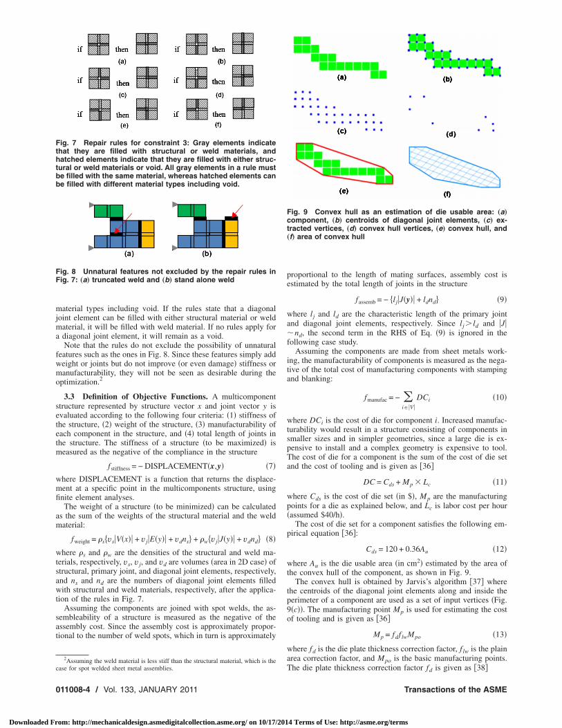
aterial types including void. If the rules state that a diagonaloint element can be filled with either structural material or weld
aterial, it will be filled with weld material. If no rules apply fordiagonal joint element, it will remain as a void.Note that the rules do not exclude the possibility of unnatural
eatures such as the ones in Fig. 8. Since these features simply addeight or joints but do not improve �or even damage� stiffness oranufacturability, they will not be seen as desirable during the
ptimization.2
3.3 Definition of Objective Functions. A multicomponenttructure represented by structure vector x and joint vector y isvaluated according to the following four criteria: �1� stiffness ofhe structure, �2� weight of the structure, �3� manufacturability ofach component in the structure, and �4� total length of joints inhe structure. The stiffness of a structure �to be maximized� is
easured as the negative of the compliance in the structure
fstiffness = − DISPLACEMENT�x,y� �7�here DISPLACEMENT is a function that returns the displace-ent at a specific point in the multicomponents structure, usingnite element analyses.The weight of a structure �to be minimized� can be calculated
s the sum of the weights of the structural material and the weldaterial:
fweight = �s�vs�V�x�� + v j�E�y�� + vdns + �w�v j�J�y�� + vdnd �8�
here �s and �w are the densities of the structural and weld ma-erials, respectively, vs, v j, and vd are volumes �area in 2D case� oftructural, primary joint, and diagonal joint elements, respectively,nd ns and nd are the numbers of diagonal joint elements filledith structural and weld materials, respectively, after the applica-
ion of the rules in Fig. 7.Assuming the components are joined with spot welds, the as-
embleability of a structure is measured as the negative of thessembly cost. Since the assembly cost is approximately propor-ional to the number of weld spots, which in turn is approximately
2Assuming the weld material is less stiff than the structural material, which is the
ig. 8 Unnatural features not excluded by the repair rules inig. 7: „a… truncated weld and „b… stand alone weld
ig. 7 Repair rules for constraint 3: Gray elements indicatehat they are filled with structural or weld materials, andatched elements indicate that they are filled with either struc-ural or weld materials or void. All gray elements in a rule muste filled with the same material, whereas hatched elements cane filled with different material types including void.
ase for spot welded sheet metal assemblies.
11008-4 / Vol. 133, JANUARY 2011
om: http://mechanicaldesign.asmedigitalcollection.asme.org/ on 10/17/201
proportional to the length of mating surfaces, assembly cost isestimated by the total length of joints in the structure
fassemb = − �lj�J�y�� + ldnd �9�
where lj and ld are the characteristic length of the primary jointand diagonal joint elements, respectively. Since lj � ld and �J��nd, the second term in the RHS of Eq. �9� is ignored in thefollowing case study.
Assuming the components are made from sheet metals work-ing, the manufacturability of components is measured as the nega-tive of the total cost of manufacturing components with stampingand blanking:
fmanufac = − �i��V�
DCi �10�
where DCi is the cost of die for component i. Increased manufac-turability would result in a structure consisting of components insmaller sizes and in simpler geometries, since a large die is ex-pensive to install and a complex geometry is expensive to tool.The cost of die for a component is the sum of the cost of die setand the cost of tooling and is given as �36�
DC = Cds + Mp � Lc �11�
where Cds is the cost of die set �in $�, Mp are the manufacturingpoints for a die as explained below, and Lc is labor cost per hour�assumed $40/h�.
The cost of die set for a component satisfies the following em-pirical equation �36�:
Cds = 120 + 0.36Au �12�
where Au is the die usable area �in cm2� estimated by the area ofthe convex hull of the component, as shown in Fig. 9.
The convex hull is obtained by Jarvis’s algorithm �37� wherethe centroids of the diagonal joint elements along and inside theperimeter of a component are used as a set of input vertices �Fig.9�c��. The manufacturing point Mp is used for estimating the costof tooling and is given as �36�
Mp = fdf lwMpo �13�
where fd is the die plate thickness correction factor, f lw is the plainarea correction factor, and Mpo is the basic manufacturing points.
Fig. 9 Convex hull as an estimation of die usable area: „a…component, „b… centroids of diagonal joint elements, „c… ex-tracted vertices, „d… convex hull vertices, „e… convex hull, and„f… area of convex hull
The die plate thickness correction factor fd is given as �38�
Transactions of the ASME
4 Terms of Use: http://asme.org/terms
wa
wupmac
wm
s
o
Fa
Fi
J
Downloaded Fr
fd = 0.5 + 0.02 hd �14�
here hd �in mm� is the die plate thickness, which in turn is givens �39�
hd = 9 + 2.5 loge�U/Ums�Vph2 �15�
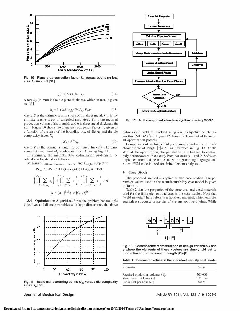
here U is the ultimate tensile stress of the sheet metal, Ums is theltimate tensile stress of annealed mild steel, Vp is the requiredroduction volumes �thousands�, and h is sheet metal thickness �inm�. Figure 10 shows the plane area correction factor f lw given asfunction of the area of the bounding box of die Ab and the die
omplexity index Xp:
Xp = P2/Ab �16�
here P is the perimeter length to be shared �in cm�. The basicanufacturing point Mp is obtained from Xp using Fig. 11.In summary, the multiobjective optimization problem to be
olved can be stated as follows:Minimize fstiffness, fassemb, fmanufac, and fweight, subject to
IS _ CONNECTED��V�x�,E�y� � J�y��� = TRUE
� i=1
NBP
�j�SBPi
xj� · � i=1
NLP
�j�SLPi
xj� · � i=1
NDP
�j�SDPi
xj� � 0
x � �0,1�V0�,y � �0,1,2�E0�
3.4 Optimization Algorithm. Since the problem has multiplebjectives and discrete variables with large dimensions, the above
ig. 10 Plane area correction factor flw versus bounding boxrea Ab „in cm2
… †36‡
ig. 11 Basic manufacturing points Mp0 versus die complexity
ndex Xp †36‡ournal of Mechanical Design
om: http://mechanicaldesign.asmedigitalcollection.asme.org/ on 10/17/201
optimization problem is solved using a multiobjective genetic al-gorithm �MOGA� �40�. Figure 12 shows the flowchart of the over-all optimization process.
Components of vectors x and y are simply laid out in a linearchromosome of length �V�+ �E�, as illustrated in Fig. 13. At thestart of the optimization, the population is initialized to containonly chromosomes that satisfy both constraints 1 and 2. Softwareimplementation is done in the DELPHI programming language, andANSYS FEM code is used for finite element analyses.
4 Case StudyThe proposed method is applied to two case studies. The pa-
rameter values used in the manufacturability cost model is givenin Table 1.
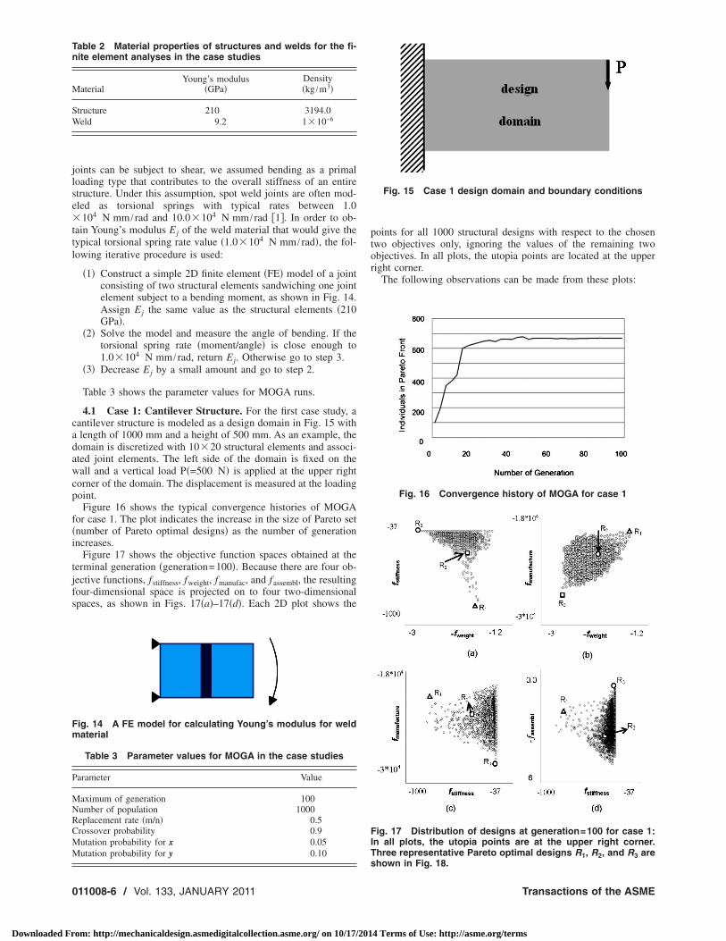
Table 2 lists the properties of the structures and weld materialsused for the finite element analyses in the case studies. Note that“weld material” here refers to a fictitious material, which exhibitsequivalent structural properties of average spot weld joints. While
Fig. 12 Multicomponent structure synthesis using MOGA
Fig. 13 Chromosome representation of design variables x andy where the elements of these vectors are simply laid out toform a linear chromosome of length �V�+ �E�
Table 1 Parameter values in the manufacturability cost model
Parameter Value
Required production volumes �Vp� 500,000Sheet metal thickness �h� 1.52 mmLabor cost per hour �Lc� $40/h
JANUARY 2011, Vol. 133 / 011008-5
4 Terms of Use: http://asme.org/terms
jlse�ttl
cadawcp
f�i
tjfs
Tn
M
SW
Fm
P
MNRCMM
0
Downloaded Fr
oints can be subject to shear, we assumed bending as a primaloading type that contributes to the overall stiffness of an entiretructure. Under this assumption, spot weld joints are often mod-led as torsional springs with typical rates between 1.0104 N mm / rad and 10.0�104 N mm / rad �1�. In order to ob-
ain Young’s modulus Ej of the weld material that would give theypical torsional spring rate value �1.0�104 N mm / rad�, the fol-owing iterative procedure is used:
�1� Construct a simple 2D finite element �FE� model of a jointconsisting of two structural elements sandwiching one jointelement subject to a bending moment, as shown in Fig. 14.Assign Ej the same value as the structural elements �210GPa�.
�2� Solve the model and measure the angle of bending. If thetorsional spring rate �moment/angle� is close enough to1.0�104 N mm / rad, return Ej. Otherwise go to step 3.
�3� Decrease Ej by a small amount and go to step 2.
Table 3 shows the parameter values for MOGA runs.
4.1 Case 1: Cantilever Structure. For the first case study, aantilever structure is modeled as a design domain in Fig. 15 withlength of 1000 mm and a height of 500 mm. As an example, theomain is discretized with 10�20 structural elements and associ-ted joint elements. The left side of the domain is fixed on theall and a vertical load P�=500 N� is applied at the upper right
orner of the domain. The displacement is measured at the loadingoint.
Figure 16 shows the typical convergence histories of MOGAor case 1. The plot indicates the increase in the size of Pareto setnumber of Pareto optimal designs� as the number of generationncreases.
Figure 17 shows the objective function spaces obtained at theerminal generation �generation=100�. Because there are four ob-ective functions, fstiffness, fweight, fmanufac, and fassembl, the resultingour-dimensional space is projected on to four two-dimensionalpaces, as shown in Figs. 17�a�–17�d�. Each 2D plot shows the
able 2 Material properties of structures and welds for the fi-ite element analyses in the case studies
aterialYoung’s modulus
�GPa�Density�kg /m3�
tructure 210 3194.0eld 9.2 1�10−6
ig. 14 A FE model for calculating Young’s modulus for weldaterial
Table 3 Parameter values for MOGA in the case studies
arameter Value
aximum of generation 100umber of population 1000eplacement rate �m/n� 0.5rossover probability 0.9utation probability for x 0.05utation probability for y 0.10
11008-6 / Vol. 133, JANUARY 2011
om: http://mechanicaldesign.asmedigitalcollection.asme.org/ on 10/17/201
points for all 1000 structural designs with respect to the chosentwo objectives only, ignoring the values of the remaining twoobjectives. In all plots, the utopia points are located at the upperright corner.
The following observations can be made from these plots:
Fig. 15 Case 1 design domain and boundary conditions
Fig. 16 Convergence history of MOGA for case 1
Fig. 17 Distribution of designs at generation=100 for case 1:In all plots, the utopia points are at the upper right corner.Three representative Pareto optimal designs R1, R2, and R3 are
shown in Fig. 18.Transactions of the ASME
4 Terms of Use: http://asme.org/terms
Rfiel
FRn
RRR
J
Downloaded Fr
• Observation 1. In the fweight− fstiffness space �Fig. 17�a��, de-signs are concentrated on the upper portion.
Possible explanation. Higher weight implies more ele-ments, which tends to increase stiffness.
• Observation 2. The fweight− fmanufac space �Fig. 17�b�� showsapproximately a proportional trend between fweight andfmanufac.
Possible explanation. Higher manufacturability impliessmaller die area, which decreases total weight.
• Observation 3. Designs with lower stiffness have lesservariations in manufacturability and assembleability than theones with higher stiffness �Figs. 17�c� and 17�d��.
Possible explanation. Lower stiffness structures tend tobe slenderer with less structural materials, which can limitthe types of feasible component geometry and joint configu-rations, resulting in a narrow range of manufacturability andassembleability. Highly stiff structures with more structuralmaterials, on the other hand, can be realized by variety ofcomponent geometry and joint configurations, resulting in awide range of manufacturability and assembleability.
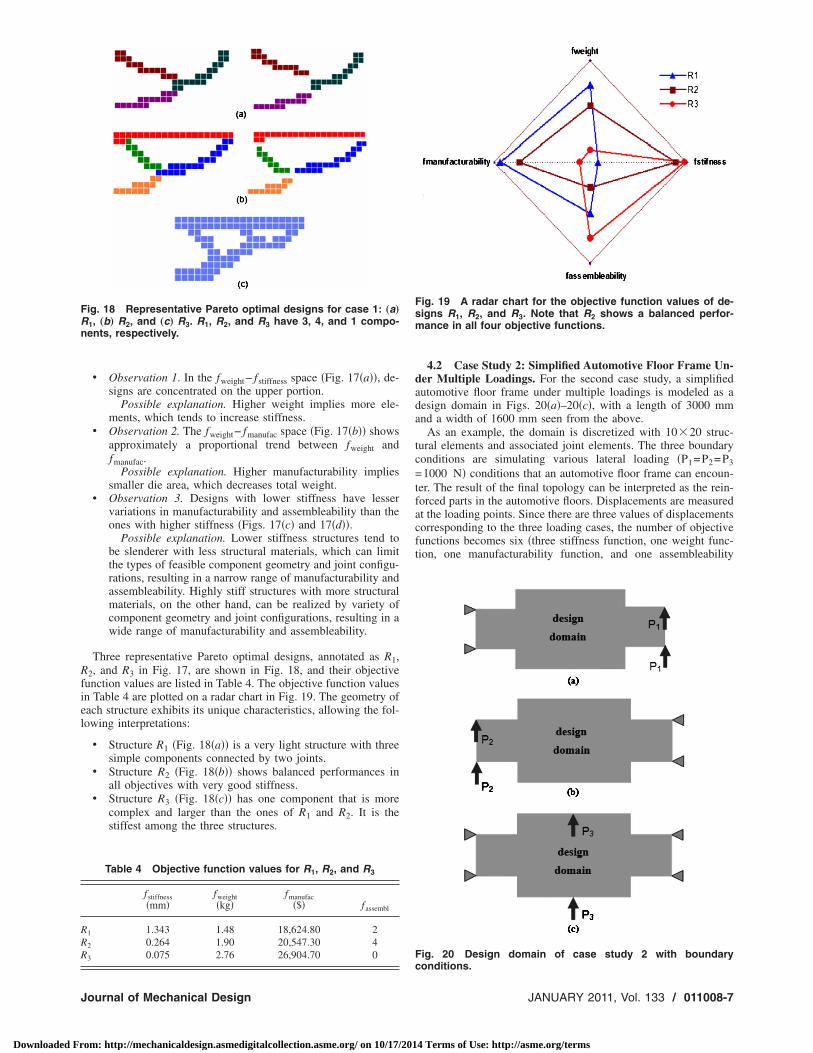
Three representative Pareto optimal designs, annotated as R1,2, and R3 in Fig. 17, are shown in Fig. 18, and their objective
unction values are listed in Table 4. The objective function valuesn Table 4 are plotted on a radar chart in Fig. 19. The geometry ofach structure exhibits its unique characteristics, allowing the fol-owing interpretations:
• Structure R1 �Fig. 18�a�� is a very light structure with threesimple components connected by two joints.
• Structure R2 �Fig. 18�b�� shows balanced performances inall objectives with very good stiffness.
• Structure R3 �Fig. 18�c�� has one component that is morecomplex and larger than the ones of R1 and R2. It is thestiffest among the three structures.
ig. 18 Representative Pareto optimal designs for case 1: „a…1, „b… R2, and „c… R3. R1, R2, and R3 have 3, 4, and 1 compo-ents, respectively.
Table 4 Objective function values for R1, R2, and R3
fstiffness�mm�
fweight�kg�
fmanufac�$� fassembl
1 1.343 1.48 18,624.80 2
2 0.264 1.90 20,547.30 4
3 0.075 2.76 26,904.70 0
ournal of Mechanical Design
om: http://mechanicaldesign.asmedigitalcollection.asme.org/ on 10/17/201
4.2 Case Study 2: Simplified Automotive Floor Frame Un-der Multiple Loadings. For the second case study, a simplifiedautomotive floor frame under multiple loadings is modeled as adesign domain in Figs. 20�a�–20�c�, with a length of 3000 mmand a width of 1600 mm seen from the above.
As an example, the domain is discretized with 10�20 struc-tural elements and associated joint elements. The three boundaryconditions are simulating various lateral loading �P1=P2=P3=1000 N� conditions that an automotive floor frame can encoun-ter. The result of the final topology can be interpreted as the rein-forced parts in the automotive floors. Displacements are measuredat the loading points. Since there are three values of displacementscorresponding to the three loading cases, the number of objectivefunctions becomes six �three stiffness function, one weight func-tion, one manufacturability function, and one assembleability
Fig. 19 A radar chart for the objective function values of de-signs R1, R2, and R3. Note that R2 shows a balanced perfor-mance in all four objective functions.
Fig. 20 Design domain of case study 2 with boundary
conditions.JANUARY 2011, Vol. 133 / 011008-7
4 Terms of Use: http://asme.org/terms
f
Rv5si
F„
r
0
Downloaded Fr
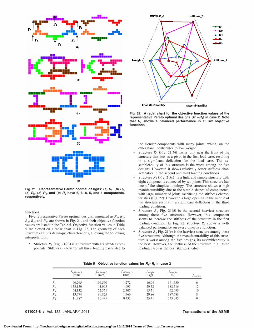
unction�.Five representative Pareto optimal designs, annotated as R1, R2,
3, R4, and R5, are shown in Fig. 21, and their objective functionalues are listed in the Table 5. Objective function values in Tableare plotted on a radar chart in Fig. 22. The geometry of each
tructure exhibits its unique characteristics, allowing the followingnterpretations:
• Structure R1 �Fig. 21�a�� is a structure with six slender com-ponents. Stiffness is low for all three loading cases due to
ig. 21 Representative Pareto optimal designs: „a… R1, „b… R2,c… R3, „d… R4, and „e… R5 have 6, 6, 8, 5, and 1 components,espectively.
Table 5 Objective functio
fstiffness_1�mm�
fstiffness_2�mm�
fsti�m
R1 96.265 109.560 1R2 133.150 11.005 1R3 64.132 72.551 2R4 13.774 80.825 1R5 11.787 10.495 0
11008-8 / Vol. 133, JANUARY 2011
om: http://mechanicaldesign.asmedigitalcollection.asme.org/ on 10/17/201
the slender components with many joints, which, on theother hand, contributes to low weight.
• Structure R2 �Fig. 21�b�� has a joint near the front of thestructure that acts as a pivot in the first load case, resultingin a significant deflection for the load case. The as-sembleability of this structure is the worst among the fivedesigns. However, it shows relatively better stiffness char-acteristics in the second and third loading conditions.
• Structure R3 �Fig. 21�c�� is a light and simple structure witheight components connected by ten joints. This structure hasone of the simplest topology. The structure shows a highmanufacturability due to the simple shapes of components,with large number of joints sacrificing the stiffness charac-teristics �Fig. 22�. However, a large opening in the middle ofthe structure results in a significant deflection in the thirdloading condition.
• Structure R4 Fig. 21�d� is the second heaviest structureamong these five structures. However, this componentseems to increase the stiffness of the structure in the firstloading condition. In Fig. 22, structure R4 shows a well-balanced performance on every objective function.
• Structure R5 Fig. 21�e� is the heaviest structure among thesefive structures. Although the manufacturability of this struc-ture is worst among the five designs, its assembleability isthe best. However, the stiffness of the structure in all threeloading cases is the best stiffness value.
alues for R1–R5 in case 2
_3 fweight�kg�
fmanufac�$� fassembl
16.04 141.530 620.32 182.516 1215.51 92.093 1020.86 187.588 825.41 243.045 0
Fig. 22 A radar chart for the objective function values of therepresentative Pareto optimal designs „R1–R5… in case 2. Notethat R4 shows a balanced performance in all six objectivefunctions.
n v
ffnessm�
.272
.095
.305
.466
.432
Transactions of the ASME
4 Terms of Use: http://asme.org/terms
5
ntibmpbRtdtat
rmtacmi
A
MtB
R
J
Downloaded Fr
Summary and Future WorkThis paper described a method for synthesizing multicompo-
ent structural assemblies in a continuum domain. Dissimilar tohe previous work that presumes component boundary as givennputs, the method synthesizes component geometry and partoundary as an outcome of optimizing for structural performance,anufacturability, and assembleability. The continuum-based to-
ology synthesis of multicomponent structural systems has nevereen formulated and solved in the manner presented in the paper.elaxing our previous work based on discrete element approach,
his paper presented a new formulation in a continuum designomain, which enhances the ability to represent complex struc-ural geometry observed in real-world products. Case studies withcantilever and a simplified automotive floor frame are presented
o demonstrate the effectiveness of the proposed method.The possible future work includes the development of more
ealistic assembleability model for spot welds, incorporation ofultiple structural materials and context-dependent joint property,
he subsequent finer-level optimization of component geometrynd joint locations, investigations of case studies with multiply-onnected design domains, the extension to 3D and otheranufacturing/assembly processes, and finally the demonstration
n real-world problems.
cknowledgmentThis work is done during Dr. Yildiz’s visit to the University ofichigan in 2006–2008. The funding for the visit is provided by
he Scientific and Technological Research Council of Turkey �TU-ITAK� under the Postdoctoral Research Scholarship Award.
eferences�1� Lyu, N., and Saitou, K., 2005, “Topology Optimization of Multi-Component
Structures via Decomposition-Based Assembly Synthesis,” ASME J. Mech.Des., 127, pp. 170–183.
�2� Dorn, W. C., Gomory, R. E., and Greenberg, H. J., 1964, “Automatic Designof Optimal Structures,” J. Mech., 3, pp. 25–52.
�3� Bendsøe, M. P., and Kikuchi, N., 1988, “Generating Optimal Topologies inStructural Design Using a Homogenization Method,” Comput. Methods Appl.Mech. Eng., 71, pp. 197–224.
�4� Saitou, K., Nishiwaki, S., Izui, K., and Papalambros, P., 2005, “A Survey ofStructural Optimization in Mechanical Product Development,” ASME J. Com-put. Inf. Sci. Eng., 5�3�, pp. 214–226.
�5� Bendsøe, M. P., Ben-Tal, A., and Zowe, J., 1994, “Optimization Methods forTruss Geometry and Topology Design,” Struct. Optim., 7, pp. 141–159.
�6� Kirsch, U., 1989, “Optimal Topologies of Structures,” Appl. Mech. Rev.,42�8�, pp. 223–238.
�7� Rozvany, G. I. N., Bendsøe, M. P., and Kirsch, U., 1995, “Layout Optimiza-tion of Structures,” Appl. Mech. Rev., 48, pp. 41–119.
�8� Shea, K., Cagan, J., and Fenves, S. J., 1997, “A Shape Annealing Approach toOptimal Truss Design With Dynamic Grouping of Members,” ASME J. Mech.Des., 119�3�, pp. 388–394.
�9� Reddy, G., and Cagan, J., 1995, “Optimally Directed Truss Topology Genera-tion Using Shape Annealing,” ASME J. Mech. Des., 117�1�, pp. 206–209.
�10� Gil, L., and Andreu, A., 2001, “Shape and Cross-Section Optimisation of aTruss Structure,” Comput. Struct., 79, pp. 681–689.
�11� Pedersen, N. L., and Nielsen, A. K., 2003, “Optimization of Practical TrussesWith Constraints on Eigenfrequencies, Displacements, Stresses, and Buck-ling,” Struct. Multidiscip. Optim., 25�5–6�, pp. 436–445.
�12� Suzuki, K., and Kikuchi, N., 1991, “A Homogenization Method for Shape andTopology Optimization,” Comput. Methods Appl. Mech. Eng., 93, pp. 291–318.
�13� Yildiz, A. R., 2009, “A New Design Optimization Framework Based on Im-mune Algorithm and Taguchi’s Method,” Comput Ind., 60�8�, pp. 613–620.
�14� Yildiz, A. R., 2009, “An Effective Hybrid Immune-Hill Climbing Optimiza-
tion Approach for Solving Design and Manufacturing Optimization Problemsournal of Mechanical Design
om: http://mechanicaldesign.asmedigitalcollection.asme.org/ on 10/17/201
in Industry,” J. Mater. Process. Technol., 209�6�, pp. 2773–2780.�15� Yildiz, A. R., 2009, “A Novel Particle Swarm Optimization Approach for
Product Design and Manufacturing,” Int. J. Adv. Manuf. Technol., 40�5–6�,pp. 617–628.
�16� Chapman, C., Saitou, K., and Jakiela, M., 1994, “Genetic Algorithms as anApproach to Configuration and Topology Design,” ASME J. Mech. Des.,116�4�, pp. 1005–1012.
�17� Chapman, C. D., and Jakiela, M. J., 1996, “Genetic Algorithm-Based Struc-tural Topology Design With Compliance and Topology Simplification Consid-erations,” ASME J. Mech. Des., 118�1�, pp. 89–98.
�18� Diaz, A. R., and Kikuchi, N., 1992, “Solutions to Shape and Topology Eigen-value Optimization Using a Homogenization Method,” Int. J. Numer. MethodsEng., 35, pp. 487–1502.
�19� Ma, Z.-D., Kikuchi, N., and Cheng, H.-C., 1995, “Topological Design forVibrating Structures,” Comput. Methods Appl. Mech. Eng., 121�1–4�, pp.259–280.
�20� Mayer, R. R., Kikuchi, N., and Scott, R. A., 1996, “Application of TopologicalOptimization Techniques to Structural Crashworthiness,” Int. J. Numer. Meth-ods Eng., 39�8�, pp. 1383–1403.
�21� Luo, J., Gea, H. C., and Yang, R. J., 2000, “Topology Optimization for CrushDesign,” Proceedings of the Eighth AIAA/USAF/NASA/ISSMO Symposiumon Multidisciplinary Analysis and Optimization, Long Beach, CA, Sep 6–8,AIAA Paper No. AIAA-2000-4770.
�22� Mayer, R. R., Maurer, D., and Bottcher, C., 2000, “Application of TopologicalOptimization Program to the Danner Test Simulation,” ASME Paper No.DETC2000/DAC-14292.
�23� Gea, H. C., and Luo, J., 2001, “Design for Energy Absorption: A TopologyOptimization Approach,” ASME Paper No. DETC2001/DAC-21060.
�24� Soto, C. A., 2001, “Optimal Structural Topology Design for Energy Absorp-tion: A Heurtistic Approach,” ASME Paper No. DETC-2001/DAC-21126.
�25� Soto, C. A., 2001, “Structural Topology for Crashworthiness Design by Match-ing Plastic Strain and Stress Levels,” ASME Paper No. IMECE2001/AMD-25455.
�26� Bae, K.-K., Wang, S. W., and Choi, K. K., 2002, “Reliability-Based TopologyOptimization With Uncertainties,” Proceedings of the Second China-Japan-Korea Joint Symposium on Optimization of Structural and Mechanical Sys-tems �CJK-OSM 2�, Busan, Korea, Nov 4–8, pp. 647–653.
�27� Kharmanda, G., Olhoff, N., Mohamed, A., and Lemaire, M., 2004,“Reliability-Based Topology Optimization,” Struct. Multidiscip. Optim.,26�5�, pp. 295–307.
�28� Johanson, R., Kikuchi, N., and Papalambros, P., 1994, “Simultaneous Topol-ogy and Material Microstructure Design,” Advances in Structural Optimiza-tion, B. H. V. Topping and M. Papadrakakis, eds., Civil-Comp Ltd., Edinburgh,Scotland, pp. 143–149.
�29� Jiang, T., and Chirehdast, M., 1997, “A Systems Approach to Structural To-pology Optimization: Designing Optimal Connections,” ASME J. Mech. Des.,119, pp. 40–47.
�30� Chickermane, H., and Gea, H. C., 1997, “Design of Multi-Component Struc-tural System for Optimal Layout Topology and Joint Locations,” Eng. Com-put., 13, pp. 235–243.
�31� Li, Q., Steven, G. P., and Xie, Y. M., 2001, “Evolutionary Structural Optimi-zation for Connection Topology Design of Multi-Component Systems,” Eng.Comput., 18�3/4�, pp. 460–479.
�32� Yetis, A., and Saitou, K., 2002, “Decomposition-Based Assembly SynthesisBased on Structural Considerations,” ASME J. Mech. Des., 124, pp. 593–601.
�33� Lyu, N., and Saitou, K., 2003, “Decomposition-Based Assembly Synthesis forStructural Stiffness,” ASME J. Mech. Des., 125�3�, pp. 452–463.
�34� Lyu, N., and Saitou, K., 2005, “Decomposition-Based Assembly Synthesis of aThree-Dimensional Body-in-White Model for Structural Stiffness,” ASME J.Mech. Des., 127, pp. 34–48.
�35� Lyu, N., and Saitou, K., 2006, “Decomposition-Based Assembly Synthesis ofSpace Frame Structures Using Joint Library,” ASME J. Mech. Des., 128, pp.57–65.
�36� Boothroyd, G., Dewhurst, P., and Knight, W., 1994, Product Design for Manu-facturing and Assembly, Dekker, New York.
�37� Jarvis, R. A., 1973, “On the Identification of the Convex Hull of a Finite Set ofPoints in the Plane,” Inf. Process. Lett., 2, pp. 18–21.
�38� Zenger, D., and Dewhurst, P., 1988, “Early Assessment of Tooling Costs in theDesign of Sheet Metal Parts,” Report No. 29.
�39� Nordquist, W. N., 1955, Die Designing and Estimating, 4th ed., Huebner,Cleveland, OH.
�40� Coello, C., Veldhuizen, D., and Lamont, G., 2002, Evolutionary Algorithms for
Solving Multi-Objective Problems, Kluwer Academic, Dordrecht.JANUARY 2011, Vol. 133 / 011008-9
4 Terms of Use: http://asme.org/terms
Related Documents