Topics covered: Input/Output Organization CSE243: Introduction to Computer Architecture and Hardware/Software Interface

Topics covered: Input/Output Organization CSE243: Introduction to Computer Architecture and Hardware/Software Interface.
Dec 19, 2015
Welcome message from author
This document is posted to help you gain knowledge. Please leave a comment to let me know what you think about it! Share it to your friends and learn new things together.
Transcript
Topics covered:Input/Output Organization
CSE243: Introduction to Computer Architecture and Hardware/Software Interface

2
Interrupts (contd..)
Multiple I/O devices may be connected to the processor and the memory via a bus. Some or all of these devices may be capable of generating interrupt requests. Each device operates independently, and hence no definite
order can be imposed on how the devices generate interrupt requests?
How does the processor know which device has generated an interrupt?
How does the processor know which interrupt service routine needs to be executed?
When the processor is executing an interrupt service routine for one device, can other device interrupt the processor?
If two interrupt-requests are received simultaneously, then how to break the tie?

3
Interrupts (contd..)
Consider a simple arrangement where all devices send their interrupt-requests over a single control line in the bus.
When the processor receives an interrupt request over this control line, how does it know which device is requesting an interrupt?
This information is available in the status register of the device requesting an interrupt: The status register of each device has an IRQ bit which it
sets to 1 when it requests an interrupt. Interrupt service routine can poll the I/O devices
connected to the bus. The first device with IRQ equal to 1 is the one that is serviced.
Polling mechanism is easy, but time consuming to query the status bits of all the I/O devices connected to the bus.

4
Interrupts (contd..)
The device requesting an interrupt may identify itself directly to the processor. Device can do so by sending a special code (4 to 8 bits)
the processor over the bus. Code supplied by the device may represent a part of the
starting address of the interrupt-service routine. The remainder of the starting address is obtained by the
processor based on other information such as the range of memory addresses where interrupt service routines are located.
Usually the location pointed to by the interrupting device is used to store the starting address of the interrupt-service routine.

5
Interrupts (contd..)
Previously, before the processor started executing the interrupt service routine for a device, it disabled the interrupts from the device.
In general, same arrangement is used when multiple devices can send interrupt requests to the processor. During the execution of an interrupt service routine of
device, the processor does not accept interrupt requests from any other device.
Since the interrupt service routines are usually short, the delay that this causes is generally acceptable.
However, for certain devices this delay may not be acceptable. Which devices can be allowed to interrupt a processor
when it is executing an interrupt service routine of another device?

6
Interrupts (contd..)
I/O devices are organized in a priority structure: An interrupt request from a high-priority device is accepted
while the processor is executing the interrupt service routine of a low priority device.
A priority level is assigned to a processor that can be changed under program control. Priority level of a processor is the priority of the program
that is currently being executed. When the processor starts executing the interrupt service
routine of a device, its priority is raised to that of the device.
If the device sending an interrupt request has a higher priority than the processor, the processor accepts the interrupt request.

7
Interrupts (contd..)
Processor’s priority is encoded in a few bits of the processor status register. Priority can be changed by instructions that write into the
processor status register. Usually, these are privileged instructions, or instructions
that can be executed only in the supervisor mode. Privileged instructions cannot be executed in the user
mode. Prevents a user program from accidentally or intentionally
changing the priority of the processor. If there is an attempt to execute a privileged instruction
in the user mode, it causes a special type of interrupt called as privilege exception.

8
Interrupts (contd..)
Priority arbitration
Device 1 Device 2 Device p
Proc
esso
r
INTA1
INTR1 INTRp
INTAp
•Each device has a separate interrupt-request and interrupt-acknowledge line. •Each interrupt-request line is assigned a different priority level. •Interrupt requests received over these lines are sent to a priority arbitration circuit in the processor. •If the interrupt request has a higher priority level than the priority of the processor, then the request is accepted.
9
Interrupts (contd..)
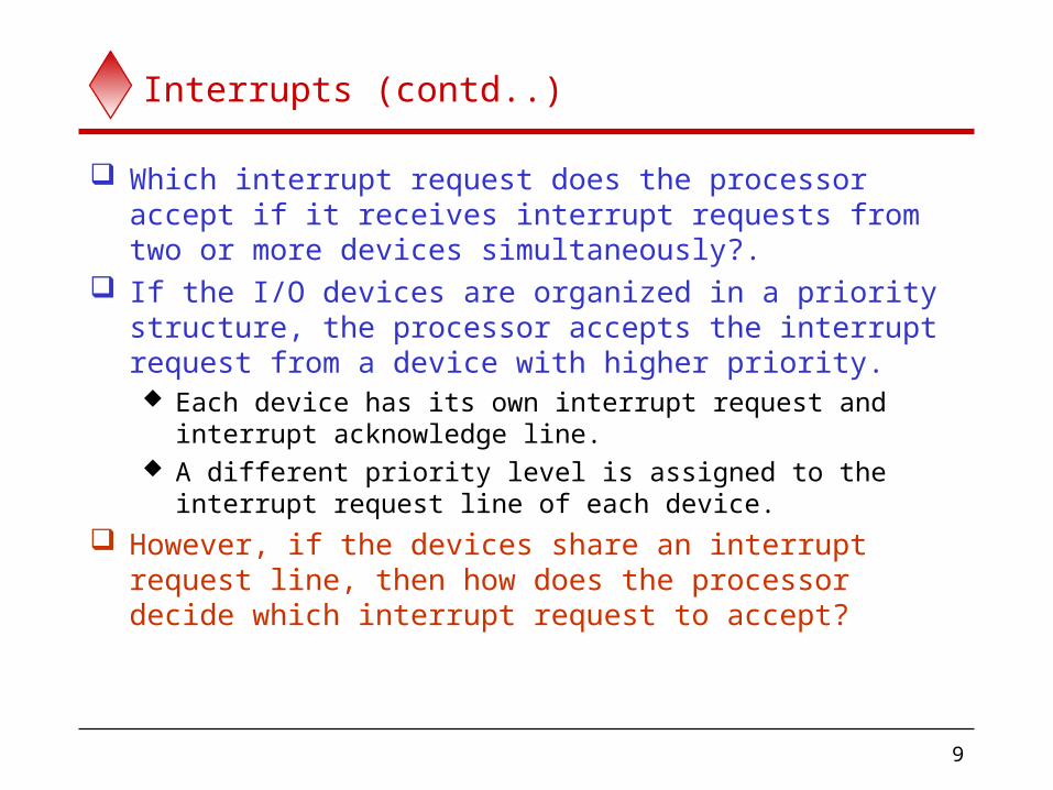
Which interrupt request does the processor accept if it receives interrupt requests from two or more devices simultaneously?.
If the I/O devices are organized in a priority structure, the processor accepts the interrupt request from a device with higher priority. Each device has its own interrupt request and interrupt
acknowledge line. A different priority level is assigned to the interrupt
request line of each device. However, if the devices share an interrupt request line,
then how does the processor decide which interrupt request to accept?
10
Interrupts (contd..)
Pro
cess
or
Device 2
INTR
INTADevice nDevice 1
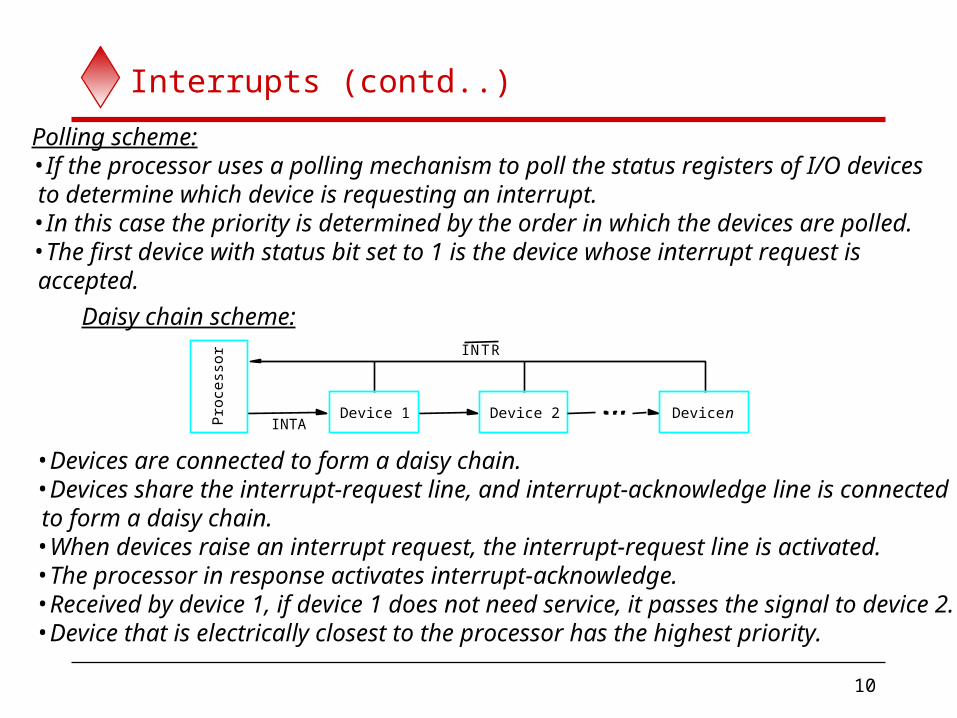
Polling scheme:•If the processor uses a polling mechanism to poll the status registers of I/O devices to determine which device is requesting an interrupt.•In this case the priority is determined by the order in which the devices are polled.•The first device with status bit set to 1 is the device whose interrupt request is accepted.
Daisy chain scheme:
•Devices are connected to form a daisy chain. •Devices share the interrupt-request line, and interrupt-acknowledge line is connected to form a daisy chain. •When devices raise an interrupt request, the interrupt-request line is activated.•The processor in response activates interrupt-acknowledge. •Received by device 1, if device 1 does not need service, it passes the signal to device 2.•Device that is electrically closest to the processor has the highest priority.
11
Interrupts (contd..)
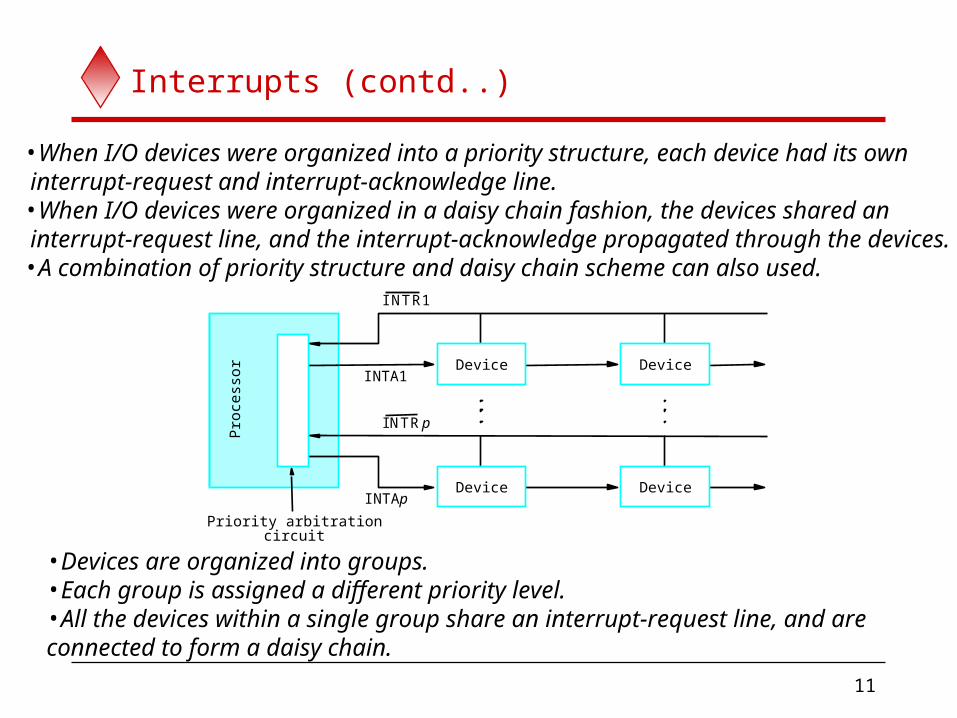
•When I/O devices were organized into a priority structure, each device had its own interrupt-request and interrupt-acknowledge line.•When I/O devices were organized in a daisy chain fashion, the devices shared an interrupt-request line, and the interrupt-acknowledge propagated through the devices.•A combination of priority structure and daisy chain scheme can also used.
Device Device
circuitPriority arbitration
Pro
cess
or
Device Device
INTR1
INTR p
INTA1
INTAp
•Devices are organized into groups. •Each group is assigned a different priority level. •All the devices within a single group share an interrupt-request line, and are connected to form a daisy chain.

12
Interrupts (contd..)
Only those devices that are being used in a program should be allowed to generate interrupt requests.
To control which devices are allowed to generate interrupt requests, the interface circuit of each I/O device has an interrupt-enable bit. If the interrupt-enable bit in the device interface is set to 1,
then the device is allowed to generate an interrupt-request.
Interrupt-enable bit in the device’s interface circuit determines whether the device is allowed to generate an interrupt request.
Interrupt-enable bit in the processor status register or the priority structure of the interrupts determines whether a given interrupt will be accepted.

13
Exceptions
Interrupts caused by interrupt-requests sent by I/O devices.
Interrupts could be used in many other situations where the execution of one program needs to be suspended and execution of another program needs to be started.
In general, the term exception is used to refer to any event that causes an interruption. Interrupt-requests from I/O devices is one type of an
exception. Other types of exceptions are:
Recovery from errors Debugging Privilege exception

14
Exceptions (contd..)
Many sources of errors in a processor. For example: Error in the data stored. Error during the execution of an instruction.
When such errors are detected, exception processing is initiated. Processor takes the same steps as in the case of I/O
interrupt-request. It suspends the execution of the current program, and starts
executing an exception-service routine. Difference between handling I/O interrupt-request and
handling exceptions due to errors: In case of I/O interrupt-request, the processor usually
completes the execution of an instruction in progress before branching to the interrupt-service routine.
In case of exception processing however, the execution of an instruction in progress usually cannot be completed.

15
Exceptions (contd..)
Debugger uses exceptions to provide important features: Trace, Breakpoints.
Trace mode: Exception occurs after the execution of every instruction. Debugging program is used as the exception-service
routine. Breakpoints:
Exception occurs only at specific points selected by the user.
Debugging program is used as the exception-service routine.
16
Exceptions (contd..)
Certain instructions can be executed only when the processor is in the supervisor mode. These are called privileged instructions.
If an attempt is made to execute a privileged instruction in the user mode, a privilege exception occurs.
Privilege exception causes: Processor to switch to the supervisor mode, Execution of an appropriate exception-servicing routine.

17
Direct Memory Access
Program-controlled I/O: Processor polls a status flag in the device interface. Overhead associated with polling the status flag.
I/O using interrupts: Processor waits for the device to send an interrupt request. Overhead associated with saving and restoring the
Program Counter (PC) and other state information. In addition, if we want to transfer a group of words, the
processor needs to execute instructions which increment the memory address and keep track of the word count.
To transfer large blocks of data at high speed, an alternative approach is used.

18
Direct Memory Access (contd..)
Direct Memory Access (DMA): A special control unit may be provided to transfer a block
of data directly between an I/O device and the main memory, without continuous intervention by the processor.
Control unit which performs these transfers is a part of the I/O device’s interface circuit. This control unit is called as a DMA controller.
DMA controller performs functions that would be normally carried out by the processor: For each word, it provides the memory address and all the
control signals. To transfer a block of data, it increments the memory
addresses and keeps track of the number of transfers.
19
Direct Memory Access (contd..)
DMA controller can transfer a block of data from an external device to the processor, without any intervention from the processor. However, the operation of the DMA controller must be
under the control of a program executed by the processor. That is, the processor must initiate the DMA transfer.
To initiate the DMA transfer, the processor informs the DMA controller of: Starting address, Number of words in the block. Direction of transfer (I/O device to the memory, or memory
to the I/O device). Once the DMA controller completes the DMA transfer, it
informs the processor by raising an interrupt signal.

20
Direct Memory Access (contd..)
Done
IE
IRQ
Status and control
Starting address
Word count
WR/
31 30 1 0
•DMA controllers have one register to hold the starting address, and one register to hold the word count. •A third register called as status register contains status and control bits. •R/W = 1 specifies a read operation, R/W = 0 specifies a write operation. •When the transfer is complete, the Done bit is set to 1. •If IE = 1, the DMA controller raises an interrupt after the transfer is complete.•To raise an interrupt, it sets the IRQ bit to 1.•Status register may also record other information such as whether the transfer took place correctly, or errors occurred.

21
Direct Memory Access (contd..)
memoryProcessor
System bus
Main
Keyboard
InterfaceNetwork
Disk/DMAcontroller Printer
DMAcontroller
DiskDisk
•DMA controller connects a high-speed network to the computer bus. •Disk controller, which controls two disks also has DMA capability. It provides two DMA channels. •It can perform two independent DMA operations, as if each disk has its own DMA controller. The registers to store the memory address, word count and status and control information are duplicated.
22
Direct Memory Access (contd..)
Processor and DMA controllers have to use the bus in an interwoven fashion to access the memory. DMA devices are given higher priority than the processor
to access the bus. Among different DMA devices, high priority is given to
high-speed peripherals such as a disk or a graphics display device.
Processor originates most memory access cycles on the bus. DMA controller can be said to “steal” memory access
cycles from the bus. This interweaving technique is called as “cycle stealing”.
An alternate approach is the provide a DMA controller an exclusive capability to initiate transfers on the bus, and hence exclusive access to the main memory. This is known as the block or burst mode.
Related Documents