TopSolid 2006 i TopSolid’Design 2006 Training Guide TopSolid 'Design

Welcome message from author
This document is posted to help you gain knowledge. Please leave a comment to let me know what you think about it! Share it to your friends and learn new things together.
Transcript

TopSolid 2006
i
TopSolid’Design 2006Training Guide
TopSolid'Design

TopSolid 2006
ii
© 2006, Missler Software.7, Rue du Bois SauvageF-91055 Evry, FRANCEWeb : http://www.topsolid.comE-mail : [email protected] rights reserved.
Information is subject to change without notice. No material may be reproduced or transmitted in any formor by any means, electronic or mechanical, for any purpose without the express written permission of Mis-sler Software.
TopSolid ® is a registered trademark of Missler Software.
TopSolid ® is a product name of Missler Software.
The information and the software discussed in this document are subject to change without notice andshould not be considered commitments by Missler Software.
The software discussed in this document is furnished under a license and may be used or copied only inaccordance with the terms of this license.
TopSolid 2006
iii
Foreword............................................................................................................................1Pre-requisites ......................................................................................................................2About the course and manual .............................................................................................2About the software ..............................................................................................................2Where to find files to start? .................................................................................................3
General...............................................................................................................................5The TopSolid Interface........................................................................................................6Functions.............................................................................................................................8Shaft .................................................................................................................................21Cover Plate ......................................................................................................................29Body .................................................................................................................................37Piston ...............................................................................................................................47Connecting rod..................................................................................................................53Arm ...................................................................................................................................55Yoke .................................................................................................................................65
Working with assemblies ...............................................................................................73Bottom-up assembly .........................................................................................................75Design in place 1/2............................................................................................................93Design in place 2/2............................................................................................................99
Components ..................................................................................................................107
Kinematics & Dynamics ...............................................................................................115Kinematics.......................................................................................................................116Dynamics ........................................................................................................................124
Surfaces .........................................................................................................................127
Mechanically Welded Chassis .....................................................................................139
Sheet Metal Work & Piping...........................................................................................149
Realistic Rendering.......................................................................................................161Managing the environment..............................................................................................164Managing materials.........................................................................................................167Advanced rendering ........................................................................................................170Managing textures and logos ..........................................................................................171
Importing and repairing shapes ..................................................................................173Introduction .....................................................................................................................174Communication difficulties ..............................................................................................174Advanced Geometric Cleaning Module...........................................................................175Non-associative mode.....................................................................................................175Importing models.............................................................................................................175Verify shapes ..................................................................................................................177Eliminate .........................................................................................................................178Repairs............................................................................................................................178Sewing ............................................................................................................................179

TopSolid 2006
iv
Capping models ..............................................................................................................180Simplification ...................................................................................................................181Importing IGES................................................................................................................183Importing DWG Geometry...............................................................................................187Tool box for shapes.........................................................................................................191Advanced 2D Import .......................................................................................................197
2D Drafting.....................................................................................................................205
Title block ......................................................................................................................213

TopSolid 2006
1
Foreword

TopSolid 2006
2
Pre-requisitesAttendees should be familiar with the Microsoft Windows operating system. You should also be familiarwith the principles and practises associated with mechanical design.
About the course and manualThis manual is intended to be used as a teaching in a classroom environment. The book itself is not there-fore a self-teaching document and it does not cover every aspect in detail. The exercises in the manualare designed to be explained and supported by an experienced instructor.
About the softwareTopSolid is a contemporary CAD product that runs in the Windows environment. TopSolid is the coreproduct of a family of integrated software solutions developed by Missler Software that offer a global andintegrated general mechanical solution for both design and manufacturing.
The family of solutions includes:
• TopSolid’Design: 3D design and surface modelling• TopSolid’Draft: drawing features and 2D design• TopSolid'Castor: FEA analysis of structures in terms of volume beams and hulls• TopSolid'Motion: dynamic calculation of motion• TopSolid'Mold: mold and tooling design• TopSolid'Progress: progression and stamping tool design• TopSolid'Fold: design and unfolding of sheet metal applications• TopSolid'Cam: 2 to 5 axis 2D/3D milling, turning and wire EDM• TopSolid'PunchCut: punching, nibbling and cutting for sheet metal applications

TopSolid 2006
3
These products share the same user interface and associative database. For each module, MisslerSoftware offers a product with real associative CAD/CAM, thus avoiding duplication of informationtransfer between the engineering and manufacturing departments.
The result is an impressive gain in productivity. To make all this possible, TopSolid implements a methodof design using functions and components that already contain the information needed for assemblingand manufacturing.
About the course and manualDuring the course we will be modelling several parts. Ensure to save them as we will use them again inthe assembly module.
Where to find files to start?Some of the training lessons need files to start: they are all available from TopSolid 2006 DVD inDocumentation folder followed by the product and the chapter name (e.g.Documentation\TopSolidDesign\Shaft).

TopSolid 2006
4

TopSolid 2006
5
General

TopSolid 2006
6
The TopSolid Interface
Status barProvides feedback and allows the user to quickly set layers, colors etc. and set display tolerances andinvisible parts. Click directly onto the value to change it..
Graphic area
Function Bar
Prompt Line
Context Bar
Drop down menus System Bar
Alpha Bar
Title Bar
Snap grid on or off Edit material
Hides or displays invisible items
Edit display toleranceNote This will directly affect filesize
Set picking mode:3D=SpatialPr=ProjectedPl=Planar
Manage layers and transparency
Cursor position

TopSolid 2006
7
Mouse FunctionsDifferent functions are associated with the threebuttons of the mouse.
Left Mouse Button (LM) :• Selection of any function from the menus• Selection of an element (dynamic selection) or creation
of a point
Middle Mouse Button (MM) :• Creation of points on the current plane when clicked
(advanced)• Dynamic Zoom using Scroll• Dynamic Pan when held down
Right Mouse Button (RM) :• The first option of the current command is accepted
when the right mouse button is clicked• Or the context menu of the current command is displayed when held down.
Three further important uses1. Intersection of 2 Items: To obtain the intersection of two items left
click and hold LM in the graphics area away from the intersection then move the mouse over the intersection then release the mouse key; - The size of the square can be changed using the + and – but-tons on the keyboard.
2. Rotative picking of items: When the mouse is moved over an item, the nearest item is automatically highlighted if this is not the required item, press and hold down the left mouse button and use the right mouse RM click to allow Rotative picking through the items at the cur-rent position. When the correct item is highlighted release the left mouse LM.
3. The middle button has one more distinct property in that when draw-ing lines for instance it will always create a NEW point even if you click onto an existing one.
1 – Here we draw 2 sepa-rate lines that join at a point. All done with the
left button.
If we move the common point, then we see that
both lines alter to remain joined.
2 - Here we draw 2 sepa-rate lines that join at a
point however the second line was drawn with the
right button.
If we move the common point we see that the two lines are in fact separate and can move indepen-
dently.
MM RM
LM

TopSolid 2006
8
Functions
The iconsThere are two types of icons in Topsolid, simple icons and icons with options.
The simple icons execute the function with a single left mouse click LM.
The icons with options using the left mouse LM on the Icon selects the command as above.
• If you use a left click LM the option selected becomes the default option for the next time you use this function
• If you use a right click RM the default option does not change
Using the Context icon barMany of the functions are grouped together in context usingthe context bar (the vertical icons bar located on the left ofthe screen) Selecting an icon will change the functionsdisplayed in the work bar (horizontal icons bar locatedunder the system icon bar), and in some cases the menusare also changed when you change the current context.
The buttons• Input boxes for values, when TopSolid needs input from the user, it will display an empty box. In this
case, the input is done directly via the keyboard.
• The buttons without drop down menus.
• These allow switching between several options. For example to draw a circle by default the option Diameter is selected. A click on the but-ton switches the command to Radius.

TopSolid 2006
9
• Some allow the selection of options from a drop down menu. For example Transforma-tion has a drop down box showing the other available options as shown here:
Keyboard actionsLeft mouse down with Control enters dynamic rotation, Shift enters dynamic pan and both keys togetherenters dynamic zoom.
The function keys in TopSolid have the following uses, as well as the normal windows functions.
User defined shortcuts can be created using the Tools, Options menu.
Typing in CoordinatesCartesian coordinates: defines coordinates whose values are absolute from the current coordinatesystem origin (X, Y, Z). Commas separate the values, the Z value is optional.Ex: 12,45,21
Polar coordinates: defines polar coordinates length in XY plan, angle and a height in Z (length; angle,z). The Z height is optional.Ex: 20;45,5
Spherical coordinates: defines spherical coordinates length in XY plan, angle in XY then angle in YZview of the current direction (Length;angle1;angle2).Ex: 5;45;30
Relative coordinates: defines coordinates relative to the previous point specified the coordinates arepreceded by the symbol &.Ex: &10,10,10
Key Function
F1 Online Help
F2 Information on points and elements
F3 Dynamic Zoom
F4 Dynamic Pan
F5 Dynamic rotation around X
F6 Dynamic rotation around Y
F7 Dynamic rotation around Z
F8 Cancel Dynamic rotation
F9 Dynamic Rotation
F10
F11
F12 Floating windows On/Off

TopSolid 2006
10
The compassA compass that allows changing the view orientation is available in eachview. In its default position, it represents the current coordinate systemorientation. Each part of the compass allows you to make dynamic actionsview along a direction, centred rotation, rotation around axes, translations.
In its default position, the compass shows the orientation of the currentcoordinate system. It is used to manipulate the view. It has sensitive parts,each of which enable dynamic actions to be performed: i.e. orientation along a direction, centeredrotations, rotations along axes, translations.
Transformation Area(s) to click
Displacement of theview (Panoramic)
Spherical rotation
Rotation along an axis
Rotation around X Rotation around Y Rotation around Z
Modification of a vieworientation
View along X(Right)
View along Y(Back)
View along Z(Top)

TopSolid 2006
11
The compass may be positioned anywhere in the view or hooked to anelement of the document by sliding-moving its centre point.Hooking the compass to an element allows the user:• to manipulate the view according to the new orientation of the compass:
rotations along the hook axes…• to create a coordinate system on the hook (accessed via the context-
sensitive menu, right button)• to create a current coordinate system on the hook (accessed via the
context-sensitive menu, right button)A symbolic coordinate system representing the current coordinate systemis maintained at the compass default position if the compass is moved (whether hooked or left free in theview).When the compass has been moved, it may be moved back to its place at the bottom left of the screen,and vice versa, by double-clicking.The compass may be temporarily hidden via its context-sensitive menu. Use the context-sensitive menuof the default coordinate system to make it reappear.When the compass does not appear in the view (i.e. if it has been hooked to an element that has passedoutside the view), it may be retrieved by clicking on the default coordinate system.
Main functions presentation
New document There are a selection of Templates provided for creating new documents inTopSolid’Design and TopSolid’Draft. User defined templates can be stored in theConfig/Template directory of the software. For training we will useAssociative 3 Csystems mm.
Open an existing document TopSolid shows a list of files in the current folder withthe extension .top and .dft and also files supportedby the direct interfaces STEP, IGES, DXF, DWG,Parasolid, ACIS etc. Some direct interfaces areseparately purchasable.
Note: New creates a new document. The Configurebutton is active depending on the type of direct interfacefile used.
Save or Save as to save as a different name3D design files are saved with the extension .top and 2D files are saved with the extension .dft.In the title bar, if the name of the file is followed by a *, this means that there are changes to the file thathave not been saved. If there is an exclamation mark it means there are some invalid elements. Files canalso be saved in other formats such as STEP, IGES, DWG, DXF, etc.
Area to click

TopSolid 2006
12
Print Prints the current document. Depending of the application used you have will have different printingoptions.
Cancel Cancels all the actions carried out within the current function but does not exit it, to quit the function pressthe Escape key.
Undo Undo the previous action within the current command.
Delete element Deletes the selected elements. The option ALL THE ELEMENTS allows, after confirmation, to clear thecurrent document.
Extract element Extract a portion or feature of anelement.(e.g.: point of a contour, drill orfillet on a shape, union, boss, title blockelement,...).If there is an ambiguity, TopSolid will askyou to choose between them. The element or the operation is destroyed but the elements that were usedto create it are preserved. Example: the extraction of a boss eliminates the boss but not the profile fromwhich it was generated (The profile remains invisible).
Insert element Insert an element (e.g. point, line, circle).
Modify element Modify an element or operation e.g. contour, radius boss, transformation…
Move parents Move an element and its construction elements if the element is not fully constrained Topsolid will showdynamically the possible positions.
Contour Creates contours over existing sketch lines, or on the grid of the active coordinate system, closedcontours are automatically created when the start point is re-selected.
Sketch lines Sketch lines are created relative to points or elements, the option boxes allow the change of angles etc.

TopSolid 2006
13
Extrude shape Creates an extruded surface or solid from a profile. Generally if the profile is open a surface is created, ifit is closed a solid is created.
Revolved shape Creates a revolved surface or solid from a profile around the selected axis.
Drawing contoursThere are two ways of drawing contours either by clicking point to point or alternatively by tracing overconstruction geometry.
Simple contoursTo define the contour using points, lines are sketched defining the relevant points of the part. The actual dimensions / angles of the shape are defined later by dimensioning.Once the shape has been drawn you can use Modify to change the conditionsat a vertex (chamfer, fillet or nothing) or between two points you can change thelink type (line, arc, tangential) Depending on whether you select near an end orin the middle of a side.

TopSolid 2006
14
Creation from construction lines:To define the contour the user uses basic sketch elements(lines, circles etc.). The dimensions of the contour depend ondimensions and positions of the sketch lines.
What does parametric mean?Parametric modelling allows the part to automatically link to the basic geometry from which it wascreated, so that changes can be automatically updated throughout the design process. A simple example is as follows.
In a traditional cad system when the operator creates a point at the intersection of two lines the point iscreated but if one of the lines moves later, the point does not automatically move with it.
In a parametric system when the operator creates a point at the intersection of two lines it remembersthis operation so that if one of the lines moves later the point is automatically updated to be at the newintersection point.
Parametric systemBasic system
Point remains in position Point follows new condition

TopSolid 2006
15
The coordinate systemsA coordinate system allows the creation of a work plane forthe construction of elements. When we start a newdocument (associative 3 Systems mm) there are threecoordinate systems: the absolute XY one, and a XZ plus aYZ coordinate system. To change or create a coordinate system, select in the
system bar the function Current coordinate system then pick a face or a coordinate system.
In the example, it is necessary to select the yellow face.
Numerous forms of coordinate system are available and these can be accessed from the coordinatesystem tool bar.
NOTE
• This icon will allow you to set any coordinate system as the current or active one.
• This icon displays the coordinate system tool bar and allows the user to create a new coordinate system.
• If used alone the coordinate system created will NOT automatically become current, however if you
use first of all, then the resultant coordinate system WILL automatically become current.The current (or active) coordinate system is drawn in a thicker outline.
The most widely used coordinate systems are:
Examples of their use:
Coordinate system on point
Coordinate system through 3 points
Coordinate system on profile
Coordinate system on a profile and point.
Coordinate system on face and a point
Coordinate system constrained on a face
Duplicated coordinate system
Current system
Absolute system

TopSolid 2006
16
Coordinate system on a point: Constructs a coordinate system positioned on a point, taking the
orientation of the current coordinate system.
Coordinate system on curve and point: Lets you to create a coordinate system that is based ona curve and a point. The curve defines the orientation of the coordinate system (XY normal in relation tothe curve), the point defines its position.
Constrained coordinate system on a face: Creates acoordinate system placed on a face and positioned in respect of theedges or contiguous faces. The DYNAMIC button enables searchingfor these edges or sides used.Note: Very convenient as the two dimensions easily allow thecoordinate system to be moved later.
Duplicated coordinate system: Creates a copy of a coordinatesystem by applying a transformation, translate, rotate etc.
Systems duplicated by rotation
Original system
System duplicated par translation

TopSolid 2006
17
PointsPoints are elements that comprise a distinct position. They are maintained during associative modedesign. Points are used to join dimensions, to impose dimensional and positional constraints. In contrast,in “free design mode” and “non associative curves mode” points are deleted immediately as soon as thefunction is changed, as they cannot be used to constrain an element.
Creation of points in TopSolid is performed in several ways: First of all, during construction of b-splinecurves, the user is actually tracing points without realizing it. These points include, for example, thecentre of a circle that is placed on the grid, a line that is joined to the end of an existing curve, etc. Theother method is to use a specific point creation function, by choosing the menu Tools, Points or thepoints tool bar.
The most widely used points systems are:
Using points
Intersection point: creates an intersection pointbetween curves.
Middle point and Centre point: creates a centrepoint of the arcs and then the middle point between the twocentre points.
Intersection point: point at the intersection of 2 curves.
Middle point: a point created between 2 other points.
Centre point: a point in the middle of an element. (lines or circles).
Point on a curve: create a point attached to a curve.
Barycentre point: a point at the centre of gravity.
Duplicate point: a duplicated point which is translated from the original.
Axis-curve/plane-face intersection point: The Intersection point between an axis/curve axe and a plane/face allows you to create an intersection point between a curve or an axis an a face or a plane.

TopSolid 2006
18
Point on a curve: creates a point on the upper edge of the cylinder.
It is possible to combine the coordinate systems withpoints on coordinate systems with icons showing a redpoint. For example, in the following case, a coordinatesystem on face and point will be created, and the pointwill correspond to a middle point between 2 otherpoints (which are actually the centre points of the 2circles).
Transformation and associativityA part or element can be transformed or moved fromone place to another. Or it can be duplicated eithersingle or multiple) The most common propagationsare translation and rotation, but it may be symmetry,double symmetry, homothetic, rectangular, etc. Theimportant question with respect to the associativitymechanism is: what happens to the parents when such a propagation is applied?There are numerous options for the user to choose from and the correct choice will depend on therequired outcome.
Move and turn functionsThese 2 functions apply the translation and rotation to the parents of the selected element. The entireelement will be affected. For elements such as lines or circles and simplistic shapes this has very littleimpact. But if a part that you are applying a move and turn function to has several other parts based fromit the result will also be applied to those parts this may not give you the desired effect.
Repeat or duplicate?When applying a propagation, it may be useful if the number of resulting elements were to be aparameter, so that it can be changed later. The Edit, Repeat function allows for this, however the Edit,Duplicate function does not (but it is less complex in terms of associativity). The main effect of theRepeat function is to create a top level element other the copies, and the copies themselves are in factconsidered as completely new elements. For example, you may have to detect an element inside therepetition to access it.
Repeat (or not) any further modification to the original?The duplicated or repeated elements may be allowed to follow any new operations (chamfer, holes,...)applied to the original. This has to be set by the user. By default, the subsequent operations to theoriginal will applied on the duplicated or repeated elements too.
Linked or independent copies?
Middle point
Face

TopSolid 2006
19
If you simply want to copy an element without any link back to the original, use the Copy withoutreference option.This has the effect of breaking the associativity between the original and its copies.

TopSolid 2006
20

TopSolid 2006
21
Shaft Topics covered:• Create a simple contour.• Dimension/Half part dimension.• Revolved solid.• Extruded solid.• Trimming with curves.• Creating a reference system.• Subtraction (cutting).• Chamfer & Fillet.• Simple part drawing.
1 Starting a new design document
Open a new file then select a new design document and select a template.
Click on the profile icon in the context bar . The Profile command will start automatically.
NOTE: this will only happen the first time you select the context menu.
Use the profile tool to draw the profiles shown below. Create the profile by clicking free pointsbut use the cursor feedback information as a guide. Start your profile on the coordinate centre point.
To close a profile either click onto the first segment or click onto the last (previous segment).Then end the open profile (shown in grey line).
Click STOP.
2 Dimensions
Dimension both contours as shown, use the and for diameters.
3 Create the revolved solid
Activate the shapes context menu select the revolved shape icon .

TopSolid 2006
22
Select your curve then select the horizontal base as your rotation axis.
Click OK to accept a 360 degrees rotation.
NOTE: Changing the direction (in this case) will have no effect.
4 Adding the chamfer
Click on the chamfer icon .
Choose the chamfer type as LENGTH/LENGTH, enter 1mm in the first length box then click onto thefront edge of the shaft.
5 Limiting with a profile (trimming)
Click on the trimming icon .
For the shape to trim select the shaft.
For the trimming shape select the open profile.

TopSolid 2006
23
Ensure that the large red arrow is pointing towards the inside of the curve (area to delete) then clickOK.
Cut the keyway.
Select the menu Tools, Coordinate system.
Select XZ.
Click SET AS CURRENT then top view.
Draw and extrude the key.
Draw a circle using the circle icon .
Radius 8mm, Centre point 17,8,0.Extrude the circle to 4mm.
Activate the shape context menu then select the extrude icon .
Click on the circle.
Click on the NORMAL button to change it to CENTRED, then type in 4mm.
TopSolid 2006
24
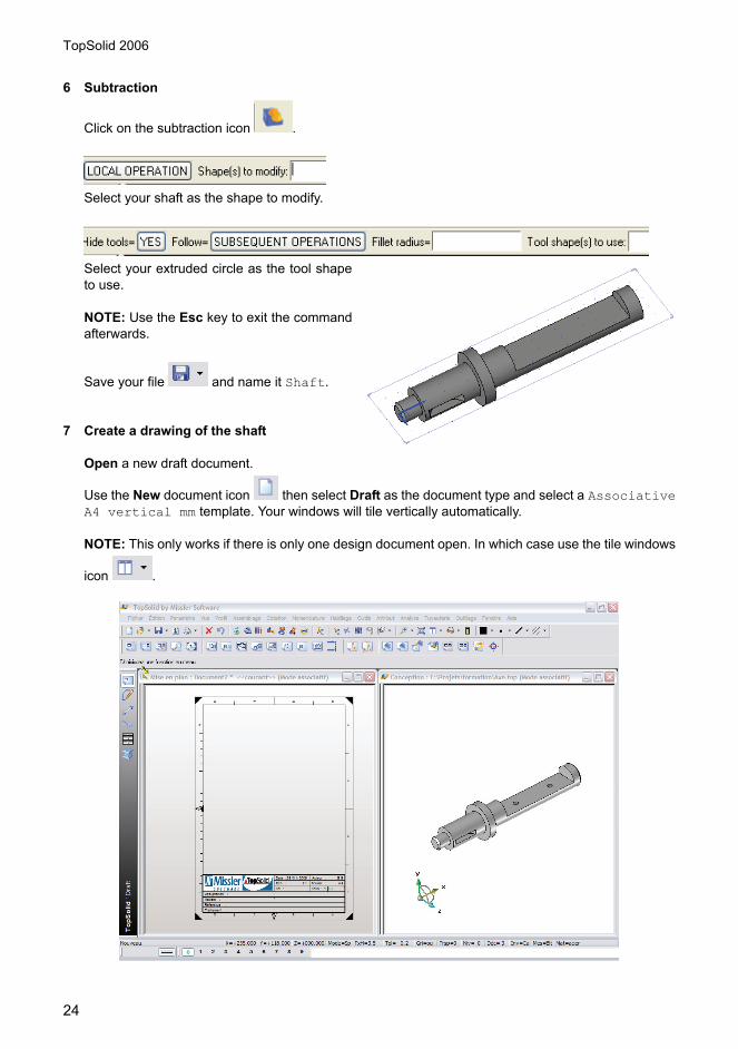
6 Subtraction
Click on the subtraction icon .
Select your shaft as the shape to modify.
Select your extruded circle as the tool shapeto use.
NOTE: Use the Esc key to exit the commandafterwards.
Save your file and name it Shaft.
7 Create a drawing of the shaft
Open a new draft document.
Use the New document icon then select Draft as the document type and select a AssociativeA4 vertical mm template. Your windows will tile vertically automatically.
NOTE: This only works if there is only one design document open. In which case use the tile windows
icon .

TopSolid 2006
25
Select the main view icon .
Click on the shaft.
Orientate the view with the green arrows and type anew scaling factor if required, select OK to accept.
Position the view onto the sheet and left click.
Select AUXILIARY VIEW (or right click) to create the projected and isometric views.
Save your file and exit.
NOTE: By default the name of the file will be Shaft.dft. You may of course choose another name.

TopSolid 2006
26
Modifications to the shaft
8 Drilling holes
Use the menu file Open icon and select the file Shaft.top.
Click OK.
We will add 2xM4 tapped holes onto the face of the cut-out:
Select the drilling icon , select the face anduse the cursor to position the first hole position.Notice the green and yellow dimensions.
Select hole+tapping.

TopSolid 2006
27
Select M4, tick Through and OK.
The design calls for 2 holes. So use the PROPAGATE button to pattern the second hole.
Select LINEAR.
Select one of the long edges to define the propagation direction. Ensure the direction arrow is correct.
The total distance is 25mm.
Total number is 2.
Save your file.
Open the shaft drawing file Shaft.dft.

TopSolid 2006
28
9 Local SectionLet’s add a local section to the main view.
Activate the views context menu and select the local section icon then select the main view.
Select B-SPLINE.
Draw the spline by clicking points, then STOP.
NOTE: You could in fact draw any shape first, thenselect CONTOUR.
Click onto the outline of the shaft.
Result.
10 Drilling dimensions
Activate the dimensions context menu then select the hole dimensions icon .
Select any element belonging to a machined hole, then place the dimension.
Save the file.

TopSolid 2006
29
Cover Plate Topics covered:• Cylindrical primitive.• Drilling.• Coordinate systems.• Points.• Propagation.• Chamfer.• Feature tree.• Detail drawing.
1 New document
Open a New document select Design as the type.
2 Cylinder
Activate the shapes context menu then select the cylinder icon .
Enter 50mm.
Select Z+.
Enter 6mm.
Enter 0,0,0.

TopSolid 2006
30
3 DrillingDrill a Ø14 plain hole in the centre of the cylinder.
Select the drilling icon then select the face, fill out thedrilling dialogue for a plain 14mm hole.
4 Sketch for the PCD
Change your line color and style .
Draw a circle diameter 38mm centred on the 0,0 point.
Draw a vertical sketch line using through 0,0.
Select CHANGE TO VERTICAL then ENTER or click the centre point.
5 Points
Click on to activate the points menu bar.
Select the curve intersection icon .
Click on the circle followed by the vertical line. Pick close to actual intersection point to identify whichone of the two possible solutions you require.
6 Place the coordinate system
Click on the icon to activate the coordinate systems menu bar.

TopSolid 2006
31
Select the coordinate system on a point icon . Thenclick on the point created at the intersection.
Drill Ø5 holes on the newly created coordinate system.
Select COORDINATE SYSTEM.
Click onto the coordinatesystem then onto the face ofthe cover plate.
Select PROPAGATE.
Select CIRCULAR.
Select Z+ (or select the vertical side of the cover plate).

TopSolid 2006
32
Right click to accept 360°.
Type 3 and Enter.
Esc to exit the command
7 Chamfer
Select the chamfer icon , place a 1mm x 45° cham-fer around the top edge.
8 Feature treeTo open the feature tree click on the left hand side of thegraphics window, then onto your shape.
Alternatively left click and drag on the left hand side of thegraphics window to open it, then right click in this area andselect Edit then click on the shape.
Change the chamfer 1.5mm.Change the number of holes to 6.Change the diameter of the centre hole to 10.
Now change them all back to their original values with
Save the file as CoverPlate.top.

TopSolid 2006
33
9 Detail drawing of the cover plate
Open a New document with select Draft asthe document type. Create a Main view.
10 Axis Drawing axis may be placed one at a time or in this case we will do all the axis on the part automati-cally.
Select PROJECTED AXIS.
Select your view.
Select AUTOMATIC.
Then OK.
11 Cross-section
Select the full section icon .
Select CUTTING CURVE DEFINED IN DRAFT.

TopSolid 2006
34
Click the vertical axis.
Select OK.
Select OK and place the view.
12 Change the position of the A-A
Click the modify tool then click the text A-A.
Select FREE POSITION to put the text wherever you want it.
NOTE:
INVERT will change the direction of the cutting arrows. EXTREMITIES controls the position of the 2 endsof the cutting line.

TopSolid 2006
35
13 Dimensions
Dimension the holes .
Dimension the chamfer with this icon .
NOTE: For chamfers that are not at 45° you must use the START AND TERMINATE SEGMENTSfunction.
Select the lines on either side of the chamfer to establish the angle and size.
Put the other dimensions onto the drawing with and select the relevant lines and arcs.
Save the file as CoverPlate.dft

TopSolid 2006
36
TopSolid 2006
37
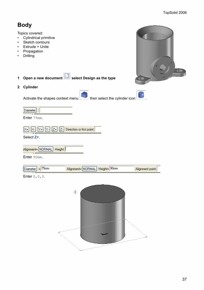
Body Topics covered:• Cylindrical primitive• Sketch contours• Extrude + Unite• Propagation• Drilling
1 Open a new document select Design as the type
2 Cylinder
Activate the shapes context menu then select the cylinder icon .
Enter 75mm.
Select Z+.
Enter 90mm.
Enter 0,0,0.

TopSolid 2006
38
3 Add the feet
Draw a construction circle of Ø100.
Draw a vertical construction line through 0,0.
Draw a circle of radius 12.5 on the top intersection pointof the circle and the line. Use the “cursor slide” selection tech-nique to find the intersection.
Draw 2 vertical lines tangent to both sides of the circle.
Draw a horizontal line at 0,30.
Change your line color and style and draw a contour bytracing over the construction lines.
TopSolid 2006
39
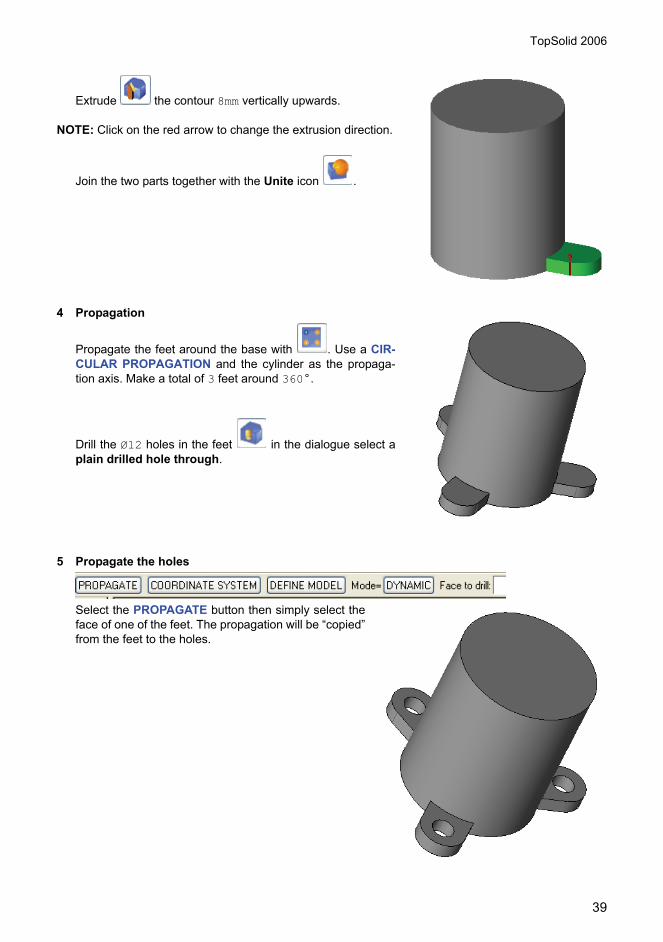
Extrude the contour 8mm vertically upwards.
NOTE: Click on the red arrow to change the extrusion direction.
Join the two parts together with the Unite icon .
4 Propagation
Propagate the feet around the base with . Use a CIR-CULAR PROPAGATION and the cylinder as the propaga-tion axis. Make a total of 3 feet around 360°.
Drill the Ø12 holes in the feet in the dialogue select aplain drilled hole through.
5 Propagate the holes
Select the PROPAGATE button then simply select theface of one of the feet. The propagation will be “copied”from the feet to the holes.

TopSolid 2006
40
Drill another hole in the centre of Ø50 with achamfer (or countersink) of Ø70 x 45°.
Select the top face of the body then select hole +countersinking as the hole type. Note the 2 dia-logues

TopSolid 2006
41
6 Change the workplaneSelect the menu Tools, Coordinate system.
Select XZ.
Choose SET AS CURRENT then TOP VIEW.
Draw a circle of diameter 50 at 0,28.
Extrude the circle by 40.5 in Z+.
With the unite icon join them together.
Open the feature tree and move the drilling operation so that it comes after the unite. This will havethe effect of removing the obstruction from inside the hole. Close the feature tree by clicking on theedge

TopSolid 2006
42
7 Drill the counter bored hole Ø14-25 Select the face of the Ø50 cylinder.
Choose hole+facing and fill out the dia-logues as shown.
.
8 Drill and tap 3 holes M4
Set the current coordinate system onto the face of the 50mm cylinder .
Select the normal (or top) view .
Draw a 38mm diameter circle at 0,0 .
Place the axis lines on the circle .

TopSolid 2006
43
Create another coordinate system at the intersection between the circle and the horizontal axis with
(use the cursor slide again if you wish).
Select the drilling icon .
Select COORDINATE SYSTEM then clickon the new coordinate system, then thecylinder face. Choose the tapped hole andfill out the dialogue as below (note thedepth of the holes).
Propagate the holes with a circular propa-gation using the 50mm cylinder as thepropagation axis. We need 3 holes.
Finally put 1mm fillets around theedges and corners of the feet as shown.Save the file as Body.top.

TopSolid 2006
44
9 Detail drawing of the body
Open a new document with select Draft as the document type.Create a main view and projected view as shown.
10 Section view
Click on the section icon then onto the main view.
Click the circle; the circles axis will appear automatically, use the vertical line of the axis as the cuttingcontour.
Select OK.
Set the hidden lines to HIDDEN then OK.
Place the view on the drawing.

TopSolid 2006
45
11 Partial section
Draw the projected axis .
Draw a line from the centre of the 50mm hole to the centre of the drilled hole in the foot.
You can use the trim function to extend as well as shorten. Select the line and click on a pointjust outside the foot (as shown).
Select MAKE TRIM.
Click on the partial section icon .
Select the view.
Click on the line we have just drawn.
Select OK.
Set hidden lines as HIDDEN, then OK.
You will see that the view is incorrectly aligned, go back and select NO and YES as shown.
Position the view correctly and Esc to exit the com-mand.

TopSolid 2006
46
Dimension the rest of the drawing as shown.
12 Tolerance reference
Activate the dimensions and detailing context menu then .
Click on the line to use as a reference and place the symbol.
13 Geometric tolerance
Select the geometric tolerance icon .
Select the correct type of symbol from the list then OK.
Click on the element you wish to refer to.
Click onto the reference letter A, then STOP.
Save the file as Body.dft.

TopSolid 2006
47
Piston Topics covered:• Freehand contour.• Revolved solid.• Grooves.• Slots.• Drilling on cylinders.
1 Shape creation
Open a new document select Design as the type.
Draw the initial profile as shown .
Dimension with .
Revolve the shape with .
2 Groove
Select the groove icon .
Click on the face as shown.

TopSolid 2006
48
Click on the front face.
Select OK.
Enter the values d=5, D=45 and l=2
Then OK.
3 The SlotPlace a coordinate system on the back face. From the coordinate sys-
tem menu bar, select Constrained coordinate system on face .
TopSolid 2006
49
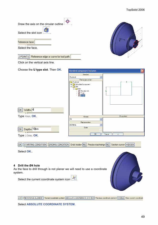
Draw the axis on the circular outline .
Select the slot icon .
Select the face.
Click on the vertical axis line.
Choose the U type slot. Then OK.
Type 4mm. OK.
Type 10mm. OK.
Select OK..
4 Drill the Ø4 hole As the face to drill through is not planar we will need to use a coordinatesystem.
Select the current coordinate system icon .
Select ABSOLUTE COORDINATE SYSTEM.

TopSolid 2006
50
Select the top view icon .
From the points menu bar , draw a point .
Place the point 5mm in from the end of the 15mm diameter.
Create a coordinate system on a face and point face = face of the Ø15 cylinder and the point isthe preceding point.
Drill the hole using this coordinate system . Make it a plain drilled hole Ø4 through all.
5 Detail drawing of the piston
Open a new document with . Select Draft as the document type.Create a main view and projected view as shown.
Create a local section as shown.
Draw the axis .
Dimension the part as shown .

TopSolid 2006
51
6 Adding tolerances
Click on the dimension to adjust with , thenselect the tolerance style. Enter the values forthe upper and lower limits as shown below.
7 Adding Notes
Activate the detailing context menu with . Then select the notes icon .Enter your text, notes and set the style,etc.…
Place your note on the drawing.
Click on a line segment to place the headof your leader.
Select STOP.
Before After

TopSolid 2006
52
8 Shaded view
Modify the view with then tick theshaded view checkbox.

TopSolid 2006
53
Connecting rodTopics covered:• Thicken.• Symmetry constraints.• Extruding.• Propagated drilling.
1 Constrained line
Draw a line with .
Dimension the line .
Adjust the length to 3mm.Add a symmetrical constraint about the Y axis.
2 Thicken the profile
Select the thicken icon .
Enter the thickness 5mm and select CIRCLES OUTSIDE then click on the line.
Select OK (or right click).
Extrude the contour 4mm .
Drill a hole in one end Ø4mm.

TopSolid 2006
54
Propagate the drilled hole using SIMPLE MIRROR through theYZ plane.
Save the file as ConnectingRod.top.

TopSolid 2006
55
Arm Topics covered:• Sketch Contours.• Modifying elements.• Extrude solids.• Unite.• Merge (contours).• Pocket.• Drilling.• Standard profiles.• Fillets.• Some advanced drawing methods.
1 Arm profile
Open a new document select Design as the document type.
Draw 2 circles with the circle icon and dimension change to a dottedline first.
NOTE: You can draw the circles roughly then correct their size and position using thedimension tool, however it’s a good idea to place the first one on the coordinate 0,0.
Draw a 2 lines tangent to the 2 circles use the Contour command but use a different colour.
Click the first circle.
Ensure PASS ON SEGMENT is selected, click the second circle at 2 o’clock and again at 5 o’clock.
Click on the first circle to close the profile.

TopSolid 2006
56
2 Modify an element
Click on the modify tool then select the top straight-line segment of your profile.
Simply type 125mm as the circle size (no need to select the circle button) and Enter.
If the arc goes the wrong way, click on the tool again and select INVERT.
Repeat the procedure for the bottom arc using 70mm radius.
3 Extrude the shape
Use the extrude icon extrude the 2 circles to a thickness of 11mm (CENTRED).
NOTE: Use the lasso to select them both at the same time.
Then extrude the contour by 5mm (CENTRED)..
Unite .

TopSolid 2006
57
Select the centre shape.
Select the two cylinders.
Esc to exit.
4 Merge contours
Draw a circle Ø14 and a rectangle 3X5
as shown : use the RECTANGULARoption and select the two diagonal points.
Hold down the right mouse key and selectAUTO DIMENSION, then use SYMMETRYconstraints to add a constraint on the X axis.Add a 10mm dimension to position the rectan-gle.
Use the merge icon to merge the 2contours together. Remember to pick the contourson the section you wish to keep.
5 Pocket
With the pocket command use the profile to cut the pocket on the boss.

TopSolid 2006
58
Select the face.
Select the profile.
Select Through all and OK.
6 Drilling
With the drilling icon click on the face of the otherboss. As the boss is circular the system will automaticallyselect the centre. Select a plain hole then OK.

TopSolid 2006
59
Type in 10mm for the diameter and click Through all thenOK.
7 Do the drawing
Use the New document icon then select Draft as the document type and select a AssociativeA4 horizontal mm template. Your windows will tile vertically automatically.
Select the main view icon .
Select AUXILIARY VIEW (or right click) to create the projected and isometric views as shown.
8 Create a detail view
Click on the detail view icon .
Click on the main view (shown above with a highlighted border).

TopSolid 2006
60
Select CIRCLE.
Click on a point close to the keyway then click again to open up the circle.
Place the view where you want it.
9 Projected dimensions
Activate the dimensions context menu then select the projected dimensions icon .
Select the main view.
Click on AUTOMATIC.
Repeat for the other views.
NOTE: These are driving dimensions, which means that they can be changed in the drawing and willdirectly change the model.
Save the file , name the files Arm.top and Arm.dft.

TopSolid 2006
61
10 Modify the ArmOpen the fie Arm.top.To see the elements that are driving the model
click on the driving elements icon .Click on the centre face.
Use the circle tool to draw an arc of radius 90mm passing through the centre of the 2 circles.
NOTE: change the color and line style using and .
11 Standard Profile
Draw a radiused slot using a standard profile.Double click on each of the values. Type in 90mm for the radius, 10mm for the thickness and 20degrees for the angle. Ensure the key point is set to middle.

TopSolid 2006
62
Place the slot onto the centre of the90mm arc.
Now use the pocket command once again to cut the pocketthrough the arm. This time use the fillet option to add a 1mm fillettop and bottom.
12 Fillets
Activate the shapes context menu then select the fillet icon .
Select the four edges between the boss’s and the centresection and click compute fillets.

TopSolid 2006
63
Save the file with .
Open the arm’s draft document to see that it has automatically been updated with the changes.

TopSolid 2006
64

TopSolid 2006
65
Yoke Topics covered:• Rectangular contour.• Extrude.• Chamfer.• Drilling a face.
Use your newly acquired skills to model this part yourself (it needs to fit into the cut-out on the end of theshaft and the connecting rod fits inside the slot).

TopSolid 2006
66
2 x M4
A-A

TopSolid 2006
67

TopSolid 2006
68
A-A
3 holes Ø5

TopSolid 2006
69
A-A
B-B
3 tapping holes M4x5Counterbore Ø25x5

TopSolid 2006
70

TopSolid 2006
71
2xØ4

TopSolid 2006
72

TopSolid 2006
73
Working with assemblies

TopSolid 2006
74
Topics covered:• Assembly methods.• Defining a part.• Defining an assembly.• Assembly using constraints.• Assembly using coordinate systems.• Dynamic simulation and the constraints system.• Using standard components.• Producing assembly drawings.• Exploded views.• Bill of materials and indexes.• Designing in place or top down method.
When bringing parts together in an assembly we can work in two different ways:• Bottom up.
The separate pieces of the assembly are modeled individually and then brought together to make the assembly. They are fitted together using constraints or coordinates.
• In place (or top down)All the parts are built in place in the same file.
Design AssemblySub-assemblies Creation of independent parts
Creation of parts in place
The Full assembly
Creation in place of a part in its assembly context

TopSolid 2006
75
Bottom-up assembly1 Creating parts & different sub-assembliesWe will start by making a sub-assembly of the shaft and yoke.
2 Defining a partEach component of an assembly needs to be identified and some characteristics specified. This will be ofuse later when we do drawings and bill of materials.
Open the Shaft.top file .
Activate the assembly context menu then select Define a part .Select the shaft then fill out the dialogue box as follows.Name = Shaft, reference=SH-01, Material=Steel
Click OK.
NOTE: If you need to modify any of the inputs later, you can selectCharacteristics from the feature tree.
Shaft Yoke

TopSolid 2006
76
The BOM index tab is available if you want to manually insert a specificBOM index.
Save the file.
Repeat the same process for the Yoke:Name = Yoke, reference=YK-01, Material=Steel
Save the file.
NOTE: You will by now have realized that this process (of defining thepart) is prompted for each time you save a file in TopSolid. If the part youhave been working on when this happens is in fact to be included in anassembly later on then of course it will be much more convenient toaccept the prompt and fill out the dialogue at that point.
3 Assembly using constraints
Open a new design document .
Activate the assembly context menu then select Include sub assembly/part .
Select EXPLORE and open the file Shaft.top.
Place the part anywhere.
Select STOP.
Select NO PROPAGATION.
Select OTHER COMPONENT.
Select EXPLORE and open the file Yoke.top.

TopSolid 2006
77
Place the part close to its final position.
Select the base face of the yoke (i.e. thecontact face between the two parts).
Select the destination face (the flat faceon the shaft).
Select OK.
NOTE: TopSolid has proposed a logical constraint for the two faces you selected, however the MATEbutton allows you to select your own constraints and positioning.
Click on the cylindrical hole in the yoke.

TopSolid 2006
78
Select the corresponding cylindrical face in the shaft.
NOTE: TopSolid selects the only possible constraint (axis on axis).
Click on the 2nd cylindrical hole in the yoke.
Again select the corresponding cylindrical face in the shaft.
Select STOP.
Open the feature treeEdit the assembly.Expand the Constraint Positioning.
NOTE: During assembly In AUTO mode, TopSolid will propose thecorrect constraint in around 80% of cases.

TopSolid 2006
79
Here we can add the details (characteristics) of our sub-assembly by selecting Assembly and right-click and selecting
Characteristics.Alternatively, select Define Assembly then select CHARACTERISTICS.
Save your file.
Close the Shaft and Yoke files.

TopSolid 2006
80
4 Adding a standard componentActivate the assembly context menu
Include standard .From the ISO library select an M4x10cap screw, then click OK.
Select the face close to the circular edge. This will orientate thescrew correctly and at the same time place it in the hole.
Select STOP.
Select STOP.
Select STOP.
Again select the face close to the circular edge at the other endof the yoke. This will orientate the screw correctly and at thesame time place it in the hole.
Select STOP.
Select STOP.

TopSolid 2006
81
Select STOP Then Esc.
The two screws will automatically be added to theassembly.
Save the file.
5 Complete Assembly of the ValveOpen the file Body.top.
Define the part :Designation = BODYReference = BD-01Material = Grey cast iron
Open the file ConnectingRod.top.
Define the part .Designation = CONNECTING RODReference = RD-01Material = SteelOpen the file Piston.top.
Define the part .Designation = PISTONReference = PS-01Material = Steel
Open a New design document. .
Activate the assembly context menu then select Include sub assembly/part .
Find and open the file Body.top.
Select OTHER POSITIONING.
TopSolid will open the Body.top file automatically in order for you to select a new reference face orcoordinate system.
Select the Coordinate system at the top of the body (the absolute coordinate system).

TopSolid 2006
82
TopSolid will then return to the new file.
Click onto the absolute coordinate system then select NO PROPAGATION.
NOTE: The body is now constrained by the position of its coordinate system.
Add the Sub-assembly we did earlier (shaft and yoke).Constrain the axis of the shaft to the axis of the hole in the body.
Constrain the shaft in the longitudinal direction by fixing the face on the back of the flange to the facein the bottom of the counterbore.

TopSolid 2006
83
Define the characteristics of the assembly:Designation = ValveReference = VN-01
Save the file.
6 Assemble the Cover Plate
Activate the assembly context menu then select Include sub assembly/part .
Select EXPLORE and open the file CoverPlate.top.Place it down.
Select the face on the back of the cover plate then the top of the boss.
Select OK.
Choose the cylindrical face in one of the holes of the cover plate then a corresponding hole in theboss.

TopSolid 2006
84
Repeat the operation for a second hole.
Place 3 M4x10 cap screws in the holes.This time place one screw then propagate the rest through 360°.
Save the file.
7 Add the Arm
Activate the assembly context menu then select Include sub assembly/part .
Select EXPLORE and open the file Arm.top.
Position it as follows:

TopSolid 2006
85
Save the file.
8 Add the connecting rodTo see the yoke more clearly we can move the body to layer 1.Do this easily by right-clicking 1 on the quick layers toolbar.
Left click on the body then OK.
NOTE: The part disappears because level 1 is not set as a visiblelayer.
Activate the assembly context menu then select Include sub assembly/part .
Select EXPLORE and open the file ConnectingRod.top.
Type of constraint Origin Geometry Destination GeometryAxis on Axis
Alignment on faces
Alignment on thekey

TopSolid 2006
86
Save the file.
9 Add the Piston
Activate the assembly context menu then select Include sub assembly/part .
Select EXPLORE and open the file Piston.top.
Save the file.
10 Dynamic SimulationFirst we need to tell TopSolid which parts need to move together. We do this by creating a Constraintssystem.
Select Create Constraints system icon .
Type of constraint Origin Geometry Destination GeometryAxis on Axis
Type of constraint Origin Geometry Destination GeometryAxis on axis
Alignment on faces

TopSolid 2006
87
Select all the pieces to be involved with the simulation.- Shaft and Yoke.- Connecting rod.- Piston.- Arm.
Use Esc to end the command.
For correct simulation we also need to constrain the piston tothe body. (Don’t forget you will need to activate layer 1 to seethe body – simply left click on 1 on the quick layers tool bar).
Select the Add constraints icon .
NOTE: The connecting rod will automatically move to accommodate the constraints.
You will be given an error at this point. This is expected. You now need to check your parts forcorrect design and alignment (Tip: Make the body transparent and view it from the side).
Individual parts can be viewed or edited by using the modify element icon and then usingTEMPLATE.
Type of constraint Origin Geometry Destination GeometryAxis on axis

TopSolid 2006
88
Add a blind nut from the AFNOR library(M8) onto the end of the shaft.
You will need to use OTHER POSTITIONING.
Place the nut down.
Select ORIGIN GEOMETRY and proceed as before.
To accurately simulate the dynamics (to make the nut rotate along with the shaft) we need to insert thenut into the constraints system we set up earlier.
Open the tree and edit the constraints set, expand the constraintsset and right-click on the components. Select Insert and click onthe nut.
Save the file.
11 Assembly DrawingOpen a new draft document (A3 Horizontal mm).
Select the Main View icon .

TopSolid 2006
89
Select ASSEMBLY.
Click in the model document.
Use the view dialogue to configure the main view. Place it on the drawing and project a side view.
Save the file.
12 Exploded ViewGo back to the model view (click on the title bar at the top of the window).
Activate the Exploded view context menu .
Click in the model document.
Select a new design document then OK.
Select OK.
Click on the body.

TopSolid 2006
90
The part will change color to green.
Click onto the piston.
Click on the connecting rod, then OK.
Either type in a distance or just use your mouse.
. Click onto the red torus to move it around, this defines the direction of displacement. Move it down tothe shaft axis.
Repeat the operation to explode the cover plate, screws, arm, shaft and yoke (all together) as shownhere.

TopSolid 2006
91
Then separate them as shown here:
Select VALIDATE DEPENDENCE.
13 Add Exploded Axes (assembly lines)
Select the Create Exploded Axis icon .
Select AUTOMATIC.
Save the file. Call it ExplodedValveAssembly.
Switch back to the assembly drawing. We will nowadd the exploded view onto it.
Use the Main view icon .

TopSolid 2006
92
Select the exploded view model from the drop down list.
Select MAIN ASSEMBLY and place the view onto the sheet.
Save the drawing file and close the exploded model.
14 BOM & Indexes
Activate the Bill of Material context menu then select .
Choose the template called IdxNbDesMatCom.bom.
Click in one of the 2D views.
Click on the title block.
Select the Automatic BOM Index icon .
Click on the view you wish to place the indexes onto.

TopSolid 2006
93
Save the file and close it.
Design in place 1/2
Open a new design document.
15 The HubDraw circle Ø200 at point 0,0.Extrude the circle by 100 along Z-.Draw a circle Ø150 at point 0,0.
Use the boss icon create a boss 15mm high with the Ø150mm circle.Place a 1x45°chamfer on the top edge.Define the part as Hub.

TopSolid 2006
94
16 PlateSet layer 1 as current.Change color.Draw a Ø400 circle at point 0,0.Draw its axes.Switch off layer 0.Draw a circle Ø100 at the intersection point of thehorizontal axis and the circle (200,0).Extrude the Ø 400 circle by 14mm along Z+.Cut a pocket through all with the Ø100 circle.Propagate the pocket through Z, 6 times through360°.
Activate layer 0.Copy the edge of the boss on the hub to form a newcircle.Cut a pocket through the plate using the circle.Switch off layer 0.Chamfer the pocket 1x45°.Define the part: Plate.
Place a new coordinate system on the face of theplate.Draw a circle of Ø175mm at point 0,0.Draw its axes.Add a M5x25 cap screw at one of the intersectionpoints (87.5,0).Repeat the screw 6 times around Z.Use the screws process to drill the plate and tap thehub.
17 SpindleTurn the plate over and work on the underside.Make layer 2 current.Change colour.Draw 2 offset circles 15mm parallel to the existingcircles as shown.

TopSolid 2006
95
Create a point at the intersection of these 2 circles. Place a coordinate system on the point.Place a 8mm washer (ISO 7093) onto the point.Place a radial ball bearing (type AFNOR 20 02) on top of
the washer (use then to pick a placing point onthe top face of the washer and in the centre of the hole.
Switch off layers 0 & 1.Move the washer and the bearing to layer 3.Draw a Ø8 circle at point 0,0.Extrude the Ø8 circle by 20mm (offset the extrusion by –2mmfrom the circle to allow for the washer).
Draw a circle Ø20 at point 0,0.Create a boss 13.5mm high with the Ø20 circle.Draw a circle Ø25 at point 0,0.Create a boss 5mm high with the Ø25 circle.Add 1mmx45° chamfers.Define the part as: Spindle.
Draw a horizontal line through 0,0Cut a 2x2mm groove along the line.Add a thread to the Ø8.
TopSolid 2006
96
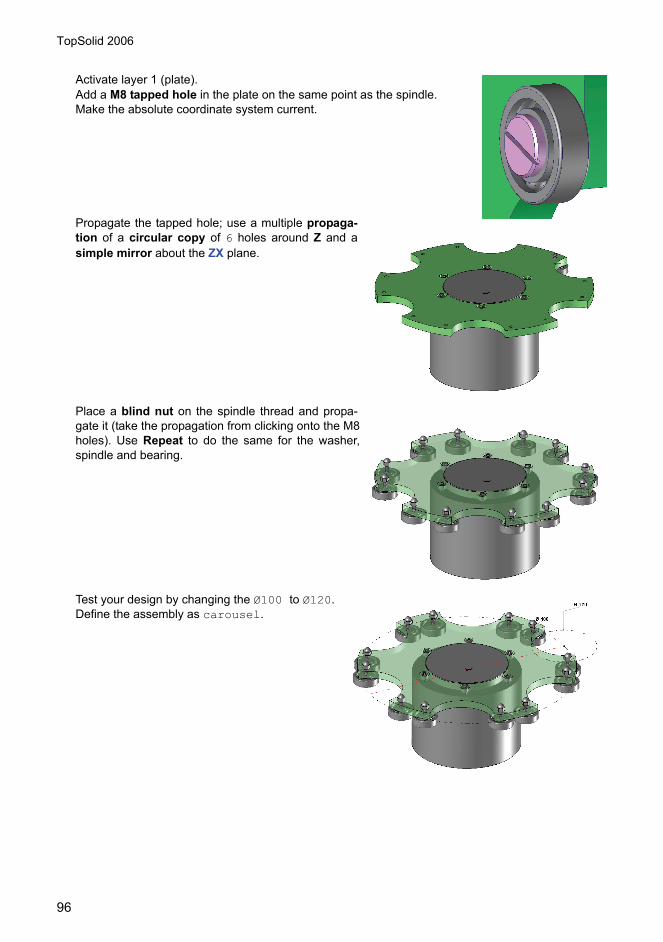
Activate layer 1 (plate).Add a M8 tapped hole in the plate on the same point as the spindle.Make the absolute coordinate system current.
Propagate the tapped hole; use a multiple propaga-tion of a circular copy of 6 holes around Z and asimple mirror about the ZX plane.
Place a blind nut on the spindle thread and propa-gate it (take the propagation from clicking onto the M8holes). Use Repeat to do the same for the washer,spindle and bearing.
Test your design by changing the Ø100 to Ø120.Define the assembly as carousel.

TopSolid 2006
97
Do a drawing and BOM.
Add a second drawing sheet with Tools, Drawing (copy the existing sheet and title block).
Then add views of the separate components. Select the Main View icon (you now have 2
drawings so select the border of the new sheet) then use to pick out the individual parts fromthe assembly.
Save the file.

TopSolid 2006
98

TopSolid 2006
99
Design in place 2/2 Topics covered:• Contour• Extrusion• Assembly and design in place
Most of the exercises performed to this point have been based on a single coordinate system: theabsolute coordinate system. In this example, we will see how to use other types of coordinate systems.When there are multiple coordinate systems in the same file, it is essential to use the concept of the
current coordinate system . The current coordinate system is the coordinate system in which thedrafter will construct his geometry.
1 ContourConstruct the contour bythe point in the coordinatesystem. Comply with thedimension and the align-ment constraints.
Position the part in rela-tion to the absolute coordi-nate system so that itsorigin is on point 1. Indoing so, the position ofthe contour is constrained,and therefore a dimensionmust be created.
70
40 30°
120
10
70
70
4030°
120
10
70

TopSolid 2006
100
Note: For a dynamic displacement, use the Move parents function. The NON-DYNAMIC option is usedfor displacement between two points.
Draw a line by two pointsand create the dimension.
To make the Oblong profile,use the Thicken operationon the line. Select the SYMMETRICALOPTION = YES with a thick-ness of 2mm; the end is theinner arc type.
Replicate the oblong profileby translation along the Y-axis of 25mm.
Note: Any replica element isexactly identical to its original.
2 ExtrusionBy selection, extrude thecontour as well as the twooblong profiles on 4mm alongthe Z+ axes.
Note: By clicking on the redarrow, the extrusion direction isreversed.
70
4030°
8
6
120
10
70
6
70
4030°
8
6
120
10
70
6

TopSolid 2006
101
3 Creating a coordinate system on the lower face of the plate.To create a coordinate system on a face, it simplyneeds to be made current.
Name the coordinate system F2.
After increasing the extent of the coordinate systemusing Modify element, draw a RECTANGULAR con-tour. Dimension the contour as shown to the right.
4mm extrusion of the contour along the Z+axes.
Creating a contour onthe face at a 30° angle.
Dimensioning of thecontour in relation tothe edges of the plate.

TopSolid 2006
102
Extrude the contour 8mm along the Z- axis. Make the two 5mm fillets.
Subtract the solid from the plate then maketwo Ø3mm drill holes concentric to the 5mmradii.
Drill at M4 and repeat the drilling in each cor-ner.
Note: Use the edges of the plate to indicate thetwo propagation directions.
Make current the 2 coordinate sys-tem.
Duplicate this coordinate system bytranslation along Z+. To indicate thedisplacement value, specify the platewith the 4 holes.
Name this new coordinate system 3and make it current.
Draw a RECTANGULAR contour.Dimension it to have a 2mm marginon all sides.
Execute a 25mm extrusion.

TopSolid 2006
103
Modify the M4 tappings and replace them with Ø4.5 holes.Call up the standard componentlibrary and take a CHC M4x16 screw.
Position it on the coordinate systemof the first drill hole and repeat thisusing the 4-corner drill hole propaga-tion.
Execute the TAPPING procedure onthe lower block, specifying which faceto drill.
Save the file.
Use the Assembly, Part definition function to attribute a designation and characteristics to each ofthe parts.
Click the parts, validate and fill in the boxes according to the values:Designation: PlateReference: P01
Also attribute a designation to the assembly.
4 Creating a part to assembleOpen a new Design document.
Create the insert shown here.
Start by drawing a rectangularcontour of 41.5mm x 8mm, towhich you apply 2 fillets of radius5mm.
Construct a 3mm parallel. Extrudethis parallel by 2.5mm, then add aboss with a height of 2mm.
Save the file and remember to use the Part definition function.
5 AssemblyOpen the document containing the in situ assembly.
Import the last part created using the Assembly, Include assembly/part function.
Place the insert in the Assembly document by clicking a point anywhere in the workspace.

TopSolid 2006
104
Show a face of the insert and make itcorrelate to the bearing face on thesquare. Validate the contact distance.
Continue, specifying the next faces inorder to position the insert in the notchon the square.
6 LayoutCall a new Draft document.
To create the layout of an assembly, you need to select the Main view function and then mustclick on the ASSEMBLY button.
If the 3D document is open, you may then select it by clicking directly in the document or via the drop-down list; otherwise, you have to use the BROWSE button.
Select the desired view configuration and place it in the drawing. Create the desired auxiliary views.
To insert a bill of material, use the Bill of material function , select the IdxNbDesMatObs tablemodel, click the ASSEMBLY button and select the assembly file name in the drop-down list. SelectDepth=FLAT LEVEL and click the title block to position the table.

TopSolid 2006
105
Then show the parts on the views to position the coordinate systems.
Regenerate the bill of materials using the function.

TopSolid 2006
106

TopSolid 2006
107
Components

TopSolid 2006
108
Concepts to introduce:• Define the geometry• Define the drivers• Define the tools associated with the component• Define the key points• Edit the component's catalog• Save a standard template
1 Define the geometryCreate a new Design document.Tools, Coordinate System menu. Select XZ.
Select SET AS CURRENT.
Select TOP VIEW.
Enable the Curve context . Then create the contour representing the half-part.
Dimensioning the contour: linear dimensioning and half-part dimensioning for diameter dimensions
.
Adjust and name the dimensions .
Enter a name for each of the driver dimensions.Name di = inner diameterName ht = height of the collarName h = height of the body
2 Adjust the dimensionsModify the dimension to di+5 for the body.Modify the dimension to di+10 for the collar.

TopSolid 2006
109
Enable the Shape context and create a revolu-
tion shape .
Create the chamfers from 1 to 45°.
3 Define the part
Assembly context , Define part .Click on the part, enter the part characteristics: desig-nation, reference, material, etc. then OK.
Save the document as Ring.
4 Define the componentAssembly, Define Component menu.
Note: Cut the Define component menu to keep it open.
5 Define driversAssembly, Define Component, Define drivers menu.
Click on dimension di.
Enter the driver designation: Inner Diameter, then OK.
Note: A set of drivers is created.
Repeat the operation for the other drivers, ht and hc:Body Height for hc, Collar Height for ht.
6 Define the key pointsThe key points are the component positioning points. In our example, we are going to define two positioning points, below and above the collar.
Set the absolute reference on current.Assembly, Define Component, Define key points menu.
Click on the absolute reference.
Erase ABSOLUTE REFERENCE and enter BOTTOM, then OK.
Note: A set of key points/references is created.
Create a duplicate coordinate system .
Click on the absolute reference (current reference).
Select TRANSLATION.

TopSolid 2006
110
Select Z+.
Enter parameter ht (height of the collar).
Click on the newly created reference.
Enter TOP, then Enter.
Select OK.
7 Insert the part into an assemblyOpen or create a new Design document.
Select Ring in the list of open components.
Enter the required values:di = 20mmhc = 10mmht = 10mm
Note: The proposed values are the template values.
Click on the position of the component on the receiving part.
Note: The positioning of the component is defined by a reference positioning on a reference on face withconstraints.
Select STOP.
The component is positioned in relation to the first key point.Select as required, then STOP.
Save the assembly document, then close.
8 Define the toolsIf required, go back to the Ring document.
Bottom Top

TopSolid 2006
111
Display the ring control elements .
Set the sketch reference to current.
Select REFERENCE ELEMENT.
Click on the sketch.The sketch creation reference becomes current.
Set level 1 on current. Click on the knurled wheel on level 1.
9 Create the tool geometry as the ring geometryAdjust and modify the dimensions according to the parameters.
Deactivate level 0.
Create a revolved shape.
Modify the tool transparency if need be (transparency attribute).
Assembly, Define component, Define tools menu.
Select SUBTRACT OPERATIONS ON SHAPES, then click on thetool shape.
Enter the tool name: Ring housing.
Enter the tool designation, then OK.
Note: A set of tools is created.
Save the document.
Open the previous assembly document.
Enable the Assembly context and select Use processes .
Click the Ring.

TopSolid 2006
112
Click the shape which is to undergo the process.
Select STOP.
Note: The process associated with the ring is displayed in the alpha bar. Ifneed be, use the modification of the positioning in order to change keypoints.
Save the document.
10 Edit the component's catalogReturn to the Ring document.Assembly, Define Component, Edit catalog heading menu.Select All the parameters and texts.
Note: Excel starts automatically if it is installed on your station. If it is not,Windows WordPad is opened.
Enter the various values for your rings.
Save the Ring.xls file.
Quit Excel.
11 Test the catalog
Assembly context , Catalog code .
Select the code of your choice.
Open the assembly document.
Modify element .Click the ring.

TopSolid 2006
113
Modify the code.
12 Save a standard templateAssembly, Define Component, Edit/save template.
Select SAVE STANDARD TEMPLATE.Enter your component’s classification.1. Select Standard MY 3D STANDARD2. New Family GUIDE3. New Type RING4. New Variant COLLAR5. Keep version 006. Keep Representation NORMAL
Select OK to validate.Note: The part file is RING#V=COLLAR#I=00#R=NR.top#V corresponds to the variant.#I corresponds to the version.#R corresponds to the representation.
7 Edit the standard component's catalogAssembly, Define Component, Edit catalog heading menu.
Select All the parameters and texts.
Enter the values or copy / paste the values from the previous catalog.
Save the file.
Quit Excel.
Note: The Excel file is name of template file.xls,In this case = RING#V=COLLAR#I=00#R=NR.xls.
8 Create a pictureFile, Save as menu.
Select the Bitmap format, then OK.
Adjust the values, then OK:
Size 300x300Type PNGBackground color WHITE
Click anywhere in the view to be captured.
Note: The BOX option is used to frame part of the view.
Close the file.
TopSolid 2006
114
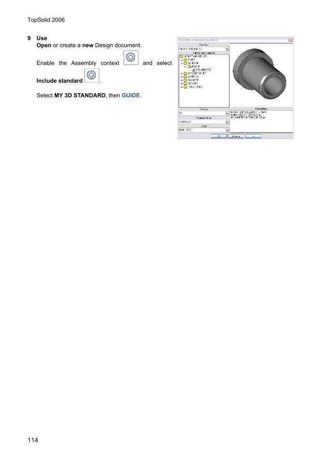
9 UseOpen or create a new Design document.
Enable the Assembly context and select
Include standard .
Select MY 3D STANDARD, then GUIDE.

TopSolid 2006
115
Kinematics & Dynamics

TopSolid 2006
116
KinematicsConcepts to introduce:• Joints.• Scenario.• Trajectory.• Replicate a state.• Positions.• Rigid sets.• Check collisions.• Approach.
IntroductionThe kinematics menu is used to define and simulate an articulated mechanism.• It is possible to define kinematics after the event on a predefined mechanical assembly.• It is possible to define kinematics for a mechanical assembly that includes parts made “in place”
(kinematics is independent of positioning constraints).• It is possible to define kinematics for a wireframe model in order to complete a preliminary study.• It is possible to define several scenarios for the same kinematics, in order to study several phases of
the movement.• It is possible to define stops on joints.• A few complex joints are available in order to represent, for instance, the screw / nut systems and
gears.• It is possible to generate a video clip of the graphical animation for marketing purposes.
Principle:The definition of the mechanism’s kinematics is done using two types of elements:
JointsJoints enable us to define mechanical articulations between elements.A joint is defined between a base element and a linked element: When the joint is enabled, the linkedelement moves in relation to the base element, which remains fixed (unless it is itself a linked element inanother joint, or attached to a linked element).It should be noted that a joint is always defined between two simple elements. For instance, when a jointis defined between two sub-assembly components, it is defined between two simple elements in eachcomponent.In contrast, when defining a rigid set, when we designate a composite element (sub-assemblycomponent, group), all its parts are assumed to be rigid. It is nonetheless possible to make the elementsof a single component mobile in relation to each other, by using the designation with detection (as this isless practical, it is recommended to organize the design of the mechanism in non-articulated sub-assemblies).Kinematics defined in this way are used to perform various simulations: animation, trajectory analysis...,but to do this, it is necessary to define the phase of the movement to be simulated, using a scenario.A scenario is a text file associated with the document (filename extension .scn), which describes theevolution of the articulated driving coordinates in the form of a simple column-based table, whose firstcolumn specifies the date when the articulations are performed, while the subsequent columns specifythe values for the articulated coordinates at this date.There may be several scenarios for a single kinematics (each scenario being identified by a name),which will help to study several phases of the movement.
Rigid setsRigid sets allow us to group together moving rigid elements in a logical manner (by default, each elementis assumed to be free and independent).The elements in a single rigid set are considered to be immobile in respect of each other, such as, forinstance, parts fixed by screws or bolts.

TopSolid 2006
117
These sets are grouped together in the rigid set group, which can be edited in the symbolic tree.It should be noted that there is no point in defining rigid sets when setting up a kinematics on a simple set(pre-study) where each element is independent.
Steps:To begin a study, follow these steps:• Model the mechanism in one of its kinematic states, using the standard functions.• If necessary, define the rigid sets.• Define the kinematic joints.• Create a scenario.• Launch an animation, in order to view the movement.
The kinematics definition being associative, it is obviously possible to modify the mechanical assemblyand to restart a simulation directly.
1 JointsOpen the Kinematics document.Study of a hand pump mechanism.
Enable the Kinematics context , then
select Joints .
2 ChassisSelect FIXED.
Click on the absolute reference.The tree opens automatically to display all the joints.
NOTE: A set of joints is created.
3 1st jointSelect PIVOT.Click on the chassis (absolute reference).Click the handle.Click the X- rotation axis of the handle in relation to the chassis.
Select OK.

TopSolid 2006
118
Name the joint: A.
4 2nd jointSelect PIVOT.
Click the handle.
Click the connecting rod.
Click the rotation axis X- of the connecting rod in relation to the handle.
Select OK.
Select ANONYMOUS.
5 3rd jointSelect PIVOT.
Click the connecting rod.
Click the piston.
Click the rotation axis X- of the connecting rod in relation to the piston.
Select OK.
Select ANONYMOUS.
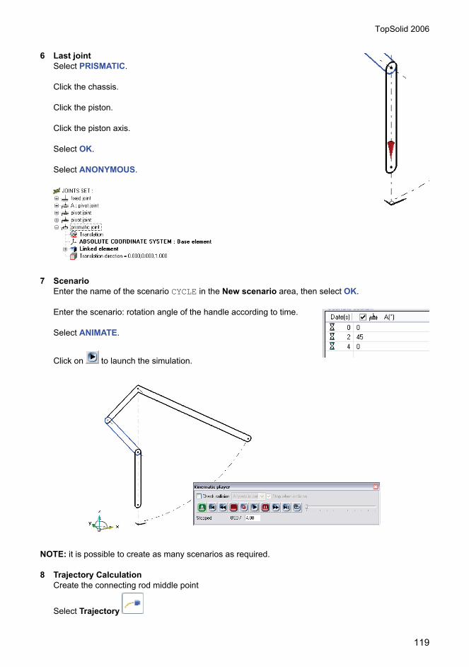
TopSolid 2006
119
6 Last jointSelect PRISMATIC.
Click the chassis.
Click the piston.
Click the piston axis.
Select OK.
Select ANONYMOUS.
7 ScenarioEnter the name of the scenario CYCLE in the New scenario area, then select OK.
Enter the scenario: rotation angle of the handle according to time.
Select ANIMATE.
Click on to launch the simulation.
NOTE: it is possible to create as many scenarios as required.
8 Trajectory CalculationCreate the connecting rod middle point
Select Trajectory

TopSolid 2006
120
Select FIXED COORDINATE SYSTEM.
Click the connecting rod.
Click the point.
9 Replicate a state
Select Replicate a state .
Enter the time and level of the element to be replicated:time = 2 and level = 5, then click the connecting rod.
10 Positions
Select Positions .
Select FIXED COORDINATE SYSTEM.
Click the connecting rod.
Click the connecting rod.
Some positions overlap.

TopSolid 2006
121
11 Rigid setsCreate a cylinder with a 20 mm diameter.
Select Rigid sets .
Click the piston sketch.
Click the cylinder, then STOP.
Note: a set of rigid sets is created. Each rigid set contains elementswhich will move together during the simulation.
12 Check collisionsUsed to check collisions during the movement.Only works on 3D templates.Enable level 1.
.
Select Collision Control Set .
Enter CHECK1.
Click the cylinder.
Click the ring.
Note: a set of collision checks is created.
Select Animate .
Check Stop when collision box.Select CHECK1.Check Stop when collision.Launch the animation.
Note: The simulation will be interrupted on the first collision encountered.
Select Duplicate state to keep the parts in collisions.

TopSolid 2006
122
Enter Level = 3 and click the cylinder.
Note: a set of sets of kinematic shots is created.
Each set contains the mobile elements involved in the simulation.
The time is indicated in the group name = 1.953 second in the CYCLE scenario.
13 ApproachUsed to calculate the distance between two bodies during thesimulation.
Create an extrusion of the sketch of the 10 mm handle in CEN-TERED mode.Create a rigid set comprising the sketch and the shape.
Select Closest approach .
Click the cylinder.
Click the new handle shape.
Click on OK.The approach lines are displayed on the screen.
The approach distance is displayed in the alpha area: Approach distance = [61.181mm, 92.735mm]
NOTE: it is not possible to display the simulation and the lines or to adjust the number of lines. A nilapproach distance indicates a collision.
14 StopsEdit the set of joints.Right-click on the pivot joint: A.
Select Modify in the context-sensitive menu.
Select NO INITIAL VALUE.
Select NO MINIMUM VALUE.
Enter 30° as maximal value.
Launch the simulation.The “Stop exceeded (A)” message is displayed in the alpha area. This is because the max. A value is reached, whereas in the scenario the A simulation angle is 45°.
The state can be replicated if required.
15 Application on partsOpen the Assembly file.Add the joints.

TopSolid 2006
123
Simulate the movement.

TopSolid 2006
124
DynamicsNOTE: Dynamics only works on an assembly with a constraint system.
Concepts to introduce:• Gravity.• Animate.• Measurement.• Record measurements.• Export and analyze results.
Open the Pump file.
16 Gravity
Select Add Gravity .
Select OK.
Select Z- or click on the cylindrical face of the body of the pump.
Gravity is represented by a red arrow.
NOTE: A set of forces is created, and gravity is to be added tothis set.
17 Mechanism calculation
Select Animate .
Select to launch the calculation.
Select to launch the simulation.
Move the absorption factor and observe the difference.
Select to launch the calculation.
Modify the physical attributes of the handle and change the material: aluminum.
Select to launch the calculation.
18 MeasurementWe wish to measure the angle between the connecting rod and the body of the pump.

TopSolid 2006
125
Select Measure .
Select the ANGLE measurement type and enter a name for thismeasurement: MEASUREMENT1.
Click Z- or the pump axis.
Click an edge of the connecting rod.
Select OK.
Select NEW MEASURE SET.
Enter the name of the measurement group ANALYSIS.
NOTE: A set of measurements is created, and the angle measurement is to be added to this set.
19 Record measurements
Select Animate .
Select to access the options.
Check Measure and select ANALYSIS.
Select Browse, then specify the file name and location.
Note: file name_measurement name.xt is proposed as the file name. You can select an .xls extension.In our example PUMP_ANALYSIS.XLS, since we are going to plot the curve with Excel.
Select to launch the simulation.
Close the animation box.
Open the PUMP_ANALYSIS.XLS file.
Plot the curve.

TopSolid 2006
126

TopSolid 2006
127
Surfaces

TopSolid 2006
128
Topics covered:• Basic surface design (Loft, Offset, Flat...)• Advanced design (Dome, Blend, Swept...)• Surfaces operations (Remove, Sew,...)
1 Contour creation
Create a new Design document .
Select Tools, Coordinate System.Select XZ.Select SET AS CURRENT.Select TOP VIEW.
Select Edit, Name.Click on the coordinate system.Input FRONT, then OK.
Set layer 1 as current.
Select Curves context , create a line from 0,0 to0,150.
Select Curves context , create 2 points on the line ,then dimension them like here.

TopSolid 2006
129
Select , then ABSOLUTE COORDINATE SYS-TEM.Switch to a perspective view.
Create coordinate systems to create section curves.with Tools, Coordinate System.Click on previously created points.
2 Create section curves
Create a circle , diameter 60mm, cen-tered on the absolute coordinate system.SET AS CURRENT the second coordinate system.
Create an ellipse , center 0,0, XRadius=30, Y Radius=25SET AS CURRENT the third coordinate system.
Create a circle , diameter 50mm, cen-tered on the current coordinate system.SET AS CURRENT the fourth coordinate system.
Create a circle , diameter 25mm, cen-tered on the current coordinate system.
Set the line invisible.
3 Loft Surface
Select Loft surface .
Select curves.

TopSolid 2006
130
All curves are in the same direction. Select STOPWITH NULL CURVATURE.
Create a 45° sketch line , passingthrough the point 0,50.
Create a 5mm offset line.
Shape, Trim
Select BY SWEEPING CURVE, then click on the sur-face.
Click the 45° sketch line.
Select KEEP BOTH PARTS.Change the color of the top surface.
4 Offset a surfaceShape, Other Operations, Offset
Click on the top surface.
Global distance = -2mm.
Select SAME DISTANCE FOR ALL FACES.
Trim the surface by the offset sketch line.

TopSolid 2006
131
5 Ruled surface
Ruled Surface .SET AS CURRENT the absolute coordinate system.Switch to a perspective view.
Click on boundaries of the 2 surfaces, invert directionif needed.
6 Create the top of the bottleSET AS CURRENT the highest coordinate system.Create a duplicated coordinate system on Z+ = 2mm.
SET AS CURRENT the new coordinate system.
Create a circle , diameter 25mm, centered on thecurrent coordinate system.
Extrude , SURFACIC on 15mm.
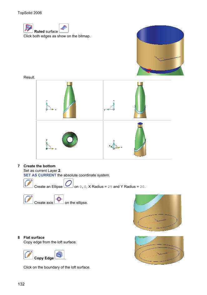
TopSolid 2006
132
Ruled surface Click both edges as show on the bitmap.
Result.
7 Create the bottomSet as current Layer 2.SET AS CURRENT the absolute coordinate system.
Create an Ellipse on 0,0, X Radius = 25 and Y Radius = 20.
Create axis on the ellipse.
8 Flat surfaceCopy edge from the loft surface.
Copy Edge .
Click on the boundary of the loft surface.

TopSolid 2006
133
Switch off layer 1.
Flat surface .
Select the 2 curves , then click on OK.
9 Dome surface
Driving elements.Click on the flat surface.
Create intersection points between the ellipse and its axis.SET AS CURRENT the coordinate named FRONT.
Create a circle .Create two arcs passing by 3 points likeshown below.
Trim both arcs on their intersection point
Create a dome .
Click on the ellipse.
Click on the first arc.
Click on the second arc, then OK.An axis has been automatically created.
Select OK.
Select OK.

TopSolid 2006
134
10 Blend surface, 3 facesSelect Transparency = 6 then click on the body of the bottle.
Create Blend .
Select 3 FACES BLEND.Click on the body of the bottle.
If needed, invert the direction, then select OK.Click on the flat face.If needed, invert the direction, then Select OK.
Click on the dome surface.
If needed, invert the direction, then select OK.
Click on the circular edge.
Result.
Set the flat surface on layer number 5.

TopSolid 2006
135
11 Trim surfaces
Select Trim .
Select BY IMPRINTING CURVES, then click on the body of thebottle.
Click on the edge of the 3 faces blend surface.
The arrow shows the side you want to remove, then, click on OK.
Click on OK.
Select NO then OK.
Repeat the operation with the dome surface.
12 Create the threadSET AS CURRENT the highest coordinate sys-tem.Set current layer 3.
Create a duplicated coordinate system on Z+ = 5mm.

TopSolid 2006
136
Select Curve, Other Curves, Spiral / Helix.
Click on the 0,0 point.Input values like shown on the bitmap, then OK.
Create a rectangle , CENTERED, X = 2mm and Y =2mm.
Swept surface .Select the first choice: One guide curve and one section curve.
Click on the helix.Click on Z+.
Select POSITION SECTION CURVE.Click on the rectangle.
Select USE CURRENT COORDINATE SYSTEM ORIGIN.Click on SURFACE to switch into a SOLID mode, then OK.
Create fillets of 5mm.

TopSolid 2006
137
Create chamfers 0.75mm x 0.75mm.
13 Remove faceRemove the internal face of the thread.
Remove .
Click the internal face like shown.
Select OK.
Duplicate the thread with a 180° rotation around Z+.
14 Intersection of faces
Intersection
Click on the top of the bottle.
Select ALL FACES.
Click on the thread.
Do the same thing for the second thread.
15 Imprint
Imprint .
Click on the top of the bottle.
Select all curves we've created just before.
Select NORMAL.
Select OK.
Remove imprinted faces on the top of the bottle.

TopSolid 2006
138
Create a circle, diameter = 25mm, on point 0,0.
Trim the 2 threads by this circle.
16 Sew surfaces
Sew .
Select all surfaces.
Select DON'T COPY BOUNDARY EDGES.
NOTE: You've a message in the alpha bar: Result is asurface.
17 ThickenShape, Other Operations, Thicken.Input 0.5mm along the arrow direction, then OK.
Result.

TopSolid 2006
139
Mechanically WeldedChassis

TopSolid 2006
140
Concepts to introduce:• Assembly on a sketch.• Constrained assembly.• Modifications.• Cuts.
1 Assembly on a sketchOpen the ChassisSketch docu-ment.In the Assembly context, click on
.Select a 200 UAP beam extruded.
Click on the 1st point in the segment.
Click on the 2nd point in the segment.
If need be, turn the iron by entering an angular value (90°or 180°), then click on STOP.
Repeat the procedure on the other extruded elements.
1
2

TopSolid 2006
141
Note: In this example, in order to avoid having to enter an angular value, click on the pointscounterclockwise.
2 Curve trimming: Miter cut
In the Shape context, click on .Scroll down the list and select EXTENDED CUT,then in Mode, select MITER CUT.
Click the first shape.
Click the second shape.
The arrows indicate the cutting direction for theextruded elements.
Click on OK.
Result of the cut.
Repeat the procedure on the other extruded elements.
1
2

TopSolid 2006
142
Lay the crosspieces in the same way as above.
3 Curve trimming: Main cut
In the Shape context, click on .Scroll down the list and select EXTENDED CUT, then in Mode,select MAIN CUT.
Click the first shape.
Click the second shape.The arrow indicates the cutting direction for the extruded ele-ment.
1
2

TopSolid 2006
143
Result of the cut.
Click on OK.
Repeat the procedure on the other side of the extruded ele-ment, then on the other crosspiece.
4 Changing the orientation
In the system bar, click on Modify element , then selectthe1st crosspiece.
Click on POSITIONING.
Enter 180° in the rotation angle area, then click on STOP.
Result of the change in orientation.
Repeat the procedure on the other crosspiece.
5 Assembly on sketch and face
In the Assembly context, click on .
Select a 100x10 equal-sided Angle Extruded Rolled.
Select the axis.
Click on OK.Select the outer face of the 1st
curve.
Select the outer face of the 2nd
curve.
Rotation angle = 180°.
Scroll down the key points by clicking onCORNER POINT until the result below isobtained, then STOP.
1st face
2nd face

TopSolid 2006
144
Assembly result.
Repeat the procedure on the other crosspiece.
6 Assembly on point and face
In the Assembly context, click on .Select a 50 U-shaped Small Iron Extruded Rolled.
Click on THROUGH POINT.
In the system bar, click on , then in the point bar, click on point on curve .
Select the edge of the crosspiece.
Click on Y-.
Rotation angle = - 90°, then STOP.
In the Curve context , click on Dimen-
sion .

TopSolid 2006
145
Click on the point, then on the edge, and adjustthe dimension to 300mm.
7 Constrained assemblyBeam 1 Assembly
In the Assembly context, click on .Select a 200 UAP Poutrelle extruded.
Select CONSTRAINED POSITIONING.
Enter 1000mm.
Select OTHER POSITIONING.
Click in the graphic area to position the component.
Set the assembly constraints as follows:- Mate at extremity of extruded element on blue face.- Alignment of green faces.- Alignment of yellow faces.
8 Beam 2 AssemblyRepeat the procedure for the following extruded element:extruded element length = 500mm.
Set the assembly constraints as follows:- Mate at extremity of extruded element on green face.- Alignment of blue faces.- Alignment of yellow faces.

TopSolid 2006
146
9 Modification of key pointLay a 50x5 equal-sided Angle extruded as shown below.Perform the trimming operations.
10 Change the 1st pointOpen the construction tree and edit the extruded ele-ment.
Click the right mouse button to display the context-sensi-tive menu, then select Replace.
In the list of points, select the half-way point of theextruded element.
NOTE: you can either use the center point of the edge
or the point on curve by selecting the middleoption in the drop-down list.
Perform a PLANE SYMMETRY rep-etition along the ZX plane of beam 1and 2 and of the brace.
1
2

TopSolid 2006
147
11 Do a Chassis assembly layoutSet the bill of materials for materialuse.

TopSolid 2006
148

TopSolid 2006
149
Sheet Metal Work & Piping

TopSolid 2006
150
Concepts to introduce:• Assembly on a sketch.• Inserting components.• Creating a pipe line.• Processes.• Creating a plate.• 3D contour.• 3D dimensioning.• Pipe line layout.
1 Assembly on a sketchCreate the following sketch at level 0.
Enable level 1.Include an AFNOR Boilermaking, Tank, Collar = Ø800, thickness = 10 between the two points onthe horizontal sketch.

TopSolid 2006
151
Include an AFNOR, Boilermaking, Bottoms, Dished bottom forpipes, Ø800x10 on curve and point reference.
Set level 2 to current.
Include a TOPPIPING Stainless steel, Accessory, Welding neckflange = PN10 – DN200.
Select the coordinate system on point.Click the upper vertical curve.
Note: you can select the curve to automatically position the usual flangefor the curve, and then merge the created point with the end point of thecurve using Edit, Merge.
Repeat the procedure for the lower curve: positioning of the flange and point merging.
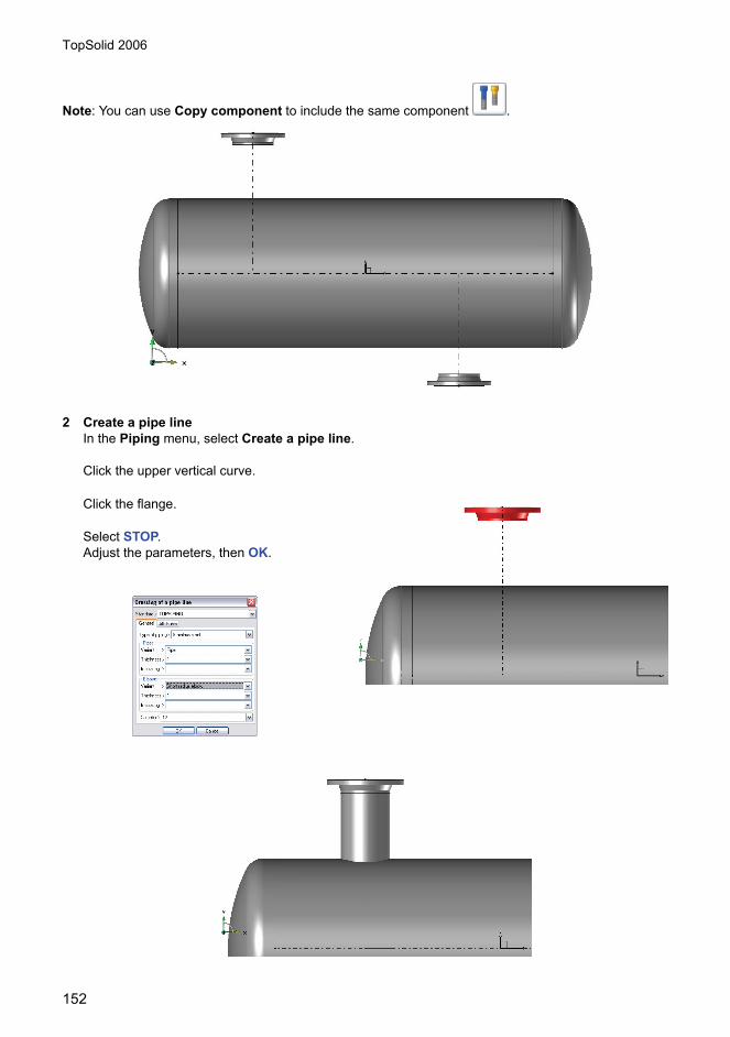
TopSolid 2006
152
Note: You can use Copy component to include the same component .
2 Create a pipe lineIn the Piping menu, select Create a pipe line.
Click the upper vertical curve.
Click the flange.
Select STOP.Adjust the parameters, then OK.

TopSolid 2006
153
Repeat the procedure for the lower curve.
3 Processes
Select Processes .
Click the tube.
Select Outer branching, then click on the ferrule.Select STOP.
Click the ferrule.
Select inner trimming, then clickthe tube.Select STOP.
Repeat the procedure for the bot-tom tube.
Set level 3 to current.
Create a point on the horizontalsketch, 100mm away from the leftextremity with Point on curve.
Dimension the point and adjust thedimension to 125mm.
Create a reference on point.
Turn the reference around X to switchto plane XZ / absolute reference.

TopSolid 2006
154
Deactivate levels 0,1 and 2.Create a U-shaped curve centered on X.
Create a 620mm extrusion along Z-.
Create a YZ plane.Create a circle with Ø812.Create two sketches at 30° and -30°.
Create two parallel lines at 50mm.
Trim the circle using the parallel lines.
Create a 250mm extrusion with the arc, leaving thesketches visible and using a –25 offset.
Create a trim on the U with the arc.

TopSolid 2006
155
Enable the Sheet metal context and select Create Sheet Metal .
Click the lining.
Enter thickness = 12mm and reverse the directionif need be. The direction of the lining thickness istowards the ferrule.
4 Create 8-size fillets on the U Create a plate on the U, 8mm thick, with the direction of thematerial towards the outside.

TopSolid 2006
156
Create a plane on the planar face of the U.Create a 740 x 200 rectangular contour.Create a point in the middle of the long edge of the U.Dimension, constraint and adjust the dimensions as shownin the picture below.
Create a 12mm extrusion.Create two holes with Ø22 as shown.
Enable the other levels.Set the absolute reference as current.Create a repetition along YZ of the foot.
5 3D contourOpen the InstallationWithoutpipes.Deactivate levels 2 and 3.Assemble clamps PN16-DN100 on theTank and Tank3.
Select 3D Contour .
Select CURRENT COORDINATE SYS-TEM.
Click a flange.

TopSolid 2006
157
Click the flange reference.
Select >>.
Set the REFERENCE PROTRACTOR on 90°, then OK.
Move the mouse to the left and enter 500mm.Move the mouse up and enter 500mm.
Select WIZARDS.
Select CUBE.
Select the point in the centerof the TANK3 flange.
Using OTHER WAY, selectthe right line, then OK.
Select STOP.
In the Piping menu, selectCreate a pipe line.
Click the 3D contour.
Click the flange.
Click the other flange, thenselect STOP.
Adjust the parameters, then OK.
6 3D dimensioning
Select 3D dimensioning .
Select AUTOMATIC DIMENSIONING.
Click the 3D contour, then QUIT.

TopSolid 2006
158
Delete the 1261.31 dimension and adjust the dimension from 500 to 200mm.
7 Pipe line layout
Select Main view or .Select ABSOLUTE COORDINATE SYS-TEM.
Click on the pipe line in the 3D template.
Place the view.
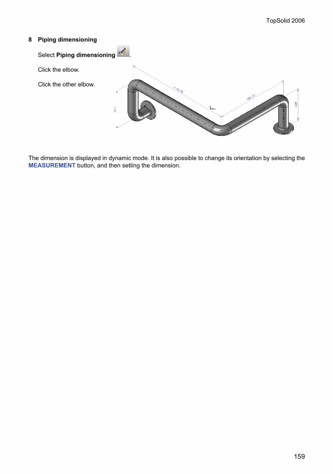
TopSolid 2006
159
8 Piping dimensioning
Select Piping dimensioning .
Click the elbow.
Click the other elbow.
The dimension is displayed in dynamic mode. It is also possible to change its orientation by selecting theMEASUREMENT button, and then setting the dimension.

TopSolid 2006
160

TopSolid 2006
161
Realistic Rendering

TopSolid 2006
162
Concept to introduce:• Use advanced functions of imaging• Add, replace and adjust texture layers• Add reflections and relief• Manage lights and textures• Set conical views• Activate advanced shadows• Set up anti-aliasing• Use shaders and advanced renders• Insert logos
1 Open the document Bank.top
2 Shift to realistic rendering
3 Click the icon DisplayIf the TopSolid/Image icon bar is not visible, display it by right-clicking the menu, and selecting Image.
4 Click the viewThe image displays throughout the progress ofthe calculation.The colors and textures are similar, but the lightsare of much higher quality.In order to cover the windows, we wish toreplace their plain green color with a texture.
5 Click the Textures icon , and select the left green window
6 Click the Textures radio buttonAdd a layer using the Add layer button. In the Pattern tab,select the Plastics family. Click the blue texture in the top leftcorner.
When TopSolid’Image is installed, the Apply button previews theresult in realistic rendering, and the Preview button previews theresult in Image rendering.
7 Click OKThe green color on the left window is replaced with the blue tex-ture.To apply the same texture as the right window, just copy the material (transporting the texture infor-mation) from the left to the right window.

TopSolid 2006
163
8 Run Attribute, MaterialClick the left window to define the template, thenthe right window to indicate the part to modify.
9 Restart a TopSolid’Image renderingThe scene is lit (among others) by a spotlightlocated above the teller. We now light it from thefront.
10 Click the Light iconThe light configuration box displays.
11 Modify the spotlight parametersSelect the Spotlight above spotlight. Disable it by uncheckingOn. Select the Front spotlight, and enable it by checking On.
12 Click the Apply button to view the new configuration, then click OK
13 Restart a TopSolid’Image renderingThe shades projected by the spotlight are neat, with asharp edge.

TopSolid 2006
164
14 Modifying the shadesIn order to soften their outline, open the light box, select Front spotlight,and position the Shade diffusion cursor on the 4th position. Restart aTopSolid’Image rendering to observe the variation.
Now save an image of the project.
15 Save the image in a fileClick the Save icon.Click the view. Keep the name and format proposed(bank.jpg).Enter the size required, and click OK. The image is calcu-lated, then saved.
Managing the environment
Creating a frame
16 Load the file Case.topIn order to produce more relief, we wish to view the case with itsshade projected onto the ground.
17 Create a mark on one of the case’s feet in the horizontal planeIn this work plane, create a large rectangular flat surface.
Considering the perspective, we can plan a surface 5 to 10 timeslarger than the subject.
18 Zoom in on the object while orienting the view approxi-mately according to the result required
19 Allocate a floor board texture to the surface, and set the scale in the Parameterization tab
We recommend setting the dynamic rotation centered around thesubject.

TopSolid 2006
165
Adjusting the lightsTo enhance the subject, light it using a spotlight lighting it exclusively.
To ensure easy lights adjusting, shift to 4 views, with the perspectiveview close to the result required, and the other views sufficiently faraway from the subject to contain the lights.
20 Creating new lightOpen the lights configuration box and deactivate directionallight. Create a new light of the spotlight type. Set the origin ofthe spotlight in the top left corner and in front of the case. Adjustthe spotlight’s opening in order to light only the subject’s sur-roundings.
To use dynamic lights adjusting in the views, we recommendreducing the project’s window, and moving the lights configurationbox outside.
In the realistic rendering, the ground seems black.This is due to the fact that in accelerated rendering,only the tops of the polygons are lit. In the case ofthe ground, its 4 corners are outside the spotlightzone.
21 Adjusting the toleranceIn the status bar, click the Tol zone, and activate the Max facet sizezone. Set the value to 200mm.

TopSolid 2006
166
The ground is now cut into 200m long triangles, which canbe lit properly. Please note that this procedure is requiredonly in accelerated rendering. TopSolid’Image calculates theimage properly without this additional cutting.
Adjusting the cameraWe now adjust the camera into the conical perspectivemode. This mode is more realistic than the parallelperspective used in design.
22 Shift into the on conical perspective view modeZoom in on element on the case.Turn around the part to position it vertically with the spotlight to the left and the lighting mark on theground to the right.Open the camera configuration box.
23 Select the Parameters tab, and click the viewSelect the conical projection and choose a 35°viewing angle.Click the Longitude, latitude, radius mode, and setthe 3rd parameter to the value 800 (this parametercorresponds to the distance between the camera andthe point targeted).Click OK to update the view.
For information, the human eye has a viewing angleranging from 35° to 45°.
24 Click QUIT, then rotate and translate the part until the scene is satisfactory. Launch a rendering using TopSolid/Image.
You can save the camera’s status using save view’sconfiguration.
It can be interesting to rotate the ground’s texture (Rotation field in the Parameterization tab) to preventthe patterns from being too well aligned with the case of the viewing direction.
Adjusting shadesThe shades obtained are a little too sharp. They can be softened.
25 Open the lights configuration box, select the spot-light, and set the Shade diffusion cursor on the 3rd settingThe shade projected by the subject is softer.
26 Open the lights configuration box, select the spot-light, and define the Penumbral shadow half-angle field to 10°The spotlight’s bright-dark transition zone is now larger.

TopSolid 2006
167
Managing materials
Colors
27 Load the Drill.top fileThe first step consists in coloring the assembly.
28 Modify the rear part’s texture, and select a yel-low ambient and diffuse color yellow. Also, color the front part in green.
Colors and textures can be easily copied from the frontpart on its symmetry using the Attribute, Materialfunction.
29 Turn the part slightly facing you, and apply a TopSolid’Image rendering.
We now wish to have an aspect slightly lighter on thefront part.
30 Modify the texture on the front part: set Smooth aspect to 20 and Brightness to 50
Basic textures
LayersTextures are defined by a superimposition of layers which each providetheir own effect. Certain effects are integrated into a same layer.
31 Load the Vase.top fileAdd a texture layer with a pattern Minerals, Pink granite.
The rendering is rather dull. Adding a brightness effect is required.
32 In the Colors page, set Smooth aspect to 20 and Brightness to 50
In the Textures page, Style tab, check Specular.
The Specular option enables adding the specularity effect to the color effectprovided by the texture. However, for a more advanced reflection effect, wecan use a special layer.
33 Add a texture layer, select the Reflections / Brightness pattern, and choose the Reflection effect parameterizationWe then use this effect added to the basic pattern.
34 Modify the 2nd layer, by shifting its style to Add with a value 0.4

TopSolid 2006
168
StyleIn the previous exercise, we used the Add mode.
35 Try the Add, Mix and Filter modes
The types of plating enable using an existing texture with other colors.
36 Delete the second layer, and replace the current pattern by Tex-tile/Spotted fur
37 Select the Degraded type, and define the first color with a light color, and the second color with dark brown.
ParameterizationThe parameterization tab enables choosing a texture plating adapted to theobject’s shape.
38 Load the Vase.top file and add a layer of the TopSolid/Marble texture
The texture is tightened on the level of the collars.
39 Set the parameterization to Auto axes
The texture is less distorted, but the texture seams are visible.
40 Set the parameterization to Cylindrical, click Main mark, and set the values U Scale to 0.2rev and V Scale to 50mm
The result is correct, except on the level of the foot, which is too horizontal.TopSolid’Image’s 3D textures do not need 2D plating, and do not sufferfrom any distortion or seam effect.
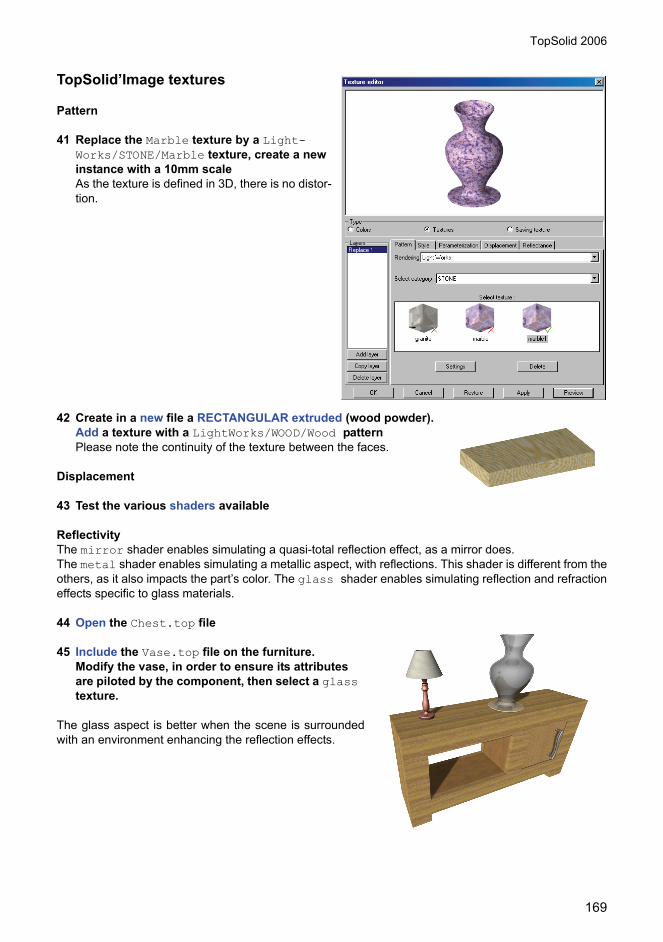
TopSolid 2006
169
TopSolid’Image textures
Pattern
41 Replace the Marble texture by a Light-Works/STONE/Marble texture, create a new instance with a 10mm scaleAs the texture is defined in 3D, there is no distor-tion.
42 Create in a new file a RECTANGULAR extruded (wood powder). Add a texture with a LightWorks/WOOD/Wood patternPlease note the continuity of the texture between the faces.
Displacement
43 Test the various shaders available
ReflectivityThe mirror shader enables simulating a quasi-total reflection effect, as a mirror does.The metal shader enables simulating a metallic aspect, with reflections. This shader is different from theothers, as it also impacts the part’s color. The glass shader enables simulating reflection and refractioneffects specific to glass materials.
44 Open the Chest.top file
45 Include the Vase.top file on the furniture.Modify the vase, in order to ensure its attributes are piloted by the component, then select a glass texture.
The glass aspect is better when the scene is surroundedwith an environment enhancing the reflection effects.

TopSolid 2006
170
Advanced rendering
Study of a metallic part
46 Open the Holder.top file and perform a renderingThe result lacks brightness.
47 Modifying the part’s texture Increase the smooth aspect to 20 and brightness to50.The rounded edges are brighter, but overall it remainsdull.
48 Modify the part’s reflectivityAdd a layer of reflectivity of the metal type, and choose aluminum.The result is correct, but the clear shades do not provide a pleasant result.
49 Modify the shadesOpen the lights configuration box, select the front lightand set the Shade diffusion cursor to the third set-ting.The result is clearly more pleasant for the eye.
50 Modify the textureChoose gold, copper, etc. Play on the variousshade parameters.
We now want to give a more irregular aspect to the sur-face.
51 Modify the part’s texture Uncheck the shader for reflectivity and select the pattern Metals/Rough galvanized metalsheet.Add a new layer.Use the Add style with a value 1, and use the reflectivity shader defined previously.Change it by setting the values Ambient factor and Diffusion factor to zero.
The result combines the pattern of the first layer withthe reflection of the second. We can note that the parthas bluish reflections. This is due to the reflection ofthe screen background in the part. We can avoid thiseffect, by changing the application’s background colorto black. But in this case, the image obtained will havea black background if the background is visible in cer-tain locations.
In order to achieve a rough aspect, a displacementshader is added.

TopSolid 2006
171
52 Modifying the part’s textureAdd to the first layer a rough displacement shaderwith a 20mm scale and a 0.1 amplitude.
We obtain a rough aspect, but it is too strong toenable the reflection to provide an effect.
53 Modifying the amplitude of the displacement shader to 0.02, and the metal layer reflection factor to 0.3.We obtain a reflection distorted by the perfectly real-istic roughness.
Managing textures and logos54 Load the Case.top file.
We wish to add a logo in the hollow section of the case.
55 Modify the texture of the blue panel on the front of the caseAdd a layer, and choose a logo on a white back-ground in the TopSolid Logos family.In the Parameterization tab, choose the Ortho-graphic type and uncheck Wrap U and Wrap V.Uncouple the U and V scales, and set the U scale to100mm and the V scale to 50mm. Center the logoapproximately.In the Style tab, choose the Relief mode, and set thevalue to 2.
Realistic display becomes very slow. The relief dis-play can be deactivated in the rendering viewingoptions (Relief, Viewing option).The TopSolid’Imagerendering takes the logo into account in relief.We now wish to replace the TopSolid logo with a per-sonal Missler logo.
56 Run the Attribute, Texture function, and click MANAGING TEXTURES.

TopSolid 2006
172
57 Create a new familyClick Create a new family and create a family named My logos.Then click Import texture and select the Missler.gif file.In the texture definition box, check the Logo option, then clickOK.
This bitmap can now be used as a texture by TopSolid.
58 Replace the TopSolid texture by the Missler texture in the My logos family, and run a TopSolid’Image calculation.

TopSolid 2006
173
Importing and repairingshapes

TopSolid 2006
174
In this workshop, you will learn how to:• Import templates of different formats• Check the validity of shapes• Eliminate parasite elements• Repair shapes• Sew surfaces • Cap holes• Simplify parts
IntroductionThis chapter deals with the methods available for importing and repairing external geometric datarepresenting solid or surface shapes (this does not include the import of drawings).The aim is to take a file from a source other than TopSolid, extract the geometry and repair it in order toproduce solid or surface-type shapes that can than be worked on as normal within TopSolid.This method should be applied when the normalimport method does not function correctly, andsimply using the File, Open function with theappropriate format does not provide satisfactoryresults.It should be also noted that even if the originalsystem also uses the Parasolid accurate volumemodeller format, we strongly recommend that youuse a native Parasolid file format (X_T or X_B) asan intermediary, as this usually ensuresimmediate success.
Communication difficultiesThe question might be asked why the problem of exchanging data between CAD systems has not yetbeen fully resolved, despite the existence of standard formats (IGES, STEP), and the fact that it is evensometimes possible to read the native format of certain systems (AutoCAD, CATIA, etc.) directly.It is important to dwell a while on this subject, as understanding of the difficulties involved will be of greathelp when one is confronted with problems in the future.A neutral file format definition standard is actually concerned with the syntax used (the way in which thegeometry is described), and does not make any assumptions in regard of the quality of the informationthat is transported: The contents of the book is of little importance – the important fact is that it does notcontain any spelling mistakes!This is not due to an oversight on the part of those who designed the standard, but nevertheless provesto be the necessary condition to allow communication between several CAD systems with differentcharacteristics.Thus, when TopSolid reads an IGES file, it not only has to interpret the file syntax, but also has to adaptthe characteristics of the imported geometry to comply with its own demands.TopSolid is a modern application, it works with numeric values that are accurate to 15 significant figures,and manipulates geometry with a great deal of accuracy (0.01 µm); this is not necessarily the case witholder existing design systems.Furthermore, TopSolid is permanently testing the quality of the geometry to ensure that it corresponds tothe physical world and in particular that there are no auto-intersections (surfaces of curves that create aloop.).It is possible that a system that does not perform these checks may consider a geometry to be valid,whilst TopSolid considers this same geometry to be invalid. This may seem like a useless constraint thatis imposed by TopSolid. However, is it better to live in ignorance and only discover at the end of themonth that your bank account is overdrawn, or to be warned in a timely fashion as soon as a purchasemight cause a problem?

TopSolid 2006
175
Advanced Geometric Cleaning ModuleManual repair of invalid geometric data can prove to bean extremely tiresome and time-consuming task,especially when there are a large number of elements tohandle.In addition, by default, TopSolid is capable of performing acertain amount of repairs automatically.A specific module, dedicated to repairing geometriesautomatically, is also available as an option. This is theAdvanced Geometric Cleaning Module (known hereafteras the AGC module). You can check to see whether it isactive by choosing Tools, Options, Shape.This module implements complex algorithms that enableit to handle even more types of invalid geometry automatically. If you are required to import external datafrequently, we strongly recommend this module.Some of the functionality described below is only available with the AGC module. This will be explainedin more detail where appropriate.
Non-associative modeOf the work modes available under TopSolid, the Non-associative mode is most suited to data repairs.It is actually useless to save the history of all the operations necessary to repair a model. In fact this mayeven damage the model.Also, it is advisable to change the work mode using File, Properties, General just after import, as soonas the TopSolid document has been created.When the model has been repaired, you will be able to switch back to whatever mode you prefer, andstart modelling (associatively or otherwise) around a valid basic shape.
Importing modelsOptions configuration for interfaces can be adjusted:• with File, Open and select Configurate button (active
when IGESfile or other format is selected)• or with Tools, Options, Interfaces
IGES files
Parameter restrictionsFirstly, it should be clear that the IGES format enables twomethods of representation of trimmed surfaces: parametricmode and spatial mode.Without going into detail, it is sufficient to remember that themode that provides the greatest chance of avoiding problems is the parametric trimming mode, and thisis selected by default. In addition, do not change the mode unless you are totally sure that the originalsystem does not produce good quality parametric trimming and believe that you would probably be facedwith a heavier repairs workload.

TopSolid 2006
176
Smoothing polygonal trimmingThe parametric trims of a surface are represented by planarcurves, which may have angular points (discontinuity oftangent), called vertices.Each segment between two vertices will correspond to anedge on the final shape, which it is possible to view usingCurve, Other curves, Edge.Some CAD systems use polygonal parametric trims with alarge number of segments, which therefore produce shapeswith a very high number of edges.This produces models that are very hard to manipulate(handling time) and store (file size), and even worse, verydifficult to sew (see below).For this reason, TopSolid enables these polygons to besmoothed; you simply have to select the Smooth trimming contours operation from the Other tab.If you do not know whether or not the originating system uses polygonal trimming, you need to perform atest on a test file: the number of edges on the shapes that have been extracted should be lower when thesmoothing is activated.
Postponing simplificationIt is possible to simplify the geometry automatically on import: This causes almost planar polynomialsurfaces to be transformed into perfect planes.However, this presents the inconvenience of not knowing where a problem arises if a shape is invalid:was the shape invalid to start with, or has it become invalid as a result of the simplification?Furthermore, in the case of importing complex data, it is advisable that the Simplify geometry option isnot selected on the Other tab, but that the simplification is postponed to a later stage (see below).
Standard cleaningA certain amount of cleaning of the geometry can be performed automatically on import.Without going into detail, it is worth mentioning some tasks that are performed by the standard automaticcleaning routines:• Division of surfaces containing discontinuities of tangency.• Removal of self-intersecting areas that are outside the useful trimmed part.In contrast to what has been said previously about simplification, it is better to perform the cleaningoperation immediately on import, and therefore to select the Clean geometry option on the Other tab.Moreover, some cleaning operations cannot be performed in a second session.
Advanced cleaningIf you have the AGC module installed, the cleaning operation will be much more complete (it will alsotake much longer). Without going into detail, the following comprise some of the tasks performed by theadvanced automatic cleaning routines:• Advanced repairs to parametric trimming• Smoothing of surfaces that contain discontinuities of tangency• Repairs to certain self-intersecting areas of surfaces.

TopSolid 2006
177
Layers 998 and 999When a surface trim is in such a state that it cannot be retrieved,TopSolid creates the surface without any trimming on layer 999.In (rare) cases where the support surface is an offset surface, the non-trimmed surface is created on layer 998.These surfaces must be trimmed using edges from neighbouringsurfaces before being used. Do this using the Shape, Trim commandwith the option BY IMPRINTING CURVES.
CATIA fileFor the reasons mentioned above, it is recommended that you do not selectthe Simplify faces option, but do select Clean faces.The CATIA interface also offers the option of sewing solid shapesautomatically, which is of great help… when it works!Nevertheless, experience shows that, except in simple cases, it is rare that avalid solid will be obtained from the automatic method without also performingthe steps described below.
Other formatsAs far as other formats are concerned, there are no specific characteristics tobe aware of during import. Nevertheless, as cleaning will not yet have beenperformed, it is better to use the Shape, Manage, Clean geometry function inorder to initiate subsequent cleaning.
Verify shapes
Visual verificationOnce the import has been completed, it is necessary to evaluate the state of the parts. The mostimportant tools that you can use are your own eyes!If there are any misplaced or incorrect elements, these should either be deleted or, if possible, repaired.
Verifying geometryThe function Shape, Manage, Check geometry enables you to perform exhaustive geometricverifications (which may take a long time to complete: you can interrupt the function by pressing theEscape key). This function should be launched by clicking on the ALL SHAPES button with the Showproblems option set to YES, and specifying the number of the layer on which invalid elements shouldbe placed.If there is no invalid shape (the message No invalid shapes appears in the alphanumeric field), you canprogress straight to the sew stage. In all other cases, it is recommended that you carry on reading thissection.In order to identify the problems, you can print the LIST OF VERIFICATION RESULTS in the treestructure. Each geometrically invalid shape is referenced in the list, followed by a list of problems thatwere encountered (one line per problem).For each problem, a group is created with a short description of the problem, containing components thatallow the default position to be located.

TopSolid 2006
178
Eliminate
Small surfacesIncluded amongst the elements that are considered to be invalidare sometimes tiny surfaces, or very fine bands.
In addition, even if these are considered to be valid, the surfaceshapes with dimensions that are smaller than the level ofprecision that you wish to attain will not contribute to the parts andmay make the sewing operation more difficult (see below).
The easiest method is simply to eliminate these elements.In order to do this, the selection filter should be used with thePhysical properties criteria and the SURFACE AREA option,and all the surface shapes with a very small surface area should be placed on a separate layer.Following brief visual examination, most of these surfaces can be deleted.
Redundant surfacesIt may also be the case that some surfaces will be duplicated, or that trimmed and non-trimmed surfacesmay be superimposed (the latter overlapping the former): in such a case, the non-useful elements shouldbe deleted, to avoid possible problems during the sewing operation.
Non-useful surfacesIn the same respect, some systems create surfaces representing the bottom of tapped hole threadsduring export: these surfaces should be deleted, or placed on an inactive layer for subsequent use; theydo not belong to the actual part, and can cause problems during the sewing operation.
Detection of non-useful surfaces can sometimes prove difficult in the case of a shape that contains manyfaces. It is also often the case that these surfaces are not detected until later, when the sewing operationfails: if this happens, you should consider whether or not there are still surfaces to be deleted, and returnto this stage (or unsew the suspect area, then delete the non-useful surfaces, and re-sew everything).
Repairs
Need for repairsAlthough not obligatory, it is advisable to repair invalid shapes, when possible, in order to arrive at a “zeroerror” model (this ideal cannot, unfortunately, always be achieved).It is, therefore, worth while differentiating between several degrees of invalidity.• A geometry may be so invalid that TopSolid is unable even to retrieve it (although this is rare), there
are no other options but to reconstruct it, or to request a better version from the originating system (which can sometimes be awkward).
• A geometry may be retrieved, but declared invalid during the verification stage. It is still possible to work with the geometry, but it is probable that some TopSolid functions will not work correctly on this geometry (facetting, union, fillets, sewing, etc.), and it is, therefore, better to attempt to make repairs.
The following sections provide some indication of how to repair certain types of error.
Self-intersecting geometryWhen the fault is a self-intersecting geometry, this indicates that the surface is looping, and there is nosimple method of repairing this type of problem. There are two alternatives open to you:• Rebuild the surface, using the invalid surfaces as a model.• Leave the surface as it is, hoping that the problem will not have consequences on the subsequent

TopSolid 2006
179
actions to be taken.The more pragmatic attitude is to leave the element as it is, and to rebuild the shape afterwards, only if asituation occurs where progression is impeded (a Boolean operation fails, etc.).
Parametric trimMost of the time, the problem does not arise from the base surface, but from the trims (e.g.: errors of thetype The surface trims are self-intersecting), in which case it is sufficient to modify these.The easiest method is to use the function Shape, Manage, Trim UV, which enables the parametric trimsto be edited directly.
Spatial trimmingWhen it is not possible to repair parametric trims locally, the simplest method comprises deleting all trims(using the function Shape, Other operations, Remove with mode remove = TRIMMING), and trimmingthe surface shapes using the neighbouring shapes (using the function Shape, Trim).It is also possible to use Shape, Manage, Repair sheet, this requires to have previously sewn validsurfaces, in order to use boundaries edges to define new spatial trimming of invalid shapes.
Sewing
PrincipleWhen all preceding stages have been completed successfully, the result is a fairly large quantity of valid,independent surface shapes. These, once sewn together, will delimit one or more solids (the final resultto be obtained may also be a partially open surface shape, but in the main we will discuss the case of thesolid, as the type of problems encountered are similar).The sewing operation consists of locating the topological connections that were lost during the transferstage; this is done by joining edges that are identical to a given tolerance (specified by you).The aim, therefore, is to collect the boundary edges of surface shapes to be sewn together in pairs: themajority of problems that will be encountered will arise because TopSolid cannot find a pair of surfaces tojoin! We can differentiate two cases:• When an edge is found on its own, it will not be joined, and will, therefore, form a part of the boundary
edges of the final shape thus making a hole…• When more than two edges are found to match the given tolerance, joining them would produce a
non-Eulerian topology, which does not delimit a valid solid: the sew operation will fail.It should be remembered that the sewing operation is purely logical, and does not modify the geometry inany way (except when performed with the AGC module, see below). In addition if your trimmed surfacesare badly connected, even if you do manage to sew these together, the cracks that separate themcontinue to exist, a fact that can be verified by unsewing the shape.TopSolid is able to work with these shapes which have closed topologies, even through the geometry isnot completely closed (the likelihood of success of Boolean and local operations will, however, decreaseif the geometric connectivity is of very bad quality), but if you export these shapes to other systems (e.g.using IGES), the initial geometry will be restored, and the interstices will reappear.
MethodThe most common method comprises sewing all the surfaces using the Shape, Other operations, Sewfunction (click on the button ALL SURFACES), progressively increasing the tolerance.Usually, we start off at 0.01 mm, and double the value at the start of each iteration, selecting the resultfrom the preceding operation, or more simply, clicking on the ALL SURFACES button again.In the case of assembly of parts in contact, it is often preferable to consolidate all restricted surfacesbelonging to a same part on the same level, and to hence produce sewing isolated on this level. Thisenables preventing invalid associations of surfaces during sewing (association of surfaces belonging todifferent parts).

TopSolid 2006
180
It should be noted at this point that the sewing operation is capable of working on a single partially sewnsurface, and therefore allows boundary edges that delimit holes to be sewn once the tolerance becomeslarge enough for these to be considered as coincident to each other.With each iteration, the number of solids created is displayed in the alphanumeric field, and when a solidcould not be created, you will be given the number of surfaces with the number of internal holes.One small pitfall should be avoided: When we want to obtain a solid, and there is 1 surface with n holes,we actually have to cap n+1 holes, as one of the holes is counted as being the natural limit of the surface.
Problem edgesWhen TopSolid encounters matching edges (at a given tolerance) that it cannot join (as the resultingtopology would be invalid), it does not join them and leaves them free, whilst indicating the problem withthe message Problems have been encountered at some edges.In addition, conflicting edges are indicated by the creation of thick magenta curves that aresuperimposed.As was mentioned before, several causes may lead to this type of problem, and the only remedy is toclean the affected areas manually:• Elimination of duplicate surfaces• Elimination of non-useful surfaces• Limitation of a badly trimmed surfaceIn some cases, unsewing certain surfaces with edges belonging to these edges representing problems,then resewing them to the largest composite surface they have just been unsewn from, resolves certaintopological problems (face-face error, inconsistent loops).
Advanced sewingIf you have the AGC module, the sewing operation also includes an automatic capping procedure. Thisphase consists of trying to automatically cap certain types of hole with an opening that is smaller than thesew tolerance, by modifying the trims of the neighbouring faces, or even by creating new surfaces.This avoids, at least partially, the laborious tasks described in the following paragraph.
Capping modelsUsually, there will be a certain number of holes that cannot be filled automatically, simply by increasingthe sew tolerance.The job must, therefore, be completed by hand, by creating new “hole fill” surfaces which must be sewnto the shape being repaired.
These holes can be identified using the function Curve, Other curves, Edge and clicking on the EDGECURVE button (in order to repair micro-holes, it is better to switch to the Create middle points = YESmode, and use a highly visible type of mark, such as a star.).
Moreover, this function is suggested automatically at the end of the sewing operation: simply click on theCOPY BOUNDARY EDGES WITH CENTRAL POINTS button.Once the hole has been identified, you can try to fill the hole with Shape, Other operations, Fill holeand if still unsuccessful, use the boundary edges to construct a valid surface, often using the Flat, Ruledor 4 curves shapes.
The problem often arises from the fact that the surface that is produced is naturally self-intersecting, sothe correct edges must be selected as a basis.Sometimes, the situation is so complex that the only way of escaping is to locally unsew the neighbouringfaces using the Shape, Other operations, Unsew function and to place these on a new layer wherethey are easier to work with.Once the hole has been capped, the unsewn faces are re-sewn to each other, and then the wholeelement is re-sewn to the main shape.

TopSolid 2006
181
SimplificationWhen all of the preceding stages have been completed successfully, a valid shape is produced. Thisshape can be simplified using the function Shape, Manage, Simplify geometry.This function replaces polynomial planar surfaces with analytical planes (less demanding of memory andallowing faster handling) and recalculates certain edges by intersection between neighbouring faces.In addition, the neighbouring faces that share a base surface are joined into one single face.If you have the AGC module, the handling is faster, and in particular the polynomial surfaces thatrepresent an analytical surface such as a plane, cylinder, cone or sphere with a given tolerance arereplaced by an analytical surface.Simplification is a complex operation, which can sometimes raise cases of invalid geometry, so it isrecommended that a verification is performed again to ensure that this is not the case.If invalid elements are found, the simplest solution is not to perform the simplification (and it is useful tohave saved the document just before starting the simplification!), but it is sometimes a pity to undo thesimplification because of one unfortunate micro-surface that does not fit…The solution, therefore, consists in performing the simplification before the sewing operation, avoidingapplying it to the areas that fail.This can nevertheless prove to be laborious, as it is necessary to batch the simplification and verificationand to undo if the verification detects something invalid.

TopSolid 2006
182

TopSolid 2006
183
Importing IGESTopics covered:• How to import an IGES file: to import an IGES
file we need to use the function File, Open.• How to create a solid from surfaces: in order to
transform surfaces into a solid, we need to sew them and fill in any holes.
The file Clamp.igs is a transfer file containing anetwork of surfaces. We are going to use thesesurfaces to realise a solid.
How to import an IGES file
1 Import the templateUse the function File, Open. Select the file type IGES, and open thefile Clamp.igs.
2 Enable all dataOnce the file is open, use the layers edi-tor to check which layers are used. Inthe file Clamp.igs, layer 15 should beactivated as it contains all of the sur-faces.
How to create a solid from surfaces
Sewing
3 Initial sewingChoose the function Shape, Other operations, Sew.Use this function in NON-ASSOCIATIVE mode in order that the base surfaces that do not possessany construction history are not linked once the sewing has been completed.Then in the dialog row, leave all settings at default and sew ALL SURFACES.After calculations are completed, the sewing report is:Tolerance = 0.01mm solids count = 0 surfaces count = 1 holes count = 4
Identify holesAfter the sew operation, TopSolid indicates that the part has four holes. These must be identified andcapped.

TopSolid 2006
184
4 Identify holesIn order to do this, increase the thickness of the cur-rent line type, then click on the COPY BOUNDARYEDGES button, which appears at the end of the sew-ing operation then click on STOP.It is also possible to use the Curve, Other curves,Copy edge function clicking on the BOUNDARYEDGES button and designating the appropriate part.
Cap holes with surfacesThere are several techniques for capping holes:• Duplicate an existing area by symmetry• Create a swept surface• Create a ruled surface• Create a 4 curves surface
Duplicate an existing surface by symmetryHole number 1 can be capped by copying the triangular symmetric surface.
5 Copy the missing symmetric faceUse the Shape, Other shapes, Copy face with theTRIMMED face option to duplicate the surface.
6 Duplicate by symmetryThen use the Shape, Other operations, Transform function.
Click on the previously duplicated surface, choose the MIRROR SYMMETRY transformation andselect the plane XZ.
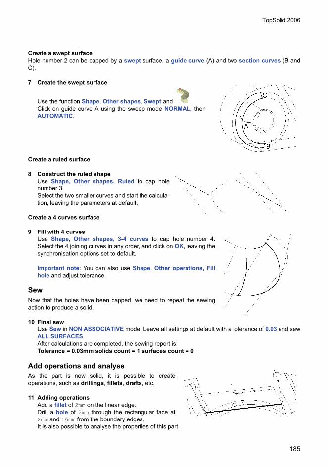
TopSolid 2006
185
Create a swept surfaceHole number 2 can be capped by a swept surface, a guide curve (A) and two section curves (B andC).
7 Create the swept surface
Use the function Shape, Other shapes, Swept and .Click on guide curve A using the sweep mode NORMAL, thenAUTOMATIC.
Create a ruled surface
8 Construct the ruled shapeUse Shape, Other shapes, Ruled to cap holenumber 3.Select the two smaller curves and start the calcula-tion, leaving the parameters at default.
Create a 4 curves surface
9 Fill with 4 curvesUse Shape, Other shapes, 3-4 curves to cap hole number 4.Select the 4 joining curves in any order, and click on OK, leaving thesynchronisation options set to default.
Important note: You can also use Shape, Other operations, Fillhole and adjust tolerance.
SewNow that the holes have been capped, we need to repeat the sewingaction to produce a solid.
10 Final sewUse Sew in NON ASSOCIATIVE mode. Leave all settings at default with a tolerance of 0.03 and sewALL SURFACES.After calculations are completed, the sewing report is:Tolerance = 0.03mm solids count = 1 surfaces count = 0
Add operations and analyseAs the part is now solid, it is possible to createoperations, such as drillings, fillets, drafts, etc.
11 Adding operationsAdd a fillet of 2mm on the linear edge.Drill a hole of 2mm through the rectangular face at2mm and 16mm from the boundary edges.It is also possible to analyse the properties of this part.

TopSolid 2006
186
12 Analyse the mass of the modelWith a steel construction, the mass is 1273.185 g.

TopSolid 2006
187
Importing DWG GeometryConcept to introduce:• How to retrieve a 2D file originating in another CAD sys-
tem.• How to configure contours.• Modelling the part.
The Wheel.dwg file is a file that has been created entirely in2D; we will retrieve the different views, and rebuild the wheelas a parameterized 3D volume.
1 Importing the dwg fileStart the File, Open function.
Open the File type list and select AutoCAD - DXF / DWG(*.dxf, *.dwg).
We are about to rebuild a volume model, so we must con-firm the default options:Unit = Auto Standard= Auto
Then click OK to validate.
After retrieving the data, the followingdrawing is obtained:
The result of the import can be dis-played by clicking on YES to the fol-lowing prompt:
Display the contents of the results file
This information can be of use in thecase of error messages that arisewhen importing the DWG file. Theimport result file is a text file in ASCIIformat, and has the same name asthe DWG file that was imported, withthe extension .res (in our caseWheel.res); the file is loaded inWindows Notepad.

TopSolid 2006
188
Parameterization of contoursWe will now delete any geometry that is not of use for modelling the solid shape.
2 Sorting elementsChoose Delete and only keep thefollowing elements (contours foreach view).
3 Creation of coordinate systemsFor each of the views, create a coor-dinate system using the Tools,Coordinate system menu item, thenchoose an intersection point.
4 Parameterization of the first contourTrim the horizontal line in respect of the 2 vertical lines using Curve,Trim in order to obtain joined elements.
Start sewing the curves using Curve, Other operations, Sew in NON-ASSOCIATIVE mode and check the option Delete original curves.When the sew operation is complete, select the REBUILD option; thisoption corresponds to choosing the Curve, Other curves, Rebuild func-tion.
The results of the sew operation are displayed in the message field atthe bottom of the screen.The contour created in this way is an associative contour; it can be con-strained using driving dimensions.
Please remember that contours must be sewn in their respective coordinate systems.
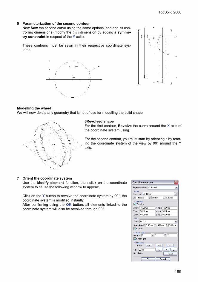
TopSolid 2006
189
5 Parameterization of the second contourNow Sew the second curve using the same options, and add its con-trolling dimensions (modify the 4mm dimension by adding a symme-try constraint in respect of the Y axis).
These contours must be sewn in their respective coordinate sys-tems.
Modelling the wheelWe will now delete any geometry that is not of use for modelling the solid shape.
6Revolved shapeFor the first contour, Revolve the curve around the X axis ofthe coordinate system using.
For the second contour, you must start by orienting it by rotat-ing the coordinate system of the view by 90° around the Yaxis.
7 Orient the coordinate systemUse the Modify element function, then click on the coordinatesystem to cause the following window to appear:
Click on the Y button to revolve the coordinate system by 90°, thecoordinate system is modified instantly.After confirming using the OK button, all elements linked to thecoordinate system will also be revolved through 90°.

TopSolid 2006
190
8 TrimNow apply a trim using Shape, Trim with the TRIM WITH A SWEPTCURVE option and Sweep mode = EXTRUSION, on the shaperotated by the second contour (it may be necessary to invert the extru-sion direction).
The parametric part obtained in this way can be modified as required, usedin the assembly, transformed into a standard component, etc.

TopSolid 2006
191
Tool box for shapesTopics covered:• Tool box functions to work with surfaces
1 Open the part
Select the ToolBox.top file with File, Open .Open the construction tree (CTRL+²).Then Select the part on the screen.
Analysis:It is a basic part. The part may be the result of an importation by TopSolid interfaces (IGES, STEP…).
2 Modifications
Expand the tool box menu Shape, Tool box by clicking on .Position the menu on your screen.
Redimension the face, then Select cylindrical face 1.Enter OK then the new diameter 10mm.CRITERIA constraint on the diameter: enter equals then 8 andthen OK.Select the part (the 3 other open pocket diameters must becomered) then the new diameter 10mm and OK.
Remove faces then select the 3 faces of chamfer 2.Healing=Fillet then OK.
Reblend radius then Select fillet 3 and OK.New Radius = 12mm then OK.
Constrain face, then select cylindrical face 1.Type of constraint = Alignment, select cylindrical face 3.
Constrain face, select face 4.Type of constraint = distance, select the bottom of the part as the reference face, then new dis-tance = 5mm.
Reblend radius then select inner fillet 5.New radius = 7mm
Reblend radius then select outer fillet 5.New radius = 12mm.
1
2
3
4
5

TopSolid 2006
192
3 Other holesSwitch to top view.Use Stretch, click 2 points to obtain the rect-angle selected.X- then translation distance = 15mm.Select the part.
Move Feature or Face, select loop 1 then thebottom face of the part as the trim face, and thenOK.TRANSLATION, Y+ and 15mm.Move Feature or Face.Move = face, then select cylindrical face 2.Translation, Y+, 10mm.
The final result must be as shownhere:
Save the file under the nameToolBoxINDB.top.
2
1

TopSolid 2006
193
4 Open ToolBoxTraining.top file.
Activate levels 2 and 3.
Edit in the tree:The PINK part to see that it is basicThen the CYAN part, a part constructed in place, based on the PINK part (contour and drill hole con-centric to the spot faced hole) and depending to the tools of the 4 screws).
Window, Tile vertically
Activate the assembly
Use Shape, Manage, Replace geometry .Shape to be replaced: Select the PINK part of the assembly.Replacement shape: Select the INDB shape.Option: NO TRANSFORMATIONThen OK.
In the INDB document, select the edges corresponding to the highlighted edges in the assembly.
Result: You must obtain the result shownhere. Only the edges required for theconstruction in place are requested, i.e. the4 upper circular edges of the holes as wellas the lower circular edge of the spot facedhole.
In the aim of testing another possible
use to Cancel the operation.
Restart the previous procedure, thistime selecting the following option: plugall in the dialog box (If the edges orfaces no longer exist (function deletion) select the no replacing edges option or define the equiva-lent).
Result: The procedure is longer. TopSolid first asks you for the face equivalent and then the edgeequivalent. Only to be used if you have created an external associativity (layout, assembly by
component) For machining, instead use the part/ compare and replace function which will allowyou to reconnect the machining operations.

TopSolid 2006
194
In the aim of testing another possible use to Cancel the operation.Open ToolBoxTraining.dft.Restart the previous procedure, this time selecting the following option: Plug those being locallyreferenced in the dialog box.
Result: The procedure is at the halfway point compared to the two previous ones. Indeed, TopSolid alsoasks you for the edges required for the associativity of the 2D dimensions.
In the aim of working with a problematic case, use to Cancel the operation.
Close the layout document ToolBoxTraining.dftRestart the previous procedure, this time selecting the following option: Plug those being locallyreferenced in the dialog box.
Open ToolBoxTraining.dft.
Result: Several dimensions are to become orange. This meansthey are disconnected.
To reconnect them, use Edit, Modify element on the discon-nected witness line and then on the new edge. The dimensionmust then return to its normal color.
File, Close all, tick the Apply to all documents option.Then NO.
Open ToolBoxTraining.dft.File, Reroute then select ToolBoxTraining.top in thedrop-down list.BROWSE.Then select ToolBoxINDB.top
Result: All the dimensions are reconnected correctly. Indeed, all the modifications to the new 3D file havebeen made in TopSolid using the tool box, in this case
When the new document is from a different software program, opt for the replace/ geometryfunction (opening the previously referenced documents, if any). When the new document isfrom TopSolid, opt for the reroute function (as the identification of the entities does not vary).
File, Close all, tick the Apply to all documents option.Then NO.
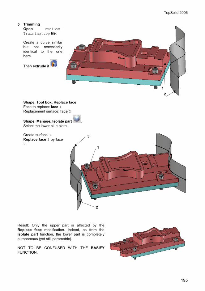
TopSolid 2006
195
5 TrimmingOpen ToolBox-Training.top file.
Create a curve similarbut not necessarilyidentical to the onehere.
Then extrude it .
Shape, Tool box, Replace faceFace to replace: face 1Replacement surface: face 2
Shape, Manage, Isolate part .Select the lower blue plate.
Create surface 3Replace face 1 by face2.
Result: Only the upper part is affected by theReplace face modification. Indeed, as from theIsolate part function, the lower part is completelyautonomous (yet still parametric).
NOT TO BE CONFUSED WITH THE BASIFYFUNCTION.
12
3
1
2

TopSolid 2006
196

TopSolid 2006
197
Advanced 2D Import
Topics covered:• Rebuilding of 2D elements.• Repairing and creating 3D from 2D.
1 Import 2D DWGFile, Open
Select the Geometry.dwg file.Click on CONFIGURATION.
Set the options as shown abovethen OK.Re-enter OK.Keep the default settings(Unit:auto; Standard:auto andCreate views: NO) then OK.
Result: The .dft and the .top are not connected. The 2D elements of the design document are merelycopied into the draft. The dimensions are converted and may be modified.
File, Close All and NO.Restart the operation, this time using the following options:Break dimensions: YESBreak groups: YES(in the dialog box) create views: YES
Result: The .dft and the .top are connected. We have opted to load the AutoCAD paper space (the objectspace is necessarily loaded). TopSolid will therefore create 2 files (a .top corresponding to the objectspace and a .dft corresponding to the paper space).
Recommendation: In the Open window, you may select the type of file to be generated during animportation. Here, TopSolid'Draft (Set on TopSolid'Design by default)
2 Advanced 2DOpen Advanced2D.top file.
3 Modifications on basic curves (level 1)
Analysis, Geometry on the various elements
OR
- Edit the various elements (in the tree)
OR
- F2 then pass to an element
OR
- Analysis, Element on the various elements
1 2
3
1’
2’

TopSolid 2006
198
Result: All the elements are basic, even if they are recognized as simple curves (line, arc, circle, andellipse). The dimensions obtained are therefore driven (yellow).
Using the Edit, Modify element function,modify the following elements:
Curves, Manage, Rebuild .On elements A to E.Arc and lines option for curve F.
Tools, Dimension on the curve.
Result: The elements are now parametric (green driving dimensions). The advantage is that the ModifyElement function may be used to do almost everything.
Difference trim extend cut
4 Trim
Using the Curve, Trim function, modify the following elements:
A The radius option on the arc.On the arc, extract and healing = YESDisplacement of ends
B Change the values on the chamferThe extract option on the chamfer
C On the circle (value, angle, passing point)
D On the arc (value, angle)
E On the ellipse (angle, radius X, radius Y)
F On the curve (option…)
A On the horizontal line
B
A B FDC E
G
H

TopSolid 2006
199
5 Extend
Using the Curve, Extend function, modify the curve:
6 Cut
Using the Curve, Cut function, modify the curve:
Result: The Trim function is for general use; Extend and Cut are for use in 2 specific cases.
7 Difference between 2D pattern, 3D pattern and propagate operation
8 2D Pattern
Using the Curve, Pattern function, create:
B On the horizontal line, automatic option
C On the horizontal line, share option
D On the arc
E The circle by 2 pointsThe circle by the curve
F The 3 H lines by the V line
G Left part tangent, Right part curvature
H ALL CURVES option, ONE CURVE option
A A circular pattern (nb=4)
B A linear pattern (nb=4; step=20)
C A double mirroring pattern
A B C
D
E F

TopSolid 2006
200
9 3D Pattern
Using the Curve/ Other operations/ Pattern function, create:
10 ExtendHaving first executed a trim by sweeping curve,
Result: There are various ways to obtain the same result.
By preference, use the 3D functions which may be directly modified and simplified in theconstruction log.
11 SewingOpen Layout.dwg.
Examine zones A and B.
Result: Zone A contains non contiguous curves that must have been created without being hooked toobjects. Zone B contains broken and non contiguous curves.
Curve, Other operations, Sew .NON ASSOCIATIVE option.
Select the curves.Tolerance=2.
D A mirroring pattern
F A circular pattern then subtract
E
Execute Shape, Propagate operation (circular)
A
B
1
2
3
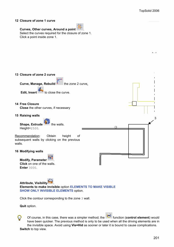
TopSolid 2006
201
12 Closure of zone 1 curve
Curves, Other curves, Around a point .Select the curves required for the closure of zone 1.Click a point inside zone 1.
13 Closure of zone 2 curve
Curve, Manage, Rebuild the zone 2 curve.
Edit, Insert to close the curve.
14 Free ClosureClose the other curves, if necessary
15 Raising walls
Shape, Extrude the walls.Height=2500.
Recommendation: Obtain height ofsubsequent walls by clicking on the previouswalls.
16 Modifying walls
Modify, Parameter .Click on one of the walls.Enter 3000.
Attribute, Visibility .Elements to make invisible option ELEMENTS TO MAKE VISIBLESHOW ONLY INVISIBLE ELEMENTS option.
Click the contour corresponding to the zone 3 wall.
Quit option.
Of course, in this case, there was a simpler method; the function (control element) wouldhave been quicker. The previous method is only to be used when all the driving elements are inthe invisible space. Avoid using Vis=Hid as sooner or later it is bound to cause complications.
Switch to top view.
3

TopSolid 2006
202
Edit, Stretch parents .Click 2 points defining zone 3.Option X+.Distance 3000.Make a window surrounding all the elements.
17 2D to 3D migrationOpen base.dwg.
18 Method 1: by parameter on auxil-iary view
Break the 3 views.
Curve, Manage, Rebuild .NON ASSOCIATIVE option.OK.ALL CURVES option.Tolerance=0.
Shape, Extrude Select curve 3.
Parameter then Distance
between point 1 and 2.Name:h
Stretch parents .Click 2 points defining zone 4.Y+ option.Translation distance=20.Elements to transform window surrounding the top view.
Result: This method is better suited to 2 ½ D parts for which the main view contains the main partdimensions.
3
4
2
1

TopSolid 2006
203
19 Method 2: by reconstruction and then modification of the coordi-nate system
Tools, Coordinate system, createcoordinate systems at points 1, 2, 3.For each view:
Coordinate system, Current the view coordinate system.Shape, Other operations, Sew
in NON ASSOCIATIVE.
Shape, Manage, Rebuild (ifnecessary) the elements not recon-structed by sewing.
Then rotation of coordinate systems:
Modify, Element .Coordinate system 2 -90° on YCoordinate system 3 -90° on X
Shape, Extrude the contour of the face view.Height: click on the high point of the top view.
Shape, Trim .By sweeping curve option to create the auxiliary view drill holes.
Result: Goes a little further than the previous method. Allows the possibility of realigning views usingMove parents on the coordinate systems, not dynamically. For complex parts, use Shape, Other
operations, Intersect .
3
21

TopSolid 2006
204
20 Method 3: using the curve/transform option: positioning
Curve, Transform .Positioning option.
Click point 1 then point 2 and finallypoint 3.Point 1’ then &0,0,10 and finallypoint 2’.
Select the left view elements.
Repeat the same on the top view.
Result: Universal method (allowing any 3D spatial transformation to be executed). Very useful in simpleor double balancing with any angles
General summary: Whatever method is used, always reproject the 3D part and verify that it is OK(dimension forced, view not aligned).
1 2
3
1’
2’

TopSolid 2006
205
2D Drafting

TopSolid 2006
206
Concept to introduce:• Opening a new TopSolid’Draft document• Creating a 2D view• Creating an auxiliary view• Modifying the scale of the document drawing• Creating geometry• Anchoring automatically on views• Creating perpendicular views• Inserting fastener element• Create a detail view• Move views
This exercise provides an example for production of a pure 2D drawing. The exercise introduces the ideaof a parameter as a means of maintaining correspondence between the views. Use of parameters is notalways needed or called for, and modifications are then managed as on a drawing board.
1 Open a new TopSolid’Draft documentOpen a new document on the Draft tab.Select one of the standard templates Associative horizontal A3 mm.
2D viewThe 2D view function enables you to define a drawing space to characterize a view. All the lines in thisview can be moved simultaneously. You can change the scale in respect of the document scale, usingthe Modify element function by clicking on the format box, or change the proportions in respect of theother views.
2 Create a 2D viewIn this exercise, use the 2D view functionto create a main view and position it inthe document space, for example at thetop left of the document. This will be theface view.
Auxiliary viewThe auxiliary view function enables you todefine a view maintaining the alignment inrespect of another view.

TopSolid 2006
207
3 Create an auxiliary viewIn this exercise, create an auxiliary viewto the right of the 2D view (left-handview), create another below (bottomview) and another to the bottom right (toprovide a perspective view).
Modify the scale of the document drawingThe scale of your draft document is thatwhich is specified in the drafting border; itcontrols the size of all 2D views.
4 Modify the scaleTo modify the scale, the format and prop-erties of the document box, use the Mod-ify element function, and click on the document box.Modify scale to 1.
5 Create geometryIn the front view, use the Contour function and build a contour using theoption RECTANGULAR. Construct the rectangle, aligning the bottomalong the origin. Use the option AUTO DIMENSION to constrain the rect-angle.
Build a second RECTANGULAR Contour with one point common tothe first rectangle.Build a third Contour element using the right-angle shape. Select theexisting contour points using the left mouse button (use the middlemouse button for an independent contour).
6 Copy geometryUse the Edit, Copy command to copy thefirst rectangle with the SYMMETRY option inrespect of the Y axis.
Use the Edit, Duplicate function to copy theother two contours.Dimension the length of the copy of the firstrectangle.

TopSolid 2006
208
7 Modification and dimensionDimension the length of the copy of the firstrectangle from 55 to 70mm.
Construct a chamfer on the origin rightangle from 5mm to 30°.
Construct the missing segments using theLine function.
Create hatching on the sections using theHatching area function in the Detailingmenu.Set the hatching pattern in the attribute bar.
Dimension the central boring diameter to 20mm using a symmetry CONSTRAINT.
Anchor automatically on viewsThe Automatic 2D view selection function enables you to activate and deactivate the automatic anchorfor lines on the nearest view by activating its point.
Create top view
8 Automatic selectionDe-activate the Automatic 2D view selection mode.
9 Sketch lineSet the coordinates for the top view as current usingthe Coordinate system current tool.Construct sketch lines by taking vertical alignmentswith front view.Construct a horizontal sketch line passing through theorigin of the coordinate.Construct an offset for BOTH SIDES at 90mm.
Then construct a Contour based on the sketch lines ofthe decal base.Construct circles centred on the origin, and tangentsto the corresponding sketch lines. Define two chamfersusing the chamfer function in the Curves menu.
Create side view
10 Base linesSet the left view coordinates as currentand draw a vertical sketch line.
Draw two Parallels to this line using theBOTH SIDES option, click on the 120mmdimension on the top view to define thedistance.

TopSolid 2006
209
11 Contour on sketch lineConstruct a Contour on the sketch lines of the decal base.
12 Finishing the contourUse the Duplicate function in the Edit menu to copy the right angles and small rectangles with theTRANSLATION option from the origin of the right-hand coordinate towards the origin of the left-handcoordinate.Construct a Contour between the copies of the right angle.Construct the missing Lines and modify the type of line for the copies to dotted.Construct 2 Parallel lines at the edges of the decal to represent the chamfers. Use the Merge func-tion from the Parameter menu. Keep the origin parameter by selecting the chamfer line and choos-ing LENGTH. Apply this value to the sides of the parallel lines.
Reactivate the Automatic 2D view selection.
Fasteners element
13 Insert 2D screwUse the include standard function from the Assembly menuto include fastener screws. Select AFNOR2D and, in the frontview, include a curve view M5x20 screw and position it on theright angle line using the middle mouse button.
Press STOP and select the Drill hole and Tap processes, andapply to the parts.
Press STOP to position a second screw.In the top view, include the same screw inthe top view to a point on the vertical of thecentre of the bore.
Repeat the screw in a Circular manner over360° with 4 copies.

TopSolid 2006
210
In the left view, include a screw and posi-tion it on the side of the view.
Use the Ungroup function in the Editmenu to break up the lines, then theGroup function of the same menu to jointhe lines to the head of the screw.
Use Copy to move the screw to its posi-tion. Use Duplicate to copy the screwhead with symmetry.
Delete the original screw.
Move the sketch lines and constraintdimensions into the invisible space usingthe Visibility function on the Attributemenu.
Use the Selection by Type (Dimensionand Lines) from the tools in the toolbar onthe left.Designate supplementary lines to hidden orinverse.
Draw axis lines using the Axes function inthe Curve menu.
Create a detail viewA detail view is an enlargement of a section of a view. The software enables you to cut a section of thedetail using a circle, rectangle or a pre-defined curve.
14 Detail viewChoose View, Detail view and the CIRCLEoption and position the centre of the circlearound the area to be enlarged.Then position the detail view.
Move viewsThe Move parents function is used to move the position of a view during the drafting process.
2D views are independent, and when moved, carry with them the auxiliary views which are attached tothem.

TopSolid 2006
211
The Auxiliary views are dependent on their reference view and maintain their alignment in respect ofthe reference view. It is possible to cancel or re-establish alignment using the Modify alignmentfunction from the view menu.
It is possible to adjust the alignment for several views using the Adjust alignment function.

TopSolid 2006
212
TopSolid 2006
213
Title block
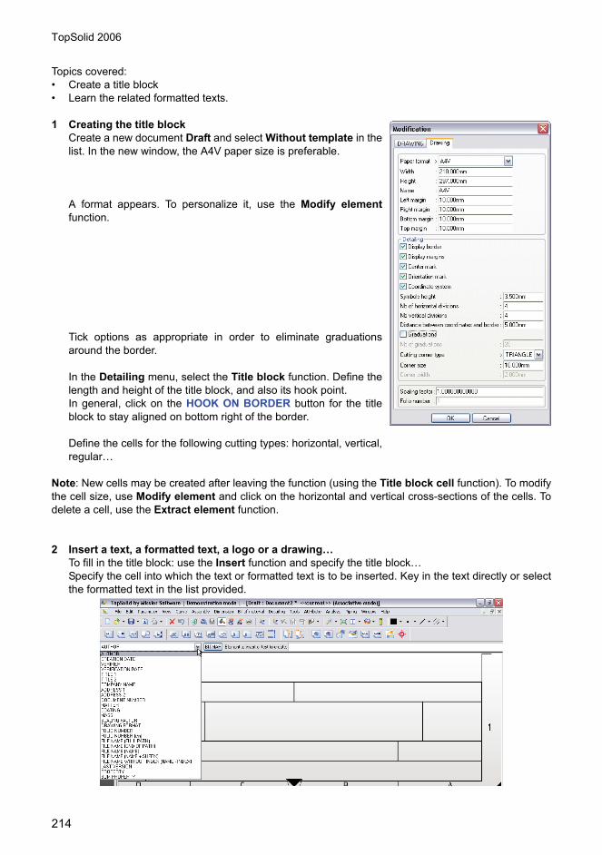
TopSolid 2006
214
Topics covered:• Create a title block• Learn the related formatted texts.
1 Creating the title blockCreate a new document Draft and select Without template in thelist. In the new window, the A4V paper size is preferable.
A format appears. To personalize it, use the Modify elementfunction.
Tick options as appropriate in order to eliminate graduationsaround the border.
In the Detailing menu, select the Title block function. Define thelength and height of the title block, and also its hook point. In general, click on the HOOK ON BORDER button for the titleblock to stay aligned on bottom right of the border.
Define the cells for the following cutting types: horizontal, vertical,regular…
Note: New cells may be created after leaving the function (using the Title block cell function). To modifythe cell size, use Modify element and click on the horizontal and vertical cross-sections of the cells. Todelete a cell, use the Extract element function.
2 Insert a text, a formatted text, a logo or a drawing…To fill in the title block: use the Insert function and specify the title block…Specify the cell into which the text or formatted text is to be inserted. Key in the text directly or selectthe formatted text in the list provided.

TopSolid 2006
215
Once the formatted text has been selected, it may be adjusted usingthe window that appears…
Note: In the list of formatted texts, the PROPERTY line allows access tothe information defined on a part in the 3D file (name, reference, material,etc.). This information automatically appears in the title block whenever apart or assembly is projected.
More than one element may be inserted into the same cell.
Draw the element outside the format. Group the elements concerned using the Group functionlocated in the Edit menu.
Insert the element into a title block cell (specify the appropriate title block and cell)…Adjust its position using the dialog box.
Hide the geometry located outside the format using the Visibility function in the Attribute menu.

TopSolid 2006
216
The logo may also be a bitmap format file (bmp, tiff, jpeg, png…) and inserted in the same way as acell.
The formatted texts and the logo may be repositioned once they have been placed in the cells. Clickon the text to be modified using the modify element function.
3 Save and rename the title blockSave the file in the Missler\Config\Template directory. For different formats, simply modify theproperties of the border and save the file with the desired format.
Note: Remember to set the different options for the properties of the dimensions, texts, bills of materialindexes… via the File, Properties function.
Name the title block as a new document and select the desired tem-plate in the list of user templates.

TopSolid 2006
217
4 Using the title blockTo fill in the title block, select the Properties function in the File menu. Click in General information,and fill in the field. The information will appear in the title block.
Note: only information such as author, company name, address 1 and address 2 are saved when using aformat. The creation date uses the computer date as a reference.
Related Documents