Tool Wear SY B.Tech.

Tool Wear
Nov 01, 2014
Welcome message from author
This document is posted to help you gain knowledge. Please leave a comment to let me know what you think about it! Share it to your friends and learn new things together.
Transcript

Tool Wear
SY B.Tech.

Introduction• The life of a cutting tool can be terminated by a number of means, although
they fall broadly into two main categories:– gradual wearing of certain regions of the face and flank of the cutting tool, and – abrupt tool failure.
• Considering the more desirable case 1. the life of a cutting tool is therefore determined by the amount of wear that
has occurred on the tool profile and which reduces the efficiency of cutting to an unacceptable level, or
2. eventually causes tool failure.• When the tool wear reaches an initially accepted amount, there are two
options,a) to resharpen the tool on a tool grinder, orb) to replace the tool with a new one. This second possibility applies in two
cases,i. when the resource for tool resharpening is exhausted. or ii. the tool does not allow

Wear zones• Gradual wear occurs at three principal location
on a cutting tool. Accordingly, three main types of tool wear can be distinguished,
I. crater wearII. flank wearIII. corner wear
These three wear types are illustrated in the figure:
Types of wear observed in cutting tools

Figure (a) Flank wear and crater wear in a cutting tool; the tool moves to the left as in Fig. (b) View of the rake face of a turning tool, showing various wear patterns. (c) View of the flank face of a turning tool, showing various wear patterns. (d) Types of wear on a turning tool: 1. flank wear; 2. crater wear; 3. chipped cutting edge; 4. thermal cracking on rake face; 5. built-up edge; 6. catastrophic failure. (See also Fig. Source: Courtesy of Kennametal, Inc.
Manufacturing, Engineering & Technology, Fifth Edition, by Serope Kalpakjian and
Steven R. Schmid.ISBN 0-13-148965-8. © 2006 Pearson
Education, Inc., Upper Saddle River, NJ. All rights reserved.
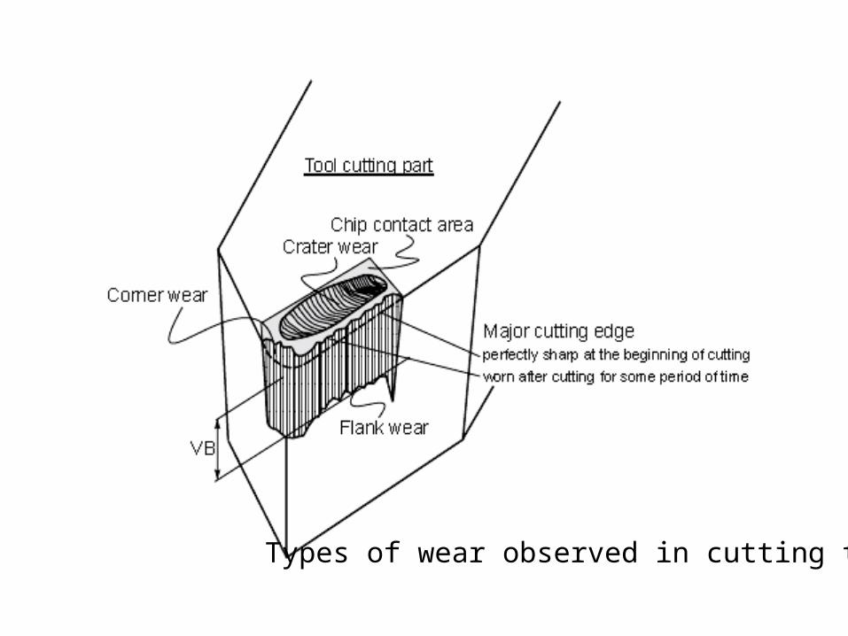
Types of Wear seen in Cutting Tools
Figure (a) Schematic illustration of types of wear observed on various cutting tools. (b) Schematic illustrations of catastrophic tool failures. A wide range of parameters influence these wear and failure patterns. Source: Courtesy of V. C. Venkatesh.

Manufacturing, Engineering & Technology, Fifth Edition, by Serope Kalpakjian and Steven R. Schmid.ISBN 0-13-148965-8. © 2006 Pearson Education, Inc., Upper Saddle River, NJ. All rights reserved.
Relationship between Crater-Wear Rate and Average Tool-Chip Interface Temperature
Figure : Relationship between crater-wear rate and average tool-chip interface temperature: 1) High-speed steel, 2) C-1 carbide, and 3) C-5 carbide (see Table ). Note how rapidly crater-wear rate increases with an incremental increase in temperature. Source: After B. T Chao and K. J Trigger.

Crater wear
• consists of a concave section on the tool face formed by the action of the chip sliding on the surface.
• Crater wear affects the mechanics of the process increasing the actual rake angle of the cutting tool and consequently, making cutting easier.
• At the same time, the crater wear weakens the tool wedge and increases the possibility for tool breakage. In general, crater wear is of a relatively small concern.
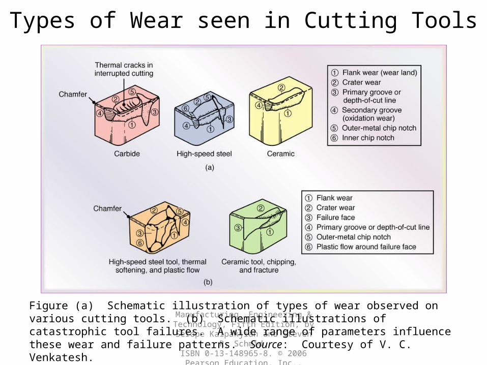
Flank wear• Flank wear occurs on the tool flank as a result of
friction between the machined surface of the workpiece and the tool flank.
• Flank wear appears in the form of so-called wear land and is measured by the width of this wear land, VB, Flank wear affects to the great extend the mechanics of cutting. Cutting forces increase significantly with flank wear.
• If the amount of flank wear exceeds some critical value (VB > 0.5~0.6 mm), the excessive cutting force may cause tool failure.


Corner wear• Corner wear occurs on the tool corner. Can be
considered as a part of the wear land and respectively flank wear since there is no distinguished boundary between the corner wear and flank wear land.
• We consider corner wear as a separate wear type because of its importance for the precision of machining.
• Corner wear actually shortens the cutting tool thus increasing gradually the dimension of machined surface and introducing a significant dimensional error in machining, which can reach values of about 0.03~0.05 mm.

Top view showing the effect of tool corner wear on the dimensionalprecision in turning
Related Documents