Toothed belt axis units ELGS-TB-KF This product is also available as a modular mechanical system Toothed belt axis ELGC-TB-KF

Welcome message from author
This document is posted to help you gain knowledge. Please leave a comment to let me know what you think about it! Share it to your friends and learn new things together.
Transcript
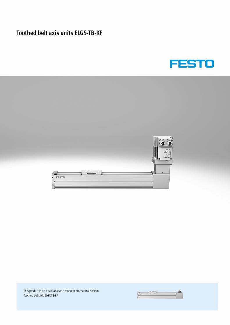
Toothed belt axis units ELGS-TB-KF
TOC BookmarkToothed belt axis units ELGS-TB-KFKey features
Type codes
Peripherals overview
Datasheet
Technical data
Sectional view
Dimensions
Ordering data
Ordering data – Modular product system
Accessories
Profile mounting EAHF-L2-…-P-S
Profile mounting EAHF-L2-...-P
Profile mounting EAHF-L2-…-P-D...
Adapter kit
Angle kit
Switch lug
Sensor bracket
Centring sleeve
Clamping element
Push-in fitting
Proximity switch
Connecting cable
Supply cable
Connecting cable
IO-Link master
Adapter
This product is also available as a modular mechanical systemToothed belt axis ELGC-TB-KF
2 d Internet: www.festo.com/catalogue/... Subject to change – 2021/11
Toothed belt axis units ELGS-TB-KF
Key features
At a glancePlug and work with the Simplified Motion Series
The simplicity of pneumatics is now combined for the first time with the advantages of electric automation thanks to the Simplified Motion Series. These integrated drives are the perfect solution for all users who are looking for an electric alternative for very simple movement and positioning tasks between two mechanical end positions, but don't want the commissioning process for traditional electric drive systems that can often be quite complex.
There is no need for any software since operation is simply based on the "plug and work" principle. Digital I/O (DIO) and IO-Link are always automatically included – a product with two types of control as standard.
Integrated Easy Standardised Connected
The integrated electronics in the drive are at the heart of the Simplified Motion Series.
For commissioning, simply set all rele-vant parameters directly on the drive:• Speed and force• Reference end position and
cushioning• Manual operation
Electrical connection via M12 plug design• Power (4-pin): power supply for the
motor• Logic (8-pin): control signal, sensor
signal and power for the integrated electronics
Use of extended functions possible via IO-Link:• Remote configuration of motion
parameters• Copy and backup function for
transferring parameters• Read function for extended process
parameters• Freely definable intermediate
position• Firmware update
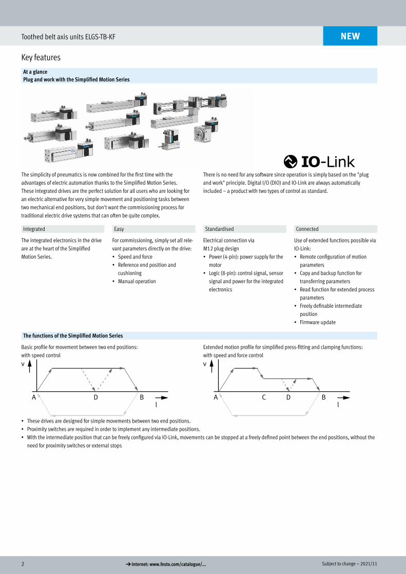
The functions of the Simplified Motion Series
Basic profile for movement between two end positions: with speed control
Extended motion profile for simplified press-fitting and clamping functions: with speed and force control
v
l
A BD
v
l
A BC D
• These drives are designed for simple movements between two end positions. • Proximity switches are required in order to implement any intermediate positions.• With the intermediate position that can be freely configured via IO-Link, movements can be stopped at a freely defined point between the end positions, without the
need for proximity switches or external stops
NEW
Key features
32021/11 – Subject to change d Internet: www.festo.com/catalogue/...
Toothed belt axis units ELGS-TB-KF
Key features
At a glance
• Without external servo drive: all the necessary electronic components are combined in the integrated drive
• Two control options integrated as standard: digital I/O and IO-Link• Complete solution for simple movements between mechanical end positions• Protected against external influences by internal guide• Simplified commissioning: all parameters can be manually set directly on the
drive• No special expertise required for commissioning• End-position feedback similar to that of a conventional proximity switch is
integrated as standard• Clean Look design: easy to clean and less prone to contamination
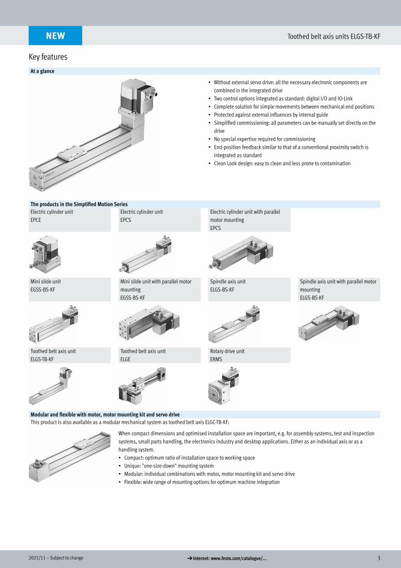
The products in the Simplified Motion SeriesElectric cylinder unitEPCE
Electric cylinder unitEPCS
Electric cylinder unit with parallel motor mountingEPCS
Mini slide unitEGSS-BS-KF
Mini slide unit with parallel motor mountingEGSS-BS-KF
Spindle axis unitELGS-BS-KF
Spindle axis unit with parallel motor mountingELGS-BS-KF
Toothed belt axis unit ELGS-TB-KF
Toothed belt axis unit ELGE
Rotary drive unitERMS
Modular and flexible with motor, motor mounting kit and servo driveThis product is also available as a modular mechanical system as toothed belt axis ELGC-TB-KF:
When compact dimensions and optimised installation space are important, e.g. for assembly systems, test and inspection systems, small parts handling, the electronics industry and desktop applications. Either as an individual axis or as a handling system.• Compact: optimum ratio of installation space to working space• Unique: "one-size-down" mounting system• Modular: individual combinations with motor, motor mounting kit and servo drive• Flexible: wide range of mounting options for optimum machine integration
NEW
4 d Internet: www.festo.com/catalogue/... Subject to change – 2021/11
Toothed belt axis units ELGS-TB-KF
Key features
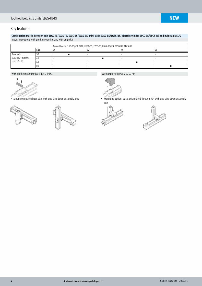
Combination matrix between axis ELGC-TB/ELGS-TB, ELGC-BS/ELGS-BS, mini slide EGSC-BS/EGSS-BS, electric cylinder EPCC-BS/EPCS-BS and guide axis ELFCMounting options with profile mounting and with angle kit
Assembly axis ELGC-BS/-TB; ELFC; EGSC-BS; EPCC-BS; ELGS-BS/-TB; EGSS-BS, EPCS-BSSize 25 32 45 60
Base axisELGC-BS/-TB; ELFC; ELGS-BS/-TB
32 h – – –
45 – h – –
60 – – h –
80 – – – h
With profile mounting EAHF-L2-…-P-D… With angle kit EHAA-D-L2-…-AP
• Mounting option: base axis with one-size-down assembly axis • Mounting option: base axis rotated through 90° with one-size-down assembly axis
NEW
52021/11 – Subject to change d Internet: www.festo.com/catalogue/...
Toothed belt axis units ELGS-TB-KF
Key features
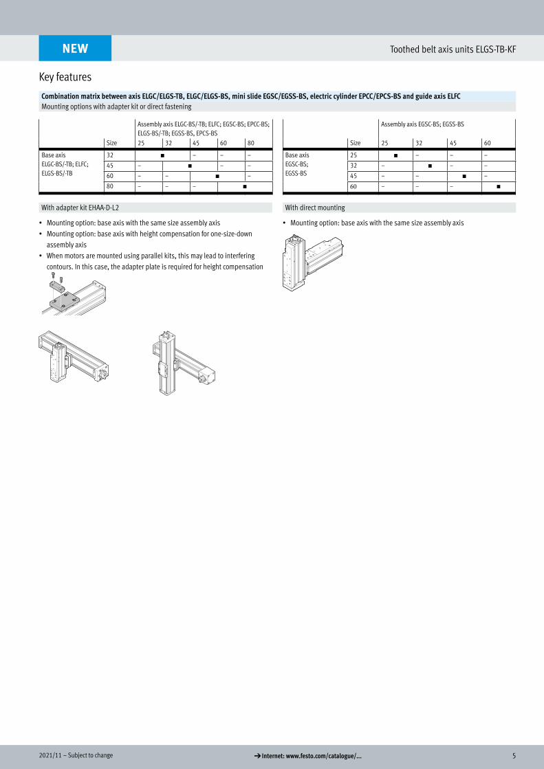
Combination matrix between axis ELGC/ELGS-TB, ELGC/ELGS-BS, mini slide EGSC/EGSS-BS, electric cylinder EPCC/EPCS-BS and guide axis ELFCMounting options with adapter kit or direct fastening
Assembly axis ELGC-BS/-TB; ELFC; EGSC-BS; EPCC-BS; ELGS-BS/-TB; EGSS-BS, EPCS-BS
Assembly axis EGSC-BS; EGSS-BS
Size 25 32 45 60 80 Size 25 32 45 60
Base axisELGC-BS/-TB; ELFC; ELGS-BS/-TB
32 h – – – Base axisEGSC-BS; EGSS-BS
25 h – – –
45 – h – – 32 – h – –
60 – – h – 45 – – h –
80 – – – h 60 – – – h
With adapter kit EHAA-D-L2 With direct mounting
• Mounting option: base axis with the same size assembly axis • Mounting option: base axis with height compensation for one-size-down
assembly axis• When motors are mounted using parallel kits, this may lead to interfering
contours. In this case, the adapter plate is required for height compensation
• Mounting option: base axis with the same size assembly axis
NEW
6 d Internet: www.festo.com/catalogue/... Subject to change – 2021/11
Toothed belt axis units ELGS-TB-KF
Key features
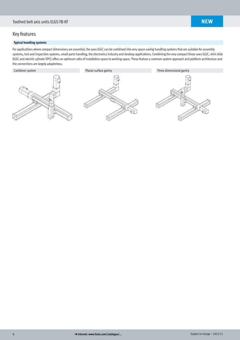
Typical handling systems
For applications where compact dimensions are essential, the axes ELGC can be combined into very space-saving handling systems that are suitable for assembly systems, test and inspection systems, small parts handling, the electronics industry and desktop applications. Combining the very compact linear axes ELGC, mini slide EGSC and electric cylinder EPCC offers an optimum ratio of installation space to working space. These feature a common system approach and platform architecture and the connections are largely adapterless.
Cantilever system Planar surface gantry Three dimensional gantry
NEW
72021/11 – Subject to change d Internet: www.festo.com/catalogue/...
Toothed belt axis units ELGS-TB-KF
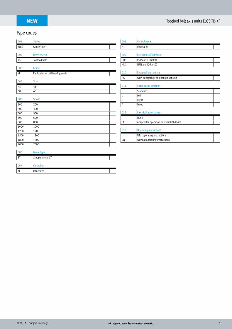
Type codes
NEW
001 Series
ELGS Gantry axis
002 Drive system
TB Toothed belt
003 Guide
KF Recirculating ball bearing guide
004 Size
45 45
60 60
005 Stroke
200 200
300 300
500 500
600 600
800 800
1000 1000
1200 1200
1500 1500
1800 1800
2000 2000
006 Motor type
ST Stepper motor ST
007 Controller
M Integrated
008 Control panel
H1 Integrated
009 Bus protocol/activation
PLK PNP and IO-Link®
NLK NPN and IO-Link®
010 End-position sensing
AA With integrated end-position sensing
011 Cable outlet direction
Standard
L Left
R Right
F Front
012 Electrical accessories
None
L1 Adapter for operation as IO-Link® device
013 Operating instructions
With operating instructions
DN Without operating instructions
Type codes
8 d Internet: www.festo.com/catalogue/... Subject to change – 2021/11
Toothed belt axis units ELGS-TB-KF
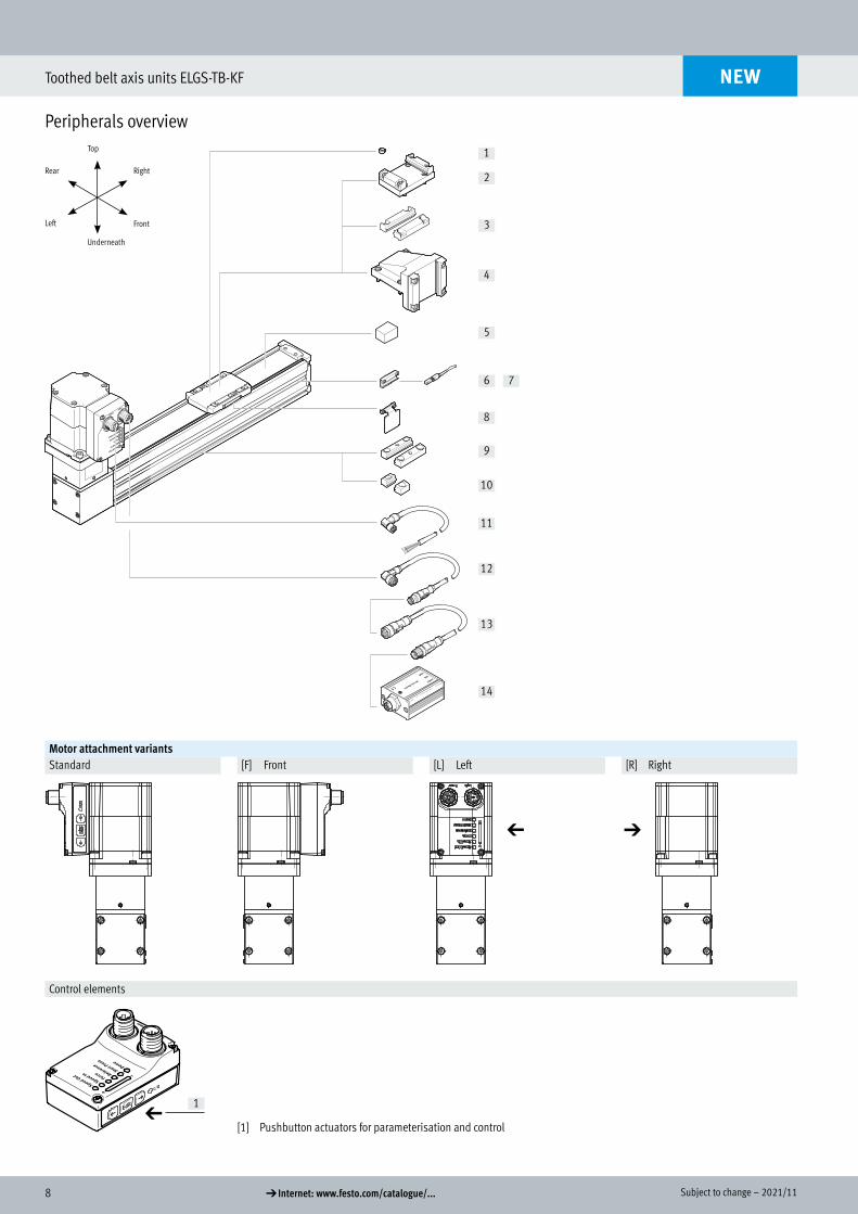
Peripherals overview
2
1
3
4
5
6
8
7
9
10
11
12
13
14
Motor attachment variantsStandard [F] Front [L] Left [R] Right
Control elements
a 1
[1] Pushbutton actuators for parameterisation and control
NEW
Peripherals overview
Front
Rear
Underneath
Top
Right
Left
a a
92021/11 – Subject to change d Internet: www.festo.com/catalogue/...
Toothed belt axis units ELGS-TB-KF
Peripherals overview
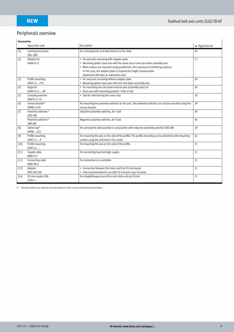
AccessoriesType/order code Description a Page/Internet
[1] Centring pin/sleeveZBS, ZBH
For centring loads and attachments on the slide 30
[2] Adapter kitEHAA-D-L2
• For axis/axis mounting with adapter plate• Mounting option: base axis with the same size or one-size-down assembly axis• When motors are mounted using parallel kits, this may lead to interfering contours.
In this case, the adapter plate is required for height compensation (download CAD data a www.festo.com)
27
[3] Profile mountingEAHF-L2-…-P-D
• For axis/axis mounting without adapter plate• Mounting option: base axis with one-size-down assembly axis
26
[4] Angle kitEHAA-D-L2-...-AP
• For mounting one-size-down vertical axes (assembly axes) on• base axes with mounting position "slide at top"
28
[5] Clamping elementEADT-S-L5-32
• Tool for retensioning the cover strip 30
[6] Sensor bracket1)
EAPM-L2-SHFor mounting the proximity switches on the axis. The proximity switches can only be mounted using the sensor bracket
29
[7] Proximity switches1)
SIES-8MInductive proximity switches, for T-slot 30
Proximity switches1)
SMT-8MMagnetic proximity switches, for T-slot 30
[8] Switch lug1)
EAPM-…-SLSFor sensing the slide position in conjunction with inductive proximity switches SIES-8M 29
[9] Profile mountingEAHF-L2-...-P
For mounting the axis on the side of the profile. The profile mounting can be attached to the mounting surface using the drill hole in the centre
24
[10] Profile mountingEAHF-L2-...-
For mounting the axis on the side of the profile 25
[11] Supply cableNEBL-T12
For connecting load and logic supply 31
[12] Connecting cableNEBC-M12
For connection to a controller 31
[13] AdapterNEFC-M12G8
• Connection between the motor and the IO-Link master• Only recommended for use with IO-Link port class A master
31
[14] IO-Link master USBCDSU-1
For straightforward use of the mini slide unit via IO-Link 31
1) Proximity switches are optional and only required in order to sense any intermediate positions.
NEW
10 d Internet: www.festo.com/catalogue/... Subject to change – 2021/11
Toothed belt axis units ELGS-TB-KF
Datasheet
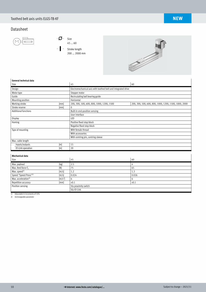
-N- Size 45 ... 60
-T- Stroke length 200 ... 2000 mm
General technical dataSize 45 60
Design Electromechanical axis with toothed belt and integrated drive
Motor type Stepper motorGuide Recirculating ball bearing guideMounting position HorizontalWorking stroke [mm] 200, 300, 500, 600, 800, 1000, 1200, 1500 200, 300, 500, 600, 800, 1000, 1200, 1500, 1800, 2000Stroke reserve [mm] 0Additional functions Built-in end-position sensing
User interfaceDisplay LED
Homing Positive fixed stop blockNegative fixed stop block
Type of mounting With female threadWith accessoriesWith centring pin, centring sleeve
Max. cable lengthInputs/outputs [m] 15IO-Link operation [m] 20
Mechanical dataSize 45 60
Max. payload [kg] 2.5 4Max. feed force Fx [N] 75 65Max. speed1) [m/s] 1.2 1.3Speed "Speed Press"2) [m/s] 0.024 0.026Max. acceleration2) [m/s2] 6 6Repetition accuracy [mm] ±0.1 ±0.1Position sensing Via proximity switch
Via IO-Link
1) Adjustable in increments of 10%2) Unchangeable parameter
NEW
Datasheet
Technical data
112021/11 – Subject to change d Internet: www.festo.com/catalogue/...
Toothed belt axis units ELGS-TB-KF
Datasheet
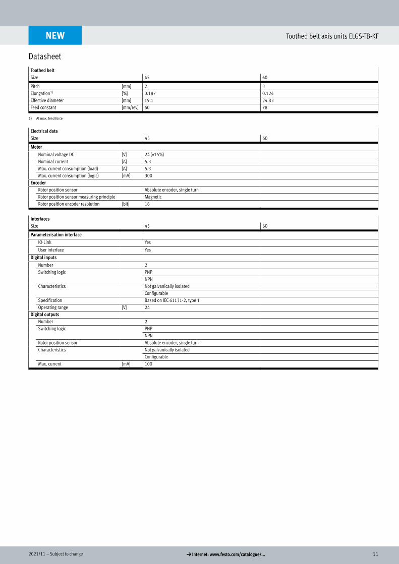
Toothed beltSize 45 60
Pitch [mm] 2 3Elongation1) [%] 0.187 0.124Effective diameter [mm] 19.1 24.83Feed constant [mm/rev] 60 78
1) At max. feed force
Electrical dataSize 45 60
MotorNominal voltage DC [V] 24 (±15%)Nominal current [A] 5.3Max. current consumption (load) [A] 5.3Max. current consumption (logic) [mA] 300
EncoderRotor position sensor Absolute encoder, single turnRotor position sensor measuring principle MagneticRotor position encoder resolution [bit] 16
InterfacesSize 45 60
Parameterisation interfaceIO-Link Yes
User interface Yes
Digital inputsNumber 2Switching logic PNP
NPNCharacteristics Not galvanically isolated
ConfigurableSpecification Based on IEC 61131-2, type 1Operating range [V] 24
Digital outputsNumber 2Switching logic PNP
NPNRotor position sensor Absolute encoder, single turnCharacteristics Not galvanically isolated
ConfigurableMax. current [mA] 100
NEW
12 d Internet: www.festo.com/catalogue/... Subject to change – 2021/11
Toothed belt axis units ELGS-TB-KF
Datasheet
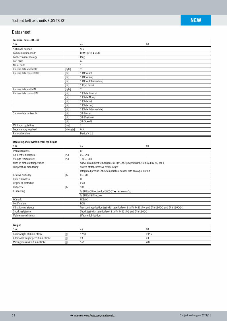
Technical data – IO-LinkSize 45 60
SIO mode support YesCommunication mode COM3 (230.4 kBd)Connection technology PlugPort class ANo. of ports 1Process data width OUT [byte] 2Process data content OUT [bit] 1 (Move in)
[bit] 1 (Move out)[bit] 1 (Move Intermediate)[bit] 1 (Quit Error)
Process data width IN [byte] 2Process data content IN [bit] 1 (State Device)
[bit] 1 (State Move)[bit] 1 (State in)[bit] 1 (State out)[bit] 1 (State Intermediate)
Service data content IN [bit] 32 (Force)[bit] 32 (Position)[bit] 32 (Speed)
Minimum cycle time [ms] 1Data memory required [kilobyte] 0.5Protocol version Device V 1.1
Operating and environmental conditionsSize 45 60
Insulation class BAmbient temperature [°C] 0 ... +50Storage temperature [°C] –20 ... +60Note on ambient temperature Above an ambient temperature of 30°C, the power must be reduced by 2% per KTemperature monitoring Switch-off for excessive temperature
Integrated precise CMOS temperature sensor with analogue outputRelative humidity [%] 0 ... 90Protection class IIIDegree of protection IP40Duty cycle [%] 100CE marking To EU EMC Directive for EMCS-ST a festo.com/sp
To EU RoHS DirectiveKC mark KC EMCCertification RCMVibration resistance Transport application test with severity level 1 to FN 942017-4 and EN 61800-2 and EN 61800-5-1Shock resistance Shock test with severity level 1 to FN 942017-5 and EN 61800-2Maintenance interval Lifetime lubrication
WeightSize 45 60
Basic weight at 0 mm stroke [g] 1790 2955Additional weight per 10 mm stroke [g] 23 43Moving mass with 0 mm stroke [g] 169 482
NEW
132021/11 – Subject to change d Internet: www.festo.com/catalogue/...
Toothed belt axis units ELGS-TB-KF
Datasheet
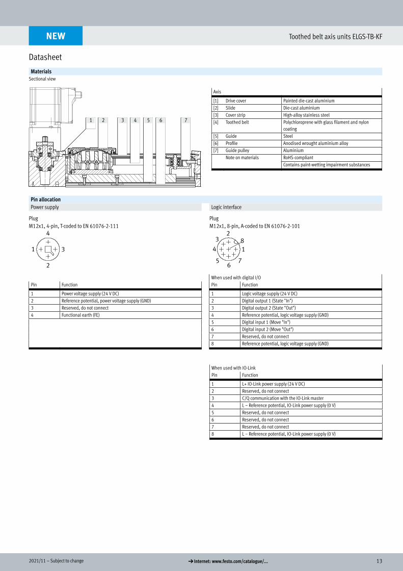
MaterialsSectional view
Axis
[1] Drive cover Painted die-cast aluminium[2] Slide Die-cast aluminium[3] Cover strip High-alloy stainless steel[4] Toothed belt Polychloroprene with glass filament and nylon
coating[5] Guide Steel[6] Profile Anodised wrought aluminium alloy[7] Guide pulley Aluminium
Note on materials RoHS-compliantContains paint-wetting impairment substances
Pin allocationPower supply Logic interface
Plug PlugM12x1, 4-pin, T-coded to EN 61076-2-111 M12x1, 8-pin, A-coded to EN 61076-2-101
When used with digital I/OPin Function Pin Function
1 Power voltage supply (24 V DC) 1 Logic voltage supply (24 V DC)2 Reference potential, power voltage supply (GND) 2 Digital output 1 (State "In")3 Reserved, do not connect 3 Digital output 2 (State "Out")4 Functional earth (FE) 4 Reference potential, logic voltage supply (GND)
5 Digital input 1 (Move "In")6 Digital input 2 (Move "Out")7 Reserved, do not connect8 Reference potential, logic voltage supply (GND)
When used with IO-LinkPin Function
1 L+ IO-Link power supply (24 V DC)2 Reserved, do not connect3 C/Q communication with the IO-Link master4 L – Reference potential, IO-Link power supply (0 V)5 Reserved, do not connect6 Reserved, do not connect7 Reserved, do not connect8 L – Reference potential, IO-Link power supply (0 V)
NEW
Sectional view
2 3 4 5 6 71
14 d Internet: www.festo.com/catalogue/... Subject to change – 2021/11
Toothed belt axis units ELGS-TB-KF
Datasheet
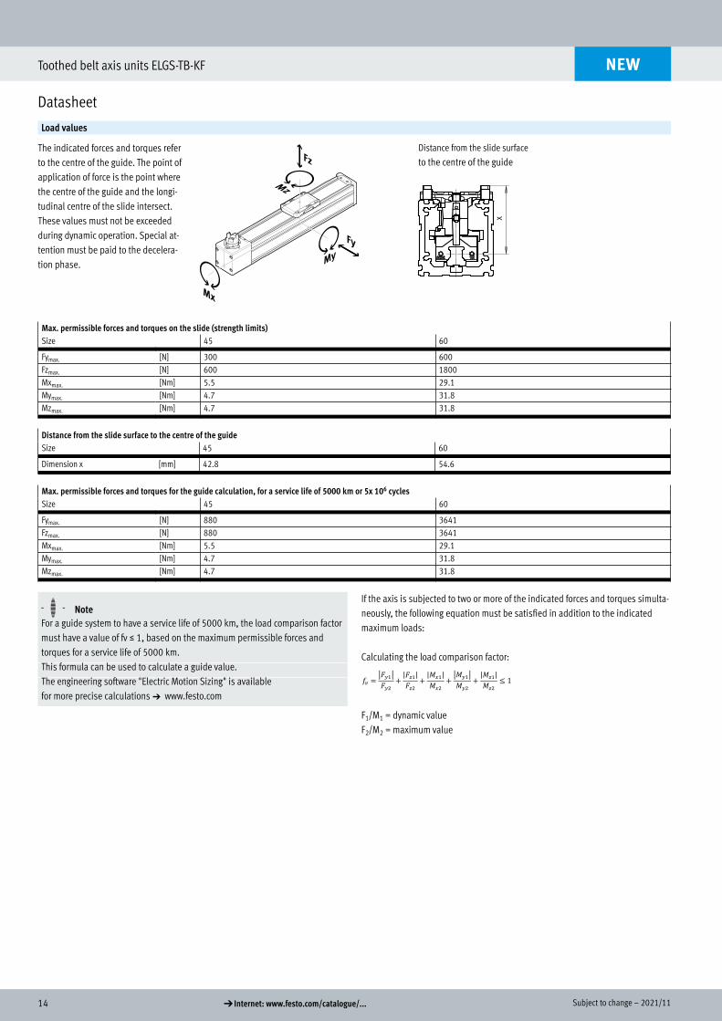
Load values
The indicated forces and torques refer to the centre of the guide. The point of application of force is the point where the centre of the guide and the longi-tudinal centre of the slide intersect.These values must not be exceeded during dynamic operation. Special at-tention must be paid to the decelera-tion phase.
Distance from the slide surface
to the centre of the guide
x
Max. permissible forces and torques on the slide (strength limits)Size 45 60
Fymax. [N] 300 600Fzmax. [N] 600 1800Mxmax. [Nm] 5.5 29.1Mymax. [Nm] 4.7 31.8Mzmax. [Nm] 4.7 31.8
Distance from the slide surface to the centre of the guideSize 45 60
Dimension x [mm] 42.8 54.6
Max. permissible forces and torques for the guide calculation, for a service life of 5000 km or 5x 10⁶ cyclesSize 45 60
Fymax. [N] 880 3641Fzmax. [N] 880 3641Mxmax. [Nm] 5.5 29.1Mymax. [Nm] 4.7 31.8Mzmax. [Nm] 4.7 31.8
H- - NoteIf the axis is subjected to two or more of the indicated forces and torques simulta-neously, the following equation must be satisfied in addition to the indicated maximum loads:
Calculating the load comparison factor:
F1/M1 = dynamic valueF2/M2 = maximum value
For a guide system to have a service life of 5000 km, the load comparison factor must have a value of fv š 1, based on the maximum permissible forces and torques for a service life of 5000 km.This formula can be used to calculate a guide value.The engineering software "Electric Motion Sizing" is available for more precise calculations a www.festo.com
NEW
𝑓𝑓𝑓𝑓𝑣𝑣𝑣𝑣 =�𝐹𝐹𝐹𝐹𝑦𝑦𝑦𝑦1�𝐹𝐹𝐹𝐹𝑦𝑦𝑦𝑦2
+|𝐹𝐹𝐹𝐹𝑧𝑧𝑧𝑧1|𝐹𝐹𝐹𝐹𝑧𝑧𝑧𝑧2
+|𝑀𝑀𝑀𝑀𝑥𝑥𝑥𝑥1|𝑀𝑀𝑀𝑀𝑥𝑥𝑥𝑥2
+�𝑀𝑀𝑀𝑀𝑦𝑦𝑦𝑦1�𝑀𝑀𝑀𝑀𝑦𝑦𝑦𝑦2
+|𝑀𝑀𝑀𝑀𝑧𝑧𝑧𝑧1|𝑀𝑀𝑀𝑀𝑧𝑧𝑧𝑧2
≤ 1
152021/11 – Subject to change d Internet: www.festo.com/catalogue/...
Toothed belt axis units ELGS-TB-KF
Datasheet
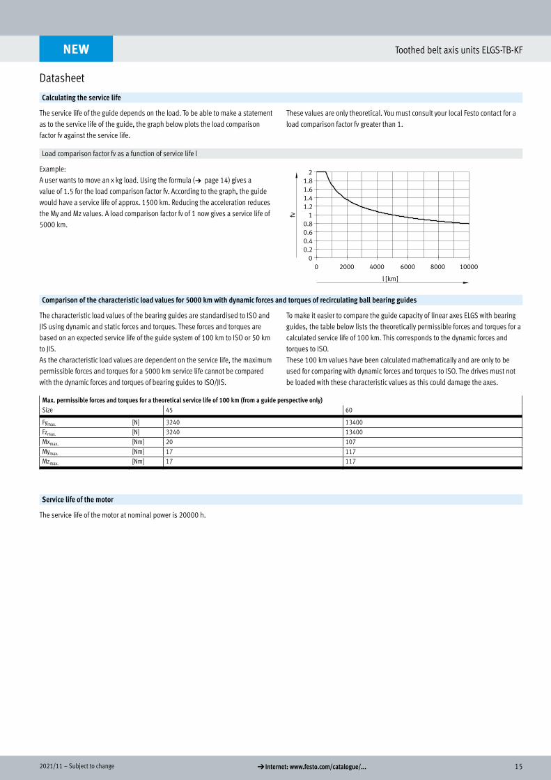
Calculating the service life
The service life of the guide depends on the load. To be able to make a statement as to the service life of the guide, the graph below plots the load comparison factor fv against the service life.
These values are only theoretical. You must consult your local Festo contact for a load comparison factor fv greater than 1.
Load comparison factor fv as a function of service life l
Example:A user wants to move an x kg load. Using the formula (a page 14) gives a value of 1.5 for the load comparison factor fv. According to the graph, the guide would have a service life of approx. 1500 km. Reducing the acceleration reduces the My and Mz values. A load comparison factor fv of 1 now gives a service life of 5000 km.
Comparison of the characteristic load values for 5000 km with dynamic forces and torques of recirculating ball bearing guides
The characteristic load values of the bearing guides are standardised to ISO and JIS using dynamic and static forces and torques. These forces and torques are based on an expected service life of the guide system of 100 km to ISO or 50 km to JIS.As the characteristic load values are dependent on the service life, the maximum permissible forces and torques for a 5000 km service life cannot be compared with the dynamic forces and torques of bearing guides to ISO/JIS.
To make it easier to compare the guide capacity of linear axes ELGS with bearing guides, the table below lists the theoretically permissible forces and torques for a calculated service life of 100 km. This corresponds to the dynamic forces and torques to ISO.These 100 km values have been calculated mathematically and are only to be used for comparing with dynamic forces and torques to ISO. The drives must not be loaded with these characteristic values as this could damage the axes.
Max. permissible forces and torques for a theoretical service life of 100 km (from a guide perspective only)Size 45 60
Fymax. [N] 3240 13400Fzmax. [N] 3240 13400Mxmax. [Nm] 20 107Mymax. [Nm] 17 117Mzmax. [Nm] 17 117
Service life of the motor
The service life of the motor at nominal power is 20000 h.
NEW
16 d Internet: www.festo.com/catalogue/... Subject to change – 2021/11
Toothed belt axis units ELGS-TB-KF
Datasheet
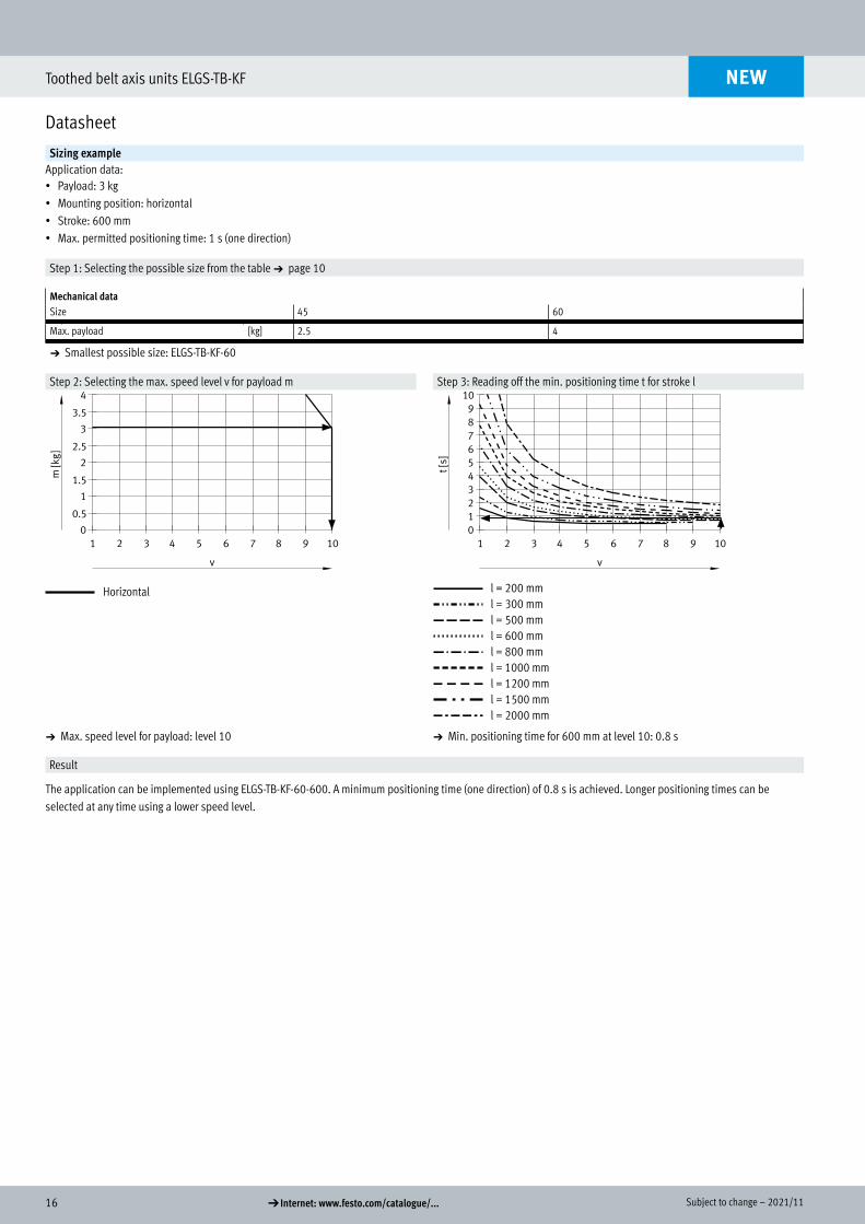
Sizing exampleApplication data:• Payload: 3 kg• Mounting position: horizontal• Stroke: 600 mm• Max. permitted positioning time: 1 s (one direction)
Step 1: Selecting the possible size from the table a page 10
Mechanical dataSize 45 60
Max. payload [kg] 2.5 4
a Smallest possible size: ELGS-TB-KF-60
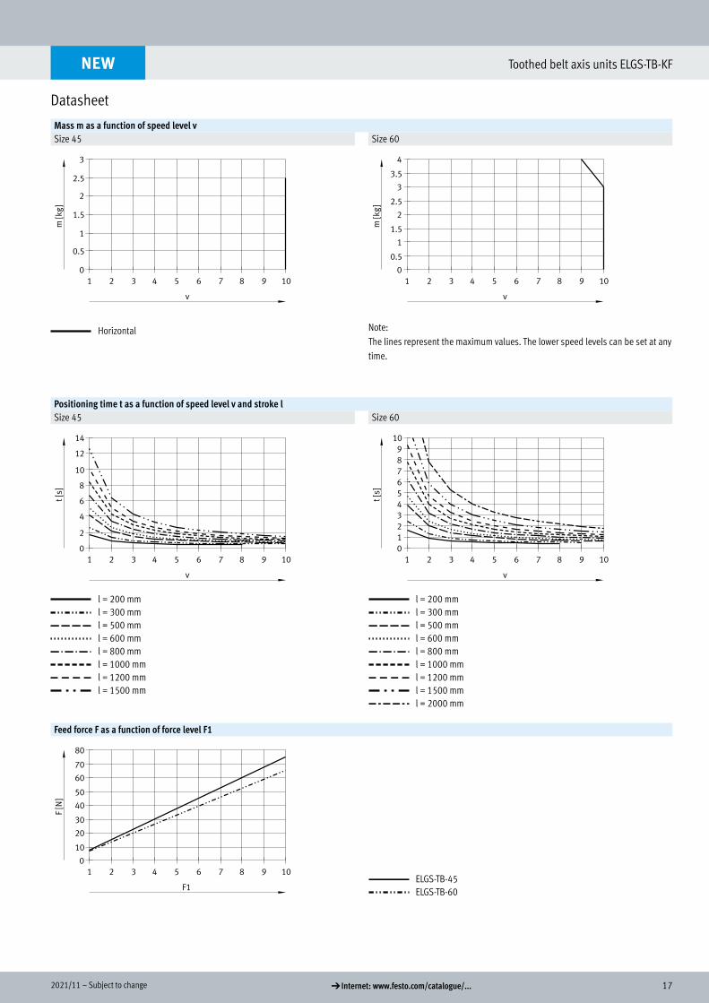
Step 2: Selecting the max. speed level v for payload m Step 3: Reading off the min. positioning time t for stroke l
Horizontal l = 200 mml = 300 mml = 500 mml = 600 mml = 800 mml = 1000 mml = 1200 mml = 1500 mml = 2000 mm
a Max. speed level for payload: level 10 a Min. positioning time for 600 mm at level 10: 0.8 s
Result
The application can be implemented using ELGS-TB-KF-60-600. A minimum positioning time (one direction) of 0.8 s is achieved. Longer positioning times can be selected at any time using a lower speed level.
NEW
172021/11 – Subject to change d Internet: www.festo.com/catalogue/...
Toothed belt axis units ELGS-TB-KF
Datasheet
Mass m as a function of speed level vSize 45 Size 60
Horizontal Note:The lines represent the maximum values. The lower speed levels can be set at any time.
Positioning time t as a function of speed level v and stroke lSize 45 Size 60
l = 200 mml = 300 mml = 500 mml = 600 mml = 800 mml = 1000 mml = 1200 mml = 1500 mm
l = 200 mml = 300 mml = 500 mml = 600 mml = 800 mml = 1000 mml = 1200 mml = 1500 mml = 2000 mm
Feed force F as a function of force level F1
ELGS-TB-45ELGS-TB-60
NEW
18 d Internet: www.festo.com/catalogue/... Subject to change – 2021/11
Toothed belt axis units ELGS-TB-KF
Datasheet
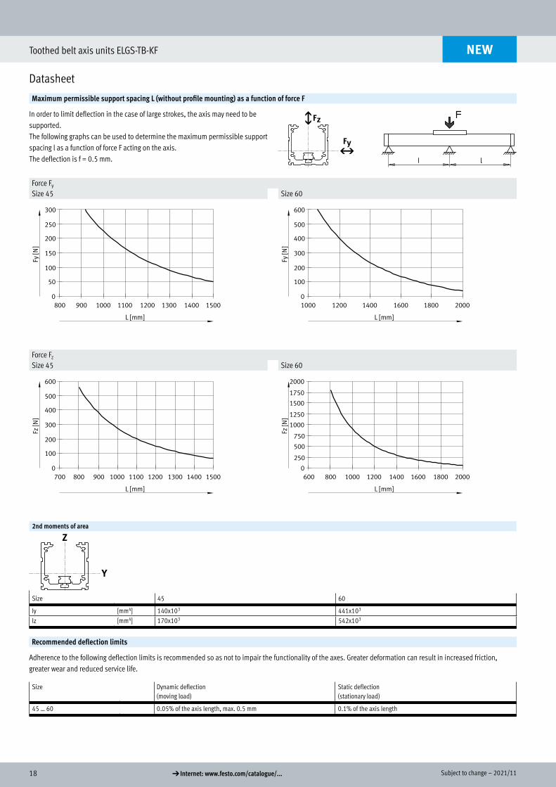
Maximum permissible support spacing L (without profile mounting) as a function of force F
In order to limit deflection in the case of large strokes, the axis may need to be supported. The following graphs can be used to determine the maximum permissible support spacing l as a function of force F acting on the axis.The deflection is f = 0.5 mm.
Force Fy
Size 45 Size 60
Force Fz
Size 45 Size 60
2nd moments of area
Size 45 60
Iy [mm4] 140x103 441x103
Iz [mm4] 170x103 542x103
Recommended deflection limits
Adherence to the following deflection limits is recommended so as not to impair the functionality of the axes. Greater deformation can result in increased friction, greater wear and reduced service life.
Size Dynamic deflection(moving load)
Static deflection(stationary load)
45 … 60 0.05% of the axis length, max. 0.5 mm 0.1% of the axis length
NEW
192021/11 – Subject to change d Internet: www.festo.com/catalogue/...
Toothed belt axis units ELGS-TB-KF
Datasheet
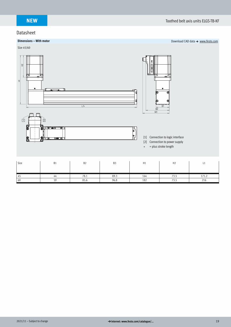
Dimensions – With motor Download CAD data a www.festo.com
Size 45/60
Size B1 B2 B3 H1 H2 L1
45 44 78.1 89.3 164 73.5 171.260 59 85.6 96.8 182 73.5 216
NEW
Dimensions
[1] Connection to logic interface[2] Connection to power supply+ = plus stroke length
20 d Internet: www.festo.com/catalogue/... Subject to change – 2021/11
Toothed belt axis units ELGS-TB-KF
Datasheet
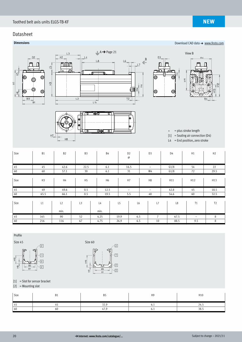
Dimensions Download CAD data a www.festo.com
Size B1 B2 B3 B4 D2@
D3 D4 H1 H2
45 45 42.6 22.5 6.1 16.5 – G1/8 54 2260 60 57.1 30 6.1 31 M4 G1/8 72 29.5
Size H3 H4 H5 H6 H7 H8 H11 H12 H13
45 49 49.6 0.5 12.5 – – 42.8 45 18.560 65.5 66.1 0.5 19.5 5.5 48 54.6 60 32.5
Size L1 L2
min.
L3 L4
min.
L5 L6 L7 L8 T1 T2
45 165 90 52 4.25 19.9 6.5 7 67.5 – 860 216 116 67 4.75 26.9 6.5 10 88.5 9.5 8
Profile
Size 45 Size 60
[1] = Slot for sensor bracket[2] = Mounting slot
Size B1 B5 H9 H10
45 45 32.9 6.1 24.560 60 47.9 6.1 38.5
NEW
A d Page 21 View B
+ = plus stroke length[1] = Sealing air connection (D4)L4 = End position, zero stroke
B
212021/11 – Subject to change d Internet: www.festo.com/catalogue/...
Toothed belt axis units ELGS-TB-KF
Datasheet
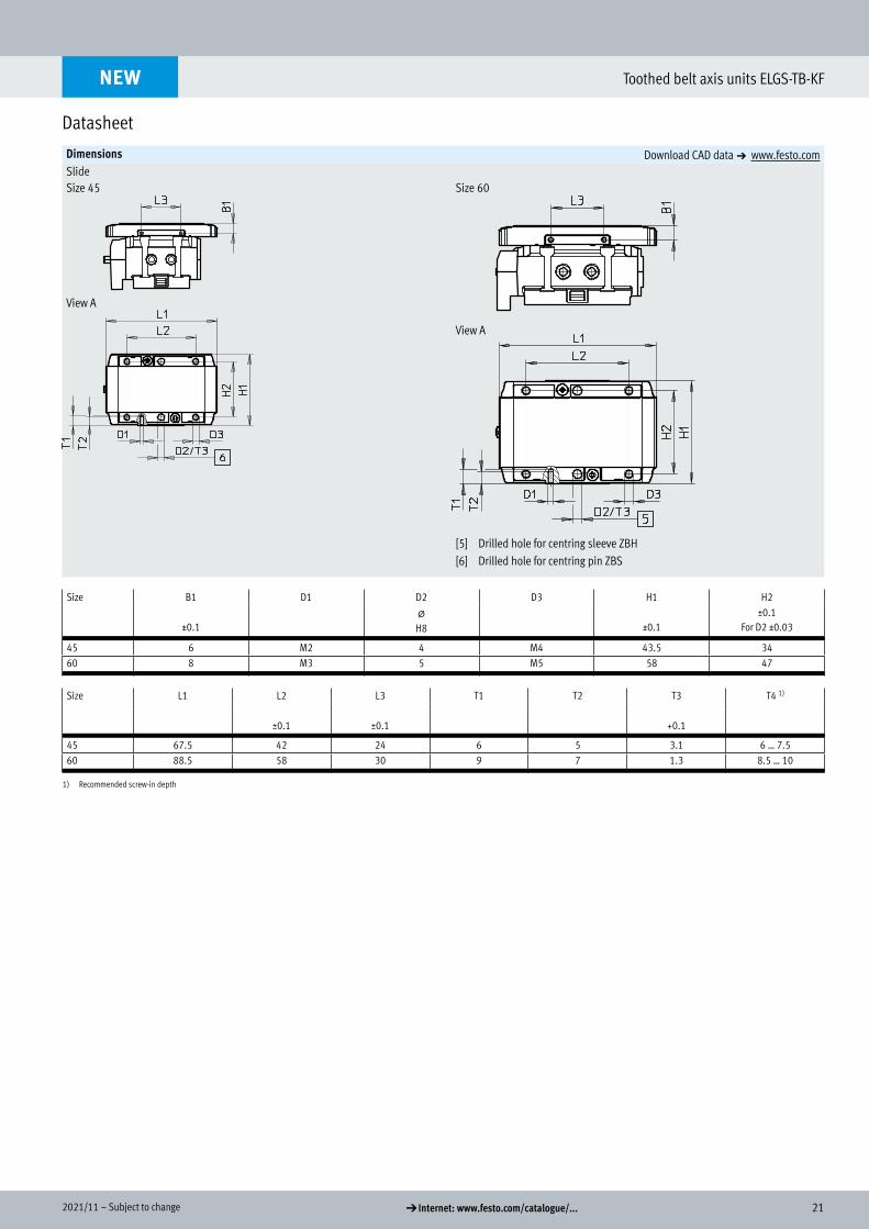
Dimensions Download CAD data a www.festo.comSlideSize 45 Size 60
[5] Drilled hole for centring sleeve ZBH[6] Drilled hole for centring pin ZBS
Size B1 D1 D2 D3 H1 H2
±0.1@
H8 ±0.1±0.1
For D2 ±0.03
45 6 M2 4 M4 43.5 3460 8 M3 5 M5 58 47
Size L1 L2 L3 T1 T2 T3 T4 1)
±0.1 ±0.1 +0.1
45 67.5 42 24 6 5 3.1 6 … 7.560 88.5 58 30 9 7 1.3 8.5 … 10
1) Recommended screw-in depth
NEW
View A
View A
22 d Internet: www.festo.com/catalogue/... Subject to change – 2021/11
Toothed belt axis units ELGS-TB-KF
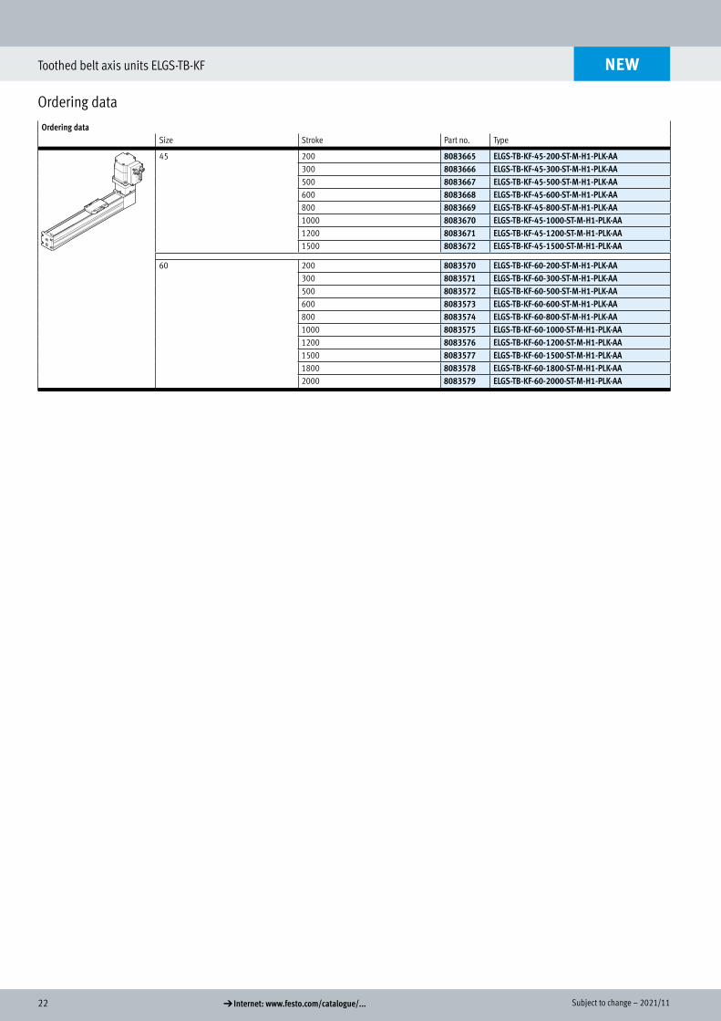
Ordering data
Ordering data Size Stroke Part no. Type
45 200 8083665 ELGS-TB-KF-45-200-ST-M-H1-PLK-AA300 8083666 ELGS-TB-KF-45-300-ST-M-H1-PLK-AA500 8083667 ELGS-TB-KF-45-500-ST-M-H1-PLK-AA600 8083668 ELGS-TB-KF-45-600-ST-M-H1-PLK-AA800 8083669 ELGS-TB-KF-45-800-ST-M-H1-PLK-AA1000 8083670 ELGS-TB-KF-45-1000-ST-M-H1-PLK-AA1200 8083671 ELGS-TB-KF-45-1200-ST-M-H1-PLK-AA1500 8083672 ELGS-TB-KF-45-1500-ST-M-H1-PLK-AA
60 200 8083570 ELGS-TB-KF-60-200-ST-M-H1-PLK-AA300 8083571 ELGS-TB-KF-60-300-ST-M-H1-PLK-AA500 8083572 ELGS-TB-KF-60-500-ST-M-H1-PLK-AA600 8083573 ELGS-TB-KF-60-600-ST-M-H1-PLK-AA800 8083574 ELGS-TB-KF-60-800-ST-M-H1-PLK-AA1000 8083575 ELGS-TB-KF-60-1000-ST-M-H1-PLK-AA1200 8083576 ELGS-TB-KF-60-1200-ST-M-H1-PLK-AA1500 8083577 ELGS-TB-KF-60-1500-ST-M-H1-PLK-AA1800 8083578 ELGS-TB-KF-60-1800-ST-M-H1-PLK-AA2000 8083579 ELGS-TB-KF-60-2000-ST-M-H1-PLK-AA
NEW
Ordering data
232021/11 – Subject to change d Internet: www.festo.com/catalogue/...
Toothed belt axis units ELGS-TB-KF
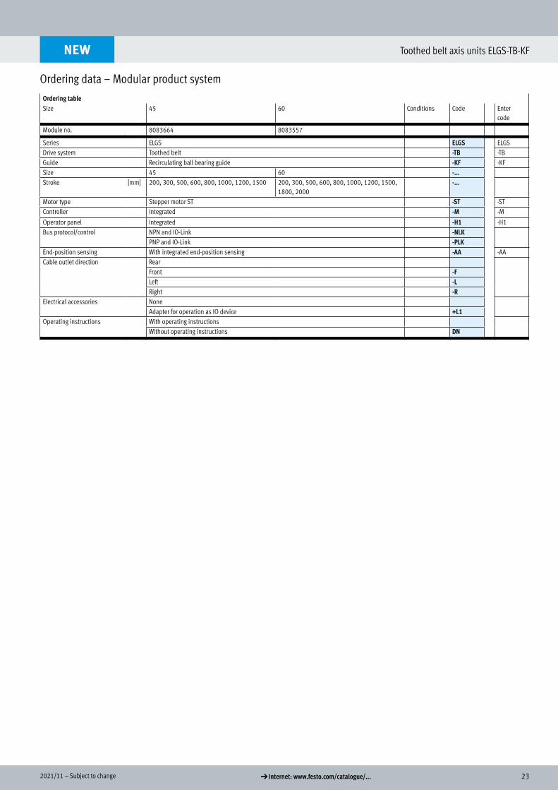
Ordering data – Modular product system
Ordering tableSize 45 60 Conditions Code Enter
code
Module no. 8083664 8083557
Series ELGS ELGS ELGSDrive system Toothed belt -TB -TBGuide Recirculating ball bearing guide -KF -KFSize 45 60 -...Stroke [mm] 200, 300, 500, 600, 800, 1000, 1200, 1500 200, 300, 500, 600, 800, 1000, 1200, 1500,
1800, 2000-...
Motor type Stepper motor ST -ST -STController Integrated -M -M
Operator panel Integrated -H1 -H1Bus protocol/control NPN and IO-Link -NLK
PNP and IO-Link -PLKEnd-position sensing With integrated end-position sensing -AA -AACable outlet direction Rear
Front -FLeft -LRight -R
Electrical accessories NoneAdapter for operation as IO device +L1
Operating instructions With operating instructionsWithout operating instructions DN
NEW
Ordering data – Modular product system
24 d Internet: www.festo.com/catalogue/... Subject to change – 2021/11
Toothed belt axis units ELGS-TB-KF
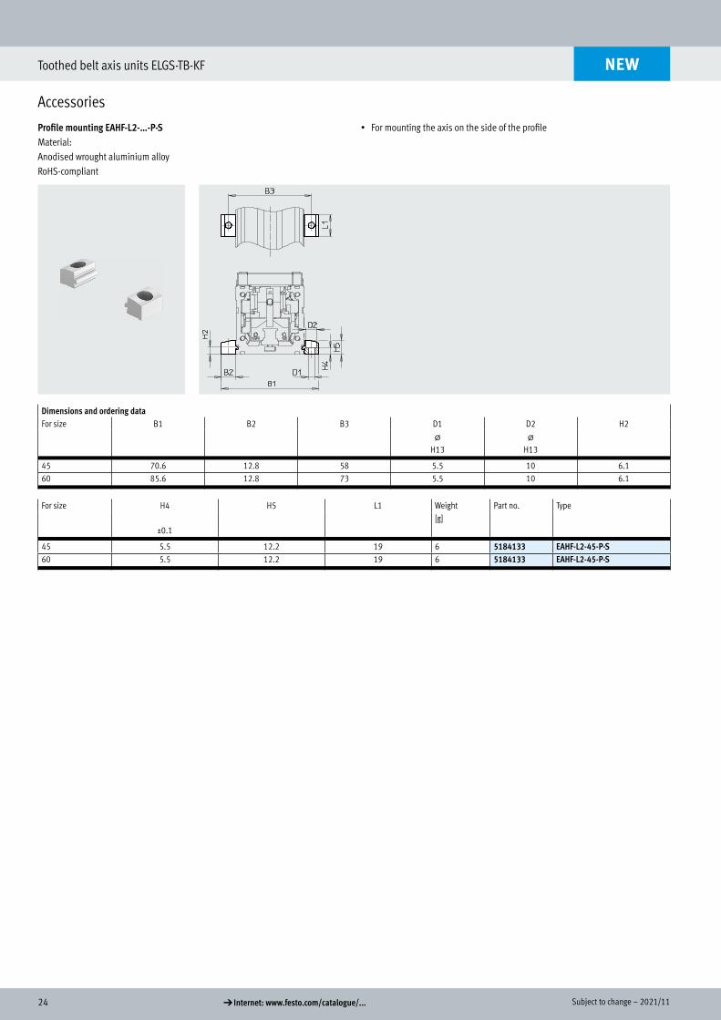
Accessories
Profile mounting EAHF-L2-…-P-S Material:Anodised wrought aluminium alloyRoHS-compliant
• For mounting the axis on the side of the profile
Dimensions and ordering dataFor size B1 B2 B3 D1 D2 H2
@H13
@H13
45 70.6 12.8 58 5.5 10 6.160 85.6 12.8 73 5.5 10 6.1
For size H4 H5 L1 Weight Part no. Type
±0.1[g]
45 5.5 12.2 19 6 5184133 EAHF-L2-45-P-S60 5.5 12.2 19 6 5184133 EAHF-L2-45-P-S
NEW
Accessories
Profile mounting EAHF-L2-…-P-S
252021/11 – Subject to change d Internet: www.festo.com/catalogue/...
Toothed belt axis units ELGS-TB-KF
Accessories
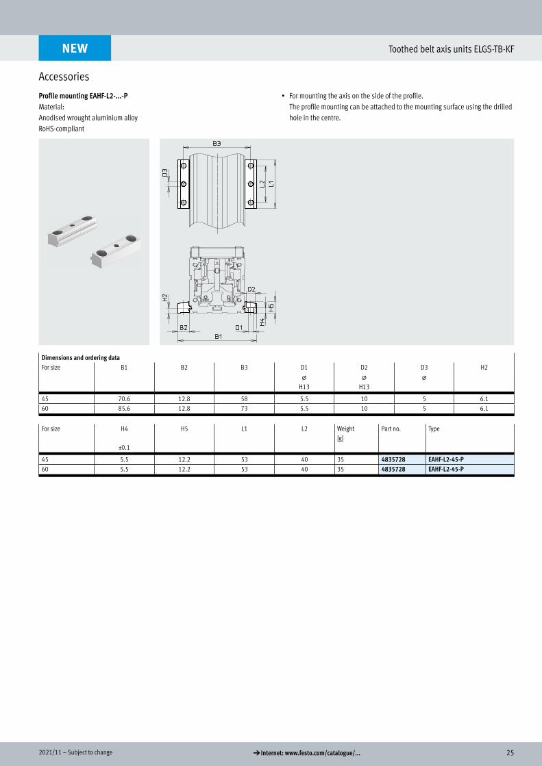
Profile mounting EAHF-L2-...-P Material:Anodised wrought aluminium alloyRoHS-compliant
• For mounting the axis on the side of the profile. The profile mounting can be attached to the mounting surface using the drilled hole in the centre.
Dimensions and ordering dataFor size B1 B2 B3 D1 D2 D3 H2
@H13
@H13
@
45 70.6 12.8 58 5.5 10 5 6.160 85.6 12.8 73 5.5 10 5 6.1
For size H4 H5 L1 L2 Weight Part no. Type
±0.1[g]
45 5.5 12.2 53 40 35 4835728 EAHF-L2-45-P60 5.5 12.2 53 40 35 4835728 EAHF-L2-45-P
NEW
Profile mounting EAHF-L2-...-P
26 d Internet: www.festo.com/catalogue/... Subject to change – 2021/11
Toothed belt axis units ELGS-TB-KF
Accessories
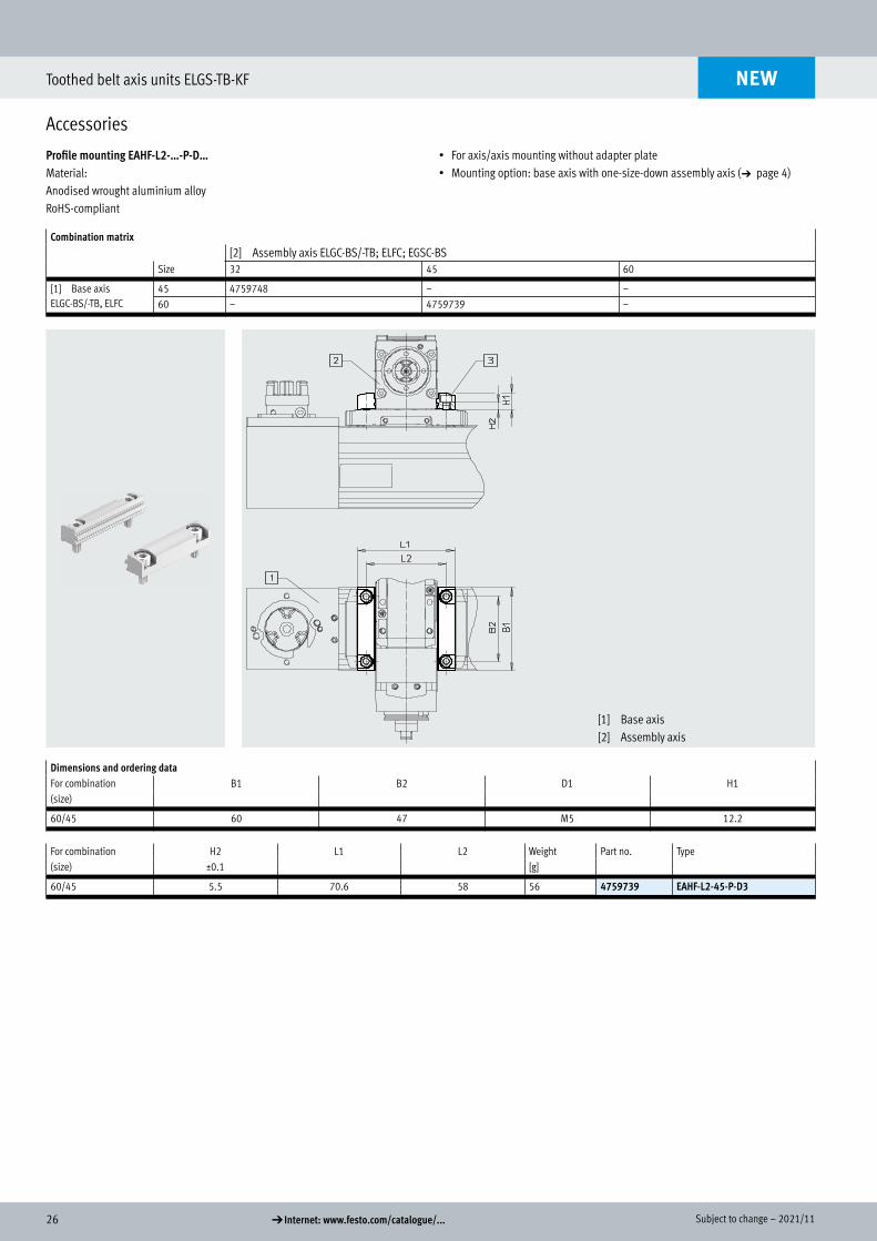
Profile mounting EAHF-L2-…-P-D… Material:Anodised wrought aluminium alloyRoHS-compliant
• For axis/axis mounting without adapter plate• Mounting option: base axis with one-size-down assembly axis (a page 4)
Combination matrix[2] Assembly axis ELGC-BS/-TB; ELFC; EGSC-BS
Size 32 45 60
[1] Base axisELGC-BS/-TB, ELFC
45 4759748 – –60 – 4759739 –
Dimensions and ordering dataFor combination B1 B2 D1 H1(size)
60/45 60 47 M5 12.2
For combination H2 L1 L2 Weight Part no. Type(size) ±0.1 [g]
60/45 5.5 70.6 58 56 4759739 EAHF-L2-45-P-D3
NEW
Profile mounting EAHF-L2-…-P-D...
[1] Base axis[2] Assembly axis
272021/11 – Subject to change d Internet: www.festo.com/catalogue/...
Toothed belt axis units ELGS-TB-KF
Accessories
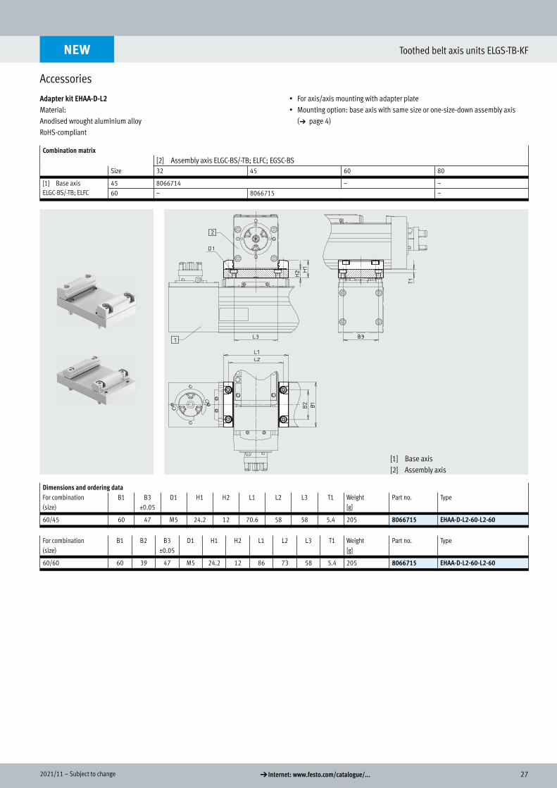
Adapter kit EHAA-D-L2 Material:Anodised wrought aluminium alloyRoHS-compliant
• For axis/axis mounting with adapter plate• Mounting option: base axis with same size or one-size-down assembly axis
(a page 4)
Combination matrix[2] Assembly axis ELGC-BS/-TB; ELFC; EGSC-BS
Size 32 45 60 80
[1] Base axisELGC-BS/-TB; ELFC
45 8066714 – –60 – 8066715 –
Dimensions and ordering dataFor combination B1 B3 D1 H1 H2 L1 L2 L3 T1 Weight Part no. Type(size) ±0.05 [g]
60/45 60 47 M5 24.2 12 70.6 58 58 5.4 205 8066715 EHAA-D-L2-60-L2-60
For combination B1 B2 B3 D1 H1 H2 L1 L2 L3 T1 Weight Part no. Type(size) ±0.05 [g]
60/60 60 39 47 M5 24.2 12 86 73 58 5.4 205 8066715 EHAA-D-L2-60-L2-60
NEW
Adapter kit
[1] Base axis[2] Assembly axis
28 d Internet: www.festo.com/catalogue/... Subject to change – 2021/11
Toothed belt axis units ELGS-TB-KF
Accessories
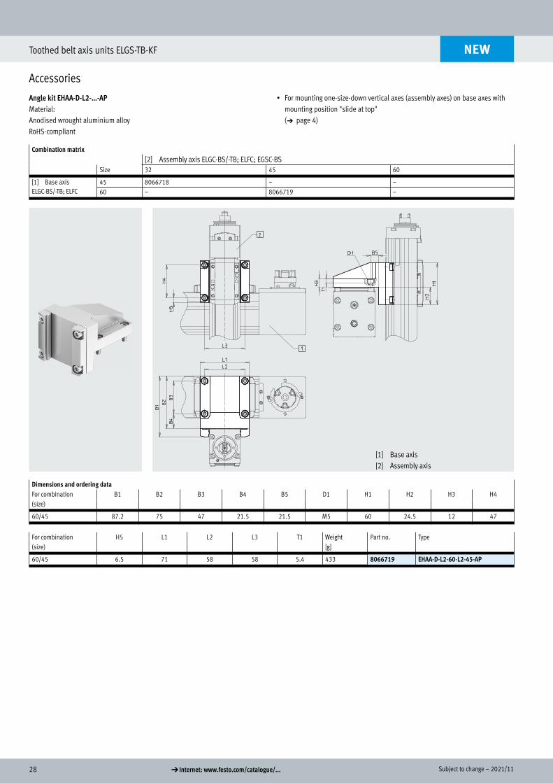
Angle kit EHAA-D-L2-…-AP Material:Anodised wrought aluminium alloyRoHS-compliant
• For mounting one-size-down vertical axes (assembly axes) on base axes with mounting position "slide at top" (a page 4)
Combination matrix[2] Assembly axis ELGC-BS/-TB; ELFC; EGSC-BS
Size 32 45 60
[1] Base axisELGC-BS/-TB; ELFC
45 8066718 – –60 – 8066719 –
Dimensions and ordering dataFor combination B1 B2 B3 B4 B5 D1 H1 H2 H3 H4(size)
60/45 87.2 75 47 21.5 21.5 M5 60 24.5 12 47
For combination H5 L1 L2 L3 T1 Weight Part no. Type(size) [g]
60/45 6.5 71 58 58 5.4 433 8066719 EHAA-D-L2-60-L2-45-AP
NEW
Angle kit
[1] Base axis[2] Assembly axis
292021/11 – Subject to change d Internet: www.festo.com/catalogue/...
Toothed belt axis units ELGS-TB-KF
Accessories
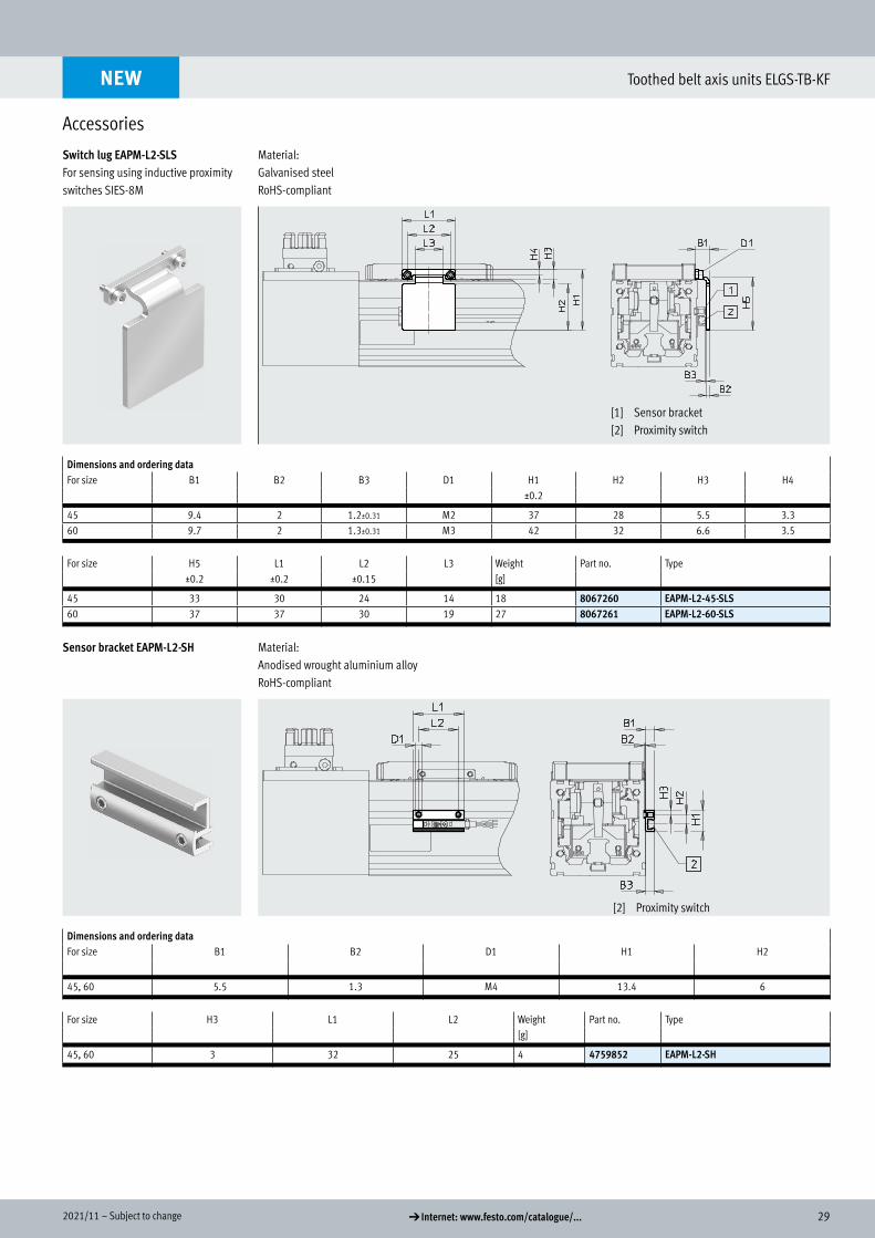
Switch lug EAPM-L2-SLS For sensing using inductive proximity switches SIES-8M
Material:Galvanised steelRoHS-compliant
Dimensions and ordering dataFor size B1 B2 B3 D1 H1 H2 H3 H4
±0.2
45 9.4 2 1.2±0.31 M2 37 28 5.5 3.360 9.7 2 1.3±0.31 M3 42 32 6.6 3.5
For size H5 L1 L2 L3 Weight Part no. Type±0.2 ±0.2 ±0.15 [g]
45 33 30 24 14 18 8067260 EAPM-L2-45-SLS60 37 37 30 19 27 8067261 EAPM-L2-60-SLS
Sensor bracket EAPM-L2-SH Material:Anodised wrought aluminium alloyRoHS-compliant
Dimensions and ordering dataFor size B1 B2 D1 H1 H2
45, 60 5.5 1.3 M4 13.4 6
For size H3 L1 L2 Weight Part no. Type[g]
45, 60 3 32 25 4 4759852 EAPM-L2-SH
NEW
Switch lug
Sensor bracket
[1] Sensor bracket[2] Proximity switch
[2] Proximity switch
30 d Internet: www.festo.com/catalogue/... Subject to change – 2021/11
Toothed belt axis units ELGS-TB-KF
Accessories
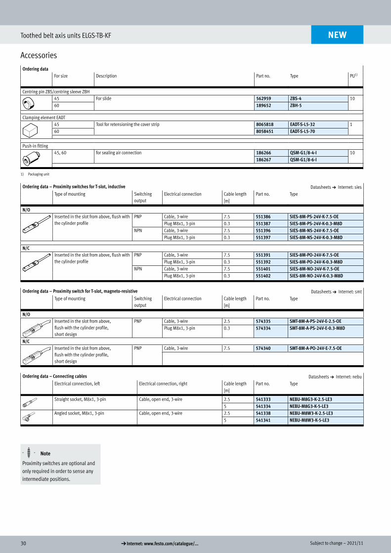
Ordering dataFor size Description Part no. Type PU1)
Centring pin ZBS/centring sleeve ZBH 45 For slide 562959 ZBS-4 1060 189652 ZBH-5
Clamping element EADT 45 Tool for retensioning the cover strip 8065818 EADT-S-L5-32 160 8058451 EADT-S-L5-70
Push-in fitting45, 60 for sealing air connection 186266 QSM-G1/8-4-I 10
186267 QSM-G1/8-6-I
1) Packaging unit
Ordering data – Proximity switches for T-slot, inductive Datasheets a Internet: siesType of mounting Switching
outputElectrical connection Cable length Part no. Type
[m]
N/OInserted in the slot from above, flush with the cylinder profile
PNP Cable, 3-wire 7.5 551386 SIES-8M-PS-24V-K-7.5-OEPlug M8x1, 3-pin 0.3 551387 SIES-8M-PS-24V-K-0.3-M8D
NPN Cable, 3-wire 7.5 551396 SIES-8M-NS-24V-K-7.5-OEPlug M8x1, 3-pin 0.3 551397 SIES-8M-NS-24V-K-0.3-M8D
N/CInserted in the slot from above, flush with the cylinder profile
PNP Cable, 3-wire 7.5 551391 SIES-8M-PO-24V-K-7.5-OEPlug M8x1, 3-pin 0.3 551392 SIES-8M-PO-24V-K-0.3-M8D
NPN Cable, 3-wire 7.5 551401 SIES-8M-NO-24V-K-7.5-OEPlug M8x1, 3-pin 0.3 551402 SIES-8M-NO-24V-K-0.3-M8D
Ordering data – Proximity switch for T-slot, magneto-resistive Datasheets a Internet: smtType of mounting Switching
outputElectrical connection Cable length Part no. Type
[m]
N/OInserted in the slot from above, flush with the cylinder profile, short design
PNP Cable, 3-wire 2.5 574335 SMT-8M-A-PS-24V-E-2.5-OEPlug M8x1, 3-pin 0.3 574334 SMT-8M-A-PS-24V-E-0.3-M8D
N/CInserted in the slot from above, flush with the cylinder profile, short design
PNP Cable, 3-wire 7.5 574340 SMT-8M-A-PO-24V-E-7.5-OE
Ordering data – Connecting cables Datasheets a Internet: nebuElectrical connection, left Electrical connection, right Cable length Part no. Type
[m]
Straight socket, M8x1, 3-pin Cable, open end, 3-wire 2.5 541333 NEBU-M8G3-K-2.5-LE35 541334 NEBU-M8G3-K-5-LE3
Angled socket, M8x1, 3-pin Cable, open end, 3-wire 2.5 541338 NEBU-M8W3-K-2.5-LE35 541341 NEBU-M8W3-K-5-LE3
H- - Note
Proximity switches are optional and only required in order to sense any intermediate positions.
NEW
Centring sleeve
Clamping element
Push-in fitting
Proximity switch
Connecting cable
312021/11 – Subject to change d Internet: www.festo.com/catalogue/...
Toothed belt axis units ELGS-TB-KF
Accessories
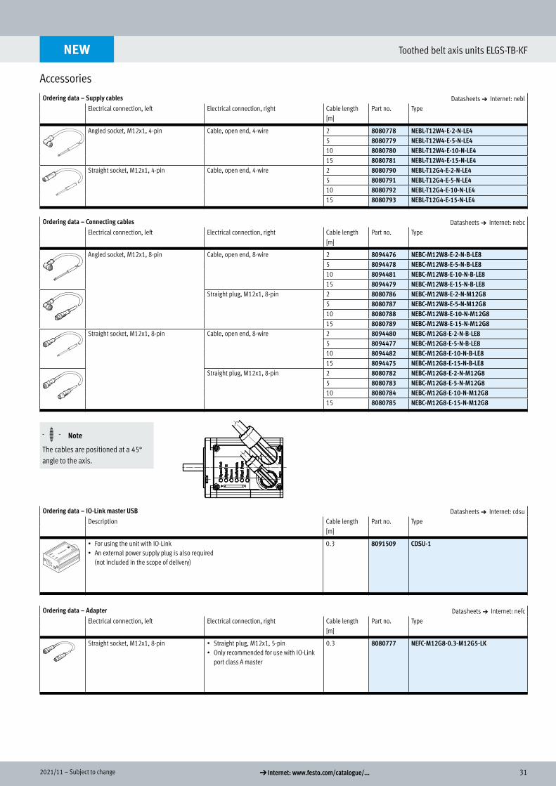
Ordering data – Supply cables Datasheets a Internet: neblElectrical connection, left Electrical connection, right Cable length Part no. Type
[m]
Angled socket, M12x1, 4-pin Cable, open end, 4-wire 2 8080778 NEBL-T12W4-E-2-N-LE45 8080779 NEBL-T12W4-E-5-N-LE410 8080780 NEBL-T12W4-E-10-N-LE415 8080781 NEBL-T12W4-E-15-N-LE4
Straight socket, M12x1, 4-pin Cable, open end, 4-wire 2 8080790 NEBL-T12G4-E-2-N-LE45 8080791 NEBL-T12G4-E-5-N-LE410 8080792 NEBL-T12G4-E-10-N-LE415 8080793 NEBL-T12G4-E-15-N-LE4
Ordering data – Connecting cables Datasheets a Internet: nebcElectrical connection, left Electrical connection, right Cable length Part no. Type
[m]
Angled socket, M12x1, 8-pin Cable, open end, 8-wire 2 8094476 NEBC-M12W8-E-2-N-B-LE85 8094478 NEBC-M12W8-E-5-N-B-LE810 8094481 NEBC-M12W8-E-10-N-B-LE815 8094479 NEBC-M12W8-E-15-N-B-LE8
Straight plug, M12x1, 8-pin 2 8080786 NEBC-M12W8-E-2-N-M12G85 8080787 NEBC-M12W8-E-5-N-M12G810 8080788 NEBC-M12W8-E-10-N-M12G815 8080789 NEBC-M12W8-E-15-N-M12G8
Straight socket, M12x1, 8-pin Cable, open end, 8-wire 2 8094480 NEBC-M12G8-E-2-N-B-LE85 8094477 NEBC-M12G8-E-5-N-B-LE810 8094482 NEBC-M12G8-E-10-N-B-LE815 8094475 NEBC-M12G8-E-15-N-B-LE8
Straight plug, M12x1, 8-pin 2 8080782 NEBC-M12G8-E-2-N-M12G85 8080783 NEBC-M12G8-E-5-N-M12G810 8080784 NEBC-M12G8-E-10-N-M12G815 8080785 NEBC-M12G8-E-15-N-M12G8
H- - Note
The cables are positioned at a 45° angle to the axis.
Ordering data – IO-Link master USB Datasheets a Internet: cdsuDescription Cable length Part no. Type
[m]
• For using the unit with IO-Link• An external power supply plug is also required
(not included in the scope of delivery)
0.3 8091509 CDSU-1
Ordering data – Adapter Datasheets a Internet: nefcElectrical connection, left Electrical connection, right Cable length Part no. Type
[m]
Straight socket, M12x1, 8-pin • Straight plug, M12x1, 5-pin• Only recommended for use with IO-Link
port class A master
0.3 8080777 NEFC-M12G8-0.3-M12G5-LK
NEW
Supply cable
Connecting cable
IO-Link master
Adapter
Related Documents