Before using this guide to setup your Tobii Eye Tracker we strongly recommend reading the Tobii Whitepaper entitled “Using Eye Tracking to Test Mobile Devices” for a detailed explanation of the different factors to consider when doing mobile device eye tracking. Eye Tracking Mobile Devices with Tobii Eye Trackers etup Guide S January 29, 2010 Tobii Technology AB

Tobii Eye Tracker Setup Guide For Testing Mobile Devices
Nov 18, 2014
Welcome message from author
This document is posted to help you gain knowledge. Please leave a comment to let me know what you think about it! Share it to your friends and learn new things together.
Transcript

Before using this guide to setup your Tobii Eye Tracker we strongly recommend reading the Tobii Whitepaper entitled “Using Eye Tracking to Test Mobile Devices” for a detailed explanation of the different factors to consider when doing mobile device eye tracking.
Eye Tracking Mobile Devices with Tobii Eye
Trackersetup Guide S January 29, 2010 Tobii Technology AB

Contents 1 Emulator setup ..................................................................................................................... 3
1.1 Setup Procedure .......................................................................................................... 4
1.1.1 Equipment setup ..................................................................................................... 4
1.1.2 Creating the test in Tobii Studio ............................................................................. 4
1.2 Testing ......................................................................................................................... 6
2 Below table setup ................................................................................................................ 7
2.1 Setup Procedure .......................................................................................................... 8
2.1.1 Equipment setup ..................................................................................................... 8
2.1.2 Creating a Tobii Studio test ..................................................................................... 9
2.2 Testing ....................................................................................................................... 10
3 Inverted X‐series setup ....................................................................................................... 11
3.1 Setup Procedure ........................................................................................................ 12
3.1.1 Equipment setup ................................................................................................... 12
3.1.2 Creating the test in Tobii Studio ........................................................................... 14
3.1.3 Configuring the inverted Tobii X‐series ................................................................ 14
3.1.4 Perspective calibration ......................................................................................... 15
3.1.4 Participant calibration .......................................................................................... 17
3.2 Testing ....................................................................................................................... 18
© 2010 Tobii Technology ‐ All rights reserved. Tobii Technology and the Tobii logo are either registered trademarks or trademarks of Tobii Technology in the United States and/or other countries.
www.tobii.com
2
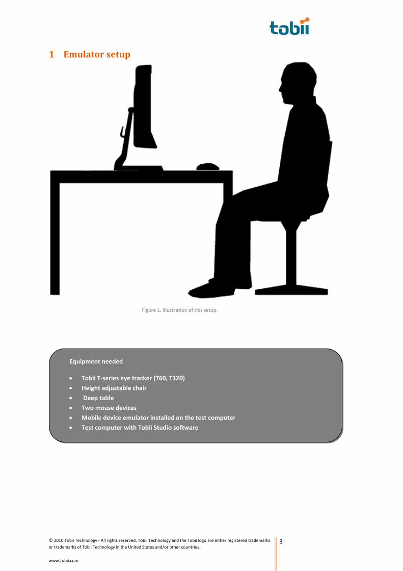
1 Emulator setup
Figure 1. Illustration of this setup.
• Test computer with Tobii Studio software
• Mobile device emulator installed on the test computer
• Two mouse devices
• Height adjustable chair
• Deep table
Equipment needed
• Tobii T‐series eye tracker (T60, T120)
© 2010 Tobii Technology ‐ All rights reserved. Tobii Technology and the Tobii logo are either registered trademarks or trademarks of Tobii Technology in the United States and/or other countries.
www.tobii.com
3

1.1 Setup Procedure
Figure 2. Overview of the setup.
1.1.1 Equipment setup The first, and probably the most time consuming step of this setup is to locate and install the emulator to be used during testing. As that procedure is specific for which device to be emulated, we can unfortunately not provide any guidance regarding how to do this.
1.1.2 Creating the test in Tobii Studio After installing a stable emulator on the computer running Tobii Studio, connect computer to the Tobii T‐series eye tracker. Create a Tobii Studio Project and a test in which a screen recording element (to record the emulator) is selected and dragged into the work space, i.e. onto the timeline. If needed, also include an instruction element on the timeline to provide the participants with some initial guidance before the test commences. Using the Questionnaire element can also be valuable in order to collect data from the participants.
Figure 3. Extended desktop display. The dashed line highlights the division between the two screens.
© 2010 Tobii Technology ‐ All rights reserved. Tobii Technology and the Tobii logo are either registered trademarks or trademarks of Tobii Technology in the United States and/or other countries.
www.tobii.com
4

© 2010 Tobii Technology ‐ All rights reserved. Tobii Technology and the Tobii logo are either registered trademarks or trademarks of Tobii Technology in the United States and/or other countries.
www.tobii.com
5
It is advisable to use two screens connected to the computer running Tobii Studio during testing using this setup. By using two screens the moderator control the start and stop of the recording and ensure that the participant is positioned correctly as well as that eye tracking data is collected continuously during the entire session. Set the screen on the Tobii Studio computer to share the interface as an extended desktop with the eye tracker (see Figure 3). Select the eye tracker as the presentation screen using the presentation screen selector tool in Tobii Studio1. Click on [identify] to confirm you have selected the right screen setup. Connect an extra mouse to the Tobii Studio computer to allow the participants to interact with the interface of the emulator. Start the emulator and drag it onto the eye tracker screen. Choose a suitable position for the emulator on the screen and ensure that position is not altered during the testing as that will eliminate the possibility of quantitative analysis of the combined eye tracking data from several participants. Enable Show Track Status (Ctrl+T) and position the Track status window (see Figure 4) on the moderator’s screen. The Track status window is useful when positioning the participant correctly in front of the eye tracker as well as for ensuring that the participant stays within trackable distance from the eye tracker.
Figure 4. Track status window.
1 This feature is available from Tobii Studio 2.0. However, it is not included in the Basic version of the software. If using the Basic version or a previous version of Tobii Studio, the eye tracker monitor has to be set as the primary monitor by using the Display Settings in Windows.
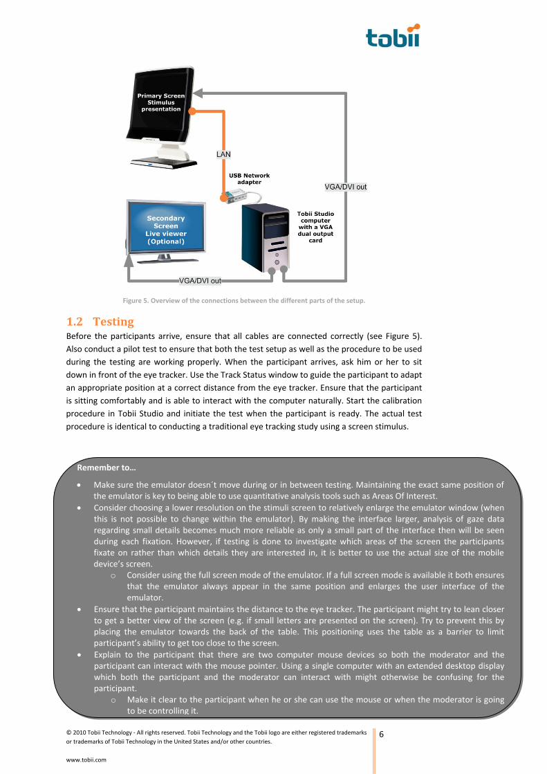
Figure 5. Overview of the connections between the different parts of the setup.
1.2 Testing Before the participants arrive, ensure that all cables are connected correctly (see Figure 5). Also conduct a pilot test to ensure that both the test setup as well as the procedure to be used during the testing are working properly. When the participant arrives, ask him or her to sit down in front of the eye tracker. Use the Track Status window to guide the participant to adapt an appropriate position at a correct distance from the eye tracker. Ensure that the participant is sitting comfortably and is able to interact with the computer naturally. Start the calibration procedure in Tobii Studio and initiate the test when the participant is ready. The actual test procedure is identical to conducting a traditional eye tracking study using a screen stimulus.
o Make it clear to the participant when he or she can use the mouse or when the moderator is going to be controlling it.
• Explain to the participant that there are two computer mouse devices so both the moderator and the participant can interact with the mouse pointer. Using a single computer with an extended desktop display which both the participant and the moderator can interact with might otherwise be confusing for the participant.
• Ensure that the participant maintains the distance to the eye tracker. The participant might try to lean closer to get a better view of the screen (e.g. if small letters are presented on the screen). Try to prevent this by placing the emulator towards the back of the table. This positioning uses the table as a barrier to limit participant’s ability to get too close to the screen.
o Consider using the full screen mode of the emulator. If a full screen mode is available it both ensures that the emulator always appear in the same position and enlarges the user interface of the emulator.
• Consider choosing a lower resolution on the stimuli screen to relatively enlarge the emulator window (when this is not possible to change within the emulator). By making the interface larger, analysis of gaze data regarding small details becomes much more reliable as only a small part of the interface then will be seen during each fixation. However, if testing is done to investigate which areas of the screen the participants fixate on rather than which details they are interested in, it is better to use the actual size of the mobile device’s screen.
• Make sure the emulator doesn´t move during or in between testing. Maintaining the exact same position of the emulator is key to being able to use quantitative analysis tools such as Areas Of Interest.
Remember to…
© 2010 Tobii Technology ‐ All rights reserved. Tobii Technology and the Tobii logo are either registered trademarks or trademarks of Tobii Technology in the United States and/or other countries.
www.tobii.com
6

2 Below table setup
Figure 6. Illustration of the setup.
• Test computer with Tobii Studio software
• User cam. (built‐in)
• Mobile device to test
• Deep table, height adjustable (preferable fixed)
• Height adjustable chair
• Adjustable lighting fixture with a light source (e.g. a small battery operated LED light)
• A small external video camera with a high resolution and frame rate (recommended at least. 800X600 @ 15fps, preferably more)
• Mobile device holder or a sled (long bended piece of plastic or metal) with adhesive (tape strip) to hold the mobile device
• Floor stand to attach the mobile device holder, fixed in place
• Tobii T‐series eye tracker (T60, T120)
Equipment needed
© 2010 Tobii Technology ‐ All rights reserved. Tobii Technology and the Tobii logo are either registered trademarks or trademarks of Tobii Technology in the United States and/or other countries.
www.tobii.com
7

2.1 Setup Procedure
Figure 7. Overview of the setup.
2.1.1 Equipment setup In this setup a deep and high table is needed. The depth of the table prevents the participant from getting too close to the eye tracker. A high table provides more space for the participant when interacting below the table with the phone and eliminates the need for the participant to lean forwards to use the setup.
2.1.1.1 The eye tracker Place the eye tracker close to the back of the table and connect it to a Tobii Studio computer. It is recommended to position the table against a wall to eliminate the risk of the eye tracker falling off the edge of the table. Position the floor stand with the mobile device holder attached to it at a height that feels comfortable for the participant when using the mobile device below the table. A height adjustable chair can provide more flexibility to this setup by allowing the participant to adapt a comfortable position without changing the position of the floor stand.
2.1.1.2 The light source Mount a flexible light source to illuminate the mobile device. Either attach the light to the floor stand, to the floor or fix it underneath the table. Ensure it doesn´t get in the way of the participant when testing with the setup. After the camera is configured and properly set up, check that no unwanted reflections caused by the light source are visible on the screen of the mobile device when looking at the video feed.
© 2010 Tobii Technology ‐ All rights reserved. Tobii Technology and the Tobii logo are either registered trademarks or trademarks of Tobii Technology in the United States and/or other countries.
www.tobii.com
8

2.1.1.3 The camera position and video feed Connect the camera to the computer running Tobii Studio and monitor the image while setting it up. Position the webcam just at the edge directly underneath the table, facing the mobile device (see Figure 8). Make sure it will not obstruct the participant when using the mobile device, and secure it firmly to eliminate any accidental movement. Make sure the hands of the participant will be visible as well on the video stream shown on the eye tracker screen. This helps with orientation and coordination of the participants’ actions while performing the test and will decrease the time needed for learning how to use the setup when using it for the first time.
Figure 8. Positions of the camera, the light source and the mobile device.
2.1.1.4 The mobile device Adjust the mobile device to a downward pointing angle in relation to the webcam. This is to improve the perception of depth and perspective for the participant. The video camera will otherwise degrade this significantly which will make it harder for the participants to operate the mobile device accurately and intuitively.
2.1.2 Creating a Tobii Studio test Create a new Tobii Studio project and a test with an external video element. Double click the element, select the video source and adjust the settings of the video feed. Choose a codec and settings which provides a good quality image as what the participant sees on the screen is what will guide them on how to interact with the phone. Also ensure that the time delay of the video feed is kept at a minimum as it otherwise can be confusing or frustrating for the participant when they cannot see the feedback of actions they have done as quick as they might expect. Tick the
checkbox that is labeled ‘Use video as stimulus’ (see Figure 9).
Figure 9. External Video Setup.
© 2010 Tobii Technology ‐ All rights reserved. Tobii Technology and the Tobii logo are either registered trademarks or trademarks of Tobii Technology in the United States and/or other countries.
www.tobii.com
9

Figure 10. Overview of the connections between the different parts of the setup.
2.2 Testing If everything is connected correctly, the connections between the different parts of the setup should be as can be seen in Figure 10.
When the participants arrive, ask them to position themselves comfortably whilst holding the mobile device below the table. Once seated, ensure the participants are sitting at a good distance from the eye tracker. As discussed in ‘Testing’ for the Emulator setup, using the Track Status feature in Tobii Studio simplifies this activity. Start the calibration and test recording whenever the participant is ready.
© 2010 Tobii Technology ‐ All rights reserved. Tobii Technology and the Tobii logo are either registered trademarks or trademarks of Tobii Technology in the United States and/or other countries.
www.tobii.com
10
o Depending on the type of testing being done, the participants might want to get acquainted with the phone by handling it like they normally would before using the testing setup. If testing the physical interface of the phone is not the purpose of the test, letting the participant get to know the phone before the actual testing begins can reduce the time needed for getting used to interact with the phone under the table.
• Make sure the mobile device is fully charged to avoid having to use a charger during testing. • Consider having a second mobile device (same as the one being tested) available if explanations about how
to interact with the device or how it works are necessary before the testing commences. Using the device mounted below the table for such explanations is difficult. Hence, using a second device is to be preferred.
• Consider adding an extra light source. Participants might unintentionally obstruct the single light source by their arms or hands below the table, leaving them with a dark image on the viewed video stream. Poor viewing conditions can be annoying and distracting both for the participant during testing and as well as for the researcher during analysis.
• Fix the focus on the camera so the screen of the mobile device is in focus. This is to avoid the screen appearing less sharp and therefore unreadable at any point during testing.
• Ensure that the video settings and the mobile device’s screen settings are configured correctly. It might be necessary to lower the mobile device´s screen’s brightness to avoid overexposing the video stream when switching between interfaces on the device with large differences in contrast.
• Make sure everything that needs to be stationary is securely fixed in place during the testing. If the data is going to be used for creating Areas Of Interest (AOIs), it is important that the position of the mobile phone and the camera remains the same for all participants.
Remember to…
© 2010 Tobii Technology ‐ All rights reserved. Tobii Technology and the Tobii logo are either registered trademarks or trademarks of Tobii Technology in the United States and/or other countries.
www.tobii.com
11
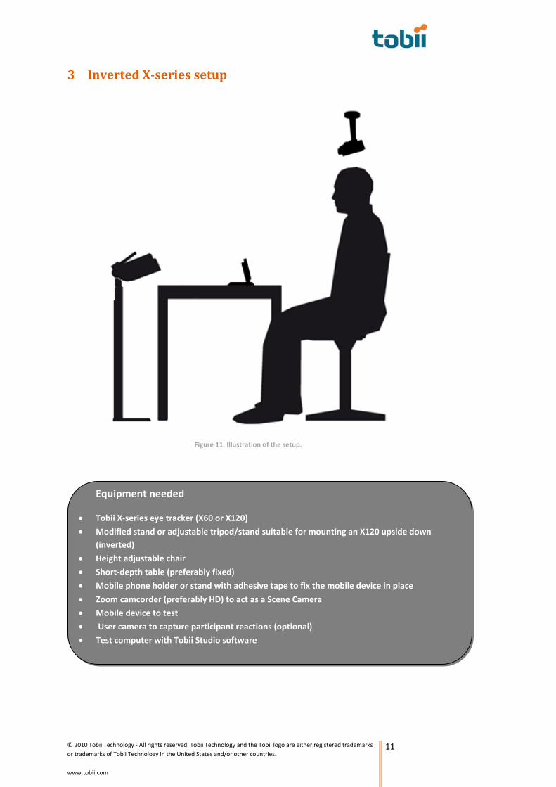
3 Inverted Xseries setup
Figure 11. Illustration of the setup.
Equipment needed
• Tobii X‐series eye tracker (X60 or X120)
• Modified stand or adjustable tripod/stand suitable for mounting an X120 upside down (inverted)
• Height adjustable chair
• Short‐depth table (preferably fixed)
• Mobile phone holder or stand with adhesive tape to fix the mobile device in place
• Zoom camcorder (preferably HD) to act as a Scene Camera
• Mobile device to test
• User camera to capture participant reactions (optional)
• Test computer with Tobii Studio software
© 2010 Tobii Technology ‐ All rights reserved. Tobii Technology and the Tobii logo are either registered trademarks or trademarks of Tobii Technology in the United States and/or other countries.
www.tobii.com
12
3.1 Setup Procedure
3.1.1 Equipment setup
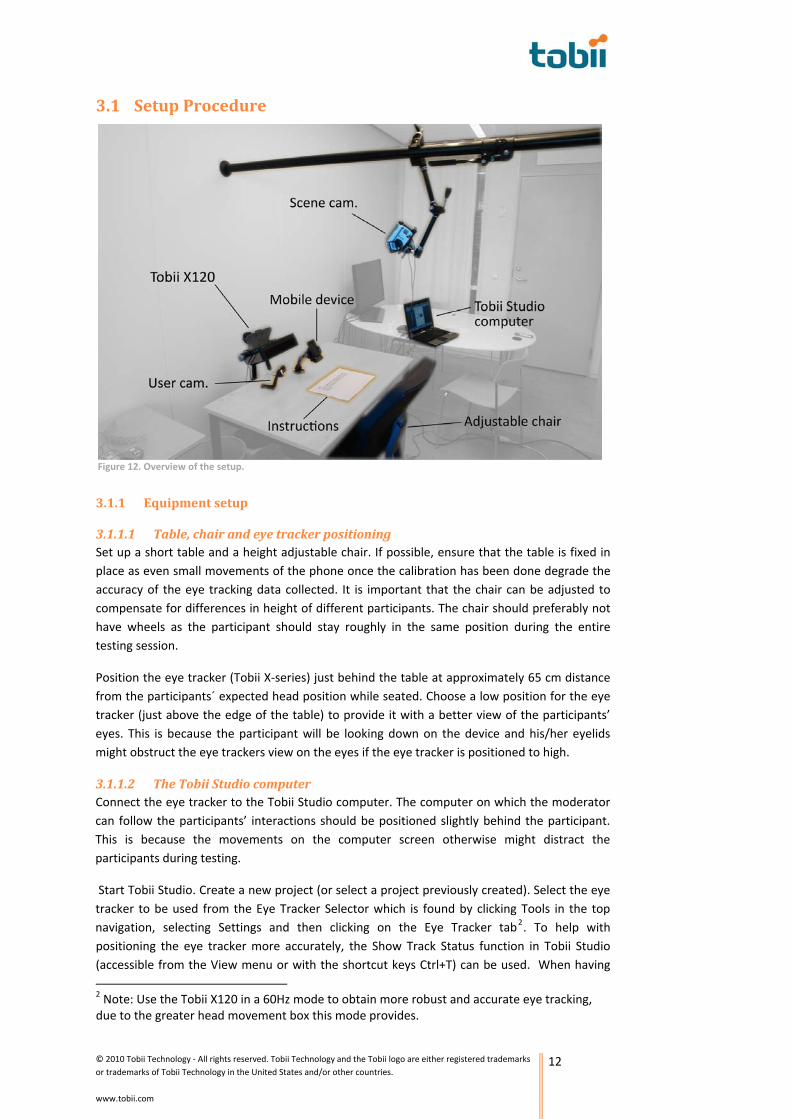
3.1.1.1 Table, chair and eye tracker positioning Set up a short table and a height adjustable chair. If possible, ensure that the table is fixed in place as even small movements of the phone once the calibration has been done degrade the accuracy of the eye tracking data collected. It is important that the chair can be adjusted to compensate for differences in height of different participants. The chair should preferably not have wheels as the participant should stay roughly in the same position during the entire testing session.
Position the eye tracker (Tobii X‐series) just behind the table at approximately 65 cm distance from the participants´ expected head position while seated. Choose a low position for the eye tracker (just above the edge of the table) to provide it with a better view of the participants’ eyes. This is because the participant will be looking down on the device and his/her eyelids might obstruct the eye trackers view on the eyes if the eye tracker is positioned to high.
3.1.1.2 The Tobii Studio computer Connect the eye tracker to the Tobii Studio computer. The computer on which the moderator can follow the participants’ interactions should be positioned slightly behind the participant. This is because the movements on the computer screen otherwise might distract the participants during testing.
Start Tobii Studio. Create a new project (or select a project previously created). Select the eye tracker to be used from the Eye Tracker Selector which is found by clicking Tools in the top navigation, selecting Settings and then clicking on the Eye Tracker tab2. To help with positioning the eye tracker more accurately, the Show Track Status function in Tobii Studio (accessible from the View menu or with the shortcut keys Ctrl+T) can be used. When having 2 Note: Use the Tobii X120 in a 60Hz mode to obtain more robust and accurate eye tracking, due to the greater head movement box this mode provides.
Figure 12. Overview of the setup.

© 2010 Tobii Technology ‐ All rights reserved. Tobii Technology and the Tobii logo are either registered trademarks or trademarks of Tobii Technology in the United States and/or other countries.
www.tobii.com
13
opened the show Track Status function, position the eye tracker in a way that makes the participants’ eyes (i.e. the white dots) appear in the center of the Track Status window and with a distance measure (i.e. what can be seen to the right in the Track Status window) of approximately 65‐70cm.
3.1.1.3 The mobile device he mobile device in a
h
Place the phone in such a way that from the
more of the eye and, in addition, the
3.1.1.4 The scene camera Place the scene camera just above the expected head
ir y
Also consider adding a camera to the setup positioned in
Position the holder with tposition which makes it comfortable for the participants to interact wit the device when sitting at the chair. Keep in mind the following guidelines:
participants´ point of view the top of the mobile device is aligned with the bottom of the inverted Tobii X‐series Eye Tracker. This is to avoid obstructing the eye tracker’s field of view (see Figure 13). Placing the mobile device more towards the participant may improve accuracy of tracking (the screen appears bigger to the participants’ eyes when held closer), but might also cause the participants’ eyelids to obstruct the eye tracker’s view of the participants’ eyes. When the participant looks downwards, the eyelids cover eyelashes also become a factor that obstructs the view
of the eyes. For our test setup we used a distance of about 36 cm from the front of the phone to the back of the eye tracker. This provided a good compromise between trackability and a comfortable holding and viewing position for the participants.
position of the participant, allowing some extra space for the participants to get in and out of the seat without obstructing the view of the camera or accidentally change its position. Also take in to consideration that the part cipants´ hair might potentially block the came a´s view. If ou, during the setup, notice that this might become a problem, try to place the camera more towards the front of the participant. Use a camera with good zoom functionality to get a full view on the mobile device’s screen. To ensure accurate results, zoom in as much as possible whilst still keeping the whole interface (screen and buttons) of the device visible.
a way that allows it to record the participants´ physical behavior during the test as this can be used for qualitative analysis of the participant reactions.
Figure 13. Position of the eye tracker and the mobile device.
Figure 14. Scene camera setup.
A variation to this setup has previously been implemented, but not thoroughly tested. The phone was then placed directly below the eye tracker. What needs to be considered if such a setup is used is that the distance between the eye tracker and the participant still needs to be at least 50 cm which can be problematic if the participant has short arms or a tendency to lean forward to get a better look at the screen (which then also is positioned at least 50 cm from the participant).
© 2010 Tobii Technology ‐ All rights reserved. Tobii Technology and the Tobii logo are either registered trademarks or trademarks of Tobii Technology in the United States and/or other countries.
www.tobii.com
14
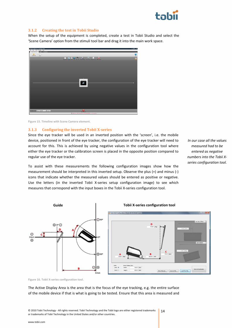
3.1.2 Creating the test in Tobii Studio When the setup of the equipment is completed, create a test in Tobii Studio and select the ‘Scene Camera’ option from the stimuli tool bar and drag it into the main work space.
Figure 15. Timeline with Scene Camera element.
3.1.3 Configuring the inverted Tobii Xseries Since the eye tracker will be used in an inverted position with the ‘screen’, i.e. the mobile device, positioned in front of the eye tracker, the configuration of the eye tracker will need to account for this. This is achieved by using negative values in the configuration tool where either the eye tracker or the calibration screen is placed in the opposite position compared to regular use of the eye tracker.
To assist with these measurements the following configuration images show how the measurement should be interpreted in this inverted setup. Observe the plus (+) and minus (‐) icons that indicate whether the measured values should be entered as positive or negative. Use the letters (in the inverted Tobii X‐series setup configuration image) to see which measures that correspond with the input boxes in the Tobii X‐series configuration tool.
The Active Display Area is the area that is the focus of the eye tracking, e.g. the entire surface of the mobile device if that is what is going to be tested. Ensure that this area is measured and
Guide Tobii X‐series configuration tool
Figure 16. Tobii X‐series configuration tool.
In our case all the values measured had to be entered as negative
numbers into the Tobii X‐series configuration tool.

© 2010 Tobii Technology ‐ All rights reserved. Tobii Technology and the Tobii logo are either registered trademarks or trademarks of Tobii Technology in the United States and/or other countries.
www.tobii.com
15
input into the configuration tool as this has impact on the accuracy of the eye tracking. Also keep in mind that it is from the surface of the Active Display, i.e. in our case the front of the mobile device, that the distance B in the configuration tool should be measured (see Figure 16).
3.1.4 Perspective calibration When using the Tobii X‐series in an inverted setup, the dots in the Perspective calibration tool in Tobii Studio need to be inverted as well. Use the following instruction to do this:
3.1.4.1 Opening up the calibration tool Open the Scene Camera Setup by double clicking on the Scene Camera element on the timeline in Tobii Studio (see Figure 17). Select the Video Source you want to use, e.g. a HD USB zoom camera connected to the computer, and do the necessary adjustments to the camera and/or video settings to provide a clear high resolution image with a reasonable frame rate. Our testing showed that the resolution of the camera has to be at least 640x480 and the frame rate 25 frames per second (fps). When selecting which codec to use, keep in mind that it needs to be able to handle the extensive amount of data generated by the scene camera efficiently. Use the Live Viewer to identify which codec is most suitable and what are the best possible settings for the compression rate while still maintaining the video quality. The Live Viewer can be accessed by clicking on View in the top navigation and selecting Live Viewer from the drop down list.
3.1.4.2 Setting up the calibration grid When using the Scene Camera option in Tobii Studio, the calibration has to be set manually as there is no screen available for the participants to look at. In order to do this a calibration grid has to be created. During the calibration, the calibration grid should be placed where the surface of the device will be positioned during the test. Ideally, the calibration grid should be shown on the display of the mobile device if the mobile device display is the main focus of the eye tracking test. This is because that automatically places the grid in the same plane as the object to be eye tracked.
Figure 17. How to get to the Scene Camera Setup.
Set the camera resolution to at least 640x480 pixels and the frame rate of
minimum 25 frames per second.
© 2010 Tobii Technology ‐ All rights reserved. Tobii Technology and the Tobii logo are either registered trademarks or trademarks of Tobii Technology in the United States and/or other countries.
www.tobii.com
16
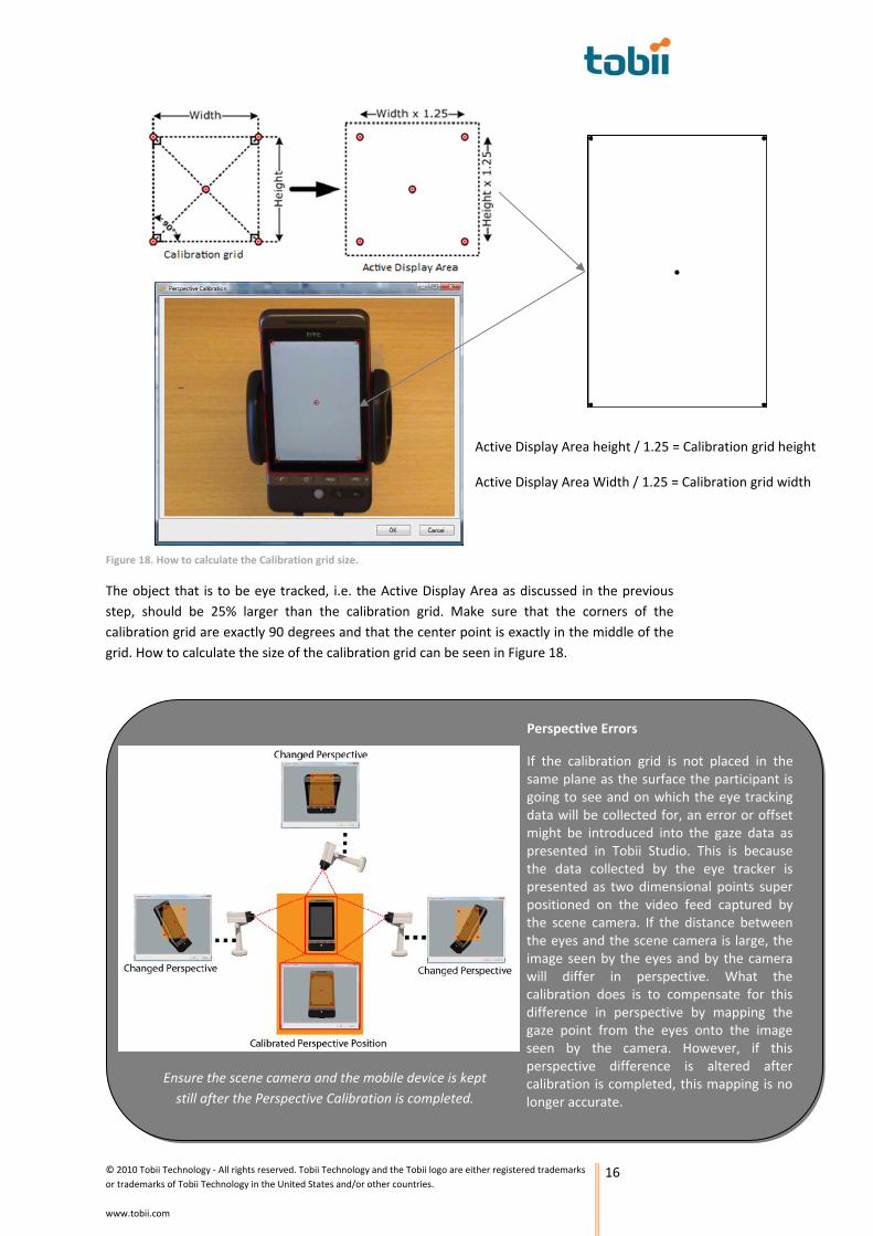
The object that is to be eye tracked, i.e. the Active Display Area as discussed in the previous step, should be 25% larger than the calibration grid. Make sure that the corners of the calibration grid are exactly 90 degrees and that the center point is exactly in the middle of the grid. How to calculate the size of the calibration grid can be seen in Figure 18.
Active Display Area height / 1.25 = Calibration grid height
Active Display Area Width / 1.25 = Calibration grid width
Ensure the scene camera and the mobile device is kept still after the Perspective Calibration is completed.
Perspective Errors
If the calibration grid is not placed in the same plane as the surface the participant is going to see and on which the eye tracking data will be collected for, an error or offset might be introduced into the gaze data as presented in Tobii Studio. This is because the data collected by the eye tracker is presented as two dimensional points super positioned on the video feed captured by the scene camera. If the distance between the eyes and the scene camera is large, the image seen by the eyes and by the camera will differ in perspective. What the calibration does is to compensate for this difference in perspective by mapping the gaze point from the eyes onto the image seen by the camera. However, if this perspective difference is altered after calibration is completed, this mapping is no longer accurate.
Figure 18. How to calculate the Calibration grid size.

© 2010 Tobii Technology ‐ All rights reserved. Tobii Technology and the Tobii logo are either registered trademarks or trademarks of Tobii Technology in the United States and/or other countries.
www.tobii.com
17
3.1.4.3 Mapping the calibration grid with the eye tracker Once the calibration grid has been created it is time to do the mapping between what the user sees and the scene camera. For this, the Perspective Calibration tool is used. The Perspective Calibration tool is accessed by first taking a snapshot using the scene camera (which can be done by clicking New in the Scene Camera Setup window) and then by clicking the Zoom button (see Figure 19).
3.1.4 Participant calibration
The participant calibration is, similar to the Perspective calibration, used to map collected data together in Tobii Studio. However, this time the data to combine is the eye gaze data, i.e. what the participant actually is looking, and what the eye tracker thinks the participant is viewing. This is done by asking the participant to look at the dots in the calibration grid in a predefined order known by the eye tracker. In the previous step the calibration grid was ´flipped´ in order to compensate for the inverted eye tracker position. Hence, the calibration will also need to be done in a different order than normal as well, i.e. upside down and back to front.
3.1.4.4 Selecting to use a manual calibration procedure The gaze data calibration of a participant when using the Scene Camera stimuli needs to be done using the manual calibration routine in Tobii Studio. This calibration mode is selected by clicking on Setup in the Design and record view, selecting Settings in the drop down list, clicking on the Calibration tab and ticking the radio button next to Manual under Calibration Type. Also ensure that the number of calibration points selected in this view corresponds to the number of points in the calibration grid.
Figure 19. Modifying the Perspective Calibration points.
1 2
3 4
1
2
3 4
1
2
3
4
2 1
4
3
2 1
4 3
Step 1 Step 2 Step 3
Step 4 Step 5
Figure 20. Selecting manual calibration.
The circle in the centre will move away from there
during this process. Don’t worry – when
the process is completed it will automatically be positioned at the centre again.

© 2010 Tobii Technology ‐ All rights reserved. Tobii Technology and the Tobii logo are either registered trademarks or trademarks of Tobii Technology in the United States and/or other countries.
www.tobii.com
18
3.1.4.5 Doing the calibration with the participant When starting the recording of the participant and doing the calibration, the moderator conducting the study has to manually step through the calibration points by asking the participant to look at the points in the order as presented on the screen of the computer running Tobii Studio. However, as mentioned above, this order is not correct when using the eye tracker in the way done when using this setup. Hence, the moderator has to modify the order of looking at the points according to Figure 21. This means that, e.g., when the manual calibration procedure indicates that the participant should look at the top left dot, the participant should instead be asked to focus on the lower right dot and so forth.
3.2 Testing Now the actual setup is completed and everything should be ready for the testing to begin. However, during testing some things need to be considered. To verify that the setup is set up and working properly it is always advisably to make a few test recordings. Also check that the connections are done correctly (see Figure 22).
Prior to each test, check that the equipment and the setup are working properly. When participants arrive, ensure that they adapt a comfortable seating position as changing this position radically, e.g. by moving too close to or too far away from the eye tracker, during the
Calibration order as seen on the Tobii Studio computer screen
Calibration order as it should be carried out with the participants
1
2
3
4
5
54
3
2
1
Figure 22. Overview of the setup and the connections between the different parts of the setup.
Figure 21. Order of the calibration points when using an inverted setup.

© 2010 Tobii Technology ‐ All rights reserved. Tobii Technology and the Tobii logo are either registered trademarks or trademarks of Tobii Technology in the United States and/or other countries.
www.tobii.com
19
testing might have a negative impact on the accuracy of the eye tracking data. Use the Show Track Status window to verify that the participant is positioned at an appropriate distance from the eye tracker. Start the test and perform the inverted calibration procedure as described in step 4. When calibration is completed and the participant is ready, initiate the recording and start the test.
Remember to…
• Fix the focus on the camera (to the distance to the screen) to avoid the screen becoming less sharp and therefore unreadable during testing.
• Set the devices´ brightness so it doesn’t cause overexposure or underexposure when being filmed by the scene camera. Beware of external light sources causing reflections on the screen and move the setup or the light sources to avoid them showing up in the video recording.
o Lowering the brightness of the mobile device avoids overexposing the scene camera image when switching between functions in the device that has big difference in contrast. Overexposure might otherwise make the screen unreadable and the test results difficult to analyze.
• Use a power cord for the scene camera. This enables it to stay on and eliminates the risk of accidentally re‐adjusting the zoom and the camera view when changing batteries. By keeping the scene camera and the mobile device in the same position during all tests, good accuracy can be maintained which simplifies quantitative analysis of the results.
• Make sure the mobile device is fully charged to avoid having to use a charger during testing.
Related Documents


