1 INTRODUCTION The main goal of the fire test on a floor of an administrative building was the overall be- haviour of the structure, which may not be observed on the separate tests on individual elements. A new building was erected in front of the Czech Technical University in Pra- gue educational centre Joseph gallery in Mokrsko in Central Bohemia. The experiment followed the seven large fire tests in Cardington laboratory on steel frame conducted be- tween 1998 and 2003, see (Wald et al, 2006). The structure was design complex to al- low a simple as well as advanced modelling of today modern buildings. Except of the three types of flooring systems were tested six wall structures with mineral wool. On one half of the floor was used the composite slab supported by the fire unprotected compos- ite pretty castellated beams with large openings ArcellorMittal Angelina TM , see Figure 1. The experimental structure represents a part of a floor of administrative building of size 18 x 12 m with height 2,68 m, see (Kallerová P. & Wald F., 2009). Figure 1. Thermocouples located at the midspan on the castellated beams and its connections. To fire design of cellular beams F. Wald, A. Pelouchová, J. Chlouba & M. Strejček Czech Technical University in Prague, Czech Republic Natural hazards (optimisation of protection, interaction with structures) 85

Welcome message from author
This document is posted to help you gain knowledge. Please leave a comment to let me know what you think about it! Share it to your friends and learn new things together.
Transcript

1 INTRODUCTION
The main goal of the fire test on a floor of an administrative building was the overall be-haviour of the structure, which may not be observed on the separate tests on individual elements. A new building was erected in front of the Czech Technical University in Pra-gue educational centre Joseph gallery in Mokrsko in Central Bohemia. The experiment followed the seven large fire tests in Cardington laboratory on steel frame conducted be-tween 1998 and 2003, see (Wald et al, 2006). The structure was design complex to al-low a simple as well as advanced modelling of today modern buildings. Except of the three types of flooring systems were tested six wall structures with mineral wool. On one half of the floor was used the composite slab supported by the fire unprotected compos-ite pretty castellated beams with large openings ArcellorMittal AngelinaTM, see Figure 1. The experimental structure represents a part of a floor of administrative building of size 18 x 12 m with height 2,68 m, see (Kallerová P. & Wald F., 2009).
Figure 1. Thermocouples located at the midspan on the castellated beams and its connections.
To fire design of cellular beams
F. Wald, A. Pelouchová, J. Chlouba & M. Strejček Czech Technical University in Prague, Czech Republic
Natural hazards (optimisation of protection, interaction with structures)
85

A B C
3
1
9 000 9 000
+0,00
+4,00
N
6 000
6 000
2
AS6
AS5
AS4
AS3
AS2
AS1
AS7CS3
CS2
CS1
CS4
S4
S3
S2
S1
S5
Concrete wallSandwich panels
Cladding
Hollow core panelsCellular
Beams with corrugated web
beams
Windowopening
Windowopening
Door
Slab
Slab
TG09
TG08
TG009TG008
V03
V03
Figure 2. Structure of experimental building for fire test.
The composite slab on the castellated beams was designed with a span 9 to 12 m and on beams with corrugated webs with a span 9 to 6 m. The deck was a simple trapezoidal composite slab of thickness 60 mm with the height over the rib 120 mm with sheeting CF60 (Cofraplus 0,75 mm) and concrete of measured cubic strength 34 N/mm3 in 28 days reinforced by a smooth mesh ø 5 mm 100/100 mm; with strength 500 MPa and coverage 20 mm. The castellated beams with sinusoidal shape openings were made from profile IPE 270 and its web height was 395 mm. The beam has the parameters Anet = 3769,5 mm2 Agross = 5419,5 mm2; Iy,net = 128,8 ⋅ 106 mm4; Iy,gross = 137,4 ⋅ 106
mm4. The connections were design as simple with header plate connection partially en-cased in the concrete slab.
The test was observed apart from other by more then 300 thermocouples, twenty deflectometers, six flux density meters, two meteorological stations, ten video, and four thermo imagine cameras. The gas temperature round the castellated beam was measured by thermocouples TG08 and TG09 at the level of lower flange, see Figure 1. Round the experimental building was erected the structure from scaffold. The vertical deformations were measured from the twins of timber formwork beams, which were fixed on linear scaffolds and on bridged truss girders 1,5 m above the building floor.
The mechanical load was designed for typical administrative building, where the variable action in Czech Republic reached usually from 2,5 to 3,5 kN/m2. The dead load of the composite slab and beams reached 2,6 kN/m2. The load was created by bags. The load represents the variable load at ambient temperature 3,0 kN/m2 and added perma-nent load 1,0 kN/m2 in characteristic values. Mechanical load 3,0 kN/m2 was repre-sented by 78 sand bags; each bag had approximately 900 kg. These sand bags were put
Natural hazards (optimisation of protection, interaction with structures)
86
on wooden pallets and uniformly distributed on the composite slab and pre-stressed panels.
Two window openings in the front wall with dimension 2.43 x 4.0 m provided air supply into the fire compartment. Fire load was made of rough battens from soft pine wood, total volume of 15 m3. The usual characteristic value of the fire load for adminis-trative building is 420 MJ/m2, by the experiment the fire load reached 515 MJ/m2.
The aim of this paper is to show the accuracy of simplified modelling of the shear behaviour of the composite castellated beam. The prediction of the beam AS4 located between the columns A2 and B2 is presented.
2 HEAT TRANSFER INTO THE CASTELLATED BEAM
In fire, the temperature distribution across a composite member is non-uniform, since the web and bottom flange have thin cross-sections and a greater exposed perimeter than the top flange. The deterioration of the material properties of the web may therefore be-come an important effect on the overall performance of the member in the event of fire. The former fire resistance studies has been focussed to intumescent protection, see (Bai-ley, 2004,), as well as temperature developments in unprotected steel, see (Nadjaia et al, 2007).
TC43TC43
TC68TC42
TC42
TC44TC44
TC68
Temperature, °C
Time, min0
100
200
300
400
500
600
700
800
900
1000
0 15 30 45 60
TC68
TC43 TC44
TC42
1100
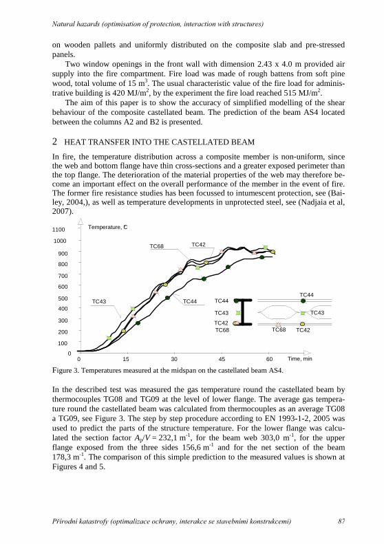
Figure 3. Temperatures measured at the midspan on the castellated beam AS4.
In the described test was measured the gas temperature round the castellated beam by thermocouples TG08 and TG09 at the level of lower flange. The average gas tempera-ture round the castellated beam was calculated from thermocouples as an average TG08 a TG09, see Figure 3. The step by step procedure according to EN 1993-1-2, 2005 was used to predict the parts of the structure temperature. For the lower flange was calcu-lated the section factor Ap/V = 232,1 m-1, for the beam web 303,0 m-1, for the upper flange exposed from the three sides 156,6 m-1 and for the net section of the beam 178,3 m-1. The comparison of this simple prediction to the measured values is shown at Figures 4 and 5.
Natural hazards (optimisation of protection, interaction with structures)
87

Figure 4. Temperatures measured at the midspan on the castellated beam AS4.
Figure 5. Calculated and measured temperature of the beam web.
3 BEAM RESISTANCE
Several investigations into the castellated beams structural behaviour have sup-ported the widespread use of as structural members in steel to concrete compos-ite frames. First studies at ambient temperature concentrated on in plane re-sponse in the elastic range and later plastic one as well. Extensive measurements were made of the stress distributions across the cross-section, and these were compared with the predictions of various theoretical studies em-ploying a Vierendeel analogy, finite difference techniques, and a complex vari-able analytical method. As a result of various series of tests a number of differ-ent failure modes have been observed, see (Kerdal & Nethercot, 1984), The main failure modes are a Vierendeel collapse mechanism in which plastic hinges form at the section touching the four re-entrant corners of a castellation, buckling of a
Natural hazards (optimisation of protection, interaction with structures)
88

web-post, and web weld failure. Several prediction of collapse mechanisms have been proposed, see (RT1006, 2004), and the lateral buckling of the web-posts has been analysed. Only limited investigations of composite floors using castellated steel beams at ambient temperature have been conducted, see (Megharief & Redwood, 1998). The beams have been used widely in roof and composite construction without having been rigorously investigated under fire conditions. A composite concrete floor-slab has the effect of significantly in-creasing the flexural resistance of a steel section. Investigation of the behaviour of composite beams with isolated web openings in otherwise solid webs has shown that the slab significantly increases the shear-carrying capacity beyond that of the steel beam alone. This is due to the enhanced flexural and shear ca-pacity of the upper part of the beam across an opening, although an unsupported webpost is more susceptible to buckling, see (Bitar et al, 2005) and (Nadjaia et al, 2007). The simplified model for evaluation of the fire resistance of the beams was developed based on FE modelling approved by two fire tests, see [10].
In the fire test in Mokrsko 2008 were examined beams with large web open-ings which are sensitive to the shear resistance of the web and flanges. The ad-vanced FE model was prepared to predict the behaviour before and after the fire test au University of Sheffield, see (Kallerová & Wald, 2009). In the simplified calculation were utilised for the internal forces distribution by the Vierendeel analogy and the adequate failure modes were observed, see (Pelouchová, 2010).
Time, min
Deflection, mm
0
V3
15 4530
-100
-200
-300
-400
-500
-600
-700
-800
-900
0 60
V3
Horizontal shear
Shear in opening
Shear at support
Horizontal shear
Shear in opening
Shear at support
ky,θ
for kp,0,2,θ�
for ky,θ
for kp,0,2,θ�
ky,θ
for kp,0,2,θ�
for
for
Figure 6. Measured deflection of the castellated beam AS4 with reached shear resis-tances.
The beam was exposed a uniform action f = 6,8 + 2,6 = 9,4 kN/m, which creates a bending moment M = f ⋅ l2/2 = 9,4 ⋅ 92/2= 95,175 kNm and acting shear force V = f ⋅ l/2 = 9,4⋅ 9/2 = 42,3 kNm. In evaluation of the shear resistance was assumed the shear area at beam support as 395 ⋅ 6,6 = 2607 mm2; the area of the web in opening 0,9 (2⋅ 72,5⋅ 6,6) = 861,3 mm2; the minimal horizontal shear area is 0,9 ⋅ 250 ⋅ 6,6 = 1485 mm2. The critical temperature of the shear resistance in support
Natural hazards (optimisation of protection, interaction with structures)
89

Vmax = 42,3 kN may be calculated from the reduction factor of the effective yield stress from 42,3 = ky,θ ⋅ 0,6 ⋅ 235 2607/103 which is ky,θ = 0,1151. Thus the critical tem-
perature is 795,7 °C. The beam web reached this steel temperature in 34 min. From the reduction factor of proportional limit for steel at elevated temperature kp,0,2,θ the tempera-ture of steel 661,8 °C is derived, which was reached in 25 min.
For the shear resistance in the beam web opening Vmax = 36,2 kN may be the reduc-tion factor of the effective yield stress calculated from 36,19 = ky,θ ⋅ 0,6 ⋅ 235 861,3/103
and ky,θ = 0,2980. The adequate beam web temperature 673,7 °C will be reached in 25 min. For the effective yield stress it is kp,0,2,θ it is web temperature 544,5 °C in 21 min.
From the horizontal shear resistance Vh, which is Vmax = 54,8 kN may be derived for 54,8 = ky,θ ⋅ 0,6 ⋅ 235 1484/103 the factor ky,θ = 0,2620 and the temperature 686,8 °C, which is reached on 24 min. The proportional limit kp,0,2,θ = 0,2620. The reached values of degradation of the beam are shown on Figure 6. No beam weld failure was observed on collapsed structure.
Figure 7. Strain gauges on the web of the castellated beam.
Close to connections was the beam instrumented with strain gauges for high tempera-tures to assume the shear stress across the web during the fire test. The application of the free-filament high-temperature strain gauges, which are sandwiched between two thin ceramics cement layers, allow to measure up to a temperature of 1150 °C. The accuracy of the measurement is 3 % till the 5000 µm, which limits the positioning of the strain gauges. Two strain gauges were applied in the middle third of the web height of castel-lated beam, see Figure 7. The stress at elevated temperature σθ was derived from the measured strain using Young´s modulus of elasticity at elevated temperature Ea,θ = kEθ E and the corresponding temperature recorded by the thermocouples
σθ = min (kE,θ E εθ; ky,θ fy) (1)
Natural hazards (optimisation of protection, interaction with structures)
90

where kE,θ is the reduction factor for the slope of the linear elastic range at the steel tem-perature, see [5], E is the elastic modulus of steel; εθ is the strain at elevated tempera-ture; ky,θ is the reduction factor for the yield strength of steel at the steel temperature, see [5]; fy is the yield strength at ambient temperature, 355 MPa. Figure 8 documents the strain development the predicted loss of the shear resistance.
-400
-300
-200
-100
0
100
200
300
0 15 30 45 60
Time, min
Stress, MPa
Effective yield stress
130
65
165 TC48
TC46165
SG6
SG5Effective yield stressStrain gauge SG6
Strain gauge SG5
Shear resistance at support for proportional limit stress
Shear resistance at support for efective yield stress
Figure 8. The measured stresses on the web of the castellated beam and predicted shear resistance.
Figure 9. The deformed beams in the 35 min of the fire test.
Natural hazards (optimisation of protection, interaction with structures)
91

Locate tables close to the first reference to them in the text and number them consecu-tively. Avoid abbreviations in column headings. Indicate units in the line immediately below the heading. Explanations should be given at the foot of the table, not within the table itself. Use only horizontal rules: One above and one below the column headings and one at the foot of the table (Table rule tag: Use the Shift-minus key to actually type the rule exactly where you want it). For simple tables use the tab key and not the table option. Type all text in tables in small type (Table text tag). Align all headings to the left of their column and start these headings with an initial capital. Type the caption above the table to the same width as the table (Table caption tag). See for example Table 2.
4 CONCLUSION
The fire test approved a good fire resistance of composite slab with unprotected castel-lated beams, which is higher compare to the separate composite beam resistance, see Figure 9. The slab resistance, designed for R60, was reached at 62 min and the beam shear resistance in 21 min.
The experimental data confirms a reasonable accuracy of prediction just by a simple model, even though the stresses of beam in structure are highly influenced be elements elongation/shortening.
PREFERENCES
Bailey C. G., 2004, Indicative fire tests to investigate the behavior of cellular beams pro-tected with intumescent coatings, Fire Safety Journal, 39, pp. 689-709.
Bitar D., Demarco T. & Martin P. O., 2005, Steel and non-composite cellular beams-novel approach for design based on experimental studies and numerical investiga-tions in Proceedings of EUROSTEEL, Coimbra.
EN 1993-1-2, 2005, Eurocode 3: Design of steel structures - Part 1-2: General rules - Structural fire design, CEN.
Kallerová P. & Wald F., 2009, Fire test on experimental building in Mokrsko, CTU in Prague, Prague., ISBN 978-80-01-04146-8.
Kerdal D. & Nethercot D. A., 1984, Failure modes for castellated beams, Journal of Constructional Steel Research, 4, pp. 295–315.
Megharief J. & Redwood R., 1998, Behaviour of Composite Castellated Beams, Journal of Constructional Steel Research, 46, pp.199-200.
Nadjaia A., Goodfellow N., Vassart O., Ali F. & Choi S., 2008, Simple calculation me-thod of cellular composite floor beams at elevated temperatures, in Structures in fire, Singapore, pp. 551-559, ISBN 978-981-08-0767-2.
Nadjaia A., Vassart O., Ali F., Talamonab D., Allamb A. & Hawes M., 2007, Perform-ance of cellular composite floor beams at elevated temperatures, Fire Safety Journal,42, pp. 489-497.
Pelouchová A., 2010, Evaluation of fire resistance of castellated beams at Mokrsko fire test, part IV of Diploma theses, CTU in Prague, Prague.
RT1006 version 02; 2004, Fire design of cellular beams with slender web posts, SCI, Ascot.
Wald F., Simoes da Silva L., Moore D.B., Lennon T., Chladná M., Santiago A., Beneš M. & Borges L., 2006, Experimental behaviour of a steel structure under natural fire, Fire Safety Journal, 41, pp. 509-522.
Natural hazards (optimisation of protection, interaction with structures)
92
Related Documents


