DOCUMENT RESUME ED 058 718 TITLE Demodulator 1971. INSTITUTION GTE Lenkurt, San Carlos, Calif. PUB DATE 71 NOTE 109p. EM 009 491 EDRS PRICE MF-$0.65 HC-$6.58 DESCRIPTORS Broadcast Reception Equipment; Cable Television; *Communications; *Communication Satellites; Community 'Antennas; Computers; Microwave Relay Systems; Pollution; Technological Advancement; *Telecommunication; Telephone Communications Industry ABSTRACT Twelve articles dealing with telecommunications systems are presented. The articles are for the most part considerations of some of the potential uses and of the technical problems of communication networks used for commercial and educational purposes. Among the topics are the application of communication technology to control pollution, the CATV (Community Antenna Television) video microwave link, the computer in industry, coaxial cable transmision, and the 12 GHz band. (JY)

Welcome message from author
This document is posted to help you gain knowledge. Please leave a comment to let me know what you think about it! Share it to your friends and learn new things together.
Transcript

DOCUMENT RESUME
ED 058 718
TITLE Demodulator 1971.
INSTITUTION GTE Lenkurt, San Carlos, Calif.
PUB DATE 71
NOTE 109p.
EM 009 491
EDRS PRICE MF-$0.65 HC-$6.58DESCRIPTORS Broadcast Reception Equipment; Cable Television;
*Communications; *Communication Satellites; Community
'Antennas; Computers; Microwave Relay Systems;
Pollution; Technological Advancement;
*Telecommunication; Telephone Communications
Industry
ABSTRACTTwelve articles dealing with telecommunications
systems are presented. The articles are for the most part
considerations of some of the potential uses and of the technical
problems of communication networks used for commercial and
educational purposes. Among the topics are the application of
communication technology to control pollution, the CATV (Community
Antenna Television) video microwave link, the computer in industry,
coaxial cable transmision, and the 12 GHz band. (JY)


I/
U.1
U.S. DEPARTMENT OF HEALTH,EDUCATION & WELFAREOFFICE OF EDUCATION
THIS DOCUMENT HAS BEEN REPRO-DUCED EXACTLY AS RECEIVED FROMTHE PERSON OR ORGANIZATION ORIG-INATING IT. POINTS OF VIEW OR OPIN-IONS STATED DO NOT NECESSARILYREPRESENT OFFICIAL OFFICE OF EDU-CATION POSITION OR POLICY.
LEnKURT
DEMODULATOR
1971ISSUES

Video
GTE Lenkurt Demodulator is pub-
lished monthly and circulatedwithout charge to those employedby companies or government agen-
cies who use and operate com-munications systems and to educa-
tional institutions.
This complimentary volume in-cludes the 12 issues that appeared
in 1971. To receive future issuesof the GTE Lenkurt Demodulator,write:
EditorGTE Lenkurt, C1341105 County RoadSan Carlos, CA 94070.
GTE Lenkurt is a recognized leader in the development and
manufacture of telecommunications systems and equipment for
telephone companies, railroads, power companies, petroleum and
pipeline companies, broadcast and CATV firms, business and
private data users, and military and government agencies.
For more information about GTE Lenkurt products &nd services,
please contact a sales office or government engineering represen-
tative, or write our Main Office in San Carlos.
District Sales Offices
1105 County RoadSan Carlos, California 94070Phone 415 591-8451
361 E. Paces Ferry Rd., N.E.Atlanta, Georgia 30305Phone 404 261-8282
130 North Franklin StreetChicago, Illinois 60606Phone 312 263-1321
340 Northcrest BuildingB609 Northwest Plaza DriveDallas, Texas 75225Phone 214 363.0286
McIlvaine Building8201 Leesburg PikeFalls Church, Virginia 22044Phore 703 533-3344
Government EngineeringRepresentatives
1027 Kikowaena PlaceHonolulu, Hawaii 96819Phone BOB 839-5288
McIlvaine Building6201 Leesburg PikeFalls Church, Virginia 22044Phone 703 533-3344
GTE InternationalSales Office
1105 County RoadSan Carlos, California 94070Phone 415 591-8461Cable: GENTELINT
Main Office
cern) LE1111CURT1105 County RoadSan Carlos, California 94070
3

Contents
JAN Communications and the Environment
FEB The CATV Video Microwave Link
MAR PCM Signaling and Timing
APR The Computer in Industry
MAY Coaxial Cable Transmission
JUN 12 GHz, A New Look by Industrials
JUL PCM-FDM Compatibility Part 1
AUG PCM-FDM Compatibility Part 2
SEP PCM-FDM Compatibility Part 3
OCT Data Modems
NOV Line Equalization for Data Transmission
DEC Cable Tests and Measurements for PCM

"PERMISSION TO REPRODUCE THIS COPY-
RIGHTEO MATERIAL HAS BEEN GRANTED
BY
Dbe clq LeonLc'-% Kurt, 111C.
TO ERIC AND ORGANIZATIONS OPERATING
UNDER AGREEMENTSWITH THE U.S OFFICE
OF EDUCATION. FURTHER REPRODUCTION
OUTSIDE THE ERIC SYSTEM REQUIRES PER-
MISSION OF THE COPYRIGHT OWNER
Copyright 1971
by
LEITIKURTINCORPORATED
Printed In the United States of America
5

JA JARY 1971
0

Proper application of today'scommunication technology canbring people together and improvethe atmosphere in which they live.
Environment includes not onlygeographic features, but also
thc people and the subsequent cultureof an area. Present communicationlinks can be expanded for environ-mental channels voice and videochannels for education and exchangeof ideas, as well as data channels forearth resources management. This ex-pansion can be realized by utilizing to-day's communications technology.
Remote data collection and central-ized computer analysis of the data canprovide an efficient means of measur-ing, analyzing, and correcting envi-ronmental pollution. By providingmore channels of communication,more opportunities for expression ofideas through dialogue would be avail-able. These communication channelscan be provided by increased two-wayvideo, voice, and data communication.
Pollution ControlAlthough it is not physically or
financially feasible to establishmanned laboratories in every geo-graphic ky.mtion where pollution ismost likely to occur, it is possible, bymeans of a network of unmanned datacollection stations, to sample the sur-roundings and transmit information onair, earth, and water conditions to acentral processing laboratory for anal-ysis. In this way, computer technologyand remote data acquisition can con-tribute to pollution control.
2
COPyrTINT 0 1071 LFN.KURT LrTRC CO INC SYOL 20. NO I
P r ototypc pollu tion monitoringsystems are presently in operation.What look like ordinary navigationbuoys are really ocean pollutant de-tectors. Instrumented buoys, anchoredin oceans and inland waterways areequipped with sensor systems andautomatic data handling equipment.These unattended buoys arc able tomeasure and transmit such data aswater and air temperature, wind speedand direction, and barometric pres-sure. Such systems are being designedfor low-power consumption and long-life expectancy which should provideeasily-maintained, low-cost environ-mental monitoring. A network ofocean monitoring buoys, or stationscan communicate with a central pro-cessor either over a direct microwavelink or via satellite relay links (seeFigure 1).
Another pollution detection devicenow under development employs apatrol aircraft that measures thechanges in microwave radiation fromthe surface of the water (see Figure 2);thereby, determining what the pollu-tant is oil or gas and how thickthe spill is.
Similar tests can also be made onthe atmosphere to detect air pollution.The proper transmission links permitmeasurement at many remote loca-tions and processing at one location.Depending upon the results of theanalyzed data, the proper corrective
7

actions can be transmitted by thecentral processor for the particularpollution location.
Information can be transmittedfrom the data collection points to acentral processor by microwave tech-niques. For getting information fromthe remote data collection points, sat-ellites seem to offer a convenientmeans. In some cases, &per...ling uponthe type of data being collected, thesatellite may be able to actually gatherthe raw data and transmit it directly tothe central processor without a sur-face-collection system.
Satellite NetworkA network of satellites and surface-
probing sensor systems may be used tostudy natural resources. In addition tothe oceans and air, this network cantake inventory of whet, where, andhow well forests and craps are grow-ing, and the condition of the soil andits ability to be put to work; thuspermitting regional, national, or globalpredictions of crop yields, livestockinventory, and patterns of fire, insect,
3
Figure 1. Satellite re-lay techniques areused to monitor nat-ural resources whena direct microwavelink is not practicalor feasible.
and disease damage. Informationabout stream and river flow, excesssurface water, pollution, and glacialaction can be studied in order to plan
better irrigation and flood controlsystems, develop and maintain waterresources, and control erosion.
Air pollution is generally correlatedwith population distribution and geo-graphic features that can be studiedwith satellite mapping techniques. De-tailed maps of the earth's features canbe used for planning land use, urbandevelopmcnt, and transportation facili-ties. Aerial data collection can also beused to map ocean currents, ice, andother navigational hazards. Fish andother marine biology of interest, aswell as pollutants, can be studied forthe seafood industry, shipping, andmarine ecology.
Surface-collection relay satellitesand remote-sensing satellites, alongwith non-satellite remote sensing de-vices including sounding rockets,balloons, aircraft, buoys, and ground-based platforms are capable oftratmitting the gathered information

Figure 2. Airbornesystems detect pet-roleum spills in theocean and transmitthe information to acen tral office forcleanup operations.
to a central computer. The computer'srole in this overall environmental man-agement system is that of soothsayer
if, for example, a decision weremade to irrigate thousands of squaremiles of desert to create a new agricul-tural area, the computer could predictsuch things as the plan's effect on:climate, population, water resources,and international trade.
In order to manage world resourceseffectively, adequate information mustbe available. Information has for cen-turies been gathered by man on thesurface of the earth. In recent times,aerial observations have broadened thefield of view, the amount, and theusefulness of the information. Withthe mass acquisition of data and so-phisticated computer processing, itmay be possible to stem the tide ofdiminishing resources, and pollution of
the existing resources.
Human EnvironmentSolving the problems of an area's
pollution and diminishing natural re-sources will do little to improve the
4
total environment, if the people in the
area are unable to communicate andclear up differences. These differencesoften represent a widening gap be-
tween expectations, and reality. In anaffluent society, we expect m,,re, and
better communications are raising
these expectations. Through propereducation and exchange of ideas it ispossible to bring expectations in line
with reality.The areas of communication of-
fered to bring expectations closer toreality include: education, communityexpression, cultural enrichment, andpolitics. Some specific services offeredinclude: home library service, facsim-ile, delivery of mail, crime detectionand prevention, remote data acquisi-
tion and central processing, education-
al television, remote participation atconferences, and armchair shopping.
Expanded ServicesThese new services can be divided
into two classes: one-way transmissionwith no interaction between transmit-
ter and receiver; and two-way trans-

mission where there is a transmitter
and receiver on both ends which pro-vides the opportunity for interaction
and response.Utility meter-reading is one-way
transmission from many subscribers to
a central office where the informationis processed (see Figure 3). The gath-ered data from each subscriber is sentthrough a central processing unit forcharge computation. The actual billing
could be included in the processing,
which would make meter-reading atwo-way transmission process. But, itis more likely that billing will continue
to use a centralized mail distributionsystem, since it would not be economi-
cal for utilities to operate their own
video or data transmission system.Facsimile (the art of sending pic-
tures or other printed material) is aform of one-way transmission in thatthere is no interaction between thetransmitter and receiver, but both ter-
minals are transmitter/receivers. Astechnology advances, it may eventual-
ly become economical to bring facsim-
ile into the home for such things as
Fig u re 3. Utilityme ter-reading em-ploys one-way trans-mission from manysubscribers to onecentral office.
home library service and newspaperdistribution if a printed copy of the
transmitted image is desired. Thetransmission of color is possible asdemonstrated by color television, buta color facsimile printout deviceneeds to be perfected. Law enforce-ment agencies are using black andwhite facsimile printers to speed infor-mation across the country for crimedetection and prevention. The addi-tion of color would offer improvedimage recognition.
If printed copy is not needed avideo system like television providesreadable, although not permanent,written material. The information isread directly off the screen and whenfinished, the viewer terminates thesignal. Cable television, with local pro-gramming, could provide channels tobring these services library andnewspaper into the home. Video-phone service could also bring thesevisual images into the home.
Mail transmission and distribution,as well as video-phone, is a two-waytransmission service that could use
5
1 0

Figure 4. Mail trans-mission and distri-bution, as well asvideo-phone, uses aswitched network.
the same transmission and distributionplan that is presently used for tele-phone service. That is, a switchednetwork where an individual sends hismessage through a central office whichredirects the message to the receiver(see Figure 4). With mail transmissionand distribution, the service need notbe completed at the same time; there-fore, delaying the interaction or re-sponse. This delay would provide formore efficient use of the transmissionchannels transmitting mail in non-peak hours. Mail transmission and dis-tribution will not eliminate the lettercarrier, but it can relieve the lettercarrier of over 75% of his load withouttransmitting actual correspondencepersonal, business, and government let-ters over the air or through a cable.The receiver for such a system couldbe either a facsimile printer or a video
screen depending upon whetherprinted copy is needed for future use.Another plan gives the sender a choiceof transmission modes instantaneoustransmission over telegraph lines to thereceiving "post office" where a letter
6
carrier would deliver the message orletter "posting" common today wherethe original document is "hand" car-ried to its destination.
Totally automated system monitor-ing is a two-way system using pro-grammed transmitter/receiver termi-nals. This is essentially the same tech-nique used for natural resource con-trol, but also used for monitoring oth-er remote systems. Remote data ac-cess and central processing also in-cludes time-sharing computer service.As the complexity and cost of theseterminals is reduced, more people willtake advantage of the benefits offered.
Educational television and remoteconference participation are similar tovideo-phone with instantaneous voiceand video communication. Wherethese services differ from video-phoneis that there is a central transmitter/receiver and many remote trans-mitter/receivers that interact with thecentral unit (see Figure 5). Using sucha service, government officials havedirect contact with their constituents.This service has the greatest potential
11

for bringing people together because it
is possible to clear up any misunder-
standings that might arise before they
have a chance to cause dissention inthe ranks. This service could put ex-pectations and reality into proper per-spective. Communities can expressthemselves over a two-way voice/video
channel so the public has the opportu-nity to know the full story and to
express their approval or objection.And, educational television provides
the means for educating large masses
in one geographic region or selectgroups scattered over several regions.Increased educational facilities provide
the means to close the gap between
expectations and reality.
figure 5. There is
twoway communi-cation between onecentral location andmany remote sub-scribers for educa-tional television andremote conferenceparticipation.
New DirectionExpanded means of communication
have the potential to provide a moreefficient society with an informedpublic living in a healthy, plentifulenvironment. Presently, the possibil-ities are practically unlimited, but soare the possibilities for this expansiongetting out of control. If the bestinterests of the public are to be real-ized, the most efficient and moqeconomical systems must be put intoeffect. None of these expanded ser-vices will be totally adopted unlesspresent costs can be substantially re-duced. Technology has developedthese services, economics will dictatetheir future.
7 12

Th e
a.
4.4-140 ; fc;
.11
kt-: - ,..
.e.3
VII'
I
11.,11111111
4
The CATfr, , -LA
%...,-'/6) I . If°, ,..4,, . 1 ,::'.... V < .n ,,,,cf.,,-.
o . r. ,,-,
e,-')",, \ "7i''').-,,; ,
,
'4244-4:ti
a.
r I, fric

From its beginning as a tiny measure of light picked up by a TVcamera and changed into electrical energy, to the time it is viewed onthe screen, the television signal undergoes a complex adventure on itsjourney from broadcast transmitter to television receiver.
T
IMAAA
h e television signal leaves thebroadcast transmitter as com-
posite video information modulatedon an RF (radio frequency) carrier.
This composite signal contains thevideo (picture signals), sound, color,blanking, and synchronizing informa-tion necessary to materialize a pictureon the television screen (Figure 1). Ifthe path between the transmitter andreceiver is straight and unobstructed,viewers will enjoy a good picture withfew complications ever arising. How-ever, if TV viewers live in an arcawhere irregular terrain or sheer dis-tance blocks reception of televisionsignals, some means of making tele-vision reception available in that areais necessary. Since the distance a tele-vision signal travels after it leaves thebroadcast transmitter is generally lim-ited to a line-of-sight characteristic,reception is confined to a relativelysmall geographical area. One methodof extending TV programs to viewersin remote areas is by use of a micro-wave CATV (Community AntennaTelevision) system (Figure 2). In thistype of system, an off-the-air pickup
of the television signal is made at a"head end" station. Here the signal isamplified and processed to produce aTV baseband signal which is essentiallya duplicate of the original TV base-band signal that went into the input of
E00v0IGNE C 19/I LENKURT E LECTRIC CO . INC. VOL 20. NO. 2
the distant broadcast transmitter. Thissignal is then relayed by a series ofline-of-site repeaters to the remotearea.
The types of microwave repeaters,their methods of operation, their ap-propriateness in certain systems, andtheir overall performance in a multi-hop video microwave link constitutesome aspects of a CATV system thatare discussed in this article.
A system of line-of-sight repeaterswhich amplify the incoming micro-wave signal and send it on its directedpath comprises the major part of avideo microwave system. One of themost important considerations in theplanning of a microwave installation ischoice of equipment which will ac-commodate future growth expecta-tions and at the same time providesatisfactory video information at theinitial terminal point.
The microwave repeater performstwo important functions. The first ofthese functions is to amplify the in-coming signal sufficiently so that itmay reach the next repeater. Theamplified output signal may be any-where from 55 to 105 dB greater inpower than the incoming signal. Sec .ondly, the repeater must convert theincoming signal to a different fmquen-cy so that in transmission the outgoingsignal does not interfere with the
2
1_

incoming signal; interference usually
being due to limitations on antennafront-to-back ratios and foregroundreflections. Most CATV microwavesystems operate in the CARS (Com-munity Antenna Relay Service) band.In the CARS band the frequency shift
is usually 25 MHz or some mutliple of
it.There are three types of microwave
repeaters baseband, IF heterodyne,and RF heterodyne (Figure 3). Videomicrowave systems use the first two
types almost exclusively. Each hasadvantages and disadvantages which
must be considered when planning avideo microwave system. Generally thechoice of repeaters is based on the
distance the microwave signal musttravel.
Baseband RepeatersBaseband or remodulating type of
radio equipment is usually employed
15
Figure I. The com-posite video signal.The color burst is
transmitted duringthe blanking pulse toserve as a phase ref-erence for the colorinformation whichmodulates the basicvideo or luminancesignal.
when designing systems of two hun-dred miles or less. The baseband con-
sists of the composite video signal,
program channels, and supervisory sig-
nals that are used to modulate aparticular carrier. In a baseband re-peater the incoming microwave signalis mixed to produce an intermediatefrequency; this is then amplified, de-
modulated, and amplified again at theoriginal baseband frequency. Lastly,the signal is remodulated and trans-mitted at the microwave frequency.The baseband repeater is generallyused only in short haul applicationsbecause each time the video signal ismodulated or demodulated, a certainamount of distortion is generated dueto noniinearities in the conversionfrom amplitude variations to frequen-
cy variations.Since the incoming signal is demod-
ulated to its baseband frequency ateach repeater, it is possible to make

television signals available for recep-tion anywhere along the main back-bone route. This convenient availabili-ty of baseband signals at each repeateris one of the advantages of a basebandsystem.
Al thoughusually the maximum length con-
ten hops in tandem are
4
sidered for baseband type equipment,GTE Lenkurt 76C microwave equip-ment was successfully used in a 17 hopsystem, providing low enough distor-tion in both differential phase (phasevariation) and differential gain (gainvariation), to permit a color projectionon a 30 foot (9.2 meters) by 40 foot

.;
(12.2 meters) screen at EXPO '67 inMontreal.
IF Heterodyne RepeatersIn the IF heterodyne repeater,
amplification is performed at theintermediate-frequency stage withoutgoing through the demodulation andremodulation process required in thebaseband repeater. The incoming sig-nal is first heterodyned to the IF stage.This process involves mixing the in-coming signal with a constant signal
provided by a local oscillator. Theresult is two frequencies equal to thesum and difference of the first two,each containing identical information.At this point the difference frequencyis amplified, then passed through anup-converter to be translated to theoutgoing microwave frequency. Theelimination of the demodulation andremodulation process gives improvednoise performance since distortion is
kept to a minimum. Other advantagesof heterodyne repeaters over basebandrepeaters are less maintenance, betterbaseband level stability, higher poweroutput, and greater distance betweenhops. The greatest limitation of aheterodyne repeater is its cost. Be-cause o! ;is more sophisticated compo-nents which include a traveling-wavetube and associated power supply re-quirement:., the cost of the heterodynerepeater is higher than that of thebaseband repeater.
In the heterodyne system, the base-band is not as readily available at eachrepeater station as it is in the basebandrepeater although it may be easilyacquired by adding a 70-MHz discrimi-nator. In the discriminator, the Lase-band is separated. from the incomingfrequency-modulated carrier wave bychanging modulations in terms of fre-
quency variations into amplitude varia-tions. The low distortion of IF hetero-
5
dyne repeaters makes it possible tocarry video infonnation over greatdistances without any appreciabledegradation of the picture at the ter-minal point.
Composite systems utilizing a mix-ture of both IF heterodyne and base-band repeaters are often used. In acomposite system, the heterodyne re-peater may form the backbone routeof the system while baseband repeatersare used on short side legs to providelocal television reception along theroute. In some systems, IF heterodynerepeaters are combined with basebandterminals as an economic compromise.The main purpose of these systems is
to combine the low costs of thebaseband repeater with the low distor-tion of the heterodyne repeater.
RF Heterodyne RepeatersAlthough RF heterodyne repeaters
are not presently used in video micro-wave links, they are mentioned here asa point of interest and to acknowledgetheir existence. All solid state RFrepeaters (though not rated as videocapable) are "state of the art" at 2GHz, and not readily available abovethis frequency.
The RF heterodyne repeater pro-vides amplification directly at the in-coming microwave frequencies. Theincoming microwave signal is first am-plified, then heterodyned with a signal
at the shift frequency to produce anoutput at the desired microwave out-put frequency. This latter is thenfiltered and amplified for transmissionover the next hop. The prohibitivecost of the RF heterodyne repeatermakes it a seldom used item. This high
expense manifests itself in the form ofproviding gain at microwave frequen-cies, producing filters selective at mi-crowave frequencies, and provision ofadequate limiting, automatic gain con-
17

trol and delay distortion correctionall necessary, all expensive.
Overall PerformancePublished industry standards are
available as guide lines for calculatingoverall color video performance*. EIAhas established a standard of 0.6 dB asmaximum differential gain and ±1.5degrees as maximum differential phasethat should exist in an overall system.These standards are established relativeto the maximum gain at 50% APL(average picture level). Actual perfor-mance measurements taken at an op-erating microwave installation mayshow performance to be within thesetolerances. For example, in a 6-hop IFheterodyne system, the total differential gain may be 0.3 dB and the totaldifferential phase may measure 0.4degrees. A 6-hop bascband system hasshown measurements of 0.5 dB fordifferential gain and 1.0 degrees fordifferential phase.
Other factors to consider in calcu-lating overall video performance arefrequency response and signal-to-noiseratios. Frequency response roll-off onthe baseband system has a tendency toaccumulate at a predictable rate; roll-off being the gradual increase in atten-utation as frequency is varied in eitherdirection beyond the flat protion ofthe frequency response curve. Thisattenuation rate can be reduced byutilizing correctional amplitude equal-izers as required, thus tailoring individ-ual hop frequency response.
In an IF heterodyne system, ampli-tude response and group delay accu-mulations tend to have an unfavorablebearing on the video performance.However, by using 70-MHz parabolicand slope equalizers on a periodicbasis, a system will show considerablyimproved video characteristics.
'ElA (Electronic Industries Association) standard RS-250-A.
6
MIXER AMP
UPCONV
SHIFTOSC
UPCONV
LOCALOSC
AMP
AMP MIXER AMP AMP
CONVOSC
Figure 3. Microwave repeaters are clas-sified by whether they provide amplifi-cation at baseband frequency, interme-diate frequency, or radio frequency.

Signal-to-noise measurementsshould be made using weighting net-works. In a weighting network anartificial factor is inserted into themeasurement to compensate for condi-tions which, during normal use of adevice, would otherwise differ fromthe conditions during measurement.These conditions are subjective in na-ture and can be assigned a degradationfactor based on their relative effect.For example, background noise meas-urements may be weighted by apply-ing factors or inserting networks thatreduce measured values in inverse ratioto the interfering effect. The essentialfunction of a weighting network is tomake the measurement parameters re-flect as accurately as possible thedegree of annoyance to an averageviewer or user. For example, an inter-fering tone or noise in the higher partsof the video baseband will usuallycause less degradation to a viewer thana tone or noise of the same power inthe lower portions of the baseband.The weighting network is designed tocompensate for these subjective ef-fects, which have beer. determined byactual trial and error tests on manysubjects. Bell laboratories evolved acolor TV weighting curve that wouldapply to various transmission mediaand which has since been adopted byEIA. Signal-to-noise ratios (peak-to-peak video to RMS noise) of 75 dB permicrowave path are normal, and wouldallow 100 hops before a 55-dB signal-to-noise ratio was attained. An outagelevel of 33-dB signal-to-noise ratio wasadopted by the EIA committee.
In addition to the electronics designproblems in a microwave system, thereare wave propagation considerationssuch as path attenuation between twopoints under free-space conditions, at-mospheric and ground effects on prop-agation, and reflection and refractioneffects on the microwave path. Lossesdue to these effects may sometimes beforecast with some degree of accuracybut loss data due to atmospheric ef-fects for a particular area may berealized only by survey measurementsin that area.
Still more considerations in plan-ning a television microwave systeminclude antenna design to be used,location of towers, routine mainte-nance, adequate temperature con-trolled housing for equipment, contin-uous power supply requirements,back-up equipment with automaticswitching devices, and security ofequipment. Only when these require-ments have been completed is there asource of television signals available atthe terminal station.
It is at the terminal station thatsignals are brought to proper levels andremodulated to VHF and UHF fre-quencies. At this point the microwavelink is complete. Signals are conveyedto viewers by means of private distri-bution systems, usually by means of acable television system.
Planning, engineering, and evensome solid intuition are all necessaryfor the successful realization of amicrowave system that brings dailytelevision programs to home, school,and business.
41111
19

LEF1KURT
I DEMODULATORMARCH 1971
PCM Signaling and Timing

The integration of puise code modulation (PCM)carrier systems into the telephone plant has leftpersonnel, expert in dealing with the traditionalfrequency-division multiplex systems, grapplingwith less familiar terms such as "sampling," "quan-tizing," and "coding."
Th e principles of messagetransmission in a PCM system
have been described in a variety ofarticles and books. (See, for example,The Lenkurt Demodulator, November,1966.) While message transmission is,of course, the objective of such sys-tems, it is not the whole story. Amessage with no place to go is nomessage at all.
How, then, do PCM systems carrythe various types of signaling andsupervisory information that controlan ordinary telephone call? And howcan a PCM carrier system integrateinto an existing plant that alreadyincludes such diverse types of signalingas E&M (receive and transmit), loopdial, and foreign exchange? Further-more, how are these signaling andsupervisory functions handled in sec-ond generation PCM systems?
The answers to these questions arcinextricably bound up with the carri-er's nervous system the timing ar-rangement that sorts out more than ani i I lion-and-a-half information bitseach second to form individual mes-sage channels and their associated sig-naling information. A good startingplace is a brief review of the trans-mission techniques used in first-generation PCM systems. These sys-
2
COPVEMeTT C 1971 GTE LEPIKURT INCORPORATED 001. 20 NO 2
terns are built by several manufac-turers. Regardless of their origin, how-ever, they conform to the same general
system parameters.
T-Carrier Trans: iissionFor convenience, the entire carrier
system is referred to here as a T-earrier
sy stem, in accordance with theWestern Electric Company designa-
tion. However, comnion usage hasseparated the TI repeatered line fromthe DI channel bank the actualmultiplex terminal. It is in the DIbank that sampling, quantizing, andencoding occur. It is also the D1 bankthat controls system timing, the all-important brain of the system.
The analog voice signals are firstsampled in sequence to form pulseamplitude modulated signals. Eachpulse is then quantized assigned thenearest discrete value to its actualamplitude. Logic circuitry then en-codes the pulse into a binary numberthat defines this discrete value. Thisbinary number is expressed as a seriesof identical pulses, or spaces. A pulseindicates a binary "1" and a spaceindicates a binary "0".
The series of pulses and spaces thatdefines one quantized sample fromone channel makes up a PCM word.

Figure 1. Frame format of D1 channel bank consists of 248-bit PCM words plusone framing time slot. The D1 time slot in each word is reserved for signalinginformation for the previous channel.
The length of the word limits thenumber of quantizing steps that can beused, and hence the fidelity withwhich the original analog signal can bereproduced at the receiving terminal.The Di bank uses a seven-bit encodingscheme, which permits 27, or 128,quantizing steps. (Other considerationspreclude the use of 0000000, so 127steps are actually available for quantiz-ing the voice signal.)
However, there is one necessaryingredient in the PCM word associatedwith one sample from a single channel.This is some way to carry the signalingand supervisory information. In theDI bank, this is done by adding oneadditional bit to form an eight-bitword. The first, or DI, time slot ineach word is reserved for signaling andsupervisory information for the previ-ous channel.
Since the system handles 24 voicechannels, 24 eight-bit words (a total of192 bits) are contained in one scan-ruMg cycle one word from eachchannel. These 192 bits make up a
"frame." Without a means for thereceiving terminal to identify the be-ginning and end of these frames, thetransmitting and receiving terminalswill not be synchronized and thereceiving terminal will be unable toroute the individual words to theappropriate channels. Therefore, a
193rd time slot is inserted in eachframe, as shown in Figure 1, to pro-vide timing information.
This framing bit alternates betweena "1" and a "0" for succeeding frames.The result is a stable signal componentat one-half the frame rate. Since theframes recur at a rate of 8-kHz, thealternating framing pulses produce a4-kFlz component, as shown in Figure2. The framing circuitry in the receiverlocks onto the frame rate. In the eventof loss of synchronization, the receiver"slips" one bit per frame until itregains synchronization. If it has notregained the frame rate after checkingeach bit in two frames, an alarm isinitiated. It takes 48.25 millisecondsto check these 386 bits.
3 22

Figure 2. Alternatingone and zero fram-ing bits produce a4-kHz pulse rate toestablish the syn-
chronization be-
tween transmit andreceive terminals.
Transmitting SignalingInformation
As far as the DI bank is concerned,there are two types of nonmessageinformation to be transmitted: super-visory information (on-hook, off-hook) and signaling information (dialpulses and multi-frequency tones).Supervisory information is transmittedusing two possible electrical statessuch as open or closed loop; poten-tial on either side of the incoming line;or battery or absence of battery on thesignaling leads. These two varying elec-trical states result in a series of eitherI 's or O's in the DI time slot of, say,channel one. When the electrical statechanges, the I's change to O's, and viceversa. At the receiving terminal, theseries of pulses and spaces is used toreconstruct the original DC potentialfor transmission to the office switch-ing equipment.
Transmission of dial pulses is nearlyas simple as transmitting the supervi-sory information. Assuming, for easeof calculation, a 50/50 make/breakpercentage, a dial pulse at a nominal10-pulse-per-second rate has a durationof 50,000 microseconds. Since a sam-ple is taken every 125 microseconds(in the original DI bank), each pulse issampled 400 times. (See Figure 3.)
4
Thus, neither the pulse rate nor themake/break ratio is critical. The PCMsystem sees dial pulses as slowly chang-ing potentials.
Since there are only two possiblestates in both supervisory informationand dial pulses, neither needs to gothrough the quantizing process usedfor voice signals. All that is required issampling at the appropriate time andconversion to the correct voltage levelat the receive terminal. Thus, thesignaling and supervisory informationenters the transmission path just be-fore the bit stream goes on the line.Conversely, this information is ex-tracted from the bit stream as soon asit comes off the- line at the receiveterminal.
Multi-frequency signaling tonesconsist of varying AC within the voiceband. Therefore, the D1 bank treatsthem like voice signals. It samples,quantizes, and encodes them. At thereceive terminal, they are recon-structed in the same manner as a voicesignal. Thus, when multi-frequency sig-naling is used, the actual signaling pathin the carrier system handles onlysupervisory information.
There are two possible separatesignaling paths through the entire com-mon carrier equipment. Not all signal-

Figure 3. Each dial pulse is sampledapproximately 400 times at an 8-kHz
sampling rate.
ing arrangements require both paths.Dial pulse and E&M signaling, forinstance, each need only one path.
However, more complex signaling
schemes that must send two types of
information simultaneously require
both paths.For example, foreign exchange sig-
naling arranged for forward disconnect
must hold the subscriber terminal busywhile the office disconnects. It is amatter of controlling two relays, one
to hold the subscriber off-hook, andthe other to provide on-hook/off-hookinformation about the office condi-
tion. Nevertheless, two separate signal-
ing paths are required for such anarrangement.
Two Paths on One Bit?Since two signaling paths arc neces-
sary for certain types of signaling, andonly one bit in each word is set aside
for signaling information, how can thetwo paths be kept separate? WesternElectric Company has developed two
separate signaling schemes for the D1channel bank. These two schemes are
called DIA and DIB.
Although only one digit is set aside
for signaling, it is possible to borrowone of the voice digits to provide the
second signaling path. The D1A ar-rangement borrows the eighth bit ofthe PCM word (the least significantbit) to provide the second signalingpath. Hence, this option is often re-ferred to as D1/D8 signaling. Eventhough this technique uses one of the
voice digits, it does not affect thequality of voice transmission through
the channel; since once the call is
established, D8 is returned for exclu-sive use in voice encoding. A pulse in
Dl indicates the channel is in anon-hook condition. When no pulse
appears in the D1 time slot, the calledterminal has gone off-hook, and mes-
sage traffic is imminent. The absenceof a DI pulse inhibits the use of theD8 time slot for signaling, freeing theD8 time slot for full seven-bit voicesignal encoding.
This arrangement works out well
except in eases where the called termi-nal sends back no on-hook/off-hooksupervisory information. These arc theso-called "free" calls (to directoryassistance or a test line, for example)where there is no reverse battery su-pervision. In such a case, a pulse
appears in the D1 time slot even whenthe called terminal goes off-hook.Therefore, D8 would continue to be
used for signaling, using a digit thatwould normally be reserved for voicetransmission. As a result, the voice
signal is encoded in only six bits
instead of the usual seven. The in-
creased quantizing noise with 63 quan-tizing steps, rather than the usual 127,substantially degrades the quality ofthe voice channel.
This condition is not a universal
problem because it only occurs with
certain types of signaling and then
only on free calls. Nevertheless, it can
5 24
Figure 4. In DILI sig-naling, the first sig-naling path is pro-vided by the DItime slot on firstframe, the secondsignaling path usesthe DI time slot ofthe second frame,and neither uses iton third and fourthframes.
be avoided with a different techniquefor providing two signaling paths. Thisimproved two-path arrangement is re-ferred to as DIB.
Since DIB uses only the DI timeslot for signaling, it is sometimes called"DI only." The Dl time slot in thefirst frame provides the first signalingpath, the DI time slot in the secondframe provides the second path, andboth paths are inhibited during thethird and fourth frames. Then thepattern repeats. This four-frame pat-tern, shown in Figure 4, is necessary toavoid confusing the receiving terminalwith false framing information. Sup-pose, for instance, that the signalingpaths were to use the D1 time slot inalternate frames, and one of themproduced a series of pulses while theother produced no pulses. The result-ing series of alternating l's and O'swould produce a 4-kHz fundamentalcomponent that would be indistin-guishable from the framing bits.
Each signaling path for a particularchannel is sampled only once everyfour frames and the entire framelength is 125 microseconds; therefore,samples of signaling information arctaken every 500 microseconds orabout 100 samples during a typicaldial pulse.
6
Second-Generation PCM SystemsThe second-generation PCM carrier
terminal is the D2 channel bank. Likethe D1 bank, D2 uses an eight-bit PCMword. However, the D2 bank is in-tended to meet intertoll requirementsfor lengths up to 500 miles. Seven-bitencoding is not good enouffh toachieve this objective. The quantizingnoise would be too high. Therefore, itis not possible to reserve one digit outof the eight to provide signaling infor-mation.
The solution is a second level oftime-division multiplexing. In five outof every six frames, the D2 bankencodes the voice signal in eight bits.In the sixth frame, it uses only seven-bit encoding, borrowing the eighth bitfor signaling information. The result isan average 7-5/6 bit encoding for thevoice signal. This improved perfor-mance meets the intertoll objectives.
Two signaling paths, for four-statesignaling, are provided in much thesame way as in the D1B channel bank.The signaling bit in every other sixthframe carries one two-state channel,while the same bit in alternate sixthframes carries the other two-statechannel. In this way, complete infor-mation about the condition of bothsignaling paths can be transmitted in
n

12 frames about 1.5 milliseconds. Ifonly one signaling path is required, asin the case of E&M signaling, bothpaths are still used providing signal-ing every six frames.
One effect of this time sharingevery sixth frame is the necessity for
tnore framing information in the
eighth bit of each word. Not onlymust the receiving terminal recognizethe beginning and end of each frame,but it must also determine whether ornot a particular frame arries messageor signaling information on the eighthbit of each word. Once again theanswer is time sharing. The traming bitin every other frame contains theinformation for terminal synchroniza-tion (see Figure 5). This leaves the
Figure 5. D2 frameformat consists of 248-bit words plus al-bit framing word.Signaling borrowsone bit from eachchannel word, inevery sixth frame.
framing bit in alternate frames free tocarry the information necessary todistinguish the one frame in six thatcarries signaling information.
The net result is a gross frameformat and an operating bit rate iden-tical to that of the D1 bank. However,the D1 and D2 banks cannot beoperated end-to-end. Not only do theirframing and signaling arrangementsdiffer, but they also have differentPCM coding schemes and compandingcharacteristics.
While these two channel banksDI. and D2 lack such direct compati-bility, they can operate over the samerepeatered lines. And they are closelyrelated members of the emerging fami-ly of digital transmission systems.
MD-
26
GTE '4
p'7"71-71 .(ff--:IL:r; Fi7.11a I I
I.
gi-; "lied Ii612111- -! 117: III.= al in IIa7]Ins 1-j
111111:1111111/511.1 CAE 2,1_f121 114F
the computer in industry2 7

Computers play an integral part in the design, manufacture, and
installation of communications systems, and in dispensing with the
associated paperwork needed to carry out these processes.
The new generation of digitalcomputers the third genera-
tion stresses user conveniences. Theassociated input-output devices are de-
signed to make man-machine commu-nication as convenient as possible. Thisthird generation has introduced theidea of computer graphics which canconvert pages of data into meaningfuland useful design concepts. The cath-ode ray tube and the x-y plotter arethe two primary input-output devices
that have made these computer graph-
ics possible.The computer gaphics of the third
generation complement the capability
of the previous generations rather thanmaking them obsolete. This developingand expanding use of the computer is
helping industry keep up with rapid
changes in all areas of technology.
Engineering DesignStarting with the initial design of a
communications system, the computeris a significant aid. One common com-
puter use is in network design andanalysis of both passive and activefilters. The computer can perform
many functions in carrying out thefilter design. Synthesis, optimization,performance analysis, and sensitivityanalysis are some of these functions.
Knowing the desired input and out-put characteristics of the filter, theengineer uses a synthesis program todesign the filter circuit. With the de-signer supplying sample frequencies inthe stopbands and passbands, the com-puter calculates the loss at each ofthese frequencies from which an accu-rate loss curve can be plotted. Accord-ing to mathematical equations speci-
2
Copv Nobt 0 1911 GTE Len loot incorporated Vol. 20. No. 4
fied hy the computer program, thecomputer cal, design a filter circuit tomatch this loss curve.
If the designer is satisfied with thecircuit and predicted performance, anoptimization program determines thecomponent values necessary to opti-mize the circuit parameters.
Once the proper circuit and respec-tive components have been selected,filter performance is checked using thecomputer. In the performance analysisstep, the computer "predicts" suchparameters as total loss, phase shift,envelope delay, reflection coefficient,and input impedance.
. In order to complete the networkdesign, the computer uses a sensitivityprogram to study network perfor-mance when the contponents go out oftolerance, the temperature clianges, aninductance changes, or any other pre-dictable change occurs. The results ofthis program give the engineer someidea of how valid his chosen tolerances
are and allows him to adjust histolerances to meet performance re-quirements while minimizing cost.
When the total system is designed
and ready for pre-production and man-ufacturing, the r nnputer comes intoserivce again. Sheet metal templatelayout, printed wiring card artworkand thick film circuits are some of theareas covered by computer aided de-
sign (CAD).
Sheet Metal TemplatesSheet metal template layout by
computer is another time saving opera-tion both from the standpoint ofprototype layout and production runs
even with design changes. The use of
4.. (5

the computer to make a master tem-plate eliminates the need to handscribe a sheet of metal that has beencovered with a thin coat of paint. Inthe hand scribe method, the layoutman scribes the sheet according to thedimensions given on the engineeringdrawing for the various items to bereproduced on an actual manufacturedsheet metal part. This operation istime consuming and requires a skilledlayout man to produce the neededaccuracy.
Using this hand scribe method, itbecomes even more costly if it is
necessary to make an identical tem-plate if the first has become worn orbecause the part is being made in morethan one location. And, if designchanges are required, an updated engi-neering drawing is needed before anew template can be scribed.
The major advantage of computerassisted template layout is the easewith which identical templates can bescribed. If instead of scribing lines thelayout man puts his time and effortinto coding the layout for use with asuitably programmed computer, thesecond template can be scribed in anaverage time of 15 minutes, on aflatbed, x-y plotter.
If any changes or modifications arcrequired in the original design, the
ingtesskt.
Figure 1. An x-y plotter scribes direct-ly on a painted metal plate to make asheet metal template.
appropriate changes or modificationsare made in the input data before thenew template is produced. This inputdeck is made up of the informationfrom the engineering drawing of thesheet metal part. The mnemonic cod-ing language for template layout usessingle letters to designate standardfabrication operations, such as arc,band, countersink, and notch. Anadded advantage is that the engineer-ing drawing to be coded can show theformed sheet metal part, and thecomputer can be programmed to com-pensate for the necessary bend allow-ances in laying out the flat, unformedtemplate.
Using the computer assisted layoutprocedure, the designer can check theinput data before making the tem-plate. This is done by plotting thelayout on paper before scribing it onmetal. Once this paper plot has beenchecked, the painted metal for thetemplate is put on the plotter to beappropriately scribed, as shown inFigure 1. Necessary written instruc-tions are scribed right on the templateso they are legible and cannot bemisplaced.
The coded information used togenerate the sheet metal template canalso be programmed to generate apunched tape for use on a numericallycontrolled milling machine for machin-ing holes, slots, counterbores, andother machined operations.
Printed Wiring CardsAnother area of computer aided
design helpful in getting a product intoproduction is printed wiring card(PWC) layout. Under non-computeraided conditions, four different stepsare involved after the circuit designerhas completed his design. First, a maskmust be drawn.or taped for the circuit,designating all the wires and compo-nent pads. Second, a muse side maskmust be made indicating component

designations and locations. A thirdmask is a solder resist mask. Andfourth, a tape is punched for numeri-cally controlled drilling of the card.
In order to achieve the necessaryaccuracy, the masks are made at twicethe desired finished size and thencamera reduced to the proper size. Thereduced masks are then used to makesilkscreens for printing acid resistantmaterial on the cards. After screening,the cards are acid etched to removethe unwanted metal leaving only theprinted wiring circuit on the card.
Using the computer to generate thefinal artwork, the designer makes arough sketch of the circuit to beplaced on the card. This sketch indi-cates the placement of componentsand the routing of the paths. Tofacilitate coding, the designer usuallydoes the routing of wires on a grid.
To save time in the computer cod-ing process, each component is listedgiving a standardized descriptionwhich is referenced to a drawing ofthat part. These reference drawingsgive the component dimensions andpad locations and can be called fromthe central processor memory whenneeded. Each component in the list isthen coded for position and angle ofrotation from the orientation of thereference component. Each pad is thengiven a number so that a path connec-tion list can be compiled, withoutknowing the pads' x-y coordinates.
From this input data and a suitablecomputer program, the same x-y plot-ter that was used to make sheet metaltemplates can be used to draw thethree irasks necessary for makingPWC's. This same program and datadeck provide the information neces-
Figure 2. In the production of thick film circuits, mask cutting is done on an x-yplotter (A,B,C,D), a composite mask is also drawn by the plotter (E), and then themasks are photographically reduced to the proper size (F).
4 30

sary for punching the tape for numer-ically controlled drilling of the cards.
One of the most obvious savingsexperienced using the computer forPWC artwork is that the output fromthe plotter is to scale; therefore, elimi-
nating the camera reduction step. Up-
dates and changes are easily made tothe input data and new photographicmasks plotted. The new masks can be
plotted on paper if updated drawingsare necessary for documentation.
Thick Film CircuitsComputer assistance is provided at
two points in the design and produc-tion of masks for thick film circuitsceramic substrates with electronic cir-
cuit elements desposited in layers. The
computer in conjunction with theplotter, is used to generate the properresistor shapes for the needed values.These shapes are then plotted on paperas aids to the designer for the finalcircuit design.
Using these paper aids the designerlays out a separate mask for each layerof the thick film circuit, in much the
same way a PWC might 'be laid out. Inorder to achieve the required accuracy,the artwork for these masks is drawnat ten times the desired size by askillful draftsman. Or, using a coding
process similar to PWC coding, each
layer can be put into a form accept-able for the computer. The computer/plotter combination uses this codedinformation to produce a mask foreach layer of the thick film circuit.These masks are cut five times oversizeand reduced down by camera a
savings of 50% in material alone. Reg-istration accuracy for all layers is alsoguaranteed using the computer tech-nique. Figure 2 shows masks generatedby the plotter.
ProductionStatistical analysis can be a tedious
process, but it can be helpful inchecking the quality assurance of in-coming parts. When receiving ship-ments of components such as capaci-tors, inductors, and crystals a randomsample of these items is tested to scchow they fall within the specifiedtolerance range. Using the computer,statistical analysis can be carried outto predict the tolerance variation ofthe total shipment. From this analysisa decision is made as to accept orreject the shipment. Such a techniquesaves inspection time and assures fewersystem failures caused by componentsnot meeting specification.
If a shipment is accepted, the partsare processed through a computerizedinventory system. The flow of all parts
131
Figure 3. Finishedsystems are quickly andeasily inspected using acomputer-controlledtest procedure.

and material is monitored by comput-er. This inventory control system has
been designed to show what parts arcused in what products and in whatquantities, as well as the number ofparts available. This same system re-cords the parts as they go into produc-tion and as they are returned assubsystems and then total systems.
At this point the finished systemsare given a final inspection. Suchsystems as the GTE Lenkurt 91A PCMchannel units are inspected with acomputer-controlled tcst device (seeFigure 3). The previous 20-minutcnon-computer-controlled routinewhich includes 25 tests takes only oneminute with the aid of the computer.If any of the tests performed on thechannel unit indicate a problem, thetest set begins an automatic trouble-shooting sequence. In order to locatethe fault, as many as 75 additionaltests may be made, taking only oneadditional minute. When the fault islocated, a printout device records thefault location data on paper tape, andat the same time the failure data isstored in the computer's memory. Thisinformation is tabulated in order todiscover possible design weaknesses.
System PlanningWhen a customer wishes to pur-
chase and install a communicationssystem, he sometimes only knows thathe wants to get information from onepoint to another and he does notnecessarily know what equipment isrequired to install this desired commu-nications link.
Computer technology and program-ming skill has helped to make thisinformation more readily available.For example, microwave site calcula-
Figure 4. Stock status reports providestatistical information used by produc-tion control to aid their scheduling ofproduction.
NNNONNNNNNoiNniNN
Li g g
.
.0 .4 0.1 CI to c0 LA as .0 .0 as 0 as 0 4)N NNNN N at KtN N IA IA 0, as.4 N0 .
t.,CO 4
...rt
o gY. 0
1 rfriricir')171.S 't.74:r7 -.:) 0 .1 IA , .
1,..., , 1
., .
IC
fu zz ;c':.;a
&
0
IA
aILI1,0
en .0 al at CO h Nas CO
itg n,.,.?
a a...a.>x.u 4
NTT- IF- Ds KKK qr -4 fnin In vf .4 ON 4 cnella4
1 N N .O. .4
t161 0.0.0%0.0,0,0,0,C., a.o±o'a..
nZevo zoaa= 0 "
43-1 6% 43I N tir
o4CS I g
.8...
co o 43.1. o .0 0 .0N 4'
V0?..
4' .r en .ONN4NN 43CONNN
tot6
1.." Igattlatiniala.". ."
as In A i',; ','; i,; ;1i; A A g A g; A A 'A
1: u, ul u, vl in It.
VIM ffilpFV-w4 034 ol
0
IA WI WI WI ul WI WI WI WI
44 '14 .40000.0
',4 44000
I E
0
13 of:logo 0000 o o o00000N N N (4 NC'
odocioalo0oN es.i cs, ry cs, el eu ni N',^3,
tO 0 .0 0 ,0P.,'
et4) 0.0 .0 o Clor..r.r... cioa.m.,.-
lii.usr,
- uZ--a ...,
0
8/Z
.g
o
I
- - ------.--
58
.I
03 4.1 M
/
---,--- --
4.CO
II:4
o
at;I
00EMETZIM
5T
. ztv 6cv 04./a.
,IC7W,M.3.n=07..1.SMCV..7,1M.N..0 0.0 0 - 0 0
:tie 'WNW. llf vrerZ.741,14131X..E.NNNNN cw..'0 0 0.0 00 0 0 00-.....1.1'..,), '-' ".",4",,ala
-Ira"iv
OM.1.C.L:a
CO'
.4 I. 0.1 040C400000.4 .4 .4 .1 0.1
0.0 .....00000.1 0.4 el .4 .4
0 -04
0.400.4
622

tions can and are being made bycomputer. By making measurementsof the geography of the area, it is
possible to determine, for a giventransmitter/receiver combination, theantenna placement and orientation aswell as such performance informationas free space loss. This informationmust be documented and sent to theFCC for approval before it can beinstalled; therefore, the sooner it is
submitted, the better. All approvedinstallations could be recorded in acentral memory system so that anyproposed system could be checkedagainst the memory for conflicts.
If it is a cable repeater installationrather than a microwave system that isunder consideration, the computer isalso of assistance in laying out thecommunications link. Such informa-tion as the system length, the lengthsand types of existing cable, and thetype of information to be transmittedis fed to the programmed computerwhich prints out the optimum repeaterspacing and the repeater slope andvoltage settings. The specified repeaterlocations are then checked to deter-mine if it is possible to place therepeaters exactly as specified. If not,due to physical obstructions or othercauses, the necessary adjusted spacingsare fed into the computer which thencalculates voltage drops and repeaterslope settings to accompany these newspacings. The printout of the spacingsand voltage drops and slope settings isused as an installer's document for theproposed system.
Actual system design is also aidedby the computer. Using a series ofdecision tables programmed into thecomputer, complex systems are opti-mized for performance and manufac-ture. Where there are many optionsavailable, such a program assures thebest arrangement of the system parts
1-4111-I
and also guarantees consistency ofdesign if the same sct of options arcordered at another tune. Once thedesired system has been designed andlaid out, the computer, by searchingits master parts list generates a partslist for this particular system.
Paper WorkWhen a customer places an order
for equipment, the computer cheeksthe inventory list to determine whatequipment, subsystems, parts, and rawmaterials are available to fill the order.If the order cannot be filled with thematerials at hand, thc computer printsout the items and quantities to bebuilt or purchased and a list of vendorsand their respective lead times.
Using the inventory informationfrom a computerized production con-trol record (see Figmre 4), the custom-er shipping date is established.
The computer that is used forinventory and production control is
also used for accounting and otherbusiness applications. It is used forordering and check writing for payingfor materials, billing customers, andwriting paychecks. In general, thecomputer can be and is being used tokeep track of the company's assets andliabilities.
Whether it is a routine bookkeepingmatter or a tedious statistical analysis,the computer can only do what it isprogrammed to do and its computa-tions are only as accurate as the datathat is fed into it. Therefore, thecomputer can save time, effort, andmoney only if the assigned jobs areproperly designed and programmed.With this in mind, it is necessary tohave personnel familiar with the tasksto be performed and with systemsdesign and computer programming ex-pertise in order to take full advantageof the computer's capacity.
33
arCi LEr1KURT
TORMAY 1971
J...-t=1 ;--,:-1/4,-i -:-.:-5:-.,!:+43.- -
ri,E ..:,,,-,,A.:,--79gt-24--csSi- -i o. "g; -1,=-6q--.'2;_y'r..:,'W.-..-,2-2,----01-, - ...-..,-- - ,b.,,^,-6, ,t,-1/4,--,..1,...,, r.st-, i
../ '?'.. r,
RT,2#51---frfst- ,...,..4 ,,..._._r ......,----=-i. = --
- 1-
-triLzEra...,
- -.....
,..r.,..1-,
Ar_L'
coaxial communications
3 4
I"

Cover photo courtesy of "The Telecommunication Journal of Australia."
Coaxial cable communications can provide short-haul, as well aslong-haul, high-density communications facilities.
Over the years, microwave radiosystems have become well
established as a primary communica-tions network component because oftheir economy, flexibility, and generalavailability. In certain applications,these advantages are no longer valid.Therefore, new considerations arc be-ing given to cable transmission, partic-ularly transmission via coaxial cable.
A major factor for this interest incoaxial cable in the United States is
that congestion in the lower and moredesirable frequency bands is making itincreasingly difficult to select clearmicrowave channels for new systems.In areas not suffering from microwavecongestion, underground coaxial ca-bles can provide high-density systemswith room for expansion.
Radio vs. CableFrequently, a microwave system op-
erator will find that a building permithas been granted that blocks one of his
metropolitan paths. With microwavefrequency congestion increasing, it
may be difficult to engineer a radiosolution to this dilemma.
The obvious solution to these prob-lems is to select the less congested,higher frequency bands. However,these higher bands impose such restric-tions as shorter path lengths due torainfall attenuation, and more costlyequipment, antennas, and towers.
But engineers are still working onsystems of the future, which will usefrequencies between 18 and 100 GHzand PCM modulation techniques atspeeds of 6-600 megabits. It is ex-pected that these systems will be used
2
Gopytmet C 1971 GTE Lenkutt Incorporated I Vol Tel No 5
in applications where the channel den-sities require sufficient bandwidth tojustify the cost per channel on thenecessary short path lengths (3-6miles). But this is still in the future.
Coaxial cable transmission systems,on the other hand, arc available andprovide short-haul as well as long-haul,high-density communications.
Such coaxial cable systems havebeen employed in the United States bythe Bell System for many years, begin-ning with the L-1 system; and likewisein Europe by the various governmentalentities responsible for the communi-cations network in Europe. Considera-tions in planning coaxial cable systemsmust include such factors as right-of-way acquisitions; cost of the cable tobe placed; installation expenses, suchas earth burial and splicing c6sts; andlastly, the electronics imiestment. Theinitial costs per channel-mile varywidely depending upon the effect ofthese various factors. But, regardless ofinitial costs, coaxial systems usuallyhave lower maintenance expenses thantheir microwave counterparts.
The microwave system and the co-axial system have many basic similar-ities. Both systems require a means ofstacking message channels. This is typi-cally done using the frequency divisionmultiplexing mode, but PCM systemsare also under development. In mostcircumstances, the same channelizingequipment is used for both systems.For example, GTE Lenkurt's 46A ra-dio multiplex system is also used forcoaxial cable systems. Slight differ-ences may occur because of specificrequirements of the coaxial system.

Figure 1 shows a typical terminal
equipment installation.
Cable CharacteristicsCommunications coaxial cable pro-
v;dcs the two necessar.' electrical pathsby having a solid copper tube for theouter-conductor and a concentric solid
copper inner-conductor. Coaxial cableswith spaced insulators approach the
ideal condition of having the conduc-tors separated by a dielectric of air.The concentric conductors minimizeexternal interference that can affectthe information being carried on the
Figure 1. GTE Lenkurt's 46V coaxialcable systems can provide four differ-
ent capacities 300 channels, 960channels, 1200 channels plus TV, and
2700 channels.
inner conductor. These conductorpairs are called "pipes" or "tubes."
The extremely broad bandwidth ofcoaxial cable is limited by the present-ly available multiplex equipment toabout sixty megalv:rtz. This band-width permits up to 10,800 two-way
voice channels to be frequency-multiplexed and simultaneously trans-mitted over a pair of coaxial tubes.However, the effective bandwidth of acoaxial cable is limited by the requiredgain needed to maintain good signal
quality. With different modulationtechniques it may be possible to lower
the required gain and increase theacceptable bandwidth.
Although a coaxial line will transmitsignals down to zero frequency de
a higher lower-limit is usually set. Thisis because the coaxial line does notprovide good shielding at low frequen-cies and because it is difficult toequalize the line at low frequencies.
The upper frequency limit for agiven coaxial system is determined bycable dimensions and construction,and permissible attenuation. All ofthese factors interact; therefore, a
compromise must be made to find theoptimum upper limit.
The attenuation of a coaxial cable isgiven by the following:
A 9./ 9 x /0s + "14log (alb)
whereA = attenuation ina = radius of inner conductor
in millimeters (Figure 2)b = inner radius of outer conduc-
tor in millimeters (Figure 2)f = frequency in hertz.
This illustrates how frequency andcable dimensions interact with cableattenuation. The attenuation varies di-rectly with the square root of frequen-cy and inversely with cable size.

Coaxial EquipmentWhile terminal equipment for mi-
crowave and coaxial cable systems isessentially the same, the coaxial lineequipment differs for the two systems.For example, in a microwave system,an external power source must beprovided at each repeater. But, withcoaxial cable systems, the repeaters arepowered over the coaxial tube center-
conductors; therefore, the repeatersmay be located in less accessible areas.For a typical system operated from24-volt or 48-volt office batteries, thevoltage is stepped up to a higher dcpotential by means of inverters, andapplied to a number of repeaters usingconstant current regulation. The exactvoltage required will depend upon thenumber of repeaters in series, and withthe low-voltage requirements of to-day's all solid-state repeaters, it is notunusual to have as many as 24 repeat-ers (with spacings of from 1 - 12 miles)powered from a common power feed.
A nominal value for the attenuationbetween repeaters is on the order of40 dB, which will still provide a highsignal-to-noise ratio. Both transmit andreceive attenuation equalizers are com-monly employed to permit wide re-peater spacings and still keep theattenuation within 40 dB. This ar-rangement performs approximatelythe same function as pre-emphasis andde-emphasis in a microwave system.
In addition to the transmit andreceive attenuation equalizers there are
"mop up" attenuation equalizers pro-vided on the receive side to correct for
any minor irregularities in the responseof the cables, or the repeater equaliz-
ers on all but the shortest of systems.
Pilot stop-filters eliminate any signals
at the coaxial pilot frequencies fromthe multiplex signals to prevent theinteraction of the coaxial repeatered-
line pilots and the multiplex signal.Figure 3 shows the block diagram of a
coaxial cable system.4
b INNER RADIUS OfOUTER OUTER CONDUCTORCONDUCTOR
INNERCONDUCTOR a RADIUS Of
INNER CONDUCTOR
Figure 2. A coaxial pipe or tubeconsists of two concentric conductors.
Buried SystemThe frequency response and inser-
tion loss of a length of coaxial cable is
a function of the temperature of thecable. The temperature coefficient ofcoaxial cable is 0.2% per °C, in thecarrier frequency range of interest. Asthe temperature of the cable increases,the attenuation of the cable increases,
and it is necessary for the repeater gain
to be varied to maintain the properoperating levels for succeeding repeat-ers and the terminal equipment. Incoaxial cable systems this is handled
by periodically placed pilot-regulatedrepeaters. Figure 4 shows the water-tight containers for pilot-regulated
repeaters.In the planning of cable systems
where the cable temperature varies
over wide ambient ranges, it may benecessary to place these pilot-regulatedrepeaters as often as every other re-
peater. In conventional systems the
placement of the coaxial cable under-ground reduces the temperature fluc-
tuations and the pilot-regulated repeat-ers may be spaced further apest withup to six or seven fixed-gain repeatersbetween the pilot-regulated repeaters.
r-1
3

Some predistortion is usually desir-able in these cases, to stay as close aspossible to the design operating pointfor the intermediate fixed-gain repeat-
ers. For example, when the loss ishigher than normal, the pilot-regulatedrepeater makes up for this loss, andalso transmits at a higher level, todistribute the deviations from the nor-mal fixed-gain repeaters.
An interesting variation in the con-trol of repeater gain is to have the gaindependent upon the temperature of
the repeater. Siemens AG of Munich,Germany, has developed such a repeat-
TRANSMITCARRIERSYNC INPUT
PILOT
MULTIPLEX MP'SIGNAL
FLTRPREEMP.NETWORK
RECEIVEr-
PILOTOSC
HYBRIDCOMB.
er which is used in the GTE Lenkurt46V coaxial cable system. This tem-perature-dependent repeater employs asemi-conducting element of indium-
antimonide in its feedback circuit. By
selection of the proper proportions of
this compound and doping with
nickel-antimonide, it is possible tochange the resistance of the semi-conductor and thus match the temper-
ature and gain quite accurately.
'Vernier adjustments are provided forslight variations in repeater spacing.
This variable gain repeater automatic-ally matches the gain and temperature
AMP.
SIG,MONITOR
PILOTEQUAL.
POWERFLTR
JPOWERFEED
REPEATEREDLINEr-
PILOTSTOP-
IIIILTIPI"E*FLTR &ONAL 0E-EMP.
NETWORK
MOD-UPEOUAL.
HYBRID [4,COMB.
PILOTEQUAL.
PILOTTFLTRAMP CAT.
PILOTAMP.
IMINNO
EQUAL. L POWERAMP. FLTR
PILOTREG.
FIXED-GAINRPTR
PILOT.REG.RPTR
TEMP:DEPEND.RPTR
TEMP.-DEPEND.RPTR
PILOT-REG.RPTR
FIXED-GAINRPTR.
JL J
Figure 3. The simplified block diagram of a representative coxial cable system
illustrates the functions of the terminal ugine equipment.

system can be limited in terms ofmaximum channelization and systemlength. Extra cable loss and morefrequent repeater spacings cause thenoise performance for systems em-ploying 0.174 inch cable to be higherthan that obtained with 0.375 inchcable
A general rule that has been fol-lowed is that the communications ca-pacity can be tripled when the repeat-er spacings are halved. By alwayscutting the spacings by a sub-multiplefor expansion, reuse of existing build-ings, repeater housings, and other aux-iliary features is possible. This reusekeeps expansion costs down, snakingthe long term investment in coaxialcable more attractive.
ApplicationsRecent interest in wideband com-
munications has also directed atten-tion to coaxial cable transmissionsystems. Video-phone, facsimile, andtelevision are some of the areas ofcommunication that are bringing snoreattention to coaxial cable. In order toprovide the necessary bandwidth, high-er microwave frequencies can also beused, but there are some transmissionrestrictions with these higher frequen-cies (these will be discussed in a futureDemodulator article). Its metropolitanareas, even if a clear frequency alloca-tion can be obtained, it is not alwayspossible to obtain a transmission path
Figure 6. The CCITThas established chan-nel capacities and re-peater spacings forcoaxial cable sys-tems as a function ofcable diameter.
clear of obstacles buildings, othertowers, etc. With coaxial cable, wide-band services are not affected by theobstacles experienced with radio trans-mission, but right-of-way acquisitionsmay be difficult to obtain.
Communications are increasing effi-ciency in industrial and municipal op-erations. The availability of a frequen-cy band of a megahertz or so on acoaxial cable system can offer a suffi-cient number of communicationschannels to serve these users' needs formany years in the future. A small sizecable without repeaters can provide anextremely reliable, short-haul transmis-sion system. The cost is not greatconsidering the capacity and versatilityprovided. Applications could includeemergency alarm signaling, voice com-munications, data, and slow-scan tele-vision.
The next break-through in coaxialcable transmission will come whenequipment for PCM on coaxial be-comes readily available. New tech-niques for cable burial are also rapidlybeing developed which should lowercable installation costs.
Coaxial cable transmission can prJ-vide even better transmission qt-dityand wider channels than microvavesystems. So, it may not be long beforethe user cats freely choose betweencoaxial cable and microwave depend-ing upon which befit fits his needs andphysical environment.
7 40


For industrial usem, rain attenuation at 12 GHz may actually be morebenign than other transmission outages. So, shouldn't the industrialsuse the 12-GHz band?
Most industrial users, for a vari-ety of reasons, have usually
selected the two lower frequencyban( s the 2- and 6-G1 lz bands. Arevicw of the FCC frequency listingsshows only a few hundred licenses inthe 12-611z band, compared to manythousands in the 2- and 6-GHz bands.
The most common reason for thisstrong preference for the lower fre-quencies is the susceptibility of the12-6Hz band to rainfall attenuation.Although the effect is present to somedegree at the lower frequencies, itincreases rapidly with frequency. And,a rainfall intensity causing only a fewdB of attenuation at a lower frequencycould be sufficient to cause a pathoutage at 12 Gllz (see Figure 1).
Even without the rain effect, userswhose operational experience has beenin the lower bands tend to prefer themto a band with which they are le&sfamiliar. The availability and cost ofaccessories such as antennas, wave-guides, and test equipment have alsobeen an important factor affectingusage. .
A New Look?Several things point toward a "yes"
answer to this question. For example,as more microwave systems come into
existence, there is growing frequencycongestion and in some areas it is
already difficult, if not impossible, tofind interference-free frequencies fornew systems or paths in the 2- or6-G1-1z bands.
RF (radio frequency) channels arelicensable with 20 MHz of bandwidthin the 12-G1-1z band; whereas only 10MHz are available at 6; and 8 MHz at2, under FCC rules. Thus, of the threebands, 12 Gllz is the best suited forwideband services.
Equipment for the 12-Gllz frequen-cy band, including antennas, wave-
guides, and test equipment, is nowwidely available, with proven qualityand reliability quite on a par withequipment for the lower bands. Expe-rience in the 12-Gllz band has shownthat the only really important propa-gation differential is that of the rainattenuation effect.
FCC policy for a number of yearshas been aimed at promoting increasedusage of the bands above 10 Gllz. Onerequirement which has been in effectfor some years is that any new systemsentirely within a municipal or localarea must use frequencies above 10GHz. The Conunission has also soughtto encourage use of the 12-6Hz bandfor short spur legs on long systems,

li'ts''',11?,;,; -'7,1r..-5p.: 'fi.1 , LT- .,1
1.14.:-.ni.t......!.t.....>jt..Lit...2.__IL.. ,.._41i....L1.4i., '
.:I' ''''fi. If' ."it ,-1 ,...s . fr ' if ,-..';r
.,..,;. J "1.r.' il '''' .1 r it .1. -Lil.'---j"'Irg41(......"...J::.1-.:141-er.."4::;i11...:-.....:tc...11.1.1;
_A. L._.' _ ..1 -__IE'r 'it 1r, -ir ._,P., )11- It ._' sir 4f .' ..i,--, - .---2r,..-:-- ----..-1,..-,
:'.7._.ii._-_IL-A.LIL.I.i.}L-n jL.,../L...-iL.-f,q-.__j[J',..4.__.] ,-_-_,,,-... :',...,
--ir''' 1.11,:i.- :,!--"-.! t.
__.,,h. . 26.2 t_._ ..1;____Ji.:.31: 1L.1i 1Lii` ....ii_.:11.,,.if...J1.;. ,..iL__:"L._,ICL.1If If If .* -r1,, 7 p! 'Tc,' ;I ,t _ '.41 -_,i,
c.. 21- ;.': _ _.. iii tc...._:',0,Hiii itt -:,,,..,,,., Iii 011.: ...:11 iL-: L.. ._ .. i, ,,L . _, .11. ii. Ai t :-. .i.,i
" ' 1,.,-
,IL47.1L---:.; .-- ,,`:---' If"..",.--;! .-,n. 'a , :Jr -,-.,. -d., . Ir. :'i '.1(.. '..if di ,...1L ....A.......IL___.._,_.. ---:;.--;,---
- ----/ -1 ',II' 'L ,1- .: Ji._,...ilt_ -:,.., ,t ..-_11.-. -..L.. ,
I.,- 10 MINUTES
AININEM.
Figure I. This recording of two simultaneously transmitted channels illustrates the
susceptibility of the 124;11z channels to rain attenuation.
thus keeping the lower frequenciesavailable for backbone routes.
Non-Rain TransmissionComparing 6- and 12-GIlz transmis-
sion diaracteristics under nonrainconditions shows that there is reallylittle difference between the two sys-tems in overall expected performance.For example, on a given path with twogiven antennas. the path attenuation isgreater at 12 Gliz than at 6. But. theantenna gain is greater at 12 than at 6.Adding waveguide loN-es in order todetermine end-to-end path ION. (pathloss plus wmeguide los.es minus anten-na gains) shows the as erage 12- and6-Gliz systenb to be comparable (seeFigure 2).
Receiver noise-figures tend to be 1 -
2 dB greater at 12 Wiz than at 6 Gllz,and for comparable types of equip-ment there may be from 1 - 3 dB less
transmitter output power at 12 Gllzthan at 6. Thus, with present dayequipment, one might expect a given12-Gllz hop to be at a disadvantage offrom 2 - 5 till from the standpoint ofequipment. This differentia! may wellbe reduced as even better componentsbecome available at the higher band.
Path clearance requirements. for agiven degree of performance. are
slightly lower at 12 Gliz than atbecause the Fresnel zone radius at 12is only about three-quarters as large as
at 6 (see Figttre 3). Ilowevcr. thisdifference is not enough to be
143

Figure 2. When compared to a G-GHz system, a 12-GI lz system has a similareild-to-end path loss.
cant. Fading of the multipath type isquite similar in nature to that experi-enced ai 6, though it is now generallyvonsidered that the fading at the high-er frequencies is somewhat greater.Miere necessary, space diversity canbe used to overcome multipath fading,and the same spacing is even moreeffective at 12 than at 6 611z.
Summing up, the total net differen-tial between the 6- and 12-Cliz bandsis relatively small, and in some casesmay even favor the 12-G1 lz band.Thus, if it were not for the rainattenuation effect, there would be noreason why the 12-Cl lz band couldnot be used in much the same wav asthe lower frequency bands.
Rain AttenuationRain attemnItion at the higher mi-
crowave frequencies has been ue.lerstudy and investigation for more than25 tvars. Much is known about thequalitative aspects, but the problems
faced by the microwave transmissionengineer that of making quantitativeestimates of the probability distribu-tion of the rainfall attenuation for agiven frequency band as a function ofpath length and geographic arearemains an extremely difficult one.
In order to estimate this probabilitydistribution, instantaneous rainfall da-ta is needed. Unfortunately the avail-able rainfall data is usually in the formof a statistical description of theamount of rain which falls at a givenmeasurement point over various timeperiods generally at least an hour inlength.
The rain-induced attenuation alonga given path at a given instant in tnne,however, is a function of the inte-grated effect of the rainfall existing atall points along the path and is af-fected not only by the total amount ofwater in the path at that instant hutalso lay its distribution along the pathin volume and drop size.

Figure 3. Fresnel zone radii are a function of the signal wavelength, and
consequently, the signal frequency.
For heavy rain rates the instantane-ous distribution of volume and dropsize along the path is highly variable,and is difficult to predict with any sortof accuracy from the kind of rainfall
data generally available.One of the earliest and most com-
prehensive attempts at developing aworkable prediction method was car-ried out by Bell Laboratories in the1950's, and was described in a classicpaper by Hathaway and Evans(1958)*. In their paper Hathaway andEvans developed a method of predict-ing annual outages for microwavepaths operating in the 11-GHz com-mon carrier band, as a function ofpath length, fade margin, and geo-
"Other investigations were carried out for theFederal Aviation Administration and are cov-ered by Report No. FAA-RD-70-21, Rain At.tenuation Study for l5.CHr Relay Design, and
Report No. FAA-RD-7047, Weather Effects onApproach and Landing Systems.
graphiCal area within the contiguousUnited States.
This study has proved to be aworthwhile prediction tool, and whenused with a recognition of its limita-tions, is still one of the best references
available for microwave engineersworking within the United States. TheHathaway and Evans method can bemodified slightly to adapt it to the12-GHz industrial band rather than the11-GHz common carrier band (seeFigures 4 and 5).
Increasing fade margin and shorten-ing path lengths are the most readilyavailable tools for reducing the perhop outage in a given area. For fademargins other than 40 dB as shown inFigure 5, correction factors (shown in
Figure 6) can be used,The total annual rainfall in an area
has almost no relation to the rainattenuation for the area. Within theU.S., the northwestern states, for ex-ample, have the greatest annual rain-

Figure 4. The contours of this map have the same average rainfalldistribution andcan be used with Figure 5 to predict the effect of rainfall on outage time.
fall, in excess of 100 inches per year,but it is produced by long periods ofsteady rain of relatively low intensityat any given time. Other areas of thecountry with much lower annual ratesexperience types of rainfall such asthunderstoms and frontal squallswhie'n produce short duration rains ofextreme intensity, and it is the inci-dence of rainstorms of this type whiclidetermines the rain attenuation char-acteristics of an arca.
Even the rain statistics for a day oran hour have little relationship to theexcess path attenuation. A day withonly a fraction of an inch of totalrainfall may have a path outage due toa short period of extremely high inten-
6
sity, while another day aith severalinches of total rainfall may experiencelittle or no excess path attenuationbecause the rain is spread over a longtime period.
Reliability ObjectivesA company with its own communi-
cations system is the end user as wellas the operator of the system, and thus
is in a more flexible position than thecommon carriers who are selling com-munications service to the public. Theprivate user can meet exact reliabilityrequirements for different parts of asystem. For example, a spur leg to afacility of minor importance might beconsidered satisfactory with a pre-

Figure 5. These curves. for use with the contour map of Figure 4, are based on12-GHz paths with 40-dB fade margins.
dieted outage of several hours peryear. in sharp contrast to the require-ments for a backbone hop of a longsystem or into a site of major impor-tance.
Fade Margin Change annualoutage bY:
35 dB + 20%
45 dB 15%
50 dB 25%
Figure 6. Using these correction fac-tors, Figure 5 can bc adapted for pathswith different fade margins.
In -,onsidering how to establishrealistic outage or reliability objec-tives, several things need to be kept inmind. A single overall design objectivefor not more than X hours, minutes,or seconds outage over some periodsuch as a year, is an over-simplifica-tion. The character of the particularkind of outage and its effect on thesystem should be taken into accountand perhaps there should even bedifferent objectives for different typesof outage.
For example, propagation outagesdue to multipath fading are usuallyshort. An outage of an hour per yeardue to multipath fading might repre-sent 1,000 or more individual outages,

averaging about 3 or 4 seconds each.
On the other hand, propagation out-ages totalling an hour per hop due torain attenuation, on a path with a large
fade margin, might consist of four orfhe individual outages averaging ten tofifteen minutes each. The effects ofthese two types of system outagewould be quite different in nature.
A distinction should be made be-
tween communications circuits forwhich an outage of a few seconds or afew minutes is just a nuisance or aninconvenience, and circuits for whichsuch an outage might result in dangerto life, great economic loss, or othercatastropic consequencs. The suitabil-ity or unsuitability of a rain-affekedhand such as 12 GHz could differwidely for these two situations.
Even if the maximum possible relia-bility objectives are cstablishedand apath or a system is engineered to the
full limit of the state of the art, the
possiblity of an outage can never beeliminated but can only be reduced toa very low probability. Thus it is
imperative to make any ultra-important services as fail-safe as possi-ble against a loss of the communica-tions channel. Therefore, regardless ofthe degree of reliability, a systemshould be engineered so that if anoutage does occur it can be tolerated
or its effects at least kept withinreasonable bounds.
It seems that in some cases, perhapsmany cases, a somewhat more relaxedattitude might be taken toward rain-induced outages than toward multi-path outages or even equipment out-ages. In several respects such rain
outages seem to be somewhat benign
in nature. If the fade margins are kept
high and the paths are not stretchedout too much, even in the less advan-
tageous areas of the country, the
number of outages per year should not
be very large, and the length of indi-vidual outages on a hop should onlyrarely exceed some two to perhapstwenty minutes.
Furthermore, such outages wouldoccur only with extremely heavy rain-fall somewhere along the path, and theconditions when this is likely to occurare usually known in advance andfairly well publicized. This type ofoutage should be considered tolerablesince it occurs rather infrequently.seldom happens without some advancewarning, don't last long when it domhappen, and is self-healing.
For high reliability systems, usuallyinvolving long-haul systems with agreat many hops in tandem, the perhop objectives may be as stringent as99.9999% or so, allowing only about30 seconds outage per year. Shorthaulsystems, up to say ten hops, mighthave per hop design objectives ofabout 99.999%, roughly 5 minutesoutage per year. Spur legs or singlehop systems may be designed forsomething on the order of 99.99% orabout 53 minutes outage per year.Objectives of this kind are typical ofthose used in the telephone industry,for public strvice networks. For othersituations, and for other types ofservice, even lower reliabilities may be
acceptable, down to 99.9% or about 9hours outage per year.
Figure 5 shows the predicted annu-al outages as percentages, and a littlestudy of the numbers indicates thateven in favorable areas of the countryone would have to use quite shortpaths in order to get much beyond the99.99% line (53 minutes per year).Attempts to extrapolate down to the99.999% or the 99.9999% areas wouldbe subject to great uncertainty.
Using Figure 5 as a guideline, it isapparent that there are few areaswhere it would be feasible to use 12
4

talz as a part of the backbone routeof a long-hanl sy stem using coin en-tional path lengths. partienlarlY.
requirements are high. On thebasis of this data. it seems that the12-Ccl lz band would he most useful forsitnatilms in which the per Imp relia-bility design cbjectiy es fall in the rangeof 9.9.9f; up to at least 99.TY.
Diversity PlansIn the adjacent I 1-6117. band. wide-
spread Ilsr has been made of cross-band diyersitv sy stems. a form offrequency diversity- in which one oftbe frequeneks is in the 6-Cllz com-mon carrier band and the other in the11-611z common carrier band. Thisemnbination is a y ery effective ourand ran be used in any part of thecountry without any particular con-cern about path length. In heaYY rainareas the I l -CI ft half of the path canbe expected to experience outagesduring heavy rainfall but the 6-Gllzpath will be only slightly affected.Furthermore_ mnItipath fading is sel-dom experienceci during hemy rainfallso the temporarv outage of the11-C117. path will base no effect on thesvstem unless the 6-C117. path failsduring this time because of equipmenttrouble. a very low probabilitv situa-tion in well engineered systems.
Cross-band diversity between the6-C117. and 12-GlIt industrial band in
technically feasible and would beequally useful. Hut nnder FCC licens-ing policies in the industrial bands.cross-band diversity- is onlv available inspecial eases where a definite need canbe demonstrated. Also its use woulc .not result in any reduction in the6-C11t band usage. since industr;a1nsers are not allowed to use in-bandfrequency. diversity.
There are a few cross-band hops inthe industrial band. and Figure 1. is a
rerording from one such path. s-11 owingan example of a rain outage on the12-C117. half of the path. This is quitetYpical of the rain induced outages inthe higher hawk both in epth andlength. The excess attenuation of the
2-Cllz side exceeded -10 dB for aperiod of abont 12 minutes_ bottom-ing the recorder. The aetna) depth mayhas e been «nisiderablY greater than -10
During the same interval. the6.7-6117. path ex perieneed i mlv a smallamonnt of rain attennation about 7dit at the maximmn and of no realsignificance to the :-ystem.
This particular path is abtmt 21miles long. but the appearance of theattennation (lent indicates that it wasprobably caused by a single rain celloccupying a relathely small portion ofthe path. rather than by uniform rainspread all along it. This leads to theeonclusion that the eyent might havecreurred. in about the same magni-t 16. (-yen if the path had been quiteshort. pethaps men as short as fiveutiles. Howes yr, the number of suchvelltS which Would be expected to
ur over a given period of time in afive mile path would be only one-fcrrth the number which would becl..pected to occur in a twenty milep LA h. In other words. it seems likelythat for paths over about five miles it
not the amount of excess attenua-1.ion which determines path length. butrather the number of expected outageevents and the total length of theexpected ou tages.
Another approach to a high-reliabil-ity. system uses a combination of veryshort path lengths plus route diversityto defeat the rain attenuation prob-lem. These path lengths are from 2 to5 miles. so the number of repeaterswould be large compared to conven-tional microwave systems where theltops average sometbing like 25 - 30
9

Figure 7. If one link of a closed loop network fails, a loop diversity arrangementwill reverse the transmission direction to complete the transmission path betweenter m inaLc.
miles in length. A system of this kindis called a "pole line radio. For suchan arrangement. repeaters must be lowin cost, highly reliable. virtually main-tenance-free. low in power consump-tion, and capable of being placed in anincraspicuous housing at the top ofsome sort of simple pole structure. Inadjition the repeaters must be broad-band to allow high channel densityand each repeater must introduce alow amonnt of distortion and noise.The latter effect would be achieved byusing PCNI transmission for the sys-tem, with regeneration at sufficient
intervals along the line to keep theerror rate at the desired low level.
Th is whole technique. thoughpromising, is still in the experimentalstage and its potentialities and prob-lems are still largely unkrviwn. Onebasic principle is that it would requirenew frequency bands. not already inuse by systems with conventional tech-niques. since the integration problemsbetween the old and new would belarge.
For the industrial user there is littlelikelihood that Ss stems of this tvpewould come into use in the

-M
IN
0
'4
_
1-1

1111111.11111r1
P";r: ,11,10001
0 i',11040,1 041t.-!1
It has been the practiee in thecommunications industry to
avoid [daring pulse rode modulation(PCM) and frequeney division nnilti-ples (FI)\I) systems in die same cable
sheath. The reason for this taboostems from the fact that the signallevel on a PCM system is so high incomparison to that of an FIN signalthat indiscriminate mixing of the twosystems may result in rendering the
FDM system partially or totally use-less. Nearly all noise and crosstalkbetween the two systems is unidirec-tional. from the I'CM system to theF'DM system. The performance of aPCM system will hardly ever he af-fected by the presence of an FDMsystem on the same cable.
Because there are economic as wellas convenience advantages to the userin combining PCM and FDNI systemswithin the same cable sheath (whetherfor a temporary or extended period),tes.ts have recently been conducted atthe GTE Lenkurt laboratories on the
problem of PCM-FDM compatibility.The preliminary results of these testsand the tentative ground rules thathave been subsequently established
may serve as a guideline to the userwho is comptemplating a combinationof PCM and FDM systems in the samecable sheath.
Why Combine PCM and FDM?There are several instances when a
user of cable carrier systems maydesire to operate PCM and FDM sys-
2
: /917 C.TE LP, ,1 s O %GI
Under certain conditions,pulse code modulationcable carrier systemsare compatible withfrequency division multiplexsystems on cable pairswithin the same cable sheath.
trills over cable pairs v.ithin the samecable sheath. Fur example. he maywant to graduallv phase out an exist-ing FDM cable carrier system and
convert to PCNI circuits over a cable
route. Or. he may want to install PCMsvstems on a cable which already hasFDM carrier in it to avoid the expenseof installing new cable. The FDMcarrier, in this ease, may include sub-scriber carrier. N-type carrier or ex-change carrier systems.
There may be many cable pairs inone cable and althmigh the metalsheath that encompasses them pro-vides protection from external inter-ference. interference generated withinthe eable by some of these pairs maycanse noise which degrades the qualityof the intelligence being conveyed onother pairs.
It is important to realize that thePCM line signal of all 24-channel,T -ty pe, U.S.-manufactured PCM
systems using DI-type channel banks
look identical. Also, all D2IT1-typeline signals look identical to each other(even though they are slightly differ-ent than DIM-type signals). There-fore, if one manufacturer can mixPCM and FDM systems on a cable, anyother can also. The references to DI-and D2-type systems in this discussionimply particular types of 24-channelPCM terminals (channel banks) bothof which are often used in combina-tion with the Tl-type repeatered line(regenerative repeaters and associatedequipment).

PCMFDM PossibilitiesWhether it is possible to operate a
POI system in the same cable sheathwith one or several FIAI systems isdetermined by the crosstalk couplingloss between the cable pairs imoked.Gken a certain crosstalk coupling lossin a cable between the FDNI cablepairs and the PCM cable pairs. compat-ibilitv then depends on the frequencyrange of the FDM system, the base-band frequency of the FDM channelsequipped, the number of PCM systemsinvoked, the length of exposure (interms of number of FDM repeatersections). kind of FDNI system (mod-ulation method), and the permissibleamommt of performance degradationallowed in the FDM system due toPCM carrier interference. When all ofthese factors are considered, thev areevaluated against the power distribu-tion in a TI-type PCNI signal as afunction of frequency (the powerspectrum). What that power spectrumlooks like is of vital importance whenPCM-FDM compatibility is evaluated.The hight frequency slot in the FDMsystem will always be the one of mostconcern, since it will be the slot mostvulnerable to interference from thePCM signal.
As a general rule, interference intothe FDM carrier system can be re-duced by equipping only the lower-frequency channels in the FDM sys-tem. Therefore, when phasing out anFDM system which must operate forsome time on the same cable sheath
with PCM, the higher FDM channelsshould be phased out first. The powerspectrum components in a PCM line-signal drop sharply below 96.5 kHz,and interference into FDM systemsbelow that frequency is usually negli-gible. The point of maximum power ina TI-type PCM power spectrum occursat approximately 710 kHz for busyhour conditions. The maximum PCMpower, in this case, indicates the maxi-
MIMI amount of interferem.r thatthreaten. the FIAl
Cable CharacteristicsTime achievable crosstalk mnpling
loss between two cable pairs increaseswith the number of cable pairs in thecable sheath. This is because there isincreasingly less crosstalk coupling iiiproportion to the physical distancebetween pairs.
The actual I aim. of crosstalk coup-ling loss between two cable pairs de-pends upon which splicing groups haveheea selected. the splicing methodsused, and the general crosstalk char-acteristics of the cable (such as cablegauge and dielectric insulation mate-rial).
Direction CoordinationA PCM repeatered line laid out for
one-cable operation has a minimumnear-end crosstalk (NEXT) couplingloss requirement between its two di-rections of transmission. Failure tomeet this requirement may result ininterference between the two direc-tions. Such systems are often plannedwith the pairs for opposite directionsof transmission assigned to nonadja-cent splicing groups (see Figure 1). Itis therefore important to keep theFDM pairs protected against interfer-ence from either direction of transmis-sion of the PCM system. However,PCM to FDM interference betweencable pairs belonging to the samedirection of transmission is not nearlyas serious as interference between pairsbelonging to opposite directions oftransmission. The reason for this isthat time difference between the signallevel on a PCM cable pair and tbat ofar FDM signal on another pair. is atmost points along a cable, greater foropposite directions of transmissionthan between pairs for the same trans-mission direction. The crosstalk disad-vantage is thus greatest between cable
3 54

pairs for opposite directions of trans-mission. Figures 2A through 2C showthe near-end, and far-end cros*talk(NEXT and FEXT) characteristics fordifferent directions of transmission invarious systems. It is assumed that allFDM system repeaters coincide withrepeater locations of the PCM system.tine repeater section of the FDMsystem may correspond to one orseveral repeater sectiow of the TI-lypePCM system.
The only NEXT paths of signifi-cance between the TI and N3 carriersystems shown in Figure 2C are theones indicating near-end crosstalk overrepeater section 3. The contributionsfrom the other two repeater sectionsarrhe at the FDM repeater greatlyattenuated and can be neglected.Therefore, this cause can be treated asif all the near-end crosstalk on thisFDM repeater section originated onthe Tl-type repeater section adjacentto the FDM repeater input.
Likewise, FEXT coupling betweenTI-type carrier and N carrier is due
4.1
-
Figure I. A cable divided into fourbinder groups. At a splice, if group in-tegrity is maintained, I and III, II andIV, are still non-adjacent beyond thesplice. Also, I and II, IV and III, arestill adjacent beyond the splice.
4
almost totally to the FEXT couplingover the T I -type repeater section adja-
cent to the FDM repeater input.If a PCM system shares a cable with
an FOM system for a distance compris-ing more than one FDM system repeat-er section, the interference will add upon a 10 log k basis, where k is thenumber of FDM system repeater sec-tions exposed to PCM interference.
The number of interfering PCMsystems also has an influence on thedetermination of required crosstalkcoupling loss, since the noise powersadd up. If the number of POI systemsis n, and 10 log n is used to accountfor the number of systems. the ILAsumption is then made (conservative-ly) that the l'CM disturbers all inter-fere with the FDM system at equalcoupling losses.
Each PCM system engineered forone-cable operation interferes witheach FDM system both by way ofnear-end and far-end crosstalk. Sincesuch a cable system has the pairs forboth transmission directions inside thesame cable sheath, the interferenceinto each direction of transmission ofan FDM system thus originates fromboth transmission directions of eachPCM system (two cable operation im-plies that both directions of transmis-sion are assigned to pairs containedwithin separate cable sheaths).
Considering that a one-cable PCMsystem should be engineered with pairsfor opposite directions of transmissionin different binder groups (often non-adjacent in the cable), in some casesone type of crosstalk (near-end orfar-end) may dominate over the other.In other cases, it may be necessary toconservatively assign half of the cross-talk ,,:ontribution to eich type ofcrosstaik, when estimrting minimumcrosstalk coupling loss between PCMand FDM caNe pairs.
The idea! condition is when theFDM sykerns are assigned to pairs in a

splicing pouf) or unit in the cablewhich lie nonadjacent to anv of thetwo groups or units used for the twodin-dims of transmission for the PCNIcarrier. If this is not possible. direr-tion-coordination should then be con-sidered. This implies that the twodirections of transmission of the FDMsystem lte coordinated with the PCMcarrier pairs in such a way that pairsbdonging to the same directions oftransmission for the two types ofsystems are assigned to the same splic-ing group or unit in the cable.
Screen SeparationSeveral manufacturers of multipair
cable have developed an internalscreen which allows separation of ca-ble pairs into two compartments. Thistwreen is intended to provide electricalpartitioning between pairs used foropposite directions of transmission,thus reducing near-end crosstalk inPCM systems. This offers an opportu-nity for direction coordination, ifFDM systems are to be transmittedover such cable along with PCM sys-tems.
5 5 G

It has been suggested by one manu-facturer of screened cable that thescr-ening concapt may be found usefulfor providing isolation between PCNI
and HAI systems. For example, twoscreens could be provided. rlividing thecable core into three compartments.two for l'01 and one for FIAI usage.
The PCM Power Spectrumside from the observation of
direction-coordination between cablepair:4, other important factors must be
taken into consideration when investi-gating the possibility of combiningl'CM and FUM systems in the same
Figure 3. Unipolar pulse.
Figure 4. Bipolar pulse train.
cable sheath. What these factors are,and the nature of their potential] dis-turbing effect. may determine whetheror not compatibility between the twosystems is possible.
A unipolar pulse is shown in Figure3. It represents a pulse sudi as itappears in the terminal equipment orin a regenerative repeater before theconversion to a bipolar format hastaken place. It is an idealized pulse inthat rise and fall times as well asaftershoot have been neglected. Theduty cycle of the pulse train is 50percent. This means that a unipolarstring of binary ones in a terminal witha period T has a pulse width of T/2.
On a working 1)1/T1-type systemwith 24 voice channels carrying traffic.pulses occur randomly and with apulse density closely approaching0.50. That is, over a long enoughperiod of time the number of binaryones and zeros (pulses and spaces)tend to be approximately equal. On aD2/TI-type system, pulses will tend tooccur with a density somewhat greaterthan 0.50 (0.55 to 0.65 for busy-hourcondition).
Before application to the transmis-sion line, the pulse train is convertedto a bipolar format by inverting everyother pulse to opposite polarity (seeFigure 4). The purpose of this inver-
6 5 -;
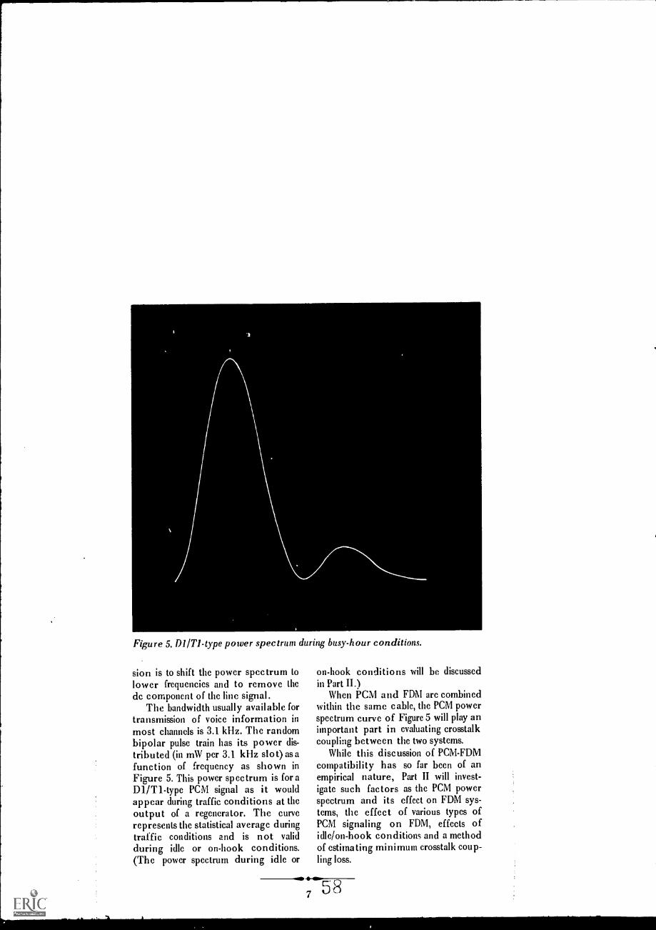
Figure 5. MITI-type power spectrum during busy-hour conditions.
sion is to shift the power spectrum tolower frequencies and to remove thedc component of the line signal.
The bandwidth usually available fortransmission of voice information inmost channels is 3.1 kHz. The randombipolar pulse train has its power dis-tributed (in mW per 3.1 kHz slot) as afunction of frequency as shown inFigure 5. This power spectrum is for aDl/T1-type PCM signal as it wouldappear during traffic conditions at theoutput of a regenerator. The curverepresents the statistical average duringtraffic conditions and is not validduring idle or on-hook conditions.(The power spectrum during idle or
on-hook conditions will be discussedin Part II.)
When PCM and FDM are combinedwithin the same cable, the PCM powerspectrum curve of Figure 5 will play animportant part in evaluating crosstalkcoupling between the two systems.
While this discussion of PCM-FDMcompatibility has so far been of anempirical nature, Part II will invest-igate such factors as the PCM powerspectrum and its effect on FDM sys-tems, the effect of various types ofPCM signaling on FDM, effects ofidle/on-hook conditions and a methodof estimating minimum crosstalk coup-ling loss.

1313 LEF1KURT
DEMODULATORAUGUST 1971
PCM-FDM Compatibility Part 2
I I
I( _ Li.%',, f3.-",...P-.--.4A-V1,4- i,.- -,,,, - ,:,:(-, 41'46.; ,, '- : ,,, , ',,..-- ... , ' -, -,-
59

The GTE Lenkurt study of PCM-FDM compatibility has yieldeduseful data in a quantity such that it will require three issues tocover all the information instead of the aforementioned twoissues. Part II will deal with the theoretical aspects of PCM-FDMcompatibility while Part III will apply these theories to apractical analysis of compatibility using a hypothetical PCM andFIN combination.
In the July issue (POI-FDMCOMPATI 111 L IT Y, PART 1)
of the Demodulator, the focus ofattention was mainly on how to use tobest advantage the empirical informa-tion thus far accumulated by GTE
Lenkurt in the study of PCM-FDMcompatibility. This included informa-tion on direction coordination of cablepairs within the same cable sheath anda discussion of the effects of far-endand near-end crosstalk on an FDMsystem.
This issue goes one step further inguiding the user toward achieving com-patibility between PCM and FDMsystems which lie within the samecable sheath.
Sampling, Quantiy.ing andEncoding
The sampling, quantizing and en-coding into digital form of an analogsignal are the three major functions ofa PCM terminal. The information usedin this discussion is based on thesampling, quantizing, and encodingscheme used in the GTE Lenkurt9001A, 9001B (both Dl-type) and9002A (D2-type) PCM channel bankassemblies. These assemblies are end-toend compatible with the Western Elec-tric DI arid D2 channel bank assem-
blies and to similar terminals producedby other communications equipmentmanufacturers; henee the designation,"1)1- and 92- type."
The level at which a voltage sampleis quantized is relevant in evaluatingPCM-FDM compatibility and is partic-ularly important at the lower voltagelevels since this is where the powerspectrum may sometimes be confinedto discrete frequencies during quietand idle conditions in the PCM termi-nal. An "idle condition" implies thatthe telephone receiver may be on oroff the hook and that no message isbeing transmitted even though theremay be a line open between twoparties.
In DI-type systems, each voice fre-quency channel is sampled g000 timesper second and each voltage samplehas 127 discrete voltage levels availablefor quantization. The zero voltagelevel is known as level 64. There are 63levels above level 64 in the positivedirection, and 63 levels below level 64in the negative direction. The numberof the quantization level nearest thelevel sampled is encoded into a se-quence of binary pulses and spaces, apulse corresponding to a "one" and aspace to a "zero". Figure IA gives anexample of noise or of low-level voice
NOTE:The back cover of this issue contains errata for the GTE Lenkurt publica-tion, Engineering Considerations For Microwave Communications SystemS.
60Cop,r.;mt 1971 719E Lent urt Incorporated Vo, :N) No Fi
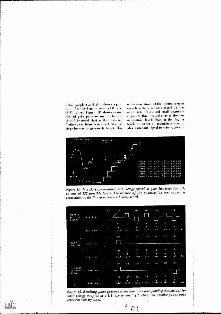
1141i.1 .11,,w4 J 114
limo iii Ihr tor! .lns 1.1 )t.l%prPENI 4,1111. hoar,- Ir 41111W. .N41,1-
Ulf 1111110' pattrros.. 11111 OW ISM', It
4111,1111 111 II0141 lila 1 am O 11,1.1A grllartlirr jva (mut /rt., (11.vr) 114),sty v. lorctitur progrrsAi%I.I largyr.T16
tov 4 JIl4I II4 i.1 1,i thr intiqns.sts..PS III
'I1r4'1I1 4lgst414 5,4 Elmo riitratrI 41 lib htjIllphiljdr by 4-1 4 4/111 4111411 4)11411 III III
Ir 1)m a rh, I ltii. arrilI psi. if, l AI I h.. liw41110111141r fr IA than at thr higher
1,1 Ifolro. II, maintain 4 r-.1.s.a.ith1), Atallt sigria11 4)-114,61- ratio, I ill.
NIMBI II
4 /T !MI
:f 111),44,,
1-44-01
40.4,4 Ililvi 61
' 1,,AN II/II) 4;1
I I I% /I'AN'I/ I) ['II V F
`NAVII'l I 4 I\ N l I 4 1 Vt I 40.1
4)44.1°,4H/101?) f V I 4 Cif;
I 11 IS 4)IJAN I vi"`AMPI I VF I 1.0
Ylgure IA. In a DI-type terminal, each voltage sample is quantized (rounded off)to one of 127 possible levels. The number of the quanitzation level chosen istransmitted to the line as an encoded binary word.
Mat
Figure 1B. Resulting pulse patterns on the line and corresponding calculations for
small voltage samples in a DI-type terminal. (Positive and negative pulses bothrepresent a binary one.)
3
61

drprvidrnt nf ujtuI loirl) which is throlpjrctivr 01 for *ere h-loadrd 1101trio- phoor strms.
Aftrr thr II1Jgr iis quantiArd(roundril off to thr nrarrst qualifica-ti)n Iri,r1), it is rocodrd into a 7-bitbinary pulse pattrrn Of binary' word. Abinary word consists of right digitsallcd DI through 1)8. The designationfor the eight binary digits of the codeword appear as DI through 1)8 butshould not be confused with the desig-nation for Dl- and 1)2- type terminals,they are two separate entities. DigitDI is used for signaling informationonly, while digits D2 through 1)8represent the encoded version of thcquantized sample (scc Figure IB). Thc24 binary words representing the 24voicc channels plus the framing digitcomprisc onc frame. There arc 8000frames per second and 8x24+1493bits per framc. Evcry other pulsc isinvcrtcd to producc a bipolar pulscpattcrn for transmission.
In D2-typc systcms, thc samplingratc is also 8000 timcs per sccond, butthc numbcr of quantization stcps andthc encoding mcthod arc diffcrcnt. Infive framcs out of cvery six all cightdigits (D1 through D8) arc uscd forencoding. Therc arc thcn 255 discrctcvoltage levels availablc for quantiza-tion. Thcsc levels arc numbcred +0 to+127 and 0 to 127, zcro quantiza-tion level corrcsponding to -±127. Fig-ure 1C shows how a noise or low-levelvoicc signal is sampled and quantizcdin a D2-typc PCM system. Figure 1Dshows cxamplcs of pulsc pattcrns onthe line. If the noise level in thctcrminal is sufficicntly low to rcsult in+127 or 127 quantized levels inevery samplc, a string of binary ones(pulscs) brokcn by a zcro (spacc) onthc averagc only oncc every sixteendigits will bc produccd. In the sixthframc, onc digit is uscd for signalinginformation so that only scven digits(127 levels) arc availablc for quantiz-
isut. Thr gsiLsb.ht f right digits forquantiAJtom 5,1ith4 thr tirnr pro-ides for lw tor signal quality than in a
I /I-typr sy strrn.
Power Spectrum CurvesThr power spectrum curve is an
important t(1ol in rvaluatingPC.M.F1)M crosstalk sincr from it eanhe derived the amount of pot( ntialinterferrnce to an FI)M system than-nel which may be transmitted at acertain frequency.
The power Spectrum (power as afunction of frequency) of aDI/TI-type PCM bipolar pulse train asit would appear during traffic condi-tions at the output of a regenerator isshown in Figure 2. Thc curve is cali-brated in dBm per 3.1-kIlz slot. Forthis discussion, only a portion ofFigure 2 is necessary sincc the maxi-mum disturbancc generated into anFDM linc by a PCM systcm will occurat approximatcly 710 kHz and thcFDM cable carricr systcms of mostconccrn for this discussion occupy thcfrequency range undcr 400 kHz. Fig-urc 3 shows thc significant portion ofthe powcr spectrum curvc in cxpandedform. Also shown in cxpandcd form, isthe curve for a D2/T1-type system.Although the D1- and D2-typc tcrmi-nals cannot be operatcd cnd-to-end,they can both bc operatcd ovcr thcTl-type rcpcatercd line.
Thc power spectrum for aDI/Tl-type systcm is bascd on a pulsedcnsity value of p=0.50, whcrc p is theprobability of a binary onc (a pulsc).This value for p is quitc constant withvarying loads in a Dl/T1-type systemprovidcd that thcrc is traffic on atleast six of thc 24 channcls in thetcrminal. The p=0.50 implics thatthcrc is an equal probability of a oneor a zero in the pulsc train.
The curve for a D2/T1-type powcrspcctrum is bascd on a pulsc dcnsity ofp=0.55 during busy-hour traffic condi-
4 62

%. 111,14 it .ailaig; p find-4r) will increase, 8.. 40111/4 in J
fir( rt'Ase ill 111, i)liwre) At Itlib freollien-e1es Ow low approoninatelv 121) Ws)awl All 111i rrase .orountl 710MA.
D1 A. and D 1 B SignalingIn ilit And) a Pt Ili FI)N1
interferrnee, the type of signaling usedin the 14:M system will dictate thefundammtal frequeiwy or multiplethereof at whieh the greatest interfer-ence will occur when the rot systemis in the idle comlition (no traffic).
'Iwo types of signaling are usedwith DI-type terminals. These two
410.1111q vt)1111414r4lIttloa lira the 16 141
MI Iv.. trw ole.o.go,,,th,,, of Awl
)111.
11ItIr, 1)1 ijiltil.ignalsug: the 1)1 110t lit
Ibirs b11141' 't4 tis.i (Airs iniliTy frame to. coon% cy the .ignalioginformation. h, the on-liook fonditiomthere is, then, always it pulse (a binaryone) in the 1)1 time slot no ever% Irani,for a given c!unmel. A prololcm ariseswhen for certain signaling require-ments (foreign exchange or revertivepulse signaling, for example) a secondsignaling channel is reqolired. If thishappens during voice transmission
Figure IC. In a D2-type terminal, each voltage is quantized to one of 255 possiblelevels.
Figure 1D. Pulse patterns resulting from small voltage samples in a D2-typeterminal will result in a pulse density close to 100 percent.
583

thp4 can 11411pr11, whrn01.4, 4.01,WEr 4urnoo.to, oudvdigit. I E.: I hr. m;411 V: 1.1% ) at'
Jill tdc 1.4 rrprcrnlit4 tb. quan.hind .amplr. .4% digst ,nvouling coorrrlliltnet4 111 6:11E1,41444 ciimpazEd I., thr
11+11.11 127 el. fur cm-luting.encutling rcsult. it, I.,rgrr
brtwrvu lolvb, and runsoluen.lygrratly increascil quantizing
ih Pt sy skin itsulf.TI) a oid an% Merease dur
to requirnments fur enure than onesignaling channel, the MB (also t ailed'1)1 only') signaling arraagnment wasdeveli pill With 1)11t signaling. thesignaling rain is divided by a factor offour SO (hit 1)1 digit is used forsignaling information only once everyfourth frame (per signaling chanm1).This effectivdy creates the potential
Figure 2. Power spectrum of a DItype system at the output of a regener-ator during traffic conditions.
Figure 3. Expanded power spectrum curve of a Tl-type pulse train under trafficconditions. C11
6

br 1,11se si,aIiut rhal1ne14 noitrait sittine, Although AA a ruir. Mit Hoer thentwo chafing-14 Are issyst. (.4er thr %lorh,
1.-sur of the 1.enkurt Dr.modulator for An rtrupove Irreitinent
ti.N1
Cable Characteristics%Anti- from removing the lie sompo-
nent from the line, conversion of thePCM pulse train to a bipolar formatalso shifts the power spectrum tolower frequencies. This shift in powerspectrum is advantageous for 1)01systems because the crosstalk charm.-teristics of cables are better at lowerfrequencies. Operation at lower Ire-quencies also results in relaxed require-ments on cable makeup. pair selection,and/or repeater spacing.
While the impedance of a cahle pairis mainly a function of frequency, italso depends on such factors as cablegauge, insulation, and capacitance. Ca-
ble impedance falls rapidly from avalue of 600-900 ohms at voice fre-quencies to approximately 100 ohmsat 300 kHz and stays relatively con-stant above that frequency. A compro-mise value of 110 ohms has beenchosen for the 50-400 kHz regionwhich is the band of greatest interestfor this study. This compromise im-pedance is accurate within this fre-quency range to within approximately10 percent.
Idle/On-Hook Pulse PatternThe idle/on-hook pulse pattern is
important in the study of interferencesince an idic and quiet PCM system (all24 channels idle) can sometimes (if thenoise level is sufficiently low) producea repetitive pulse pattern (resulting- ina power spectrum confined to discretefrequencies only) instead of the ran-dom distribution of binary ones andzcros normally present when comput-ing the power spectrum. This cancause excessive interference at certain
7
111)44' (rElpilr frpetlitisimipule* pawn, will emporia on ilsktitthroutih flit in a Itt tvr 4v4tem if ayr," hi,* ',slow kyrl is preirsit at theterminal. The odue of the Di dwit if$Ilse idle condition is determined forthe httYpe terminal nly by then,hook o, off hook condition of thrhannrk
DIA Idle/On-HookIf a 1)1type sy stein is arranged for
1)1A signaling. and 11 11)11111111/11 1`741sis
in which all channels or im-hook,with 41 very low noise level in the KMterminal, there will be pulses for all 1)1and 1)2 digits in every frame (digits 1)3through DB being zeros or spaces)since this sequence (or digits 1)2
through D8 represents a zero inputlevel (level (4) and since 1)1 is usedstrictly for signaling information (theon-hook condition is represented by abinary one). Such a repetitive pulsepattern has a line power spectrum(power concentrated at discrete fre-quencies). This means that the powerin the signal can be represented bycomponents of power at discrete fre-quencies which are multiples (harmon-ics) of a fundamental frequency, inthis case, 193 kHz. This componentmay create serious interference in the36-268 kHz band occupied by anN-type FDM carrier system, for ex-ample.
The fundamental frequency is de-rived for a periodic pulse pattern bythe formula:
1 1
° T 5.18 x 10-6193 kHz,
where T is the length of one period insec onds.
The periodic idle/on-hook pulsepattern and its corresponding linepower spectrum for D1A signalingappear as shown in Figures 4A and 4B.A PCM terminal in a telephone officegenerally picks up some noise from
65

Figure 41 shows the pulse pattern as it appears out of a POI terminal orregenerator in the idle/on-hook condition when DIA (DI /D8) signaling is used.The resulting line power spectrum is shown in Figure 4B.
Figure 4C represents the pulse pattern in three frames out of four for the idle/onhook condition and DI B signaling.
Figure 4D is the line power spectrum resulting from the idle/on-hook pulsepattern in a DI-type terminal when DI B (DI only) signaling is used. That patternis according to Figure 4A every fourth frame; according to Figure 4C theremaining three (out of four) frames.
8

switching transients, which causes thepower spectrum on the transmissionline to be less clean-cut than thatshown in Figure 4B. In most workingsystems, noise will cause the quantizedsamples of the input signal to fluctuaterandomly around level 64. These ran-dom fluctuations will introduce morepulses per binary word and thus more
9
high-frequency components to theline. Even rather small noise levels (forexample, resulting in levels 63 or 65most of the time, rather than 64) will
result in a pulse density of approxi-mately 50 percent. Only when all volt-age samples are consistently quantizedto zero level does the power spectrumbecome a series of spectral lines.

ig u r e 5. Powerspectrum for a work-ing Pal system dur-ing a busy-hour con-dition (10 a.m.) on aweek day.
F ig r e 6. Powerspectrum for a work-ing POI system dur-ing a low traffic con-dition (midnight).
t. ,
Figures 5 and 6 show the powerspectrum of the line signal as it ap-pears at the output of a PCM terminalunder different traffk conditions.These photographs were taken in thefield on a working 24-channel DIAsystem. Figure 6 shows that the powerspectrum only approaches a spectralline condition due to the presence of
r
A .2 A
r
ambient noise. However, a spectral linecondition can be attained in the labo-ratory where ambient noise is morestrictly controlled.
Although a periodic pulse pattern isa rather unusual case since it corre-sponds to all channels off hook and avery low noise level, it is importantbecause it usually represents the worst
/0 6

interference condition as far as FDMchannels in the corresponding discretefrequency slots are concerned. As thepulses occur randomly with traffic, thepower spectrum of a PCM system willtend to assume a smooth curvature asshown in Figure 3. Figure 413 repre-sents the worst ease for the all chan-nels on-hook condition, as far as cross-talk at low frequencies is concorned.
D1B Idle/On-HookWhen a terminal is arranged for
D1B ("D1 only") signaling, the idle/on-hook pulse pattern is somewhatmore complicated than for D1A signal-ing. In one frame out of four the pulsepattern will be as shown in Figure 4A;in three frames out of four it will be asshown in figure 4C. The pulse train inone frame out of four for the idle/on-hook condition is thus identical tothat for DIA signaling. This will pro-duce lines in the power spectrum -atmultiples of 193 kHz as for D1Asignaling, but their magnitudes arereduced by a factor of four (6dB)because it represents only the pulsepattern in every fourth frame. Theimportant thing to be noted about thepower spectrum for an all channelsidle and on-hook condition, (as inFigure 4D) is that it consists of twosets of spectral lines for D1B signaling.One set has lines at all odd multiplesof 96.5 kHz caused by the pulsepattern in three out of four frames.The other set has lines at even multi-ples of 96.5 kHz (which is the same asmultiples of 193 kHz) caused by thepulse pattern in one out of every fourframes.
D2/T1-Type Idle/On-HookThe pulse pattern for the idle/on-
hook conditions for a D2/T1-type
system is a sequence of consecutivepulses (a string of binary ones), brokenby an occasional space. If the system isidle with all channels in the on-hookcondition, and the noise level is suffi-ciently low, the voltage samples will allbe quantized to +127 or 127 in fiveframes out of six; to +63 or 63 inone frame out of six. The signalingdigit for the on-hook condition Is abinary one. For this condition, on theaverage 15 out of every 16 digits willbe binary ones. Analysis of this typeof pulse train shows a reduction ofsingle-tone interference below 400kHz amounting to 1.1 dB (compared toidle/on-hook DIA) or 7 dB (comparedto idle/on-hook DIB).
Crosstalk EvaluationFrom a study of idle/on-hook con-
ditions for DIA and D1B signaling it isapparent that PCM to FDM interfer-ence will show greatest potential fordisturbance at multiples of 96.5 kHzor 193 kHz during the -times of theday or night when most of the PCMchannels are idle. The value of theworst ease component under this con-dition can be obtained from the appli-cable diagram in Figure 4. It is possiblethat this disturbing effect from thePCM system in its idle condition willin some eases necessitate the elimina-tion of FDM channels in basebandslots at or adjacent to multiples of96.5 kHz.
In Part III of PCM-FDM COMPATI-BILITY, the theoretical aspects ofcompatibility which have been dis-cussed in the previous two issues ofthe Demodulator will be put to practi-cal application. A hypotheticalPCM-FDM combination will be evalu-ated to determine if the two systemsare compatible.
1169

.. 4.___%. -k

Subjection of an FDM system to interference from PCM signals is themajor factor which discourages the user of communications equip-ment from placing PCM and FDM systems in the same cable sheath.By giving careful consideration to direction coordination of cable, andby evaluating the effects of PCM to FDM crosstalk, single-tone inter-ference, and length of repeater sections, the user may find his FDMsystem compatible with PCM without extensive modifications.
Parts I and II of the PCM-FDMco m p a tibility series dealt
with the empirical and theoretical as-pects of PCM and FDM systems whichlie in the same cable sheath. Some ofthe factors influencing the amount ofinterference between these two typesof systems arc crosstalk coupling loss,length of exposure of FDM to PCM,the frequency band occupied by theFDM system, and the type of PCMsignaling utilized. The discussion ofthese subjects brings to light a way ofevaluating the amount of interferencewhich the FDM system receives fromthe PCM system.
A series of steps may be taken toevaluate the possibility of compatibili-ty between PCM and FDM systemswhich operate on pairs Within thesame cable sheath. To demonstratehow this series of steps can be usefulto the communications equipmentuser, an example is given in this issue(using a hypothetical PCM-FDM com-bination) on the process of estimatingthe minimum crosstalk coupling lossrequired if two systems are to becompatible.
The example for crosstalk evalua-tic* will employ a GTE Lenkurt24-channel 9 1 A PCM system(DI/T1-type) equipped for DIA sig-naling and a GTE Lenkurt 47A (anN-type FDM system) equipped withcompandors, The calculations are validfor any DI/TI -type PCM system andany NI or N2-type FDM system.
The 47A is a 12-channel, double-sideband, amplitude-modulated carrier
29, 1071 t t I no cf ,141/.11,t1 V :0
system which operates over two cablepairs, one for each direction of trans-mission. .It is end-to-end compatiblewith Western Electric N1 or N2 sys-tems (depending on the option of 47Aused). Compandors arc optional forthese systems. On any section of thecable, the two directions of transmis-sion utilize different frequency linegroups. The low-frequency group ex-tends from 40 to 128 kHz and thehigh-frequency group from 176 to 264kHz as shown in Figure 1. In eachrepeater there is a modulator whichshifts the signal from one band to theother (frequency frogging) in order tocombat near-end crosstalk.
For this example it is assumed thatmaxi mum-length repeater sectionlengths are used for the 47A system(40 dB at 176 kHz) and that endsections (or any sections adjacent to atelephone switching office) do notexceed 25 dB at 176 kHz. The 40-dBvalue is the maximum allowable powerloss over an intermediate repeater sec-tion where little interference will beencountered from external sources; forthis discussion an intermediate repeat-er location not at a switching centerwill be referred to as a "low-noisepoint." The 25-dB value is the maxi-mum allowable power loss over arepeater section adjacent to an office(an end section, for example). At anoffice the repeater is subject to inter-ference from office switching equip-inent; for this discussion offices will bereferred to as "high noise points." For22-gauge PIC (polyethylene insulated
1041
A' 4,

Figure 1. Frequency designations for the GTE Lenkurt 474 FDM System.
Channel 1 (not shown) is an optional channel which is seldom used due toperformance limitations at that frequency although it may be used in lieu of any
of the other available channels.
cable) with a capacitance of 0.083 tiF
per mile, the 40- and 25-dB valuescorrespond to repeater section lengthsof 3.88 miles and 2.42 miles, respec-tively. The loss at 772 kHz (the loss at
this frequency determines the Palrepealer spacing) is 90 dB over a 3.88-
mile section of such cable. Assumingthat the PCM intermediate repeatersections are exactly one third of the47A repeater section (this corresponds
to 30 dB at 772 kHz), that the 47Arepeater locations withM the section
exposed to PCM interference alwayscoincide with a PCM repeater point,and that the exposure to PCM occursover three 47A intermediate repeater
sections plus one end section, the sys-
tem layout will appear as in Figure 2.
Noise InterferenceThe interference from a PCM sys-
tem consists either of noise or single-
tone interference depending on the
traffic loading of the PCM system andthe noise level at each PCM terminal.The first consideration will be that ofnoise interference from a traffic-loaded PCM system.
The near-end crosstalk interferencefrom a PCM system to an FDM system
is shown in Figure 2 by the greenarrows which indicate the near-endcrosstalk paths of importance. Theinterference from PCM is most severeat the high-level outputs of the PCMrepeaters (regenerators). However, tieonly near-end crosstalk of importanceoccurs on the PCM repeater sections
adjacent to FDM repeater receive-
inputs, as the green arrows in Figure 2indicate. This is because the level ofthe received signal on the FDM systemis the lowest and most noise-sensitive
at that point. The PCM to FDMnear-end crosstalk originating on PCM
repeater sections not adjacent to anFDM repeater reeeive-input will be
attenuated by 10 dI3 or more beforereaching the FDM repeater input and
can be neglected.The allowable degradation of noise
performance in the 47A system hasbeen chosen such that the presence ofPCM carrier interference should notcause the noise performance to deteri-
orate to worse than 27 dBrne. This isone dB worse than the worst line-up
.37 2

IM...Mh...MittIM.M. l-Figure 2. PCM-FUM combination showing three intermediate repeater sections andone end section of the FUM system exposed to PCM interference.
noise performance allowed for a longdistance 47A system without PCMinterference (26 dBrne). Based on thisrequirement, the total noise contri-bution originating from PCM carriersystems must not exceed 20 dBrne,since by dB addition laws, 26 dBrne +20 dBrnc = 27 dBrne. The dBrne unitis used to measure absolute noise andfrom the conversion table shown inFigure 3, a 20-dBrne value converts to100 pW psophometrically weighted(100 pWp).
A performance requirement of 20dBrne for PCM interference corre-sponds to an FDM signal-to-PCM inter-ference noise ratio (test tone-to-PCMinterference noise ratio) of 68 dB (asshown in Figure 3). The expression"signal-to-noise ratio" generally usedin FDM system terminology actuallymeans test tone-to.noise ratio since itrefers to a test tone which is injectedinto the system from a signal generatorfor measurement purposes. At testtone level, a 47A non.compressed car-rier is amplitude-modulated with a
modulation index of 0.35 (35 per-cent). This 35% value was ebosen inthe initial system design to avoid
4
exceeding 100 percent modulation ateven the highest speech volumes.
Figure 4 shows the relationshipbetween carrier and test tone signals inone channel of an FDM system. Inorder to solve for unknown noiselevels a meaningful relationship mustbe established between the ,carrier-to-noise and signal-to-noise ratios. Forthis non-compressed, double-sideband,amplitude-modulated, 47A FDM sys-tem, in which a test tone modulatesthe cariier 35 percent, the followingequation is true:
Equation 1
+ 9 dB(CNt)6.2 kHz (51C1) 3.1 kliz
where C/N stands for FDM carrier-to-PCM interference noise ratio (wherethe carrier is at one specific frequencyand the PCM noise is over 6.2 kHz)and S/N for FDM test tone-to-PCMinterference noise ratio, with referenceto the voice frequency drop point. The3.1 kHz value, corresponds to theusable sideband bandwidths in a voicechannel. Since the 47A uses double
111

f, 40. n ti
1,
111( 1 /;+,
I I 1,1 ), / //1,
I 1. :11111 /4
:11
/11 I
IF
Figure 3. Noise measurement conver-sion table.
sideband operation, each carrier is
associated with noise interferenc(1 overa bandwidth of 6.2 kHz. Equation I
states that carrier-to-noise is equal tothe signal-to-noise + 9 dB.
The maximum allowable noise per-formance for a GTE Lenkurt 47Asystem is 26 dBrne. In a case wherethe repeater sections arc of acceptablelengths and good cable and line-upprocedures arc used, the noise perfor-mance will usually be much betterthan 26 dBrne. However, this discus-sion will proceed as if the noise perfor-mance on the system was at the 26-dBrnc point (worst ease) before theaddition of PCM interference. In orderto allow for this PCM interference, oneadditional dB of interference will beaccepted which will make the totalnoise performance 27 dBrne. For thisdiscussion the 20-dBrne value will beregarded as the total noise interferenceto the FDM system although it mustbe remembered that a 26-dBrne noisevalue does exist in addition to the 20dBrne.
The 20 -dime PCM noise require-ment previously calculated corre-
5
Figure 4. When a carrierof frequency fc is mod-ulated by a sinusodial 1-kHz test tone, sidebandfrequencies appear atfrequencies (fc-1) kHzand (fc+1) kHz. Eachone of these two side-band frequency compo-nents are of a powerlevel 15 dB below thelevel of the carrier. Thisis based on the testtone modulating thecarrier with a modula-tion index of 0.35(such as in a non-corn-pandored 47/1 system).

sponds to an FDM signal-to-PCM inter-ference noise ratio of 68 dB, and thusconverts to a requirement for FDMcarrier-to-PCM interference noise ratioof:
N 6.2 kHz N 3.1 kHz 9 dB
N 6.268+9 dB
kHz
77 dB; (non-compressed),(11)6.2 kIIz
For this discussion a compandor willbc inserted in accordance with theoriginal conditions at the beginning ofthis example. This produces a 20-dBcompandor advantage and results in arequirement of:
N 6.2 kHz57 dB (compressed).
The carrier with the lowest powerlevel will differ in level and frequencydepending upon the 47A repeater sec-tion length and whether the low-groupor the high-group is being observed.Levels will thus be different on repeat-er sections adjacent to switching cen-ters (as in end sections) compared tointermediate sections adjacent to low-noise points. If the spacing rules forN-typc carrier are adhered to (end-sections not to exceed 25 dB at 176kHz, intermediate sections not exceed-ing 40 dB), the lowest carrier levels ona 47A system have been calculated tobe approximately:
(a) At a high-group repeater input atthe high-frequency end of theband (264 kHz) . . . 48 dBm
(b) At a low-group repeater input atthe high-frequeney end of theband (128 kHz) . . 42 dBm
6
(c) At a high- or low-gmup repeaterinput or terminal input locatedin or adjacent to a switchingcenter 28 dBm.
These "lowest" FDM carrier powerlevels are significant when evaluatingPCM to FDM interference since it is atthese levels that an interfering PCMsystem will have the greatest effect onFDM. It is assumed throughout thefollowing calculations that the spacingrules quoted above were followedwhen laying out the N-type carriersystem.
A repeater input on a section adja-cent to a switching center is at least 14dB less sensitive to PCM interferencethan other intermediate sections dueto its shorter length (compare values--28 dBm versus 42 dBm and 28dBm versus 48 dBm), End-sectionsand other sections adjacent to high-noise points can thus be neglected forthe purpose of these interference cal-culations if there arc at least as manynormal (adjacent to low-noise points)intermediate 47A repeater sections inthe section being exposed to PCMinterference as there arc 47A repeatersections adjacent to high-noise points.The approximation error thus incurredis no more than 0.2 dB.
If a 47A carrier system is exposedto PCM interference over several inter-mediate sections (as in this example),about half the number of sectionsexposed (for any direction of transmis-sion) are high-group sections and halfare low-group sections. Considerationmust therefore be given to the relativeeffects of interference into these twogroups.
High-Group Repeater InputThe minimum FDM earrier-to-PCM
noise ratio requirement has been calcu-lated to be 57 dB (68 dB + 9 dB 20dB = 57 dB). The lowest power level(this is the worst acceptable ease con-
5
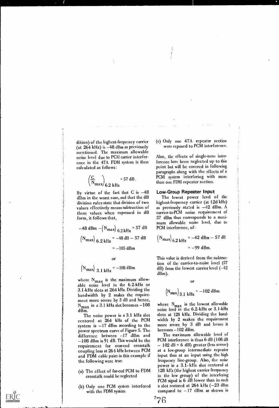
dition) of the highest-frequency carrier(at 264 kHz) is 48 dBm as previouslymentioned. The maximum allowablenoise level due to PCM carrier interfer-ence in the 47A FDM system is thencalculated as follows:
c.Nmax)6.2 kHz
= 57 dB.
By virtue of the fact that C is 48dBm in the worst case, and that the dBdivision rules state that division of twovalues effectively means subtraction ofthese values when expressed in dBform, it follows that,
48 dBm (N max) 6.2 kHz 57 dB
(Nmax) 6.2 kHz48 dB 57 dB
= 105 dBm
or
(Nmax) 3.1 kHz= 108 dBm
where Nmax is the maximum allow-able noise level in the 6.2-kHz or3.1-kHz slots at 264 kHz. Dividing thebandwidth by 2 makes the require-ment more severe by 3 dB and hence,Nmax in a 3.1 kHz slot becomes 108dBm.
The noise power in a 3.1 kHz slotcentered at 264 kHz of the PCMsystem is 17 dBm according to thepower spectrum curve of Figure 5. Thedifference between 17 dBm and108 dBin is 91 dB. This would be therequirement for near-end crosstalkcoupling loss at 264 kHz between PCMand FDM cable pairs in this example ifthe following were true:
(a) The effect of far-end PCM to FDMcrosstalk could be neglected
(b) Only one PCM system interferedwith the FDM system
(c) Only one 47A repeater sectionwere exposed to PCM interference.
Also, the effects of single-tone inter-ference have been neglected up to thispoint but will be covered in followingparagraphs along with the effects of aPCM system interfering with morethan one FDM repeater section.
Low-Group Repeater InputThe lowest power level of the
highest-frequency carrier (at 128 kHz)as previously stated is 42 dBm. Aearrier-to-PCM noise requirement of57 dBm thus corresponds to a maxi-mum allowable noise level, due toPCM interference, of:
(Nmax) 6.2 kHz= 42 dBm 57 dB
= 99 dBm.
This value is derived from the subtrac-tion of the carrier-to-noise level (57dB) from the lowest carrier level (-42dBm).
or
= 102 dBm(Nmax)kHz
where Nmax is the lowest allowablenoise level in the 6.2-kHz or 3.1-kHzslots at 128 kHz. Dividing the band-width by 2 makes the requirementmore severe by 3 dB and hence itbecomes 102 dBm.
The maximum allowable level ofPCM interference is thus 6 dB (108 dB
102 dB = 6 dB) greater (less severe)at a low-group intermediate repeaterinput than at an input using the highfrequency line-group. Also, the noisepower in a 3.1- kHz slot centered at128 kHz (the highest carrier frequencyin the low group) of the interferingPCM signal is 6 dB lower than in sucha slot centered at 264 kHz (-23 (Himcompared to 17 dBm as shown in
G

Figure 5. Power Spectrum of a Tl-type PCM pulse train under traffic conditionsat the output of a regenerator.
Figure 5). A low-group intermediaterepeater input is thus 12 dB lesssensitive to interference from a PCMsystem with traffic than such an inputusing the high line-group (due to two 6-(lB advantage fuctors).
Based on the above calculations, itcan be concluded that only the high-group intermediate repeater inputs,being the ones most sensitive to inter-ference, are going to determine therequired value of near-end or far-endcrosstalk coupling loss between] PCMand FDM cable pain. Therefore, inthis example tlw effects of all low-group repeater inputs may be neg-lected. The error incurred by thisapproximation does not exceed 0.5 d13provided that the section of the 47Asystem exposed to PCM interference
8
contains more than one intermediate47A repeater section.
PCM Noise ConclusionFor this example, in the A to B
direction of transmission shown in
Figure 2, two high-group intermediaterepeater sections are exposed to l'CMinterference. Had only one such sec-tion been exposed, the near-end cross-talk coupling loss requirement wouldhave been 91 d13 at 264 kHz. Sincethere are two exposed high-group in-termediate FOM repeater sections, therequirement is 91 t 10 log 2 dB, or 94dB, for iwar-end crosstalk couplingloss at 264 Id lz. 'Phis is based on oneinterfering l'CM system mid the lengthof its exposure to the FHM system asshown in Figure 2.

The value of 94 dB for near-end-crosstalk coupling loss is based ontotal PCM to FDM noise crosstalkcontributions. The assumption is madehere that near-end crosstalk contri-butions will be much more likely tocause interference than the contri-butions of PCM to FDM interferencedue to far-end crosstalk. If this as-sumption cannot be made, half of thecrosstalk contribution can be assignedto near-end crosstalk (making thatrequirement 3 dB more severe, or 97dB), and half to far-end crosstalk. Therequirements for coupling losses be-tween PCM and FDM cable pairs arcthen as follows:
(a) Near-end crosstalk coupling lossrequirement at 264 kHz is 97 dB
(b) Far-end crosstalk coupling loss re-quirement at 264 Zs Hz (as mea-sured over one PCM repeater sec-tion length) is (97 C dB), whereC is the loss in dB at 264 kHz ofthe cable pair over one PCM re-peater section length.
In the B to A direction of transmis-sion shown in Figure 2, there is onlyone intermediate high-group repeatersection exposed to PCM interferencethat is not adjacent to a high-noisepoint. For simplicity, this example hasconsidered only the worst direction oftransmission (the A to B direction).
Sing Ie-Tone InterferenceThe next problem to consider is
that of single-tone near-end interfer-ence (between opposite directions oftransmission) from the PCM systeminto the 47A FDM system. Figure 6shows that the only frequency ofconcern in this case is 193 kHz (D1A-type signaling, and highest frequencyin the PDM system of 264 kHz).
An interfering tone at 193 kHz willfall at the 1-kHz point (1 kHz on one
side of the carrier) in the upper side-band of Channel 4 of the high groupof the 47A system (see Channel 4,Figure 1). The maximum allowablelevel of such a 1-kHz tone is set to70 dBm0, that is, 70 dB below testtone [(Nei. This is consistent withprevious assumptions since this corre-sponds to 100 pWp at the zero-leveltest-tone point. The maximum allow-able PCM noise level in the previouscalculations was 20 dBrnc, which cor-responds to 100 pW psophometricallyweighted (see Figure 3). It should beremembered that the PCM to FDMinterference occurs either as noise orsingle-tone interference, never bothtypes simultaneously.
In this case (DIA-type sigrling)only the high-group repeater inputs lreof interest, since the interfering tonefalls within the high-group frequencyrange. End sections or repeater sec-tions adjacent to high-noise points canbe disregarded as before if the lengthof the 47A system section being ex-posed to PCM interference contains atleast as many normal (adjacent tolow-noise points) intermediate 47Arepeater sections as there arc 47Arepeater sections adjacent to high-noise points.
The lowest carrier level encoun-tered at a high-group repeater input is48 dBm, in accordance with thevalue used earlier in this example. Thisvalue is for the highest-frequency car-rier (Channel 13) at 264 kHz. ForChannel 4, the lowest level encoun-tered is 41 dBm. Since in a 47Asystem without compandors the levelof each sideband of a test tone is 15dB below the carrier level (see Figure4), the lowest such sideband levelencountered is 56 dBm (-41 dBm15 dB). The interfering tone must beat least 70 dB below that, in otherwords, less than 126 dBm.
For the 47A system in this discus-sion, the compandor advantage allows
V8

Figure 6. The line power spectrum which results in a 1)1-type terminal underidlelon-hook conditions when D1/1 (D11D8) signaling is used.
this requirement to be relaxed by 20dB to 106 dBm.
The level of the 193-kHz tone of anidle PCM system with D1A-type signal-ing is 4 dBm as shown in Figure 6.The difference between 4 dBm and106 dBm is102 dB. The requirementfor near-end crosstalk coupling loss at193 kHz between PCM and FDM cablepairs tIms becomes 102 dB per ex-posed high-group 47A intermediaterepeater section. Since there are twosuch sections exposed hi the A to Bdirection of transmission as shown inFigure 2, this requiR..ement becomes105 dB (102 + 10 log 2 dB = 105 dB)for this direction. 011ie requirementfor the other direction is 3 dB less, butfor simplicity only the worst ease willbe considere(l here.) This 105-dB valueis based only on single-tone interfer-
ence and on the assumption that thefollowing additional circumstances aretrue:
(a) the effect of far-end PCM to FDMcrosstalk can be neglected
(b) only one PCM system is involved.
If far-end l'CM to FDM crosstalkcan for some reason not be neglected,3 dB should be added to the require-ment above. This new value (108 dB at193 kHz) becomes the new near-endcrosstalk requirement; (108-D) dB isthe far-end crosstalk requirement asmeasured over one PCM repeater sec-tion length. (I) is the loss in dB of thecable pair at 193 kllz over one repeat-er section length of the PCM system.)This assumption effectively dssigns
10 7

half of the single-tone interference tonear-end crosstalk and half to far-endcrosstalk contributions.
Overall Conclusion For ThisExample
In this example, the resulting re-quirements on near-end and far-endcrosstalk were:
(a) For near-end crosstalk over one re-peater section length of the PCMsystem,97 dB at 264 kHz108 dB at 193 kHz
(b) For far-end crosstalk over one re-peater section length of the PCMsystem,(97-C) dB at 264 kHz(108-D) dB at 193 kHz
where, C and D are the losses in dB ofthe cable pair at 264 and 193 kHz,respectively, over one PCM systemrepeater section length.
If the requirements at 264 kHz canbe met (this is necessary to combatnoise across the band coming from thePCM system when it is loaded withtraffic) but the requirements at 193kHz cannot be simultaneously met,consideration should be given to re-moving the 47A channel affected(Channel 4) from service.
Conclusions Regarding "T to N"PC M- F DM I nterference
The results and conclusions of theexample just discussed are valid forany DI/T1-type PCM system equippedfor DIA-type signaling , disturbing anN1 or N2-type FDM system equippedwith compandors.
If the DI/T1 system is equippedfor DIB signaling there will be anadditional component of single-toneinterference falling at 96.5 kHz, corre-sponding to the 500-Hz point (on one
11
side of the carrier) of one of thesidebands of Channel 6 in the lowerline group. This will produce an addi-tional requirement (at that frequency)for near-end and far-end crosstalk cou-pling loss, respectively.
If the PCM system is a D2/T1-typesystem, the single-tone interferenceproblem is reduced significantly.
The calculations regarding noiseinterference from a traffic-loaded PCMsystem are the same for a DIB as for aD1A-type P CM system. For aD2/T1-type system, a separate curve isused (see Figure 5).
If a DI/T1- or D2/T1-type PCMsystem is disturbing an N3-type systemsuch as the GTE Lenkurt 46B, there isa 3-dB disadvantage since the single-sideband 46B system does not havethe advantage of coherent detection ofa double-sideband signal (as the 47Adoes) since,
Equation 2
(t) NJ 3.1 kHz
(4N 6.2 kHz \
12 dB
where P/N is the pilot-to-PCM interfer-ence noise ratio, and S/N is the testtone-to-PCM interference noise ratio.In equation 2, the 3-dB disadvantageshows up in the +I2-dB value whencompared to the +9 - dB value ofEquation 1.
This three part series on PCM-FDMcompatibility has endeavored to pro-vide the user of communicationsequipment with as much informationas has been gathered to date by GTELenkurt on the problem of combiningPCM and FDM within the same cablesheath. Adherence to the ground-ruleslaid out in this series should enable theuser to systematically phase out an oldFDM system while using PCM, orpermanently combine PCM and FDM
the same cable sheath.

;',.

Modems . . . those unglamorous butvital "black boxes" that form theinterfaces between digital machinesand the communications network.
Modems have lwen referred toas data sets, line adapters,
modulators, or subsets. Regardless ofthe name used, the purpose of each ofthese black boxes is to convert digitalpulses into analog signals, such asaudible tones, suitable for !ransmissionover the telephone network.
If two machines such as compu-ters, data terminals, or facshnile ma-chines arc communicating via thetelephone network, it is necessary tohave a modem at each end of the lineto act as the interface between themachine and the communications line.These black boxes must be capable ofmodulating and then demodulating thesignals hence, the contraction mo-dern from modulate and demodulate.
A pair of modems arc considered"transparent" since the signals into thefirst (the input) arc identical to thedemodulated signals (the output) fromthe second modem. Figure 1 illustratesthe position of the modems in a datalink and the signals into and out ofeach element of the link.
The modem and the communica-tions line can be connected directly
(hardwire) or indirectly (acoustic orinductive coupling). Acoustically cou-pkd modems are portable since theycan be used with any available tele-phone. With acoustic coupling, the dedata signals are converted to audiblesounds which are picked up by themicrophone (or transmitter) in an or-dinary telephone handset. The audiblesignal is converted to electrical signals,and transmitted over the telephonenetwork. The process is reversed at thereceiving end.
Inductive coupling, like acousticcoupling, requires no direct connec-,tion. With inductive coupling a datasignal passes to the telephone throughan electromagnetic field by way of ahybrid coil.
Acoustic/inductive couplers gener-ally do not operate as reliably as directelectrically connected moderns, be-
cause they involve an extra conversionstep (for example, digital to audible toelectrical) where noise and distortionsmay be introduced. For this reasonacoustic/inductive modems are pres-ently limited to transmission speedsbelow 1200 bps (bits per second).
JW.11.A.
Figure I. A data link requires a modem on each end of the transmission channel.2
Coo, 1977 G TE LenIuel locolOorated Vol 20 No /082

A direct hook-up to the communi-cations channel, therefore, is prefer-able, since it is less error-prone and notlimited to low speed transmission.
Asynchronous or SynchronousHaving connected the digital ma-
chine to the communications line it isnecessary to coordinate the data re-ceived with the data sent. This coordi-»ation or synchronization can be ac-complished in two ways. If start andstop bits are used to "frame" eachcharacter, the transmission is asyn-
chronous. Synchronous modems re-quire the use of clocking devices whichlock the transmitted signal of themodem and the terminal device to-gether at a fixed transmission rate.
High-speed data generally uses
synchronous transmission since foridentical data coding levels and trans-mission bit speeds, a higher data speedcan he achieved. Asynchronous trans-mission requires the use of two orthree start- and stop-bits for eachcharacter depending upon the type ofmachine generating the digital signal.Consequently, if an eight-bit code isbeing used, asynchronous transmissionrequires 10 or 11 bits per characterand synchronous requires oitly 8.Synchronous modems can thereforetransmit at least 25% morc charactersthan asynchronous modems at thesame bit speed (see Figure 2).
Although synchronous transmissionis cfficicnt, the clocking mechanismrequires added circuitry which Makes
the equipment more costly than asyn-chronous modems for the sante speed.
Asynchronous modems have a spec-ified maximum transmission speed,
but they can be used to transmit dataat any speed up to this maximum.Asynchronous modems are used forlow- and medium-speed transmissionup to approximately 1800 bps.
ligh-speed modems, on the otherhand, are intended for synchronousoperation at a fixed transmission rate.The transmission speed of a synchro-nous modem is established by theclocking source which is generally acrystal oscillator. If a synchronousmodem has more than one speed, thespeeds are generally multiples of theoscillator frequency.
Parallel or SerialAnother way to classify data mo-
dems is according to the type of bitstream used parallel or serial. Figure3 illustrates the difference betweenserial and parallel bit streams. Serialbit streams arc most commonly used
since the digital information can be
modulated as it comes from the digitalmachine. As long as sufficient band-width is available for transmission
without degradation, a serial bitstream mav be used.
If, however, transmission is to take
place over bandwidths which do nothave uniform transmission characteris-tics, a serial bit stream can be con-verted to a parallel bit stream. At the
receiver; a parallel-to-serial conversion
Figure 2. Each char-acter is at least 25%longer with an asyn-chronous systemthan with a synchro-nous system.

'I'll I I I
Figure 3. With parallel transmission,longer bits are used to transmit thesame amount of data in a given period.
takes place. This technique is oftenused to transmit data at 4800 bps andhigher over a voice channel.
Parallel channels with their longersymbols provide better correlation offade and phase factors and multipathdelay distortion in the propagationmedium radio or cable. (See Sep-tember, 1970, Demodulator for discus-sion of transmission impairments.)However, the complex circuitry forparallel transmission makes parallelmodems more costly. They are alsoless efficient since bandwidth is usedfor flanking of the bandpass filters ineach channel. For these reasons serialmodems have been accepted as anindustry standard.
ModulationModems can also be classified ac-
cording to the analog signal generatedin the D/A (digital to analog) conver-sion. These analog signals may beamplitude, frequency, and phase mod-ulated. Four types of modulation areused extensively in digital data trans-mission: amplitude modulation (AM),frequency modulation (FM), phasemodulation (PM), or AM combinedwith either FM or PM.
With an AM modern, the sinusoidalcarrier wave is varied in amplitude tocorrespond to the digital information
being transmitted. Upper and lowersidcbands equal to the carrier plus themodulating signal and the carrier mi-nus the modulating signal, respective-ly, occupy a total bandwidth of twicethe modulation rate (see Figure 4).The entire double-sideband AM signal,a single-sideband AM signal, or a vesti-gial-sideband AM signal can be trans-mitted depending upon how the signalis processed at the receiving end.
In single-sideband only, one side-band is transmitted with or withoutthe carrier, and the required transmis-sion bandwidth is only half that re-quired hy double-sideband AM. But, ifit is necessary to transmit a dc compo-nent for signal processing, vestigial-sideband AM must be used transmit-ting the wanted sideband, part of thecarrier, and the low frequency end ofthe unwanted sideband.
Single-sideband AM gives the bestbandwidth economy, but not the bestequipment economy. The filtering nec-essary for single-sideband AM is diffi-cult to achieve; consequently, thetechnique is used primarily for high-speed data transmission over a band-limited channel where the advantagesoutweigh the disadvantages.
Vestigial-sideband AM systems re-quire a bandwidth approximately 1.3times that required for single-sidebandAM systems, and the technique is
typically used in data modems oper-ating at speeds of up to 7200 bps overvoice-grade lines.
In AM transmission the amplitudeof the carrier is varied but with FMtransmission the carrier frequency var-ies proportionally to the instantaneousvalue of the modulating signal thedata bit stream. When transmittingbinary data, the frequency of thetransmitted wave shifts between twodiscrete values (determined by thechannel bandwidth), one representingbinary one and the other, binary zero.This is a double-sidebaad system calledfrequency, shift keying (FSK) and re-
4 8

quires approximately the same band-width as double-sideband AM.
For phase modulation the phase ofthe transmitted carrier varies propor-tionally to the instantaneous value ofthe modulating signal. For binary datatransmission the phase is shifted 1800for each transition between one andzero, or zero and one. Phase shiftkeying (PSK) is extensively used forsynchronous high-speed data transmis-sion systems up to 2400 bps. Howeverto transmit at 240 bps and above, itis necessary to resort to a four-phasesystem utilizing 900 shifts. PSK, likeFSK, is a double-sideband system.
In a special form of FSK calledduobinary, FSK modulation is used inconjunction with kInobinary codingwhich uses a three-levei code to repre-sent the binary data. The duobinarycoding technique, developed at GTELenkurt, is used in the GTE Lenkurt26C data modem. Assuming a constantbandwidth data channel, duobinaryFSK transmits at twice the speed ofFSK. Figure 5 shows the differencebetween FSK and duobinary FSK.
Factors to consider when selectinga modulation scheme are complexityof electronic circuits, required band-width, quality of transmission channel,signal-to-noise ratio, tolerance to delaydistortions, tolerance to amplitudechanges, tolerance to jitter, and reli-ability. Each system has some advan-tages relative to the other systems.
5
Figure 4. The waveenvelope is the sameas the modulatingdata s ig nal. Thebandwidth of thedouble-side band AMsignal is twice thebandwidth of themodulating signal.
Compared to Voice BandAnother way to classify modems is
by their required transmission band-width. Modems can be divided intothree categories: sub-voice, voice, andgreater-than-voice band (or wideband).The chart in Figure 6 relates band-width to transmission speed, and illus-trates that transmission speed is gener-ally proportional to bandwidth.
Sub-voice 'band modems use only afraction of the 4-kHz voice band foreach data channel. These modems gen-erally serve slow digital devices withspeeds of up to 600 bps. Frequencydivision (FEW) or time division (TOM)
II
Figure 5. Duobinary FSK transmissionis twice as fast as FSK transmissionshowing four binary bits compressed
nze cycle of the line signal.

I II I
Figure 6. Bandwidth aud transmission speed are generally related as shown in thischart the wider the bandwidth, the higher the speed.
multiplex techniques are used to fillthe voice band. With FDM, a multi-plexer is not needed because the mo-dem conditions the data signal fortransmission in its proper frequencyslot on the telephone line the signalis in essence frequency modulated andtranslated. GTE Lenkurt's 25C datamodem performs such a multiplexingfunction. But, with TDM, a multiplex-er conthines the digital signals in time.This new high-specd, serial bit streamthen goes to a modern for digital toanalog conversion and transmissionover the telephone circuit. Figure 7illustrates the difference between FDMand 1DM systems.
FDM and 1DM are equally suitablefor voice grade channels. However,TDM is more efficient in bandwidthutilization; therefore, more channelscan be multipkxed on a single chan-nel. Conversely, FDM is best suitedwhere few circuits are dropped off andpicked up at scattered points, andwhere thc greater reliability of individ-ual channel modems is desired.
Since voice band modems range inspeed from as low as 300 up to 9600
6
bps or higher, they arc not defined asmuch by speed as by the facility andmeans of transmission. Voice banddata is the most efficient means ofutilizing thc telephone network.
Satisfactory modem performance at3600 bps and above generally requirescomplex equalization circuitry to pre-condition the signal for non-linear orvarying line parameters such asdelay distortion mid attenuation.Some high-speed modems, generallyused over leased lines with relativelyconstant characteristics, use manuallyadjusted equalizers. Other high-speedmoderns use automatic or adaptiveequalizers to continually adjust to theline characteristics.
Medium-speed voice band modemsoperating in the 1200- to 2400-bpsrange have been in general use for overten years and have achieved a degreeof reliability and low-error perfor-mance adequate for most data trans-mission applications. Most of thesemedium-speed modems tolerate orpre-condition the signal for minorchanges in telephone line characteris-tics without error or interruption of
8 6

a
UI
Figure 7. A time division multiplexsystem requires the use of a multiplex-er and a modem.
transmission. Medium- to high-speedmodems at 4800, 7200, and 9600 bpsare finding wider use as transmissionspeeds continue to increase.
The telephone network is designedsuch that when the signal bandwidthexceeds one voice channel, the nexttransmission channel has a group band-width or supergroup bandwidthequivalent to 12 or 60 voice channels.Greater-than-voice band or widebandmodems operate at speeds from18,750 to 500,000 bps. Top speed ispresently limited by the expense ofleasing wider bandwidths and the lim-ited need to move much larger vol-umes of data at these rates.
Wideband moderns are not truemodems since they do not contain amodulator or dcrnodulator, but theydo condition a digital signal for trans-mission over the telephone network.In wideband data sets, the digital
signal is first put through a scramblerwhich inverts every other pulse toeliminate sustaiiwd intervals of ones orzeros that might create an undesirablede component in the line. Next thesignal is filtered to remove low- andhigh-frequency components. The resuit is an ac signal which, for 50,000bps data, has a 25-kIlz fundamentalfrequency since two bits complete acycle, the fundamental frequency ishalf the bit rate. There is no need totranslate the widcband signal in fre-quency, as there is for sub-voice andvoice baud modems.
This ac signal readily passes throughtransformer-coupled circuits and overnon-loaded physical cable pairs withreasonable equalization and amplifica-tion. The signal can also be fit into atwelve-ehannel bandwidth for analogexchange and trunk carrier systems.
High-speed modems may be fr-quency division multiplexed to put anumber of them in parallel on a singlewideband circuit.
The great advantage of digital trans-mission via wideband systems is thathigh data transmission rates may beobtained while keeping the data
stream in serial form. In the multiplex-ing equipment it is not necessary tocome down to the nominal voice
channels (4-kHz), but the serial datastreams may be modulated on a groupbandwidth (48-kHz) with a data ratecapability of 50,000 bps, or a super-group bandwidth (240-kHz) at up to500,000 bps.
All-Digital NetworkAll-digital transmission networks
which would not require data modemsare being designed, developed, andtested, but it will be a long time beforethe sub-voice and voice band datasystems requiring moderns are elimi-nated from the telephone network ifthey ever arc.
7 B7

LEMLIRT
DEMODULATORNOVEMBER 1971
.0
OR DATA TRANSMISSIO\
88
1

The envelope delay and frequency responseof a voice channel must be controlled foracceptable, high-speed data transmission.
Adigital communications sys-tem is typically made up of a
digital source such as a computer, adata modem that "conditions" digitalsignals for transmission over voice tele-phone lines, the telephone transmis-sion line, and a receiving terminal witha modem and a data sink. The trans-mission line, which may be one or acombination of Many transmission me-dia such as microwave or coaxial cable,may be leased from the telephonecompany on a dedicated, private-linebasis or through the switched tele-phone network.
In leasing a line, the potential usermust first determine his data require-ments in terms of transmission speedsand number of channels. A chartsimilar to the one shown in Figure 1,can be used to determine the datachannel-allocations on a voice line andif it is necessary to condition the linefor acceptable transmission. For exam-ple, it is necessary to have C2 condi-tioning to transmit 11, 150-bps chan-nels over a single line.
A voice circuit or line can transmita limited amount of data withoutspecial conditioning. But as data trans-mission speeds increase, the bandwidthrequired for each data channel alsoincreases and fewer data channels canbe transmitted on an unconditionedline. Conditioning a voice line providesa wider band of frequencies for datachannel-allocation by adding equali-
2
: 71 G TE L ,c Incorp,7,71,1 Vo, :171.7.:<, 71
zers that reduce the deviation in enve-lope delay and frequency response.
Line conditioning provides a certainlevel of envelope delay and frequencyresponse on a voice circuit. Othertransmission parameters such as im-pulse noise and phase jitter are notaffected by line conditioning, but mayneed to be controlled.
Envelope DelayDuring transmission some frequen-
cy components of a signal are delayedmore than others. This phenomenon,illustrated in Figure 2, is called enve-lope delay distortion since it distortsthe envelope of a multi-frequency sig-nal. At low frequencies in a voice-frequency transmission facility, enve-lope delay is primarily caused byinductive effects of transformers andamplifiers in the total system. Thecapacitive effects are the primarycause at high frequencies. In carriertransmission facilities, the filters in thechannel equipment also cause envelopedelay.
Envelope delay must be equalizedwhen the delay begins to interferewith the intelligibility of the signal.The human ear is relatively insensitiveto the effects of envelope delay, soequalization is not needed for speechtransmission.
Digital signals, on the other hand,can be misunderstood if the effects ofenvelope delay are not corrected. Data

,11111E11131311E111311111111E1
samnimi
sumpumsasimi
Figure I. Data channel allocations and the necessary voice channel conditioningcan be seen from this chart.
bits usually originate as rectangular-shaped pulses which are used to modu-late a carrier at a particular keying ratefor transmission over a communica-tions circuit. The AM or FM signalsused in transmission are composed ofmany frequencies.
If such a multi-frequency signalpasses through a circuit with a non-uniform delay characteristic, it be-comes severely distorted. In fact, thesignal energy may "spread out" to thepoint where the original signal is nolonger intelligible.
When considering the cause of de-lay distortion, it should be noted thatan appreciable impedance mismatchbetween line sections, or between theline and the office apparatus, will also
influence the delay characteristics ofthe facility.
Frequency ResponseAn ideal data communications
channel has a flat frequency-responsethroughout. Some frequencies withinthe typical 4-kHz voice channel areattenuated more than others; conse-quently, the voice channel is not anideal data channel. But, any multi-frequency communications channel ex-hibits this varying frequency attenua-tion, known as attenuation distortion.
This non-flat frequency responsetakes the form of band-edge roll-offand in-band ripple. An ideal transmis-sion channel would have sharp cut-offfrequencies, but band-edge roll-off re-
3 90
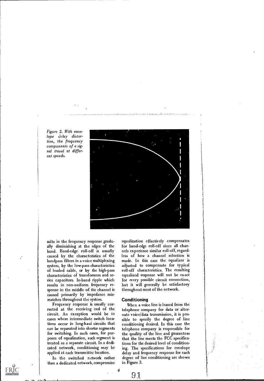
Figure 2. IPith enve-lope delay distor-tion, the frequencycomponents of a sig-nal travel at differ-ent speeds.
sults in the frequency response gradu-ally diminishing at the edges of thehand. Band-edge roll-off is usuallycaused by the characteristics of thebandpass filters in a voice multiplexingsystem, by the low-pass characteristicsof loaded cable, or by the high-passcharacteristics of transformers and se-ries capacitors. In-band ripple whichresults in non-uniform frequency re-sponse in the middle of the channel iscaused primarily by impedance mis-matches throughout the system.
Frequency response is usually cor-rected at the receiving end of thecircuit. An exception would be incases where intermediate switch loca-tions occur in long-haui circuits thatcan be separated into shorter segmentsfor switching. In such cases, for pur-poses of equalization, each segment istreated as a separate circuit. In a dedi-cated network, conditioning may beapplied at each transmittu location.
In the switched network ratherthan a dedicated network, compromise
4
equalization effectively compensatesfor band-edge roll-off since all chan-nels experience similar roll-off, regard-less of how a channel selection is
made. In this case the equalizer is
adjusted to compensate for typicalroll-off characteristics. The resultingequalized response will not be exactfor every possible circuit connection,but it will generally be satisfactorythroughout most of the network.
ConditioningWhen a voice line is leased from the
telephone company for data or alter-nate voice/data transmission, it is pos-sible to specify the degree of lineconditioning desired. In this case thetelephone company is responsible forthe quality of the line and guaranteesthat the line meets the FCC specifica-tions for the desired level of condition-ing. The specifications for envelopedelay and frequency response for eachdegree of line conditioning are shownin Figure 3.
9 1

V!.
When the telephone company fur-nishes thc modem and subsequent lineconditioning to establish a data trans-mission system, the expected long-range error ratc performance undernormal conditions is one crror in100,000 bits (or an crror rate of 105).When the user leases an unconditionedor conditioned line for usc with hisown data system, he is responsible forthe system's overall performance.Therefore, it is thc responsibility ofthe customer to decide what condi-tioning arrangement is needed for hisdata transmission system.
lf an unconditioned linc is leased,the user, as a result of the Carterfonedccision of 1968, may condition theline himself. By purchasing his ownequipment, the user may condition theline for his desired service.
The types of conditioning that areavailable from the telephone companyfor standard 3002 voice lines are Cl,
C2, C4, C3, and C5, listed in increasingquality. The table in Figure 3 showsthe differences in these line condition-ings. The C5 conditioning was recentlyestablished for serial data speeds of9600 bps and above.
Regardless of the level of condition-ing used it is normally desirable toselect channels from the middle of theband. This minimizes the effect ofenvelope delay and attenuation whicharc morc severe at thc edges of thevoice channel.
When determining what type ofservice to lease from the telephonecompany, the user should consider thevarious options available. For example,a user who presently has a CI-condi-tioned line and is transmitting ninechannels of 150-bps data, may find hehas a requirement for 2 additionalchannels at 150 bps or a total of 11channels. Referring to Figure 1, thereare three options available.
ik
Figure 3. Each degree of line conditioning provides tighter specifications onenvelope delay and frequency response.
92

First, the line can be conditionedfor C2 or C4, to provide for additionalfuture channels. Second, a new uncon-ditioned line could be leased in addi-tion to the existing C1 line. Or third,the conditioning on his present linecould be removed and another uncon-ditioned line added. The cost of leas-ing these different options will varyand the user must decide which is themost economical for his present in-creased needs and perhaps his futureneeds.
A line is conditioned to improve itstransmission capability. With a leased,dedicated, private-line facility, it is
possible to determine the envelopedelay and frequency response charac-teristics in the system. Then dependingupon the speed of data to be transmit-ted over the facility and the number ofchannels required, it is possible tocondition the line to compensate forthe distortions introduced by the facil-ity. The higher the speed of transmis-sion, the fewer distortions that can betolerated by the data signal.
Switched NetworkThe switched telephone network
(the standard dial-up voice network)provides a totally different picture asfar as data transmission is concerned.Since slow-speed data such as tele-graph can be transmitted over anunconditioned line, there is no prob-lem with using the switched network.But for higher speeds or greater capaci-ty low-speed systems, a switched net-work can prove to be unsatisfactorysince it is not possible to predict theroute the signal will take and conse-quently the distortions it will be sub-jected to.
Use of the switched telephone net-work for high-speed data communica-tions can be summed up in one word
unpredictable. With a dedicatedsystem it is possible to determine the
6
I I 1
THE BELL SYSTEM TECHNICAL JOURNAL, APRIL 1971
Figure 4. The results of a statisticalstudy are used to predict performanceon the switched network.
9 3

performance on the line and thencompensate for the envelope delay andfrequency response. With the properequalization, it is possible to keepthese characteristics within tolerablelevels for the desired transmissionspeeds.
But on a switched network, it is notpossible to predict the exact route thedata signals will take between centraloffices before it gets to its destination.Consequently, it is not possible topredict the distortions that the signalwill be subjected to. What is possible, isto take a statistical sampling of signalssent over the switched network anddetermine the average performance ofthe network. It is then possible todesign compromise equalizers that willcompensate for average delay and atten-uation distortions.
A compromise equalizer cannot beused to guarantee a certain level ofconditioning. This means that forsome of the routes the compensationwill be greater than necessary and forother routes it will not be greatenough.
With data up to speeds of 600 bpsit is not necessary to compensate forenvelope delay and frequency responseon a switched network. GTE Lenkurt'stype 25 data modems work quitesatisfactorily on the switched network.
As transmission speeds increase, thenumber of lines within the switchednetwork, suitable for acceptable trans-mission, decreases. Therefore, the per-centagc of suitable circuits decreasesand the probability of having anc`error-free" transmission.. also de-
creases.With compromise equalizers it is
possible to have 80-90% of the circuitssuitable for transmission speeds of up
to 2400 bps. The GTE Lenkurt 26Cdata modem can be equipped with acompromise equalizer for use over theswitched network.
The telephone companies also pro-vide compromise equalizers. Suchequalizers are used on the leased linefrom the terminal to central officewhich connects the user to theswitched network.
On a dedicated line envelope delayand frequency response are the mostimportant transmission parametersthat the user has to be concerned with.But, with the switched network thereis another arca of concern impulsenoise (voltage spikes or transients).Each switching office along the datapath introduces more impulse noise onthe line. On a switched network it ispossible to have some routes that areunsatisfactory for data transmissionbecause the impulse noise gets toohigh and too frequent.
Figure 4 shows the predicted errorrate for different data speeds throughthe switched network. These curves,which are the result of a Bell Labsstudy, take into consideration enve-lope delay, frequency response, im-pulse noise, and other impairmentsthat might show up on a randomsampling of the switched network.
Specific or CompromiseWhether the user wishes to use a
dedicated, private telephone line, or aline into the switched telephone net-work, it is possible to equalize thc lineso that a high degree of reliability canbe achieved in his data transmissionsystem. This line equalization can bedone with either specific CI, C2, C4,C3, or C5 line conditioning or com-promise equalizers.
9 4


For the user of communications equipmentwho is contemplating connecting new equip-ment to cable that has already had consider-able service, it is wise to be sure that existinglines are in acceptable condition.
Nw equipment has on manyoccasions been connected to
older cable resulting in an unsatis-factory system. In a situation such asthis, if only part of the total numberof channds function properly whatis at faidt, the cable or the equipment?Because it is difficult to reliably esti-mate the overall condition of oldercable without testing, this questioncan only be answered after a completesnries of tests and measurements havebeen performed on the cable.
Because of its period of usage,deterioration of older cable may resultin such faults as shorted cable pairs ormoisture within the sheath. To detectfaults such as these, measurement ofeach calk pair is still the ideal methodof operation. Although the measure-ments discussed here tend to favortesting for PCM, they are suited for alltypes of carrier operation.
The use of cable pairs for PCM orany other type of carrier service re-quires that they be free of loadingcoils, building-out networks, crosses,splits, high resistance splices, grounds,moisture, bridged taps, and cabie ter-minals bridged across pairs (when sub-scriber cable is used). Should a bridgedtap, loading coil, or building-out net-work scheduled for removal be over-looked when reading. a cable locationmap, subsequent visual observationsmay completely fail to detect it. Forthis reason, pulse reflection tests usinga radar test set are recommended when
2
COPY( Qht C 1971 GTE Lenkurt Incoroorated Vol. 20 . No 12
the presence of any of these externaladditions is suspected. Additional testswhich help to evaluate the overallcondition of a cable include:
(1) DC loop resistance and conductorresistance balance test using aWheatstone bridge.
(2) Insulation resistance measurementusing a megger test set.
(3) Frequency response test to 1 MHzusing an oscillator and frequencyselective voltmeter.
Radar Cable Test SetThe radar cable test set is an invalu-
able tool in detection of cable dis-crepancies and attached networks. Thetest set, as its name implies, operateson the simple principle of pulse reflec-tion. The nature of the return pulsereveals the type of discontinuity pre-sent in a cable. For example, a positive(upward) deflection on the test setoscilloscope trace indicates an opencircuit or high impedance mismatchwhile a negative deflection indicates ashort circuit or low impedance mis-match. A shorted pair returns a strongnegative pip at the point of shortcircuit since almost all energy is re-turned from the fault. A good cablepair will show either no reflection oran open (positive pulse) providing theend of the cable is within the range ofthe radar test set. In addition to
9
A

-
revealing the nature of the discrepancyin a cable, the radar test set can also
show the actual distance to the point
of fault.Although the operation of a radar
test set is relatively simple, some ex-perience is necessary on the part of theoperator in the interpretation of thereturn signals. For example, a negativereturn pulse displayed on the oscillo-
scope of the radar test set for twoseparate cable pairs does not necessari-ly mean that the cable pairs havesimilar discrepancies. The method ofdetection in this case would be tonotice the amplitude of the returnpulse since different amplitudes indi-cate different cable faults.
Open ConductorsAn open in either conductor will
result in a positive pulse on the oscillo-
937
Figure .1A. A pairwith one conductoropen will show apositive return pulse.
scope screen although of lesser ampli-tude than if both conductors wereopen. Figures 1A and 1B show theoscilloscope display as it would appearwith one and two conductors open.Also shown are the correspondingcable pair and sheath with the appro-
priate conductor designations. Thereflection from the end of a cable maysometimes be observed in spite of anopen in one of the conductors, butthis depends upon the closeness of thefault to the end of the cable and uponthe size of conductor used. Telephonecommunications lines generally use
cable which ranges from 16 to 26gauge; the attenuation of the cableincreases in direct proportion to thegauge number. The return pulses in26-gauge cable are the weakest sincethis gauge has the greatest attenuationdue to its higher resistance. Testing

Figure 1B. Whenboth conductors areo pen the returnpulse will be ofgr ea ter amplitudethan that for oneconductor open.
a 26-gauge conductor, the maximumfault location distance is about 4000feet. For greater distances (8000 to10,000 feet) a special pulse amplifiermust be used to sec the return signal.
Historically, the tip (T) and ring(R) designations were so called be-cause they corresponded to the con-tacting part at the tip and ring of thephone plug used to make circuit con-nections in a manual switchboard.Today, the designations tip (T) andring (R) arc used to identify the twoconductors of a cable pair. The sleeveof the plug is used for certain controlfunctions, not directly associated withthe cable pair.
Loading Coils and Building-outNetworks
The function of a loading coil is toincrease line inductance and thereby
improve transmission characteristics.As shown in Figure 2, the tip and ringconductors connect to separate wind-ings on the donut-shaped core. Thetwo coils arc wound in a direction thatproduces an aiding magnetic field. Acable which runs between two pointsis engineered according to a predeter-mined loading plan. For example, anH88 loading plan requires 88-milli-henry coils to be placed at 6,000-footintervals along the cable.
If for some reason, be it geographi-cal obstruction or inconvenient loca-tion, a loading coil cannot be placed inthe designated area, a building-outnetwork is used to artificially make upthe required distance (6000 feet in thecase of H88 loading). The building-outnetwork consists of resistors and ca-pacitors connected in such a way thatelectrically, the distance between load-

ing coils conforms to the requiredloading plan. That is, the building-outnetwork contains the resistance andcapacity inherent in the length ofcable necessary to conform to theloading plan. Loading coils and build-ing-out networks must be removedfrom the cable before it can be cor-rectly evaluated for use.
Open Sheath DetectionA high-frequency pulse such as is
emitted from the radar test set willusually be prevented from passingthrough a loading coil by the chokingeffect of inductance on high frequen-cies. However, using a certain hookupprocedure, the radar test set may bemade to measure beyond loading coilpoints.
Individually, the tip and ring wind-ings of the loading coil will have anullifying effect on a high frequencypulse, but when the pair conductorsarc connected together, this effect iscou nteracted to some ex ten t.
To detect an open sheath, one ormore cable pairs which have beentested and found to be serviceablemust be connected in parallel to oneterminal of the radar test set; the other
terminal is connected to the cablesheath. In this way the effect of theloading coils is cancelled and the testpulses can pass beyond the attenuatinginductance. Figure 3 shows the radartest set hookup and correspondingoscilloscope display for open sheathdetection.
Grounded Sheath On BuriedCable
When cable is buried by means of acable plow, the surrounding earth willremain loose, thus creating a voidaround the cable. With the passage oftime a gradual repacking takes placeand the void is eliminated. Should agrounded sheath exist during a voidenvironment, detection of the fault ispossible provided the void is filledwith water such as occurs in an arcawith a high water table or after arainfall which has heavily wetted theground.
Plowed cable normally disturbs thesurrounding earth to such an extentthat the sheath-to-ground capacitanceis non-uniform. This causes sufficientvariation in capacitance to make prop-agation of the radar pulses difficult.However, when the void is filled with
19
Figure 2. Loadingc oil w ith corres-ponding tip and ringconnec tions.

Figure 3. Displayand hookup foropen sheath detec-tion.
RADARTESTSET
water, or earth conductivity is low (40to 50 ohms), the capacitance tends tobecome more constant, and a pulsemay be returned with sufficientstrength to be visible. Figurc 4 showsthe grounded sheath oscilloscope dis-play with the corresponding tcst setconncctions.
Cable SplicesDue to thc changc in relationship
between cable pairs and the sheath, asplice represents a decrease in capici-lance, and will appear as a smallrounded positive pip (radar returnpulse) followed by a small negative pipon the oscilloscope trace. At times, thenegative pip may not appear. A knownsplice may be used as a reference pointfor calibration when performing mea-surements in a cable of unknowndidectric constant.
0 1 2 3 4 5 6 7 8 9 10
CrossesMetallic crosscs (short circuits) be-
tween pairs present somewhat thesame indication as a short to thesheath. Since a metallic cross is usuallya solid connection it may seem thatthe easiest way to find the other pairor conductor involved is by perform-ing a standard battery and earphonetest. However, since the radar test setindicates the distance to the trouble,once thc sheath is opened the troublecan be found visually.
Crosses due to moisture in the cableappear as an extremely noisy tracewith a vertical displacement of theentire trace throughout the wet sec-tion, as shown in Figure 5. Anyreference points, such as splices withinthe wet area will appear farther apartthan normal. Ranges in the wet areawill appear approximately 60% greater
6 10 0

0 1 2 3 4 5 6 7 8 9 10
RADARTESTSET
0 1 2 3
RADARTESTSET
INSULATIONPINHOLES
L _
4 5
I I
SPLICE
6 7 8 9 10
071
Figure 4. Groundedsheath on buried ca-ble.
Figure 5. Crossesdue to moisture ap-pear as an extremelynoisy trace with avertical shift.

Figure6. A split pairon a cable causes adecrease in capaci-tance and a positivepulse on the scope.
than the reference distance if the fixedPolyethdyne Dielectric setting on theradar test set is being used. This settingtakes into consideration only dry PICcable, the PVC (propagation velocityconstant) of which is 0.667. Thisvelocity constant means that high-frequency signals in the cable willtravel only 66.7% as fast as they wouldtravel in free space. The retardationeffect caused by the higher dielectricconstant of water decreases the propa-gation velocity of the pulse, yielding aslower traverse of the pulse throughthe wet section. To accurately measurethe distance within the wet area, theCable Dielectric Switch on the radartest set may be manually adjusteduntil a known reference point such asa splice is correctly positioned. Thecorrect distance may now be read inspite of a change in PVC. The propaga-
tion velocity constant of wet cable isapproximately 0.400.
Split PairsA spht occurs at a splice when the
tip or ring of one cable pair is acciden-tally spliced tc the tip or ring of adifferent cable pair. Without the radartest set, the location of a split is oftenvery difficult to find, especially onburied eabk. The oscilloscope presen-tation for a split will show a capaci-tance discontinuity similar in form tothat of a splice at the point where theconductors arc separated. That is, a
decrease in capacitance will be indi-cated by a positive pip as shown inFigure 6. If a re-split (restoration tonormal condition) occurs in a subse-quent splice, the pip will appear withthe opposite polarity of that shownfor the split.
8 102

Bridged TapsFor any type of FDM or PCM
carrier operation, bridged taps must beremoved since they represent a capaci-tance mismatch at high frequencies.These taps appear as negative pips,having a negative amplitude with afollowing positive overshoot or tail asshown i» Figure 7. The amplitude ofthe overshoot is directly proportionalto the length of the tap. Generallythree or four taps with an averagelength of 100 feet will absorb all theoutput energy of the test set. In orderto verify that all bridged taps areremoved, it is necessary to repeat thetest from the location of the lastremoved tap. A bridged cable and themain cable will present an overlappedtrace. If a fault (short, cross orground) also exists on the same cablepair, measurement from two locations
Figure 7. Bridgedtaps appear as nega-tive pips with a posi-tive overshoot.
is necessary to determine positivelythe location of the fault.
Loading Coil and Building-OutNetwork Detection
Loading coils and building-out net-works that have been overlooked inthe process of deloading a cable forcarrier use, are perhaps the most diffi-cult things to locate without the aid ofan instrument such as a radar test set.A building-out network will appear onthe oscilloscope display as a shortcircuit (the capacitors in the networkshort-circuit the radar pulse) and aloading coil appears as an open circuitsince the pulse will not pass throughthe coil (see Figures 8 and 9).
Change in Wire GaugeAn increase in wire size such as at a
splice decreases the resistance of the
9103

Figure 8. Building-out networks appearas short circuits.
REPAIRTESTSET
line and will give a negative pip similarto that of a bridged tap, but of lesseramplitude. The propagation velocityconstant varies by approximately 1%
per gauge number. (A change from 22to 24 gauge will change the PVC byabout 2%.)
Change in Dielectric MaterialA change from PIC to PULP (paper
insulation) cable will also cause areflection indication. In this ease, thepropagation velocity constant will in-crease, producing a decrease in surgeimpedance, thereby yielding a negativepulse on the oscilloscope screen. Theresultant pip amplitudes arc generallysmall, less than those caused bybridged taps. If the dielectric constantof the insulation is known, the changein propagation velocity cunstant canbe calculated by thc formuhr
0 1 2 3 4 5 6 7 8 9 10
APVC1
where c is the dielectric constant.
DC Loop Resistance andConductor Resistance Balance
This test is advisable to verify thecorrectness of loop resistance and con-ductor resistance balance, which isnecessary for proper carrier operation.Because the allowable resistance varia-tion between conductors in thc con-ductor resistance test is a maximum of-±0.5%, it is necessary to use a Wheat-stone bridge since its accuracy isdependable within this tolerance. Mea-sured loop resistance should checkwithin 10% of the calculated valuesgiven in Figurc 10. Due to the rela-tively wide tolerance in the loop tcst,and the fact that the balance test is acomparison measurement, it is permis-

0 2 3 4 5
RADARTESTSET
sible to neglect the effect of tempera-ture on the wire rcsistancc.
With a Wheatstone bridge con-nected to the pair to be measured anda short-circuit placed across the distantend of the pair, the hookup will
Figure 10. Total "out and back" con-duc tor loop resistance.
10
Figure 9. A loadingcoil appears as anopen circuit.
appear as in Figure 11A. The loopresistance should be within the re-quired 10% tolerance of the calculatedvalues given in Figure 10, noting thatthis is the total resistance "out andback." Removal of the short circuit atthe distant end should indicate anopen circuit. This step is necessary toverify that the pair being measuredactually had a short circuit placed onit, and was not showing a loop due tosonic other connection.
Example:
Assuming that 6200 feet (6,2 kft) of22 gauge cable is used in one regener-ator (repeater) sec tion,
Loop resistance= 6.2 kft x 32.28 ohins/kft= 200.14 ohms.
405

Figure 11A. Loopresistance measure-ment.
Figure 11B. Conduc-tor resistance bal-ance measurements.
To measure the conductor resis-tance balance, the Wheatstone bridgeshould be connected as shown inFigure 11B, using a second pair in thesame cable as a third conductor. lndi .vidual measurement of the tip and ringconductors of the pair under test is
necessary and is performed as shownby the arrow connections. First the tipthen the ring of the pair under test ismeasured using thc second cable pairas a return path.
Example:
For 6.2 kft of 22 gauge cable,
Loop resistance
= 6.2 kft x 32.28 oluns/kft= 200.14 ohms
Average tip or ring resistance
200.14100.07 ohms
Average tip or ring resistance plusthird-conductor resistance (1/4 of loopresistance)
= 100.07 ohms 4 50.03 ohms= 150.10 ohms
05% Tolerance in ohms= 150.10 ohms x .005= .75 ohms
Therefore, total resistance of tip orring plus the resistance of the secondeable pair should be between 149.35ohms (150.10 - .75) and 150.85 ohm:(150.10 + .75).
12

MEGGERTESTSET
MEGGERTESTSET
Insulation ResistanceMeasurement
A megger test set is used to measurethe insulation resistance between eachconductor and ground and betweeneach conductor of the pair. The dis.tant end of the pair should be openand ungrounded for this test.
The operator should exercise ex-treme caution in avoiding contact withany of the terntinals or wires duringthis test since the circuit is at apotential of sereral hundred coltsabove ground.
Once the meggrr is put into opera.tion the resistance is then indicated onthe megger test set meter. This resis.lance reading is then divided by thelength in miles of the cable under test.Tlw insulation resistance should be the
Figure 1221. Meggertest on one cablepair.
! Figure I2B. Meggertest of cable pair toground.
same between the two conductors of apair (Figure I 2A) and between thepair to ground (Figure 12I1). Paperinsulated cable should indicate a mini-mum insulation resistance of 500 meg-ohms per mile. Polyethylene insulatedcable should indicate a minimum insu-lation resistance of IWO megohms per
Frequency ResponseFor POI use, the cable pair fre-
quency response must he ellerked toat least I MHz. Although the maxi-mum energy of the PCM band occursaround 772 kHz, a considerable por-tion of energy exists up to I MHz. Thefrequencies above I MHz decrease inimportance, so that measurementsAmy this lir nit are not necessary.
/:11 n

Figure 13A. Equipment arrangement for calibration.
Figure 1311. Equipment arrangement for cable frequencpattenuation test.
Likewise, the frequencies below about400 kHz decrease in importance fortransmission of PCM circuits, so theycan therefore be neglected during measureme nts.
To verify the frequency responseand insertion loss of the test trans-formers, test equipment should beconnected as shown in Figure 13A.The test transformers are necemary ifthe output impedance of the oscillatorand/or the input impedance of the
voltmeter is 600 ohms. At the frequen-cies of interest, the cable impedance is
approximately 130 ohms. The oscil-lator frequency should be set to 1
MHz and the meter tuned to thisfrequency. The oscillator output levelshould be adjusted to indicate 0 dBmon the meter.
Tuning the oscillator between 400kHz and 1 MHz, and tracking thefrequency with the ohmeter tuner,any variation about the 0 (Him level, at
141 OR

every 50-kHz interval should be notedand recorded.
At the end of the test the oscillatoroutput power must still be 0 dBm onthe meter. The oscillator output levelduring the frequency run on the cablemust not be changed.
To cheek cable attenuation the testequipment should be connected asshown in Figure 13B. The oscillatorshould be tuned from 400 kHz to 1MHz, and thc received level readingshould be recorded at every 50 kHzinterval. In addition, the receivet: levelat 772 kHz should be recorded. Thisfrequency is used in transmission cal-culations for the PCM carrier, and canbe used to verify the cable attenuationfigures used for calculation.
The amount of projessive attenu-ation of the cable should be plotted atthe end of the test and any abruptchange in received level should benoted since this would indicate a
change in the transmission characteris-tics of the cable. Paper-insulated cablewill usually exhibit a somewhat higherattenuation than PIC, perhaps 0.5 to1.0 dB greater per thousand feet at772 kHz.
Economic BenefitsReturning to the original questionwhat is at fault on a system with
new equipment and older cable, whenonly part of the total number ofchannels function properly? Withpulse reflection, resistance, and fre-quency response tests complete, andwith any unserviceable pairs removed,this question may now be answered.
Once equipment checkout is com-plete and verification of adequatecrosstalk coupling loss in the system ismade, the communications equipmentuser may then reap the economicbenefits of using previously installedcable for his new equipment.
,, 109
Related Documents