In This Section… Overview....................................................................................H-2 One-Piece Connector Overview .............................................................................H-3 Shield-Kon RSK ....................................................................H-4 Installation Methods & Procedures .......................................H-5 Tools.....................................................................................H-6 Dies ......................................................................................H-7 Connector & Die Selector ....................................................H-7 Two-Piece Connector Overview .............................................................................H-8 Installation Methods in the Hexagonal Range........................H-9 Connector & Die Selection in the Hexagonal Range ............H-10 Grounding Connectors & Dies for the Hexagonal Range ............................................................H-11 Insulated Grounding Connectors & Dies for the Hexagonal Range ............................................................H-12 Tool for Hexagonal Range ...................................................H-12 Overview & Installation Methods for the Circular Range......H-13 Connectors & Tools for the Circular Range ..........................H-14 Grounding Connectors Grounding Connectors United States Tel: 901.252.8000 800.816.7809 Fax: 901.252.1354 Technical Services Tel: 888.862.3289 www.tnb.com

Welcome message from author
This document is posted to help you gain knowledge. Please leave a comment to let me know what you think about it! Share it to your friends and learn new things together.
Transcript

onlinec
omponen
ts.co
m
In This Section…
Overview....................................................................................H-2
One-Piece Connector
Overview .............................................................................H-3
Shield-Kon RSK ....................................................................H-4
Installation Methods & Procedures .......................................H-5
Tools.....................................................................................H-6
Dies......................................................................................H-7
Connector & Die Selector ....................................................H-7
Two-Piece Connector
Overview .............................................................................H-8
Installation Methods in the Hexagonal Range........................H-9
Connector & Die Selection in the Hexagonal Range ............H-10
Grounding Connectors & Dies for the Hexagonal Range ............................................................H-11
Insulated Grounding Connectors & Dies for the Hexagonal Range ............................................................H-12
Tool for Hexagonal Range ...................................................H-12
Overview & Installation Methods for the Circular Range......H-13
Connectors & Tools for the Circular Range..........................H-14
Grounding Connectors
Grounding Connectors
United StatesTel: 901.252.8000
800.816.7809Fax: 901.252.1354
Technical ServicesTel: 888.862.3289
www.tnb.com
onlinec
omponen
ts.co
m
Overview
Grou
ndin
g Co
nnec
tors
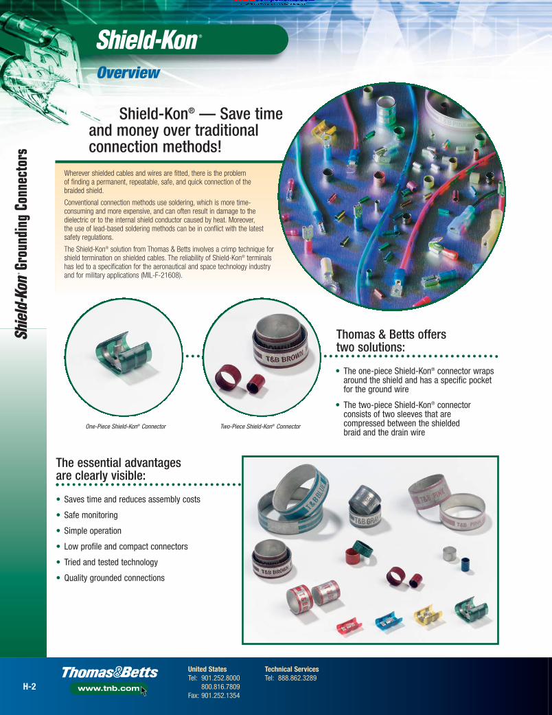
Wherever shielded cables and wires are fitted, there is the problem of finding a permanent, repeatable, safe, and quick connection of the braided shield.
Conventional connection methods use soldering, which is more time-consuming and more expensive, and can often result in damage to thedielectric or to the internal shield conductor caused by heat. Moreover, the use of lead-based soldering methods can be in conflict with the latestsafety regulations.
The Shield-Kon® solution from Thomas & Betts involves a crimp technique forshield termination on shielded cables. The reliability of Shield-Kon® terminalshas led to a specification for the aeronautical and space technology industry and for military applications (MIL-F-21608).
• The one-piece Shield-Kon® connector wrapsaround the shield and has a specific pocketfor the ground wire
• The two-piece Shield-Kon® connectorconsists of two sleeves that are compressed between the shielded braid and the drain wire
Shield-Kon® — Save timeand money over traditionalconnection methods!
Thomas & Betts offers two solutions:
• Saves time and reduces assembly costs
• Safe monitoring
• Simple operation
• Low profile and compact connectors
• Tried and tested technology
• Quality grounded connections
The essential advantages are clearly visible:
One-Piece Shield-Kon® Connector Two-Piece Shield-Kon® Connector
H-2
United StatesTel: 901.252.8000
800.816.7809Fax: 901.252.1354
Technical ServicesTel: 888.862.3289
www.tnb.com

onlinec
omponen
ts.co
m and Accessories
This solderless, wraparound connector terminates shielded cable in seconds...with uniform precision. It’s particularly well suited for production work in aircraft, aerospace, and electronic industries where size and weight are important.
Once crimped, it provides a compact, lightweight, low-resistance, high-strength connection, which meets and exceeds the performancerequirements of MIL-F-21608.
The connector works equally well on braided, wrapped, or foil shields and has the added advantage of being able to be used as a mid-span termination.
Only four sizes, which can be easily identified by the color of their insulation,are needed to cover a range of shielding diameters from .05" to .3".
• Compact, low-profile connector
• One piece wraparound design
• Tough polyester insulation (Mylar® type)
• Inventory savings: only 4 sizes
• Transparent insulation, easily inspected
• MIL specified, industry-approved technology
• No heat or power required to install
• No damage to inner conductor
• Less installation time required
• Uniform, precise connection every time
• Low installed cost
• Mid-span termination possible, eliminating the need to demount a cable already installed
The one-piece Shield-Kon® connectors meet the MIL-F-21608 standards for the following environmental specifications:
• Voltage Drop: 9 mV max. at 1A after environmental exposure
• Insulation Dielectric Strength: 500 VRMS at 60Hz for 1 minute
• Corrosion Resistance: 48 hours in 5% salt fog
• Pullout Strength: 15 lbs. min. for 22 AWG, and 19 lbs. min. for 20 AWG
• Vibration: 0.03" double amplitude between 10 and 55Hz for 6 hours on each of two axis
• Material: Copper, conform to CDA No. 110
• Plating: Tin, electro-plated (thickness 3 to 8 μm), in accordance with MIL-T-10727A
• Insulation: Polyester film (Mylar® type), color coded for size identification
• Temperature: -85° F to +257° F (-65° C to +125° C)
Terminate shielded cable inseconds without heat or power!
. . . . . . . . . . . . . . . . . . . Specifications . . . . . . . . . . . . . . . . .
One-Piece Connector Overview
.59" – .64"
.11" .11"
Ground wire trap
Insulation
In addition, hypot tests have shown that the cable manufacturers’specified working voltage rating is maintained after the installation of Shield-Kon RSK connectors. It is, however, still advisable to evaluatethe suitability of these connectors and verify their performance for theparticular application.
H-3
United StatesTel: 901.252.8000
800.816.7809Fax: 901.252.1354
Technical ServicesTel: 888.862.3289
www.tnb.com

onlinec
omponen
ts.co
m
Grou
ndin
g Co
nnec
tors
One-Piece Connector
CONNECTOR GROUND& COLOR METAL DIES WIRE DIE GAUGE APPLICATION TOOLCAT. NO. SHIELD DIAMETER FOR ERG740 RANGE CAT. NO. CAT. NO.
(1.27–1.78 mm)D-101A
1 or 2101AG
RSK101 .050–.070 in. #24 AWG STR(1.80–2.26 mm)
D-101Bor 1
101BG.071–.089 in. #22 AWG STR
(2.29–2.54 mm)D-201C 201CG
.090–.100 in.(2.56–3.00 mm)
D-201D1 or 2
201DGRSK201 .101–.118 in. #22 AWG STR
(3.022–3.33 mm)D-201E
or 1201EG
.119–.131 in. #20 AWG STR(3.35-3.63 mm)
D-201F 201FG.132–.143 in. Hand Tool
(3.66–4.11 mm)D-301G 301GG
ERG740.144–.162 in. 1 or 2
RSK301 (4.14–4.70 mm)D-301H
#22 AWG STR301HG
.163–.185 in. or 1 or 2(4.72–5.10 mm)
D-301J#20 AWG STR
301JG.186–.201 in.
(5.13–5.84 mm) D-401K 401KG.202–.230 in.
(5.87–6.35 mm)D-401L
1 or 2401LG
RSK401 .231–.250 in. #20 AWG STR(6.37–6.98 mm)
D-401Mor 1
401MG.251–.275 in. #18 AWG STR
(7.01–7.62 mm)D-401N 401NG
.276–.300 in.
Shield-Kon® RSK Connectors
Maintains voltage and is easy to install!
DIMENSIONS (IN.) STD.CAT. NO. COLOR A B C D E THICKNESS PKG.
RSK-101 .31 .16 .18 .06 .15 .02 1,000RSK-201 .38 .22 .18 .06 .18 .02 1,000RSK-301 .47 .28 .24 .07 .22 .03 1,000RSK-401 .69 .43 .37 .08 .37 .03 500
Order multiple is std. pkg.
Red
YellowBlue
Green
How to use connector die and tool selection chart:1. Use a calibrated measuring tool lightly over shield for most
accurate measurement. Rotate shielded wire to pick up highspots on cable. Use “Shield Diameter” column to match themeasured dimension.
2. Select connector and die for ERG740 tool.
NOTE: 1. Do not solder-dip ends of ground leads.2. For ground wire combinations not covered
in table, consult Technical Service.
Red
Yellow
Blue
GRLEA
A
E
B
C
D
GroundLead Trap
One-Piece Shield-Kon® Connectors & Die Selection Table
Green
H-4
United StatesTel: 901.252.8000
800.816.7809Fax: 901.252.1354
Technical ServicesTel: 888.862.3289
www.tnb.com

onlinec
omponen
ts.co
m and Accessories
Connector opening faces away from tool
One-Piece Connector Installation Methods & Procedures
Installation that’s as easy as 1-2-3!
Mid-Span Method
Enables installationanywhere along the cable.
Insulation
Shield Cable
Insulation
Shield Cable
7⁄16" (11 mm)
7⁄16" (11 mm)
Standard Method
Use the standard methodwhen the shielded cableor the inner conductors areembedded in a dielectric.
Fold-Back Method 1
If there is no commondielectric for several interiorcables but the gaps arefilled by textile threadsor something similar, careshould be taken to ensurethat the insulating thick nessof the individual cables is notless than 0.38 mm for PVC,and not less than 0.25 mmfor Teflon. If this insulationthickness falls below thisvalue, Fold-Back Method 1should be used.
Fold-Back Method 2
Fold-Back Method 2 shouldbe used if the cable shieldis applied spirally or ifa foil shield is being used.
Installation Methods Installation Procedure
Step 3
Select the appropriate die set for thecrimp tool, according to the size of the shielded cable (see page H-4) and mount the dies on the tool. Insert the connector (with the shieldedcable and the ground wire) between the dies of the tool.
Squeeze the tool handles firmly to crimpthe connector around the shielding and the ground wire.
Shield Conductors
Jacket
Insulation
1⁄4" (6 mm)
Butt insulating jacketsagainst metal edge
Insulation
Shield Cable
Insulation
Shield
Cable
Step 1
Prepare shielded wire and ground wire insulation as shown.
If two ground wires are required in a Shield-Kon® connection, twist both conductors before insertion into the connector.
Step 2
Select the appropriate connector according to the size of the shielded cable (see page H-4). Place the ground wire around the trap hook and the shielded wire into the bottom of the connector.
When inserting the shielded cable and grounding wire, care must be takento ensure that their insulation is overlapped by the connector’s Polyesterinsulation film.
100% insulation is possible after crimping when the stripped length of outer jacket (visible shielding) is 7⁄16" (11mm) maximum.
For a complete listing of One PieceConnectors see page H-4.
For a complete listing of One PieceConnector Dies see page H-4.
H-5
United StatesTel: 901.252.8000
800.816.7809Fax: 901.252.1354
Technical ServicesTel: 888.862.3289
www.tnb.com

onlinec
omponen
ts.co
m
One-Piece Connector Tools
Ergonomic Hand Tool• Robust construction: metallic frame, partially
covered with plastic
• Use with metal dies (see page H-7) for low-,medium- or high-volume applications
• All the dies are easily interchangeable (to be ordered separately)
• Parallel action crimp
• ShureStake® mechanism: once pressing has commenced, the tool canbe re-opened only after successful completion of the crimping cycle
• Supplied in a plastic case with:
– 1 tool– 1 benchmount stand for easier use in volume production– 1 gauge (Cat. No. RSK-LEHRE) for instant selection
of the die and the connector to be used
Comfort and versatility!
Everything you needin a handy kit!Ergonomic Hand Tool Kit
• Dimensions of Plastic Case: 9.65"L x 8.27"W x 2.17"H
• Weight of Plastic Case & Contents: 2.65 lbs.
. . . . . . . . . Specifications . . . . . . . . .
• Dimensions of Tool: 8.27"L x 6.10"W x 0.98"H
• Weight of Tool: 1.04 lbs.
• Dimensions of Plastic Case: 9.65"L x 8.27"W x 2.17"H
• Weight of Plastic Case & Contents: 2.05 lbs.
. . . . . . . . . Specifications . . . . . . . . .
CAT. NO. DESCRIPTION STD. PKG.
ERG740-01 Ergonomic Hand Tool Kit 1
CAT. NO. DESCRIPTION STD. PKG.
ERG740 Ergonomic Hand Tool 1
Same as ERG740, but suppliedin a plastic case with 1 tool,1 benchmount stand for easier usein mass production, 1 RSK-LEHREgauge for instant selection of the die,and 4 metal dies: D-101A, D-201C,D-301J, D-401M.
Grou
ndin
g Co
nnec
tors
H-6
United StatesTel: 901.252.8000
800.816.7809Fax: 901.252.1354
Technical ServicesTel: 888.862.3289
www.tnb.com

onlinec
omponen
ts.co
m
Dies & Connector/Die Selector
Select the connectorsyou need quickly!RSK-LEHRE Gauge
The choice of the appropriate connector and die set mainly depends on thesize of the shielded cable. The selection can be done very quickly with theRSK-LEHRE gauge.
Remove the outer jacket from the shielded cable, makingthe shielding visible.
Insert this stripped end of the cable into the slots locatedaround the gauge. The correct slot will be found when thecable can slide only in the upper part of the slot. If thecable can slide completely to the bottom of the slot, youshould try with the smaller adjacent slot.
Once the appropriate slot is found, the corresponding RSKconnector is defined by the color of the strip around theslot, whereas the corresponding plastic die set is given bythe number marked below the slot (for the metal die set,add prefix “D” to this number).
The table on page H-4 summarizes the differentcombinations of connector/die set, as well as the sizeof ground wire that can be used.
CAT. NO. DESCRIPTION STD. PKG.
RSK-LEHRE Connector & Die Gauge 1
1
2
3
4
and Accessories
H-7
United StatesTel: 901.252.8000
800.816.7809Fax: 901.252.1354
Technical ServicesTel: 888.862.3289
www.tnb.com
Order multiple is std. pkg.
DIE SHIELD FOR STD.CAT. NO. DIE COLOR DIAMETER (IN.) CONNECTOR PKG.
D-101A .050–.070 RSK 101 Red 1D-101B .071–.089 RSK 101 Red 1D-201C .090–.100 RSK 202 Blue 1D-201D .101–.118 RSK 202 Blue 1D-201E .119–.131 RSK 202 Blue 1D-201F .132–.143 RSK 202 Blue 1D-301G .144–.162 RSK 301 Yellow 1D-301H .163–.185 RSK 301 Yellow 1D-301J .186–.201 RSK 301 Yellow 1D-401K .202–.230 RSK 401 Green 1D-401L .231–.250 RSK 401 Green 1D-401M .251–.275 RSK 401 Green 1D-401N .276–.300 RSK 401 Green 1
YellowYellowYellow
RedRedBlueBlueBlueBlue
GreenGreenGreenGreen
Metal Dies for ERG740• For mass production and medium to high volumes
• Made of hardened steel — does not wear
• Only for the ERG740 hand tool
• The Product Ref. is engraved on the upper part and on the lower part of the die set
• Marked with a dot having the same coloras the corresponding connector
• Weight — approximately 2.6 oz.

onlinec
omponen
ts.co
m
Two-Piece Connector Overview
Grou
ndin
g Co
nnec
tors
The Shield-Kon® two-piece shield termination system fromThomas & Betts consists of two sleeves: an inner sleeve with asmaller diameter, and an outer sleeve that has a larger diameterbut is shorter and less hard than the inner sleeve. All inner andouter sleeves are color-coded according to their size.
The conductors of the cable are inserted through the innersleeve, whereas the shield (braided or foiled) and the groundwire are inserted between the two sleeves. The crimp operationis done by compressing the outer sleeve with a tool, while the inner sleeve provides mechanical protection for the inner conductors.
This unique shield termination system can be used with cables havinga diameter of dielectric (after removing the outer insulation and the shield) between .043" and 2.87".
In the “Hexagonal Range” (diameters of dielectric between .043" and .38"), the outer sleeve is crimped with a hand tool and the result is a hexagonal-shaped crimp. This range is used to crimp shielded and coaxial cables.
The “Circular Range” for Multiple or Overall shielded cables, refers to larger diameters of dielectric (between .39" and 2.87") and owes its name to the circular shape of the crimp.
Unique shield termination systemgets the job done right!
The Thomas & Betts hexagonal compression (for diameters of dielectric up to .37") is a reliable method for grounding,terminating, and insulating shielded and coaxial cable.
It has literally millions of installations in communications, aerospace, electronic, telephone, radio, and TV applications.
Two-piece connector — the Hexagonal Range
Circular Range
Hexagonal Range
H-8
United StatesTel: 901.252.8000
800.816.7809Fax: 901.252.1354
Technical ServicesTel: 888.862.3289
www.tnb.com

onlinec
omponen
ts.co
m and Accessories
Two-Piece Connector Installation Methods in the Hexagonal Range
H-9
United StatesTel: 901.252.8000
800.816.7809Fax: 901.252.1354
Technical ServicesTel: 888.862.3289
www.tnb.com
Three installation methods are possible in the hexagonal range for a quick, neat, and accurately completed termination...at a greatly reduced production cost.
Quick and neat terminations made easy!
GSC outer sleeve Shielding
Outer insulator .50" (12.7 mm)
GSB inner sleeve Shielding
Outer insulator .50" (12.7 mm) 1.0" (25.4 mm)
GSB inner sleeve Shielding
Outer insulator
GSB inner sleeve
GSC outer sleeve GSC outer sleeve
Method 1: Standard Method 2: Fold Back Method 3: Large Insulation
After stripping the shield (.50" in length),slip the outer sleeve over the outerinsulation. If this is too big, slip the outer sleeve on, after method describedin method 3.
1 After stripping the shield (.50" in length), slip the inner sleeve over the outer insulation.
1 After stripping the shield (1.0" in length), slip the inner sleeve over the braided shield.
Slip the ground wire (22AWG–20AWG)under the outer sleeve (from the front or behind) and slip the outer sleeve over the braided shield.
Slip the drain wire (22AWG–20AWG)under the outer sleeve (from the front or behind) and slip the outer sleeve over the braided shield.
Slip the ground wire (22AWG–20AWG)under the outer sleeve (from the front or behind) and slip the outer sleeve over the braided shield.
Position the outer sleeve and ensure that the ends of all wires in the braidedshield and ground wire are covered.
Crimp both sleeves with the correct tool and die. Finished.
Position the outer sleeve and ensure that the ends of all wires in the braidedshield and ground wire are covered.
Crimp both sleeves with the correct tool and die. Finished.
Position the outer sleeve and ensure that the ends of all wires in the braidedshield and ground wire are covered.
Crimp both sleeves with the correct tool and die. Finished.
Position the inner sleeve so that about.06" protrudes beyond the end of thebraided shield.
Fold back the braided shield over theinner sleeve and slip the outer sleeveover the braided shield.
Fold back the braided shield over theinner sleeve and slip the outer sleeveover the braided shield.
Widen the braided shield by gentlyrotating the inner conductor, then slip the inner sleeve under the braided shield.
Widen the braided shield by gentlyrotating the inner conductor.
Widen the braided shield by gentlyrotating the inner conductor.
1
2 2 2
3 3 3
4 4 4
5 5 5

onlinec
omponen
ts.co
m
Two-Piece Connector and Die Selection in the Hexagonal Range
Grou
ndin
g Co
nnec
tors
The choice of the appropriate combination of inner sleeve,outer sleeve, and crimp tool/die will depend on the diameterof the dielectric.
However, a direct correlation with the diameter of the dielectricis not possible, because several different inner sleeves can becombined with the same outer sleeve (according to the typeof shield).
With the directions shown below, a measuring instrument(caliper) is all that is required to make the right selection in 3 steps:
Select connectors and diesin 3 easy steps!
2. Selection of the outer sleeve (GSC)
Normal method:• Slide the selected inner sleeve underneath the shield of the cable
• Measure the maximum diameter with the shield over the inner sleeve
• Add .03" to the measured value. The sum will give the Inner Diameter (I.D.) of the GSC sleeve
• In the table on page H-11, select the GSC outer sleeve having this I.D. or the nearest larger I.D.
Quick method:In most cases, a quicker method can be used to define the correct GSC outer sleeve:
• Once the appropriate GSB inner sleeve is found, the table on page H-11 will give the Outer Diameter (O.D.) of this GSB sleeve
• Add .06" to this O.D. and the sum will give the Inner Diameter (I.D.) of the GSC sleeve
• In the table on page H-11, select the GSC sleeve having this I.D. or the nearest larger I.D.
3. Selection of the die
Dies for GSB/GSC Shield-Kon® can be found on page H-11.Tools for GSB/GSC Shield-Kon® can be found on page H-12. See GSC outer sleeve table.
H-10
United StatesTel: 901.252.8000
800.816.7809Fax: 901.252.1354
Technical ServicesTel: 888.862.3289
www.tnb.com
1. Selection of the inner sleeve (GSB)
• Strip the outer insulator and remove the shield
• Measure the maximum value of the diameter of the dielectric (diameter without shield) by gently rotating the cable. When doing so, it should be possible to turn the cable easily between the jaws of the caliper
• Add .01" to the measured value. The sum will give the Inner Diameter (I.D.) of the GSB inner sleeve
• In the table on page H-11, select the GSB inner sleeve having this I.D. or the nearest larger I.D

onlinec
omponen
ts.co
m and Accessories
Two-Piece Grounding Connectors and Dies for the Hexagonal Range
H-11
United StatesTel: 901.252.8000
800.816.7809Fax: 901.252.1354
Technical ServicesTel: 888.862.3289
www.tnb.com
Stay grounded with easy-to-install connectors!Connector Inner and Outer Sleeves
TOOLSCOLOR I.D. O.D. MILITARY STD COLOR DIE NOS. FOR DIE NOS. FOR MILITARY STD.
CAT. NO. CODE (IN.) (IN.) SPEC. NO. PKG. CAT. NO. CODE I.D. O.D. WT440/WT540* 11901A SPEC. NO. PKG.
Inner Sleeves Outer Sleeves
GSB046 Gray .046 .075 21981-046 1,000 GSC101 Gray .101 .124 4419 11989 21980-101 1,000GSB058 Yellow .058 .083 21981-058 1,000 GSC128 Blue .128 .152 4400 11970 21980-128 1,000GSB063 Red .063 .088 21981-063 1,000 GSC149 Purple .149 .179 4401 11971 21980-149 1,000GSB071 Green .071 .096 21981-071 1,000 GSC156 Yellow .156 .193 4402 11972 21980-156 1,000GSB080 Blue .080 .103 21981-080 1,000 GSC175 Blue .175 .215 4403 11973 21980-175 1,000GSB090 Orange .090 .113 21981-090 1,000 GSC187 Orange .187 .227 4406 11976 21980-187 1,000GSB096 Purple .096 .119 21981-096 1,000 GSC194 Red .194 .226 4406 11976 21980-194 1,000GSB101 Yellow .101 .124 21981-101 1,000 GSC199 Gray .199 .235 4406 11976 21980-199 1,000GSB109 Red .109 .131 21981-109 1,000 GSC205 Yellow .205 .245 4408 11978 21980-205 1,000GSB115 Gray .115 .146 21981-115 1,000 GSC219 Green .219 .250 4408 11978 21980-219 1,000GSB124 Green .124 .145 21981-124 1,000 GSC225 Purple .225 .256 4409 11979 21980-225 1,000GSB128 Gray .128 .152 21981-128 1,000 GSC232 Orange .232 .263 4410 11980 21980-232 1,000GSB134 Orange .134 .156 21981-134 1,000 GSC261 Yellow .261 .297 4411 11981 21980-261 1,000GSB149 Blue .149 .179 21981-149 1,000 GSC275 Gray .275 .306 4412 11982 21980-275 1,000GSB156 Red .156 .193 21981-156 1,000 GSC281 Purple .281 .331 4414 11984 21980-281 1,000GSB165 Gray .165 .194 21981-165 1,000 GSC287 Blue .287 .327 4414 11984 21980-287 1,000GSB175 Green .175 .215 21981-175 1,000 GSC297 Green .297 .335 4414 11984 21980-297 1,000GSB187 Yellow .187 .227 21981-187 1,000 GSC312 Yellow .312 .362 4415 11985 21980-312 1,000GSB194 Blue .194 .226 21981-194 1,000 GSC327 Gray .327 .372 4416 11986 21980-327 1,000GSB205 Orange .205 .245 21981-205 1,000 GSC348 Orange .348 .393 4417 11987 21980-348 1,000GSB219 Gray .219 .250 21981-219 1,000 GSC359 Purple .359 .399 5450 — 21980-359 1,000GSB225 Yellow .225 .256 21981-225 1,000 GSC375 Yellow .375 .406 5451 — 21980-375 1,000GSB232 Red .232 .263 21981-232 1,000 GSC405 Red .405 .453 5452 11988 21980-405 1,000GSB250 Green .250 .281 21981-250 1,000 GSC415 Blue .415 .463 5452 11988 21980-415 1,000GSB261 Blue .261 .297 21981-261 1,000 GSC425 Gray .425 .475 5454 — — 1,000GSB266 Gray .266 .297 21981-266 1,000 GSC460 Gray .460 .510 5456 — 21980-460 1,000GSB275 Orange .275 .306 21981-275 1,000 GSC500 Green .500 .550 5457 — 21980-500 1,000GSB281 Yellow .281 .331 21981-281 1,000GSB287 Gray .287 .327 21981-287 1,000GSB297 Red .297 .335 21981-297 1,000GSB312 Purple .312 .362 21981-312 1,000GSB348 Orange .348 .400 21981-348 1,000GSB375 Blue .375 .406 21981-375 1,000
Order multiple is standard package
Non-Insulated Inner Sleeve — Cat. GSB
• Hard bronze inner sleeve is installed under braid
• Length 5⁄16"
• Tin plated per MIL-T-10727A
• Soft bronze outer sleeve slips over the braid and ground wire
• Length 1⁄4"
• Tin plated per MIL-T-10727A
Gray
RedYellow
GreenBlue
PurpleOrange
YellowRed
GreenGray
GrayOrange
RedBlue
GrayGreen
BlueYellow
OrangeGray
RedYellow
GreenBlue
OrangeGray
YellowGray
PurpleRed
OrangeBlue
GrayBlue
PurpleYellowBlue
OrangeRedGray
YellowGreenPurpleOrangeYellowGray
PurpleBlue
GreenYellowGray
OrangePurpleYellow
RedBlueGrayGray
Green
*Dies 4419 to 4417 are for WT440. Dies 5450 to 5457 are for WT540.
Order multiple is standard package
Non-Insulated Outer Sleeve — Cat. GSC

onlinec
omponen
ts.co
m
Grou
ndin
g Co
nnec
tors
Insulated Two-Piece Grounding Connectors, Dies and Toolfor the Hexagonal Range
Nylon-insulated Shield-Kon® connectors for addedinsulation protection.
Insulated ConnectorOuter Sleeve
TOOLSCOLOR DIE NOS. FOR DIE NOS. FOR MILITARY STD.
CAT. NO. CODE I.D. O.D. WT440/WT540* 11901A SPEC. NO. PKG.
InsulatedGSR101 Gray .101 .124 4400 11970 18121-101 500GSR128 Blue .128 .152 4401 11971 18121-128 500GSR149 Purple .149 .179 4403 11973 18121-149 500GSR156 Yellow .156 .193 4406 11976 18121-156 500GSR175 Blue .175 .215 4408 11978 18121-175 500GSR187 Orange .187 .227 4410 11980 18121-187 500GSR194 Red .194 .226 4410 11980 18121-194 500GSR199 Gray .199 .235 4410 11980 18121-199 500GSR205 Yellow .205 .245 4411 11981 18121-205 500GSR219 Green .219 .250 4411 11981 18121-219 500GSR225 Purple .225 .256 4411 11981 18121-225 500GSR232 Orange .232 .263 4412 11982 18121-232 500GSR261 Yellow .261 .297 4414 11984 18121-261 500GSR275 Gray .275 .306 4415 11985 18121-275 500GSR281 Purple .281 .331 4417 11987 18121-281 500GSR287 Blue .287 .327 4417 11987 18121-287 500GSR297 Green .297 .335 4417 11987 18121-297 500GSR312 Yellow .312 .362 5451 – 18121-312 100GSR327 Gray .327 .372 5452 11988 18121-327 100GSR348 Orange .348 .393 5452 11988 18121-348 100GSR359 Purple .359 .399 5452 – 18121-359 100GSR375 Yellow .375 .406 5453 – 18121-375 100GSR405 Red .405 .453 5455 – 18121-405 100GSR415 Blue .415 .463 5455 – 18121-415 100GSR460 Gray .460 .510 5458 – 18121-460 100GSR500 Green .500 .550 5459 – 18121-500 100
Insulated Outer Sleeve — Cat. GSR
• Use with GSB inner sleeves
• Soft bronze outer sleeve with nylon insulation over the braided groundwire
GrayBlue
PurpleYellowBlue
OrangeRedGray
YellowGreenPurpleOrangeYellowGray
PurpleBlue
GreenYellowGray
OrangePurpleYellow
RedBlueGrayGreen
*Dies 4400 to 4417 are for WT440. Dies 5451 to 5459 are for WT540
Order multiple is standard package
H-12
United StatesTel: 901.252.8000
800.816.7809Fax: 901.252.1354
Technical ServicesTel: 888.862.3289
www.tnb.com
. . . . . . . . . . . . . . . . . . Specifications . . . . . . . . . . . . . . . . . .
WT440• Length: 8"
• Weight: 1.0 lbs
• Dies: Series 4400
WT540• Length: 10.4"
• Weight: 1.19 lbs.
• Dies: Series 5450
WT440 and WT540 Ratchet Hand Tools
• Parallel-action hand tools
• MIL-specified
• Frame, with the option of interchangeable steel dies
• A versatile tool, one frame with a selection of dies covers the whole range of shield diameters in the Hexagonal Range
• ShureStake® mechanism: once pressing has started, the tool can be re-opened only after successful completion of the crimping cycle
• Packaging: wood box containing 1 frame (dies to be ordered separately, see selection chart on page H-11 and above for Die Nos.)
CAT. NO. DESCRIPTION STD PKG.
WT440 Ratchet Hand Tool 1WT540 Ratchet Hand Tool 1
onlinec
omponen
ts.co
m and Accessories
Two-Piece Connector for the Circular Range
H-13
United StatesTel: 901.252.8000
800.816.7809Fax: 901.252.1354
Technical ServicesTel: 888.862.3289
www.tnb.com
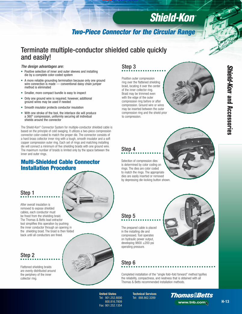
Step 1
After overall insulation isremoved to expose shieldedcables, each conductor mustbe freed from the shielding braid.The Thomas & Betts lead extractortool simplifies this operation by pushingthe inner conductor through an opening inthe shielding braid. The braid is then foldedback until all conductors are freed.
The design advantages are:• Positive selection of inner and outer sleeves and installing
die by a complete color-coded system
• A more reliable grounding termination because only one ground wire connection is made — conventional daisy chain jumper method is eliminated
• Smaller, more compact bundle is easy to inspect
• Only one ground wire is required; however, additional ground wires may be used if needed
• Smooth insulator protects conductor insulation
• With one stroke of the tool, the interlace die will produce a 360° compression, uniformly securing all individual shields around the connector
The Shield-Kon® Connector System for multiple-conductor shielded cable isbased on the principle of cold swaging. It utilizes a two-piece compressionconnector color-coded to match the proper die. The connector consists ofa hard brass collector inner ring with a tough, smooth insulator and a softcopper compression outer ring. Each set of rings and matching installingdie will connect a minimum of five shielding braids with one ground wire.The maximum number of braids is limited only by the space between theinner and outer rings.
Step 2
Flattened shielding braidsare evenly distributed aroundthe periphery of the innercollector ring.
Step 3
Position outer compressionring over the flattened shieldingbraid, locating it over the centerof the inner collector ring.Braid may be trimmed evenwith the edge of the outercompression ring before or aftercompression. Ground wire or wiresmay be inserted between the outercompression ring and the shield priorto compression.
Step 4
Selection of compression diesis determined by color coding onrings. The dies are color codedto match the rings. The appropriatedies are easily inserted or removedby depressing die-locking button shown.
Step 5
The prepared cable is placed in the installing die andcompressed. Tool operates on hydraulic power output,developing 9800 ±200 psi operating pressure.
Step 6
Completed installation of the “single fold–fold forward” method typifies the reliability, compactness, and neatness that is obtained with all Thomas & Betts recommended installation methods.
Multi-Shielded Cable ConnectorInstallation Procedure
Terminate multiple-conductor shielded cable quicklyand easily!
onlinec
omponen
ts.co
m
I.D. O.D. COLOR STD. I.D. O.D. DIES NOS. FOR COLOR STD.CAT. NO. (IN.) (IN.) CODE PKG. CAT. NO. (IN.) (IN.) 13640 CODE PKG.
Inner Ring Outer RingGSB430 .430 .500 50 GSC590 .590 .670 GS590 50GSB550 .550 .620 50 GSC710 .710 .790 GS710 50GSB670 .670 .750 50 GSC840 .840 .920 GS840 50GSB810 .810 .880 50 GSC1010 1.010 1.090 GS1010 50GSB920 .920 1.000 50 GSC1130 1.130 1.210 GS1130 50GSB1040 1.040 1.120 50 GSC1250 1.250 1.330 GS1250 50GSB1122 1.122 1.192 50 GSC1332 1.332 1.412 GS1332 50GSB1224 1.224 1.294 50 GSC1440 1.440 1.520 GS1440 50GSB1353 1.353 1.423 50 GSC1563 1.563 1.643 GS1563 50GSB1425 1.425 1.545 50 GSC1670 1.670 1.750 GS1670 5
Red
GrayBlue
BrownGreen
OrangePink
PurpleYellow
Red
Red Red
GrayBlue
BrownGreen
OrangePink
PurpleYellow
Two-Piece Connectors & Tools for the Circular Range
Grou
ndin
g Co
nnec
tors
Hydraulic Head Installing Tool
CAT. NO. DESCRIPTION STD. PKG
13640 Installing Head 1(order dies separately)
13606 Hand-Foot Pump 113600 Electric Hydraulic Pump 113620 Hand Switch 113589A Foot Switch 113619 Hydraulic Hose 10 ft. 113760 Air-Operated Hydraulic Pump 1
All the 2-piece Shield-Kon® in the circular range need to be crimped with the 13640 hydraulic head equipped with the appropriate die.
• 3.5 ton nominal pressure (output)
• For 2-piece Shield-Kon® terminals in the circular range
• Coupling for quick assembly
• Requires a 9,800 psi (approx. 690 bar)operating service pressure
• Quick interchangeable steel dies (to be ordered separately, see abovefor die selection)
• Interlace die with 360° compression—provides uniform pressure aroundcircumference of connector
Order multiple is std pkg Order multiple is std pkg
Order multiple is std pkg
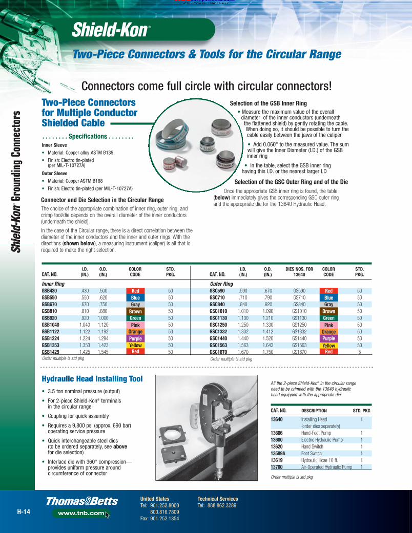
Two-Piece Connectorsfor Multiple ConductorShielded Cable. . . . . . . . Specifications . . . . . . . . .Inner Sleeve• Material: Copper alloy ASTM B135
• Finish: Electro tin-plated (per MIL-T-10727A)
Outer Sleeve• Material: Copper ASTM B188
• Finish: Electro tin-plated (per MIL-T-10727A)
Connector and Die Selection in the Circular RangeThe choice of the appropriate combination of inner ring, outer ring, andcrimp tool/die depends on the overall diameter of the inner conductors(underneath the shield).
In the case of the Circular range, there is a direct correlation between thediameter of the inner conductors and the inner and outer rings. With thedirections (shown below), a measuring instrument (caliper) is all that isrequired to make the right selection.
Selection of the GSB Inner Ring• Measure the maximum value of the overall
diameter of the inner conductors (underneath the flattened shield) by gently rotating the cable.When doing so, it should be possible to turn thecable easily between the jaws of the caliper
• Add 0.060" to the measured value. The sumwill give the Inner Diameter (I.D.) of the GSBinner ring
• In the table, select the GSB inner ring having this I.D. or the nearest larger I.D
Selection of the GSC Outer Ring and of the Die Once the appropriate GSB inner ring is found, the table
(below) immediately gives the corresponding GSC outer ring and the appropriate die for the 13640 Hydraulic Head.
Connectors come full circle with circular connectors!
H-14
United StatesTel: 901.252.8000
800.816.7809Fax: 901.252.1354
Technical ServicesTel: 888.862.3289
www.tnb.com
Related Documents