Tennessee Department of Transportation Roadside Safety Field Guide Guidelines for the Installation and Maintenance of Roadside Safety Hardware. 2014

Welcome message from author
This document is posted to help you gain knowledge. Please leave a comment to let me know what you think about it! Share it to your friends and learn new things together.
Transcript

Tennessee
Department of Transportation
Roadside Safety
Field Guide
Guidelines for the Installation and Maintenance of Roadside Safety Hardware.
2014


i
This guide was sponsored by the Federal Highway Administration (FHWA), under FHWA Contract
DTFH61‐10‐D‐00021, Roadside Safety Systems Installers and Designers Mentor Program.
The following individuals prepared or reviewed this document:
Project Team
William P. Longstreet ‐ FHWA Safety Office COTM
Karen L. Boodlal ‐ KLS Engineering, LLC
Richard D. Powers ‐ KLS Engineering, LLC
John C. Durkos ‐ KLS Engineering, LLC
TDOT Representatives
Ali Hangul – Roadway Design (Contract Lead)
Jerry Hatcher – Maintenance
Brian Egan – Construction
March 2014

ii
ContentsAcronyms ..................................................................................................................................................... iv
Glossary ......................................................................................................................................................... v
Introduction .................................................................................................................................................. 1
Guardrail Basics ............................................................................................................................................. 2
Barrier Guidelines: .................................................................................................................................... 2
Establishing Barrier Guidelines ................................................................................................................. 2
Considerations .......................................................................................................................................... 2
Clear Zone ..................................................................................................................................................... 3
Design Options (In order of preference) ....................................................................................................... 4
Roadside Obstacles ....................................................................................................................................... 5
Roadside Slopes (Embankments) .............................................................................................................. 6
Barriers ...................................................................................................................................................... 7
Rigid Systems ........................................................................................................................................ 7
Semi‐Rigid Systems ............................................................................................................................... 8
Flexible Systems .................................................................................................................................... 9
Work Zone Barriers ............................................................................................................................. 11
Additional Design Considerations ........................................................................................................... 16
Design Deflection Distance ..................................................................................................................... 16
Height Measurement .................................................................................................................................. 16
Barrier Placement on Slopes ................................................................................................................... 17
Guardrail and Curb .................................................................................................................................. 18
Guardrail and Trees ................................................................................................................................. 19
Connections to Bridge Barriers ............................................................................................................... 19
Guardrail at Intersections and Driveways ............................................................................................... 21
Terminals and Crash Cushions .................................................................................................................... 22
Terminals ................................................................................................................................................. 22
Terminal Selection .................................................................................................................................. 23
Types of Terminals .................................................................................................................................. 24
Buried in Backslope (Type 12) ............................................................................................................. 24

iii
TL‐2 Terminals (Not to be used on NHS Projects) ............................................................................... 24
Energy Absorbing Terminals (Type 38) ............................................................................................... 25
Non‐Energy Absorbing Terminals (Type 21) ....................................................................................... 28
Terminal Grading Details ........................................................................................................................ 29
Terminal Inspection ................................................................................................................................ 30
Crash Cushions ........................................................................................................................................ 31
Maintenance ............................................................................................................................................... 39
Longitudinal Barrier Damage .................................................................................................................. 39
Summary of W‐beam barrier repair thresholds ..................................................................................... 41
Summary of generic end terminal repair thresholds .............................................................................. 46
Resources .................................................................................................................................................... 51
iv
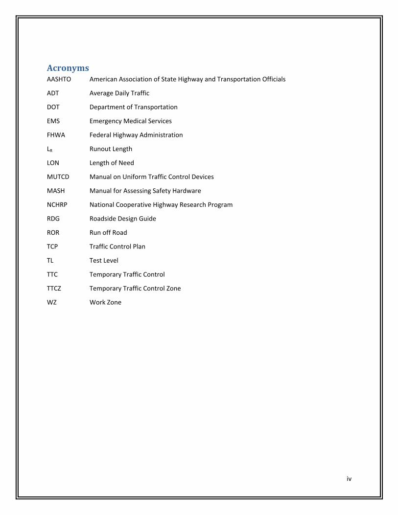
AcronymsAASHTO American Association of State Highway and Transportation Officials
ADT Average Daily Traffic
DOT Department of Transportation
EMS Emergency Medical Services
FHWA Federal Highway Administration
LR Runout Length
LON Length of Need
MUTCD Manual on Uniform Traffic Control Devices
MASH Manual for Assessing Safety Hardware
NCHRP National Cooperative Highway Research Program
RDG Roadside Design Guide
ROR Run off Road
TCP Traffic Control Plan
TL Test Level
TTC Temporary Traffic Control
TTCZ Temporary Traffic Control Zone
WZ Work Zone

v
GlossaryAdjacent Grading—Adjacent grading refers to the area on which the terminal is installed and the area
immediately behind it.
Advance Grading—Advance grading refers to the area over which a vehicle may travel before any
contact with a barrier terminal is made.
Anchorage—A device which anchors a flexible or semi‐rigid barrier to the ground so as to develop the
barrier’s tensile strength during an impact. Anchorages differ from terminals in that they are not
considered crashworthy.
Area of Concern—An object or roadside condition that may warrant safety treatment.
Barricade—A device which provides a visual indicator of a hazardous location or the desired path a
motorist should take. It is not intended to contain or redirect an errant vehicle.
Barrier—A device which provides a physical limitation through which a vehicle would not normally pass.
It is intended to contain or redirect an errant vehicle.
Bi‐directional—For the purposes of classifying crash cushions, bi‐directional describes the capability of a
crash cushion to safely operate the median of a divided highway or an undivided roadway, where it will
be exposed to impacts from two different directions of traffic. A bi‐directional crash cushion is
considered. A bi‐directional crash cushion is also a uni‐directional crash cushion. A crash cushion is
considered to be bi‐directional when it has been qualified through a reverse‐direction crash test.
Breakaway—A design feature which allows a device such as a sign, luminaire, or traffic signal support to
yield or separate upon impact The release mechanism may be a slip plane, plastic hinges, fracture
elements, or a combination of these.
Bridge Railing—A longitudinal barrier whose primary function is to prevent an errant vehicle form going
over the side of the bridge structure.
Clearance—Lateral distance from edge of traveled way to a roadside object or feature.
Clear Runout Area—The area at the toe of a non‐recoverable slope available for safe use by an errant
vehicle.
Clear Zone—The total roadside border area, starting at the edge of the traveled way, available for safe
use by errant vehicles. This area may consist of a shoulder, a recoverable slope, a non‐recoverable slope,
and/or a clear run‐out area. The desired width is dependent upon traffic volumes, speeds and roadside
geometry.
Conservation of Momentum Principle—A concept of crash cushion design which involves the
dissipation of the kinetic energy of an impacting vehicle by transferring the vehicles momentum to the
variable masses of materials in the crash cushion, such as sand contained in sand barrels.

vi
Cost‐effective—An item or action taken that is economical in terms of tangible benefits produced for
the money spent.
Crash Cushion—Device that prevents an errant vehicle from impacting a fixed object by gradually
decelerating the vehicle to a safe stop or by redirecting the vehicle away from the obstacle.
Crash Tests—vehicular impact tests by which the structural and safety performance of roadside barriers
and other highway appearances may be determined. Three evaluation criteria are considered, namely
(1) structural adequacy, (2) impact severity, and (3) vehicular post‐impact trajectory.
Crashworthy—A feature that has been proven acceptable for use under specified conditions either
through crash testing or in‐service performance.
Design Speed—A selected speed used to determine the various geometric design features of the
roadway. The assumed design speed should be a logical one with respect to the topography, anticipated
operating speed, the adjacent land use, and the functional classification of the highway.
Drainage Feature—Roadside items whose primary purpose is to provide adequate roadway drainage
such as curbs, culverts, ditches, and drop inlets.
End Treatment—The designed modification of the end of a roadside or median barrier.
Flare—The variable offset distance of a barrier to move it farther from the traveled way; generally in
reference to the upstream end of the barrier.
Frangible—A structure quality or feature that makes the structure readily or easily broken upon impact.
Fuse Plate—The plate which provides structural reinforcement to the sign post hinge to resist wind
loads but which will release or fracture upon impact of a vehicle with the post.
Glare Screen—A device used to shield a driver’s eye from the headlights of an oncoming vehicle.
Hinge—The weakened section of a sign post designed to allow the post to rotate upward when
impacted by a vehicle.
Impact Angle—For a longitudinal barrier, it is the angle between a tangent to the face of the barrier and
tangent to the vehicle’s path at impact. For a crash cushion, it is the angle between the axis of symmetry
of the crash cushion and a tangent to the vehicles path of impact.
Impact Attenuator—See Crash Cushion.
Length of Need—Total length of a longitudinal barrier needed to shield an area of concern.
Length of Need (LON) Point—That point on the terminal or longitudinal barrier at which it will contain
and redirected an impacting vehicle along the face of the terminal barrier.

vii
Level of Performance—The degree to which a longitudinal barrier, including bridge railing, is designed
for containment and redirection of different types of vehicles.
Longitudinal barriers—A barrier whose primary function is to prevent penetration and to safely redirect
an errant vehicle away from a roadside or median obstacle.
Low Maintenance/Self Restoring Crash Cushions—Crash Cushions that either suffer very little, if any
damage, upon impact and are easily pulled back into their full operating condition, or they partially
rebound after an impact and may only need an inspection to ensure that no parts have been damaged,
misaligned, or otherwise disabled.
Median—The portion of a divided highway separating the traveled ways for traffic in opposite
directions.
Multidirectional—The capability of the fracture mechanism of a breakaway support or the plates of a
split‐base support to work when struck from any direction. These are also referred to as omni‐
directional.
Median Barrier—A longitudinal barrier used to prevent an errant vehicle from crossing the median.
Non‐Recoverable Slope—A slope which is considered traversable but on which an errant vehicle will
continue to the bottom of the slope. Embankment slopes between 3H:1V and 4H:1V may be considered
traversable but non‐recoverable if they are smooth and free of fixed objects.
Offset—Lateral distance from the edge of traveled way to a roadside object or feature.
Omni‐directional—See Multidirectional.
Operating Speed—The highest speed at which reasonably prudent drivers can be expected to operate
vehicles on a section of highway under low traffic densities and good weather. This speed may be higher
or lower than posted or legislated speed limits or nominal design speeds where alignment, surface,
roadside development, or other features affect vehicle operations.
Operational Barrier—One that has performed satisfactorily in full‐scale crash tests and has
demonstrated satisfactory in‐service performance.
Performance Level—See Level of Performance.
Recoverable Slope—A slope on which a motorist may, to a greater or lesser extent, retain, or regain
control of a vehicle. Slopes flatter than 4H:1V are generally considered recoverable.
Recovery Area—Generally synonymous with clear zone.
Reusable Crash Cushions—Reusable crash cushions have some major components that may be able to
survive most impacts intact and can be salvaged when the unit is being repaired.

viii
Roadside—That area between the outside shoulder edge and the right‐of‐way limits. The area between
roadways of a divided highway may also be considered roadside.
Roadside Barrier—A longitudinal barrier used to shield roadside obstacles or no‐traversable terrain
features. It may occasionally be used to protect pedestrians or “bystanders” from vehicle traffic.
Roadside Signs—Roadside signs can be divided into 3 main categories: overhead signs, large roadside
signs, and small roadside signs. Large roadside signs may be defined as those greater than or equal to
50ft2 in area. Small roadside signs may be defined as those less than 50ft2 in area.
Roadway—The portion of a highway, including shoulders for vehicular use.
Rounding—The introduction of a vertical curve between two transverse slopes to minimize the abrupt
slope change and to maximize vehicle stability and maneuverability.
Runout Distance Grading—Refers to the area into which a vehicle may travel after impacting a terminal
ahead of its LON point.
Sacrificial Crash Cushions—Sacrificial crash cushions are crashworthy roadside safety devices designed
for a single impact. These system’s major comments are destroyed in impacts and must be replaced, but
many of the other parts of the system can be reused.
Severity Index—A severity index (SI) is a number from zero to ten used to categorize accidents by the
probability of their resulting in property damage, personal injury, or a fatality, or any combination of
these possible outcomes. The resultant number can then be translated into an accident cost and the
relative effectiveness of alternate safety treatments can be estimated.
Shielding—The introduction of a barrier or crash cushion between the vehicle and an obstacle or area of
concern to reduce the severity of impacts of errant vehicles.
Shy Distance—The distance from the edge of the traveled way beyond which a roadside object will not
be perceived as an obstacle by the typical driver to the extent that the driver will change the vehicle’s
placement or speed.
Slip Base—A structural element at or near the bottom of a post or pole which will allow release of the
post from its base upon impact while resisting wind loads.
Slope—The relative steepness of the terrain expressed as a ratio or percentage. Slopes may be
categorized as positive (backslopes) or negative (foreslopes) or as a parallel or cross slope (in relation to
the direction of traffic).
Staged Attenuation Device—A crash cushion that is designed to be progressively stiffer as an impacting
vehicle deforms or penetrates it.
ix
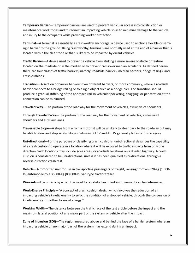
Temporary Barrier—Temporary barriers are used to prevent vehicular access into construction or
maintenance work zones and to redirect an impacting vehicle so as to minimize damage to the vehicle
and injury to the occupants while providing worker protection.
Terminal—A terminal is essentially a crashworthy anchorage, a device used to anchor a flexible or semi‐
rigid barrier to the ground. Being crashworthy, terminals are normally used at the end of a barrier that is
located within the clear zone or that is likely to be impacted by errant vehicles.
Traffic Barrier—A device used to prevent a vehicle from striking a more severe obstacle or feature
located on the roadside or in the median or to prevent crossover median accidents. As defined herein,
there are four classes of traffic barriers, namely; roadside barriers, median barriers, bridge railings, and
crash cushions.
Transition—A section of barrier between two different barriers, or more commonly, where a roadside
barrier connects to a bridge railing or to a rigid object such as a bridge pier. The transition should
produce a gradual stiffening of the approach rail so vehicular pocketing, snagging, or penetration at the
connection can be minimized.
Traveled Way—The portion of the roadway for the movement of vehicles, exclusive of shoulders.
Through Traveled Way—The portion of the roadway for the movement of vehicles, exclusive of
shoulders and auxiliary lanes.
Traversable Slope—A slope from which a motorist will be unlikely to steer back to the roadway but may
be able to slow and stop safely. Slopes between 3H:1V and 4H:1V generally fall into this category.
Uni‐directional—For the purposes of classifying crash cushions, uni‐directional describes the capability
of a crash cushion to operate in a location where it will be exposed to traffic impacts from only one
direction. Such locations may include gore areas, or roadside locations on a divided highway. A crash
cushion is considered to be uni‐directional unless it has been qualified as bi‐directional through a
reverse‐direction crash test.
Vehicle—A motorized unit for use in transporting passengers or freight, ranging from an 820‐kg [1,800‐
lb] automobile to a 36000‐kg [80,000‐lb] van‐type tractor trailer.
Warrants—The criteria by which the need for a safety treatment improvement can be determined.
Work‐Energy Principle—“A concept of crash cushion design which involves the reduction of an
impacting vehicle’s kinetic energy to zero, the condition of a stopped vehicle, through the conversion of
kinetic energy into other forms of energy.”
Working Width—The distance between the traffic face of the test article before the impact and the
maximum lateral position of any major part of the system or vehicle after the impact.
Zone of Intrusion (ZOI)—The region measured above and behind the face of a barrier system where an
impacting vehicle or any major part of the system may extend during an impact.

1
IntroductionGuardrail systems are designed and installed for one primary reason: to reduce the severity of a crash by
preventing a motorist from reaching a more hazardous fixed object or terrain feature. The purpose of
this document is to summarize important information contained in the TDOT Roadside Design Guide,
Construction Specifications, Roadside Safety Drawings and Approved Proprietary Products that can be
used in the field to ensure that all barrier installations are built and maintained to current standards and
can be expected to perform acceptably when hit.
Questions We Must Ask Ourselves
When reviewing proposed and existing barrier installations in the field, we need to ask ourselves the
following questions:
1. Is the guardrail system more hazardous than the condition being shielding?
2. Is an existing guardrail installation still warranted?
3. If the guardrail is installed as originally planned, is there a possibility of a motorist still reaching the hazard?
4. Can the guardrail be extended to shield a secondary obstruction?
5. Are there any vertical obstructions within the guardrail system’s design deflection?
6. Is the guardrail ending within 200 feet of the start of another guardrail run that could be connected?
7. Is the guardrail terminating within 200 feet of a cut slope?
8. Does the slope need any regrading?
9. Has the guardrail height been reset after an overlay?
10. Is the best end treatment for the site being used?
11. Is guardrail considered in sensitive areas such as school playgrounds and reservoirs?
12. Is there adequate soil support behind strong post guardrail shielding a slope or are longer posts required?
This document provides the information needed to answer these and other questions pertaining to
optimal design, installation, and maintenance of guardrail systems.

2
Part1
GuardrailBasics
BarrierGuidelines: Are pre‐determined situations or conditions where the use of a traffic barrier is normally
considered. Refer to the Tables on pages 5 and 6 for fixed object and embankment guidelines.
Should be considered when determining the need for a barrier, but they should not be
construed as warrants.
Are not a substitute for engineering judgment.
EstablishingBarrierGuidelines Barrier guidelines are based on the premise that a traffic barrier should be installed only if it
reduces the severity of potential crashes.
There are instances where it is not immediately obvious whether the barrier or the unshielded
condition presents the greater danger to a motorist.
In such instances, guidelines may be established by using a benefit/cost analysis whereby factors
such as design speed, roadway alignment, and traffic volumes can be evaluated in relation to
the barrier need. Costs associated with the barrier (installation, maintenance, and crash‐related
costs) are compared to crash costs associated with the unshielded condition.
This procedure is typically used to evaluate three options:
1. Remove or reduce the condition so that it no longer requires shielding,
2. Install an appropriate barrier,
3. Leave the condition unshielded.
Considerations Consider eliminating short lengths of guardrail since these sections are often less effective than
no barrier at all.
Avoid short gaps between guardrail installations by making guardrail continuous where the
points of need are determined to be about 200 feet apart or less.
Consider keeping the slope clear of fixed objects when guardrail is not required due to the
height of the slope.
Consider guardrail in sensitive areas such as school playgrounds or reservoirs.

3
ClearZoneThe term “clear zone” is used to designate an area bordering the roadway, starting at the edge of the
traveled way, which is available for safe use by errant vehicles. Safe use generally means the slope is flat
enough and free of fixed object hazards so a motorist leaving the road is able to stop and return to the
roadway safely.
The clear zone distances shown below represent minimum recommended distances and are based on
limited data. The best answer to the question “How wide should the clear zone be ?” is “As wide as
practical in each situation – but at least as wide as the distances, shown in the Table below”.
Design Clear Zone (Lc) (feet)
Design
Speed
(mph)
Design
ADT
Foreslopes Backslopes
6H:1V
or flatter
5H:1V to
4H:1V 3H:1V
6H:1V or
flatter 5H:1V to 4H:1V 3H:1V
≤40 UNDER 750⑦
750‐1500
1500‐6000
OVER 6000
7‐10
10‐12
12‐14
14‐16
7‐10
12‐14
14‐16
16‐18
④
④
④
④
7‐10
12‐14
14‐16
16‐18
7‐10
12‐14
14‐16
16‐18
7‐10
12‐14
14‐16
16‐18
45‐50 UNDER 750⑦
750‐1500
1500‐6000
OVER 6000
10‐12
14‐16
16‐18
20‐22
12‐14
16‐20
20‐26
24‐28
④
④
④
④
10‐12
14‐16
16‐18
20‐22
8‐10
12‐14
14‐16
18‐20
8‐10
10‐12
12‐14
14‐16
55 UNDER 750⑦
750‐1500
1500‐6000
OVER 6000
12‐14
16‐18
20‐22
22‐24
14‐18
20‐24
24‐30
26‐32③
④
④
④
④
10‐12
16‐18
20‐22
22‐24
10‐12
14‐16
16‐18
20‐22
8‐10
10‐12
14‐16
16‐18
60 UNDER 750⑦
750‐1500
1500‐6000
OVER 6000
16‐18
20‐24
26‐30
30‐32③
⑨
⑨
⑨
⑨
⑨
⑨
⑨
⑨
14‐16
20‐22
24‐26
26‐28
12‐14
16‐18
18‐22
24‐26
10‐12
12‐14
14‐18
20‐22
65‐70d UNDER 750
⑦
750‐1500
1500‐6000
OVER 6000
18‐20
24‐26
28‐32③
30‐34③
⑨
⑨
⑨
⑨
⑨
⑨
⑨
⑨
14‐16
20‐22
26‐28
28‐30
14‐16
18‐20
22‐24
26‐30
10‐12
12‐16
16‐20
22‐24
4
NOTES:
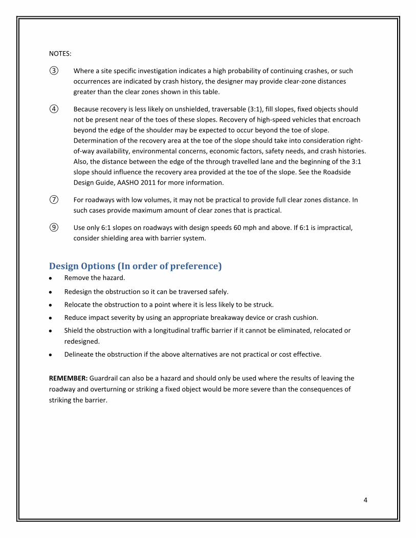
③ Where a site specific investigation indicates a high probability of continuing crashes, or such
occurrences are indicated by crash history, the designer may provide clear‐zone distances
greater than the clear zones shown in this table.
④ Because recovery is less likely on unshielded, traversable (3:1), fill slopes, fixed objects should
not be present near of the toes of these slopes. Recovery of high‐speed vehicles that encroach
beyond the edge of the shoulder may be expected to occur beyond the toe of slope.
Determination of the recovery area at the toe of the slope should take into consideration right‐
of‐way availability, environmental concerns, economic factors, safety needs, and crash histories.
Also, the distance between the edge of the through travelled lane and the beginning of the 3:1
slope should influence the recovery area provided at the toe of the slope. See the Roadside
Design Guide, AASHO 2011 for more information.
⑦ For roadways with low volumes, it may not be practical to provide full clear zones distance. In
such cases provide maximum amount of clear zones that is practical.
⑨ Use only 6:1 slopes on roadways with design speeds 60 mph and above. If 6:1 is impractical,
consider shielding area with barrier system.
DesignOptions(Inorderofpreference) Remove the hazard.
Redesign the obstruction so it can be traversed safely.
Relocate the obstruction to a point where it is less likely to be struck.
Reduce impact severity by using an appropriate breakaway device or crash cushion.
Shield the obstruction with a longitudinal traffic barrier if it cannot be eliminated, relocated or
redesigned.
Delineate the obstruction if the above alternatives are not practical or cost effective.
REMEMBER: Guardrail can also be a hazard and should only be used where the results of leaving the
roadway and overturning or striking a fixed object would be more severe than the consequences of
striking the barrier.
5
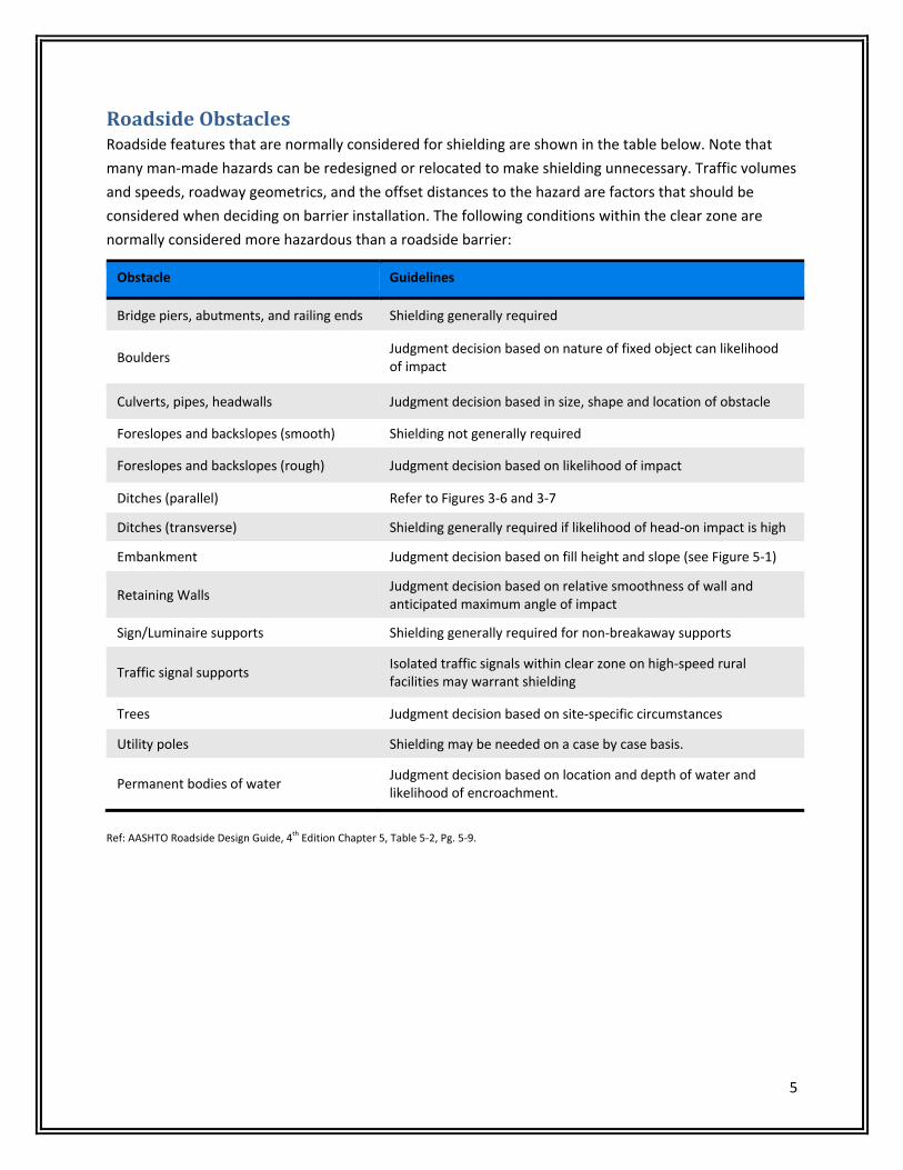
RoadsideObstaclesRoadside features that are normally considered for shielding are shown in the table below. Note that
many man‐made hazards can be redesigned or relocated to make shielding unnecessary. Traffic volumes
and speeds, roadway geometrics, and the offset distances to the hazard are factors that should be
considered when deciding on barrier installation. The following conditions within the clear zone are
normally considered more hazardous than a roadside barrier:
Obstacle Guidelines
Bridge piers, abutments, and railing ends Shielding generally required
Boulders Judgment decision based on nature of fixed object can likelihood of impact
Culverts, pipes, headwalls Judgment decision based in size, shape and location of obstacle
Foreslopes and backslopes (smooth) Shielding not generally required
Foreslopes and backslopes (rough) Judgment decision based on likelihood of impact
Ditches (parallel) Refer to Figures 3‐6 and 3‐7
Ditches (transverse) Shielding generally required if likelihood of head‐on impact is high
Embankment Judgment decision based on fill height and slope (see Figure 5‐1)
Retaining Walls Judgment decision based on relative smoothness of wall and anticipated maximum angle of impact
Sign/Luminaire supports Shielding generally required for non‐breakaway supports
Traffic signal supports Isolated traffic signals within clear zone on high‐speed rural facilities may warrant shielding
Trees Judgment decision based on site‐specific circumstances
Utility poles Shielding may be needed on a case by case basis.
Permanent bodies of water Judgment decision based on location and depth of water and likelihood of encroachment.
Ref: AASHTO Roadside Design Guide, 4
th Edition Chapter 5, Table 5‐2, Pg. 5‐9.

6
RoadsideSlopes(Embankments)Although the AASHTO RDG graph for barrier requirements at embankments suggests that slopes steeper
than 1V:3H are candidates for shielding, it does not take traffic speeds or volumes or roadway
geometrics into consideration. Some transportation agencies have developed modified guidelines based
on these additional factors.
Barrier Requirements for Embankment Heights
TDOT Barrier Guidelines, 4‐705.12, 2013.

7
BarriersA roadside barrier is a longitudinal barrier used to shield motorists from natural and man‐made
obstacles located along either side of a traveled way. They are usually categorized as rigid, semi‐rigid or
flexible depending on their deflection characteristics when impacted.
RigidSystems The New Jersey Safety‐Shape Barrier was the most widely
used safety shape concrete barrier prior to the
introduction of the F‐shape. As shown, the "break‐point"
between the 55 deg and 84 deg slope is 13 inches above
the pavement, including the 3 inch vertical reveal. The
flatter lower slope is intended to redirect vehicles
impacting at shallow angles with little sheet metal
damage, but can cause significant instability to vehicles
impacting at high speeds and angles. TL‐4: 32” Tall and TL‐
5: 42” Tall.
The F‐Shape Barrier has the same basic geometry as the
New Jersey barrier, but the "break‐point" between the
lower and upper slopes is 10 inches above the pavement.
This modification results in less vehicle climb in severe
impacts and improved post‐crash trajectories. The 7.5
inch horizontal distance from the toe of the F‐shape to its
top corner also reduces the roll angle of impacting trucks
and other vehicles with high centers‐of‐gravity. TL‐4: 32”
Tall and TL‐5: 42” Tall.
The Single Sloped Barrier, developed in Texas, has a
constant 10.8 degree slope and performs comparably to
the New Jersey barrier.

8
Semi‐RigidSystems Midwest Guardrail System (MGS)
Test Level: NCHRP 350/MASH TL‐3
Post: W6 x 9 or W6 x 8.5 x 6 ft. Steel or 6” x 8” or 8” diameter
wood posts.
Height: 31”
Splice: At midspan.
Post Spacing: 6’‐3”
Block‐outs: 8” timber or plastic block‐outs.
Strong‐Steel or Wood Post W‐Beam with wood or plastic
block‐outs
Test Level: NCHRP 350/MASH TL‐3
Post: W6 x 9 or W6 x 8.5 x 6 ft. Steel or 6” x 8” or 8” diameter
wood posts.
Height: 27”
Post Spacing: 6’‐3”
Block‐outs: 6” wide x 8” x 14” routed (w/steel post) timber or plastic block‐outs. Double block‐outs
can be used.
9
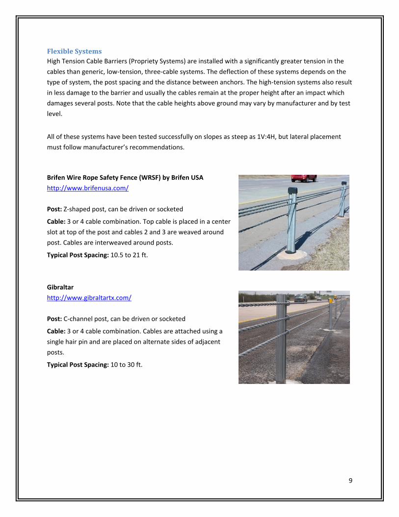
FlexibleSystemsHigh Tension Cable Barriers (Propriety Systems) are installed with a significantly greater tension in the
cables than generic, low‐tension, three‐cable systems. The deflection of these systems depends on the
type of system, the post spacing and the distance between anchors. The high‐tension systems also result
in less damage to the barrier and usually the cables remain at the proper height after an impact which
damages several posts. Note that the cable heights above ground may vary by manufacturer and by test
level.
All of these systems have been tested successfully on slopes as steep as 1V:4H, but lateral placement
must follow manufacturer’s recommendations.
Brifen Wire Rope Safety Fence (WRSF) by Brifen USA
http://www.brifenusa.com/
Post: Z‐shaped post, can be driven or socketed
Cable: 3 or 4 cable combination. Top cable is placed in a center
slot at top of the post and cables 2 and 3 are weaved around
post. Cables are interweaved around posts.
Typical Post Spacing: 10.5 to 21 ft.
Gibraltar
http://www.gibraltartx.com/
Post: C‐channel post, can be driven or socketed
Cable: 3 or 4 cable combination. Cables are attached using a
single hair pin and are placed on alternate sides of adjacent
posts.
Typical Post Spacing: 10 to 30 ft.

10
Safence by Gregory Highway Products
http://www.gregorycorp.com/highway_safence.cfm
Post: C‐Shaped post, can be driven or socketed
Cable: 3 or 4 cable combination. All cables are inserted in a slot at the
center of the post and separated by plastic spacers.
Typical Post Spacing: 6.5 to 32.2 ft.
CASS by Trinity
http://www.highwayguardrail.com/products/cb.html
Post: C‐Shaped and I‐beam Post, can be driven or socketed
Cable: 3 or 4 cable combination. Cables are placed in a wave‐shaped slot
at the center of the post and separated by plastic spacers. Some
versions also have cables that are supported on the flanges of the post.
Typical Post Spacing: 6.5 to 32.5 ft.
Nu‐Cable by Nucor Marion Steel
http://nucorhighway.com/nu‐cable.html
Post: U‐Channel Post, can be driven or socketed
Cable: 3 or 4 cable combination. Cables are attached using
locking hook bolts or hook bolts and a strap. 2 of 4 cables are
placed on one side of post and the other two are placed on
the opposite side.
Typical Post Spacing: 6.5 to 32.5 ft.

11
WorkZoneBarriersUse of temporary longitudinal barriers should be based on an engineering analysis. There are a number
of factors, including traffic volume, traffic operating speed, offset, and duration, that affect barrier
needs within work zones. These barriers are designed to shield motorists as well as roadside workers.
TDOT may require portable (temporary) barrier rail if the vertical drop between the traffic lane and the
unfinished work is greater than 6 inches but less than 18 inches. For drop‐offs greater than 18 inches,
the use of portable barrier rail is mandatory. See Section 4‐712.10 of the Roadway Design Guidelines for
full details.
Types of work zone barriers include:
Concrete Safety Shape Barrier
Free‐standing, precast concrete segments, with built‐in
connecting devices.
Requires heavy equipment for installation and removal.
Adequate longitudinal reinforcement and positive
connections provide for individual segments to act together
as a smooth, continuous unit.
Portable Steel Barriers
Free‐standing, galvanized steel panels of various lengths.
Light‐weight and stackable, which allows larger quantities of barrier to be transported on a single
truck.
BarrierGuard 800
http://www.highwaycareint.com/product_info/44/barrierguard800
ArmorGuard Barrier
http://www.barriersystemsinc.com/movable‐workzone‐barrier
ZoneGuard Barrier
http://www.hshighway.com/products/zoneguard
Vulcan Barrier
http://www.energyabsorption.com/products/products_vulcan_tl3.asp

12
Plastic‐water filled
Free‐standing, polyethylene plastic shells with a steel framework.
Steel frame can be inside the plastic or outside the plastic shell.
Internal Steel Frame
External Steel Frame
13
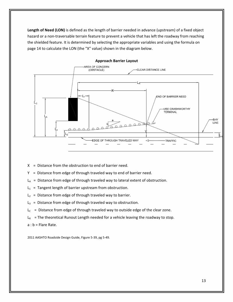
Length of Need (LON) is defined as the length of barrier needed in advance (upstream) of a fixed object
hazard or a non‐traversable terrain feature to prevent a vehicle that has left the roadway from reaching
the shielded feature. It is determined by selecting the appropriate variables and using the formula on
page 14 to calculate the LON (the “X” value) shown in the diagram below.
Approach Barrier Layout
X = Distance from the obstruction to end of barrier need.
Y = Distance from edge of through traveled way to end of barrier need.
LA = Distance from edge of through traveled way to lateral extent of obstruction.
L1 = Tangent length of barrier upstream from obstruction.
L2 = Distance from edge of through traveled way to barrier.
L3 = Distance from edge of through traveled way to obstruction.
LC = Distance from edge of through traveled way to outside edge of the clear zone.
LR = The theoretical Runout Length needed for a vehicle leaving the roadway to stop.
a : b = Flare Rate.
2011 AASHTO Roadside Design Guide, Figure 5‐39, pg 5‐49.

14
Length of Need Procedure:
1. Choose an appropriate LA as it is a critical part of the design process. This distance should include all features or hazards that need to be shielded, up to the design clear zone at each site.
2. Select a Runout Length (LR) from the table below.
3. The designer selects the tangent length, (L1), if the barrier is flared. If the installation is parallel to the roadway, L1 = 0. If a semi rigid barrier is connected to a rigid barrier, the tangent length should be at least as long as the transition section.
4. If the barrier is flared away from the roadway, the maximum recommended flare rate for median installation shown below should not be exceeded.
5. Calculate the Length of Need (X) from the following equation and round the calculated value up to the nearest 12.5‐foot or 25‐foot rail segment:
6. For parallel installations i.e. no flare rate, the previous equation becomes:
* Note: The 0.75‐ft adjustment factor is applicable when the flare on the installed terminal results in a
0.75‐foot offset at post No.3, the point along the installation considered to be the beginning of the
Length of Need.
Runout Lengths
RUNOUT LENGTHS (LR) FOR
BARRIER DESIGN (FT) MEDIAN APPLICATION
DESIGN
SPEED
(MPH)
DESIGN TRAFFIC VOLUME (ADT) FLARE RATE (a:b)
OVER
10,000 VPD
5,000 –
10,000 VPD
1,000 –
5,000 VPD
UNDER
1,000 VPD
Concrete
Barrier
W‐Beam
Barrier
70 360 330 290 250 20:1 15:1
60 300 250 210 200 18:1 14:1
50 230 190 160 150 14:1 11:1
40 160 130 110 100 10:1 8:1
30 110 90 80 70 8:1 7:1
LA + (b/a)(L1) – L2
(b/a) + (LA/LR) X =
LA – L2
LA / LR X(AASHTO) =
LA – L2 – 0.75
LA / LR
or
*X(TDOT) =
15
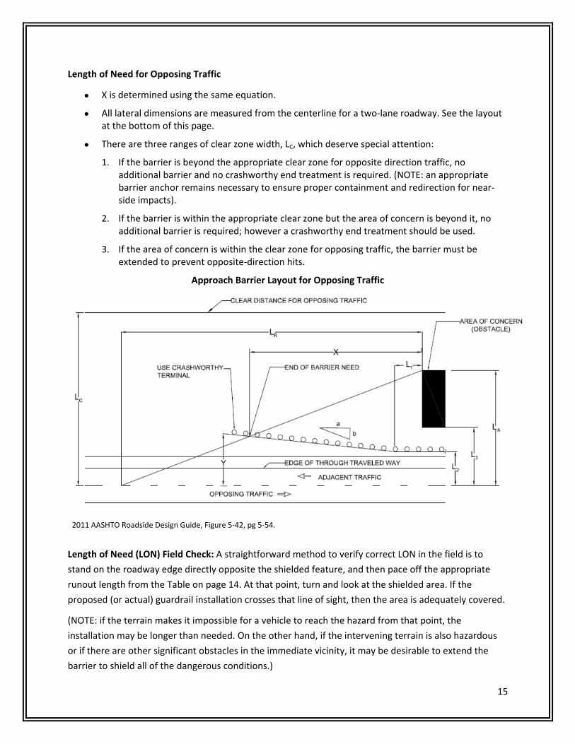
Length of Need for Opposing Traffic
X is determined using the same equation.
All lateral dimensions are measured from the centerline for a two‐lane roadway. See the layout at the bottom of this page.
There are three ranges of clear zone width, LC, which deserve special attention:
1. If the barrier is beyond the appropriate clear zone for opposite direction traffic, no additional barrier and no crashworthy end treatment is required. (NOTE: an appropriate barrier anchor remains necessary to ensure proper containment and redirection for near‐side impacts).
2. If the barrier is within the appropriate clear zone but the area of concern is beyond it, no additional barrier is required; however a crashworthy end treatment should be used.
3. If the area of concern is within the clear zone for opposing traffic, the barrier must be extended to prevent opposite‐direction hits.
Approach Barrier Layout for Opposing Traffic
2011 AASHTO Roadside Design Guide, Figure 5‐42, pg 5‐54. Length of Need (LON) Field Check: A straightforward method to verify correct LON in the field is to
stand on the roadway edge directly opposite the shielded feature, and then pace off the appropriate
runout length from the Table on page 14. At that point, turn and look at the shielded area. If the
proposed (or actual) guardrail installation crosses that line of sight, then the area is adequately covered.
(NOTE: if the terrain makes it impossible for a vehicle to reach the hazard from that point, the
installation may be longer than needed. On the other hand, if the intervening terrain is also hazardous
or if there are other significant obstacles in the immediate vicinity, it may be desirable to extend the
barrier to shield all of the dangerous conditions.)

16
AdditionalDesignConsiderationsAlthough it is critical that the correct length of need be installed, there are several other placement
considerations essential to good barrier performance. These include adequate deflection distances
behind each type of barrier, barrier height, guardrail flare rates, and the location of barrier on slopes
and behind curbs. These factors are discussed in the next sections.
DesignDeflectionDistanceis based on the results of 62‐mph impacts into the barrier at a 25‐
degree impact angle by the NCHRP Report 350 or MASH pickup truck. In the field, actual deflections can
be much greater (or less) depending on actual impact conditions. Note that the AASHTO RDG measures
the distance from the back of the posts.
HeightMeasurementThe minimum height of Strong‐Steel Post W‐Beam Guardrail is 27” and MGS is 31”, measured as shown
below or from the gutter line when set above a curb. If set behind a sidewalk barrier height should be
set from the sidewalk elevation.

17
BarrierPlacementonSlopesBarrier, regardless of type, performs best when an impacting vehicle is stable when contact is first made.
Since vehicles running off the road at high speeds tend to become airborne and are likely to override
barrier placed on a slope, the following guidelines apply:
Do not place W‐beam guardrail on slopes steeper than 1V:6H.
W‐beam systems can be placed anywhere on 1V:10H or flatter slopes.
MGS barrier can be installed on 1V:8H slopes but 1V:10H is preferred.
When the slopes are between 1V:10H and 1V:6H, the face of the barrier must not be between 2 to 12 feet beyond the grade hinge point.
Strong post systems need 2 feet of soil support behind the rail for support. When 2 feet is not obtainable, strong posts that are a minimum of 1 foot longer shall be provided.
Cable barrier can be placed anywhere on a 1V:6H or flatter roadside slope, but that are some placement restrictions when used in a median application. Most proprietary systems can be placed on 1V:4H slopes, but manufacturers’ recommendations must be followed.
See AASHTO Roadside Design Guide, 4th Edition, Figure 5-38, pg 5-47.
18
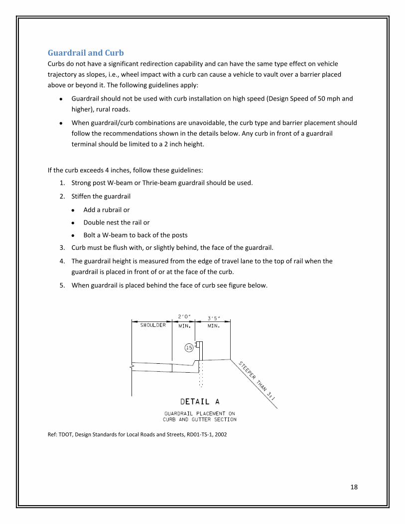
GuardrailandCurbCurbs do not have a significant redirection capability and can have the same type effect on vehicle
trajectory as slopes, i.e., wheel impact with a curb can cause a vehicle to vault over a barrier placed
above or beyond it. The following guidelines apply:
Guardrail should not be used with curb installation on high speed (Design Speed of 50 mph and
higher), rural roads.
When guardrail/curb combinations are unavoidable, the curb type and barrier placement should
follow the recommendations shown in the details below. Any curb in front of a guardrail
terminal should be limited to a 2 inch height.
If the curb exceeds 4 inches, follow these guidelines:
1. Strong post W‐beam or Thrie‐beam guardrail should be used.
2. Stiffen the guardrail
Add a rubrail or
Double nest the rail or
Bolt a W‐beam to back of the posts
3. Curb must be flush with, or slightly behind, the face of the guardrail.
4. The guardrail height is measured from the edge of travel lane to the top of rail when the
guardrail is placed in front of or at the face of the curb.
5. When guardrail is placed behind the face of curb see figure below.
Ref: TDOT, Design Standards for Local Roads and Streets, RD01‐TS‐1, 2002

19
GuardrailandTrees Generally guardrail is not used to shield utility poles or trees. However, individual trees and
poles that are in vulnerable locations and cannot be removed or relocated are sometimes
shielded.
Where guardrail is used in front of poles or trees due to other obstructions barrier deflection
must be considered.
Consider removing trees where they are an obstruction and in locations where they are likely to
be hit.
Use crash history at similar sites, scars indicating previous crashes or field reviews to determine
removable trees.
Tree removal is usually a preferred option but an assessment regarding its expense and
effectiveness should be considered.
Roadways through wooded areas with heavy nighttime traffic volumes, frequent fog, and
narrow lanes should be well delineated.
Pavement markings and post mounted delineators are among the most effective and least costly
improvements that can be made to a roadway.
ConnectionstoBridgeBarriersSince there are numerous bridge barrier designs currently in place on Tennessee highways, the
attachment details shown in the latest Design Standards for new construction will not always be directly
applicable for every project. However, crashworthy designs can be developed if three concerns are met:
an adequate transition between the bridge end and the approach guardrail, an adequate attachment to
the bridge barrier itself, and the elimination of any potential snag points at the bridge end.
A transition is simply a gradual stiffening of the approach guardrail at the bridge end so the rail
cannot deflect enough to result in a vehicle “pocketing” when it reaches the rigid bridge barrier.
A structurally adequate attachment of the guardrail to the bridge barrier is shown on the
transition details as well. This detail is needed to prevent the approach railing from pulling free
from the bridge barrier. Some existing bridge railings may not be structurally adequate to
support such a connection. In such situations extending the guardrail across the structure
eliminates the need for a structural connection at the bridge end and may increase the capacity
of the bridge barrier itself.
Finally, if the bridge barrier is significantly higher then the approach railing, a truck or SUV
impacting the approach railing could lean over the railing far enough to snag on the end of the
bridge barrier, or if no rubrail or concrete curb is used, a vehicle’s tire could fold under the
guardrail and snag on the bottom edge of the bridge parapet.

20
TDOT, Roadside Safety Drawings, S‐GRC‐1, 2013

21
GuardrailatIntersectionsandDrivewaysWhen secondary roads or driveways intersect a main road
so close to a bridge or other hazard that a full run of
barrier cannot be installed, a strong post W‐beam
guardrail can be curved around the radius where the two
roads meet. While the site conditions can vary greatly,
there are two major concerns that should be addressed.
1. If the hazard is a bridge end or pier, a crashworthy transition design is required. A crash cushion can be used if the space is too limited to use a standard transition. The section of barrier along the primary road must be long enough to react in tension to redirect impacting vehicles away from the shielded rigid object.
2. Oftentimes the feature traversed by a structure or another hazardous feature between the intersecting road and the structure can be shielded using a curved rail design. By using a curved rail design, high angle impacts into the curved section are likely. To reduce the risk of a vehicle going through or over the W‐beam, modifications can be made to the posts, the W‐beam‐to‐post connections, and the end treatment along the intersecting road or driveway. TDOT ‘s typical treatment at such locations is shown here.
Ref: TDOT, Roadside Safety Systems, S‐PL‐2, 2013

22
Part2TerminalsandCrashCushionsTerminalsCrashworthy terminals anchor a barrier installation and are designed to eliminate spearing or vaulting
when hit head‐on, or redirect a vehicle away from the shielded object or terrain feature when the
barrier is struck on the traffic face near the terminal. Typical Tennessee installations require a TL‐3 end
terminal.
Definitions:
Energy Absorbing Terminals can stop vehicles in relatively short distances in direct end‐on impacts
(usually 50 feet or less depending on type of terminal).
Non‐Energy Absorbing Systems will allow an unbraked vehicle to travel 150 feet or more behind and
parallel to guardrail installations or along the top of the barrier when struck head‐on at high speeds.
Flared Terminals: have up to 4‐foot offset at the approach end, but require a larger platform for
installation.
Tangent Terminals: are installed parallel to the roadway but may have a 2‐foot offset over the first 50
feet of length.
NOTE:
At the trailing end of guardrail, a distance of 50 feet beyond the end treatment is to be kept
clear of all roadside obstructions (hazards) or the rail may be extended to shield such secondary
hazards.
This "downstream clear zone" is intended to minimize the likelihood that a vehicle may be
forced into an obstruction by the barrier.
On two lane highways with two way traffic, provide end treatments on both the approach and
trailing ends of the guardrail.
On four‐lane divided highways, use crashworthy end treatments on the approach ends. If the
departure rail is within the clear zone for opposing traffic, provide end treatments on both the
approach and trailing ends. Note that oftentimes no rail is needed on the departure ends of
bridges on divided roadways unless site specific circumstances require additional barrier.

23
TerminalSelectionThe flowchart below can be used by a designer to select the most appropriate type based on site
conditions.
Is Barrier Needed ?
No
Yes
Discuss Elimination Of Hazard with Engineer
No
Yes
Is Length of Barrier Optimal?
Adjust Length of Barrier
Is there a Backslope nearby ?
No No
Yes
Yes
Can Barrier be Terminated in Backslope ?
Use Buried in Backslope Terminal
Is Runout Area beyond Terminal
Adequate ?
Use Energy Absorbing Terminal
Use any Crashworthy Terminal
No
Can barrier be extended to obtain adequate
runout area?
Yes No
Yes
24
TypesofTerminalsThe following terminals include those often used in Tennessee.
For additional terminals go to the FHWA website at
http://safety.fhwa.dot.gov/roadway_dept/policy_guide/road_hardware/barriers/index.cfm
Buried in Backslope (Type 12)
TL‐2 Terminals (Not to be used on NHS Projects)
Energy Absorbing Terminals (Type 38)
Non‐Energy Absorbing Terminals (Type 21)
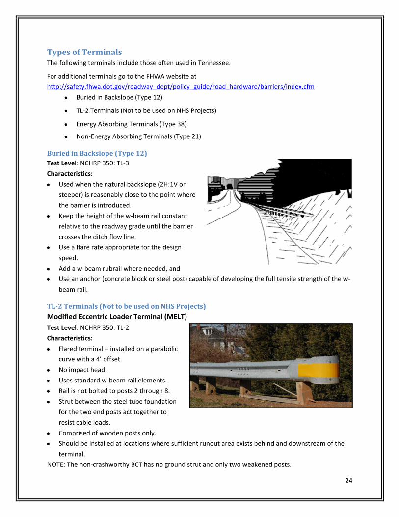
BuriedinBackslope(Type12)Test Level: NCHRP 350: TL‐3
Characteristics:
Used when the natural backslope (2H:1V or
steeper) is reasonably close to the point where
the barrier is introduced.
Keep the height of the w‐beam rail constant
relative to the roadway grade until the barrier
crosses the ditch flow line.
Use a flare rate appropriate for the design
speed.
Add a w‐beam rubrail where needed, and
Use an anchor (concrete block or steel post) capable of developing the full tensile strength of the w‐
beam rail.
TL‐2Terminals(NottobeusedonNHSProjects)Modified Eccentric Loader Terminal (MELT)
Test Level: NCHRP 350: TL‐2
Characteristics:
Flared terminal – installed on a parabolic
curve with a 4’ offset.
No impact head.
Uses standard w‐beam rail elements.
Rail is not bolted to posts 2 through 8.
Strut between the steel tube foundation
for the two end posts act together to
resist cable loads.
Comprised of wooden posts only.
Should be installed at locations where sufficient runout area exists behind and downstream of the
terminal.
NOTE: The non‐crashworthy BCT has no ground strut and only two weakened posts.

25
EnergyAbsorbingTerminals(Type38) Used for single runs of strong post guardrail
Redirection begins beyond the third post
Extruder Terminal ET‐2000 Plus
Test Level: NCHRP 350: TL‐3
Characteristics:
Tangent terminal.
Rectangular impact front face (Extruder
head).
Rectangular holes in 1st rail support the tabs
of the cable anchor bracket.
Steel HBA and SYTP and wood post options
are available.
SYTP Retrofit in tube sleeve option available.
End of W‐beam rail with offset of 0’ to 2’‐0”.
http://www.highwayguardrail.com/products/etplus.html
Sequential Kinking Terminal (SKT-350)
Test Level: NCHRP 350: TL‐3
Characteristics:
Tangent terminal.
Square impact front face.
Has a feeder chute (channel section that
surrounds the rail) which gets wider at
the downstream end.
Breakaway steel end posts #1 and #2 and
standard steel guardrail posts #3 and
beyond.
http://roadsystems.com/skt.html
Rail has 3 (1/2” x 4” long) slots in the valley of the rail.
There may be 5 additional slots (1/2” x 4” long) on both the top and bottom corrugations of the w‐
beam section, which makes it interchangeable with the FLEAT system.
Cable anchor bracket is fully seated on the shoulder portion of the cable anchor bolts.
All hinge steel post, plug weld steel posts, or wood posts available.
End of W‐beam rail with offset of 0’ to 2’‐0”.

26
Flared Energy Absorbing Terminal Median (FLEAT-MT)
Test Level: NCHRP 350: TL‐3
Characteristics:
Flared terminal.
Rectangular impact front face, with steel tube on
top.
Rail has 5 slots (1/2” x 4” long) on both the top
and bottom corrugations of the w‐beam section.
There may be 3 additional (1/2”x4” long) slots in
the valley of the rail which makes it
interchangeable with the SKT system.
Breakaway steel end posts #1 and #2, standard
steel guardrail posts #3 and beyond.
http://roadsystems.com/fleat‐mt.html
Cable anchor bracket is fully seated on the shoulder portion of the cable anchor bolts.
All hinge steel post, plug weld steel posts, or wood posts available.
End of W‐beam rail with offset of 2’‐6” to 4’‐0”.
X‐Tension Median Attenuator System (X‐MAS)
Test Level: NCHRP 350: TL‐3
Characteristics:
Impact head with locking bar to lock
cables into place.
Strut between the first post and a front
anchor post.
Steel and wood post options available.
Two cables attached to soil anchor extend
the entire length of the terminal.
http://www.barriersystemsinc.com/xmas‐impact‐attenuator

27
TREND 350 Terminals
Test Level: NCHRP 350: TL‐3
Characteristics:
Rectangular Impact Face.
All steel driven posts.
Breakaway steel posts at #1 and #2, standard
steel guardrail posts #3 and beyond.
Steel Strut between posts #1 and #2.
During head on impacts the system telescopes
rearward, using friction between the guardrail
panels and deformation of the rail sections to
decelerate the vehicle. http://www.highwayguardrail.com/products/et.html
SoftStop
Test Level: MASH TL‐3
Characteristics:
Rectangular Impact Face.
All steel driven posts.
Breakaway steel posts at #1 and #2,
standard steel guardrail posts #3 and
beyond.
Impact head flattens and extrudes w‐beam
guardrail upon end‐on impact. http://www.highwayguardrail.com/products/SoftStop.html
X‐Lite
Test Level: NCHRP 350: TL‐3
Characteristics:
Rectangular Impact Face.
All steel driven posts.
Uses a slider mechanism between post 1 and 2
that gathers and retains the rail when hit.
The anchor consists of posts #1 and #2
connected by tension struts and a soil plate
below grade on post #2.
Both Tangent and Flared Layout.
http://www.barriersystemsinc.com/xlite‐end‐terminal

28
Non‐EnergyAbsorbingTerminals(Type21) Used for single runs of strong post w‐beam guardrail.
Redirection begins beyond the third post.
Slotted Rail Terminal (SRT-350)
Test Level: NCHRP 350: TL‐3
Characteristics:
Flared terminal.
No impact head.
Longitudinal slots on w‐beam rail
element.
Strut and cable anchor bracket between
posts #1 and #2 act together to resist the
cable loads.
Slot Guards on downstream end of slots.
Steel and wood post options available.
Parabolic flare on wood post option.
Straight line flare on all SYTP steel post
and HBA steel/wood post options.
http://www.highwayguardrail.com/products/et‐srt350.html
Should be installed at locations where sufficient runout area exists behind and downstream of the
terminal.
End of w‐beam rail with offset of 4’‐0”
Wood post option has 3’‐0” to 4’‐0” offsets.
29
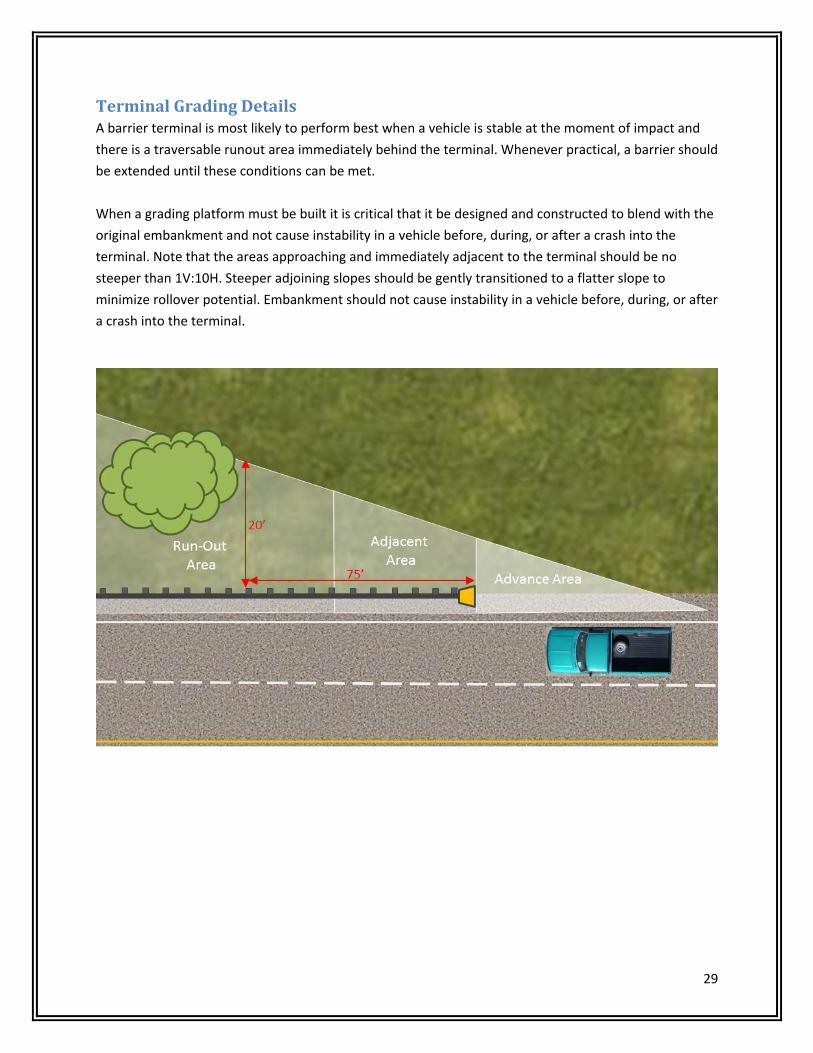
TerminalGradingDetailsA barrier terminal is most likely to perform best when a vehicle is stable at the moment of impact and
there is a traversable runout area immediately behind the terminal. Whenever practical, a barrier should
be extended until these conditions can be met.
When a grading platform must be built it is critical that it be designed and constructed to blend with the
original embankment and not cause instability in a vehicle before, during, or after a crash into the
terminal. Note that the areas approaching and immediately adjacent to the terminal should be no
steeper than 1V:10H. Steeper adjoining slopes should be gently transitioned to a flatter slope to
minimize rollover potential. Embankment should not cause instability in a vehicle before, during, or after
a crash into the terminal.

30
TerminalInspectionAll new guardrail, new guardrail end terminals, repair of existing guardrail, repair of existing guardrail
end terminals, adjustment of guardrail, etc. shall be constructed in accordance with the appropriate
section(s) of the TDOT Standard Specifications and/or Special Provisions and/or the appropriate TDOT
Standard Drawing and/or approved NCHRP 350 shop drawings.
The TDOT inspector/representative shall complete the Guardrail and Guardrail Terminal Anchor Daily
Field Report. The form must be signed by both the inspector and the Contractor’s authorized
representative. All certifications and FHWA eligibility letters for end treatments shall be attached to the
inspection form. (It will only be necessary to supply one certification letter and FHWA eligibility letter for
each type used.)
Installation decals shall be applied to all end terminal sections, either new installation or repair as shown
below. The tag should be placed on the guardrail end terminal in an area that is least likely to be
damaged on impact.
31
HAZARD UNLIKELY TO BE IMPACTED AT A HIGHER THAN 20˚ ANGLE OR IMPACTED
AT CORNER (WORK ZONE)
CHOOSE GATING CRASH CUSHIONSEE S‐CC‐2
(B)
HAZARD (F) WIDER THAN 16’
ADT ≥ 25000 VEH/DAY
DISTANCE FROM TRAVELED WAY ≤ 10’
RECORDED OR EXPECTED IMPACTS ≥ 3/YEAR
RECORDED OR EXPECTED IMPACTS ≥ 1/YEAR
CHOOSE SACRAFICAL NON‐GATING CRASH CUSHION
(B)
CAN HAZARD (F) BE NARROWED TO < 16’
HAZARD (F) WIDER THAN 3’
HAZARD (F) WIDER THAN 3’
CHOOSE LOW MAINTENANCE NON‐GATING CRASH CUSHION
(WIDE) (B)
CHOOSE LOW MAINTENANCE NON‐GATING CRASH CUSHION
(NARROW) (B)
CHOOSE REUSABLE NON‐GATING CRASH CUSHION (WIDE) (B)
CHOOSE REUSABLE NON‐GATING CRASH CUSHION
(NARROW) (B)
YES
NO
YES
YES
YES
YES
NO
NO
NO
NO
NO
NO
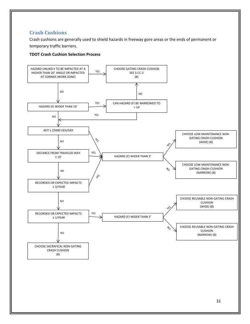
CrashCushionsCrash cushions are generally used to shield hazards in freeway gore areas or the ends of permanent or
temporary traffic barriers.
TDOT Crash Cushion Selection Process
32
TDOT Crash Cushions Types
Reusable Systems – Only TL‐3 systems must be used for TDOT projects.
Low maintenance (self‐restoring) – Only TL‐3 systems must be used for TDOT projects.
Gating (Non‐redirective) Systems – Only TL‐3 systems shall be used on National Highway Systems
For additional commonly used attenuators throughout the U.S., go to the FHWA website at
http://safety.fhwa.dot.gov/roadway_dept/policy_guide/road_hardware/barriers/index.cfm
ReusableSystems
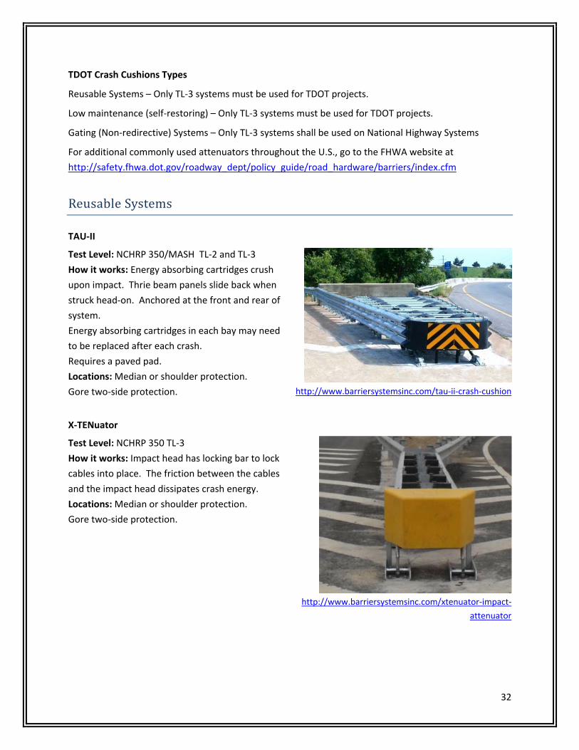
TAU‐II
Test Level: NCHRP 350/MASH TL‐2 and TL‐3
How it works: Energy absorbing cartridges crush
upon impact. Thrie beam panels slide back when
struck head‐on. Anchored at the front and rear of
system.
Energy absorbing cartridges in each bay may need
to be replaced after each crash.
Requires a paved pad.
Locations: Median or shoulder protection.
Gore two‐side protection. http://www.barriersystemsinc.com/tau‐ii‐crash‐cushion
X‐TENuator
Test Level: NCHRP 350 TL‐3
How it works: Impact head has locking bar to lock
cables into place. The friction between the cables
and the impact head dissipates crash energy.
Locations: Median or shoulder protection.
Gore two‐side protection.
http://www.barriersystemsinc.com/xtenuator‐impact‐
attenuator
33
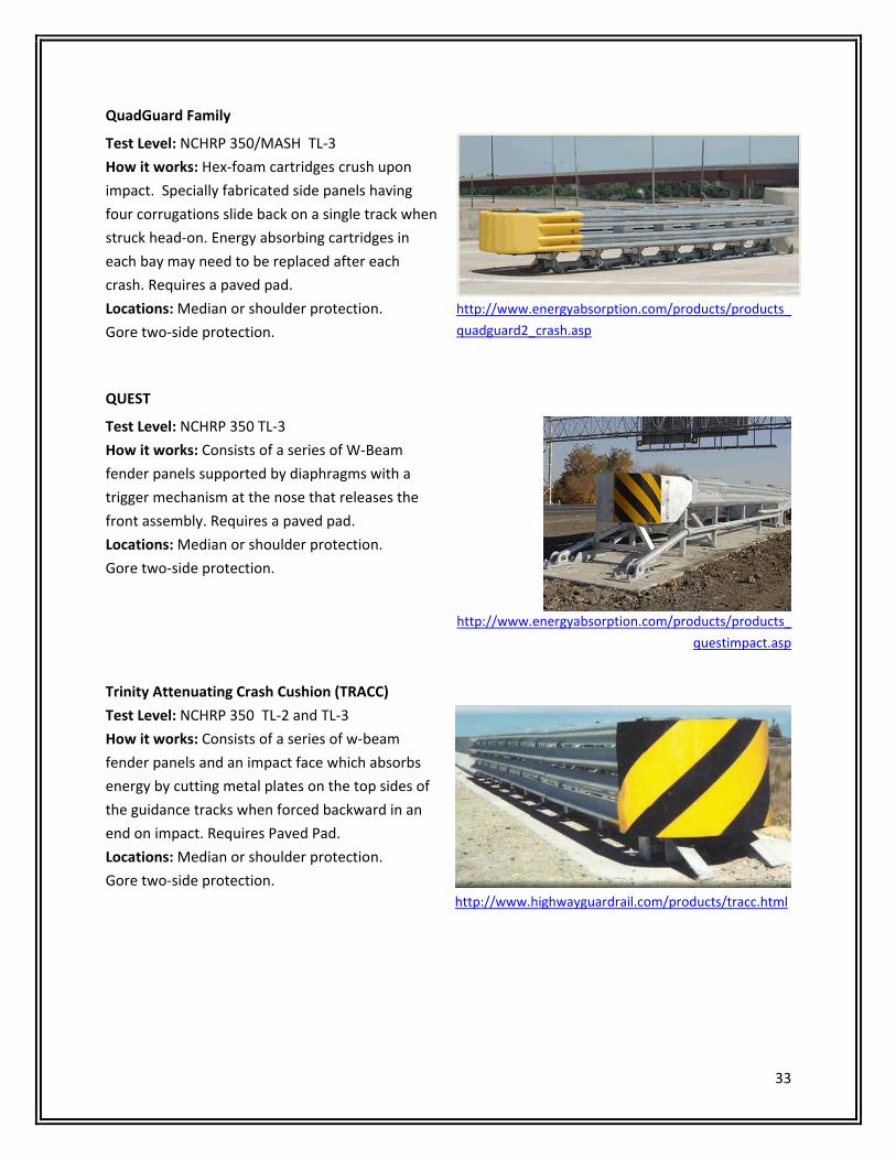
QuadGuard Family
Test Level: NCHRP 350/MASH TL‐3
How it works: Hex‐foam cartridges crush upon
impact. Specially fabricated side panels having
four corrugations slide back on a single track when
struck head‐on. Energy absorbing cartridges in
each bay may need to be replaced after each
crash. Requires a paved pad.
Locations: Median or shoulder protection.
Gore two‐side protection.
http://www.energyabsorption.com/products/products_
quadguard2_crash.asp
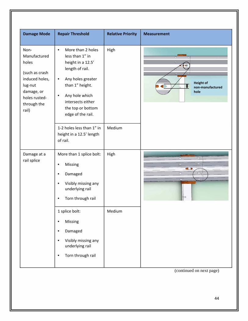
QUEST
Test Level: NCHRP 350 TL‐3
How it works: Consists of a series of W‐Beam
fender panels supported by diaphragms with a
trigger mechanism at the nose that releases the
front assembly. Requires a paved pad.
Locations: Median or shoulder protection.
Gore two‐side protection.
http://www.energyabsorption.com/products/products_
questimpact.asp
Trinity Attenuating Crash Cushion (TRACC)
Test Level: NCHRP 350 TL‐2 and TL‐3
How it works: Consists of a series of w‐beam
fender panels and an impact face which absorbs
energy by cutting metal plates on the top sides of
the guidance tracks when forced backward in an
end on impact. Requires Paved Pad.
Locations: Median or shoulder protection.
Gore two‐side protection.
http://www.highwayguardrail.com/products/tracc.html

34
LowMaintenanceSystems
Hazards Narrower Than 36” Wide
TAU‐IIR
Test Level: NCHRP 350 TL‐3
How it works: Hyperelastic modules crush upon impact.
Thrie beam panels slide back when struck head‐on.
Anchored at the front and rear of system. Requires a
paved pad.
Locations: Median or shoulder protection. Gore Two‐
side protection.
http://www.barriersystemsinc.com/tau‐ii‐r‐crash‐cushion
Smart Cushion Innovation (SCI)
Test Level: NCHRP 350 TL‐3
How it works: Hydraulic cylinders in the
attenuator provides resistance to stop a vehicle
before it reaches the end of the cushion’s usable
length. Requires a paved pad.
Locations: Median or shoulder protection.
Gore two‐side protection. http://www.workareaprotection.com/attenuator.htm
REACT 350
Test Level: NCHRP 350 TL‐3
How it works: Hollow high molecular weight, high
density polyethylene cylinders crush upon impact.
Cables on the side are for side impacts.
Requires a paved pad.
Locations: Median or shoulder protection.
Gore two‐side protection.
http://www.energyabsorption.com/products/products_react
350_impact.asp

35
QuadGuard Elite Family
Test Level: NCHRP 350 TL‐3
How it works: High Density Polyethylene cylinders
and flex‐belt nose collapse upon impact. Specially
fabricated side panels having four corrugations
slide back on a single track when struck head‐on.
Requires a paved pad.
Locations: Median or shoulder protection.
Gore two‐side protection.
http://www.energyabsorption.com/products/products_quadg
uard_elite.asp
Compressor
Test Level: NCHRP 350 TL‐3
How it works: Modules molded from High Density
Polyethylene absorb the impact energy. Steel side
panel translate during end‐on impacts. The assembly is
combined with Uni‐Base. Requires a paved pad.
Locations: Median protection or shoulder protection.
Gore two‐side protection.
http://traffixdevices.com/cgi‐
local/SoftCart.exe/compressor.htm?L+scstore+tsjv8007f
ff838f8+1360807249
Hybrid Energy Absorption Reusable Terminal (HEART)
Test Level: NCHRP 350 TL‐3
How it works: High Molecular Weight / High
Density Polyethylene side panels connected to
steel diaphragms mounted on tubular steel tracks
which compress upon impact.
Requires a paved pad.
Locations: Median or shoulder protection.
Gore two‐side protection.
http://www.highwayguardrail.com/products/heart.html

36
LowMaintenanceSystems
Hazards Wider Than 36”
REACT 350 (WIDE SYSTEM)
Test Level: NCHRP 350 TL‐3
How it works: Hollow high molecular weight, high
density polyethylene cylinders crush upon impact.
Cables on the side are for side impacts.
Requires a paved pad.
Locations: Median or shoulder protection.
Gore two‐side protection.
http://www.energyabsorption.com/products/products_react
350_impact.asp
Gating(Non‐redirective)Systems
Sand Barriers
Test Level: NCHRP 350 TL‐2 and TL‐3
How it works: Sand‐filled plastic barrels dissipate the kinetic energy of an impacting vehicle by
transferring the vehicle’s momentum to the variable masses of sand in the barrels that are hit.
Locations: Temporary Construction Worksites i.e. Ends of Concrete Barriers; Gore Two‐sided Protection;
Wide Medians; Bridge Piers.
CrashGard (TL‐3)
http://plasticsafety.com/Products/Crash‐Cushion/CrashGard‐Sand‐Barrel‐
System.aspx
Fitch Universal Barrel (TL‐3)
http://www.energyabsorption.com/products/products_universal_barrels.asp

37
Energite III (TL‐3)
http://www.energyabsorption.com/products/products_energite_iii.asp
WaterFilledCrashedCushions
Temporary Work Zone Applications Only
Absorb 350
Test Level: NCHRP 350 TL‐3
How it works: Plastic waterfilled elements allow
vehicles to be decelerated.
Locations: Any locations where it is safe for the post
impact trajectories to be on the back side of the
system.
http://www.barriersystemsinc.com/absorb‐350‐
crash‐cushion
ACZ – 350
Test Level: NCHRP 350 TL‐3
How it works: Plastic waterfilled elements allow
vehicles to be decelerated.
Locations: Any locations where it is safe for the post
impact trajectories to be on the back side of the
system.
http://www.energyabsorption.com/products/products_a
cz.asp

38
SLED
Test Level: NCHRP 350 TL‐3
How it works: Plastic waterfilled elements allow
vehicles to be decelerated.
Locations: Any locations where it is safe for the post
impact trajectories to be on the back side of the
system.
http://www.traffixdevices.com/products/attenuato
rs/sled/sled‐us/
Miscellaneous
RAPTOR
Test Level: NCHRP 350 TL‐1
How it works: Enclosed energy absorbing material
crushes on impact.
Locations: Poles/trees located close to the road.
http://www.barriersystemsinc.com/pole‐and‐tree‐
attenuator
BEAT‐SSCC (Single Sided Crash Cushion)
Test Level: NCHRP 350 TL‐3
How it works: Mandrel section of the impact head
bursts the tubing to absorb the impact energy.
Attaches directly to rigid barriers, bridge rails and
abutments.
Locations: Shoulder protection. Ground mounted or
surface mounted post on a concrete pad.
http://www.roadsystems.com/beat‐sscc.html

39
Part3Maintenance
Guardrail systems must be kept in good working condition (near “as‐built condition”) if they are to
contain and redirect impacting vehicles. Some deterioration occurs as a result of crash damage and
environmental degradation. Much of this damage can be considered “cosmetic” and may not
measurably affect barrier performance. However, some kinds of damage may seriously degrade
performance such as those listed below in the Longitudinal Barrier Damage and Terminal Damage
sections. Repairs to these types of damage should be given priority.
While it is not practical to quantitatively define “in a timely manner”, each identified damaged barrier
site must be assessed, prioritized and scheduled for repairs based upon risk exposure (highway type,
extent of barrier/terminal damage, potential for being restruck within the repair time window).
LongitudinalBarrierDamageThe types of guardrail damage listed below may result in inadequate structural and substandard
redirective performance.
Vertical tears in the W‐beam rail that begin at the top or bottom edge. These are likely to result in
rail separation in a subsequent crash.
Similarly, holes in the rail resulting from damage or deterioration that reaches the top or bottom of
a rail or one hole with a section greater than 1 inch or several holes with a dimension less than 1
inch within a 12.5‐foot length of rail.
More than 2 missing or ineffective splice bolts.
More than 9 inches of lateral deflection over a 25‐foot length of rail.
Top rail height more than 2 inches lower than the original rail height.
Rail flattening that increases the W‐beam section width from its original 12 inches.
Terminal Damage
These types of guardrail terminal damage can result in inadequate performance if hit:
Broken or damaged end posts.
Missing or very slack rail‐to‐end post cables.
Missing cable bearing plate at end posts.
Impact head not properly aligned with W‐beam rail elements.
W‐beam rail element not properly seated in the impact head.

40
The following pages consist of excerpts from NCHRP Report 656, Criteria for the Restoration of
Longitudinal Barrier. Note that the types and degree of damage to the barrier itself and to barrier
terminals is prioritized as High, Medium, or Low. These rankings, along with the perceived likelihood of a
second impact in the same location can be used to set repair priorities.
Repair priority scheme
Priority Level Description
High A second impact results in unacceptable safety performance including barrier
penetration and/or vehicle rollover.
Medium A second impact results in degraded but not unacceptable safety performance.
Low A second impact results in no discernible difference in performance from an
undamaged barrier.

41
SummaryofW‐beambarrierrepairthresholds
Damage
Mode
Repair Threshold Relative
Priority
Measurement
Post and Rail
Deflection
One or more of the
following thresholds:
• More than 9 inches
of lateral deflection
anywhere over a 25 ft
length of rail.
• Top of rail height 2 or
more inches lower
than original top of
rail height.
High
6‐9 inches lateral
deflection anywhere over
a 25 ft length of rail.
Medium
Less than 6 inches of
lateral deflection over 25
ft length of rail.
Low
Rail
Deflection
Only
6‐9 inches of lateral
deflection between any
two adjacent posts.
Note: For deflection over
9 inches, use post/rail
deflection guidelines.
Medium
Less than 6 inches of
lateral deflection
between any two
adjacent posts.
Low
(continued on next page)

42
Damage Mode Repair Threshold Relative
Priority
Measurement
Rail Flattening One of more of the following thresholds:
• Rail cross‐section height, h, more than 17” (such as may occur if rail is flattened).
• Rail cross‐section height, h, less than 9” (such as a dent to top edge).
Medium
Rail cross‐section height,
h, between 9 and 17
inches.
Low
Posts
Separated from
Rail
• 2 or more posts with
block‐out attached
with post‐rail
separation less than
3 inches.
• 1 or more post with
post‐rail separation
which exceeds 3
inches.
Medium
Note:
1. If the block‐out is not firmly attached to
the post, use the missing block‐out
guidelines.
2. Damage should also be evaluated against
post/rail deflection guidelines.
• 1 post with block‐out
attached with post‐
rail separation less
than 3 inches.
Low
(continued on next page)

43
Damage Mode Repair Threshold Relative
Priority
Measurement
Missing/Broken
Posts
1 or more posts
• Missing
• Cracked across the grain
• Broken
• Rotten
• With metal tears
High
Missing Block‐
out
Any block‐outs
• Missing
• Cracked across the grain
• Cracked from top or bottom block‐out through post bolt hole
• Rotted
Medium
Twisted Block‐
outs
Any misaligned block‐
outs, top edge of block 6
inches or more from
bottom edge.
Note: Repairs of twisted
block‐out are relatively
quick and inexpensive
Low
(continued on next page)
44
Damage Mode Repair Threshold Relative Priority Measurement
Non‐
Manufactured
holes
(such as crash
induced holes,
lug‐nut
damage, or
holes rusted‐
through the
rail)
• More than 2 holes
less than 1” in
height in a 12.5’
length of rail.
• Any holes greater
than 1” height.
• Any hole which
intersects either
the top or bottom
edge of the rail.
High
1‐2 holes less than 1” in
height in a 12.5’ length
of rail.
Medium
Damage at a
rail splice
More than 1 splice bolt:
• Missing
• Damaged
• Visibly missing any underlying rail
• Torn through rail
High
1 splice bolt:
• Missing
• Damaged
• Visibly missing any underlying rail
• Torn through rail
Medium
(continued on next page)
Height of non‐manufactured hole

45
Damage
Mode
Repair Threshold Relative Priority Measurement
Vertical Tear Any length vertical
(transverse) tear
High
Horizontal
Tear
Horizontal (longitudinal)
tears greater than 12
inches long or greater
than 0.5 inches wide.
Note: for horizontal tears
less than 12 inches in
length or less than 0.5
inches in height, use the
non‐manufactured holes
guidelines.
Medium

46
Summaryofgenericendterminalrepairthresholds
Damage Mode
Repair Threshold Relative Priority Measurement
Damage End
Post
Not functional (sheared,
rotted, cracked across
the grain)
High
Anchor Cable Missing High
Anchor Cable More than 1” of
movement when pushed
down by hand
Medium
Cable Anchor
Bracket
Loose or not firmly
seated in rail
Medium
(continued on next page)
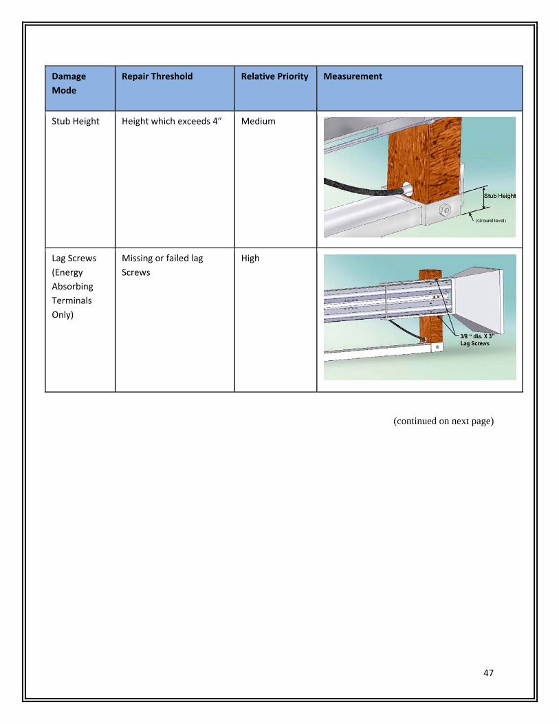
47
Damage
Mode
Repair Threshold Relative Priority Measurement
Stub Height Height which exceeds 4” Medium
Lag Screws
(Energy
Absorbing
Terminals
Only)
Missing or failed lag
Screws
High
(continued on next page)
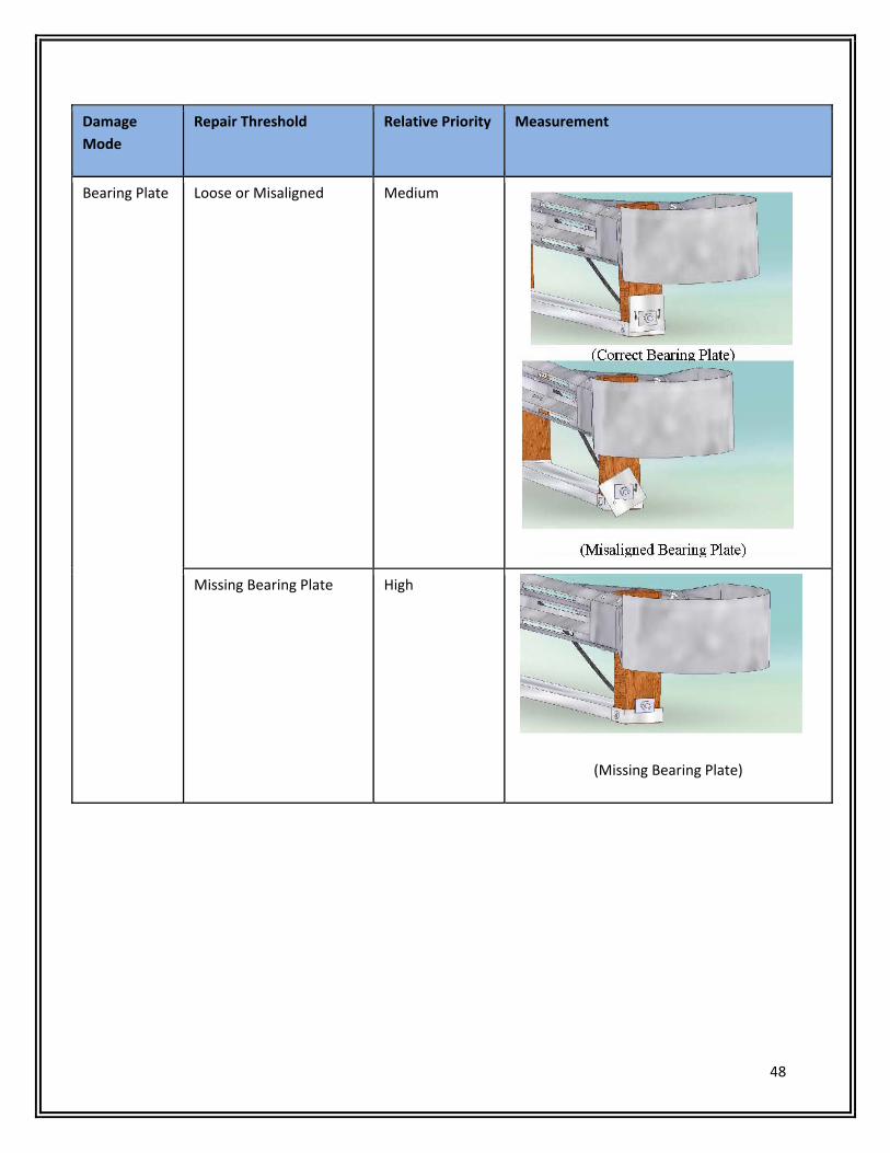
48
Damage
Mode
Repair Threshold Relative Priority Measurement
Bearing Plate Loose or Misaligned Medium
Missing Bearing Plate High
(Missing Bearing Plate)
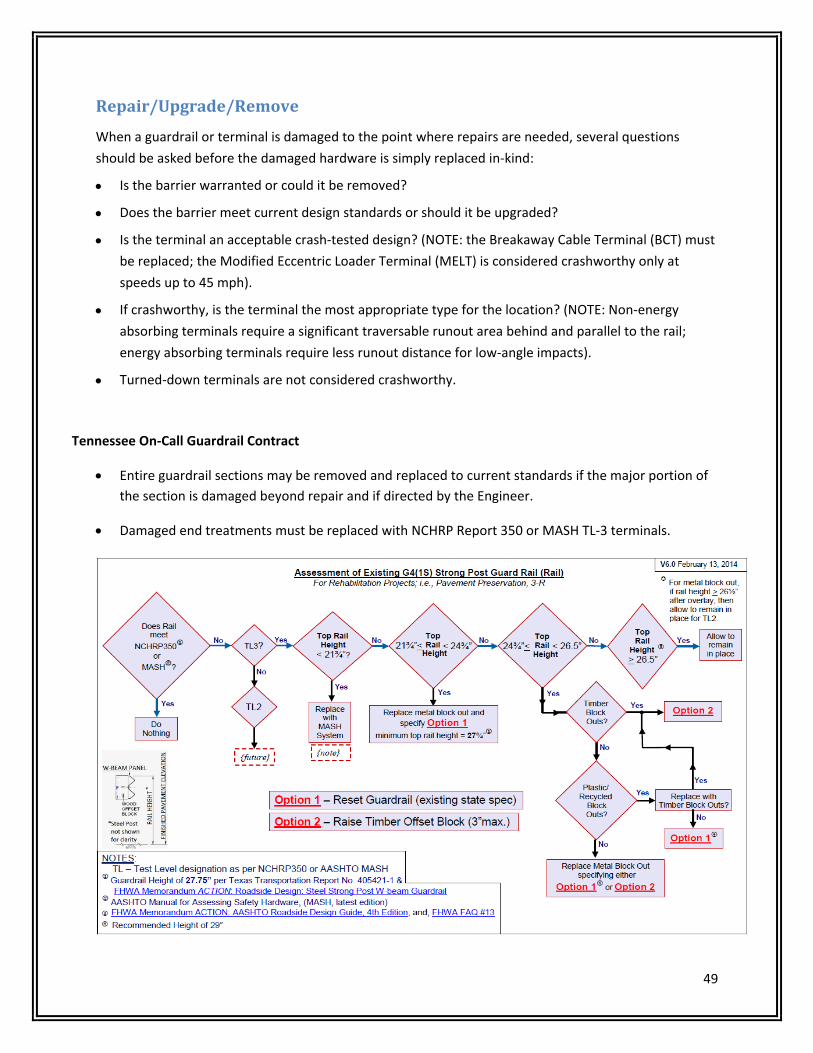
49
Repair/Upgrade/Remove
When a guardrail or terminal is damaged to the point where repairs are needed, several questions
should be asked before the damaged hardware is simply replaced in‐kind:
Is the barrier warranted or could it be removed?
Does the barrier meet current design standards or should it be upgraded?
Is the terminal an acceptable crash‐tested design? (NOTE: the Breakaway Cable Terminal (BCT) must
be replaced; the Modified Eccentric Loader Terminal (MELT) is considered crashworthy only at
speeds up to 45 mph).
If crashworthy, is the terminal the most appropriate type for the location? (NOTE: Non‐energy
absorbing terminals require a significant traversable runout area behind and parallel to the rail;
energy absorbing terminals require less runout distance for low‐angle impacts).
Turned‐down terminals are not considered crashworthy.
Tennessee On‐Call Guardrail Contract
Entire guardrail sections may be removed and replaced to current standards if the major portion of
the section is damaged beyond repair and if directed by the Engineer.
Damaged end treatments must be replaced with NCHRP Report 350 or MASH TL‐3 terminals.
50
TDOT On‐call Guardrail Contract requires:
Work to begin within 14 calendar days from receipt of work order, or
Within 2 days after receipt of emergency work order.
Once started, repair work must be continuous until completed.
Other Considerations (Maintenance only):
Shortened Posts (27” high rail)
Minimum length: 64 inches
Minimum embedment: 36 inches
NO FIELD CUTTING ALLOWED
Missing Posts
No more than two may be omitted.
Nested rail across span to 2nd post on both sides.
Additional Blockouts
Only one additional blockout per post.
No more than 3 consecutive posts.

51
ResourcesAASHTO, Roadside Design Guide, 2011
Manual on Uniform Traffic Control Devices for Streets and Highways, 2009
AASHTO, Manual for Assessing Safety Hardware, 2009
FHWA Hardware Policy and Guidance http://safety.fhwa.dot.gov/roadway_dept/policy_guide/road_hardware/
FHWA Longitudinal Barriers http://safety.fhwa.dot.gov/roadway_dept/policy_guide/road_hardware/barriers/
AASHTO Task Force 13 website https://www.aashtotf13.org/
AASHTO Guide to Standardized Highway Barrier Hardware;
https://www.aashtotf13.org/Barrier‐Hardware.php
NHTSA FARS web site: http://www‐fars.nhtsa.dot.gov/Main/index.aspx
Roadside Safety Pooled Fund sites:
MwRSF: http://mwrsf‐qa.unl.edu/
TTI: http://www.roadsidepooledfund.org/
NCHRP Research Projects http://www.trb.org/NCHRP/Public/NCHRPProjects.aspx
Bridge Rail Guide: http://guides.roadsafellc.com/
NCHRP Report 350: http://onlinepubs.trb.org/onlinepubs/nchrp/nchrp_rpt_350‐a.pdf
Tennessee Strategic Highway Safety Plan
TDOT QPL, List 34:
http://www.tdot.state.tn.us/materials/reseval/docs/qualprodlist.pdf
TDOT Safety Devices Standard Drawings:
http://www.tdot.state.tn.us/Chief_Engineer/engr_library/design/S.htm
TDOT Design Guidelines:
tdot.state.tn.us/Chief_Engineer/assistant_engineer_design/design/DesGuide.htm
4‐705 Roadside Barriers:
http://www.tdot.state.tn.us/Chief_Engineer/assistant_engineer_design/design/DGpdf/dg‐s4.pdf

52
NOTES
Related Documents