TMS320C6000 Assembly Language Tools v7.4 User's Guide Literature Number: SPRU186W July 2012

Welcome message from author
This document is posted to help you gain knowledge. Please leave a comment to let me know what you think about it! Share it to your friends and learn new things together.
Transcript
TMS320C6000 Assembly Language Toolsv7.4
User's Guide
Literature Number: SPRU186W
July 2012
Contents
Preface ...................................................................................................................................... 10
1 Introduction to the Software Development Tools ................................................................... 131.1 Software Development Tools Overview ................................................................................ 141.2 Tools Descriptions ......................................................................................................... 15
2 Introduction to Object Modules ........................................................................................... 182.1 Sections ..................................................................................................................... 192.2 How the Assembler Handles Sections .................................................................................. 20
2.2.1 Uninitialized Sections ............................................................................................ 202.2.2 Initialized Sections ................................................................................................ 212.2.3 Named Sections .................................................................................................. 222.2.4 Subsections ....................................................................................................... 222.2.5 Section Program Counters ...................................................................................... 232.2.6 Using Sections Directives ....................................................................................... 23
2.3 How the Linker Handles Sections ....................................................................................... 262.3.1 Default Memory Allocation ...................................................................................... 262.3.2 Placing Sections in the Memory Map .......................................................................... 27
2.4 Relocation .................................................................................................................. 272.4.1 Expressions With Multiple Relocatable Symbols (COFF Only) ............................................ 282.4.2 Dynamic Relocation Entries (ELF Only) ....................................................................... 28
2.5 Run-Time Relocation ...................................................................................................... 292.6 Loading a Program ........................................................................................................ 292.7 Symbols in an Object File ................................................................................................ 30
2.7.1 External Symbols ................................................................................................. 302.8 Object File Format Specifications ....................................................................................... 31
3 Assembler Description ....................................................................................................... 323.1 Assembler Overview ...................................................................................................... 333.2 The Assembler's Role in the Software Development Flow .......................................................... 343.3 Invoking the Assembler ................................................................................................... 353.4 Controlling Application Binary Interface ................................................................................ 363.5 Naming Alternate Directories for Assembler Input .................................................................... 36
3.5.1 Using the --include_path Assembler Option .................................................................. 373.5.2 Using the C6X_A_DIR Environment Variable ................................................................ 37
3.6 Source Statement Format ................................................................................................ 393.6.1 Label Field ......................................................................................................... 403.6.2 Mnemonic Field ................................................................................................... 403.6.3 Unit Specifier Field ............................................................................................... 413.6.4 Operand Field ..................................................................................................... 413.6.5 Comment Field .................................................................................................... 41
3.7 Constants ................................................................................................................... 423.7.1 Binary Integers .................................................................................................... 423.7.2 Octal Integers ..................................................................................................... 423.7.3 Decimal Integers .................................................................................................. 423.7.4 Hexadecimal Integers ............................................................................................ 433.7.5 Character Constants ............................................................................................. 433.7.6 Assembly-Time Constants ...................................................................................... 43
2 Contents SPRU186W–July 2012Submit Documentation Feedback
Copyright © 2012, Texas Instruments Incorporated
www.ti.com
3.8 Character Strings .......................................................................................................... 443.9 Symbols ..................................................................................................................... 44
3.9.1 Labels .............................................................................................................. 443.9.2 Local Labels ....................................................................................................... 443.9.3 Symbolic Constants .............................................................................................. 473.9.4 Defining Symbolic Constants (--asm_define Option) ........................................................ 473.9.5 Predefined Symbolic Constants ................................................................................ 483.9.6 Register Pairs ..................................................................................................... 503.9.7 Register Quads (C6600 Only) .................................................................................. 513.9.8 Substitution Symbols ............................................................................................. 51
3.10 Expressions ................................................................................................................ 523.10.1 Operators ......................................................................................................... 523.10.2 Expression Overflow and Underflow .......................................................................... 523.10.3 Well-Defined Expressions ...................................................................................... 533.10.4 Conditional Expressions ........................................................................................ 533.10.5 Legal Expressions ............................................................................................... 533.10.6 Expression Examples ........................................................................................... 54
3.11 Built-in Functions and Operators ........................................................................................ 553.11.1 Built-In Math and Trigonometric Functions ................................................................... 553.11.2 C6x Built-In ELF Relocation Generating Operators ......................................................... 56
3.12 Source Listings ............................................................................................................ 603.13 Debugging Assembly Source ............................................................................................ 623.14 Cross-Reference Listings ................................................................................................. 63
4 Assembler Directives ......................................................................................................... 644.1 Directives Summary ....................................................................................................... 654.2 Directives That Define Sections ......................................................................................... 694.3 Directives That Initialize Constants ..................................................................................... 714.4 Directives That Perform Alignment and Reserve Space ............................................................. 724.5 Directives That Format the Output Listings ............................................................................ 734.6 Directives That Reference Other Files .................................................................................. 744.7 Directives That Enable Conditional Assembly ......................................................................... 754.8 Directives That Define Union or Structure Types ..................................................................... 754.9 Directives That Define Enumerated Types ............................................................................. 764.10 Directives That Define Symbols at Assembly Time ................................................................... 764.11 Miscellaneous Directives ................................................................................................. 774.12 Directives Reference ...................................................................................................... 78
5 Macro Description ............................................................................................................ 1415.1 Using Macros ............................................................................................................. 1425.2 Defining Macros .......................................................................................................... 1425.3 Macro Parameters/Substitution Symbols ............................................................................. 144
5.3.1 Directives That Define Substitution Symbols ................................................................ 1455.3.2 Built-In Substitution Symbol Functions ....................................................................... 1465.3.3 Recursive Substitution Symbols .............................................................................. 1475.3.4 Forced Substitution ............................................................................................. 1475.3.5 Accessing Individual Characters of Subscripted Substitution Symbols .................................. 1485.3.6 Substitution Symbols as Local Variables in Macros ........................................................ 149
5.4 Macro Libraries ........................................................................................................... 1495.5 Using Conditional Assembly in Macros ............................................................................... 1505.6 Using Labels in Macros ................................................................................................. 1525.7 Producing Messages in Macros ........................................................................................ 1535.8 Using Directives to Format the Output Listing ....................................................................... 1545.9 Using Recursive and Nested Macros ................................................................................. 1555.10 Macro Directives Summary ............................................................................................. 157
3SPRU186W–July 2012 ContentsSubmit Documentation Feedback
Copyright © 2012, Texas Instruments Incorporated
www.ti.com
6 Archiver Description ........................................................................................................ 1586.1 Archiver Overview ........................................................................................................ 1596.2 The Archiver's Role in the Software Development Flow ............................................................ 1606.3 Invoking the Archiver .................................................................................................... 1616.4 Archiver Examples ....................................................................................................... 1626.5 Library Information Archiver Description .............................................................................. 163
6.5.1 Invoking the Library Information Archiver .................................................................... 1636.5.2 Library Information Archiver Example ........................................................................ 1646.5.3 Listing the Contents of an Index Library ..................................................................... 1646.5.4 Requirements .................................................................................................... 164
7 Linker Description ........................................................................................................... 1667.1 Linker Overview .......................................................................................................... 1677.2 The Linker's Role in the Software Development Flow .............................................................. 1687.3 Invoking the Linker ....................................................................................................... 1697.4 Linker Options ............................................................................................................ 170
7.4.1 Wild Cards in File, Section, and Symbol Patterns .......................................................... 1737.4.2 Relocation Capabilities (--absolute_exe and --relocatable Options) ..................................... 1737.4.3 Allocate Memory for Use by the Loader to Pass Arguments (--arg_size Option) ...................... 1747.4.4 Compression (--cinit_compression and --copy_compression Option) ................................... 1747.4.5 Control Linker Diagnostics ..................................................................................... 1757.4.6 Disable Automatic Library Selection (--disable_auto_rts Option) ......................................... 1757.4.7 Controlling Unreferenced and Unused Sections ............................................................ 1757.4.8 Link Command File Preprocessing (--disable_pp, --define and --undefine Options) ................... 1767.4.9 Define an Entry Point (--entry_point Option) ................................................................ 1777.4.10 Set Default Fill Value (--fill_value Option) .................................................................. 1777.4.11 Define Heap Size (--heap_size Option) ..................................................................... 1777.4.12 Hiding Symbols ................................................................................................. 1787.4.13 Alter the Library Search Algorithm (--library Option, --search_path Option, and C6X_C_DIR
Environment Variable) .......................................................................................... 1797.4.14 Change Symbol Localization ................................................................................. 1817.4.15 Create a Map File (--map_file Option) ...................................................................... 1827.4.16 Managing Map File Contents (--mapfile_contents Option) ............................................... 1837.4.17 Disable Name Demangling (--no_demangle) .............................................................. 1857.4.18 Disable Merge of Symbolic Debugging Information (--no_sym_merge Option) ....................... 1857.4.19 Strip Symbolic Information (--no_symtable Option) ....................................................... 1867.4.20 Name an Output Module (--output_file Option) ............................................................ 1867.4.21 Prioritizing Function Placement (--preferred_order Option) .............................................. 1867.4.22 C Language Options (--ram_model and --rom_model Options) ......................................... 1867.4.23 Retain Discarded Sections (--retain Option) ................................................................ 1877.4.24 Create an Absolute Listing File (--run_abs Option) ........................................................ 1877.4.25 Scan All Libraries for Duplicate Symbol Definitions (--scan_libraries) .................................. 1877.4.26 Define Stack Size (--stack_size Option) .................................................................... 1877.4.27 Enforce Strict Compatibility (--strict_compatibility Option) ................................................ 1887.4.28 Mapping of Symbols (--symbol_map Option) .............................................................. 1887.4.29 Generate Far Call Trampolines (--trampolines Option) ................................................... 1887.4.30 Introduce an Unresolved Symbol (--undef_sym Option) .................................................. 1907.4.31 Display a Message When an Undefined Output Section Is Created (--warn_sections Option) ..... 1907.4.32 Generate XML Link Information File (--xml_link_info Option) ............................................ 1917.4.33 Zero Initialization (--zero_init Option) ........................................................................ 191
7.5 Linker Command Files .................................................................................................. 1927.5.1 Reserved Names in Linker Command Files ................................................................. 1937.5.2 Constants in Linker Command Files ......................................................................... 1937.5.3 The MEMORY Directive ........................................................................................ 194
4 Contents SPRU186W–July 2012Submit Documentation Feedback
Copyright © 2012, Texas Instruments Incorporated
www.ti.com
7.5.4 The SECTIONS Directive ...................................................................................... 1967.5.5 Specifying a Section's Run-Time Address ................................................................... 2117.5.6 Using UNION and GROUP Statements ...................................................................... 2137.5.7 Special Section Types (DSECT, COPY, NOLOAD, and NOINIT) ........................................ 2177.5.8 Assigning Symbols at Link Time .............................................................................. 2187.5.9 Creating and Filling Holes ..................................................................................... 223
7.6 Object Libraries ........................................................................................................... 2267.7 Default Allocation Algorithm ............................................................................................ 227
7.7.1 How the Allocation Algorithm Creates Output Sections ................................................... 2277.7.2 Reducing Memory Fragmentation ............................................................................ 228
7.8 Linker-Generated Copy Tables ........................................................................................ 2287.8.1 A Current Boot-Loaded Application Development Process ............................................... 2287.8.2 An Alternative Approach ....................................................................................... 2297.8.3 Overlay Management Example ............................................................................... 2307.8.4 Generating Copy Tables Automatically With the Linker ................................................... 2307.8.5 The table() Operator ............................................................................................ 2317.8.6 Boot-Time Copy Tables ........................................................................................ 2327.8.7 Using the table() Operator to Manage Object Components ............................................... 2327.8.8 Compression Support .......................................................................................... 2337.8.9 Copy Table Contents ........................................................................................... 2367.8.10 General Purpose Copy Routine .............................................................................. 2377.8.11 Linker-Generated Copy Table Sections and Symbols .................................................... 2387.8.12 Splitting Object Components and Overlay Management ................................................. 239
7.9 Partial (Incremental) Linking ............................................................................................ 2417.10 Linking C/C++ Code ..................................................................................................... 242
7.10.1 Run-Time Initialization ......................................................................................... 2427.10.2 Object Libraries and Run-Time Support .................................................................... 2437.10.3 Setting the Size of the Stack and Heap Sections ......................................................... 2437.10.4 Autoinitialization of Variables at Run Time ................................................................. 2437.10.5 Initialization of Variables at Load Time ...................................................................... 2437.10.6 The --rom_model and --ram_model Linker Options ....................................................... 244
7.11 Linker Example ........................................................................................................... 2457.12 Dynamic Linking with the C6000 Code Generation Tools .......................................................... 248
7.12.1 Static vs Dynamic Linking .................................................................................... 2487.12.2 Embedded Application Binary Interface (EABI) Required ................................................ 2497.12.3 Bare-Metal Dynamic Linking Model ......................................................................... 2497.12.4 Building a Dynamic Executable .............................................................................. 2517.12.5 Building a Dynamic Library ................................................................................... 2527.12.6 Symbol Import/Export ......................................................................................... 254
8 Absolute Lister Description ............................................................................................... 2588.1 Producing an Absolute Listing .......................................................................................... 2598.2 Invoking the Absolute Lister ............................................................................................ 2608.3 Absolute Lister Example ................................................................................................ 261
9 Cross-Reference Lister Description ................................................................................... 2649.1 Producing a Cross-Reference Listing ................................................................................. 2659.2 Invoking the Cross-Reference Lister .................................................................................. 2669.3 Cross-Reference Listing Example ..................................................................................... 267
10 Object File Utilities ........................................................................................................... 26810.1 Invoking the Object File Display Utility ................................................................................ 26910.2 Invoking the Disassembler .............................................................................................. 27010.3 Invoking the Name Utility ............................................................................................... 27010.4 Invoking the Strip Utility ................................................................................................. 271
5SPRU186W–July 2012 ContentsSubmit Documentation Feedback
Copyright © 2012, Texas Instruments Incorporated
www.ti.com
11 Hex Conversion Utility Description .................................................................................... 27211.1 The Hex Conversion Utility's Role in the Software Development Flow ........................................... 27311.2 Invoking the Hex Conversion Utility ................................................................................... 274
11.2.1 Invoking the Hex Conversion Utility From the Command Line .......................................... 27411.2.2 Invoking the Hex Conversion Utility With a Command File .............................................. 276
11.3 Understanding Memory Widths ........................................................................................ 27711.3.1 Target Width .................................................................................................... 27711.3.2 Specifying the Memory Width ................................................................................ 27811.3.3 Partitioning Data Into Output Files ........................................................................... 27911.3.4 Specifying Word Order for Output Words ................................................................... 281
11.4 The ROMS Directive ..................................................................................................... 28111.4.1 When to Use the ROMS Directive ........................................................................... 28211.4.2 An Example of the ROMS Directive ......................................................................... 283
11.5 The SECTIONS Directive ............................................................................................... 28511.6 The Load Image Format (--load_image Option) ..................................................................... 286
11.6.1 Load Image Section Formation .............................................................................. 28611.6.2 Load Image Characteristics .................................................................................. 286
11.7 Excluding a Specified Section .......................................................................................... 28611.8 Assigning Output Filenames ............................................................................................ 28711.9 Image Mode and the --fill Option ....................................................................................... 288
11.9.1 Generating a Memory Image ................................................................................. 28811.9.2 Specifying a Fill Value ......................................................................................... 28811.9.3 Steps to Follow in Using Image Mode ...................................................................... 288
11.10 Building a Table for an On-Chip Boot Loader ....................................................................... 28911.10.1 Description of the Boot Table ............................................................................... 28911.10.2 The Boot Table Format ...................................................................................... 28911.10.3 How to Build the Boot Table ................................................................................ 29111.10.4 Using the C6000 Boot Loader .............................................................................. 292
11.11 Controlling the ROM Device Address ................................................................................. 29411.12 Control Hex Conversion Utility Diagnostics .......................................................................... 29511.13 Description of the Object Formats ..................................................................................... 296
11.13.1 ASCII-Hex Object Format (--ascii Option) ................................................................. 29611.13.2 Intel MCS-86 Object Format (--intel Option) .............................................................. 29711.13.3 Motorola Exorciser Object Format (--motorola Option) .................................................. 29811.13.4 Extended Tektronix Object Format (--tektronix Option) ................................................. 29911.13.5 Texas Instruments SDSMAC (TI-Tagged) Object Format (--ti_tagged Option) ...................... 30011.13.6 TI-TXT Hex Format (--ti_txt Option) ........................................................................ 301
12 Sharing C/C++ Header Files With Assembly Source ............................................................. 30212.1 Overview of the .cdecls Directive ...................................................................................... 30312.2 Notes on C/C++ Conversions .......................................................................................... 303
12.2.1 Comments ...................................................................................................... 30312.2.2 Conditional Compilation (#if/#else/#ifdef/etc.) .............................................................. 30412.2.3 Pragmas ......................................................................................................... 30412.2.4 The #error and #warning Directives ......................................................................... 30412.2.5 Predefined symbol _ _ASM_HEADER_ _ .................................................................. 30412.2.6 Usage Within C/C++ asm( ) Statements .................................................................... 30412.2.7 The #include Directive ......................................................................................... 30412.2.8 Conversion of #define Macros ............................................................................... 30412.2.9 The #undef Directive .......................................................................................... 30512.2.10 Enumerations ................................................................................................. 30512.2.11 C Strings ....................................................................................................... 30512.2.12 C/C++ Built-In Functions .................................................................................... 30612.2.13 Structures and Unions ....................................................................................... 306
6 Contents SPRU186W–July 2012Submit Documentation Feedback
Copyright © 2012, Texas Instruments Incorporated
www.ti.com
12.2.14 Function/Variable Prototypes ............................................................................... 30612.2.15 C Constant Suffixes .......................................................................................... 30712.2.16 Basic C/C++ Types ........................................................................................... 307
12.3 Notes on C++ Specific Conversions ................................................................................... 30712.3.1 Name Mangling ................................................................................................ 30712.3.2 Derived Classes ................................................................................................ 30712.3.3 Templates ....................................................................................................... 30812.3.4 Virtual Functions ............................................................................................... 308
12.4 Special Assembler Support ............................................................................................. 30812.4.1 Enumerations (.enum/.emember/.endenum) ............................................................... 30812.4.2 The .define Directive ........................................................................................... 30812.4.3 The .undefine/.unasg Directives ............................................................................. 30812.4.4 The $defined( ) Built-In Function ............................................................................. 30912.4.5 The $sizeof Built-In Function ................................................................................. 30912.4.6 Structure/Union Alignment and $alignof( ) .................................................................. 30912.4.7 The .cstring Directive .......................................................................................... 309
A Symbolic Debugging Directives ......................................................................................... 310A.1 DWARF Debugging Format ............................................................................................ 311A.2 COFF Debugging Format ............................................................................................... 311A.3 Debug Directive Syntax ................................................................................................. 312
B XML Link Information File Description ................................................................................ 313B.1 XML Information File Element Types .................................................................................. 314B.2 Document Elements ..................................................................................................... 314
B.2.1 Header Elements ................................................................................................ 314B.2.2 Input File List .................................................................................................... 315B.2.3 Object Component List ......................................................................................... 316B.2.4 Logical Group List ............................................................................................... 317B.2.5 Placement Map .................................................................................................. 319B.2.6 Far Call Trampoline List ........................................................................................ 320B.2.7 Symbol Table .................................................................................................... 321
C Glossary ......................................................................................................................... 322
7SPRU186W–July 2012 ContentsSubmit Documentation Feedback
Copyright © 2012, Texas Instruments Incorporated
www.ti.com
List of Figures
1-1. TMS320C6000 Software Development Flow ......................................................................... 14
2-1. Partitioning Memory Into Logical Blocks ............................................................................... 19
2-2. Using Sections Directives Example ..................................................................................... 24
2-3. Object Code Generated by the File in ................................................................................. 25
2-4. Combining Input Sections to Form an Executable Object Module.................................................. 26
3-1. The Assembler in the TMS320C6000 Software Development Flow................................................ 34
3-2. Example Assembler Listing .............................................................................................. 61
4-1. The .field Directive ........................................................................................................ 71
4-2. Initialization Directives .................................................................................................... 72
4-3. The .align Directive........................................................................................................ 72
4-4. The .space and .bes Directives.......................................................................................... 73
4-5. Double-Precision Floating-Point Format................................................................................ 95
4-6. The .field Directive ....................................................................................................... 102
4-7. Single-Precision Floating-Point Format ............................................................................... 103
4-8. The .usect Directive ..................................................................................................... 139
6-1. The Archiver in the TMS320C6000 Software Development Flow ................................................. 160
7-1. The Linker in the TMS320C6000 Software Development Flow.................................................... 168
7-2. Section Allocation Defined by ......................................................................................... 198
7-3. Run-Time Execution of ................................................................................................. 213
7-4. Memory Allocation Shown in and ..................................................................................... 214
7-5. Compressed Copy Table................................................................................................ 233
7-6. Handler Table ............................................................................................................ 234
7-7. Autoinitialization at Run Time .......................................................................................... 243
7-8. Initialization at Load Time............................................................................................... 244
7-9. A Basic DSP Run-Time Model ......................................................................................... 249
7-10. Dynamic Linking Model ................................................................................................. 250
7-11. Base Image Executable ................................................................................................. 251
8-1. Absolute Lister Development Flow .................................................................................... 259
9-1. The Cross-Reference Lister Development Flow ..................................................................... 265
11-1. The Hex Conversion Utility in the TMS320C6000 Software Development Flow ................................ 273
11-2. Hex Conversion Utility Process Flow.................................................................................. 277
11-3. Object File Data and Memory Widths ................................................................................. 278
11-4. Data, Memory, and ROM Widths ...................................................................................... 280
11-5. The infile.out File Partitioned Into Four Output Files ................................................................ 283
11-6. ASCII-Hex Object Format............................................................................................... 296
11-7. Intel Hexadecimal Object Format ...................................................................................... 297
11-8. Motorola-S Format ....................................................................................................... 298
11-9. Extended Tektronix Object Format .................................................................................... 299
11-10. TI-Tagged Object Format ............................................................................................... 300
11-11. TI-TXT Object Format ................................................................................................... 301
8 List of Figures SPRU186W–July 2012Submit Documentation Feedback
Copyright © 2012, Texas Instruments Incorporated
www.ti.com
List of Tables
3-1. TMS320C6000 Assembler Options ..................................................................................... 35
3-2. CPU Control Registers.................................................................................................... 48
3-3. Processor Symbols........................................................................................................ 49
3-4. Operators Used in Expressions (Precedence) ........................................................................ 52
3-5. Built-In Mathematical Functions ......................................................................................... 55
3-6. Symbol Attributes.......................................................................................................... 63
4-1. Directives That Define Sections ......................................................................................... 65
4-2. Directives That Initialize Values (Data and Memory) ................................................................. 65
4-3. Directives That Perform Alignment and Reserve Space ............................................................. 66
4-4. Directives That Format the Output Listing ............................................................................. 66
4-5. Directives That Reference Other Files.................................................................................. 66
4-6. Directives That Effect Symbol Linkage and Visibility ................................................................. 67
4-7. Directives That Control Dynamic Symbol Visibility.................................................................... 67
4-8. Directives That Enable Conditional Assembly ......................................................................... 67
4-9. Directives That Define Union or Structure Types ..................................................................... 67
4-10. Directives That Define Symbols ......................................................................................... 68
4-11. Directives That Define Common Data Sections ....................................................................... 68
4-12. Directives That Create or Effect Macros ............................................................................... 68
4-13. Directives That Control Diagnostics..................................................................................... 68
4-14. Directives That Perform Assembly Source Debug .................................................................... 68
4-15. Directives That Are Used by the Absolute Lister ...................................................................... 69
4-16. Directives That Perform Miscellaneous Functions .................................................................... 69
5-1. Substitution Symbol Functions and Return Values.................................................................. 146
5-2. Creating Macros.......................................................................................................... 157
5-3. Manipulating Substitution Symbols .................................................................................... 157
5-4. Conditional Assembly ................................................................................................... 157
5-5. Producing Assembly-Time Messages................................................................................. 157
5-6. Formatting the Listing ................................................................................................... 157
7-1. Basic Options Summary ................................................................................................ 170
7-2. File Search Path Options Summary ................................................................................... 170
7-3. Command File Preprocessing Options Summary ................................................................... 170
7-4. Diagnostic Options Summary .......................................................................................... 170
7-5. Linker Output Options Summary....................................................................................... 171
7-6. Symbol Management Options Summary ............................................................................. 171
7-7. Run-Time Environment Options Summary ........................................................................... 171
7-8. Link-Time Optimization Options Summary ........................................................................... 172
7-9. Dynamic Linking Options Summary ................................................................................... 172
7-10. Miscellaneous Options Summary ...................................................................................... 172
7-11. Groups of Operators Used in Expressions (Precedence) .......................................................... 219
7-12. Compiler Options For Dynamic Linking ............................................................................... 253
7-13. Linker Options For Dynamic Linking .................................................................................. 254
9-1. Symbol Attributes in Cross-Reference Listing........................................................................ 267
11-1. Basic Hex Conversion Utility Options ................................................................................. 274
11-2. Boot-Loader Options..................................................................................................... 291
11-3. Options for Specifying Hex Conversion Formats .................................................................... 296
A-1. Symbolic Debugging Directives ........................................................................................ 312
9SPRU186W–July 2012 List of TablesSubmit Documentation Feedback
Copyright © 2012, Texas Instruments Incorporated
PrefaceSPRU186W–July 2012
Read This First
About This Manual
The TMS320C6000 Assembly Language Tools User's Guide explains how to use these assemblylanguage tools:
• Assembler
• Archiver
• Linker
• Library information archiver
• Absolute lister
• Cross-reference lister
• Disassembler
• Object file display utility
• Name utility
• Strip utility
• Hex conversion utility
How to Use This Manual
This book helps you learn how to use the Texas Instruments assembly language tools designedspecifically for the TMS320C6000 ™ 32-bit devices. This book consists of four parts:
• Introductory information, consisting of Chapter 1 and Chapter 2, gives you an overview of theassembly language development tools. It also discusses object modules, which helps you to use theTMS320C6000 tools more effectively. Read Chapter 2 before using the assembler and linker.
• Assembler description, consisting of Chapter 3 through Chapter 5, contains detailed informationabout using the assembler. This portion explains how to invoke the assembler and discusses sourcestatement format, valid constants and expressions, assembler output, and assembler directives. It alsodescribes the macro language.
• Additional assembly language tools description, consisting of Chapter 6 through Chapter 11,describes in detail each of the tools provided with the assembler to help you create executable objectfiles. For example, Chapter 7 explains how to invoke the linker, how the linker operates, and how touse linker directives; Chapter 11 explains how to use the hex conversion utility.
• Reference material, consisting of Appendix A through Appendix C, provides supplementaryinformation including symbolic debugging directives that the TMS320C6000 C/C++ compiler uses. Italso provides a description of the XML link information file and a glossary.
10 Read This First SPRU186W–July 2012Submit Documentation Feedback
Copyright © 2012, Texas Instruments Incorporated
www.ti.com Notational Conventions
Notational Conventions
This document uses the following conventions:• Program listings, program examples, and interactive displays are shown in a special typeface.
Interactive displays use a bold version of the special typeface to distinguish commands that you enterfrom items that the system displays (such as prompts, command output, error messages, etc.).
Here is a sample of C code:#include <stdio.h>main(){ printf("hello, cruel world\n");}
• In syntax descriptions, the instruction, command, or directive is in a bold typeface and parameters arein an italic typeface. Portions of a syntax that are in bold should be entered as shown; portions of asyntax that are in italics describe the type of information that should be entered.
• Square brackets ( [ and ] ) identify an optional parameter. If you use an optional parameter, you specifythe information within the brackets. Unless the square brackets are in the bold typeface, do not enterthe brackets themselves. The following is an example of a command that has an optional parameter:
cl6x [options] [filenames] [--run_linker [link_options] [object files]]
• Braces ( { and } ) indicate that you must choose one of the parameters within the braces; you do notenter the braces themselves. This is an example of a command with braces that are not included in theactual syntax but indicate that you must specify either the --rom_model or --ram_model option:
cl6x --run_linker {--rom_model | --ram_model} filenames [--output_file= name.out]
--library= libraryname
• In assembler syntax statements, column 1 is reserved for the first character of a label or symbol. If thelabel or symbol is optional, it is usually not shown. If it is a required parameter, it is shown startingagainst the left margin of the box, as in the example below. No instruction, command, directive, orparameter, other than a symbol or label, can begin in column 1.
symbol .usect "section name", size in bytes[, alignment]
• Some directives can have a varying number of parameters. For example, the .byte directive can havemultiple parameters. This syntax is shown as [, ..., parameter].
• The TMS320C6200 core is referred to as C6200. The TMS320C6400 core is referred to as C6400.The TMS320C6700 core is referred to as C6700. TMS320C6000 and C6000 can refer to either C6200,C6400, C6400+, C6700, C6700+, C6740, or C6600.
• Following are other symbols and abbreviations used throughout this document:
Symbol Definition
B,b Suffix — binary integer
H, h Suffix — hexadecimal integer
LSB Least significant bit
MSB Most significant bit
0x Prefix — hexadecimal integer
Q, q Suffix — octal integer
11SPRU186W–July 2012 Read This FirstSubmit Documentation Feedback
Copyright © 2012, Texas Instruments Incorporated
Related Documentation From Texas Instruments www.ti.com
Related Documentation From Texas Instruments
You can use the following books to supplement this user's guide:
SPRAAO8 — Common Object File Format Application Report. Provides supplementary information onthe internal format of COFF object files. Much of this information pertains to the symbolicdebugging information that is produced by the C compiler.
SPRAB89— The C6000 Embedded Application Binary Interface Application Note. Provides aspecification for the ELF-based Embedded Application Binary Interface (EABI) for the C6000 familyof processors from Texas Instruments. The EABI defines the low-level interface between programs,program components, and the execution environment, including the operating system if one ispresent.
SPRU187 —TMS320C6000 Optimizing Compiler v7.4 User's Guide. Describes the TMS320C6000 Ccompiler and the assembly optimizer. This C compiler accepts ANSI standard C source code andproduces assembly language source code for the TMS320C6000 platform of devices (including theC64x+ and C67x+ generations). The assembly optimizer helps you optimize your assembly code.
SPRU190 —TMS320C6000 DSP Peripherals Overview Reference Guide. Provides an overview andbriefly describes the peripherals available on the TMS320C6000 family of digital signal processors(DSPs).
SPRU198 —TMS320C6000 Programmer's Guide. Reference for programming the TMS320C6000 digitalsignal processors (DSPs). Before you use this manual, you should install your code generation anddebugging tools. Includes a brief description of the C6000 DSP architecture and code developmentflow, includes C code examples and discusses optimization methods for the C code, describes thestructure of assembly code and includes examples and discusses optimizations for the assemblycode, and describes programming considerations for the C64x DSP.
SPRU731 —TMS320C62x DSP CPU and Instruction Set Reference Guide. Describes the CPUarchitecture, pipeline, instruction set, and interrupts for the TMS320C62x digital signal processors(DSPs) of the TMS320C6000 DSP family. The C62x DSP generation comprises fixed-point devicesin the C6000 DSP platform.
SPRU732 —TMS320C64x/C64x+ DSP CPU and Instruction Set Reference Guide. Describes the CPUarchitecture, pipeline, instruction set, and interrupts for the TMS320C64x and TMS320C64x+ digitalsignal processors (DSPs) of the TMS320C6000 DSP family. The C64x/C64x+ DSP generationcomprises fixed-point devices in the C6000 DSP platform. The C64x+ DSP is an enhancement ofthe C64x DSP with added functionality and an expanded instruction set.
SPRU733 —TMS320C67x/C67x+ DSP CPU and Instruction Set Reference Guide. Describes the CPUarchitecture, pipeline, instruction set, and interrupts for the TMS320C67x and TMS320C67x+ digitalsignal processors (DSPs) of the TMS320C6000 DSP platform. The C67x/C67x+ DSP generationcomprises floating-point devices in the C6000 DSP platform. The C67x+ DSP is an enhancement ofthe C67x DSP with added functionality and an expanded instruction set.
SPRUGH7 —TMS320C66x CPU and Instruction Set Reference Guide Describes the CPU architecture,pipeline, instruction set, and interrupts for the TMS320C66x digital signal processors (DSPs) of theTMS320C6000 DSP platform. The C66x DSP generation comprises floating-point devices in theC6000 DSP platform.
TMS320C6000 is a trademark of Texas Instruments.All other trademarks are the property of their respective owners.
12 Read This First SPRU186W–July 2012Submit Documentation Feedback
Copyright © 2012, Texas Instruments Incorporated
Chapter 1SPRU186W–July 2012
Introduction to the Software Development Tools
The TMS320C6000™ is supported by a set of software development tools, which includes an optimizingC/C++ compiler, an assembly optimizer, an assembler, a linker, and assorted utilities. This chapterprovides an overview of these tools.
The TMS320C6000 is supported by the following assembly language development tools:
• Assembler
• Archiver
• Linker
• Library information archiver
• Absolute lister
• Cross-reference lister
• Object file display utility
• Disassembler
• Name utility
• Strip utility
• Hex conversion utility
This chapter shows how these tools fit into the general software tools development flow and gives a briefdescription of each tool. For convenience, it also summarizes the C/C++ compiler and debugging tools.For detailed information on the compiler and debugger, and for complete descriptions of theTMS320C6000, refer to the books listed in Related Documentation From Texas Instruments.
Topic ........................................................................................................................... Page
1.1 Software Development Tools Overview ................................................................ 141.2 Tools Descriptions ............................................................................................ 15
13SPRU186W–July 2012 Introduction to the Software Development ToolsSubmit Documentation Feedback
Copyright © 2012, Texas Instruments Incorporated
C/C++source
files
C/C++compiler
Assemblersource
Assembler
Executableobject file
DebuggingtoolsLibrary-build
utility
Run-time-supportlibrary
Archiver
Archiver
Macrolibrary
Absolute lister
Hex-conversionutility
Cross-referencelister
Object fileutilities
C6000
Linker
Linearassembly
Assemblyoptimizer
Assemblyoptimized
file
Macrosource
files
Objectfiles
EPROMprogrammer
Library ofobjectfiles
Software Development Tools Overview www.ti.com
1.1 Software Development Tools Overview
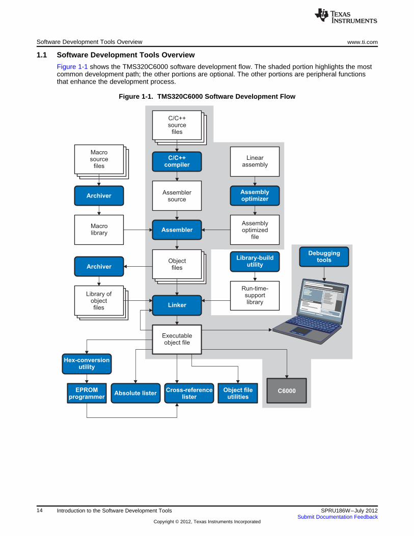
Figure 1-1 shows the TMS320C6000 software development flow. The shaded portion highlights the mostcommon development path; the other portions are optional. The other portions are peripheral functionsthat enhance the development process.
Figure 1-1. TMS320C6000 Software Development Flow
14 Introduction to the Software Development Tools SPRU186W–July 2012Submit Documentation Feedback
Copyright © 2012, Texas Instruments Incorporated
www.ti.com Tools Descriptions
1.2 Tools Descriptions
The following list describes the tools that are shown in Figure 1-1:
• The C/C++ compiler accepts C/C++ source code and produces TMS320C6000 machine code objectmodules. A shell program, an optimizer, and an interlist utility are included in the compilerpackage:
– The shell program enables you to compile, assemble, and link source modules in one step.
– The optimizer modifies code to improve the efficiency of C/C++ programs.
– The interlist utility interlists C/C++ source statements with assembly language output to correlatecode produced by the compiler with your source code.
See the TMS320C6000 Optimizing Compiler User's Guide for more information.
• The assembly optimizer allows you to write linear assembly code without being concerned with thepipeline structure or with assigning registers. It accepts assembly code that has not been register-allocated and is unscheduled. The assembly optimizer assigns registers and uses loop optimization toturn linear assembly into highly parallel assembly that takes advantage of software pipelining. See theTMS320C6000 Optimizing Compiler User's Guide for more information.
• The assembler translates assembly language source files into machine language object modules.Source files can contain instructions, assembler directives, and macro directives. You can useassembler directives to control various aspects of the assembly process, such as the source listingformat, data alignment, and section content. See Chapter 3 through Chapter 5. See the TMS320C62xDSP CPU and Instruction Set Reference Guide, TMS320C64x/C64x+ DSP CPU and Instruction SetReference Guide, TMS320C67x/C67x+ DSP CPU and Instruction Set Reference Guide, andTMS320C66x CPU and Instruction Set Reference Guide for detailed information on the assemblylanguage instruction set.
• The linker combines object files into a single static executable or object dynamic object module. As itcreates a static executable module, it performs relocation and resolves external references. The linkeraccepts relocatable object modules (created by the assembler) as input. It also accepts archiver librarymembers and output modules created by a previous linker run. Link directives allow you to combineobject file sections, bind sections or symbols to addresses or within memory ranges, and define orredefine global symbols. See Chapter 7.
For more information about creating a dynamic object module, seehttp://processors.wiki.ti.com/index.php/C6000_Dynamic_Linking.
• The archiver allows you to collect a group of files into a single archive file, called a library. You canalso use the archiver to collect a group of object files into an object library. You can collect severalmacros into a macro library. The assembler searches the library and uses the members that are calledas macros by the source file. The linker includes in the library the members that resolve externalreferences during the link. The archiver allows you to modify a library by deleting, replacing, extracting,or adding members. See Section 6.1.
• The library information archiver allows you to create an index library of several object file libraryvariants, which is useful when several variants of a library with different options are available. Ratherthan refer to a specific library, you can link against the index library, and the linker will choose the bestmatch from the indexed libraries. See Section 6.5.
• You can use the library-build utility to build your own customized run-time-support library. See theTMS320C6000 Optimizing Compiler User's Guide for more information.
• The hex conversion utility converts an object file into TI-Tagged, ASCII-Hex, Intel, Motorola-S, orTektronix object format. The converted file can be downloaded to an EPROM programmer. SeeChapter 11.
• The absolute lister uses linked object files to create .abs files. These files can be assembled toproduce a listing of the absolute addresses of object code. See Chapter 8.
• The cross-reference lister uses object files to produce a cross-reference listing showing symbols,their definition, and their references in the linked source files. See Chapter 9.
• The main product of this development process is a executable object file that can be executed in aTMS320C6000 device. You can use one of several debugging tools to refine and correct your code.Available products include:
– An instruction-accurate and clock-accurate software simulator
15SPRU186W–July 2012 Introduction to the Software Development ToolsSubmit Documentation Feedback
Copyright © 2012, Texas Instruments Incorporated
Tools Descriptions www.ti.com
– An XDS emulator
16 Introduction to the Software Development Tools SPRU186W–July 2012Submit Documentation Feedback
Copyright © 2012, Texas Instruments Incorporated
www.ti.com Tools Descriptions
In addition, the following utilities are provided:
• The object file display utility prints the contents of object files, executable files, and archive librariesin either human readable or XML formats. See Section 10.1.
• The disassembler decodes object modules to show the assembly instructions that it represents. SeeSection 10.2.
• The name utility prints a list of linknames of objects and functions defined or referenced in a object oran executable file. See Section 10.3.
• The strip utility removes symbol table and debugging information from object and executable files.See Section 10.4.
17SPRU186W–July 2012 Introduction to the Software Development ToolsSubmit Documentation Feedback
Copyright © 2012, Texas Instruments Incorporated
Chapter 2SPRU186W–July 2012
Introduction to Object Modules
The assembler creates object modules from assembly code, and the linker creates executable object filesfrom object modules. These executable object files can be executed by a TMS320C6000 device.
Object modules make modular programming easier because they encourage you to think in terms ofblocks of code and data when you write an assembly language program. These blocks are known assections. Both the assembler and the linker provide directives that allow you to create and manipulatesections.
This chapter focuses on the concept and use of sections in assembly language programs.
Topic ........................................................................................................................... Page
2.1 Sections ........................................................................................................... 192.2 How the Assembler Handles Sections ................................................................. 202.3 How the Linker Handles Sections ........................................................................ 262.4 Relocation ........................................................................................................ 272.5 Run-Time Relocation ......................................................................................... 292.6 Loading a Program ............................................................................................ 292.7 Symbols in an Object File ................................................................................... 302.8 Object File Format Specifications ........................................................................ 31
18 Introduction to Object Modules SPRU186W–July 2012Submit Documentation Feedback
Copyright © 2012, Texas Instruments Incorporated
Object file
.bss
.data
.text
RAM
EEPROM
ROM
Target memory
www.ti.com Sections
2.1 Sections
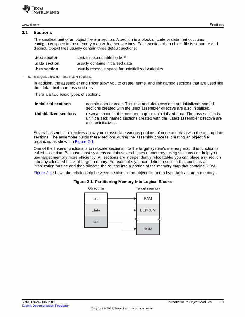
The smallest unit of an object file is a section. A section is a block of code or data that occupiescontiguous space in the memory map with other sections. Each section of an object file is separate anddistinct. Object files usually contain three default sections:
.text section contains executable code (1)
.data section usually contains initialized data
.bss section usually reserves space for uninitialized variables
(1) Some targets allow non-text in .text sections.
In addition, the assembler and linker allow you to create, name, and link named sections that are used likethe .data, .text, and .bss sections.
There are two basic types of sections:
Initialized sections contain data or code. The .text and .data sections are initialized; namedsections created with the .sect assembler directive are also initialized.
Uninitialized sections reserve space in the memory map for uninitialized data. The .bss section isuninitialized; named sections created with the .usect assembler directive arealso uninitialized.
Several assembler directives allow you to associate various portions of code and data with the appropriatesections. The assembler builds these sections during the assembly process, creating an object fileorganized as shown in Figure 2-1.
One of the linker's functions is to relocate sections into the target system's memory map; this function iscalled allocation. Because most systems contain several types of memory, using sections can help youuse target memory more efficiently. All sections are independently relocatable; you can place any sectioninto any allocated block of target memory. For example, you can define a section that contains aninitialization routine and then allocate the routine into a portion of the memory map that contains ROM.
Figure 2-1 shows the relationship between sections in an object file and a hypothetical target memory.
Figure 2-1. Partitioning Memory Into Logical Blocks
19SPRU186W–July 2012 Introduction to Object ModulesSubmit Documentation Feedback
Copyright © 2012, Texas Instruments Incorporated
How the Assembler Handles Sections www.ti.com
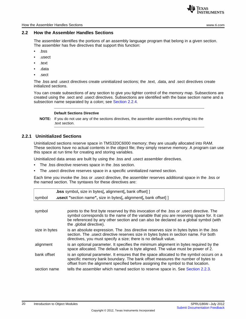
2.2 How the Assembler Handles Sections
The assembler identifies the portions of an assembly language program that belong in a given section.The assembler has five directives that support this function:
• .bss
• .usect
• .text
• .data
• .sect
The .bss and .usect directives create uninitialized sections; the .text, .data, and .sect directives createinitialized sections.
You can create subsections of any section to give you tighter control of the memory map. Subsections arecreated using the .sect and .usect directives. Subsections are identified with the base section name and asubsection name separated by a colon; see Section 2.2.4.
Default Sections Directive
NOTE: If you do not use any of the sections directives, the assembler assembles everything into the.text section.
2.2.1 Uninitialized Sections
Uninitialized sections reserve space in TMS320C6000 memory; they are usually allocated into RAM.These sections have no actual contents in the object file; they simply reserve memory. A program can usethis space at run time for creating and storing variables.
Uninitialized data areas are built by using the .bss and .usect assembler directives.
• The .bss directive reserves space in the .bss section.
• The .usect directive reserves space in a specific uninitialized named section.
Each time you invoke the .bss or .usect directive, the assembler reserves additional space in the .bss orthe named section. The syntaxes for these directives are:
.bss symbol, size in bytes[, alignment[, bank offset] ]
symbol .usect "section name", size in bytes[, alignment[, bank offset] ]
symbol points to the first byte reserved by this invocation of the .bss or .usect directive. Thesymbol corresponds to the name of the variable that you are reserving space for. It canbe referenced by any other section and can also be declared as a global symbol (withthe .global directive).
size in bytes is an absolute expression. The .bss directive reserves size in bytes bytes in the .bsssection. The .usect directive reserves size in bytes bytes in section name. For bothdirectives, you must specify a size; there is no default value.
alignment is an optional parameter. It specifies the minimum alignment in bytes required by thespace allocated. The default value is byte aligned. The value must be power of 2.
bank offset is an optional parameter. It ensures that the space allocated to the symbol occurs on aspecific memory bank boundary. The bank offset measures the number of bytes tooffset from the alignment specified before assigning the symbol to that location.
section name tells the assembler which named section to reserve space in. See Section 2.2.3.
20 Introduction to Object Modules SPRU186W–July 2012Submit Documentation Feedback
Copyright © 2012, Texas Instruments Incorporated
www.ti.com How the Assembler Handles Sections
The initialized section directives (.text, .data, and .sect) tell the assembler to stop assembling into thecurrent section and begin assembling into the indicated section. The .bss and .usect directives, however,do not end the current section and begin a new one; they simply escape from the current sectiontemporarily. The .bss and .usect directives can appear anywhere in an initialized section without affectingits contents. For an example, see Section 2.2.6.
The .usect directive can also be used to create uninitialized subsections. See Section 2.2.4, for moreinformation on creating subsections.
2.2.2 Initialized Sections
Initialized sections contain executable code or initialized data. The contents of these sections are stored inthe object file and placed in TMS320C6000 memory when the program is loaded. Each initialized sectionis independently relocatable and may reference symbols that are defined in other sections. The linkerautomatically resolves these section-relative references.
Three directives tell the assembler to place code or data into a section. The syntaxes for these directivesare:
.text
.data
.sect "section name"
The assembler adds code or data to one section at a time. The section the assembler is currently filling isthe current section. The .text, .data, and .sect directives change the current section. When the assemblerencounters one of these directives, it stops assembling into the current section (acting as an implied endof current section command). The assembler sets the designated section as the current section andassembles subsequent code into the designated section until it encounters another .text, .data, or .sectdirective.
If one of these directives sets the current section to a section that already has code or data in it, theassembler resumes adding to the end of that section. The assembler generates only one contiguoussection for each given section name. This section is formed by concatenating allof the code or data whichwas placed in that section.
Initialized subsections are created with the .sect directive. The .sect directive can also be used to createinitialized subsections. See Section 2.2.4, for more information on creating subsections.
21SPRU186W–July 2012 Introduction to Object ModulesSubmit Documentation Feedback
Copyright © 2012, Texas Instruments Incorporated
How the Assembler Handles Sections www.ti.com
2.2.3 Named Sections
Named sections are sections that you create. You can use them like the default .text, .data, and .bsssections, but they are assembled separately.
For example, repeated use of the .text directive builds up a single .text section in the object file. Whenlinked, this .text section is allocated into memory as a single unit. Suppose there is a portion of executablecode (perhaps an initialization routine) that you do not want allocated with .text. If you assemble thissegment of code into a named section, it is assembled separately from .text, and you can allocate it intomemory separately. You can also assemble initialized data that is separate from the .data section, andyou can reserve space for uninitialized variables that is separate from the .bss section.
Two directives let you create named sections:
• The .usect directive creates uninitialized sections that are used like the .bss section. These sectionsreserve space in RAM for variables.
• The .sect directive creates initialized sections, like the default .text and .data sections, that can containcode or data. The .sect directive creates named sections with relocatable addresses.
The syntaxes for these directives are:
symbol .usect "section name", size in bytes[, alignment[, bank offset] ]
.sect "section name"
The section name parameter is the name of the section. For COFF, you can create up to 32 767 separatenamed sections. For ELF, the max number of sections is 232-1 (4294967295). For the .usect and .sectdirectives, a section name can refer to a subsection; see Section 2.2.4 for details.
Each time you invoke one of these directives with a new name, you create a new named section. Eachtime you invoke one of these directives with a name that was already used, the assembler assemblescode or data (or reserves space) into the section with that name. You cannot use the same names withdifferent directives. That is, you cannot create a section with the .usect directive and then try to use thesame section with .sect.
2.2.4 Subsections
Subsections are smaller sections within larger sections. Like sections, subsections can be manipulated bythe linker. Placing each function and object in a uniquely-named subsection allows finer-grained memoryplacement, and also allows the linker finer-grained unused-function elimination. You can createsubsections by using the .sect or .usect directive. The syntaxes for a subsection name are:
symbol .usect "section name:subsection name",size in bytes[,alignment[,bank offset]]
.sect "section name:subsection name"
A subsection is identified by the base section name followed by a colon and the name of the subsection. Asubsection can be allocated separately or grouped with other sections using the same base name. Forexample, you create a subsection called _func within the .text section:
.sect ".text:_func"
Using the linker's SECTIONS directive, you can allocate .text:_func separately, or with all the .textsections. See Section 7.5.4.1 for an example using subsections.
You can create two types of subsections:
• Initialized subsections are created using the .sect directive. See Section 2.2.2.
• Uninitialized subsections are created using the .usect directive. See Section 2.2.1.
Subsections are allocated in the same manner as sections. See Section 7.5.4 for information on theSECTIONS directive.
22 Introduction to Object Modules SPRU186W–July 2012Submit Documentation Feedback
Copyright © 2012, Texas Instruments Incorporated
www.ti.com How the Assembler Handles Sections
2.2.5 Section Program Counters
The assembler maintains a separate program counter for each section. These program counters areknown as section program counters, or SPCs.
An SPC represents the current address within a section of code or data. Initially, the assembler sets eachSPC to 0. As the assembler fills a section with code or data, it increments the appropriate SPC. If youresume assembling into a section, the assembler remembers the appropriate SPC's previous value andcontinues incrementing the SPC from that value.
The assembler treats each section as if it began at address 0; the linker relocates each section accordingto its final location in the memory map. See Section 2.4 for information on relocation.
2.2.6 Using Sections Directives
Figure 2-2 shows how you can build sections incrementally, using the sections directives to swap backand forth between the different sections. You can use sections directives to begin assembling into asection for the first time, or to continue assembling into a section that already contains code. In the lattercase, the assembler simply appends the new code to the code that is already in the section.
The format in Figure 2-2 is a listing file. Figure 2-2 shows how the SPCs are modified during assembly. Aline in a listing file has four fields:
Field 1 contains the source code line counter.Field 2 contains the section program counter.Field 3 contains the object code.Field 4 contains the original source statement.
See Section 3.12 for more information on interpreting the fields in a source listing.
23SPRU186W–July 2012 Introduction to Object ModulesSubmit Documentation Feedback
Copyright © 2012, Texas Instruments Incorporated
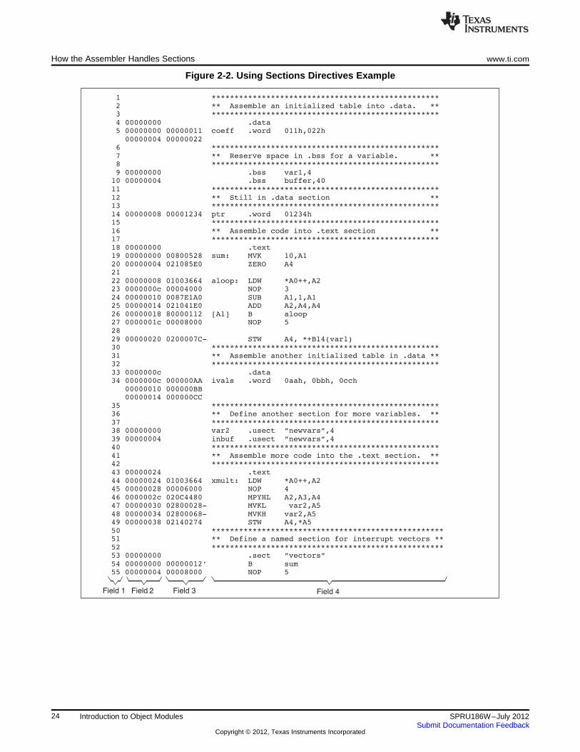
4 00000000 .data5 00000000 00000011 coeff .word 011h,022h
00000004 00000022
9 00000000 .bss var1,410 00000004 .bss buffer,40
14 00000008 00001234 ptr .word 01234h
18 00000000 .text19 00000000 00800528 sum: MVK 10,A1
20 00000004 021085E0 ZERO A421
22 00000008 01003664 aloop: LDW *A0++,A223 0000000c 00004000 NOP 3
24 00000010 0087E1A0 SUB A1,1,A125 00000014 021041E0 ADD A2,A4,A4
26 00000018 80000112 [A1] B aloop27 0000001c 00008000 NOP 5
28
29 00000020 0200007C- STW A4, *+B14(var1)
33 0000000c .data34 0000000c 000000AA ivals .word 0aah, 0bbh, 0cch
00000010 000000BB00000014 000000CC
38 00000000 var2 .usect ”newvars”,4
39 00000004 inbuf .usect ”newvars”,4
43 00000024 .text
44 00000024 01003664 xmult: LDW *A0++,A245 00000028 00006000 NOP 4
46 0000002c 020C4480 MPYHL A2,A3,A447 00000030 02800028- MVKL var2,A5
48 00000034 02800068- MVKH var2,A549 00000038 02140274 STW A4,*A5
53 00000000 .sect ”vectors”
54 00000000 00000012’ B sum55 00000004 00008000 NOP 5
Field 2Field 1 Field 3 Field 4
How the Assembler Handles Sections www.ti.com
Figure 2-2. Using Sections Directives Example
24 Introduction to Object Modules SPRU186W–July 2012Submit Documentation Feedback
Copyright © 2012, Texas Instruments Incorporated
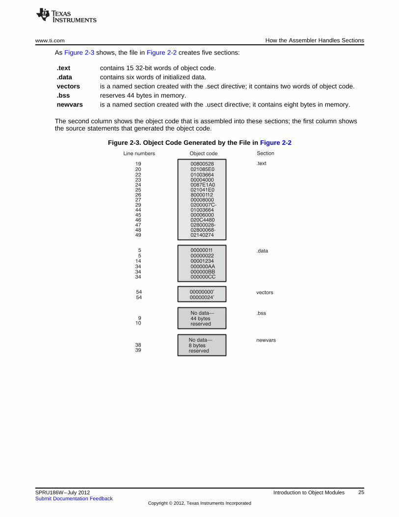
Line numbers Object code
.text
.data
.bss
Section
00800528021085E001003664
000000110000002200001234000000AA000000BB
No data—44 bytesreserved
192022
55
143434
9
2324
000040000087E1A0
vectors00000000’00000024’
5454
newvarsNo data—8 bytesreserved
3839
25262729444546474849
021041E080000112000080000200007C-0100366400006000020C448002800028-02800068-02140274
34 000000CC
10
www.ti.com How the Assembler Handles Sections
As Figure 2-3 shows, the file in Figure 2-2 creates five sections:
.text contains 15 32-bit words of object code.
.data contains six words of initialized data.vectors is a named section created with the .sect directive; it contains two words of object code..bss reserves 44 bytes in memory.newvars is a named section created with the .usect directive; it contains eight bytes in memory.
The second column shows the object code that is assembled into these sections; the first column showsthe source statements that generated the object code.
Figure 2-3. Object Code Generated by the File in Figure 2-2
25SPRU186W–July 2012 Introduction to Object ModulesSubmit Documentation Feedback
Copyright © 2012, Texas Instruments Incorporated
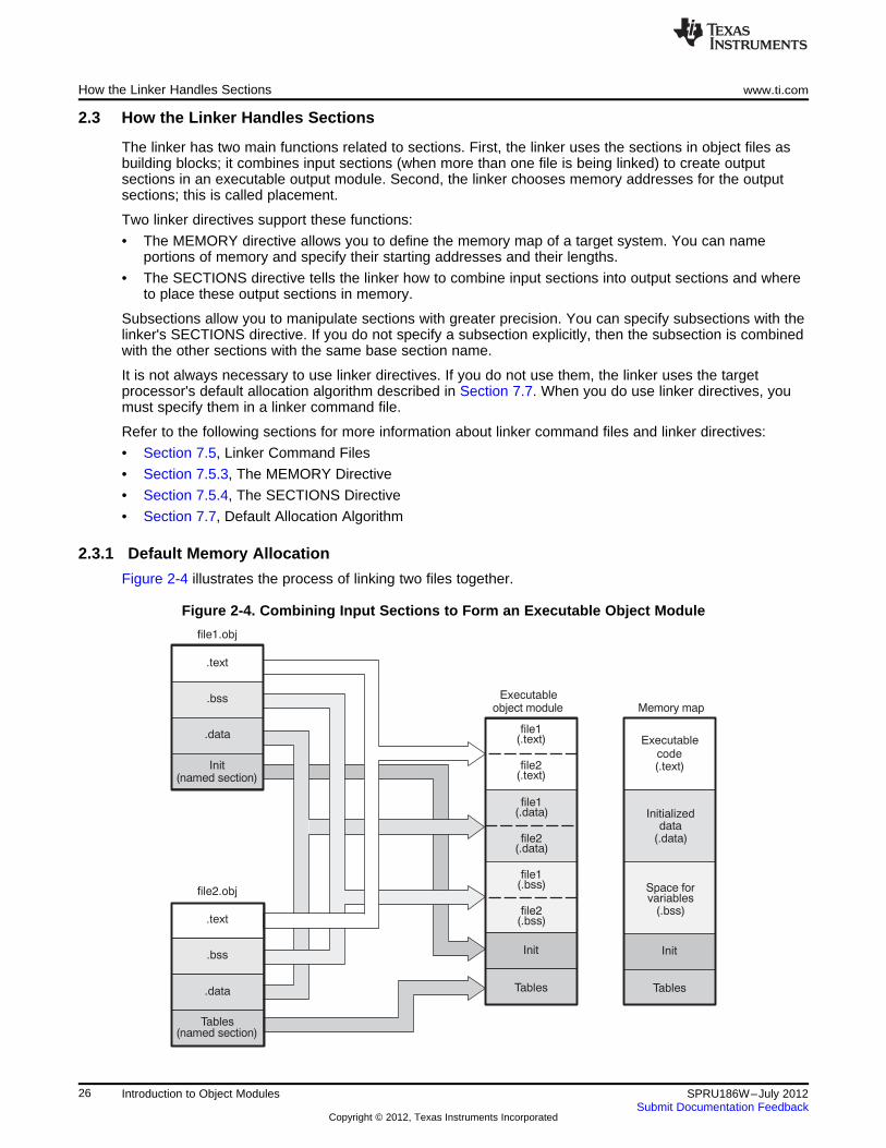
How the Linker Handles Sections www.ti.com
2.3 How the Linker Handles Sections
The linker has two main functions related to sections. First, the linker uses the sections in object files asbuilding blocks; it combines input sections (when more than one file is being linked) to create outputsections in an executable output module. Second, the linker chooses memory addresses for the outputsections; this is called placement.
Two linker directives support these functions:
• The MEMORY directive allows you to define the memory map of a target system. You can nameportions of memory and specify their starting addresses and their lengths.
• The SECTIONS directive tells the linker how to combine input sections into output sections and whereto place these output sections in memory.
Subsections allow you to manipulate sections with greater precision. You can specify subsections with thelinker's SECTIONS directive. If you do not specify a subsection explicitly, then the subsection is combinedwith the other sections with the same base section name.
It is not always necessary to use linker directives. If you do not use them, the linker uses the targetprocessor's default allocation algorithm described in Section 7.7. When you do use linker directives, youmust specify them in a linker command file.
Refer to the following sections for more information about linker command files and linker directives:
• Section 7.5, Linker Command Files
• Section 7.5.3, The MEMORY Directive
• Section 7.5.4, The SECTIONS Directive
• Section 7.7, Default Allocation Algorithm
2.3.1 Default Memory Allocation
Figure 2-4 illustrates the process of linking two files together.
Figure 2-4. Combining Input Sections to Form an Executable Object Module
26 Introduction to Object Modules SPRU186W–July 2012Submit Documentation Feedback
Copyright © 2012, Texas Instruments Incorporated
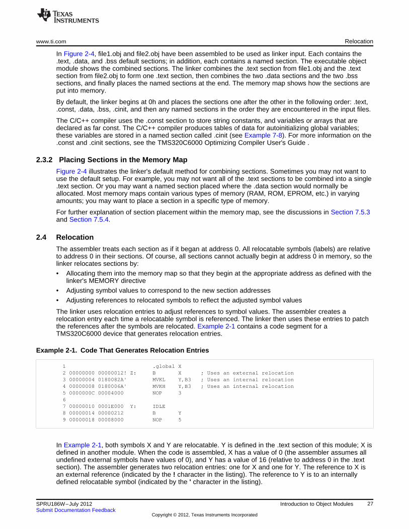
www.ti.com Relocation
In Figure 2-4, file1.obj and file2.obj have been assembled to be used as linker input. Each contains the.text, .data, and .bss default sections; in addition, each contains a named section. The executable objectmodule shows the combined sections. The linker combines the .text section from file1.obj and the .textsection from file2.obj to form one .text section, then combines the two .data sections and the two .bsssections, and finally places the named sections at the end. The memory map shows how the sections areput into memory.
By default, the linker begins at 0h and places the sections one after the other in the following order: .text,.const, .data, .bss, .cinit, and then any named sections in the order they are encountered in the input files.
The C/C++ compiler uses the .const section to store string constants, and variables or arrays that aredeclared as far const. The C/C++ compiler produces tables of data for autoinitializing global variables;these variables are stored in a named section called .cinit (see Example 7-8). For more information on the.const and .cinit sections, see the TMS320C6000 Optimizing Compiler User's Guide .
2.3.2 Placing Sections in the Memory Map
Figure 2-4 illustrates the linker's default method for combining sections. Sometimes you may not want touse the default setup. For example, you may not want all of the .text sections to be combined into a single.text section. Or you may want a named section placed where the .data section would normally beallocated. Most memory maps contain various types of memory (RAM, ROM, EPROM, etc.) in varyingamounts; you may want to place a section in a specific type of memory.
For further explanation of section placement within the memory map, see the discussions in Section 7.5.3and Section 7.5.4.
2.4 Relocation
The assembler treats each section as if it began at address 0. All relocatable symbols (labels) are relativeto address 0 in their sections. Of course, all sections cannot actually begin at address 0 in memory, so thelinker relocates sections by:
• Allocating them into the memory map so that they begin at the appropriate address as defined with thelinker's MEMORY directive
• Adjusting symbol values to correspond to the new section addresses
• Adjusting references to relocated symbols to reflect the adjusted symbol values
The linker uses relocation entries to adjust references to symbol values. The assembler creates arelocation entry each time a relocatable symbol is referenced. The linker then uses these entries to patchthe references after the symbols are relocated. Example 2-1 contains a code segment for aTMS320C6000 device that generates relocation entries.
Example 2‑‑1. Code That Generates Relocation Entries
1 .global X2 00000000 00000012! Z: B X ; Uses an external relocation3 00000004 0180082A' MVKL Y,B3 ; Uses an internal relocation4 00000008 0180006A' MVKH Y,B3 ; Uses an internal relocation5 0000000C 00004000 NOP 367 00000010 0001E000 Y: IDLE8 00000014 00000212 B Y9 00000018 00008000 NOP 5
In Example 2-1, both symbols X and Y are relocatable. Y is defined in the .text section of this module; X isdefined in another module. When the code is assembled, X has a value of 0 (the assembler assumes allundefined external symbols have values of 0), and Y has a value of 16 (relative to address 0 in the .textsection). The assembler generates two relocation entries: one for X and one for Y. The reference to X isan external reference (indicated by the ! character in the listing). The reference to Y is to an internallydefined relocatable symbol (indicated by the ' character in the listing).
27SPRU186W–July 2012 Introduction to Object ModulesSubmit Documentation Feedback
Copyright © 2012, Texas Instruments Incorporated
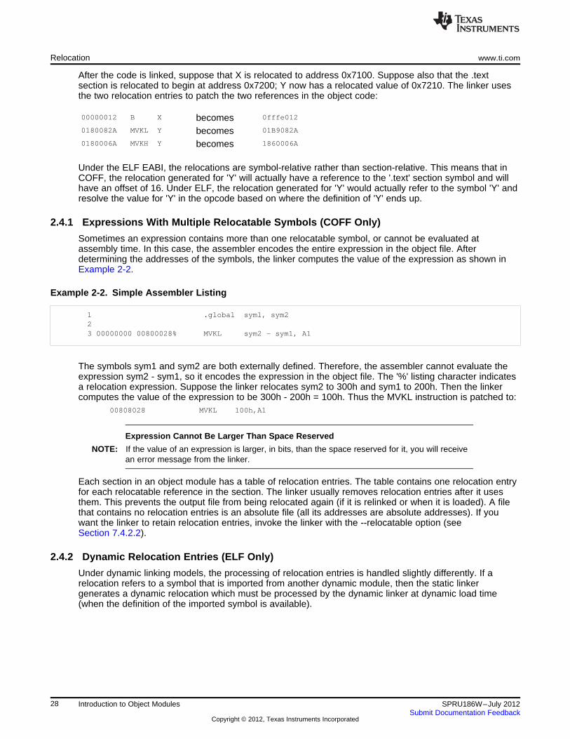
Relocation www.ti.com
After the code is linked, suppose that X is relocated to address 0x7100. Suppose also that the .textsection is relocated to begin at address 0x7200; Y now has a relocated value of 0x7210. The linker usesthe two relocation entries to patch the two references in the object code:
00000012 B X 0fffe012becomes0180082A MVKL Y 01B9082Abecomes0180006A MVKH Y 1860006Abecomes
Under the ELF EABI, the relocations are symbol-relative rather than section-relative. This means that inCOFF, the relocation generated for 'Y' will actually have a reference to the '.text' section symbol and willhave an offset of 16. Under ELF, the relocation generated for 'Y' would actually refer to the symbol 'Y' andresolve the value for 'Y' in the opcode based on where the definition of 'Y' ends up.
2.4.1 Expressions With Multiple Relocatable Symbols (COFF Only)
Sometimes an expression contains more than one relocatable symbol, or cannot be evaluated atassembly time. In this case, the assembler encodes the entire expression in the object file. Afterdetermining the addresses of the symbols, the linker computes the value of the expression as shown inExample 2-2.
Example 2-2. Simple Assembler Listing
1 .global sym1, sym223 00000000 00800028% MVKL sym2 - sym1, A1
The symbols sym1 and sym2 are both externally defined. Therefore, the assembler cannot evaluate theexpression sym2 - sym1, so it encodes the expression in the object file. The '%' listing character indicatesa relocation expression. Suppose the linker relocates sym2 to 300h and sym1 to 200h. Then the linkercomputes the value of the expression to be 300h - 200h = 100h. Thus the MVKL instruction is patched to:
00808028 MVKL 100h,A1
Expression Cannot Be Larger Than Space Reserved
NOTE: If the value of an expression is larger, in bits, than the space reserved for it, you will receivean error message from the linker.
Each section in an object module has a table of relocation entries. The table contains one relocation entryfor each relocatable reference in the section. The linker usually removes relocation entries after it usesthem. This prevents the output file from being relocated again (if it is relinked or when it is loaded). A filethat contains no relocation entries is an absolute file (all its addresses are absolute addresses). If youwant the linker to retain relocation entries, invoke the linker with the --relocatable option (seeSection 7.4.2.2).
2.4.2 Dynamic Relocation Entries (ELF Only)
Under dynamic linking models, the processing of relocation entries is handled slightly differently. If arelocation refers to a symbol that is imported from another dynamic module, then the static linkergenerates a dynamic relocation which must be processed by the dynamic linker at dynamic load time(when the definition of the imported symbol is available).
28 Introduction to Object Modules SPRU186W–July 2012Submit Documentation Feedback
Copyright © 2012, Texas Instruments Incorporated
www.ti.com Run-Time Relocation
2.5 Run-Time Relocation
At times you may want to load code into one area of memory and run it in another. For example, you mayhave performance-critical code in an external-memory-based system. The code must be loaded intoexternal memory, but it would run faster in internal memory.
The linker provides a simple way to handle this. Using the SECTIONS directive, you can optionally directthe linker to allocate a section twice: first to set its load address and again to set its run address. Use theload keyword for the load address and the run keyword for the run address.
The load address determines where a loader places the raw data for the section. Any references to thesection (such as references to labels in it) refer to its run address. The application must copy the sectionfrom its load address to its run address before the first reference of the symbol is encountered at run time;this does not happen automatically simply because you specify a separate run address. For an examplethat illustrates how to move a block of code at run time, see Example 7-10.
If you provide only one allocation (either load or run) for a section, the section is allocated only once andloads and runs at the same address. If you provide both allocations, the section is actually allocated as if itwere two separate sections of the same size.
Uninitialized sections (such as .bss) are not loaded, so the only significant address is the run address. Thelinker allocates uninitialized sections only once; if you specify both run and load addresses, the linkerwarns you and ignores the load address.
For a complete description of run-time relocation, see Section 7.5.5.
2.6 Loading a Program
The linker can be used to produce static executable object modules. An executable object module has thesame format as object files that are used as linker input; the sections in an executable object module,however, are combined and relocated into target memory, and the relocations are all resolved.
To run a program, the data in the executable object module must be transferred, or loaded, into targetsystem memory. Several methods can be used for loading a program, depending on the executionenvironment. Common situations are described below:
• Code Composer Studio can load an executable object module onto hardware. The Code ComposerStudio loader reads the executable file and copies the program into target memory.
• You can use the hex conversion utility (hex6x, which is shipped as part of the assembly languagepackage) to convert the executable object module into one of several object file formats. You can thenuse the converted file with an EPROM programmer to burn the program into an EPROM.
• A standalone simulator can be invoked by the load6x command and the name of the executable objectmodule. The standalone simulator reads the executable file, copies the program into the simulator andexecutes it, displaying any C I/O.
29SPRU186W–July 2012 Introduction to Object ModulesSubmit Documentation Feedback
Copyright © 2012, Texas Instruments Incorporated
Symbols in an Object File www.ti.com
2.7 Symbols in an Object File
An object file contains a symbol table that stores information about symbols in the program. The linkeruses this table when it performs relocation.
2.7.1 External Symbols
External symbols are symbols that are defined in one file and referenced in another file. You can use the.def, .ref, or .global directive to identify symbols as external:
.def The symbol is defined in the current file and used in another file.
.ref The symbol is referenced in the current file, but defined in another file.
.global The symbol can be either of the above.
The following code segment illustrates these definitions.
.def x
.ref y
.global z
.global q
q: B B3NOP 4MVK 1, B1
x: MV A0,A1MVKL y,B3MVKH y,B3B zNOP 5
In this example, the .def definition of x says that it is an external symbol defined in this file and that otherfiles can reference x. The .ref definition of y says that it is an undefined symbol that is defined in anotherfile. The .global definition of z says that it is defined in some file and available in this file. The .globaldefinition of q says that it is defined in this file and that other files can reference q.
The assembler places x, y, z, and q in the object file's symbol table. When the file is linked with otherobject files, the entries for x and q resolve references to x and q in other files. The entries for y and zcause the linker to look through the symbol tables of other files for y's and z's definitions.
The linker must match all references with corresponding definitions. If the linker cannot find a symbol'sdefinition, it prints an error message about the unresolved reference. This type of error prevents the linkerfrom creating an executable object module.
30 Introduction to Object Modules SPRU186W–July 2012Submit Documentation Feedback
Copyright © 2012, Texas Instruments Incorporated
www.ti.com Object File Format Specifications
2.8 Object File Format Specifications
The object files created by the assembler and linker conform to either the ELF (Executable and LinkingFormat) or COFF (Common Object File Format) binary formats, depending on the ABI selected whenbuilding your program. When using the EABI mode, the ELF format is used. For the older COFF ABImode, the legacy COFF format is used.
Some features of the assembler may apply only to the ELF or COFF object file format. In these cases, theproper object file format is stated in the feature description.
See the TMS320C6000 Optimizing Compiler User's Guide and The C6000 Embedded Application BinaryInterface Application Report for information on the different ABIs available.
See the Common Object File Format Application Note (SPRAAO8) for information about the COFF objectfile format.
The ELF object files generated by the assembler and linker conform to the December 17, 2003 snapshotof the System V generic ABI (or gABI).
31SPRU186W–July 2012 Introduction to Object ModulesSubmit Documentation Feedback
Copyright © 2012, Texas Instruments Incorporated
Chapter 3SPRU186W–July 2012
Assembler Description
The TMS320C6000 assembler translates assembly language source files into machine language objectfiles. These files are in object modules, which are discussed in Chapter 2. Source files can contain thefollowing assembly language elements:
Assembler directives described in Chapter 4Macro directives described in Chapter 5Assembly language instructions described in the TMS320C62x DSP CPU and Instruction Set
Reference Guide, TMS320C64x/C64x+ DSP CPU andInstruction Set Reference Guide, TMS320C67x/C67x+ DSPCPU and Instruction Set Reference Guide, and TMS320C66xCPU and Instruction Set Reference Guide.
Topic ........................................................................................................................... Page
3.1 Assembler Overview .......................................................................................... 333.2 The Assembler's Role in the Software Development Flow ...................................... 343.3 Invoking the Assembler ..................................................................................... 353.4 Controlling Application Binary Interface ............................................................... 363.5 Naming Alternate Directories for Assembler Input ................................................. 363.6 Source Statement Format ................................................................................... 393.7 Constants ......................................................................................................... 423.8 Character Strings .............................................................................................. 443.9 Symbols ........................................................................................................... 443.10 Expressions ...................................................................................................... 523.11 Built-in Functions and Operators ........................................................................ 553.12 Source Listings ................................................................................................. 603.13 Debugging Assembly Source .............................................................................. 623.14 Cross-Reference Listings ................................................................................... 63
32 Assembler Description SPRU186W–July 2012Submit Documentation Feedback
Copyright © 2012, Texas Instruments Incorporated
www.ti.com Assembler Overview
3.1 Assembler Overview
The assembler does the following:
• Processes the source statements in a text file to produce a relocatable object file
• Produces a source listing (if requested) and provides you with control over this listing
• Allows you to divide your code into sections and maintain a section program counter (SPC) for eachsection of object code
• Defines and references global symbols and appends a cross-reference listing to the source listing (ifrequested)
• Allows conditional assembly
• Supports macros, allowing you to define macros inline or in a library
33SPRU186W–July 2012 Assembler DescriptionSubmit Documentation Feedback
Copyright © 2012, Texas Instruments Incorporated

C/C++source
files
C/C++compiler
Assemblersource
Assembler
Executableobject file
DebuggingtoolsLibrary-build
utility
Run-time-supportlibrary
Archiver
Archiver
Macrolibrary
Absolute lister
Hex-conversionutility
Cross-referencelister
Object fileutilities
C6000
Linker
Linearassembly
Assemblyoptimizer
Assemblyoptimized
file
Macrosource
files
Objectfiles
EPROMprogrammer
Library ofobjectfiles
The Assembler's Role in the Software Development Flow www.ti.com
3.2 The Assembler's Role in the Software Development Flow
Figure 3-1 illustrates the assembler's role in the software development flow. The shaded portion highlightsthe most common assembler development path. The assembler accepts assembly language source filesas input, both those you create and those created by the TMS320C6000 C/C++ compiler.
Figure 3-1. The Assembler in the TMS320C6000 Software Development Flow
34 Assembler Description SPRU186W–July 2012Submit Documentation Feedback
Copyright © 2012, Texas Instruments Incorporated
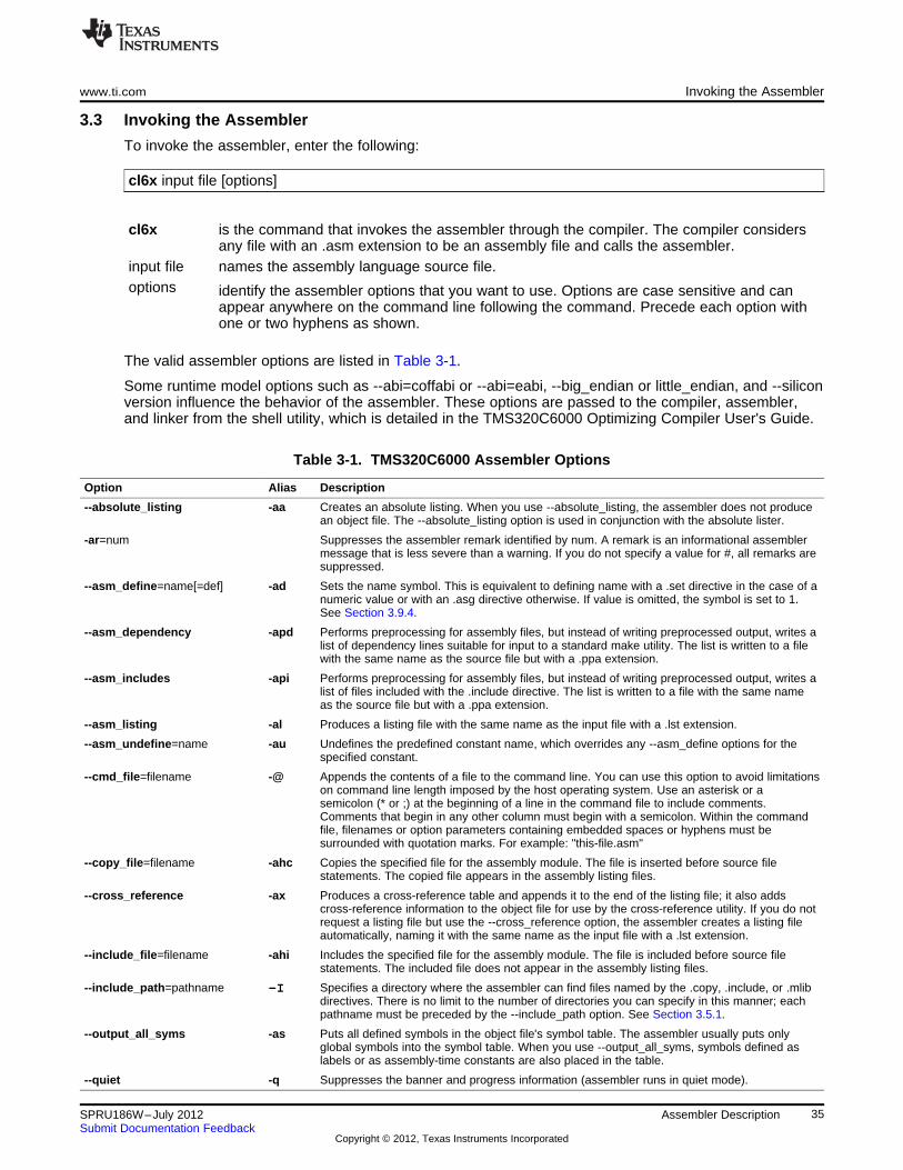
www.ti.com Invoking the Assembler
3.3 Invoking the Assembler
To invoke the assembler, enter the following:
cl6x input file [options]
cl6x is the command that invokes the assembler through the compiler. The compiler considersany file with an .asm extension to be an assembly file and calls the assembler.
input file names the assembly language source file.options identify the assembler options that you want to use. Options are case sensitive and can
appear anywhere on the command line following the command. Precede each option withone or two hyphens as shown.
The valid assembler options are listed in Table 3-1.
Some runtime model options such as --abi=coffabi or --abi=eabi, --big_endian or little_endian, and --siliconversion influence the behavior of the assembler. These options are passed to the compiler, assembler,and linker from the shell utility, which is detailed in the TMS320C6000 Optimizing Compiler User's Guide.
Table 3-1. TMS320C6000 Assembler Options
Option Alias Description
--absolute_listing -aa Creates an absolute listing. When you use --absolute_listing, the assembler does not producean object file. The --absolute_listing option is used in conjunction with the absolute lister.
-ar=num Suppresses the assembler remark identified by num. A remark is an informational assemblermessage that is less severe than a warning. If you do not specify a value for #, all remarks aresuppressed.
--asm_define=name[=def] -ad Sets the name symbol. This is equivalent to defining name with a .set directive in the case of anumeric value or with an .asg directive otherwise. If value is omitted, the symbol is set to 1.See Section 3.9.4.
--asm_dependency -apd Performs preprocessing for assembly files, but instead of writing preprocessed output, writes alist of dependency lines suitable for input to a standard make utility. The list is written to a filewith the same name as the source file but with a .ppa extension.
--asm_includes -api Performs preprocessing for assembly files, but instead of writing preprocessed output, writes alist of files included with the .include directive. The list is written to a file with the same nameas the source file but with a .ppa extension.
--asm_listing -al Produces a listing file with the same name as the input file with a .lst extension.
--asm_undefine=name -au Undefines the predefined constant name, which overrides any --asm_define options for thespecified constant.
--cmd_file=filename -@ Appends the contents of a file to the command line. You can use this option to avoid limitationson command line length imposed by the host operating system. Use an asterisk or asemicolon (* or ;) at the beginning of a line in the command file to include comments.Comments that begin in any other column must begin with a semicolon. Within the commandfile, filenames or option parameters containing embedded spaces or hyphens must besurrounded with quotation marks. For example: "this-file.asm"
--copy_file=filename -ahc Copies the specified file for the assembly module. The file is inserted before source filestatements. The copied file appears in the assembly listing files.
--cross_reference -ax Produces a cross-reference table and appends it to the end of the listing file; it also addscross-reference information to the object file for use by the cross-reference utility. If you do notrequest a listing file but use the --cross_reference option, the assembler creates a listing fileautomatically, naming it with the same name as the input file with a .lst extension.
--include_file=filename -ahi Includes the specified file for the assembly module. The file is included before source filestatements. The included file does not appear in the assembly listing files.
--include_path=pathname Specifies a directory where the assembler can find files named by the .copy, .include, or .mlib-Idirectives. There is no limit to the number of directories you can specify in this manner; eachpathname must be preceded by the --include_path option. See Section 3.5.1.
--output_all_syms -as Puts all defined symbols in the object file's symbol table. The assembler usually puts onlyglobal symbols into the symbol table. When you use --output_all_syms, symbols defined aslabels or as assembly-time constants are also placed in the table.
--quiet -q Suppresses the banner and progress information (assembler runs in quiet mode).
35SPRU186W–July 2012 Assembler DescriptionSubmit Documentation Feedback
Copyright © 2012, Texas Instruments Incorporated
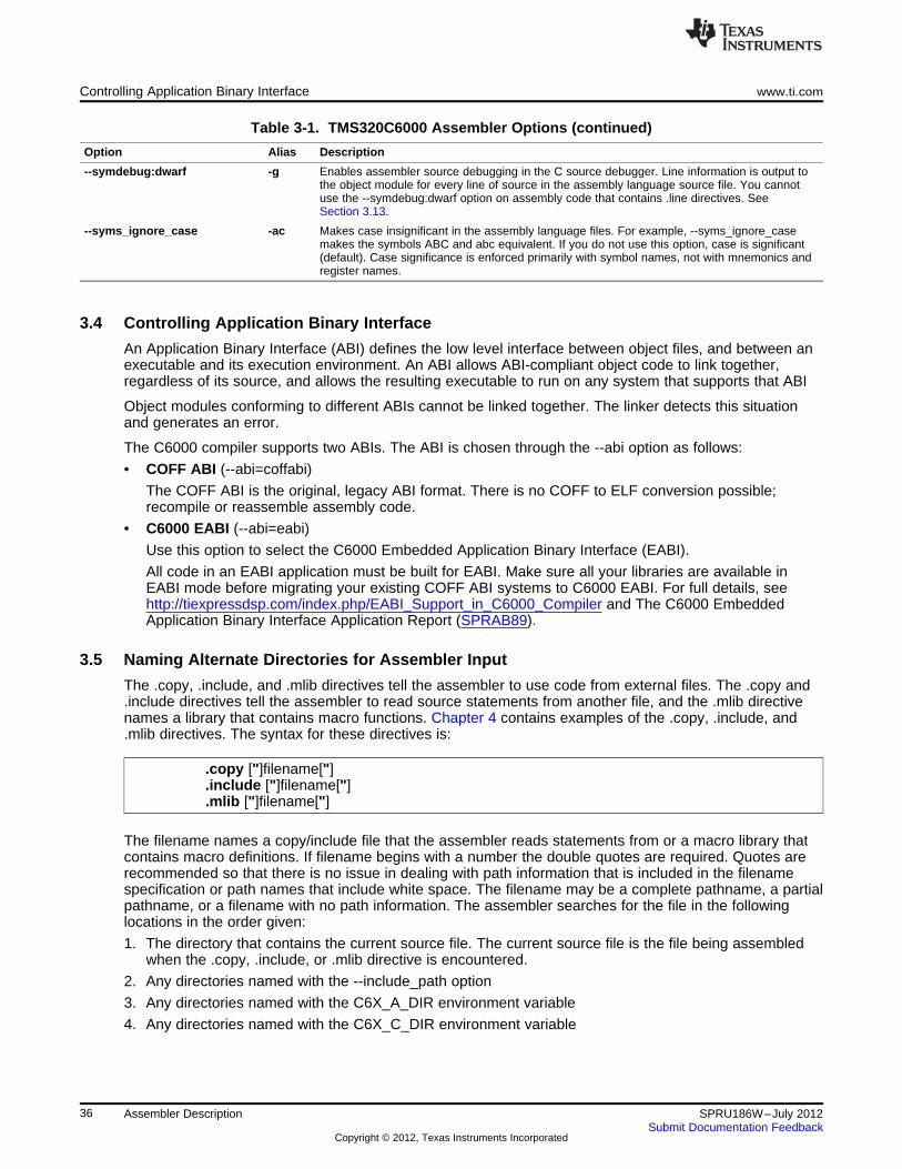
Controlling Application Binary Interface www.ti.com
Table 3-1. TMS320C6000 Assembler Options (continued)
Option Alias Description
--symdebug:dwarf -g Enables assembler source debugging in the C source debugger. Line information is output tothe object module for every line of source in the assembly language source file. You cannotuse the --symdebug:dwarf option on assembly code that contains .line directives. SeeSection 3.13.
--syms_ignore_case -ac Makes case insignificant in the assembly language files. For example, --syms_ignore_casemakes the symbols ABC and abc equivalent. If you do not use this option, case is significant(default). Case significance is enforced primarily with symbol names, not with mnemonics andregister names.
3.4 Controlling Application Binary Interface
An Application Binary Interface (ABI) defines the low level interface between object files, and between anexecutable and its execution environment. An ABI allows ABI-compliant object code to link together,regardless of its source, and allows the resulting executable to run on any system that supports that ABI
Object modules conforming to different ABIs cannot be linked together. The linker detects this situationand generates an error.
The C6000 compiler supports two ABIs. The ABI is chosen through the --abi option as follows:
• COFF ABI (--abi=coffabi)
The COFF ABI is the original, legacy ABI format. There is no COFF to ELF conversion possible;recompile or reassemble assembly code.
• C6000 EABI (--abi=eabi)
Use this option to select the C6000 Embedded Application Binary Interface (EABI).
All code in an EABI application must be built for EABI. Make sure all your libraries are available inEABI mode before migrating your existing COFF ABI systems to C6000 EABI. For full details, seehttp://tiexpressdsp.com/index.php/EABI_Support_in_C6000_Compiler and The C6000 EmbeddedApplication Binary Interface Application Report (SPRAB89).
3.5 Naming Alternate Directories for Assembler Input
The .copy, .include, and .mlib directives tell the assembler to use code from external files. The .copy and.include directives tell the assembler to read source statements from another file, and the .mlib directivenames a library that contains macro functions. Chapter 4 contains examples of the .copy, .include, and.mlib directives. The syntax for these directives is:
.copy ["]filename["]
.include ["]filename["]
.mlib ["]filename["]
The filename names a copy/include file that the assembler reads statements from or a macro library thatcontains macro definitions. If filename begins with a number the double quotes are required. Quotes arerecommended so that there is no issue in dealing with path information that is included in the filenamespecification or path names that include white space. The filename may be a complete pathname, a partialpathname, or a filename with no path information. The assembler searches for the file in the followinglocations in the order given:
1. The directory that contains the current source file. The current source file is the file being assembledwhen the .copy, .include, or .mlib directive is encountered.
2. Any directories named with the --include_path option
3. Any directories named with the C6X_A_DIR environment variable
4. Any directories named with the C6X_C_DIR environment variable
36 Assembler Description SPRU186W–July 2012Submit Documentation Feedback
Copyright © 2012, Texas Instruments Incorporated
www.ti.com Naming Alternate Directories for Assembler Input
Because of this search hierarchy, you can augment the assembler's directory search algorithm by usingthe --include_path option (described in Section 3.5.1) or the C6X_A_DIR environment variable (describedin Section 3.5.2). The C6X_C_DIR environment variable is discussed in the TMS320C6000 OptimizingCompiler User's Guide.
3.5.1 Using the --include_path Assembler Option
The --include_path assembler option names an alternate directory that contains copy/include files ormacro libraries. The format of the --include_path option is as follows:
cl6x --include_path= pathname source filename [other options]
There is no limit to the number of --include_path options per invocation; each --include_path option namesone pathname. In assembly source, you can use the .copy, .include, or .mlib directive without specifyingpath information. If the assembler does not find the file in the directory that contains the current sourcefile, it searches the paths designated by the --include_path options.
For example, assume that a file called source.asm is in the current directory; source.asm contains thefollowing directive statement:
.copy "copy.asm"
Assume the following paths for the copy.asm file:
UNIX: /tools/files/copy.asmWindows: c:\tools\files\copy.asm
You could set up the search path with the commands shown below:
Operating System Enter
UNIX (Bourne shell) cl6x --include_path=/tools/files source.asm
Windows cl6x --include_path=c:\tools\files source.asm
The assembler first searches for copy.asm in the current directory because source.asm is in the currentdirectory. Then the assembler searches in the directory named with the --include_path option.
3.5.2 Using the C6X_A_DIR Environment Variable
An environment variable is a system symbol that you define and assign a string to. The assembler usesthe C6X_A_DIR environment variable to name alternate directories that contain copy/include files ormacro libraries.
The assembler looks for the C6X_A_DIR environment variable and then reads and processes it. If theassembler does not find the C6X_A_DIR variable, it then searches for C6X_C_DIR. The processor-specific variables are useful when you are using Texas Instruments tools for different processors at thesame time.
See the TMS320C6000 Optimizing Compiler User's Guide for details on C6X_C_DIR.
The command syntax for assigning the environment variable is as follows:
Operating System Enter
UNIX (Bourne Shell) C6X_A_DIR=" pathname1 ; pathname2 ; . . . "; export C6X_A_DIR
Windows set C6X_A_DIR= pathname1 ; pathname2 ; . . .
37SPRU186W–July 2012 Assembler DescriptionSubmit Documentation Feedback
Copyright © 2012, Texas Instruments Incorporated
Naming Alternate Directories for Assembler Input www.ti.com
The pathnames are directories that contain copy/include files or macro libraries. The pathnames mustfollow these constraints:
• Pathnames must be separated with a semicolon.
• Spaces or tabs at the beginning or end of a path are ignored. For example the space before and afterthe semicolon in the following is ignored:set C6X_A_DIR= c:\path\one\to\tools ; c:\path\two\to\tools
• Spaces and tabs are allowed within paths to accommodate Windows directories that contain spaces.For example, the pathnames in the following are valid:set C6X_A_DIR=c:\first path\to\tools;d:\second path\to\tools
In assembly source, you can use the .copy, .include, or .mlib directive without specifying path information.If the assembler does not find the file in the directory that contains the current source file or in directoriesnamed by the --include_path option, it searches the paths named by the environment variable.
For example, assume that a file called source.asm contains these statements:.copy "copy1.asm".copy "copy2.asm"
Assume the following paths for the files:
UNIX: /tools/files/copy1.asm and /dsys/copy2.asmWindows: c:\tools\files\copy1.asm and c:\dsys\copy2.asm
You could set up the search path with the commands shown below:
Operating System Enter
UNIX (Bourne shell) C6X_A_DIR="/dsys"; export C6X_A_DIRcl6x --include_path=/tools/files source.asm
Windows set C6X_A_DIR=c:\dsyscl6x --include_path=c:\tools\files source.asm
The assembler first searches for copy1.asm and copy2.asm in the current directory because source.asmis in the current directory. Then the assembler searches in the directory named with the --include_pathoption and finds copy1.asm. Finally, the assembler searches the directory named with C6X_A_DIR andfinds copy2.asm.
The environment variable remains set until you reboot the system or reset the variable by entering one ofthese commands:
Operating System Enter
UNIX (Bourne shell) unset C6X_A_DIR
Windows set C6X_A_DIR=
38 Assembler Description SPRU186W–July 2012Submit Documentation Feedback
Copyright © 2012, Texas Instruments Incorporated
www.ti.com Source Statement Format
3.6 Source Statement Format
TMS320C6000 assembly language source programs consist of source statements that can containassembler directives, assembly language instructions, macro directives, and comments. A sourcestatement can contain five ordered fields (label, mnemonic, unit specifier, operand list, and comment). Thegeneral syntax for source statements is as follows:
[label[:]] [||] [[ register ]] mnemonic [unit specifier] [operand list][;comment]
A label can only be associated with the first instruction in an execute packet (a group of instructions that isto be executed in parallel).
Following are examples of source statements:two .set 2 ; Symbol Two = 2Label: MVK two,A2 ; Move 2 into register A2
.word 016h ; Initialize a word with 016h
There is no limit on characters per source statement. Use a backslash (\) to indicate continuation of thesame instruction/directive across multiple lines.
Follow these guidelines:
• All statements must begin with a label, a blank, an asterisk, or a semicolon.
• Labels are optional; if used, they must begin in column 1.
• One or more space or tab characters must separate each field.
• Comments are optional. Comments that begin in column 1 can begin with an asterisk or a semicolon (*or ;), but comments that begin in any other column must begin with a semicolon.
• In a conditional instruction, the condition register must be surrounded by square brackets.
• The functional unit specifier is optional. If you do not specify the functional unit, the assembler assignsa legal functional unit based on the mnemonic field and the other instructions in the execute packet.
• A mnemonic cannot begin in column 1 or it will be interpreted as a label. The assembler does notcheck to make sure you do not have a mnemonic in the label field.
The following sections describe each of the fields.
39SPRU186W–July 2012 Assembler DescriptionSubmit Documentation Feedback
Copyright © 2012, Texas Instruments Incorporated
||||||||||
Inst1Inst2Inst3Inst4Inst5Inst6Inst7
These five instructions runin parallel with the firstinstruction.
Source Statement Format www.ti.com
3.6.1 Label Field
Labels are optional for all assembly language instructions and for most (but not all) assembler directives.When used, a label must begin in column 1 of a source statement. A label can contain up to 400alphanumeric characters (A-Z, a-z, 0-9, _, and $). Labels are case sensitive (except when the --syms_ignore_case option is used), and the first character cannot be a number. A label can be followed bya colon (:). The colon is not treated as part of the label name. If you do not use a label, the first characterposition must contain a blank, a semicolon, or an asterisk. You cannot use a label on an instruction that isin parallel with a previous instruction.
When you use a label, its value is the current value of the SPC. The label points to the statement it isassociated with. For example, if you use the .word directive to initialize several words, a label points to thefirst word. In the following example, the label Start has the value 40h.. . . .. . . .
9 * Assume some code was assembled10 00000040 0000000A Start: .word 0Ah,3,7
00000044 0000000300000048 00000007
The label assigns the current value of the section program counter to the label; this is equivalent to thefollowing directive statement:label .equ $ ; $ provides the current value of the SPC
When a label appears on a line by itself, it points to the instruction on the next line (the SPC is notincremented):
1 00000000 Here:2 00000000 00000003 .word 3
If you do not use a label, the character in column 1 must be a blank, an asterisk, or a semicolon.
3.6.2 Mnemonic Field
The mnemonic field follows the label field. The mnemonic field cannot start in column 1; if it does, it isinterpreted as a label. There is one exception: the parallel bars (||) of the mnemonic field can start incolumn 1. The mnemonic field can begin with one of the following items:
• Parallel bars (||) indicate instructions that are in parallel with a previous instruction. You can have up toeight instructions that will be executed in parallel. The following example demonstrates six instructionsto be executed in parallel:
• Square brackets ([ ]) indicate conditional instructions. The machine-instruction mnemonic is executedbased on the value of the register within the brackets; valid register names are A0 for C64xx only, A1,A2, B0, B1, and B2. These registers are often called predicate registers.
The instruction is executed if the value of the register is nonzero. If the register name is preceded byan exclamation point (!), then the instruction is executed if the value of the register is 0. For example:[A1] ZERO A2 ; If A1 is not equal to zero, A2 = 0
The preceding exclamation point, if specified, is called a "logical NOT operator" or a "unary NOToperator".
40 Assembler Description SPRU186W–July 2012Submit Documentation Feedback
Copyright © 2012, Texas Instruments Incorporated
www.ti.com Source Statement Format
Next, the mnemonic field contains one of the following items:
• Machine-instruction mnemonic (such as ADDK, MVKH, B)
• Assembler directive (such as .data, .list, .equ, .macro, .var, .mexit)
The || and "[predicate register]" contructs are not legal in combination with an assembler directive.
• Macro call
3.6.3 Unit Specifier Field
The unit specifier field is an optional field that follows the mnemonic field for machine-instructionmnemonics. The unit specifier field begins with a period (.) followed by a functional unit specifier. Ingeneral, one instruction can be assigned to each functional unit in a single instruction cycle. There areeight functional units, two of each functional type:
.D1 and .D2 Data/addition/subtraction
.L1 and .L2 ALU/compares/long data arithmetic
.M1 and .M2 Multiply
.S1 and .S2 Shift/ALU/branch/bit fieldALU refers to an arithmetic logic unit.
There are several ways to use the unit specifier field:
• You can specify the particular functional unit (for example, .D1).
• You can specify only the functional type (for example, .M), and the assembler assigns the specific unit(for example, .M2).
• If you do not specify the functional unit, the assembler assigns the functional unit based on themnemonic field, operand fields, and other instructions in the same execute packet.
For more information on functional units, including which assembly instructions require which functionaltype, see the TMS320C62x DSP CPU and Instruction Set Reference Guide, TMS320C64x/C64x+ DSPCPU and Instruction Set Reference Guide, or TMS320C67x/C67x+ DSP CPU and Instruction SetReference Guide.
3.6.4 Operand Field
The operand field follows the mnemonic field and contains one or more operands. The operand field is notrequired for all instructions or directives. An operand consists of the following items:
• Constants (see Section 3.7)
• Character strings (see Section 3.8)
• Symbols (see Section 3.9)
• Expressions (combination of constants and symbols; see Section 3.10)
You must separate operands with commas.
3.6.5 Comment Field
A comment can begin in any column and extends to the end of the source line. A comment can containany ASCII character, including blanks. Comments are printed in the assembly source listing, but they donot affect the assembly.
A source statement that contains only a comment is valid. If it begins in column 1, it can start with asemicolon ( ; ) or an asterisk ( *). Comments that begin anywhere else on the line must begin with asemicolon. The asterisk identifies a comment only if it appears in column 1.
41SPRU186W–July 2012 Assembler DescriptionSubmit Documentation Feedback
Copyright © 2012, Texas Instruments Incorporated
Constants www.ti.com
3.7 Constants
The assembler supports several types of constants:
• Binary integer
• Octal integer
• Decimal integer
• Hexadecimal integer
• Character
• Assembly time
The assembler maintains each constant internally as a 32-bit quantity. Constants are not sign extended.For example, the constant 00FFh is equal to 00FF (base 16) or 255 (base 10); it does not equal -1.However, when used with the .byte directive, -1 is equivalent to 00FFh.
3.7.1 Binary Integers
A binary integer constant is a string of up to 32 binary digits (0s and 1s) followed by the suffix B (or b). Iffewer than 32 digits are specified, the assembler right justifies the value and fills the unspecified bits withzeros. These are examples of valid binary constants:
00000000B Constant equal to 010 or 016
0100000b Constant equal to 3210 or 2016
01b Constant equal to 110 or 116
11111000B Constant equal to 24810 or 0F816
3.7.2 Octal Integers
An octal integer constant is a string of up to 11 octal digits (0 through 7) followed by the suffix Q (or q).These are examples of valid octal constants:
10Q Constant equal to 810 or 816
010 Constant equal to 810 or 816 © format)100000Q Constant equal to 32 76810 or 800016
226q Constant equal to 15010 or 9616
3.7.3 Decimal Integers
A decimal integer constant is a string of decimal digits ranging from -2147 483 648 to 4 294 967 295.These are examples of valid decimal constants:
1000 Constant equal to 100010 or 3E816
-32768 Constant equal to -32 76810 or 800016
25 Constant equal to 2510 or 1916
42 Assembler Description SPRU186W–July 2012Submit Documentation Feedback
Copyright © 2012, Texas Instruments Incorporated
www.ti.com Constants
3.7.4 Hexadecimal Integers
A hexadecimal integer constant is a string of up to eight hexadecimal digits followed by the suffix H (or h)or preceded by 0x. Hexadecimal digits include the decimal values 0-9 and the letters A-F or a-f. Ahexadecimal constant must begin with a decimal value (0-9). If fewer than eight hexadecimal digits arespecified, the assembler right justifies the bits. These are examples of valid hexadecimal constants:
78h Constant equal to 12010 or 007816
0x78 Constant equal to 12010 or 007816 © format)0Fh Constant equal to 1510 or 000F16
37ACh Constant equal to 14 25210 or 37AC16
3.7.5 Character Constants
A character constant is a single character enclosed in single quotes. The characters are representedinternally as 8-bit ASCII characters. Two consecutive single quotes are required to represent each singlequote that is part of a character constant. A character constant consisting only of two single quotes is validand is assigned the value 0. These are examples of valid character constants:
'a' Defines the character constant a and is represented internally as 6116
'C' Defines the character constant C and is represented internally as 4316
'''' Defines the character constant ' and is represented internally as 2716
'' Defines a null character and is represented internally as 0016
Notice the difference between character constants and character strings (Section 3.8 discussescharacter strings). A character constant represents a single integer value; a string is a sequence ofcharacters.
3.7.6 Assembly-Time Constants
If you use the .set directive to assign a value to a symbol (see Define Assembly-Time Constant), thesymbol becomes a constant. To use this constant in expressions, the value that is assigned to it must beabsolute. For example:sym .set 3
MVK sym,B1
You can also use the .set directive to assign symbolic constants for register names. In this case, thesymbol becomes a synonym for the register:sym .set B1
MVK 10,sym
43SPRU186W–July 2012 Assembler DescriptionSubmit Documentation Feedback
Copyright © 2012, Texas Instruments Incorporated
Character Strings www.ti.com
3.8 Character Strings
A character string is a string of characters enclosed in double quotes. Double quotes that are part ofcharacter strings are represented by two consecutive double quotes. The maximum length of a stringvaries and is defined for each directive that requires a character string. Characters are representedinternally as 8-bit ASCII characters.
These are examples of valid character strings:
"sample program" defines the 14-character string sample program."PLAN ""C""" defines the 8-character string PLAN "C".
Character strings are used for the following:
• Filenames, as in .copy "filename"
• Section names, as in .sect "section name"
• Data initialization directives, as in .byte "charstring"
• Operands of .string directives
3.9 Symbols
Symbols are used as labels, constants, and substitution symbols. A symbol name is a string ofalphanumeric characters, the dollar sign, and underscores (A-Z, a-z, 0-9, $, and _). The first character in asymbol cannot be a number, and symbols cannot contain embedded blanks. The symbols you define arecase sensitive; for example, the assembler recognizes ABC, Abc, and abc as three unique symbols. Youcan override case sensitivity with the --syms_ignore_case assembler option (see Section 3.3). A symbol isvalid only during the assembly in which it is defined, unless you use the .global directive or the .defdirective to declare it as an external symbol (see Identify Global Symbols).
3.9.1 Labels
Symbols used as labels become symbolic addresses that are associated with locations in the program.Labels used locally within a file must be unique. Mnemonic opcodes and assembler directive nameswithout the . prefix are valid label names.
Labels can also be used as the operands of .global, .ref, .def, or .bss directives; for example:.global label1
label2: MVKL label2, B3MVKH label2, B3B label1NOP 5
3.9.2 Local Labels
Local labels are special labels whose scope and effect are temporary. A local label can be defined in twoways:
• $n, where n is a decimal digit in the range 0-9. For example, $4 and $1 are valid local labels. SeeExample 3-1.
• name?, where name is any legal symbol name as described above. The assembler replaces thequestion mark with a period followed by a unique number. When the source code is expanded, you willnot see the unique number in the listing file. Your label appears with the question mark as it did in thesource definition. You cannot declare this label as global. See Example 3-2.
Normal labels must be unique (they can be declared only once), and they can be used as constants in theoperand field. Local labels, however, can be undefined and defined again. Local labels cannot be definedby directives.
44 Assembler Description SPRU186W–July 2012Submit Documentation Feedback
Copyright © 2012, Texas Instruments Incorporated
www.ti.com Symbols
A local label can be undefined or reset in one of these ways:
• By using the .newblock directive
• By changing sections (using a .sect, .text, or .data directive)
• By entering an include file (specified by the .include or .copy directive)
• By leaving an include file (specified by the .include or .copy directive)
Example 3-1. Local Labels of the Form $n
This is an example of code that declares and uses a local label legally:$1:
SUB A1,1,A1[A1] B $1
SUBC A3,A0,A3NOP 4
.newblock ; undefine $1 to use it again
$1 SUB A2,1,A2[A2] B $1
MPY A3,A3,A3NOP 4
The following code uses a local label illegally:$1:
SUB A1,1,A1[A1] B $1
SUBC A3,A0,A3NOP 4
$1 SUB A2,1,A2 ; WRONG - $1 is multiply defined[A2] B $1
MPY A3,A3,A3NOP 4
The $1 label is not undefined before being reused by the second branch instruction. Therefore, $1 isredefined, which is illegal.
Local labels are especially useful in macros. If a macro contains a normal label and is called more thanonce, the assembler issues a multiple-definition error. If you use a local label and .newblock within amacro, however, the local label is used and reset each time the macro is expanded.
Up to ten local labels of the $n form can be in effect at one time. Local labels of the form name? are notlimited. After you undefine a local label, you can define it and use it again. Local labels do not appear inthe object code symbol table.
Because local labels are intended to be used only locally, branches to local labels are not expanded incase the branch's offset is out of range.
45SPRU186W–July 2012 Assembler DescriptionSubmit Documentation Feedback
Copyright © 2012, Texas Instruments Incorporated
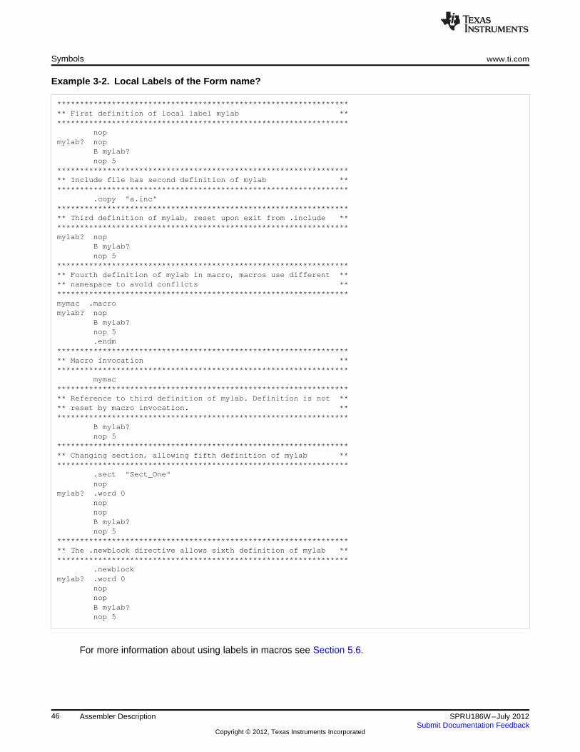
Symbols www.ti.com
Example 3-2. Local Labels of the Form name?
****************************************************************** First definition of local label mylab ******************************************************************
nopmylab? nop
B mylab?nop 5
****************************************************************** Include file has second definition of mylab ******************************************************************
.copy "a.inc"****************************************************************** Third definition of mylab, reset upon exit from .include ******************************************************************mylab? nop
B mylab?nop 5
****************************************************************** Fourth definition of mylab in macro, macros use different **** namespace to avoid conflicts ******************************************************************mymac .macromylab? nop
B mylab?nop 5.endm
****************************************************************** Macro invocation ******************************************************************
mymac****************************************************************** Reference to third definition of mylab. Definition is not **** reset by macro invocation. ******************************************************************
B mylab?nop 5
****************************************************************** Changing section, allowing fifth definition of mylab ******************************************************************
.sect "Sect_One"nop
mylab? .word 0nopnopB mylab?nop 5
****************************************************************** The .newblock directive allows sixth definition of mylab ******************************************************************
.newblockmylab? .word 0
nopnopB mylab?nop 5
For more information about using labels in macros see Section 5.6.
46 Assembler Description SPRU186W–July 2012Submit Documentation Feedback
Copyright © 2012, Texas Instruments Incorporated
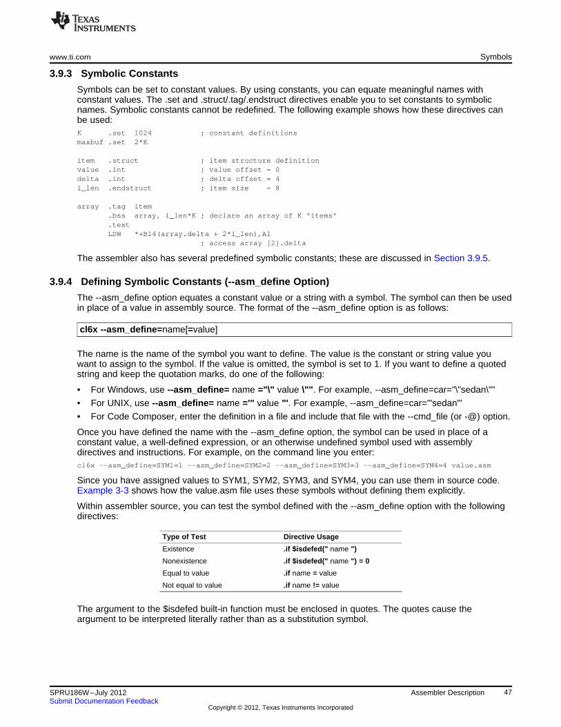
www.ti.com Symbols
3.9.3 Symbolic Constants
Symbols can be set to constant values. By using constants, you can equate meaningful names withconstant values. The .set and .struct/.tag/.endstruct directives enable you to set constants to symbolicnames. Symbolic constants cannot be redefined. The following example shows how these directives canbe used:K .set 1024 ; constant definitionsmaxbuf .set 2*K
item .struct ; item structure definitionvalue .int ; value offset = 0delta .int ; delta offset = 4i_len .endstruct ; item size = 8
array .tag item.bss array, i_len*K ; declare an array of K "items".textLDW *+B14(array.delta + 2*i_len),A1
; access array [2].delta
The assembler also has several predefined symbolic constants; these are discussed in Section 3.9.5.
3.9.4 Defining Symbolic Constants (--asm_define Option)
The --asm_define option equates a constant value or a string with a symbol. The symbol can then be usedin place of a value in assembly source. The format of the --asm_define option is as follows:
cl6x --asm_define=name[=value]
The name is the name of the symbol you want to define. The value is the constant or string value youwant to assign to the symbol. If the value is omitted, the symbol is set to 1. If you want to define a quotedstring and keep the quotation marks, do one of the following:
• For Windows, use --asm_define= name ="\" value \"". For example, --asm_define=car="\"sedan\""
• For UNIX, use --asm_define= name ='" value "'. For example, --asm_define=car='"sedan"'
• For Code Composer, enter the definition in a file and include that file with the --cmd_file (or -@) option.
Once you have defined the name with the --asm_define option, the symbol can be used in place of aconstant value, a well-defined expression, or an otherwise undefined symbol used with assemblydirectives and instructions. For example, on the command line you enter:cl6x --asm_define=SYM1=1 --asm_define=SYM2=2 --asm_define=SYM3=3 --asm_define=SYM4=4 value.asm
Since you have assigned values to SYM1, SYM2, SYM3, and SYM4, you can use them in source code.Example 3-3 shows how the value.asm file uses these symbols without defining them explicitly.
Within assembler source, you can test the symbol defined with the --asm_define option with the followingdirectives:
Type of Test Directive Usage
Existence .if $isdefed(" name ")
Nonexistence .if $isdefed(" name ") = 0
Equal to value .if name = value
Not equal to value .if name != value
The argument to the $isdefed built-in function must be enclosed in quotes. The quotes cause theargument to be interpreted literally rather than as a substitution symbol.
47SPRU186W–July 2012 Assembler DescriptionSubmit Documentation Feedback
Copyright © 2012, Texas Instruments Incorporated
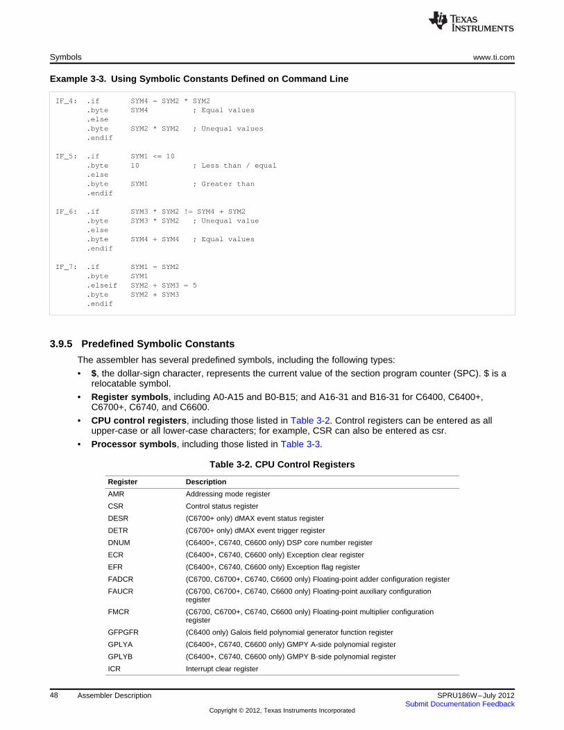
Symbols www.ti.com
Example 3‑‑3. Using Symbolic Constants Defined on Command Line
IF_4: .if SYM4 = SYM2 * SYM2.byte SYM4 ; Equal values.else.byte SYM2 * SYM2 ; Unequal values.endif
IF_5: .if SYM1 <= 10.byte 10 ; Less than / equal.else.byte SYM1 ; Greater than.endif
IF_6: .if SYM3 * SYM2 != SYM4 + SYM2.byte SYM3 * SYM2 ; Unequal value.else.byte SYM4 + SYM4 ; Equal values.endif
IF_7: .if SYM1 = SYM2.byte SYM1.elseif SYM2 + SYM3 = 5.byte SYM2 + SYM3.endif
3.9.5 Predefined Symbolic Constants
The assembler has several predefined symbols, including the following types:
• $, the dollar-sign character, represents the current value of the section program counter (SPC). $ is arelocatable symbol.
• Register symbols, including A0-A15 and B0-B15; and A16-31 and B16-31 for C6400, C6400+,C6700+, C6740, and C6600.
• CPU control registers, including those listed in Table 3-2. Control registers can be entered as allupper-case or all lower-case characters; for example, CSR can also be entered as csr.
• Processor symbols, including those listed in Table 3-3.
Table 3-2. CPU Control Registers
Register Description
AMR Addressing mode register
CSR Control status register
DESR (C6700+ only) dMAX event status register
DETR (C6700+ only) dMAX event trigger register
DNUM (C6400+, C6740, C6600 only) DSP core number register
ECR (C6400+, C6740, C6600 only) Exception clear register
EFR (C6400+, C6740, C6600 only) Exception flag register
FADCR (C6700, C6700+, C6740, C6600 only) Floating-point adder configuration register
FAUCR (C6700, C6700+, C6740, C6600 only) Floating-point auxiliary configurationregister
FMCR (C6700, C6700+, C6740, C6600 only) Floating-point multiplier configurationregister
GFPGFR (C6400 only) Galois field polynomial generator function register
GPLYA (C6400+, C6740, C6600 only) GMPY A-side polynomial register
GPLYB (C6400+, C6740, C6600 only) GMPY B-side polynomial register
ICR Interrupt clear register
48 Assembler Description SPRU186W–July 2012Submit Documentation Feedback
Copyright © 2012, Texas Instruments Incorporated
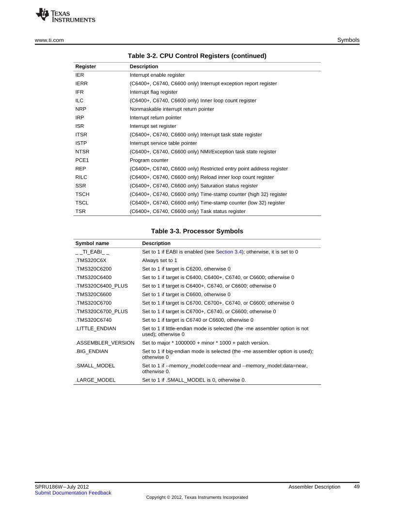
www.ti.com Symbols
Table 3-2. CPU Control Registers (continued)
Register Description
IER Interrupt enable register
IERR (C6400+, C6740, C6600 only) Interrupt exception report register
IFR Interrupt flag register
ILC (C6400+, C6740, C6600 only) Inner loop count register
NRP Nonmaskable interrupt return pointer
IRP Interrupt return pointer
ISR Interrupt set register
ITSR (C6400+, C6740, C6600 only) Interrupt task state register
ISTP Interrupt service table pointer
NTSR (C6400+, C6740, C6600 only) NMI/Exception task state register
PCE1 Program counter
REP (C6400+, C6740, C6600 only) Restricted entry point address register
RILC (C6400+, C6740, C6600 only) Reload inner loop count register
SSR (C6400+, C6740, C6600 only) Saturation status register
TSCH (C6400+, C6740, C6600 only) Time-stamp counter (high 32) register
TSCL (C6400+, C6740, C6600 only) Time-stamp counter (low 32) register
TSR (C6400+, C6740, C6600 only) Task status register
Table 3-3. Processor Symbols
Symbol name Description
_ _TI_EABI_ _ Set to 1 if EABI is enabled (see Section 3.4); otherwise, it is set to 0
.TMS320C6X Always set to 1
.TMS320C6200 Set to 1 if target is C6200, otherwise 0
.TMS320C6400 Set to 1 if target is C6400, C6400+, C6740, or C6600; otherwise 0
.TMS320C6400_PLUS Set to 1 if target is C6400+, C6740, or C6600; otherwise 0
.TMS320C6600 Set to 1 if target is C6600, otherwise 0
.TMS320C6700 Set to 1 if target is C6700, C6700+, C6740, or C6600; otherwise 0
.TMS320C6700_PLUS Set to 1 if target is C6700+, C6740, or C6600; otherwise 0
.TMS320C6740 Set to 1 if target is C6740 or C6600, otherwise 0
.LITTLE_ENDIAN Set to 1 if little-endian mode is selected (the -me assembler option is notused); otherwise 0
.ASSEMBLER_VERSION Set to major * 1000000 + minor * 1000 + patch version.
.BIG_ENDIAN Set to 1 if big-endian mode is selected (the -me assembler option is used);otherwise 0
.SMALL_MODEL Set to 1 if --memory_model:code=near and --memory_model:data=near,otherwise 0.
.LARGE_MODEL Set to 1 if .SMALL_MODEL is 0, otherwise 0.
49SPRU186W–July 2012 Assembler DescriptionSubmit Documentation Feedback
Copyright © 2012, Texas Instruments Incorporated
Symbols www.ti.com
3.9.6 Register Pairs
Many instructions in the C6000 instruction set across the various available target processors (C6200,C6400, C6400+, etc.) support a 64-bit register operand which can be specified as a register pair.
A register pair should be specified on the A side or the B side, depending on which functional unit aninstruction is to be executed on, and whether a cross functional unit data path is utilized by the instruction.You cannot mix A-side and B-side registers in the same register pair operand.
The syntax for a register pair is as follows where (n%2 == 0):
Rn+1:Rn
The legal register pairs are:
A1:A0 B1:B0A3:A2 B3:B2A5:A4 B5:B4A7:A6 B7:B6A9:A8 B9:B8A11:A10 B11:B10A13:A12 B13:B12A15:A14 B15:B14
In addition, these register pairs are available on C6400, C6400+, C6600 (not C62xx or C67xx):
A17:A16 B17:B16A19:A18 B19:B18A21:A20 B21:B20A23:A22 B23:B22A25:A24 B25:B24A27:A26 B27:B26A29:A30 B29:B30A31:A32 B31:B32
Here is an example of an ADD instruction that uses a register pair operand:ADD.L1 A5:A4,A1,A3:A2
For details on using register pairs in linear assembly, see the TMS320C6000 Optimizing Compiler User'sGuide.
For more information on functional units, including which assembly instructions require which functionaltype, see the TMS320C62x DSP CPU and Instruction Set Reference Guide, TMS320C64x/C64x+ DSPCPU and Instruction Set Reference Guide, TMS320C67x/C67x+ DSP CPU and Instruction Set ReferenceGuide, or TMS320C66x CPU and Instruction Set Reference Guide.
50 Assembler Description SPRU186W–July 2012Submit Documentation Feedback
Copyright © 2012, Texas Instruments Incorporated
www.ti.com Symbols
3.9.7 Register Quads (C6600 Only)
Several instructions in the C6600 instruction set support a 128-bit register operand which can be specifiedas a register quad.
A register quad should be specified on the A side or the B side, depending on which functional unit aninstruction is to be executed on, and whether a cross functional unit data path is utilized by the instruction.You cannot mix A-side and B-side registers in the same register quad operand.
The general syntax for a register quad is as follows, where (n%4 == 0):
Rn+3:Rn+2:Rn+1:Rn or Rn+3::Rn
The legal register quads are:
A Register Quads Short Form B Register Quads Short Form
A3:A2:A1:A0 A3::A0 B3:B2:B1:B0 B3::B0
A7:A6:A5:A4 A7::A4 B7:B6:B5:B4 B7::B4
A11:A10:A9:A8 A11::A8 B11:B10:B9:B8 B11::B8
A15:A14:A13:A12 A15::A12 B15:B14:B13:B12 B15::B12
A19:A18:A17:A16 A19::A16 B19:B18:B17:B16 B19::B16
A23:A22:A21:A20 A23::A20 B23:B22:B21:B20 B23::B20
A27:A26:A25:A24 A27::A24 B27:B26:B25:B24 B27::B24
A31:A30:A29:A28 A31::A28 B31:B30:B29:B28 B31::B28
Here is an example of an ADD instruction that uses register quad operands:QMPYSP .M1 A27:A26:A25:A24, A11:A10:A9:A8, A19:A18:A17:A16
For details on using register quads in C6600 linear assembly, see the TMS320C6000 Optimizing CompilerUser's Guide.
For more information on functional units, including which assembly instructions require which functionaltype, see the TMS320C66x CPU and Instruction Set Reference Guide.
3.9.8 Substitution Symbols
Symbols can be assigned a string value (variable). This enables you to alias character strings by equatingthem to symbolic names. Symbols that represent character strings are called substitution symbols. Whenthe assembler encounters a substitution symbol, its string value is substituted for the symbol name. Unlikesymbolic constants, substitution symbols can be redefined.
A string can be assigned to a substitution symbol anywhere within a program; for example:.global _table.asg "B14", PAGEPTR.asg "*+B15(4)", LOCAL1.asg "*+B15(8)", LOCAL2LDW *+PAGEPTR(_table),A0NOP 4STW A0,LOCAL1
When you are using macros, substitution symbols are important because macro parameters are actuallysubstitution symbols that are assigned a macro argument. The following code shows how substitutionsymbols are used in macros:MAC .macro src1, src2, dst ; Multiply/Accumulate macro
MPY src1, src2, src2NOPADD src2, dst, dst.endm
* MAC macro invocationMAC A0,A1,A2
See Chapter 5 for more information about macros.
51SPRU186W–July 2012 Assembler DescriptionSubmit Documentation Feedback
Copyright © 2012, Texas Instruments Incorporated
Expressions www.ti.com
3.10 Expressions
An expression is a constant, a symbol, or a series of constants and symbols separated by arithmeticoperators. The 32-bit ranges of valid expression values are -2147 483 648 to 2147 483 647 for signedvalues, and 0 to 4 294 967 295 for unsigned values. Three main factors influence the order of expressionevaluation:
Parentheses Expressions enclosed in parentheses are always evaluated first.8 / (4 / 2) = 4, but 8 / 4 / 2 = 1You cannot substitute braces ( { } ) or brackets ( [ ] ) for parentheses.
Precedence groups Operators, listed in Table 3-4, are divided into nine precedence groups.When parentheses do not determine the order of expression evaluation,the highest precedence operation is evaluated first.8 + 4 / 2 = 10 (4 / 2 is evaluated first)
Left-to-right evaluation When parentheses and precedence groups do not determine the order ofexpression evaluation, the expressions are evaluated from left to right,except for Group 1, which is evaluated from right to left.8 / 4*2 = 4, but 8 / (4*2) = 1
3.10.1 Operators
Table 3-4 lists the operators that can be used in expressions, according to precedence group.
Table 3-4. Operators Used in Expressions (Precedence)
Group (1) Operator Description (2)
1 + Unary plus- Unary minus~ 1s complement! Logical NOT
2 * Multiplication/ Division
% Modulo
3 + Addition- Subtraction
4 << Shift left>> Shift right
5 < Less than<= Less than or equal to> Greater than
>= Greater than or equal to
6 =[=] Equal to!= Not equal to
7 & Bitwise AND
8 ^ Bitwise exclusive OR (XOR)
9 | Bitwise OR(1) Group 1 operators are evaluated right to left. All other operators are evaluated left to right.(2) Unary + and - have higher precedence than the binary forms.
3.10.2 Expression Overflow and Underflow
The assembler checks for overflow and underflow conditions when arithmetic operations are performed atassembly time. It issues a warning (the message Value Truncated) whenever an overflow or underflowoccurs. The assembler does not check for overflow or underflow in multiplication.
52 Assembler Description SPRU186W–July 2012Submit Documentation Feedback
Copyright © 2012, Texas Instruments Incorporated
www.ti.com Expressions
3.10.3 Well-Defined Expressions
Some assembler directives require well-defined expressions as operands. Well-defined expressionscontain only symbols or assembly-time constants that are defined before they are encountered in theexpression. The evaluation of a well-defined expression must be absolute.
This is an example of a well-defined expression:1000h+X
where X was previously defined as an absolute symbol.
3.10.4 Conditional Expressions
The assembler supports relational operators that can be used in any expression; they are especiallyuseful for conditional assembly. Relational operators include the following:
= Equal to Not equal to! =< Less than <= Less than or equal to> Greater than > = Greater than or equal toConditional expressions evaluate to 1 if true and 0 if false and can be used only on operands ofequivalent types; for example, absolute value compared to absolute value, but not absolute valuecompared to relocatable value.
3.10.5 Legal Expressions
With the exception of the following expression contexts, there is no restriction on combinations ofoperations, constants, internally defined symbols, and externally defined symbols.
When an expression contains more than one relocatable symbol or cannot be evaluated at assembly time,the assembler encodes a relocation expression in the object file that is later evaluated by the linker. If thefinal value of the expression is larger in bits than the space reserved for it, you receive an error messagefrom the linker. See Section 2.4 for more information on relocation expressions.
• When using the register relative addressing mode, the expression in brackets or parenthesis must be awell-defined expression, as described in Section 3.10.3. For example:
*+A4[15]
• Expressions used to describe the offset in register relative addressing mode for the registers B14 andB15, or expressions used as the operand to the branch instruction, are subject to the same limitations.For these two cases, all legal expressions can be reduced to one of two forms:
*+XA4[7]
B (extern_1-10)relocatable symbol ± absolute symbolor
*+B14/B15[14]a well-defined expression
53SPRU186W–July 2012 Assembler DescriptionSubmit Documentation Feedback
Copyright © 2012, Texas Instruments Incorporated
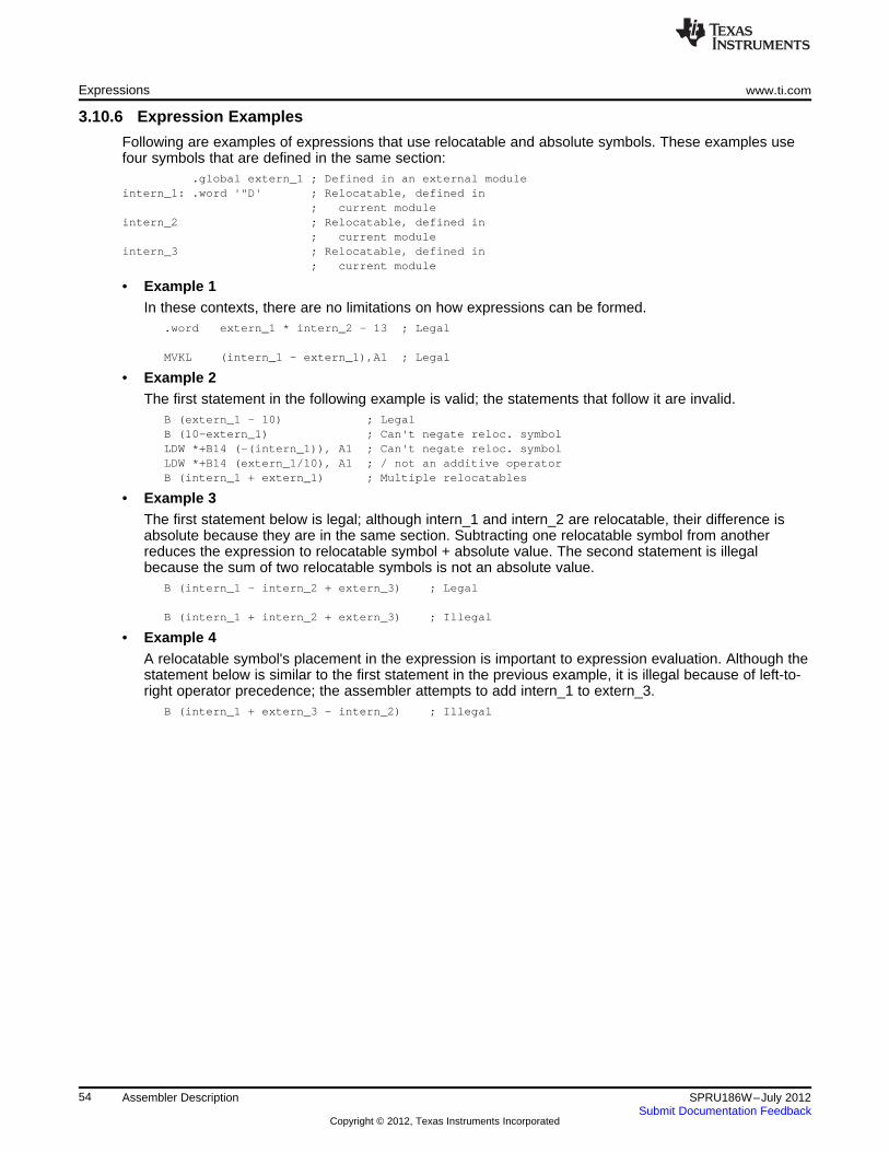
Expressions www.ti.com
3.10.6 Expression Examples
Following are examples of expressions that use relocatable and absolute symbols. These examples usefour symbols that are defined in the same section:
.global extern_1 ; Defined in an external moduleintern_1: .word '"D' ; Relocatable, defined in
; current moduleintern_2 ; Relocatable, defined in
; current moduleintern_3 ; Relocatable, defined in
; current module
• Example 1In these contexts, there are no limitations on how expressions can be formed.
.word extern_1 * intern_2 - 13 ; Legal
MVKL (intern_1 - extern_1),A1 ; Legal
• Example 2The first statement in the following example is valid; the statements that follow it are invalid.
B (extern_1 - 10) ; LegalB (10-extern_1) ; Can't negate reloc. symbolLDW *+B14 (-(intern_1)), A1 ; Can't negate reloc. symbolLDW *+B14 (extern_1/10), A1 ; / not an additive operatorB (intern_1 + extern_1) ; Multiple relocatables
• Example 3The first statement below is legal; although intern_1 and intern_2 are relocatable, their difference isabsolute because they are in the same section. Subtracting one relocatable symbol from anotherreduces the expression to relocatable symbol + absolute value. The second statement is illegalbecause the sum of two relocatable symbols is not an absolute value.
B (intern_1 - intern_2 + extern_3) ; Legal
B (intern_1 + intern_2 + extern_3) ; Illegal
• Example 4A relocatable symbol's placement in the expression is important to expression evaluation. Although thestatement below is similar to the first statement in the previous example, it is illegal because of left-to-right operator precedence; the assembler attempts to add intern_1 to extern_3.
B (intern_1 + extern_3 - intern_2) ; Illegal
54 Assembler Description SPRU186W–July 2012Submit Documentation Feedback
Copyright © 2012, Texas Instruments Incorporated
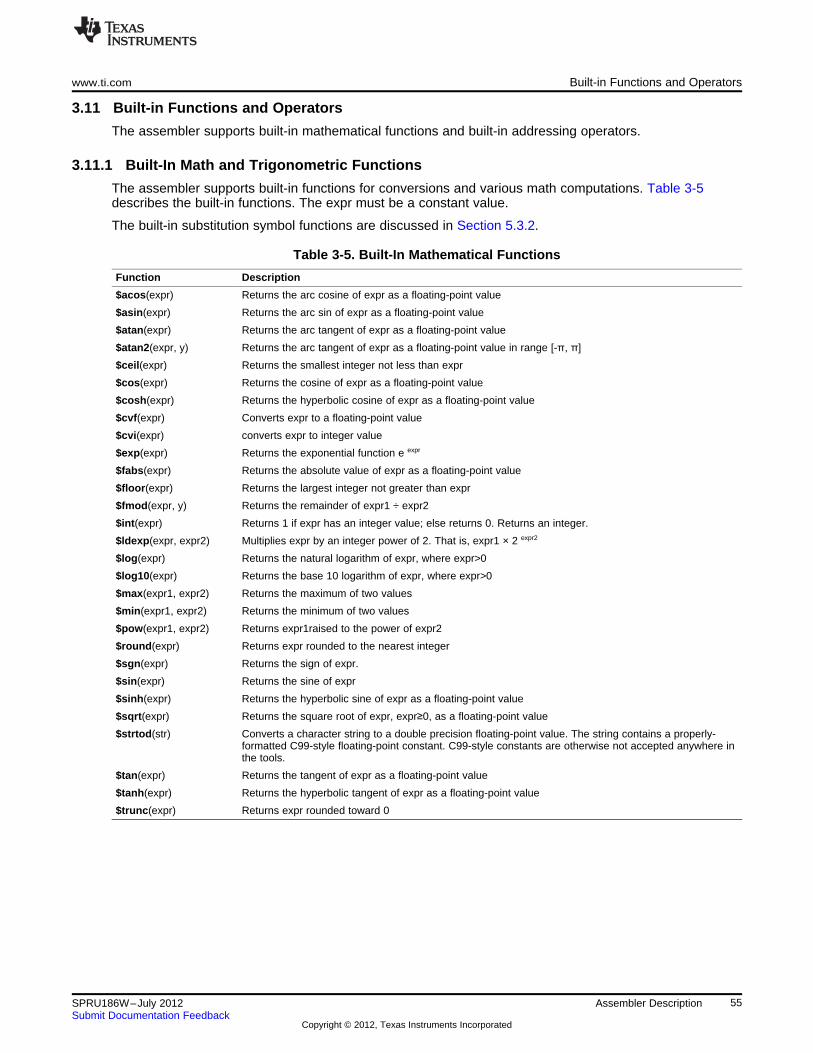
www.ti.com Built-in Functions and Operators
3.11 Built-in Functions and Operators
The assembler supports built-in mathematical functions and built-in addressing operators.
3.11.1 Built-In Math and Trigonometric Functions
The assembler supports built-in functions for conversions and various math computations. Table 3-5describes the built-in functions. The expr must be a constant value.
The built-in substitution symbol functions are discussed in Section 5.3.2.
Table 3-5. Built-In Mathematical Functions
Function Description
$acos(expr) Returns the arc cosine of expr as a floating-point value
$asin(expr) Returns the arc sin of expr as a floating-point value
$atan(expr) Returns the arc tangent of expr as a floating-point value
$atan2(expr, y) Returns the arc tangent of expr as a floating-point value in range [-π, π]
$ceil(expr) Returns the smallest integer not less than expr
$cos(expr) Returns the cosine of expr as a floating-point value
$cosh(expr) Returns the hyperbolic cosine of expr as a floating-point value
$cvf(expr) Converts expr to a floating-point value
$cvi(expr) converts expr to integer value
$exp(expr) Returns the exponential function e expr
$fabs(expr) Returns the absolute value of expr as a floating-point value
$floor(expr) Returns the largest integer not greater than expr
$fmod(expr, y) Returns the remainder of expr1 ÷ expr2
$int(expr) Returns 1 if expr has an integer value; else returns 0. Returns an integer.
$ldexp(expr, expr2) Multiplies expr by an integer power of 2. That is, expr1 × 2 expr2
$log(expr) Returns the natural logarithm of expr, where expr>0
$log10(expr) Returns the base 10 logarithm of expr, where expr>0
$max(expr1, expr2) Returns the maximum of two values
$min(expr1, expr2) Returns the minimum of two values
$pow(expr1, expr2) Returns expr1raised to the power of expr2
$round(expr) Returns expr rounded to the nearest integer
$sgn(expr) Returns the sign of expr.
$sin(expr) Returns the sine of expr
$sinh(expr) Returns the hyperbolic sine of expr as a floating-point value
$sqrt(expr) Returns the square root of expr, expr≥0, as a floating-point value
$strtod(str) Converts a character string to a double precision floating-point value. The string contains a properly-formatted C99-style floating-point constant. C99-style constants are otherwise not accepted anywhere inthe tools.
$tan(expr) Returns the tangent of expr as a floating-point value
$tanh(expr) Returns the hyperbolic tangent of expr as a floating-point value
$trunc(expr) Returns expr rounded toward 0
55SPRU186W–July 2012 Assembler DescriptionSubmit Documentation Feedback
Copyright © 2012, Texas Instruments Incorporated
Built-in Functions and Operators www.ti.com
3.11.2 C6x Built-In ELF Relocation Generating Operators
The assembler supports several C6000-specific ELF relocation generating built-in operators. Theoperators are used in compiler-generated code to support symbolic addressing of objects.
The operators are used to support various forms of DP-relative and PC-relative addressing instructionsequences. For more detailed information about DP-relative and PC-relative addressing instructionsequences, please see The C6000 Embedded Application Binary Interface Application Report(SPRAB89).
3.11.2.1 $DPR_BYTE(sym) / $DPR_HWORD(sym) / $DPR_WORD(sym)
The $DPR_BYTE(sym), $DPR_HWORD(sym), or $DPR_WORD(sym) operator can be applied in thesource operand of a MVKL or MVKH instruction to load the DP-relative offset of a symbol's address into aregister. These operators are used by the compiler when accessing data objects that are not within thesigned 15-bit offset range that is needed for using the DP-relative addressing mode.
For example, suppose the compiler needs to access a 32-bit aligned data object called 'xyz' that is definedin the .far section. The compiler must assume that the .far section is too far away from the base of the.bss section (whose address the runtime library's boot routine has loaded into the DP register), so usingDP-relative addressing mode to access 'xyz' directly is not possible. Instead, the compiler will use aMVKL/MVKH/LDW sequence of instructions:
MVKL $DPR_WORD(xyz),A0 ; load (xyz - $bss)/4 into A0MVKH $DPR_WORD(xyz),A0LDW *+DP[A0],A1 ; load *xyz into A1
This sequence of instructions is also referred to as far DP-relative addressing. The LDW instruction uses ascaled version of DP-relative indexed addressing. Similar to the $DPR_WORD(sym) operator, the$DPR_BYTE(sym) operator is provided to facilitate far DP-relative addressing of 8-bit data objects:
MVKL $DPR_BYTE(xyz),A0 ; load (xyz - $bss) into A0MVKH $DPR_BYTE(xyz),A0LDB *+DP[A0],A1 ; load *xyz into A1
The $DPR_HWORD(sym) operator is provided to facilitate far DP-relative addressing of 16-bit dataobjects:
MVKL $DPR_HWORD(xyz),A0 ; load (xyz - $bss)/2 into A0MVKH $DPR_HWORD(xyz),A0LDH *+DP[A0],A1 ; load *xyz into A1
For code on processors that are not compatible with C64x+, the compiler also uses these operators whenit needs to take the address of an object that is within signed 16-bit range of the DP. For example, thecompiler can compute the address of an 8-bit data object in the .bss section:
MVK $DPR_BYTE(_char_X),A4 ; load (_char_X - $bss) into A4ADD DP,A4,A4 ; compute address of _char_X
Similarly, the compiler can compute the address of a 16-bit data object that is defined in the .bss section:MVK $DPR_HWORD(_short_X),A4 ; load (_short_X - $bss)/2 into A4ADD DP,A4,A4 ; compute address of _short_X
It can also compute a 32-bit data object that is defined in the .bss section:MVK $DPR_WORD(_int_X),A4 ; load (_int_X - $bss)/4 into A4ADD DP,A4,A4 ; compute address of _int_X
These operators were added to the assembler to assist in migrating existing COFF code, which usedexpressions like 'xyz - $bss' to indicate DP-relative access to the address of a data object, to ELF codewhich is able to resolve the DP-relative offset calculation with a single relocation.
In summary:$DPR_BYTE(sym) is equivalent to 'sym - $bss'$DPR_HWORD(sym) is equivalent to '(sym - $bss) / 2'$DPR_WORD(sym) is equivalent to '(sym - $bss) / 4'
56 Assembler Description SPRU186W–July 2012Submit Documentation Feedback
Copyright © 2012, Texas Instruments Incorporated
www.ti.com Built-in Functions and Operators
3.11.2.2 $GOT(sym) / $DPR_GOT(sym)
The $GOT(sym) operator can be applied in the source operand of an LDW instruction. The$DPR_GOT(sym) operator can be applied in the source operand of a MVKL or MVKH instruction. Theseoperators are used in the context of compiler-generated code under a dynamic linking ABI (either theBare-Metal or Linux Dynamic Linking Model; see the external wiki(http://processors.wiki.ti.com/index.php/C6000_Dynamic_Linking) for more details on the dynamic linkingmodels supported in the C6000 Code Generation Tools (CGT)).
Symbols that are preemptable or are imported by a dynamic module will be accessed via the Global OffsetTable (GOT). A GOT entry for a symbol will contain the address of the symbol as it is determined atdynamic load time. To facilitate this resolution, the static linker will emit a dynamic relocation entry that isto be processed by the dynamic linker/loader. For more information on the GOT, see the Dynamic Linkingwiki site or The C6000 Embedded Application Binary Interface Application Report (SPRAB89).
If the GOT entry for a symbol, xyz, is accessible using DP-relative addressing mode, then the compiler willgenerate a sequence to load the symbol that uses the $GOT(sym) op0erator as the offset part of the DP-relative addressing mode operand:
LDW *+DP[$GOT(xyz)],A0 ; load address of xyz into A0; via access to GOT entry
LDW *A0,A1 ; load xyz into A2
The actual semantics of the $GOT(sym) operator is to return the DP- relative offset of the GOT entry forthe referenced symbol (xyz above).
While $DPR_GOT(sym) is semantically similar to the $GOT(sym) operator, it is used when the GOT is notaccessible using DP-relative addressing mode (offset is not within signed 15-bit range of the static baseaddress that is loaded into the data pointer register (DP)). The DP-relative offset to the GOT entry is thenloaded into an index register using a MVKL/MVKH instruction sequence, and the GOT entry is thenaccessed via DP-relative indexed addressing to load the address of the referenced symbol:
MVKL $DPR_GOT(xyz),A0 ; load DP-relative offset ofMVKH $DPR_GOT(xyz),A0 ; GOT entry for xyz into A0LDW *+DP[A0],A1 ; get address of xyz via GOT entryLDW *A1,A2 ; load xyz into A2
3.11.2.3 $PCR_OFFSET(x,y)
The $PCR_OFFSET(x,y) operator can be applied in the source operand of a MVKL, MVKH, or ADDKinstruction to compute a PC-relative offset to be loaded into (in the case of MVKL/MVKH) or added to (inthe case of ADDK) a register.
This operator is used in the context of compiler-generated code under the Linux ABI (using --linuxcompiler option). It helps the compiler to generate position-independent code by accessing a symbol thatis defined in the same RO segment using PC-relative addressing.
For example, if there is to be a call to a function defined in the same file, but you would like to avoidgenerating a dynamic relocation that accesses the symbol that represents the destination of the call, thenyou can use the $PCR_OFFSET operator as follows:dest:
<code>...
make_pcr_call:MVC PCE1, B0 ; set up PC reference point in B0MVKL $PCR_OFFSET(dest, make_pcr_call), B1 ; compute dest - make_pcr_callMVKH $PCR_OFFSET(dest, make_pcr_call), B1 ; and load it into B1ADD B0,B1,B0 ; compute dest address into B0 registerB B0 ; call dest indirectly through B0...
The above code sequence is position independent. No matter what address 'dest' is placed at load time,the call to 'dest' will still work since it is independent of the actual address of 'dest'. However, the call doeshave to maintain its position relative to the definition of 'dest'.
57SPRU186W–July 2012 Assembler DescriptionSubmit Documentation Feedback
Copyright © 2012, Texas Instruments Incorporated
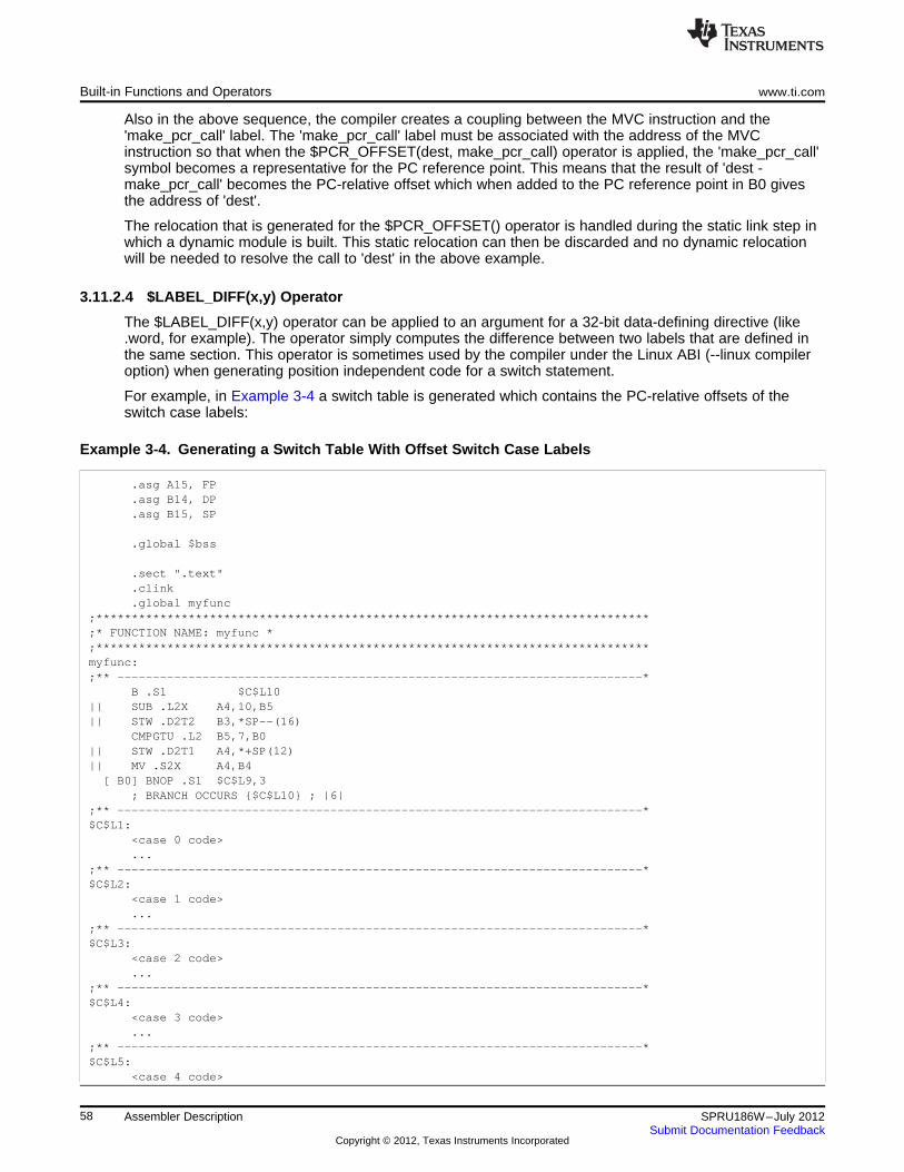
Built-in Functions and Operators www.ti.com
Also in the above sequence, the compiler creates a coupling between the MVC instruction and the'make_pcr_call' label. The 'make_pcr_call' label must be associated with the address of the MVCinstruction so that when the $PCR_OFFSET(dest, make_pcr_call) operator is applied, the 'make_pcr_call'symbol becomes a representative for the PC reference point. This means that the result of 'dest -make_pcr_call' becomes the PC-relative offset which when added to the PC reference point in B0 givesthe address of 'dest'.
The relocation that is generated for the $PCR_OFFSET() operator is handled during the static link step inwhich a dynamic module is built. This static relocation can then be discarded and no dynamic relocationwill be needed to resolve the call to 'dest' in the above example.
3.11.2.4 $LABEL_DIFF(x,y) Operator
The $LABEL_DIFF(x,y) operator can be applied to an argument for a 32-bit data-defining directive (like.word, for example). The operator simply computes the difference between two labels that are defined inthe same section. This operator is sometimes used by the compiler under the Linux ABI (--linux compileroption) when generating position independent code for a switch statement.
For example, in Example 3-4 a switch table is generated which contains the PC-relative offsets of theswitch case labels:
Example 3-4. Generating a Switch Table With Offset Switch Case Labels
.asg A15, FP
.asg B14, DP
.asg B15, SP
.global $bss
.sect ".text"
.clink
.global myfunc;******************************************************************************;* FUNCTION NAME: myfunc *;******************************************************************************myfunc:;** --------------------------------------------------------------------------*
B .S1 $C$L10|| SUB .L2X A4,10,B5|| STW .D2T2 B3,*SP--(16)
CMPGTU .L2 B5,7,B0|| STW .D2T1 A4,*+SP(12)|| MV .S2X A4,B4[ B0] BNOP .S1 $C$L9,3
; BRANCH OCCURS {$C$L10} ; |6|;** --------------------------------------------------------------------------*$C$L1:
<case 0 code>...
;** --------------------------------------------------------------------------*$C$L2:
<case 1 code>...
;** --------------------------------------------------------------------------*$C$L3:
<case 2 code>...
;** --------------------------------------------------------------------------*$C$L4:
<case 3 code>...
;** --------------------------------------------------------------------------*$C$L5:
<case 4 code>
58 Assembler Description SPRU186W–July 2012Submit Documentation Feedback
Copyright © 2012, Texas Instruments Incorporated
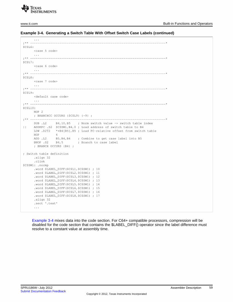
www.ti.com Built-in Functions and Operators
Example 3-4. Generating a Switch Table With Offset Switch Case Labels (continued)
...;** --------------------------------------------------------------------------*$C$L6:
<case 5 code>...
;** --------------------------------------------------------------------------*$C$L7:
<case 6 code>...
;** --------------------------------------------------------------------------*$C$L8:
<case 7 code>...
;** --------------------------------------------------------------------------*$C$L9:
<default case code>...
;** --------------------------------------------------------------------------*$C$L10:
NOP 2; BRANCHCC OCCURS {$C$L9} {-9} ;
;** --------------------------------------------------------------------------*SUB .L2 B4,10,B5 ; Norm switch value -> switch table index
|| ADDKPC .S2 $C$SW1,B4,0 ; Load address of switch table to B4LDW .D2T2 *+B4[B5],B5 ; Load PC-relative offset from switch tableNOP 4ADD .L2 B5,B4,B4 ; Combine to get case label into B5BNOP .S2 B4,5 ; Branch to case label; BRANCH OCCURS {B4} ;
; Switch table definition.align 32.clink
$C$SW1: .nocmp.word $LABEL_DIFF($C$L1,$C$SW1) ; 10.word $LABEL_DIFF($C$L2,$C$SW1) ; 11.word $LABEL_DIFF($C$L3,$C$SW1) ; 12.word $LABEL_DIFF($C$L4,$C$SW1) ; 13.word $LABEL_DIFF($C$L5,$C$SW1) ; 14.word $LABEL_DIFF($C$L6,$C$SW1) ; 15.word $LABEL_DIFF($C$L7,$C$SW1) ; 16.word $LABEL_DIFF($C$L8,$C$SW1) ; 17.align 32.sect ".text"...
Example 3-4 mixes data into the code section. For C64+ compatible processors, compression will bedisabled for the code section that contains the $LABEL_DIFF() operator since the label difference mustresolve to a constant value at assembly time.
59SPRU186W–July 2012 Assembler DescriptionSubmit Documentation Feedback
Copyright © 2012, Texas Instruments Incorporated
Source Listings www.ti.com
3.12 Source Listings
A source listing shows source statements and the object code they produce. To obtain a listing file, invokethe assembler with the --asm_listing option (see Section 3.3).
Two banner lines, a blank line, and a title line are at the top of each source listing page. Any title suppliedby the .title directive is printed on the title line. A page number is printed to the right of the title. If you donot use the .title directive, the name of the source file is printed. The assembler inserts a blank line belowthe title line.
Each line in the source file produces at least one line in the listing file. This line shows a source statementnumber, an SPC value, the object code assembled, and the source statement. and show these in actuallisting files.
Each line in the source file produces at least one line in the listing file. This line shows a source statementnumber, an SPC value, the object code assembled, and the source statement. Figure 3-2 shows these inan actual listing file.
Field 1: Source Statement NumberLine numberThe source statement number is a decimal number. The assembler numbers source lines as itencounters them in the source file; some statements increment the line counter but are not listed. (Forexample, .title statements and statements following a .nolist are not listed.) The difference between twoconsecutive source line numbers indicates the number of intervening statements in the source file thatare not listed.Include file letterA letter preceding the line number indicates the line is assembled from the include file designated bythe letter.Nesting level numberA number preceding the line number indicates the nesting level of macro expansions or loop blocks.
Field 2: Section Program CounterThis field contains the SPC value, which is hexadecimal. All sections (.text, .data, .bss, and namedsections) maintain separate SPCs. Some directives do not affect the SPC and leave this field blank.
Field 3: Object CodeThis field contains the hexadecimal representation of the object code. All machine instructions anddirectives use this field to list object code. This field also indicates the relocation type associated withan operand for this line of source code. If more than one operand is relocatable, this column indicatesthe relocation type for the first operand. The characters that can appear in this column and theirassociated relocation types are listed below:
! undefined external reference' .text relocatable+ .sect relocatable" .data relocatable- .bss, .usect relocatable
% relocation expression
Field 4: Source Statement FieldThis field contains the characters of the source statement as they were scanned by the assembler. Theassembler accepts a maximum line length of 200 characters. Spacing in this field is determined by thespacing in the source statement.
Figure 3-2 shows an assembler listing with each of the four fields identified.
60 Assembler Description SPRU186W–July 2012Submit Documentation Feedback
Copyright © 2012, Texas Instruments Incorporated
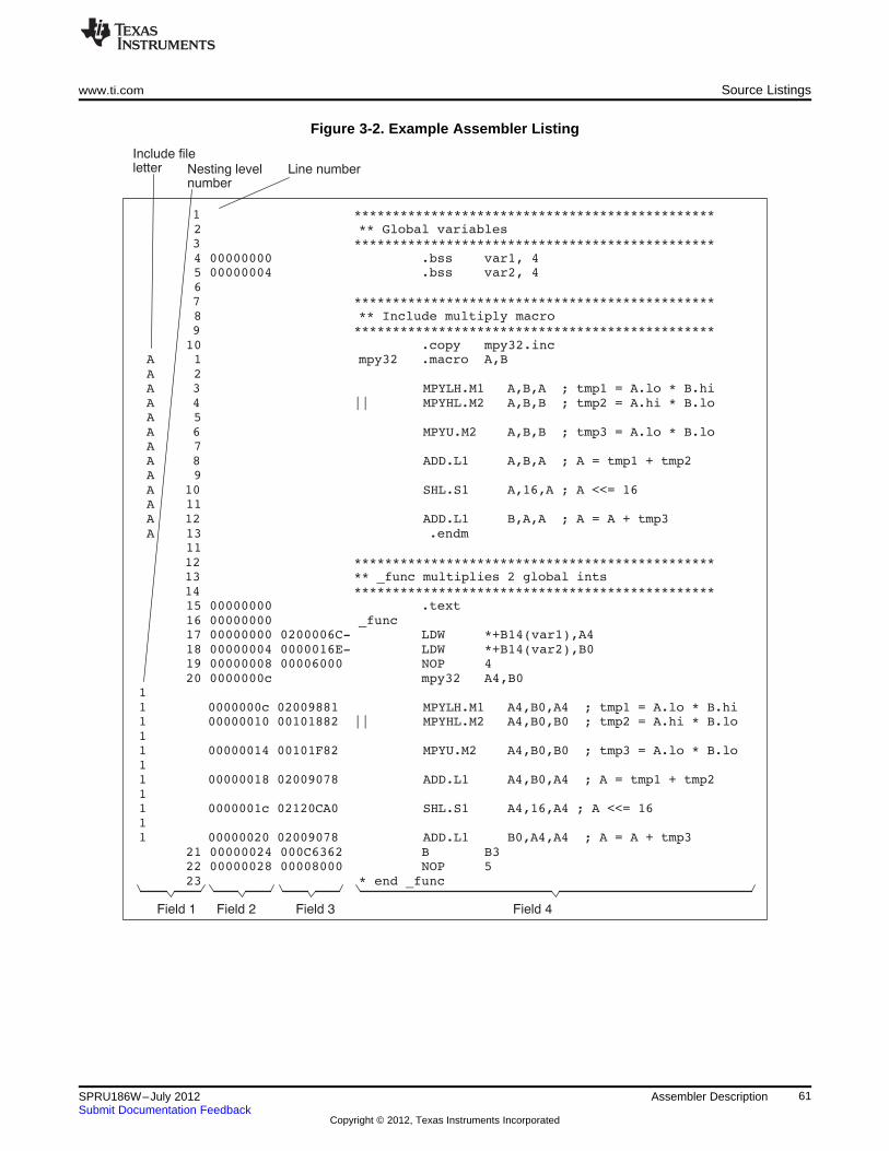
number
2 ** Global variables
4 00000000 .bss var1, 45 00000004 .bss var2, 46
8 ** Include multiply macro
10 .copy mpy32.incA 1 mpy32 .macro A,BA 2
A 5
A 7
A 9
A 11
A 13 .endm11
15 00000000 .text16 00000000 _func17 00000000 0200006C- LDW *+B14(var1),A418 00000004 0000016E- LDW *+B14(var2),B019 00000008 00006000 NOP 420 0000000c mpy32 A4,B0
1
1
1
1
1
21 00000024 000C6362 B B322 00000028 00008000 NOP 523 * end _func
Include fileletter Line numberNesting level
Field 1 Field 2 Field 3 Field 4
www.ti.com Source Listings
Figure 3-2. Example Assembler Listing
61SPRU186W–July 2012 Assembler DescriptionSubmit Documentation Feedback
Copyright © 2012, Texas Instruments Incorporated
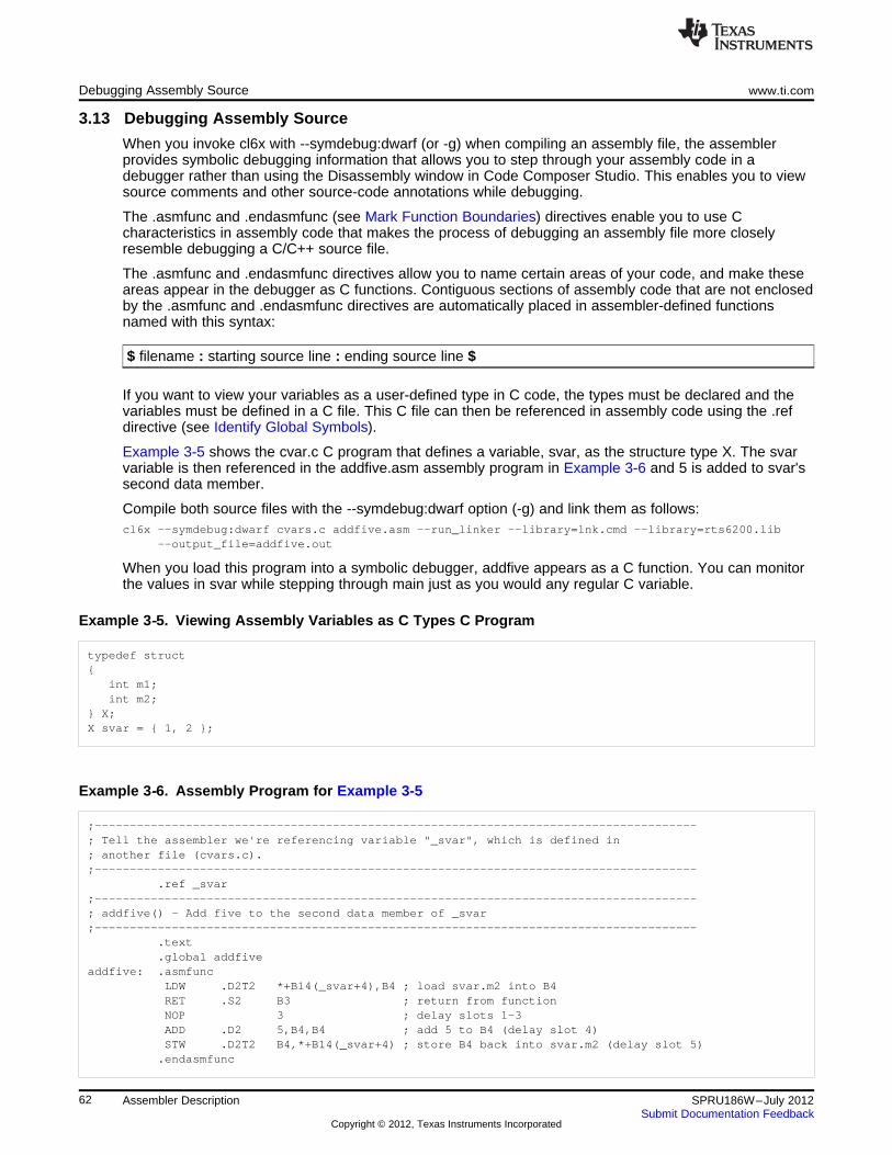
Debugging Assembly Source www.ti.com
3.13 Debugging Assembly Source
When you invoke cl6x with --symdebug:dwarf (or -g) when compiling an assembly file, the assemblerprovides symbolic debugging information that allows you to step through your assembly code in adebugger rather than using the Disassembly window in Code Composer Studio. This enables you to viewsource comments and other source-code annotations while debugging.
The .asmfunc and .endasmfunc (see Mark Function Boundaries) directives enable you to use Ccharacteristics in assembly code that makes the process of debugging an assembly file more closelyresemble debugging a C/C++ source file.
The .asmfunc and .endasmfunc directives allow you to name certain areas of your code, and make theseareas appear in the debugger as C functions. Contiguous sections of assembly code that are not enclosedby the .asmfunc and .endasmfunc directives are automatically placed in assembler-defined functionsnamed with this syntax:
$ filename : starting source line : ending source line $
If you want to view your variables as a user-defined type in C code, the types must be declared and thevariables must be defined in a C file. This C file can then be referenced in assembly code using the .refdirective (see Identify Global Symbols).
Example 3-5 shows the cvar.c C program that defines a variable, svar, as the structure type X. The svarvariable is then referenced in the addfive.asm assembly program in Example 3-6 and 5 is added to svar'ssecond data member.
Compile both source files with the --symdebug:dwarf option (-g) and link them as follows:cl6x --symdebug:dwarf cvars.c addfive.asm --run_linker --library=lnk.cmd --library=rts6200.lib
--output_file=addfive.out
When you load this program into a symbolic debugger, addfive appears as a C function. You can monitorthe values in svar while stepping through main just as you would any regular C variable.
Example 3‑‑5. Viewing Assembly Variables as C Types C Program
typedef struct{
int m1;int m2;
} X;X svar = { 1, 2 };
Example 3‑‑6. Assembly Program for Example 3-5
;--------------------------------------------------------------------------------------; Tell the assembler we're referencing variable "_svar", which is defined in; another file (cvars.c).;--------------------------------------------------------------------------------------
.ref _svar;--------------------------------------------------------------------------------------; addfive() - Add five to the second data member of _svar;--------------------------------------------------------------------------------------
.text
.global addfiveaddfive: .asmfunc
LDW .D2T2 *+B14(_svar+4),B4 ; load svar.m2 into B4RET .S2 B3 ; return from functionNOP 3 ; delay slots 1-3ADD .D2 5,B4,B4 ; add 5 to B4 (delay slot 4)STW .D2T2 B4,*+B14(_svar+4) ; store B4 back into svar.m2 (delay slot 5)
.endasmfunc
62 Assembler Description SPRU186W–July 2012Submit Documentation Feedback
Copyright © 2012, Texas Instruments Incorporated
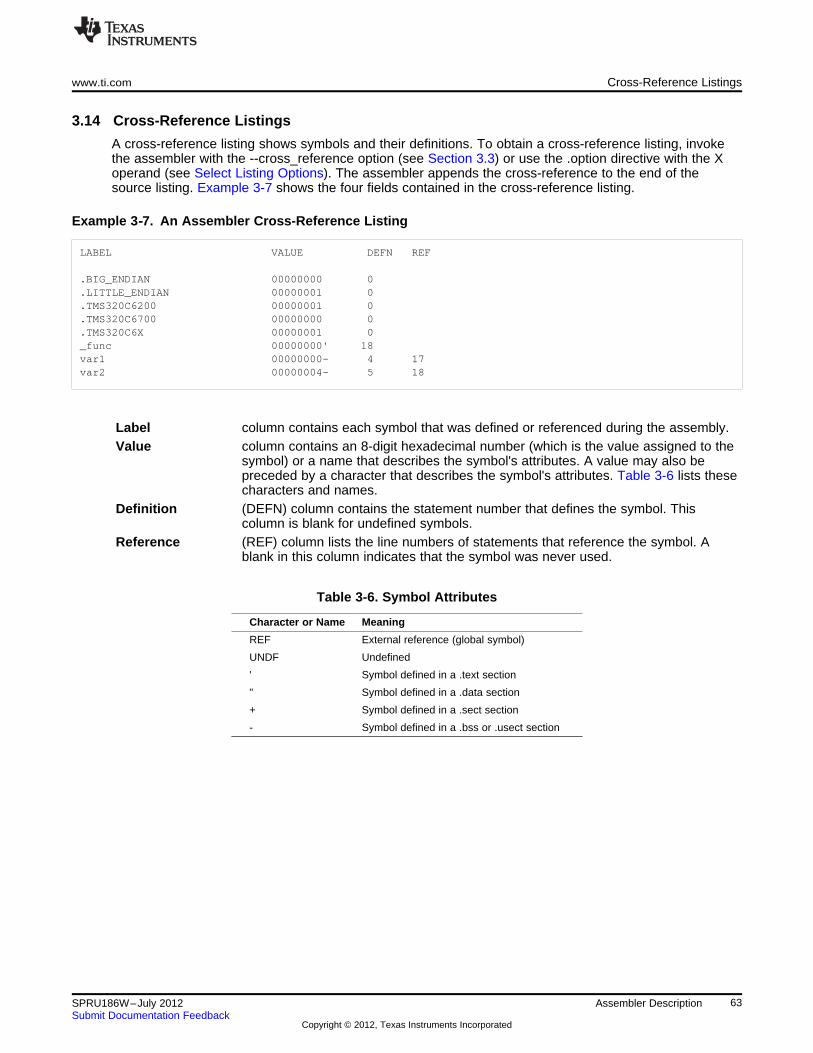
www.ti.com Cross-Reference Listings
3.14 Cross-Reference Listings
A cross-reference listing shows symbols and their definitions. To obtain a cross-reference listing, invokethe assembler with the --cross_reference option (see Section 3.3) or use the .option directive with the Xoperand (see Select Listing Options). The assembler appends the cross-reference to the end of thesource listing. Example 3-7 shows the four fields contained in the cross-reference listing.
Example 3‑‑7. An Assembler Cross-Reference Listing
LABEL VALUE DEFN REF
.BIG_ENDIAN 00000000 0
.LITTLE_ENDIAN 00000001 0
.TMS320C6200 00000001 0
.TMS320C6700 00000000 0
.TMS320C6X 00000001 0_func 00000000' 18var1 00000000- 4 17var2 00000004- 5 18
Label column contains each symbol that was defined or referenced during the assembly.Value column contains an 8-digit hexadecimal number (which is the value assigned to the
symbol) or a name that describes the symbol's attributes. A value may also bepreceded by a character that describes the symbol's attributes. Table 3-6 lists thesecharacters and names.
Definition (DEFN) column contains the statement number that defines the symbol. Thiscolumn is blank for undefined symbols.
Reference (REF) column lists the line numbers of statements that reference the symbol. Ablank in this column indicates that the symbol was never used.
Table 3-6. Symbol Attributes
Character or Name Meaning
REF External reference (global symbol)
UNDF Undefined
' Symbol defined in a .text section
" Symbol defined in a .data section
+ Symbol defined in a .sect section
- Symbol defined in a .bss or .usect section
63SPRU186W–July 2012 Assembler DescriptionSubmit Documentation Feedback
Copyright © 2012, Texas Instruments Incorporated
Chapter 4SPRU186W–July 2012
Assembler Directives
Assembler directives supply data to the program and control the assembly process. Assembler directivesenable you to do the following:
• Assemble code and data into specified sections
• Reserve space in memory for uninitialized variables
• Control the appearance of listings
• Initialize memory
• Assemble conditional blocks
• Define global variables
• Specify libraries from which the assembler can obtain macros
• Examine symbolic debugging information
This chapter is divided into two parts: the first part (Section 4.1 through Section 4.11) describes thedirectives according to function, and the second part (Section 4.12) is an alphabetical reference.
Topic ........................................................................................................................... Page
4.1 Directives Summary .......................................................................................... 654.2 Directives That Define Sections .......................................................................... 694.3 Directives That Initialize Constants ...................................................................... 714.4 Directives That Perform Alignment and Reserve Space ......................................... 724.5 Directives That Format the Output Listings .......................................................... 734.6 Directives That Reference Other Files .................................................................. 744.7 Directives That Enable Conditional Assembly ....................................................... 754.8 Directives That Define Union or Structure Types ................................................... 754.9 Directives That Define Enumerated Types ............................................................ 764.10 Directives That Define Symbols at Assembly Time ................................................ 764.11 Miscellaneous Directives .................................................................................... 774.12 Directives Reference .......................................................................................... 78
64 Assembler Directives SPRU186W–July 2012Submit Documentation Feedback
Copyright © 2012, Texas Instruments Incorporated
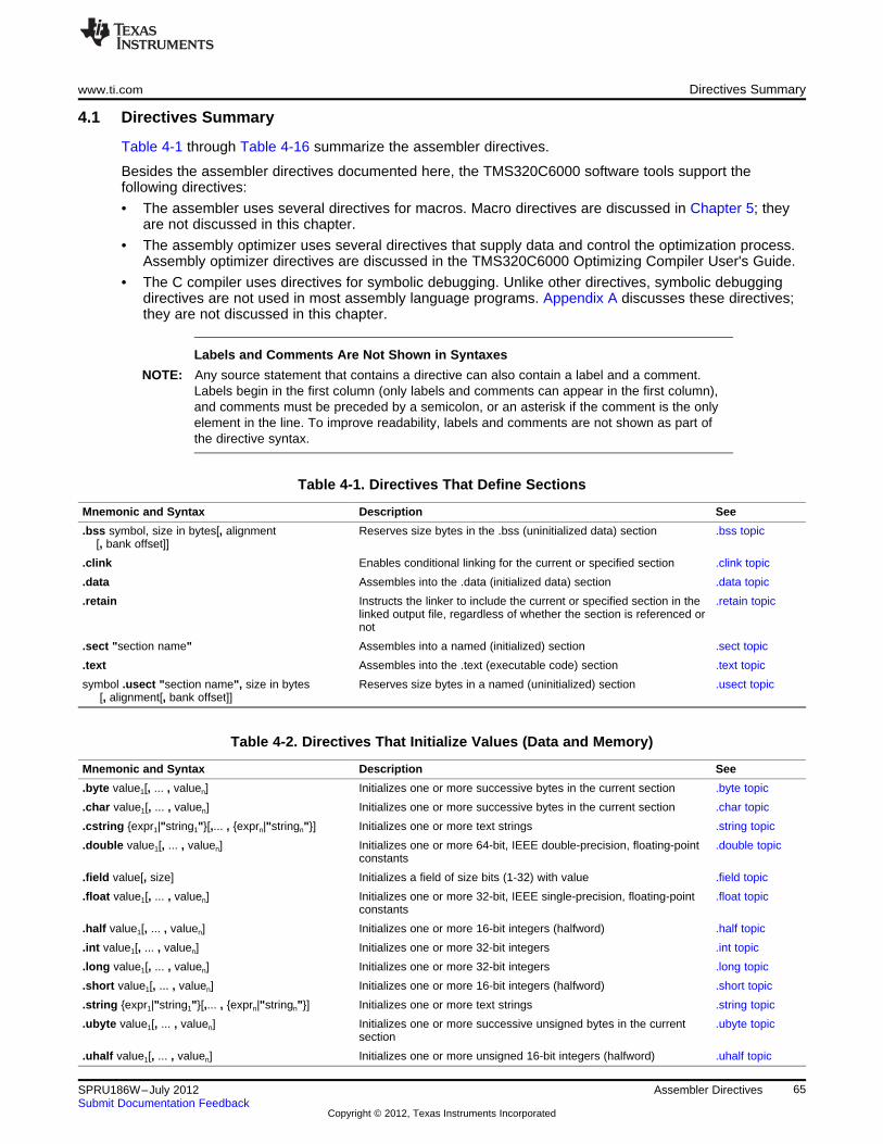
www.ti.com Directives Summary
4.1 Directives Summary
Table 4-1 through Table 4-16 summarize the assembler directives.
Besides the assembler directives documented here, the TMS320C6000 software tools support thefollowing directives:
• The assembler uses several directives for macros. Macro directives are discussed in Chapter 5; theyare not discussed in this chapter.
• The assembly optimizer uses several directives that supply data and control the optimization process.Assembly optimizer directives are discussed in the TMS320C6000 Optimizing Compiler User's Guide.
• The C compiler uses directives for symbolic debugging. Unlike other directives, symbolic debuggingdirectives are not used in most assembly language programs. Appendix A discusses these directives;they are not discussed in this chapter.
Labels and Comments Are Not Shown in Syntaxes
NOTE: Any source statement that contains a directive can also contain a label and a comment.Labels begin in the first column (only labels and comments can appear in the first column),and comments must be preceded by a semicolon, or an asterisk if the comment is the onlyelement in the line. To improve readability, labels and comments are not shown as part ofthe directive syntax.
Table 4-1. Directives That Define Sections
Mnemonic and Syntax Description See
.bss symbol, size in bytes[, alignment Reserves size bytes in the .bss (uninitialized data) section .bss topic[, bank offset]]
.clink Enables conditional linking for the current or specified section .clink topic
.data Assembles into the .data (initialized data) section .data topic
.retain Instructs the linker to include the current or specified section in the .retain topiclinked output file, regardless of whether the section is referenced ornot
.sect "section name" Assembles into a named (initialized) section .sect topic
.text Assembles into the .text (executable code) section .text topic
symbol .usect "section name", size in bytes Reserves size bytes in a named (uninitialized) section .usect topic[, alignment[, bank offset]]
Table 4-2. Directives That Initialize Values (Data and Memory)
Mnemonic and Syntax Description See
.byte value1[, ... , valuen] Initializes one or more successive bytes in the current section .byte topic
.char value1[, ... , valuen] Initializes one or more successive bytes in the current section .char topic
.cstring {expr1|"string1"}[,... , {exprn|"stringn"}] Initializes one or more text strings .string topic
.double value1[, ... , valuen] Initializes one or more 64-bit, IEEE double-precision, floating-point .double topicconstants
.field value[, size] Initializes a field of size bits (1-32) with value .field topic
.float value1[, ... , valuen] Initializes one or more 32-bit, IEEE single-precision, floating-point .float topicconstants
.half value1[, ... , valuen] Initializes one or more 16-bit integers (halfword) .half topic
.int value1[, ... , valuen] Initializes one or more 32-bit integers .int topic
.long value1[, ... , valuen] Initializes one or more 32-bit integers .long topic
.short value1[, ... , valuen] Initializes one or more 16-bit integers (halfword) .short topic
.string {expr1|"string1"}[,... , {exprn|"stringn"}] Initializes one or more text strings .string topic
.ubyte value1[, ... , valuen] Initializes one or more successive unsigned bytes in the current .ubyte topicsection
.uhalf value1[, ... , valuen] Initializes one or more unsigned 16-bit integers (halfword) .uhalf topic
65SPRU186W–July 2012 Assembler DirectivesSubmit Documentation Feedback
Copyright © 2012, Texas Instruments Incorporated
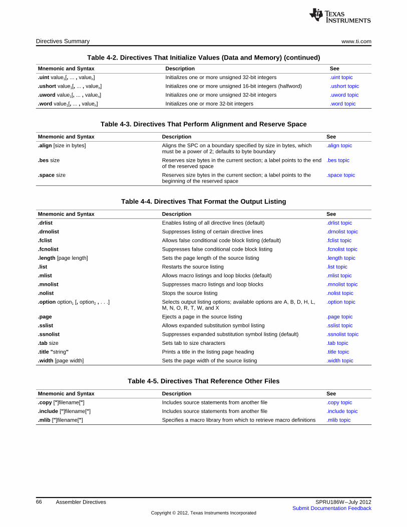
Directives Summary www.ti.com
Table 4-2. Directives That Initialize Values (Data and Memory) (continued)
Mnemonic and Syntax Description See
.uint value1[, ... , valuen] Initializes one or more unsigned 32-bit integers .uint topic
.ushort value1[, ... , valuen] Initializes one or more unsigned 16-bit integers (halfword) .ushort topic
.uword value1[, ... , valuen] Initializes one or more unsigned 32-bit integers .uword topic
.word value1[, ... , valuen] Initializes one or more 32-bit integers .word topic
Table 4-3. Directives That Perform Alignment and Reserve Space
Mnemonic and Syntax Description See
.align [size in bytes] Aligns the SPC on a boundary specified by size in bytes, which .align topicmust be a power of 2; defaults to byte boundary
.bes size Reserves size bytes in the current section; a label points to the end .bes topicof the reserved space
.space size Reserves size bytes in the current section; a label points to the .space topicbeginning of the reserved space
Table 4-4. Directives That Format the Output Listing
Mnemonic and Syntax Description See
.drlist Enables listing of all directive lines (default) .drlist topic
.drnolist Suppresses listing of certain directive lines .drnolist topic
.fclist Allows false conditional code block listing (default) .fclist topic
.fcnolist Suppresses false conditional code block listing .fcnolist topic
.length [page length] Sets the page length of the source listing .length topic
.list Restarts the source listing .list topic
.mlist Allows macro listings and loop blocks (default) .mlist topic
.mnolist Suppresses macro listings and loop blocks .mnolist topic
.nolist Stops the source listing .nolist topic
.option option1 [, option2 , . . .] Selects output listing options; available options are A, B, D, H, L, .option topicM, N, O, R, T, W, and X
.page Ejects a page in the source listing .page topic
.sslist Allows expanded substitution symbol listing .sslist topic
.ssnolist Suppresses expanded substitution symbol listing (default) .ssnolist topic
.tab size Sets tab to size characters .tab topic
.title "string" Prints a title in the listing page heading .title topic
.width [page width] Sets the page width of the source listing .width topic
Table 4-5. Directives That Reference Other Files
Mnemonic and Syntax Description See
.copy ["]filename["] Includes source statements from another file .copy topic
.include ["]filename["] Includes source statements from another file .include topic
.mlib ["]filename["] Specifies a macro library from which to retrieve macro definitions .mlib topic
66 Assembler Directives SPRU186W–July 2012Submit Documentation Feedback
Copyright © 2012, Texas Instruments Incorporated
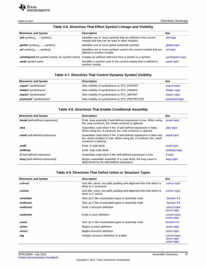
www.ti.com Directives Summary
Table 4-6. Directives That Effect Symbol Linkage and Visibility
Mnemonic and Syntax Description See
.def symbol1[, ... , symboln] Identifies one or more symbols that are defined in the current .def topicmodule and that can be used in other modules
.global symbol1[, ... , symboln] Identifies one or more global (external) symbols .global topic
.ref symbol1[, ... , symboln] Identifies one or more symbols used in the current module that are .ref topicdefined in another module
.symdepend dst symbol name[, src symbol name] Creates an artificial reference from a section to a symbol .symdepend topic
.weak symbol name Identifies a symbol used in the current module that is defined in .weak topicanother module
Table 4-7. Directives That Control Dynamic Symbol Visibility
Mnemonic and Syntax Description See
.export "symbolname" Sets visibility of symbolname to STV_EXPORT .export topic
.hidden"symbolname" Sets visibility of symbolname to STV_HIDDEN .hidden topic
.import "symbolname" Sets visibility of symbolname to STV_IMPORT .import topic
.protected "symbolname" Sets visibility of symbolname to STV_PROTECTED .protected topic
Table 4-8. Directives That Enable Conditional Assembly
Mnemonic and Syntax Description See
.break [well-defined expression] Ends .loop assembly if well-defined expression is true. When using .break topicthe .loop construct, the .break construct is optional.
.else Assembles code block if the .if well-defined expression is false. .else topicWhen using the .if construct, the .else construct is optional.
.elseif well-defined expression Assembles code block if the .if well-defined expression is false and .elseif topicthe .elseif condition is true. When using the .if construct, the .elseifconstruct is optional.
.endif Ends .if code block .endif topic
.endloop Ends .loop code block .endloop topic
.if well-defined expression Assembles code block if the well-defined expression is true .if topic
.loop [well-defined expression] Begins repeatable assembly of a code block; the loop count is .loop topicdetermined by the well-defined expression.
Table 4-9. Directives That Define Union or Structure Types
Mnemonic and Syntax Description See
.cstruct Acts like .struct, but adds padding and alignment like that which is .cstruct topicdone to C structures
.cunion Acts like .union, but adds padding and alignment like that which is .cunion topicdone to C unions
.emember Sets up C-like enumerated types in assembly code Section 4.9
.endenum Sets up C-like enumerated types in assembly code Section 4.9
.endstruct Ends a structure definition .cstruct topic,.struct topic
.endunion Ends a union definition .cunion topic,.union topic
.enum Sets up C-like enumerated types in assembly code Section 4.9
.union Begins a union definition .union topic
.struct Begins structure definition .struct topic
.tag Assigns structure attributes to a label .cstruct topic,.struct topic.union topic
67SPRU186W–July 2012 Assembler DirectivesSubmit Documentation Feedback
Copyright © 2012, Texas Instruments Incorporated
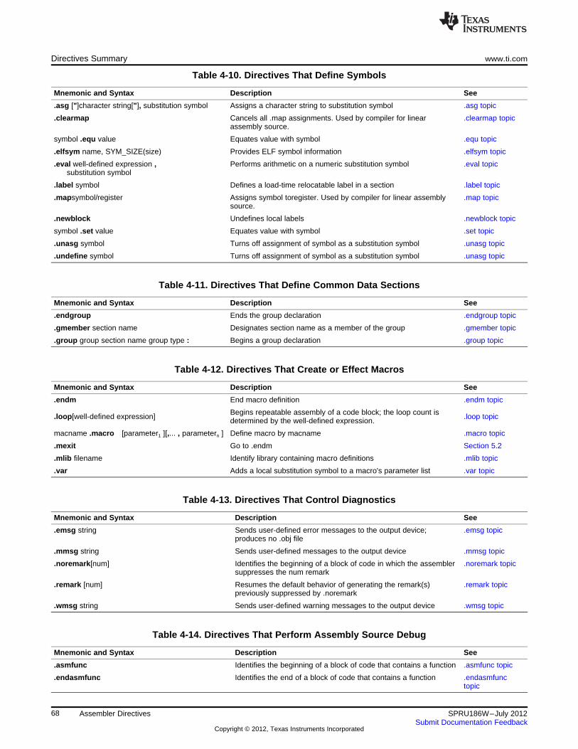
Directives Summary www.ti.com
Table 4-10. Directives That Define Symbols
Mnemonic and Syntax Description See
.asg ["]character string["], substitution symbol Assigns a character string to substitution symbol .asg topic
.clearmap Cancels all .map assignments. Used by compiler for linear .clearmap topicassembly source.
symbol .equ value Equates value with symbol .equ topic
.elfsym name, SYM_SIZE(size) Provides ELF symbol information .elfsym topic
.eval well-defined expression , Performs arithmetic on a numeric substitution symbol .eval topicsubstitution symbol
.label symbol Defines a load-time relocatable label in a section .label topic
.mapsymbol/register Assigns symbol toregister. Used by compiler for linear assembly .map topicsource.
.newblock Undefines local labels .newblock topic
symbol .set value Equates value with symbol .set topic
.unasg symbol Turns off assignment of symbol as a substitution symbol .unasg topic
.undefine symbol Turns off assignment of symbol as a substitution symbol .unasg topic
Table 4-11. Directives That Define Common Data Sections
Mnemonic and Syntax Description See
.endgroup Ends the group declaration .endgroup topic
.gmember section name Designates section name as a member of the group .gmember topic
.group group section name group type : Begins a group declaration .group topic
Table 4-12. Directives That Create or Effect Macros
Mnemonic and Syntax Description See
.endm End macro definition .endm topic
Begins repeatable assembly of a code block; the loop count is.loop[well-defined expression] .loop topicdetermined by the well-defined expression.
macname .macro [parameter1 ][,... , parametern ] Define macro by macname .macro topic
.mexit Go to .endm Section 5.2
.mlib filename Identify library containing macro definitions .mlib topic
.var Adds a local substitution symbol to a macro's parameter list .var topic
Table 4-13. Directives That Control Diagnostics
Mnemonic and Syntax Description See
.emsg string Sends user-defined error messages to the output device; .emsg topicproduces no .obj file
.mmsg string Sends user-defined messages to the output device .mmsg topic
.noremark[num] Identifies the beginning of a block of code in which the assembler .noremark topicsuppresses the num remark
.remark [num] Resumes the default behavior of generating the remark(s) .remark topicpreviously suppressed by .noremark
.wmsg string Sends user-defined warning messages to the output device .wmsg topic
Table 4-14. Directives That Perform Assembly Source Debug
Mnemonic and Syntax Description See
.asmfunc Identifies the beginning of a block of code that contains a function .asmfunc topic
.endasmfunc Identifies the end of a block of code that contains a function .endasmfunctopic
68 Assembler Directives SPRU186W–July 2012Submit Documentation Feedback
Copyright © 2012, Texas Instruments Incorporated
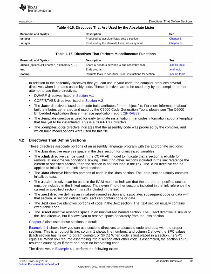
www.ti.com Directives That Define Sections
Table 4-15. Directives That Are Used by the Absolute Lister
Mnemonic and Syntax Description See
.setsect Produced by absolute lister; sets a section Chapter 8
.setsym Produced by the absolute lister; sets a symbol Chapter 8
Table 4-16. Directives That Perform Miscellaneous Functions
Mnemonic and Syntax Description See
.cdecls [options ,]"filename"[, "filename2"[, ...] Share C headers between C and assembly code .cdecls topic
.end Ends program .end topic
.nocmp Instructs tools to not utilize 16-bit instructions for section .nocmp topic
In addition to the assembly directives that you can use in your code, the compiler produces severaldirectives when it creates assembly code. These directives are to be used only by the compiler; do notattempt to use these directives.
• DWARF directives listed in Section A.1
• COFF/STABS directives listed in Section A.2
• The .battr directive is used to encode build attributes for the object file. For more information aboutbuild attributes generated and used by the C6000 Code Generation Tools, please see The C6000Embedded Application Binary Interface application report (SPRAB89).
• The .template directive is used for early template instantiation. It encodes information about a templatethat has yet to be instantiated. This is a COFF C++ directive.
• The .compiler_opts directive indicates that the assembly code was produced by the compiler, andwhich build model options were used for this file.
4.2 Directives That Define Sections
These directives associate portions of an assembly language program with the appropriate sections:
• The .bss directive reserves space in the .bss section for uninitialized variables.
• The .clink directive can be used in the COFF ABI model to indicate that a section is eligible forremoval at link-time via conditional linking. Thus if no other sections included in the link reference thecurrent or specified section, then the section is not included in the link. The .clink directive can beapplied to initialized or uninitialized sections.
• The .data directive identifies portions of code in the .data section. The .data section usually containsinitialized data.
• The .retain directive can be used in the EABI model to indicate that the current or specified sectionmust be included in the linked output. Thus even if no other sections included in the link reference thecurrent or specified section, it is still included in the link.
• The .sect directive defines an initialized named section and associates subsequent code or data withthat section. A section defined with .sect can contain code or data.
• The .text directive identifies portions of code in the .text section. The .text section usually containsexecutable code.
• The .usect directive reserves space in an uninitialized named section. The .usect directive is similar tothe .bss directive, but it allows you to reserve space separately from the .bss section.
Chapter 2 discusses these sections in detail.
Example 4-1 shows how you can use sections directives to associate code and data with the propersections. This is an output listing; column 1 shows line numbers, and column 2 shows the SPC values.(Each section has its own program counter, or SPC.) When code is first placed in a section, its SPCequals 0. When you resume assembling into a section after other code is assembled, the section's SPCresumes counting as if there had been no intervening code.
The directives in Example 4-1 perform the following tasks:
69SPRU186W–July 2012 Assembler DirectivesSubmit Documentation Feedback
Copyright © 2012, Texas Instruments Incorporated
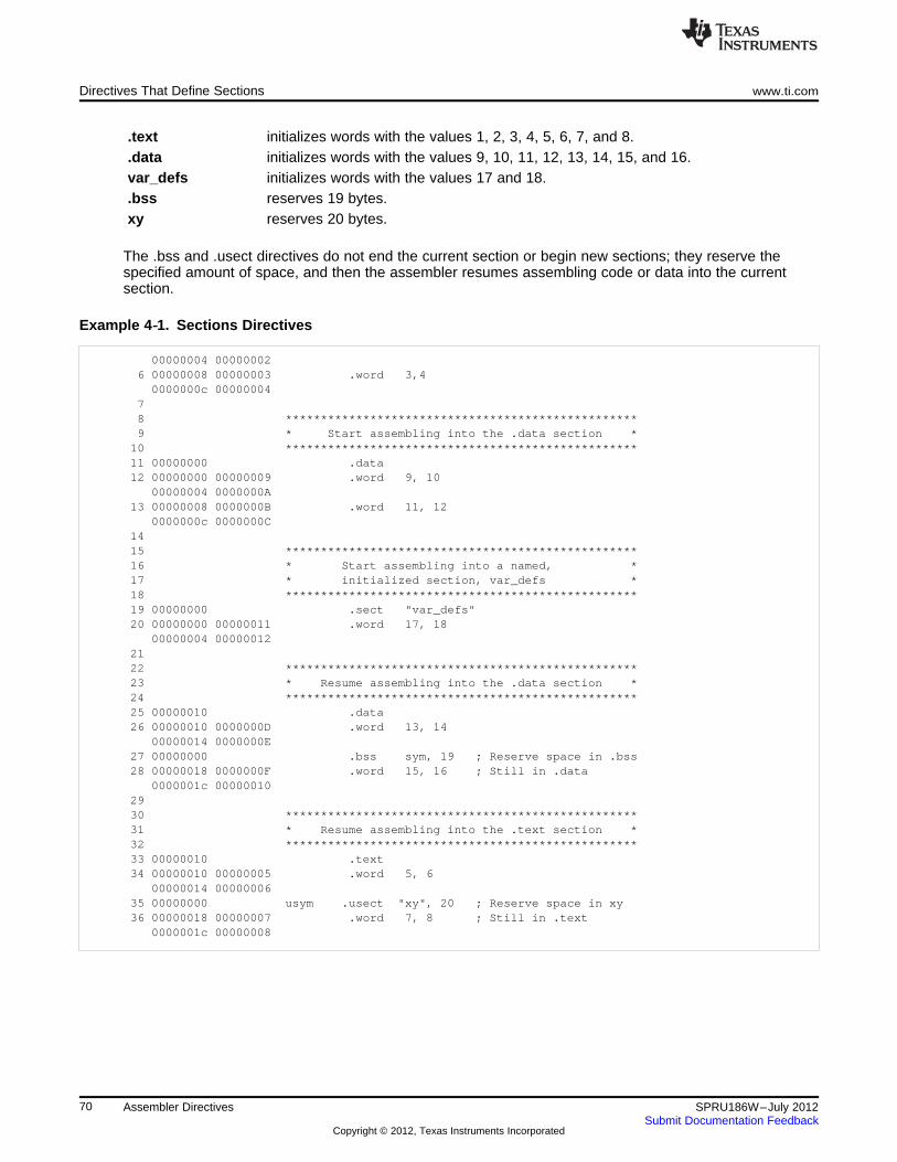
Directives That Define Sections www.ti.com
.text initializes words with the values 1, 2, 3, 4, 5, 6, 7, and 8.
.data initializes words with the values 9, 10, 11, 12, 13, 14, 15, and 16.var_defs initializes words with the values 17 and 18..bss reserves 19 bytes.xy reserves 20 bytes.
The .bss and .usect directives do not end the current section or begin new sections; they reserve thespecified amount of space, and then the assembler resumes assembling code or data into the currentsection.
Example 4‑‑1. Sections Directives
00000004 000000026 00000008 00000003 .word 3,40000000c 00000004
78 **************************************************9 * Start assembling into the .data section *10 **************************************************11 00000000 .data12 00000000 00000009 .word 9, 10
00000004 0000000A13 00000008 0000000B .word 11, 12
0000000c 0000000C1415 **************************************************16 * Start assembling into a named, *17 * initialized section, var_defs *18 **************************************************19 00000000 .sect "var_defs"20 00000000 00000011 .word 17, 18
00000004 000000122122 **************************************************23 * Resume assembling into the .data section *24 **************************************************25 00000010 .data26 00000010 0000000D .word 13, 14
00000014 0000000E27 00000000 .bss sym, 19 ; Reserve space in .bss28 00000018 0000000F .word 15, 16 ; Still in .data
0000001c 000000102930 **************************************************31 * Resume assembling into the .text section *32 **************************************************33 00000010 .text34 00000010 00000005 .word 5, 6
00000014 0000000635 00000000 usym .usect "xy", 20 ; Reserve space in xy36 00000018 00000007 .word 7, 8 ; Still in .text
0000001c 00000008
70 Assembler Directives SPRU186W–July 2012Submit Documentation Feedback
Copyright © 2012, Texas Instruments Incorporated
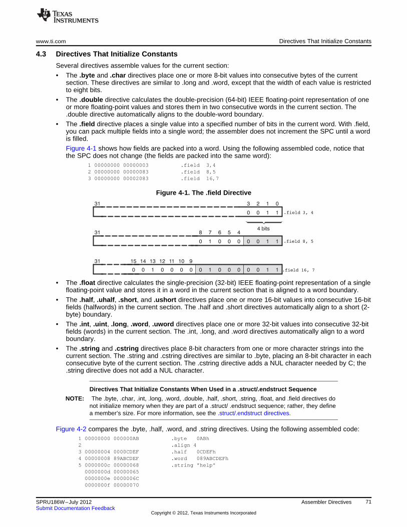
www.ti.com Directives That Initialize Constants
4.3 Directives That Initialize Constants
Several directives assemble values for the current section:
• The .byte and .char directives place one or more 8-bit values into consecutive bytes of the currentsection. These directives are similar to .long and .word, except that the width of each value is restrictedto eight bits.
• The .double directive calculates the double-precision (64-bit) IEEE floating-point representation of oneor more floating-point values and stores them in two consecutive words in the current section. The.double directive automatically aligns to the double-word boundary.
• The .field directive places a single value into a specified number of bits in the current word. With .field,you can pack multiple fields into a single word; the assembler does not increment the SPC until a wordis filled.
Figure 4-1 shows how fields are packed into a word. Using the following assembled code, notice thatthe SPC does not change (the fields are packed into the same word):
1 00000000 00000003 .field 3,42 00000000 00000083 .field 8,53 00000000 00002083 .field 16,7
Figure 4-1. The .field Directive
• The .float directive calculates the single-precision (32-bit) IEEE floating-point representation of a singlefloating-point value and stores it in a word in the current section that is aligned to a word boundary.
• The .half, .uhalf, .short, and .ushort directives place one or more 16-bit values into consecutive 16-bitfields (halfwords) in the current section. The .half and .short directives automatically align to a short (2-byte) boundary.
• The .int, .uint, .long, .word, .uword directives place one or more 32-bit values into consecutive 32-bitfields (words) in the current section. The .int, .long, and .word directives automatically align to a wordboundary.
• The .string and .cstring directives place 8-bit characters from one or more character strings into thecurrent section. The .string and .cstring directives are similar to .byte, placing an 8-bit character in eachconsecutive byte of the current section. The .cstring directive adds a NUL character needed by C; the.string directive does not add a NUL character.
Directives That Initialize Constants When Used in a .struct/.endstruct Sequence
NOTE: The .byte, .char, .int, .long, .word, .double, .half, .short, .string, .float, and .field directives donot initialize memory when they are part of a .struct/ .endstruct sequence; rather, they definea member’s size. For more information, see the .struct/.endstruct directives.
Figure 4-2 compares the .byte, .half, .word, and .string directives. Using the following assembled code:1 00000000 000000AB .byte 0ABh2 .align 43 00000004 0000CDEF .half 0CDEFh4 00000008 89ABCDEF .word 089ABCDEFh5 0000000c 00000068 .string "help"0000000d 000000650000000e 0000006C0000000f 00000070
71SPRU186W–July 2012 Assembler DirectivesSubmit Documentation Feedback
Copyright © 2012, Texas Instruments Incorporated
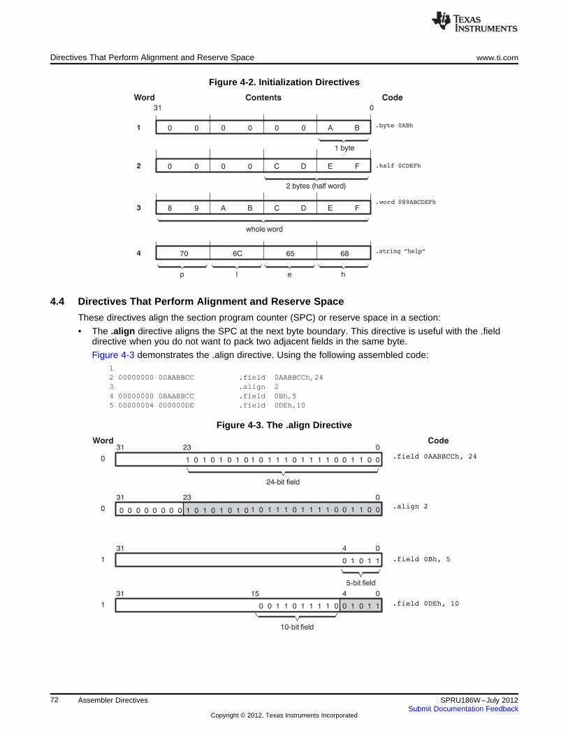
Directives That Perform Alignment and Reserve Space www.ti.com
Figure 4-2. Initialization Directives
4.4 Directives That Perform Alignment and Reserve Space
These directives align the section program counter (SPC) or reserve space in a section:
• The .align directive aligns the SPC at the next byte boundary. This directive is useful with the .fielddirective when you do not want to pack two adjacent fields in the same byte.
Figure 4-3 demonstrates the .align directive. Using the following assembled code:12 00000000 00AABBCC .field 0AABBCCh,243 .align 24 00000000 0BAABBCC .field 0Bh,55 00000004 000000DE .field 0DEh,10
Figure 4-3. The .align Directive
72 Assembler Directives SPRU186W–July 2012Submit Documentation Feedback
Copyright © 2012, Texas Instruments Incorporated
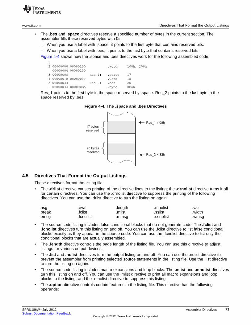
17 bytesreserved
20 bytesreserved
Res_1 = 08h
Res_2 = 33h
www.ti.com Directives That Format the Output Listings
• The .bes and .space directives reserve a specified number of bytes in the current section. Theassembler fills these reserved bytes with 0s.
– When you use a label with .space, it points to the first byte that contains reserved bits.
– When you use a label with .bes, it points to the last byte that contains reserved bits.
Figure 4-4 shows how the .space and .bes directives work for the following assembled code:12 00000000 00000100 .word 100h, 200h00000004 00000200
3 00000008 Res_1: .space 174 0000001c 0000000F .word 155 00000033 Res_2: .bes 206 00000034 000000BA .byte 0BAh
Res_1 points to the first byte in the space reserved by .space. Res_2 points to the last byte in thespace reserved by .bes.
Figure 4-4. The .space and .bes Directives
4.5 Directives That Format the Output Listings
These directives format the listing file:
• The .drlist directive causes printing of the directive lines to the listing; the .drnolist directive turns it offfor certain directives. You can use the .drnolist directive to suppress the printing of the followingdirectives. You can use the .drlist directive to turn the listing on again.
.asg .eval .length .mnolist .var
.break .fclist .mlist .sslist .width
.emsg .fcnolist .mmsg .ssnolist .wmsg
• The source code listing includes false conditional blocks that do not generate code. The .fclist and.fcnolist directives turn this listing on and off. You can use the .fclist directive to list false conditionalblocks exactly as they appear in the source code. You can use the .fcnolist directive to list only theconditional blocks that are actually assembled.
• The .length directive controls the page length of the listing file. You can use this directive to adjustlistings for various output devices.
• The .list and .nolist directives turn the output listing on and off. You can use the .nolist directive toprevent the assembler from printing selected source statements in the listing file. Use the .list directiveto turn the listing on again.
• The source code listing includes macro expansions and loop blocks. The .mlist and .mnolist directivesturn this listing on and off. You can use the .mlist directive to print all macro expansions and loopblocks to the listing, and the .mnolist directive to suppress this listing.
• The .option directive controls certain features in the listing file. This directive has the followingoperands:
73SPRU186W–July 2012 Assembler DirectivesSubmit Documentation Feedback
Copyright © 2012, Texas Instruments Incorporated
Directives That Reference Other Files www.ti.com
A turns on listing of all directives and data, and subsequent expansions, macros, and blocks.B limits the listing of .byte and .char directives to one line.D turns off the listing of certain directives (same effect as .drnolist).H limits the listing of .half and .short directives to one line.L limits the listing of .long directives to one line.M turns off macro expansions in the listing.N turns off listing (performs .nolist).O turns on listing (performs .list).R resets the B, H, L, M, T, and W directives (turns off the limits of B, H, L, M, T, and W).T limits the listing of .string directives to one line.W limits the listing of .word and .int directives to one line.X produces a cross-reference listing of symbols. You can also obtain a cross-reference listing
by invoking the assembler with the --cross_reference option (see Section 3.3).
• The .page directive causes a page eject in the output listing.
• The source code listing includes substitution symbol expansions. The .sslist and .ssnolist directivesturn this listing on and off. You can use the .sslist directive to print all substitution symbol expansionsto the listing, and the .ssnolist directive to suppress this listing. These directives are useful fordebugging the expansion of substitution symbols.
• The .tab directive defines tab size.
• The .title directive supplies a title that the assembler prints at the top of each page.
• The .width directive controls the page width of the listing file. You can use this directive to adjustlistings for various output devices.
4.6 Directives That Reference Other Files
These directives supply information for or about other files that can be used in the assembly of the currentfile:
• The .copy and .include directives tell the assembler to begin reading source statements from anotherfile. When the assembler finishes reading the source statements in the copy/include file, it resumesreading source statements from the current file. The statements read from a copied file are printed inthe listing file; the statements read from an included file are not printed in the listing file.
• The .def directive identifies a symbol that is defined in the current module and that can be used inanother module. The assembler includes the symbol in the symbol table.
• The .global directive declares a symbol external so that it is available to other modules at link time.(For more information about global symbols, see Section 2.7.1). The .global directive does double duty,acting as a .def for defined symbols and as a .ref for undefined symbols. The linker resolves anundefined global symbol reference only if the symbol is used in the program. The .global directivedeclares a 16-bit symbol.
• The .mlib directive supplies the assembler with the name of an archive library that contains macrodefinitions. When the assembler encounters a macro that is not defined in the current module, itsearches for it in the macro library specified with .mlib.
• The .ref directive identifies a symbol that is used in the current module but is defined in anothermodule. The assembler marks the symbol as an undefined external symbol and enters it in the objectsymbol table so the linker can resolve its definition. The .ref directive forces the linker to resolve asymbol reference.
• The .symdepend directive creates an artificial reference from the section defining the source symbolname to the destination symbol. The .symdepend directive prevents the linker from removing thesection containing the destination symbol if the source symbol section is included in the output module.
• The .weak directive identifies a symbol that is used in the current module but is defined in anothermodule. It is equivalent to the .ref directive, except that the reference has weak linkage.
74 Assembler Directives SPRU186W–July 2012Submit Documentation Feedback
Copyright © 2012, Texas Instruments Incorporated
www.ti.com Directives That Enable Conditional Assembly
4.7 Directives That Enable Conditional Assembly
Conditional assembly directives enable you to instruct the assembler to assemble certain sections of codeaccording to a true or false evaluation of an expression. Two sets of directives allow you to assembleconditional blocks of code:
• The .if/.elseif/.else/.endif directives tell the assembler to conditionally assemble a block of codeaccording to the evaluation of an expression..if well-defined expression marks the beginning of a conditional block and assembles code
if the .if well-defined expression is true.[.elseif well-defined expression] marks a block of code to be assembled if the .if well-defined
expression is false and the .elseif condition is true..else marks a block of code to be assembled if the .if well-defined
expression is false and any .elseif conditions are false..endif marks the end of a conditional block and terminates the block.
• The .loop/.break/.endloop directives tell the assembler to repeatedly assemble a block of codeaccording to the evaluation of an expression..loop [well-defined expression] marks the beginning of a repeatable block of code. The optional
expression evaluates to the loop count..break [well-defined expression] tells the assembler to assemble repeatedly when the .break
well-defined expression is false and to go to the codeimmediately after .endloop when the expression is true oromitted.
.endloop marks the end of a repeatable block.The assembler supports several relational operators that are useful for conditional expressions. For moreinformation about relational operators, see Section 3.10.4.
4.8 Directives That Define Union or Structure Types
These directives set up specialized types for later use with the .tag directive, allowing you to use symbolicnames to refer to portions of a complex object. The types created are analogous to the struct and uniontypes of the C language.
The .struct, .union, .cstruct, and .cunion directives group related data into an aggregate structure which ismore easily accessed. These directives do not allocate space for any object. Objects must be separatelyallocated, and the .tag directive must be used to assign the type to the object.
COORDT .struct ; structure tag definitionX .byte ;Y .byteT_LEN .endstruct
COORD .tag COORDT ; declare COORD (coordinate).bss COORD, T_LEN ; actual memory allocation
LDB *+B14(COORD.Y), A2 ; move member Y of structure; COORD into register A2
The .cstruct and .cunion directives guarantee that the data structure will have the same alignment andpadding as if the structure were defined in analogous C code. This allows structures to be shared betweenC and assembly code. See Chapter 12. For .struct and .union, element offset calculation is left up to theassembler, so the layout may be different than .cstruct and .cunion.
75SPRU186W–July 2012 Assembler DirectivesSubmit Documentation Feedback
Copyright © 2012, Texas Instruments Incorporated
Directives That Define Enumerated Types www.ti.com
4.9 Directives That Define Enumerated Types
These directives set up specialized types for later use in expressions allowing you to use symbolic namesto refer to compile-time constants. The types created are analogous to the enum type of the C language.This allows enumerated types to be shared between C and assembly code. See Chapter 12.
See Section 12.2.10 for an example of using .enum.
4.10 Directives That Define Symbols at Assembly Time
Assembly-time symbol directives equate meaningful symbol names to constant values or strings.
• The .asg directive assigns a character string to a substitution symbol. The value is stored in thesubstitution symbol table. When the assembler encounters a substitution symbol, it replaces thesymbol with its character string value. Substitution symbols can be redefined..asg "10, 20, 30, 40", coefficients
; Assign string to substitution symbol..byte coefficients
; Place the symbol values 10, 20, 30, and 40; into consecutive bytes in current section.
• The .eval directive evaluates a well-defined expression, translates the results into a character string,and assigns the character string to a substitution symbol. This directive is most useful for manipulatingcounters:.asg 1 , x ; x = 1.loop ; Begin conditional loop..byte x*10h ; Store value into current section..break x = 4 ; Break loop if x = 4..eval x+1, x ; Increment x by 1..endloop ; End conditional loop.
• The .define directive assigns a character string to a substitution symbol. The value is stored in thesubstitution symbol table. When the assembler encounters a substitution symbol, it replaces thesymbol with its character string value. Substitution symbols created with .define cannot be redefined.
• The .label directive defines a special symbol that refers to the load-time address within the currentsection. This is useful when a section loads at one address but runs at a different address. Forexample, you may want to load a block of performance-critical code into slower off-chip memory tosave space and move the code to high-speed on-chip memory to run. See the .label topic for anexample using a load-time address label.
• The .set and .equ directives set a constant value to a symbol. The symbol is stored in the symbol tableand cannot be redefined; for example:bval .set 0100h ; Set bval = 0100h
.long bval, bval*2, bval+12; Store the values 0100h, 0200h, and 010Ch; into consecutive words in current section.
The .set and .equ directives produce no object code. The two directives are identical and can be usedinterchangeably.
• The .unasg directive turns off substitution symbol assignment made with .asg.
• The .undefine directive turns off substitution symbol assignment made with .define.
• The .var directive allows you to use substitution symbols as local variables within a macro.
76 Assembler Directives SPRU186W–July 2012Submit Documentation Feedback
Copyright © 2012, Texas Instruments Incorporated
www.ti.com Miscellaneous Directives
4.11 Miscellaneous Directives
These directives enable miscellaneous functions or features:
• The .asmfunc and .endasmfunc directives mark function boundaries. These directives are used withthe compiler --symdebug:dwarf (-g) option to generate debug information for assembly functions.
• The .cdecls directive enables programmers in mixed assembly and C/C++ environments to share Cheaders containing declarations and prototypes between C and assembly code.
• The .end directive terminates assembly. If you use the .end directive, it should be the last sourcestatement of a program. This directive has the same effect as an end-of-file character.
• The .group, .gmember, and .endgroup directives define a common data section for member of anELF group section.
• The .import, .export, .hidden, and .protected directives set the dynamic visibility of a global symbolfor ELF only. See Section 7.12 for an explanation of symbol visibility
• The .newblock directive resets local labels. Local labels are symbols of the form $n, where n is adecimal digit, or of the form NAME?, where you specify NAME. They are defined when they appear inthe label field. Local labels are temporary labels that can be used as operands for jump instructions.The .newblock directive limits the scope of local labels by resetting them after they are used. SeeSection 3.9.2 for information on local labels.
• The .nocmp directive for C6400+, C6740, and C6600 instructs the tools to not utilize 16-bit instructionsfor the section .nocmp appears in.
• The .noremark directive begins a block of code in which the assembler suppresses the specifiedassembler remark. A remark is an informational assembler message that is less severe than awarning. The .remark directive re-enables the remark(s) previously suppressed by .noremark.
These three directives enable you to define your own error and warning messages:
• The .emsg directive sends error messages to the standard output device. The .emsg directivegenerates errors in the same manner as the assembler, incrementing the error count and preventingthe assembler from producing an object file.
• The .mmsg directive sends assembly-time messages to the standard output device. The .mmsgdirective functions in the same manner as the .emsg and .wmsg directives but does not set the errorcount or the warning count. It does not affect the creation of the object file.
• The .wmsg directive sends warning messages to the standard output device. The .wmsg directivefunctions in the same manner as the .emsg directive but increments the warning count rather than theerror count. It does not affect the creation of the object file.
For more information about using the error and warning directives in macros, see Section 5.7.
77SPRU186W–July 2012 Assembler DirectivesSubmit Documentation Feedback
Copyright © 2012, Texas Instruments Incorporated
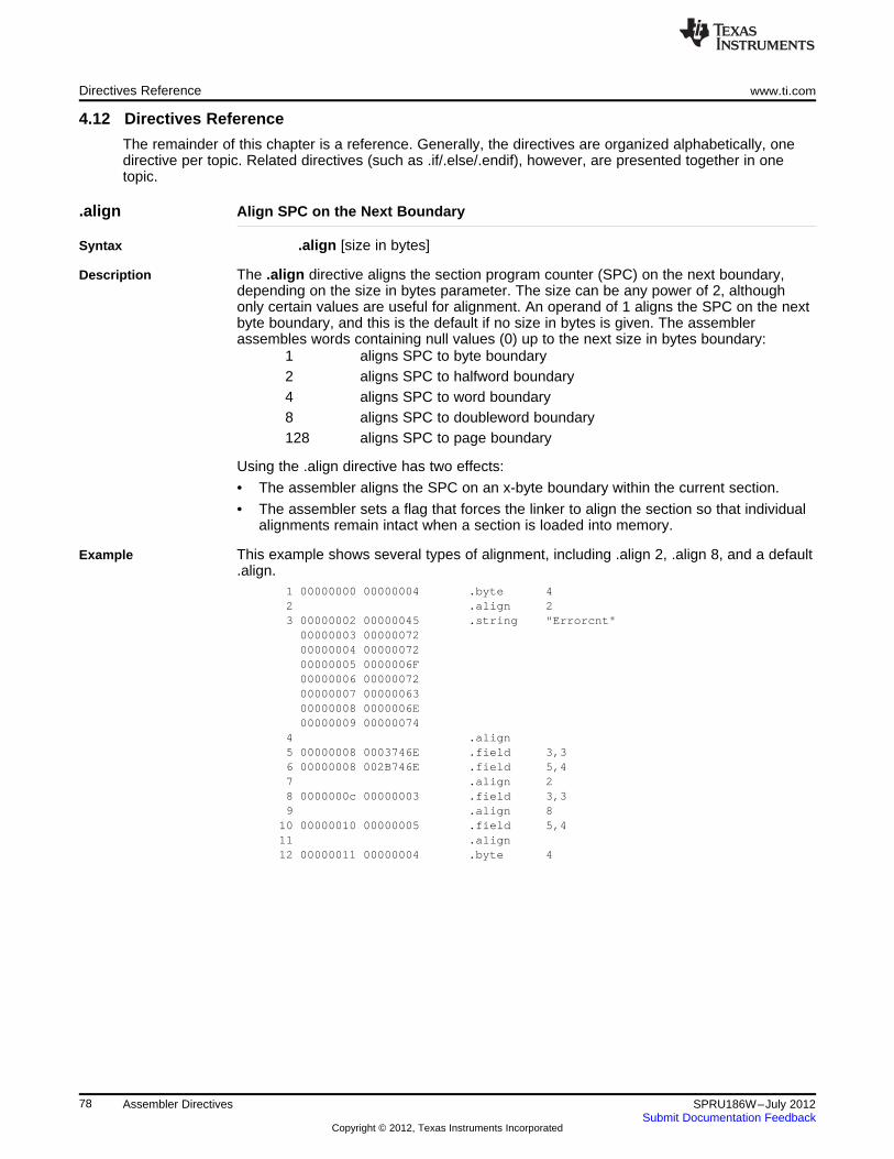
Directives Reference www.ti.com
4.12 Directives Reference
The remainder of this chapter is a reference. Generally, the directives are organized alphabetically, onedirective per topic. Related directives (such as .if/.else/.endif), however, are presented together in onetopic.
.align Align SPC on the Next Boundary
Syntax .align [size in bytes]
Description The .align directive aligns the section program counter (SPC) on the next boundary,depending on the size in bytes parameter. The size can be any power of 2, althoughonly certain values are useful for alignment. An operand of 1 aligns the SPC on the nextbyte boundary, and this is the default if no size in bytes is given. The assemblerassembles words containing null values (0) up to the next size in bytes boundary:
1 aligns SPC to byte boundary2 aligns SPC to halfword boundary4 aligns SPC to word boundary8 aligns SPC to doubleword boundary128 aligns SPC to page boundary
Using the .align directive has two effects:
• The assembler aligns the SPC on an x-byte boundary within the current section.
• The assembler sets a flag that forces the linker to align the section so that individualalignments remain intact when a section is loaded into memory.
Example This example shows several types of alignment, including .align 2, .align 8, and a default.align.
1 00000000 00000004 .byte 42 .align 23 00000002 00000045 .string "Errorcnt"00000003 0000007200000004 0000007200000005 0000006F00000006 0000007200000007 0000006300000008 0000006E00000009 00000074
4 .align5 00000008 0003746E .field 3,36 00000008 002B746E .field 5,47 .align 28 0000000c 00000003 .field 3,39 .align 8
10 00000010 00000005 .field 5,411 .align12 00000011 00000004 .byte 4
78 Assembler Directives SPRU186W–July 2012Submit Documentation Feedback
Copyright © 2012, Texas Instruments Incorporated
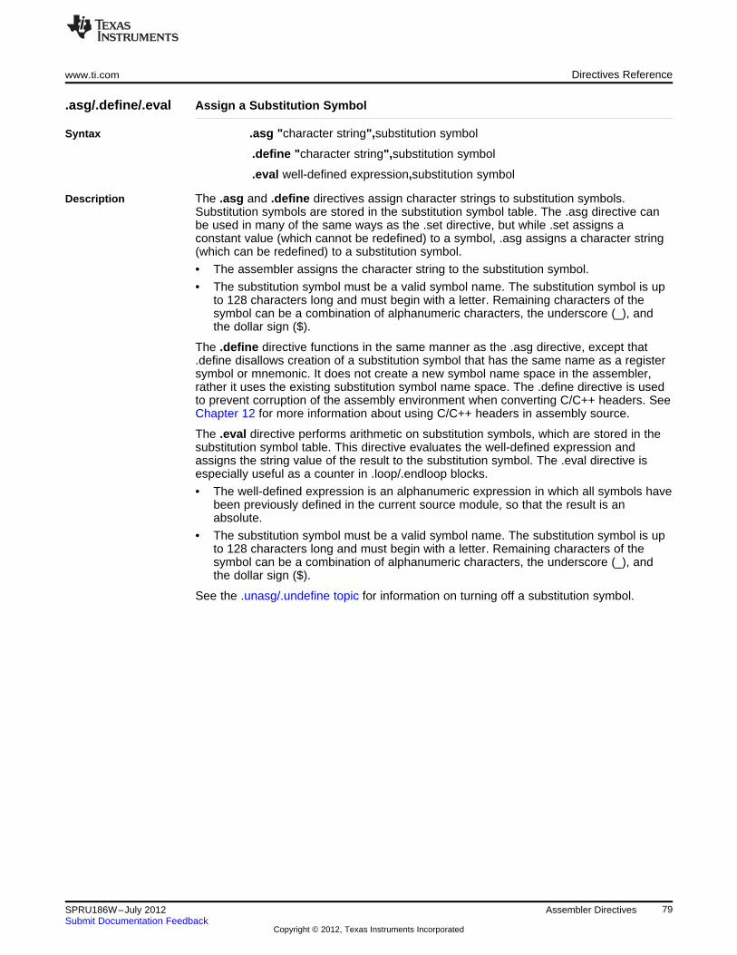
www.ti.com Directives Reference
.asg/.define/.eval Assign a Substitution Symbol
Syntax .asg "character string",substitution symbol
.define "character string",substitution symbol
.eval well-defined expression,substitution symbol
Description The .asg and .define directives assign character strings to substitution symbols.Substitution symbols are stored in the substitution symbol table. The .asg directive canbe used in many of the same ways as the .set directive, but while .set assigns aconstant value (which cannot be redefined) to a symbol, .asg assigns a character string(which can be redefined) to a substitution symbol.
• The assembler assigns the character string to the substitution symbol.
• The substitution symbol must be a valid symbol name. The substitution symbol is upto 128 characters long and must begin with a letter. Remaining characters of thesymbol can be a combination of alphanumeric characters, the underscore (_), andthe dollar sign ($).
The .define directive functions in the same manner as the .asg directive, except that.define disallows creation of a substitution symbol that has the same name as a registersymbol or mnemonic. It does not create a new symbol name space in the assembler,rather it uses the existing substitution symbol name space. The .define directive is usedto prevent corruption of the assembly environment when converting C/C++ headers. SeeChapter 12 for more information about using C/C++ headers in assembly source.
The .eval directive performs arithmetic on substitution symbols, which are stored in thesubstitution symbol table. This directive evaluates the well-defined expression andassigns the string value of the result to the substitution symbol. The .eval directive isespecially useful as a counter in .loop/.endloop blocks.
• The well-defined expression is an alphanumeric expression in which all symbols havebeen previously defined in the current source module, so that the result is anabsolute.
• The substitution symbol must be a valid symbol name. The substitution symbol is upto 128 characters long and must begin with a letter. Remaining characters of thesymbol can be a combination of alphanumeric characters, the underscore (_), andthe dollar sign ($).
See the .unasg/.undefine topic for information on turning off a substitution symbol.
79SPRU186W–July 2012 Assembler DirectivesSubmit Documentation Feedback
Copyright © 2012, Texas Instruments Incorporated
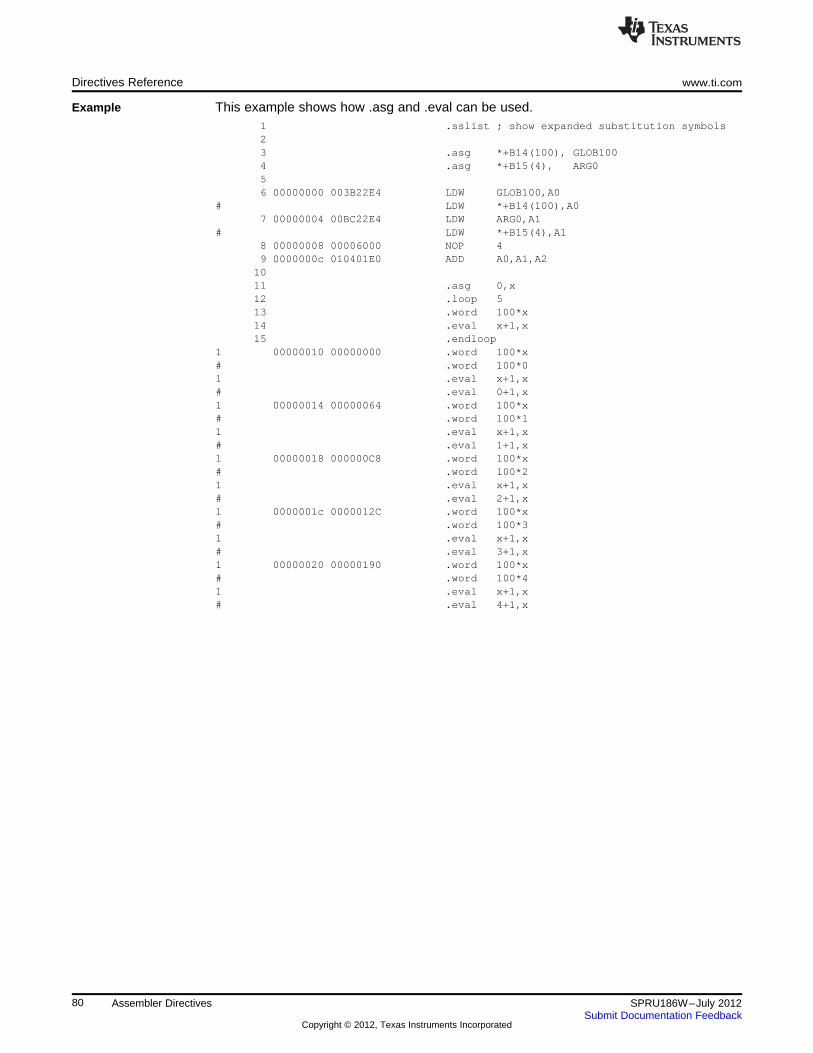
Directives Reference www.ti.com
Example This example shows how .asg and .eval can be used.1 .sslist ; show expanded substitution symbols23 .asg *+B14(100), GLOB1004 .asg *+B15(4), ARG056 00000000 003B22E4 LDW GLOB100,A0
# LDW *+B14(100),A07 00000004 00BC22E4 LDW ARG0,A1
# LDW *+B15(4),A18 00000008 00006000 NOP 49 0000000c 010401E0 ADD A0,A1,A2
1011 .asg 0,x12 .loop 513 .word 100*x14 .eval x+1,x15 .endloop
1 00000010 00000000 .word 100*x# .word 100*01 .eval x+1,x# .eval 0+1,x1 00000014 00000064 .word 100*x# .word 100*11 .eval x+1,x# .eval 1+1,x1 00000018 000000C8 .word 100*x# .word 100*21 .eval x+1,x# .eval 2+1,x1 0000001c 0000012C .word 100*x# .word 100*31 .eval x+1,x# .eval 3+1,x1 00000020 00000190 .word 100*x# .word 100*41 .eval x+1,x# .eval 4+1,x
80 Assembler Directives SPRU186W–July 2012Submit Documentation Feedback
Copyright © 2012, Texas Instruments Incorporated
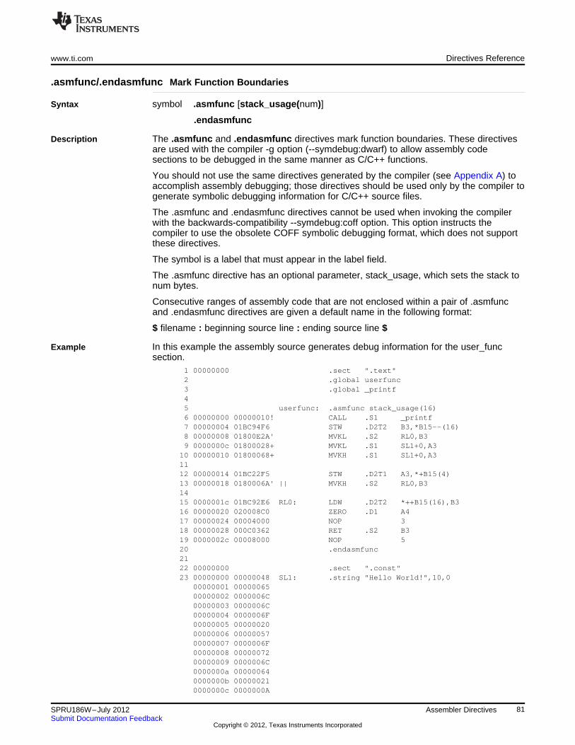
www.ti.com Directives Reference
.asmfunc/.endasmfunc Mark Function Boundaries
Syntax symbol .asmfunc [stack_usage(num)]
.endasmfunc
Description The .asmfunc and .endasmfunc directives mark function boundaries. These directivesare used with the compiler -g option (--symdebug:dwarf) to allow assembly codesections to be debugged in the same manner as C/C++ functions.
You should not use the same directives generated by the compiler (see Appendix A) toaccomplish assembly debugging; those directives should be used only by the compiler togenerate symbolic debugging information for C/C++ source files.
The .asmfunc and .endasmfunc directives cannot be used when invoking the compilerwith the backwards-compatibility --symdebug:coff option. This option instructs thecompiler to use the obsolete COFF symbolic debugging format, which does not supportthese directives.
The symbol is a label that must appear in the label field.
The .asmfunc directive has an optional parameter, stack_usage, which sets the stack tonum bytes.
Consecutive ranges of assembly code that are not enclosed within a pair of .asmfuncand .endasmfunc directives are given a default name in the following format:
$ filename : beginning source line : ending source line $
Example In this example the assembly source generates debug information for the user_funcsection.
1 00000000 .sect ".text"2 .global userfunc3 .global _printf45 userfunc: .asmfunc stack_usage(16)6 00000000 00000010! CALL .S1 _printf7 00000004 01BC94F6 STW .D2T2 B3,*B15--(16)8 00000008 01800E2A' MVKL .S2 RL0,B39 0000000c 01800028+ MVKL .S1 SL1+0,A3
10 00000010 01800068+ MVKH .S1 SL1+0,A31112 00000014 01BC22F5 STW .D2T1 A3,*+B15(4)13 00000018 0180006A' || MVKH .S2 RL0,B31415 0000001c 01BC92E6 RL0: LDW .D2T2 *++B15(16),B316 00000020 020008C0 ZERO .D1 A417 00000024 00004000 NOP 318 00000028 000C0362 RET .S2 B319 0000002c 00008000 NOP 520 .endasmfunc2122 00000000 .sect ".const"23 00000000 00000048 SL1: .string "Hello World!",10,0
00000001 0000006500000002 0000006C00000003 0000006C00000004 0000006F00000005 0000002000000006 0000005700000007 0000006F00000008 0000007200000009 0000006C0000000a 000000640000000b 000000210000000c 0000000A
81SPRU186W–July 2012 Assembler DirectivesSubmit Documentation Feedback
Copyright © 2012, Texas Instruments Incorporated
Directives Reference www.ti.com
0000000d 00000000
82 Assembler Directives SPRU186W–July 2012Submit Documentation Feedback
Copyright © 2012, Texas Instruments Incorporated
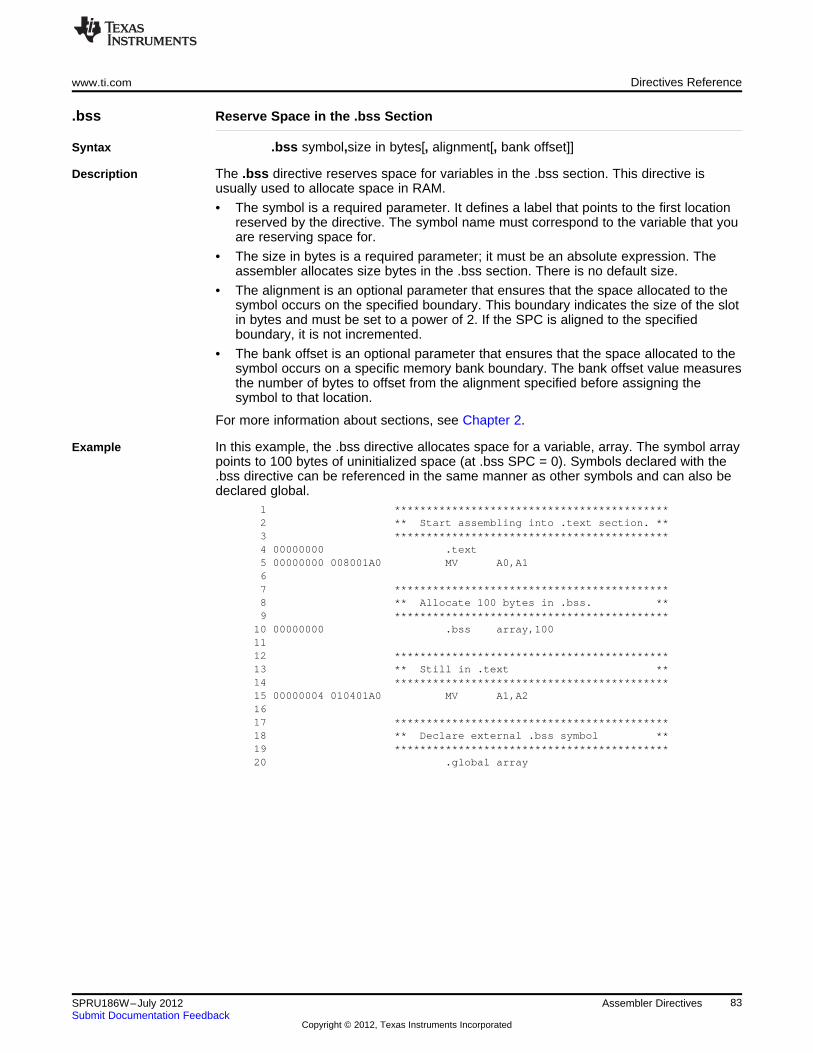
www.ti.com Directives Reference
.bss Reserve Space in the .bss Section
Syntax .bss symbol,size in bytes[, alignment[, bank offset]]
Description The .bss directive reserves space for variables in the .bss section. This directive isusually used to allocate space in RAM.
• The symbol is a required parameter. It defines a label that points to the first locationreserved by the directive. The symbol name must correspond to the variable that youare reserving space for.
• The size in bytes is a required parameter; it must be an absolute expression. Theassembler allocates size bytes in the .bss section. There is no default size.
• The alignment is an optional parameter that ensures that the space allocated to thesymbol occurs on the specified boundary. This boundary indicates the size of the slotin bytes and must be set to a power of 2. If the SPC is aligned to the specifiedboundary, it is not incremented.
• The bank offset is an optional parameter that ensures that the space allocated to thesymbol occurs on a specific memory bank boundary. The bank offset value measuresthe number of bytes to offset from the alignment specified before assigning thesymbol to that location.
For more information about sections, see Chapter 2.
Example In this example, the .bss directive allocates space for a variable, array. The symbol arraypoints to 100 bytes of uninitialized space (at .bss SPC = 0). Symbols declared with the.bss directive can be referenced in the same manner as other symbols and can also bedeclared global.
1 *******************************************2 ** Start assembling into .text section. **3 *******************************************4 00000000 .text5 00000000 008001A0 MV A0,A167 *******************************************8 ** Allocate 100 bytes in .bss. **9 *******************************************
10 00000000 .bss array,1001112 *******************************************13 ** Still in .text **14 *******************************************15 00000004 010401A0 MV A1,A21617 *******************************************18 ** Declare external .bss symbol **19 *******************************************20 .global array
83SPRU186W–July 2012 Assembler DirectivesSubmit Documentation Feedback
Copyright © 2012, Texas Instruments Incorporated
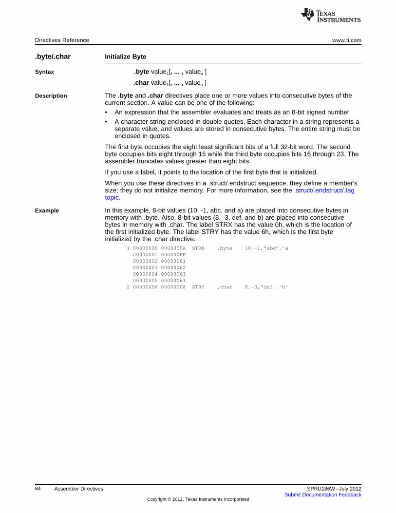
Directives Reference www.ti.com
.byte/.char Initialize Byte
Syntax .byte value1[, ... , valuen ]
.char value1[, ... , valuen ]
Description The .byte and .char directives place one or more values into consecutive bytes of thecurrent section. A value can be one of the following:
• An expression that the assembler evaluates and treats as an 8-bit signed number
• A character string enclosed in double quotes. Each character in a string represents aseparate value, and values are stored in consecutive bytes. The entire string must beenclosed in quotes.
The first byte occupies the eight least significant bits of a full 32-bit word. The secondbyte occupies bits eight through 15 while the third byte occupies bits 16 through 23. Theassembler truncates values greater than eight bits.
If you use a label, it points to the location of the first byte that is initialized.
When you use these directives in a .struct/.endstruct sequence, they define a member'ssize; they do not initialize memory. For more information, see the .struct/.endstruct/.tagtopic.
Example In this example, 8-bit values (10, -1, abc, and a) are placed into consecutive bytes inmemory with .byte. Also, 8-bit values (8, -3, def, and b) are placed into consecutivebytes in memory with .char. The label STRX has the value 0h, which is the location ofthe first initialized byte. The label STRY has the value 6h, which is the first byteinitialized by the .char directive.
1 00000000 0000000A STRX .byte 10,-1,"abc",'a'00000001 000000FF00000002 0000006100000003 0000006200000004 0000006300000005 00000061
2 00000006 00000008 STRY .char 8,-3,"def",'b'
84 Assembler Directives SPRU186W–July 2012Submit Documentation Feedback
Copyright © 2012, Texas Instruments Incorporated
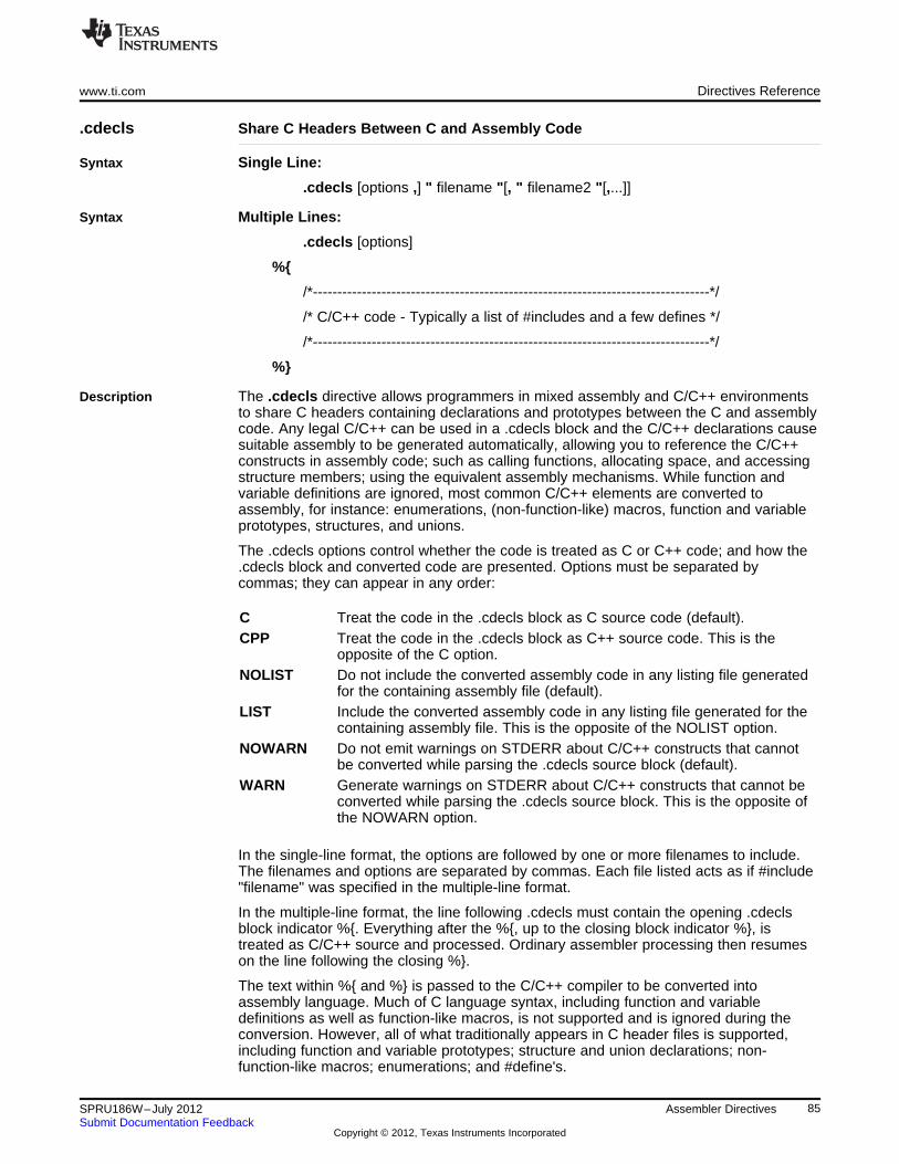
www.ti.com Directives Reference
.cdecls Share C Headers Between C and Assembly Code
Syntax Single Line:
.cdecls [options ,] " filename "[, " filename2 "[,...]]
Syntax Multiple Lines:
.cdecls [options]
%{
/*---------------------------------------------------------------------------------*/
/* C/C++ code - Typically a list of #includes and a few defines */
/*---------------------------------------------------------------------------------*/
%}
Description The .cdecls directive allows programmers in mixed assembly and C/C++ environmentsto share C headers containing declarations and prototypes between the C and assemblycode. Any legal C/C++ can be used in a .cdecls block and the C/C++ declarations causesuitable assembly to be generated automatically, allowing you to reference the C/C++constructs in assembly code; such as calling functions, allocating space, and accessingstructure members; using the equivalent assembly mechanisms. While function andvariable definitions are ignored, most common C/C++ elements are converted toassembly, for instance: enumerations, (non-function-like) macros, function and variableprototypes, structures, and unions.
The .cdecls options control whether the code is treated as C or C++ code; and how the.cdecls block and converted code are presented. Options must be separated bycommas; they can appear in any order:
C Treat the code in the .cdecls block as C source code (default).CPP Treat the code in the .cdecls block as C++ source code. This is the
opposite of the C option.NOLIST Do not include the converted assembly code in any listing file generated
for the containing assembly file (default).LIST Include the converted assembly code in any listing file generated for the
containing assembly file. This is the opposite of the NOLIST option.NOWARN Do not emit warnings on STDERR about C/C++ constructs that cannot
be converted while parsing the .cdecls source block (default).WARN Generate warnings on STDERR about C/C++ constructs that cannot be
converted while parsing the .cdecls source block. This is the opposite ofthe NOWARN option.
In the single-line format, the options are followed by one or more filenames to include.The filenames and options are separated by commas. Each file listed acts as if #include"filename" was specified in the multiple-line format.
In the multiple-line format, the line following .cdecls must contain the opening .cdeclsblock indicator %{. Everything after the %{, up to the closing block indicator %}, istreated as C/C++ source and processed. Ordinary assembler processing then resumeson the line following the closing %}.
The text within %{ and %} is passed to the C/C++ compiler to be converted intoassembly language. Much of C language syntax, including function and variabledefinitions as well as function-like macros, is not supported and is ignored during theconversion. However, all of what traditionally appears in C header files is supported,including function and variable prototypes; structure and union declarations; non-function-like macros; enumerations; and #define's.
85SPRU186W–July 2012 Assembler DirectivesSubmit Documentation Feedback
Copyright © 2012, Texas Instruments Incorporated
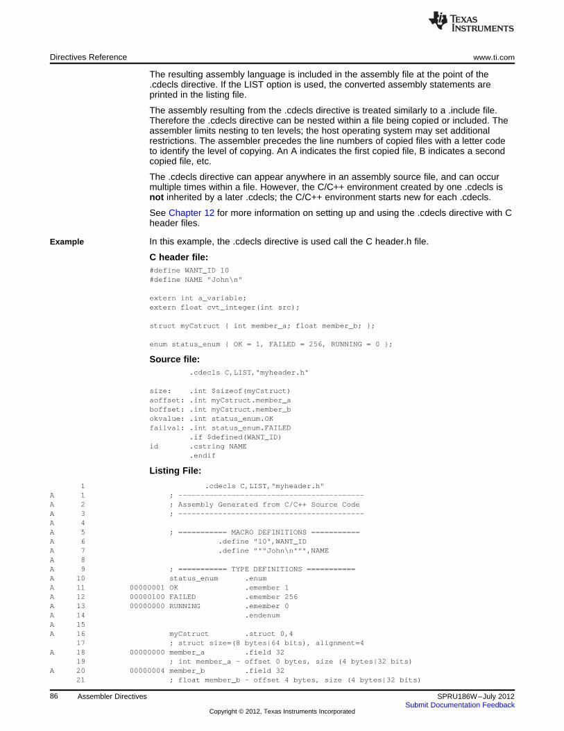
Directives Reference www.ti.com
The resulting assembly language is included in the assembly file at the point of the.cdecls directive. If the LIST option is used, the converted assembly statements areprinted in the listing file.
The assembly resulting from the .cdecls directive is treated similarly to a .include file.Therefore the .cdecls directive can be nested within a file being copied or included. Theassembler limits nesting to ten levels; the host operating system may set additionalrestrictions. The assembler precedes the line numbers of copied files with a letter codeto identify the level of copying. An A indicates the first copied file, B indicates a secondcopied file, etc.
The .cdecls directive can appear anywhere in an assembly source file, and can occurmultiple times within a file. However, the C/C++ environment created by one .cdecls isnot inherited by a later .cdecls; the C/C++ environment starts new for each .cdecls.
See Chapter 12 for more information on setting up and using the .cdecls directive with Cheader files.
Example In this example, the .cdecls directive is used call the C header.h file.
C header file:#define WANT_ID 10#define NAME "John\n"
extern int a_variable;extern float cvt_integer(int src);
struct myCstruct { int member_a; float member_b; };
enum status_enum { OK = 1, FAILED = 256, RUNNING = 0 };
Source file:.cdecls C,LIST,"myheader.h"
size: .int $sizeof(myCstruct)aoffset: .int myCstruct.member_aboffset: .int myCstruct.member_bokvalue: .int status_enum.OKfailval: .int status_enum.FAILED
.if $defined(WANT_ID)id .cstring NAME
.endif
Listing File:
1 .cdecls C,LIST,"myheader.h"A 1 ; ------------------------------------------A 2 ; Assembly Generated from C/C++ Source CodeA 3 ; ------------------------------------------A 4A 5 ; =========== MACRO DEFINITIONS ===========A 6 .define "10",WANT_IDA 7 .define """John\n""",NAMEA 8A 9 ; =========== TYPE DEFINITIONS ===========A 10 status_enum .enumA 11 00000001 OK .emember 1A 12 00000100 FAILED .emember 256A 13 00000000 RUNNING .emember 0A 14 .endenumA 15A 16 myCstruct .struct 0,4
17 ; struct size=(8 bytes|64 bits), alignment=4A 18 00000000 member_a .field 32
19 ; int member_a - offset 0 bytes, size (4 bytes|32 bits)A 20 00000004 member_b .field 32
21 ; float member_b - offset 4 bytes, size (4 bytes|32 bits)
86 Assembler Directives SPRU186W–July 2012Submit Documentation Feedback
Copyright © 2012, Texas Instruments Incorporated
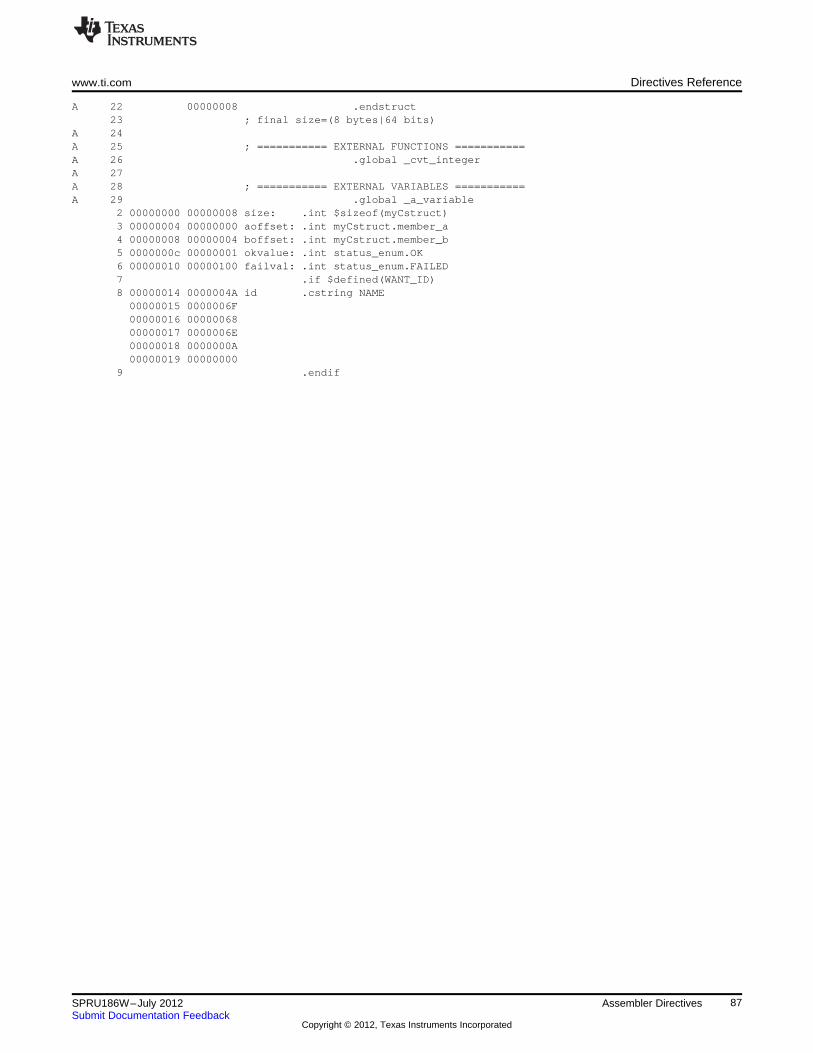
www.ti.com Directives Reference
A 22 00000008 .endstruct23 ; final size=(8 bytes|64 bits)
A 24A 25 ; =========== EXTERNAL FUNCTIONS ===========A 26 .global _cvt_integerA 27A 28 ; =========== EXTERNAL VARIABLES ===========A 29 .global _a_variable
2 00000000 00000008 size: .int $sizeof(myCstruct)3 00000004 00000000 aoffset: .int myCstruct.member_a4 00000008 00000004 boffset: .int myCstruct.member_b5 0000000c 00000001 okvalue: .int status_enum.OK6 00000010 00000100 failval: .int status_enum.FAILED7 .if $defined(WANT_ID)8 00000014 0000004A id .cstring NAME00000015 0000006F00000016 0000006800000017 0000006E00000018 0000000A00000019 00000000
9 .endif
87SPRU186W–July 2012 Assembler DirectivesSubmit Documentation Feedback
Copyright © 2012, Texas Instruments Incorporated
Directives Reference www.ti.com
.clink/.retain Control Whether to Conditionally Leave Section Out of Object Module Output
Syntax .clink["section name"]
.retain["section name"]
Description The .clink directive enables conditional linking by telling the linker to leave a section outof the final object module output of the linker if there are no references found to anysymbol in that section. The .clink directive can be applied to initialized or uninitializedsections.
The section name identifies the section. If the directive is used without a section name, itapplies to the current initialized section. If the directive is applied to an uninitializedsection, the section name is required. The section name must be enclosed in doublequotes. A section name can contain a subsection name in the form sectionname:subsection name.
The .clink directive is useful only with the COFF object file format. Under the COFF ABImodel, the linker assumes that all sections are ineligible for removal via conditionallinking by default. If you want to make a section eligible for removal, you must apply a.clink directive to it. In contrast, under the ELF EABI model, the linker assumes that allsections are eligible for removal via conditional linking. Therefore, the .clink directive hasno effect under EABI.
A section in which the entry point of a C program is defined cannot be marked as aconditionally linked section.
The .retain directive indicates that the current or specified section is not eligible forremoval via conditional linking. You can also override conditional linking for a givensection with the --retain linker option. You can disable conditional linking entirely with the--unused_section_elimination=off linker option.
Since under the ELF EABI model the linker assumes that all sections are eligible forremoval via conditional linking by default, the .retain directive becomes useful foroverriding the default conditional linking behavior for those sections that you want tokeep included in the link, even if the section is not referenced by any other section in thelink. For example, you could apply a .retain directive to an interrupt function that youhave written in assembly language, but which is not referenced from any normal entrypoint in the application.
Under the COFF ABI model, the linker assumes that all sections are not eligible forremoval via conditional linking by default. So under the COFF ABI mode, the .retaindirective does not have any real effect on the section.
88 Assembler Directives SPRU186W–July 2012Submit Documentation Feedback
Copyright © 2012, Texas Instruments Incorporated
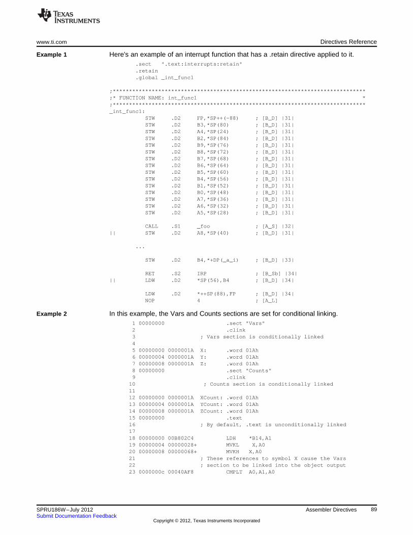
www.ti.com Directives Reference
Example 1 Here's an example of an interrupt function that has a .retain directive applied to it..sect ".text:interrupts:retain".retain.global _int_func1
;******************************************************************************;* FUNCTION NAME: int_func1 *;******************************************************************************_int_func1:
STW .D2 FP,*SP++(-88) ; [B_D] |31|STW .D2 B3,*SP(80) ; [B_D] |31|STW .D2 A4,*SP(24) ; [B_D] |31|STW .D2 B2,*SP(84) ; [B_D] |31|STW .D2 B9,*SP(76) ; [B_D] |31|STW .D2 B8,*SP(72) ; [B_D] |31|STW .D2 B7,*SP(68) ; [B_D] |31|STW .D2 B6,*SP(64) ; [B_D] |31|STW .D2 B5,*SP(60) ; [B_D] |31|STW .D2 B4,*SP(56) ; [B_D] |31|STW .D2 B1,*SP(52) ; [B_D] |31|STW .D2 B0,*SP(48) ; [B_D] |31|STW .D2 A7,*SP(36) ; [B_D] |31|STW .D2 A6,*SP(32) ; [B_D] |31|STW .D2 A5,*SP(28) ; [B_D] |31|
CALL .S1 _foo ; [A_S] |32||| STW .D2 A8,*SP(40) ; [B_D] |31|
...
STW .D2 B4,*+DP(_a_i) ; [B_D] |33|
RET .S2 IRP ; [B_Sb] |34||| LDW .D2 *SP(56),B4 ; [B_D] |34|
LDW .D2 *++SP(88),FP ; [B_D] |34|NOP 4 ; [A_L]
Example 2 In this example, the Vars and Counts sections are set for conditional linking.1 00000000 .sect "Vars"2 .clink3 ; Vars section is conditionally linked45 00000000 0000001A X: .word 01Ah6 00000004 0000001A Y: .word 01Ah7 00000008 0000001A Z: .word 01Ah8 00000000 .sect "Counts"9 .clink
10 ; Counts section is conditionally linked1112 00000000 0000001A XCount: .word 01Ah13 00000004 0000001A YCount: .word 01Ah14 00000008 0000001A ZCount: .word 01Ah15 00000000 .text16 ; By default, .text is unconditionally linked1718 00000000 00B802C4 LDH *B14,A119 00000004 00000028+ MVKL X,A020 00000008 00000068+ MVKH X,A021 ; These references to symbol X cause the Vars22 ; section to be linked into the object output23 0000000c 00040AF8 CMPLT A0,A1,A0
89SPRU186W–July 2012 Assembler DirectivesSubmit Documentation Feedback
Copyright © 2012, Texas Instruments Incorporated
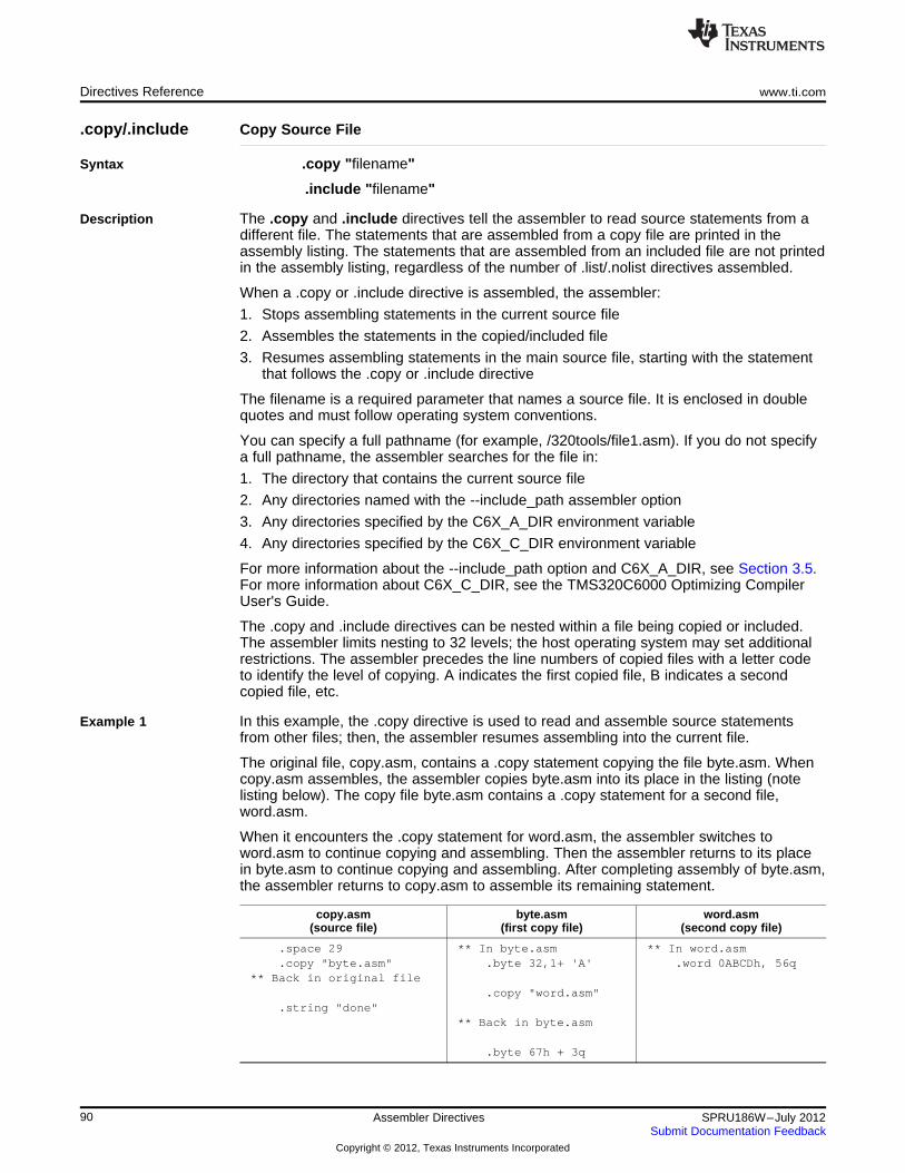
Directives Reference www.ti.com
.copy/.include Copy Source File
Syntax .copy "filename"
.include "filename"
Description The .copy and .include directives tell the assembler to read source statements from adifferent file. The statements that are assembled from a copy file are printed in theassembly listing. The statements that are assembled from an included file are not printedin the assembly listing, regardless of the number of .list/.nolist directives assembled.
When a .copy or .include directive is assembled, the assembler:
1. Stops assembling statements in the current source file
2. Assembles the statements in the copied/included file
3. Resumes assembling statements in the main source file, starting with the statementthat follows the .copy or .include directive
The filename is a required parameter that names a source file. It is enclosed in doublequotes and must follow operating system conventions.
You can specify a full pathname (for example, /320tools/file1.asm). If you do not specifya full pathname, the assembler searches for the file in:
1. The directory that contains the current source file
2. Any directories named with the --include_path assembler option
3. Any directories specified by the C6X_A_DIR environment variable
4. Any directories specified by the C6X_C_DIR environment variable
For more information about the --include_path option and C6X_A_DIR, see Section 3.5.For more information about C6X_C_DIR, see the TMS320C6000 Optimizing CompilerUser's Guide.
The .copy and .include directives can be nested within a file being copied or included.The assembler limits nesting to 32 levels; the host operating system may set additionalrestrictions. The assembler precedes the line numbers of copied files with a letter codeto identify the level of copying. A indicates the first copied file, B indicates a secondcopied file, etc.
Example 1 In this example, the .copy directive is used to read and assemble source statementsfrom other files; then, the assembler resumes assembling into the current file.
The original file, copy.asm, contains a .copy statement copying the file byte.asm. Whencopy.asm assembles, the assembler copies byte.asm into its place in the listing (notelisting below). The copy file byte.asm contains a .copy statement for a second file,word.asm.
When it encounters the .copy statement for word.asm, the assembler switches toword.asm to continue copying and assembling. Then the assembler returns to its placein byte.asm to continue copying and assembling. After completing assembly of byte.asm,the assembler returns to copy.asm to assemble its remaining statement.
copy.asm byte.asm word.asm(source file) (first copy file) (second copy file)
.space 29 ** In byte.asm ** In word.asm
.copy "byte.asm" .byte 32,1+ 'A' .word 0ABCDh, 56q** Back in original file
.copy "word.asm".string "done"
** Back in byte.asm
.byte 67h + 3q
90 Assembler Directives SPRU186W–July 2012Submit Documentation Feedback
Copyright © 2012, Texas Instruments Incorporated
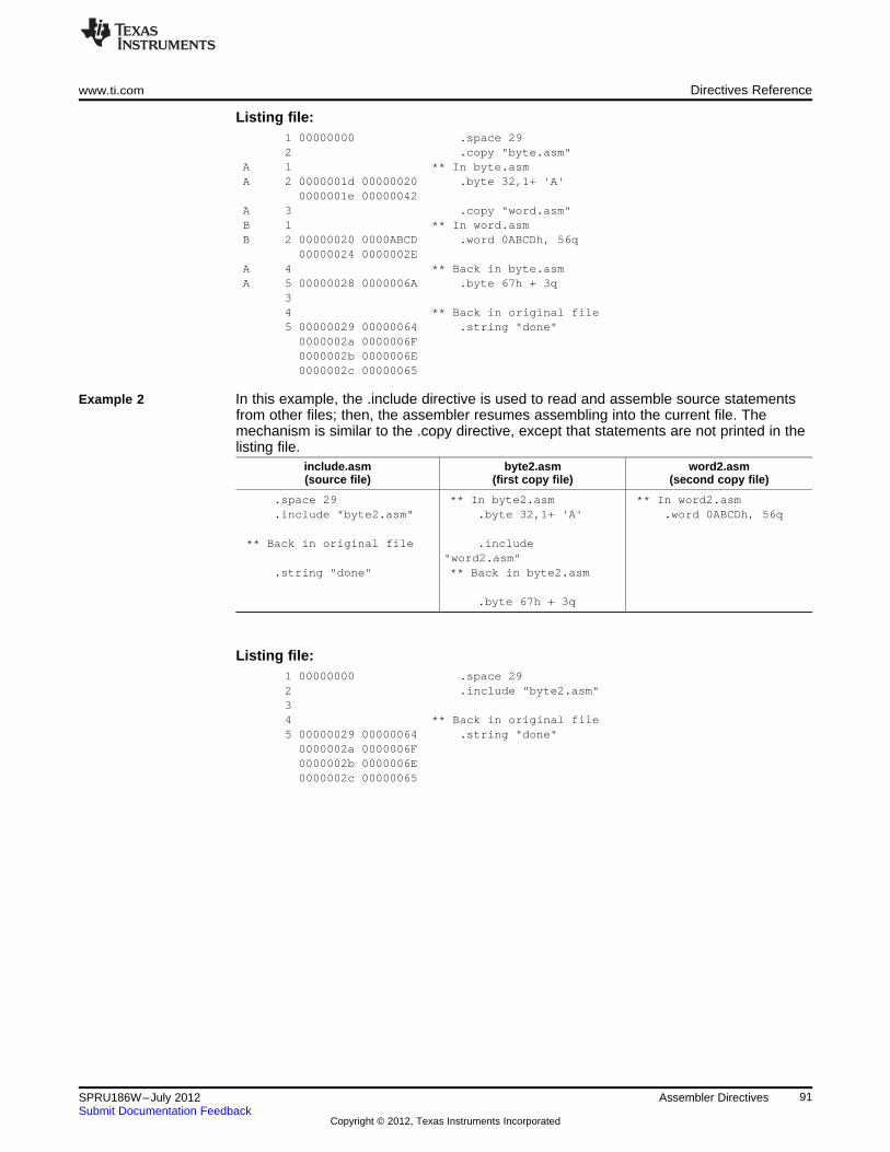
www.ti.com Directives Reference
Listing file:1 00000000 .space 292 .copy "byte.asm"
A 1 ** In byte.asmA 2 0000001d 00000020 .byte 32,1+ 'A'
0000001e 00000042A 3 .copy "word.asm"B 1 ** In word.asmB 2 00000020 0000ABCD .word 0ABCDh, 56q
00000024 0000002EA 4 ** Back in byte.asmA 5 00000028 0000006A .byte 67h + 3q
34 ** Back in original file5 00000029 00000064 .string "done"0000002a 0000006F0000002b 0000006E0000002c 00000065
Example 2 In this example, the .include directive is used to read and assemble source statementsfrom other files; then, the assembler resumes assembling into the current file. Themechanism is similar to the .copy directive, except that statements are not printed in thelisting file.
include.asm byte2.asm word2.asm(source file) (first copy file) (second copy file)
.space 29 ** In byte2.asm ** In word2.asm
.include "byte2.asm" .byte 32,1+ 'A' .word 0ABCDh, 56q
** Back in original file .include"word2.asm"
.string "done" ** Back in byte2.asm
.byte 67h + 3q
Listing file:1 00000000 .space 292 .include "byte2.asm"34 ** Back in original file5 00000029 00000064 .string "done"0000002a 0000006F0000002b 0000006E0000002c 00000065
91SPRU186W–July 2012 Assembler DirectivesSubmit Documentation Feedback
Copyright © 2012, Texas Instruments Incorporated
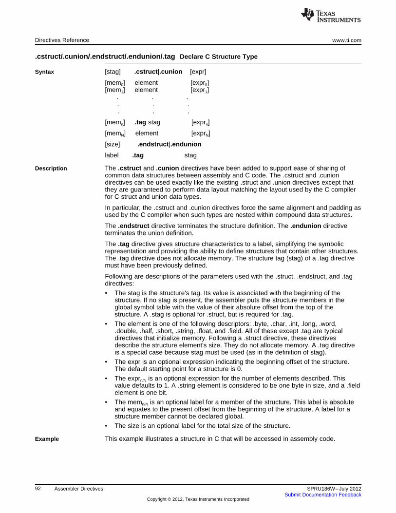
Directives Reference www.ti.com
.cstruct/.cunion/.endstruct/.endunion/.tag Declare C Structure Type
Syntax [stag] .cstruct|.cunion [expr]
[mem0] element [expr0][mem1] element [expr1]
. . .. . .. . .
[memn] .tag stag [exprn]
[memN] element [exprN]
[size] .endstruct|.endunion
label .tag stag
Description The .cstruct and .cunion directives have been added to support ease of sharing ofcommon data structures between assembly and C code. The .cstruct and .cuniondirectives can be used exactly like the existing .struct and .union directives except thatthey are guaranteed to perform data layout matching the layout used by the C compilerfor C struct and union data types.
In particular, the .cstruct and .cunion directives force the same alignment and padding asused by the C compiler when such types are nested within compound data structures.
The .endstruct directive terminates the structure definition. The .endunion directiveterminates the union definition.
The .tag directive gives structure characteristics to a label, simplifying the symbolicrepresentation and providing the ability to define structures that contain other structures.The .tag directive does not allocate memory. The structure tag (stag) of a .tag directivemust have been previously defined.
Following are descriptions of the parameters used with the .struct, .endstruct, and .tagdirectives:
• The stag is the structure's tag. Its value is associated with the beginning of thestructure. If no stag is present, the assembler puts the structure members in theglobal symbol table with the value of their absolute offset from the top of thestructure. A .stag is optional for .struct, but is required for .tag.
• The element is one of the following descriptors: .byte, .char, .int, .long, .word,.double, .half, .short, .string, .float, and .field. All of these except .tag are typicaldirectives that initialize memory. Following a .struct directive, these directivesdescribe the structure element's size. They do not allocate memory. A .tag directiveis a special case because stag must be used (as in the definition of stag).
• The expr is an optional expression indicating the beginning offset of the structure.The default starting point for a structure is 0.
• The exprn/N is an optional expression for the number of elements described. Thisvalue defaults to 1. A .string element is considered to be one byte in size, and a .fieldelement is one bit.
• The memn/N is an optional label for a member of the structure. This label is absoluteand equates to the present offset from the beginning of the structure. A label for astructure member cannot be declared global.
• The size is an optional label for the total size of the structure.
Example This example illustrates a structure in C that will be accessed in assembly code.
92 Assembler Directives SPRU186W–July 2012Submit Documentation Feedback
Copyright © 2012, Texas Instruments Incorporated
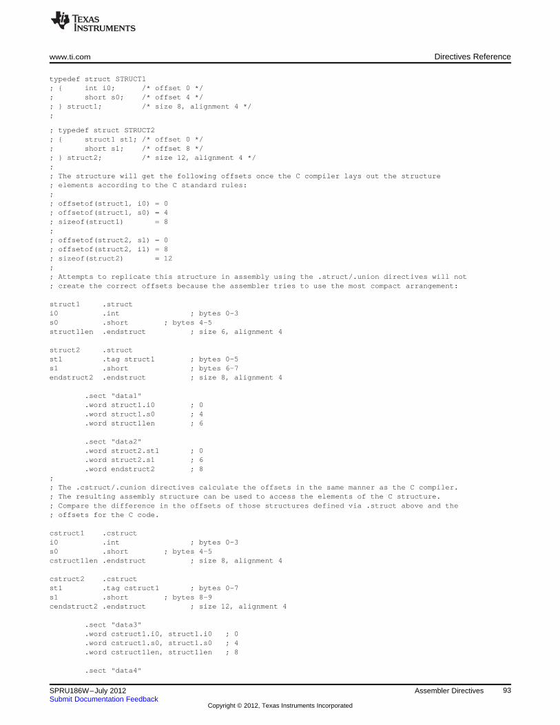
www.ti.com Directives Reference
typedef struct STRUCT1; { int i0; /* offset 0 */; short s0; /* offset 4 */; } struct1; /* size 8, alignment 4 */;
; typedef struct STRUCT2; { struct1 st1; /* offset 0 */; short s1; /* offset 8 */; } struct2; /* size 12, alignment 4 */;; The structure will get the following offsets once the C compiler lays out the structure; elements according to the C standard rules:;; offsetof(struct1, i0) = 0; offsetof(struct1, s0) = 4; sizeof(struct1) = 8;; offsetof(struct2, s1) = 0; offsetof(struct2, i1) = 8; sizeof(struct2) = 12;; Attempts to replicate this structure in assembly using the .struct/.union directives will not; create the correct offsets because the assembler tries to use the most compact arrangement:
struct1 .structi0 .int ; bytes 0-3s0 .short ; bytes 4-5struct1len .endstruct ; size 6, alignment 4
struct2 .structst1 .tag struct1 ; bytes 0-5s1 .short ; bytes 6-7endstruct2 .endstruct ; size 8, alignment 4
.sect "data1"
.word struct1.i0 ; 0
.word struct1.s0 ; 4
.word struct1len ; 6
.sect "data2"
.word struct2.st1 ; 0
.word struct2.s1 ; 6
.word endstruct2 ; 8;; The .cstruct/.cunion directives calculate the offsets in the same manner as the C compiler.; The resulting assembly structure can be used to access the elements of the C structure.; Compare the difference in the offsets of those structures defined via .struct above and the; offsets for the C code.
cstruct1 .cstructi0 .int ; bytes 0-3s0 .short ; bytes 4-5cstruct1len .endstruct ; size 8, alignment 4
cstruct2 .cstructst1 .tag cstruct1 ; bytes 0-7s1 .short ; bytes 8-9cendstruct2 .endstruct ; size 12, alignment 4
.sect "data3"
.word cstruct1.i0, struct1.i0 ; 0
.word cstruct1.s0, struct1.s0 ; 4
.word cstruct1len, struct1len ; 8
.sect "data4"
93SPRU186W–July 2012 Assembler DirectivesSubmit Documentation Feedback
Copyright © 2012, Texas Instruments Incorporated
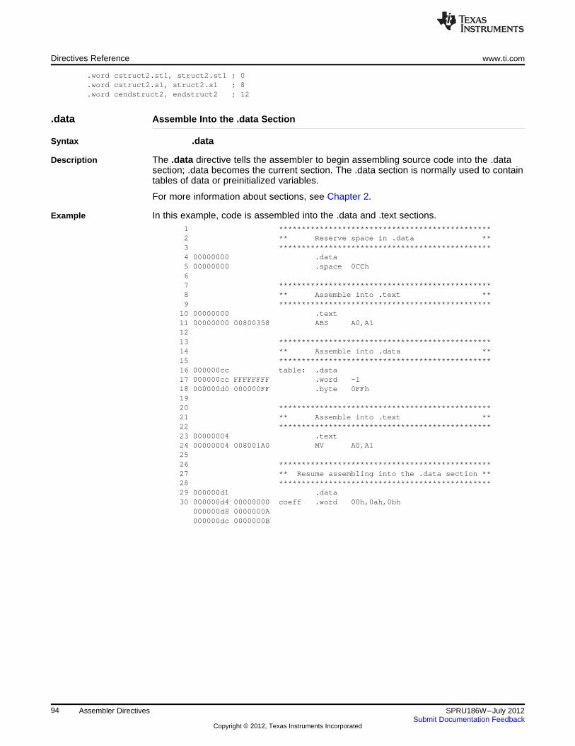
Directives Reference www.ti.com
.word cstruct2.st1, struct2.st1 ; 0
.word cstruct2.s1, struct2.s1 ; 8
.word cendstruct2, endstruct2 ; 12
.data Assemble Into the .data Section
Syntax .data
Description The .data directive tells the assembler to begin assembling source code into the .datasection; .data becomes the current section. The .data section is normally used to containtables of data or preinitialized variables.
For more information about sections, see Chapter 2.
Example In this example, code is assembled into the .data and .text sections.1 ***********************************************2 ** Reserve space in .data **3 ***********************************************4 00000000 .data5 00000000 .space 0CCh67 ***********************************************8 ** Assemble into .text **9 ***********************************************
10 00000000 .text11 00000000 00800358 ABS A0,A11213 ***********************************************14 ** Assemble into .data **15 ***********************************************16 000000cc table: .data17 000000cc FFFFFFFF .word -118 000000d0 000000FF .byte 0FFh1920 ***********************************************21 ** Assemble into .text **22 ***********************************************23 00000004 .text24 00000004 008001A0 MV A0,A12526 ***********************************************27 ** Resume assembling into the .data section **28 ***********************************************29 000000d1 .data30 000000d4 00000000 coeff .word 00h,0ah,0bh
000000d8 0000000A000000dc 0000000B
94 Assembler Directives SPRU186W–July 2012Submit Documentation Feedback
Copyright © 2012, Texas Instruments Incorporated
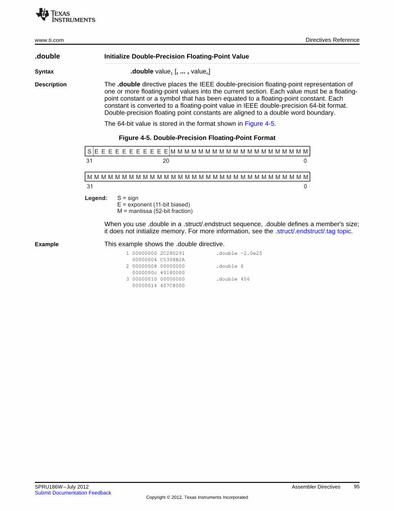
S E E E E E E E E E E E M M M M M M M M M M M M M M M M M M M M
31 20 0
M M M M M M M M M M M M M M M M M M M M M M M M M M M M M M M M
031
Legend: S = signE = exponent (11-bit biased)M = mantissa (52-bit fraction)
www.ti.com Directives Reference
.double Initialize Double-Precision Floating-Point Value
Syntax .double value1 [, ... , valuen]
Description The .double directive places the IEEE double-precision floating-point representation ofone or more floating-point values into the current section. Each value must be a floating-point constant or a symbol that has been equated to a floating-point constant. Eachconstant is converted to a floating-point value in IEEE double-precision 64-bit format.Double-precision floating point constants are aligned to a double word boundary.
The 64-bit value is stored in the format shown in Figure 4-5.
Figure 4-5. Double-Precision Floating-Point Format
When you use .double in a .struct/.endstruct sequence, .double defines a member's size;it does not initialize memory. For more information, see the .struct/.endstruct/.tag topic.
Example This example shows the .double directive.1 00000000 2C280291 .double -2.0e2500000004 C5308B2A
2 00000008 00000000 .double 60000000c 40180000
3 00000010 00000000 .double 45600000014 407C8000
95SPRU186W–July 2012 Assembler DirectivesSubmit Documentation Feedback
Copyright © 2012, Texas Instruments Incorporated
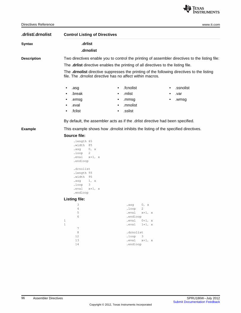
Directives Reference www.ti.com
.drlist/.drnolist Control Listing of Directives
Syntax .drlist
.drnolist
Description Two directives enable you to control the printing of assembler directives to the listing file:
The .drlist directive enables the printing of all directives to the listing file.
The .drnolist directive suppresses the printing of the following directives to the listingfile. The .drnolist directive has no affect within macros.
• .asg • .fcnolist • .ssnolist
• .break • .mlist • .var
• .emsg • .mmsg • .wmsg
• .eval • .mnolist
• .fclist • .sslist
By default, the assembler acts as if the .drlist directive had been specified.
Example This example shows how .drnolist inhibits the listing of the specified directives.
Source file:.length 65.width 85.asg 0, x.loop 2.eval x+1, x.endloop
.drnolist
.length 55
.width 95
.asg 1, x
.loop 3
.eval x+1, x
.endloop
Listing file:3 .asg 0, x4 .loop 25 .eval x+1, x6 .endloop
1 .eval 0+1, x1 .eval 1+1, x
78 .drnolist
12 .loop 313 .eval x+1, x14 .endloop
96 Assembler Directives SPRU186W–July 2012Submit Documentation Feedback
Copyright © 2012, Texas Instruments Incorporated
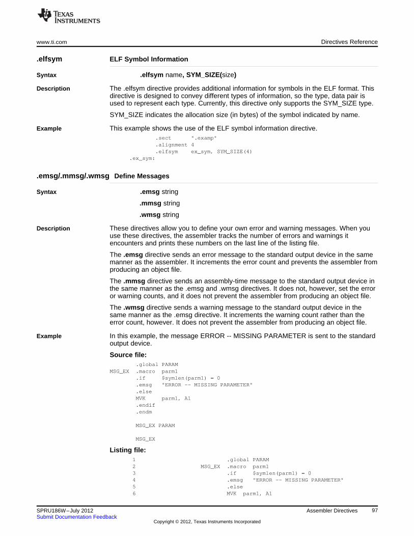
www.ti.com Directives Reference
.elfsym ELF Symbol Information
Syntax .elfsym name, SYM_SIZE(size)
Description The .elfsym directive provides additional information for symbols in the ELF format. Thisdirective is designed to convey different types of information, so the type, data pair isused to represent each type. Currently, this directive only supports the SYM_SIZE type.
SYM_SIZE indicates the allocation size (in bytes) of the symbol indicated by name.
Example This example shows the use of the ELF symbol information directive..sect ".examp".alignment 4.elfsym ex_sym, SYM_SIZE(4)
.ex_sym:
.emsg/.mmsg/.wmsg Define Messages
Syntax .emsg string
.mmsg string
.wmsg string
Description These directives allow you to define your own error and warning messages. When youuse these directives, the assembler tracks the number of errors and warnings itencounters and prints these numbers on the last line of the listing file.
The .emsg directive sends an error message to the standard output device in the samemanner as the assembler. It increments the error count and prevents the assembler fromproducing an object file.
The .mmsg directive sends an assembly-time message to the standard output device inthe same manner as the .emsg and .wmsg directives. It does not, however, set the erroror warning counts, and it does not prevent the assembler from producing an object file.
The .wmsg directive sends a warning message to the standard output device in thesame manner as the .emsg directive. It increments the warning count rather than theerror count, however. It does not prevent the assembler from producing an object file.
Example In this example, the message ERROR -- MISSING PARAMETER is sent to the standardoutput device.
Source file:.global PARAM
MSG_EX .macro parm1.if $symlen(parm1) = 0.emsg "ERROR -- MISSING PARAMETER".elseMVK parm1, A1.endif.endm
MSG_EX PARAM
MSG_EX
Listing file:1 .global PARAM2 MSG_EX .macro parm13 .if $symlen(parm1) = 04 .emsg "ERROR -- MISSING PARAMETER"5 .else6 MVK parm1, A1
97SPRU186W–July 2012 Assembler DirectivesSubmit Documentation Feedback
Copyright © 2012, Texas Instruments Incorporated
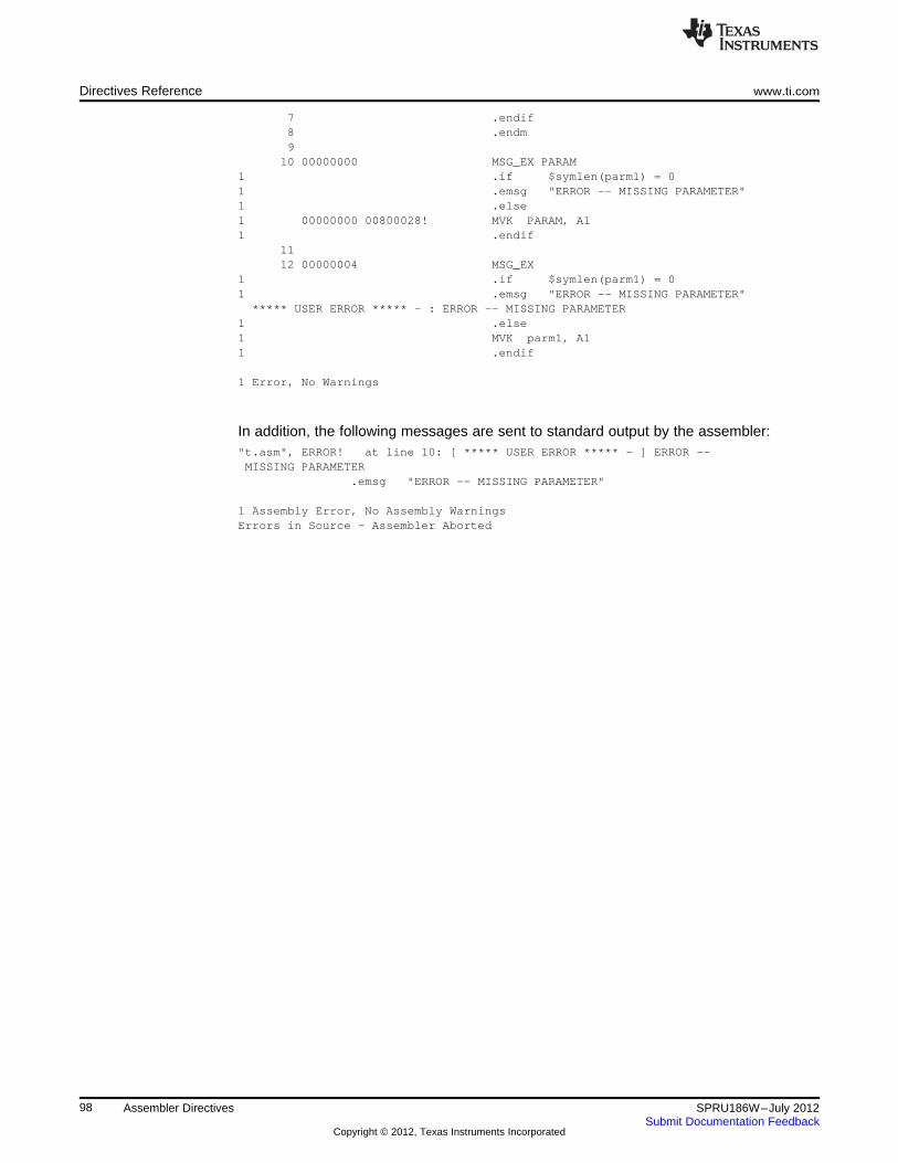
Directives Reference www.ti.com
7 .endif8 .endm9
10 00000000 MSG_EX PARAM1 .if $symlen(parm1) = 01 .emsg "ERROR -- MISSING PARAMETER"1 .else1 00000000 00800028! MVK PARAM, A11 .endif
1112 00000004 MSG_EX
1 .if $symlen(parm1) = 01 .emsg "ERROR -- MISSING PARAMETER"
***** USER ERROR ***** - : ERROR -- MISSING PARAMETER1 .else1 MVK parm1, A11 .endif
1 Error, No Warnings
In addition, the following messages are sent to standard output by the assembler:"t.asm", ERROR! at line 10: [ ***** USER ERROR ***** - ] ERROR --MISSING PARAMETER
.emsg "ERROR -- MISSING PARAMETER"
1 Assembly Error, No Assembly WarningsErrors in Source - Assembler Aborted
98 Assembler Directives SPRU186W–July 2012Submit Documentation Feedback
Copyright © 2012, Texas Instruments Incorporated
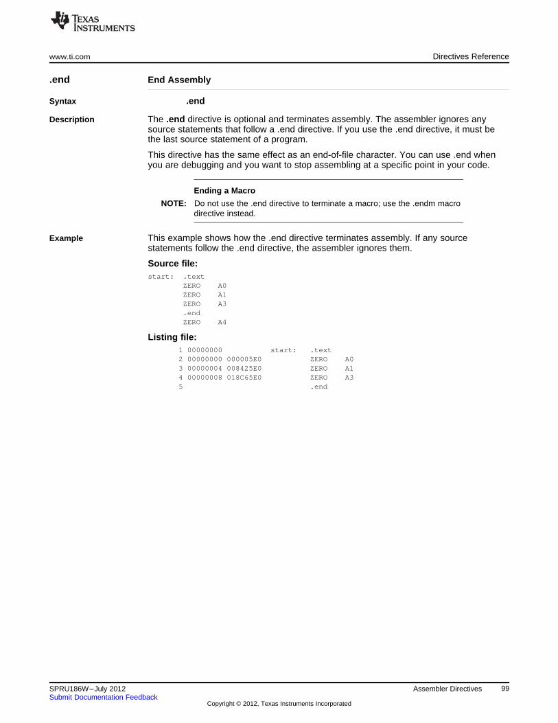
www.ti.com Directives Reference
.end End Assembly
Syntax .end
Description The .end directive is optional and terminates assembly. The assembler ignores anysource statements that follow a .end directive. If you use the .end directive, it must bethe last source statement of a program.
This directive has the same effect as an end-of-file character. You can use .end whenyou are debugging and you want to stop assembling at a specific point in your code.
Ending a Macro
NOTE: Do not use the .end directive to terminate a macro; use the .endm macrodirective instead.
Example This example shows how the .end directive terminates assembly. If any sourcestatements follow the .end directive, the assembler ignores them.
Source file:start: .text
ZERO A0ZERO A1ZERO A3.endZERO A4
Listing file:1 00000000 start: .text2 00000000 000005E0 ZERO A03 00000004 008425E0 ZERO A14 00000008 018C65E0 ZERO A35 .end
99SPRU186W–July 2012 Assembler DirectivesSubmit Documentation Feedback
Copyright © 2012, Texas Instruments Incorporated
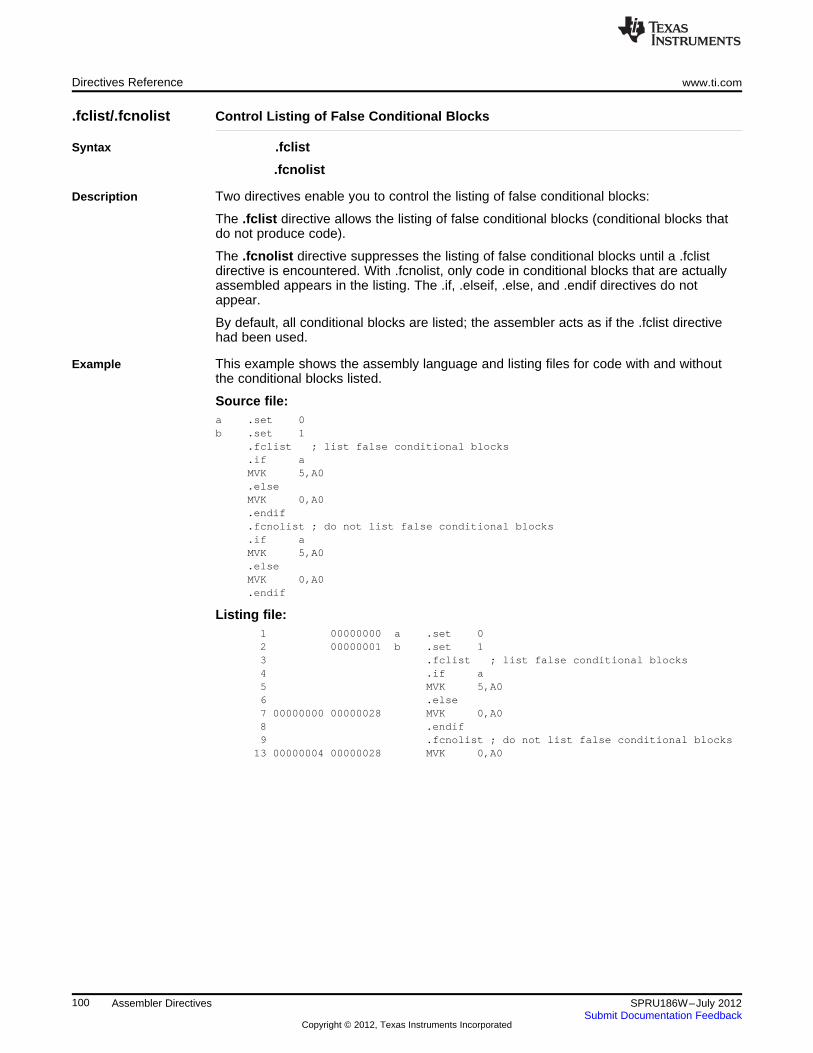
Directives Reference www.ti.com
.fclist/.fcnolist Control Listing of False Conditional Blocks
Syntax .fclist
.fcnolist
Description Two directives enable you to control the listing of false conditional blocks:
The .fclist directive allows the listing of false conditional blocks (conditional blocks thatdo not produce code).
The .fcnolist directive suppresses the listing of false conditional blocks until a .fclistdirective is encountered. With .fcnolist, only code in conditional blocks that are actuallyassembled appears in the listing. The .if, .elseif, .else, and .endif directives do notappear.
By default, all conditional blocks are listed; the assembler acts as if the .fclist directivehad been used.
Example This example shows the assembly language and listing files for code with and withoutthe conditional blocks listed.
Source file:a .set 0b .set 1
.fclist ; list false conditional blocks
.if aMVK 5,A0.elseMVK 0,A0.endif.fcnolist ; do not list false conditional blocks.if aMVK 5,A0.elseMVK 0,A0.endif
Listing file:1 00000000 a .set 02 00000001 b .set 13 .fclist ; list false conditional blocks4 .if a5 MVK 5,A06 .else7 00000000 00000028 MVK 0,A08 .endif9 .fcnolist ; do not list false conditional blocks
13 00000004 00000028 MVK 0,A0
100 Assembler Directives SPRU186W–July 2012Submit Documentation Feedback
Copyright © 2012, Texas Instruments Incorporated
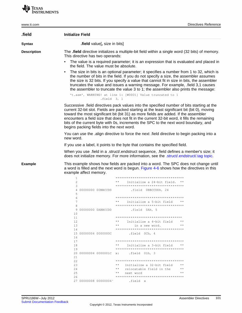
www.ti.com Directives Reference
.field Initialize Field
Syntax .field value[, size in bits]
Description The .field directive initializes a multiple-bit field within a single word (32 bits) of memory.This directive has two operands:
• The value is a required parameter; it is an expression that is evaluated and placed inthe field. The value must be absolute.
• The size in bits is an optional parameter; it specifies a number from 1 to 32, which isthe number of bits in the field. If you do not specify a size, the assembler assumesthe size is 32 bits. If you specify a value that cannot fit in size in bits, the assemblertruncates the value and issues a warning message. For example, .field 3,1 causesthe assembler to truncate the value 3 to 1; the assembler also prints the message:"t.asm", WARNING! at line 1: [W0001] Value truncated to 1
.field 3, 1
Successive .field directives pack values into the specified number of bits starting at thecurrent 32-bit slot. Fields are packed starting at the least significant bit (bit 0), movingtoward the most significant bit (bit 31) as more fields are added. If the assemblerencounters a field size that does not fit in the current 32-bit word, it fills the remainingbits of the current byte with 0s, increments the SPC to the next word boundary, andbegins packing fields into the next word.
You can use the .align directive to force the next .field directive to begin packing into anew word.
If you use a label, it points to the byte that contains the specified field.
When you use .field in a .struct/.endstruct sequence, .field defines a member's size; itdoes not initialize memory. For more information, see the .struct/.endstruct/.tag topic.
Example This example shows how fields are packed into a word. The SPC does not change untila word is filled and the next word is begun. Figure 4-6 shows how the directives in thisexample affect memory.
1 ************************************2 ** Initialize a 24-bit field. **3 ************************************4 00000000 00BBCCDD .field 0BBCCDDh, 2456 ************************************7 ** Initialize a 5-bit field **8 ************************************9 00000000 0ABBCCDD .field 0Ah, 5
1011 ***********************************12 ** Initialize a 4-bit field **13 ** in a new word. **14 ************************************15 00000004 0000000C .field 0Ch, 41617 ************************************18 ** Initialize a 3-bit field **19 ************************************20 00000004 0000001C x: .field 01h, 32122 ************************************23 ** Initialize a 32-bit field **24 ** relocatable field in the **25 ** next word **26 ************************************27 00000008 00000004' .field x
101SPRU186W–July 2012 Assembler DirectivesSubmit Documentation Feedback
Copyright © 2012, Texas Instruments Incorporated
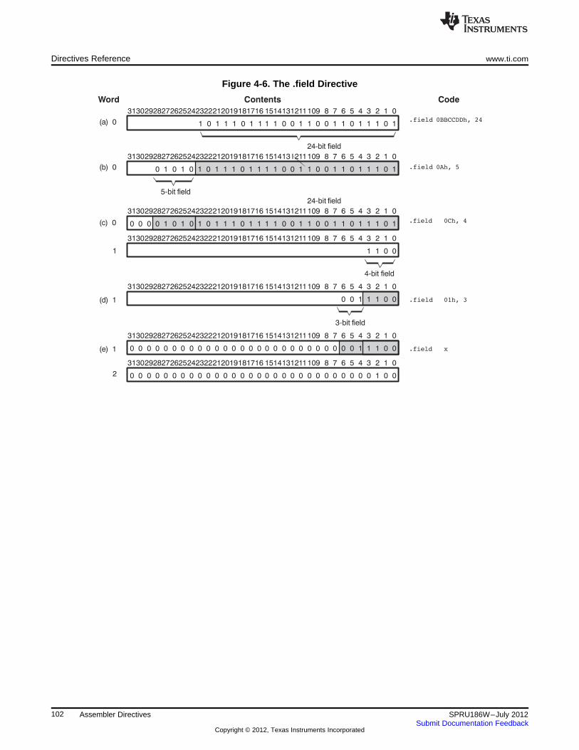
Directives Reference www.ti.com
Figure 4-6. The .field Directive
102 Assembler Directives SPRU186W–July 2012Submit Documentation Feedback
Copyright © 2012, Texas Instruments Incorporated
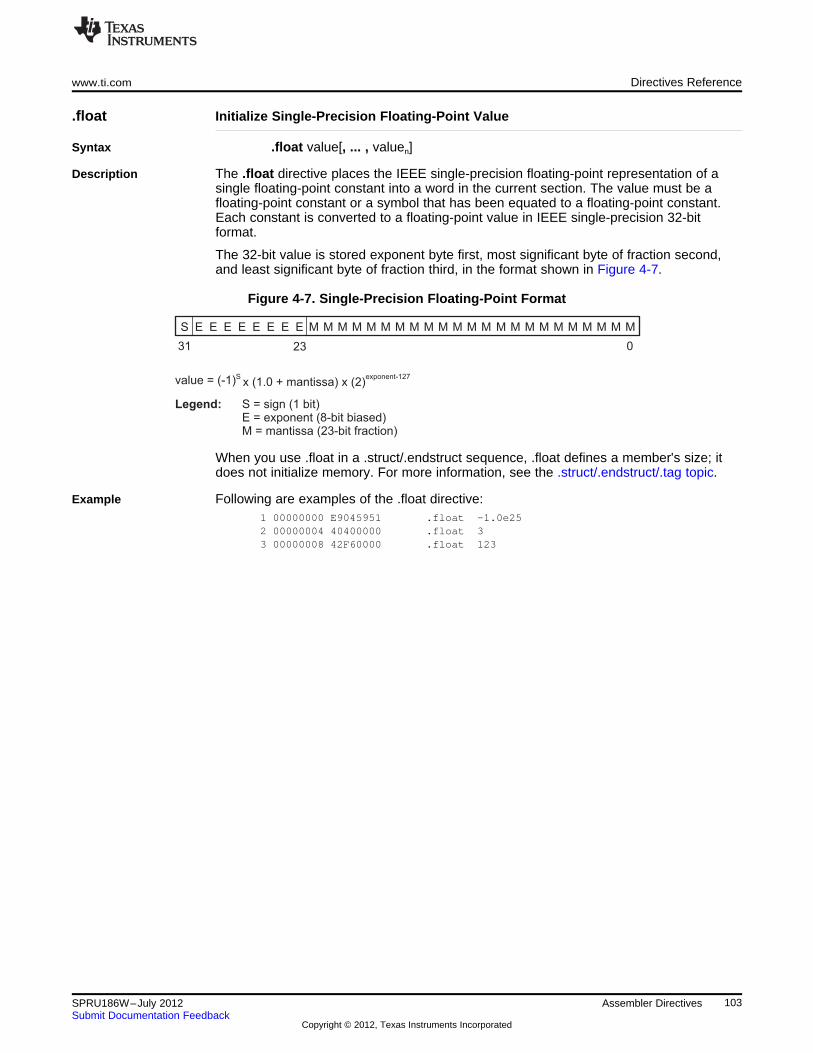
S E E E E E E E E M M M M M M M M M M M M M M M M M M M M M M M
31 23 0
Legend: S = sign (1 bit)E = exponent (8-bit biased)M = mantissa (23-bit fraction)
value = (-1)Sx (1.0 + mantissa) x (2)
exponent-127
www.ti.com Directives Reference
.float Initialize Single-Precision Floating-Point Value
Syntax .float value[, ... , valuen]
Description The .float directive places the IEEE single-precision floating-point representation of asingle floating-point constant into a word in the current section. The value must be afloating-point constant or a symbol that has been equated to a floating-point constant.Each constant is converted to a floating-point value in IEEE single-precision 32-bitformat.
The 32-bit value is stored exponent byte first, most significant byte of fraction second,and least significant byte of fraction third, in the format shown in Figure 4-7.
Figure 4-7. Single-Precision Floating-Point Format
When you use .float in a .struct/.endstruct sequence, .float defines a member's size; itdoes not initialize memory. For more information, see the .struct/.endstruct/.tag topic.
Example Following are examples of the .float directive:1 00000000 E9045951 .float -1.0e252 00000004 40400000 .float 33 00000008 42F60000 .float 123
103SPRU186W–July 2012 Assembler DirectivesSubmit Documentation Feedback
Copyright © 2012, Texas Instruments Incorporated
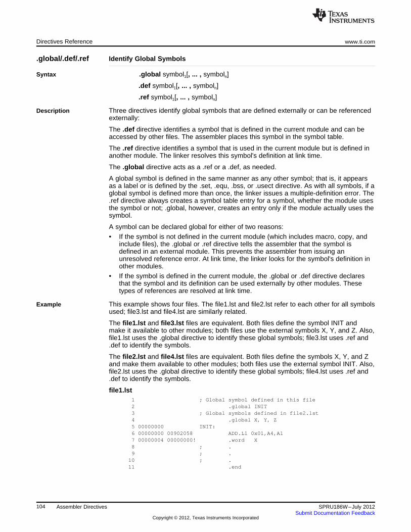
Directives Reference www.ti.com
.global/.def/.ref Identify Global Symbols
Syntax .global symbol1[, ... , symboln]
.def symbol1[, ... , symboln]
.ref symbol1[, ... , symboln]
Description Three directives identify global symbols that are defined externally or can be referencedexternally:
The .def directive identifies a symbol that is defined in the current module and can beaccessed by other files. The assembler places this symbol in the symbol table.
The .ref directive identifies a symbol that is used in the current module but is defined inanother module. The linker resolves this symbol's definition at link time.
The .global directive acts as a .ref or a .def, as needed.
A global symbol is defined in the same manner as any other symbol; that is, it appearsas a label or is defined by the .set, .equ, .bss, or .usect directive. As with all symbols, if aglobal symbol is defined more than once, the linker issues a multiple-definition error. The.ref directive always creates a symbol table entry for a symbol, whether the module usesthe symbol or not; .global, however, creates an entry only if the module actually uses thesymbol.
A symbol can be declared global for either of two reasons:
• If the symbol is not defined in the current module (which includes macro, copy, andinclude files), the .global or .ref directive tells the assembler that the symbol isdefined in an external module. This prevents the assembler from issuing anunresolved reference error. At link time, the linker looks for the symbol's definition inother modules.
• If the symbol is defined in the current module, the .global or .def directive declaresthat the symbol and its definition can be used externally by other modules. Thesetypes of references are resolved at link time.
Example This example shows four files. The file1.lst and file2.lst refer to each other for all symbolsused; file3.lst and file4.lst are similarly related.
The file1.lst and file3.lst files are equivalent. Both files define the symbol INIT andmake it available to other modules; both files use the external symbols X, Y, and Z. Also,file1.lst uses the .global directive to identify these global symbols; file3.lst uses .ref and.def to identify the symbols.
The file2.lst and file4.lst files are equivalent. Both files define the symbols X, Y, and Zand make them available to other modules; both files use the external symbol INIT. Also,file2.lst uses the .global directive to identify these global symbols; file4.lst uses .ref and.def to identify the symbols.
file1.lst1 ; Global symbol defined in this file2 .global INIT3 ; Global symbols defined in file2.lst4 .global X, Y, Z5 00000000 INIT:6 00000000 00902058 ADD.L1 0x01,A4,A17 00000004 00000000! .word X8 ; .9 ; .
10 ; .11 .end
104 Assembler Directives SPRU186W–July 2012Submit Documentation Feedback
Copyright © 2012, Texas Instruments Incorporated
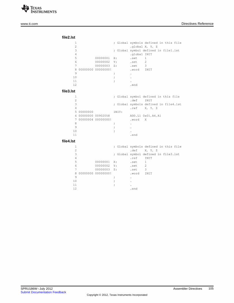
www.ti.com Directives Reference
file2.lst1 ; Global symbols defined in this file2 .global X, Y, Z3 ; Global symbol defined in file1.lst4 .global INIT5 00000001 X: .set 16 00000002 Y: .set 27 00000003 Z: .set 38 00000000 00000000! .word INIT9 ; .
10 ; .11 ; .12 .end
file3.lst1 ; Global symbol defined in this file2 .def INIT3 ; Global symbols defined in file4.lst4 .ref X, Y, Z5 00000000 INIT:6 00000000 00902058 ADD.L1 0x01,A4,A17 00000004 00000000! .word X8 ; .9 ; .
10 ; .11 .end
file4.lst1 ; Global symbols defined in this file2 .def X, Y, Z3 ; Global symbol defined in file3.lst4 .ref INIT5 00000001 X: .set 16 00000002 Y: .set 27 00000003 Z: .set 38 00000000 00000000! .word INIT9 ; .
10 ; .11 ; .12 .end
105SPRU186W–July 2012 Assembler DirectivesSubmit Documentation Feedback
Copyright © 2012, Texas Instruments Incorporated
Directives Reference www.ti.com
.group/.gmember/.endgroup Define Common Data Section
Syntax .group group section name group type
.gmember section name
.endgroup
Description Three directives instruct the assembler to make certain sections members of an ELFgroup section (see ELF specification for more information on group sections).
The .group directive begins the group declaration. The group section name designatesthe name of the group section. The group type designates the type of the group. Thefollowing types are supported:
0x0 Regular ELF group0x1 COMDAT ELF group
The .gmember directive designates section name as a member of the group.
The .endgroup directive ends the group declaration.
106 Assembler Directives SPRU186W–July 2012Submit Documentation Feedback
Copyright © 2012, Texas Instruments Incorporated
www.ti.com Directives Reference
.half/.short/.uhalf/.ushort Initialize 16-Bit Integers
Syntax .half value1[, ... , valuen ]
.short value1[, ... , valuen ]
.uhalf value1[, ... , valuen ]
.ushort value1[, ... , valuen ]
Description The .half, .uhalf, .short, and .ushort directives place one or more values intoconsecutive halfwords in the current section. Each value is placed in a 2-byte slot byitself. A value can be either:
• An expression that the assembler evaluates and treats as a 16-bit signed or unsignednumber
• A character string enclosed in double quotes. Each character in a string represents aseparate value and is stored alone in the least significant eight bits of a 16-bit field,which is padded with 0s.
The assembler truncates values greater than 16 bits.
If you use a label with .half, .short, .uhalf, or .ushort; it points to the location where theassembler places the first byte.
These directives perform a halfword (16-bit) alignment before data is written to thesection. This guarantees that data resides on a 16-bit boundary.
When you use .half, .short, .uhalf, or .ushort in a .struct/.endstruct sequence, they definea member's size; they do not initialize memory. For more information, see the.struct/.endstruct/.tag topic.
Example In this example, .half is used to place 16-bit values (10, -1, abc, and a) into consecutivehalfwords in memory; .short is used to place 16-bit values (8, -3, def, and b) intoconsecutive halfwords in memory. The label STRN has the value 100ch, which is thelocation of the first initialized halfword for .short.
1 00000000 .space 100h * 162 00001000 0000000A .half 10, -1, "abc", 'a'00001002 0000FFFF00001004 0000006100001006 0000006200001008 000000630000100a 00000061
3 0000100c 00000008 STRN .short 8, -3, "def", 'b'0000100e 0000FFFD00001010 0000006400001012 0000006500001014 0000006600001016 00000062
107SPRU186W–July 2012 Assembler DirectivesSubmit Documentation Feedback
Copyright © 2012, Texas Instruments Incorporated
Directives Reference www.ti.com
.if/.elseif/.else/.endif Assemble Conditional Blocks
Syntax .if well-defined expression
[.elseif well-defined expression]
[.else]
.endif
Description Four directives provide conditional assembly:
The .if directive marks the beginning of a conditional block. The well-defined expressionis a required parameter.
• If the expression evaluates to true (nonzero), the assembler assembles the code thatfollows the expression (up to a .elseif, .else, or .endif).
• If the expression evaluates to false (0), the assembler assembles code that follows a.elseif (if present), .else (if present), or .endif (if no .elseif or .else is present).
The .elseif directive identifies a block of code to be assembled when the .if expression isfalse (0) and the .elseif expression is true (nonzero). When the .elseif expression isfalse, the assembler continues to the next .elseif (if present), .else (if present), or .endif(if no .elseif or .else is present). The .elseif directive is optional in the conditional block,and more than one .elseif can be used. If an expression is false and there is no .elseifstatement, the assembler continues with the code that follows a .else (if present) or a.endif.
The .else directive identifies a block of code that the assembler assembles when the .ifexpression and all .elseif expressions are false (0). The .else directive is optional in theconditional block; if an expression is false and there is no .else statement, the assemblercontinues with the code that follows the .endif.
The .endif directive terminates a conditional block.
The .elseif and .else directives can be used in the same conditional assembly block, andthe .elseif directive can be used more than once within a conditional assembly block.
See Section 3.10.4 for information about relational operators.
Example This example shows conditional assembly:1 00000001 SYM1 .set 12 00000002 SYM2 .set 23 00000003 SYM3 .set 34 00000004 SYM4 .set 456 If_4: .if SYM4 = SYM2 * SYM27 00000000 00000004 .byte SYM4 ; Equal values8 .else9 .byte SYM2 * SYM2 ; Unequal values
10 .endif1112 If_5: .if SYM1 <;= 1013 00000001 0000000A .byte 10 ; Less than / equal14 .else15 .byte SYM1 ; Greater than16 .endif1718 If_6: .if SYM3 * SYM2 != SYM4 + SYM219 .byte SYM3 * SYM2 ; Unequal value20 .else21 00000002 00000008 .byte SYM4 + SYM4 ; Equal values22 .endif2324 If_7: .if SYM1 = SYM225 .byte SYM1
108 Assembler Directives SPRU186W–July 2012Submit Documentation Feedback
Copyright © 2012, Texas Instruments Incorporated
www.ti.com Directives Reference
26 .elseif SYM2 + SYM3 = 527 00000003 00000005 .byte SYM2 + SYM328 .endif
109SPRU186W–July 2012 Assembler DirectivesSubmit Documentation Feedback
Copyright © 2012, Texas Instruments Incorporated
Directives Reference www.ti.com
.import/.export/.hidden/.protected Set Dynamic Visibility of Global Symbol
Syntax .import "symbolname"
.export "symbolname"
.hidden "symbolname"
.protected "symbolname"
Description These directives set the dynamic visibility of a global symbol. Each takes a single symbolname, optionally enclosed in double-quotes.
• The .import directive sets the visibility of symbolname to STV_IMPORT.
• The .export directive sets the visibility of symbolname to STV_EXPORT.
• The .hidden directive sets the visibility of symbolname to STV_HIDDEN.
• The .protected directive sets the visibility of symbolname to STV_PROTECTED.
See Section 7.12 for an explanation of symbol visibility.
Theses directives are commonly used in the context of dynamic linking, for more detailsee the Dynamic Linking wiki site(http://processors.wiki.ti.com/index.php/C6000_Dynamic_Linking).
110 Assembler Directives SPRU186W–July 2012Submit Documentation Feedback
Copyright © 2012, Texas Instruments Incorporated
www.ti.com Directives Reference
.int/.long/.word/.uint/.uword Initialize 32-Bit Integers
Syntax .int value1[, ... , valuen ]
.long value1[, ... , valuen ]
.word value1[, ... , valuen ]
.uint value1[, ... , valuen ]
.uword value1[, ... , valuen ]
Description The .int, .uint, .long, .word, and .uword directives place one or more values intoconsecutive words in the current section. Each value is placed in a 32-bit word by itselfand is aligned on a word boundary. A value can be either:
• An expression that the assembler evaluates and treats as a 32-bit signed or unsignednumber
• A character string enclosed in double quotes. Each character in a string represents aseparate value and is stored alone in the least significant eight bits of a 32-bit field,which is padded with 0s.
A value can be either an absolute or a relocatable expression. If an expression isrelocatable, the assembler generates a relocation entry that refers to the appropriatesymbol; the linker can then correctly patch (relocate) the reference. This allows you toinitialize memory with pointers to variables or labels.
If you use a label with these directives, it points to the first word that is initialized.
When you use these directives in a .struct/.endstruct sequence, they define a member'ssize; they do not initialize memory. See the .struct/.endstruct/.tag topic.
Example 1 This example uses the .int directive to initialize words. Notice that the symbol SYMPTRputs the symbol's address in the object code and generates a relocatable reference(indicated by the - character appended to the object word).
1 00000000 .space 73h2 00000000 .bss PAGE, 1283 00000080 .bss SYMPTR, 34 00000074 003C12E4 INST: LDW.D2 *++B15[0],A05 00000078 0000000A .int 10, SYMPTR, -1, 35 + 'a', INST0000007c 00000080-00000080 FFFFFFFF00000084 0000008400000088 00000074'
Example 2 This example initializes two 32-bit fields and defines DAT1 to point to the first location.The contents of the resulting 32-bit fields are FFFABCDh and 141h.
1 00000000 FFFFABCD DAT1: .long 0FFFFABCDh,'A'+100h00000004 00000141
Example 3 This example initializes five words. The symbol WordX points to the first word.1 00000000 00000C80 ;WordX .word 3200,1+'AB',-'AF',0F410h,'A'00000004 0000424200000008 FFFFB9BF0000000c 0000F41000000010 00000041
111SPRU186W–July 2012 Assembler DirectivesSubmit Documentation Feedback
Copyright © 2012, Texas Instruments Incorporated
Directives Reference www.ti.com
.label Create a Load-Time Address Label
Syntax .label symbol
Description The .label directive defines a special symbol that refers to the load-time address ratherthan the run-time address within the current section. Most sections created by theassembler have relocatable addresses. The assembler assembles each section as if itstarted at 0, and the linker relocates it to the address at which it loads and runs.
For some applications, it is desirable to have a section load at one address and run at adifferent address. For example, you may want to load a block of performance-criticalcode into slower memory to save space and then move the code to high-speed memoryto run it. Such a section is assigned two addresses at link time: a load address and a runaddress. All labels defined in the section are relocated to refer to the run-time addressso that references to the section (such as branches) are correct when the code runs.
The .label directive creates a special label that refers to the load-time address. Thisfunction is useful primarily to designate where the section was loaded for purposes ofthe code that relocates the section.
Example This example shows the use of a load-time address label.sect ".examp"
.label examp_load ; load address of sectionstart: ; run address of section
<code>finish: ; run address of section end
.label examp_end ; load address of section end
See Section 7.5.5 for more information about assigning run-time and load-timeaddresses in the linker.
112 Assembler Directives SPRU186W–July 2012Submit Documentation Feedback
Copyright © 2012, Texas Instruments Incorporated
www.ti.com Directives Reference
.length/.width Set Listing Page Size
Syntax .length [page length]
.width [page width]
Description Two directives allow you to control the size of the output listing file.
The .length directive sets the page length of the output listing file. It affects the currentand following pages. You can reset the page length with another .length directive.
• Default length: 60 lines. If you do not use the .length directive or if you use the.length directive without specifying the page length, the output listing length defaultsto 60 lines.
• Minimum length: 1 line
• Maximum length: 32 767 lines
The .width directive sets the page width of the output listing file. It affects the next lineassembled and the lines following. You can reset the page width with another .widthdirective.
• Default width: 132 characters. If you do not use the .width directive or if you use the.width directive without specifying a page width, the output listing width defaults to132 characters.
• Minimum width: 80 characters
• Maximum width: 200 characters
The width refers to a full line in a listing file; the line counter value, SPC value, andobject code are counted as part of the width of a line. Comments and other portions of asource statement that extend beyond the page width are truncated in the listing.
The assembler does not list the .width and .length directives.
Example The following example shows how to change the page length and width.********************************************** Page length = 65 lines **** Page width = 85 characters **********************************************
.length 65
.width 85
********************************************** Page length = 55 lines **** Page width = 100 characters **********************************************
.length 55
.width 100
113SPRU186W–July 2012 Assembler DirectivesSubmit Documentation Feedback
Copyright © 2012, Texas Instruments Incorporated
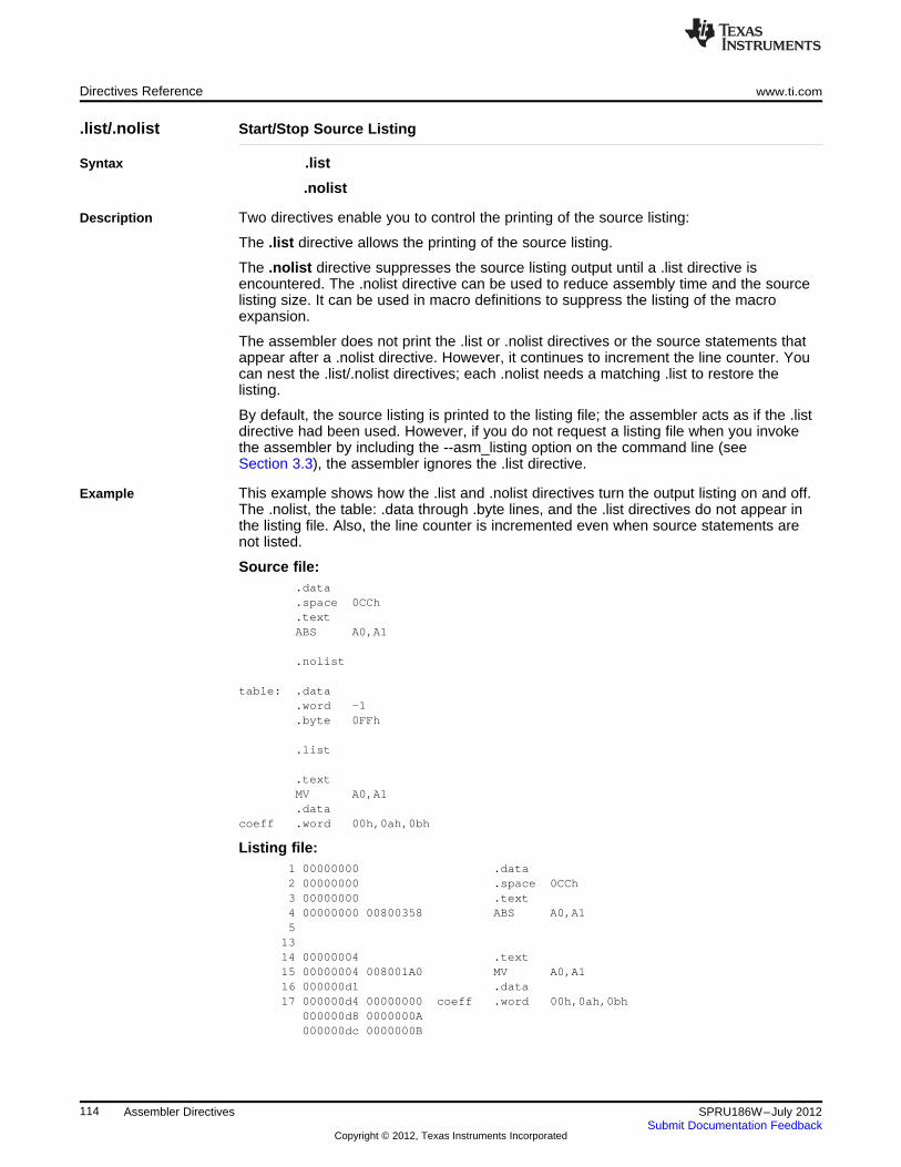
Directives Reference www.ti.com
.list/.nolist Start/Stop Source Listing
Syntax .list
.nolist
Description Two directives enable you to control the printing of the source listing:
The .list directive allows the printing of the source listing.
The .nolist directive suppresses the source listing output until a .list directive isencountered. The .nolist directive can be used to reduce assembly time and the sourcelisting size. It can be used in macro definitions to suppress the listing of the macroexpansion.
The assembler does not print the .list or .nolist directives or the source statements thatappear after a .nolist directive. However, it continues to increment the line counter. Youcan nest the .list/.nolist directives; each .nolist needs a matching .list to restore thelisting.
By default, the source listing is printed to the listing file; the assembler acts as if the .listdirective had been used. However, if you do not request a listing file when you invokethe assembler by including the --asm_listing option on the command line (seeSection 3.3), the assembler ignores the .list directive.
Example This example shows how the .list and .nolist directives turn the output listing on and off.The .nolist, the table: .data through .byte lines, and the .list directives do not appear inthe listing file. Also, the line counter is incremented even when source statements arenot listed.
Source file:.data.space 0CCh.textABS A0,A1
.nolist
table: .data.word -1.byte 0FFh
.list
.textMV A0,A1.data
coeff .word 00h,0ah,0bh
Listing file:1 00000000 .data2 00000000 .space 0CCh3 00000000 .text4 00000000 00800358 ABS A0,A15
1314 00000004 .text15 00000004 008001A0 MV A0,A116 000000d1 .data17 000000d4 00000000 coeff .word 00h,0ah,0bh
000000d8 0000000A000000dc 0000000B
114 Assembler Directives SPRU186W–July 2012Submit Documentation Feedback
Copyright © 2012, Texas Instruments Incorporated
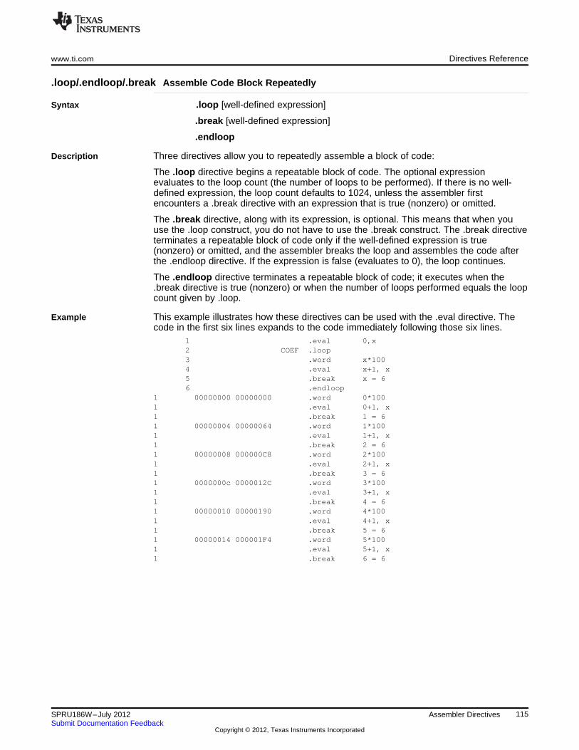
www.ti.com Directives Reference
.loop/.endloop/.break Assemble Code Block Repeatedly
Syntax .loop [well-defined expression]
.break [well-defined expression]
.endloop
Description Three directives allow you to repeatedly assemble a block of code:
The .loop directive begins a repeatable block of code. The optional expressionevaluates to the loop count (the number of loops to be performed). If there is no well-defined expression, the loop count defaults to 1024, unless the assembler firstencounters a .break directive with an expression that is true (nonzero) or omitted.
The .break directive, along with its expression, is optional. This means that when youuse the .loop construct, you do not have to use the .break construct. The .break directiveterminates a repeatable block of code only if the well-defined expression is true(nonzero) or omitted, and the assembler breaks the loop and assembles the code afterthe .endloop directive. If the expression is false (evaluates to 0), the loop continues.
The .endloop directive terminates a repeatable block of code; it executes when the.break directive is true (nonzero) or when the number of loops performed equals the loopcount given by .loop.
Example This example illustrates how these directives can be used with the .eval directive. Thecode in the first six lines expands to the code immediately following those six lines.
1 .eval 0,x2 COEF .loop3 .word x*1004 .eval x+1, x5 .break x = 66 .endloop
1 00000000 00000000 .word 0*1001 .eval 0+1, x1 .break 1 = 61 00000004 00000064 .word 1*1001 .eval 1+1, x1 .break 2 = 61 00000008 000000C8 .word 2*1001 .eval 2+1, x1 .break 3 = 61 0000000c 0000012C .word 3*1001 .eval 3+1, x1 .break 4 = 61 00000010 00000190 .word 4*1001 .eval 4+1, x1 .break 5 = 61 00000014 000001F4 .word 5*1001 .eval 5+1, x1 .break 6 = 6
115SPRU186W–July 2012 Assembler DirectivesSubmit Documentation Feedback
Copyright © 2012, Texas Instruments Incorporated
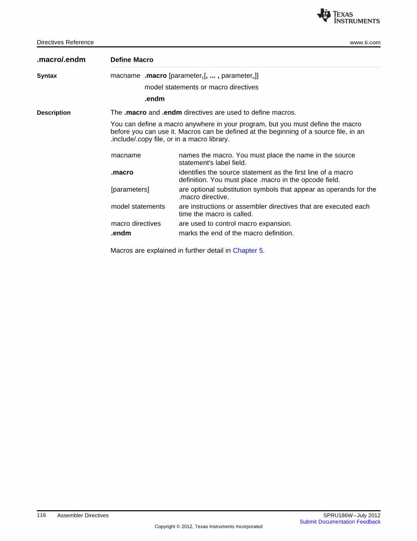
Directives Reference www.ti.com
.macro/.endm Define Macro
Syntax macname .macro [parameter1[, ... , parametern]]
model statements or macro directives
.endm
Description The .macro and .endm directives are used to define macros.
You can define a macro anywhere in your program, but you must define the macrobefore you can use it. Macros can be defined at the beginning of a source file, in an.include/.copy file, or in a macro library.
macname names the macro. You must place the name in the sourcestatement's label field.
.macro identifies the source statement as the first line of a macrodefinition. You must place .macro in the opcode field.
[parameters] are optional substitution symbols that appear as operands for the.macro directive.
model statements are instructions or assembler directives that are executed eachtime the macro is called.
macro directives are used to control macro expansion..endm marks the end of the macro definition.
Macros are explained in further detail in Chapter 5.
116 Assembler Directives SPRU186W–July 2012Submit Documentation Feedback
Copyright © 2012, Texas Instruments Incorporated
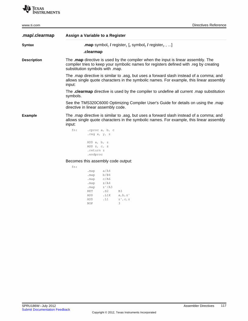
www.ti.com Directives Reference
.map/.clearmap Assign a Variable to a Register
Syntax .map symbol1 / register1 [, symbol2 / register2 , ...]
.clearmap
Description The .map directive is used by the compiler when the input is linear assembly. Thecompiler tries to keep your symbolic names for registers defined with .reg by creatingsubstitution symbols with .map.
The .map directive is similar to .asg, but uses a forward slash instead of a comma; andallows single quote characters in the symbolic names. For example, this linear assemblyinput:
The .clearmap directive is used by the compiler to undefine all current .map substitutionsymbols.
See the TMS320C6000 Optimizing Compiler User's Guide for details on using the .mapdirective in linear assembly code.
Example The .map directive is similar to .asg, but uses a forward slash instead of a comma; andallows single quote characters in the symbolic names. For example, this linear assemblyinput:
fn: .cproc a, b, c.reg x, y, z
ADD a, b, zADD z, c, z.return z.endproc
Becomes this assembly code output:fn:
.map a/A4
.map b/B4
.map c/A6
.map z/A4
.map z'/A3RET .S2 B3ADD .L1X a,b,z'ADD .L1 z',c,zNOP 3
117SPRU186W–July 2012 Assembler DirectivesSubmit Documentation Feedback
Copyright © 2012, Texas Instruments Incorporated
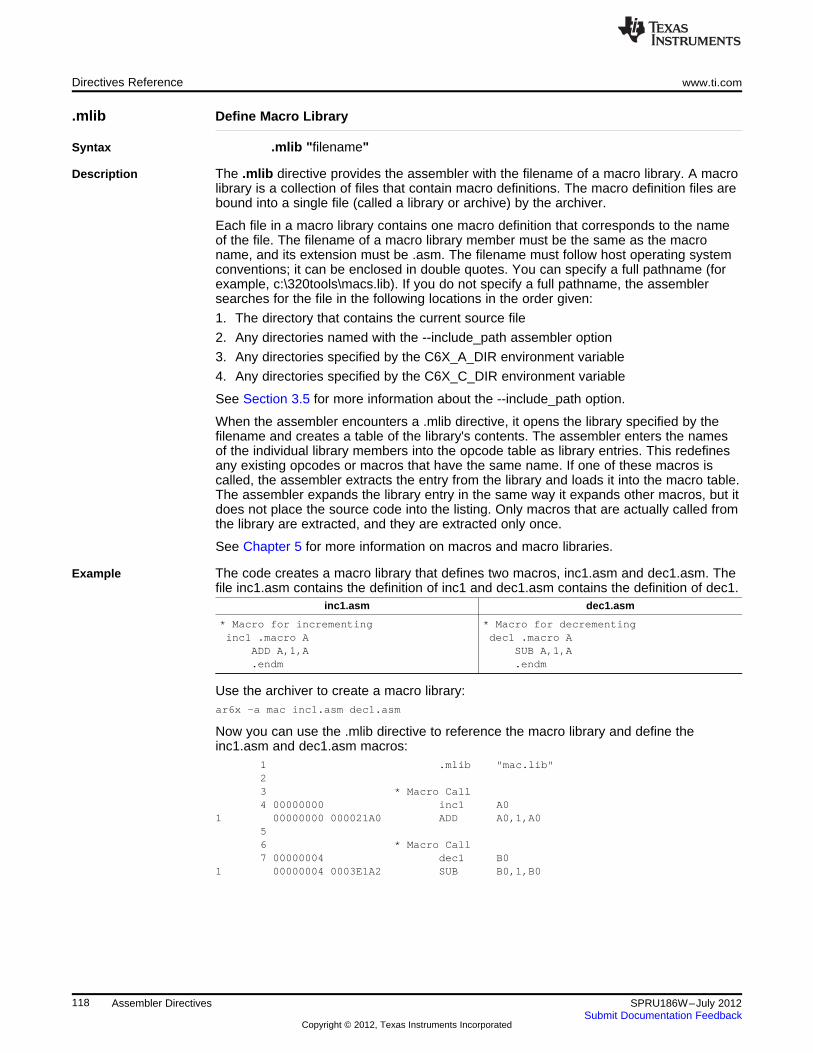
Directives Reference www.ti.com
.mlib Define Macro Library
Syntax .mlib "filename"
Description The .mlib directive provides the assembler with the filename of a macro library. A macrolibrary is a collection of files that contain macro definitions. The macro definition files arebound into a single file (called a library or archive) by the archiver.
Each file in a macro library contains one macro definition that corresponds to the nameof the file. The filename of a macro library member must be the same as the macroname, and its extension must be .asm. The filename must follow host operating systemconventions; it can be enclosed in double quotes. You can specify a full pathname (forexample, c:\320tools\macs.lib). If you do not specify a full pathname, the assemblersearches for the file in the following locations in the order given:
1. The directory that contains the current source file
2. Any directories named with the --include_path assembler option
3. Any directories specified by the C6X_A_DIR environment variable
4. Any directories specified by the C6X_C_DIR environment variable
See Section 3.5 for more information about the --include_path option.
When the assembler encounters a .mlib directive, it opens the library specified by thefilename and creates a table of the library's contents. The assembler enters the namesof the individual library members into the opcode table as library entries. This redefinesany existing opcodes or macros that have the same name. If one of these macros iscalled, the assembler extracts the entry from the library and loads it into the macro table.The assembler expands the library entry in the same way it expands other macros, but itdoes not place the source code into the listing. Only macros that are actually called fromthe library are extracted, and they are extracted only once.
See Chapter 5 for more information on macros and macro libraries.
Example The code creates a macro library that defines two macros, inc1.asm and dec1.asm. Thefile inc1.asm contains the definition of inc1 and dec1.asm contains the definition of dec1.
inc1.asm dec1.asm
* Macro for incrementing * Macro for decrementinginc1 .macro A dec1 .macro A
ADD A,1,A SUB A,1,A.endm .endm
Use the archiver to create a macro library:ar6x -a mac inc1.asm dec1.asm
Now you can use the .mlib directive to reference the macro library and define theinc1.asm and dec1.asm macros:
1 .mlib "mac.lib"23 * Macro Call4 00000000 inc1 A0
1 00000000 000021A0 ADD A0,1,A056 * Macro Call7 00000004 dec1 B0
1 00000004 0003E1A2 SUB B0,1,B0
118 Assembler Directives SPRU186W–July 2012Submit Documentation Feedback
Copyright © 2012, Texas Instruments Incorporated
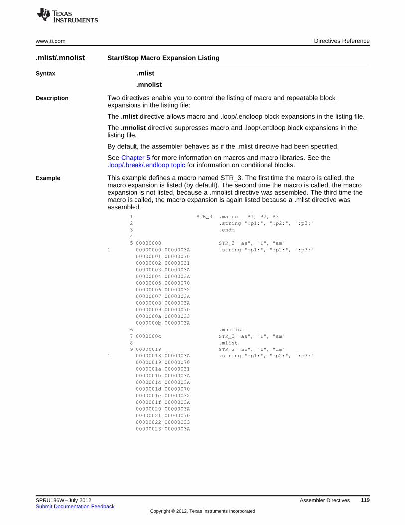
www.ti.com Directives Reference
.mlist/.mnolist Start/Stop Macro Expansion Listing
Syntax .mlist
.mnolist
Description Two directives enable you to control the listing of macro and repeatable blockexpansions in the listing file:
The .mlist directive allows macro and .loop/.endloop block expansions in the listing file.
The .mnolist directive suppresses macro and .loop/.endloop block expansions in thelisting file.
By default, the assembler behaves as if the .mlist directive had been specified.
See Chapter 5 for more information on macros and macro libraries. See the.loop/.break/.endloop topic for information on conditional blocks.
Example This example defines a macro named STR_3. The first time the macro is called, themacro expansion is listed (by default). The second time the macro is called, the macroexpansion is not listed, because a .mnolist directive was assembled. The third time themacro is called, the macro expansion is again listed because a .mlist directive wasassembled.
1 STR_3 .macro P1, P2, P32 .string ":p1:", ":p2:", ":p3:"3 .endm45 00000000 STR_3 "as", "I", "am"
1 00000000 0000003A .string ":p1:", ":p2:", ":p3:"00000001 0000007000000002 0000003100000003 0000003A00000004 0000003A00000005 0000007000000006 0000003200000007 0000003A00000008 0000003A00000009 000000700000000a 000000330000000b 0000003A
6 .mnolist7 0000000c STR_3 "as", "I", "am"8 .mlist9 00000018 STR_3 "as", "I", "am"
1 00000018 0000003A .string ":p1:", ":p2:", ":p3:"00000019 000000700000001a 000000310000001b 0000003A0000001c 0000003A0000001d 000000700000001e 000000320000001f 0000003A00000020 0000003A00000021 0000007000000022 0000003300000023 0000003A
119SPRU186W–July 2012 Assembler DirectivesSubmit Documentation Feedback
Copyright © 2012, Texas Instruments Incorporated
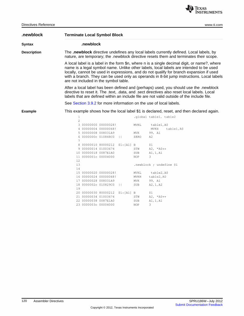
Directives Reference www.ti.com
.newblock Terminate Local Symbol Block
Syntax .newblock
Description The .newblock directive undefines any local labels currently defined. Local labels, bynature, are temporary; the .newblock directive resets them and terminates their scope.
A local label is a label in the form $n, where n is a single decimal digit, or name?, wherename is a legal symbol name. Unlike other labels, local labels are intended to be usedlocally, cannot be used in expressions, and do not qualify for branch expansion if usedwith a branch. They can be used only as operands in 8-bit jump instructions. Local labelsare not included in the symbol table.
After a local label has been defined and (perhaps) used, you should use the .newblockdirective to reset it. The .text, .data, and .sect directives also reset local labels. Locallabels that are defined within an include file are not valid outside of the include file.
See Section 3.9.2 for more information on the use of local labels.
Example This example shows how the local label $1 is declared, reset, and then declared again.1 .global table1, table223 00000000 00000028! MVKL table1,A04 00000004 00000068! MVKH table1,A05 00000008 008031A9 MVK 99, A16 0000000c 010848C0 || ZERO A278 00000010 80000212 $1:[A1] B $19 00000014 01003674 STW A2, *A0++
10 00000018 0087E1A0 SUB A1,1,A111 0000001c 00004000 NOP 31213 .newblock ; undefine $11415 00000020 00000028! MVKL table2,A016 00000024 00000068! MVKH table2,A017 00000028 008031A9 MVK 99, A118 0000002c 010829C0 || SUB A2,1,A21920 00000030 80000212 $1:[A1] B $121 00000034 01003674 STW A2, *A0++22 00000038 0087E1A0 SUB A1,1,A123 0000003c 00004000 NOP 3
120 Assembler Directives SPRU186W–July 2012Submit Documentation Feedback
Copyright © 2012, Texas Instruments Incorporated
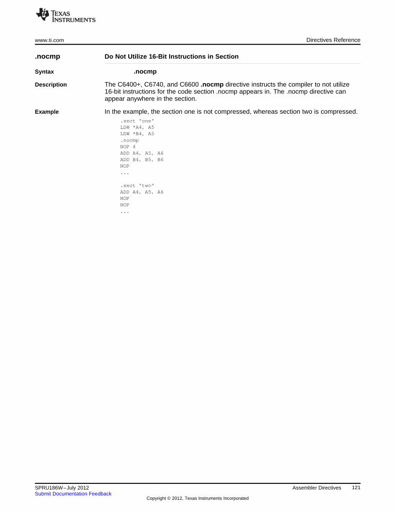
www.ti.com Directives Reference
.nocmp Do Not Utilize 16-Bit Instructions in Section
Syntax .nocmp
Description The C6400+, C6740, and C6600 .nocmp directive instructs the compiler to not utilize16-bit instructions for the code section .nocmp appears in. The .nocmp directive canappear anywhere in the section.
Example In the example, the section one is not compressed, whereas section two is compressed..sect "one"LDW *A4, A5LDW *B4, A5.nocmpNOP 4ADD A4, A5, A6ADD B4, B5, B6NOP...
.sect "two"ADD A4, A5, A6NOPNOP...
121SPRU186W–July 2012 Assembler DirectivesSubmit Documentation Feedback
Copyright © 2012, Texas Instruments Incorporated
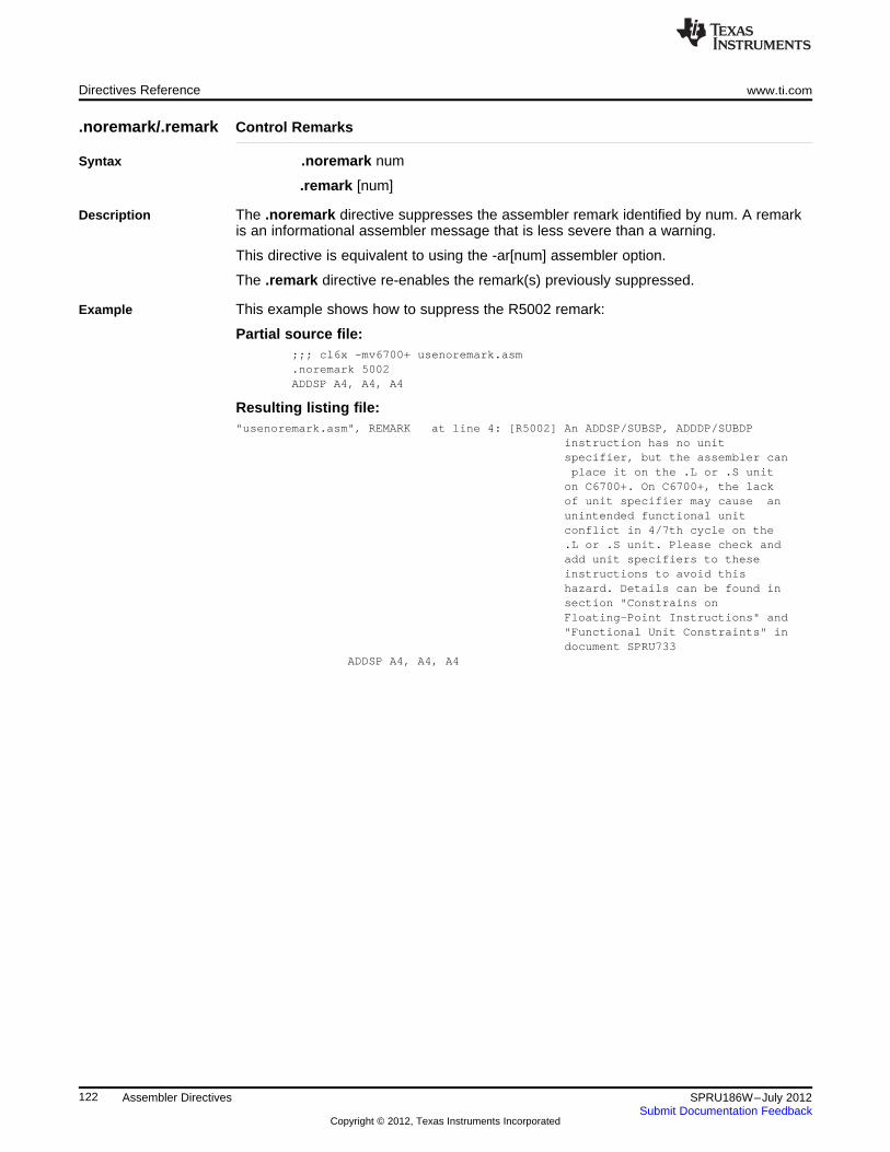
Directives Reference www.ti.com
.noremark/.remark Control Remarks
Syntax .noremark num
.remark [num]
Description The .noremark directive suppresses the assembler remark identified by num. A remarkis an informational assembler message that is less severe than a warning.
This directive is equivalent to using the -ar[num] assembler option.
The .remark directive re-enables the remark(s) previously suppressed.
Example This example shows how to suppress the R5002 remark:
Partial source file:;;; cl6x -mv6700+ usenoremark.asm.noremark 5002ADDSP A4, A4, A4
Resulting listing file:"usenoremark.asm", REMARK at line 4: [R5002] An ADDSP/SUBSP, ADDDP/SUBDP
instruction has no unitspecifier, but the assembler canplace it on the .L or .S uniton C6700+. On C6700+, the lackof unit specifier may cause anunintended functional unitconflict in 4/7th cycle on the.L or .S unit. Please check andadd unit specifiers to theseinstructions to avoid thishazard. Details can be found insection "Constrains onFloating-Point Instructions" and"Functional Unit Constraints" indocument SPRU733
ADDSP A4, A4, A4
122 Assembler Directives SPRU186W–July 2012Submit Documentation Feedback
Copyright © 2012, Texas Instruments Incorporated
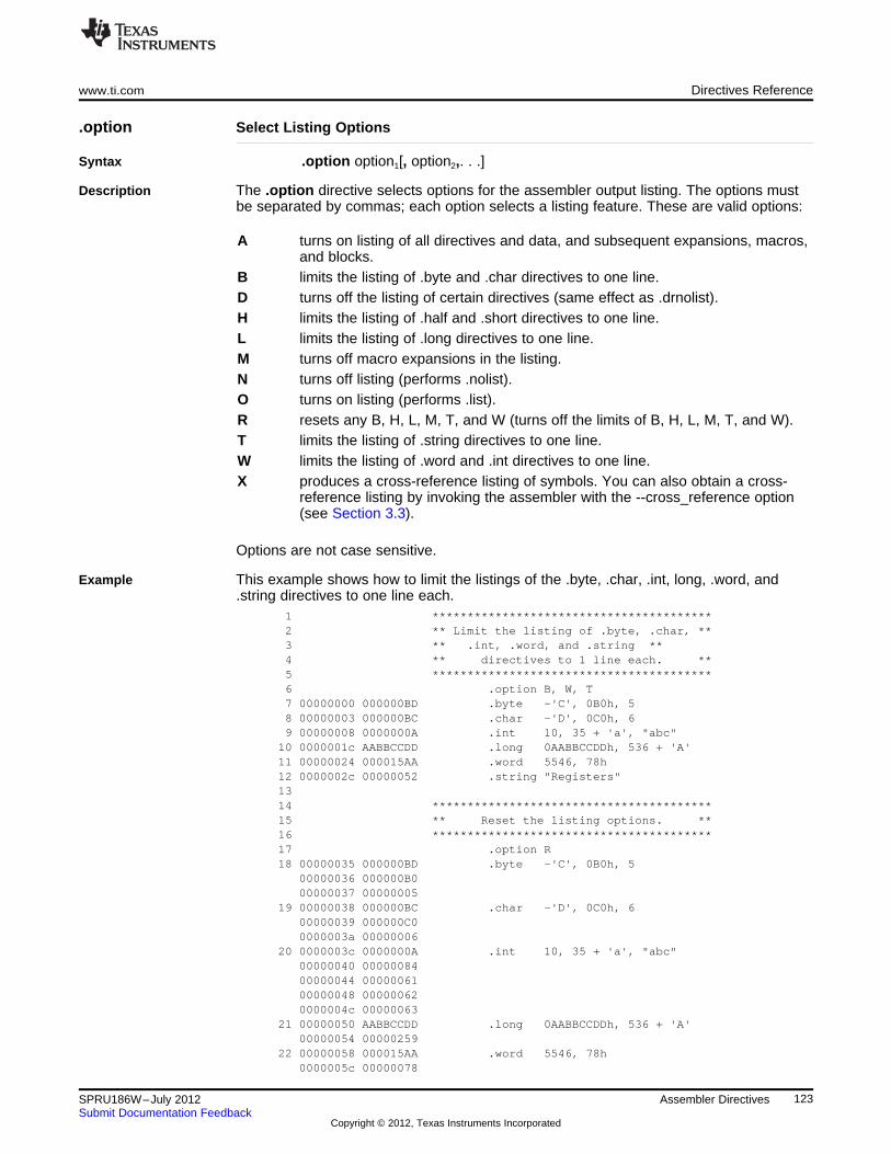
www.ti.com Directives Reference
.option Select Listing Options
Syntax .option option1[, option2,. . .]
Description The .option directive selects options for the assembler output listing. The options mustbe separated by commas; each option selects a listing feature. These are valid options:
A turns on listing of all directives and data, and subsequent expansions, macros,and blocks.
B limits the listing of .byte and .char directives to one line.D turns off the listing of certain directives (same effect as .drnolist).H limits the listing of .half and .short directives to one line.L limits the listing of .long directives to one line.M turns off macro expansions in the listing.N turns off listing (performs .nolist).O turns on listing (performs .list).R resets any B, H, L, M, T, and W (turns off the limits of B, H, L, M, T, and W).T limits the listing of .string directives to one line.W limits the listing of .word and .int directives to one line.X produces a cross-reference listing of symbols. You can also obtain a cross-
reference listing by invoking the assembler with the --cross_reference option(see Section 3.3).
Options are not case sensitive.
Example This example shows how to limit the listings of the .byte, .char, .int, long, .word, and.string directives to one line each.
1 ****************************************2 ** Limit the listing of .byte, .char, **3 ** .int, .word, and .string **4 ** directives to 1 line each. **5 ****************************************6 .option B, W, T7 00000000 000000BD .byte -'C', 0B0h, 58 00000003 000000BC .char -'D', 0C0h, 69 00000008 0000000A .int 10, 35 + 'a', "abc"
10 0000001c AABBCCDD .long 0AABBCCDDh, 536 + 'A'11 00000024 000015AA .word 5546, 78h12 0000002c 00000052 .string "Registers"1314 ****************************************15 ** Reset the listing options. **16 ****************************************17 .option R18 00000035 000000BD .byte -'C', 0B0h, 5
00000036 000000B000000037 00000005
19 00000038 000000BC .char -'D', 0C0h, 600000039 000000C00000003a 00000006
20 0000003c 0000000A .int 10, 35 + 'a', "abc"00000040 0000008400000044 0000006100000048 000000620000004c 00000063
21 00000050 AABBCCDD .long 0AABBCCDDh, 536 + 'A'00000054 00000259
22 00000058 000015AA .word 5546, 78h0000005c 00000078
123SPRU186W–July 2012 Assembler DirectivesSubmit Documentation Feedback
Copyright © 2012, Texas Instruments Incorporated
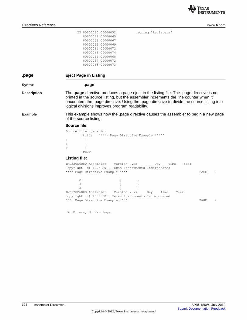
Directives Reference www.ti.com
23 00000060 00000052 .string "Registers"00000061 0000006500000062 0000006700000063 0000006900000064 0000007300000065 0000007400000066 0000006500000067 0000007200000068 00000073
.page Eject Page in Listing
Syntax .page
Description The .page directive produces a page eject in the listing file. The .page directive is notprinted in the source listing, but the assembler increments the line counter when itencounters the .page directive. Using the .page directive to divide the source listing intological divisions improves program readability.
Example This example shows how the .page directive causes the assembler to begin a new pageof the source listing.
Source file:Source file (generic)
.title "**** Page Directive Example ****"; .; .; .
.page
Listing file:TMS320C6000 Assembler Version x.xx Day Time YearCopyright (c) 1996-2011 Texas Instruments Incorporated**** Page Directive Example **** PAGE 1
2 ; .3 ; .4 ; .
TMS320C6000 Assembler Version x.xx Day Time YearCopyright (c) 1996-2011 Texas Instruments Incorporated**** Page Directive Example **** PAGE 2
No Errors, No Warnings
124 Assembler Directives SPRU186W–July 2012Submit Documentation Feedback
Copyright © 2012, Texas Instruments Incorporated
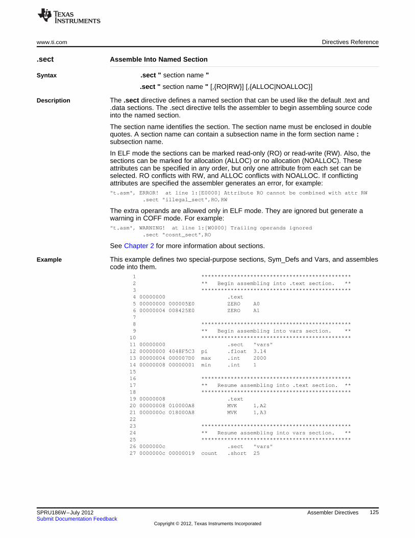
www.ti.com Directives Reference
.sect Assemble Into Named Section
Syntax .sect " section name "
.sect " section name " [,{RO|RW}] [,{ALLOC|NOALLOC}]
Description The .sect directive defines a named section that can be used like the default .text and.data sections. The .sect directive tells the assembler to begin assembling source codeinto the named section.
The section name identifies the section. The section name must be enclosed in doublequotes. A section name can contain a subsection name in the form section name :subsection name.
In ELF mode the sections can be marked read-only (RO) or read-write (RW). Also, thesections can be marked for allocation (ALLOC) or no allocation (NOALLOC). Theseattributes can be specified in any order, but only one attribute from each set can beselected. RO conflicts with RW, and ALLOC conflicts with NOALLOC. If conflictingattributes are specified the assembler generates an error, for example:"t.asm", ERROR! at line 1:[E0000] Attribute RO cannot be combined with attr RW
.sect "illegal_sect",RO,RW
The extra operands are allowed only in ELF mode. They are ignored but generate awarning in COFF mode. For example:"t.asm", WARNING! at line 1:[W0000] Trailing operands ignored
.sect "cosnt_sect",RO
See Chapter 2 for more information about sections.
Example This example defines two special-purpose sections, Sym_Defs and Vars, and assemblescode into them.
1 **********************************************2 ** Begin assembling into .text section. **3 **********************************************4 00000000 .text5 00000000 000005E0 ZERO A06 00000004 008425E0 ZERO A178 **********************************************9 ** Begin assembling into vars section. **
10 **********************************************11 00000000 .sect "vars"12 00000000 4048F5C3 pi .float 3.1413 00000004 000007D0 max .int 200014 00000008 00000001 min .int 11516 **********************************************17 ** Resume assembling into .text section. **18 **********************************************19 00000008 .text20 00000008 010000A8 MVK 1,A221 0000000c 018000A8 MVK 1,A32223 **********************************************24 ** Resume assembling into vars section. **25 **********************************************26 0000000c .sect "vars"27 0000000c 00000019 count .short 25
125SPRU186W–July 2012 Assembler DirectivesSubmit Documentation Feedback
Copyright © 2012, Texas Instruments Incorporated
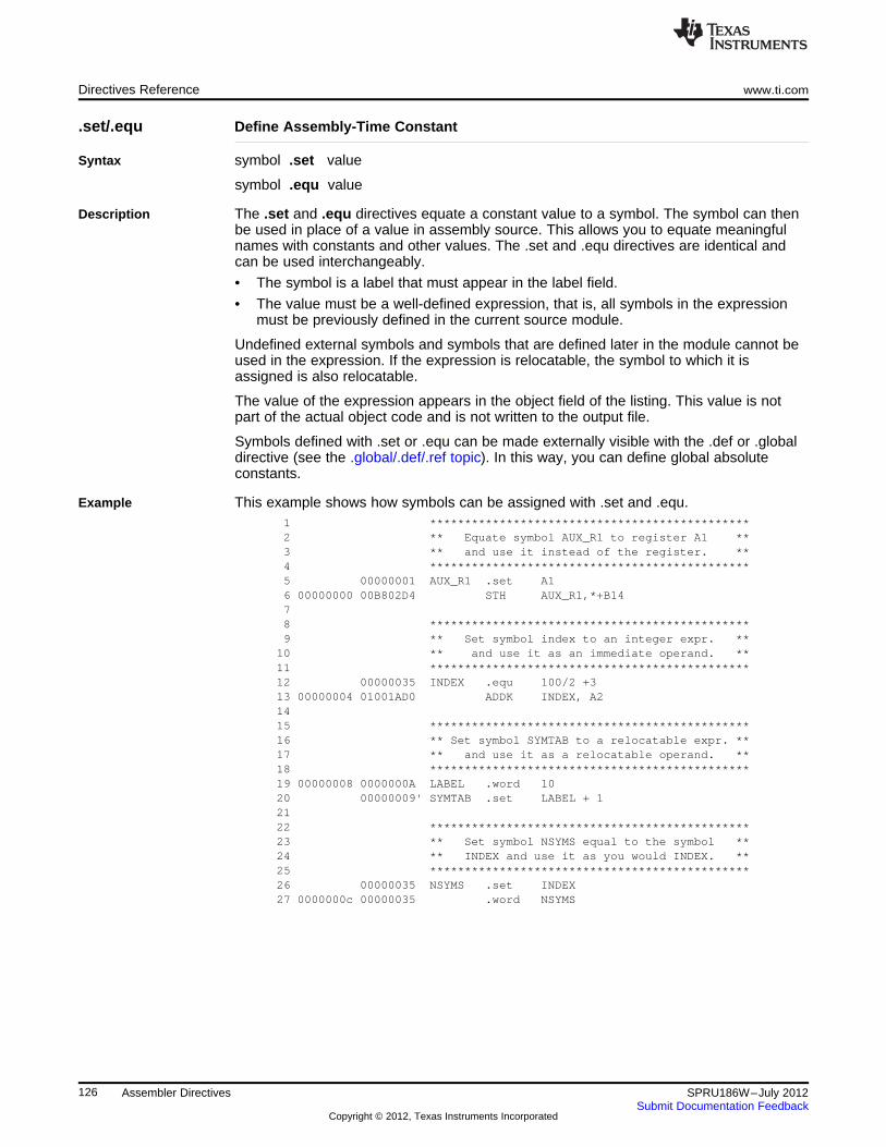
Directives Reference www.ti.com
.set/.equ Define Assembly-Time Constant
Syntax symbol .set value
symbol .equ value
Description The .set and .equ directives equate a constant value to a symbol. The symbol can thenbe used in place of a value in assembly source. This allows you to equate meaningfulnames with constants and other values. The .set and .equ directives are identical andcan be used interchangeably.
• The symbol is a label that must appear in the label field.
• The value must be a well-defined expression, that is, all symbols in the expressionmust be previously defined in the current source module.
Undefined external symbols and symbols that are defined later in the module cannot beused in the expression. If the expression is relocatable, the symbol to which it isassigned is also relocatable.
The value of the expression appears in the object field of the listing. This value is notpart of the actual object code and is not written to the output file.
Symbols defined with .set or .equ can be made externally visible with the .def or .globaldirective (see the .global/.def/.ref topic). In this way, you can define global absoluteconstants.
Example This example shows how symbols can be assigned with .set and .equ.1 **********************************************2 ** Equate symbol AUX_R1 to register A1 **3 ** and use it instead of the register. **4 **********************************************5 00000001 AUX_R1 .set A16 00000000 00B802D4 STH AUX_R1,*+B1478 **********************************************9 ** Set symbol index to an integer expr. **
10 ** and use it as an immediate operand. **11 **********************************************12 00000035 INDEX .equ 100/2 +313 00000004 01001AD0 ADDK INDEX, A21415 **********************************************16 ** Set symbol SYMTAB to a relocatable expr. **17 ** and use it as a relocatable operand. **18 **********************************************19 00000008 0000000A LABEL .word 1020 00000009' SYMTAB .set LABEL + 12122 **********************************************23 ** Set symbol NSYMS equal to the symbol **24 ** INDEX and use it as you would INDEX. **25 **********************************************26 00000035 NSYMS .set INDEX27 0000000c 00000035 .word NSYMS
126 Assembler Directives SPRU186W–July 2012Submit Documentation Feedback
Copyright © 2012, Texas Instruments Incorporated
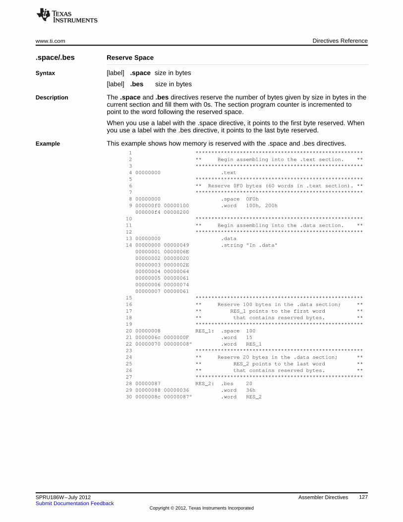
www.ti.com Directives Reference
.space/.bes Reserve Space
Syntax [label] .space size in bytes
[label] .bes size in bytes
Description The .space and .bes directives reserve the number of bytes given by size in bytes in thecurrent section and fill them with 0s. The section program counter is incremented topoint to the word following the reserved space.
When you use a label with the .space directive, it points to the first byte reserved. Whenyou use a label with the .bes directive, it points to the last byte reserved.
Example This example shows how memory is reserved with the .space and .bes directives.1 *****************************************************2 ** Begin assembling into the .text section. **3 *****************************************************4 00000000 .text5 *****************************************************6 ** Reserve 0F0 bytes (60 words in .text section). **7 *****************************************************8 00000000 .space 0F0h9 000000f0 00000100 .word 100h, 200h000000f4 00000200
10 *****************************************************11 ** Begin assembling into the .data section. **12 *****************************************************13 00000000 .data14 00000000 00000049 .string "In .data"
00000001 0000006E00000002 0000002000000003 0000002E00000004 0000006400000005 0000006100000006 0000007400000007 00000061
15 *****************************************************16 ** Reserve 100 bytes in the .data section; **17 ** RES_1 points to the first word **18 ** that contains reserved bytes. **19 *****************************************************20 00000008 RES_1: .space 10021 0000006c 0000000F .word 1522 00000070 00000008" .word RES_123 *****************************************************24 ** Reserve 20 bytes in the .data section; **25 ** RES_2 points to the last word **26 ** that contains reserved bytes. **27 *****************************************************28 00000087 RES_2: .bes 2029 00000088 00000036 .word 36h30 0000008c 00000087" .word RES_2
127SPRU186W–July 2012 Assembler DirectivesSubmit Documentation Feedback
Copyright © 2012, Texas Instruments Incorporated
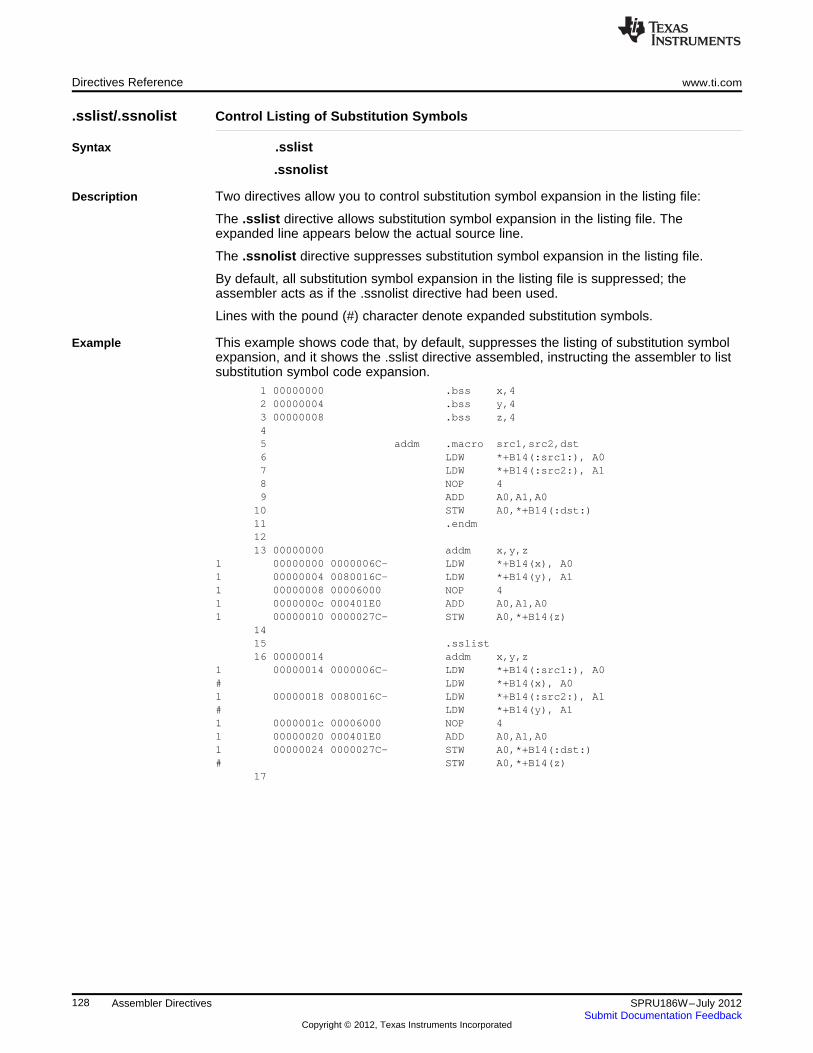
Directives Reference www.ti.com
.sslist/.ssnolist Control Listing of Substitution Symbols
Syntax .sslist
.ssnolist
Description Two directives allow you to control substitution symbol expansion in the listing file:
The .sslist directive allows substitution symbol expansion in the listing file. Theexpanded line appears below the actual source line.
The .ssnolist directive suppresses substitution symbol expansion in the listing file.
By default, all substitution symbol expansion in the listing file is suppressed; theassembler acts as if the .ssnolist directive had been used.
Lines with the pound (#) character denote expanded substitution symbols.
Example This example shows code that, by default, suppresses the listing of substitution symbolexpansion, and it shows the .sslist directive assembled, instructing the assembler to listsubstitution symbol code expansion.
1 00000000 .bss x,42 00000004 .bss y,43 00000008 .bss z,445 addm .macro src1,src2,dst6 LDW *+B14(:src1:), A07 LDW *+B14(:src2:), A18 NOP 49 ADD A0,A1,A0
10 STW A0,*+B14(:dst:)11 .endm1213 00000000 addm x,y,z
1 00000000 0000006C- LDW *+B14(x), A01 00000004 0080016C- LDW *+B14(y), A11 00000008 00006000 NOP 41 0000000c 000401E0 ADD A0,A1,A01 00000010 0000027C- STW A0,*+B14(z)
1415 .sslist16 00000014 addm x,y,z
1 00000014 0000006C- LDW *+B14(:src1:), A0# LDW *+B14(x), A01 00000018 0080016C- LDW *+B14(:src2:), A1# LDW *+B14(y), A11 0000001c 00006000 NOP 41 00000020 000401E0 ADD A0,A1,A01 00000024 0000027C- STW A0,*+B14(:dst:)# STW A0,*+B14(z)
17
128 Assembler Directives SPRU186W–July 2012Submit Documentation Feedback
Copyright © 2012, Texas Instruments Incorporated
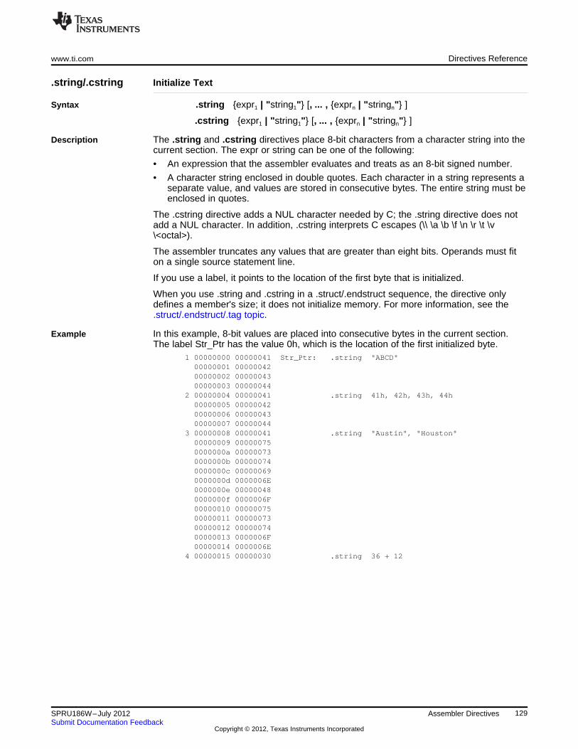
www.ti.com Directives Reference
.string/.cstring Initialize Text
Syntax .string {expr1 | "string1"} [, ... , {exprn | "stringn"} ]
.cstring {expr1 | "string1"} [, ... , {exprn | "stringn"} ]
Description The .string and .cstring directives place 8-bit characters from a character string into thecurrent section. The expr or string can be one of the following:
• An expression that the assembler evaluates and treats as an 8-bit signed number.
• A character string enclosed in double quotes. Each character in a string represents aseparate value, and values are stored in consecutive bytes. The entire string must beenclosed in quotes.
The .cstring directive adds a NUL character needed by C; the .string directive does notadd a NUL character. In addition, .cstring interprets C escapes (\\ \a \b \f \n \r \t \v\<octal>).
The assembler truncates any values that are greater than eight bits. Operands must fiton a single source statement line.
If you use a label, it points to the location of the first byte that is initialized.
When you use .string and .cstring in a .struct/.endstruct sequence, the directive onlydefines a member's size; it does not initialize memory. For more information, see the.struct/.endstruct/.tag topic.
Example In this example, 8-bit values are placed into consecutive bytes in the current section.The label Str_Ptr has the value 0h, which is the location of the first initialized byte.
1 00000000 00000041 Str_Ptr: .string "ABCD"00000001 0000004200000002 0000004300000003 00000044
2 00000004 00000041 .string 41h, 42h, 43h, 44h00000005 0000004200000006 0000004300000007 00000044
3 00000008 00000041 .string "Austin", "Houston"00000009 000000750000000a 000000730000000b 000000740000000c 000000690000000d 0000006E0000000e 000000480000000f 0000006F00000010 0000007500000011 0000007300000012 0000007400000013 0000006F00000014 0000006E
4 00000015 00000030 .string 36 + 12
129SPRU186W–July 2012 Assembler DirectivesSubmit Documentation Feedback
Copyright © 2012, Texas Instruments Incorporated
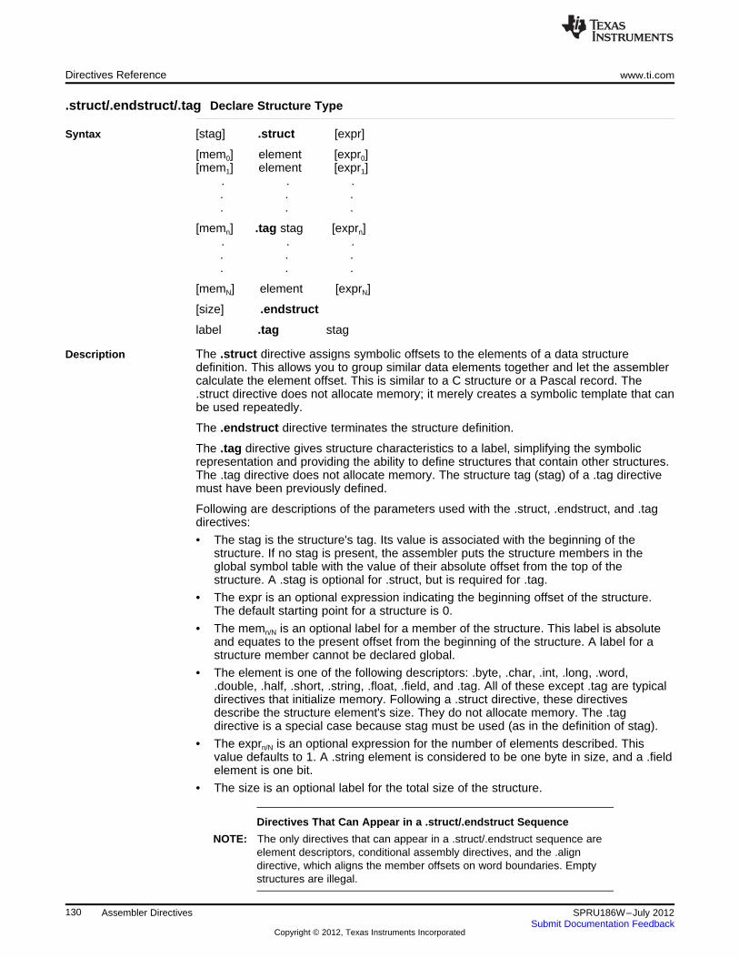
Directives Reference www.ti.com
.struct/.endstruct/.tag Declare Structure Type
Syntax [stag] .struct [expr]
[mem0] element [expr0][mem1] element [expr1]
. . .. . .. . .
[memn] .tag stag [exprn]. . .. . .. . .
[memN] element [exprN]
[size] .endstruct
label .tag stag
Description The .struct directive assigns symbolic offsets to the elements of a data structuredefinition. This allows you to group similar data elements together and let the assemblercalculate the element offset. This is similar to a C structure or a Pascal record. The.struct directive does not allocate memory; it merely creates a symbolic template that canbe used repeatedly.
The .endstruct directive terminates the structure definition.
The .tag directive gives structure characteristics to a label, simplifying the symbolicrepresentation and providing the ability to define structures that contain other structures.The .tag directive does not allocate memory. The structure tag (stag) of a .tag directivemust have been previously defined.
Following are descriptions of the parameters used with the .struct, .endstruct, and .tagdirectives:
• The stag is the structure's tag. Its value is associated with the beginning of thestructure. If no stag is present, the assembler puts the structure members in theglobal symbol table with the value of their absolute offset from the top of thestructure. A .stag is optional for .struct, but is required for .tag.
• The expr is an optional expression indicating the beginning offset of the structure.The default starting point for a structure is 0.
• The memn/N is an optional label for a member of the structure. This label is absoluteand equates to the present offset from the beginning of the structure. A label for astructure member cannot be declared global.
• The element is one of the following descriptors: .byte, .char, .int, .long, .word,.double, .half, .short, .string, .float, .field, and .tag. All of these except .tag are typicaldirectives that initialize memory. Following a .struct directive, these directivesdescribe the structure element's size. They do not allocate memory. The .tagdirective is a special case because stag must be used (as in the definition of stag).
• The exprn/N is an optional expression for the number of elements described. Thisvalue defaults to 1. A .string element is considered to be one byte in size, and a .fieldelement is one bit.
• The size is an optional label for the total size of the structure.
Directives That Can Appear in a .struct/.endstruct Sequence
NOTE: The only directives that can appear in a .struct/.endstruct sequence areelement descriptors, conditional assembly directives, and the .aligndirective, which aligns the member offsets on word boundaries. Emptystructures are illegal.
130 Assembler Directives SPRU186W–July 2012Submit Documentation Feedback
Copyright © 2012, Texas Instruments Incorporated
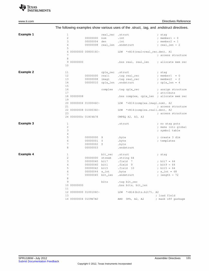
www.ti.com Directives Reference
The following examples show various uses of the .struct, .tag, and .endstruct directives.
Example 1 1 real_rec .struct ; stag2 00000000 nom .int ; member1 = 03 00000004 den .int ; member2 = 14 00000008 real_len .endstruct ; real_len = 256 00000000 0080016C- LDW *+B14(real+real_rec.den), A17 ; access structure89 00000000 .bss real, real_len ; allocate mem rec
10
Example 2 11 cplx_rec .struct ; stag12 00000000 reali .tag real_rec ; member1 = 013 00000008 imagi .tag real_rec ; member2 = 214 00000010 cplx_len .endstruct ; cplx_len = 41516 complex .tag cplx_rec ; assign structure17 ; attribute18 00000008 .bss complex, cplx_len ; allocate mem rec1920 00000004 0100046C- LDW *+B14(complex.imagi.nom), A221 ; access structure22 00000008 0100036C- LDW *+B14(complex.reali.den), A223 ; access structure24 0000000c 018C4A78 CMPEQ A2, A3, A3
Example 3 1 .struct ; no stag puts2 ; mems into global3 ; symbol table45 00000000 X .byte ; create 3 dim6 00000001 Y .byte ; templates7 00000002 Z .byte8 00000003 .endstruct
Example 4 1 bit_rec .struct ; stag2 00000000 stream .string 643 00000040 bit7 .field 7 ; bit7 = 644 00000040 bit1 .field 9 ; bit9 = 645 00000042 bit5 .field 10 ; bit5 = 646 00000044 x_int .byte ; x_int = 687 00000045 bit_len .endstruct ; length = 7289 bits .tag bit_rec
10 00000000 .bss bits, bit_len1112 00000000 0100106C- LDW *+B14(bits.bit7), A213 ; load field14 00000004 0109E7A0 AND 0Fh, A2, A2 ; mask off garbage
131SPRU186W–July 2012 Assembler DirectivesSubmit Documentation Feedback
Copyright © 2012, Texas Instruments Incorporated
Directives Reference www.ti.com
.symdepend/.weak Effect Symbol Linkage and Visibility
Syntax .symdepend dst symbol name[, src symbol name]
.weak symbol name
Description These directives are used to effect symbol linkage and visibility. The .weak directive isonly valid when ELF mode is used.
The .symdepend directive creates an artificial reference from the section defining srcsymbol name to the symbol dst symbol name. This prevents the linker from removing thesection containing dst symbol name if the section defining src symbol name is includedin the output module. If src symbol name is not specified, a reference from the currentsection is created.
The .weak directive identifies a symbol that is used in the current module but is definedin another module. The linker resolves this symbol's definition at link time. The .weakdirective is equivalent to the .ref directive, except that the reference has weak linkage.
A global symbol is defined in the same manner as any other symbol; that is, it appearsas a label or is defined by the .set, .equ, .bss, or .usect directive. As with all symbols, if aglobal symbol is defined more than once, the linker issues a multiple-definition error. The.weak directive always creates a symbol table entry for a symbol, whether the moduleuses the symbol or not; .symdepend, however, creates an entry only if the moduleactually uses the symbol.
A symbol can be declared global for either of two reasons:
• If the symbol is not defined in the current module (which includes macro, copy, andinclude files), the .weak directive tells the assembler that the symbol is defined in anexternal module. This prevents the assembler from issuing an unresolved referenceerror. At link time, the linker looks for the symbol's definition in other modules.
• If the symbol is defined in the current module, the .symdepend directive declares thatthe symbol and its definition can be used externally by other modules. These types ofreferences are resolved at link time.
132 Assembler Directives SPRU186W–July 2012Submit Documentation Feedback
Copyright © 2012, Texas Instruments Incorporated
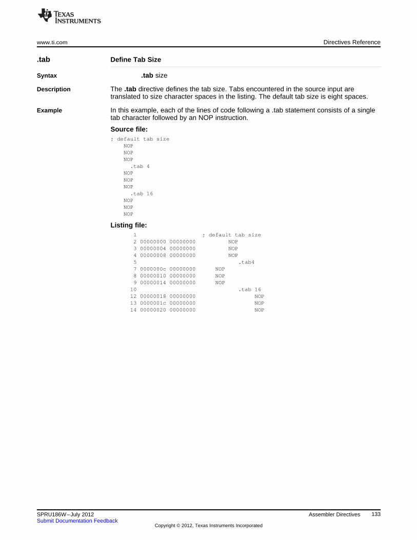
www.ti.com Directives Reference
.tab Define Tab Size
Syntax .tab size
Description The .tab directive defines the tab size. Tabs encountered in the source input aretranslated to size character spaces in the listing. The default tab size is eight spaces.
Example In this example, each of the lines of code following a .tab statement consists of a singletab character followed by an NOP instruction.
Source file:; default tab size
NOPNOPNOP
.tab 4NOPNOPNOP
.tab 16NOPNOPNOP
Listing file:1 ; default tab size2 00000000 00000000 NOP3 00000004 00000000 NOP4 00000008 00000000 NOP5 .tab47 0000000c 00000000 NOP8 00000010 00000000 NOP9 00000014 00000000 NOP
10 .tab 1612 00000018 00000000 NOP13 0000001c 00000000 NOP14 00000020 00000000 NOP
133SPRU186W–July 2012 Assembler DirectivesSubmit Documentation Feedback
Copyright © 2012, Texas Instruments Incorporated
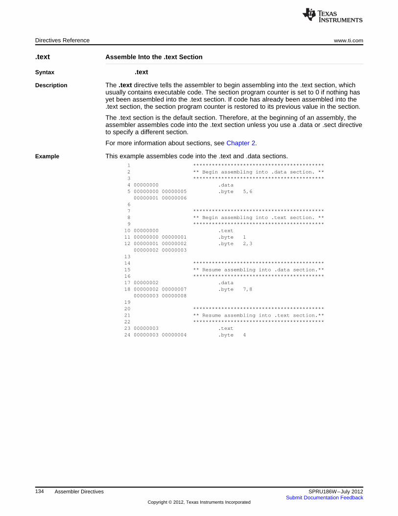
Directives Reference www.ti.com
.text Assemble Into the .text Section
Syntax .text
Description The .text directive tells the assembler to begin assembling into the .text section, whichusually contains executable code. The section program counter is set to 0 if nothing hasyet been assembled into the .text section. If code has already been assembled into the.text section, the section program counter is restored to its previous value in the section.
The .text section is the default section. Therefore, at the beginning of an assembly, theassembler assembles code into the .text section unless you use a .data or .sect directiveto specify a different section.
For more information about sections, see Chapter 2.
Example This example assembles code into the .text and .data sections.1 ******************************************2 ** Begin assembling into .data section. **3 ******************************************4 00000000 .data5 00000000 00000005 .byte 5,600000001 00000006
67 ******************************************8 ** Begin assembling into .text section. **9 ******************************************
10 00000000 .text11 00000000 00000001 .byte 112 00000001 00000002 .byte 2,3
00000002 000000031314 ******************************************15 ** Resume assembling into .data section.**16 ******************************************17 00000002 .data18 00000002 00000007 .byte 7,8
00000003 000000081920 ******************************************21 ** Resume assembling into .text section.**22 ******************************************23 00000003 .text24 00000003 00000004 .byte 4
134 Assembler Directives SPRU186W–July 2012Submit Documentation Feedback
Copyright © 2012, Texas Instruments Incorporated
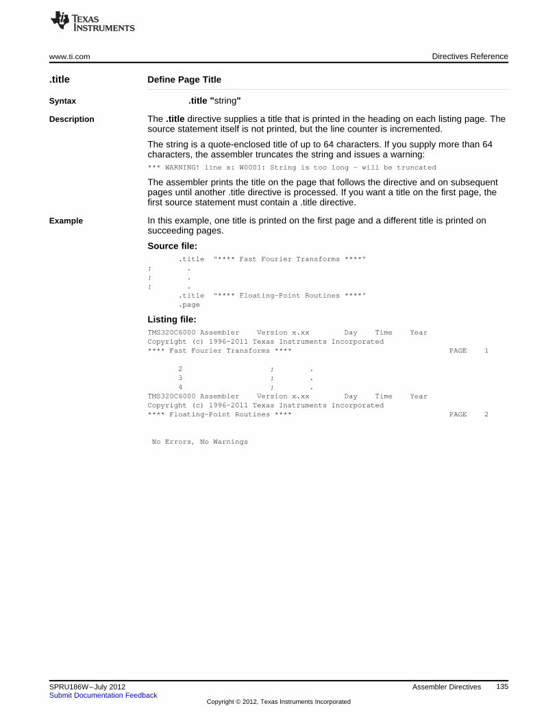
www.ti.com Directives Reference
.title Define Page Title
Syntax .title "string"
Description The .title directive supplies a title that is printed in the heading on each listing page. Thesource statement itself is not printed, but the line counter is incremented.
The string is a quote-enclosed title of up to 64 characters. If you supply more than 64characters, the assembler truncates the string and issues a warning:*** WARNING! line x: W0001: String is too long - will be truncated
The assembler prints the title on the page that follows the directive and on subsequentpages until another .title directive is processed. If you want a title on the first page, thefirst source statement must contain a .title directive.
Example In this example, one title is printed on the first page and a different title is printed onsucceeding pages.
Source file:.title "**** Fast Fourier Transforms ****"
; .; .; .
.title "**** Floating-Point Routines ****"
.page
Listing file:TMS320C6000 Assembler Version x.xx Day Time YearCopyright (c) 1996-2011 Texas Instruments Incorporated**** Fast Fourier Transforms **** PAGE 1
2 ; .3 ; .4 ; .
TMS320C6000 Assembler Version x.xx Day Time YearCopyright (c) 1996-2011 Texas Instruments Incorporated**** Floating-Point Routines **** PAGE 2
No Errors, No Warnings
135SPRU186W–July 2012 Assembler DirectivesSubmit Documentation Feedback
Copyright © 2012, Texas Instruments Incorporated
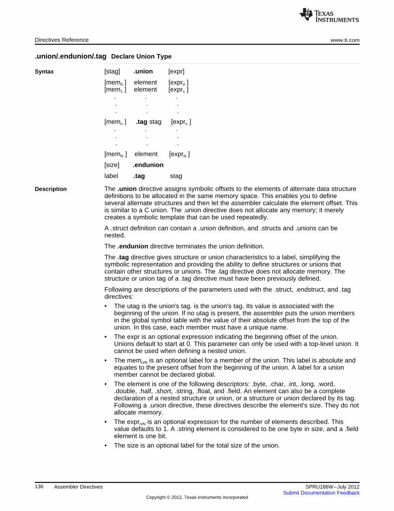
Directives Reference www.ti.com
.union/.endunion/.tag Declare Union Type
Syntax [stag] .union [expr]
[mem0 ] element [expr0 ][mem1 ] element [expr1 ]
. . .. . .. . .
[memn ] .tag stag [exprn ]. . .. . .. . .
[memN ] element [exprN ]
[size] .endunion
label .tag stag
Description The .union directive assigns symbolic offsets to the elements of alternate data structuredefinitions to be allocated in the same memory space. This enables you to defineseveral alternate structures and then let the assembler calculate the element offset. Thisis similar to a C union. The .union directive does not allocate any memory; it merelycreates a symbolic template that can be used repeatedly.
A .struct definition can contain a .union definition, and .structs and .unions can benested.
The .endunion directive terminates the union definition.
The .tag directive gives structure or union characteristics to a label, simplifying thesymbolic representation and providing the ability to define structures or unions thatcontain other structures or unions. The .tag directive does not allocate memory. Thestructure or union tag of a .tag directive must have been previously defined.
Following are descriptions of the parameters used with the .struct, .endstruct, and .tagdirectives:
• The utag is the union's tag. is the union's tag. Its value is associated with thebeginning of the union. If no utag is present, the assembler puts the union membersin the global symbol table with the value of their absolute offset from the top of theunion. In this case, each member must have a unique name.
• The expr is an optional expression indicating the beginning offset of the union.Unions default to start at 0. This parameter can only be used with a top-level union. Itcannot be used when defining a nested union.
• The memn/N is an optional label for a member of the union. This label is absolute andequates to the present offset from the beginning of the union. A label for a unionmember cannot be declared global.
• The element is one of the following descriptors: .byte, .char, .int, .long, .word,.double, .half, .short, .string, .float, and .field. An element can also be a completedeclaration of a nested structure or union, or a structure or union declared by its tag.Following a .union directive, these directives describe the element's size. They do notallocate memory.
• The exprn/N is an optional expression for the number of elements described. Thisvalue defaults to 1. A .string element is considered to be one byte in size, and a .fieldelement is one bit.
• The size is an optional label for the total size of the union.
136 Assembler Directives SPRU186W–July 2012Submit Documentation Feedback
Copyright © 2012, Texas Instruments Incorporated
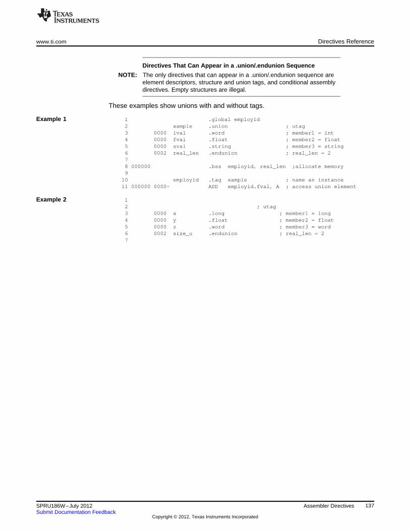
www.ti.com Directives Reference
Directives That Can Appear in a .union/.endunion Sequence
NOTE: The only directives that can appear in a .union/.endunion sequence areelement descriptors, structure and union tags, and conditional assemblydirectives. Empty structures are illegal.
These examples show unions with and without tags.
Example 1 1 .global employid2 xample .union ; utag3 0000 ival .word ; member1 = int4 0000 fval .float ; member2 = float5 0000 sval .string ; member3 = string6 0002 real_len .endunion ; real_len = 278 000000 .bss employid, real_len ;allocate memory9
10 employid .tag xample ; name an instance11 000000 0000- ADD employid.fval, A ; access union element
Example 2 12 ; utag3 0000 x .long ; member1 = long4 0000 y .float ; member2 = float5 0000 z .word ; member3 = word6 0002 size_u .endunion ; real_len = 27
137SPRU186W–July 2012 Assembler DirectivesSubmit Documentation Feedback
Copyright © 2012, Texas Instruments Incorporated
Directives Reference www.ti.com
.usect Reserve Uninitialized Space
Syntax symbol .usect "section name", size in bytes[, alignment[, bank offset] ]
Description The .usect directive reserves space for variables in an uninitialized, named section. Thisdirective is similar to the .bss directive; both simply reserve space for data and thatspace has no contents. However, .usect defines additional sections that can be placedanywhere in memory, independently of the .bss section.
• The symbol points to the first location reserved by this invocation of the .usectdirective. The symbol corresponds to the name of the variable for which you arereserving space.
• The section name must be enclosed in double quotes. This parameter names theuninitialized section. A section name can contain a subsection name in the formsection name : subsection name.
• The size in bytes is an expression that defines the number of bytes that are reservedin section name.
• The alignment is an optional parameter that ensures that the space allocated to thesymbol occurs on the specified boundary. This boundary indicates the size of the slotin bytes and must be set to a power of 2.
• The bank offset is an optional parameter that ensures that the space allocated to thesymbol occurs on a specific memory bank boundary. The bank offset value measuresthe number of bytes to offset from the alignment specified before assigning thesymbol to that location.
Initialized sections directives (.text, .data, and .sect) end the current section and tell theassembler to begin assembling into another section. A .usect or .bss directiveencountered in the current section is simply assembled, and assembly continues in thecurrent section.
Variables that can be located contiguously in memory can be defined in the samespecified section; to do so, repeat the .usect directive with the same section name andthe subsequent symbol (variable name).
For more information about sections, see Chapter 2.
Example This example uses the .usect directive to define two uninitialized, named sections, var1and var2. The symbol ptr points to the first byte reserved in the var1 section. The symbolarray points to the first byte in a block of 100 bytes reserved in var1, and dflag points tothe first byte in a block of 50 bytes in var1. The symbol vec points to the first bytereserved in the var2 section.
138 Assembler Directives SPRU186W–July 2012Submit Documentation Feedback
Copyright © 2012, Texas Instruments Incorporated
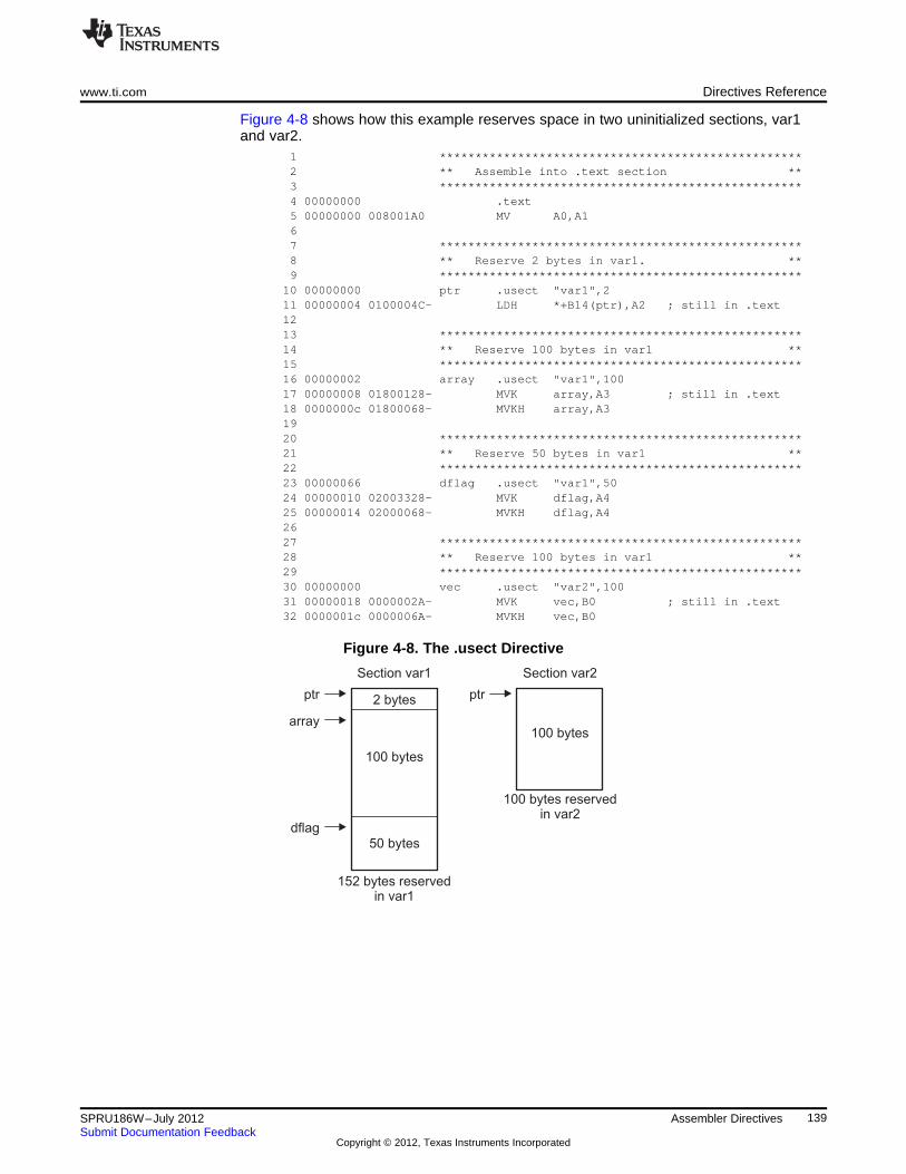
2 bytes
100 bytes
50 bytes
array
ptr
dflag
Section var1
152 bytes reservedin var1
100 bytes
ptr
Section var2
100 bytes reservedin var2
www.ti.com Directives Reference
Figure 4-8 shows how this example reserves space in two uninitialized sections, var1and var2.
1 ***************************************************2 ** Assemble into .text section **3 ***************************************************4 00000000 .text5 00000000 008001A0 MV A0,A167 ***************************************************8 ** Reserve 2 bytes in var1. **9 ***************************************************
10 00000000 ptr .usect "var1",211 00000004 0100004C- LDH *+B14(ptr),A2 ; still in .text1213 ***************************************************14 ** Reserve 100 bytes in var1 **15 ***************************************************16 00000002 array .usect "var1",10017 00000008 01800128- MVK array,A3 ; still in .text18 0000000c 01800068- MVKH array,A31920 ***************************************************21 ** Reserve 50 bytes in var1 **22 ***************************************************23 00000066 dflag .usect "var1",5024 00000010 02003328- MVK dflag,A425 00000014 02000068- MVKH dflag,A42627 ***************************************************28 ** Reserve 100 bytes in var1 **29 ***************************************************30 00000000 vec .usect "var2",10031 00000018 0000002A- MVK vec,B0 ; still in .text32 0000001c 0000006A- MVKH vec,B0
Figure 4-8. The .usect Directive
139SPRU186W–July 2012 Assembler DirectivesSubmit Documentation Feedback
Copyright © 2012, Texas Instruments Incorporated
Directives Reference www.ti.com
.unasg/.undefine Turn Off Substitution Symbol
Syntax .unasg symbol
.undefine symbol
Description The .unasg and .undefine directives remove the definition of a substitution symbolcreated using .asg or .define. The named symbol will removed from the substitutionsymbol table from the point of the .undefine or .unasg to the end of the assembly file.See Section 3.9.8 for more information on substitution symbols.
These directives can be used to remove from the assembly environment any C/C++macros that may cause a problem. See Chapter 12 for more information about usingC/C++ headers in assembly source.
.var Use Substitution Symbols as Local Variables
Syntax .var sym1 [, sym2 , ... , symn ]
Description The .var directive allows you to use substitution symbols as local variables within amacro. With this directive, you can define up to 32 local macro substitution symbols(including parameters) per macro.
The .var directive creates temporary substitution symbols with the initial value of the nullstring. These symbols are not passed in as parameters, and they are lost afterexpansion.
See Section 3.9.8 for more information on substitution symbols .See Chapter 5 forinformation on macros.
140 Assembler Directives SPRU186W–July 2012Submit Documentation Feedback
Copyright © 2012, Texas Instruments Incorporated
Chapter 5SPRU186W–July 2012
Macro Description
The TMS320C6000 assembler supports a macro language that enables you to create your owninstructions. This is especially useful when a program executes a particular task several times. The macrolanguage lets you:
• Define your own macros and redefine existing macros
• Simplify long or complicated assembly code
• Access macro libraries created with the archiver
• Define conditional and repeatable blocks within a macro
• Manipulate strings within a macro
• Control expansion listing
Topic ........................................................................................................................... Page
5.1 Using Macros .................................................................................................. 1425.2 Defining Macros .............................................................................................. 1425.3 Macro Parameters/Substitution Symbols ............................................................ 1445.4 Macro Libraries ............................................................................................... 1495.5 Using Conditional Assembly in Macros .............................................................. 1505.6 Using Labels in Macros .................................................................................... 1525.7 Producing Messages in Macros ......................................................................... 1535.8 Using Directives to Format the Output Listing .................................................... 1545.9 Using Recursive and Nested Macros .................................................................. 1555.10 Macro Directives Summary ............................................................................... 157
141SPRU186W–July 2012 Macro DescriptionSubmit Documentation Feedback
Copyright © 2012, Texas Instruments Incorporated
Using Macros www.ti.com
5.1 Using Macros
Programs often contain routines that are executed several times. Instead of repeating the sourcestatements for a routine, you can define the routine as a macro, then call the macro in the places whereyou would normally repeat the routine. This simplifies and shortens your source program.
If you want to call a macro several times but with different data each time, you can assign parameterswithin a macro. This enables you to pass different information to the macro each time you call it. Themacro language supports a special symbol called a substitution symbol, which is used for macroparameters. See Section 5.3 for more information.
Using a macro is a 3-step process.
Step 1. Define the macro. You must define macros before you can use them in your program. Thereare two methods for defining macros:
(a) Macros can be defined at the beginning of a source file or in a copy/include file. SeeSection 5.2, Defining Macros, for more information.
(b) Macros can also be defined in a macro library. A macro library is a collection of files inarchive format created by the archiver. Each member of the archive file (macro library)may contain one macro definition corresponding to the member name. You can access amacro library by using the .mlib directive. For more information, see Section 5.4.
Step 2. Call the macro. After you have defined a macro, call it by using the macro name as amnemonic in the source program. This is referred to as a macro call.
Step 3. Expand the macro. The assembler expands your macros when the source program callsthem. During expansion, the assembler passes arguments by variable to the macroparameters, replaces the macro call statement with the macro definition, then assembles thesource code. By default, the macro expansions are printed in the listing file. You can turn offexpansion listing by using the .mnolist directive. For more information, see Section 5.8.
When the assembler encounters a macro definition, it places the macro name in the opcode table. Thisredefines any previously defined macro, library entry, directive, or instruction mnemonic that has the samename as the macro. This allows you to expand the functions of directives and instructions, as well as toadd new instructions.
5.2 Defining Macros
You can define a macro anywhere in your program, but you must define the macro before you can use it.Macros can be defined at the beginning of a source file or in a .copy/.include file (see Copy Source File);they can also be defined in a macro library. For more information about macro libraries, see Section 5.4.
Macro definitions can be nested, and they can call other macros, but all elements of the macro must bedefined in the same file. Nested macros are discussed in Section 5.9.
A macro definition is a series of source statements in the following format:
macname .macro [parameter1 ] [, ... , parametern ]
model statements or macro directives
[.mexit]
.endm
macname names the macro. You must place the name in the source statement's label field.Only the first 128 characters of a macro name are significant. The assemblerplaces the macro name in the internal opcode table, replacing any instruction orprevious macro definition with the same name.
.macro is the directive that identifies the source statement as the first line of a macrodefinition. You must place .macro in the opcode field.
parameter 1, are optional substitution symbols that appear as operands for the .macro directive.parameter n Parameters are discussed in Section 5.3.
142 Macro Description SPRU186W–July 2012Submit Documentation Feedback
Copyright © 2012, Texas Instruments Incorporated
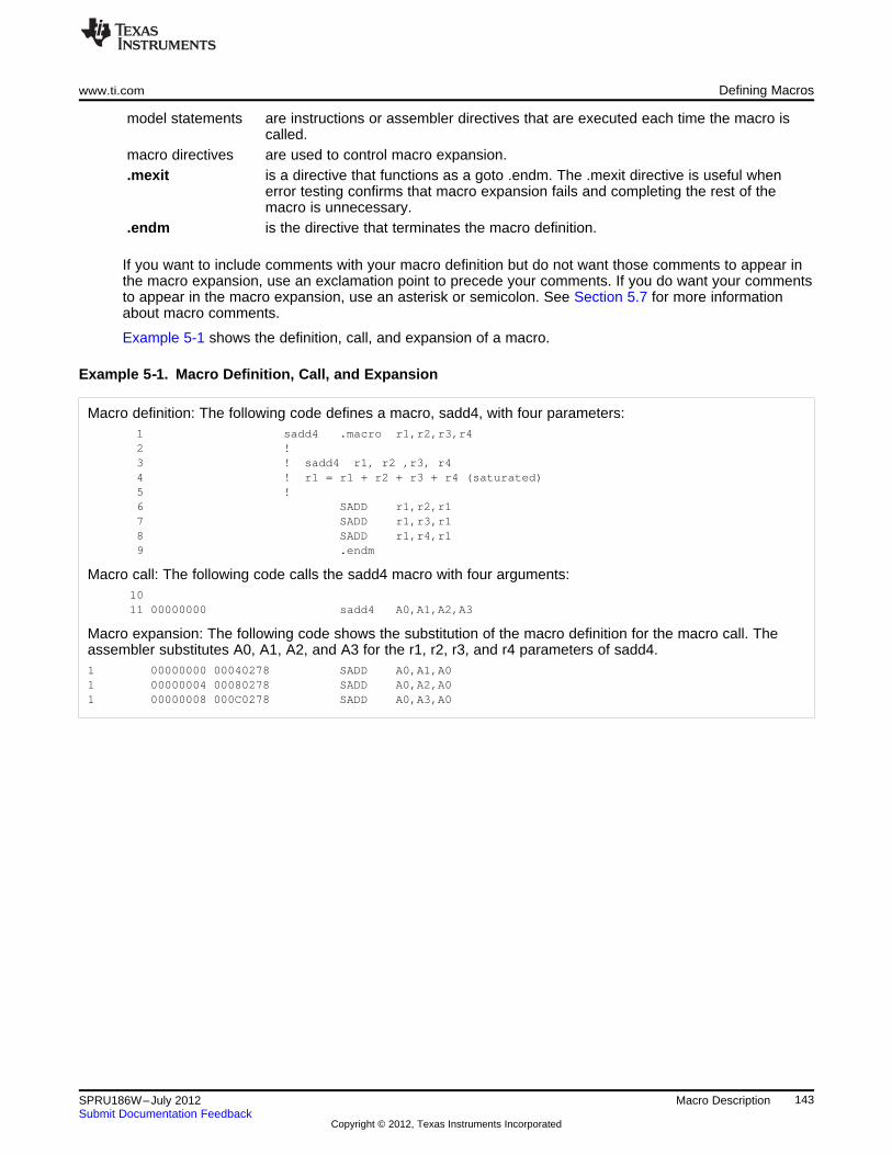
www.ti.com Defining Macros
model statements are instructions or assembler directives that are executed each time the macro iscalled.
macro directives are used to control macro expansion..mexit is a directive that functions as a goto .endm. The .mexit directive is useful when
error testing confirms that macro expansion fails and completing the rest of themacro is unnecessary.
.endm is the directive that terminates the macro definition.
If you want to include comments with your macro definition but do not want those comments to appear inthe macro expansion, use an exclamation point to precede your comments. If you do want your commentsto appear in the macro expansion, use an asterisk or semicolon. See Section 5.7 for more informationabout macro comments.
Example 5-1 shows the definition, call, and expansion of a macro.
Example 5‑‑1. Macro Definition, Call, and Expansion
Macro definition: The following code defines a macro, sadd4, with four parameters:1 sadd4 .macro r1,r2,r3,r42 !3 ! sadd4 r1, r2 ,r3, r44 ! r1 = r1 + r2 + r3 + r4 (saturated)5 !6 SADD r1,r2,r17 SADD r1,r3,r18 SADD r1,r4,r19 .endm
Macro call: The following code calls the sadd4 macro with four arguments:1011 00000000 sadd4 A0,A1,A2,A3
Macro expansion: The following code shows the substitution of the macro definition for the macro call. Theassembler substitutes A0, A1, A2, and A3 for the r1, r2, r3, and r4 parameters of sadd4.1 00000000 00040278 SADD A0,A1,A01 00000004 00080278 SADD A0,A2,A01 00000008 000C0278 SADD A0,A3,A0
143SPRU186W–July 2012 Macro DescriptionSubmit Documentation Feedback
Copyright © 2012, Texas Instruments Incorporated
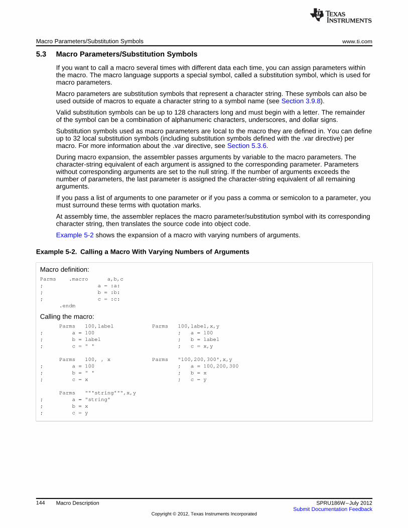
Macro Parameters/Substitution Symbols www.ti.com
5.3 Macro Parameters/Substitution Symbols
If you want to call a macro several times with different data each time, you can assign parameters withinthe macro. The macro language supports a special symbol, called a substitution symbol, which is used formacro parameters.
Macro parameters are substitution symbols that represent a character string. These symbols can also beused outside of macros to equate a character string to a symbol name (see Section 3.9.8).
Valid substitution symbols can be up to 128 characters long and must begin with a letter. The remainderof the symbol can be a combination of alphanumeric characters, underscores, and dollar signs.
Substitution symbols used as macro parameters are local to the macro they are defined in. You can defineup to 32 local substitution symbols (including substitution symbols defined with the .var directive) permacro. For more information about the .var directive, see Section 5.3.6.
During macro expansion, the assembler passes arguments by variable to the macro parameters. Thecharacter-string equivalent of each argument is assigned to the corresponding parameter. Parameterswithout corresponding arguments are set to the null string. If the number of arguments exceeds thenumber of parameters, the last parameter is assigned the character-string equivalent of all remainingarguments.
If you pass a list of arguments to one parameter or if you pass a comma or semicolon to a parameter, youmust surround these terms with quotation marks.
At assembly time, the assembler replaces the macro parameter/substitution symbol with its correspondingcharacter string, then translates the source code into object code.
Example 5-2 shows the expansion of a macro with varying numbers of arguments.
Example 5-2. Calling a Macro With Varying Numbers of Arguments
Macro definition:Parms .macro a,b,c; a = :a:; b = :b:; c = :c:
.endm
Calling the macro:Parms 100,label Parms 100,label,x,y
; a = 100 ; a = 100; b = label ; b = label; c = " " ; c = x,y
Parms 100, , x Parms "100,200,300",x,y; a = 100 ; a = 100,200,300; b = " " ; b = x; c = x ; c = y
Parms """string""",x,y; a = "string"; b = x; c = y
144 Macro Description SPRU186W–July 2012Submit Documentation Feedback
Copyright © 2012, Texas Instruments Incorporated
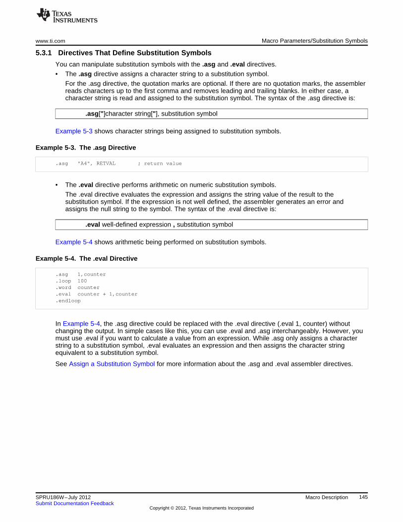
www.ti.com Macro Parameters/Substitution Symbols
5.3.1 Directives That Define Substitution Symbols
You can manipulate substitution symbols with the .asg and .eval directives.
• The .asg directive assigns a character string to a substitution symbol.
For the .asg directive, the quotation marks are optional. If there are no quotation marks, the assemblerreads characters up to the first comma and removes leading and trailing blanks. In either case, acharacter string is read and assigned to the substitution symbol. The syntax of the .asg directive is:
.asg["]character string["], substitution symbol
Example 5-3 shows character strings being assigned to substitution symbols.
Example 5-3. The .asg Directive
.asg "A4", RETVAL ; return value
• The .eval directive performs arithmetic on numeric substitution symbols.
The .eval directive evaluates the expression and assigns the string value of the result to thesubstitution symbol. If the expression is not well defined, the assembler generates an error andassigns the null string to the symbol. The syntax of the .eval directive is:
.eval well-defined expression , substitution symbol
Example 5-4 shows arithmetic being performed on substitution symbols.
Example 5-4. The .eval Directive
.asg 1,counter
.loop 100
.word counter
.eval counter + 1,counter
.endloop
In Example 5-4, the .asg directive could be replaced with the .eval directive (.eval 1, counter) withoutchanging the output. In simple cases like this, you can use .eval and .asg interchangeably. However, youmust use .eval if you want to calculate a value from an expression. While .asg only assigns a characterstring to a substitution symbol, .eval evaluates an expression and then assigns the character stringequivalent to a substitution symbol.
See Assign a Substitution Symbol for more information about the .asg and .eval assembler directives.
145SPRU186W–July 2012 Macro DescriptionSubmit Documentation Feedback
Copyright © 2012, Texas Instruments Incorporated
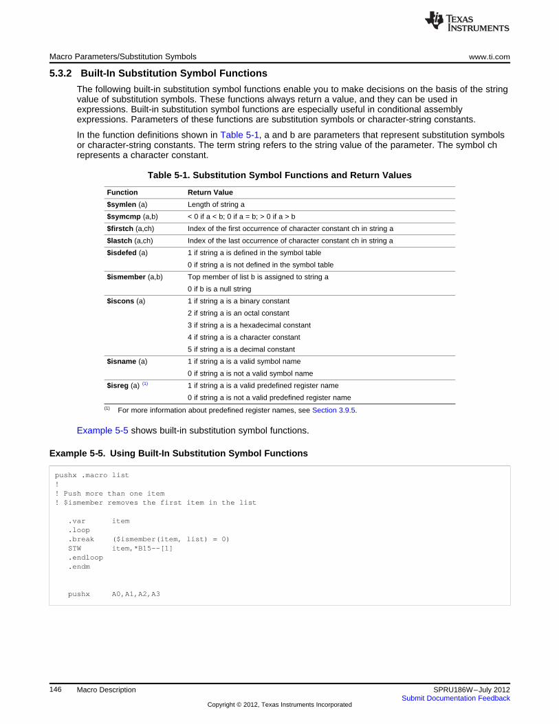
Macro Parameters/Substitution Symbols www.ti.com
5.3.2 Built-In Substitution Symbol Functions
The following built-in substitution symbol functions enable you to make decisions on the basis of the stringvalue of substitution symbols. These functions always return a value, and they can be used inexpressions. Built-in substitution symbol functions are especially useful in conditional assemblyexpressions. Parameters of these functions are substitution symbols or character-string constants.
In the function definitions shown in Table 5-1, a and b are parameters that represent substitution symbolsor character-string constants. The term string refers to the string value of the parameter. The symbol chrepresents a character constant.
Table 5-1. Substitution Symbol Functions and Return Values
Function Return Value
$symlen (a) Length of string a
$symcmp (a,b) < 0 if a < b; 0 if a = b; > 0 if a > b
$firstch (a,ch) Index of the first occurrence of character constant ch in string a
$lastch (a,ch) Index of the last occurrence of character constant ch in string a
$isdefed (a) 1 if string a is defined in the symbol table
0 if string a is not defined in the symbol table
$ismember (a,b) Top member of list b is assigned to string a
0 if b is a null string
$iscons (a) 1 if string a is a binary constant
2 if string a is an octal constant
3 if string a is a hexadecimal constant
4 if string a is a character constant
5 if string a is a decimal constant
$isname (a) 1 if string a is a valid symbol name
0 if string a is not a valid symbol name
$isreg (a) (1) 1 if string a is a valid predefined register name
0 if string a is not a valid predefined register name(1) For more information about predefined register names, see Section 3.9.5.
Example 5-5 shows built-in substitution symbol functions.
Example 5‑‑5. Using Built-In Substitution Symbol Functions
pushx .macro list!! Push more than one item! $ismember removes the first item in the list
.var item
.loop
.break ($ismember(item, list) = 0)STW item,*B15--[1].endloop.endm
pushx A0,A1,A2,A3
146 Macro Description SPRU186W–July 2012Submit Documentation Feedback
Copyright © 2012, Texas Instruments Incorporated
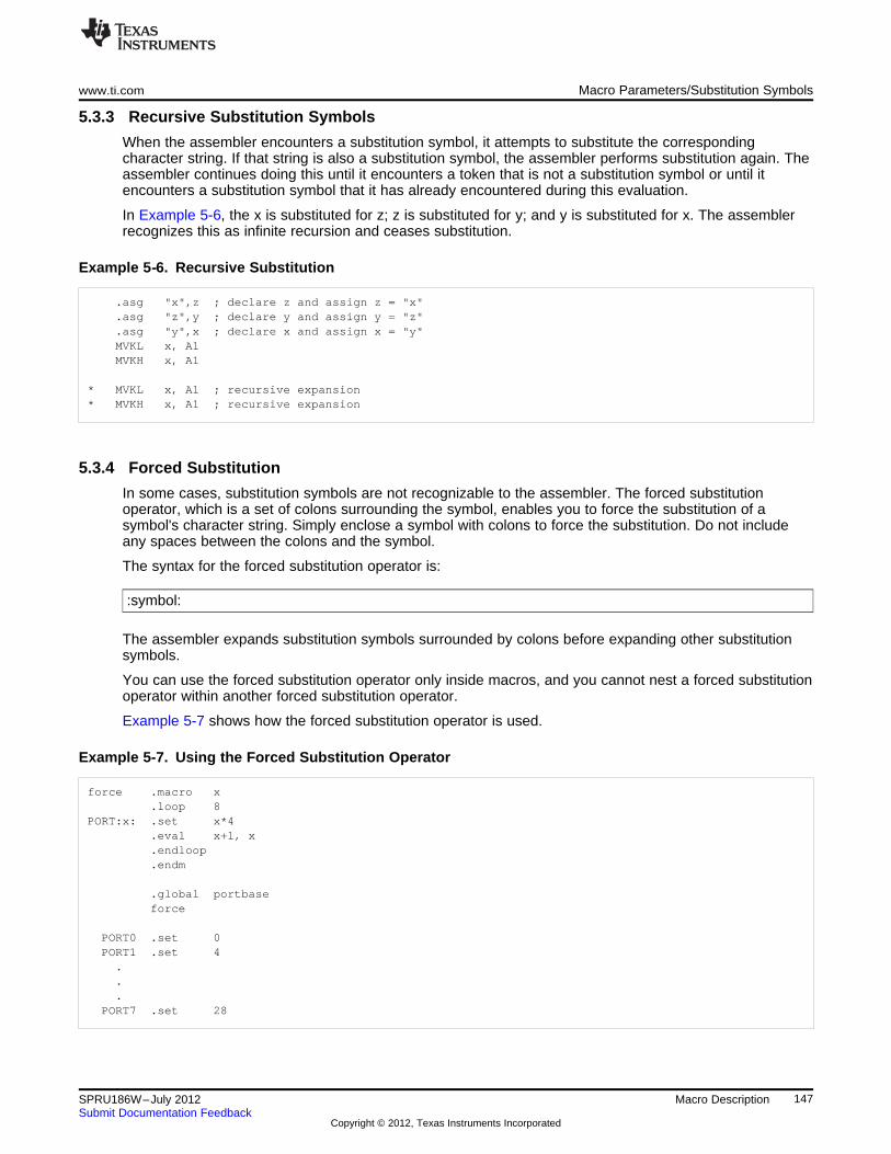
www.ti.com Macro Parameters/Substitution Symbols
5.3.3 Recursive Substitution Symbols
When the assembler encounters a substitution symbol, it attempts to substitute the correspondingcharacter string. If that string is also a substitution symbol, the assembler performs substitution again. Theassembler continues doing this until it encounters a token that is not a substitution symbol or until itencounters a substitution symbol that it has already encountered during this evaluation.
In Example 5-6, the x is substituted for z; z is substituted for y; and y is substituted for x. The assemblerrecognizes this as infinite recursion and ceases substitution.
Example 5‑‑6. Recursive Substitution
.asg "x",z ; declare z and assign z = "x"
.asg "z",y ; declare y and assign y = "z"
.asg "y",x ; declare x and assign x = "y"MVKL x, A1MVKH x, A1
* MVKL x, A1 ; recursive expansion* MVKH x, A1 ; recursive expansion
5.3.4 Forced Substitution
In some cases, substitution symbols are not recognizable to the assembler. The forced substitutionoperator, which is a set of colons surrounding the symbol, enables you to force the substitution of asymbol's character string. Simply enclose a symbol with colons to force the substitution. Do not includeany spaces between the colons and the symbol.
The syntax for the forced substitution operator is:
:symbol:
The assembler expands substitution symbols surrounded by colons before expanding other substitutionsymbols.
You can use the forced substitution operator only inside macros, and you cannot nest a forced substitutionoperator within another forced substitution operator.
Example 5-7 shows how the forced substitution operator is used.
Example 5-7. Using the Forced Substitution Operator
force .macro x.loop 8
PORT:x: .set x*4.eval x+1, x.endloop.endm
.global portbaseforce
PORT0 .set 0PORT1 .set 4...
PORT7 .set 28
147SPRU186W–July 2012 Macro DescriptionSubmit Documentation Feedback
Copyright © 2012, Texas Instruments Incorporated
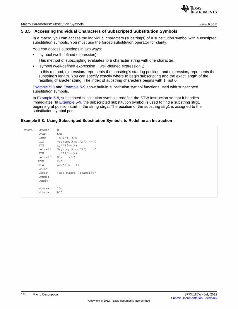
Macro Parameters/Substitution Symbols www.ti.com
5.3.5 Accessing Individual Characters of Subscripted Substitution Symbols
In a macro, you can access the individual characters (substrings) of a substitution symbol with subscriptedsubstitution symbols. You must use the forced substitution operator for clarity.
You can access substrings in two ways:
• :symbol (well-defined expression):
This method of subscripting evaluates to a character string with one character.
• :symbol (well-defined expression 1, well-defined expression 2):
In this method, expression1 represents the substring's starting position, and expression2 represents thesubstring's length. You can specify exactly where to begin subscripting and the exact length of theresulting character string. The index of substring characters begins with 1, not 0.
Example 5-8 and Example 5-9 show built-in substitution symbol functions used with subscriptedsubstitution symbols.
In Example 5-8, subscripted substitution symbols redefine the STW instruction so that it handlesimmediates. In Example 5-9, the subscripted substitution symbol is used to find a substring strg1beginning at position start in the string strg2. The position of the substring strg1 is assigned to thesubstitution symbol pos.
Example 5‑‑8. Using Subscripted Substitution Symbols to Redefine an Instruction
storex .macro x.var tmp.asg :x(1):, tmp.if $symcmp(tmp,"A") == 0STW x,*A15--(4).elseif $symcmp(tmp,"B") == 0STW x,*A15--(4).elseif $iscons(x)MVK x,A0STW A0,*A15--(4).else.emsg "Bad Macro Parameter".endif.endm
storex 10hstorex A15
148 Macro Description SPRU186W–July 2012Submit Documentation Feedback
Copyright © 2012, Texas Instruments Incorporated
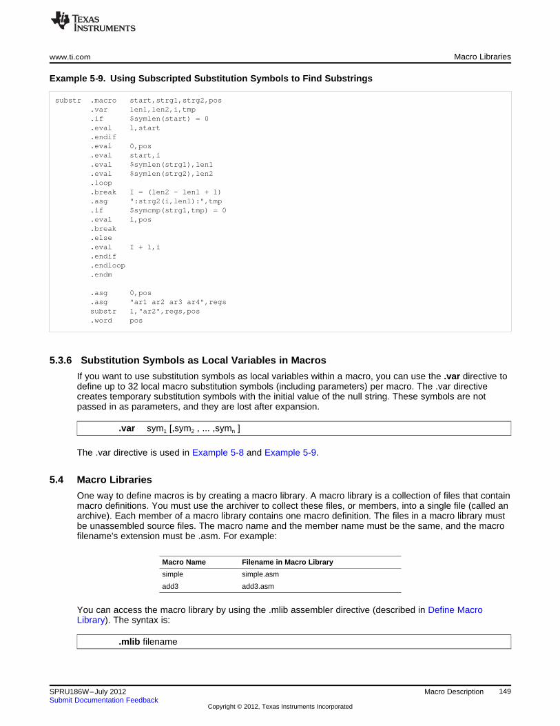
www.ti.com Macro Libraries
Example 5‑‑9. Using Subscripted Substitution Symbols to Find Substrings
substr .macro start,strg1,strg2,pos.var len1,len2,i,tmp.if $symlen(start) = 0.eval 1,start.endif.eval 0,pos.eval start,i.eval $symlen(strg1),len1.eval $symlen(strg2),len2.loop.break I = (len2 - len1 + 1).asg ":strg2(i,len1):",tmp.if $symcmp(strg1,tmp) = 0.eval i,pos.break.else.eval I + 1,i.endif.endloop.endm
.asg 0,pos
.asg "ar1 ar2 ar3 ar4",regssubstr 1,"ar2",regs,pos.word pos
5.3.6 Substitution Symbols as Local Variables in Macros
If you want to use substitution symbols as local variables within a macro, you can use the .var directive todefine up to 32 local macro substitution symbols (including parameters) per macro. The .var directivecreates temporary substitution symbols with the initial value of the null string. These symbols are notpassed in as parameters, and they are lost after expansion.
.var sym1 [,sym2 , ... ,symn ]
The .var directive is used in Example 5-8 and Example 5-9.
5.4 Macro Libraries
One way to define macros is by creating a macro library. A macro library is a collection of files that containmacro definitions. You must use the archiver to collect these files, or members, into a single file (called anarchive). Each member of a macro library contains one macro definition. The files in a macro library mustbe unassembled source files. The macro name and the member name must be the same, and the macrofilename's extension must be .asm. For example:
Macro Name Filename in Macro Library
simple simple.asm
add3 add3.asm
You can access the macro library by using the .mlib assembler directive (described in Define MacroLibrary). The syntax is:
.mlib filename
149SPRU186W–July 2012 Macro DescriptionSubmit Documentation Feedback
Copyright © 2012, Texas Instruments Incorporated
Using Conditional Assembly in Macros www.ti.com
When the assembler encounters the .mlib directive, it opens the library named by filename and creates atable of the library's contents. The assembler enters the names of the individual members within the libraryinto the opcode tables as library entries; this redefines any existing opcodes or macros that have the samename. If one of these macros is called, the assembler extracts the entry from the library and loads it intothe macro table.
The assembler expands the library entry in the same way it expands other macros. See Section 5.1 forhow the assembler expands macros. You can control the listing of library entry expansions with the .mlistdirective. For more information about the .mlist directive, see Section 5.8 and Start/Stop Macro ExpansionListing. Only macros that are actually called from the library are extracted, and they are extracted onlyonce.
You can use the archiver to create a macro library by including the desired files in an archive. A macrolibrary is no different from any other archive, except that the assembler expects the macro library tocontain macro definitions. The assembler expects only macro definitions in a macro library; putting objectcode or miscellaneous source files into the library may produce undesirable results. For information aboutcreating a macro library archive, see Section 6.1.
5.5 Using Conditional Assembly in Macros
The conditional assembly directives are .if/.elseif/.else/.endif and .loop/ .break/.endloop. They can benested within each other up to 32 levels deep. The format of a conditional block is:
.if well-defined expression
[.elseif well-defined expression]
[.else]
.endif
The .elseif and .else directives are optional in conditional assembly. The .elseif directive can be usedmore than once within a conditional assembly code block. When .elseif and .else are omitted and whenthe .if expression is false (0), the assembler continues to the code following the .endif directive. SeeAssemble Conditional Blocks for more information on the .if/ .elseif/.else/.endif directives.
The .loop/.break/.endloop directives enable you to assemble a code block repeatedly. The format of arepeatable block is:
.loop [well-defined expression]
[.break [well-defined expression]]
.endloop
The .loop directive's optional well-defined expression evaluates to the loop count (the number of loops tobe performed). If the expression is omitted, the loop count defaults to 1024 unless the assemblerencounters a .break directive with an expression that is true (nonzero). See Assemble Conditional BlocksRepeatedly for more information on the .loop/.break/.endloop directives.
The .break directive and its expression are optional in repetitive assembly. If the expression evaluates tofalse, the loop continues. The assembler breaks the loop when the .break expression evaluates to true orwhen the .break expression is omitted. When the loop is broken, the assembler continues with the codeafter the .endloop directive.
For more information, see Section 4.7.
Example 5-10, Example 5-11, and Example 5-12 show the .loop/.break/ .endloop directives, properlynested conditional assembly directives, and built-in substitution symbol functions used in a conditionalassembly code block.
150 Macro Description SPRU186W–July 2012Submit Documentation Feedback
Copyright © 2012, Texas Instruments Incorporated
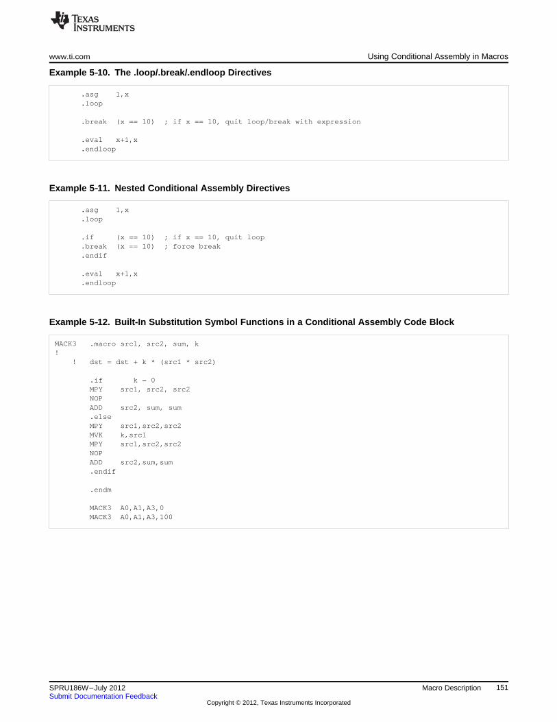
www.ti.com Using Conditional Assembly in Macros
Example 5‑‑10. The .loop/.break/.endloop Directives
.asg 1,x
.loop
.break (x == 10) ; if x == 10, quit loop/break with expression
.eval x+1,x
.endloop
Example 5‑‑11. Nested Conditional Assembly Directives
.asg 1,x
.loop
.if (x == 10) ; if x == 10, quit loop
.break (x == 10) ; force break
.endif
.eval x+1,x
.endloop
Example 5‑‑12. Built-In Substitution Symbol Functions in a Conditional Assembly Code Block
MACK3 .macro src1, src2, sum, k!
! dst = dst + k * (src1 * src2)
.if k = 0MPY src1, src2, src2NOPADD src2, sum, sum.elseMPY src1,src2,src2MVK k,src1MPY src1,src2,src2NOPADD src2,sum,sum.endif
.endm
MACK3 A0,A1,A3,0MACK3 A0,A1,A3,100
151SPRU186W–July 2012 Macro DescriptionSubmit Documentation Feedback
Copyright © 2012, Texas Instruments Incorporated
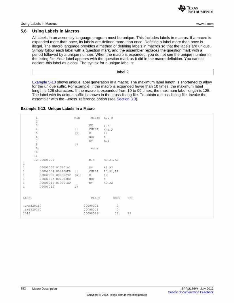
Using Labels in Macros www.ti.com
5.6 Using Labels in Macros
All labels in an assembly language program must be unique. This includes labels in macros. If a macro isexpanded more than once, its labels are defined more than once. Defining a label more than once isillegal. The macro language provides a method of defining labels in macros so that the labels are unique.Simply follow each label with a question mark, and the assembler replaces the question mark with aperiod followed by a unique number. When the macro is expanded, you do not see the unique number inthe listing file. Your label appears with the question mark as it did in the macro definition. You cannotdeclare this label as global. The syntax for a unique label is:
label ?
Example 5-13 shows unique label generation in a macro. The maximum label length is shortened to allowfor the unique suffix. For example, if the macro is expanded fewer than 10 times, the maximum labellength is 126 characters. If the macro is expanded from 10 to 99 times, the maximum label length is 125.The label with its unique suffix is shown in the cross-listing file. To obtain a cross-listing file, invoke theassembler with the --cross_reference option (see Section 3.3).
Example 5‑‑13. Unique Labels in a Macro
1 min .macro x,y,z23 MV y,z4 || CMPLT x,y,y5 [y] B l?6 NOP 57 MV x,z8 l?9 .endm101112 00000000 MIN A0,A1,A2
11 00000000 010401A1 MV A1,A21 00000004 00840AF8 || CMPLT A0,A1,A11 00000008 80000292 [A1] B l?1 0000000c 00008000 NOP 51 00000010 010001A0 MV A0,A21 00000014 l?
LABEL VALUE DEFN REF
.TMS320C60 00000001 0
.tms320C60 00000001 0l$1$ 00000014' 12 12
152 Macro Description SPRU186W–July 2012Submit Documentation Feedback
Copyright © 2012, Texas Instruments Incorporated
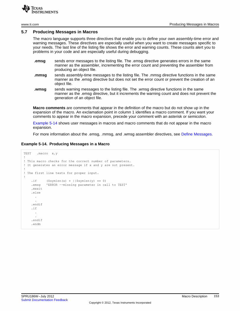
www.ti.com Producing Messages in Macros
5.7 Producing Messages in Macros
The macro language supports three directives that enable you to define your own assembly-time error andwarning messages. These directives are especially useful when you want to create messages specific toyour needs. The last line of the listing file shows the error and warning counts. These counts alert you toproblems in your code and are especially useful during debugging.
.emsg sends error messages to the listing file. The .emsg directive generates errors in the samemanner as the assembler, incrementing the error count and preventing the assembler fromproducing an object file.
.mmsg sends assembly-time messages to the listing file. The .mmsg directive functions in the samemanner as the .emsg directive but does not set the error count or prevent the creation of anobject file.
.wmsg sends warning messages to the listing file. The .wmsg directive functions in the samemanner as the .emsg directive, but it increments the warning count and does not prevent thegeneration of an object file.
Macro comments are comments that appear in the definition of the macro but do not show up in theexpansion of the macro. An exclamation point in column 1 identifies a macro comment. If you want yourcomments to appear in the macro expansion, precede your comment with an asterisk or semicolon.
Example 5-14 shows user messages in macros and macro comments that do not appear in the macroexpansion.
For more information about the .emsg, .mmsg, and .wmsg assembler directives, see Define Messages.
Example 5‑‑14. Producing Messages in a Macro
TEST .macro x,y!! This macro checks for the correct number of parameters.! It generates an error message if x and y are not present.!! The first line tests for proper input.!
.if ($symlen(x) + ||$symlen(y) == 0)
.emsg "ERROR --missing parameter in call to TEST"
.mexit
.else..
.endif
.if..
.endif
.endm
153SPRU186W–July 2012 Macro DescriptionSubmit Documentation Feedback
Copyright © 2012, Texas Instruments Incorporated
Using Directives to Format the Output Listing www.ti.com
5.8 Using Directives to Format the Output Listing
Macros, substitution symbols, and conditional assembly directives may hide information. You may need tosee this hidden information, so the macro language supports an expanded listing capability.
By default, the assembler shows macro expansions and false conditional blocks in the list output file. Youmay want to turn this listing off or on within your listing file. Four sets of directives enable you to controlthe listing of this information:
• Macro and loop expansion listing.mlist expands macros and .loop/.endloop blocks. The .mlist directive prints all code
encountered in those blocks.suppresses the listing of macro expansions and .loop/ .endloop blocks..mnolist
For macro and loop expansion listing, .mlist is the default.
• False conditional block listing.fclist causes the assembler to include in the listing file all conditional blocks that do not
generate code (false conditional blocks). Conditional blocks appear in the listingexactly as they appear in the source code.
.fcnolist suppresses the listing of false conditional blocks. Only the code in conditional blocksthat actually assemble appears in the listing. The .if, .elseif, .else, and .endif directivesdo not appear in the listing.
For false conditional block listing, .fclist is the default.
• Substitution symbol expansion listing.sslist expands substitution symbols in the listing. This is useful for debugging the expansion
of substitution symbols. The expanded line appears below the actual source line..ssnolist turns off substitution symbol expansion in the listing.For substitution symbol expansion listing, .ssnolist is the default.
• Directive listing.drlist causes the assembler to print to the listing file all directive lines..drnolist suppresses the printing of certain directives in the listing file. These directives are
.asg, .eval, .var, .sslist, .mlist, .fclist, .ssnolist, .mnolist, .fcnolist, .emsg, .wmsg,
.mmsg, .length, .width, and .break.For directive listing, .drlist is the default.
154 Macro Description SPRU186W–July 2012Submit Documentation Feedback
Copyright © 2012, Texas Instruments Incorporated
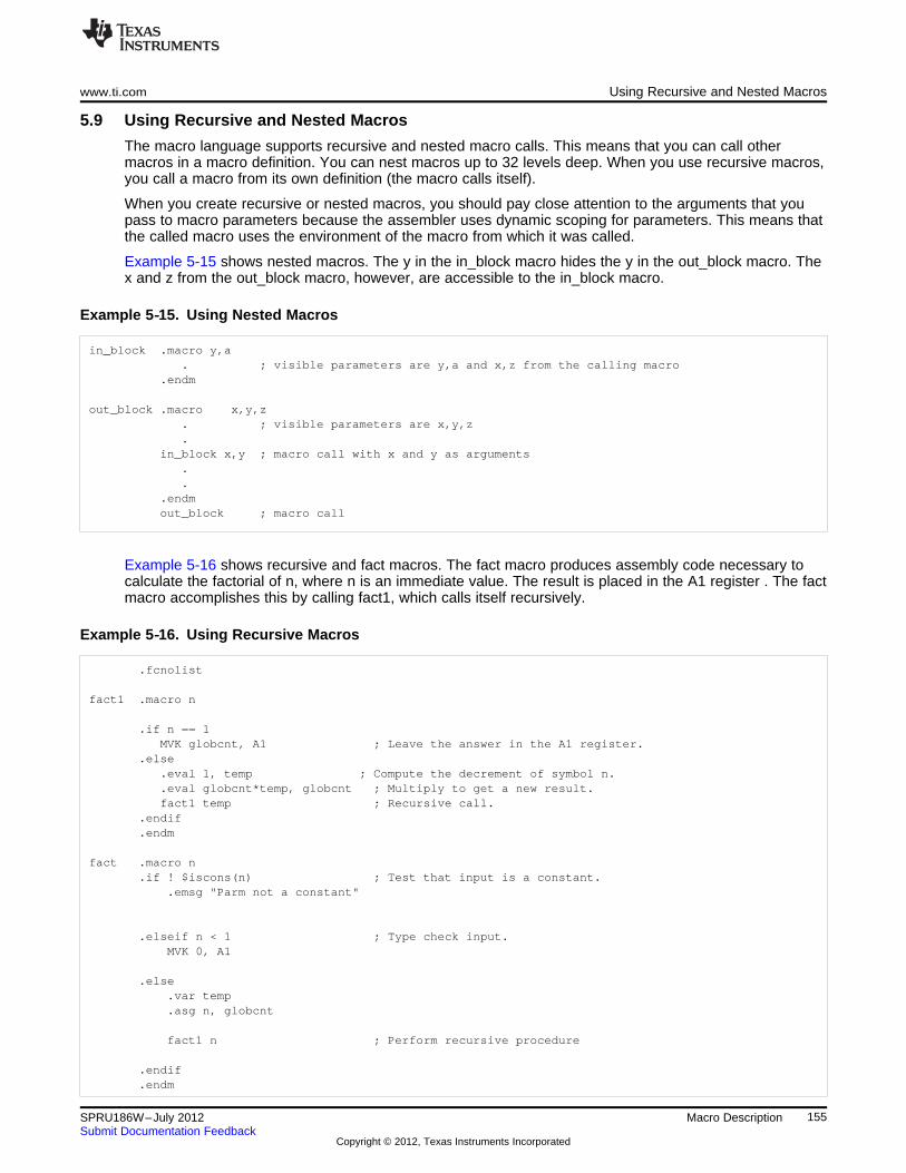
www.ti.com Using Recursive and Nested Macros
5.9 Using Recursive and Nested Macros
The macro language supports recursive and nested macro calls. This means that you can call othermacros in a macro definition. You can nest macros up to 32 levels deep. When you use recursive macros,you call a macro from its own definition (the macro calls itself).
When you create recursive or nested macros, you should pay close attention to the arguments that youpass to macro parameters because the assembler uses dynamic scoping for parameters. This means thatthe called macro uses the environment of the macro from which it was called.
Example 5-15 shows nested macros. The y in the in_block macro hides the y in the out_block macro. Thex and z from the out_block macro, however, are accessible to the in_block macro.
Example 5‑‑15. Using Nested Macros
in_block .macro y,a. ; visible parameters are y,a and x,z from the calling macro
.endm
out_block .macro x,y,z. ; visible parameters are x,y,z.
in_block x,y ; macro call with x and y as arguments..
.endmout_block ; macro call
Example 5-16 shows recursive and fact macros. The fact macro produces assembly code necessary tocalculate the factorial of n, where n is an immediate value. The result is placed in the A1 register . The factmacro accomplishes this by calling fact1, which calls itself recursively.
Example 5‑‑16. Using Recursive Macros
.fcnolist
fact1 .macro n
.if n == 1MVK globcnt, A1 ; Leave the answer in the A1 register.
.else.eval 1, temp ; Compute the decrement of symbol n..eval globcnt*temp, globcnt ; Multiply to get a new result.fact1 temp ; Recursive call.
.endif
.endm
fact .macro n.if ! $iscons(n) ; Test that input is a constant.
.emsg "Parm not a constant"
.elseif n < 1 ; Type check input.MVK 0, A1
.else.var temp.asg n, globcnt
fact1 n ; Perform recursive procedure
.endif
.endm
155SPRU186W–July 2012 Macro DescriptionSubmit Documentation Feedback
Copyright © 2012, Texas Instruments Incorporated
Using Recursive and Nested Macros www.ti.com
156 Macro Description SPRU186W–July 2012Submit Documentation Feedback
Copyright © 2012, Texas Instruments Incorporated
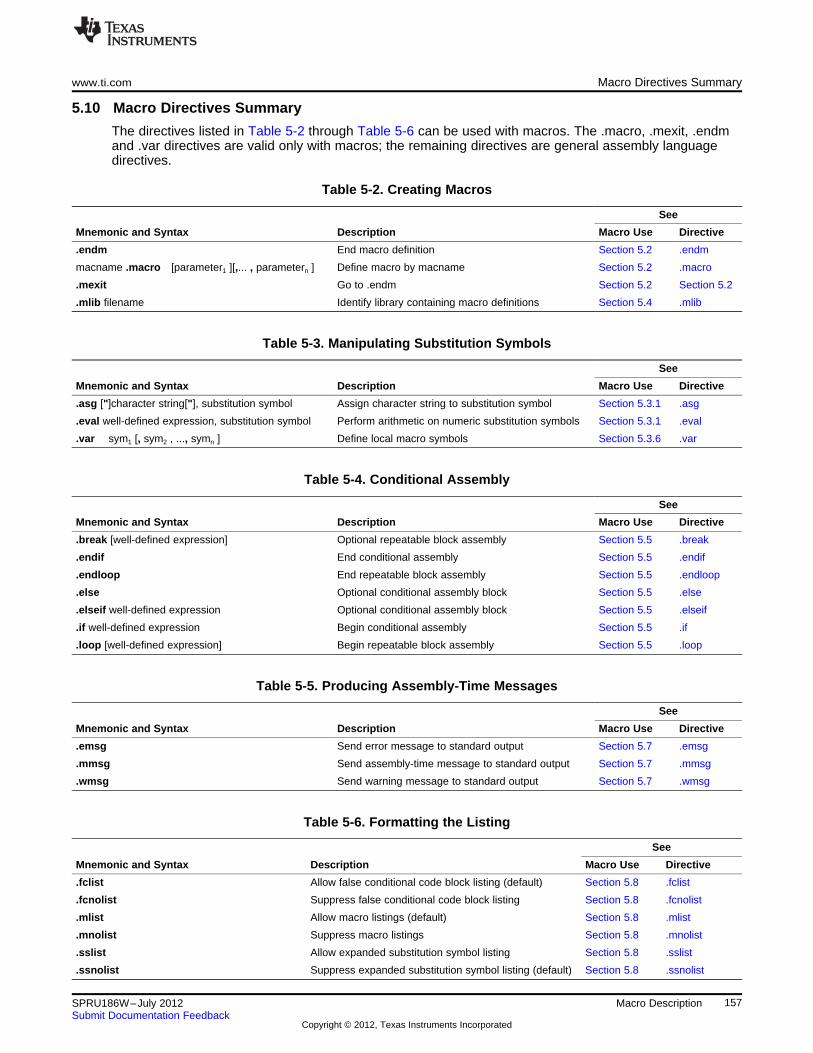
www.ti.com Macro Directives Summary
5.10 Macro Directives Summary
The directives listed in Table 5-2 through Table 5-6 can be used with macros. The .macro, .mexit, .endmand .var directives are valid only with macros; the remaining directives are general assembly languagedirectives.
Table 5-2. Creating Macros
See
Mnemonic and Syntax Description Macro Use Directive
.endm End macro definition Section 5.2 .endm
macname .macro [parameter1 ][,... , parametern ] Define macro by macname Section 5.2 .macro
.mexit Go to .endm Section 5.2 Section 5.2
.mlib filename Identify library containing macro definitions Section 5.4 .mlib
Table 5-3. Manipulating Substitution Symbols
See
Mnemonic and Syntax Description Macro Use Directive
.asg ["]character string["], substitution symbol Assign character string to substitution symbol Section 5.3.1 .asg
.eval well-defined expression, substitution symbol Perform arithmetic on numeric substitution symbols Section 5.3.1 .eval
.var sym1 [, sym2 , ..., symn ] Define local macro symbols Section 5.3.6 .var
Table 5-4. Conditional Assembly
See
Mnemonic and Syntax Description Macro Use Directive
.break [well-defined expression] Optional repeatable block assembly Section 5.5 .break
.endif End conditional assembly Section 5.5 .endif
.endloop End repeatable block assembly Section 5.5 .endloop
.else Optional conditional assembly block Section 5.5 .else
.elseif well-defined expression Optional conditional assembly block Section 5.5 .elseif
.if well-defined expression Begin conditional assembly Section 5.5 .if
.loop [well-defined expression] Begin repeatable block assembly Section 5.5 .loop
Table 5-5. Producing Assembly-Time Messages
See
Mnemonic and Syntax Description Macro Use Directive
.emsg Send error message to standard output Section 5.7 .emsg
.mmsg Send assembly-time message to standard output Section 5.7 .mmsg
.wmsg Send warning message to standard output Section 5.7 .wmsg
Table 5-6. Formatting the Listing
See
Mnemonic and Syntax Description Macro Use Directive
.fclist Allow false conditional code block listing (default) Section 5.8 .fclist
.fcnolist Suppress false conditional code block listing Section 5.8 .fcnolist
.mlist Allow macro listings (default) Section 5.8 .mlist
.mnolist Suppress macro listings Section 5.8 .mnolist
.sslist Allow expanded substitution symbol listing Section 5.8 .sslist
.ssnolist Suppress expanded substitution symbol listing (default) Section 5.8 .ssnolist
157SPRU186W–July 2012 Macro DescriptionSubmit Documentation Feedback
Copyright © 2012, Texas Instruments Incorporated
Chapter 6SPRU186W–July 2012
Archiver Description
The TMS320C6000 archiver lets you combine several individual files into a single archive file. Forexample, you can collect several macros into a macro library. The assembler searches the library anduses the members that are called as macros by the source file. You can also use the archiver to collect agroup of object files into an object library. The linker includes in the library the members that resolveexternal references during the link. The archiver allows you to modify a library by deleting, replacing,extracting, or adding members.
Topic ........................................................................................................................... Page
6.1 Archiver Overview ........................................................................................... 1596.2 The Archiver's Role in the Software Development Flow ........................................ 1606.3 Invoking the Archiver ....................................................................................... 1616.4 Archiver Examples ........................................................................................... 1626.5 Library Information Archiver Description ............................................................ 163
158 Archiver Description SPRU186W–July 2012Submit Documentation Feedback
Copyright © 2012, Texas Instruments Incorporated
www.ti.com Archiver Overview
6.1 Archiver Overview
You can build libraries from any type of files. Both the assembler and the linker accept archive libraries asinput; the assembler can use libraries that contain individual source files, and the linker can use librariesthat contain individual object files.
One of the most useful applications of the archiver is building libraries of object modules. For example,you can write several arithmetic routines, assemble them, and use the archiver to collect the object filesinto a single, logical group. You can then specify the object library as linker input. The linker searches thelibrary and includes members that resolve external references.
You can also use the archiver to build macro libraries. You can create several source files, each of whichcontains a single macro, and use the archiver to collect these macros into a single, functional group. Youcan use the .mlib directive during assembly to specify that macro library to be searched for the macrosthat you call. Chapter 5 discusses macros and macro libraries in detail, while this chapter explains how touse the archiver to build libraries.
159SPRU186W–July 2012 Archiver DescriptionSubmit Documentation Feedback
Copyright © 2012, Texas Instruments Incorporated
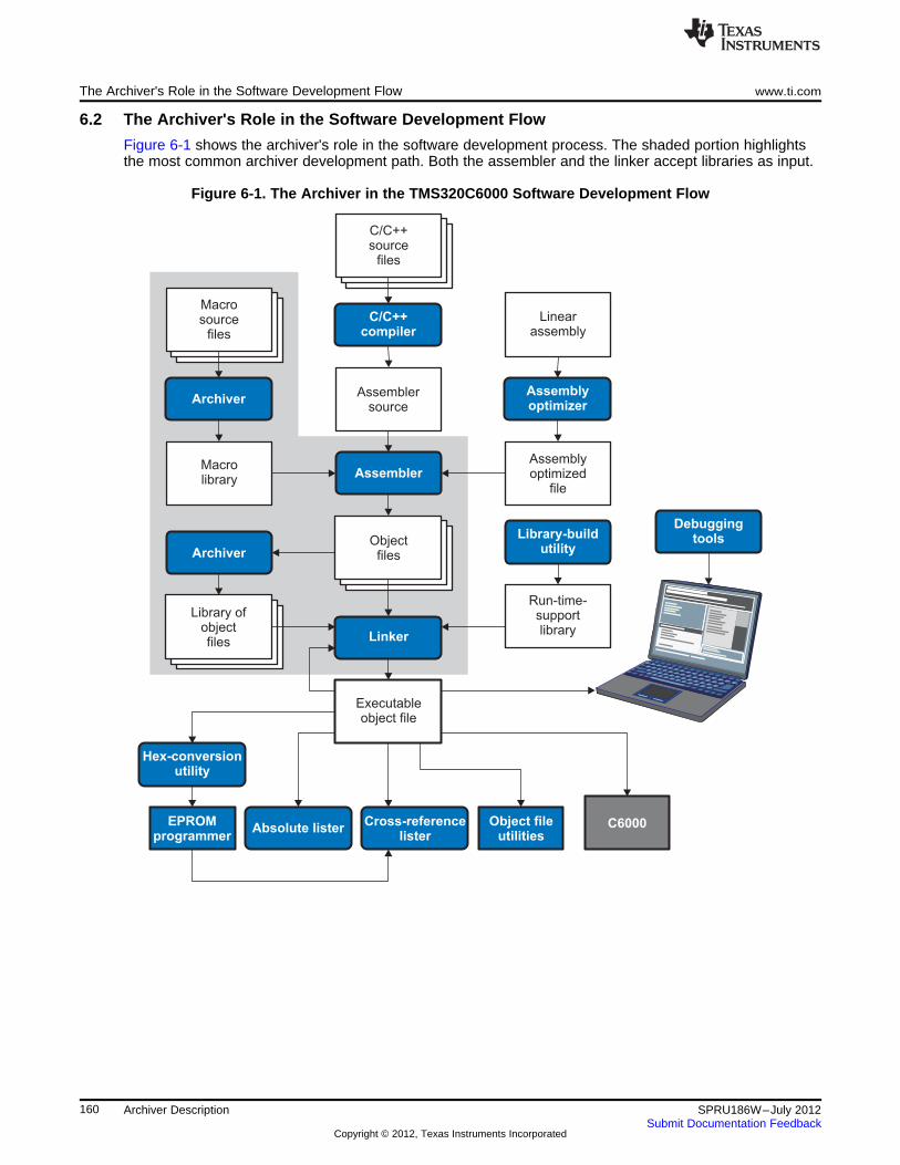
C/C++source
files
C/C++compiler
Assemblersource
Assembler
Executableobject file
DebuggingtoolsLibrary-build
utility
Run-time-supportlibrary
Archiver
Archiver
Macrolibrary
Absolute lister
Hex-conversionutility
Cross-referencelister
Object fileutilities
C6000
Linker
Linearassembly
Assemblyoptimizer
Assemblyoptimized
file
Macrosource
files
Objectfiles
EPROMprogrammer
Library ofobjectfiles
The Archiver's Role in the Software Development Flow www.ti.com
6.2 The Archiver's Role in the Software Development Flow
Figure 6-1 shows the archiver's role in the software development process. The shaded portion highlightsthe most common archiver development path. Both the assembler and the linker accept libraries as input.
Figure 6-1. The Archiver in the TMS320C6000 Software Development Flow
160 Archiver Description SPRU186W–July 2012Submit Documentation Feedback
Copyright © 2012, Texas Instruments Incorporated
www.ti.com Invoking the Archiver
6.3 Invoking the Archiver
To invoke the archiver, enter:
ar6x [-]command [options] libname [filename1 ... filenamen ]
ar6x is the command that invokes the archiver.[-]command tells the archiver how to manipulate the existing library members and any specified. A
command can be preceded by an optional hyphen. You must use one of the followingcommands when you invoke the archiver, but you can use only one command perinvocation. The archiver commands are as follows:@ uses the contents of the specified file instead of command line entries. You can
use this command to avoid limitations on command line length imposed by thehost operating system. Use a ; at the beginning of a line in the command file toinclude comments. (See Example 6-1 for an example using an archiver commandfile.)
a adds the specified files to the library. This command does not replace an existingmember that has the same name as an added file; it simply appends newmembers to the end of the archive.
d deletes the specified members from the library.r replaces the specified members in the library. If you do not specify filenames, the
archiver replaces the library members with files of the same name in the currentdirectory. If the specified file is not found in the library, the archiver adds it insteadof replacing it.
t prints a table of contents of the library. If you specify filenames, only those filesare listed. If you do not specify any filenames, the archiver lists all the members inthe specified library.
x extracts the specified files. If you do not specify member names, the archiverextracts all library members. When the archiver extracts a member, it simplycopies the member into the current directory; it does not remove it from the library.
options In addition to one of the commands, you can specify options. To use options, combinethem with a command; for example, to use the a command and the s option, enter -asor as. The hyphen is optional for archiver options only. These are the archiver options:-q (quiet) suppresses the banner and status messages.-s prints a list of the global symbols that are defined in the library. (This option is
valid only with the a, r, and d commands.)-u replaces library members only if the replacement has a more recent modification
date. You must use the r command with the -u option to specify which members toreplace.
-v (verbose) provides a file-by-file description of the creation of a new library from anold library and its members.
libname names the archive library to be built or modified. If you do not specify an extension forlibname, the archiver uses the default extension .lib.
filenames names individual files to be manipulated. These files can be existing library members ornew files to be added to the library. When you enter a filename, you must enter acomplete filename including extension, if applicable.
Naming Library Members
NOTE: It is possible (but not desirable) for a library to contain several members with the samename. If you attempt to delete, replace, or extract a member whose name is the same asanother library member, the archiver deletes, replaces, or extracts the first library memberwith that name.
161SPRU186W–July 2012 Archiver DescriptionSubmit Documentation Feedback
Copyright © 2012, Texas Instruments Incorporated
Archiver Examples www.ti.com
6.4 Archiver Examples
The following are examples of typical archiver operations:
• If you want to create a library called function.lib that contains the files sine.obj, cos.obj, and flt.obj,enter:ar6x -a function sine.obj cos.obj flt.obj
The archiver responds as follows:==> new archive 'function.lib' ==> building new archive 'function.lib'
• You can print a table of contents of function.lib with the -t command, enter:ar6x -t function
The archiver responds as follows:FILE NAME SIZE DATE
---------------- ----- ------------------------sine.obj 300 Wed Jun 15 10:00:24 2011cos.obj 300 Wed Jun 15 10:00:30 2011flt.obj 300 Wed Jun 15 09:59:56 2011
• If you want to add new members to the library, enter:ar6x -as function atan.obj
The archiver responds as follows:==> symbol defined: '_sin'==> symbol defined: '_cos'==> symbol defined: '_tan'==> symbol defined: '_atan==> building archive 'function.lib'
Because this example does not specify an extension for the libname, the archiver adds the files to thelibrary called function.lib. If function.lib does not exist, the archiver creates it. (The -s option tells thearchiver to list the global symbols that are defined in the library.)
• If you want to modify a library member, you can extract it, edit it, and replace it. In this example,assume there is a library named macros.lib that contains the members push.asm, pop.asm, andswap.asm.ar6x -x macros push.asm
The archiver makes a copy of push.asm and places it in the current directory; it does not removepush.asm from the library. Now you can edit the extracted file. To replace the copy of push.asm in thelibrary with the edited copy, enter:ar6x -r macros push.asm
• If you want to use a command file, specify the command filename after the -@ command. Forexample:ar6x [email protected]
The archiver responds as follows:==> building archive 'modules.lib'
Example 6-1 is the modules.cmd command file. The r command specifies that the filenames given inthe command file replace files of the same name in the modules.lib library. The -u option specifies thatthese files are replaced only when the current file has a more recent revision date than the file that isin the library.
162 Archiver Description SPRU186W–July 2012Submit Documentation Feedback
Copyright © 2012, Texas Instruments Incorporated
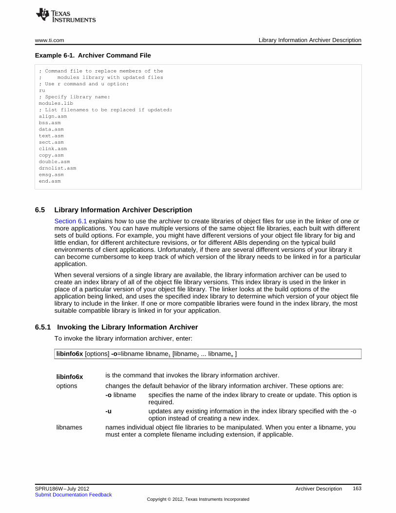
www.ti.com Library Information Archiver Description
Example 6‑‑1. Archiver Command File
; Command file to replace members of the; modules library with updated files; Use r command and u option:ru; Specify library name:modules.lib; List filenames to be replaced if updated:align.asmbss.asmdata.asmtext.asmsect.asmclink.asmcopy.asmdouble.asmdrnolist.asmemsg.asmend.asm
6.5 Library Information Archiver Description
Section 6.1 explains how to use the archiver to create libraries of object files for use in the linker of one ormore applications. You can have multiple versions of the same object file libraries, each built with differentsets of build options. For example, you might have different versions of your object file library for big andlittle endian, for different architecture revisions, or for different ABIs depending on the typical buildenvironments of client applications. Unfortunately, if there are several different versions of your library itcan become cumbersome to keep track of which version of the library needs to be linked in for a particularapplication.
When several versions of a single library are available, the library information archiver can be used tocreate an index library of all of the object file library versions. This index library is used in the linker inplace of a particular version of your object file library. The linker looks at the build options of theapplication being linked, and uses the specified index library to determine which version of your object filelibrary to include in the linker. If one or more compatible libraries were found in the index library, the mostsuitable compatible library is linked in for your application.
6.5.1 Invoking the Library Information Archiver
To invoke the library information archiver, enter:
libinfo6x [options] -o=libname libname1 [libname2 ... libnamen ]
is the command that invokes the library information archiver.libinfo6xoptions changes the default behavior of the library information archiver. These options are:
-o libname specifies the name of the index library to create or update. This option isrequired.
-u updates any existing information in the index library specified with the -ooption instead of creating a new index.
libnames names individual object file libraries to be manipulated. When you enter a libname, youmust enter a complete filename including extension, if applicable.
163SPRU186W–July 2012 Archiver DescriptionSubmit Documentation Feedback
Copyright © 2012, Texas Instruments Incorporated
Library Information Archiver Description www.ti.com
6.5.2 Library Information Archiver Example
Consider these object file libraries that all have the same members, but are built with different buildoptions:
Object File Library Name Build Options
mylib_6200_be.lib -mv6200 --endian=big
mylib_6200_le.lib -mv6200 --endian=little
mylib_64plus_be.lib -mv64plus --endian=big
mylib_64plus_le.lib -mv64plus --endian=little
Using the library information archiver, you can create an index library called mylib.lib from the abovelibraries:libinfo62 -o mylib.lib mylib_6200_be.lib mylib_6200_le.lib
mylib_64plus_be.lib mylib_64plus_le.lib
You can now specify mylib.lib as a library for the linker of an application. The linker uses the index libraryto choose the appropriate version of the library to use. If the --issue_remarks option is specified before the--run_linker option, the linker reports which library was chosen.
• Example 1 (ISA 64plus, little endian):cl6x -mv64plus --endian=little --issue_remarks main.c -z -l lnk.cmd ./mylib.lib<Linking>remark: linking in "mylib_64plus_le.lib" in place of "mylib.lib"
• Example 2 (ISA 6700, big endian):cl6x -mv6700 --endian=big --issue_remarks main.c -z -l lnk.cmd ./mylib.lib<Linking>remark: linking in "mylib_6200_be.lib" in place of "mylib.lib"
In Example 2, there was no version of the library for C6700, but a C6200 library was available and iscompatible, so it was used.
6.5.3 Listing the Contents of an Index Library
The archiver’s -t option can be used on an index library to list the archives indexed by an index library:ar6x t mylib.lib
SIZE DATE FILE NAME-------- ------------------------ -----------------
119 Wed Feb 03 12:45:22 2010 mylib_6200_be.lib119 Wed Feb 03 12:45:22 2010 mylib_6200_le.lib119 Wed Feb 03 12:45:22 2010 mylib_64plus_be.lib119 Wed Feb 03 12:45:22 2010 mylib_64plus_le.lib0 Wed Sep 30 12:45:22 2009 __TI_$$LIBINFO
The indexed object file libraries have an additional .libinfo extension in the archiver listing. The__TI_$$LIBINFO member is a special member that designates mylib.lib as an index library, rather than aregular library.
If the archiver’s -d command is used on an index library to delete a .libinfo member, the linker will nolonger choose the corresponding library when the index library is specified.
Using any other archiver option with an index library, or using -d to remove the __TI_$$LIBINFO member,results in undefined behavior, and is not supported.
6.5.4 Requirements
You must follow these requirements to use library index files:
• At least one of the application’s object files must appear on the linker command line before the indexlibrary.
• Each object file library specified as input to the library information archiver must only contain object filemembers that are built with the same build options.
164 Archiver Description SPRU186W–July 2012Submit Documentation Feedback
Copyright © 2012, Texas Instruments Incorporated
www.ti.com Library Information Archiver Description
• The linker expects the index library and all of the libraries it indexes to be in a single directory.
165SPRU186W–July 2012 Archiver DescriptionSubmit Documentation Feedback
Copyright © 2012, Texas Instruments Incorporated

Chapter 7SPRU186W–July 2012
Linker Description
The TMS320C6000 linker can be used to create a static executable or dynamic object module bycombining object modules. This chapter describes the linker options, directives, and statements used tocreate static executables and dynamic object modules. Object libraries, command files, and other keyconcepts are discussed as well.
The concept of sections is basic to linker operation; Chapter 2 discusses the object module sections indetail.
Topic ........................................................................................................................... Page
7.1 Linker Overview .............................................................................................. 1677.2 The Linker's Role in the Software Development Flow ........................................... 1687.3 Invoking the Linker .......................................................................................... 1697.4 Linker Options ................................................................................................ 1707.5 Linker Command Files ..................................................................................... 1927.6 Object Libraries ............................................................................................... 2267.7 Default Allocation Algorithm ............................................................................. 2277.8 Linker-Generated Copy Tables .......................................................................... 2287.9 Partial (Incremental) Linking ............................................................................. 2417.10 Linking C/C++ Code ......................................................................................... 2427.11 Linker Example ............................................................................................... 2457.12 Dynamic Linking with the C6000 Code Generation Tools ...................................... 248
166 Linker Description SPRU186W–July 2012Submit Documentation Feedback
Copyright © 2012, Texas Instruments Incorporated
www.ti.com Linker Overview
7.1 Linker Overview
The TMS320C6000 linker allows you to configure system memory by allocating output sections efficientlyinto the memory map. As the linker combines object files, it performs the following tasks:
• Allocates sections into the target system's configured memory
• Relocates symbols and sections to assign them to final addresses
• Resolves undefined external references between input files
The linker command language controls memory configuration, output section definition, and addressbinding. The language supports expression assignment and evaluation. You configure system memory bydefining and creating a memory model that you design. Two powerful directives, MEMORY andSECTIONS, allow you to:
• Allocate sections into specific areas of memory
• Combine object file sections
• Define or redefine global symbols at link time
167SPRU186W–July 2012 Linker DescriptionSubmit Documentation Feedback
Copyright © 2012, Texas Instruments Incorporated
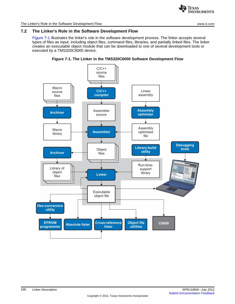
C/C++source
files
C/C++compiler
Assemblersource
Assembler
Executableobject file
DebuggingtoolsLibrary-build
utility
Run-time-supportlibrary
Archiver
Archiver
Macrolibrary
Absolute lister
Hex-conversionutility
Cross-referencelister
Object fileutilities
C6000
Linker
Linearassembly
Assemblyoptimizer
Assemblyoptimized
file
Macrosource
files
Objectfiles
EPROMprogrammer
Library ofobjectfiles
The Linker's Role in the Software Development Flow www.ti.com
7.2 The Linker's Role in the Software Development Flow
Figure 7-1 illustrates the linker's role in the software development process. The linker accepts severaltypes of files as input, including object files, command files, libraries, and partially linked files. The linkercreates an executable object module that can be downloaded to one of several development tools orexecuted by a TMS320C6000 device.
Figure 7-1. The Linker in the TMS320C6000 Software Development Flow
168 Linker Description SPRU186W–July 2012Submit Documentation Feedback
Copyright © 2012, Texas Instruments Incorporated
www.ti.com Invoking the Linker
7.3 Invoking the Linker
The general syntax for invoking the linker is:
cl6x --run_linker [options] filename1 .... filenamen
cl6x --run_linker is the command that invokes the linker. The --run_linker option's short form is-z.
options can appear anywhere on the command line or in a link command file. (Optionsare discussed in Section 7.4.)
filename 1, filename n can be object files, link command files, or archive libraries. The defaultextension for all input files is .obj; any other extension must be explicitlyspecified. The linker can determine whether the input file is an object or ASCIIfile that contains linker commands. The default output filename is a.out, unlessyou use the --output_file option to name the output file.
There are two methods for invoking the linker:
• Specify options and filenames on the command line. This example links two files, file1.obj and file2.obj,and creates an output module named link.out.cl6x --run_linker file1.obj file2.obj --output_file=link.out
• Put filenames and options in a link command file. Filenames that are specified inside a link commandfile must begin with a letter. For example, assume the file linker.cmd contains the following lines:--output_file=link.out file1.obj file2.obj
Now you can invoke the linker from the command line; specify the command filename as an input file:cl6x --run_linker linker.cmd
When you use a command file, you can also specify other options and files on the command line. Forexample, you could enter:cl6x --run_linker --map_file=link.map linker.cmd file3.obj
The linker reads and processes a command file as soon as it encounters the filename on thecommand line, so it links the files in this order: file1.obj, file2.obj, and file3.obj. This example creates anoutput file called link.out and a map file called link.map.
For information on invoking the linker for C/C++ files, see Section 7.10.
169SPRU186W–July 2012 Linker DescriptionSubmit Documentation Feedback
Copyright © 2012, Texas Instruments Incorporated
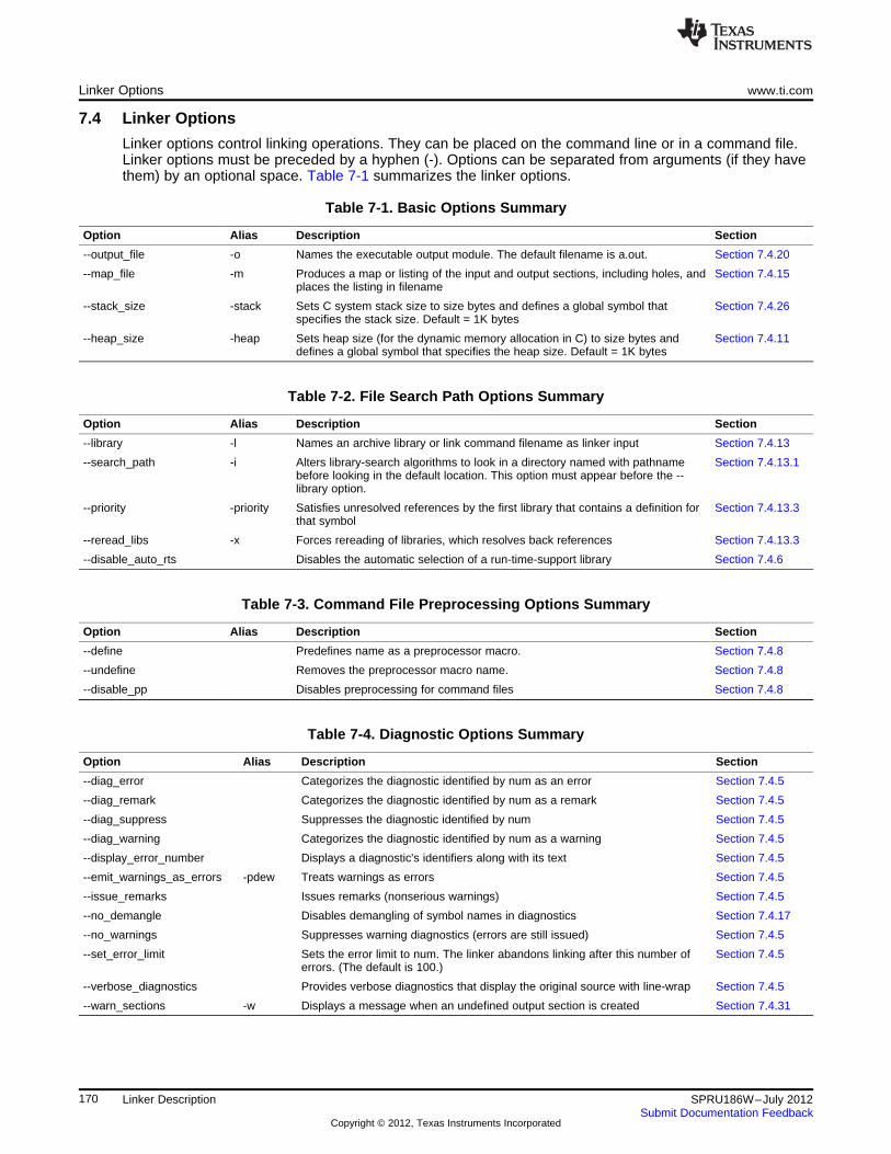
Linker Options www.ti.com
7.4 Linker Options
Linker options control linking operations. They can be placed on the command line or in a command file.Linker options must be preceded by a hyphen (-). Options can be separated from arguments (if they havethem) by an optional space. Table 7-1 summarizes the linker options.
Table 7-1. Basic Options Summary
Option Alias Description Section
--output_file -o Names the executable output module. The default filename is a.out. Section 7.4.20
--map_file -m Produces a map or listing of the input and output sections, including holes, and Section 7.4.15places the listing in filename
--stack_size -stack Sets C system stack size to size bytes and defines a global symbol that Section 7.4.26specifies the stack size. Default = 1K bytes
--heap_size -heap Sets heap size (for the dynamic memory allocation in C) to size bytes and Section 7.4.11defines a global symbol that specifies the heap size. Default = 1K bytes
Table 7-2. File Search Path Options Summary
Option Alias Description Section
--library -l Names an archive library or link command filename as linker input Section 7.4.13
--search_path -i Alters library-search algorithms to look in a directory named with pathname Section 7.4.13.1before looking in the default location. This option must appear before the --library option.
--priority -priority Satisfies unresolved references by the first library that contains a definition for Section 7.4.13.3that symbol
--reread_libs -x Forces rereading of libraries, which resolves back references Section 7.4.13.3
--disable_auto_rts Disables the automatic selection of a run-time-support library Section 7.4.6
Table 7-3. Command File Preprocessing Options Summary
Option Alias Description Section
--define Predefines name as a preprocessor macro. Section 7.4.8
--undefine Removes the preprocessor macro name. Section 7.4.8
--disable_pp Disables preprocessing for command files Section 7.4.8
Table 7-4. Diagnostic Options Summary
Option Alias Description Section
--diag_error Categorizes the diagnostic identified by num as an error Section 7.4.5
--diag_remark Categorizes the diagnostic identified by num as a remark Section 7.4.5
--diag_suppress Suppresses the diagnostic identified by num Section 7.4.5
--diag_warning Categorizes the diagnostic identified by num as a warning Section 7.4.5
--display_error_number Displays a diagnostic's identifiers along with its text Section 7.4.5
--emit_warnings_as_errors -pdew Treats warnings as errors Section 7.4.5
--issue_remarks Issues remarks (nonserious warnings) Section 7.4.5
--no_demangle Disables demangling of symbol names in diagnostics Section 7.4.17
--no_warnings Suppresses warning diagnostics (errors are still issued) Section 7.4.5
--set_error_limit Sets the error limit to num. The linker abandons linking after this number of Section 7.4.5errors. (The default is 100.)
--verbose_diagnostics Provides verbose diagnostics that display the original source with line-wrap Section 7.4.5
--warn_sections -w Displays a message when an undefined output section is created Section 7.4.31
170 Linker Description SPRU186W–July 2012Submit Documentation Feedback
Copyright © 2012, Texas Instruments Incorporated
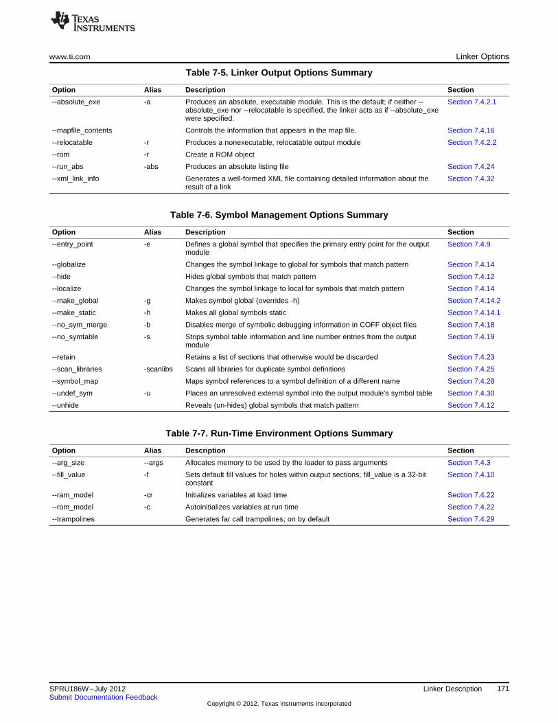
www.ti.com Linker Options
Table 7-5. Linker Output Options Summary
Option Alias Description Section
--absolute_exe -a Produces an absolute, executable module. This is the default; if neither -- Section 7.4.2.1absolute_exe nor --relocatable is specified, the linker acts as if --absolute_exewere specified.
--mapfile_contents Controls the information that appears in the map file. Section 7.4.16
--relocatable -r Produces a nonexecutable, relocatable output module Section 7.4.2.2
--rom -r Create a ROM object
--run_abs -abs Produces an absolute listing file Section 7.4.24
--xml_link_info Generates a well-formed XML file containing detailed information about the Section 7.4.32result of a link
Table 7-6. Symbol Management Options Summary
Option Alias Description Section
--entry_point -e Defines a global symbol that specifies the primary entry point for the output Section 7.4.9module
--globalize Changes the symbol linkage to global for symbols that match pattern Section 7.4.14
--hide Hides global symbols that match pattern Section 7.4.12
--localize Changes the symbol linkage to local for symbols that match pattern Section 7.4.14
--make_global -g Makes symbol global (overrides -h) Section 7.4.14.2
--make_static -h Makes all global symbols static Section 7.4.14.1
--no_sym_merge -b Disables merge of symbolic debugging information in COFF object files Section 7.4.18
--no_symtable -s Strips symbol table information and line number entries from the output Section 7.4.19module
--retain Retains a list of sections that otherwise would be discarded Section 7.4.23
--scan_libraries -scanlibs Scans all libraries for duplicate symbol definitions Section 7.4.25
--symbol_map Maps symbol references to a symbol definition of a different name Section 7.4.28
--undef_sym -u Places an unresolved external symbol into the output module's symbol table Section 7.4.30
--unhide Reveals (un-hides) global symbols that match pattern Section 7.4.12
Table 7-7. Run-Time Environment Options Summary
Option Alias Description Section
--arg_size --args Allocates memory to be used by the loader to pass arguments Section 7.4.3
--fill_value -f Sets default fill values for holes within output sections; fill_value is a 32-bit Section 7.4.10constant
--ram_model -cr Initializes variables at load time Section 7.4.22
--rom_model -c Autoinitializes variables at run time Section 7.4.22
--trampolines Generates far call trampolines; on by default Section 7.4.29
171SPRU186W–July 2012 Linker DescriptionSubmit Documentation Feedback
Copyright © 2012, Texas Instruments Incorporated
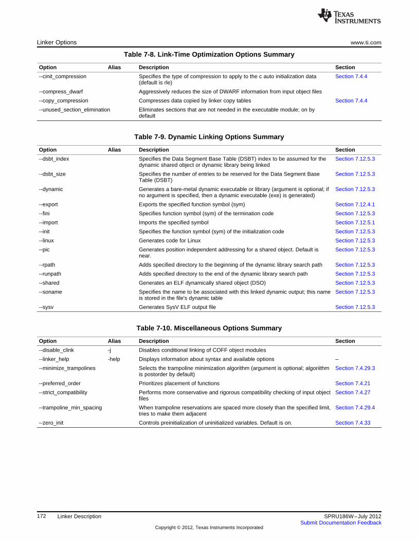
Linker Options www.ti.com
Table 7-8. Link-Time Optimization Options Summary
Option Alias Description Section
--cinit_compression Specifies the type of compression to apply to the c auto initialization data Section 7.4.4(default is rle)
--compress_dwarf Aggressively reduces the size of DWARF information from input object files
--copy_compression Compresses data copied by linker copy tables Section 7.4.4
--unused_section_elimination Eliminates sections that are not needed in the executable module; on bydefault
Table 7-9. Dynamic Linking Options Summary
Option Alias Description Section
--dsbt_index Specifies the Data Segment Base Table (DSBT) index to be assumed for the Section 7.12.5.3dynamic shared object or dynamic library being linked
--dsbt_size Specifies the number of entries to be reserved for the Data Segment Base Section 7.12.5.3Table (DSBT)
--dynamic Generates a bare-metal dynamic executable or library (argument is optional; if Section 7.12.5.3no argument is specified, then a dynamic executable (exe) is generated)
--export Exports the specified function symbol (sym) Section 7.12.4.1
--fini Specifies function symbol (sym) of the termination code Section 7.12.5.3
--import Imports the specified symbol Section 7.12.5.1
--init Specifies the function symbol (sym) of the initialization code Section 7.12.5.3
--linux Generates code for Linux Section 7.12.5.3
--pic Generates position independent addressing for a shared object. Default is Section 7.12.5.3near.
--rpath Adds specified directory to the beginning of the dynamic library search path Section 7.12.5.3
--runpath Adds specified directory to the end of the dynamic library search path Section 7.12.5.3
--shared Generates an ELF dynamically shared object (DSO) Section 7.12.5.3
--soname Specifies the name to be associated with this linked dynamic output; this name Section 7.12.5.3is stored in the file's dynamic table
--sysv Generates SysV ELF output file Section 7.12.5.3
Table 7-10. Miscellaneous Options Summary
Option Alias Description Section
--disable_clink -j Disables conditional linking of COFF object modules
--linker_help -help Displays information about syntax and available options –
--minimize_trampolines Selects the trampoline minimization algorithm (argument is optional; algoriithm Section 7.4.29.3is postorder by default)
--preferred_order Prioritizes placement of functions Section 7.4.21
--strict_compatibility Performs more conservative and rigorous compatibility checking of input object Section 7.4.27files
--trampoline_min_spacing When trampoline reservations are spaced more closely than the specified limit, Section 7.4.29.4tries to make them adjacent
--zero_init Controls preinitialization of uninitialized variables. Default is on. Section 7.4.33
172 Linker Description SPRU186W–July 2012Submit Documentation Feedback
Copyright © 2012, Texas Instruments Incorporated
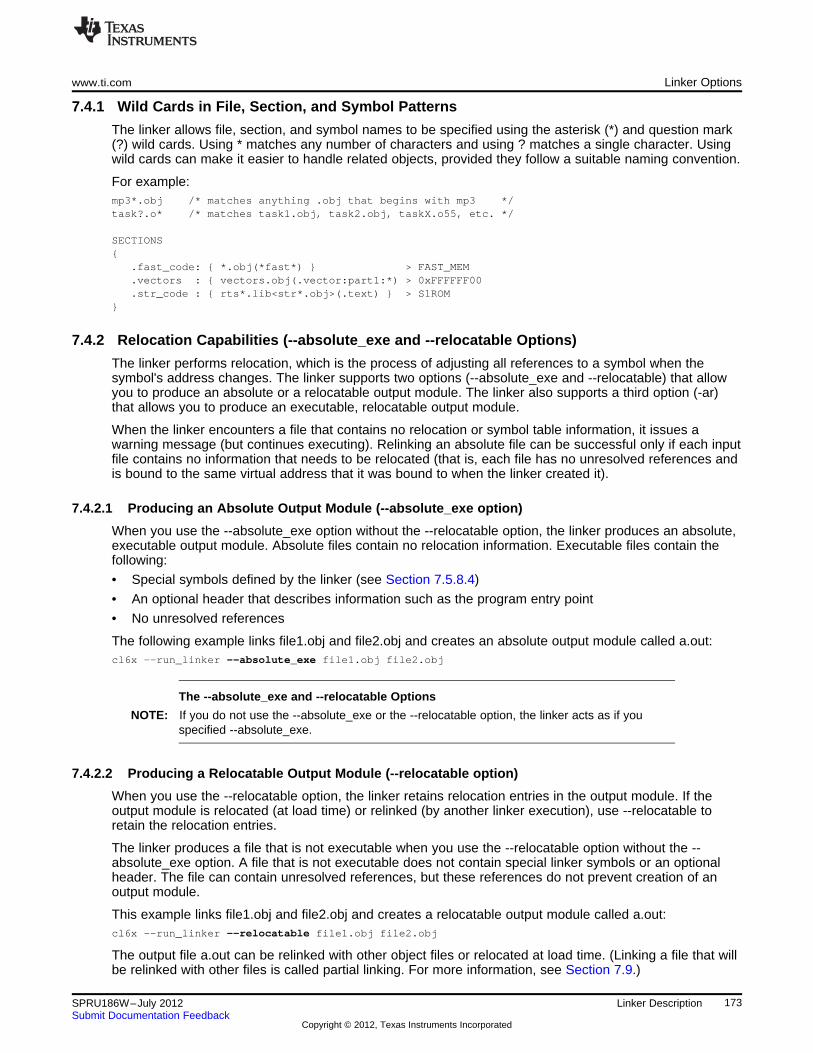
www.ti.com Linker Options
7.4.1 Wild Cards in File, Section, and Symbol Patterns
The linker allows file, section, and symbol names to be specified using the asterisk (*) and question mark(?) wild cards. Using * matches any number of characters and using ? matches a single character. Usingwild cards can make it easier to handle related objects, provided they follow a suitable naming convention.
For example:mp3*.obj /* matches anything .obj that begins with mp3 */task?.o* /* matches task1.obj, task2.obj, taskX.o55, etc. */
SECTIONS{
.fast_code: { *.obj(*fast*) } > FAST_MEM
.vectors : { vectors.obj(.vector:part1:*) > 0xFFFFFF00
.str_code : { rts*.lib<str*.obj>(.text) } > S1ROM}
7.4.2 Relocation Capabilities (--absolute_exe and --relocatable Options)
The linker performs relocation, which is the process of adjusting all references to a symbol when thesymbol's address changes. The linker supports two options (--absolute_exe and --relocatable) that allowyou to produce an absolute or a relocatable output module. The linker also supports a third option (-ar)that allows you to produce an executable, relocatable output module.
When the linker encounters a file that contains no relocation or symbol table information, it issues awarning message (but continues executing). Relinking an absolute file can be successful only if each inputfile contains no information that needs to be relocated (that is, each file has no unresolved references andis bound to the same virtual address that it was bound to when the linker created it).
7.4.2.1 Producing an Absolute Output Module (--absolute_exe option)
When you use the --absolute_exe option without the --relocatable option, the linker produces an absolute,executable output module. Absolute files contain no relocation information. Executable files contain thefollowing:
• Special symbols defined by the linker (see Section 7.5.8.4)
• An optional header that describes information such as the program entry point
• No unresolved references
The following example links file1.obj and file2.obj and creates an absolute output module called a.out:cl6x --run_linker --absolute_exe file1.obj file2.obj
The --absolute_exe and --relocatable Options
NOTE: If you do not use the --absolute_exe or the --relocatable option, the linker acts as if youspecified --absolute_exe.
7.4.2.2 Producing a Relocatable Output Module (--relocatable option)
When you use the --relocatable option, the linker retains relocation entries in the output module. If theoutput module is relocated (at load time) or relinked (by another linker execution), use --relocatable toretain the relocation entries.
The linker produces a file that is not executable when you use the --relocatable option without the --absolute_exe option. A file that is not executable does not contain special linker symbols or an optionalheader. The file can contain unresolved references, but these references do not prevent creation of anoutput module.
This example links file1.obj and file2.obj and creates a relocatable output module called a.out:cl6x --run_linker --relocatable file1.obj file2.obj
The output file a.out can be relinked with other object files or relocated at load time. (Linking a file that willbe relinked with other files is called partial linking. For more information, see Section 7.9.)
173SPRU186W–July 2012 Linker DescriptionSubmit Documentation Feedback
Copyright © 2012, Texas Instruments Incorporated
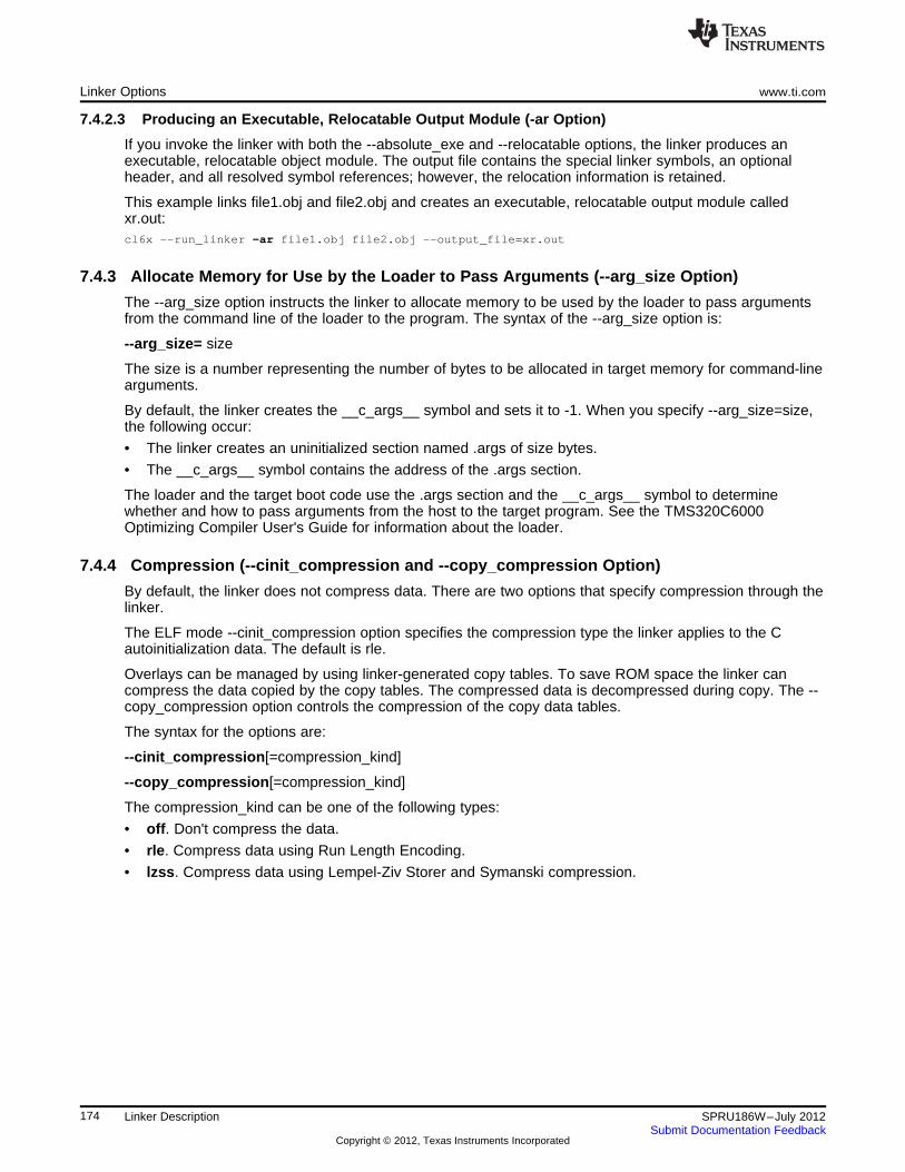
Linker Options www.ti.com
7.4.2.3 Producing an Executable, Relocatable Output Module (-ar Option)
If you invoke the linker with both the --absolute_exe and --relocatable options, the linker produces anexecutable, relocatable object module. The output file contains the special linker symbols, an optionalheader, and all resolved symbol references; however, the relocation information is retained.
This example links file1.obj and file2.obj and creates an executable, relocatable output module calledxr.out:cl6x --run_linker -ar file1.obj file2.obj --output_file=xr.out
7.4.3 Allocate Memory for Use by the Loader to Pass Arguments (--arg_size Option)
The --arg_size option instructs the linker to allocate memory to be used by the loader to pass argumentsfrom the command line of the loader to the program. The syntax of the --arg_size option is:
--arg_size= size
The size is a number representing the number of bytes to be allocated in target memory for command-linearguments.
By default, the linker creates the __c_args__ symbol and sets it to -1. When you specify --arg_size=size,the following occur:
• The linker creates an uninitialized section named .args of size bytes.
• The __c_args__ symbol contains the address of the .args section.
The loader and the target boot code use the .args section and the __c_args__ symbol to determinewhether and how to pass arguments from the host to the target program. See the TMS320C6000Optimizing Compiler User's Guide for information about the loader.
7.4.4 Compression (--cinit_compression and --copy_compression Option)
By default, the linker does not compress data. There are two options that specify compression through thelinker.
The ELF mode --cinit_compression option specifies the compression type the linker applies to the Cautoinitialization data. The default is rle.
Overlays can be managed by using linker-generated copy tables. To save ROM space the linker cancompress the data copied by the copy tables. The compressed data is decompressed during copy. The --copy_compression option controls the compression of the copy data tables.
The syntax for the options are:
--cinit_compression[=compression_kind]
--copy_compression[=compression_kind]
The compression_kind can be one of the following types:
• off. Don't compress the data.
• rle. Compress data using Run Length Encoding.
• lzss. Compress data using Lempel-Ziv Storer and Symanski compression.
174 Linker Description SPRU186W–July 2012Submit Documentation Feedback
Copyright © 2012, Texas Instruments Incorporated
www.ti.com Linker Options
7.4.5 Control Linker Diagnostics
The linker uses certain C/C++ compiler options to control linker-generated diagnostics. The diagnosticoptions must be specified before the --run_linker option.
--diag_error=num Categorizes the diagnostic identified by num as an error. To determine thenumeric identifier of a diagnostic message, use the --display_error_numberoption first in a separate link. Then use --diag_error=num to recategorize thediagnostic as an error. You can only alter the severity of discretionarydiagnostics.
--diag_remark=num Categorizes the diagnostic identified by num as a remark. To determine thenumeric identifier of a diagnostic message, use the --display_error_numberoption first in a separate link. Then use --diag_remark=num to recategorizethe diagnostic as a remark. You can only alter the severity of discretionarydiagnostics.
--diag_suppress=num Suppresses the diagnostic identified by num. To determine the numericidentifier of a diagnostic message, use the --display_error_number option firstin a separate link. Then use --diag_suppress=num to suppress thediagnostic. You can only suppress discretionary diagnostics.
--diag_warning=num Categorizes the diagnostic identified by num as a warning. To determine thenumeric identifier of a diagnostic message, use the --display_error_numberoption first in a separate link. Then use --diag_warning=num to recategorizethe diagnostic as a warning. You can only alter the severity of discretionarydiagnostics.
--display_error_number Displays a diagnostic's numeric identifier along with its text. Use this option indetermining which arguments you need to supply to the diagnosticsuppression options (--diag_suppress, --diag_error, --diag_remark, and --diag_warning). This option also indicates whether a diagnostic isdiscretionary. A discretionary diagnostic is one whose severity can beoverridden. A discretionary diagnostic includes the suffix -D; otherwise, nosuffix is present. See the TMS320C6000 Optimizing Compiler User's Guidefor more information on understanding diagnostic messages.
--emit_warnings_as_ Treats all warnings as errors. This option cannot be used with the --errors no_warnings option. The --diag_remark option takes precedence over this
option. This option takes precedence over the --diag_warning option.--issue_remarks Issues remarks (nonserious warnings), which are suppressed by default.--no_warnings Suppresses warning diagnostics (errors are still issued).--set_error_limit=num Sets the error limit to num, which can be any decimal value. The linker
abandons linking after this number of errors. (The default is 100.)--verbose_diagnostics Provides verbose diagnostics that display the original source with line-wrap
and indicate the position of the error in the source line
7.4.6 Disable Automatic Library Selection (--disable_auto_rts Option)
The --disable_auto_rts option disables the automatic selection of a run-time-support library. See theTMS320C6000 Optimizing Compiler User's Guide for details on the automatic selection process.
7.4.7 Controlling Unreferenced and Unused Sections
7.4.7.1 Disable Conditional Linking (--disable_clink Option)
The --disable_clink option disables removal of unreferenced sections in COFF object modules. Onlysections marked as candidates for removal with the .clink assembler directive are affected by conditionallinking. See Conditionally Leave Section Out of Object Module Output for details on setting up conditionallinking using the .clink directive, which is available under ELF as well as COFF.
175SPRU186W–July 2012 Linker DescriptionSubmit Documentation Feedback
Copyright © 2012, Texas Instruments Incorporated
Linker Options www.ti.com
7.4.7.2 Do Not Remove Unused Sections (--unused_section_elimination Option)
In order to minimize the foot print, the ELF linker does not include a section that is not needed to resolveany references in the final executable. Use --unused_section_elimination=off to disable this optimization.The syntax for the option is:
--unused_section_elimination[=on|off]
The linker default behavior is equivalent to --unused_section_elimination=on.
7.4.8 Link Command File Preprocessing (--disable_pp, --define and --undefine Options)
The linker preprocesses link command files using a standard C preprocessor. Therefore, the commandfiles can contain well-known preprocessing directives such as #define, #include, and #if / #endif.
Three linker options control the preprocessor:
--disable_pp Disables preprocessing for command files--define=name[=val] Predefines name as a preprocessor macro--undefine=name Removes the macro name
The compiler has --define and --undefine options with the same meanings. However, the linker options aredistinct; only --define and --undefine options specified after --run_linker are passed to the linker. Forexample:cl6x --define=FOO=1 main.c --run_linker --define=BAR=2 lnk.cmd
The linker sees only the --define for BAR; the compiler only sees the --define for FOO.
When one command file #includes another, preprocessing context is carried from parent to child in theusual way (that is, macros defined in the parent are visible in the child). However, when a command file isinvoked other than through #include, either on the command line or by the typical way of being named inanother command file, preprocessing context is not carried into the nested file. The exception to this is --define and --undefine options, which apply globally from the point they are encountered. For example:--define GLOBAL#define LOCAL
#include "incfile.cmd" /* sees GLOBAL and LOCAL */nestfile.cmd /* only sees GLOBAL */
Two cautions apply to the use of --define and --undefine in command files. First, they have global effect asmentioned above. Second, since they are not actually preprocessing directives themselves, they aresubject to macro substitution, probably with unintended consequences. This effect can be defeated byquoting the symbol name. For example:--define MYSYM=123--undefine MYSYM /* expands to --undefine 123 (!) */--undefine "MYSYM" /* ahh, that's better */
The linker uses the same search paths to find #include files as it does to find libraries. That is, #includefiles are searched in the following places:
1. If the #include file name is in quotes (rather than <brackets>), in the directory of the current file
2. In the list of directories specified with --Iibrary options or environment variables (see Section 7.4.13)
There are two exceptions: relative pathnames (such as "../name") always search the current directory; andabsolute pathnames (such as "/usr/tools/name") bypass search paths entirely.
The linker has the standard built-in definitions for the macros __FILE__, __DATE__, and __TIME__. Itdoes not, however, have the compiler-specific options for the target (__.TMS320C6000__), version(__TI_COMPILER_VERSION__), run-time model, and so on.
176 Linker Description SPRU186W–July 2012Submit Documentation Feedback
Copyright © 2012, Texas Instruments Incorporated
www.ti.com Linker Options
7.4.9 Define an Entry Point (--entry_point Option)
The memory address at which a program begins executing is called the entry point. When a loader loadsa program into target memory, the program counter (PC) must be initialized to the entry point; the PC thenpoints to the beginning of the program.
The linker can assign one of four values to the entry point. These values are listed below in the order inwhich the linker tries to use them. If you use one of the first three values, it must be an external symbol inthe symbol table.
• The value specified by the --entry_point option. The syntax is:
--entry_point= global_symbol
where global_symbol defines the entry point and must be defined as an external symbol of the inputfiles. The external symbol name of C or C++ objects may be different than the name as declared in thesource language; refer to the TMS320C6000 Optimizing Compiler User's Guide.
• The value of symbol _c_int00 (if present). The _c_int00 symbol must be the entry point if you arelinking code produced by the C compiler.
• The value of symbol _main (if present)
• 0 (default value)
This example links file1.obj and file2.obj. The symbol begin is the entry point; begin must be defined asexternal in file1 or file2.cl6x --run_linker --entry_point=begin file1.obj file2.obj
7.4.10 Set Default Fill Value (--fill_value Option)
The --fill_value option fills the holes formed within output sections. The syntax for the option is:
--fill_value= value
The argument value is a 32-bit constant (up to eight hexadecimal digits). If you do not use --fill_value, thelinker uses 0 as the default fill value.
This example fills holes with the hexadecimal value ABCDABCD:cl6x --run_linker --fill_value=0xABCDABCD file1.obj file2.obj
7.4.11 Define Heap Size (--heap_size Option)
The C/C++ compiler uses an uninitialized section called .sysmem for the C run-time memory pool used bymalloc(). You can set the size of this memory pool at link time by using the --heap_size option. The syntaxfor the --heap_size option is:
--heap_size= size
The size must be a constant. This example defines a 4K byte heap:cl6x --run_linker --heap_size=0x1000 /* defines a 4k heap (.sysmem section)*/
The linker creates the .sysmem section only if there is a .sysmem section in an input file.
The linker also creates a global symbol __SYSMEM_SIZE and assigns it a value equal to the size of theheap. The default size is 1K bytes.
For more information about C/C++ linking, see Section 7.10.
177SPRU186W–July 2012 Linker DescriptionSubmit Documentation Feedback
Copyright © 2012, Texas Instruments Incorporated
Linker Options www.ti.com
7.4.12 Hiding Symbols
Symbol hiding prevents the symbol from being listed in the output file's symbol table. While localization isused to prevent name space clashes in a link unit, symbol hiding is used to obscure symbols which shouldnot be visible outside a link unit. Such symbol’s names appear only as empty strings or “no name” inobject file readers. The linker supports symbol hiding through the --hide and --unhide options.
The syntax for these options are:
--hide=' pattern '
--unhide=' pattern '
The pattern is a string with optional wildcards ? or *. Use ? to match a single character and use * to matchzero or more characters.
The --hide option hides global symbols which have a linkname matching the pattern. It hides the symbolsmatching the pattern by changing the name to an empty string. A global symbol which is hidden is alsolocalized.
The --unhide option reveals (un-hides) global symbols that match the pattern that are hidden by the --hideoption. The --unhide option excludes symbols that match pattern from symbol hiding provided the patterndefined by --unhide is more restrictive than the pattern defined by --hide.
These options have the following properties:
• The --hide and --unhide options can be specified more than once on the command line.
• The order of --hide and --unhide has no significance.
• A symbol is matched by only one pattern defined by either --hide or --unhide.
• A symbol is matched by the most restrictive pattern. Pattern A is considered more restrictive thanPattern B, if Pattern A matches a narrower set than Pattern B.
• It is an error if a symbol matches patterns from --hide and --unhide and if one does not supersedeother. Pattern A supersedes pattern B if A can match everything B can, and some more. If Pattern Asupersedes Pattern B, then Pattern B is said to more restrictive than Pattern A.
• These options affect final and partial linking.
In map files these symbols are listed under the Hidden Symbols heading.
178 Linker Description SPRU186W–July 2012Submit Documentation Feedback
Copyright © 2012, Texas Instruments Incorporated
www.ti.com Linker Options
7.4.13 Alter the Library Search Algorithm (--library Option, --search_path Option, andC6X_C_DIR Environment Variable)
Usually, when you want to specify a file as linker input, you simply enter the filename; the linker looks forthe file in the current directory. For example, suppose the current directory contains the library object.lib.Assume that this library defines symbols that are referenced in the file file1.obj. This is how you link thefiles:cl6x --run_linker file1.obj object.lib
If you want to use a file that is not in the current directory, use the --library linker option. The --libraryoption's short form is -l. The syntax for this option is:
--library=[pathname] filename
The filename is the name of an archive, an object file, or link command file. You can specify up to 128search paths.
The --library option is not required when one or more members of an object library are specified for inputto an output section. For more information about allocating archive members, see Section 7.5.4.5.
You can augment the linker's directory search algorithm by using the --search_path linker option or theC6X_C_DIR environment variable. The linker searches for object libraries and command files in thefollowing order:
1. It searches directories named with the --search_path linker option. The --search_path option mustappear before the --Iibrary option on the command line or in a command file.
2. It searches directories named with C6X_C_DIR.
3. If C6X_C_DIR is not set, it searches directories named with the assembler's C6X_A_DIR environmentvariable.
4. It searches the current directory.
7.4.13.1 Name an Alternate Library Directory (--search_path Option)
The --search_path option names an alternate directory that contains input files. The --search_path option'sshort form is -I. The syntax for this option is:
--search_path= pathname
The pathname names a directory that contains input files.
When the linker is searching for input files named with the --library option, it searches through directoriesnamed with --search_path first. Each --search_path option specifies only one directory, but you can haveseveral --search_path options per invocation. When you use the --search_path option to name analternate directory, it must precede any --library option used on the command line or in a command file.
For example, assume that there are two archive libraries called r.lib and lib2.lib that reside in ld and ld2directories. The table below shows the directories that r.lib and lib2.lib reside in, how to set environmentvariable, and how to use both libraries during a link. Select the row for your operating system:
Operating System Enter
cl6x --run_linker f1.obj f2.obj --search_path=/ld --search_path=/ld2
UNIX (Bourne shell) --library=r.lib --library=lib2.lib
cl6x --run_linker f1.obj f2.obj --search_path=\ld --search_path=\ld2
Windows --library=r.lib --library=lib2.lib
179SPRU186W–July 2012 Linker DescriptionSubmit Documentation Feedback
Copyright © 2012, Texas Instruments Incorporated
Linker Options www.ti.com
7.4.13.2 Name an Alternate Library Directory (C6X_C_DIR Environment Variable)
An environment variable is a system symbol that you define and assign a string to. The linker uses anenvironment variable named C6X_C_DIR to name alternate directories that contain object libraries. Thecommand syntaxes for assigning the environment variable are:
Operating System Enter
UNIX (Bourne shell) C6X_C_DIR=" pathname1; pathname2; . . . "; export C6X_C_DIR
Windows set C6X_C_DIR= pathname1 ; pathname2 ; . . .
The pathnames are directories that contain input files. Use the --library linker option on the command lineor in a command file to tell the linker which library or link command file to search for. The pathnames mustfollow these constraints:
• Pathnames must be separated with a semicolon.
• Spaces or tabs at the beginning or end of a path are ignored. For example the space before and afterthe semicolon in the following is ignored:set C6X_C_DIR= c:\path\one\to\tools ; c:\path\two\to\tools
• Spaces and tabs are allowed within paths to accommodate Windows directories that contain spaces.For example, the pathnames in the following are valid:set C6X_C_DIR=c:\first path\to\tools;d:\second path\to\tools
In the example below, assume that two archive libraries called r.lib and lib2.lib reside in ld and ld2directories. The table below shows how to set the environment variable, and how to use both librariesduring a link. Select the row for your operating system:
Operating System Invocation Command
C6X_C_DIR="/ld ;/ld2"; export C6X_C_DIR;
UNIX (Bourne shell) cl6x --run linker f1.obj f2.obj --library=r.lib --library=lib2.lib
C6X_C_DIR=\ld;\ld2
Windows cl6x --run linker f1.obj f2.obj --library=r.lib --library=lib2.lib
The environment variable remains set until you reboot the system or reset the variable by entering:
Operating System Enter
UNIX (Bourne shell) unset C6X_C_DIR
Windows set C6X_C_DIR=
The assembler uses an environment variable named C6X_A_DIR to name alternate directories thatcontain copy/include files or macro libraries. If C6X_C_DIR is not set, the linker searches for objectlibraries in the directories named with C6X_A_DIR. For information about C6X_A_DIR, see Section 3.5.2.For more information about object libraries, see Section 7.6.
7.4.13.3 Exhaustively Read and Search Libraries (--reread_libs and --priority Options)
There are two ways to exhaustively search for unresolved symbols:
• Reread libraries if you cannot resolve a symbol reference (--reread_libs).
• Search libraries in the order that they are specified (--priority).
The linker normally reads input files, including archive libraries, only once when they are encountered onthe command line or in the command file. When an archive is read, any members that resolve referencesto undefined symbols are included in the link. If an input file later references a symbol defined in apreviously read archive library, the reference is not resolved.
180 Linker Description SPRU186W–July 2012Submit Documentation Feedback
Copyright © 2012, Texas Instruments Incorporated
www.ti.com Linker Options
With the --reread_libs option, you can force the linker to reread all libraries. The linker rereads librariesuntil no more references can be resolved. Linking using --reread_libs may be slower, so you should use itonly as needed. For example, if a.lib contains a reference to a symbol defined in b.lib, and b.lib contains areference to a symbol defined in a.lib, you can resolve the mutual dependencies by listing one of thelibraries twice, as in:cl6x --run_linker --library=a.lib --library=b.lib --library=a.lib
or you can force the linker to do it for you:cl6x --run_linker --reread_libs --library=a.lib --library=b.lib
The --priority option provides an alternate search mechanism for libraries. Using --priority causes eachunresolved reference to be satisfied by the first library that contains a definition for that symbol. Forexample:objfile references Alib1 defines Blib2 defines A, B; obj defining A references B
% cl6x --run_linker objfile lib1 lib2
Under the existing model, objfile resolves its reference to A in lib2, pulling in a reference to B, whichresolves to the B in lib2.
Under --priority, objfile resolves its reference to A in lib2, pulling in a reference to B, but now B is resolvedby searching the libraries in order and resolves B to the first definition it finds, namely the one in lib1.
The --priority option is useful for libraries that provide overriding definitions for related sets of functions inother libraries without having to provide a complete version of the whole library.
For example, suppose you want to override versions of malloc and free defined in the rts6200.lib withoutproviding a full replacement for rts6200.lib. Using --priority and linking your new library before rts6200.libguarantees that all references to malloc and free resolve to the new library.
The --priority option is intended to support linking programs with SYS/BIOS where situations like the oneillustrated above occur.
7.4.14 Change Symbol Localization
Symbol localization changes symbol linkage from global to local (static). This is used to obscure globalsymbols in a library which should not be visible outside the library, but must be global because they areaccessed by several modules in the library. The linker supports symbol localization through the --localizeand --globalize linker options.
The syntax for these options are:
--localize=' pattern '
--globalize=' pattern '
The pattern is a string with optional wild cards ? or *. Use ? to match a single character and use * tomatch zero or more characters.
The --localize option changes the symbol linkage to local for symbols matching the pattern.
The --globalize option changes the symbol linkage to global for symbols matching the pattern. The --globalize option only affects symbols that are localized by the --localize option. The --globalize optionexcludes symbols that match the pattern from symbol localization, provided the pattern defined by --globalize is more restrictive than the pattern defined by --localize.
181SPRU186W–July 2012 Linker DescriptionSubmit Documentation Feedback
Copyright © 2012, Texas Instruments Incorporated
Linker Options www.ti.com
Specifying C/C++ Symbols with --localize and --globalize
NOTE: For COFF ABI, the compiler prepends an underscore _ to the beginning of all C/C++identifiers. That is, for a function named foo2(), foo2() is prefixed with _ and _foo2 becomesthe link-time symbol. The --localize and --globalize options accept the link-time symbols.Thus, you specify --localize='_foo2' to localize the C function _foo2(). For more informationon linknames see the C/C++ Language Implementation chapter in the TMS320C6000Optimizing Compiler User's Guide.
For EABI, the link-time symbol is the same as the C/C++ identifier name.
These options have the following properties:
• The --localize and --globalize options can be specified more than once on the command line.
• The order of --localize and --globalize options has no significance.
• A symbol is matched by only one pattern defined by either --localize or --globalize.
• A symbol is matched by the most restrictive pattern. Pattern A is considered more restrictive thanPattern B, if Pattern A matches a narrower set than Pattern B.
• It is an error if a symbol matches patterns from --localize and --globalize and if one does not supersedeother. Pattern A supersedes pattern B if A can match everything B can, and some more. If Pattern Asupersedes Pattern B, then Pattern B is said to more restrictive than Pattern A.
• These options affect final and partial linking.
In map files these symbols are listed under the Localized Symbols heading.
7.4.14.1 Make All Global Symbols Static (--make_static Option)
The --make_static option makes all global symbols static. Static symbols are not visible to externally linkedmodules. By making global symbols static, global symbols are essentially hidden. This allows externalsymbols with the same name (in different files) to be treated as unique.
The --make_static option effectively nullifies all .global assembler directives. All symbols become local tothe module in which they are defined, so no external references are possible. For example, assumefile1.obj and file2.obj both define global symbols called EXT. By using the --make_static option, you canlink these files without conflict. The symbol EXT defined in file1.obj is treated separately from the symbolEXT defined in file2.obj.cl6x --run_linker --make_static file1.obj file2.obj
7.4.14.2 Make a Symbol Global (--make_global Option)
The --make_static option makes all global symbols static. If you have a symbol that you want to remainglobal and you use the --make_static option, you can use the --make_global option to declare that symbolto be global. The --make_global option overrides the effect of the --make_static option for the symbol thatyou specify. The syntax for the --make_global option is:
--make_global= global_symbol
7.4.15 Create a Map File (--map_file Option)
The syntax for the --map_file option is:
--map_file= filename
The linker map describes:
• Memory configuration
• Input and output section allocation
• Linker-generated copy tables
• Trampolines
• The addresses of external symbols after they have been relocated
• Hidden and localized symbols
182 Linker Description SPRU186W–July 2012Submit Documentation Feedback
Copyright © 2012, Texas Instruments Incorporated
www.ti.com Linker Options
The map file contains the name of the output module and the entry point; it can also contain up to threetables:
• A table showing the new memory configuration if any nondefault memory is specified (memoryconfiguration). The table has the following columns; this information is generated on the basis of theinformation in the MEMORY directive in the link command file:
– Name. This is the name of the memory range specified with the MEMORY directive.
– Origin. This specifies the starting address of a memory range.
– Length. This specifies the length of a memory range.
– Unused. This specifies the total amount of unused (available) memory in that memory area.
– Attributes. This specifies one to four attributes associated with the named range:
R specifies that the memory can be read.W specifies that the memory can be written to.X specifies that the memory can contain executable code.I specifies that the memory can be initialized.
For more information about the MEMORY directive, see Section 7.5.3.
• A table showing the linked addresses of each output section and the input sections that make up theoutput sections (section allocation map). This table has the following columns; this information isgenerated on the basis of the information in the SECTIONS directive in the link command file:
– Output section. This is the name of the output section specified with the SECTIONS directive.
– Origin. The first origin listed for each output section is the starting address of that output section.The indented origin value is the starting address of that portion of the output section.
– Length. The first length listed for each output section is the length of that output section. Theindented length value is the length of that portion of the output section.
– Attributes/input sections. This lists the input file or value associated with an output section. If theinput section could not be allocated, the map file will indicate this with "FAILED TO ALLOCATE".
For more information about the SECTIONS directive, see Section 7.5.4.
• A table showing each external symbol and its address sorted by symbol name.
• A table showing each external symbol and its address sorted by symbol address.
The following example links file1.obj and file2.obj and creates a map file called map.out:cl6x --run_linker file1.obj file2.obj --map_file=map.out
Example 7-26 shows an example of a map file.
7.4.16 Managing Map File Contents (--mapfile_contents Option)
The --mapfile_contents option assists with managing the content of linker-generated map files. The syntaxfor the --mapfile_contents option is:
--mapfile_contents= filter[, filter]
When the --map_file option is specified, the linker produces a map file containing information aboutmemory usage, placement information about sections that were created during a link, details about linker-generated copy tables, and symbol values.
The new --mapfile_contents option provides a mechanism for you to control what information is included inor excluded from a map file. When you specify --mapfile_contents=help from the command line, a helpscreen listing available filter options is displayed.
The following filter options are available:
183SPRU186W–July 2012 Linker DescriptionSubmit Documentation Feedback
Copyright © 2012, Texas Instruments Incorporated
Linker Options www.ti.com
Attribute Description Default State
copytables Copy tables On
entry Entry point On
load_addr Display load addresses Off
memory Memory ranges On
sections Sections On
sym_defs Defined symbols per file Off
sym_name Symbols sorted by name On
sym_runaddr Symbols sorted by run address On
all Enables all attributes
none Disables all attributes
The --mapfile_contents option controls display filter settings by specifying a comma-delimited list of displayattributes. When prefixed with the word no, an attribute is disabled instead of enabled. For example:--mapfile_contents=copytables,noentry--mapfile_contents=all,nocopytables--mapfile_contents=none,entry
184 Linker Description SPRU186W–July 2012Submit Documentation Feedback
Copyright © 2012, Texas Instruments Incorporated
www.ti.com Linker Options
By default, those sections that are currently included in the map file when the --map_file option is specifiedare included. The filters specified in the --mapfile_contents options are processed in the order that theyappear in the command line. In the third example above, the first filter, none, clears all map file content.The second filter, entry, then enables information about entry points to be included in the generated mapfile. That is, when --mapfile_contents=none,entry is specified, the map file contains only information aboutentry points.
There are two new filters included with the --mapfile_contents option, load_addr and sym_defs. These areboth disabled by default. If you turn on the load_addr filter, the map file includes the load address ofsymbols that are included in the symbol list in addition to the run address (if the load address is differentfrom the run address).
The sym_defs filter can be used to include information about all static and global symbols defined in anapplication on a file by file basis. You may find it useful to replace the sym_name and sym_runaddrsections of the map file with the sym_defs section by specifying the following --mapfile_contents option:--mapfile_contents=nosym_name,nosym_runaddr,sym_defs
7.4.17 Disable Name Demangling (--no_demangle)
By default, the linker uses demangled symbol names in diagnostics. For example:
undefined symbol first referenced in fileANewClass::getValue() test.obj
The --no_demangle option disables the demangling of symbol names in diagnostics. For example:
undefined symbol first referenced in file_ZN9ANewClass8getValueEv test.obj
7.4.18 Disable Merge of Symbolic Debugging Information (--no_sym_merge Option)
By default, the linker eliminates duplicate entries of symbolic debugging information. Such duplicateinformation is commonly generated when a C program is compiled for debugging. For example:-[ header.h ]-typedef struct{
<define some structure members>} XYZ;
-[ f1.c ]-#include "header.h"...
-[ f2.c ]-#include "header.h"...
When these files are compiled for debugging, both f1.obj and f2.obj have symbolic debugging entries todescribe type XYZ. For the final output file, only one set of these entries is necessary. The linkereliminates the duplicate entries automatically.
Use the COFF only --no_sym_merge option if you want the linker to keep such duplicate entries in COFFobject files. Using the --no_sym_merge option has the effect of the linker running faster and using lesshost memory during linking, but the resulting executable file may be very large due to duplicated debuginformation.
185SPRU186W–July 2012 Linker DescriptionSubmit Documentation Feedback
Copyright © 2012, Texas Instruments Incorporated
Linker Options www.ti.com
7.4.19 Strip Symbolic Information (--no_symtable Option)
The --no_symtable option creates a smaller output module by omitting symbol table information and linenumber entries. The --no_sym_table option is useful for production applications when you do not want todisclose symbolic information to the consumer.
This example links file1.obj and file2.obj and creates an output module, stripped of line numbers andsymbol table information, named nosym.out:cl6x --run_linker --output_file=nosym.out --no_symtable file1.obj file2.obj
Using the --no_symtable option limits later use of a symbolic debugger.
Stripping Symbolic Information
NOTE: The --no_symtable option is deprecated. To remove symbol table information, use the strip6xutility as described in Section 10.4.
7.4.20 Name an Output Module (--output_file Option)
The linker creates an output module when no errors are encountered. If you do not specify a filename forthe output module, the linker gives it the default name a.out. If you want to write the output module to adifferent file, use the --output_file option. The syntax for the --output_file option is:
--output_file= filename
The filename is the new output module name.
This example links file1.obj and file2.obj and creates an output module named run.out:cl6x --run_linker --output_file=run.out file1.obj file2.obj
7.4.21 Prioritizing Function Placement (--preferred_order Option)
The compiler prioritizes the placement of a function relative to others based on the order in which --preferred_order options are encountered during the linker invocation. The syntax is:
--preferred_order=function specification
Refer to the TMS320C6000 Optimizing Compiler User's Guide for details on the program cache layout toolwhich is impacted most by --preferred_option.
7.4.22 C Language Options (--ram_model and --rom_model Options)
The --ram_model and --rom_model options cause the linker to use linking conventions that are required bythe C compiler.
• The --ram_model option tells the linker to initialize variables at load time.
• The --rom_model option tells the linker to autoinitialize variables at run time.
For more information, see Section 7.10, Section 7.10.4, and Section 7.10.5.
186 Linker Description SPRU186W–July 2012Submit Documentation Feedback
Copyright © 2012, Texas Instruments Incorporated
www.ti.com Linker Options
7.4.23 Retain Discarded Sections (--retain Option)
When --unused_section_elimination is on, the ELF linker does not include a section in the final link if it isnot needed in the executable to resolve references. The --retain option tells the linker to retain a list ofsections that would otherwise not be retained. This option accepts the wildcards '*' and '?'. Whenwildcards are used, the argument should be in quotes. The syntax for this option is:
--retain=sym_or_scn_spec
The --retain option take one of the following forms:
• --retain= symbol_spec
Specifying the symbol format retains sections that define symbol_spec. For example, this code retainssections that define symbols that start with init:--retain='init*'
You cannot specify --retain='*'.
• --retain= file_spec(scn_spec[, scn_spec, ...]
Specifying the file format retains sections that match one or more scn_spec from files matching thefile_spec. For example, this code retains .initvec sections from all input files:--retain='init*'
You can specify --retain='*(*)' to retain all sections from all input files. However, this does not preventsections from library members from being optimized out.
• --retain= ar_spec<mem_spec, [mem_spec, ...>(scn_spec[, scn_spec, ...]
Specifying the archive format retains sections matching one or more scn_spec from membersmatching one or more mem_spec from archive files matching ar_spec. For example, this code retainsthe .text sections from printf.obj in the rts64plus_eabi.lib library:--retain=rts64plus_eabi.lib<printf.obj>(.text)
If the library is specified with the --library option (--library=rts64plus_eabi.lib) the library search path isused to search for the library. You cannot specify '*<*>(*)'.
7.4.24 Create an Absolute Listing File (--run_abs Option)
The --run_abs option produces an output file for each file that was linked. These files are named with theinput filenames and an extension of .abs. Header files, however, do not generate a corresponding .absfile.
7.4.25 Scan All Libraries for Duplicate Symbol Definitions (--scan_libraries)
The --scan_libraries option scans all libraries during a link looking for duplicate symbol definitions to thosesymbols that are actually included in the link. The scan does not consider absolute symbols or symbolsdefined in COMDAT sections. The --scan_libraries option helps determine those symbols that wereactually chosen by the linker over other existing definitions of the same symbol in a library.
The library scanning feature can be used to check against unintended resolution of a symbol reference toa definition when multiple definitions are available in the libraries.
7.4.26 Define Stack Size (--stack_size Option)
The TMS320C6000 C/C++ compiler uses an uninitialized section, .stack, to allocate space for the run-timestack. You can set the size of this section in bytes at link time with the --stack_size option. The syntax forthe --stack_size option is:
--stack_size= size
The size must be a constant and is in bytes. This example defines a 4K byte stack:cl6x --run_linker --stack_size=0x1000 /* defines a 4K heap (.stack section)*/
If you specified a different stack size in an input section, the input section stack size is ignored. Anysymbols defined in the input section remain valid; only the stack size is different.
187SPRU186W–July 2012 Linker DescriptionSubmit Documentation Feedback
Copyright © 2012, Texas Instruments Incorporated
Linker Options www.ti.com
When the linker defines the .stack section, it also defines a global symbol, __STACK_SIZE, and assigns ita value equal to the size of the section. The default software stack size is 1K bytes.
7.4.27 Enforce Strict Compatibility (--strict_compatibility Option)
The linker performs more conservative and rigorous compatibility checking of input object files when youspecify the --strict_compatibility option. Using this option guards against additional potential compatibilityissues, but may signal false compatibility errors when linking in object files built with an older toolset, orwith object files built with another compiler vendor's toolset. To avoid issues with legacy libraries, the --strict_compatibility option is turned off by default.
7.4.28 Mapping of Symbols (--symbol_map Option)
Symbol mapping allows a symbol reference to be resolved by a symbol with a different name. Symbolmapping allows functions to be overridden with alternate definitions. This feature can be used to patch inalternate implementations, which provide patches (bug fixes) or alternate functionality. The syntax for the --symbol_map option is:
--symbol_map= refname=defname
For example, the following code makes the linker resolve any references to foo by the definitionfoo_patch:--symbol_map='foo=foo_patch'
7.4.29 Generate Far Call Trampolines (--trampolines Option)
The C6000 device has PC-relative call and PC-relative branch instructions whose range is smaller thanthe entire address space. When these instructions are used, the destination address must be near enoughto the instruction that the difference between the call and the destination fits in the available encoding bits.If the called function is too far away from the calling function, the linker generates an error.
The alternative to a PC-relative call is an absolute call, which is often implemented as an indirect call: loadthe called address into a register, and call that register. This is often undesirable because it takes moreinstructions (speed- and size-wise) and requires an extra register to contain the address.
By default, the compiler generates near calls. The --trampolines option causes the linker to generate atrampoline code section for each call that is linked out-of-range of its called destination. The trampolinecode section contains a sequence of instructions that performs a transparent long branch to the originalcalled address. Each calling instruction that is out-of-range from the called function is redirected to thetrampoline.
For example, in a section of C code the bar function calls the foo function. The compiler generates thiscode for the function:bar:
...call foo ; call the function "foo"...
If the foo function is placed out-of-range from the call to foo that is inside of bar, then with --trampolinesthe linker changes the original call to foo into a call to foo_trampoline as shown:bar:
...call foo_trampoline ; call a trampoline for foo...
The above code generates a trampoline code section called foo_trampoline, which contains code thatexecutes a long branch to the original called function, foo. For example:foo_trampoline:
branch_long foo
Trampolines can be shared among calls to the same called function. The only requirement is that all callsto the called function be linked near the called function's trampoline.
The syntax for this option is:
188 Linker Description SPRU186W–July 2012Submit Documentation Feedback
Copyright © 2012, Texas Instruments Incorporated
www.ti.com Linker Options
--trampolines[=on|off]
The default setting is on. For C6000, trampolines are turned on by default.
When the linker produces a map file (the --map_file option) and it has produced one or more trampolines,then the map file will contain statistics about what trampolines were generated to reach which functions. Alist of calls for each trampoline is also provided in the map file.
The Linker Assumes B15 Contains the Stack Pointer
NOTE: Assembly language programmers must be aware that the linker assumes B15 contains thestack pointer. The linker must save and restore values on the stack in trampoline code that itgenerates. If you do not use B15 as the stack pointer, you should use the linker option thatdisables trampolines, --trampolines=off. Otherwise, trampolines could corrupt memory andoverwrite register values.
7.4.29.1 Carrying Trampolines From Load Space to Run Space
It is sometimes useful to load code in one location in memory and run it in another. The linker provides thecapability to specify separate load and run allocations for a section. The burden of actually copying thecode from the load space to the run space is left to you.
A copy function must be executed before the real function can be executed in its run space. To facilitatethis copy function, the assembler provides the .label directive, which allows you to define a load-timeaddress. These load-time addresses can then be used to determine the start address and size of the codeto be copied. However, this mechanism will not work if the code contains a call that requires a trampolineto reach its called function. This is because the trampoline code is generated at link time, after the load-time addresses associated with the .label directive have been defined. If the linker detects the definition ofa .label symbol in an input section that contains a trampoline call, then a warning is generated.
To solve this problem, you can use the START(), END(), and SIZE() operators (see Section 7.5.8.7).These operators allow you to define symbols to represent the load-time start address and size inside thelink command file. These symbols can be referenced by the copy code, and their values are not resolveduntil link time, after the trampoline sections have been allocated.
Here is an example of how you could use the START() and SIZE() operators in association with an outputsection to copy the trampoline code section along with the code containing the calls that need trampolines:SECTIONS{ .foo : load = ROM, run = RAM, start(foo_start), size(foo_size)
{ x.obj(.text) }
.text: {} > ROM
.far : { -l=rts.lib(.text) } > FAR_MEM}
A function in x.obj contains an run-time-support call. The run-time-support library is placed in far memoryand so the call is out-of-range. A trampoline section will be added to the .foo output section by the linker.The copy code can refer to the symbols foo_start and foo_size as parameters for the load start addressand size of the entire .foo output section. This allows the copy code to copy the trampoline section alongwith the original x.obj code in .text from its load space to its run space.
7.4.29.2 Disadvantages of Using Trampolines
An alternative method to creating a trampoline code section for a call that cannot reach its called functionis to actually modify the source code for the call. In some cases this can be done without affecting the sizeof the code. However, in general, this approach is extremely difficult, especially when the size of the codeis affected by the transformation.
While generating far call trampolines provides a more straightforward solution, trampolines have thedisadvantage that they are somewhat slower than directly calling a function. They require both a call and abranch. Additionally, while inline code could be tailored to the environment of the call, trampolines aregenerated in a more general manner, and may be slightly less efficient than inline code.
189SPRU186W–July 2012 Linker DescriptionSubmit Documentation Feedback
Copyright © 2012, Texas Instruments Incorporated
Linker Options www.ti.com
7.4.29.3 Minimizing the Number of Trampolines Required (--minimize_trampolines Option)
The --minimize_trampolines option attempts to place sections so as to minimize the number of far calltrampolines required, possibly at the expense of optimal memory packing. The syntax is:
--minimize_trampolines=postorder
The argument selects a heuristic to use. The postorder heuristic attempts to place functions before theircallers, so that the PC-relative offset to the callee is known when the caller is placed.
When a call is placed and the callee's address is unknown, the linker must provisionally reserve space fora far call trampoline in case the callee turns out to be too far away. Even if the callee ends up being closeenough, the trampoline reservation can interfere with optimal placement for very large code sections. Byplacing the callee first, its address is known when the caller is placed so the linker can definitively know ifa trampoline is required.
7.4.29.4 Making Trampoline Reservations Adjacent (--trampoline_min_spacing Option)
When trampoline reservations are spaced more closely than the specified limit, use the --trampoline_min_spacing option to try to make them adjacent. The syntax is:
--trampoline_min_spacing=size
A higher value minimizes fragmentation, but may result in more trampolines. A lower value may reducetrampolines, at the expense of fragmentation and linker running time. Specifying 0 for this option disablescoalescing. The default is 16K.
7.4.30 Introduce an Unresolved Symbol (--undef_sym Option)
The --undef_sym option introduces the linkname for an unresolved symbol into the linker's symbol table.This forces the linker to search a library and include the member that defines the symbol. The linker mustencounter the --undef_sym option before it links in the member that defines the symbol. The syntax for the--undef_sym option is:
--undef_sym= symbol
For example, suppose a library named rts6200.lib contains a member that defines the symbol symtab;none of the object files being linked reference symtab. However, suppose you plan to relink the outputmodule and you want to include the library member that defines symtab in this link. Using the --undef_symoption as shown below forces the linker to search rts6200.lib for the member that defines symtab and tolink in the member.cl6x --run_linker --undef_sym=symtab file1.obj file2.obj rts6200.lib
If you do not use --undef_sym, this member is not included, because there is no explicit reference to it infile1.obj or file2.obj.
7.4.31 Display a Message When an Undefined Output Section Is Created (--warn_sectionsOption)
In a link command file, you can set up a SECTIONS directive that describes how input sections arecombined into output sections. However, if the linker encounters one or more input sections that do nothave a corresponding output section defined in the SECTIONS directive, the linker combines the inputsections that have the same name into an output section with that name. By default, the linker does notdisplay a message to tell you that this occurred.
You can use the --warn_sections option to cause the linker to display a message when it creates a newoutput section.
For more information about the SECTIONS directive, see Section 7.5.4. For more information about thedefault actions of the linker, see Section 7.7.
190 Linker Description SPRU186W–July 2012Submit Documentation Feedback
Copyright © 2012, Texas Instruments Incorporated
www.ti.com Linker Options
7.4.32 Generate XML Link Information File (--xml_link_info Option)
The linker supports the generation of an XML link information file through the --xml_link_info=file option.This option causes the linker to generate a well-formed XML file containing detailed information about theresult of a link. The information included in this file includes all of the information that is currently producedin a linker generated map file.
See Appendix B for specifics on the contents of the generated XML file.
7.4.33 Zero Initialization (--zero_init Option)
In ANSI C, global and static variables that are not explicitly initialized must be set to 0 before programexecution. The C/C++ EABI compiler supports preinitialization of uninitialized variables by default. Thiscan be turned off by specifying the linker option --zero_init=off. COFF ABI does not support zeroinitialization.
The syntax for the --zero_init option is:
--zero_init[={on|off}]
191SPRU186W–July 2012 Linker DescriptionSubmit Documentation Feedback
Copyright © 2012, Texas Instruments Incorporated
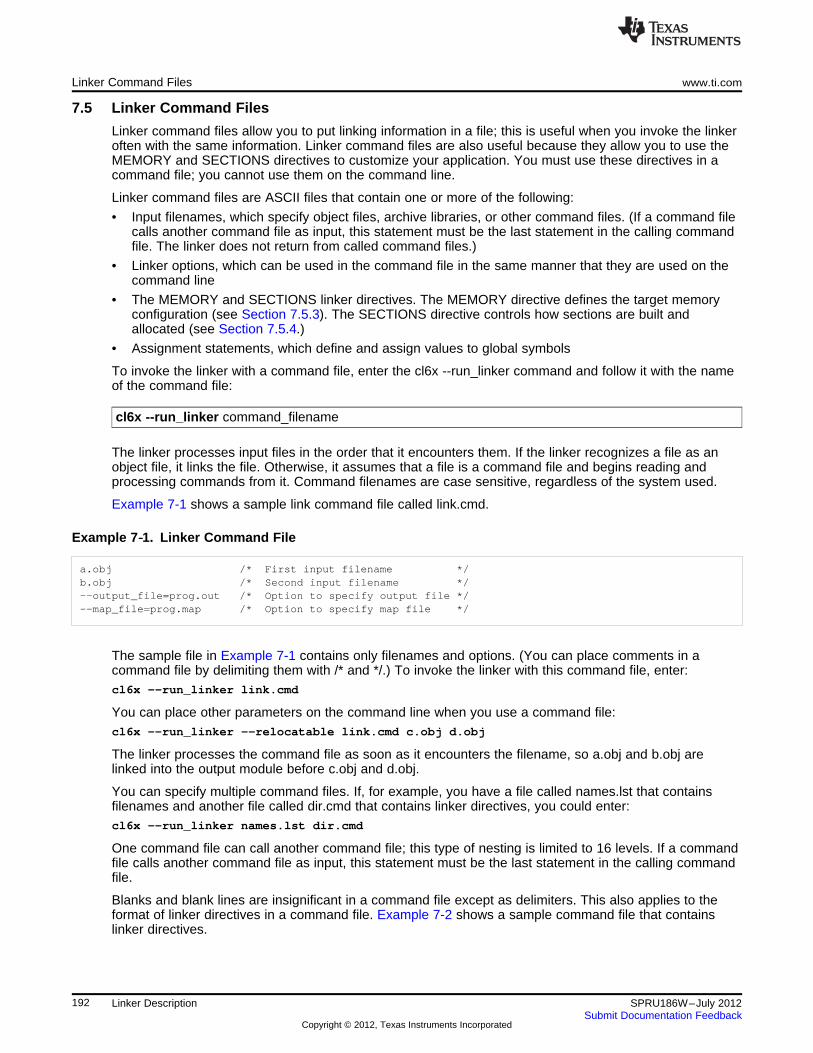
Linker Command Files www.ti.com
7.5 Linker Command Files
Linker command files allow you to put linking information in a file; this is useful when you invoke the linkeroften with the same information. Linker command files are also useful because they allow you to use theMEMORY and SECTIONS directives to customize your application. You must use these directives in acommand file; you cannot use them on the command line.
Linker command files are ASCII files that contain one or more of the following:
• Input filenames, which specify object files, archive libraries, or other command files. (If a command filecalls another command file as input, this statement must be the last statement in the calling commandfile. The linker does not return from called command files.)
• Linker options, which can be used in the command file in the same manner that they are used on thecommand line
• The MEMORY and SECTIONS linker directives. The MEMORY directive defines the target memoryconfiguration (see Section 7.5.3). The SECTIONS directive controls how sections are built andallocated (see Section 7.5.4.)
• Assignment statements, which define and assign values to global symbols
To invoke the linker with a command file, enter the cl6x --run_linker command and follow it with the nameof the command file:
cl6x --run_linker command_filename
The linker processes input files in the order that it encounters them. If the linker recognizes a file as anobject file, it links the file. Otherwise, it assumes that a file is a command file and begins reading andprocessing commands from it. Command filenames are case sensitive, regardless of the system used.
Example 7-1 shows a sample link command file called link.cmd.
Example 7‑‑1. Linker Command File
a.obj /* First input filename */b.obj /* Second input filename */--output_file=prog.out /* Option to specify output file */--map_file=prog.map /* Option to specify map file */
The sample file in Example 7-1 contains only filenames and options. (You can place comments in acommand file by delimiting them with /* and */.) To invoke the linker with this command file, enter:cl6x --run_linker link.cmd
You can place other parameters on the command line when you use a command file:cl6x --run_linker --relocatable link.cmd c.obj d.obj
The linker processes the command file as soon as it encounters the filename, so a.obj and b.obj arelinked into the output module before c.obj and d.obj.
You can specify multiple command files. If, for example, you have a file called names.lst that containsfilenames and another file called dir.cmd that contains linker directives, you could enter:cl6x --run_linker names.lst dir.cmd
One command file can call another command file; this type of nesting is limited to 16 levels. If a commandfile calls another command file as input, this statement must be the last statement in the calling commandfile.
Blanks and blank lines are insignificant in a command file except as delimiters. This also applies to theformat of linker directives in a command file. Example 7-2 shows a sample command file that containslinker directives.
192 Linker Description SPRU186W–July 2012Submit Documentation Feedback
Copyright © 2012, Texas Instruments Incorporated
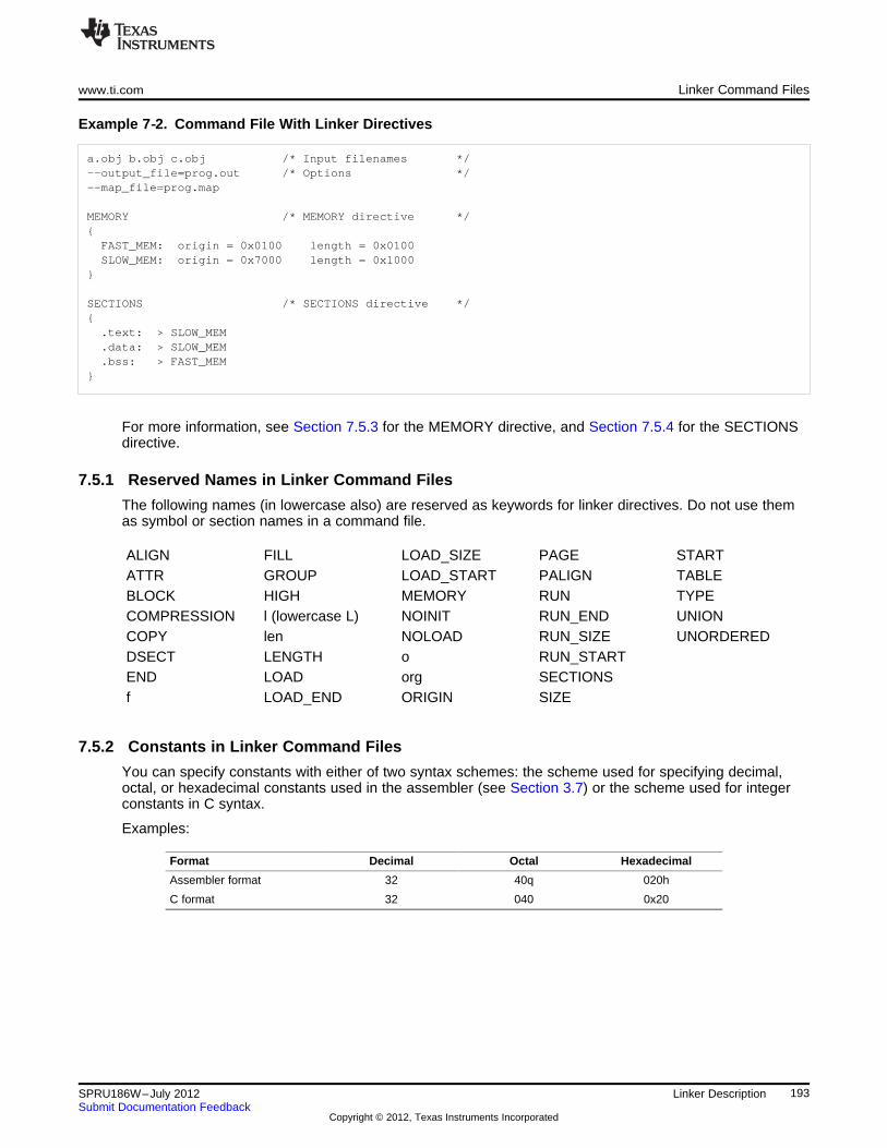
www.ti.com Linker Command Files
Example 7‑‑2. Command File With Linker Directives
a.obj b.obj c.obj /* Input filenames */--output_file=prog.out /* Options */--map_file=prog.map
MEMORY /* MEMORY directive */{FAST_MEM: origin = 0x0100 length = 0x0100SLOW_MEM: origin = 0x7000 length = 0x1000
}
SECTIONS /* SECTIONS directive */{.text: > SLOW_MEM.data: > SLOW_MEM.bss: > FAST_MEM
}
For more information, see Section 7.5.3 for the MEMORY directive, and Section 7.5.4 for the SECTIONSdirective.
7.5.1 Reserved Names in Linker Command Files
The following names (in lowercase also) are reserved as keywords for linker directives. Do not use themas symbol or section names in a command file.
ALIGN FILL LOAD_SIZE PAGE STARTATTR GROUP LOAD_START PALIGN TABLEBLOCK HIGH MEMORY RUN TYPECOMPRESSION l (lowercase L) NOINIT RUN_END UNIONCOPY len NOLOAD RUN_SIZE UNORDEREDDSECT LENGTH o RUN_STARTEND LOAD org SECTIONSf LOAD_END ORIGIN SIZE
7.5.2 Constants in Linker Command Files
You can specify constants with either of two syntax schemes: the scheme used for specifying decimal,octal, or hexadecimal constants used in the assembler (see Section 3.7) or the scheme used for integerconstants in C syntax.
Examples:
Format Decimal Octal Hexadecimal
Assembler format 32 40q 020h
C format 32 040 0x20
193SPRU186W–July 2012 Linker DescriptionSubmit Documentation Feedback
Copyright © 2012, Texas Instruments Incorporated
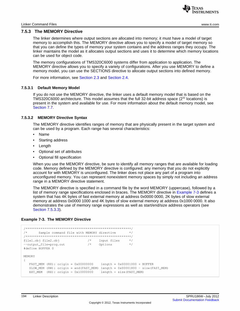
Linker Command Files www.ti.com
7.5.3 The MEMORY Directive
The linker determines where output sections are allocated into memory; it must have a model of targetmemory to accomplish this. The MEMORY directive allows you to specify a model of target memory sothat you can define the types of memory your system contains and the address ranges they occupy. Thelinker maintains the model as it allocates output sections and uses it to determine which memory locationscan be used for object code.
The memory configurations of TMS320C6000 systems differ from application to application. TheMEMORY directive allows you to specify a variety of configurations. After you use MEMORY to define amemory model, you can use the SECTIONS directive to allocate output sections into defined memory.
For more information, see Section 2.3 and Section 2.4.
7.5.3.1 Default Memory Model
If you do not use the MEMORY directive, the linker uses a default memory model that is based on theTMS320C6000 architecture. This model assumes that the full 32-bit address space (232 locations) ispresent in the system and available for use. For more information about the default memory model, seeSection 7.7.
7.5.3.2 MEMORY Directive Syntax
The MEMORY directive identifies ranges of memory that are physically present in the target system andcan be used by a program. Each range has several characteristics:
• Name
• Starting address
• Length
• Optional set of attributes
• Optional fill specification
When you use the MEMORY directive, be sure to identify all memory ranges that are available for loadingcode. Memory defined by the MEMORY directive is configured; any memory that you do not explicitlyaccount for with MEMORY is unconfigured. The linker does not place any part of a program intounconfigured memory. You can represent nonexistent memory spaces by simply not including an addressrange in a MEMORY directive statement.
The MEMORY directive is specified in a command file by the word MEMORY (uppercase), followed by alist of memory range specifications enclosed in braces. The MEMORY directive in Example 7-3 defines asystem that has 4K bytes of fast external memory at address 0x0000 0000, 2K bytes of slow externalmemory at address 0x0000 1000 and 4K bytes of slow external memory at address 0x1000 0000. It alsodemonstrates the use of memory range expressions as well as start/end/size address operators (seeSection 7.5.3.3).
Example 7-3. The MEMORY Directive
/********************************************************//* Sample command file with MEMORY directive *//********************************************************/file1.obj file2.obj /* Input files */--output_file=prog.out /* Options */#define BUFFER 0
MEMORY{
FAST_MEM (RX): origin = 0x00000000 length = 0x00001000 + BUFFERSLOW_MEM (RW): origin = end(FAST_MEM) length = 0x00001800 - size(FAST_MEM)EXT_MEM (RX): origin = 0x10000000 length = size(FAST_MEM)
194 Linker Description SPRU186W–July 2012Submit Documentation Feedback
Copyright © 2012, Texas Instruments Incorporated
www.ti.com Linker Command Files
The general syntax for the MEMORY directive is:MEMORY{
name 1 [( attr )] : origin = expression , length = expression [, fill = constant]..name n [( attr )] : origin = expression , length = expression [, fill = constant]
}
name names a memory range. A memory name can be one to 64 characters; valid charactersinclude A-Z, a-z, $, ., and _. The names have no special significance to the linker; theysimply identify memory ranges. Memory range names are internal to the linker and are notretained in the output file or in the symbol table. All memory ranges must have uniquenames and must not overlap.
attr specifies one to four attributes associated with the named range. Attributes are optional;when used, they must be enclosed in parentheses. Attributes restrict the allocation ofoutput sections into certain memory ranges. If you do not use any attributes, you canallocate any output section into any range with no restrictions. Any memory for which noattributes are specified (including all memory in the default model) has all four attributes.Valid attributes are:R specifies that the memory can be read.W specifies that the memory can be written to.X specifies that the memory can contain executable code.I specifies that the memory can be initialized.
origin specifies the starting address of a memory range; enter as origin, org, or o. The value,specified in bytes, is an expression of 32-bit constants, which can be decimal, octal, orhexadecimal.
length specifies the length of a memory range; enter as length, len, or l. The value, specified inbytes, is an expression of 32-bit constants, which can be decimal, octal, or hexadecimal.
fill specifies a fill character for the memory range; enter as fill or f. Fills are optional. The valueis a integer constant and can be decimal, octal, or hexadecimal. The fill value is used to fillareas of the memory range that are not allocated to a section.
Filling Memory Ranges
NOTE: If you specify fill values for large memory ranges, your output file will be very large becausefilling a memory range (even with 0s) causes raw data to be generated for all unallocatedblocks of memory in the range.
The following example specifies a memory range with the R and W attributes and a fill constant of0FFFFFFFFh:MEMORY{
RFILE (RW) : o = 0x00000020, l = 0x00001000, f = 0xFFFFFFFF}
You normally use the MEMORY directive in conjunction with the SECTIONS directive to control allocationof output sections. After you use MEMORY to specify the target system's memory model, you can useSECTIONS to allocate output sections into specific named memory ranges or into memory that hasspecific attributes. For example, you could allocate the .text and .data sections into the area namedFAST_MEM and allocate the .bss section into the area named SLOW_MEM.
195SPRU186W–July 2012 Linker DescriptionSubmit Documentation Feedback
Copyright © 2012, Texas Instruments Incorporated
Linker Command Files www.ti.com
7.5.3.3 Expressions and Address Operators
Memory range origin and length can now use expressions of integer constants with below operators:
Binary operators: * / % + - << >> == =< <= > >= & | && ||
Unary operators: - ~ !
Expressions are evaluated using standard C operator precedence rules.
No checking is done for overflow or underflow, however, expressions are evaluated using a larger integertype.
Preprocess directive #define constants can be used in place of integer constants. Global symbols cannotbe used in Memory Directive expressions.
Three new address operators have been added for referencing memory range properties from priormemory range entries:
START(MR) Returns start address for previously defined memory range MR.SIZE(MR) Returns size of previously defined memory range MR.END(MR) Returns end address for previously defined memory range MR.
Example 7-4. Origin and Length as Expressions
/********************************************************//* Sample command file with MEMORY directive *//********************************************************/file1.obj file2.obj /* Input files */--output_file=prog.out /* Options */#define ORIGIN 0x00000000#define BUFFER 0x00000200#define CACHE 0x0001000
MEMORY{
FAST_MEM (RX): origin = ORIGIN + CACHE length = 0x00001000 + BUFFERSLOW_MEM (RW): origin = end(FAST_MEM) length = 0x00001800 - size(FAST_MEM)EXT_MEM (RX): origin = 0x10000000 length = size(FAST_MEM) - CACHE
7.5.4 The SECTIONS Directive
The SECTIONS directive controls your sections in the following ways:
• Describes how input sections are combined into output sections
• Defines output sections in the executable program
• Specifies where output sections are placed in memory (in relation to each other and to the entirememory space)
• Permits renaming of output sections
For more information, see Section 2.3, Section 2.4, and Section 2.2.4. Subsections allow you tomanipulate sections with greater precision.
If you do not specify a SECTIONS directive, the linker uses a default algorithm for combining andallocating the sections. Section 7.7 describes this algorithm in detail.
7.5.4.1 SECTIONS Directive Syntax
The SECTIONS directive is specified in a command file by the word SECTIONS (uppercase), followed bya list of output section specifications enclosed in braces.
196 Linker Description SPRU186W–July 2012Submit Documentation Feedback
Copyright © 2012, Texas Instruments Incorporated
www.ti.com Linker Command Files
The general syntax for the SECTIONS directive is:
SECTIONS{
name : [property [, property] [, property] . . . ]name : [property [, property] [, property] . . . ]name : [property [, property] [, property] . . . ]
}
Each section specification, beginning with name, defines an output section. (An output section is a sectionin the output file.) A section name can be a subsection specification. (See Section 7.5.4.4 for informationon multi-level subsections.) After the section name is a list of properties that define the section's contentsand how the section is allocated. The properties can be separated by optional commas. Possibleproperties for a section are as follows:
• Load allocation defines where in memory the section is to be loaded.Syntax: load = allocation or
allocation or> allocation
• Run allocation defines where in memory the section is to be run.Syntax: run = allocation or
run > allocation
• Input sections defines the input sections (object files) that constitute the output section.Syntax: { input_sections }
• Section type defines flags for special section types. See Section 7.5.7Syntax: type = COPY or
type = DSECT ortype = NOLOAD
• Fill value defines the value used to fill uninitialized holes. See Section 7.5.9.Syntax: fill = value or
name : [properties = value]
Example 7-5 shows a SECTIONS directive in a sample link command file.
Example 7-5. The SECTIONS Directive
/**************************************************//* Sample command file with SECTIONS directive *//**************************************************/file1.obj file2.obj /* Input files */--output_file=prog.out /* Options */
SECTIONS{
.text: load = EXT_MEM, run = 0x00000800
.const: load = FAST_MEM
.bss: load = SLOW_MEM
.vectors: load = 0x00000000{
t1.obj(.intvec1)t2.obj(.intvec2)endvec = .;
197SPRU186W–July 2012 Linker DescriptionSubmit Documentation Feedback
Copyright © 2012, Texas Instruments Incorporated
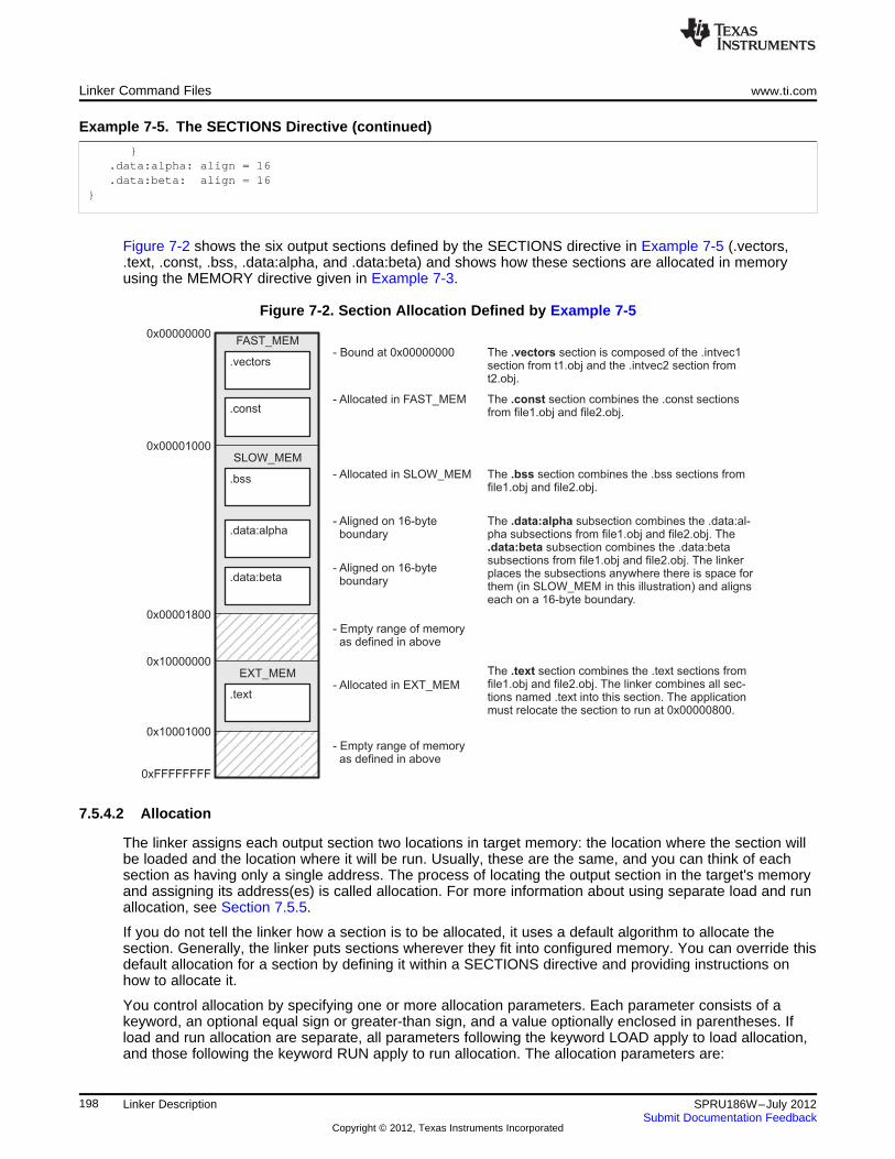
.const
.data:alpha
.vectors
FAST_MEM
.bss
SLOW_MEM
.data:beta
.text
EXT_MEM
0x00000000
0x00001000
0x00001800
0x10000000
0x10001000
0xFFFFFFFF
- Bound at 0x00000000
- Allocated in FAST_MEM
- Allocated in SLOW_MEM
- Aligned on 16-byteboundary
- Aligned on 16-byteboundary
- Empty range of memoryas defined in above
- Allocated in EXT_MEM
- Empty range of memoryas defined in above
The section is composed of the .intvec1section from t1.obj and the .intvec2 section fromt2.obj.
.vectors
The section combines the .const sectionsfrom file1.obj and file2.obj.
.const
The section combines the .bss sections fromfile1.obj and file2.obj.
.bss
The subsection combines the .data:al-pha subsections from file1.obj and file2.obj. The
subsection combines the .data:betasubsections from file1.obj and file2.obj. The linkerplaces the subsections anywhere there is space forthem (in SLOW_MEM in this illustration) and alignseach on a 16-byte boundary.
.data:alpha
.data:beta
The section combines the .text sections fromfile1.obj and file2.obj. The linker combines all sec-tions named .text into this section. The applicationmust relocate the section to run at 0x00000800.
.text
Linker Command Files www.ti.com
Example 7-5. The SECTIONS Directive (continued)
}.data:alpha: align = 16.data:beta: align = 16
}
Figure 7-2 shows the six output sections defined by the SECTIONS directive in Example 7-5 (.vectors,.text, .const, .bss, .data:alpha, and .data:beta) and shows how these sections are allocated in memoryusing the MEMORY directive given in Example 7-3.
Figure 7-2. Section Allocation Defined by Example 7-5
7.5.4.2 Allocation
The linker assigns each output section two locations in target memory: the location where the section willbe loaded and the location where it will be run. Usually, these are the same, and you can think of eachsection as having only a single address. The process of locating the output section in the target's memoryand assigning its address(es) is called allocation. For more information about using separate load and runallocation, see Section 7.5.5.
If you do not tell the linker how a section is to be allocated, it uses a default algorithm to allocate thesection. Generally, the linker puts sections wherever they fit into configured memory. You can override thisdefault allocation for a section by defining it within a SECTIONS directive and providing instructions onhow to allocate it.
You control allocation by specifying one or more allocation parameters. Each parameter consists of akeyword, an optional equal sign or greater-than sign, and a value optionally enclosed in parentheses. Ifload and run allocation are separate, all parameters following the keyword LOAD apply to load allocation,and those following the keyword RUN apply to run allocation. The allocation parameters are:
198 Linker Description SPRU186W–July 2012Submit Documentation Feedback
Copyright © 2012, Texas Instruments Incorporated
www.ti.com Linker Command Files
Binding allocates a section at a specific address..text: load = 0x1000
Named memory allocates the section into a range defined in the MEMORY directive with the specifiedname (like SLOW_MEM) or attributes..text: load > SLOW_MEM
Alignment uses the align or palign keyword to specify that the section must start on an addressboundary..text: align = 0x100
Blocking uses the block keyword to specify that the section must fit between two addressboundaries: if the section is too big, it starts on an address boundary..text: block(0x100)
For the load (usually the only) allocation, you can simply use a greater-than sign and omit the loadkeyword:
.text: > SLOW_MEM
.text: {...} > SLOW_MEM
.text: > 0x4000
If more than one parameter is used, you can string them together as follows:.text: > SLOW_MEM align 16
Or if you prefer, use parentheses for readability:.text: load = (SLOW_MEM align(16))
You can also use an input section specification to identify the sections from input files that are combinedto form an output section. See Section 7.5.4.3.
7.5.4.2.1 Binding
You can supply a specific starting address for an output section by following the section name with anaddress:
.text: 0x00001000
This example specifies that the .text section must begin at location 0x1000. The binding address must bea 32-bit constant.
Output sections can be bound anywhere in configured memory (assuming there is enough space), butthey cannot overlap. If there is not enough space to bind a section to a specified address, the linker issuesan error message.
Binding is Incompatible With Alignment and Named Memory
NOTE: You cannot bind a section to an address if you use alignment or named memory. If you try todo this, the linker issues an error message.
7.5.4.2.2 Named Memory
You can allocate a section into a memory range that is defined by the MEMORY directive (seeSection 7.5.3). This example names ranges and links sections into them:MEMORY{
SLOW_MEM (RIX) : origin = 0x00000000, length = 0x00001000FAST_MEM (RWIX) : origin = 0x03000000, length = 0x00000300
}
SECTIONS{
.text : > SLOW_MEM
.data : > FAST_MEM ALIGN(128)
.bss : > FAST_MEM
199SPRU186W–July 2012 Linker DescriptionSubmit Documentation Feedback
Copyright © 2012, Texas Instruments Incorporated
Linker Command Files www.ti.com
}
In this example, the linker places .text into the area called SLOW_MEM. The .data and .bss outputsections are allocated into FAST_MEM. You can align a section within a named memory range; the .datasection is aligned on a 128-byte boundary within the FAST_MEM range.
Similarly, you can link a section into an area of memory that has particular attributes. To do this, specify aset of attributes (enclosed in parentheses) instead of a memory name. Using the same MEMORY directivedeclaration, you can specify:SECTIONS{
.text: > (X) /* .text --> executable memory */
.data: > (RI) /* .data --> read or init memory */
.bss : > (RW) /* .bss --> read or write memory */}
In this example, the .text output section can be linked into either the SLOW_MEM or FAST_MEM areabecause both areas have the X attribute. The .data section can also go into either SLOW_MEM orFAST_MEM because both areas have the R and I attributes. The .bss output section, however, must gointo the FAST_MEM area because only FAST_MEM is declared with the W attribute.
You cannot control where in a named memory range a section is allocated, although the linker uses lowermemory addresses first and avoids fragmentation when possible. In the preceding examples, assuming noconflicting assignments exist, the .text section starts at address 0. If a section must start on a specificaddress, use binding instead of named memory.
7.5.4.2.3 Controlling Allocation Using The HIGH Location Specifier
The linker allocates output sections from low to high addresses within a designated memory range bydefault. Alternatively, you can cause the linker to allocate a section from high to low addresses within amemory range by using the HIGH location specifier in the SECTION directive declaration.
For example, given this MEMORY directive:MEMORY{
RAM : origin = 0x0200, length = 0x0800FLASH : origin = 0x1100, length = 0xEEE0VECTORS : origin = 0xFFE0, length = 0x001ERESET : origin = 0xFFFE, length = 0x0002
}
and an accompanying SECTIONS directive:SECTIONS{
.bss : {} > RAM
.sysmem : {} > RAM
.stack : {} > RAM (HIGH)}
The HIGH specifier used on the .stack section allocation causes the linker to attempt to allocate .stack intothe higher addresses within the RAM memory range. The .bss and .sysmem sections are allocated intothe lower addresses within RAM. Example 7-6 illustrates a portion of a map file that shows where thegiven sections are allocated within RAM for a typical program.
Example 7-6. Linker Allocation With the HIGH Specifier
.bss 0 00000200 00000270 UNINITIALIZED00000200 0000011a rtsxxx.lib : defs.obj (.bss)0000031a 00000088 : trgdrv.obj (.bss)000003a2 00000078 : lowlev.obj (.bss)0000041a 00000046 : exit.obj (.bss)00000460 00000008 : memory.obj (.bss)00000468 00000004 : _lock.obj (.bss)0000046c 00000002 : fopen.obj (.bss)0000046e 00000002 hello.obj (.bss)
200 Linker Description SPRU186W–July 2012Submit Documentation Feedback
Copyright © 2012, Texas Instruments Incorporated
www.ti.com Linker Command Files
Example 7-6. Linker Allocation With the HIGH Specifier (continued)
.sysmem 0 00000470 00000120 UNINITIALIZED00000470 00000004 rtsxxx .lib : memory.obj (.sysmem)
.stack 0 000008c0 00000140 UNINITIALIZED000008c0 00000002 rtsxxx .lib : boot.obj (.stack)
As shown in Example 7-6 , the .bss and .sysmem sections are allocated at the lower addresses of RAM(0x0200 - 0x0590) and the .stack section is allocated at address 0x08c0, even though lower addressesare available.
Without using the HIGH specifier, the linker allocation would result in the code shown in Example 7-7
The HIGH specifier is ignored if it is used with specific address binding or automatic section splitting (>>operator).
Example 7-7. Linker Allocation Without HIGH Specifier
.bss 0 00000200 00000270 UNINITIALIZED00000200 0000011a rtsxxx.lib : defs.obj (.bss)0000031a 00000088 : trgdrv.obj (.bss)000003a2 00000078 : lowlev.obj (.bss)0000041a 00000046 : exit.obj (.bss)00000460 00000008 : memory.obj (.bss)00000468 00000004 : _lock.obj (.bss)0000046c 00000002 : fopen.obj (.bss)0000046e 00000002 hello.obj (.bss)
.stack 0 00000470 00000140 UNINITIALIZED00000470 00000002 rtsxxx.lib : boot.obj (.stack)
.sysmem 0 000005b0 00000120 UNINITIALIZED000005b0 00000004 rtsxxx.lib : memory.obj (.sysmem)
7.5.4.2.4 Alignment and Blocking
You can tell the linker to place an output section at an address that falls on an n-byte boundary, where nis a power of 2, by using the align keyword. For example, the following code allocates .text so that it fallson a 32-byte boundary:
.text: load = align(32)
You can specify the same alignment with the palign keyword. In addition, palign ensures the section's sizeis a multiple of its placement alignment restrictions, padding the section size up to such a boundary, asneeded.
Blocking is a weaker form of alignment that allocates a section anywhere within a block of size n. Thespecified block size must be a power of 2. For example, the following code allocates .bss so that the entiresection is contained in a single 128-byte page or begins on that boundary:bss: load = block(0x0080)
You can use alignment or blocking alone or in conjunction with a memory area, but alignment andblocking cannot be used together.
201SPRU186W–July 2012 Linker DescriptionSubmit Documentation Feedback
Copyright © 2012, Texas Instruments Incorporated
Linker Command Files www.ti.com
7.5.4.2.5 Alignment With Padding
As with align, you can tell the linker to place an output section at an address that falls on an n-byteboundary, where n is a power of 2, by using the palign keyword. In addition, palign ensures that the sizeof the section is a multiple of its placement alignment restrictions, padding the section size up to such aboundary, as needed.
For example, the following code lines allocate .text on a 2-byte boundary within the PMEM area. The .textsection size is guaranteed to be a multiple of 2 bytes. Both statements are equivalent:
.text: palign(2) {} > PMEM
.text: palign = 2 {} > PMEM
If the linker adds padding to an initialized output section then the padding space is also initialized. Bydefault, padding space is filled with a value of 0 (zero). However, if a fill value is specified for the outputsection then any padding for the section is also filled with that fill value.
For example, consider the following section specification:.mytext: palign(8), fill = 0xffffffff {} > PMEM
In this example, the length of the .mytext section is 6 bytes before the palign operator is applied. Thecontents of .mytext are as follows:addr content---- -------0000 0x12340002 0x12340004 0x1234
After the palign operator is applied, the length of .mytext is 8 bytes, and its contents are as follows:addr content---- -------0000 0x12340002 0x12340004 0x12340006 0xffff
The size of .mytext has been bumped to a multiple of 8 bytes and the padding created by the linker hasbeen filled with 0xff.
The fill value specified in the linker command file is interpreted as a 16-bit constant, so if you specify thiscode:
.mytext: palign(8), fill = 0xff {} > PMEM
The fill value assumed by the linker is 0x00ff, and .mytext will then have the following contents:addr content---- -------0000 0x12340002 0x12340004 0x12340006 0xffff0008 0x00ff000a 0x00ff
If the palign operator is applied to an uninitialized section, then the size of the section is bumped to theappropriate boundary, as needed, but any padding created is not initialized.
The palign operator can also take a parameter of power2. This parameter tells the linker to add padding toincrease the section's size to the next power of two boundary. In addition, the section is aligned on thatpower of 2 as well.
For example, consider the following section specification:.mytext: palign(power2) {} > PMEM
Assume that the size of the .mytext section is 120 bytes and PMEM starts at address 0x10020. Afterapplying the palign(power2) operator, the .mytext output section will have the following properties:name addr size align
202 Linker Description SPRU186W–July 2012Submit Documentation Feedback
Copyright © 2012, Texas Instruments Incorporated
www.ti.com Linker Command Files
------- ---------- ----- -----.mytext 0x00010080 0x80 128
203SPRU186W–July 2012 Linker DescriptionSubmit Documentation Feedback
Copyright © 2012, Texas Instruments Incorporated
Linker Command Files www.ti.com
7.5.4.3 Specifying Input Sections
An input section specification identifies the sections from input files that are combined to form an outputsection. In general, the linker combines input sections by concatenating them in the order in which theyare specified. However, if alignment or blocking is specified for an input section, all of the input sectionswithin the output section are ordered as follows:
• All aligned sections, from largest to smallest
• All blocked sections, from largest to smallest
• All other sections, from largest to smallest
The size of an output section is the sum of the sizes of the input sections that it comprises.
Example 7-8 shows the most common type of section specification; note that no input sections are listed.
Example 7-8. The Most Common Method of Specifying Section Contents
SECTIONS{
.text:
.data:
.bss:}
In Example 7-8, the linker takes all the .text sections from the input files and combines them into the .textoutput section. The linker concatenates the .text input sections in the order that it encounters them in theinput files. The linker performs similar operations with the .data and .bss sections. You can use this type ofspecification for any output section.
You can explicitly specify the input sections that form an output section. Each input section is identified byits filename and section name. If the filename is hyphenated (or contains special characters), enclose itwithin quotes:SECTIONS{.text : /* Build .text output section */{f1.obj(.text) /* Link .text section from f1.obj */f2.obj(sec1) /* Link sec1 section from f2.obj */"f3-new.obj" /* Link ALL sections from f3-new.obj */f4.obj"(.text,sec2) /* Link .text and sec2 from f4.obj */}
}
It is not necessary for input sections to have the same name as each other or as the output section theybecome part of. If a file is listed with no sections,all of its sections are included in the output section. If anyadditional input sections have the same name as an output section but are not explicitly specified by theSECTIONS directive, they are automatically linked in at the end of the output section. For example, if thelinker found more .text sections in the preceding example and these .text sections were not specifiedanywhere in the SECTIONS directive, the linker would concatenate these extra sections after f4.obj(sec2).
The specifications in Example 7-8 are actually a shorthand method for the following:SECTIONS{.text: { *(.text) }.data: { *(.data) }.bss: { *(.bss) }
}
The specification *(.text) means the unallocated .text sections from all the input files. This format is usefulwhen:
• You want the output section to contain all input sections that have a specified name, but the outputsection name is different from the input sections' name.
204 Linker Description SPRU186W–July 2012Submit Documentation Feedback
Copyright © 2012, Texas Instruments Incorporated
www.ti.com Linker Command Files
• You want the linker to allocate the input sections before it processes additional input sections orcommands within the braces.
205SPRU186W–July 2012 Linker DescriptionSubmit Documentation Feedback
Copyright © 2012, Texas Instruments Incorporated
Linker Command Files www.ti.com
The following example illustrates the two purposes above:SECTIONS{
.text : {abc.obj(xqt)
*(.text)}
.data : {*(.data)fil.obj(table)
}}
In this example, the .text output section contains a named section xqt from file abc.obj, which is followedby all the .text input sections. The .data section contains all the .data input sections, followed by a namedsection table from the file fil.obj. This method includes all the unallocated sections. For example, if one ofthe .text input sections was already included in another output section when the linker encountered*(.text), the linker could not include that first .text input section in the second output section.
7.5.4.4 Using Multi-Level Subsections
Subsections can be identified with the base section name and one or more subsection names separatedby colons. For example, A:B and A:B:C name subsections of the base section A. In certain places in a linkcommand file specifying a base name, such as A, selects the section A as well as any subsections of A,such as A:B or A:C:D.
A name such as A:B can be used to specify a (sub)section of that name as well as any (multi-level)subsections beginning with that name, such as A:B:C, A:B:OTHER, etc. All the subsections of A:B arealso subsections of A. A and A:B are supersections of A:B:C. Among a group of supersections of asubsection, the nearest supersection is the supersection with the longest name. Thus, among {A, A:B} thenearest supersection of A:B:C:D is A:B.
With multiple levels of subsections, the constraints are the following:
1. When specifying input sections within a file (or library unit) the section name selects an input sectionof the same name and any subsections of that name.
2. Input sections that are not explicitly allocated are allocated in an existing output section of the samename or in the nearest existing supersection of such an output section. An exception to this rule is thatduring a partial link (specified by the --relocatable linker option) a subsection is allocated only to anexisting output section of the same name.
3. If no such output section described in 2) is defined, the input section is put in a newly created outputsection with the same name as the base name of the input section
Consider linking input sections with the following names:europe:north:norway europe:central:france europe:south:spaineurope:north:sweden europe:central:germany europe:south:italyeurope:north:finland europe:central:denmark europe:south:maltaeurope:north:iceland
This SECTIONS specification allocates the input sections as indicated in the comments:SECTIONS {nordic: {*(europe:north)
*(europe:central:denmark)} /* the nordic countries */central: {*(europe:central)} /* france, germany */therest: {*(europe)} /* spain, italy, malta */
}
206 Linker Description SPRU186W–July 2012Submit Documentation Feedback
Copyright © 2012, Texas Instruments Incorporated
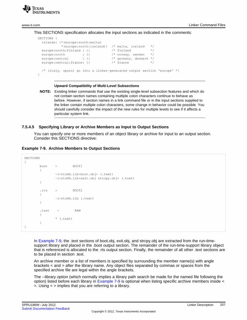
www.ti.com Linker Command Files
This SECTIONS specification allocates the input sections as indicated in the comments:SECTIONS {islands: {*(europe:south:malta)
*(europe:north:iceland)} /* malta, iceland */europe:north:finland : {} /* finland */europe:north : {} /* norway, sweden */europe:central : {} /* germany, denmark */europe:central:france: {} /* france */
/* (italy, spain) go into a linker-generated output section "europe" */}
Upward Compatibility of Multi-Level Subsections
NOTE: Existing linker commands that use the existing single-level subsection features and which donot contain section names containing multiple colon characters continue to behave asbefore. However, if section names in a link command file or in the input sections supplied tothe linker contain multiple colon characters, some change in behavior could be possible. Youshould carefully consider the impact of the new rules for multiple levels to see if it affects aparticular system link.
7.5.4.5 Specifying Library or Archive Members as Input to Output Sections
You can specify one or more members of an object library or archive for input to an output section.Consider this SECTIONS directive:
Example 7-9. Archive Members to Output Sections
SECTIONS{
boot > BOOT1{
-l=rtsXX.lib<boot.obj> (.text)-l=rtsXX.lib<exit.obj strcpy.obj> (.text)
}
.rts > BOOT2{
-l=rtsXX.lib (.text)}
.text > RAM{
* (.text)}
}
In Example 7-9, the .text sections of boot.obj, exit.obj, and strcpy.obj are extracted from the run-time-support library and placed in the .boot output section. The remainder of the run-time-support library objectthat is referenced is allocated to the .rts output section. Finally, the remainder of all other .text sections areto be placed in section .text.
An archive member or a list of members is specified by surrounding the member name(s) with anglebrackets < and > after the library name. Any object files separated by commas or spaces from thespecified archive file are legal within the angle brackets.
The --library option (which normally implies a library path search be made for the named file following theoption) listed before each library in Example 7-9 is optional when listing specific archive members inside <>. Using < > implies that you are referring to a library.
207SPRU186W–July 2012 Linker DescriptionSubmit Documentation Feedback
Copyright © 2012, Texas Instruments Incorporated
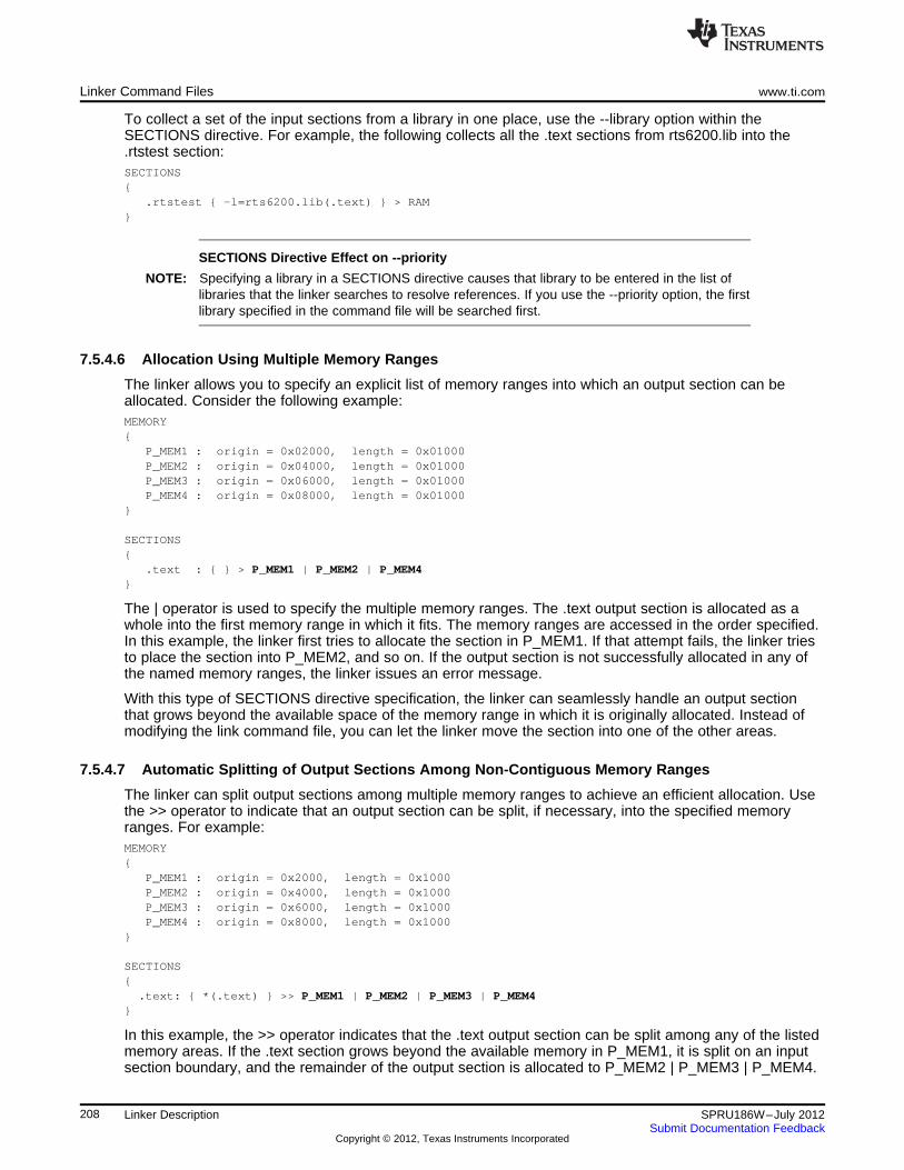
Linker Command Files www.ti.com
To collect a set of the input sections from a library in one place, use the --library option within theSECTIONS directive. For example, the following collects all the .text sections from rts6200.lib into the.rtstest section:SECTIONS{
.rtstest { -l=rts6200.lib(.text) } > RAM}
SECTIONS Directive Effect on --priority
NOTE: Specifying a library in a SECTIONS directive causes that library to be entered in the list oflibraries that the linker searches to resolve references. If you use the --priority option, the firstlibrary specified in the command file will be searched first.
7.5.4.6 Allocation Using Multiple Memory Ranges
The linker allows you to specify an explicit list of memory ranges into which an output section can beallocated. Consider the following example:MEMORY{
P_MEM1 : origin = 0x02000, length = 0x01000P_MEM2 : origin = 0x04000, length = 0x01000P_MEM3 : origin = 0x06000, length = 0x01000P_MEM4 : origin = 0x08000, length = 0x01000
}
SECTIONS{
.text : { } > P_MEM1 | P_MEM2 | P_MEM4}
The | operator is used to specify the multiple memory ranges. The .text output section is allocated as awhole into the first memory range in which it fits. The memory ranges are accessed in the order specified.In this example, the linker first tries to allocate the section in P_MEM1. If that attempt fails, the linker triesto place the section into P_MEM2, and so on. If the output section is not successfully allocated in any ofthe named memory ranges, the linker issues an error message.
With this type of SECTIONS directive specification, the linker can seamlessly handle an output sectionthat grows beyond the available space of the memory range in which it is originally allocated. Instead ofmodifying the link command file, you can let the linker move the section into one of the other areas.
7.5.4.7 Automatic Splitting of Output Sections Among Non-Contiguous Memory Ranges
The linker can split output sections among multiple memory ranges to achieve an efficient allocation. Usethe >> operator to indicate that an output section can be split, if necessary, into the specified memoryranges. For example:MEMORY{
P_MEM1 : origin = 0x2000, length = 0x1000P_MEM2 : origin = 0x4000, length = 0x1000P_MEM3 : origin = 0x6000, length = 0x1000P_MEM4 : origin = 0x8000, length = 0x1000
}
SECTIONS{.text: { *(.text) } >> P_MEM1 | P_MEM2 | P_MEM3 | P_MEM4
}
In this example, the >> operator indicates that the .text output section can be split among any of the listedmemory areas. If the .text section grows beyond the available memory in P_MEM1, it is split on an inputsection boundary, and the remainder of the output section is allocated to P_MEM2 | P_MEM3 | P_MEM4.
208 Linker Description SPRU186W–July 2012Submit Documentation Feedback
Copyright © 2012, Texas Instruments Incorporated
www.ti.com Linker Command Files
The | operator is used to specify the list of multiple memory ranges.
209SPRU186W–July 2012 Linker DescriptionSubmit Documentation Feedback
Copyright © 2012, Texas Instruments Incorporated
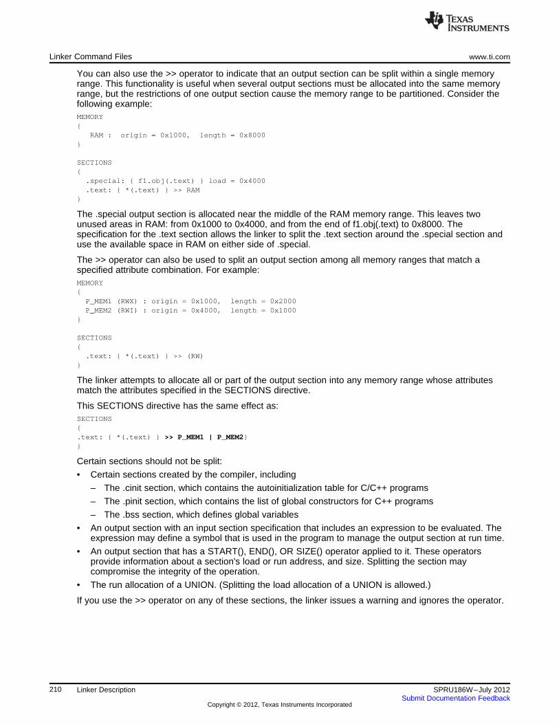
Linker Command Files www.ti.com
You can also use the >> operator to indicate that an output section can be split within a single memoryrange. This functionality is useful when several output sections must be allocated into the same memoryrange, but the restrictions of one output section cause the memory range to be partitioned. Consider thefollowing example:MEMORY{
RAM : origin = 0x1000, length = 0x8000}
SECTIONS{.special: { f1.obj(.text) } load = 0x4000.text: { *(.text) } >> RAM
}
The .special output section is allocated near the middle of the RAM memory range. This leaves twounused areas in RAM: from 0x1000 to 0x4000, and from the end of f1.obj(.text) to 0x8000. Thespecification for the .text section allows the linker to split the .text section around the .special section anduse the available space in RAM on either side of .special.
The >> operator can also be used to split an output section among all memory ranges that match aspecified attribute combination. For example:MEMORY{P_MEM1 (RWX) : origin = 0x1000, length = 0x2000P_MEM2 (RWI) : origin = 0x4000, length = 0x1000
}
SECTIONS{.text: { *(.text) } >> (RW)
}
The linker attempts to allocate all or part of the output section into any memory range whose attributesmatch the attributes specified in the SECTIONS directive.
This SECTIONS directive has the same effect as:SECTIONS{.text: { *(.text) } >> P_MEM1 | P_MEM2}}
Certain sections should not be split:
• Certain sections created by the compiler, including
– The .cinit section, which contains the autoinitialization table for C/C++ programs
– The .pinit section, which contains the list of global constructors for C++ programs
– The .bss section, which defines global variables
• An output section with an input section specification that includes an expression to be evaluated. Theexpression may define a symbol that is used in the program to manage the output section at run time.
• An output section that has a START(), END(), OR SIZE() operator applied to it. These operatorsprovide information about a section's load or run address, and size. Splitting the section maycompromise the integrity of the operation.
• The run allocation of a UNION. (Splitting the load allocation of a UNION is allowed.)
If you use the >> operator on any of these sections, the linker issues a warning and ignores the operator.
210 Linker Description SPRU186W–July 2012Submit Documentation Feedback
Copyright © 2012, Texas Instruments Incorporated
www.ti.com Linker Command Files
7.5.5 Specifying a Section's Run-Time Address
At times, you may want to load code into one area of memory and run it in another. For example, you mayhave performance-critical code in slow external memory. The code must be loaded into slow externalmemory, but it would run faster in fast external memory.
The linker provides a simple way to accomplish this. You can use the SECTIONS directive to direct thelinker to allocate a section twice: once to set its load address and again to set its run address. Forexample:
.fir: load = SLOW_MEM, run = FAST_MEM
Use the load keyword for the load address and the run keyword for the run address.
See Section 2.5 for an overview on run-time relocation.
7.5.5.1 Specifying Load and Run Addresses
The load address determines where a loader places the raw data for the section. Any references to thesection (such as labels in it) refer to its run address. The application must copy the section from its loadaddress to its run address; this does not happen automatically when you specify a separate run address.(The TABLE operator instructs the linker to produce a copy table; see Section 7.8.5.
If you provide only one allocation (either load or run) for a section, the section is allocated only once andloads and runs at the same address. If you provide both allocations, the section is allocated as if it weretwo sections of the same size. This means that both allocations occupy space in the memory map andcannot overlay each other or other sections. (The UNION directive provides a way to overlay sections; seeSection 7.5.6.1.)
If either the load or run address has additional parameters, such as alignment or blocking, list them afterthe appropriate keyword. Everything related to allocation after the keyword load affects the load addressuntil the keyword run is seen, after which, everything affects the run address. The load and run allocationsare completely independent, so any qualification of one (such as alignment) has no effect on the other.You can also specify run first, then load. Use parentheses to improve readability.
The examples below specify load and run addresses:.data: load = SLOW_MEM, align = 32, run = FAST_MEM
(align applies only to load).data: load = (SLOW_MEM align 32), run = FAST_MEM
(identical to previous example).data: run = FAST_MEM, align 32,
load = align 16
(align 32 in FAST_MEM for run; align 16 anywhere for load)
For more information on run-time relocation see
7.5.5.2 Uninitialized Sections
Uninitialized sections (such as .bss) are not loaded, so their only significant address is the run address.The linker allocates uninitialized sections only once: if you specify both run and load addresses, the linkerwarns you and ignores the load address. Otherwise, if you specify only one address, the linker treats it asa run address, regardless of whether you call it load or run. This example specifies load and runaddresses for an uninitialized section:
.bss: load = 0x1000, run = FAST_MEM
A warning is issued, load is ignored, and space is allocated in FAST_MEM. All of the following exampleshave the same effect. The .bss section is allocated in FAST_MEM.
.bss: load = FAST_MEM
.bss: run = FAST_MEM
.bss: > FAST_MEM
211SPRU186W–July 2012 Linker DescriptionSubmit Documentation Feedback
Copyright © 2012, Texas Instruments Incorporated
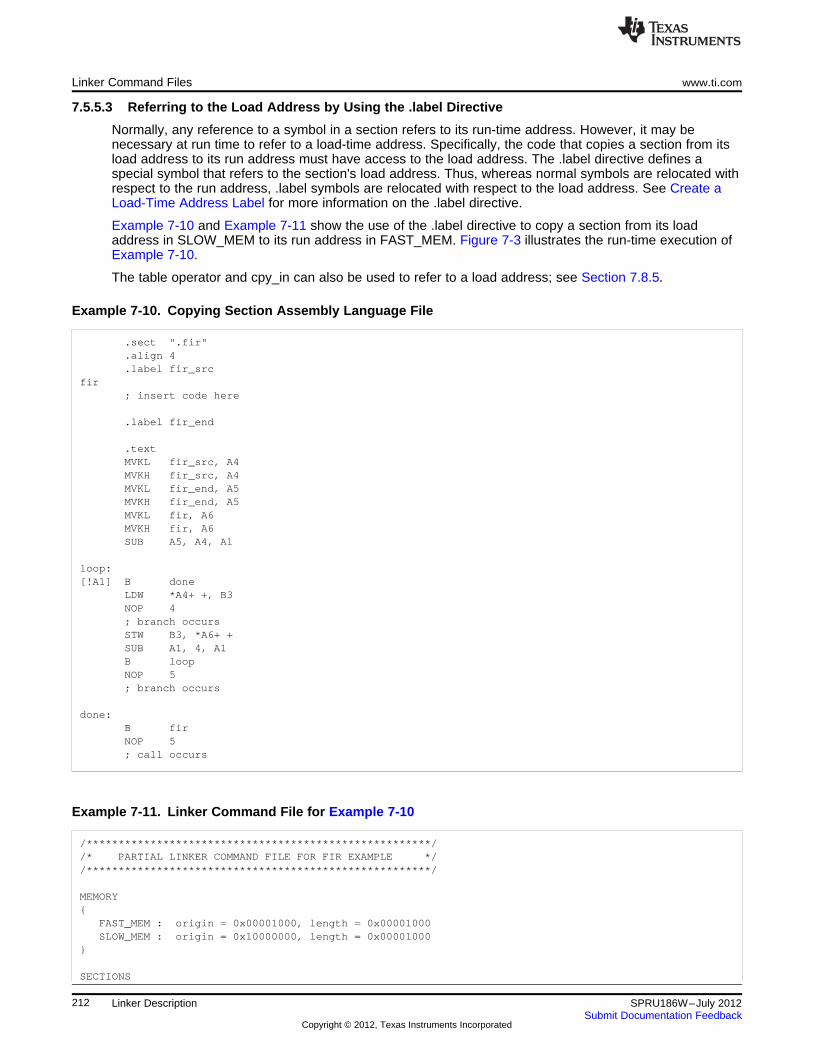
Linker Command Files www.ti.com
7.5.5.3 Referring to the Load Address by Using the .label Directive
Normally, any reference to a symbol in a section refers to its run-time address. However, it may benecessary at run time to refer to a load-time address. Specifically, the code that copies a section from itsload address to its run address must have access to the load address. The .label directive defines aspecial symbol that refers to the section's load address. Thus, whereas normal symbols are relocated withrespect to the run address, .label symbols are relocated with respect to the load address. See Create aLoad-Time Address Label for more information on the .label directive.
Example 7-10 and Example 7-11 show the use of the .label directive to copy a section from its loadaddress in SLOW_MEM to its run address in FAST_MEM. Figure 7-3 illustrates the run-time execution ofExample 7-10.
The table operator and cpy_in can also be used to refer to a load address; see Section 7.8.5.
Example 7-10. Copying Section Assembly Language File
.sect ".fir"
.align 4
.label fir_srcfir
; insert code here
.label fir_end
.textMVKL fir_src, A4MVKH fir_src, A4MVKL fir_end, A5MVKH fir_end, A5MVKL fir, A6MVKH fir, A6SUB A5, A4, A1
loop:[!A1] B done
LDW *A4+ +, B3NOP 4; branch occursSTW B3, *A6+ +SUB A1, 4, A1B loopNOP 5; branch occurs
done:B firNOP 5; call occurs
Example 7-11. Linker Command File for Example 7-10
/******************************************************//* PARTIAL LINKER COMMAND FILE FOR FIR EXAMPLE *//******************************************************/
MEMORY{
FAST_MEM : origin = 0x00001000, length = 0x00001000SLOW_MEM : origin = 0x10000000, length = 0x00001000
}
SECTIONS
212 Linker Description SPRU186W–July 2012Submit Documentation Feedback
Copyright © 2012, Texas Instruments Incorporated
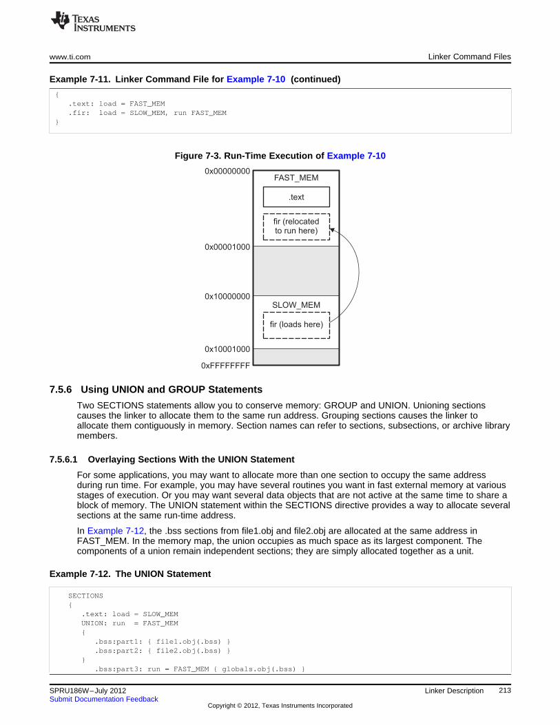
fir (relocatedto run here)
.text
FAST_MEM
SLOW_MEM
fir (loads here)
0x00000000
0x00001000
0x10000000
0x10001000
0xFFFFFFFF
www.ti.com Linker Command Files
Example 7-11. Linker Command File for Example 7-10 (continued)
{.text: load = FAST_MEM.fir: load = SLOW_MEM, run FAST_MEM
}
Figure 7-3. Run-Time Execution of Example 7-10
7.5.6 Using UNION and GROUP Statements
Two SECTIONS statements allow you to conserve memory: GROUP and UNION. Unioning sectionscauses the linker to allocate them to the same run address. Grouping sections causes the linker toallocate them contiguously in memory. Section names can refer to sections, subsections, or archive librarymembers.
7.5.6.1 Overlaying Sections With the UNION Statement
For some applications, you may want to allocate more than one section to occupy the same addressduring run time. For example, you may have several routines you want in fast external memory at variousstages of execution. Or you may want several data objects that are not active at the same time to share ablock of memory. The UNION statement within the SECTIONS directive provides a way to allocate severalsections at the same run-time address.
In Example 7-12, the .bss sections from file1.obj and file2.obj are allocated at the same address inFAST_MEM. In the memory map, the union occupies as much space as its largest component. Thecomponents of a union remain independent sections; they are simply allocated together as a unit.
Example 7-12. The UNION Statement
SECTIONS{
.text: load = SLOW_MEMUNION: run = FAST_MEM{
.bss:part1: { file1.obj(.bss) }
.bss:part2: { file2.obj(.bss) }}
.bss:part3: run = FAST_MEM { globals.obj(.bss) }
213SPRU186W–July 2012 Linker DescriptionSubmit Documentation Feedback
Copyright © 2012, Texas Instruments Incorporated
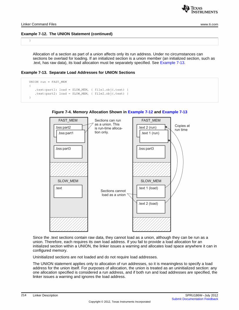
.bss:part2
.bss:part1
.bss:part3
FAST_MEM
.text
SLOW_MEM
Sections can runas a union. Thisis run-time alloca-tion only.
.text 2 (run)
.text 1 (run)
.bss:part3
FAST_MEM
.text 1 (load)
SLOW_MEM
.text 2 (load)
Sections cannotload as a union
Copies atrun time
Linker Command Files www.ti.com
Example 7-12. The UNION Statement (continued)
}
Allocation of a section as part of a union affects only its run address. Under no circumstances cansections be overlaid for loading. If an initialized section is a union member (an initialized section, such as.text, has raw data), its load allocation must be separately specified. See Example 7-13.
Example 7-13. Separate Load Addresses for UNION Sections
UNION run = FAST_MEM{
.text:part1: load = SLOW_MEM, { file1.obj(.text) }
.text:part2: load = SLOW_MEM, { file2.obj(.text) }}
Figure 7-4. Memory Allocation Shown in Example 7-12 and Example 7-13
Since the .text sections contain raw data, they cannot load as a union, although they can be run as aunion. Therefore, each requires its own load address. If you fail to provide a load allocation for aninitialized section within a UNION, the linker issues a warning and allocates load space anywhere it can inconfigured memory.
Uninitialized sections are not loaded and do not require load addresses.
The UNION statement applies only to allocation of run addresses, so it is meaningless to specify a loadaddress for the union itself. For purposes of allocation, the union is treated as an uninitialized section: anyone allocation specified is considered a run address, and if both run and load addresses are specified, thelinker issues a warning and ignores the load address.
214 Linker Description SPRU186W–July 2012Submit Documentation Feedback
Copyright © 2012, Texas Instruments Incorporated
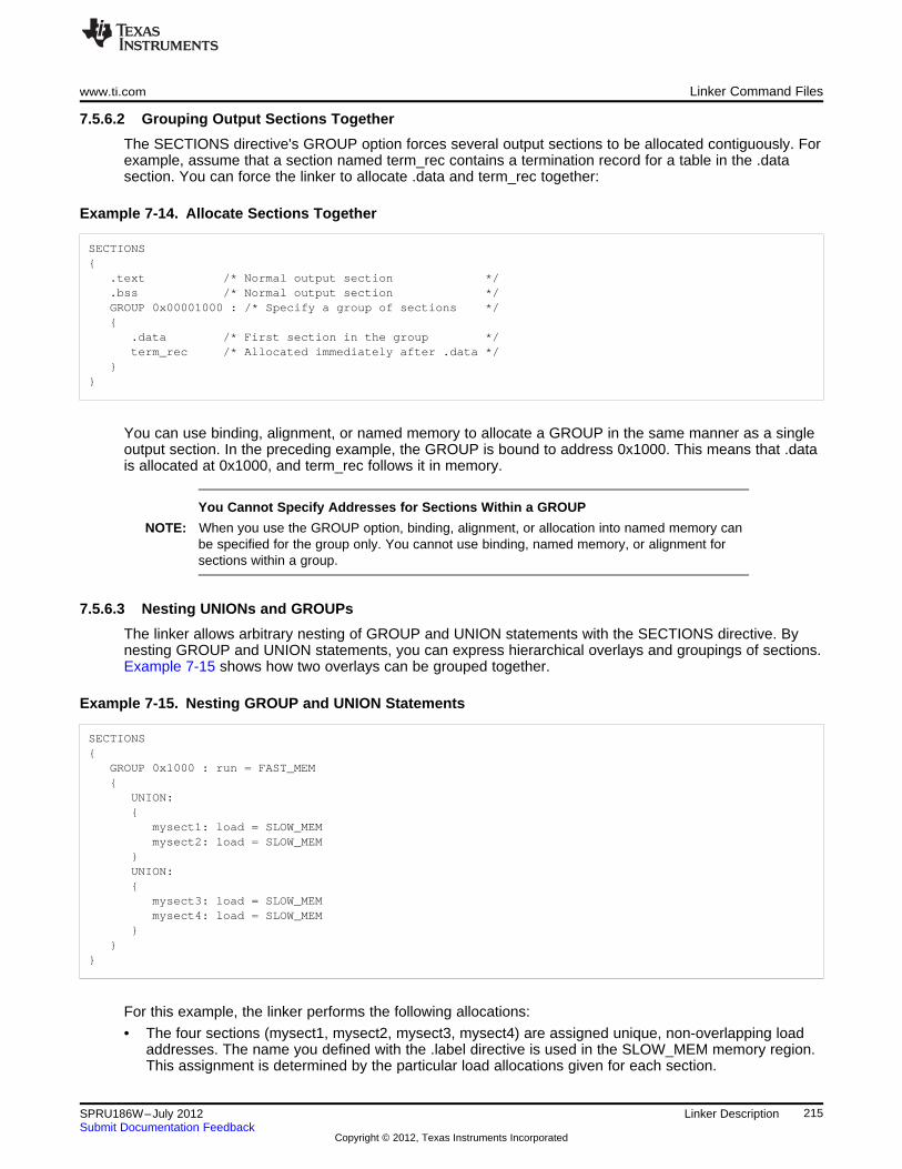
www.ti.com Linker Command Files
7.5.6.2 Grouping Output Sections Together
The SECTIONS directive's GROUP option forces several output sections to be allocated contiguously. Forexample, assume that a section named term_rec contains a termination record for a table in the .datasection. You can force the linker to allocate .data and term_rec together:
Example 7-14. Allocate Sections Together
SECTIONS{
.text /* Normal output section */
.bss /* Normal output section */GROUP 0x00001000 : /* Specify a group of sections */{
.data /* First section in the group */term_rec /* Allocated immediately after .data */
}}
You can use binding, alignment, or named memory to allocate a GROUP in the same manner as a singleoutput section. In the preceding example, the GROUP is bound to address 0x1000. This means that .datais allocated at 0x1000, and term_rec follows it in memory.
You Cannot Specify Addresses for Sections Within a GROUP
NOTE: When you use the GROUP option, binding, alignment, or allocation into named memory canbe specified for the group only. You cannot use binding, named memory, or alignment forsections within a group.
7.5.6.3 Nesting UNIONs and GROUPs
The linker allows arbitrary nesting of GROUP and UNION statements with the SECTIONS directive. Bynesting GROUP and UNION statements, you can express hierarchical overlays and groupings of sections.Example 7-15 shows how two overlays can be grouped together.
Example 7-15. Nesting GROUP and UNION Statements
SECTIONS{
GROUP 0x1000 : run = FAST_MEM{
UNION:{
mysect1: load = SLOW_MEMmysect2: load = SLOW_MEM
}UNION:{
mysect3: load = SLOW_MEMmysect4: load = SLOW_MEM
}}
}
For this example, the linker performs the following allocations:
• The four sections (mysect1, mysect2, mysect3, mysect4) are assigned unique, non-overlapping loadaddresses. The name you defined with the .label directive is used in the SLOW_MEM memory region.This assignment is determined by the particular load allocations given for each section.
215SPRU186W–July 2012 Linker DescriptionSubmit Documentation Feedback
Copyright © 2012, Texas Instruments Incorporated
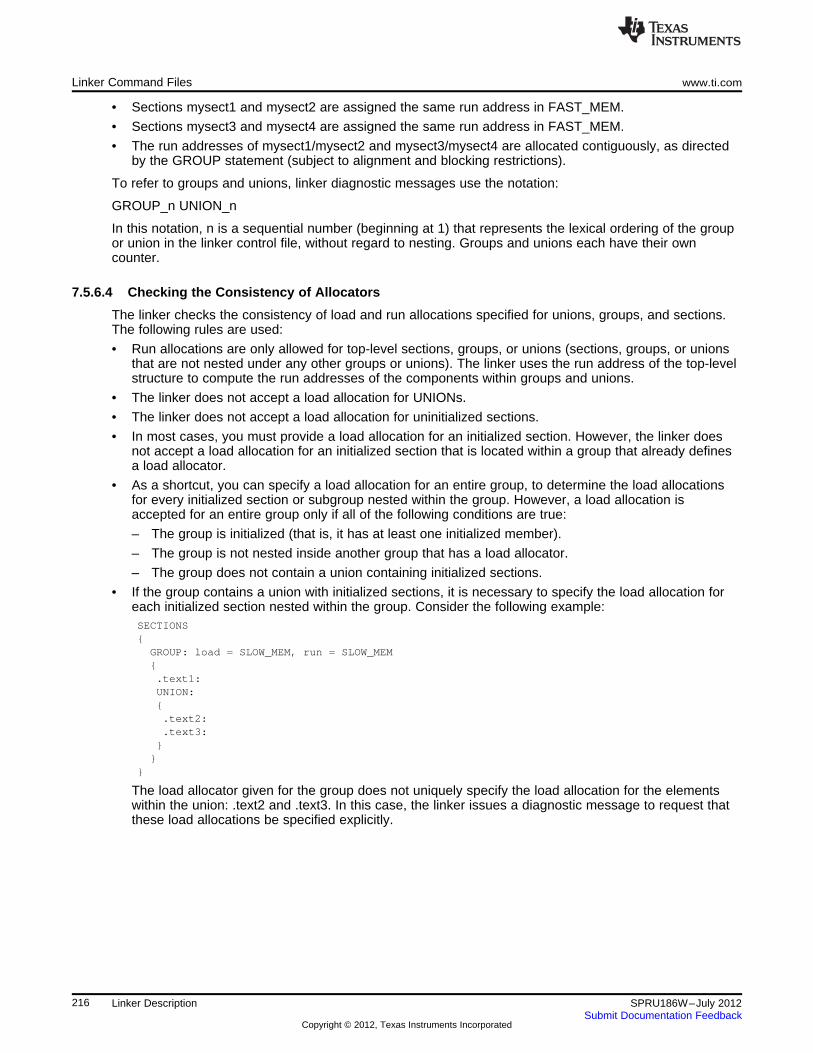
Linker Command Files www.ti.com
• Sections mysect1 and mysect2 are assigned the same run address in FAST_MEM.
• Sections mysect3 and mysect4 are assigned the same run address in FAST_MEM.
• The run addresses of mysect1/mysect2 and mysect3/mysect4 are allocated contiguously, as directedby the GROUP statement (subject to alignment and blocking restrictions).
To refer to groups and unions, linker diagnostic messages use the notation:
GROUP_n UNION_n
In this notation, n is a sequential number (beginning at 1) that represents the lexical ordering of the groupor union in the linker control file, without regard to nesting. Groups and unions each have their owncounter.
7.5.6.4 Checking the Consistency of Allocators
The linker checks the consistency of load and run allocations specified for unions, groups, and sections.The following rules are used:
• Run allocations are only allowed for top-level sections, groups, or unions (sections, groups, or unionsthat are not nested under any other groups or unions). The linker uses the run address of the top-levelstructure to compute the run addresses of the components within groups and unions.
• The linker does not accept a load allocation for UNIONs.
• The linker does not accept a load allocation for uninitialized sections.
• In most cases, you must provide a load allocation for an initialized section. However, the linker doesnot accept a load allocation for an initialized section that is located within a group that already definesa load allocator.
• As a shortcut, you can specify a load allocation for an entire group, to determine the load allocationsfor every initialized section or subgroup nested within the group. However, a load allocation isaccepted for an entire group only if all of the following conditions are true:
– The group is initialized (that is, it has at least one initialized member).
– The group is not nested inside another group that has a load allocator.
– The group does not contain a union containing initialized sections.
• If the group contains a union with initialized sections, it is necessary to specify the load allocation foreach initialized section nested within the group. Consider the following example:SECTIONS{
GROUP: load = SLOW_MEM, run = SLOW_MEM{.text1:UNION:{.text2:.text3:
}}
}
The load allocator given for the group does not uniquely specify the load allocation for the elementswithin the union: .text2 and .text3. In this case, the linker issues a diagnostic message to request thatthese load allocations be specified explicitly.
216 Linker Description SPRU186W–July 2012Submit Documentation Feedback
Copyright © 2012, Texas Instruments Incorporated
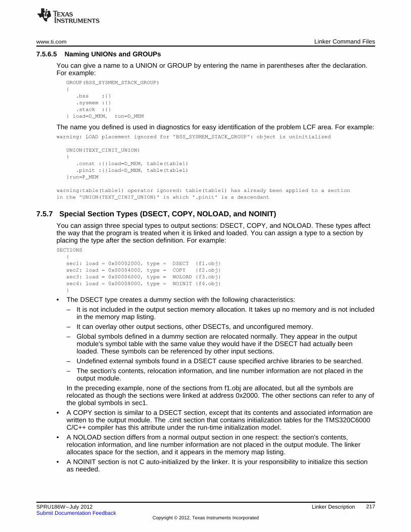
www.ti.com Linker Command Files
7.5.6.5 Naming UNIONs and GROUPs
You can give a name to a UNION or GROUP by entering the name in parentheses after the declaration.For example:
GROUP(BSS_SYSMEM_STACK_GROUP){
.bss :{}
.sysmem :{}
.stack :{}} load=D_MEM, run=D_MEM
The name you defined is used in diagnostics for easy identification of the problem LCF area. For example:warning: LOAD placement ignored for "BSS_SYSMEM_STACK_GROUP": object is uninitialized
UNION(TEXT_CINIT_UNION){
.const :{}load=D_MEM, table(table1)
.pinit :{}load=D_MEM, table(table1)}run=P_MEM
warning:table(table1) operator ignored: table(table1) has already been applied to a sectionin the "UNION(TEXT_CINIT_UNION)" in which ".pinit" is a descendant
7.5.7 Special Section Types (DSECT, COPY, NOLOAD, and NOINIT)
You can assign three special types to output sections: DSECT, COPY, and NOLOAD. These types affectthe way that the program is treated when it is linked and loaded. You can assign a type to a section byplacing the type after the section definition. For example:SECTIONS
{sec1: load = 0x00002000, type = DSECT {f1.obj}sec2: load = 0x00004000, type = COPY {f2.obj}sec3: load = 0x00006000, type = NOLOAD {f3.obj}sec4: load = 0x00008000, type = NOINIT {f4.obj}}
• The DSECT type creates a dummy section with the following characteristics:
– It is not included in the output section memory allocation. It takes up no memory and is not includedin the memory map listing.
– It can overlay other output sections, other DSECTs, and unconfigured memory.
– Global symbols defined in a dummy section are relocated normally. They appear in the outputmodule's symbol table with the same value they would have if the DSECT had actually beenloaded. These symbols can be referenced by other input sections.
– Undefined external symbols found in a DSECT cause specified archive libraries to be searched.
– The section's contents, relocation information, and line number information are not placed in theoutput module.
In the preceding example, none of the sections from f1.obj are allocated, but all the symbols arerelocated as though the sections were linked at address 0x2000. The other sections can refer to any ofthe global symbols in sec1.
• A COPY section is similar to a DSECT section, except that its contents and associated information arewritten to the output module. The .cinit section that contains initialization tables for the TMS320C6000C/C++ compiler has this attribute under the run-time initialization model.
• A NOLOAD section differs from a normal output section in one respect: the section's contents,relocation information, and line number information are not placed in the output module. The linkerallocates space for the section, and it appears in the memory map listing.
• A NOINIT section is not C auto-initialized by the linker. It is your responsibility to initialize this sectionas needed.
217SPRU186W–July 2012 Linker DescriptionSubmit Documentation Feedback
Copyright © 2012, Texas Instruments Incorporated
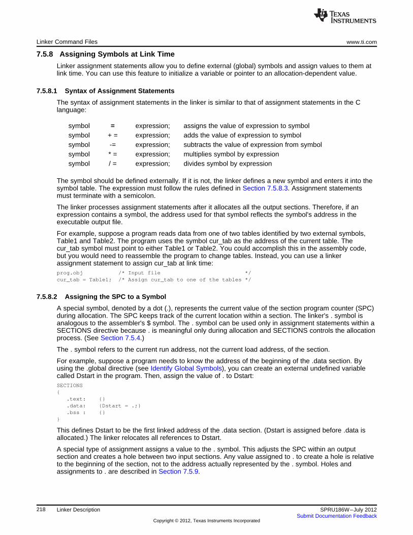
Linker Command Files www.ti.com
7.5.8 Assigning Symbols at Link Time
Linker assignment statements allow you to define external (global) symbols and assign values to them atlink time. You can use this feature to initialize a variable or pointer to an allocation-dependent value.
7.5.8.1 Syntax of Assignment Statements
The syntax of assignment statements in the linker is similar to that of assignment statements in the Clanguage:
symbol = expression; assigns the value of expression to symbolsymbol + = expression; adds the value of expression to symbolsymbol -= expression; subtracts the value of expression from symbolsymbol * = expression; multiplies symbol by expressionsymbol / = expression; divides symbol by expression
The symbol should be defined externally. If it is not, the linker defines a new symbol and enters it into thesymbol table. The expression must follow the rules defined in Section 7.5.8.3. Assignment statementsmust terminate with a semicolon.
The linker processes assignment statements after it allocates all the output sections. Therefore, if anexpression contains a symbol, the address used for that symbol reflects the symbol's address in theexecutable output file.
For example, suppose a program reads data from one of two tables identified by two external symbols,Table1 and Table2. The program uses the symbol cur_tab as the address of the current table. Thecur_tab symbol must point to either Table1 or Table2. You could accomplish this in the assembly code,but you would need to reassemble the program to change tables. Instead, you can use a linkerassignment statement to assign cur_tab at link time:prog.obj /* Input file */cur_tab = Table1; /* Assign cur_tab to one of the tables */
7.5.8.2 Assigning the SPC to a Symbol
A special symbol, denoted by a dot (.), represents the current value of the section program counter (SPC)during allocation. The SPC keeps track of the current location within a section. The linker's . symbol isanalogous to the assembler's $ symbol. The . symbol can be used only in assignment statements within aSECTIONS directive because . is meaningful only during allocation and SECTIONS controls the allocationprocess. (See Section 7.5.4.)
The . symbol refers to the current run address, not the current load address, of the section.
For example, suppose a program needs to know the address of the beginning of the .data section. Byusing the .global directive (see Identify Global Symbols), you can create an external undefined variablecalled Dstart in the program. Then, assign the value of . to Dstart:SECTIONS{
.text: {}
.data: {Dstart = .;}
.bss : {}}
This defines Dstart to be the first linked address of the .data section. (Dstart is assigned before .data isallocated.) The linker relocates all references to Dstart.
A special type of assignment assigns a value to the . symbol. This adjusts the SPC within an outputsection and creates a hole between two input sections. Any value assigned to . to create a hole is relativeto the beginning of the section, not to the address actually represented by the . symbol. Holes andassignments to . are described in Section 7.5.9.
218 Linker Description SPRU186W–July 2012Submit Documentation Feedback
Copyright © 2012, Texas Instruments Incorporated
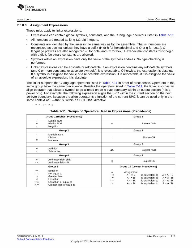
www.ti.com Linker Command Files
7.5.8.3 Assignment Expressions
These rules apply to linker expressions:
• Expressions can contain global symbols, constants, and the C language operators listed in Table 7-11.
• All numbers are treated as long (32-bit) integers.
• Constants are identified by the linker in the same way as by the assembler. That is, numbers arerecognized as decimal unless they have a suffix (H or h for hexadecimal and Q or q for octal). Clanguage prefixes are also recognized (0 for octal and 0x for hex). Hexadecimal constants must beginwith a digit. No binary constants are allowed.
• Symbols within an expression have only the value of the symbol's address. No type-checking isperformed.
• Linker expressions can be absolute or relocatable. If an expression contains any relocatable symbols(and 0 or more constants or absolute symbols), it is relocatable. Otherwise, the expression is absolute.If a symbol is assigned the value of a relocatable expression, it is relocatable; if it is assigned the valueof an absolute expression, it is absolute.
The linker supports the C language operators listed in Table 7-11 in order of precedence. Operators in thesame group have the same precedence. Besides the operators listed in Table 7-11, the linker also has analign operator that allows a symbol to be aligned on an n-byte boundary within an output section (n is apower of 2). For example, the following expression aligns the SPC within the current section on the next16-byte boundary. Because the align operator is a function of the current SPC, it can be used only in thesame context as . —that is, within a SECTIONS directive.
. = align(16);
Table 7-11. Groups of Operators Used in Expressions (Precedence)
Group 1 (Highest Precedence) Group 6
! Logical NOT~ Bitwise NOT & Bitwise AND- Negation
Group 2 Group 7
* Multiplication/ Division | Bitwise OR
% Modulus
Group 3 Group 8
+ Addition && Logical AND- Subtraction
Group 4 Group 9
>> Arithmetic right shift || Logical OR<< Arithmetic left shift
Group 5 Group 10 (Lowest Precedence)
== Equal to = Assignment! = Not equal to + = A + = B is equivalent to A = A + B> Greater than - = A - = B is equivalent to A = A - B< Less than * = A * = B is equivalent to A = A * B< = Less than or equal to / = A / = B is equivalent to A = A / B> = Greater than or equal to
219SPRU186W–July 2012 Linker DescriptionSubmit Documentation Feedback
Copyright © 2012, Texas Instruments Incorporated
Linker Command Files www.ti.com
7.5.8.4 Symbols Defined by the Linker
The linker automatically defines several symbols based on which sections are used in your assemblysource. A program can use these symbols at run time to determine where a section is linked. Since thesesymbols are external, they appear in the linker map. Each symbol can be accessed in any assemblylanguage module if it is declared with a .global directive (see Identify Global Symbols). You must haveused the corresponding section in a source module for the symbol to be created. Values are assigned tothese symbols as follows:
.text is assigned the first address of the .text output section.(It marks the beginning of executable code.)
etext is assigned the first address following the .text output section.(It marks the end of executable code.)
.data is assigned the first address of the .data output section.(It marks the beginning of initialized data tables.)
edata is assigned the first address following the .data output section.(It marks the end of initialized data tables.)
.bss is assigned the first address of the .bss output section.(It marks the beginning of uninitialized data.)
end is assigned the first address following the .bss output section.(It marks the end of uninitialized data.)
The following symbols are defined only for C/C++ support when the --ram_model or --rom_model option isused.
__TI_STACK_END is assigned the end of the .stack size for ELF.__TI_STACK_SIZE is assigned the size of the .stack section for ELF.__TI_STATIC_BASE is assigned the value to be loaded into the data pointer register (DP)
at boot time. This is typically the start of the first section containing adefinition of a symbol that is referenced via near-DP addressing.
__STACK_END is assigned the end of the .stack size for COFF.__STACK_SIZE is assigned the size of the .stack section for COFF.__SYSMEM_SIZE is assigned the size of the .sysmem section for COFF.__TI_SYSMEM_SIZE is assigned the size of the .sysmem section for ELF.
7.5.8.5 Assigning Exact Start, End, and Size Values of a Section to a Symbol
The code generation tools currently support the ability to load program code in one area of (slow) memoryand run it in another (faster) area. This is done by specifying separate load and run addresses for anoutput section or group in the link command file. Then execute a sequence of instructions (the copyingcode in Example 7-10) that moves the program code from its load area to its run area before it is needed.
There are several responsibilities that a programmer must take on when setting up a system with thisfeature. One of these responsibilities is to determine the size and run-time address of the program code tobe moved. The current mechanisms to do this involve use of the .label directives in the copying code. Asimple example is illustrated Example 7-10.
This method of specifying the size and load address of the program code has limitations. While it worksfine for an individual input section that is contained entirely within one source file, this method becomesmore complicated if the program code is spread over several source files or if the programmer wants tocopy an entire output section from load space to run space.
Another problem with this method is that it does not account for the possibility that the section beingmoved may have an associated far call trampoline section that needs to be moved with it.
220 Linker Description SPRU186W–July 2012Submit Documentation Feedback
Copyright © 2012, Texas Instruments Incorporated
www.ti.com Linker Command Files
7.5.8.6 Why the Dot Operator Does Not Always Work
The dot operator (.) is used to define symbols at link-time with a particular address inside of an outputsection. It is interpreted like a PC. Whatever the current offset within the current section is, that is thevalue associated with the dot. Consider an output section specification within a SECTIONS directive:outsect:{
s1.obj(.text)end_of_s1 = .;start_of_s2 = .;s2.obj(.text)end_of_s2 = .;
}
This statement creates three symbols:
• end_of_s1—the end address of .text in s1.obj
• start_of_s2—the start address of .text in s2.obj
• end_of_s2—the end address of .text in s2.obj
Suppose there is padding between s1.obj and s2.obj that is created as a result of alignment. Thenstart_of_s2 is not really the start address of the .text section in s2.obj, but it is the address before thepadding needed to align the .text section in s2.obj. This is due to the linker's interpretation of the dotoperator as the current PC. It is also due to the fact that the dot operator is evaluated independently of theinput sections around it.
Another potential problem in the above example is that end_of_s2 may not account for any padding thatwas required at the end of the output section. You cannot reliably use end_of_s2 as the end address ofthe output section. One way to get around this problem is to create a dummy section immediately after theoutput section in question. For example:GROUP{
outsect:{
start_of_outsect = .;...
}dummy: { size_of_outsect = . - start_of_outsect; }
}
7.5.8.7 Address and Dimension Operators
Six new operators have been added to the link command file syntax:
LOAD_START( sym ) Defines sym with the load-time start address of related allocation unitSTART( sym )LOAD_END( sym ) Defines sym with the load-time end address of related allocation unitEND( sym )LOAD_SIZE( sym ) Defines sym with the load-time size of related allocation unitSIZE( sym )RUN_START( sym ) Defines sym with the run-time start address of related allocation unitRUN_END( sym ) Defines sym with the run-time end address of related allocation unitRUN_SIZE(sym ) Defines sym with the run-time size of related allocation unit
Linker Command File Operator Equivalencies
NOTE: LOAD_START() and START() are equivalent, as are LOAD_END()/END() andLOAD_SIZE()/SIZE(). The LOAD names are recommended for clarity.
221SPRU186W–July 2012 Linker DescriptionSubmit Documentation Feedback
Copyright © 2012, Texas Instruments Incorporated
Linker Command Files www.ti.com
The new address and dimension operators can be associated with several different kinds of allocationunits, including input items, output sections, GROUPs, and UNIONs. The following sections provide someexamples of how the operators can be used in each case.
7.5.8.7.1 Input Items
Consider an output section specification within a SECTIONS directive:outsect:{
s1.obj(.text)end_of_s1 = .;start_of_s2 = .;s2.obj(.text)end_of_s2 = .;
}
This can be rewritten using the START and END operators as follows:outsect:{
s1.obj(.text) { END(end_of_s1) }s2.obj(.text) { START(start_of_s2), END(end_of_s2) }
}
The values of end_of_s1 and end_of_s2 will be the same as if you had used the dot operator in theoriginal example, but start_of_s2 would be defined after any necessary padding that needs to be addedbetween the two .text sections. Remember that the dot operator would cause start_of_s2 to be definedbefore any necessary padding is inserted between the two input sections.
The syntax for using these operators in association with input sections calls for braces { } to enclose theoperator list. The operators in the list are applied to the input item that occurs immediately before the list.
7.5.8.7.2 Output Section
The START, END, and SIZE operators can also be associated with an output section. Here is an example:outsect: START(start_of_outsect), SIZE(size_of_outsect){
<list of input items>}
In this case, the SIZE operator defines size_of_outsect to incorporate any padding that is required in theoutput section to conform to any alignment requirements that are imposed.
The syntax for specifying the operators with an output section does not require braces to enclose theoperator list. The operator list is simply included as part of the allocation specification for an outputsection.
7.5.8.7.3 GROUPs
Here is another use of the START and SIZE operators in the context of a GROUP specification:GROUP{
outsect1: { ... }outsect2: { ... }
} load = ROM, run = RAM, START(group_start), SIZE(group_size);
This can be useful if the whole GROUP is to be loaded in one location and run in another. The copyingcode can use group_start and group_size as parameters for where to copy from and how much is to becopied. This makes the use of .label in the source code unnecessary.
222 Linker Description SPRU186W–July 2012Submit Documentation Feedback
Copyright © 2012, Texas Instruments Incorporated
www.ti.com Linker Command Files
7.5.8.7.4 UNIONs
The RUN_SIZE and LOAD_SIZE operators provide a mechanism to distinguish between the size of aUNION's load space and the size of the space where its constituents are going to be copied before theyare run. Here is an example:UNION: run = RAM, LOAD_START(union_load_addr),
LOAD_SIZE(union_ld_sz), RUN_SIZE(union_run_sz){
.text1: load = ROM, SIZE(text1_size) { f1.obj(.text) }
.text2: load = ROM, SIZE(text2_size) { f2.obj(.text) }}
Here union_ld_sz is going to be equal to the sum of the sizes of all output sections placed in the union.The union_run_sz value is equivalent to the largest output section in the union. Both of these symbolsincorporate any padding due to blocking or alignment requirements.
7.5.9 Creating and Filling Holes
The linker provides you with the ability to create areas within output sections that have nothing linked intothem. These areas are called holes. In special cases, uninitialized sections can also be treated as holes.This section describes how the linker handles holes and how you can fill holes (and uninitialized sections)with values.
7.5.9.1 Initialized and Uninitialized Sections
There are two rules to remember about the contents of output sections. An output section contains either:
• Raw data for the entire section
• No raw data
A section that has raw data is referred to as initialized. This means that the object file contains the actualmemory image contents of the section. When the section is loaded, this image is loaded into memory atthe section's specified starting address. The .text and .data sections always have raw data if anything wasassembled into them. Named sections defined with the .sect assembler directive also have raw data.
By default, the .bss section (see Reserve Space in the .bss Section) and sections defined with the .usectdirective (see Reserve Uninitialized Space) have no raw data (they are uninitialized). They occupy spacein the memory map but have no actual contents. Uninitialized sections typically reserve space in fastexternal memory for variables. In the object file, an uninitialized section has a normal section header andcan have symbols defined in it; no memory image, however, is stored in the section.
7.5.9.2 Creating Holes
You can create a hole in an initialized output section. A hole is created when you force the linker to leaveextra space between input sections within an output section. When such a hole is created, the linker mustsupply raw data for the hole.
Holes can be created only within output sections. Space can exist between output sections, but suchspace is not a hole. To fill the space between output sections, see Section 7.5.3.2.
To create a hole in an output section, you must use a special type of linker assignment statement withinan output section definition. The assignment statement modifies the SPC (denoted by .) by adding to it,assigning a greater value to it, or aligning it on an address boundary. The operators, expressions, andsyntaxes of assignment statements are described in Section 7.5.8.
223SPRU186W–July 2012 Linker DescriptionSubmit Documentation Feedback
Copyright © 2012, Texas Instruments Incorporated
Linker Command Files www.ti.com
The following example uses assignment statements to create holes in output sections:SECTIONS{
outsect:{
file1.obj(.text). += 0x0100 /* Create a hole with size 0x0100 */file2.obj(.text)
. = align(16); /* Create a hole to align the SPC */file3.obj(.text)
}}
The output section outsect is built as follows:
1. The .text section from file1.obj is linked in.
2. The linker creates a 256-byte hole.
3. The .text section from file2.obj is linked in after the hole.
4. The linker creates another hole by aligning the SPC on a 16-byte boundary.
5. Finally, the .text section from file3.obj is linked in.
All values assigned to the . symbol within a section refer to the relative address within the section. Thelinker handles assignments to the . symbol as if the section started at address 0 (even if you havespecified a binding address). Consider the statement . = align(16) in the example. This statementeffectively aligns the file3.obj .text section to start on a 16-byte boundary within outsect. If outsect isultimately allocated to start on an address that is not aligned, the file3.obj .text section will not be alignedeither.
The . symbol refers to the current run address, not the current load address, of the section.
Expressions that decrement the . symbol are illegal. For example, it is invalid to use the -= operator in anassignment to the . symbol. The most common operators used in assignments to the . symbol are += andalign.
If an output section contains all input sections of a certain type (such as .text), you can use the followingstatements to create a hole at the beginning or end of the output section.
.text: { .+= 0x0100; } /* Hole at the beginning */
.data: { *(.data). += 0x0100; } /* Hole at the end */
Another way to create a hole in an output section is to combine an uninitialized section with an initializedsection to form a single output section. In this case, the linker treats the uninitialized section as a hole andsupplies data for it. The following example illustrates this method:SECTIONS{
outsect:{
file1.obj(.text)file1.obj(.bss) /* This becomes a hole */
}}
Because the .text section has raw data, all of outsect must also contain raw data. Therefore, theuninitialized .bss section becomes a hole.
Uninitialized sections become holes only when they are combined with initialized sections. If severaluninitialized sections are linked together, the resulting output section is also uninitialized.
224 Linker Description SPRU186W–July 2012Submit Documentation Feedback
Copyright © 2012, Texas Instruments Incorporated
www.ti.com Linker Command Files
7.5.9.3 Filling Holes
When a hole exists in an initialized output section, the linker must supply raw data to fill it. The linker fillsholes with a 32-bit fill value that is replicated through memory until it fills the hole. The linker determinesthe fill value as follows:
1. If the hole is formed by combining an uninitialized section with an initialized section, you can specify afill value for the uninitialized section. Follow the section name with an = sign and a 32-bit constant. Forexample:
SECTIONS{ outsect:
{file1.obj(.text)file2.obj(.bss)= 0xFF00FF00 /* Fill this hole with 0xFF00FF00 */
}}
2. You can also specify a fill value for all the holes in an output section by supplying the fill value after thesection definition:
SECTIONS{ outsect:fill = 0xFF00FF00 /* Fills holes with 0xFF00FF00 */
{. += 0x0010; /* This creates a hole */file1.obj(.text)file1.obj(.bss) /* This creates another hole */
}}
3. If you do not specify an initialization value for a hole, the linker fills the hole with the value specifiedwith the --fill_value option (see Section 7.4.10). For example, suppose the command file link.cmdcontains the following SECTIONS directive:
SECTIONS { .text: { .= 0x0100; } /* Create a 100 word hole */ }
Now invoke the linker with the --fill_value option:cl6x --run_linker --fill_value=0xFFFFFFFF link.cmd
This fills the hole with 0xFFFFFFFF.
4. If you do not invoke the linker with the --fill_value option or otherwise specify a fill value, the linker fillsholes with 0s.
Whenever a hole is created and filled in an initialized output section, the hole is identified in the link mapalong with the value the linker uses to fill it.
7.5.9.4 Explicit Initialization of Uninitialized Sections
You can force the linker to initialize an uninitialized section by specifying an explicit fill value for it in theSECTIONS directive. This causes the entire section to have raw data (the fill value). For example:SECTIONS{
.bss: fill = 0x12341234 /* Fills .bss with 0x12341234 */}
Filling Sections
NOTE: Because filling a section (even with 0s) causes raw data to be generated for the entiresection in the output file, your output file will be very large if you specify fill values for largesections or holes.
225SPRU186W–July 2012 Linker DescriptionSubmit Documentation Feedback
Copyright © 2012, Texas Instruments Incorporated
Object Libraries www.ti.com
7.6 Object Libraries
An object library is a partitioned archive file that contains object files as members. Usually, a group ofrelated modules are grouped together into a library. When you specify an object library as linker input, thelinker includes any members of the library that define existing unresolved symbol references. You can usethe archiver to build and maintain libraries. Section 6.1 contains more information about the archiver.
Using object libraries can reduce link time and the size of the executable module. Normally, if an objectfile that contains a function is specified at link time, the file is linked whether the function is used or not;however, if that same function is placed in an archive library, the file is included only if the function isreferenced.
The order in which libraries are specified is important, because the linker includes only those membersthat resolve symbols that are undefined at the time the library is searched. The same library can bespecified as often as necessary; it is searched each time it is included. Alternatively, you can use the --reread_libs option to reread libraries until no more references can be resolved (see Section 7.4.13.3). Alibrary has a table that lists all external symbols defined in the library; the linker searches through the tableuntil it determines that it cannot use the library to resolve any more references.
The following examples link several files and libraries, using these assumptions:
• Input files f1.obj and f2.obj both reference an external function named clrscr.
• Input file f1.obj references the symbol origin.
• Input file f2.obj references the symbol fillclr.
• Member 0 of library libc.lib contains a definition of origin.
• Member 3 of library liba.lib contains a definition of fillclr.
• Member 1 of both libraries defines clrscr.
If you enter:cl6x --run_linker f1.obj f2.obj liba.lib libc.lib
then:
• Member 1 of liba.lib satisfies the f1.obj and f2.obj references to clrscr because the library is searchedand the definition of clrscr is found.
• Member 0 of libc.lib satisfies the reference to origin.
• Member 3 of liba.lib satisfies the reference to fillclr.
If, however, you enter:cl6x --run_linker f1.obj f2.obj libc.lib liba.lib
then the references to clrscr are satisfied by member 1 of libc.lib.
If none of the linked files reference symbols defined in a library, you can use the --undef_sym option toforce the linker to include a library member. (See Section 7.4.30.) The next example creates an undefinedsymbol rout1 in the linker's global symbol table:cl6x --run_linker --undef_sym=rout1 libc.lib
If any member of libc.lib defines rout1, the linker includes that member.
Library members are allocated according to the SECTIONS directive default allocation algorithm; seeSection 7.5.4.
Section 7.4.13 describes methods for specifying directories that contain object libraries.
226 Linker Description SPRU186W–July 2012Submit Documentation Feedback
Copyright © 2012, Texas Instruments Incorporated
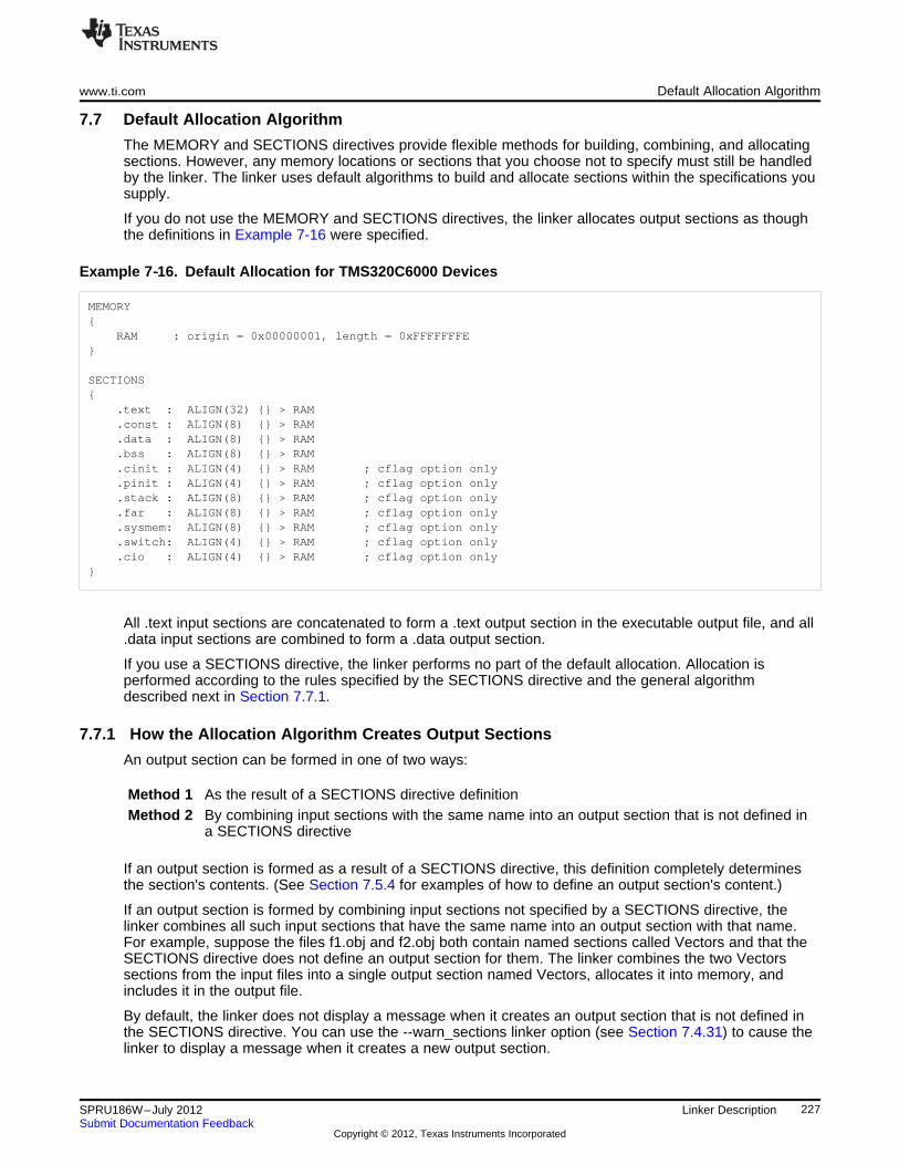
www.ti.com Default Allocation Algorithm
7.7 Default Allocation Algorithm
The MEMORY and SECTIONS directives provide flexible methods for building, combining, and allocatingsections. However, any memory locations or sections that you choose not to specify must still be handledby the linker. The linker uses default algorithms to build and allocate sections within the specifications yousupply.
If you do not use the MEMORY and SECTIONS directives, the linker allocates output sections as thoughthe definitions in Example 7-16 were specified.
Example 7‑‑16. Default Allocation for TMS320C6000 Devices
MEMORY{
RAM : origin = 0x00000001, length = 0xFFFFFFFE}
SECTIONS{
.text : ALIGN(32) {} > RAM
.const : ALIGN(8) {} > RAM
.data : ALIGN(8) {} > RAM
.bss : ALIGN(8) {} > RAM
.cinit : ALIGN(4) {} > RAM ; cflag option only
.pinit : ALIGN(4) {} > RAM ; cflag option only
.stack : ALIGN(8) {} > RAM ; cflag option only
.far : ALIGN(8) {} > RAM ; cflag option only
.sysmem: ALIGN(8) {} > RAM ; cflag option only
.switch: ALIGN(4) {} > RAM ; cflag option only
.cio : ALIGN(4) {} > RAM ; cflag option only}
All .text input sections are concatenated to form a .text output section in the executable output file, and all.data input sections are combined to form a .data output section.
If you use a SECTIONS directive, the linker performs no part of the default allocation. Allocation isperformed according to the rules specified by the SECTIONS directive and the general algorithmdescribed next in Section 7.7.1.
7.7.1 How the Allocation Algorithm Creates Output Sections
An output section can be formed in one of two ways:
Method 1 As the result of a SECTIONS directive definitionMethod 2 By combining input sections with the same name into an output section that is not defined in
a SECTIONS directive
If an output section is formed as a result of a SECTIONS directive, this definition completely determinesthe section's contents. (See Section 7.5.4 for examples of how to define an output section's content.)
If an output section is formed by combining input sections not specified by a SECTIONS directive, thelinker combines all such input sections that have the same name into an output section with that name.For example, suppose the files f1.obj and f2.obj both contain named sections called Vectors and that theSECTIONS directive does not define an output section for them. The linker combines the two Vectorssections from the input files into a single output section named Vectors, allocates it into memory, andincludes it in the output file.
By default, the linker does not display a message when it creates an output section that is not defined inthe SECTIONS directive. You can use the --warn_sections linker option (see Section 7.4.31) to cause thelinker to display a message when it creates a new output section.
227SPRU186W–July 2012 Linker DescriptionSubmit Documentation Feedback
Copyright © 2012, Texas Instruments Incorporated
Linker-Generated Copy Tables www.ti.com
After the linker determines the composition of all output sections, it must allocate them into configuredmemory. The MEMORY directive specifies which portions of memory are configured. If there is noMEMORY directive, the linker uses the default configuration as shown in Example 7-16. (SeeSection 7.5.3 for more information on configuring memory.)
7.7.2 Reducing Memory Fragmentation
The linker's allocation algorithm attempts to minimize memory fragmentation. This allows memory to beused more efficiently and increases the probability that your program will fit into memory. The algorithmcomprises these steps:
1. Each output section for which you have supplied a specific binding address is placed in memory at thataddress.
2. Each output section that is included in a specific, named memory range or that has memory attributerestrictions is allocated. Each output section is placed into the first available space within the namedarea, considering alignment where necessary.
3. Any remaining sections are allocated in the order in which they are defined. Sections not defined in aSECTIONS directive are allocated in the order in which they are encountered. Each output section isplaced into the first available memory space, considering alignment where necessary.
7.8 Linker-Generated Copy Tables
The linker supports extensions to the link command file syntax that enable the following:
• Make it easier for you to copy objects from load-space to run-space at boot time
• Make it easier for you to manage memory overlays at run time
• Allow you to split GROUPs and output sections that have separate load and run addresses
7.8.1 A Current Boot-Loaded Application Development Process
In some embedded applications, there is a need to copy or download code and/or data from one locationto another at boot time before the application actually begins its main execution thread. For example, anapplication may have its code and/or data in FLASH memory and need to copy it into on-chip memorybefore the application begins execution.
One way you can develop an application like this is to create a copy table in assembly code that containsthree elements for each block of code or data that needs to be moved from FLASH into on-chip memoryat boot time:
• The load address
• The run address
• The size
The process you follow to develop such an application might look like this:
1. Build the application to produce a .map file that contains the load and run addresses of each sectionthat has a separate load and run placement.
2. Edit the copy table (used by the boot loader) to correct the load and run addresses as well as the sizeof each block of code or data that needs to be moved at boot time.
3. Build the application again, incorporating the updated copy table.
4. Run the application.
This process puts a heavy burden on you to maintain the copy table (by hand, no less). Each time a pieceof code or data is added or removed from the application, you must repeat the process in order to keepthe contents of the copy table up to date.
228 Linker Description SPRU186W–July 2012Submit Documentation Feedback
Copyright © 2012, Texas Instruments Incorporated
www.ti.com Linker-Generated Copy Tables
7.8.2 An Alternative Approach
You can avoid some of this maintenance burden by using the LOAD_START(), RUN_START(), andSIZE() operators that are already part of the link command file syntax . For example, instead of buildingthe application to generate a .map file, the link command file can be annotated:SECTIONS{
.flashcode: { app_tasks.obj(.text) }load = FLASH, run = PMEM,LOAD_START(_flash_code_ld_start),RUN_START(_flash_code_rn_start),SIZE(_flash_code_size)
...}
In this example, the LOAD_START(), RUN_START(), and SIZE() operators instruct the linker to createthree symbols:
Symbol Description
_flash_code_ld_start Load address of .flashcode section
_flash_code_rn_start Run address of .flashcode section
_flash_code_size Size of .flashcode section
These symbols can then be referenced from the copy table. The actual data in the copy table will beupdated automatically each time the application is linked. This approach removes step 1 of the processdescribed in Section 7.8.1.
While maintenance of the copy table is reduced markedly, you must still carry the burden of keeping thecopy table contents in sync with the symbols that are defined in the link command file. Ideally, the linkerwould generate the boot copy table automatically. This would avoid having to build the application twiceand free you from having to explicitly manage the contents of the boot copy table.
For more information on the LOAD_START(), RUN_START(), and SIZE() operators, see Section 7.5.8.7.
229SPRU186W–July 2012 Linker DescriptionSubmit Documentation Feedback
Copyright © 2012, Texas Instruments Incorporated
Linker-Generated Copy Tables www.ti.com
7.8.3 Overlay Management Example
Consider an application which contains a memory overlay that must be managed at run time. The memoryoverlay is defined using a UNION in the link command file as illustrated in Example 7-17:
Example 7-17. Using a UNION for Memory Overlay
SECTIONS{
...
UNION{
GROUP{
.task1: { task1.obj(.text) }
.task2: { task2.obj(.text) }
} load = ROM, LOAD_START(_task12_load_start), SIZE(_task12_size)
GROUP{
.task3: { task3.obj(.text) }
.task4: { task4.obj(.text) }
} load = ROM, LOAD_START(_task34_load_start), SIZE(_task_34_size)
} run = RAM, RUN_START(_task_run_start)
...}
The application must manage the contents of the memory overlay at run time. That is, whenever anyservices from .task1 or .task2 are needed, the application must first ensure that .task1 and .task2 areresident in the memory overlay. Similarly for .task3 and .task4.
To affect a copy of .task1 and .task2 from ROM to RAM at run time, the application must first gain accessto the load address of the tasks (_task12_load_start), the run address (_task_run_start), and the size(_task12_size). Then this information is used to perform the actual code copy.
7.8.4 Generating Copy Tables Automatically With the Linker
The linker supports extensions to the link command file syntax that enable you to do the following:
• Identify any object components that may need to be copied from load space to run space at somepoint during the run of an application
• Instruct the linker to automatically generate a copy table that contains (at least) the load address, runaddress, and size of the component that needs to be copied
• Instruct the linker to generate a symbol specified by you that provides the address of a linker-generated copy table. For instance, Example 7-17 can be written as shown in Example 7-18:
230 Linker Description SPRU186W–July 2012Submit Documentation Feedback
Copyright © 2012, Texas Instruments Incorporated
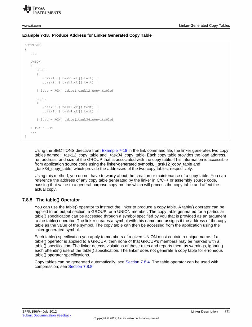
www.ti.com Linker-Generated Copy Tables
Example 7-18. Produce Address for Linker Generated Copy Table
SECTIONS{
...
UNION{
GROUP{
.task1: { task1.obj(.text) }
.task2: { task2.obj(.text) }
} load = ROM, table(_task12_copy_table)
GROUP{
.task3: { task3.obj(.text) }
.task4: { task4.obj(.text) }
} load = ROM, table(_task34_copy_table)
} run = RAM...
}
Using the SECTIONS directive from Example 7-18 in the link command file, the linker generates two copytables named: _task12_copy_table and _task34_copy_table. Each copy table provides the load address,run address, and size of the GROUP that is associated with the copy table. This information is accessiblefrom application source code using the linker-generated symbols, _task12_copy_table and_task34_copy_table, which provide the addresses of the two copy tables, respectively.
Using this method, you do not have to worry about the creation or maintenance of a copy table. You canreference the address of any copy table generated by the linker in C/C++ or assembly source code,passing that value to a general purpose copy routine which will process the copy table and affect theactual copy.
7.8.5 The table() Operator
You can use the table() operator to instruct the linker to produce a copy table. A table() operator can beapplied to an output section, a GROUP, or a UNION member. The copy table generated for a particulartable() specification can be accessed through a symbol specified by you that is provided as an argumentto the table() operator. The linker creates a symbol with this name and assigns it the address of the copytable as the value of the symbol. The copy table can then be accessed from the application using thelinker-generated symbol.
Each table() specification you apply to members of a given UNION must contain a unique name. If atable() operator is applied to a GROUP, then none of that GROUP's members may be marked with atable() specification. The linker detects violations of these rules and reports them as warnings, ignoringeach offending use of the table() specification. The linker does not generate a copy table for erroneoustable() operator specifications.
Copy tables can be generated automatically; see Section 7.8.4. The table operator can be used withcompression; see Section 7.8.8.
231SPRU186W–July 2012 Linker DescriptionSubmit Documentation Feedback
Copyright © 2012, Texas Instruments Incorporated
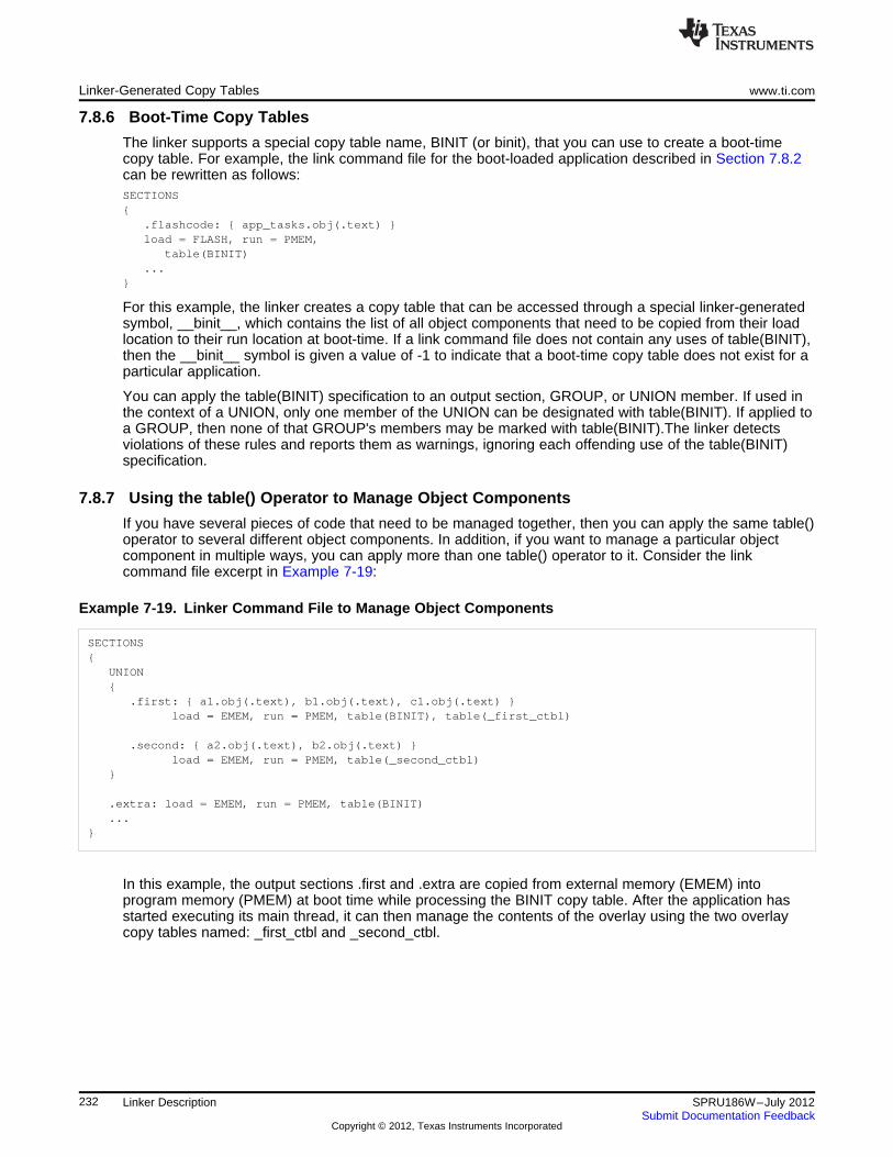
Linker-Generated Copy Tables www.ti.com
7.8.6 Boot-Time Copy Tables
The linker supports a special copy table name, BINIT (or binit), that you can use to create a boot-timecopy table. For example, the link command file for the boot-loaded application described in Section 7.8.2can be rewritten as follows:SECTIONS{
.flashcode: { app_tasks.obj(.text) }load = FLASH, run = PMEM,
table(BINIT)...
}
For this example, the linker creates a copy table that can be accessed through a special linker-generatedsymbol, __binit__, which contains the list of all object components that need to be copied from their loadlocation to their run location at boot-time. If a link command file does not contain any uses of table(BINIT),then the __binit__ symbol is given a value of -1 to indicate that a boot-time copy table does not exist for aparticular application.
You can apply the table(BINIT) specification to an output section, GROUP, or UNION member. If used inthe context of a UNION, only one member of the UNION can be designated with table(BINIT). If applied toa GROUP, then none of that GROUP's members may be marked with table(BINIT).The linker detectsviolations of these rules and reports them as warnings, ignoring each offending use of the table(BINIT)specification.
7.8.7 Using the table() Operator to Manage Object Components
If you have several pieces of code that need to be managed together, then you can apply the same table()operator to several different object components. In addition, if you want to manage a particular objectcomponent in multiple ways, you can apply more than one table() operator to it. Consider the linkcommand file excerpt in Example 7-19:
Example 7-19. Linker Command File to Manage Object Components
SECTIONS{
UNION{
.first: { a1.obj(.text), b1.obj(.text), c1.obj(.text) }load = EMEM, run = PMEM, table(BINIT), table(_first_ctbl)
.second: { a2.obj(.text), b2.obj(.text) }load = EMEM, run = PMEM, table(_second_ctbl)
}
.extra: load = EMEM, run = PMEM, table(BINIT)
...}
In this example, the output sections .first and .extra are copied from external memory (EMEM) intoprogram memory (PMEM) at boot time while processing the BINIT copy table. After the application hasstarted executing its main thread, it can then manage the contents of the overlay using the two overlaycopy tables named: _first_ctbl and _second_ctbl.
232 Linker Description SPRU186W–July 2012Submit Documentation Feedback
Copyright © 2012, Texas Instruments Incorporated
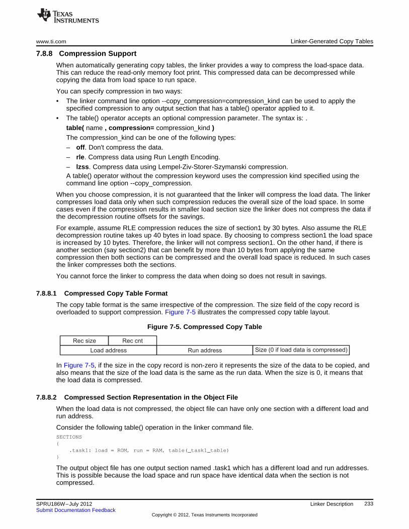
Load address Run address Size (0 if load data is compressed)
Rec size Rec cnt
www.ti.com Linker-Generated Copy Tables
7.8.8 Compression Support
When automatically generating copy tables, the linker provides a way to compress the load-space data.This can reduce the read-only memory foot print. This compressed data can be decompressed whilecopying the data from load space to run space.
You can specify compression in two ways:
• The linker command line option --copy_compression=compression_kind can be used to apply thespecified compression to any output section that has a table() operator applied to it.
• The table() operator accepts an optional compression parameter. The syntax is: .
table( name , compression= compression_kind )The compression_kind can be one of the following types:
– off. Don't compress the data.
– rle. Compress data using Run Length Encoding.
– lzss. Compress data using Lempel-Ziv-Storer-Szymanski compression.A table() operator without the compression keyword uses the compression kind specified using thecommand line option --copy_compression.
When you choose compression, it is not guaranteed that the linker will compress the load data. The linkercompresses load data only when such compression reduces the overall size of the load space. In somecases even if the compression results in smaller load section size the linker does not compress the data ifthe decompression routine offsets for the savings.
For example, assume RLE compression reduces the size of section1 by 30 bytes. Also assume the RLEdecompression routine takes up 40 bytes in load space. By choosing to compress section1 the load spaceis increased by 10 bytes. Therefore, the linker will not compress section1. On the other hand, if there isanother section (say section2) that can benefit by more than 10 bytes from applying the samecompression then both sections can be compressed and the overall load space is reduced. In such casesthe linker compresses both the sections.
You cannot force the linker to compress the data when doing so does not result in savings.
7.8.8.1 Compressed Copy Table Format
The copy table format is the same irrespective of the compression. The size field of the copy record isoverloaded to support compression. Figure 7-5 illustrates the compressed copy table layout.
Figure 7-5. Compressed Copy Table
In Figure 7-5, if the size in the copy record is non-zero it represents the size of the data to be copied, andalso means that the size of the load data is the same as the run data. When the size is 0, it means thatthe load data is compressed.
7.8.8.2 Compressed Section Representation in the Object File
When the load data is not compressed, the object file can have only one section with a different load andrun address.
Consider the following table() operation in the linker command file.SECTIONS{
.task1: load = ROM, run = RAM, table(_task1_table)}
The output object file has one output section named .task1 which has a different load and run addresses.This is possible because the load space and run space have identical data when the section is notcompressed.
233SPRU186W–July 2012 Linker DescriptionSubmit Documentation Feedback
Copyright © 2012, Texas Instruments Incorporated
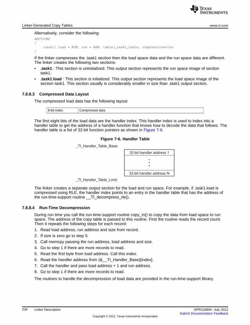
32-bit handler address 1
32-bit handler address N
_TI_Handler_Table_Base:
_TI_Handler_Table_Limit:
Linker-Generated Copy Tables www.ti.com
Alternatively, consider the following:SECTIONS{
.task1: load = ROM, run = RAM, table(_task1_table, compression=rle)}
If the linker compresses the .task1 section then the load space data and the run space data are different.The linker creates the following two sections:
• .task1 : This section is uninitialized. This output section represents the run space image of sectiontask1.
• .task1.load : This section is initialized. This output section represents the load space image of thesection task1. This section usually is considerably smaller in size than .task1 output section.
7.8.8.3 Compressed Data Layout
The compressed load data has the following layout:
8-bit index Compressed data
The first eight bits of the load data are the handler index. This handler index is used to index into ahandler table to get the address of a handler function that knows how to decode the data that follows. Thehandler table is a list of 32-bit function pointers as shown in Figure 7-6.
Figure 7-6. Handler Table
The linker creates a separate output section for the load and run space. For example, if .task1.load iscompressed using RLE, the handler index points to an entry in the handler table that has the address ofthe run-time-support routine __TI_decompress_rle().
7.8.8.4 Run-Time Decompression
During run time you call the run-time-support routine copy_in() to copy the data from load space to runspace. The address of the copy table is passed to this routine. First the routine reads the record count.Then it repeats the following steps for each record:
1. Read load address, run address and size from record.
2. If size is zero go to step 5.
3. Call memcpy passing the run address, load address and size.
4. Go to step 1 if there are more records to read.
5. Read the first byte from load address. Call this index.
6. Read the handler address from (&__TI_Handler_Base)[index].
7. Call the handler and pass load address + 1 and run address.
8. Go to step 1 if there are more records to read.
The routines to handle the decompression of load data are provided in the run-time-support library.
234 Linker Description SPRU186W–July 2012Submit Documentation Feedback
Copyright © 2012, Texas Instruments Incorporated
www.ti.com Linker-Generated Copy Tables
7.8.8.5 Compression Algorithms
Run Length Encoding (RLE):
8-bit index Initialization data compressed using run length encoding
The data following the 8-bit index is compressed using run length encoded (RLE) format. C6000 uses asimple run length encoding that can be decompressed using the following algorithm:
1. Read the first byte, Delimiter (D).
2. Read the next byte (B).
3. If B != D, copy B to the output buffer and go to step 2.
4. Read the next byte (L).
(a) If L == 0, then length is either a 16-bit, a 24-bit value, or we’ve reached the end of the data, readnext byte (L).
(i) If L == 0, length is a 24-bit value or the end of the data is reached, read next byte (L).
(i) If L == 0, the end of the data is reached, go to step 7.
(ii) Else L <<= 16, read next two bytes into lower 16 bits of L to complete 24-bit value for L.
(ii) Else L <<= 8, read next byte into lower 8 bits of L to complete 16-bit value for L.
(b) Else if L > 0 and L < 4, copy D to the output buffer L times. Go to step 2.
(c) Else, length is 8-bit value (L).
5. Read the next byte (C); C is the repeat character.
6. Write C to the output buffer L times; go to step 2.
7. End of processing.
The C6000 run-time support library has a routine __TI_decompress_rle24() to decompress datacompressed using RLE. The first argument to this function is the address pointing to the byte after the 8-bit index. The second argument is the run address from the C auto initialization record.
RLE Decompression Routine
NOTE: The previous decompression routine, __TI_decompress_rle(), is included in the run-time-support library for decompressing RLE encodings that are generated by older versions of thelinker.
Lempel-Ziv-Storer-Szymanski Compression (LZSS):
8-bit index Data compressed using LZSS
The data following the 8-bit index is compressed using LZSS compression. The C6000 run-time-supportlibrary has the routine __TI_decompress_lzss() to decompress the data compressed using LZSS. The firstargument to this function is the address pointing to the byte after the 8-bit Index, and the second argumentis the run address from the C auto initialization record.
235SPRU186W–July 2012 Linker DescriptionSubmit Documentation Feedback
Copyright © 2012, Texas Instruments Incorporated
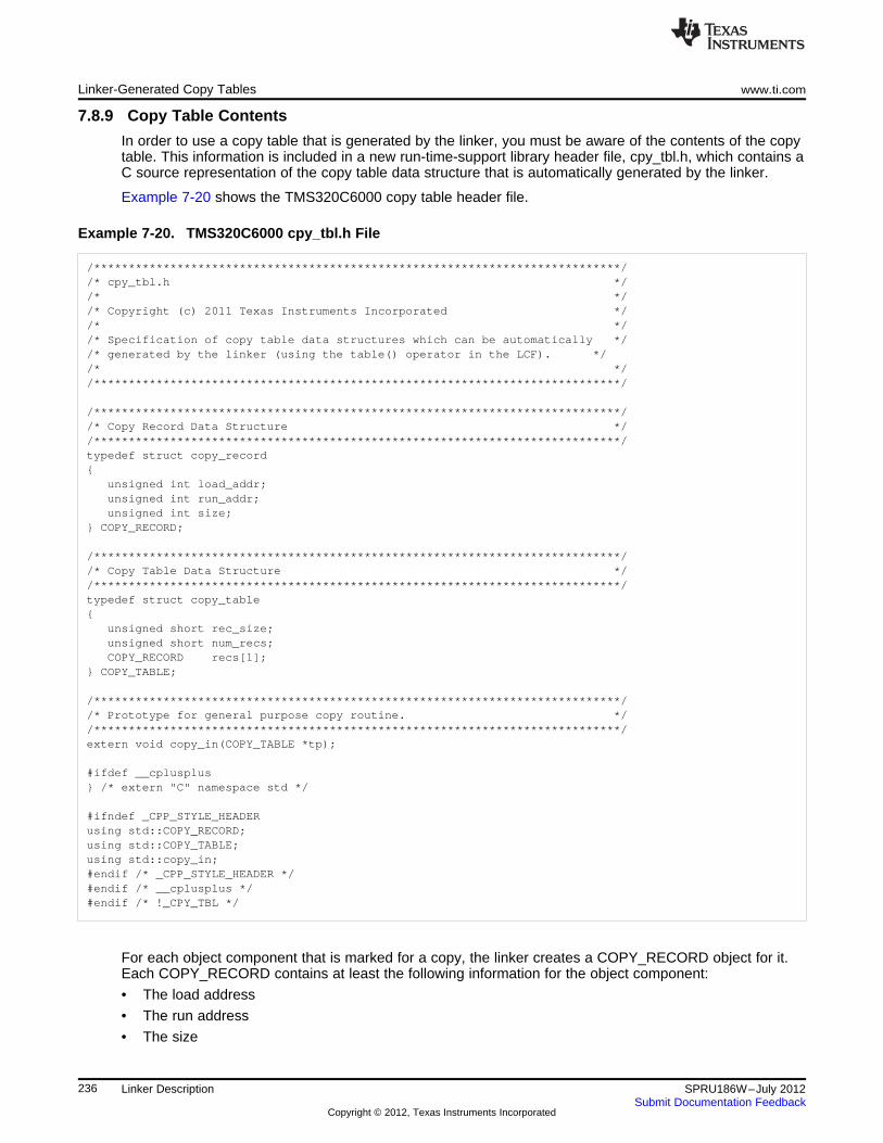
Linker-Generated Copy Tables www.ti.com
7.8.9 Copy Table Contents
In order to use a copy table that is generated by the linker, you must be aware of the contents of the copytable. This information is included in a new run-time-support library header file, cpy_tbl.h, which contains aC source representation of the copy table data structure that is automatically generated by the linker.
Example 7-20 shows the TMS320C6000 copy table header file.
Example 7-20. TMS320C6000 cpy_tbl.h File
/****************************************************************************//* cpy_tbl.h *//* *//* Copyright (c) 2011 Texas Instruments Incorporated *//* *//* Specification of copy table data structures which can be automatically *//* generated by the linker (using the table() operator in the LCF). *//* *//****************************************************************************/
/****************************************************************************//* Copy Record Data Structure *//****************************************************************************/typedef struct copy_record{
unsigned int load_addr;unsigned int run_addr;unsigned int size;
} COPY_RECORD;
/****************************************************************************//* Copy Table Data Structure *//****************************************************************************/typedef struct copy_table{
unsigned short rec_size;unsigned short num_recs;COPY_RECORD recs[1];
} COPY_TABLE;
/****************************************************************************//* Prototype for general purpose copy routine. *//****************************************************************************/extern void copy_in(COPY_TABLE *tp);
#ifdef __cplusplus} /* extern "C" namespace std */
#ifndef _CPP_STYLE_HEADERusing std::COPY_RECORD;using std::COPY_TABLE;using std::copy_in;#endif /* _CPP_STYLE_HEADER */#endif /* __cplusplus */#endif /* !_CPY_TBL */
For each object component that is marked for a copy, the linker creates a COPY_RECORD object for it.Each COPY_RECORD contains at least the following information for the object component:
• The load address
• The run address
• The size
236 Linker Description SPRU186W–July 2012Submit Documentation Feedback
Copyright © 2012, Texas Instruments Incorporated
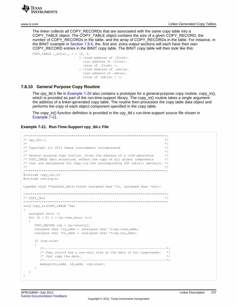
www.ti.com Linker-Generated Copy Tables
The linker collects all COPY_RECORDs that are associated with the same copy table into aCOPY_TABLE object. The COPY_TABLE object contains the size of a given COPY_RECORD, thenumber of COPY_RECORDs in the table, and the array of COPY_RECORDs in the table. For instance, inthe BINIT example in Section 7.8.6, the .first and .extra output sections will each have their ownCOPY_RECORD entries in the BINIT copy table. The BINIT copy table will then look like this:COPY_TABLE __binit__ = { 12, 2,
{ <load address of .first>,<run address of .first>,<size of .first> },
{ <load address of .extra>,<run address of .extra>,<size of .extra> } };
7.8.10 General Purpose Copy Routine
The cpy_tbl.h file in Example 7-20 also contains a prototype for a general-purpose copy routine, copy_in(),which is provided as part of the run-time-support library. The copy_in() routine takes a single argument:the address of a linker-generated copy table. The routine then processes the copy table data object andperforms the copy of each object component specified in the copy table.
The copy_in() function definition is provided in the cpy_tbl.c run-time-support source file shown inExample 7-21.
Example 7-21. Run-Time-Support cpy_tbl.c File
/****************************************************************************//* cpy_tbl.c *//* *//* Copyright (c) 2011 Texas Instruments Incorporated *//* *//* General purpose copy routine. Given the address of a link-generated *//* COPY_TABLE data structure, effect the copy of all object components *//* that are designated for copy via the corresponding LCF table() operator. *//* *//****************************************************************************/#include <cpy_tbl.h>#include <string.h>
typedef void (*handler_fptr)(const unsigned char *in, unsigned char *out);
/****************************************************************************//* COPY_IN() *//****************************************************************************/void copy_in(COPY_TABLE *tp){
unsigned short I;for (I = 0; I < tp->num_recs; I++){
COPY_RECORD crp = tp->recs[i];unsigned char *ld_addr = (unsigned char *)crp.load_addr;unsigned char *rn_addr = (unsigned char *)crp.run_addr;
if (crp.size){
/*------------------------------------------------------------------*//* Copy record has a non-zero size so the data is not compressed. *//* Just copy the data. *//*------------------------------------------------------------------*/memcpy(rn_addr, ld_addr, crp.size);
}}
}
237SPRU186W–July 2012 Linker DescriptionSubmit Documentation Feedback
Copyright © 2012, Texas Instruments Incorporated
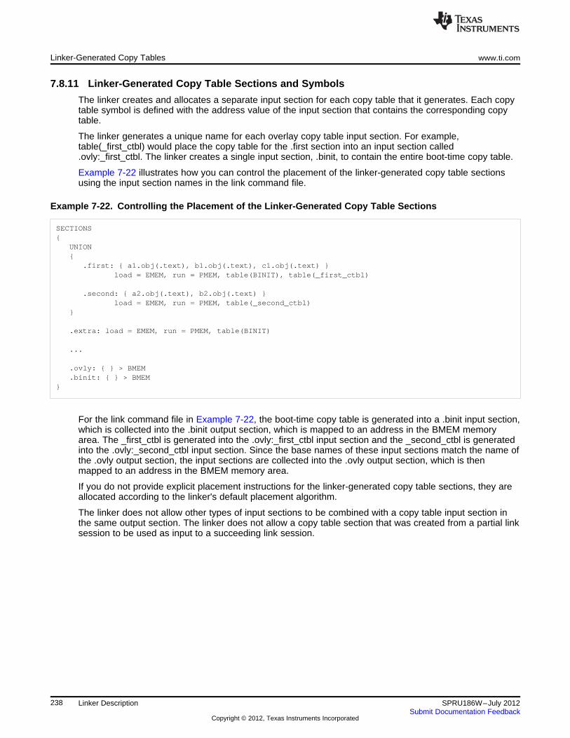
Linker-Generated Copy Tables www.ti.com
7.8.11 Linker-Generated Copy Table Sections and Symbols
The linker creates and allocates a separate input section for each copy table that it generates. Each copytable symbol is defined with the address value of the input section that contains the corresponding copytable.
The linker generates a unique name for each overlay copy table input section. For example,table(_first_ctbl) would place the copy table for the .first section into an input section called.ovly:_first_ctbl. The linker creates a single input section, .binit, to contain the entire boot-time copy table.
Example 7-22 illustrates how you can control the placement of the linker-generated copy table sectionsusing the input section names in the link command file.
Example 7-22. Controlling the Placement of the Linker-Generated Copy Table Sections
SECTIONS{
UNION{
.first: { a1.obj(.text), b1.obj(.text), c1.obj(.text) }load = EMEM, run = PMEM, table(BINIT), table(_first_ctbl)
.second: { a2.obj(.text), b2.obj(.text) }load = EMEM, run = PMEM, table(_second_ctbl)
}
.extra: load = EMEM, run = PMEM, table(BINIT)
...
.ovly: { } > BMEM
.binit: { } > BMEM}
For the link command file in Example 7-22, the boot-time copy table is generated into a .binit input section,which is collected into the .binit output section, which is mapped to an address in the BMEM memoryarea. The _first_ctbl is generated into the .ovly:_first_ctbl input section and the _second_ctbl is generatedinto the .ovly:_second_ctbl input section. Since the base names of these input sections match the name ofthe .ovly output section, the input sections are collected into the .ovly output section, which is thenmapped to an address in the BMEM memory area.
If you do not provide explicit placement instructions for the linker-generated copy table sections, they areallocated according to the linker's default placement algorithm.
The linker does not allow other types of input sections to be combined with a copy table input section inthe same output section. The linker does not allow a copy table section that was created from a partial linksession to be used as input to a succeeding link session.
238 Linker Description SPRU186W–July 2012Submit Documentation Feedback
Copyright © 2012, Texas Instruments Incorporated
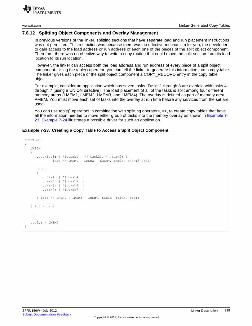
www.ti.com Linker-Generated Copy Tables
7.8.12 Splitting Object Components and Overlay Management
In previous versions of the linker, splitting sections that have separate load and run placement instructionswas not permitted. This restriction was because there was no effective mechanism for you, the developer,to gain access to the load address or run address of each one of the pieces of the split object component.Therefore, there was no effective way to write a copy routine that could move the split section from its loadlocation to its run location.
However, the linker can access both the load address and run address of every piece of a split objectcomponent. Using the table() operator, you can tell the linker to generate this information into a copy table.The linker gives each piece of the split object component a COPY_RECORD entry in the copy tableobject.
For example, consider an application which has seven tasks. Tasks 1 through 3 are overlaid with tasks 4through 7 (using a UNION directive). The load placement of all of the tasks is split among four differentmemory areas (LMEM1, LMEM2, LMEM3, and LMEM4). The overlay is defined as part of memory areaPMEM. You must move each set of tasks into the overlay at run time before any services from the set areused.
You can use table() operators in combination with splitting operators, >>, to create copy tables that haveall the information needed to move either group of tasks into the memory overlay as shown in Example 7-23. Example 7-24 illustrates a possible driver for such an application.
Example 7-23. Creating a Copy Table to Access a Split Object Component
SECTIONS{
UNION{
.task1to3: { *(.task1), *(.task2), *(.task3) }load >> LMEM1 | LMEM2 | LMEM4, table(_task13_ctbl)
GROUP{
.task4: { *(.task4) }
.task5: { *(.task5) }
.task6: { *(.task6) }
.task7: { *(.task7) }
} load >> LMEM1 | LMEM3 | LMEM4, table(_task47_ctbl)
} run = PMEM
...
.ovly: > LMEM4}
239SPRU186W–July 2012 Linker DescriptionSubmit Documentation Feedback
Copyright © 2012, Texas Instruments Incorporated
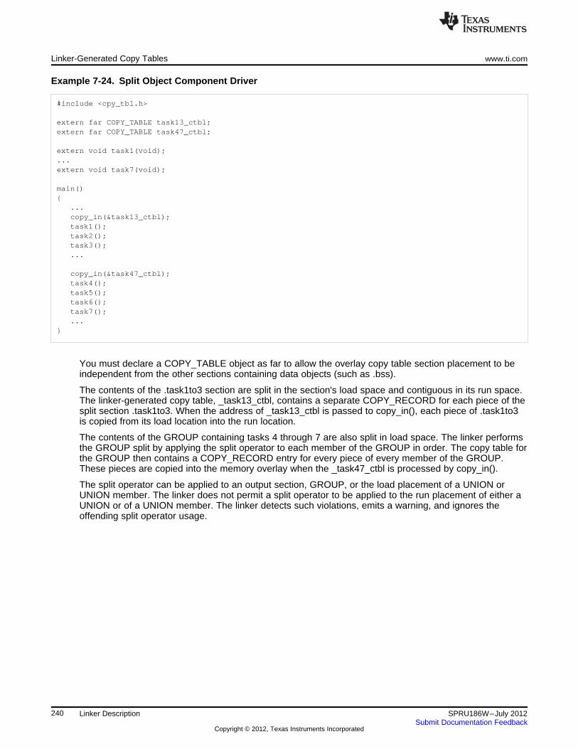
Linker-Generated Copy Tables www.ti.com
Example 7-24. Split Object Component Driver
#include <cpy_tbl.h>
extern far COPY_TABLE task13_ctbl;extern far COPY_TABLE task47_ctbl;
extern void task1(void);...extern void task7(void);
main(){
...copy_in(&task13_ctbl);task1();task2();task3();...
copy_in(&task47_ctbl);task4();task5();task6();task7();...
}
You must declare a COPY_TABLE object as far to allow the overlay copy table section placement to beindependent from the other sections containing data objects (such as .bss).
The contents of the .task1to3 section are split in the section's load space and contiguous in its run space.The linker-generated copy table, _task13_ctbl, contains a separate COPY_RECORD for each piece of thesplit section .task1to3. When the address of _task13_ctbl is passed to copy_in(), each piece of .task1to3is copied from its load location into the run location.
The contents of the GROUP containing tasks 4 through 7 are also split in load space. The linker performsthe GROUP split by applying the split operator to each member of the GROUP in order. The copy table forthe GROUP then contains a COPY_RECORD entry for every piece of every member of the GROUP.These pieces are copied into the memory overlay when the _task47_ctbl is processed by copy_in().
The split operator can be applied to an output section, GROUP, or the load placement of a UNION orUNION member. The linker does not permit a split operator to be applied to the run placement of either aUNION or of a UNION member. The linker detects such violations, emits a warning, and ignores theoffending split operator usage.
240 Linker Description SPRU186W–July 2012Submit Documentation Feedback
Copyright © 2012, Texas Instruments Incorporated
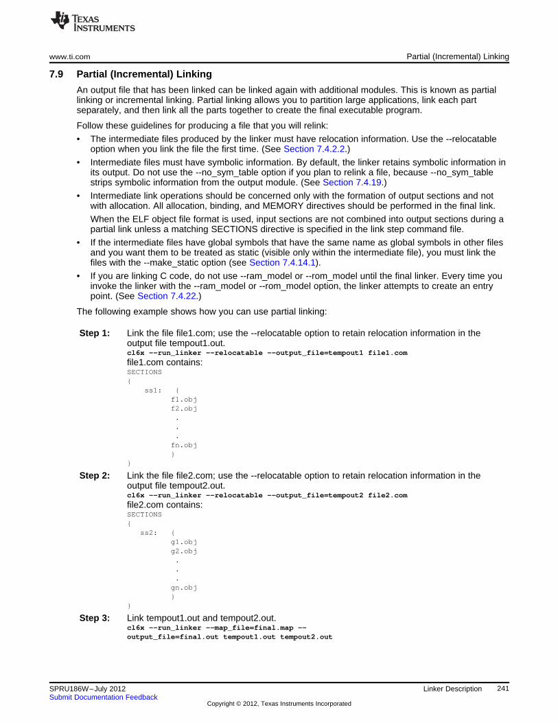
www.ti.com Partial (Incremental) Linking
7.9 Partial (Incremental) Linking
An output file that has been linked can be linked again with additional modules. This is known as partiallinking or incremental linking. Partial linking allows you to partition large applications, link each partseparately, and then link all the parts together to create the final executable program.
Follow these guidelines for producing a file that you will relink:
• The intermediate files produced by the linker must have relocation information. Use the --relocatableoption when you link the file the first time. (See Section 7.4.2.2.)
• Intermediate files must have symbolic information. By default, the linker retains symbolic information inits output. Do not use the --no_sym_table option if you plan to relink a file, because --no_sym_tablestrips symbolic information from the output module. (See Section 7.4.19.)
• Intermediate link operations should be concerned only with the formation of output sections and notwith allocation. All allocation, binding, and MEMORY directives should be performed in the final link.
When the ELF object file format is used, input sections are not combined into output sections during apartial link unless a matching SECTIONS directive is specified in the link step command file.
• If the intermediate files have global symbols that have the same name as global symbols in other filesand you want them to be treated as static (visible only within the intermediate file), you must link thefiles with the --make_static option (see Section 7.4.14.1).
• If you are linking C code, do not use --ram_model or --rom_model until the final linker. Every time youinvoke the linker with the --ram_model or --rom_model option, the linker attempts to create an entrypoint. (See Section 7.4.22.)
The following example shows how you can use partial linking:
Step 1: Link the file file1.com; use the --relocatable option to retain relocation information in theoutput file tempout1.out.cl6x --run_linker --relocatable --output_file=tempout1 file1.com
file1.com contains:SECTIONS{
ss1: {f1.objf2.obj...fn.obj}
}
Step 2: Link the file file2.com; use the --relocatable option to retain relocation information in theoutput file tempout2.out.cl6x --run_linker --relocatable --output_file=tempout2 file2.com
file2.com contains:SECTIONS{
ss2: {g1.objg2.obj...gn.obj}
}
Step 3: Link tempout1.out and tempout2.out.cl6x --run_linker --map_file=final.map --output_file=final.out tempout1.out tempout2.out
241SPRU186W–July 2012 Linker DescriptionSubmit Documentation Feedback
Copyright © 2012, Texas Instruments Incorporated
Linking C/C++ Code www.ti.com
7.10 Linking C/C++ Code
The C/C++ compiler produces assembly language source code that can be assembled and linked. Forexample, a C program consisting of modules prog1, prog2, etc., can be assembled and then linked toproduce an executable file called prog.out:cl6x --run_linker --rom_model --output_file prog.out prog1.obj prog2.obj ... rts6200.lib
The --rom_model option tells the linker to use special conventions that are defined by the C/C++environment.
The archive libraries shipped by TI contain C/C++ run-time-support functions.
C, C++, and mixed C and C++ programs can use the same run-time-support library. Run-time-supportfunctions and variables that can be called and referenced from both C and C++ will have the samelinkage.
For more information about the TMS320C6000 C/C++ language, including the run-time environment andrun-time-support functions, see the TMS320C6000 Optimizing Compiler User's Guide.
7.10.1 Run-Time Initialization
All C/C++ programs must be linked with code to initialize and execute the program, called a bootstraproutine, also known as the boot.obj object module. The symbol _c_int00 is defined as the program entrypoint and is the start of the C boot routine in boot.obj; referencing _c_int00 ensures that boot.obj isautomatically linked in from the run-time-support library. When a program begins running, it executesboot.obj first. The boot.obj symbol contains code and data for initializing the run-time environment andperforms the following tasks:
• Sets up the system stack and configuration registers
• Processes the run-time .cinit initialization table and autoinitializes global variables (when the linker isinvoked with the --rom_model option)
• Disables interrupts and calls _main
The run-time-support object libraries contain boot.obj. You can:
• Use the archiver to extract boot.obj from the library and then link the module in directly.
• Include the appropriate run-time-support library as an input file (the linker automatically extractsboot.obj when you use the --ram_model or --rom_model option).
242 Linker Description SPRU186W–July 2012Submit Documentation Feedback
Copyright © 2012, Texas Instruments Incorporated
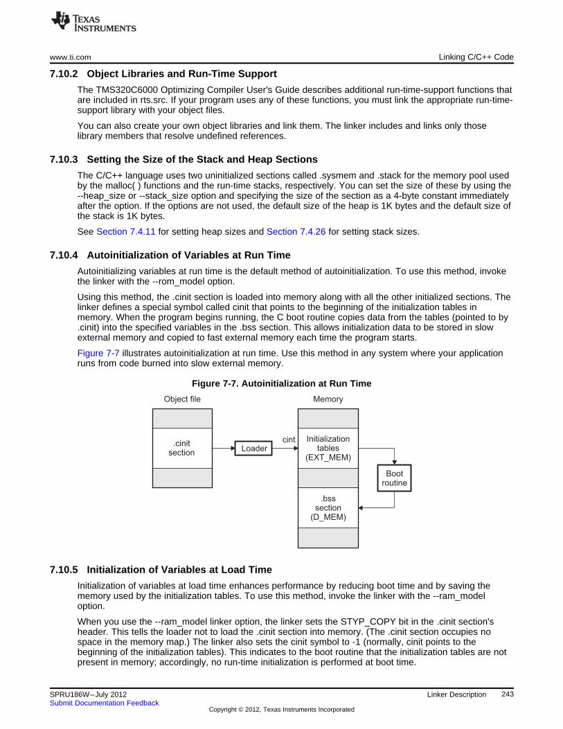
Initializationtables
(EXT_MEM)
.bsssection
(D_MEM)
Bootroutine
.cinitsection
Loader
Object file Memory
cint
www.ti.com Linking C/C++ Code
7.10.2 Object Libraries and Run-Time Support
The TMS320C6000 Optimizing Compiler User's Guide describes additional run-time-support functions thatare included in rts.src. If your program uses any of these functions, you must link the appropriate run-time-support library with your object files.
You can also create your own object libraries and link them. The linker includes and links only thoselibrary members that resolve undefined references.
7.10.3 Setting the Size of the Stack and Heap Sections
The C/C++ language uses two uninitialized sections called .sysmem and .stack for the memory pool usedby the malloc( ) functions and the run-time stacks, respectively. You can set the size of these by using the--heap_size or --stack_size option and specifying the size of the section as a 4-byte constant immediatelyafter the option. If the options are not used, the default size of the heap is 1K bytes and the default size ofthe stack is 1K bytes.
See Section 7.4.11 for setting heap sizes and Section 7.4.26 for setting stack sizes.
7.10.4 Autoinitialization of Variables at Run Time
Autoinitializing variables at run time is the default method of autoinitialization. To use this method, invokethe linker with the --rom_model option.
Using this method, the .cinit section is loaded into memory along with all the other initialized sections. Thelinker defines a special symbol called cinit that points to the beginning of the initialization tables inmemory. When the program begins running, the C boot routine copies data from the tables (pointed to by.cinit) into the specified variables in the .bss section. This allows initialization data to be stored in slowexternal memory and copied to fast external memory each time the program starts.
Figure 7-7 illustrates autoinitialization at run time. Use this method in any system where your applicationruns from code burned into slow external memory.
Figure 7-7. Autoinitialization at Run Time
7.10.5 Initialization of Variables at Load Time
Initialization of variables at load time enhances performance by reducing boot time and by saving thememory used by the initialization tables. To use this method, invoke the linker with the --ram_modeloption.
When you use the --ram_model linker option, the linker sets the STYP_COPY bit in the .cinit section'sheader. This tells the loader not to load the .cinit section into memory. (The .cinit section occupies nospace in the memory map.) The linker also sets the cinit symbol to -1 (normally, cinit points to thebeginning of the initialization tables). This indicates to the boot routine that the initialization tables are notpresent in memory; accordingly, no run-time initialization is performed at boot time.
243SPRU186W–July 2012 Linker DescriptionSubmit Documentation Feedback
Copyright © 2012, Texas Instruments Incorporated
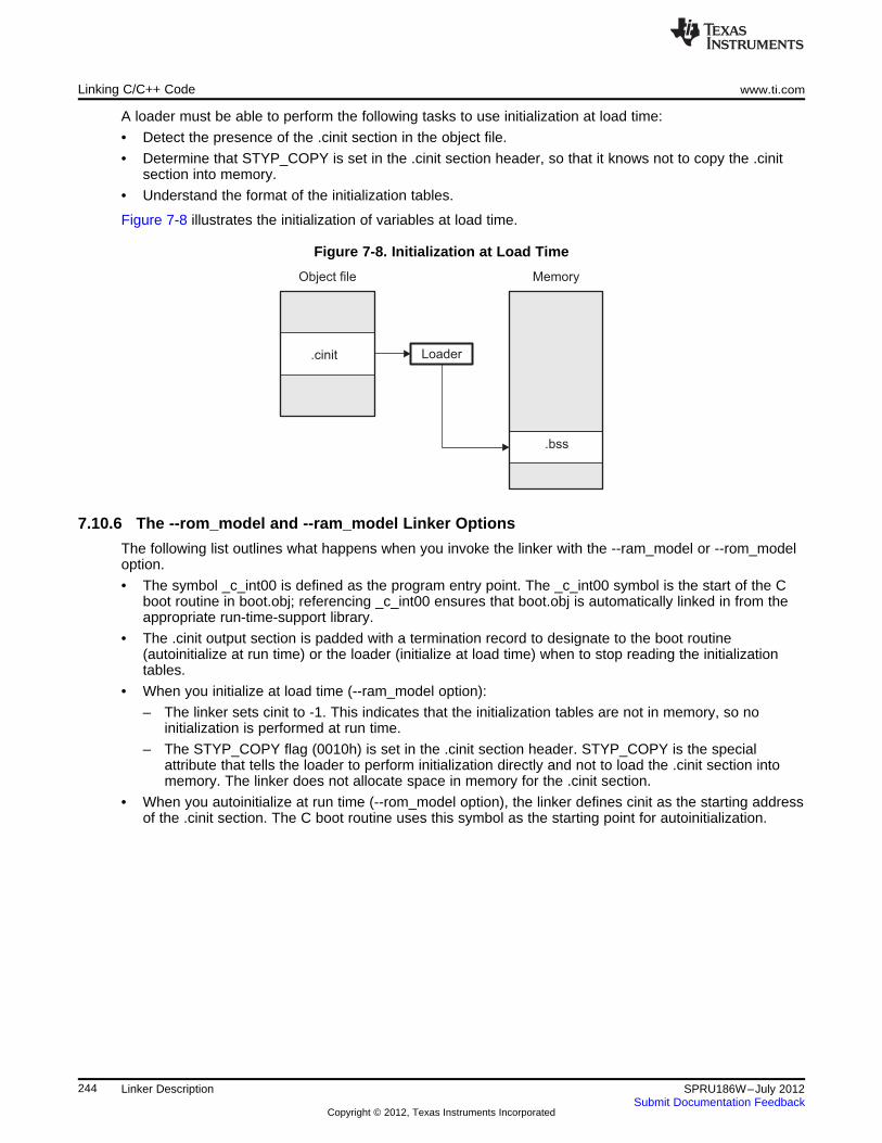
.bss
.cinit Loader
Object file Memory
Linking C/C++ Code www.ti.com
A loader must be able to perform the following tasks to use initialization at load time:
• Detect the presence of the .cinit section in the object file.
• Determine that STYP_COPY is set in the .cinit section header, so that it knows not to copy the .cinitsection into memory.
• Understand the format of the initialization tables.
Figure 7-8 illustrates the initialization of variables at load time.
Figure 7-8. Initialization at Load Time
7.10.6 The --rom_model and --ram_model Linker Options
The following list outlines what happens when you invoke the linker with the --ram_model or --rom_modeloption.
• The symbol _c_int00 is defined as the program entry point. The _c_int00 symbol is the start of the Cboot routine in boot.obj; referencing _c_int00 ensures that boot.obj is automatically linked in from theappropriate run-time-support library.
• The .cinit output section is padded with a termination record to designate to the boot routine(autoinitialize at run time) or the loader (initialize at load time) when to stop reading the initializationtables.
• When you initialize at load time (--ram_model option):
– The linker sets cinit to -1. This indicates that the initialization tables are not in memory, so noinitialization is performed at run time.
– The STYP_COPY flag (0010h) is set in the .cinit section header. STYP_COPY is the specialattribute that tells the loader to perform initialization directly and not to load the .cinit section intomemory. The linker does not allocate space in memory for the .cinit section.
• When you autoinitialize at run time (--rom_model option), the linker defines cinit as the starting addressof the .cinit section. The C boot routine uses this symbol as the starting point for autoinitialization.
244 Linker Description SPRU186W–July 2012Submit Documentation Feedback
Copyright © 2012, Texas Instruments Incorporated
www.ti.com Linker Example
7.11 Linker Example
This example links three object files named demo.obj, ctrl.obj, and tables.obj and creates a program calleddemo.out.
Assume that target memory has the following program memory configuration:
Address Range Contents0x00000000 to 0x00001000 SLOW_MEM0x00001000 to 0x00002000 FAST_MEM0x08000000 to 0x08000400 EEPROM
The output sections are constructed in the following manner:
• Executable code, contained in the .text sections of demo.obj, fft.obj, and tables.obj, is linked intoprogram memory ROM.
• Variables, contained in the var_defs section of demo.obj, are linked into data memory in blockFAST_MEM_2.
• Tables of coefficients in the .data sections of demo.obj, tables.obj, and fft.obj are linked intoFAST_MEM_1. A hole is created with a length of 100 and a fill value of 0x07A1C.
• The xy section form demo.obj, which contains buffers and variables, is linked by default into page 1 ofthe block STACK, since it is not explicitly linked.
• Executable code, contained in the .text sections of demo.obj, ctrl.obj, and tables.obj, must be linkedinto FAST_MEM.
• A set of interrupt vectors, contained in the .intvecs section of tables.obj, must be linked at address0x00000000.
• A table of coefficients, contained in the .data section of tables.obj, must be linked into EEPROM. Theremainder of block EEPROM must be initialized to the value 0xFF00FF00.
• A set of variables, contained in the .bss section of ctrl.obj, must be linked into SLOW_MEM andpreinitialized to 0x00000100.
• The .bss sections of demo.obj and tables.obj must be linked into SLOW_MEM.
Example 7-25 shows the link command file for this example. Example 7-26 shows the map file.
245SPRU186W–July 2012 Linker DescriptionSubmit Documentation Feedback
Copyright © 2012, Texas Instruments Incorporated
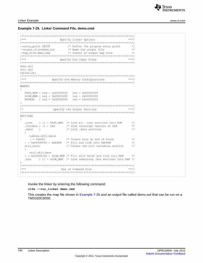
Linker Example www.ti.com
Example 7‑‑25. Linker Command File, demo.cmd
/**********************************************************************//*** Specify Linker Options ***//**********************************************************************/--entry_point SETUP /* Define the program entry point */--output_file=demo.out /* Name the output file */--map_file=demo.map /* Create an output map file *//**********************************************************************//*** Specify the Input Files ***//**********************************************************************/demo.objctrl.objtables.obj/**********************************************************************//*** Specify the Memory Configurations ***//**********************************************************************/MEMORY{
FAST_MEM : org = 0x00000000 len = 0x00001000SLOW_MEM : org = 0x00001000 len = 0x00001000EEPROM : org = 0x08000000 len = 0x00000400
}/**********************************************************************//* Specify the Output Sections ***//**********************************************************************/SECTIONS{
.text : {} > FAST_MEM /* Link all .text sections into ROM */
.intvecs : {} > 0x0 /* Link interrupt vectors at 0x0 */
.data : /* Link .data sections */{
tables.obj(.data). = 0x400; /* Create hole at end of block */
} = 0xFF00FF00 > EEPROM /* Fill and link into EEPROM */ctrl_vars: /* Create new ctrl variables section */{
ctrl.obj(.bss)} = 0x00000100 > SLOW_MEM /* Fill with 0x100 and link into RAM */.bss : {} > SLOW_MEM /* Link remaining .bss sections into RAM */
}/**********************************************************************//*** End of Command File ***//**********************************************************************/
Invoke the linker by entering the following command:cl6x --run_linker demo.cmd
This creates the map file shown in Example 7-26 and an output file called demo.out that can be run on aTMS320C6000.
246 Linker Description SPRU186W–July 2012Submit Documentation Feedback
Copyright © 2012, Texas Instruments Incorporated
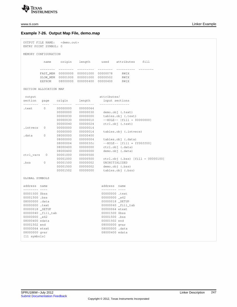
www.ti.com Linker Example
Example 7‑‑26. Output Map File, demo.map
OUTPUT FILE NAME: <demo.out>ENTRY POINT SYMBOL: 0
MEMORY CONFIGURATION
name origin length used attributes fill
-------- -------- --------- -------- ---------- --------FAST_MEM 00000000 000001000 00000078 RWIXSLOW_MEM 00001000 000001000 00000502 RWIXEEPROM 08000000 000000400 00000400 RWIX
SECTION ALLOCATION MAP
output attributes/section page origin length input sections-------- ---- ---------- ---------- ----------------.text 0 00000000 00000064
00000000 00000030 demo.obj (.text)00000030 00000000 tables.obj (.text)00000030 00000010 --HOLE-- [fill = 00000000]00000040 00000024 ctrl.obj (.text)
.intvecs 0 00000000 0000001400000000 00000014 tables.obj (.intvecs)
.data 0 08000000 0000040008000000 00000004 tables.obj (.data)08000004 000003fc --HOLE-- [fill = ff00ff00]08000400 00000000 ctrl.obj (.data)08000400 00000000 demo.obj (.data)
ctrl_vars 0 00001000 0000050000001000 00000500 ctrl.obj (.bss) [fill = 00000100]
.bss 0 00001500 00000002 UNINITIALIZED00001500 00000002 demo.obj (.bss)00001502 00000000 tables.obj (.bss)
GLOBAL SYMBOLS
address name address name-------- ---- -------- ----00001500 $bss 00000000 .text00001500 .bss 00000000 _x4208000000 .data 00000018 _SETUP00000000 .text 00000040 _fill_tab00000018 _SETUP 00000064 etext00000040 _fill_tab 00001500 $bss00000000 _x42 00001500 .bss08000400 edata 00001502 end00001502 end 08000000 gvar00000064 etext 08000000 .data08000000 gvar 08000400 edata[11 symbols]
247SPRU186W–July 2012 Linker DescriptionSubmit Documentation Feedback
Copyright © 2012, Texas Instruments Incorporated
Dynamic Linking with the C6000 Code Generation Tools www.ti.com
7.12 Dynamic Linking with the C6000 Code Generation Tools
The C6000 v7.2 Code Generation Tools (CGT) support dynamic linking provided you build with EABI. Ifyou are not already familiar with the limitations of EABI support in the C6000 compiler, please seehttp://processors.wiki.ti.com/index.php/EABI_Support_in_C6000_Compiler and The C6000 EmbeddedApplication Binary Interface Application Report (SPRAB89).
7.12.1 Static vs Dynamic Linking
Static linking is the traditional process of combining relocatable object files and static libraries into a staticlink unit: either an ELF executable file (.exe) or an ELF shared object (.so). The term object is used torefer generically to either.
7.12.1.1 Code Size Reduction
A program consists of exactly one executable file (also commonly known as a client application) and anyadditional shared objects (such as libraries) that it depends on to satisfy any undefined references. Ifmultiple executables depend on the same library, they can share a single copy of its code (hence the“shared” in “shared object”), thereby significantly reducing the memory requirements of the system.
A dynamic shared object (DSO), as the name implies, can be shared among several applications that maybe running one-at-a-time in a single threaded environment, or at the same time in a multi-threadedenvironment. Rather than making a separate copy of the DSO code in memory for each application thatneeds to use it, a single version of the code can reside in one location (like ROM) where references to itsfunctions can be resolved as the executables and other DSOs that use it are loaded and dynamicallylinked.
7.12.1.2 Binding Time
In a conventionally linked static executable, symbols are bound to addresses and library code is bound tothe executable at link-time, so the library that the executable is bound to at link-time is the one that it willalways use, regardless of changes or defect fixes that are made to the library.
In a static shared library, symbols are still bound to addresses at link-time, but the library code is notbound to the executable that uses the library until run-time.
With a dynamic shared library, decisions about binding library symbols to addresses and resolving symbolreferences between a dynamic shared library and the other objects that use it (or are used by it) aredelayed until actual load-time. This allows you to load a shared library when its services are needed, andunload it when its services are not needed. Thus, making more effective use of limited target memoryspace.
7.12.1.3 Modular Development
Dynamically linking encourages modular development. The interface for a dynamic shared object isexplicitly defined via the importing and exporting of global symbols. A cleanly defined interface for adynamic shared object will tend to improve the cohesion of the code that implements the servicesprovided by a given dynamic object.
7.12.1.4 Recommended Reading
For a more detailed discussion of the benefits and disadvantages of using dynamic executables anddynamic shared objects, please refer to available literature on the subject, including John R. Levine'sexcellent book Linkers & Loaders (ISBN-13: 978-1-55860-496-4).
248 Linker Description SPRU186W–July 2012Submit Documentation Feedback
Copyright © 2012, Texas Instruments Incorporated
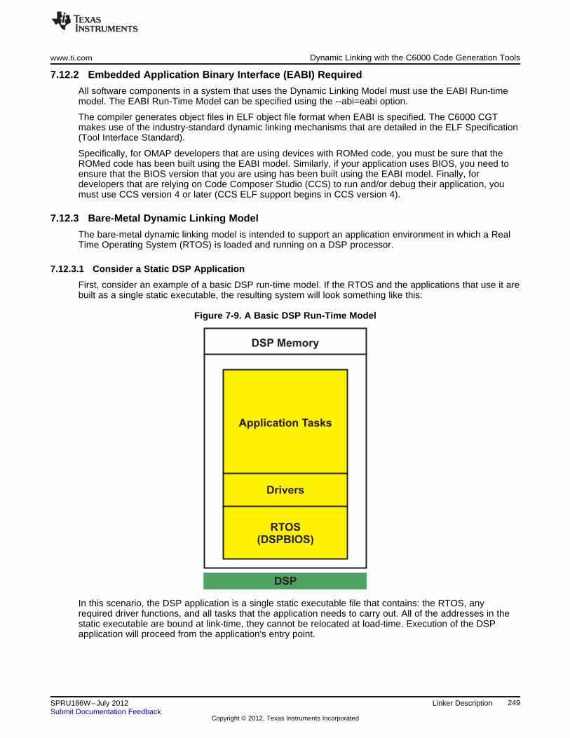
DSP Memory
Application Tasks
Drivers
RTOS(DSPBIOS)
DSP
www.ti.com Dynamic Linking with the C6000 Code Generation Tools
7.12.2 Embedded Application Binary Interface (EABI) Required
All software components in a system that uses the Dynamic Linking Model must use the EABI Run-timemodel. The EABI Run-Time Model can be specified using the --abi=eabi option.
The compiler generates object files in ELF object file format when EABI is specified. The C6000 CGTmakes use of the industry-standard dynamic linking mechanisms that are detailed in the ELF Specification(Tool Interface Standard).
Specifically, for OMAP developers that are using devices with ROMed code, you must be sure that theROMed code has been built using the EABI model. Similarly, if your application uses BIOS, you need toensure that the BIOS version that you are using has been built using the EABI model. Finally, fordevelopers that are relying on Code Composer Studio (CCS) to run and/or debug their application, youmust use CCS version 4 or later (CCS ELF support begins in CCS version 4).
7.12.3 Bare-Metal Dynamic Linking Model
The bare-metal dynamic linking model is intended to support an application environment in which a RealTime Operating System (RTOS) is loaded and running on a DSP processor.
7.12.3.1 Consider a Static DSP Application
First, consider an example of a basic DSP run-time model. If the RTOS and the applications that use it arebuilt as a single static executable, the resulting system will look something like this:
Figure 7-9. A Basic DSP Run-Time Model
In this scenario, the DSP application is a single static executable file that contains: the RTOS, anyrequired driver functions, and all tasks that the application needs to carry out. All of the addresses in thestatic executable are bound at link-time, they cannot be relocated at load-time. Execution of the DSPapplication will proceed from the application's entry point.
249SPRU186W–July 2012 Linker DescriptionSubmit Documentation Feedback
Copyright © 2012, Texas Instruments Incorporated
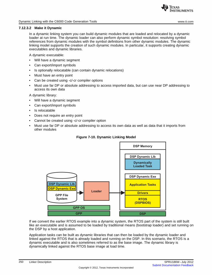
Loader
GPP OS
GPP
GPP FileSystem
DSP Memory
DSP Dynamic Lib
DynamicallyLoaded Task
DSP Dynamic Exe
Application Tasks
Drivers
RTOS(DSPBIOS)
DSP
DSP Dynamic Exe
DSP Dynamic Lib
Dynamic Linking with the C6000 Code Generation Tools www.ti.com
7.12.3.2 Make it Dynamic
In a dynamic linking system you can build dynamic modules that are loaded and relocated by a dynamicloader at run time. The dynamic loader can also perform dynamic symbol resolution: resolving symbolreferences from dynamic modules with the symbol definitions from other dynamic modules. The dynamiclinking model supports the creation of such dynamic modules. In particular, it supports creating dynamicexecutables and dynamic libraries.
A dynamic executable:
• Will have a dynamic segment
• Can export/import symbols
• Is optionally relocatable (can contain dynamic relocations)
• Must have an entry point
• Can be created using -c/-cr compiler options
• Must use far DP or absolute addressing to access imported data, but can use near DP addressing toaccess its own data
A dynamic library:
• Will have a dynamic segment
• Can export/import symbols
• Is relocatable
• Does not require an entry point
• Cannot be created using -c/-cr compiler option
• Must use far DP or absolute addressing to access its own data as well as data that it imports fromother modules
Figure 7-10. Dynamic Linking Model
If we convert the earlier RTOS example into a dynamic system, the RTOS part of the system is still builtlike an executable and is assumed to be loaded by traditional means (bootstrap loader) and set running onthe DSP by a host application.
Application tasks can be built as dynamic libraries that can then be loaded by the dynamic loader andlinked against the RTOS that is already loaded and running on the DSP. In this scenario, the RTOS is adynamic executable and is also sometimes referred to as the base image. The dynamic library isdynamically linked against the RTOS base image at load time.
250 Linker Description SPRU186W–July 2012Submit Documentation Feedback
Copyright © 2012, Texas Instruments Incorporated
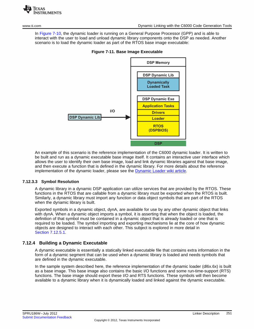
DSP Memory
DSP Dynamic Lib
DynamicallyLoaded Task
I/O
DSP Dynamic Exe
Application Tasks
Drivers
Loader
RTOS(DSPBIOS)
DSP
DSP Dynamic Lib
www.ti.com Dynamic Linking with the C6000 Code Generation Tools
In Figure 7-10, the dynamic loader is running on a General Purpose Processor (GPP) and is able tointeract with the user to load and unload dynamic library components onto the DSP as needed. Anotherscenario is to load the dynamic loader as part of the RTOS base image executable:
Figure 7-11. Base Image Executable
An example of this scenario is the reference implementation of the C6000 dynamic loader. It is written tobe built and run as a dynamic executable base image itself. It contains an interactive user interface whichallows the user to identify their own base image, load and link dynamic libraries against that base image,and then execute a function that is defined in the dynamic library. For more details about the referenceimplementation of the dynamic loader, please see the Dynamic Loader wiki article.
7.12.3.3 Symbol Resolution
A dynamic library in a dynamic DSP application can utilize services that are provided by the RTOS. Thesefunctions in the RTOS that are callable from a dynamic library must be exported when the RTOS is built.Similarly, a dynamic library must import any function or data object symbols that are part of the RTOSwhen the dynamic library is built.
Exported symbols in a dynamic object, dynA, are available for use by any other dynamic object that linkswith dynA. When a dynamic object imports a symbol, it is asserting that when the object is loaded, thedefinition of that symbol must be contained in a dynamic object that is already loaded or one that isrequired to be loaded. The symbol importing and exporting mechanisms lie at the core of how dynamicobjects are designed to interact with each other. This subject is explored in more detail inSection 7.12.5.1.
7.12.4 Building a Dynamic Executable
A dynamic executable is essentially a statically linked executable file that contains extra information in theform of a dynamic segment that can be used when a dynamic library is loaded and needs symbols thatare defined in the dynamic executable.
In the sample system described here, the reference implementation of the dynamic loader (dl6x.6x) is builtas a base image. This base image also contains the basic I/O functions and some run-time-support (RTS)functions. The base image should export these I/O and RTS functions. These symbols will then becomeavailable to a dynamic library when it is dynamically loaded and linked against the dynamic executable.
251SPRU186W–July 2012 Linker DescriptionSubmit Documentation Feedback
Copyright © 2012, Texas Instruments Incorporated
Dynamic Linking with the C6000 Code Generation Tools www.ti.com
7.12.4.1 Exporting Symbols
To accomplish exporting of symbols, there are two methods available:
• Recommended: Declare exported symbols explicitly in the source of the dynamic executable using__declspec(dllexport).
For example, if you want to export exp_func from the dynamic executable, you can declare it in yoursource as follows:__declspec(dllexport) int exp_func();
• Use the --export option at link time. You can specify one or more symbols to be exported with --export=symbol on the linker command line or in a linker command file. For example, you could exportexp_func() at link time with:cl6x --abi=elfabi ... -z --dynamic=exe --export=exp_func ...
In general, to build a dynamic executable, you must specify --dynamic=exe or --dynamic on the linkercommand line or in a linker command file. Consider the build of the dl6x.6x file described in theDynamic Loader wiki article at http://processors.wiki.ti.com/index.php/C6000_EABI:Dynamic_Loader asan example of how to build a dynamic executable or base image:cl6x --abi=elfabi ... -z *.obj ... --dynamic --export=printf ...
In this example, the --dynamic option indicates that the result of the link is going to be a dynamicexecutable. The --export=printf indicates that the printf() run-time-support function is exported by thedynamic executable and, if imported by a dynamic library, can be called at run time by the functionsdefined in the dynamic library.
7.12.5 Building a Dynamic Library
A dynamic library is a shared object that contains dynamic information in the form of a dynamic segment.It is relocatable and can import symbols from other ELF dynamic objects that it links against and it canalso export symbols that it defines itself.
7.12.5.1 Importing/Exporting Symbols
Importing and exporting of symbols can be accomplished in two ways, similarly to how it can be done indynamic executables:
• Recommended: Declare exported and/or imported symbols explicitly in the source code of thedynamic library using __declspec(dllexport) for exported symbols and __declspec(dllimport) forimported symbols.
For example, if you want to export a function, red_fish(), and import another function, blue_fish(), youcould specify this in a source file as follows:__declspec(dllexport) long red_fish();__declspec(dllimport) int blue_fish();
• You can also specify symbols to be imported or exported on the linker command line (or in a linkercommand file) using --import=symbol or "--export=symbol.
So at link time, you might say:cl6x --abi=elfabi ... -z --dynamic=lib --export=red_fish --import=blue_fish
blue.dll -o red.dll
This informs the linker that the definition of red_fish() will be in the red.dll dynamic library and that wecan find and use the definition of blue_fish() in blue.dll.
In general, to build a dynamic library, you must specify --dynamic=lib on the linker command line or in alinker command file. In addition, if any symbols are imported from other dynamic objects, then thosedynamic objects must be specified on the linker command line when the dynamic library is built. This issometimes referred to as static binding.
252 Linker Description SPRU186W–July 2012Submit Documentation Feedback
Copyright © 2012, Texas Instruments Incorporated
www.ti.com Dynamic Linking with the C6000 Code Generation Tools
7.12.5.2 A Simple Example - hello.dll
This section describes a simple walk-through of the process used to build, load, and run a function that isdefined in a dynamic library.
• First compile this simple "Hello World" source:hello.c:
#include <stdio.h>__declspec(dllexport) int start();int start(){
printf("Hello World\n");return 0;
}
• Then build a dynamic library called hello.dll:cl6x -mv6400+ --abi=elfabi hello.c -z --import=printf --dynamic=lib -o hello.dll
dl6x.6x -e start
• Now, load the dynamic loader using a loader that supports C6000 ELF executable object files. Thenstart the dynamic loader running. When using the reference implementation of the dynamic loader(RIDL), you will see the RIDL prompt come up and then you need to issue the following commands:RIDL> base_image dl6x.6xRIDL> load hello.dllRIDL> execute
You should see the "Hello World" message displayed and then control will return to the RIDL prompt.To terminate the dynamic loader you can enter the exit command from the RIDL prompt.
For more details, see the Dynamic Loader wiki site(http://processors.wiki.ti.com/index.php/C6000_Dynamic_Loader))
7.12.5.3 Summary of Compiler and Linker Options
This is a brief summary of the compiler and linker options that are related to support for the DynamicLinking Model in the C6000 CGT. For more details, see the C6000 EABI wiki article(http://processors.wiki.ti.com/index.php/EABI_Support_in_C6000_Compiler).
Table 7-12. Compiler Options For Dynamic Linking
Option Description
--abi=eabi Specifies that EABI run-time model is to be used.
--dsbt Generates addressing via Dynamic Segment Base Table
--export_all_cpp_vtbl Exports C++ virtual tables by default
Specifies that all global symbol references that are not defined in a module are imported. Default--import_undef[=off|on] is on.
Specifies that all compiler generated calls to run-time-support functions are treated as calls to--import_helper_functions imported functions. See Section 7.12.6.
--inline_plt[=off|on] Inlines the import function call stub. Default is on.
--linux Generates code for Linux.
--pic[=off|on] Generates position independent addressing for a shared object. Default is near.
--visibility={hidden| Specifies a default visibility to be assumed for global symbols. See Section 7.12.6.default|protected}
Generates 32-bit wchar_t type when --abi=eabi is specified. By default the compiler generates 16-–wchar_t bit wchar_t.
253SPRU186W–July 2012 Linker DescriptionSubmit Documentation Feedback
Copyright © 2012, Texas Instruments Incorporated
Dynamic Linking with the C6000 Code Generation Tools www.ti.com
Table 7-13. Linker Options For Dynamic Linking
Option Description
Requests a specific Data Segment Base Table (DSBT) index to be associated with the current output--dsbt_index=int file. If the DSBT model is being used, and you do not request a specific DSBT index for the output file,
then a DSBT index is assigned to the module at load time.
Specifies the size of the Data Segment Base Table (DSBT) for the current output file, in words. If the--dsbt_size=int DSBT model is being used, this option can be used to override the default DSBT size (8 words).
--dynamic[=exe] Specifies that the result of a link will be a dynamic executable. See Section 7.12.4.1.
--dynamic=lib Specifies that the result of a link will be a dynamic library. See Section 7.12.5.1.
--export=symbol Specifies that symbol is exported by the ELF object that is generated for this link.
--fini=symbol Specifies the symbol name of the termination code for the output file currently being linked.
--import=symbol Specifies that symbol is imported by the ELF object that is generated for this link.
--init=symbol Specifies the symbol name of the initialization code for the output file currently being linked.
--rpath=dir Adds a directory to the beginning of the dynamic library search path.
--runpath=dir Adds a directory to the end of the dynamic library search path.
--shared Generates a dynamically shared object.
Specifies shared object name to be used to identify this ELF object to the any downstream ELF object--soname=string consumers.
--sysv Generates SysV ELF output file.
7.12.6 Symbol Import/Export
In a dynamic linking system you can build dynamic modules that are loaded and relocated by a dynamicloader at run time. The dynamic loader can also perform dynamic symbol resolution: resolve referencesfrom dynamic modules with the definitions from other dynamic objects.
Only symbols explicitly imported or exported have dynamic linkage and participate in dynamic linking.Normal global symbols don't participate in dynamic symbol resolution. A symbol is exported if it is visiblefrom a module during dynamic symbol resolution. A dynamic object is a dynamic library or a dynamicexecutable. Such a dynamic object imports a symbol when its symbol references are resolved bydefinitions from another dynamic object. The dynamic object that has the definition and makes it visible issaid to export the symbol.
7.12.6.1 ELF Symbols
ELF symbols have two attributes that contribute to static and dynamic symbol binding:
• Symbol Binding - symbol’s scope with respect to other files
• Symbol Visibility - symbol’s scope with respect to other run-time components (dynamic executable ordynamic libraries)
A more detailed discussion of the symbol binding and visibility characteristics can be found in the ELFSpecification (Tool Interface Standard).
7.12.6.1.1 Symbol Binding Attribute Values• STB_LOCAL
– Indicates that a symbol is not visible outside the module where it is defined.
– Any local references to the symbol will be resolved by the definition in the current module.
• STB_GLOBAL– Indicates that a symbol is visible to all files being combined during the link step
– Any references to a global symbol that are left unresolved will result in a link-time error
• STB_WEAK– Indicates that a symbol is visible to all files being combined during a link step.
– Global symbol definition takes precedence over corresponding weak symbol def.
254 Linker Description SPRU186W–July 2012Submit Documentation Feedback
Copyright © 2012, Texas Instruments Incorporated
www.ti.com Dynamic Linking with the C6000 Code Generation Tools
7.12.6.1.2 ELF Symbol Visibility
GLOBAL/WEAK symbols can have any of the following visibility attributes:
• STV_DEFAULT– Symbol definition is visible outside the defining component.
– Symbol definition can be preempted.
– Symbol references can be resolved by definition outside the referenced component.
• STV_PROTECTED– Symbol definition is visible outside the defining component.
– Symbol definition cannot be preempted.
– Symbol reference must be resolved by a definition in the same component.
• STV_HIDDEN– Symbol definition is not visible outside its own component.
– Symbol reference must be resolved by a definition in the same component.
7.12.6.2 Controlling Import/Export of Symbols
Symbols can be imported/exported by using:
• Source Code Annotations
• ELF Linkage Macros
• Compiler Options
• Linker Options
7.12.6.2.1 Source Code Annotations (Recommended)
A global symbol can be imported or exported by adding a __declspec() symbol annotation to the sourcefile.
• Export Using __declspec(dllexport)__declspec(dllexport) int foo() { }
__declspec(dllexport) can be applied to both symbol declarations and symbol definitions.
• Import Using __declspec(dllimport)__declspec(dllimport) int bar();
__declspec(dllimport) can be applied to a symbol declaration.
The compiler generates a warning if __declspec(dllimport) is applied to a symbol definition.
• Typically an API is exported by a module and is imported by another module. __declspec() can beadded to the API header file
• The linker uses the most restrictive visibility for symbols. For example, consider if the following weretrue:
– foo() is declared with __declspec(dllimport) in a.c
– foo() is declared plain (no __declspec()) in b.c
– a.c and b.c are compiled into ab.dll
Then, the symbol, foo, is not imported in ab.dll and the linker reports an error indicating that thereference to foo() is unresolved.
• Some of the benefits of using the __declspec() approach include:
– It enables the compiler to generate more optimal code.
– The optimizer does not optimize out exported symbols.
– The source code becomes a self-documenting in specifying the API for a given module, making iteasier to read and maintain.
– It can be used in the Dynamic Linking Model
255SPRU186W–July 2012 Linker DescriptionSubmit Documentation Feedback
Copyright © 2012, Texas Instruments Incorporated
Dynamic Linking with the C6000 Code Generation Tools www.ti.com
7.12.6.2.2 Import/Export Using ELF Linkage Macros (elf_linkage.h)
The C6000 compiler provides a header file, elf_linkage.h, in the include sub-directory of the installedtoolset. The elf_linkage.h file defines several macros that can be used to control symbol visibility:
• TI_IMPORT symbol declaration
This macro imports the declared symbol. The TI_IMPORT macro cannot be applied to symboldefinitions.
TI_IMPORT int foo(void);extern TI_IMPORT long global_variable;
• TI_EXPORT symbol definition|symbol declaration
This macro exports the symbol that is being declared or defined. The source module that makes use ofthis macro must contain a definition of the symbol.
TI_EXPORT int foo(void);TI_EXPORT long global_variable;
• TI_PATCHABLE symbol definition
This macro makes the definition of the symbol visible outside of the source module that uses it. Othermodules can import the defined symbol. Also, a reference to the symbol can be patched (or re-directed) to a different definition of the symbol if needed. The compiler will generate an indirect call to afunction that has been marked as patchable. This technique is also sometimes called symbolpreemption.
TI_PATCHABLE int foo(void);TI_PATCHABLE long global_variable;
• TI_DEFAULT symbol definition|symbol declaration
This macro specifies that the symbol in question can be either imported or exported. The definition ofthe symbol is visible outside the module. Other modules can import the symbol definition. Anyreferences to the symbol can also be patched.
• TI_PROTECTED symbol definition|symbol declaration
This macro specifies that the symbol in question is visible outside of the module. Other modules canimport the symbol definition. However, a reference to the symbol can never be patched (symbol is non-preemptable).
• TI_HIDDEN symbol definition|symbol declaration
The definition of the symbol is not visible outside the module that defines it.
7.12.6.2.3 Import/Export Using Compiler Options
The following compiler options can be used to control the symbol visibility of global symbols. The symbolsusing source code annotations to control the visibility are not effected by these compiler options.
• --visibility=default visibility
The --visibility option specifies the default visibility for global symbols. This option does not affect thevisibility of symbols that use the __declspec() or TI_xxx macros to specify a visibility in the sourcecode. The default visibility is one of the following:
– hidden - Global symbols are not imported or exported. This is the default compiler behavior.
– default - All global symbols are imported, exported, and patchable.
– protected - All global symbols are exported.
• --import_undefThe --import_undef option makes all of the global symbol references imported. This option can becombined with the --visibility option. For example, the following option combination makes alldefinitions exported and all references imported:--import_undef --visibility=protected
The --import_undef option takes precedence over the --visibility option.
256 Linker Description SPRU186W–July 2012Submit Documentation Feedback
Copyright © 2012, Texas Instruments Incorporated
www.ti.com Dynamic Linking with the C6000 Code Generation Tools
• --import_helper_functionsThe compiler generates calls to functions that are defined in the run-time-support library. For example,to perform unsigned long division in user code, the compiler generates a call to __c6xabi_divul. Sincethere is no declaration and you do not call these functions directly, the __declspec() annotation cannotbe used. This prevents you from importing such functions from the run-time-support library that is builtas a dynamic library. To address this issue, the compiler supports the --import_helper_functions option.When specified on the compiler command line, for each run-time-support function that is called by thecompiler, that function symbol will be imported.
7.12.6.2.4 Import/Export Using Linker Options
To import or export a symbol when the source code can not be updated with a __declspec() annotation,the following linker options can be used:
• --import=symbol
This option adds symbol to the dynamic symbol table as an imported reference. At link-time, the staticlinker searches through any object libraries that are included in the link to make sure that a definition ofsymbol is available.
If a definition of symbol is included in the current link, then the --import option is ignored with awarning.
• --export=symbol
This option adds symbolto the dynamic symbol table as an exported definition. At link-time, if the areany objects that contain an unresolved external reference to symbol when the object that exportssymbol is encountered, then the object that contains the exported definition is included in the link.
If the --export=symbol option is used on the compile of an object that does not have a definition ofsymbol in it, then the compiler generates an error.
The --import and --export Options
NOTE: The --import and --export options cannot be used when building a Linux executable or DSO.
257SPRU186W–July 2012 Linker DescriptionSubmit Documentation Feedback
Copyright © 2012, Texas Instruments Incorporated
Chapter 8SPRU186W–July 2012
Absolute Lister Description
The TMS320C6000 absolute lister is a debugging tool that accepts linked object files as input and creates.abs files as output. These .abs files can be assembled to produce a listing that shows the absoluteaddresses of object code. Manually, this could be a tedious process requiring many operations; however,the absolute lister utility performs these operations automatically.
Absolute Listing Is Not Supported for C6400+, C6740, and C6600
NOTE: The absolute listing capability is not supported for C6400+, C6740, and C6600. You can usethe disassembler (dis6x) or the --map_file linker option instead.
Topic ........................................................................................................................... Page
8.1 Producing an Absolute Listing .......................................................................... 2598.2 Invoking the Absolute Lister ............................................................................. 2608.3 Absolute Lister Example ................................................................................... 261
258 Absolute Lister Description SPRU186W–July 2012Submit Documentation Feedback
Copyright © 2012, Texas Instruments Incorporated
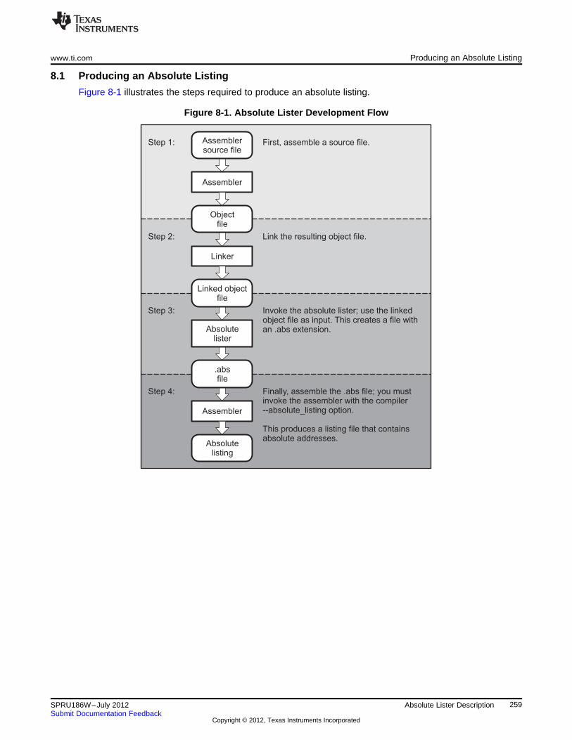
First, assemble a source file.
Link the resulting object file.
Invoke the absolute lister; use the linkedobject file as input. This creates a file withan .abs extension.
Finally, assemble the .abs file; you mustinvoke the assembler with the compiler--absolute_listing option.
This produces a listing file that containsabsolute addresses.
Step 1:
Step 2:
Step 3:
Step 4:
Assemblersource file
Assembler
Objectfile
Linker
Linked objectfile
Absolutelister
.absfile
Assembler
Absolutelisting
www.ti.com Producing an Absolute Listing
8.1 Producing an Absolute Listing
Figure 8-1 illustrates the steps required to produce an absolute listing.
Figure 8-1. Absolute Lister Development Flow
259SPRU186W–July 2012 Absolute Lister DescriptionSubmit Documentation Feedback
Copyright © 2012, Texas Instruments Incorporated
Invoking the Absolute Lister www.ti.com
8.2 Invoking the Absolute Lister
The syntax for invoking the absolute lister is:
abs6x [-options] input file
abs6x is the command that invokes the absolute lister.options identifies the absolute lister options that you want to use. Options are not case sensitive
and can appear anywhere on the command line following the command. Precede eachoption with a hyphen (-). The absolute lister options are as follows:-e enables you to change the default naming conventions for filename extensions on
assembly files, C source files, and C header files. The valid options are:
• ea [.]asmext for assembly files (default is .asm)
• ec [.]cext for C source files (default is .c)
• eh [.]hext for C header files (default is .h)
• ep [.]pext for CPP source files (default is cpp)The . in the extensions and the space between the option and the extension areoptional.
-q (quiet) suppresses the banner and all progress information.input file names the linked object file. If you do not supply an extension, the absolute lister
assumes that the input file has the default extension .out. If you do not supply an inputfilename when you invoke the absolute lister, the absolute lister prompts you for one.
The absolute lister produces an output file for each file that was linked. These files are named with theinput filenames and an extension of .abs. Header files, however, do not generate a corresponding .absfile.
Assemble these files with the --absolute_listing assembler option as follows to create the absolute listing:
cl6x --absolute_listing filename .abs
The -e options affect both the interpretation of filenames on the command line and the names of theoutput files. They should always precede any filename on the command line.
The -e options are useful when the linked object file was created from C files compiled with the debuggingoption (--symdebug:dwarf compiler option). When the debugging option is set, the resulting linked objectfile contains the name of the source files used to build it. In this case, the absolute lister does not generatea corresponding .abs file for the C header files. Also, the .abs file corresponding to a C source file usesthe assembly file generated from the C source file rather than the C source file itself.
For example, suppose the C source file hello.csr is compiled with the debugging option set; the debuggingoption generates the assembly file hello.s. The hello.csr file includes hello.hsr. Assuming the executablefile created is called hello.out, the following command generates the proper .abs file:abs6x -ea s -ec csr -eh hsr hello.out
An .abs file is not created for hello.hsr (the header file), and hello.abs includes the assembly file hello.s,not the C source file hello.csr.
260 Absolute Lister Description SPRU186W–July 2012Submit Documentation Feedback
Copyright © 2012, Texas Instruments Incorporated
www.ti.com Absolute Lister Example
8.3 Absolute Lister Example
This example uses three source files. The files module1.asm and module2.asm both include the fileglobals.def.
module1.asm.text.align 4.bss array, 100.bss dflag, 4.copy globals.def
MVKL offset, A0MVKH offset, A0LDW *+b14(dflag), A2nop 4
module2.asm.bss offset,2.copy globals.def
mvkl offset,a0mvkh offset,a0mvkl array,a3mvkh array,a3
globals.def.global dflag.global array.global offset
The following steps create absolute listings for the files module1.asm and module2.asm:
Step 1: First, assemble module1.asm and module2.asm:cl6x module1cl6x module2
This creates two object files called module1.obj and module2.obj.Step 2: Next, link module1.obj and module2.obj using the following linker command file, called
bttest.cmd:
--output_file=bttest.out--map_file=bttest.mapmodule1.objmodule2.objMEMORY{
PMEM: origin=00000000h length=00010000hDMEM: origin=80000000h length=00010000h
}SECTIONS{
.data: >DMEM
.text: >PMEM
.bss: >DMEM}
Invoke the linker:cl6x --run_linker bttest.cmd
This command creates an executable object file called bttest.out; use this new file as inputfor the absolute lister.
261SPRU186W–July 2012 Absolute Lister DescriptionSubmit Documentation Feedback
Copyright © 2012, Texas Instruments Incorporated
Absolute Lister Example www.ti.com
Step 3: Now, invoke the absolute lister:abs6x bttest.out
This command creates two files called module1.abs and module2.abs:
module1.abs:
.nolistarray .setsym 080000000hdflag .setsym 080000064hoffset .setsym 080000068h.data .setsym 080000000h___data__ .setsym 080000000hedata .setsym 080000000h___edata__ .setsym 080000000h.text .setsym 000000000h___text__ .setsym 000000000hetext .setsym 000000040h___etext__ .setsym 000000040h.bss .setsym 080000000h___bss__ .setsym 080000000hend .setsym 08000006ah___end__ .setsym 08000006ah$bss .setsym 080000000h
.setsect ".text",000000020h
.setsect ".data",080000000h
.setsect ".bss",080000000h
.list
.text
.copy "module1.asm"
module2.abs:
.nolistarray .setsym 080000000hdflag .setsym 080000064hoffset .setsym 080000068h.data .setsym 080000000h___data__ .setsym 080000000hedata .setsym 080000000h___edata__ .setsym 080000000h.text .setsym 000000000h___text__ .setsym 000000000hetext .setsym 000000040h___etext__ .setsym 000000040h.bss .setsym 080000000h___bss__ .setsym 080000000hend .setsym 08000006ah___end__ .setsym 08000006ah$bss .setsym 080000000h
.setsect ".text",000000000h
.setsect ".data",080000000h
.setsect ".bss",080000068h
.list
.text
.copy "module2.asm"
262 Absolute Lister Description SPRU186W–July 2012Submit Documentation Feedback
Copyright © 2012, Texas Instruments Incorporated
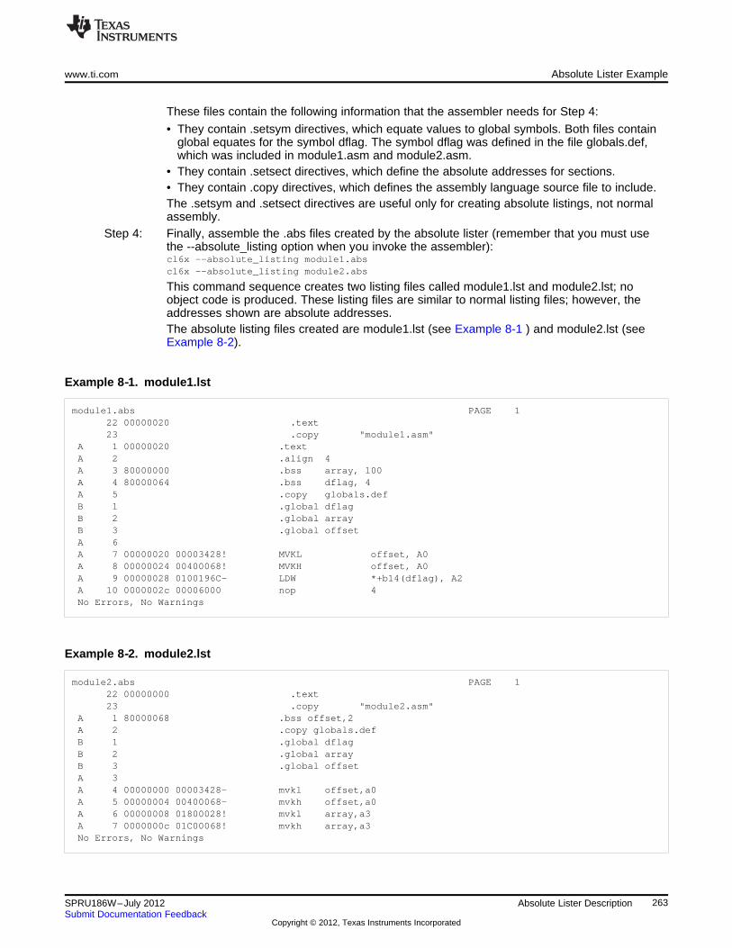
www.ti.com Absolute Lister Example
These files contain the following information that the assembler needs for Step 4:
• They contain .setsym directives, which equate values to global symbols. Both files containglobal equates for the symbol dflag. The symbol dflag was defined in the file globals.def,which was included in module1.asm and module2.asm.
• They contain .setsect directives, which define the absolute addresses for sections.• They contain .copy directives, which defines the assembly language source file to include.The .setsym and .setsect directives are useful only for creating absolute listings, not normalassembly.
Step 4: Finally, assemble the .abs files created by the absolute lister (remember that you must usethe --absolute_listing option when you invoke the assembler):cl6x --absolute_listing module1.abscl6x --absolute_listing module2.abs
This command sequence creates two listing files called module1.lst and module2.lst; noobject code is produced. These listing files are similar to normal listing files; however, theaddresses shown are absolute addresses.The absolute listing files created are module1.lst (see Example 8-1 ) and module2.lst (seeExample 8-2).
Example 8‑‑1. module1.lst
module1.abs PAGE 122 00000020 .text23 .copy "module1.asm"
A 1 00000020 .textA 2 .align 4A 3 80000000 .bss array, 100A 4 80000064 .bss dflag, 4A 5 .copy globals.defB 1 .global dflagB 2 .global arrayB 3 .global offsetA 6A 7 00000020 00003428! MVKL offset, A0A 8 00000024 00400068! MVKH offset, A0A 9 00000028 0100196C- LDW *+b14(dflag), A2A 10 0000002c 00006000 nop 4No Errors, No Warnings
Example 8‑‑2. module2.lst
module2.abs PAGE 122 00000000 .text23 .copy "module2.asm"
A 1 80000068 .bss offset,2A 2 .copy globals.defB 1 .global dflagB 2 .global arrayB 3 .global offsetA 3A 4 00000000 00003428- mvkl offset,a0A 5 00000004 00400068- mvkh offset,a0A 6 00000008 01800028! mvkl array,a3A 7 0000000c 01C00068! mvkh array,a3No Errors, No Warnings
263SPRU186W–July 2012 Absolute Lister DescriptionSubmit Documentation Feedback
Copyright © 2012, Texas Instruments Incorporated
Chapter 9SPRU186W–July 2012
Cross-Reference Lister Description
The TMS320C6000 cross-reference lister is a debugging tool. This utility accepts linked object files asinput and produces a cross-reference listing as output. This listing shows symbols, their definitions, andtheir references in the linked source files.
Cross-Reference Listing Not Supported for C6400+, C6740, and C6600
NOTE: The cross-reference listing capability is not supported for C6400+, C6740, and C6600. Youcan use the disassembler, the -m linker option or the object file utility (ofd6x) to obtain similarinformation.
Topic ........................................................................................................................... Page
9.1 Producing a Cross-Reference Listing ................................................................. 2659.2 Invoking the Cross-Reference Lister .................................................................. 2669.3 Cross-Reference Listing Example ...................................................................... 267
264 Cross-Reference Lister Description SPRU186W–July 2012Submit Documentation Feedback
Copyright © 2012, Texas Instruments Incorporated
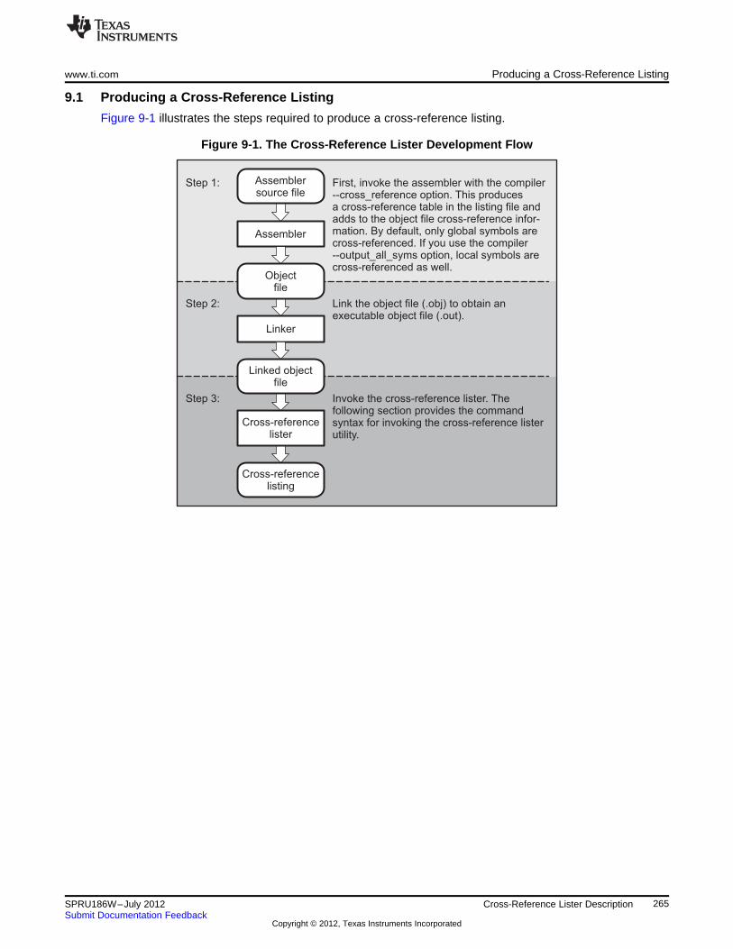
First, invoke the assembler with the compiler--cross_reference option. This producesa cross-reference table in the listing file andadds to the object file cross-reference infor-mation. By default, only global symbols arecross-referenced. If you use the compiler--output_all_syms option, local symbols arecross-referenced as well.
Link the object file (.obj) to obtain anexecutable object file (.out).
Invoke the cross-reference lister. Thefollowing section provides the commandsyntax for invoking the cross-reference listerutility.
Step 1:
Step 2:
Step 3:
Assemblersource file
Assembler
Objectfile
Linker
Linked objectfile
Cross-referencelister
Cross-referencelisting
www.ti.com Producing a Cross-Reference Listing
9.1 Producing a Cross-Reference Listing
Figure 9-1 illustrates the steps required to produce a cross-reference listing.
Figure 9-1. The Cross-Reference Lister Development Flow
265SPRU186W–July 2012 Cross-Reference Lister DescriptionSubmit Documentation Feedback
Copyright © 2012, Texas Instruments Incorporated
Invoking the Cross-Reference Lister www.ti.com
9.2 Invoking the Cross-Reference Lister
To use the cross-reference utility, the file must be assembled with the correct options and then linked intoan executable file. Assemble the assembly language files with the --cross_reference option. This optioncreates a cross-reference listing and adds cross-reference information to the object file. By default, theassembler cross-references only global symbols, but if the assembler is invoked with the --output_all_syms option, local symbols are also added. Link the object files to obtain an executable file.
To invoke the cross-reference lister, enter the following:
xref6x [options] [input filename [output filename]]
is the command that invokes the cross-reference utility.xref6xoptions identifies the cross-reference lister options you want to use. Options are not case
sensitive and can appear anywhere on the command line following the command.-l (lowercase L) specifies the number of lines per page for the output file. The format
of the -l option is -lnum, where num is a decimal constant. For example, -l30 setsthe number of lines per page in the output file to 30. The space between theoption and the decimal constant is optional. The default is 60 lines per page.
-q suppresses the banner and all progress information (run quiet).input filename is a linked object file. If you omit the input filename, the utility prompts for a filename.output filename is the name of the cross-reference listing file. If you omit the output filename, the default
filename is the input filename with an .xrf extension.
266 Cross-Reference Lister Description SPRU186W–July 2012Submit Documentation Feedback
Copyright © 2012, Texas Instruments Incorporated
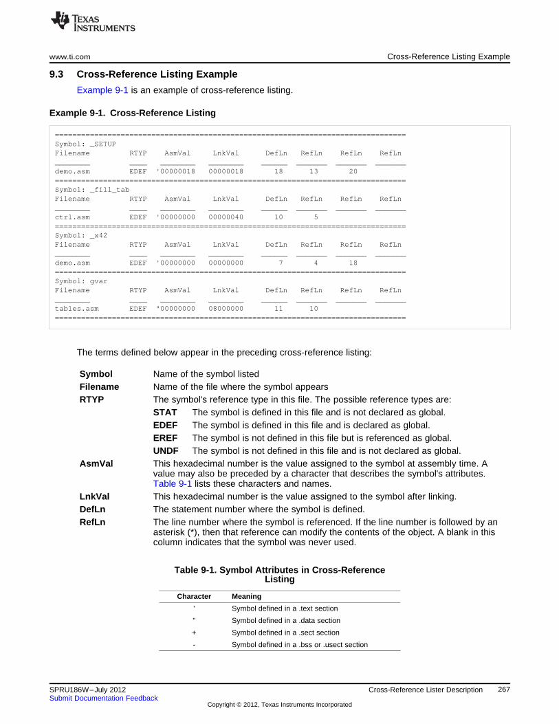
www.ti.com Cross-Reference Listing Example
9.3 Cross-Reference Listing Example
Example 9-1 is an example of cross-reference listing.
Example 9‑‑1. Cross-Reference Listing
================================================================================Symbol: _SETUPFilename RTYP AsmVal LnkVal DefLn RefLn RefLn RefLn________ ____ ________ ________ ______ _______ _______ _______demo.asm EDEF '00000018 00000018 18 13 20================================================================================Symbol: _fill_tabFilename RTYP AsmVal LnkVal DefLn RefLn RefLn RefLn________ ____ ________ ________ ______ _______ _______ _______ctrl.asm EDEF '00000000 00000040 10 5================================================================================Symbol: _x42Filename RTYP AsmVal LnkVal DefLn RefLn RefLn RefLn________ ____ ________ ________ ______ _______ _______ _______demo.asm EDEF '00000000 00000000 7 4 18================================================================================Symbol: gvarFilename RTYP AsmVal LnkVal DefLn RefLn RefLn RefLn________ ____ ________ ________ ______ _______ _______ _______tables.asm EDEF "00000000 08000000 11 10================================================================================
The terms defined below appear in the preceding cross-reference listing:
Symbol Name of the symbol listedFilename Name of the file where the symbol appearsRTYP The symbol's reference type in this file. The possible reference types are:
STAT The symbol is defined in this file and is not declared as global.EDEF The symbol is defined in this file and is declared as global.EREF The symbol is not defined in this file but is referenced as global.UNDF The symbol is not defined in this file and is not declared as global.
AsmVal This hexadecimal number is the value assigned to the symbol at assembly time. Avalue may also be preceded by a character that describes the symbol's attributes.Table 9-1 lists these characters and names.
LnkVal This hexadecimal number is the value assigned to the symbol after linking.DefLn The statement number where the symbol is defined.RefLn The line number where the symbol is referenced. If the line number is followed by an
asterisk (*), then that reference can modify the contents of the object. A blank in thiscolumn indicates that the symbol was never used.
Table 9-1. Symbol Attributes in Cross-ReferenceListing
Character Meaning
' Symbol defined in a .text section
" Symbol defined in a .data section
+ Symbol defined in a .sect section
- Symbol defined in a .bss or .usect section
267SPRU186W–July 2012 Cross-Reference Lister DescriptionSubmit Documentation Feedback
Copyright © 2012, Texas Instruments Incorporated
Chapter 10SPRU186W–July 2012
Object File Utilities
This chapter describes how to invoke the following utilities:
• The object file display utility prints the contents of object files, executable files, and/or archivelibraries in both text and XML formats.
• The disassembler accepts object files and executable files as input and produces an assembly listingas output. This listing shows assembly instructions, their opcodes, and the section program countervalues.
• The name utility prints a list of names defined and referenced in an object file, executable files, and/orarchive libraries.
• The strip utility removes symbol table and debugging information from object and executable files.
Topic ........................................................................................................................... Page
10.1 Invoking the Object File Display Utility ............................................................... 26910.2 Invoking the Disassembler ................................................................................ 27010.3 Invoking the Name Utility .................................................................................. 27010.4 Invoking the Strip Utility ................................................................................... 271
268 Object File Utilities SPRU186W–July 2012Submit Documentation Feedback
Copyright © 2012, Texas Instruments Incorporated
www.ti.com Invoking the Object File Display Utility
10.1 Invoking the Object File Display Utility
The object file display utility, ofd6x, prints the contents of object files (.obj), executable files (.out), and/orarchive libraries (.lib) in both text and XML formats. Hidden symbols are listed as no name, while localizedsymbols are listed like any other local symbol.
To invoke the object file display utility, enter the following:
ofd6x [options] input filename [input filename]
ofd6x is the command that invokes the object file display utility.input filename names the object file (.obj), executable file (.out), or archive library (.lib) source file.
The filename must contain an extension.options identify the object file display utility options that you want to use. Options are not case
sensitive and can appear anywhere on the command line following the command.Precede each option with a hyphen.--dwarf_display=attributes controls the DWARF display filter settings by specifying a
comma-delimited list of attributes. When prefixed with no,an attribute is disabled instead of enabled.Examples: --dwarf_display=nodabbrev,nodline
--dwarf_display=all,nodabbrev--dwarf_display=none,dinfo,types
The ordering of attributes is important (see --obj_display).The list of available display attributes can be obtained byinvoking ofd6x --dwarf_display=help.
-g appends DWARF debug information to program output.-h displays help-o=filename sends program output to filename rather than to the
screen.--obj_display attributes controls the object file display filter settings by specifying
a comma-delimited list of attributes. When prefixed withno, an attribute is disabled instead of enabled.Examples: --obj_display=rawdata,nostrings
--obj_display=all,norawdata--obj_display=none,header
The ordering of attributes is important. For instance, in "--obj_display=none,header", ofd6x disables all output, thenre-enables file header information. If the attributes arespecified in the reverse order, (header,none), the fileheader is enabled, the all output is disabled, including thefile header. Thus, nothing is printed to the screen for thegiven files. The list of available display attributes can beobtained by invoking ofd6x --obj_display=help.
-v prints verbose text output.-x displays output in XML format.--xml_indent=num sets the number of spaces to indent nested XML tags.
If an archive file is given as input to the object file display utility, each object file member of the archive isprocessed as if it was passed on the command line. The object file members are processed in the order inwhich they appear in the archive file.
If the object file display utility is invoked without any options, it displays information about the contents ofthe input files on the console screen.
269SPRU186W–July 2012 Object File UtilitiesSubmit Documentation Feedback
Copyright © 2012, Texas Instruments Incorporated
Invoking the Disassembler www.ti.com
Object File Display Format
NOTE: The object file display utility produces data in a text format by default. This data is notintended to be used as input to programs for further processing of the information. XMLformat should be used for mechanical processing.
10.2 Invoking the Disassembler
The disassembler, dis6x, examines the output of the assembler or linker. This utility accepts an object fileor executable file as input and writes the disassembled object code to standard output or a specified file.
To invoke the disassembler, enter the following:
dis6x [options] input filename[.] [output filename]
dis6x is the command that invokes the disassembler.options identifies the name utility options you want to use. Options are not case sensitive and
can appear anywhere on the command line following the invocation. Precede eachoption with a hyphen (-). The name utility options are as follows:-a disables the printing of branch destination addresses along with labels.-b displays data as bytes instead of words.-c dumps the object file information.-d disables display of data sections.-h shows the current help screen.-i disassembles .data sections as instructions.-l disassembles data sections as text.-n suppresses FP header information for C64x+ Compact FPs.-o## disassembles single word ## or 0x## then exits.-q (quiet mode) suppresses the banner and all progress information.-qq (super quiet mode) suppresses all headers.-s suppresses printing of address and data words.-t suppresses the display of text sections in the listing.-v displays family of the target.
input is the name of the input file. If the optional extension is not specified, the file isfilename[.ext] searched for in this order:
1. infile
2. infile.out, an executable file
3. infile.obj, an object fileoutput filename is the name of the optional output file to which the disassembly will be written. If an
output filename is not specified, the disassembly is written to standard output.
10.3 Invoking the Name Utility
The name utility, nm6x, prints the list of names defined and referenced in an object file, executable file, orarchive library. It also prints the symbol value and an indication of the kind of symbol. Hidden symbols arelisted as "".
To invoke the name utility, enter the following:
nm6x [-options] [input filenames]
270 Object File Utilities SPRU186W–July 2012Submit Documentation Feedback
Copyright © 2012, Texas Instruments Incorporated
www.ti.com Invoking the Strip Utility
nm6x is the command that invokes the name utility.input filename is an object file (.obj), executable file (.out), or archive library (.lib).options identifies the name utility options you want to use. Options are not case sensitive and
can appear anywhere on the command line following the invocation. Precede eachoption with a hyphen (-). The name utility options are as follows:-a prints all symbols.-c also prints C_NULL symbols for a COFF object module.-d also prints debug symbols for a COFF object module.-f prepends file name to each symbol.-g prints only global symbols.-h shows the current help screen.-l produces a detailed listing of the symbol information.-n sorts symbols numerically rather than alphabetically.-o file outputs to the given file.-p causes the name utility to not sort any symbols.-q (quiet mode) suppresses the banner and all progress information.-r sorts symbols in reverse order.-t also prints tag information symbols for a COFF object module.-u only prints undefined symbols.
10.4 Invoking the Strip Utility
The strip utility, strip6x, removes symbol table and debugging information from object and executable files.
To invoke the strip utility, enter the following:
strip6x [-p] input filename [input filename]
strip6x is the command that invokes the strip utility.input filename is an object file (.obj) or an executable file (.out).options identifies the strip utility options you want to use. Options are not case sensitive and can
appear anywhere on the command line following the invocation. Precede each optionwith a hyphen (-). The strip utility option is as follows:-o filename writes the stripped output to filename.-p removes all information not required for execution. This option causes more
information to be removed than the default behavior, but the object file isleft in a state that cannot be linked. This option should be used only withstatic executable or dynamic object module files.
When the strip utility is invoked without the -o option, the input object files are replaced with the strippedversion.
271SPRU186W–July 2012 Object File UtilitiesSubmit Documentation Feedback
Copyright © 2012, Texas Instruments Incorporated
Chapter 11SPRU186W–July 2012
Hex Conversion Utility Description
The TMS320C6000 assembler and linker create object files which are in binary formats that encouragemodular programming and provide powerful and flexible methods for managing code segments and targetsystem memory.
Most EPROM programmers do not accept object files as input. The hex conversion utility converts anobject file into one of several standard ASCII hexadecimal formats, suitable for loading into an EPROMprogrammer. The utility is also useful in other applications requiring hexadecimal conversion of an objectfile (for example, when using debuggers and loaders).
The hex conversion utility can produce these output file formats:
• ASCII-Hex, supporting 32-bit addresses
• Extended Tektronix (Tektronix)
• Intel MCS-86 (Intel)
• Motorola Exorciser (Motorola-S), supporting 16-bit addresses
• Texas Instruments SDSMAC (TI-Tagged), supporting 16-bit addresses
• Texas Instruments TI-TXT format, supporting 16-bit addresses
Topic ........................................................................................................................... Page
11.1 The Hex Conversion Utility's Role in the Software Development Flow .................... 27311.2 Invoking the Hex Conversion Utility ................................................................... 27411.3 Understanding Memory Widths ......................................................................... 27711.4 The ROMS Directive ......................................................................................... 28111.5 The SECTIONS Directive ................................................................................... 28511.6 The Load Image Format (--load_image Option) .................................................... 28611.7 Excluding a Specified Section ........................................................................... 28611.8 Assigning Output Filenames ............................................................................. 28711.9 Image Mode and the --fill Option ........................................................................ 28811.10 Building a Table for an On-Chip Boot Loader .................................................... 28911.11 Controlling the ROM Device Address ................................................................ 29411.12 Control Hex Conversion Utility Diagnostics ....................................................... 29511.13 Description of the Object Formats .................................................................... 296
272 Hex Conversion Utility Description SPRU186W–July 2012Submit Documentation Feedback
Copyright © 2012, Texas Instruments Incorporated
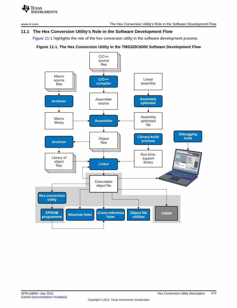
C/C++source
files
C/C++compiler
Assemblersource
Assembler
Executableobject file
DebuggingtoolsLibrary-build
process
Run-time-supportlibrary
Archiver
Archiver
Macrolibrary
Absolute lister
Hex-conversionutility
Cross-referencelister
Object fileutilities
C6000
Linker
Linearassembly
Assemblyoptimizer
Assemblyoptimized
file
Macrosource
files
Objectfiles
EPROMprogrammer
Library ofobjectfiles
www.ti.com The Hex Conversion Utility's Role in the Software Development Flow
11.1 The Hex Conversion Utility's Role in the Software Development Flow
Figure 11-1 highlights the role of the hex conversion utility in the software development process.
Figure 11-1. The Hex Conversion Utility in the TMS320C6000 Software Development Flow
273SPRU186W–July 2012 Hex Conversion Utility DescriptionSubmit Documentation Feedback
Copyright © 2012, Texas Instruments Incorporated
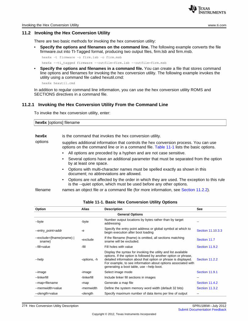
Invoking the Hex Conversion Utility www.ti.com
11.2 Invoking the Hex Conversion Utility
There are two basic methods for invoking the hex conversion utility:
• Specify the options and filenames on the command line. The following example converts the filefirmware.out into TI-Tagged format, producing two output files, firm.lsb and firm.msb.hex6x -t firmware -o firm.lsb -o firm.msb
hex6x --ti_tagged firmware --outfile=firm.lsb --outfile=firm.msb
• Specify the options and filenames in a command file. You can create a file that stores commandline options and filenames for invoking the hex conversion utility. The following example invokes theutility using a command file called hexutil.cmd:hex6x hexutil.cmd
In addition to regular command line information, you can use the hex conversion utility ROMS andSECTIONS directives in a command file.
11.2.1 Invoking the Hex Conversion Utility From the Command Line
To invoke the hex conversion utility, enter:
hex6x [options] filename
hex6x is the command that invokes the hex conversion utility.options supplies additional information that controls the hex conversion process. You can use
options on the command line or in a command file. Table 11-1 lists the basic options.
• All options are preceded by a hyphen and are not case sensitive.
• Several options have an additional parameter that must be separated from the optionby at least one space.
• Options with multi-character names must be spelled exactly as shown in thisdocument; no abbreviations are allowed.
• Options are not affected by the order in which they are used. The exception to this ruleis the --quiet option, which must be used before any other options.
filename names an object file or a command file (for more information, see Section 11.2.2).
Table 11-1. Basic Hex Conversion Utility Options
Option Alias Description See
General Options
Number output locations by bytes rather than by target--byte -byte --addressing
Specify the entry point address or global symbol at which to--entry_point=addr -e Section 11.10.3.3begin execution after boot loading
--exclude={fname(sname) | If the filename (fname) is omitted, all sections matching-exclude Section 11.7sname} sname will be excluded.
--fill=value -fill Fill holes with value Section 11.9.2
Display the syntax for invoking the utility and list availableoptions. If the option is followed by another option or phrase,
--help -options, -h detailed information about that option or phrase is displayed. Section 11.2.2For example, to see information about options associated withgenerating a boot table, use --help boot.
--image -image Select image mode Section 11.9.1
--linkerfill -linkerfill Include linker fill sections in images --
--map=filename -map Generate a map file Section 11.4.2
--memwidth=value -memwidth Define the system memory word width (default 32 bits) Section 11.3.2
--olength=value -olength Specify maximum number of data items per line of output --
274 Hex Conversion Utility Description SPRU186W–July 2012Submit Documentation Feedback
Copyright © 2012, Texas Instruments Incorporated
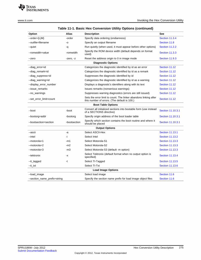
www.ti.com Invoking the Hex Conversion Utility
Table 11-1. Basic Hex Conversion Utility Options (continued)
Option Alias Description See
--order={L|M} -order Specify data ordering (endianness) Section 11.3.4
--outfile=filename -o Specify an output filename Section 11.8
--quiet -q Run quietly (when used, it must appear before other options) Section 11.2.2
Specify the ROM device width (default depends on format--romwidth=value -romwidth Section 11.3.3used)
--zero -zero, -z Reset the address origin to 0 in image mode Section 11.9.3
Diagnostic Options
--diag_error=id Categorizes the diagnostic identified by id as an error Section 11.12
--diag_remark=id Categorizes the diagnostic identified by id as a remark Section 11.12
--diag_suppress=id Suppresses the diagnostic identified by id Section 11.12
--diag_warning=id Categorizes the diagnostic identified by id as a warning Section 11.12
--display_error_number Displays a diagnostic's identifiers along with its text Section 11.12
--issue_remarks Issues remarks (nonserious warnings) Section 11.12
--no_warnings Suppresses warning diagnostics (errors are still issued) Section 11.12
Sets the error limit to count. The linker abandons linking after--set_error_limit=count Section 11.12this number of errors. (The default is 100.)
Boot Table Options
Convert all initialized sections into bootable form (use instead--boot -boot Section 11.10.3.1of a SECTIONS directive)
--bootorg=addr -bootorg Specify origin address of the boot loader table Section 11.10.3.1
Specify which section contains the boot routine and where it--bootsection=section -bootsection Section 11.10.3.1should be placed
Output Options
--ascii -a Select ASCII-Hex Section 11.13.1
--intel -i Select Intel Section 11.13.2
--motorola=1 -m1 Select Motorola-S1 Section 11.13.3
--motorola=2 -m2 Select Motorola-S2 Section 11.13.3
--motorola=3 -m3 Select Motorola-S3 (default -m option) Section 11.13.3
Select Tektronix (default format when no output option is--tektronix -x Section 11.13.4specified)
--ti_tagged -t Select TI-Tagged Section 11.13.5
--ti_txt Select TI-Txt Section 11.13.6
Load Image Options
--load_image Select load image Section 11.6
--section_name_prefix=string Specify the section name prefix for load image object files Section 11.6
275SPRU186W–July 2012 Hex Conversion Utility DescriptionSubmit Documentation Feedback
Copyright © 2012, Texas Instruments Incorporated
Invoking the Hex Conversion Utility www.ti.com
11.2.2 Invoking the Hex Conversion Utility With a Command File
A command file is useful if you plan to invoke the utility more than once with the same input files andoptions. It is also useful if you want to use the ROMS and SECTIONS hex conversion utility directives tocustomize the conversion process.
Command files are ASCII files that contain one or more of the following:
• Options and filenames. These are specified in a command file in exactly the same manner as on thecommand line.
• ROMS directive. The ROMS directive defines the physical memory configuration of your system as alist of address-range parameters. (See Section 11.4.)
• SECTIONS directive. The hex conversion utility SECTIONS directive specifies which sections from theobject file are selected. (See Section 11.5.)
• Comments. You can add comments to your command file by using the /* and */ delimiters. Forexample:/* This is a comment. */
To invoke the utility and use the options you defined in a command file, enter:
hex6x command_filename
You can also specify other options and files on the command line. For example, you could invoke theutility by using both a command file and command line options:hex6x firmware.cmd --map=firmware.mxp
The order in which these options and filenames appear is not important. The utility reads all input from thecommand line and all information from the command file before starting the conversion process. However,if you are using the -q option, it must appear as the first option on the command line or in a command file.
The --help option displays the syntax for invoking the compiler and lists available options. If the --helpoption is followed by another option or phrase, detailed information about the option or phrase isdisplayed. For example, to see information about options associated with generating a boot table use --help boot.
The --quiet option suppresses the hex conversion utility's normal banner and progress information.
• Assume that a command file named firmware.cmd contains these lines:firmware.out /* input file */--ti_tagged /* TI-Tagged */--outfile=firm.lsb /* output file */--outfile=firm.msb /* output file */
You can invoke the hex conversion utility by entering:hex6x firmware.cmd
• This example shows how to convert a file called appl.out into eight hex files in Intel format. Each outputfile is one byte wide and 4K bytes long.appl.out /* input file */--intel /* Intel format */--map=appl.mxp /* map file */
ROMS{
ROW1: origin=0x00000000 len=0x4000 romwidth=8files={ appl.u0 appl.u1 app1.u2 appl.u3 }
ROW2: origin=0x00004000 len=0x4000 romwidth=8files={ app1.u4 appl.u5 appl.u6 appl.u7 }
}
SECTIONS{ .text, .data, .cinit, .sect1, .vectors, .const:}
276 Hex Conversion Utility Description SPRU186W–July 2012Submit Documentation Feedback
Copyright © 2012, Texas Instruments Incorporated
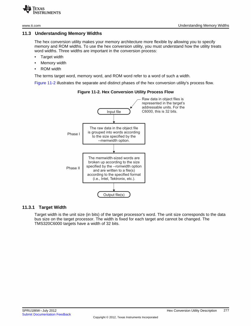
The raw data in the object fileis grouped into words according
to the size specified by the--memwidth option.
The memwidth-sized words arebroken up according to the size
specified by the --romwidth optionand are written to a file(s)
according to the specified format(i.e., Intel, Tektronix, etc.).
Phase I
Phase II
Input file
Output file(s)
Raw data in object files isrepresented in the target’saddressable units. For theC6000, this is 32 bits.
www.ti.com Understanding Memory Widths
11.3 Understanding Memory Widths
The hex conversion utility makes your memory architecture more flexible by allowing you to specifymemory and ROM widths. To use the hex conversion utility, you must understand how the utility treatsword widths. Three widths are important in the conversion process:
• Target width
• Memory width
• ROM width
The terms target word, memory word, and ROM word refer to a word of such a width.
Figure 11-2 illustrates the separate and distinct phases of the hex conversion utility's process flow.
Figure 11-2. Hex Conversion Utility Process Flow
11.3.1 Target Width
Target width is the unit size (in bits) of the target processor's word. The unit size corresponds to the databus size on the target processor. The width is fixed for each target and cannot be changed. TheTMS320C6000 targets have a width of 32 bits.
277SPRU186W–July 2012 Hex Conversion Utility DescriptionSubmit Documentation Feedback
Copyright © 2012, Texas Instruments Incorporated
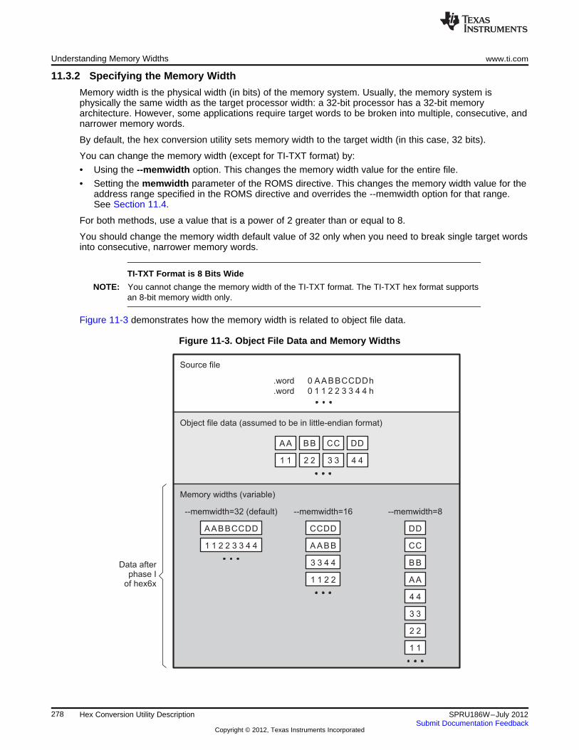
AABBCCDD
1 1 2 2 3 3 4 4
CCDD
A ABB
3 3 4 4
1 1 2 2
DD
CC
B B
AA
4 4
3 3
2 2
1 1
--memwidth=32 (default) --memwidth=16 --memwidth=8
Memory widths (variable)
AA BB CC DD
1 1 2 2 3 3 4 4
Object file data (assumed to be in little-endian format)
Source file
.word
.word
AABBCCDD0 h
1 1 2 2 3 3 4 40 h
Data afterphase I
of hex6x
Understanding Memory Widths www.ti.com
11.3.2 Specifying the Memory Width
Memory width is the physical width (in bits) of the memory system. Usually, the memory system isphysically the same width as the target processor width: a 32-bit processor has a 32-bit memoryarchitecture. However, some applications require target words to be broken into multiple, consecutive, andnarrower memory words.
By default, the hex conversion utility sets memory width to the target width (in this case, 32 bits).
You can change the memory width (except for TI-TXT format) by:
• Using the --memwidth option. This changes the memory width value for the entire file.
• Setting the memwidth parameter of the ROMS directive. This changes the memory width value for theaddress range specified in the ROMS directive and overrides the --memwidth option for that range.See Section 11.4.
For both methods, use a value that is a power of 2 greater than or equal to 8.
You should change the memory width default value of 32 only when you need to break single target wordsinto consecutive, narrower memory words.
TI-TXT Format is 8 Bits Wide
NOTE: You cannot change the memory width of the TI-TXT format. The TI-TXT hex format supportsan 8-bit memory width only.
Figure 11-3 demonstrates how the memory width is related to object file data.
Figure 11-3. Object File Data and Memory Widths
278 Hex Conversion Utility Description SPRU186W–July 2012Submit Documentation Feedback
Copyright © 2012, Texas Instruments Incorporated
A A B B C C D D 1 1 2 2 3 3 4 4
--memwidth=32
31 0
www.ti.com Understanding Memory Widths
11.3.3 Partitioning Data Into Output Files
ROM width specifies the physical width (in bits) of each ROM device and corresponding output file(usually one byte or eight bits). The ROM width determines how the hex conversion utility partitions thedata into output files. After the object file data is mapped to the memory words, the memory words arebroken into one or more output files. The number of output files is determined by the following formulas:
• If memory width ≥ ROM width:
number of files = memory width ÷ ROM width
• If memory width < ROM width:
number of files = 1
For example, for a memory width of 32, you could specify a ROM width value of 32 and get a singleoutput file containing 32-bit words. Or you can use a ROM width value of 16 to get two files, eachcontaining 16 bits of each word.
The default ROM width that the hex conversion utility uses depends on the output format:
• All hex formats except TI-Tagged are configured as lists of 8-bit bytes; the default ROM width for theseformats is 8 bits.
• TI-Tagged is a 16-bit format; the default ROM width for TI-Tagged is 16 bits.
The TI-Tagged Format is 16 Bits Wide
NOTE: You cannot change the ROM width of the TI-Tagged format. The TI-Tagged format supportsa 16-bit ROM width only.
TI-TXT Format is 8 Bits Wide
NOTE: You cannot change the ROM width of the TI-TXT format. The TI-TXT hex format supportsonly an 8-bit ROM width.
You can change ROM width (except for TI-Tagged and TI-TXT formats) by:
• Using the --romwidth option. This option changes the ROM width value for the entire object file.
• Setting the romwidth parameter of the ROMS directive. This parameter changes the ROM width valuefor a specific ROM address range and overrides the --romwidth option for that range. SeeSection 11.4.
For both methods, use a value that is a power of 2 greater than or equal to 8.
If you select a ROM width that is wider than the natural size of the output format (16 bits for TI-Tagged or8 bits for all others), the utility simply writes multibyte fields into the file.
Figure 11-4 illustrates how the object file data, memory, and ROM widths are related to one another.
Memory width and ROM width are used only for grouping the object file data; they do not representvalues. Thus, the byte ordering of the object file data is maintained throughout the conversion process. Torefer to the partitions within a memory word, the bits of the memory word are always numbered from rightto left as follows:
279SPRU186W–July 2012 Hex Conversion Utility DescriptionSubmit Documentation Feedback
Copyright © 2012, Texas Instruments Incorporated
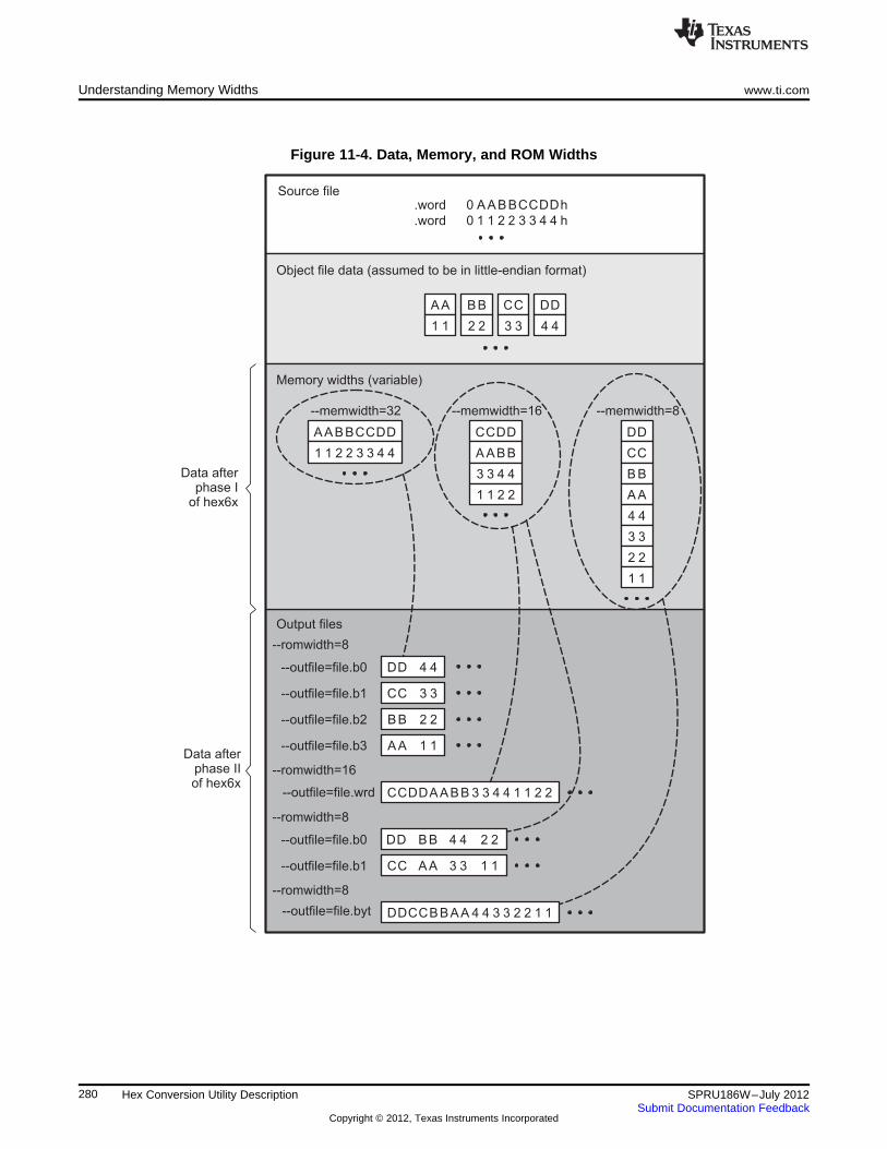
Data afterphase IIof hex6x
AABBCCDD
1 1 2 2 3 3 4 4
CCDD
A ABB
3 3 4 4
1 1 2 2
DD
CC
B B
AA
4 4
3 3
2 2
1 1
--memwidth=32 --memwidth=16 --memwidth=8
Memory widths (variable)
AA BB CC DD
1 1 2 2 3 3 4 4
Object file data (assumed to be in little-endian format)
Source file.word
.word
AABBCCDD0 h
1 1 2 2 3 3 4 40 h
Data afterphase I
of hex6x
DD 4 4
Output files
--romwidth=8
--outfile=file.b0
CC 3 3--outfile=file.b1
BB 2 2--outfile=file.b2
AA 1 1--outfile=file.b3
--romwidth=16
--outfile=file.wrd CCDDAABB 3 3 4 4 1 1 2 2
--romwidth=8
--outfile=file.b0
--outfile=file.b1
--romwidth=8
--outfile=file.byt DDCCBBAA 4 4 3 3 2 2 1 1
DD BB 4 4 2 2
CC AA 3 3 1 1
Understanding Memory Widths www.ti.com
Figure 11-4. Data, Memory, and ROM Widths
280 Hex Conversion Utility Description SPRU186W–July 2012Submit Documentation Feedback
Copyright © 2012, Texas Instruments Incorporated
www.ti.com The ROMS Directive
11.3.4 Specifying Word Order for Output Words
There are two ways to split a wide word into consecutive memory locations in the same hex conversionutility output file:
• --order=M specifies big-endian ordering, in which the most significant part of the wide word occupiesthe first of the consecutive locations.
• --order=L specifies little-endian ordering, in which the least significant part of the wide word occupiesthe first of the consecutive locations.
By default, the utility uses little-endian format. Unless your boot loader program expects big-endian format,avoid using --order=M.
When the -order Option AppliesNOTE:
• This option applies only when you use a memory width with a value of 32 (--memwidth32). Otherwise, the hex utility does not have access to the entire 32-bit wordand cannot perform the byte swapping necessary to change the endianness; --order isignored.
• This option does not affect the way memory words are split into output files. Think of thefiles as a set: the set contains a least significant file and a most significant file, but thereis no ordering over the set. When you list filenames for a set of files, you always list theleast significant first, regardless of the --order option.
11.4 The ROMS Directive
The ROMS directive specifies the physical memory configuration of your system as a list of address-rangeparameters.
Each address range produces one set of files containing the hex conversion utility output data thatcorresponds to that address range. Each file can be used to program one single ROM device.
The ROMS directive is similar to the MEMORY directive of the TMS320C6000 linker: both define thememory map of the target address space. Each line entry in the ROMS directive defines a specificaddress range. The general syntax is:
ROMS{
romname : [origin=value,] [length=value,] [romwidth=value,][memwidth=value,] [fill=value][files={ filename 1, filename 2, ...}]
romname : [origin=value,] [length=value,] [romwidth=value,][memwidth=value,] [fill=value][files={ filename 1, filename 2, ...}]
...}
ROMS begins the directive definition.romname identifies a memory range. The name of the memory range can be one to eight
characters in length. The name has no significance to the program; it simply identifiesthe range, except when the output is for a load image in which case it denotes thesection name. (Duplicate memory range names are allowed.)
origin specifies the starting address of a memory range. It can be entered as origin, org, or o.The associated value must be a decimal, octal, or hexadecimal constant. If you omitthe origin value, the origin defaults to 0. The following table summarizes the notationyou can use to specify a decimal, octal, or hexadecimal constant:
281SPRU186W–July 2012 Hex Conversion Utility DescriptionSubmit Documentation Feedback
Copyright © 2012, Texas Instruments Incorporated
The ROMS Directive www.ti.com
Constant Notation Example
Hexadecimal 0x prefix or h suffix 0x77 or 077h
Octal 0 prefix 077
Decimal No prefix or suffix 77
length specifies the length of a memory range as the physical length of the ROM device. Itcan be entered as length, len, or l. The value must be a decimal, octal, or hexadecimalconstant. If you omit the length value, it defaults to the length of the entire addressspace.
romwidth specifies the physical ROM width of the range in bits (see Section 11.3.3). Any valueyou specify here overrides the --romwidth option. The value must be a decimal, octal,or hexadecimal constant that is a power of 2 greater than or equal to 8.
memwidth specifies the memory width of the range in bits (see Section 11.3.2). Any value youspecify here overrides the --memwidth option. The value must be a decimal, octal, orhexadecimal constant that is a power of 2 greater than or equal to 8. When using thememwidth parameter, you must also specify the paddr parameter for each section inthe SECTIONS directive. (See Section 11.5.)
fill specifies a fill value to use for the range. In image mode, the hex conversion utilityuses this value to fill any holes between sections in a range. A hole is an area betweenthe input sections that comprises an output section that contains no actual code ordata. The fill value must be a decimal, octal, or hexadecimal constant with a widthequal to the target width. Any value you specify here overrides the --fill option. Whenusing fill, you must also use the --image command line option. (See Section 11.9.2.)
files identifies the names of the output files that correspond to this range. Enclose the list ofnames in curly braces and order them from least significant to most significant outputfile, where the bits of the memory word are numbered from right to left. The number offile names must equal the number of output files that the range generates. To calculatethe number of output files, see Section 11.3.3. The utility warns you if you list too manyor too few filenames.
Unless you are using the --image option, all of the parameters that define a range are optional; thecommas and equal signs are also optional. A range with no origin or length defines the entire addressspace. In image mode, an origin and length are required for all ranges.
Ranges must not overlap and must be listed in order of ascending address.
11.4.1 When to Use the ROMS Directive
If you do not use a ROMS directive, the utility defines a single default range that includes the entireaddress space. This is equivalent to a ROMS directive with a single range without origin or length.
Use the ROMS directive when you want to:
• Program large amounts of data into fixed-size ROMs. When you specify memory rangescorresponding to the length of your ROMs, the utility automatically breaks the output into blocks that fitinto the ROMs.
• Restrict output to certain segments. You can also use the ROMS directive to restrict the conversionto a certain segment or segments of the target address space. The utility does not convert the datathat falls outside of the ranges defined by the ROMS directive. Sections can span range boundaries;the utility splits them at the boundary into multiple ranges. If a section falls completely outside any ofthe ranges you define, the utility does not convert that section and issues no messages or warnings.Thus, you can exclude sections without listing them by name with the SECTIONS directive. However, ifa section falls partially in a range and partially in unconfigured memory, the utility issues a warning andconverts only the part within the range.
282 Hex Conversion Utility Description SPRU186W–July 2012Submit Documentation Feedback
Copyright © 2012, Texas Instruments Incorporated
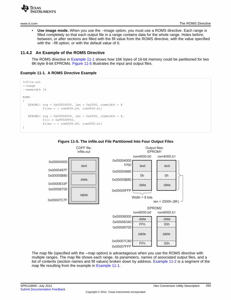
.text
.data
Width = 8 bits
0h
rom4000.b0
.text
.data
0h
rom4000.b1
len = 2000h (8K)
0x00004000(org)
0x00004880
0x00005B80
0x00005FFF
Output files:EPROM1
.data
.table
FFh
rom6000.b0 rom6000.b1
0x00006000
0x00006340
0x00006700
0x00007FFF
EPROM2
FFh0x00007C80
.data
.table
00h
00h
.text
.data
.table
COFF file:infile.out
0x00004000
0x0000487F
0x00005B80
0x0000633F
0x00006700
0x00007C7F
www.ti.com The ROMS Directive
• Use image mode. When you use the --image option, you must use a ROMS directive. Each range isfilled completely so that each output file in a range contains data for the whole range. Holes before,between, or after sections are filled with the fill value from the ROMS directive, with the value specifiedwith the --fill option, or with the default value of 0.
11.4.2 An Example of the ROMS Directive
The ROMS directive in Example 11-1 shows how 16K bytes of 16-bit memory could be partitioned for two8K-byte 8-bit EPROMs. Figure 11-5 illustrates the input and output files.
Example 11-1. A ROMS Directive Example
infile.out--image--memwidth 16
ROMS{
EPROM1: org = 0x00004000, len = 0x2000, romwidth = 8files = { rom4000.b0, rom4000.b1}
EPROM2: org = 0x00006000, len = 0x2000, romwidth = 8,fill = 0xFF00FF00,files = { rom6000.b0, rom6000.b1}
}
Figure 11-5. The infile.out File Partitioned Into Four Output Files
The map file (specified with the --map option) is advantageous when you use the ROMS directive withmultiple ranges. The map file shows each range, its parameters, names of associated output files, and alist of contents (section names and fill values) broken down by address. Example 11-2 is a segment of themap file resulting from the example in Example 11-1.
283SPRU186W–July 2012 Hex Conversion Utility DescriptionSubmit Documentation Feedback
Copyright © 2012, Texas Instruments Incorporated
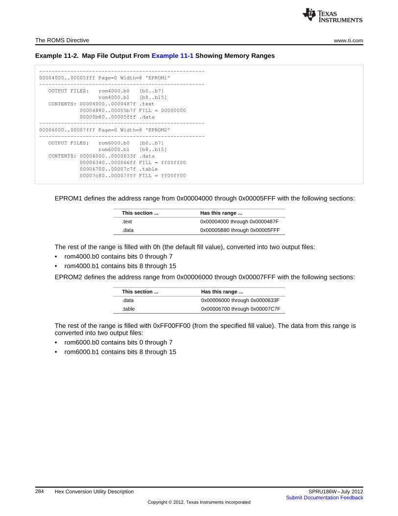
The ROMS Directive www.ti.com
Example 11-2. Map File Output From Example 11-1 Showing Memory Ranges
-----------------------------------------------------00004000..00005fff Page=0 Width=8 "EPROM1"-----------------------------------------------------
OUTPUT FILES: rom4000.b0 [b0..b7]rom4000.b1 [b8..b15]
CONTENTS: 00004000..0000487f .text00004880..00005b7f FILL = 0000000000005b80..00005fff .data
-----------------------------------------------------00006000..00007fff Page=0 Width=8 "EPROM2"-----------------------------------------------------
OUTPUT FILES: rom6000.b0 [b0..b7]rom6000.b1 [b8..b15]
CONTENTS: 00006000..0000633f .data00006340..000066ff FILL = ff00ff0000006700..00007c7f .table00007c80..00007fff FILL = ff00ff00
EPROM1 defines the address range from 0x00004000 through 0x00005FFF with the following sections:
This section ... Has this range ...
.text 0x00004000 through 0x0000487F
.data 0x00005B80 through 0x00005FFF
The rest of the range is filled with 0h (the default fill value), converted into two output files:
• rom4000.b0 contains bits 0 through 7
• rom4000.b1 contains bits 8 through 15
EPROM2 defines the address range from 0x00006000 through 0x00007FFF with the following sections:
This section ... Has this range ...
.data 0x00006000 through 0x0000633F
.table 0x00006700 through 0x00007C7F
The rest of the range is filled with 0xFF00FF00 (from the specified fill value). The data from this range isconverted into two output files:
• rom6000.b0 contains bits 0 through 7
• rom6000.b1 contains bits 8 through 15
284 Hex Conversion Utility Description SPRU186W–July 2012Submit Documentation Feedback
Copyright © 2012, Texas Instruments Incorporated
www.ti.com The SECTIONS Directive
11.5 The SECTIONS Directive
You can convert specific sections of the object file by name with the hex conversion utility SECTIONSdirective. You can also specify those sections that you want to locate in ROM at a different address thanthe load address specified in the linker command file. If you:
• Use a SECTIONS directive, the utility converts only the sections that you list in the directive andignores all other sections in the object file.
• Do not use a SECTIONS directive, the utility converts all initialized sections that fall within theconfigured memory.
Uninitialized sections are never converted, whether or not you specify them in a SECTIONS directive.
Sections Generated by the C/C++ Compiler
NOTE: The TMS320C6000 C/C++ compiler automatically generates these sections:• Initialized sections: .text, .const, .cinit, and .switch• Uninitialized sections: .bss, .stack, and .sysmem
Use the SECTIONS directive in a command file. (See Section 11.2.2.) The general syntax for theSECTIONS directive is:
SECTIONS{
oname(sname)[:] [paddr=value]oname(sname)[:] [paddr= boot]oname(sname)[:] [boot]...
}
SECTIONS begins the directive definition.oname identifies the object filename the section is located within. The filename is optional
when only a single input file is given, but required otherwise.sname identifies a section in the input file. If you specify a section that does not exist, the
utility issues a warning and ignores the name.paddr=value specifies the physical ROM address at which this section should be located. This value
overrides the section load address given by the linker. This value must be a decimal,octal, or hexadecimal constant. It can also be the word boot (to indicate a boot tablesection for use with a boot loader). If your file contains multiple sections, and if onesection uses a paddr parameter, then all sections must use a paddr parameter.
boot configures a section for loading by a boot loader. This is equivalent to usingpaddr=boot. Boot sections have a physical address determined by the location of theboot table. The origin of the boot table is specified with the --bootorg option.
For more similarity with the linker's SECTIONS directive, you can use colons after the section names (inplace of the equal sign on the boot keyboard). For example, the following statements are equivalent:SECTIONS { .text: .data: boot }
SECTIONS { .text: .data = boot }
In the example below, the object file contains six initialized sections: .text, .data, .const, .vectors, .coeff,and .tables. Suppose you want only .text and .data to be converted. Use a SECTIONS directive to specifythis:SECTIONS { .text: .data: }
To configure both of these sections for boot loading, add the boot keyword:SECTIONS { .text = boot .data = boot }
285SPRU186W–July 2012 Hex Conversion Utility DescriptionSubmit Documentation Feedback
Copyright © 2012, Texas Instruments Incorporated
The Load Image Format (--load_image Option) www.ti.com
Using the --boot Option and the SECTIONS Directive
NOTE: When you use the SECTIONS directive with the boot table (--boot) option, the --boot optionis ignored. You must explicitly specify any boot sections in the SECTIONS directive. Formore information about --boot and other command line options associated with boot tables,see Section 11.2 and Section 11.10.
11.6 The Load Image Format (--load_image Option)
A load image is an object file which contains the load addresses and initialized sections of one or moreexecutable files. The load image object file can be used for ROM masking or can be relinked in asubsequent link step.
11.6.1 Load Image Section Formation
The load image sections are formed by collecting the initialized sections from the input executables. Thereare two ways the load image sections are formed:
• Using the ROMS Directive. Each memory range that is given in the ROMS directive denotes a loadimage section. The romname is the section name. The origin and length parameters are required. Thememwidth, romwidth, and files parameters are invalid and are ignored.
When using the ROMS directive and the load_image option, the --image option is required.
• Default Load Image Section Formation. If no ROMS directive is given, the load image sections areformed by combining contiguous initialized sections in the input executables. Sections with gapssmaller than the target word size are considered contiguous.
The default section names are image_1, image_2, ... If another prefix is desired, the --section_name_prefix=prefix option can be used.
11.6.2 Load Image Characteristics
All load image sections are initialized data sections. In the absence of a ROMS directive, the load/runaddress of the load image section is the load address of the first input section in the load image section. Ifthe SECTIONS directive was used and a different load address was given using the paddr parameter, thisaddress will be used.
The load image format always creates a single load image object file. The format of the load image objectfile is determined based on the input files. The file is not marked executable and does not contain an entrypoint. The default load image object file name is ti_load_image.obj. This can be changed using the --outfile option. Only one --outfile option is valid when creating a load image, all other occurrences areignored.
Concerning Load Image Format
NOTE: These options are invalid when creating a load image:
• --memwidth
• --romwidth
• --order
• --zero
• --byte
If a boot table is being created, either using the SECTIONS directive or the --boot option, theROMS directive must be used.
11.7 Excluding a Specified Section
The --exclude section_name option can be used to inform the hex utility to ignore the specified section. Ifa SECTIONS directive is used, it overrides the --exclude option.
286 Hex Conversion Utility Description SPRU186W–July 2012Submit Documentation Feedback
Copyright © 2012, Texas Instruments Incorporated
www.ti.com Assigning Output Filenames
For example, if a SECTIONS directive containing the section name mysect is used and an --excludemysect is specified, the SECTIONS directive takes precedence and mysect is not excluded.
The --exclude option has a limited wildcard capability. The * character can be placed at the beginning orend of the name specifier to indicate a suffix or prefix, respectively. For example, --exclude sect*disqualifies all sections that begin with the characters sect.
If you specify the --exclude option on the command line with the * wildcard, enter quotes around thesection name and wildcard. For example, --exclude"sect*". Using quotes prevents the * from beinginterpreted by the hex conversion utility. If --exclude is in a command file, then the quotes should not bespecified.
If multiple object files are given, the object file in which the section to be excluded can be given in the formoname(sname). If the object filename is not provided, all sections matching the section name areexcluded. Wildcards cannot be used for the filename, but can appear within the parentheses.
11.8 Assigning Output Filenames
When the hex conversion utility translates your object file into a data format, it partitions the data into oneor more output files. When multiple files are formed by splitting memory words into ROM words, filenamesare always assigned in order from least to most significant, where bits in the memory words are numberedfrom right to left. This is true, regardless of target or endian ordering.
The hex conversion utility follows this sequence when assigning output filenames:
1. It looks for the ROMS directive. If a file is associated with a range in the ROMS directive and youhave included a list of files (files = {. . .}) on that range, the utility takes the filename from the list.
For example, assume that the target data is 32-bit words being converted to four files, each eight bitswide. To name the output files using the ROMS directive, you could specify:
ROMS{
RANGE1: romwidth=8, files={ xyz.b0 xyz.b1 xyz.b2 xyz.b3 }}
The utility creates the output files by writing the least significant bits to xyz.b0 and the most significantbits to xyz.b3.
2. It looks for the --outfile options. You can specify names for the output files by using the --outfileoption. If no filenames are listed in the ROMS directive and you use --outfile options, the utility takesthe filename from the list of --outfile options. The following line has the same effect as the exampleabove using the ROMS directive:
--outfile=xyz.b0 --outfile=xyz.b1 --outfile=xyz.b2 --outfile=xyz.b3
If both the ROMS directive and --outfile options are used together, the ROMS directive overrides the --outfile options.
3. It assigns a default filename. If you specify no filenames or fewer names than output files, the utilityassigns a default filename. A default filename consists of the base name from the input file plus a 2- to3-character extension. The extension has three parts:
(a) A format character, based on the output format (see Section 11.13):
a for ASCII-Hexi for Intelm for Motorola-St for TI-Taggedx for Tektronix
(b) The range number in the ROMS directive. Ranges are numbered starting with 0. If there is noROMS directive, or only one range, the utility omits this character.
(c) The file number in the set of files for the range, starting with 0 for the least significant file.
For example, assume a.out is for a 32-bit target processor and you are creating Intel format output.With no output filenames specified, the utility produces four output files named a.i0, a.i1, a.i2, a.i3.
287SPRU186W–July 2012 Hex Conversion Utility DescriptionSubmit Documentation Feedback
Copyright © 2012, Texas Instruments Incorporated
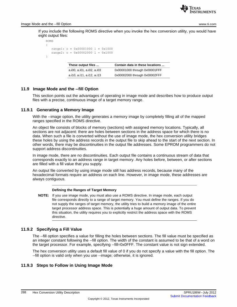
Image Mode and the --fill Option www.ti.com
If you include the following ROMS directive when you invoke the hex conversion utility, you would haveeight output files:
ROMS{
range1: o = 0x00001000 l = 0x1000range2: o = 0x00002000 l = 0x1000
}
These output files ... Contain data in these locations ...
a.i00, a.i01, a.i02, a.i03 0x00001000 through 0x00001FFF
a.i10, a.i11, a.i12, a.i13 0x00002000 through 0x00002FFF
11.9 Image Mode and the --fill Option
This section points out the advantages of operating in image mode and describes how to produce outputfiles with a precise, continuous image of a target memory range.
11.9.1 Generating a Memory Image
With the --image option, the utility generates a memory image by completely filling all of the mappedranges specified in the ROMS directive.
An object file consists of blocks of memory (sections) with assigned memory locations. Typically, allsections are not adjacent: there are holes between sections in the address space for which there is nodata. When such a file is converted without the use of image mode, the hex conversion utility bridgesthese holes by using the address records in the output file to skip ahead to the start of the next section. Inother words, there may be discontinuities in the output file addresses. Some EPROM programmers do notsupport address discontinuities.
In image mode, there are no discontinuities. Each output file contains a continuous stream of data thatcorresponds exactly to an address range in target memory. Any holes before, between, or after sectionsare filled with a fill value that you supply.
An output file converted by using image mode still has address records, because many of thehexadecimal formats require an address on each line. However, in image mode, these addresses arealways contiguous.
Defining the Ranges of Target Memory
NOTE: If you use image mode, you must also use a ROMS directive. In image mode, each outputfile corresponds directly to a range of target memory. You must define the ranges. If you donot supply the ranges of target memory, the utility tries to build a memory image of the entiretarget processor address space. This is potentially a huge amount of output data. To preventthis situation, the utility requires you to explicitly restrict the address space with the ROMSdirective.
11.9.2 Specifying a Fill Value
The --fill option specifies a value for filling the holes between sections. The fill value must be specified asan integer constant following the --fill option. The width of the constant is assumed to be that of a word onthe target processor. For example, specifying --fill=0x0FFF. The constant value is not sign extended.
The hex conversion utility uses a default fill value of 0 if you do not specify a value with the fill option. The--fill option is valid only when you use --image; otherwise, it is ignored.
11.9.3 Steps to Follow in Using Image Mode
288 Hex Conversion Utility Description SPRU186W–July 2012Submit Documentation Feedback
Copyright © 2012, Texas Instruments Incorporated
www.ti.com Building a Table for an On-Chip Boot Loader
Step 1: Define the ranges of target memory with a ROMS directive. See Section 11.4.Step 2: Invoke the hex conversion utility with the --image option. You can optionally use the --zero
option to reset the address origin to 0 for each output file. If you do not specify a fill valuewith the ROMS directive and you want a value other than the default of 0, use the --fill option.
11.10 Building a Table for an On-Chip Boot Loader
On the C621x, C671x, and C64x devices, a ROM boot process is supported where the EDMA copies 1Kbytes from the beginning of CE1 (EMIFB CE1 on C64x) to address 0, using default ROM timings. After thetransfer, the CPU begins executing from address 0. In this mode a second level boot load typically occurs,due to the limited amount of memory copied at boot.
The hex conversion utility supports the second level boot loader by automatically building the boot table.
11.10.1 Description of the Boot Table
The input for a boot loader is the boot table. The boot table contains records that instruct the boot loaderto copy blocks of data contained in the table to specified destination addresses. The hex conversion utilityautomatically builds the boot table for the boot loader. Using the utility, you specify the sections you wantthe boot loader to initialize through the boot table, the table location, and the name of the sectioncontaining the boot loader and where it should be located. The hex conversion utility builds a completeimage of the table and converts it into hexadecimal in the output files. Then, you can burn the table intoROM.
11.10.2 The Boot Table Format
The boot table format is simple. There is a header record containing a 4-byte field that indicates where theboot loader should branch after it has completed copying data. After the header, each section that is to beincluded in the boot table will have the following:
1. 4-byte field containing the size of the section
2. 4-byte field containing the destination address for the copy
3. The actual data to be copied
Multiple sections can be entered; a termination block containing a 4-byte field of zeros follows the lastsection.
289SPRU186W–July 2012 Hex Conversion Utility DescriptionSubmit Documentation Feedback
Copyright © 2012, Texas Instruments Incorporated
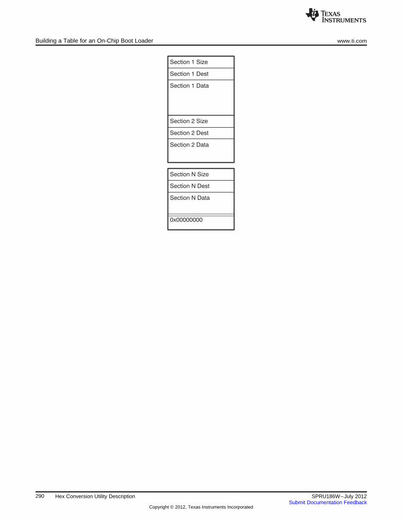
Section 1 Size
Section 1 Dest
Section 1 Data
Section 2 Size
Section 2 Dest
Section 2 Data
Section N Size
Section N Dest
Section N Data
0x00000000
Building a Table for an On-Chip Boot Loader www.ti.com
290 Hex Conversion Utility Description SPRU186W–July 2012Submit Documentation Feedback
Copyright © 2012, Texas Instruments Incorporated
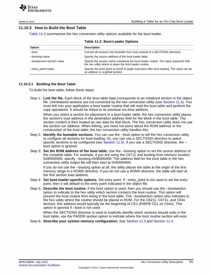
www.ti.com Building a Table for an On-Chip Boot Loader
11.10.3 How to Build the Boot Table
Table 11-2 summarizes the hex conversion utility options available for the boot loader.
Table 11-2. Boot-Loader Options
Option Description
--boot Convert all sections into bootable form (use instead of a SECTIONS directive).
--bootorg=value Specify the source address of the boot loader table.
--bootsection=section value Specify the section name containing the boot loader routine. The value argument tellsthe hex utility where to place the boot loader routine.
--entry_point=value Specify the entry point at which to begin execution after boot loading. The value can bean address or a global symbol.
11.10.3.1 Building the Boot Table
To build the boot table, follow these steps:
Step 1: Link the file. Each block of the boot table data corresponds to an initialized section in the objectfile. Uninitialized sections are not converted by the hex conversion utility (see Section 11.5). Youmust link into your application a boot loader routine that will read the boot table and perform thecopy operations. It should be linked to its eventual run-time address.When you select a section for placement in a boot-loader table, the hex conversion utility placesthe section's load address in the destination address field for the block in the boot table. Thesection content is then treated as raw data for that block. The hex conversion utility does not usethe section run address. When linking, you need not worry about the ROM address or theconstruction of the boot table; the hex conversion utility handles this.
Step 2: Identify the bootable sections. You can use the --boot option to tell the hex conversion utilityto configure all sections for boot loading. Or, you can use a SECTIONS directive to selectspecific sections to be configured (see Section 11.5). If you use a SECTIONS directive, the --boot option is ignored.
Step 3: Set the ROM address of the boot table. Use the --bootorg option to set the source address ofthe complete table. For example, if you are using the C6711 and booting from memory location0x90000400, specify --bootorg=0x90000400. The address field for the boot table in the hexconversion utility output file will then start at 0x90000400.If you do not use the --bootorg option at all, the utility places the table at the origin of the firstmemory range in a ROMS directive. If you do not use a ROMS directive, the table will start atthe first section load address.
Step 4: Set boot-loader-specific options. Set entry point. If --entry_point is not used to set the entrypoint, then it will default to the entry point indicated in the object file.
Step 5: Describe the boot routine. If the boot option is used, then you should use the --bootsectionoption to indicate to the hex utility which section contains the boot routine. This option willprevent the boot routine from being in the boot table. The --bootsection option also indicates tothe hex utility where the routine should be placed in ROM. For the C621x, C671x, and C64xdevices, this address would typically be the beginning of CE1 (EMIFB CE1 on C64x). Thisoption is ignored if --boot is not used.When the SECTIONS directive is used to explicitly identify which sections should exits in theboot table, use the PADDR section option to indicate where the boot routine section will exist.
Step 6: Describe your system memory configuration. See Section 11.3 and Section 11.4.
291SPRU186W–July 2012 Hex Conversion Utility DescriptionSubmit Documentation Feedback
Copyright © 2012, Texas Instruments Incorporated
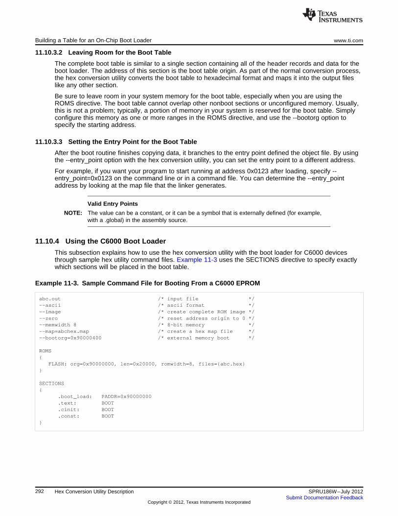
Building a Table for an On-Chip Boot Loader www.ti.com
11.10.3.2 Leaving Room for the Boot Table
The complete boot table is similar to a single section containing all of the header records and data for theboot loader. The address of this section is the boot table origin. As part of the normal conversion process,the hex conversion utility converts the boot table to hexadecimal format and maps it into the output fileslike any other section.
Be sure to leave room in your system memory for the boot table, especially when you are using theROMS directive. The boot table cannot overlap other nonboot sections or unconfigured memory. Usually,this is not a problem; typically, a portion of memory in your system is reserved for the boot table. Simplyconfigure this memory as one or more ranges in the ROMS directive, and use the --bootorg option tospecify the starting address.
11.10.3.3 Setting the Entry Point for the Boot Table
After the boot routine finishes copying data, it branches to the entry point defined the object file. By usingthe --entry_point option with the hex conversion utility, you can set the entry point to a different address.
For example, if you want your program to start running at address 0x0123 after loading, specify --entry_point=0x0123 on the command line or in a command file. You can determine the --entry_pointaddress by looking at the map file that the linker generates.
Valid Entry Points
NOTE: The value can be a constant, or it can be a symbol that is externally defined (for example,with a .global) in the assembly source.
11.10.4 Using the C6000 Boot Loader
This subsection explains how to use the hex conversion utility with the boot loader for C6000 devicesthrough sample hex utility command files. Example 11-3 uses the SECTIONS directive to specify exactlywhich sections will be placed in the boot table.
Example 11-3. Sample Command File for Booting From a C6000 EPROM
abc.out /* input file */--ascii /* ascii format */--image /* create complete ROM image */--zero /* reset address origin to 0 */--memwidth 8 /* 8-bit memory */--map=abchex.map /* create a hex map file */--bootorg=0x90000400 /* external memory boot */
ROMS{
FLASH: org=0x90000000, len=0x20000, romwidth=8, files={abc.hex}}
SECTIONS{
.boot_load: PADDR=0x90000000
.text: BOOT
.cinit: BOOT
.const: BOOT}
292 Hex Conversion Utility Description SPRU186W–July 2012Submit Documentation Feedback
Copyright © 2012, Texas Instruments Incorporated
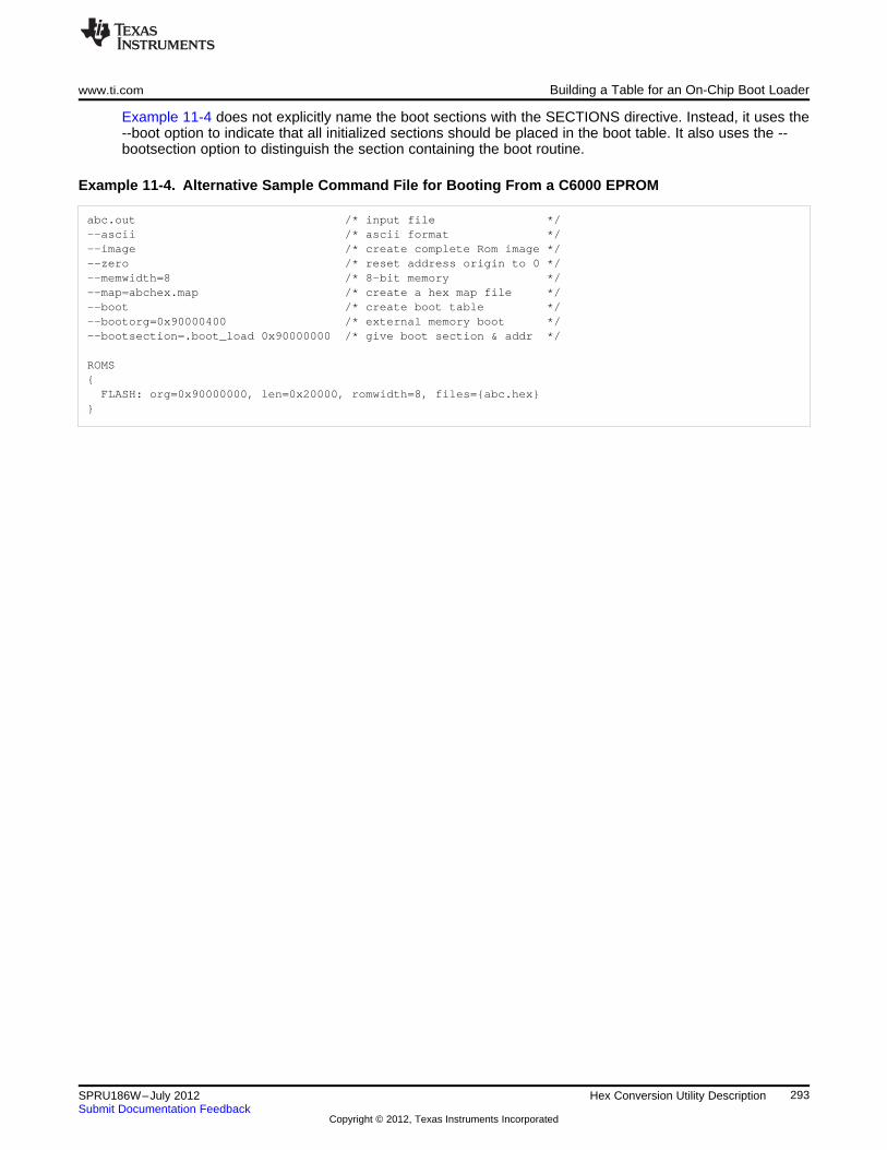
www.ti.com Building a Table for an On-Chip Boot Loader
Example 11-4 does not explicitly name the boot sections with the SECTIONS directive. Instead, it uses the--boot option to indicate that all initialized sections should be placed in the boot table. It also uses the --bootsection option to distinguish the section containing the boot routine.
Example 11-4. Alternative Sample Command File for Booting From a C6000 EPROM
abc.out /* input file */--ascii /* ascii format */--image /* create complete Rom image */--zero /* reset address origin to 0 */--memwidth=8 /* 8-bit memory */--map=abchex.map /* create a hex map file */--boot /* create boot table */--bootorg=0x90000400 /* external memory boot */--bootsection=.boot_load 0x90000000 /* give boot section & addr */
ROMS{FLASH: org=0x90000000, len=0x20000, romwidth=8, files={abc.hex}
}
293SPRU186W–July 2012 Hex Conversion Utility DescriptionSubmit Documentation Feedback
Copyright © 2012, Texas Instruments Incorporated
Controlling the ROM Device Address www.ti.com
11.11 Controlling the ROM Device Address
The hex conversion utility output address field corresponds to the ROM device address. The EPROMprogrammer burns the data into the location specified by the hex conversion utility output file address field.The hex conversion utility offers some mechanisms to control the starting address in ROM of eachsection. However, many EPROM programmers offer direct control of the location in ROM in which thedata is burned.
Depending on whether or not you are using the boot loader, the hex conversion utility output filecontrolling mechanisms are different.
Non-boot loader mode. The address field of the hex conversion utility output file is controlled by thefollowing mechanisms listed from low to high priority:
1. The linker command file. By default, the address field of the hex conversion utility output file is theload address (as given in the linker command file).
2. The paddr parameter of the SECTIONS directive. When the paddr parameter is specified for asection, the hex conversion utility bypasses the section load address and places the section in theaddress specified by paddr.
3. The --zero option. When you use the --zero option, the utility resets the address origin to 0 for eachoutput file. Since each file starts at 0 and counts upward, any address records represent offsets fromthe beginning of the file (the address within the ROM) rather than actual target addresses of the data.
You must use the --zero option in conjunction with the --image option to force the starting address ineach output file to be zero. If you specify the --zero option without the --image option, the utility issuesa warning and ignores the --zero option.
Boot-Loader Mode. When the boot loader is used, the hex conversion utility places the different sectionsthat are in the boot table into consecutive memory locations. Each section becomes a boot table blockwhose destination address is equal to the linker-assigned section load address.
In a boot table, the address field of the hex conversion utility output file is not related to the section loadaddresses assigned by the linker. The address fields of the boot table are simply offsets to the beginningof the table. The section load addresses assigned by the linker will be encoded into the boot table alongwith the size of the section and the data contained within the section. These addresses will be used tostore the data into memory during the boot load process.
The beginning of the boot table defaults to the linked load address of the first bootable section in the inputfile, unless you use one of the following mechanisms, listed here from low to high priority. Higher prioritymechanisms override the values set by low priority options in an overlapping range.
1. The ROM origin specified in the ROMS directive. The hex conversion utility places the boot table atthe origin of the first memory range in a ROMS directive.
2. The --bootorg option. The hex conversion utility places the boot table at the address specified by the--bootorg option if you select boot loading from memory.
294 Hex Conversion Utility Description SPRU186W–July 2012Submit Documentation Feedback
Copyright © 2012, Texas Instruments Incorporated
www.ti.com Control Hex Conversion Utility Diagnostics
11.12 Control Hex Conversion Utility Diagnostics
The hex conversion utility uses certain C/C++ compiler options to control hex-converter-generateddiagnostics.
--diag_error=id Categorizes the diagnostic identified by id as an error. To determine thenumeric identifier of a diagnostic message, use the --display_error_numberoption first in a separate link. Then use --diag_error=id to recategorize thediagnostic as an error. You can only alter the severity of discretionarydiagnostics.
--diag_remark=id Categorizes the diagnostic identified by id as a remark. To determine thenumeric identifier of a diagnostic message, use the --display_error_numberoption first in a separate link. Then use --diag_remark=id to recategorize thediagnostic as a remark. You can only alter the severity of discretionarydiagnostics.
--diag_suppress=id Suppresses the diagnostic identified by id. To determine the numericidentifier of a diagnostic message, use the --display_error_number option firstin a separate link. Then use --diag_suppress=id to suppress the diagnostic.You can only suppress discretionary diagnostics.
--diag_warning=id Categorizes the diagnostic identified by id as a warning. To determine thenumeric identifier of a diagnostic message, use the --display_error_numberoption first in a separate link. Then use --diag_warning=id to recategorize thediagnostic as a warning. You can only alter the severity of discretionarydiagnostics.
--display_error_number Displays a diagnostic's numeric identifier along with its text. Use this option indetermining which arguments you need to supply to the diagnosticsuppression options (--diag_suppress, --diag_error, --diag_remark, and --diag_warning). This option also indicates whether a diagnostic isdiscretionary. A discretionary diagnostic is one whose severity can beoverridden. A discretionary diagnostic includes the suffix -D; otherwise, nosuffix is present. See the TMS320C6000 Optimizing Compiler User's Guidefor more information on understanding diagnostic messages.
--issue_remarks Issues remarks (nonserious warnings), which are suppressed by default.--no_warnings Suppresses warning diagnostics (errors are still issued).--set_error_limit=count Sets the error limit to count, which can be any decimal value. The linker
abandons linking after this number of errors. (The default is 100.)--verbose_diagnostics Provides verbose diagnostics that display the original source with line-wrap
and indicate the position of the error in the source line
295SPRU186W–July 2012 Hex Conversion Utility DescriptionSubmit Documentation Feedback
Copyright © 2012, Texas Instruments Incorporated
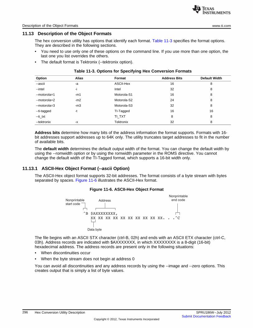
^B $AXXXXXXXX,
XX XX XX XX XX XX XX XX XX XX. . .^C
Nonprintablestart code
Nonprintableend codeAddress
Data byte
Description of the Object Formats www.ti.com
11.13 Description of the Object Formats
The hex conversion utility has options that identify each format. Table 11-3 specifies the format options.They are described in the following sections.
• You need to use only one of these options on the command line. If you use more than one option, thelast one you list overrides the others.
• The default format is Tektronix (--tektronix option).
Table 11-3. Options for Specifying Hex Conversion Formats
Option Alias Format Address Bits Default Width
--ascii -a ASCII-Hex 16 8
--intel -i Intel 32 8
--motorola=1 -m1 Motorola-S1 16 8
--motorola=2 -m2 Motorola-S2 24 8
--motorola=3 -m3 Motorola-S3 32 8
--ti-tagged -t TI-Tagged 16 16
--ti_txt TI_TXT 8 8
--tektronix -x Tektronix 32 8
Address bits determine how many bits of the address information the format supports. Formats with 16-bit addresses support addresses up to 64K only. The utility truncates target addresses to fit in the numberof available bits.
The default width determines the default output width of the format. You can change the default width byusing the --romwidth option or by using the romwidth parameter in the ROMS directive. You cannotchange the default width of the TI-Tagged format, which supports a 16-bit width only.
11.13.1 ASCII-Hex Object Format (--ascii Option)
The ASCII-Hex object format supports 32-bit addresses. The format consists of a byte stream with bytesseparated by spaces. Figure 11-6 illustrates the ASCII-Hex format.
Figure 11-6. ASCII-Hex Object Format
The file begins with an ASCII STX character (ctrl-B, 02h) and ends with an ASCII ETX character (ctrl-C,03h). Address records are indicated with $AXXXXXXX, in which XXXXXXXX is a 8-digit (16-bit)hexadecimal address. The address records are present only in the following situations:
• When discontinuities occur
• When the byte stream does not begin at address 0
You can avoid all discontinuities and any address records by using the --image and --zero options. Thiscreates output that is simply a list of byte values.
296 Hex Conversion Utility Description SPRU186W–July 2012Submit Documentation Feedback
Copyright © 2012, Texas Instruments Incorporated
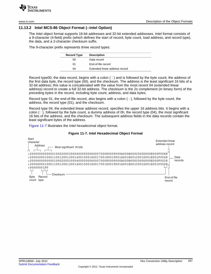
:00000001FF
Startcharacter
Bytecount
Checksum
Datarecords
Recordtype
AddressMost significant 16 bits
Extended linearaddress record
End-of-filerecord
www.ti.com Description of the Object Formats
11.13.2 Intel MCS-86 Object Format (--intel Option)
The Intel object format supports 16-bit addresses and 32-bit extended addresses. Intel format consists ofa 9-character (4-field) prefix (which defines the start of record, byte count, load address, and record type),the data, and a 2-character checksum suffix.
The 9-character prefix represents three record types:
Record Type Description
00 Data record
01 End-of-file record
04 Extended linear address record
Record type00, the data record, begins with a colon ( : ) and is followed by the byte count, the address ofthe first data byte, the record type (00), and the checksum. The address is the least significant 16 bits of a32-bit address; this value is concatenated with the value from the most recent 04 (extended linearaddress) record to create a full 32-bit address. The checksum is the 2s complement (in binary form) of thepreceding bytes in the record, including byte count, address, and data bytes.
Record type 01, the end-of-file record, also begins with a colon ( : ), followed by the byte count, theaddress, the record type (01), and the checksum.
Record type 04, the extended linear address record, specifies the upper 16 address bits. It begins with acolon ( : ), followed by the byte count, a dummy address of 0h, the record type (04), the most significant16 bits of the address, and the checksum. The subsequent address fields in the data records contain theleast significant bytes of the address.
Figure 11-7 illustrates the Intel hexadecimal object format.
Figure 11-7. Intel Hexadecimal Object Format
297SPRU186W–July 2012 Hex Conversion Utility DescriptionSubmit Documentation Feedback
Copyright © 2012, Texas Instruments Incorporated
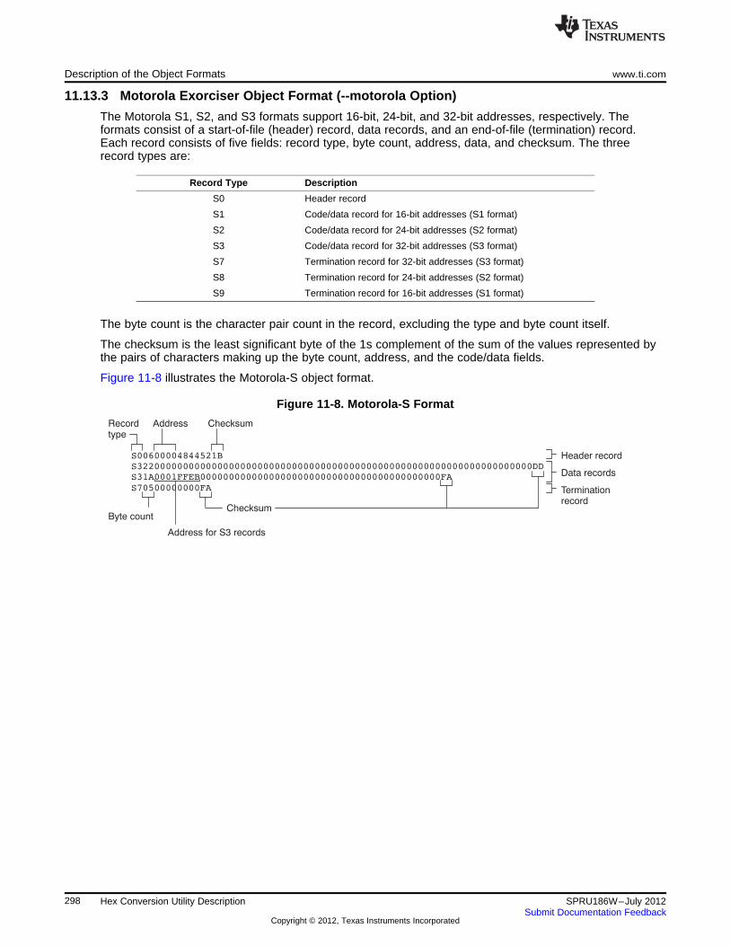
S00600004844521B
S31A0001FFEB000000000000000000000000000000000000000000FA
S70500000000FA
Recordtype
Byte countChecksum
Data records
Address
Header record
Terminationrecord
Checksum
Address for S3 records
Description of the Object Formats www.ti.com
11.13.3 Motorola Exorciser Object Format (--motorola Option)
The Motorola S1, S2, and S3 formats support 16-bit, 24-bit, and 32-bit addresses, respectively. Theformats consist of a start-of-file (header) record, data records, and an end-of-file (termination) record.Each record consists of five fields: record type, byte count, address, data, and checksum. The threerecord types are:
Record Type Description
S0 Header record
S1 Code/data record for 16-bit addresses (S1 format)
S2 Code/data record for 24-bit addresses (S2 format)
S3 Code/data record for 32-bit addresses (S3 format)
S7 Termination record for 32-bit addresses (S3 format)
S8 Termination record for 24-bit addresses (S2 format)
S9 Termination record for 16-bit addresses (S1 format)
The byte count is the character pair count in the record, excluding the type and byte count itself.
The checksum is the least significant byte of the 1s complement of the sum of the values represented bythe pairs of characters making up the byte count, address, and the code/data fields.
Figure 11-8 illustrates the Motorola-S object format.
Figure 11-8. Motorola-S Format
298 Hex Conversion Utility Description SPRU186W–July 2012Submit Documentation Feedback
Copyright © 2012, Texas Instruments Incorporated
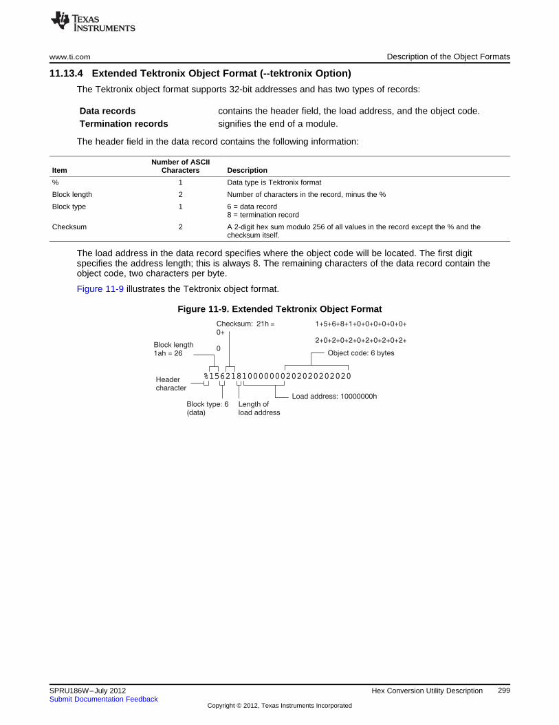
%15621810000000202020202020
Block length1ah = 26
Checksum: 21h = 1+5+6+8+1+0+0+0+0+0+0+0+
2+0+2+0+2+0+2+0+2+0+2+0
Load address: 10000000h
Headercharacter
Block type: 6(data)
Object code: 6 bytes
Length ofload address
www.ti.com Description of the Object Formats
11.13.4 Extended Tektronix Object Format (--tektronix Option)
The Tektronix object format supports 32-bit addresses and has two types of records:
Data records contains the header field, the load address, and the object code.Termination records signifies the end of a module.
The header field in the data record contains the following information:
Number of ASCIIItem Characters Description
% 1 Data type is Tektronix format
Block length 2 Number of characters in the record, minus the %
Block type 1 6 = data record8 = termination record
Checksum 2 A 2-digit hex sum modulo 256 of all values in the record except the % and thechecksum itself.
The load address in the data record specifies where the object code will be located. The first digitspecifies the address length; this is always 8. The remaining characters of the data record contain theobject code, two characters per byte.
Figure 11-9 illustrates the Tektronix object format.
Figure 11-9. Extended Tektronix Object Format
299SPRU186W–July 2012 Hex Conversion Utility DescriptionSubmit Documentation Feedback
Copyright © 2012, Texas Instruments Incorporated
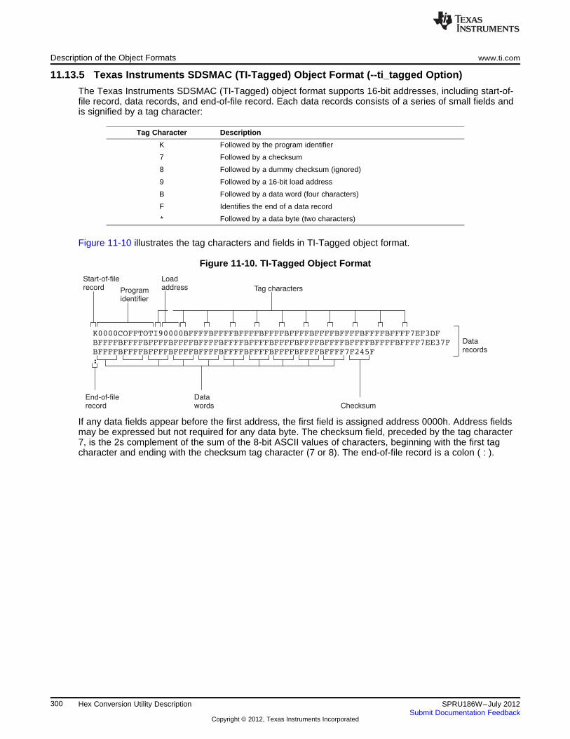
BFFFFBFFFFBFFFFBFFFFBFFFFBFFFFBFFFFBFFFFBFFFFBFFFF7F245F
:
Tag charactersProgramidentifier
Loadaddress
Datawords Checksum
Datarecords
End-of-filerecord
Start-of-filerecord
Description of the Object Formats www.ti.com
11.13.5 Texas Instruments SDSMAC (TI-Tagged) Object Format (--ti_tagged Option)
The Texas Instruments SDSMAC (TI-Tagged) object format supports 16-bit addresses, including start-of-file record, data records, and end-of-file record. Each data records consists of a series of small fields andis signified by a tag character:
Tag Character Description
K Followed by the program identifier
7 Followed by a checksum
8 Followed by a dummy checksum (ignored)
9 Followed by a 16-bit load address
B Followed by a data word (four characters)
F Identifies the end of a data record
* Followed by a data byte (two characters)
Figure 11-10 illustrates the tag characters and fields in TI-Tagged object format.
Figure 11-10. TI-Tagged Object Format
If any data fields appear before the first address, the first field is assigned address 0000h. Address fieldsmay be expressed but not required for any data byte. The checksum field, preceded by the tag character7, is the 2s complement of the sum of the 8-bit ASCII values of characters, beginning with the first tagcharacter and ending with the checksum tag character (7 or 8). The end-of-file record is a colon ( : ).
300 Hex Conversion Utility Description SPRU186W–July 2012Submit Documentation Feedback
Copyright © 2012, Texas Instruments Incorporated
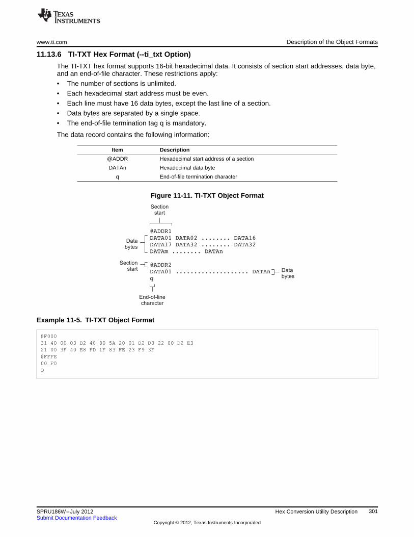
@ADDR1
DATA01 DATA02 ........ DATA16
DATA17 DATA32 ........ DATA32
DATAm ........ DATAn
@ADDR2
DATA01 .................... DATAn
q
Sectionstart
End-of-linecharacter
Databytes
Databytes
Sectionstart
www.ti.com Description of the Object Formats
11.13.6 TI-TXT Hex Format (--ti_txt Option)
The TI-TXT hex format supports 16-bit hexadecimal data. It consists of section start addresses, data byte,and an end-of-file character. These restrictions apply:
• The number of sections is unlimited.
• Each hexadecimal start address must be even.
• Each line must have 16 data bytes, except the last line of a section.
• Data bytes are separated by a single space.
• The end-of-file termination tag q is mandatory.
The data record contains the following information:
Item Description
@ADDR Hexadecimal start address of a section
DATAn Hexadecimal data byte
q End-of-file termination character
Figure 11-11. TI-TXT Object Format
Example 11-5. TI-TXT Object Format
@F00031 40 00 03 B2 40 80 5A 20 01 D2 D3 22 00 D2 E321 00 3F 40 E8 FD 1F 83 FE 23 F9 3F@FFFE00 F0Q
301SPRU186W–July 2012 Hex Conversion Utility DescriptionSubmit Documentation Feedback
Copyright © 2012, Texas Instruments Incorporated
Chapter 12SPRU186W–July 2012
Sharing C/C++ Header Files With Assembly Source
You can use the .cdecls assembler directive to share C headers containing declarations and prototypesbetween C and assembly code. Any legal C/C++ can be used in a .cdecls block and the C/C++declarations will cause suitable assembly to be generated automatically, allowing you to reference theC/C++ constructs in assembly code.
Topic ........................................................................................................................... Page
12.1 Overview of the .cdecls Directive ....................................................................... 30312.2 Notes on C/C++ Conversions ............................................................................ 30312.3 Notes on C++ Specific Conversions ................................................................... 30712.4 Special Assembler Support ............................................................................... 308
302 Sharing C/C++ Header Files With Assembly Source SPRU186W–July 2012Submit Documentation Feedback
Copyright © 2012, Texas Instruments Incorporated
www.ti.com Overview of the .cdecls Directive
12.1 Overview of the .cdecls Directive
The .cdecls directive allows programmers in mixed assembly and C/C++ environments to share C headerscontaining declarations and prototypes between the C and assembly code. Any legal C/C++ can be usedin a .cdecls block and the C/C++ declarations will cause suitable assembly to be generated automatically.This allows the programmer to reference the C/C++ constructs in assembly code — calling functions,allocating space, and accessing structure members — using the equivalent assembly mechanisms. Whilefunction and variable definitions are ignored, most common C/C++ elements are converted to assembly:enumerations, (non function-like) macros, function and variable prototypes, structures, and unions.
See the .cdecls directive description for details on the syntax of the .cdecls assembler directive.
The .cdecls directive can appear anywhere in an assembly source file, and can occur multiple times withina file. However, the C/C++ environment created by one .cdecls is not inherited by a later .cdecls; theC/C++ environment starts over for each .cdecls instance.
For example, the following code causes the warning to be issued:.cdecls C,NOLIST%{
#define ASMTEST 1%}
.cdecls C,NOLIST%{
#ifndef ASMTEST#warn "ASMTEST not defined!" /* will be issued */
#endif%}
Therefore, a typical use of the .cdecls block is expected to be a single usage near the beginning of theassembly source file, in which all necessary C/C++ header files are included.
Use the compiler --include_path=path options to specify additional include file paths needed for the headerfiles used in assembly, as you would when compiling C files.
Any C/C++ errors or warnings generated by the code of the .cdecls are emitted as they normally would forthe C/C++ source code. C/C++ errors cause the directive to fail, and any resulting converted assembly isnot included.
C/C++ constructs that cannot be converted, such as function-like macros or variable definitions, cause acomment to be output to the converted assembly file. For example:; ASM HEADER WARNING - variable definition 'ABCD' ignored
The prefix ASM HEADER WARNING appears at the beginning of each message. To see the warnings,either the WARN parameter needs to be specified so the messages are displayed on STDERR, or elsethe LIST parameter needs to be specified so the warnings appear in the listing file, if any.
Finally, note that the converted assembly code does not appear in the same order as the original C/C++source code and C/C++ constructs may be simplified to a normalized form during the conversion process,but this should not affect their final usage.
12.2 Notes on C/C++ Conversions
The following sections describe C and C++ conversion elements that you need to be aware of whensharing header files with assembly source.
12.2.1 Comments
Comments are consumed entirely at the C level, and do not appear in the resulting converted assemblyfile.
303SPRU186W–July 2012 Sharing C/C++ Header Files With Assembly SourceSubmit Documentation Feedback
Copyright © 2012, Texas Instruments Incorporated
Notes on C/C++ Conversions www.ti.com
12.2.2 Conditional Compilation (#if/#else/#ifdef/etc.)
Conditional compilation is handled entirely at the C level during the conversion step. Define any necessarymacros either on the command line (using the compiler --define=name=value option) or within a .cdeclsblock using #define. The #if, #ifdef, etc. C/C++ directives are not converted to assembly .if, .else, .elseif,and .endif directives.
12.2.3 Pragmas
Pragmas found in the C/C++ source code cause a warning to be generated as they are not converted.They have no other effect on the resulting assembly file. See the .cdecls topic for the WARN andNOWARN parameter discussion for where these warnings are created.
12.2.4 The #error and #warning Directives
These preprocessor directives are handled completely by the compiler during the parsing step ofconversion. If one of these directives is encountered, the appropriate error or warning message is emitted.These directives are not converted to .emsg or .wmsg in the assembly output.
12.2.5 Predefined symbol _ _ASM_HEADER_ _
The C/C++ macro _ _ASM_HEADER_ _ is defined in the compiler while processing code within .cdecls.This allows you to make changes in your code, such as not compiling definitions, during the .cdeclsprocessing.
Be Careful With the _ _ASM_HEADER_ _ Macro
NOTE: You must be very careful not to use this macro to introduce any changes in the code thatcould result in inconsistencies between the code processed while compiling the C/C++source and while converting to assembly.
12.2.6 Usage Within C/C++ asm( ) Statements
The .cdecls directive is not allowed within C/C++ asm( ) statements and will cause an error to begenerated.
12.2.7 The #include Directive
The C/C++ #include preprocessor directive is handled transparently by the compiler during the conversionstep. Such #includes can be nested as deeply as desired as in C/C++ source. The assembly directives.include and .copy are not used or needed within a .cdecls. Use the command line --include_path option tospecify additional paths to be searched for included files, as you would for C compilation.
12.2.8 Conversion of #define Macros
Only object-like macros are converted to assembly. Function-like macros have no assemblyrepresentation and so cannot be converted. Pre-defined and built-in C/C++ macros are not converted toassembly (i.e., __FILE__, __TIME__, __TI_COMPILER_VERSION__, etc.). For example, this code isconverted to assembly because it is an object-like macro:#define NAME Charley
This code is not converted to assembly because it is a function-like macro:#define MAX(x,y) (x>y ? x : y)
Some macros, while they are converted, have no functional use in the containing assembly file. Forexample, the following results in the assembly substitution symbol FOREVER being set to the valuewhile(1), although this has no useful use in assembly because while(1) is not legal assembly code.#define FOREVER while(1)
304 Sharing C/C++ Header Files With Assembly Source SPRU186W–July 2012Submit Documentation Feedback
Copyright © 2012, Texas Instruments Incorporated
www.ti.com Notes on C/C++ Conversions
Macro values are not interpreted as they are converted. For example, the following results in theassembler substitution symbol OFFSET being set to the literal string value 5+12 and not the value 17.This happens because the semantics of the C/C++ language require that macros are evaluated in contextand not when they are parsed.#define OFFSET 5+12
Because macros in C/C++ are evaluated in their usage context, C/C++ printf escape sequences such as\n are not converted to a single character in the converted assembly macro. See Section 12.2.11 forsuggestions on how to use C/C++ macro strings.
Macros are converted using the new .define directive (see Section 12.4.2), which functions similarly to the.asg assembler directive. The exception is that .define disallows redefinitions of register symbols andmnemonics to prevent the conversion from corrupting the basic assembly environment. To remove amacro from the assembly scope, .undef can be used following the .cdecls that defines it (seeSection 12.4.3).
The macro functionality of # (stringize operator) is only useful within functional macros. Since functionalmacros are not supported by this process, # is not supported either. The concatenation operator ## is onlyuseful in a functional context, but can be used degenerately to concatenate two strings and so it issupported in that context.
12.2.9 The #undef Directive
Symbols undefined using the #undef directive before the end of the .cdecls are not converted to assembly.
12.2.10 Enumerations
Enumeration members are converted to .enum elements in assembly. For example:enum state { ACTIVE=0x10, SLEEPING=0x01, INTERRUPT=0x100, POWEROFF, LAST};
is converted to the following assembly code:state .enumACTIVE .emember 16SLEEPING .emember 1NTERRUPT .emember 256POWEROFF .emember 257LAST .emember 258
.endenum
The members are used via the pseudo-scoping created by the .enum directive.
The usage is similar to that for accessing structure members, enum_name.member.
This pseudo-scoping is used to prevent enumeration member names from corrupting other symbols withinthe assembly environment.
12.2.11 C Strings
Because C string escapes such as \n and \t are not converted to hex characters 0x0A and 0x09 until theiruse in a string constant in a C/C++ program, C macros whose values are strings cannot be representedas expected in assembly substitution symbols. For example:#define MSG "\tHI\n"
becomes, in assembly:.define """\tHI\n""",MSG ; 6 quoted characters! not 5!
When used in a C string context, you expect this statement to be converted to 5 characters (tab, H, I,newline, NULL), but the .string assembler directive does not know how to perform the C escapeconversions.
You can use the .cstring directive to cause the escape sequences and NULL termination to be properlyhandled as they would in C/C++. Using the above symbol MSG with a .cstring directive results in 5characters of memory being allocated, the same characters as would result if used in a C/C++ strongcontext. (See Section 12.4.7 for the .cstring directive syntax.)
305SPRU186W–July 2012 Sharing C/C++ Header Files With Assembly SourceSubmit Documentation Feedback
Copyright © 2012, Texas Instruments Incorporated
Notes on C/C++ Conversions www.ti.com
12.2.12 C/C++ Built-In Functions
The C/C++ built-in functions, such as sizeof( ), are not translated to their assembly counterparts, if any, ifthey are used in macros. Also, their C expression values are not inserted into the resulting assemblymacro because macros are evaluated in context and there is no active context when converting themacros to assembly.
Suitable functions such as $sizeof( ) are available in assembly expressions. However, as the basic typessuch as int/char/float have no type representation in assembly, there is no way to ask for $sizeof(int), forexample, in assembly.
12.2.13 Structures and Unions
C/C++ structures and unions are converted to assembly .struct and .union elements. Padding and endingalignments are added as necessary to make the resulting assembly structure have the same size andmember offsets as the C/C++ source. The primary purpose is to allow access to members of C/C++structures, as well as to facilitate debugging of the assembly code. For nested structures, the assembly.tag feature is used to refer to other structures/unions.
The alignment is also passed from the C/C++ source so that the assembly symbol is marked with thesame alignment as the C/C++ symbol. (See Section 12.2.3 for information about pragmas, which mayattempt to modify structures.) Because the alignment of structures is stored in the assembly symbol, built-in assembly functions like $sizeof( ) and $alignof( ) can be used on the resulting structure name symbol.
When using unnamed structures (or unions) in typedefs, such as:typedef struct { int a_member; } mystrname;
This is really a shorthand way of writing:struct temporary_name { int a_member; };typedef temporary_name mystrname;
The conversion processes the above statements in the same manner: generating a temporary name forthe structure and then using .define to output a typedef from the temporary name to the user name. Youshould use your mystrname in assembly the same as you would in C/C++, but do not be confused by theassembly structure definition in the list, which contains the temporary name. You can avoid the temporaryname by specifying a name for the structure, as in:typedef struct a_st_name { ... } mystrname;
If a shorthand method is used in C to declare a variable with a particular structure, for example:extern struct a_name { int a_member; } a_variable;
Then after the structure is converted to assembly, a .tag directive is generated to declare the structure ofthe external variable, such as:_a_variable .tag a_st_name
This allows you to refer to _a_variable.a_member in your assembly code.
12.2.14 Function/Variable Prototypes
Non-static function and variable prototypes (not definitions) will result in a .global directive being generatedfor each symbol found.
See Section 12.3.1 for C++ name mangling issues.
Function and variable definitions will result in a warning message being generated (see theWARN/NOWARN parameter discussion for where these warnings are created) for each, and they will notbe represented in the converted assembly.
The assembly symbol representing the variable declarations will not contain type information about thosesymbols. Only a .global will be issued for them. Therefore, it is your responsibility to ensure the symbol isused appropriately.
See Section 12.2.13 for information on variables names which are of a structure/union type.
306 Sharing C/C++ Header Files With Assembly Source SPRU186W–July 2012Submit Documentation Feedback
Copyright © 2012, Texas Instruments Incorporated
www.ti.com Notes on C++ Specific Conversions
12.2.15 C Constant Suffixes
The C constant suffixes u, l, and f are passed to the assembly unchanged. The assembler will ignorethese suffixes if used in assembly expressions.
12.2.16 Basic C/C++ Types
Only complex types (structures and unions) in the C/C++ source code are converted to assembly. Basictypes such as int, char, or float are not converted or represented in assembly beyond any existing .int,.char, .float, etc. directives that previously existed in assembly.
Typedefs of basic types are therefore also not represented in the converted assembly.
12.3 Notes on C++ Specific Conversions
The following sections describe C++ specific conversion elements that you need to be aware of whensharing header files with assembly source.
12.3.1 Name Mangling
Symbol names may be mangled in C++ source files. When mangling occurs, the converted assembly willuse the mangled names to avoid symbol name clashes. You can use the demangler (dem6x) to demanglenames and identify the correct symbols to use in assembly.
To defeat name mangling in C++ for symbols where polymorphism (calling a function of the same namewith different kinds of arguments) is not required, use the following syntax:extern "C" void somefunc(int arg);
The above format is the short method for declaring a single function. To use this method for multiplefunctions, you can also use the following syntax:extern "C"{
void somefunc(int arg);int anotherfunc(int arg);...
}
12.3.2 Derived Classes
Derived classes are only partially supported when converting to assembly because of issues related toC++ scoping which does not exist in assembly. The greatest difference is that base class members do notautomatically become full (top-level) members of the derived class. For example:----------------------------------------------------------
class base{
public:int b1;
};
class derived : public base{
public:int d1;
}
In C++ code, the class derived would contain both integers b1 and d1. In the converted assemblystructure "derived", the members of the base class must be accessed using the name of the base class,such as derived.__b_base.b1 rather than the expected derived.b1.
A non-virtual, non-empty base class will have __b_ prepended to its name within the derived class tosignify it is a base class name. That is why the example above is derived.__b_base.b1 and not simplyderived.base.b1.
307SPRU186W–July 2012 Sharing C/C++ Header Files With Assembly SourceSubmit Documentation Feedback
Copyright © 2012, Texas Instruments Incorporated
Special Assembler Support www.ti.com
12.3.3 Templates
No support exists for templates.
12.3.4 Virtual Functions
No support exists for virtual functions, as they have no assembly representation.
12.4 Special Assembler Support
12.4.1 Enumerations (.enum/.emember/.endenum)
New directives have been created to support a pseudo-scoping for enumerations.
The format of these new directives is:
ENUM_NAME .enumMEMBER1 .emember [value]MEMBER2 .emember [value]...
.endenum
The .enum directive begins the enumeration definition and .endenum terminates it.
The enumeration name (ENUM_NAME) cannot be used to allocate space; its size is reported as zero.
The format to use the value of a member is ENUM_NAME.MEMBER, similar to a structure memberusage.
The .emember directive optionally accepts the value to set the member to, just as in C/C++. If notspecified, the member takes a value one more than the previous member. As in C/C++, member namescannot be duplicated, although values can be. Unless specified with .emember, the first enumerationmember will be given the value 0 (zero), as in C/C++.
The .endenum directive cannot be used with a label, as structure .endstruct directives can, because the.endenum directive has no value like the .endstruct does (containing the size of the structure).
Conditional compilation directives (.if/.else/.elseif/.endif) are the only other non-enumeration code allowedwithin the .enum/.endenum sequence.
12.4.2 The .define Directive
The new .define directive functions in the same manner as the .asg directive, except that .define disallowscreation of a substitution symbol that has the same name as a register symbol or mnemonic. It does notcreate a new symbol name space in the assembler, rather it uses the existing substitution symbol namespace. The syntax for the directive is:
.define substitution string , substitution symbol name
The .define directive is used to prevent corruption of the assembly environment when converting C/C++headers.
12.4.3 The .undefine/.unasg Directives
The .undef directive is used to remove the definition of a substitution symbol created using .define or .asg.This directive will remove the named symbol from the substitution symbol table from the point of the .undefto the end of the assembly file. The syntax for these directives is:
.undefine substitution symbol name
.unasg substitution symbol name
This can be used to remove from the assembly environment any C/C++ macros that may cause aproblem.
308 Sharing C/C++ Header Files With Assembly Source SPRU186W–July 2012Submit Documentation Feedback
Copyright © 2012, Texas Instruments Incorporated
www.ti.com Special Assembler Support
Also see Section 12.4.2, which covers the .define directive.
12.4.4 The $defined( ) Built-In Function
The $defined directive returns true/1 or false/0 depending on whether the name exists in the currentsubstitution symbol table or the standard symbol table. In essence $defined returns TRUE if theassembler has any user symbol in scope by that name. This differs from $isdefed in that $isdefed onlytests for NON-substitution symbols. The syntax is:
$defined( substitution symbol name )
A statement such as ".if $defined(macroname)" is then similar to the C code "#ifdef macroname".
See Section 12.4.2 and Section 12.4.3 for the use of .define and .undef in assembly.
12.4.5 The $sizeof Built-In Function
The new assembly built-in function $sizeof( ) can be used to query the size of a structure in assembly. It isan alias for the already existing $structsz( ). The syntax is:
$sizeof( structure name )
The $sizeof function can then be used similarly to the C built-in function sizeof( ).
The assembler's $sizeof( ) built-in function cannot be used to ask for the size of basic C/C++ types, suchas $sizeof(int), because those basic type names are not represented in assembly. Only complex types areconverted from C/C++ to assembly.
Also see Section 12.2.12, which notes that this conversion does not happen automatically if the C/C++sizeof( ) built-in function is used within a macro.
12.4.6 Structure/Union Alignment and $alignof( )
The assembly .struct and .union directives now take an optional second argument which can be used tospecify a minimum alignment to be applied to the symbol name. This is used by the conversion process topass the specific alignment from C/C++ to assembly.
The assembly built-in function $alignof( ) can be used to report the alignment of these structures. This canbe used even on assembly structures, and the function will return the minimum alignment calculated bythe assembler.
12.4.7 The .cstring Directive
You can use the new .cstring directive to cause the escape sequences and NULL termination to beproperly handled as they would in C/C++.
.cstring "String with C escapes.\nWill be NULL terminated.\012"
See Section 12.2.11 for more information on the new .cstring directive.
309SPRU186W–July 2012 Sharing C/C++ Header Files With Assembly SourceSubmit Documentation Feedback
Copyright © 2012, Texas Instruments Incorporated
Appendix ASPRU186W–July 2012
Symbolic Debugging Directives
The assembler supports several directives that the TMS320C6000 C/C++ compiler uses for symbolicdebugging. These directives differ for the two debugging formats, DWARF and COFF.
These directives are not meant for use by assembly-language programmers. They require arguments thatcan be difficult to calculate manually, and their usage must conform to a predetermined agreementbetween the compiler, the assembler, and the debugger. This appendix documents these directives forinformational purposes only.
Topic ........................................................................................................................... Page
A.1 DWARF Debugging Format ............................................................................... 311A.2 COFF Debugging Format .................................................................................. 311A.3 Debug Directive Syntax .................................................................................... 312
310 Symbolic Debugging Directives SPRU186W–July 2012Submit Documentation Feedback
Copyright © 2012, Texas Instruments Incorporated
www.ti.com DWARF Debugging Format
A.1 DWARF Debugging Format
A subset of the DWARF symbolic debugging directives are always listed in the assembly language file thatthe compiler creates for program analysis purposes. To list the complete set used for full symbolic debug,invoke the compiler with the --symdebug:dwarf option, as shown below:cl6x --symdebug:dwarf --keep_asm input_file
The --keep_asm option instructs the compiler to retain the generated assembly file.
To disable the generation of all symbolic debug directives, invoke the compiler with the -symdebug:noneoption:cl6x --symdebug:none --keep_asm input_file
The DWARF debugging format consists of the following directives:
• The .dwtag and .dwendtag directives define a Debug Information Entry (DIE) in the .debug_infosection.
• The .dwattr directive adds an attribute to an existing DIE.
• The .dwpsn directive identifies the source position of a C/C++ statement.
• The .dwcie and .dwendentry directives define a Common Information Entry (CIE) in the .debug_framesection.
• The .dwfde and .dwendentry directives define a Frame Description Entry (FDE) in the .debug_framesection.
• The .dwcfi directive defines a call frame instruction for a CIE or FDE.
A.2 COFF Debugging Format
COFF symbolic debug is now obsolete. These directives are supported for backwards-compatibility only.The decision to switch to DWARF as the symbolic debug format was made to overcome many limitationsof COFF symbolic debug, including the absence of C++ support.
The COFF debugging format consists of the following directives:
• The .sym directive defines a global variable, a local variable, or a function. Several parameters allowyou to associate various debugging information with the variable or function.
• The .stag, .etag, and .utag directives define structures, enumerations, and unions, respectively. The.member directive specifies a member of a structure, enumeration, or union. The .eos directive ends astructure, enumeration, or union definition.
• The .func and .endfunc directives specify the beginning and ending lines of a C/C++ function.
• The .block and .endblock directives specify the bounds of C/C++ blocks.
• The .file directive defines a symbol in the symbol table that identifies the current source filename.
• The .line directive identifies the line number of a C/C++ source statement.
311SPRU186W–July 2012 Symbolic Debugging DirectivesSubmit Documentation Feedback
Copyright © 2012, Texas Instruments Incorporated
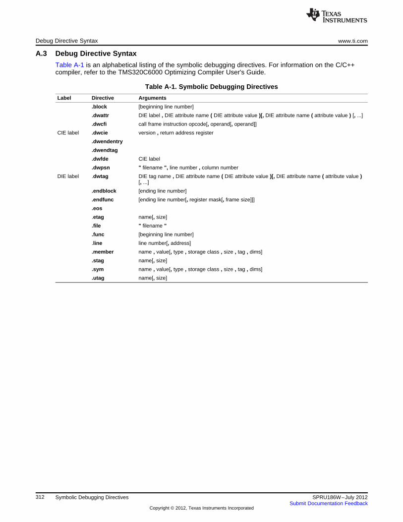
Debug Directive Syntax www.ti.com
A.3 Debug Directive Syntax
Table A-1 is an alphabetical listing of the symbolic debugging directives. For information on the C/C++compiler, refer to the TMS320C6000 Optimizing Compiler User's Guide.
Table A-1. Symbolic Debugging Directives
Label Directive Arguments
.block [beginning line number]
.dwattr DIE label , DIE attribute name ( DIE attribute value )[, DIE attribute name ( attribute value ) [, ...]
.dwcfi call frame instruction opcode[, operand[, operand]]
CIE label .dwcie version , return address register
.dwendentry
.dwendtag
.dwfde CIE label
.dwpsn " filename ", line number , column number
DIE label .dwtag DIE tag name , DIE attribute name ( DIE attribute value )[, DIE attribute name ( attribute value )[, ...]
.endblock [ending line number]
.endfunc [ending line number[, register mask[, frame size]]]
.eos
.etag name[, size]
.file " filename "
.func [beginning line number]
.line line number[, address]
.member name , value[, type , storage class , size , tag , dims]
.stag name[, size]
.sym name , value[, type , storage class , size , tag , dims]
.utag name[, size]
312 Symbolic Debugging Directives SPRU186W–July 2012Submit Documentation Feedback
Copyright © 2012, Texas Instruments Incorporated
Appendix BSPRU186W–July 2012
XML Link Information File Description
The TMS320C6000 linker supports the generation of an XML link information file via the --xml_link_infofile option. This option causes the linker to generate a well-formed XML file containing detailed informationabout the result of a link. The information included in this file includes all of the information that is currentlyproduced in a linker-generated map file.
As the linker evolves, the XML link information file may be extended to include additional information thatcould be useful for static analysis of linker results.
This appendix enumerates all of the elements that are generated by the linker into the XML linkinformation file.
Topic ........................................................................................................................... Page
B.1 XML Information File Element Types .................................................................. 314B.2 Document Elements ......................................................................................... 314
313SPRU186W–July 2012 XML Link Information File DescriptionSubmit Documentation Feedback
Copyright © 2012, Texas Instruments Incorporated
XML Information File Element Types www.ti.com
B.1 XML Information File Element Types
These element types will be generated by the linker:
• Container elements represent an object that contains other elements that describe the object.Container elements have an id attribute that makes them accessible from other elements.
• String elements contain a string representation of their value.
• Constant elements contain a 32-bit unsigned long representation of their value (with a 0x prefix).
• Reference elements are empty elements that contain an idref attribute that specifies a link to anothercontainer element.
In Section B.2, the element type is specified for each element in parentheses following the elementdescription. For instance, the <link_time> element lists the time of the link execution (string).
B.2 Document Elements
The root element, or the document element, is <link_info>. All other elements contained in the XML linkinformation file are children of the <link_info> element. The following sections describe the elements thatan XML information file can contain.
B.2.1 Header Elements
The first elements in the XML link information file provide general information about the linker and the linksession:
• The <banner> element lists the name of the executable and the version information (string).
• The <copyright> element lists the TI copyright information (string).
• The <link_time> is a timestamp representation of the link time (unsigned 32-bit int).
• The <output_file> element lists the name of the linked output file generated (string).
• The <entry_point> element specifies the program entry point, as determined by the linker (container)with two entries:
– The <name> is the entry point symbol name, if any (string).
– The <address> is the entry point address (constant).
Example B-1. Header Element for the hi.out Output File
<banner>TMS320Cxx Linker Version x.xx (Jan 6 2008)</banner><copyright>Copyright (c) 1996-2008 Texas Instruments Incorporated</copyright><link_time>0x43dfd8a4</link_time><output_file>hi.out</output_file><entry_point>
<name>_c_int00</name><address>0xaf80</address>
</entry_point>
314 XML Link Information File Description SPRU186W–July 2012Submit Documentation Feedback
Copyright © 2012, Texas Instruments Incorporated
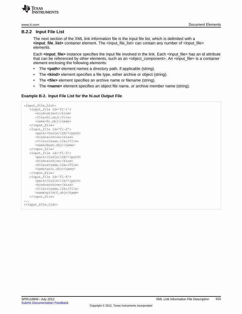
www.ti.com Document Elements
B.2.2 Input File List
The next section of the XML link information file is the input file list, which is delimited with a<input_file_list> container element. The <input_file_list> can contain any number of <input_file>elements.
Each <input_file> instance specifies the input file involved in the link. Each <input_file> has an id attributethat can be referenced by other elements, such as an <object_component>. An <input_file> is a containerelement enclosing the following elements:
• The <path> element names a directory path, if applicable (string).
• The <kind> element specifies a file type, either archive or object (string).
• The <file> element specifies an archive name or filename (string).
• The <name> element specifies an object file name, or archive member name (string).
Example B-2. Input File List for the hi.out Output File
<input_file_list><input_file id="fl-1">
<kind>object</kind><file>hi.obj</file><name>hi.obj</name>
</input_file><input_file id="fl-2">
<path>/tools/lib/</path><kind>archive</kind><file>rtsxxx.lib</file><name>boot.obj</name>
</input_file><input_file id="fl-3">
<path>/tools/lib/</path><kind>archive</kind><file>rtsxxx.lib</file><name>exit.obj</name>
</input_file><input_file id="fl-4">
<path>/tools/lib/</path><kind>archive</kind><file>rtsxxx.lib</file><name>printf.obj</name>
</input_file>...</input_file_list>
315SPRU186W–July 2012 XML Link Information File DescriptionSubmit Documentation Feedback
Copyright © 2012, Texas Instruments Incorporated
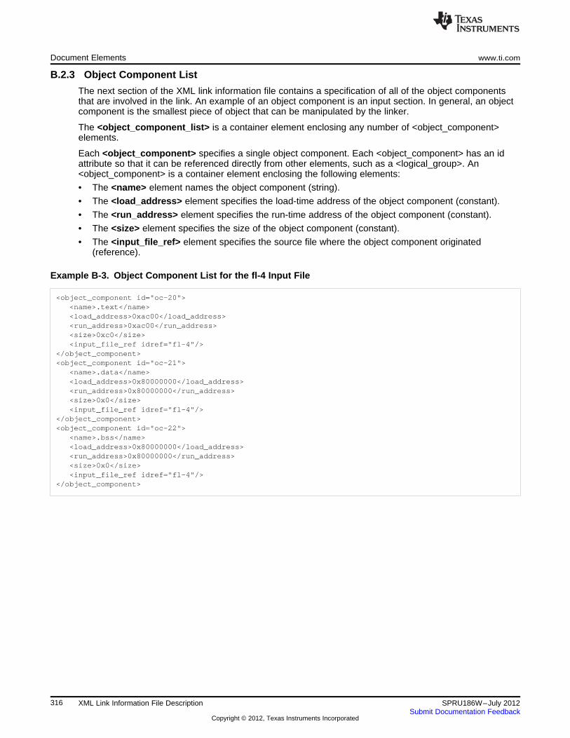
Document Elements www.ti.com
B.2.3 Object Component List
The next section of the XML link information file contains a specification of all of the object componentsthat are involved in the link. An example of an object component is an input section. In general, an objectcomponent is the smallest piece of object that can be manipulated by the linker.
The <object_component_list> is a container element enclosing any number of <object_component>elements.
Each <object_component> specifies a single object component. Each <object_component> has an idattribute so that it can be referenced directly from other elements, such as a <logical_group>. An<object_component> is a container element enclosing the following elements:
• The <name> element names the object component (string).
• The <load_address> element specifies the load-time address of the object component (constant).
• The <run_address> element specifies the run-time address of the object component (constant).
• The <size> element specifies the size of the object component (constant).
• The <input_file_ref> element specifies the source file where the object component originated(reference).
Example B-3. Object Component List for the fl-4 Input File
<object_component id="oc-20"><name>.text</name><load_address>0xac00</load_address><run_address>0xac00</run_address><size>0xc0</size><input_file_ref idref="fl-4"/>
</object_component><object_component id="oc-21">
<name>.data</name><load_address>0x80000000</load_address><run_address>0x80000000</run_address><size>0x0</size><input_file_ref idref="fl-4"/>
</object_component><object_component id="oc-22">
<name>.bss</name><load_address>0x80000000</load_address><run_address>0x80000000</run_address><size>0x0</size><input_file_ref idref="fl-4"/>
</object_component>
316 XML Link Information File Description SPRU186W–July 2012Submit Documentation Feedback
Copyright © 2012, Texas Instruments Incorporated
www.ti.com Document Elements
B.2.4 Logical Group List
The <logical_group_list> section of the XML link information file is similar to the output section listing in alinker-generated map file. However, the XML link information file contains a specification of GROUP andUNION output sections, which are not represented in a map file. There are three kinds of list items thatcan occur in a <logical_group_list>:
• The <logical_group> is the specification of a section or GROUP that contains a list of objectcomponents or logical group members. Each <logical_group> element is given an id so that it may bereferenced from other elements. Each <logical_group> is a container element enclosing the followingelements:
– The <name> element names the logical group (string).
– The <load_address> element specifies the load-time address of the logical group (constant).
– The <run_address> element specifies the run-time address of the logical group (constant).
– The <size> element specifies the size of the logical group (constant).
– The <contents> element lists elements contained in this logical group (container). These elementsrefer to each of the member objects contained in this logical group:
• The <object_component_ref> is an object component that is contained in this logical group(reference).
• The <logical_group_ref> is a logical group that is contained in this logical group (reference).
• The <overlay> is a special kind of logical group that represents a UNION, or a set of objects thatshare the same memory space (container). Each <overlay> element is given an id so that it may bereferenced from other elements (like from an <allocated_space> element in the placement map). Each<overlay> contains the following elements:
– The <name> element names the overlay (string).
– The <run_address> element specifies the run-time address of overlay (constant).
– The <size> element specifies the size of logical group (constant).
– The <contents> container element lists elements contained in this overlay. These elements refer toeach of the member objects contained in this logical group:
• The <object_component_ref> is an object component that is contained in this logical group(reference).
• The <logical_group_ref> is a logical group that is contained in this logical group (reference).
• The <split_section> is another special kind of logical group that represents a collection of logicalgroups that is split among multiple memory areas. Each <split_section> element is given an id so thatit may be referenced from other elements. The id consists of the following elements.
– The <name> element names the split section (string).
– The <contents> container element lists elements contained in this split section. The<logical_group_ref> elements refer to each of the member objects contained in this split section,and each element referenced is a logical group that is contained in this split section (reference).
317SPRU186W–July 2012 XML Link Information File DescriptionSubmit Documentation Feedback
Copyright © 2012, Texas Instruments Incorporated
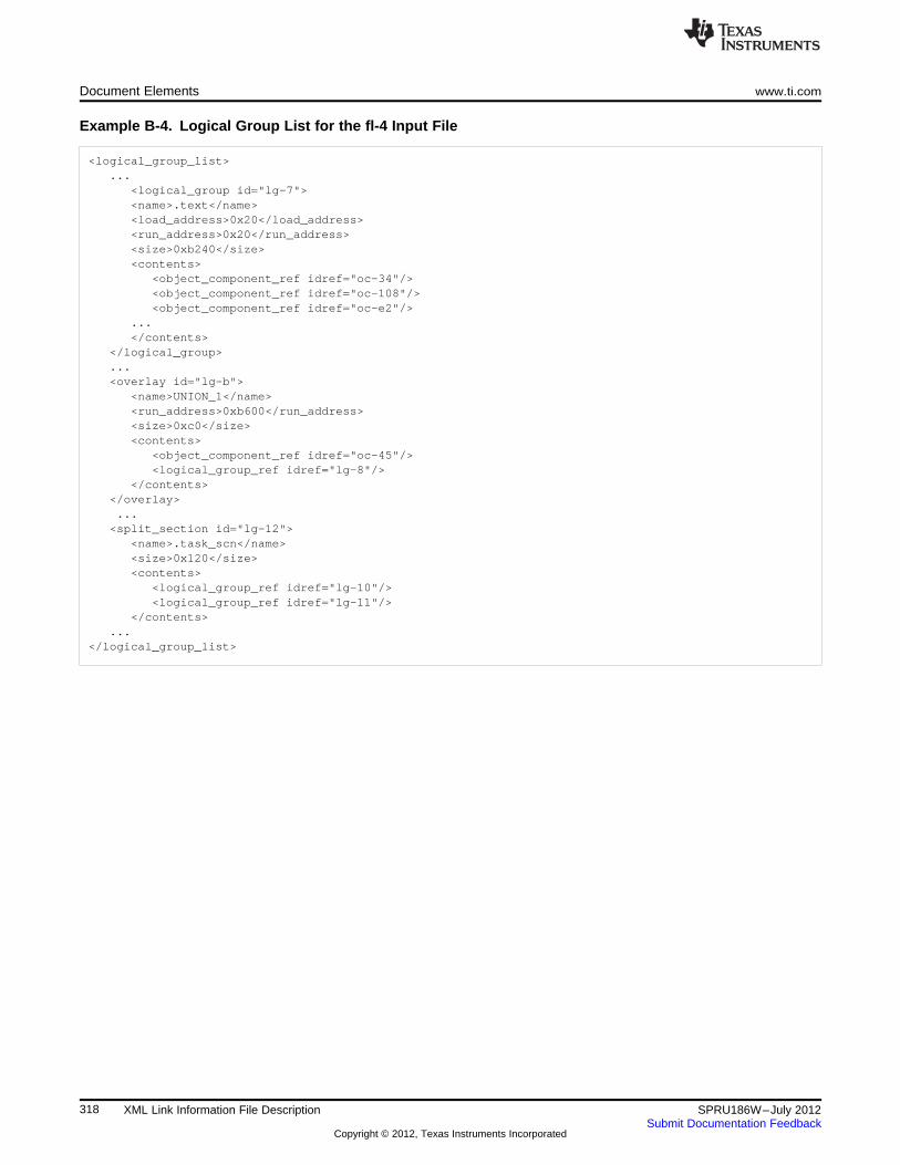
Document Elements www.ti.com
Example B-4. Logical Group List for the fl-4 Input File
<logical_group_list>...
<logical_group id="lg-7"><name>.text</name><load_address>0x20</load_address><run_address>0x20</run_address><size>0xb240</size><contents>
<object_component_ref idref="oc-34"/><object_component_ref idref="oc-108"/><object_component_ref idref="oc-e2"/>
...</contents>
</logical_group>...<overlay id="lg-b">
<name>UNION_1</name><run_address>0xb600</run_address><size>0xc0</size><contents>
<object_component_ref idref="oc-45"/><logical_group_ref idref="lg-8"/>
</contents></overlay>...<split_section id="lg-12">
<name>.task_scn</name><size>0x120</size><contents>
<logical_group_ref idref="lg-10"/><logical_group_ref idref="lg-11"/>
</contents>...
</logical_group_list>
318 XML Link Information File Description SPRU186W–July 2012Submit Documentation Feedback
Copyright © 2012, Texas Instruments Incorporated
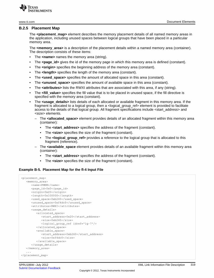
www.ti.com Document Elements
B.2.5 Placement Map
The <placement_map> element describes the memory placement details of all named memory areas inthe application, including unused spaces between logical groups that have been placed in a particularmemory area.
The <memory_area> is a description of the placement details within a named memory area (container).The description consists of these items:
• The <name> names the memory area (string).
• The <page_id> gives the id of the memory page in which this memory area is defined (constant).
• The <origin> specifies the beginning address of the memory area (constant).
• The <length> specifies the length of the memory area (constant).
• The <used_space> specifies the amount of allocated space in this area (constant).
• The <unused_space> specifies the amount of available space in this area (constant).
• The <attributes> lists the RWXI attributes that are associated with this area, if any (string).
• The <fill_value> specifies the fill value that is to be placed in unused space, if the fill directive isspecified with the memory area (constant).
• The <usage_details> lists details of each allocated or available fragment in this memory area. If thefragment is allocated to a logical group, then a <logical_group_ref> element is provided to facilitateaccess to the details of that logical group. All fragment specifications include <start_address> and<size> elements.
– The <allocated_space> element provides details of an allocated fragment within this memory area(container):
• The <start_address> specifies the address of the fragment (constant).
• The <size> specifies the size of the fragment (constant).
• The <logical_group_ref> provides a reference to the logical group that is allocated to thisfragment (reference).
– The <available_space element provides details of an available fragment within this memory area(container):
• The <start_address> specifies the address of the fragment (constant).
• The <size> specifies the size of the fragment (constant).
Example B-5. Placement Map for the fl-4 Input File
<placement_map><memory_area>
<name>PMEM</name><page_id>0x0</page_id><origin>0x20</origin><length>0x100000</length><used_space>0xb240</used_space><unused_space>0xf4dc0</unused_space><attributes>RWXI</attributes><usage_details>
<allocated_space><start_address>0x20</start_address><size>0xb240</size><logical_group_ref idref="lg-7"/>
</allocated_space><available_space>
<start_address>0xb260</start_address><size>0xf4dc0</size>
</available_space></usage_details>
</memory_area>...
</placement_map>
319SPRU186W–July 2012 XML Link Information File DescriptionSubmit Documentation Feedback
Copyright © 2012, Texas Instruments Incorporated
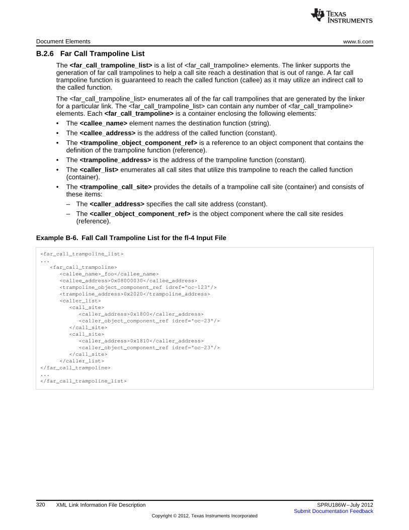
Document Elements www.ti.com
B.2.6 Far Call Trampoline List
The <far_call_trampoline_list> is a list of <far_call_trampoline> elements. The linker supports thegeneration of far call trampolines to help a call site reach a destination that is out of range. A far calltrampoline function is guaranteed to reach the called function (callee) as it may utilize an indirect call tothe called function.
The <far_call_trampoline_list> enumerates all of the far call trampolines that are generated by the linkerfor a particular link. The <far_call_trampoline_list> can contain any number of <far_call_trampoline>elements. Each <far_call_trampoline> is a container enclosing the following elements:
• The <callee_name> element names the destination function (string).
• The <callee_address> is the address of the called function (constant).
• The <trampoline_object_component_ref> is a reference to an object component that contains thedefinition of the trampoline function (reference).
• The <trampoline_address> is the address of the trampoline function (constant).
• The <caller_list> enumerates all call sites that utilize this trampoline to reach the called function(container).
• The <trampoline_call_site> provides the details of a trampoline call site (container) and consists ofthese items:
– The <caller_address> specifies the call site address (constant).
– The <caller_object_component_ref> is the object component where the call site resides(reference).
Example B-6. Fall Call Trampoline List for the fl-4 Input File
<far_call_trampoline_list>...
<far_call_trampoline><callee_name>_foo</callee_name><callee_address>0x08000030</callee_address><trampoline_object_component_ref idref="oc-123"/><trampoline_address>0x2020</trampoline_address><caller_list>
<call_site><caller_address>0x1800</caller_address><caller_object_component_ref idref="oc-23"/>
</call_site><call_site>
<caller_address>0x1810</caller_address><caller_object_component_ref idref="oc-23"/>
</call_site></caller_list>
</far_call_trampoline>...</far_call_trampoline_list>
320 XML Link Information File Description SPRU186W–July 2012Submit Documentation Feedback
Copyright © 2012, Texas Instruments Incorporated
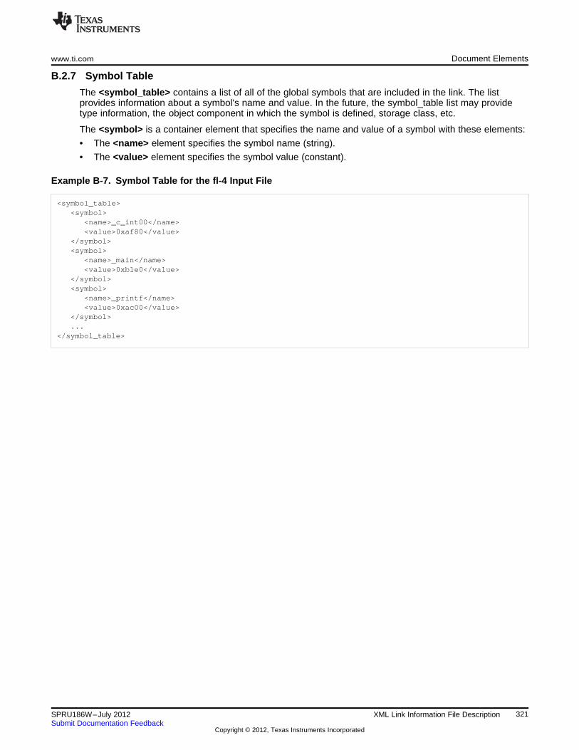
www.ti.com Document Elements
B.2.7 Symbol Table
The <symbol_table> contains a list of all of the global symbols that are included in the link. The listprovides information about a symbol's name and value. In the future, the symbol_table list may providetype information, the object component in which the symbol is defined, storage class, etc.
The <symbol> is a container element that specifies the name and value of a symbol with these elements:
• The <name> element specifies the symbol name (string).
• The <value> element specifies the symbol value (constant).
Example B-7. Symbol Table for the fl-4 Input File
<symbol_table><symbol>
<name>_c_int00</name><value>0xaf80</value>
</symbol><symbol>
<name>_main</name><value>0xb1e0</value>
</symbol><symbol>
<name>_printf</name><value>0xac00</value>
</symbol>...
</symbol_table>
321SPRU186W–July 2012 XML Link Information File DescriptionSubmit Documentation Feedback
Copyright © 2012, Texas Instruments Incorporated
Appendix CSPRU186W–July 2012
Glossary
ABI— Application binary interface.
absolute address— An address that is permanently assigned to a TMS320C6000 memory location.
absolute lister— A debugging tool that allows you to create assembler listings that contain absoluteaddresses.
alignment— A process in which the linker places an output section at an address that falls on an n-byteboundary, where n is a power of 2. You can specify alignment with the SECTIONS linker directive.
allocation— A process in which the linker calculates the final memory addresses of output sections.
ANSI— American National Standards Institute; an organization that establishes standards voluntarilyfollowed by industries.
archive library— A collection of individual files grouped into a single file by the archiver.
archiver— A software program that collects several individual files into a single file called an archivelibrary. With the archiver, you can add, delete, extract, or replace members of the archive library.
ASCII— American Standard Code for Information Interchange; a standard computer code forrepresenting and exchanging alphanumeric information.
assembler— A software program that creates a machine-language program from a source file thatcontains assembly language instructions, directives, and macro definitions. The assemblersubstitutes absolute operation codes for symbolic operation codes and absolute or relocatableaddresses for symbolic addresses.
assembly-time constant— A symbol that is assigned a constant value with the .set directive.
big endian— An addressing protocol in which bytes are numbered from left to right within a word. Moresignificant bytes in a word have lower numbered addresses. Endian ordering is hardware-specificand is determined at reset. See also little endian
binding— A process in which you specify a distinct address for an output section or a symbol.
block— A set of statements that are grouped together within braces and treated as an entity.
.bss section— One of the default object file sections. You use the assembler .bss directive to reserve aspecified amount of space in the memory map that you can use later for storing data. The .bsssection is uninitialized.
byte— Per ANSI/ISO C, the smallest addressable unit that can hold a character.
C/C++ compiler— A software program that translates C source statements into assembly languagesource statements.
COFF— Common object file format; a system of object files configured according to a standarddeveloped by AT&T. These files are relocatable in memory space.
command file— A file that contains options, filenames, directives, or commands for the linker or hexconversion utility.
322 Glossary SPRU186W–July 2012Submit Documentation Feedback
Copyright © 2012, Texas Instruments Incorporated
www.ti.com Appendix C
comment— A source statement (or portion of a source statement) that documents or improvesreadability of a source file. Comments are not compiled, assembled, or linked; they have no effecton the object file.
compiler program— A utility that lets you compile, assemble, and optionally link in one step. Thecompiler runs one or more source modules through the compiler (including the parser, optimizer,and code generator), the assembler, and the linker.
conditional processing— A method of processing one block of source code or an alternate block ofsource code, according to the evaluation of a specified expression.
configured memory— Memory that the linker has specified for allocation.
constant— A type whose value cannot change.
cross-reference lister— A utility that produces an output file that lists the symbols that were defined,what file they were defined in, what reference type they are, what line they were defined on, whichlines referenced them, and their assembler and linker final values. The cross-reference lister useslinked object files as input.
cross-reference listing— An output file created by the assembler that lists the symbols that weredefined, what line they were defined on, which lines referenced them, and their final values.
.data section— One of the default object file sections. The .data section is an initialized section thatcontains initialized data. You can use the .data directive to assemble code into the .data section.
directives— Special-purpose commands that control the actions and functions of a software tool (asopposed to assembly language instructions, which control the actions of a device).
ELF— Executable and linking format; a system of object files configured according to the System VApplication Binary Interface specification.
emulator— A hardware development system that duplicates the TMS320C6000 operation.
entry point— A point in target memory where execution starts.
environment variable— A system symbol that you define and assign to a string. Environmental variablesare often included in Windows batch files or UNIX shell scripts such as .cshrc or .profile.
epilog— The portion of code in a function that restores the stack and returns. See also pipelined-loopepilog.
executable module— A linked object file that can be executed in a target system.
expression— A constant, a symbol, or a series of constants and symbols separated by arithmeticoperators.
external symbol— A symbol that is used in the current program module but defined or declared in adifferent program module.
field— For the TMS320C6000, a software-configurable data type whose length can be programmed tobe any value in the range of 1-32 bits.
global symbol— A symbol that is either defined in the current module and accessed in another, oraccessed in the current module but defined in another.
GROUP— An option of the SECTIONS directive that forces specified output sections to be allocatedcontiguously (as a group).
hex conversion utility— A utility that converts object files into one of several standard ASCIIhexadecimal formats, suitable for loading into an EPROM programmer.
high-level language debugging— The ability of a compiler to retain symbolic and high-level languageinformation (such as type and function definitions) so that a debugging tool can use thisinformation.
323SPRU186W–July 2012 GlossarySubmit Documentation Feedback
Copyright © 2012, Texas Instruments Incorporated
Appendix C www.ti.com
hole— An area between the input sections that compose an output section that contains no code.
incremental linking— Linking files in several passes. Incremental linking is useful for large applications,because you can partition the application, link the parts separately, and then link all of the partstogether.
initialization at load time— An autoinitialization method used by the linker when linking C/C++ code. Thelinker uses this method when you invoke it with the --ram_model link option. This method initializesvariables at load time instead of run time.
initialized section— A section from an object file that will be linked into an executable module.
input section— A section from an object file that will be linked into an executable module.
ISO— International Organization for Standardization; a worldwide federation of national standardsbodies, which establishes international standards voluntarily followed by industries.
label— A symbol that begins in column 1 of an assembler source statement and corresponds to theaddress of that statement. A label is the only assembler statement that can begin in column 1.
linker— A software program that combines object files to form an object module that can be allocatedinto system memory and executed by the device.
listing file— An output file, created by the assembler, that lists source statements, their line numbers,and their effects on the section program counter (SPC).
little endian— An addressing protocol in which bytes are numbered from right to left within a word. Moresignificant bytes in a word have higher numbered addresses. Endian ordering is hardware-specificand is determined at reset. See also big endian
loader— A device that places an executable module into system memory.
macro— A user-defined routine that can be used as an instruction.
macro call— The process of invoking a macro.
macro definition— A block of source statements that define the name and the code that make up amacro.
macro expansion— The process of inserting source statements into your code in place of a macro call.
macro library— An archive library composed of macros. Each file in the library must contain one macro;its name must be the same as the macro name it defines, and it must have an extension of .asm.
map file— An output file, created by the linker, that shows the memory configuration, sectioncomposition, section allocation, symbol definitions and the addresses at which the symbols weredefined for your program.
member— The elements or variables of a structure, union, archive, or enumeration.
memory map— A map of target system memory space that is partitioned into functional blocks.
mnemonic— An instruction name that the assembler translates into machine code.
model statement— Instructions or assembler directives in a macro definition that are assembled eachtime a macro is invoked.
named section— An initialized section that is defined with a .sect directive.
object file— An assembled or linked file that contains machine-language object code.
object library— An archive library made up of individual object files.
object module— A linked, executable object file that can be downloaded and executed on a targetsystem.
324 Glossary SPRU186W–July 2012Submit Documentation Feedback
Copyright © 2012, Texas Instruments Incorporated
www.ti.com Appendix C
operand— An argument of an assembly language instruction, assembler directive, or macro directivethat supplies information to the operation performed by the instruction or directive.
optimizer— A software tool that improves the execution speed and reduces the size of C programs. Seealso assembly optimizer.
options— Command-line parameters that allow you to request additional or specific functions when youinvoke a software tool.
output module— A linked, executable object file that is downloaded and executed on a target system.
output section— A final, allocated section in a linked, executable module.
partial linking— Linking files in several passes. Incremental linking is useful for large applicationsbecause you can partition the application, link the parts separately, and then link all of the partstogether.
quiet run— An option that suppresses the normal banner and the progress information.
raw data— Executable code or initialized data in an output section.
relocation— A process in which the linker adjusts all the references to a symbol when the symbol'saddress changes.
ROM width— The width (in bits) of each output file, or, more specifically, the width of a single data valuein the hex conversion utility file. The ROM width determines how the utility partitions the data intooutput files. After the target words are mapped to memory words, the memory words are brokeninto one or more output files. The number of output files is determined by the ROM width.
run address— The address where a section runs.
run-time-support library— A library file, rts.src, that contains the source for the run time-supportfunctions.
section— A relocatable block of code or data that ultimately will be contiguous with other sections in thememory map.
section program counter (SPC)— An element that keeps track of the current location within a section;each section has its own SPC.
sign extend— A process that fills the unused MSBs of a value with the value's sign bit.
simulator— A software development system that simulates TMS320C6000 operation.
source file— A file that contains C/C++ code or assembly language code that is compiled or assembledto form an object file.
static variable— A variable whose scope is confined to a function or a program. The values of staticvariables are not discarded when the function or program is exited; their previous value is resumedwhen the function or program is reentered.
storage class— An entry in the symbol table that indicates how to access a symbol.
string table— A table that stores symbol names that are longer than eight characters (symbol names ofeight characters or longer cannot be stored in the symbol table; instead they are stored in the stringtable). The name portion of the symbol's entry points to the location of the string in the string table.
structure— A collection of one or more variables grouped together under a single name.
subsection— A relocatable block of code or data that ultimately will occupy continuous space in thememory map. Subsections are smaller sections within larger sections. Subsections give you tightercontrol of the memory map.
symbol— A string of alphanumeric characters that represents an address or a value.
325SPRU186W–July 2012 GlossarySubmit Documentation Feedback
Copyright © 2012, Texas Instruments Incorporated
Appendix C www.ti.com
symbolic debugging— The ability of a software tool to retain symbolic information that can be used by adebugging tool such as a simulator or an emulator.
tag— An optional type name that can be assigned to a structure, union, or enumeration.
target memory— Physical memory in a system into which executable object code is loaded.
.text section— One of the default object file sections. The .text section is initialized and containsexecutable code. You can use the .text directive to assemble code into the .text section.
unconfigured memory— Memory that is not defined as part of the memory map and cannot be loadedwith code or data.
uninitialized section— A object file section that reserves space in the memory map but that has noactual contents. These sections are built with the .bss and .usect directives.
UNION— An option of the SECTIONS directive that causes the linker to allocate the same address tomultiple sections.
union— A variable that can hold objects of different types and sizes.
unsigned value— A value that is treated as a nonnegative number, regardless of its actual sign.
variable— A symbol representing a quantity that can assume any of a set of values.
well-defined expression— A term or group of terms that contains only symbols or assembly-timeconstants that have been defined before they appear in the expression.
word— A 32-bit addressable location in target memory
326 Glossary SPRU186W–July 2012Submit Documentation Feedback
Copyright © 2012, Texas Instruments Incorporated
IMPORTANT NOTICE
Texas Instruments Incorporated and its subsidiaries (TI) reserve the right to make corrections, enhancements, improvements and otherchanges to its semiconductor products and services per JESD46C and to discontinue any product or service per JESD48B. Buyers shouldobtain the latest relevant information before placing orders and should verify that such information is current and complete. Allsemiconductor products (also referred to herein as “components”) are sold subject to TI’s terms and conditions of sale supplied at the timeof order acknowledgment.
TI warrants performance of its components to the specifications applicable at the time of sale, in accordance with the warranty in TI’s termsand conditions of sale of semiconductor products. Testing and other quality control techniques are used to the extent TI deems necessaryto support this warranty. Except where mandated by applicable law, testing of all parameters of each component is not necessarilyperformed.
TI assumes no liability for applications assistance or the design of Buyers’ products. Buyers are responsible for their products andapplications using TI components. To minimize the risks associated with Buyers’ products and applications, Buyers should provideadequate design and operating safeguards.
TI does not warrant or represent that any license, either express or implied, is granted under any patent right, copyright, mask work right, orother intellectual property right relating to any combination, machine, or process in which TI components or services are used. Informationpublished by TI regarding third-party products or services does not constitute a license to use such products or services or a warranty orendorsement thereof. Use of such information may require a license from a third party under the patents or other intellectual property of thethird party, or a license from TI under the patents or other intellectual property of TI.
Reproduction of significant portions of TI information in TI data books or data sheets is permissible only if reproduction is without alterationand is accompanied by all associated warranties, conditions, limitations, and notices. TI is not responsible or liable for such altereddocumentation. Information of third parties may be subject to additional restrictions.
Resale of TI components or services with statements different from or beyond the parameters stated by TI for that component or servicevoids all express and any implied warranties for the associated TI component or service and is an unfair and deceptive business practice.TI is not responsible or liable for any such statements.
Buyer acknowledges and agrees that it is solely responsible for compliance with all legal, regulatory and safety-related requirementsconcerning its products, and any use of TI components in its applications, notwithstanding any applications-related information or supportthat may be provided by TI. Buyer represents and agrees that it has all the necessary expertise to create and implement safeguards whichanticipate dangerous consequences of failures, monitor failures and their consequences, lessen the likelihood of failures that might causeharm and take appropriate remedial actions. Buyer will fully indemnify TI and its representatives against any damages arising out of the useof any TI components in safety-critical applications.
In some cases, TI components may be promoted specifically to facilitate safety-related applications. With such components, TI’s goal is tohelp enable customers to design and create their own end-product solutions that meet applicable functional safety standards andrequirements. Nonetheless, such components are subject to these terms.
No TI components are authorized for use in FDA Class III (or similar life-critical medical equipment) unless authorized officers of the partieshave executed a special agreement specifically governing such use.
Only those TI components which TI has specifically designated as military grade or “enhanced plastic” are designed and intended for use inmilitary/aerospace applications or environments. Buyer acknowledges and agrees that any military or aerospace use of TI componentswhich have not been so designated is solely at the Buyer's risk, and that Buyer is solely responsible for compliance with all legal andregulatory requirements in connection with such use.
TI has specifically designated certain components which meet ISO/TS16949 requirements, mainly for automotive use. Components whichhave not been so designated are neither designed nor intended for automotive use; and TI will not be responsible for any failure of suchcomponents to meet such requirements.
Products Applications
Audio www.ti.com/audio Automotive and Transportation www.ti.com/automotive
Amplifiers amplifier.ti.com Communications and Telecom www.ti.com/communications
Data Converters dataconverter.ti.com Computers and Peripherals www.ti.com/computers
DLP® Products www.dlp.com Consumer Electronics www.ti.com/consumer-apps
DSP dsp.ti.com Energy and Lighting www.ti.com/energy
Clocks and Timers www.ti.com/clocks Industrial www.ti.com/industrial
Interface interface.ti.com Medical www.ti.com/medical
Logic logic.ti.com Security www.ti.com/security
Power Mgmt power.ti.com Space, Avionics and Defense www.ti.com/space-avionics-defense
Microcontrollers microcontroller.ti.com Video and Imaging www.ti.com/video
RFID www.ti-rfid.com
OMAP Mobile Processors www.ti.com/omap TI E2E Community e2e.ti.com
Wireless Connectivity www.ti.com/wirelessconnectivity
Mailing Address: Texas Instruments, Post Office Box 655303, Dallas, Texas 75265Copyright © 2012, Texas Instruments Incorporated
Related Documents