TMM140045ACXXXA Ÿ High density, high brightness chip array for use in Class 2 Circular applications Ÿ Constant current for maximum efficacy Ÿ Available in standard CCT's Ÿ Dimmable when used with a dimmable driver Ÿ Integral thermal feedback protection to safeguard against overheating Ÿ Suitable for DLC and Energy Star compliant luminaires Ÿ 80 CRI standard and 90 CRI available E351548 5000 lumens at 4000K / 80 CRI* 1400 mA 45W 32V ± 4V DC 120° 80, 90 -35 to +40°C / -31 to +104ºF +85°C >50,000 hours at max Tc Binning per ANSI C78.377-2008; 7 SDCM 3" diameter x 0.17" H MCPCB / 32g 35 inch - ounces cURus (File # E351548) Class 2 Lighting System RoHS Compliant; CE 5 years with suitable Fulham LED Drivers and thermal feedback utilization Nominal DC Power Consumption @ Max Current Max Lumen Output @ Max Current Max Current Input Nominal Operating Voltage @ Max Current Beam Angle CRI Operating Ambient Temperature Range (Ta) Maximum Module Case Temperature (Tc) Estimated Lumen Maintenance (L70) Color Consistency Overall Size Material / Weight Maximum Screw Installation Torque Safety/Compliance Warranty General Ratings Constant Current LED Round Module Page 1 of 6 2015-542 Rev C * At Tc mod = 25ºC ** If external dimming is required, a passive 0-10V dimmer must be used. See more on Thermal Feedback Protection use on Page 3 Yes; 0-10V Dimmable Driver Required** Thermal Feedback Protection

Welcome message from author
This document is posted to help you gain knowledge. Please leave a comment to let me know what you think about it! Share it to your friends and learn new things together.
Transcript
TMM140045ACXXXA
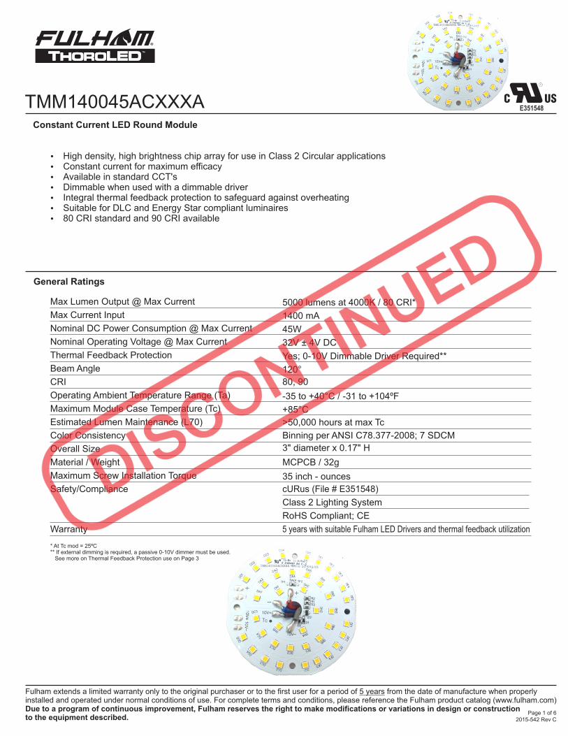
Ÿ High density, high brightness chip array for use in Class 2 Circular applicationsŸ Constant current for maximum efficacyŸ Available in standard CCT'sŸ Dimmable when used with a dimmable driverŸ Integral thermal feedback protection to safeguard against overheatingŸ Suitable for DLC and Energy Star compliant luminairesŸ 80 CRI standard and 90 CRI available
E351548
5000 lumens at 4000K / 80 CRI*
1400 mA
45W
32V ± 4V DC
120°
80, 90
-35 to +40°C / -31 to +104ºF
+85°C
>50,000 hours at max Tc
Binning per ANSI C78.377-2008; 7 SDCM
3" diameter x 0.17" H
MCPCB / 32g
35 inch - ounces
cURus (File # E351548)
Class 2 Lighting System
RoHS Compliant; CE
5 years with suitable Fulham LED Drivers and thermal feedback utilization
Nominal DC Power Consumption @ Max Current
Max Lumen Output @ Max Current
Max Current Input
Nominal Operating Voltage @ Max Current
Beam Angle
CRI
Operating Ambient Temperature Range (Ta)
Maximum Module Case Temperature (Tc)
Estimated Lumen Maintenance (L70)
Color Consistency
Overall Size
Material / Weight
Maximum Screw Installation Torque
Safety/Compliance
Warranty
General Ratings
Constant Current LED Round Module
Page 1 of 62015-542 Rev C
* At Tc mod = 25ºC** If external dimming is required, a passive 0-10V dimmer must be used. See more on Thermal Feedback Protection use on Page 3
Yes; 0-10V Dimmable Driver Required**Thermal Feedback Protection
TMM140045ACXXXA
Electrical and Optical Specifications
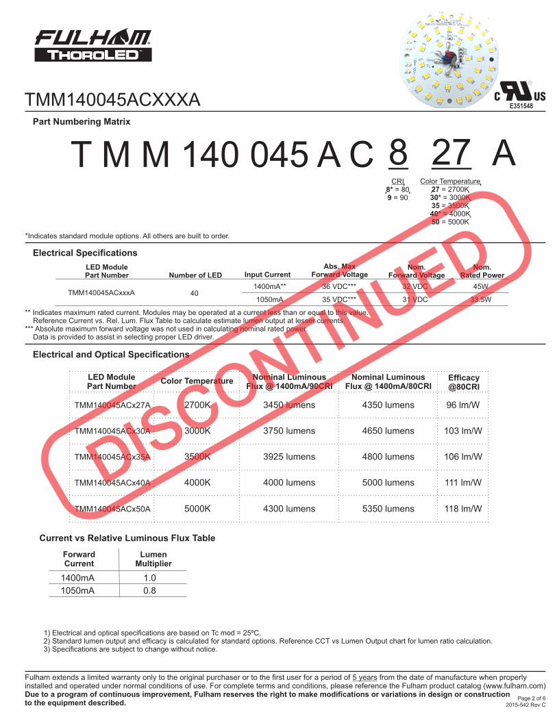
Part Numbering Matrix
T M M 140 045 A C 27Color Temperature
27 = 2700K30* = 3000K35 = 3500K40* = 4000K50 = 5000K
8CRI
8* = 809 = 90
Page 2 of 6
E351548
2015-542 Rev C
Electrical Specifications
LED Module Part Number
TMM140045ACx27A
TMM140045ACx30A
TMM140045ACx35A
TMM140045ACx40A
TMM140045ACx50A
Color Temperature
2700K
3000K
3500K
4000K
5000K
Nominal Luminous Flux @ 1400mA/90CRI
3450 lumens
3750 lumens
3925 lumens
4000 lumens
4300 lumens
Efficacy@80CRI
96 lm/W
103 lm/W
106 lm/W
111 lm/W
118 lm/W
Nominal Luminous Flux @ 1400mA/80CRI
4350 lumens
4650 lumens
4800 lumens
5000 lumens
5350 lumens
*Indicates standard module options. All others are built to order.
Input Current
1400mA** 36 VDC***
Abs. MaxForward Voltage
Nom.Rated Power
45W
LED Module Part Number
Number of LED
1050mA 35 VDC*** 33.5W40TMM140045ACxxxA
Current vs Relative Luminous Flux Table
LumenMultiplier
ForwardCurrent
1400mA
1050mA 0.8
1.0
A
** Indicates maximum rated current. Modules may be operated at a current less than or equal to this value. Reference Current vs. Rel. Lum. Flux Table to calculate estimate lumen output at lesser currents.*** Absolute maximum forward voltage was not used in calculating nominal rated power. Data is provided to assist in selecting proper LED driver.
1) Electrical and optical specifications are based on Tc mod = 25ºC.2) Standard lumen output and efficacy is calculated for standard options. Reference CCT vs Lumen Output chart for lumen ratio calculation.3) Specifications are subject to change without notice.
Nom.Forward Voltage
32 VDC
31 VDC
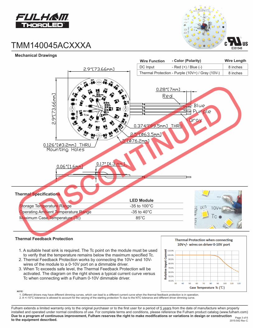
TMM140045ACXXXAMechanical Drawings
Thermal Specifications
Page 3 of 6
E351548
2015-542 Rev C
Maximum Case Temperature (Tc)
Storage Temperature Range
Operating Ambient Temperature Range
-35 to 100°C
-35 to 40°C
85°C
LED Module
Thermal Feedback Protection
1. A suitable heat sink is required. The Tc point on the module must be used to verify that the temperature remains below the maximum specified Tc.2. Thermal Feedback Protection works by connecting the 10V+ and 10V- wires of the module to a 0-10V port on a dimmable driver. 3. When Tc exceeds safe level, the Thermal Feedback Protection will be activated. The diagram on the right shows a typical current curve versus Tc when connecting with a Fulham 0-10V dimmable driver.
NOTE:
1. Different drivers may have different dimming curves, which can lead to a different current curve when the thermal feedback protection is in operation.2. A +/-10°C tolerance is allowed to account for the varying of the starting protection Tc due to the NTC tolerance and different driver dimming curve.
8 inches
Wire Function
DC Input - Red (+) / Blue (-)
Thermal Protection - Purple (10V+) / Gray (10V-) 8 inches
- Color (Polarity) Wire Length
TMM140045ACXXXA
If fastening by screw hole, use any screw with diameter less than 0.125 in (3.2mm). Use all available screw holes to ensure good contact between back side of module and mounting surface. Refer to max specified torque for installation. Suggested screw sizes: #5 or M3 Pan Head screw.
Fastening Notes
Modules are rated for dry locations, unless option for conformal coating is requested.
Conformal coating is acrylic based and rated for Environment and Moisture Protection per IPC-CC-830.
Environmental Rating
Fulham LED products should be handled with proper measures to protect against any potential ESD damage.
When servicing, personnel should be ground and direct contact with LED should be avoided.
Electrostatic Sensitive Product (ESD)
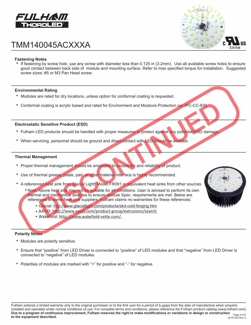
Proper thermal management should be employed to ensure life and reliability of product.
Use of thermal grease, paste, pad, or other material interface is highly recommended.
A referenced heat sink from Glacial Light: Model FR091 or equivalent heat sinks from other sources
Thermal Management
Modules are polarity sensitive.
Ensure that “positive” from LED Driver is connected to “positive” of LED modules and that “negative” from LED Driver is connected to “negative” of LED modules.
Polarities of modules are marked with “+” for positive and “-” for negative.
Polarity Notes
Page 4 of 6
•
•
•
•
•
•
•
•
•
•
E351548
2015-542 Rev C
•
Note: Above heat sink may not be suitable for all conditions. User is advised to perform its own thermal and mechanical analysis to ensure module Spec. requirements are met. Below are references to some heat sink suppliers. Fulham claims no warranties for these references:
Glacial: http://www.glaciallight.com/products/skd-cold-forging.htm
AAVID: http://www.aavid.com/product-group/extrusions/searchWakefield: http://www.wakefield-vette.com/.
•
• • •
0,48
0,46
0,44
0,42
0,38
0,36
0,34
0,32
0,30
0,40
0,400,280,30 0,32 0,34 0,36 0,38 0,42 0,44 0,46 0,48 0,50
7,040K
6,020K 5,310K 4,745K 4,260K 3,710K 3,220K 2,870K
2,580K
x
y Blackbody Locus
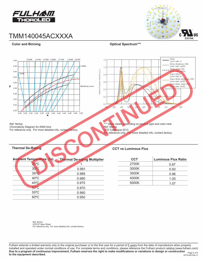
Ref. NichiaChromaticity Diagram for ANSI binsFor reference only. For more detailed info, contact factory.
*** Value varies depending on product type and color rankRef. NichiaLED Catalogue 2013For reference only. For more detailed info, contact factory.
Color and Binning Optical Spectrum***
TMM140045ACXXXA
Page 5 of 6
E351548
2015-542 Rev C
Thermal De-Rating
Ref. NichiaLED757 Spec SheetFor reference only. For more detailed info, contact factory.
1
0.991
0.989
0.980
0.975
0.970
0.960
0.950
Thermal De-rating MultiplierAmbient Temperature (Ta)
30ºC
25ºC
35ºC
40ºC
45ºC
50ºC
55ºC
60ºC
CCT vs Luminous Flux
CCT Luminous Flux Ratio
2700K 0.87
3000K 0.93
3500K 0.96
4000K 1.00
5000K 1.07
TMM140045ACXXXA
Fulham Part Number Driver Description # of Modules/Driver
T1M1UNV1400-60L
T1UNV1400-60L
1400 mA, 60W CC Driver, Universal Input, 0-10V dimmable
1400 mA, 60W CC Driver, Universal Input 1
1
Compatible Fulham LED Drivers
NOTE:
1. Subject to rated loading conditions.2. Modules are polarity sensitive. Ensure that “positive” from LED Driver is connected to “positive” of LED modules and that “negative” from LED Driver is connected to “negative” of LED modules. 3. List is subject to change without notice.4. Refer to below wiring diagram for more information
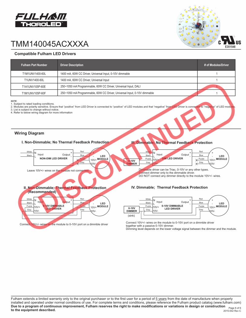
Wiring Diagram
Page 6 of 6
E351548
2015-542 Rev C
T1A1UNV105P-60E
T1M1UNV105P-60F
250~1050 mA Programmable, 60W CC Driver, Universal Input, DALI
250~1050 mA Programmable, 60W CC Driver, Universal Input, 0-10V dimmable
1
1
0-10V DIMMABLELED DRIVER
Output+
-Input
White
Black
Purple
Gray
Red
Blue
Gray
Purple
N
L10V+
10V-
LEDMODULE
+
-
10V+
10V-
NON-DIM LED DRIVER
Output+
-Input
White
Black
Red
Blue
Gray
Purple
N
L LEDMODULE
+
-
10V+
10V-
I. Non-Dimmable; No Thermal Feedback Protection
0-10V DIMMABLELED DRIVER
LEDMODULE
Output+
-Input
White
Black
Purple
Gray
Red
Blue+
-
10V+
10V-Gray
Purple
N
L10V+
10V-0-10V
DIMMER
II. Non-Dimmable; Thermal Feedback Protection (Recommended)
DIM LED DRIVER
Output+
-Input
White
Black
Red
Blue
Gray
Purple
N
L LEDMODULE
+
-
10V+
10V-
Purple
Gray
10V+
10V-0-10V
DIMMER
III. Dimmable; No Thermal Feedback Protection
IV. Dimmable; Thermal Feedback Protection
Dimmable driver can be Triac, 0-10V or any other types. Connect dimmer only to the dimmable driver. DO NOT connect any dimmer directly to the module 10V+/- wires.
Leave 10V+/- wires on the module not connected.
Connect 10V+/- wires on the module to 0-10V port on a dimmble driverConnect 10V+/- wires on the module to 0-10V port on a dimmble driver together with a passive 0-10V dimmer.Dimming level depends on the lower voltage signal between the dimmer and the module.
(sink)
Related Documents