TMK UP™ FIELD MANUAL FSM-001 REV. 5

Welcome message from author
This document is posted to help you gain knowledge. Please leave a comment to let me know what you think about it! Share it to your friends and learn new things together.
Transcript

T M K U P ™F I E L D M A N U A L
FSM-001 REV. 5

3INTRODUCTION
FIELD SERVICE SUPPORT
QUICK REFERENCE GUIDE
PRE-RUN CHECK LIST
GENERAL GUIDELINES
TMK UP™ RECOMMENDED FIELD PRACTICESTMK UP TORQ® SFW™
TMK UP TORQ® QXW™
TMK UP TORQ® DQW™
TMK UP ULTRA™ SF & SFI I
TMK UP ULTRA™ FJ
TMK UP ULTRA™ FX
TMK UP ULTRA™ QX
TMK UP ULTRA™ GX
TMK UP ULTRA™ DQX & DQX-HT
TMK UP ULTRA™ DQX-SR
TMK UP™ BPN
TMK UP™ BPN-SR
TMK UP™ 2S-6 & 2S-8
TABLEO F C O N T E N T S
4
5
7
9
28
29
35
42
49
57
63
69
75
81
89
97
105
113

INTRODUCTION
TMK IPSCO is an industry leader, combining state-of-the-art technology, top-notch talent, and powerful manufacturing capabilities to create and deliver a broad range of innovative tubular products.
As one of the largest North American producers of welded and seamless pipe and premium connections, TMK IPSCO is dedicated to serving the oil and gas industry and many industrial markets - that's why we have first-rate facilities strategically located in key energy producing areas.
Our legacy of quality, industry-renowned customer service, and focus on innovative products and services allow us to drive unparalleled value for our customers. With a clear corporate vision, a well-defined mission, and uncompromising values, TMK IPSCO is committed to being North America’s energy tubular supplier of choice.
As a part of OAO TMK, one of the world’s largest pipe producers, we now offer an expanded range of products to meet your energy tubular needs.
ihernandez
Typewritten Text
ihernandez
Typewritten Text
April 1, 2019
ihernandez
Typewritten Text
ihernandez
Typewritten Text
TMK UP™ Field Manual
ihernandez
Typewritten Text
3
FIELD SERVICE SUPPORT
Please contact our TMK IPSCO field service technical support group at 1-866-PIPE-123.
ihernandez
Typewritten Text
ihernandez
Typewritten Text
April 1, 2019
ihernandez
Typewritten Text
TMK UP™ Field Manual
ihernandez
Typewritten Text
4

Q U I C K
R E F E R E N C E G U I D E
April 1, 2019 TMK UP™ Field Manual 6
QUICK REFERENCE GUIDE
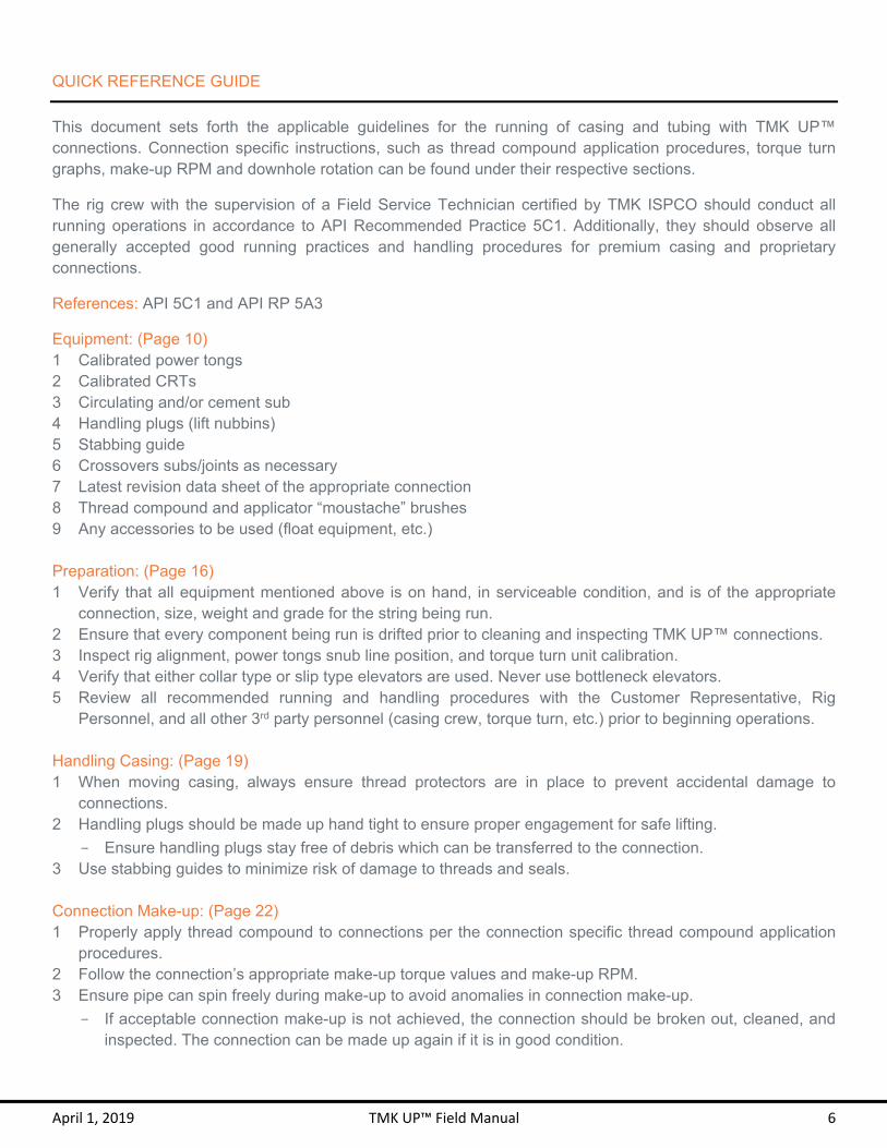
This document sets forth the applicable guidelines for the running of casing and tubing with TMK UP™ connections. Connection specific instructions, such as thread compound application procedures, torque turn graphs, make-up RPM and downhole rotation can be found under their respective sections.
The rig crew with the supervision of a Field Service Technician certified by TMK ISPCO should conduct all running operations in accordance to API Recommended Practice 5C1. Additionally, they should observe all generally accepted good running practices and handling procedures for premium casing and proprietary connections.
References: API 5C1 and API RP 5A3
Equipment: (Page 10) 1 Calibrated power tongs 2 Calibrated CRTs 3 Circulating and/or cement sub 4 Handling plugs (lift nubbins) 5 Stabbing guide 6 Crossovers subs/joints as necessary 7 Latest revision data sheet of the appropriate connection 8 Thread compound and applicator “moustache” brushes 9 Any accessories to be used (float equipment, etc.) Preparation: (Page 16) 1 Verify that all equipment mentioned above is on hand, in serviceable condition, and is of the appropriate
connection, size, weight and grade for the string being run. 2 Ensure that every component being run is drifted prior to cleaning and inspecting TMK UP™ connections. 3 Inspect rig alignment, power tongs snub line position, and torque turn unit calibration. 4 Verify that either collar type or slip type elevators are used. Never use bottleneck elevators. 5 Review all recommended running and handling procedures with the Customer Representative, Rig
Personnel, and all other 3rd party personnel (casing crew, torque turn, etc.) prior to beginning operations.
Handling Casing: (Page 19) 1 When moving casing, always ensure thread protectors are in place to prevent accidental damage to
connections. 2 Handling plugs should be made up hand tight to ensure proper engagement for safe lifting.
- Ensure handling plugs stay free of debris which can be transferred to the connection. 3 Use stabbing guides to minimize risk of damage to threads and seals. Connection Make-up: (Page 22) 1 Properly apply thread compound to connections per the connection specific thread compound application
procedures. 2 Follow the connection’s appropriate make-up torque values and make-up RPM. 3 Ensure pipe can spin freely during make-up to avoid anomalies in connection make-up.
- If acceptable connection make-up is not achieved, the connection should be broken out, cleaned, and inspected. The connection can be made up again if it is in good condition.

P R E - R U N
C H E C K L I S T

April 1, 2019 TMK UP™ Field Manual 8
PRE-RUN CHECK LIST
Pipe & Connection(s)
Connection 1: ___________________________ Footage or Joints: ________________________
Pipe Heat Treat #: ________________________ Connection Stencil Information:
_____________________________________________________________________________________________________________________
Connections Cleaned & Inspected: Y / N Cleaned with: ____________________________ Cleaned when: ___________________________ Rejected on Rack: Y / N ___________________
Drift: Y / N Drift Size: _____________________
Connection 2: ___________________________ Footage or Joints: ________________________
Pipe Heat Treat #: ________________________ Connection Stencil Information:
_____________________________________________________________________________________________________________________
Connections Cleaned & Inspected: Y / N Cleaned with: ____________________________ Cleaned when: ___________________________ Rejected on Rack: Y / N ___________________
Drift: Y / N Drift Size: _____________________
Running Equipment Handling Plugs
Connection: _____________________________ Size / Weight: ___________________________ Serial #’s: _______________________________
Stabbing Guides Circulating / Cement Sub Crossover sub(s)
Pin: _____________ Serial #’s: ______________ Box: _____________ Serials #’s _____________
Thread Compound: _______________________ Float Shoe: _____________________________ Float Collar: _____________________________ Connection Data Sheet
Published / Printed Date: ___________________ Min. Torque: ________ Opt. Torque: _________ Max. Torque: ________ Operating Torque: ________
Casing Equipment
Company: ______________________________ Single Joint Elevators CRT System
Manufacturer: ___________ Model #: _________
Power Tongs Manufacturer: ___________ Model #: _________
Calibration: ___________ Snub Line at 90°: Y / N Back-up tongs: Y / N Torque Turn
Manufacturer: ___________ Model #: _________ Main Elevators
Manufacturer: ___________ Model #: _________
HSE All Equipment in good condition Review all job specific running procedures with
personnel involved in run
Perform JSA Sign JSA (Job Safety Analysis)
Supplemental Information Rig Name: ______________________________ Well Name: _____________________________ AFE: ___________________________________ Co. Man: _______________________________ Casing Crew Supervisor: ___________________ Drilled Depth: ____________________________
Deviation: _______________________________ Build Rate: ______________________________ Hole Size: ______________________________ Mud Weight: ____________________________ Oil or Gas well: __________________________ BHP: _______ psi / MPa BHT: _______°F / °C
G E N E R A L
G U I D E L I N E S

April 1, 2019 TMK UP™ Field Manual 10
GENERAL GUIDELINES
EQUIPMENT Tools 1 Circulating, cement, and crossover subs shall have pin and box ends inspected prior to each use and shall
be verified they are compatible with the connections being run. TMK UP TORQ® QXW™, TORQ® DQW™, ULTRA DQX, ULTRA DQX-HT, ULTRA DQX-SR, BPN, BPN-SR, ULTRA GX, 2S-6 and 2S-8 connections are interchangeable between different weights of the same connection and nominal OD. TMK UP TORQ® SFW™, ULTRA SF, ULTRA SFII, ULTRA FJ, ULTRA FX, ULTRA QX, and ULTRA CX connections require the use of a crossover when changing between weights.
2 Stabbing guides are essential in running TMK UP™ connections to help prevent damage to critical areas of the connection. Ensure that the stabbing guide is appropriate for the connection being run and in serviceable condition.
3 Handling plugs shall be inspected prior to use. Only authorized handling plugs that are manufactured by and received from certified TMK IPSCO facilities or representatives shall be used.
Elevators 1 Single joint elevators of the appropriate size shall be used.
2 Slip type elevators shall be used on all TMK UP™ integral joint connections (TORQ® SFW™, ULTRA SF, ULTRA SF-II, ULTRA FJ, ULTRA FX, 2S-6 and 2S-8) and special clearance threaded & coupled connections (ULTRA CX).
3 Collar type elevators may be used on TMK UP™ non-special clearance threaded & coupled connections (TORQ® QXW™, ULTRA QX, TORQ® DQW™, ULTRA DQX, ULTRA DQX-HT, ULTRA DQX-SR, BPN, BPN-SR and ULTRA GX).
4 Collar type elevators can only lift, up to the engaged coupling face cross-sectional area which in some cases may be less than the pipe body area.
5 Bottleneck elevators (Drill Pipe) shall not be used on any TMK UP™ connections.
Power Tongs 1 Power tongs are critical for properly making up a connection. They ensure that the connections are not over
or under torqued and are properly aligned and gripped.
2 Power tongs shall be calibrated at least annually and be within the required torque range of the pipe size being run. It shall have the correct size jaws properly installed to prevent damage to the pipe.
3 Integrated back-up tongs are recommended for 7-5/8” casing and smaller. The back-up tongs shall be able to freely move vertically relative to the tongs while staying parallel to the tongs to avoid misalignment.
4 Back-up tongs are recommended for the first 20 joints to prevent the string from rotating.

April 1, 2019 TMK UP™ Field Manual 11
5 Power tong grip pressure should be as low as possible and the gripping area should be as large as possible
to prevent damage to the casing and to obtain undistorted accurate torque turn graphs.
6 Wraparound die configuration is recommended for 13-3/8” casing and larger to prevent damage to the casing and to obtain undistorted accurate torque turn graphs.
7 The snub line shall be at 90° to the power tongs arm and horizontal to ensure accurate torque readings.
8 The power tongs shall be perpendicular to the casing. A level may be used to ensure that the power tongs,
back up tongs, and the snub line are horizontal.
9 The weight of the power tongs shall not rest on the casing as it will cause bending, misalignment and can damage the seal and thread areas. Improper torque turn graphs might also be obtained.
April 1, 2019 TMK UP™ Field Manual 12
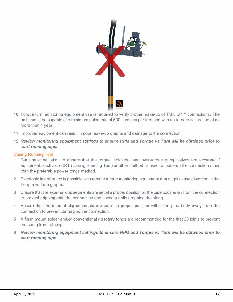
10 Torque turn monitoring equipment use is required to verify proper make-up of TMK UP™ connections. The
unit should be capable of a minimum pulse rate of 500 samples per turn and with up-to-date calibration of no more than 1 year.
11 Improper equipment can result in poor make-up graphs and damage to the connection.
12 Review monitoring equipment settings to ensure RPM and Torque vs Turn will be obtained prior to start running pipe.
Casing Running Tool 1 Care must be taken to ensure that the torque indicators and over-torque dump valves are accurate if
equipment, such as a CRT (Casing Running Tool) or other method, is used to make-up the connection other than the preferable power tongs method.
2 Electronic interference is possible with remote torque monitoring equipment that might cause distortion in the Torque vs Turn graphs.
3 Ensure that the external grip segments are set at a proper position on the pipe body away from the connection to prevent gripping onto the connection and consequently dropping the string.
4 Ensure that the internal slip segments are set at a proper position within the pipe body away from the connection to prevent damaging the connection.
5 A flush mount spider and/or conventional rig rotary tongs are recommended for the first 20 joints to prevent the string from rotating.
6 Review monitoring equipment settings to ensure RPM and Torque vs Turn will be obtained prior to start running pipe.

April 1, 2019 TMK UP™ Field Manual 13
PIPE API Color Codes
Pipe Grade Pipe (Color Bands)
Coupling
Illustration Entire
Coupling Band(s)
H40 None or black band None None or
Black
J55 Tubing 1 Green Green None
.
J55 Casing 1 Green Green 1 White
.
K55 2 Green Green None
M65 1 Green 1 Blue
Uses L80 Type 1 Couplings
N80 – 1 1 Red Red None
N80 – Q 1 Red
1 Green Red 1 Green
R95 1 Brown Brown None
L80 – 1 1 Red
1 Brown Red 1 Brown
C90 1 Purple Purple None
T95 1 Silver Silver None
C110 1 White 2 Brown
White 2 Brown

April 1, 2019 TMK UP™ Field Manual 14
Pipe Grade Pipe (Color Bands)
Coupling
Illustration Entire
Coupling Band(s)
P110 1 White White None
Q125 1 Orange Orange None
Proprietary Color Codes
Pipe Grade Pipe (color bands)
Coupling
Illustration Entire
coupling Band(s)
K55 HC 2 Green 1 Gray
Green None
I80 1 Purple 1 Green
Use L80 Type 1 Couplings
I80 MS-1 1 Purple 2 Green
Use L80 Type 1 Couplings
I95 1 Orange 1 Purple
Use P110 Couplings
I110 1 Purple 1 White
Use P110 Couplings
L80 HC 1 Red
1 Brown 1 Gray
Use L80 Type 1 Couplings
L80 CYHP 1 Red
1 Brown 1 White
Red 1 Brown 1 White
P110 HC 1 White 1 Gray
White None

April 1, 2019 TMK UP™ Field Manual 15
Pipe Grade Pipe (color bands)
Coupling
Illustration Entire
coupling Band(s)
P110 MS-1 1 White 1 Blue
White 1 Blue
C110 Couplings Accepted
P110 MS-2 1 White 2 Blue
White 2 Blue
C110 Couplings Accepted
P110 CYHP 1 White
2 Orange White 1 Orange
P110 CY 1 White 1 Pink
White 1 Pink
Q125HC 1 Orange,
1 Gray Orange None
Q125 CYHP 1 Orange 2 White
Orange 1 White
April 1, 2019 TMK UP™ Field Manual 16
Corrosion Resistant Alloys 1 Extra care must be taken when running CRA (Corrosion Resistant Alloy) grades to not mar or gouge the pipe
to prevent premature failure of the casing or tubing.
2 Movement of pipe from the pipe rack to the rig should be done using nylon or other soft strap instead of a metal sling, unless the metal sling is padded.
3 After the pipe is stabbed, nylon or other soft strap wrenches should be used to make-up connections to hand tight position. The use of spinning chains should be avoided to prevent damage to the casing or tubing.
4 Only non-marking wraparound dies shall be used to make-up the connection.
5 Only non-marking dies should be used in the slips.
6 The make-up speed should not exceed 10 RPM for 8-5/8” casing and smaller or 5 RPM for 9-5/8” casing and bigger.
7 Avoid metal to metal contact in the pipe rack by using a plastic bump ring.
8 Avoid metal to metal contact between pipe and handling equipment.
9 Handling plugs are required on threaded & couple connections using CRA to protect the threads and seals.
10 Avoid long term contact between carbon steel and CRA.
11 Ensure adequate padding on forks of forklift and on pipe rack.
12 The Field Service Technician shall inspect all connections to ensure an even coat of Molybdenum Disulfide (dry moly) covers the entire pin and box.
13 The use of copper plating is recommended but copper plating shall be used only in the box end of the connection. Do not apply “dry moly” to the copper plated area.
14 Molybdenum Disulfide grease “Moly Paste” shall be applied instead of thread compound to both pin and box if the connection is not copper plated.
PREPARATION Drift 1 Compressed air may be used if available prior to drifting. Each joint must be blasted from box end to pin end.
2 The pipe shall be drifted with the use of a drift mandrel of the appropriate size prior to cleaning and inspecting TMK UP™ connections.
3 It is a good practice to drift the casing or tubing while the pipe is on the rack.
4 Drift requirements:
- Drift mandrel must meet the API 5CT dimensional requirements.
- Special drift mandrel must be used for pipe with special drift requirements.
- Drift mandrel must be clean.
- Drift mandrel must not damage the connection.
- Drift from box end to pin end.
- Plastic or plastic-coated drift mandrels must be used on all internally coated and CRA pipe.
5 Any joints that do not drift shall be clearly marked red and segregated from the remaining prime joints.
6 Do not force the drift mandrel through the pipe.
7 Standard API Drift Dimensions:

April 1, 2019 TMK UP™ Field Manual 17
Product Min. Standard Drift Dimensions
Length Diameter
Casing in. mm. in. mm.
< 9-5/8 6 152 d - 1/8 d - 3.18
≥ 9-5/8 to ≤ 13-3/8 12 305 d - 5/32 d - 3.97
> 13-3/8 12 305 d - 3/16 d - 4.76
Tubing
≤ 2-7/8 42 1,067 d - 3/32 d - 2.38
> 2-7/8 to ≤ 8-5/8 42 1,067 d - 1/8 d - 3.18
> 8-5/8 to < 10-3/4 42 1,067 d - 5/32 d - 3.97
d Nominal Inside Diameter
Verify with API 5CT table C.28 and E.28
Cleaning 1 Thread protectors should only be removed, and cleaning conducted, immediately prior to running the casing
or tubing. This will limit the exposure of the connections to the environmental conditions on location that could have adverse effects on the connections (e.g., water, dust, mud, etc.).
2 TMK UP™ connections shall be cleaned prior to make-up to remove the storage compound.
3 Compressed air shall be blasted from box end to pin end if available.
4 A pressure washer, steam cleaning with water or solvent, cleaning solvent and rags, or non-metallic bristle brushes that do not leave residues, can be used. Any residues must be wiped or blown out from the thread roots and any other entrapped areas of the connection. The pressure washer must not remove the “dry moly”.
5 Pipe should be able to be rolled a minimum of one turn to ensure that all areas of boxes and pins are cleaned of storage compound and debris.
6 Lubricating oil or corrosion inhibitors may be used as additional measurement to prevent surface corrosion in the connection.
7 The connection shall not be exposed after cleaning and before running the connection for more than 3 hours without lubricating oil or a corrosion inhibitor.
8 Spray the dried connection with an even coat of “dry moly” and allow it to dry on CRA grades.
9 Clean thread protectors with solvent and rags or non-metallic bristle brushes.
10 Never use metal brushes, gasoline or diesel to clean TMK UP™ connections.
Inspection 1 Only Field Service Technicians certified by TMK IPSCO are authorized to inspect and field repair TMK UP™
connections.
2 The stencil information on the pipe should be recorded. Photos of mill and threading stencils may be included in the reporting documents.
3 All TMK UP™ connections should be thoroughly cleaned and dried at the rig site prior to inspection.
4 A visual inspection of all pins and boxes on location shall be conducted prior to running the casing or tubing.

April 1, 2019 TMK UP™ Field Manual 18
5 Features that should be inspected if applicable include:
- Seal surface
- Thread form
- Run-in and Run-out threads
- Torque shoulder
- Connection face
- Proper coupling installation
6 Potential damages that might occur include:
- Scratches
- Corrosion
- Pitting
- Dent
- Galling
- Discoloration
- Burrs
7 The seal area must be free of the above mentioned damages and may be buffed to remove only a minor blemish with the use of a heavy duty hand pad such as Scotch-Brite™ 7446 or 7440 with light pressures without the use of power tools. Molybdenum Disulfide must be applied on the buffed surface.
8 The entire connection must be inspected to ensure full coverage of dry moly. Dry moly must be applied to any portion of the connections where dry moly is not present.
9 Refer to the specific connection Field Repair section of the TMK UP™ RECOMMENDED FIELD PRACTICES section starting on page 28 for field repair instructions.
10 If any areas of the threads or seals are found to be unserviceable, these connections and joints shall be clearly marked red and segregated from the remaining prime joints.
11 Install centralizers and any other tools attaching to the OD of the pipe if available per company representative directive.
12 Apply thread compound to the connection per the specific connection Thread Compound Application section of the TMK UP™ RECOMMENDED FIELD PRACTICES section starting on page 28.
13 Install cleaned and dried pin thread protectors at hand tight position.
Gauging 1 The connection shall be cleaned, dried and visually inspected prior to gauging.
2 If available, only the following features are required to be gauged in the field:
- Seal Diameter
- Pitch Diameter
- Shoulder Length
3 A “Soft Gauge” shall be used to verify MRP gauge settings. The soft gauge may be a calibrated standard or a threaded pup joint of known dimensions.
4 All dimensions shall be recorded using the appropriate tolerance sheets.
April 1, 2019 TMK UP™ Field Manual 19
HANDLING API 5C1 shall be abided by in addition to these recommended procedures in the storage, loading, unloading and handling of all OCTG in the yard and on rig location.
Thread Protectors 1 Thread protectors shall be installed whenever pipe is being moved.
2 Ensure that thread protectors are clean prior to installation.
3 Thread protectors for TMK UP™ TORQ® QXW™, TORQ® DQW™, ULTRA DQX, ULTRA DQX-SR, ULTRA DQX-HT, BPN and BPN-SR connections are interchangeable between different weights of the same connection and nominal OD. All other connections require a specific thread protector for each size and weight.
4 Ensure the correct thread protectors are being used. Thread protectors are labeled with the connection name, size and weight. Thread protectors for TMK UP™ TORQ® QXW™, TORQ® DQW™, ULTRA DQX, ULTRA DQX-SR, ULTRA DQX-HT, BPN and BPN-SR are labeled only with the connection name and size.
5 Wrong thread protectors can potentially damage the connection or become loose and falloff during handling or transportation.
6 Pin thread protectors shall remain in place until the pipe is hanging in the derrick and is ready to be stabbed. Quickie protectors may be used.
7 If tubing or casing is expected to sit on the rack for an extended period after cleaning, then a fresh coat of running compound shall be applied to the entire connection and clean thread protectors shall be reinstalled hand tight.
8 If tubing or casing will be returned to the storage yard, then a fresh coat of storage compound shall be applied to the entire connection and clean thread protectors shall be reinstalled with the use of a wrench or steel bar.
9 Do not over tighten the thread protectors.
Handling Plugs 1 Handling plugs are required when running integral connections and recommended in threaded & coupled
connections.
2 Handling plugs are required for threaded & coupled connections if tools will be ran inside the coupling prior to make-up.
3 Handling plugs provide protection for the box threads and seals when the pipe is run.
4 All TMK UP™ handling plugs are specially made with modified dimensions which differ from the production connection design. Each TMK UP™ handling plug manufactured by TMK IPSCO or a licensee has a unique serial number located on the “head diameter” area. The head diameter is the biggest outside diameter on the handling plug and it is the same as the API coupling outside diameter.
5 Handling plugs for TMK UP™ TORQ® QXW™, TORQ® DQW™, ULTRRA DQX, ULTRA DQX-SR, ULTRA DQX-HT, BPN and BPN-SR connections are interchangeable between different weights of the same connection and nominal OD. However, ensure that the Handling Plug meets any required drift. All other connections require a specific handling plug for each size and weight.
6 The characteristics of a proper TMK UP™ handling plug include:
- Machined ID
- Proper Head Diameter
- Serialization
- Holes are located on the head diameter area

April 1, 2019 TMK UP™ Field Manual 20
7 Handling plugs shall be cleaned, dried and inspected before each run and at any point they are dropped or come into contact with foreign debris.
8 The handling plug and the connection box end should be free of any debris to insure proper thread engagement and prevent damage to the connection.
9 Handling plugs shall be installed to a firm, hand-tight position to ensure full engagement for safe handling with the use of a wrench or a steel bar through the holes provided in all TMK IPSCO handling plugs.
10 Never use a hammer to tighten the handling plug or strike the box to loosen and remove the handling plug.
11 Handling plugs should remain in place in the box end until the string is set in the slips and the next pipe is ready to be stabbed. This will ensure that the connection box has protection during the lowering of the string and while the string is filled with mud if a fill up tool, CRT system or mud valve is being used.
12 All TMK UP™ handling plugs will shoulder with the coupling or box end face except for TMK UP™ TORQ® SFW™, TORQ® DQW™ and TORQ® QXW™.
13 Handling plugs are designed to hold only up to 3 joints or 10,000 lbs and shall not be used to raise or lower the tubing or casing string.
14 The use of unapproved handling plugs may result in serious personal injury, improper thread engagement, reduced handling capacity, dropped pipe or damage to the threads and seals of TMK UP™ connections.
15 All handling plugs shall be properly maintained and periodically re-gauged. Using improperly maintained tools can lead to serious injuries.
Thread Compound 1 The use of proper thread compound is critical to the performance and protection of the connection.
2 TMK IPSCO recommends the use of thread compounds that meet or exceed ISO 13678 or API RP 5A3 requirements.
3 A specified dropping point of 450°F (232°C) or higher in the thread compound data sheet is recommended for elevated temperature.
4 A specified dropping point of 727°F (386°C) or higher in the thread compound data sheet is recommended for steam injection applications.
5 A specified dropping point in the thread compound data sheet of 150°F (66°C) or higher than the maximum well temperature is preferable.
6 Artic grade is recommended for applications where the outside temperature is below 32°F (0°C).
7 The thread compound expiration date must be reviewed to confirm that it is serviceable.
8 The thread compound shall be stirred immediately prior to its use and frequently throughout its use to prevent settling of heavy metals or large particles in metal free running compound.
9 The thread compound bucket should be covered to prevent the accumulation of water when raining. Discard thread compound with accumulated water as this may cause distorted torque turn graphs and corrosion in the connection.
10 Lubricating oil or corrosion inhibitors may be used between the connection cleaning and thread compound application as an additional measure to prevent corrosion in the connection.
11 Thread compound may be applied directly to the connections without removing the light oil base or corrosion inhibitor.

April 1, 2019 TMK UP™ Field Manual 21
12 The use of an applicator “moustache” brush is recommended for the box and a paintbrush for the pin to best control the application and quantity of thread compound.
13 Thread compound should be applied per the specific connection Thread Compound Application section of the TMK UP™ RECOMMENDED FIELD PRACTICES section starting on page 28.
14 Prior to stabbing, verify that the proper distribution of thread compound on both box and pin has been achieved.
15 Prevent the mud from covering the threaded and seal area of the box and wipe the box if the mud overflows. Overflowing the mud through the box can cause distorted graphs and may affect the thread compound performance.
16 Add 10% to the optimum make-up torque when using thread locking compound. A torque shoulder must be clearly visible to ensure proper make-up. Apply the thread locking compound to the threads only and apply running compound to the seal area.
17 Do not dilute thread compounds with diesel, motor oil or any other substance.
18 The TMK Field Service Technician is responsible for the application of thread compound on all connections, either by training the rig personnel or the Field Service Technician performing the proper thread compound application his or herself.
19 Consult with the TMK IPSCO field service technical support group for thread compound requirements.
20 Direct contact with thread compound should be avoided. The use of gloves is recommended to prevent skin contacting the chemicals and heavy metals in the thread compound. The MSDS (Material Safety Data Sheet) shall be reviewed by anyone who may come into contact with thread compound. In addition, it is important to prevent the compound from spilling or dripping onto the ground which may cause environmental pollution.

April 1, 2019 TMK UP™ Field Manual 22
Storage Compound 1 Storage compound protects the connection prior to the connection make-up.
2 Storage compound shall be applied to the entire connection instead of thread compound if the connection will not be made-up within one month.
3 The connections are susceptible to corrosion, scratches and other damages without proper storage compound.
4 Storage compound is intended to prevent corrosive damage to the connection and is distinctly different from thread compound.
5 Storage or drilling compound shall not be used for the make-up of any TMK UP™ connections.
Stabbing Guide 1 The use of a stabbing guide is required for the proper make-up of all TMK UP™ connections.
2 The stabbing guide centralizes the pin in the box as the pin is lowered into the box. This prevents the pin
face from contacting the box face and provides proper pin alignment into the box prior to thread engagement.
3 The stabbing guide reduces the risk of cross threading.
4 Damage to the connection face, threads and seals may occur if incorrect or improperly adjusted stabbing guides are used.
5 If the stabbing guide does not close easily on the box, the wrong or faulty stabbing guide may have been selected or a slight adjustment may be needed to ensure a proper fit.
6 Stabbing guides may or may not be interchange among different connections and among different weights within the same OD.

April 1, 2019 TMK UP™ Field Manual 23
CONNECTION MAKE-UP Connection Data Sheets 1 The most current Connection Data Sheets should be obtained from TMK IPSCO prior to each run to ensure
the most current information is available and applied to the running of TMK UP™ connections. Please visit our website at www.tmkup.com or contact our Technical Sales department at (281) 949-1023 or [email protected] for this information.
2 The specified minimum make-up torque in the data sheet is the minimum torque to which the connection shall be assembled.
3 The specified optimum make-up torque in the data sheet should be used as the target make-up torque for best performance.
4 The specified maximum make-up torque in the data sheet should be used as the highest recommended make-up torque for normal operations.
5 The specified operating torque is the maximum allowable torque for downhole rotation.
TMK UP™ Connections 1 Connections require connection-specific considerations during make-up.
2 Refer to the TMK UP™ RECOMMENDED FIELD PRACTICES section starting on page 28 for applicable connection information; including thread compound application, make-up RPM, torque shoulder acceptable torque range, and downhole rotation capabilities for each connection:
- TMK UP TORQ® SFW™
- TMK UP TORQ® QXW™
- TMK UP TORQ® DQW™
- TMK UP ULTRA™ SF & SFII
- TMK UP ULTRA™ FJ
- TMK UP ULTRA™ FX
- TMK UP ULTRA™ QX
- TMK UP ULTRA™ GX
- TMK UP ULTRA™ DQX & DQX-HT
- TMK UP ULTRA™ DQX-SR
- TMK UP™ BPN
- TMK UP™ BPN-SR
- TMK UP™ 2S-6 & 2S-8
Stabbing 1 Remove the pin thread protector once the joint is on the rig floor.
2 Alignment shall be checked by ensuring that the center line of the pin is suspended over the centerline of the box.
April 1, 2019 TMK UP™ Field Manual 24
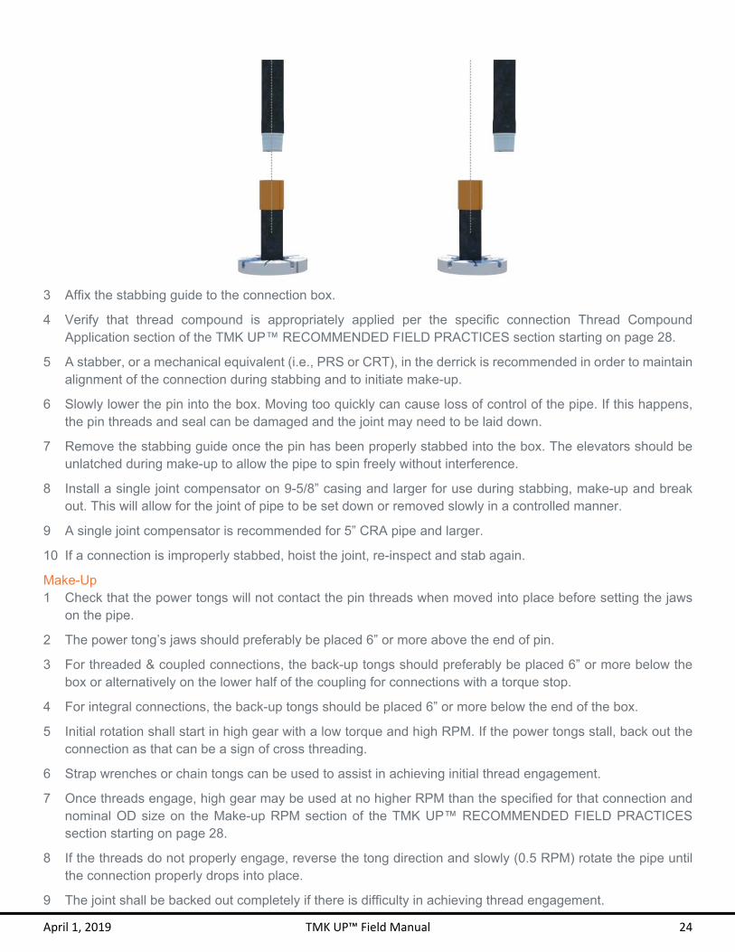
3 Affix the stabbing guide to the connection box.
4 Verify that thread compound is appropriately applied per the specific connection Thread Compound Application section of the TMK UP™ RECOMMENDED FIELD PRACTICES section starting on page 28.
5 A stabber, or a mechanical equivalent (i.e., PRS or CRT), in the derrick is recommended in order to maintain alignment of the connection during stabbing and to initiate make-up.
6 Slowly lower the pin into the box. Moving too quickly can cause loss of control of the pipe. If this happens, the pin threads and seal can be damaged and the joint may need to be laid down.
7 Remove the stabbing guide once the pin has been properly stabbed into the box. The elevators should be unlatched during make-up to allow the pipe to spin freely without interference.
8 Install a single joint compensator on 9-5/8” casing and larger for use during stabbing, make-up and break out. This will allow for the joint of pipe to be set down or removed slowly in a controlled manner.
9 A single joint compensator is recommended for 5” CRA pipe and larger.
10 If a connection is improperly stabbed, hoist the joint, re-inspect and stab again.
Make-Up 1 Check that the power tongs will not contact the pin threads when moved into place before setting the jaws
on the pipe.
2 The power tong’s jaws should preferably be placed 6” or more above the end of pin.
3 For threaded & coupled connections, the back-up tongs should preferably be placed 6” or more below the box or alternatively on the lower half of the coupling for connections with a torque stop.
4 For integral connections, the back-up tongs should be placed 6” or more below the end of the box.
5 Initial rotation shall start in high gear with a low torque and high RPM. If the power tongs stall, back out the connection as that can be a sign of cross threading.
6 Strap wrenches or chain tongs can be used to assist in achieving initial thread engagement.
7 Once threads engage, high gear may be used at no higher RPM than the specified for that connection and nominal OD size on the Make-up RPM section of the TMK UP™ RECOMMENDED FIELD PRACTICES section starting on page 28.
8 If the threads do not properly engage, reverse the tong direction and slowly (0.5 RPM) rotate the pipe until the connection properly drops into place.
9 The joint shall be backed out completely if there is difficulty in achieving thread engagement.
April 1, 2019 TMK UP™ Field Manual 25
10 Switch to low gear at approximately 1,000 ft-lbs, before the seal engagement appears in the torque turn graph. Stopping and starting the connection should be avoided when the connection is near final position because static friction effects could lead to a misinterpretation of the final torque.
11 Refer to the Torque Shoulder section of the TMK UP™ RECOMMENDED FIELD PRACTICES section starting on page 28 for proper torque turn graph.
12 Power tongs should remain in low gear and at a constant RPM once the seal engages.
13 Ensure that proper alignment is maintained during the make-up operation.
14 Monitor the torque turn system throughout the entire connection make-up. If there are any unexpected features on the torque turn graph, the make-up process should immediately be terminated, the connection broken out, cleaned and inspected.
15 After the make-up is complete, the graph should be reviewed to ensure that it has a clear torque shoulder, all required torque parameters are met and no unexpected features or anomalies are present.
16 The joint shall be laid down and replaced after a maximum of three unsuccessful attempts are made to make-up a connection. The box end on which the three make-up attempts were made shall be cleaned and inspected. The joint shall be pulled out and laid down if any damage to the thread or seal area is visible.
Break out 1 Ensure that the back-up tongs of appropriate size are used if disassembly of a connection is required.
2 Place the back-up tongs preferably in the lower half of the coupling and not on the pipe body for threaded & couple connections to ensure breaking out the field end pin.
3 If the back-up tongs are placed on the pipe body and the coupling starts to spin during break out, the break out process should be stopped and the back-up tongs of the appropriate size shall be placed on the lower half of the coupling.
4 Power tongs must be in low gear for break out. It is common for the break out torque to be higher than the make-up torque.
5 Slowly increase the torque until the connection begins to rotate counter clockwise.
6 The connection shall not be hammered to assist in the break out.
7 Continue rotating slowly at no higher than 8 RPM until the pin slightly “jumps” from the last engaged thread. This indicates that pin and box are no longer engaged and may be separated.
8 Stop rotating the pin once the pin “jump” occurs.
9 Install the stabbing guide prior to the “jump” of the pin when separating the two joints to prevent damage to pin and box.
10 Ensure that proper alignment is maintained during the break out operation.
11 In case of a re-run, clean, inspect, and apply an even coat of “dry moly” to the pin and box and allow it to dry. Otherwise, apply storage compound and clean thread protectors to box and pin.
12 Refer to the specific connection Field Repair section of the TMK UP™ RECOMMENDED FIELD PRACTICES section starting on page 28 for field repair instructions.

April 1, 2019 TMK UP™ Field Manual 26
Torque Turn 1 Torque turn monitoring is required for assessing a proper make-up of TMK UP™ connections.
2 Torque turn equipment provides evidence and enables the verification and recording of each connection make-up. It also aids in the recognition of any issues that may take place during the running of tubing or casing.
3 The initial turns of the makeup will have low torque due to thread interference starting to build up. The torque will increase at a faster rate when the seal engages. The torque will spike quickly when the torque shoulder is engaged causing the final torque to be reached.
4 Each connection will have a different graph and final make-up torque. The final make-up torque should be between the minimum and maximum make-up torque specified on the connection data sheet.
5 Different graphs are obtained due to threading tolerances, material properties, thread compound and other variables.
6 The graph requires showing the last section of the thread interference, transition to seal interference, torque shoulder and final torque.
7 A torque shoulder must be clearly visible for proper make-up.
8 The torque shoulder must be properly marked in the graph from proper calculation of delta turn and delta torque.
9 The operator must confirm the correct placement of the torque shoulder marking if the torque turn system uses automatic shoulder detection.
10 If any graph does not meet the requirements specified in the Torque Shoulder section of the TMK UP™ RECOMMENDED FIELD PRACTICES section starting on page 28, the connection should be broken out, cleaned and inspected prior to a further make-up attempt.

April 1, 2019 TMK UP™ Field Manual 27
11 The torque turn graph should provide the well name, connection name, size, weight, material grade, date, time, joint number, RPM, total turns, delta turn, shoulder torque, final torque and delta torque.
12 The delta turn is defined as the amount of turns past the torque shoulder contact.
13 The delta torque is defined as the amount of torque past the torque shoulder contact.
14 The scale of the graph can cause the make-up graph to look different. If it is stretched, it will look like more turns were made. If it is shortened, it will look like fewer turns were made.
15 In case of a re-run, each joint shall be labeled with the same tally number as the previous make-up attempt following by a hyphen or a period and the make-up attempt number to indicate that it is subsequent make-up of the same joint.
16 Only competent personnel such as Field Service Technicians certified by TMK IPSCO can validate acceptable torque turn graphs.

T M K U P ™ R E C O M M E N D E D
F I E L D P R A C T I C E

April 1, 2019 TMK UP™ Field Manual 30
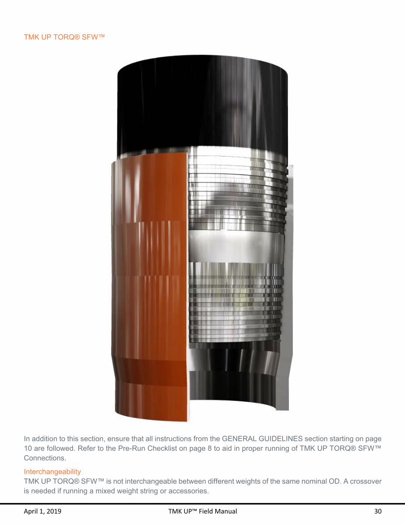
TMK UP TORQ® SFW™
In addition to this section, ensure that all instructions from the GENERAL GUIDELINES section starting on page 10 are followed. Refer to the Pre-Run Checklist on page 8 to aid in proper running of TMK UP TORQ® SFW™ Connections.
Interchangeability TMK UP TORQ® SFW™ is not interchangeable between different weights of the same nominal OD. A crossover is needed if running a mixed weight string or accessories.

April 1, 2019 TMK UP™ Field Manual 31
Features
1 TMK UP TORQ® SFW™ utilized a tapered wedge thread form on both steps of the connection. 2 A fully made up TMK UP TORQ® SFW™ connection may have up to two exposed threads on the pin OD. 3 TMK UP TORQ® SFW™ can be distinguished by its unique spherical seal configuration in between the
two thread steps and a thread dope relief adjacent to the seal on both pin and box.
Thread Compound Application 1 TMK IPSCO recommends the use of thread compounds that meet or exceed ISO 13678 or API RP 5A3
requirements.
2 The use of an applicator “moustache” brush is recommended for the box and a paintbrush for the pin to best control the application and quantity of thread compound.
3 Inspect that the brush is clean and free of any dirt. If the brush has been recently cleaned, make sure that no water or other foreign debris remains in the bristles.
4 Water that is on the brush, connection, or in the running compound bucket must be completely removed before applying the compound. The brush and connection can be dried with a clean rag.
5 Apply an evenly distributed light coat of thread compound on both steps and seal of the pin as demonstrated in the graphic below. A “light coat” means that the machined thread profile can be clearly and distinctly seen, with no more than 30% of the thread height filled with thread compound.

April 1, 2019 TMK UP™ Field Manual 32
Make-up Torque 1 TMK UP TORQ® SFW™ connections shall be made up to the torque specified on the most current
Connection Data Sheet.
2 The specified minimum make-up torque in the data sheet is the minimum torque to which the connection should be assembled.
3 The specified optimum make-up torque in the data sheet should be used as the target make-up torque for optimum performance.
4 The specified maximum make-up torque in the data sheet should be used as the highest recommended make-up torque for normal operations.
5 Add 10% to the optimum make-up torque when using thread locking compound. A wedge lock must be visible for proper make-up. Apply the thread locking compound to the threads only and apply running compound to the seal area.
Make-up RPM 1 Initial RPM shall start in high gear with a low torque and high RPM.
2 Switch to low gear before the seal engagement appears in the torque turn graph.
3 Power tongs should remain in low gear and at a constant RPM once the seal engages.
4 The below table lists the approximate recommended make-up RPM for the TMK UP TORQ® SFW™ connections.
Target Make-up RPM
OD Initial RPM Final RPM
4 – 5 ½ 35 15 6 ⅝ – 7 ⅝ 20 10
8 ⅝ – 9 ⅝ 10 5
10 ¾ – 13 ⅝ 6 3 Wedge Lock Torque 1. The wedge lock shall be clearly visible at a minimum of 20% of minimum make-up torque and at a maximum
of 90% of minimum make-up torque.
2. If the wedge lock is outside of these specifications, break out and inspect the pin and box.
3. A large torque increase prior to 1 turn from the wedge lock may indicate a problem in make-up such as cross threading or galling.
4. See the example graph below that demonstrates the make-up limits for TMK UP TORQ® SFW™ connections.

April 1, 2019 TMK UP™ Field Manual 33
Downhole Rotation 1. TMK IPSCO recommends using the minimum amount of torque necessary to break the friction between the
tubing or casing and the well bore if downhole rotation of the string is required.
2. The TMK UP TORQ® SFW™ connection should not be rotated beyond the specified operating torque and RPM should be limited to 40 RPM or lower.
3. Care should be taken to gradually increase and decrease torque when rotating to allow the stored kinetic energy to dissipate and prevent downhole connection yielding or break out.
4. TMK IPSCO advises caution as the torque measurement accuracy and dump-valve response time may vary depending on the specific equipment used.
Re-run 1. The pin and box must be thoroughly cleaned and visually inspected for any damage after each break out.
2. Apply an even coat of “dry moly” to the pin and box and allow it to dry.
3. Do not re-run the string if any portion of the string has been taken beyond the specified operating torque.
Field Repair 1 Field repair of TMK UP TORQ® SFW™ connections shall only be conducted by Field Service Technicians
certified by TMK IPSCO.
2 Minor tears, galls, dents or burrs on the thread profile may be able to be repaired by qualified personnel in the field.
3 Small scratches and dents on the pin and box face may be permissible or repaired.
4 Repair connections using a file, stone, sand paper or appropriate abrasive tool, and Scotch-Brite™ sponge or equivalent.
5 Spray the connection with an even coat of “dry moly” and allow it to dry.
6 Only qualified personnel may make the decision regarding the serviceability of a given connection.

April 1, 2019 TMK UP™ Field Manual 34
7 Seal areas cannot be repaired in the field and must be free of any damages.
8 Loose burrs and sharp raised edges must be removed or rounded down.

April 1, 2019 TMK UP™ Field Manual 36
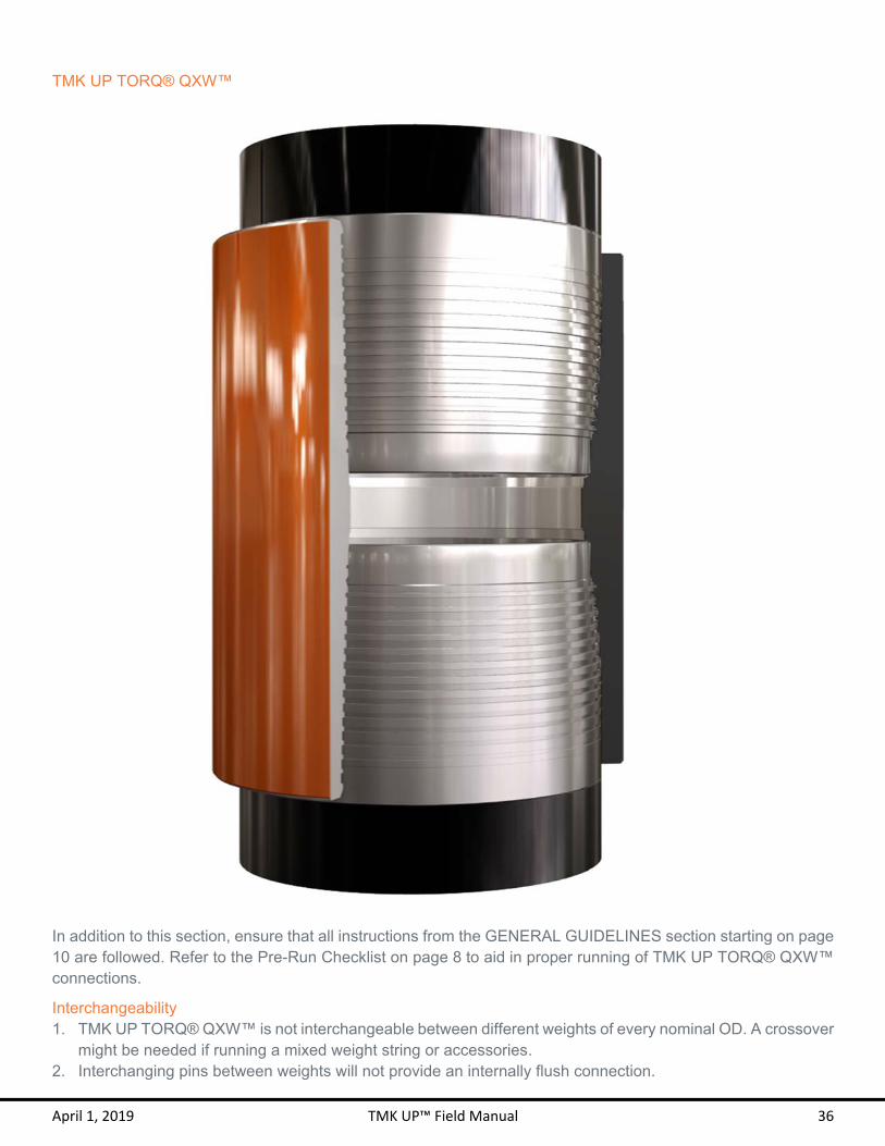
TMK UP TORQ® QXW™
In addition to this section, ensure that all instructions from the GENERAL GUIDELINES section starting on page 10 are followed. Refer to the Pre-Run Checklist on page 8 to aid in proper running of TMK UP TORQ® QXW™ connections.
Interchangeability 1. TMK UP TORQ® QXW™ is not interchangeable between different weights of every nominal OD. A crossover
might be needed if running a mixed weight string or accessories. 2. Interchanging pins between weights will not provide an internally flush connection.

April 1, 2019 TMK UP™ Field Manual 37
Features 1 TMK UP TORQ® QXW™ utilized a tapered wedge thread form. 2 A fully made up TMK UP TORQ® QXW™ connection may have up to two exposed threads on the pin OD.
Thread Compound Application 1 TMK IPSCO recommends the use of thread compounds that meet or exceed ISO 13678 or API RP 5A3
requirements.
2 The use of an applicator “moustache” brush is recommended for the box and a paintbrush for the pin to best control the application and quantity of thread compound.
3 Inspect that the brush is clean and free of any dirt. If the brush has been recently cleaned, make sure that no water or other foreign debris remains in the bristles.
4 Water that is on the brush, connection, or in the running compound bucket must be completely removed before applying the compound. The brush and connection can be dried with a clean rag.
5 Apply an evenly distributed light coat of thread compound to the pin face, seal and all threads as demonstrated in the graphics below. A “light coat” means that the machined thread profile can be clearly and distinctly seen, with no more than 30% of the thread height filled with thread compound.

April 1, 2019 TMK UP™ Field Manual 38
Make-up 1 TMK UP TORQ® QXW™ connections shall be made up to the torque specified on the most current
Connection Data Sheet.
2 The specified minimum make-up torque in the data sheet is the minimum torque to which the connection should be assembled.
3 The specified optimum make-up torque in the data sheet should be used as the target make-up torque for optimum performance.
4 The specified maximum make-up torque in the data sheet should be used as the highest recommended make-up torque for normal operations.
5 Add 10% to the optimum make-up torque when using thread locking compound. A wedge lock must be visible for proper make-up. Apply the thread locking compound to the threads only and apply running compound to the seal area.
6 The connection may be made up by holding or floating the coupling. Back-up tongs should be placed on the mill end side if holding the coupling.
7 TMK IPSCO allows coupling movement of no more than ¼ turn on the mill end during make-up.
Make-up RPM 1 Initial RPM shall start in high gear with a low torque and high RPM.
2 Switch to low gear before the wedge lock engagement appears in the torque turn graph.
3 The below table lists the approximate recommended make-up RPM for the TMK UP TORQ® QXW™ connections.
Target Make-up RPM
OD Initial RPM Final RPM
4 ½ – 5 ½ 35 15 6 ⅝ – 7 ⅝ 20 10 8 ⅝ – 9 ⅝ 10 5
10 ¾ – 13 ⅝ 6 3
Wedge Lock Torque 1. The wedge lock shall be clearly visible at a minimum of 20% of minimum make-up torque and at a maximum
of 90% of minimum make-up torque when using torque turn monitoring system.
2. If the wedge lock is outside of these specifications, break out and inspect the pin and box.
3. A large torque increase prior to 1 turn from the wedge lock may indicate a problem in make-up such as cross threading or galling.
4. See the example graph below that demonstrates the make-up limits for TMK UP TORQ® QXW™ connections.

April 1, 2019 TMK UP™ Field Manual 39
Downhole Rotation 1. TMK IPSCO recommends using the minimum amount of torque necessary to break the friction between the
tubing or casing and the well bore if downhole rotation of the string is required.
2. The TMK UP TORQ® QXW™ connection should not be rotated beyond the specified operating torque and RPM should be limited to 40 RPM or lower.
3. Care should be taken to gradually increase and decrease torque when rotating to allow the stored kinetic energy to dissipate and prevent downhole connection yielding or break out.
4. TMK IPSCO advises caution as the torque measurement accuracy and dump-valve response time may vary depending on the specific equipment used.
Re-Run 1. The TMK UP TORQ® QXW™ connections may be used as work strings.
2. It is recommended to apply the backup tongs on the lower half of the coupling during pin field end break out to prevent backing out the coupling.
3. The pin and coupling must be thoroughly cleaned and visually inspected for any damage after each break out.
4. The joint must be laid down if for any reason it is determined that a coupling must be bucked-off.
5. Do not re-run the string if any portion of the string has been taken beyond the specified operating torque.
April 1, 2019 TMK UP™ Field Manual 40
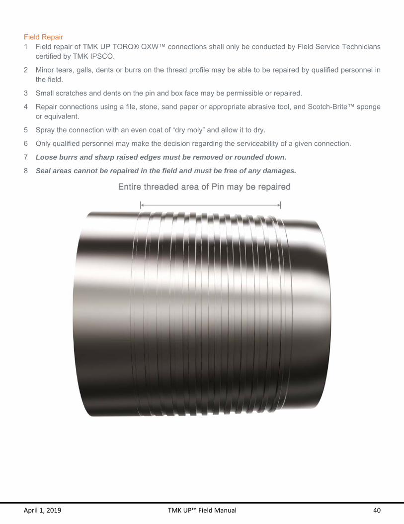
Field Repair 1 Field repair of TMK UP TORQ® QXW™ connections shall only be conducted by Field Service Technicians
certified by TMK IPSCO.
2 Minor tears, galls, dents or burrs on the thread profile may be able to be repaired by qualified personnel in the field.
3 Small scratches and dents on the pin and box face may be permissible or repaired.
4 Repair connections using a file, stone, sand paper or appropriate abrasive tool, and Scotch-Brite™ sponge or equivalent.
5 Spray the connection with an even coat of “dry moly” and allow it to dry.
6 Only qualified personnel may make the decision regarding the serviceability of a given connection.
7 Loose burrs and sharp raised edges must be removed or rounded down.
8 Seal areas cannot be repaired in the field and must be free of any damages.

April 1, 2019 TMK UP™ Field Manual 41

April 1, 2019 TMK UP™ Field Manual 43
TMK UP TORQ® DQW™
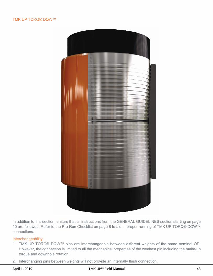
In addition to this section, ensure that all instructions from the GENERAL GUIDELINES section starting on page 10 are followed. Refer to the Pre-Run Checklist on page 8 to aid in proper running of TMK UP TORQ® DQW™ connections.
Interchangeability 1. TMK UP TORQ® DQW™ pins are interchangeable between different weights of the same nominal OD.
However, the connection is limited to all the mechanical properties of the weakest pin including the make-up torque and downhole rotation.
2. Interchanging pins between weights will not provide an internally flush connection.

April 1, 2019 TMK UP™ Field Manual 44
Features 1 TMK UP TORQ® DQW™ utilized a tapered wedge thread form. 2 A fully made up TMK UP TORQ® DQW™ connection may have up to two exposed threads on the pin OD. 3 TMK UP TORQ® DQW™ can be distinguished by its unique stamp on the pins.
Thread Compound Application 1 TMK IPSCO recommends the use of BestOLife 2000® or equivalent copper based thread compound with
particle size less than 450 microns that meet or exceed ISO 13678 or API RP 5A3 requirements.
2 The use of an applicator “moustache” brush is recommended for the box and a paintbrush for the pin to best control the application and quantity of thread compound.
3 Inspect that the brush is clean and free of any dirt. If the brush has been recently cleaned, make sure that no water or other foreign debris remains in the bristles.
4 Water that is on the brush, connection, or in the running compound bucket must be completely removed before applying the compound. The brush and connection can be dried with a clean rag.
5 Apply an evenly distributed light coat of thread compound to the pin face and all threads as demonstrated in the graphics below. A “light coat” means that the machined thread profile can be clearly and distinctly seen, with no more than 30% of the thread height filled with thread compound.

April 1, 2019 TMK UP™ Field Manual 45
Make-up 1 The TMK UP TORQ® DQW™ connections may be made up without the preferred method of a torque turn
graph.
2 The connection should be made up by floating the coupling to allow the coupling self-center itself.
3 For make-up without a torque turn graph, the wedge lock is indicated when the torque gauge needle spikes.
4 Two ⅜ inch squares axially spaced from each other along the axis of the pipe are stamped on both pins.
5 A 1 inch by 24 inch white stripe aligned with the squares is painted on the field end pin to aid in locating the squares.
6 All make-ups without the use of torque turn graph must be visually verified with the stamp. The coupling must be positioned between the two squares edges.
7 TMK UP TORQ® DQW™ connection should be made up to the torque specified on the most current Connection Data Sheet.
8 The specified minimum make-up torque in the data sheet is the minimum torque to which the connection should be assembled.
9 The specified optimum make-up torque in the data sheet should be used as the target make-up torque for optimum performance.
10 The specified maximum make-up torque in the data sheet should be used as the highest recommended make-up torque for normal operations.
11 Add 10% to the optimum make-up torque when using thread locking compound. A torque shoulder must be visible for proper make-up.
Make-up RPM 1 Initial RPM shall start in high gear with a low torque and high RPM.
2 Switch to low gear before the wedge lock engagement appears in the torque turn graph.
3 The below table lists the approximate recommended make-up RPM for the TMK UP TORQ® DQW™ connections.

April 1, 2019 TMK UP™ Field Manual 46
Target Make-up RPM
OD Initial RPM Final RPM
4 ½ – 5 ½ 35 15 6 ⅝ – 7 ⅝ 20 10
Wedge Lock Torque 1. The wedge lock shall be clearly visible at a minimum of 20% of minimum make-up torque and at a maximum
of 90% of minimum make-up torque when using torque turn monitoring system.
2. If the wedge lock is outside of these specifications, break out and inspect the pin and box.
3. A large torque increase prior to 1 turn from the wedge lock may indicate a problem in make-up such as cross threading or galling.
4. See the example graph below that demonstrates the make-up limits for TMK UP TORQ® DQW™ connections.
Spinning Coupling 1. TMK IPSCO allows coupling movement of no more than ½ turn on the mill end during make-up.
2. Back-up tongs should not be placed on the coupling to avoid coupling spinning. Spinning of the coupling allows the coupling to self-center in preparation for downhole extreme torque rotating.
3. Mill end make-up can be visually verified for proper position with the squares stamp. The coupling must be positioned between the two squares edges.

April 1, 2019 TMK UP™ Field Manual 47
Downhole Rotation 1. TMK IPSCO recommends using the minimum amount of torque necessary to break the friction between the
tubing or casing and the well bore if downhole rotation of the string is required.
2. The TMK UP TORQ® DQW™ connection should not be rotated beyond the specified operating torque and RPM should be limited to 40 RPM or lower.
3. Care should be taken to gradually increase and decrease torque when rotating to allow the stored kinetic energy to dissipate and prevent downhole connection yielding or break out.
4. TMK IPSCO advises caution as the torque measurement accuracy and dump-valve response time may vary depending on the specific equipment used.
Re-Run 1. The TMK UP TORQ® DQW™ connections may be used as work strings.
2. It is recommended to apply the backup tongs to the lower half of the coupling during pin field end break out to prevent backing out the coupling.
3. The pin and coupling must be thoroughly cleaned and visually inspected for any damage after each break out.
4. The joint must be laid down if for any reason it is determined that a coupling must be bucked-off.
5. Do not re-run the string if any portion of the string has been taken beyond the specified operating torque.
Field Repair 1 Field repair of TMK UP TORQ® DQW™ connections shall only be conducted by Field Service Technicians
certified by TMK IPSCO.
2 Minor tears, galls, dents or burrs on the thread profile may be able to be repaired by qualified personnel in the field.
3 Galling on pin face may be repaired if it does not exceed 25% of the pipe circumference. The repair shall fully remove any protrusions which may cause galling on subsequent make-up.
4 Repair connections using a file, stone, sand paper or appropriate abrasive tool, and Scotch-Brite™ sponge or equivalent.
5 Only qualified personnel may make the decision regarding the serviceability of a given connection.
6 Loose burrs and sharp raised edges must be removed or rounded down.

April 1, 2019 TMK UP™ Field Manual 48
Minor tearing and galling in the pin face may be repaired

SF &SFII
T M K U P ULTRA™

April 1, 2019 TMK UP™ Field Manual 50
TMK UP ULTRA™ SF & SFII
In addition to this section, ensure that all instructions from the GENERAL GUIDELINES section starting on page 10 are followed. Refer to the Pre-Run Checklist on page 8 to aid in proper running of TMK UP ULTRA™ SF & SFII connections.
Interchangeability TMK UP ULTRA™ SF and SFII are neither compatible between both connections nor interchangeable between different weights of the same connection and nominal OD. A crossover is needed if running a mixed weight string or accessories.
April 1, 2019 TMK UP™ Field Manual 51
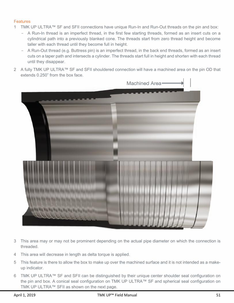
Features 1 TMK UP ULTRA™ SF and SFII connections have unique Run-In and Run-Out threads on the pin and box:
- A Run-In thread is an imperfect thread, in the first few starting threads, formed as an insert cuts on a cylindrical path into a previously blanked cone. The threads start from zero thread height and become taller with each thread until they become full in height.
- A Run-Out thread (e.g. Buttress pin) is an imperfect thread, in the back end threads, formed as an insert cuts on a taper path and intersects a cylinder. The threads start full in height and shorten with each thread until they disappear.
2 A fully TMK UP ULTRA™ SF and SFII shouldered connection will have a machined area on the pin OD that extends 0.250” from the box face.
3 This area may or may not be prominent depending on the actual pipe diameter on which the connection is threaded.
4 This area will decrease in length as delta torque is applied.
5 This feature is there to allow the box to make up over the machined surface and it is not intended as a make-up indicator.
6 TMK UP ULTRA™ SF and SFII can be distinguished by their unique center shoulder seal configuration on the pin and box. A conical seal configuration on TMK UP ULTRA™ SF and spherical seal configuration on TMK UP ULTRA™ SFII as shown on the next page.

April 1, 2019 TMK UP™ Field Manual 52
Thread Compound Application 1 TMK IPSCO recommends the use of thread compounds that meet or exceed ISO 13678 or API RP 5A3
requirements.
2 The use of an applicator “moustache” brush is recommended for the box and a paintbrush for the pin to best control the application and quantity of thread compound.
3 Inspect that the brush is clean and free of any dirt. If the brush has been recently cleaned, make sure that no water or other foreign debris remains in the bristles.
4 Water that is on the brush, connection, or in the running compound bucket must be completely removed before applying the compound. The brush and connection can be dried with a clean rag.
5 Apply an evenly distributed light coat of thread compound to the box seal and back step threads and to the pin seal and back step threads as demonstrated in the graphics below. A “light coat” means that the machined thread profile can be clearly and distinctly seen, with no more than 30% of the thread height filled with thread compound.
TMK UP ULTRA™ SF
TMK UP ULTRA™ SFII
April 1, 2019 TMK UP™ Field Manual 53
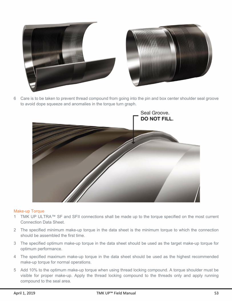
6 Care is to be taken to prevent thread compound from going into the pin and box center shoulder seal groove to avoid dope squeeze and anomalies in the torque turn graph.
Make-up Torque 1 TMK UP ULTRA™ SF and SFII connections shall be made up to the torque specified on the most current
Connection Data Sheet.
2 The specified minimum make-up torque in the data sheet is the minimum torque to which the connection should be assembled the first time.
3 The specified optimum make-up torque in the data sheet should be used as the target make-up torque for optimum performance.
4 The specified maximum make-up torque in the data sheet should be used as the highest recommended make-up torque for normal operations.
5 Add 10% to the optimum make-up torque when using thread locking compound. A torque shoulder must be visible for proper make-up. Apply the thread locking compound to the threads only and apply running compound to the seal area.

April 1, 2019 TMK UP™ Field Manual 54
Make-up RPM 1 Initial RPM shall start in high gear with a low torque and high RPM.
2 Switch to low gear before the seal engagement appears in the torque turn graph.
3 Power tongs should remain in low gear and at a constant RPM once the seal engages.
4 The below table lists the approximate recommended make-up RPM for the TMK UP ULTRA™ SF and SFII connections.
Target Make-up RPM
OD Initial RPM Final RPM
3 ½ 30 15 4 – 5 ½ 20 10
6 ⅝ – 7 ⅝ 15 7
8 ⅝ – 9 ⅝ 10 5
10 ¾ – 14 6 3 16 ≥ 4 2
Shoulder Torque 1. The shoulder torque shall be clearly visible at a minimum of 20% of optimum make-up torque and at a
maximum of 70% of optimum make-up torque and with a 0.020 – 0.200 delta turn range.
2. If the shoulder torque is outside of these specifications, break out and inspect the pin and box.
3. A large torque increase prior to 1 turn from shouldering may indicate a problem in make-up such as cross threading or galling.
4. See the example graph below that demonstrates the make-up limits for TMK UP ULTRA™ SF and SFII connections.
April 1, 2019 TMK UP™ Field Manual 55
Downhole Rotation 1. TMK IPSCO recommends using the minimum amount of torque necessary to break the friction between the
tubing or casing and the well bore if downhole rotation of the string is required.
2. The minimum make-up torque is the safest downhole rotating torque. This will ensure that the connection can be broken out and made up again.
3. The TMK UP ULTRA™ SF and SFII connection should not be rotated beyond the specified operating torque and RPM should be limited to 40 RPM or lower.
4. The seals will swell and the connection may not disassemble beyond the operating torque.
5. Care should be taken to gradually increase and decrease torque when rotating to allow the stored kinetic energy to dissipate and prevent downhole connection yielding or break out.
6. TMK IPSCO advises caution as the torque measurement accuracy and dump-valve response time may vary depending on the specific equipment used.
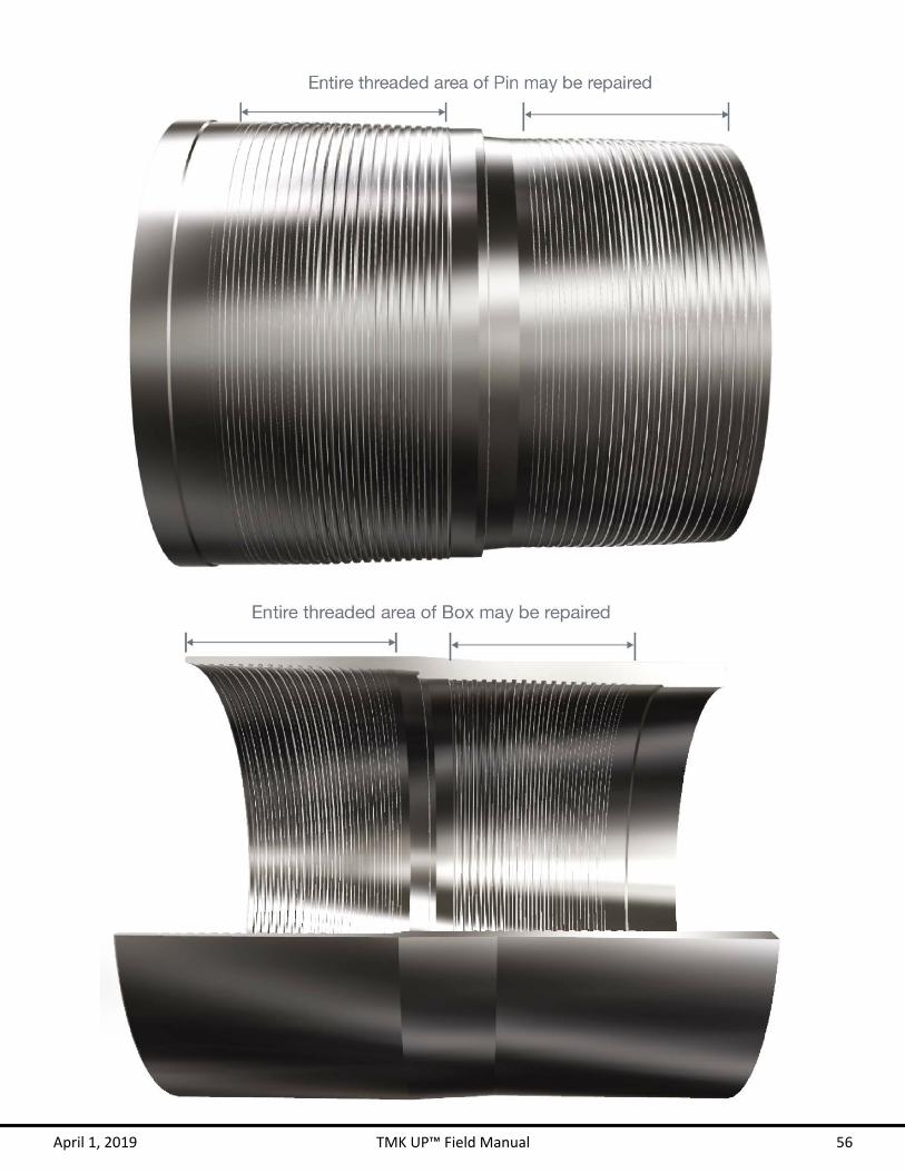
Re-run 1. The pin and box must be thoroughly cleaned and visually inspected for any damage after each break out.
2. Apply an even coat of “dry moly” to the pin and box and allow it to dry.
1 Field repair of TMK UP ULTRA™ SF and SFII connections shall only be conducted by Field Service Technicians certified by TMK IPSCO.
2 Minor tears, galls, dents or burrs on the thread profile may be able to be repaired by qualified personnel in the field.
3 Small scratches and dents on the pin and box face may be permissible or repaired.
4 Repair connections using a file, stone, sand paper or appropriate abrasive tool, and Scotch-Brite™ sponge or equivalent.
5 Spray the connection with an even coat of “dry moly” and allow it to dry.
6 Only qualified personnel may make the decision regarding the serviceability of a given connection.
7 Seal areas cannot be repaired in the field and must be free of any damages.
8 Loose burrs and sharp raised edges must be removed or rounded down.
3. Do not re-run the string if any portion of the string has been taken beyond the specified operating torque.
4. The TMK UP ULTRA™ SF and SFII connections shall not be used as work strings.
Field Repair
April 1, 2019 TMK UP™ Field Manual 56


April 1, 2019 TMK UP™ Field Manual 58
TMK UP ULTRA™ FJ
In addition to this section, ensure that all instructions from the GENERAL GUIDELINES section starting on page 10 are followed. Refer to the Pre-Run Checklist on page 8 to aid in proper running of TMK UP ULTRA™ FJ connections.
Interchangeability TMK UP ULTRA™ FJ is not interchangeable between different weights of the same nominal OD. A crossover is needed if running a mixed weight string or accessories.

April 1, 2019 TMK UP™ Field Manual 59
Features 1 TMK UP ULTRA™ FJ connections have unique Run-In and Run-Out threads on the pin and box:
- A Run-In thread is an imperfect thread, in the first few starting threads, formed as an insert cuts on a cylindrical path into a previously blanked cone. The threads start from zero thread height and become taller with each thread until they become full in height.
- A Run-Out thread (e.g. Buttress pin) is an imperfect thread, in the back end threads, formed as an insert cuts on a taper path and intersects a cylinder. The threads start full in height and shorten with each thread until they disappear.
Thread Compound Application 1 TMK IPSCO recommends the use of thread compounds that meet or exceed ISO 13678 or API RP 5A3
requirements.
2 The use of an applicator “moustache” brush is recommended for the box and a paintbrush for the pin to best control the application and quantity of thread compound.
3 Inspect that the brush is clean and free of any dirt. If the brush has been recently cleaned, make sure that no water or other foreign debris remains in the bristles.
4 Water that is on the brush, connection, or in the running compound bucket must be completely removed before applying the compound. The brush and connection can be dried with a clean rag.
5 Apply an evenly distributed light coat of thread compound to the entire box and to the pin face and seal area as demonstrated in the graphics below. A “light coat” means that the machined thread profile can be clearly and distinctly seen, with no more than 30% of the thread height filled with thread compound.

April 1, 2019 TMK UP™ Field Manual 60
Make-up Torque 1 TMK UP ULTRA™ FJ connections shall be made up to the torque specified on the most current Connection
Data Sheet.
2 The specified minimum make-up torque in the data sheet is the minimum torque to which the connection should be assembled the first time.
3 The specified optimum make-up torque in the data sheet should be used as the target make-up torque for optimum performance.
4 The specified maximum make-up torque in the data sheet should be used as the highest recommended make-up torque for normal operations.
5 Add 10% to the optimum make-up torque when using thread locking compound. A torque shoulder must be visible for proper make-up. Apply the thread locking compound to the threads only and apply running compound to the seal area.
Make-up RPM 1 Initial RPM shall start in high gear with a low torque and high RPM.
2 Switch to low gear before the seal engagement appears in the torque turn graph.
3 Power tongs should remain in low gear and at a constant RPM once the seal engages.
4 The below table lists the approximate recommended make-up RPM for the TMK UP ULTRA™ FJ connections.
Target Make-up RPM
OD Initial RPM Final RPM
2 ⅞ – 3 ½ 30 15 4 – 5 ½ 20 10
6 ⅝ – 7 ⅝ 15 7
8 ⅝ – 9 ⅝ 10 5
10 ¾ – 14 6 3 16 ≥ 4 2
Shoulder Torque 1. The shoulder torque shall be clearly visible at a minimum of 10% of optimum make-up torque and at a
maximum of 80% of optimum make-up torque and with a 0.020 – 0.100 delta turn range.
2. If the shoulder torque is outside of these specifications, break out and inspect the pin and box.
3. A large torque increase prior to 1 turn from shouldering may indicate a problem in make-up such as cross threading or galling.
4. See the example graph below that demonstrates the make-up limits for TMK UP ULTRA™ FJ connections.

April 1, 2019 TMK UP™ Field Manual 61
Downhole Rotation 1. TMK IPSCO recommends using the minimum amount of torque necessary to break the friction between the
tubing or casing and the well bore if downhole rotation of the string is required.
2. The TMK UP ULTRA™ FJ connection should not be rotated beyond the specified operating torque and RPM should be limited to 30 RPM or lower.
3. Care should be taken to gradually increase and decrease torque when rotating to allow the stored kinetic energy to dissipate and prevent downhole connection yielding or break out.
4. TMK IPSCO advises caution as the torque measurement accuracy and dump-valve response time may vary depending on the specific equipment used.
Re-Run 1. The pin and box must be thoroughly cleaned and visually inspected for any damage after each break out.
2. Apply an even coat of “dry moly” to the pin and box and allow it to dry.
Field Repair 1 Field repair of TMK UP ULTRA™ FJ connections shall only be conducted by Field Service Technicians
certified by TMK IPSCO.
2 Minor tears, galls, dents or burrs on the thread profile may be able to be repaired by qualified personnel in the field.
3 Minor tears and scratches on the pin and box face may be repaired.
4 Repair connections using a file, stone, sand paper or appropriate abrasive tool, and Scotch-Brite™ sponge or equivalent.
3. The TMK UP ULTRA™ FJ connections shall not be used as work strings.

April 1, 2019 TMK UP™ Field Manual 62
5 Spray the connection with an even coat of “dry moly” and allow it to dry.
6 Only qualified personnel may make the decision regarding the serviceability of a given connection.
7 Seal areas cannot be repaired in the field and must be free of any damages.
8 Loose burrs and sharp raised edges must be removed or rounded down.

FXT M K U P U L T R A ™

April 1, 2019 TMK UP™ Field Manual 64
TMK UP ULTRA™ FX
In addition to this section, ensure that all instructions from the GENERAL GUIDELINES section starting on page 10 are followed. Refer to the Pre-Run Checklist on page 8 to aid in proper running of TMK UP ULTRA™ FX connections.
Interchangeability TMK UP ULTRA™ FX is not interchangeable between different weights of the same nominal OD. A crossover is needed if running a mixed weight string or accessories.

April 1, 2019 TMK UP™ Field Manual 65
Features 1 TMK UP ULTRA™ FX connections have unique Run-In and Run-Out threads on the pin and box:
- A Run-In thread is an imperfect thread, in the first few starting threads, formed as an insert cuts on a cylindrical path into a previously blanked cone. The threads start from zero thread height and become taller with each thread until they become full in height.
- A Run-Out thread (e.g. Buttress pin) is an imperfect thread, in the back end threads, formed as an insert cuts on a taper path and intersects a cylinder. The threads start full in height and shorten with each thread until they disappear.
Thread Compound Application 1 TMK IPSCO recommends the use of thread compounds that meet or exceed ISO 13678 or API RP 5A3
requirements.
2 The use of an applicator “moustache” brush is recommended for the box and a paintbrush for the pin to best control the application and quantity of thread compound.
3 Inspect that the brush is clean and free of any dirt. If the brush has been recently cleaned, make sure that no water or other foreign debris remains in the bristles.
4 Water that is on the brush, connection, or in the running compound bucket must be completely removed before applying the compound. The brush and connection can be dried with a clean rag.
5 Apply an evenly distributed light coat of thread compound only to the entire pin including the pin face and shoulder as demonstrated in the graphic below. A “light coat” means that the machined thread profile can be clearly and distinctly seen, with no more than 30% of the thread height filled with thread compound.
Make-up Torque 1 TMK UP ULTRA™ FX connections shall be made up to the torque specified on the most current Connection
Data Sheet.
2 The specified minimum make-up torque in the data sheet is the minimum torque to which the connection should be assembled the first time.
3 The specified optimum make-up torque in the data sheet should be used as the target make-up torque for optimum performance.
4 The specified maximum make-up torque in the data sheet should be used as the highest recommended make-up torque for normal operations.

April 1, 2019 TMK UP™ Field Manual 66
5 Add 10% to the optimum make-up torque when using thread locking compound. A torque shoulder must be visible for proper make-up. Apply the thread locking compound to the threads only and apply running compound to the seal area.
Make-up RPM 1 Initial RPM shall start in high gear with a low torque and high RPM.
2 Switch to low gear before the seal engagement appears in the torque turn graph.
3 Power tongs should remain in low gear and at a constant RPM once the seal engages.
4 The below table lists the approximate recommended make-up RPM for the TMK UP ULTRA™ FX connections.
Target Make-up RPM
OD Initial RPM Final RPM
2 ⅜ – 3 ½ 30 15 4 – 5 ½ 20 10
Shoulder Torque 1. The shoulder torque shall be clearly visible at a minimum of 10% of optimum make-up torque and at a
maximum of 70% of optimum make-up torque and with a 0.020 – 0.100 delta turn range.
2. If the shoulder torque is outside of these specifications, break out and inspect the pin and box.
3. A large torque increase prior to 1 turn from shouldering may indicate a problem in make-up such as cross threading or galling.
4. See the example graph below that demonstrates the make-up limits for TMK UP ULTRA™ FX connections.

April 1, 2019 TMK UP™ Field Manual 67
Downhole Rotation 1. TMK IPSCO recommends using the minimum amount of torque necessary to break the friction between the
tubing or casing and the well bore if downhole rotation of the string is required.
2. The TMK UP ULTRA™ FX connection should not be rotated beyond the specified operating torque and RPM should be limited to 30 RPM or lower.
3. Care should be taken to gradually increase and decrease torque when rotating to allow the stored kinetic energy to dissipate and prevent downhole connection yielding or break out.
4. TMK IPSCO advises caution as the torque measurement accuracy and dump-valve response time may vary depending on the specific equipment used.
Re-Run 1. The pin and box must be thoroughly cleaned and visually inspected for any damage after each break out.
2. Apply an even coat of “dry moly” to the pin and box and allow it to dry.
3. Do not re-run the string if any portion of the string has been taken beyond the specified operating torque.
4. The TMK UP ULTRA™ FX connections shall not be used as work strings.
Field Repair 1 Field repair of TMK UP ULTRA™ FX connections shall only be conducted by Field Service Technicians
certified by TMK IPSCO.
2 Minor tears, galls, dents or burrs on the thread profile may be able to be repaired by qualified personnel in the field.
3 Minor tears and scratches on the pin and box face may be repaired.
4 Repair connections using a file, stone, sand paper or appropriate abrasive tool, and Scotch-Brite™ sponge or equivalent.
5 Spray the connection with an even coat of “dry moly” and allow it to dry.
6 Only qualified personnel may make the decision regarding the serviceability of a given connection.
7 Seal areas cannot be repaired in the field and must be free of any damages.
8 Loose burrs and sharp raised edges must be removed or rounded down.
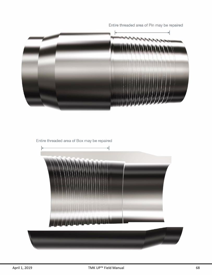
April 1, 2019 TMK UP™ Field Manual 68

QXT M K U P U L T R A ™

April 1, 2019 TMK UP™ Field Manual 70
TMK UP ULTRA™ QX
In addition to this section, ensure that all instructions from the GENERAL GUIDELINES section starting on page 10 are followed. Refer to the Pre-Run Checklist on page 8 to aid in proper running of TMK UP ULTRA™ QX connections.
Interchangeability TMK UP ULTRA™ QX pins are not interchangeable between different weights of the same nominal OD. A crossover is needed if running a mixed weight string or accessories.
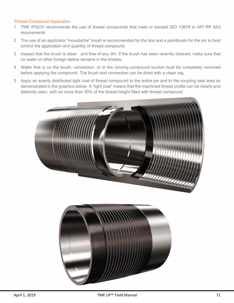
April 1, 2019 TMK UP™ Field Manual 71
Thread Compound Application 1 TMK IPSCO recommends the use of thread compounds that meet or exceed ISO 13678 or API RP 5A3
requirements.
2 The use of an applicator “moustache” brush is recommended for the box and a paintbrush for the pin to best control the application and quantity of thread compound.
3 Inspect that the brush is clean and free of any dirt. If the brush has been recently cleaned, make sure that no water or other foreign debris remains in the bristles.
4 Water that is on the brush, connection, or in the running compound bucket must be completely removed before applying the compound. The brush and connection can be dried with a clean rag.
5 Apply an evenly distributed light coat of thread compound to the entire pin and to the coupling seal area as demonstrated in the graphics below. A “light coat” means that the machined thread profile can be clearly and distinctly seen, with no more than 30% of the thread height filled with thread compound.

April 1, 2019 TMK UP™ Field Manual 72
Make-up Torque 1 TMK UP ULTRA™ QX connections shall be made up to the torque specified on the most current Connection
Data Sheet.
2 The specified minimum make-up torque in the data sheet is the minimum torque to which the connection should be assembled the first time.
3 The specified optimum make-up torque in the data sheet should be used as the target make-up torque for optimum performance.
4 The specified maximum make-up torque in the data sheet should be used as the highest recommended make-up torque for normal operations.
5 Add 10% to the optimum make-up torque when using thread locking compound. A torque shoulder must be visible for proper make-up. Apply the thread locking compound to the threads only and apply running compound to the seal area.
Make-up RPM 1 Initial RPM shall start in high gear with a low torque and high RPM.
2 Switch to low gear before the seal engagement appears in the torque turn graph.
3 Power tongs should remain in low gear and at a constant RPM once the seal engages.
4 The below table lists the approximate recommended make-up RPM for the TMK UP ULTRA™ QX connections.
Target Make-up RPM
OD Initial RPM Final RPM
4 ½ – 5 ½ 20 10 6 ⅝ – 7 ⅝ 15 7
8 ⅝ – 9 ⅝ 10 5
10 ¾ – 14 6 3 16 ≥ 4 2
Shoulder Torque 1. The shoulder torque shall be clearly visible at a minimum of 10% of optimum make-up torque and at a
maximum of 70% of optimum make-up torque and with a 0.020 – 0.100 delta turn range.
2. If the shoulder torque is outside of these specifications, break out and inspect the pin and coupling.
3. A large torque increase prior to 1 turn from shouldering may indicate a problem in make-up such as cross threading or galling.
4. See the example graph below that demonstrates the make-up limits for TMK UP ULTRA™ QX connections.
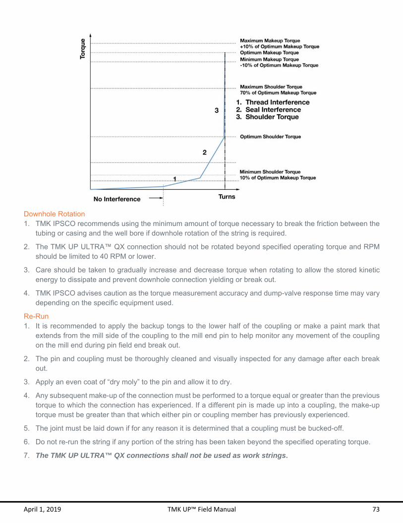
April 1, 2019 TMK UP™ Field Manual 73
Downhole Rotation 1. TMK IPSCO recommends using the minimum amount of torque necessary to break the friction between the
tubing or casing and the well bore if downhole rotation of the string is required.
2. The TMK UP ULTRA™ QX connection should not be rotated beyond specified operating torque and RPM should be limited to 40 RPM or lower.
3. Care should be taken to gradually increase and decrease torque when rotating to allow the stored kinetic energy to dissipate and prevent downhole connection yielding or break out.
4. TMK IPSCO advises caution as the torque measurement accuracy and dump-valve response time may vary depending on the specific equipment used.
Re-Run 1. It is recommended to apply the backup tongs to the lower half of the coupling or make a paint mark that
extends from the mill side of the coupling to the mill end pin to help monitor any movement of the coupling on the mill end during pin field end break out.
2. The pin and coupling must be thoroughly cleaned and visually inspected for any damage after each break out.
3. Apply an even coat of “dry moly” to the pin and allow it to dry.
4. Any subsequent make-up of the connection must be performed to a torque equal or greater than the previous torque to which the connection has experienced. If a different pin is made up into a coupling, the make-up torque must be greater than that which either pin or coupling member has previously experienced.
5. The joint must be laid down if for any reason it is determined that a coupling must be bucked-off.
6. Do not re-run the string if any portion of the string has been taken beyond the specified operating torque.
7. The TMK UP ULTRA™ QX connections shall not be used as work strings.

April 1, 2019 TMK UP™ Field Manual 74
Field Repair 1 Field repair of TMK UP ULTRA™ QX connections shall only be conducted by Field Service Technicians
certified by TMK IPSCO.
2 Minor tears, galls, dents or burrs on the thread profile may be able to be repaired by qualified personnel in the field.
3 Minor tears and scratches on the pin face may be repaired.
4 Repair connections using a file, stone, sand paper or appropriate abrasive tool, and Scotch-Brite™ sponge or equivalent.
5 Spray the connection with an even coat of “dry moly” and allow it to dry.
6 Only qualified personnel may make the decision regarding the serviceability of a given connection.
7 Seal areas cannot be repaired in the field and must be free of any damages.
8 Loose burrs and sharp raised edges must be removed or rounded down.

TMK UP ULTRA ™
GX

April 1, 2019 TMK UP™ Field Manual 76
TMK UP ULTRA™ GX
In addition to this section, ensure that all instructions from the GENERAL GUIDELINES section starting on page 10 are followed. Refer to the Pre-Run Checklist on page 8 to aid in proper running of TMK UP ULTRA™ GX connections.
Interchangeability TMK UP ULTRA™ GX pins are not interchangeable between different weights of the same nominal OD. A crossover is needed if running a mixed weight string or accessories.

April 1, 2019 TMK UP™ Field Manual 77
Thread Compound Application 1 TMK IPSCO recommends the use of thread compounds that meet or exceed ISO 13678 or API RP 5A3
requirements.
2 The use of an applicator “moustache” brush is recommended for the box and a paintbrush for the pin to best control the application and quantity of thread compound.
3 Inspect that the brush is clean and free of any dirt. If the brush has been recently cleaned, make sure that no water or other foreign debris remains in the bristles.
4 Water that is on the brush, connection, or in the running compound bucket must be completely removed before applying the compound. The brush and connection can be dried with a clean rag.
5 Apply an evenly distributed light coat of thread compound to the entire pin and to the coupling seal area as demonstrated in the graphics below. A “light coat” means that the machined thread profile can be clearly and distinctly seen, with no more than 30% of the thread height filled with thread compound.

April 1, 2019 TMK UP™ Field Manual 78
Make-up Torque 1 TMK UP ULTRA™ GX connections shall be made up to the torque specified on the most current Connection
Data Sheet.
2 The specified minimum make-up torque in the data sheet is the minimum torque to which the connection should be assembled the first time.
3 The specified optimum make-up torque in the data sheet should be used as the target make-up torque for optimum performance.
4 The specified maximum make-up torque in the data sheet should be used as the highest recommended make-up torque for normal operations.
5 Add 10% to the optimum make-up torque when using thread locking compound. A torque shoulder must be visible for proper make-up. Apply the thread locking compound to the threads only and apply running compound to the seal area.
Make-up RPM 1 Initial RPM shall start in high gear with a low torque and high RPM.
2 Switch to low gear before the seal engagement appears in the torque turn graph.
3 Power tongs should remain in low gear and at a constant RPM once the seal engages.
4 The below table lists the approximate recommended make-up RPM for the TMK UP ULTRA™ GX connections.
Target Make-up RPM
OD Initial RPM Final RPM
4 ½ – 5 ½ 20 10 6 ⅝ – 7 ⅝ 15 7
8 ⅝ – 9 ⅝ 10 5 10 ¾ – 14 6 3
Shoulder Torque 1. The shoulder torque shall be clearly visible at a minimum of 10% of optimum make-up torque and at a
maximum of 70% of optimum make-up torque and with a 0.020 – 0.100 delta turn range.
2. If the shoulder torque is outside of these specifications, break out and inspect the pin and coupling.
3. A large torque increase prior to 1 turn from shouldering may indicate a problem in make-up such as cross threading or galling.
4. See the example graph below that demonstrates the make-up limits for TMK UP ULTRA™ GX connections.

April 1, 2019 TMK UP™ Field Manual 79
Downhole Rotation 1. TMK IPSCO recommends using the minimum amount of torque necessary to break the friction between the
tubing or casing and the well bore if downhole rotation of the string is required.
2. The TMK UP ULTRA™ GX connection should not be rotated beyond the specified operating torque and RPM should be limited to 40 RPM or lower.
3. Care should be taken to gradually increase and decrease torque when rotating to allow the stored kinetic energy to dissipate and prevent downhole connection yielding or break out.
4. TMK IPSCO advises caution as the torque measurement accuracy and dump-valve response time may vary depending on the specific equipment used.
Re-Run 1. It is recommended to apply the backup tongs to the lower half of the coupling or make a paint mark that
extends from the mill side of the coupling to the mill end pin to help monitor any movement of the coupling on the mill end during pin field end break out.
2. The pin and coupling must be thoroughly cleaned and visually inspected for any damage after each break out.
3. Apply an even coat of “dry moly” to the pin and allow it to dry.
4. Any subsequent make-up of the connection must be performed to a torque equal or greater than the previous torque to which the connection has experienced. If a different pin is made up into a coupling, the make-up torque must be greater than that which either pin or coupling member has previously experienced.
5. The joint must be laid down if for any reason it is determined that a coupling must be bucked-off.
6. Do not re-run the string if any portion of the string has been taken beyond the specified operating torque.
7. The TMK UP ULTRA™ GX connections shall not be used as work strings.

April 1, 2019 TMK UP™ Field Manual 80
Field Repair 1 Field repair of TMK UP ULTRA™ GX connections shall only be conducted by Field Service Technicians
certified by TMK IPSCO.
2 Minor tears, galls, dents or burrs on the thread profile may be able to be repaired by qualified personnel in the field.
3 Minor tears and scratches on the pin face may be repaired.
4 Repair connections using a file, stone, sand paper or appropriate abrasive tool, and Scotch-Brite™ sponge or equivalent.
5 Spray the connection with an even coat of “dry moly” and allow it to dry.
6 Only qualified personnel may make the decision regarding the serviceability of a given connection.
7 Seal areas cannot be repaired in the field and must be free of any damages.
8 Loose burrs and sharp raised edges must be removed or rounded down.

DQX &DQX HT
T M K U P U L T R A ™

April 1, 2019 TMK UP™ Field Manual 82
TMK UP ULTRA™ DQX & DQX-HT
In addition to this section, ensure that all instructions from the GENERAL GUIDELINES section starting on page 10 are followed. Refer to the Pre-Run Checklist on page 8 to aid in proper running of TMK UP ULTRA™ DQX & DQX HT connections.
Interchangeability 1. TMK UP ULTRA™ DQX and DQX-HT pins are interchangeable between both connections and with different
weights of the same nominal OD. However, the connection is limited to all the mechanical properties of the weakest pin including the make-up torque and downhole rotation.
2. Interchanging pins between connections and weights will not provide an internally flush connection.
3. TMK UP ULTRA™ DQX and DQX-HT can be distinguished by inspecting the pin nose ID. TMK UP ULTRA™ DQX has a non-machined ID surface and TMK UP ULTRA™ DQX-HT has a swaged and bored ID surface.

April 1, 2019 TMK UP™ Field Manual 83
Thread Compound Application 1 TMK IPSCO recommends the use of thread compounds that meet or exceed ISO 13678 or API RP 5A3
requirements.
2 The use of an applicator “moustache” brush is recommended for the box and a paintbrush for the pin to best control the application and quantity of thread compound.
3 Inspect that the brush is clean and free of any dirt. If the brush has been recently cleaned, make sure that no water or other foreign debris remains in the bristles.
4 Water that is on the brush, connection, or in the running compound bucket must be completely removed before applying the compound. The brush and connection can be dried with a clean rag.
5 Apply an evenly distributed light coat of thread compound to the pin face and full threads and to the coupling threads as demonstrated in the graphics below. A “light coat” means that the machined thread profile can be clearly and distinctly seen, with no more than 30% of the thread height filled with thread compound. Do not fill the dope pocket (see coupling diagram).
TMK UP ULTRA™ DQX
TMK UP ULTRA™ DQX-HT
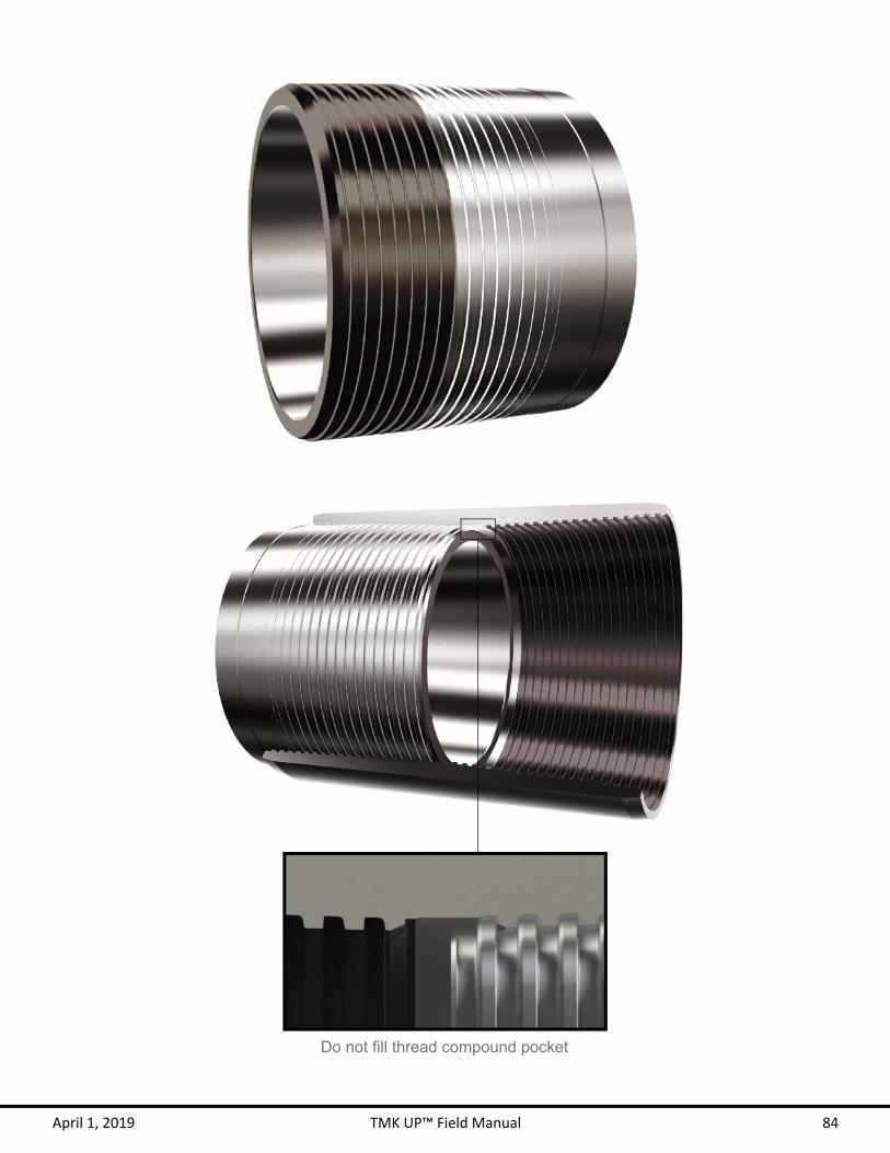
April 1, 2019 TMK UP™ Field Manual 84
Do not fill thread compound pocket
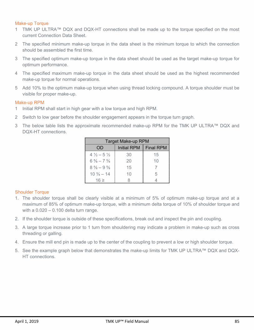
April 1, 2019 TMK UP™ Field Manual 85
Make-up Torque 1 TMK UP ULTRA™ DQX and DQX-HT connections shall be made up to the torque specified on the most
current Connection Data Sheet.
2 The specified minimum make-up torque in the data sheet is the minimum torque to which the connection should be assembled the first time.
3 The specified optimum make-up torque in the data sheet should be used as the target make-up torque for optimum performance.
4 The specified maximum make-up torque in the data sheet should be used as the highest recommended make-up torque for normal operations.
5 Add 10% to the optimum make-up torque when using thread locking compound. A torque shoulder must be visible for proper make-up.
Make-up RPM 1 Initial RPM shall start in high gear with a low torque and high RPM.
2 Switch to low gear before the shoulder engagement appears in the torque turn graph.
3 The below table lists the approximate recommended make-up RPM for the TMK UP ULTRA™ DQX and DQX-HT connections.
Target Make-up RPM
OD Initial RPM Final RPM
4 ½ – 5 ½ 30 15 6 ⅝ – 7 ⅝ 20 10
8 ⅝ – 9 ⅝ 15 7
10 ¾ – 14 10 5 16 ≥ 8 4
Shoulder Torque 1. The shoulder torque shall be clearly visible at a minimum of 5% of optimum make-up torque and at a
maximum of 85% of optimum make-up torque, with a minimum delta torque of 10% of shoulder torque and with a 0.020 – 0.100 delta turn range.
2. If the shoulder torque is outside of these specifications, break out and inspect the pin and coupling.
3. A large torque increase prior to 1 turn from shouldering may indicate a problem in make-up such as cross threading or galling.
4. Ensure the mill end pin is made up to the center of the coupling to prevent a low or high shoulder torque.
5. See the example graph below that demonstrates the make-up limits for TMK UP ULTRA™ DQX and DQX-HT connections.

April 1, 2019 TMK UP™ Field Manual 86
Spinning Coupling 1. Ensure the mill end pin is made up to the center of the coupling to prevent spinning couplings.
2. TMK IPSCO allows coupling movement of no more than ½ turn on the mill end during make-up.
3. Back-up tongs can be placed on the lower half of the coupling if the coupling spins during make-up.
4. A ruler or caliper may be used to verify the coupling position. Measure from the coupling face to the pin nose face. The acceptable length is ½ the overall coupling length ± 1/32”. Take two readings 180° apart and verify that both readings are within tolerance, if either reading is out of tolerances, take two more and average the four readings.
Downhole Rotation 1. TMK IPSCO recommends using the minimum amount of torque necessary to break the friction between the
tubing or casing and the well bore if downhole rotation of the string is required.
2. The TMK UP ULTRA™ DQX and DQX-HT connection should not be rotated beyond the specified operating torque and RPM should be limited to 40 RPM or lower.
3. Care should be taken to gradually increase and decrease torque when rotating to allow the stored kinetic energy to dissipate and prevent downhole connection yielding or break out.
4. TMK IPSCO advises caution as the torque measurement accuracy and dump-valve response time may vary depending on the specific equipment used.

April 1, 2019 TMK UP™ Field Manual 87
Re-Run 1. The TMK UP ULTRA™ DQX and DQX-HT connections may be used as work strings.
2. It is recommended to apply the backup tongs to the lower half of the coupling or make a paint mark that extends from the mill side of the coupling to the mill end pin to help monitor any movement of the coupling on the mill end during pin field end break out.
3. The pin and coupling must be thoroughly cleaned and visually inspected for any damage after each break out.
4. Any subsequent make-up of the connection must be performed to a torque equal or greater than the previous torque to which the connection has experienced. If a different pin is made up into a coupling, the make-up torque must be greater than that which either pin or coupling member has previously experienced.
5. The joint must be laid down if for any reason it is determined that a coupling must be bucked-off.
6. Do not re-run the string if any portion of the string has been taken beyond the specified operating torque.
Field Repair 1 Field repair of TMK UP ULTRA™ DQX and DQX-HT connections shall only be conducted by Field Service
Technicians certified by TMK IPSCO.
2 Minor tears, galls, dents or burrs on the thread profile may be able to be repaired by qualified personnel in the field.
3 Galling on pin face may be repaired if it does not exceed 25% of the pipe circumference. The repair shall fully remove any protrusions which may cause galling on subsequent make-up.
4 Repair connections using a file, stone, sand paper or appropriate abrasive tool, and Scotch-Brite™ sponge or equivalent.
5 Only qualified personnel may make the decision regarding the serviceability of a given connection.
6 Loose burrs and sharp raised edges must be removed or rounded down.

April 1, 2019 TMK UP™ Field Manual 88
Repairs may be made to the entire coupling
Minor tears and scratches on pin nose face may be repaired

DQX-SRT M K U P U L T R A ™

April 1, 2019 TMK UP™ Field Manual 90
TMK UP ULTRA™ DQX-SR
In addition to this section, ensure that all instructions from the GENERAL GUIDELINES section starting on page 10 are followed. Refer to the Pre-Run Checklist on page 8 to aid in proper running of TMK UP ULTRA™ DQX-SR connections.
Interchangeability 1. TMK UP ULTRA™ DQX-SR pin are interchangeable between different weights of the same nominal OD.
However, the connection is limited to all the mechanical properties of the weakest pin including the make-up torque and downhole rotation.
2. Interchanging pins between weights will not provide an internally flush connection.
3. TMK UP ULTRA™ DQX-SR can be distinguished by inspecting the coupling for a visible Seal Ring. TMK UP ULTRA™ DQX-SR has a non-machined ID surface.

April 1, 2019 TMK UP™ Field Manual 91
Thread Compound Application 1 TMK IPSCO recommends the use of thread compounds that meet or exceed ISO 13678 or API RP 5A3
requirements.
2 The use of an applicator “moustache” brush is recommended for the box and a paintbrush for the pin to best control the application and quantity of thread compound.
3 Inspect that the brush is clean and free of any dirt. If the brush has been recently cleaned, make sure that no water or other foreign debris remains in the bristles.
4 Water that is on the brush, connection, or in the running compound bucket must be completely removed before applying the compound. The brush and connection can be dried with a clean rag.
5 Apply an evenly distributed light coat of thread compound to the pin face and full threads and to the coupling threads as demonstrated in the graphics below. A “light coat” means that the machined thread profile can be clearly and distinctly seen, with no more than 30% of the thread height filled with thread compound. Do not fill the dope pocket (see coupling diagram).
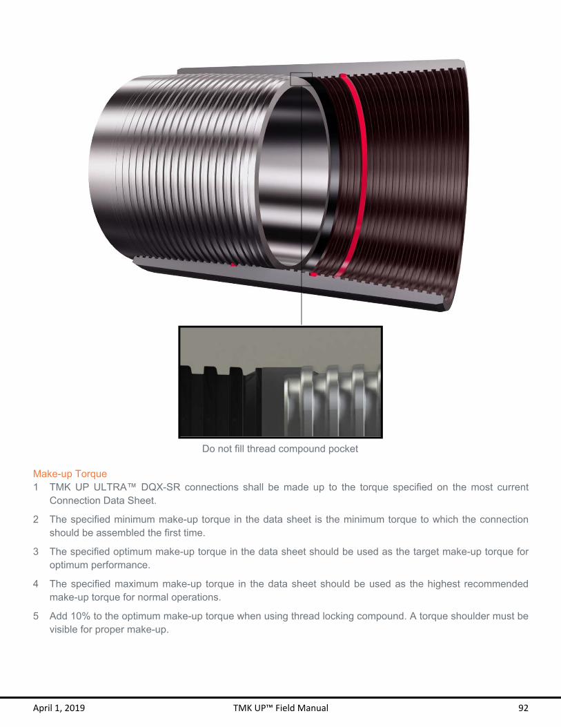
April 1, 2019 TMK UP™ Field Manual 92
Make-up Torque 1 TMK UP ULTRA™ DQX-SR connections shall be made up to the torque specified on the most current
Connection Data Sheet.
2 The specified minimum make-up torque in the data sheet is the minimum torque to which the connection should be assembled the first time.
3 The specified optimum make-up torque in the data sheet should be used as the target make-up torque for optimum performance.
4 The specified maximum make-up torque in the data sheet should be used as the highest recommended make-up torque for normal operations.
5 Add 10% to the optimum make-up torque when using thread locking compound. A torque shoulder must be visible for proper make-up.
Do not fill thread compound pocket

April 1, 2019 TMK UP™ Field Manual 93
Make-up RPM 1 Initial RPM shall start in high gear with a low torque and high RPM.
2 Switch to low gear before the shoulder engagement appears in the torque turn graph.
3 The below table lists the approximate recommended make-up RPM for the TMK UP ULTRA™ DQX-SR connections.
Target Make-up RPM
OD Initial RPM Final RPM
4 ½ – 5 ½ 30 15 6 ⅝ – 7 ⅝ 20 10
8 ⅝ – 9 ⅝ 15 7
10 ¾ – 14 10 5 16 ≥ 8 4
Shoulder Torque 1. The shoulder torque shall be clearly visible at a minimum of 5% of optimum make-up torque and at a
maximum of 85% of optimum make-up torque, with a minimum delta torque of 10% of shoulder torque and with a 0.020 – 0.100 delta turn range.
2. If the shoulder torque is outside of these specifications, break out and inspect the pin and coupling.
3. A large torque increase prior to 1 turn from shouldering may indicate a problem in make-up such as cross threading or galling.
4. Ensure the mill end pin is made up to the center of the coupling to prevent a low or high shoulder torque.
5. See the example graph below that demonstrates the make-up limits for TMK UP ULTRA™ DQX-SR connections.
April 1, 2019 TMK UP™ Field Manual 94
Spinning Coupling 1. Ensure the mill end pin is made up to the center of the coupling to prevent spinning couplings.
2. TMK IPSCO allows coupling movement of no more than ½ turn on the mill end during make-up.
3. Back-up tongs can be placed on the lower half of the coupling if the coupling spins during make-up.
4. A ruler or caliper may be used to verify the coupling position. Measure from the coupling face to the pin nose face. The acceptable length is ½ the overall coupling length ± 1/32”. Take two readings 180° apart and verify that both readings are within tolerance, if either reading is out of tolerances, take two more and average the four readings.
Downhole Rotation 1. TMK IPSCO recommends using the minimum amount of torque necessary to break the friction between the
tubing or casing and the well bore if downhole rotation of the string is required.
2. The TMK UP ULTRA™ DQX-SR connection should not be rotated beyond the specified operating torque and RPM should be limited to 40 RPM or lower.
3. Care should be taken to gradually increase and decrease torque when rotating to allow the stored kinetic energy to dissipate and prevent downhole connection yielding or break out.
4. TMK IPSCO advises caution as the torque measurement accuracy and dump-valve response time may vary depending on the specific equipment used.
Seal Ring Installation 1. Before installing the seal ring, both the Box groove and the seal ring must be dry and free of debris.
2. Place the seal ring in the box groove until the ring snaps into the box groove. If necessary use a non-metallic tool to properly seat the seal ring.
3. Ensure that the seal ring can freely spin inside the groove, indicating proper installation.
4. Avoid adding excessive thread compound as it may damage the seal ring during make up.
5. The seal ring must be removed and replaced after every breakout.
Re-Run 1. It is recommended to apply the backup tongs to the lower half of the coupling or make a paint mark that
extends from the mill side of the coupling to the mill end pin to help monitor any movement of the coupling on the mill end during pin field end break out.
2. The pin and coupling must be thoroughly cleaned and visually inspected for any damage after each break out.
3. Any subsequent make-up of the connection must be performed to a torque equal or greater than the previous torque to which the connection has experienced. If a different pin is made up into a coupling, the make-up torque must be greater than that which either pin or coupling member has previously experienced.
4. The joint must be laid down if for any reason it is determined that a coupling must be bucked-off.
5. Do not re-run the string if any portion of the string has been taken beyond the specified operating torque.

April 1, 2019 TMK UP™ Field Manual 95
Field Repair 1 Field repair of TMK UP ULTRA™ DQX-SR connections shall only be conducted by Field Service Technicians
certified by TMK IPSCO.
2 Minor tears, galls, dents or burrs on the thread profile may be able to be repaired by qualified personnel in the field.
3 Galling on pin face may be repaired if it does not exceed 25% of the pipe circumference. The repair shall fully remove any protrusions which may cause galling on subsequent make-up.
4 Repair connections using a file, stone, sand paper or appropriate abrasive tool, and Scotch-Brite™ sponge or equivalent.
5 Only qualified personnel may make the decision regarding the serviceability of a given connection.
6 Loose burrs and sharp raised edges must be removed or rounded down.
Tears and scratches on pin nose face may be repaired

April 1, 2019 TMK UP™ Field Manual 96

BPNT M K U P ™

April 1, 2019 TMK UP™ Field Manual 98
TMK UP™ BPN
In addition to this section, ensure that all instructions from the GENERAL GUIDELINES section starting on page 10 are followed. Refer to the Pre-Run Checklist on page 8 to aid in proper running of TMK UP™ BPN connections.
Interchangeability 1 TMK UP™ BPN pins are interchangeable with API BTC and with different weights of the same nominal OD.
However, the connection is limited to all the mechanical properties of the weakest pin including the make-up torque and downhole rotation.
2 Interchanging pins between weights will not provide an internally flush connection.
3 When making up a TMK UP™ BPN pin into an API BTC coupling, API make-up procedures take precedence.
4 When making up an API BTC pin into a TMK UP™ BPN coupling, TMK UP™ BPN procedures prevail.
5 Never make-up past the base of the triangle or beyond the maximum make-up torque when using a TMK UP™ BPN coupling.

April 1, 2019 TMK UP™ Field Manual 99
Thread Compound Application 1 TMK IPSCO recommends the use of thread compounds that meet or exceed ISO 13678 or API RP 5A3
requirements.
2 The use of an applicator “moustache” brush is recommended for the box and a paintbrush for the pin to best control the application and quantity of thread compound.
3 Inspect that the brush is clean and free of any dirt. If the brush has been recently cleaned, make sure that no water or other foreign debris remains in the bristles.
4 Water that is on the brush, connection, or in the running compound bucket must be completely removed before applying the compound. The brush and connection can be dried with a clean rag.
5 Apply an evenly distributed light coat of thread compound to the pin and coupling as demonstrated in the graphics below. A “light coat” means that the machined thread profile can be clearly and distinctly seen, with no more than 30% of the thread height filled with thread compound. Do not fill the dope pocket (see coupling diagram).
Do not fill thread compound pocket
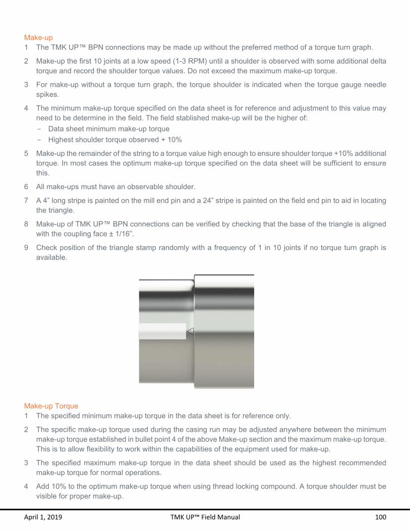
April 1, 2019 TMK UP™ Field Manual 100
Make-up 1 The TMK UP™ BPN connections may be made up without the preferred method of a torque turn graph.
2 Make-up the first 10 joints at a low speed (1-3 RPM) until a shoulder is observed with some additional delta torque and record the shoulder torque values. Do not exceed the maximum make-up torque.
3 For make-up without a torque turn graph, the torque shoulder is indicated when the torque gauge needle spikes.
4 The minimum make-up torque specified on the data sheet is for reference and adjustment to this value may need to be determine in the field. The field stablished make-up will be the higher of:
- Data sheet minimum make-up torque
- Highest shoulder torque observed + 10%
5 Make-up the remainder of the string to a torque value high enough to ensure shoulder torque +10% additional torque. In most cases the optimum make-up torque specified on the data sheet will be sufficient to ensure this.
6 All make-ups must have an observable shoulder.
7 A 4” long stripe is painted on the mill end pin and a 24” stripe is painted on the field end pin to aid in locating the triangle.
8 Make-up of TMK UP™ BPN connections can be verified by checking that the base of the triangle is aligned with the coupling face ± 1/16”.
9 Check position of the triangle stamp randomly with a frequency of 1 in 10 joints if no torque turn graph is available.
Make-up Torque 1 The specified minimum make-up torque in the data sheet is for reference only.
2 The specific make-up torque used during the casing run may be adjusted anywhere between the minimum make-up torque established in bullet point 4 of the above Make-up section and the maximum make-up torque. This is to allow flexibility to work within the capabilities of the equipment used for make-up.
3 The specified maximum make-up torque in the data sheet should be used as the highest recommended make-up torque for normal operations.
4 Add 10% to the optimum make-up torque when using thread locking compound. A torque shoulder must be visible for proper make-up.

April 1, 2019 TMK UP™ Field Manual 101
Make-up RPM 1 Initial RPM shall start in high gear with a low torque and high RPM.
2 Switch to low gear before the shoulder engagement appears in the torque turn graph.
3 The below table lists the approximate recommended make-up RPM for the TMK UP™ BPN connections.
Target Make-up RPM
OD Initial RPM Final RPM
4 – 5 ½ 30 15 6 ⅝ – 7 ⅝ 20 10
8 ⅝ – 9 ⅝ 15 7
10 ¾ – 14 10 5 16 ≥ 8 4
Shoulder Torque 1. The shoulder torque shall be clearly visible at a minimum of 20% of maximum make-up torque and at a
maximum of 90% of maximum make-up torque, with a minimum delta torque of 10% of shoulder torque and with a 0.015 – 0.080 delta turn range.
2. If the shoulder torque is outside of these specifications, break out and inspect the pin and coupling.
3. A large torque increase prior to 1 turn from shouldering may indicate a problem in make-up such as cross threading or galling.
4. Ensure the mill end pin is made up to half way the coupling length to prevent a low or high shoulder torque.
5. See the example graph below that demonstrates the make-up limits for TMK UP™ BPN connections.

April 1, 2019 TMK UP™ Field Manual 102
Spinning Coupling 1. Ensure the mill end pin is made up to the center of the coupling to prevent spinning couplings.
2. TMK IPSCO allows coupling movement of no more than ½ turn on the mill end during make-up.
3. If any coupling movement is noticed, TMK IPSCO recommends applying the backup tongs to the lower half of the coupling and completing the connection make-up.
4. A ruler or caliper may be used to verify the coupling position. Measure from the coupling face to the pin nose face. The acceptable length is ½ the overall coupling length ± 1/32”. Take two readings 180° apart and verify that both readings are within tolerance, if either reading is out of tolerances, take two more and average the four readings.
TMK UP™ BPN Pin into API Buttress Couplings 1. When crossing over from a TMK UP™ BPN pin to an API Buttress coupling, API procedures prevail.
2. TMK UP™ BPN pins are 100% interchangeable with API Buttress pins of the same size and weight. Performance (including torque) is limited to that of standard API Buttress.
3. Rotation of the string is not permitted without the use of thread locking compound.
API Buttress Pin into TMK UP™ BPN Couplings 1. When crossing over to a TMK UP™ BPN coupling, make-up is to TMK UP™ BPN torque and position. Follow
all TMK UP™ BPN recommended procedures.
2. Never make-up past the base of the triangle or beyond the maximum make-up torque when using a TMK UP™ BPN coupling.
3. Rotation of the string is not permitted without the use of thread locking compound.
Accessories 1. TMK UP™ BPN accessories are available and preferred over API Buttress accessories.
2. Float equipment threaded with API Buttress can be used with thread locking compound and rotated at TMK UP™ BPN torque values.
3. It is strongly recommended that accessories other than float equipment be threaded with TMK UP™ BPN to rotate at TMK UP™ BPN torque values.
Downhole Rotation 1. TMK IPSCO recommends using the minimum amount of torque necessary to break the friction between the
tubing or casing and the well bore if downhole rotation of the string is required.
2. The TMK UP™ BPN connection should not be rotated beyond the specified operating torque and RPM should be limited to 40 RPM or lower.
3. Care should be taken to gradually increase and decrease torque when rotating to allow the stored kinetic energy to dissipate and prevent downhole connection yielding or break out.
4. TMK IPSCO advises caution as the torque measurement accuracy and dump-valve response time may vary depending on the specific equipment used.

April 1, 2019 TMK UP™ Field Manual 103
Re-Run 1. The TMK UP™ BPN connections may be used as work strings.
2. It is recommended to apply the backup tongs to the lower half of the coupling or make a paint mark that extends from the mill side of the coupling to the mill end pin to help monitor any movement of the coupling on the mill end pin during field end break out.
3. Break out in low gear at a RPM equal to or lower than the target make-up RPM to prevent the connection from overheating and galling. If overheating is observed, lower the break out RPM to prevent damage to the connection.
4. The pin and coupling must be thoroughly cleaned and visually inspected for any damage after each break out.
5. Any subsequent make-up of the connection must be performed to a torque equal or greater than the previous torque to which the connection has experienced. If a different pin is made up into a coupling, the make-up torque must be greater than that which either pin or coupling member has previously experienced.
6. The joint must be laid down if for any reason it is determined that a coupling must be bucked-off.
7. Do not re-run the string if any portion of the string has been taken beyond the specified operating torque.
Field Repair 1 Field Repair of TMK UP™ BPN connections shall only be conducted by Field Service Technicians certified
by TMK IPSCO.
2 Minor tears, galls or dents on the thread profile may be able to be repaired by qualified personnel in the field.
3 Galling on pin face may be repaired if it does not exceed 25% of the pipe circumference. The repair shall fully remove any protrusions which may cause galling on subsequent make-up.
4 Repair connections using a file, stone, sand paper or appropriate abrasive tool, and Scotch-Brite™ sponge or equivalent.
5 Only qualified personnel may make the decision regarding the serviceability of a given connection.
6 Loose burrs and sharp raised edges must be removed or rounded down.

April 1, 2019 TMK UP™ Field Manual 104
Entire threaded area of pin may be repaired
Pin nose face may be repaired
Repairs may be made to the entire coupling
BPN-SRT M K U P ™
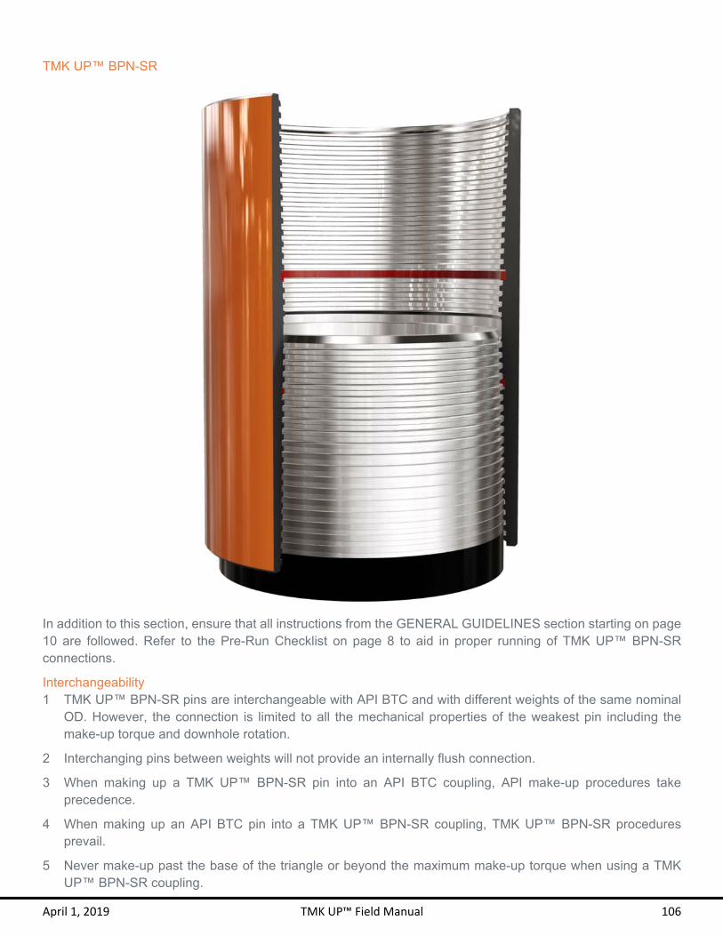
April 1, 2019 TMK UP™ Field Manual 106
TMK UP™ BPN-SR
In addition to this section, ensure that all instructions from the GENERAL GUIDELINES section starting on page 10 are followed. Refer to the Pre-Run Checklist on page 8 to aid in proper running of TMK UP™ BPN-SR connections.
Interchangeability 1 TMK UP™ BPN-SR pins are interchangeable with API BTC and with different weights of the same nominal
OD. However, the connection is limited to all the mechanical properties of the weakest pin including the make-up torque and downhole rotation.
2 Interchanging pins between weights will not provide an internally flush connection.
3 When making up a TMK UP™ BPN-SR pin into an API BTC coupling, API make-up procedures take precedence.
4 When making up an API BTC pin into a TMK UP™ BPN-SR coupling, TMK UP™ BPN-SR procedures prevail.
5 Never make-up past the base of the triangle or beyond the maximum make-up torque when using a TMK UP™ BPN-SR coupling.

April 1, 2019 TMK UP™ Field Manual 107
Thread Compound Application 1 TMK IPSCO recommends the use of thread compounds that meet or exceed ISO 13678 or API RP 5A3
requirements.
2 The use of an applicator “moustache” brush is recommended for the box and a paintbrush for the pin to best control the application and quantity of thread compound.
3 Inspect that the brush is clean and free of any dirt. If the brush has been recently cleaned, make sure that no water or other foreign debris remains in the bristles.
4 Water that is on the brush, connection, or in the running compound bucket must be completely removed before applying the compound. The brush and connection can be dried with a clean rag.
5 Apply an evenly distributed light coat of thread compound to the pin and coupling as demonstrated in the graphics below. A “light coat” means that the machined thread profile can be clearly and distinctly seen, with no more than 30% of the thread height filled with thread compound. Do not fill the dope pocket (see coupling diagram).
Do not fill thread compound pocket

April 1, 2019 TMK UP™ Field Manual 108
Make-up 1 The TMK UP™ BPN-SR connections may be made up without the preferred method of a torque turn graph.
2 Make-up the first 10 joints at a low speed (1-3 RPM) until a shoulder is observed with some additional delta torque and record the shoulder torque values. Do not exceed the maximum make-up torque.
3 For make-up without a torque turn graph, the torque shoulder is indicated when the torque gauge needle spikes.
4 The minimum make-up torque specified on the data sheet is for reference and adjustment to this value may need to be determine in the field. The field stablished make-up will be the higher of:
- Data sheet minimum make-up torque
- Highest shoulder torque observed + 10%
5 Make-up the remainder of the string to a torque value high enough to ensure shoulder torque +10% additional torque. In most cases the optimum make-up torque specified on the data sheet will be sufficient to ensure this.
6 All make-ups must have an observable shoulder.
7 A 4” long stripe is painted on the mill end pin and a 24” stripe is painted on the field end pin to aid in locating the triangle.
8 Make-up of TMK UP™ BPN-SR connections can be verified by checking that the base of the triangle is aligned with the coupling face ± 1/16”.
9 Check position of the triangle stamp randomly with a frequency of 1 in 10 joints if no torque turn graph is available.
Make-up Torque 1 The specified minimum make-up torque in the data sheet is for reference only.
2 The specific make-up torque used during the casing run may be adjusted anywhere between the minimum make-up torque established in bullet point 4 of the above Make-up section and the maximum make-up torque. This is to allow flexibility to work within the capabilities of the equipment used for make-up.
3 The specified maximum make-up torque in the data sheet should be used as the highest recommended make-up torque for normal operations.

April 1, 2019 TMK UP™ Field Manual 109
4 Add 10% to the optimum make-up torque when using thread locking compound. A torque shoulder must be visible for proper make-up.
Make-up RPM 1 Initial RPM shall start in high gear with a low torque and high RPM.
2 Switch to low gear before the shoulder engagement appears in the torque turn graph.
3 The below table lists the approximate recommended make-up RPM for the TMK UP™ BPN-SR connections.
Target Make-up RPM
OD Initial RPM Final RPM
4 – 5 ½ 30 15 6 ⅝ – 7 ⅝ 20 10
8 ⅝ – 10 15 7
10 ¾ – 14 10 5 16 ≥ 8 4
Shoulder Torque 1. The shoulder torque shall be clearly visible at a minimum of 20% of maximum make-up torque and at a
maximum of 90% of maximum make-up torque, with a minimum delta torque of 10% of shoulder torque and with a 0.015 – 0.080 delta turn range.
2. If the shoulder torque is outside of these specifications, break out and inspect the pin and coupling.
3. A large torque increase prior to 1 turn from shouldering may indicate a problem in make-up such as cross threading or galling.
4. Ensure the mill end pin is made up to half way the coupling length to prevent a low or high shoulder torque.
5. See the example graph below that demonstrates the make-up limits for TMK UP™ BPN-SR connections.

April 1, 2019 TMK UP™ Field Manual 110
Spinning Coupling 1. Ensure the mill end pin is made up to the center of the coupling to prevent spinning couplings.
2. TMK IPSCO allows coupling movement of no more than ½ turn on the mill end during make-up.
3. If any coupling movement is noticed, TMK IPSCO recommends applying the backup tongs to the lower half of the coupling and completing the connection make-up.
4. A ruler or caliper may be used to verify the coupling position. Measure from the coupling face to the pin nose face. The acceptable length is ½ the overall coupling length ± 1/32”. Take two readings 180° apart and verify that both readings are within tolerance, if either reading is out of tolerances, take two more and average the four readings.
TMK UP™ BPN-SR Pin into API Buttress Couplings 1. When crossing over from a TMK UP™ BPN-SR pin to an API Buttress coupling, API procedures prevail.
2. TMK UP™ BPN-SR pins are 100% interchangeable with API Buttress pins of the same size and weight. Performance (including torque) is limited to that of standard API Buttress.
3. Rotation of the string is not permitted without the use of thread locking compound.
API Buttress Pin into TMK UP™ BPN-SR Couplings 1. When crossing over to a TMK UP™ BPN-SR coupling, make-up is to TMK UP™ BPN-SR torque and position.
Follow all TMK UP™ BPN-SR recommended procedures.
2. Never make-up past the base of the triangle or beyond the maximum make-up torque when using a TMK UP™ BPN-SR coupling.
3. Rotation of the string is not permitted without the use of thread locking compound.
Accessories 1. TMK UP™ BPN-SR accessories are available and preferred over API Buttress accessories.
2. Float equipment threaded with API Buttress can be used with thread locking compound and rotated at TMK UP™ BPN-SR torque values.
3. It is strongly recommended that accessories other than float equipment be threaded with TMK UP™ BPN-SR to rotate at TMK UP™ BPN-SR torque values.
Downhole Rotation 1. TMK IPSCO recommends using the minimum amount of torque necessary to break the friction between the
tubing or casing and the well bore if downhole rotation of the string is required.
2. The TMK UP™ BPN-SR connection should not be rotated beyond the operating torque and RPM should be limited to 40 RPM or lower.
3. Care should be taken to gradually increase and decrease torque when rotating to allow the stored kinetic energy to dissipate and prevent downhole connection yielding or break out.
4. The fatigue life of TMK UP™ BPN-SR connections is greater than the number of turns it takes to rotate the tubing or casing into a drilled formation as long the dogleg severity is 20°/100 ft. or less.
5. TMK IPSCO advises caution as the torque measurement accuracy and dump-valve response time may vary depending on the specific equipment used.

April 1, 2019 TMK UP™ Field Manual 111
Seal Ring Installation 1. Before installing the seal ring, both the Box groove and the seal ring must be dry and free of debris.
2. Place the seal ring in the box groove until the ring snaps into the box groove. If necessary use a non-metallic tool to properly seat the seal ring.
3. Ensure that the seal ring can freely spin inside the groove, indicating proper installation.
4. Avoid adding excessive thread compound as it may damage the seal ring during make up.
5. The seal ring must be removed and replaced after every breakout.
Re-Run 1. It is recommended to apply the backup tongs to the lower half of the coupling or make a paint mark that
extends from the mill side of the coupling to the mill end pin to help monitor any movement of the coupling on the mill end pin during field end break out.
2. Break out in low gear at a RPM equal to or lower than the target make-up RPM to prevent the connection from overheating and galling. If overheating is observed, lower the break out RPM to prevent damage to the connection.
3. The pin and coupling must be thoroughly cleaned and visually inspected for any damage after each break out.
4. Any subsequent make-up of the connection must be performed to a torque equal or greater than the previous torque to which the connection has experienced. If a different pin is made up into a coupling, the make-up torque must be greater than that which either pin or coupling member has previously experienced.
5. The joint must be laid down if for any reason it is determined that a coupling must be bucked-off.
6. Do not re-run the string if any portion of the string has been taken beyond the specified operating torque.
Field Repair 1 Field Repair of TMK UP™ BPN-SR connections shall only be conducted by Field Service Technicians
certified by TMK IPSCO.
2 Minor tears, galls or dents on the thread profile may be able to be repaired by qualified personnel in the field.
3 Galling on pin face may be repaired if it does not exceed 25% of the pipe circumference. The repair shall fully remove any protrusions which may cause galling on subsequent make-up.
4 Repair connections using a file, stone, sand paper or appropriate abrasive tool, and Scotch-Brite™ sponge or equivalent.
5 Only qualified personnel may make the decision regarding the serviceability of a given connection.
6 Loose burrs and sharp raised edges must be removed or rounded down.

April 1, 2019 TMK UP™ Field Manual 112
Entire threaded area of pin may be repaired
Pin nose face may be repaired

TMK UP™
2 S -6 & 2S-8
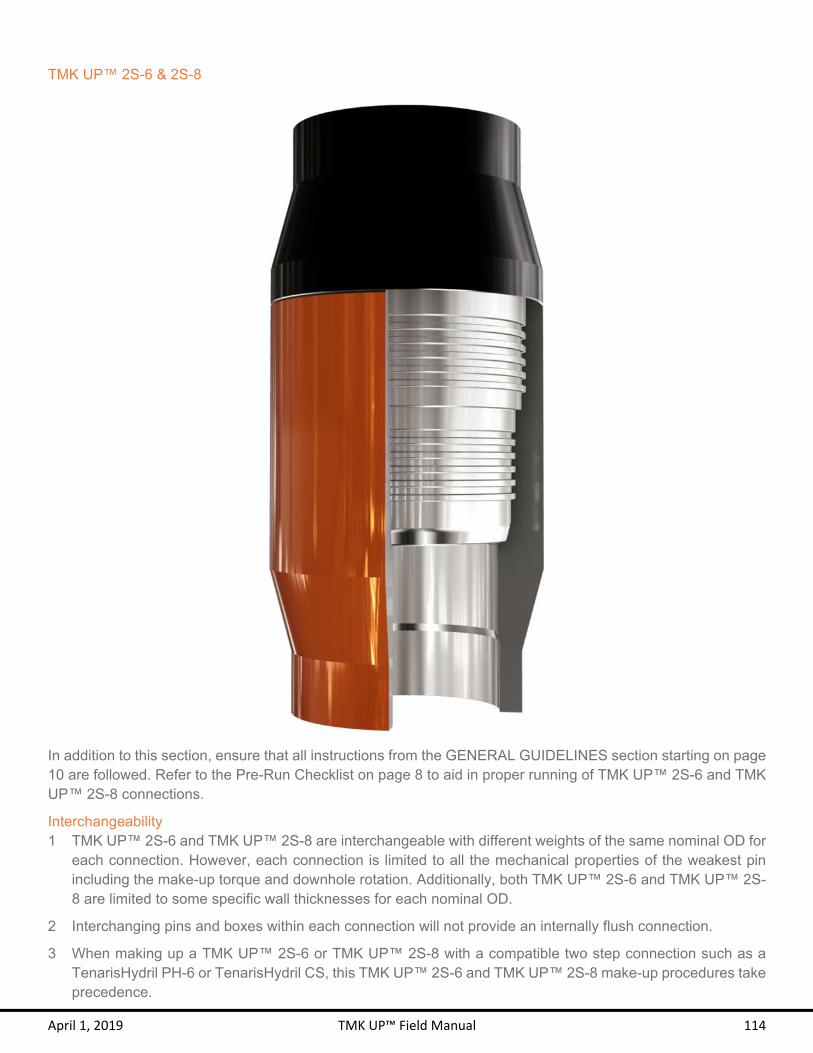
April 1, 2019 TMK UP™ Field Manual 114
TMK UP™ 2S-6 & 2S-8
In addition to this section, ensure that all instructions from the GENERAL GUIDELINES section starting on page 10 are followed. Refer to the Pre-Run Checklist on page 8 to aid in proper running of TMK UP™ 2S-6 and TMK UP™ 2S-8 connections.
Interchangeability 1 TMK UP™ 2S-6 and TMK UP™ 2S-8 are interchangeable with different weights of the same nominal OD for
each connection. However, each connection is limited to all the mechanical properties of the weakest pin including the make-up torque and downhole rotation. Additionally, both TMK UP™ 2S-6 and TMK UP™ 2S-8 are limited to some specific wall thicknesses for each nominal OD.
2 Interchanging pins and boxes within each connection will not provide an internally flush connection.
3 When making up a TMK UP™ 2S-6 or TMK UP™ 2S-8 with a compatible two step connection such as a TenarisHydril PH-6 or TenarisHydril CS, this TMK UP™ 2S-6 and TMK UP™ 2S-8 make-up procedures take precedence.

April 1, 2019 TMK UP™ Field Manual 115
Thread Compound Application 1 TMK IPSCO recommends the use of thread compounds that meet or exceed ISO 13678 or API RP 5A3
requirements.
2 The use of an applicator “moustache” brush is recommended for the box and a paintbrush for the pin to best control the application and quantity of thread compound.
3 Inspect that the brush is clean and free of any dirt. If the brush has been recently cleaned, make sure that no water or other foreign debris remains in the bristles.
4 Water that is on the brush, connection, or in the running compound bucket must be completely removed before applying the compound. The brush and connection can be dried with a clean rag.
5 Apply an evenly distributed medium coat of thread compound to the pin threads and seals as demonstrated in the graphics below. No thread compound should be applied to the box. A “medium coat” means that the machined thread profile can be clearly and distinctly seen, with no more than 50% of the thread height filled with thread compound.
6 Thread compound shall be applied to the entire box on corrosion resistant alloys.
Make-up 1 TMK UP™ 2S-6 and TMK UP™ 2S-8 connections may be made up without the preferred method of a torque
turn graph.
2 The specified minimum make-up torque in the data sheet is the minimum torque to which the connection should be assembled the first time.
3 The specified optimum make-up torque in the data sheet should be used as the target make-up torque for optimum performance.

April 1, 2019 TMK UP™ Field Manual 116
4 The specified maximum make-up torque in the data sheet should be used as the highest recommended make-up torque for normal operations.
5 Add 10% to the optimum make-up torque when using thread locking compound. A torque shoulder must be visible for proper make-up. Apply the thread locking compound to the threads only and apply running compound to the seal area.
Make-up RPM 1 Initial RPM shall start in high gear with a low torque and high RPM.
2 Switch to low gear before the shoulder engagement.
3 Up to 30 RPM is allowed in high gear and up to 15 RPM is allowed in low gear.
Shoulder 1. The shoulder shall be clearly visible below the minimum make-up torque, with a minimum delta torque of
10% of minimum make-up torque and with a 0.015 – 0.080 delta turn range.
2. A large torque increase prior to 1 turn from shouldering may indicate a problem in make-up such as cross threading or galling.
3. See the example graph below that demonstrates the make-up limits for TMK UP™ 2S-6 & 2S-8 connections.

April 1, 2019 TMK UP™ Field Manual 117
Accessories 1. It is strongly recommended that accessories be threaded with TMK UP™ 2S-6 and 2S-8.
Downhole Rotation 1. TMK IPSCO recommends using the minimum amount of torque necessary to break the friction between the
tubing or casing and the well bore if downhole rotation of the string is required.
2. The TMK UP™ 2S-6 and 2S-8 connection should not be rotated beyond the operating torque and RPM should be limited to 40 RPM or lower.
3. Care should be taken to gradually increase and decrease torque when rotating to allow the stored kinetic energy to dissipate and prevent downhole connection yielding or break out.
4. TMK IPSCO advises caution as the torque measurement accuracy and dump-valve response time may vary depending on the specific equipment used.
5. A maximum of 3.5% OD wear is acceptable.
Re-run 1. The TMK UP™ 2S-6 and 2S-8 connections may be used as work strings.
2. Break out in low gear at a RPM equal to or lower than the target make-up RPM to prevent the connection from overheating and galling. If overheating is observed, lower the break out RPM to prevent damage to the connection.
3. The pin and box must be thoroughly cleaned and visually inspected for any damage after each break out.
4. Do not re-run the string if any portion of the string has been taken beyond the specified operating torque.
Field Repair 1 Field Repair of TMK UP™ 2S-6 and 2S-8 connections shall only be conducted by Field Service Technicians
certified by TMK IPSCO.
2 Minor tears, galls, dents or burrs on the thread profile may be able to be repaired by qualified personnel in the field.
3 Minor tears and scratches on the pin face may be repaired.
4 Repair connections using a file, stone, sand paper or appropriate abrasive tool, and Scotch-Brite™ sponge or equivalent.
5 Only qualified personnel may make the decision regarding the serviceability of a given connection.
6 Seal areas cannot be repaired in the field and must be free of any damages.
7 Loose burrs and sharp raised edges must be removed or rounded down.

April 1, 2019 TMK UP™ Field Manual 118
Related Documents