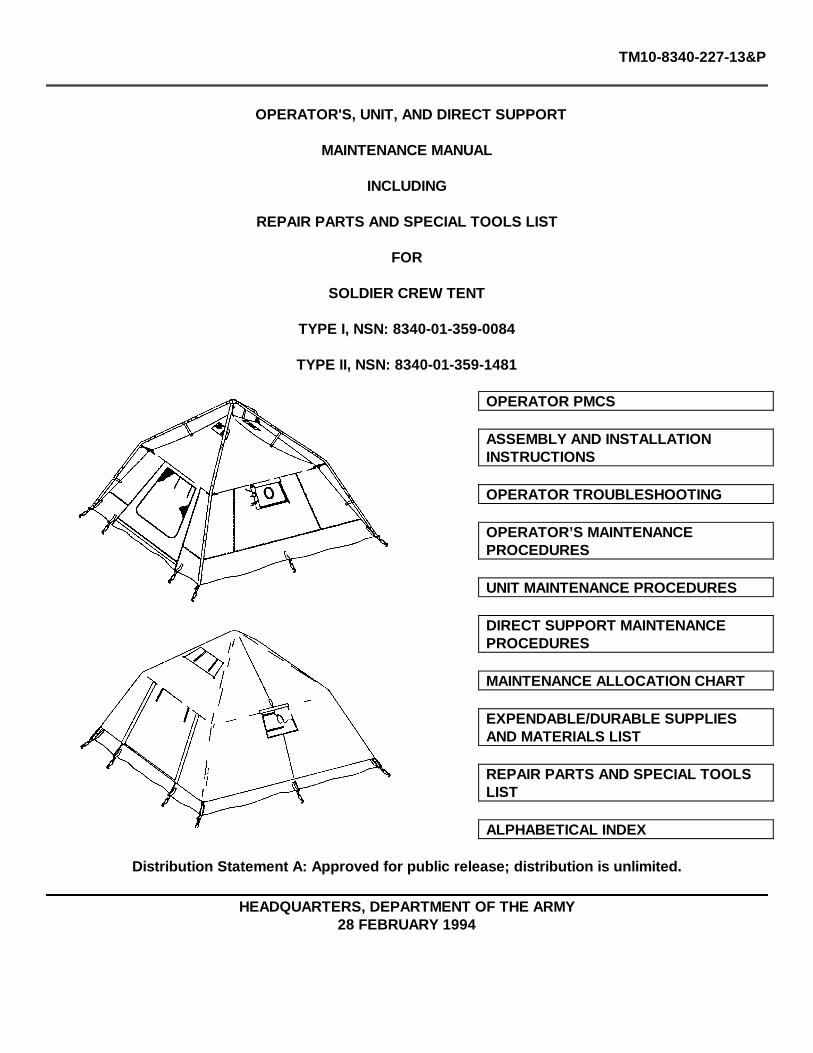
TM10-8340-227-13&P OPERATOR'S, UNIT, AND DIRECT SUPPORT MAINTENANCE MANUAL INCLUDING REPAIR PARTS AND SPECIAL TOOLS LIST FOR SOLDIER CREW TENT TYPE I, NSN: 8340-01-359-0084 TYPE II, NSN: 8340-01-359-1481 OPERATOR PMCS ASSEMBLY AND INSTALLATION INSTRUCTIONS OPERATOR TROUBLESHOOTING OPERATOR’S MAINTENANCE PROCEDURES UNIT MAINTENANCE PROCEDURES DIRECT SUPPORT MAINTENANCE PROCEDURES MAINTENANCE ALLOCATION CHART EXPENDABLE/DURABLE SUPPLIES AND MATERIALS LIST REPAIR PARTS AND SPECIAL TOOLS LIST ALPHABETICAL INDEX Distribution Statement A: Approved for public release; distribution is unlimited. HEADQUARTERS, DEPARTMENT OF THE ARMY 28 FEBRUARY 1994

Welcome message from author
This document is posted to help you gain knowledge. Please leave a comment to let me know what you think about it! Share it to your friends and learn new things together.
Transcript
TM10-8340-227-13&P
OPERATOR'S, UNIT, AND DIRECT SUPPORT
MAINTENANCE MANUAL
INCLUDING
REPAIR PARTS AND SPECIAL TOOLS LIST
FOR
SOLDIER CREW TENT
TYPE I, NSN: 8340-01-359-0084
TYPE II, NSN: 8340-01-359-1481
OPERATOR PMCS
ASSEMBLY AND INSTALLATIONINSTRUCTIONS
OPERATOR TROUBLESHOOTING
OPERATOR’S MAINTENANCEPROCEDURES
UNIT MAINTENANCE PROCEDURES
DIRECT SUPPORT MAINTENANCEPROCEDURES
MAINTENANCE ALLOCATION CHART
EXPENDABLE/DURABLE SUPPLIESAND MATERIALS LIST
REPAIR PARTS AND SPECIAL TOOLSLIST
ALPHABETICAL INDEX
Distribution Statement A: Approved for public release; distribution is unlimited.
HEADQUARTERS, DEPARTMENT OF THE ARMY28 FEBRUARY 1994


TM 10-8340-227-13&P
WARNING
SUFFOCATION HAZARD. Soldier Crew Tent fabric does not "breathe." Open windows and flaps asnecessary to ensure adequate ventilation. If all openings are closed, it is possible to use up all of theoxygen contained in the tent, especially during sleeping hours, RESULTING IN DEATH.
FIRE HAZARD. When using the M-1941 (pot belly) or M-1950 (Yukon) stove inside the Soldier CrewTent always place the heater onto a metal sheet or inside a sandbox to reduce the possibility of a fuelspill on the tent floor. Such a fuel spill can degrade the fabric or create a fire hazard.
When using the M-1941 (pot belly) or M-1950 (Yukon) stove, be sure to secure the tent liner to the tentwall so that it does not come in contact with the heated stove pipe. A fire hazard could result.
Seam sealer and solvent are extremely flammable and fumes toxic contains isopropyl alcohol. Do notsmoke or use seam sealer or solvent near open flame. Death or serious injury may result from explosionor fire.
Use seam sealer and solvent in an open, well-ventilated area away from sources of combustion; indoorswear a respirator. Avoid contact with skin and eyes. Wear goggles and gloves when using seam sealerand solvent. Inhalation of fumes may cause toxic sickness.
Refer to FM 21-11 for first aid procedures.
a/(b blank)

TM 10-8340-227-13&P
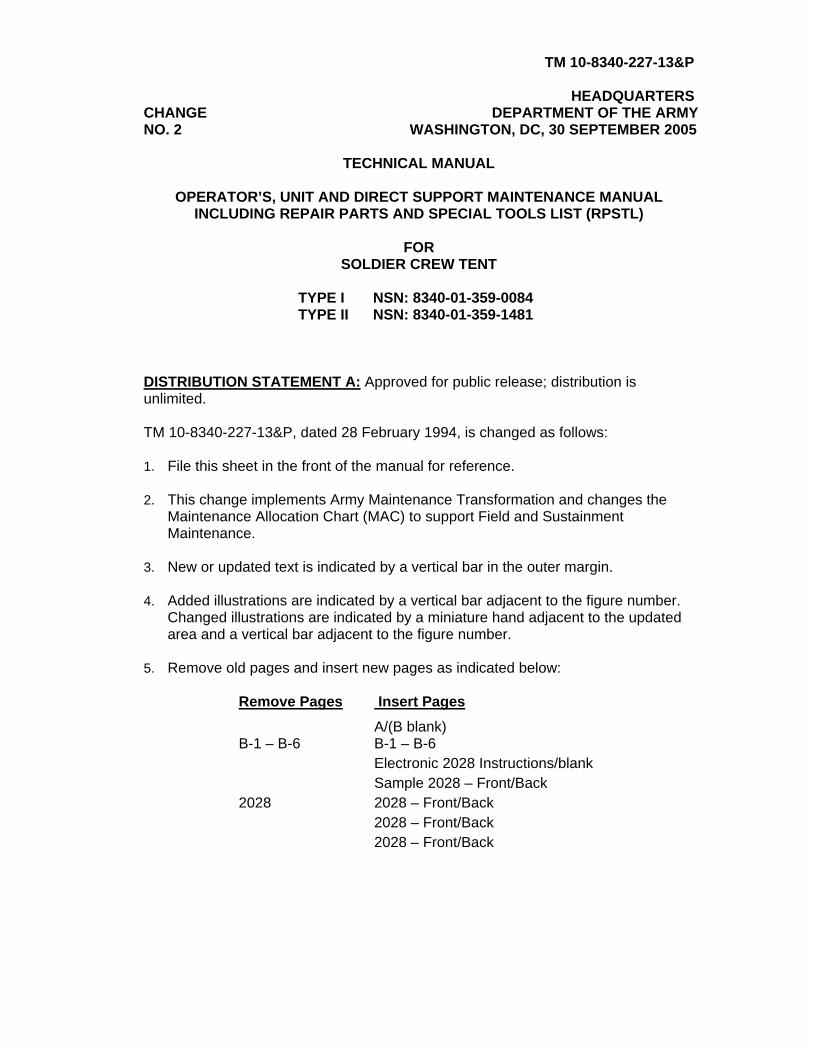
HEADQUARTERS CHANGE DEPARTMENT OF THE ARMY NO. 2 WASHINGTON, DC, 30 SEPTEMBER 2005
TECHNICAL MANUAL
OPERATOR’S, UNIT AND DIRECT SUPPORT MAINTENANCE MANUAL INCLUDING REPAIR PARTS AND SPECIAL TOOLS LIST (RPSTL)
FOR
SOLDIER CREW TENT
TYPE I NSN: 8340-01-359-0084 TYPE II NSN: 8340-01-359-1481
DISTRIBUTION STATEMENT A: Approved for public release; distribution is unlimited. TM 10-8340-227-13&P, dated 28 February 1994, is changed as follows: 1. File this sheet in the front of the manual for reference. 2. This change implements Army Maintenance Transformation and changes the
Maintenance Allocation Chart (MAC) to support Field and Sustainment Maintenance.
3. New or updated text is indicated by a vertical bar in the outer margin. 4. Added illustrations are indicated by a vertical bar adjacent to the figure number.
Changed illustrations are indicated by a miniature hand adjacent to the updated area and a vertical bar adjacent to the figure number.
5. Remove old pages and insert new pages as indicated below:
Remove Pages Insert Pages A/(B blank) B-1 – B-6 B-1 – B-6 Electronic 2028 Instructions/blank Sample 2028 – Front/Back 2028 2028 – Front/Back 2028 – Front/Back 2028 – Front/Back
TM 10-8340-227-13&P C2
By Order of the Secretary of the Army:
PETER J. SCHOOMAKER General, United States Army Chief of Staff
Official:
SANDRA R. RILEY Administrative Assistant to the Secretary of the Army 0525503 Distribution: To be distributed in accordance with initial distribution number (IDN) 256201 requirements for TM 10-8340-227-23&P.
TM 10-8340-227-13&PC1
CHANGE HEADQUARTERSDEPARTMENT OF THE ARMY
NO. 1 WASHINGTON, D.C.,15 November 1994
Operator's, Unit, and Direct SupportMaintenance Manual
IncludingRepair Parts and Special Tools List
for
SOLDIER CREW TENTTYPE I, NSN: 8340-0135-84
TYPE II, NSN; 8340-011-359-481
DISTRIBUTION STATEMENT A: Approved for public release; distributions is unlimited.
TM 10-8340-227-13&P, 28 February 1994, is changed as follows:
1. Remove and insert pages as indicated below. New or changed text material is indicated by a vertical bar in themargin. An illustration change is indicated by a miniature pointing hand.
Remove pages Insert pages
F-31 through F-34 F-31 through F-34F-67 and F-68 F-67 and F-68F-75 and F-76 F-75 and F-76
2. Retain this sheet in front of manual for reference purposes.


TM 10-8340-227-13&P
INSERT LATEST CHANGED PAGES. DESTROY SUPERSEDED PAGES.
Change 2 A/(B blank)
LIST OF EFFECTIVE PAGES
NOTE: The portion of text affected by the change is indicated by a vertical line in the outer margins of the
page. Changes to illustrations are indicated by shaded or screened areas, or by miniature pointing hands. Zero in the “Change No.” column indicates an original page.
Dates of issue for original and changed pages: Original .. 0 .. 28 February 1994 Change .. 1 .. 15 November 1994 Change .. 2 .. 30 September 2005
TOTAL NUMBER OF PAGES IN THIS PUBLICATION IS 208, CONSISTING OF THE FOLLOWING:
Page No.
Change No.
Page No.
Change No.
Title 0 D-1 0
a/(b blank) 0 E-1 - E-2 0
i - iv 0 F-1 - F-30 0
1-0 -1-6 0 F-31 - F-34 1
2-1 - 2-46 0 F-35/(F-36 blank) - F-67 0
3-1 - 3-7 0 F-68 1
4-1 - 4-11 0 F-69 - F-75 0
5-1 - 5-2 0 F-76 1
A-1 0 F-77 - F-79/(F-80 blank) 0
B-1 - B-6 2 Index-1 0
C-1 - C-10 0 Back Cover 0

TM 10-8340-227-13&P
Operator's, Unit, and Direct SupportMaintenance Manual
IncludingRepair Parts and Special Tools List
SOLDIER CREW TENTType I, NSN 8340-01-359-0084Type II, NSN 8340-01-359-1481
Reporting Equipment Improvement Recommendations
You can help improve this manual. If you find any mistakes or if you know of a way to improve the procedures, pleaselet us know. Mail your letter, DA Form 2028 (Recommended Changes to Publications and Blank Forms), or DA Form2028-2 (located in the back of this manual) direct to: Commander, U.S. Army Aviation and Troop Command, ATTN:AMSAT-I-MP, 4300 Goodfellow Blvd., St. Louis, MO 63210-1798. A reply will be furnished to you.
Distribution Statement A; Approved for public release; distribution is unlimited
TABLE OF CONTENTS
Chapter/Section Page
CHAPTER 1 INTRODUCTION ...........................................................................................1-1
Section I General Information .......................................................................................1-1
Section II Equipment Description ...................................................................................1-2
Section III Technical Principles of Operation ...................................................................1-5
CHAPTER 2 OPERATING INSTRUCTIONS ......................................................................2-1
Section I Description and Use of Operator's Controls and Indicators .............................2-1
Section II Operator's Preventive Maintenance Checks and Services ..............................2-1
Section III Operation Under Usual Conditions ...............................................................2-24
Section IV Operation Under Unusual Conditions ...........................................................2-45
i

TM 10-8340-227-13&P
TABLE OF CONTENTS - Continued
Chapter/Section Page
CHAPTER 3 OPERATOR'S MAINTENANCE INSTRUCTIONS...........................................3-1
Section I Lubrication Instructions ...................................................................................3-1
Section II Operator's Troubleshooting Procedures...........................................................3-1
Section III Operator's Maintenance Procedures................................................................3-4
CHAPTER 4 UNIT MAINTENANCE INSTRUCTIONS .........................................................4-1
Section I Lubrication Instructions ...................................................................................4-1
Section II Repair Parts, Special Tools, TMDE, and Support Equipment ..........................4-1
Section III Service Upon Receipt .....................................................................................4-1
Section IV Unit Preventive Maintenance Checks and Services (PMCS) ...........................4-2
Section V Unit Troubleshooting Procedures ....................................................................4-2
Section VI Unit Maintenance Procedures .........................................................................4-2
Section VII Preparation for Storage and Shipment.. ........................................................4-11
CHAPTER 5 DIRECT SUPPORT MAINTENANCE INSTRUCTIONS...................................5-1
Section I Repair Parts, Special Tools, Test Measurement DiagnosticEquipment (TMDE) and Support Equipment....................................................5-1
Section II Direct Support Maintenance Procedures ........................................................ 5-1
APPENDIX A REFERENCES ............................................................................................ .A-1
APPENDIX B MAINTENANCE ALLOCATION CHART ........................................................ B-1
APPENDIX C COMPONENTS OF END ITEM AND BASIC ISSUE ITEM LIST .......................C-1
ii
TM 10-8340-227-13&P
TABLE OF CONTENTS - Continued
Chapter/Section Page
APPENDIX D ADDITIONAL AUTHORIZATION LIST .......................................................... .D-1
APPENDIX E EXPENDABLE/DURABLE SUPPLIES AND MATERIALS LIST ...................... E-1
APPENDIX F REPAIR PARTS AND SPECIAL TOOLS LIST ................................................F-1
ALPHABETICAL INDEX......................................................................... INDEX-1
iii
TM 10-8340-227-13&P
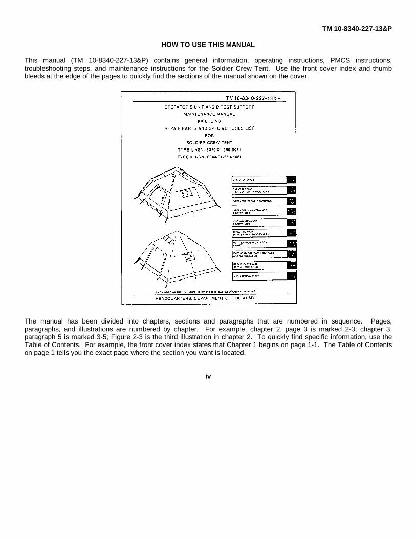
HOW TO USE THIS MANUAL
This manual (TM 10-8340-227-13&P) contains general information, operating instructions, PMCS instructions,troubleshooting steps, and maintenance instructions for the Soldier Crew Tent. Use the front cover index and thumbbleeds at the edge of the pages to quickly find the sections of the manual shown on the cover.
The manual has been divided into chapters, sections and paragraphs that are numbered in sequence. Pages,paragraphs, and illustrations are numbered by chapter. For example, chapter 2, page 3 is marked 2-3; chapter 3,paragraph 5 is marked 3-5; Figure 2-3 is the third illustration in chapter 2. To quickly find specific information, use theTable of Contents. For example, the front cover index states that Chapter 1 begins on page 1-1. The Table of Contentson page 1 tells you the exact page where the section you want is located.
iv

TM 10-8340-227-13&P
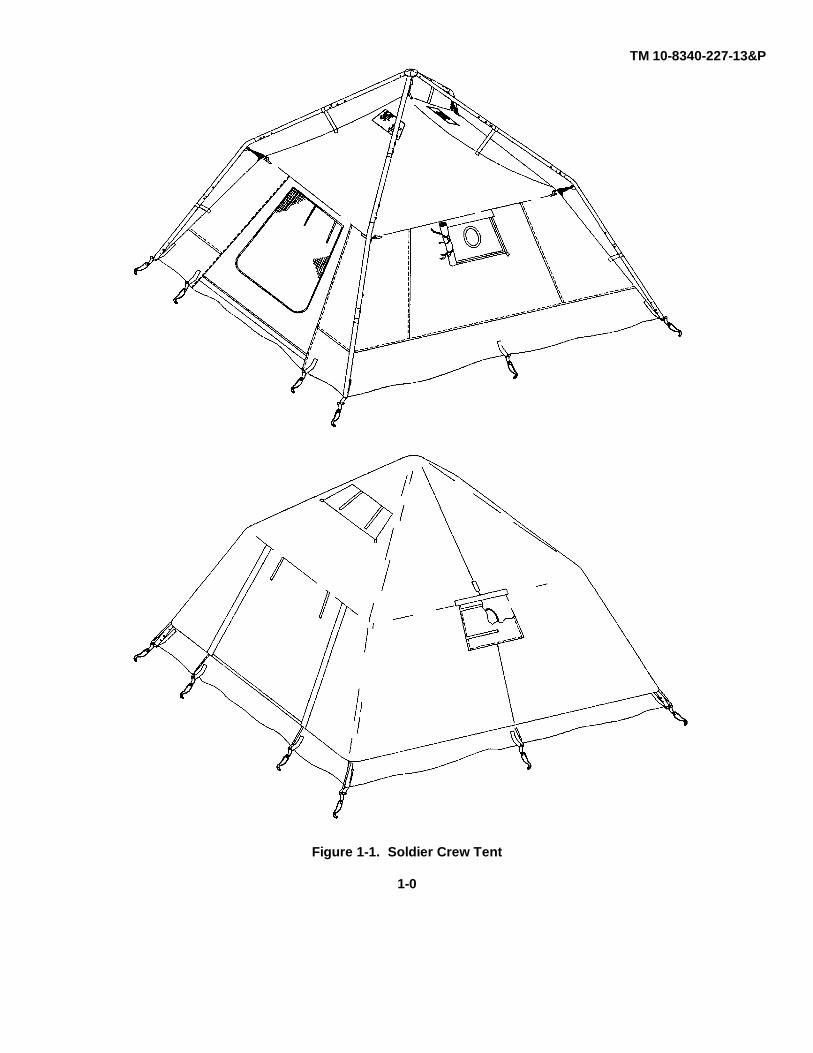
Figure 1-1. Soldier Crew Tent
1-0
TM 10-8340-227-13&P
CHAPTER 1
INTRODUCTION
Section I. GENERAL INFORMATION
1-1. SCOPE.
a. Type of Manual. Operator's, Unit, and Direct Support Maintenance Manual that provides instructions for theset-up, operation, take down, maintenance, repair parts and procedures for all components of the Soldier Crew Tent.
b. Purpose of Equipment. Provide environmental protection and shelter to crew member personnel.
c. Special Features. Lightweight tent and frame assembly can be easily set up by one or two soldiers.
d. Model Number and Equipment Name. There is no model number for the Soldier Crew Tent. Table 1-1 liststhe various tent configurations and nomenclatures.
1-2. MAINTENANCE FORMS AND RECORDS. Department of the Army forms and procedures used for equipmentmaintenance will be those prescribed by DA PAM 738-750, The Army Maintenance Management System (TAMMS).
1-3. DESTRUCTION OF ARMY MATERIEL TO PREVENT ENEMY USE. Destruction procedures for Soldier Crew Tentcomponents covered in this manual are described in TM 750-244-3.
1-4. PREPARATION FOR STORAGE OR SHIPMENT. Refer to paragraph 2-7 to prepare the Soldier Crew Tent forstorage or shipment.
1-5. QUALITY ASSURANCE (QA). All maintenance actions will be inspected to assure that all applicable qualityassurance standards are met. Refer to FM 10-16 for fabric repair standards.
1-6. NOMENCLATURE CROSS-REFERENCE.
COMMON NAME OFFICIAL NAMEFrame Frame AssemblyTent Soldier Crew Tent
1-7. REPORTING EQUIPMENT IMPROVEMENT RECOMMENDATIONS (EIR). If your Soldier Crew Tent componentsneed improvement, let us know. Send us an EIR. You, the user, are the only one who can tell us what you don't likeabout your equipment. Let us know why you don't like the design or performance. Put it on an SF 368 (QualityDeficiency Report). Mail it to us at: Commander, U.S. Army Aviation and Troop Command, ATTN: AMSAT-I-MDO, 4300Goodfellow Blvd., St. Louis, MO 63120-1798. We'll send you a reply.
1-1

TM 10-8340-227-13&P
1-8. CORROSION PREVENTION AND CONTROL (CPC). Corrosion Prevention and Control (CPC) of Army materiel isa continuing concern. It is important that any corrosion problems with this item be reported so that the problem can becorrected and improvements made to prevent the problem in future items. While corrosion is typically associated withrusting of metals, it can also include deterioration of other materials, such as rubber and plastic. Unusual cracking,softening, swelling, or breaking of the materials may be corrosion problems. If a corrosion problem is identified, it can bereported using Standard Form 368, Product Quality Deficiency Report. Use key words such as "rust", "deterioration","corrosion", or "cracking" to insure that the information is identified as a CPC problem. The form should be submitted to:Commander, U.S. Army Aviation and Troop Command, ATTN: AMSAT-I-MDO, 4300 Goodfellow Blvd., St. Louis, MO631201798.
1-9. LIST OF ABBREVIATIONS AND TERMS.
CPC Corrosion Prevention and ControlEIR Equipment Improvement ReportESC Equipment Serviceability CriteriaMWO Modification Work OrderU/M Unit of MeasureUOC Usable On Code
Section II. EQUIPMENT DESCRIPTION
1-10. EQUIPMENT CHARACTERISTICS, CAPABILITIES AND FEATURES. The Type I Soldier Crew Tent comes ingreen, with a reversible green/tan fly. The Type II Soldier Crew Tent also comes in green, with a reversible green/whitefly. Except for fly color, the characteristics, capabilities and features of both tents are identical.
a. Characteristics.
(1) Usable in a variety of climates.
(2) Constructed of lightweight materials.
(3) Deployed in forward battle areas.
b. Capabilities and Features.
(1) Can be set up quickly by one or two soldiers.
(2) Frame assembly consists of aluminum poles that unfold and are connected by wire cables.
(3) Soldier Crew Tent is made of water resistant, flame resistant, lightweight, nylon fabric.
(4) Can be heated by a portable, internal source.
1-2

TM 10-8340-227-13&P
1-10. EQUIPMENT CHARACTERISTICS, CAPABILITIES AND FEATURES - Continued
b. Capabilities and Features - Continued
(5) Constructed with tear and weather resistant, reinforced floor.
1-11. LOCATION AND DESCRIPTION OF MAJOR COMPONENTS.
Figure 1-2. Major Components of the Soldier Crew Tent
1-3
TM 10-8340-227-13&P
1-11. LOCATION AND DESCRIPTION OF MAJOR COMPONENTS - Continued
a. Frame Assembly. The frame assembly (1) consists of four aluminum poles that, when erected, are joined at acenter hub. The assembled frame is an external frame from which the tent body is suspended and over which the fly ispositioned.
b. Tent Body Assembly. The body assembly (2) is suspended from the frame assembly. The body contains afront and rear door, a stovepipe opening, and two roof vents. The tent floor is part of the tent body assembly.
c. Fly Assembly. The fly assembly (3) is made from lightweight, reversible, coated cloth and covers the frameand tent body assemblies. Openings in the fly assembly match those in the tent body assembly. The fly assemblyissued with the Type I Soldier Crew Tent is green/tan; the fly issued with the Type II Soldier Crew Tent is green/white.
d. Liner Assembly. The liner assembly (4) is made from flame resistant cotton oxford cloth. It is suspended fromthe interior of the tent body. The liner assembly has openings which match those in the tent body.
e. Gear Loft Assembly. The gear loft assembly (5) provides overhead storage. It consists of a mesh fabric boundat the edges with fabric tape. The gear loft can be suspended from either the tent body or liner assembly.
f. Frame Bag Assembly. The frame bag assembly (6) provides storage for the frame assembly.
g. Cover Assembly. The cover assembly (7) is made from waterproof polyester or nylon coated cloth and isoctagonal in shape, with two sets of straps.
h. Pegs, Bag. The pegs stowed in bag (8) are used to anchor the Soldier Crew Tent.
i. Repair Kit. Contents of repair kit are stowed in two pockets (9) inside tent body.
1-12. DIFFERENCES BETWEEN MODELS. Table 1-1 lists the major differences between the Type I and Type IISoldier Crew Tents.
1-4
TM 10-8340-227-13&P
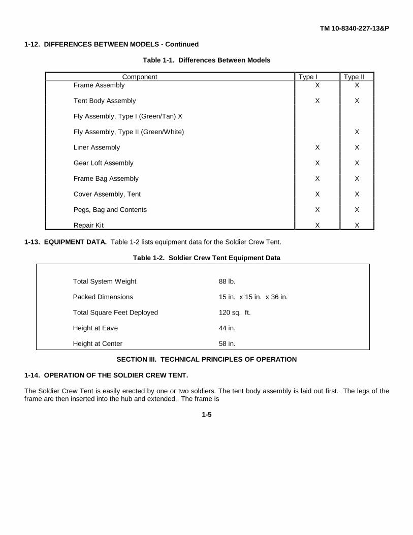
1-12. DIFFERENCES BETWEEN MODELS - Continued
Table 1-1. Differences Between Models
Component Type I Type IIFrame Assembly X X
Tent Body Assembly X X
Fly Assembly, Type I (Green/Tan) X
Fly Assembly, Type II (Green/White) X
Liner Assembly X X
Gear Loft Assembly X X
Frame Bag Assembly X X
Cover Assembly, Tent X X
Pegs, Bag and Contents X X
Repair Kit X X
1-13. EQUIPMENT DATA. Table 1-2 lists equipment data for the Soldier Crew Tent.
Table 1-2. Soldier Crew Tent Equipment Data
Total System Weight 88 lb.
Packed Dimensions 15 in. x 15 in. x 36 in.
Total Square Feet Deployed 120 sq. ft.
Height at Eave 44 in.
Height at Center 58 in.
SECTION III. TECHNICAL PRINCIPLES OF OPERATION
1-14. OPERATION OF THE SOLDIER CREW TENT.
The Soldier Crew Tent is easily erected by one or two soldiers. The tent body assembly is laid out first. The legs of theframe are then inserted into the hub and extended. The frame is
1-5

TM 10-8340-227-13&P
1-14. OPERATION OF THE SOLDIER CREW TENT - Continued
positioned over the tent, and the center of the tent roof is attached to the frame. The legs of the frame are secured to thetent corners, then the eaves and sides of the tent are attached to the frame. The sides of the tent are staked down. Ifdesired, the tent fly is installed over the pitched tent and frame, providing an extra layer of weather and camouflageprotection. The liner and gear loft may be installed as necessary.
1-6
TM 10-8340-227-13&PCHAPTER 2
OPERATING INSTRUCTIONS
Section I Description and Use of Operator's Controls and Indicators .................................................................2-1
2-1 Operator's Controls and Indicators .................................................................................................2-1
Section II Operator's Preventive Maintenance Checks and Services (PMCS) .................................................. 2-1
2-2 Introduction ...............................................................................................................................................2-1
Section III Operation under Usual Conditions ................................................................................................2-24
2-3 Assembly and Preparation for Use ........................................................................................2-242-4 Unpacking and Inspection .....................................................................................................2-242-5 Assembly and Installation Instructions ...................................................................................2-242-6 Decals and Instruction Plates ................................................................................................2-372-7 Preparation for Movement and Storage .................................................................................2-43
Section IV Operation under Unusual Conditions ............................................................................................2-45
2-8 General ......................................................................................................................................2-45
SECTION I. DESCRIPTION AND USE OF OPERATOR'S CONTROLS AND INDICATORS
2-1. OPERATOR'S CONTROLS AND INDICATORS. There are no controls or indicators applicable to this equipment.
SECTION II. OPERATOR'S PREVENTIVE MAINTENANCE CHECKS AND SERVICES (PMCS)
2-2. INTRODUCTION. Soldier Crew Tent components must be inspected regularly to find and correct defects. Recordall defects found during the performance of PMCS and the steps taken to correct them on DA Form 2404, EquipmentInspection and Maintenance Worksheet. Instructions for reporting/correcting noted deficiencies are contained in DA PAM738-750.
a. General. Table 2-1 (PMCS Table) has been provided so you can keep your equipment in good operatingcondition and ready for its primary mission.
(1) Before you operate. Always keep in mind the CAUTIONS and WARNINGS. Perform your before (B)PMCS prior to the equipment leaving its containment area or performing its intended mission.
(2) While you operate. Always keep in mind the CAUTIONS and WARNINGS. Perform your DURING (D)PMCS when the equipment is being used in its intended mission.
2-1
TM 10-8340-227-13&P
2-2. INTRODUCTION - Continued
(3) After you operate. Be sure to perform your after (A) PMCS after the equipment has been taken out ofits mission mode or returned to its containment area.
(4) If your equipment fails to operate. Troubleshoot with proper equipment. Report any deficiencies usingthe proper forms. See DA Pam 738-750.
b. Warnings and Cautions. Always observe the WARNINGS and CAUTIONS appearing in your PMCStable. Warnings and cautions appear before applicable procedures. You must observe theseWARNINGS and CAUTIONS to prevent serious injury to yourself and others or prevent your equipmentfrom being damaged.
c. Explanation of table entries.
(1) Item number column. Numbers in this column are for reference. When completing DA Form 2404(Equipment Inspection and Maintenance Worksheet), include the item number for the check/serviceindicating a fault. Item numbers also appear in the order that you must do checks and services for theintervals listed.
(2) Interval column. This column tells you when you must do the procedure in the procedure column.BEFORE procedures must be done before you operate or use the equipment for its intended mission.DURING procedures must be done during the time you are operating or using the equipment for itsintended mission. AFTER procedures must be done immediately after you have operated or used theequipment.
(3) Location, Item to Check/Service column. This column provides the location and the item to be checkedor serviced. The item location is underlined.
(4) Procedure column. This column gives the procedure you must do to check or service the item listed inthe Check/Service column to know if the equipment is ready or available for its intended mission or foroperation. You must perform the procedure at the time stated in the interval column.
(5) Not fully mission capable if: column. Information in this column tells you what faults will keep yourequipment from being capable of performing its primary mission. If you make check and serviceprocedures that show faults listed in this column, do not operate the equipment. Follow standardoperating procedures for maintaining the equipment or reporting equipment failure.
d. Other table entries. Be sure to observe all special information and notes that appear in your table.
2-2
TM 10-8340-227-13&P
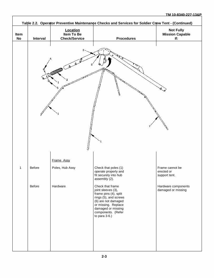
Table 2.2. Operator Preventive Maintenance Checks and Services for Soldier Crew Tent - (Continued)
Location Not FullyItem Item To Be Mission CapableNo Interval Check/Service Procedures If:
Frame Assy
1 Before Poles, Hub Assy Check that poles (1) Frame cannot beoperate properly and erected orfit securely into hub support tent.assembly (2).
Before Hardware Check that frame Hardware componentsjoint sleeves (3), damaged or missingframe pins (4), splitrings (5), and screws(6) are not damagedor missing. Replacedamaged or missingcomponents. (Referto para 3-6.)
2-3
TM 10-8340-227-13&P
Table 2.2. Operator Preventive Maintenance Checks and Services for Solider Crew Tent - (Continued)
Location Not FullyItem Item To Be Procedures Mission CapableNo Interval Check/Service If:
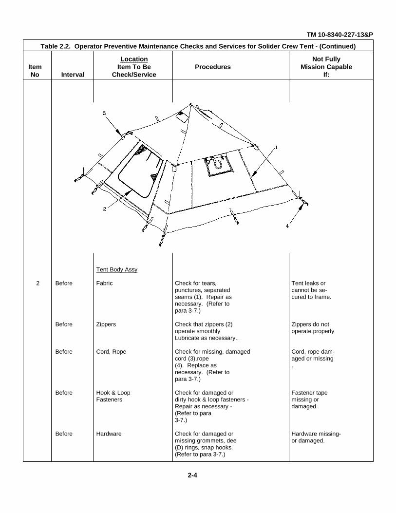
Tent Body Assy
2 Before Fabric Check for tears, Tent leaks orpunctures, separated cannot be se-seams (1). Repair as cured to frame.necessary. (Refer topara 3-7.)
Before Zippers Check that zippers (2) Zippers do notoperate smoothly operate properlyLubricate as necessary..
Before Cord, Rope Check for missing, damaged Cord, rope dam-cord (3),rope aged or missing(4). Replace as .necessary. (Refer topara 3-7.)
Before Hook & Loop Check for damaged or Fastener tapeFasteners dirty hook & loop fasteners - missing or
Repair as necessary - damaged.(Refer to para3-7.)
Before Hardware Check for damaged or Hardware missing-missing grommets, dee or damaged.(D) rings, snap hooks.(Refer to para 3-7.)
2-4

TM 10-8340-227-13&P
Table 2.2. Operator Preventive Maintenance Checks and Services for Soldier Crew Tent - Continued -
Location Not FullyItem Item To Be Procedures Mission CapableNo Interval Check/Service If:
Fly Assembly
3 Before Fabric Check for tears, Tent leaks orpunctures, separated cannot be se-seams (1). Repair as cured to frame.necessary. (Refer topara 3-7.)
Before Zippers Check that zippers (2) Zippers do notoperate smoothly. Lu- operate properlybricate as necessary.
Before Cord Check for missing, dam- Cord, rope dam-aged cord (3). Replace aged or missingas necessary. (Referto para 3-7.)
Before Hook & Loop Check for damaged or Fastener tapeFasteners dirty hook & loop fas- missing or
teners. Repair as nec- damaged.essary. (Refer to para3-7.)
Before Hardware Check for damaged or Hardware miss-missing grommets, snap ing or damaged.hooks. (Refer to para3-7.)
2-5

TM 10-8340-227-13&P
Table 2.2. Operator Preventive Maintenance Checks and Services for Soldier Crew Tent - Continued
Location Not FullyItem Item To Be Mission CapableNo Interval Check/Service Procedures If:
Liner Assembly
4 Before Fabric Check for tears, Liner cannot bepunctures, separated secured to tentseams (1). Repair as body.necessary. (Refer topara 3-7.)
Before Hook & Loop Check for damaged or Fastener tapeFasteners dirty hook & loop fas- missing or
teners (2). Repair as damaged.necessary. (Refer topara 3-7.)
Before Hardware Check for damaged ormissing dee (D) rings, Liner cannot besnap hooks, grommets. secured to tentReplace as necessary. body.(Refer to para 3-7.)
2-6
TM 10-8340-227-13&P
Table 2.2. Operator Preventive Maintenance Checks and Services - (Continued)
Location Not FullyItem Item To Be Mission CapableNo Interval Check/Service Procedures If:
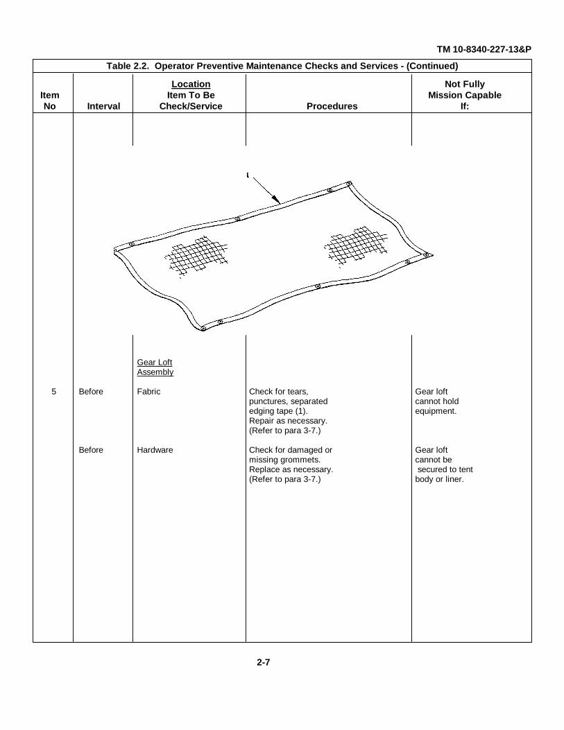
Gear LoftAssembly
5 Before Fabric Check for tears, Gear loftpunctures, separated cannot holdedging tape (1). equipment.Repair as necessary.(Refer to para 3-7.)
Before Hardware Check for damaged or Gear loftmissing grommets. cannot beReplace as necessary. secured to tent(Refer to para 3-7.) body or liner.
2-7
TM 10-8340-227-13&P
Table 2.2. Operator Preventive Maintenance Checks and Services - (Continued)
Location Not FullyItem Item To Be Mission CapableNo Interval Check/Service Procedures If:
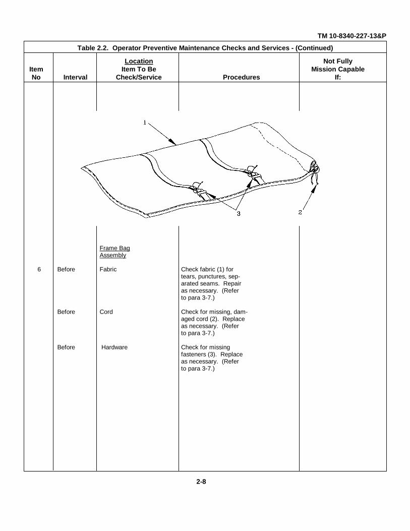
Frame BagAssembly
6 Before Fabric Check fabric (1) fortears, punctures, sep-arated seams. Repairas necessary. (Referto para 3-7.)
Before Cord Check for missing, dam-aged cord (2). Replaceas necessary. (Referto para 3-7.)
Before Hardware Check for missingfasteners (3). Replaceas necessary. (Referto para 3-7.)
2-8

TM 10-8340-227-13&PTable 2.2. Operator Preventive Maintenance Checks and Services for Soldier Crew Tent - Continued -
Location Not FullyItem Item To Be Procedures Mission CapableNo Interval Check/Service If:
Cover Assembly
7 Before Fabric Check fabric (1) fortears, punctures, sep-arated seams. Repairas necessary. (Referto para 3-7.)
Before Webbing Check webbing (2) fordamage or separationfrom cover fabric.Repair as necessary.(Refer to para 3-7.)
Before Hardware Check for missingfasteners (3). Replaceas necessary. (Referto para 3-7.)
2-9

TM 10-8340-227-13&P
Table 2.2. Operator Preventive Maintenance Checks and Services for Soldier Crew Tent - Continued -
Location Not FullyItem Item To Be Mission CapableNo Interval Check/Service Procedures If:
Peqs, Bag
8 Before Fabric Check fabric (1) fortears, punctures, sep-arated seams. Repairas necessary. (Referto para 3-7.)
Before Cord Check for missing, dam-aged cord (2). Replaceas necessary. (Referto para 3-7.)
Before Pegs Check for missing or Tent cannot bedamaged pegs (3). Re- secured.place as necessary.
\\
2-10
TM 10-8340-227-13&P
Table 2.2. Operator Preventive Maintenance Checks and Services for Soldier Crew Tent - (Continued)
Location Not FullyItem Item To Be Procedures Mission CapableNo Interval Check/Service If:
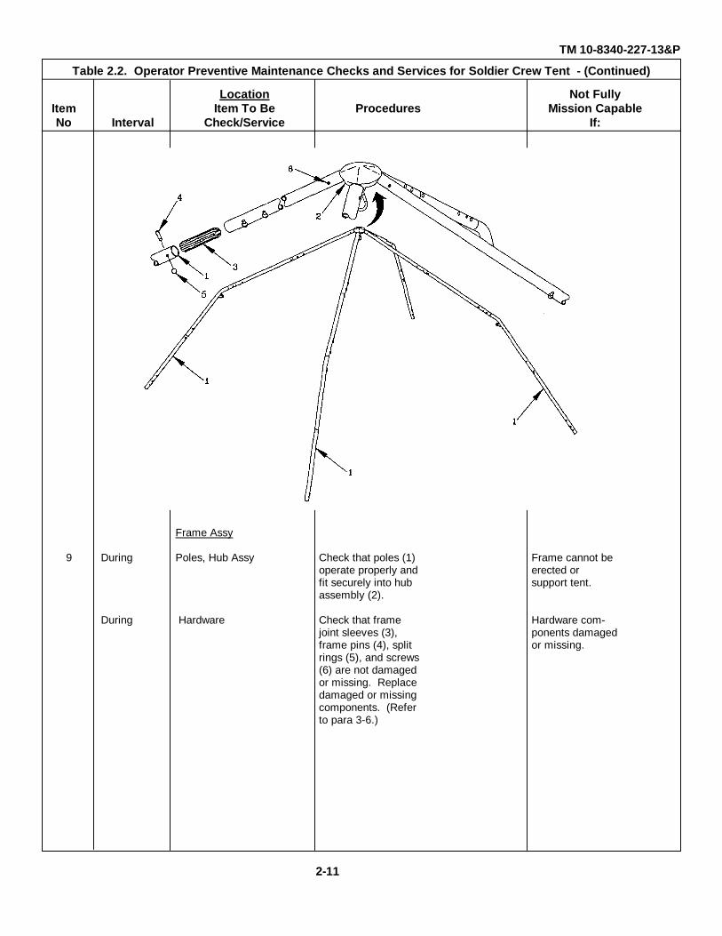
Frame Assy
9 During Poles, Hub Assy Check that poles (1) Frame cannot beoperate properly and erected orfit securely into hub support tent.assembly (2).
During Hardware Check that frame Hardware com-joint sleeves (3), ponents damagedframe pins (4), split or missing.rings (5), and screws(6) are not damagedor missing. Replacedamaged or missingcomponents. (Referto para 3-6.)
2-11
TM 10-8340-227-13&P
Table 2.2. Operator Preventive Maintenance Checks and Services for Soldier Crew Tent - Continued
Location Not FullyItem Item To Be Mission CapableNo Interval Check/Service Procedures If:
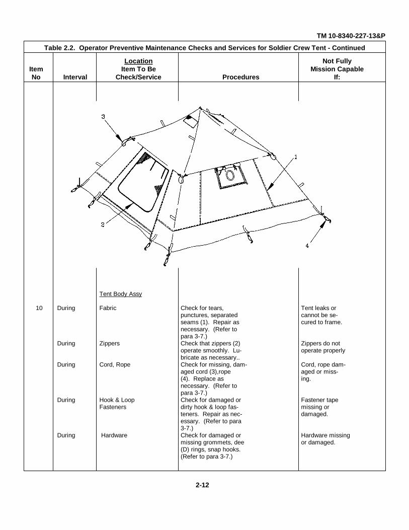
Tent Body Assy
10 During Fabric Check for tears, Tent leaks orpunctures, separated cannot be se-seams (1). Repair as cured to frame.necessary. (Refer topara 3-7.)
During Zippers Check that zippers (2) Zippers do notoperate smoothly. Lu- operate properlybricate as necessary..
During Cord, Rope Check for missing, dam- Cord, rope dam-aged cord (3),rope aged or miss-(4). Replace as ing.necessary. (Refer topara 3-7.)
During Hook & Loop Check for damaged or Fastener tapeFasteners dirty hook & loop fas- missing or
teners. Repair as nec- damaged.essary. (Refer to para3-7.)
During Hardware Check for damaged or Hardware missingmissing grommets, dee or damaged.(D) rings, snap hooks.(Refer to para 3-7.)
2-12
TM 10-8340-227-13&P
Table 2.2. Operator Preventive Maintenance Checks and Services for Soldier Crew Tent - Continued -
Location Not FullyItem Item To Be Procedures Mission CapableNo Interval Check/Service If:
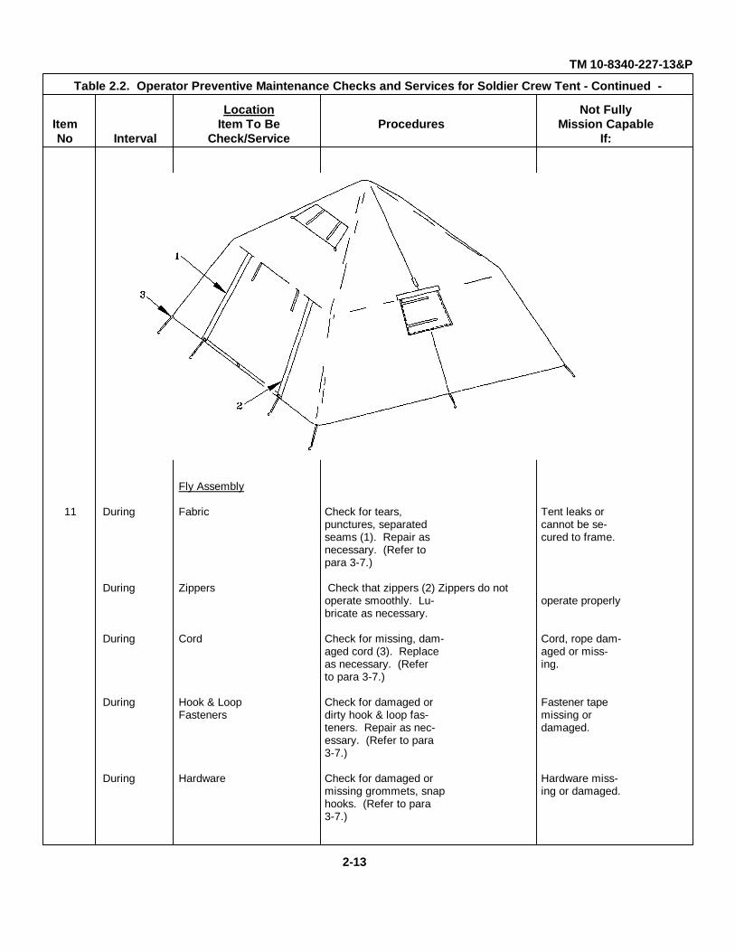
Fly Assembly
11 During Fabric Check for tears, Tent leaks orpunctures, separated cannot be se-seams (1). Repair as cured to frame.necessary. (Refer topara 3-7.)
During Zippers Check that zippers (2) Zippers do notoperate smoothly. Lu- operate properlybricate as necessary.
During Cord Check for missing, dam- Cord, rope dam-aged cord (3). Replace aged or miss-as necessary. (Refer ing.to para 3-7.)
During Hook & Loop Check for damaged or Fastener tapeFasteners dirty hook & loop fas- missing or
teners. Repair as nec- damaged.essary. (Refer to para3-7.)
During Hardware Check for damaged or Hardware miss-missing grommets, snap ing or damaged.hooks. (Refer to para3-7.)
2-13
TM 10-8340-227-13&P
Table 2.2. Operator Preventive Maintenance Checks and Services for Soldier Crew Tent - Continued -
Location Not FullyItem Item To Be Procedures Mission CapableNo Interval Check/Service If:
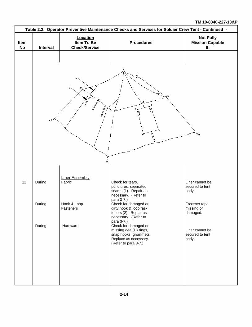
Liner Assembly12 During Fabric Check for tears, Liner cannot be
punctures, separated secured to tentseams (1). Repair as body.necessary. (Refer topara 3-7.)
During Hook & Loop Check for damaged or Fastener tapeFasteners dirty hook & loop fas- missing or
teners (2). Repair as damaged.necessary. (Refer topara 3-7.)
During Hardware Check for damaged ormissing dee (D) rings, Liner cannot besnap hooks, grommets. secured to tentReplace as necessary. body.(Refer to para 3-7.)
2-14
TM 10-8340-227-13&P
Table 2.2. Operator Preventive Maintenance Checks and Services for Soldier Crew Tent - Continued
Location Not FullyItem Item To Be Procedures Mission CapableNo Interval Check/Service If:
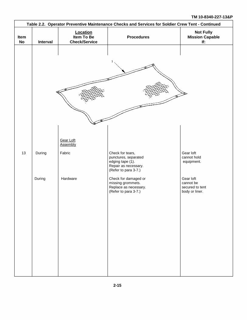
Gear LoftAssembly
13 During Fabric Check for tears, Gear loftpunctures, separated cannot holdedging tape (1). equipment.Repair as necessary.(Refer to para 3-7.)
During Hardware Check for damaged or Gear loftmissing grommets. cannot beReplace as necessary. secured to tent(Refer to para 3-7.) body or liner.
2-15
TM 10-8340-227-13&P
Table 2.2. Operator Preventive Maintenance Checks and Services for Soldier Crew Tent - Continued
Location Not FullyItem Item To Be Procedures Mission CapableNo Interval Check/Service If:
Frame Assy
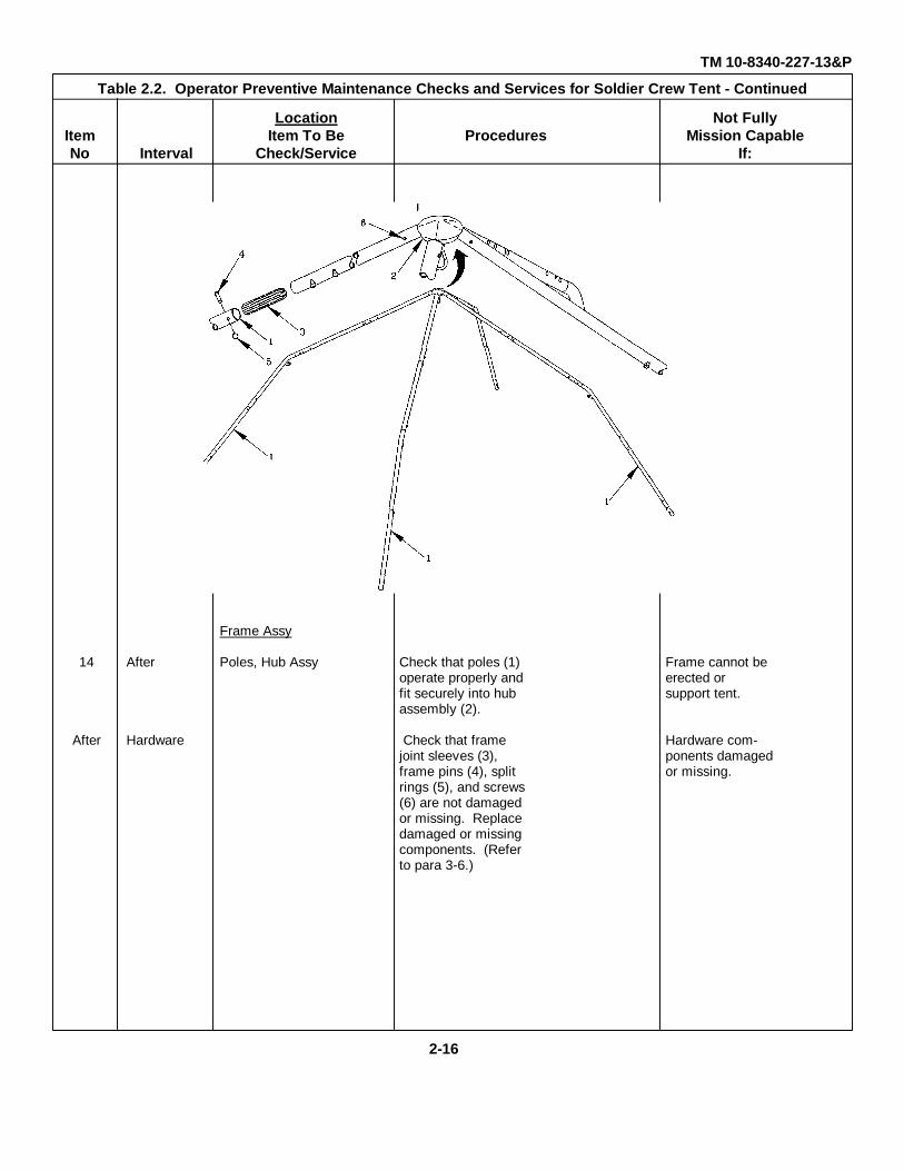
14 After Poles, Hub Assy Check that poles (1) Frame cannot beoperate properly and erected orfit securely into hub support tent.assembly (2).
After Hardware Check that frame Hardware com-joint sleeves (3), ponents damagedframe pins (4), split or missing.rings (5), and screws(6) are not damagedor missing. Replacedamaged or missingcomponents. (Referto para 3-6.)
2-16

TM 10-8340-227-13&PTable 2-2. Operator Preventive Maintenance Checks and Services for Soldier Crew Tent - Continued
Location Not FullyItem Item To Be Mission CapableNo Interval Check/Service Procedures If:
Tent Body Assy15 After Fabric Check for tears, Tent leaks or
punctures, separated cannot be se-seams (1). Repair as cured to frame.necessary. (Refer topara 3-7.)
After Zippers Check that zippers (2) Zippers do notoperate smoothly. Lu- operate proper-bricate as necessary. ly.
After Cord, Rope Check for missing, dam- Cord, rope dam-aged cord (3), rope aged or miss-(4). Replace as ing.necessary. (Refer topara 3-7.)
After Hook & Loop Check for damaged or Fastener tapeFasteners dirty hook & loop fas- missing or
teners. Repair as nec- damaged.essary. (Refer to para3-7.)
After Hardware Check for damaged or Hardware miss-missing grommets, dee ing or damaged.(D) rings, snap hooks.(Refer to para 3-7.)
2-17
TM 10-8340-227-13&PTable 2-2. Operator Preventive Maintenance Checks and Services for Soldier Crew Tent - Continued
Location Not FullyItem Item To Be Mission CapableNo Interval Check/Service Procedures If:
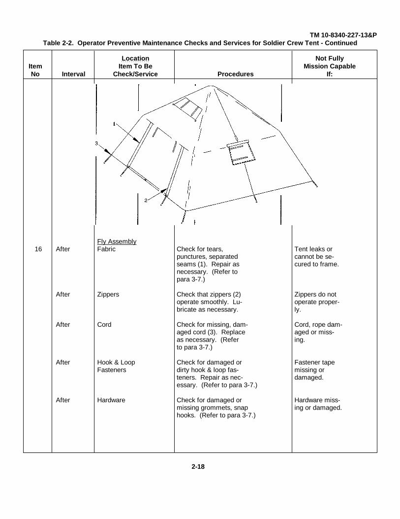
Fly Assembly16 After Fabric Check for tears, Tent leaks or
punctures, separated cannot be se-seams (1). Repair as cured to frame.necessary. (Refer topara 3-7.)
After Zippers Check that zippers (2) Zippers do notoperate smoothly. Lu- operate proper-bricate as necessary. ly.
After Cord Check for missing, dam- Cord, rope dam-aged cord (3). Replace aged or miss-as necessary. (Refer ing.to para 3-7.)
After Hook & Loop Check for damaged or Fastener tapeFasteners dirty hook & loop fas- missing or
teners. Repair as nec- damaged.essary. (Refer to para 3-7.)
After Hardware Check for damaged or Hardware miss-missing grommets, snap ing or damaged.hooks. (Refer to para 3-7.)
2-18
TM 10-8340-227-13&PTable 2-2. Operator Preventive Maintenance Checks and Services for Soldier Crew Tent - Continued
Location Not FullyItem Item To Be Mission CapableNo Interval Check/Service Procedures If:
Liner Assembly
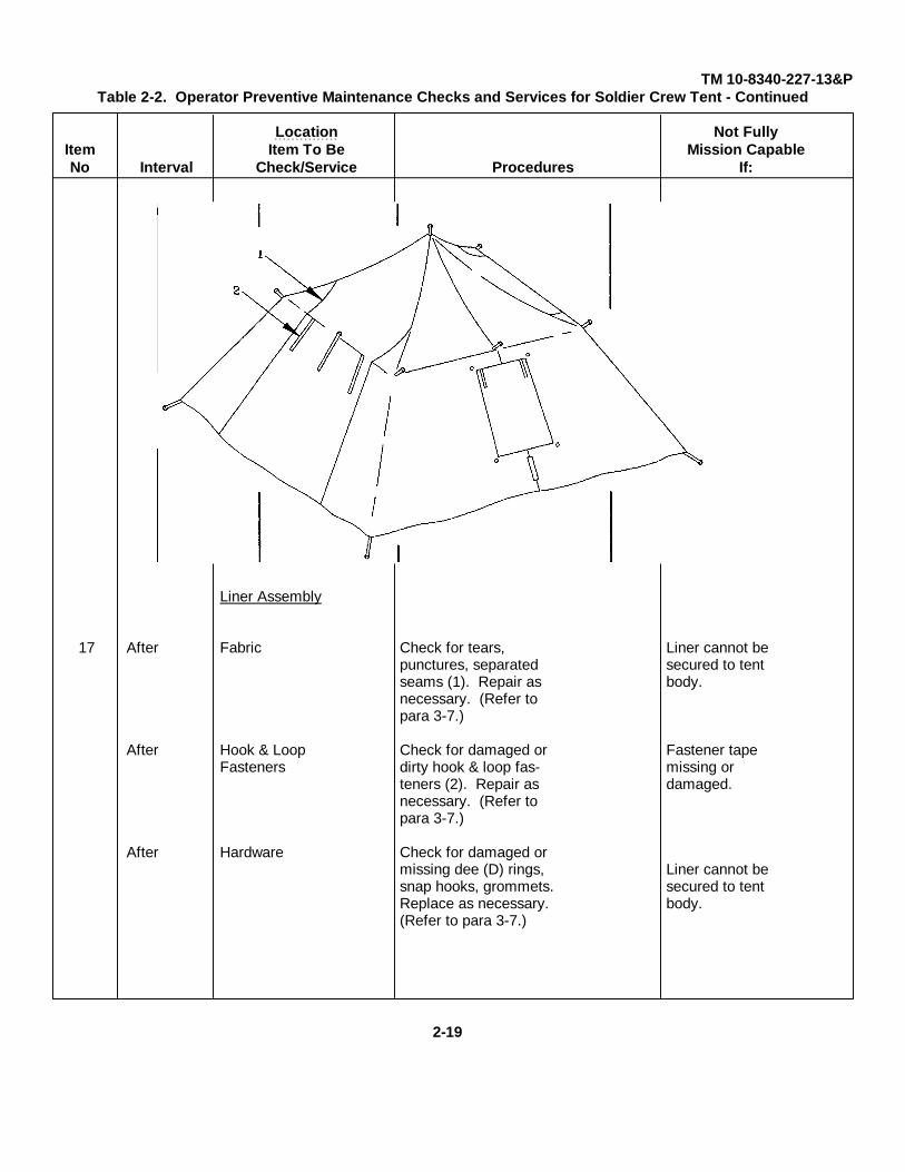
17 After Fabric Check for tears, Liner cannot bepunctures, separated secured to tentseams (1). Repair as body.necessary. (Refer topara 3-7.)
After Hook & Loop Check for damaged or Fastener tapeFasteners dirty hook & loop fas- missing or
teners (2). Repair as damaged.necessary. (Refer topara 3-7.)
After Hardware Check for damaged ormissing dee (D) rings, Liner cannot besnap hooks, grommets. secured to tentReplace as necessary. body.(Refer to para 3-7.)
2-19
TM 10-8340-227-13&PTable 2-2. Operator Preventive Maintenance Checks and Services for Soldier Crew Tent - Continued
Location Not FullyItem Item To Be Mission CapableNo Interval Check/Service Procedures If:
Gear LoftAssembly
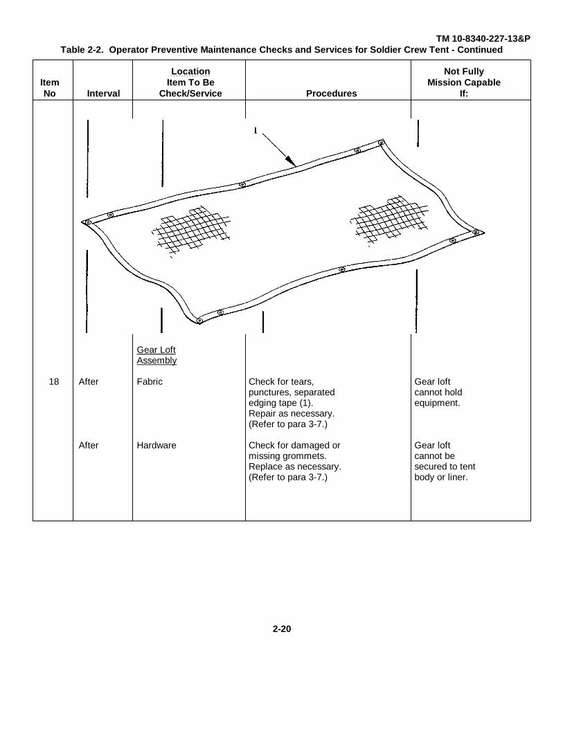
18 After Fabric Check for tears, Gear loftpunctures, separated cannot holdedging tape (1). equipment.Repair as necessary.(Refer to para 3-7.)
After Hardware Check for damaged or Gear loftmissing grommets. cannot beReplace as necessary. secured to tent(Refer to para 3-7.) body or liner.
2-20
TM 10-8340-227-13&PTable 2-2. Operator Preventive Maintenance Checks and Services for Soldier Crew Tent - Continued
Location Not FullyItem Item To Be Mission CapableNo Interval Check/Service Procedures If:
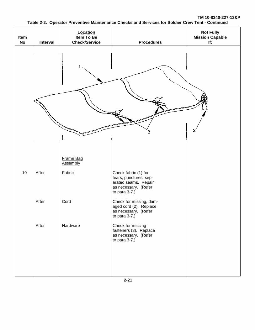
Frame BagAssembly
19 After Fabric Check fabric (1) fortears, punctures, sep-arated seams. Repairas necessary. (Referto para 3-7.)
After Cord Check for missing, dam-aged cord (2). Replaceas necessary. (Referto para 3-7.)
After Hardware Check for missingfasteners (3). Replaceas necessary. (Referto para 3-7.)
2-21
TM 10-8340-227-13&PTable 2-2. Operator Preventive Maintenance Checks and Services for Soldier Crew Tent - Continued
Location Not FullyItem Item To Be Mission CapableNo Interval Check/Service Procedures If:
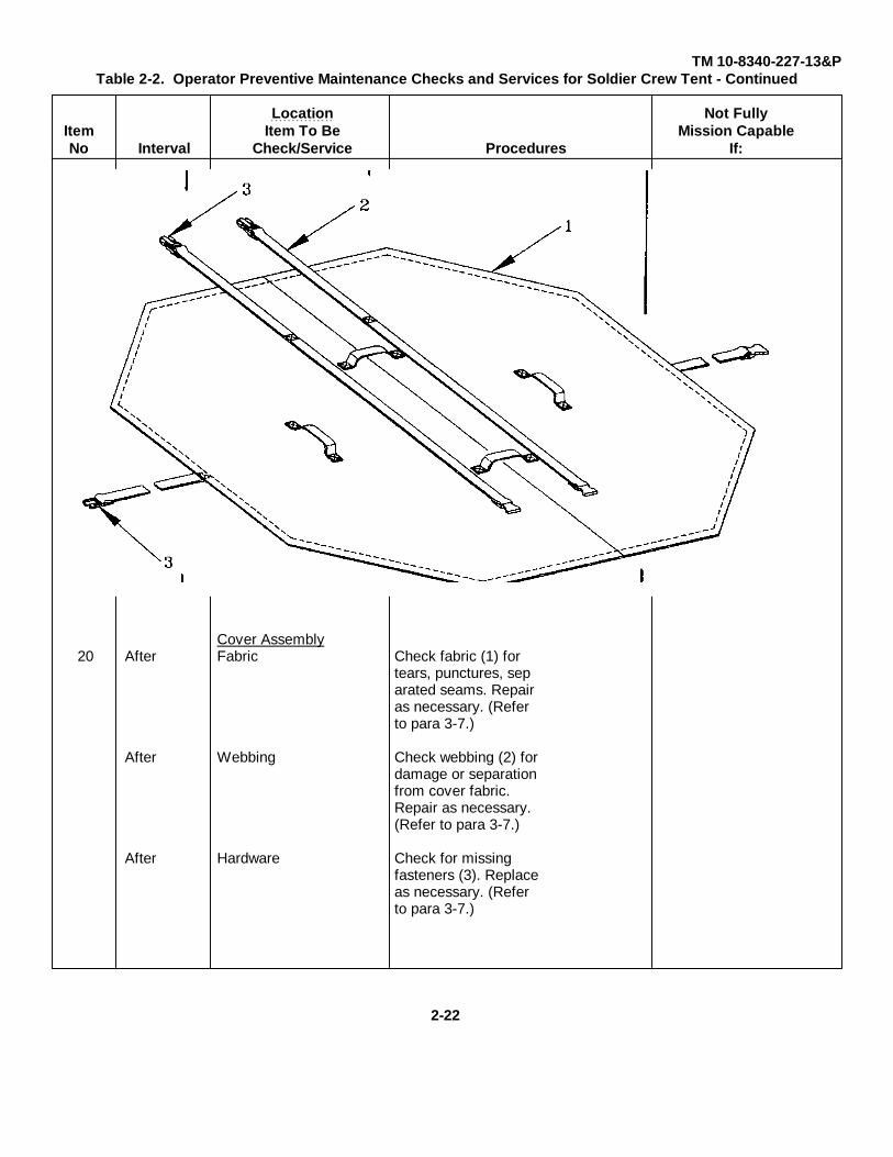
Cover Assembly20 After Fabric Check fabric (1) for
tears, punctures, separated seams. Repairas necessary. (Referto para 3-7.)
After Webbing Check webbing (2) fordamage or separationfrom cover fabric.Repair as necessary.(Refer to para 3-7.)
After Hardware Check for missingfasteners (3). Replaceas necessary. (Referto para 3-7.)
2-22
TM 10-8340-227-13&PTable 2-2. Operator Preventive Maintenance Checks and Services for Soldier Crew Tent - Continued
Location Not FullyItem Item To Be Mission CapableNo Interval Check/Service Procedures If:
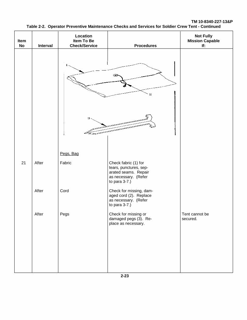
Pegs, Bag
21 After Fabric Check fabric (1) fortears, punctures, sep-arated seams. Repairas necessary. (Referto para 3-7.)
After Cord Check for missing, dam-aged cord (2). Replaceas necessary. (Referto para 3-7.)
After Pegs Check for missing or Tent cannot bedamaged pegs (3). Re- secured.place as necessary.
2-23

TM 10-8340-227-13&P
SECTION III. OPERATION UNDER USUAL CONDITIONS
2-3. ASSEMBLY AND PREPARATION FOR USE. This section provides detailed instructions for setting up the SoldierCrew Tent.
2-4. UNPACKING AND INSPECTION. Unpack crates/transport bags and visually inspect their contents. Make sure thateverything is there, including end items and basic issue items, as listed in Appendix C. Also refer to Table 2-1, OperatorPMCS, for inspection procedures.
2-5. ASSEMBLY AND INSTALLATION INSTRUCTIONS. To assemble the Soldier Crew Tent, proceed as follows:
a. Site Selection. When selecting a site on which to set up the Soldier Crew Tent:
(1) Select a level area.
(2) If possible, the area should be sheltered from high winds.
(3) Clear area of all rocks and underbrush.
(4) If necessary, dig a drainage ditch around the tent site.
b. Pitching the Tent.
2-24
TM 10-8340-227-13&P
2-5. ASSEMBLY AND INSTALLATION INSTRUCTIONS - Continued
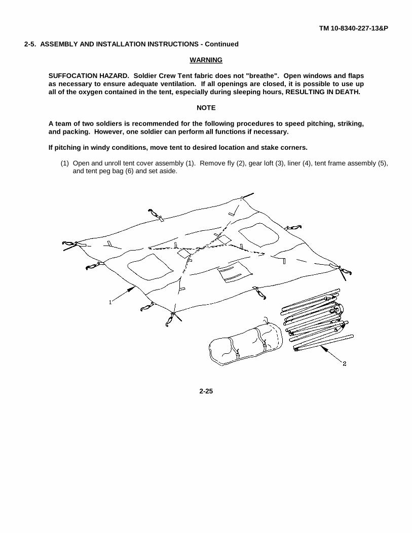
WARNING
SUFFOCATION HAZARD. Soldier Crew Tent fabric does not "breathe". Open windows and flapsas necessary to ensure adequate ventilation. If all openings are closed, it is possible to use upall of the oxygen contained in the tent, especially during sleeping hours, RESULTING IN DEATH.
NOTE
A team of two soldiers is recommended for the following procedures to speed pitching, striking,and packing. However, one soldier can perform all functions if necessary.
If pitching in windy conditions, move tent to desired location and stake corners.
(1) Open and unroll tent cover assembly (1). Remove fly (2), gear loft (3), liner (4), tent frame assembly (5),and tent peg bag (6) and set aside.
2-25
TM 10-8340-227-13&P
2-5. ASSEMBLY AND INSTALLATION INSTRUCTIONS - Continued
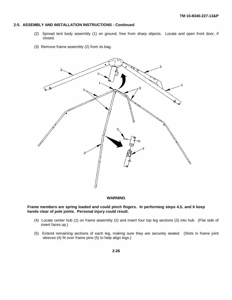
(2) Spread tent body assembly (1) on ground, free from sharp objects. Locate and open front door, ifclosed.
(3) Remove frame assembly (2) from its bag.
WARNING
Frame members are spring loaded and could pinch fingers. In performing steps 4,5, and 6 keephands clear of pole joints. Personal injury could result.
(4) Locate center hub (1) on frame assembly (2) and insert four top leg sections (3) into hub. (Flat side ofinsert faces up.)
(5) Extend remaining sections of each leg, making sure they are securely seated. (Slots in frame jointsleeves (4) fit over frame pins (5) to help align legs.)
2-26
TM 10-8340-227-13&P
2-5. ASSEMBLY AND INSTALLATION INSTRUCTIONS - Continued
CAUTION
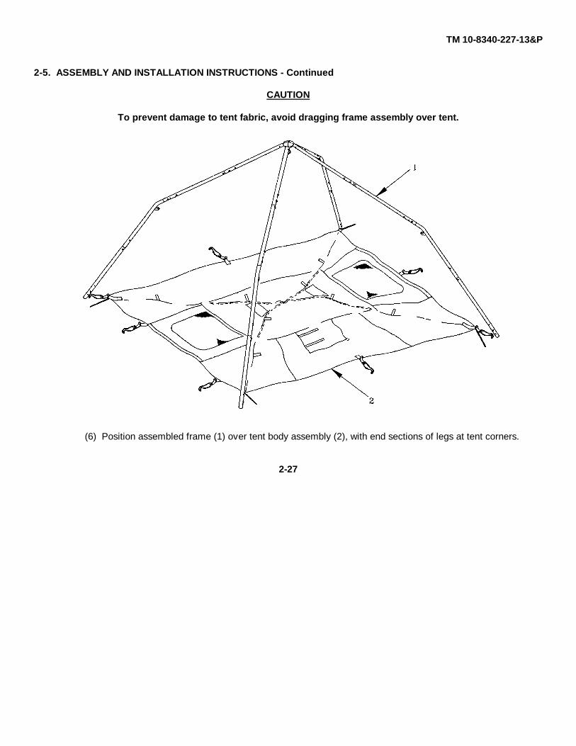
To prevent damage to tent fabric, avoid dragging frame assembly over tent.
(6) Position assembled frame (1) over tent body assembly (2), with end sections of legs at tent corners.
2-27
TM 10-8340-227-13&P
2-5. ASSEMBLY AND INSTALLATION INSTRUCTIONS - Continued
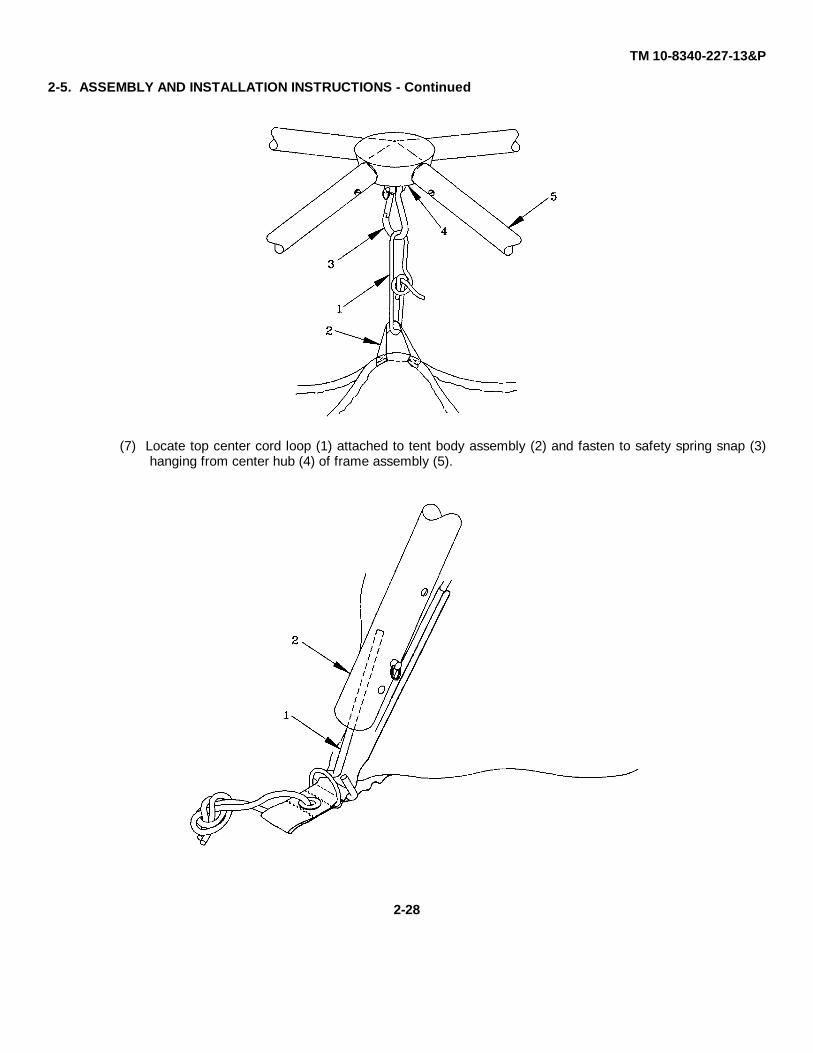
(7) Locate top center cord loop (1) attached to tent body assembly (2) and fasten to safety spring snap (3)hanging from center hub (4) of frame assembly (5).
2-28

TM 10-8340-227-13&P
2-5. ASSEMBLY AND INSTALLATION INSTRUCTIONS - Continued
WARNING
Frame assembly will be under tension when inserting pins. Stand to side of frame assemblypoles when performing the next step. Frame members could strike and injure you if they slip.
(8) Insert 5" triangular steel pin (1) attached to tent corner into bottom of frame pole (2). Insert diagonallyopposite pin into bottom of corresponding pole. Repeat process at remaining corners.
(9) Standing at one corner of the tent, attach one side of the cord loop (1) on the tent roof to the hook (2) onthe tent frame assembly (3). After attaching the first side of the loop to the hook, grasp the second sideof the loop and place over the hook. Repeat at remaining corners.
2-29
TM 10-8340-227-13&P
2-5. ASSEMBLY AND INSTALLATION INSTRUCTIONS - Continued
CAUTION
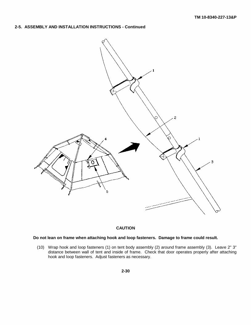
Do not lean on frame when attaching hook and loop fasteners. Damage to frame could result.
(10) Wrap hook and loop fasteners (1) on tent body assembly (2) around frame assembly (3). Leave 2" 3"distance between wall of tent and inside of frame. Check that door operates properly after attachinghook and loop fasteners. Adjust fasteners as necessary.
2-30
TM 10-8340-227-13&P
2-5. ASSEMBLY AND INSTALLATION INSTRUCTIONS - Continued
WARNING
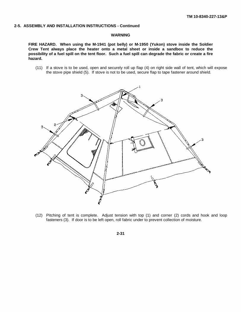
FIRE HAZARD. When using the M-1941 (pot belly) or M-1950 (Yukon) stove inside the SoldierCrew Tent always place the heater onto a metal sheet or inside a sandbox to reduce thepossibility of a fuel spill on the tent floor. Such a fuel spill can degrade the fabric or create a firehazard.
(11) If a stove is to be used, open and securely roll up flap (4) on right side wall of tent, which will exposethe stove pipe shield (5). If stove is not to be used, secure flap to tape fastener around shield.
(12) Pitching of tent is complete. Adjust tension with top (1) and corner (2) cords and hook and loopfasteners (3). If door is to be left open, roll fabric under to prevent collection of moisture.
2-31

TM 10-8340-227-13&P
2-5. ASSEMBLY AND INSTALLATION INSTRUCTIONS - Continued
c. Pitching the Fly.
NOTE
Fly is reversible to provide camouflage protection.
(1) Position fly so that the side (green or camouflage) which will be visible when the tent is erected facesdown. Locate vent flaps (1) near center of fly. Open and securely fasten vent flaps on this side with tietapes.
(2) Locate stove pipe shield flap (2) that will align with stove pipe shield (3) on tent body when fly is turnedto correct side. Open stove pipe shield flap (2) and fasten securely with tie tapes. Secure top flap (4)with hook and loop tape to keep from contact with stove pipe.
(3) Turn fly to correct side, with stove pipe shield flap (2) on same side as stove pipe shield (3). Drape flyover pitched tent and frame, making sure fly doors line up with doors of tent.
2-32

TM 10-8340-227-13&P
2-5. ASSEMBLY AND INSTALLATION INSTRUCTIONS - Continued
(4) Secure adjustable hooks (1) on fly assembly to dee (D) rings (2) at corners of tent.
NOTE
Adjustable hooks may be attached to pole legs if dee (D) rings are damaged or missing.
(5) Fasten adjustable hooks (1) to dee (D) rings (2) at sides of tent. (Door side of fly has two hooks.)
(6) Adjust position and tension of fly by loosening or tightening webbing through adjustable hooks.
(7) If doors or vent flaps are to be left open, roll fabric under to prevent collection of moisture.
2-33
TM 10-8340-227-13&P
2-5. ASSEMBLY AND INSTALLATION INSTRUCTIONS - Continued
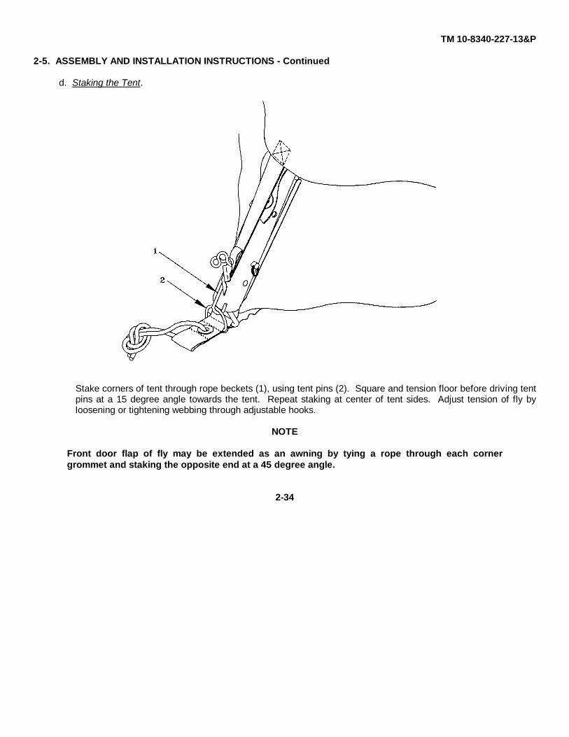
d. Staking the Tent.
Stake corners of tent through rope beckets (1), using tent pins (2). Square and tension floor before driving tentpins at a 15 degree angle towards the tent. Repeat staking at center of tent sides. Adjust tension of fly byloosening or tightening webbing through adjustable hooks.
NOTE
Front door flap of fly may be extended as an awning by tying a rope through each cornergrommet and staking the opposite end at a 45 degree angle.
2-34
TM 10-8340-227-13&P
2-5. ASSEMBLY AND INSTALLATION INSTRUCTIONS - Continued
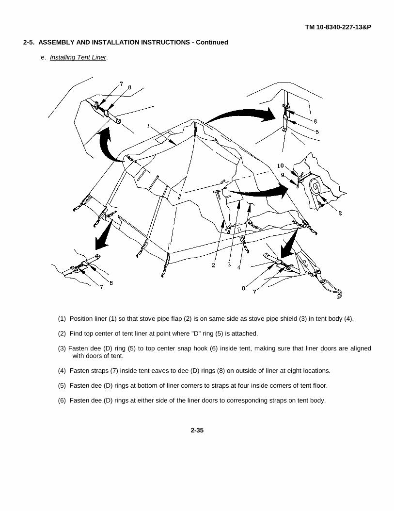
e. Installing Tent Liner.
(1) Position liner (1) so that stove pipe flap (2) is on same side as stove pipe shield (3) in tent body (4).
(2) Find top center of tent liner at point where "D" ring (5) is attached.
(3) Fasten dee (D) ring (5) to top center snap hook (6) inside tent, making sure that liner doors are alignedwith doors of tent.
(4) Fasten straps (7) inside tent eaves to dee (D) rings (8) on outside of liner at eight locations.
(5) Fasten dee (D) rings at bottom of liner corners to straps at four inside corners of tent floor.
(6) Fasten dee (D) rings at either side of the liner doors to corresponding straps on tent body.
2-35
TM 10-8340-227-13&P
2-5. ASSEMBLY AND INSTALLATION INSTRUCTIONS - Continued
WARNING
When using the M-1941 (pot belly) or M-1950 (Yukon) stove, be sure to secure the tent liner to thetent wall so that it does not come in contact with the heated stove pipe. A fire hazard couldresult.
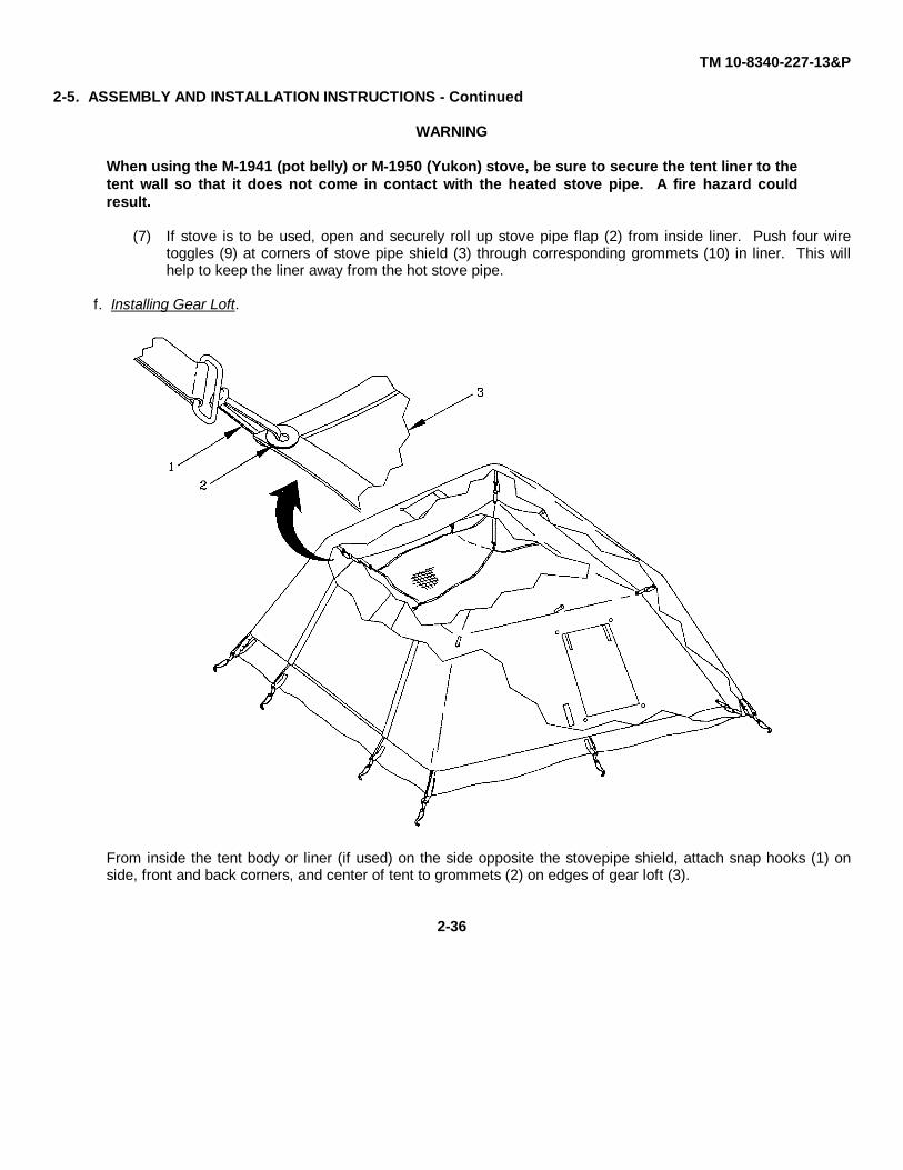
(7) If stove is to be used, open and securely roll up stove pipe flap (2) from inside liner. Push four wiretoggles (9) at corners of stove pipe shield (3) through corresponding grommets (10) in liner. This willhelp to keep the liner away from the hot stove pipe.
f. Installing Gear Loft.
From inside the tent body or liner (if used) on the side opposite the stovepipe shield, attach snap hooks (1) onside, front and back corners, and center of tent to grommets (2) on edges of gear loft (3).
2-36

TM 10-8340-227-13&P
2-6. DECALS AND INSTRUCTION PLATES. A label containing abbreviated setup instructions is sewn to the insidefront wall of the tent body assembly. An identical label is sewn to the inside of the tent cover. An identification label isattached to the frame assembly.
2-37
TM 10-8340-227-13&P
2-6. DECALS AND INSTRUCTION PLATES - Continued
TENT, CREW, SOLDIER
TEAM OF TWO SOLDIERS IS RECOMMENDED TO WORK THROUGH FOLLOWING PROCEDURES TO SPEEDPITCHING, STRIKING, AND PACKING. HOWEVER, ONE SOLDIER CAN PERFORM ALL FUNCTIONS, IFNECESSARY.
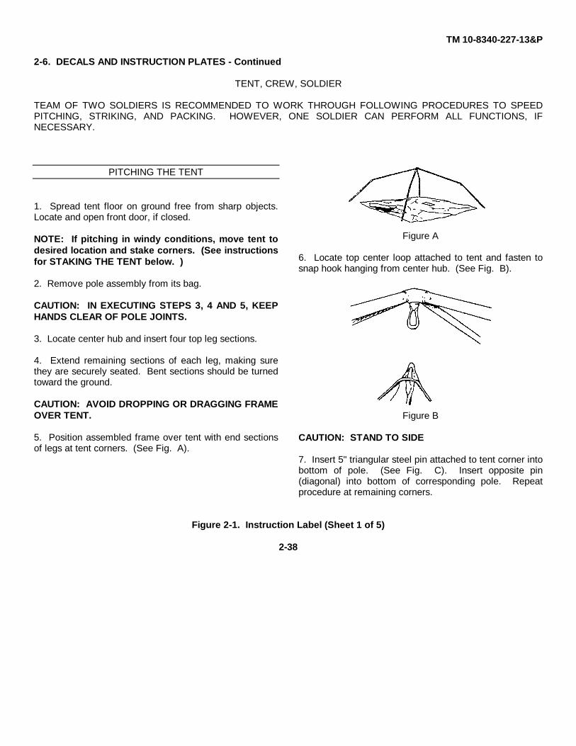
PITCHING THE TENT
1. Spread tent floor on ground free from sharp objects.Locate and open front door, if closed.
NOTE: If pitching in windy conditions, move tent todesired location and stake corners. (See instructionsfor STAKING THE TENT below. )
2. Remove pole assembly from its bag.
CAUTION: IN EXECUTING STEPS 3, 4 AND 5, KEEPHANDS CLEAR OF POLE JOINTS.
3. Locate center hub and insert four top leg sections.
4. Extend remaining sections of each leg, making surethey are securely seated. Bent sections should be turnedtoward the ground.
CAUTION: AVOID DROPPING OR DRAGGING FRAMEOVER TENT.
5. Position assembled frame over tent with end sectionsof legs at tent corners. (See Fig. A).
Figure A
6. Locate top center loop attached to tent and fasten tosnap hook hanging from center hub. (See Fig. B).
Figure B
CAUTION: STAND TO SIDE
7. Insert 5" triangular steel pin attached to tent corner intobottom of pole. (See Fig. C). Insert opposite pin(diagonal) into bottom of corresponding pole. Repeatprocedure at remaining corners.
Figure 2-1. Instruction Label (Sheet 1 of 5)
2-38
TM 10-8340-227-13&P
2-6. DECALS AND INSTRUCTION PLATES - Continued
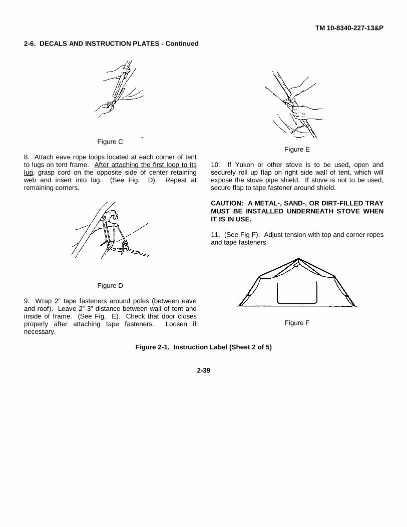
Figure C
8. Attach eave rope loops located at each corner of tentto lugs on tent frame. After attaching the first loop to itslug, grasp cord on the opposite side of center retainingweb and insert into lug. (See Fig. D). Repeat atremaining corners.
Figure D
9. Wrap 2" tape fasteners around poles (between eaveand roof). Leave 2"-3" distance between wall of tent andinside of frame. (See Fig. E). Check that door closesproperly after attaching tape fasteners. Loosen ifnecessary.
Figure E
10. If Yukon or other stove is to be used, open andsecurely roll up flap on right side wall of tent, which willexpose the stove pipe shield. If stove is not to be used,secure flap to tape fastener around shield.
CAUTION: A METAL-, SAND-, OR DIRT-FILLED TRAYMUST BE INSTALLED UNDERNEATH STOVE WHENIT IS IN USE.
11. (See Fig F). Adjust tension with top and corner ropesand tape fasteners.
Figure F
Figure 2-1. Instruction Label (Sheet 2 of 5)
2-39
TM 10-8340-227-13&P
2-6. DECALS AND INSTRUCTION PLATES - Continued
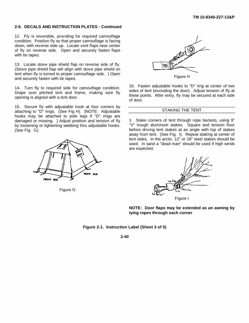
12. Fly is reversible, providing for required camouflagecondition. Position fly so that proper camouflage is facingdown, with reverse side up. Locate vent flaps near centerof fly on reverse side. Open and securely fasten flapswith tie tapes.
13. Locate stove pipe shield flap on reverse side of fly.(Stove pipe shield flap will align with stove pipe shield ontent when fly is turned to proper camouflage side. ) Openand securely fasten with tie tapes.
14. Turn fly to required side for camouflage condition.Drape over pitched tent and frame, making sure flyopening is aligned with a tent door.
15. Secure fly with adjustable hook at four corners byattaching to "D" rings. (See Fig H). [NOTE: Adjustablehooks may be attached to pole legs if "D" rings aredamaged or missing. ] Adjust position and tension of flyby loosening or tightening webbing thru adjustable hooks.(See Fig. G).
Figure G
Figure H
16. Fasten adjustable hooks to "D" ring at center of twosides of tent (excluding the door). Adjust tension of fly atthese points. After entry, fly may be secured at each sideof door.
STAKING THE TENT
1. Stake corners of tent through rope beckets, using 9""V" trough aluminum stakes. Square and tension floorbefore driving tent stakes at an angle with top of stakesaway from tent. (See Fig. I). Repeat staking at center oftent sides. In the arctic, 12" or 18" steel stakes should beused. In sand a "dead man" should be used if high windsare expected.
Figure I
NOTE: Door flaps may be extended as an awning bytying ropes through each corner
Figure 2-1. Instruction Label (Sheet 3 of 5)
2-40
TM 10-8340-227-13&P
2-6. DECALS AND INSTRUCTION PLATES - Continued
grommet on flap and staking opposite ends of rope at 45degree angles.
INSTALLING TENT FROST LINER
Find top center of liner at point where "D" ring is attached.Fasten "D" ring to top center snap inside tent, makingsure that the opening in the side of liner is aligned withstove pipe shield of tent. Fasten snaps inside tent to ringson outside of liner around eave of tent at eight locations,starting at either door of tent. Fasten bottom of liner tobottom of tent at inside corner snap and ring locations.Secure two tape fasteners at center bottom of each sidewall to complete installation of liner. (No fastener atdoors of tent).
NOTE: Tent may be packed without removing liner.DO NOT PACK WET LINER.
PACKING THE TENT
1. Take down the tent, reversing pitching procedures.
NOTE: Tent may be packed without removal of liner.DO NOT PACK WET LINER.
2. Insert folded tent frame into pole bag, closedrawstring, and cinch web straps.
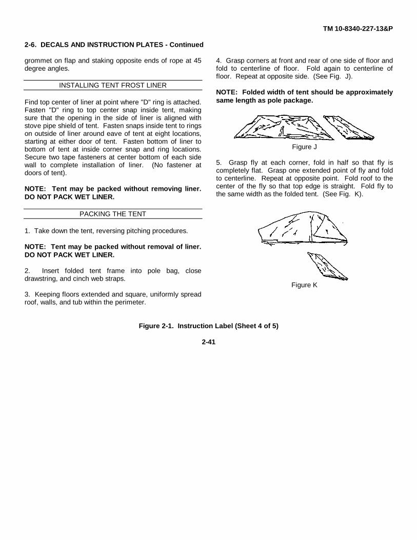
3. Keeping floors extended and square, uniformly spreadroof, walls, and tub within the perimeter.
4. Grasp corners at front and rear of one side of floor andfold to centerline of floor. Fold again to centerline offloor. Repeat at opposite side. (See Fig. J).
NOTE: Folded width of tent should be approximatelysame length as pole package.
Figure J
5. Grasp fly at each corner, fold in half so that fly iscompletely flat. Grasp one extended point of fly and foldto centerline. Repeat at opposite point. Fold roof to thecenter of the fly so that top edge is straight. Fold fly tothe same width as the folded tent. (See Fig. K).
Figure K
Figure 2-1. Instruction Label (Sheet 4 of 5)
2-41
TM 10-8340-227-13&P
2-6. DECALS AND INSTRUCTION PLATES - Continued
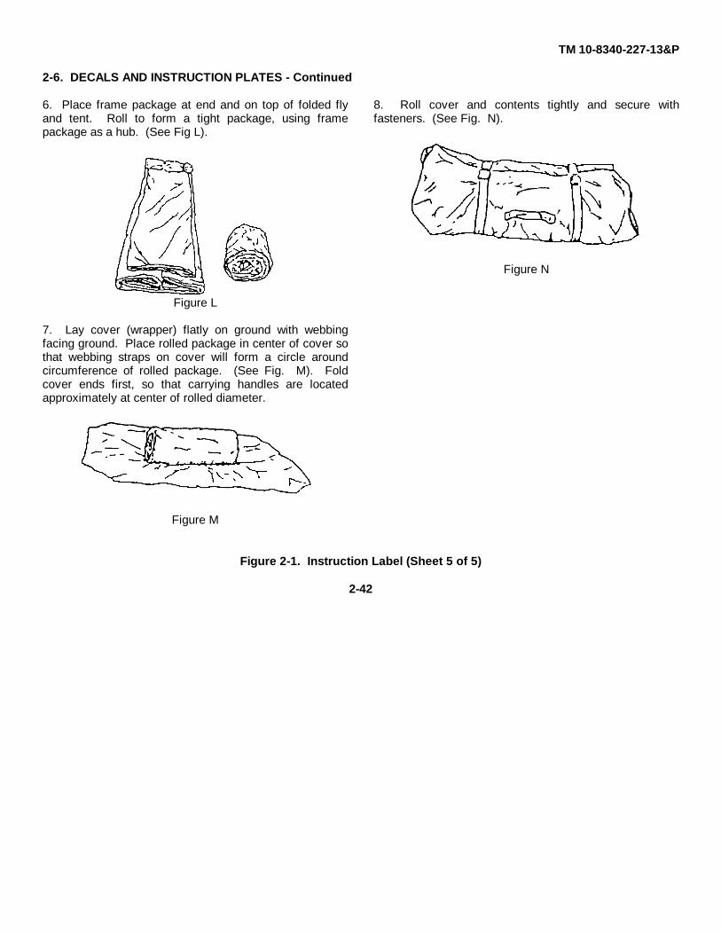
6. Place frame package at end and on top of folded flyand tent. Roll to form a tight package, using framepackage as a hub. (See Fig L).
Figure L
7. Lay cover (wrapper) flatly on ground with webbingfacing ground. Place rolled package in center of cover sothat webbing straps on cover will form a circle aroundcircumference of rolled package. (See Fig. M). Foldcover ends first, so that carrying handles are locatedapproximately at center of rolled diameter.
Figure M
8. Roll cover and contents tightly and secure withfasteners. (See Fig. N).
Figure N
Figure 2-1. Instruction Label (Sheet 5 of 5)
2-42
TM 10-8340-227-13&P
2-7. PREPARATION FOR MOVEMENT AND STORAGE. To prepare the Soldier Crew Tent for movement, follow theprocedures outlined below. As time and circumstances allow, perform operator PMCS "After" services. Clean and drytent fabric sections and frame.
NOTE
Tent may be packed without removing liner. DO NOT PACK WET LINER.
a. Remove gear loft. (Gear loft may be left in position if desired. )
b. Close stove pipe flap and remove liner, if installed. Grasp liner at each corner. Fold in half so that liner iscompletely flat. Grasp one extended point of liner and fold to centerline. Repeat for opposite point. Fold roofto the center of the liner so that top edge is straight. Fold other side so that folded liner is same width as foldedbody. (Liner may be left in position if desired. )
c. Close and secure fly doors, vent flaps and stove pipe flaps.
d. Disconnect adjustable hooks and dee (D) rings and hook and loop fasteners and remove fly. Turn fly over andsecure vent and stovepipe shield flaps.
e. Grasp fly at each corner. Fold in half so that fly is completely flat. Grasp one extended point of fly and fold tocenterline. Repeat for opposite point. Fold roof to the center of the fly so that top edge is straight. Fold otherside so that folded fly is same width as folded body.
f. Close doors, screens and stovepipe shield flap on tent body assembly. (Leave doors partially open. Thisprevents a vacuum at next setup. )
g. Disconnect hook and loop fasteners securing tent body assembly to frame.
h. Disconnect cord loops attaching tent body assembly to hooks on frame assembly.
i. Remove top center cord loop from safety spring snap on center hub.
2-43
TM 10-8340-227-13&P
2-7. PREPARATION FOR MOVEMENT AND STORAGE - Continued
WARNING
Frame assembly will be under tension when removing pins. Stand to side of frame assemblypoles when performing the next step. Frame members could strike and injure you if they slip.
CAUTION
Do not lean on frame when removing hook and loop fasteners. Damage to frame could result.
To prevent damage to tent fabric, avoid dragging frame assembly over tent.
j. Remove frame assembly from tent body assembly.
k. Remove four frame poles from center hub.
l. Fold frame poles and secure with rubber bands.
m. Insert folded tent frame assembly into its bag. Close drawstring and cinch web straps.
n. Remove tent pegs and store in peg bag.
o. Keeping tent body assembly extended and square, uniformly spread roof, walls, and floor.
p. Grasp corners at front and rear of one side of tent body assembly and fold to centerline. Fold again tocenterline. Repeat for opposite side.
NOTE
Folded width of tent should be approximately same length as stowed frame assembly.
q. Place folded fly, liner, gear loft, and tent pin bag on tent body.
r. Place frame assembly package at end and on top of folded fly and tent body assembly. Roll to form a tightpackage, using frame package as a hub.
2-44

TM 10-8340-227-13&P
2-7. PREPARATION FOR MOVEMENT AND STORAGE - Continued
s. Lay tent cover on ground with webbing facing down. Place rolled package in center of cover so that webbingstraps on cover will form a circle around circumference of rolled package. Fold cover ends first, so thatcarrying handles are located approximately at center of rolled diameter.
t. Roll cover and contents tightly and secure with fasteners.
SECTION IV. OPERATION UNDER UNUSUAL CONDITIONS
2-8. GENERAL. While it is not possible to prepare for all unusual conditions to which the Soldier Crew Tent will beexposed, the following information should be helpful during unusual climatic conditions.
a. Operation in High Wind.
(1) Ensure that Soldier Crew Tent is staked.
WARNING
SUFFOCATION HAZARD. Soldier Crew Tent fabric does not "breathe". Open windows and flapsas necessary to ensure adequate ventilation. If all openings are closed, it is possible to use upall of the oxygen contained in the tent, especially during sleeping hours, RESULTING IN DEATH.
(2) Close and secure all openings and doors.
(3) Frequently check all tent pegs and lines.
b. Wet Climate.
(1) If heavy rain is expected or the Soldier Crew Tent is going to be set up for a long period of time, dig atrench around the tent to channel water away from it.
(2) Tent lines may shrink from dampness, so keep tent lines loose enough to prevent tent pegs from beingpulled out of the ground.
(3) Dry all Soldier Crew Tent components before packing.
2-45

TM 10-8340-227-13&P
c. Operation in Snow/Extreme Cold.
WARNING
SUFFOCATION HAZARD. Soldier Crew Tent fabric does not "breathe". Open windows and flapsas necessary to ensure adequate ventilation. If all openings are closed, it is possible to use upall of the oxygen contained in the tent, especially during sleeping hours, RESULTING IN DEATH.
(1) Gently push up on the roof cap from inside the Soldier Crew Tent to remove snow.
(2) If erecting the Soldier Crew Tent in snow, lightly pack the snow to provide a firm surface on which to setup.
(3) If ground is frozen too hard to drive steel tent pegs, chop small holes to set them in. Fill holes with slushor water and allow to freeze and anchor pegs.
(4) Install liner assembly.
2-46
TM 10-8340-227-13&P
CHAPTER 3
OPERATOR'S MAINTENANCE INSTRUCTIONS
Section I Lubrication Instructions ....................................................................................................................... 3-1
3-1 General ........................................................................................................................................... 3-1
Section II Operator's Troubleshooting Procedures .............................................................................................. 3-1
3-2 General Instructions ...................................................................................................................... 3-23-3 Use of Table.................................................................................................................................. 3-2
Section III Operator's Maintenance Procedures .................................................................................................. 3-4
3-4 Inspection...................................................................................................................................... 3-43-5 Cleaning........................................................................................................................................ 3-43-6 Repair Frame Assembly................................................................................................................ 3-43-7 Repair Fabric Assemblies.............................................................................................................. 3-6
Section I. LUBRICATION INSTRUCTIONS
3-1. GENERAL. Zippers can be lubricated using the slide fastener lubricant (Item 2, Appendix E), also contained in therepair kit.
SECTION II. OPERATOR'S TROUBLESHOOTING PROCEDURES
3-2. GENERAL INSTRUCTIONS. Table 3-1 contains troubleshooting instructions designed to aid in diagnosingunsatisfactory operation or failure of Soldier Crew Tent components. The table lists common malfunctions that you mayfind during normal use or maintenance of the equipment. This manual cannot list all malfunctions that may occur, nor alltests and inspections and corrective actions. If a malfunction is not listed or is not corrected by the prescribed action,notify unit maintenance.
MALFUNCTION INDEX
Soldier Crew Tent Troubleshooting ProceduresParagraph
Tent Unstable ..........................................................................................................................................1Tent Leaks ..............................................................................................................................................2
3-3. USE OF TABLE. You should perform the tests/inspections and corrective actions in the order listed.
a. Malfunction. Check for where or what the malfunction is.
b. Test or Inspection. Test or inspect the cause of the malfunction.
c. Corrective Action. Once the malfunction is determined, correct the situation.
3-1

TM 10-8340-227-13&P
TABLE 3-1. OPERATOR TROUBLESHOOTING - Continued
MALFUNCTIONTEST OR INSPECTION
CORRECTIVE ACTION
1. TENT UNSTABLE
Step 1. Check frame assembly for proper setup, loose or missing hardware (1). Check that floor to frameconnectors (2) are installed in bottom of frame poles (3).
Adjust frame as necessary. Install floor to frame connectors in poles. Tighten/replace loose/missinghardware.
Step 2. Check that cords (4) are properly adjusted. Check that hook and loop fasteners (5) are properlyadjusted. Check for missing/loose tent pegs (6).
Adjust cords and hook and loop fasteners as necessary. Replace tent pegs as necessary.
3-2

TM 10-8340-227-13&P
TABLE 3-1. OPERATOR TROUBLESHOOTING - Continued
MALFUNCTIONTEST OR INSPECTION
CORRECTIVE ACTION
2. TENT LEAKS
Step 1. Check for improperly closed flaps.
Secure flaps.
Step 2. Check for holes, tears, or cuts in fabric.
Repair as necessary. (See para 3-7)
Step 3. Check seams for leaks.
Repair as necessary. (See para 3-7)
3-3
TM 10-8340-227-13&P
Section III. OPERATOR'S MAINTENANCE PROCEDURES
3-4. INSPECTION. Perform inspection as described in Chapter 2, Section II, PMCS. Report defects on DA Form 2404.
3-5. CLEANING. Clean all Soldier Crew Tent fabric components with a brush (Item 1, Appendix E) and mild soapywater (Item 3, Appendix E). Let fabric components air dry.
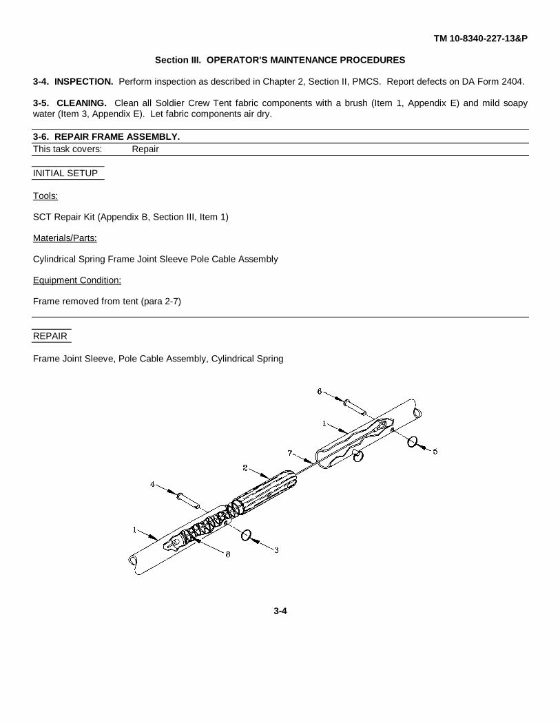
3-6. REPAIR FRAME ASSEMBLY.This task covers: Repair
INITIAL SETUP
Tools:
SCT Repair Kit (Appendix B, Section III, Item 1)
Materials/Parts:
Cylindrical Spring Frame Joint Sleeve Pole Cable Assembly
Equipment Condition:
Frame removed from tent (para 2-7)
REPAIR
Frame Joint Sleeve, Pole Cable Assembly, Cylindrical Spring
3-4
TM 10-8340-227-13&P
3-6. REPAIR FRAME ASSEMBLY - Continued
a. Remove
(1) Gently pull the frame poles (1) closest to the joint sleeve (2) to be replaced apart. Do not open the jointmore than necessary. This will keep pressure off the spring and make it easier to hold the cable.
(2) Carefully spread the split ring (3) and remove it from the frame pin (4) securing the frame joint sleeve (2)to the frame pole (1).
(3) Remove the frame pin (4).
(4) Pull frame joint sleeve (2) and pole cable assembly (7) and spring (8) out of frame pole (1).
(5) Carefully spread the split ring (5) and remove it from the frame pin (6) securing the pole cable assembly(7) to the frame pole (1). Remove the frame pin.
(6) Remove the frame joint sleeve (2) and cylindrical spring (8) by pulling them over the pole cableassembly (7). Retain cable assembly and cylindrical spring for re-use.
b. Install
(1) Slide cylindrical spring (8) and new frame joint sleeve (2) over the pole cable assembly (7).
(2) Extend the cable and pass the frame pin (6) through one side of the frame pole (1), through the loop inthe pole cable assembly (7), and out the other side of the frame pole (1).
(3) Carefully spread the split ring (5) and thread it through the hole in the frame pin (6).
(4) Insert pole cable assembly (7), spring (8), and frame joint sleeve (2) into frame pole (3).
(5) Align holes in frame joint sleeve (2) with holes in frame pole (1) and push frame pin (4) through both setsof holes.
(6) Carefully spread the split ring (3) and thread it through the hole in the frame pin (4).
(7) Check frame assembly for proper operation.
3-5

TM 10-8340-227-13&P
3-7. REPAIR FABRIC ASSEMBLIESThis task covers: Repair
INITIAL SETUP
Tools:
SCT Repair Kit (Appendix B, Section III, Item 1)
Materials/Parts:
Denatured Alcohol (Appendix E, Section II, Item 4)SCT Repair Kit (Appendix B, Section III, Item 1)Gloves, Latex-Nitrile (Appendix E, Section II, Item 6)Goggles, Chemical Splash (Appendix E, Section II, Item 7)Wiping Rags (Appendix E, Section II, Item 11)
Equipment Condition:
Although the fabric assemblies can be repaired during operational use of the tent when necessary, it is recommendedthat the fabric be repaired when the tent is not in use. Fabric assemblies should be clean and dry.
Repair Fabric Assemblies
WARNING
Seam sealer and solvent are extremely flammable and fumes toxic contains isopropyl alcohol.Do Not smoke or use seam sealer or solvent near open flame. Death or serious injury mayresult from explosion or fire.
Use seam sealer and solvent in an open, well ventilated area away from sources of combustion;indoors wear a respirator. Avoid contact with skin and eyes. Wear goggles and gloves whenusing seam sealer and solvent. Inhalation of fumes may cause toxic sickness.
Repair minor rips and tears (maximum of six inches in length) or holes (maximum of two inches in diameter) with thematerials in the Soldier Crew Tent repair kit. Seam sealer can be used on pinholes, stitching, and small repairs.
3-6
TM 10-8340-227-13&P
3-7. REPAIR FABRIC ASSEMBLIES - Cont'd.
WARNING
Seam sealer and solvent are extremely flammable and fumes toxic contains toluene andisopropyl alcohol. Do Not smoke or use seam sealer or solvent near open flame. Death orserious injury may result from explosion or fire.
Use seam sealer and solvent in an open, well ventilated area away from sources of combustion;indoors wear a respirator. Avoid contact with skin and eyes. Wear goggles and gloves whenusing seam sealer and solvent. Inhalation of fumes may cause toxic sickness.
NOTE
The tape contained in the repair kit can be used for temporary repairs. The sewing awl in therepair kit can be used for minor sewing repairs. Turn in fabric assemblies to unit maintenancefor anything other than minor repairs.
Replace missing rope or make minor repairs to hook and loop fasteners with material in therepair kit.
3-7

TM 10-8340-227-13&P
CHAPTER 4
UNIT MAINTENANCE INSTRUCTIONS
Section I. LUBRICATION INSTRUCTIONS.
4-1. GENERAL. Zippers can be lubricated using the slide fastener lubricant (Item 2, Appendix E), also contained in therepair kit.
Section II. REPAIR PARTS, SPECIAL TOOLS, TMDE, AND SUPPORT EQUIPMENT.
4-2. COMMON TOOLS AND EQUIPMENT. For authorized common tools and equipment, refer to the Modified Table ofOrganization and Equipment (MTOE) applicable to your unit.
4-3. SPECIAL TOOLS. Refer to Appendix B, Section II, Tool and Test Equipment Requirements, MaintenanceAllocation Chart, for additional tool and equipment requirements.
4-4. REPAIR PARTS. The repair parts required for unit level maintenance are listed and illustrated in Appendix F,Repair Parts and Special Tools List.
Section III. SERVICE UPON RECEIPT.
4-5. UNPACKING. Upon receipt, open the tent cover assembly and remove the Soldier Crew Tent components listedbelow. Report any damage to the carrier and your supervisor.
a. Frame assembly and frame bag assemblyb. Fly assemblyc. Liner assemblyd. Gear loft assemblye. Tent cover assemblyf. Tent pegs and bagg. Tent body assembly
4-6. INSPECTING UNPACKED EQUIPMENT. Inspect the unpacked components for damage, completeness, andapplication of applicable Modification Work Orders (MWOs) as follows:
a. Damage. Check the equipment for damage incurred during shipment. Report any damage on DD Form 6,Packaging Improvement Report. Also note damage on DA Form 2404, Equipment Inspection and MaintenanceWorksheet, and initiate corrective maintenance procedures in accordance with Section III of this chapter.
b. Completeness. Inspect the contents of the shipment against the packing slip to see if any items are missing(See Appendix C, Components of End Item). Report any discrepancies noted in accordance with instructions in DA PAM738-750. The equipment can be placed in service even if accessories or other parts/ assemblies that do not affectproper functioning are missing.
4-1
TM 10-8340-227-13&P
4-6. INSPECTING UNPACKED EQUIPMENT Continued
c. Modifications. Check DA PAM 25-30 to see if there are any MWOs applicable to the components you areunpacking. If an MWO is listed, check to see if it has been applied to the equipment. The MWO number will be shownon the case/bag near the equipment nomenclature. If a current MWO is listed in DA PAM 25-30 but there is no evidencethat it has been applied to the equipment you are unpacking, note discrepancy on DA Form 2404, Equipment Inspectionand Maintenance Worksheet.
Section IV. UNIT PREVENTIVE MAINTENANCE CHECKS AND SERVICES (PMCS)
4-7. GENERAL. There is no separate Unit PMCS required for the Soldier Crew Tent. Refer to Chapter 2 for detailedOperator PMCS procedures.
Section V. UNIT TROUBLESHOOTING
4-8. GENERAL. There are no separate Unit troubleshooting procedures for the Soldier Crew Tent. Refer to Chapter 3for operator troubleshooting procedures.
Section VI. UNIT MAINTENANCE PROCEDURES
WARNING
Seam sealer and solvent are extremely flammable and fumes toxic contains isopropyl alcohol.Do not smoke or use seam sealer or solvent near open flame. Death or serious injury may resultfrom explosion or fire.
Use seam sealer and solvent in an open, well ventilated area away from sources of combustion;indoors wear a respirator. Avoid contact with skin and eyes. Wear goggles and gloves whenusing seam sealer and solvent. Inhalation of fumes may cause toxic sickness.
4-9. GENERAL. This section contains unit maintenance procedures applicable to the Soldier Crew Tent components asauthorized by the Maintenance Allocation Chart (MAC), Appendix B of this manual. Repairs will be limited to sewingfabric rips and tears (maximum of six inches in length) or holes (maximum of two inches in diameter) and application ofseam sealer. Consult FM 10-16 for specific tentage repair guidelines.
4-2
TM 10-8340-227-13&P
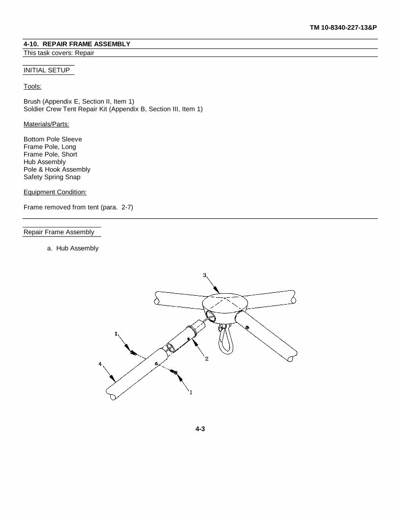
4-10. REPAIR FRAME ASSEMBLYThis task covers: Repair
INITIAL SETUP
Tools:
Brush (Appendix E, Section II, Item 1)Soldier Crew Tent Repair Kit (Appendix B, Section III, Item 1)
Materials/Parts:
Bottom Pole SleeveFrame Pole, LongFrame Pole, ShortHub AssemblyPole & Hook AssemblySafety Spring Snap
Equipment Condition:
Frame removed from tent (para. 2-7)
Repair Frame Assembly
a. Hub Assembly
4-3
TM 10-8340-227-13&P
4-10. REPAIR FRAME ASSEMBLY - Continued
(1) Remove
(a) Remove eight screws (1) securing pole legs (2) of hub assembly (3) to frame poles (4).
(b) Remove hub assembly (3) from frame poles (4).
(2) Install
(a) Insert pole legs (2) of hub assembly (3) into frame poles (4).
(b) Secure pole legs (2) of hub assembly (3) to frame poles (4) with screws (1).
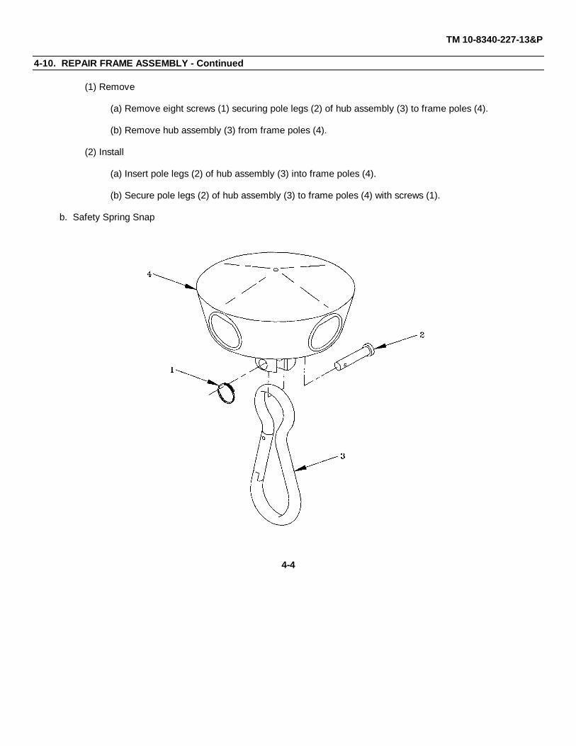
b. Safety Spring Snap
4-4

TM 10-8340-227-13&P
4-10. REPAIR FRAME ASSEMBLY - Continued
(1) Remove
(a) Remove split ring (1) and frame pin (2) securing safety spring snap (3) to hub assembly (4).
(b) Remove safety spring snap (3) from hub assembly (4).
(2) Install
(a) Align safety spring snap (3) with holes in hub assembly (4).
(b) Insert frame pin (2) through hub assembly (4) and safety spring snap (3) and secure with split ring (1).
c. Bottom Pole Sleeve
4-5
TM 10-8340-227-13&P
4-10. REPAIR FRAME ASSEMBLY - Continued
(1) Remove
(a) Remove split ring (1) and frame pin (2) securing bottom pole sleeve (3) to frame pole (4).
(b) Remove bottom pole sleeve (3) from frame pole (4).
(2) Install
(a) Insert bottom pole sleeve (3) into frame pole (4).
(b) Align holes in bottom pole sleeve (3) and frame pole (4), so that bottom pole sleeve is flush withframe pole.
(c) Insert frame pin (2) through holes in bottom pole sleeve (3) and frame pole (4) and secure with splitring (1).
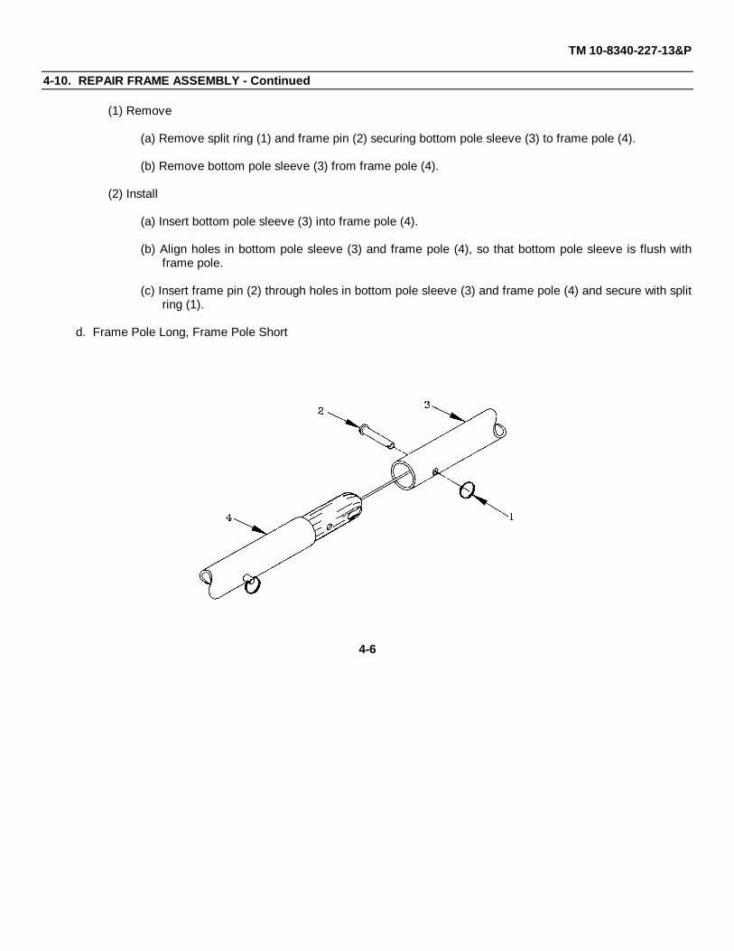
d. Frame Pole Long, Frame Pole Short
4-6
TM 10-8340-227-13&P
4-10. REPAIR FRAME ASSEMBLY - Continued
(1) Remove
(a) Remove hub assembly (refer to para 4-10.a).
(b) Remove bottom pole sleeve (refer to para 4-10.c).
(c) Remove frame joint sleeve (refer to para 3-6).
(d) Remove split ring (1) and aligning frame pin (2) from frame pole (3). Retain for re-use.
(e) Remove frame pole (4) from frame assembly.
(2) Install
(a) Install aligning frame pin (2) and split ring (1) in frame pole (3).
(b) Install frame pole (4) on frame assembly.
(c) Install frame joint sleeve (refer to para 3-6).
(d) Install hub assembly (refer to para 4-10.a.).
(e) Install bottom pole sleeve. (Refer to Para 4-10.c.)
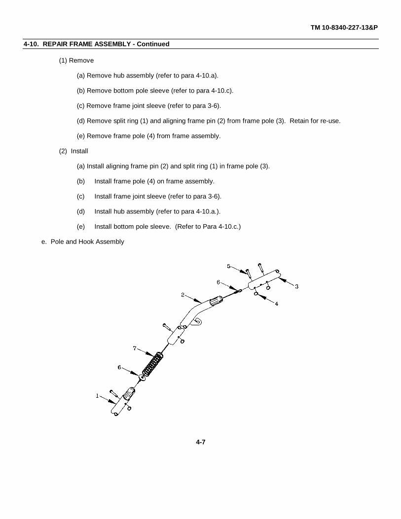
e. Pole and Hook Assembly
4-7
TM 10-8340-227-13&P
4-10. REPAIR FRAME ASSEMBLY - Continued
(1) Remove
WARNING
Cable is under tension. Do not attempt to remove frame pole short without first removing framejoint sleeve.
(a) Remove frame joint sleeve from frame pole short (1) (refer to para 3-6).
(b) Insert pole and hook assembly (2) into frame pole short (3).
WARNING
Cable is under tension. Ensure poles are connected before proceeding.
(c) Remove split ring (4) and frame pin (5) securing cable assembly (6).
(d) Remove cable assembly (6) and cylindrical spring (7) from bottom of pole and hook assembly (2)
(2) Install
(a) Insert cylindrical spring (7) and cable assembly (6) through bottom of pole and hook assembly (2).
(b) Align loop in cable assembly (6) with proper hole in frame pole short (3).
(c) Insert frame pin (5) through frame pole short (3) and loop in cable assembly (6). Secure with splitring (4).
(d) Install frame joint sleeve on frame pole short (1) (refer to para 3-6).
4-8
TM 10-8340-227-13&P
4-11. REPAIR FABRIC ASSEMBLIES.
This task covers: Repair
INITIAL SETUP
Tools:
Punch and Die, Grommet Inserting (Appendix B, Section III, Item 2)SCT Repair Kit (Appendix B, Section III, Item 1)Tentage Repair Kit (Appendix B, Section III, Item 3)
Materials/Parts:
Brush (Appendix E, Section II, Item 1)Denatured Alcohol (Appendix E, Section II, Item 4)Filter, Cartridge (Appendix E, Section II, Item 5)Gloves, Latex-Nitrile (Appendix E, Section II, Item 6)Goggles, Chemical Splash (Appendix E, Section II, Item 7)Respirator (Appendix E, Section II, Item 8)Seam Sealer (Appendix E, Section II, Item 10)Wiping Rags (Appendix E, Section II, Item 11)
Equipment Condition:
Although the fabric assemblies can be repaired during operational use of the tent when necessary, it is recommendedthat the fabric be repaired when the tent is not in use, since repairs are easier when the fabric assemblies are separated.The fabric assemblies should be clean and dry.
Repair Fabric Assemblies
a. Repair all rips, tears or holes up to a maximum of six inches by sewing or patching, using the tools andmaterials listed above. Follow the procedures in FM 10-16 to make these repairs. Turn in fabric assemblies todirect support maintenance for repair of holes 6" or larger or ripped seams.
WARNING
Seam sealer and solvent are extremely flammable and fumes toxic - contains isopropyl alcohol.Do not smoke or use seam sealer or solvent near open flame. Death or serious injury may resultfrom explosion or fire.
4-9
TM 10-8340-227-13&P
4-11. REPAIR TENT FABRIC ASSEMBLIES - Continued
WARNING
Use seam sealer and solvent in an open, well-ventilated area away from sources of combustion;indoors wear a respirator. Avoid contact with skin and eyes. Wear goggles and gloves whenusing seam sealer and solvent. Inhalation of fumes may cause toxic sickness.
b. Apply seam sealer to repaired areas as follows:
NOTE
Tent may be erected or fabric assemblies may be removed and laid flat.
Do not use a foam brush. Use a bristle brush only.
Sealer may be applied to outside or inside of fabric assemblies.
Sealer should only be applied to new stitches and patches, or to those areas that have shownwater leakage.
Two light coats of sealant are more effective than one thick coat. Do not use excessive amountsof sealer, as this does not increase effectiveness and will give the tent a poor appearance.
Do not leave original sealer container open, as sealer will thicken and become unusable. Limitthe amount of time container is open.
(1) Clean surface to be sealed as thoroughly as practical and dry completely before applying sealer.
(2) Apply sealer to stitching or repair to be sealed, overlapping seam stitching or edges of repair by 1/2".Immediately reseal container.
(3) Allow first coat to dry to the touch.
(4) Apply second coat as described in step (3).
4-10
TM 10-8340-227-13&P
Section VII. PREPARATION FOR STORAGE AND SHIPMENT
4-12. PREPARATION FOR STORAGE. To prepare the Soldier Crew Tent for storage, clean and dry the fabric sectionsand other components as described in paragraph 3-5. Perform operator PMCS as specified in Table 2-2.
Pack the fabric and frame assemblies as described in paragraph 2-7. Place on a wooden pallet and store in a dry place.
Special Instructions for Administrative Storage.
Placement of equipment in administrative storage should be for short periods of time when a shortage ofmaintenance resources exists. Items should be in mission readiness within 24 hours or within the time factorsdetermined by the directing authority. Appropriate maintenance records will be kept during storage.
Before placing equipment in administrative storage, current maintenance services and Preventive MaintenanceChecks and Services (PMCS) should be completed, shortcomings and deficiencies should be corrected, and allModification Work Orders (MWOs) should be applied.
Storage site selection. Inside storage is preferred for items selected for administrative storage. If inside storageis not available, trucks, vans, conex or other containers may be used.
4-13. PRESERVATION. If the Soldier Crew Tent components are to be stored without regular PMCS being performed,consult TM 38-230-2 for preservation requirements.
4-14. PREPARATION FOR SHIPMENT. Prepare the Soldier Crew Tent components for shipment by packing them inthe tent cover assembly.
4-11

TM 10-8340-227-13&P
CHAPTER 5
DIRECT SUPPORT MAINTENANCE INSTRUCTIONS
Section I. REPAIR PARTS; SPECIAL TOOLS; TEST, MEASUREMENT AND DIAGNOSTIC EQUIPMENT (TMDE);AND SUPPORT EQUIPMENT
5-1. COMMON TOOLS AND EQUIPMENT. For authorized common tools and equipment refer to the Modified Table ofOrganization and Equipment (MTOE) applicable to your unit.
5-2. SPECIAL TOOLS, TMDE, AND SUPPORT EQUIPMENT. Refer to Appendix B, Section II, Tool and TestEquipment Requirements, Maintenance Allocation Chart, for additional tool and equipment requirements.
5-3. REPAIR PARTS. Repair parts are listed and illustrated in Appendix F, Repair Parts and Special Tools List.
Section II. MAINTENANCE PROCEDURES
5-4. GENERAL. Direct Support maintenance functions identified in Section II, Appendix B, consist of machine repair ofsewn components. Procedures for machine stitching are provided in paragraph 5-5. Specific tentage repair proceduresare provided in FM 10-16.
5-5. MACHINE STITCHING. All stitch types, except bartacking, shall conform to FED-STD-751. Type 301 stitchingrequires 5-8 stitches per inch. Type 401 stitching requires 6-9 stitches per inch. All stitching is to be 1/8 inch from edgeor 1/8 inch apart, unless otherwise specified. Bartacking shall be free of breaks and loose stitching.
a. Thread Breaks. Thread breaks in stitching shall be overstitched not less than 1 inch at each break on stitchtype 301, and not less than 1 1/2" at each break on stitch type 401. Thread breaks in type 401 may be overstitched withstitch type 301. Thread breaks noted during inspection must be repaired by overstitching the existing stitching, startingfrom a distance of 1 inch beyond the break. The ends of repair stitching are not required to be backstitched.
b. Stitching Ends. The ends of type 301 stitching shall be overstitched not less than 1 inch except where ends areturned under in a hem or held down by other stitching. Where 301 stitching is performed automatically on stitch patternssuch as box, box with cross-stitch , "W" stitching or straight line tacking, at least three tying, overlapping, or back stitchesshall be used to secure the ends of stitching.
c. Skipped Stitches. Two or more consecutively skipped stitches occurring in type 301 stitching shall beoverstitched not less than 1 inch. Any skipped stitches in type 401 stitching
5-1
TM 10-8340-227-13&P
5-5. MACHINE STITCHING - Continued
shall be overstitched not less than 1 1/2 inches. Skipped stitches in 401 stitching may be overstitched with type 301stitching. Skipped stitches noted during inspection shall be repaired as specified for thread breaks in a., above.
5-6. AUTOMATIC STITCHING. Automatic stitching machines may be used to perform any of the required stitchpatterns provided the requirements of the stitch pattern, stitches per inch, size and type of thread are met, and at leastthree or more overlapping, tying or backstitches secure the ends of the stitching.
5-7. REPAIR FABRIC ASSEMBLIES
This task covers: Repair
INITIAL SETUP
Tools:
Sewing Machine (Appendix B, Section III, Item 5)
Materials/Parts:
Refer to Appendix F
Equipment Condition:
Although the fabric assemblies can be repaired during operational use of the tent when necessary, it is recommendedthat the fabric be repaired when the tent is not in use, since repairs are easier when the fabric assemblies are separated.The fabric assemblies should be clean and dry.
Repair Fabric Assemblies
Repair rips, tears, holes or separated seams as necessary. Follow the procedures outlined in paragraphs 5-6 and 5-7above and FM 10-16 to perform the repairs.
5-2
TM 10-8340-227-13&P
APPENDIX A
REFERENCES
Scope
This appendix lists all forms, field manuals and technical manuals referenced in this manual.
Forms
Equipment Inspection and Maintenance Worksheet ...................................................................................DA Form 2404Recommended Changes to Publications and Blank Forms ........................................................................DA Form 2028Recommended Changes to Equipment Technical Manuals ....................................................................DA Form 2028-2Packaging Improvement Report ......................................................................................................................DD Form 6Quality Deficiency Report ..................................................................................................................................... SF 368
Field Manuals
General Fabric Repair .......................................................................................................................................FM 10-16First Aid for Soldiers ..........................................................................................................................................FM 21-11
Technical Manuals
Destruction of Army Materiel to Prevent Enemy Use ..................................................................................TM 750-244-3Preservation, Packaging and Packing of Military Supplies and Equipment ...................................................TM 38-230-2
DA Pamphlets
The Army Maintenance Management System (TAMMS) .......................................................................DA PAM 738-750Consolidated Index of Army Publications and Blank Forms ...................................................................... DA PAM 25-30
Federal Standards
Stitches, Seams and Stitchings ...................................................................................................................FED-STD-451
A-1


TM 10-8340-227-13&P
APPENDIX B
MAINTENANCE ALLOCATION CHART (MAC)
Change 2 B-1
Section I. INTRODUCTION
B-1. The Army Maintenance System MAC This introduction provides a general explanation of all maintenance and repair functions authorized at the two maintenance levels under the Two-Level Maintenance System concept. This MAC (immediately following the introduction) designates overall authority and responsibility for the performance of maintenance functions on the identified end item or component. The application of the maintenance functions to the end item or component shall be consistent with the capacities and capabilities of the designated maintenance levels, which are shown on the MAC in column (4) as:
Field - includes two columns, Unit maintenance and Direct Support maintenance. The Unit maintenance column is divided again into two more subcolumns, C for Operator or Crew and O for Unit maintenance.
Sustainment – includes two subcolumns, General Support (H) and Depot (D).
The tools and test equipment requirements (immediately following the MAC) list the tools and test equipment (both special tools and common tool sets) required for each maintenance function as referenced from the MAC. The remarks (immediately following the tools and test equipment requirements) contain supplemental instructions and explanatory notes for a particular maintenance function. B-2. Maintenance Functions Maintenance functions are limited to and defined as follows: 1. Inspect. To determine the serviceability of an item by comparing its physical, mechanical, and/or
electrical characteristics with established standards through examination (e.g., by sight, sound, or feel.) This includes scheduled inspection and gagings and evaluation of cannon tubes.
2. Test. To verify serviceability by measuring the mechanical, pneumatic, hydraulic, or electrical characteristics of an item and comparing those characteristics with prescribed standards on a scheduled basis, i.e., load testing of lift devices and hydrostatic testing of pressure hoses.
3. Service. Operations required periodically to keep an item in proper operating condition; e.g., to clean (includes decontaminate, when required), to preserve, to drain, to paint, or to replenish fuel, lubricants, chemical fluids, or gases. This includes scheduled exercising and purging of recoil mechanisms. The following are examples of service functions:
a. Unpack. To remove from packing box for service or when required for the performance of
maintenance operations.
b. Repack. To return item to packing box after service and other maintenance operations.
c. Clean. To rid the item of contamination.

TM 10-8340-227-13&P
Change 2 B-2
d. Touch up. To spot paint scratched or blistered surfaces.
e. Mark. To restore obliterated identification. 4. Adjust. To maintain or regulate, within prescribed limits, by bringing into proper position, or by setting
the operating characteristics to specified parameters.
5. Align. To adjust specified variable elements of an item to bring about optimum or desired performance
6. Calibrate. To determine and cause corrections to be made or to be adjusted on instruments of test, measuring, and diagnostic equipment used in precision measurement. Consists of comparisons of two instruments, one of which is a certified standard of known accuracy, to detect and adjust any discrepancy in the accuracy of the instrument being compared.
7. Remove/Install. To remove and install the same item when required to perform service or other maintenance functions. Install may be the act of emplacing, seating, or fixing into position a spare, repair part, or module (component or assembly) in a manner to allow the proper functioning of an equipment or system.
8. Paint. To prepare and spray color coats of paint so that the ammunition can be identified and protected. The color indicating primary use is applied, preferably, to the entire exterior surface as the background color of the item. Other markings are to be repainted as original so as to retain proper ammunition identification.
9. Replace. To remove an unserviceable item and install a serviceable counterpart in its place. “Replace” is authorized by the MAC and assigned maintenance level is shown as the third position code of the Source, Maintenance and Recoverability (SMR) code.
10. Repair. The application of maintenance services, including fault location/troubleshooting, removal/installation, disassembly/assembly procedures and maintenance actions to identify troubles and restore serviceability to an item by correcting specific damage, fault, malfunction, or failure in a part, subassembly, module (component or assembly), end item, or system.
NOTE
The following definitions are applicable to the “repair” maintenance function: Services. Inspect, test, service, adjust, align, calibrate, and/or replace. Fault location/troubleshooting. The process of investigating and detecting the cause of equipment malfunctioning; the act of isolating a fault within a system or Unit Under Test (UUT). Disassembly/assembly. The step-by-step breakdown (taking apart) of a spare/functional group coded item to the level of its least component, that is assigned an SMR code for the level of maintenance under consideration (i.e., identified as maintenance significant). Actions. Welding, grinding, riveting, straightening, facing, machining, and/or resurfacing.
TM 10-8340-227-13&P
Change 2 B-3
11. Overhaul. That maintenance effort (service/action) prescribed to restore an item to a completely
serviceable/operational condition as required by maintenance standards in appropriate technical publications. Overhaul is normally the highest degree of maintenance performed by the Army. Overhaul does not normally return an item to like new condition.
12. Rebuild. Consists of those services/actions necessary for the restoration of unserviceable equipment to a like new condition in accordance with original manufacturing standards. Rebuild is the highest degree of material maintenance applied to Army equipment. The rebuild operation includes the act of returning to zero those age measurements (e.g., hours/miles) considered in classifying Army equipment/components.
B-3. Explanation of Columns in the MAC, Section II Column (1) Group Number. Column (1) lists Functional Group Code (FGC) numbers, the purpose of which is to identify maintenance significant components, assemblies, subassemblies, and modules with the Next Higher Assembly (NHA). Column (2) Component/Assembly. Column (2) contains the names of components, assemblies, subassemblies, and modules for which maintenance is authorized. Column (3) Maintenance Function. Column (3) lists the functions to be performed on the item listed in column (2). (For a detailed explanation of these functions refer to “Maintenance Functions” outlined above). Column (4) Maintenance Level. Column (4) specifies each level of maintenance authorized to perform each function listed in column (3), by indicating work time required (expressed as manhours in whole hours or decimals) in the appropriate subcolumn. This work time figure represents the active time required to perform that maintenance function at the indicated level of maintenance. If the number or complexity of the tasks within the listed maintenance function varies at different maintenance levels, appropriate work time figures are to be shown for each level. The work time figure represents the average time required to restore an item (assembly, subassembly, component, module, end item, or system) to a serviceable condition under typical field operating conditions. This time includes preparation time (including any necessary disassembly/assembly time), troubleshooting/fault location time, and quality assurance time in addition to the time required to perform the specific tasks identified for the maintenance functions authorized in the MAC. The system designations for the various maintenance levels are as follows: Field:
Sustainment:
C Operator or Crew maintenance O Unit maintenance F Direct Support maintenance
L Specialized Repair Activity H General Support maintenance D Depot maintenance
TM 10-8340-227-13&P
Change 2 B-4
NOTE
The “L” maintenance level is not included in column (4) of the MAC. Functions to this level of maintenance are identified by work time figure in the “H” column of column (4), and an associated reference code is used in the REMARKS column (6). This code is keyed to the remarks and the SRA complete repair application is explained there.
Column (5) Tools and Equipment Reference Code. Column (5) specifies, by code, those common tool sets (not individual tools), common Test, Measurement and Diagnostic Equipment (TMDE), and special tools, special TMDE and special support equipment required to perform the designated function. Codes are keyed to the entries in the tools and test equipment table. Column (6) Remarks Code. When applicable, this column contains a letter code, in alphabetic order, which is keyed to the remarks table entries. B-4. Explanation of Columns in the Tools and Test Equipment Requirements, Section III Column (1) - Tool or Test Equipment Reference Code. The tool or test equipment reference code correlates with a code used in column (5) of the MAC. Column (2) - Maintenance Level. The lowest level of maintenance authorized to use the tool or test equipment. Column (3) - Nomenclature. Name or identification of tool or test equipment. Column (4) - National Stock Number (NSN). The NSN of the tool or test equipment. Column (5) - Tool Number. The manufacturer’s part number. B-5. Explanation of Columns in Remarks, Section IV Column (1) - Remarks Code. The code recorded in column (6) of the MAC. Column (2) - Remarks. This column lists information pertinent to the maintenance function being performed as indicated in the MAC.
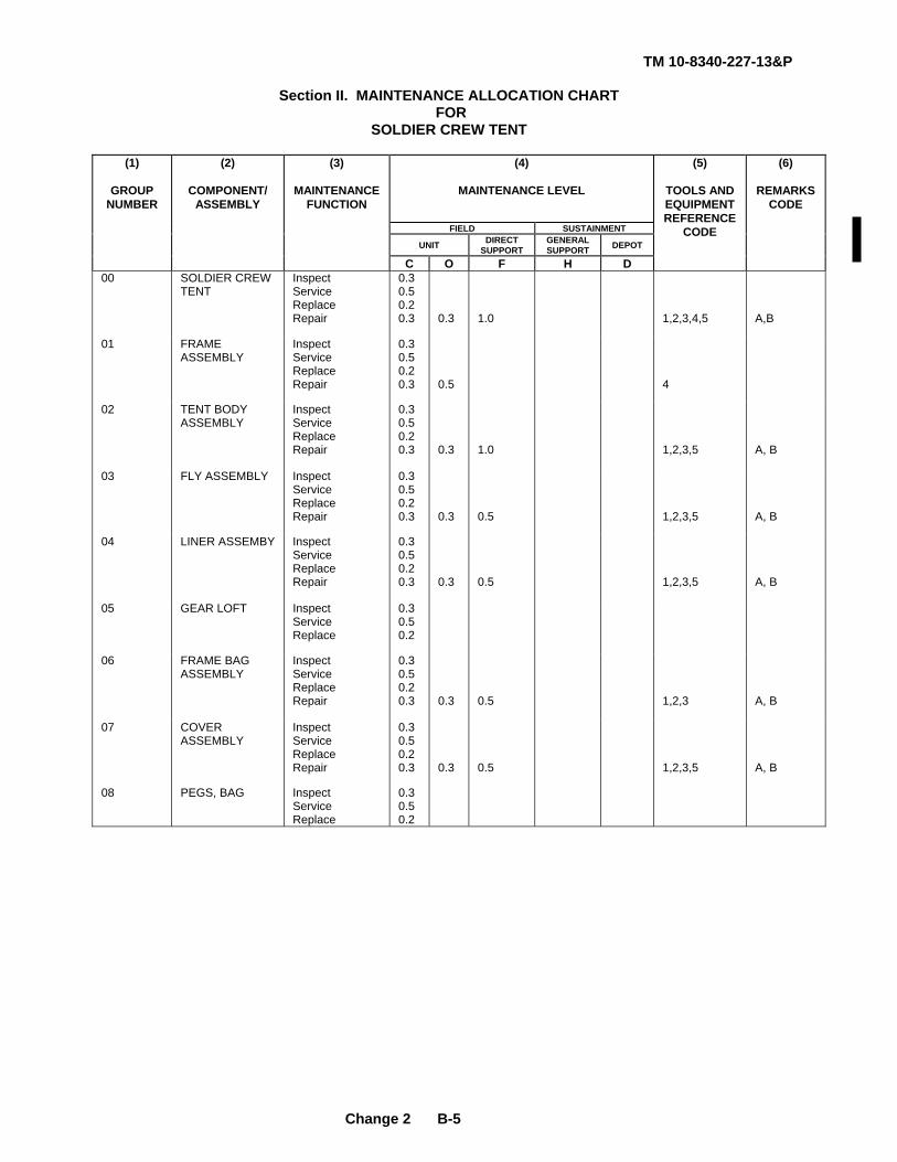
TM 10-8340-227-13&P
Change 2 B-5
Section II. MAINTENANCE ALLOCATION CHART
FOR SOLDIER CREW TENT
(4)
MAINTENANCE LEVEL
FIELD SUSTAINMENT
UNIT DIRECT SUPPORT
GENERAL SUPPORT DEPOT
(1)
GROUP NUMBER
(2)
COMPONENT/ ASSEMBLY
(3)
MAINTENANCE FUNCTION
C O F H D
(5)
TOOLS AND EQUIPMENT REFERENCE
CODE
(6)
REMARKS CODE
00 SOLDIER CREW TENT
Inspect Service Replace Repair
0.3 0.5 0.2 0.3
0.3
1.0
1,2,3,4,5
A,B
01 FRAME ASSEMBLY
Inspect Service Replace Repair
0.3 0.5 0.2 0.3
0.5
4
02 TENT BODY ASSEMBLY
Inspect Service Replace Repair
0.3 0.5 0.2 0.3
0.3
1.0
1,2,3,5
A, B
03 FLY ASSEMBLY Inspect Service Replace Repair
0.3 0.5 0.2 0.3
0.3
0.5
1,2,3,5
A, B
04 LINER ASSEMBY Inspect Service Replace Repair
0.3 0.5 0.2 0.3
0.3
0.5
1,2,3,5
A, B
05 GEAR LOFT Inspect Service Replace
0.3 0.5 0.2
06 FRAME BAG ASSEMBLY
Inspect Service Replace Repair
0.3 0.5 0.2 0.3
0.3
0.5
1,2,3
A, B
07 COVER ASSEMBLY
Inspect Service Replace Repair
0.3 0.5 0.2 0.3
0.3
0.5
1,2,3,5
A, B
08 PEGS, BAG Inspect Service Replace
0.3 0.5 0.2

TM 10-8340-227-13&P
Change 2 B-6
Section III. TOOLS AND TEST EQUIPMENT FOR
SOLDIER CREW TENT
(1)
TOOL OR TEST EQUIPMENT REFERENCE
CODE
(2) MAINTENANCE
LEVEL
(3) NOMENCLATURE
(4) NATIONAL STOCK
NUMBER
(5) TOOL NUMBER
1 C SCT Repair Kit 5-4-7683-1 2 O Punch & Die, Grommet Inserting 5120-00-221-1150 3 O Tentage Repair Kit 8340-00-262-5767 4 O Tool Kit, General Mechanic’s 5180-00-177-7033 5 F Sewing Machine, Industrial 3530-00-892-4631
Section IV. REMARKS FOR
SOLDIER CREW TENT
(1) REMARKS
CODE
(2) REMARKS
A Repair of fabric at operator/crew level is limited to the capability of the SCT Repair Kit B Repair of fabric at organizational level is limited to the capability of the Tentage Repair Kit
TM 10-8340-227-13&P
APPENDIX C
COMPONENTS OF END ITEM AND BASIC ISSUE ITEM LISTS
SECTION I. INTRODUCTION
C-1. SCOPE. This appendix lists components of the end item and basic issue items for the Soldier Crew Tent to helpyou inventory items required for safe and efficient operation of the equipment.
C-2. GENERAL. The Components of End Item and Basic Issue Items (BII) Lists are divided into the following sections:
a. Section II. Components of End Item. This listing is for information purposes only, and is not authority torequisition replacements. These items are part of the Soldier Crew Tent, but they are to be removed andseparately packaged for transportation or shipment. As part of the end item, these items must be with the enditem whenever it is issued or transferred between property accounts. Illustrations are furnished to help you findand identify the items.
b. Section III. Basic Issue Items. These essential items are required to place the Soldier Crew Tent in operation,operate it, and to do emergency repairs. Although shipped separately packaged, BII must be with the SoldierCrew Tent during operation and when it is transferred between property accounts. Listing these items is yourauthority to request/requisition them for replacement based on authorization of the end item by theTOE/MTOE. Illustrations are furnished to help you find and identify the items.
C-3. EXPLANATION OF COLUMNS. The following provides an explanation of columns found in the Components ofEnd Item and Basic Issue Items tables:
a. Column (1), Illus Number, gives you the number of the item illustrated.
b. Column (2), National Stock Number, identifies the stock number of the item to be used for requisitioningpurposes.
c. Column (3), Description and Usable On Code, identifies the Federal item name (in all capital letters) followed bya minimum description when needed. The last line below the description is the CAGEC (commercial andGovernment entity code) (in parentheses) and the part number.
If the item you need is not the same for different models of the equipment, a Usable On Code will appear on theright side of the description column on the same line as the part number. These codes are identified below:
C-1

TM 10-8340-227-13&P
C-3. EXPLANATION OF COLUMNS - Continued
CODE USED ON
FGW Soldier Crew Tent, Type IFGX Soldier Crew Tent, Type II
d. Column (4), U/I (unit of issue), indicates how the item is issued for the National Stock Number shown in columntwo.
e. Column (5), Qty Rqd, indicates the quantity required.
C-2
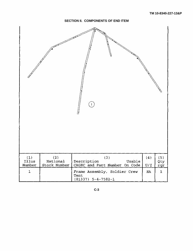
TM 10-8340-227-13&P
SECTION II. COMPONENTS OF END ITEM
C-3
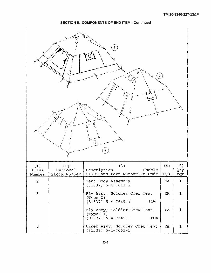
TM 10-8340-227-13&P
SECTION II. COMPONENTS OF END ITEM - Continued
C-4
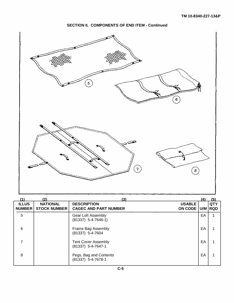
TM 10-8340-227-13&P
SECTION II. COMPONENTS OF END ITEM - Continued
(1) (2) (3) (4) (5)ILLUS NATIONAL DESCRIPTION USABLE QTY
NUMBER STOCK NUMBER CAGEC AND PART NUMBER ON CODE U/M RQD
5 Gear Loft Assembly EA 1(81337) 5-4-7646-1)
6 Frame Bag Assembly EA 1(81337) 5-4-7604
7 Tent Cover Assembly EA 1(81337) 5-4-7647-1
8 Pegs, Bag and Contents EA 1(81337) 5-4-7678-1
C-5
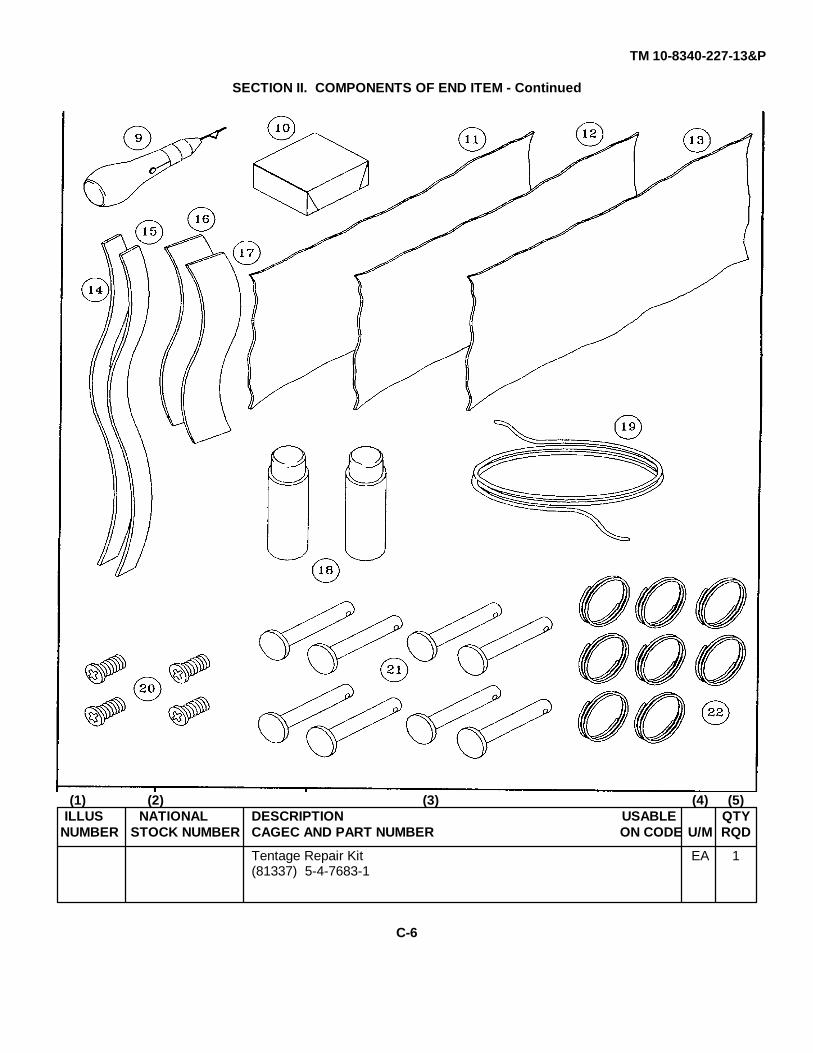
TM 10-8340-227-13&P
SECTION II. COMPONENTS OF END ITEM - Continued
(1) (2) (3) (4) (5)ILLUS NATIONAL DESCRIPTION USABLE QTY
NUMBER STOCK NUMBER CAGEC AND PART NUMBER ON CODE U/M RQD
Tentage Repair Kit EA 1(81337) 5-4-7683-1
C-6

TM 10-8340-227-13&P
Section II. COMPONENTS OF END ITEM - Continued
(1) (2) (3) (4) (5)ILLUS NATIONAL DESCRIPTION USABLE QTY
NUMBER STOCK NUMBER CAGEC AND PART NUMBER ON CODE U/I RQD
Tentage Repair Kit - Continued
9 5120-00-257- Sewing Awl5541 (81337) 5-4-7685-1 EA 1
10 Repair Tape(81337) 5-4-7688-1 EA 1
11 Cloth, Class 1(81349) MIL-C-44423 EA 1
12 Cloth, Class 2(81349) MIL-C-44423 FGW EA 1
13 Cloth, Class 3(81349) MIL-C-44423 FGX EA 1
14 Fastener Tape, Hook, 1 in.(81349) MIL-F-21840 EA 1
15 Fastener Tape, Loop, 1 in.(81349) MIL-F-21840 EA 1
16 Fastener Tape, Hook, 2 in.(81349) MIL-F-21840 EA 1
17 Fastener Tape, Loop, 2 in.(81349) MIL-F-21840 EA 1
18 Seam Sealer(81337) 5-4-7619-1 EA 2
19 Rope(81349) MIL-R-1670 EA 1
20 Screw(96906) MS1958-59 EA 4
21 Frame Pin(81337) 5-4-7589-1 EA 8
22 Split Ring(81337) 5-4-7599-1 EA 8
C-7
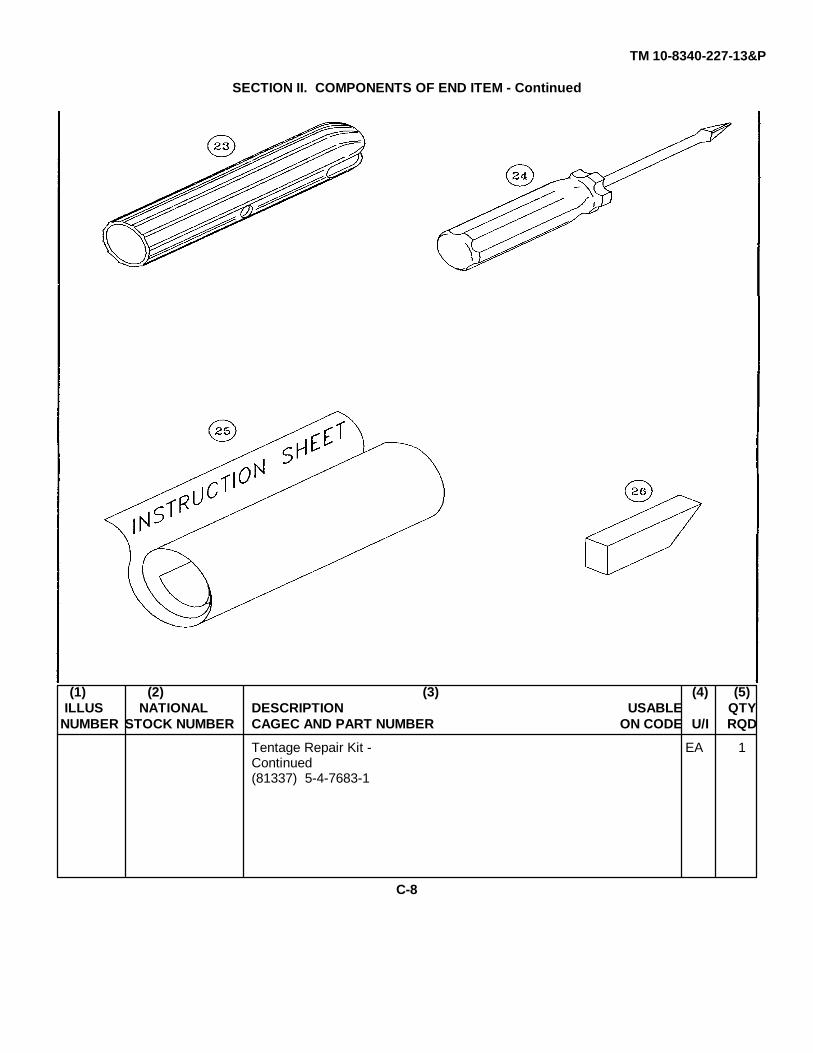
TM 10-8340-227-13&P
SECTION II. COMPONENTS OF END ITEM - Continued
(1) (2) (3) (4) (5)ILLUS NATIONAL DESCRIPTION USABLE QTY
NUMBER STOCK NUMBER CAGEC AND PART NUMBER ON CODE U/I RQD
Tentage Repair Kit - EA 1Continued(81337) 5-4-7683-1
C-8
TM 10-8340-227-13&P
Section II. COMPONENTS OF END ITEM - Continued
(1) (2) (3) (4) (5)ILLUS NATIONAL DESCRIPTION USABLE QTY
NUMBER STOCK NUMBER CAGEC AND PART NUMBER ON CODE U/I RQD
Tentage Repair Kit (Continued)23 Frame Joint Sleeve EA 2
(81337) 5-4-7591-1
24 Screwdriver, Cross Tip EA 1
25 Instruction Label(81337) 5-4-7674-1 EA 1
26 9150-00- Zipperease278-7548 (96980) ZE-2 or equivalent EA BOX
C-9
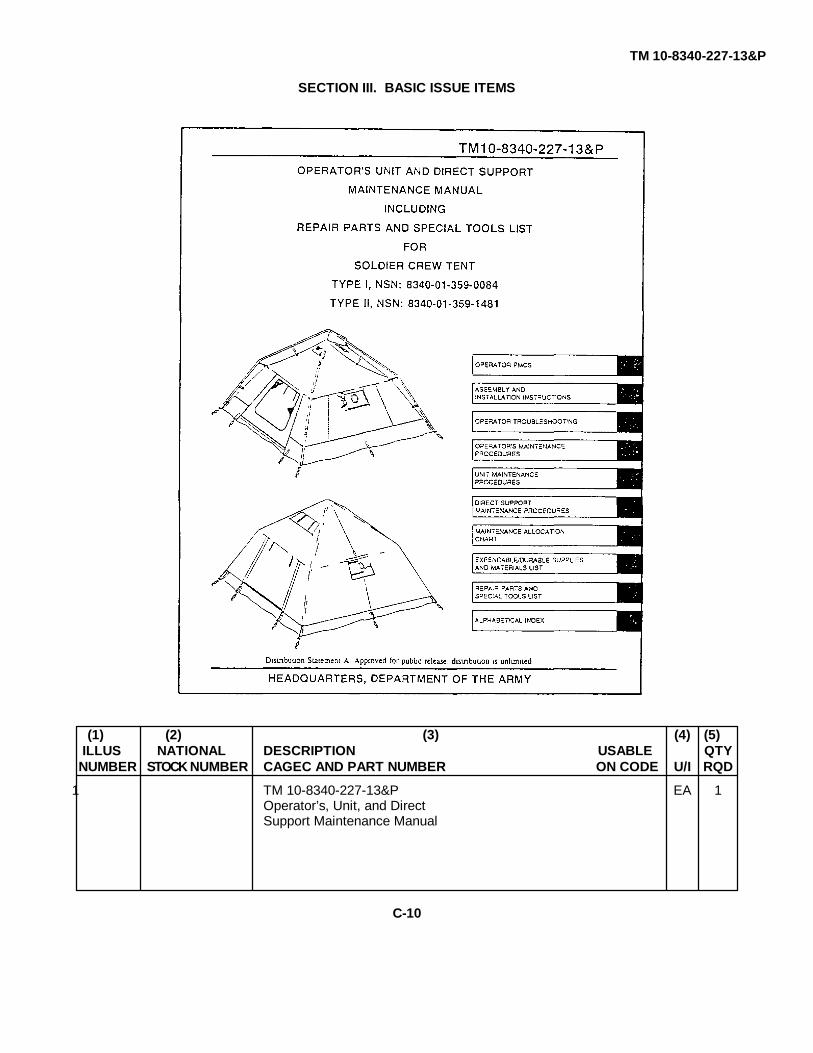
TM 10-8340-227-13&P
SECTION III. BASIC ISSUE ITEMS
(1) (2) (3) (4) (5)ILLUS NATIONAL DESCRIPTION USABLE QTY
NUMBER STOCK NUMBER CAGEC AND PART NUMBER ON CODE U/I RQD
1 TM 10-8340-227-13&P EA 1Operator’s, Unit, and DirectSupport Maintenance Manual
C-10
TM 10-8340-227-13&P
APPENDIX D
ADDITIONAL AUTHORIZATION LIST
Section I. INTRODUCTION
D-1. SCOPE. This appendix lists additional items you are authorized for the support of the Soldier Crew Tent.
D-2. GENERAL. This list identifies items that do not have to accompany the Soldier Crew Tent and that do not have tobe turned in with it. These items are all authorized to you by CTA, MTOE, TDA, or JTA.
D-3. EXPLANATION OF LISTING. National Stock Number, descriptions, and quantities are provided to help youidentify and request the additional items you require to support this equipment. The items are listed in alphabeticalsequence by item name.
Section II. ADDITIONAL AUTHORIZED ITEMS LIST
(1) (2) (3) (4)NATIONAL DESCRIPTION
STOCK CAGEC & PART NUMBER USABLE ON CODE U/I QTYNUMBER RECM
8340-00-951-6423 GROUND ANCHOR KIT EA 15120-00-926-7116 MALLET, WOOD EA 1
D-1

TM 10-8340-227-13&P
APPENDIX E
EXPENDABLE AND DURABLE ITEMS LIST
Section I. INTRODUCTION
E-1. SCOPE. This appendix lists expendable and durable items you will need to operate and maintain the Soldier CrewTent. This listing is for informational purposes only and is not authority to requisition the listed items. These items areauthorized to you by CTA 50-970, Expendable/Durable Items (Except medical, class V, repair parts, and heraldic items),or CTA 8-100, Army Medical Department Expendable/Durable Items.
E-2. EXPLANATION OF COLUMNS.
a. Column 1. Item number. This number is assigned to the entry in the listing and is referenced in the narrativeinstructions to identify the item (e. g. , "Use denatured alcohol, item 4, Appendix E").b. Column 2. Level. This column identifies the lowest level of maintenance that requires the item.c. Column 3. National stock number. This is the national stock number assigned to the item which you can useto requisition it.d. Column 4. Item name, description, Commercial and Government Entity Code (CAGEC), and part number.This provides the other information you need to identify the item.e. Column 5. Unit of measure. This code shows the physical measurement or count of an item, such as gallon,dozen, gross, etc.
E-1
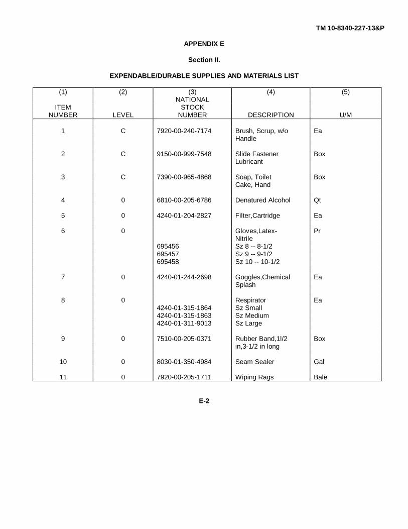
TM 10-8340-227-13&P
APPENDIX E
Section II.
EXPENDABLE/DURABLE SUPPLIES AND MATERIALS LIST
(1) (2) (3) (4) (5)NATIONAL
ITEM STOCKNUMBER LEVEL NUMBER DESCRIPTION U/M
1 C 7920-00-240-7174 Brush, Scrup, w/o EaHandle
2 C 9150-00-999-7548 Slide Fastener BoxLubricant
3 C 7390-00-965-4868 Soap, Toilet BoxCake, Hand
4 0 6810-00-205-6786 Denatured Alcohol Qt
5 0 4240-01-204-2827 Filter,Cartridge Ea
6 0 Gloves,Latex- PrNitrile
695456 Sz 8 -- 8-1/2695457 Sz 9 -- 9-1/2695458 Sz 10 -- 10-1/2
7 0 4240-01-244-2698 Goggles,Chemical EaSplash
8 0 Respirator Ea4240-01-315-1864 Sz Small4240-01-315-1863 Sz Medium4240-01-311-9013 Sz Large
9 0 7510-00-205-0371 Rubber Band,1l/2 Boxin,3-1/2 in long
10 0 8030-01-350-4984 Seam Sealer Gal
11 0 7920-00-205-1711 Wiping Rags Bale
E-2
TM 10-8340-227-13&P
APPENDIX F
UNIT AND DIRECT SUPPORT MAINTENANCE
REPAIR PARTS AND SPECIAL TOOLS LIST
Section I. INTRODUCTION
F-1. SCOPE. This Repair Parts and Special Tools List (RPSTL) lists and authorizes spares and repair parts; specialtools; special Test, Measurement, and Diagnostic Equipment (TMDE); and other special support equipment required forperformance of organizational and direct support maintenance of the SCT. It authorizes the requisition, issue, anddisposition of spares, repair parts, and special tools as indicated by the Source, Maintenance, and Recoverability (SMR)codes.
F-2. GENERAL. In addition to Section I, Introduction, this RPSTL is divided into the following sections:
a. Section II. Repair Parts List. A list of spares and repair parts authorized by this RPSTL for use in theperformance of maintenance. The list also includes parts that must be removed for replacement of the authorized parts.Parts lists are composed of functional groups in ascending alpha-numeric sequence, with the parts in each group listed inascending figure and item number sequence. Repair parts kits or sets are listed in ascending figure and item numbersequence. Bulk materials are listed by item name in FIG BULK at the end of the section. Repair parts kits or sets arelisted separately in their own functional group within section II. Repair parts for repairable special tools are also listed inthe section.
b. Section III. Special Tools List. A list of special tools, special TMDE, and other special support equipmentauthorized by this RPSTL (as indicated by Basis of Issue (BOI) information in DESCRIPTION AND USABLE ON CODE(UOC) column) for the performance of maintenance.
c. Section IV. National Stock Number and Part Number Index. A list, in National Item Identification Number (NIIN)sequence, of all national stock numbered items appearing in the listings, followed by a list in alpha-numeric sequence ofall part numbers appearing in the listing. NSNs and part numbers are cross-referenced to each illustration figure anditem number appearance. The figure and item number index lists figure and item number in alphanumeric sequence andcross-references NSN, FSCM and part number.
F-3. EXPLANATION OF COLUMNS. (Sections II and III).
a. ITEM NO. (Column (1)). Indicates the number used to identify items called out in the illustration.
F-1
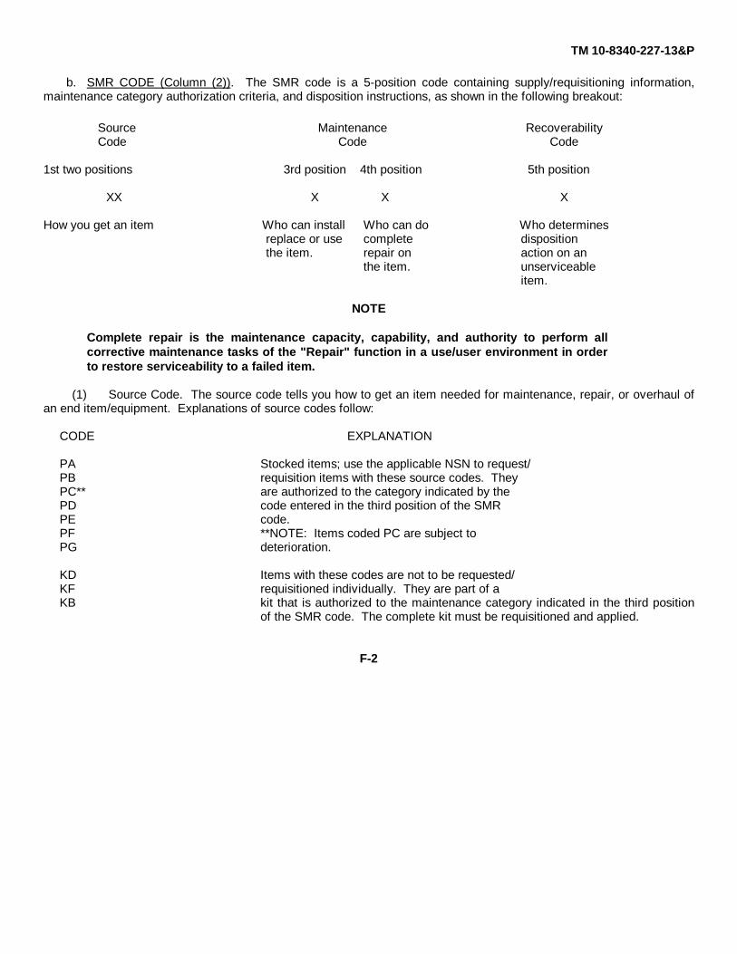
TM 10-8340-227-13&P
b. SMR CODE (Column (2)). The SMR code is a 5-position code containing supply/requisitioning information,maintenance category authorization criteria, and disposition instructions, as shown in the following breakout:
Source Maintenance RecoverabilityCode Code Code
1st two positions 3rd position 4th position 5th position
XX X X X
How you get an item Who can install Who can do Who determinesreplace or use complete dispositionthe item. repair on action on an
the item. unserviceableitem.
NOTE
Complete repair is the maintenance capacity, capability, and authority to perform allcorrective maintenance tasks of the "Repair" function in a use/user environment in orderto restore serviceability to a failed item.
(1) Source Code. The source code tells you how to get an item needed for maintenance, repair, or overhaul ofan end item/equipment. Explanations of source codes follow:
CODE EXPLANATION
PA Stocked items; use the applicable NSN to request/PB requisition items with these source codes. TheyPC** are authorized to the category indicated by thePD code entered in the third position of the SMRPE code.PF **NOTE: Items coded PC are subject toPG deterioration.
KD Items with these codes are not to be requested/KF requisitioned individually. They are part of aKB kit that is authorized to the maintenance category indicated in the third position
of the SMR code. The complete kit must be requisitioned and applied.
F-2
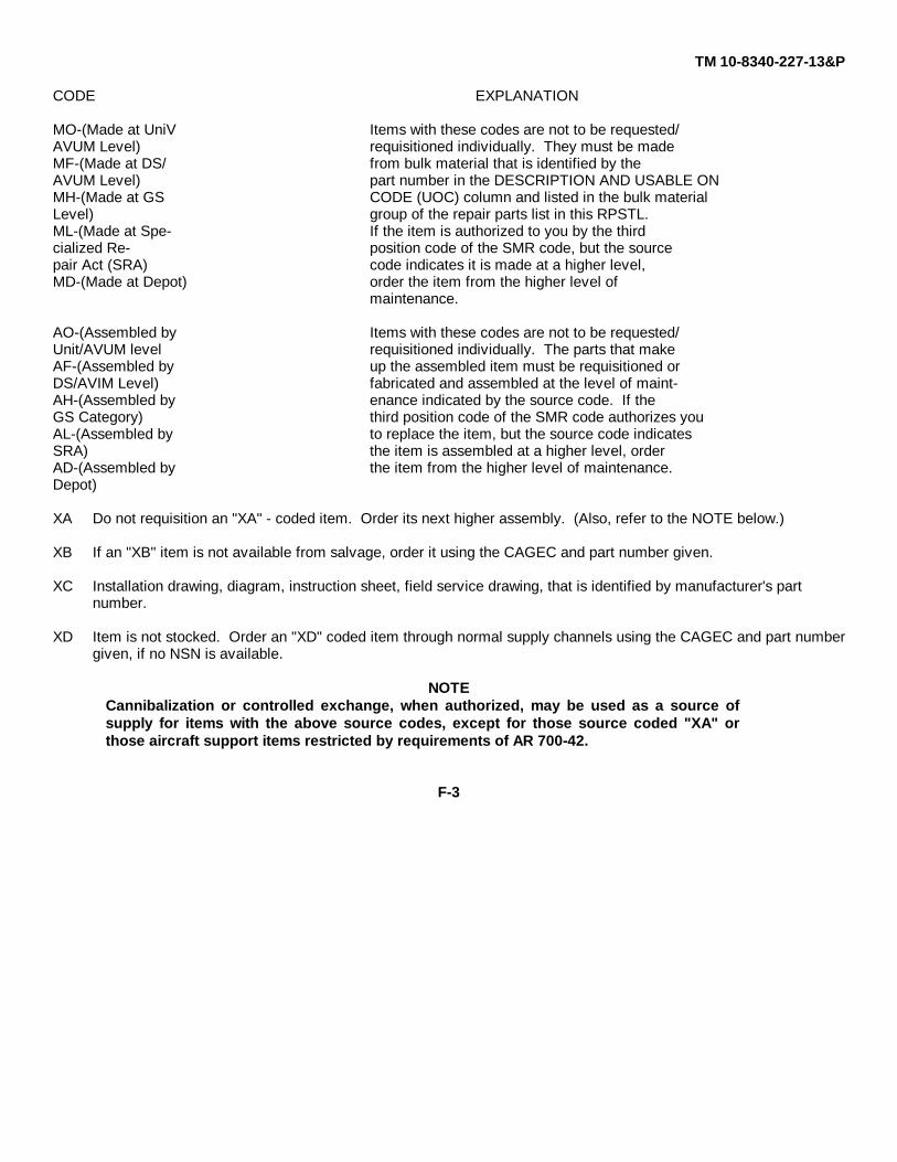
TM 10-8340-227-13&P
CODE EXPLANATION
MO-(Made at UniV Items with these codes are not to be requested/AVUM Level) requisitioned individually. They must be madeMF-(Made at DS/ from bulk material that is identified by theAVUM Level) part number in the DESCRIPTION AND USABLE ONMH-(Made at GS CODE (UOC) column and listed in the bulk materialLevel) group of the repair parts list in this RPSTL.ML-(Made at Spe- If the item is authorized to you by the thirdcialized Re- position code of the SMR code, but the sourcepair Act (SRA) code indicates it is made at a higher level,MD-(Made at Depot) order the item from the higher level of
maintenance.
AO-(Assembled by Items with these codes are not to be requested/Unit/AVUM level requisitioned individually. The parts that makeAF-(Assembled by up the assembled item must be requisitioned orDS/AVIM Level) fabricated and assembled at the level of maint-AH-(Assembled by enance indicated by the source code. If theGS Category) third position code of the SMR code authorizes youAL-(Assembled by to replace the item, but the source code indicatesSRA) the item is assembled at a higher level, orderAD-(Assembled by the item from the higher level of maintenance.Depot)
XA Do not requisition an "XA" - coded item. Order its next higher assembly. (Also, refer to the NOTE below.)
XB If an "XB" item is not available from salvage, order it using the CAGEC and part number given.
XC Installation drawing, diagram, instruction sheet, field service drawing, that is identified by manufacturer's part number.
XD Item is not stocked. Order an "XD" coded item through normal supply channels using the CAGEC and part numbergiven, if no NSN is available.
NOTECannibalization or controlled exchange, when authorized, may be used as a source ofsupply for items with the above source codes, except for those source coded "XA" orthose aircraft support items restricted by requirements of AR 700-42.
F-3

TM 10-8340-227-13&P
(2) Maintenance Code. Maintenance codes tell you the level(s) of maintenance authorized to USE and REPAIRsupport items. The maintenance codes are entered in the third and fourth positions of the SMR Code as follows:
(a) The maintenance code entered in the third position tells you the lowest maintenance level authorized toremove, replace, and use the support item. The maintenance code entered in the third position will indicate authorizationto one of the following levels of maintenance:
Code Application/Explanation
C Crew or operator maintenance done withinorganizational or aviation unit maintenance.
O Unit or aviation unit category canremove, replace, and use the item.
F Direct support or aviation intermediate level canremove, replace, and use the item.
H General support level can remove, replace, and usethe item.
L Specialized repair activity can remove, replace,and use the item.
D Depot level can remove, replace, and use the item.
(b) The maintenance code entered in the fourth position tells whether or not the item is to be repaired andidentifies the lowest maintenance level with the capability to do complete repair (i. e., perform all authorized repairfunctions. ) (NOTE: Some limited repair may be done to the item at a lower level of maintenance, if authorized by theMaintenance Allocation Chart (MAC) and SMR codes.) This position will contain one of the following maintenance codes:
Code Application/Explanation
0 Unit or aviation unit is the lowest levelthat can do complete repair of the item.
F Direct support or aviation intermediate is the lowestlevel that can do complete repair of the item.
H General support is the lowest level that can docomplete repair of the item.
L Specialized repair activity (designate thespecialized repair activity) is the lowest level thatcan do complete repair of the item.
F-4
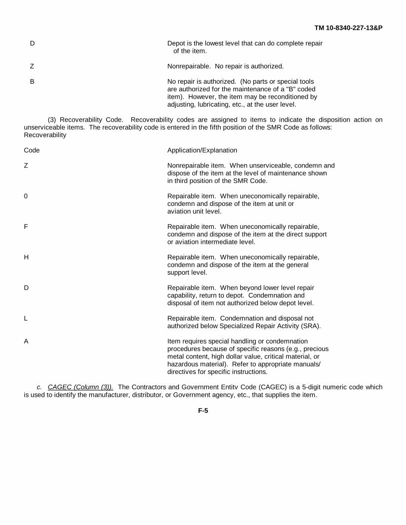
TM 10-8340-227-13&P
D Depot is the lowest level that can do complete repairof the item.
Z Nonrepairable. No repair is authorized.
B No repair is authorized. (No parts or special toolsare authorized for the maintenance of a "B" codeditem). However, the item may be reconditioned byadjusting, lubricating, etc., at the user level.
(3) Recoverability Code. Recoverability codes are assigned to items to indicate the disposition action onunserviceable items. The recoverability code is entered in the fifth position of the SMR Code as follows:Recoverability
Code Application/Explanation
Z Nonrepairable item. When unserviceable, condemn anddispose of the item at the level of maintenance shownin third position of the SMR Code.
0 Repairable item. When uneconomically repairable,condemn and dispose of the item at unit oraviation unit level.
F Repairable item. When uneconomically repairable,condemn and dispose of the item at the direct supportor aviation intermediate level.
H Repairable item. When uneconomically repairable,condemn and dispose of the item at the generalsupport level.
D Repairable item. When beyond lower level repaircapability, return to depot. Condemnation anddisposal of item not authorized below depot level.
L Repairable item. Condemnation and disposal notauthorized below Specialized Repair Activity (SRA).
A Item requires special handling or condemnationprocedures because of specific reasons (e.g., preciousmetal content, high dollar value, critical material, orhazardous material). Refer to appropriate manuals/directives for specific instructions.
c. CAGEC (Column (3)). The Contractors and Government Entitv Code (CAGEC) is a 5-digit numeric code whichis used to identify the manufacturer, distributor, or Government agency, etc., that supplies the item.
F-5
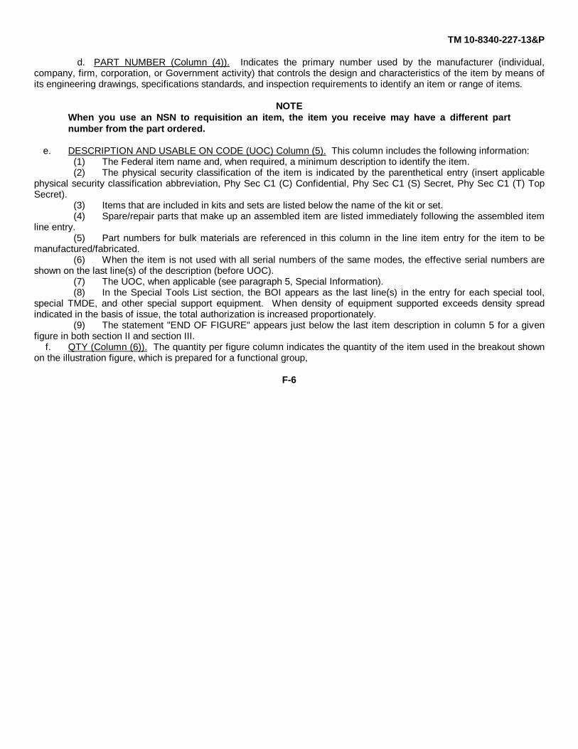
TM 10-8340-227-13&P
d. PART NUMBER (Column (4)). Indicates the primary number used by the manufacturer (individual,company, firm, corporation, or Government activity) that controls the design and characteristics of the item by means ofits engineering drawings, specifications standards, and inspection requirements to identify an item or range of items.
NOTEWhen you use an NSN to requisition an item, the item you receive may have a different partnumber from the part ordered.
e. DESCRIPTION AND USABLE ON CODE (UOC) Column (5). This column includes the following information:(1) The Federal item name and, when required, a minimum description to identify the item.(2) The physical security classification of the item is indicated by the parenthetical entry (insert applicable
physical security classification abbreviation, Phy Sec C1 (C) Confidential, Phy Sec C1 (S) Secret, Phy Sec C1 (T) TopSecret).
(3) Items that are included in kits and sets are listed below the name of the kit or set.(4) Spare/repair parts that make up an assembled item are listed immediately following the assembled item
line entry.(5) Part numbers for bulk materials are referenced in this column in the line item entry for the item to be
manufactured/fabricated.(6) When the item is not used with all serial numbers of the same modes, the effective serial numbers are
shown on the last line(s) of the description (before UOC).(7) The UOC, when applicable (see paragraph 5, Special Information).(8) In the Special Tools List section, the BOI appears as the last line(s) in the entry for each special tool,
special TMDE, and other special support equipment. When density of equipment supported exceeds density spreadindicated in the basis of issue, the total authorization is increased proportionately.
(9) The statement "END OF FIGURE" appears just below the last item description in column 5 for a givenfigure in both section II and section III.
f. QTY (Column (6)). The quantity per figure column indicates the quantity of the item used in the breakout shownon the illustration figure, which is prepared for a functional group,
F-6
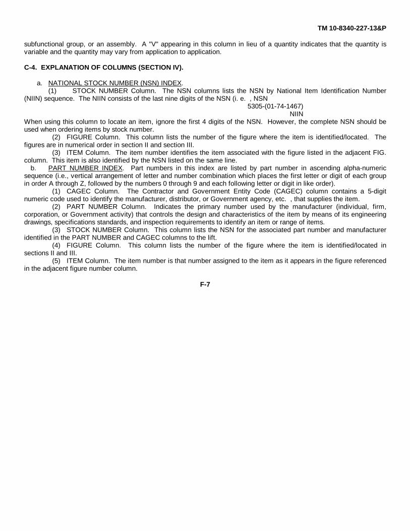
TM 10-8340-227-13&P
subfunctional group, or an assembly. A "V" appearing in this column in lieu of a quantity indicates that the quantity isvariable and the quantity may vary from application to application.
C-4. EXPLANATION OF COLUMNS (SECTION IV).
a. NATIONAL STOCK NUMBER (NSN) INDEX.(1) STOCK NUMBER Column. The NSN columns lists the NSN by National Item Identification Number
(NIIN) sequence. The NIIN consists of the last nine digits of the NSN (i. e. , NSN5305-(01-74-1467)
NIINWhen using this column to locate an item, ignore the first 4 digits of the NSN. However, the complete NSN should beused when ordering items by stock number.
(2) FIGURE Column. This column lists the number of the figure where the item is identified/located. Thefigures are in numerical order in section II and section III.
(3) ITEM Column. The item number identifies the item associated with the figure listed in the adjacent FIG.column. This item is also identified by the NSN listed on the same line.
b. PART NUMBER INDEX. Part numbers in this index are listed by part number in ascending alpha-numericsequence (i.e., vertical arrangement of letter and number combination which places the first letter or digit of each groupin order A through Z, followed by the numbers 0 through 9 and each following letter or digit in like order).
(1) CAGEC Column. The Contractor and Government Entity Code (CAGEC) column contains a 5-digitnumeric code used to identify the manufacturer, distributor, or Government agency, etc. , that supplies the item.
(2) PART NUMBER Column. Indicates the primary number used by the manufacturer (individual, firm,corporation, or Government activity) that controls the design and characteristics of the item by means of its engineeringdrawings, specifications standards, and inspection requirements to identify an item or range of items.
(3) STOCK NUMBER Column. This column lists the NSN for the associated part number and manufactureridentified in the PART NUMBER and CAGEC columns to the lift.
(4) FIGURE Column. This column lists the number of the figure where the item is identified/located insections II and III.
(5) ITEM Column. The item number is that number assigned to the item as it appears in the figure referencedin the adjacent figure number column.
F-7
TM 10-8340-227-13&P
c. FIGURE AND ITEM NUMBER INDEX.(1) FIGURE Column. This column lists the number of the figure where the item is identified/located in
sections II and III.(2) ITEM Column. The item number is that number assigned to the item as it appears in the figure referenced
in the adjacent figure number column.(3) STOCK NUMBER Column. This column lists the NSN for the item.(4) CAGEC Column. The Contractor and Government Entity Code (CAGEC) column contains a 5-digit
numeric code used to identify the manufacturer, distributor, or Government agency, etc. , that supplies the item.(5) PART NUMBER Column. Indicates the primary number used by the manufacturer (individual, firm,
corporation, or Government activity) that controls the design and characteristics of the item by means of its engineeringdrawings, specifications standards, and inspection requirements to identify an item or range of items.
F-5. SPECIAL INFORMATION.
a. USABLE ON CODE. Not Applicable.b. FABRICATION INSTRUCTIONS. Bulk materials required to manufacture items are listed in the Bulk Material
functional group of this RPSTL. Part numbers for bulk materials are also referenced in the DESCRIPTION column of theline item to be manufactured/fabricated. Detailed fabrication instructions for item source codes to be manufactured orfabricated are found in FM 10-16.
c. ASSEMBLY INSTRUCTIONS. Not Applicable.d. KITS. Not Applicable.e. INDEX NUMBERS. Items which have the word "BULK" in the FIGURE column will have an index number shown
in the ITEM NUMBER column. This index number is a cross-reference between the National Stock Number/ PartNumber Index and the bulk material list in Section II.
F-6. HOW TO LOCATE REPAIR PARTS.
a. When National Stock Number or Part Number is Not Known.(1) First. Using the table of contents, determine the assembly group or subassembly group to which the item
belongs. This is necessary since figures are prepared for assembly groups and subassembly groups, and listings aredivided into the same groups.
(2) Second. Find the figure covering the assembly group or subassembly group to which the item belongs.
F-8

TM 10-8340-227-13&P
(3) Third. Identify the item on the figure and use the Figure and Item Number Index to find the NSN.b. When National Stock Number or Part Number is Known:
(1) First. Using the National Stock Number or the Part Number Index, find the pertinent National StockNumber or Part Number. The NSN index is in National Item Identification Number (NIIN) sequence. The part numbersin the Part Number index are listed in ascending alpha-numeric sequence. Both indexes cross-reference you to theillustration/figure and item number of the item you are looking for.
(2) Second. Turn to the figure and item number, verify that the item is the one you're looking for, then locatethe item number in the repair parts list for the figure.
F-7. ABBREVIATIONS. Not Applicable.
F-9
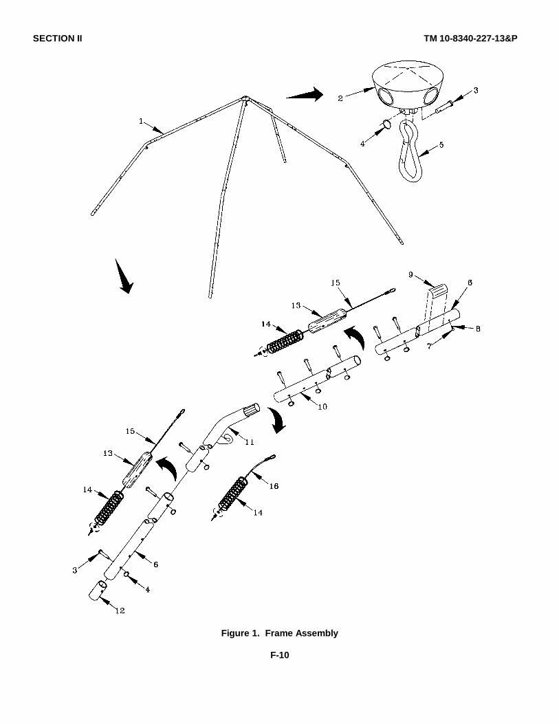
SECTION II TM 10-8340-227-13&P
Figure 1. Frame Assembly
F-10

SECTION II TM 10-8340-227-13&P
(1) (2) (3) (4) (5) (6)ITEM SMR PARTNO CODE CAGEC NUMBER DESCRIPTION AND USABLE ON CODES(UOC) QTY
GROUP 01 FRAME ASSEMBLY
FIG 1 FRAME ASSEMBLY
1 PAOOO 81337 5-4-7582-1 FRAME ASSY,SCT ....................................................... 12 XDOZZ 81337 5-4-7585-1 .HUB ASSEMBLY.......................................................... 13 PAOZZ 81337 5-4-7589-1 .PIN,FRAME................................................................... 334 PAOZZ 81337 5-4-7599-1 .RING,SPLIT .................................................................. 335 XDOZZ 81337 5-4-7602-1 .SNAP,SAFETY SPRING .............................................. 16 XDOZZ 81337 5-4-7593-1 .POLE,FRAME,SHORT.................................................. 87 PAOZZ 96906 MS51958-59 .SCREW,MACHINE........................................................ 88 XDOZZ 81349 MIL-S-46163TYIIG .THREAD COMPOUND.................................................. V
RADEN9 XBOZZ 81349 MIL-P-19834TYIST .PLATE,IDENTIFICATIO ................................................ 4
Y4, SIZE 610 XDOZZ 81337 5-4-7586-1 .POLE,FRAME,LONG .................................................... 411 XDOZZ 81337 5-4-7587-1 .POLE&HOOK ASSY ..................................................... 412 XDOZZ 81337 5-4-7590-1 .SLEEVE,BOTTOM,POLES ........................................... 413 XBOZZ 81337 5-4-7591-1 .SLEEVE,FRAME,JOINT................................................ 814 XDOZZ 81337 5-4-7601-1 .SPRING,CYLINDRICAL ................................................ 1215 XDOZZ 81337 5-4-7592-2 .CABLE ASSY,POLE...................................................... 816 XDOZZ 81337 5-4-7592-1 .CABLE ASSY,POLE...................................................... 4
END OF FIGURE
F-11
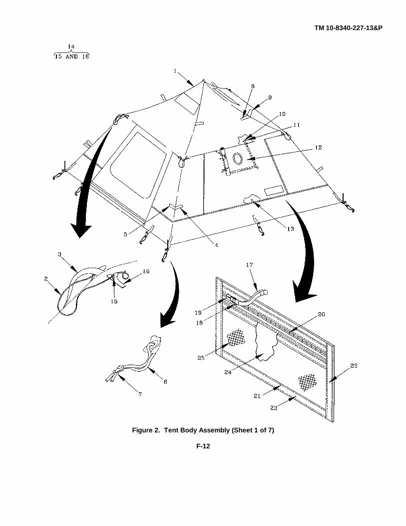
TM 10-8340-227-13&P
Figure 2. Tent Body Assembly (Sheet 1 of 7)
F-12
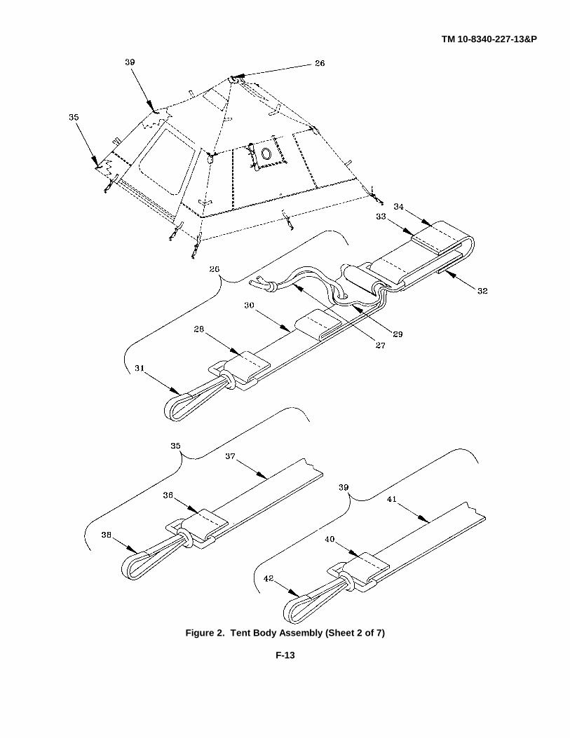
TM 10-8340-227-13&P
Figure 2. Tent Body Assembly (Sheet 2 of 7)
F-13
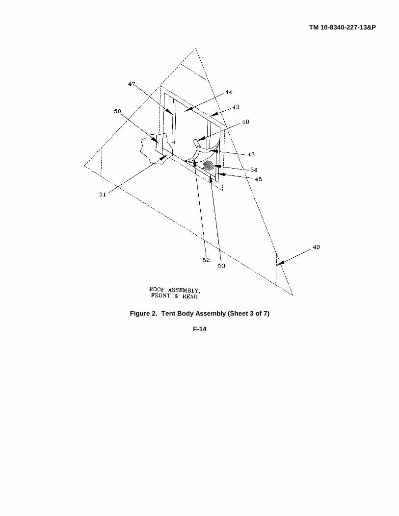
TM 10-8340-227-13&P
Figure 2. Tent Body Assembly (Sheet 3 of 7)
F-14
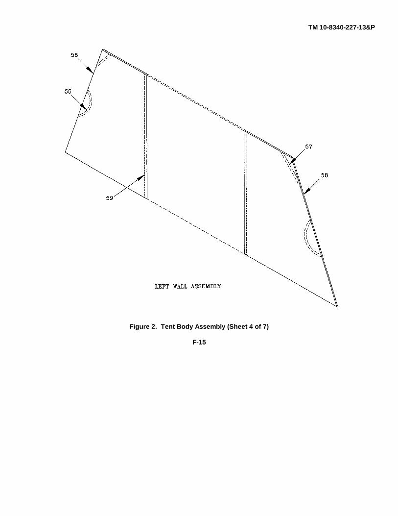
TM 10-8340-227-13&P
Figure 2. Tent Body Assembly (Sheet 4 of 7)
F-15

TM 10-8340-227-13&P
Figure 2. Tent Body Assembly (Sheet 5 of 7)
F-16
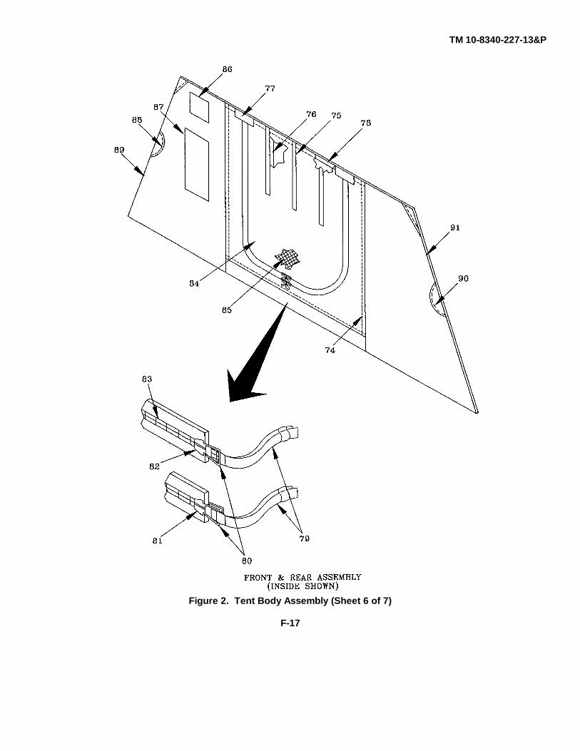
TM 10-8340-227-13&P
Figure 2. Tent Body Assembly (Sheet 6 of 7)
F-17
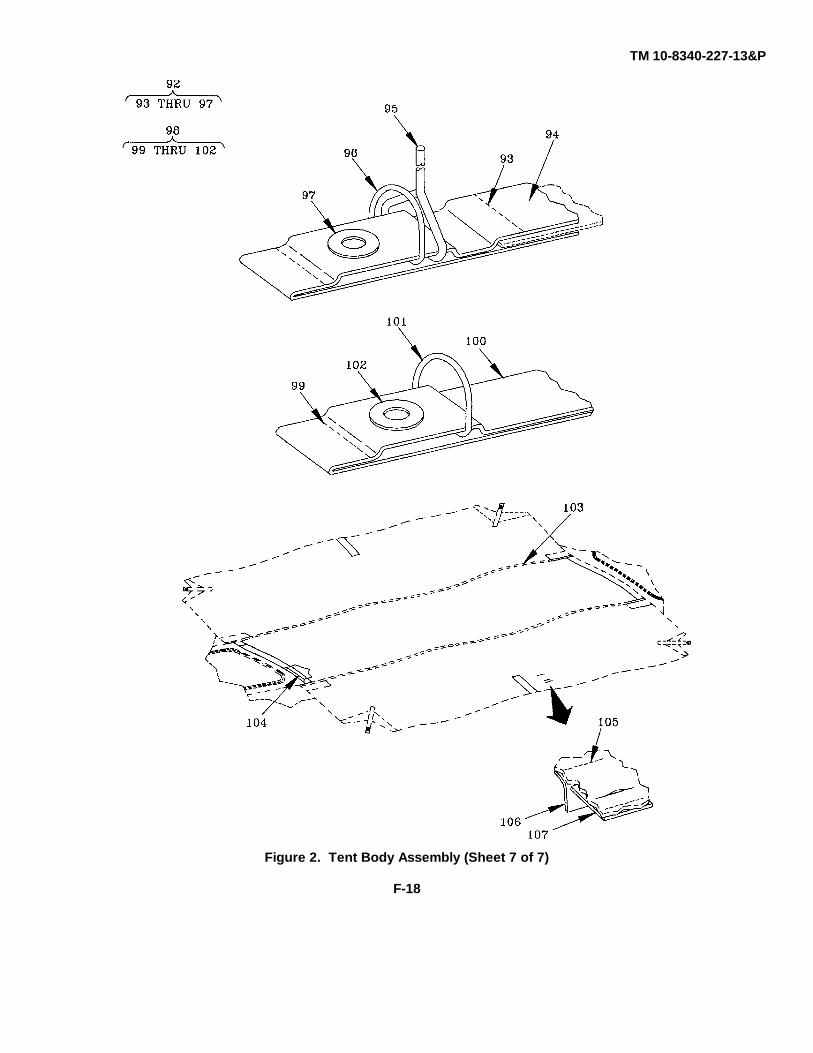
TM 10-8340-227-13&P
Figure 2. Tent Body Assembly (Sheet 7 of 7)
F-18
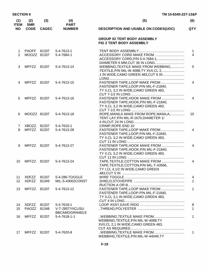
SECTION II TM 10-8340-227-13&P
(1) (2) (3) (4) (5) (6)ITEM SMR PARTNO CODE CAGEC NUMBER DESCRIPTION AND USABLE ON CODES(UOC) QTY
GROUP 02 TENT BODY ASSEMBLYFIG 2 TENT BODY ASSEMBLY
1 PAOFF 81337 5-4-7613-1 .TENT BODY ASSEMBLY.............................................. 12 MOOZZ 81337 5-4-7684-1 .ACCESSORY CORD MAKE FROM .............................. 4
.ACCESSORY CORD,P/N 5-4-7684-1,...........................
.DIAMETER 6 MM,CUT 36 IN LONG..............................3 MFFZZ 81337 5-4-7613-14 .WEBBING,TEXTILE MAKE FROM WEBBING,............. 5
.TEXTILE,P/N MIL-W-4088,TY XVII,CL 2, ......................
.1 IN WIDE,CAMO GREEN 483,CUT 6 IN......................
.LONG............................................................................4 MFFZZ 81337 5-4-7613-15 .FASTENER TAPE,LOOP MAKE FROM........................ 4
.FASTENER TAPE,LOOP,P/N MIL-F-21840,
.TY II,CL 3,2 IN WIDE,CAMO GREEN 483,
.CUT 7-1/2 IN LONG ......................................................5 MFFZZ 81337 5-4-7613-16 .FASTENER TAPE,HOOK MAKE FROM ....................... 4
.FASTENER TAPE,HOOK,P/N MIL-F-21840,
.TY II,CL 3,2 IN WIDE,CAMO GREEN 483,
.CUT 7-1/2 IN LONG ......................................................6 MOOZZ 81337 5-4-7613-18 .ROPE,MANILA MAKE FROM ROPE,MANILA,.............. 10
.TENT LAY,P/N MIL-R-1670,DIAMETER 1/
.4 IN,CUT 24 IN LONG...................................................7 XBOZZ 81337 5-4-7610-1 .CRIMP,ROPE END 108 MFFZZ 81337 5-4-7613-28 .FASTENER TAPE,LOOP MAKE FROM........................ 4
.FASTENER TAPE,LOOP,P/N MIL-F-21840,
.TY II,CL 3,2 IN WIDE,CAMO GREEN 483,
.CUT 11 IN LONG ..........................................................9 MFFZZ 81337 5-4-7613-27 .FASTENER TAPE,HOOK MAKE FROM ....................... 4
.FASTENER TAPE,HOOK,P/N MIL-F-21840,
.TY II,CL 3,2 IN WIDE,CAMO GREEN 483,
.CUT 11 IN LONG ..........................................................10 MFFZZ 81337 5-4-7613-24 .TAPE,TEXTILE,COTTON MAKE FROM ....................... 4
.TAPE,TEXTILE,COTTON,P/N MIL-T-43566,
.TY I,CL 4,1/2 IN WIDE,CAMO GREEN
.483,CUT 5 IN ...............................................................11 XDFZZ 81337 5-4-286-TOGGLE .WIRE TOGGLE ............................................................ 412 XDFZZ 81349 MIL-S-43002CONST .SHIELD,STOVEPIPE ................................................... 1
.RUCTION A OR B.........................................................13 MFFZZ 81337 5-4-7613-12 .FASTENER TAPE,LOOP MAKE FROM........................ 1
.FASTENER TAPE,LOOP,P/N MIL-F-21840,
.TY II,CL 3,1 IN WIDE,CAMO GREEN 483,
.CUT 4 IN LONG ............................................................14 XDFZZ 81337 5-4-7618-1 .LOOP ASSY,EAVE RIDG ............................................. 815 PAOZZ 81348 V-T-285TYIICLlSU ..THREAD,POLYESTER ............................................... 1
BBCAMOGRN483,E16 MFFZZ 81337 5-4-7618-1-1 ..WEBBING,TEXTILE MAKE FROM............................... 1
WEBBING,TEXTILE,P/N MIL-W-4088,TYXVII,CL 2,1 IN WIDE,CAMO GREEN 483,CUT AS REQUIRED.......................................................
17 MFFZZ 81337 5-4-7620-8 ..WEBBING,TEXTILE MAKE FROM............................... 1WEBBIHG,TEXTILE,P/N MIL-W-44049,TY
F-19
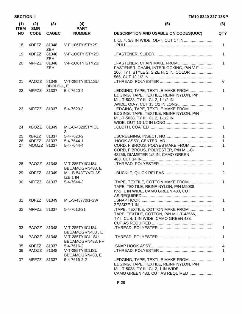
SECTION II TM10-8340-227-13&P
(1) (2) (3) (4) (5) (6)ITEM SMR PARTNO CODE CAGEC NUMBER DESCRIPTION AND USABLE ON CODES(UOC) QTY
I, CL 4, 3/8 IN WIDE, OD-7, CUT 17 IN..........................18 XDFZZ 81348 V-F-106TYISTY2SI ..PULL ............................................................................ 1
ZEH19 XDFZZ 81348 V-F-1O6TYISTY2SI ..FASTENER, SLIDER.................................................... 1
ZEH20 MFFZZ 81348 V-F-1O6TYISTY2SI ..FASTENER, CHAIN MAKE FROM ............................... 1
ZEH FASTENER, CHAIN, INTERLOCKING, P/N V-F- ...........106, TY I, STYLE 2, SIZE H, 1 IN, COLOR ....................566, CUT 13 1/2 IN.........................................................
21 PAOZZ 81348 V-T-285TYIICL1SU ..THREAD, POLYESTER ............................................... VBBODS-1, E
22 MFFZZ 81337 5-4-7620-4 ..EDGING, TAPE, TEXTILE MAKE FROM ..................... 1EDGING, TAPE, TEXTILE, REINF NYLON, P/hMIL-T-5038, TY III, CL 2, 1-1/2 IN.WIDE, OD-7, CUT 13 1/2 IN LONG...............................
23 MFFZZ 81337 5-4-7620-3 ..EDGING, TAPE, TEXTILE MAKE FROM ..................... 1EDGING, TAPE, TEXTILE, REINF NYLON, P/NMIL-T-5038, TY III, CL 2, 1-1/2 INWIDE, OUT 13-1/2 IN LONG..........................................
24 XBOZZ 81349 MIL-C-43285TYICL ..CLOTH, COATED ....................................................... 13
25 XBFZZ 81337 5-4-7620-2 ..SCREENING, INSECT, NO.......................................... 126 XDFZZ 81337 5-4-7644-1 .HOOK ASSY, CENTER, AD.......................................... 127 MOOZZ 81337 5-4-7644-4 CORD, FIBROUS, POLYES MAKE FROM..................... 1
CORD, FIBROUS, POLYESTER, P/N MIL-C-43256, DIAMETER 1/8 IN, CAMO GREEN483, CUT 14 IN...............................................................
28 PAOZZ 81348 V-T-285TYIICLISU ..THREAD, POLYESTER .............................................. 1BBCAMOGRN483, E
29 XDFZZ 81349 MIL-B-543TYVCL3S ..BUCKLE, QUICK RELEAS .......................................... 2IZE 1 IN
30 MFFZZ 81337 5-4-7644-3 .TAPE, TEXTILE, COTTON MAKE FROM ..................... 1TAPE, TEXTILE, REINF NYLON, P/N M5038-IV-2, 1 IN WIDE, CAMO GREEN 483, CUTAS REQUIRED...............................................................
31 XDFZZ 81349 MIL-S-43770/1-SW ..SNAP HOOK................................................................ 1ZE3SIZE 1 IN .................................................................
32 MFFZZ 81337 5-4-7613-21 .TAPE, TEXTILE, COTTON MAKE FROM ..................... 1TAPE, TEXTILE, COTTON, P/N MIL-T-43566,TY I, CL 4, 1 IN WIDE, CAMO GREEN 483,CUT AS REQUIRED ......................................................
33 PAOZZ 81348 V-T-285TYIICLISU .THREAD, POLYESTER ............................................... 1BBCAMOGRN483 , E
34 PAOZZ 81348 V-T-285TYIICL1SU .THREAD, POLYESTER ............................................... 1BBCAMOGRN483, FF
35 XDFZZ 81337 5-4-7616-2 .SNAP HOOK ASSY....................................................... 436 PAOZZ 81348 V-T-285TYIICLISU ..THREAD, POLYESTER ............................................... 1
BBCAMOGRN483, E37 MFFZZ 81337 5-4-7616-2-2 ..EDGING, TAPE, TEXTILE MAKE FROM ..................... 1
EDGING, TAPE, TEXTILE, REINF NYLON, P/NMIL-T-5038, TY III, CL 2, 1 IN WIDE,CAMO GREEN 483, CUT AS REQUIRED......................
F-20
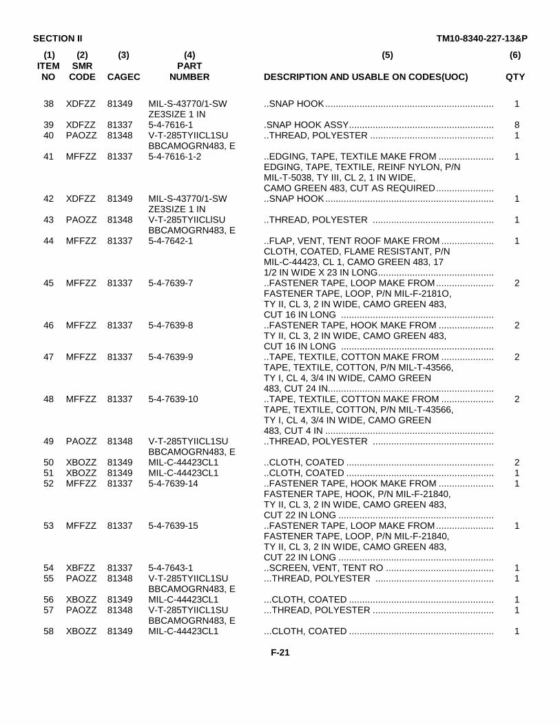
SECTION II TM10-8340-227-13&P
(1) (2) (3) (4) (5) (6)ITEM SMR PARTNO CODE CAGEC NUMBER DESCRIPTION AND USABLE ON CODES(UOC) QTY
38 XDFZZ 81349 MIL-S-43770/1-SW ..SNAP HOOK................................................................ 1ZE3SIZE 1 IN
39 XDFZZ 81337 5-4-7616-1 .SNAP HOOK ASSY....................................................... 840 PAOZZ 81348 V-T-285TYIICL1SU ..THREAD, POLYESTER ............................................... 1
BBCAMOGRN483, E41 MFFZZ 81337 5-4-7616-1-2 ..EDGING, TAPE, TEXTILE MAKE FROM ..................... 1
EDGING, TAPE, TEXTILE, REINF NYLON, P/NMIL-T-5038, TY III, CL 2, 1 IN WIDE,CAMO GREEN 483, CUT AS REQUIRED......................
42 XDFZZ 81349 MIL-S-43770/1-SW ..SNAP HOOK................................................................ 1ZE3SIZE 1 IN
43 PAOZZ 81348 V-T-285TYIICLlSU ..THREAD, POLYESTER .............................................. 1BBCAMOGRN483, E
44 MFFZZ 81337 5-4-7642-1 ..FLAP, VENT, TENT ROOF MAKE FROM .................... 1CLOTH, COATED, FLAME RESISTANT, P/NMIL-C-44423, CL 1, CAMO GREEN 483, 171/2 IN WIDE X 23 IN LONG............................................
45 MFFZZ 81337 5-4-7639-7 ..FASTENER TAPE, LOOP MAKE FROM...................... 2FASTENER TAPE, LOOP, P/N MIL-F-2181O,TY II, CL 3, 2 IN WIDE, CAMO GREEN 483,CUT 16 IN LONG ..........................................................
46 MFFZZ 81337 5-4-7639-8 ..FASTENER TAPE, HOOK MAKE FROM ..................... 2TY II, CL 3, 2 IN WIDE, CAMO GREEN 483,CUT 16 IN LONG ..........................................................
47 MFFZZ 81337 5-4-7639-9 ..TAPE, TEXTILE, COTTON MAKE FROM .................... 2TAPE, TEXTILE, COTTON, P/N MIL-T-43566,TY I, CL 4, 3/4 IN WIDE, CAMO GREEN483, CUT 24 IN...............................................................
48 MFFZZ 81337 5-4-7639-10 ..TAPE, TEXTILE, COTTON MAKE FROM .................... 2TAPE, TEXTILE, COTTON, P/N MIL-T-43566,TY I, CL 4, 3/4 IN WIDE, CAMO GREEN483, CUT 4 IN ................................................................
49 PAOZZ 81348 V-T-285TYIICL1SU ..THREAD, POLYESTER ..............................................BBCAMOGRN483, E
50 XBOZZ 81349 MIL-C-44423CL1 ..CLOTH, COATED ........................................................ 251 XBOZZ 81349 MIL-C-44423CL1 ..CLOTH, COATED ........................................................ 152 MFFZZ 81337 5-4-7639-14 ..FASTENER TAPE, HOOK MAKE FROM ..................... 1
FASTENER TAPE, HOOK, P/N MIL-F-21840,TY II, CL 3, 2 IN WIDE, CAMO GREEN 483,CUT 22 IN LONG ...........................................................
53 MFFZZ 81337 5-4-7639-15 ..FASTENER TAPE, LOOP MAKE FROM...................... 1FASTENER TAPE, LOOP, P/N MIL-F-21840,TY II, CL 3, 2 IN WIDE, CAMO GREEN 483,CUT 22 IN LONG ...........................................................
54 XBFZZ 81337 5-4-7643-1 ..SCREEN, VENT, TENT RO ......................................... 155 PAOZZ 81348 V-T-285TYIICL1SU ...THREAD, POLYESTER ............................................. 1
BBCAMOGRN483, E56 XBOZZ 81349 MIL-C-44423CL1 ...CLOTH, COATED ....................................................... 157 PAOZZ 81348 V-T-285TYIICL1SU ...THREAD, POLYESTER .............................................. 1
BBCAMOGRN483, E58 XBOZZ 81349 MIL-C-44423CL1 ...CLOTH, COATED ....................................................... 1
F-21
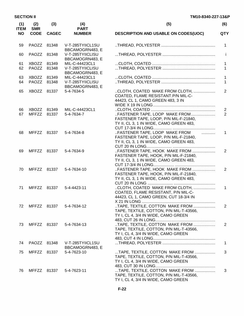
SECTION II TM10-8340-227-13&P
(1) (2) (3) (4) (5) (6)ITEM SMR PARTNO CODE CAGEC NUMBER DESCRIPTION AND USABLE ON CODES(UOC) QTY
59 PAOZZ 81348 V-T-285TYIICL1SU ..THREAD, POLYESTER ............................................... 1BBCAMOGRN483, E
60 PAOZZ 81348 V-T-285TYIICLISU ...THREAD, POLYESTER .............................................. iBBCAMOGRN483, E
61 XBOZZ 81349 MIL-C-44423CL1 ...CLOTH, COATED ....................................................... 162 PAOZZ 81348 V-T-285TYIICLISU ...THREAD, POLYESTER .............................................. 1
BBCAMOGRN483, E63 XBOZZ 81349 MIL-C-44423CL1 ...CLOTH, COATED ....................................................... 164 PAOZZ 81348 V-T-285TYIICLISU ..THREAD, POLYESTER ............................................... 1
BBCAMOGRN483, E65 XBOZZ 81337 5-4-7634-5 ..CLOTH, COATED MAKE FROM CLOTH, ................... 2
COATED, FLAME RESISTANT.P/N MIL-C-44423, CL 1, CAMO GREEN 483, 3 INWIDE X 19 IN LONG......................................................
66 XBOZZ 81349 MIL-C-44423CL1 ..CLOTH, COATED ........................................................ 267 MFFZZ 81337 5-4-7634-7 ..FASTENER TAPE, LOOP MAKE FROM..................... 2
FASTENER TAPE, LOOP, P/N MIL-F-21840,TY II, CL 3, 1 IN WIDE, CAMO GREEN 483,CUT 17-3/4 IN LONG................ .....................................
68 MFFZZ 81337 5-4-7634-8 ..FASTENER TAPE, LOOP MAKE FROM ............ 1FASTENER TAPE, LOOP, P/N MIL-F-21840,TY II, CL 3, 1 IN WIDE, CAMO GREEN 483,CUT 20 IN LONG...................... .....................................
69 MFFZZ 81337 5-4-7634-9 ..FASTENER TAPE, HOOK MAKE FROM .................... 2FASTENER TAPE, HOOK, P/N MIL-F-21840,TY II, CL 3, 1 IN WIDE, CAMO GREEN 483,CUT 17-3/4 IN LONG.................. ...................................
70 MFFZZ 81337 5-4-7634-10 ..FASTENER TAPE, HOOK MAKE FROM .................... 2FASTENER TAPE, HOOK, P/N MIL-F-21840,TY II, CL 3, 1 IN WIDE, CAMO GREEN 483,CUT 20 IN LONG ...................... ....................................
71 MFFZZ 81337 5-4-4423-11 ..CLOTH, COATED MAKE FROM CLOTH, ................... 1COATED, FLAME RESISTANT, P/N MIL-C-44423, CL 1, CAMO GREEN, CUT 18-3/4 INX 21 IN LONG ................................................................
72 MFFZZ 81337 5-4-7634-12 ..TAPE, TEXTILE, COTTON MAKE FROM ................... 2TAPE, TEXTILE, COTTON, P/N MIL-T-43566,TY I, CL 4, 3/4 IN WIDE, CAMO GREEN483, CUT 26 IN LONG....................................................
73 MFFZZ 81337 5-4-7634-13 ..TAPE, TEXTILE, COTTON MAKE FROM ................... 2TAPE, TEXTILE, COTTON, P/N MIL-T-43566,TY I, CL 4, 3/4 IN WIDE, CAMO GREEN483, CUT 4 IN LONG......................................................
74 PAOZZ 81348 V-T-285TYIICL1SU ...THREAD, POLYESTER .............................................. 1BBCAMOGRN483, E
75 MFFZZ 81337 5-4-7623-10 ...TAPE, TEXTILE, COTTON MAKE FROM .................. 3TAPE, TEXTILE, COTTON, P/N MIL-T-43566,TY I, CL 4, 3/4 IN WIDE, CAMO GREEN483, CUT 30 IN LONG....................................................
76 MFFZZ 81337 5-4-7623-11 ...TAPE, TEXTILE, COTTON MAKE FROM .................. 3TAPE, TEXTILE, COTTON, P/N MIL-T-43566,TY I, CL 4, 3/4 IN WIDE, CAMO GREEN
F-22
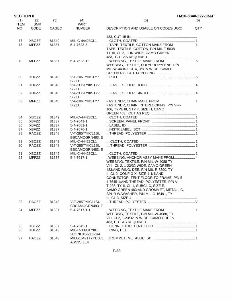
SECTION II TM10-8340-227-13&P(1) (2) (3) (4) (5) (6)
ITEM SMR PARTNO CODE CAGEC NUMBER DESCRIPTION AND USABLE ON CODES(UOC) QTY
483, CUT 15 IN..................................................................77 XBOZZ 81349 MIL-C-44423CL1 ...CLOTH, COATED ........................................................ 178 MFFZZ 81337 5-4-7623-8 ...TAPE, TEXTILE, COTTON MAKE FROM 1
TAPE, TEXTILE, COTTON, P/N MIL-T-5038,TY III, CL 2, 1 IN WIDE, CAMO GREEN483, CUT AS REQUIRED .................................................
79 MFFZZ 81337 5-4-7623-12 ...WEBBING, TEXTILE MAKE FROM 6WEBBING, TEXTILE, POLYPROPYLENE, P/NMIL-W-44049, CL 4, 3/8 IN WIDE, CAMOGREEN 483, CUT 14 IN LONG..........................................
80 XDFZZ 81348 V-F-106TYIIISTY7 ...PULL ........................................................................... 6SIZEH
81 XDFZZ 81348 V-F-1O6TYIIISTY7 ....FAST., SLIDER, DOUBLE .......................................... 4SIZEH
82 XDFZZ 81348 V-F-1O6TYIIISTY7 ....FAST., SLIDER, SINGLE ............................................ 4SIZEH
83 MFFZZ 81348 V-F-106TYIIISTY7 FASTENER, CHAIN MAKE FROM 1SIZEH FASTENER, CHAIN, INTERLOCKING, P/N V-F-
106, TYPE III, STY 7, SIZE H, CAMOGREEN 483, CUT AS REQ ..............................................
84 XBOZZ 81349 MIL-C-44423CL1 ...CLOTH, COATED ........................................................ 185 XBFZZ 81337 5-4-7641-1 ...SCREEN, PANEL FRONT ........................................... 186 XBFZZ 81337 5-4-7681-1 ...LABEL, ID .................................................................... 187 XBFZZ 81337 5-4-7676-1 ...INSTR LABEL, SCT ..................................................... 188 PAOZZ 81348 V-T-285TYIICL1SU ...THREAD, POLYESTER ............................................... 1
BBCAMOGRN483, E89 XBOZZ 81349 MIL-C-44423CL1 ....CLOTH, COATED ....................................................... 190 PAOZZ 81348 V-T-285TYIICL1SU ....THREAD, POLYESTER .............................................. 1
BBCAMOGRN483, E91 XBOZZ 81349 MIL-C-44423CL1 ...CLOTH, COATED ........................................................ 192 MFFZZ 81337 5-4-7617-1 ..WEBBING, ANCHOR ASSY MAKE FROM..................... 4
WEBBING, TEXTILE, P/N MIL-W-4088 TYVIII, CL 2, 1-23/32 WIDE, CAMO GREEN483;AND RING, DEE, P/N MIL-R-3390, TYII, CL 2, CONFIG X, SIZE 1-1/4;ANDCONNECTOR, TENT FLOOR TO FRAME, P/N 5-4-7645-1;AND THREAD, POLYESTER, P/N V-T-285, TY II, CL 1, SUBCL C, SIZE E,CAMO GREEN 483;AND GROMMET, METALLIC,SPUR W/WASHER, P/N MIL-G-16491, TYIII, CL 3, SIZE 4.................................................................
93 PAOZZ 81348 V-T-285TYIICL1SU ...THREAD, POLYESTER ...............................................VBBCAMOGRN483, E
94 MFFZZ 81337 5-4-7617-1-1 ...WEBBING, TEXTILE MAKE FROM 1WEBBING, TEXTILE, P/N MIL-W-4088, TYVIII, CL2, 1-23/32 IN WIDE, CAMO GREEN483, CUT AS REQUIRED ..................................................
95 XBFZZ 81337 5-4-7645-1 ...CONNECTOR, TENT FLOO ........................................ 196 XDFZZ 81349 MIL-R-3390TYIICL ...RING, DEE .................................................................. 1
2CONFXSIZE1-1/497 PAOZZ 81349 MILG16491TYPE3CL ...GROMMET, METALLIC, SP .......................................... 1
ASS3SIZE4
F-23
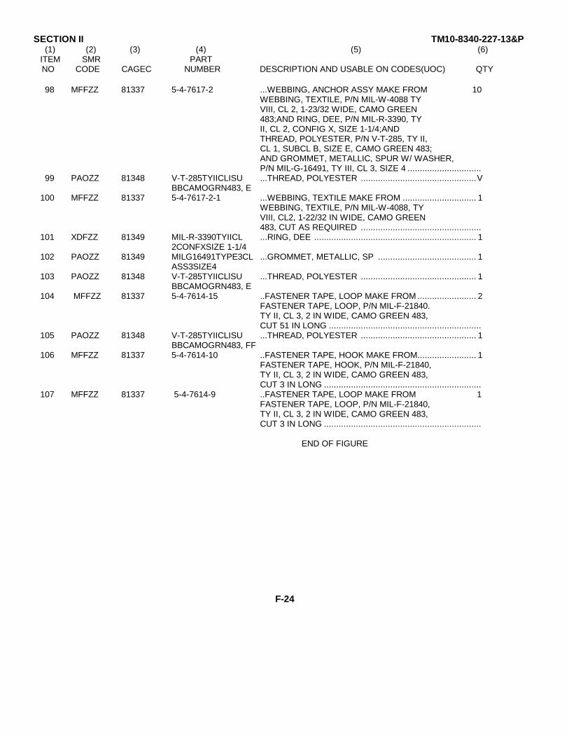
SECTION II TM10-8340-227-13&P(1) (2) (3) (4) (5) (6)
ITEM SMR PARTNO CODE CAGEC NUMBER DESCRIPTION AND USABLE ON CODES(UOC) QTY
98 MFFZZ 81337 5-4-7617-2 ...WEBBING, ANCHOR ASSY MAKE FROM 10WEBBING, TEXTILE, P/N MIL-W-4088 TYVIII, CL 2, 1-23/32 WIDE, CAMO GREEN483;AND RING, DEE, P/N MIL-R-3390, TYII, CL 2, CONFIG X, SIZE 1-1/4;ANDTHREAD, POLYESTER, P/N V-T-285, TY II,CL 1, SUBCL B, SIZE E, CAMO GREEN 483;AND GROMMET, METALLIC, SPUR W/ WASHER,P/N MIL-G-16491, TY III, CL 3, SIZE 4 ..............................
99 PAOZZ 81348 V-T-285TYIICLISU ...THREAD, POLYESTER ...............................................VBBCAMOGRN483, E
100 MFFZZ 81337 5-4-7617-2-1 ...WEBBING, TEXTILE MAKE FROM .............................. 1WEBBING, TEXTILE, P/N MIL-W-4088, TYVIII, CL2, 1-22/32 IN WIDE, CAMO GREEN483, CUT AS REQUIRED .................................................
101 XDFZZ 81349 MIL-R-3390TYIICL ...RING, DEE .................................................................. 12CONFXSIZE 1-1/4
102 PAOZZ 81349 MILG16491TYPE3CL ...GROMMET, METALLIC, SP ........................................ 1ASS3SIZE4
103 PAOZZ 81348 V-T-285TYIICLlSU ...THREAD, POLYESTER ............................................... 1BBCAMOGRN483, E
104 MFFZZ 81337 5-4-7614-15 ..FASTENER TAPE, LOOP MAKE FROM ........................ 2FASTENER TAPE, LOOP, P/N MIL-F-21840.TY II, CL 3, 2 IN WIDE, CAMO GREEN 483,CUT 51 IN LONG ..............................................................
105 PAOZZ 81348 V-T-285TYIICLISU ...THREAD, POLYESTER ............................................... 1BBCAMOGRN483, FF
106 MFFZZ 81337 5-4-7614-10 ..FASTENER TAPE, HOOK MAKE FROM........................ 1FASTENER TAPE, HOOK, P/N MIL-F-21840,TY II, CL 3, 2 IN WIDE, CAMO GREEN 483,CUT 3 IN LONG ................................................................
107 MFFZZ 81337 5-4-7614-9 ..FASTENER TAPE, LOOP MAKE FROM 1FASTENER TAPE, LOOP, P/N MIL-F-21840,TY II, CL 3, 2 IN WIDE, CAMO GREEN 483,CUT 3 IN LONG ................................................................
END OF FIGURE
F-24
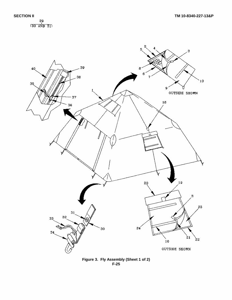
SECTION II TM 10-8340-227-13&P
Figure 3. Fly Assembly (Sheet 1 of 2)F-25
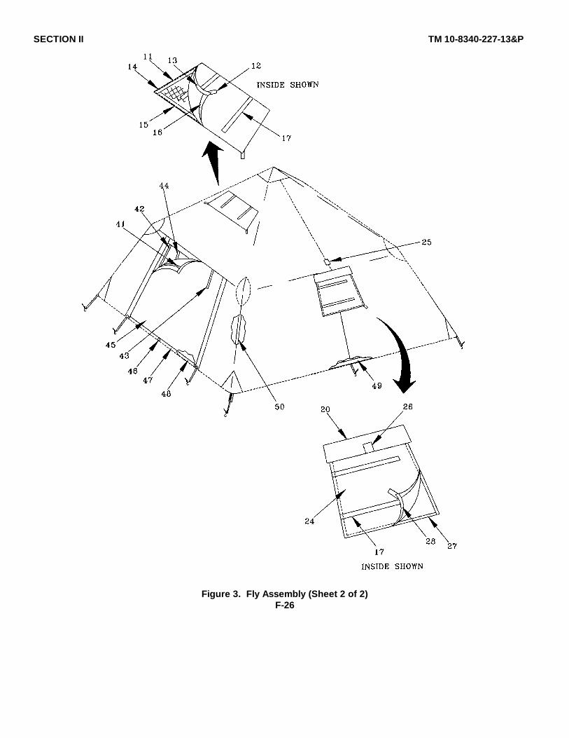
SECTION II TM 10-8340-227-13&P
Figure 3. Fly Assembly (Sheet 2 of 2)F-26
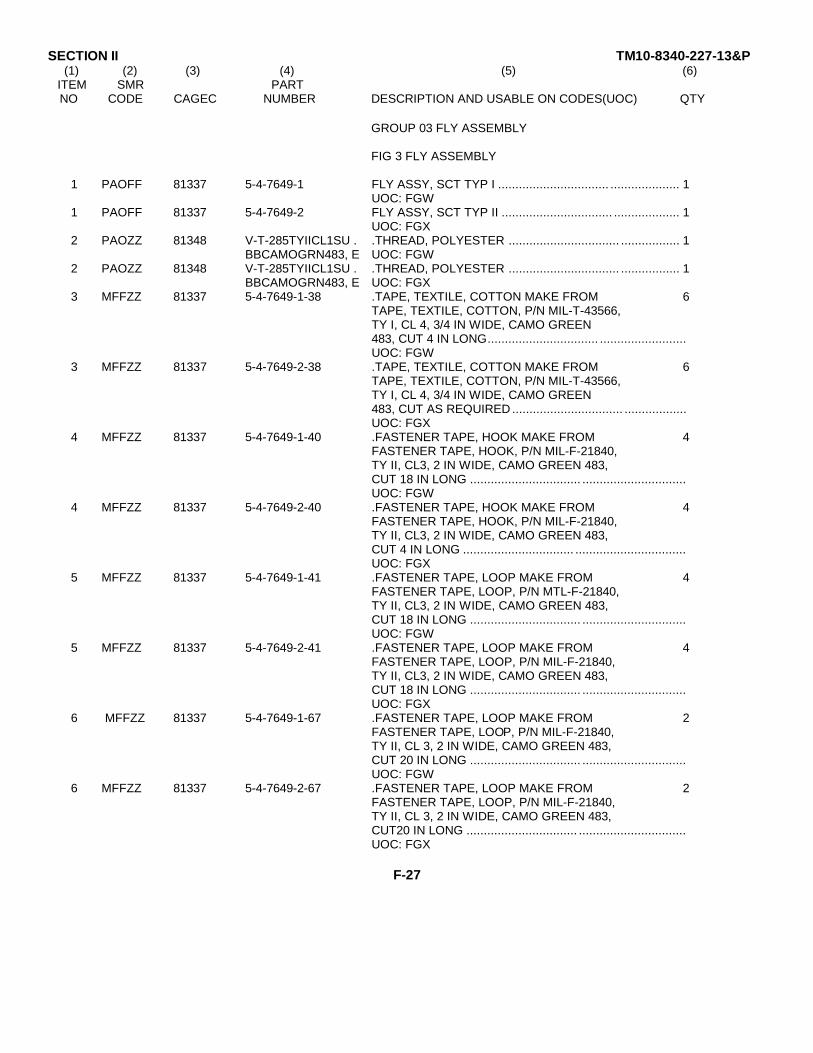
SECTION II TM10-8340-227-13&P(1) (2) (3) (4) (5) (6)
ITEM SMR PARTNO CODE CAGEC NUMBER DESCRIPTION AND USABLE ON CODES(UOC) QTY
GROUP 03 FLY ASSEMBLY
FIG 3 FLY ASSEMBLY
1 PAOFF 81337 5-4-7649-1 FLY ASSY, SCT TYP I ................................ .................... 1UOC: FGW
1 PAOFF 81337 5-4-7649-2 FLY ASSY, SCT TYP II ................................ ................... 1UOC: FGX
2 PAOZZ 81348 V-T-285TYIICL1SU . .THREAD, POLYESTER ................................ ................. 1BBCAMOGRN483, E UOC: FGW
2 PAOZZ 81348 V-T-285TYIICL1SU . .THREAD, POLYESTER ................................ ................. 1BBCAMOGRN483, E UOC: FGX
3 MFFZZ 81337 5-4-7649-1-38 .TAPE, TEXTILE, COTTON MAKE FROM 6TAPE, TEXTILE, COTTON, P/N MIL-T-43566,TY I, CL 4, 3/4 IN WIDE, CAMO GREEN483, CUT 4 IN LONG................................ .........................UOC: FGW
3 MFFZZ 81337 5-4-7649-2-38 .TAPE, TEXTILE, COTTON MAKE FROM 6TAPE, TEXTILE, COTTON, P/N MIL-T-43566,TY I, CL 4, 3/4 IN WIDE, CAMO GREEN483, CUT AS REQUIRED ................................ ..................UOC: FGX
4 MFFZZ 81337 5-4-7649-1-40 .FASTENER TAPE, HOOK MAKE FROM 4FASTENER TAPE, HOOK, P/N MIL-F-21840,TY II, CL3, 2 IN WIDE, CAMO GREEN 483,CUT 18 IN LONG ................................ ..............................UOC: FGW
4 MFFZZ 81337 5-4-7649-2-40 .FASTENER TAPE, HOOK MAKE FROM 4FASTENER TAPE, HOOK, P/N MIL-F-21840,TY II, CL3, 2 IN WIDE, CAMO GREEN 483,CUT 4 IN LONG ................................ ................................UOC: FGX
5 MFFZZ 81337 5-4-7649-1-41 .FASTENER TAPE, LOOP MAKE FROM 4FASTENER TAPE, LOOP, P/N MTL-F-21840,TY II, CL3, 2 IN WIDE, CAMO GREEN 483,CUT 18 IN LONG ................................ ..............................UOC: FGW
5 MFFZZ 81337 5-4-7649-2-41 .FASTENER TAPE, LOOP MAKE FROM 4FASTENER TAPE, LOOP, P/N MIL-F-21840,TY II, CL3, 2 IN WIDE, CAMO GREEN 483,CUT 18 IN LONG ................................ ..............................UOC: FGX
6 MFFZZ 81337 5-4-7649-1-67 .FASTENER TAPE, LOOP MAKE FROM 2FASTENER TAPE, LOOP, P/N MIL-F-21840,TY II, CL 3, 2 IN WIDE, CAMO GREEN 483,CUT 20 IN LONG ................................ ..............................UOC: FGW
6 MFFZZ 81337 5-4-7649-2-67 .FASTENER TAPE, LOOP MAKE FROM 2FASTENER TAPE, LOOP, P/N MIL-F-21840,TY II, CL 3, 2 IN WIDE, CAMO GREEN 483,CUT20 IN LONG ................................ ...............................UOC: FGX
F-27
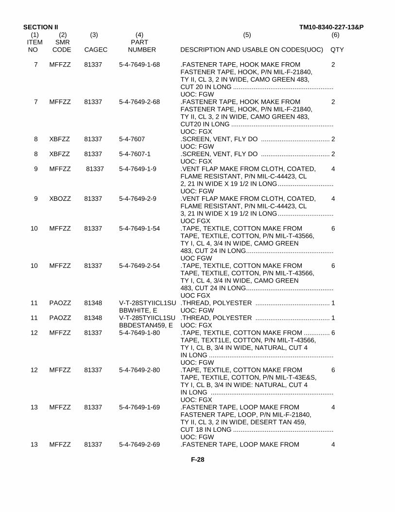
SECTION II TM10-8340-227-13&P(1) (2) (3) (4) (5) (6)
ITEM SMR PARTNO CODE CAGEC NUMBER DESCRIPTION AND USABLE ON CODES(UOC) QTY
7 MFFZZ 81337 5-4-7649-1-68 .FASTENER TAPE, HOOK MAKE FROM 2FASTENER TAPE, HOOK, P/N MIL-F-21840,TY II, CL 3, 2 IN WIDE, CAMO GREEN 483,CUT 20 IN LONG ......................................................UOC: FGW
7 MFFZZ 81337 5-4-7649-2-68 .FASTENER TAPE, HOOK MAKE FROM 2FASTENER TAPE, HOOK, P/N MIL-F-21840,TY II, CL 3, 2 IN WIDE, CAMO GREEN 483,CUT20 IN LONG .......................................................UOC: FGX
8 XBFZZ 81337 5-4-7607 .SCREEN, VENT, FLY DO ..................................... 2UOC: FGW
8 XBFZZ 81337 5-4-7607-1 .SCREEN, VENT, FLY DO ..................................... 2UOC: FGX
9 MFFZZ 81337 5-4-7649-1-9 .VENT FLAP MAKE FROM CLOTH, COATED, 4FLAME RESISTANT, P/N MIL-C-44423, CL2, 21 IN WIDE X 19 1/2 IN LONG..............................UOC: FGW
9 XBOZZ 81337 5-4-7649-2-9 .VENT FLAP MAKE FROM CLOTH, COATED, 4FLAME RESISTANT, P/N MIL-C-44423, CL3, 21 IN WIDE X 19 1/2 IN LONG..............................UOC FGX
10 MFFZZ 81337 5-4-7649-1-54 .TAPE, TEXTILE, COTTON MAKE FROM 6TAPE, TEXTILE, COTTON, P/N MIL-T-43566,TY I, CL 4, 3/4 IN WIDE, CAMO GREEN483, CUT 24 IN LONG...............................................UOC FGW
10 MFFZZ 81337 5-4-7649-2-54 .TAPE, TEXTILE, COTTON MAKE FROM 6TAPE, TEXTILE, COTTON, P/N MIL-T-43566,TY I, CL 4, 3/4 IN WIDE, CAMO GREEN483, CUT 24 IN LONG...............................................UOC FGX
11 PAOZZ 81348 V-T-28STYIICL1SU .THREAD, POLYESTER ........................................ 1BBWHITE, E UOC: FGW
11 PAOZZ 81348 V-T-285TYIICL1SU .THREAD, POLYESTER ........................................ 1BBDESTAN459, E UOC: FGX
12 MFFZZ 81337 5-4-7649-1-80 .TAPE, TEXTILE, COTTON MAKE FROM .............. 6TAPE, TEXT1LE, COTTON, P/N MIL-T-43566,TY I, CL B, 3/4 IN WIDE, NATURAL, CUT 4IN LONG ...................................................................UOC: FGW
12 MFFZZ 81337 5-4-7649-2-80 .TAPE, TEXTILE, COTTON MAKE FROM 6TAPE, TEXTILE, COTTON, P/N MIL-T-43E&S,TY I, CL B, 3/4 IN WIDE: NATURAL, CUT 4IN LONG ..................................................................UOC: FGX
13 MFFZZ 81337 5-4-7649-1-69 .FASTENER TAPE, LOOP MAKE FROM 4FASTENER TAPE, LOOP, P/N MIL-F-21840,TY II, CL 3, 2 IN WIDE, DESERT TAN 459,CUT 18 IN LONG ......................................................UOC: FGW
13 MFFZZ 81337 5-4-7649-2-69 .FASTENER TAPE, LOOP MAKE FROM 4
F-28
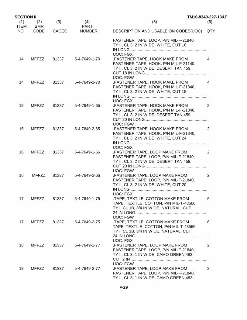
SECTION II TM10-8340-227-13&P(1) (2) (3) (4) (5) (6)
ITEM SMR PARTNO CODE CAGEC NUMBER DESCRIPTION AND USABLE ON CODES(UOC) QTY
FASTENER TAPE, LOOP, P/N MIL-F-21840,TY II, CL 3, 2 IN WIDE, WHITE, CUT 18IN LONG ..................................................................UOC: FGX
14 MFFZZ 81337 5-4-7649-1-70 .FASTENER TAPE, HOOK MAKE FROM 4FASTENER TAPE, HOOK, P/N MIL-F-21140.TY II, CL 3, 2 IN WIDE, DESERT TAN 459,CUT 18 IN LONG ......................................................UOC: FGW
14 MFFZZ 81337 5-4-7649-2-70 .FASTENER TAPE, HOOK MAKE FROM 4FASTENER TAPE, HOOK, P/N MIL-F-21840,TY II, CL 3, 2 IN WIDE, WHITE, CUT 18IN LONG ..................................................................UOC: FGX
15 MFFZZ 81337 5-4-7649-1-65 .FASTENER TAPE, HOOK MAKE FROM 2FASTENER TAPE, HOOK, P/N MIL-F-21840,TY II, CL 3, 2 IN WIDE, DESERT TAN 459,CUT 20 IN LONG ......................................................UOC: FGW
15 MFFZZ 81337 5-4-7649-2-65 .FASTENER TAPE, HOOK MAKE FROM 2FASTENER TAPE, HOOK, P/N MIL-F-21840,TY II, CL 3, 2 IN WIDE, WHITE, CUT 24IN LONG ...................................................................UOC: FGX
16 MFFZZ 81337 5-4-7649-1-66 .FASTENER TAPE, LOOP MAKE FROM 2FASTENER TAPE, LOOP, P/N MIL-F-21840,TY II, CL 3, 2 IN WIDE, DESERT TAN 459,CUT 20 IN LONG .....................................................UOC: FGW
16 MFFZZ 81337 5-4-7649-2-66 .FASTENER TAPE, LOOP MAKE FROM 2FASTENER TAPE, LOOP, P/N MIL-F-21840,TY II, CL 3, 2 IN WIDE, WHITE, CUT 20IN LONG ...................................................................UOC: FGX
17 MFFZZ 81337 5-4-7649-1-75 .TAPE, TEXTILE, COTTON MAKE FROM 6TAPE, TEXTILE, COTTON, P/N MIL-T-43566,TY I, CL 1B, 3/4 IN WIDE, NATURAL, CUT24 IN LONG...............................................................UOC: FGW
17 MFFZZ 81337 5-4-7649-2-75 .TAPE, TEXTILE, COTTON MAKE FROM 6TAPE, TEXTILE, COTTON, P/N MIL-T-43566,TY I, CL 1B, 3/4 IN WIDE, NATURAL, CUT24 IN LONG...............................................................UOC: FGX
18 MFFZZ 81337 5-4-7649-1-77 .FASTENER TAPE, LOOP MAKE FROM 2FASTENER TAPE, LOOP, P/N MIL-F-21840,TY II, CL 3, 1 IN WIDE, CAMO GREEN 483,CUT 2 IN ..................................................................UOC: FGW
18 MFFZZ 81337 5-4-7649-2-77 .FASTENER TAPE, LOOP MAKE FROM 2FASTENER TAPE, LOOP, P/N MIL-F-21840,TY II, CL 3, 1 IN WIDE, CAMO GREEN 483-
F-29

SECTION II TM10-8340-227-13&P(1) (2) (3) (4) (5) (6)
ITEM SMR PARTNO CODE CAGEC NUMBER DESCRIPTION AND USABLE ON CODES(UOC) QTY
CUT2 IN LONG .................................................................UOC FGX
19 MFFZZ 81337 5-4-7649-1-76 .FASTENER TAPE, HOOK MAKE FROM 1FASTENER TAPE, HOOK, P/N MIL-F-21840,TY II, CL 3, 1 IN WIDE, CAMO GREEN 483,CUT 4 IN LONG ...............................................................UOC: FGW
19 MFFZZ 337 4-7649-2-76 .FASTENER TAPE, HOOK MAKE FROM 1FASTENER TAPE, HOOK, P/N MIL-F-21840,TY II, CL 3, 1 IN WIDE, CAMO GREEN 483,CUT4 IN LONG .................................................................UOC: FGX
20 MFFZZ 81337 5-4-7649-1-63 .CLOTH, COATED MAKE FROM CLOTH, 2COATED, FLAME RESISTANT, P/N MIL-C-44423, CL 2, CUT 7 IN WIDE X 22 INLONG ...............................................................................UOC: FGW
20 MFFZZ 81337 5-4-7649-2-63 .CLOTH, COATED MAKE FROM CLOTH, 2COATED, FLAME RESISTANT, P/N MIL-C-44423, CL 3, DESERT TAN, CUT 7 IN WIDEX 22 IN LONG ...................................................................UOC: FGX
21 MFFZZ 81337 5-4-7649-1-50 .FASTENER TAPE, HOOK MAKE FROM 3FASTENER TAPE, HOOK, P/N MIL-F-21840,TY II, CL 3, 1 IN WIDE, CAMO GREEN 483,CUT 20 IN LONG ..............................................................UOC: FGW
21 MFFZZ 81337 5-4-7649-2-50 .FASTENER TAPE, HOOK MAKE FROM 3FASTENER TAPE, HOOK, P/N MIL-F-21840,TY II, CL 3, 1 IN WIDE, CAMO GREEN 483,CUT20 IN LONG ...............................................................UOC: FGX
22 MFFZZ 81337 5-4-7649-1-51 .FASTENER TAPE, LOOP MAKE FROM 3FASTENER TAPE, LOOP, P/N MIL-F-21840,TY II, CL 3, 1 IN WIDE, CAMO GREEN 483,CUT 20 IN LONG ..............................................................UOC: FGW
22 MFFZZ 81337 5-4-7649-2-51 .FASTENER TAPE, LOOP MAKE FROM 3FASTENER TAPE, LOOP, P/N MIL-F-21840,TY II, CL 3, 1 IN WIDE, CAMO GREEN 483,CUT20 IN LONG ...............................................................UOC: FGX
23 XDFZZ 81349 MIL-S-43002CONST .SHIELD, STOVEPIPE..................................................... 1RUCTION A OR B UOC: FGW
23 XDFZZ 81349 L-S-43002CONST .SHIELD, STOVEPIPE .................................................... 1RUCTION A OR B UOC: FGX
24 MFFZZ 81337 5-4-7649-1-10 .STOVEPIPE FLAP MAKE FROM CLOTH, 2COATED, FLAME RESISTANT, P/N MIL-C-44423, CL 2, 20 IN WIDE X 20 IN LONG...........................UOC: FGW
24 XBOZZ 81337 5-4-7649-2-10 .STOVEPIPE FLAP MAKE FROM CLOTH, 2COATED, FLAME RESISTANT, P/N MIL-C-
F-30
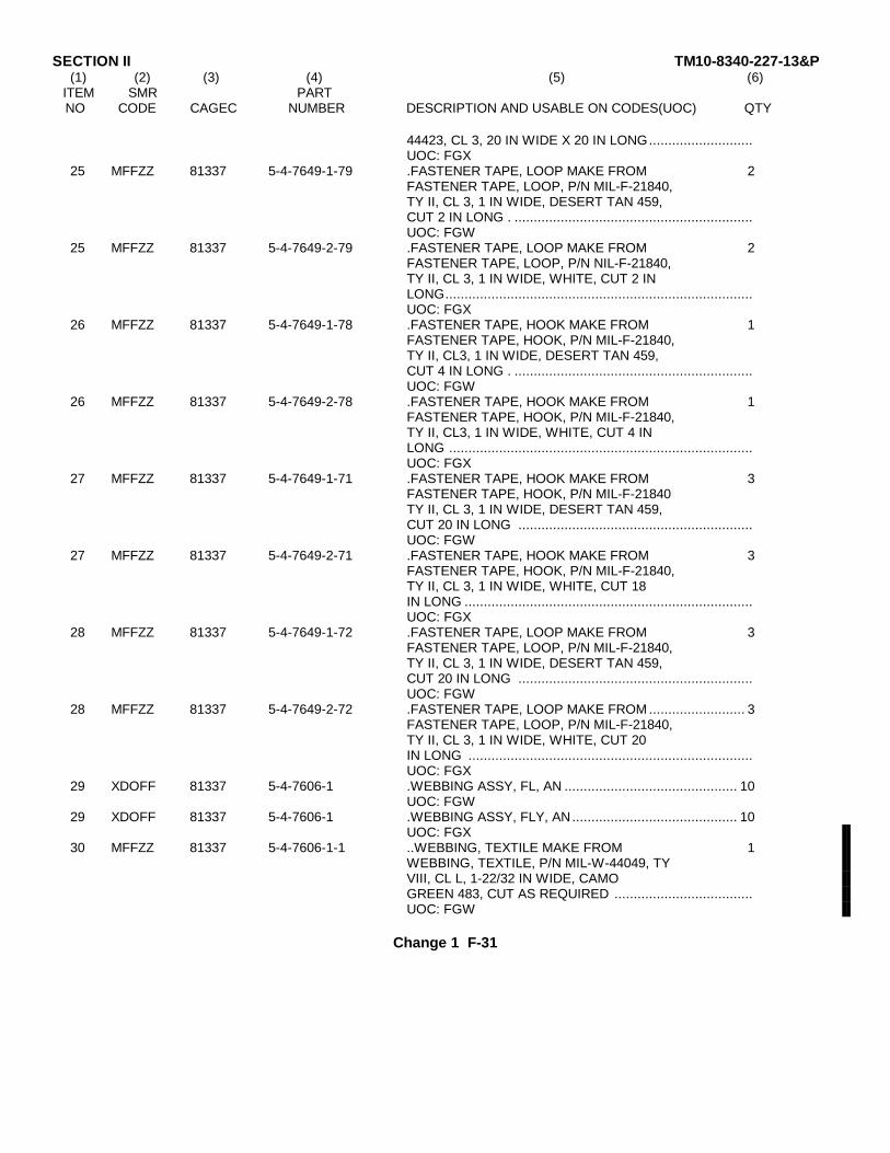
SECTION II TM10-8340-227-13&P(1) (2) (3) (4) (5) (6)
ITEM SMR PARTNO CODE CAGEC NUMBER DESCRIPTION AND USABLE ON CODES(UOC) QTY
44423, CL 3, 20 IN WIDE X 20 IN LONG...........................UOC: FGX
25 MFFZZ 81337 5-4-7649-1-79 .FASTENER TAPE, LOOP MAKE FROM 2FASTENER TAPE, LOOP, P/N MIL-F-21840,TY II, CL 3, 1 IN WIDE, DESERT TAN 459,CUT 2 IN LONG . ..............................................................UOC: FGW
25 MFFZZ 81337 5-4-7649-2-79 .FASTENER TAPE, LOOP MAKE FROM 2FASTENER TAPE, LOOP, P/N NIL-F-21840,TY II, CL 3, 1 IN WIDE, WHITE, CUT 2 INLONG................................................................................UOC: FGX
26 MFFZZ 81337 5-4-7649-1-78 .FASTENER TAPE, HOOK MAKE FROM 1FASTENER TAPE, HOOK, P/N MIL-F-21840,TY II, CL3, 1 IN WIDE, DESERT TAN 459,CUT 4 IN LONG . ..............................................................UOC: FGW
26 MFFZZ 81337 5-4-7649-2-78 .FASTENER TAPE, HOOK MAKE FROM 1FASTENER TAPE, HOOK, P/N MIL-F-21840,TY II, CL3, 1 IN WIDE, WHITE, CUT 4 INLONG ...............................................................................UOC: FGX
27 MFFZZ 81337 5-4-7649-1-71 .FASTENER TAPE, HOOK MAKE FROM 3FASTENER TAPE, HOOK, P/N MIL-F-21840TY II, CL 3, 1 IN WIDE, DESERT TAN 459,CUT 20 IN LONG .............................................................UOC: FGW
27 MFFZZ 81337 5-4-7649-2-71 .FASTENER TAPE, HOOK MAKE FROM 3FASTENER TAPE, HOOK, P/N MIL-F-21840,TY II, CL 3, 1 IN WIDE, WHITE, CUT 18IN LONG ...........................................................................UOC: FGX
28 MFFZZ 81337 5-4-7649-1-72 .FASTENER TAPE, LOOP MAKE FROM 3FASTENER TAPE, LOOP, P/N MIL-F-21840,TY II, CL 3, 1 IN WIDE, DESERT TAN 459,CUT 20 IN LONG .............................................................UOC: FGW
28 MFFZZ 81337 5-4-7649-2-72 .FASTENER TAPE, LOOP MAKE FROM ......................... 3FASTENER TAPE, LOOP, P/N MIL-F-21840,TY II, CL 3, 1 IN WIDE, WHITE, CUT 20IN LONG ..........................................................................UOC: FGX
29 XDOFF 81337 5-4-7606-1 .WEBBING ASSY, FL, AN ............................................. 10UOC: FGW
29 XDOFF 81337 5-4-7606-1 .WEBBING ASSY, FLY, AN........................................... 10UOC: FGX
30 MFFZZ 81337 5-4-7606-1-1 ..WEBBING, TEXTILE MAKE FROM 1WEBBING, TEXTILE, P/N MIL-W-44049, TYVIII, CL L, 1-22/32 IN WIDE, CAMOGREEN 483, CUT AS REQUIRED ....................................UOC: FGW
Change 1 F-31
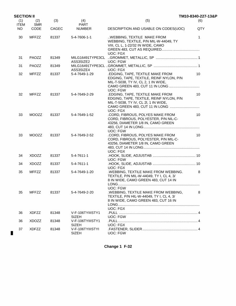
SECTION II TM10-8340-227-13&P(1) (2) (3) (4) (5) (6)
ITEM SMR PARTNO CODE CAGEC NUMBER DESCRIPTION AND USABLE ON CODES(UOC) QTY
30 MFFZZ 81337 5-4-7606-1-1 ..WEBBING, TEXTILE MAKE FROM 1WEBBING, TEXTILE, P/N MIL-W-44049, TYVIII, CL L, 1-22/32 IN WIDE, CAMOGREEN 483, CUT AS REQUIRED........... ..........................UOC: FGX
31 PAOZZ 81349 MILG16491TYPE3CL ..GROMMET, METALLIC, SP ......................................... 1ASS3SIZE2 UOC: FGW
31 PAOZZ 81349 MILG16491TYPE3CL ..GROMMET, METALLIC, SP ........................................... 1ASS3SIZE4 UOC: FGX
32 MFFZZ 81337 5-4-7649-1-29 .EDGING, TAPE, TEXTILE MAKE FROM 10EDGING, TAPE, TEXTILE, REINF NYLON, P/NMIL-T-5038, TY IV, CL 2, 1 IN WIDE,CAMO GREEN 483, CUT 11 IN LONG ..............................UOC: FGW
32 MFFZZ 81337 5-4-7649-2-29 .EDGING, TAPE, TEXTILE MAKE FROM 10EDGING, TAPE, TEXTILE, REINF NYLON, P/NMIL-T-5038, TY IV, CL 2l, 1 IN WIDE,CAMO GREEN 483, CUT 11 IN LONG .............................UOC: FGX
33 MOOZZ 81337 5-4-7649-1-52 .CORD, FIBROUS, POLYES MAKE FROM 10CORD, FIBROUS, POLYESTER, P/N NIL-C-43256, DIAMETER 1/8 IN, CAMO GREEN483, CUT 14 IN LONG.......................................................UOC: FGW
33 MOOZZ 81337 5-4-7649-2-52 .CORD, FIBROUS, POLYES MAKE FROM 10CORD, FIBROUS, POLYESTER, P/N MIL-C-43256, DIAMETER 1/8 IN, CAMO GREEN483, CUT 14 IN LONG.......................................................UOC: FGX
34 XDOZZ 81337 5-4-7611-1 .HOOK, SLIDE, ADJUSTAB .......................................... 10UOC: FGW
34 XDOZZ 81337 5-4-7611-1 .HOOK, SLIDE, ADJUSTAB .......................................... 10UOC: FGX
35 MFFZZ 81337 5-4-7649-1-20 .WEBBING, TEXTILE MAKE FROM WEBBING. 8TEXTILE, P/N MIL-W-44049, TY I, CL 4, 3/8 IN WIDE, CAMO GREEN 483, CUT 14 INLONG................................................................................UOC: FGW
35 MFFZZ 81337 5-4-7649-2-20 .WEBBING, TEXTILE MAKE FROM WEBBING, 8TEXTILE, P/N HIL-W-44049, TY I, CL 4, 3/8 IN WIDE, CAMO GREEN 483, CUT 16 INLONG................................................................................UOC: FGX
36 XDFZZ 81348 V-F-106TYIIISTY1 .PULL ............................................................................. 4SIZEH UOC: FGW
36 XDOZZ 81348 V-F-106TYIIISTY1 .PULL .............................................................................. 4SIZEH UOC: FGX
37 XDFZZ 81348 V-F-106TYIIISTYI .FASTENER, SLIDER...................................................... 4SIZEH UOC: FGW
Change 1 F-32
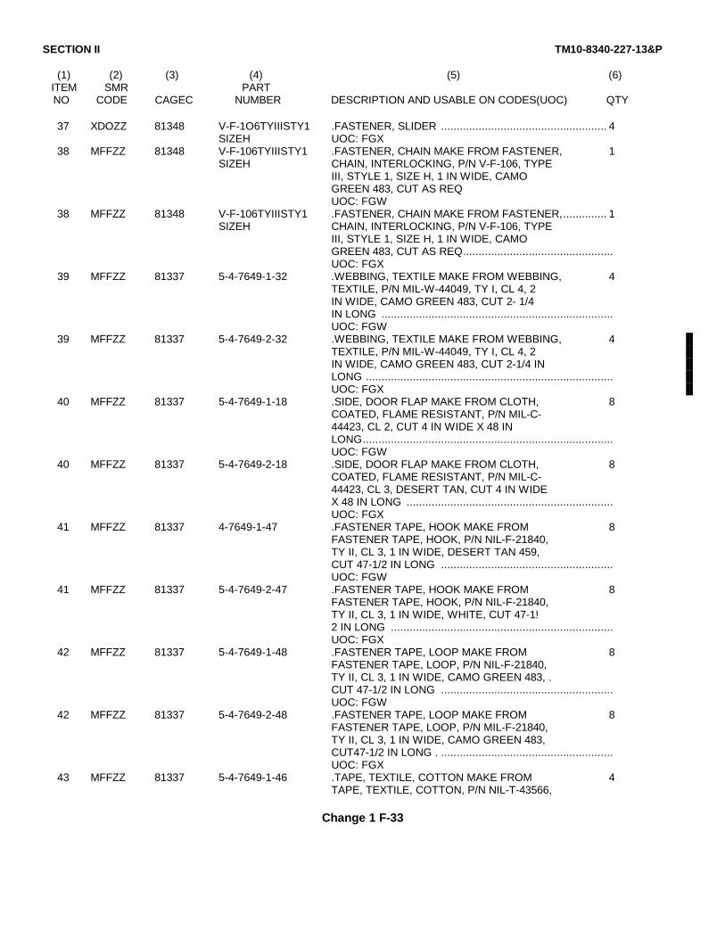
SECTION II TM10-8340-227-13&P
(1) (2) (3) (4) (5) (6)ITEM SMR PARTNO CODE CAGEC NUMBER DESCRIPTION AND USABLE ON CODES(UOC) QTY
37 XDOZZ 81348 V-F-1O6TYIIISTY1 .FASTENER, SLIDER ..................................................... 4SIZEH UOC: FGX
38 MFFZZ 81348 V-F-106TYIIISTY1 .FASTENER, CHAIN MAKE FROM FASTENER, 1SIZEH CHAIN, INTERLOCKING, P/N V-F-106, TYPE
III, STYLE 1, SIZE H, 1 IN WIDE, CAMOGREEN 483, CUT AS REQUOC: FGW
38 MFFZZ 81348 V-F-106TYIIISTY1 .FASTENER, CHAIN MAKE FROM FASTENER,.............. 1SIZEH CHAIN, INTERLOCKING, P/N V-F-106, TYPE
III, STYLE 1, SIZE H, 1 IN WIDE, CAMOGREEN 483, CUT AS REQ................................................UOC: FGX
39 MFFZZ 81337 5-4-7649-1-32 .WEBBING, TEXTILE MAKE FROM WEBBING, 4TEXTILE, P/N MIL-W-44049, TY I, CL 4, 2IN WIDE, CAMO GREEN 483, CUT 2- 1/4IN LONG ..........................................................................UOC: FGW
39 MFFZZ 81337 5-4-7649-2-32 .WEBBING, TEXTILE MAKE FROM WEBBING, 4TEXTILE, P/N MIL-W-44049, TY I, CL 4, 2IN WIDE, CAMO GREEN 483, CUT 2-1/4 INLONG ...............................................................................UOC: FGX
40 MFFZZ 81337 5-4-7649-1-18 .SIDE, DOOR FLAP MAKE FROM CLOTH, 8COATED, FLAME RESISTANT, P/N MIL-C-44423, CL 2, CUT 4 IN WIDE X 48 INLONG................................................................................UOC: FGW
40 MFFZZ 81337 5-4-7649-2-18 .SIDE, DOOR FLAP MAKE FROM CLOTH, 8COATED, FLAME RESISTANT, P/N MIL-C-44423, CL 3, DESERT TAN, CUT 4 IN WIDEX 48 IN LONG ..................................................................UOC: FGX
41 MFFZZ 81337 4-7649-1-47 .FASTENER TAPE, HOOK MAKE FROM 8FASTENER TAPE, HOOK, P/N NIL-F-21840,TY II, CL 3, 1 IN WIDE, DESERT TAN 459,CUT 47-1/2 IN LONG .......................................................UOC: FGW
41 MFFZZ 81337 5-4-7649-2-47 .FASTENER TAPE, HOOK MAKE FROM 8FASTENER TAPE, HOOK, P/N NIL-F-21840,TY II, CL 3, 1 IN WIDE, WHITE, CUT 47-1!2 IN LONG .......................................................................UOC: FGX
42 MFFZZ 81337 5-4-7649-1-48 .FASTENER TAPE, LOOP MAKE FROM 8FASTENER TAPE, LOOP, P/N NIL-F-21840,TY II, CL 3, 1 IN WIDE, CAMO GREEN 483, .CUT 47-1/2 IN LONG .......................................................UOC: FGW
42 MFFZZ 81337 5-4-7649-2-48 .FASTENER TAPE, LOOP MAKE FROM 8FASTENER TAPE, LOOP, P/N MIL-F-21840,TY II, CL 3, 1 IN WIDE, CAMO GREEN 483,CUT47-1/2 IN LONG . .......................................................UOC: FGX
43 MFFZZ 81337 5-4-7649-1-46 .TAPE, TEXTILE, COTTON MAKE FROM 4TAPE, TEXTILE, COTTON, P/N NIL-T-43566,
Change 1 F-33
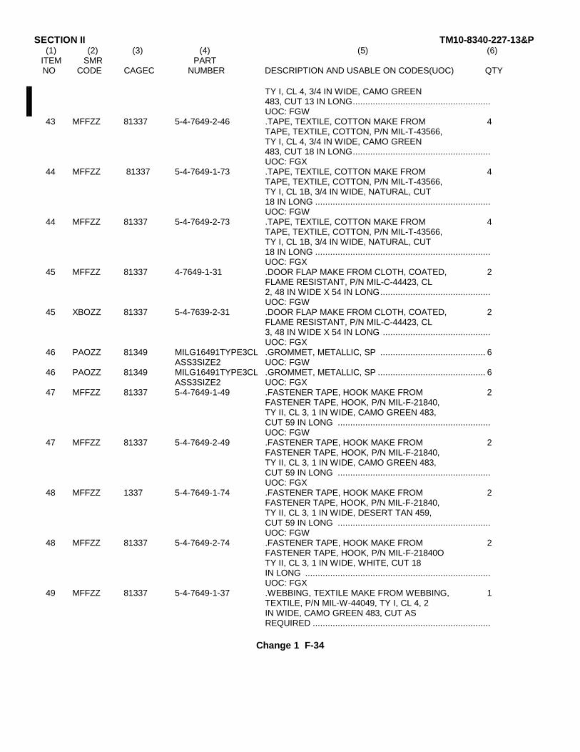
SECTION II TM10-8340-227-13&P(1) (2) (3) (4) (5) (6)
ITEM SMR PARTNO CODE CAGEC NUMBER DESCRIPTION AND USABLE ON CODES(UOC) QTY
TY I, CL 4, 3/4 IN WIDE, CAMO GREEN483, CUT 13 IN LONG.......................................................UOC: FGW
43 MFFZZ 81337 5-4-7649-2-46 .TAPE, TEXTILE, COTTON MAKE FROM 4TAPE, TEXTILE, COTTON, P/N MIL-T-43566,TY I, CL 4, 3/4 IN WIDE, CAMO GREEN483, CUT 18 IN LONG.......................................................UOC: FGX
44 MFFZZ 81337 5-4-7649-1-73 .TAPE, TEXTILE, COTTON MAKE FROM 4TAPE, TEXTILE, COTTON, P/N MIL-T-43566,TY I, CL 1B, 3/4 IN WIDE, NATURAL, CUT18 IN LONG ......................................................................UOC: FGW
44 MFFZZ 81337 5-4-7649-2-73 .TAPE, TEXTILE, COTTON MAKE FROM 4TAPE, TEXTILE, COTTON, P/N MIL-T-43566,TY I, CL 1B, 3/4 IN WIDE, NATURAL, CUT18 IN LONG ......................................................................UOC: FGX
45 MFFZZ 81337 4-7649-1-31 .DOOR FLAP MAKE FROM CLOTH, COATED, 2FLAME RESISTANT, P/N MIL-C-44423, CL2, 48 IN WIDE X 54 IN LONG............................................UOC: FGW
45 XBOZZ 81337 5-4-7639-2-31 .DOOR FLAP MAKE FROM CLOTH, COATED, 2FLAME RESISTANT, P/N MIL-C-44423, CL3, 48 IN WIDE X 54 IN LONG ...........................................UOC: FGX
46 PAOZZ 81349 MILG16491TYPE3CL .GROMMET, METALLIC, SP .......................................... 6ASS3SIZE2 UOC: FGW
46 PAOZZ 81349 MILG16491TYPE3CL .GROMMET, METALLIC, SP ........................................... 6ASS3SIZE2 UOC: FGX
47 MFFZZ 81337 5-4-7649-1-49 .FASTENER TAPE, HOOK MAKE FROM 2FASTENER TAPE, HOOK, P/N MIL-F-21840,TY II, CL 3, 1 IN WIDE, CAMO GREEN 483,CUT 59 IN LONG .............................................................UOC: FGW
47 MFFZZ 81337 5-4-7649-2-49 .FASTENER TAPE, HOOK MAKE FROM 2FASTENER TAPE, HOOK, P/N MIL-F-21840,TY II, CL 3, 1 IN WIDE, CAMO GREEN 483,CUT 59 IN LONG .............................................................UOC: FGX
48 MFFZZ 1337 5-4-7649-1-74 .FASTENER TAPE, HOOK MAKE FROM 2FASTENER TAPE, HOOK, P/N MIL-F-21840,TY II, CL 3, 1 IN WIDE, DESERT TAN 459,CUT 59 IN LONG .............................................................UOC: FGW
48 MFFZZ 81337 5-4-7649-2-74 .FASTENER TAPE, HOOK MAKE FROM 2FASTENER TAPE, HOOK, P/N MIL-F-21840OTY II, CL 3, 1 IN WIDE, WHITE, CUT 18IN LONG ..........................................................................UOC: FGX
49 MFFZZ 81337 5-4-7649-1-37 .WEBBING, TEXTILE MAKE FROM WEBBING, 1TEXTILE, P/N MIL-W-44049, TY I, CL 4, 2IN WIDE, CAMO GREEN 483, CUT ASREQUIRED .......................................................................
Change 1 F-34
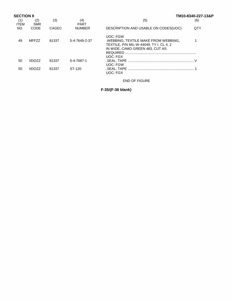
SECTION II TM10-8340-227-13&P(1) (2) (3) (4) (5) (6)
ITEM SMR PARTNO CODE CAGEC NUMBER DESCRIPTION AND USABLE ON CODES(UOC) QTY
UOC: FGW49 MFFZZ 81337 5-4-7649-2-37 .WEBBING, TEXTILE MAKE FROM WEBBING, 1
TEXTILE, P/N MIL-W-44049, TY I, CL 4, 2IN WIDE, CAMO GREEN 483, CUT ASREQUIRED .......................................................................UOC: FGX
50 XDOZZ 81337 5-4-7687-1 .SEAL, TAPE ..................................................................VUOC: FGW
50 XDOZZ 81337 ST-120 .SEAL, TAPE .................................................................. 1UOC: FGX
END OF FIGURE
F-35/(F-36 blank)

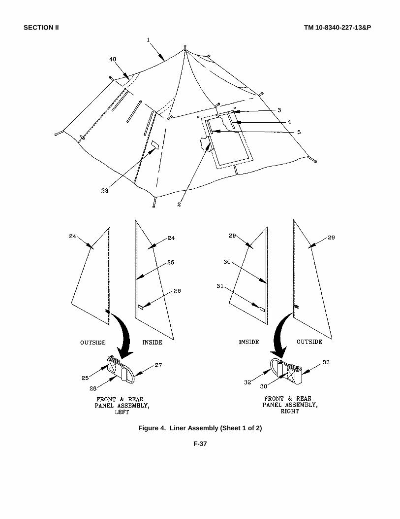
SECTION II TM 10-8340-227-13&P
Figure 4. Liner Assembly (Sheet 1 of 2)
F-37
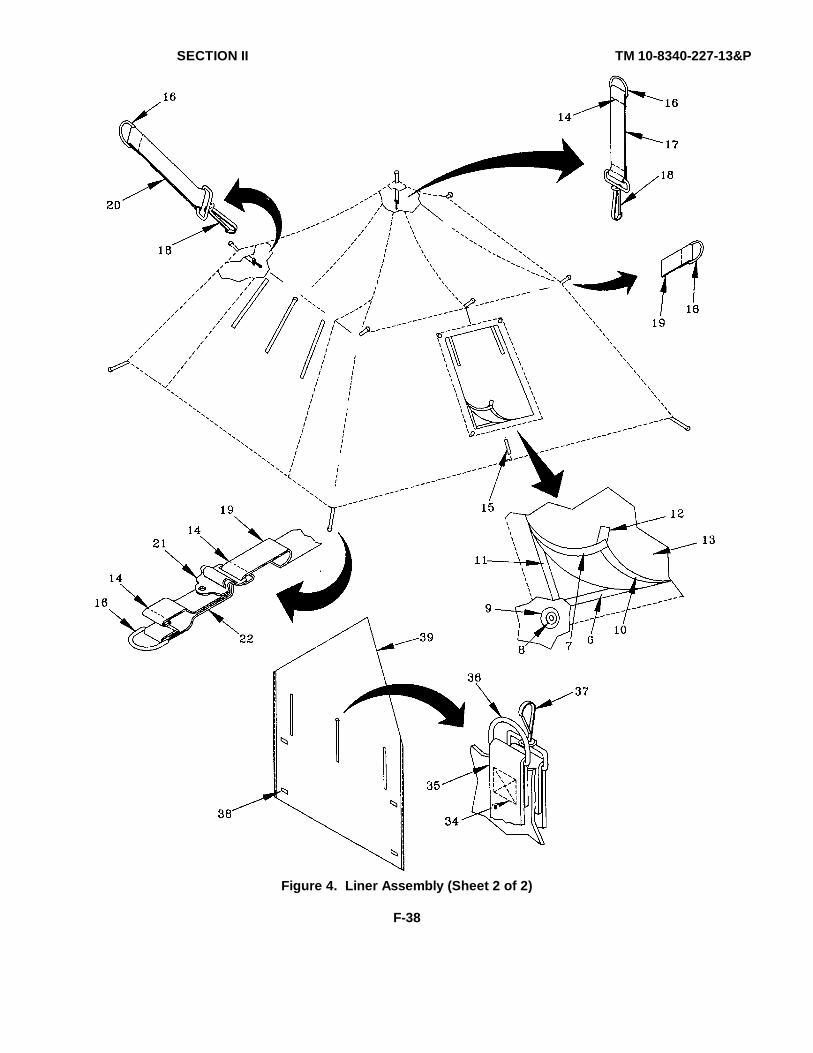
SECTION II TM 10-8340-227-13&P
Figure 4. Liner Assembly (Sheet 2 of 2)
F-38
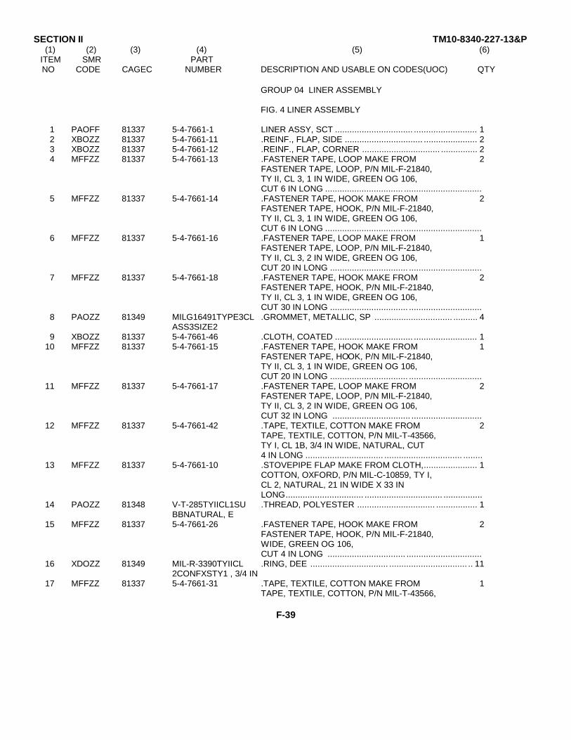
SECTION II TM10-8340-227-13&P(1) (2) (3) (4) (5) (6)
ITEM SMR PARTNO CODE CAGEC NUMBER DESCRIPTION AND USABLE ON CODES(UOC) QTY
GROUP 04 LINER ASSEMBLY
FIG. 4 LINER ASSEMBLY
1 PAOFF 81337 5-4-7661-1 LINER ASSY, SCT ................................ .......................... 12 XBOZZ 81337 5-4-7661-11 .REINF., FLAP, SIDE ................................ ...................... 23 XBOZZ 81337 5-4-7661-12 .REINF., FLAP, CORNER ................................ ............... 24 MFFZZ 81337 5-4-7661-13 .FASTENER TAPE, LOOP MAKE FROM 2
FASTENER TAPE, LOOP, P/N MIL-F-21840,TY II, CL 3, 1 IN WIDE, GREEN OG 106,CUT 6 IN LONG ................................ ................................
5 MFFZZ 81337 5-4-7661-14 .FASTENER TAPE, HOOK MAKE FROM 2FASTENER TAPE, HOOK, P/N MIL-F-21840,TY II, CL 3, 1 IN WIDE, GREEN OG 106,CUT 6 IN LONG ................................ ................................
6 MFFZZ 81337 5-4-7661-16 .FASTENER TAPE, LOOP MAKE FROM 1FASTENER TAPE, LOOP, P/N MIL-F-21840,TY II, CL 3, 2 IN WIDE, GREEN OG 106,CUT 20 IN LONG ................................ ..............................
7 MFFZZ 81337 5-4-7661-18 .FASTENER TAPE, HOOK MAKE FROM 2FASTENER TAPE, HOOK, P/N MIL-F-21840,TY II, CL 3, 1 IN WIDE, GREEN OG 106,CUT 30 IN LONG ................................ ..............................
8 PAOZZ 81349 MILG16491TYPE3CL .GROMMET, METALLIC, SP ................................ .......... 4ASS3SIZE2
9 XBOZZ 81337 5-4-7661-46 .CLOTH, COATED ................................ .......................... 110 MFFZZ 81337 5-4-7661-15 .FASTENER TAPE, HOOK MAKE FROM 1
FASTENER TAPE, HOOK, P/N MIL-F-21840,TY II, CL 3, 1 IN WIDE, GREEN OG 106,CUT 20 IN LONG ................................ ..............................
11 MFFZZ 81337 5-4-7661-17 .FASTENER TAPE, LOOP MAKE FROM 2FASTENER TAPE, LOOP, P/N MIL-F-21840,TY II, CL 3, 2 IN WIDE, GREEN OG 106,CUT 32 IN LONG ................................ .............................
12 MFFZZ 81337 5-4-7661-42 .TAPE, TEXTILE, COTTON MAKE FROM 2TAPE, TEXTILE, COTTON, P/N MIL-T-43566,TY I, CL 1B, 3/4 IN WIDE, NATURAL, CUT4 IN LONG ................................ ................................ ........
13 MFFZZ 81337 5-4-7661-10 .STOVEPIPE FLAP MAKE FROM CLOTH,...................... 1COTTON, OXFORD, P/N MIL-C-10859, TY I,CL 2, NATURAL, 21 IN WIDE X 33 INLONG................................ ................................ ................
14 PAOZZ 81348 V-T-285TYIICL1SU .THREAD, POLYESTER ................................ ................. 1BBNATURAL, E
15 MFFZZ 81337 5-4-7661-26 .FASTENER TAPE, HOOK MAKE FROM 2FASTENER TAPE, HOOK, P/N MIL-F-21840,WIDE, GREEN OG 106,CUT 4 IN LONG ................................ ...............................
16 XDOZZ 81349 MIL-R-3390TYIICL .RING, DEE ................................ ................................ .. 112CONFXSTY1 , 3/4 IN
17 MFFZZ 81337 5-4-7661-31 .TAPE, TEXTILE, COTTON MAKE FROM 1TAPE, TEXTILE, COTTON, P/N MIL-T-43566,
F-39

SECTION II TM10-8340-227-13&P(1) (2) (3) (4) (5) (6)
ITEM SMR PARTNO CODE CAGEC NUMBER DESCRIPTION AND USABLE ON CODES(UOC) QTY
TY I, CL 1B, 3/4 IN WIDE, NATURAL, CUT10 IN LONG .....................................................................
18 XDOZZ 81349 MIL-S-43770/1-SW .SNAP HOOK ................................................................. 4ZE2SIZE 3/4 IN
19 MFFZZ 81337 5-4-7661-30 .TAPE, TEXTILE, COTTON MAKE FROM 7TAPE, TEXTILE, COTTON, P/N MIL-T-43566,TY I, CL 1B, 3/4 IN WIDE, NATURAL, CUT3 IN LONG ........................................................................
20 MFFZZ 81337 5-4-7661-29 .TAPE, TEXTILE, COTTON MAKE FROM 3TAPE, TEXTILE, COTTON, PIN MIL-T-43566,TY I, CL 1B, 3/4 IN WIDE, NATURAL, CUT7 IN LONG ........................................................................
21 PAOZZ 81349 MIL-B-543TYVCL3S .BUCKLE, QUICK RELEAS ............................................. 4IZE 3/4 IN
22 MFFZZ 81337 5-4-7661-32 TAPE, TEXTILE, COTTON MAKE FROM 4TAPE, TEXTILE, COTTON, P/N MIL-T-43566,TY I, CL 1B, 3/4 IN WIDE, NATURAL, CUT7 IN LONG ........................................................................
23 XBOZZ 81337 5-4-7681-1 .LABEL, ID ..................................................................... 124 XBOZZ 81349 MIL-C-10859TYICL ... CLOTH, OXFORD, COTTON .......................................... 1
225 PAOZZ 81348 V-T-28STYIICL1SU ...THREAD, POLYESTER ............................................... 1
BBNATURAL, E26 MFFZZ 81337 5-4-7662-1-2 ...FASTENER TAPE, HOOK MAKE FROM 2
FASTENER TAPE, HOOK, P/N MIL-F-21840,TY II, CL 3, 1 IN WIDE, GREEN OG 106,CUT 2 IN LONG ................................................................
27 XDOZZ 81349 MIL-R-3390TYIICL ...RING, DEE .................................................................. 12CONFXSTY1, 3/4 IN
28 MFFZZ 81337 5-4-7662-1-5 ...TAPE, TEXTILE, COTTON MAKE FROM 1TAPE, TEXTILE, COTTON, P/N MIL-T-43566,TY I, CL 1B, 3/4 IN WIDE, CUT 3 IN LONG
29 XBOZZ 81349 MIL-C-10859TYICL ...CLOTH, OXFORD, COTTON ....................................... 12
30 PAOZZ 81348 V-T-285TYIICL1SU ...THREAD, POLYESTER ............................................... 1BBNATURAL, E
31 MFFZZ 81337 5-4-7663-1-2 ...FASTENER TAPE, HOOK MAKE FROM 2FASTENER TAPE, HOOK, P/N MIL-F-21840,TY II, CL 3, 1 IN WIDE, GREEN OG 106,CUT 2 IN LONG ................................................................
32 XDOZZ 81349 MIL-R-3390TYIICL ...RING, DEE .................................................................. 12CONFXSTY1, 3/4IN
33 MFFZZ 81337 5-4-7663-1-5 ...TAPE, TEXTILE, COTTON MAKE FROM 1TAPE, TEXTILE, COTTON, P/N MIL-T-43566,TY I, CL 1B, 3/4 IN WIDE, NATURAL,CUT 3 IN LONG ................................................................
34 PAOZZ 81348 V-T-285TYIICL1SU ...THREAD, POLYESTER ............................................... 1BBNATURAL, E
35 MFFZZ 81337 5-4-7667-1-4 ....TAPE, TEXTILE, COTTON MAKE FROM 6TAPE, TEXTILE, COTTON, P/N MIL-T-43566,TY I, CL 1B, 3/4 IN WIDE, NATURAL, CUT15 IN LONG ......................................................................
F-40
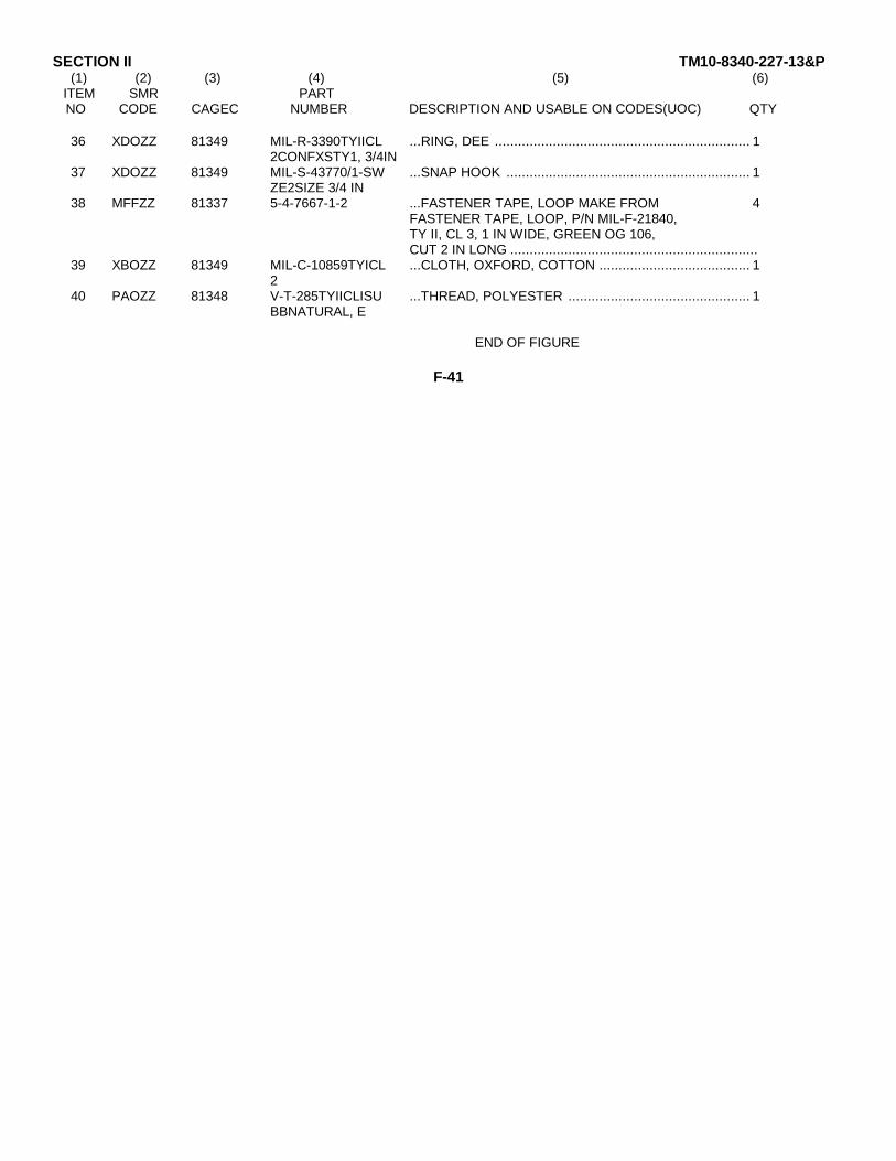
SECTION II TM10-8340-227-13&P(1) (2) (3) (4) (5) (6)
ITEM SMR PARTNO CODE CAGEC NUMBER DESCRIPTION AND USABLE ON CODES(UOC) QTY
36 XDOZZ 81349 MIL-R-3390TYIICL ...RING, DEE .................................................................. 12CONFXSTY1, 3/4IN
37 XDOZZ 81349 MIL-S-43770/1-SW ...SNAP HOOK ............................................................... 1ZE2SIZE 3/4 IN
38 MFFZZ 81337 5-4-7667-1-2 ...FASTENER TAPE, LOOP MAKE FROM 4FASTENER TAPE, LOOP, P/N MIL-F-21840,TY II, CL 3, 1 IN WIDE, GREEN OG 106,CUT 2 IN LONG ................................................................
39 XBOZZ 81349 MIL-C-10859TYICL ...CLOTH, OXFORD, COTTON ....................................... 12
40 PAOZZ 81348 V-T-285TYIICLISU ...THREAD, POLYESTER ............................................... 1BBNATURAL, E
END OF FIGURE
F-41
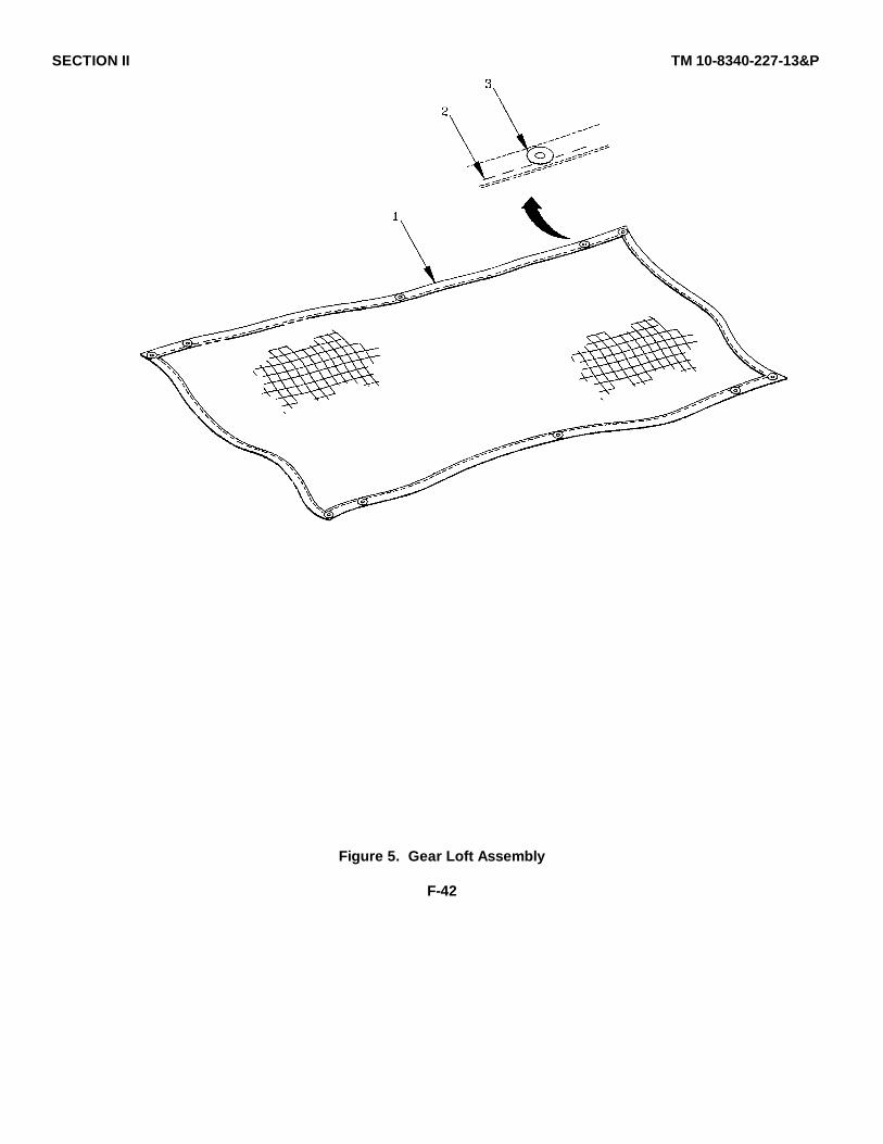
SECTION II TM 10-8340-227-13&P
Figure 5. Gear Loft Assembly
F-42
SECTION II TM10-8340-227-13&P(1) (2) (3) (4) (5) (6)
ITEM SMR PARTNO CODE CAGEC NUMBER DESCRIPTION AND USABLE ON CODES(UOC) QTY
GROUP 05 GEAR LOFT ASSEMBLY
FIG. 5 GEAR LOFT ASSEMBLY
1 PAOZZ 81337 5-4-7646-1 GEAR LOFT ASSEMBLY ................................ ................ 12 PAOZZ 81348 V-T-28STYIICL1SU .THREAD, POLYESTER ................................ ................. 1
BBCAMOGRN483, E3 PAOZZ 81349 MILG16491TYPE3CL .GROMMET, METALLIC, SP BRASS WITH 10
ASS3SIZE0 BLACK CHEMICAL FINISH ................................ ..............
END OF FIGURE
F-43
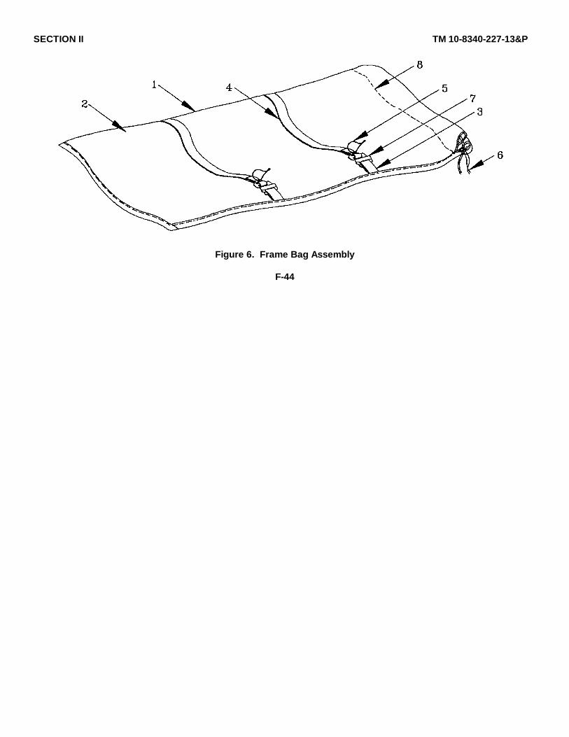
SECTION II TM 10-8340-227-13&P
Figure 6. Frame Bag Assembly
F-44
SECTION II TM10-8340-227-13&P(1) (2) (3) (4) (5) (6)
ITEM SMR PARTNO CODE CAGEC NUMBER DESCRIPTION AND USABLE ON CODES(UOC) QTY
GROUP 06 FRAME BAG ASSEMBLY
FIG. 6 FRAME BAG ASSEMBLY
1 XDOOO 81337 5-4-7604-1 BAG ASSY, FRAME................................ ........................ 12 XBOZZ 81337 5-4-7604-1-1 .CLOTH, COATED................................ ........................... 13 MFFZZ 81337 5-4-7604-1-2 .WEBBING, TEXTILE MAKE FROM WEBBING, 2
TEXTILE, P/N MIL-W-4088, TY XVII, CL 2,1 IN WIDE, CAMO GREEN 483, CUT 3INLONG................................ ................................ ................
4 MFFZZ 81337 5-4-7604-1-3 .WEBBING, TEXTILE MAKE FROM WEBBING, 2TEXTILE:P/N MIL-W-4088, TY XVII, CL 2,1 IN WIDE, CAMO GREEN 483, CUT 18-1/4IN LONG ................................ ................................ ...........
5 MFFZZ 81337 5-4-7604-1-4 .CORD, FIBROUS, POLYES MAKE FROM 2CORD, FIBROUS, POLYESTER, P/N MIL-C-43256, DIAMETER 1/8 IN, CAMO GREEN483, CUT 14 IN LONG................................ .......................
6 MFFZZ 81337 5-4-7604-1-5 .CORD, FIBROUS, POLYES MAKE FROM 1CORD, FIBROUS, POLYESTER, P/N MIL-C-43256, DIAME1ER 1/8 IN, CAMO GREEN483, CUT 36 IN LONG................................ .......................
7 XDFZZ 81349 MIL-B-543TYVCL3S .BUCKLE, QUICK RELEAS ................................ ............. 2IZE 1 IN
8 PAOZZ 81348 V-T-285TYIICLISU .THREAD, POLYESTER ................................ ................. 1BBCAMOGRN483, E
END OF FIGURE
F-45
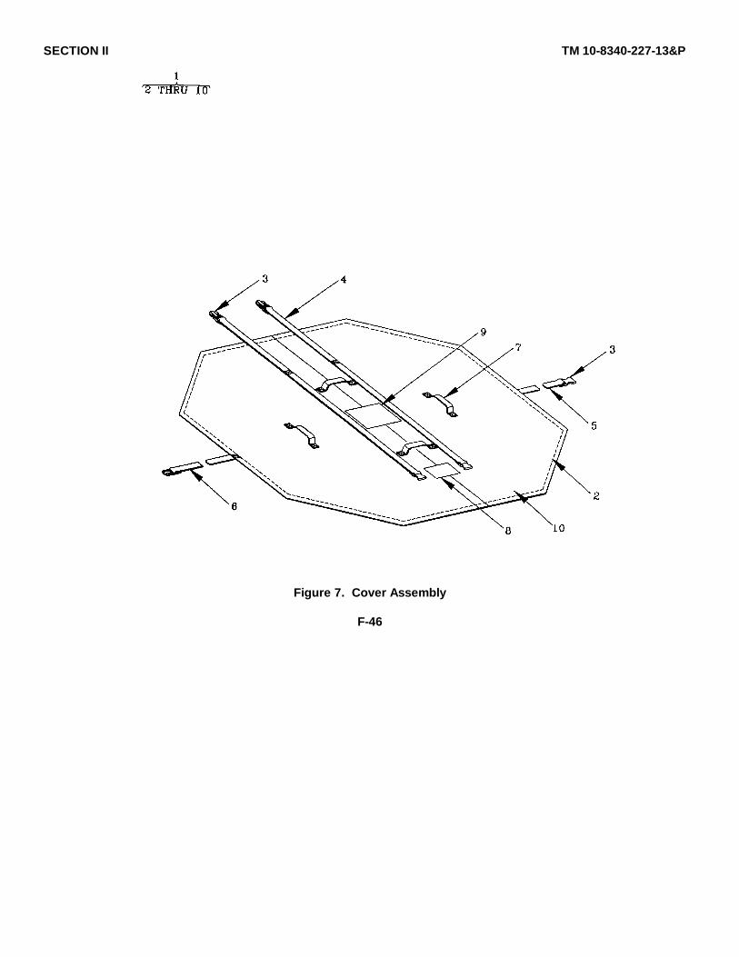
SECTION II TM 10-8340-227-13&P
Figure 7. Cover Assembly
F-46
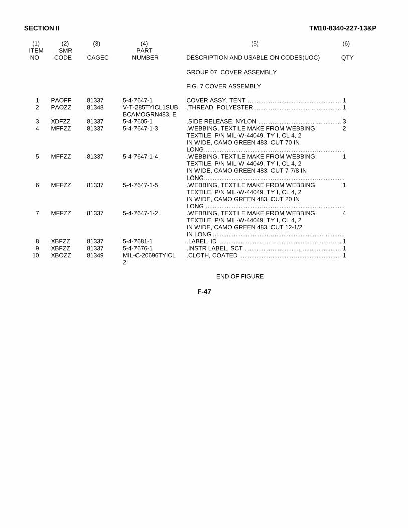
SECTION II TM10-8340-227-13&P
(1) (2) (3) (4) (5) (6)ITEM SMR PARTNO CODE CAGEC NUMBER DESCRIPTION AND USABLE ON CODES(UOC) QTY
GROUP 07 COVER ASSEMBLY
FIG. 7 COVER ASSEMBLY
1 PAOFF 81337 5-4-7647-1 COVER ASSY, TENT ................................ ..................... 12 PAOZZ 81348 V-T-285TYICL1SUB .THREAD, POLYESTER ................................ ................. 1
BCAMOGRN483, E3 XDFZZ 81337 5-4-7605-1 .SIDE RELEASE, NYLON ................................ ............... 34 MFFZZ 81337 5-4-7647-1-3 .WEBBING, TEXTILE MAKE FROM WEBBING, 2
TEXTILE, P/N MIL-W-44049, TY I, CL 4, 2IN WIDE, CAMO GREEN 483, CUT 70 INLONG................................ ................................ ................
5 MFFZZ 81337 5-4-7647-1-4 .WEBBING, TEXTILE MAKE FROM WEBBING, 1TEXTILE, P/N MIL-W-44049, TY I, CL 4, 2IN WIDE, CAMO GREEN 483, CUT 7-7/8 INLONG................................ ................................ ................
6 MFFZZ 81337 5-4-7647-1-5 .WEBBING, TEXTILE MAKE FROM WEBBING, 1TEXTILE, P/N MIL-W-44049, TY I, CL 4, 2IN WIDE, CAMO GREEN 483, CUT 20 INLONG ................................ ................................ ...............
7 MFFZZ 81337 5-4-7647-1-2 .WEBBING, TEXTILE MAKE FROM WEBBING, 4TEXTILE, P/N MIL-W-44049, TY I, CL 4, 2IN WIDE, CAMO GREEN 483, CUT 12-1/2IN LONG ................................ ................................ ...........
8 XBFZZ 81337 5-4-7681-1 .LABEL, ID ................................ ................................ ..... 19 XBFZZ 81337 5-4-7676-1 .INSTR LABEL, SCT ................................ ....................... 1
10 XBOZZ 81349 MIL-C-20696TYICL .CLOTH, COATED ................................ .......................... 12
END OF FIGURE
F-47
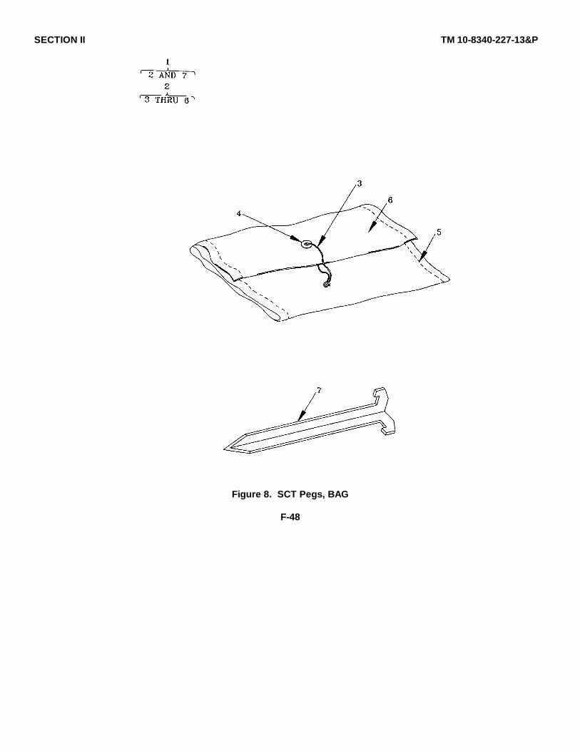
SECTION II TM 10-8340-227-13&P
Figure 8. SCT Pegs, BAG
F-48

SECTION II TM10-8340-227-13&P
(1) (2) (3) (4) (5) (6)ITEM SMR PARTNO CODE CAGEC NUMBER DESCRIPTION AND USABLE ON CODES(UOC) QTY
GROUP 08 PEGS, BAG
FIG. 8 PEGS, BAG
1 XDOZZ 81337 5-4-7678-1 SCT PEGS, BAG&CONTEN ................................ ........... 12 XDOZZ 81337 5-4-7679-1 .PARTS BAG, COMMON, SC ................................ ......... 13 MFFZZ 81337 5-4-7679-1-3 ..CORD, FIBROUS, POLYES MAKE FROM 1
CORD, FIBROUS, POLYESTER, P/N MIL-C-43256, DIAMETER 1/8 IN, CAMO GREEN483, CUT 14 IN LONG................................ .......................
4 PAOZZ 81349 MILG16491TYPE3CL ..GROMMET, METALLIC, SP ................................ ......... 1ASS3SIZEO
5 PAOZZ 81348 V-T-285TYIICL1SU ..THREAD, POLYESTER ................................ ................ 1BBCAMOGRN483, E
6 XBOZZ 81349 MIL-C-20696TYICL ..CLOTH, COATED ................................ ......................... 12
7 PAOZZ 81349 MIL-P-501TYI .PINS, TENT, TYPE I ................................ .................... 10
END OF FIGURE
F-49/(F-50 blank)

SECTION II TM 10-8340-227-13&P
Figure 9. Repair Kit Contents (Sheet 1 of 2)
F-51
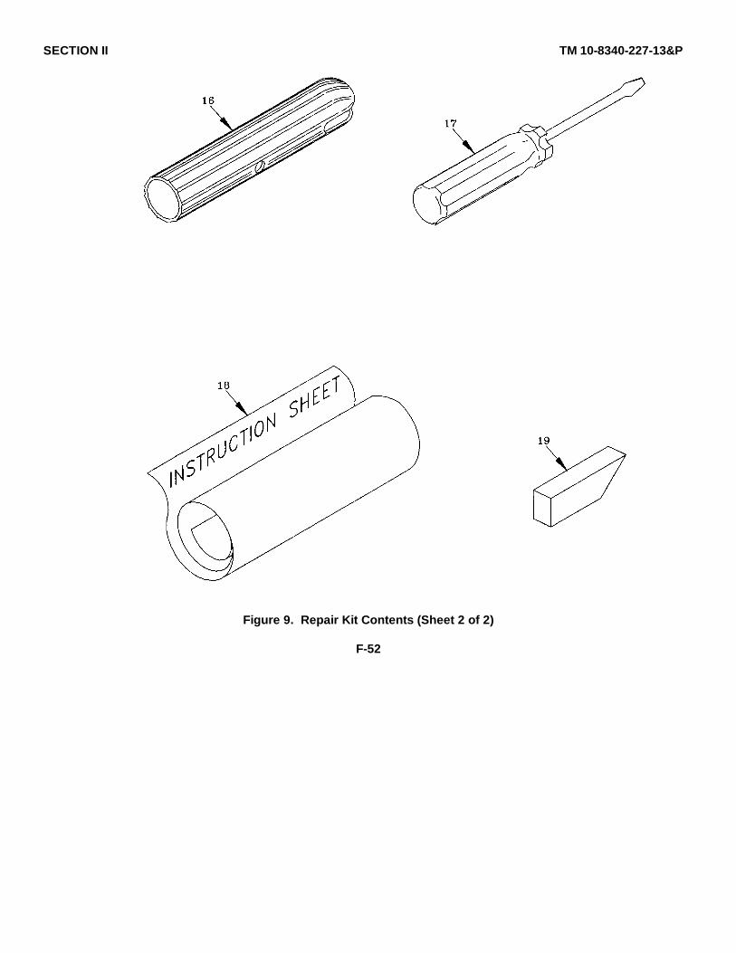
SECTION II TM 10-8340-227-13&P
Figure 9. Repair Kit Contents (Sheet 2 of 2)
F-52

SECTION II TM10-8340-227-13&P
(1) (2) (3) (4) (5) (6)ITEM SMR PARTNO CODE CAGEC NUMBER DESCRIPTION AND USABLE ON CODES(UOC) QTY
GROUP 9 REPAIR KIT
FIG. 9 REPAIR KIT
1 XCOZZ 81337 5-4-7683-1 REPAIR KIT CONTENTS ................................................ 12 XDOZZ 81337 5-4-7685-1 .SEWING AWL ............................................................... 13 PAOZZ 81337 5-4-7688-1 .K-TAPE, REPAIR ...................... .................................... 14 MOOZZ 81349 MIL-C-44423CL1 .CLOTH, COATED MAKE FROM CLOTH, V
COATED, FLAME RESISTANT, P/N MIL-C-44423, CL 1, 9 IN WIDE X 18 IN LONG...
5 MOOZZ 81349 MIL-C-44423CL2 .CLOTH, COATED MAKE FROM CLOTH, VCOATED, FLAME RESISTANT, P/N MIL-C-44423, CL 2, 9 IN WIDE X 18 IN LONG...UOC: FGW
6 MOOZZ 81349 MIL-C-44423CL3 .CLOTH, COATED MAKE FROM CLOTH, VCOATED, FLAME RESISTANT, P/N MIL-C-44423, CL3, 9 IN WIDE X 19 IN LONG.......................... ....UOC: :FGX
7 MOOZZ 81349 MIL-F-21840TYIIC FASTENER TAPE, HOOK MAKE FROM 1L3 FASTENER TAPE, HOOK, P/N MIL-F-21840,
TY II, CL 3, 1 IN WIDE, CAMO GREEN 483,CUT 18 IN ........................................................................ .
8 MOOZZ 81349 MIL-F-21840TYIIC FASTENER TAPE, LOOP MAKE FROM 1L3 FASTENER TAPE, LOOP, P/N MIL-F-21840,
TY II, CL 3, 1 IN WIDE, CAMO GREEN 483,CUT 18 IN. ........................................................................
9 MOOZZ 81349 MIL-F-21840TYIIC FASTENER TAPE, HOOK MAKE FROM 1L3 FASTENER TAPE, HOOK, P/N MIL-F-21840,
TY II, CL 3, 2 IN WIDE, CAMO GREEN 483,CUT 12 IN. ........................................................................
10 MOOZZ 81349 MIL-F-21840TYIIC FASTENER TAPE, LOOP MAKE FROM 1L3 FASTENER TAPE, LOOP, P/N MIL-F-21840,
TY II, CL 3, 2 IN WIDE, CAMO GREEN 483,CUT 12 IN........................... ..............................................
11 PCOZZ OR6NI 83-234C SEAM SEALER ........................ ...................................... 212 MOOZZ 81349 A-A-50057 .ROPE, FIBROUS MAKE FROM ROPE, ........................ 1
MANILA, TENT LAY, TYPE I, CLASS 2, 1/4IN DIA, CUT 5 1/2 IN LONG............ ..................................
13 PAOZZ 96906 MS51958-59 .SCREW, MACHINE ............................. .......................... 414 PAOZZ 81337 5-4-7589-1 .PIN, FRAME................................................................... 815 PAOZZ 81337 5-4-7599-1 .RING, SPLIT ......................... ........................................ 816 XDOZZ 81337 5-4-7591-1 .SLEEVE, FRAME, JOINT ................... ........................... 217 PAOZZ 81337 5-4-7683-17 .SCREWDRIVER, COMMON .......................................... 118 XCOZZ 81337 5-4-7674-1 .INSTRUCTION LABEL, R ................ .............................. 119 PAOZZ 96980 ZIPPEREASE .LUBRICANT, INTERLOCK ............................................. 1
END OF FIGURE
F-53/(F-54 blank)

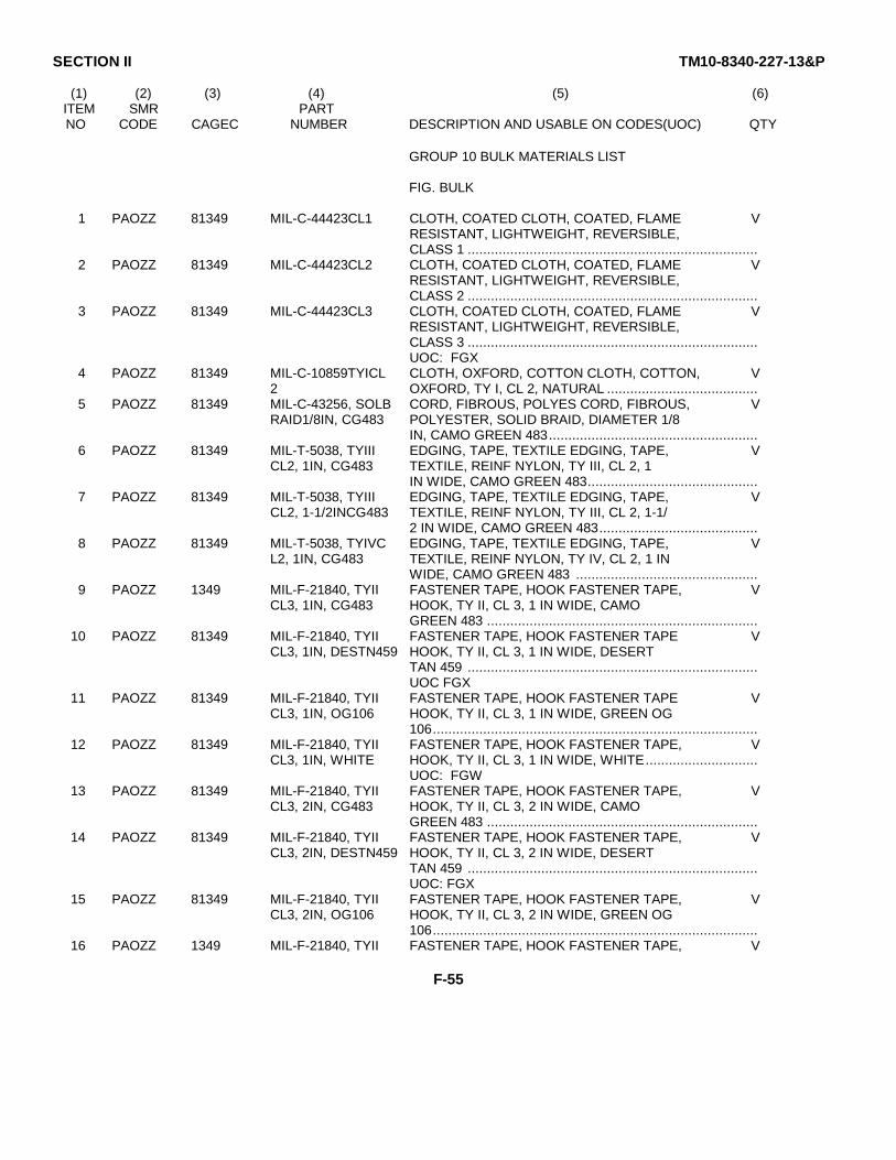
SECTION II TM10-8340-227-13&P
(1) (2) (3) (4) (5) (6)ITEM SMR PARTNO CODE CAGEC NUMBER DESCRIPTION AND USABLE ON CODES(UOC) QTY
GROUP 10 BULK MATERIALS LIST
FIG. BULK
1 PAOZZ 81349 MIL-C-44423CL1 CLOTH, COATED CLOTH, COATED, FLAME VRESISTANT, LIGHTWEIGHT, REVERSIBLE,CLASS 1 ...........................................................................
2 PAOZZ 81349 MIL-C-44423CL2 CLOTH, COATED CLOTH, COATED, FLAME VRESISTANT, LIGHTWEIGHT, REVERSIBLE,CLASS 2 ...........................................................................
3 PAOZZ 81349 MIL-C-44423CL3 CLOTH, COATED CLOTH, COATED, FLAME VRESISTANT, LIGHTWEIGHT, REVERSIBLE,CLASS 3 ...........................................................................UOC: FGX
4 PAOZZ 81349 MIL-C-10859TYICL CLOTH, OXFORD, COTTON CLOTH, COTTON, V2 OXFORD, TY I, CL 2, NATURAL .......................................
5 PAOZZ 81349 MIL-C-43256, SOLB CORD, FIBROUS, POLYES CORD, FIBROUS, VRAID1/8IN, CG483 POLYESTER, SOLID BRAID, DIAMETER 1/8
IN, CAMO GREEN 483......................................................6 PAOZZ 81349 MIL-T-5038, TYIII EDGING, TAPE, TEXTILE EDGING, TAPE, V
CL2, 1IN, CG483 TEXTILE, REINF NYLON, TY III, CL 2, 1IN WIDE, CAMO GREEN 483............................................
7 PAOZZ 81349 MIL-T-5038, TYIII EDGING, TAPE, TEXTILE EDGING, TAPE, VCL2, 1-1/2INCG483 TEXTILE, REINF NYLON, TY III, CL 2, 1-1/
2 IN WIDE, CAMO GREEN 483.........................................8 PAOZZ 81349 MIL-T-5038, TYIVC EDGING, TAPE, TEXTILE EDGING, TAPE, V
L2, 1IN, CG483 TEXTILE, REINF NYLON, TY IV, CL 2, 1 INWIDE, CAMO GREEN 483 ...............................................
9 PAOZZ 1349 MIL-F-21840, TYII FASTENER TAPE, HOOK FASTENER TAPE, VCL3, 1IN, CG483 HOOK, TY II, CL 3, 1 IN WIDE, CAMO
GREEN 483 ......................................................................10 PAOZZ 81349 MIL-F-21840, TYII FASTENER TAPE, HOOK FASTENER TAPE V
CL3, 1IN, DESTN459 HOOK, TY II, CL 3, 1 IN WIDE, DESERTTAN 459 ...........................................................................UOC FGX
11 PAOZZ 81349 MIL-F-21840, TYII FASTENER TAPE, HOOK FASTENER TAPE VCL3, 1IN, OG106 HOOK, TY II, CL 3, 1 IN WIDE, GREEN OG
106....................................................................................12 PAOZZ 81349 MIL-F-21840, TYII FASTENER TAPE, HOOK FASTENER TAPE, V
CL3, 1IN, WHITE HOOK, TY II, CL 3, 1 IN WIDE, WHITE.............................UOC: FGW
13 PAOZZ 81349 MIL-F-21840, TYII FASTENER TAPE, HOOK FASTENER TAPE, VCL3, 2IN, CG483 HOOK, TY II, CL 3, 2 IN WIDE, CAMO
GREEN 483 ......................................................................14 PAOZZ 81349 MIL-F-21840, TYII FASTENER TAPE, HOOK FASTENER TAPE, V
CL3, 2IN, DESTN459 HOOK, TY II, CL 3, 2 IN WIDE, DESERTTAN 459 ...........................................................................UOC: FGX
15 PAOZZ 81349 MIL-F-21840, TYII FASTENER TAPE, HOOK FASTENER TAPE, VCL3, 2IN, OG106 HOOK, TY II, CL 3, 2 IN WIDE, GREEN OG
106....................................................................................16 PAOZZ 1349 MIL-F-21840, TYII FASTENER TAPE, HOOK FASTENER TAPE, V
F-55
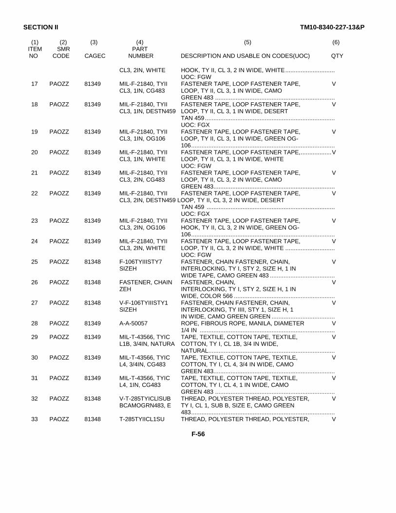
SECTION II TM10-8340-227-13&P
(1) (2) (3) (4) (5) (6)ITEM SMR PARTNO CODE CAGEC NUMBER DESCRIPTION AND USABLE ON CODES(UOC) QTY
CL3, 2IN, WHITE HOOK, TY II, CL 3, 2 IN WIDE, WHITE.............................UOC: FGW
17 PAOZZ 81349 MIL-F-21840, TYII FASTENER TAPE, LOOP FASTENER TAPE, VCL3, 1IN, CG483 LOOP, TY II, CL 3, 1 IN WIDE, CAMO
GREEN 483 ......................................................................18 PAOZZ 81349 MIL-F-21840, TYII FASTENER TAPE, LOOP FASTENER TAPE, V
CL3, 1IN, DESTN459 LOOP, TY II, CL 3, 1 IN WIDE, DESERTTAN 459 ............................................................................UOC: FGX
19 PAOZZ 81349 MIL-F-21840, TYII FASTENER TAPE, LOOP FASTENER TAPE, VCL3, 1IN, OG106 LOOP, TY II, CL 3, 1 IN WIDE, GREEN OG-
106....................................................................................20 PAOZZ 81349 MIL-F-21840, TYII FASTENER TAPE, LOOP FASTENER TAPE,..................V
CL3, 1IN, WHITE LOOP, TY II, CL 3, 1 IN WIDE, WHITEUOC: FGW
21 PAOZZ 81349 MIL-F-21840, TYII FASTENER TAPE, LOOP FASTENER TAPE, VCL3, 2IN, CG483 LOOP, TY II, CL 3, 2 IN WIDE, CAMO
GREEN 483.......................................................................22 PAOZZ 81349 MIL-F-21840, TYII FASTENER TAPE, LOOP FASTENER TAPE, V
CL3, 2IN, DESTN459 LOOP, TY II, CL 3, 2 IN WIDE, DESERTTAN 459 ...........................................................................UOC: FGX
23 PAOZZ 81349 MIL-F-21840, TYII FASTENER TAPE, LOOP FASTENER TAPE, VCL3, 2IN, OG106 HOOK, TY II, CL 3, 2 IN WIDE, GREEN OG-
106....................................................................................24 PAOZZ 81349 MIL-F-21840, TYII FASTENER TAPE, LOOP FASTENER TAPE, V
CL3, 2IN, WHITE LOOP, TY II, CL 3, 2 IN WIDE, WHITE .............................UOC: FGW
25 PAOZZ 81348 F-106TYIIISTY7 FASTENER, CHAIN FASTENER, CHAIN, VSIZEH INTERLOCKING, TY I, STY 2, SIZE H, 1 IN
WIDE TAPE, CAMO GREEN 483 ......................................26 PAOZZ 81348 FASTENER, CHAIN FASTENER, CHAIN, V
ZEH INTERLOCKING, TY I, STY 2, SIZE H, 1 INWIDE, COLOR 566 ...........................................................
27 PAOZZ 81348 V-F-106TYIIISTY1 FASTENER, CHAIN FASTENER, CHAIN, VSIZEH INTERLOCKING, TY IIII, STY 1, SIZE H, 1
IN WIDE, CAMO GREEN GREEN .....................................28 PAOZZ 81349 A-A-50057 ROPE, FIBROUS ROPE, MANILA, DIAMETER V
1/4 IN ...............................................................................29 PAOZZ 81349 MIL-T-43566, TYIC TAPE, TEXTILE, COTTON TAPE, TEXTILE, V
L1B, 3/4IN, NATURA COTTON, TY I, CL 1B, 3/4 IN WIDE,NATURAL..........................................................................
30 PAOZZ 81349 MIL-T-43566, TYIC TAPE, TEXTILE, COTTON TAPE, TEXTILE, VL4, 3/4IN, CG483 COTTON, TY I, CL 4, 3/4 IN WIDE, CAMO
GREEN 483.......................................................................31 PAOZZ 81349 MIL-T-43566, TYIC TAPE, TEXTILE, COTTON TAPE, TEXTILE, V
L4, 1IN, CG483 COTTON, TY I, CL 4, 1 IN WIDE, CAMOGREEN 483 ......................................................................
32 PAOZZ 81348 V-T-285TYICLlSUB THREAD, POLYESTER THREAD, POLYESTER, VBCAMOGRN483, E TY I, CL 1, SUB B, SIZE E, CAMO GREEN
483....................................................................................33 PAOZZ 81348 T-285TYIICL1SU THREAD, POLYESTER THREAD, POLYESTER, V
F-56
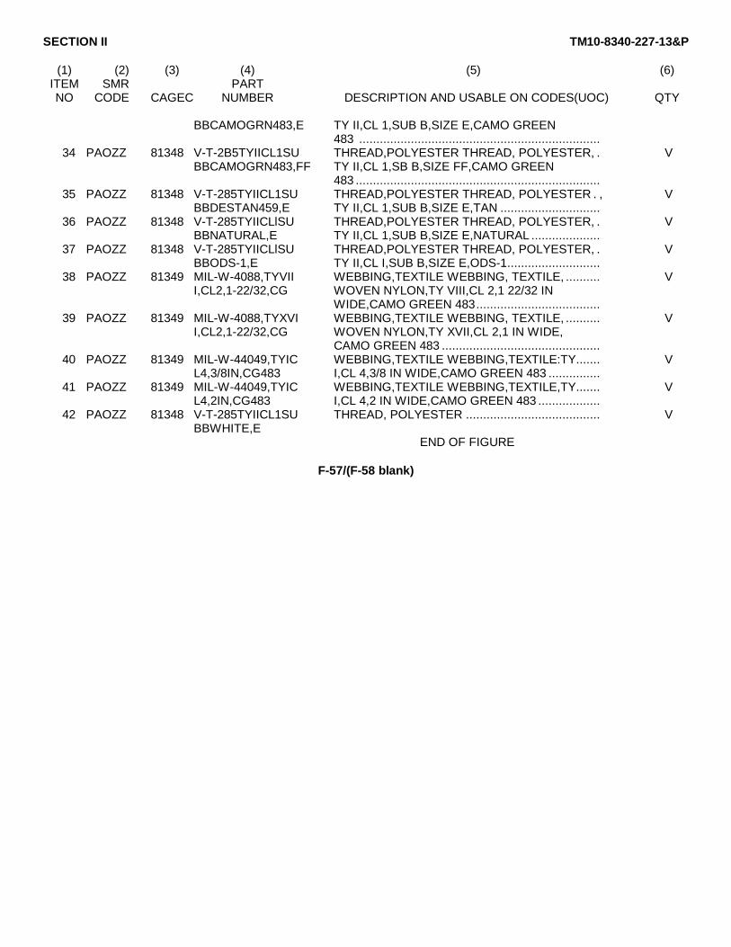
SECTION II TM10-8340-227-13&P
(1) (2) (3) (4) (5) (6)ITEM SMR PARTNO CODE CAGEC NUMBER DESCRIPTION AND USABLE ON CODES(UOC) QTY
BBCAMOGRN483,E TY II,CL 1,SUB B,SIZE E,CAMO GREEN483 ......................................................................
34 PAOZZ 81348 V-T-2B5TYIICL1SU THREAD,POLYESTER THREAD, POLYESTER, . VBBCAMOGRN483,FF TY II,CL 1,SB B,SIZE FF,CAMO GREEN
483 .......................................................................35 PAOZZ 81348 V-T-285TYIICL1SU THREAD,POLYESTER THREAD, POLYESTER . , V
BBDESTAN459,E TY II,CL 1,SUB B,SIZE E,TAN .............................36 PAOZZ 81348 V-T-285TYIICLlSU THREAD,POLYESTER THREAD, POLYESTER, . V
BBNATURAL,E TY II,CL 1,SUB B,SIZE E,NATURAL ....................37 PAOZZ 81348 V-T-285TYIICLlSU THREAD,POLYESTER THREAD, POLYESTER, . V
BBODS-1,E TY II,CL I,SUB B,SIZE E,ODS-1...........................38 PAOZZ 81349 MIL-W-4088,TYVII WEBBING,TEXTILE WEBBING, TEXTILE, .......... V
I,CL2,1-22/32,CG WOVEN NYLON,TY VIII,CL 2,1 22/32 INWIDE,CAMO GREEN 483....................................
39 PAOZZ 81349 MIL-W-4088,TYXVI WEBBING,TEXTILE WEBBING, TEXTILE, .......... VI,CL2,1-22/32,CG WOVEN NYLON,TY XVII,CL 2,1 IN WIDE,
CAMO GREEN 483 ..............................................40 PAOZZ 81349 MIL-W-44049,TYIC WEBBING,TEXTILE WEBBING,TEXTILE:TY....... V
L4,3/8IN,CG483 I,CL 4,3/8 IN WIDE,CAMO GREEN 483 ...............41 PAOZZ 81349 MIL-W-44049,TYIC WEBBING,TEXTILE WEBBING,TEXTILE,TY....... V
L4,2IN,CG483 I,CL 4,2 IN WIDE,CAMO GREEN 483 ..................42 PAOZZ 81348 V-T-285TYIICL1SU THREAD, POLYESTER ....................................... V
BBWHITE,EEND OF FIGURE
F-57/(F-58 blank)


SECTION III TM10-8340-227-13&P
SPECIAL TOOLS LIST
NOT APPLICABLE
F-59/(F-60 blank)


SECTION IV TM10-8340-227-13&P
CROSS-REFERENCE INDEXES
NATIONAL STOCK NUMBER INDEXSTOCK NUMBER FIG. ITEM STOCK NUMBER FIG. ITEM
5305-00-059-3655 1 79 13
5325-00-231-6622 2 972 1023 31
5325-00-641-0404 3 313 463 464 8
9150-00-999-7548 9 19
F-61
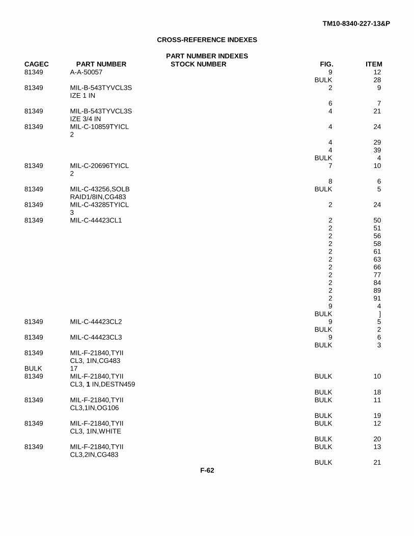
TM10-8340-227-13&P
CROSS-REFERENCE INDEXES
PART NUMBER INDEXESCAGEC PART NUMBER STOCK NUMBER FIG. ITEM81349 A-A-50057 9 12
BULK 2881349 MIL-B-543TYVCL3S 2 9
IZE 1 IN6 7
81349 MIL-B-543TYVCL3S 4 21IZE 3/4 IN
81349 MIL-C-10859TYICL 4 242
4 294 39
BULK 481349 MIL-C-20696TYICL 7 10
28 6
81349 MIL-C-43256,SOLB BULK 5RAID1/8IN,CG483
81349 MIL-C-43285TYICL 2 243
81349 MIL-C-44423CL1 2 502 512 562 582 612 632 662 772 842 892 919 4
BULK ]81349 MIL-C-44423CL2 9 5
BULK 281349 MIL-C-44423CL3 9 6
BULK 381349 MIL-F-21840,TYII
CL3, 1IN,CG483BULK 1781349 MIL-F-21840,TYII BULK 10
CL3, 1 IN,DESTN459BULK 18
81349 MIL-F-21840,TYII BULK 11CL3,1IN,OG106
BULK 1981349 MIL-F-21840,TYII BULK 12
CL3, 1IN,WHITEBULK 20
81349 MIL-F-21840,TYII BULK 13CL3,2IN,CG483
BULK 21F-62

TM10-8340-227-13&P
CROSS-REFERENCE INDEXES
PART NUMBER INDEXESCAGEC PART NUMBER STOCK NUMBER FIG. ITEM
81349 MIL-F-21840,TYII BULK 14CL3t2IN,DESTN459
BULK 2281349 MIL-F-21840,TYII BULK 15
CL3,2IN,OG106BULK 2381349 MIL-F-21840,TYII BULK 16
CL3,2IN,WHITEBULK 2481349 MIL-F-21840TYIIC 9 7
L39 89 99 10
81349 MIL-P-19834TYIST 1 9Y4,SIZE6
81349 MIL-P-501TYI 8 781349 MIL-R-3390TYIICL 2 96
2CONFXSIZEl-1/42 101
81349 MIL-R-3390TYIICL 4 162CONFXSTY1,3/4IN
4 274 324 36
81349 MIL-S-43002CONST 2 12RUCTION A OR B
3 233 23
81349 MIL-S-43770/1-SW 4 18ZE2SIZE 3/4 IN
4 3781349 MIL-S-43770/1-SW 2 31
ZE3SIZE 1 IN2 382 42
81349 MIL-S-46163TYIIG 1 8RADEN
81349 MIL-T-43566,TYIC BULK 29LIB,3/4IN,NATURA
81349 MIL-T-43566,TYIC BULK 31L4, 1 IN,CG483
81349 MIL-T-43566,TYIC BULK 30L4,3/4IN,CG483
81349 MIL-T-5038,TYIII BULK 7CL2,1-1/2INCG483
81349 MIL-T-5038,TYIII BULK 6CL2, 1IN,CG483
81349 MIL-T-5038,TYIVC BULK 8L2,1IN,CG483
81349 MIL-W-4088,TYVII BULK 38I,CL2,1-22/32,CG
F-63
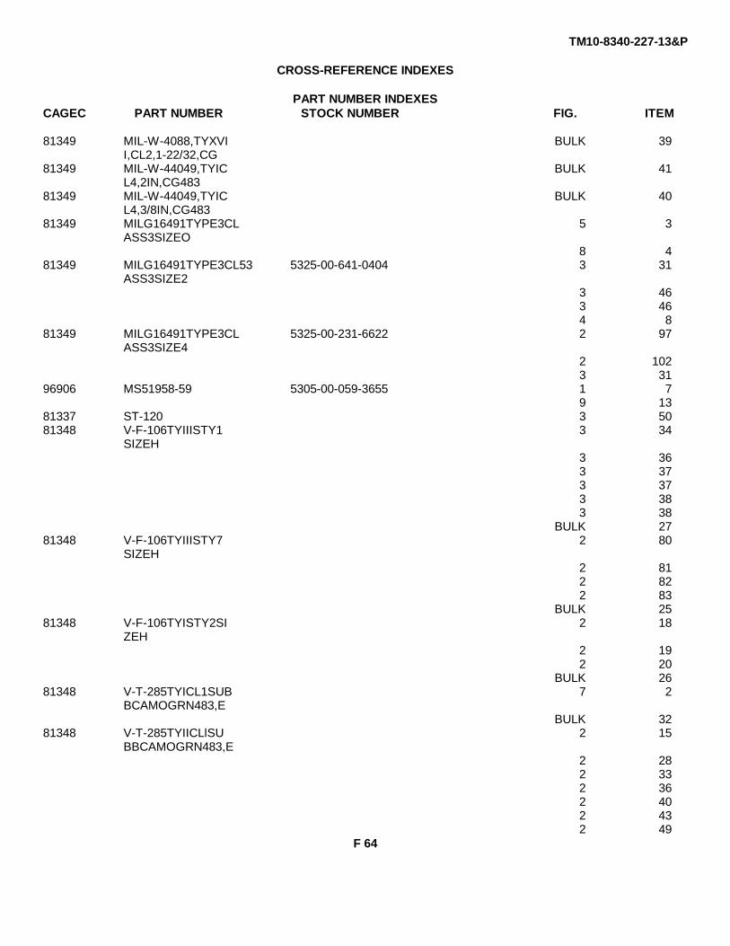
TM10-8340-227-13&P
CROSS-REFERENCE INDEXES
PART NUMBER INDEXESCAGEC PART NUMBER STOCK NUMBER FIG. ITEM
81349 MIL-W-4088,TYXVI BULK 39I,CL2,1-22/32,CG
81349 MIL-W-44049,TYIC BULK 41L4,2IN,CG483
81349 MIL-W-44049,TYIC BULK 40L4,3/8IN,CG483
81349 MILG16491TYPE3CL 5 3ASS3SIZEO
8 481349 MILG16491TYPE3CL53 5325-00-641-0404 3 31
ASS3SIZE23 463 464 8
81349 MILG16491TYPE3CL 5325-00-231-6622 2 97ASS3SIZE4
2 1023 31
96906 MS51958-59 5305-00-059-3655 1 79 13
81337 ST-120 3 5081348 V-F-106TYIIISTY1 3 34
SIZEH3 363 373 373 383 38
BULK 2781348 V-F-106TYIIISTY7 2 80
SIZEH2 812 822 83
BULK 2581348 V-F-106TYISTY2SI 2 18
ZEH2 192 20
BULK 2681348 V-T-285TYICL1SUB 7 2
BCAMOGRN483,EBULK 32
81348 V-T-285TYIICLlSU 2 15BBCAMOGRN483,E
2 282 332 362 402 432 49
F 64
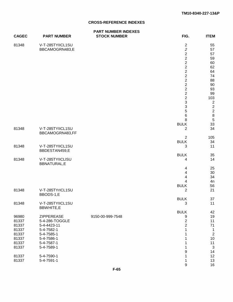
TM10-8340-227-13&P
CROSS-REFERENCE INDEXES
PART NUMBER INDEXESCAGEC PART NUMBER STOCK NUMBER FIG. ITEM
81348 V-T-285TYIICL1SU 2 55BBCAMOGRN483,E 2 57
2 572 592 602 622 642 742 882 902 932 992 1033 23 25 26 88 5
BULK 3381348 V-T-285TYIICL1SU 2 34
BBCAMOGRN483,FF2 105
BULK 3481348 V-T-285TYIICL1SU 3 11
BBDESTAN459,EBULK 35
81348 V-T-285TYIICLlSU 4 14BBNATURAL,E
4 254 304 344 4n
BULK S681348 V-T-285TYrICL1SU 2 21
BBODS-1,EBULK 37
81348 V-T-285TYIICL1SU 3 11BBWHITE,E
BULK 4296980 ZIPPEREASE 9150-00-999-7548 9 1981337 5-4-286-TOGGLE 2 1181337 5-4-4423-11 2 7181337 5-4-7582-1 1 181337 5-4-7585-1 1 281337 5-4-7586-1 1 1081337 5-4-7587-1 1 1181337 5-4-7589-1 1 3
9 1481337 5-4-7590-1 1 1281337 5-4-7591-1 1 13
9 16F-65

TM10-8340-227-13&P
CROSS-REFERENCE INDEXES
PART NUMBER INDEXESCAGEC PART NUMBER STOCK NUMBER FIG. ITEM
81337 5-4-7592-1 1 1681337 5-4-7592-2 1 1581337 5-4-7593-1 1 681337 5-4-7599-1 1 4
9 1581337 5-4-7601-1 1 1481337 5-4-7602-1 1 581337 5-4-7604-1 6 181337 5-4-7604-1-1 6 281337 5-4-7604-1-2 6 381337 5-4-7604-1-3 6 481337 5-4-7604-1-4 6 581337 5-4-7604-1-5 6 281337 5-4-7605-1 7 381337 5-4-7606-1 3 29
3 2981337 5-4-7606-1-1 3 30
3 3081337 5-4-7607 3 881337 5-4-7607-1 3 881337 5-4-7610-1 2 781337 5-4-7611-1 3 34
3 3481337 5-4-7613-1 2 181337 5-4-7613-12 2 1381337 5-4-7613-14 2 381337 5-4-7613-15 2 481337 5-4-7613-16 2 581337 5-4-7613-18 2 681337 5-4-7613-21 2 3281337 5-4-7613-24 2 1081337 5-4-7613-27 2 981337 5-4-7613-28 2 881337 5-4-7614-10 2 10681337 5-4-7614-15 2 10481337 5-4-7614-9 2 10781337 5-4-7616-1 2 3981337 5-4-7616-1-2 2 4181337 5-4-76136-2 2 3581337 5-4-7616-2-2 2 3781337 5-4-7617-1 2 9281337 5-4-7617-1-1 2 9481337 5-4-7617-2 2 9881337 5-4-7617-2-1 2 10081337 5-4-7618-1 2 1481337 5-4-7618-1-1 2 1681337 5-4-7620-2 2 2581337 5-4-7620-3 2 2381337 5-4-7620-4 2 2281337 5-4-7620-8 2 1781337 5-4-7623-10 2 75
F-66
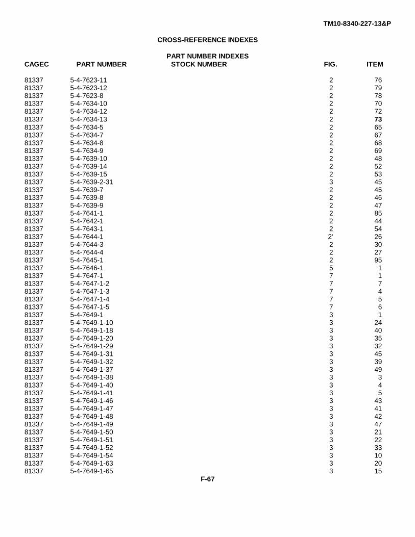
TM10-8340-227-13&P
CROSS-REFERENCE INDEXES
PART NUMBER INDEXESCAGEC PART NUMBER STOCK NUMBER FIG. ITEM
81337 5-4-7623-11 2 7681337 5-4-7623-12 2 7981337 5-4-7623-8 2 7881337 5-4-7634-10 2 7081337 5-4-7634-12 2 7281337 5-4-7634-13 2 7381337 5-4-7634-5 2 6581337 5-4-7634-7 2 6781337 5-4-7634-8 2 6881337 5-4-7634-9 2 6981337 5-4-7639-10 2 4881337 5-4-7639-14 2 5281337 5-4-7639-15 2 5381337 5-4-7639-2-31 3 4581337 5-4-7639-7 2 4581337 5-4-7639-8 2 4681337 5-4-7639-9 2 4781337 5-4-7641-1 2 8581337 5-4-7642-1 2 4481337 5-4-7643-1 2 5481337 5-4-7644-1 2' 2681337 5-4-7644-3 2 3081337 5-4-7644-4 2 2781337 5-4-7645-1 2 9581337 5-4-7646-1 5 181337 5-4-7647-1 7 181337 5-4-7647-1-2 7 781337 5-4-7647-1-3 7 481337 5-4-7647-1-4 7 581337 5-4-7647-1-5 7 681337 5-4-7649-1 3 181337 5-4-7649-1-10 3 2481337 5-4-7649-1-18 3 4081337 5-4-7649-1-20 3 3581337 5-4-7649-1-29 3 3281337 5-4-7649-1-31 3 4581337 5-4-7649-1-32 3 3981337 5-4-7649-1-37 3 4981337 5-4-7649-1-38 3 381337 5-4-7649-1-40 3 481337 5-4-7649-1-41 3 581337 5-4-7649-1-46 3 4381337 5-4-7649-1-47 3 4181337 5-4-7649-1-48 3 4281337 5-4-7649-1-49 3 4781337 5-4-7649-1-50 3 2181337 5-4-7649-1-51 3 2281337 5-4-7649-1-52 3 3381337 5-4-7649-1-54 3 1081337 5-4-7649-1-63 3 2081337 5-4-7649-1-65 3 15
F-67

TM10-8340-227-13&P
CROSS-REFERENCE INDEXES
PART NUMBER INDEXESCAGEC PART NUMBER STOCK NUMBER FIG. ITEM
81337 5-4-7649-1-66 3 1681337 5-4-7649-1-67 3 681337 5-4-7649-1-68 3 781337 5-4-7649-1-69 3 1381337 5-4-7649-1-70 3 1481337 5-4-7649-1-71 3 2781337 5-4-7649-1-72 3 2881337 5-4-7649-1-73 3 4481337 5-4-7649-1-74 3 4881337 5-4-7649-1-75 3 1781337 5-4-7649-1-76 3 1981337 5-4-7649-1-77 3 1881337 5-4-7649-1-78 3 2681337 5-4-7649-1-79 3 2581337 5-4-7649-1-80 3 1281337 5-4-7649-1-9 3 981337 5-4-7649-2 3 181337 5-4-7649-2-10 3 2481337 5-4-7649-2-18' 3 4081337 5-4-7649-2-20 3 3581337 5-4-7649-2-29 3 3281337 5-4-7649-2-32 3 3981337 5-4-7649-2-37 3 4981337 5-4-7649-2-38 3 381337 5-4-7649-2-40 3 481337 5-4-7649-2-41 3 581337 5-4-7649-2-46 3 4381337 5-4-7649-2-47 3 4181337 5-4-7649-2-48 3 4281337 5-4-7649-2-49 3 4781337 5-4-7649-2-50 3 2181337 5-4-7649-2-51 3 2281337 5-4-7649-2-52 3 3381337 5-4-7649-2-54 3 1081337 5-4-7649-2-63 3 2081337 5-4-7649-2-65 3 1581337 5-4-7649-2-66 3 1681337 5-4-7649-2-67 3 681337 5-4-7649-2-68 3 781337 5-4-7649-2-69 3 1381337 5-4-7649-2-70 3 1481337 5-4-7649-2-71 3 2781337 5-4-7649-2-72 3 2881337 5-4-7649-2-73 3 4481337 5-4-7649-2-74 3 4881337 5-4-7649-2-75 3 1781337 5-4-7649-2-76 3 1981337 5-4-7649-2-77 3 1881337 5-4-7649-2-78 3 2681337 5-4-7649-2-79 3 2581337 5-4-7649-2-80 3 12
Change 1 F-68
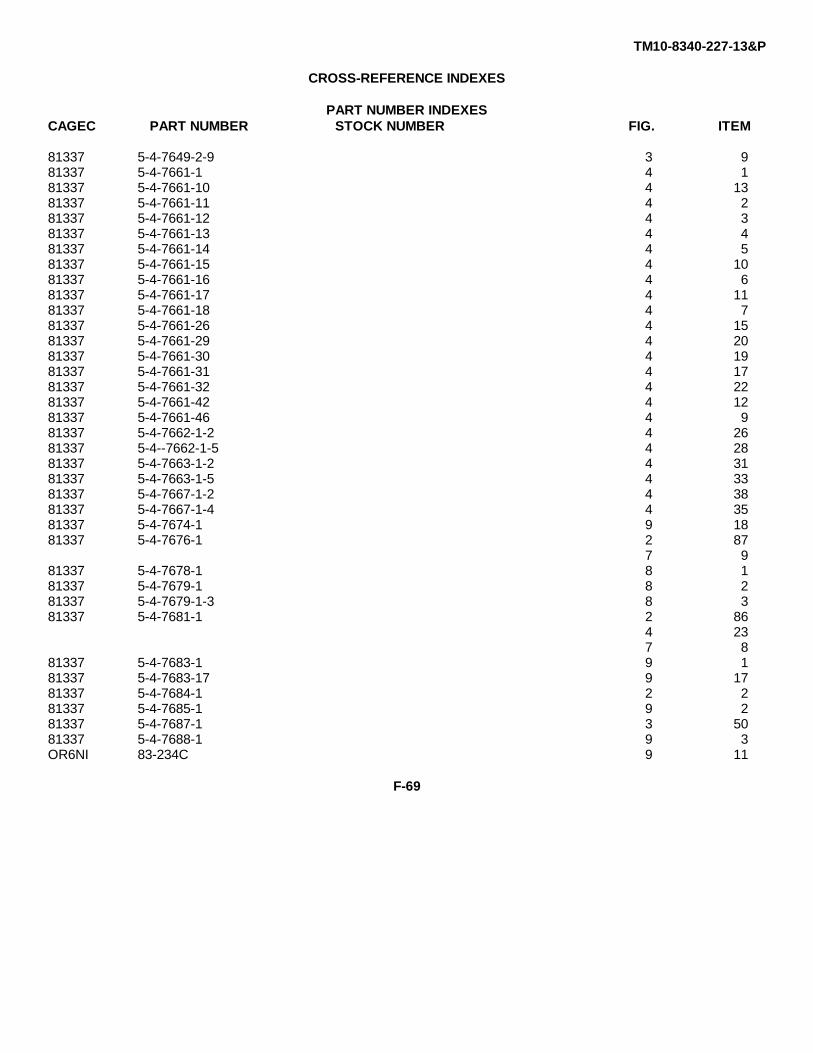
TM10-8340-227-13&P
CROSS-REFERENCE INDEXES
PART NUMBER INDEXESCAGEC PART NUMBER STOCK NUMBER FIG. ITEM
81337 5-4-7649-2-9 3 981337 5-4-7661-1 4 181337 5-4-7661-10 4 1381337 5-4-7661-11 4 281337 5-4-7661-12 4 381337 5-4-7661-13 4 481337 5-4-7661-14 4 581337 5-4-7661-15 4 1081337 5-4-7661-16 4 681337 5-4-7661-17 4 1181337 5-4-7661-18 4 781337 5-4-7661-26 4 1581337 5-4-7661-29 4 2081337 5-4-7661-30 4 1981337 5-4-7661-31 4 1781337 5-4-7661-32 4 2281337 5-4-7661-42 4 1281337 5-4-7661-46 4 981337 5-4-7662-1-2 4 2681337 5-4--7662-1-5 4 2881337 5-4-7663-1-2 4 3181337 5-4-7663-1-5 4 3381337 5-4-7667-1-2 4 3881337 5-4-7667-1-4 4 3581337 5-4-7674-1 9 1881337 5-4-7676-1 2 87
7 981337 5-4-7678-1 8 181337 5-4-7679-1 8 281337 5-4-7679-1-3 8 381337 5-4-7681-1 2 86
4 237 8
81337 5-4-7683-1 9 181337 5-4-7683-17 9 1781337 5-4-7684-1 2 281337 5-4-7685-1 9 281337 5-4-7687-1 3 5081337 5-4-7688-1 9 3OR6NI 83-234C 9 11
F-69
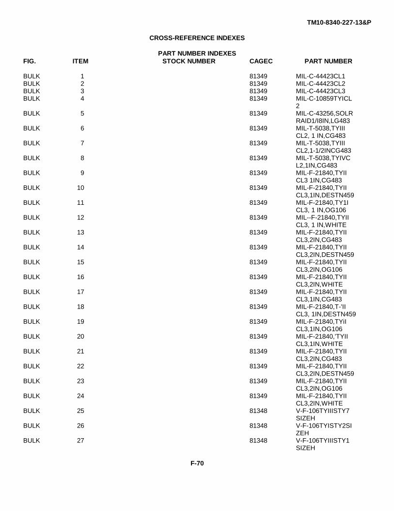
TM10-8340-227-13&P
CROSS-REFERENCE INDEXES
PART NUMBER INDEXESFIG. ITEM STOCK NUMBER CAGEC PART NUMBER
BULK 1 81349 MIL-C-44423CL1BULK 2 81349 MIL-C-44423CL2BULK 3 81349 MIL-C-44423CL3BULK 4 81349 MIL-C-10859TYICL
2BULK 5 81349 MIL-C-43256,SOLR
RAID1/I8IN,LG483BULK 6 81349 MIL-T-5038,TYIII
CL2, 1 IN,CG483BULK 7 81349 MIL-T-5038,TYIII
CL2,1-1/2INCG483BULK 8 81349 MIL-T-5038,TYIVC
L2,1IN,CG483BULK 9 81349 MIL-F-21840,TYII
CL3 1IN,CG483BULK 10 81349 MIL-F-21840,TYII
CL3,1IN,DESTN459BULK 11 81349 MIL-F-21840,TY1I
CL3, 1 IN,OG106BULK 12 81349 MIL--F-21840,TYII
CL3, 1 IN,WHITEBULK 13 81349 MIL-F-21840,TYII
CL3,2IN,CG483BULK 14 81349 MIL-F-21840,TYII
CL3,2IN,DESTN459BULK 15 81349 MIL-F-21840,TYII
CL3,2IN,OG106BULK 16 81349 MIL-F-21840,TYII
CL3,2IN,WHITEBULK 17 81349 MIL-F-21840,TYII
CL3,1IN,CG483BULK 18 81349 MIL-F-21840,T-'II
CL3, 1IN,DESTN459BULK 19 81349 MIL-F-21840,TYiI
CL3,1IN,OG106BULK 20 81349 MIL-F-21840,'TYII
CL3,1IN,WHITEBULK 21 81349 MIL-F-21840,TYII
CL3,2IN,CG483BULK 22 81349 MIL-F-21840,TYII
CL3,2IN,DESTN459BULK 23 81349 MIL-F-21840,TYII
CL3,2IN,OG106BULK 24 81349 MIL-F-21840,TYII
CL3,2IN,WHITEBULK 25 81348 V-F-106TYIIISTY7
SIZEHBULK 26 81348 V-F-106TYISTY2SI
ZEHBULK 27 81348 V-F-106TYIIISTY1
SIZEH
F-70
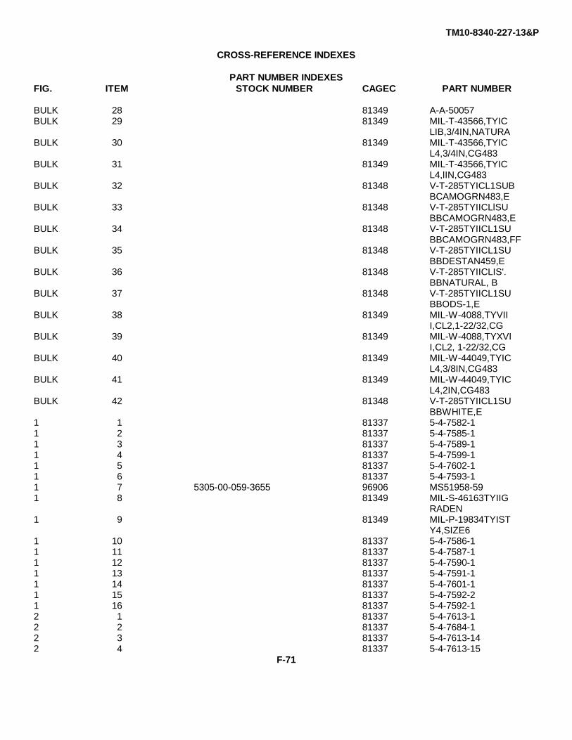
TM10-8340-227-13&P
CROSS-REFERENCE INDEXES
PART NUMBER INDEXESFIG. ITEM STOCK NUMBER CAGEC PART NUMBER
BULK 28 81349 A-A-50057BULK 29 81349 MIL-T-43566,TYIC
LIB,3/4IN,NATURABULK 30 81349 MIL-T-43566,TYIC
L4,3/4IN,CG483BULK 31 81349 MIL-T-43566,TYIC
L4,lIN,CG483BULK 32 81348 V-T-285TYICL1SUB
BCAMOGRN483,EBULK 33 81348 V-T-285TYIICLlSU
BBCAMOGRN483,EBULK 34 81348 V-T-285TYIICL1SU
BBCAMOGRN483,FFBULK 35 81348 V-T-285TYIICL1SU
BBDESTAN459,EBULK 36 81348 V-T-285TYIICLIS'.
BBNATURAL, BBULK 37 81348 V-T-285TYIICL1SU
BBODS-1,EBULK 38 81349 MIL-W-4088,TYVII
I,CL2,1-22/32,CGBULK 39 81349 MIL-W-4088,TYXVI
I,CL2, 1-22/32,CGBULK 40 81349 MIL-W-44049,TYIC
L4,3/8IN,CG483BULK 41 81349 MIL-W-44049,TYIC
L4,2IN,CG483BULK 42 81348 V-T-285TYIICL1SU
BBWHITE,E1 1 81337 5-4-7582-11 2 81337 5-4-7585-11 3 81337 5-4-7589-11 4 81337 5-4-7599-11 5 81337 5-4-7602-11 6 81337 5-4-7593-11 7 5305-00-059-3655 96906 MS51958-591 8 81349 MIL-S-46163TYIIG
RADEN1 9 81349 MIL-P-19834TYIST
Y4,SIZE61 10 81337 5-4-7586-11 11 81337 5-4-7587-11 12 81337 5-4-7590-11 13 81337 5-4-7591-11 14 81337 5-4-7601-11 15 81337 5-4-7592-21 16 81337 5-4-7592-12 1 81337 5-4-7613-12 2 81337 5-4-7684-12 3 81337 5-4-7613-142 4 81337 5-4-7613-15
F-71
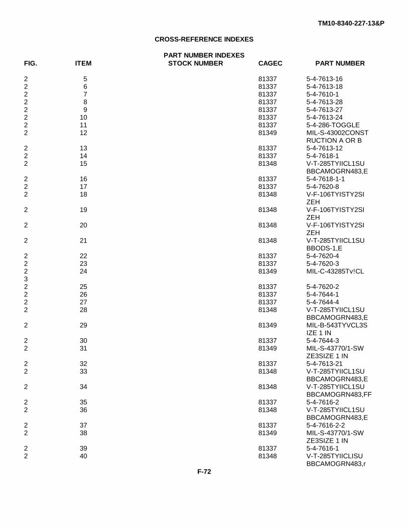
TM10-8340-227-13&P
CROSS-REFERENCE INDEXES
PART NUMBER INDEXESFIG. ITEM STOCK NUMBER CAGEC PART NUMBER
2 5 81337 5-4-7613-162 6 81337 5-4-7613-182 7 81337 5-4-7610-12 8 81337 5-4-7613-282 9 81337 5-4-7613-272 10 81337 5-4-7613-242 11 81337 5-4-286-TOGGLE2 12 81349 MIL-S-43002CONST
RUCTION A OR B2 13 81337 5-4-7613-122 14 81337 5-4-7618-12 15 81348 V-T-285TYIICL1SU
BBCAMOGRN483,E2 16 81337 5-4-7618-1-12 17 81337 5-4-7620-82 18 81348 V-F-106TYISTY2SI
ZEH2 19 81348 V-F-106TYISTY2SI
ZEH2 20 81348 V-F-106TYISTY2SI
ZEH2 21 81348 V-T-285TYIICL1SU
BBODS-1,E2 22 81337 5-4-7620-42 23 81337 5-4-7620-32 24 81349 MIL-C-43285Tv!CL32 25 81337 5-4-7620-22 26 81337 5-4-7644-12 27 81337 5-4-7644-42 28 81348 V-T-285TYIICL1SU
BBCAMOGRN483,E2 29 81349 MIL-B-543TYVCL3S
IZE 1 IN2 30 81337 5-4-7644-32 31 81349 MIL-S-43770/1-SW
ZE3SIZE 1 IN2 32 81337 5-4-7613-212 33 81348 V-T-285TYIICL1SU
BBCAMOGRN483,E2 34 81348 V-T-285TYIICL1SU
BBCAMOGRN483,FF2 35 81337 5-4-7616-22 36 81348 V-T-285TYIICL1SU
BBCAMOGRN483,E2 37 81337 5-4-7616-2-22 38 81349 MIL-S-43770/1-SW
ZE3SIZE 1 IN2 39 81337 5-4-7616-12 40 81348 V-T-285TYIICLISU
BBCAMOGRN483,rF-72
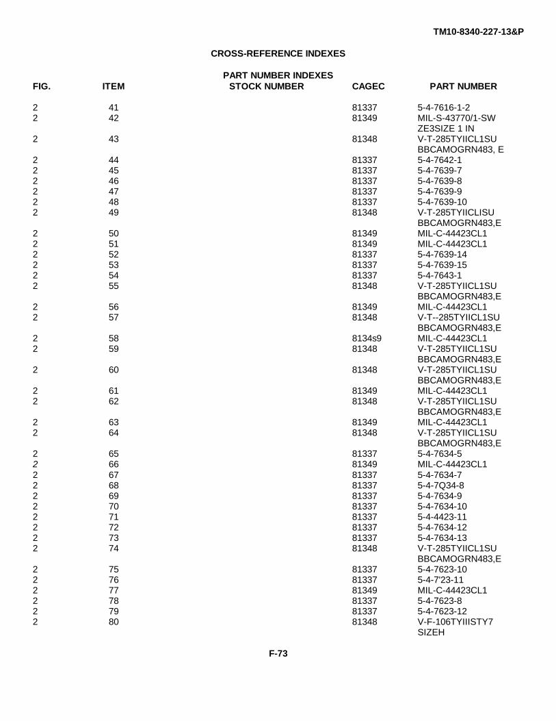
TM10-8340-227-13&P
CROSS-REFERENCE INDEXES
PART NUMBER INDEXESFIG. ITEM STOCK NUMBER CAGEC PART NUMBER
2 41 81337 5-4-7616-1-22 42 81349 MIL-S-43770/1-SW
ZE3SIZE 1 IN2 43 81348 V-T-285TYIICL1SU
BBCAMOGRN483, E2 44 81337 5-4-7642-12 45 81337 5-4-7639-72 46 81337 5-4-7639-82 47 81337 5-4-7639-92 48 81337 5-4-7639-102 49 81348 V-T-285TYIICLISU
BBCAMOGRN483,E2 50 81349 MIL-C-44423CL12 51 81349 MIL-C-44423CL12 52 81337 5-4-7639-142 53 81337 5-4-7639-152 54 81337 5-4-7643-12 55 81348 V-T-285TYIICL1SU
BBCAMOGRN483,E2 56 81349 MIL-C-44423CL12 57 81348 V-T--285TYIICL1SU
BBCAMOGRN483,E2 58 8134s9 MIL-C-44423CL12 59 81348 V-T-285TYIICL1SU
BBCAMOGRN483,E2 60 81348 V-T-285TYIICL1SU
BBCAMOGRN483,E2 61 81349 MIL-C-44423CL12 62 81348 V-T-285TYIICL1SU
BBCAMOGRN483,E2 63 81349 MIL-C-44423CL12 64 81348 V-T-285TYIICL1SU
BBCAMOGRN483,E2 65 81337 5-4-7634-52 66 81349 MIL-C-44423CL12 67 81337 5-4-7634-72 68 81337 5-4-7Q34-82 69 81337 5-4-7634-92 70 81337 5-4-7634-102 71 81337 5-4-4423-112 72 81337 5-4-7634-122 73 81337 5-4-7634-132 74 81348 V-T-285TYIICL1SU
BBCAMOGRN483,E2 75 81337 5-4-7623-102 76 81337 5-4-7'23-112 77 81349 MIL-C-44423CL12 78 81337 5-4-7623-82 79 81337 5-4-7623-122 80 81348 V-F-106TYIIISTY7
SIZEH
F-73
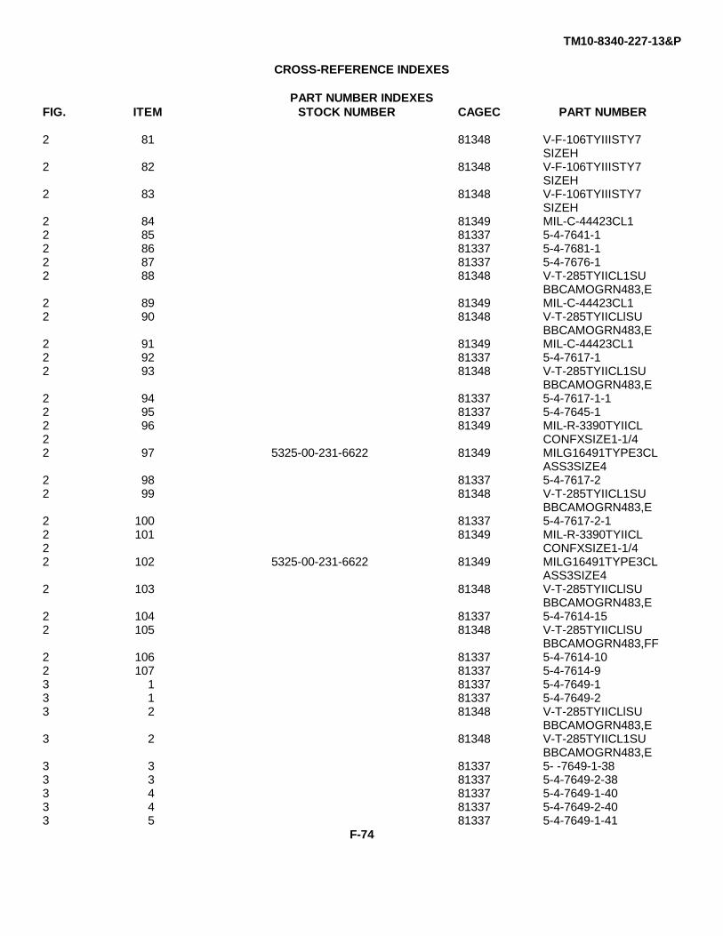
TM10-8340-227-13&P
CROSS-REFERENCE INDEXES
PART NUMBER INDEXESFIG. ITEM STOCK NUMBER CAGEC PART NUMBER
2 81 81348 V-F-106TYIIISTY7SIZEH
2 82 81348 V-F-106TYIIISTY7SIZEH
2 83 81348 V-F-106TYIIISTY7SIZEH
2 84 81349 MIL-C-44423CL12 85 81337 5-4-7641-12 86 81337 5-4-7681-12 87 81337 5-4-7676-12 88 81348 V-T-285TYIICL1SU
BBCAMOGRN483,E2 89 81349 MIL-C-44423CL12 90 81348 V-T-285TYIICLlSU
BBCAMOGRN483,E2 91 81349 MIL-C-44423CL12 92 81337 5-4-7617-12 93 81348 V-T-285TYIICL1SU
BBCAMOGRN483,E2 94 81337 5-4-7617-1-12 95 81337 5-4-7645-12 96 81349 MIL-R-3390TYIICL2 CONFXSIZE1-1/42 97 5325-00-231-6622 81349 MILG16491TYPE3CL
ASS3SIZE42 98 81337 5-4-7617-22 99 81348 V-T-285TYIICL1SU
BBCAMOGRN483,E2 100 81337 5-4-7617-2-12 101 81349 MIL-R-3390TYIICL2 CONFXSIZE1-1/42 102 5325-00-231-6622 81349 MILG16491TYPE3CL
ASS3SIZE42 103 81348 V-T-285TYIICLlSU
BBCAMOGRN483,E2 104 81337 5-4-7614-152 105 81348 V-T-285TYIICLlSU
BBCAMOGRN483,FF2 106 81337 5-4-7614-102 107 81337 5-4-7614-93 1 81337 5-4-7649-13 1 81337 5-4-7649-23 2 81348 V-T-285TYIICLlSU
BBCAMOGRN483,E3 2 81348 V-T-285TYIICL1SU
BBCAMOGRN483,E3 3 81337 5- -7649-1-383 3 81337 5-4-7649-2-383 4 81337 5-4-7649-1-403 4 81337 5-4-7649-2-403 5 81337 5-4-7649-1-41
F-74
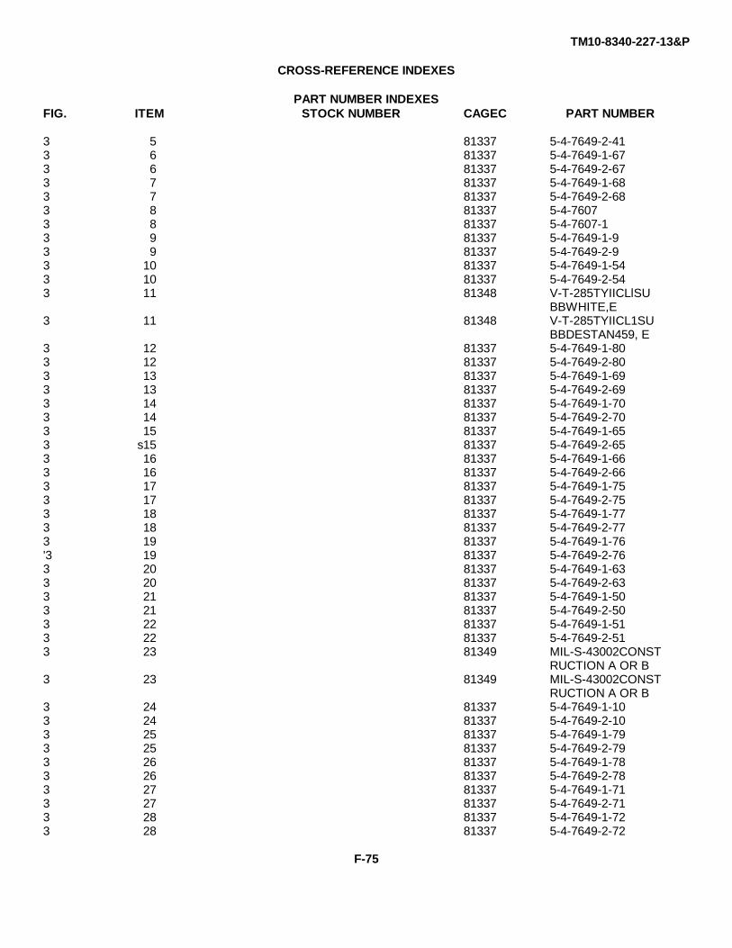
TM10-8340-227-13&P
CROSS-REFERENCE INDEXES
PART NUMBER INDEXESFIG. ITEM STOCK NUMBER CAGEC PART NUMBER
3 5 81337 5-4-7649-2-413 6 81337 5-4-7649-1-673 6 81337 5-4-7649-2-673 7 81337 5-4-7649-1-683 7 81337 5-4-7649-2-683 8 81337 5-4-76073 8 81337 5-4-7607-13 9 81337 5-4-7649-1-93 9 81337 5-4-7649-2-93 10 81337 5-4-7649-1-543 10 81337 5-4-7649-2-543 11 81348 V-T-285TYIICLlSU
BBWHITE,E3 11 81348 V-T-285TYIICL1SU
BBDESTAN459, E3 12 81337 5-4-7649-1-803 12 81337 5-4-7649-2-803 13 81337 5-4-7649-1-693 13 81337 5-4-7649-2-693 14 81337 5-4-7649-1-703 14 81337 5-4-7649-2-703 15 81337 5-4-7649-1-653 s15 81337 5-4-7649-2-653 16 81337 5-4-7649-1-663 16 81337 5-4-7649-2-663 17 81337 5-4-7649-1-753 17 81337 5-4-7649-2-753 18 81337 5-4-7649-1-773 18 81337 5-4-7649-2-773 19 81337 5-4-7649-1-76'3 19 81337 5-4-7649-2-763 20 81337 5-4-7649-1-633 20 81337 5-4-7649-2-633 21 81337 5-4-7649-1-503 21 81337 5-4-7649-2-503 22 81337 5-4-7649-1-513 22 81337 5-4-7649-2-513 23 81349 MIL-S-43002CONST
RUCTION A OR B3 23 81349 MIL-S-43002CONST
RUCTION A OR B3 24 81337 5-4-7649-1-103 24 81337 5-4-7649-2-103 25 81337 5-4-7649-1-793 25 81337 5-4-7649-2-793 26 81337 5-4-7649-1-783 26 81337 5-4-7649-2-783 27 81337 5-4-7649-1-713 27 81337 5-4-7649-2-713 28 81337 5-4-7649-1-723 28 81337 5-4-7649-2-72
F-75
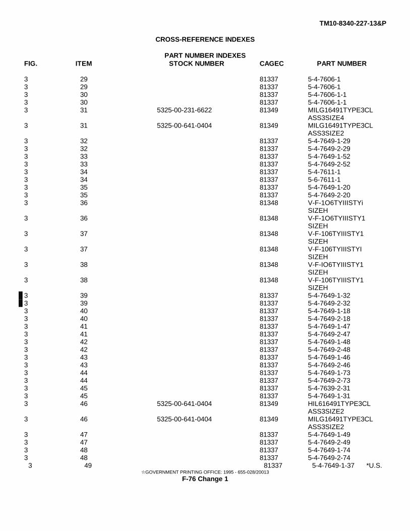
TM10-8340-227-13&P
CROSS-REFERENCE INDEXES
PART NUMBER INDEXESFIG. ITEM STOCK NUMBER CAGEC PART NUMBER
3 29 81337 5-4-7606-13 29 81337 5-4-7606-13 30 81337 5-4-7606-1-13 30 81337 5-4-7606-1-13 31 5325-00-231-6622 81349 MILG16491TYPE3CL
ASS3SIZE43 31 5325-00-641-0404 81349 MILG16491TYPE3CL
ASS3SIZE23 32 81337 5-4-7649-1-293 32 81337 5-4-7649-2-293 33 81337 5-4-7649-1-523 33 81337 5-4-7649-2-523 34 81337 5-4-7611-13 34 81337 5-6-7611-13 35 81337 5-4-7649-1-203 35 81337 5-4-7649-2-203 36 81348 V-F-1O6TYIIISTYi
SIZEH3 36 81348 V-F-1O6TYIIISTY1
SIZEH3 37 81348 V-F-106TYIIISTY1
SIZEH3 37 81348 V-F-106TYIIISTYI
SIZEH3 38 81348 V-F-IO6TYIIISTY1
SIZEH3 38 81348 V-F-106TYIIISTY1
SIZEH3 39 81337 5-4-7649-1-323 39 81337 5-4-7649-2-323 40 81337 5-4-7649-1-183 40 81337 5-4-7649-2-183 41 81337 5-4-7649-1-473 41 81337 5-4-7649-2-473 42 81337 5-4-7649-1-483 42 81337 5-4-7649-2-483 43 81337 5-4-7649-1-463 43 81337 5-4-7649-2-463 44 81337 5-4-7649-1-733 44 81337 5-4-7649-2-733 45 81337 5-4-7639-2-313 45 81337 5-4-7649-1-313 46 5325-00-641-0404 81349 HIL616491TYPE3CL
ASS3SIZE23 46 5325-00-641-0404 81349 MILG16491TYPE3CL
ASS3SIZE23 47 81337 5-4-7649-1-493 47 81337 5-4-7649-2-493 48 81337 5-4-7649-1-743 48 81337 5-4-7649-2-74
3 49 81337 5-4-7649-1-37 *U.S.GOVERNMENT PRINTING OFFICE: 1995 - 655-028/20013
F-76 Change 1
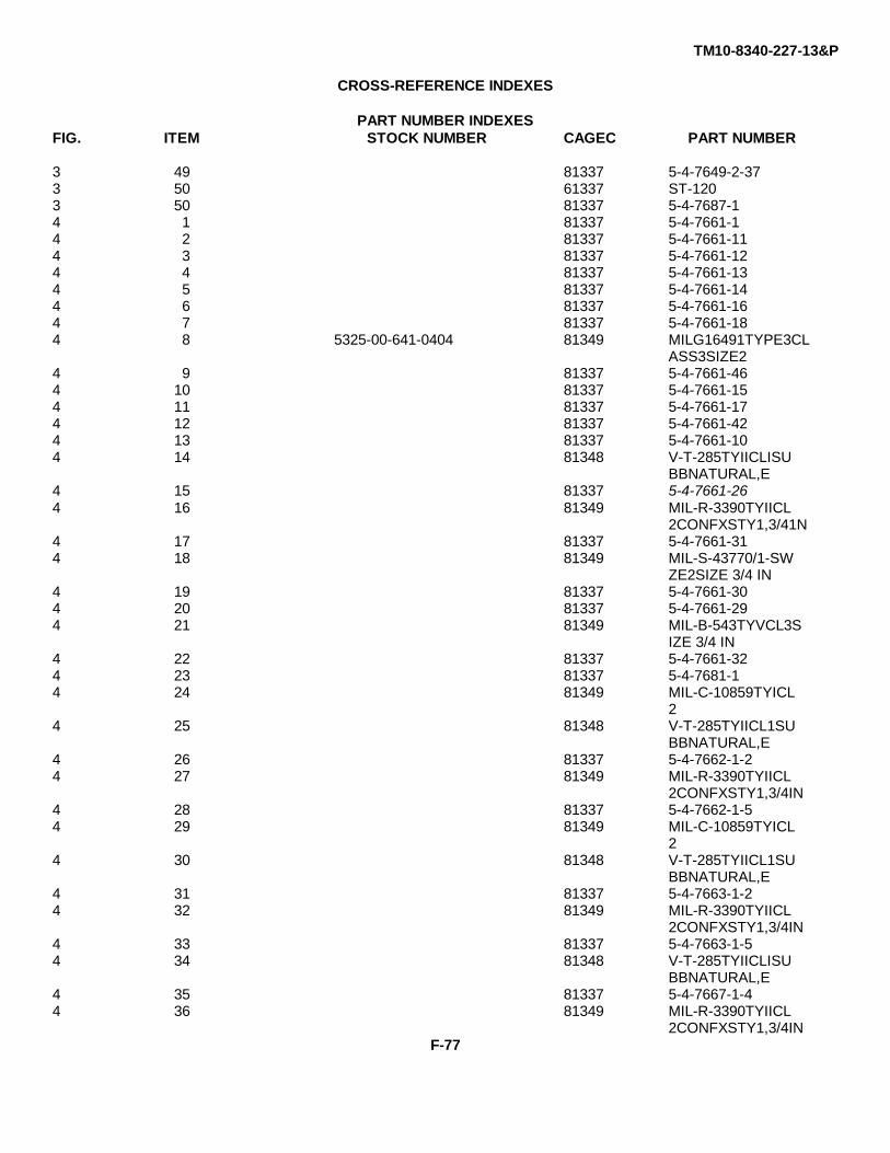
TM10-8340-227-13&P
CROSS-REFERENCE INDEXES
PART NUMBER INDEXESFIG. ITEM STOCK NUMBER CAGEC PART NUMBER
3 49 81337 5-4-7649-2-373 50 61337 ST-1203 50 81337 5-4-7687-14 1 81337 5-4-7661-14 2 81337 5-4-7661-114 3 81337 5-4-7661-124 4 81337 5-4-7661-134 5 81337 5-4-7661-144 6 81337 5-4-7661-164 7 81337 5-4-7661-184 8 5325-00-641-0404 81349 MILG16491TYPE3CL
ASS3SIZE24 9 81337 5-4-7661-464 10 81337 5-4-7661-154 11 81337 5-4-7661-174 12 81337 5-4-7661-424 13 81337 5-4-7661-104 14 81348 V-T-285TYIICLISU
BBNATURAL,E4 15 81337 5-4-7661-264 16 81349 MIL-R-3390TYIICL
2CONFXSTY1,3/41N4 17 81337 5-4-7661-314 18 81349 MIL-S-43770/1-SW
ZE2SIZE 3/4 IN4 19 81337 5-4-7661-304 20 81337 5-4-7661-294 21 81349 MIL-B-543TYVCL3S
IZE 3/4 IN4 22 81337 5-4-7661-324 23 81337 5-4-7681-14 24 81349 MIL-C-10859TYICL
24 25 81348 V-T-285TYIICL1SU
BBNATURAL,E4 26 81337 5-4-7662-1-24 27 81349 MIL-R-3390TYIICL
2CONFXSTY1,3/4IN4 28 81337 5-4-7662-1-54 29 81349 MIL-C-10859TYICL
24 30 81348 V-T-285TYIICL1SU
BBNATURAL,E4 31 81337 5-4-7663-1-24 32 81349 MIL-R-3390TYIICL
2CONFXSTY1,3/4IN4 33 81337 5-4-7663-1-54 34 81348 V-T-285TYIICLISU
BBNATURAL,E4 35 81337 5-4-7667-1-44 36 81349 MIL-R-3390TYIICL
2CONFXSTY1,3/4INF-77
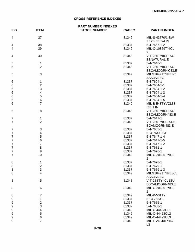
TM10-8340-227-13&P
CROSS-REFERENCE INDEXES
PART NUMBER INDEXESFIG. ITEM STOCK NUMBER CAGEC PART NUMBER
4 37 81349 MIL-S-43770/1-SWZE2SIZE 3/4 IN
4 38 81337 5-4-7667-1-24 39 81349 MIL-C-10859TYICL
24 40 81348 V-T-285TYIICL1SU
BBNATURAL,E5 1 81337 5-4-7646-15 2 81348 V-T-285TYIICL1SU
BBCAMOGRN'C33,E5 3 81349 MILG16491TYPE3CL
ASS3SIZEO6 1 81337 5-4-7604-16 2 81337 5-4-7604-1-16 3 81337 5-4-7604-1-26 4 81337 5-4-7604-1-36 5 81337 5-4-7604-1-46 6 81337 5-4-7604-1-56 7 81349 MIL-B-543TYVCL3S
IZE 1 IN6 8 81348 V-T-285TYIICL1SU
BBCAMOGRN483,E7 1 81337 5-4-7647-17 2 81348 V-T-285TYICL1SUB
BCAMOGRN483,E7 3 81337 5-4-7605-17 4 81337 5--4-7647-1-37 5 81337 5-4-7647-1-47 6 81337 5-4-7647-1-57 7 81337 5-4-7647-1-27 8 81337 5-4-7681-17 9 81337 5-4-7676-17 10 81349 MIL-C-20696TYICL
28 1 81337 5-4-7678-18 2 81337 5-4-7679-18 3 81337 5-4-7679-1-38 4 81349 MILG16491TYPE3CL
ASS3SIZEO8 5 81348 V-T-28STYIICL1SU
BBCAMOGRN483,E8 6 81349 MIL-C-20696TYICL
28 7 81349 MIL-P-501TYI9 1 81337 5-?4-7683-19 2 81337 5-4-7685-19 3 81337 5-4-7688-19 4 81349 MIL-C-44423CL19 5 81349 MIL-C-44423CL29 6 81349 MIL-C-44423CL39 7 81349 MIL-F-21840TYIIC
L3F-78
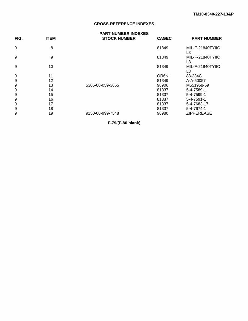
TM10-8340-227-13&P
CROSS-REFERENCE INDEXES
PART NUMBER INDEXESFIG. ITEM STOCK NUMBER CAGEC PART NUMBER
9 8 81349 MIL-F-21840TYIICL3
9 9 81349 MIL-F-21840TYIICL3
9 10 81349 MIL-F-21840TYIICL3
9 11 OR6NI 83-234C9 12 81349 A-A-500579 13 5305-00-059-3655 96906 M551958-599 14 81337 5-4-7589-19 15 81337 5-4-7599-19 16 81337 5-4-7591-19 17 81337 5-4-7683-179 18 81337 5-4-7674-19 19 9150-00-999-7548 96980 ZIPPEREASE
F-79/(F-80 blank)

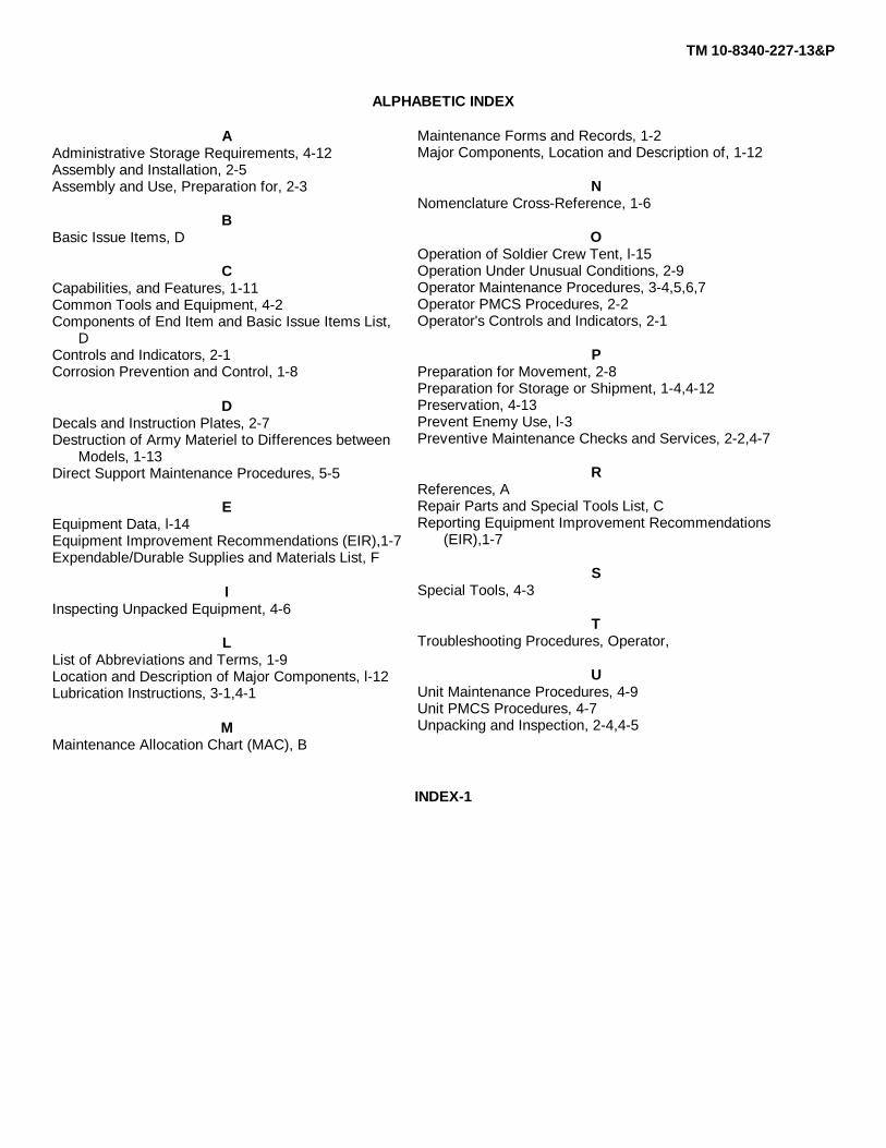
TM 10-8340-227-13&P
ALPHABETIC INDEX
AAdministrative Storage Requirements, 4-12Assembly and Installation, 2-5Assembly and Use, Preparation for, 2-3
BBasic Issue Items, D
CCapabilities, and Features, 1-11Common Tools and Equipment, 4-2Components of End Item and Basic Issue Items List,
DControls and Indicators, 2-1Corrosion Prevention and Control, 1-8
DDecals and Instruction Plates, 2-7Destruction of Army Materiel to Differences between
Models, 1-13Direct Support Maintenance Procedures, 5-5
EEquipment Data, l-14Equipment Improvement Recommendations (EIR),1-7Expendable/Durable Supplies and Materials List, F
IInspecting Unpacked Equipment, 4-6
LList of Abbreviations and Terms, 1-9Location and Description of Major Components, l-12Lubrication Instructions, 3-1,4-1
MMaintenance Allocation Chart (MAC), B
Maintenance Forms and Records, 1-2Major Components, Location and Description of, 1-12
NNomenclature Cross-Reference, 1-6
OOperation of Soldier Crew Tent, l-15Operation Under Unusual Conditions, 2-9Operator Maintenance Procedures, 3-4,5,6,7Operator PMCS Procedures, 2-2Operator's Controls and Indicators, 2-1
PPreparation for Movement, 2-8Preparation for Storage or Shipment, 1-4,4-12Preservation, 4-13Prevent Enemy Use, l-3Preventive Maintenance Checks and Services, 2-2,4-7
RReferences, ARepair Parts and Special Tools List, CReporting Equipment Improvement Recommendations
(EIR),1-7
SSpecial Tools, 4-3
TTroubleshooting Procedures, Operator,
UUnit Maintenance Procedures, 4-9Unit PMCS Procedures, 4-7Unpacking and Inspection, 2-4,4-5
INDEX-1


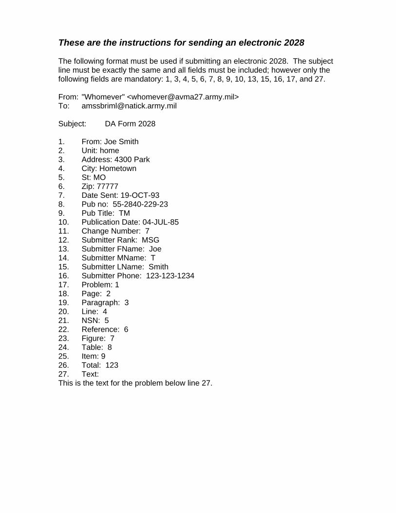
These are the instructions for sending an electronic 2028 The following format must be used if submitting an electronic 2028. The subject line must be exactly the same and all fields must be included; however only the following fields are mandatory: 1, 3, 4, 5, 6, 7, 8, 9, 10, 13, 15, 16, 17, and 27. From: "Whomever" <[email protected]> To: [email protected] Subject: DA Form 2028 1. From: Joe Smith 2. Unit: home 3. Address: 4300 Park 4. City: Hometown 5. St: MO 6. Zip: 77777 7. Date Sent: 19-OCT-93 8. Pub no: 55-2840-229-23 9. Pub Title: TM 10. Publication Date: 04-JUL-85 11. Change Number: 7 12. Submitter Rank: MSG 13. Submitter FName: Joe 14. Submitter MName: T 15. Submitter LName: Smith 16. Submitter Phone: 123-123-1234 17. Problem: 1 18. Page: 2 19. Paragraph: 3 20. Line: 4 21. NSN: 5 22. Reference: 6 23. Figure: 7 24. Table: 8 25. Item: 9 26. Total: 123 27. Text: This is the text for the problem below line 27.

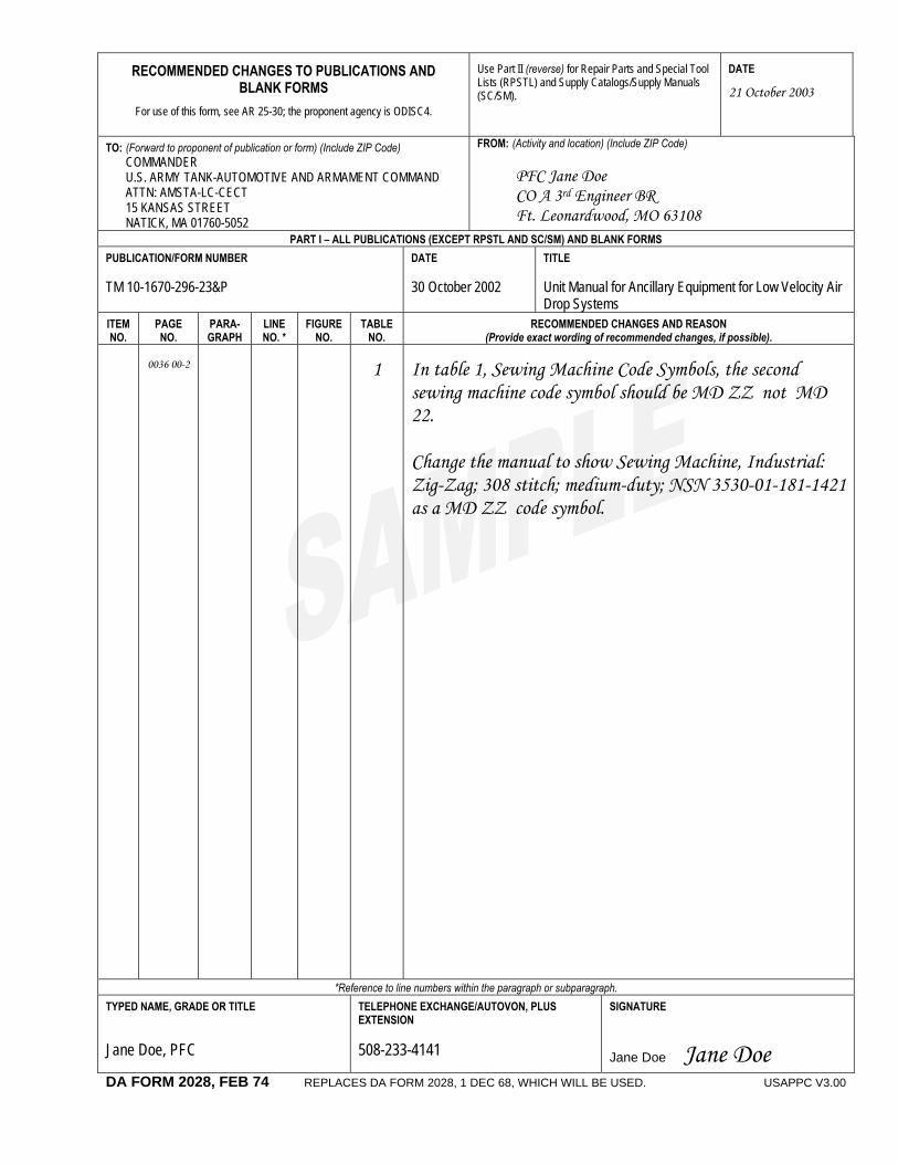
RECOMMENDED CHANGES TO PUBLICATIONS AND BLANK FORMS
For use of this form, see AR 25-30; the proponent agency is ODISC4.
Use Part II (reverse) for Repair Parts and Special Tool Lists (RPSTL) and Supply Catalogs/Supply Manuals (SC/SM).
DATE
21 October 2003
TO: (Forward to proponent of publication or form) (Include ZIP Code) COMMANDER U.S. ARMY TANK-AUTOMOTIVE AND ARMAMENT COMMAND ATTN: AMSTA-LC-CECT 15 KANSAS STREET NATICK, MA 01760-5052
FROM: (Activity and location) (Include ZIP Code) PFC Jane Doe CO A 3rd Engineer BR Ft. Leonardwood, MO 63108
PART I – ALL PUBLICATIONS (EXCEPT RPSTL AND SC/SM) AND BLANK FORMS PUBLICATION/FORM NUMBER TM 10-1670-296-23&P
DATE 30 October 2002
TITLE Unit Manual for Ancillary Equipment for Low Velocity Air Drop Systems
ITEM NO.
PAGE NO.
PARA- GRAPH
LINE NO. *
FIGURE NO.
TABLE NO.
RECOMMENDED CHANGES AND REASON (Provide exact wording of recommended changes, if possible).
0036 00-2
1
In table 1, Sewing Machine Code Symbols, the second sewing machine code symbol should be MD ZZ not MD 22. Change the manual to show Sewing Machine, Industrial: Zig-Zag; 308 stitch; medium-duty; NSN 3530-01-181-1421 as a MD ZZ code symbol.
*Reference to line numbers within the paragraph or subparagraph. TYPED NAME, GRADE OR TITLE Jane Doe, PFC
TELEPHONE EXCHANGE/AUTOVON, PLUS EXTENSION 508-233-4141
SIGNATURE
Jane Doe Jane Doe
DA FORM 2028, FEB 74 REPLACES DA FORM 2028, 1 DEC 68, WHICH WILL BE USED. USAPPC V3.00
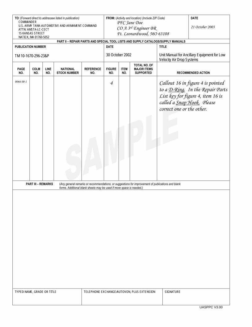
TO: (Forward direct to addressee listed in publication) COMMANDER U.S. ARMY TANK-AUTOMOTIVE AND ARMAMENT COMMAND ATTN: AMSTA-LC-CECT 15 KANSAS STREET NATICK, MA 01760-5052
FROM: (Activity and location) (Include ZIP Code) PFC Jane Doe CO A 3rd Engineer BR Ft. Leonardwood, MO 63108
DATE 21 October 2003
PART II – REPAIR PARTS AND SPECIAL TOOL LISTS AND SUPPLY CATALOGS/SUPPLY MANUALS PUBLICATION NUMBER TM 10-1670-296-23&P
DATE 30 October 2002
TITLE Unit Manual for Ancillary Equipment for Low Velocity Air Drop Systems
PAGE NO.
COLM
NO.
LINE NO.
NATIONAL
STOCK NUMBER
REFERENCE
NO.
FIGURE
NO.
ITEM NO.
TOTAL NO. OF MAJOR ITEMS SUPPORTED
RECOMMENDED ACTION 0066 00-1
4
Callout 16 in figure 4 is pointed to a D-Ring. In the Repair Parts List key for figure 4, item 16 is called a Snap Hook. Please correct one or the other.
PART III – REMARKS (Any general remarks or recommendations, or suggestions for improvement of publications and blank forms. Additional blank sheets may be used if more space is needed.)
TYPED NAME, GRADE OR TITLE
TELEPHONE EXCHANGE/AUTOVON, PLUS EXTENSION
SIGNATURE
UASPPC V3.00
RECOMMENDED CHANGES TO PUBLICATIONS AND BLANK FORMS
For use of this form, see AR 25-30; the proponent agency is ODISC4.
Use Part II (reverse) for Repair Parts and Special Tool Lists (RPSTL) and Supply Catalogs/Supply Manuals (SC/SM).
DATE
TO: (Forward to proponent of publication or form) (Include ZIP Code) COMMANDER U.S. ARMY TANK-AUTOMOTIVE AND ARMAMENT COMMAND ATTN: AMSTA-LC-CECT 15 KANSAS STREET NATICK, MA 01760-5052
FROM: (Activity and location) (Include ZIP Code)
PART I – ALL PUBLICATIONS (EXCEPT RPSTL AND SC/SM) AND BLANK FORMS PUBLICATION/FORM NUMBER TM 10-8340-227-13&P
DATE 28 February 1994
TITLE Operator’s, Unit, and Direct Support Maintenance Manual, Including Repair Parts and Special Tools Lists (RPSTL) for Soldier Crew Tent
ITEM NO.
PAGE NO.
PARA- GRAPH
LINE NO. *
FIGURE NO.
TABLE NO.
RECOMMENDED CHANGES AND REASON (Provide exact wording of recommended changes, if possible).
*Reference to line numbers within the paragraph or subparagraph. TYPED NAME, GRADE OR TITLE TELEPHONE EXCHANGE/AUTOVON, PLUS
EXTENSION SIGNATURE
DA FORM 2028, FEB 74 REPLACES DA FORM 2028, 1 DEC 68, WHICH WILL BE USED. USAPPC V3.00

TO: (Forward direct to addressee listed in publication) COMMANDER U.S. ARMY TANK-AUTOMOTIVE AND ARMAMENT COMMAND ATTN: AMSTA-LC-CECT 15 KANSAS STREET NATICK, MA 01760-5052
FROM: (Activity and location) (Include ZIP Code) DATE
PART II – REPAIR PARTS AND SPECIAL TOOL LISTS AND SUPPLY CATALOGS/SUPPLY MANUALS PUBLICATION NUMBER TM 10-8340-227-13&P
DATE 28 February 1994
TITLE Operator’s, Unit, and Direct Support Maintenance Manual, Including Repair Parts and Special Tools Lists (RPSTL) for Soldier Crew Tent
PAGE NO.
COLM
NO.
LINE NO.
NATIONAL STOCK
NUMBER
REFERENCE
NO.
FIGURE
NO.
ITEM NO.
TOTAL NO. OF MAJOR
ITEMS SUPPORTED
RECOMMENDED ACTION
PART III – REMARKS (Any general remarks or recommendations, or suggestions for improvement of publications and blank forms. Additional blank sheets may be used if more space is needed.)
TYPED NAME, GRADE OR TITLE TELEPHONE EXCHANGE/AUTOVON, PLUS EXTENSION SIGNATURE
UASPPC V3.00

RECOMMENDED CHANGES TO PUBLICATIONS AND BLANK FORMS
For use of this form, see AR 25-30; the proponent agency is ODISC4.
Use Part II (reverse) for Repair Parts and Special Tool Lists (RPSTL) and Supply Catalogs/Supply Manuals (SC/SM).
DATE
TO: (Forward to proponent of publication or form) (Include ZIP Code) COMMANDER U.S. ARMY TANK-AUTOMOTIVE AND ARMAMENT COMMAND ATTN: AMSTA-LC-CECT 15 KANSAS STREET NATICK, MA 01760-5052
FROM: (Activity and location) (Include ZIP Code)
PART I – ALL PUBLICATIONS (EXCEPT RPSTL AND SC/SM) AND BLANK FORMS PUBLICATION/FORM NUMBER TM 10-8340-227-13&P
DATE 28 February 1994
TITLE Operator’s, Unit, and Direct Support Maintenance Manual, Including Repair Parts and Special Tools Lists (RPSTL) for Soldier Crew Tent
ITEM NO.
PAGE NO.
PARA- GRAPH
LINE NO. *
FIGURE NO.
TABLE NO.
RECOMMENDED CHANGES AND REASON (Provide exact wording of recommended changes, if possible).
*Reference to line numbers within the paragraph or subparagraph. TYPED NAME, GRADE OR TITLE TELEPHONE EXCHANGE/AUTOVON, PLUS
EXTENSION SIGNATURE
DA FORM 2028, FEB 74 REPLACES DA FORM 2028, 1 DEC 68, WHICH WILL BE USED. USAPPC V3.00

TO: (Forward direct to addressee listed in publication) COMMANDER U.S. ARMY TANK-AUTOMOTIVE AND ARMAMENT COMMAND ATTN: AMSTA-LC-CECT 15 KANSAS STREET NATICK, MA 01760-5052
FROM: (Activity and location) (Include ZIP Code) DATE
PART II – REPAIR PARTS AND SPECIAL TOOL LISTS AND SUPPLY CATALOGS/SUPPLY MANUALS PUBLICATION NUMBER TM 10-8340-227-13&P
DATE 28 February 1994
TITLE Operator’s, Unit, and Direct Support Maintenance Manual, Including Repair Parts and Special Tools Lists (RPSTL) for Soldier Crew Tent
PAGE NO.
COLM
NO.
LINE NO.
NATIONAL STOCK
NUMBER
REFERENCE
NO.
FIGURE
NO.
ITEM NO.
TOTAL NO. OF MAJOR
ITEMS SUPPORTED
RECOMMENDED ACTION
PART III – REMARKS (Any general remarks or recommendations, or suggestions for improvement of publications and blank forms. Additional blank sheets may be used if more space is needed.)
TYPED NAME, GRADE OR TITLE TELEPHONE EXCHANGE/AUTOVON, PLUS EXTENSION SIGNATURE
UASPPC V3.00
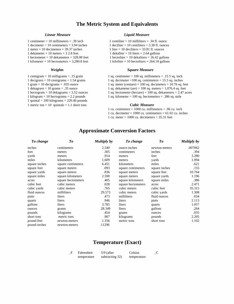
The Metric System and Equivalents Linear Measure Liquid Measure 1 centimeter = 10 millimeters = .39 inch 1 centiliter = 10 milliliters = .34 fl. ounce 1 decimeter = 10 centimeters = 3.94 inches 1 deciliter = 10 centiliters = 3.38 fl. ounces 1 meter = 10 decimeters = 39.37 inches 1 liter = 10 deciliters = 33.81 fl. ounces 1 dekameter = 10 meters = 3 2.8 feet 1 dekaliter = 10 liters = 2.64 gallons 1 hectometer = 10 dekameters = 328.08 feet 1 hectoliter = 10 dekaliters = 26.42 gallons 1 kilometer = 10 hectometers = 3,280.8 feet 1 kiloliter = 10 hectoliters = 264.18 gallons Weights Square Measure 1 centigram = 10 milligrams = .15 grain 1 sq. centimeter = 100 sq. millimeters = .15 5 sq. inch 1 decigrarn = 10 centigrams = 1.54 grains 1 sq. decimeter =100 sq. centimeters = 15.5 sq. inches 1 gram = 10 decigrams = .035 ounce 1 sq. meter (centare) = 100 sq. decimeters = 10.76 sq. feet 1 dekagrarn = 10 grams = .35 ounce 1 sq. dekameter (are) = 100 sq. meters = 1,076.4 sq. feet 1 hectogram = 10 dekagrams = 3.52 ounces 1 sq. hectometer (hectare) = 100 sq. dekameters = 2.47 acres 1 kilogram = 10 hectograms = 2.2 pounds 1 sq. kilometer = 100 sq. hectometers = .386 sq. mile 1 quintal = 100 kilograms = 220.46 pounds 1 metric ton = 10 quintals = 1.1 short tons Cubic Measure 1 cu. centimeter = 1000 cu. millimeters = .06 cu. inch 1 cu. decimeter = 1000 cu. centimeters = 61.02 cu. inches 1 cu. meter = 1000 cu. decimeters = 35.31 feet
Approximate Conversion Factors
To change To Multiply by To change To Multiply by inches centimeters 2.540 ounce-inches newton-meters .007062 feet meters .305 centimeters inches .394 yards meters .914 meters feet 3.280 miles kilometers 1.609 meters yards 1.094 square inches square centimeters 6.451 kilometers miles .621 square feet square meters .093 square centimeters square inches .155 square yards square meters .836 square meters square feet 10.764 square miles square kilometers 2.590 square meters square yards 1.196 acres square hectometers .405 square kilometers square miles .386 cubic feet cubic meters .028 square hectometers acres 2.471 cubic yards cubic meters .765 cubic meters cubic feet 35.315 fluid ounces milliliters 29.573 cubic meters cubic yards 1.308 pints Iiters .473 milliliters fluid ounces .034 quarts Iiters .946 liters pints 2.113 gallons Iiters 3.785 liters quarts 1.057 ounces grams 28.349 liters gallons .264 pounds kilograms .454 grams ounces .035 short tons metric tons .907 kilograms pounds 2.205 pound-feet newton-meters 1.356 metric tons short tons 1.102 pound-inches newton-meters .11296
Temperature (Exact)
_F Fahrenheit 5/9 (after Celsius _C temperature subtracting 32) temperature

PIN: 072329-000

This fine document...
Was brought to you by me:
Liberated Manuals -- free army and government manuals
Why do I do it? I am tired of sleazy CD-ROM sellers, who take publicly available information, slap “watermarks” and other junk on it, and sell it. Those masters of search engine manipulation make sure that their sites that sell free information, come up first in search engines. They did not create it... They did not even scan it... Why should they get your money? Why are not letting you give those free manuals to your friends?
I am setting this document FREE. This document was made by the US Government and is NOT protected by Copyright. Feel free to share, republish, sell and so on.
I am not asking you for donations, fees or handouts. If you can, please provide a link to liberatedmanuals.com, so that free manuals come up first in search engines:
<A HREF=http://www.liberatedmanuals.com/>Free Military and Government Manuals</A>
– SincerelyIgor Chudovhttp://igor.chudov.com/
– Chicago Machinery Movers
Related Documents
![Modul Mekanika Teknik [TM10]](https://static.cupdf.com/doc/110x72/563db823550346aa9a90e075/modul-mekanika-teknik-tm10.jpg)


![Modul Strategic Human Resource Management [TM10]](https://static.cupdf.com/doc/110x72/577c7d011a28abe0549cf77b/modul-strategic-human-resource-management-tm10.jpg)