File Ref: 600-100 CP No.: CP1120 Rev. 1 Page: 1 of 24 CERTIFIED TEST REPORT Cooper Power Systems 15 kV Class – 600 Amp 8.3/14.4 kV CLĒĒR TM LOADBREAK SEPARABLE CONNECTOR SYSTEM REV. 1 DATE September 1, 2011 ORIGINAL REPORT DATE: July 11, 2011 © Cooper Industries

Welcome message from author
This document is posted to help you gain knowledge. Please leave a comment to let me know what you think about it! Share it to your friends and learn new things together.
Transcript
File Ref: 600-100
CP No.: CP1120 Rev. 1 Page: 1 of 24
CERTIFIED
TEST REPORT
Cooper Power Systems
15 kV Class – 600 Amp
8.3/14.4 kV
CLĒĒRTM
LOADBREAK SEPARABLE
CONNECTOR SYSTEM
REV. 1 DATE September 1, 2011 ORIGINAL REPORT DATE: July 11, 2011 © Cooper Industries
File Ref: 600-100
CP No.: CP1120 Rev. 1 Page: 2 of 24
Cooper Power Systems
15 kV Class – 600 Amp
8.3/14.4 kV
CLĒĒR LOADBREAK SEPARABLE CONNECTOR SYSTEM
CERTIFICATION
Statements made and data shown are, to the best of our knowledge and belief, correct and within the usual limits of commercial testing practice.
_____________________________ _______________________________ Paul M. Roscizewski, P.E. David C. Hughes Chief Engineer Staff Engineer
File Ref: 600-100
CP No.: CP1120 Rev. 1 Page: 3 of 24
INTRODUCTION
8.3/14.4 kV
The Cooper Power Systems 15 kV Class 600 Amp Clēēr
TM Loadbreak Separable Connectors
are designed as a fully shielded and insulated termination system for connecting medium-voltage extruded underground cable to transformers, switchgear, and other apparatus. This report certifies that all system component parts that were tested were installed according to the applicable installation instructions and tested to the applicable design tests required by the IEEE Standard for Separable Insulated Connector Systems for Power Distribution Systems Above 600V, designated as IEEE Std 386™-2006 standard; the ANSI Standard for Connectors for Use Between Aluminum-to-Aluminum or Aluminum-to-Copper Bare Overhead Conductors, designated as ANSI
® C119.4-2004; and the IEEE Standard Requirements for Subsurface, Vault, and Pad-
Mounted Load Interrupter Switchgear and Fused Load-Interrupter Switchgear for Alternating Current Systems Up to 38kV, designated as IEEE Std C37.74™-2003 standard.

File Ref: 600-100
CP No.: CP1120 Rev. 1 Page: 4 of 24
TEST PROGRAM
8.3/14.4 kV
Object: To demonstrate that the Cooper Power Systems 15 kV Class 600 Amp Clēēr Loadbreak Separable Connector System meets the applicable requirements of IEEE Std 386™-2006 standard, ANSI
® C119.4-2004, and IEEE Std C37.74™-2003 standard.
Procedure: Design tests were performed on the number of samples as specified in Table 5 of IEEE Std 386™-2006 standard. The 15 kV 600 Amp Clēēr Loadbreak Separable Connector System consists of the products listed below. Representative product was tested to all of the applicable Design Tests as specified in Table 5 of IEEE Std 386™-2006 standard, ANSI
® C119.4-2004, and
IEEE Std C37.74™ standard. Product List: 15 kV Class 600 Amp Clēēr Loadbreak Separable Connector System Products: 1. 15 kV 600A Loadbreak Connector LCN615 2. 15 kV 600A Deadbreak-Loadbreak Junction DLJ615A2 3. 15 kV 600A Loadbreak Protective Cap LPC615
File Ref: 600-100
CP No.: CP1120 Rev. 1 Page: 5 of 24
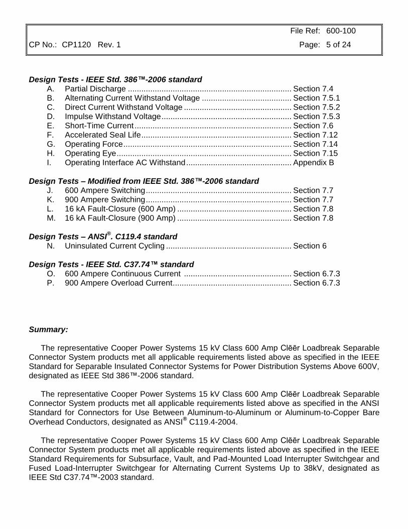
Design Tests - IEEE Std. 386™-2006 standard A. Partial Discharge ......................................................................... Section 7.4 B. Alternating Current Withstand Voltage ........................................ Section 7.5.1 C. Direct Current Withstand Voltage ................................................ Section 7.5.2 D. Impulse Withstand Voltage .......................................................... Section 7.5.3 E. Short-Time Current ...................................................................... Section 7.6 F. Accelerated Seal Life ................................................................... Section 7.12 G. Operating Force ........................................................................... Section 7.14 H. Operating Eye .............................................................................. Section 7.15 I. Operating Interface AC Withstand ............................................... Appendix B Design Tests – Modified from IEEE Std. 386™-2006 standard J. 600 Ampere Switching ................................................................. Section 7.7 K. 900 Ampere Switching ................................................................. Section 7.7 L. 16 kA Fault-Closure (600 Amp) ................................................... Section 7.8 M. 16 kA Fault-Closure (900 Amp) ................................................... Section 7.8 Design Tests – ANSI
®. C119.4 standard
N. Uninsulated Current Cycling ........................................................ Section 6 Design Tests - IEEE Std. C37.74™ standard O. 600 Ampere Continuous Current ................................................ Section 6.7.3 P. 900 Ampere Overload Current ..................................................... Section 6.7.3 Summary: The representative Cooper Power Systems 15 kV Class 600 Amp Clēēr Loadbreak Separable Connector System products met all applicable requirements listed above as specified in the IEEE Standard for Separable Insulated Connector Systems for Power Distribution Systems Above 600V, designated as IEEE Std 386™-2006 standard. The representative Cooper Power Systems 15 kV Class 600 Amp Clēēr Loadbreak Separable Connector System products met all applicable requirements listed above as specified in the ANSI Standard for Connectors for Use Between Aluminum-to-Aluminum or Aluminum-to-Copper Bare
Overhead Conductors, designated as ANSI® C119.4-2004.
The representative Cooper Power Systems 15 kV Class 600 Amp Clēēr Loadbreak Separable Connector System products met all applicable requirements listed above as specified in the IEEE Standard Requirements for Subsurface, Vault, and Pad-Mounted Load Interrupter Switchgear and Fused Load-Interrupter Switchgear for Alternating Current Systems Up to 38kV, designated as IEEE Std C37.74™-2003 standard.

File Ref: 600-100
CP No.: CP1120 Rev. 1 Page: 6 of 24
Test A 8.3/14.4 kV
Partial Discharge Test
Section 7.4 Object: To demonstrate that the Cooper Power Systems 15 kV Class 600 Amp Clēēr Loadbreak Separable Connector System products meet or exceed the IEEE Std 386™-2006 standard, Section 7.4, minimum partial discharge extinction voltage level of 11 kV rms. Procedure: Ten of each of the applicable separable connector system products were tested with mating parts for a 15 kV class minimum partial discharge voltage level of 11 kV rms. The test voltage is gradually increased to 20% above the 11 kV corona level (13.2 kV). If the partial discharge exceeds 3 pC, the voltage is decreased to the partial discharge voltage level of 11 kV and maintained between 3 and 60 seconds. The partial discharge shall not exceed 3 pC at the specified 11 kV partial discharge voltage level. The products tested were 1-3 of the Product List on page 4. Results: For all ten samples of each product tested the partial discharge level was less than 3 pC at the specified minimum partial discharge extinction voltage level of 11 kV rms. Conclusion: The representative Cooper Power Systems 15 kV Class 600 Amp Clēēr Loadbreak Separable Connector System products met or exceeded the IEEE Std 386™-2006 standard, Section 7.4, minimum partial discharge voltage level of 11 kV rms.
File Ref: 600-100
CP No.: CP1120 Rev. 1 Page: 7 of 24
TEST B 8.3/14.4 kV
Alternating Current Withstand Voltage Test
Section 7.5.1 Object: To demonstrate that the Cooper Power Systems 15 kV Class 600 Amp Clēēr Loadbreak Separable Connector System products meet the IEEE Std 386™-2006 standard, Section 7.5.1, 60 Hz, one minute ac withstand level of 34 kV rms. Procedure: Ten of each of the applicable separable connector system products were tested with mating parts by raising the 60 Hz ac test voltage to 34 kV rms in less than 30 seconds, then maintaining the voltage at 34 kV rms for one minute. The products tested were 1-3 of the Product List on page 4. Results: All samples of each product withstood a 34 kV rms, 60 Hz ac one minute voltage withstand without a puncture or flashover. Conclusion: The representative Cooper Power Systems 15 kV Class 600 Amp Clēēr Loadbreak Separable Connector System products met the IEEE Std 386™-2006 standard, Section 7.5.1, 60 Hz, one minute ac voltage withstand level of 34 kV rms without a puncture or flashover.

File Ref: 600-100
CP No.: CP1120 Rev. 1 Page: 8 of 24
TEST C 8.3/14.4 kV
Direct Current Withstand Voltage Test
Section 7.5.2 Object: To demonstrate that the Cooper Power Systems 15 kV Class 600 Amp Clēēr Loadbreak Separable Connector System products meet the IEEE Std 386™-2006 standard, Section 7.5.2, 15 minute dc withstand level of 53 kV. Procedure: Ten of each of the applicable separable connector system products were tested with mating parts by connecting the negative dc voltage terminal to the test specimen and raising the test voltage to 53 kV, then holding the voltage at 53 kV for 15 minutes. The products tested were 1-3 of the Product List on page 4. Results: All samples of each product withstood a 53 kV 15 minute dc withstand without a puncture or flashover. Conclusion: The representative Cooper Power Systems 15 kV Class 600 Amp Clēēr Loadbreak Separable Connector System products met the IEEE Std 386™-2006 standard, Section 7.5.2, 15 minute dc voltage withstand level of 53 kV without a puncture or flashover.

File Ref: 600-100
CP No.: CP1120 Rev. 1 Page: 9 of 24
TEST D 8.3/14.4 kV
Impulse Withstand Voltage Test
Section 7.5.3 Object: To demonstrate that the Cooper Power Systems 15 kV Class 600 Amp Clēēr Loadbreak Separable Connector System products meet the IEEE Std 386™-2006 standard, Section 7.5.3, impulse level of 95 kV crest. Procedure: Ten of each of the applicable separable connector system products were tested with mating parts and subjected to an impulse voltage having 1.2/50 microsecond wave and crest value of 95 kV crest. Each sample was subjected to three positive and three negative full wave impulses with the following wave shape.
WAVE SHAPE
Measured Quantity Tolerance ±%
Crest Value 3
Front Time 30
Time to Half Value 20
Nominal Rate of Rise of Wave Front 20
The products tested were 1-3 of the Product List on page 4. Results: All samples of each product withstood three positive and three negative full wave impulses with 95 kV crests without a puncture or flashover.
Conclusion: The representative Cooper Power Systems 15 kV Class 600 Amp Clēēr Loadbreak Separable Connector System products met the IEEE Std 386™-2006 standard, Section 7.5.3, impulse withstand voltage level of 95 kV crest without a puncture or flashover.
File Ref: 600-100
CP No.: CP1120 Rev. 1 Page: 10 of 24
TEST E 8.3/14.4 kV
Short-Time Current Test
Section 7.6 Object: To demonstrate that the Cooper Power Systems 15 kV Class 600 Amp Clēēr Loadbreak Separable Connector System products meet the IEEE Std 386™-2006 standard, Section 7.6, short-time current requirements for 200 Amp connectors. Procedure: Four representative samples of each of the applicable separable connector products were connected in a manner approximating service conditions and subjected to short-time currents with magnitudes and durations of 10,000 Amperes rms symmetrical for 3 seconds (180 cycles) and 16,000 Amperes rms symmetrical for 0.17 seconds (10 cycles) [note: Short-time current rating is limited to the maximum fault-closure rating of the Clēēr Separable Connector System of 16,000 Amperes]. The rms value of the first major loop of the current wave exceeded 1.3 times the specified current magnitude measured in accordance with IEEE Std C37.09™-1979 standard. Results: All samples tested withstood short-time currents with magnitudes and durations of 10,000 Amperes rms symmetrical for 3 seconds (180 cycles) and 16,000 Amperes rms symmetrical for 0.17 seconds (10 cycles) without any separation of the interfaces or impairing the connector’s ability to meet the other requirements of IEEE Std 386™-2006 standard. Summary: The test results demonstrate that all the applicable separable connector products (items 1-2 of the Product List on Page 4) meet the requirements of the short-time current test. Conclusion: The representative Cooper Power Systems 15 kV Class 600 Amp Clēēr Loadbreak Separable Connector System products met the short-time current requirements of IEEE Std 386™-2006 standard, Section 7.6.
File Ref: 600-100
CP No.: CP1120 Rev. 1 Page: 11 of 24
TEST F 8.3/14.4 kV
Accelerated Seal Life Test
Section 7.12 Object: To demonstrate that the Cooper Power Systems 15 kV Class 600 Amp Clēēr Loadbreak Separable Connector System products are capable of meeting the long term sealing requirements specified in the Accelerated Seal Life Test of IEEE Std 386™-2006 standard, Section 7.12. Procedure: Four representative assemblies of each of the applicable separable connector products consisting of a loadbreak connector, two deadbreak-loadbreak junctions, and two standard Bol-T connectors were assembled using proper installation techniques for each product. A plastic mandrel made of acetal resin (DuPont Delrin) was used to simulate the test cable during the oven aging portion of the test. The four assemblies were placed in an oven having a 121°C temperature for three weeks. After the three week oven aging, the four assemblies were removed from the oven and operated once by using the operating eye of the loadbreak connector. The four assemblies were then reassembled with 750 kcmil stranded aluminum 15 kV XLPE insulated test cables and subjected to 50 cycles of the following sequence of operations: 1. The assemblies were connected in series with a 72 inch control cable and heated in
air using sufficient current to raise the temperature of the conductor of the control cable to 90°C ± 5°C for one hour.
2. After applying current for one hour, the assemblies were de-energized and within
three minutes submerged in 25°C ± 10°C conductive water (5000 ohm-cm max) to a depth of one foot for one hour.
3. After the 50
th cycle, each assembly was subjected to three positive and three negative
full wave impulses with 95 kV crest values, following the test procedure as described in Section 7.5.3 of IEEE Std 386™-2006 standard.

File Ref: 600-100
CP No.: CP1120 Rev. 1 Page: 12 of 24
Results: Following the 50 accelerated sealing life test cycles, all samples tested withstood three positive and three negative full wave impulses having 95 kV crest values, without a puncture or flashover. Summary: The test results demonstrate that all the applicable separable connector products (items 1-2 of the Product List on Page 4) meet the requirements of the Accelerated Seal Life Test. Conclusion: The representative Cooper Power Systems 15 kV Class 600 Amp Clēēr Loadbreak Separable Connector System products met the long term sealing requirements as specified in Section 7.12 of IEEE Std 386™-2006 standard.
File Ref: 600-100
CP No.: CP1120 Rev. 1 Page: 13 of 24
TEST G 8.3/14.4 kV
Operating Force Test
Section 7.14 Object: To demonstrate that the Cooper Power Systems 15 kV Class 600 Amp Clēēr Loadbreak Separable Connector System products meet the IEEE Std 386™-2006 standard operating force requirements of 50 to 200 pounds-force at temperatures of -20°C, +25°C and +65°C. Procedure: Four representative samples of each of the applicable separable connector products were lubricated and mated per the Cooper Power Systems installation instructions. The operating force for each connector assembly was applied when the temperature of the components was at -20°C, +25°C and +65°C, for three separate tests. Each test consisted of closing the connector, then reopening it within 10 minutes. The force was applied to the operating eye of the connector parallel to the axes of the probes, at a rate of 5 in/min. Results: Each set of four connector/bushing insert assemblies had operating forces between 50 lbf and 200 lbf at the -20°C, +25°C and +65°C temperatures. Summary: The test results demonstrate that all the applicable separable connector products (items 1-3) meet the requirements of the Operating Force Test. Conclusion: The representative Cooper Power Systems 15 kV Class 600 Amp Clēēr Loadbreak Separable Connector System products met the operating force requirements of 50 to 200 pounds-force at temperatures of -20°C, +25°C and +65°C when tested per Section 7.14 of IEEE Std 386™-1995 standard.
File Ref: 600-100
CP No.: CP1120 Rev. 1 Page: 14 of 24
TEST H 8.3/14.4 kV
Operating Eye Test
Section 7.15 Object: To demonstrate that the Cooper Power Systems 15 kV Class 600 Amp Clēēr Loadbreak Separable Connector System products meet the IEEE Std 386™-2006 standard operating eye test requirements of a 120 lb-in rotational force and a 500 pounds-force static tensile pull force at ambient temperature. Procedure: Four representative samples of each applicable separable connector product were subjected to the Operating Eye Test. A tensile force of 500 pounds-force was applied at the rate of 5 in/min to the operating eye parallel to the axis of the probe and held for one minute. Then a rotational force of 120 lb-in was applied to the operating eye with a live-line tool simulating fixture in a clockwise and then a counter-clockwise direction. The connectors were assembled onto mating bushings and the partial discharge voltage level was measured before and after the mechanical tests per the requirements of Section 7.4. Results: The operating eye of each product tested was still serviceable after the withstand tests for tensile and rotational force. All samples met the requirements of a partial discharge extinction voltage level of 11 kV rms before and after the mechanical tests. Summary: The test results demonstrate that all the applicable separable connector products (items 1 and 3 of the Product List on Page 4) meet the requirements of the Operating Eye Test. Conclusion: The representative Cooper Power Systems 15 kV Class 600 Amp Clēēr Loadbreak Separable Connector System products met the operating eye test requirements of IEEE Std 386™-2006 standard, Section 7.15.
File Ref: 600-100
CP No.: CP1120 Rev. 1 Page: 15 of 24
TEST I 8.3/14.4 kV
Operating Interface AC Withstand Test
Appendix B Object: To demonstrate that the Cooper Power Systems 15 kV Class 600 Amp Clēēr Loadbreak Separable Connector System products are capable of being separated without a flashover when tested per the requirements of the Operating Interface AC Withstand Test (OIACWT), Annex B of IEEE Std 386™-2006 standard. The key parameters are switching a connector assembly with a stuck interface at -20°C at an elevated line-to-ground test voltage without a flashover. Procedure: Tests conducted per Option A of the OIACWT, Annex B, of IEEE Std 386™-2006 standard. The 600 Amp loadbreak operating interfaces of the connectors and bushings were cleaned and degreased to ensure a consistently stuck interface condition. The separation force at -20°C as measured on similarly prepared parts ranges from 200 to 500 lbs. The Clēēr loadbreak connectors were each assembled to mating deadbreak-loadbreak junctions at an ambient temperature of 25°C ± 5°C without applying lubrication to the 600 Amp loadbreak operating interfaces. The Clēēr connector assemblies were chilled in a cold chamber at -20°C to -25°C for a minimum of 16 hours. The connector assemblies were removed from the cold chamber and mounted to the face plate of a grounded test stand. The face plate mounting was constructed in a manner simulating a typical field application. The loadbreak connector was then separated from the bushing within 5 minutes after removal from the cold chamber. The opening operation was performed with a positive continuous motion applied by a mechanical actuator at 35 in/sec average speed over the initial 1” of travel. The test circuit and circuit parameters are detailed in the following Figure A and Table A. The line-to-ground test voltage for the 8.3/14.4 kV rated connectors was 17 kV rms (2x Rated L-G voltage).

File Ref: 600-100
CP No.: CP1120 Rev. 1 Page: 16 of 24
FIGURE A
Circuit Diagram
VL-G
RS XS
RG
ELBOW
CAP
TABLE A
Circuit Parameters VLG = 2 X (RATED L-G Voltage)
ZS = XS + RS
XS/RS = 5.0 - 7.0
ZS 0.10 x RG
IF = V/(ZS + RG) 50 Amps
Conclusion: The representative Cooper Power Systems 15 kV Class 600 Amp Clēēr Loadbreak Separable Connector System products met the requirements of the Option A procedure in the Operating Interface AC Withstand Test of Annex B, IEEE Std 386™-2006 standard.
File Ref: 600-100
CP No.: CP1120 Rev. 1 Page: 17 of 24
TEST J 8.3/14.4 kV
600 Ampere Switching Test
Section 7.7 Object: To demonstrate that the Cooper Power Systems 15 kV Class 600 Amp Clēēr Loadbreak Separable Connector System products are capable of closing and interrupting 600 Amps at 14.4 kV phase-to-phase when tested per the switching test requirements as specified in Section 7.7 of IEEE Std 386™-2006 standard. Procedure: Thirty (30) 15 kV Class 600 Amp Clēēr Loadbreak Separable Connector assemblies were tested to IEEE Std 386™ standard Section 7.7 with one modification: load current was set to 600 Amperes rms instead of the 200 Ampere circuit the standard specifies. Each 15 kV Class 600 Amp Clēēr Loadbreak Separable Connector System assembly was subjected to 10 complete 600 Amp switching operations at 14.4 kV phase-to-phase under the conditions listed in Figure 19 (circuit diagram A) of the IEEE Std 386™-2006 standard for connectors with a voltage rating of 8.3/14.4 kV. A complete switching operation consists of closing and opening the connector. Switching operations were performed manually with one operator. Successive switching operations were performed at time intervals greater than 1 minute. Before each closing operation took place, a minimum dwell time of 5 seconds was maintained after the probe was positioned in the arc extinguishing area of the bushing. Appropriate ground-fault detection equipment was incorporated into the test set-up. The last switching operation for each sample was recorded on an oscillogram. Results: The connector samples exceeded the switching requirement of ten consecutive samples without a flashover to ground. Conclusion: The representative Cooper Power Systems 15 kV Class 600 Amp Clēēr Loadbreak Separable Connector System products met the 600 Ampere 14.4 kV phase-to-phase switching requirements as specified in Section 7.7 of IEEE Std 386™-2006 standard (modified to switch 600 Amperes 10 full operations on each sample instead of 200 Amperes 10 full operations on each sample).

File Ref: 600-100
CP No.: CP1120 Rev. 1 Page: 18 of 24
TEST K 8.3/14.4 kV
900 Ampere Switching Test
Section 7.7 Object: To demonstrate that the Cooper Power Systems 15 kV Class 600 Amp Clēēr Loadbreak Separable Connector System products are capable of closing and interrupting 900 Amps at 14.4 kV phase-to-phase when tested per the switching test requirements as specified in Section 7.7 of IEEE Std 386™-2006 standard. Procedure: Thirty (30) 15 kV Class 600 Amp Clēēr Loadbreak Separable Connector assemblies were tested to IEEE Std 386™ standard Section 7.7 with the following modification: load current was set to 900 Amperes rms and samples were switched 3 times each instead of the 200 Ampere circuit with samples switched 10 times each. Each 15 kV Class 600 Amp Clēēr Loadbreak Separable Connector System assembly was subjected to 3 complete 900 Amp switching operations at 14.4 kV phase-to-phase under the conditions listed in Figure 19 (circuit diagram A) of the IEEE Std 386™-2006 standard for connectors with a voltage rating of 8.3/14.4 kV. A complete switching operation consists of closing and opening the connector. Switching operations were performed manually with one operator. Successive switching operations were performed at time intervals greater than 1 minute. Before each closing operation took place, a minimum dwell time of 5 seconds was maintained after the probe was positioned in the arc extinguishing area of the bushing. Appropriate ground-fault detection equipment was incorporated into the test set-up. The last switching operation for each sample was recorded on an oscillogram. Results: The connector samples exceeded the switching requirement of ten consecutive samples without a flashover to ground. Conclusion: The representative Cooper Power Systems 15 kV Class 600 Amp Clēēr
Loadbreak Separable
Connector System products met the 900 Ampere 14.4 kV phase-to-phase switching requirements as specified in Section 7.7 of IEEE Std 386™-2006 standard (modified to switch 900 Amperes 3 full operations on each sample instead of 200 Amperes 10 full operations on each sample).
File Ref: 600-100
CP No.: CP1120 Rev. 1 Page: 19 of 24
TEST L 8.3/14.4 kV
Fault-Closure Test
(From samples switched 600 A and 10 times each)
Section 7.8 Object:
To demonstrate that the Cooper Power Systems 15 kV Class 600 Amp Clēēr Loadbreak Separable Connector System products are capable of closing on a 16,000 Ampere, 0.17 second (10 cycle) fault at 14.4 kV phase-to-phase, when tested per the fault-closure requirements specified in Section 7.8 of IEEE Std 386™-2006 standard with the following modification: fault-closure current is 16,000 Amperes instead of 10,000 Amperes. Procedure:
The insert/elbow assemblies which passed the ten switching operations at 600 Amperes in Test J, Section 7.7, of this report were used for the fault-closure test. The Clēēr Separable Connector sets were fault-closure tested in the same sequence as was done in the switching test. The mounting preparation for the fault-closure test was the same as specified in the switching test (Test J, Section 7.7) of this report. The switched assemblies were subjected to one 16 kA, 0.17 second (10 cycle), 14.4 kV phase-to-phase fault-closure under the conditions shown in Figure 20 (circuit A) of IEEE Std 386™-2006 standard. Before each fault-closing operation, a 5 second dwell time was maintained after the probe was positioned in the arc extinguishing area of the insert. Fault-closure testing continued until at least 10 consecutive assemblies passed the criteria of having no external ground current shown on the oscillograms, all component parts remaining within the closed connector assembly and at least one connector was closed when the voltage was 80% or more of the peak voltage value. All connectors were closed-in with a human operator using a clampstick. Results:
Of the successful switching assemblies, ten consecutive samples passed the 16 kA, 0.17 second (10 cycle), 14.4 kV phase-to-phase fault-closure with no external ground current, all component parts remained within the closed connector assembly, and at least one connector was closed when the voltage was 80% or more of the peak test voltage. Conclusion:
The representative Cooper Power Systems 15 kV Class 600 Amp Clēēr Loadbreak Separable Connector System products met the 16 kA, 0.17 second (10 cycle), 14.4 kV phase-to-phase fault-closure requirements as specified in Section 7.8 of IEEE Std 386™-2006 standard (modified to fault-close at 16 kA instead of 10 kA) on parts switched 10 full operations at 600 Amperes.
File Ref: 600-100
CP No.: CP1120 Rev. 1 Page: 20 of 24
TEST M 8.3/14.4 kV
Fault-Closure Test
(From samples switched 900A and 3 times each)
Section 7.8 Object:
To demonstrate that the Cooper Power Systems 15 kV Class 600 Amp Clēēr Loadbreak Separable Connector System products are capable of closing on a 16,000 Ampere, 0.17 second (10 cycle) fault at 14.4 kV phase-to-phase, when tested per the fault-closure requirements specified in Section 7.8 of IEEE Std 386™-2006 standard with the following modification: fault-closure current is 16,000 Amperes instead of 10,000 Amperes. Procedure:
The insert/elbow assemblies which passed the three switching operations at 900 Amperes in Test K, Section 7.7, of this report were used for the fault-closure test. The Clēēr Separable Connector sets were fault-closure tested in the same sequence as was done in the switching test. The mounting preparation for the fault-closure test was the same as specified in the switching test (Test K, Section 7.7) of this report. The switched assemblies were subjected to one 16 kA, 0.17 second (10 cycle), 14.4 kV phase-to-phase fault-closure under the conditions shown in Figure 20 (circuit A) of IEEE Std 386™-2006 standard. Before each fault-closing operation, a 5 second dwell time was maintained after the probe was positioned in the arc extinguishing area of the insert. Fault-closure testing continued until at least 10 consecutive assemblies passed the criteria of having no external ground current shown on the oscillograms, all component parts remaining within the closed connector assembly and at least one connector was closed when the voltage was 80% or more of the peak voltage value. All connectors were closed-in with a human operator using a clampstick. Results:
Of the successful switching assemblies, ten consecutive samples passed the 16 kA, 0.17 second (10 cycle), 14.4 kV phase-to-phase fault-closure with no external ground current, all component parts remained within the closed connector assembly, and at least one connector was closed when the voltage was 80% or more of the peak test voltage. Conclusion:
The representative Cooper Power Systems 15 kV Class 600 Amp Clēēr Loadbreak Separable Connector System products met the 16 kA, 0.17 second (10 cycle), 14.4 kV phase-to-phase fault-closure requirements as specified in Section 7.8 of IEEE Std 386™-2006 standard (modified to fault-close at 16 kA instead of 10 kA) on parts switched 3 full operations at 900 Amperes.
File Ref: 600-100
CP No.: CP1120 Rev. 1 Page: 21 of 24
TEST N
Uninsulated Current Cycling Test
ANSI® C119.4-2004
Object To demonstrate the ability of the uninsulated components of the Cooper Power Systems 15 kV Class 600 Amp Clēēr Loadbreak Separable Connector System products to maintain their required continuous current carrying capability when subjected to cyclical loads as given in ANSI
® C119.4-
2004. Procedure In accordance with ANSI® C119.4-2004, four of each of the applicable uninsulated connector system products were installed on a 750 kcmil aluminum conductor and subjected to 100 current cycles for Class A rating using the CCST method. Resistance measurements and temperature readings were taken as described in the standard. Results The resistance measurements did not deviate from the average resistance by more than five percent (5%). The temperature rises of the samples did not exceed the temperature rises of the control conductor and temperature stability was maintained as defined in ANSI® C119.4-2004. Conclusion The representative uninsulated components of the Cooper Power Systems 15 kV Class 600 Amp Clēēr Loadbreak Separable Connector System products met the requirements set forth by ANSI® C119.4-2004 for Class A connections.

File Ref: 600-100
CP No.: CP1120 Rev. 1 Page: 22 of 24
TEST O
600 Ampere Continuous Current Test
IEEE Std C37.74™-2003 standard Object To demonstrate the ability of the insulated components of the Cooper Power Systems 15 kV Class 600 Amp Clēēr Loadbreak Separable Connector System products to maintain their required continuous current carrying capability per the type tests given in IEEE Std C37.74™-2003 standard. Procedure In accordance with IEEE Std C37.74™-2003 standard, four of each of the applicable insulated connector system products were installed on a 750 kcmil aluminum conductor and subjected to 600 Amperes until temperatures stabilized. Resistance measurements and temperature readings were taken as described in the standard. Results The resistance and temperature measurements stabilized per the requirements of IEEE Std C37.74-2003 standard. The temperature rises of the samples did not exceed the temperature rises allowed in IEEE Std C37.74™-2003 standard Section 5.3.2. Conclusion The representative insulated components of the Cooper Power Systems 15 kV Class 600 Amp Clēēr Loadbreak Separable Connector System products met the requirements set forth by IEEE
Std C37.74™-2003 standard for a 600 Ampere continuous current rating.
File Ref: 600-100
CP No.: CP1120 Rev. 1 Page: 23 of 24
TEST P
900 Ampere Overload Current Test
IEEE Std C37.74™-2003 standard Object To demonstrate the ability of the insulated components of the Cooper Power Systems 15 kV Class 600 Amp Clēēr Loadbreak Separable Connector System products to maintain their required 900 Ampere 4 hour overload current carrying capability per the type tests given in IEEE Std C37.74™-2003 standard. Procedure In accordance with IEEE Std C37.74™-2003 standard, four of each of the applicable insulated connector system products were installed on a 750 kcmil aluminum conductor and subjected to 600 Amperes until temperatures stabilized. Current was then increased to 900 Amperes for 4 hours and then lowered back to 600 Amperes until temperatures stabilized. Resistance measurements and temperature readings were taken as described in the standard. Results The resistance and temperature measurements stabilized per the requirements of IEEE Std C37.74-2003 standard. The temperature rises of the samples did not exceed the temperature rises allowed in IEEE Std C37.74™-2003 standard Section 5.3.2 during the continuous current rating periods. Conclusion The representative insulated components of the Cooper Power Systems 15 kV Class 600 Amp Clēēr Loadbreak Separable Connector System products met the requirements set forth by IEEE Std C37.74™-2003 standard for a 900 Ampere overload current rating.
File Ref: 600-100
CP No.: CP1120 Rev. 1 Page: 24 of 24
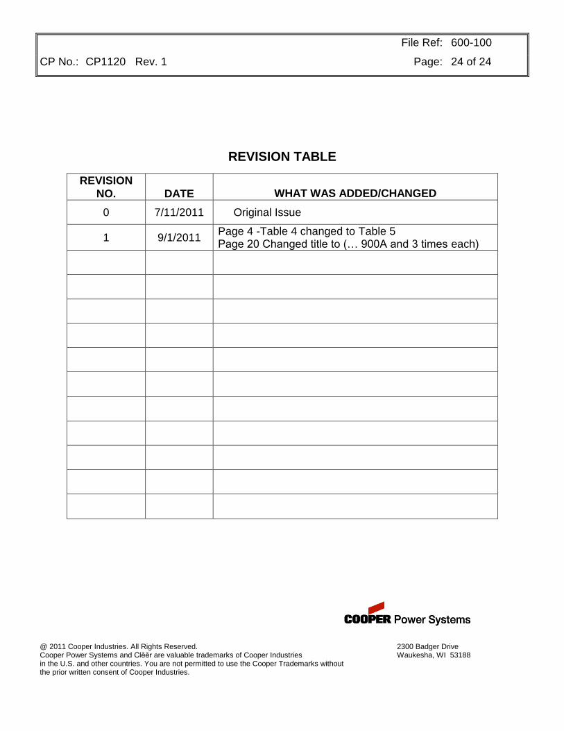
REVISION TABLE
REVISION
NO.
DATE
WHAT WAS ADDED/CHANGED
0 7/11/2011 Original Issue
1 9/1/2011 Page 4 -Table 4 changed to Table 5 Page 20 Changed title to (… 900A and 3 times each)
@ 2011 Cooper Industries. All Rights Reserved. 2300 Badger Drive Cooper Power Systems and Clēēr are valuable trademarks of Cooper Industries Waukesha, WI 53188 in the U.S. and other countries. You are not permitted to use the Cooper Trademarks without the prior written consent of Cooper Industries.
Related Documents