*TM 9-2350-277-20-1 TECHNICAL MANUAL UNIT MAINTENANCE MANUAL FOR CARRIER, PERSONNEL, FULL TRACKED, ARMORED M113A3 2350-01-219-7577 (EIC AEY) CARRIER, COMMAND POST, LIGHT TRACKED M577A3 2350-01-369-6085 (EIC AE7) CARRIER, SMOKE GENERATOR, FULL TRACKED M1059A3 2350-01-369-6083 (EIC AFA) CARRIER, MORTAR, 120-MM M121, SELF-PROPELLED M1064A3 2350-01-369-6082 (EIC AE8) CARRIER, STANDARDIZED INTEGRATED COMMAND POST SYSTEM (SICPS) M1068A3 2350-01-369-6086 (EIC AFC) CARRIER, MECHANIZED SMOKE OBSCURANT M58 2350-01-418-6654 (EIC 5CG) *S U P E R S E D U R E N O T I C E — S supersedes TM 9-2350-277-20, 24 July 1994, including all changes. D I S T R I B U T I O N S T A T E M E N T A — Approved for public release; distribution is unlimited. HEADQUARTERS, DEPARTMENT OF THE ARMY January 2001

Welcome message from author
This document is posted to help you gain knowledge. Please leave a comment to let me know what you think about it! Share it to your friends and learn new things together.
Transcript
*TM 9-2350-277-20-1
TECHNICAL MANUAL
UNIT MAINTENANCE MANUAL
FORCARRIER, PERSONNEL, FULL TRACKED, ARMORED M113A3
2350-01-219-7577 (EIC AEY)
CARRIER, COMMAND POST, LIGHT TRACKED M577A32350-01-369-6085 (EIC AE7)
CARRIER, SMOKE GENERATOR, FULL TRACKED M1059A32350-01-369-6083 (EIC AFA)
CARRIER, MORTAR, 120-MM M121, SELF-PROPELLED M1064A32350-01-369-6082 (EIC AE8)
CARRIER, STANDARDIZED INTEGRATED COMMAND POST SYSTEM(SICPS) M1068A3
2350-01-369-6086 (EIC AFC)
CARRIER, MECHANIZED SMOKE OBSCURANT M582350-01-418-6654 (EIC 5CG)
*SUPERSEDURE NOTICE — Ssupersedes TM 9-2350-277-20, 24 July 1994, including all changes.
DISTRIBUTION STATEMENT A — Approved for public release; distribution is unlimited.
HEADQUARTERS, DEPARTMENT OF THE ARMY
January 2001

TM 9-2350-277-20-1
WARNING SUMMARYWARNING SUMMARYThis list summarizes critical WARNINGS in this manual. They are repeated here to let you know how important they are.Study these WARNINGS carefully; they can save your life and the lives of personnel you work with.
GENERAL WARNINGS NOT FOUND IN WP PROCEDURESThe following WARNINGs are general safety statements. They are not unique to any specific procedures and, therefore, donot appear elsewhere in this TM. All personnel operating this equipment or working near this equipment must understand andcontinually observe the precautions in these WARNINGs.
WARNING
Heater and engine exhaust fumes contain deadly poisonous gases. Severe exposure can causedeath or permanent brain damage. Exhaust gases are most dangerous in places with poorair flow.
To protect yourself and your partners, always obey the following rules:Do not run heater or engine indoors unless you have very good air flow.Do not idle engine for a long time unless there is very good air flow.Do not drive carrier with any power plant access covers open or removed.Be alert at all times. Check for the smell of exhaust fumes. If you notice any fumes, OPEN
HATCH COVERS, RAMP ACCESS DOOR, OR RAMP, RIGHT AWAY.
Exhaust gas poisoning causes dizziness, headache, loss of muscle control, sleepiness, coma,and death. If anyone shows signs of exhaust gas poisoning, get ALL PERSONNEL out of thecarrier. Make sure they have lots of fresh air. KEEP THEM WARM, CALM, AND INACTIVE.GET MEDICAL HELP. If anyone stops breathing, give artificial respiration. See FM 4-25.11for first aid.
WARNING
Hydraulic fluid is poison and can be absorbed through your skin. Wash off hydraulic fluid thatcontacts your skin. Fire resistant hydraulic (FRH) fluid may contain Tricresyl Phosphate which,if taken internally, can produce paralysis. Wear long sleeves, gloves, goggles, and face shield. IfFRH gets in eyes, wash them immediately and get medical aid immediately. If FRH gets onskin, thoroughly wash with soap and water. Wash hands thoroughly prior to eating or smoking.
a Change 5
TM 9-2350-277-20-1
WARNING SUMMARY (cont)
WARNING
Noises from carrier or weapons can damage hearing of personnel in carrier. All personnel incarrier MUST WEAR DOUBLE HEARING PROTECTION when gun or carrier is operated.Hearing protection devices must be properly worn to provide effective protection.
If DOUBLE HEARING PROTECTION is not worn, the safe level of noise exposure will beexceeded in a short time. Hearing loss occurs gradually. Each noise exposure that exceeds theear protection guidelines below will cause a temporary hearing loss. Over time, the loss inhearing will become permanent. Plan each day’s operation, and be sure all crew and ridershave the required ear protectors. Spare foam earplugs must be available.
Definitions:DH-132 The "tankers helmet," also called "CVC" helmet. Must be in good condition,
with liner and earcups fitted tightly, and chin strap worn at all times.
Earplugs Only standard issue earplugs are acceptable. All of the dismounted squadsoldiers must be trained in how to use them. Since they may be removed andlost, spares must be carried.
Double Hearing Protection Use of two hearing protection devices at the same time. For this carrier, useearplugs with the DH-132 helmet.
Ear Protection Guidelines:Driver Must wear DH-132 helmet at all times.
Must wear DH-132 helmet plus earplugs for operations exceeding 14 miles(23 km) in 24 hours.
Must close hatch immediately if .50 caliber machine gun is fired over frontpart of carrier.
Hatch may remain open and locked during carrier operation.
Commander Must wear DH-132 helmet at all times.
Must wear DH-132 helmet plus earplugs for operations exceeding 14 miles(23 km) in 24 hours.
Hatch may be locked open at all times.
Squad Members Must wear helmet and ear plugs at all times.
Use of Radio with EarplugsWearing foam earplugs in addition to your DH-132 helmet can actually improve your ability to hear the radio in a high levelnoise area. DO NOT remove the earplugs to use the radio.
LIST OF WARNINGS IN WP PROCEDURESThis list includes all the critical WARNINGs in the WP procedures. Study these WARNINGs carefully. They can saveyour life and the lives of soldiers with whom you work.
bChange 5
TM 9-2350-277-20-1
WARNING SUMMARY (cont)
WARNING
Moving parts of power unit can seriously injure you.
Clear personnel away from power unit before startup. Stay clear of moving parts when powerunit is running.
WARNING
Hot parts can burn you.
Allow parts to cool before working on or near them. If necessary, use heat protective gloves towork on hot parts.
WARNING
Ensure FUEL SHUT-OFF handle is in OFF position. Engine could start. Personnel could beinjured. Stay clear of possible moving parts.
WARNING
Perform test outdoors or in a well-ventilated area to avoid illness or death caused by inhalationof carbon monoxide from the engine exhaust.
c Change 5
TM 9-2350-277-20-1
WARNING SUMMARY (cont)
WARNING
Carrier may move forward. Personnel may be injured or killed. Keep personnel away fromfront of carrier.
WARNING
Lowering ramp could injure personnel. Make sure no one is in ramp zone before you lowerramp. If tactical situation permits, sound horn before dropping ramp.
WARNING
HIGH VOLTAGE is used in the operation of this equipment.
DEATH ON CONTACT may result if personnel fail to observe safety precautions.
NEVER work on equipment unless at least one other person familiar with the operation andhazards of the equipment is nearby. That person should also be familiar with giving first aid.When an operator helps a mechanic, that operator must be warned about dangerous areas.
SHUT OFF POWER supply to equipment before beginning work. Make sure all externalpower is off/disconnected.
BE CAREFUL not to contact high-voltage connections when installing or operating thisequipment.
WARNING
Make sure ALL AC external and internal power is OFF.
dChange 5
TM 9-2350-277-20-1
WARNING SUMMARY (cont)
WARNING
Air pressure in excess of 30 psi (207 kPa) can injure personnel. Do not direct pressurized airat yourself or others. Always wear goggles.
WARNING
When shifting gear selector into PIVOT, vehicle can move if steering yoke is moved fromcentered position. Soldiers can be killed or injured. Hold brake pedal on. Clear all soldiersaway from vehicle when shifting into PIVOT. Do not move yoke from centered position.
WARNING
Failure to set the parking brake and block road wheels can allow the carrier to move andresult in injury or death. Always set the parking brake and block road wheels before workingon the carrier.
WARNING
Never perform stall check. Transmission can be damaged. Personnel may be injured.
e Change 5
TM 9-2350-277-20-1
WARNING SUMMARY (cont)
WARNING
Hot parts can burn you. Use care when you work near hot power unit.
WARNING
Diesel fuel can catch fire and seriously injure or kill soldiers and damage or destroy the vehicle.Wipe up fuel spills immediately. Do not smoke near fuel or when working on the fuel system.Disconnect vehicle ground when working on the fuel system.
WARNING
Lowering ramp could injure personnel. Make sure no one is in ramp zone before you lowerramp. Unlocked ramp can fall open suddenly. Personnel can be killed or injured. Ramp systemand hull can get damaged if ramp unlocks when carrier is in operation. Do not operate carrierif locks do not secure ramp properly. Keep away from ramps that have come open duringcarrier operation.
WARNING
Ramp wire rope (cable) failure may cause bodily injury or death to personnel or damage toequipment .
fChange 5
TM 9-2350-277-20-1
WARNING SUMMARY (cont)
WARNING
Power plant door may spring open. When opening door, stay out of door path. Soldiers can beinjured.
WARNING
Hydraulic fluid is poisonous and can be absorbed through your skin. Wash off any hydraulicfluid that contacts your skin. Read the hydraulic fluid warning in the front of this manual.
WARNING
You could be injured if cylinder discharges when it is out of its mounting brackets or is dropped.Handle with great care.
WARNING
Battery posts and cables touched by metal objects can short circuit and burn you. Do notwear jewelry, necklaces, or watches when working on the electrical system. Keep tools awayfrom posts, wires, and terminals.
g Change 5
TM 9-2350-277-20-1
WARNING SUMMARY (cont)
WARNING
Gas from batteries can explode and injure you. Do not allow sparks near batteries. Battery acidcan burn or blind you. Do not get acid on your skin or eyes.
WARNING
Lethal voltage is present when light set is connected to power source. Disconnect from powersource before inspecting or repairing any electrical component. Be careful not to contactelectrical connections. Electrical shock and death may result from failure to heed this warning.
WARNING
Seat can spring up and hit you when vertical control handle is released. Make sure you aresitting in the seat before releasing vertical control handle.
WARNING
Fuel cut-off control at driver’s position must be pulled all the way out to prevent engine fromstarting. Personnel could be injured or killed if engine starts during this PMCS check.
hChange 5
TM 9-2350-277-20-1
WARNING SUMMARY (cont)
WARNING
Removing lower brake bearing from brake pivot shaft link while parking brake is on can causeshaft link to spring up and injure personnel. Disengage parking brake when doing this task.
WARNING
Damaged slings can fail when loaded. Breaking slings can strike and injure personnel.Suspended load can fall and crush personnel.
Inspect all slings before use. Do not use damaged slings. Clearly mark all damaged slingsas DAMAGED - DO NOT USE.
WARNING
Hanging loads can kill or injure you. Keep away from hanging loads and overhead equipment.Keep hands out of compartment while power plant is being lifted for removal or lowered forinstallation.
WARNING
Blocking power plant on unlevel, soft ground can cause power plant to sink and tip over.Personnel can be injured and power plant can be damaged. Make sure to block power plant onflat, hard ground.
i Change 5
TM 9-2350-277-20-1
WARNING SUMMARY (cont)
WARNING
Fuel fumes can explode and burn you. Do not smoke or allow open flame near carrier whenremoving and cleaning fuel cap(s).
WARNING
Fuel flowing over a metal surface causes static electricity. This will cause a spark unless thesurface is grounded.
WARNING
Make sure parking brake is set before you start engine. Carrier could lurch and injure you.
WARNING
Hot exhaust pipes can burn you. Let power unit cool before you start work.
WARNING
Sharp edge safety wire can cut your fingers. Make sure to twist end of wire and bend backclose to the attaching hole.
jChange 5

TM 9-2350-277-20-1
WARNING SUMMARY (cont)
WARNING
Hot radiator coolant can burn you. Remove cap only if cool to touch. Drain cocks may be hot.Turn cap slowly to release pressure. Replace cap by pressing down and turning until tight.
WARNING
Radiator is heavy and can cause back injury if handled improperly. Be sure to use a hoist andhelper to remove radiator.
WARNING
Generator weighs 80 lb (37 kg) and can cause back injury if handled improperly. Be sure touse a hoist or a helper to remove generator.
WARNING
Starter weighs 75 lbs (34 kg) and can cause back injury if handled improperly. Be sure to use ahoist or a helper to remove starter.
k Change 5
TM 9-2350-277-20-1
WARNING SUMMARY (cont)
WARNING
Battery posts and cables touched by metal objects can short circuit and burn you or injureyou. Use caution when you work with tools or other metal objects. Do not wear jewelry whenworking on electrical system.
Some circuits remain energized even when MASTER SWITCH is OFF. Make sure groundstrap is disconnected when there is any possibility that the circuit you are working on couldbe energized.
WARNING
Electrical current can burn you. Disconnect ground lead before starting task.
WARNING
Gas from batteries can explode and injure you. Do not allow sparks near batteries. Battery acidcan burn or blind you. Do not get acid on your skin or eyes. ALWAYS disconnect ground leadfirst and connect it last.
WARNING
Electrolyte and battery corrosion can cause injury to you. Wear safety goggles and gloves. Ifelectrolyte or battery corrosion contacts the eyes, skin, or clothing, flush immediately with largeamounts of cold water. In case of eye or skin contact, see a doctor immediately.
lChange 5
TM 9-2350-277-20-1
WARNING SUMMARY (cont)
WARNING
Battery is heavy and can cause back injury if handled improperly. Be sure to have helper assistyou to remove and replace battery. Battery weighs about 75 lb (34 kg).
WARNING
Sharp wire end can injure hands. Make sure wire is doubled over as a safety measure.
WARNING
High voltage in the AN/VVS-2 driver’s night vision can cause serious injury or death. Toavoid accidents:
ALWAYS connect power cable to periscope BEFORE turning MASTER SWITCH and DNVPOWER switch to ON.
After turning DNV POWER and MASTER switch OFF, ALWAYS wait at least 2 minutesBEFORE disconnecting power cable from DNV. Do not disconnect power cable until imagedisappears from DNV screen.
NEVER touch the end of the cable or allow it to contact metal surfaces. Voltage could exceed16,000 volts.
WARNING
Breathing carbon monoxide fumes from engine exhaust could kill you or injure you. Performtests outdoors or in a well-ventilated area.
m Change 5
TM 9-2350-277-20-1
WARNING SUMMARY (cont)
WARNING
Clear the area before checking adjustment. Carrier may pivot steer and injure personnel. Placetransmission controller in SL before checking adjustment.
WARNING
If steering wheel is turned while engine is running at 1000 RPM or greater, the carrier will pivotand personnel could be killed or equipment damaged.
WARNING
The final drive is heavy and can cause back injury if handled improperly. Be sure to use a hoistor a helper to remove final drive.
WARNING
Failure of control linkage can cause carrier to crash. Crash could kill or injure personnel.
nChange 5
TM 9-2350-277-20-1
WARNING SUMMARY (cont)
WARNING
If road wheel lifter slips while lowering road arm, it could injure you. Stand clear before youlower road arm.
WARNING
Hanging loads, heavy parts, and overhead equipment can fall unexpectedly. Falling loads cankill or seriously injure personnel.
Keep away from hanging loads, heavy parts, and overhead equipment. Use correct liftingdevices to move hanging loads and heavy parts. Always have a helper guide you. Keep handsand feet out of confined spaces from which heavy loads are being installed or removed.
WARNING
Your eyes can be injured with pressurized water and dirt particles. Wear safety goggles.
WARNING
Before adjusting track, ensure there are 63 track shoes on the left side track, and 64 trackshoes on the right side track. Improper number of track shoes may prevent track from beingproperly adjusted, creating a safety hazard.
o Change 5
TM 9-2350-277-20-1
WARNING SUMMARY (cont)
WARNING
Position retainer stops inside of end connectors to prevent the lifter from slipping off andcausing injury and/or death to personnel.
WARNING
With the transmission controller in any range except SL and if the locking pin is protrudingfrom the steering wheel housing any amount, the steering wheel will not turn properly anddeath of personnel or damage of equipment may occur.
WARNING
Engine exhaust gas is deadly poison. Make sure the bellows are installed properly in enginecompartment panel hole.
WARNING
Carbon monoxide gas is deadly poison. Play it safe! Make sure power plant access panels areclosed tight before you start engine.
pChange 5
TM 9-2350-277-20-1
WARNING SUMMARY (cont)
WARNING
The grill assembly will swing when screws are removed. To avoid injury, do not stand in frontof or behind grill assembly.
WARNING
Grill and access cover are very heavy. Use extreme caution when lifting blocking, and loweringassembly. Allowing assembly to fall could cause death or injury.
WARNING
Power plant door is heavy. It can fall and injure you. Do not remove housing before relievingspring tension by lifting and holding with lifting device.
WARNING
Hanging loads, heavy parts, and overhead equipment can fall unexpectedly and kill or injureyou.
Stay clear of hanging loads, heavy parts, and overhead equipment. Use correct lifting devices.Always have helper guide heavy parts and equipment.
q Change 5
TM 9-2350-277-20-1
WARNING SUMMARY (cont)
WARNING
Driver’s hatch cover may spring up and injure you. Open and support hatch cover in verticalposition.
WARNING
Mortar hatch sections must be in a vertical position to release torsion spring tension beforeremoving torsion spring brackets.
WARNING
Personnel could be injured if they slip on oil or graphite on top of carrier. Clean up spillsimmediately. Personnel on top of carrier should always use three point stance.
WARNING
Do not remove screws securing door to hull. It may fall and injure personnel. Tag door handleto warn those who want access to turbine compartment.
rChange 5
TM 9-2350-277-20-1
WARNING SUMMARY (cont)
WARNING
Falling hatch could seriously injure you.
Keep head lower than closed hatch position when opening or closing hatch. Keep hands clearof hatch rim when closing. Make sure latch pin or mechanism is fully engaged when hatchis in any open position.
WARNING
An inoperable/unsafe ramp can fall and kill soldiers. Follow these procedures and never getbehind a raised, inoperable/unsafe ramp that is not secured.
WARNING
Falling ramp could cause severe injuries. Keep personnel clear of ramp area.
WARNING
Magnesium may catch on fire if welded on or exposed to high temperatures. Do not weld onmagnesium castings or expose them to high temperatures.
s Change 5
TM 9-2350-277-20-1
WARNING SUMMARY (cont)
WARNING
Fine particles of magnesium can catch fire and burn you. Be very careful when filing orgrinding on magnesium. Use grinding equipment marked FOR MAGNESIUM GRINDINGONLY. Keep a Class D fire extinguisher nearby.
WARNING
Water and foam-type fire extinguishers will cause magnesium fires to flare up. Use a Class Dfire extinguisher or a sodium chloride base dry powder to fight magnesium fires.
WARNING
Improper disposal of magnesium can cause a fire or explosion. Do not expose magnesiumto high temperatures. Let magnesium dry before placing in sealed metal containers. Labelcontainers and ship to a Class 1 hazardous waste disposal site.
WARNING
Do not weld on plastic molding material. Welding on plastic molding creates toxic fumes.Fumes are hazardous to your health and can result in death.
tChange 5
TM 9-2350-277-20-1
WARNING SUMMARY (cont)
WARNING
Fuel fumes can explode and burn you. Before welding:Drain all fuel.Disconnect and cap all fuel and vent lines.Purge fuel residue and fumes by steam cleaning.Purge air from fuel tank with CO2.
WARNING
Apply pressure on tube to prevent spring from releasing when handle is pulled out. Injury topersonnel can result from flying tube and spring.
WARNING
Rear trays of ammo rack could collapse when removed. To prevent injury, move ammo rackfrom the front. Keep fingers away from spaces between trays on the back of ammo rack.
WARNING
Fire Resistant Hydraulic fluid (FRH) is toxic if absorbed through skin or ingested.
Do not service hydraulic system when FRH is hot or pressurized.Wear gloves and avoid contact with skin.If FRH contacts skin, wash immediately with soap.If FRH gets into eyes, wash with lots of water for 15 minutes and get medical attention.If FRH is swallowed, get medical attention.
u Change 5
TM 9-2350-277-20-1
WARNING SUMMARY (cont)
WARNING
Wearing loose clothing around moving parts can allow personnel to get caught and resultin injury or death. Tuck in loose clothing.
WARNING
Lifting or moving objects in excess of 70 lbs (32 kg) could injure you. Make sure to get anassistant or use a lifting device to move generator set enclosure or other heavy objects.
WARNING
Diesel fuel can catch fire and seriously injure or kill soldiers and damage or destroy vehicles.Wipe up fuel spills immediately. Do not smoke near fuel or when working on the fuel system.
WARNING
Exhaust fumes can poison you if wrong heater is installed. Do not interchange “common air”heater for a “dual air” heater.
vChange 5
TM 9-2350-277-20-1
WARNING SUMMARY (cont)
WARNING
The insulator blanket is made out of asbestos. Handle with care. Discard insulator blanketproperly as a hazardous material per local standard operating procedure. The insulator washertakes the place of the blanket.
WARNING
Older gaskets are made out of asbestos. Handle with care. Discard older gasket properly as ahazardous material per local standard operating procedure.
WARNING
To prevent litter tilt, which could cause injury, be sure to install repair link at chain link No. 47.
WARNING
Armor plates are heavy and can cause injury or death. Support armor plate properly to avoidinjury.
w Change 5
TM 9-2350-277-20-1
WARNING SUMMARY (cont)
WARNING
Power plant door contains a torsion spring assembly which could cause injury or death topersonnel. Door must be raised to neutral position before removing two screws from housing.
WARNING
Ramp door is heavy and can cause injury or death. Support ramp door properly to avoid injury.
WARNING
Fog oil is slippery and can cause soldiers to fall and get injured. Clean up all spillage or leakageof fog oil as soon as possible by washing the area or absorbing the fog oil with sand or otherabsorbent material.
WARNING
Lifting or moving objects in excess of 70 lbs (32 kg) could injure you. Make sure to get anassistant or use a lifting device to move fog oil tank, armor, or other heavy objects.
xChange 5
TM 9-2350-277-20-1
WARNING SUMMARY (cont)
WARNING
Hanging loads can kill or injure you. Keep away from hanging loads and overhead equipment.Keep hands away from pinch points.
WARNING
Compressed air pressure from smoke generator can cause serious injury or death. To avoidaccidents, bleed air before working on air compressor assembly or disconnecting any air hose.
WARNING
Before you do any maintenance, discharge all capacitors to ground or electrical shock couldinjure personnel.
WARNING
Fuel and fog oil can burn and could poison you.
y Change 5
TM 9-2350-277-20-1
WARNING SUMMARY (cont)
WARNING
Contaminated filters are hazardous to personnel. Use precautions when handling filters.Dispose of filters using trained chemical environment personnel.
WARNING
Removing cables from the regulator without disconnecting the vehicle battery ground cablemay hurt personnel and damage equipment from electrical power.
WARNING
Hot exhaust pipes can burn you. Let power unit cool before you start work.
WARNING
Battery posts and cables touched by metal objects can short circuit and burn you. Use cautionwhen you work with tools or other metal objects. Do not wear jewelry when you work onelectrical system.
zChange 5
TM 9-2350-277-20-1
WARNING SUMMARY (cont)
WARNING
You could be injured if cylinder discharges when it is out of its mounting brackets or is dropped.Discharge cylinder completely before removing from its mount. Handle with great care.
WARNING
Adhesive, primer, sealant compounds, and isopropyl alcohol are toxic and flammable. Thesecompounds are toxic to eyes, skin, and respiratory tract. Continued exposure can make youdizzy and irritate your eyes and throat.
Always use in well ventilated areas, away from heat, sparks, and flames. Do not breathe fumes.Do not allow into contact with skin and eyes. Use goggles or face shield and protective gloves.
WARNING
The grill assembly will swing when screws are removed. To avoid injury, do not stand in frontof or behind grill assembly.
Damaged lifting slings can fail with load. Soldiers can be killed or injured. Inspect all slingsbefore use. Do not use damaged slings.
Grill and access cover are very heavy. Use extreme caution when lifting, blocking, and loweringassembly. Allowing assembly to fall could cause death or injury.
aa Change 5
TM 9-2350-277-20-1
WARNING SUMMARY (cont)
WARNING
Personnel can be killed or injured by a falling 800 lb (363 kg) mine armor plate. Use a forkliftor mechanical lifting device capable of lifting 800 lb (363 kg) to position hull mine armorplate for assembly.
WARNING
Personnel can be killed or injured by a falling 800 lb (363 kg) mine armor plate. Use a forkliftor mechanical lifting device capable of lifting 800 lb (363 kg) to support hull mine armor platefor removal. Verify that armor plate is properly supported before reaching under to removehardened washers and screws.
WARNING
Metal chips and grinding dust can cause eye injury. Wear goggles and gloves.
WARNING
To avoid possible rupture of fuel tank and personnel injury, do not drill any holes prior totilting of table top.
abChange 5

TM 9-2350-277-20-1
WARNING SUMMARY (cont)
WARNING
To ease in the removal of power distribution assembly (PDA), use hand to support PDA. Usecare to avoid injury to personnel or damage to equipment.
WARNING
To avoid personnel injury or damage to equipment, when removing positive cable, avoid anycontact of positive battery cable with surrounding metal surfaces. Contact can cause batteryarcing or explosion. Wear safety glasses.
WARNING
To avoid personnel injury and damage to equipment, route cable 4W6 in position clear ofpersonnel heater.
WARNING
Each Outback inverter assembly weighs 70 lbs (32kg) and may be awkward to handle. Usecorrect lifting procedures, indicated lifting devices, and/or assistance from other personnel toavoid injury. Failure to comply could result in injury to personnel and equipment damage.
ac Change 5
TM 9-2350-277-20-1
WARNING SUMMARY (cont)
WARNING
Battery posts and power cables can short circuit and burn you.
Remove vehicle ground cable before starting task. Do not touch battery posts with tools orother metal objects. Do not wear jewelry when working with battery or electrical system.
FIRST AIDFor first aid information, see FM 4-25.11.
adChange 5
TM 9-2350-277-20-1
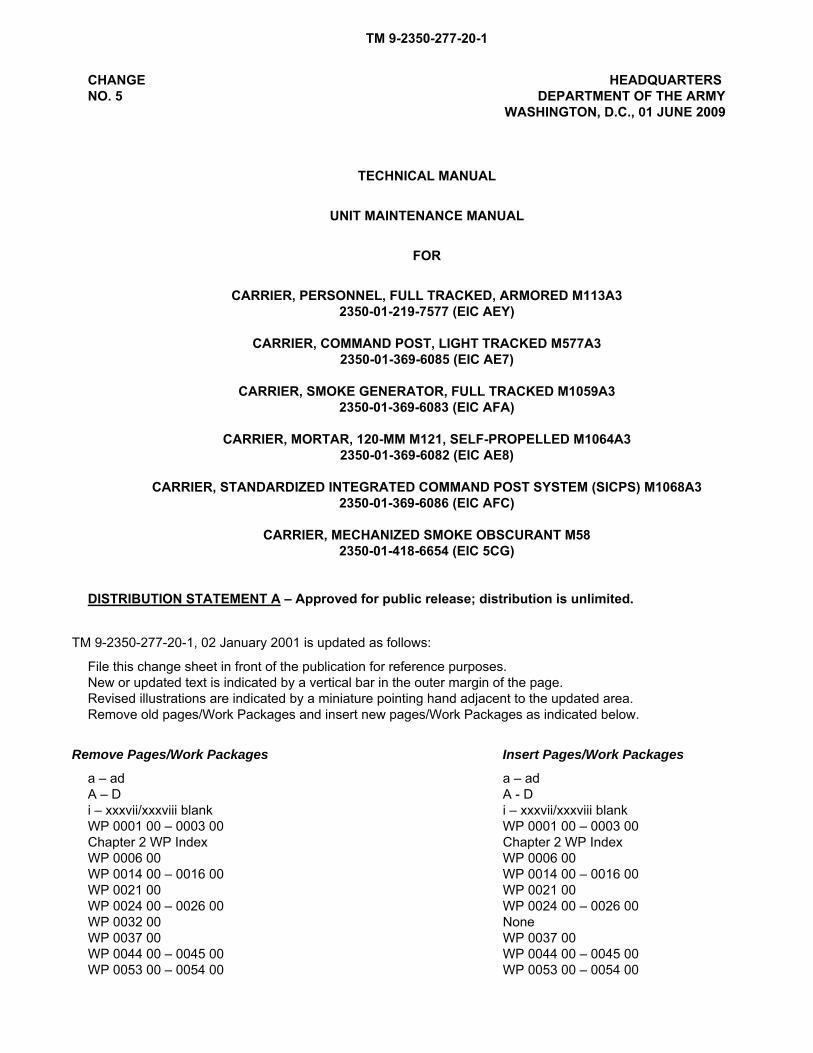
CHANGE HEADQUARTERS NO. 5 DEPARTMENT OF THE ARMY WASHINGTON, D.C., 01 JUNE 2009
TECHNICAL MANUAL
UNIT MAINTENANCE MANUAL
FOR
CARRIER, PERSONNEL, FULL TRACKED, ARMORED M113A3 2350-01-219-7577 (EIC AEY)
CARRIER, COMMAND POST, LIGHT TRACKED M577A3 2350-01-369-6085 (EIC AE7)
CARRIER, SMOKE GENERATOR, FULL TRACKED M1059A3 2350-01-369-6083 (EIC AFA)
CARRIER, MORTAR, 120-MM M121, SELF-PROPELLED M1064A3 2350-01-369-6082 (EIC AE8)
CARRIER, STANDARDIZED INTEGRATED COMMAND POST SYSTEM (SICPS) M1068A3 2350-01-369-6086 (EIC AFC)
CARRIER, MECHANIZED SMOKE OBSCURANT M58 2350-01-418-6654 (EIC 5CG)
DISTRIBUTION STATEMENT A – Approved for public release; distribution is unlimited.
TM 9-2350-277-20-1, 02 January 2001 is updated as follows:
File this change sheet in front of the publication for reference purposes. New or updated text is indicated by a vertical bar in the outer margin of the page. Revised illustrations are indicated by a miniature pointing hand adjacent to the updated area. Remove old pages/Work Packages and insert new pages/Work Packages as indicated below.
Remove Pages/Work Packages Insert Pages/Work Packages
a – ad a – ad A – D A - D i – xxxvii/xxxviii blank i – xxxvii/xxxviii blank WP 0001 00 – 0003 00 WP 0001 00 – 0003 00 Chapter 2 WP Index Chapter 2 WP Index WP 0006 00 WP 0006 00 WP 0014 00 – 0016 00 WP 0014 00 – 0016 00 WP 0021 00 WP 0021 00 WP 0024 00 – 0026 00 WP 0024 00 – 0026 00 WP 0032 00 None WP 0037 00 WP 0037 00 WP 0044 00 – 0045 00 WP 0044 00 – 0045 00 WP 0053 00 – 0054 00 WP 0053 00 – 0054 00

TM 9-2350-277-20-1
Remove Pages/Work Packages (Continued) Insert Pages/Work Packages (Continued)
WP 0056 00 – 0059 00 WP 0056 00 – 0059 00 WP 0061 00 – 0073 00 WP 0061 00 – 0073 00 WP 0084 00 WP 0084 00 WP 0086 00 WP 0086 00 WP 0089 00 WP 0089 00 None WP 0109 01 WP 0115 00 – 0130 00 WP 0115 00 – 0130 00 WP 0131 00 None WP 0132 00 – 0136 00 WP 0132 00 – 0136 00 WP 0138 00 – 0139 00 None WP 0140 00 – 0153 00 WP 0140 00 – 0153 00 WP 0155 00 WP 0155 00 WP 0161 00 WP 0161 00 Chapter 5 WP Index Chapter 5 WP Index WP 0166 00 WP 0166 00 WP 0169 00 WP 0169 00 None WP 0169 01 WP 0170 00 WP 0170 00 WP 0172 00 WP 0172 00 WP 0175 00 WP 0175 00 WP 0213 00 – 0214 00 WP 0213 00 – 0214 00 WP 0216 00 – 0220 00 WP 0216 00 – 0220 00 WP 0221 00 WP 0221 00 WP 0223 00 – 0226 00 WP 0223 00 – 0226 00 WP 0228 00 WP 0228 00 Chapter 8 WP Index Chapter 8 WP Index WP 0260 00 WP 0260 00 WP 0262 00 WP 0262 00 WP 0279 00 – 0279 01 WP 0279 00 – 0279 01 WP 0282 00 WP 0282 00 WP 0295 00 – 0295 01 WP 0295 00 – 0295 01 WP 0297 00 None WP 0303 00 – 0304 00 WP 0303 00 – 0304 00 WP 0325 00 WP 0325 00 WP 0360 00 – 0361 00 WP 0360 00 - 0361 00 WP 0366 00 WP 0366 00 WP 0373 00 WP 0373 00 WP 0390 00 – 0391 00 WP 0390 00 – 0391 00 WP 0394 00 WP 0394 00 WP 0397 00 – 0398 00 WP 0397 00 – 0398 00 WP 0400 00 WP 0400 00 WP 0402 00 – 0404 00 WP 0402 00 – 0404 00 WP 0405 00 – 0407 00 WP 0405 00 – 0407 00 WP 0409 00 – 0411 00 WP 0409 00 – 0411 00 WP 0430 00 WP 0430 00 Chapter 17 WP Index Chapter 17 WP Index WP 0447 00 – 0449 00 WP 0447 00 – 0449 00 WP 0458 00 – 0463 00 None WP 0464 00 WP 0464 00 WP 0470 00 – 0471 00 WP 0470 00 – 0471 00 WP 0473 00 WP 0473 00 WP 0508 00 – 0510 00 WP 0508 00 – 0510 00 WP 0574 00 WP 0574 00 WP 0631 00 – 0632 00 WP 0631 00 – 0632 00 WP 0636 00 – 0637 00 WP 0636 00 – 0637 00

TM 9-2350-277-20-1
Remove Pages/Work Packages (Continued) Insert Pages/Work Packages (Continued)
WP 0640 00 – 0648 00 WP 0640 00 – 0648 00 WP 0651 00 – 0654 00 WP 0651 00 – 0654 00 WP 0655 00 WP 0655 00 WP 0657 00 – 0658 00 WP 0657 00 – 0658 00 Chapter 22 WP Index Chapter 22 WP Index WP 0710 00 WP 0710 00 WP 0712 00 – 0715 00 WP 0712 00 – 0715 00 WP 0724 00 WP 0724 00 WP 0728 00 WP 0728 00 WP 0730 00 – 0731 00 WP 0730 00 – 0731 00 WP 0733 00 WP 0733 00 WP 0735 00 WP 0735 00 None WP 0751 01 WP 0812 05 WP 0812 05 WP 0812 10 WP 0812 10 WP 0812 12 WP 0812 12 WP 0812 14 WP 0812 14 Chapter 24 WP Index Chapter 24 WP Index WP 0828 00 WP 0828 00 None WP 0830 01 WP 0847 00 WP 0847 00 None WP 0847 01 WP 0860 00 – 0861 00 WP 0860 00 – 0861 00 WP 0863 00 – 0865 00 WP 0863 00 – 0865 00 Chapter 27 WP Index Chapter 27 WP Index WP 0866 01 – 0866 05 WP 0866 01 – 0866 05 WP 0867 00 – 0868 00 WP 0867 00 – 0868 00 WP 0870 00 – 0871 00 WP 0870 00 – 0871 00 WP 0873 00 – 0875 00 WP 0873 00 – 0875 00 WP 0877 00 – 0879 00 WP 0877 00 – 0879 00 WP 0881 00 – 0882 00 WP 0881 00 – 0882 00 WP 0899 00 WP 0899 00 WP 0924 00 – 0926 00 WP 0924 00 – 0926 00 Index-1 – Index-99/100 blank Index-1 – Index-99/100 blank FP-1 – FP-30.1/FP-30.2 blank FP-1 – FP-30.1/FP-30.2 blank FP-63 – FP 103/FP-104 blank FP-63 – FP 103/FP-104 blank FP-106.1 – FP-121/FP-122 blank FP-106.1 – FP-121/FP-122 blank
0913105
DISTRIBUTION:
To be distributed in accordance with the initial distribution requirements for (IDN) 371205, TM 9-2350-277-20-1.
By Order of the Secretary of the Army: GEORGE W. CASEY, JR. General, United States Army Chief of Staff
Official:
JOYCE E. MORROW Administrative Assistant to
the Secretary of the Army
DA 2028 Forms DA 2028 Forms

TM 9-2350-277-20-1
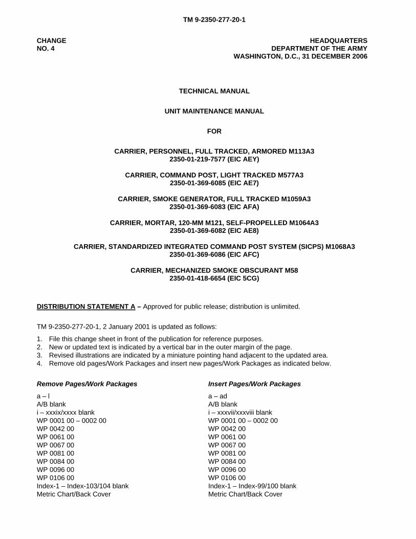
CHANGE HEADQUARTERS NO. 4 DEPARTMENT OF THE ARMY WASHINGTON, D.C., 31 DECEMBER 2006
TECHNICAL MANUAL
UNIT MAINTENANCE MANUAL
FOR
CARRIER, PERSONNEL, FULL TRACKED, ARMORED M113A3 2350-01-219-7577 (EIC AEY)
CARRIER, COMMAND POST, LIGHT TRACKED M577A3 2350-01-369-6085 (EIC AE7)
CARRIER, SMOKE GENERATOR, FULL TRACKED M1059A3 2350-01-369-6083 (EIC AFA)
CARRIER, MORTAR, 120-MM M121, SELF-PROPELLED M1064A3 2350-01-369-6082 (EIC AE8)
CARRIER, STANDARDIZED INTEGRATED COMMAND POST SYSTEM (SICPS) M1068A3 2350-01-369-6086 (EIC AFC)
CARRIER, MECHANIZED SMOKE OBSCURANT M58 2350-01-418-6654 (EIC 5CG)
DISTRIBUTION STATEMENT A – Approved for public release; distribution is unlimited.
TM 9-2350-277-20-1, 2 January 2001 is updated as follows:
1. File this change sheet in front of the publication for reference purposes. 2. New or updated text is indicated by a vertical bar in the outer margin of the page. 3. Revised illustrations are indicated by a miniature pointing hand adjacent to the updated area. 4. Remove old pages/Work Packages and insert new pages/Work Packages as indicated below.
Remove Pages/Work Packages Insert Pages/Work Packages
a – l a – ad A/B blank A/B blank i – xxxix/xxxx blank i – xxxvii/xxxviii blank WP 0001 00 – 0002 00 WP 0001 00 – 0002 00 WP 0042 00 WP 0042 00 WP 0061 00 WP 0061 00 WP 0067 00 WP 0067 00 WP 0081 00 WP 0081 00 WP 0084 00 WP 0084 00 WP 0096 00 WP 0096 00 WP 0106 00 WP 0106 00 Index-1 – Index-103/104 blank Index-1 – Index-99/100 blank Metric Chart/Back Cover Metric Chart/Back Cover

TM 9-2350-277-20-1
0632403 DISTRIBUTION: To be distributed in accordance with the initial distribution requirements for (IDN) 371205, TM 9-2350-277-20-1.
By Order of the Secretary of the Army:
PETER J. SCHOOMAKER General, United States Army
Chief of Staff Official:
JOYCE E. MORROW Administrative Assistant to the
Secretary of the Army
TM 9-2350-277-20-1
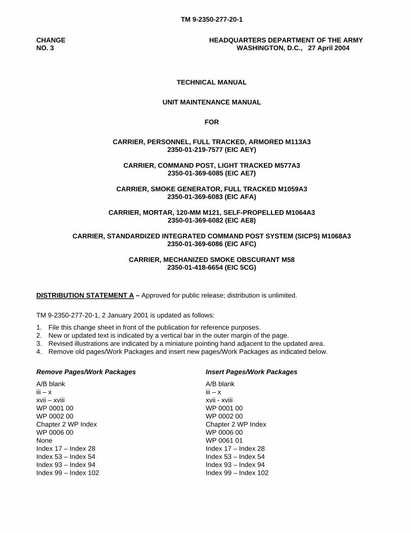
CHANGE HEADQUARTERS DEPARTMENT OF THE ARMY NO. 3 WASHINGTON, D.C., 27 April 2004
TECHNICAL MANUAL
UNIT MAINTENANCE MANUAL
FOR
CARRIER, PERSONNEL, FULL TRACKED, ARMORED M113A3 2350-01-219-7577 (EIC AEY)
CARRIER, COMMAND POST, LIGHT TRACKED M577A3 2350-01-369-6085 (EIC AE7)
CARRIER, SMOKE GENERATOR, FULL TRACKED M1059A3 2350-01-369-6083 (EIC AFA)
CARRIER, MORTAR, 120-MM M121, SELF-PROPELLED M1064A3 2350-01-369-6082 (EIC AE8)
CARRIER, STANDARDIZED INTEGRATED COMMAND POST SYSTEM (SICPS) M1068A3 2350-01-369-6086 (EIC AFC)
CARRIER, MECHANIZED SMOKE OBSCURANT M58 2350-01-418-6654 (EIC 5CG)
DISTRIBUTION STATEMENT A – Approved for public release; distribution is unlimited.
TM 9-2350-277-20-1, 2 January 2001 is updated as follows:
1. File this change sheet in front of the publication for reference purposes. 2. New or updated text is indicated by a vertical bar in the outer margin of the page. 3. Revised illustrations are indicated by a miniature pointing hand adjacent to the updated area. 4. Remove old pages/Work Packages and insert new pages/Work Packages as indicated below.
Remove Pages/Work Packages Insert Pages/Work Packages
A/B blank A/B blank iii – x iii – x xvii – xviii xvii - xviii WP 0001 00 WP 0001 00 WP 0002 00 WP 0002 00 Chapter 2 WP Index Chapter 2 WP Index WP 0006 00 WP 0006 00 None WP 0061 01 Index 17 – Index 28 Index 17 – Index 28 Index 53 – Index 54 Index 53 – Index 54 Index 93 – Index 94 Index 93 – Index 94 Index 99 – Index 102 Index 99 – Index 102
TM 9-2350-277-20-1
By Order of the Secretary of the Army:
Official:
JOEL B. HUDSON Administrative Assistant to the Secretary of the Army 0404106
DISTRIBUTION: To be distributed in accordance with the initial distribution number (IDN) 371205 requirements for TM 9-2350-277-20-1.
PETER J. SCHOOMAKERGeneral, United States Army
Chief of Staff
TM 9-2350-277-20-1
CHANGE HEADQUARTERSNO. 2 DEPARTMENT OF THE ARMY
WASHINGTON, D.C., 02 October 2003
TECNICAL MANUAL
UNIT MAINTENANCE MANUAL
FOR
CARRIER, PERSONNEL, FULL TRACKED, ARMORED M113A32350-01-219-7577 (EIC AEY)
CARRIER, COMMAND POST, LIGHT TRACKED M577A32350-01-369-6085 (EIC AE7)
CARRIER, SMOKE GENERATOR, FULL TRACKED M1059A32350-01-369-6083 (EIC AFA)
CARRIER, MORTAR, 120-MM M121, SELF-PROPELLED M1064A32350-01-369-6082 (EIC AE8)
CARRIER, STANDARDIZED INTEGRATED COMMAND POST SYSTEM (SICPS) M1068A32350-01-369-6086 (EIC AFC)
CARRIER, MECHANIZED SMOKE OBSCURANT M582350-01-418-6654 (EIC 5CG)
DISTRIBUTION STATEMENT A – Approved for public release; distribution is unlimited.
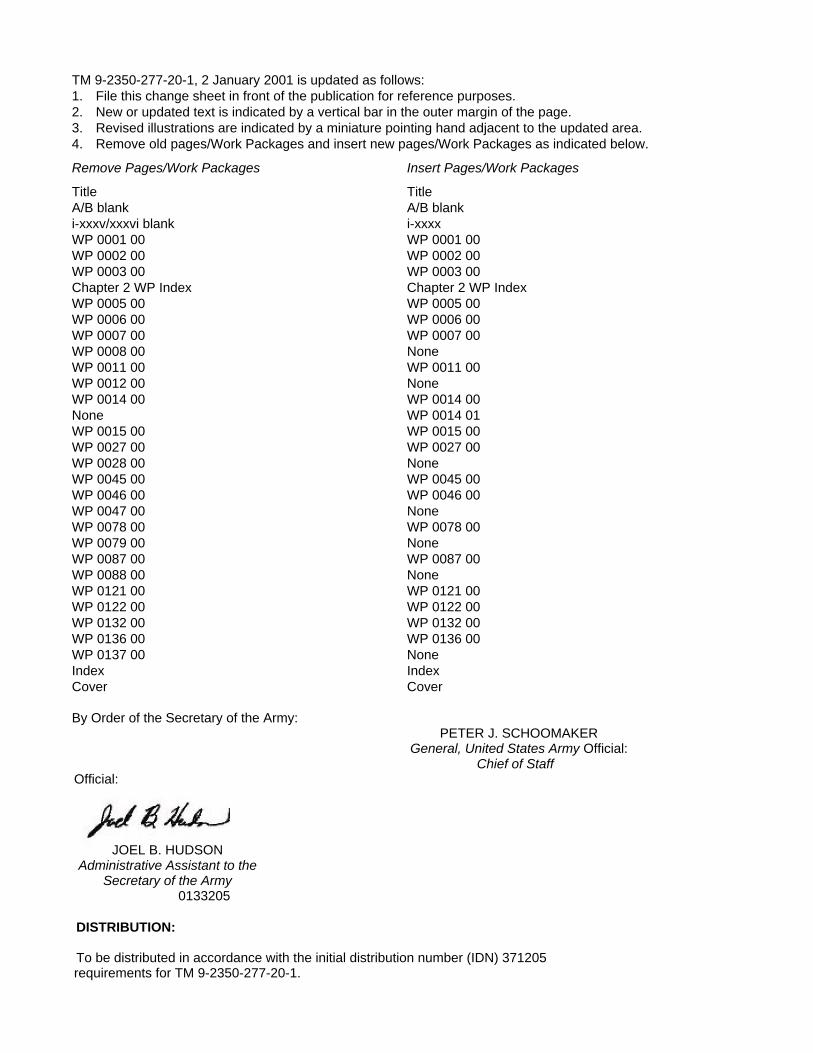
TM 9-2350-277-20-1, 2 January 2001 is updated as follows: 1. File this change sheet in front of the publication for reference purposes. 2. New or updated text is indicated by a vertical bar in the outer margin of the page. 3. Revised illustrations are indicated by a miniature pointing hand adjacent to the updated area. 4. Remove old pages/Work Packages and insert new pages/Work Packages as indicated below.
Remove Pages/Work Packages Insert Pages/Work Packages
Title Title A/B blank A/B blank i-xxxv/xxxvi blank i-xxxx WP 0001 00 WP 0001 00 WP 0002 00 WP 0002 00 WP 0003 00 WP 0003 00 Chapter 2 WP Index Chapter 2 WP Index WP 0005 00 WP 0005 00 WP 0006 00 WP 0006 00 WP 0007 00 WP 0007 00 WP 0008 00 None WP 0011 00 WP 0011 00 WP 0012 00 None WP 0014 00 WP 0014 00 None WP 0014 01 WP 0015 00 WP 0015 00 WP 0027 00 WP 0027 00 WP 0028 00 None WP 0045 00 WP 0045 00 WP 0046 00 WP 0046 00 WP 0047 00 None WP 0078 00 WP 0078 00 WP 0079 00 None WP 0087 00 WP 0087 00 WP 0088 00 None WP 0121 00 WP 0121 00 WP 0122 00 WP 0122 00 WP 0132 00 WP 0132 00 WP 0136 00 WP 0136 00 WP 0137 00 None Index Index Cover Cover
By Order of the Secretary of the Army: PETER J. SCHOOMAKER General, United States Army Official: Chief of Staff Official:
JOEL B. HUDSON Administrative Assistant to the Secretary of the Army 0133205
DISTRIBUTION: To be distributed in accordance with the initial distribution number (IDN) 371205 requirements for TM 9-2350-277-20-1.

TM 9-2350-277-20-1
CHANGE HEADQUARTERSNO. 1 DEPARTMENT OF THE ARMY
WASHINGTON, D.C., 05 SEPTEMBER 2003
TECHNICAL MANUAL
UNIT MAINTENANCE MANUAL
FOR
CARRIER, PERSONNEL, FULL TRACKED, ARMORED M113A32350-01-219-7577 (EIC AEY)
CARRIER, COMMAND POST, LIGHT TRACKED M577A32350-01-369-6085 (EIC AE7)
CARRIER, ANTI-TANK (TOW), FULL TRACKED, ARMORED M901A32350-01-369-7253 (EIC AFD)
CARRIER, FIRE SUPPORT PERSONNEL, FULL TRACKED, ARMORED M981A32350-01-369-6079 (EIC AFB)
CARRIER, SMOKE GENERATOR, FULL TRACKED M1059A32350-01-369-6083 (EIC AFA)
CARRIER, MORTAR, 120-MM M121, SELF-PROPELLED M1064A32350-01-369-6082 (EIC AE8)
CARRIER, STANDARDIZED INTEGRATED COMMAND POST SYSTEM (SICPS) M1068A32350-01-369-6086 (EIC AFC)
CARRIER, MECHANIZED SMOKE OBSCURANT M582350-01-418-6654 (EIC 5CG)
DISTRIBUTION STATEMENT A – Approved for public release; distribution is unlimited.
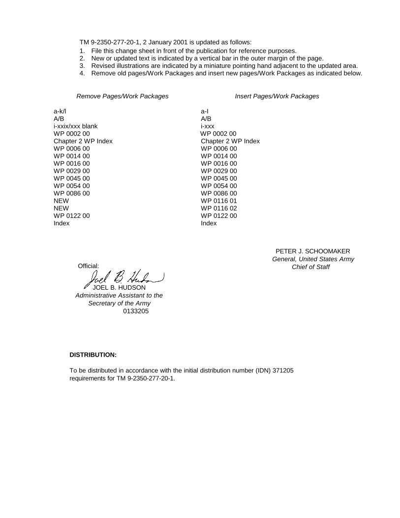
1. File this change sheet in front of the publication for reference purposes.2. New or updated text is indicated by a vertical bar in the outer margin of the page.3. Revised illustrations are indicated by a miniature pointing hand adjacent to the updated area.4. Remove old pages/Work Packages and insert new pages/Work Packages as indicated below.
Remove Pages/Work Packages Insert Pages/Work Packages
a-k/l a-IA/B A/Bi-xxix/xxx blank i-xxx WP 0002 00 WP 0002 00Chapter 2 WP Index Chapter 2 WP IndexWP 0006 00 WP 0006 00WP 0014 00 WP 0014 00WP 0016 00 WP 0016 00WP 0029 00 WP 0029 00WP 0045 00 WP 0045 00WP 0054 00 WP 0054 00WP 0086 00 WP 0086 00NEW WP 0116 01NEW WP 0116 02WP 0122 00 WP 0122 00Index Index
TM 9-2350-277-20-1, 2 January 2001 is updated as follows:
0133205
To be distributed in accordance with the initial distribution number (IDN) 371205
DISTRIBUTION:
requirements for TM 9-2350-277-20-1.
PETER J. SCHOOMAKER General, United States Army
Chief of StaffOfficial:
JOEL B. HUDSON
Secretary of the ArmyAdministrative Assistant to the
TM 9-2350-277-20-1
INSERT LATEST UPDATED PAGES/WORK PACKAGES. DESTROY SUPERSEDED DATA.
A
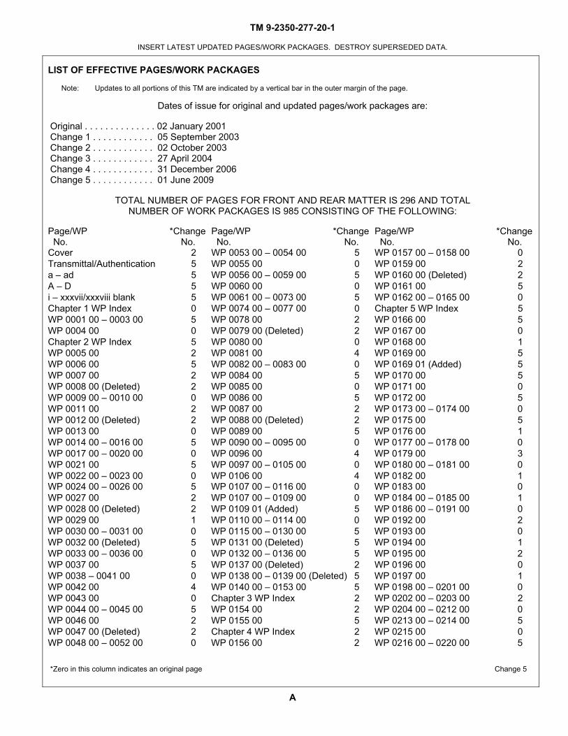
LIST OF EFFECTIVE PAGES/WORK PACKAGES
Note: Updates to all portions of this TM are indicated by a vertical bar in the outer margin of the page.
Dates of issue for original and updated pages/work packages are:
Original . . . . . . . . . . . . . . 02 January 2001 Change 1 . . . . . . . . . . . . 05 September 2003 Change 2 . . . . . . . . . . . . 02 October 2003 Change 3 . . . . . . . . . . . . 27 April 2004 Change 4 . . . . . . . . . . . . 31 December 2006 Change 5 . . . . . . . . . . . . 01 June 2009
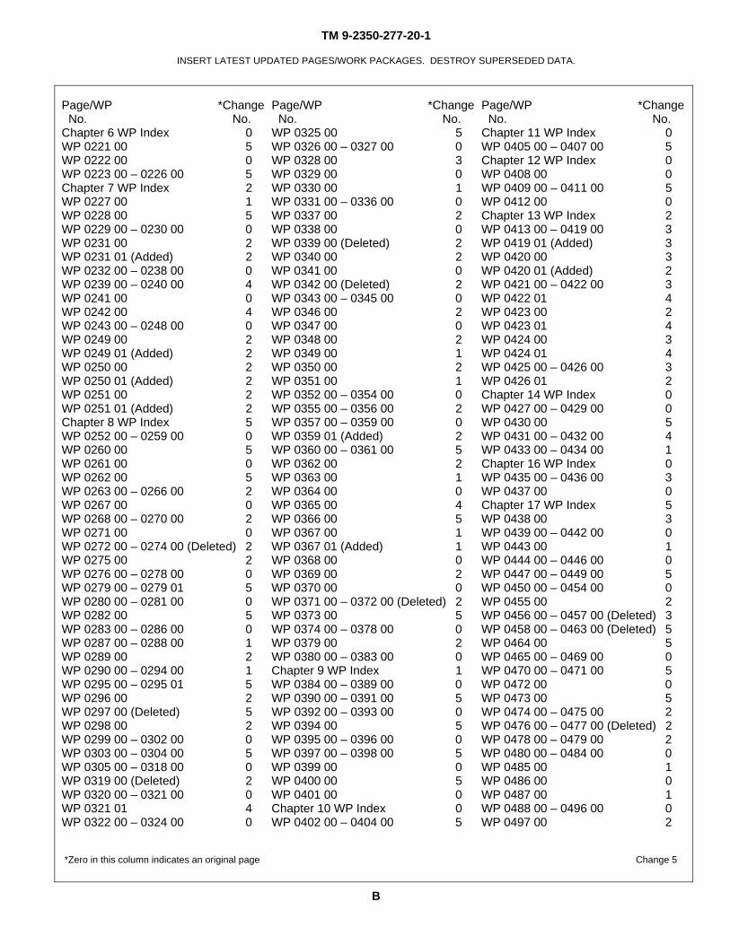
TOTAL NUMBER OF PAGES FOR FRONT AND REAR MATTER IS 296 AND TOTAL NUMBER OF WORK PACKAGES IS 985 CONSISTING OF THE FOLLOWING:
Page/WP *Change No. No.
Page/WP *Change No. No.
Page/WP *Change No. No.
Cover 2 WP 0053 00 – 0054 00 5 WP 0157 00 – 0158 00 0 Transmittal/Authentication 5 WP 0055 00 0 WP 0159 00 2 a – ad 5 WP 0056 00 – 0059 00 5 WP 0160 00 (Deleted) 2 A – D 5 WP 0060 00 0 WP 0161 00 5 i – xxxvii/xxxviii blank 5 WP 0061 00 – 0073 00 5 WP 0162 00 – 0165 00 0 Chapter 1 WP Index 0 WP 0074 00 – 0077 00 0 Chapter 5 WP Index 5 WP 0001 00 – 0003 00 5 WP 0078 00 2 WP 0166 00 5 WP 0004 00 0 WP 0079 00 (Deleted) 2 WP 0167 00 0 Chapter 2 WP Index 5 WP 0080 00 0 WP 0168 00 1 WP 0005 00 2 WP 0081 00 4 WP 0169 00 5 WP 0006 00 5 WP 0082 00 – 0083 00 0 WP 0169 01 (Added) 5 WP 0007 00 2 WP 0084 00 5 WP 0170 00 5 WP 0008 00 (Deleted) 2 WP 0085 00 0 WP 0171 00 0 WP 0009 00 – 0010 00 0 WP 0086 00 5 WP 0172 00 5 WP 0011 00 2 WP 0087 00 2 WP 0173 00 – 0174 00 0 WP 0012 00 (Deleted) 2 WP 0088 00 (Deleted) 2 WP 0175 00 5 WP 0013 00 0 WP 0089 00 5 WP 0176 00 1 WP 0014 00 – 0016 00 5 WP 0090 00 – 0095 00 0 WP 0177 00 – 0178 00 0 WP 0017 00 – 0020 00 0 WP 0096 00 4 WP 0179 00 3 WP 0021 00 5 WP 0097 00 – 0105 00 0 WP 0180 00 – 0181 00 0 WP 0022 00 – 0023 00 0 WP 0106 00 4 WP 0182 00 1 WP 0024 00 – 0026 00 5 WP 0107 00 – 0116 00 0 WP 0183 00 0 WP 0027 00 2 WP 0107 00 – 0109 00 0 WP 0184 00 – 0185 00 1 WP 0028 00 (Deleted) 2 WP 0109 01 (Added) 5 WP 0186 00 – 0191 00 0 WP 0029 00 1 WP 0110 00 – 0114 00 0 WP 0192 00 2 WP 0030 00 – 0031 00 0 WP 0115 00 – 0130 00 5 WP 0193 00 0 WP 0032 00 (Deleted) 5 WP 0131 00 (Deleted) 5 WP 0194 00 1 WP 0033 00 – 0036 00 0 WP 0132 00 – 0136 00 5 WP 0195 00 2 WP 0037 00 5 WP 0137 00 (Deleted) 2 WP 0196 00 0 WP 0038 – 0041 00 0 WP 0138 00 – 0139 00 (Deleted) 5 WP 0197 00 1 WP 0042 00 4 WP 0140 00 – 0153 00 5 WP 0198 00 – 0201 00 0 WP 0043 00 0 Chapter 3 WP Index 2 WP 0202 00 – 0203 00 2 WP 0044 00 – 0045 00 5 WP 0154 00 2 WP 0204 00 – 0212 00 0 WP 0046 00 2 WP 0155 00 5 WP 0213 00 – 0214 00 5 WP 0047 00 (Deleted) 2 Chapter 4 WP Index 2 WP 0215 00 0 WP 0048 00 – 0052 00 0 WP 0156 00 2 WP 0216 00 – 0220 00 5 *Zero in this column indicates an original page Change 5
TM 9-2350-277-20-1
INSERT LATEST UPDATED PAGES/WORK PACKAGES. DESTROY SUPERSEDED DATA.
B
Page/WP *Change No. No.
Page/WP *Change No. No.
Page/WP *Change No. No.
Chapter 6 WP Index 0 WP 0325 00 5 Chapter 11 WP Index 0 WP 0221 00 5 WP 0326 00 – 0327 00 0 WP 0405 00 – 0407 00 5 WP 0222 00 0 WP 0328 00 3 Chapter 12 WP Index 0 WP 0223 00 – 0226 00 5 WP 0329 00 0 WP 0408 00 0 Chapter 7 WP Index 2 WP 0330 00 1 WP 0409 00 – 0411 00 5 WP 0227 00 1 WP 0331 00 – 0336 00 0 WP 0412 00 0 WP 0228 00 5 WP 0337 00 2 Chapter 13 WP Index 2 WP 0229 00 – 0230 00 0 WP 0338 00 0 WP 0413 00 – 0419 00 3 WP 0231 00 2 WP 0339 00 (Deleted) 2 WP 0419 01 (Added) 3 WP 0231 01 (Added) 2 WP 0340 00 2 WP 0420 00 3 WP 0232 00 – 0238 00 0 WP 0341 00 0 WP 0420 01 (Added) 2 WP 0239 00 – 0240 00 4 WP 0342 00 (Deleted) 2 WP 0421 00 – 0422 00 3 WP 0241 00 0 WP 0343 00 – 0345 00 0 WP 0422 01 4 WP 0242 00 4 WP 0346 00 2 WP 0423 00 2 WP 0243 00 – 0248 00 0 WP 0347 00 0 WP 0423 01 4 WP 0249 00 2 WP 0348 00 2 WP 0424 00 3 WP 0249 01 (Added) 2 WP 0349 00 1 WP 0424 01 4 WP 0250 00 2 WP 0350 00 2 WP 0425 00 – 0426 00 3 WP 0250 01 (Added) 2 WP 0351 00 1 WP 0426 01 2 WP 0251 00 2 WP 0352 00 – 0354 00 0 Chapter 14 WP Index 0 WP 0251 01 (Added) 2 WP 0355 00 – 0356 00 2 WP 0427 00 – 0429 00 0 Chapter 8 WP Index 5 WP 0357 00 – 0359 00 0 WP 0430 00 5 WP 0252 00 – 0259 00 0 WP 0359 01 (Added) 2 WP 0431 00 – 0432 00 4 WP 0260 00 5 WP 0360 00 – 0361 00 5 WP 0433 00 – 0434 00 1 WP 0261 00 0 WP 0362 00 2 Chapter 16 WP Index 0 WP 0262 00 5 WP 0363 00 1 WP 0435 00 – 0436 00 3 WP 0263 00 – 0266 00 2 WP 0364 00 0 WP 0437 00 0 WP 0267 00 0 WP 0365 00 4 Chapter 17 WP Index 5 WP 0268 00 – 0270 00 2 WP 0366 00 5 WP 0438 00 3 WP 0271 00 0 WP 0367 00 1 WP 0439 00 – 0442 00 0 WP 0272 00 – 0274 00 (Deleted) 2 WP 0367 01 (Added) 1 WP 0443 00 1 WP 0275 00 2 WP 0368 00 0 WP 0444 00 – 0446 00 0 WP 0276 00 – 0278 00 0 WP 0369 00 2 WP 0447 00 – 0449 00 5 WP 0279 00 – 0279 01 5 WP 0370 00 0 WP 0450 00 – 0454 00 0 WP 0280 00 – 0281 00 0 WP 0371 00 – 0372 00 (Deleted) 2 WP 0455 00 2 WP 0282 00 5 WP 0373 00 5 WP 0456 00 – 0457 00 (Deleted) 3 WP 0283 00 – 0286 00 0 WP 0374 00 – 0378 00 0 WP 0458 00 – 0463 00 (Deleted) 5 WP 0287 00 – 0288 00 1 WP 0379 00 2 WP 0464 00 5 WP 0289 00 2 WP 0380 00 – 0383 00 0 WP 0465 00 – 0469 00 0 WP 0290 00 – 0294 00 1 Chapter 9 WP Index 1 WP 0470 00 – 0471 00 5 WP 0295 00 – 0295 01 5 WP 0384 00 – 0389 00 0 WP 0472 00 0 WP 0296 00 2 WP 0390 00 – 0391 00 5 WP 0473 00 5 WP 0297 00 (Deleted) 5 WP 0392 00 – 0393 00 0 WP 0474 00 – 0475 00 2 WP 0298 00 2 WP 0394 00 5 WP 0476 00 – 0477 00 (Deleted) 2 WP 0299 00 – 0302 00 0 WP 0395 00 – 0396 00 0 WP 0478 00 – 0479 00 2 WP 0303 00 – 0304 00 5 WP 0397 00 – 0398 00 5 WP 0480 00 – 0484 00 0 WP 0305 00 – 0318 00 0 WP 0399 00 0 WP 0485 00 1 WP 0319 00 (Deleted) 2 WP 0400 00 5 WP 0486 00 0 WP 0320 00 – 0321 00 0 WP 0401 00 0 WP 0487 00 1 WP 0321 01 4 Chapter 10 WP Index 0 WP 0488 00 – 0496 00 0 WP 0322 00 – 0324 00 0 WP 0402 00 – 0404 00 5 WP 0497 00 2
*Zero in this column indicates an original page Change 5
TM 9-2350-277-20-1
INSERT LATEST UPDATED PAGES/WORK PACKAGES. DESTROY SUPERSEDED DATA.
C
Page/WP *Change No. No.
Page/WP *Change No. No.
Page/WP *Change No. No.
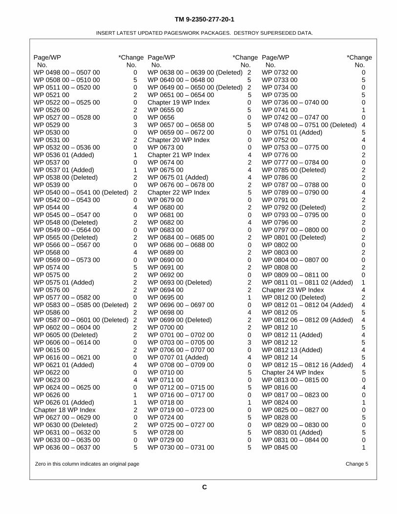
WP 0498 00 – 0507 00 0 WP 0638 00 – 0639 00 (Deleted) 2 WP 0732 00 0 WP 0508 00 – 0510 00 5 WP 0640 00 – 0648 00 5 WP 0733 00 5 WP 0511 00 – 0520 00 0 WP 0649 00 – 0650 00 (Deleted) 2 WP 0734 00 0 WP 0521 00 2 WP 0651 00 – 0654 00 5 WP 0735 00 5 WP 0522 00 – 0525 00 0 Chapter 19 WP Index 0 WP 0736 00 – 0740 00 0 WP 0526 00 2 WP 0655 00 5 WP 0741 00 1 WP 0527 00 – 0528 00 0 WP 0656 0 WP 0742 00 – 0747 00 0 WP 0529 00 3 WP 0657 00 – 0658 00 5 WP 0748 00 – 0751 00 (Deleted) 4 WP 0530 00 0 WP 0659 00 – 0672 00 0 WP 0751 01 (Added) 5 WP 0531 00 2 Chapter 20 WP Index 0 WP 0752 00 4 WP 0532 00 – 0536 00 0 WP 0673 00 0 WP 0753 00 – 0775 00 0 WP 0536 01 (Added) 1 Chapter 21 WP Index 4 WP 0776 00 2 WP 0537 00 0 WP 0674 00 2 WP 0777 00 – 0784 00 0 WP 0537 01 (Added) 1 WP 0675 00 4 WP 0785 00 (Deleted) 2 WP 0538 00 (Deleted) 2 WP 0675 01 (Added) 4 WP 0786 00 2 WP 0539 00 0 WP 0676 00 – 0678 00 2 WP 0787 00 – 0788 00 0 WP 0540 00 – 0541 00 (Deleted) 2 Chapter 22 WP Index 5 WP 0789 00 – 0790 00 4 WP 0542 00 – 0543 00 0 WP 0679 00 0 WP 0791 00 2 WP 0544 00 4 WP 0680 00 2 WP 0792 00 (Deleted) 2 WP 0545 00 – 0547 00 0 WP 0681 00 0 WP 0793 00 – 0795 00 0 WP 0548 00 (Deleted) 2 WP 0682 00 4 WP 0796 00 2 WP 0549 00 – 0564 00 0 WP 0683 00 0 WP 0797 00 – 0800 00 0 WP 0565 00 (Deleted) 2 WP 0684 00 – 0685 00 2 WP 0801 00 (Deleted) 2 WP 0566 00 – 0567 00 0 WP 0686 00 – 0688 00 0 WP 0802 00 0 WP 0568 00 4 WP 0689 00 2 WP 0803 00 2 WP 0569 00 – 0573 00 0 WP 0690 00 0 WP 0804 00 – 0807 00 0 WP 0574 00 5 WP 0691 00 2 WP 0808 00 2 WP 0575 00 2 WP 0692 00 0 WP 0809 00 – 0811 00 0 WP 0575 01 (Added) 2 WP 0693 00 (Deleted) 2 WP 0811 01 – 0811 02 (Added) 1 WP 0576 00 2 WP 0694 00 2 Chapter 23 WP Index 4 WP 0577 00 – 0582 00 0 WP 0695 00 1 WP 0812 00 (Deleted) 2 WP 0583 00 – 0585 00 (Deleted) 2 WP 0696 00 – 0697 00 0 WP 0812 01 – 0812 04 (Added) 4 WP 0586 00 2 WP 0698 00 4 WP 0812 05 5 WP 0587 00 – 0601 00 (Deleted) 2 WP 0699 00 (Deleted) 2 WP 0812 06 – 0812 09 (Added) 4 WP 0602 00 – 0604 00 2 WP 0700 00 2 WP 0812 10 5 WP 0605 00 (Deleted) 2 WP 0701 00 – 0702 00 0 WP 0812 11 (Added) 4 WP 0606 00 – 0614 00 0 WP 0703 00 – 0705 00 3 WP 0812 12 5 WP 0615 00 2 WP 0706 00 – 0707 00 0 WP 0812 13 (Added) 4 WP 0616 00 – 0621 00 0 WP 0707 01 (Added) 4 WP 0812 14 5 WP 0621 01 (Added) 4 WP 0708 00 – 0709 00 0 WP 0812 15 – 0812 16 (Added) 4 WP 0622 00 0 WP 0710 00 5 Chapter 24 WP Index 5 WP 0623 00 4 WP 0711 00 0 WP 0813 00 – 0815 00 0 WP 0624 00 – 0625 00 0 WP 0712 00 – 0715 00 5 WP 0816 00 4 WP 0626 00 1 WP 0716 00 – 0717 00 0 WP 0817 00 – 0823 00 0 WP 0626 01 (Added) 1 WP 0718 00 1 WP 0824 00 1 Chapter 18 WP Index 2 WP 0719 00 – 0723 00 0 WP 0825 00 – 0827 00 0 WP 0627 00 – 0629 00 0 WP 0724 00 5 WP 0828 00 5 WP 0630 00 (Deleted) 2 WP 0725 00 – 0727 00 0 WP 0829 00 – 0830 00 0 WP 0631 00 – 0632 00 5 WP 0728 00 5 WP 0830 01 (Added) 5 WP 0633 00 – 0635 00 0 WP 0729 00 0 WP 0831 00 – 0844 00 0 WP 0636 00 – 0637 00 5 WP 0730 00 – 0731 00 5 WP 0845 00 1
Zero in this column indicates an original page Change 5
TM 9-2350-277-20-1
INSERT LATEST UPDATED PAGES/WORK PACKAGES. DESTROY SUPERSEDED DATA.
D
Page/WP *Change No. No.
Page/WP *Change No. No.
Page/WP *Change No. No.
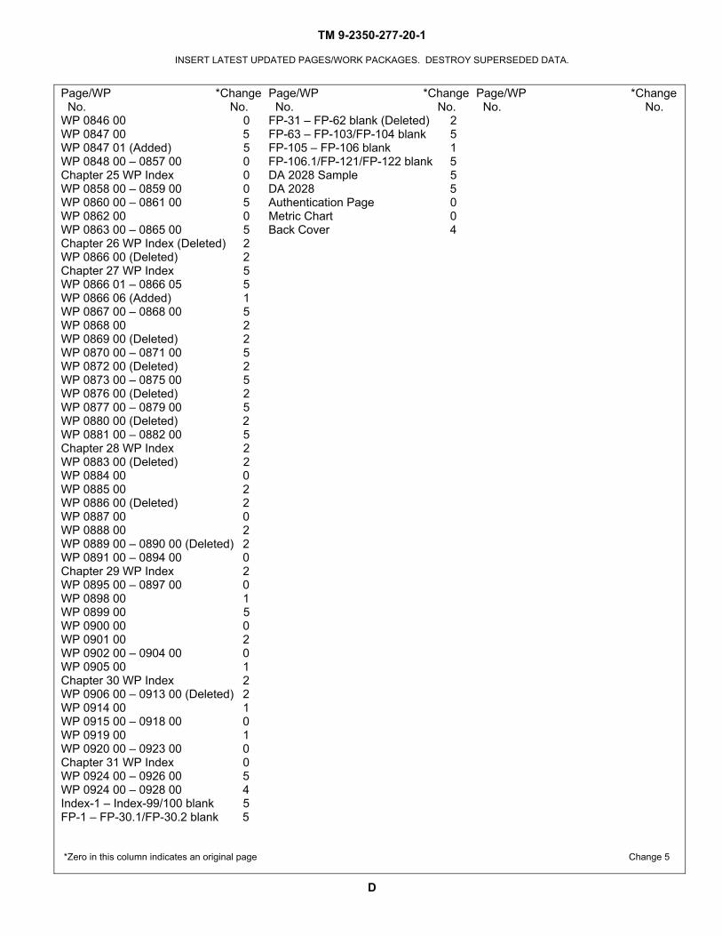
WP 0846 00 0 FP-31 – FP-62 blank (Deleted) 2 WP 0847 00 5 FP-63 – FP-103/FP-104 blank 5 WP 0847 01 (Added) 5 FP-105 – FP-106 blank 1 WP 0848 00 – 0857 00 0 FP-106.1/FP-121/FP-122 blank 5 Chapter 25 WP Index 0 DA 2028 Sample 5 WP 0858 00 – 0859 00 0 DA 2028 5 WP 0860 00 – 0861 00 5 Authentication Page 0 WP 0862 00 0 Metric Chart 0 WP 0863 00 – 0865 00 5 Back Cover 4 Chapter 26 WP Index (Deleted) 2 WP 0866 00 (Deleted) 2 Chapter 27 WP Index 5 WP 0866 01 – 0866 05 5 WP 0866 06 (Added) 1 WP 0867 00 – 0868 00 5 WP 0868 00 2 WP 0869 00 (Deleted) 2 WP 0870 00 – 0871 00 5 WP 0872 00 (Deleted) 2 WP 0873 00 – 0875 00 5 WP 0876 00 (Deleted) 2 WP 0877 00 – 0879 00 5 WP 0880 00 (Deleted) 2 WP 0881 00 – 0882 00 5 Chapter 28 WP Index 2 WP 0883 00 (Deleted) 2 WP 0884 00 0 WP 0885 00 2 WP 0886 00 (Deleted) 2 WP 0887 00 0 WP 0888 00 2 WP 0889 00 – 0890 00 (Deleted) 2 WP 0891 00 – 0894 00 0 Chapter 29 WP Index 2 WP 0895 00 – 0897 00 0 WP 0898 00 1 WP 0899 00 5 WP 0900 00 0 WP 0901 00 2 WP 0902 00 – 0904 00 0 WP 0905 00 1 Chapter 30 WP Index 2 WP 0906 00 – 0913 00 (Deleted) 2 WP 0914 00 1 WP 0915 00 – 0918 00 0 WP 0919 00 1 WP 0920 00 – 0923 00 0 Chapter 31 WP Index 0 WP 0924 00 – 0926 00 5 WP 0924 00 – 0928 00 4 Index-1 – Index-99/100 blank 5 FP-1 – FP-30.1/FP-30.2 blank 5
*Zero in this column indicates an original page Change 5
*TM 9-2350-277-20-1
TECHNICAL MANUAL
UNIT MAINTENANCE MANUAL
CARRIER, PERSONNEL, FULL TRACKED, ARMORED M113A3 2350–01–219–7577
(EIC AEY)
CARRIER, COMMAND POST, LIGHT TRACKED M577A3 2350–01–369–6085
(EIC AE7)
CARRIER, SMOKE GENERATOR, FULL TRACKED M1059A3 2350–01–369–6083
(EIC AFA)
CARRIER, MORTAR, 120–MM M121, SELF-PROPELLED M1064A3 2350–01–369–6082
(EIC AE8)
CARRIER, STANDARDIZED INTEGRATED COMMAND POST SYSTEM (SICPS) M1068A3 2350–01–369–6086
(EIC AFC)
CARRIER, MECHANIZED SMOKE OBSCURANT M58 2350–01–418–6654
(EIC 5CG)
REPORTING ERRORS AND RECOMMENDING IMPROVEMENTS
CURRENT AS OF 30 April 2008
*SUPERSEDURE NOTICE —Supersedes TM 9-2350-277-20, 24 July 1994, including all changes.
DISTRIBUTION STATEMENT A — Approved for public release; distribution is unlimited.
i Change 5
HEADQUARTERS DEPARTMENT OF THE ARMY
WASHINGTON, D.C., 02 January 2001
You can help improve this publication. If you find any errors, or if you would like to recommend anyimprovements to the procedures in this publication, please let us know. The preferred method is to submit yourDA Form 2028 (Recommended Changes to Publications and Blank Forms) through the Internet, on the ArmyElectronic Product Support (AEPS) website. The Internet address is http://aeps.ria.army.mil. The DA Form 2028is located under the Public Applications section in the AEPS Public Home Page. Fill out the form and click onSUBMIT. Using this form on the AEPS will enable us to respond quicker to your comments and better managethe DA Form 2028 program. You may also mail, e-mail, or fax your comments or DA Form 2028 directly to theU.S. Army TACOM Life Cycle Management Command. The postal mail address is U.S. Army TACOM LifeCycle Management Command, ATTN: AMSTA-LC-LMPP / TECH PUBS, 1 Rock Island Arsenal, Rock Island,IL 61299-7630. The email address is [email protected]. The fax number is DSN 793-0726 orCommercial (309) 782-0726.
TM 9-2350-277-20-1
TABLE OF CONTENTS
WP Sequence No.
Volume 1
WARNING SUMMARY
HOW TO USE THIS MANUAL
CHAPTER 1 — UNIT INTRODUCTORY INFORMATION WITH THEORY OF OPERATIONGENERAL INFORMATION..............................................................................................................................0001 00EQUIPMENT DESCRIPTION...........................................................................................................................0002 00THEORY OF OPERATION................................................................................................................................0003 00REPAIR PARTS, SPECIAL TOOLS, TMDE, AND SUPPORT EQUIPMENT................................................0004 00
CHAPTER 2 — UNIT TROUBLESHOOTING PROCEDURESINTRODUCTION HOW TO USE TROUBLESHOOTING..............................................................................0005 00MALFUNCTION/SYMPTOM INDEX WP.......................................................................................................0006 00ENGINE CHARGING SYSTEM SCHEMATIC................................................................................................0007 00DELETED............................................................................................................................................................0008 00ENGINE FUEL SYSTEM SCHEMATIC (ALL EXCEPT M577A3 AND M1068A3).....................................0009 00ENGINE FUEL SYSTEM SCHEMATIC (M577A3 AND M1068A3 ONLY)..................................................0010 00ENGINE STARTER CIRCUIT SCHEMATIC....................................................................................................0011 00DELETED............................................................................................................................................................0012 00ENGINE AIR BOX HEATER SCHEMATIC.....................................................................................................0013 00ENGINE OVERHEATS (OLD VSFD CONFIGURATION)..............................................................................0014 00ENGINE OVERHEATS (NEW VSFD CONFIGURATION).............................................................................0014 01ENGINE OVERCOOLS......................................................................................................................................0015 00ENGINE DOES NOT CRANK...........................................................................................................................0016 00ENGINE DOES NOT START (COLD WEATHER ONLY)..............................................................................0017 00WAIT INDICATOR FLASHES DURING START ATTEMPTS (PREGLOW OR
AFTERGLOW)..........................................................................................................................................0018 00WAIT INDICATOR LIGHT DOESN’T LIGHT.................................................................................................0019 00ENGINE CRANKS SLOWLY............................................................................................................................0020 00ENGINE CRANKS BUT WILL NOT START...................................................................................................0021 00ENGINE CRANKS BUT WON’T START BELOW 40 F (AIR BOX HEATER IS
USED)........................................................................................................................................................0022 00ENGINE CRANKS BUT WON’T START BELOW 40 F (GLOW PLUGS ARE USED). ..............................0023 00ENGINE RUNS ROUGH, STALLS, OR DOESN’T PUT OUT FULL POWER..............................................0024 00GENERATOR MALFUNCTIONS AS INDICATED BY BATTERY/GENERATOR
INDICATOR..............................................................................................................................................0025 00ENGINE OIL LOW PRESSURE INDICATOR COMES ON............................................................................0026 00ELECTRICAL SCHEMATIC.............................................................................................................................0027 00DELETED............................................................................................................................................................0028 00
iiChange 5
TM 9-2350-277-20-1
TABLE OF CONTENTS (cont)WP Sequence No.
NO EXTERIOR LIGHTS OPERATE.................................................................................................................0029 00BLACKOUT DRIVE LIGHT DOESN’T WORK..............................................................................................0030 00SERVICE HEADLIGHTS DON’T WORK........................................................................................................0031 00DELETED............................................................................................................................................................0032 00SERVICE AND/OR BLACKOUT STOP LIGHTS MALFUNCTION..............................................................0033 00BLACKOUT MARKER LIGHT(S) DON’T WORK.........................................................................................0034 00SERVICE TAILLIGHT DOESN’T WORK........................................................................................................0035 00TRAILER LIGHTS DON’T WORK...................................................................................................................0036 00HORN DOES NOT WORK................................................................................................................................0037 00INSTRUMENT PANEL AND/OR TRANS CONTROLLER ILLUMINATION LIGHTS
MALFUNCTION.......................................................................................................................................0038 00DOME LIGHT(S) DO NOT WORK...................................................................................................................0039 00DOME LIGHT MALFUNCTION (M577A3 ONLY).........................................................................................0040 00BLACKOUT DOME LIGHTS DO NOT WORK (M1068A3 ONLY)...............................................................0041 00RIGHT REAR UTILITY OUTLET/ADMITTANCE BUZZER WORKS IMPROPERLY
(M577A3 AND M1068A3 ONLY)............................................................................................................0042 00LEFT REAR UTILITY OUTLET/BLOWER DOES NOT WORK (M577A3 AND
M1068A3 ONLY)......................................................................................................................................0043 00RADIO(S) DON’T WORK.................................................................................................................................0044 00SMOKE GRENADE LAUNCHER(S) MALFUNCTION (M113A3 AND M1059A3
ONLY)........................................................................................................................................................0045 00INDICATORS SCHEMATIC..............................................................................................................................0046 00DELETED............................................................................................................................................................0047 00MASTER SWITCH ON INDICATOR DOESN’T LIGHT.................................................................................0048 00FUEL LEVEL INDICATOR MALFUNCTIONS...............................................................................................0049 00HIGH BEAM INDICATOR LIGHT DOESN’T WORK....................................................................................0050 00BATTERY/GENERATOR INDICATOR MALFUNCTIONS............................................................................0051 00PARKING BRAKE INDICATOR MALFUNCTIONS.......................................................................................0052 00COOLANT TEMP INDICATOR MALFUNCTIONS........................................................................................0053 00STEERING LOCKED INDICATOR MALFUNCTIONS..................................................................................0054 00ENGINE OIL LOW PRESSURE INDICATOR MALFUNCTIONS.................................................................0055 00TRANSMISSION OIL LOW PRESSURE INDICATOR MALFUNCTIONS...................................................0056 00TRANS OIL HI TEMP INDICATOR MALFUNCTIONS.................................................................................0057 00ENGINE COOLANT LOW LEVEL INDICATOR MALFUNCTIONS............................................................0058 00TRANS FILTER CLOGGED INDICATOR MALFUNCTIONS.......................................................................0059 00TRANSMISSION SYSTEM SCHEMATIC.......................................................................................................0060 00CARRIER MOVES WITH TRANSMISSION IN SL........................................................................................0061 00CARRIER DOES NOT ATTAIN HIGH SPEED................................................................................................0061 01CARRIER DOES NOT MOVE IN ANY SHIFT LEVER POSITION...............................................................0062 00CARRIER DRIFTS OR DOES NOT STEER.....................................................................................................0063 00SERVICE AND/OR PARKING BRAKE WON’T HOLD CARRIER...............................................................0064 00
iii Change 5

TM 9-2350-277-20-1
TABLE OF CONTENTS (cont)WP Sequence No.
TRANSMISSION WON’T UPSHIFT OR SHIFTS ERRATICALLY IN 1-4 POSITION.................................0065 00TRANSMISSION DOES NOT DOWNSHIFT IN 1-4 POSITION....................................................................0066 00TRANSMISSION DOES NOT HOLD 1ST POSITION....................................................................................0067 00TRANSMISSION DOES NOT HOLD 2ND POSITION...................................................................................0068 00TRANSMISSION DOES NOT HOLD 3RD POSITION...................................................................................0069 00TRANSMISSION DOES NOT REVERSE.........................................................................................................0070 00TRANSMISSION DOES NOT PIVOT STEER.................................................................................................0071 00TRANSMISSION HIGH TEMP INDICATOR COMES ON.............................................................................0072 00TRANSMISSION LOW LUBE INDICATOR COMES ON..............................................................................0073 00STEERING LOCK SCHEMATIC (SOLENOID-ACTIVATED LOCK)............................................................0074 00STEERING LOCK SCHEMATIC (CABLE-ACTIVATED LOCK)...................................................................0075 00SOLENOID-ACTIVATED STEERING LOCK MALFUNCTIONS..................................................................0076 00CABLE-ACTIVATED STEERING LOCK MALFUNCTIONS.........................................................................0077 00BILGE PUMP SCHEMATIC..............................................................................................................................0078 00DELETED............................................................................................................................................................0079 00FRONT AND/OR REAR BILGE PUMP(S) AND/OR LIGHTS DON’T WORK.............................................0080 00RAMP SCHEMATIC..........................................................................................................................................0081 00RAMP WILL NOT LOWER...............................................................................................................................0082 00RAMP OPERATION IS SLOW OR SLUGGISH...............................................................................................0083 00RAMP WILL NOT RAISE OR FREE FALLS...................................................................................................0084 00PERSONNEL HEATER SCHEMATIC..............................................................................................................0085 00PERSONNEL HEATER MALFUNCTIONS......................................................................................................0086 00COOLANT HEATER SCHEMATIC..................................................................................................................0087 00DELETED............................................................................................................................................................0088 00COOLANT HEATER MALFUNCTIONS..........................................................................................................0089 00POWER CONTROL ENCLOSURE A1 DC INPUT/OUTPUT INOPERATIVE
(M1068A3 ONLY).....................................................................................................................................0090 00NO AC POWER FROM TENT INTERFACE PANEL A5 (M1068A3 ONLY).................................................0091 00NO DC POWER FROM TENT INTERFACE PANEL A5 (M1068A3 ONLY).................................................0092 00NO POWER FROM ROADSIDE AC POWER EXTENSION BOX A6 (M1068A3
ONLY)........................................................................................................................................................0093 00NO POWER FROM CURBSIDE AC POWER EXTENSION BOX A7 (M1068A3
ONLY)........................................................................................................................................................0094 00NO POWER FROM DC POWER EXTENSION BOX A9 (ALL EXCEPT JACK J23)
(M1068A3 ONLY).....................................................................................................................................0095 00NO POWER FROM DC POWER EXTENSION BOX A9, JACK J23 (JTIDS)
(M1068A3 ONLY).....................................................................................................................................0096 00NO DC POWER TO SINGLE POINT LAN GROUND BOX A15 (M1068A3 ONLY)...................................0097 00NO POWER FROM UPS POWER EXTENSION BOX A18 (M1068A3 ONLY)............................................0098 00NO POWER FROM CURBSIDE UPS POWER EXTENSION BOX A19 (M1068A3
ONLY)........................................................................................................................................................0099 00NO AC/DC INPUT TO ATCCS UPS POWER BOX (M1068A3 ONLY).........................................................0100 00
ivChange 5
TM 9-2350-277-20-1
TABLE OF CONTENTS (cont)WP Sequence No.
IN BLACKOUT MODE, FLUORESCENT LIGHTS OPERATE INCORRECTLY(M1068A3 ONLY).....................................................................................................................................0101 00
FLUORESCENT LIGHTS DO NOT OPERATE (M1068A3 ONLY)................................................................0102 00VEHICLE BATTERIES DISCHARGE WITH EXTERNAL AC POWER APPLIED
(M1068A3 ONLY).....................................................................................................................................0103 00VEHICLE WILL NOT ACCEPT EXTERNAL AC POWER (M1068A3 ONLY)............................................0104 00VEHICLE WILL NOT ACCEPT INVERTER AC POWER (M1068A3 ONLY)..............................................0105 00NO POWER TO DC CIRCUITS (M1068A3 ONLY).........................................................................................0106 00NO POWER TO AC CIRCUITS (M1068A3 ONLY).........................................................................................0107 00NO DC OUTPUT FROM DC POWER SUPPLY (M1068A3 ONLY)...............................................................0108 00NO AC POWER FROM INVERTERS (M1068A3 ONLY)...............................................................................0109 00INVERTER POWER-UP FAILURE (M1068A3 ONLY)...................................................................................0109 01NO DATA OUTPUT FROM DATA PANEL A12 (M1068A3 ONLY)...............................................................0110 00NO LAN OUTPUT FROM DATA PANEL A12 (M1068A3 ONLY).................................................................0111 00NO DATA OUTPUT FROM DATA PANEL A13 (M1068A3 ONLY)...............................................................0112 00NO LAN OUTPUT FROM DATA PANEL A13 (M1068A3 ONLY).................................................................0113 00PHONE EXTENSION BOX A14 POST(S) INOPERATIVE (M1068A3 ONLY).............................................0114 00SPEEDOMETER MALFUNCTIONS.................................................................................................................0115 00TACHOMETER MALFUNCTIONS..................................................................................................................0116 00DRIVER’S VISION ENHANCER (DVE) DISPLAY DOES NOT WORK......................................................0116 01COMMANDER’S VISION ENHANCER (DVE) DISPLAY DOES NOT WORK (M58
ONLY)........................................................................................................................................................0116 02HOOK UP/REMOVE MSD/ICE TEST SET TO DCA 6...................................................................................0117 00MSD/ICE TEST 10 ENGINE RPM....................................................................................................................0118 00MSD/ICE TEST 24 FUEL SUPPLY PRESSURE..............................................................................................0119 00MSD/ICE TEST 25 FUEL RETURN PRESSURE.............................................................................................0120 00MSD/ICE TEST 26 FUEL FILTER PRESSURE DROP....................................................................................0121 00MSD/ICE TEST 30 TURBOCHARGER OUTLET PRESSURE.......................................................................0122 00MSD/ICE TEST 32 AIR BOX PRESSURE........................................................................................................0123 00MSD/ICE TEST 67 BATTERY VOLTAGE........................................................................................................0124 00MSD/ICE TEST 68 STARTER MOTOR VOLTAGE.........................................................................................0125 00MSD/ICE TEST 69 STARTER NEGATIVE CABLE VOLTAGE DROP..........................................................0126 00MSD/ICE TEST 70 STARTER SOLENOID VOLTAGE...................................................................................0127 00MSD/ICE TEST 71 STARTER CURRENT (AVERAGE)..................................................................................0128 00MSD/ICE TEST 72 STARTER CURRENT (FIRST PEAK)..............................................................................0129 00MSD/ICE TEST 73 BATTERY RESISTANCE AND MSD/ICE TEST 75 BATTERY
RESISTANCE CHANGE (PACK)............................................................................................................0130 00
MSD/ICE TEST 80 BATTERY CURRENT.......................................................................................................0132 00MSD/ICE TEST 82 GENERATOR OUTPUT VOLTAGE.................................................................................0133 00MSD/ICE TEST 83 GENERATOR FIELD VOLTAGE.....................................................................................0134 00
v Change 5
DELETED............................................................................................................................................................0131 00
TM 9-2350-277-20-1
TABLE OF CONTENTS (cont)WP Sequence No.
MSD/ICE TEST 84 GENERATOR NEGATIVE CABLE VOLTAGE DROP...................................................0135 00MSD/ICE SCHEMATIC......................................................................................................................................0136 00DELETED............................................................................................................................................................0137 00
MSD/ICE TEST 10, 11, 12 AND 13 DIAGNOSTIC TROUBLESHOOTING..................................................0140 00DCA BATTERY VOLTAGE DIAGNOSTIC TROUBLESHOOTING..............................................................0141 00DCA CURRENT SHUNT DIAGNOSTIC TROUBLESHOOTING..................................................................0142 00MSD/ICE TEST 24 FUEL SUPPLY PRESSURE DIAGNOSTIC
TROUBLESHOOTING.............................................................................................................................0143 00MSD/ICE TEST 25 FUEL RETURN PRESSURE DIAGNOSTIC
TROUBLESHOOTING.............................................................................................................................0144 00MSD/ICE TEST 26 FUEL FILTER PRESSURE DROP DIAGNOSTIC
TROUBLESHOOTING.............................................................................................................................0145 00MSD/ICE TEST 30 TURBOCHARGER OUTLET PRESSURE DIAGNOSTIC
TROUBLESHOOTING.............................................................................................................................0146 00MSD/ICE TEST 32 AIR BOX PRESSURE DIAGNOSTIC TROUBLESHOOTING......................................0147 00MSD/ICE TEST 68 STARTER MOTOR VOLTAGE DIAGNOSTIC
TROUBLESHOOTING.............................................................................................................................0148 00MSD/ICE TEST 69 STARTER NEGATIVE CABLE VOLTAGE DROP DIAGNOSTIC
TROUBLESHOOTING.............................................................................................................................0149 00MSD/ICE TEST 70 STARTER SOLENOID VOLTAGE DIAGNOSTIC
TROUBLESHOOTING.............................................................................................................................0150 00MSD/ICE TEST 82 GENERATOR OUTPUT VOLTAGE DIAGNOSTIC
TROUBLESHOOTING.............................................................................................................................0151 00MSD/ICE TEST 83 GENERATOR FIELD VOLTAGE DIAGNOSTIC
TROUBLESHOOTING.............................................................................................................................0152 00MSD/ICE TEST 84 GENERATOR NEGATIVE CABLE VOLTAGE DROP
DIAGNOSTIC TROUBLESHOOTING....................................................................................................0153 00
Volume 2
WARNING SUMMARY
CHAPTER 3 — UNIT MAINTENANCE INSTRUCTIONS FOR MAINTENANCEOF CARRIER
SERVICE UPON RECEIPT................................................................................................................................0154 00PREVENTIVE MAINTENANCE CHECKS AND SERVICES (PMCS), INCLUDING
LUBRICATION INSTRUCTIONS...........................................................................................................0155 00
CHAPTER 4 — UNIT MAINTENANCE INSTRUCTIONS FOR ENGINEREMOVE/INSTALL POWER PLANT ASSEMBLY........................................................................................0156 00BLOCK POWER PLANT...................................................................................................................................0157 00REPLACE ENGINE MOUNTS .........................................................................................................................0158 00REPLACE LEFT AND RIGHT AIR BOX DRAIN CHECK VALVE AND TUBES........................................0159 00
viChange 5
DELETED............................................................................................................................................................0138 00DELETED............................................................................................................................................................0139 00
TM 9-2350-277-20-1
TABLE OF CONTENTS (cont)WP Sequence No.
DELETED............................................................................................................................................................0160 00REPLACE ENGINE LIFTING BRACKET........................................................................................................0161 00REPLACE ENGINE OIL FILLER CAP.............................................................................................................0162 00REPLACE ENGINE OIL SAMPLING VALVE AND HOSE............................................................................0163 00REPLACE OIL GAUGE ROD AND TUBE.......................................................................................................0164 00REPLACE ENGINE OIL FILTER ELEMENT..................................................................................................0165 00
CHAPTER 5 — UNIT MAINTENANCE INSTRUCTIONS FOR FUEL SYSTEMREPLACE ENGINE FUEL PUMP.....................................................................................................................0166 00SERVICE AIR CLEANER FILTER ELEMENT................................................................................................0167 00REPLACE AIR CLEANER AND ELBOW........................................................................................................0168 00REPLACE AIR CLEANER DOOR....................................................................................................................0169 00REPAIR AIR CLEANER ASSEMBLY..............................................................................................................0169 01REPAIR AIR CLEANER RETAINER................................................................................................................0170 00REPLACE AIR CLEANER RESTRICTION INDICATOR...............................................................................0171 00REPLACE AIR CLEANER RESTRICTION INDICATOR HOSE...................................................................0172 00REMOVE/INSTALL AIR INTAKE ELBOW....................................................................................................0173 00REPLACE GRILL AIR INTAKE ELBOW AND HOSE...................................................................................0174 00REPLACE EXHAUST EVACUATOR VALVE AND CONNECTOR...............................................................0175 00CLEAN FUEL CAP VENT AND FILTER SCREEN.........................................................................................0176 00DRAIN TANKS (ALL EXCEPT M577A3 AND M1068A3).............................................................................0177 00DRAIN FUEL TANKS (M577A3 AND M1068A3 ONLY)...............................................................................0178 00REPLACE EXTERNAL FUEL TANKS (ALL EXCEPT M577A3 AND M1068A3)......................................0179 00REPLACE FUEL TANKS (M577A3 AND M1068A3 ONLY)..........................................................................0180 00TEMPORARY FUEL TANK REPAIR (M577A3 AND M1068A3 ONLY)......................................................0181 00REPLACE FUEL TANK FILLER COVER AND LOCK (ALL EXCEPT M577A3 AND
M1068A3)..................................................................................................................................................0182 00REPLACE FUEL TANK FILLER COVER AND LOCK (M577A3 AND M1068A3
ONLY)........................................................................................................................................................0183 00REPLACE FILLER CAP AND STRAINER PARTS (ALL EXCEPT M577A3 AND
M1068A3)..................................................................................................................................................0184 00REPLACE FILLER CAP AND STRAINER PARTS (M577A3 AND M1068A3 ONLY)................................0185 00REPLACE FUEL FILLER AND STRAINER PARTS (M577A3 AND M1068A3 ONLY)...............................0186 00REPLACE FUEL TANK ACCESS COVERS AND DRAIN PLUGS (ALL EXCEPT
M577A3 AND M1068A3).........................................................................................................................0187 00REPLACE FUEL TANK ACCESS COVERS (M577A3 AND M1068A3 ONLY)...........................................0188 00REPLACE FUEL TANK FILLER FLANGE (M577A3 AND M1068A3 ONLY).............................................0189 00REPLACE FUEL QUANTITY TRANSMITTER (ALL EXCEPT M577A3 AND
M1068A3)..................................................................................................................................................0190 00REPLACE FUEL QUANTITY TRANSMITTER (M577A3 AND M1068A3 ONLY).....................................0191 00REPLACE FUEL SUPPLY HOSES, TUBES, AND FITTINGS (M113A3, M1059A3,
AND M58 ONLY)......................................................................................................................................0192 00
vii Change 5
TM 9-2350-277-20-1
TABLE OF CONTENTS (cont)WP Sequence No.
REPLACE FUEL SUPPLY HOSES, TUBES AND FITTINGS (M577A3 ANDM1068A3 ONLY)......................................................................................................................................0193 00
REPLACE FUEL SUPPLY HOSES, TUBES, AND FITTINGS (M1064A3 ONLY)........................................0194 00REPLACE FUEL RETURN HOSES, TUBES, AND FITTINGS (M113A3, M1059A3,
AND M58 ONLY)......................................................................................................................................0195 00REPLACE FUEL RETURN HOSES, TUBES, AND FITTINGS (M577A3 AND
M1068A3 ONLY)......................................................................................................................................0196 00REPLACE FUEL RETURN HOSES, TUBES, AND FITTINGS (M1064A3 ONLY)......................................0197 00REPLACE FUEL VENT HOSES, TUBES, AND FITTINGS (M577A3 AND M1068A3
ONLY)........................................................................................................................................................0198 00REPLACE FUEL VALVE MOUNTING BLOCKS (ALL EXCEPT M577A3 AND
M1068A3)..................................................................................................................................................0199 00REPLACE ENGINE FUEL SUPPLY HOSE......................................................................................................0200 00REPLACE ENGINE FUEL RETURN HOSE....................................................................................................0201 00REPLACE PRIMARY AND SECONDARY FUEL FILTER ELEMENTS.......................................................0202 00REPLACE PRIMARY AND SECONDARY FUEL FILTERS AND BRACKET.............................................0203 00REPLACE AIR BOX HEATER IGNITION WIRE............................................................................................0204 00REPLACE AIR BOX HEATER WIRING HARNESS.......................................................................................0205 00REPLACE AIR BOX HEATER LOWER FUEL LINE......................................................................................0206 00REPLACE AIR HEATER ELECTRODE...........................................................................................................0207 00REPLACE AIR BOX IGNITION COIL.............................................................................................................0208 00REPLACE GLOW PLUG HARNESS AND GLOW PLUGS............................................................................0209 00REPLACE GLOW PLUG CONTROLLER........................................................................................................0210 00REPLACE GLOW PLUG POWER HARNESS.................................................................................................0211 00REPLACE GLOW PLUG CONTROLLER MOUNTING BRACKET.............................................................0212 00ADJUST THROTTLE VALVE (TV) MODULATOR........................................................................................0213 00ADJUST ACCELERATOR LINKAGE..............................................................................................................0214 00REPLACE LOWER ACCELERATOR PEDAL.................................................................................................0215 00REPLACE UPPER ACCELERATOR PEDAL ASSEMBLY.............................................................................0216 00REPLACE FUEL CONTROL SHAFT AND LINKAGE...................................................................................0217 00REPLACE THROTTLE VALVE (TV) MODULATOR AND LEVER..............................................................0218 00REPLACE HAND THROTTLE CONTROL CABLE ASSEMBLY..................................................................0219 00REPLACE FUEL CUTOFF CONTROL CABLE ASSEMBLY.........................................................................0220 00
CHAPTER 6 — UNIT MAINTENANCE INSTRUCTIONS FOR EXHAUST SYSTEMREPLACE ENGINE EXHAUST ELBOWS AND DOUBLE FLEX JOINT.....................................................0221 00REPAIR DOUBLE FLEX EXHAUST JOINT....................................................................................................0222 00REPLACE MUFFLER EXTENSION AND CAP..............................................................................................0223 00REPLACE EXHAUST MUFFLER AND BRACKET.......................................................................................0224 00REPLACE ENGINE LEFT/RIGHT EXHAUST ELBOWS...............................................................................0225 00REPLACE LEFT/RIGHT TURBO EXHAUST PIPE HEAT SHIELD..............................................................0226 00
CHAPTER 7 — UNIT MAINTENANCE INSTRUCTIONS FOR COOLING SYSTEM
viiiChange 5
TM 9-2350-277-20-1
TABLE OF CONTENTS (cont)WP Sequence No.
DRAIN AND FILL COOLING SYSTEM..........................................................................................................0227 00CLEAN RADIATOR...........................................................................................................................................0228 00REPLACE RADIATOR AND PARTS................................................................................................................0229 00REPLACE AUXILIARY TANK.........................................................................................................................0230 00REPLACE THERMOSTATIC FAN SPEED SWITCH (OLD CONFIGURATION).........................................0231 00REPLACE VARIABLE SPEED FAN DRIVE VALVE AND OVERRIDE SWITCH
(NEW CONFIGURATION).......................................................................................................................0231 01REPLACE UPPER COOLANT HOSE AND TUBE..........................................................................................0232 00REPLACE RADIATOR OUTLET TUBE AND HOSES...................................................................................0233 00REPLACE BALANCE HOSE............................................................................................................................0234 00REPLACE DRAIN COCK AND HOSE.............................................................................................................0235 00REPLACE COOLANT AIR SEPARATOR........................................................................................................0236 00REPLACE THERMOSTAT/COVER..................................................................................................................0237 00REPLACE THERMOSTAT TUBE/HOSES.......................................................................................................0238 00ADJUST COOLANT PUMP BELTS..................................................................................................................0239 00REPLACE COOLANT PUMP IDLER PULLEY/BELTS..................................................................................0240 00REPLACE ENGINE COOLANT PUMP............................................................................................................0241 00ADJUST VENTILATING FAN DRIVE BELT...................................................................................................0242 00REPLACE VENTILATING FAN DRIVE BELT................................................................................................0243 00REPLACE VENTILATING FAN DRIVE PULLEY..........................................................................................0244 00REPLACE FLAT PULLEYS AND BEARINGS................................................................................................0245 00REPLACE IDLER ARM AND SPRING TENSIONER.....................................................................................0246 00REPLACE VENTILATING FAN ASSEMBLY..................................................................................................0247 00REPLACE FAN DRIVE SHAFT AND BEARING HOUSING.........................................................................0248 00REPLACE FAN AND GENERATOR VARIABLE SPEED FAN DRIVE (OLD
CONFIGURATION)..................................................................................................................................0249 00REPLACE VARIABLE SPEED FAN DRIVE ASSEMBLY (NEW CONFIGURATION)................................0249 01REPLACE HOSES FROM THERMOSTAT SWITCH TO VARIABLE SPEED FAN
DRIVE (OLD CONFIGURATION)..........................................................................................................0250 00REPLACE VARIABLE SPEED FAN DRIVE CONTROLLER (NEW
CONFIGURATION)..................................................................................................................................0250 01REPLACE TRANSMISSION OIL SUPPLY AND RETURN HOSES..............................................................0251 00REPLACE HOSE FROM VARIABLE SPEED FAN DRIVE OVERRIDE SWITCH TO
VSFD DRIVE (NEW CONFIGURATION)..............................................................................................0251 01
Volume 3
WARNING SUMMARY
CHAPTER 8 — UNIT MAINTENANCE INSTRUCTIONS FOR ELECTRICAL SYSTEMADJUST GENERATOR DRIVE BELT..............................................................................................................0252 00REPLACE GENERATOR DRIVE BELT...........................................................................................................0253 00REPLACE GENERATOR TURNBUCKLE PARTS..........................................................................................0254 00
ix Change 5
TM 9-2350-277-20-1
TABLE OF CONTENTS (cont)WP Sequence No.
REPLACE GENERATOR/BRACKET...............................................................................................................0255 00ADJUST VOLTAGE REGULATOR...................................................................................................................0256 00REPLACE REGULATOR ASSEMBLY.............................................................................................................0257 00REPLACE STARTER RELAY SWITCH...........................................................................................................0258 00REPLACE STARTER.........................................................................................................................................0259 00REPLACE MASTER SWITCH PANEL ASSEMBLY (M113A3, M1059A3, M1064A3,
AND M58 ONLY)......................................................................................................................................0260 00REPLACE MASTER SWITCH PANEL ASSEMBLY (M577A3 AND M1068A3 ONLY)...............................0261 00REPLACE MASTER SWITCH (M113A3, M1059A3, M1064A3, AND M58 ONLY)....................................0262 00REPLACE AUXILIARY POWER (SLAVE) RECEPTACLE (M113A3, M1059A3,
M1064A3, AND M58 ONLY)...................................................................................................................0263 00REPLACE NATO AUXILIARY POWER (SLAVE) RECEPTACLE (M577A3 AND
M1068A3 ONLY)......................................................................................................................................0264 00REPLACE UTILITY OUTLET RECEPTACLE................................................................................................0265 00REPLACE MASTER SWITCH TO DISTRIBUTION BOX LEAD (CIRCUIT 49)
(M113A3, M1059A3, M1064A3, AND M58 ONLY)...............................................................................0266 00REPLACE MASTER SWITCH TO DISTRIBUTION BOX LEAD (CIRCUIT 49)
(M577A3 AND M1068A3 ONLY)............................................................................................................0267 00REPLACE MASTER SWITCH TO AUXILIARY POWER RECEPTACLE LEAD
(CIRCUIT 50) (M113A3, M1059A3, M1064A3, AND M58)..................................................................0268 00REPLACE DISTRIBUTION BOX (M113A3, M1059A3, M1064A3, AND M58 ONLY). ..............................0269 00REPAIR DISTRIBUTION BOX (M113A3, M1059A3, M1064A3, AND M58 ONLY)...................................0270 00REPLACE DISTRIBUTION BOX ASSEMBLY (M577A3 AND M1068A3 ONLY)......................................0271 00DELETED............................................................................................................................................................0272 00DELETED............................................................................................................................................................0273 00DELETED............................................................................................................................................................0274 00REPLACE BILGE PUMP CIRCUIT BREAKERS............................................................................................0275 00REPLACE REAR UTILITY RECEPTACLE CIRCUIT BREAKERS (M577A3 AND
M1068A3 ONLY)......................................................................................................................................0276 00REPLACE FUEL SELECTOR SWITCH (M577A3 AND M1068A3 ONLY)..................................................0277 00REPLACE BLOWER SWITCH (M577A3 AND M1068A3 ONLY).................................................................0278 00REPLACE INSTRUMENT PANEL ASSEMBLY (OLD CONFIGURATION)................................................0279 00REPLACE INSTRUMENT PANEL ASSEMBLY (NEW CONFIGURATION)...............................................0279 01REPLACE CIRCUIT BREAKER.......................................................................................................................0280 00REPLACE FUEL SELECT SWITCH TO GAUGE LEAD (ALL EXCEPT M577A3
AND M1068A3)........................................................................................................................................0281 00REPLACE INSTRUMENT PANEL ON-OFF SWITCHES...............................................................................0282 00REPLACE MAIN LIGHT SWITCH...................................................................................................................0283 00REPLACE ENGINE START SWITCH..............................................................................................................0284 00REPLACE INSTRUMENT PANEL GAUGES..................................................................................................0285 00REPLACE PANEL LIGHTS AND INDICATOR LIGHTS................................................................................0286 00REPLACE INSTRUMENT PANEL WARNING LIGHTS................................................................................0287 00
xChange 5
TM 9-2350-277-20-1
TABLE OF CONTENTS (cont)WP Sequence No.
REPLACE INSTRUMENT WARNING LIGHT PANEL...................................................................................0288 00REPLACE INSTRUMENT PANEL BATTERY-GENERATOR GAUGE WIRING
HARNESS..................................................................................................................................................0289 00REPLACE INSTRUMENT PANEL SPECIAL PURPOSE CABLE..................................................................0290 00REPLACE WARNING LIGHT PANEL ASSEMBLY (ALL EXCEPT M58)...................................................0291 00REPLACE WARNING LIGHT PANEL (ALL EXCEPT M58).........................................................................0292 00REPLACE HORN SWITCH (ALL EXCEPT M58)...........................................................................................0293 00REPLACE HORN SWITCH (M58 ONLY)........................................................................................................0293 01REPLACE WARNING PANEL LIGHTS (ALL EXCEPT M58).......................................................................0294 00REPLACE WARNING PANEL LIGHTS (M58 ONLY)....................................................................................0294 01REPLACE INSTRUMENT PANEL MOUNTS AND GROUND LEAD (OLD
CONFIGURATION)..................................................................................................................................0295 00REPLACE INSTRUMENT PANEL MOUNTS AND GROUND LEAD (NEW
CONFIGURATION)..................................................................................................................................0295 01REPLACE TELEPOSTS AND COVER.............................................................................................................0296 00DELETED............................................................................................................................................................0297 00REPLACE STOP LIGHT-TAIL LIGHT AND GUARDS (ALL EXCEPT M577A3 AND
M1068A3)..................................................................................................................................................0298 00REPLACE LEFT STOP LIGHT-TAIL LIGHT (M577A3 AND M1068A3 ONLY).........................................0299 00REPAIR LEFT STOP LIGHT-TAIL LIGHT......................................................................................................0300 00REPLACE RIGHT STOP LIGHT-TAIL LIGHT (M577A3 ONLY)..................................................................0301 00REPAIR RIGHT STOP LIGHT-TAIL LIGHT....................................................................................................0302 00REPLACE SERVICE HEADLIGHTS................................................................................................................0303 00REPAIR SERVICE HEADLIGHTS....................................................................................................................0304 00REPLACE BLACKOUT HEADLIGHT.............................................................................................................0305 00REPAIR BLACKOUT HEADLIGHT.................................................................................................................0306 00REPLACE BLACKOUT MARKER LIGHT......................................................................................................0307 00REPAIR BLACKOUT MARKER LIGHT..........................................................................................................0308 00REPLACE DOME LIGHT (ALL EXCEPT M577A3 AND M1068A3)............................................................0309 00REPAIR DOME LIGHT (ALL EXCEPT M577A3 AND M1068A3)................................................................0310 00REPLACE DOME LIGHT (M577A3 AND M1068A3 ONLY).........................................................................0311 00REPAIR DOME LIGHT AND MOUNT (M577A3 AND M1068A3 ONLY)....................................................0312 00REPLACE DOME LIGHT LENS (ALL EXCEPT M577A3 AND M1068A3).................................................0313 00REPLACE FRONT DOME LIGHT SWITCH (M577A3 AND M1068A3 ONLY)...........................................0314 00REPLACE REAR DOME LIGHT SWITCH (M577A3 AND M1068A3 ONLY).............................................0315 00REPLACE DOME LIGHT CIRCUIT BREAKER (M577A3 AND M1068A3 ONLY)....................................0316 00REPLACE DOME BLACKOUT LIGHT BYPASS SWITCH (M577A3 AND M1068A3
ONLY)........................................................................................................................................................0317 00REPLACE TENT LIGHT ASSEMBLY (M577A3 AND M1068A3 ONLY).....................................................0318 00DELETED............................................................................................................................................................0319 00REPLACE ENGINE OIL LOW PRESSURE TRANSMITTER AND HARDWARE.......................................0320 00
xi Change 5
TM 9-2350-277-20-1
TABLE OF CONTENTS (cont)WP Sequence No.
REPLACE COOLANT TEMPERATURE TRANSMITTER.............................................................................0321 00REPLACE VARIABLE SPEED FAN DRIVE SENSORS AND SWITCHES (NEW
CONFIGURATION)..................................................................................................................................0321 01REPLACE TRANSMISSION OIL HIGH TEMPERATURE SWITCH.............................................................0322 00REPLACE GENERATOR FIELD PRESSURE SWITCH..................................................................................0323 00REPLACE FUEL SUPPLY PRESSURE TRANSDUCER.................................................................................0324 00REPLACE FUEL RETURN PRESSURE TRANSDUCER...............................................................................0325 00REPLACE TURBO OUTLET PRESSURE TRANSDUCER............................................................................0326 00REPLACE AIR BOX PRESSURE TRANSDUCER..........................................................................................0327 00REPLACE FUEL FILTER DIFFERENTIAL PRESSURE SWITCH................................................................0328 00REPLACE AUXILIARY TANK FLUID LEVEL DETECTOR.........................................................................0329 00REPLACE STEERING LOCK SWITCH...........................................................................................................0330 00REPLACE PARKING BRAKE SWITCH/BRACKET.......................................................................................0331 00REPLACE STOP SWITCH.................................................................................................................................0332 00REPLACE HEADLIGHT HIGH BEAM SELECTOR SWITCH.......................................................................0333 00REPLACE ADMITTANCE BUZZER AND SWITCH (M577A3 AND M1068A3
ONLY)........................................................................................................................................................0334 00REPLACE RAMP DOOR SWITCH AND MOUNT (M577A3 AND M1068A3 ONLY).. ..............................0335 00REPLACE HORN AND GROUND LEAD........................................................................................................0336 00DISCONNECT/CONNECT BATTERY GROUND STRAP (M113A3, M1059A3,
M1064A3, AND M58 ONLY)...................................................................................................................0337 00DISCONNECT/CONNECT BATTERY GROUND LEAD (M577A3 AND M1068A3
ONLY)........................................................................................................................................................0338 00DELETED............................................................................................................................................................0339 00REPLACE BATTERY LEADS AND TERMINALS (M113A3 AND M1059A3 ONLY).................................0340 00REPLACE BATTERY LEADS AND TERMINALS (M577A3 AND M1068A3 ONLY).................................0341 00DELETED............................................................................................................................................................0342 00REPLACE BATTERY LEADS AND TERMINALS (LEFT SIDE) (M1064A3 ONLY)...................................0343 00REPLACE BATTERY LEADS AND TERMINALS (RIGHT SIDE) (M1064A3 ONLY)................................0344 00REPLACE BATTERY LEADS AND TERMINALS (M58 ONLY)...................................................................0345 00REPLACE BATTERIES AND RETAINERS (M113A3 AND M1059A3 ONLY)............................................0346 00REPLACE BATTERIES AND RETAINERS (M577A3 AND M1068A3 ONLY)............................................0347 00REPLACE BATTERIES AND BATTERY BOX (M58 ONLY).........................................................................0348 00REPLACE BATTERIES AND RETAINERS (M1064A3 ONLY) ....................................................................0349 00REPAIR BATTERY BOX (M113A3 AND M1059A3 ONLY)..........................................................................0350 00REPAIR BATTERY BOX (M577A3 AND M1068A3 ONLY)..........................................................................0351 00REPAIR BATTERY BOX ACCESS COVER (M577A3 AND M1068A3 ONLY)............................................0352 00REPAIR BATTERY DRAWER (M1064A3 ONLY)...........................................................................................0353 00REPAIR BATTERY BOX (RIGHT SIDE) (M1064A3)......................................................................................0354 00REPLACE BATTERY BOX VENT FITTING (M58 ONLY)............................................................................0355 00REPLACE BATTERY TO MASTER SWITCH LEAD (CIRCUIT 6) (M113A3 AND
M1059A3 ONLY)......................................................................................................................................0356 00
xiiChange 5
TM 9-2350-277-20-1
TABLE OF CONTENTS (cont)WP Sequence No.
REPLACE BATTERY TO MASTER SWITCH LEAD (CIRCUIT 6) (M577A3 ANDM1068A3 ONLY)......................................................................................................................................0357 00
REPLACE BATTERY TO MASTER SWITCH LEAD (CIRCUIT 6) (M1064A3 ONLY)...............................0358 00REPLACE ENGINE WIRING HARNESS.........................................................................................................0359 00REPLACE VARIABLE SPEED FAN DRIVE WIRING HARNESS, 3W1 (NEW
CONFIGURATION)..................................................................................................................................0359 01REPLACE TRANSMISSION WIRING HARNESS .........................................................................................0360 00REPLACE TRANSMISSION CONTROLLER WIRING HARNESS...............................................................0361 00REPLACE REAR MAIN WIRING HARNESS (M113A3, M1059A3, AND M58)..........................................0362 00REPLACE REAR MAIN WIRING HARNESS (M577A3 ONLY)...................................................................0363 00REPLACE REAR MAIN WIRING HARNESS (M1064A3 ONLY).................................................................0364 00REPLACE REAR MAIN WIRING HARNESS (M1068A3 ONLY).................................................................0365 00REPLACE SMOKE GRENADE LAUNCHER WIRING HARNESS (M113A3,
M1059A3, AND M58 ONLY)...................................................................................................................0366 00REPLACE STEERING LOCK SWITCH WIRING HARNESS (ALL EXCEPT M58)....................................0367 00REPLACE STEERING LOCK SWITCH WIRING HARNESS (M58 ONLY).................................................0367 01REPLACE DRIVER’S NIGHT VISION (DNV) (AN/VVS-2) POWER SUPPLY CABLE
ASSEMBLY (ALL EXCEPT M58)...........................................................................................................0368 00REPLACE BATTERY-TO-RADIO WIRING HARNESS (LEFT SIDE) (M113A3 AND
M1059A3 ONLY)......................................................................................................................................0369 00REPLACE BATTERY-TO-RADIO WIRING HARNESS (RIGHT SIDE) (M113A3
ONLY)........................................................................................................................................................0370 00DELETED............................................................................................................................................................0371 00DELETED............................................................................................................................................................0372 00REPLACE RIGHT HEADLIGHT WIRING HARNESS...................................................................................0373 00REPLACE WARNING PANEL WIRING HARNESS.......................................................................................0374 00REPLACE TRAILER HARNESS.......................................................................................................................0375 00REPLACE RADIAC WIRE HARNESS (M113A3, M577A3, AND M1068A3 ONLY)...................................0376 00REPLACE UTILITY OUTLET LEAD ASSEMBLY (M577A3 AND M1068A3 ONLY)................................0377 00REPLACE REAR UTILITY OUTLET RECEPTACLES (M577A3 AND M1068A3
ONLY)........................................................................................................................................................0378 00REPLACE AUXILIARY POWER (SLAVE) RECEPTACLE GROUND LEAD
(M113A3, M1059A3, M1064A3, AND M58 ONLY)...............................................................................0379 00REPLACE MASTER SWITCH PANEL DOME LIGHTS LEAD ASSEMBLY (M577A3
AND M1068A3 ONLY).............................................................................................................................0380 00REPAIR INTERVEHICLE POWER CABLE (M577A3 AND M1068A3 ONLY)............................................0381 00REPAIR WIRING HARNESS.............................................................................................................................0382 00REPLACE VENTILATION FAN (M577A3 AND M1068A3 ONLY)...............................................................0383 00
CHAPTER 9 — UNIT MAINTENANCE INSTRUCTIONS FOR TRANSMISSIONREPLACE TRANSMISSION OIL DRAIN TUBES AND BRACKET.............................................................0384 00REPLACE TRANSMISSION MOUNTS...........................................................................................................0385 00
xiii Change 5
TM 9-2350-277-20-1
TABLE OF CONTENTS (cont)WP Sequence No.
REPLACE TRANSMISSION RANGE CONTROLLER/BRACKET (USED WITHSOLENOID-ACTIVATED STEERING LOCK).......................................................................................0386 00
REPLACE TRANSMISSION RANGE CONTROLLER/BRACKET (USED WITHCABLE-ACTIVATED STEERING LOCK)..............................................................................................0387 00
REPLACE TRANSMISSION RANGE CONTROLLER LAMP.......................................................................0388 00REPLACE TRANSMISSION RANGE CONTROLLER SWITCH...................................................................0389 00ADJUST TOW START CONTROL CABLE ASSEMBLY................................................................................0390 00REPLACE TOW START CONTROL ASSEMBLY AND BEARING..............................................................0391 00REPLACE TOW START CONTROL ASSEMBLY COVER............................................................................0392 00ADJUST TRANSMISSION STEERING............................................................................................................0393 00ADJUST TRANSMISSION BRAKES...............................................................................................................0394 00REPLACE TRANSMISSION OIL LEVEL DIPSTICK, FILLER TUBE, AND
ADAPTER (X200-4 ONLY)......................................................................................................................0395 00REPLACE TRANSMISSION OIL LEVEL DIPSTICK, FILLER TUBE, AND
ADAPTER (X200-4A ONLY)...................................................................................................................0396 00REPLACE GOVERNOR ASSEMBLY...............................................................................................................0397 00REPLACE TRANSMISSION OIL AND OIL FILTER ELEMENT..................................................................0398 00REPLACE TRANSMISSION OIL COOLER HOSES, FITTINGS, AND MOUNTING..................................0399 00REPLACE TRANSMISSION OIL SAMPLING VALVE AND PRESSURE SWITCH....................................0400 00REPLACE DIFFERENTIAL PRESSURE SWITCH AND BYPASS PLUG.....................................................0401 00
CHAPTER 10 — UNIT MAINTENANCE INSTRUCTIONS FOR TRANSFER ANDFINAL DRIVE ASSEMBLIES
REPLACE FINAL DRIVE FILLER TUBE AND DIPSTICK...........................................................................0402 00REPLACE FINAL DRIVE..................................................................................................................................0403 00REPLACE FINAL DRIVE DIFFERENTIAL OIL SEAL..................................................................................0404 00
CHAPTER 11 — UNIT MAINTENANCE INSTRUCTIONS FOR PROPELLERSHAFTS AND UNIVERSAL JOINTS
REPLACE PROPELLER SHAFT AND UNIVERSAL JOINTS.......................................................................0405 00
CHAPTER 12 — UNIT MAINTENANCE INSTRUCTIONS FOR BRAKESCHECK TRANSMISSION BRAKE ADJUSTMENT........................................................................................0406 00ADJUST SERVICE BRAKE CONTROL LINKAGE........................................................................................0407 00ADJUST PARKING BRAKE .............................................................................................................................0408 00REPLACE UPPER AND LOWER SERVICE BRAKE PEDAL........................................................................0409 00REPLACE SERVICE BRAKE CONTROL LINKAGE.....................................................................................0410 00REPLACE PARKING BRAKE CONTROL CABLE ASSEMBLY ..................................................................0411 00REPLACE PARKING BRAKE CONTROL LEVER ASSEMBLY ..................................................................0412 00
Volume 4
WARNING SUMMARY
xivChange 5
TM 9-2350-277-20-1
TABLE OF CONTENTS (cont)WP Sequence No.
CHAPTER 13 — UNIT MAINTENANCE INSTRUCTIONS FOR WHEELS AND TRACKSREPLACE TORSION BAR................................................................................................................................0413 00REPLACE TORSION BAR ANCHOR..............................................................................................................0414 00REPLACE ROAD WHEEL SUPPORT ARM, BEARING, AND SEALS........................................................0415 00REPLACE ROAD WHEEL HUB.......................................................................................................................0416 00REPLACE IDLER WHEEL ARM ASSEMBLY................................................................................................0417 00REPLACE IDLER WHEEL ARM BEARINGS AND SEALS..........................................................................0418 00REPLACE TRACK TENSION ADJUSTER AND MOUNT.............................................................................0419 00REVERSE T150 TRACK DRIVE SPROCKET AND TRACK ASSEMBLIES...............................................0419 01REPLACE T130 DRIVE SPROCKET AND WHEEL ASSEMBLY.................................................................0420 00REPAIR T150 DRIVE SPROCKET WHEEL ASSEMBLY...............................................................................0420 01REPAIR T130 DRIVE SPROCKET WHEEL ASSEMBLY...............................................................................0421 00REPLACE T130 TRACK....................................................................................................................................0422 00REPLACE T150 TRACK....................................................................................................................................0422 01REPLACE T130 TRACK SHOE ASSEMBLY..................................................................................................0423 00REPLACE T150 TRACK SHOE ASSEMBLY..................................................................................................0423 01REPLACE T130 TRACK SHOE PAD................................................................................................................0424 00REPLACE T150 TRACK SHOE PAD................................................................................................................0424 01REPLACE IDLER WHEEL................................................................................................................................0425 00REPLACE TRACK ROAD WHEEL (T130)......................................................................................................0426 00REPLACE ROAD WHEEL (T150 )...................................................................................................................0426 01
CHAPTER 14 — UNIT MAINTENANCE INSTRUCTIONS FOR STEERINGADJUST STEERING WHEEL LINKAGE.........................................................................................................0427 00REPLACE STEERING LOCK SOLENOID, BRACKET, LINKS, AND PINS
(SOLENOID-ACTIVATED LOCK)..........................................................................................................0428 00REPLACE PUSH-PULL CONTROL ASSEMBLY, BRACKET, LINKS, AND PINS
(CABLE-ACTIVATED LOCK).................................................................................................................0429 00REPLACE STEERING WHEEL LINKAGE......................................................................................................0430 00REPLACE QUICK RELEASE PIN AND LANYARD......................................................................................0431 00REPLACE STEERING SUPPORT, BRACKETS, AND SHAFT......................................................................0432 00
CHAPTER 15 — UNIT MAINTENANCE INSTRUCTIONS FOR TOWING ATTACHMENTSREPLACE TOWING PINTLE............................................................................................................................0433 00REPAIR TOWING PINTLE................................................................................................................................0434 00
CHAPTER 16 — UNIT MAINTENANCE INSTRUCTIONS FOR SHOCK ADSORBERSREPLACE SHOCK ABSORBER.......................................................................................................................0435 00REPLACE SHOCK ABSORBER MOUNT.......................................................................................................0436 00REPLACE SHOCK ABSORBER PIN................................................................................................................0437 00
CHAPTER 17 — UNIT MAINTENANCE INSTRUCTIONS FOR HULL
xv Change 5
TM 9-2350-277-20-1
TABLE OF CONTENTS (cont)WP Sequence No.
REPLACE TRACK COVER...............................................................................................................................0438 00REPAIR/REPLACE POWER PLANT REAR ACCESS PANELS....................................................................0439 00REMOVE/INSTALL FAN DRIVE PULLEY ACCESS COVER......................................................................0440 00REPLACE DRIVER’S POWER PLANT ACCESS PANEL..............................................................................0441 00REPAIR PAMPHLET BAG MOUNTING..........................................................................................................0442 00REPLACE TOWING HOOK AND EYE............................................................................................................0443 00REPLACE LIFTING EYE..................................................................................................................................0444 00REPLACE REAR TIEDOWN PLATES.............................................................................................................0445 00REPLACE HEADLIGHT GUARD....................................................................................................................0446 00REPLACE LEFT FRONT ARMOR PLATE......................................................................................................0447 00REPLACE RIGHT FRONT ARMOR PLATE....................................................................................................0448 00REPLACE HULL FRONT ACCESS COVER...................................................................................................0449 00REPLACE POWER PLANT BOTTOM ACCESS COVER..............................................................................0450 00REPLACE HULL DRAIN PLUG.......................................................................................................................0451 00REPLACE FINAL DRIVE HULL DRAIN PLUGS...........................................................................................0452 00REPLACE DRIVER’S COMPARTMENT FLOOR PLATES............................................................................0453 00REPLACE REAR COMPARTMENT AIR VENTILATOR...............................................................................0454 00REPLACE SMOKE GRENADE LAUNCHER GUARD, PLATE, AND BASE (M113A3
AND M1059A3 ONLY).............................................................................................................................0455 00DELETED............................................................................................................................................................0456 00DELETED............................................................................................................................................................0457 00DELETED............................................................................................................................................................0458 00DELETED............................................................................................................................................................0459 00DELETED............................................................................................................................................................0460 00DELETED............................................................................................................................................................0461 00DELETED............................................................................................................................................................0462 00DELETED............................................................................................................................................................0463 00RAISE AND LOWER POWER PLANT GRILLE.............................................................................................0464 00REMOVE/INSTALL POWER PLANT GRILLE...............................................................................................0465 00REPLACE COMBAT FILLER COVER AND LOCK ......................................................................................0466 00REPLACE POWER PLANT GRILL SUPPORT ARM .....................................................................................0467 00REPLACE POWER PLANT GRILL SCREEN..................................................................................................0468 00REPLACE RADIATOR ACCESS DOOR..........................................................................................................0469 00REPLACE POWER PLANT DOOR (M113A3 ONLY).....................................................................................0470 00REPLACE POWER PLANT DOOR (ALL EXCEPT M113A3)........................................................................0471 00REPAIR POWER PLANT DOOR......................................................................................................................0472 00REPLACE POWER PLANT DOOR COMBAT LOCK.....................................................................................0473 00REPLACE CARGO HATCH HOLD-OPEN HOOK AND BUMPERS (M113A3 AND
M1059A3 ONLY)......................................................................................................................................0474 00REPLACE CARGO HATCH INTERIOR LATCH (M113A3 AND M1059A3 ONLY)....................................0475 00DELETED............................................................................................................................................................0476 00
xviChange 5
TM 9-2350-277-20-1
TABLE OF CONTENTS (cont)WP Sequence No.
DELETED............................................................................................................................................................0477 00REPLACE CARGO HATCH SEALS (M113A3 AND M1059A3 ONLY)........................................................0478 00REPLACE CARGO HATCH COVER (M113A3 AND M1059A3 ONLY).......................................................0479 00REPLACE MORTAR HATCH EXTERIOR CATCHES AND BUMPERS (M1064A3
ONLY)........................................................................................................................................................0480 00REPLACE MORTAR HATCH INTERIOR RELEASE MECHANISMS (M1064A3
ONLY)........................................................................................................................................................0481 00REPLACE MORTAR HATCH COVERS (M1064A3 ONLY)...........................................................................0482 00REPLACE HOPPER HATCH LOCK ASSEMBLY (M58 ONLY)....................................................................0483 00REPLACE HOPPER HATCH (M58 ONLY)......................................................................................................0484 00REPLACE TURBINE ACCESS DOOR (M58 ONLY)......................................................................................0485 00REPLACE TURBINE ACCESS DOOR GASKET (M58 ONLY).....................................................................0486 00REPLACE TURBINE ACCESS DOOR HINGES (M58 ONLY)......................................................................0487 00REPLACE COMMANDER’S CUPOLA CUSHIONING PAD AND HANDLE
(M113A3, M1059A3, M58, AND M1064A3 ONLY)...............................................................................0488 00REPLACE COMMANDER’S CUPOLA AZIMUTH LOCK (M113A3, M1059A3, M58
AND M1064A3 ONLY).............................................................................................................................0489 00REPLACE COMMANDER’S CUPOLA VISION BLOCK, LOCKS AND SEALS
(M113A3, M1059A3 AND M58 ONLY)..................................................................................................0490 00REPLACE COMMANDER’S CUPOLA VISION BLOCK LOCKS AND SEALS
(M1064A3 ONLY).....................................................................................................................................0491 00REPLACE COMMANDER’S CUPOLA BRAKE ASSEMBLY (M113A3, M1059A3,
M58, AND M1064A3 ONLY)...................................................................................................................0492 00REPLACE COMMANDER’S CUPOLA COVER (M113A3, M1059A3, M58, AND
M1064A3 ONLY)......................................................................................................................................0493 00REPLACE COMMANDER’S CUPOLA HOLD-OPEN HOOK AND BUMPER
(M113A3, M1059A3, M58, AND M1064A3 ONLY)...............................................................................0494 00REPLACE COMMANDER’S CUPOLA SAFETY PIN STOWAGE BLOCK (M113A3,
M1059A3, M58, AND M1064A3 ONLY).................................................................................................0495 00REPLACE COMMANDER’S CUPOLA INTERIOR LATCH (M113A3, M1059A3,
M58, AND M1064A3 ONLY)...................................................................................................................0496 00REPLACE COMMANDER’S CUPOLA MACHINE GUN MOUNT (M113A3,
M1059A3, M58, AND M1064A3 ONLY).................................................................................................0497 00REPAIR COMMANDER’S CUPOLA MACHINE GUN MOUNT (M113A3, M1059A3,
M58, AND M1064A3 ONLY)...................................................................................................................0498 00REPLACE COMMANDER’S CUPOLA MACHINE GUN MOUNT STOPS (M1059A3
ONLY)........................................................................................................................................................0499 00REPLACE COMMANDER’S HATCH CUSHIONING PAD AND HANDLE (M577A3
AND M1068A3 ONLY).............................................................................................................................0500 00REPLACE COMMANDER’S HATCH HOOK AND BUMPER (M577A3 AND
M1068A3 ONLY)......................................................................................................................................0501 00REPLACE COMMANDER’S HATCH INTERIOR LATCH (M577A3 AND M1068A3
ONLY)........................................................................................................................................................0502 00REPLACE COMMANDER’S HATCH COVER (M577A3 AND M1068A3 ONLY) ......................................0503 00
xvii Change 5
TM 9-2350-277-20-1
TABLE OF CONTENTS (cont)WP Sequence No.
REPLACE RIGHT SIDE SPALL LINERS (M113A3 ONLY)...........................................................................0504 00REPLACE LEFT SIDE SPALL LINERS (M113A3 ONLY)..............................................................................0505 00REPAIR SPALL LINER QUICK RELEASE PINS AND PLATES (M113A3 ONLY).....................................0506 00REPLACE FORWARD SPALL LINER AND BRACKET (M113A3 ONLY)...................................................0507 00REPLACE FORWARD UPPER RIGHT AND LEFT SIDE SPALL LINERS (M113A3
ONLY)........................................................................................................................................................0508 00REPLACE SPALL LINER ON CARGO HATCH COVER (M113A3 ONLY)..................................................0509 00REPLACE REAR UPPER HULL SPALL LINER (M113A3 ONLY)...............................................................0510 00REPLACE SPALL LINER ON RAMP DOOR (M113A3 ONLY).....................................................................0511 00REPLACE SPALL LINER ON RAMP (M113A3 ONLY).................................................................................0512 00RAISE/LOWER INOPERABLE/UNSAFE RAMP............................................................................................0513 00REPLACE RAMP SEAL....................................................................................................................................0514 00REPLACE RAMP DRAIN PLUGS....................................................................................................................0515 00REPLACE RAMP BRACKET (M113A3, M577A3, AND M1068A3 ONLY).................................................0516 00REPLACE RAMP DOOR STOP BRACKET.....................................................................................................0517 00REPLACE RAMP DOOR HOOK AND SPRING..............................................................................................0518 00REPLACE RAMP DOOR HANDLES AND SHAFT........................................................................................0519 00REPLACE RAMP DOOR SEAL........................................................................................................................0520 00ADJUST RAMP LOCK (M113A3 AND M1059A3 ONLY).............................................................................0521 00ADJUST RAMP LOCK (M577A3 AND M1068A3 ONLY).............................................................................0522 00ADJUST RAMP LOCK (M1064A3 ONLY).......................................................................................................0523 00REPLACE RAMP LOCK HANDLE AND ARMS (ALL EXCEPT M577A3 AND
M1068A3)..................................................................................................................................................0524 00REPLACE RAMP LOCK LEVER AND CABLE (M577A3 AND M1068A3 ONLY).....................................0525 00REPLACE RAMP LINKAGE (M113A3 AND M1059A3 ONLY)....................................................................0526 00REPLACE RAMP LINKAGE (M577A3 AND M1068A3 ONLY)....................................................................0527 00REPLACE RAMP LINKAGE (M1064A3 ONLY).............................................................................................0528 00REPAIR HULL BY WELDING..........................................................................................................................0529 00REPLACE DRIVER’S HATCH CUSHIONING PAD.......................................................................................0530 00REPLACE DRIVER’S HATCH COVER AND EXTERIOR LOCK.................................................................0531 00REPLACE DRIVER’S HATCH HOLD-OPEN HOOK AND BUMPER (M113A3,
M1059A3, M1064A3, AND M58 ONLY).................................................................................................0532 00REPLACE DRIVER’S HATCH HOLD-OPEN HOOK AND BUMPER (M577A3 AND
M1068A3 ONLY)......................................................................................................................................0533 00REPLACE DRIVER’S HATCH INTERIOR LOCK AND LATCH...................................................................0534 00REPLACE DRIVER’S HATCH VISION BLOCK LOCKS AND SEALS........................................................0535 00REPLACE DRIVER’S HATCH AN/VVS-2 DRIVER’S NIGHT VISION GUARD (ALL
EXCEPT M58)...........................................................................................................................................0536 00REPLACE DRIVER’S HATCH NIGHT VISION GUARD (M58 ONLY)........................................................0536 01REPLACE AN/VVS-2 DRIVER’S NIGHT VISION MOUNT (ALL EXCEPT M58).....................................0537 00REPLACE DRIVER’S HATCH NIGHT VISION MOUNT (M58 ONLY).......................................................0537 01DELETED............................................................................................................................................................0538 00
xviiiChange 5
TM 9-2350-277-20-1
TABLE OF CONTENTS (cont)WP Sequence No.
REPLACE FLOOR PLATES (M113A3 AND M577A3 ONLY).......................................................................0539 00DELETED............................................................................................................................................................0540 00DELETED............................................................................................................................................................0541 00REPLACE FLOOR PLATES (M1059A3 ONLY)...............................................................................................0542 00REPLACE FLOOR PLATES(M1064A3 ONLY)................................................................................................0543 00REPLACE COMPARTMENT FLOOR PLATES (M1068A3 ONLY)...............................................................0544 00REPLACE FLOOR PLATES (M58 ONLY).......................................................................................................0545 00REPLACE PERSONNEL SEATS, CUSHIONS, AND BELTS (M113A3 ONLY)...........................................0546 00REPLACE PERSONNEL SEATS, CUSHIONS, AND BELTS (M577A3 ONLY)...........................................0547 00DELETED............................................................................................................................................................0548 00REPLACE PERSONNEL SEATS, BACKRESTS, CUSHIONS, AND BELTS (M1059A3
ONLY)........................................................................................................................................................0549 00REPLACE PERSONNEL SEATS, BACKRESTS, CUSHIONS, AND BELTS (M1064A3
ONLY)........................................................................................................................................................0550 00REPLACE DRIVER’S SEAT ASSEMBLY........................................................................................................0551 00REPAIR DRIVER’S SEAT..................................................................................................................................0552 00REPLACE DRIVER’S SEAT BACK ASSEMBLY............................................................................................0553 00REPAIR DRIVER’S SEAT BACK ASSEMBLY................................................................................................0554 00REPLACE DRIVER’S SEAT IMPACT ABSORBER........................................................................................0555 00REPLACE DRIVER’S SEAT POST ASSEMBLY.............................................................................................0556 00REPAIR DRIVER’S SEAT POST ASSEMBLY.................................................................................................0557 00REPLACE DRIVER’S FOOTREST...................................................................................................................0558 00REPLACE/REPAIR COMMANDER’S PLATFORM (M113A3, M1059A3, M1064A3,
AND M58 ONLY)......................................................................................................................................0559 00REPLACE COMMANDER’S SEAT AND POST (M113A3, M1059A3, AND M58
ONLY)........................................................................................................................................................0560 00REPLACE COMMANDER’S SEAT AND POST (M1064A3 ONLY)..............................................................0561 00REPAIR COMMANDER’S SEAT (M113A3, M1059A3, M1064A3, AND M58 ONLY)................................0562 00REPLACE COMMANDER’S JUMP SEAT (M113A3 ONLY).........................................................................0563 00REPLACE/REPAIR COMMANDER’S PLATFORM AND POST (M577A3 AND
M1068A3 ONLY)......................................................................................................................................0564 00DELETED............................................................................................................................................................0565 00REPLACE/REPAIR COMMANDER’S SEAT (M1068A3 ONLY)...................................................................0566 00REPLACE/REPAIR OPERATOR’S SEAT (M1059A3 ONLY).........................................................................0567 00REPLACE/REPAIR RADIO OPERATOR’S SEAT (M1068A3 AND M58).....................................................0568 00REPLACE WEBBING STRAPS........................................................................................................................0569 00REPLACE CUSHIONING PADS.......................................................................................................................0570 00REPLACE TOOL BOX LOOPS.........................................................................................................................0571 00REPLACE AN/VVS-2 DRIVER’S NIGHT VISION STOWAGE MOUNT (ALL
EXCEPT M58)...........................................................................................................................................0572 00REPLACE RIFLE BRACKETS..........................................................................................................................0573 00REPLACE OIL CAN BRACKET.......................................................................................................................0574 00
xix Change 5
TM 9-2350-277-20-1
TABLE OF CONTENTS (cont)WP Sequence No.
REPLACE ANTENNA GUARDS......................................................................................................................0575 00REPLACE T150 TRACK SHOE STOWAGE BRACKET.................................................................................0575 01REPLACE ANTENNA COVERS.......................................................................................................................0576 00REPLACE LEFT BULKHEAD RADIO STOWAGE RACKS (M577A3 AND M1068A3
ONLY)........................................................................................................................................................0577 00REPLACE LEFT TABLE (M577A3 ONLY)......................................................................................................0578 00REPLACE RIGHT FRONT RADIO STOWAGE RACK (M577A3 ONLY).....................................................0579 00REPLACE MAP BOARD (M577A3 ONLY).....................................................................................................0580 00REPLACE RIGHT FORWARD TABLE (M577A3 ONLY)...............................................................................0581 00REPLACE RIGHT REARWARD TABLE (M577A3 ONLY)............................................................................0582 00DELETED............................................................................................................................................................0583 00DELETED............................................................................................................................................................0584 00DELETED............................................................................................................................................................0585 00REPLACE/REPAIR RAMP VISION PORT AND SHIELD (M58 ONLY).......................................................0586 00DELETED............................................................................................................................................................0587 00DELETED............................................................................................................................................................0588 00DELETED............................................................................................................................................................0589 00DELETED............................................................................................................................................................0590 00DELETED............................................................................................................................................................0591 00DELETED............................................................................................................................................................0592 00DELETED............................................................................................................................................................0593 00DELETED............................................................................................................................................................0594 00DELETED............................................................................................................................................................0595 00DELETED............................................................................................................................................................0596 00DELETED............................................................................................................................................................0597 00DELETED............................................................................................................................................................0598 00DELETED............................................................................................................................................................0599 00DELETED............................................................................................................................................................0600 00DELETED............................................................................................................................................................0601 00REPLACE ANTENNA SUPPORT (M58 ONLY)..............................................................................................0602 00REPLACE CABLE REEL HOLDER ASSEMBLY (M1064A3 ONLY)............................................................0603 00REPAIR CABLE REEL HOLDER ASSEMBLY(M1064A3 ONLY).................................................................0604 00DELETED............................................................................................................................................................0605 00REPLACE HORIZONTAL AMMUNITION RACK (M1064A3 ONLY) .........................................................0606 00REPAIR HORIZONTAL AMMUNITION RACK (M1064A3 ONLY)..............................................................0607 00REPLACE VERTICAL AMMUNITION RACK (M1064A3 ONLY)................................................................0608 00REPLACE RADIO STOWAGE RACK (M1064A3 ONLY)..............................................................................0609 00REPLACE GRENADE STOWAGE BOX (M1064A3 ONLY)..........................................................................0610 00REPLACE PERISCOPE STOWAGE BOX (M1064A3 ONLY)........................................................................0611 00REPLACE RIFLE RACK (M1064A3 ONLY)....................................................................................................0612 00REPLACE SIGHT EXTENSION ARM STOWAGE BRACKETS (M1064A3 ONLY)....................................0613 00
xxChange 5
TM 9-2350-277-20-1
TABLE OF CONTENTS (cont)WP Sequence No.
REPLACE WINDSHIELD STOWAGE BRACKET (M1064A3 ONLY)..........................................................0614 00REPLACE MORTAR BASE STOWAGE BRACKET (M1064A3 ONLY).......................................................0615 00REPLACE LEFT SIDE RACK BASE (M1068A3 ONLY)................................................................................0616 00REPLACE PERSONNEL HEATER CONTROL BOX AND INTERCOM BOX
BRACKET (M1068A3 ONLY).................................................................................................................0617 00REPLACE/REPAIR MAP BOARD (M1068A3 ONLY)....................................................................................0618 00REPLACE MAP STORAGE BOX (M1068A3 ONLY).....................................................................................0619 00REPAIR MAP STORAGE BOX (M1068A3 ONLY).........................................................................................0620 00REPLACE RIGHT SIDE SHELF ASSEMBLY (M1068A3 ONLY)..................................................................0621 00REPLACE ALTERNATE RIGHT SIDE SHELF ASSEMBLY (M1068A3 ONLY)..........................................0621 01REPLACE RIGHT SIDE RACK BASE (M1068A3 ONLY).............................................................................0622 00REPLACE RIGHT SIDE BASE EXTENSION (M1068A3 ONLY)..................................................................0623 00REPLACE RIGHT SIDE BASE EXTENSION SUPPORTS (M1068A3 ONLY)..............................................0624 00REPLACE/REPAIR ANTENNA MAST BRACKET ASSEMBLY, TAILLIGHT
WIRING HARNESS, AND BRACKET (M1068A3 ONLY)....................................................................0625 00REPLACE REAR EXTERNAL STOWAGE FRAME (M1068A3 ONLY).......................................................0626 00REPLACE STOWAGE BRACKETS FOR W1, W2, AND NATO SLAVE CABLES
(M1068A3 AND M577A3)........................................................................................................................0626 01
Volume 5
WARNING SUMMARY
CHAPTER 18 — UNIT MAINTENANCE INSTRUCTIONS FOR HULL ACCESSORY ITEMSREPLACE TENT AND TENT CLAMPS (M577A3 ONLY).............................................................................0627 00REPLACE TENT AND FRAME MOUNTS (M577A3 ONLY)........................................................................0628 00REPLACE BLACKOUT CURTAIN AND FRAME (M577A3 AND M1068A3 ONLY).................................0629 00DELETED............................................................................................................................................................0630 00REPLACE FRONT BILGE PUMP PIPES.........................................................................................................0631 00REPLACE FRONT BILGE PUMP AND STRAINER.......................................................................................0632 00REPLACE FRONT BILGE VALVE...................................................................................................................0633 00REPLACE REAR BILGE PUMP PIPES............................................................................................................0634 00REPLACE REAR BILGE PUMP AND STRAINER.........................................................................................0635 00STENCILS (M113A3 ONLY).............................................................................................................................0636 00STENCILS (M577A3 ONLY).............................................................................................................................0637 00DELETED............................................................................................................................................................0638 00DELETED............................................................................................................................................................0639 00STENCILS (M1059A3 ONLY)...........................................................................................................................0640 00STENCILS (M1064A3 ONLY)...........................................................................................................................0641 00STENCILS (M1068A3 ONLY)...........................................................................................................................0642 00STENCILS (M58 ONLY)....................................................................................................................................0643 00DATAPLATES, DECALS, AND MARKERS (ALL MODELS).......................................................................0644 00
xxi Change 5
TM 9-2350-277-20-1
TABLE OF CONTENTS (cont)WP Sequence No.
DATAPLATES, DECALS, AND MARKERS (M113A3 AND M1059A3 ONLY)...........................................0645 00DATAPLATES, DECALS, AND MARKERS (M113A3, M1059A3, M58 ONLY)...........................................0646 00DATAPLATES, DECALS, AND MARKERS (M113A3, M1059A3 ONLY)....................................................0647 00DATAPLATES, DECALS, AND MARKERS (M577A3, M1068A3 ONLY)....................................................0648 00DELETED............................................................................................................................................................0649 00DELETED............................................................................................................................................................0650 00DATAPLATES, DECALS, AND MARKERS (M1059A3 ONLY).....................................................................0651 00DATAPLATES, DECALS, AND MARKERS (M1064A3 ONLY).....................................................................0652 00DATAPLATES, DECALS, AND MARKERS (M58 ONLY).............................................................................0653 00REPLACE DATAPLATES, STENCILS, MARKERS, AND DECALS.............................................................0654 00
CHAPTER 19 — UNIT MAINTENANCE INSTRUCTIONS FOR HYDRAULIC SYSTEMREPLACE RAMP HYDRAULIC PUMP...........................................................................................................0655 00REPLACE RAMP CYLINDER..........................................................................................................................0656 00INSPECT RAMP WIRE ROPE (CABLE)..........................................................................................................0656 01REPLACE WIRE ROPE AND PULLEYS (ALL EXCEPT M1064A3)............................................................0657 00REPLACE WIRE ROPE AND PULLEYS (M1064A3 ONLY).........................................................................0658 00REPLACE RAMP CONTROL VALVE (WITH EXTERNAL RELIEF VALVE) AND
FITTINGS..................................................................................................................................................0659 00REPLACE RAMP CONTROL VALVE, EXTERNAL RELIEF VALVE, AND FITTINGS
WITH RAMP CONTROL VALVE (INTERNAL RELIEF VALVE)........................................................0660 00REPLACE RAMP CONTROL VALVE (WITH INTERNAL RELIEF VALVE) AND
FITTINGS..................................................................................................................................................0661 00REPLACE SAFETY RELIEF VALVE, TUBE, HOSE, AND FITTINGS.........................................................0662 00REPLACE RAMP CONTROL VALVE HOSE AND ELBOW.........................................................................0663 00REPLACE TUBE FROM RAMP CONTROL VALVE TO BULKHEAD.........................................................0664 00REPLACE HOSE FROM BULKHEAD CONNECTION TO RAMP CYLINDER..........................................0665 00REPLACE RAMP CYLINDER BREATHER HOSE (ALL EXCEPT M1064A3)............................................0666 00REPLACE RAMP CYLINDER BREATHER HOSE (M1064A3 ONLY).........................................................0667 00REPLACE POWER PLANT HYDRAULIC HOSES.........................................................................................0668 00SERVICE HYDRAULIC RESERVOIR..............................................................................................................0669 00SERVICE HYDRAULIC RESERVOIR BREATHER........................................................................................0670 00REPLACE HYDRAULIC RESERVOIR............................................................................................................0671 00REPAIR HYDRAULIC RESERVOIR................................................................................................................0672 00
CHAPTER 20 — UNIT MAINTENANCE INSTRUCTIONS FOR TOOLS ANDTEST EQUIPMENT
INSPECT POWER PLANT SLING....................................................................................................................0673 00
CHAPTER 21 — UNIT MAINTENANCE INSTRUCTIONS FOR AUXILIARY GENERATORREPLACE 4.2 KW GENERATOR SET ENCLOSURE (M577A3 AND M1068A3
ONLY)........................................................................................................................................................0674 00REPAIR 5.0 KW AUXILIARY POWER UNIT (M577A3 AND M1068A3)....................................................0675 00
xxii
TM 9-2350-277-20-1
TABLE OF CONTENTS (cont)WP Sequence No.
REPLACE 5.0 KW AUXILIARY POWER UNIT (APU) (M577A3 AND M1068A3).....................................0675 01REPLACE 5.0 KW AUXILIARY POWER UNIT FUEL SHUTOFF VALVE (M577A3
AND M1068A3 ONLY).............................................................................................................................0676 00REPLACE 5.0 KW AUXILIARY POWER UNIT VALVE-TO-BULKHEAD FUEL
SUPPLY HOSES (M577A3 AND M1068A3 ONLY)...............................................................................0677 00REPLACE 5.0 KW AUXILIARY POWER UNIT BULKHEAD-TO-HULL FUEL
SUPPLY HOSES (M577A3 AND M1068A3 ONLY)...............................................................................0678 00
CHAPTER 22 — UNIT MAINTENANCE INSTRUCTIONS FOR SPECIAL PURPOSE KITSBLEED AIR FROM PERSONNEL HEATER FUEL LINES.............................................................................0679 00SERVICE PERSONNEL HEATER FUEL FILTER............................................................................................0680 00SERVICE PERSONNEL HEATER FUEL PUMP..............................................................................................0681 00REPLACE HEATER AIR INTAKE AND EXHAUST PIPES (ALL EXCEPT M1064A3)...............................0682 00REPLACE HEATER AIR INTAKE AND EXHAUST PIPES (M1064A3 ONLY) ..........................................0683 00REPLACE FUEL SHUT-OFF VALVE ASSEMBLY (M113A3, M1059A3, AND M58
ONLY)........................................................................................................................................................0684 00REPLACE HEATER/FILTER FUEL SUPPLY HOSES (M113A3, M1059A3, AND M58
ONLY)........................................................................................................................................................0685 00REPLACE PERSONNEL HEATER FUEL TUBE (ALL EXCEPT M1064A3)................................................0686 00REPLACE BULKHEAD CONNECTION TO PERSONNEL HEATER TUBE (M577A3
AND M1068A3 ONLY).............................................................................................................................0687 00REPLACE PERSONNEL HEATER FUEL FILTER, HOSES, AND FITTINGS
(M1064A3 ONLY).....................................................................................................................................0688 00REPLACE PERSONNEL HEATER FUEL PUMP HOSE (M113A3, M1059A3, AND
M58 ONLY)...............................................................................................................................................0689 00REPLACE FUEL TANK TO FUEL PUMP HOSE (M577A3 AND M1068A3 ONLY)...................................0690 00REPLACE FUEL PUMP TO BULKHEAD CONNECTION HOSE (M113A3,
M1059A3, AND M58 ONLY)...................................................................................................................0691 00REPLACE FUEL PUMP TO BULKHEAD CONNECTION HOSE (M577A3 AND
M1068A3 ONLY)......................................................................................................................................0692 00DELETED............................................................................................................................................................0693 00REPLACE FUEL PUMP HOSE TO HEATER FUEL SHUTOFF VALVE (M1064A3
ONLY)........................................................................................................................................................0694 00REPLACE PERSONNEL HEATER FUEL PUMP (M113A3, M1059A3, AND M58
ONLY)........................................................................................................................................................0695 00REPLACE PERSONNEL HEATER FUEL PUMP (M577A3 AND M1068A3 ONLY)...................................0696 00REPLACE HEATER FUEL PUMP (M1064A3 ONLY).....................................................................................0697 00REPLACE PERSONNEL HEATER FUEL FILTER/BRACKET (M113A3, M1059A3,
AND M58 ONLY)......................................................................................................................................0698 00DELETED............................................................................................................................................................0699 00REPLACE PERSONNEL HEATER FUEL FILTER, HOSE, TUBE, AND FITTINGS
(M577A3 AND M1068A3 ONLY)............................................................................................................0700 00REPLACE PERSONNEL HEATER CONTROL BOX......................................................................................0701 00REPAIR PERSONNEL HEATER CONTROL BOX..........................................................................................0702 00
xxiii
TM 9-2350-277-20-1
TABLE OF CONTENTS (cont)WP Sequence No.
REPLACE PERSONNEL HEATER ASSEMBLY (ALL EXCEPT M1064A3)................................................0703 00REPLACE PERSONNEL HEATER ASSEMBLY (M1064A3 ONLY)..............................................................0704 00REPAIR PERSONNEL HEATER ASSEMBLY.................................................................................................0705 00REPLACE PERSONNEL HEATER DUCT AND HOSES................................................................................0706 00REPAIR PERSONNEL HEATER DUCT...........................................................................................................0707 00REPLACE PERSONNEL HEATER WIRING HARNESS GUIDE (M577A3 AND
M1068A3)..................................................................................................................................................0707 01SERVICE COOLANT HEATER FUEL FILTER................................................................................................0708 00SERVICE COOLANT HEATER FUEL PUMP..................................................................................................0709 00DRAIN AND FILL ENGINE COOLANT HEATER SYSTEM.........................................................................0710 00REPLACE COOLANT HEATER FUEL PUMP HOSE.....................................................................................0711 00REPLACE COOLANT HEATER FUEL INLET HOSE AND FITTINGS........................................................0712 00REPLACE COOLANT PUMP TO BATTERY BOX HOSES............................................................................0713 00REPLACE ENGINE TO BATTERY BOX HOSE..............................................................................................0714 00REPLACE COOLANT HEATER TO ENGINE ELBOW HOSE......................................................................0715 00REPLACE COOLANT HEATER FILTER VALVE HOSE................................................................................0716 00REPLACE ENGINE BLOCK FITTING AND HARDWARE...........................................................................0717 00REPLACE BATTERY BOX INSULATION AND HEAT EXCHANGER........................................................0718 00REPLACE BATTERY DRAWER INSULATION AND HEAT EXCHANGER
(M1064A3 ONLY).....................................................................................................................................0719 00REPLACE COOLANT HEATER FUEL SHUTOFF VALVE............................................................................0720 00REPLACE FUEL PUMP TEE TO ELBOW HOSE............................................................................................0721 00REPLACE BATTERY PLATE TO BATTERY PLATE HOSE..........................................................................0722 00REPLACE COOLANT HEATER FUEL PUMP................................................................................................0723 00REPLACE COOLANT HEATER EXHAUST ELBOW AND PIPES...............................................................0724 00REPLACE HEATER TO SURGE TANK HOSE................................................................................................0725 00REPLACE FUEL FILTER...................................................................................................................................0726 00ADJUST FLAME DETECTOR SWITCH..........................................................................................................0727 00REPLACE COOLANT HEATER AND PUMP UNIT.......................................................................................0728 00REPLACE COOLANT HEATER.......................................................................................................................0729 00REPLACE IGNITER...........................................................................................................................................0730 00REPLACE COOLANT HEATER PUMP...........................................................................................................0731 00REPLACE COOLANT HEATER AND COOLANT PUMP BRACKET..........................................................0732 00REPLACE COOLANT PUMP TO HEATER WIRING HARNESS..................................................................0733 00REPLACE FLAME DETECTOR SWITCH.......................................................................................................0734 00REPLACE COOLANT HEATER WIRING HARNESS....................................................................................0735 00REPLACE COOLANT HEATER CONTROL BOX..........................................................................................0736 00REPAIR COOLANT HEATER CONTROL BOX..............................................................................................0737 00REPLACE NON-SKID PLATES (M1064A3 ONLY)........................................................................................0738 00REPLACE DRIVER’S WINDSHIELD..............................................................................................................0739 00REPLACE DRIVER’S WINDSHIELD STOWAGE BAG, STRAPS, AND DECAL.......................................0740 00
xxiv
TM 9-2350-277-20-1
TABLE OF CONTENTS (cont)WP Sequence No.
INITIAL INSTALLATION OF LITTER KIT (M113A3 ONLY).......................................................................0741 00REPLACE POST ASSEMBLY (M113A3 ONLY).............................................................................................0742 00REPAIR POST ASSEMBLY (M113A3 ONLY).................................................................................................0743 00REPLACE CHAIN ASSEMBLY (M113A3 ONLY)..........................................................................................0744 00REPAIR CHAIN ASSEMBLY (M113A3 ONLY)..............................................................................................0745 00REPLACE ARTILLERY COMMUNICATION INSIDE CABLE (M577A3 ONLY).......................................0746 00REPLACE COMMANDER’S CUPOLA ARMOR SHIELDS (M113A3 AND M1064A3
ONLY)........................................................................................................................................................0747 00DELETED............................................................................................................................................................0748 00DELETED............................................................................................................................................................0749 00DELETED............................................................................................................................................................0750 00DELETED............................................................................................................................................................0751 00INSTALL/REMOVE BASE PLATE MOUNTING ADAPTORS WITH ARMOR KIT
INSTALLED (M1064A3 ONLY)..............................................................................................................0751 01INSTALL/REMOVE MINE ARMOR KIT (M113A3 ONLY)...........................................................................0752 00REPLACE FOG OIL TANK MODULE (M1059A3 ONLY).............................................................................0753 00REPLACE SMOKE GENERATOR BREATHER HOSE ASSEMBLY (M1059A3
ONLY)........................................................................................................................................................0754 00REPLACE SMOKE GENERATOR ASSEMBLY AND SUPPORT BRACKET
(M1059A3 ONLY).....................................................................................................................................0755 00REPLACE SMOKE GENERATOR CONTROL PANEL ASSEMBLY (M1059A3
ONLY)........................................................................................................................................................0756 00REPLACE SMOKE GENERATOR SYSTEM POWER SUPPLY CABLE ASSEMBLY
(M1059A3 ONLY).....................................................................................................................................0757 00REPLACE AIR COMPRESSOR ELECTRICAL CABLE ASSEMBLY (M1059A3
ONLY)........................................................................................................................................................0758 00REPLACE FOG OIL PUMP ELECTRICAL CABLE ASSEMBLY..................................................................0759 00REPLACE SMOKE GENERATOR INTERNAL CABLE ASSEMBLY (M1059A3
ONLY)........................................................................................................................................................0760 00REPLACE ADAPTER ACCESS PLATE TO GENERATOR ELECTRICAL CABLE
ASSEMBLY (M1059A3 ONLY)...............................................................................................................0761 00REPLACE AIR COMPRESSOR ASSEMBLY (M1059A3 ONLY)...................................................................0762 00REPLACE FOG OIL PUMP ASSEMBLY (M1059A3 ONLY).........................................................................0763 00REPLACE SMOKE GENERATOR FUEL CAN LID ASSEMBLY (M1059A3 ONLY)..................................0764 00REPLACE SMOKE GENERATOR FUEL LINES AND GUARDS (M1059A3 ONLY)..................................0765 00REPLACE SMOKE GENERATOR ADAPTER ACCESS PLATE AND GASKET
(M1059A3 ONLY).....................................................................................................................................0766 00REPLACE SMOKE GENERATOR COMPRESSOR RESERVOIR TO ADAPTER
ACCESS PLATE AIR HOSE (M1059A3 ONLY).....................................................................................0767 00REPLACE SMOKE GENERATOR ADAPTER ACCESS PLATE TO COVER
ASSEMBLY AIR HOSE (M1059A3 ONLY)............................................................................................0768 00REPLACE FOG OIL TANK QUICK DISCONNECT TO ADAPTER ACCESS PLATE
HOSE (M1059A3 ONLY)..........................................................................................................................0769 00
xxv
TM 9-2350-277-20-1
TABLE OF CONTENTS (cont)WP Sequence No.
REPLACE COVER ASSEMBLY FOG OIL QUICK DISCONNECT TO ADAPTERACCESS PLATE HOSE (M1059A3 ONLY).............................................................................................0770 00
REPLACE SMOKE GENERATOR ARMOR (M1059A3 ONLY).....................................................................0771 00REPLACE SMOKE GENERATOR GLOW PLUG CABLE ASSEMBLIES (M1059A3
ONLY)........................................................................................................................................................0772 00REPLACE/REPAIR SMOKE GENERATOR FUEL FILTER/WATER SEPARATOR
(M1059A3 ONLY).....................................................................................................................................0773 00REPLACE M14 AIR PURIFIER AND FRAME (M113A3 ONLY)..................................................................0774 00REPLACE NBC AIR PURIFIER AND FRAME (M113A3 ONLY)..................................................................0775 00REPLACE NBC AIR PURIFIER AND FRAME (M577A3 ONLY)..................................................................0776 00REPLACE M8A3 NBC AIR PURIFIER AND FRAME (M1059A3 ONLY)....................................................0777 00REPLACE M13 AIR PURIFIER AND FRAME (M1059A3 ONLY)................................................................0778 00REPLACE M13 AIR PURIFIER AND FRAME (M1068A3 ONLY)................................................................0779 00REPLACE M8A3/M14 ORIFICE CONNECTOR ASSEMBLY, SUPPORT, AND
QUICK COUPLING HALF (M113A3, M1059A3, AND M577A3 ONLY)............................................0780 00REPLACE M13 ORIFICE CONNECTOR ASSEMBLY, BRACKET, AND QUICK
COUPLING HALF (M1068A3 ONLY)....................................................................................................0781 00REPLACE M3 NBC HEATER HOSES AND FITTINGS (M113A3 ONLY)....................................................0782 00REPLACE M14 NBC HOSES AND BRACKETS (M113A3 AMBULANCE ONLY).....................................0783 00REPLACE M3 NBC HEATER HOSES AND FITTINGS (M113A3 AMBULANCE
ONLY)........................................................................................................................................................0784 00DELETED............................................................................................................................................................0785 00REPLACE NBC FILTERS AND HOSES (M577A3 ONLY).............................................................................0786 00REPLACE M8A3 NBC HOSES AND BRACKETS (M1059A3 ONLY)..........................................................0787 00REPLACE M3 NBC HOSES AND FITTINGS (M1059A3 ONLY)..................................................................0788 00REPLACE M13 NBC FILTERS AND HOSES (M1068A3 ONLY)..................................................................0789 00REPLACE M13 NBC HEATER HOSES (M1068A3 ONLY)............................................................................0790 00REPLACE M3 NBC HEATER CONTROL BOX, REGULATOR, AND BRACKET
(M113A3 AND M577A3)..........................................................................................................................0791 00DELETED............................................................................................................................................................0792 00REPLACE M3 NBC HEATER CONTROL BOX (M1068A3 ONLY)..............................................................0793 00REPLACE M3 NBC HEATERS AND CONTROLLERS (M113A3 ONLY)....................................................0794 00REPLACE M3 NBC HEATERS AND CONTROLLERS (M113A3 AMBULANCES
ONLY)........................................................................................................................................................0795 00REPLACE NBC HEATERS AND MOUNTS (M577A3 ONLY).......................................................................0796 00REPLACE M3 NBC HEATERS AND CONTROLLERS (M1059A3 ONLY)..................................................0797 00REPLACE M13 NBC HEATERS (M1068A3 ONLY)........................................................................................0798 00REPLACE M14 NBC CABLES AND SWITCH ASSEMBLY (M1059A3 ONLY)..........................................0799 00REPLACE NBC CABLE TO HEATERS, AIR PURIFIER, AND SWITCH ASSEMBLY
(M113A3 ONLY).......................................................................................................................................0800 00DELETED............................................................................................................................................................0801 00REPLACE NBC FILTER SWITCH ASSEMBLY (M113A3 AND M113A3
AMBULANCE ONLY)..............................................................................................................................0802 00
xxvi
TM 9-2350-277-20-1
TABLE OF CONTENTS (cont)WP Sequence No.
REPLACE NBC FILTER SWITCH AND MOUNT BRACKET (M577A3 ONLY).........................................0803 00REPLACE M8A3/M3 NBC FILTER SWITCH ASSEMBLY (M1059A3 ONLY)............................................0804 00REPLACE M13 NBC FILTER SWITCH (M1068A3 ONLY)............................................................................0805 00REPLACE M3 NBC HEATER WIRING HARNESS (M1059A3 ONLY).........................................................0806 00REPLACE M14 NBC HEATER WIRING HARNESS (M113A3 AMBULANCE ONLY)...............................0807 00REPLACE NBC HEATER WIRING HARNESS (M577A3 ONLY).................................................................0808 00REPLACE M13 NBC HEATER WIRING HARNESS (M1068A3 ONLY).......................................................0809 00REPLACE WATER/RATION HEATER POWER CABLE (M113A3 ONLY)..................................................0810 00REPLACE WATER/RATION HEATER MOUNT BRACKET (M113A3 ONLY)............................................0811 00INSTALL TOW PINTLE EXTENDER KIT (M113A3 ONLY).........................................................................0811 01REPAIR TOW PINTLE EXTENDER ASSEMBLY (M113A3 ONLY).............................................................0811 02
CHAPTER 23 — UNIT MAINTENANCE INSTRUCTIONS FOR MORTAR FIRECONTROL SYSTEM
DELETED............................................................................................................................................................0812 00MORTAR FIRE CONTROL SYSTEM (MFCS), M95/M96 (M577A3 AND M1064A3).................................0812 01COMMANDER’S INTERFACE BRACKET ASSEMBLY MAINTENANCE (MFCS)
(M577A3 ONLY).......................................................................................................................................0812 02REPAIR/REPLACE COMMANDER’S INTERFACE BRACKET ASSEMBLY (MFCS)
(M1064A3 ONLY).....................................................................................................................................0812 03REPAIR/REPLACE POWER DISTRIBUTION ASSEMBLY (MFCS) (M577A3 ONLY)...............................0812 04REPAIR/REPLACE POWER DISTRIBUTION ASSEMBLY (MFCS) (M1064A3
ONLY)........................................................................................................................................................0812 05REPAIR/REPLACE CABLE HANGER (MFCS) (M577A3 ONLY).................................................................0812 06REPAIR/REPLACE MORTAR FIRE CONTROL SYSTEM (MFCS) CABLES (M577A3
ONLY)........................................................................................................................................................0812 07REPAIR/REPLACE PRECISION LIGHTWEIGHT GPS RECEIVER (PLGR) AND
BRACKET (MFCS) (M1064A3 ONLY)...................................................................................................0812 08REPAIR/REPLACE PRECISION LIGHTWEIGHT GPS RECEIVER (PLGR)
ANTENNA AND ANTENNA BRACKET (MFCS) (M1064A3 ONLY).................................................0812 09REPAIR/REPLACE DRIVER’S DISPLAY ASSEMBLY (MFCS) (M1064A3 ONLY)....................................0812 10REPAIR/REPLACE DRIVER’S DISPLAY EXTERIOR MOUNTING BALL (MFCS)
(M1064A3 ONLY).....................................................................................................................................0812 11REPAIR/REPLACE VEHICLE MOTION SENSOR ASSEMBLY (MFCS) (M1064A3
ONLY)........................................................................................................................................................0812 12REPAIR/REPLACE TRAVEL LOCK ADAPTER (MFCS) (M1064A3 ONLY)...............................................0812 13REPAIR/REPLACE MORTAR FIRE CONTROL SYSTEM CABLES (MFCS)
(M1064A3 ONLY).....................................................................................................................................0812 14REPLACE ALTERNATE LOCATION GUNNER’S DISPLAY BLOCK..........................................................0812 15REPLACE DAGR HOLDER MOUNTING BRACKET AND/OR SHOCK ISOLATOR.................................0812 16
Volume 6
WARNING SUMMARY
xxvii
TM 9-2350-277-20-1
TABLE OF CONTENTS (cont)WP Sequence No.
CHAPTER 24 — UNIT MAINTENANCE INSTRUCTIONS FOR ELECTRICALEQUIPMENT (M1068A3 ONLY)
REPLACE ADAPTIVE PROGRAMMABLE INTERFACE UNIT (APIU) RACKMOUNT AND BRACKET (M1068A3 ONLY)........................................................................................0813 00
REPLACE RIGHT EQUIPMENT RACK BRACKETS AND MOUNTS (M1068A3ONLY)........................................................................................................................................................0814 00
REPLACE A.C. POWER EXTENSION BOX A7 (M1068A3 ONLY)..............................................................0815 00REPLACE SIGNAL PATCH PANEL BOX A10 (M1068A3 ONLY)................................................................0816 00REPLACE EXTERNAL COMMUNICATION BOX A11 (M1068A3 ONLY).................................................0817 00REPLACE EXTERNAL COMMUNICATION BOX A11 LID AND LATCHES
(M1068A3 ONLY).....................................................................................................................................0818 00REPLACE CURBSIDE DATA PANEL ASSEMBLY A12 (M1068A3 ONLY)................................................0819 00REPLACE LAN GROUND BOX ASSEMBLY A15 (M1068A3 ONLY).........................................................0820 00REPAIR LAN GROUND BOX ASSEMBLY A15 (M1068A3 ONLY).............................................................0821 00REPLACE A.C. POWER EXTENSION BOX A19 (M1068A3 ONLY)............................................................0822 00REPLACE/REPAIR PRINTER MOUNT (M1068A3 ONLY)............................................................................0823 00REPLACE/REPAIR POWER SUPPLY STORAGE BOX ASSEMBLY (M1068A3
ONLY)........................................................................................................................................................0824 00REPLACE FLUORESCENT LIGHT ASSEMBLIES (M1068A3 ONLY)........................................................0825 00REPLACE POWER CONTROL ENCLOSURE ASSEMBLY A1 (M1068A3 ONLY).....................................0826 00REPLACE POWER CONTROL ENCLOSURE AC AND DC METERS AND LIGHT
INDICATORS (M1068A3 ONLY)............................................................................................................0827 00REPAIR POWER CONTROL ENCLOSURE FACEPLATE AND BRACKET (M1068A3
ONLY)........................................................................................................................................................0828 00REPLACE POWER CONTROL ENCLOSURE CIRCUIT 44A LEAD (M1068A3
ONLY)........................................................................................................................................................0829 00REPLACE INVERTER HOUSING A2 TERMINAL BLOCKS TB1 AND TB2
(M1068A3 ONLY).....................................................................................................................................0830 00CONVERT PRIMARY POWER INVERTER TO SLAVE (ALL EXCEPT OUTBACK).................................0830 01REPLACE/REPAIR POWER DISTRIBUTION BOX A3 (M1068A3 ONLY)..................................................0831 00REPLACE POWER ENTRY BOX ASSEMBLY A4 (M1068A3 ONLY)..........................................................0832 00REPLACE TENT INTERFACE PANEL BOX ASSEMBLY A5 (M1068A3 ONLY).......................................0833 00REPLACE AC POWER EXTENSION BOX A6 AND DC POWER EXTENSION BOX
A9 AND MOUNT (M1068A3 ONLY)......................................................................................................0834 00REPLACE ROADSIDE DATA PANEL ASSEMBLY A13 AND BRACKET (M1068A3
ONLY)........................................................................................................................................................0835 00REPLACE POWER EXTENSION BOX A18 AND BRACKET (M1068A3 ONLY).......................................0836 00REPLACE POWER DISTRIBUTION CABLE (W3) (M1068A3 ONLY)........................................................0837 00REPLACE DC BATTERY CABLE (W4) (M1068A3 ONLY)...........................................................................0838 00REPLACE/REPAIR INVERTER AC CABLE (W5) (M1068A3 ONLY)..........................................................0839 00REPLACE INVERTER DC CABLE (W6) (M1068A3 ONLY).........................................................................0840 00REPAIR CABLE ASSEMBLY (W4/W6) (M1068A3 ONLY)...........................................................................0841 00REPLACE AC POWER EXTENSION CABLE (W7) (M1068A3 ONLY).......................................................0842 00
xxviii
TM 9-2350-277-20-1
TABLE OF CONTENTS (cont)WP Sequence No.
REPLACE AC POWER EXTENSION CABLE (W8) (M1068A3 ONLY).......................................................0843 00REPLACE DC POWER EXTENSION CABLE (W10) (M1068A3 ONLY).....................................................0844 00REPLACE AC LIGHT CABLE (W11) (M1068A3 ONLY)...............................................................................0845 00REPLACE GROUND STRAP (W12) (M1068A3 ONLY).................................................................................0846 00REPLACE CASCADE REMOTE HARNESS (M1068A3 ONLY)....................................................................0847 00REPLACE OUTBACK REMOTE CABLE ASSEMBLY (M1068A3 ONLY)..................................................0847 01REPLACE HARNESS W32 (M1068A3 ONLY)................................................................................................0848 00REPLACE CABLE W35, CABLE W28, AND CABLE ADAPTER (M1068A3 ONLY).................................0849 00REPLACE CABLE W38, CABLE W29, AND CABLE ADAPTER (M1068A3 ONLY).................................0850 00REPLACE SINGLE POINT LAN CABLE (W40) (M1068A3 ONLY).............................................................0851 00REPLACE CABLES W42, W43, AND W251 (M1068A3 ONLY)....................................................................0852 00REPLACE CABLE W45 (M1068A3 ONLY).....................................................................................................0853 00REPLACE LAN A OR B CABLE (W103/W104) (M1068A3 ONLY)..............................................................0854 00REPLACE CABLE W124 (M1068A3 ONLY)...................................................................................................0855 00REPLACE CABLE W126 (M1068A3 ONLY)...................................................................................................0856 00REPLACE AC CABLE ASSEMBLY (W252) (M1068A3 ONLY)....................................................................0857 00
CHAPTER 25 — UNIT MAINTENANCE INSTRUCTIONS FOR GAUGESSERVICE SPEEDOMETER/TACHOMETER CABLE FLEXIBLE CORE......................................................0858 00REPLACE SPEEDOMETER..............................................................................................................................0859 00REPLACE SPEEDOMETER CABLE AND ADAPTER...................................................................................0860 00REPAIR SPEEDOMETER CABLE....................................................................................................................0861 00REPLACE TACHOMETER................................................................................................................................0862 00REPLACE TACHOMETER ENGINE ADAPTER............................................................................................0863 00REPLACE TACHOMETER CABLE..................................................................................................................0864 00REPAIR TACHOMETER CABLE......................................................................................................................0865 00
CHAPTER 26 — UNIT MAINTENANCE INSTRUCTIONS FOR DELETEDDELETED............................................................................................................................................................0866 00
CHAPTER 27 — UNIT MAINTENANCE INSTRUCTIONS FOR PRECISIONINSTRUMENTS AND SYSTEMS
REPLACE DVE SENSOR SET ASSEMBLY POWER CABLE.......................................................................0866 01REPLACE DRIVER’S DISPLAY MOUNTING BRACKET (DVE)................................................................0866 02REPLACE AN/VAS-5 DRIVER’S VISION ENHANCER STOWAGE BRACKET.........................................0866 03REPLACE DRIVER’S VISION ENHANCER (DVE) AN/VAS-5 POWER SUPPLY
CABLE.......................................................................................................................................................0866 04REPLACE AN/VAS-5 DRIVER’S NIGHT VISION ENHANCER (DVE) SENSOR SET
ASSEMBLY ADAPTER............................................................................................................................0866 05REPLACE COMMANDER’S DISPLAY MOUNTING BRACKET (DVE) (M58 ONLY)...............................0866 06REPLACE MSD/ICE PULSE TACHOMETER.................................................................................................0867 00REPLACE MSD/ICE SHUNT GUARD (M113A3 AND M1059A3 ONLY)....................................................0868 00DELETED............................................................................................................................................................0869 00
xxix
TM 9-2350-277-20-1
TABLE OF CONTENTS (cont)WP Sequence No.
REPLACE MSD/ICE SHUNT (M113A3 AND M1059A3 ONLY)...................................................................0870 00REPLACE MSD/ICE SHUNT (M577A3 AND M1068A3 ONLY)...................................................................0871 00DELETED............................................................................................................................................................0872 00REPLACE MSD/ICE SHUNT (M1064A3 ONLY)............................................................................................0873 00REPLACE MSD/ICE DISTRIBUTION BOX (M113A3 AND M1059A3 ONLY)...........................................0874 00REPLACE MSD/ICE DISTRIBUTION BOX (M577A3 AND M1068A3 ONLY)...........................................0875 00DELETED............................................................................................................................................................0876 00REPLACE MSD/ICE DISTRIBUTION BOX (M1064A3 ONLY)....................................................................0877 00REPLACE MSD/ICE CREW WIRING HARNESS (M113A3 AND M1059A3 ONLY)..................................0878 00REPLACE MSD/ICE CREW WIRING HARNESS (M577A3 AND M1068A3 ONLY)..................................0879 00DELETED............................................................................................................................................................0880 00REPLACE MSD/ICE CREW WIRING HARNESS (M1064A3 ONLY)...........................................................0881 00REPLACE MSD/ICE ENGINE WIRING HARNESS........................................................................................0882 00
CHAPTER 28 — UNIT MAINTENANCE INSTRUCTIONS FOR COMMUNICATIONSYSTEM (M58 ONLY)
DELETED............................................................................................................................................................0883 00COMMUNICATION CABLING DIAGRAM (M58 ONLY).............................................................................0884 00REPLACE INTERCOMMUNICATIONS SET CONTROL (M58 ONLY).......................................................0885 00DELETED............................................................................................................................................................0886 00REPLACE AS3916/VRC ANTENNA (M58 ONLY).........................................................................................0887 00REPLACE INTERCOM AMPLIFIER (M58 ONLY).........................................................................................0888 00DELETED............................................................................................................................................................0889 00DELETED............................................................................................................................................................0890 00REPLACE RADIO RACK (M58 ONLY)...........................................................................................................0891 00REPLACE DRIVERS INTERCOMMUNICATION SET CABLE (M58 ONLY).............................................0892 00REPLACE COMMANDERS INTERCOMMUNICATION SET CABLE (M58 ONLY)..................................0893 00REPLACE OPERATORS INTERCOMMUNICATION SET CABLE (M58 ONLY)........................................0894 00
CHAPTER 29 — UNIT MAINTENANCE INSTRUCTIONS FOR FIRE FIGHTINGEQUIPMENT
REPLACE PORTABLE FIRE EXTINGUISHER MOUNT (ALL EXCEPT M1068A3)..................................0895 00REPLACE FIRE EXTINGUISHER AND MOUNT (M1059A3 ONLY)...........................................................0896 00REPLACE/REPAIR PORTABLE FIRE EXTINGUISHER MOUNT (M1068A3 ONLY)................................0897 00REPLACE FIXED FIRE EXTINGUISHER CYLINDER AND MOUNT........................................................0898 00REPLACE CYLINDER DISCHARGE TUBES.................................................................................................0899 00REPLACE TURBINE CYLINDER DISCHARGE TUBES (M58 ONLY)........................................................0900 00REPLACE EXTERNAL HANDLE SHIELD (M113A3 AND M1059A3 ONLY)............................................0901 00REPLACE EXTERNAL HANDLE SHIELD (M577A3 AND M1068A3 ONLY)............................................0902 00REPLACE EXTERNAL HANDLE SHIELD (M1064A3 ONLY).....................................................................0903 00REPLACE FIRE EXTINGUISHER CONTROL VALVE AND EXTERNAL HANDLE.................................0904 00REPLACE EXTERNAL CABLE TUBE............................................................................................................0905 00
xxx
TM 9-2350-277-20-1
TABLE OF CONTENTS (cont)WP Sequence No.
CHAPTER 30 — UNIT MAINTENANCE INSTRUCTIONS FOR NUCLEAR, BIOLOGICAL,AND CHEMICAL (NBC) EQUIPMENT
DELETED............................................................................................................................................................0906 00DELETED............................................................................................................................................................0907 00DELETED............................................................................................................................................................0908 00DELETED............................................................................................................................................................0909 00DELETED............................................................................................................................................................0910 00DELETED............................................................................................................................................................0911 00DELETED............................................................................................................................................................0912 00DELETED............................................................................................................................................................0913 00REPLACE NBC AIR PURIFIER AND FRAME (M58 ONLY)........................................................................0914 00REMOVE/INSTALL NBC HOSE ASSEMBLIES (M58 ONLY)......................................................................0915 00REPLACE NBC ORIFICE CONNECTOR ASSEMBLY, MOUNTING BRACKET, AND
SWITCH (M58 ONLY)..............................................................................................................................0916 00REMOVE/INSTALL NBC CABLE ASSEMBLY (M58 ONLY).......................................................................0917 00INSTALL/REMOVE CHEMICAL AGENT AUTOMATIC ALARM KIT (M113A3
ONLY)........................................................................................................................................................0918 00REPLACE CHEMICAL ALARM JUNCTION BOX/POWER CABLE/ALARM CABLE
(M113A3 ONLY).......................................................................................................................................0919 00REPAIR CHEMICAL ALARM JUNCTION BOX (M113A3 ONLY)..............................................................0920 00REPLACE/REPAIR CHEMICAL ALARM SPARE BATTERY BRACKET (M113A3
ONLY)........................................................................................................................................................0921 00REPLACE CHEMICAL ALARM REFILL TRAY BRACKET (M113A3 ONLY)...........................................0922 00REPLACE CHEMICAL ALARM M43 UNIT INTERFACE WIRING HARNESSES
(M113A3 ONLY).......................................................................................................................................0923 00
CHAPTER 31 — UNIT SUPPORTING INFORMATIONREFERENCES....................................................................................................................................................0924 00MAINTENANCE ALLOCATION CHART (MAC)...........................................................................................0925 00COMMON TOOLS AND SUPPLEMENTS AND SPECIAL TOOLS/FIXTURES LIST................................0926 00FABRICATED TOOLS.......................................................................................................................................0927 00EXPENDABLE/DURABLE SUPPLIES AND MATERIALS LIST..................................................................0928 00
xxxi
M113A3 ELECTRICAL WIRING DIAGRAM .................................................................................................M577A3/M1068A3 ELECTRICAL WIRING DIAGRAM ...............................................................................DELETED............................................................................................................................................................DELETED............................................................................................................................................................M1059A3 ELECTRICAL WIRING DIAGRAM ...............................................................................................M1064A3 ELECTRICAL WIRING DIAGRAM ...............................................................................................M58 ELECTRICAL WIRING DIAGRAM ........................................................................................................M1068A3 SICPS ELECTRICAL EQUIPMENT................................................................................................
FP-1FP-15FP-31FP-47FP-63FP-77FP-91FP-107

TM 9-2350-277-20-1
TABLE OF CONTENTS (cont)WP Sequence No.
xxxii
M1068A3 SICPS POWER CONTROL ENCLOSURE A1................................................................................MSD/ICE SCHEMATIC......................................................................................................................................M113A3 NBC WIRING DIAGRAM..................................................................................................................
FP-113FP-117FP-121
TM 9-2350-277-20-1
HOW TO USE THIS MANUALHOW TO USE THIS MANUAL
This manual tells you how to perform unit maintenance for the M113A3, M577A3, M1059A3, M1064A3, M58, andM1068A3 carriers.Before starting a task or procedure, make sure you have read this HOW TO USE section and the General MaintenanceProcedures Work Package.
WHAT’S IN THE MANUAL — FRONT TO BACK
This TM is divided into chapters and front and rear matter. The chapters are further divided into Work Packages (WPs) forease of use.The WARNING SUMMARY section provides safety and first aid information. This section includes general warnings notfound in the TM text and a list of the most important detailed warnings extracted from the WPs. All of these warningscover hazards that could kill or injure personnel.The TABLE OF CONTENTS lists the WPs in each chapter.CHAPTER 1 covers General Information, Equipment Description and Data, Theory of Operation, and Repair Parts, SpecialTools, TMDE, and Support Equipment. The Equipment Description WP gives a brief description of major parts and featuresof the vehicle. The Theory of Operation WP provides information that will help you understand how the vehicle componentswork.CHAPTER 2 contains the troubleshooting WPs, which are used to find the cause of vehicle malfunctions.CHAPTER 3 includes the Preventive Maintenance Checks and Services (PMCS) and other maintenance WPs. These WPscontain all the maintenance procedures authorized at the unit level.CHAPTER 31 provides supporting information for the TM. It includes the following WPs:
The REFERENCES WP lists references to be used by personnel in operating and maintaining the carrier. Thesereferences include technical manuals and other publications.
The MAINTENANCE ALLOCATION CHART (MAC) WP contains a listing for the hull.The EXPENDABLE/DURABLE SUPPLIES AND MATERIALS WP lists expendable supplies and materials used
to maintain or repair the carrier.The COMMON TOOLS AND SUPPLEMENTS AND SPECIAL TOOLS/FIXTURES WP lists the common tools,
supplements, and special tools used to maintain or repair the carrier.The FABRICATED TOOLS WP lists fabricated tools used to maintain or repair the carrier.
The INDEX is an alphabetical listing of all the major controls, procedures, indicators, systems, and subsystems covered inthis manual. Each entry is cross-referenced to the WP number and page number.ELECTRICAL WIRING DIAGRAMS for each carrier are at the end of the manual.DA FORM 2028 is used to report errors and to recommend improvements for procedures in this manual. Three blank DAForms 2028 are in the back of this manual. A sample is provided to show you how to fill out the DA Form 2028.The back cover includes a METRIC CONVERSION CHART that can be used to convert U.S. customary measurements totheir metric equivalents. Measurements in this manual are given in U.S. customary unit with metric units in parentheses.
USING YOUR MANUAL ON THE JOB
The best way to learn about this manual is to practice using it. Knowing how to use this manual will save both time andenergy.
HOW TO USE THE WORK PACKAGES
How to find the WP you need
Pick a key word from the vehicle part or system to be used. Look in the INDEX for this key word or the name of the actionyou will perform. Turn to the WP and page indicated.The INDEX lists each WP under one or more headings. For example, the WP titled REPLACE TOWING PINTLE couldbe found under the two headings “Pintle,” and “Towing.”
xxxiii Change 5
TM 9-2350-277-20-1
HOW TO USE THIS MANUAL (cont)
How to read the WP
Pay attention to all WARNINGs, CAUTIONs, and NOTEs. These can appear in all types of procedures. They help youavoid harm to yourself, other personnel, and equipment. They also tell you things you should know about the procedure.Before you start a procedure, get all the tools, supplies, and personnel you need to do the procedure. These items will be listedin the INITIAL SETUP of the WP.Start with Step 1 and do each step in the order given. Numbered primary steps tell you WHAT to do. Alpha substeps tellyou HOW to do it.
Maintenance Procedures WPs
Maintenance Procedures WPs keep the carrier in shape to operate. Maintenance Procedures are used to present maintenanceinstructions. Each maintenance procedure details steps which you need to perform. If the vehicle and parts need maintenancethat is not included in any procedure in the manual, notify your supervisor.Read the INITIAL SETUP section carefully before you start any procedure. Get the tools and supplies listed and thepersonnel needed. Be sure the equipment is in the condition required.Read all of the WP before starting. Follow the steps in the order given.FOLLOW-THROUGH STEPS tell you what to do after the maintenance task is done. The words END OF TASK will tellyou when you have finished the procedure.
Troubleshooting WPs
Troubleshooting WPs help you locate faulty parts. They direct you to the maintenance procedure to correct these faults.Chapter 2, Troubleshooting contains detailed information on how to perform troubleshooting procedures. Read HOW TOUSE TROUBLESHOOTING WP (WP 0005 00) before performing the troubleshooting procedures in the chapter.
Preventive Maintenance Checks and Services (PMCS) WP
Preventive maintenance is required to keep your carrier in good running condition. The PMCS procedures for unitmaintenance are performed on a periodic basis.There are two types of PMCS for the vehicle, as follows:
The SEMI-ANNUAL PMCS must be done every 6 months or every 1,500 miles.The ANNUAL PMCS must be done annually.
If anything seems wrong with the vehicle systems and you cannot fix it yourself, notify unit maintenance. Common things towatch for are loose bolts or damaged welds. Watch for worn insulation, loose clamps, and loose connectors when checkingwiring harnesses.
DEFINITION OF WP TERMS
Warnings, Cautions, And Notes
Pay attention to all warnings and cautions within the WP. Ignoring a warning could cause death or injury to yourself orother personnel. Ignoring a caution could cause damage to equipment. Notes contain facts to make the procedure easier.WARNINGs, CAUTIONs, and NOTEs always appear just above the step to which they apply.
WARNINGS Call attention to things that could kill or injure personnel. Warnings are alsolisted in the Warning Summary section (page a).
CAUTIONS Call attention to actions or materials that could damage equipment.
NOTES Contain important facts to make the procedure easier.
xxxivChange 5
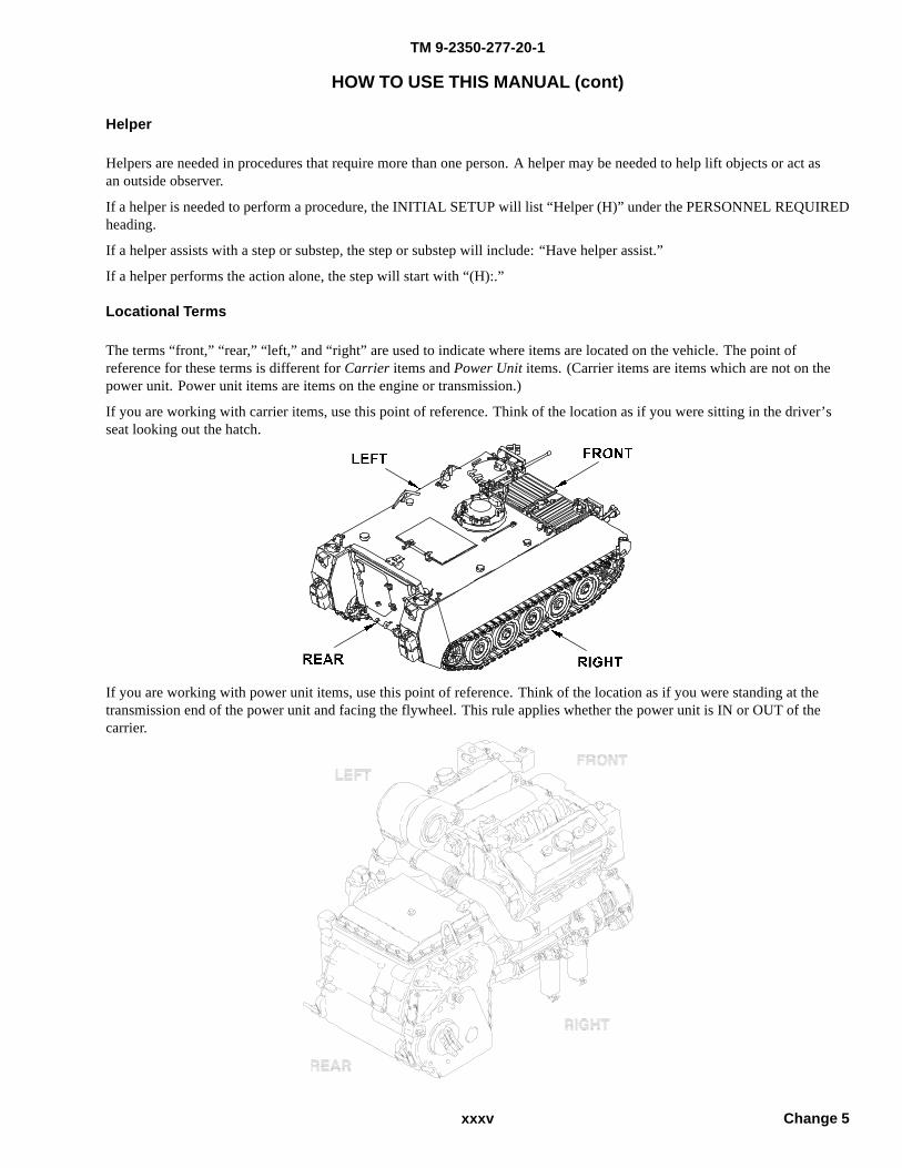
TM 9-2350-277-20-1
HOW TO USE THIS MANUAL (cont)
Helper
Helpers are needed in procedures that require more than one person. A helper may be needed to help lift objects or act asan outside observer.
If a helper is needed to perform a procedure, the INITIAL SETUP will list “Helper (H)” under the PERSONNEL REQUIREDheading.
If a helper assists with a step or substep, the step or substep will include: “Have helper assist.”
If a helper performs the action alone, the step will start with “(H):.”
Locational Terms
The terms “front,” “rear,” “left,” and “right” are used to indicate where items are located on the vehicle. The point ofreference for these terms is different for Carrier items and Power Unit items. (Carrier items are items which are not on thepower unit. Power unit items are items on the engine or transmission.)
If you are working with carrier items, use this point of reference. Think of the location as if you were sitting in the driver’sseat looking out the hatch.
If you are working with power unit items, use this point of reference. Think of the location as if you were standing at thetransmission end of the power unit and facing the flywheel. This rule applies whether the power unit is IN or OUT of thecarrier.
xxxv Change 5
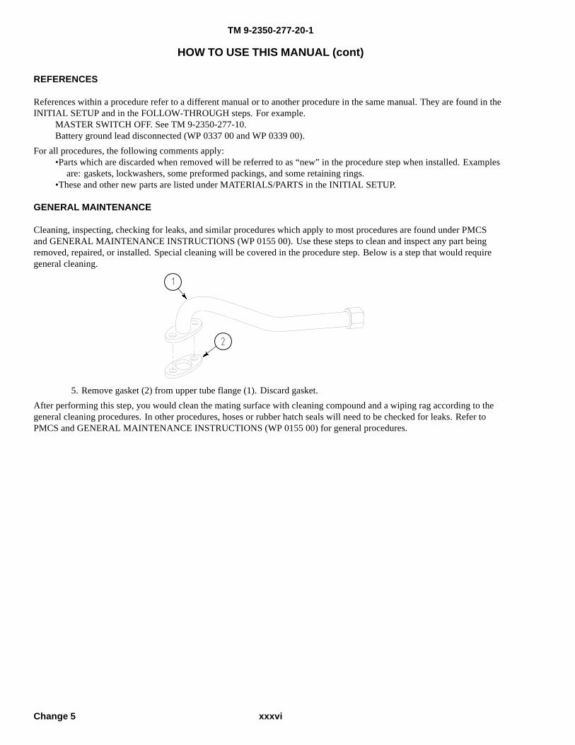
TM 9-2350-277-20-1
HOW TO USE THIS MANUAL (cont)
REFERENCES
References within a procedure refer to a different manual or to another procedure in the same manual. They are found in theINITIAL SETUP and in the FOLLOW-THROUGH steps. For example.
MASTER SWITCH OFF. See TM 9-2350-277-10.Battery ground lead disconnected (WP 0337 00 and WP 0339 00).
For all procedures, the following comments apply:•Parts which are discarded when removed will be referred to as “new” in the procedure step when installed. Examples
are: gaskets, lockwashers, some preformed packings, and some retaining rings.•These and other new parts are listed under MATERIALS/PARTS in the INITIAL SETUP.
GENERAL MAINTENANCE
Cleaning, inspecting, checking for leaks, and similar procedures which apply to most procedures are found under PMCSand GENERAL MAINTENANCE INSTRUCTIONS (WP 0155 00). Use these steps to clean and inspect any part beingremoved, repaired, or installed. Special cleaning will be covered in the procedure step. Below is a step that would requiregeneral cleaning.
5. Remove gasket (2) from upper tube flange (1). Discard gasket.After performing this step, you would clean the mating surface with cleaning compound and a wiping rag according to thegeneral cleaning procedures. In other procedures, hoses or rubber hatch seals will need to be checked for leaks. Refer toPMCS and GENERAL MAINTENANCE INSTRUCTIONS (WP 0155 00) for general procedures.
xxxviChange 5
TM 9-2350-277-20-1
HOW TO USE THIS MANUAL (cont)
HOW TO USE THE REPAIR PARTS AND SPECIAL TOOLS LIST (RPSTL) WITH THIS MANUAL
The RPSTL (TM 9-2350-277-24P) gives the National Stock Number (NSN) required to order parts used in the maintenanceprocedure. To use the RPSTL to identify and order a part, do the following:
1. In this manual, turn to the first page of the procedure to be performed.
2. Find Materials/Parts under INITIAL SETUP and read the part(s) that need replacement. If required, find the illustratedpart in the procedure steps.
3. Go to the RPSTL and find the same illustrated part. That part will have an item number assigned to it. Look this itemnumber up in the listing for that figure. Use the figure and item number index to find the NSN.
4. If you inspect an item and find that it is damaged, go to the RPSTL and find the SMR code for the item. If the SMR codedoes not authorize you to repair the item, reassemble it and send it to the authorized level of maintenance.
5. The usable on code in the RPSTL appears in the lower left corner of the Description column heading. Usableon codes are shown as ’UOC.... ...’ in the Description column (justified left) on the first line following the itemdescription/nomenclature. Uncoded items are applicable to all models. Identification of the usable on codes in theRPSTL are:
Table 1. RPSTL Usable On Codes
Code Used on
APC M113A3 Carrier, Personnel
AP5 M577A3 Carrier, Command Post
AP2 M1064A3 Carrier, 120 mm Mortar
AP6 M1059A3 Carrier, Smoke Generator
AP3 M1068A3 Carrier, Standardized IntegratedCommand Post System (SICPS)
AP8 M58 Carrier, Mechanized SmokeObscurant
xxxvii/xxxviii blank Change 5


TM 9-2350-277-20-1
CHAPTER 1
UNIT INTRODUCTORY INFORMATION WITH THEORY OF OPERATION
WORK PACKAGE INDEX
Title Sequence No.
GENERAL INFORMATION.............................................................................................................................................0001 00
EQUIPMENT DESCRIPTION..........................................................................................................................................0002 00
THEORY OF OPERATION...............................................................................................................................................0003 00
REPAIR PARTS, SPECIAL TOOLS, TMDE, AND SUPPORT EQUIPMENT...............................................................0004 00

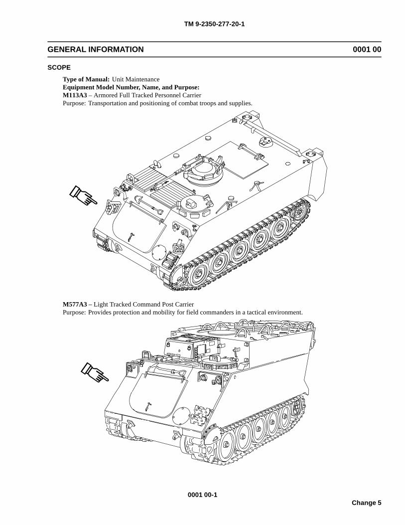
TM 9-2350-277-20-1
GENERAL INFORMATION 0001 00
SCOPE
Type of Manual: Unit MaintenanceEquipment Model Number, Name, and Purpose:M113A3 – Armored Full Tracked Personnel CarrierPurpose: Transportation and positioning of combat troops and supplies.
M577A3 – Light Tracked Command Post CarrierPurpose: Provides protection and mobility for field commanders in a tactical environment.
0001 00-1Change 5
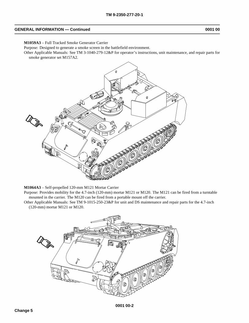
TM 9-2350-277-20-1
GENERAL INFORMATION — Continued 0001 00
M1059A3 – Full Tracked Smoke Generator CarrierPurpose: Designed to generate a smoke screen in the battlefield environment.Other Applicable Manuals: See TM 3-1040-279-12&P for operator’s instructions, unit maintenance, and repair parts for
smoke generator set M157A2.
M1064A3 – Self-propelled 120-mm M121 Mortar CarrierPurpose: Provides mobility for the 4.7-inch (120-mm) mortar M121 or M120. The M121 can be fired from a turntable
mounted in the carrier. The M120 can be fired from a portable mount off the carrier.Other Applicable Manuals: See TM 9-1015-250-23&P for unit and DS maintenance and repair parts for the 4.7-inch
(120-mm) mortar M121 or M120.
0001 00-2Change 5
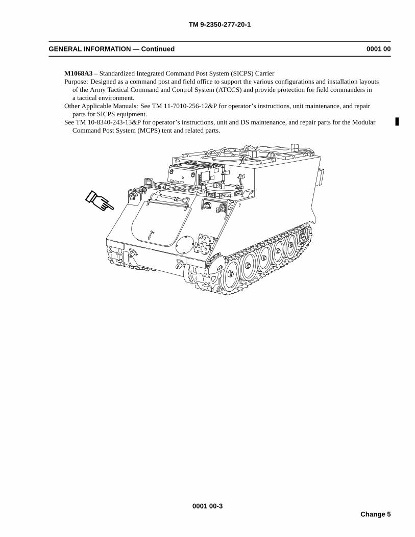
TM 9-2350-277-20-1
GENERAL INFORMATION — Continued 0001 00
M1068A3 – Standardized Integrated Command Post System (SICPS) CarrierPurpose: Designed as a command post and field office to support the various configurations and installation layouts
of the Army Tactical Command and Control System (ATCCS) and provide protection for field commanders ina tactical environment.
Other Applicable Manuals: See TM 11-7010-256-12&P for operator’s instructions, unit maintenance, and repairparts for SICPS equipment.
See TM 10-8340-243-13&P for operator’s instructions, unit and DS maintenance, and repair parts for the ModularCommand Post System (MCPS) tent and related parts.
0001 00-3Change 5
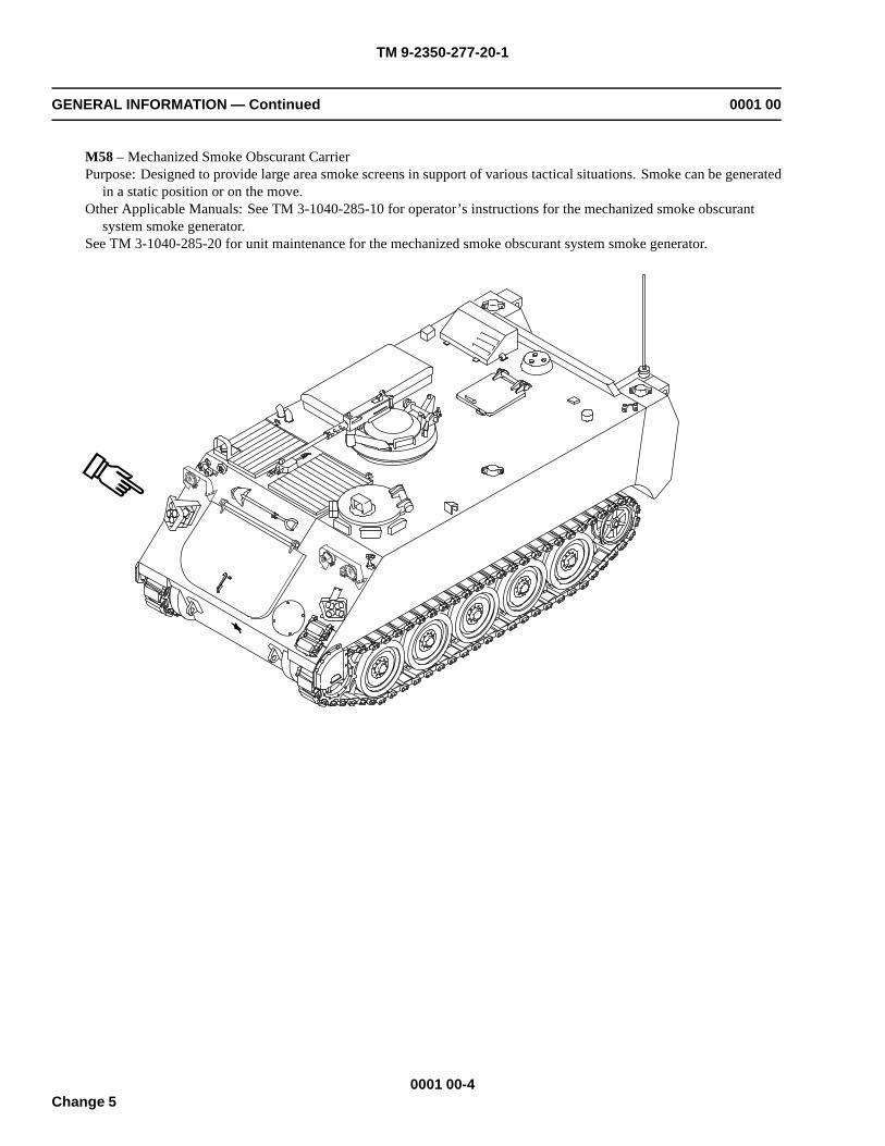
TM 9-2350-277-20-1
GENERAL INFORMATION — Continued 0001 00
M58 – Mechanized Smoke Obscurant CarrierPurpose: Designed to provide large area smoke screens in support of various tactical situations. Smoke can be generated
in a static position or on the move.Other Applicable Manuals: See TM 3-1040-285-10 for operator’s instructions for the mechanized smoke obscurant
system smoke generator.See TM 3-1040-285-20 for unit maintenance for the mechanized smoke obscurant system smoke generator.
0001 00-4Change 5
TM 9-2350-277-20-1
GENERAL INFORMATION — Continued 0001 00
MAINTENANCE FORMS, RECORDS, AND REPORTSDepartment of the Army forms and procedures used for equipment maintenance will be those prescribed by DA PAM 750-8,Functional User’s Manual for the Army Maintenance Management System (TAMMS).
REPORTING EQUIPMENT IMPROVEMENT RECOMMENDATIONS (EIR)If your carrier needs improvement, let us know. Send us an EIR. You, the user, are the only one who can tell us what you don’tlike about your equipment. Let us know why you don’t like the design or performance. Tell us why a procedure is hard toperform. Put your ideas on an SF 368 (Quality Deficiency Report). Mail it to us at: Commander, US Army Tank-automotiveArmaments Command, ATTN: AMSTA-TR-QCL, Warren, MI 48397-5000. We will send you a reply.
CORROSION PREVENTION AND CONTROL (CPC)Corrosion Prevention and Control (CPC) of Army materiel is a continuing concern. It is important that any corrosionproblems with this item be reported so that the problem can be corrected and improvements can be made to prevent theproblem in future items.Corrosion specifically occurs with metals. It is an electrochemical process that causes the degradation of metals. It iscommonly caused by exposure to moisture, acids, bases, or salts. An example is the rusting of iron. Corrosion damage inmetals can be seen, depending on the metal, as tarnishing, pitting, fogging, surface residue, and/or cracking.Plastics, composites, and rubbers can also degrade. Degradation is caused by thermal (heat), oxidation (oxygen), solvation(solvents), or photolytic (light, typically UV) processes. The most common exposures are excessive heat or light. Damagefrom these processes will appear as cracking, softening, swelling, and/or breaking.SF Form 368, Product Quality Deficiency Report should be submitted to the address specified in DA PAM 750-8, FunctionalUser’s Manual for the Army Maintenance Management System (TAMMS).
DESTRUCTION OF ARMY MATERIEL TO PREVENT ENEMY USESee the following technical manuals for information on destruction of Army materiel:
TM 750-244-2TM 43-0002-33TM 750-244-6TM 750-244-7
PREPARATION FOR STORAGE OR SHIPMENTFor information about administrative storage or shipment of the carriers, see the following documents:
Specification Applicable Carriers
MIL-DTL-45360 M113A3, M1064A3, M1059A3, M58ATPD 2227 M577A3 & M1068A3
CAUTION
To avoid damage to commander’s interface (CI) keyboard cableconnector, disconnect cable and install dust protective cap priorto placement of CI into carrying case.
For information about storage or shipment for the Mortar Fire Control System (MFCS), follow unit standard operatingprocedures (SOP).
NOMENCLATURE CROSS-REFERENCEThis listing includes nomenclature cross references used in this manual.
Adapter Nipple, pipe, unionBattery clamp Battery terminal adapterBattery clamp Terminal lug
0001 00-5Change 5

TM 9-2350-277-20-1
GENERAL INFORMATION — Continued 0001 00
Bilge pump Rotary pump
Breather Air filter intakeBulb Incandescent lampCoolant gauge Temperature indicatorDetector Liquid transmitterDipstick Liquid level gauge rodDrain plug Pipe plugEngine oil filter Fluid pressure filterEngine oil gauge Dial pressure gaugeExhaust collector Exhaust connectionFastener Toggle pinFire bottle Compression gas cylinderFluid level detector Liquid transmitterFuel control cable Fuel controlFuel filter Fluid filterFuel gauge Liquid quantity gaugeGear box Mechanical housingGrease fitting Lubrication fittingHand brake Parking brake leverHatch Hatch coverHinge pin Headless straight pinHinge pin Machine boltHorn switch Push switchHub SupportHydraulic power unit Ramp power unitIndicator light Indicator lampInlet grill Intake grillJack ReceptacleJamnut Hexagonal nutKey washers Locking platesLink Plain rod bearingLocknut Self-locking nutLockscrew Self-locking boltParking brake lever Manual control leverPlug ConnectorPropeller shaft Flexible drive shaftQuick disconnect Quick coupling halfRoad wheel Solid rubber wheelRod Connecting link
0001 00-6Change 5

TM 9-2350-277-20-1
GENERAL INFORMATION — Continued 0001 00
Screen Metal grillScrew Machine bolt
Shim Spacer
Shim pack Spacer assortment
Splined shaft Output carrierStarter switch Interlock switchStoplight TaillightStowage box Vehicular accessory boxTie strap Electric tiedown strapSwitch Circuit breakerThrottle control cable Throttle controlTowing pintle Pintle hook latchTurn signal assembly Vehicle directional lightUniversal joint Universal joint spiderVSFD Variable speed fan driveVSFD Cooling system pump (old configuration)
LIST OF ABBREVIATIONS / ACRONYMSMany abbreviations are used in this manual. They are listed below. Learn what each one means, it will make your job easier.
AC Alternating CurrentAOAP Army Oil Analysis ProgramAPU Auxiliary Power UnitATCCS Army Tactical Command and Control System
BATT BatteryBO BlackoutBRT BrightCARC Chemical Agent Resistant CoatingCB Circuit BreakerCI Commander’s InterfaceCO2 Carbon DioxideDAGR Defense Advanced GPS ReceiverDC Direct CurrentDD Driver’s DisplayDNV Driver’s Night Vision (AN/VVS-2)DVE Driver’s Vision Enhancer (AN/VAS-5)EIR Equipment Improvement RecommendationFDC Fire Direction CenterFRH Fire Resistant Hydraulic FluidFOV Family of VehiclesGAA Grease, Automotive and Artillery
0001 00-7Change 5
TM 9-2350-277-20-1
GENERAL INFORMATION — Continued 0001 00
GD Gunner’s Display
GEN Generator
IN InchIN-LB Inch PoundIR InfraredLB Pound
LB-FT Pound Feet
MCPS Modular Command Post System
MFCS Mortar Fire Control System
MPH Miles Per HourMSD/ICE Maintenance Support Device Internal Combustion EngineMTOE Modified Table of Organization and EquipmentNBC Nuclear, Biological, and ChemicalOC On-ConditionPD Pointing DevicePMCS Preventive Maintenance Checks and ServicesPSI Pounds per Square InchRPM Revolutions Per MinuteRPSTL Repair Parts Special Tools ListSCIPS Standardized Integrated Command Post SystemTAMMS The Army Maintenance Management SystemTBD To Be Determined
TM Technical Manual
TRANS Transmission
V Volt
VSFD Variable Speed Fan Drive
WP Work PackageMetric equivalents are used throughout this manual. Metric symbols and units are:
SYMBOL UNIT
C Celsius
cc cubic centimeter
cm centimeter
j joule
kg kilogram
kg/min kilogram per minute
km kilometer
km/h kilometer per hour
0001 00-8Change 5
TM 9-2350-277-20-1
GENERAL INFORMATION — Continued 0001 00
kPa kilopascal
kw hr kilowatt hour
l liter
m meter
mm millimeter
N·m Newton-meters
QUALITY OF MATERIALMaterial used for replacement, repair, or modification must meet the requirements of this TM. If quality of materialrequirements are not stated in this manual, the material must meet the requirements of the drawings, standards, specifications,or approved engineering change proposals applicable to the subject equipment.
SAFETY, CARE, AND HANDLING
Read warnings in WARNING SUMMARY.
0001 00-9/10 blankChange 5

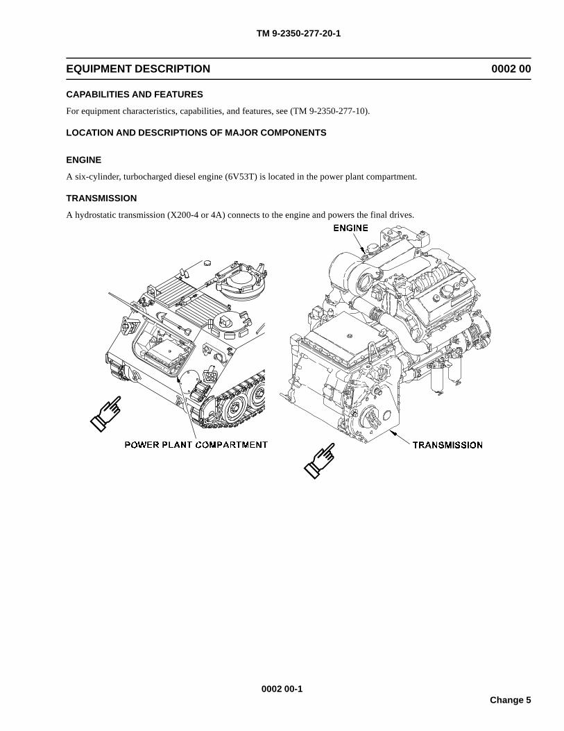
TM 9-2350-277-20-1
EQUIPMENT DESCRIPTION 0002 00
CAPABILITIES AND FEATURES
For equipment characteristics, capabilities, and features, see (TM 9-2350-277-10).
LOCATION AND DESCRIPTIONS OF MAJOR COMPONENTS
ENGINE
A six-cylinder, turbocharged diesel engine (6V53T) is located in the power plant compartment.
TRANSMISSION
A hydrostatic transmission (X200-4 or 4A) connects to the engine and powers the final drives.
0002 00-1Change 5
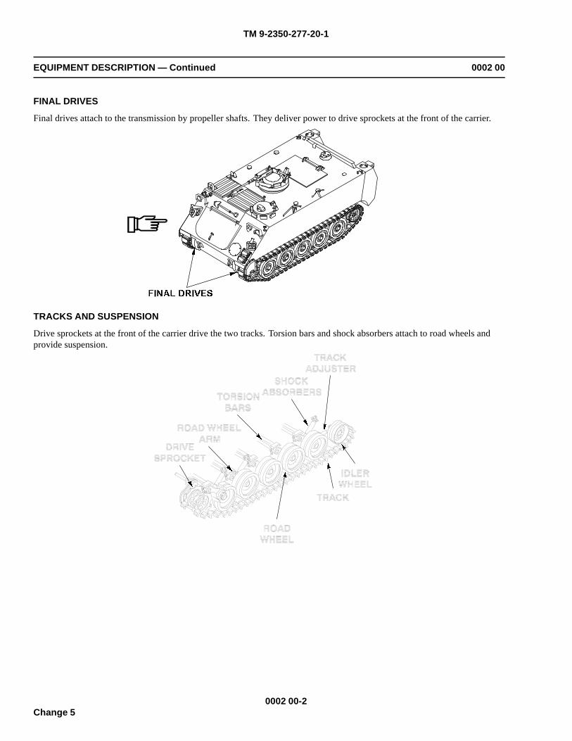
TM 9-2350-277-20-1
EQUIPMENT DESCRIPTION — Continued 0002 00
FINAL DRIVES
Final drives attach to the transmission by propeller shafts. They deliver power to drive sprockets at the front of the carrier.
TRACKS AND SUSPENSION
Drive sprockets at the front of the carrier drive the two tracks. Torsion bars and shock absorbers attach to road wheels andprovide suspension.
0002 00-2Change 5
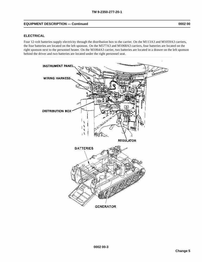
TM 9-2350-277-20-1
EQUIPMENT DESCRIPTION — Continued 0002 00
ELECTRICAL
Four 12-volt batteries supply electricity through the distribution box to the carrier. On the M113A3 and M1059A3 carriers,the four batteries are located on the left sponson. On the M577A3 and M1068A3 carriers, four batteries are located on theright sponson next to the personnel heater. On the M1064A3 carrier, two batteries are located in a drawer on the left sponsonbehind the driver and two batteries are located under the right personnel seat.
0002 00-3Change 5

TM 9-2350-277-20-1
EQUIPMENT DESCRIPTION — Continued 0002 00
FUEL SYSTEM
The M113A3, M1059A3, and M1064A3 carriers have two external fuel tanks located at the rear of thecarrier on each side of the ramp. Total capacity is 95 gallons. The M577A3 and M1068A3 carriers have twointernal fuel tanks located on the rear left and right sponsons under work tables. Total capacity is 120 gallons.
EXHAUST SYSTEM
The exhaust system drives the turbocharger and carries exhaust gases through manifolds and muffler.
0002 00-4Change 5
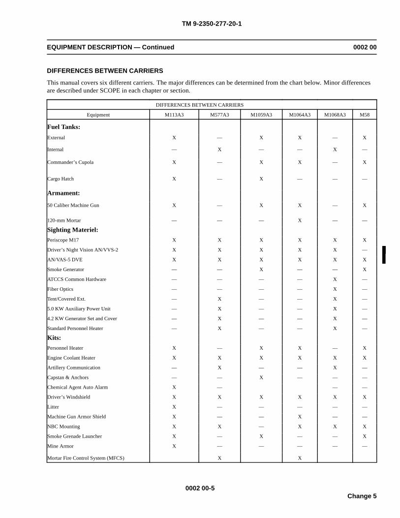
TM 9-2350-277-20-1
EQUIPMENT DESCRIPTION — Continued 0002 00
DIFFERENCES BETWEEN CARRIERS
This manual covers six different carriers. The major differences can be determined from the chart below. Minor differencesare described under SCOPE in each chapter or section.
DIFFERENCES BETWEEN CARRIERS
Equipment M113A3 M577A3 M1059A3 M1064A3 M1068A3 M58
Fuel Tanks:External X — X X — X
Internal — X — — X —
Commander’s Cupola X — X X — X
Cargo Hatch X — X — — —
Armament:
50 Caliber Machine Gun X — X X — X
120-mm Mortar — — — X — —
Sighting Materiel:Periscope M17 X X X X X X
Driver’s Night Vision AN/VVS-2 X X X X X —
AN/VAS-5 DVE X X X X X X
Smoke Generator — — X — — X
ATCCS Common Hardware — — — — X —
Fiber Optics — — — — X —
Tent/Covered Ext. — X — — X —
5.0 KW Auxiliary Power Unit — X — — X —
4.2 KW Generator Set and Cover — X — — X —
Standard Personnel Heater — X — — X —
Kits:Personnel Heater X — X X — X
Engine Coolant Heater X X X X X X
Artillery Communication — X — — X —
Capstan & Anchors — — X — — —
Chemical Agent Auto Alarm X — — —
Driver’s Windshield X X X X X X
Litter X — — — — —
Machine Gun Armor Shield X — — X — —
NBC Mounting X X — X X X
Smoke Grenade Launcher X — X — — X
Mine Armor X — — — — —
Mortar Fire Control System (MFCS) X X
0002 00-5Change 5

TM 9-2350-277-20-1
EQUIPMENT DESCRIPTION — Continued 0002 00
EQUIPMENT DATA
For equipment data, see (TM 9-2350-277-10).
0002 00-6Change 5
TM 9-2350-277-20-1
THEORY OF OPERATION 0003 00
SCOPEThis section describes how major systems and components of the carrier operate. An understanding of how each partfunctions in a system and how components relate to each other will help solve possible maintenance problems with the carrier.
POWER PLANTThe power plant consists of the diesel engine and transmission. The fuel, exhaust, cooling, starter, generator, and engine airsystems are support systems for the power plant.
DIESEL ENGINE
The diesel engine is the primary source of power for the carrier. The engine converts air and diesel fuel into energy anddelivers this power to the transmission.
STARTER
The engine is equipped with a heavy duty starter. The starter, with built-in solenoid, is used to crank the engine for starting.
GENERATOR
The generator is part of the carrier electrical system. It is driven directly by engine power. The generator charges the batteriesin the carrier when the engine is running. A regulator mounted in the driver’s compartment keeps the voltage at correct levels.
OIL SYSTEM
Oil system provides lubrication for the engine. Oil is cycled throughout the engine by a pump. The pump is located internallybehind the front engine cover. An oil filter cleans the oil, and an oil cooler reduces oil temperature.
FUEL SYSTEM
Diesel fuel is stored in two fuel tanks located at the rear of the carrier. Fuel is drawn from fuel tanks by the fuel pump whichpumps fuel through filters to the engine injectors. The injectors force fuel into combustion cylinders where it is mixedwith air and changed into energy.
TRANSMISSION SYSTEM
The carrier uses hydromechanical transmission with hydrostatic steering. The transmission has its own oil system with filtersand separately mounted oil cooler. This transmission oil system is separate from the engine oil system.The transmission delivers power from the engine to the left and right final drives. The left and right final drives are driven bypropeller shafts. The final drives deliver power to drive sprockets in the suspension system.
EXHAUST SYSTEM
Major exhaust system parts are the turbocharger, exhaust manifolds, muffler, and exhaust pipes.The turbocharger is driven by exhaust gases from the engine. The turbocharger helps the engine develop more power andoperate more efficiently. The exhaust manifolds carry the exhaust gases to the turbocharger from the engine. The muffler cutsdown engine noise and allows exhaust to escape through the exhaust pipes to outside of the carrier.
COOLING SYSTEM
The cooling system cools the engine and transmission. It consists of a fan, fan drive, fan speed control assembly, radiator,coolant pump, auxiliary tank, transmission oil cooler, engine oil cooler, and thermostats. The cooling system contains
0003 00-1Change 5
TM 9-2350-277-20-1
THEORY OF OPERATION — Continued 0003 00
approximately 14.8 gallons of liquid coolant. The liquid coolant is cycled through the engine and transmission oil cooler bythe coolant pump. This process keeps the engine and transmission temperature in a safe operation range.As coolant flows through the engine, it absorbs heat from the engine and transmission. The heated coolant then flows to theradiator to remove coolant heat. The coolant fan pulls outside air in and through the radiator to remove heat. The fan ispowered by the engine through a fan drive.The radiator auxiliary tank acts as an overflow tank to keep the cooling system from overpressurizing. It also removes airfrom the engine coolant. There is a low coolant level transmitter to signal the operator if more coolant is needed.
ENGINE AIR SYSTEM
The engine air system allows air to enter the engine. The air cleaner cleans air that enters the engine. Dust is drawn outthrough a scavenge outlet. Air is filtered through a reusable filter element before delivery to the engine. An air filterindicator shows when the element is clogged and needs cleaning or replacing. After being filtered, the air moves throughthe turbocharger and into the engine cylinders.
AUXILIARY AUTOMOTIVE SYSTEMThe auxiliary automotive system includes driver controls, fuel cells, personnel heater, bilge pumps, crew ventilation system,and fire suppression system.
DRIVER CONTROLS
The driver controls regulate the engine, transmission, and steering braking systems of the carrier.The fuel shutoff control is used to stop the supply of fuel to the engine injectors. To start the engine, the driver must open thevalve. The throttle linkages are used to control the engine speed. The gear selector allows the driver to choose the propergear for the carrier. The steering system controls the direction of the carrier. The steering control consists of a steeringwheel and linkage connected to the transmission.The brake system allows the driver to stop a moving carrier and hold the carrier in position. The braking system consistsof the service brake and the parking brake. The service brakes are hydraulic and applied by pedal. The parking brakemechanically locks the transmission brakes to prevent carrier movement. Also, the system has levers, rods, shafts, andlinkages connecting to the brake shaft of the transmission.
PERSONNEL HEATER
The personnel heater system provides heat inside the carrier. Major parts are the combination combustion chamber/heatexchanger, blowers, a fuel pump, and an electrical control and safety system. The heater operates using diesel fuel drawn fromthe fuel tanks. Fuel is delivered to the combustion chamber from the fuel pump. Outside air is drawn into the combustionchamber by one of the blowers. A blower draws air from the crew compartment into the combustion chamber. The air iswarmed by heat by the combustion process and then returned to the crew compartment.
BILGE PUMPS
Two electrically driven bilge pumps remove water and other liquids from the hull. Water enters the pumps through a screenedinlet. The pumps force water out of the carrier through outlet tubes. The bilge pumps are controlled by a switch on thedriver’s instrument panel.
HYDRAULIC SYSTEM
The ramp is raised or lowered by an hydraulic system which consists of a pump, a cylinder, a control valve, and an hydraulictank. This system is controlled by a three position valve located near the driver. Moving the valve to either RAISE orLOWER position directs fluid to the appropriate port on the ramp cylinder.
0003 00-2Change 5
TM 9-2350-277-20-1
THEORY OF OPERATION — Continued 0003 00
FIRE EXTINGUISHER SYSTEM
The fire extinguisher system consists of two CO2 (Carbon Dioxide) cylinders, one fixed and one portable. Carbon Dioxidecan put out fires quickly and effectively. The fixed cylinder only extinguishes fires in the power plant compartment. It islocated behind the driver and is actuated manually by a handle/knob on the cylinder or by an external handle connected to thecylinder by a cable. The portable fire extinguisher is located in the crew compartment and is manually discharged.
SUSPENSION SYSTEM
The suspension system supports the carrier and delivers engine power to the road. It allows the carrier to maneuver and bestable. Suspension system parts are the drive sprockets, tracks, idler wheels, track tension adjuster, road wheels, and supportarms. Also, there are torsion bars and shock absorbers.The drive sprockets drive the tracks. They are powered by left and right final drives from the transmission. The tracksconsist of two flexible chains of track shoes. The tracks ride on the drive sprockets and are guided by idler wheels. The idlerwheels can be adjusted to maintain correct track tension.There are five pairs of road wheels per side. Track centerguides fit between each pair of road wheels. Road wheels andtorsion bars are connected to support arms. The torsion bars act as springs to keep the road wheels on the ground and fromhitting the bottom of the carrier.
ELECTRICAL SYSTEM
The electrical system provides power for the carrier. The system operates on wet cell batteries and includes charging,regulating and monitoring equipment. The batteries provide a normal operating 24 volts with an amperage capability of200 amps per hour.The batteries supply the carrier with electricity when the engine is off. All electrical power is delivered through thedistribution box. Electrical power flows from the batteries through the distribution box, cables, and wiring assemblies to theelectrical equipment. The hull is a ground for the electrical system.The generator recharges the batteries and supplies electricity while the engine is running. The generator has 200 amps perhour capability.There are several electrical subsystems within the hull. Each subsystem contains at least one wiring assembly. Majorelectrical subsystems and assemblies are:Interior and Exterior Lights. Exterior lights include standard headlights, taillights/stoplights, and blackout lights. Interiorlights include domelights and panel lights.Starting and Charging. A generator with a regulator keeps the batteries charged to operating voltage. A starter with a built-insolenoid is used to crank the engine for starting.Ventilation and Heating. All carriers have a manual open-close ventilator located at the rear of the crew compartment. TheM577A3 and M1068A3 carriers also include an electric ventilation fan controlled by a switch on the master switch panel(M577A3 and M1068A3). The personnel heater is controlled by a heater control box which provides electric power forstarting and operating the heater. The control box is connected to the carrier batteries so that the heater can be operatedwithout turning the MASTER SWITCH ON.Bilge Pumps. Two pumps, one in the front and one in the rear of the carrier, remove any water that may have entered thecarrier. Both pumps are controlled by a switch on the driver’s instrument panel.
SPECIAL EQUIPMENTFor information on special purpose kits, refer to Chapter 22.
WINTERIZATION EQUIPMENTPersonnel heaters are standard equipment on M577A3, M1068A3, and M58 carriers. Since maintenance of heater componentsis the same for both standard heaters and kit heaters, they are only covered in one place in this manual. See Chapter 22 formaintenance of heater components.
0003 00-3/4 blankChange 5

TM 9-2350-277-20-1
REPAIR PARTS, SPECIAL TOOLS, TMDE, AND SUPPORT EQUIPMENT 0004 00
COMMON TOOLS AND EQUIPMENT
For authorized common tools and equipment, refer to Modified Table of Organization and Equipment (MTOE) for your unit.
SPECIAL TOOLS, TMDE, AND SUPPORT EQUIPMENT
Special tools and support equipment are needed for unit maintenance. They are listed in Repair Parts and Special Tools List(RPSTL) TM 9-2350-277-24P. Common tools and supplements and special tools and fixtures are listed in WP 0926 00.
REPAIR PARTS
Repair parts are listed and illustrated in the Repair Parts and Special Tools List (RPSTL) TM 9-2350-277-24P, covering unitmaintenance for this equipment.
0004 00-1/2 blank

TM 9-2350-277-20-1
CHAPTER 2
UNIT TROUBLESHOOTING PROCEDURES
WORK PACKAGE INDEXTitle Sequence No.
INTRODUCTION HOW TO USE TROUBLESHOOTING............................................................................................0005 00MALFUNCTION/SYMPTOM INDEX WP......................................................................................................................0006 00ENGINE CHARGING SYSTEM SCHEMATIC..............................................................................................................0007 00DELETED..........................................................................................................................................................................0008 00ENGINE FUEL SYSTEM SCHEMATIC (ALL EXCEPT M577A3 AND M1068A3)...................................................0009 00ENGINE FUEL SYSTEM SCHEMATIC (M577A3 AND M1068A3 ONLY).................................................................0010 00ENGINE STARTER CIRCUIT SCHEMATIC..................................................................................................................0011 00DELETED..........................................................................................................................................................................0012 00ENGINE AIR BOX HEATER SCHEMATIC....................................................................................................................0013 00ENGINE OVERHEATS (OLD VSFD CONFIGURATION)............................................................................................0014 00ENGINE OVERHEATS (NEW VSFD CONFIGURATION)...........................................................................................0014 01ENGINE OVERCOOLS....................................................................................................................................................0015 00ENGINE DOES NOT CRANK.........................................................................................................................................0016 00ENGINE DOES NOT START (COLD WEATHER ONLY).............................................................................................0017 00WAIT INDICATOR FLASHES DURING START ATTEMPTS (PREGLOW OR AFTERGLOW)...............................0018 00WAIT INDICATOR LIGHT DOESN’T LIGHT...............................................................................................................0019 00ENGINE CRANKS SLOWLY...........................................................................................................................................0020 00ENGINE CRANKS BUT WILL NOT START.................................................................................................................0021 00ENGINE CRANKS BUT WON’T START BELOW 40 F (AIR BOX HEATER IS USED)...........................................0022 00ENGINE CRANKS BUT WON’T START BELOW 40 F (GLOW PLUGS ARE USED)..............................................0023 00ENGINE RUNS ROUGH, STALLS, OR DOESN’T PUT OUT FULL POWER............................................................0024 00GENERATOR MALFUNCTIONS AS INDICATED BY BATTERY/GENERATOR INDICATOR...............................0025 00ENGINE OIL LOW PRESSURE INDICATOR COMES ON..........................................................................................0026 00ELECTRICAL SCHEMATIC............................................................................................................................................0027 00DELETED..........................................................................................................................................................................0028 00NO EXTERIOR LIGHTS OPERATE................................................................................................................................0029 00BLACKOUT DRIVE LIGHT DOESN’T WORK.............................................................................................................0030 00SERVICE HEADLIGHTS DON’T WORK.......................................................................................................................0031 00DELETED..........................................................................................................................................................................0032 00SERVICE AND/OR BLACKOUT STOP LIGHTS MALFUNCTION............................................................................0033 00BLACKOUT MARKER LIGHT(S) DON’T WORK.......................................................................................................0034 00SERVICE TAILLIGHT DOESN’T WORK......................................................................................................................0035 00TRAILER LIGHTS DON’T WORK.................................................................................................................................0036 00HORN DOES NOT WORK...............................................................................................................................................0037 00INSTRUMENT PANEL AND/OR TRANS CONTROLLER ILLUMINATION LIGHTS
MALFUNCTION.....................................................................................................................................................0038 00DOME LIGHT(S) DO NOT WORK.................................................................................................................................0039 00
Change 5
TM 9-2350-277-20-1
CHAPTER 2UNIT TROUBLESHOOTING PROCEDURES
WORK PACKAGE INDEX (Continued)
Title Sequence No.
DOME LIGHT MALFUNCTION (M577A3 ONLY).......................................................................................................0040 00BLACKOUT DOME LIGHTS DO NOT WORK (M1068A3 ONLY).............................................................................0041 00RIGHT REAR UTILITY OUTLET/ADMITTANCE BUZZER WORKS IMPROPERLY
(M577A3 AND M1068A3 ONLY)..........................................................................................................................0042 00LEFT REAR UTILITY OUTLET/BLOWER DOES NOT WORK (M577A3 AND M1068A3
ONLY)......................................................................................................................................................................0043 00RADIO(S) DON’T WORK................................................................................................................................................0044 00SMOKE GRENADE LAUNCHER(S) MALFUNCTION (M113A3 AND M1059A3 ONLY).......................................0045 00INDICATORS SCHEMATIC.............................................................................................................. ..............................0046 00DELETED..........................................................................................................................................................................0047 00MASTER SWITCH ON INDICATOR DOESN’T LIGHT...............................................................................................0048 00FUEL LEVEL INDICATOR MALFUNCTIONS.............................................................................................................0049 00HIGH BEAM INDICATOR LIGHT DOESN’T WORK...................................................................................................0050 00BATTERY/GENERATOR INDICATOR MALFUNCTIONS..........................................................................................0051 00PARKING BRAKE INDICATOR MALFUNCTIONS.....................................................................................................0052 00COOLANT TEMP INDICATOR MALFUNCTIONS......................................................................................................0053 00STEERING LOCKED INDICATOR MALFUNCTIONS.................................................................................................0054 00ENGINE OIL LOW PRESSURE INDICATOR MALFUNCTIONS................................................................................0055 00TRANSMISSION OIL LOW PRESSURE INDICATOR MALFUNCTIONS.................................................................0056 00TRANS OIL HI TEMP INDICATOR MALFUNCTIONS...............................................................................................0057 00ENGINE COOLANT LOW LEVEL INDICATOR MALFUNCTIONS..........................................................................0058 00TRANS FILTER CLOGGED INDICATOR MALFUNCTIONS......................................................................................0059 00TRANSMISSION SYSTEM SCHEMATIC......................................................................................................................0060 00CARRIER MOVES WITH TRANSMISSION IN SL.......................................................................................................0061 00CARRIER DOES NOT ATTAIN HIGH SPEED...............................................................................................................0061 01CARRIER DOES NOT MOVE IN ANY SHIFT LEVER POSITION.............................................................................0062 00CARRIER DRIFTS OR DOES NOT STEER...................................................................................................................0063 00SERVICE AND/OR PARKING BRAKE WON’T HOLD CARRIER.............................................................................0064 00TRANSMISSION WON’T UPSHIFT OR SHIFTS ERRATICALLY IN 1-4 POSITION...............................................0065 00TRANSMISSION DOES NOT DOWNSHIFT IN 1-4 POSITION..................................................................................0066 00TRANSMISSION DOES NOT HOLD 1ST POSITION...................................................................................................0067 00TRANSMISSION DOES NOT HOLD 2ND POSITION..................................................................................................0068 00TRANSMISSION DOES NOT HOLD 3RD POSITION..................................................................................................0069 00TRANSMISSION DOES NOT REVERSE.......................................................................................................................0070 00TRANSMISSION DOES NOT PIVOT STEER................................................................................................................0071 00TRANSMISSION HIGH TEMP INDICATOR COMES ON............................................................................................0072 00
Change 5
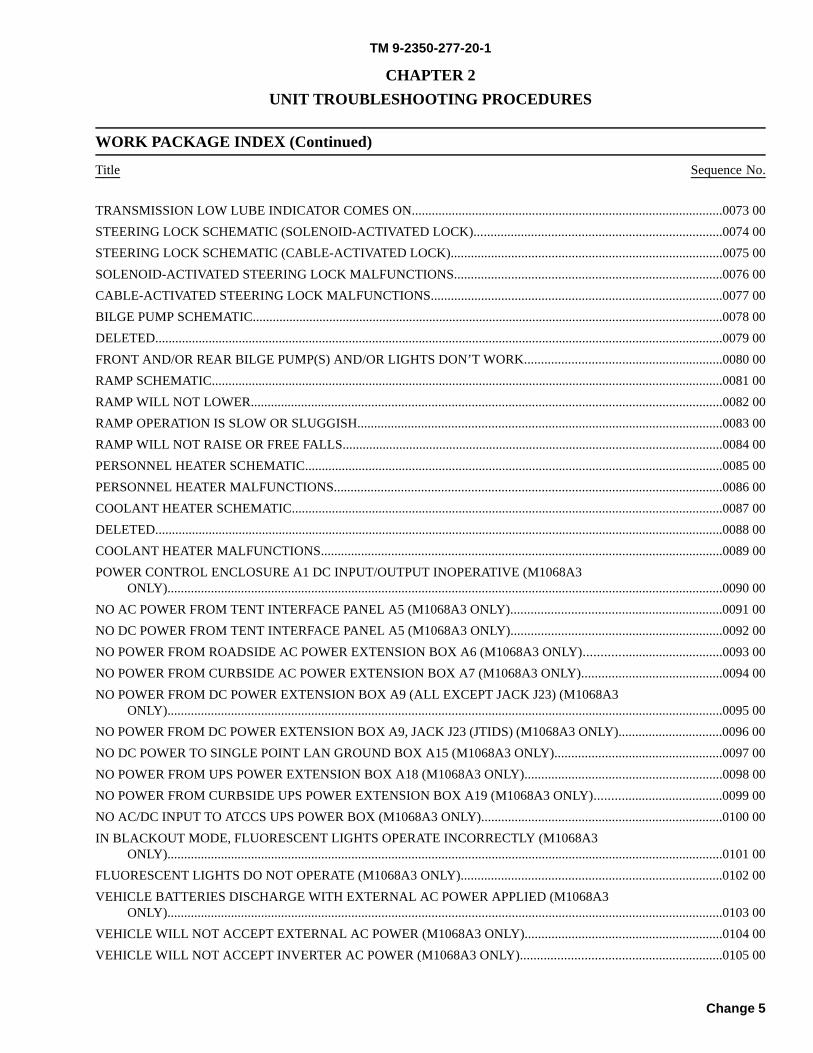
TM 9-2350-277-20-1
CHAPTER 2UNIT TROUBLESHOOTING PROCEDURES
WORK PACKAGE INDEX (Continued)
Title Sequence No.
TRANSMISSION LOW LUBE INDICATOR COMES ON.............................................................................................0073 00STEERING LOCK SCHEMATIC (SOLENOID-ACTIVATED LOCK)..........................................................................0074 00STEERING LOCK SCHEMATIC (CABLE-ACTIVATED LOCK).................................................................................0075 00SOLENOID-ACTIVATED STEERING LOCK MALFUNCTIONS................................................................................0076 00CABLE-ACTIVATED STEERING LOCK MALFUNCTIONS.......................................................................................0077 00BILGE PUMP SCHEMATIC.............................................................................................................................................0078 00DELETED..........................................................................................................................................................................0079 00FRONT AND/OR REAR BILGE PUMP(S) AND/OR LIGHTS DON’T WORK...........................................................0080 00RAMP SCHEMATIC.........................................................................................................................................................0081 00RAMP WILL NOT LOWER.............................................................................................................................................0082 00RAMP OPERATION IS SLOW OR SLUGGISH.............................................................................................................0083 00RAMP WILL NOT RAISE OR FREE FALLS..................................................................................................................0084 00PERSONNEL HEATER SCHEMATIC.............................................................................................................................0085 00PERSONNEL HEATER MALFUNCTIONS....................................................................................................................0086 00COOLANT HEATER SCHEMATIC.................................................................................................................................0087 00DELETED..........................................................................................................................................................................0088 00COOLANT HEATER MALFUNCTIONS........................................................................................................................0089 00POWER CONTROL ENCLOSURE A1 DC INPUT/OUTPUT INOPERATIVE (M1068A3
ONLY)......................................................................................................................................................................0090 00NO AC POWER FROM TENT INTERFACE PANEL A5 (M1068A3 ONLY)...............................................................0091 00NO DC POWER FROM TENT INTERFACE PANEL A5 (M1068A3 ONLY)...............................................................0092 00NO POWER FROM ROADSIDE AC POWER EXTENSION BOX A6 (M1068A3 ONLY).........................................0093 00NO POWER FROM CURBSIDE AC POWER EXTENSION BOX A7 (M1068A3 ONLY)..........................................0094 00NO POWER FROM DC POWER EXTENSION BOX A9 (ALL EXCEPT JACK J23) (M1068A3
ONLY)......................................................................................................................................................................0095 00NO POWER FROM DC POWER EXTENSION BOX A9, JACK J23 (JTIDS) (M1068A3 ONLY)...............................0096 00NO DC POWER TO SINGLE POINT LAN GROUND BOX A15 (M1068A3 ONLY)..................................................0097 00NO POWER FROM UPS POWER EXTENSION BOX A18 (M1068A3 ONLY)...........................................................0098 00NO POWER FROM CURBSIDE UPS POWER EXTENSION BOX A19 (M1068A3 ONLY)......................................0099 00NO AC/DC INPUT TO ATCCS UPS POWER BOX (M1068A3 ONLY)........................................................................0100 00IN BLACKOUT MODE, FLUORESCENT LIGHTS OPERATE INCORRECTLY (M1068A3
ONLY)......................................................................................................................................................................0101 00FLUORESCENT LIGHTS DO NOT OPERATE (M1068A3 ONLY)..............................................................................0102 00VEHICLE BATTERIES DISCHARGE WITH EXTERNAL AC POWER APPLIED (M1068A3
ONLY)......................................................................................................................................................................0103 00VEHICLE WILL NOT ACCEPT EXTERNAL AC POWER (M1068A3 ONLY)...........................................................0104 00VEHICLE WILL NOT ACCEPT INVERTER AC POWER (M1068A3 ONLY)............................................................0105 00
Change 5

TM 9-2350-277-20-1
CHAPTER 2UNIT TROUBLESHOOTING PROCEDURES
WORK PACKAGE INDEX (Continued)
Title Sequence No.
NO POWER TO DC CIRCUITS (M1068A3 ONLY).......................................................................................................0106 00NO POWER TO AC CIRCUITS (M1068A3 ONLY).......................................................................................................0107 00NO DC OUTPUT FROM DC POWER SUPPLY (M1068A3 ONLY)..............................................................................0108 00NO AC POWER FROM INVERTERS (M1068A3 ONLY)..............................................................................................0109 00INVERTER POWER-UP FAILURE (M1068A3 ONLY)..................................................................................................0109 01NO DATA OUTPUT FROM DATA PANEL A12 (M1068A3 ONLY).............................................................................0110 00NO LAN OUTPUT FROM DATA PANEL A12 (M1068A3 ONLY)...............................................................................0111 00NO DATA OUTPUT FROM DATA PANEL A13 (M1068A3 ONLY).............................................................................0112 00NO LAN OUTPUT FROM DATA PANEL A13 (M1068A3 ONLY)...............................................................................0113 00PHONE EXTENSION BOX A14 POST(S) INOPERATIVE (M1068A3 ONLY)...........................................................0114 00SPEEDOMETER MALFUNCTIONS...............................................................................................................................0115 00TACHOMETER MALFUNCTIONS.................................................................................................................................0116 00DRIVER’S VISION ENHANCER (DVE) DISPLAY DOES NOT WORK.....................................................................0116 01COMMANDER’S VISION ENHANCER (DVE) DISPLAY DOES NOT WORK (M58 ONLY)..................................0116 02HOOK UP/REMOVE MSD/ICE TEST SET TO DCA 6..................................................................................................0117 00MSD/ICE TEST 10 ENGINE RPM...................................................................................................................................0118 00MSD/ICE TEST 24 FUEL SUPPLY PRESSURE.............................................................................................................0119 00MSD/ICE TEST 25 FUEL RETURN PRESSURE...........................................................................................................0120 00MSD/ICE TEST 26 FUEL FILTER PRESSURE DROP..................................................................................................0121 00MSD/ICE TEST 30 TURBOCHARGER OUTLET PRESSURE.....................................................................................0122 00MSD/ICE TEST 32 AIR BOX PRESSURE......................................................................................................................0123 00MSD/ICE TEST 67 BATTERY VOLTAGE......................................................................................................................0124 00MSD/ICE TEST 68 STARTER MOTOR VOLTAGE.......................................................................................................0125 00MSD/ICE TEST 69 STARTER NEGATIVE CABLE VOLTAGE DROP........................................................................0126 00MSD/ICE TEST 70 STARTER SOLENOID VOLTAGE..................................................................................................0127 00MSD/ICE TEST 71 STARTER CURRENT (AVERAGE)................................................................................................0128 00MSD/ICE TEST 72 STARTER CURRENT (FIRST PEAK)............................................................................................0129 00MSD/ICE TEST 73
Change 5
BATTERY RESISTANCE................................................................................................................0130 00DELETED..........................................................................................................................................................................0131 00MSD/ICE TEST 80 BATTERY CURRENT......................................................................................................................0132 00MSD/ICE TEST 82 GENERATOR OUTPUT VOLTAGE...............................................................................................0133 00MSD/ICE TEST 83 GENERATOR FIELD VOLTAGE....................................................................................................0134 00MSD/ICE TEST 84 GENERATOR NEGATIVE CABLE VOLTAGE DROP..................................................................0135 00msd/ICE SCHEMATIC......................................................................................................................................................0136 00DELETED..........................................................................................................................................................................0137 00DELETED..........................................................................................................................................................................0138 00
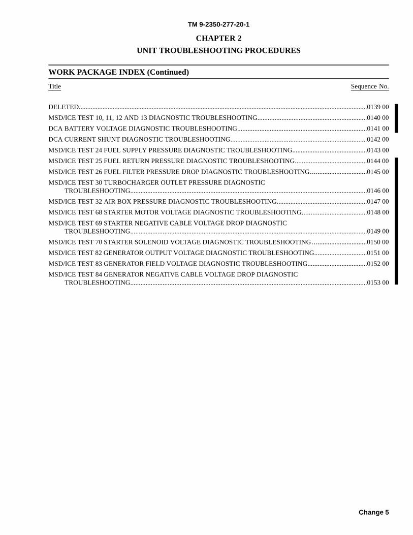
TM 9-2350-277-20-1
CHAPTER 2UNIT TROUBLESHOOTING PROCEDURES
WORK PACKAGE INDEX (Continued)
Title Sequence No.
Change 5
DELETED..........................................................................................................................................................................0139 00MSD/ICE TEST 10, 11, 12 AND 13 DIAGNOSTIC TROUBLESHOOTING................................................................0140 00DCA BATTERY VOLTAGE DIAGNOSTIC TROUBLESHOOTING............................................................................0141 00DCA CURRENT SHUNT DIAGNOSTIC TROUBLESHOOTING................................................................................0142 00MSD/ICE TEST 24 FUEL SUPPLY PRESSURE DIAGNOSTIC TROUBLESHOOTING............................................0143 00MSD/ICE TEST 25 FUEL RETURN PRESSURE DIAGNOSTIC TROUBLESHOOTING..........................................0144 00MSD/ICE TEST 26 FUEL FILTER PRESSURE DROP DIAGNOSTIC TROUBLESHOOTING.................................0145 00MSD/ICE TEST 30 TURBOCHARGER OUTLET PRESSURE DIAGNOSTIC
TROUBLESHOOTING...........................................................................................................................................0146 00MSD/ICE TEST 32 AIR BOX PRESSURE DIAGNOSTIC TROUBLESHOOTING.....................................................0147 00MSD/ICE TEST 68 STARTER MOTOR VOLTAGE DIAGNOSTIC TROUBLESHOOTING......................................0148 00MSD/ICE TEST 69 STARTER NEGATIVE CABLE VOLTAGE DROP DIAGNOSTIC
TROUBLESHOOTING...........................................................................................................................................0149 00MSD/ICE TEST 70 STARTER SOLENOID VOLTAGE DIAGNOSTIC TROUBLESHOOTING................................0150 00MSD/ICE TEST 82 GENERATOR OUTPUT VOLTAGE DIAGNOSTIC TROUBLESHOOTING...............................0151 00MSD/ICE TEST 83 GENERATOR FIELD VOLTAGE DIAGNOSTIC TROUBLESHOOTING...................................0152 00MSD/ICE TEST 84 GENERATOR NEGATIVE CABLE VOLTAGE DROP DIAGNOSTIC
TROUBLESHOOTING...........................................................................................................................................0153 00

TM 9-2350-277-20-1
INTRODUCTION TO HOW TO USE TROUBLESHOOTING 0005 00
PURPOSE
The purpose of unit troubleshooting is to diagnose problems which are reported to unit maintenance. You should not beginunit troubleshooting until ALL operator troubleshooting procedures have been performed. You will perform four actions inunit troubleshooting:
(1) Before starting a troubleshooting task, verify that the reported problem is present.(2) After verifying the symptom, find the part that is causing problem.(3) Replace or adjust that part.(4) Check to make sure problem no longer exists, and that there are no other problems.
DEFINITIONS AND DESCRIPTIONS OF TROUBLESHOOTING PARTS
Troubleshooting tasks always have a beginning and an end. You will use task steps, test procedures, indexes, maintenancetasks, and other technical manuals to troubleshoot. Troubleshooting uses the following terms that are not used in other kindsof tasks:
1. FAULT: The part that is not operating correctly and is causing the problem.
2. SYMPTOM: The problem reported to unit maintenance.
3. STE/ICE: Diagnostic and test equipment used to troubleshoot at unit maintenance level. It isused to make measurements and find faulty parts in the carrier system.
4. VERIFY NO FAULTSFOUND:
After you have completed the corrective action, you must verify that no faults exist.If the fault condition still exists, then the fault is not fixed or there is another fault.If this happens, start at the beginning of the correct/appropriate troubleshootingprocedure until you find and correct all faults. Always operate the system and/orcarrier to make sure that you have corrected the reported problem. Iftroubleshooting does not identify a faulty part, the carrier is defective beyond thelevel of unit maintenance.
0005 00-1 Change 2
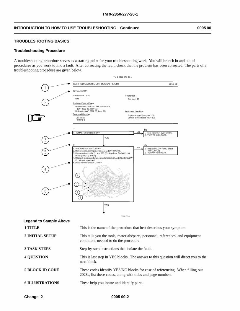
TM 9-2350-277-20-1
INTRODUCTION TO HOW TO USE TROUBLESHOOTING—Continued 0005 00
TROUBLESHOOTING BASICS
Troubleshooting Procedure
A troubleshooting procedure serves as a starting point for your troubleshooting work. You will branch in and out ofprocedures as you work to find a fault. After correcting the fault, check that the problem has been corrected. The parts of atroubleshooting procedure are given below.
INITIAL SETUP:
Unit
T
YES
NOTN
Y
YES
NOYN
0019 00-1
General mechanics tool kit: automotive (WP 0926 00, Item 65)Multimeter (WP 0926 00, Item 30)
Tools and Special Tools
Personnel Required
Maintenance Level
TM 9-2350-277-20-1
Unit Mech Helper (H)
References
See your -10
WAIT INDICATOR LIGHT DOESN’T LIGHT 0019 00
Equipment Condition
1. Is MASTER SWITCH ON? 1. Turn MASTER SWITCH ON.2. Verify no faults found.
1. Replace GLOW PLUG switch (WP 0209 00).2. Verify no faults found.
1. Turn MASTER SWITCH OFF .2. Remove instrument panel for access (WP 0279 00).3. Remove circuits 406 (1) and 27C (2) plugs from GLOW PLUG switch jacks (3) and (4).4. Measure resistance between switch jacks (3) and (4) with GLOW PLUG switch pressed.5. Does multimeter read 0 ohm?
Engine stopped (see your -10)Vehicle blocked (see your -10)
Legend to Sample Above
1 TITLE This is the name of the procedure that best describes your symptom.
2 INITIAL SETUP This tells you the tools, materials/parts, personnel, references, and equipmentconditions needed to do the procedure.
3 TASK STEPS Step-by-step instructions that isolate the fault.
4 QUESTION This is last step in YES blocks. The answer to this question will direct you to thenext block.
5 BLOCK ID CODE These codes identify YES/NO blocks for ease of referencing. When filling out2028s, list these codes, along with titles and page numbers.
6 ILLUSTRATIONS These help you locate and identify parts.
0005 00-2Change 2
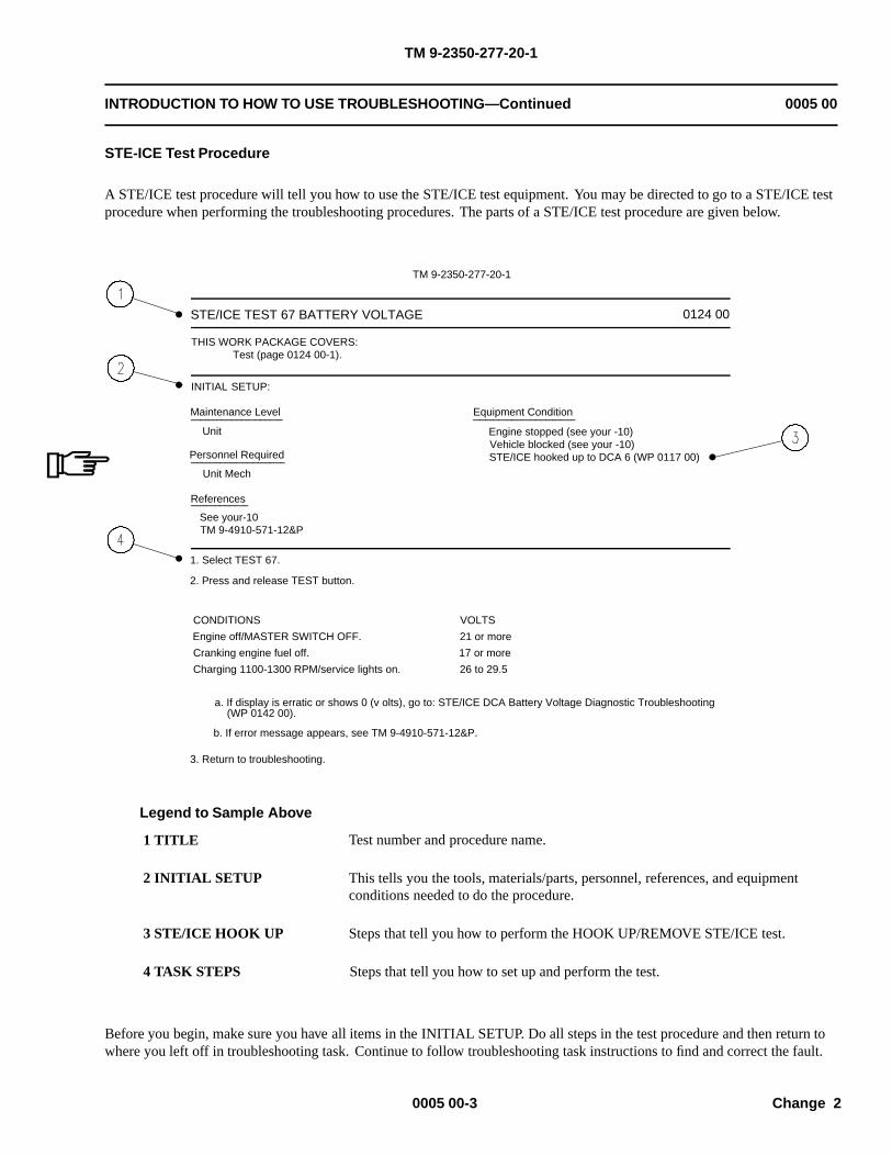
TM 9-2350-277-20-1
INTRODUCTION TO HOW TO USE TROUBLESHOOTING—Continued 0005 00
STE-ICE Test Procedure
A STE/ICE test procedure will tell you how to use the STE/ICE test equipment. You may be directed to go to a STE/ICE testprocedure when performing the troubleshooting procedures. The parts of a STE/ICE test procedure are given below.
INITIAL SETUP:
STE/ICE TEST 67 BATTERY VOLTAGE
THIS WORK PACKAGE COVERS: Test (page 0124 00-1).
Maintenance Level
Personnel Required
Unit Mech
Equipment Condition
Engine stopped (see your -10)Vehicle blocked (see your -10)STE/ICE hooked up to DCA 6 (WP 0117 00)
References
See your-10TM 9-4910-571-12&P
1. Select TEST 67.
2. Press and release TEST button.
CONDITIONS
Engine off/MASTER SWITCH OFF.
Cranking engine fuel off.
Charging 1100-1300 RPM/service lights on.
VOLTS
21 or more
17 or more
26 to 29.5
a. If display is erratic or shows 0 (v olts), go to: STE/ICE DCA Battery Voltage Diagnostic Troubleshooting (WP 0142 00).
b. If error message appears, see TM 9-4910-571-12&P.
3. Return to troubleshooting.
Unit
0124 00
TM 9-2350-277-20-1
Legend to Sample Above
1 TITLE Test number and procedure name.
2 INITIAL SETUP This tells you the tools, materials/parts, personnel, references, and equipmentconditions needed to do the procedure.
3 STE/ICE HOOK UP Steps that tell you how to perform the HOOK UP/REMOVE STE/ICE test.
4 TASK STEPS Steps that tell you how to set up and perform the test.
Before you begin, make sure you have all items in the INITIAL SETUP. Do all steps in the test procedure and then return towhere you left off in troubleshooting task. Continue to follow troubleshooting task instructions to find and correct the fault.
0005 00-3 Change 2
TM 9-2350-277-20-1
INTRODUCTION TO HOW TO USE TROUBLESHOOTING—Continued 0005 00
Locating the Correct Troubleshooting Procedure
(1) Carrier arrives at shop.(2) Read DA Form 2404.(3) Verify that the problem on DA Form 2404 exists.(4) Look up the carrier symptom in the Troubleshooting Fault Symptom Index (WP 0006 00) and go to that task.
Doing the Troubleshooting Procedure
(1) Make sure you have all items in INITIAL SETUP.(2) Perform required action(s) in Equipment Conditions.(3) Complete the first block of task steps.(4) Refer to system schematics for system components, details, and configuration.(5) Answer question at the bottom of the first block.(6) Follow YES or NO arrows to next block.(7) Move from block to block. Answer questions and follow instructions. You may be directed to:
do further checks and tests on parts;go to another manual and do tasks;or go to another task in this manual.
(8) After completing the actions called for on another page or manual, return to the point in the troubleshootingprocedure where you left off.
(9) Locate the fault in the carrier or part, and perform the corrective action.(10) Check to make sure the fault is corrected, and there are no new faults.(11) Button up by installing items listed in Equipment Conditions after finishing the troubleshooting task.
TROUBLESHOOTING SAMPLE
The following sample takes you through a typical troubleshooting procedure.
Finding the Right Troubleshooting Procedure
A carrier arrives at the shop. The DA Form 2404 shows that the engine cranks slowly. The best task match is ENGINECRANKS SLOWLY (WP 0020 00).
0005 00-4Change 2
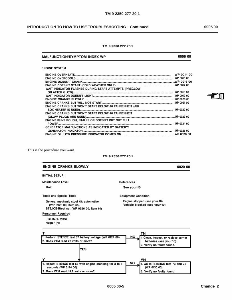
TM 9-2350-277-20-1
INTRODUCTION TO HOW TO USE TROUBLESHOOTING—Continued 0005 00
’’
This is the procedure you want.
0005 00-5 Change 2
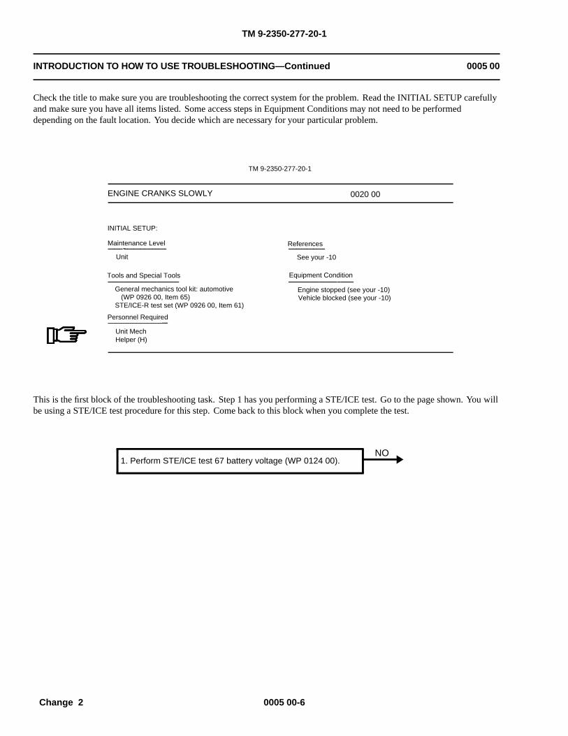
TM 9-2350-277-20-1
INTRODUCTION TO HOW TO USE TROUBLESHOOTING—Continued 0005 00
Check the title to make sure you are troubleshooting the correct system for the problem. Read the INITIAL SETUP carefullyand make sure you have all items listed. Some access steps in Equipment Conditions may not need to be performeddepending on the fault location. You decide which are necessary for your particular problem.
ENGINE CRANKS SLOWLY
TM 9-2350-277-20-1
Engine stopped (see your -10)Vehicle blocked (see your -10)
General mechanics tool kit: automotive (WP 0926 00, Item 65)STE/ICE-R test set (WP 0926 00, Item 61)
Equipment Condition
See your -10
References
INITIAL SETUP:
Maintenance Level
Unit
Tools and Special Tools
Personnel Required
Unit Mech Helper (H)
0020 00
This is the first block of the troubleshooting task. Step 1 has you performing a STE/ICE test. Go to the page shown. You willbe using a STE/ICE test procedure for this step. Come back to this block when you complete the test.
NO1. Perform STE/ICE test 67 battery voltage (WP 0124 00).
0005 00-6Change 2

TM 9-2350-277-20-1
INTRODUCTION TO HOW TO USE TROUBLESHOOTING—Continued 0005 00
Here is the STE/ICE test procedure. It will give you more steps to find the fault. Before you begin, make sue you have all theitems in the INITIAL SETUP. Do all the steps in the procedure. After you do the steps, go back to where you left off in thetroubleshooting task.
INITIAL SETUP:
STE/ICE TEST 67 BATTERY VOLTAGE
THIS WORK PACKAGE COVERS: Test (page 0124 00-1).
Maintenance Level
Personnel Required
Unit Mech
Equipment Condition
Engine stopped (see your -10)Vehicle blocked (see your -10)STE/ICE hooked up to DCA 6 (WP 0117 00)
References
See your-10TM 9-4910-571-12&P
1. Select TEST 67.
2. Press and release TEST button.
CONDITIONS
Engine off/MASTER SWITCH OFF.
Cranking engine fuel off.
Charging 1100-1300 RPM/service lights on.
VOLTS
21 or more
17 or more
26 to 29.5
a. If display is erratic or shows 0 (v olts), go to: STE/ICE DCA Battery Voltage Diagnostic Troubleshooting (WP 0142 00).
b. If error message appears, see TM 9-4910-571-12&P.
3. Return to troubleshooting.
Unit
0124 00
TM 9-2350-277-20-1
This is where you left off in the troubleshooting task. Answer the question in step 2. The answer to question depends on whatyou found when you did the STE/ICE test procedure. In this sample, let us say the test shows 22 volts. So the answer to thequestion, “Does test read 22 volts or more?” is YES. Follow the YES arrow to the next block.
2. Does VTM read 22 volts or more?NO 1. Clean, inspect, or replace carrier
batteries (see your-10).2. Verify no faults found.
0005 00-7 Change 2
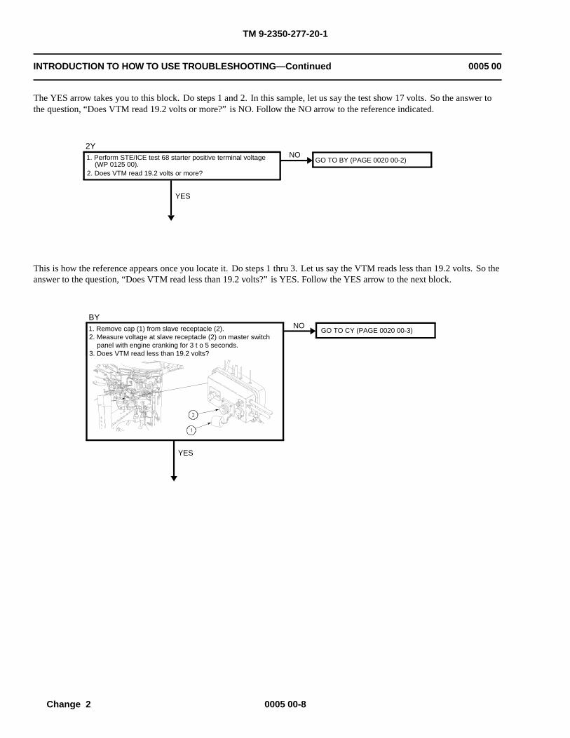
TM 9-2350-277-20-1
INTRODUCTION TO HOW TO USE TROUBLESHOOTING—Continued 0005 00
The YES arrow takes you to this block. Do steps 1 and 2. In this sample, let us say the test show 17 volts. So the answer tothe question, “Does VTM read 19.2 volts or more?” is NO. Follow the NO arrow to the reference indicated.
GO TO BY (PAGE 0020 00-2)NO
2Y1. Perform STE/ICE test 68 starter positive terminal voltage (WP 0125 00).2. Does VTM read 19.2 volts or more?
YES
This is how the reference appears once you locate it. Do steps 1 thru 3. Let us say the VTM reads less than 19.2 volts. So theanswer to the question, “Does VTM read less than 19.2 volts?” is YES. Follow the YES arrow to the next block.
GO TO CY (PAGE 0020 00-3)1. Remove cap (1) from slave receptacle (2).2. Measure voltage at slave receptacle (2) on master switch panel with engine cranking for 3 t o 5 seconds. 3. Does VTM read less than 19.2 volts?
BYNO
YES
0005 00-8Change 2
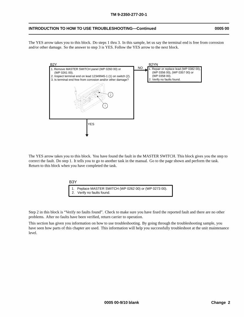
TM 9-2350-277-20-1
INTRODUCTION TO HOW TO USE TROUBLESHOOTING—Continued 0005 00
The YES arrow takes you to this block. Do steps 1 thru 3. In this sample, let us say the terminal end is free from corrosionand/or other damage. So the answer to step 3 is YES. Follow the YES arrow to the next block.
YES
1. Remove MASTER SWITCH panel (WP 0260 00) or (WP 0261 00). 2. Inspect terminal end on lead 12349945-1 (1) on switch (2). 3. Is terminal end free from corrosion and/or other damage?
1. Repair or replace lead (WP 0382 00), (WP 0356 00), (WP 0357 00) or (WP 0358 00). 2. Verify no faults found.
B2YNNO
B2Y
The YES arrow takes you to this block. You have found the fault in the MASTER SWITCH. This block gives you the step tocorrect the fault. Do step 1. It tells you to go to another task in the manual. Go to the page shown and perform the task.Return to this block when you have completed the task.
B3Y
1. Peplace MASTER SWITCH (WP 0262 00) or (WP 0273 00). 2. Verify no faults found.
Step 2 in this block is “Verify no faults found”. Check to make sure you have fixed the reported fault and there are no otherproblems. After no faults have been verified, return carrier to operation.
This section has given you information on how to use troubleshooting. By going through the troubleshooting sample, youhave seen how parts of this chapter are used. This information will help you successfully troubleshoot at the unit maintenancelevel.
0005 00-9/10 blank Change 2

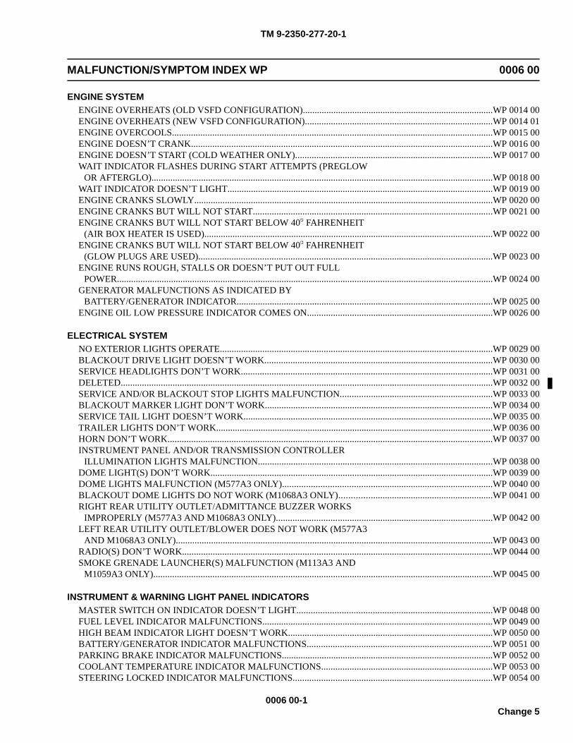
TM 9-2350-277-20-1
MALFUNCTION/SYMPTOM INDEX WP 0006 00
ENGINE SYSTEMENGINE OVERHEATS (OLD VSFD CONFIGURATION).................................................................................WP 0014 00ENGINE OVERHEATS (NEW VSFD CONFIGURATION)................................................................................WP 0014 01ENGINE OVERCOOLS........................................................................................................................................WP 0015 00ENGINE DOESN’T CRANK................................................................................................................................WP 0016 00ENGINE DOESN’T START (COLD WEATHER ONLY)....................................................................................WP 0017 00WAIT INDICATOR FLASHES DURING START ATTEMPTS (PREGLOW
OR AFTERGLO).................................................................................................................................................WP 0018 00WAIT INDICATOR DOESN’T LIGHT.................................................................................................................WP 0019 00ENGINE CRANKS SLOWLY...............................................................................................................................WP 0020 00ENGINE CRANKS BUT WILL NOT START......................................................................................................WP 0021 00ENGINE CRANKS BUT WILL NOT START BELOW 40 FAHRENHEIT
(AIR BOX HEATER IS USED)...........................................................................................................................WP 0022 00ENGINE CRANKS BUT WILL NOT START BELOW 40 FAHRENHEIT
(GLOW PLUGS ARE USED).............................................................................................................................WP 0023 00ENGINE RUNS ROUGH, STALLS OR DOESN’T PUT OUT FULL
POWER................................................................................................................................................................WP 0024 00GENERATOR MALFUNCTIONS AS INDICATED BY
BATTERY/GENERATOR INDICATOR.............................................................................................................WP 0025 00ENGINE OIL LOW PRESSURE INDICATOR COMES ON...............................................................................WP 0026 00
ELECTRICAL SYSTEMNO EXTERIOR LIGHTS OPERATE....................................................................................................................WP 0029 00BLACKOUT DRIVE LIGHT DOESN’T WORK.................................................................................................WP 0030 00SERVICE HEADLIGHTS DON’T WORK...........................................................................................................WP 0031 00DELETED..............................................................................................................................................................WP 0032 00SERVICE AND/OR BLACKOUT STOP LIGHTS MALFUNCTION.................................................................WP 0033 00BLACKOUT MARKER LIGHT DON’T WORK.................................................................................................WP 0034 00SERVICE TAIL LIGHT DOESN’T WORK..........................................................................................................WP 0035 00TRAILER LIGHTS DON’T WORK......................................................................................................................WP 0036 00HORN DON’T WORK..........................................................................................................................................WP 0037 00INSTRUMENT PANEL AND/OR TRANSMISSION CONTROLLER
ILLUMINATION LIGHTS MALFUNCTION....................................................................................................WP 0038 00DOME LIGHT(S) DON’T WORK........................................................................................................................WP 0039 00DOME LIGHTS MALFUNCTION (M577A3 ONLY).........................................................................................WP 0040 00BLACKOUT DOME LIGHTS DO NOT WORK (M1068A3 ONLY).................................................................WP 0041 00RIGHT REAR UTILITY OUTLET/ADMITTANCE BUZZER WORKS
IMPROPERLY (M577A3 AND M1068A3 ONLY)............................................................................................WP 0042 00LEFT REAR UTILITY OUTLET/BLOWER DOES NOT WORK (M577A3
AND M1068A3 ONLY).......................................................................................................................................WP 0043 00RADIO(S) DON’T WORK....................................................................................................................................WP 0044 00SMOKE GRENADE LAUNCHER(S) MALFUNCTION (M113A3 AND
M1059A3 ONLY)................................................................................................................................................WP 0045 00
INSTRUMENT & WARNING LIGHT PANEL INDICATORSMASTER SWITCH ON INDICATOR DOESN’T LIGHT...................................................................................WP 0048 00FUEL LEVEL INDICATOR MALFUNCTIONS..................................................................................................WP 0049 00HIGH BEAM INDICATOR LIGHT DOESN’T WORK.......................................................................................WP 0050 00BATTERY/GENERATOR INDICATOR MALFUNCTIONS...............................................................................WP 0051 00PARKING BRAKE INDICATOR MALFUNCTIONS..........................................................................................WP 0052 00COOLANT TEMPERATURE INDICATOR MALFUNCTIONS.........................................................................WP 0053 00STEERING LOCKED INDICATOR MALFUNCTIONS.....................................................................................WP 0054 00
0006 00-1Change 5
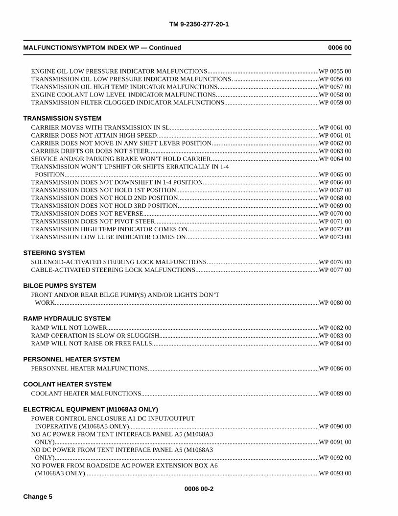
TM 9-2350-277-20-1
MALFUNCTION/SYMPTOM INDEX WP — Continued 0006 00
ENGINE OIL LOW PRESSURE INDICATOR MALFUNCTIONS....................................................................WP 0055 00TRANSMISSION OIL LOW PRESSURE INDICATOR MALFUNCTIONS. ....................................................WP 0056 00TRANSMISSION OIL HIGH TEMP INDICATOR MALFUNCTIONS..............................................................WP 0057 00ENGINE COOLANT LOW LEVEL INDICATOR MALFUNCTIONS...............................................................WP 0058 00TRANSMISSION FILTER CLOGGED INDICATOR MALFUNCTIONS..........................................................WP 0059 00
TRANSMISSION SYSTEMCARRIER MOVES WITH TRANSMISSION IN SL...........................................................................................WP 0061 00CARRIER DOES NOT ATTAIN HIGH SPEED...................................................................................................WP 0061 01CARRIER DOES NOT MOVE IN ANY SHIFT LEVER POSITION.................................................................WP 0062 00CARRIER DRIFTS OR DOES NOT STEER........................................................................................................WP 0063 00SERVICE AND/OR PARKING BRAKE WON’T HOLD CARRIER..................................................................WP 0064 00TRANSMISSION WON’T UPSHIFT OR SHIFTS ERRATICALLY IN 1-4
POSITION............................................................................................................................................................WP 0065 00TRANSMISSION DOES NOT DOWNSHIFT IN 1-4 POSITION.......................................................................WP 0066 00TRANSMISSION DOES NOT HOLD 1ST POSITION.......................................................................................WP 0067 00TRANSMISSION DOES NOT HOLD 2ND POSITION......................................................................................WP 0068 00TRANSMISSION DOES NOT HOLD 3RD POSITION......................................................................................WP 0069 00TRANSMISSION DOES NOT REVERSE...........................................................................................................WP 0070 00TRANSMISSION DOES NOT PIVOT STEER....................................................................................................WP 0071 00TRANSMISSION HIGH TEMP INDICATOR COMES ON................................................................................WP 0072 00TRANSMISSION LOW LUBE INDICATOR COMES ON.................................................................................WP 0073 00
STEERING SYSTEMSOLENOID-ACTIVATED STEERING LOCK MALFUNCTIONS....................................................................WP 0076 00CABLE-ACTIVATED STEERING LOCK MALFUNCTIONS...........................................................................WP 0077 00
BILGE PUMPS SYSTEMFRONT AND/OR REAR BILGE PUMP(S) AND/OR LIGHTS DON’T
WORK..................................................................................................................................................................WP 0080 00
RAMP HYDRAULIC SYSTEMRAMP WILL NOT LOWER..................................................................................................................................WP 0082 00RAMP OPERATION IS SLOW OR SLUGGISH..................................................................................................WP 0083 00RAMP WILL NOT RAISE OR FREE FALLS......................................................................................................WP 0084 00
PERSONNEL HEATER SYSTEMPERSONNEL HEATER MALFUNCTIONS.........................................................................................................WP 0086 00
COOLANT HEATER SYSTEMCOOLANT HEATER MALFUNCTIONS.............................................................................................................WP 0089 00
ELECTRICAL EQUIPMENT (M1068A3 ONLY)POWER CONTROL ENCLOSURE A1 DC INPUT/OUTPUT
INOPERATIVE (M1068A3 ONLY)....................................................................................................................WP 0090 00NO AC POWER FROM TENT INTERFACE PANEL A5 (M1068A3
ONLY)..................................................................................................................................................................WP 0091 00NO DC POWER FROM TENT INTERFACE PANEL A5 (M1068A3
ONLY)..................................................................................................................................................................WP 0092 00NO POWER FROM ROADSIDE AC POWER EXTENSION BOX A6
(M1068A3 ONLY)...............................................................................................................................................WP 0093 00
0006 00-2Change 5
TM 9-2350-277-20-1
MALFUNCTION/SYMPTOM INDEX WP — Continued 0006 00
NO POWER FROM CURBSIDE AC POWER EXTENSION BOX A7(M1068A3 ONLY)...............................................................................................................................................WP 0094 00
NO POWER FROM DC POWER EXTENSION BOX A9 (ALL EXCEPTJACK J23) (M1068A3 ONLY)............................................................................................................................WP 0095 00
NO POWER FROM DC POWER EXTENSION BOX A9, JACK J23(JTIDS) (M1068A3 ONLY).................................................................................................................................WP 0096 00
NO DC POWER TO SINGLE POINT LAN GROUND BOX A15 (M1068A3ONLY)..................................................................................................................................................................WP 0097 00
NO POWER FROM UPS POWER EXTENSION BOX A18 (M1068A3ONLY)..................................................................................................................................................................WP 0098 00
NO POWER FROM CURBSIDE UPS POWER EXTENSION BOX A19(M1068A3 ONLY)...............................................................................................................................................WP 0099 00
NO AC/DC INPUT TO ATCCS UPS POWER BOX (M1068A3 ONLY)............................................................WP 0100 00IN BLACKOUT MODE, FLUORESCENT LIGHTS OPERATE
INCORRECTLY (M1068A3 ONLY)..................................................................................................................WP 0101 00FLUORESCENT LIGHTS DO NOT OPERATE (M1068A3 ONLY)..................................................................WP 0102 00VEHICLE BATTERIES DISCHARGE WITH EXTERNAL AC POWER
APPLIED (M1068A3 ONLY)..............................................................................................................................WP 0103 00VEHICLE WILL NOT ACCEPT EXTERNAL AC POWER (M1068A3
ONLY)..................................................................................................................................................................WP 0104 00VEHICLE WILL NOT ACCEPT INVERTER AC POWER (M1068A3
ONLY)..................................................................................................................................................................WP 0105 00NO POWER TO DC CIRCUITS (M1068A3 ONLY)............................................................................................WP 0106 00NO POWER TO AC CIRCUITS (M1068A3 ONLY)............................................................................................WP 0107 00NO DC OUTPUT FROM DC POWER SUPPLY (M1068A3 ONLY)..................................................................WP 0108 00NO AC POWER FROM INVERTERS (M1068A3 ONLY)..................................................................................WP 0109 00INVERTER POWER-UP FAILURE (M1068A3 ONLY)......................................................................................WP 0109 01
COMMUNICATION EQUIPMENTNO DATA OUTPUT FROM DATA PANEL A12 (M1068A3 ONLY).................................................................WP 0110 00NO LAN OUTPUT FROM DATA PANEL A12 (M1068A3 ONLY)....................................................................WP 0111 00NO DATA OUTPUT FROM DATA PANEL A13 (M1068A3 ONLY).................................................................WP 0112 00NO LAN OUTPUT FROM DATA PANEL A13 (M1068A3 ONLY)....................................................................WP 0113 00PHONE EXTENSION BOX A14 POST(S) INOPERATIVE (M1068A3
ONLY)..................................................................................................................................................................WP 0114 00
GAUGESSPEEDOMETER MALFUNCTIONS...................................................................................................................WP 0115 00TACHOMETER MALFUNCTIONS.....................................................................................................................WP 0116 00
DRIVER’S VISION ENHANCERDRIVER’S VISION ENHANCER (DVE) DISPLAY DOES NOT WORK.........................................................WP 0116 01COMMANDER’S VISION ENHANCER DISPLAY DOES NOT WORK
(M58 ONLY)........................................................................................................................................................WP 0116 02
MSD/ICE TESTSHOOK UP/REMOVE MSD/ICE TEST SET TO DCA 6......................................................................................WP 0117 00MSD/ICE TEST 10 ENGINE RPM.......................................................................................................................WP 0118 00MSD/ICE TEST 24 FUEL SUPPLY PRESSURE.................................................................................................WP 0119 00MSD/ICE TEST 25 FUEL RETURN PRESSURE................................................................................................WP 0120 00MSD/ICE TEST 26 FUEL FILTER PRESSURE DROP.......................................................................................WP 0121 00
0006 00-3Change 5
TM 9-2350-277-20-1
MALFUNCTION/SYMPTOM INDEX WP — Continued 0006 00
MSD/ICE TEST 30 TURBOCHARGER OUTLET PRESSURE..........................................................................WP 0122 00MSD/ICE TEST 32 AIR BOX PRESSURE..........................................................................................................WP 0123 00MSD/ICE TEST 67 BATTERY VOLTAGE...........................................................................................................WP 0124 00MSD/ICE TEST 68 STARTER MOTOR VOLTAGE............................................................................................WP 0125 00MSD/ICE TEST 69 STARTER NEGATIVE CABLE VOLTAGE DROP.............................................................WP 0126 00MSD/ICE TEST 70 STARTER SOLENOID VOLTAGE......................................................................................WP 0127 00MSD/ICE TEST 71 STARTER CURRENT (AVERAGE)....................................................................................WP 0128 00MSD/ICE TEST 72 STARTER CURRENT (FIRST PEAK).................................................................................WP 0129 00MSD/ICE TEST 73 BATTERY RESISTANCE.....................................................................................................WP 0130 00MSD/ICE TEST 80 BATTERY CURRENT..........................................................................................................WP 0132 00MSD/ICE TEST 82 GENERATOR OUTPUT VOLTAGE....................................................................................WP 0133 00MSD/ICE TEST 83 GENERATOR FIELD VOLTAGE........................................................................................WP 0134 00MSD/ICE TEST 84 GENERATOR NEGATIVE CABLE VOLTAGE DROP......................................................WP 0135 00
MSD/ICE DIAGNOSTIC TROUBLESHOOTINGMSD/ICE TEST 10, 12, AND 13 DIAGNOSTIC TROUBLESHOOTING..........................................................WP 0140 00DCA BATTERY VOLTAGE DIAGNOSTIC TROUBLESHOOTING.................................................................WP 0141 00DCA CURRENT SHUNT DIAGNOSTIC TROUBLESHOOTING.....................................................................WP 0142 00MSD/ICE TEST 24 FUEL SUPPLY PRESSURE DIAGNOSTIC
TROUBLESHOOTING.......................................................................................................................................WP 0143 00MSD/ICE TEST 25 FUEL RETURN PRESSURE DIAGNOSTIC
TROUBLESHOOTING.......................................................................................................................................WP 0144 00MSD/ICE TEST 26 FUEL FILTER PRESSURE DROP DIAGNOSTIC
TROUBLESHOOTING.......................................................................................................................................WP 0145 00MSD/ICE TEST 30 TURBOCHARGER OUTLET PRESSURE
DIAGNOSTIC TROUBLESHOOTING..............................................................................................................WP 0146 00MSD/ICE TEST 32 AIR BOX PRESSURE DIAGNOSTIC
TROUBLESHOOTING.......................................................................................................................................WP 0147 00MSD/ICE TEST 68 STARTER MOTOR VOLTAGE DIAGNOSTIC
TROUBLESHOOTING.......................................................................................................................................WP 0148 00MSD/ICE TEST 69 STARTER NEGATIVE CABLE VOLTAGE DROP
DIAGNOSTIC TROUBLESHOOTING..............................................................................................................WP 0149 00MSD/ICE TEST 70 STARTER SOLENOID VOLTAGE DIAGNOSTIC
TROUBLESHOOTING.......................................................................................................................................WP 0150 00MSD/ICE TEST 82 GENERATOR OUTPUT VOLTAGE DIAGNOSTIC
TROUBLESHOOTING.......................................................................................................................................WP 0151 00MSD/ICE TEST 83 GENERATOR FIELD VOLTAGE DIAGNOSTIC
TROUBLESHOOTING.......................................................................................................................................WP 0152 00MSD/ICE TEST 84 GENERATOR NEGATIVE CABLE VOLTAGE DROP
DIAGNOSTIC TROUBLESHOOTING..............................................................................................................WP 0153 00
0006 00-4Change 5
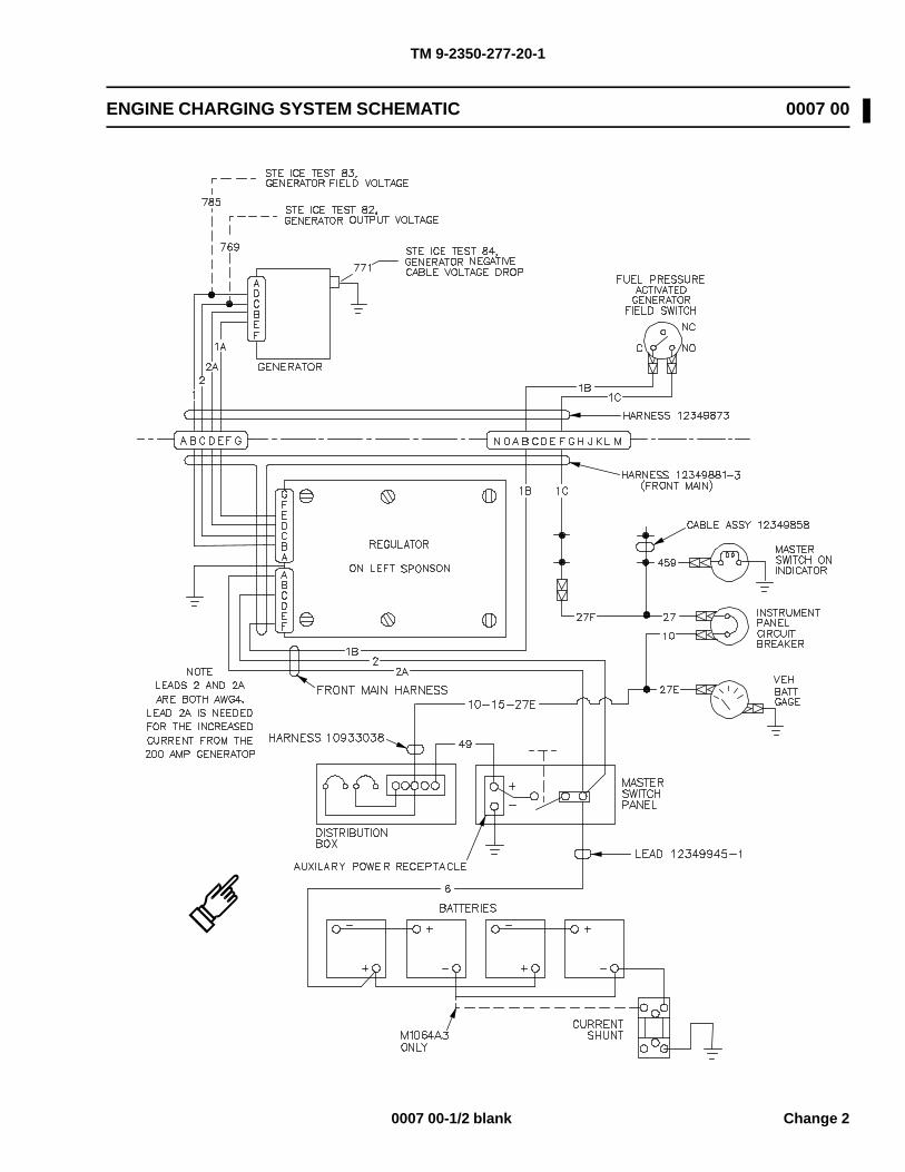
TM 9-2350-277-20-1
ENGINE CHARGING SYSTEM SCHEMATIC 0007 00
0007 00-1/2 blank Change 2

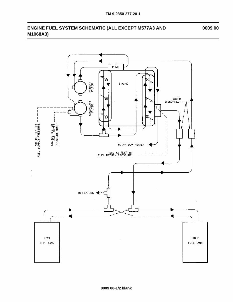
TM 9-2350-277-20-1
ENGINE FUEL SYSTEM SCHEMATIC (ALL EXCEPT M577A3 ANDM1068A3)
0009 00
0009 00-1/2 blank

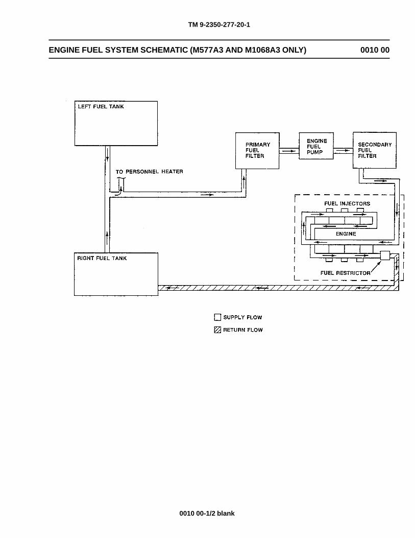
TM 9-2350-277-20-1
ENGINE FUEL SYSTEM SCHEMATIC (M577A3 AND M1068A3 ONLY) 0010 00
0010 00-1/2 blank

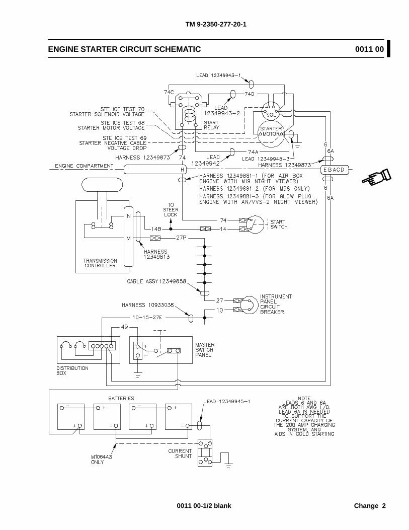
TM 9-2350-277-20-1
ENGINE STARTER CIRCUIT SCHEMATIC 0011 00
0011 00-1/2 blank Change 2

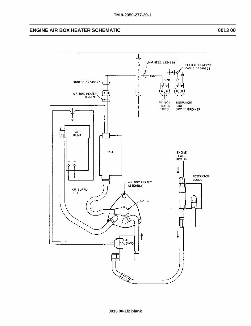
TM 9-2350-277-20-1
ENGINE AIR BOX HEATER SCHEMATIC 0013 00
0013 00-1/2 blank

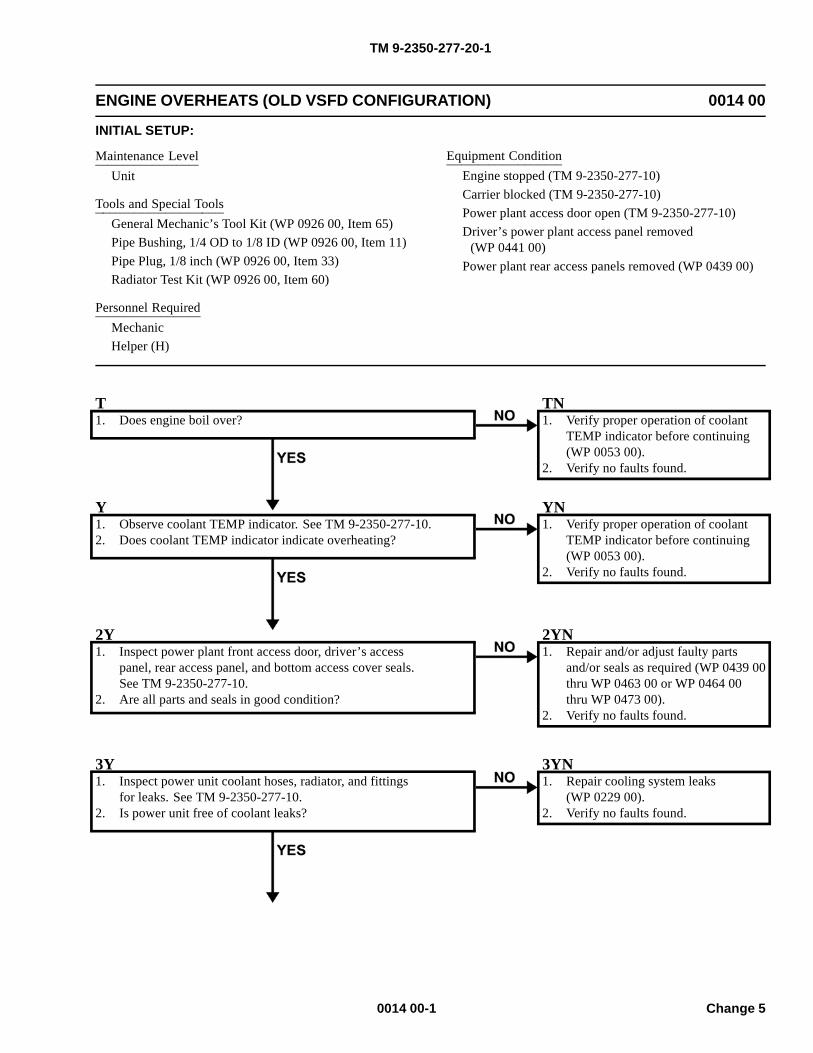
TM 9-2350-277-20-1
ENGINE OVERHEATS (OLD VSFD CONFIGURATION) 0014 00
INITIAL SETUP:
Maintenance LevelUnit
Tools and Special ToolsGeneral Mechanic’s Tool Kit (WP 0926 00, Item 65)Pipe Bushing, 1/4 OD to 1/8 ID (WP 0926 00, Item 11)Pipe Plug, 1/8 inch (WP 0926 00, Item 33)Radiator Test Kit (WP 0926 00, Item 60)
Personnel RequiredMechanicHelper (H)
Equipment ConditionEngine stopped (TM 9-2350-277-10)Carrier blocked (TM 9-2350-277-10)Power plant access door open (TM 9-2350-277-10)Driver’s power plant access panel removed
(WP 0441 00)Power plant rear access panels removed (WP 0439 00)
T1. Does engine boil over?
TN1. Verify proper operation of coolant
TEMP indicator before continuing(WP 0053 00).
2. Verify no faults found.
Y1. Observe coolant TEMP indicator. See TM 9-2350-277-10.2. Does coolant TEMP indicator indicate overheating?
YN1. Verify proper operation of coolant
TEMP indicator before continuing(WP 0053 00).
2. Verify no faults found.
2Y1. Inspect power plant front access door, driver’s access
panel, rear access panel, and bottom access cover seals.See TM 9-2350-277-10.
2. Are all parts and seals in good condition?
2YN1. Repair and/or adjust faulty parts
and/or seals as required (WP 0439 00thru WP 0463 00 or WP 0464 00thru WP 0473 00).
2. Verify no faults found.
3Y1. Inspect power unit coolant hoses, radiator, and fittings
for leaks. See TM 9-2350-277-10.2. Is power unit free of coolant leaks?
3YN1. Repair cooling system leaks
(WP 0229 00).2. Verify no faults found.
0014 00-1 Change 5
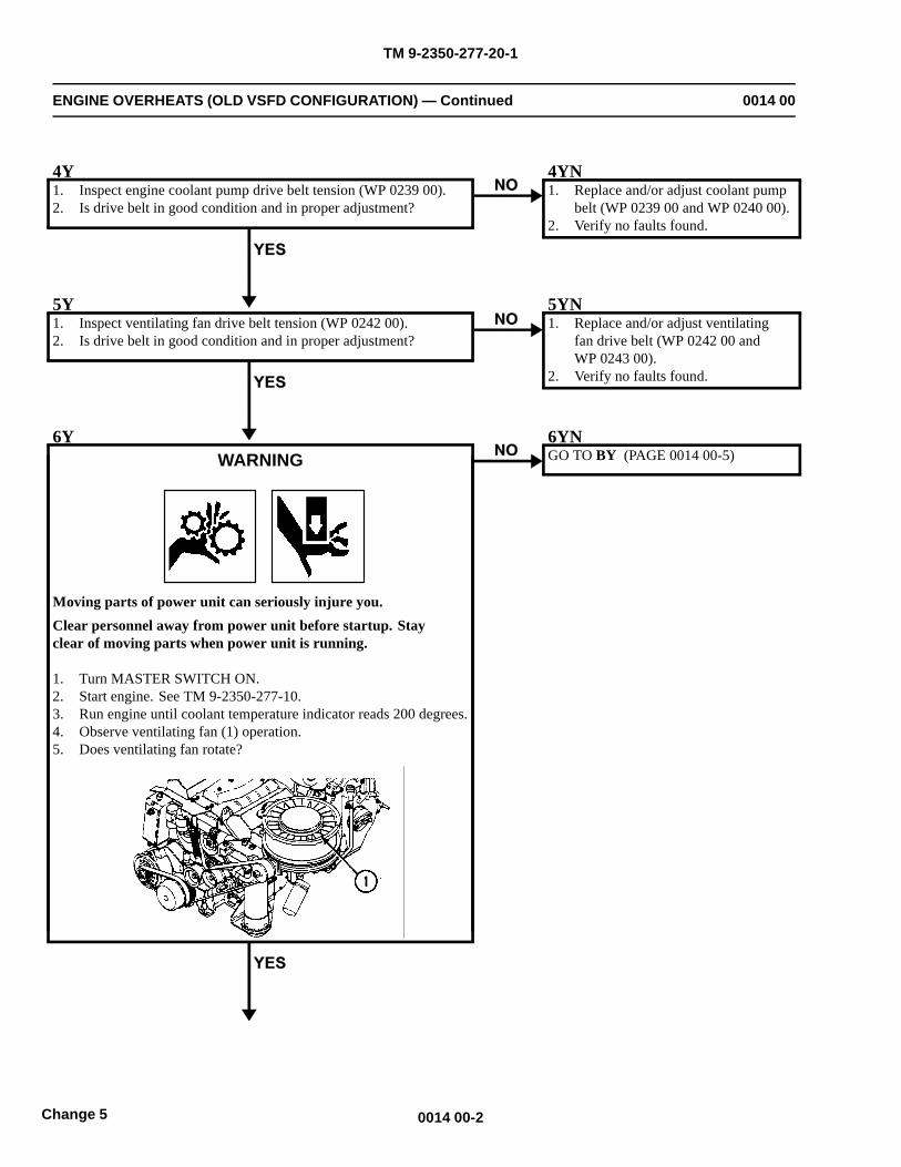
TM 9-2350-277-20-1
ENGINE OVERHEATS (OLD VSFD CONFIGURATION) — Continued 0014 00
4Y1. Inspect engine coolant pump drive belt tension (WP 0239 00).2. Is drive belt in good condition and in proper adjustment?
4YN1. Replace and/or adjust coolant pump
belt (WP 0239 00 and WP 0240 00).2. Verify no faults found.
5Y1. Inspect ventilating fan drive belt tension (WP 0242 00).2. Is drive belt in good condition and in proper adjustment?
5YN1. Replace and/or adjust ventilating
fan drive belt (WP 0242 00 andWP 0243 00).
2. Verify no faults found.
6YWARNING
Moving parts of power unit can seriously injure you.Clear personnel away from power unit before startup. Stayclear of moving parts when power unit is running.
1. Turn MASTER SWITCH ON.2. Start engine. See TM 9-2350-277-10.3. Run engine until coolant temperature indicator reads 200 degrees.4. Observe ventilating fan (1) operation.5. Does ventilating fan rotate?
6YNGO TO BY (PAGE 0014 00-5)
0014 00-2Change 5
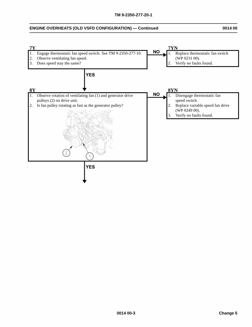
TM 9-2350-277-20-1
ENGINE OVERHEATS (OLD VSFD CONFIGURATION) — Continued 0014 00
7Y1. Engage thermostatic fan speed switch. See TM 9-2350-277-10.2. Observe ventilating fan speed.3. Does speed stay the same?
7YN1. Replace thermostatic fan switch
(WP 0231 00).2. Verify no faults found.
8Y1. Observe rotation of ventilating fan (1) and generator drive
pulleys (2) on drive unit.2. Is fan pulley rotating as fast as the generator pulley?
8YN1. Disengage thermostatic fan
speed switch.2. Replace variable speed fan drive
(WP 0249 00).3. Verify no faults found.
0014 00-3 Change 5
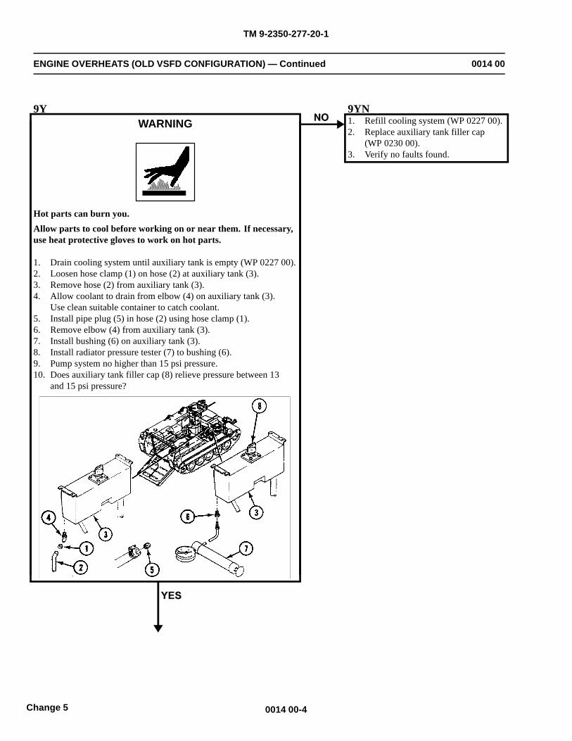
TM 9-2350-277-20-1
ENGINE OVERHEATS (OLD VSFD CONFIGURATION) — Continued 0014 00
9YWARNING
Hot parts can burn you.Allow parts to cool before working on or near them. If necessary,use heat protective gloves to work on hot parts.
1. Drain cooling system until auxiliary tank is empty (WP 0227 00).2. Loosen hose clamp (1) on hose (2) at auxiliary tank (3).3. Remove hose (2) from auxiliary tank (3).4. Allow coolant to drain from elbow (4) on auxiliary tank (3).
Use clean suitable container to catch coolant.5. Install pipe plug (5) in hose (2) using hose clamp (1).6. Remove elbow (4) from auxiliary tank (3).7. Install bushing (6) on auxiliary tank (3).8. Install radiator pressure tester (7) to bushing (6).9. Pump system no higher than 15 psi pressure.10. Does auxiliary tank filler cap (8) relieve pressure between 13
and 15 psi pressure?
9YN1. Refill cooling system (WP 0227 00).2. Replace auxiliary tank filler cap
(WP 0230 00).3. Verify no faults found.
0014 00-4Change 5
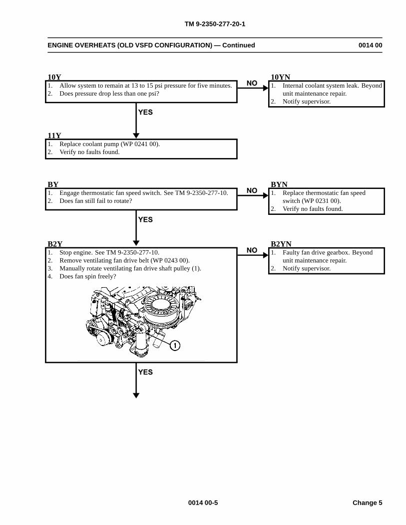
TM 9-2350-277-20-1
ENGINE OVERHEATS (OLD VSFD CONFIGURATION) — Continued 0014 00
10Y1. Allow system to remain at 13 to 15 psi pressure for five minutes.2. Does pressure drop less than one psi?
10YN1. Internal coolant system leak. Beyond
unit maintenance repair.2. Notify supervisor.
11Y1. Replace coolant pump (WP 0241 00).2. Verify no faults found.
BY1. Engage thermostatic fan speed switch. See TM 9-2350-277-10.2. Does fan still fail to rotate?
BYN1. Replace thermostatic fan speed
switch (WP 0231 00).2. Verify no faults found.
B2Y1. Stop engine. See TM 9-2350-277-10.2. Remove ventilating fan drive belt (WP 0243 00).3. Manually rotate ventilating fan drive shaft pulley (1).4. Does fan spin freely?
B2YN1. Faulty fan drive gearbox. Beyond
unit maintenance repair.2. Notify supervisor.
0014 00-5 Change 5
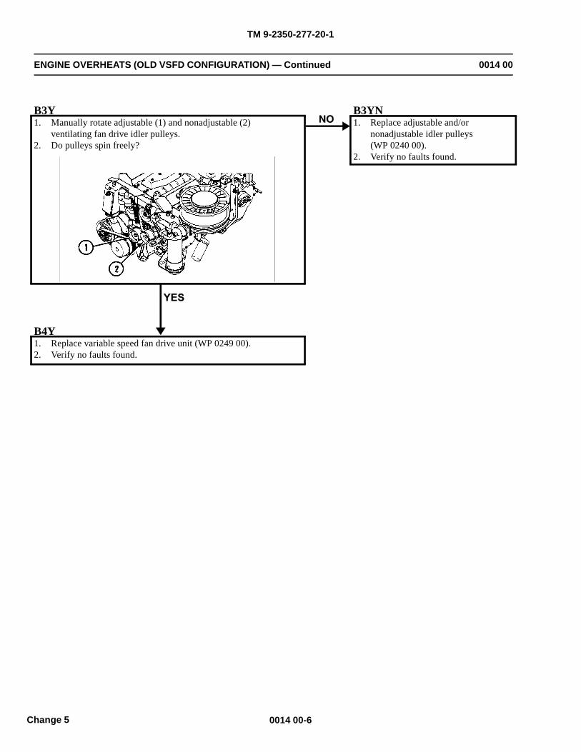
TM 9-2350-277-20-1
ENGINE OVERHEATS (OLD VSFD CONFIGURATION) — Continued 0014 00
B3Y1. Manually rotate adjustable (1) and nonadjustable (2)
ventilating fan drive idler pulleys.2. Do pulleys spin freely?
B3YN1. Replace adjustable and/or
nonadjustable idler pulleys(WP 0240 00).
2. Verify no faults found.
B4Y1. Replace variable speed fan drive unit (WP 0249 00).2. Verify no faults found.
0014 00-6Change 5
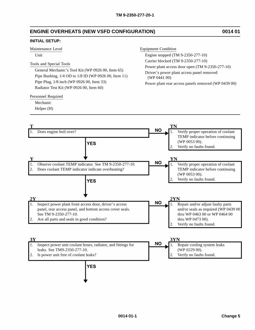
TM 9-2350-277-20-1
ENGINE OVERHEATS (NEW VSFD CONFIGURATION) 0014 01
INITIAL SETUP:
Maintenance LevelUnit
Tools and Special ToolsGeneral Mechanic’s Tool Kit (WP 0926 00, Item 65)Pipe Bushing, 1/4 OD to 1/8 ID (WP 0926 00, Item 11)Pipe Plug, 1/8 inch (WP 0926 00, Item 33)Radiator Test Kit (WP 0926 00, Item 60)
Personnel RequiredMechanicHelper (H)
Equipment ConditionEngine stopped (TM 9-2350-277-10)Carrier blocked (TM 9-2350-277-10)Power plant access door open (TM 9-2350-277-10)Driver’s power plant access panel removed
(WP 0441 00)Power plant rear access panels removed (WP 0439 00)
T1. Does engine boil over?
TN1. Verify proper operation of coolant
TEMP indicator before continuing(WP 0053 00).
2. Verify no faults found.
Y1. Observe coolant TEMP indicator. See TM 9-2350-277-10.2. Does coolant TEMP indicator indicate overheating?
YN1. Verify proper operation of coolant
TEMP indicator before continuing(WP 0053 00).
2. Verify no faults found.
2Y1. Inspect power plant front access door, driver’s access
panel, rear access panel, and bottom access cover seals.See TM 9-2350-277-10.
2. Are all parts and seals in good condition?
2YN1. Repair and/or adjust faulty parts
and/or seals as required (WP 0439 00thru WP 0463 00 or WP 0464 00thru WP 0473 00).
2. Verify no faults found.
3Y1. Inspect power unit coolant hoses, radiator, and fittings for
leaks. See TM9-2350-277-10.2. Is power unit free of coolant leaks?
3YN1. Repair cooling system leaks
(WP 0229 00).2. Verify no faults found.
0014 01-1 Change 5
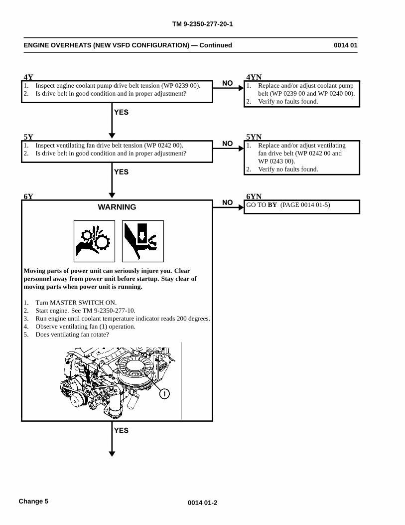
TM 9-2350-277-20-1
ENGINE OVERHEATS (NEW VSFD CONFIGURATION) — Continued 0014 01
4Y1. Inspect engine coolant pump drive belt tension (WP 0239 00).2. Is drive belt in good condition and in proper adjustment?
4YN1. Replace and/or adjust coolant pump
belt (WP 0239 00 and WP 0240 00).2. Verify no faults found.
5Y1. Inspect ventilating fan drive belt tension (WP 0242 00).2. Is drive belt in good condition and in proper adjustment?
5YN1. Replace and/or adjust ventilating
fan drive belt (WP 0242 00 andWP 0243 00).
2. Verify no faults found.
6YWARNING
Moving parts of power unit can seriously injure you. Clearpersonnel away from power unit before startup. Stay clear ofmoving parts when power unit is running.
1. Turn MASTER SWITCH ON.2. Start engine. See TM 9-2350-277-10.3. Run engine until coolant temperature indicator reads 200 degrees.4. Observe ventilating fan (1) operation.5. Does ventilating fan rotate?
6YNGO TO BY (PAGE 0014 01-5)
0014 01-2Change 5
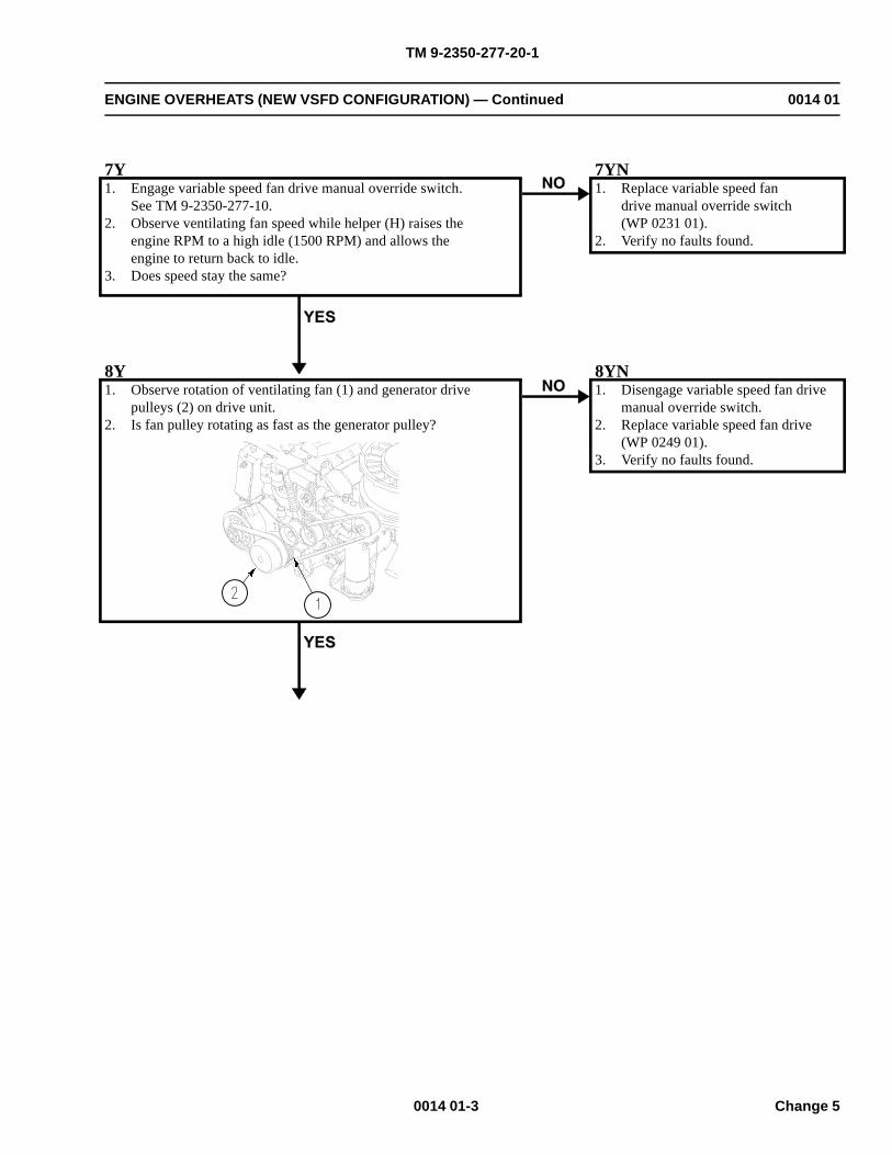
TM 9-2350-277-20-1
ENGINE OVERHEATS (NEW VSFD CONFIGURATION) — Continued 0014 01
7Y1. Engage variable speed fan drive manual override switch.
See TM 9-2350-277-10.2. Observe ventilating fan speed while helper (H) raises the
engine RPM to a high idle (1500 RPM) and allows theengine to return back to idle.
3. Does speed stay the same?
7YN1. Replace variable speed fan
drive manual override switch(WP 0231 01).
2. Verify no faults found.
8Y1. Observe rotation of ventilating fan (1) and generator drive
pulleys (2) on drive unit.2. Is fan pulley rotating as fast as the generator pulley?
8YN1. Disengage variable speed fan drive
manual override switch.2. Replace variable speed fan drive
(WP 0249 01).3. Verify no faults found.
0014 01-3 Change 5
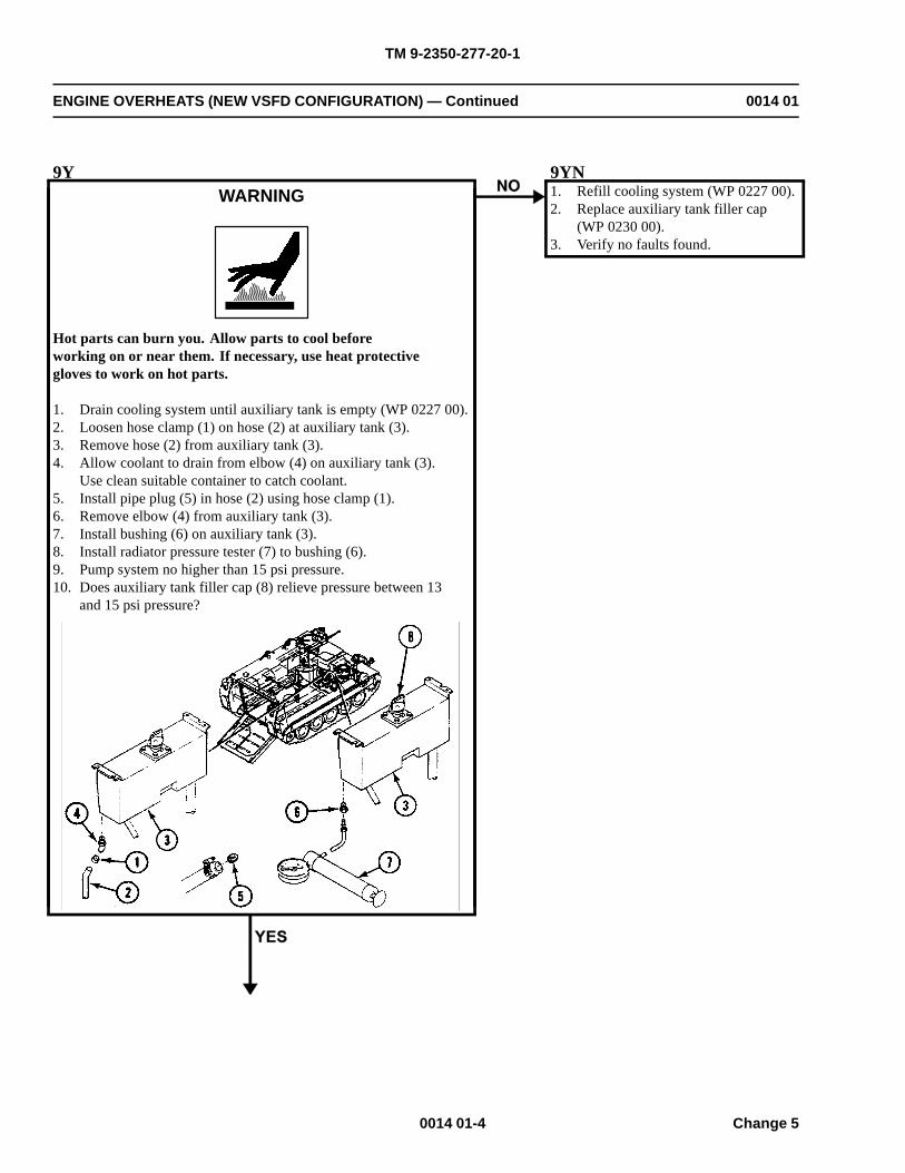
TM 9-2350-277-20-1
ENGINE OVERHEATS (NEW VSFD CONFIGURATION) — Continued 0014 01
9YWARNING
Hot parts can burn you. Allow parts to cool beforeworking on or near them. If necessary, use heat protectivegloves to work on hot parts.
1. Drain cooling system until auxiliary tank is empty (WP 0227 00).2. Loosen hose clamp (1) on hose (2) at auxiliary tank (3).3. Remove hose (2) from auxiliary tank (3).4. Allow coolant to drain from elbow (4) on auxiliary tank (3).
Use clean suitable container to catch coolant.5. Install pipe plug (5) in hose (2) using hose clamp (1).6. Remove elbow (4) from auxiliary tank (3).7. Install bushing (6) on auxiliary tank (3).8. Install radiator pressure tester (7) to bushing (6).9. Pump system no higher than 15 psi pressure.10. Does auxiliary tank filler cap (8) relieve pressure between 13
and 15 psi pressure?
9YN1. Refill cooling system (WP 0227 00).2. Replace auxiliary tank filler cap
(WP 0230 00).3. Verify no faults found.
0014 01-4 Change 5
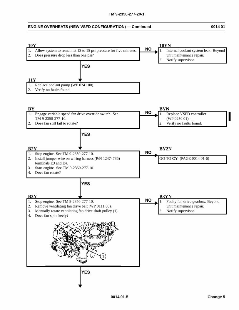
TM 9-2350-277-20-1
ENGINE OVERHEATS (NEW VSFD CONFIGURATION) — Continued 0014 01
10Y1. Allow system to remain at 13 to 15 psi pressure for five minutes.2. Does pressure drop less than one psi?
10YN1. Internal coolant system leak. Beyond
unit maintenance repair.2. Notify supervisor.
11Y1. Replace coolant pump (WP 0241 00).2. Verify no faults found.
BY1. Engage variable speed fan drive override switch. See
TM 9-2350-277-10.2. Does fan still fail to rotate?
BYN1. Replace VSFD controller
(WP 0250 01).2. Verify no faults found.
B2Y1. Stop engine. See TM 9-2350-277-10.2. Install jumper wire on wiring harness (P/N 12474786)
terminals E3 and E4.3. Start engine. See TM 9-2350-277-10.4. Does fan rotate?
BY2N
GO TO CY (PAGE 0014 01-6)
B3Y1. Stop engine. See TM 9-2350-277-10.2. Remove ventilating fan drive belt (WP 0111 00).3. Manually rotate ventilating fan drive shaft pulley (1).4. Does fan spin freely?
B3YN1. Faulty fan drive gearbox. Beyond
unit maintenance repair.2. Notify supervisor.
0014 01-5 Change 5
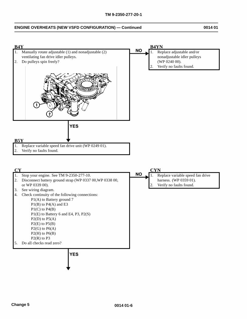
TM 9-2350-277-20-1
ENGINE OVERHEATS (NEW VSFD CONFIGURATION) — Continued 0014 01
B4Y1. Manually rotate adjustable (1) and nonadjustable (2)
ventilating fan drive idler pulleys.2. Do pulleys spin freely?
B4YN1. Replace adjustable and/or
nonadjustable idler pulleys(WP 0240 00).
2. Verify no faults found.
B5Y1. Replace variable speed fan drive unit (WP 0249 01).2. Verify no faults found.
CY1. Stop your engine. See TM 9-2350-277-10.2. Disconnect battery ground strap (WP 0337 00,WP 0338 00,
or WP 0339 00).3. See wiring diagram.4. Check continuity of the following connections:
P1(A) to Battery ground 7P1(B) to P4(A) and E3P1(C) to P4(B)P1(E) to Battery 6 and E4, P3, P2(S)P2(D) to P5(A)P2(E) to P5(B)P2(G) to P6(A)P2(H) to P6(B)P2(R) to P3
5. Do all checks read zero?
CYN1. Replace variable speed fan drive
harness. (WP 0359 01).2. Verify no faults found.
0014 01-6Change 5
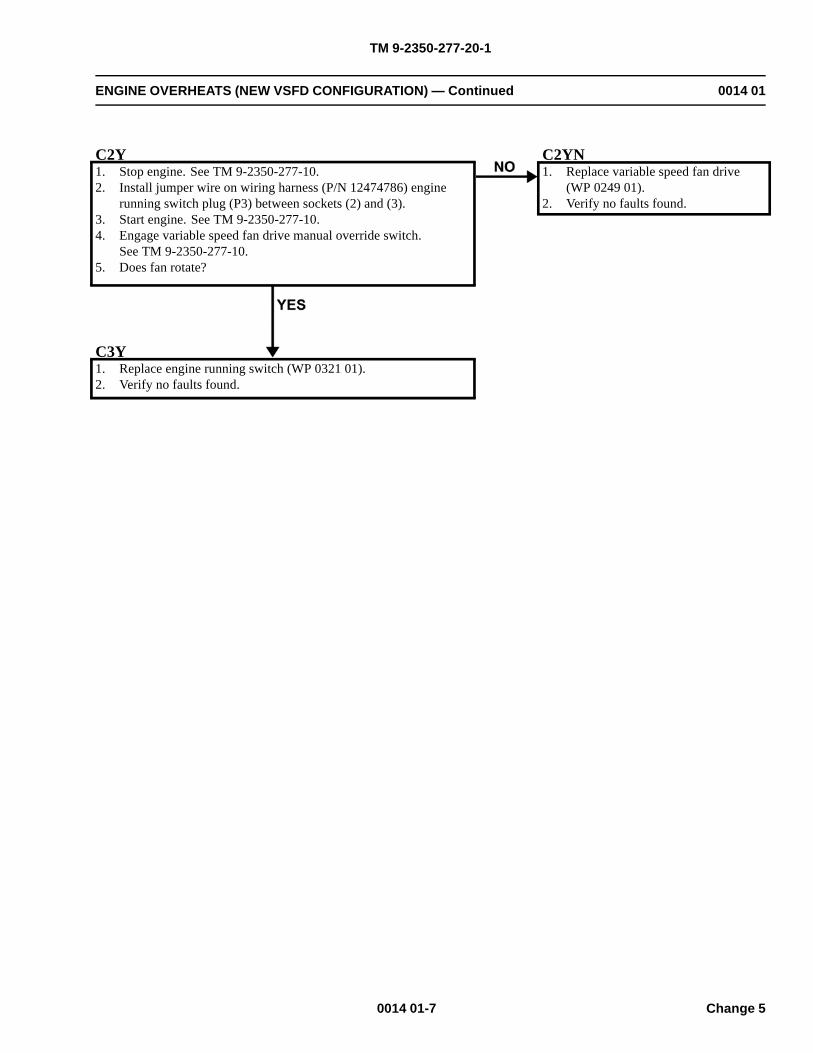
TM 9-2350-277-20-1
ENGINE OVERHEATS (NEW VSFD CONFIGURATION) — Continued 0014 01
C2Y1. Stop engine. See TM 9-2350-277-10.2. Install jumper wire on wiring harness (P/N 12474786) engine
running switch plug (P3) between sockets (2) and (3).3. Start engine. See TM 9-2350-277-10.4. Engage variable speed fan drive manual override switch.
See TM 9-2350-277-10.5. Does fan rotate?
C2YN1. Replace variable speed fan drive
(WP 0249 01).2. Verify no faults found.
C3Y1. Replace engine running switch (WP 0321 01).2. Verify no faults found.
0014 01-7 Change 5
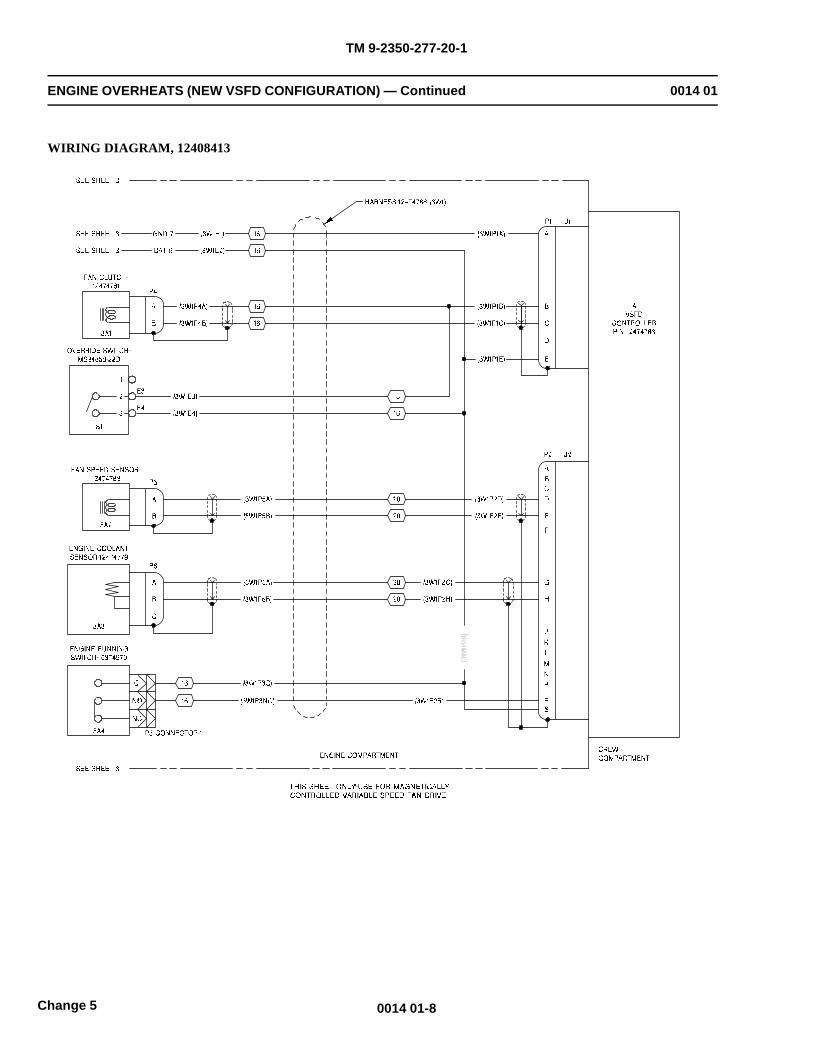
TM 9-2350-277-20-1
ENGINE OVERHEATS (NEW VSFD CONFIGURATION) — Continued 0014 01
WIRING DIAGRAM, 12408413
0014 01-8Change 5
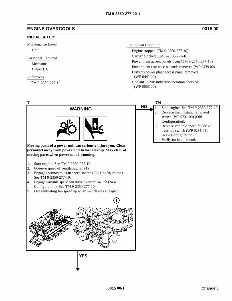
TM 9-2350-277-20-1
ENGINE OVERCOOLS 0015 00
INITIAL SETUP:
Maintenance LevelUnit
Personnel RequiredMechanicHelper (H)
ReferencesTM 9-2350-277-10
Equipment ConditionEngine stopped (TM 9-2350-277-10)Carrier blocked (TM 9-2350-277-10)Power plant access panels open (TM 9-2350-277-10)Power plant rear access panels removed (WP 0439 00)Driver’s power plant access panel removed
(WP 0441 00)Coolant TEMP indicator operation checked
(WP 0053 00)
TWARNING
Moving parts of a power unit can seriously injure you. Clearpersonnel away from power unit before startup. Stay clear ofmoving parts when power unit is running.
1. Start engine. See TM 9-2350-277-10.2. Observe speed of ventilating fan (1).3. Engage thermostatic fan speed switch (Old Configuration).
See TM 9-2350-277-10.4. Engage variable speed fan drive override switch (New
Configuration). See TM 9-2350-277-10.5. Did ventilating fan speed up when switch was engaged?
TN1. Stop engine. See TM 9-2350-277-10.2. Replace thermostatic fan speed
switch (WP 0231 00) (OldConfiguration).
3. Replace variable speed fan driveoverride switch (WP 0231 01)(New Configuration).
4. Verify no faults found.
0015 00-1 Change 5
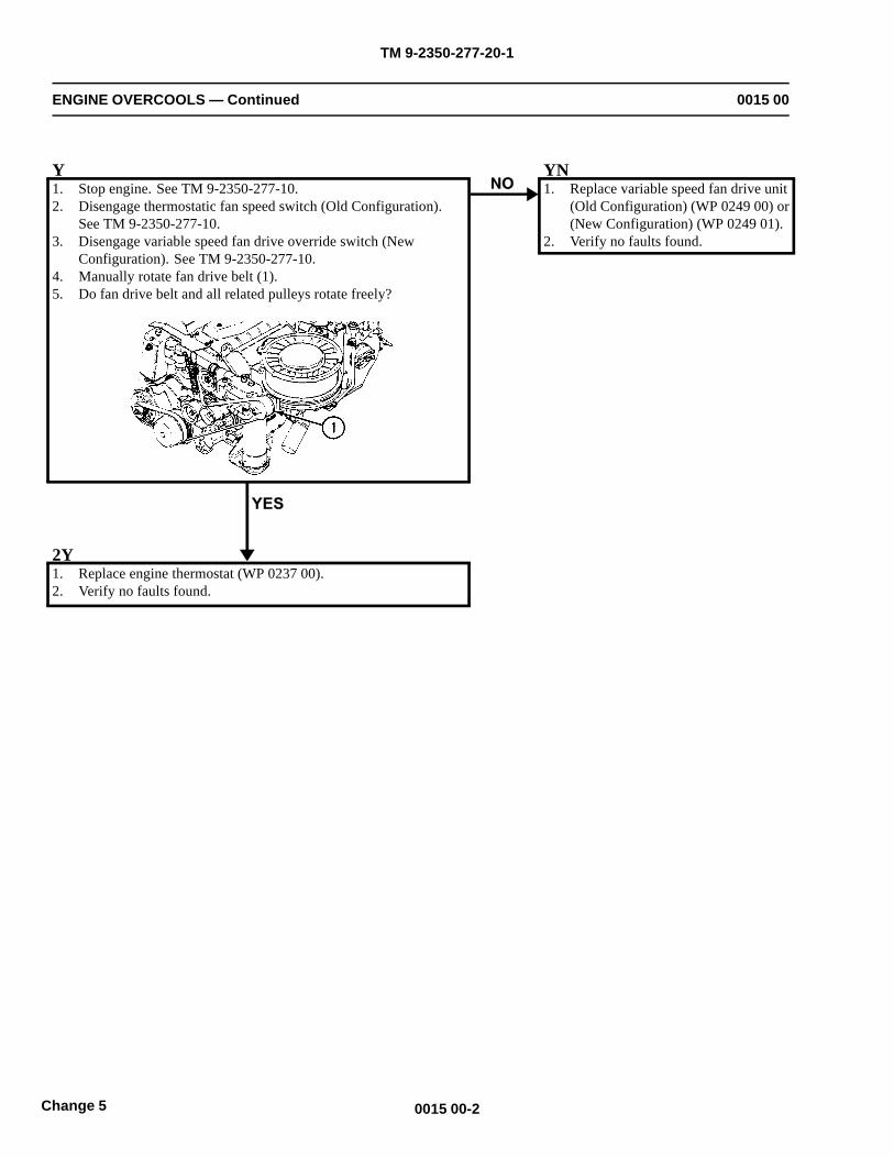
TM 9-2350-277-20-1
ENGINE OVERCOOLS — Continued 0015 00
Y1. Stop engine. See TM 9-2350-277-10.2. Disengage thermostatic fan speed switch (Old Configuration).
See TM 9-2350-277-10.3. Disengage variable speed fan drive override switch (New
Configuration). See TM 9-2350-277-10.4. Manually rotate fan drive belt (1).5. Do fan drive belt and all related pulleys rotate freely?
YN1. Replace variable speed fan drive unit
(Old Configuration) (WP 0249 00) or(New Configuration) (WP 0249 01).
2. Verify no faults found.
2Y1. Replace engine thermostat (WP 0237 00).2. Verify no faults found.
0015 00-2Change 5
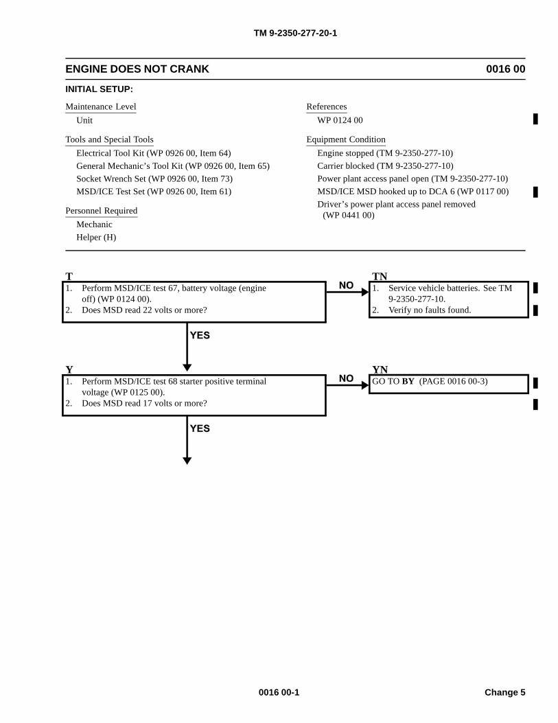
TM 9-2350-277-20-1
ENGINE DOES NOT CRANK 0016 00
INITIAL SETUP:
Maintenance LevelUnit
Tools and Special ToolsElectrical Tool Kit (WP 0926 00, Item 64)General Mechanic’s Tool Kit (WP 0926 00, Item 65)Socket Wrench Set (WP 0926 00, Item 73)MSD/ICE Test Set (WP 0926 00, Item 61)
Personnel RequiredMechanicHelper (H)
ReferencesWP 0124 00
Equipment ConditionEngine stopped (TM 9-2350-277-10)Carrier blocked (TM 9-2350-277-10)Power plant access panel open (TM 9-2350-277-10)MSD/ICE MSD hooked up to DCA 6 (WP 0117 00)Driver’s power plant access panel removed
(WP 0441 00)
T1. Perform MSD/ICE test 67, battery voltage (engine
off) (WP 0124 00).2. Does MSD read 22 volts or more?
TN1. Service vehicle batteries. See TM
9-2350-277-10.2. Verify no faults found.
Y1. Perform MSD/ICE test 68 starter positive terminal
voltage (WP 0125 00).2. Does MSD read 17 volts or more?
YNGO TO BY (PAGE 0016 00-3)
0016 00-1 Change 5
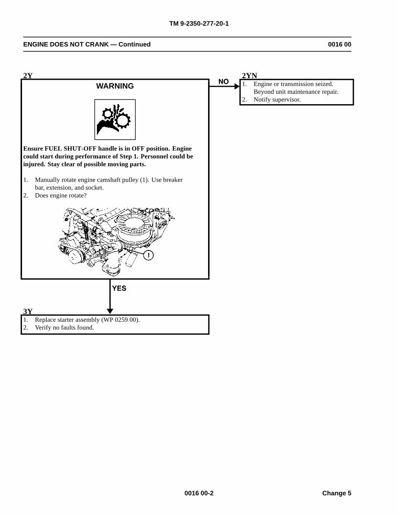
TM 9-2350-277-20-1
ENGINE DOES NOT CRANK — Continued 0016 00
2YWARNING
Ensure FUEL SHUT-OFF handle is in OFF position. Enginecould start during performance of Step 1. Personnel could beinjured. Stay clear of possible moving parts.
1. Manually rotate engine camshaft pulley (1). Use breakerbar, extension, and socket.
2. Does engine rotate?
2YN1. Engine or transmission seized.
Beyond unit maintenance repair.2. Notify supervisor.
3Y1. Replace starter assembly (WP 0259 00).2. Verify no faults found.
0016 00-2 Change 5
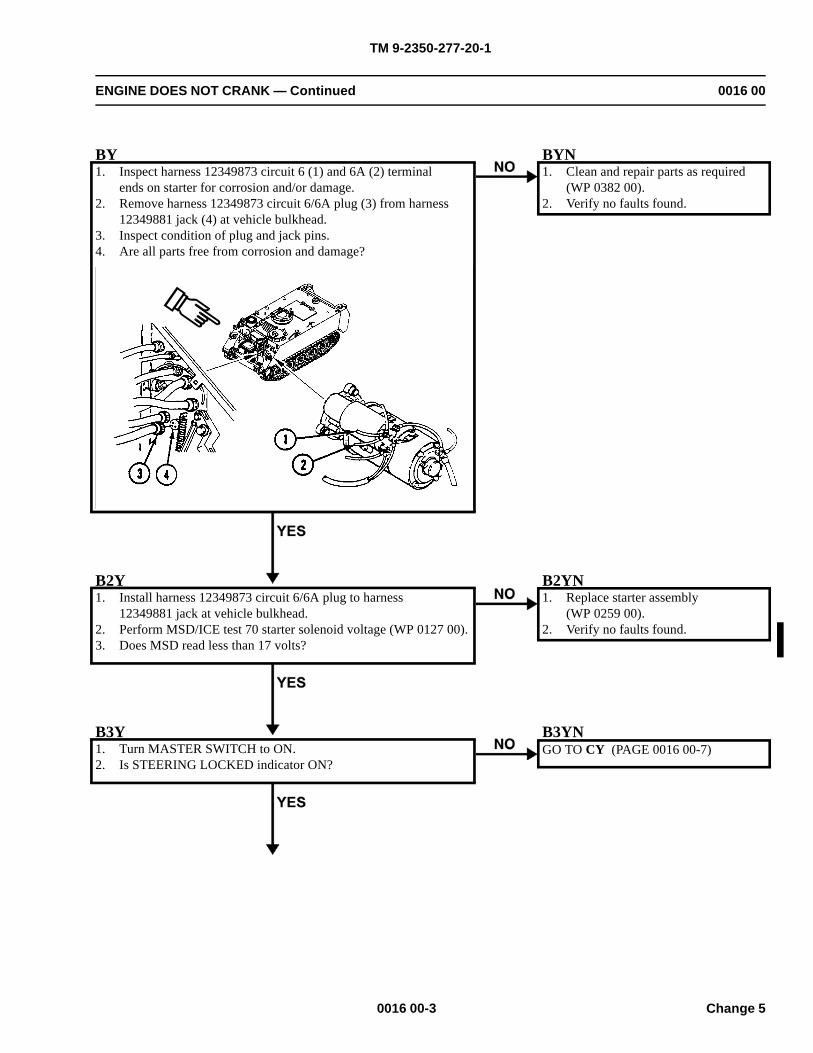
TM 9-2350-277-20-1
ENGINE DOES NOT CRANK — Continued 0016 00
BY1. Inspect harness 12349873 circuit 6 (1) and 6A (2) terminal
ends on starter for corrosion and/or damage.2. Remove harness 12349873 circuit 6/6A plug (3) from harness
12349881 jack (4) at vehicle bulkhead.3. Inspect condition of plug and jack pins.4. Are all parts free from corrosion and damage?
BYN1. Clean and repair parts as required
(WP 0382 00).2. Verify no faults found.
B2Y1. Install harness 12349873 circuit 6/6A plug to harness
12349881 jack at vehicle bulkhead.2. Perform MSD/ICE test 70 starter solenoid voltage (WP 0127 00).3. Does MSD read less than 17 volts?
B2YN1. Replace starter assembly
(WP 0259 00).2. Verify no faults found.
B3Y1. Turn MASTER SWITCH to ON.2. Is STEERING LOCKED indicator ON?
B3YNGO TO CY (PAGE 0016 00-7)
0016 00-3 Change 5
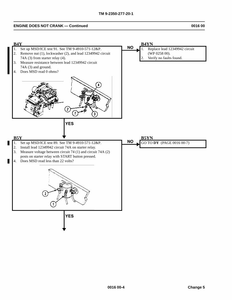
TM 9-2350-277-20-1
ENGINE DOES NOT CRANK — Continued 0016 00
B4Y1. Set up MSD/ICE test 91. See TM 9-4910-571-12&P.2. Remove nut (1), lockwasher (2), and lead 12349942 circuit
74A (3) from starter relay (4).3. Measure resistance between lead 12349942 circuit
74A (3) and ground.4. Does MSD read 0 ohms?
B4YN1. Replace lead 12349942 circuit
(WP 0258 00).2. Verify no faults found.
B5Y1. Set up MSD/ICE test 89. See TM 9-4910-571-12&P.2. Install lead 12349942 circuit 74A on starter relay.3. Measure voltage between circuit 74 (1) and circuit 74A (2)
posts on starter relay with START button pressed.4. Does MSD read less than 22 volts?
B5YNGO TO DY (PAGE 0016 00-7)
0016 00-4 Change 5
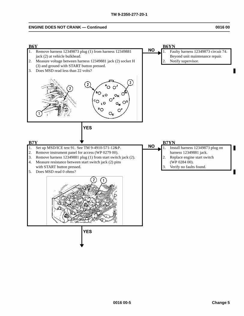
TM 9-2350-277-20-1
ENGINE DOES NOT CRANK — Continued 0016 00
B6Y1. Remove harness 12349873 plug (1) from harness 12349881
jack (2) at vehicle bulkhead.2. Measure voltage between harness 12349881 jack (2) socket H
(3) and ground with START button pressed.3. Does MSD read less than 22 volts?
B6YN1. Faulty harness 12349873 circuit 74.
Beyond unit maintenance repair.2. Notify supervisor.
B7Y1. Set up MSD/ICE test 91. See TM 9-4910-571-12&P.2. Remove instrument panel for access (WP 0279 00).3. Remove harness 12349881 plug (1) from start switch jack (2).4. Measure resistance between start switch jack (2) pins
with START button pressed.5. Does MSD read 0 ohms?
B7YN1. Install harness 12349873 plug on
harness 12349881 jack.2. Replace engine start switch
(WP 0284 00).3. Verify no faults found.
0016 00-5 Change 5
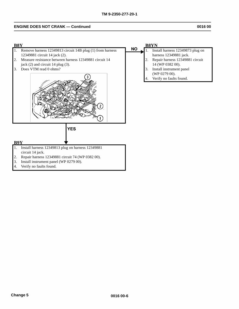
TM 9-2350-277-20-1
ENGINE DOES NOT CRANK — Continued 0016 00
B8Y1. Remove harness 12349813 circuit 14B plug (1) from harness
12349881 circuit 14 jack (2).2. Measure resistance between harness 12349881 circuit 14
jack (2) and circuit 14 plug (3).3. Does VTM read 0 ohms?
B8YN1. Install harness 12349873 plug on
harness 12349881 jack.2. Repair harness 12349881 circuit
14 (WP 0382 00).3. Install instrument panel
(WP 0279 00).4. Verify no faults found.
B9Y1. Install harness 12349813 plug on harness 12349881
circuit 14 jack.2. Repair harness 12349881 circuit 74 (WP 0382 00).3. Install instrument panel (WP 0279 00).4. Verify no faults found.
0016 00-6Change 5
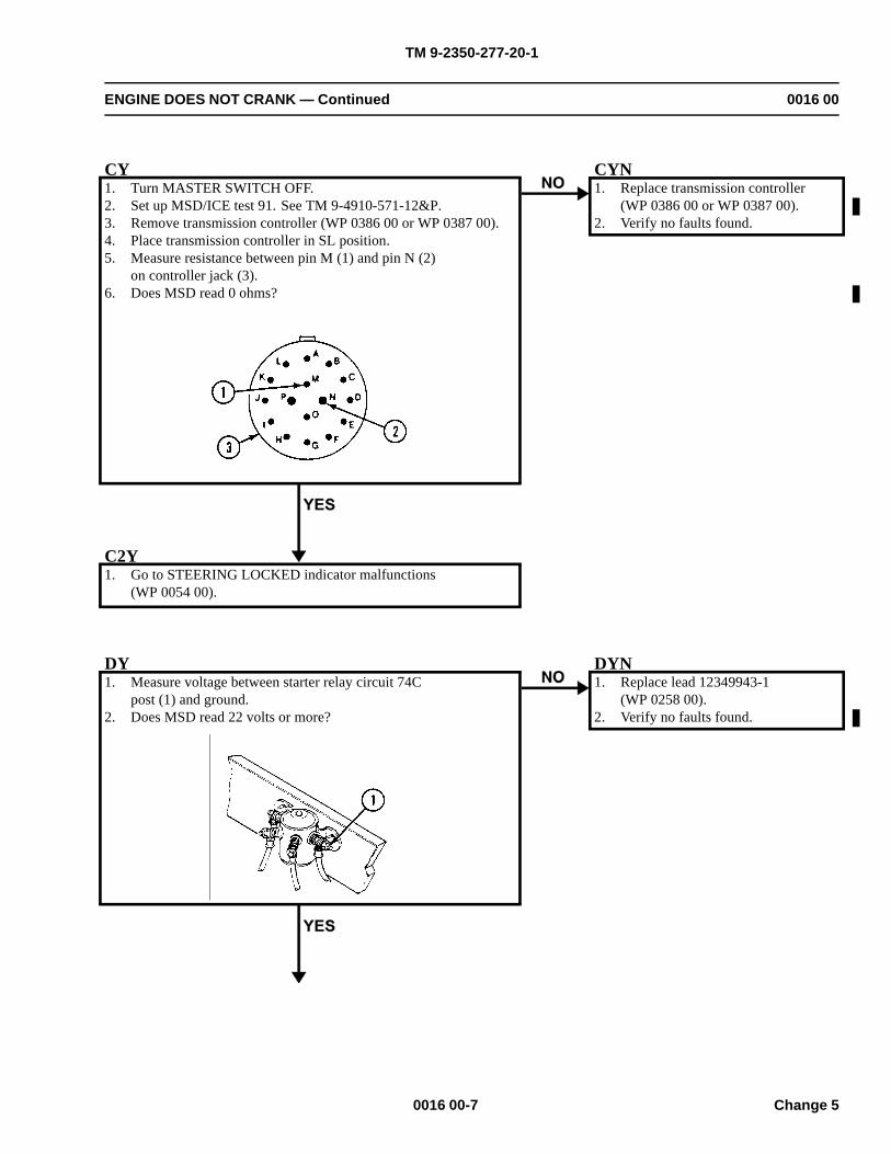
TM 9-2350-277-20-1
ENGINE DOES NOT CRANK — Continued 0016 00
CY1. Turn MASTER SWITCH OFF.2. Set up MSD/ICE test 91. See TM 9-4910-571-12&P.3. Remove transmission controller (WP 0386 00 or WP 0387 00).4. Place transmission controller in SL position.5. Measure resistance between pin M (1) and pin N (2)
on controller jack (3).6. Does MSD read 0 ohms?
CYN1. Replace transmission controller
(WP 0386 00 or WP 0387 00).2. Verify no faults found.
C2Y1. Go to STEERING LOCKED indicator malfunctions
(WP 0054 00).
DY1. Measure voltage between starter relay circuit 74C
post (1) and ground.2. Does MSD read 22 volts or more?
DYN1. Replace lead 12349943-1
(WP 0258 00).2. Verify no faults found.
0016 00-7 Change 5
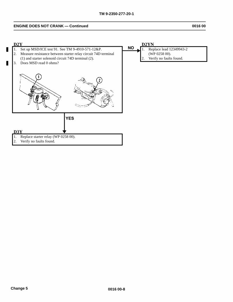
TM 9-2350-277-20-1
ENGINE DOES NOT CRANK — Continued 0016 00
D2Y1. Set up MSD/ICE test 91. See TM 9-4910-571-12&P.2. Measure resistance between starter relay circuit 74D terminal
(1) and starter solenoid circuit 74D terminal (2).3. Does MSD read 0 ohms?
D2YN1. Replace lead 12349943-2
(WP 0258 00).2. Verify no faults found.
D3Y1. Replace starter relay (WP 0258 00).2. Verify no faults found.
0016 00-8Change 5
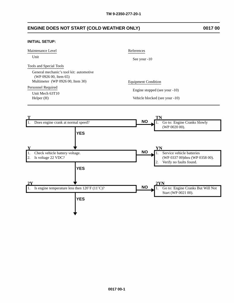
TM 9-2350-277-20-1
ENGINE DOES NOT START (COLD WEATHER ONLY) 0017 00
INITIAL SETUP:
Maintenance Level
Unit
Tools and Special Tools
General mechanic’s tool kit: automotive(WP 0926 00, Item 65)
Multimeter (WP 0926 00, Item 30)
Personnel Required
Unit Mech 63T10Helper (H)
References
See your -10
Equipment Condition
Engine stopped (see your -10)
Vehicle blocked (see your -10)
T1. Does engine crank at normal speed?
YES
NOTN1. Go to: Engine Cranks Slowly
(WP 0020 00).
Y1. Check vehicle battery voltage.2. Is voltage 22 VDC?
YES
NOYN1. Service vehicle batteries
(WP 0337 00)thru (WP 0358 00).2. Verify no faults found.
2Y1. Is engine temperature less then 120�F (11�C)?
YES
NO2YN1. Go to: Engine Cranks But Will Not
Start (WP 0021 00).
0017 00-1
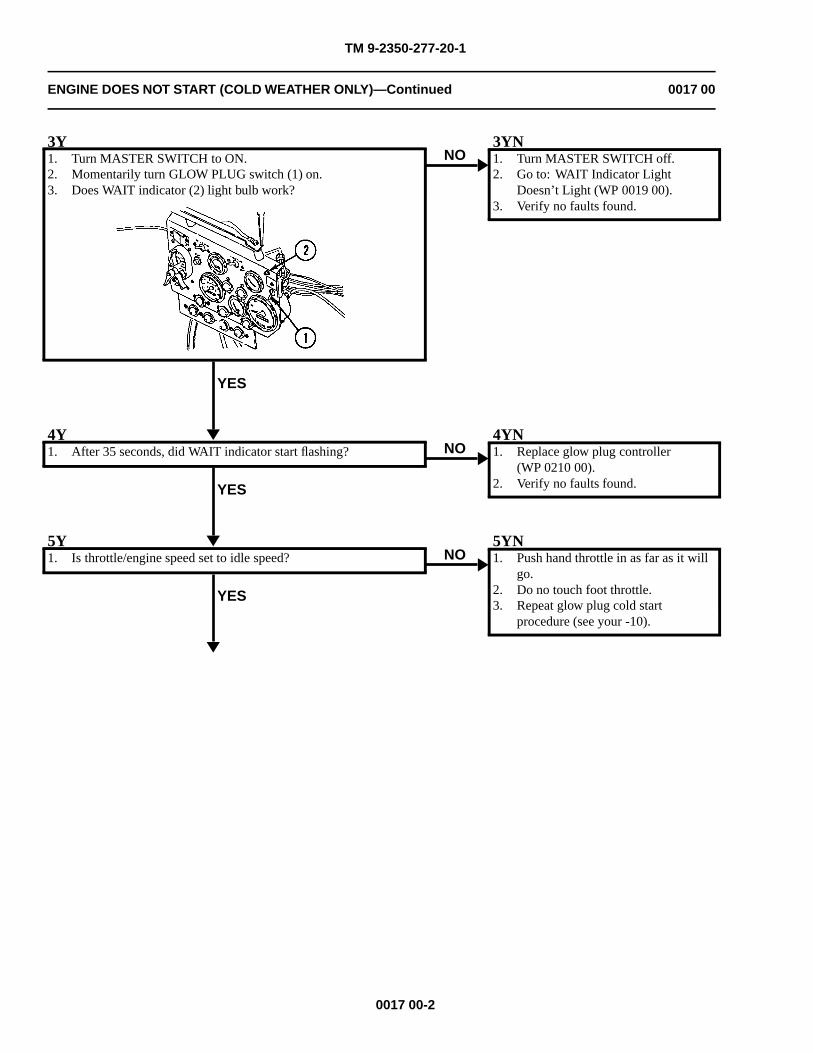
TM 9-2350-277-20-1
ENGINE DOES NOT START (COLD WEATHER ONLY)—Continued 0017 00
3Y1. Turn MASTER SWITCH to ON.2. Momentarily turn GLOW PLUG switch (1) on.3. Does WAIT indicator (2) light bulb work?
YES
NO3YN1. Turn MASTER SWITCH off.2. Go to: WAIT Indicator Light
Doesn’t Light (WP 0019 00).3. Verify no faults found.
4Y1. After 35 seconds, did WAIT indicator start flashing?
YES
NO4YN1. Replace glow plug controller
(WP 0210 00).2. Verify no faults found.
5Y1. Is throttle/engine speed set to idle speed?
YES
NO5YN1. Push hand throttle in as far as it will
go.2. Do no touch foot throttle.3. Repeat glow plug cold start
procedure (see your -10).
0017 00-2
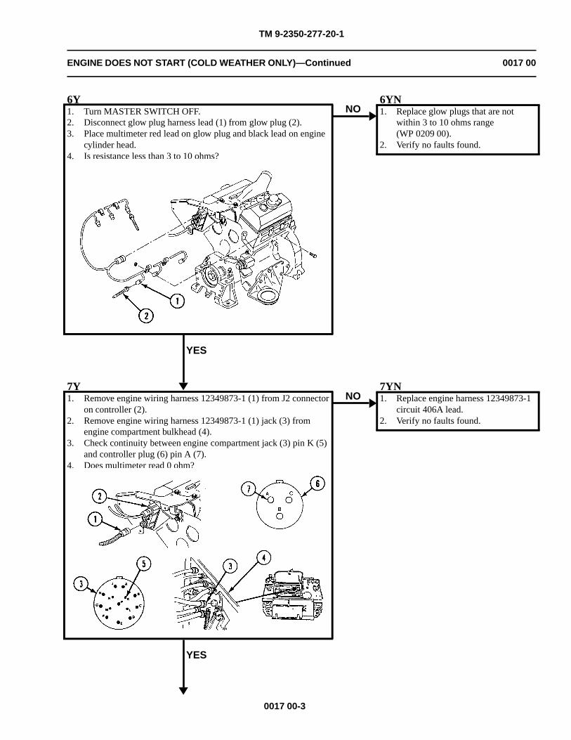
TM 9-2350-277-20-1
ENGINE DOES NOT START (COLD WEATHER ONLY)—Continued 0017 00
6Y1. Turn MASTER SWITCH OFF.2. Disconnect glow plug harness lead (1) from glow plug (2).3. Place multimeter red lead on glow plug and black lead on engine
cylinder head.4. Is resistance less than 3 to 10 ohms?
YES
NO6YN1. Replace glow plugs that are not
within 3 to 10 ohms range(WP 0209 00).
2. Verify no faults found.
7Y1. Remove engine wiring harness 12349873-1 (1) from J2 connector
on controller (2).2. Remove engine wiring harness 12349873-1 (1) jack (3) from
engine compartment bulkhead (4).3. Check continuity between engine compartment jack (3) pin K (5)
and controller plug (6) pin A (7).4. Does multimeter read 0 ohm?
YES
NO7YN1. Replace engine harness 12349873-1
circuit 406A lead.2. Verify no faults found.
0017 00-3
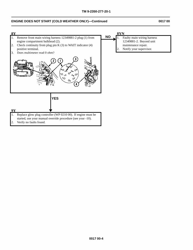
TM 9-2350-277-20-1
ENGINE DOES NOT START (COLD WEATHER ONLY)—Continued 0017 00
8Y1. Remove front main wiring harness 12349881-2 plug (1) from
engine compartment bulkhead (2).2. Check continuity from plug pin K (3) to WAIT indicator (4)
positive terminal.3. Does multimeter read 0 ohm?
YES
NO8YN1. Faulty main wiring harness
12349881-2. Beyond unitmaintenance repair.
2. Notify your supervisor.
9Y1. Replace glow plug controller (WP 0210 00). If engine must be
started, use your manual override procedure (see your -10).2. Verify no faults found.
0017 00-4
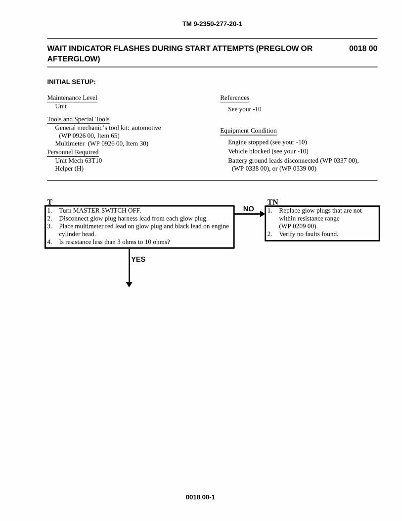
TM 9-2350-277-20-1
WAIT INDICATOR FLASHES DURING START ATTEMPTS (PREGLOW ORAFTERGLOW)
0018 00
INITIAL SETUP:
Maintenance LevelUnit
Tools and Special ToolsGeneral mechanic’s tool kit: automotive
(WP 0926 00, Item 65)Multimeter (WP 0926 00, Item 30)
Personnel RequiredUnit Mech 63T10Helper (H)
References
See your -10
Equipment Condition
Engine stopped (see your -10)
Vehicle blocked (see your -10)
Battery ground leads disconnected (WP 0337 00),(WP 0338 00), or (WP 0339 00)
T1. Turn MASTER SWITCH OFF.2. Disconnect glow plug harness lead from each glow plug.3. Place multimeter red lead on glow plug and black lead on engine
cylinder head.4. Is resistance less than 3 ohms to 10 ohms?
YES
NOTN1. Replace glow plugs that are not
within resistance range(WP 0209 00).
2. Verify no faults found.
0018 00-1
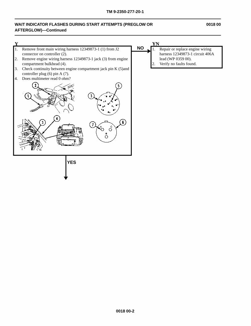
TM 9-2350-277-20-1
WAIT INDICATOR FLASHES DURING START ATTEMPTS (PREGLOW ORAFTERGLOW)—Continued
0018 00
Y1. Remove front main wiring harness 12349873-1 (1) from J2
connector on controller (2).2. Remove engine wiring harness 12349873-1 jack (3) from engine
compartment bulkhead (4).3. Check continuity between engine compartment jack pin K (5)and
controller plug (6) pin A (7).4. Does multimeter read 0 ohm?
YES
NOYN1. Repair or replace engine wiring
harness 12349873-1 circuit 406Alead (WP 0359 00).
2. Verify no faults found.
0018 00-2
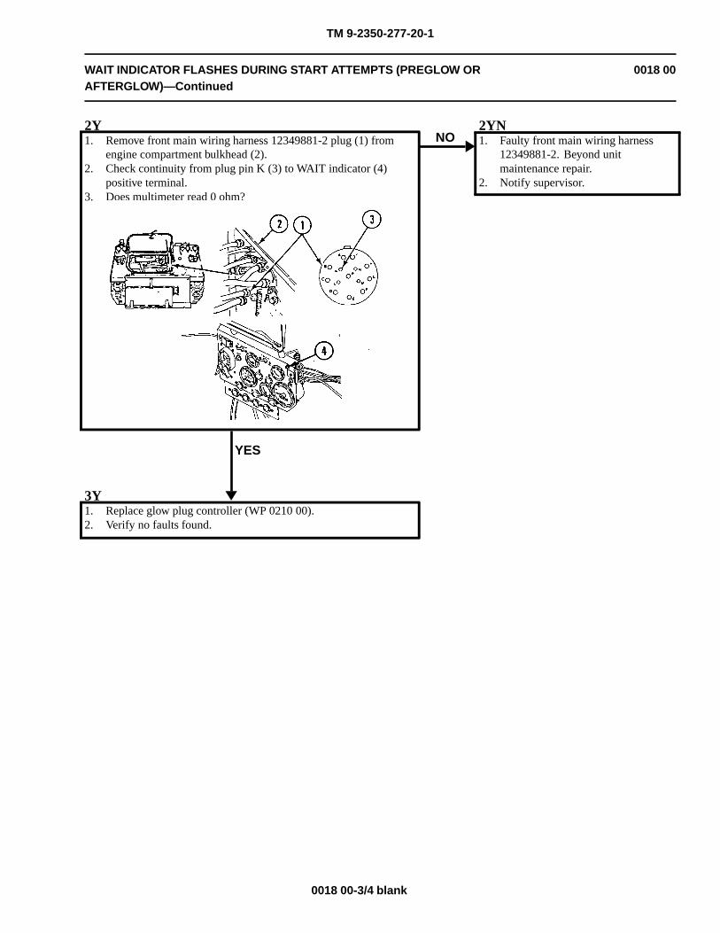
TM 9-2350-277-20-1
WAIT INDICATOR FLASHES DURING START ATTEMPTS (PREGLOW ORAFTERGLOW)—Continued
0018 00
2Y1. Remove front main wiring harness 12349881-2 plug (1) from
engine compartment bulkhead (2).2. Check continuity from plug pin K (3) to WAIT indicator (4)
positive terminal.3. Does multimeter read 0 ohm?
YES
NO2YN1. Faulty front main wiring harness
12349881-2. Beyond unitmaintenance repair.
2. Notify supervisor.
3Y1. Replace glow plug controller (WP 0210 00).2. Verify no faults found.
0018 00-3/4 blank

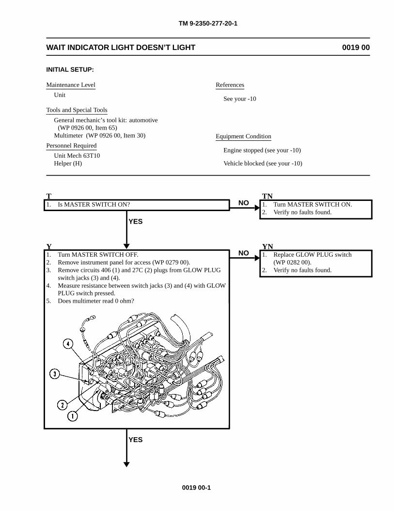
TM 9-2350-277-20-1
WAIT INDICATOR LIGHT DOESN’T LIGHT 0019 00
INITIAL SETUP:
Maintenance Level
Unit
Tools and Special Tools
General mechanic’s tool kit: automotive(WP 0926 00, Item 65)
Multimeter (WP 0926 00, Item 30)
Personnel Required
Unit Mech 63T10Helper (H)
References
See your -10
Equipment Condition
Engine stopped (see your -10)
Vehicle blocked (see your -10)
T1. Is MASTER SWITCH ON?
YES
NOTN1. Turn MASTER SWITCH ON.2. Verify no faults found.
Y1. Turn MASTER SWITCH OFF.2. Remove instrument panel for access (WP 0279 00).3. Remove circuits 406 (1) and 27C (2) plugs from GLOW PLUG
switch jacks (3) and (4).4. Measure resistance between switch jacks (3) and (4) with GLOW
PLUG switch pressed.5. Does multimeter read 0 ohm?
YES
NOYN1. Replace GLOW PLUG switch
(WP 0282 00).2. Verify no faults found.
0019 00-1
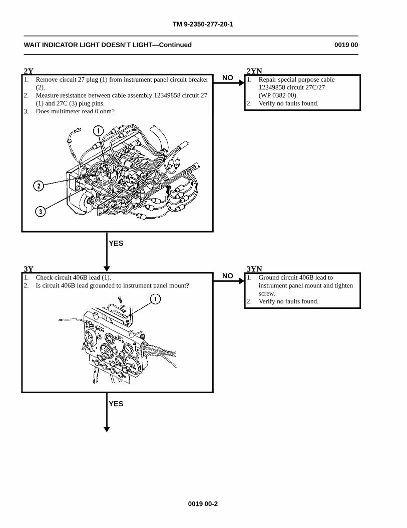
TM 9-2350-277-20-1
WAIT INDICATOR LIGHT DOESN’T LIGHT—Continued 0019 00
2Y1. Remove circuit 27 plug (1) from instrument panel circuit breaker
(2).2. Measure resistance between cable assembly 12349858 circuit 27
(1) and 27C (3) plug pins.3. Does multimeter read 0 ohm?
YES
NO2YN1. Repair special purpose cable
12349858 circuit 27C/27(WP 0382 00).
2. Verify no faults found.
3Y1. Check circuit 406B lead (1).2. Is circuit 406B lead grounded to instrument panel mount?
YES
NO3YN1. Ground circuit 406B lead to
instrument panel mount and tightenscrew.
2. Verify no faults found.
0019 00-2
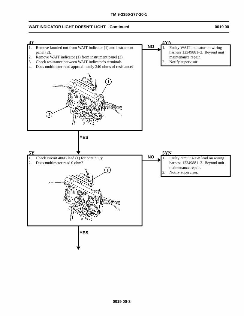
TM 9-2350-277-20-1
WAIT INDICATOR LIGHT DOESN’T LIGHT—Continued 0019 00
4Y1. Remove knurled nut from WAIT indicator (1) and instrument
panel (2).2. Remove WAIT indicator (1) from instrument panel (2).3. Check resistance between WAIT indicator’s terminals.4. Does multimeter read approximately 240 ohms of resistance?
YES
NO4YN1. Faulty WAIT indicator on wiring
harness 12349881–2. Beyond unitmaintenance repair.
2. Notify supervisor.
5Y1. Check circuit 406B lead (1) for continuity.2. Does multimeter read 0 ohm?
YES
NO5YN1. Faulty circuit 406B lead on wiring
harness 12349881–2. Beyond unitmaintenance repair.
2. Notify supervisor.
0019 00-3
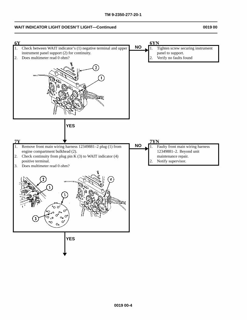
TM 9-2350-277-20-1
WAIT INDICATOR LIGHT DOESN’T LIGHT—Continued 0019 00
6Y1. Check between WAIT indicator’s (1) negative terminal and upper
instrument panel support (2) for continuity.2. Does multimeter read 0 ohm?
YES
NO6YN1. Tighten screw securing instrument
panel to support.2. Verify no faults found
7Y1. Remove front main wiring harness 12349881–2 plug (1) from
engine compartment bulkhead (2).2. Check continuity from plug pin K (3) to WAIT indicator (4)
positive terminal.3. Does multimeter read 0 ohm?
YES
NO7YN1. Faulty front main wiring harness
12349881–2. Beyond unitmaintenance repair.
2. Notify supervisor.
0019 00-4
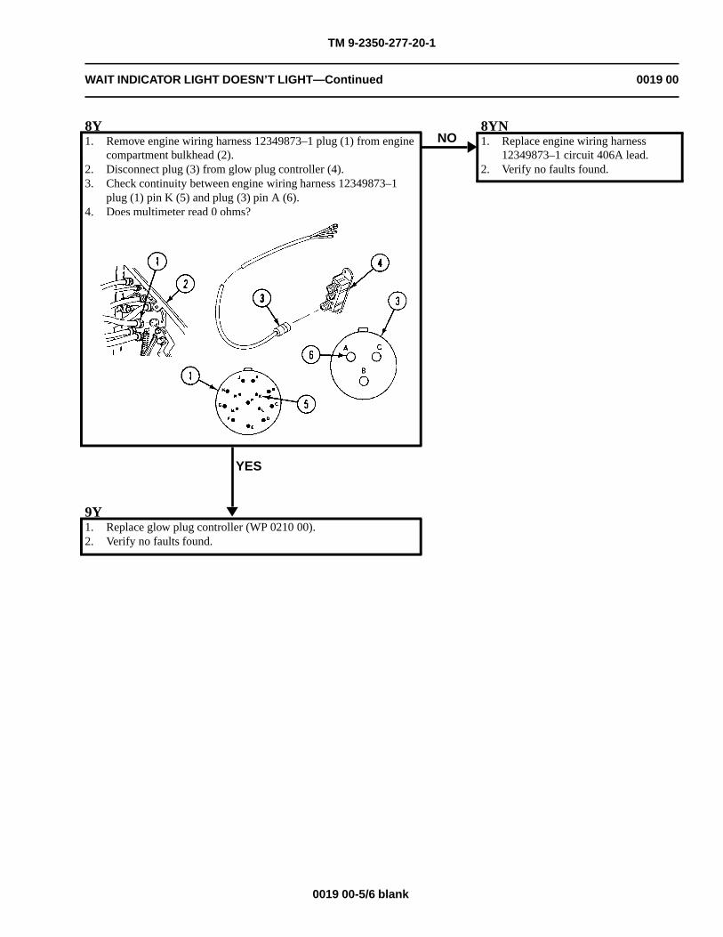
TM 9-2350-277-20-1
WAIT INDICATOR LIGHT DOESN’T LIGHT—Continued 0019 00
8Y1. Remove engine wiring harness 12349873–1 plug (1) from engine
compartment bulkhead (2).2. Disconnect plug (3) from glow plug controller (4).3. Check continuity between engine wiring harness 12349873–1
plug (1) pin K (5) and plug (3) pin A (6).4. Does multimeter read 0 ohms?
YES
NO8YN1. Replace engine wiring harness
12349873–1 circuit 406A lead.2. Verify no faults found.
9Y1. Replace glow plug controller (WP 0210 00).2. Verify no faults found.
0019 00-5/6 blank

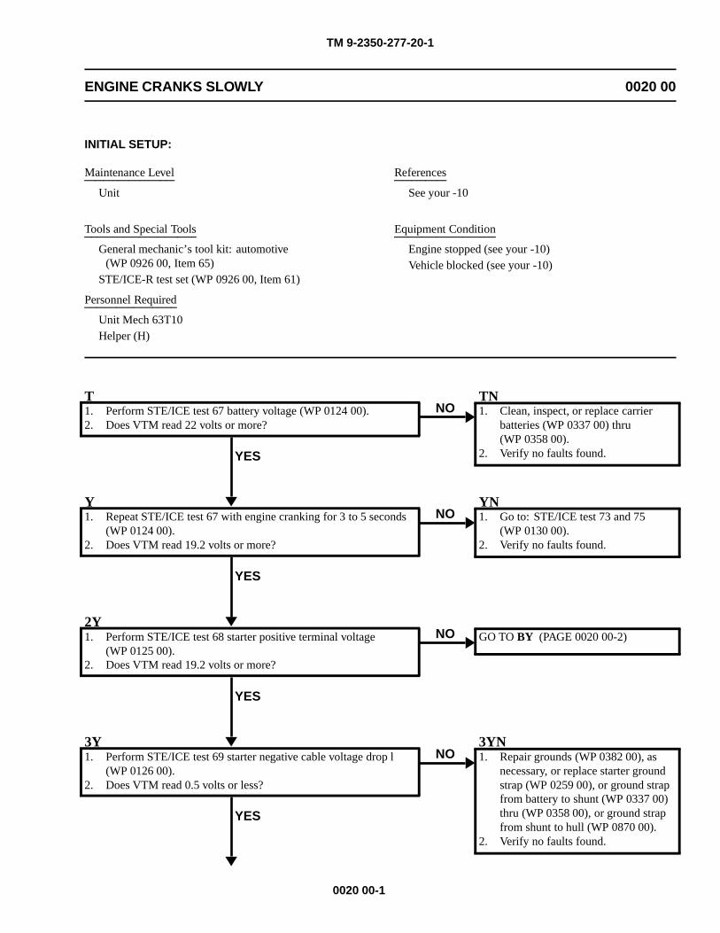
TM 9-2350-277-20-1
ENGINE CRANKS SLOWLY 0020 00
INITIAL SETUP:
Maintenance Level
Unit
Tools and Special Tools
General mechanic’s tool kit: automotive(WP 0926 00, Item 65)
STE/ICE-R test set (WP 0926 00, Item 61)
Personnel Required
Unit Mech 63T10Helper (H)
References
See your -10
Equipment Condition
Engine stopped (see your -10)Vehicle blocked (see your -10)
T1. Perform STE/ICE test 67 battery voltage (WP 0124 00).2. Does VTM read 22 volts or more?
YES
NOTN1. Clean, inspect, or replace carrier
batteries (WP 0337 00) thru(WP 0358 00).
2. Verify no faults found.
Y1. Repeat STE/ICE test 67 with engine cranking for 3 to 5 seconds
(WP 0124 00).2. Does VTM read 19.2 volts or more?
YES
NOYN1. Go to: STE/ICE test 73 and 75
(WP 0130 00).2. Verify no faults found.
2Y1. Perform STE/ICE test 68 starter positive terminal voltage
(WP 0125 00).2. Does VTM read 19.2 volts or more?
YES
NO GO TO BY (PAGE 0020 00-2)
3Y1. Perform STE/ICE test 69 starter negative cable voltage drop l
(WP 0126 00).2. Does VTM read 0.5 volts or less?
YES
NO3YN1. Repair grounds (WP 0382 00), as
necessary, or replace starter groundstrap (WP 0259 00), or ground strapfrom battery to shunt (WP 0337 00)thru (WP 0358 00), or ground strapfrom shunt to hull (WP 0870 00).
2. Verify no faults found.
0020 00-1
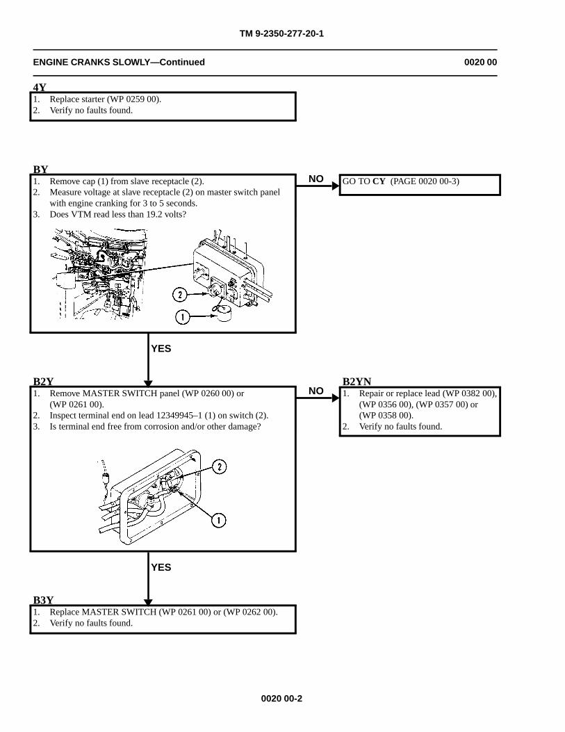
TM 9-2350-277-20-1
ENGINE CRANKS SLOWLY—Continued 0020 00
4Y1. Replace starter (WP 0259 00).2. Verify no faults found.
BY1. Remove cap (1) from slave receptacle (2).2. Measure voltage at slave receptacle (2) on master switch panel
with engine cranking for 3 to 5 seconds.3. Does VTM read less than 19.2 volts?
YES
NO GO TO CY (PAGE 0020 00-3)
B2Y1. Remove MASTER SWITCH panel (WP 0260 00) or
(WP 0261 00).2. Inspect terminal end on lead 12349945–1 (1) on switch (2).3. Is terminal end free from corrosion and/or other damage?
YES
NOB2YN1. Repair or replace lead (WP 0382 00),
(WP 0356 00), (WP 0357 00) or(WP 0358 00).
2. Verify no faults found.
B3Y1. Replace MASTER SWITCH (WP 0261 00) or (WP 0262 00).2. Verify no faults found.
0020 00-2
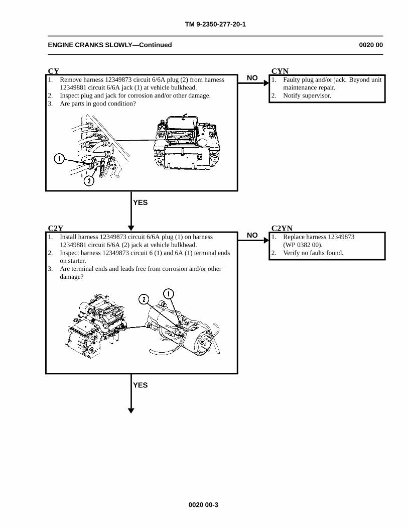
TM 9-2350-277-20-1
ENGINE CRANKS SLOWLY—Continued 0020 00
CY1. Remove harness 12349873 circuit 6/6A plug (2) from harness
12349881 circuit 6/6A jack (1) at vehicle bulkhead.2. Inspect plug and jack for corrosion and/or other damage.3. Are parts in good condition?
YES
NOCYN1. Faulty plug and/or jack. Beyond unit
maintenance repair.2. Notify supervisor.
C2Y1. Install harness 12349873 circuit 6/6A plug (1) on harness
12349881 circuit 6/6A (2) jack at vehicle bulkhead.2. Inspect harness 12349873 circuit 6 (1) and 6A (1) terminal ends
on starter.3. Are terminal ends and leads free from corrosion and/or other
damage?
YES
NOC2YN1. Replace harness 12349873
(WP 0382 00).2. Verify no faults found.
0020 00-3
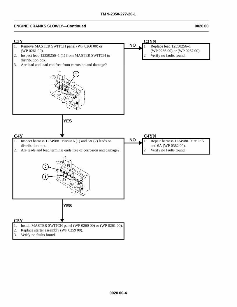
TM 9-2350-277-20-1
ENGINE CRANKS SLOWLY—Continued 0020 00
C3Y1. Remove MASTER SWITCH panel (WP 0260 00) or
(WP 0261 00).2. Inspect lead 12350256–1 (1) from MASTER SWITCH to
distribution box.3. Are lead and lead end free from corrosion and damage?
YES
NOC3YN1. Replace lead 12350256–1
(WP 0266 00) or (WP 0267 00).2. Verify no faults found.
C4Y1. Inspect harness 12349881 circuit 6 (1) and 6A (2) leads on
distribution box.2. Are leads and lead terminal ends free of corrosion and damage?
YES
NOC4YN1. Repair harness 12349881 circuit 6
and 6A (WP 0382 00).2. Verify no faults found.
C5Y1. Install MASTER SWITCH panel (WP 0260 00) or (WP 0261 00).2. Replace starter assembly (WP 0259 00).3. Verify no faults found.
0020 00-4
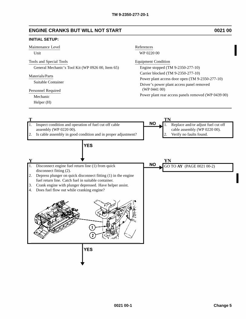
TM 9-2350-277-20-1
ENGINE CRANKS BUT WILL NOT START 0021 00
INITIAL SETUP:
Maintenance LevelUnit
Tools and Special ToolsGeneral Mechanic’s Tool Kit (WP 0926 00, Item 65)
Materials/PartsSuitable Container
Personnel RequiredMechanicHelper (H)
ReferencesWP 0220 00
Equipment ConditionEngine stopped (TM 9-2350-277-10)Carrier blocked (TM 9-2350-277-10)Power plant access door open (TM 9-2350-277-10)Driver’s power plant access panel removed
(WP 0441 00)Power plant rear access panels removed (WP 0439 00)
T1. Inspect condition and operation of fuel cut off cable
assembly (WP 0220 00).2. Is cable assembly in good condition and in proper adjustment?
TN1. Replace and/or adjust fuel cut off
cable assembly (WP 0220 00).2. Verify no faults found.
Y1. Disconnect engine fuel return line (1) from quick
disconnect fitting (2).2. Depress plunger on quick disconnect fitting (1) in the engine
fuel return line. Catch fuel in suitable container.3. Crank engine with plunger depressed. Have helper assist.4. Does fuel flow out while cranking engine?
YNGO TO AY (PAGE 0021 00-2)
0021 00-1 Change 5
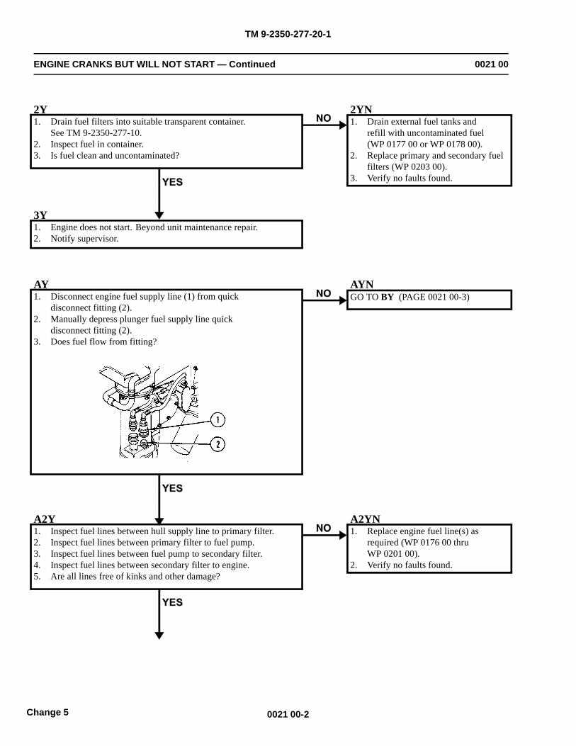
TM 9-2350-277-20-1
ENGINE CRANKS BUT WILL NOT START — Continued 0021 00
2Y1. Drain fuel filters into suitable transparent container.
See TM 9-2350-277-10.2. Inspect fuel in container.3. Is fuel clean and uncontaminated?
2YN1. Drain external fuel tanks and
refill with uncontaminated fuel(WP 0177 00 or WP 0178 00).
2. Replace primary and secondary fuelfilters (WP 0203 00).
3. Verify no faults found.
3Y1. Engine does not start. Beyond unit maintenance repair.2. Notify supervisor.
AY1. Disconnect engine fuel supply line (1) from quick
disconnect fitting (2).2. Manually depress plunger fuel supply line quick
disconnect fitting (2).3. Does fuel flow from fitting?
GO TO BY (PAGE 0021 00-3)
A2Y1. Inspect fuel lines between hull supply line to primary filter.2. Inspect fuel lines between primary filter to fuel pump.3. Inspect fuel lines between fuel pump to secondary filter.4. Inspect fuel lines between secondary filter to engine.5. Are all lines free of kinks and other damage?
A2YN1. Replace engine fuel line(s) as
required (WP 0176 00 thruWP 0201 00).
2. Verify no faults found.
0021 00-2Change 5
AYN
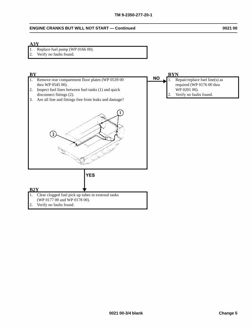
TM 9-2350-277-20-1
ENGINE CRANKS BUT WILL NOT START — Continued 0021 00
A3Y1. Replace fuel pump (WP 0166 00).2. Verify no faults found.
BY1. Remove rear compartment floor plates (WP 0539 00
thru WP 0545 00).2. Inspect fuel lines between fuel tanks (1) and quick
disconnect fittings (2).3. Are all line and fittings free from leaks and damage?
BYN1. Repair/replace fuel line(s) as
required (WP 0176 00 thruWP 0201 00).
2. Verify no faults found.
B2Y1. Clear clogged fuel pick up tubes in external tanks
(WP 0177 00 and WP 0178 00).2. Verify no faults found.
0021 00-3/4 blank Change 5

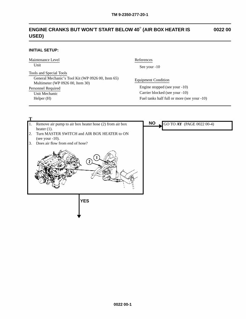
TM 9-2350-277-20-1
ENGINE CRANKS BUT WON’T START BELOW 40� (AIR BOX HEATER ISUSED)
0022 00
INITIAL SETUP:
Maintenance LevelUnit
Tools and Special ToolsGeneral Mechanic’s Tool Kit (WP 0926 00, Item 65)Multimeter (WP 0926 00, Item 30)
Personnel RequiredUnit MechanicHelper (H)
References
See your -10
Equipment Condition
Engine stopped (see your -10)
Carrier blocked (see your -10)
Fuel tanks half full or more (see your -10)
T1. Remove air pump to air box heater hose (2) from air box
heater (1).2. Turn MASTER SWITCH and AIR BOX HEATER to ON
(see your -10).3. Does air flow from end of hose?
YES
NO GO TO AY (PAGE 0022 00-4)
0022 00-1
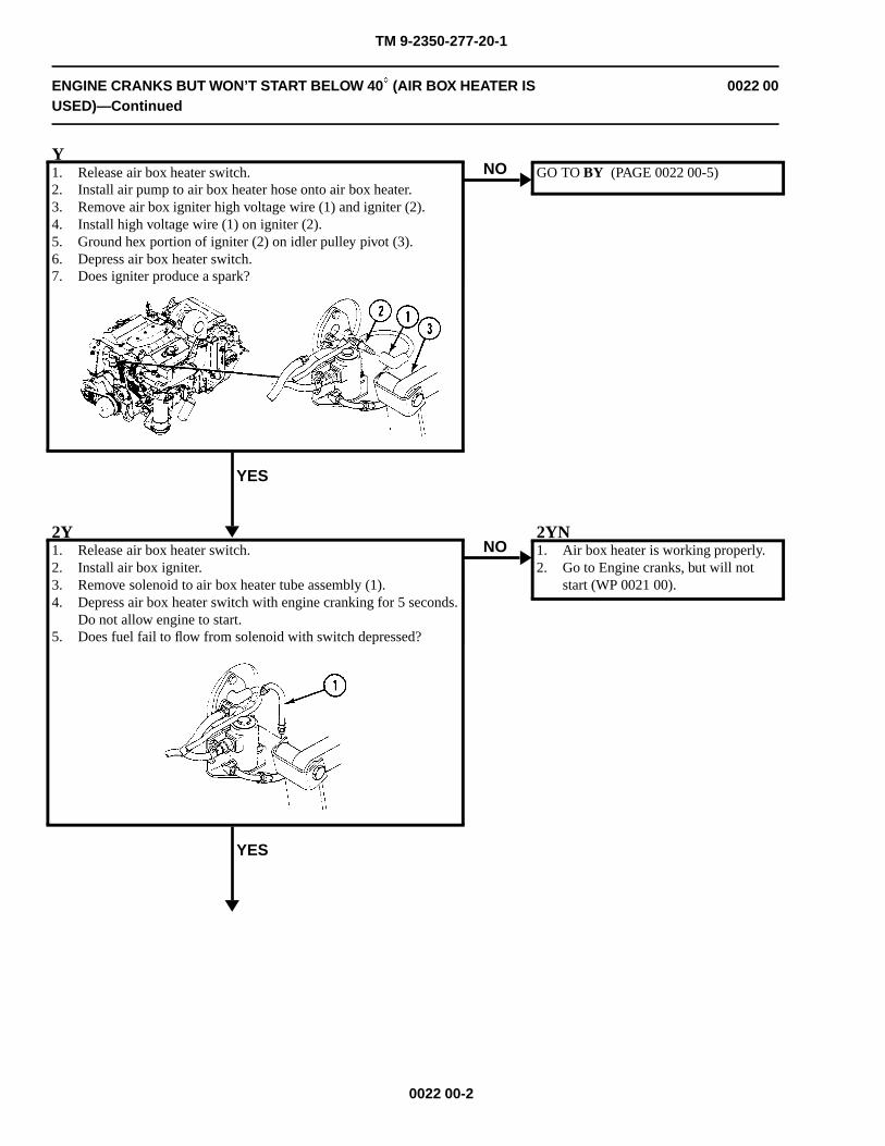
TM 9-2350-277-20-1
ENGINE CRANKS BUT WON’T START BELOW 40� (AIR BOX HEATER ISUSED)—Continued
0022 00
Y1. Release air box heater switch.2. Install air pump to air box heater hose onto air box heater.3. Remove air box igniter high voltage wire (1) and igniter (2).4. Install high voltage wire (1) on igniter (2).5. Ground hex portion of igniter (2) on idler pulley pivot (3).6. Depress air box heater switch.7. Does igniter produce a spark?
YES
NO GO TO BY (PAGE 0022 00-5)
2Y1. Release air box heater switch.2. Install air box igniter.3. Remove solenoid to air box heater tube assembly (1).4. Depress air box heater switch with engine cranking for 5 seconds.
Do not allow engine to start.5. Does fuel fail to flow from solenoid with switch depressed?
YES
NO2YN1. Air box heater is working properly.2. Go to Engine cranks, but will not
start (WP 0021 00).
0022 00-2
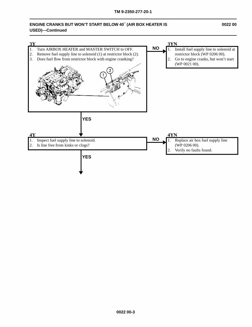
TM 9-2350-277-20-1
ENGINE CRANKS BUT WON’T START BELOW 40� (AIR BOX HEATER ISUSED)—Continued
0022 00
3Y1. Turn AIRBOX HEATER and MASTER SWITCH to OFF.2. Remove fuel supply line to solenoid (1) at restrictor block (2).3. Does fuel flow from restrictor block with engine cranking?
YES
NO3YN1. Install fuel supply line to solenoid at
restrictor block (WP 0206 00).2. Go to engine cranks, but won’t start
(WP 0021 00).
4Y1. Inspect fuel supply line to solenoid.2. Is line free from kinks or clogs?
YES
NO4YN1. Replace air box fuel supply line
(WP 0206 00).2. Verify no faults found.
0022 00-3
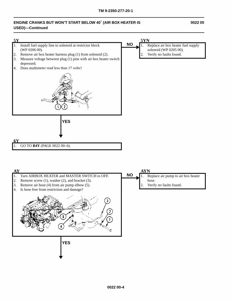
TM 9-2350-277-20-1
ENGINE CRANKS BUT WON’T START BELOW 40� (AIR BOX HEATER ISUSED)—Continued
0022 00
5Y1. Install fuel supply line to solenoid at restrictor block
(WP 0206 00).2. Remove air box heater harness plug (1) from solenoid (2).3. Measure voltage between plug (1) pins with air box heater switch
depressed.4. Does multimeter read less than 17 volts?
YES
NO5YN1. Replace air box heater fuel supply
solenoid (WP 0205 00).2. Verify no faults found.
6Y1. GO TO B4Y (PAGE 0022 00–6).
AY1. Turn AIRBOX HEATER and MASTER SWITCH to OFF.2. Remove screw (1), washer (2), and bracket (3).3. Remove air hose (4) from air pump elbow (5).4. Is hose free from restriction and damage?
YES
NOAYN1. Replace air pump to air box heater
hose.2. Verify no faults found.
0022 00-4
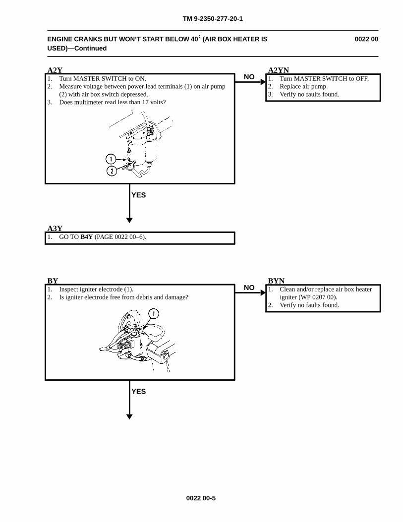
TM 9-2350-277-20-1
ENGINE CRANKS BUT WON’T START BELOW 40� (AIR BOX HEATER ISUSED)—Continued
0022 00
A2Y1. Turn MASTER SWITCH to ON.2. Measure voltage between power lead terminals (1) on air pump
(2) with air box switch depressed.3. Does multimeter read less than 17 volts?
YES
NOA2YN1. Turn MASTER SWITCH to OFF.2. Replace air pump.3. Verify no faults found.
A3Y1. GO TO B4Y (PAGE 0022 00–6).
BY1. Inspect igniter electrode (1).2. Is igniter electrode free from debris and damage?
YES
NOBYN1. Clean and/or replace air box heater
igniter (WP 0207 00).2. Verify no faults found.
0022 00-5
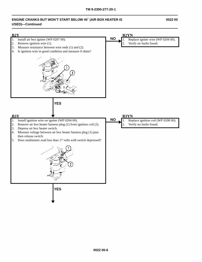
TM 9-2350-277-20-1
ENGINE CRANKS BUT WON’T START BELOW 40� (AIR BOX HEATER ISUSED)—Continued
0022 00
B2Y1. Install air box igniter (WP 0207 00).2. Remove ignition wire (1).3. Measure resistance between wire ends (1) and (2).4. Is ignition wire in good condition and measure 0 ohms?
YES
NOB2YN1. Replace igniter wire (WP 0204 00).2. Verify no faults found.
B3Y1. Install ignition wire on igniter (WP 0204 00).2. Remove air box heater harness plug (1) from ignition coil (2).3. Depress air box heater switch.4. Measure voltage between air box heater harness plug (1) pins
then release switch.5. Does multimeter read less than 17 volts with switch depressed?
YES
NOB3YN1. Replace ignition coil (WP 0208 00).2. Verify no faults found.
0022 00-6
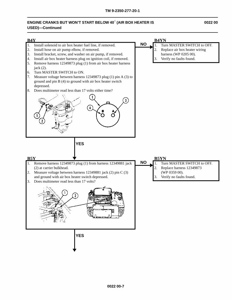
TM 9-2350-277-20-1
ENGINE CRANKS BUT WON’T START BELOW 40� (AIR BOX HEATER ISUSED)—Continued
0022 00
B4Y1. Install solenoid to air box heater fuel line, if removed.2. Install hose on air pump elbow, if removed.3. Install bracket, screw, and washer on air pump, if removed.4. Install air box heater harness plug on ignition coil, if removed.5. Remove harness 12349873 plug (1) from air box heater harness
jack (2).6. Turn MASTER SWITCH to ON.7. Measure voltage between harness 12349873 plug (1) pin A (3) to
ground and pin B (4) to ground with air box heater switchdepressed.
8. Does multimeter read less than 17 volts either time?
YES
NOB4YN1. Turn MASTER SWITCH to OFF.2. Replace air box heater wiring
harness (WP 0205 00).3. Verify no faults found.
B5Y1. Remove harness 12349873 plug (1) from harness 12349881 jack
(2) at carrier bulkhead.2. Measure voltage between harness 12349881 jack (2) pin C (3)
and ground with air box heater switch depressed.3. Does multimeter read less than 17 volts?
YES
NOB5YN1. Turn MASTER SWITCH to OFF.2. Replace harness 12349873
(WP 0359 00).3. Verify no faults found.
0022 00-7
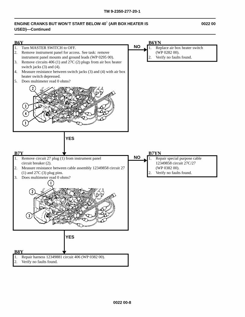
TM 9-2350-277-20-1
ENGINE CRANKS BUT WON’T START BELOW 40� (AIR BOX HEATER ISUSED)—Continued
0022 00
B6Y1. Turn MASTER SWITCH to OFF.2. Remove instrument panel for access. See task: remove
instrument panel mounts and ground leads (WP 0295 00).3. Remove circuits 406 (1) and 27C (2) plugs from air box heater
switch jacks (3) and (4).4. Measure resistance between switch jacks (3) and (4) with air box
heater switch depressed.5. Does multimeter read 0 ohms?
YES
NOB6YN1. Replace air box heater switch
(WP 0282 00).2. Verify no faults found.
B7Y1. Remove circuit 27 plug (1) from instrument panel
circuit breaker (2).2. Measure resistance between cable assembly 12349858 circuit 27
(1) and 27C (3) plug pins.3. Does multimeter read 0 ohms?
YES
NOB7YN1. Repair special purpose cable
12349858 circuit 27C/27(WP 0382 00).
2. Verify no faults found.
B8Y1. Repair harness 12349881 circuit 406 (WP 0382 00).2. Verify no faults found.
0022 00-8
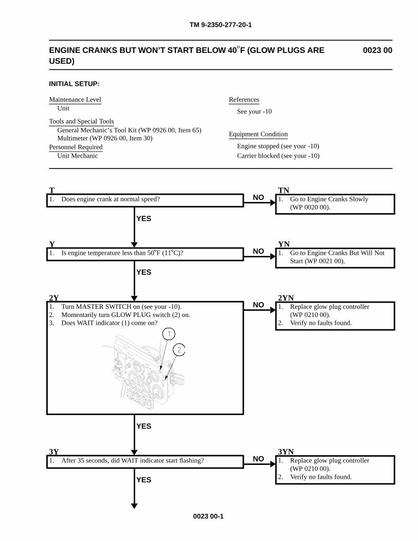
TM 9-2350-277-20-1
ENGINE CRANKS BUT WON’T START BELOW 40�F (GLOW PLUGS AREUSED)
0023 00
INITIAL SETUP:
Maintenance LevelUnit
Tools and Special ToolsGeneral Mechanic’s Tool Kit (WP 0926 00, Item 65)Multimeter (WP 0926 00, Item 30)
Personnel RequiredUnit Mechanic
References
See your -10
Equipment Condition
Engine stopped (see your -10)
Carrier blocked (see your -10)
T1. Does engine crank at normal speed?
YES
NOTN1. Go to Engine Cranks Slowly
(WP 0020 00).
Y1. Is engine temperature less than 50�F (11�C)?
YES
NOYN1. Go to Engine Cranks But Will Not
Start (WP 0021 00).
2Y1. Turn MASTER SWITCH on (see your -10).2. Momentarily turn GLOW PLUG switch (2) on.3. Does WAIT indicator (1) come on?
YES
NO2YN1. Replace glow plug controller
(WP 0210 00).2. Verify no faults found.
3Y1. After 35 seconds, did WAIT indicator start flashing?
YES
NO3YN1. Replace glow plug controller
(WP 0210 00).2. Verify no faults found.
0023 00-1
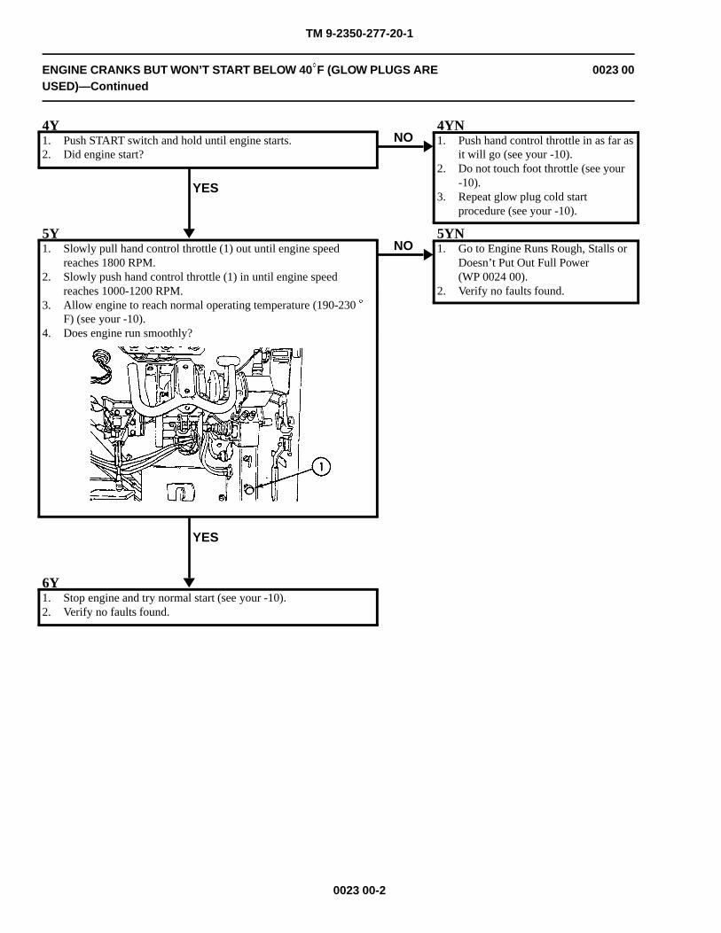
TM 9-2350-277-20-1
ENGINE CRANKS BUT WON’T START BELOW 40�F (GLOW PLUGS AREUSED)—Continued
0023 00
4Y1. Push START switch and hold until engine starts.2. Did engine start?
YES
NO4YN1. Push hand control throttle in as far as
it will go (see your -10).2. Do not touch foot throttle (see your
-10).3. Repeat glow plug cold start
procedure (see your -10).
5Y1. Slowly pull hand control throttle (1) out until engine speed
reaches 1800 RPM.2. Slowly push hand control throttle (1) in until engine speed
reaches 1000-1200 RPM.3. Allow engine to reach normal operating temperature (190-230 �
F) (see your -10).4. Does engine run smoothly?
YES
NO5YN1. Go to Engine Runs Rough, Stalls or
Doesn’t Put Out Full Power(WP 0024 00).
2. Verify no faults found.
6Y1. Stop engine and try normal start (see your -10).2. Verify no faults found.
0023 00-2
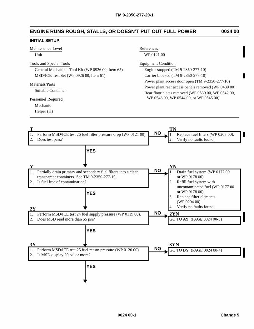
TM 9-2350-277-20-1
ENGINE RUNS ROUGH, STALLS, OR DOESN’T PUT OUT FULL POWER 0024 00
INITIAL SETUP:
Maintenance LevelUnit
Tools and Special ToolsGeneral Mechanic’s Tool Kit (WP 0926 00, Item 65)MSD/ICE Test Set (WP 0926 00, Item 61)
Materials/PartsSuitable Container
Personnel RequiredMechanicHelper (H)
ReferencesWP 0121 00
Equipment ConditionEngine stopped (TM 9-2350-277-10)Carrier blocked (TM 9-2350-277-10)Power plant access door open (TM 9-2350-277-10)Power plant rear access panels removed (WP 0439 00)Rear floor plates removed (WP 0539 00, WP 0542 00,
WP 0543 00, WP 0544 00, or WP 0545 00)
T1. Perform MSD/ICE test 26 fuel filter pressure drop (WP 0121 00).2. Does test pass?
TN1. Replace fuel filters (WP 0203 00).2. Verify no faults found.
Y1. Partially drain primary and secondary fuel filters into a clean
transparent containers. See TM 9-2350-277-10.2. Is fuel free of contamination?
YN1. Drain fuel system (WP 0177 00
or WP 0178 00).2. Refill fuel system with
uncontaminated fuel (WP 0177 00or WP 0178 00).
3. Replace filter elements(WP 0204 00).
4. Verify no faults found.2Y1. Perform MSD/ICE test 24 fuel supply pressure (WP 0119 00).2. Does MSD read more than 55 psi?
2YNGO TO AY (PAGE 0024 00-3)
3Y1. Perform MSD/ICE test 25 fuel return pressure (WP 0120 00).2. Is MSD display 20 psi or more?
3YNGO TO BY (PAGE 0024 00-4)
0024 00-1 Change 5
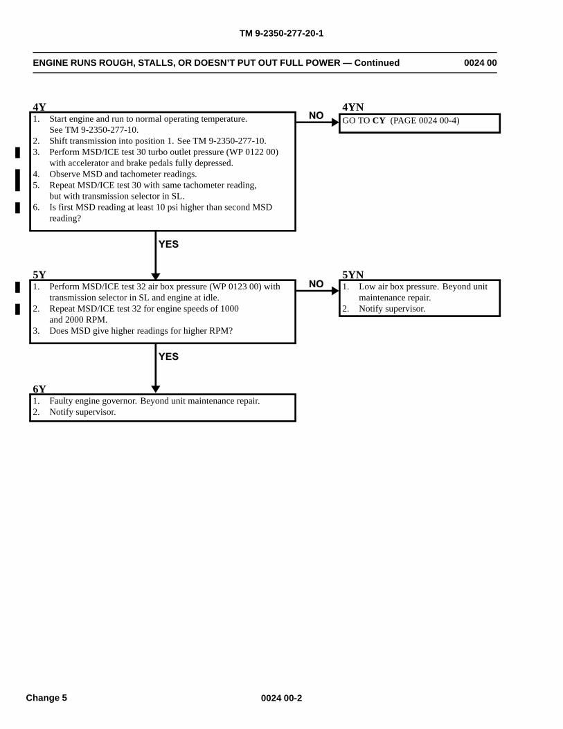
TM 9-2350-277-20-1
ENGINE RUNS ROUGH, STALLS, OR DOESN’T PUT OUT FULL POWER — Continued 0024 00
4Y1. Start engine and run to normal operating temperature.
See TM 9-2350-277-10.2. Shift transmission into position 1. See TM 9-2350-277-10.3. Perform MSD/ICE test 30 turbo outlet pressure (WP 0122 00)
with accelerator and brake pedals fully depressed.4. Observe MSD and tachometer readings.5. Repeat MSD/ICE test 30 with same tachometer reading,
but with transmission selector in SL.6. Is first MSD reading at least 10 psi higher than second MSD
reading?
4YNGO TO CY (PAGE 0024 00-4)
5Y1. Perform MSD/ICE test 32 air box pressure (WP 0123 00) with
transmission selector in SL and engine at idle.2. Repeat MSD/ICE test 32 for engine speeds of 1000
and 2000 RPM.3. Does MSD give higher readings for higher RPM?
5YN1. Low air box pressure. Beyond unit
maintenance repair.2. Notify supervisor.
6Y1. Faulty engine governor. Beyond unit maintenance repair.2. Notify supervisor.
0024 00-2Change 5
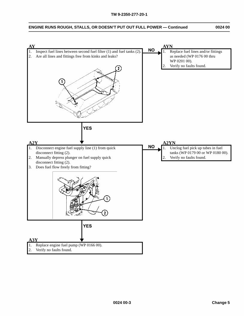
TM 9-2350-277-20-1
ENGINE RUNS ROUGH, STALLS, OR DOESN’T PUT OUT FULL POWER — Continued 0024 00
AY1. Inspect fuel lines between second fuel filter (1) and fuel tanks (2).2. Are all lines and fittings free from kinks and leaks?
AYN1. Replace fuel lines and/or fittings
as needed (WP 0176 00 thruWP 0201 00).
2. Verify no faults found.
A2Y1. Disconnect engine fuel supply line (1) from quick
disconnect fitting (2).2. Manually depress plunger on fuel supply quick
disconnect fitting (2).3. Does fuel flow freely from fitting?
A2YN1. Unclog fuel pick up tubes in fuel
tanks (WP 0179 00 or WP 0180 00).2. Verify no faults found.
A3Y1. Replace engine fuel pump (WP 0166 00).2. Verify no faults found.
0024 00-3 Change 5
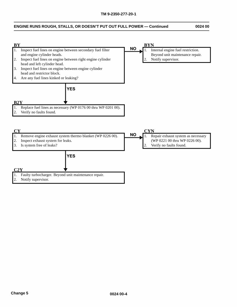
TM 9-2350-277-20-1
ENGINE RUNS ROUGH, STALLS, OR DOESN’T PUT OUT FULL POWER — Continued 0024 00
BY1. Inspect fuel lines on engine between secondary fuel filter
and engine cylinder heads.2. Inspect fuel lines on engine between right engine cylinder
head and left cylinder head.3. Inspect fuel lines on engine between engine cylinder
head and restrictor block.4. Are any fuel lines kinked or leaking?
BYN1. Internal engine fuel restriction.
Beyond unit maintenance repair.2. Notify supervisor.
B2Y1. Replace fuel lines as necessary (WP 0176 00 thru WP 0201 00).2. Verify no faults found.
CY1. Remove engine exhaust system thermo blanket (WP 0226 00).2. Inspect exhaust system for leaks.3. Is system free of leaks?
CYN1. Repair exhaust system as necessary
(WP 0221 00 thru WP 0226 00).2. Verify no faults found.
C2Y1. Faulty turbocharger. Beyond unit maintenance repair.2. Notify supervisor.
0024 00-4Change 5
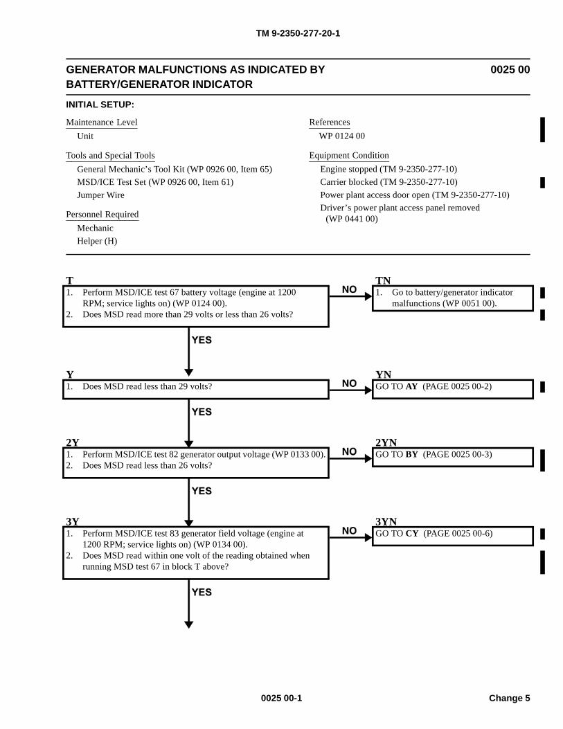
TM 9-2350-277-20-1
GENERATOR MALFUNCTIONS AS INDICATED BYBATTERY/GENERATOR INDICATOR
0025 00
INITIAL SETUP:
Maintenance LevelUnit
Tools and Special ToolsGeneral Mechanic’s Tool Kit (WP 0926 00, Item 65)MSD/ICE Test Set (WP 0926 00, Item 61)Jumper Wire
Personnel RequiredMechanicHelper (H)
ReferencesWP 0124 00
Equipment ConditionEngine stopped (TM 9-2350-277-10)Carrier blocked (TM 9-2350-277-10)Power plant access door open (TM 9-2350-277-10)Driver’s power plant access panel removed
(WP 0441 00)
T1. Perform MSD/ICE test 67 battery voltage (engine at 1200
RPM; service lights on) (WP 0124 00).2. Does MSD read more than 29 volts or less than 26 volts?
TN1. Go to battery/generator indicator
malfunctions (WP 0051 00).
Y1. Does MSD read less than 29 volts?
YNGO TO AY (PAGE 0025 00-2)
2Y1. Perform MSD/ICE test 82 generator output voltage (WP 0133 00).2. Does MSD read less than 26 volts?
2YNGO TO BY (PAGE 0025 00-3)
3Y1. Perform MSD/ICE test 83 generator field voltage (engine at
1200 RPM; service lights on) (WP 0134 00).2. Does MSD read within one volt of the reading obtained when
running MSD test 67 in block T above?
3YNGO TO CY (PAGE 0025 00-6)
0025 00-1 Change 5
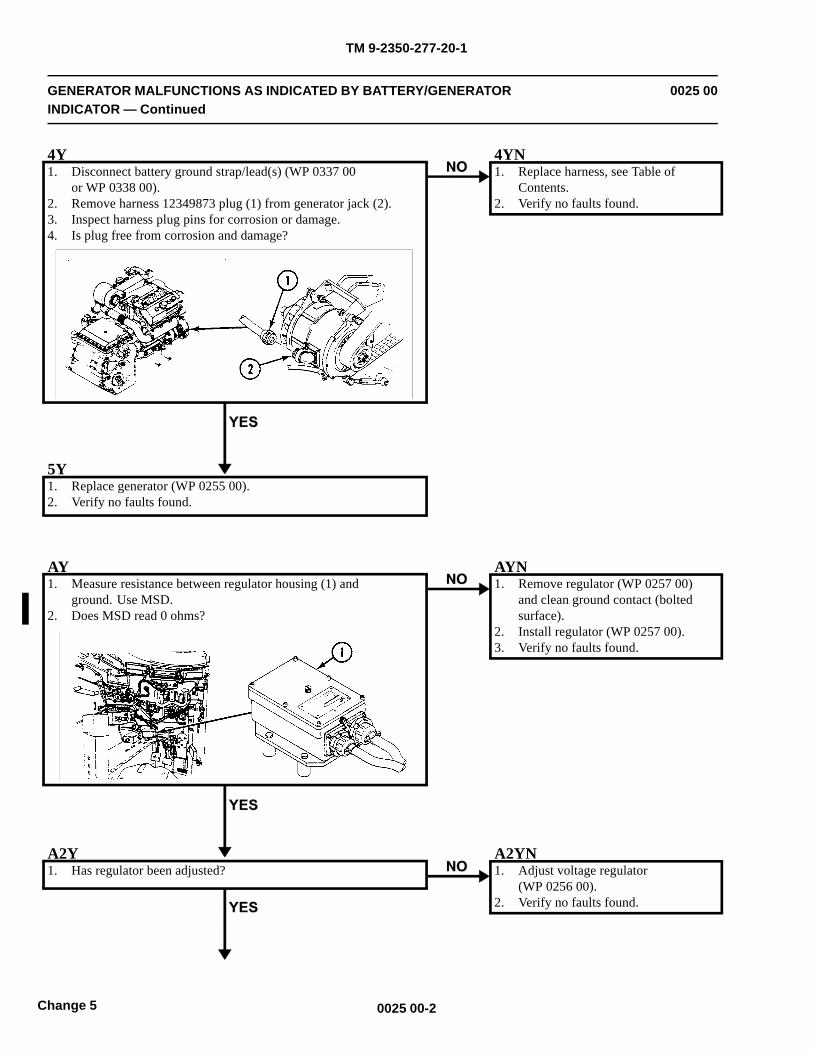
TM 9-2350-277-20-1
GENERATOR MALFUNCTIONS AS INDICATED BY BATTERY/GENERATORINDICATOR — Continued
0025 00
4Y1. Disconnect battery ground strap/lead(s) (WP 0337 00
or WP 0338 00).2. Remove harness 12349873 plug (1) from generator jack (2).3. Inspect harness plug pins for corrosion or damage.4. Is plug free from corrosion and damage?
4YN1. Replace harness, see Table of
Contents.2. Verify no faults found.
5Y1. Replace generator (WP 0255 00).2. Verify no faults found.
AY1. Measure resistance between regulator housing (1) and
ground. Use MSD.2. Does MSD read 0 ohms?
AYN1. Remove regulator (WP 0257 00)
and clean ground contact (boltedsurface).
2. Install regulator (WP 0257 00).3. Verify no faults found.
A2Y1. Has regulator been adjusted?
A2YN1. Adjust voltage regulator
(WP 0256 00).2. Verify no faults found.
0025 00-2Change 5
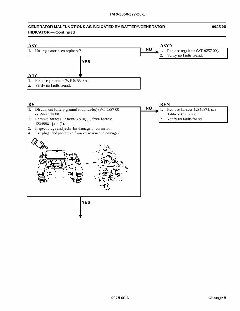
TM 9-2350-277-20-1
GENERATOR MALFUNCTIONS AS INDICATED BY BATTERY/GENERATORINDICATOR — Continued
0025 00
A3Y1. Has regulator been replaced?
A3YN1. Replace regulator (WP 0257 00).2. Verify no faults found.
A4Y1. Replace generator (WP 0255 00).2. Verify no faults found.
BY1. Disconnect battery ground strap/lead(s) (WP 0337 00
or WP 0338 00).2. Remove harness 12349873 plug (1) from harness
12349881 jack (2).3. Inspect plugs and jacks for damage or corrosion.4. Are plugs and jacks free from corrosion and damage?
BYN1. Replace harness 12349873, see
Table of Contents.2. Verify no faults found.
0025 00-3 Change 5
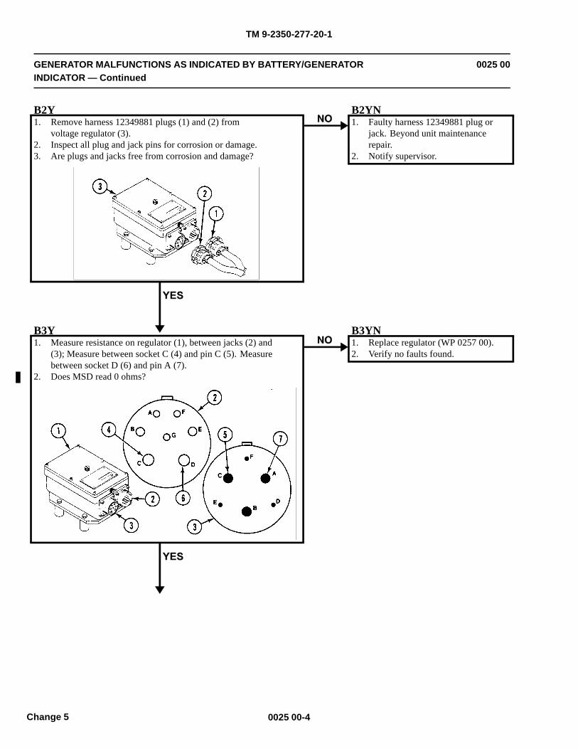
TM 9-2350-277-20-1
GENERATOR MALFUNCTIONS AS INDICATED BY BATTERY/GENERATORINDICATOR — Continued
0025 00
B2Y1. Remove harness 12349881 plugs (1) and (2) from
voltage regulator (3).2. Inspect all plug and jack pins for corrosion or damage.3. Are plugs and jacks free from corrosion and damage?
B2YN1. Faulty harness 12349881 plug or
jack. Beyond unit maintenancerepair.
2. Notify supervisor.
B3Y1. Measure resistance on regulator (1), between jacks (2) and
(3); Measure between socket C (4) and pin C (5). Measurebetween socket D (6) and pin A (7).
2. Does MSD read 0 ohms?
B3YN1. Replace regulator (WP 0257 00).2. Verify no faults found.
0025 00-4Change 5
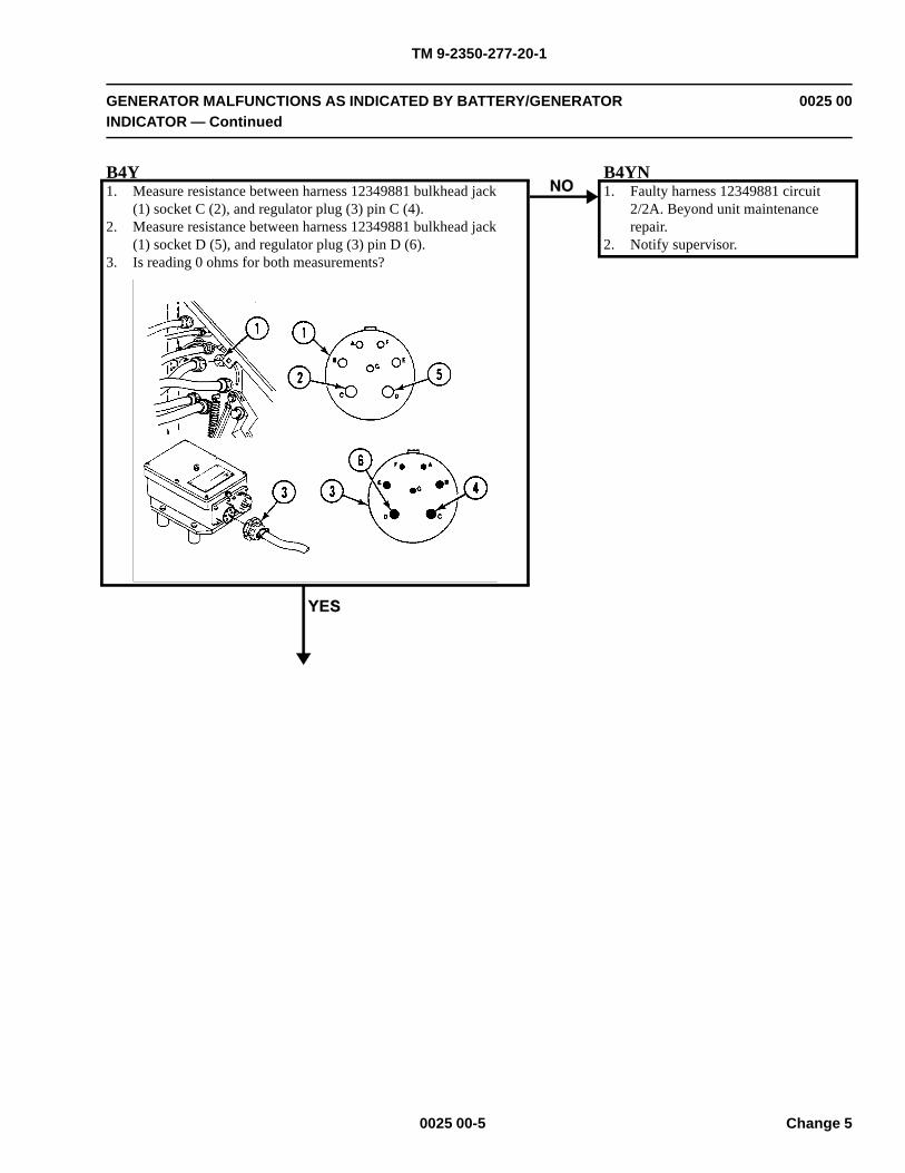
TM 9-2350-277-20-1
GENERATOR MALFUNCTIONS AS INDICATED BY BATTERY/GENERATORINDICATOR — Continued
0025 00
B4Y1. Measure resistance between harness 12349881 bulkhead jack
(1) socket C (2), and regulator plug (3) pin C (4).2. Measure resistance between harness 12349881 bulkhead jack
(1) socket D (5), and regulator plug (3) pin D (6).3. Is reading 0 ohms for both measurements?
B4YN1. Faulty harness 12349881 circuit
2/2A. Beyond unit maintenancerepair.
2. Notify supervisor.
0025 00-5 Change 5
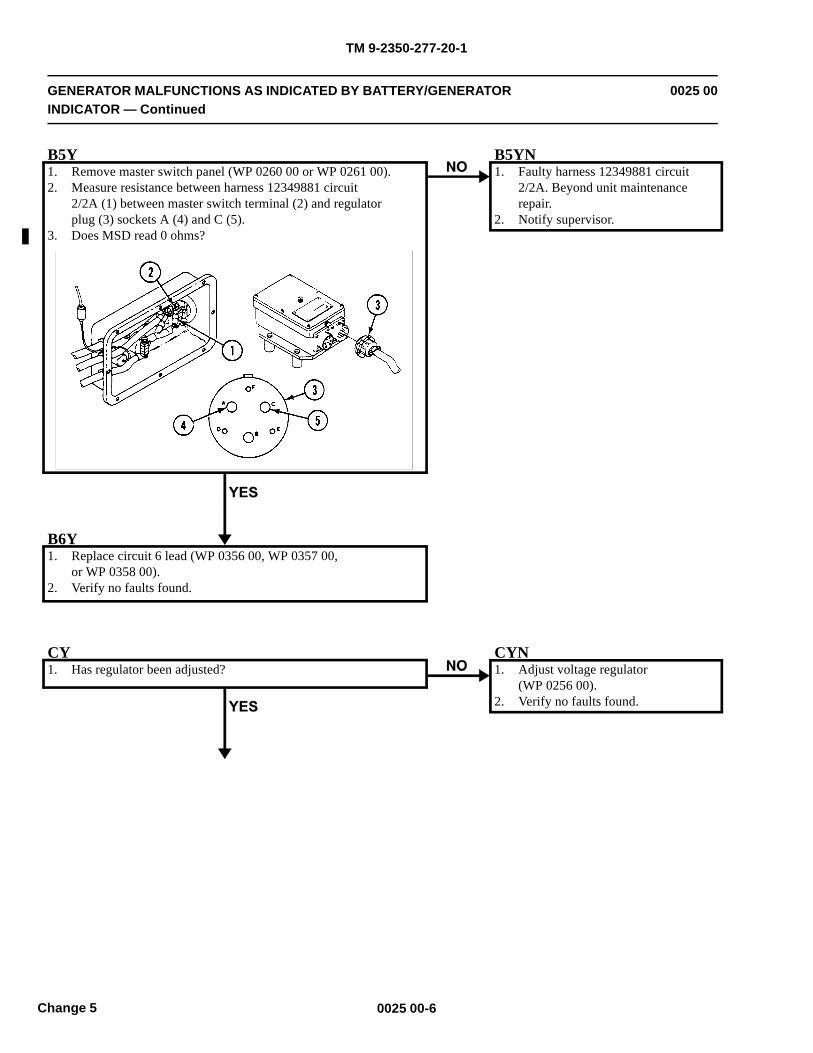
TM 9-2350-277-20-1
GENERATOR MALFUNCTIONS AS INDICATED BY BATTERY/GENERATORINDICATOR — Continued
0025 00
B5Y1. Remove master switch panel (WP 0260 00 or WP 0261 00).2. Measure resistance between harness 12349881 circuit
2/2A (1) between master switch terminal (2) and regulatorplug (3) sockets A (4) and C (5).
3. Does MSD read 0 ohms?
B5YN1. Faulty harness 12349881 circuit
2/2A. Beyond unit maintenancerepair.
2. Notify supervisor.
B6Y1. Replace circuit 6 lead (WP 0356 00, WP 0357 00,
or WP 0358 00).2. Verify no faults found.
CY1. Has regulator been adjusted?
CYN1. Adjust voltage regulator
(WP 0256 00).2. Verify no faults found.
0025 00-6Change 5
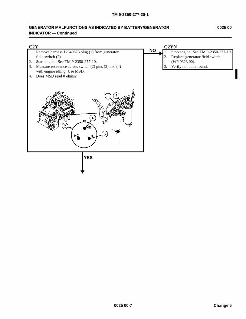
TM 9-2350-277-20-1
GENERATOR MALFUNCTIONS AS INDICATED BY BATTERY/GENERATORINDICATOR — Continued
0025 00
C2Y1. Remove harness 12349873 plug (1) from generator
field switch (2).2. Start engine. See TM 9-2350-277-10.3. Measure resistance across switch (2) pins (3) and (4)
with engine idling. Use MSD.4. Does MSD read 0 ohms?
C2YN1. Stop engine. See TM 9-2350-277-10.2. Replace generator field switch
(WP 0323 00).3. Verify no faults found.
0025 00-7 Change 5
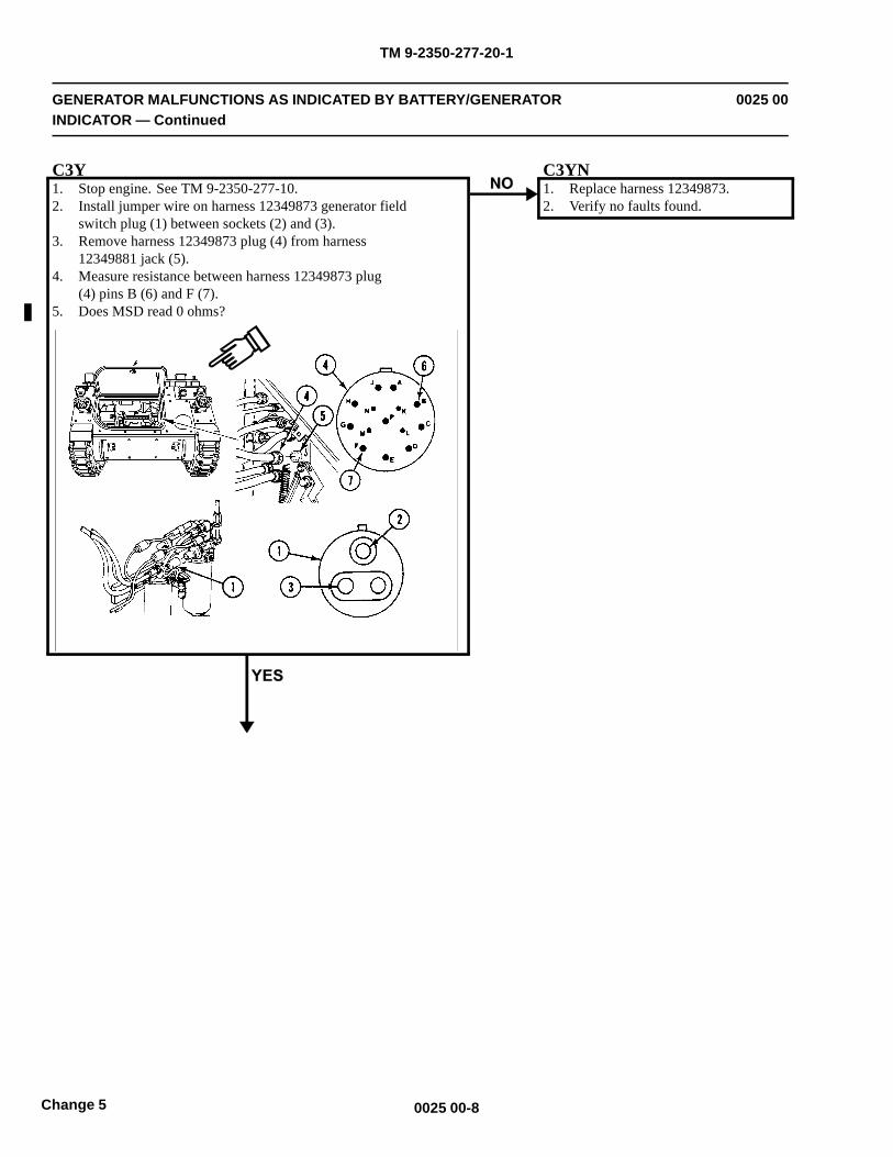
TM 9-2350-277-20-1
GENERATOR MALFUNCTIONS AS INDICATED BY BATTERY/GENERATORINDICATOR — Continued
0025 00
C3Y1. Stop engine. See TM 9-2350-277-10.2. Install jumper wire on harness 12349873 generator field
switch plug (1) between sockets (2) and (3).3. Remove harness 12349873 plug (4) from harness
12349881 jack (5).4. Measure resistance between harness 12349873 plug
(4) pins B (6) and F (7).5. Does MSD read 0 ohms?
C3YN1. Replace harness 12349873.2. Verify no faults found.
0025 00-8Change 5
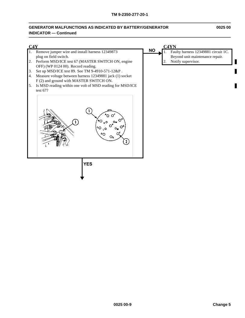
TM 9-2350-277-20-1
GENERATOR MALFUNCTIONS AS INDICATED BY BATTERY/GENERATORINDICATOR — Continued
0025 00
C4Y1. Remove jumper wire and install harness 12349873
plug on field switch.2. Perform MSD/ICE test 67 (MASTER SWITCH ON, engine
OFF) (WP 0124 00). Record reading.3. Set up MSD/ICE test 89. See TM 9-4910-571-12&P .4. Measure voltage between harness 12349881 jack (1) socket
F (2) and ground with MASTER SWITCH ON.5. Is MSD reading within one volt of MSD reading for MSD/ICE
test 67?
C4YN1. Faulty harness 12349881 circuit 1C.
Beyond unit maintenance repair.2. Notify supervisor.
0025 00-9 Change 5
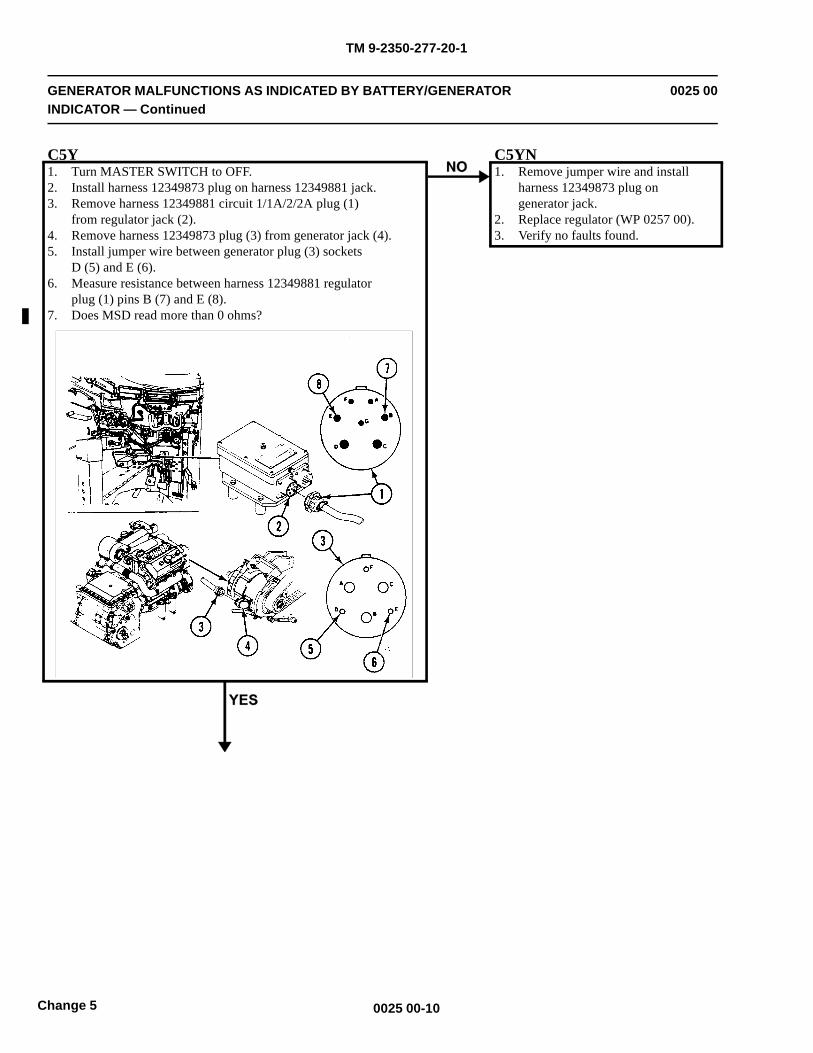
TM 9-2350-277-20-1
GENERATOR MALFUNCTIONS AS INDICATED BY BATTERY/GENERATORINDICATOR — Continued
0025 00
C5Y1. Turn MASTER SWITCH to OFF.2. Install harness 12349873 plug on harness 12349881 jack.3. Remove harness 12349881 circuit 1/1A/2/2A plug (1)
from regulator jack (2).4. Remove harness 12349873 plug (3) from generator jack (4).5. Install jumper wire between generator plug (3) sockets
D (5) and E (6).6. Measure resistance between harness 12349881 regulator
plug (1) pins B (7) and E (8).7. Does MSD read more than 0 ohms?
C5YN1. Remove jumper wire and install
harness 12349873 plug ongenerator jack.
2. Replace regulator (WP 0257 00).3. Verify no faults found.
0025 00-10Change 5
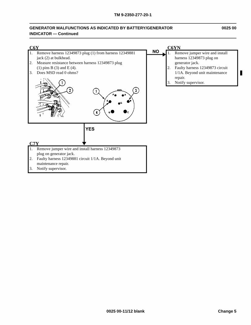
TM 9-2350-277-20-1
GENERATOR MALFUNCTIONS AS INDICATED BY BATTERY/GENERATORINDICATOR — Continued
0025 00
C6Y1. Remove harness 12349873 plug (1) from harness 12349881
jack (2) at bulkhead.2. Measure resistance between harness 12349873 plug
(1) pins B (3) and E (4).3. Does MSD read 0 ohms?
C6YN1. Remove jumper wire and install
harness 12349873 plug ongenerator jack.
2. Faulty harness 12349873 circuit1/1A. Beyond unit maintenancerepair.
3. Notify supervisor.
C7Y1. Remove jumper wire and install harness 12349873
plug on generator jack.2. Faulty harness 12349881 circuit 1/1A. Beyond unit
maintenance repair.3. Notify supervisor.
0025 00-11/12 blank Change 5

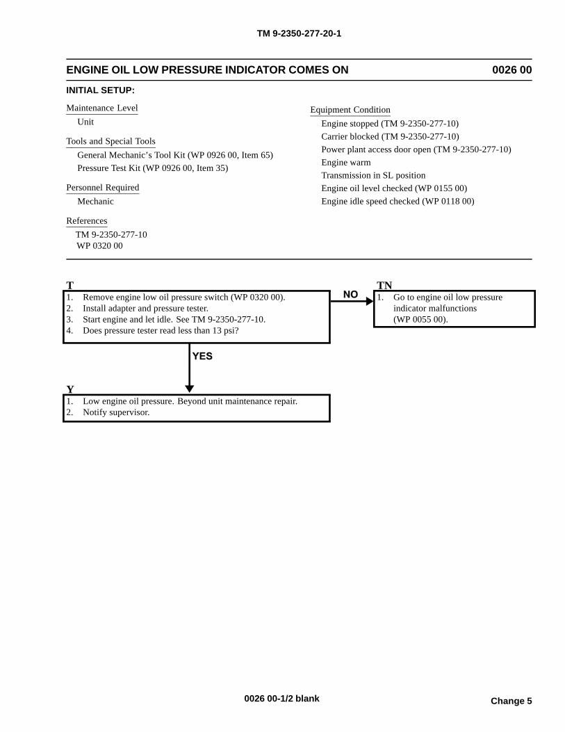
TM 9-2350-277-20-1
ENGINE OIL LOW PRESSURE INDICATOR COMES ON 0026 00
INITIAL SETUP:
Maintenance LevelUnit
Tools and Special ToolsGeneral Mechanic’s Tool Kit (WP 0926 00, Item 65)Pressure Test Kit (WP 0926 00, Item 35)
Personnel RequiredMechanic
ReferencesTM 9-2350-277-10WP 0320 00
Equipment ConditionEngine stopped (TM 9-2350-277-10)Carrier blocked (TM 9-2350-277-10)Power plant access door open (TM 9-2350-277-10)Engine warmTransmission in SL positionEngine oil level checked (WP 0155 00)Engine idle speed checked (WP 0118 00)
T1. Remove engine low oil pressure switch (WP 0320 00).2. Install adapter and pressure tester.3. Start engine and let idle. See TM 9-2350-277-10.4. Does pressure tester read less than 13 psi?
TN1. Go to engine oil low pressure
indicator malfunctions(WP 0055 00).
Y1. Low engine oil pressure. Beyond unit maintenance repair.2. Notify supervisor.
Change 50026 00-1/2 blank

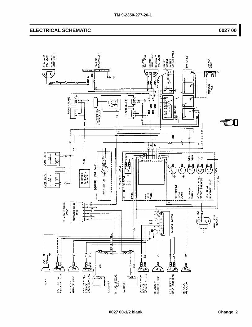
TM 9-2350-277-20-1
ELECTRICAL SCHEMATIC 0027 00
0027 00-1/2 blank Change 2

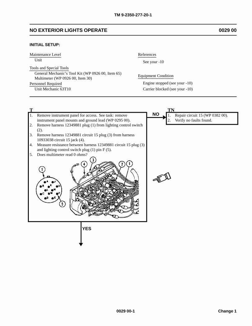
TM 9-2350-277-20-1
NO EXTERIOR LIGHTS OPERATE 0029 00
INITIAL SETUP:
Maintenance LevelUnit
Tools and Special ToolsGeneral Mechanic’s Tool Kit (WP 0926 00, Item 65)Multimeter (WP 0926 00, Item 30)
Personnel RequiredUnit Mechanic 63T10
References
See your -10
Equipment Condition
Engine stopped (see your -10)
Carrier blocked (see your -10)
T1. Remove instrument panel for access. See task: remove
instrument panel mounts and ground lead (WP 0295 00).2. Remove harness 12349881 plug (1) from lighting control switch
(2).3. Remove harness 12349881 circuit 15 plug (3) from harness
10933038 circuit 15 jack (4).4. Measure resistance between harness 12349881 circuit 15 plug (3)
and lighting control switch plug (1) pin F (5).5. Does multimeter read 0 ohms?
YES
NOTN1. Repair circuit 15 (WP 0382 00).2. Verify no faults found.
0029 00-1 Change 1
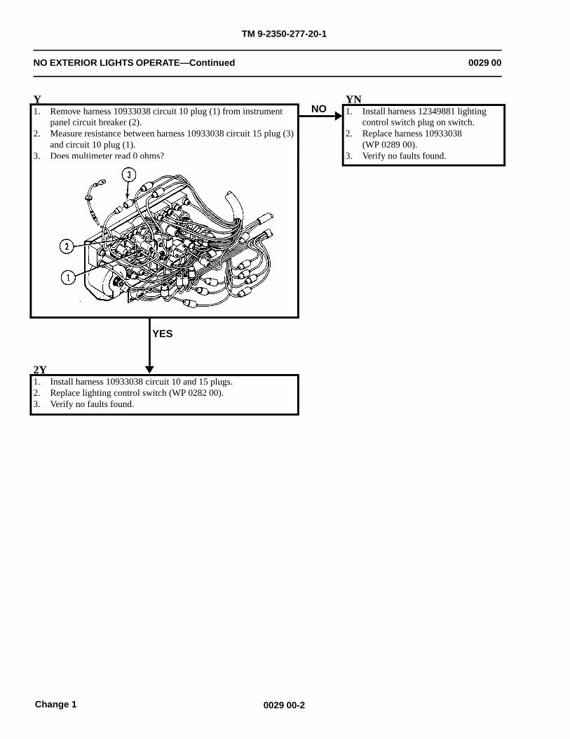
TM 9-2350-277-20-1
NO EXTERIOR LIGHTS OPERATE—Continued 0029 00
Y1. Remove harness 10933038 circuit 10 plug (1) from instrument
panel circuit breaker (2).2. Measure resistance between harness 10933038 circuit 15 plug (3)
and circuit 10 plug (1).3. Does multimeter read 0 ohms?
YES
NOYN1. Install harness 12349881 lighting
control switch plug on switch.2. Replace harness 10933038
(WP 0289 00).3. Verify no faults found.
2Y1. Install harness 10933038 circuit 10 and 15 plugs.2. Replace lighting control switch (WP 0282 00).3. Verify no faults found.
0029 00-2Change 1
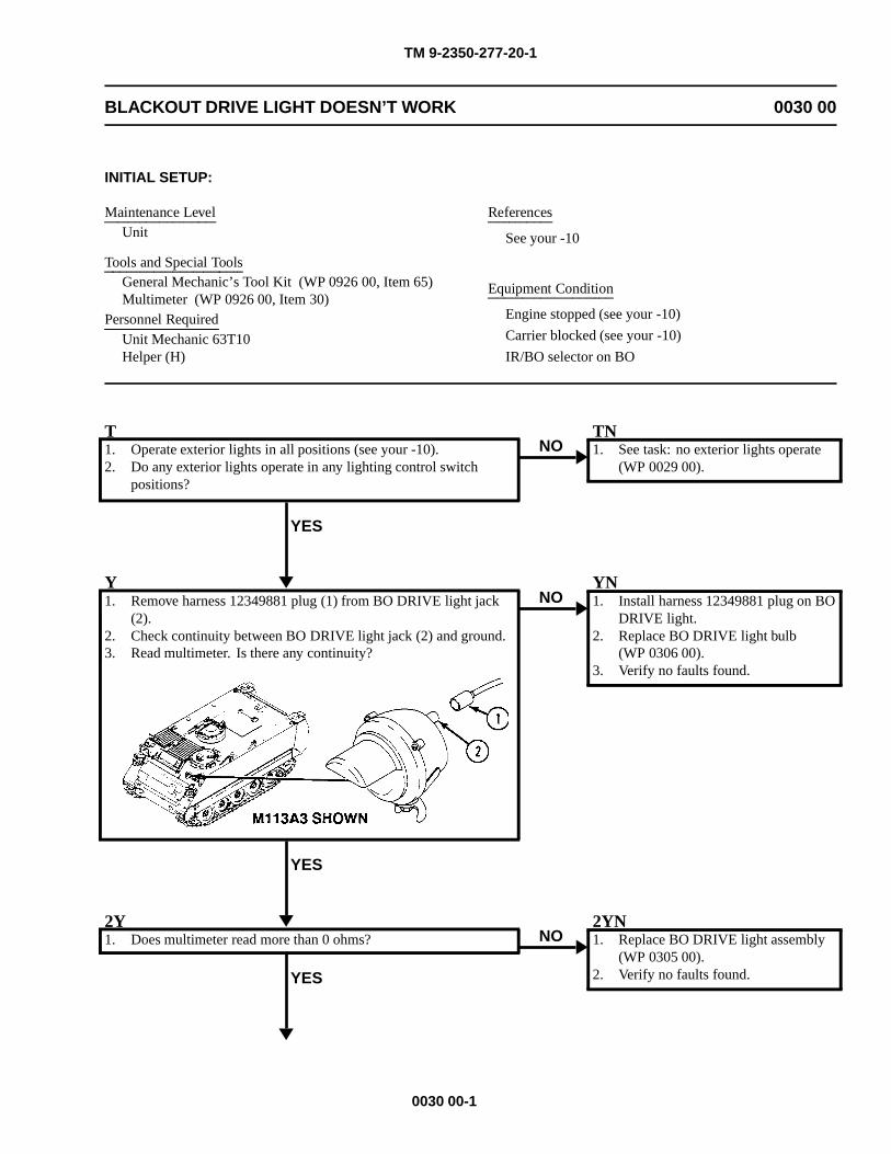
TM 9-2350-277-20-1
BLACKOUT DRIVE LIGHT DOESN’T WORK 0030 00
INITIAL SETUP:
Maintenance LevelUnit
Tools and Special ToolsGeneral Mechanic’s Tool Kit (WP 0926 00, Item 65)Multimeter (WP 0926 00, Item 30)
Personnel RequiredUnit Mechanic 63T10Helper (H)
References
See your -10
Equipment Condition
Engine stopped (see your -10)
Carrier blocked (see your -10)
IR/BO selector on BO
T1. Operate exterior lights in all positions (see your -10).2. Do any exterior lights operate in any lighting control switch
positions?
YES
NOTN1. See task: no exterior lights operate
(WP 0029 00).
Y1. Remove harness 12349881 plug (1) from BO DRIVE light jack
(2).2. Check continuity between BO DRIVE light jack (2) and ground.3. Read multimeter. Is there any continuity?
YES
NOYN1. Install harness 12349881 plug on BO
DRIVE light.2. Replace BO DRIVE light bulb
(WP 0306 00).3. Verify no faults found.
2Y1. Does multimeter read more than 0 ohms?
YES
NO2YN1. Replace BO DRIVE light assembly
(WP 0305 00).2. Verify no faults found.
0030 00-1
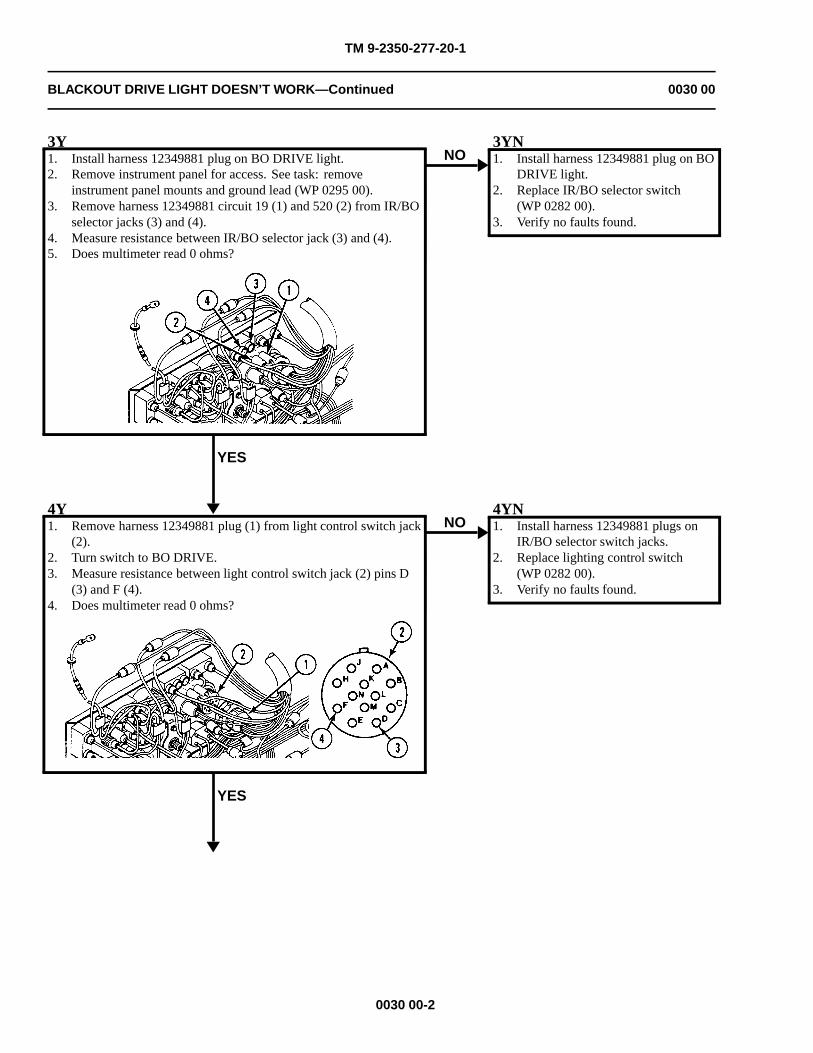
TM 9-2350-277-20-1
BLACKOUT DRIVE LIGHT DOESN’T WORK—Continued 0030 00
3Y1. Install harness 12349881 plug on BO DRIVE light.2. Remove instrument panel for access. See task: remove
instrument panel mounts and ground lead (WP 0295 00).3. Remove harness 12349881 circuit 19 (1) and 520 (2) from IR/BO
selector jacks (3) and (4).4. Measure resistance between IR/BO selector jack (3) and (4).5. Does multimeter read 0 ohms?
YES
NO3YN1. Install harness 12349881 plug on BO
DRIVE light.2. Replace IR/BO selector switch
(WP 0282 00).3. Verify no faults found.
4Y1. Remove harness 12349881 plug (1) from light control switch jack
(2).2. Turn switch to BO DRIVE.3. Measure resistance between light control switch jack (2) pins D
(3) and F (4).4. Does multimeter read 0 ohms?
YES
NO4YN1. Install harness 12349881 plugs on
IR/BO selector switch jacks.2. Replace lighting control switch
(WP 0282 00).3. Verify no faults found.
0030 00-2
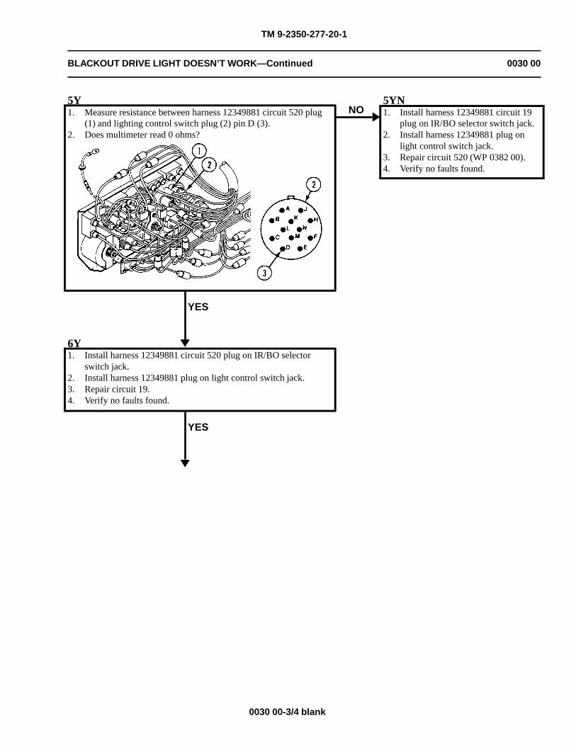
TM 9-2350-277-20-1
BLACKOUT DRIVE LIGHT DOESN’T WORK—Continued 0030 00
5Y1. Measure resistance between harness 12349881 circuit 520 plug
(1) and lighting control switch plug (2) pin D (3).2. Does multimeter read 0 ohms?
YES
NO5YN1. Install harness 12349881 circuit 19
plug on IR/BO selector switch jack.2. Install harness 12349881 plug on
light control switch jack.3. Repair circuit 520 (WP 0382 00).4. Verify no faults found.
6Y1. Install harness 12349881 circuit 520 plug on IR/BO selector
switch jack.2. Install harness 12349881 plug on light control switch jack.3. Repair circuit 19.4. Verify no faults found.
YES
0030 00-3/4 blank

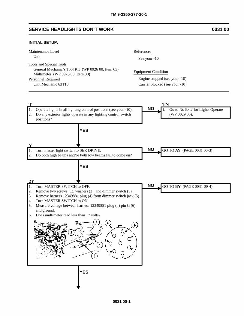
TM 9-2350-277-20-1
SERVICE HEADLIGHTS DON’T WORK 0031 00
INITIAL SETUP:
Maintenance LevelUnit
Tools and Special ToolsGeneral Mechanic’s Tool Kit (WP 0926 00, Item 65)Multimeter (WP 0926 00, Item 30)
Personnel RequiredUnit Mechanic 63T10
References
See your -10
Equipment Condition
Engine stopped (see your -10)
Carrier blocked (see your -10)
T1. Operate lights in all lighting control positions (see your -10).2. Do any exterior lights operate in any lighting control switch
positions?
YES
NOTN1. Go to No Exterior Lights Operate
(WP 0029 00).
Y1. Turn master light switch to SER DRIVE.2. Do both high beams and/or both low beams fail to come on?
YES
NO GO TO AY (PAGE 0031 00-3)
2Y1. Turn MASTER SWITCH to OFF.2. Remove two screws (1), washers (2), and dimmer switch (3).3. Remove harness 12349881 plug (4) from dimmer switch jack (5).4. Turn MASTER SWITCH to ON.5. Measure voltage between harness 12349881 plug (4) pin G (6)
and ground.6. Does multimeter read less than 17 volts?
YES
NO GO TO BY (PAGE 0031 00-4)
0031 00-1
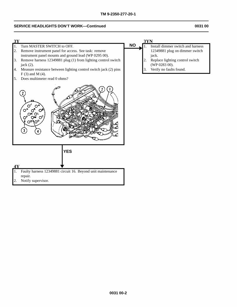
TM 9-2350-277-20-1
SERVICE HEADLIGHTS DON’T WORK—Continued 0031 00
3Y1. Turn MASTER SWITCH to OFF.2. Remove instrument panel for access. See task: remove
instrument panel mounts and ground lead (WP 0295 00).3. Remove harness 12349881 plug (1) from lighting control switch
jack (2).4. Measure resistance between lighting control switch jack (2) pins
F (3) and M (4).5. Does multimeter read 0 ohms?
YES
NO3YN1. Install dimmer switch and harness
12349881 plug on dimmer switchjack.
2. Replace lighting control switch(WP 0283 00).
3. Verify no faults found.
4Y1. Faulty harness 12349881 circuit 16. Beyond unit maintenance
repair.2. Notify supervisor.
0031 00-2
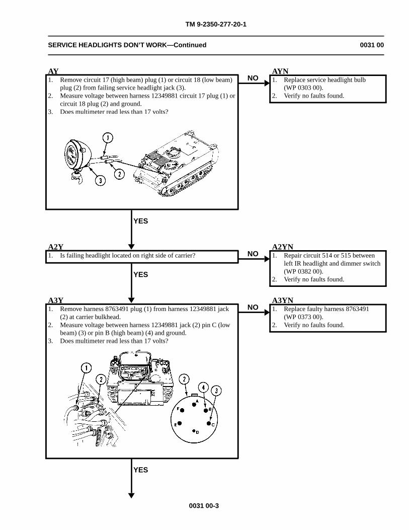
TM 9-2350-277-20-1
SERVICE HEADLIGHTS DON’T WORK—Continued 0031 00
AY1. Remove circuit 17 (high beam) plug (1) or circuit 18 (low beam)
plug (2) from failing service headlight jack (3).2. Measure voltage between harness 12349881 circuit 17 plug (1) or
circuit 18 plug (2) and ground.3. Does multimeter read less than 17 volts?
YES
NOAYN1. Replace service headlight bulb
(WP 0303 00).2. Verify no faults found.
A2Y1. Is failing headlight located on right side of carrier?
YES
NOA2YN1. Repair circuit 514 or 515 between
left IR headlight and dimmer switch(WP 0382 00).
2. Verify no faults found.
A3Y1. Remove harness 8763491 plug (1) from harness 12349881 jack
(2) at carrier bulkhead.2. Measure voltage between harness 12349881 jack (2) pin C (low
beam) (3) or pin B (high beam) (4) and ground.3. Does multimeter read less than 17 volts?
YES
NOA3YN1. Replace faulty harness 8763491
(WP 0373 00).2. Verify no faults found.
0031 00-3
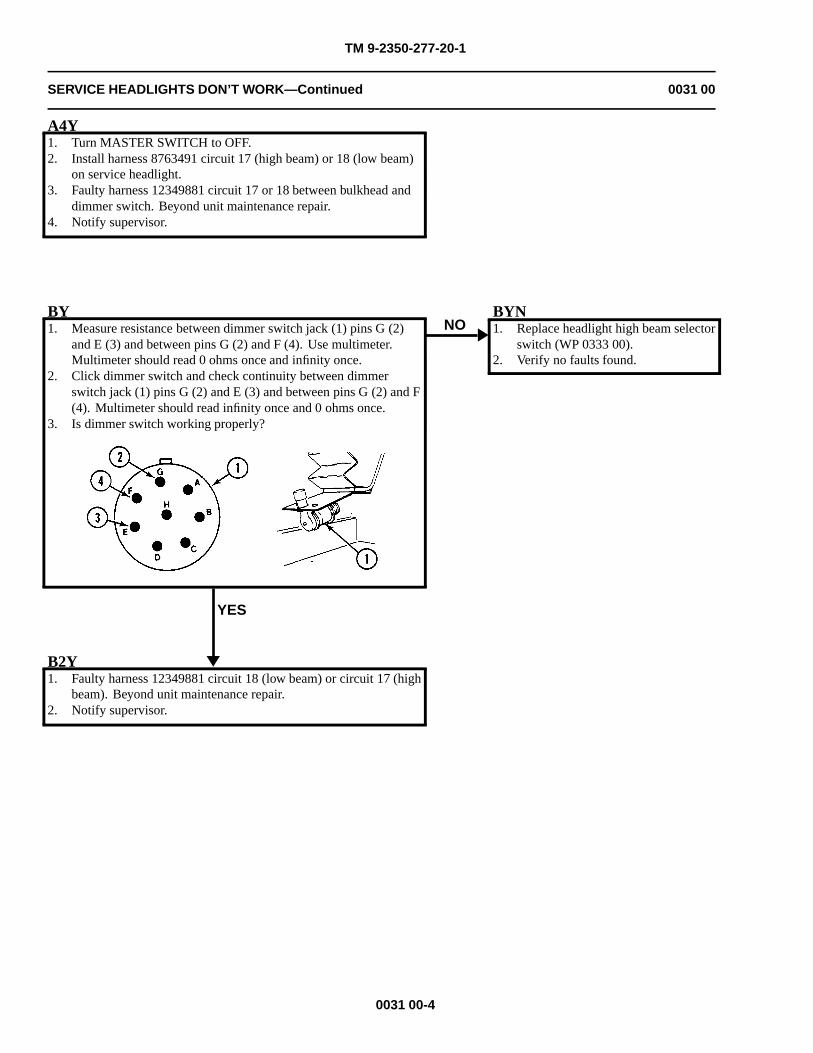
TM 9-2350-277-20-1
SERVICE HEADLIGHTS DON’T WORK—Continued 0031 00
A4Y1. Turn MASTER SWITCH to OFF.2. Install harness 8763491 circuit 17 (high beam) or 18 (low beam)
on service headlight.3. Faulty harness 12349881 circuit 17 or 18 between bulkhead and
dimmer switch. Beyond unit maintenance repair.4. Notify supervisor.
BY1. Measure resistance between dimmer switch jack (1) pins G (2)
and E (3) and between pins G (2) and F (4). Use multimeter.Multimeter should read 0 ohms once and infinity once.
2. Click dimmer switch and check continuity between dimmerswitch jack (1) pins G (2) and E (3) and between pins G (2) and F(4). Multimeter should read infinity once and 0 ohms once.
3. Is dimmer switch working properly?
YES
NOBYN1. Replace headlight high beam selector
switch (WP 0333 00).2. Verify no faults found.
B2Y1. Faulty harness 12349881 circuit 18 (low beam) or circuit 17 (high
beam). Beyond unit maintenance repair.2. Notify supervisor.
0031 00-4
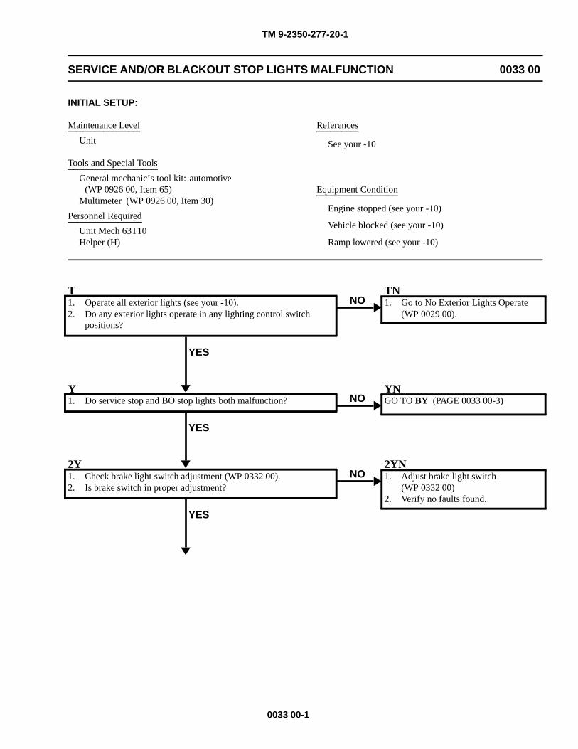
TM 9-2350-277-20-1
SERVICE AND/OR BLACKOUT STOP LIGHTS MALFUNCTION 0033 00
INITIAL SETUP:
Maintenance Level
Unit
Tools and Special Tools
General mechanic’s tool kit: automotive(WP 0926 00, Item 65)
Multimeter (WP 0926 00, Item 30)
Personnel Required
Unit Mech 63T10Helper (H)
References
See your -10
Equipment Condition
Engine stopped (see your -10)
Vehicle blocked (see your -10)
Ramp lowered (see your -10)
T1. Operate all exterior lights (see your -10).2. Do any exterior lights operate in any lighting control switch
positions?
YES
NOTN1. Go to No Exterior Lights Operate
(WP 0029 00).
Y1. Do service stop and BO stop lights both malfunction?
YES
NOYNGO TO BY (PAGE 0033 00-3)
2Y1. Check brake light switch adjustment (WP 0332 00).2. Is brake switch in proper adjustment?
YES
NO2YN1. Adjust brake light switch
(WP 0332 00)2. Verify no faults found.
0033 00-1
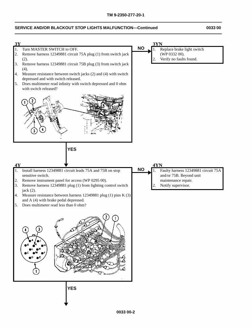
TM 9-2350-277-20-1
SERVICE AND/OR BLACKOUT STOP LIGHTS MALFUNCTION—Continued 0033 00
3Y1. Turn MASTER SWITCH to OFF.2. Remove harness 12349881 circuit 75A plug (1) from switch jack
(2).3. Remove harness 12349881 circuit 75B plug (3) from switch jack
(4).4. Measure resistance between switch jacks (2) and (4) with switch
depressed and with switch released.5. Does multimeter read infinity with switch depressed and 0 ohm
with switch released?
YES
NO3YN1. Replace brake light switch
(WP 0332 00).2. Verify no faults found.
4Y1. Install harness 12349881 circuit leads 75A and 75B on stop
sensitive switch.2. Remove instrument panel for access (WP 0295 00).3. Remove harness 12349881 plug (1) from lighting control switch
jack (2).4. Measure resistance between harness 12349881 plug (1) pins K (3)
and A (4) with brake pedal depressed.5. Does multimeter read less than 0 ohm?
YES
NO4YN1. Faulty harness 12349881 circuit 75A
and/or 75B. Beyond unitmaintenance repair.
2. Notify supervisor.
0033 00-2
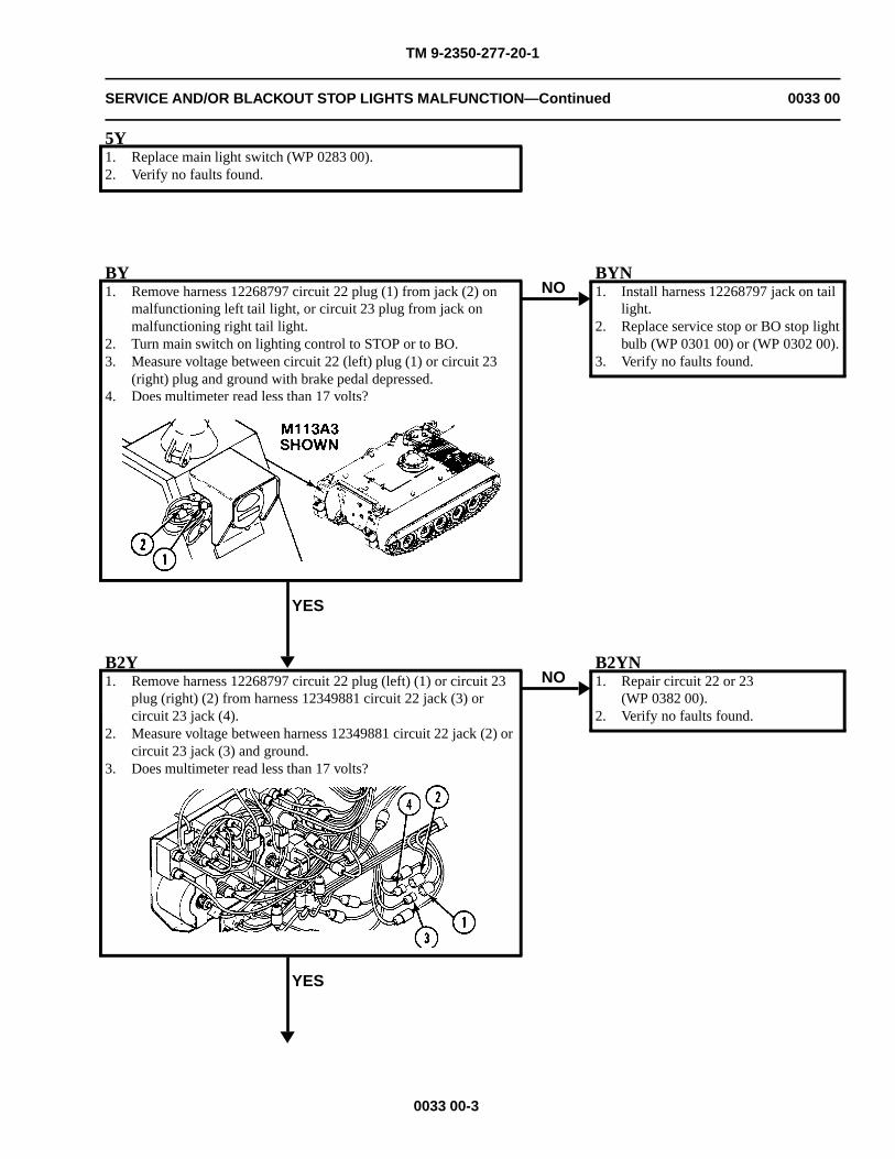
TM 9-2350-277-20-1
SERVICE AND/OR BLACKOUT STOP LIGHTS MALFUNCTION—Continued 0033 00
5Y1. Replace main light switch (WP 0283 00).2. Verify no faults found.
BY1. Remove harness 12268797 circuit 22 plug (1) from jack (2) on
malfunctioning left tail light, or circuit 23 plug from jack onmalfunctioning right tail light.
2. Turn main switch on lighting control to STOP or to BO.3. Measure voltage between circuit 22 (left) plug (1) or circuit 23
(right) plug and ground with brake pedal depressed.4. Does multimeter read less than 17 volts?
YES
NOBYN1. Install harness 12268797 jack on tail
light.2. Replace service stop or BO stop light
bulb (WP 0301 00) or (WP 0302 00).3. Verify no faults found.
B2Y1. Remove harness 12268797 circuit 22 plug (left) (1) or circuit 23
plug (right) (2) from harness 12349881 circuit 22 jack (3) orcircuit 23 jack (4).
2. Measure voltage between harness 12349881 circuit 22 jack (2) orcircuit 23 jack (3) and ground.
3. Does multimeter read less than 17 volts?
YES
NOB2YN1. Repair circuit 22 or 23
(WP 0382 00).2. Verify no faults found.
0033 00-3
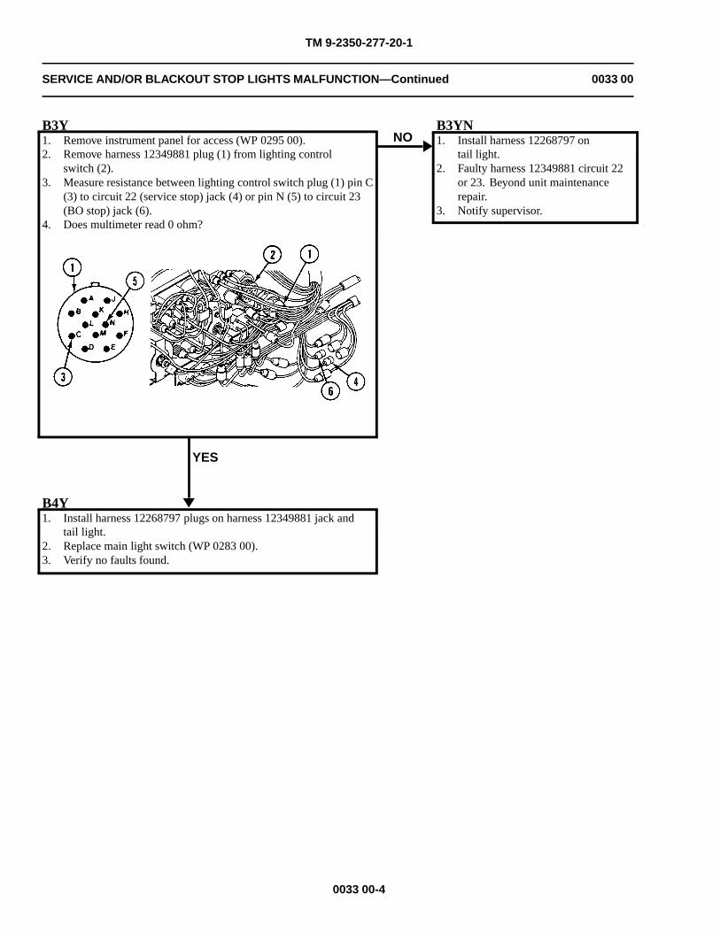
TM 9-2350-277-20-1
SERVICE AND/OR BLACKOUT STOP LIGHTS MALFUNCTION—Continued 0033 00
B3Y1. Remove instrument panel for access (WP 0295 00).2. Remove harness 12349881 plug (1) from lighting control
switch (2).3. Measure resistance between lighting control switch plug (1) pin C
(3) to circuit 22 (service stop) jack (4) or pin N (5) to circuit 23(BO stop) jack (6).
4. Does multimeter read 0 ohm?
YES
NOB3YN1. Install harness 12268797 on
tail light.2. Faulty harness 12349881 circuit 22
or 23. Beyond unit maintenancerepair.
3. Notify supervisor.
B4Y1. Install harness 12268797 plugs on harness 12349881 jack and
tail light.2. Replace main light switch (WP 0283 00).3. Verify no faults found.
0033 00-4
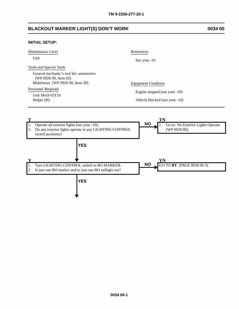
TM 9-2350-277-20-1
BLACKOUT MARKER LIGHT(S) DON’T WORK 0034 00
INITIAL SETUP:
Maintenance Level
Unit
Tools and Special Tools
General mechanic’s tool kit: automotive(WP 0926 00, Item 65)
Multimeter (WP 0926 00, Item 30)
Personnel Required
Unit Mech 63T10Helper (H)
References
See your -10
Equipment Condition
Engine stopped (see your -10)
Vehicle blocked (see your -10)
T1. Operate all exterior lights (see your -10).2. Do any exterior lights operate in any LIGHTING CONTROL
switch positions?
YES
NOTN1. Go to: No Exterior Lights Operate
(WP 0029 00).
Y1. Turn LIGHTING CONTROL switch to BO MARKER.2. Is just one BO marker and/or just one BO taillight out?
YES
NOYNGO TO BY (PAGE 0034 00-3)
0034 00-1
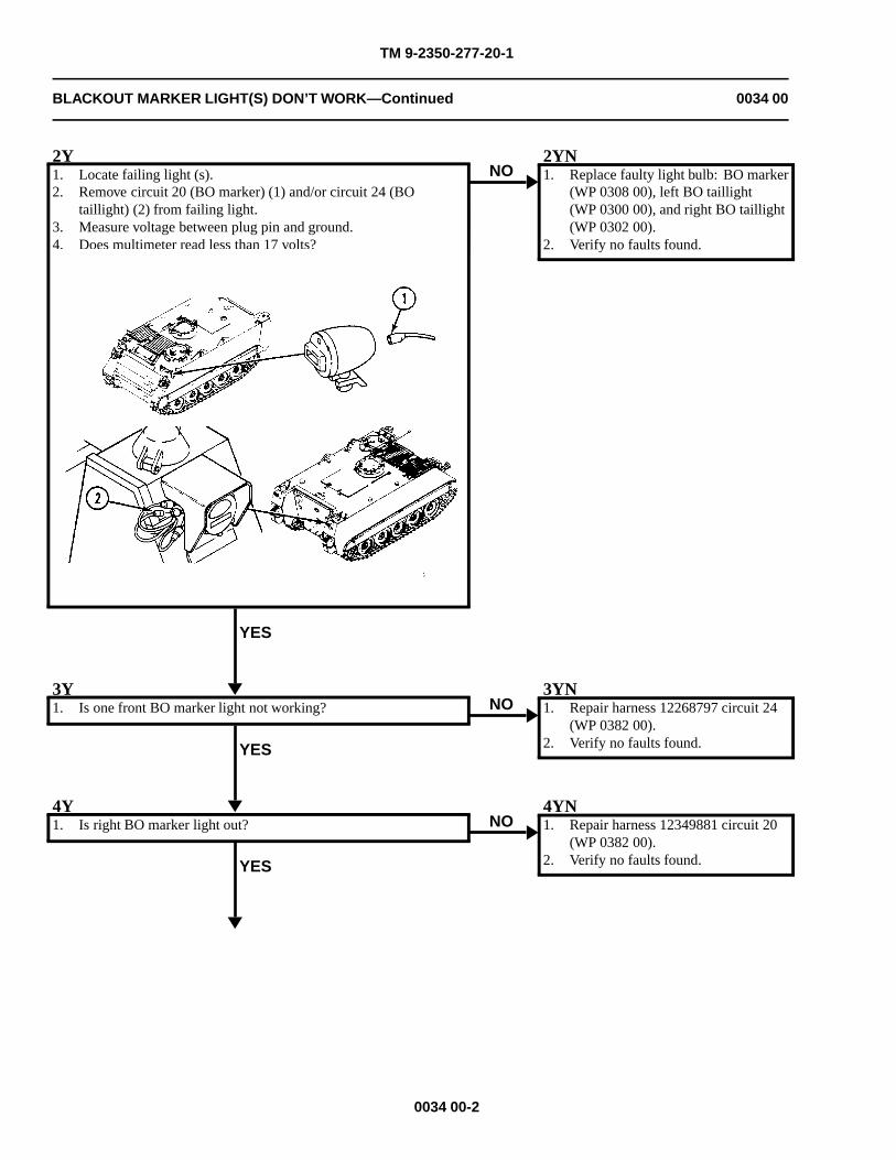
TM 9-2350-277-20-1
BLACKOUT MARKER LIGHT(S) DON’T WORK—Continued 0034 00
2Y1. Locate failing light (s).2. Remove circuit 20 (BO marker) (1) and/or circuit 24 (BO
taillight) (2) from failing light.3. Measure voltage between plug pin and ground.4. Does multimeter read less than 17 volts?
YES
NO2YN1. Replace faulty light bulb: BO marker
(WP 0308 00), left BO taillight(WP 0300 00), and right BO taillight(WP 0302 00).
2. Verify no faults found.
3Y1. Is one front BO marker light not working?
YES
NO3YN1. Repair harness 12268797 circuit 24
(WP 0382 00).2. Verify no faults found.
4Y1. Is right BO marker light out?
YES
NO4YN1. Repair harness 12349881 circuit 20
(WP 0382 00).2. Verify no faults found.
0034 00-2
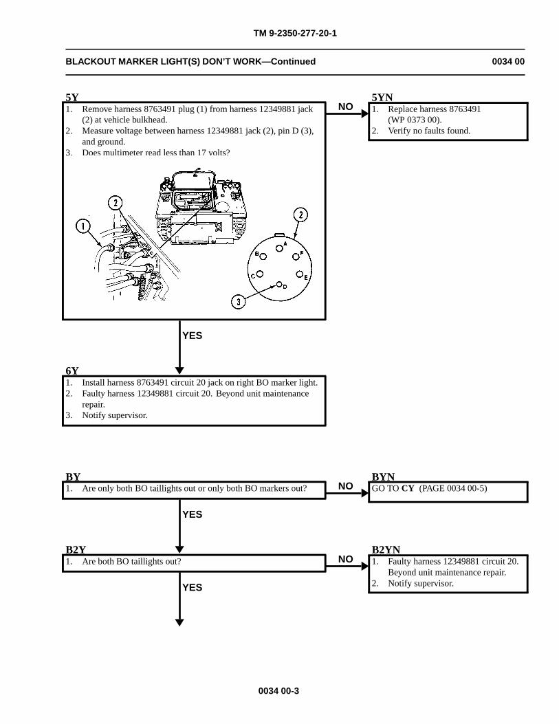
TM 9-2350-277-20-1
BLACKOUT MARKER LIGHT(S) DON’T WORK—Continued 0034 00
5Y1. Remove harness 8763491 plug (1) from harness 12349881 jack
(2) at vehicle bulkhead.2. Measure voltage between harness 12349881 jack (2), pin D (3),
and ground.3. Does multimeter read less than 17 volts?
YES
NO5YN1. Replace harness 8763491
(WP 0373 00).2. Verify no faults found.
6Y1. Install harness 8763491 circuit 20 jack on right BO marker light.2. Faulty harness 12349881 circuit 20. Beyond unit maintenance
repair.3. Notify supervisor.
BY1. Are only both BO taillights out or only both BO markers out?
YES
NOBYNGO TO CY (PAGE 0034 00-5)
B2Y1. Are both BO taillights out?
YES
NOB2YN1. Faulty harness 12349881 circuit 20.
Beyond unit maintenance repair.2. Notify supervisor.
0034 00-3
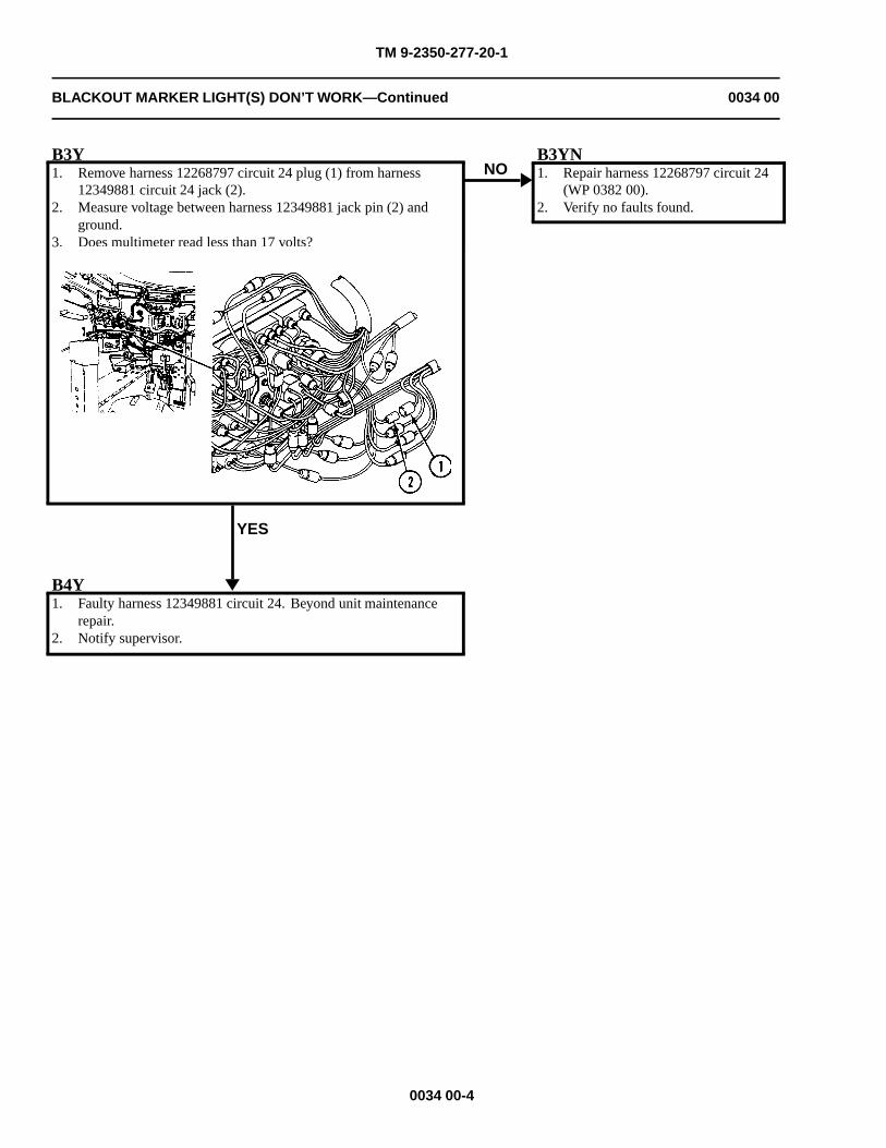
TM 9-2350-277-20-1
BLACKOUT MARKER LIGHT(S) DON’T WORK—Continued 0034 00
B3Y1. Remove harness 12268797 circuit 24 plug (1) from harness
12349881 circuit 24 jack (2).2. Measure voltage between harness 12349881 jack pin (2) and
ground.3. Does multimeter read less than 17 volts?
YES
NOB3YN1. Repair harness 12268797 circuit 24
(WP 0382 00).2. Verify no faults found.
B4Y1. Faulty harness 12349881 circuit 24. Beyond unit maintenance
repair.2. Notify supervisor.
0034 00-4
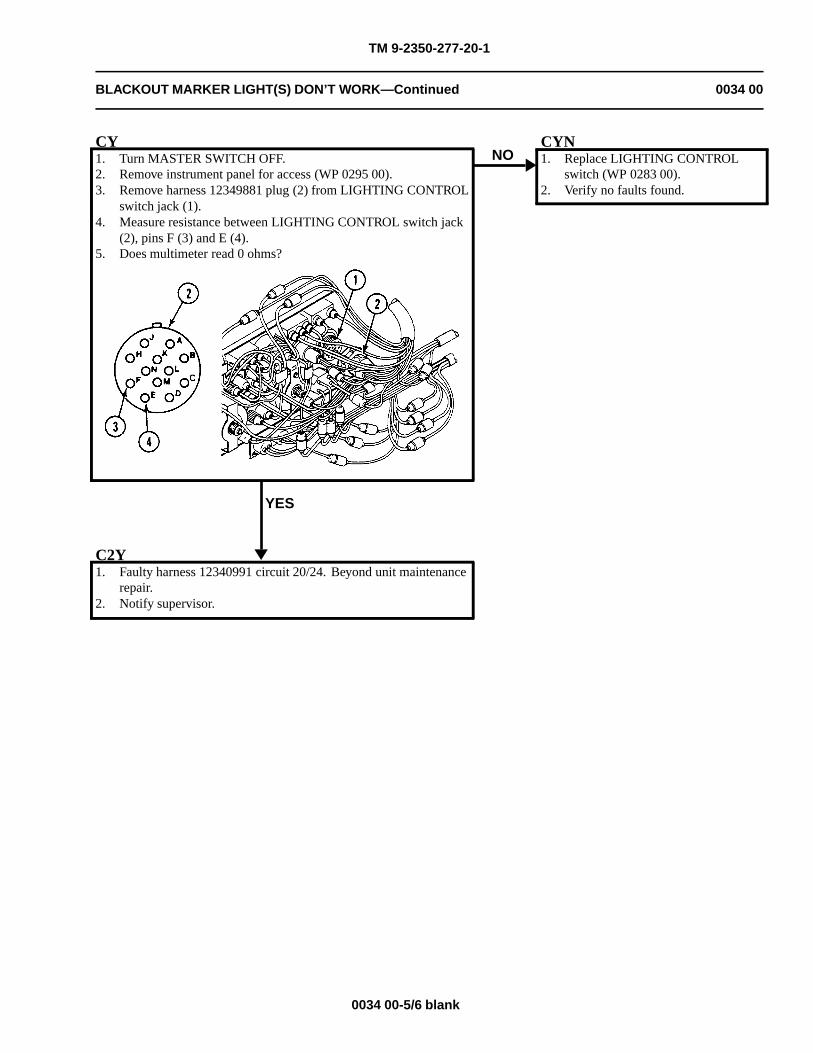
TM 9-2350-277-20-1
BLACKOUT MARKER LIGHT(S) DON’T WORK—Continued 0034 00
CY1. Turn MASTER SWITCH OFF.2. Remove instrument panel for access (WP 0295 00).3. Remove harness 12349881 plug (2) from LIGHTING CONTROL
switch jack (1).4. Measure resistance between LIGHTING CONTROL switch jack
(2), pins F (3) and E (4).5. Does multimeter read 0 ohms?
YES
NOCYN1. Replace LIGHTING CONTROL
switch (WP 0283 00).2. Verify no faults found.
C2Y1. Faulty harness 12340991 circuit 20/24. Beyond unit maintenance
repair.2. Notify supervisor.
0034 00-5/6 blank

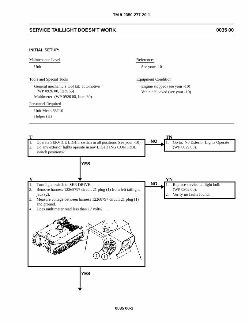
TM 9-2350-277-20-1
SERVICE TAILLIGHT DOESN’T WORK 0035 00
INITIAL SETUP:
Maintenance Level
Unit
Tools and Special Tools
General mechanic’s tool kit: automotive(WP 0926 00, Item 65)
Multimeter (WP 0926 00, Item 30)
Personnel Required
Unit Mech 63T10Helper (H)
References
See your -10
Equipment Condition
Engine stopped (see your -10)Vehicle blocked (see your -10)
T1. Operate SERVICE LIGHT switch in all positions (see your -10).2. Do any exterior lights operate in any LIGHTING CONTROL
switch positions?
YES
NOTN1. Go to: No Exterior Lights Operate
(WP 0029 00).
Y1. Turn light switch to SER DRIVE.2. Remove harness 12268797 circuit 21 plug (1) from left taillight
jack (2).3. Measure voltage between harness 12268797 circuit 21 plug (1)
and ground.4. Does multimeter read less than 17 volts?
YES
NOYN1. Replace service taillight bulb
(WP 0302 00).2. Verify no faults found.
0035 00-1
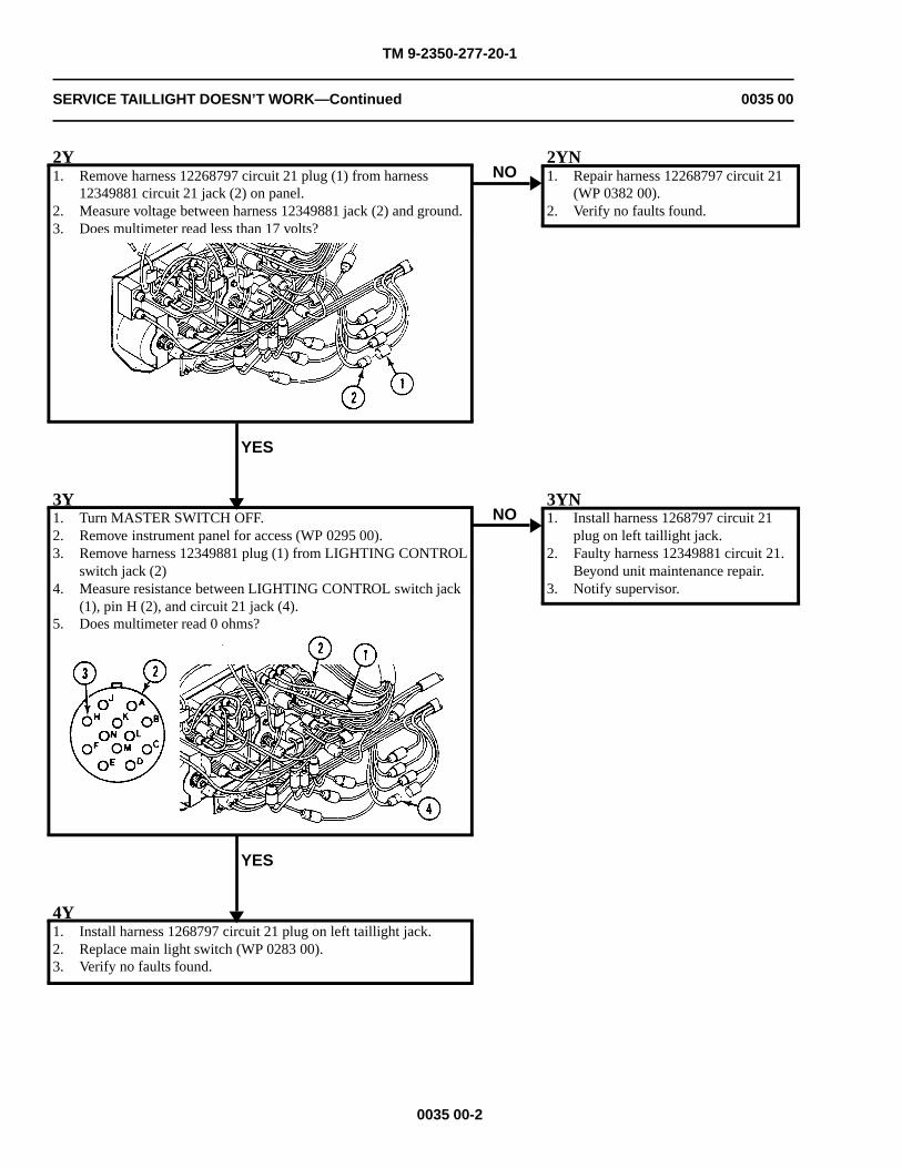
TM 9-2350-277-20-1
SERVICE TAILLIGHT DOESN’T WORK—Continued 0035 00
2Y1. Remove harness 12268797 circuit 21 plug (1) from harness
12349881 circuit 21 jack (2) on panel.2. Measure voltage between harness 12349881 jack (2) and ground.3. Does multimeter read less than 17 volts?
YES
NO2YN1. Repair harness 12268797 circuit 21
(WP 0382 00).2. Verify no faults found.
3Y1. Turn MASTER SWITCH OFF.2. Remove instrument panel for access (WP 0295 00).3. Remove harness 12349881 plug (1) from LIGHTING CONTROL
switch jack (2)4. Measure resistance between LIGHTING CONTROL switch jack
(1), pin H (2), and circuit 21 jack (4).5. Does multimeter read 0 ohms?
YES
NO3YN1. Install harness 1268797 circuit 21
plug on left taillight jack.2. Faulty harness 12349881 circuit 21.
Beyond unit maintenance repair.3. Notify supervisor.
4Y1. Install harness 1268797 circuit 21 plug on left taillight jack.2. Replace main light switch (WP 0283 00).3. Verify no faults found.
0035 00-2
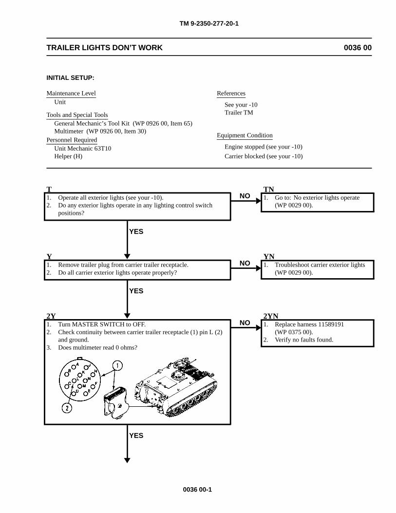
TM 9-2350-277-20-1
TRAILER LIGHTS DON’T WORK 0036 00
INITIAL SETUP:
Maintenance LevelUnit
Tools and Special ToolsGeneral Mechanic’s Tool Kit (WP 0926 00, Item 65)Multimeter (WP 0926 00, Item 30)
Personnel RequiredUnit Mechanic 63T10Helper (H)
References
See your -10Trailer TM
Equipment Condition
Engine stopped (see your -10)
Carrier blocked (see your -10)
T1. Operate all exterior lights (see your -10).2. Do any exterior lights operate in any lighting control switch
positions?
YES
NOTN1. Go to: No exterior lights operate
(WP 0029 00).
Y1. Remove trailer plug from carrier trailer receptacle.2. Do all carrier exterior lights operate properly?
YES
NOYN1. Troubleshoot carrier exterior lights
(WP 0029 00).
2Y1. Turn MASTER SWITCH to OFF.2. Check continuity between carrier trailer receptacle (1) pin L (2)
and ground.3. Does multimeter read 0 ohms?
YES
NO2YN1. Replace harness 11589191
(WP 0375 00).2. Verify no faults found.
0036 00-1
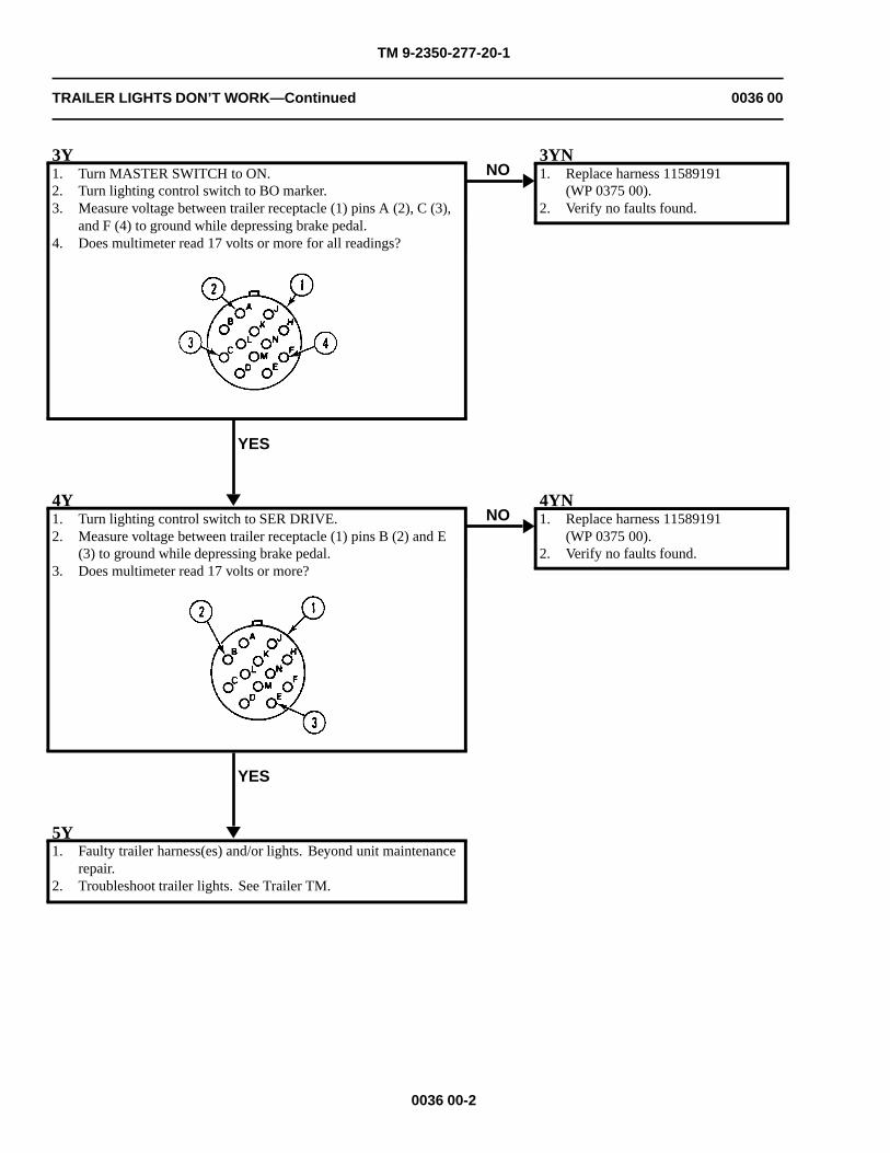
TM 9-2350-277-20-1
TRAILER LIGHTS DON’T WORK—Continued 0036 00
3Y1. Turn MASTER SWITCH to ON.2. Turn lighting control switch to BO marker.3. Measure voltage between trailer receptacle (1) pins A (2), C (3),
and F (4) to ground while depressing brake pedal.4. Does multimeter read 17 volts or more for all readings?
YES
NO3YN1. Replace harness 11589191
(WP 0375 00).2. Verify no faults found.
4Y1. Turn lighting control switch to SER DRIVE.2. Measure voltage between trailer receptacle (1) pins B (2) and E
(3) to ground while depressing brake pedal.3. Does multimeter read 17 volts or more?
YES
NO4YN1. Replace harness 11589191
(WP 0375 00).2. Verify no faults found.
5Y1. Faulty trailer harness(es) and/or lights. Beyond unit maintenance
repair.2. Troubleshoot trailer lights. See Trailer TM.
0036 00-2
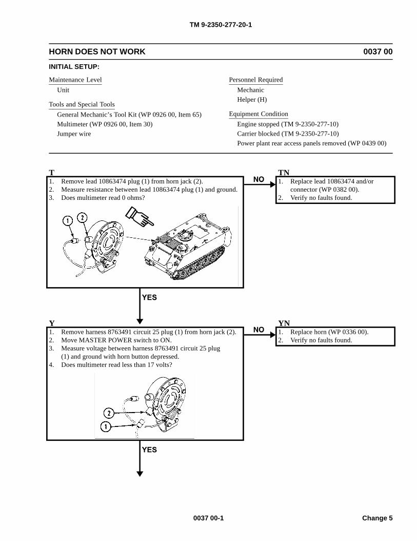
TM 9-2350-277-20-1
HORN DOES NOT WORK 0037 00
INITIAL SETUP:
Maintenance LevelUnit
Tools and Special ToolsGeneral Mechanic’s Tool Kit (WP 0926 00, Item 65)Multimeter (WP 0926 00, Item 30)Jumper wire
Personnel RequiredMechanicHelper (H)
Equipment ConditionEngine stopped (TM 9-2350-277-10)Carrier blocked (TM 9-2350-277-10)Power plant rear access panels removed (WP 0439 00)
T1. Remove lead 10863474 plug (1) from horn jack (2).2. Measure resistance between lead 10863474 plug (1) and ground.3. Does multimeter read 0 ohms?
TN1. Replace lead 10863474 and/or
connector (WP 0382 00).2. Verify no faults found.
Y1. Remove harness 8763491 circuit 25 plug (1) from horn jack (2).2. Move MASTER POWER switch to ON.3. Measure voltage between harness 8763491 circuit 25 plug
(1) and ground with horn button depressed.4. Does multimeter read less than 17 volts?
YN1. Replace horn (WP 0336 00).2. Verify no faults found.
0037 00-1 Change 5
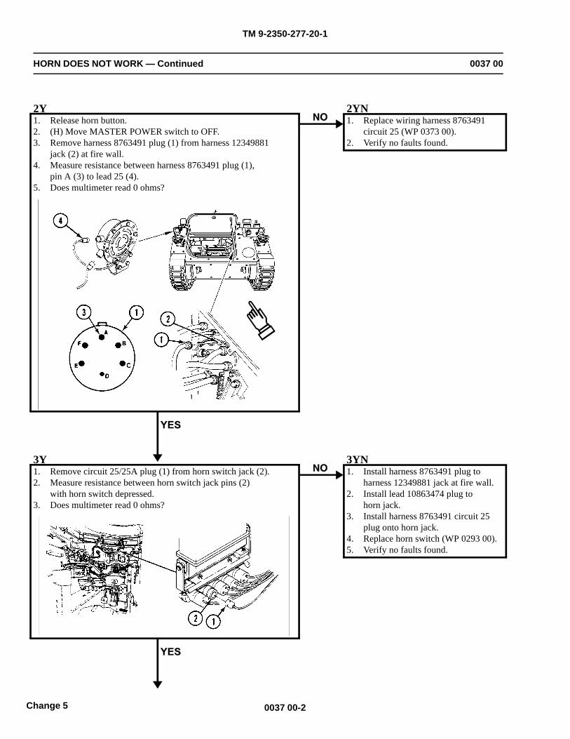
TM 9-2350-277-20-1
HORN DOES NOT WORK — Continued 0037 00
2Y1. Release horn button.2. (H) Move MASTER POWER switch to OFF.3. Remove harness 8763491 plug (1) from harness 12349881
jack (2) at fire wall.4. Measure resistance between harness 8763491 plug (1),
pin A (3) to lead 25 (4).5. Does multimeter read 0 ohms?
2YN1. Replace wiring harness 8763491
circuit 25 (WP 0373 00).2. Verify no faults found.
3Y1. Remove circuit 25/25A plug (1) from horn switch jack (2).2. Measure resistance between horn switch jack pins (2)
with horn switch depressed.3. Does multimeter read 0 ohms?
3YN1. Install harness 8763491 plug to
harness 12349881 jack at fire wall.2. Install lead 10863474 plug to
horn jack.3. Install harness 8763491 circuit 25
plug onto horn jack.4. Replace horn switch (WP 0293 00).5. Verify no faults found.
0037 00-2Change 5
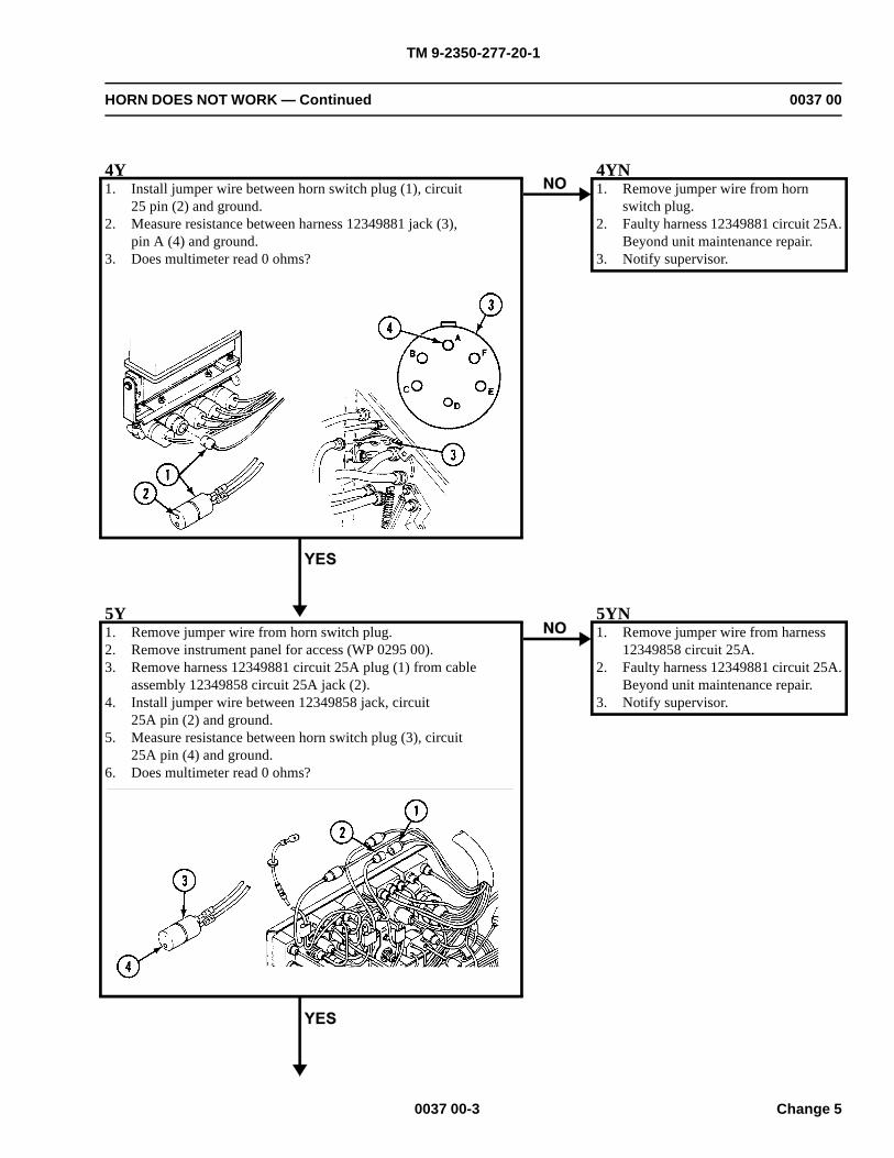
TM 9-2350-277-20-1
HORN DOES NOT WORK — Continued 0037 00
4Y1. Install jumper wire between horn switch plug (1), circuit
25 pin (2) and ground.2. Measure resistance between harness 12349881 jack (3),
pin A (4) and ground.3. Does multimeter read 0 ohms?
4YN1. Remove jumper wire from horn
switch plug.2. Faulty harness 12349881 circuit 25A.
Beyond unit maintenance repair.3. Notify supervisor.
5Y1. Remove jumper wire from horn switch plug.2. Remove instrument panel for access (WP 0295 00).3. Remove harness 12349881 circuit 25A plug (1) from cable
assembly 12349858 circuit 25A jack (2).4. Install jumper wire between 12349858 jack, circuit
25A pin (2) and ground.5. Measure resistance between horn switch plug (3), circuit
25A pin (4) and ground.6. Does multimeter read 0 ohms?
5YN1. Remove jumper wire from harness
12349858 circuit 25A.2. Faulty harness 12349881 circuit 25A.
Beyond unit maintenance repair.3. Notify supervisor.
0037 00-3 Change 5
TM 9-2350-277-20-1
HORN DOES NOT WORK — Continued 0037 00
6Y1. Remove jumper wire from harness 123498558 circuit 25A plug.2. Install circuits 25 and 25A on horn switch.3. Install harness 8761491 plug on harness 12349881
jack on fire wall.4. Repair harness 12349858 circuit 25A (WP 0382 00).5. Verify no faults found.
0037 00-4Change 5
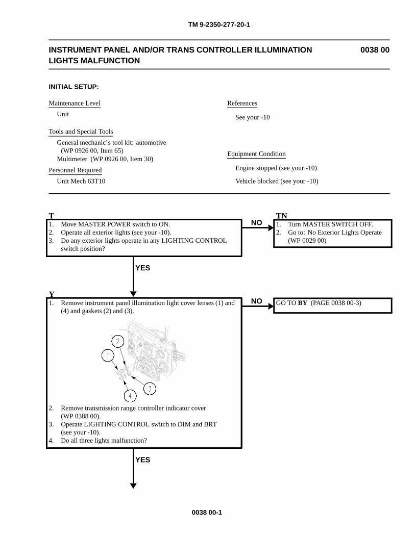
TM 9-2350-277-20-1
INSTRUMENT PANEL AND/OR TRANS CONTROLLER ILLUMINATIONLIGHTS MALFUNCTION
0038 00
INITIAL SETUP:
Maintenance Level
Unit
Tools and Special Tools
General mechanic’s tool kit: automotive(WP 0926 00, Item 65)
Multimeter (WP 0926 00, Item 30)
Personnel Required
Unit Mech 63T10
References
See your -10
Equipment Condition
Engine stopped (see your -10)
Vehicle blocked (see your -10)
T1. Move MASTER POWER switch to ON.2. Operate all exterior lights (see your -10).3. Do any exterior lights operate in any LIGHTING CONTROL
switch position?
YES
NOTN1. Turn MASTER SWITCH OFF.2. Go to: No Exterior Lights Operate
(WP 0029 00)
Y1. Remove instrument panel illumination light cover lenses (1) and
(4) and gaskets (2) and (3).
2. Remove transmission range controller indicator cover(WP 0388 00).
3. Operate LIGHTING CONTROL switch to DIM and BRT(see your -10).
4. Do all three lights malfunction?
YES
NO GO TO BY (PAGE 0038 00-3)
0038 00-1
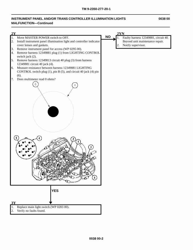
TM 9-2350-277-20-1
INSTRUMENT PANEL AND/OR TRANS CONTROLLER ILLUMINATION LIGHTSMALFUNCTION—Continued
0038 00
2Y1. Move MASTER POWER switch to OFF.2. Install instrument panel illumination light and controller indicator
cover lenses and gaskets.3. Remove instrument panel for access (WP 0295 00).4. Remove harness 12349881 plug (1) from LIGHTING CONTROL
switch jack (2).5. Remove harness 12349813 circuit 40 plug (3) from harness
12349881 circuit 40 jack (4).6. Measure resistance between harness 12349881 LIGHTING
CONTROL switch plug (1), pin B (5), and circuit 40 jack (4) pin(6).
7. Does multimeter read 0 ohms?
YES
NO2YN1. Faulty harness 12349881, circuit 40.
Beyond unit maintenance repair.2. Notify supervisor.
3Y1. Replace main light switch (WP 0283 00).2. Verify no faults found.
0038 00-2
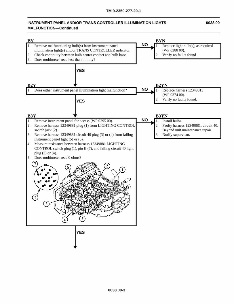
TM 9-2350-277-20-1
INSTRUMENT PANEL AND/OR TRANS CONTROLLER ILLUMINATION LIGHTSMALFUNCTION—Continued
0038 00
BY1. Remove malfunctioning bulb(s) from instrument panel
illumination light(s) and/or TRANS CONTROLLER indicator.2. Check continuity between bulb center contact and bulb base.3. Does multimeter read less than infinity?
YES
NOBYN1. Replace light bulb(s), as required
(WP 0388 00).2. Verify no faults found.
B2Y1. Does either instrument panel illumination light malfunction?
YES
NOB2YN1. Replace harness 12349813
(WP 0374 00).2. Verify no faults found.
B3Y1. Remove instrument panel for access (WP 0295 00).2. Remove harness 12349881 plug (1) from LIGHTING CONTROL
switch jack (2).3. Remove harness 12349881 circuit 40 plug (3) or (4) from failing
instrument panel light (5) or (6).4. Measure resistance between harness 12349881 LIGHTING
CONTROL switch plug (1), pin B (7), and failing circuit 40 lightplug (3) or (4).
5. Does multimeter read 0 ohms?
YES
NOB3YN1. Install bulbs.2. Faulty harness 12349881, circuit 40.
Beyond unit maintenance repair.3. Notify supervisor.
0038 00-3
TM 9-2350-277-20-1
INSTRUMENT PANEL AND/OR TRANS CONTROLLER ILLUMINATION LIGHTSMALFUNCTION—Continued
0038 00
B4Y1. Install harness 12349881 plug on LIGHTING CONTROL switch
jack.2. Replace instrument panel light assembly (WP 0287 00).3. Verify no faults found.
0038 00-4
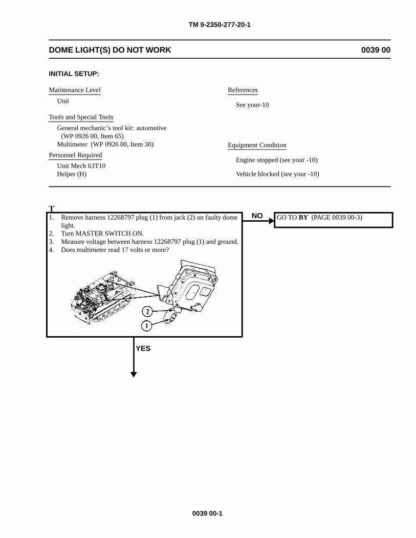
TM 9-2350-277-20-1
DOME LIGHT(S) DO NOT WORK 0039 00
INITIAL SETUP:
Maintenance Level
Unit
Tools and Special Tools
General mechanic’s tool kit: automotive(WP 0926 00, Item 65)
Multimeter (WP 0926 00, Item 30)
Personnel Required
Unit Mech 63T10Helper (H)
References
See your-10
Equipment Condition
Engine stopped (see your -10)
Vehicle blocked (see your -10)
T1. Remove harness 12268797 plug (1) from jack (2) on faulty dome
light.2. Turn MASTER SWITCH ON.3. Measure voltage between harness 12268797 plug (1) and ground.4. Does multimeter read 17 volts or more?
YES
NO GO TO BY (PAGE 0039 00-3)
0039 00-1
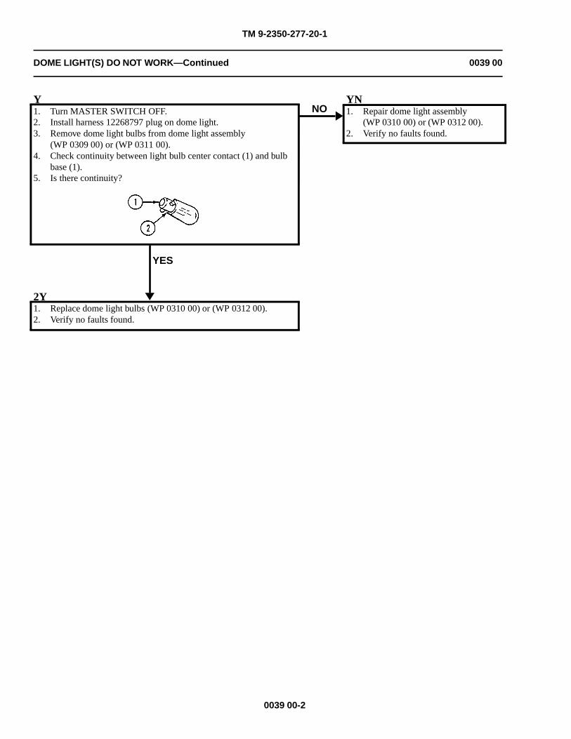
TM 9-2350-277-20-1
DOME LIGHT(S) DO NOT WORK—Continued 0039 00
Y1. Turn MASTER SWITCH OFF.2. Install harness 12268797 plug on dome light.3. Remove dome light bulbs from dome light assembly
(WP 0309 00) or (WP 0311 00).4. Check continuity between light bulb center contact (1) and bulb
base (1).5. Is there continuity?
YES
NOYN1. Repair dome light assembly
(WP 0310 00) or (WP 0312 00).2. Verify no faults found.
2Y1. Replace dome light bulbs (WP 0310 00) or (WP 0312 00).2. Verify no faults found.
0039 00-2
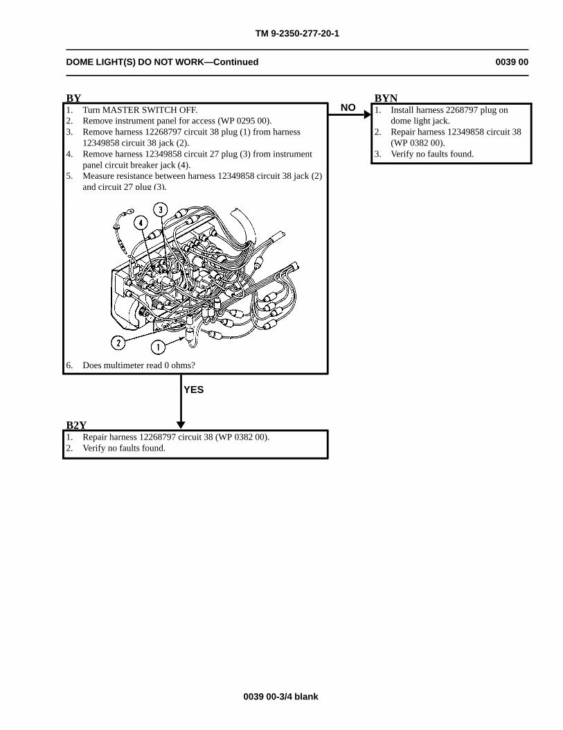
TM 9-2350-277-20-1
DOME LIGHT(S) DO NOT WORK—Continued 0039 00
BY1. Turn MASTER SWITCH OFF.2. Remove instrument panel for access (WP 0295 00).3. Remove harness 12268797 circuit 38 plug (1) from harness
12349858 circuit 38 jack (2).4. Remove harness 12349858 circuit 27 plug (3) from instrument
panel circuit breaker jack (4).5. Measure resistance between harness 12349858 circuit 38 jack (2)
and circuit 27 plug (3).
6. Does multimeter read 0 ohms?
YES
NOBYN1. Install harness 2268797 plug on
dome light jack.2. Repair harness 12349858 circuit 38
(WP 0382 00).3. Verify no faults found.
B2Y1. Repair harness 12268797 circuit 38 (WP 0382 00).2. Verify no faults found.
0039 00-3/4 blank

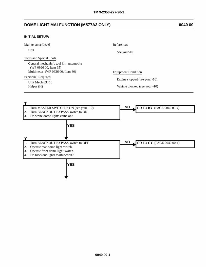
TM 9-2350-277-20-1
DOME LIGHT MALFUNCTION (M577A3 ONLY) 0040 00
INITIAL SETUP:
Maintenance Level
Unit
Tools and Special Tools
General mechanic’s tool kit: automotive(WP 0926 00, Item 65)
Multimeter (WP 0926 00, Item 30)
Personnel Required
Unit Mech 63T10Helper (H)
References
See your-10
Equipment Condition
Engine stopped (see your -10)
Vehicle blocked (see your -10)
T1. Turn MASTER SWITCH to ON (see your -10).2. Turn BLACKOUT BYPASS switch to ON.3. Do white dome lights come on?
YES
NO GO TO BY (PAGE 0040 00-4)
Y1. Turn BLACKOUT BYPASS switch to OFF.2. Operate rear dome light switch.3. Operate front dome light switch.4. Do blackout lights malfunction?
YES
NO GO TO CY (PAGE 0040 00-4)
0040 00-1
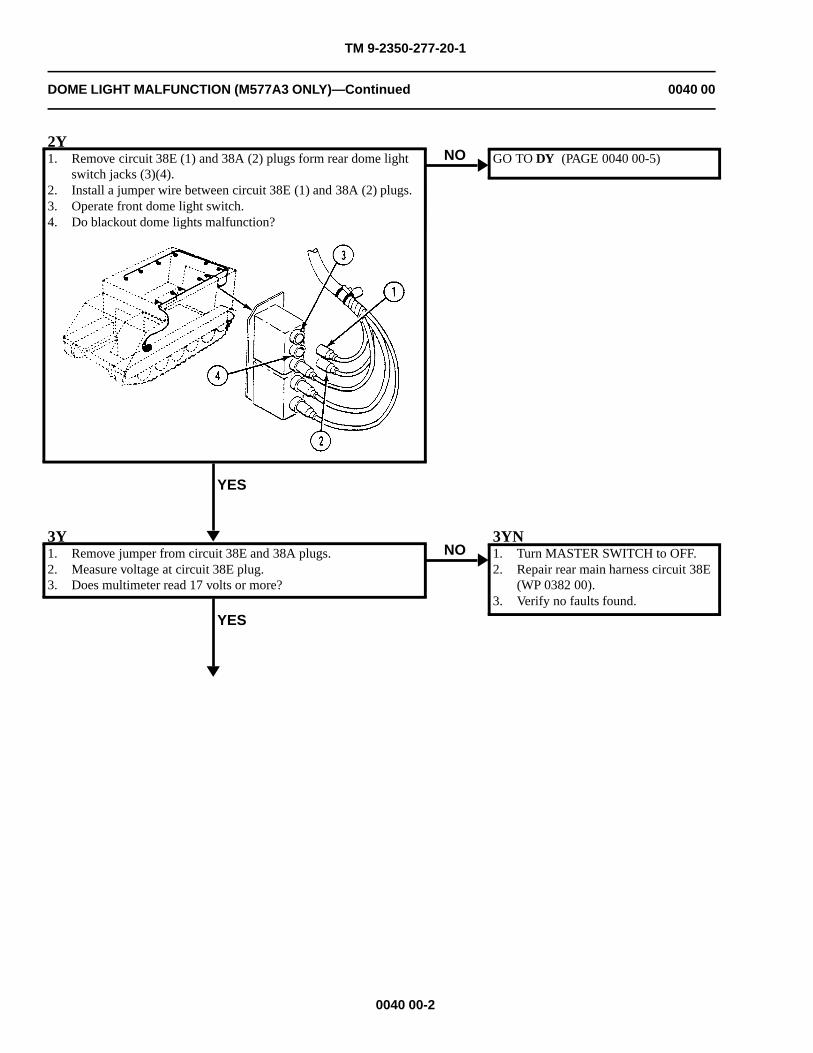
TM 9-2350-277-20-1
DOME LIGHT MALFUNCTION (M577A3 ONLY)—Continued 0040 00
2Y1. Remove circuit 38E (1) and 38A (2) plugs form rear dome light
switch jacks (3)(4).2. Install a jumper wire between circuit 38E (1) and 38A (2) plugs.3. Operate front dome light switch.4. Do blackout dome lights malfunction?
YES
NO GO TO DY (PAGE 0040 00-5)
3Y1. Remove jumper from circuit 38E and 38A plugs.2. Measure voltage at circuit 38E plug.3. Does multimeter read 17 volts or more?
YES
NO3YN1. Turn MASTER SWITCH to OFF.2. Repair rear main harness circuit 38E
(WP 0382 00).3. Verify no faults found.
0040 00-2
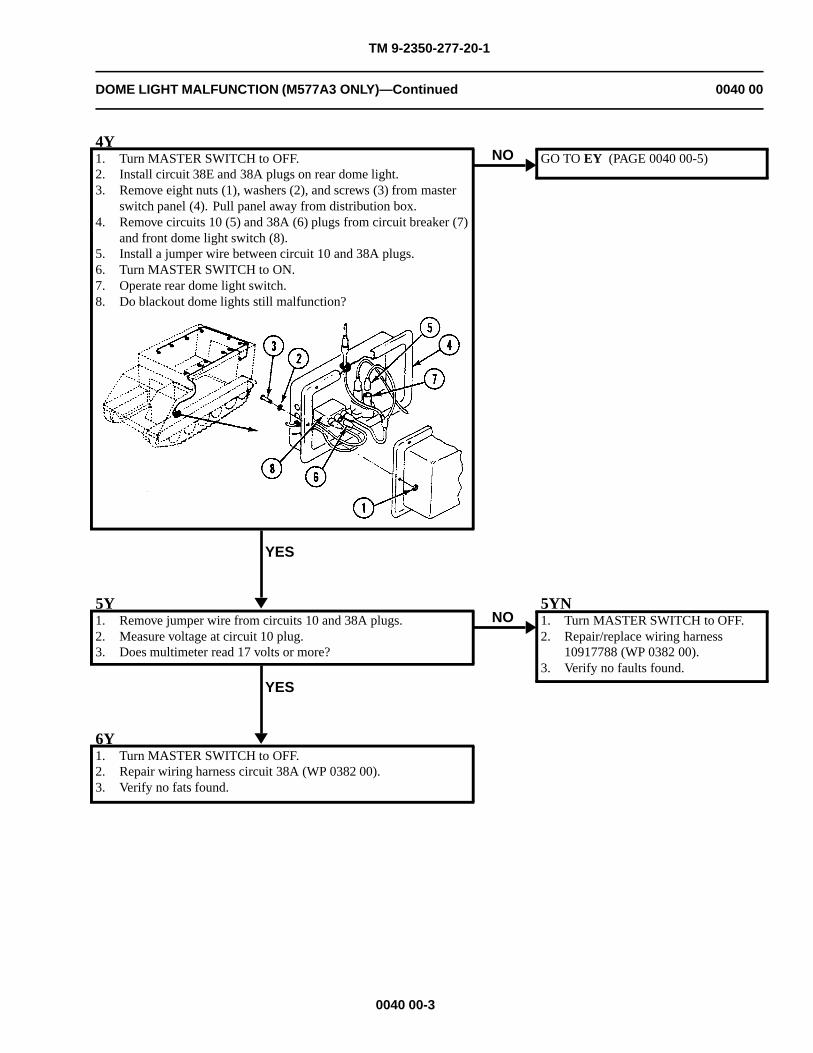
TM 9-2350-277-20-1
DOME LIGHT MALFUNCTION (M577A3 ONLY)—Continued 0040 00
4Y1. Turn MASTER SWITCH to OFF.2. Install circuit 38E and 38A plugs on rear dome light.3. Remove eight nuts (1), washers (2), and screws (3) from master
switch panel (4). Pull panel away from distribution box.4. Remove circuits 10 (5) and 38A (6) plugs from circuit breaker (7)
and front dome light switch (8).5. Install a jumper wire between circuit 10 and 38A plugs.6. Turn MASTER SWITCH to ON.7. Operate rear dome light switch.8. Do blackout dome lights still malfunction?
YES
NO GO TO EY (PAGE 0040 00-5)
5Y1. Remove jumper wire from circuits 10 and 38A plugs.2. Measure voltage at circuit 10 plug.3. Does multimeter read 17 volts or more?
YES
NO5YN1. Turn MASTER SWITCH to OFF.2. Repair/replace wiring harness
10917788 (WP 0382 00).3. Verify no faults found.
6Y1. Turn MASTER SWITCH to OFF.2. Repair wiring harness circuit 38A (WP 0382 00).3. Verify no fats found.
0040 00-3
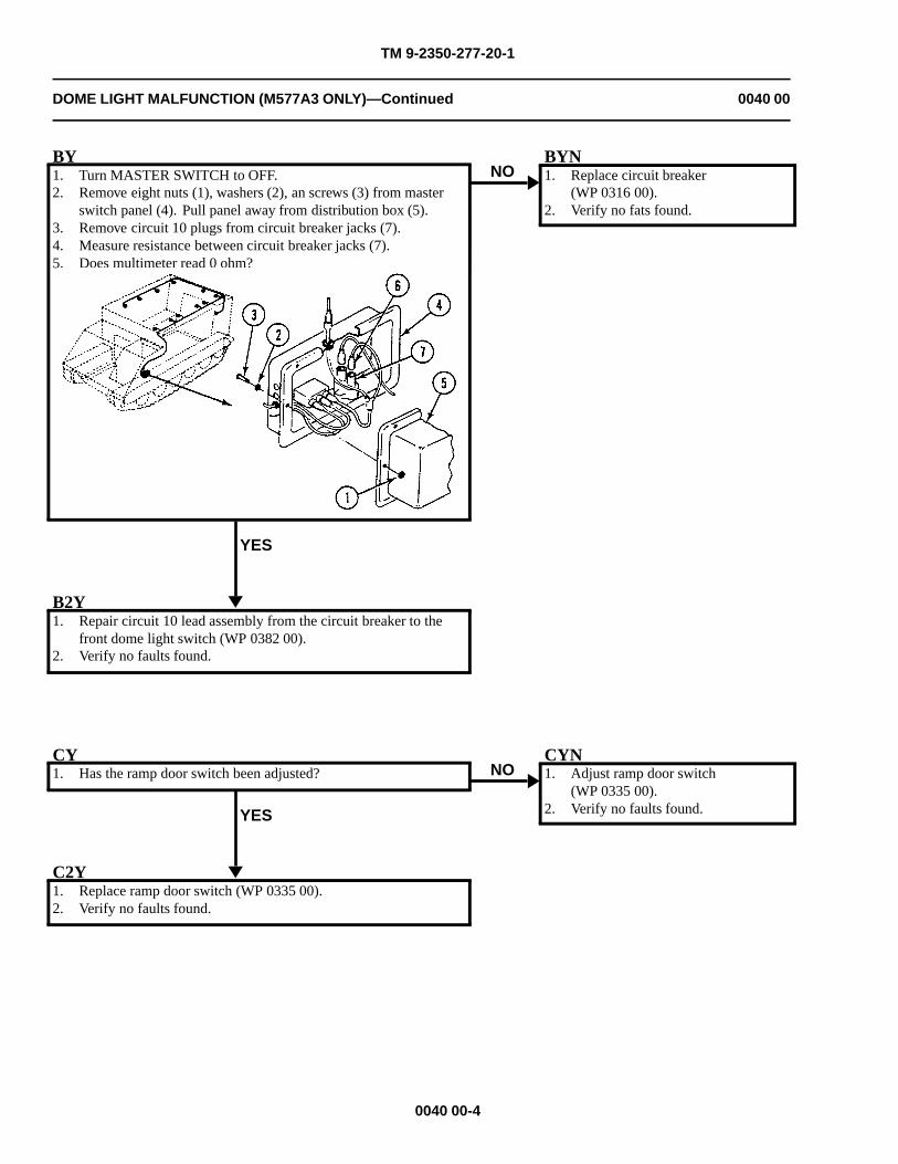
TM 9-2350-277-20-1
DOME LIGHT MALFUNCTION (M577A3 ONLY)—Continued 0040 00
BY1. Turn MASTER SWITCH to OFF.2. Remove eight nuts (1), washers (2), an screws (3) from master
switch panel (4). Pull panel away from distribution box (5).3. Remove circuit 10 plugs from circuit breaker jacks (7).4. Measure resistance between circuit breaker jacks (7).5. Does multimeter read 0 ohm?
YES
NOBYN1. Replace circuit breaker
(WP 0316 00).2. Verify no fats found.
B2Y1. Repair circuit 10 lead assembly from the circuit breaker to the
front dome light switch (WP 0382 00).2. Verify no faults found.
CY1. Has the ramp door switch been adjusted?
YES
NOCYN1. Adjust ramp door switch
(WP 0335 00).2. Verify no faults found.
C2Y1. Replace ramp door switch (WP 0335 00).2. Verify no faults found.
0040 00-4
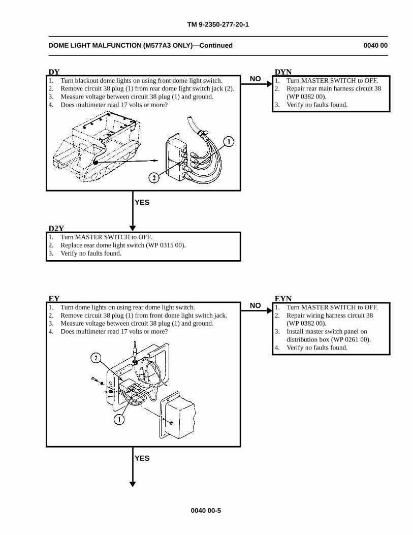
TM 9-2350-277-20-1
DOME LIGHT MALFUNCTION (M577A3 ONLY)—Continued 0040 00
DY1. Turn blackout dome lights on using front dome light switch.2. Remove circuit 38 plug (1) from rear dome light switch jack (2).3. Measure voltage between circuit 38 plug (1) and ground.4. Does multimeter read 17 volts or more?
YES
NODYN1. Turn MASTER SWITCH to OFF.2. Repair rear main harness circuit 38
(WP 0382 00).3. Verify no faults found.
D2Y1. Turn MASTER SWITCH to OFF.2. Replace rear dome light switch (WP 0315 00).3. Verify no faults found.
EY1. Turn dome lights on using rear dome light switch.2. Remove circuit 38 plug (1) from front dome light switch jack.3. Measure voltage between circuit 38 plug (1) and ground.4. Does multimeter read 17 volts or more?
YES
NOEYN1. Turn MASTER SWITCH to OFF.2. Repair wiring harness circuit 38
(WP 0382 00).3. Install master switch panel on
distribution box (WP 0261 00).4. Verify no faults found.
0040 00-5

TM 9-2350-277-20-1
DOME LIGHT MALFUNCTION (M577A3 ONLY)—Continued 0040 00
E2Y1. Turn MASTER SWITCH to OFF.2. Remove jumper wire from circuit 10 and 38 plugs.3. Replace front dome light switch (WP 0314 00).4. Verify no faults found.
0040 00-6
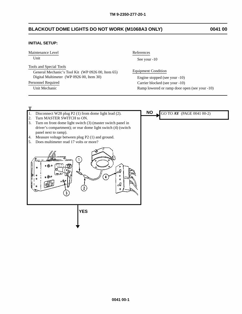
TM 9-2350-277-20-1
BLACKOUT DOME LIGHTS DO NOT WORK (M1068A3 ONLY) 0041 00
INITIAL SETUP:
Maintenance Level
Unit
Tools and Special Tools
General Mechanic’s Tool Kit (WP 0926 00, Item 65)Digital Multimeter (WP 0926 00, Item 30)
Personnel Required
Unit Mechanic
References
See your -10
Equipment Condition
Engine stopped (see your -10)Carrier blocked (see your -10)Ramp lowered or ramp door open (see your -10)
T1. Disconnect W28 plug P2 (1) from dome light lead (2).2. Turn MASTER SWITCH to ON.3. Turn on front dome light switch (3) (master switch panel in
driver’s compartment); or rear dome light switch (4) (switchpanel next to ramp).
4. Measure voltage between plug P2 (1) and ground.5. Does multimeter read 17 volts or more?
YES
NO GO TO AY (PAGE 0041 00-2)
0041 00-1
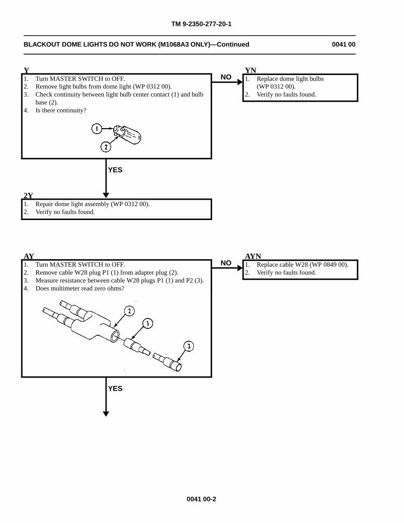
TM 9-2350-277-20-1
BLACKOUT DOME LIGHTS DO NOT WORK (M1068A3 ONLY)—Continued 0041 00
Y1. Turn MASTER SWITCH to OFF.2. Remove light bulbs from dome light (WP 0312 00).3. Check continuity between light bulb center contact (1) and bulb
base (2).4. Is there continuity?
YES
NOYN1. Replace dome light bulbs
(WP 0312 00).2. Verify no faults found.
2Y1. Repair dome light assembly (WP 0312 00).2. Verify no faults found.
AY1. Turn MASTER SWITCH to OFF.2. Remove cable W28 plug P1 (1) from adapter plug (2).3. Measure resistance between cable W28 plugs P1 (1) and P2 (3).4. Does multimeter read zero ohms?
YES
NOAYN1. Replace cable W28 (WP 0849 00).2. Verify no faults found.
0041 00-2
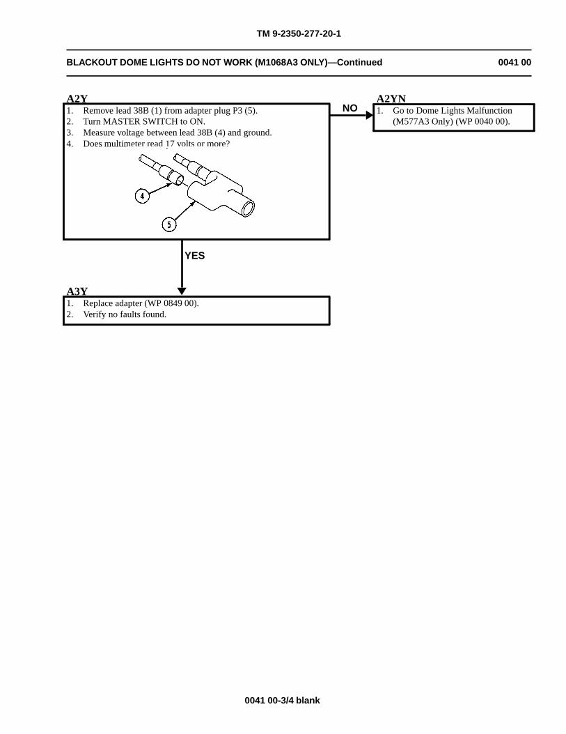
TM 9-2350-277-20-1
BLACKOUT DOME LIGHTS DO NOT WORK (M1068A3 ONLY)—Continued 0041 00
A2Y1. Remove lead 38B (1) from adapter plug P3 (5).2. Turn MASTER SWITCH to ON.3. Measure voltage between lead 38B (4) and ground.4. Does multimeter read 17 volts or more?
YES
NOA2YN1. Go to Dome Lights Malfunction
(M577A3 Only) (WP 0040 00).
A3Y1. Replace adapter (WP 0849 00).2. Verify no faults found.
0041 00-3/4 blank

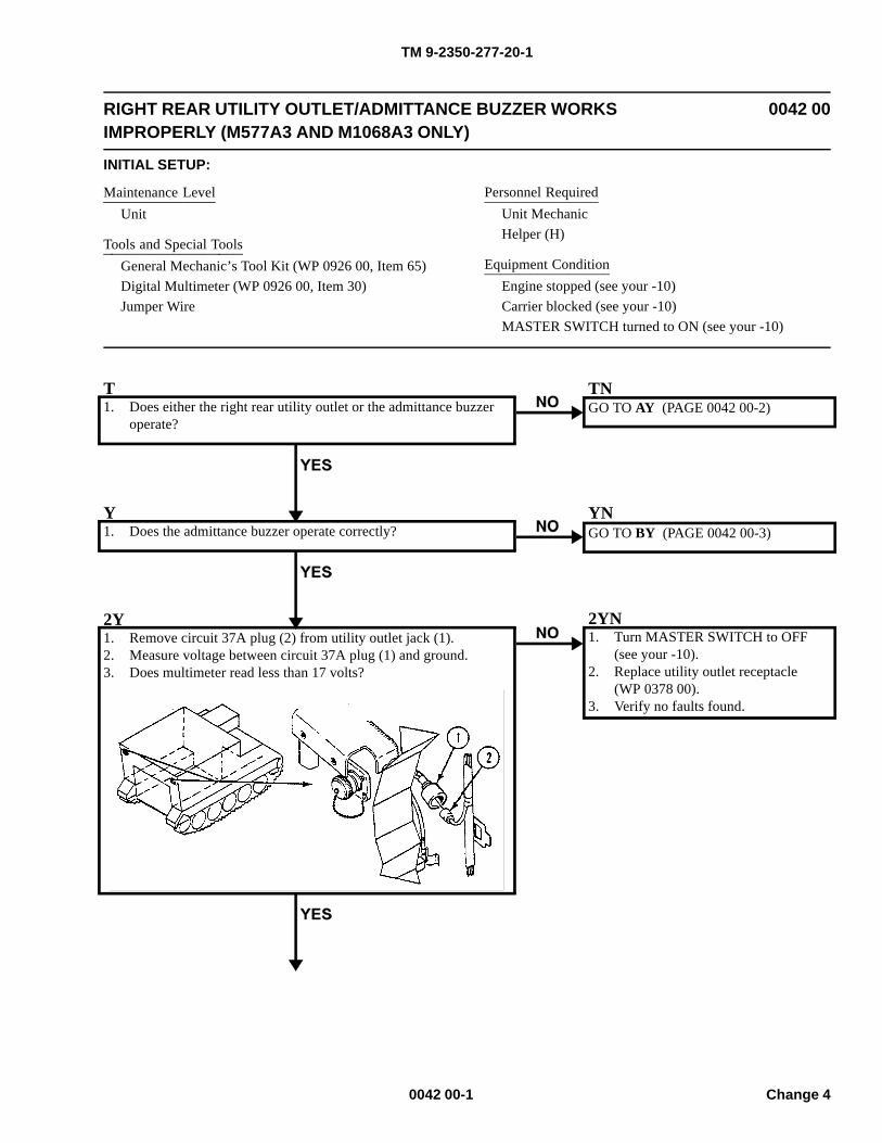
TM 9-2350-277-20-1
RIGHT REAR UTILITY OUTLET/ADMITTANCE BUZZER WORKSIMPROPERLY (M577A3 AND M1068A3 ONLY)
0042 00
INITIAL SETUP:
Maintenance LevelUnit
Tools and Special ToolsGeneral Mechanic’s Tool Kit (WP 0926 00, Item 65)Digital Multimeter (WP 0926 00, Item 30)Jumper Wire
Personnel RequiredUnit MechanicHelper (H)
Equipment ConditionEngine stopped (see your -10)Carrier blocked (see your -10)MASTER SWITCH turned to ON (see your -10)
T1. Does either the right rear utility outlet or the admittance buzzer
operate?
TNGO TO AY (PAGE 0042 00-2)
Y1. Does the admittance buzzer operate correctly?
YNGO TO BY (PAGE 0042 00-3)
2Y1. Remove circuit 37A plug (2) from utility outlet jack (1).2. Measure voltage between circuit 37A plug (1) and ground.3. Does multimeter read less than 17 volts?
2YN1. Turn MASTER SWITCH to OFF
(see your -10).2. Replace utility outlet receptacle
(WP 0378 00).3. Verify no faults found.
0042 00-1 Change 4
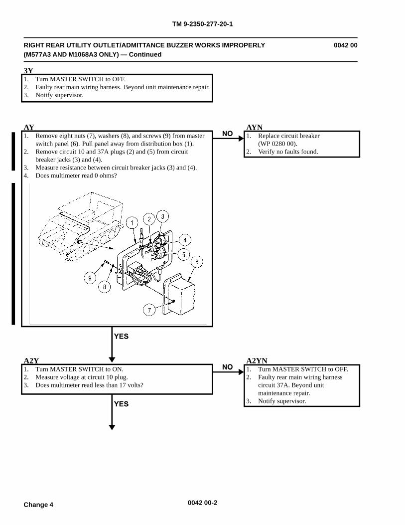
TM 9-2350-277-20-1
RIGHT REAR UTILITY OUTLET/ADMITTANCE BUZZER WORKS IMPROPERLY(M577A3 AND M1068A3 ONLY) — Continued
0042 00
3Y1. Turn MASTER SWITCH to OFF.2. Faulty rear main wiring harness. Beyond unit maintenance repair.3. Notify supervisor.
AY1. Remove eight nuts (7), washers (8), and screws (9) from master
switch panel (6). Pull panel away from distribution box (1).2. Remove circuit 10 and 37A plugs (2) and (5) from circuit
breaker jacks (3) and (4).3. Measure resistance between circuit breaker jacks (3) and (4).4. Does multimeter read 0 ohms?
AYN1. Replace circuit breaker
(WP 0280 00).2. Verify no faults found.
A2Y1. Turn MASTER SWITCH to ON.2. Measure voltage at circuit 10 plug.3. Does multimeter read less than 17 volts?
A2YN1. Turn MASTER SWITCH to OFF.2. Faulty rear main wiring harness
circuit 37A. Beyond unitmaintenance repair.
3. Notify supervisor.
0042 00-2Change 4
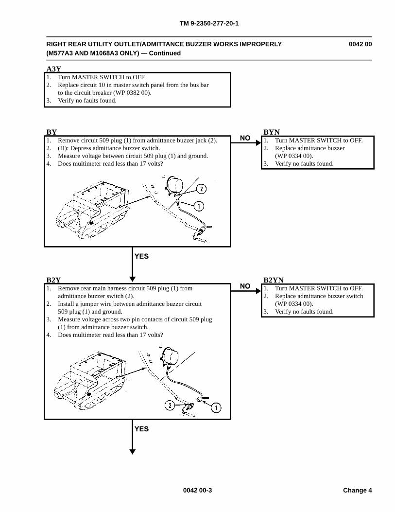
TM 9-2350-277-20-1
RIGHT REAR UTILITY OUTLET/ADMITTANCE BUZZER WORKS IMPROPERLY(M577A3 AND M1068A3 ONLY) — Continued
0042 00
A3Y1. Turn MASTER SWITCH to OFF.2. Replace circuit 10 in master switch panel from the bus bar
to the circuit breaker (WP 0382 00).3. Verify no faults found.
BY1. Remove circuit 509 plug (1) from admittance buzzer jack (2).2. (H): Depress admittance buzzer switch.3. Measure voltage between circuit 509 plug (1) and ground.4. Does multimeter read less than 17 volts?
BYN1. Turn MASTER SWITCH to OFF.2. Replace admittance buzzer
(WP 0334 00).3. Verify no faults found.
B2Y1. Remove rear main harness circuit 509 plug (1) from
admittance buzzer switch (2).2. Install a jumper wire between admittance buzzer circuit
509 plug (1) and ground.3. Measure voltage across two pin contacts of circuit 509 plug
(1) from admittance buzzer switch.4. Does multimeter read less than 17 volts?
B2YN1. Turn MASTER SWITCH to OFF.2. Replace admittance buzzer switch
(WP 0334 00).3. Verify no faults found.
0042 00-3 Change 4
TM 9-2350-277-20-1
RIGHT REAR UTILITY OUTLET/ADMITTANCE BUZZER WORKS IMPROPERLY(M577A3 AND M1068A3 ONLY) — Continued
0042 00
B3Y1. Turn MASTER SWITCH to OFF.2. Remove jumper wire.3. Faulty rear main wiring harness circuit 509. Beyond
unit maintenance repair.4. Notify supervisor.
0042 00-4Change 4
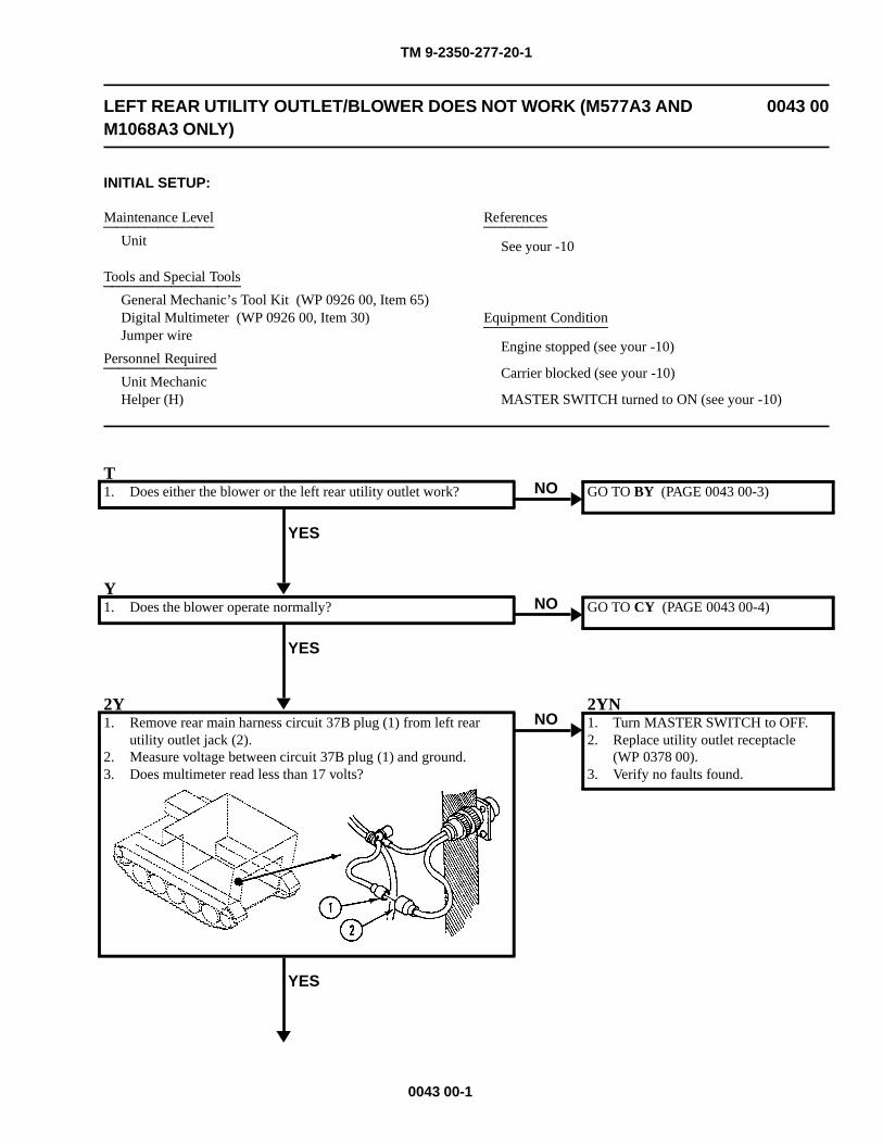
TM 9-2350-277-20-1
LEFT REAR UTILITY OUTLET/BLOWER DOES NOT WORK (M577A3 ANDM1068A3 ONLY)
0043 00
INITIAL SETUP:
Maintenance Level
Unit
Tools and Special Tools
General Mechanic’s Tool Kit (WP 0926 00, Item 65)Digital Multimeter (WP 0926 00, Item 30)Jumper wire
Personnel Required
Unit MechanicHelper (H)
References
See your -10
Equipment Condition
Engine stopped (see your -10)
Carrier blocked (see your -10)
MASTER SWITCH turned to ON (see your -10)
T1. Does either the blower or the left rear utility outlet work?
YES
NO GO TO BY (PAGE 0043 00-3)
Y1. Does the blower operate normally?
YES
NO GO TO CY (PAGE 0043 00-4)
2Y1. Remove rear main harness circuit 37B plug (1) from left rear
utility outlet jack (2).2. Measure voltage between circuit 37B plug (1) and ground.3. Does multimeter read less than 17 volts?
YES
NO2YN1. Turn MASTER SWITCH to OFF.2. Replace utility outlet receptacle
(WP 0378 00).3. Verify no faults found.
0043 00-1
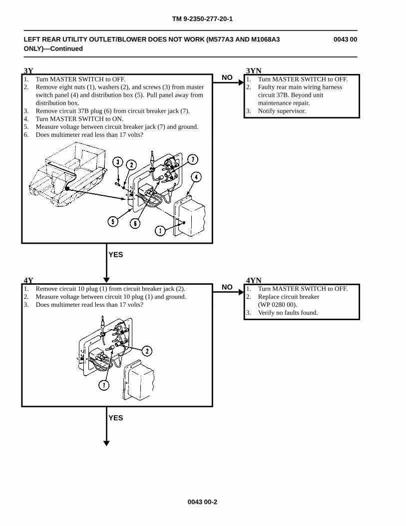
TM 9-2350-277-20-1
LEFT REAR UTILITY OUTLET/BLOWER DOES NOT WORK (M577A3 AND M1068A3ONLY)—Continued
0043 00
3Y1. Turn MASTER SWITCH to OFF.2. Remove eight nuts (1), washers (2), and screws (3) from master
switch panel (4) and distribution box (5). Pull panel away fromdistribution box.
3. Remove circuit 37B plug (6) from circuit breaker jack (7).4. Turn MASTER SWITCH to ON.5. Measure voltage between circuit breaker jack (7) and ground.6. Does multimeter read less than 17 volts?
YES
NO3YN1. Turn MASTER SWITCH to OFF.2. Faulty rear main wiring harness
circuit 37B. Beyond unitmaintenance repair.
3. Notify supervisor.
4Y1. Remove circuit 10 plug (1) from circuit breaker jack (2).2. Measure voltage between circuit 10 plug (1) and ground.3. Does multimeter read less than 17 volts?
YES
NO4YN1. Turn MASTER SWITCH to OFF.2. Replace circuit breaker
(WP 0280 00).3. Verify no faults found.
0043 00-2
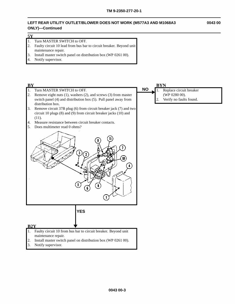
TM 9-2350-277-20-1
LEFT REAR UTILITY OUTLET/BLOWER DOES NOT WORK (M577A3 AND M1068A3ONLY)—Continued
0043 00
5Y1. Turn MASTER SWITCH to OFF.2. Faulty circuit 10 lead from bus bar to circuit breaker. Beyond unit
maintenance repair.3. Install master switch panel on distribution box (WP 0261 00).4. Notify supervisor.
BY1. Turn MASTER SWITCH to OFF.2. Remove eight nuts (1), washers (2), and screws (3) from master
switch panel (4) and distribution box (5). Pull panel away fromdistribution box.
3. Remove circuit 37B plug (6) from circuit breaker jack (7) and twocircuit 10 plugs (8) and (9) from circuit breaker jacks (10) and(11).
4. Measure resistance between circuit breaker contacts.5. Does multimeter read 0 ohms?
YES
NOBYN1. Replace circuit breaker
(WP 0280 00).2. Verify no faults found.
B2Y1. Faulty circuit 10 from bus bar to circuit breaker. Beyond unit
maintenance repair.2. Install master switch panel on distribution box (WP 0261 00).3. Notify supervisor.
0043 00-3
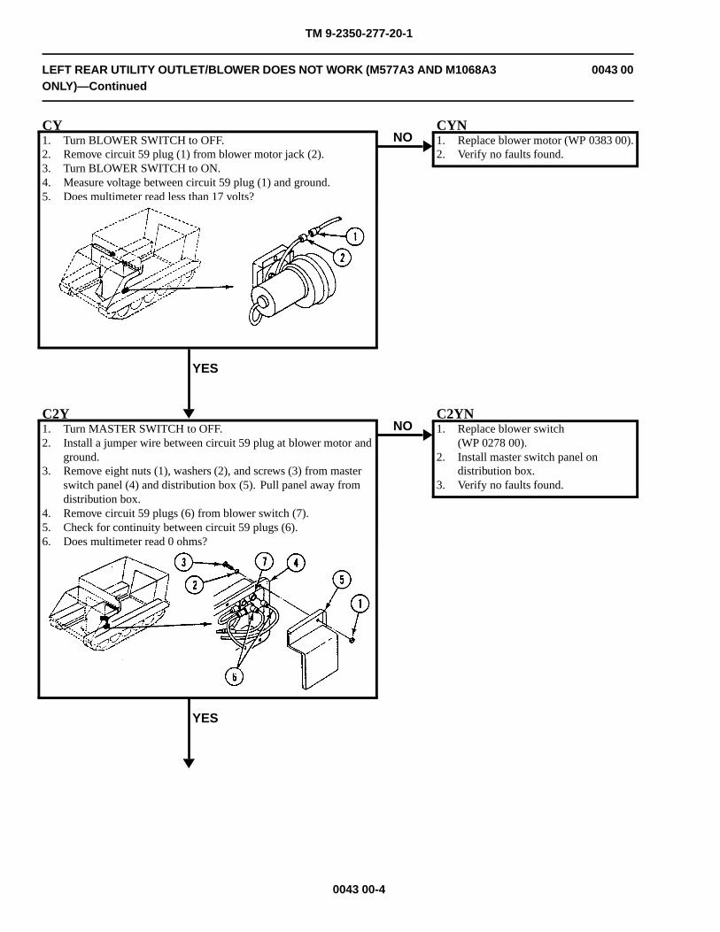
TM 9-2350-277-20-1
LEFT REAR UTILITY OUTLET/BLOWER DOES NOT WORK (M577A3 AND M1068A3ONLY)—Continued
0043 00
CY1. Turn BLOWER SWITCH to OFF.2. Remove circuit 59 plug (1) from blower motor jack (2).3. Turn BLOWER SWITCH to ON.4. Measure voltage between circuit 59 plug (1) and ground.5. Does multimeter read less than 17 volts?
YES
NOCYN1. Replace blower motor (WP 0383 00).2. Verify no faults found.
C2Y1. Turn MASTER SWITCH to OFF.2. Install a jumper wire between circuit 59 plug at blower motor and
ground.3. Remove eight nuts (1), washers (2), and screws (3) from master
switch panel (4) and distribution box (5). Pull panel away fromdistribution box.
4. Remove circuit 59 plugs (6) from blower switch (7).5. Check for continuity between circuit 59 plugs (6).6. Does multimeter read 0 ohms?
YES
NOC2YN1. Replace blower switch
(WP 0278 00).2. Install master switch panel on
distribution box.3. Verify no faults found.
0043 00-4
TM 9-2350-277-20-1
LEFT REAR UTILITY OUTLET/BLOWER DOES NOT WORK (M577A3 AND M1068A3ONLY)—Continued
0043 00
C3Y1. Faulty wiring harness circuit 59 from circuit breaker to blower
switch. Beyond unit maintenance repair.2. Install master switch panel on distribution box (WP 0261 00).3. Notify supervisor.
0043 00-5/6 blank

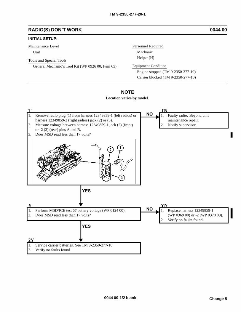
TM 9-2350-277-20-1
RADIO(S) DON’T WORK 0044 00
INITIAL SETUP:
Maintenance LevelUnit
Tools and Special ToolsGeneral Mechanic’s Tool Kit (WP 0926 00, Item 65)
Personnel RequiredMechanicHelper (H)
Equipment ConditionEngine stopped (TM 9-2350-277-10)Carrier blocked (TM 9-2350-277-10)
NOTE
T1. Remove radio plug (1) from harness 12349859-1 (left radios) or
harness 12349859-2 (right radios) jack (2) or (3).2. Measure voltage between harness 12349859-1 jack (2) (front)
or -2 (3) (rear) pins A and B.3. Does MSD read less than 17 volts?
TN1. Faulty radio. Beyond unit
maintenance repair.2. Notify supervisor.
Y1. Perform MSD/ICE test 67 battery voltage (WP 0124 00).2. Does MSD read less than 17 volts?
YN1. Replace harness 12349859-1
(WP 0369 00) or -2 (WP 0370 00).2. Verify no faults found.
2Y1. Service carrier batteries. See TM 9-2350-277-10.2. Verify no faults found.
Change 5
Location varies by model.
0044 00-1/2 blank

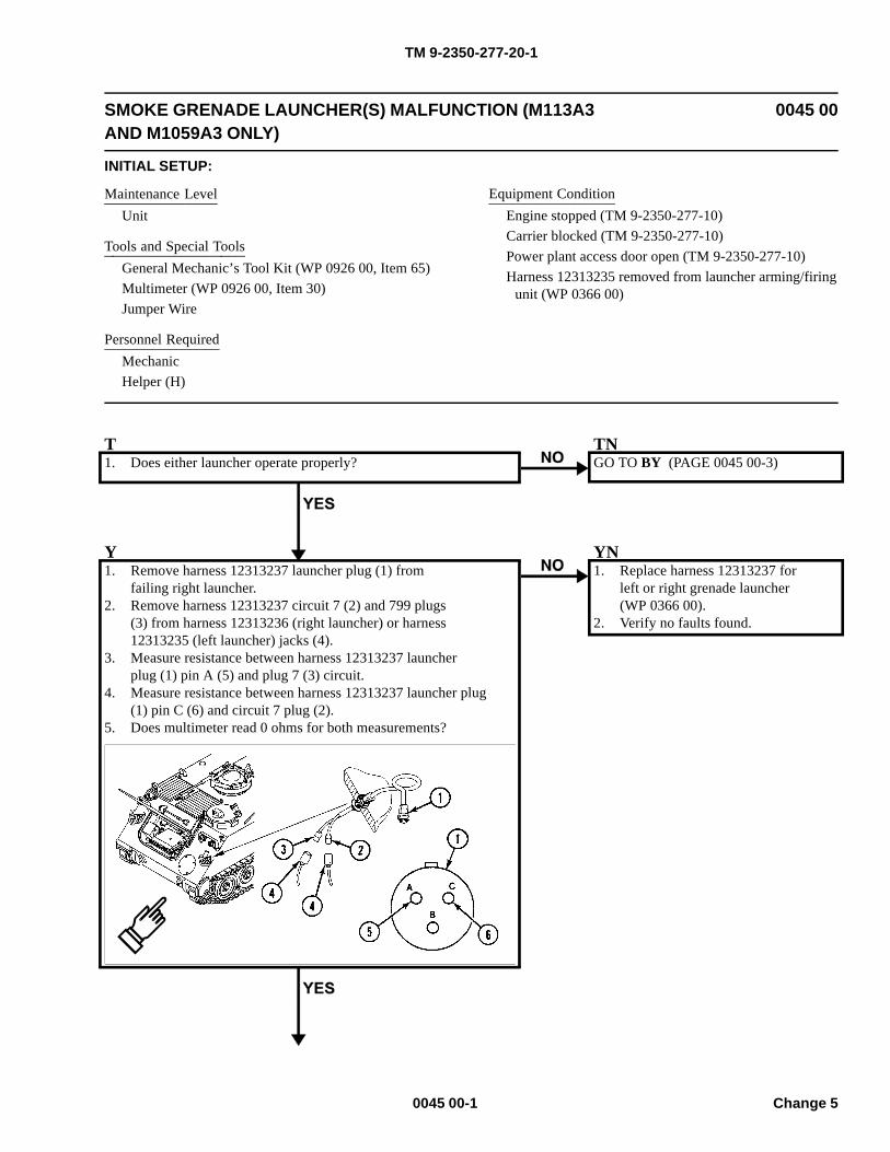
TM 9-2350-277-20-1
SMOKE GRENADE LAUNCHER(S) MALFUNCTION (M113A3AND M1059A3 ONLY)
0045 00
INITIAL SETUP:
Maintenance LevelUnit
Tools and Special ToolsGeneral Mechanic’s Tool Kit (WP 0926 00, Item 65)Multimeter (WP 0926 00, Item 30)Jumper Wire
Personnel RequiredMechanicHelper (H)
Equipment ConditionEngine stopped (TM 9-2350-277-10)Carrier blocked (TM 9-2350-277-10)Power plant access door open (TM 9-2350-277-10)Harness 12313235 removed from launcher arming/firing
unit (WP 0366 00)
T1. Does either launcher operate properly?
TNGO TO BY (PAGE 0045 00-3)
Y1. Remove harness 12313237 launcher plug (1) from
failing right launcher.2. Remove harness 12313237 circuit 7 (2) and 799 plugs
(3) from harness 12313236 (right launcher) or harness12313235 (left launcher) jacks (4).
3. Measure resistance between harness 12313237 launcherplug (1) pin A (5) and plug 7 (3) circuit.
4. Measure resistance between harness 12313237 launcher plug(1) pin C (6) and circuit 7 plug (2).
5. Does multimeter read 0 ohms for both measurements?
YN1. Replace harness 12313237 for
left or right grenade launcher(WP 0366 00).
2. Verify no faults found.
0045 00-1 Change 5
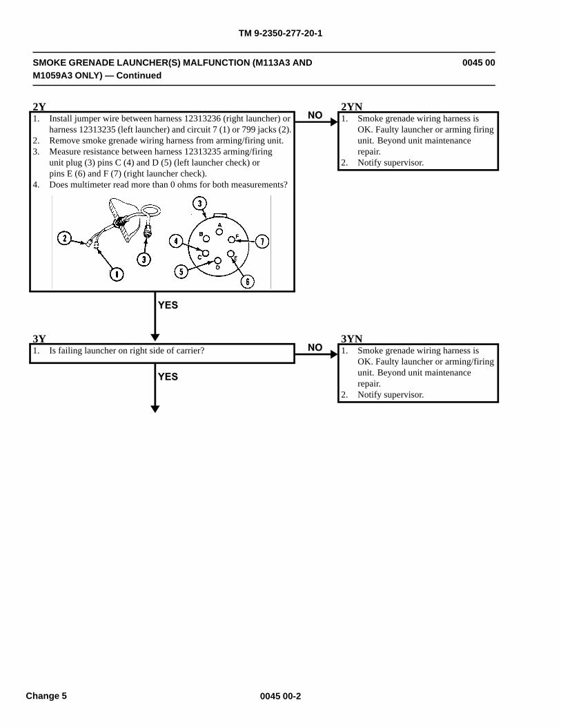
TM 9-2350-277-20-1
SMOKE GRENADE LAUNCHER(S) MALFUNCTION (M113A3 ANDM1059A3 ONLY) — Continued
0045 00
2Y1. Install jumper wire between harness 12313236 (right launcher) or
harness 12313235 (left launcher) and circuit 7 (1) or 799 jacks (2).2. Remove smoke grenade wiring harness from arming/firing unit.3. Measure resistance between harness 12313235 arming/firing
unit plug (3) pins C (4) and D (5) (left launcher check) orpins E (6) and F (7) (right launcher check).
4. Does multimeter read more than 0 ohms for both measurements?
2YN1. Smoke grenade wiring harness is
OK. Faulty launcher or arming firingunit. Beyond unit maintenancerepair.
2. Notify supervisor.
3Y1. Is failing launcher on right side of carrier?
3YN1. Smoke grenade wiring harness is
OK. Faulty launcher or arming/firingunit. Beyond unit maintenancerepair.
2. Notify supervisor.
0045 00-2Change 5
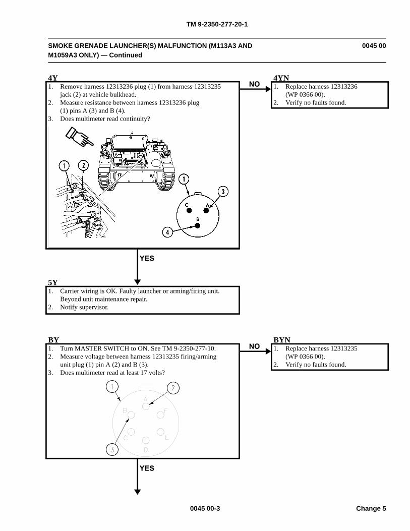
TM 9-2350-277-20-1
SMOKE GRENADE LAUNCHER(S) MALFUNCTION (M113A3 ANDM1059A3 ONLY) — Continued
0045 00
4Y1. Remove harness 12313236 plug (1) from harness 12313235
jack (2) at vehicle bulkhead.2. Measure resistance between harness 12313236 plug
(1) pins A (3) and B (4).3. Does multimeter read continuity?
4YN1. Replace harness 12313236
(WP 0366 00).2. Verify no faults found.
5Y1. Carrier wiring is OK. Faulty launcher or arming/firing unit.
Beyond unit maintenance repair.2. Notify supervisor.
BY1. Turn MASTER SWITCH to ON. See TM 9-2350-277-10.2. Measure voltage between harness 12313235 firing/arming
unit plug (1) pin A (2) and B (3).3. Does multimeter read at least 17 volts?
BYN1. Replace harness 12313235
(WP 0366 00).2. Verify no faults found.
0045 00-3 Change 5

TM 9-2350-277-20-1
SMOKE GRENADE LAUNCHER(S) MALFUNCTION (M113A3 ANDM1059A3 ONLY) — Continued
0045 00
B2Y1. Faulty arming/firing unit. Beyond unit maintenance repair.2. Notify supervisor.
0045 00-4Change 5
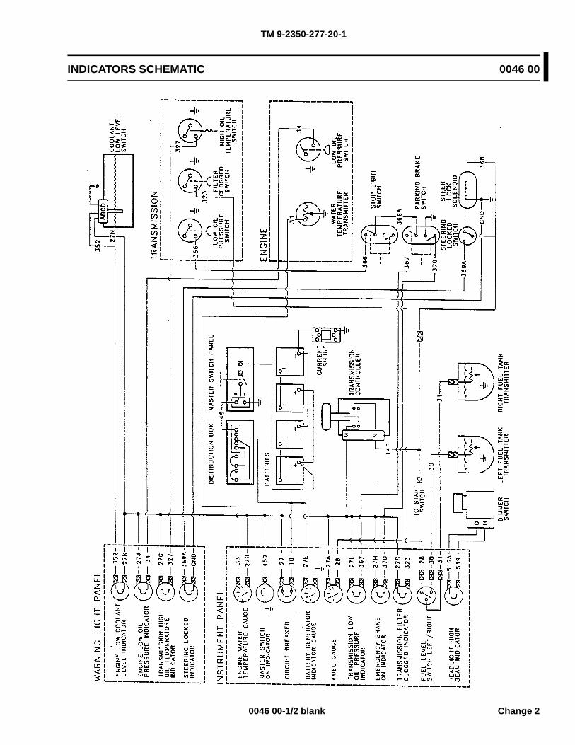
TM 9-2350-277-20-1
INDICATORS SCHEMATIC 0046 00
0046 00-1/2 blank Change 2

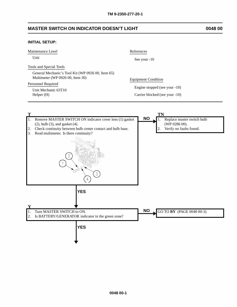
TM 9-2350-277-20-1
MASTER SWITCH ON INDICATOR DOESN’T LIGHT 0048 00
INITIAL SETUP:
Maintenance Level
Unit
Tools and Special Tools
General Mechanic’s Tool Kit (WP 0926 00, Item 65)Multimeter (WP 0926 00, Item 30)
Personnel Required
Unit Mechanic 63T10Helper (H)
References
See your -10
Equipment Condition
Engine stopped (see your -10)
Carrier blocked (see your -10)
T1. Remove MASTER SWITCH ON indicator cover lens (1) gasket
(2), bulb (3), and gasket (4).2. Check continuity between bulb center contact and bulb base.3. Read multimeter. Is there continuity?
YES
NOTN1. Replace master switch bulb
(WP 0286 00).2. Verify no faults found.
Y1. Turn MASTER SWITCH to ON.2. Is BATTERY/GENERATOR indicator in the green zone?
YES
NO GO TO BY (PAGE 0048 00-3)
0048 00-1
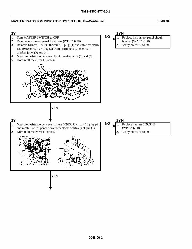
TM 9-2350-277-20-1
MASTER SWITCH ON INDICATOR DOESN’T LIGHT—Continued 0048 00
2Y1. Turn MASTER SWITCH to OFF.2. Remove instrument panel for access (WP 0296 00).3. Remove harness 10933038 circuit 10 plug (1) and cable assembly
12349858 circuit 27 plug (2) from instrument panel circuitbreaker jacks (3) and (4).
4. Measure resistance between circuit breaker jacks (3) and (4).5. Does multimeter read 0 ohms?
YES
NO2YN1. Replace instrument panel circuit
breaker (WP 0280 00).2. Verify no faults found.
3Y1. Measure resistance between harness 10933038 circuit 10 plug pin
and master switch panel power receptacle positive jack pin (1).2. Does multimeter read 0 ohms?
YES
NO3YN1. Replace harness 10933038
(WP 0266 00).2. Verify no faults found.
0048 00-2
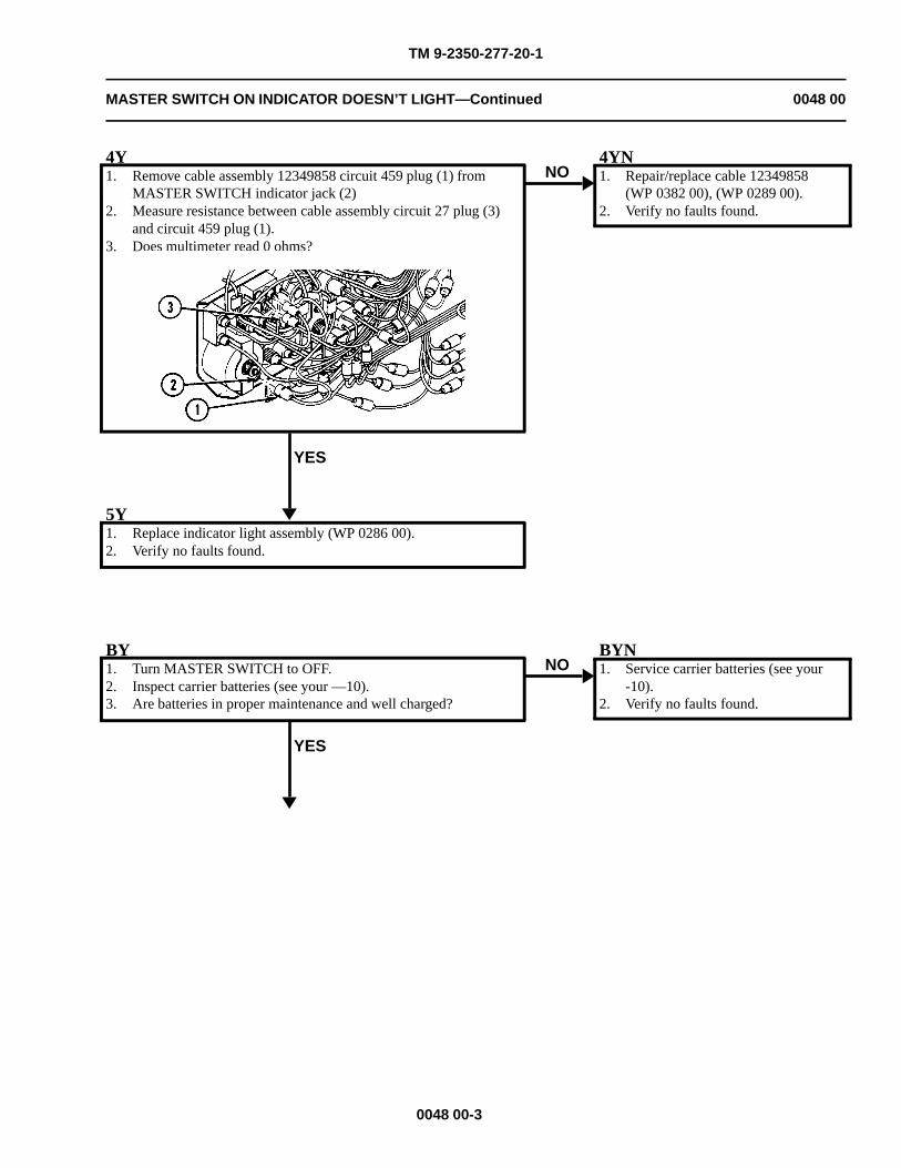
TM 9-2350-277-20-1
MASTER SWITCH ON INDICATOR DOESN’T LIGHT—Continued 0048 00
4Y1. Remove cable assembly 12349858 circuit 459 plug (1) from
MASTER SWITCH indicator jack (2)2. Measure resistance between cable assembly circuit 27 plug (3)
and circuit 459 plug (1).3. Does multimeter read 0 ohms?
YES
NO4YN1. Repair/replace cable 12349858
(WP 0382 00), (WP 0289 00).2. Verify no faults found.
5Y1. Replace indicator light assembly (WP 0286 00).2. Verify no faults found.
BY1. Turn MASTER SWITCH to OFF.2. Inspect carrier batteries (see your —10).3. Are batteries in proper maintenance and well charged?
YES
NOBYN1. Service carrier batteries (see your
-10).2. Verify no faults found.
0048 00-3
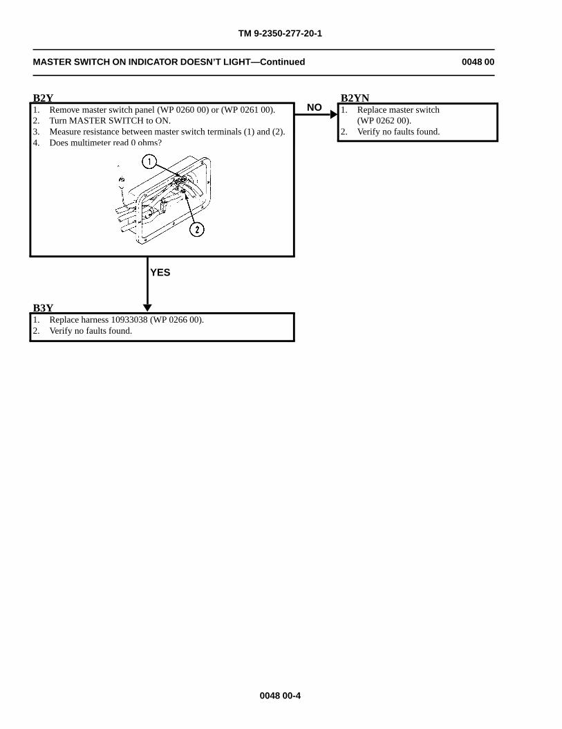
TM 9-2350-277-20-1
MASTER SWITCH ON INDICATOR DOESN’T LIGHT—Continued 0048 00
B2Y1. Remove master switch panel (WP 0260 00) or (WP 0261 00).2. Turn MASTER SWITCH to ON.3. Measure resistance between master switch terminals (1) and (2).4. Does multimeter read 0 ohms?
YES
NOB2YN1. Replace master switch
(WP 0262 00).2. Verify no faults found.
B3Y1. Replace harness 10933038 (WP 0266 00).2. Verify no faults found.
0048 00-4
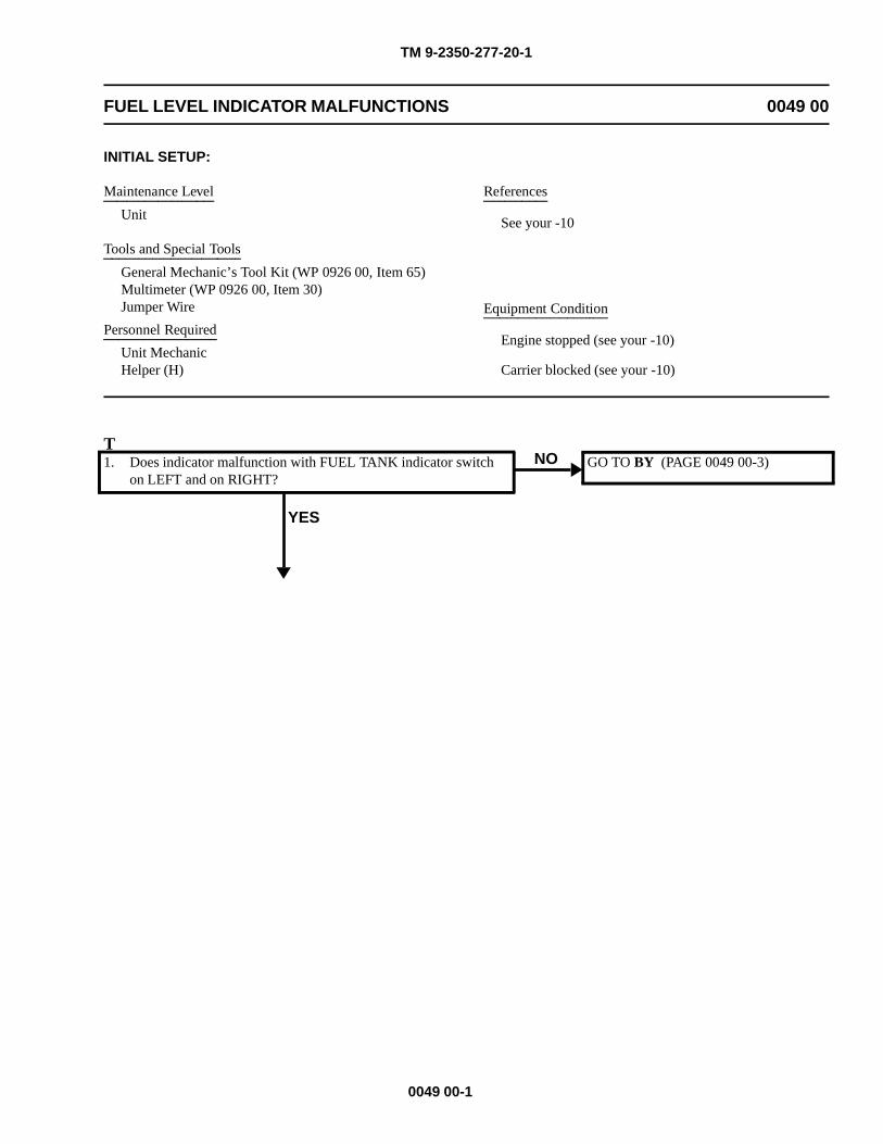
TM 9-2350-277-20-1
FUEL LEVEL INDICATOR MALFUNCTIONS 0049 00
INITIAL SETUP:
Maintenance Level
Unit
Tools and Special Tools
General Mechanic’s Tool Kit (WP 0926 00, Item 65)Multimeter (WP 0926 00, Item 30)Jumper Wire
Personnel Required
Unit MechanicHelper (H)
References
See your -10
Equipment Condition
Engine stopped (see your -10)
Carrier blocked (see your -10)
T1. Does indicator malfunction with FUEL TANK indicator switch
on LEFT and on RIGHT?
YES
NO GO TO BY (PAGE 0049 00-3)
0049 00-1
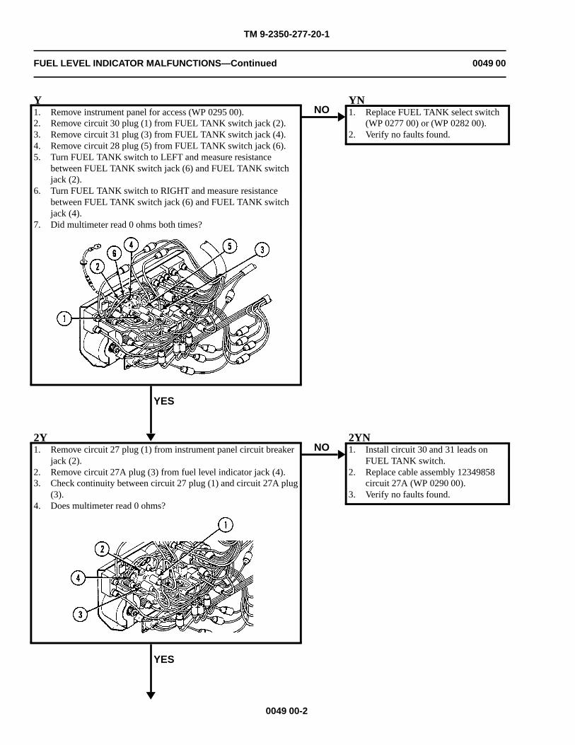
TM 9-2350-277-20-1
FUEL LEVEL INDICATOR MALFUNCTIONS—Continued 0049 00
Y1. Remove instrument panel for access (WP 0295 00).2. Remove circuit 30 plug (1) from FUEL TANK switch jack (2).3. Remove circuit 31 plug (3) from FUEL TANK switch jack (4).4. Remove circuit 28 plug (5) from FUEL TANK switch jack (6).5. Turn FUEL TANK switch to LEFT and measure resistance
between FUEL TANK switch jack (6) and FUEL TANK switchjack (2).
6. Turn FUEL TANK switch to RIGHT and measure resistancebetween FUEL TANK switch jack (6) and FUEL TANK switchjack (4).
7. Did multimeter read 0 ohms both times?
YES
NOYN1. Replace FUEL TANK select switch
(WP 0277 00) or (WP 0282 00).2. Verify no faults found.
2Y1. Remove circuit 27 plug (1) from instrument panel circuit breaker
jack (2).2. Remove circuit 27A plug (3) from fuel level indicator jack (4).3. Check continuity between circuit 27 plug (1) and circuit 27A plug
(3).4. Does multimeter read 0 ohms?
YES
NO2YN1. Install circuit 30 and 31 leads on
FUEL TANK switch.2. Replace cable assembly 12349858
circuit 27A (WP 0290 00).3. Verify no faults found.
0049 00-2
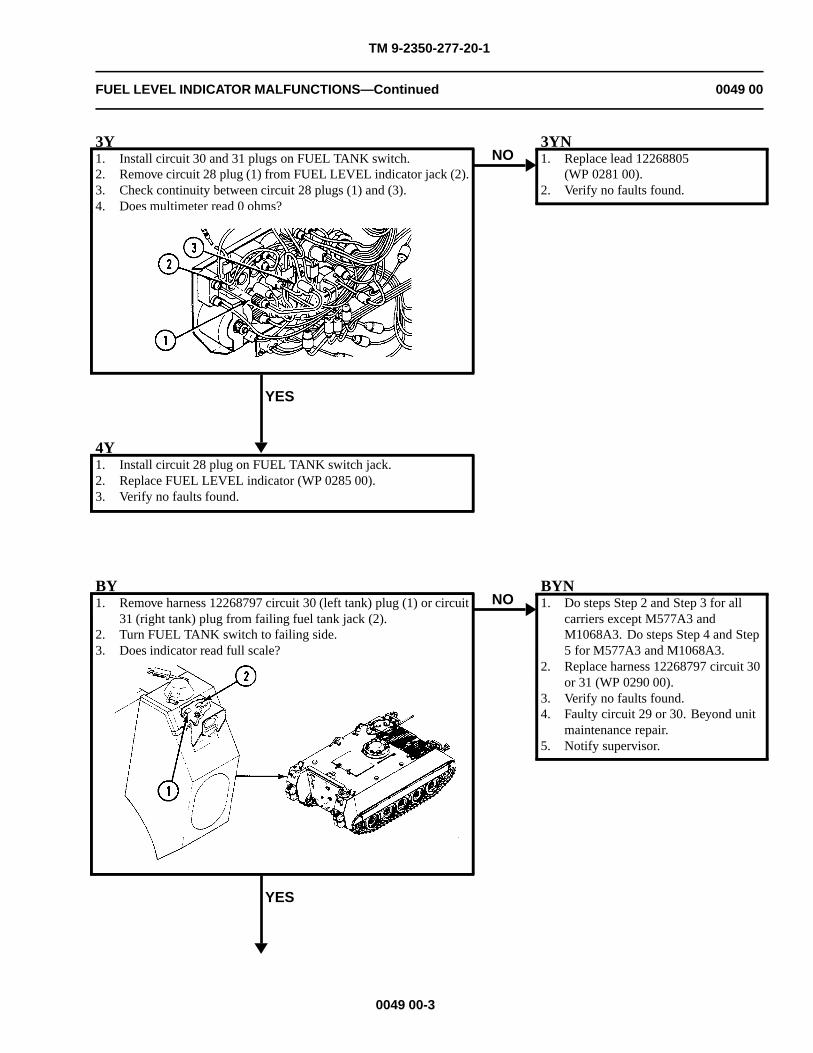
TM 9-2350-277-20-1
FUEL LEVEL INDICATOR MALFUNCTIONS—Continued 0049 00
3Y1. Install circuit 30 and 31 plugs on FUEL TANK switch.2. Remove circuit 28 plug (1) from FUEL LEVEL indicator jack (2).3. Check continuity between circuit 28 plugs (1) and (3).4. Does multimeter read 0 ohms?
YES
NO3YN1. Replace lead 12268805
(WP 0281 00).2. Verify no faults found.
4Y1. Install circuit 28 plug on FUEL TANK switch jack.2. Replace FUEL LEVEL indicator (WP 0285 00).3. Verify no faults found.
BY1. Remove harness 12268797 circuit 30 (left tank) plug (1) or circuit
31 (right tank) plug from failing fuel tank jack (2).2. Turn FUEL TANK switch to failing side.3. Does indicator read full scale?
YES
NOBYN1. Do steps Step 2 and Step 3 for all
carriers except M577A3 andM1068A3. Do steps Step 4 and Step5 for M577A3 and M1068A3.
2. Replace harness 12268797 circuit 30or 31 (WP 0290 00).
3. Verify no faults found.4. Faulty circuit 29 or 30. Beyond unit
maintenance repair.5. Notify supervisor.
0049 00-3
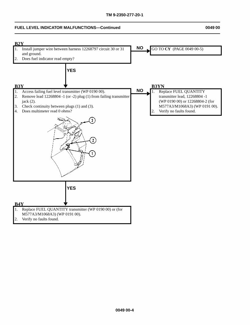
TM 9-2350-277-20-1
FUEL LEVEL INDICATOR MALFUNCTIONS—Continued 0049 00
B2Y1. Install jumper wire between harness 12268797 circuit 30 or 31
and ground.2. Does fuel indicator read empty?
YES
NO GO TO CY (PAGE 0049 00-5)
B3Y1. Access failing fuel level transmitter (WP 0190 00).2. Remove lead 12268804 -1 (or -2) plug (1) from failing transmitter
jack (2).3. Check continuity between plugs (1) and (3).4. Does multimeter read 0 ohms?
YES
NOB3YN1. Replace FUEL QUANTITY
transmitter lead, 12268804 -1(WP 0190 00) or 12268804-2 (forM577A3/M1068A3) (WP 0191 00).
2. Verify no faults found.
B4Y1. Replace FUEL QUANTITY transmitter (WP 0190 00) or (for
M577A3/M1068A3) (WP 0191 00).2. Verify no faults found.
0049 00-4
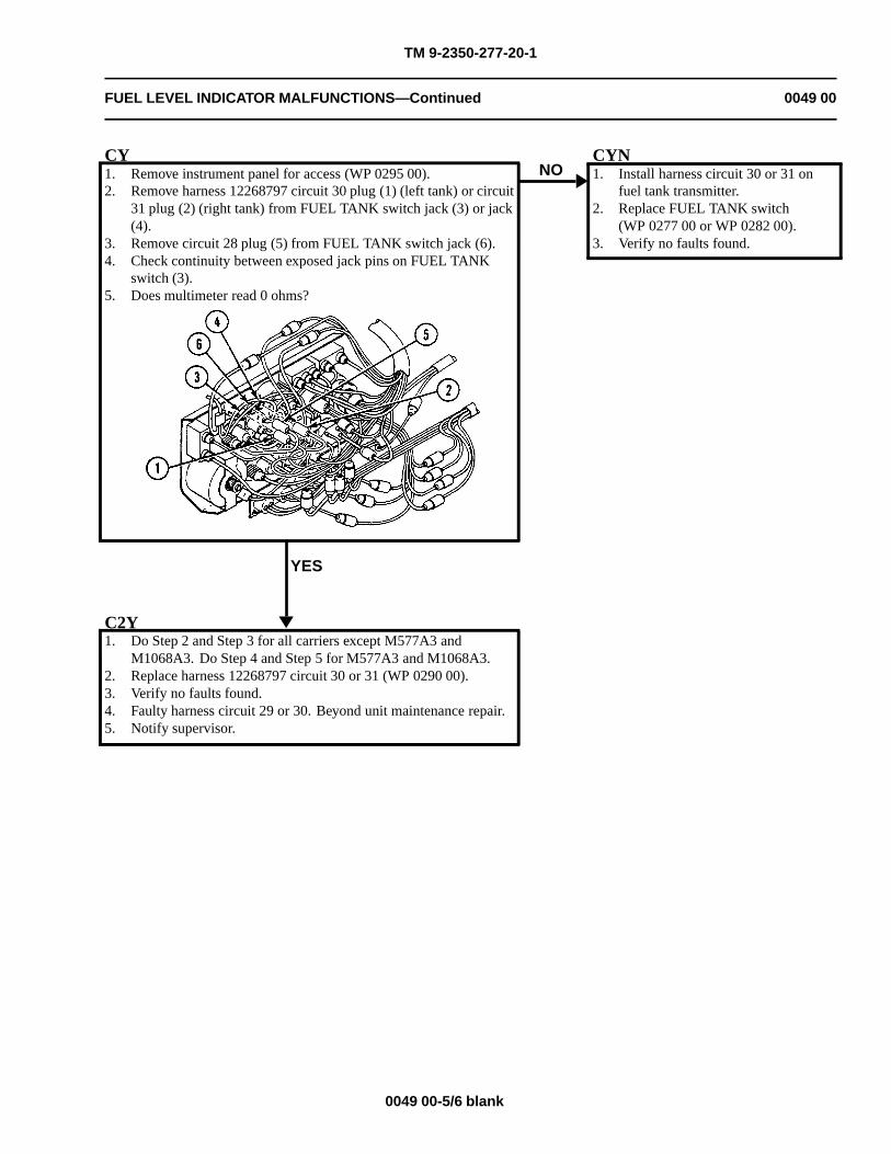
TM 9-2350-277-20-1
FUEL LEVEL INDICATOR MALFUNCTIONS—Continued 0049 00
CY1. Remove instrument panel for access (WP 0295 00).2. Remove harness 12268797 circuit 30 plug (1) (left tank) or circuit
31 plug (2) (right tank) from FUEL TANK switch jack (3) or jack(4).
3. Remove circuit 28 plug (5) from FUEL TANK switch jack (6).4. Check continuity between exposed jack pins on FUEL TANK
switch (3).5. Does multimeter read 0 ohms?
YES
NOCYN1. Install harness circuit 30 or 31 on
fuel tank transmitter.2. Replace FUEL TANK switch
(WP 0277 00 or WP 0282 00).3. Verify no faults found.
C2Y1. Do Step 2 and Step 3 for all carriers except M577A3 and
M1068A3. Do Step 4 and Step 5 for M577A3 and M1068A3.2. Replace harness 12268797 circuit 30 or 31 (WP 0290 00).3. Verify no faults found.4. Faulty harness circuit 29 or 30. Beyond unit maintenance repair.5. Notify supervisor.
0049 00-5/6 blank

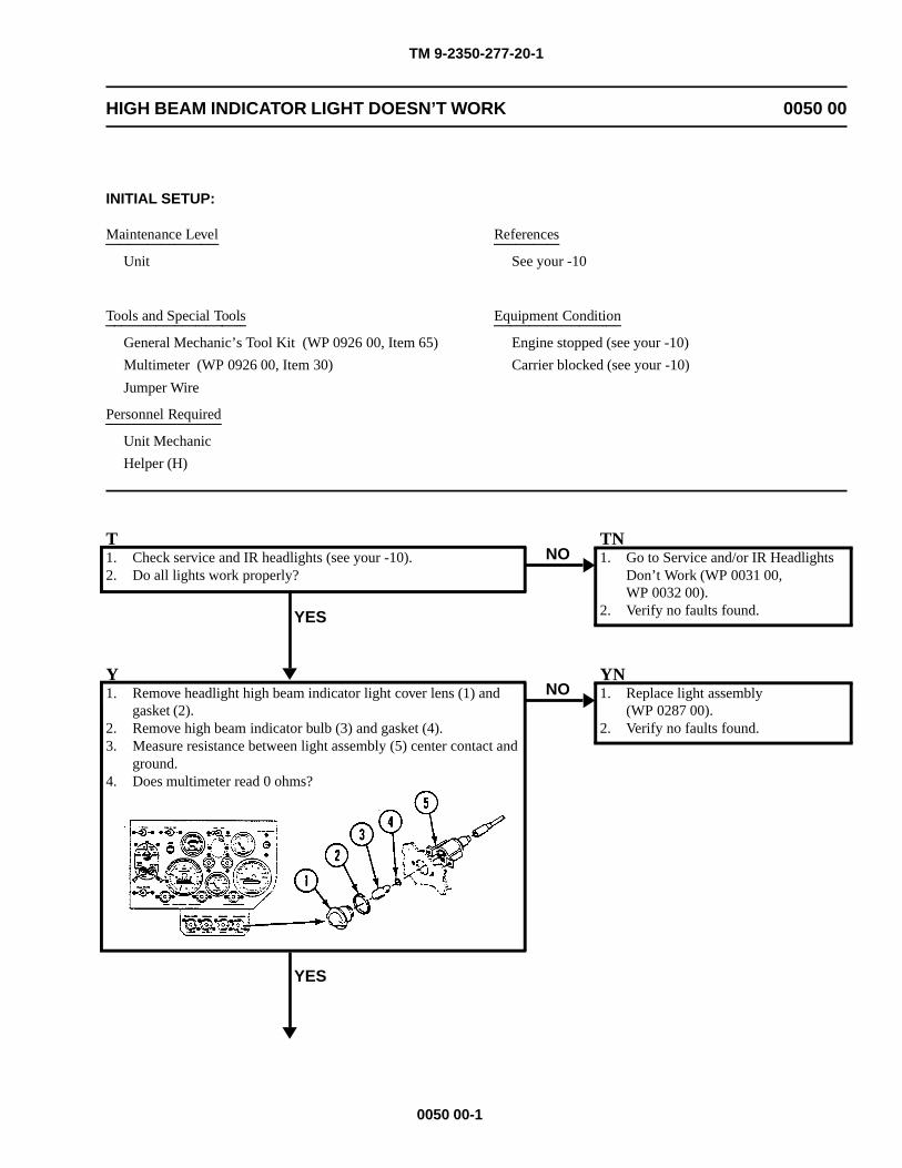
TM 9-2350-277-20-1
HIGH BEAM INDICATOR LIGHT DOESN’T WORK 0050 00
INITIAL SETUP:
Maintenance Level
Unit
Tools and Special Tools
General Mechanic’s Tool Kit (WP 0926 00, Item 65)
Multimeter (WP 0926 00, Item 30)
Jumper Wire
Personnel Required
Unit Mechanic
Helper (H)
References
See your -10
Equipment Condition
Engine stopped (see your -10)
Carrier blocked (see your -10)
T1. Check service and IR headlights (see your -10).2. Do all lights work properly?
YES
NOTN1. Go to Service and/or IR Headlights
Don’t Work (WP 0031 00,WP 0032 00).
2. Verify no faults found.
Y1. Remove headlight high beam indicator light cover lens (1) and
gasket (2).2. Remove high beam indicator bulb (3) and gasket (4).3. Measure resistance between light assembly (5) center contact and
ground.4. Does multimeter read 0 ohms?
YES
NOYN1. Replace light assembly
(WP 0287 00).2. Verify no faults found.
0050 00-1
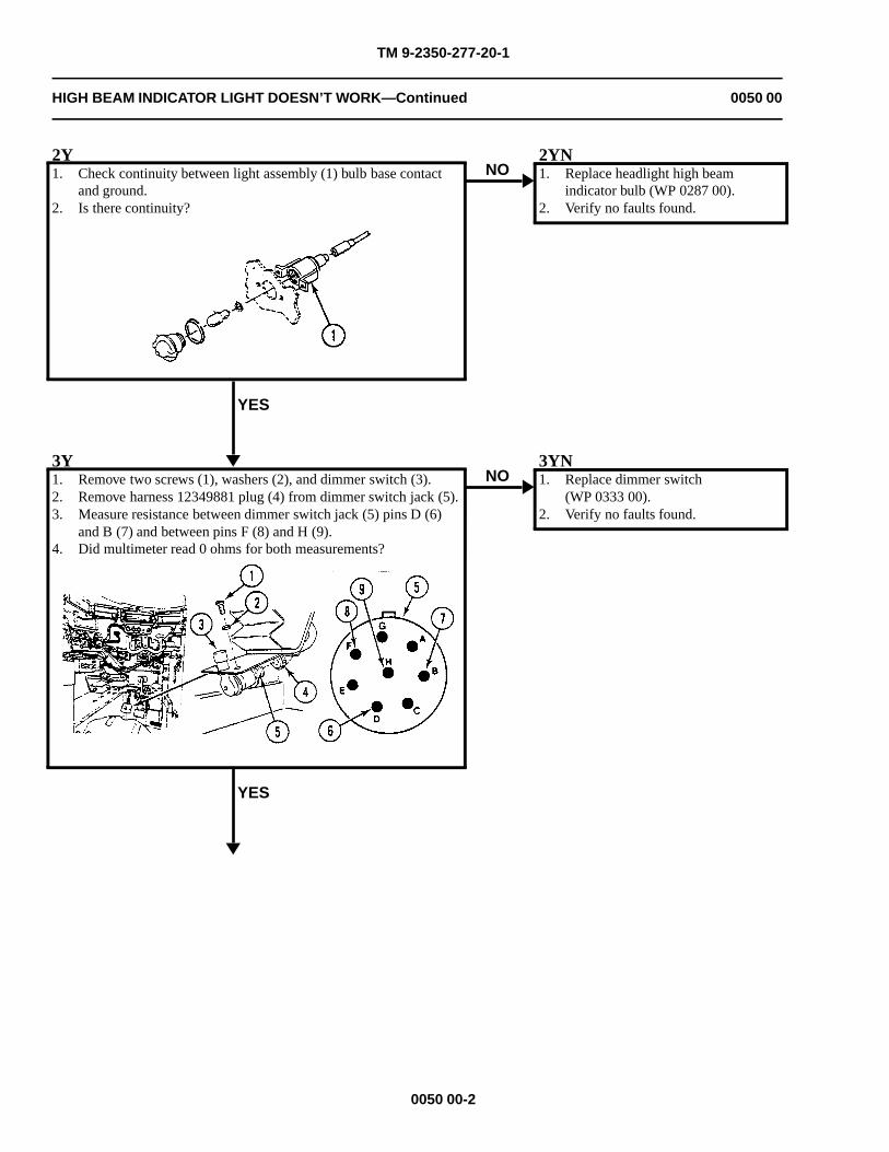
TM 9-2350-277-20-1
HIGH BEAM INDICATOR LIGHT DOESN’T WORK—Continued 0050 00
2Y1. Check continuity between light assembly (1) bulb base contact
and ground.2. Is there continuity?
YES
NO2YN1. Replace headlight high beam
indicator bulb (WP 0287 00).2. Verify no faults found.
3Y1. Remove two screws (1), washers (2), and dimmer switch (3).2. Remove harness 12349881 plug (4) from dimmer switch jack (5).3. Measure resistance between dimmer switch jack (5) pins D (6)
and B (7) and between pins F (8) and H (9).4. Did multimeter read 0 ohms for both measurements?
YES
NO3YN1. Replace dimmer switch
(WP 0333 00).2. Verify no faults found.
0050 00-2
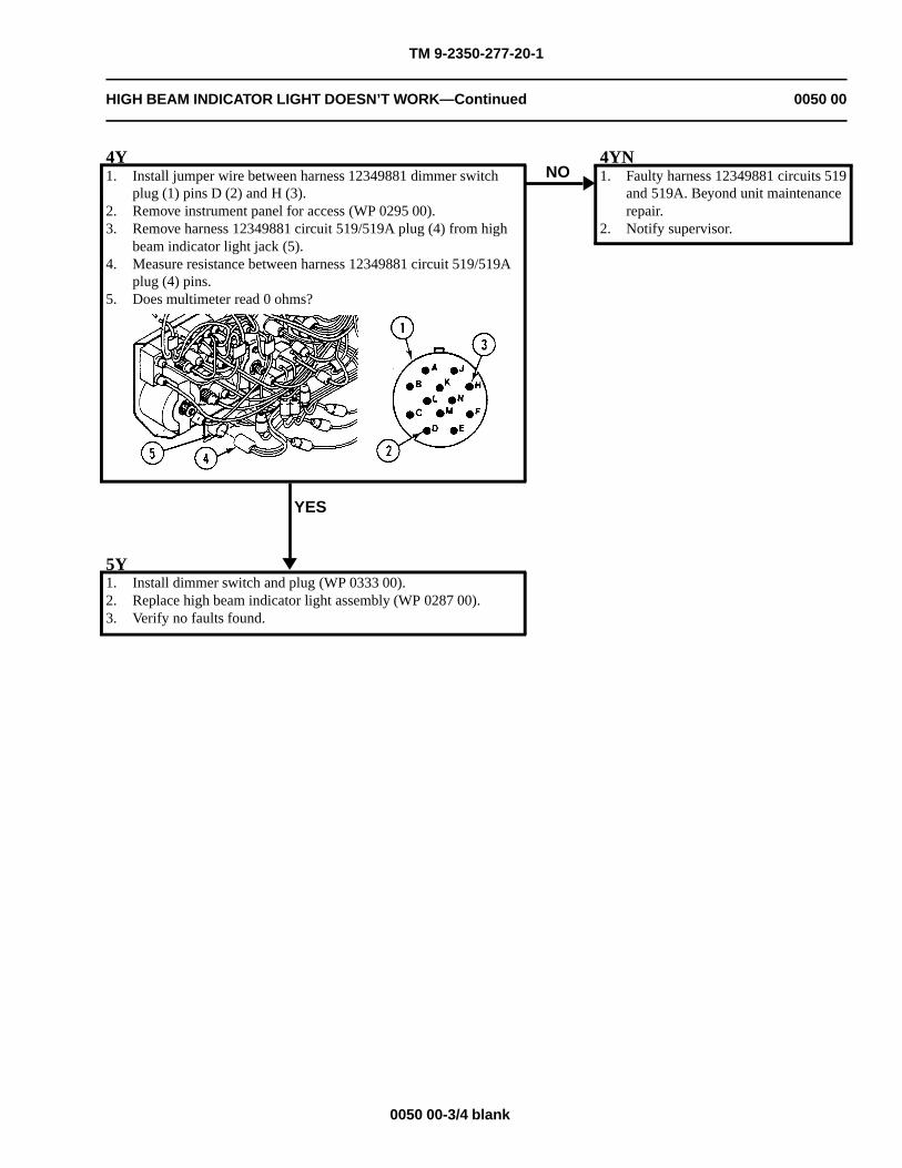
TM 9-2350-277-20-1
HIGH BEAM INDICATOR LIGHT DOESN’T WORK—Continued 0050 00
4Y1. Install jumper wire between harness 12349881 dimmer switch
plug (1) pins D (2) and H (3).2. Remove instrument panel for access (WP 0295 00).3. Remove harness 12349881 circuit 519/519A plug (4) from high
beam indicator light jack (5).4. Measure resistance between harness 12349881 circuit 519/519A
plug (4) pins.5. Does multimeter read 0 ohms?
YES
NO4YN1. Faulty harness 12349881 circuits 519
and 519A. Beyond unit maintenancerepair.
2. Notify supervisor.
5Y1. Install dimmer switch and plug (WP 0333 00).2. Replace high beam indicator light assembly (WP 0287 00).3. Verify no faults found.
0050 00-3/4 blank

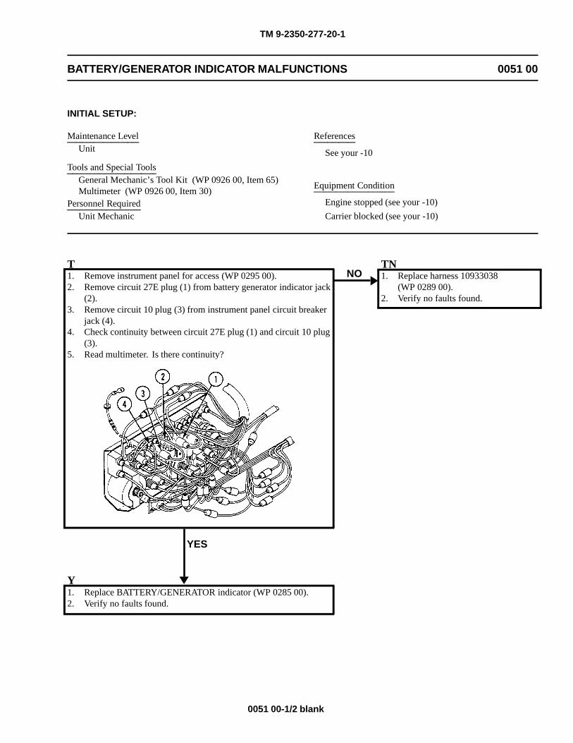
TM 9-2350-277-20-1
BATTERY/GENERATOR INDICATOR MALFUNCTIONS 0051 00
INITIAL SETUP:
Maintenance LevelUnit
Tools and Special ToolsGeneral Mechanic’s Tool Kit (WP 0926 00, Item 65)Multimeter (WP 0926 00, Item 30)
Personnel RequiredUnit Mechanic
References
See your -10
Equipment Condition
Engine stopped (see your -10)
Carrier blocked (see your -10)
T1. Remove instrument panel for access (WP 0295 00).2. Remove circuit 27E plug (1) from battery generator indicator jack
(2).3. Remove circuit 10 plug (3) from instrument panel circuit breaker
jack (4).4. Check continuity between circuit 27E plug (1) and circuit 10 plug
(3).5. Read multimeter. Is there continuity?
YES
NOTN1. Replace harness 10933038
(WP 0289 00).2. Verify no faults found.
Y1. Replace BATTERY/GENERATOR indicator (WP 0285 00).2. Verify no faults found.
0051 00-1/2 blank

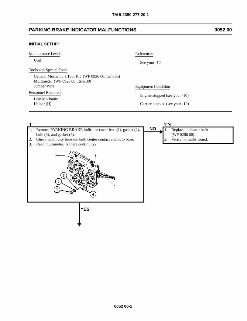
TM 9-2350-277-20-1
PARKING BRAKE INDICATOR MALFUNCTIONS 0052 00
INITIAL SETUP:
Maintenance Level
Unit
Tools and Special Tools
General Mechanic’s Tool Kit (WP 0926 00, Item 65)Multimeter (WP 0926 00, Item 30)Jumper Wire
Personnel Required
Unit MechanicHelper (H)
References
See your -10
Equipment Condition
Engine stopped (see your -10)
Carrier blocked (see your -10)
T1. Remove PARKING BRAKE indicator cover lens (1), gasket (2),
bulb (3), and gasket (4).2. Check continuity between bulb center contact and bulb base.3. Read multimeter. Is there continuity?
YES
NOTN1. Replace indicator bulb
(WP 0286 00).2. Verify no faults found.
0052 00-1
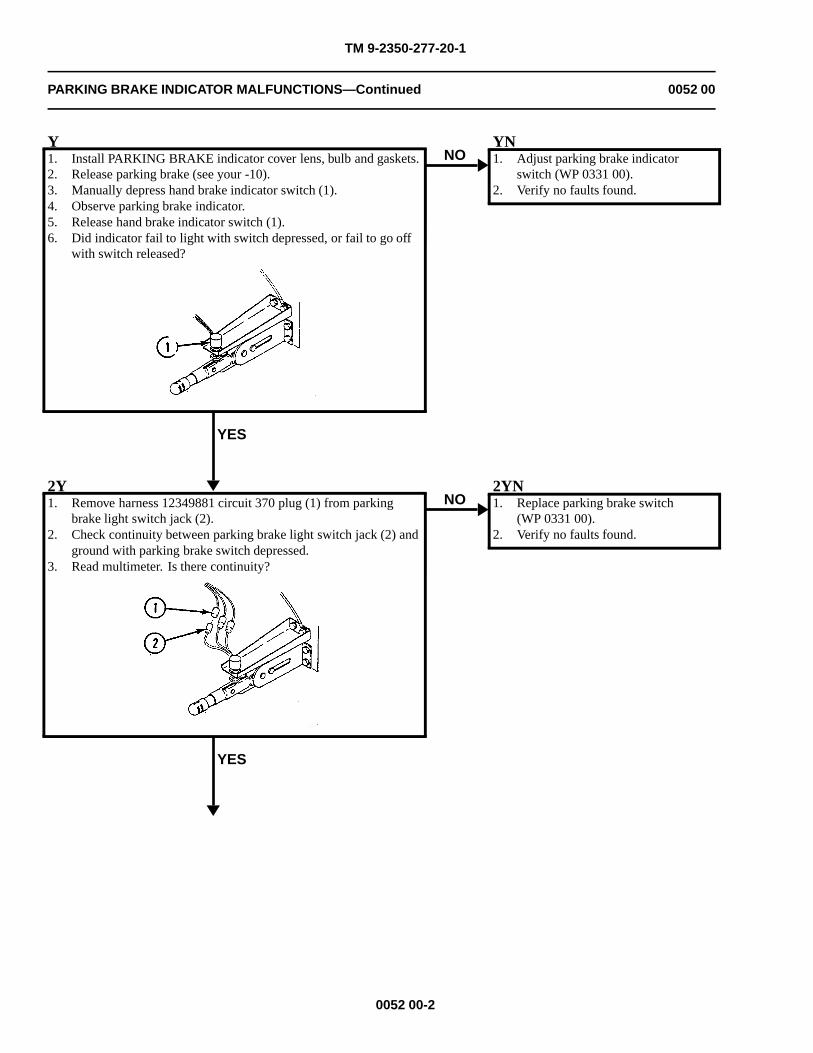
TM 9-2350-277-20-1
PARKING BRAKE INDICATOR MALFUNCTIONS—Continued 0052 00
Y1. Install PARKING BRAKE indicator cover lens, bulb and gaskets.2. Release parking brake (see your -10).3. Manually depress hand brake indicator switch (1).4. Observe parking brake indicator.5. Release hand brake indicator switch (1).6. Did indicator fail to light with switch depressed, or fail to go off
with switch released?
YES
NOYN1. Adjust parking brake indicator
switch (WP 0331 00).2. Verify no faults found.
2Y1. Remove harness 12349881 circuit 370 plug (1) from parking
brake light switch jack (2).2. Check continuity between parking brake light switch jack (2) and
ground with parking brake switch depressed.3. Read multimeter. Is there continuity?
YES
NO2YN1. Replace parking brake switch
(WP 0331 00).2. Verify no faults found.
0052 00-2
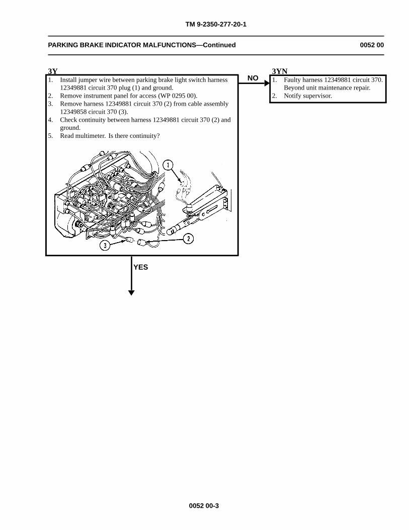
TM 9-2350-277-20-1
PARKING BRAKE INDICATOR MALFUNCTIONS—Continued 0052 00
3Y1. Install jumper wire between parking brake light switch harness
12349881 circuit 370 plug (1) and ground.2. Remove instrument panel for access (WP 0295 00).3. Remove harness 12349881 circuit 370 (2) from cable assembly
12349858 circuit 370 (3).4. Check continuity between harness 12349881 circuit 370 (2) and
ground.5. Read multimeter. Is there continuity?
YES
NO3YN1. Faulty harness 12349881 circuit 370.
Beyond unit maintenance repair.2. Notify supervisor.
0052 00-3
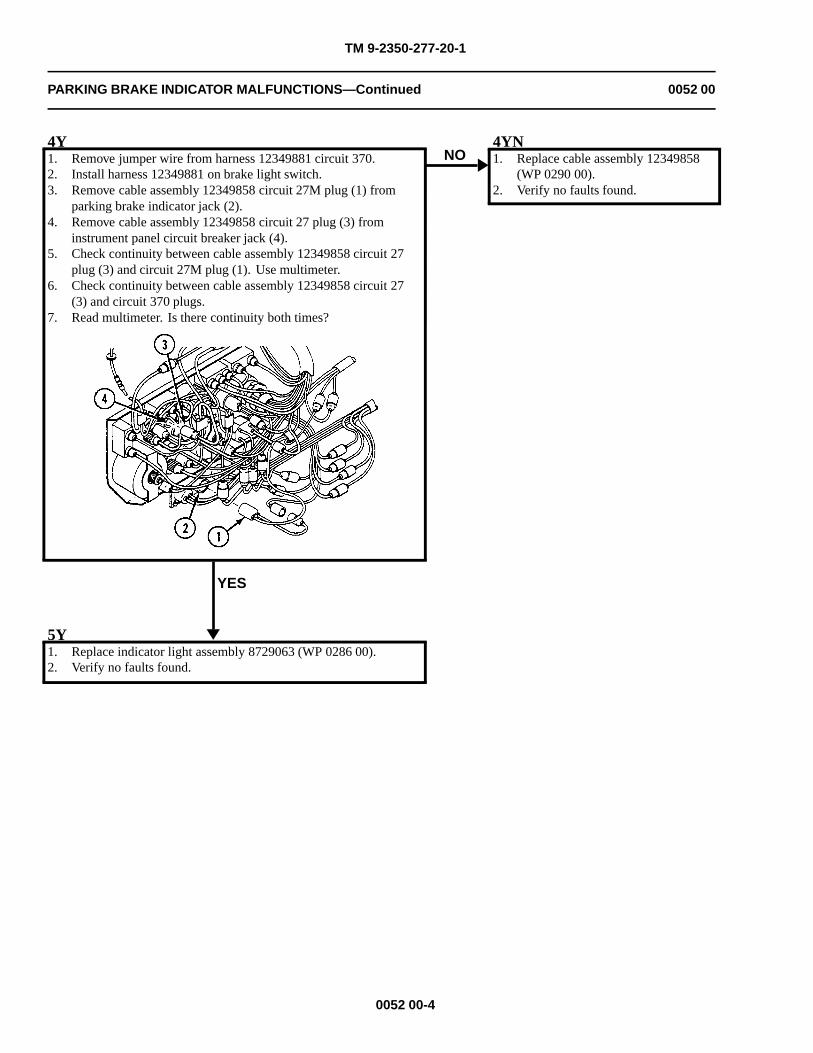
TM 9-2350-277-20-1
PARKING BRAKE INDICATOR MALFUNCTIONS—Continued 0052 00
4Y1. Remove jumper wire from harness 12349881 circuit 370.2. Install harness 12349881 on brake light switch.3. Remove cable assembly 12349858 circuit 27M plug (1) from
parking brake indicator jack (2).4. Remove cable assembly 12349858 circuit 27 plug (3) from
instrument panel circuit breaker jack (4).5. Check continuity between cable assembly 12349858 circuit 27
plug (3) and circuit 27M plug (1). Use multimeter.6. Check continuity between cable assembly 12349858 circuit 27
(3) and circuit 370 plugs.7. Read multimeter. Is there continuity both times?
YES
NO4YN1. Replace cable assembly 12349858
(WP 0290 00).2. Verify no faults found.
5Y1. Replace indicator light assembly 8729063 (WP 0286 00).2. Verify no faults found.
0052 00-4
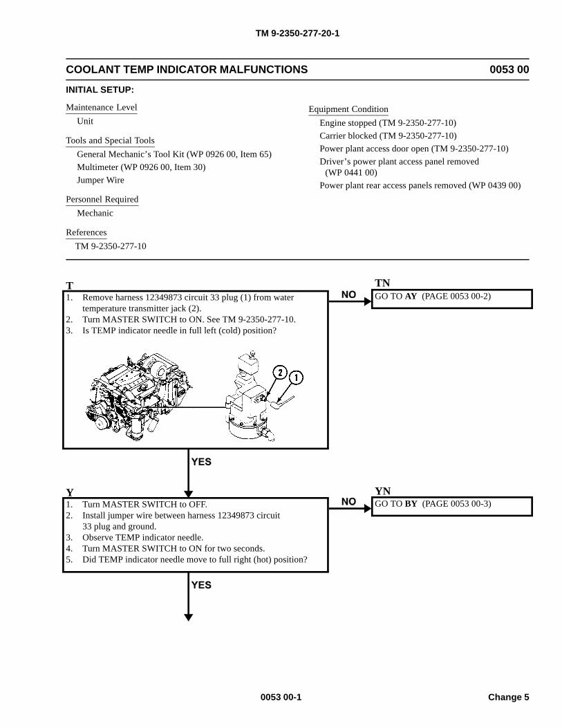
TM 9-2350-277-20-1
COOLANT TEMP INDICATOR MALFUNCTIONS 0053 00
INITIAL SETUP:
Maintenance LevelUnit
Tools and Special ToolsGeneral Mechanic’s Tool Kit (WP 0926 00, Item 65)Multimeter (WP 0926 00, Item 30)Jumper Wire
Personnel RequiredMechanic
ReferencesTM 9-2350-277-10
Equipment ConditionEngine stopped (TM 9-2350-277-10)Carrier blocked (TM 9-2350-277-10)Power plant access door open (TM 9-2350-277-10)Driver’s power plant access panel removed
(WP 0441 00)Power plant rear access panels removed (WP 0439 00)
T1. Remove harness 12349873 circuit 33 plug (1) from water
temperature transmitter jack (2).2. Turn MASTER SWITCH to ON. See TM 9-2350-277-10.3. Is TEMP indicator needle in full left (cold) position?
GO TO AY (PAGE 0053 00-2)
Y1. Turn MASTER SWITCH to OFF.2. Install jumper wire between harness 12349873 circuit
33 plug and ground.3. Observe TEMP indicator needle.4. Turn MASTER SWITCH to ON for two seconds.5. Did TEMP indicator needle move to full right (hot) position?
GO TO BY (PAGE 0053 00-3)
0053 00-1 Change 5
TN
YN
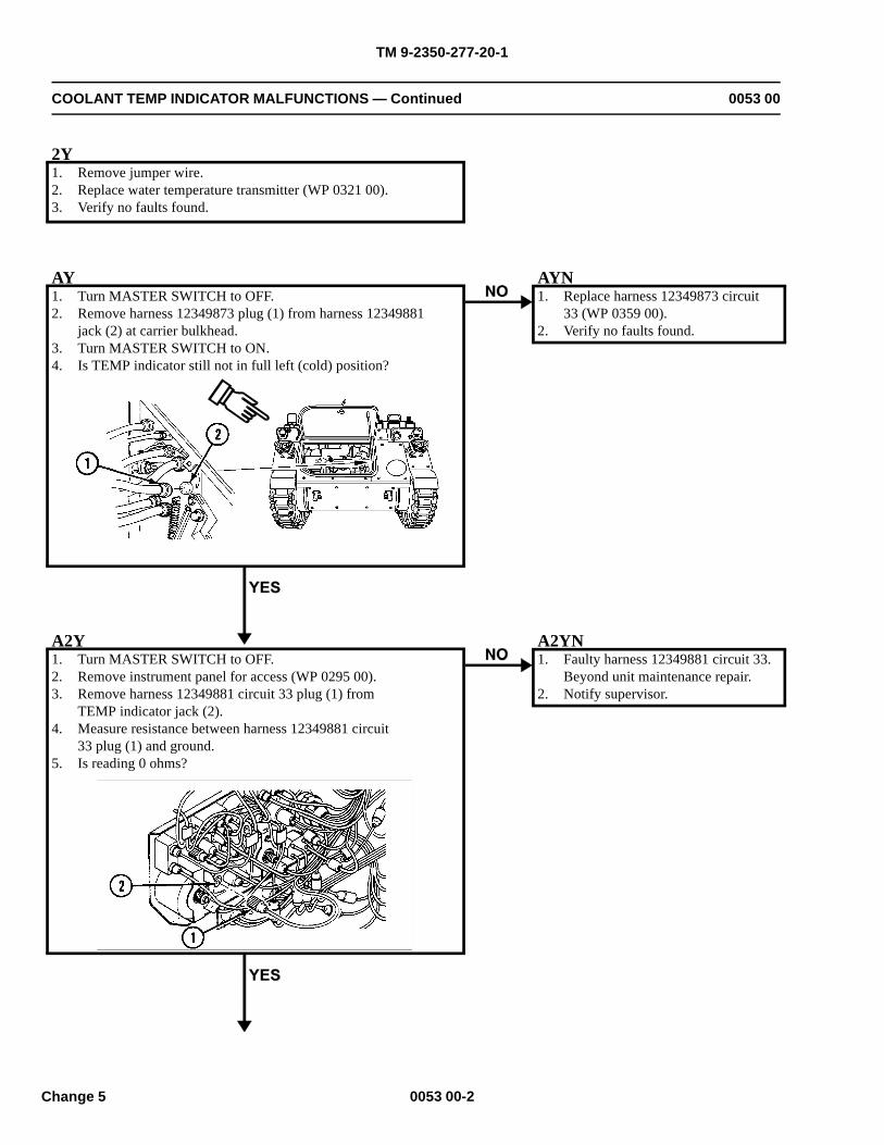
TM 9-2350-277-20-1
COOLANT TEMP INDICATOR MALFUNCTIONS — Continued 0053 00
2Y1. Remove jumper wire.2. Replace water temperature transmitter (WP 0321 00).3. Verify no faults found.
AY1. Turn MASTER SWITCH to OFF.2. Remove harness 12349873 plug (1) from harness 12349881
jack (2) at carrier bulkhead.3. Turn MASTER SWITCH to ON.4. Is TEMP indicator still not in full left (cold) position?
AYN1. Replace harness 12349873 circuit
33 (WP 0359 00).2. Verify no faults found.
A2Y1. Turn MASTER SWITCH to OFF.2. Remove instrument panel for access (WP 0295 00).3. Remove harness 12349881 circuit 33 plug (1) from
TEMP indicator jack (2).4. Measure resistance between harness 12349881 circuit
33 plug (1) and ground.5. Is reading 0 ohms?
A2YN1. Faulty harness 12349881 circuit 33.
Beyond unit maintenance repair.2. Notify supervisor.
0053 00-2Change 5
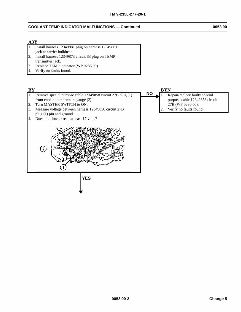
TM 9-2350-277-20-1
COOLANT TEMP INDICATOR MALFUNCTIONS — Continued 0053 00
A3Y1. Install harness 12349881 plug on harness 12349881
jack at carrier bulkhead.2. Install harness 12349873 circuit 33 plug on TEMP
transmitter jack.3. Replace TEMP indicator (WP 0285 00).4. Verify no faults found.
BY1. Remove special purpose cable 12349858 circuit 27B plug (1)
from coolant temperature gauge (2).2. Turn MASTER SWITCH to ON.3. Measure voltage between harness 12349858 circuit 27B
plug (1) pin and ground.4. Does multimeter read at least 17 volts?
BYN1. Repair/replace faulty special
purpose cable 12349858 circuit27B (WP 0290 00).
2. Verify no faults found.
0053 00-3 Change 5
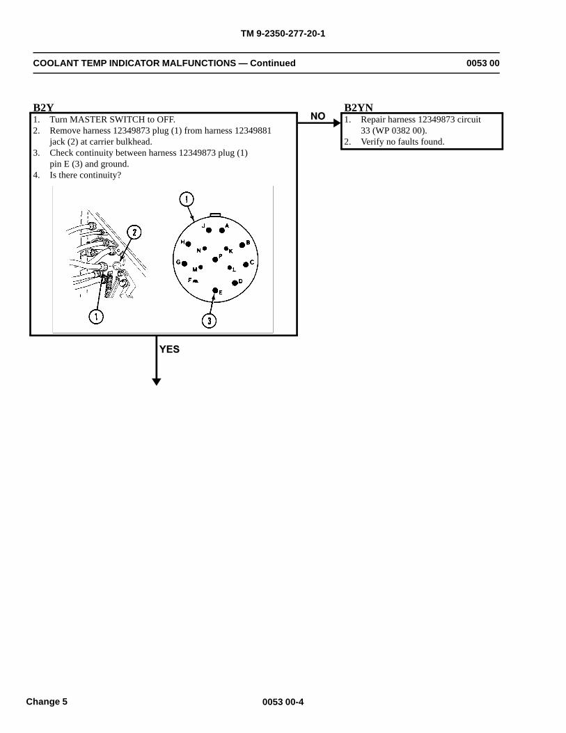
TM 9-2350-277-20-1
COOLANT TEMP INDICATOR MALFUNCTIONS — Continued 0053 00
B2Y1. Turn MASTER SWITCH to OFF.2. Remove harness 12349873 plug (1) from harness 12349881
jack (2) at carrier bulkhead.3. Check continuity between harness 12349873 plug (1)
pin E (3) and ground.4. Is there continuity?
B2YN1. Repair harness 12349873 circuit
33 (WP 0382 00).2. Verify no faults found.
0053 00-4Change 5
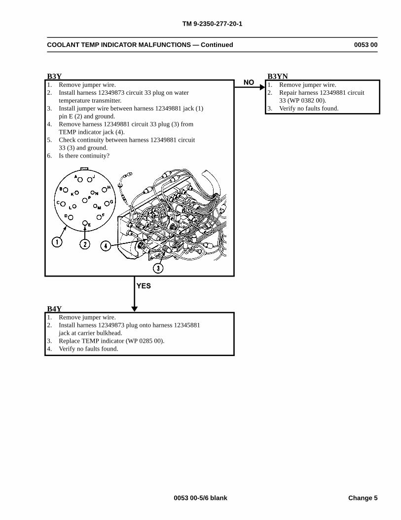
TM 9-2350-277-20-1
COOLANT TEMP INDICATOR MALFUNCTIONS — Continued 0053 00
B3Y1. Remove jumper wire.2. Install harness 12349873 circuit 33 plug on water
temperature transmitter.3. Install jumper wire between harness 12349881 jack (1)
pin E (2) and ground.4. Remove harness 12349881 circuit 33 plug (3) from
TEMP indicator jack (4).5. Check continuity between harness 12349881 circuit
33 (3) and ground.6. Is there continuity?
B3YN1. Remove jumper wire.2. Repair harness 12349881 circuit
33 (WP 0382 00).3. Verify no faults found.
B4Y1. Remove jumper wire.2. Install harness 12349873 plug onto harness 12345881
jack at carrier bulkhead.3. Replace TEMP indicator (WP 0285 00).4. Verify no faults found.
0053 00-5/6 blank Change 5

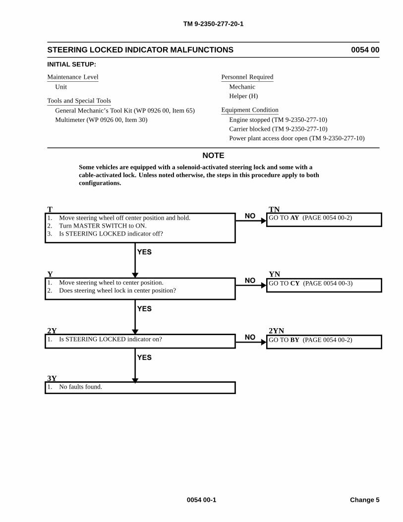
TM 9-2350-277-20-1
STEERING LOCKED INDICATOR MALFUNCTIONS 0054 00
INITIAL SETUP:
Maintenance LevelUnit
Tools and Special ToolsGeneral Mechanic’s Tool Kit (WP 0926 00, Item 65)Multimeter (WP 0926 00, Item 30)
Personnel RequiredMechanicHelper (H)
Equipment ConditionEngine stopped (TM 9-2350-277-10)Carrier blocked (TM 9-2350-277-10)Power plant access door open (TM 9-2350-277-10)
NOTESome vehicles are equipped with a solenoid-activated steering lock and some with acable-activated lock. Unless noted otherwise, the steps in this procedure apply to bothconfigurations.
T1. Move steering wheel off center position and hold.2. Turn MASTER SWITCH to ON.3. Is STEERING LOCKED indicator off?
TNGO TO AY (PAGE 0054 00-2)
Y1. Move steering wheel to center position.2. Does steering wheel lock in center position?
YNGO TO CY (PAGE 0054 00-3)
2Y1. Is STEERING LOCKED indicator on?
2YNGO TO BY (PAGE 0054 00-2)
3Y1. No faults found.
0054 00-1 Change 5
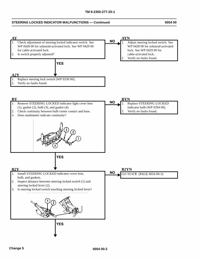
TM 9-2350-277-20-1
STEERING LOCKED INDICATOR MALFUNCTIONS — Continued 0054 00
AY1. Check adjustment of steering locked indicator switch. See
WP 0428 00 for solenoid-activated lock. See WP 0429 00for cable-activated lock.
2. Is switch properly adjusted?
AYN1. Adjust steering locked switch. See
WP 0428 00 for solenoid-activatedlock. See WP 0429 00 forcable-activated lock.
2. Verify no faults found.
A2Y1. Replace steering lock switch (WP 0330 00).2. Verify no faults found.
BY1. Remove STEERING LOCKED indicator light cover lens
(1), gasket (2), bulb (3), and gasket (4).2. Check continuity between bulb center contact and base.3. Does multimeter indicate continuity?
BYN1. Replace STEERING LOCKED
indicator bulb (WP 0294 00).2. Verify no faults found.
B2Y1. Install STEERING LOCKED indicator cover lens,
bulb, and gaskets.2. Inspect distance between steering locked switch (1) and
steering locked lever (2).3. Is steering locked switch touching steering locked lever?
GO TO CY (PAGE 0054 00-3)
0054 00-2Change 5
B2YN
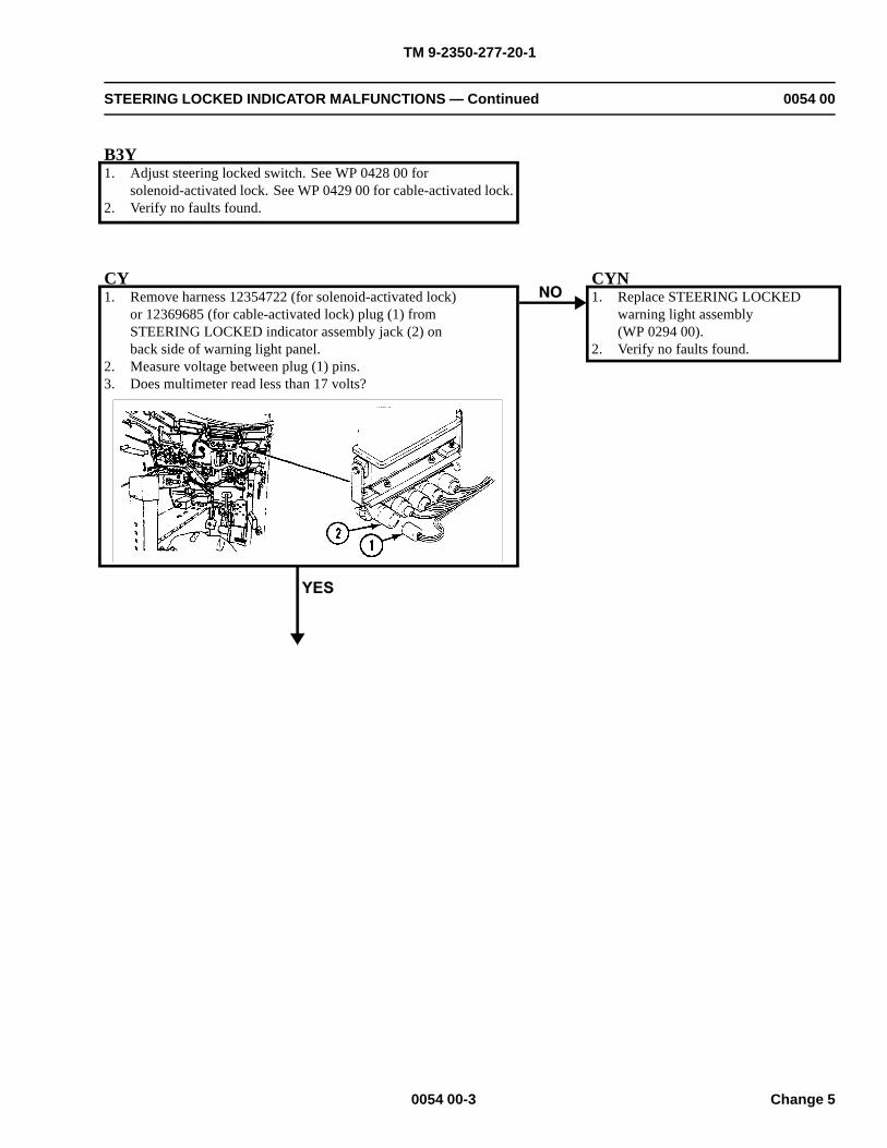
TM 9-2350-277-20-1
STEERING LOCKED INDICATOR MALFUNCTIONS — Continued 0054 00
B3Y1. Adjust steering locked switch. See WP 0428 00 for
solenoid-activated lock. See WP 0429 00 for cable-activated lock.2. Verify no faults found.
CY1. Remove harness 12354722 (for solenoid-activated lock)
or 12369685 (for cable-activated lock) plug (1) fromSTEERING LOCKED indicator assembly jack (2) onback side of warning light panel.
2. Measure voltage between plug (1) pins.3. Does multimeter read less than 17 volts?
CYN1. Replace STEERING LOCKED
warning light assembly(WP 0294 00).
2. Verify no faults found.
0054 00-3 Change 5
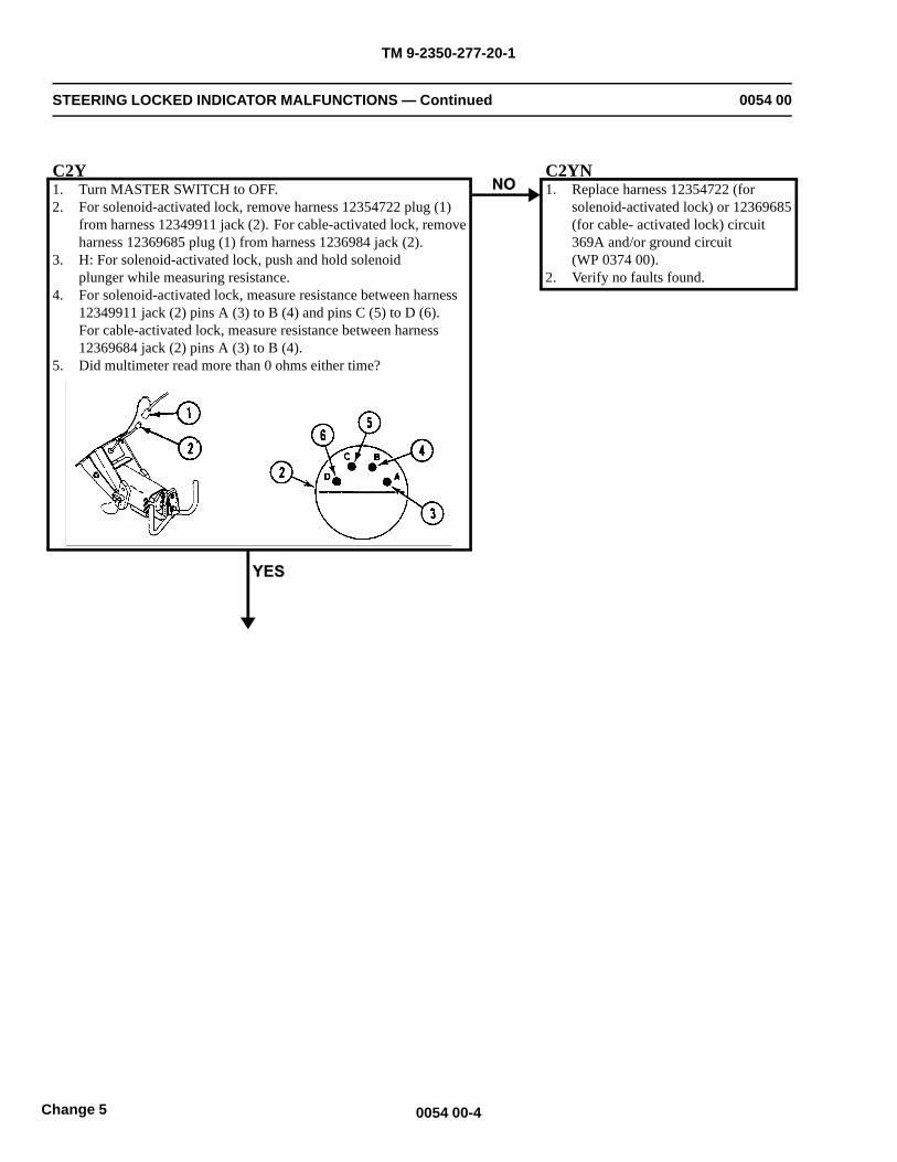
TM 9-2350-277-20-1
STEERING LOCKED INDICATOR MALFUNCTIONS — Continued 0054 00
C2Y1. Turn MASTER SWITCH to OFF.2. For solenoid-activated lock, remove harness 12354722 plug (1)
from harness 12349911 jack (2). For cable-activated lock, removeharness 12369685 plug (1) from harness 1236984 jack (2).
3. H: For solenoid-activated lock, push and hold solenoidplunger while measuring resistance.
4. For solenoid-activated lock, measure resistance between harness12349911 jack (2) pins A (3) to B (4) and pins C (5) to D (6).For cable-activated lock, measure resistance between harness12369684 jack (2) pins A (3) to B (4).
5. Did multimeter read more than 0 ohms either time?
C2YN1. Replace harness 12354722 (for
solenoid-activated lock) or 12369685(for cable- activated lock) circuit369A and/or ground circuit(WP 0374 00).
2. Verify no faults found.
0054 00-4Change 5
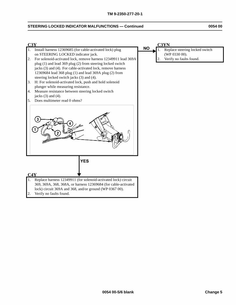
TM 9-2350-277-20-1
STEERING LOCKED INDICATOR MALFUNCTIONS — Continued 0054 00
C3Y1. Install harness 12369685 (for cable-activated lock) plug
on STEERING LOCKED indicator jack.2. For solenoid-activated lock, remove harness 12349911 lead 369A
plug (1) and lead 369 plug (2) from steering locked switchjacks (3) and (4). For cable-activated lock, remove harness12369684 lead 368 plug (1) and lead 369A plug (2) fromsteering locked switch jacks (3) and (4).
3. H: For solenoid-activated lock, push and hold solenoidplunger while measuring resistance.
4. Measure resistance between steering locked switchjacks (3) and (4).
5. Does multimeter read 0 ohms?
C3YN1. Replace steering locked switch
(WP 0330 00).2. Verify no faults found.
C4Y1. Replace harness 12349911 (for solenoid-activated lock) circuit
369, 369A, 368, 368A, or harness 12369684 (for cable-activatedlock) circuit 369A and 368, and/or ground (WP 0367 00).
2. Verify no faults found.
0054 00-5/6 blank Change 5

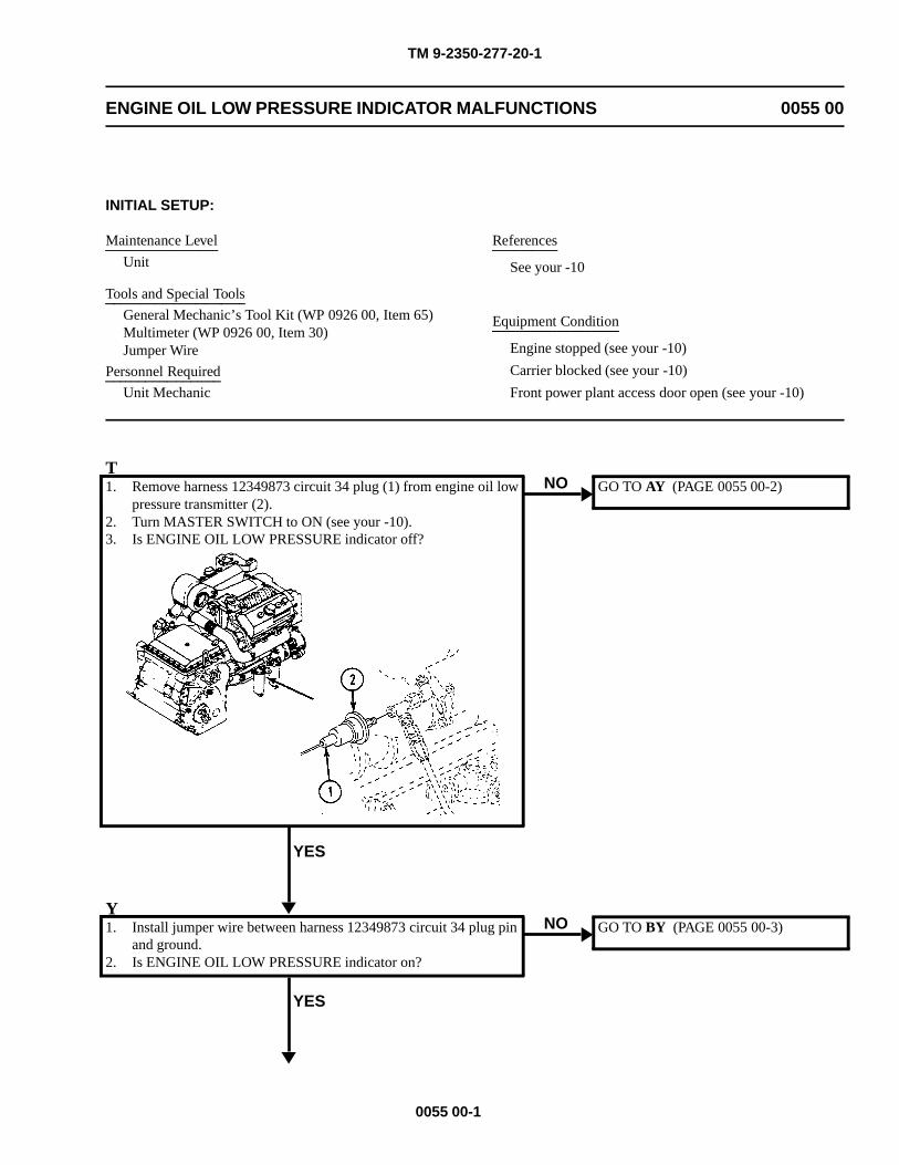
TM 9-2350-277-20-1
ENGINE OIL LOW PRESSURE INDICATOR MALFUNCTIONS 0055 00
INITIAL SETUP:
Maintenance Level
Unit
Tools and Special Tools
General Mechanic’s Tool Kit (WP 0926 00, Item 65)Multimeter (WP 0926 00, Item 30)Jumper Wire
Personnel Required
Unit Mechanic
References
See your -10
Equipment Condition
Engine stopped (see your -10)
Carrier blocked (see your -10)
Front power plant access door open (see your -10)
T1. Remove harness 12349873 circuit 34 plug (1) from engine oil low
pressure transmitter (2).2. Turn MASTER SWITCH to ON (see your -10).3. Is ENGINE OIL LOW PRESSURE indicator off?
YES
NO GO TO AY (PAGE 0055 00-2)
Y1. Install jumper wire between harness 12349873 circuit 34 plug pin
and ground.2. Is ENGINE OIL LOW PRESSURE indicator on?
YES
NO GO TO BY (PAGE 0055 00-3)
0055 00-1
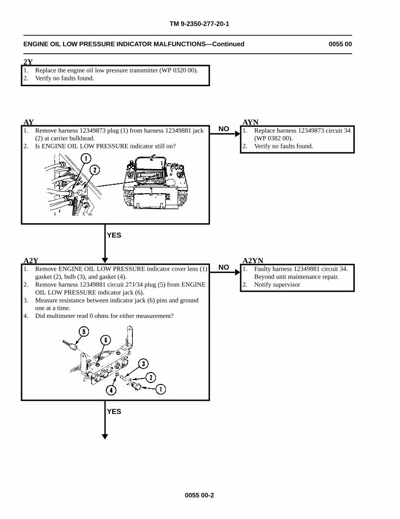
TM 9-2350-277-20-1
ENGINE OIL LOW PRESSURE INDICATOR MALFUNCTIONS—Continued 0055 00
2Y1. Replace the engine oil low pressure transmitter (WP 0320 00).2. Verify no faults found.
AY1. Remove harness 12349873 plug (1) from harness 12349881 jack
(2) at carrier bulkhead.2. Is ENGINE OIL LOW PRESSURE indicator still on?
YES
NOAYN1. Replace harness 12349873 circuit 34
(WP 0382 00).2. Verify no faults found.
A2Y1. Remove ENGINE OIL LOW PRESSURE indicator cover lens (1)
gasket (2), bulb (3), and gasket (4).2. Remove harness 12349881 circuit 27J/34 plug (5) from ENGINE
OIL LOW PRESSURE indicator jack (6).3. Measure resistance between indicator jack (6) pins and ground
one at a time.4. Did multimeter read 0 ohms for either measurement?
YES
NOA2YN1. Faulty harness 12349881 circuit 34.
Beyond unit maintenance repair.2. Notify supervisor
0055 00-2
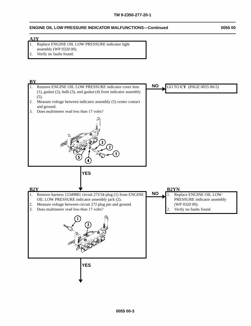
TM 9-2350-277-20-1
ENGINE OIL LOW PRESSURE INDICATOR MALFUNCTIONS—Continued 0055 00
A3Y1. Replace ENGINE OIL LOW PRESSURE indicator light
assembly (WP 0320 00).2. Verify no faults found.
BY1. Remove ENGINE OIL LOW PRESSURE indicator cover lens
(1), gasket (2), bulb (3), and gasket (4) from indicator assembly(5).
2. Measure voltage between indicator assembly (5) center contactand ground.
3. Does multimeter read less than 17 volts?
YES
NO GO TO CY (PAGE 0055 00-5)
B2Y1. Remove harness 12349881 circuit 27J/34 plug (1) from ENGINE
OIL LOW PRESSURE indicator assembly jack (2).2. Measure voltage between circuit 27J plug pin and ground.3. Does multimeter read less than 17 volts?
YES
NOB2YN1. Replace ENGINE OIL LOW
PRESSURE indicator assembly(WP 0320 00).
2. Verify no faults found.
0055 00-3
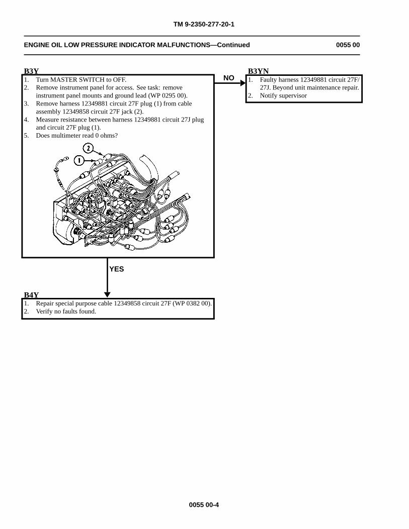
TM 9-2350-277-20-1
ENGINE OIL LOW PRESSURE INDICATOR MALFUNCTIONS—Continued 0055 00
B3Y1. Turn MASTER SWITCH to OFF.2. Remove instrument panel for access. See task: remove
instrument panel mounts and ground lead (WP 0295 00).3. Remove harness 12349881 circuit 27F plug (1) from cable
assembly 12349858 circuit 27F jack (2).4. Measure resistance between harness 12349881 circuit 27J plug
and circuit 27F plug (1).5. Does multimeter read 0 ohms?
YES
NOB3YN1. Faulty harness 12349881 circuit 27F/
27J. Beyond unit maintenance repair.2. Notify supervisor
B4Y1. Repair special purpose cable 12349858 circuit 27F (WP 0382 00).2. Verify no faults found.
0055 00-4
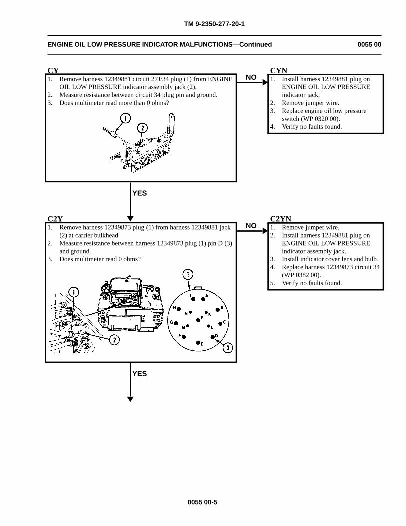
TM 9-2350-277-20-1
ENGINE OIL LOW PRESSURE INDICATOR MALFUNCTIONS—Continued 0055 00
CY1. Remove harness 12349881 circuit 27J/34 plug (1) from ENGINE
OIL LOW PRESSURE indicator assembly jack (2).2. Measure resistance between circuit 34 plug pin and ground.3. Does multimeter read more than 0 ohms?
YES
NOCYN1. Install harness 12349881 plug on
ENGINE OIL LOW PRESSUREindicator jack.
2. Remove jumper wire.3. Replace engine oil low pressure
switch (WP 0320 00).4. Verify no faults found.
C2Y1. Remove harness 12349873 plug (1) from harness 12349881 jack
(2) at carrier bulkhead.2. Measure resistance between harness 12349873 plug (1) pin D (3)
and ground.3. Does multimeter read 0 ohms?
YES
NOC2YN1. Remove jumper wire.2. Install harness 12349881 plug on
ENGINE OIL LOW PRESSUREindicator assembly jack.
3. Install indicator cover lens and bulb.4. Replace harness 12349873 circuit 34
(WP 0382 00).5. Verify no faults found.
0055 00-5
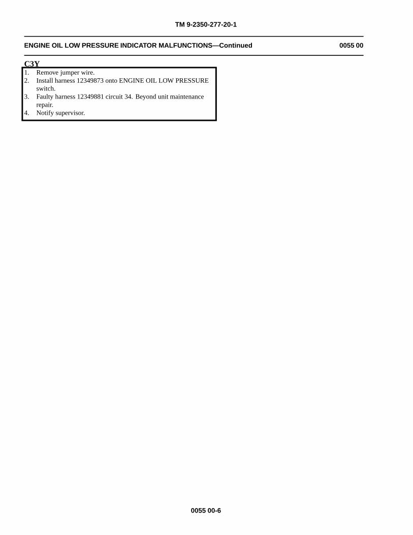
TM 9-2350-277-20-1
ENGINE OIL LOW PRESSURE INDICATOR MALFUNCTIONS—Continued 0055 00
C3Y1. Remove jumper wire.2. Install harness 12349873 onto ENGINE OIL LOW PRESSURE
switch.3. Faulty harness 12349881 circuit 34. Beyond unit maintenance
repair.4. Notify supervisor.
0055 00-6
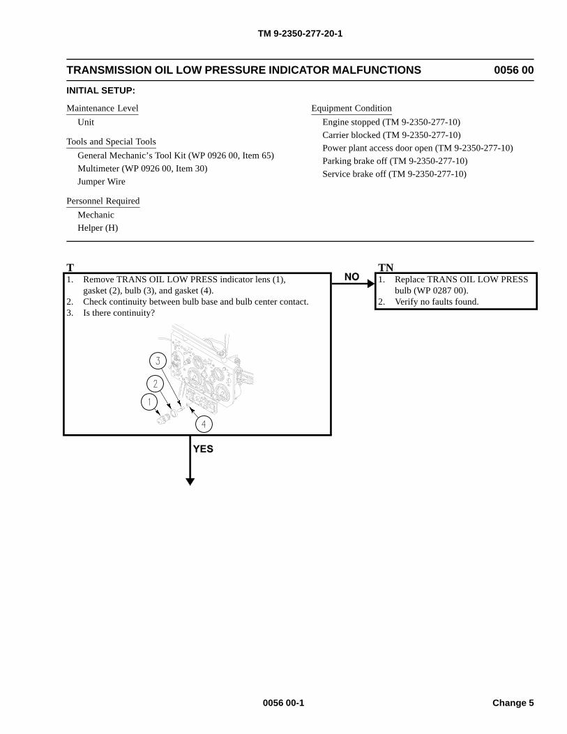
TM 9-2350-277-20-1
TRANSMISSION OIL LOW PRESSURE INDICATOR MALFUNCTIONS 0056 00
INITIAL SETUP:
Maintenance LevelUnit
Tools and Special ToolsGeneral Mechanic’s Tool Kit (WP 0926 00, Item 65)Multimeter (WP 0926 00, Item 30)Jumper Wire
Personnel RequiredMechanicHelper (H)
Equipment ConditionEngine stopped (TM 9-2350-277-10)Carrier blocked (TM 9-2350-277-10)Power plant access door open (TM 9-2350-277-10)Parking brake off (TM 9-2350-277-10)Service brake off (TM 9-2350-277-10)
T1. Remove TRANS OIL LOW PRESS indicator lens (1),
gasket (2), bulb (3), and gasket (4).2. Check continuity between bulb base and bulb center contact.3. Is there continuity?
TN1. Replace TRANS OIL LOW PRESS
bulb (WP 0287 00).2. Verify no faults found.
0056 00-1 Change 5
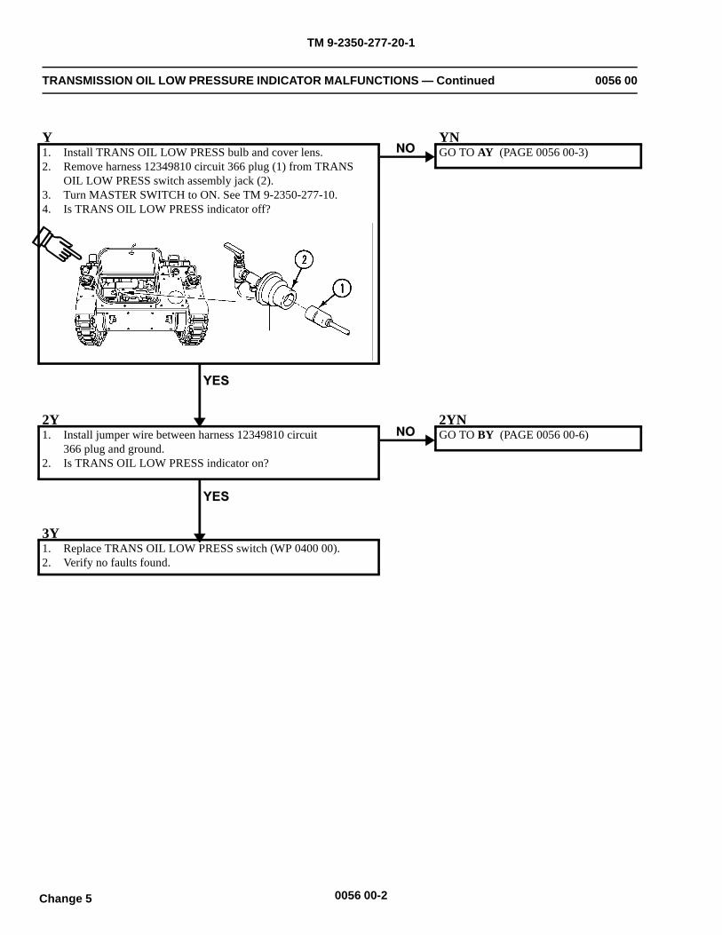
TM 9-2350-277-20-1
TRANSMISSION OIL LOW PRESSURE INDICATOR MALFUNCTIONS — Continued 0056 00
Y1. Install TRANS OIL LOW PRESS bulb and cover lens.2. Remove harness 12349810 circuit 366 plug (1) from TRANS
OIL LOW PRESS switch assembly jack (2).3. Turn MASTER SWITCH to ON. See TM 9-2350-277-10.4. Is TRANS OIL LOW PRESS indicator off?
YNGO TO AY (PAGE 0056 00-3)
2Y1. Install jumper wire between harness 12349810 circuit
366 plug and ground.2. Is TRANS OIL LOW PRESS indicator on?
2YNGO TO BY (PAGE 0056 00-6)
3Y1. Replace TRANS OIL LOW PRESS switch (WP 0400 00).2. Verify no faults found.
0056 00-2Change 5
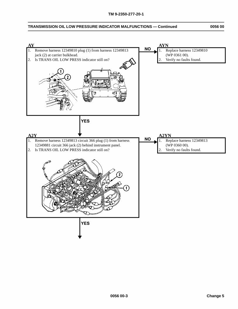
TM 9-2350-277-20-1
TRANSMISSION OIL LOW PRESSURE INDICATOR MALFUNCTIONS — Continued 0056 00
AY1. Remove harness 12349810 plug (1) from harness 12349813
jack (2) at carrier bulkhead.2. Is TRANS OIL LOW PRESS indicator still on?
AYN1. Replace harness 12349810
(WP 0361 00).2. Verify no faults found.
A2Y1. Remove harness 12349813 circuit 366 plug (1) from harness
12349881 circuit 366 jack (2) behind instrument panel.2. Is TRANS OIL LOW PRESS indicator still on?
A2YN1. Replace harness 12349813
(WP 0360 00).2. Verify no faults found.
0056 00-3 Change 5
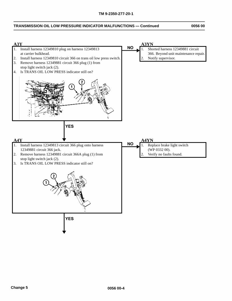
TM 9-2350-277-20-1
TRANSMISSION OIL LOW PRESSURE INDICATOR MALFUNCTIONS — Continued 0056 00
A3Y1. Install harness 12349810 plug on harness 12349813
at carrier bulkhead.2. Install harness 12349810 circuit 366 on trans oil low press switch.3. Remove harness 12349881 circuit 366 plug (1) from
stop light switch jack (2).4. Is TRANS OIL LOW PRESS indicator still on?
A3YN1. Shorted harness 12349881 circuit
366. Beyond unit maintenance repair.2. Notify supervisor.
A4Y1. Install harness 12349813 circuit 366 plug onto harness
12349881 circuit 366 jack.2. Remove harness 12349881 circuit 366A plug (1) from
stop light switch jack (2).3. Is TRANS OIL LOW PRESS indicator still on?
A4YN1. Replace brake light switch
(WP 0332 00).2. Verify no faults found.
0056 00-4Change 5
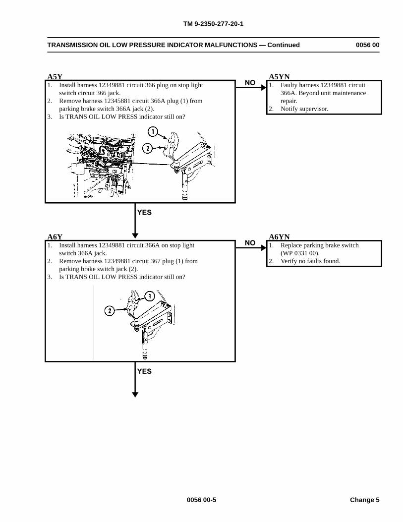
TM 9-2350-277-20-1
TRANSMISSION OIL LOW PRESSURE INDICATOR MALFUNCTIONS — Continued 0056 00
A5Y1. Install harness 12349881 circuit 366 plug on stop light
switch circuit 366 jack.2. Remove harness 12345881 circuit 366A plug (1) from
parking brake switch 366A jack (2).3. Is TRANS OIL LOW PRESS indicator still on?
A5YN1. Faulty harness 12349881 circuit
366A. Beyond unit maintenancerepair.
2. Notify supervisor.
A6Y1. Install harness 12349881 circuit 366A on stop light
switch 366A jack.2. Remove harness 12349881 circuit 367 plug (1) from
parking brake switch jack (2).3. Is TRANS OIL LOW PRESS indicator still on?
A6YN1. Replace parking brake switch
(WP 0331 00).2. Verify no faults found.
0056 00-5 Change 5
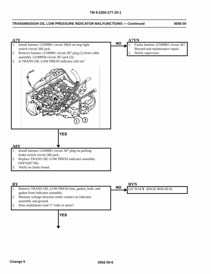
TM 9-2350-277-20-1
TRANSMISSION OIL LOW PRESSURE INDICATOR MALFUNCTIONS — Continued 0056 00
A7Y1. Install harness 12349881 circuit 366A on stop light
switch circuit 366 jack.2. Remove harness 12349881 circuit 367 plug (1) from cable
assembly 12349858 circuit 367 jack (2).3. Is TRANS OIL LOW PRESS indicator still on?
A7YN1. Faulty harness 12349881 circuit 367.
Beyond unit maintenance repair.2. Notify supervisor.
A8Y1. Install harness 12349881 circuit 367 plug on parking
brake switch circuit 366 jack.2. Replace TRANS OIL LOW PRESS indicator assembly
(WP 0287 00).3. Verify no faults found.
BY1. Remove TRANS OIL LOW PRESS lens, gasket, bulb, and
gasket from indicator assembly.2. Measure voltage between center contact on indicator
assembly and ground.3. Does multimeter read 17 volts or more?
BYNGO TO CY (PAGE 0056 00-9)
0056 00-6Change 5
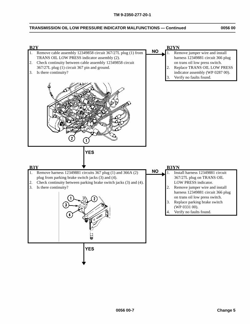
TM 9-2350-277-20-1
TRANSMISSION OIL LOW PRESSURE INDICATOR MALFUNCTIONS — Continued 0056 00
B2Y1. Remove cable assembly 12349858 circuit 367/27L plug (1) from
TRANS OIL LOW PRESS indicator assembly (2).2. Check continuity between cable assembly 12349858 circuit
367/27L plug (1) circuit 367 pin and ground.3. Is there continuity?
B2YN1. Remove jumper wire and install
harness 12349881 circuit 366 plugon trans oil low press switch.
2. Replace TRANS OIL LOW PRESSindicator assembly (WP 0287 00).
3. Verify no faults found.
B3Y1. Remove harness 12349881 circuits 367 plug (1) and 366A (2)
plug from parking brake switch jacks (3) and (4).2. Check continuity between parking brake switch jacks (3) and (4).3. Is there continuity?
B3YN1. Install harness 12349881 circuit
367/27L plug on TRANS OILLOW PRESS indicator.
2. Remove jumper wire and installharness 12349881 circuit 366 plugon trans oil low press switch.
3. Replace parking brake switch(WP 0331 00).
4. Verify no faults found.
0056 00-7 Change 5
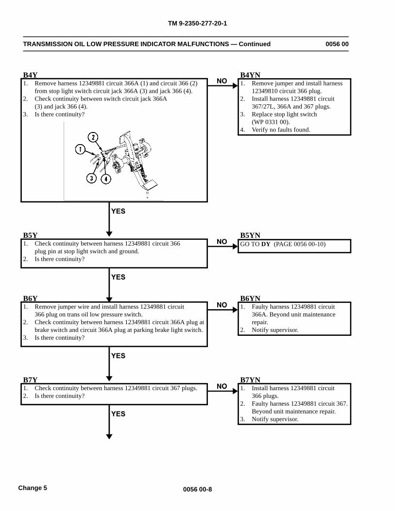
TM 9-2350-277-20-1
TRANSMISSION OIL LOW PRESSURE INDICATOR MALFUNCTIONS — Continued 0056 00
B4Y1. Remove harness 12349881 circuit 366A (1) and circuit 366 (2)
from stop light switch circuit jack 366A (3) and jack 366 (4).2. Check continuity between switch circuit jack 366A
(3) and jack 366 (4).3. Is there continuity?
B4YN1. Remove jumper and install harness
12349810 circuit 366 plug.2. Install harness 12349881 circuit
367/27L, 366A and 367 plugs.3. Replace stop light switch
(WP 0331 00).4. Verify no faults found.
B5Y1. Check continuity between harness 12349881 circuit 366
plug pin at stop light switch and ground.2. Is there continuity?
B5YNGO TO DY (PAGE 0056 00-10)
B6Y1. Remove jumper wire and install harness 12349881 circuit
366 plug on trans oil low pressure switch.2. Check continuity between harness 12349881 circuit 366A plug at
brake switch and circuit 366A plug at parking brake light switch.3. Is there continuity?
B6YN1. Faulty harness 12349881 circuit
366A. Beyond unit maintenancerepair.
2. Notify supervisor.
B7Y1. Check continuity between harness 12349881 circuit 367 plugs.2. Is there continuity?
B7YN1. Install harness 12349881 circuit
366 plugs.2. Faulty harness 12349881 circuit 367.
Beyond unit maintenance repair.3. Notify supervisor.
0056 00-8Change 5
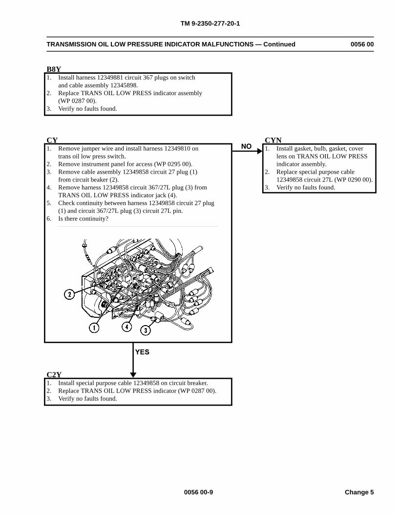
TM 9-2350-277-20-1
TRANSMISSION OIL LOW PRESSURE INDICATOR MALFUNCTIONS — Continued 0056 00
B8Y1. Install harness 12349881 circuit 367 plugs on switch
and cable assembly 12345898.2. Replace TRANS OIL LOW PRESS indicator assembly
(WP 0287 00).3. Verify no faults found.
CY1. Remove jumper wire and install harness 12349810 on
trans oil low press switch.2. Remove instrument panel for access (WP 0295 00).3. Remove cable assembly 12349858 circuit 27 plug (1)
from circuit beaker (2).4. Remove harness 12349858 circuit 367/27L plug (3) from
TRANS OIL LOW PRESS indicator jack (4).5. Check continuity between harness 12349858 circuit 27 plug
(1) and circuit 367/27L plug (3) circuit 27L pin.6. Is there continuity?
CYN1. Install gasket, bulb, gasket, cover
lens on TRANS OIL LOW PRESSindicator assembly.
2. Replace special purpose cable12349858 circuit 27L (WP 0290 00).
3. Verify no faults found.
C2Y1. Install special purpose cable 12349858 on circuit breaker.2. Replace TRANS OIL LOW PRESS indicator (WP 0287 00).3. Verify no faults found.
0056 00-9 Change 5
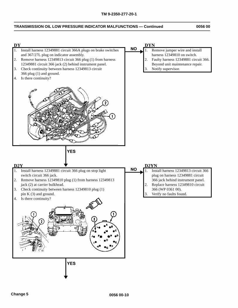
TM 9-2350-277-20-1
TRANSMISSION OIL LOW PRESSURE INDICATOR MALFUNCTIONS — Continued 0056 00
DY1. Install harness 12349881 circuit 366A plugs on brake switches
and 367/27L plug on indicator assembly.2. Remove harness 12349813 circuit 366 plug (1) from harness
12349881 circuit 366 jack (2) behind instrument panel.3. Check continuity between harness 12349813 circuit
366 plug (1) and ground.4. Is there continuity?
DYN1. Remove jumper wire and install
harness 12349810 on switch.2. Faulty harness 12349881 circuit 366.
Beyond unit maintenance repair.3. Notify supervisor.
D2Y1. Install harness 12349881 circuit 366 plug on stop light
switch circuit 366 jack.2. Remove harness 12349810 plug (1) from harness 12349813
jack (2) at carrier bulkhead.3. Check continuity between harness 12349810 plug (1)
pin K (3) and ground.4. Is there continuity?
D2YN1. Install harness 12349813 circuit 366
plug on harness 12349881 circuit366 jack behind instrument panel.
2. Replace harness 12349810 circuit366 (WP 0361 00).
3. Verify no faults found.
0056 00-10Change 5
TM 9-2350-277-20-1
TRANSMISSION OIL LOW PRESSURE INDICATOR MALFUNCTIONS — Continued 0056 00
D3Y1. Remove jumper wire and install harness 12349810 circuit
366 plug on trans oil low press switch.2. Replace harness 12349813 circuit 366 (WP 0360 00).3. Verify no faults found.
0056 00-11/12 blank Change 5

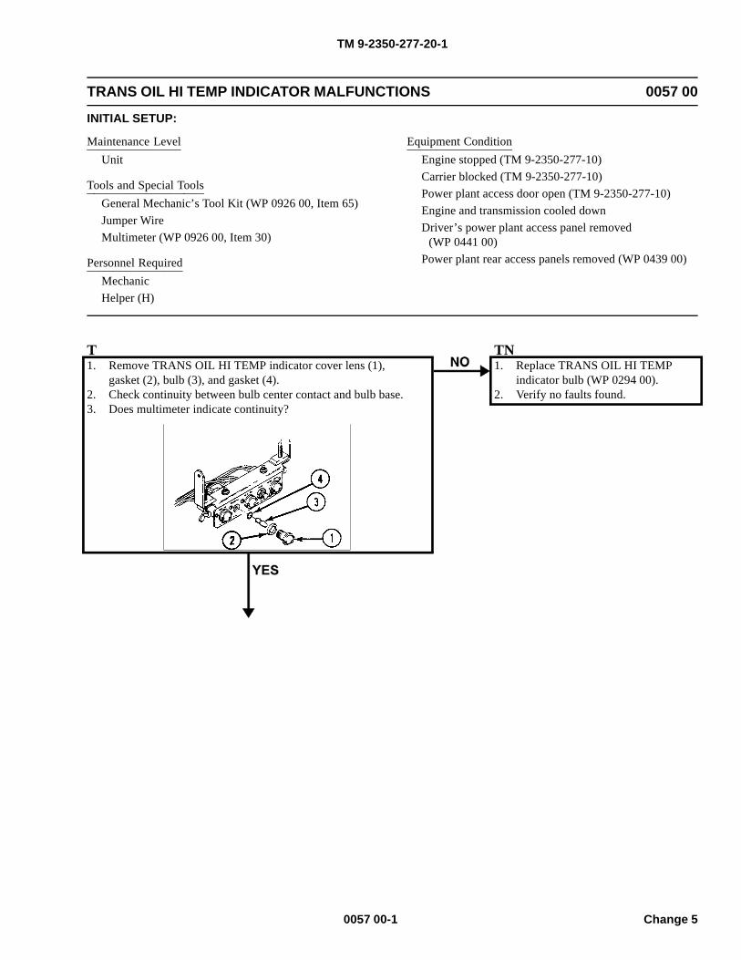
TM 9-2350-277-20-1
TRANS OIL HI TEMP INDICATOR MALFUNCTIONS 0057 00
INITIAL SETUP:
Maintenance LevelUnit
Tools and Special ToolsGeneral Mechanic’s Tool Kit (WP 0926 00, Item 65)Jumper WireMultimeter (WP 0926 00, Item 30)
Personnel RequiredMechanicHelper (H)
Equipment ConditionEngine stopped (TM 9-2350-277-10)Carrier blocked (TM 9-2350-277-10)Power plant access door open (TM 9-2350-277-10)Engine and transmission cooled downDriver’s power plant access panel removed
(WP 0441 00)Power plant rear access panels removed (WP 0439 00)
T1. Remove TRANS OIL HI TEMP indicator cover lens (1),
gasket (2), bulb (3), and gasket (4).2. Check continuity between bulb center contact and bulb base.3. Does multimeter indicate continuity?
TN1. Replace TRANS OIL HI TEMP
indicator bulb (WP 0294 00).2. Verify no faults found.
0057 00-1 Change 5
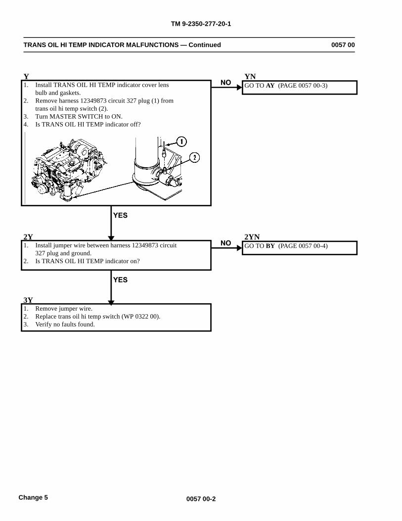
TM 9-2350-277-20-1
TRANS OIL HI TEMP INDICATOR MALFUNCTIONS — Continued 0057 00
Y1. Install TRANS OIL HI TEMP indicator cover lens
bulb and gaskets.2. Remove harness 12349873 circuit 327 plug (1) from
trans oil hi temp switch (2).3. Turn MASTER SWITCH to ON.4. Is TRANS OIL HI TEMP indicator off?
YNGO TO AY (PAGE 0057 00-3)
2Y1. Install jumper wire between harness 12349873 circuit
327 plug and ground.2. Is TRANS OIL HI TEMP indicator on?
2YNGO TO BY (PAGE 0057 00-4)
3Y1. Remove jumper wire.2. Replace trans oil hi temp switch (WP 0322 00).3. Verify no faults found.
0057 00-2Change 5
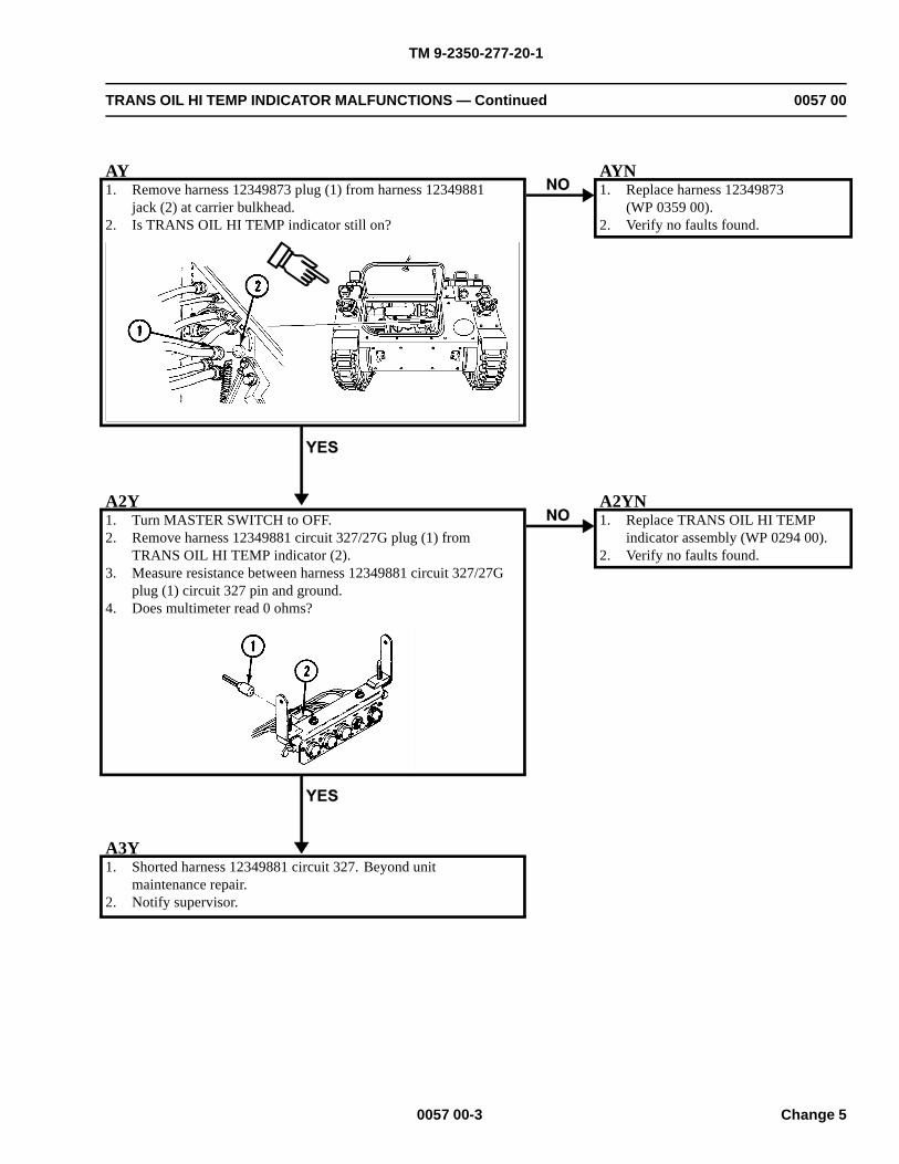
TM 9-2350-277-20-1
TRANS OIL HI TEMP INDICATOR MALFUNCTIONS — Continued 0057 00
AY1. Remove harness 12349873 plug (1) from harness 12349881
jack (2) at carrier bulkhead.2. Is TRANS OIL HI TEMP indicator still on?
AYN1. Replace harness 12349873
(WP 0359 00).2. Verify no faults found.
A2Y1. Turn MASTER SWITCH to OFF.2. Remove harness 12349881 circuit 327/27G plug (1) from
TRANS OIL HI TEMP indicator (2).3. Measure resistance between harness 12349881 circuit 327/27G
plug (1) circuit 327 pin and ground.4. Does multimeter read 0 ohms?
A2YN1. Replace TRANS OIL HI TEMP
indicator assembly (WP 0294 00).2. Verify no faults found.
A3Y1. Shorted harness 12349881 circuit 327. Beyond unit
maintenance repair.2. Notify supervisor.
0057 00-3 Change 5
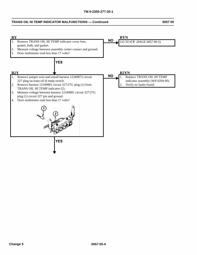
TM 9-2350-277-20-1
TRANS OIL HI TEMP INDICATOR MALFUNCTIONS — Continued 0057 00
BY1. Remove TRANS OIL HI TEMP indicator cover lens,
gasket, bulb, and gasket.2. Measure voltage between assembly center contact and ground.3. Does multimeter read less than 17 volts?
BYNGO TO CY (PAGE 0057 00-5)
B2Y1. Remove jumper wire and install harness 12349873 circuit
327 plug on trans oil hi temp switch.2. Remove harness 12349881 circuit 327/27G plug (1) from
TRANS OIL HI TEMP indicator (2).3. Measure voltage between harness 12349881 circuit 327/27G
plug (1) circuit 327 pin and ground.4. Does multimeter read less than 17 volts?
B2YN1. Replace TRANS OIL HI TEMP
indicator assembly (WP 0294 00).2. Verify no faults found.
0057 00-4Change 5
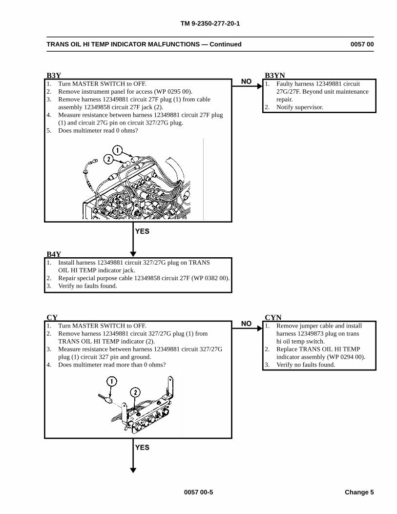
TM 9-2350-277-20-1
TRANS OIL HI TEMP INDICATOR MALFUNCTIONS — Continued 0057 00
B3Y1. Turn MASTER SWITCH to OFF.2. Remove instrument panel for access (WP 0295 00).3. Remove harness 12349881 circuit 27F plug (1) from cable
assembly 12349858 circuit 27F jack (2).4. Measure resistance between harness 12349881 circuit 27F plug
(1) and circuit 27G pin on circuit 327/27G plug.5. Does multimeter read 0 ohms?
B3YN1. Faulty harness 12349881 circuit
27G/27F. Beyond unit maintenancerepair.
2. Notify supervisor.
B4Y1. Install harness 12349881 circuit 327/27G plug on TRANS
OIL HI TEMP indicator jack.2. Repair special purpose cable 12349858 circuit 27F (WP 0382 00).3. Verify no faults found.
CY1. Turn MASTER SWITCH to OFF.2. Remove harness 12349881 circuit 327/27G plug (1) from
TRANS OIL HI TEMP indicator (2).3. Measure resistance between harness 12349881 circuit 327/27G
plug (1) circuit 327 pin and ground.4. Does multimeter read more than 0 ohms?
CYN1. Remove jumper cable and install
harness 12349873 plug on transhi oil temp switch.
2. Replace TRANS OIL HI TEMPindicator assembly (WP 0294 00).
3. Verify no faults found.
0057 00-5 Change 5
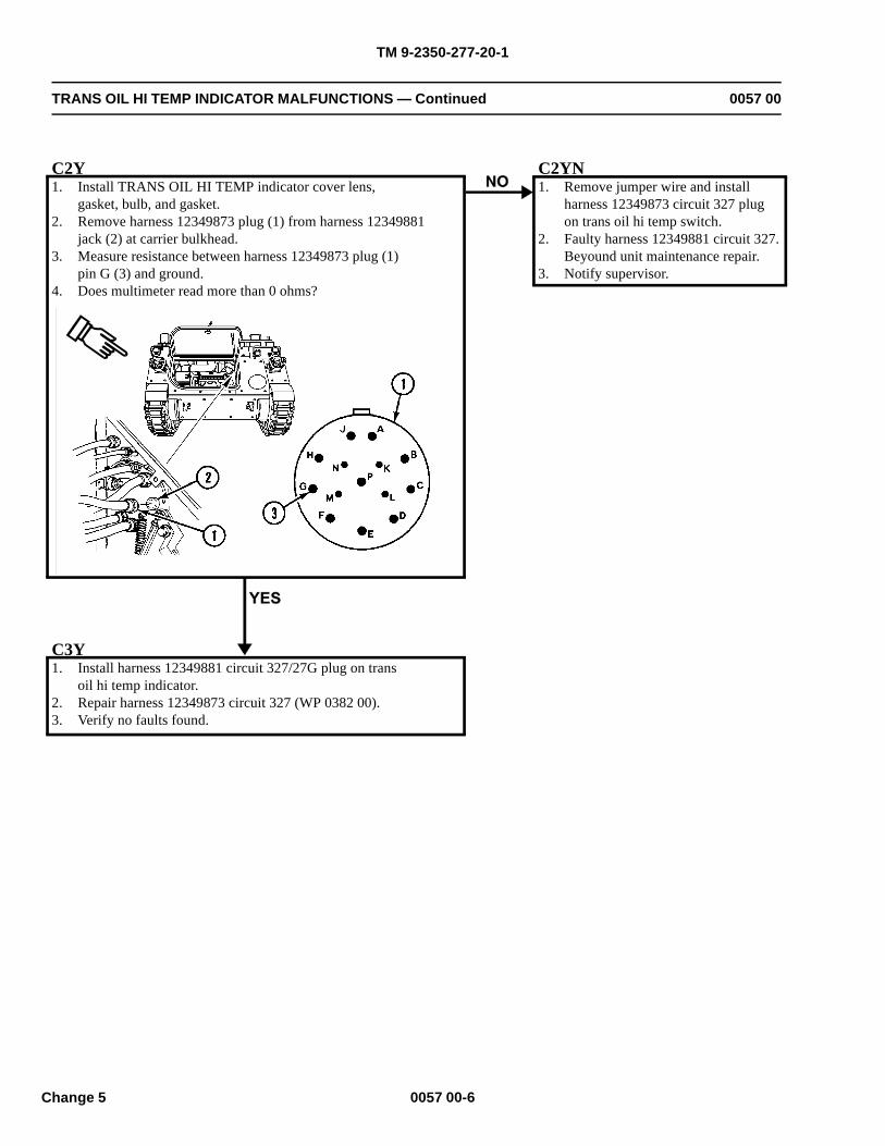
TM 9-2350-277-20-1
TRANS OIL HI TEMP INDICATOR MALFUNCTIONS — Continued 0057 00
C2Y1. Install TRANS OIL HI TEMP indicator cover lens,
gasket, bulb, and gasket.2. Remove harness 12349873 plug (1) from harness 12349881
jack (2) at carrier bulkhead.3. Measure resistance between harness 12349873 plug (1)
pin G (3) and ground.4. Does multimeter read more than 0 ohms?
C2YN1. Remove jumper wire and install
harness 12349873 circuit 327 plugon trans oil hi temp switch.
2. Faulty harness 12349881 circuit 327.Beyound unit maintenance repair.
3. Notify supervisor.
C3Y1. Install harness 12349881 circuit 327/27G plug on trans
oil hi temp indicator.2. Repair harness 12349873 circuit 327 (WP 0382 00).3. Verify no faults found.
0057 00-6Change 5
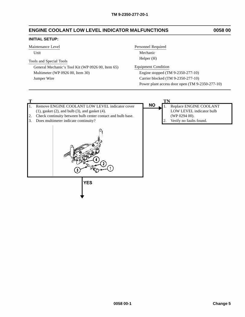
TM 9-2350-277-20-1
ENGINE COOLANT LOW LEVEL INDICATOR MALFUNCTIONS 0058 00
INITIAL SETUP:
Maintenance LevelUnit
Tools and Special ToolsGeneral Mechanic’s Tool Kit (WP 0926 00, Item 65)Multimeter (WP 0926 00, Item 30)Jumper Wire
Personnel RequiredMechanicHelper (H)
Equipment ConditionEngine stopped (TM 9-2350-277-10)Carrier blocked (TM 9-2350-277-10)Power plant access door open (TM 9-2350-277-10)
T1. Remove ENGINE COOLANT LOW LEVEL indicator cover
(1), gasket (2), and bulb (3), and gasket (4).2. Check continuity between bulb center contact and bulb base.3. Does multimeter indicate continuity?
TN1. Replace ENGINE COOLANT
LOW LEVEL indicator bulb(WP 0294 00).
2. Verify no faults found.
0058 00-1 Change 5
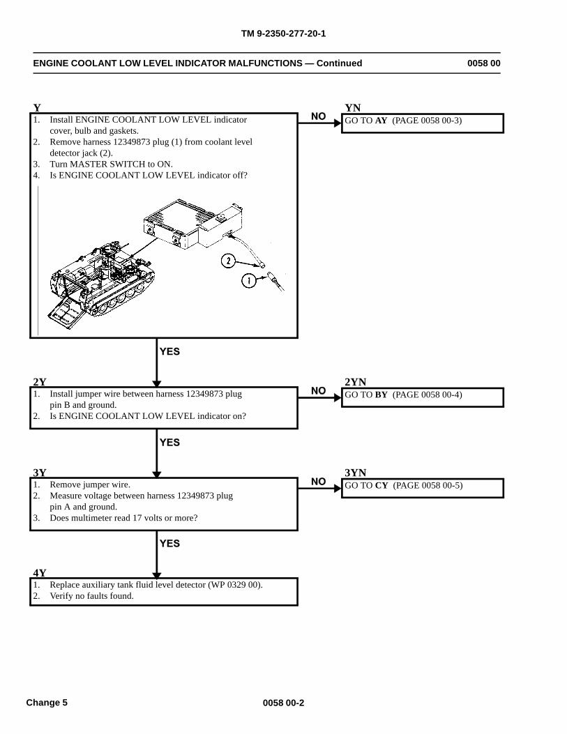
TM 9-2350-277-20-1
ENGINE COOLANT LOW LEVEL INDICATOR MALFUNCTIONS — Continued 0058 00
Y1. Install ENGINE COOLANT LOW LEVEL indicator
cover, bulb and gaskets.2. Remove harness 12349873 plug (1) from coolant level
detector jack (2).3. Turn MASTER SWITCH to ON.4. Is ENGINE COOLANT LOW LEVEL indicator off?
YNGO TO AY (PAGE 0058 00-3)
2Y1. Install jumper wire between harness 12349873 plug
pin B and ground.2. Is ENGINE COOLANT LOW LEVEL indicator on?
2YNGO TO BY (PAGE 0058 00-4)
3Y1. Remove jumper wire.2. Measure voltage between harness 12349873 plug
pin A and ground.3. Does multimeter read 17 volts or more?
3YNGO TO CY (PAGE 0058 00-5)
4Y1. Replace auxiliary tank fluid level detector (WP 0329 00).2. Verify no faults found.
0058 00-2Change 5
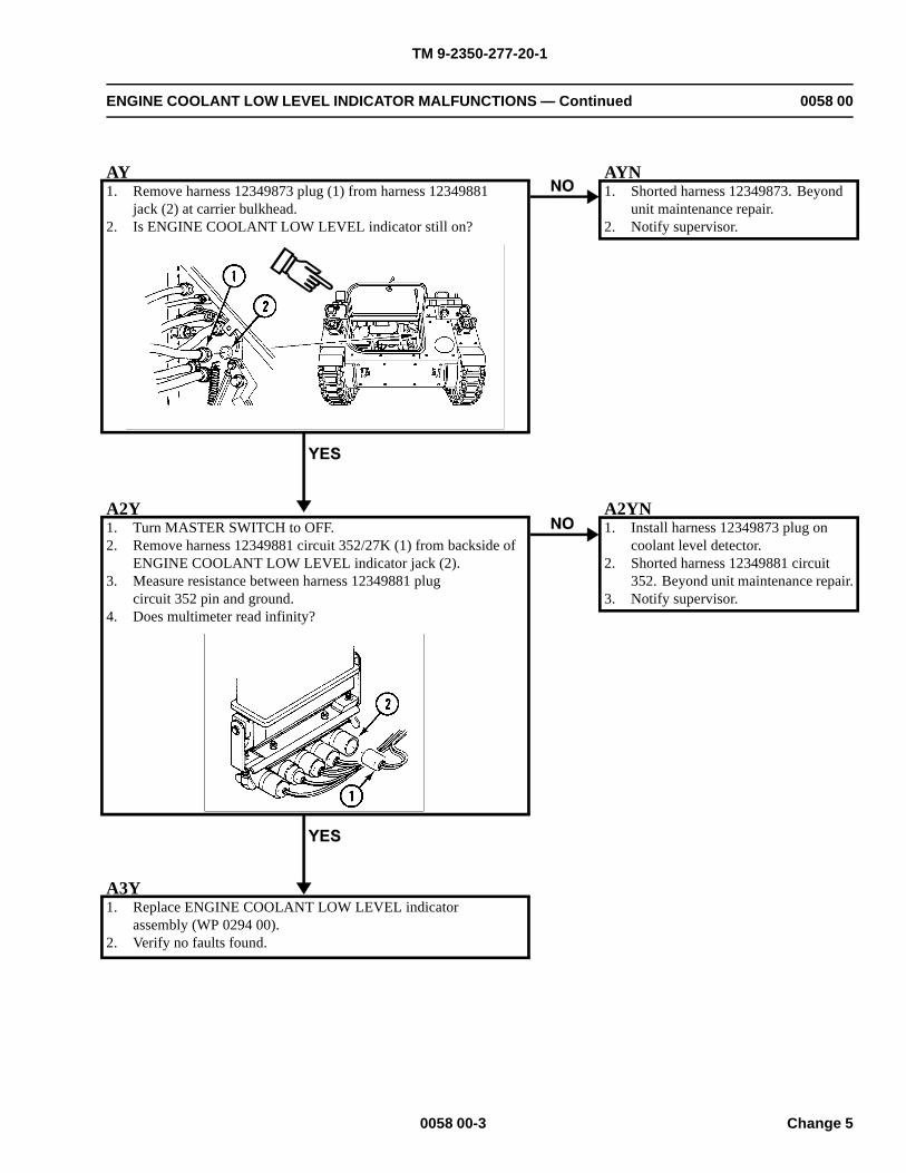
TM 9-2350-277-20-1
ENGINE COOLANT LOW LEVEL INDICATOR MALFUNCTIONS — Continued 0058 00
AY1. Remove harness 12349873 plug (1) from harness 12349881
jack (2) at carrier bulkhead.2. Is ENGINE COOLANT LOW LEVEL indicator still on?
AYN1. Shorted harness 12349873. Beyond
unit maintenance repair.2. Notify supervisor.
A2Y1. Turn MASTER SWITCH to OFF.2. Remove harness 12349881 circuit 352/27K (1) from backside of
ENGINE COOLANT LOW LEVEL indicator jack (2).3. Measure resistance between harness 12349881 plug
circuit 352 pin and ground.4. Does multimeter read infinity?
A2YN1. Install harness 12349873 plug on
coolant level detector.2. Shorted harness 12349881 circuit
352. Beyond unit maintenance repair.3. Notify supervisor.
A3Y1. Replace ENGINE COOLANT LOW LEVEL indicator
assembly (WP 0294 00).2. Verify no faults found.
0058 00-3 Change 5
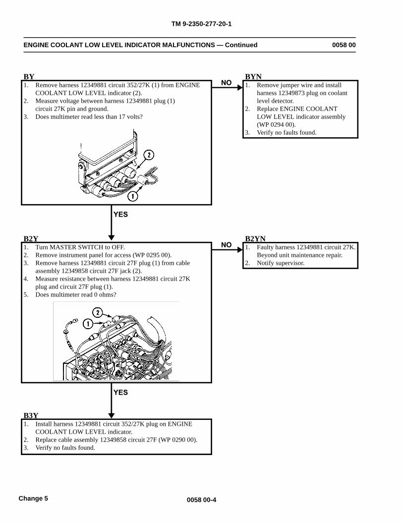
TM 9-2350-277-20-1
ENGINE COOLANT LOW LEVEL INDICATOR MALFUNCTIONS — Continued 0058 00
BY1. Remove harness 12349881 circuit 352/27K (1) from ENGINE
COOLANT LOW LEVEL indicator (2).2. Measure voltage between harness 12349881 plug (1)
circuit 27K pin and ground.3. Does multimeter read less than 17 volts?
BYN1. Remove jumper wire and install
harness 12349873 plug on coolantlevel detector.
2. Replace ENGINE COOLANTLOW LEVEL indicator assembly(WP 0294 00).
3. Verify no faults found.
B2Y1. Turn MASTER SWITCH to OFF.2. Remove instrument panel for access (WP 0295 00).3. Remove harness 12349881 circuit 27F plug (1) from cable
assembly 12349858 circuit 27F jack (2).4. Measure resistance between harness 12349881 circuit 27K
plug and circuit 27F plug (1).5. Does multimeter read 0 ohms?
B2YN1. Faulty harness 12349881 circuit 27K.
Beyond unit maintenance repair.2. Notify supervisor.
B3Y1. Install harness 12349881 circuit 352/27K plug on ENGINE
COOLANT LOW LEVEL indicator.2. Replace cable assembly 12349858 circuit 27F (WP 0290 00).3. Verify no faults found.
0058 00-4Change 5
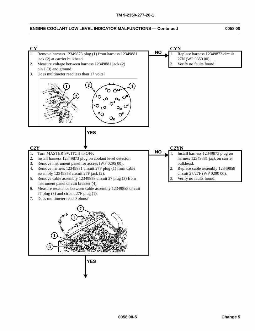
TM 9-2350-277-20-1
ENGINE COOLANT LOW LEVEL INDICATOR MALFUNCTIONS — Continued 0058 00
CY1. Remove harness 12349873 plug (1) from harness 12349881
jack (2) at carrier bulkhead.2. Measure voltage between harness 12349881 jack (2)
pin J (3) and ground.3. Does multimeter read less than 17 volts?
CYN1. Replace harness 12349873 circuit
27N (WP 0359 00).2. Verify no faults found.
C2Y1. Turn MASTER SWITCH to OFF.2. Install harness 12349873 plug on coolant level detector.3. Remove instrument panel for access (WP 0295 00).4. Remove harness 12349881 circuit 27F plug (1) from cable
assembly 12349858 circuit 27F jack (2).5. Remove cable assembly 12349858 circuit 27 plug (3) from
instrument panel circuit breaker (4).6. Measure resistance between cable assembly 12349858 circuit
27 plug (3) and circuit 27F plug (1).7. Does multimeter read 0 ohms?
C2YN1. Install harness 12349873 plug on
harness 12349881 jack on carrierbulkhead.
2. Replace cable assembly 12349858circuit 27/27F (WP 0290 00).
3. Verify no faults found.
0058 00-5 Change 5

TM 9-2350-277-20-1
ENGINE COOLANT LOW LEVEL INDICATOR MALFUNCTIONS — Continued 0058 00
C3Y1. Faulty harness 12349881 circuit 27N. Beyond unit
maintenance repair.2. Notify supervisor.
0058 00-6Change 5
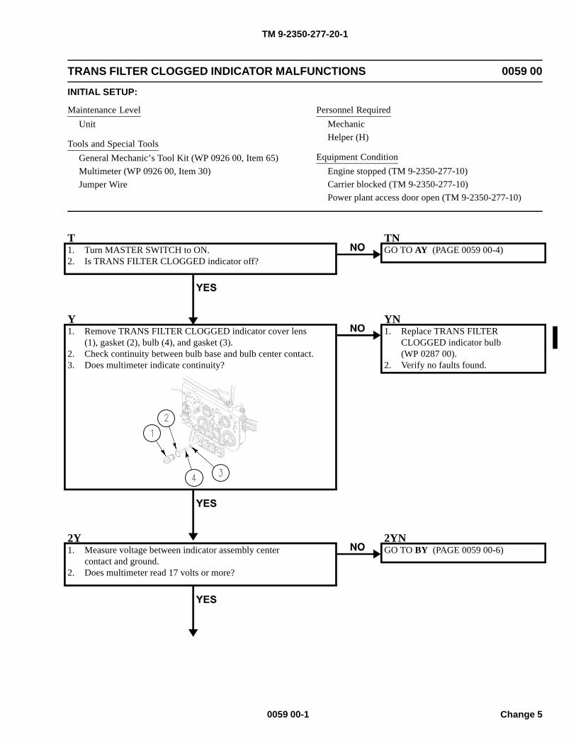
TM 9-2350-277-20-1
TRANS FILTER CLOGGED INDICATOR MALFUNCTIONS 0059 00
INITIAL SETUP:
Maintenance LevelUnit
Tools and Special ToolsGeneral Mechanic’s Tool Kit (WP 0926 00, Item 65)Multimeter (WP 0926 00, Item 30)Jumper Wire
Personnel RequiredMechanicHelper (H)
Equipment ConditionEngine stopped (TM 9-2350-277-10)Carrier blocked (TM 9-2350-277-10)Power plant access door open (TM 9-2350-277-10)
T1. Turn MASTER SWITCH to ON.2. Is TRANS FILTER CLOGGED indicator off?
TNGO TO AY (PAGE 0059 00-4)
Y1. Remove TRANS FILTER CLOGGED indicator cover lens
(1), gasket (2), bulb (4), and gasket (3).2. Check continuity between bulb base and bulb center contact.3. Does multimeter indicate continuity?
YN1. Replace TRANS FILTER
CLOGGED indicator bulb(WP 0287 00).
2. Verify no faults found.
2Y1. Measure voltage between indicator assembly center
contact and ground.2. Does multimeter read 17 volts or more?
2YNGO TO BY (PAGE 0059 00-6)
0059 00-1 Change 5
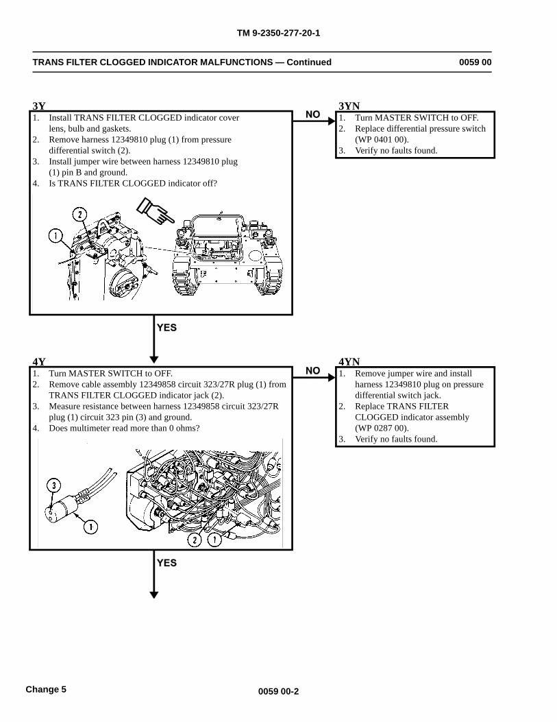
TM 9-2350-277-20-1
TRANS FILTER CLOGGED INDICATOR MALFUNCTIONS — Continued 0059 00
3Y1. Install TRANS FILTER CLOGGED indicator cover
lens, bulb and gaskets.2. Remove harness 12349810 plug (1) from pressure
differential switch (2).3. Install jumper wire between harness 12349810 plug
(1) pin B and ground.4. Is TRANS FILTER CLOGGED indicator off?
3YN1. Turn MASTER SWITCH to OFF.2. Replace differential pressure switch
(WP 0401 00).3. Verify no faults found.
4Y1. Turn MASTER SWITCH to OFF.2. Remove cable assembly 12349858 circuit 323/27R plug (1) from
TRANS FILTER CLOGGED indicator jack (2).3. Measure resistance between harness 12349858 circuit 323/27R
plug (1) circuit 323 pin (3) and ground.4. Does multimeter read more than 0 ohms?
4YN1. Remove jumper wire and install
harness 12349810 plug on pressuredifferential switch jack.
2. Replace TRANS FILTERCLOGGED indicator assembly(WP 0287 00).
3. Verify no faults found.
0059 00-2Change 5
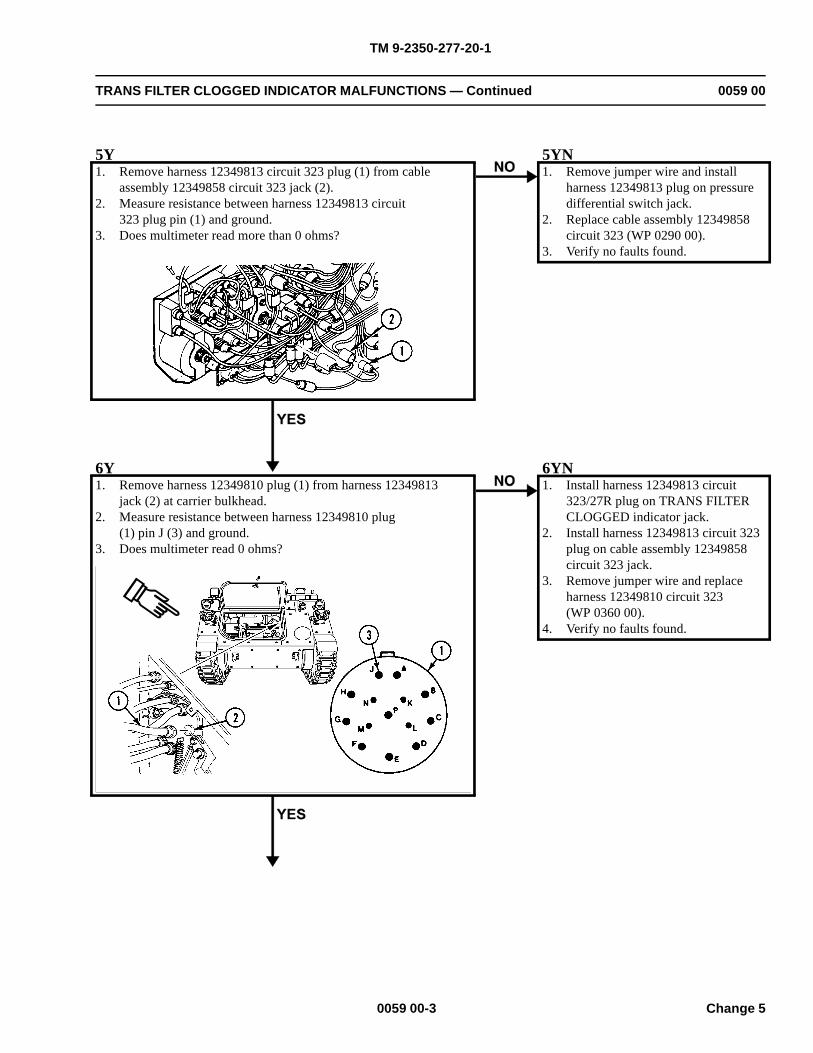
TM 9-2350-277-20-1
TRANS FILTER CLOGGED INDICATOR MALFUNCTIONS — Continued 0059 00
5Y1. Remove harness 12349813 circuit 323 plug (1) from cable
assembly 12349858 circuit 323 jack (2).2. Measure resistance between harness 12349813 circuit
323 plug pin (1) and ground.3. Does multimeter read more than 0 ohms?
5YN1. Remove jumper wire and install
harness 12349813 plug on pressuredifferential switch jack.
2. Replace cable assembly 12349858circuit 323 (WP 0290 00).
3. Verify no faults found.
6Y1. Remove harness 12349810 plug (1) from harness 12349813
jack (2) at carrier bulkhead.2. Measure resistance between harness 12349810 plug
(1) pin J (3) and ground.3. Does multimeter read 0 ohms?
6YN1. Install harness 12349813 circuit
323/27R plug on TRANS FILTERCLOGGED indicator jack.
2. Install harness 12349813 circuit 323plug on cable assembly 12349858circuit 323 jack.
3. Remove jumper wire and replaceharness 12349810 circuit 323(WP 0360 00).
4. Verify no faults found.
0059 00-3 Change 5
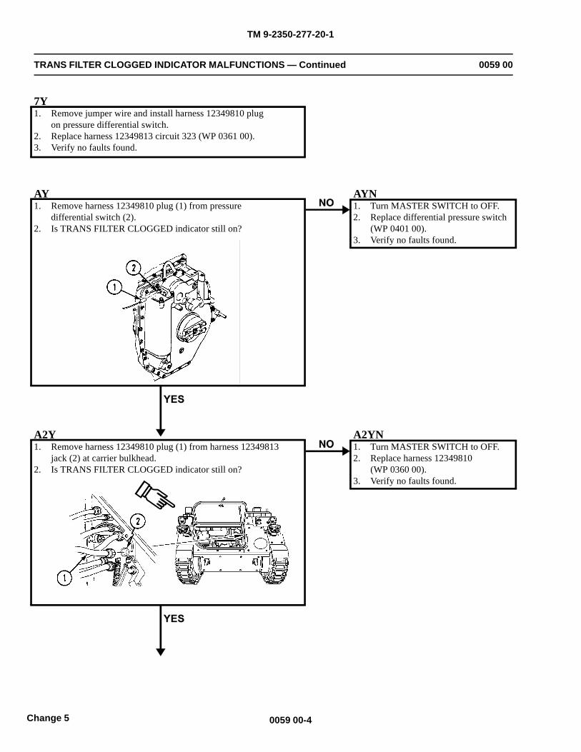
TM 9-2350-277-20-1
TRANS FILTER CLOGGED INDICATOR MALFUNCTIONS — Continued 0059 00
7Y1. Remove jumper wire and install harness 12349810 plug
on pressure differential switch.2. Replace harness 12349813 circuit 323 (WP 0361 00).3. Verify no faults found.
AY1. Remove harness 12349810 plug (1) from pressure
differential switch (2).2. Is TRANS FILTER CLOGGED indicator still on?
AYN1. Turn MASTER SWITCH to OFF.2. Replace differential pressure switch
(WP 0401 00).3. Verify no faults found.
A2Y1. Remove harness 12349810 plug (1) from harness 12349813
jack (2) at carrier bulkhead.2. Is TRANS FILTER CLOGGED indicator still on?
A2YN1. Turn MASTER SWITCH to OFF.2. Replace harness 12349810
(WP 0360 00).3. Verify no faults found.
0059 00-4Change 5
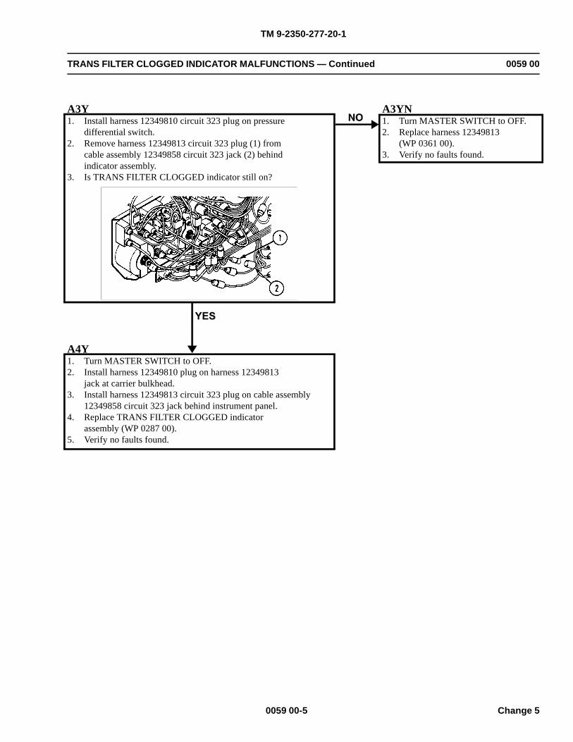
TM 9-2350-277-20-1
TRANS FILTER CLOGGED INDICATOR MALFUNCTIONS — Continued 0059 00
A3Y1. Install harness 12349810 circuit 323 plug on pressure
differential switch.2. Remove harness 12349813 circuit 323 plug (1) from
cable assembly 12349858 circuit 323 jack (2) behindindicator assembly.
3. Is TRANS FILTER CLOGGED indicator still on?
A3YN1. Turn MASTER SWITCH to OFF.2. Replace harness 12349813
(WP 0361 00).3. Verify no faults found.
A4Y1. Turn MASTER SWITCH to OFF.2. Install harness 12349810 plug on harness 12349813
jack at carrier bulkhead.3. Install harness 12349813 circuit 323 plug on cable assembly
12349858 circuit 323 jack behind instrument panel.4. Replace TRANS FILTER CLOGGED indicator
assembly (WP 0287 00).5. Verify no faults found.
0059 00-5 Change 5
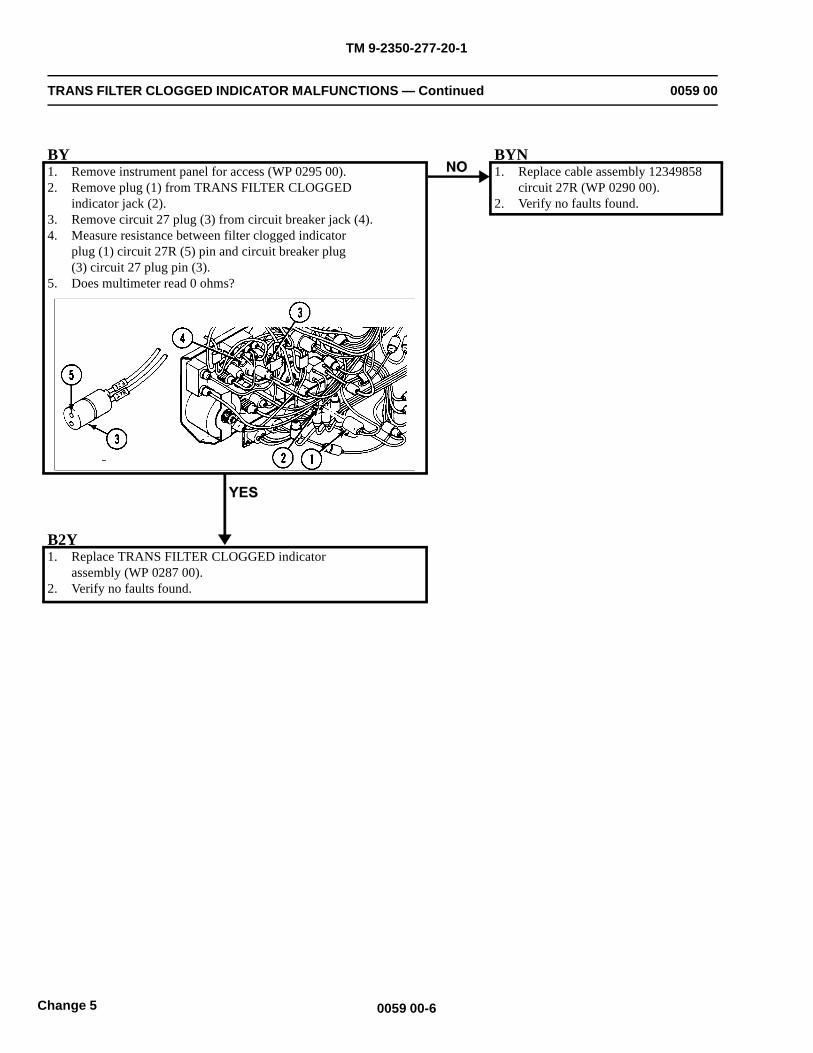
TM 9-2350-277-20-1
TRANS FILTER CLOGGED INDICATOR MALFUNCTIONS — Continued 0059 00
BY1. Remove instrument panel for access (WP 0295 00).2. Remove plug (1) from TRANS FILTER CLOGGED
indicator jack (2).3. Remove circuit 27 plug (3) from circuit breaker jack (4).4. Measure resistance between filter clogged indicator
plug (1) circuit 27R (5) pin and circuit breaker plug(3) circuit 27 plug pin (3).
5. Does multimeter read 0 ohms?
BYN1. Replace cable assembly 12349858
circuit 27R (WP 0290 00).2. Verify no faults found.
B2Y1. Replace TRANS FILTER CLOGGED indicator
assembly (WP 0287 00).2. Verify no faults found.
0059 00-6Change 5
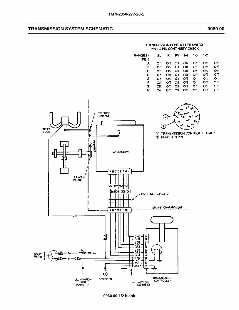
TM 9-2350-277-20-1
TRANSMISSION SYSTEM SCHEMATIC 0060 00
0060 00-1/2 blank

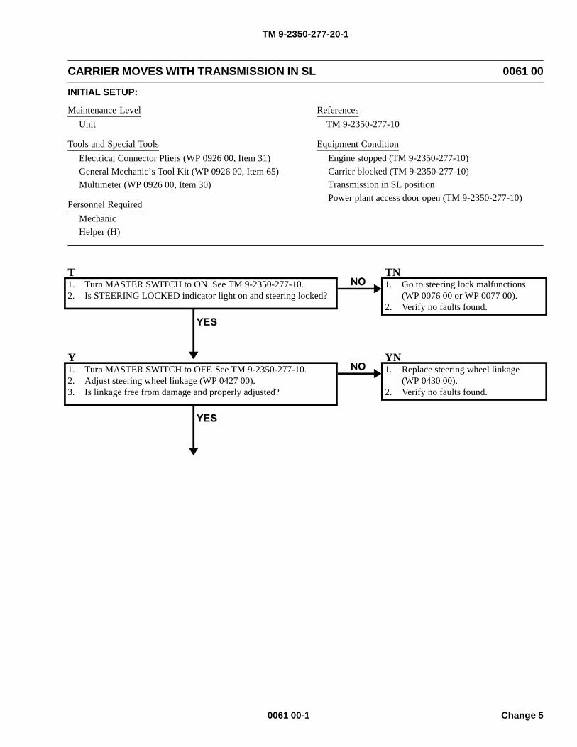
TM 9-2350-277-20-1
CARRIER MOVES WITH TRANSMISSION IN SL 0061 00
INITIAL SETUP:
Maintenance LevelUnit
Tools and Special ToolsElectrical Connector Pliers (WP 0926 00, Item 31)General Mechanic’s Tool Kit (WP 0926 00, Item 65)Multimeter (WP 0926 00, Item 30)
Personnel RequiredMechanicHelper (H)
ReferencesTM 9-2350-277-10
Equipment ConditionEngine stopped (TM 9-2350-277-10)Carrier blocked (TM 9-2350-277-10)Transmission in SL positionPower plant access door open (TM 9-2350-277-10)
T1. Turn MASTER SWITCH to ON. See TM 9-2350-277-10.2. Is STEERING LOCKED indicator light on and steering locked?
TN1. Go to steering lock malfunctions
(WP 0076 00 or WP 0077 00).2. Verify no faults found.
Y1. Turn MASTER SWITCH to OFF. See TM 9-2350-277-10.2. Adjust steering wheel linkage (WP 0427 00).3. Is linkage free from damage and properly adjusted?
YN1. Replace steering wheel linkage
(WP 0430 00).2. Verify no faults found.
0061 00-1 Change 5
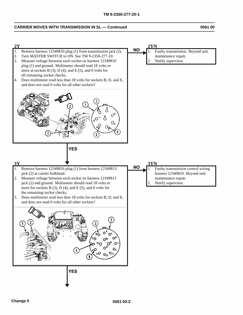
TM 9-2350-277-20-1
CARRIER MOVES WITH TRANSMISSION IN SL — Continued 0061 00
2Y1. Remove harness 12349810 plug (1) from transmission jack (2).2. Turn MASTER SWITCH to ON. See TM 9-2350-277-10.3. Measure voltage between each socket on harness 12349810
plug (1) and ground. Multimeter should read 18 volts ormore at sockets B (3), D (4), and E (5), and 0 volts forall remaining socket checks.
4. Does multimeter read less than 18 volts for sockets B, D, and E,and does not read 0 volts for all other sockets?
2YN1. Faulty transmission. Beyond unit
maintenance repair.2. Notify supervisor.
3Y1. Remove harness 12349810 plug (1) from harness 12349813
jack (2) at carrier bulkhead.2. Measure voltage between each socket on harness 12349813
jack (2) and ground. Multimeter should read 18 volts ormore for sockets B (3), D (4), and E (5), and 0 volts forthe remaining socket checks.
3. Does multimeter read less than 18 volts for sockets B, D, and E,and does not read 0 volts for all other sockets?
3YN1. Faulty transmission control wiring
harness 12349810. Beyond unitmaintenance repair.
2. Notify supervisor.
0061 00-2Change 5
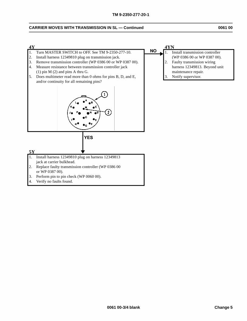
TM 9-2350-277-20-1
CARRIER MOVES WITH TRANSMISSION IN SL — Continued 0061 00
4Y1. Turn MASTER SWITCH to OFF. See TM 9-2350-277-10.2. Install harness 12349810 plug on transmission jack.3. Remove transmission controller (WP 0386 00 or WP 0387 00).4. Measure resistance between transmission controller jack
(1) pin M (2) and pins A thru G.5. Does multimeter read more than 0 ohms for pins B, D, and E,
and/or continuity for all remaining pins?
4YN1. Install transmission controller
(WP 0386 00 or WP 0387 00).2. Faulty transmission wiring
harness 12349813. Beyond unitmaintenance repair.
3. Notify supervisor.
5Y1. Install harness 12349810 plug on harness 12349813
jack at carrier bulkhead.2. Replace faulty transmission controller (WP 0386 00
or WP 0387 00).3. Perform pin to pin check (WP 0060 00).4. Verify no faults found.
0061 00-3/4 blank Change 5

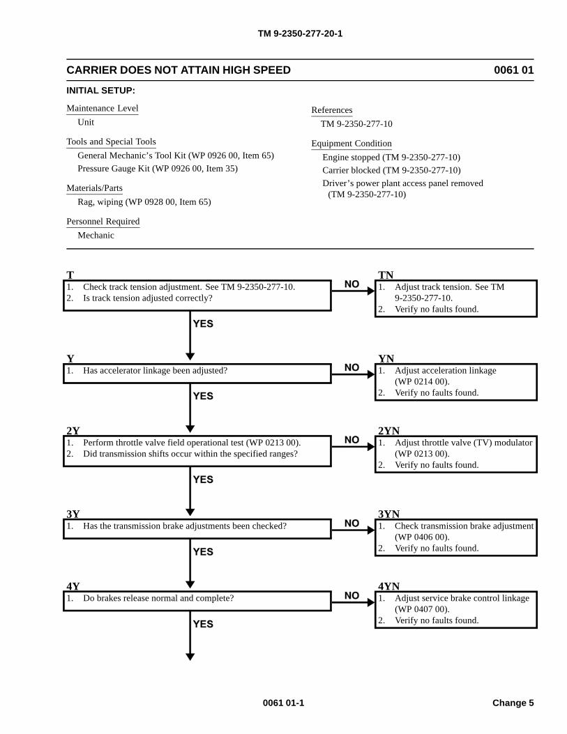
TM 9-2350-277-20-1
CARRIER DOES NOT ATTAIN HIGH SPEED 0061 01
INITIAL SETUP:
Maintenance LevelUnit
Tools and Special ToolsGeneral Mechanic’s Tool Kit (WP 0926 00, Item 65)Pressure Gauge Kit (WP 0926 00, Item 35)
Materials/PartsRag, wiping (WP 0928 00, Item 65)
Personnel RequiredMechanic
ReferencesTM 9-2350-277-10
Equipment ConditionEngine stopped (TM 9-2350-277-10)Carrier blocked (TM 9-2350-277-10)Driver’s power plant access panel removed
(TM 9-2350-277-10)
T1. Check track tension adjustment. See TM 9-2350-277-10.2. Is track tension adjusted correctly?
TN1. Adjust track tension. See TM
9-2350-277-10.2. Verify no faults found.
Y1. Has accelerator linkage been adjusted?
YN1. Adjust acceleration linkage
(WP 0214 00).2. Verify no faults found.
2Y1. Perform throttle valve field operational test (WP 0213 00).2. Did transmission shifts occur within the specified ranges?
2YN1. Adjust throttle valve (TV) modulator
(WP 0213 00).2. Verify no faults found.
3Y1. Has the transmission brake adjustments been checked?
3YN1. Check transmission brake adjustment
(WP 0406 00).2. Verify no faults found.
4Y1. Do brakes release normal and complete?
4YN1. Adjust service brake control linkage
(WP 0407 00).2. Verify no faults found.
0061 01-1 Change 5
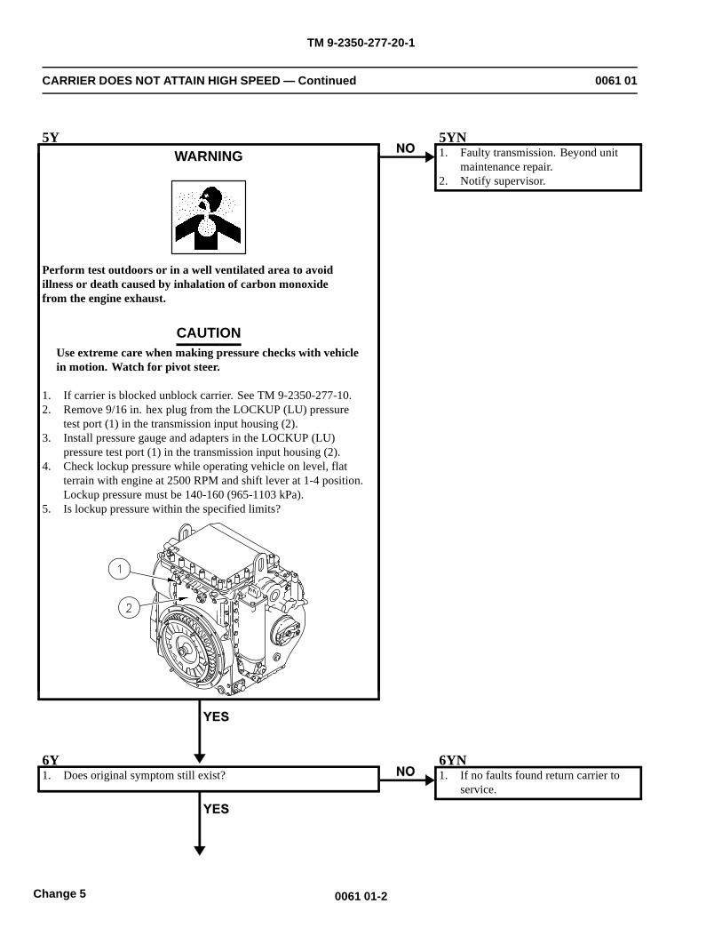
TM 9-2350-277-20-1
CARRIER DOES NOT ATTAIN HIGH SPEED — Continued 0061 01
5YWARNING
Perform test outdoors or in a well ventilated area to avoidillness or death caused by inhalation of carbon monoxidefrom the engine exhaust.
CAUTIONUse extreme care when making pressure checks with vehiclein motion. Watch for pivot steer.
1. If carrier is blocked unblock carrier. See TM 9-2350-277-10.2. Remove 9/16 in. hex plug from the LOCKUP (LU) pressure
test port (1) in the transmission input housing (2).3. Install pressure gauge and adapters in the LOCKUP (LU)
pressure test port (1) in the transmission input housing (2).4. Check lockup pressure while operating vehicle on level, flat
terrain with engine at 2500 RPM and shift lever at 1-4 position.Lockup pressure must be 140-160 (965-1103 kPa).
5. Is lockup pressure within the specified limits?
5YN1. Faulty transmission. Beyond unit
maintenance repair.2. Notify supervisor.
6Y1. Does original symptom still exist?
6YN1. If no faults found return carrier to
service.
0061 01-2Change 5
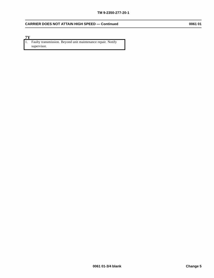
TM 9-2350-277-20-1
CARRIER DOES NOT ATTAIN HIGH SPEED — Continued 0061 01
7Y1. Faulty transmission. Beyond unit maintenance repair. Notify
supervisor.
0061 01-3/4 blank Change 5

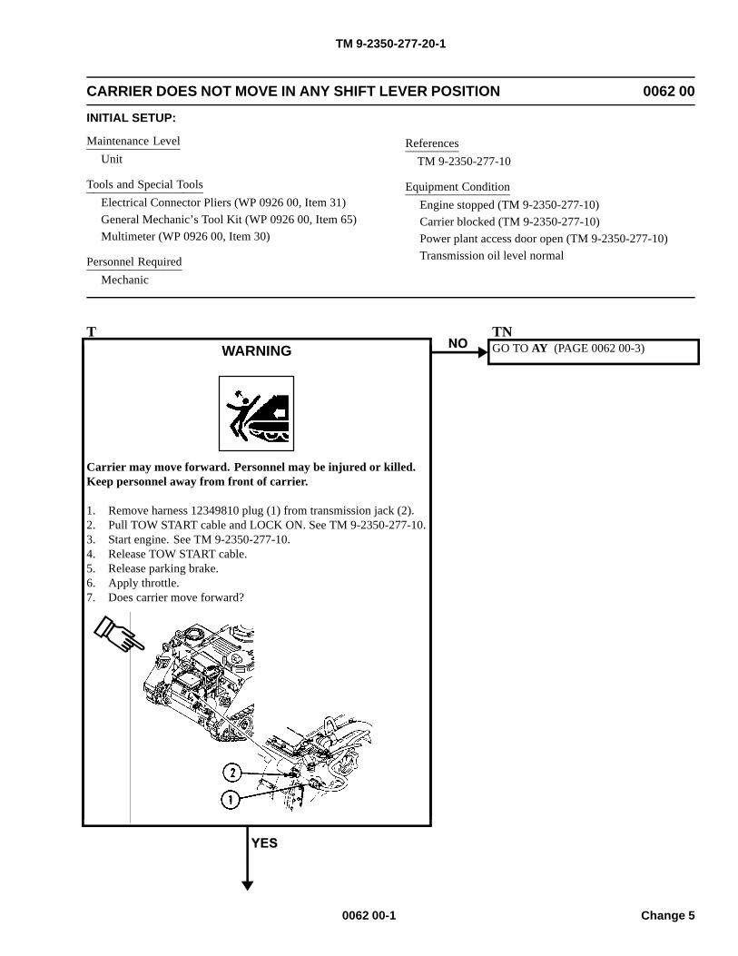
TM 9-2350-277-20-1
CARRIER DOES NOT MOVE IN ANY SHIFT LEVER POSITION 0062 00
INITIAL SETUP:
Maintenance LevelUnit
Tools and Special ToolsElectrical Connector Pliers (WP 0926 00, Item 31)General Mechanic’s Tool Kit (WP 0926 00, Item 65)Multimeter (WP 0926 00, Item 30)
Personnel RequiredMechanic
ReferencesTM 9-2350-277-10
Equipment ConditionEngine stopped (TM 9-2350-277-10)Carrier blocked (TM 9-2350-277-10)Power plant access door open (TM 9-2350-277-10)Transmission oil level normal
TWARNING
Carrier may move forward. Personnel may be injured or killed.Keep personnel away from front of carrier.
1. Remove harness 12349810 plug (1) from transmission jack (2).2. Pull TOW START cable and LOCK ON. See TM 9-2350-277-10.3. Start engine. See TM 9-2350-277-10.4. Release TOW START cable.5. Release parking brake.6. Apply throttle.7. Does carrier move forward?
TNGO TO AY (PAGE 0062 00-3)
0062 00-1 Change 5
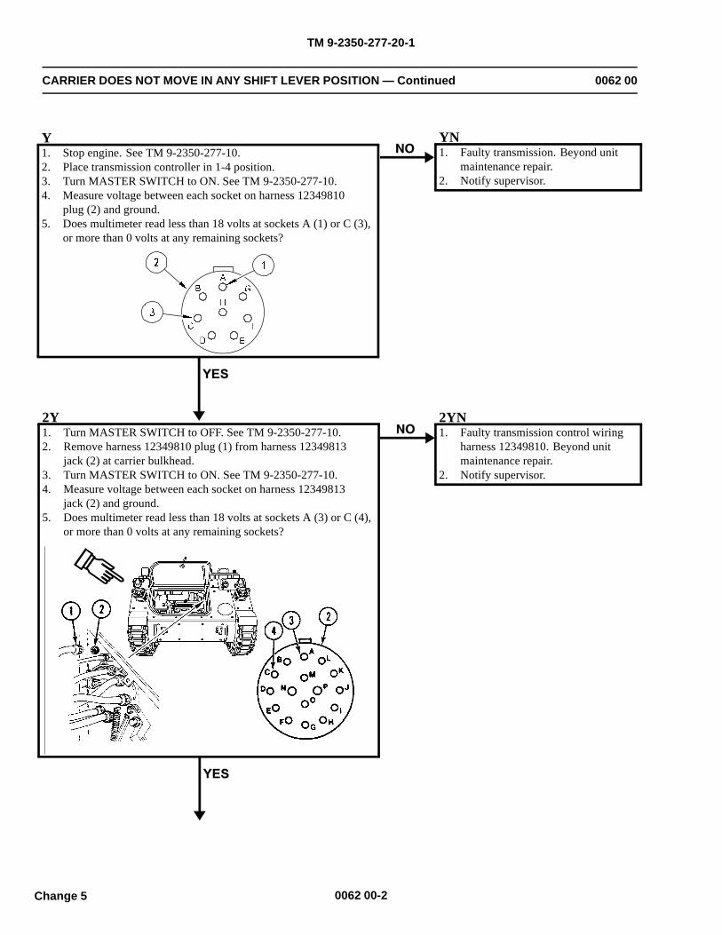
TM 9-2350-277-20-1
CARRIER DOES NOT MOVE IN ANY SHIFT LEVER POSITION — Continued 0062 00
YN1. Faulty transmission. Beyond unit
maintenance repair.2. Notify supervisor.
2Y1. Turn MASTER SWITCH to OFF. See TM 9-2350-277-10.2. Remove harness 12349810 plug (1) from harness 12349813
jack (2) at carrier bulkhead.3. Turn MASTER SWITCH to ON. See TM 9-2350-277-10.4. Measure voltage between each socket on harness 12349813
jack (2) and ground.5. Does multimeter read less than 18 volts at sockets A (3) or C (4),
or more than 0 volts at any remaining sockets?
2YN1. Faulty transmission control wiring
harness 12349810. Beyond unitmaintenance repair.
2. Notify supervisor.
0062 00-2
Y1. Stop engine. See TM 9-2350-277-10.2. Place transmission controller in 1-4 position.3. Turn MASTER SWITCH to ON. See TM 9-2350-277-10.4. Measure voltage between each socket on harness 12349810
plug (2) and ground.5. Does multimeter read less than 18 volts at sockets A (1) or C (3),
or more than 0 volts at any remaining sockets?
Change 5
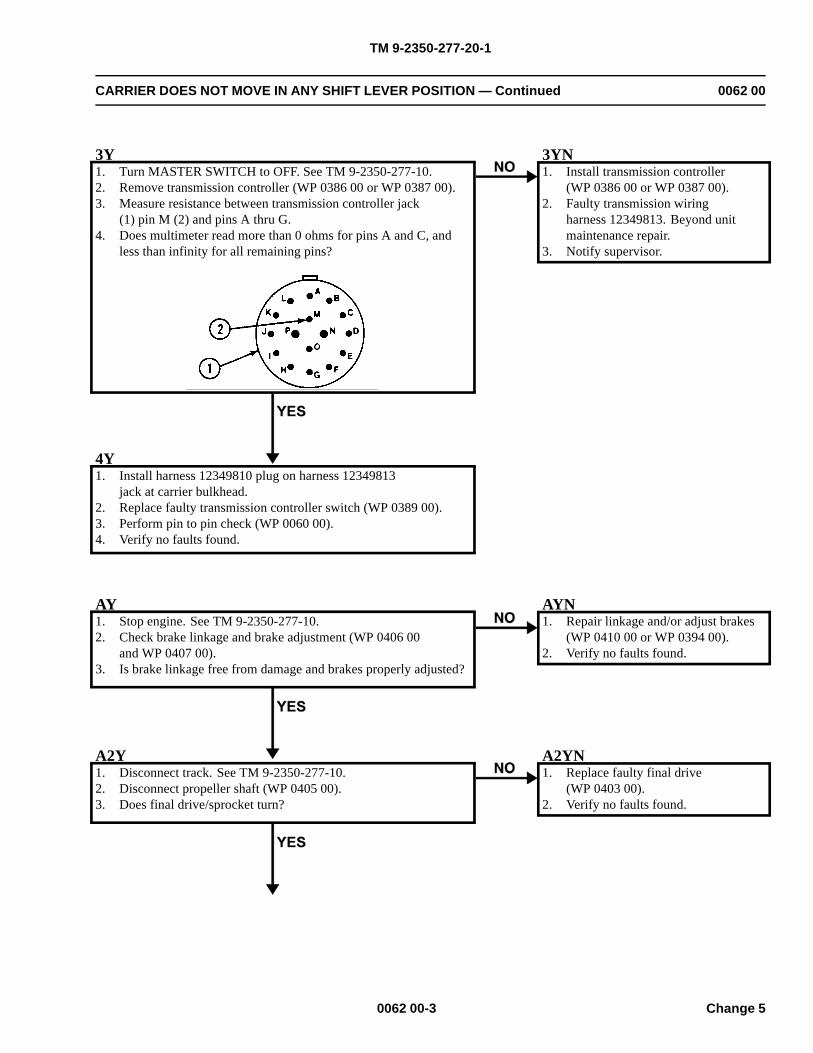
TM 9-2350-277-20-1
CARRIER DOES NOT MOVE IN ANY SHIFT LEVER POSITION — Continued 0062 00
3Y1. Turn MASTER SWITCH to OFF. See TM 9-2350-277-10.2. Remove transmission controller (WP 0386 00 or WP 0387 00).3. Measure resistance between transmission controller jack
(1) pin M (2) and pins A thru G.4. Does multimeter read more than 0 ohms for pins A and C, and
less than infinity for all remaining pins?
3YN1. Install transmission controller
(WP 0386 00 or WP 0387 00).2. Faulty transmission wiring
harness 12349813. Beyond unitmaintenance repair.
3. Notify supervisor.
4Y1. Install harness 12349810 plug on harness 12349813
jack at carrier bulkhead.2. Replace faulty transmission controller switch (WP 0389 00).3. Perform pin to pin check (WP 0060 00).4. Verify no faults found.
AY1. Stop engine. See TM 9-2350-277-10.2. Check brake linkage and brake adjustment (WP 0406 00
and WP 0407 00).3. Is brake linkage free from damage and brakes properly adjusted?
AYN1. Repair linkage and/or adjust brakes
(WP 0410 00 or WP 0394 00).2. Verify no faults found.
A2Y1. Disconnect track. See TM 9-2350-277-10.2. Disconnect propeller shaft (WP 0405 00).3. Does final drive/sprocket turn?
A2YN1. Replace faulty final drive
(WP 0403 00).2. Verify no faults found.
0062 00-3 Change 5

TM 9-2350-277-20-1
CARRIER DOES NOT MOVE IN ANY SHIFT LEVER POSITION — Continued 0062 00
A3Y1. Faulty transmission. Beyond unit maintenance repair.2. Notify supervisor.
0062 00-4Change 5
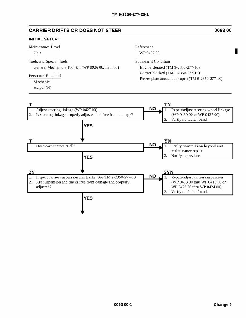
TM 9-2350-277-20-1
CARRIER DRIFTS OR DOES NOT STEER 0063 00
INITIAL SETUP:
Maintenance LevelUnit
Tools and Special ToolsGeneral Mechanic’s Tool Kit (WP 0926 00, Item 65)
Personnel RequiredMechanicHelper (H)
ReferencesWP 0427 00
Equipment ConditionEngine stopped (TM 9-2350-277-10)Carrier blocked (TM 9-2350-277-10)Power plant access door open (TM 9-2350-277-10)
T1. Adjust steering linkage (WP 0427 00).2. Is steering linkage properly adjusted and free from damage?
TN1. Repair/adjust steering wheel linkage
(WP 0430 00 or WP 0427 00).2. Verify no faults found
Y1. Does carrier steer at all?
YN1. Faulty transmission beyond unit
maintenance repair.2. Notify supervisor.
2Y1. Inspect carrier suspension and tracks. See TM 9-2350-277-10.2. Are suspension and tracks free from damage and properly
adjusted?
2YN1. Repair/adjust carrier suspension
(WP 0413 00 thru WP 0416 00 orWP 0422 00 thru WP 0424 00).
2. Verify no faults found.
0063 00-1 Change 5
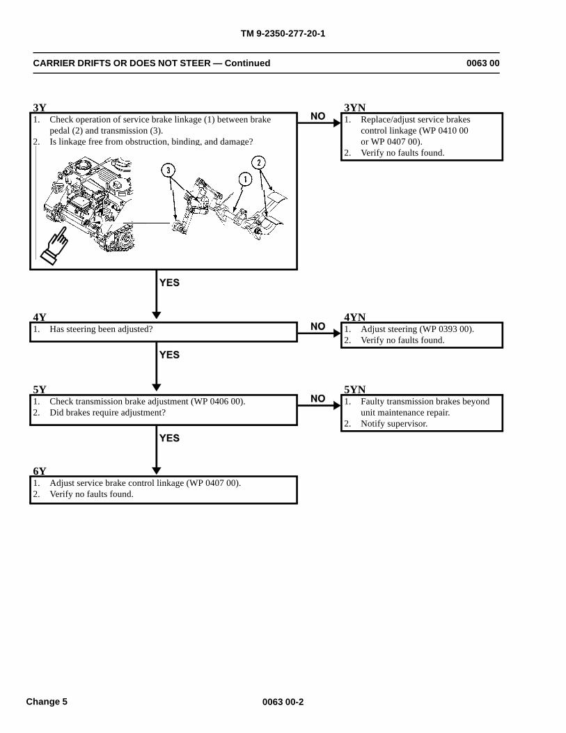
TM 9-2350-277-20-1
CARRIER DRIFTS OR DOES NOT STEER — Continued 0063 00
3Y1. Check operation of service brake linkage (1) between brake
pedal (2) and transmission (3).2. Is linkage free from obstruction, binding, and damage?
3YN1. Replace/adjust service brakes
control linkage (WP 0410 00or WP 0407 00).
2. Verify no faults found.
4Y1. Has steering been adjusted?
4YN1. Adjust steering (WP 0393 00).2. Verify no faults found.
5Y1. Check transmission brake adjustment (WP 0406 00).2. Did brakes require adjustment?
5YN1. Faulty transmission brakes beyond
unit maintenance repair.2. Notify supervisor.
6Y1. Adjust service brake control linkage (WP 0407 00).2. Verify no faults found.
0063 00-2Change 5
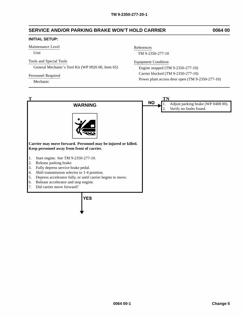
TM 9-2350-277-20-1
SERVICE AND/OR PARKING BRAKE WON’T HOLD CARRIER 0064 00
INITIAL SETUP:
Maintenance LevelUnit
Tools and Special ToolsGeneral Mechanic’s Tool Kit (WP 0926 00, Item 65)
Personnel RequiredMechanic
ReferencesTM 9-2350-277-10
Equipment ConditionEngine stopped (TM 9-2350-277-10)Carrier blocked (TM 9-2350-277-10)Power plant access door open (TM 9-2350-277-10)
TWARNING
Carrier may move forward. Personnel may be injured or killed.Keep personnel away from front of carrier.
1. Start engine. See TM 9-2350-277-10.2. Release parking brake.3. Fully depress service brake pedal.4. Shift transmission selector to 1-4 position.5. Depress accelerator fully, or until carrier begins to move.6. Release accelerator and stop engine.7. Did carrier move forward?
TN1. Adjust parking brake (WP 0408 00).2. Verify no faults found.
0064 00-1 Change 5
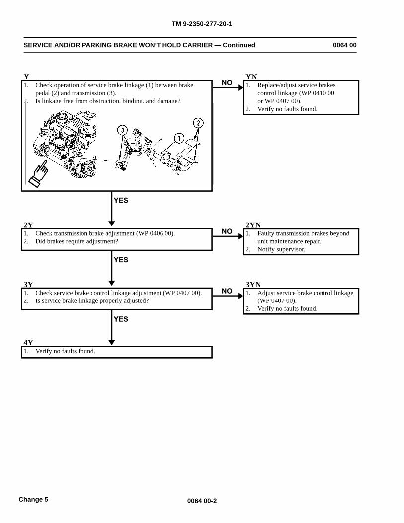
TM 9-2350-277-20-1
SERVICE AND/OR PARKING BRAKE WON’T HOLD CARRIER — Continued 0064 00
Y1. Check operation of service brake linkage (1) between brake
pedal (2) and transmission (3).2. Is linkage free from obstruction, binding, and damage?
YN1. Replace/adjust service brakes
control linkage (WP 0410 00or WP 0407 00).
2. Verify no faults found.
2Y1. Check transmission brake adjustment (WP 0406 00).2. Did brakes require adjustment?
2YN1. Faulty transmission brakes beyond
unit maintenance repair.2. Notify supervisor.
3Y1. Check service brake control linkage adjustment (WP 0407 00).2. Is service brake linkage properly adjusted?
3YN1. Adjust service brake control linkage
(WP 0407 00).2. Verify no faults found.
4Y1. Verify no faults found.
0064 00-2Change 5
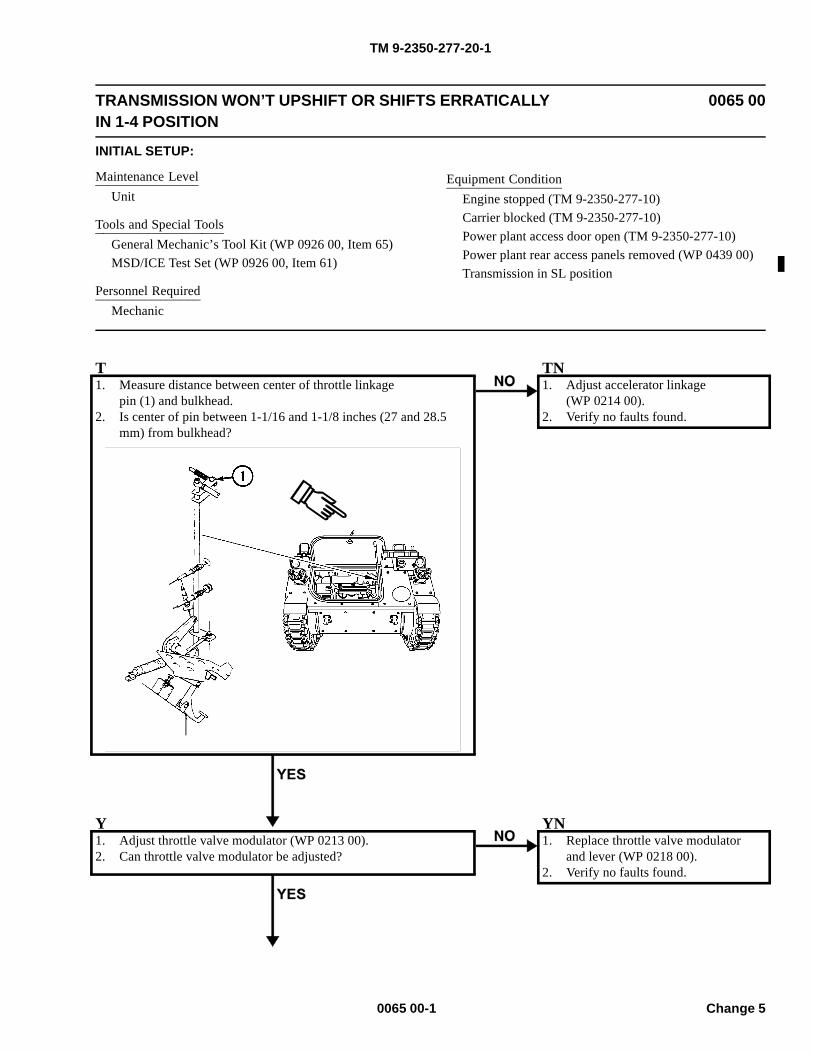
TM 9-2350-277-20-1
TRANSMISSION WON’T UPSHIFT OR SHIFTS ERRATICALLYIN 1-4 POSITION
0065 00
INITIAL SETUP:
Maintenance LevelUnit
Tools and Special ToolsGeneral Mechanic’s Tool Kit (WP 0926 00, Item 65)MSD/ICE Test Set (WP 0926 00, Item 61)
Personnel RequiredMechanic
Equipment ConditionEngine stopped (TM 9-2350-277-10)Carrier blocked (TM 9-2350-277-10)Power plant access door open (TM 9-2350-277-10)Power plant rear access panels removed (WP 0439 00)Transmission in SL position
T1. Measure distance between center of throttle linkage
pin (1) and bulkhead.2. Is center of pin between 1-1/16 and 1-1/8 inches (27 and 28.5
mm) from bulkhead?
TN1. Adjust accelerator linkage
(WP 0214 00).2. Verify no faults found.
Y1. Adjust throttle valve modulator (WP 0213 00).2. Can throttle valve modulator be adjusted?
YN1. Replace throttle valve modulator
and lever (WP 0218 00).2. Verify no faults found.
0065 00-1 Change 5
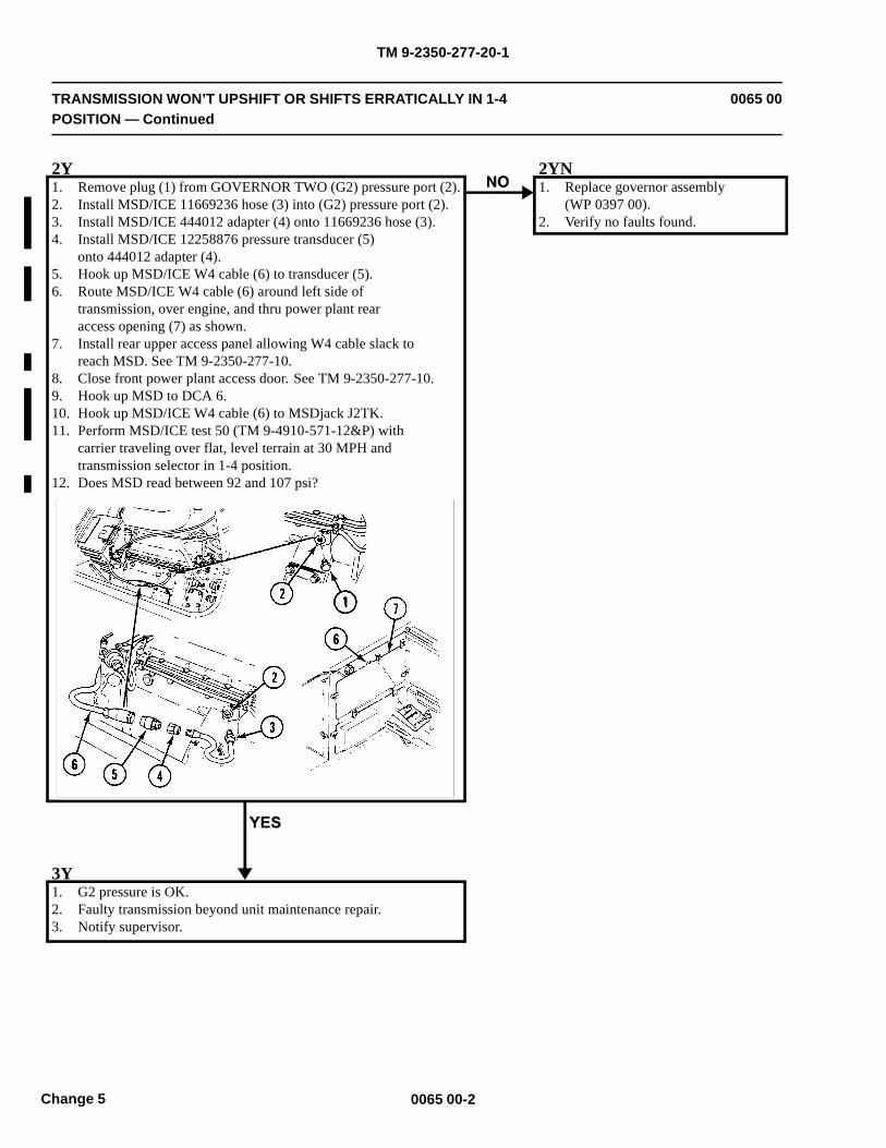
TM 9-2350-277-20-1
TRANSMISSION WON’T UPSHIFT OR SHIFTS ERRATICALLY IN 1-4POSITION — Continued
0065 00
2Y1. Remove plug (1) from GOVERNOR TWO (G2) pressure port (2).2. Install MSD/ICE 11669236 hose (3) into (G2) pressure port (2).3. Install MSD/ICE 444012 adapter (4) onto 11669236 hose (3).4. Install MSD/ICE 12258876 pressure transducer (5)
onto 444012 adapter (4).5. Hook up MSD/ICE W4 cable (6) to transducer (5).6. Route MSD/ICE W4 cable (6) around left side of
transmission, over engine, and thru power plant rearaccess opening (7) as shown.
7. Install rear upper access panel allowing W4 cable slack toreach MSD. See TM 9-2350-277-10.
8. Close front power plant access door. See TM 9-2350-277-10.9. Hook up MSD to DCA 6.10. Hook up MSD/ICE W4 cable (6) to MSDjack J2TK.11. Perform MSD/ICE test 50 (TM 9-4910-571-12&P) with
carrier traveling over flat, level terrain at 30 MPH andtransmission selector in 1-4 position.
12. Does MSD read between 92 and 107 psi?
2YN1. Replace governor assembly
(WP 0397 00).2. Verify no faults found.
3Y1. G2 pressure is OK.2. Faulty transmission beyond unit maintenance repair.3. Notify supervisor.
0065 00-2Change 5
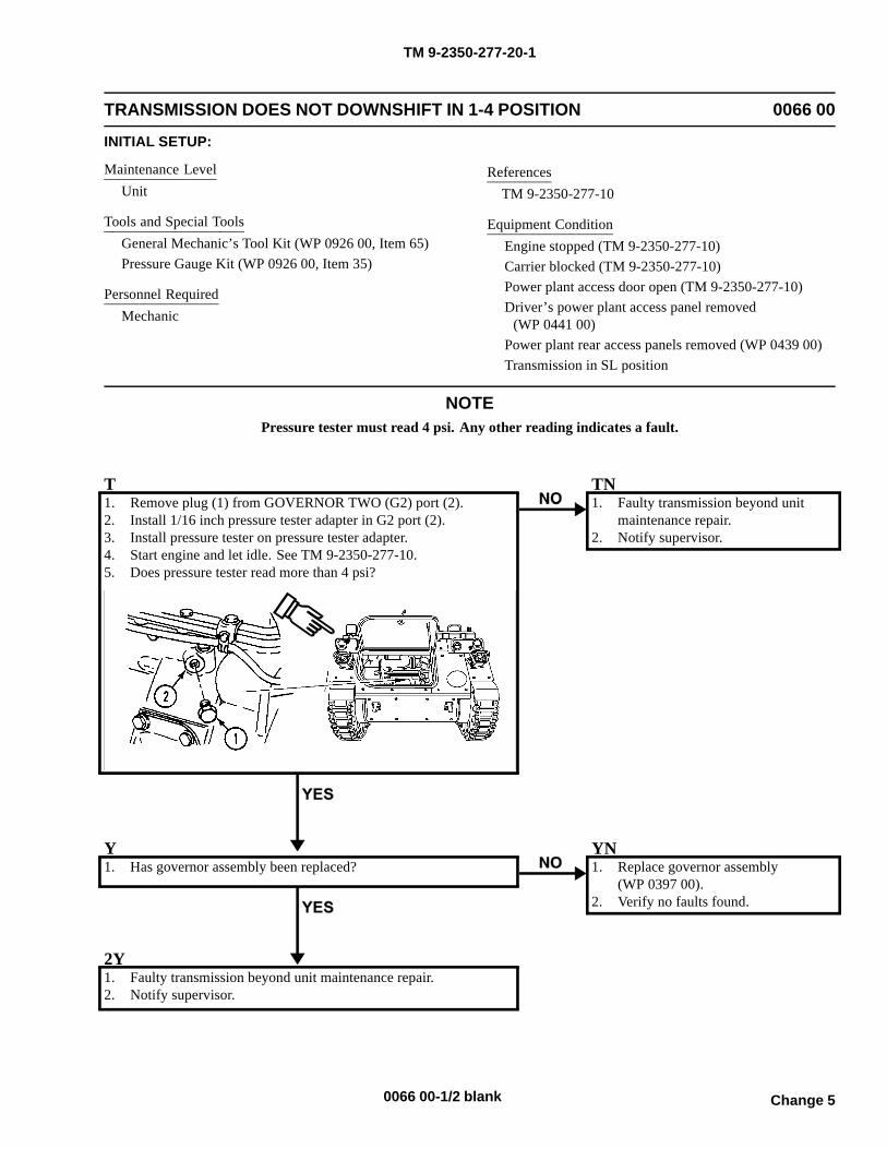
TM 9-2350-277-20-1
TRANSMISSION DOES NOT DOWNSHIFT IN 1-4 POSITION 0066 00
INITIAL SETUP:
Maintenance LevelUnit
Tools and Special ToolsGeneral Mechanic’s Tool Kit (WP 0926 00, Item 65)Pressure Gauge Kit (WP 0926 00, Item 35)
Personnel RequiredMechanic
ReferencesTM 9-2350-277-10
Equipment ConditionEngine stopped (TM 9-2350-277-10)Carrier blocked (TM 9-2350-277-10)Power plant access door open (TM 9-2350-277-10)Driver’s power plant access panel removed
(WP 0441 00)Power plant rear access panels removed (WP 0439 00)Transmission in SL position
NOTEPressure tester must read 4 psi. Any other reading indicates a fault.
T1. Remove plug (1) from GOVERNOR TWO (G2) port (2).2. Install 1/16 inch pressure tester adapter in G2 port (2).3. Install pressure tester on pressure tester adapter.4. Start engine and let idle. See TM 9-2350-277-10.5. Does pressure tester read more than 4 psi?
TN1. Faulty transmission beyond unit
maintenance repair.2. Notify supervisor.
Y1. Has governor assembly been replaced?
YN1. Replace governor assembly
(WP 0397 00).2. Verify no faults found.
2Y1. Faulty transmission beyond unit maintenance repair.2. Notify supervisor.
Change 50066 00-1/2 blank

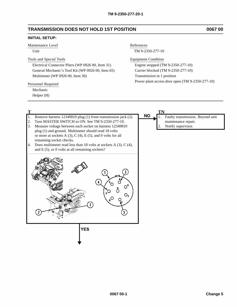
TM 9-2350-277-20-1
TRANSMISSION DOES NOT HOLD 1ST POSITION 0067 00
INITIAL SETUP:
Maintenance LevelUnit
Tools and Special ToolsElectrical Connector Pliers (WP 0926 00, Item 31)General Mechanic’s Tool Kit (WP 0926 00, Item 65)Multimeter (WP 0926 00, Item 30)
Personnel RequiredMechanicHelper (H)
ReferencesTM 9-2350-277-10
Equipment ConditionEngine stopped (TM 9-2350-277-10)Carrier blocked (TM 9-2350-277-10)Transmission in 1 positionPower plant access door open (TM 9-2350-277-10)
T1. Remove harness 12349810 plug (1) from transmission jack (2).2. Turn MASTER SWITCH to ON. See TM 9-2350-277-10.3. Measure voltage between each socket on harness 12349810
plug (1) and ground. Multimeter should read 18 voltsor more at sockets A (3), C (4), E (5), and 0 volts for allremaining socket checks.
4. Does multimeter read less than 18 volts at sockets A (3), C (4),and E (5), or 0 volts at all remaining sockets?
TN1. Faulty transmission. Beyond unit
maintenance repair.2. Notify supervisor.
0067 00-1 Change 5
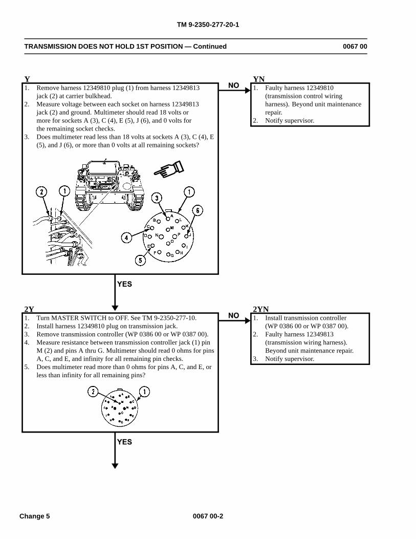
TM 9-2350-277-20-1
TRANSMISSION DOES NOT HOLD 1ST POSITION — Continued 0067 00
Y1. Remove harness 12349810 plug (1) from harness 12349813
jack (2) at carrier bulkhead.2. Measure voltage between each socket on harness 12349813
jack (2) and ground. Multimeter should read 18 volts ormore for sockets A (3), C (4), E (5), J (6), and 0 volts forthe remaining socket checks.
3. Does multimeter read less than 18 volts at sockets A (3), C (4), E(5), and J (6), or more than 0 volts at all remaining sockets?
YN1. Faulty harness 12349810
(transmission control wiringharness). Beyond unit maintenancerepair.
2. Notify supervisor.
2Y1. Turn MASTER SWITCH to OFF. See TM 9-2350-277-10.2. Install harness 12349810 plug on transmission jack.3. Remove transmission controller (WP 0386 00 or WP 0387 00).4. Measure resistance between transmission controller jack (1) pin
M (2) and pins A thru G. Multimeter should read 0 ohms for pinsA, C, and E, and infinity for all remaining pin checks.
5. Does multimeter read more than 0 ohms for pins A, C, and E, orless than infinity for all remaining pins?
2YN1. Install transmission controller
(WP 0386 00 or WP 0387 00).2. Faulty harness 12349813
(transmission wiring harness).Beyond unit maintenance repair.
3. Notify supervisor.
0067 00-2Change 5
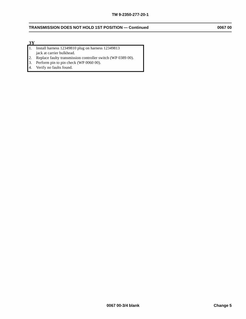
TM 9-2350-277-20-1
TRANSMISSION DOES NOT HOLD 1ST POSITION — Continued 0067 00
3Y1. Install harness 12349810 plug on harness 12349813
jack at carrier bulkhead.2. Replace faulty transmission controller switch (WP 0389 00).3. Perform pin to pin check (WP 0060 00).4. Verify no faults found.
0067 00-3/4 blank Change 5

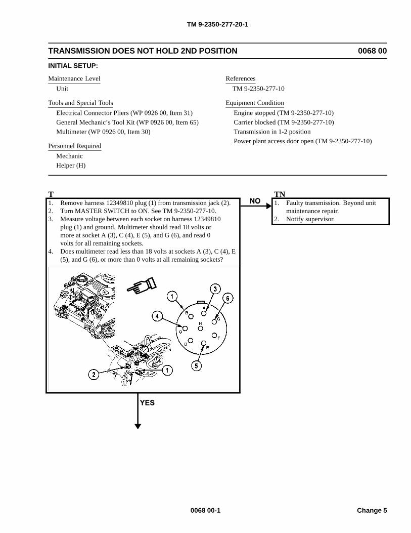
TM 9-2350-277-20-1
TRANSMISSION DOES NOT HOLD 2ND POSITION 0068 00
INITIAL SETUP:
Maintenance LevelUnit
Tools and Special ToolsElectrical Connector Pliers (WP 0926 00, Item 31)General Mechanic’s Tool Kit (WP 0926 00, Item 65)Multimeter (WP 0926 00, Item 30)
Personnel RequiredMechanicHelper (H)
ReferencesTM 9-2350-277-10
Equipment ConditionEngine stopped (TM 9-2350-277-10)Carrier blocked (TM 9-2350-277-10)Transmission in 1-2 positionPower plant access door open (TM 9-2350-277-10)
T1. Remove harness 12349810 plug (1) from transmission jack (2).2. Turn MASTER SWITCH to ON. See TM 9-2350-277-10.3. Measure voltage between each socket on harness 12349810
plug (1) and ground. Multimeter should read 18 volts ormore at socket A (3), C (4), E (5), and G (6), and read 0volts for all remaining sockets.
4. Does multimeter read less than 18 volts at sockets A (3), C (4), E(5), and G (6), or more than 0 volts at all remaining sockets?
TN1. Faulty transmission. Beyond unit
maintenance repair.2. Notify supervisor.
0068 00-1 Change 5
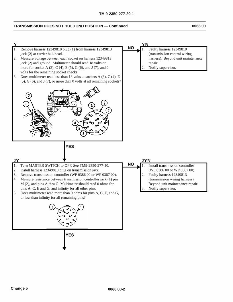
TM 9-2350-277-20-1
TRANSMISSION DOES NOT HOLD 2ND POSITION — Continued 0068 00
Y1. Remove harness 12349810 plug (1) from harness 12349813
jack (2) at carrier bulkhead.2. Measure voltage between each socket on harness 12349813
jack (2) and ground. Multimeter should read 18 volts ormore for socket A (3), C (4), E (5), G (6), and J (7), and 0volts for the remaining socket checks.
3. Does multimeter read less than 18 volts at sockets A (3), C (4), E(5), G (6), and J (7), or more than 0 volts at all remaining sockets?
YN1. Faulty harness 12349810
(transmission control wiringharness). Beyond unit maintenancerepair.
2. Notify supervisor.
2Y1. Turn MASTER SWITCH to OFF. See TM9-2350-277-10.2. Install harness 12349810 plug on transmission jack.3. Remove transmission controller (WP 0386 00 or WP 0387 00).4. Measure resistance between transmission controller jack (1) pin
M (2), and pins A thru G. Multimeter should read 0 ohms forpins A, C, E and G, and infinity for all other pins.
5. Does multimeter read more than 0 ohms for pins A, C, E, and G,or less than infinity for all remaining pins?
2YN1. Install transmission controller
(WP 0386 00 or WP 0387 00).2. Faulty harness 12349813
(transmission wiring harness).Beyond unit maintenance repair.
3. Notify supervisor.
0068 00-2Change 5

TM 9-2350-277-20-1
TRANSMISSION DOES NOT HOLD 2ND POSITION — Continued 0068 00
3Y1. Install harness 12349810 plug on harness 12349813
jack at carrier bulkhead.2. Replace faulty transmission controller switch (WP 0389 00).3. Perform pin to pin check (WP 0060 00).4. Verify no faults found.
0068 00-3/4 blank Change 5

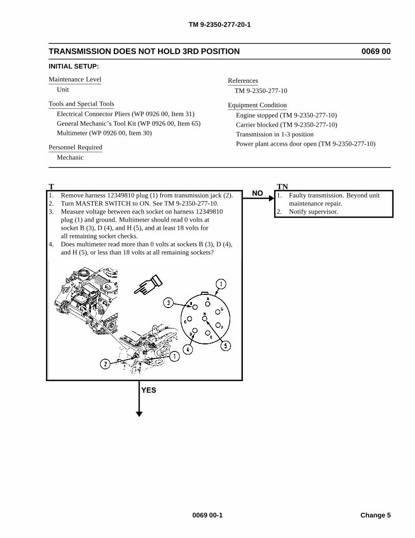
TM 9-2350-277-20-1
TRANSMISSION DOES NOT HOLD 3RD POSITION 0069 00
INITIAL SETUP:
Maintenance LevelUnit
Tools and Special ToolsElectrical Connector Pliers (WP 0926 00, Item 31)General Mechanic’s Tool Kit (WP 0926 00, Item 65)Multimeter (WP 0926 00, Item 30)
Personnel RequiredMechanic
ReferencesTM 9-2350-277-10
Equipment ConditionEngine stopped (TM 9-2350-277-10)Carrier blocked (TM 9-2350-277-10)Transmission in 1-3 positionPower plant access door open (TM 9-2350-277-10)
T1. Remove harness 12349810 plug (1) from transmission jack (2).2. Turn MASTER SWITCH to ON. See TM 9-2350-277-10.3. Measure voltage between each socket on harness 12349810
plug (1) and ground. Multimeter should read 0 volts atsocket B (3), D (4), and H (5), and at least 18 volts forall remaining socket checks.
4. Does multimeter read more than 0 volts at sockets B (3), D (4),and H (5), or less than 18 volts at all remaining sockets?
TN1. Faulty transmission. Beyond unit
maintenance repair.2. Notify supervisor.
0069 00-1 Change 5
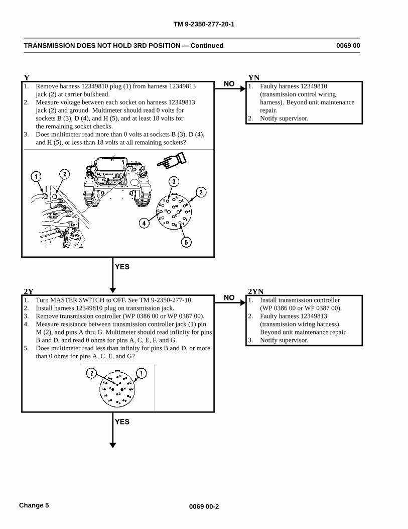
TM 9-2350-277-20-1
TRANSMISSION DOES NOT HOLD 3RD POSITION — Continued 0069 00
Y1. Remove harness 12349810 plug (1) from harness 12349813
jack (2) at carrier bulkhead.2. Measure voltage between each socket on harness 12349813
jack (2) and ground. Multimeter should read 0 volts forsockets B (3), D (4), and H (5), and at least 18 volts forthe remaining socket checks.
3. Does multimeter read more than 0 volts at sockets B (3), D (4),and H (5), or less than 18 volts at all remaining sockets?
YN1. Faulty harness 12349810
(transmission control wiringharness). Beyond unit maintenancerepair.
2. Notify supervisor.
2Y1. Turn MASTER SWITCH to OFF. See TM 9-2350-277-10.2. Install harness 12349810 plug on transmission jack.3. Remove transmission controller (WP 0386 00 or WP 0387 00).4. Measure resistance between transmission controller jack (1) pin
M (2), and pins A thru G. Multimeter should read infinity for pinsB and D, and read 0 ohms for pins A, C, E, F, and G.
5. Does multimeter read less than infinity for pins B and D, or morethan 0 ohms for pins A, C, E, and G?
2YN1. Install transmission controller
(WP 0386 00 or WP 0387 00).2. Faulty harness 12349813
(transmission wiring harness).Beyond unit maintenance repair.
3. Notify supervisor.
0069 00-2Change 5

TM 9-2350-277-20-1
TRANSMISSION DOES NOT HOLD 3RD POSITION — Continued 0069 00
3Y1. Install harness 12349810 plug on harness 12349813
jack at carrier bulkhead.2. Replace faulty transmission controller switch (WP 0389 00).3. Perform pin to pin check (WP 0060 00).4. Verify no faults found.
0069 00-3/4 blank Change 5

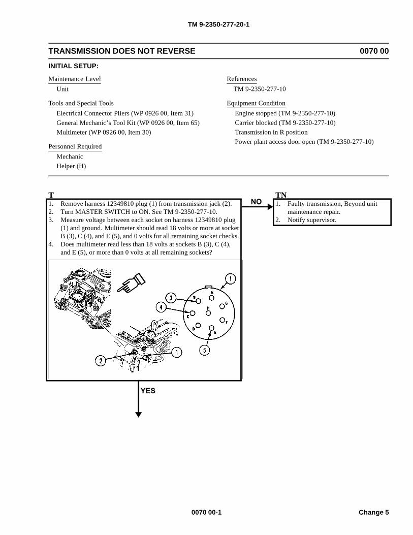
TM 9-2350-277-20-1
TRANSMISSION DOES NOT REVERSE 0070 00
INITIAL SETUP:
Maintenance LevelUnit
Tools and Special ToolsElectrical Connector Pliers (WP 0926 00, Item 31)General Mechanic’s Tool Kit (WP 0926 00, Item 65)Multimeter (WP 0926 00, Item 30)
Personnel RequiredMechanicHelper (H)
ReferencesTM 9-2350-277-10
Equipment ConditionEngine stopped (TM 9-2350-277-10)Carrier blocked (TM 9-2350-277-10)Transmission in R positionPower plant access door open (TM 9-2350-277-10)
T1. Remove harness 12349810 plug (1) from transmission jack (2).2. Turn MASTER SWITCH to ON. See TM 9-2350-277-10.3. Measure voltage between each socket on harness 12349810 plug
(1) and ground. Multimeter should read 18 volts or more at socketB (3), C (4), and E (5), and 0 volts for all remaining socket checks.
4. Does multimeter read less than 18 volts at sockets B (3), C (4),and E (5), or more than 0 volts at all remaining sockets?
TN1. Faulty transmission, Beyond unit
maintenance repair.2. Notify supervisor.
0070 00-1 Change 5
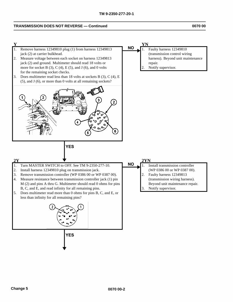
TM 9-2350-277-20-1
TRANSMISSION DOES NOT REVERSE — Continued 0070 00
Y1. Remove harness 12349810 plug (1) from harness 12349813
jack (2) at carrier bulkhead.2. Measure voltage between each socket on harness 12349813
jack (2) and ground. Multimeter should read 18 volts ormore for socket B (3), C (4), E (5), and J (6), and 0 voltsfor the remaining socket checks.
3. Does multimeter read less than 18 volts at sockets B (3), C (4), E(5), and J (6), or more than 0 volts at all remaining sockets?
YN1. Faulty harness 12349810
(transmission control wiringharness). Beyond unit maintenancerepair.
2. Notify supervisor.
2Y1. Turn MASTER SWITCH to OFF. See TM 9-2350-277-10.2. Install harness 12349810 plug on transmission jack.3. Remove transmission controller (WP 0386 00 or WP 0387 00).4. Measure resistance between transmission controller jack (1) pin
M (2) and pins A thru G. Multimeter should read 0 ohms for pinsB, C, and E, and read infinity for all remaining pins.
5. Does multimeter read more than 0 ohms for pins B, C, and E, orless than infinity for all remaining pins?
2YN1. Install transmission controller
(WP 0386 00 or WP 0387 00).2. Faulty harness 12349813
(transmission wiring harness).Beyond unit maintenance repair.
3. Notify supervisor.
0070 00-2Change 5

TM 9-2350-277-20-1
TRANSMISSION DOES NOT REVERSE — Continued 0070 00
3Y1. Install harness 12349810 plug on harness 12349813
jack at carrier bulkhead.2. Replace faulty transmission controller switch (WP 0389 00).3. Perform pin to pin check (WP 0060 00).4. Verify no faults found.
0070 00-3/4 blank Change 5

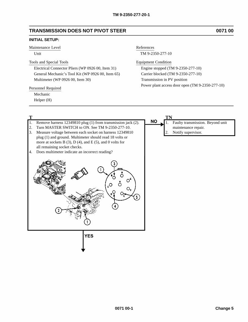
TM 9-2350-277-20-1
TRANSMISSION DOES NOT PIVOT STEER 0071 00
INITIAL SETUP:
Maintenance LevelUnit
Tools and Special ToolsElectrical Connector Pliers (WP 0926 00, Item 31)General Mechanic’s Tool Kit (WP 0926 00, Item 65)Multimeter (WP 0926 00, Item 30)
Personnel RequiredMechanicHelper (H)
ReferencesTM 9-2350-277-10
Equipment ConditionEngine stopped (TM 9-2350-277-10)Carrier blocked (TM 9-2350-277-10)Transmission in PV positionPower plant access door open (TM 9-2350-277-10)
T1. Remove harness 12349810 plug (1) from transmission jack (2).2. Turn MASTER SWITCH to ON. See TM 9-2350-277-10.3. Measure voltage between each socket on harness 12349810
plug (1) and ground. Multimeter should read 18 volts ormore at sockets B (3), D (4), and E (5), and 0 volts forall remaining socket checks.
4. Does multimeter indicate an incorrect reading?
TN1. Faulty transmission. Beyond unit
maintenance repair.2. Notify supervisor.
0071 00-1 Change 5
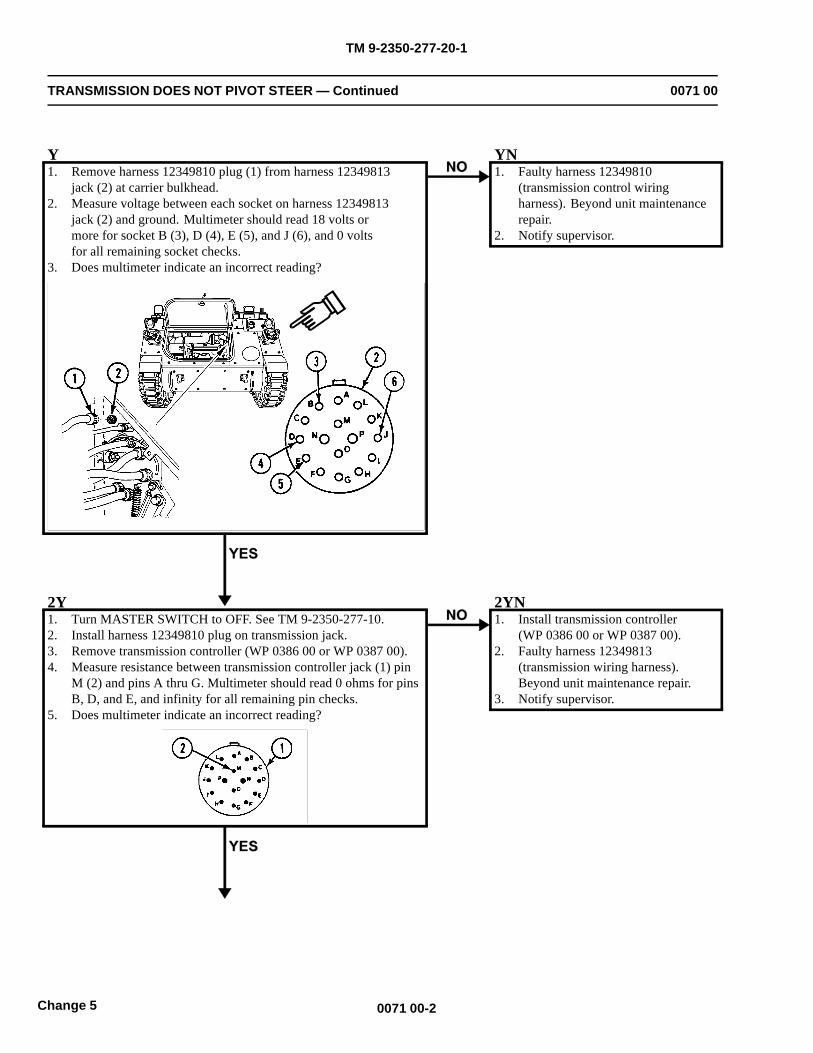
TM 9-2350-277-20-1
TRANSMISSION DOES NOT PIVOT STEER — Continued 0071 00
Y1. Remove harness 12349810 plug (1) from harness 12349813
jack (2) at carrier bulkhead.2. Measure voltage between each socket on harness 12349813
jack (2) and ground. Multimeter should read 18 volts ormore for socket B (3), D (4), E (5), and J (6), and 0 voltsfor all remaining socket checks.
3. Does multimeter indicate an incorrect reading?
YN1. Faulty harness 12349810
(transmission control wiringharness). Beyond unit maintenancerepair.
2. Notify supervisor.
2Y1. Turn MASTER SWITCH to OFF. See TM 9-2350-277-10.2. Install harness 12349810 plug on transmission jack.3. Remove transmission controller (WP 0386 00 or WP 0387 00).4. Measure resistance between transmission controller jack (1) pin
M (2) and pins A thru G. Multimeter should read 0 ohms for pinsB, D, and E, and infinity for all remaining pin checks.
5. Does multimeter indicate an incorrect reading?
2YN1. Install transmission controller
(WP 0386 00 or WP 0387 00).2. Faulty harness 12349813
(transmission wiring harness).Beyond unit maintenance repair.
3. Notify supervisor.
0071 00-2Change 5

TM 9-2350-277-20-1
TRANSMISSION DOES NOT PIVOT STEER — Continued 0071 00
3Y1. Install harness 12349810 plug on harness 12349813
jack at carrier bulkhead.2. Replace faulty transmission controller switch (WP 0389 00).3. Perform pin to pin check (WP 0060 00).4. Verify no faults found.
0071 00-3/4 blank Change 5

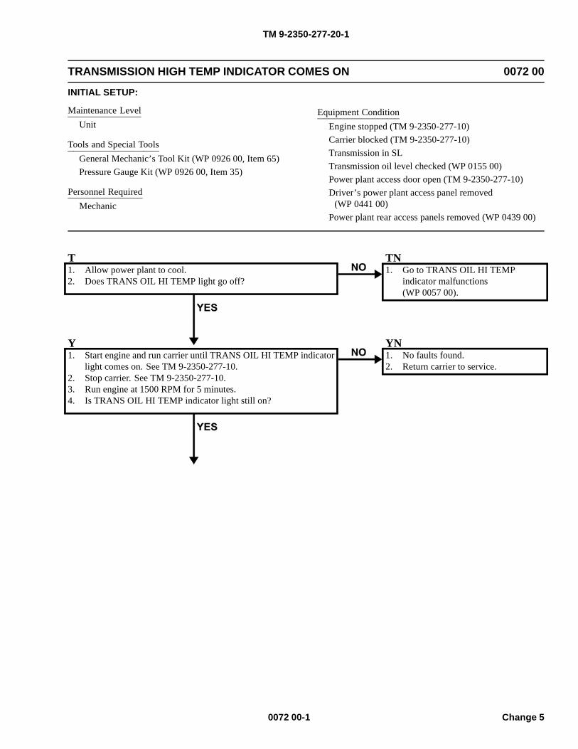
TM 9-2350-277-20-1
TRANSMISSION HIGH TEMP INDICATOR COMES ON 0072 00
INITIAL SETUP:
Maintenance LevelUnit
Tools and Special ToolsGeneral Mechanic’s Tool Kit (WP 0926 00, Item 65)Pressure Gauge Kit (WP 0926 00, Item 35)
Personnel RequiredMechanic
Equipment ConditionEngine stopped (TM 9-2350-277-10)Carrier blocked (TM 9-2350-277-10)Transmission in SLTransmission oil level checked (WP 0155 00)Power plant access door open (TM 9-2350-277-10)Driver’s power plant access panel removed
(WP 0441 00)Power plant rear access panels removed (WP 0439 00)
T1. Allow power plant to cool.2. Does TRANS OIL HI TEMP light go off?
TN1. Go to TRANS OIL HI TEMP
indicator malfunctions(WP 0057 00).
Y1. Start engine and run carrier until TRANS OIL HI TEMP indicator
light comes on. See TM 9-2350-277-10.2. Stop carrier. See TM 9-2350-277-10.3. Run engine at 1500 RPM for 5 minutes.4. Is TRANS OIL HI TEMP indicator light still on?
YN1. No faults found.2. Return carrier to service.
0072 00-1 Change 5

TM 9-2350-277-20-1
TRANSMISSION HIGH TEMP INDICATOR COMES ON — Continued 0072 00
2Y1. Stop engine. See TM 9-2350-277-10.2. Remove plug (1) from MAIN port (2) on top of filter housing.3. Install 4730-231-5632 elbow (3) into MAIN port (2).4. Remove quick disconnect (4) and adapter (5) from test hose (6).5. Install test hose (6) onto elbow (3).6. Start engine. See TM 9-2350-277-10.7. With engine at 600 RPM, measure MAIN pressure with
transmission in R, and then in 1-4 position. Use 400 psigauge. Pressure should be 280-325 psi in R. Pressure shouldbe 190-210 psi in 1-4 position.
8. Does pressure tester indicate an incorrect reading?
2YNGO TO BY (PAGE 0072 00-4)
0072 00-2Change 5

TM 9-2350-277-20-1
TRANSMISSION HIGH TEMP INDICATOR COMES ON — Continued 0072 00
3Y1. Stop engine. See TM 9-2350-277-10.2. Remove pressure tester, elbow, and install MAIN port plug (1).3. Remove plug (2) from FILTER IN port (3).4. Remove turbo air inlet duct (4) and trans filter clogged
switch plug (5).5. Install 4730-766-9000 elbow (6) into FILTER IN port (3).6. Install pressure tester into elbow (6).7. Install turbo air inlet duct (4).8. Start engine. See TM 9-2350-277-10.9. With engine at 600 RPM, measure FILTER IN pressure with
transmission in R, and then in 1-4 position. Pressure should be280-325 psi in R. Pressure should be 190-210 psi in 1-4 position.
10. Is FILTER IN pressure 35 psi or more greater than MAINpressure?
3YNGO TO CY (PAGE 0072 00-4)
4Y1. Is TRANS FILTER CLOGGED indicator ON?
4YNGO TO DY (PAGE 0072 00-4)
5Y1. Stop engine. See TM 9-2350-277-10.2. Replace transmission oil filter element (WP 0398 00).3. Verify no faults found.
0072 00-3 Change 5
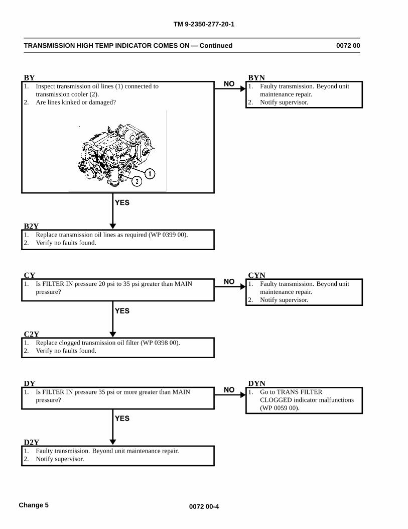
TM 9-2350-277-20-1
TRANSMISSION HIGH TEMP INDICATOR COMES ON — Continued 0072 00
BY1. Inspect transmission oil lines (1) connected to
transmission cooler (2).2. Are lines kinked or damaged?
BYN1. Faulty transmission. Beyond unit
maintenance repair.2. Notify supervisor.
B2Y1. Replace transmission oil lines as required (WP 0399 00).2. Verify no faults found.
CY1. Is FILTER IN pressure 20 psi to 35 psi greater than MAIN
pressure?
CYN1. Faulty transmission. Beyond unit
maintenance repair.2. Notify supervisor.
C2Y1. Replace clogged transmission oil filter (WP 0398 00).2. Verify no faults found.
DY1. Is FILTER IN pressure 35 psi or more greater than MAIN
pressure?
DYN1. Go to TRANS FILTER
CLOGGED indicator malfunctions(WP 0059 00).
D2Y1. Faulty transmission. Beyond unit maintenance repair.2. Notify supervisor.
0072 00-4Change 5
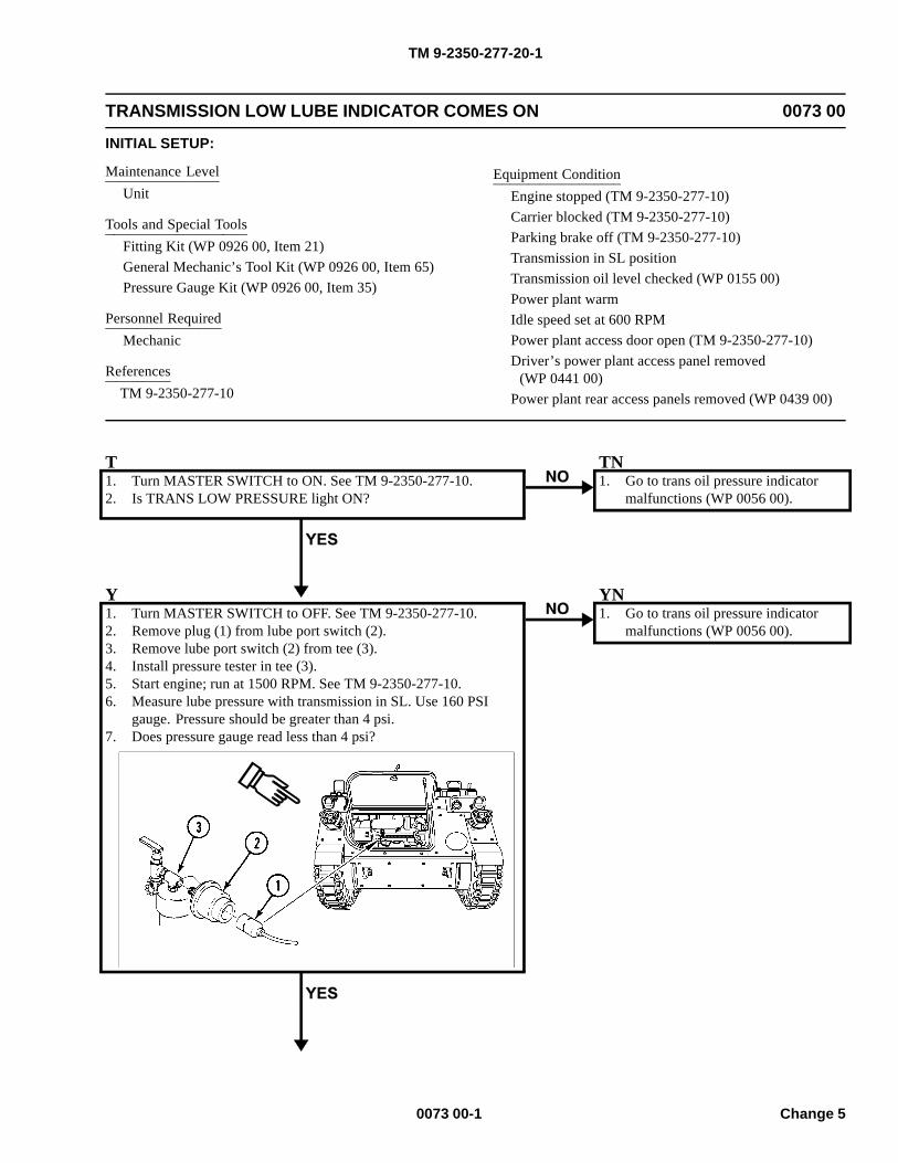
TM 9-2350-277-20-1
TRANSMISSION LOW LUBE INDICATOR COMES ON 0073 00
INITIAL SETUP:
Maintenance LevelUnit
Tools and Special ToolsFitting Kit (WP 0926 00, Item 21)General Mechanic’s Tool Kit (WP 0926 00, Item 65)Pressure Gauge Kit (WP 0926 00, Item 35)
Personnel RequiredMechanic
ReferencesTM 9-2350-277-10
Equipment ConditionEngine stopped (TM 9-2350-277-10)Carrier blocked (TM 9-2350-277-10)Parking brake off (TM 9-2350-277-10)Transmission in SL positionTransmission oil level checked (WP 0155 00)Power plant warmIdle speed set at 600 RPMPower plant access door open (TM 9-2350-277-10)Driver’s power plant access panel removed
(WP 0441 00)Power plant rear access panels removed (WP 0439 00)
T1. Turn MASTER SWITCH to ON. See TM 9-2350-277-10.2. Is TRANS LOW PRESSURE light ON?
TN1. Go to trans oil pressure indicator
malfunctions (WP 0056 00).
Y1. Turn MASTER SWITCH to OFF. See TM 9-2350-277-10.2. Remove plug (1) from lube port switch (2).3. Remove lube port switch (2) from tee (3).4. Install pressure tester in tee (3).5. Start engine; run at 1500 RPM. See TM 9-2350-277-10.6. Measure lube pressure with transmission in SL. Use 160 PSI
gauge. Pressure should be greater than 4 psi.7. Does pressure gauge read less than 4 psi?
YN1. Go to trans oil pressure indicator
malfunctions (WP 0056 00).
0073 00-1 Change 5
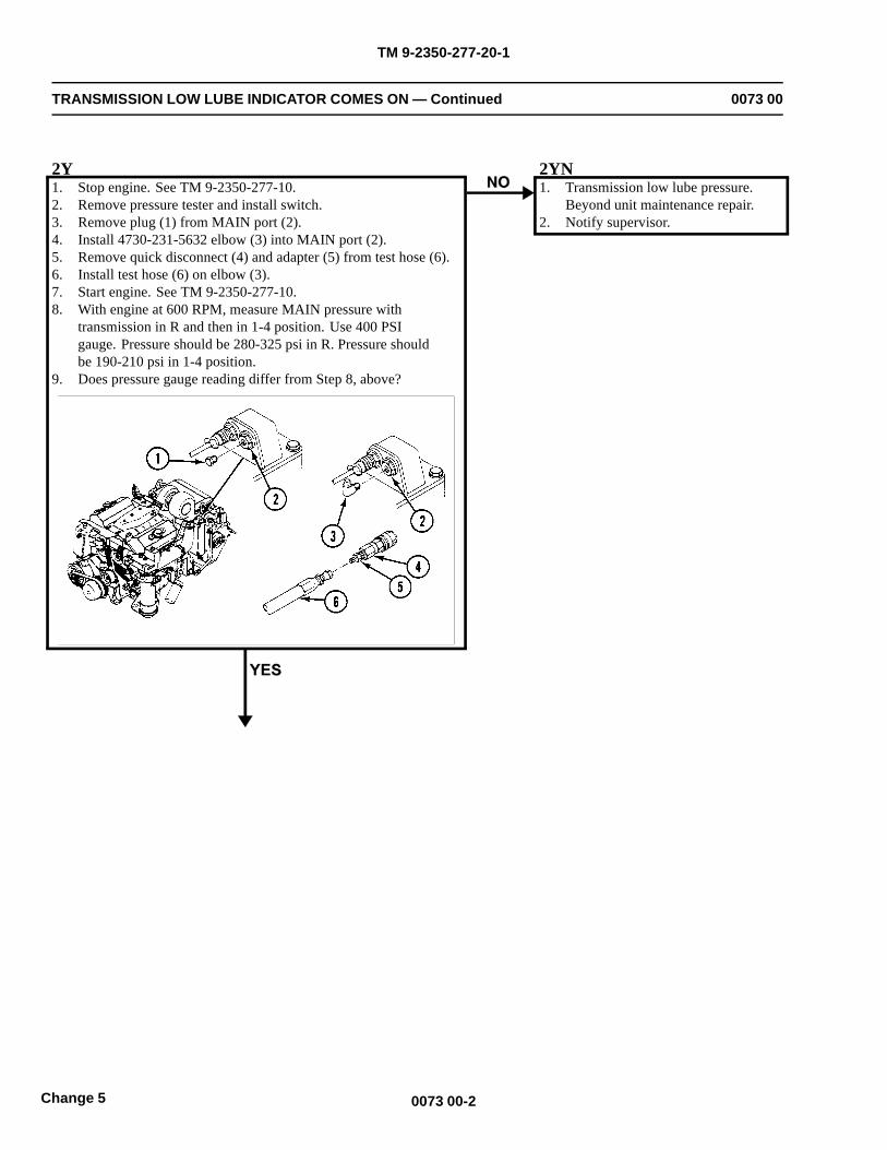
TM 9-2350-277-20-1
TRANSMISSION LOW LUBE INDICATOR COMES ON — Continued 0073 00
2Y1. Stop engine. See TM 9-2350-277-10.2. Remove pressure tester and install switch.3. Remove plug (1) from MAIN port (2).4. Install 4730-231-5632 elbow (3) into MAIN port (2).5. Remove quick disconnect (4) and adapter (5) from test hose (6).6. Install test hose (6) on elbow (3).7. Start engine. See TM 9-2350-277-10.8. With engine at 600 RPM, measure MAIN pressure with
transmission in R and then in 1-4 position. Use 400 PSIgauge. Pressure should be 280-325 psi in R. Pressure shouldbe 190-210 psi in 1-4 position.
9. Does pressure gauge reading differ from Step 8, above?
2YN1. Transmission low lube pressure.
Beyond unit maintenance repair.2. Notify supervisor.
0073 00-2Change 5
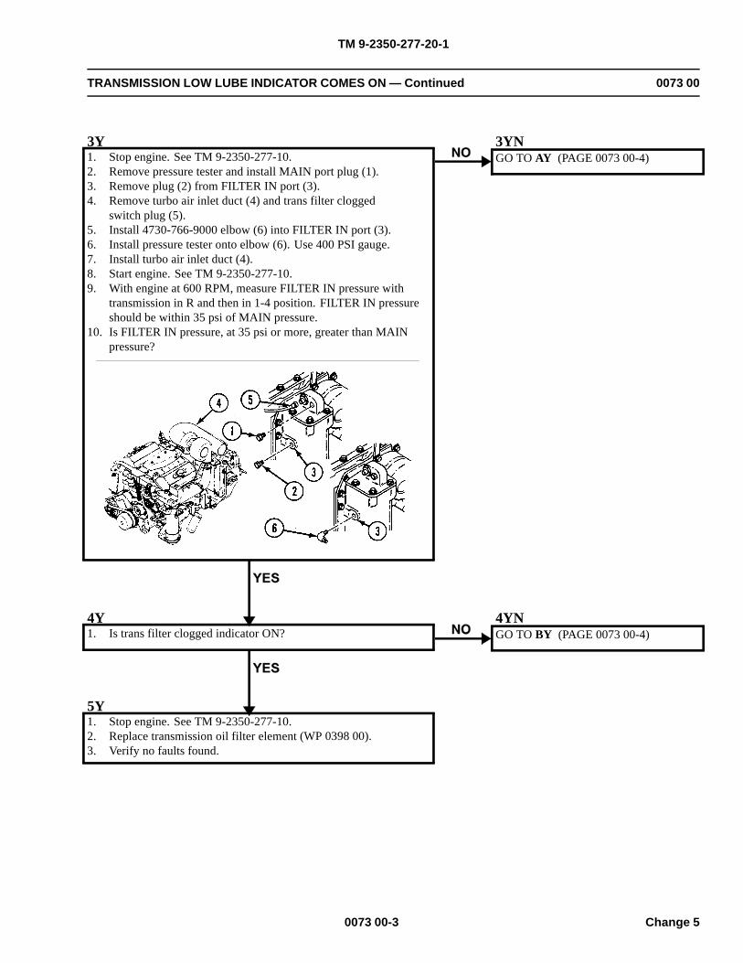
TM 9-2350-277-20-1
TRANSMISSION LOW LUBE INDICATOR COMES ON — Continued 0073 00
3Y1. Stop engine. See TM 9-2350-277-10.2. Remove pressure tester and install MAIN port plug (1).3. Remove plug (2) from FILTER IN port (3).4. Remove turbo air inlet duct (4) and trans filter clogged
switch plug (5).5. Install 4730-766-9000 elbow (6) into FILTER IN port (3).6. Install pressure tester onto elbow (6). Use 400 PSI gauge.7. Install turbo air inlet duct (4).8. Start engine. See TM 9-2350-277-10.9. With engine at 600 RPM, measure FILTER IN pressure with
transmission in R and then in 1-4 position. FILTER IN pressureshould be within 35 psi of MAIN pressure.
10. Is FILTER IN pressure, at 35 psi or more, greater than MAINpressure?
3YNGO TO AY (PAGE 0073 00-4)
4Y1. Is trans filter clogged indicator ON?
4YNGO TO BY (PAGE 0073 00-4)
5Y1. Stop engine. See TM 9-2350-277-10.2. Replace transmission oil filter element (WP 0398 00).3. Verify no faults found.
0073 00-3 Change 5
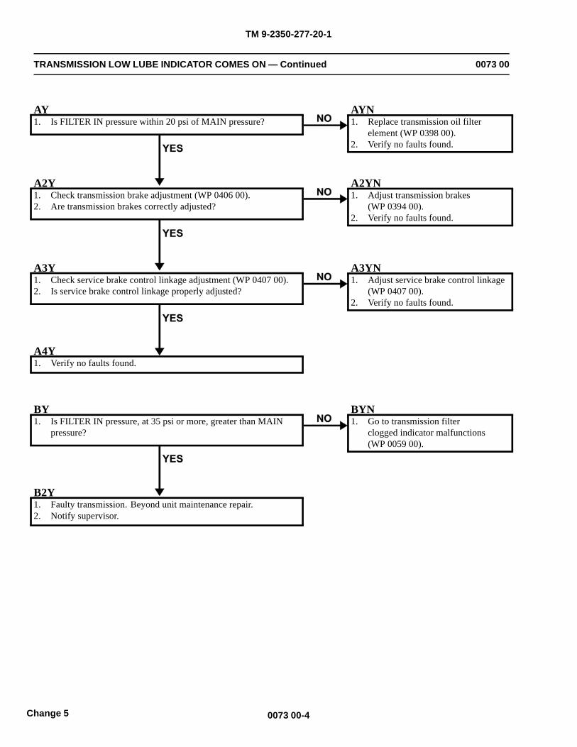
TM 9-2350-277-20-1
TRANSMISSION LOW LUBE INDICATOR COMES ON — Continued 0073 00
AY1. Is FILTER IN pressure within 20 psi of MAIN pressure?
AYN1. Replace transmission oil filter
element (WP 0398 00).2. Verify no faults found.
A2Y1. Check transmission brake adjustment (WP 0406 00).2. Are transmission brakes correctly adjusted?
A2YN1. Adjust transmission brakes
(WP 0394 00).2. Verify no faults found.
A3Y1. Check service brake control linkage adjustment (WP 0407 00).2. Is service brake control linkage properly adjusted?
A3YN1. Adjust service brake control linkage
(WP 0407 00).2. Verify no faults found.
A4Y1. Verify no faults found.
BY1. Is FILTER IN pressure, at 35 psi or more, greater than MAIN
pressure?
BYN1. Go to transmission filter
clogged indicator malfunctions(WP 0059 00).
B2Y1. Faulty transmission. Beyond unit maintenance repair.2. Notify supervisor.
0073 00-4Change 5
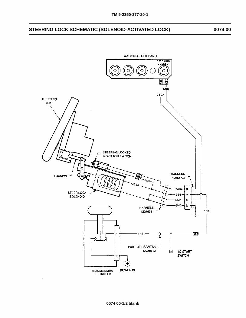
TM 9-2350-277-20-1
STEERING LOCK SCHEMATIC (SOLENOID-ACTIVATED LOCK) 0074 00
0074 00-1/2 blank

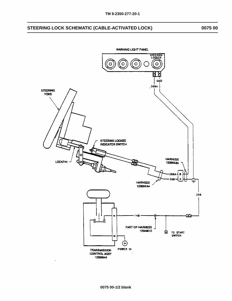
TM 9-2350-277-20-1
STEERING LOCK SCHEMATIC (CABLE-ACTIVATED LOCK) 0075 00
0075 00-1/2 blank

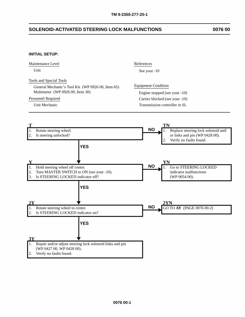
TM 9-2350-277-20-1
SOLENOID-ACTIVATED STEERING LOCK MALFUNCTIONS 0076 00
INITIAL SETUP:
Maintenance Level
Unit
Tools and Special Tools
General Mechanic’s Tool Kit (WP 0926 00, Item 65)Multimeter (WP 0926 00, Item 30)
Personnel Required
Unit Mechanic
References
See your -10
Equipment Condition
Engine stopped (see your -10)
Carrier blocked (see your -10)
Transmission controller in SL
T1. Rotate steering wheel.2. Is steering unlocked?
YES
NOTN1. Replace steering lock solenoid and/
or links and pin (WP 0428 00).2. Verify no faults found.
Y1. Hold steering wheel off center.2. Turn MASTER SWITCH to ON (see your -10).3. Is STEERING LOCKED indicator off?
YES
NOYN1. Go to STEERING LOCKED
indicator malfunctions(WP 0054 00).
2Y1. Rotate steering wheel to center.2. Is STEERING LOCKED indicator on?
YES
NO2YNGO TO AY (PAGE 0076 00-2)
3Y1. Repair and/or adjust steering lock solenoid links and pin
(WP 0427 00, WP 0428 00).2. Verify no faults found.
0076 00-1
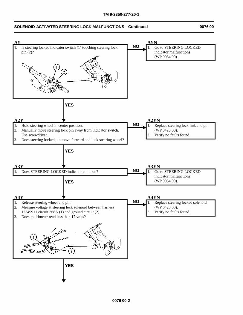
TM 9-2350-277-20-1
SOLENOID-ACTIVATED STEERING LOCK MALFUNCTIONS—Continued 0076 00
AY1. Is steering locked indicator switch (1) touching steering lock
pin (2)?
YES
NOAYN1. Go to STEERING LOCKED
indicator malfunctions(WP 0054 00).
A2Y1. Hold steering wheel in center position.2. Manually move steering lock pin away from indicator switch.
Use screwdriver.3. Does steering locked pin move forward and lock steering wheel?
YES
NOA2YN1. Replace steering lock link and pin
(WP 0428 00).2. Verify no faults found.
A3Y1. Does STEERING LOCKED indicator come on?
YES
NOA3YN1. Go to STEERING LOCKED
indicator malfunctions(WP 0054 00).
A4Y1. Release steering wheel and pin.2. Measure voltage at steering lock solenoid between harness
12349911 circuit 368A (1) and ground circuit (2).3. Does multimeter read less than 17 volts?
YES
NOA4YN1. Replace steering locked solenoid
(WP 0428 00).2. Verify no faults found.
0076 00-2

TM 9-2350-277-20-1
SOLENOID-ACTIVATED STEERING LOCK MALFUNCTIONS—Continued 0076 00
A5Y1. Repair harness 12345911 (WP 0367 00).2. Verify no faults found.
0076 00-3/4 blank

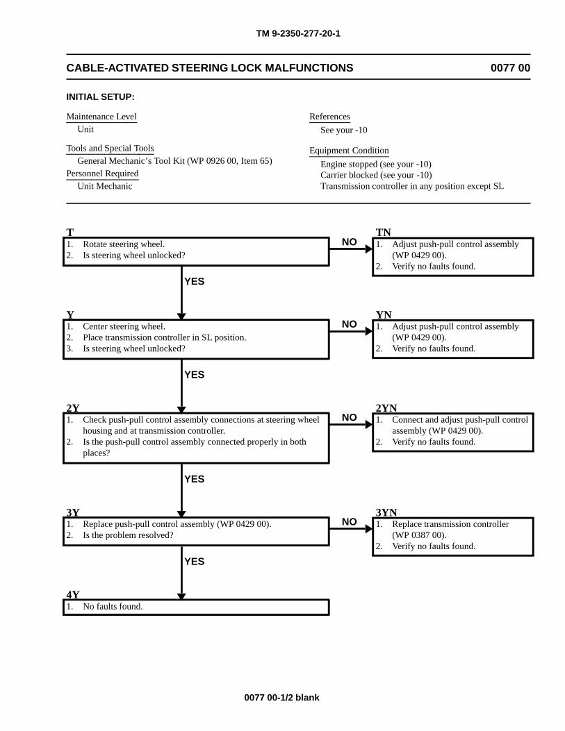
TM 9-2350-277-20-1
CABLE-ACTIVATED STEERING LOCK MALFUNCTIONS 0077 00
INITIAL SETUP:
Maintenance LevelUnit
Tools and Special ToolsGeneral Mechanic’s Tool Kit (WP 0926 00, Item 65)
Personnel RequiredUnit Mechanic
References
See your -10
Equipment Condition
Engine stopped (see your -10)Carrier blocked (see your -10)Transmission controller in any position except SL
T1. Rotate steering wheel.2. Is steering wheel unlocked?
YES
NOTN1. Adjust push-pull control assembly
(WP 0429 00).2. Verify no faults found.
Y1. Center steering wheel.2. Place transmission controller in SL position.3. Is steering wheel unlocked?
YES
NOYN1. Adjust push-pull control assembly
(WP 0429 00).2. Verify no faults found.
2Y1. Check push-pull control assembly connections at steering wheel
housing and at transmission controller.2. Is the push-pull control assembly connected properly in both
places?
YES
NO2YN1. Connect and adjust push-pull control
assembly (WP 0429 00).2. Verify no faults found.
3Y1. Replace push-pull control assembly (WP 0429 00).2. Is the problem resolved?
YES
NO3YN1. Replace transmission controller
(WP 0387 00).2. Verify no faults found.
4Y1. No faults found.
0077 00-1/2 blank

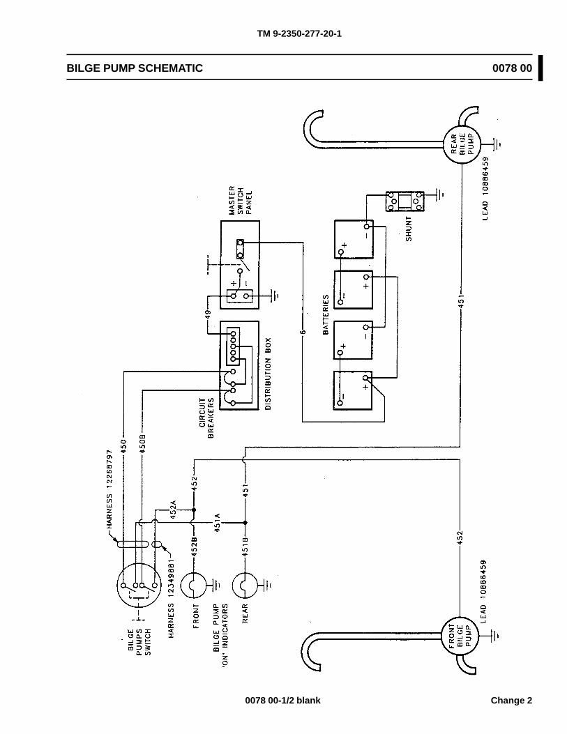
TM 9-2350-277-20-1
BILGE PUMP SCHEMATIC 0078 00
0078 00-1/2 blank Change 2

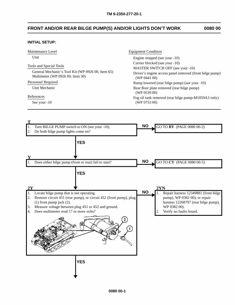
TM 9-2350-277-20-1
FRONT AND/OR REAR BILGE PUMP(S) AND/OR LIGHTS DON’T WORK 0080 00
INITIAL SETUP:
Maintenance Level
Unit
Tools and Special Tools
General Mechanic’s Tool Kit (WP 0926 00, Item 65)Multimeter (WP 0926 00, Item 30)
Personnel Required
Unit Mechanic
References
See your -10
Equipment Condition
Engine stopped (see your -10)Carrier blocked (see your -10)MASTER SWITCH OFF (see your -10)Driver’s engine access panel removed (front bilge pump)
(WP 0441 00)Ramp lowered (rear bilge pump) (see your -10)Rear floor plate removed (rear bilge pump)
(WP 0539 00)Fog oil tank removed (rear bilge pump-M1059A3 only)
(WP 0753 00)
T1. Turn BILGE PUMP switch to ON (see your -10).2. Do both bilge pump lights come on?
YES
NO GO TO BY (PAGE 0080 00-2)
Y1. Does either bilge pump (front or rear) fail to start?
YES
NO GO TO CY (PAGE 0080 00-5)
2Y1. Locate bilge pump that is not operating.2. Remove circuit 451 (rear pump), or circuit 452 (front pump), plug
(1) from pump jack (2).3. Measure voltage between plug 451 or 452 and ground.4. Does multimeter read 17 or more volts?
YES
NO2YN1. Repair harness 12349881 (front bilge
pump), WP 0382 00); or repairharness 12268797 (rear bilge pump),WP 0382 00).
2. Verify no faults found.
0080 00-1
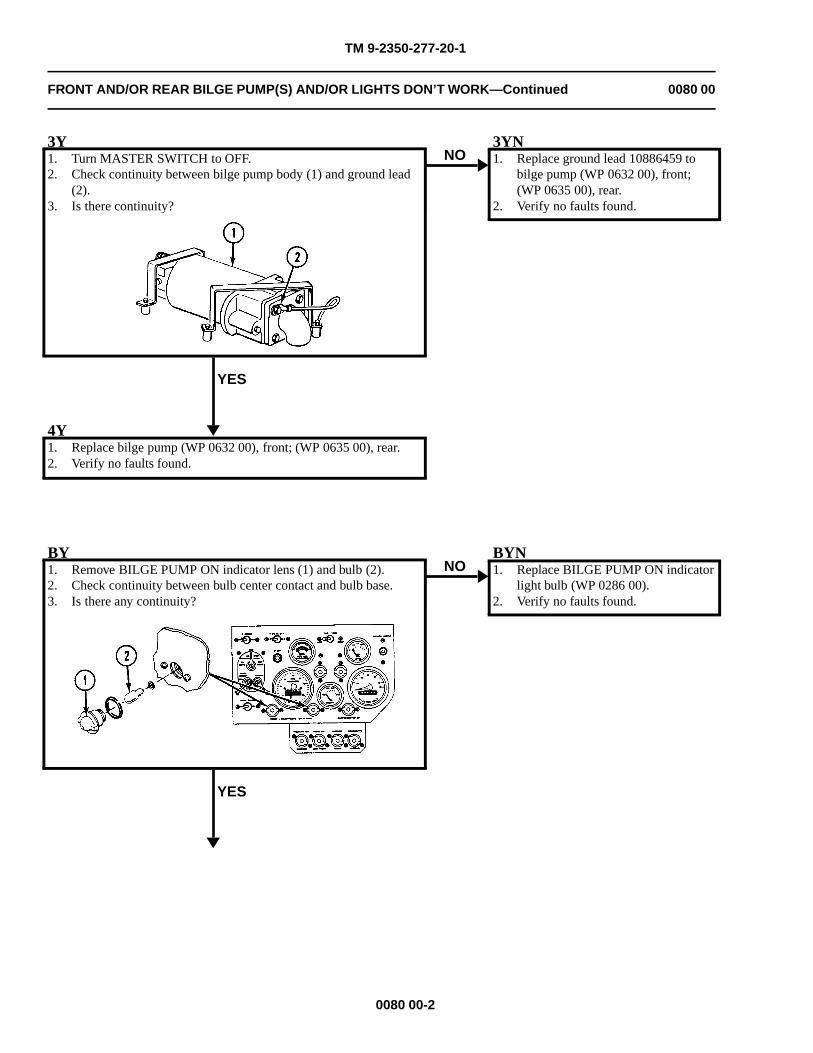
TM 9-2350-277-20-1
FRONT AND/OR REAR BILGE PUMP(S) AND/OR LIGHTS DON’T WORK—Continued 0080 00
3Y1. Turn MASTER SWITCH to OFF.2. Check continuity between bilge pump body (1) and ground lead
(2).3. Is there continuity?
YES
NO3YN1. Replace ground lead 10886459 to
bilge pump (WP 0632 00), front;(WP 0635 00), rear.
2. Verify no faults found.
4Y1. Replace bilge pump (WP 0632 00), front; (WP 0635 00), rear.2. Verify no faults found.
BY1. Remove BILGE PUMP ON indicator lens (1) and bulb (2).2. Check continuity between bulb center contact and bulb base.3. Is there any continuity?
YES
NOBYN1. Replace BILGE PUMP ON indicator
light bulb (WP 0286 00).2. Verify no faults found.
0080 00-2
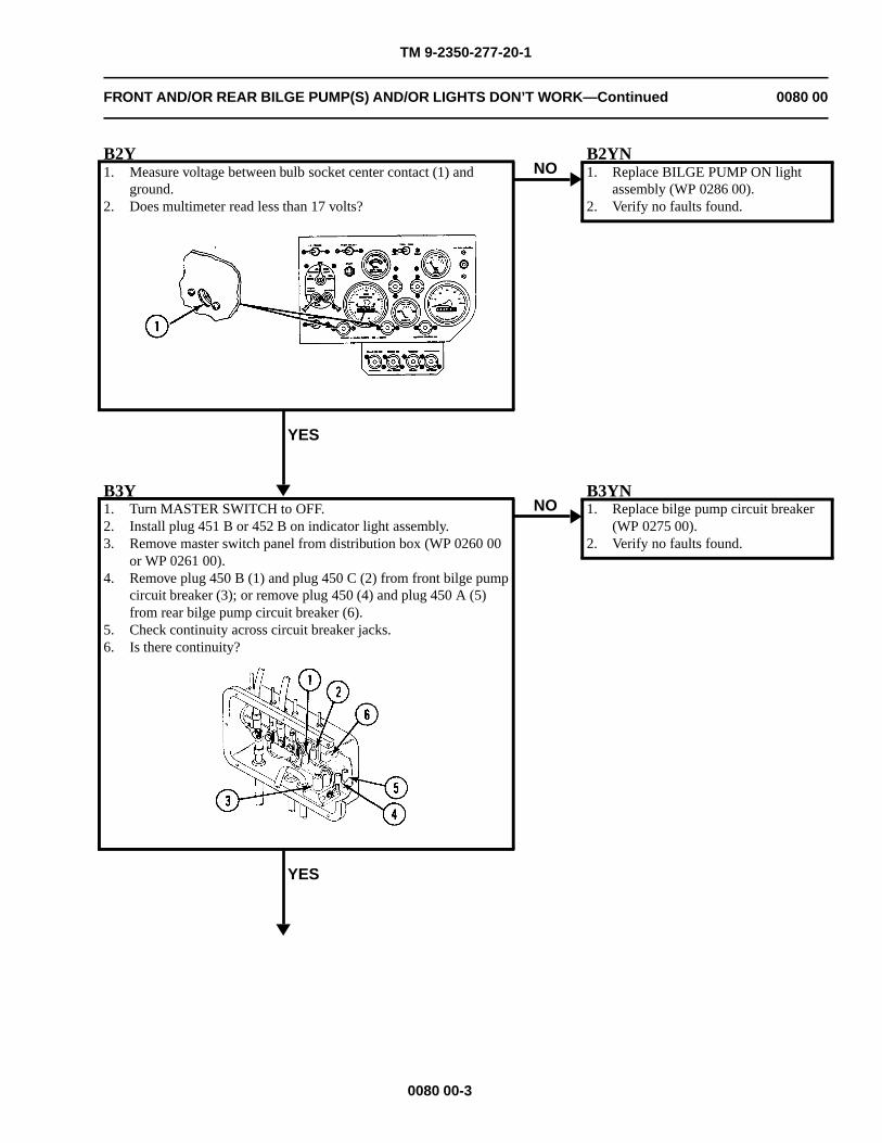
TM 9-2350-277-20-1
FRONT AND/OR REAR BILGE PUMP(S) AND/OR LIGHTS DON’T WORK—Continued 0080 00
B2Y1. Measure voltage between bulb socket center contact (1) and
ground.2. Does multimeter read less than 17 volts?
YES
NOB2YN1. Replace BILGE PUMP ON light
assembly (WP 0286 00).2. Verify no faults found.
B3Y1. Turn MASTER SWITCH to OFF.2. Install plug 451 B or 452 B on indicator light assembly.3. Remove master switch panel from distribution box (WP 0260 00
or WP 0261 00).4. Remove plug 450 B (1) and plug 450 C (2) from front bilge pump
circuit breaker (3); or remove plug 450 (4) and plug 450 A (5)from rear bilge pump circuit breaker (6).
5. Check continuity across circuit breaker jacks.6. Is there continuity?
YES
NOB3YN1. Replace bilge pump circuit breaker
(WP 0275 00).2. Verify no faults found.
0080 00-3
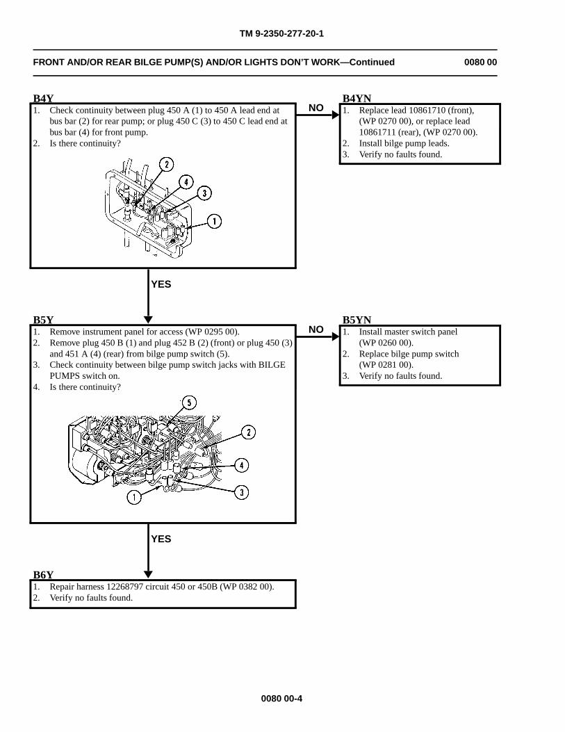
TM 9-2350-277-20-1
FRONT AND/OR REAR BILGE PUMP(S) AND/OR LIGHTS DON’T WORK—Continued 0080 00
B4Y1. Check continuity between plug 450 A (1) to 450 A lead end at
bus bar (2) for rear pump; or plug 450 C (3) to 450 C lead end atbus bar (4) for front pump.
2. Is there continuity?
YES
NOB4YN1. Replace lead 10861710 (front),
(WP 0270 00), or replace lead10861711 (rear), (WP 0270 00).
2. Install bilge pump leads.3. Verify no faults found.
B5Y1. Remove instrument panel for access (WP 0295 00).2. Remove plug 450 B (1) and plug 452 B (2) (front) or plug 450 (3)
and 451 A (4) (rear) from bilge pump switch (5).3. Check continuity between bilge pump switch jacks with BILGE
PUMPS switch on.4. Is there continuity?
YES
NOB5YN1. Install master switch panel
(WP 0260 00).2. Replace bilge pump switch
(WP 0281 00).3. Verify no faults found.
B6Y1. Repair harness 12268797 circuit 450 or 450B (WP 0382 00).2. Verify no faults found.
0080 00-4
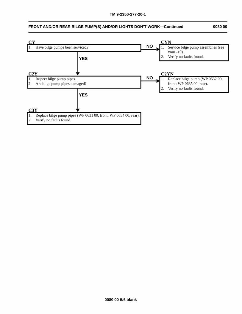
TM 9-2350-277-20-1
FRONT AND/OR REAR BILGE PUMP(S) AND/OR LIGHTS DON’T WORK—Continued 0080 00
CY1. Have bilge pumps been serviced?
YES
NOCYN1. Service bilge pump assemblies (see
your -10).2. Verify no faults found.
C2Y1. Inspect bilge pump pipes.2. Are bilge pump pipes damaged?
YES
NOC2YN1. Replace bilge pump (WP 0632 00,
front; WP 0635 00, rear).2. Verify no faults found.
C3Y1. Replace bilge pump pipes (WP 0631 00, front; WP 0634 00, rear).2. Verify no faults found.
0080 00-5/6 blank

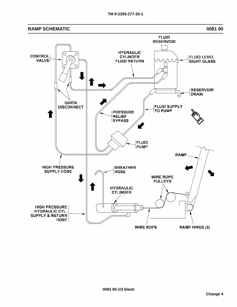
TM 9-2350-277-20-1
RAMP SCHEMATIC 0081 00
0081 00-1/2 blankChange 4

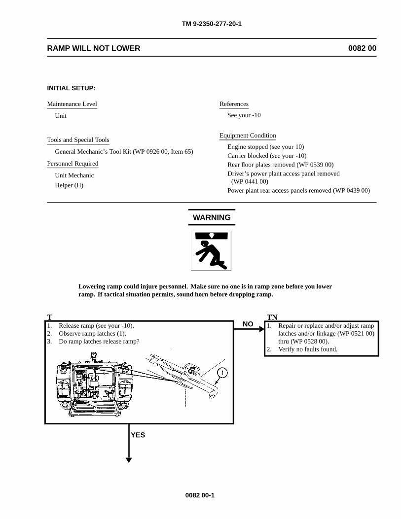
TM 9-2350-277-20-1
RAMP WILL NOT LOWER 0082 00
INITIAL SETUP:
Maintenance Level
Unit
Tools and Special Tools
General Mechanic’s Tool Kit (WP 0926 00, Item 65)
Personnel Required
Unit Mechanic
Helper (H)
References
See your -10
Equipment Condition
Engine stopped (see your 10)Carrier blocked (see your -10)Rear floor plates removed (WP 0539 00)Driver’s power plant access panel removed
(WP 0441 00)Power plant rear access panels removed (WP 0439 00)
WARNING
Lowering ramp could injure personnel. Make sure no one is in ramp zone before you lowerramp. If tactical situation permits, sound horn before dropping ramp.
T1. Release ramp (see your -10).2. Observe ramp latches (1).3. Do ramp latches release ramp?
YES
NOTN1. Repair or replace and/or adjust ramp
latches and/or linkage (WP 0521 00)thru (WP 0528 00).
2. Verify no faults found.
0082 00-1
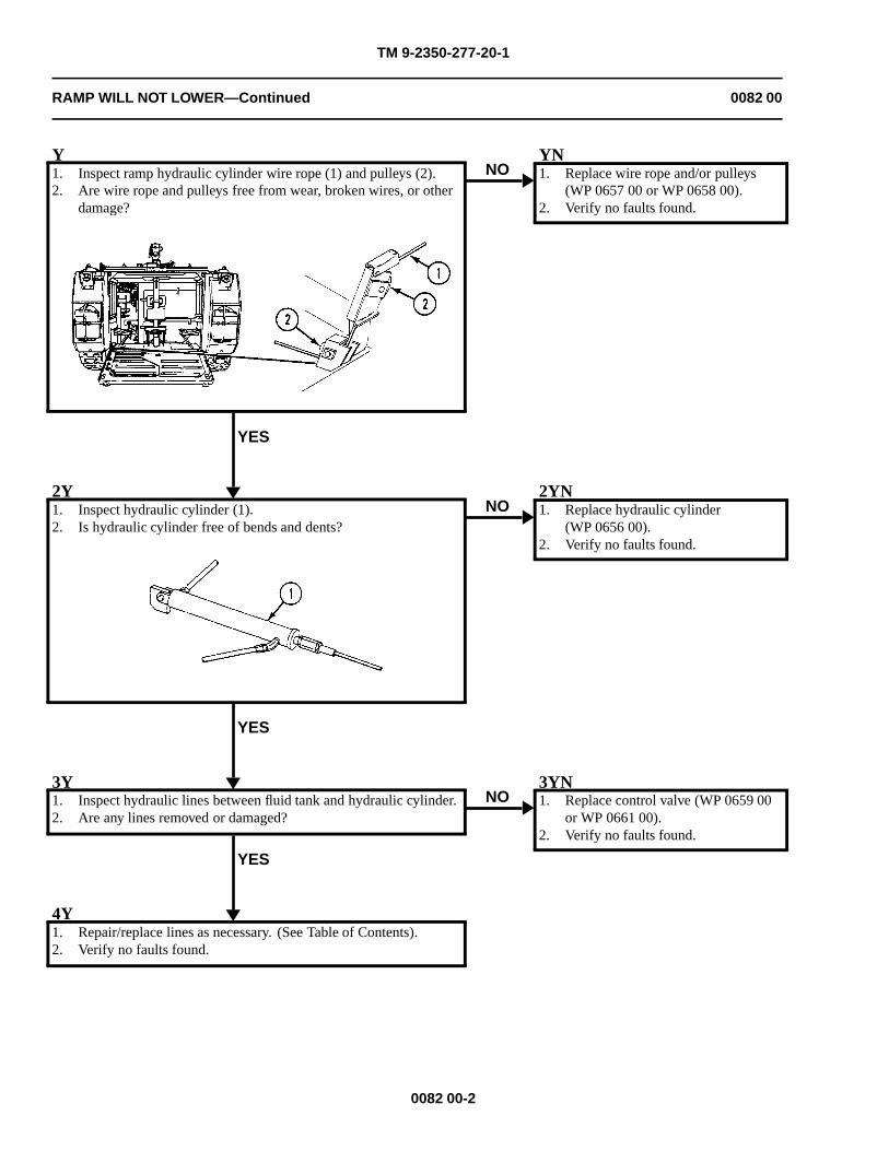
TM 9-2350-277-20-1
RAMP WILL NOT LOWER—Continued 0082 00
Y1. Inspect ramp hydraulic cylinder wire rope (1) and pulleys (2).2. Are wire rope and pulleys free from wear, broken wires, or other
damage?
YES
NOYN1. Replace wire rope and/or pulleys
(WP 0657 00 or WP 0658 00).2. Verify no faults found.
2Y1. Inspect hydraulic cylinder (1).2. Is hydraulic cylinder free of bends and dents?
YES
NO2YN1. Replace hydraulic cylinder
(WP 0656 00).2. Verify no faults found.
3Y1. Inspect hydraulic lines between fluid tank and hydraulic cylinder.2. Are any lines removed or damaged?
YES
NO3YN1. Replace control valve (WP 0659 00
or WP 0661 00).2. Verify no faults found.
4Y1. Repair/replace lines as necessary. (See Table of Contents).2. Verify no faults found.
0082 00-2
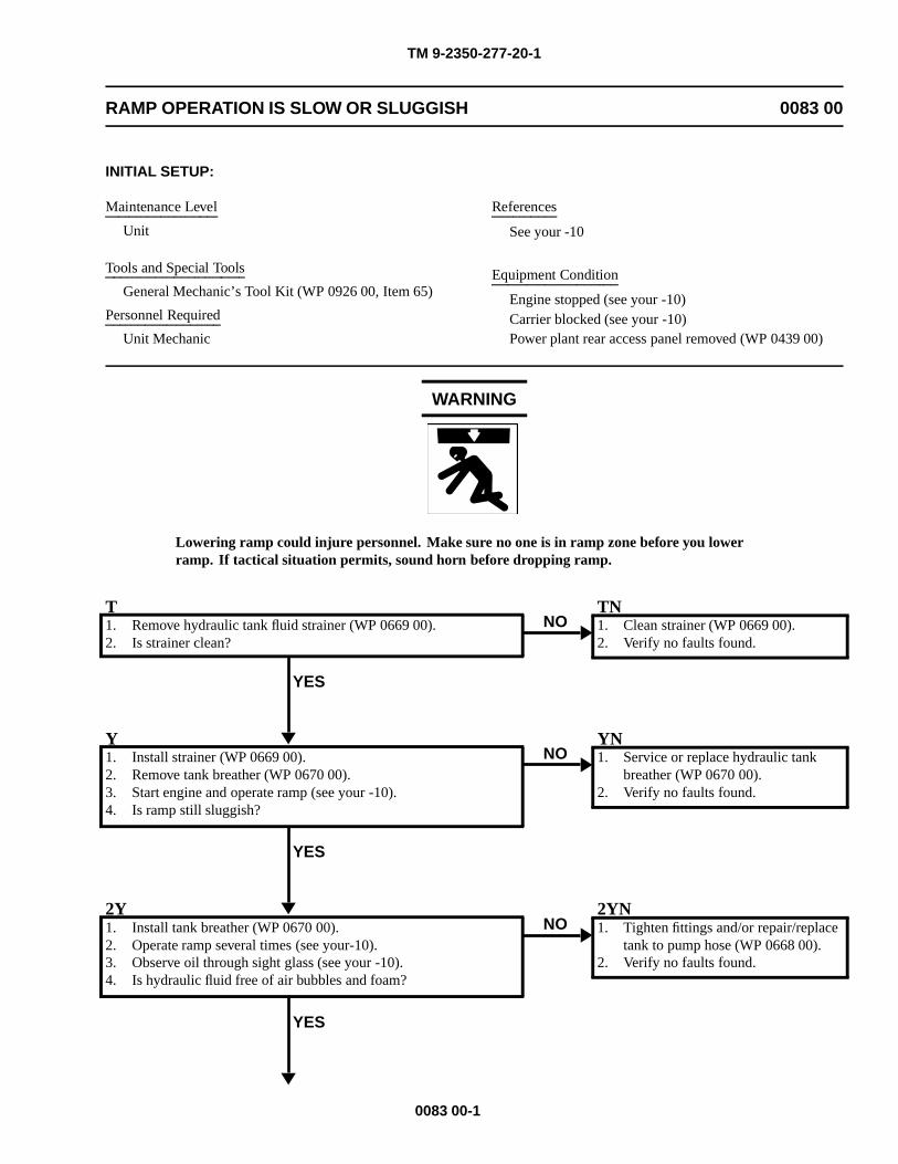
TM 9-2350-277-20-1
RAMP OPERATION IS SLOW OR SLUGGISH 0083 00
INITIAL SETUP:
Maintenance Level
Unit
Tools and Special Tools
General Mechanic’s Tool Kit (WP 0926 00, Item 65)
Personnel Required
Unit Mechanic
References
See your -10
Equipment Condition
Engine stopped (see your -10)Carrier blocked (see your -10)Power plant rear access panel removed (WP 0439 00)
WARNING
Lowering ramp could injure personnel. Make sure no one is in ramp zone before you lowerramp. If tactical situation permits, sound horn before dropping ramp.
T1. Remove hydraulic tank fluid strainer (WP 0669 00).2. Is strainer clean?
YES
NOTN1. Clean strainer (WP 0669 00).2. Verify no faults found.
Y1. Install strainer (WP 0669 00).2. Remove tank breather (WP 0670 00).3. Start engine and operate ramp (see your -10).4. Is ramp still sluggish?
YES
NOYN1. Service or replace hydraulic tank
breather (WP 0670 00).2. Verify no faults found.
2Y1. Install tank breather (WP 0670 00).2. Operate ramp several times (see your-10).3. Observe oil through sight glass (see your -10).4. Is hydraulic fluid free of air bubbles and foam?
YES
NO2YN1. Tighten fittings and/or repair/replace
tank to pump hose (WP 0668 00).2. Verify no faults found.
0083 00-1

TM 9-2350-277-20-1
RAMP OPERATION IS SLOW OR SLUGGISH—Continued 0083 00
3Y1. Go to: Ramp Will Not Raise or Free Falls (WP 0084 00).
0083 00-2
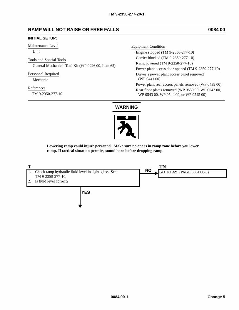
TM 9-2350-277-20-1
RAMP WILL NOT RAISE OR FREE FALLS 0084 00
INITIAL SETUP:
Maintenance LevelUnit
Tools and Special ToolsGeneral Mechanic’s Tool Kit (WP 0926 00, Item 65)
Personnel RequiredMechanic
ReferencesTM 9-2350-277-10
Equipment ConditionEngine stopped (TM 9-2350-277-10)Carrier blocked (TM 9-2350-277-10)Ramp lowered (TM 9-2350-277-10)Power plant access door opened (TM 9-2350-277-10)Driver’s power plant access panel removed
(WP 0441 00)Power plant rear access panels removed (WP 0439 00)Rear floor plates removed (WP 0539 00, WP 0542 00,
WP 0543 00, WP 0544 00, or WP 0545 00)
WARNING
Lowering ramp could injure personnel. Make sure no one is in ramp zone before you lowerramp. If tactical situation permits, sound horn before dropping ramp.
T1. Check ramp hydraulic fluid level in sight-glass. See
TM 9-2350-277-10.2. Is fluid level correct?
TNGO TO AY (PAGE 0084 00-3)
0084 00-1 Change 5
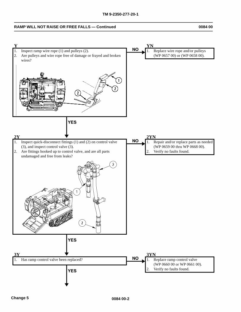
TM 9-2350-277-20-1
RAMP WILL NOT RAISE OR FREE FALLS — Continued 0084 00
Y1. Inspect ramp wire rope (1) and pulleys (2).2. Are pulleys and wire rope free of damage or frayed and broken
wires?
YN1. Replace wire rope and/or pulleys
(WP 0657 00) or (WP 0658 00).
2Y1. Inspect quick-disconnect fittings (1) and (2) on control valve
(3), and inspect control valve (3).2. Are fittings hooked up to control valve, and are all parts
undamaged and free from leaks?
2YN1. Repair and/or replace parts as needed
(WP 0659 00 thru WP 0668 00).2. Verify no faults found.
3Y1. Has ramp control valve been replaced?
3YN1. Replace ramp control valve
(WP 0660 00 or WP 0661 00).2. Verify no faults found.
0084 00-2Change 5
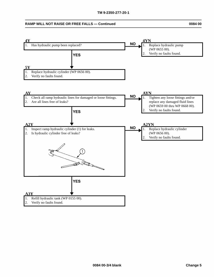
TM 9-2350-277-20-1
RAMP WILL NOT RAISE OR FREE FALLS — Continued 0084 00
4Y1. Has hydraulic pump been replaced?
4YN1. Replace hydraulic pump
(WP 0655 00).2. Verify no faults found.
5Y1. Replace hydraulic cylinder (WP 0656 00).2. Verify no faults found.
AY1. Check all ramp hydraulic lines for damaged or loose fittings.2. Are all lines free of leaks?
AYN1. Tighten any loose fittings and/or
replace any damaged fluid lines(WP 0659 00 thru WP 0668 00).
2. Verify no faults found.
A2Y1. Inspect ramp hydraulic cylinder (1) for leaks.2. Is hydraulic cylinder free of leaks?
A2YN1. Replace hydraulic cylinder
(WP 0656 00).2. Verify no faults found.
A3Y1. Refill hydraulic tank (WP 0155 00).2. Verify no faults found.
0084 00-3/4 blank Change 5

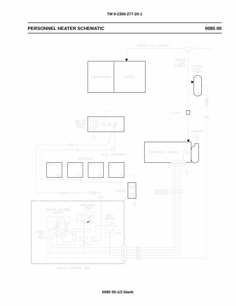
TM 9-2350-277-20-1
PERSONNEL HEATER SCHEMATIC 0085 00
0085 00-1/2 blank

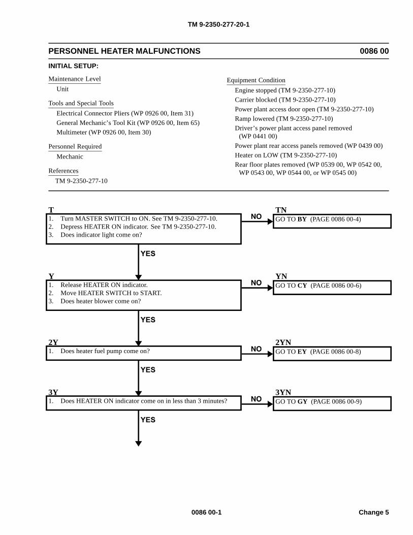
TM 9-2350-277-20-1
PERSONNEL HEATER MALFUNCTIONS 0086 00
INITIAL SETUP:
Maintenance LevelUnit
Tools and Special ToolsElectrical Connector Pliers (WP 0926 00, Item 31)General Mechanic’s Tool Kit (WP 0926 00, Item 65)Multimeter (WP 0926 00, Item 30)
Personnel RequiredMechanic
ReferencesTM 9-2350-277-10
Equipment ConditionEngine stopped (TM 9-2350-277-10)Carrier blocked (TM 9-2350-277-10)Power plant access door open (TM 9-2350-277-10)Ramp lowered (TM 9-2350-277-10)Driver’s power plant access panel removed
(WP 0441 00)Power plant rear access panels removed (WP 0439 00)Heater on LOW (TM 9-2350-277-10)Rear floor plates removed (WP 0539 00, WP 0542 00,
WP 0543 00, WP 0544 00, or WP 0545 00)
T1. Turn MASTER SWITCH to ON. See TM 9-2350-277-10.2. Depress HEATER ON indicator. See TM 9-2350-277-10.3. Does indicator light come on?
TNGO TO BY (PAGE 0086 00-4)
Y1. Release HEATER ON indicator.2. Move HEATER SWITCH to START.3. Does heater blower come on?
YNGO TO CY (PAGE 0086 00-6)
2Y1. Does heater fuel pump come on?
2YNGO TO EY (PAGE 0086 00-8)
3Y1. Does HEATER ON indicator come on in less than 3 minutes?
3YNGO TO GY (PAGE 0086 00-9)
0086 00-1 Change 5
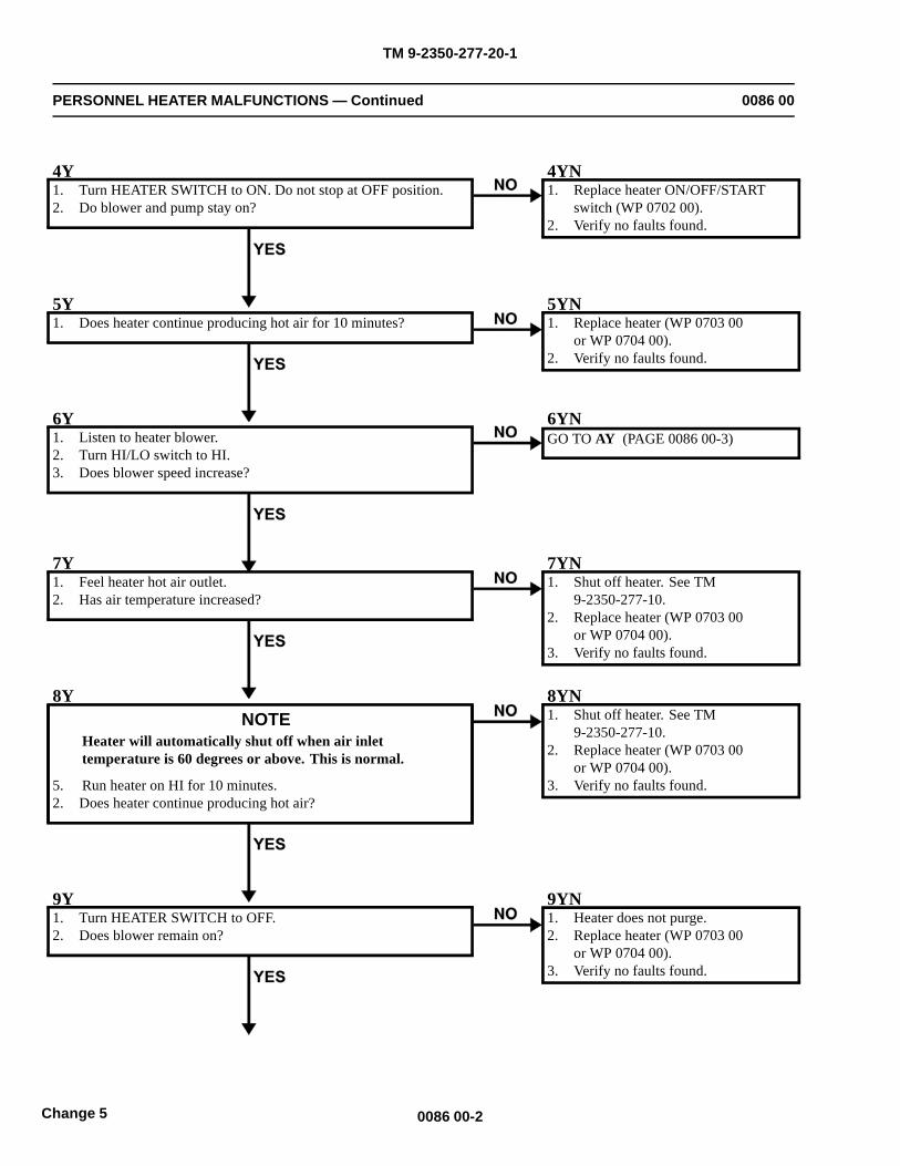
TM 9-2350-277-20-1
PERSONNEL HEATER MALFUNCTIONS — Continued 0086 00
4Y1. Turn HEATER SWITCH to ON. Do not stop at OFF position.2. Do blower and pump stay on?
4YN1. Replace heater ON/OFF/START
switch (WP 0702 00).2. Verify no faults found.
5Y1. Does heater continue producing hot air for 10 minutes?
5YN1. Replace heater (WP 0703 00
or WP 0704 00).2. Verify no faults found.
6Y1. Listen to heater blower.2. Turn HI/LO switch to HI.3. Does blower speed increase?
6YNGO TO AY (PAGE 0086 00-3)
7Y1. Feel heater hot air outlet.2. Has air temperature increased?
7YN1. Shut off heater. See TM
9-2350-277-10.2. Replace heater (WP 0703 00
or WP 0704 00).3. Verify no faults found.
8YNOTE
Heater will automatically shut off when air inlettemperature is 60 degrees or above. This is normal.
5. Run heater on HI for 10 minutes.2. Does heater continue producing hot air?
8YN1. Shut off heater. See TM
9-2350-277-10.2. Replace heater (WP 0703 00
or WP 0704 00).3. Verify no faults found.
9Y1. Turn HEATER SWITCH to OFF.2. Does blower remain on?
9YN1. Heater does not purge.2. Replace heater (WP 0703 00
or WP 0704 00).3. Verify no faults found.
0086 00-2Change 5
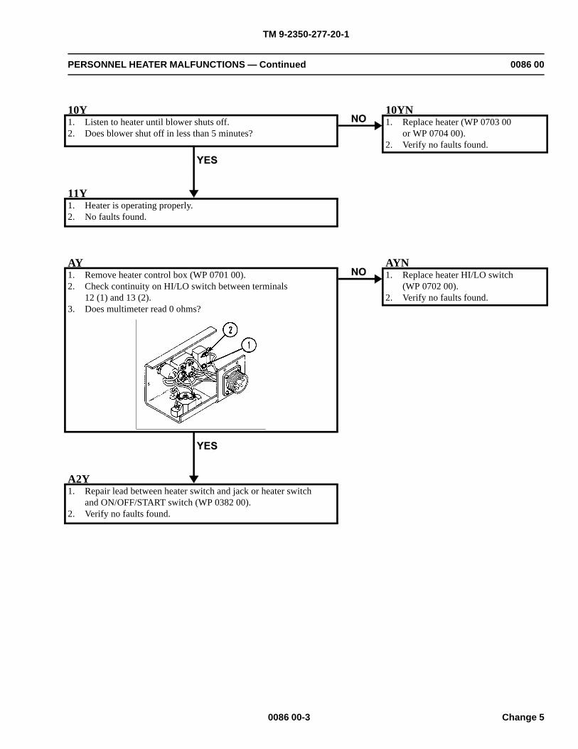
TM 9-2350-277-20-1
PERSONNEL HEATER MALFUNCTIONS — Continued 0086 00
10Y1. Listen to heater until blower shuts off.2. Does blower shut off in less than 5 minutes?
10YN1. Replace heater (WP 0703 00
or WP 0704 00).2. Verify no faults found.
11Y1. Heater is operating properly.2. No faults found.
AY1. Remove heater control box (WP 0701 00).2. Check continuity on HI/LO switch between terminals
12 (1) and 13 (2).3. Does multimeter read 0 ohms?
AYN1. Replace heater HI/LO switch
(WP 0702 00).2. Verify no faults found.
A2Y1. Repair lead between heater switch and jack or heater switch
and ON/OFF/START switch (WP 0382 00).2. Verify no faults found.
0086 00-3 Change 5
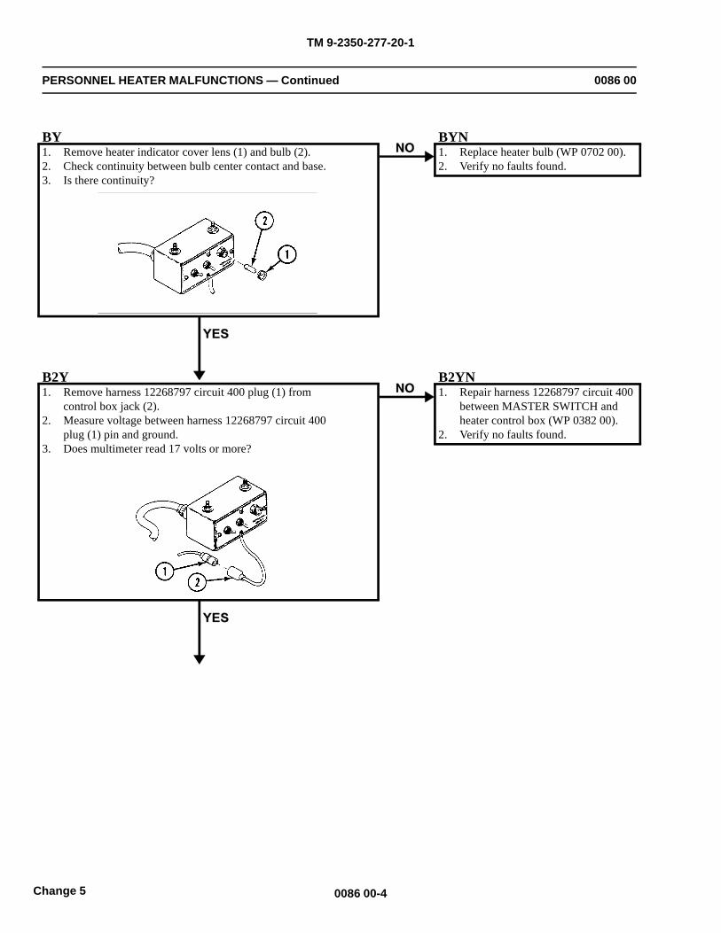
TM 9-2350-277-20-1
PERSONNEL HEATER MALFUNCTIONS — Continued 0086 00
BY1. Remove heater indicator cover lens (1) and bulb (2).2. Check continuity between bulb center contact and base.3. Is there continuity?
BYN1. Replace heater bulb (WP 0702 00).2. Verify no faults found.
B2Y1. Remove harness 12268797 circuit 400 plug (1) from
control box jack (2).2. Measure voltage between harness 12268797 circuit 400
plug (1) pin and ground.3. Does multimeter read 17 volts or more?
B2YN1. Repair harness 12268797 circuit 400
between MASTER SWITCH andheater control box (WP 0382 00).
2. Verify no faults found.
0086 00-4Change 5
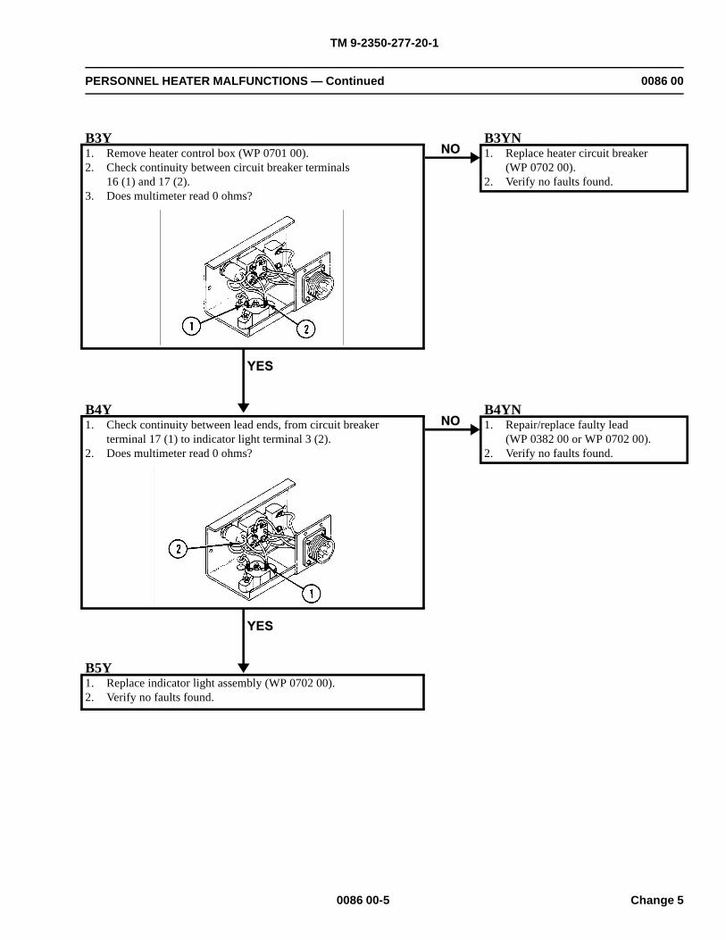
TM 9-2350-277-20-1
PERSONNEL HEATER MALFUNCTIONS — Continued 0086 00
B3Y1. Remove heater control box (WP 0701 00).2. Check continuity between circuit breaker terminals
16 (1) and 17 (2).3. Does multimeter read 0 ohms?
B3YN1. Replace heater circuit breaker
(WP 0702 00).2. Verify no faults found.
B4Y1. Check continuity between lead ends, from circuit breaker
terminal 17 (1) to indicator light terminal 3 (2).2. Does multimeter read 0 ohms?
B4YN1. Repair/replace faulty lead
(WP 0382 00 or WP 0702 00).2. Verify no faults found.
B5Y1. Replace indicator light assembly (WP 0702 00).2. Verify no faults found.
0086 00-5 Change 5
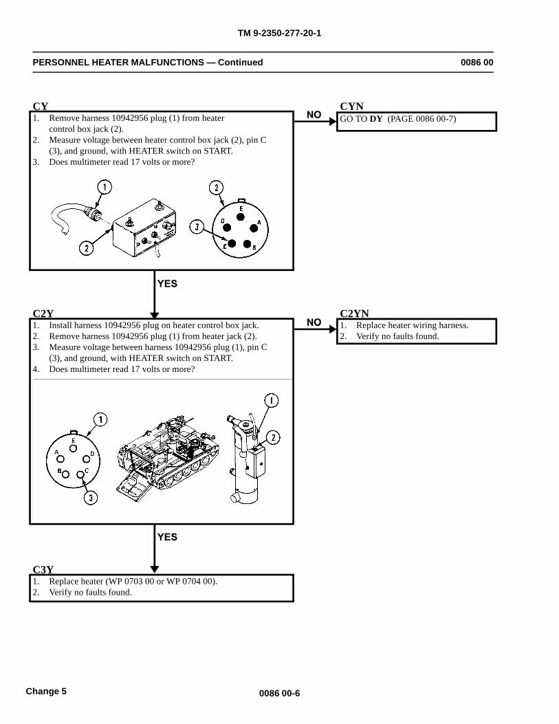
TM 9-2350-277-20-1
PERSONNEL HEATER MALFUNCTIONS — Continued 0086 00
CY1. Remove harness 10942956 plug (1) from heater
control box jack (2).2. Measure voltage between heater control box jack (2), pin C
(3), and ground, with HEATER switch on START.3. Does multimeter read 17 volts or more?
CYNGO TO DY (PAGE 0086 00-7)
C2Y1. Install harness 10942956 plug on heater control box jack.2. Remove harness 10942956 plug (1) from heater jack (2).3. Measure voltage between harness 10942956 plug (1), pin C
(3), and ground, with HEATER switch on START.4. Does multimeter read 17 volts or more?
C2YN1. Replace heater wiring harness.2. Verify no faults found.
C3Y1. Replace heater (WP 0703 00 or WP 0704 00).2. Verify no faults found.
0086 00-6Change 5
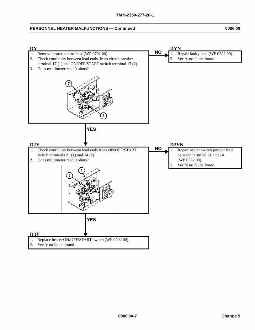
TM 9-2350-277-20-1
PERSONNEL HEATER MALFUNCTIONS — Continued 0086 00
DY1. Remove heater control box (WP 0701 00).2. Check continuity between lead ends, from circuit breaker
terminal 17 (1) and ON/OFF/START switch terminal 15 (2).3. Does multimeter read 0 ohms?
DYN1. Repair faulty lead (WP 0382 00).2. Verify no faults found.
D2Y1. Check continuity between lead ends from ON/OFF/START
switch terminals 21 (1) and 14 (2).2. Does multimeter read 0 ohms?
D2YN1. Repair heater switch jumper lead
between terminal 21 and 14(WP 0382 00).
2. Verify no faults found.
D3Y1. Replace heater ON/OFF/START switch (WP 0702 00).2. Verify no faults found.
0086 00-7 Change 5
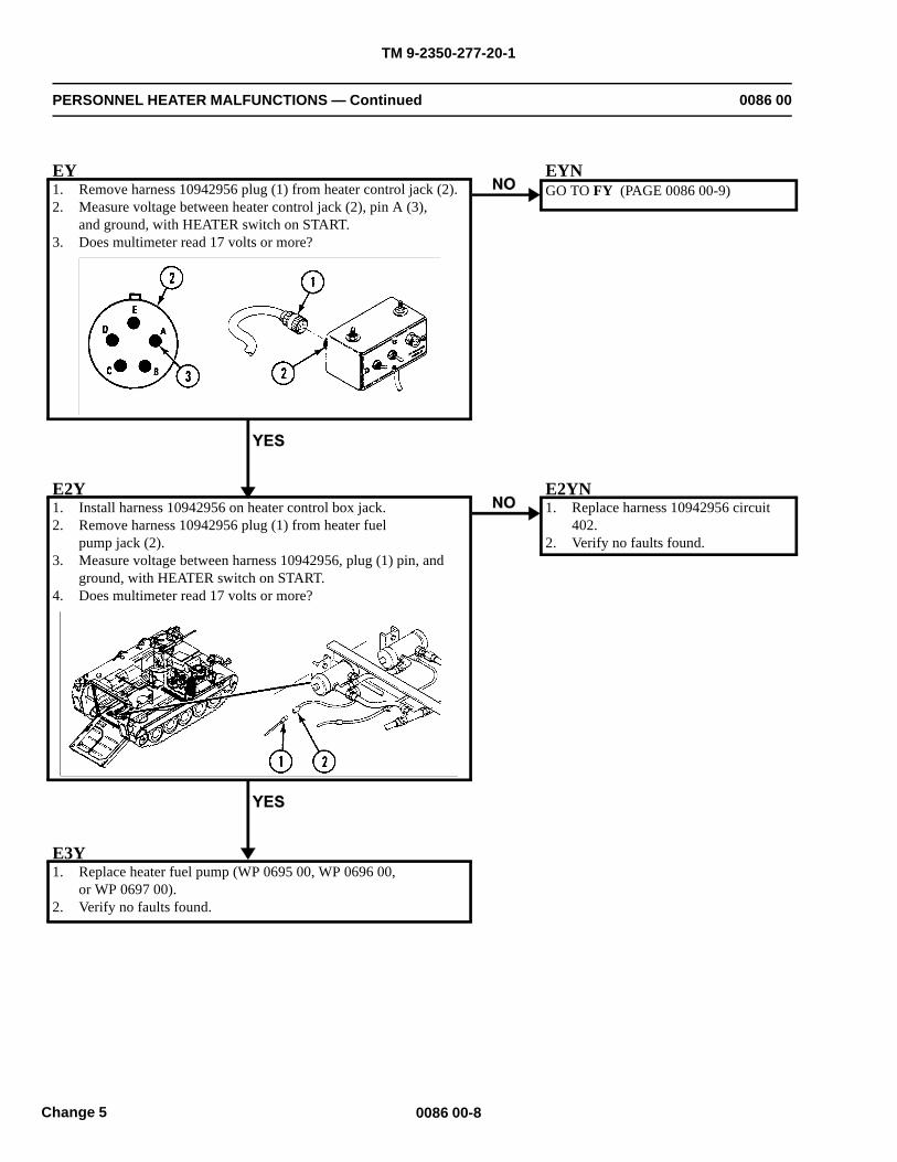
TM 9-2350-277-20-1
PERSONNEL HEATER MALFUNCTIONS — Continued 0086 00
EY1. Remove harness 10942956 plug (1) from heater control jack (2).2. Measure voltage between heater control jack (2), pin A (3),
and ground, with HEATER switch on START.3. Does multimeter read 17 volts or more?
EYNGO TO FY (PAGE 0086 00-9)
E2Y1. Install harness 10942956 on heater control box jack.2. Remove harness 10942956 plug (1) from heater fuel
pump jack (2).3. Measure voltage between harness 10942956, plug (1) pin, and
ground, with HEATER switch on START.4. Does multimeter read 17 volts or more?
E2YN1. Replace harness 10942956 circuit
402.2. Verify no faults found.
E3Y1. Replace heater fuel pump (WP 0695 00, WP 0696 00,
or WP 0697 00).2. Verify no faults found.
0086 00-8Change 5
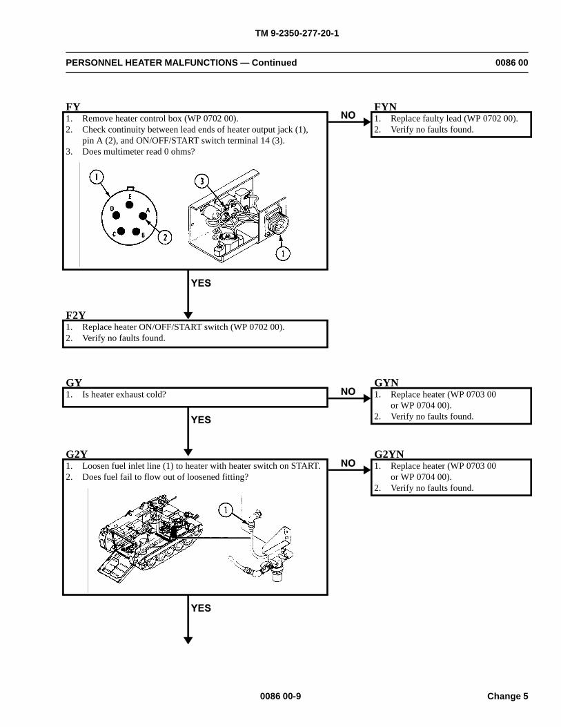
TM 9-2350-277-20-1
PERSONNEL HEATER MALFUNCTIONS — Continued 0086 00
FY1. Remove heater control box (WP 0702 00).2. Check continuity between lead ends of heater output jack (1),
pin A (2), and ON/OFF/START switch terminal 14 (3).3. Does multimeter read 0 ohms?
FYN1. Replace faulty lead (WP 0702 00).2. Verify no faults found.
F2Y1. Replace heater ON/OFF/START switch (WP 0702 00).2. Verify no faults found.
GY1. Is heater exhaust cold?
GYN1. Replace heater (WP 0703 00
or WP 0704 00).2. Verify no faults found.
G2Y1. Loosen fuel inlet line (1) to heater with heater switch on START.2. Does fuel fail to flow out of loosened fitting?
G2YN1. Replace heater (WP 0703 00
or WP 0704 00).2. Verify no faults found.
0086 00-9 Change 5
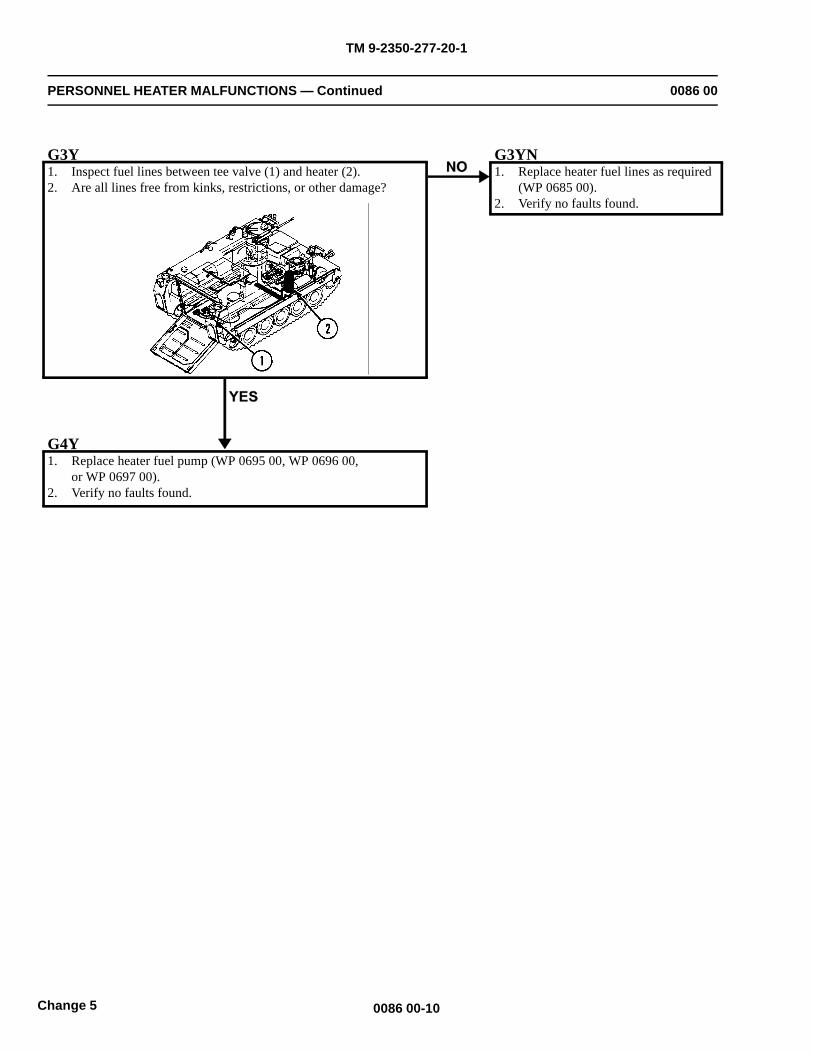
TM 9-2350-277-20-1
PERSONNEL HEATER MALFUNCTIONS — Continued 0086 00
G3Y1. Inspect fuel lines between tee valve (1) and heater (2).2. Are all lines free from kinks, restrictions, or other damage?
G3YN1. Replace heater fuel lines as required
(WP 0685 00).2. Verify no faults found.
G4Y1. Replace heater fuel pump (WP 0695 00, WP 0696 00,
or WP 0697 00).2. Verify no faults found.
0086 00-10Change 5
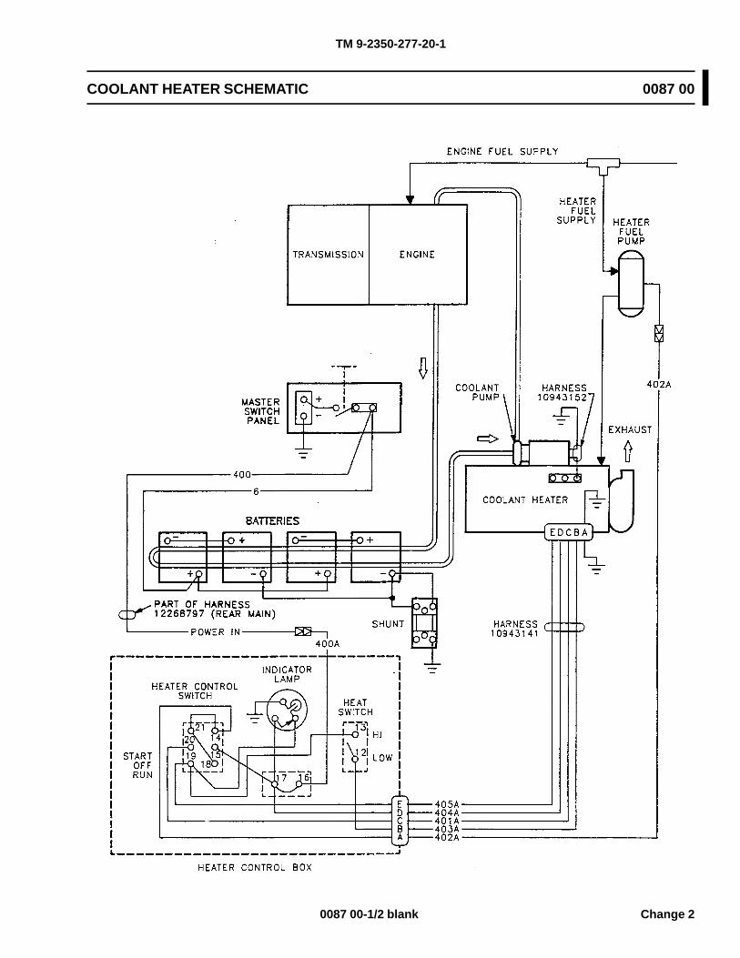
TM 9-2350-277-20-1
COOLANT HEATER SCHEMATIC 0087 00
0087 00-1/2 blank Change 2

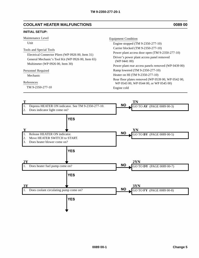
TM 9-2350-277-20-1
COOLANT HEATER MALFUNCTIONS 0089 00
INITIAL SETUP:
Maintenance LevelUnit
Tools and Special ToolsElectrical Connector Pliers (WP 0926 00, Item 31)General Mechanic’s Tool Kit (WP 0926 00, Item 65)Multimeter (WP 0926 00, Item 30)
Personnel RequiredMechanic
ReferencesTM 9-2350-277-10
Equipment ConditionEngine stopped (TM 9-2350-277-10)Carrier blocked (TM 9-2350-277-10)Power plant access door open (TM 9-2350-277-10)Driver’s power plant access panel removed
(WP 0441 00)Power plant rear access panels removed (WP 0439 00)Ramp lowered (TM 9-2350-277-10)Heater on HI (TM 9-2350-277-10)Rear floor plates removed (WP 0539 00, WP 0542 00,
WP 0543 00, WP 0544 00, or WP 0545 00)Engine cold
T1. Depress HEATER ON indicator. See TM 9-2350-277-10.2. Does indicator light come on?
TNGO TO AY (PAGE 0089 00-3)
Y1. Release HEATER ON indicator.2. Move HEATER SWITCH to START.3. Does heater blower come on?
YNGO TO BY (PAGE 0089 00-5)
2Y1. Does heater fuel pump come on?
2YNGO TO DY (PAGE 0089 00-7)
3Y1. Does coolant circulating pump come on?
3YNGO TO FY (PAGE 0089 00-8)
0089 00-1 Change 5
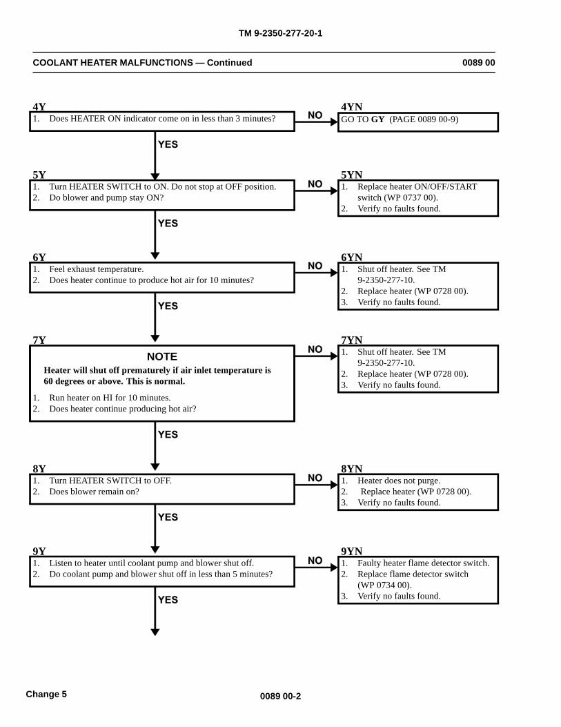
TM 9-2350-277-20-1
COOLANT HEATER MALFUNCTIONS — Continued 0089 00
4Y1. Does HEATER ON indicator come on in less than 3 minutes?
4YNGO TO GY (PAGE 0089 00-9)
5Y1. Turn HEATER SWITCH to ON. Do not stop at OFF position.2. Do blower and pump stay ON?
5YN1. Replace heater ON/OFF/START
switch (WP 0737 00).2. Verify no faults found.
6Y1. Feel exhaust temperature.2. Does heater continue to produce hot air for 10 minutes?
6YN1. Shut off heater. See TM
9-2350-277-10.2. Replace heater (WP 0728 00).3. Verify no faults found.
7YNOTE
Heater will shut off prematurely if air inlet temperature is60 degrees or above. This is normal.
1. Run heater on HI for 10 minutes.2. Does heater continue producing hot air?
7YN1. Shut off heater. See TM
9-2350-277-10.2. Replace heater (WP 0728 00).3. Verify no faults found.
8Y1. Turn HEATER SWITCH to OFF.2. Does blower remain on?
8YN1. Heater does not purge.2. Replace heater (WP 0728 00).3. Verify no faults found.
9Y1. Listen to heater until coolant pump and blower shut off.2. Do coolant pump and blower shut off in less than 5 minutes?
9YN1. Faulty heater flame detector switch.2. Replace flame detector switch
(WP 0734 00).3. Verify no faults found.
0089 00-2Change 5
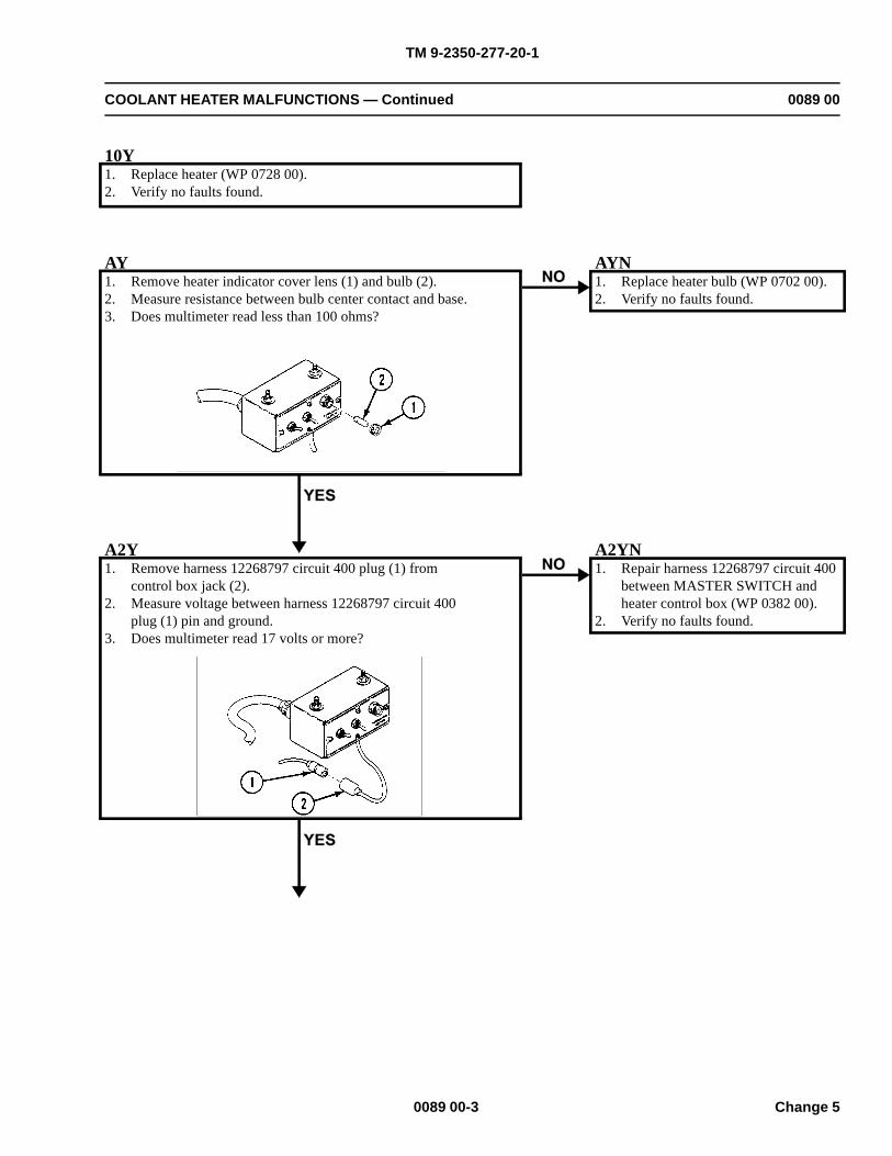
TM 9-2350-277-20-1
COOLANT HEATER MALFUNCTIONS — Continued 0089 00
10Y1. Replace heater (WP 0728 00).2. Verify no faults found.
AY1. Remove heater indicator cover lens (1) and bulb (2).2. Measure resistance between bulb center contact and base.3. Does multimeter read less than 100 ohms?
AYN1. Replace heater bulb (WP 0702 00).2. Verify no faults found.
A2Y1. Remove harness 12268797 circuit 400 plug (1) from
control box jack (2).2. Measure voltage between harness 12268797 circuit 400
plug (1) pin and ground.3. Does multimeter read 17 volts or more?
A2YN1. Repair harness 12268797 circuit 400
between MASTER SWITCH andheater control box (WP 0382 00).
2. Verify no faults found.
0089 00-3 Change 5
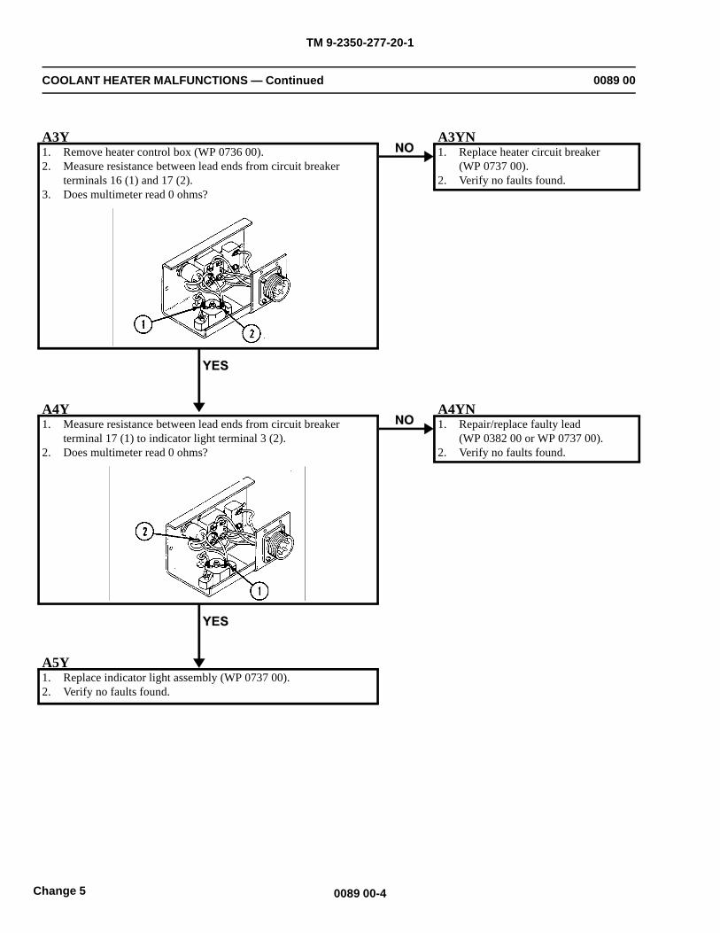
TM 9-2350-277-20-1
COOLANT HEATER MALFUNCTIONS — Continued 0089 00
A3Y1. Remove heater control box (WP 0736 00).2. Measure resistance between lead ends from circuit breaker
terminals 16 (1) and 17 (2).3. Does multimeter read 0 ohms?
A3YN1. Replace heater circuit breaker
(WP 0737 00).2. Verify no faults found.
A4Y1. Measure resistance between lead ends from circuit breaker
terminal 17 (1) to indicator light terminal 3 (2).2. Does multimeter read 0 ohms?
A4YN1. Repair/replace faulty lead
(WP 0382 00 or WP 0737 00).2. Verify no faults found.
A5Y1. Replace indicator light assembly (WP 0737 00).2. Verify no faults found.
0089 00-4Change 5
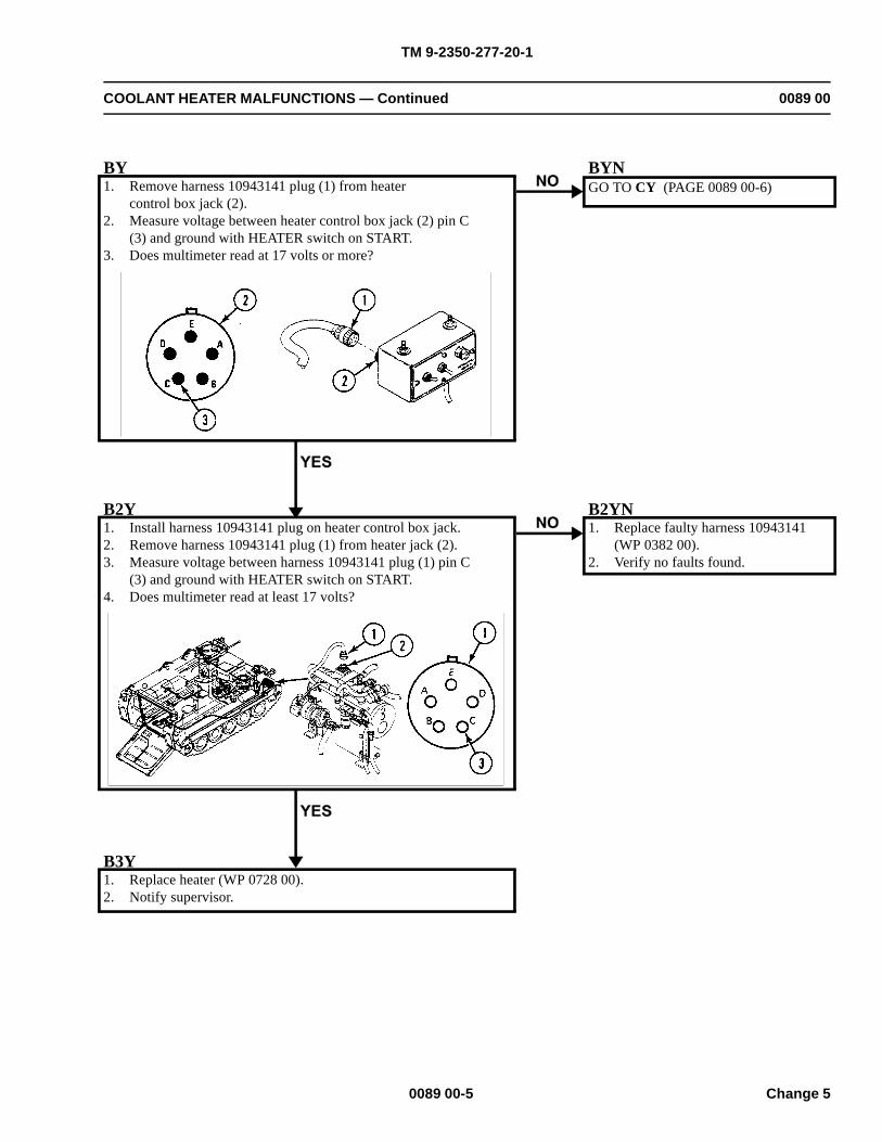
TM 9-2350-277-20-1
COOLANT HEATER MALFUNCTIONS — Continued 0089 00
BY1. Remove harness 10943141 plug (1) from heater
control box jack (2).2. Measure voltage between heater control box jack (2) pin C
(3) and ground with HEATER switch on START.3. Does multimeter read at 17 volts or more?
BYNGO TO CY (PAGE 0089 00-6)
B2Y1. Install harness 10943141 plug on heater control box jack.2. Remove harness 10943141 plug (1) from heater jack (2).3. Measure voltage between harness 10943141 plug (1) pin C
(3) and ground with HEATER switch on START.4. Does multimeter read at least 17 volts?
B2YN1. Replace faulty harness 10943141
(WP 0382 00).2. Verify no faults found.
B3Y1. Replace heater (WP 0728 00).2. Notify supervisor.
0089 00-5 Change 5
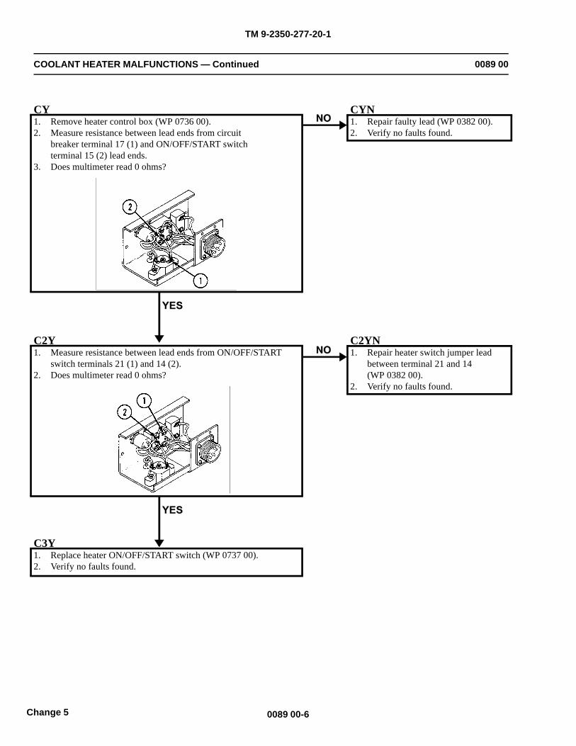
TM 9-2350-277-20-1
COOLANT HEATER MALFUNCTIONS — Continued 0089 00
CY1. Remove heater control box (WP 0736 00).2. Measure resistance between lead ends from circuit
breaker terminal 17 (1) and ON/OFF/START switchterminal 15 (2) lead ends.
3. Does multimeter read 0 ohms?
CYN1. Repair faulty lead (WP 0382 00).2. Verify no faults found.
C2Y1. Measure resistance between lead ends from ON/OFF/START
switch terminals 21 (1) and 14 (2).2. Does multimeter read 0 ohms?
C2YN1. Repair heater switch jumper lead
between terminal 21 and 14(WP 0382 00).
2. Verify no faults found.
C3Y1. Replace heater ON/OFF/START switch (WP 0737 00).2. Verify no faults found.
0089 00-6Change 5
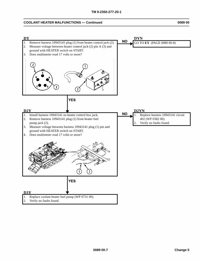
TM 9-2350-277-20-1
COOLANT HEATER MALFUNCTIONS — Continued 0089 00
DY1. Remove harness 10943141 plug (1) from heater control jack (2).2. Measure voltage between heater control jack (2) pin A (3) and
ground with HEATER switch on START.3. Does multimeter read 17 volts or more?
DYNGO TO EY (PAGE 0089 00-8)
D2Y1. Install harness 10943141 on heater control box jack.2. Remove harness 10943141 plug (1) from heater fuel
pump jack (2).3. Measure voltage between harness 10943141 plug (1) pin and
ground with HEATER switch on START.4. Does multimeter read 17 volts or more?
D2YN1. Replace harness 10943141 circuit
402 (WP 0382 00).2. Verify no faults found.
D3Y1. Replace coolant heater fuel pump (WP 0731 00).2. Verify no faults found.
0089 00-7 Change 5
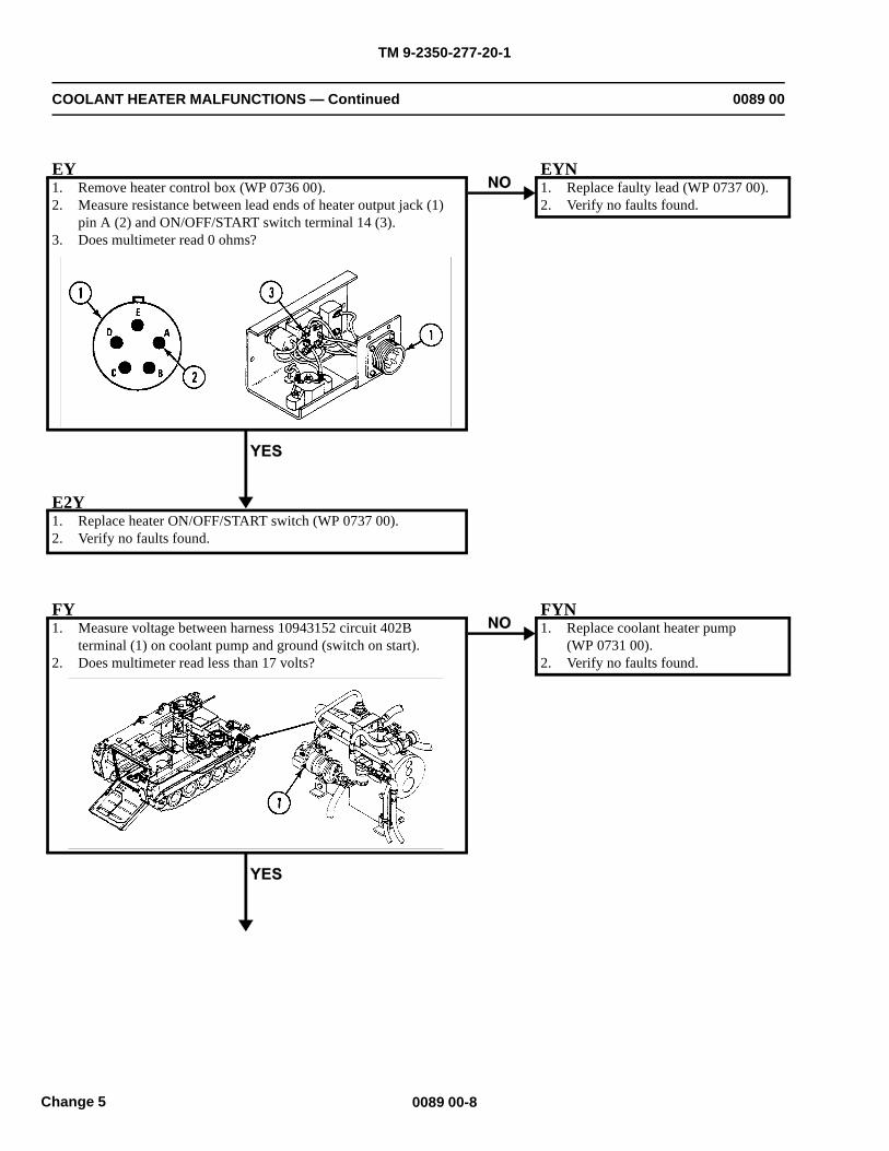
TM 9-2350-277-20-1
COOLANT HEATER MALFUNCTIONS — Continued 0089 00
EY1. Remove heater control box (WP 0736 00).2. Measure resistance between lead ends of heater output jack (1)
pin A (2) and ON/OFF/START switch terminal 14 (3).3. Does multimeter read 0 ohms?
EYN1. Replace faulty lead (WP 0737 00).2. Verify no faults found.
E2Y1. Replace heater ON/OFF/START switch (WP 0737 00).2. Verify no faults found.
FY1. Measure voltage between harness 10943152 circuit 402B
terminal (1) on coolant pump and ground (switch on start).2. Does multimeter read less than 17 volts?
FYN1. Replace coolant heater pump
(WP 0731 00).2. Verify no faults found.
0089 00-8Change 5
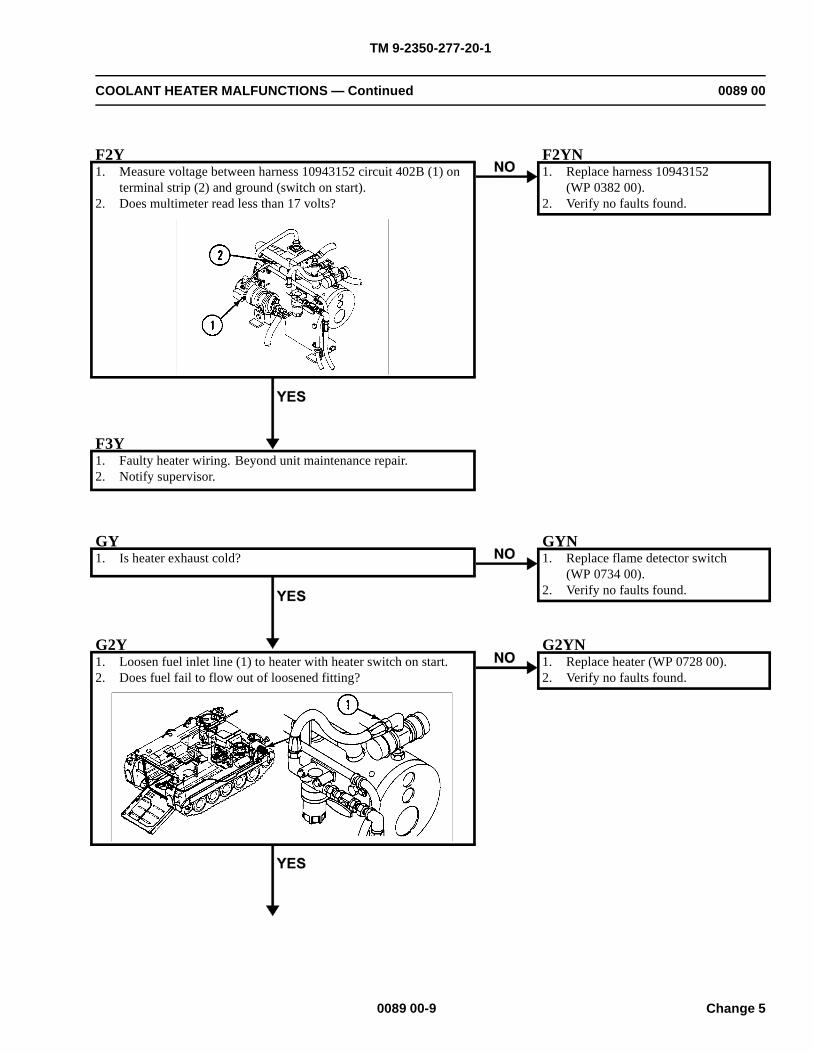
TM 9-2350-277-20-1
COOLANT HEATER MALFUNCTIONS — Continued 0089 00
F2Y1. Measure voltage between harness 10943152 circuit 402B (1) on
terminal strip (2) and ground (switch on start).2. Does multimeter read less than 17 volts?
F2YN1. Replace harness 10943152
(WP 0382 00).2. Verify no faults found.
F3Y1. Faulty heater wiring. Beyond unit maintenance repair.2. Notify supervisor.
GY1. Is heater exhaust cold?
GYN1. Replace flame detector switch
(WP 0734 00).2. Verify no faults found.
G2Y1. Loosen fuel inlet line (1) to heater with heater switch on start.2. Does fuel fail to flow out of loosened fitting?
G2YN1. Replace heater (WP 0728 00).2. Verify no faults found.
0089 00-9 Change 5
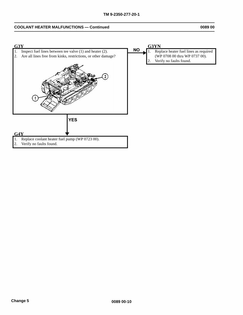
TM 9-2350-277-20-1
COOLANT HEATER MALFUNCTIONS — Continued 0089 00
G3Y1. Inspect fuel lines between tee valve (1) and heater (2).2. Are all lines free from kinks, restrictions, or other damage?
G3YN1. Replace heater fuel lines as required
(WP 0708 00 thru WP 0737 00).2. Verify no faults found.
G4Y1. Replace coolant heater fuel pump (WP 0723 00).2. Verify no faults found.
0089 00-10Change 5
TM 9-2350-277-20-1
POWER CONTROL ENCLOSURE A1 DC INPUT/OUTPUT INOPERATIVE(M1068A3 ONLY)
0090 00
INITIAL SETUP:
Maintenance Level
Unit
Tools and Special Tools
General Mechanic’s Tool Kit (WP 0926 00, Item 65)Digital Multimeter (WP 0926 00, Item 30)
Materials/Parts
Lockwasher (10)
Personnel Required
Power-Generation Equipment Repairer 52D10Helper (H)
References
See your -10TM 11-7010-256-12&P
Equipment Condition
Engine stopped (see your -10)
Carrier blocked (see your -10)
Battery box cover removed (see your -10)
WARNING
HIGH VOLTAGE is used in the operation of this equipment.
DEATH ON CONTACT may result if personnel fail to observe safety precautions.
NEVER work on equipment unless at least one other person familiar with the operation andhazards of the equipment is nearby. That person should also be familiar with giving first aid.When an operator helps a mechanic, that operator must be warned about dangerous areas.
SHUT OFF POWER supply to equipment before beginning work. Make sure all external poweris off/disconnected.
BE CAREFUL not to contact high-voltage connections when installing or operating thisequipment.
0090 00-1
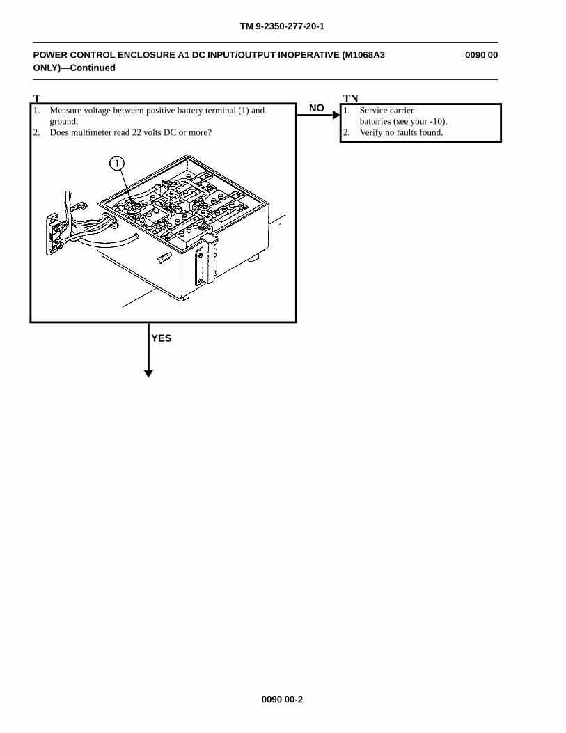
TM 9-2350-277-20-1
POWER CONTROL ENCLOSURE A1 DC INPUT/OUTPUT INOPERATIVE (M1068A3ONLY)—Continued
0090 00
T1. Measure voltage between positive battery terminal (1) and
ground.2. Does multimeter read 22 volts DC or more?
YES
NOTN1. Service carrier
batteries (see your -10).2. Verify no faults found.
0090 00-2
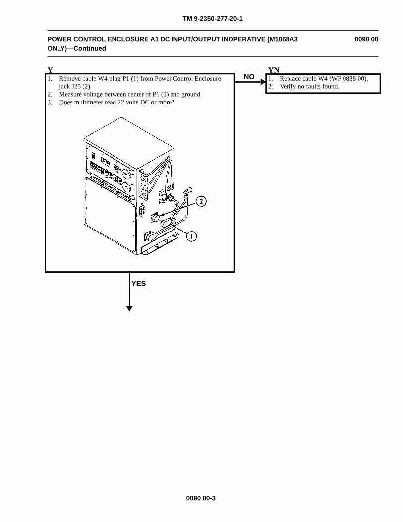
TM 9-2350-277-20-1
POWER CONTROL ENCLOSURE A1 DC INPUT/OUTPUT INOPERATIVE (M1068A3ONLY)—Continued
0090 00
Y1. Remove cable W4 plug P1 (1) from Power Control Enclosure
jack J25 (2).2. Measure voltage between center of P1 (1) and ground.3. Does multimeter read 22 volts DC or more?
YES
NOYN1. Replace cable W4 (WP 0838 00).2. Verify no faults found.
0090 00-3
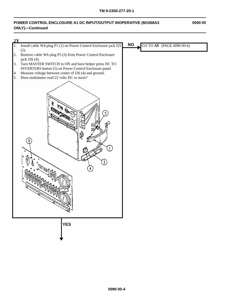
TM 9-2350-277-20-1
POWER CONTROL ENCLOSURE A1 DC INPUT/OUTPUT INOPERATIVE (M1068A3ONLY)—Continued
0090 00
2Y1. Install cable W4 plug P1 (1) on Power Control Enclosure jack J25
(2).2. Remove cable W6 plug P5 (3) from Power Control Enclosure
jack J26 (4).3. Turn MASTER SWITCH to ON and have helper press DC TO
INVERTERS button (5) on Power Control Enclosure panel.4. Measure voltage between center of J26 (4) and ground.5. Does multimeter read 22 volts DC or more?
YES
NO GO TO AY (PAGE 0090 00-6)
0090 00-4
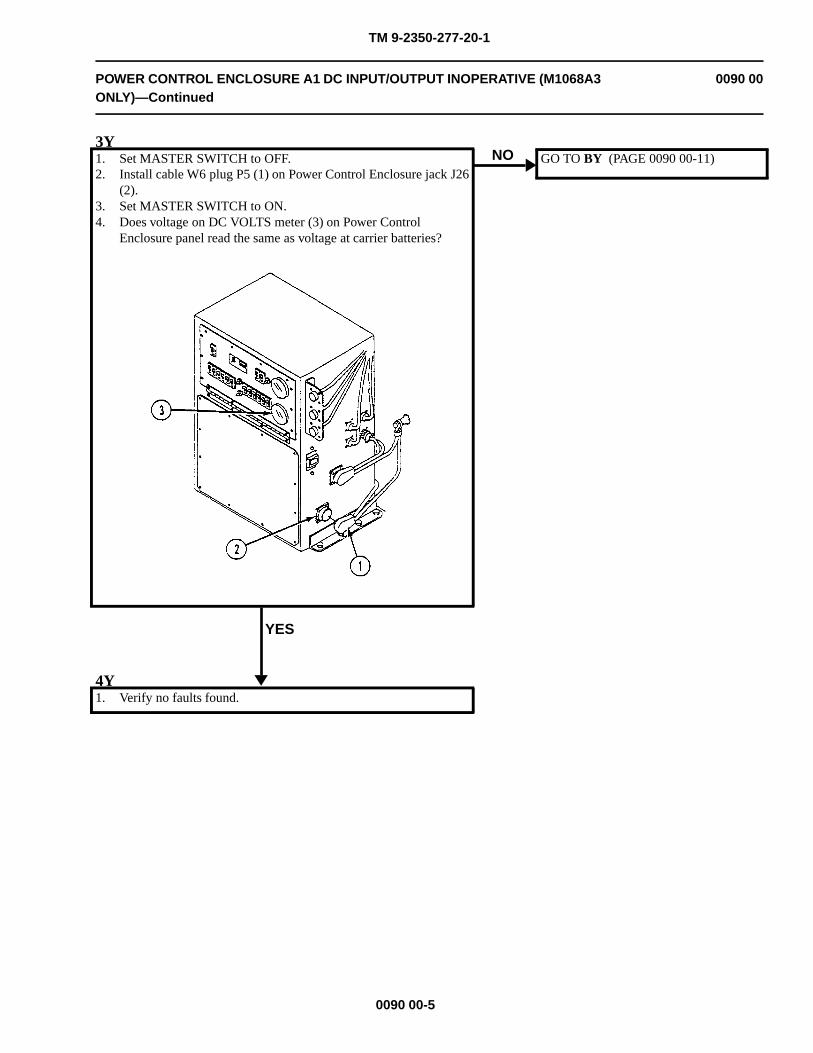
TM 9-2350-277-20-1
POWER CONTROL ENCLOSURE A1 DC INPUT/OUTPUT INOPERATIVE (M1068A3ONLY)—Continued
0090 00
3Y1. Set MASTER SWITCH to OFF.2. Install cable W6 plug P5 (1) on Power Control Enclosure jack J26
(2).3. Set MASTER SWITCH to ON.4. Does voltage on DC VOLTS meter (3) on Power Control
Enclosure panel read the same as voltage at carrier batteries?
YES
NO GO TO BY (PAGE 0090 00-11)
4Y1. Verify no faults found.
0090 00-5
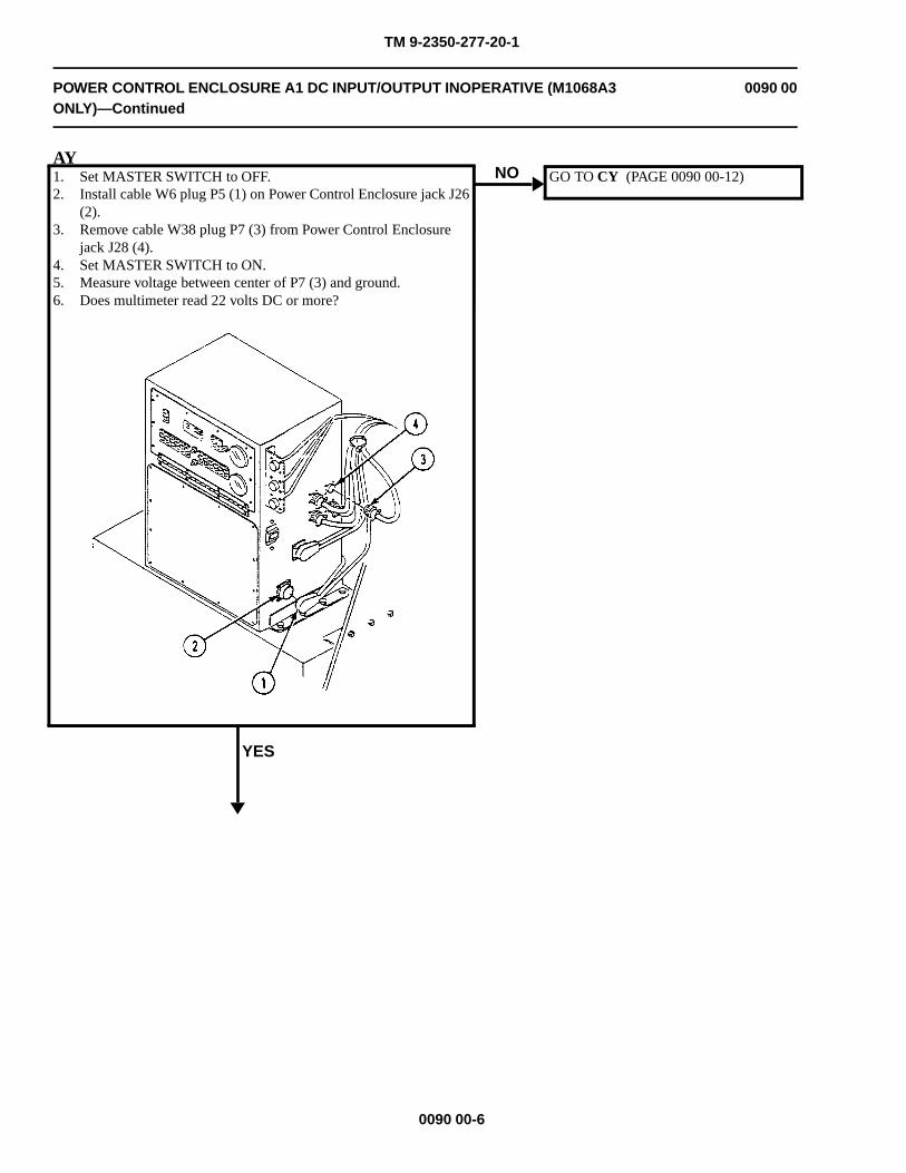
TM 9-2350-277-20-1
POWER CONTROL ENCLOSURE A1 DC INPUT/OUTPUT INOPERATIVE (M1068A3ONLY)—Continued
0090 00
AY1. Set MASTER SWITCH to OFF.2. Install cable W6 plug P5 (1) on Power Control Enclosure jack J26
(2).3. Remove cable W38 plug P7 (3) from Power Control Enclosure
jack J28 (4).4. Set MASTER SWITCH to ON.5. Measure voltage between center of P7 (3) and ground.6. Does multimeter read 22 volts DC or more?
YES
NO GO TO CY (PAGE 0090 00-12)
0090 00-6
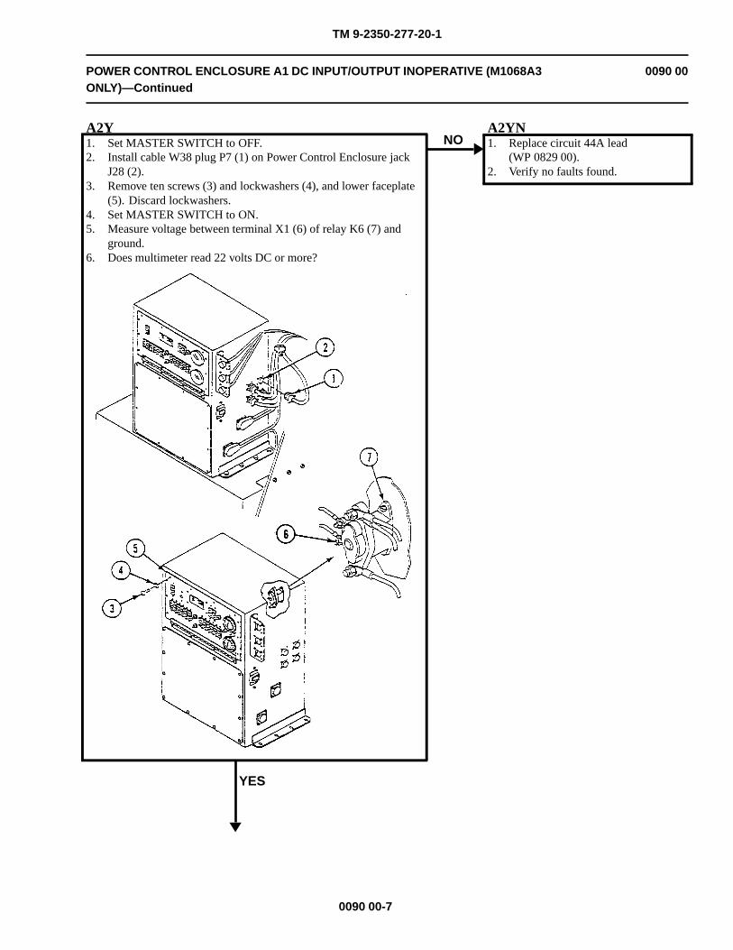
TM 9-2350-277-20-1
POWER CONTROL ENCLOSURE A1 DC INPUT/OUTPUT INOPERATIVE (M1068A3ONLY)—Continued
0090 00
A2Y1. Set MASTER SWITCH to OFF.2. Install cable W38 plug P7 (1) on Power Control Enclosure jack
J28 (2).3. Remove ten screws (3) and lockwashers (4), and lower faceplate
(5). Discard lockwashers.4. Set MASTER SWITCH to ON.5. Measure voltage between terminal X1 (6) of relay K6 (7) and
ground.6. Does multimeter read 22 volts DC or more?
YES
NOA2YN1. Replace circuit 44A lead
(WP 0829 00).2. Verify no faults found.
0090 00-7
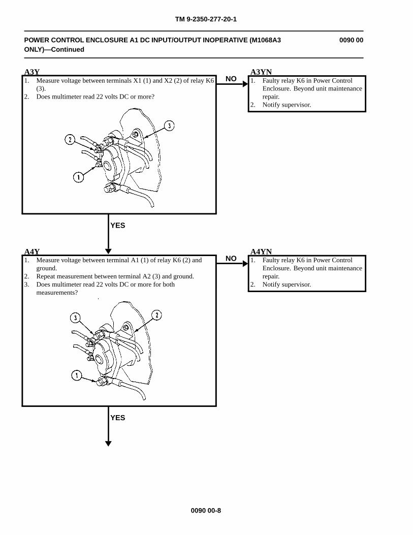
TM 9-2350-277-20-1
POWER CONTROL ENCLOSURE A1 DC INPUT/OUTPUT INOPERATIVE (M1068A3ONLY)—Continued
0090 00
A3Y1. Measure voltage between terminals X1 (1) and X2 (2) of relay K6
(3).2. Does multimeter read 22 volts DC or more?
YES
NOA3YN1. Faulty relay K6 in Power Control
Enclosure. Beyond unit maintenancerepair.
2. Notify supervisor.
A4Y1. Measure voltage between terminal A1 (1) of relay K6 (2) and
ground.2. Repeat measurement between terminal A2 (3) and ground.3. Does multimeter read 22 volts DC or more for both
measurements?
YES
NOA4YN1. Faulty relay K6 in Power Control
Enclosure. Beyond unit maintenancerepair.
2. Notify supervisor.
0090 00-8
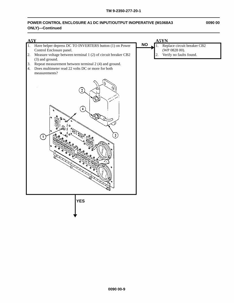
TM 9-2350-277-20-1
POWER CONTROL ENCLOSURE A1 DC INPUT/OUTPUT INOPERATIVE (M1068A3ONLY)—Continued
0090 00
A5Y1. Have helper depress DC TO INVERTERS button (1) on Power
Control Enclosure panel.2. Measure voltage between terminal 1 (2) of circuit breaker CB2
(3) and ground.3. Repeat measurement between terminal 2 (4) and ground.4. Does multimeter read 22 volts DC or more for both
measurements?
YES
NOA5YN1. Replace circuit breaker CB2
(WP 0828 00).2. Verify no faults found.
0090 00-9
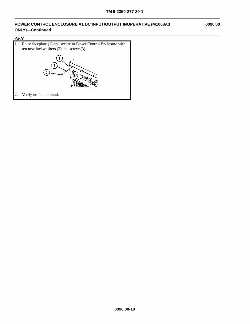
TM 9-2350-277-20-1
POWER CONTROL ENCLOSURE A1 DC INPUT/OUTPUT INOPERATIVE (M1068A3ONLY)—Continued
0090 00
A6Y1. Raise faceplate (1) and secure to Power Control Enclosure with
ten new lockwashers (2) and screws(3).
2. Verify no faults found.
0090 00-10
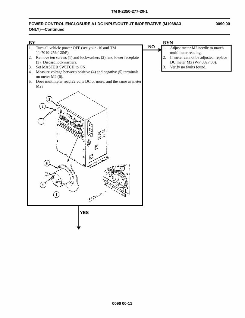
TM 9-2350-277-20-1
POWER CONTROL ENCLOSURE A1 DC INPUT/OUTPUT INOPERATIVE (M1068A3ONLY)—Continued
0090 00
BY1. Turn all vehicle power OFF (see your -10 and TM
11-7010-256-12&P).2. Remove ten screws (1) and lockwashers (2), and lower faceplate
(3). Discard lockwashers.3. Set MASTER SWITCH to ON4. Measure voltage between positive (4) and negative (5) terminals
on meter M2 (6).5. Does multimeter read 22 volts DC or more, and the same as meter
M2?
YES
NOBYN1. Adjust meter M2 needle to match
multimeter reading.2. If meter cannot be adjusted, replace
DC meter M2 (WP 0827 00).3. Verify no faults found.
0090 00-11
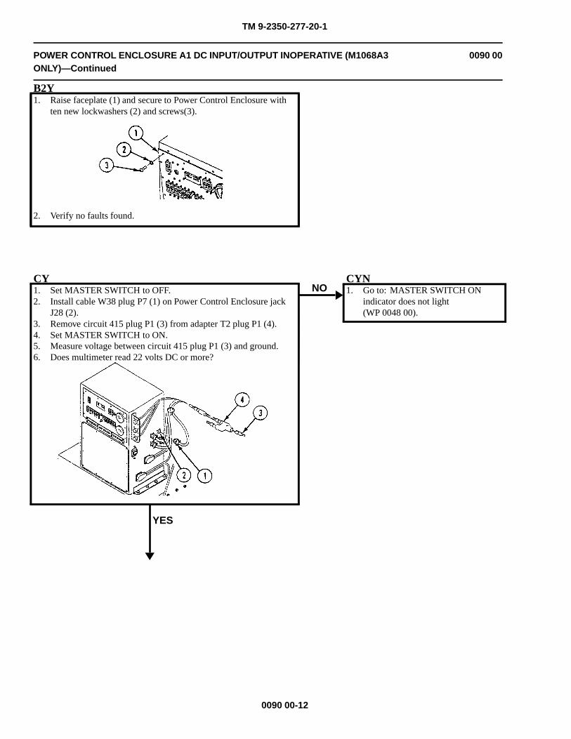
TM 9-2350-277-20-1
POWER CONTROL ENCLOSURE A1 DC INPUT/OUTPUT INOPERATIVE (M1068A3ONLY)—Continued
0090 00
B2Y1. Raise faceplate (1) and secure to Power Control Enclosure with
ten new lockwashers (2) and screws(3).
2. Verify no faults found.
CY1. Set MASTER SWITCH to OFF.2. Install cable W38 plug P7 (1) on Power Control Enclosure jack
J28 (2).3. Remove circuit 415 plug P1 (3) from adapter T2 plug P1 (4).4. Set MASTER SWITCH to ON.5. Measure voltage between circuit 415 plug P1 (3) and ground.6. Does multimeter read 22 volts DC or more?
YES
NOCYN1. Go to: MASTER SWITCH ON
indicator does not light(WP 0048 00).
0090 00-12
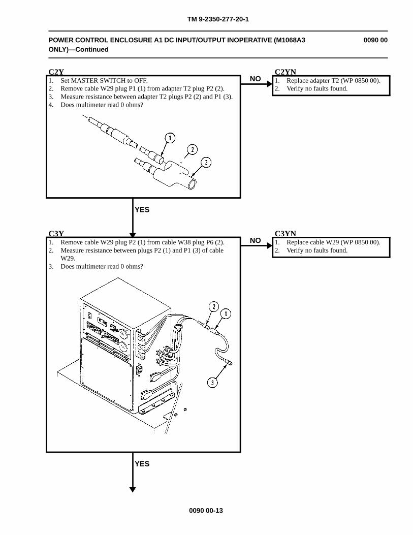
TM 9-2350-277-20-1
POWER CONTROL ENCLOSURE A1 DC INPUT/OUTPUT INOPERATIVE (M1068A3ONLY)—Continued
0090 00
C2Y1. Set MASTER SWITCH to OFF.2. Remove cable W29 plug P1 (1) from adapter T2 plug P2 (2).3. Measure resistance between adapter T2 plugs P2 (2) and P1 (3).4. Does multimeter read 0 ohms?
YES
NOC2YN1. Replace adapter T2 (WP 0850 00).2. Verify no faults found.
C3Y1. Remove cable W29 plug P2 (1) from cable W38 plug P6 (2).2. Measure resistance between plugs P2 (1) and P1 (3) of cable
W29.3. Does multimeter read 0 ohms?
YES
NOC3YN1. Replace cable W29 (WP 0850 00).2. Verify no faults found.
0090 00-13
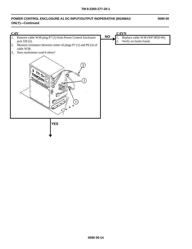
TM 9-2350-277-20-1
POWER CONTROL ENCLOSURE A1 DC INPUT/OUTPUT INOPERATIVE (M1068A3ONLY)—Continued
0090 00
C4Y1. Remove cable W38 plug P7 (1) from Power Control Enclosure
jack J28 (2).2. Measure resistance between center of plugs P7 (1) and P6 (3) of
cable W38.3. Does multimeter read 0 ohms?
YES
NOC4YN1. Replace cable W38 (WP 0850 00).2. Verify no faults found.
0090 00-14
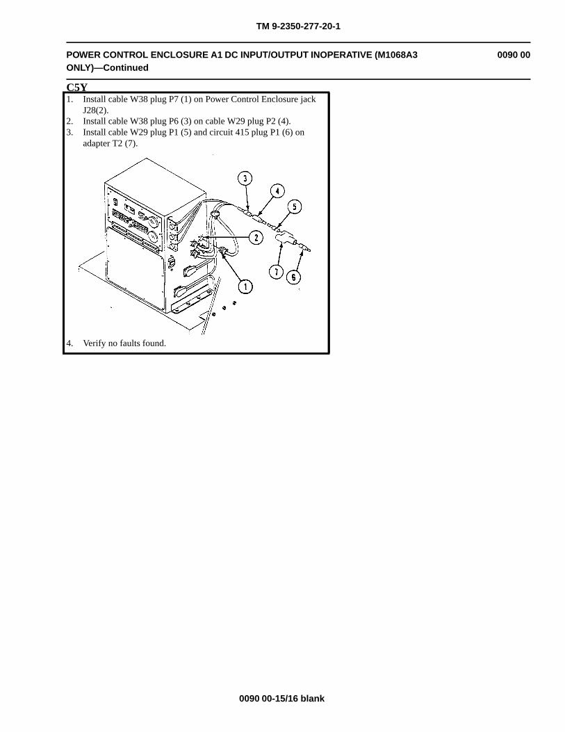
TM 9-2350-277-20-1
POWER CONTROL ENCLOSURE A1 DC INPUT/OUTPUT INOPERATIVE (M1068A3ONLY)—Continued
0090 00
C5Y1. Install cable W38 plug P7 (1) on Power Control Enclosure jack
J28(2).2. Install cable W38 plug P6 (3) on cable W29 plug P2 (4).3. Install cable W29 plug P1 (5) and circuit 415 plug P1 (6) on
adapter T2 (7).
4. Verify no faults found.
0090 00-15/16 blank

TM 9-2350-277-20-1
NO AC POWER FROM TENT INTERFACE PANEL A5 (M1068A3 ONLY) 0091 00
INITIAL SETUP:
Maintenance Level
Unit
Tools and Special Tools
General Mechanic’s Tool Kit (WP 0926 00, Item 65)Digital multimeter (WP 0926 00, Item 30)
Materials/Parts
Lockwasher (10)
Personnel Required
Power-Generation Equipment Repairer 52D10Helper (H)
References
See your -10TM 11-7010-256-12&P
Equipment Condition
Engine stopped (see your -10)Carrier blocked (see your -10)
WARNING
HIGH VOLTAGE is used in the operation of this equipment.
DEATH ON CONTACT may result if personnel fail to observe safety precautions.
NEVER work on equipment unless at least one other person familiar with the operation andhazards of the equipment is nearby. That person should also be familiar with giving first aid.When an operator helps a mechanic, that operator must be warned about dangerous areas.
SHUT OFF POWER supply to equipment before beginning work. Make sure all external poweris off/disconnected.
BE CAREFUL not to contact high-voltage connections when installing or operating thisequipment.
0091 00-1
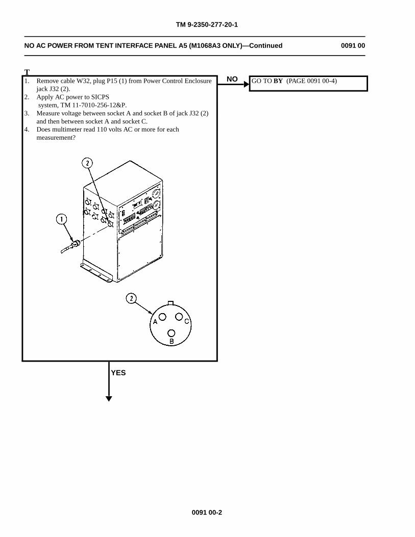
TM 9-2350-277-20-1
NO AC POWER FROM TENT INTERFACE PANEL A5 (M1068A3 ONLY)—Continued 0091 00
T1. Remove cable W32, plug P15 (1) from Power Control Enclosure
jack J32 (2).2. Apply AC power to SICPS
system, TM 11-7010-256-12&P.3. Measure voltage between socket A and socket B of jack J32 (2)
and then between socket A and socket C.4. Does multimeter read 110 volts AC or more for each
measurement?
YES
NO GO TO BY (PAGE 0091 00-4)
0091 00-2
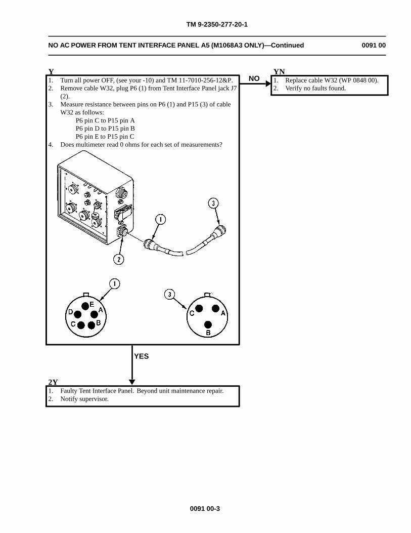
TM 9-2350-277-20-1
NO AC POWER FROM TENT INTERFACE PANEL A5 (M1068A3 ONLY)—Continued 0091 00
Y1. Turn all power OFF, (see your -10) and TM 11-7010-256-12&P.2. Remove cable W32, plug P6 (1) from Tent Interface Panel jack J7
(2).3. Measure resistance between pins on P6 (1) and P15 (3) of cable
W32 as follows:P6 pin C to P15 pin AP6 pin D to P15 pin BP6 pin E to P15 pin C
4. Does multimeter read 0 ohms for each set of measurements?
YES
NOYN1. Replace cable W32 (WP 0848 00).2. Verify no faults found.
2Y1. Faulty Tent Interface Panel. Beyond unit maintenance repair.2. Notify supervisor.
0091 00-3
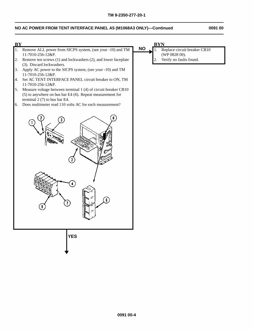
TM 9-2350-277-20-1
NO AC POWER FROM TENT INTERFACE PANEL A5 (M1068A3 ONLY)—Continued 0091 00
BY1. Remove ALL power from SICPS system, (see your -10) and TM
11-7010-256-12&P.2. Remove ten screws (1) and lockwashers (2), and lower faceplate
(3). Discard lockwashers.3. Apply AC power to the SICPS system, (see your -10) and TM
11-7010-256-12&P.4. Set AC TENT INTERFACE PANEL circuit breaker to ON, TM
11-7010-256-12&P.5. Measure voltage between terminal 1 (4) of circuit breaker CB10
(5) to anywhere on bus bar E4 (6). Repeat measurement forterminal 2 (7) to bus bar E4.
6. Does multimeter read 110 volts AC for each measurement?
YES
NOBYN1. Replace circuit breaker CB10
(WP 0828 00).2. Verify no faults found.
0091 00-4
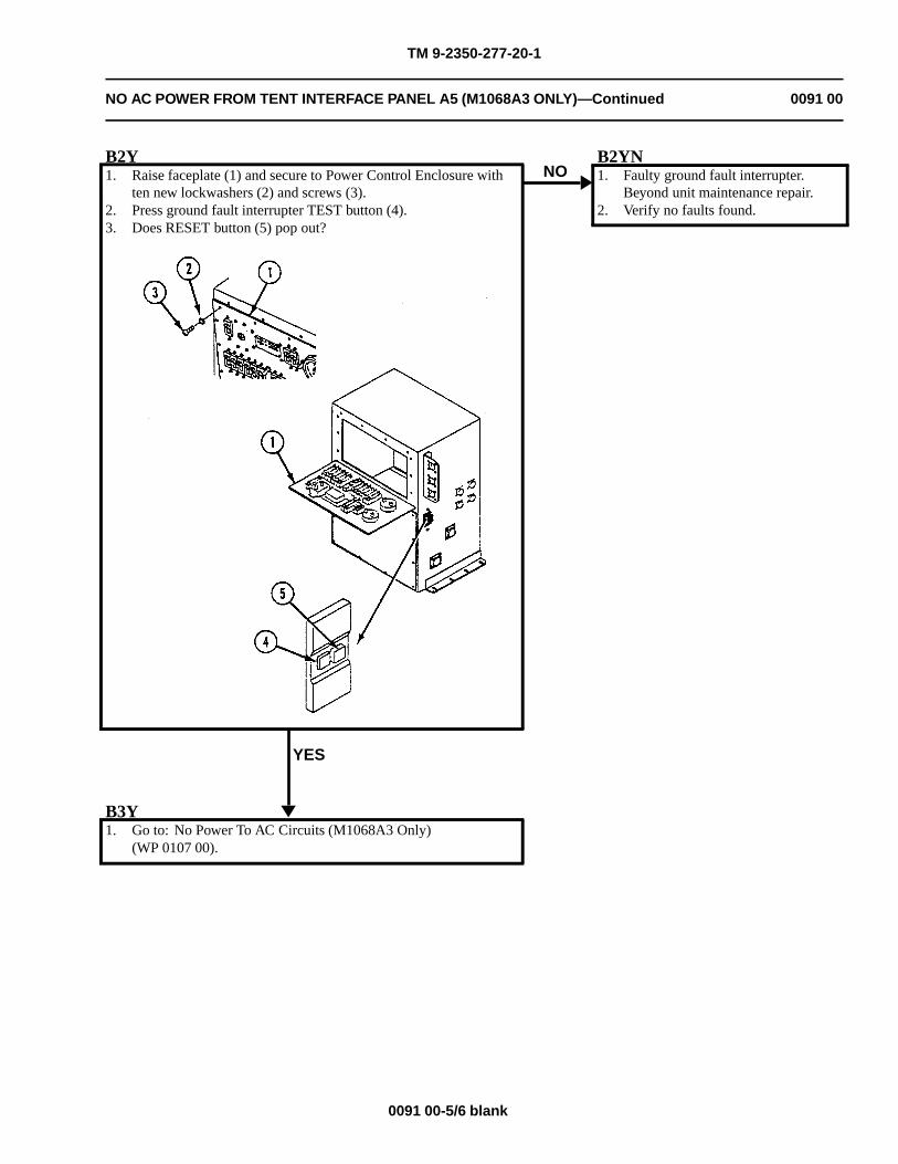
TM 9-2350-277-20-1
NO AC POWER FROM TENT INTERFACE PANEL A5 (M1068A3 ONLY)—Continued 0091 00
B2Y1. Raise faceplate (1) and secure to Power Control Enclosure with
ten new lockwashers (2) and screws (3).2. Press ground fault interrupter TEST button (4).3. Does RESET button (5) pop out?
YES
NOB2YN1. Faulty ground fault interrupter.
Beyond unit maintenance repair.2. Verify no faults found.
B3Y1. Go to: No Power To AC Circuits (M1068A3 Only)
(WP 0107 00).
0091 00-5/6 blank

TM 9-2350-277-20-1
NO DC POWER FROM TENT INTERFACE PANEL A5 (M1068A3 ONLY) 0092 00
INITIAL SETUP:
Maintenance Level
Unit
Tools and Special Tools
General Mechanic’s Tool Kit (WP 0926 00, Item 65)
Digital multimeter (WP 0926 00, Item 30)
Materials/Parts
Lockwasher (10)
Personnel Required
Power-Generation Equipment Repairer 52D10
Helper (H)
References
See your -10TM 11-7010-256-12&P
Equipment Condition
Engine stopped (see your -10)
Carrier blocked (see your -10)
WARNING
HIGH VOLTAGE is used in the operation of this equipment.
DEATH ON CONTACT may result if personnel fail to observe safety precautions.
NEVER work on equipment unless at least one other person familiar with the operation andhazards of the equipment is nearby. That person should also be familiar with giving first aid.When an operator helps a mechanic, that operator must be warned about dangerous areas.
SHUT OFF POWER supply to equipment before beginning work. Make sure all external poweris off/disconnected.
BE CAREFUL not to contact high-voltage connections when installing or operating thisequipment.
DO NOT attempt power cable connections until grounding system and signal/data cabling havebeen completed.
0092 00-1
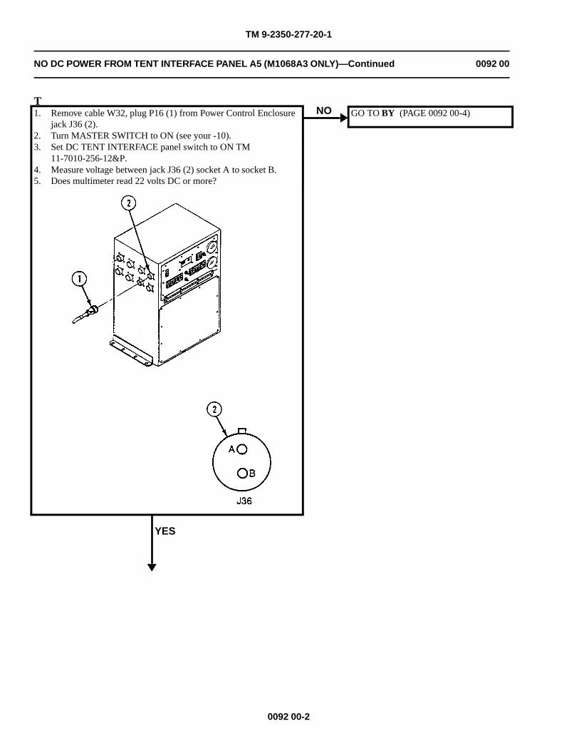
TM 9-2350-277-20-1
NO DC POWER FROM TENT INTERFACE PANEL A5 (M1068A3 ONLY)—Continued 0092 00
T1. Remove cable W32, plug P16 (1) from Power Control Enclosure
jack J36 (2).2. Turn MASTER SWITCH to ON (see your -10).3. Set DC TENT INTERFACE panel switch to ON TM
11-7010-256-12&P.4. Measure voltage between jack J36 (2) socket A to socket B.5. Does multimeter read 22 volts DC or more?
YES
NO GO TO BY (PAGE 0092 00-4)
0092 00-2
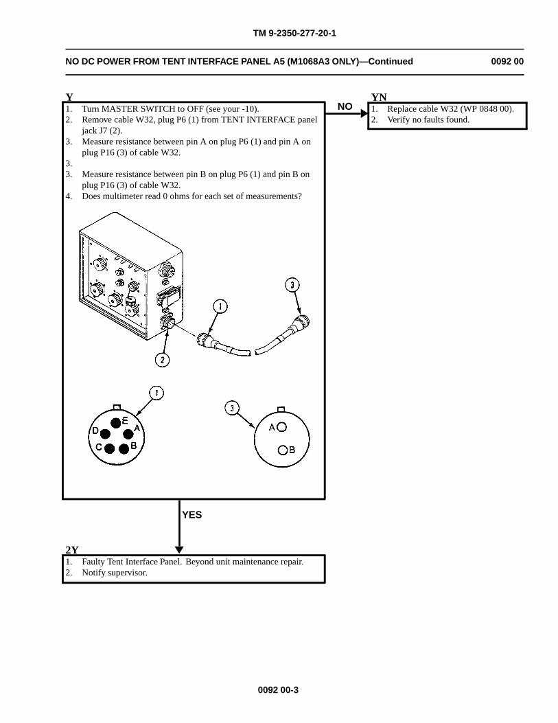
TM 9-2350-277-20-1
NO DC POWER FROM TENT INTERFACE PANEL A5 (M1068A3 ONLY)—Continued 0092 00
Y1. Turn MASTER SWITCH to OFF (see your -10).2. Remove cable W32, plug P6 (1) from TENT INTERFACE panel
jack J7 (2).3. Measure resistance between pin A on plug P6 (1) and pin A on
plug P16 (3) of cable W32.3.3. Measure resistance between pin B on plug P6 (1) and pin B on
plug P16 (3) of cable W32.4. Does multimeter read 0 ohms for each set of measurements?
YES
NOYN1. Replace cable W32 (WP 0848 00).2. Verify no faults found.
2Y1. Faulty Tent Interface Panel. Beyond unit maintenance repair.2. Notify supervisor.
0092 00-3
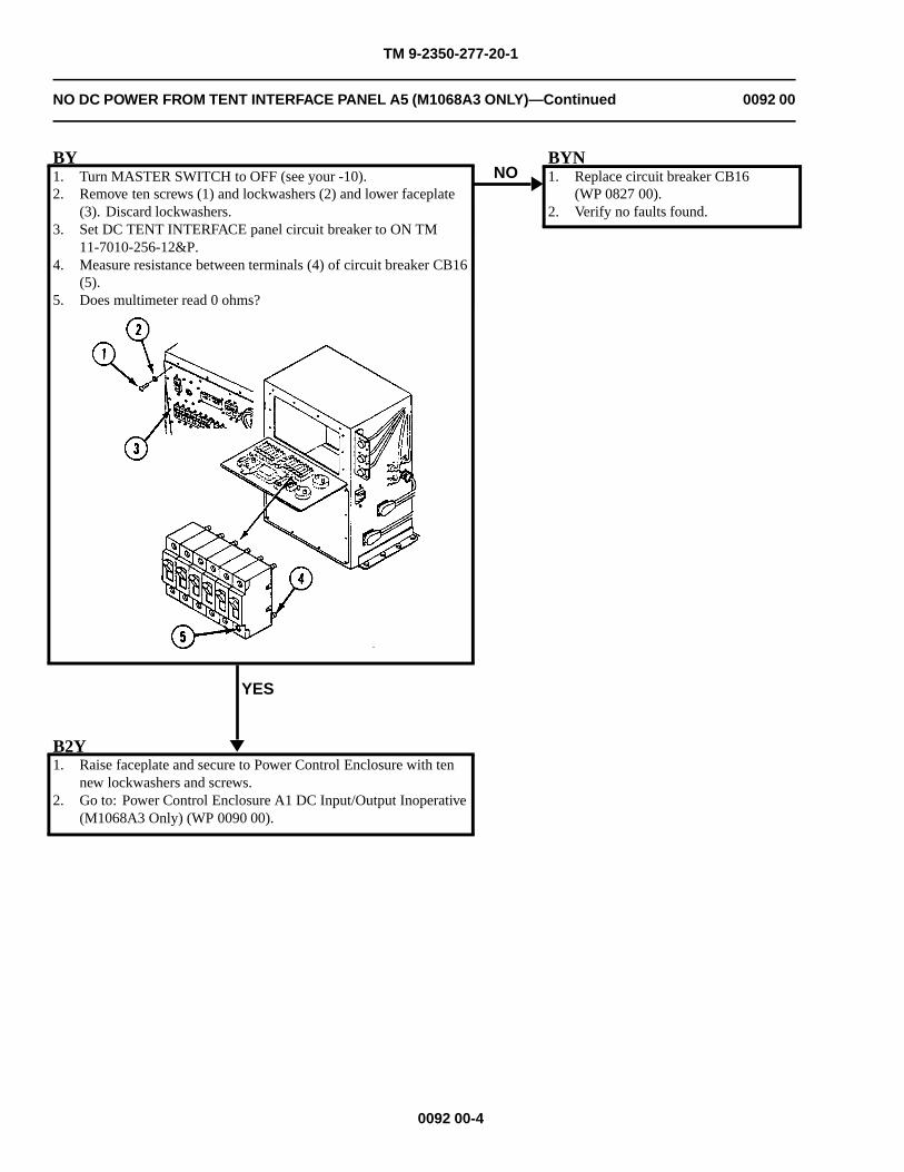
TM 9-2350-277-20-1
NO DC POWER FROM TENT INTERFACE PANEL A5 (M1068A3 ONLY)—Continued 0092 00
BY1. Turn MASTER SWITCH to OFF (see your -10).2. Remove ten screws (1) and lockwashers (2) and lower faceplate
(3). Discard lockwashers.3. Set DC TENT INTERFACE panel circuit breaker to ON TM
11-7010-256-12&P.4. Measure resistance between terminals (4) of circuit breaker CB16
(5).5. Does multimeter read 0 ohms?
YES
NOBYN1. Replace circuit breaker CB16
(WP 0827 00).2. Verify no faults found.
B2Y1. Raise faceplate and secure to Power Control Enclosure with ten
new lockwashers and screws.2. Go to: Power Control Enclosure A1 DC Input/Output Inoperative
(M1068A3 Only) (WP 0090 00).
0092 00-4
TM 9-2350-277-20-1
NO POWER FROM ROADSIDE AC POWER EXTENSION BOX A6 (M1068A3ONLY)
0093 00
INITIAL SETUP:
Maintenance Level
Unit
Tools and Special Tools
General Mechanic’s Tool Kit (WP 0926 00, Item 65)Digital Multimeter (WP 0926 00, Item 30)
Materials/Parts
Lockwasher (10)
Personnel Required
Power-Generation Equipment Repairer 52D10Helper (H)
References
See your -10TM 11-7010-256-12&P
Equipment Condition
Engine stopped (see your -10)Carrier blocked (see your -10)
WARNING
HIGH VOLTAGE is used in the operation of this equipment.
DEATH ON CONTACT may result if personnel fail to observe safety precautions.
NEVER work on equipment unless at least one other person familiar with the operation andhazards of the equipment is nearby. That person should also be familiar with giving first aid.When an operator helps a mechanic, that operator must be warned about dangerous areas.
SHUT OFF POWER supply to equipment before beginning work. Make sure all external poweris off/disconnected.
BE CAREFUL not to contact high-voltage connections when installing or operating thisequipment.
0093 00-1
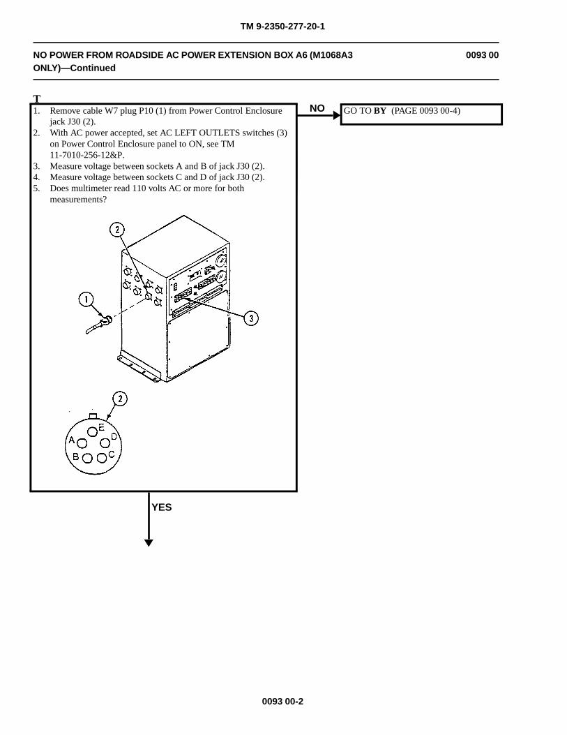
TM 9-2350-277-20-1
NO POWER FROM ROADSIDE AC POWER EXTENSION BOX A6 (M1068A3ONLY)—Continued
0093 00
T1. Remove cable W7 plug P10 (1) from Power Control Enclosure
jack J30 (2).2. With AC power accepted, set AC LEFT OUTLETS switches (3)
on Power Control Enclosure panel to ON, see TM11-7010-256-12&P.
3. Measure voltage between sockets A and B of jack J30 (2).4. Measure voltage between sockets C and D of jack J30 (2).5. Does multimeter read 110 volts AC or more for both
measurements?
YES
NO GO TO BY (PAGE 0093 00-4)
0093 00-2
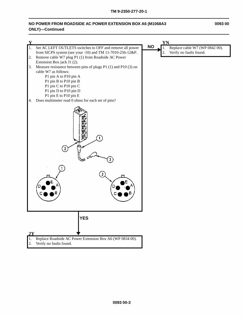
TM 9-2350-277-20-1
NO POWER FROM ROADSIDE AC POWER EXTENSION BOX A6 (M1068A3ONLY)—Continued
0093 00
Y1. Set AC LEFT OUTLETS switches to OFF and remove all power
from SICPS system (see your -10) and TM 11-7010-256-12&P.2. Remove cable W7 plug P1 (1) from Roadside AC Power
Extension Box jack J1 (2).3. Measure resistance between pins of plugs P1 (1) and P10 (3) on
cable W7 as follows:P1 pin A to P10 pin AP1 pin B to P10 pin BP1 pin C to P10 pin CP1 pin D to P10 pin DP1 pin E to P10 pin E
4. Does multimeter read 0 ohms for each set of pins?
YES
NOYN1. Replace cable W7 (WP 0842 00).2. Verify no faults found.
2Y1. Replace Roadside AC Power Extension Box A6 (WP 0834 00).2. Verify no faults found.
0093 00-3
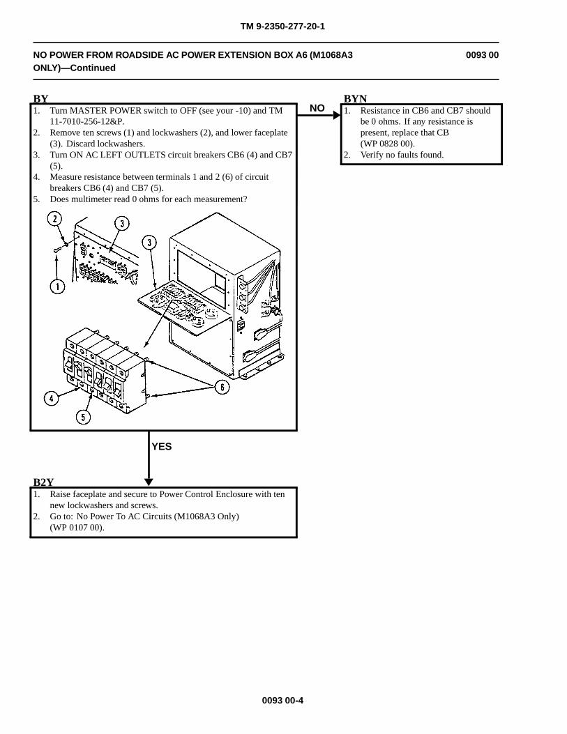
TM 9-2350-277-20-1
NO POWER FROM ROADSIDE AC POWER EXTENSION BOX A6 (M1068A3ONLY)—Continued
0093 00
BY1. Turn MASTER POWER switch to OFF (see your -10) and TM
11-7010-256-12&P.2. Remove ten screws (1) and lockwashers (2), and lower faceplate
(3). Discard lockwashers.3. Turn ON AC LEFT OUTLETS circuit breakers CB6 (4) and CB7
(5).4. Measure resistance between terminals 1 and 2 (6) of circuit
breakers CB6 (4) and CB7 (5).5. Does multimeter read 0 ohms for each measurement?
YES
NOBYN1. Resistance in CB6 and CB7 should
be 0 ohms. If any resistance ispresent, replace that CB(WP 0828 00).
2. Verify no faults found.
B2Y1. Raise faceplate and secure to Power Control Enclosure with ten
new lockwashers and screws.2. Go to: No Power To AC Circuits (M1068A3 Only)
(WP 0107 00).
0093 00-4

TM 9-2350-277-20-1
NO POWER FROM CURBSIDE AC POWER EXTENSION BOX A7 (M1068A3ONLY)
0094 00
INITIAL SETUP:
Maintenance Level
Unit
Tools and Special Tools
General Mechanic’s Tool Kit (WP 0926 00, Item 65)Digital Multimeter (WP 0926 00, Item 30)
Materials/Parts
Lockwasher (10)
Personnel Required
Power-Generation Equipment Repairer 52D10Helper (H)
References
See your -10TM 11-7010-256-12&P
Equipment Condition
Engine stopped (see your -10)Carrier blocked (see your -10)
WARNING
HIGH VOLTAGE is used in the operation of this equipment.
DEATH ON CONTACT may result if personnel fail to observe safety precautions.
NEVER work on equipment unless at least one other person familiar with the operation andhazards of the equipment is nearby. That person should also be familiar with giving first aid.When an operator helps a mechanic, that operator must be warned about dangerous areas.
SHUT OFF POWER supply to equipment before beginning work. Make sure all external poweris off/disconnected.
BE CAREFUL not to contact high-voltage connections when installing or operating thisequipment.
0094 00-1
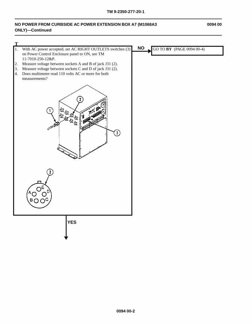
TM 9-2350-277-20-1
NO POWER FROM CURBSIDE AC POWER EXTENSION BOX A7 (M1068A3ONLY)—Continued
0094 00
T1. With AC power accepted, set AC RIGHT OUTLETS switches (3)
on Power Control Enclosure panel to ON, see TM11-7010-256-12&P.
2. Measure voltage between sockets A and B of jack J31 (2).3. Measure voltage between sockets C and D of jack J31 (2).4. Does multimeter read 110 volts AC or more for both
measurements?
YES
NO GO TO BY (PAGE 0094 00-4)
0094 00-2
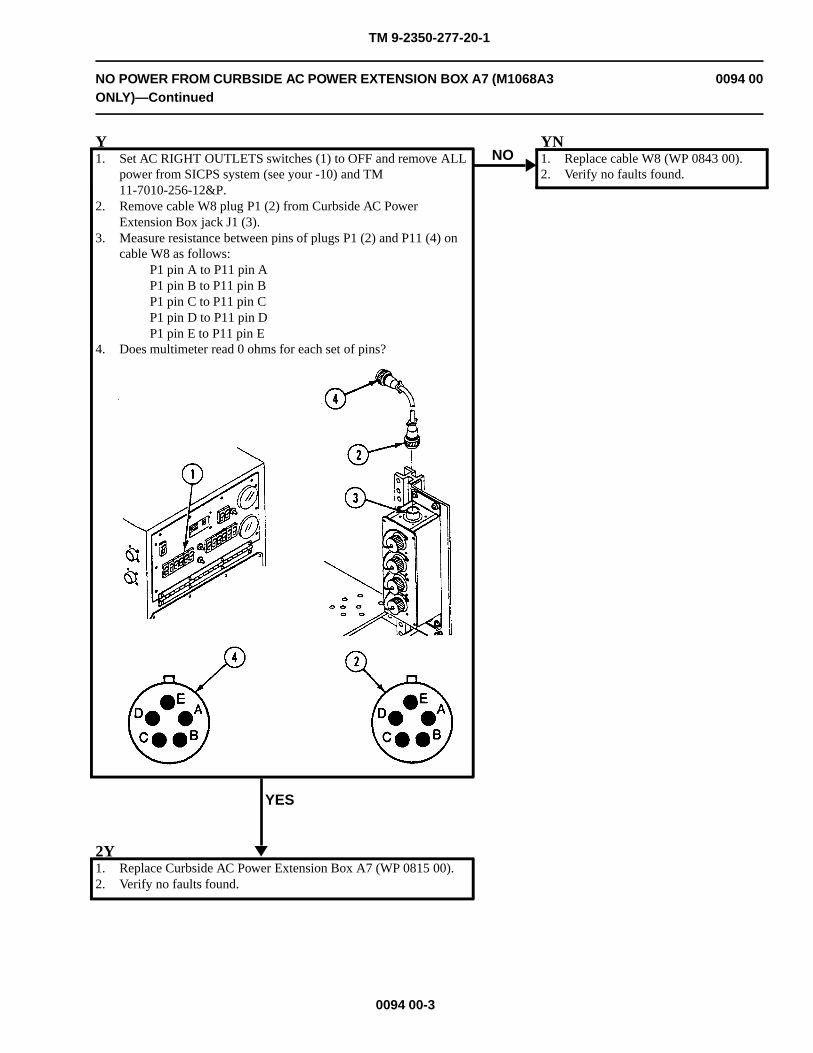
TM 9-2350-277-20-1
NO POWER FROM CURBSIDE AC POWER EXTENSION BOX A7 (M1068A3ONLY)—Continued
0094 00
Y1. Set AC RIGHT OUTLETS switches (1) to OFF and remove ALL
power from SICPS system (see your -10) and TM11-7010-256-12&P.
2. Remove cable W8 plug P1 (2) from Curbside AC PowerExtension Box jack J1 (3).
3. Measure resistance between pins of plugs P1 (2) and P11 (4) oncable W8 as follows:
P1 pin A to P11 pin AP1 pin B to P11 pin BP1 pin C to P11 pin CP1 pin D to P11 pin DP1 pin E to P11 pin E
4. Does multimeter read 0 ohms for each set of pins?
YES
NOYN1. Replace cable W8 (WP 0843 00).2. Verify no faults found.
2Y1. Replace Curbside AC Power Extension Box A7 (WP 0815 00).2. Verify no faults found.
0094 00-3
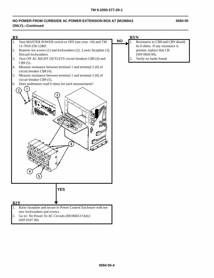
TM 9-2350-277-20-1
NO POWER FROM CURBSIDE AC POWER EXTENSION BOX A7 (M1068A3ONLY)—Continued
0094 00
BY1. Turn MASTER POWER switch to OFF (see your -10) and TM
11-7010-256-12&P.2. Remove ten screws (1) and lockwashers (2). Lower faceplate (3).
Discard lockwashers.3. Turn ON AC RIGHT OUTLETS circuit breakers CB8 (4) and
CB9 (5).4. Measure resistance between terminal 1 and terminal 2 (6) of
circuit breaker CB8 (4).5. Measure resistance between terminal 1 and terminal 2 (6) of
circuit breaker CB9 (5).6. Does multimeter read 0 ohms for each measurement?
YES
NOBYN1. Resistance in CB8 and CB9 should
be 0 ohms. If any resistance ispresent, replace that CB(WP 0828 00).
2. Verify no faults found.
B2Y1. Raise faceplate and secure to Power Control Enclosure with ten
new lockwashers and screws.2. Go to: No Power To AC Circuits (M1068A3 Only)
(WP 0107 00).
0094 00-4
TM 9-2350-277-20-1
NO POWER FROM DC POWER EXTENSION BOX A9 (ALL EXCEPT JACKJ23) (M1068A3 ONLY)
0095 00
INITIAL SETUP:
Maintenance Level
Unit
Tools and Special Tools
General Mechanic’s Tool Kit (WP 0926 00, Item 65)Digital Multimeter (WP 0926 00, Item 30)
Materials/Parts
Lockwasher (10)
Personnel Required
Power-Generation Equipment Repairer 52D10Helper (H)
References
See your -10TM 11-7010-256-12&P
Equipment Condition
Engine stopped (see your -10)Carrier blocked (see your -10)
WARNING
HIGH VOLTAGE is used in the operation of this equipment.
DEATH ON CONTACT may result if personnel fail to observe safety precautions.
NEVER work on equipment unless at least one other person familiar with the operation andhazards of the equipment is nearby. That person should also be familiar with giving first aid.When an operator helps a mechanic, that operator must be warned about dangerous areas.
SHUT OFF POWER supply to equipment before beginning work. Make sure all external poweris off/disconnected.
BE CAREFUL not to contact high-voltage connections when installing or operating thisequipment.
0095 00-1
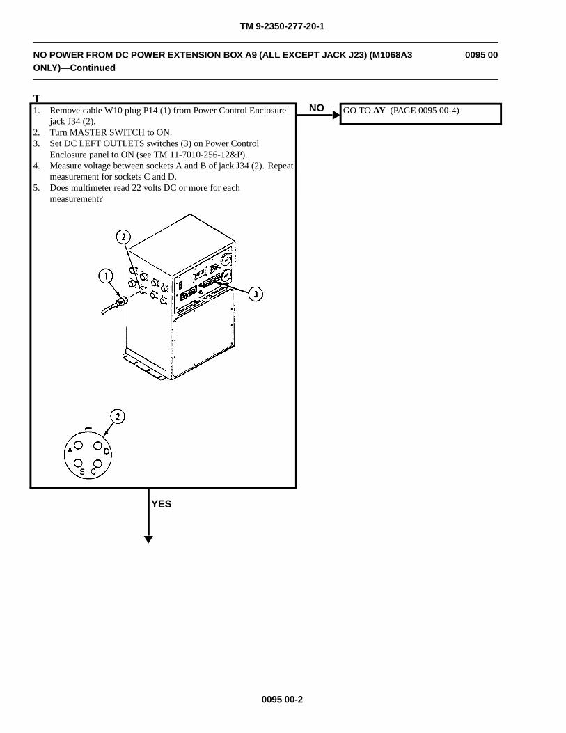
TM 9-2350-277-20-1
NO POWER FROM DC POWER EXTENSION BOX A9 (ALL EXCEPT JACK J23) (M1068A3ONLY)—Continued
0095 00
T1. Remove cable W10 plug P14 (1) from Power Control Enclosure
jack J34 (2).2. Turn MASTER SWITCH to ON.3. Set DC LEFT OUTLETS switches (3) on Power Control
Enclosure panel to ON (see TM 11-7010-256-12&P).4. Measure voltage between sockets A and B of jack J34 (2). Repeat
measurement for sockets C and D.5. Does multimeter read 22 volts DC or more for each
measurement?
YES
NO GO TO AY (PAGE 0095 00-4)
0095 00-2
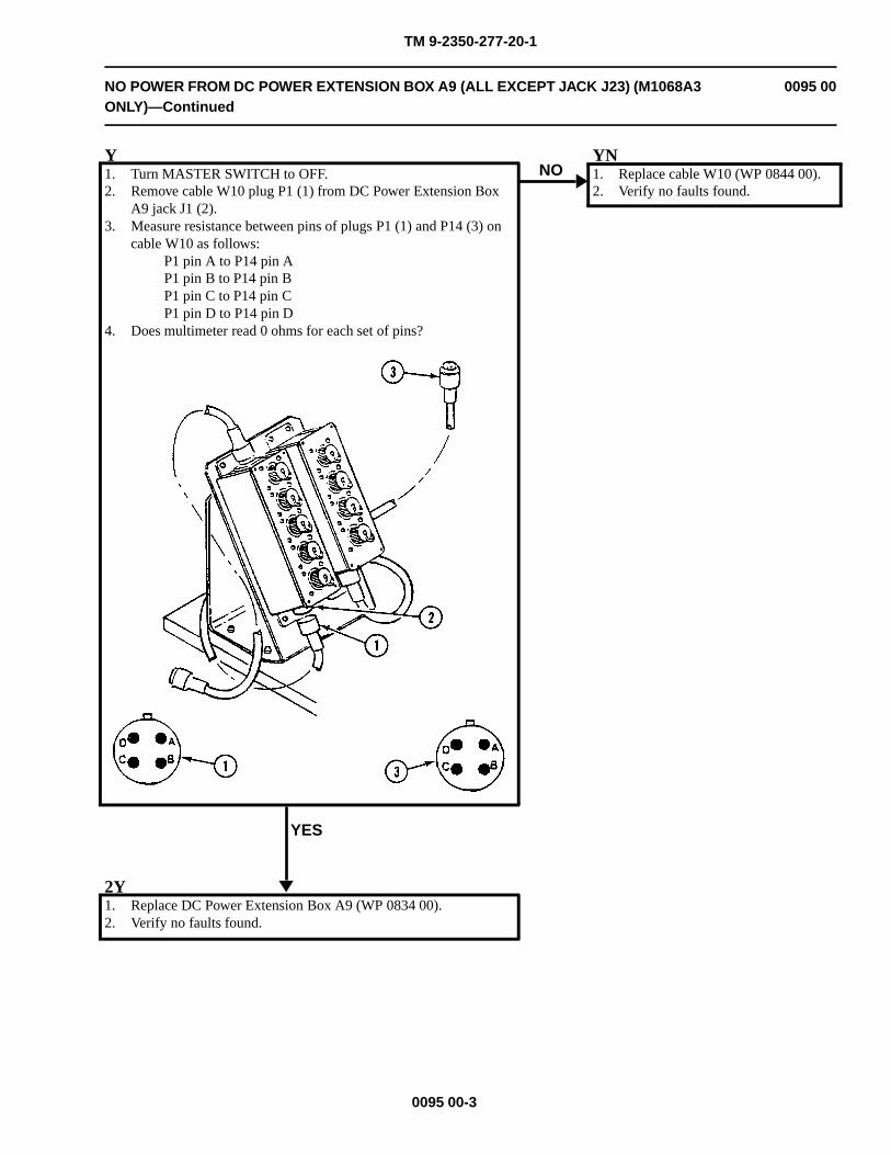
TM 9-2350-277-20-1
NO POWER FROM DC POWER EXTENSION BOX A9 (ALL EXCEPT JACK J23) (M1068A3ONLY)—Continued
0095 00
Y1. Turn MASTER SWITCH to OFF.2. Remove cable W10 plug P1 (1) from DC Power Extension Box
A9 jack J1 (2).3. Measure resistance between pins of plugs P1 (1) and P14 (3) on
cable W10 as follows:P1 pin A to P14 pin AP1 pin B to P14 pin BP1 pin C to P14 pin CP1 pin D to P14 pin D
4. Does multimeter read 0 ohms for each set of pins?
YES
NOYN1. Replace cable W10 (WP 0844 00).2. Verify no faults found.
2Y1. Replace DC Power Extension Box A9 (WP 0834 00).2. Verify no faults found.
0095 00-3
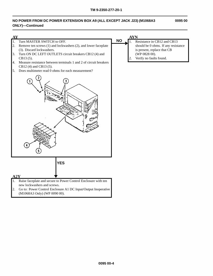
TM 9-2350-277-20-1
NO POWER FROM DC POWER EXTENSION BOX A9 (ALL EXCEPT JACK J23) (M1068A3ONLY)—Continued
0095 00
AY1. Turn MASTER SWITCH to OFF.2. Remove ten screws (1) and lockwashers (2), and lower faceplate
(3). Discard lockwashers.3. Turn ON DC LEFT OUTLETS circuit breakers CB12 (4) and
CB13 (5).4. Measure resistance between terminals 1 and 2 of circuit breakers
CB12 (4) and CB13 (5).5. Does multimeter read 0 ohms for each measurement?
YES
NOAYN1. Resistance in CB12 and CB13
should be 0 ohms. If any resistanceis present, replace that CB(WP 0828 00).
2. Verify no faults found.
A2Y1. Raise faceplate and secure to Power Control Enclosure with ten
new lockwashers and screws.2. Go to: Power Control Enclosure A1 DC Input/Output Inoperative
(M1068A3 Only) (WP 0090 00).
0095 00-4
TM 9-2350-277-20-1
NO POWER FROM DC POWER EXTENSION BOX A9, JACKJ23 (JTIDS) (M1068A3 ONLY)
0096 00
INITIAL SETUP:
Maintenance LevelUnit
Tools and Special ToolsGeneral Mechanic’s Tool Kit (WP 0926 00, Item 65)Digital Multimeter (WP 0926 00, Item 30)
Materials/PartsLockwasher (10)
Personnel RequiredPower-Generation Equipment Repairer 52D10Helper (H)
ReferencesSee your -10TM 11-7010-256-12&P
Equipment ConditionEngine stopped (see your -10)Carrier blocked (see your -10)
WARNING
HIGH VOLTAGE is used in the operation of this equipment.
DEATH ON CONTACT may result if personnel fail to observe safety precautions.
NEVER work on equipment unless at least one other person familiar with the operation andhazards of the equipment is nearby. That person should also be familiar with giving first aid.When an operator helps a mechanic, that operator must be warned about dangerous areas.
SHUT OFF POWER supply to equipment before beginning work. Make sure all externalpower is off/disconnected.
BE CAREFUL not to contact high-voltage connections when installing or operating thisequipment.
0096 00-1 Change 4
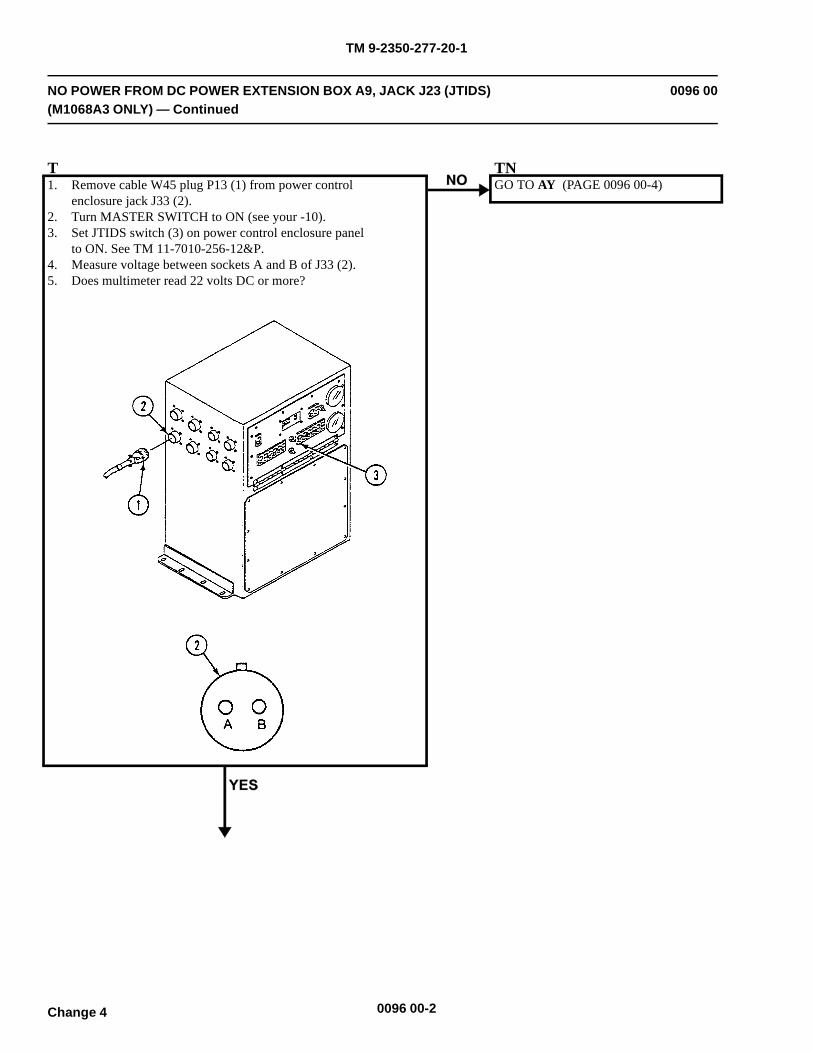
TM 9-2350-277-20-1
NO POWER FROM DC POWER EXTENSION BOX A9, JACK J23 (JTIDS)(M1068A3 ONLY) — Continued
0096 00
T1. Remove cable W45 plug P13 (1) from power control
enclosure jack J33 (2).2. Turn MASTER SWITCH to ON (see your -10).3. Set JTIDS switch (3) on power control enclosure panel
to ON. See TM 11-7010-256-12&P.4. Measure voltage between sockets A and B of J33 (2).5. Does multimeter read 22 volts DC or more?
GO TO AY (PAGE 0096 00-4)
0096 00-2Change 4
TN
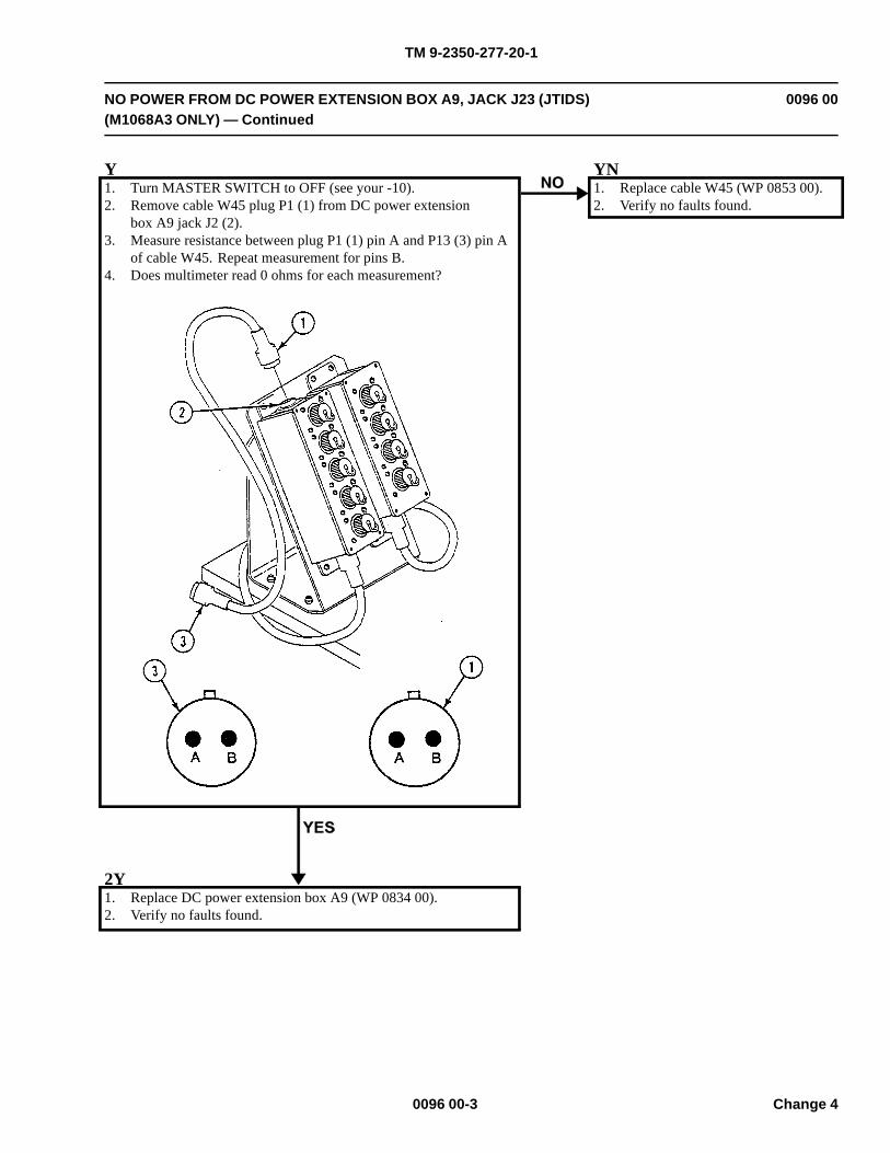
TM 9-2350-277-20-1
NO POWER FROM DC POWER EXTENSION BOX A9, JACK J23 (JTIDS)(M1068A3 ONLY) — Continued
0096 00
Y1. Turn MASTER SWITCH to OFF (see your -10).2. Remove cable W45 plug P1 (1) from DC power extension
box A9 jack J2 (2).3. Measure resistance between plug P1 (1) pin A and P13 (3) pin A
of cable W45. Repeat measurement for pins B.4. Does multimeter read 0 ohms for each measurement?
YN1. Replace cable W45 (WP 0853 00).2. Verify no faults found.
2Y1. Replace DC power extension box A9 (WP 0834 00).2. Verify no faults found.
0096 00-3 Change 4
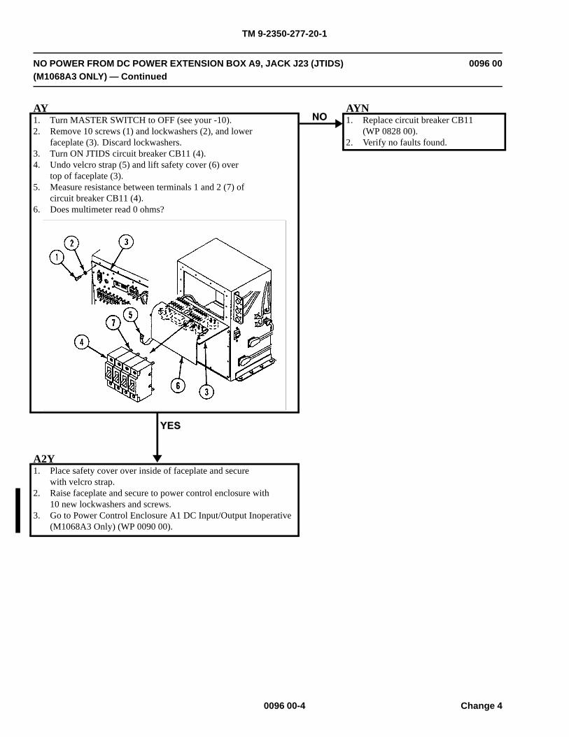
TM 9-2350-277-20-1
NO POWER FROM DC POWER EXTENSION BOX A9, JACK J23 (JTIDS)(M1068A3 ONLY) — Continued
0096 00
AY1. Turn MASTER SWITCH to OFF (see your -10).2. Remove 10 screws (1) and lockwashers (2), and lower
faceplate (3). Discard lockwashers.3. Turn ON JTIDS circuit breaker CB11 (4).4. Undo velcro strap (5) and lift safety cover (6) over
top of faceplate (3).5. Measure resistance between terminals 1 and 2 (7) of
circuit breaker CB11 (4).6. Does multimeter read 0 ohms?
AYN1. Replace circuit breaker CB11
(WP 0828 00).2. Verify no faults found.
A2Y1. Place safety cover over inside of faceplate and secure
with velcro strap.2. Raise faceplate and secure to power control enclosure with
10 new lockwashers and screws.3. Go to Power Control Enclosure A1 DC Input/Output Inoperative
(M1068A3 Only) (WP 0090 00).
0096 00-4 Change 4
TM 9-2350-277-20-1
NO DC POWER TO SINGLE POINT LAN GROUND BOX A15 (M1068A3ONLY)
0097 00
INITIAL SETUP:
Maintenance Level
Unit
Tools and Special Tools
General Mechanic’s Tool Kit (WP 0926 00, Item 65)Digital Multimeter (WP 0926 00, Item 30)
Personnel Required
Power-Generation Equipment Repairer 52D10Helper (H)
References
See your -10
Equipment Condition
Engine stopped (see your -10)
Carrier blocked (see your -10)
WARNING
HIGH VOLTAGE is used in the operation of this equipment.
DEATH ON CONTACT may result if personnel fail to observe safety precautions.
NEVER work on equipment unless at least one other person familiar with the operation andhazards of the equipment is nearby. That person should also be familiar with giving first aid.When an operator helps a mechanic, that operator must be warned about dangerous areas.
SHUT OFF POWER supply to equipment before beginning work. Make sure all external poweris off/disconnected.
BE CAREFUL not to contact high-voltage connections when installing or operating thisequipment.
0097 00-1
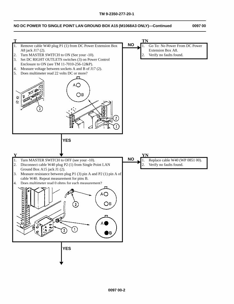
TM 9-2350-277-20-1
NO DC POWER TO SINGLE POINT LAN GROUND BOX A15 (M1068A3 ONLY)—Continued 0097 00
T1. Remove cable W40 plug P1 (1) from DC Power Extension Box
A8 jack J17 (2).2. Turn MASTER SWITCH to ON (See your -10).3. Set DC RIGHT OUTLETS switches (3) on Power Control
Enclosure to ON (see TM 11-7010-256-12&P).4. Measure voltage between sockets A and B of J17 (2).5. Does multimeter read 22 volts DC or more?
YES
NOTN1. Go To: No Power From DC Power
Extension Box A8.2. Verify no faults found.
Y1. Turn MASTER SWITCH to OFF (see your -10).2. Disconnect cable W40 plug P2 (1) from Single Point LAN
Ground Box A15 jack J1 (2).3. Measure resistance between plug P1 (3) pin A and P2 (1) pin A of
cable W40. Repeat measurement for pins B.4. Does multimeter read 0 ohms for each measurement?
YES
NOYN1. Replace cable W40 (WP 0851 00).2. Verify no faults found.
0097 00-2

TM 9-2350-277-20-1
NO DC POWER TO SINGLE POINT LAN GROUND BOX A15 (M1068A3 ONLY)—Continued 0097 00
2Y1. Repair LAN Ground Box A15 (WP 0820 00).2. Verify no faults found.
0097 00-3/4 blank

TM 9-2350-277-20-1
NO POWER FROM UPS POWER EXTENSION BOX A18 (M1068A3 ONLY) 0098 00
INITIAL SETUP:
Maintenance LevelUnit
Tools and Special ToolsGeneral Mechanic’s Tool Kit (WP 0926 00, Item 65)Digital Multimeter (WP 0926 00, Item 30)
Personnel RequiredPower-Generation Equipment Repairer 52D10Helper (H)
References
See your -10TM 11-7010-256-12&P
Equipment Condition
Engine stopped (see your -10)
Carrier blocked (see your -10)
WARNING
HIGH VOLTAGE is used in the operation of this equipment.
DEATH ON CONTACT may result if personnel fail to observe safety precautions.
NEVER work on equipment unless at least one other person familiar with the operation andhazards of the equipment is nearby. That person should also be familiar with giving first aid.When an operator helps a mechanic, that operator must be warned about dangerous areas.
SHUT OFF POWER supply to equipment before beginning work. Make sure all external poweris off/disconnected.
BE CAREFUL not to contact high-voltage connections when installing or operating thisequipment.
0098 00-1
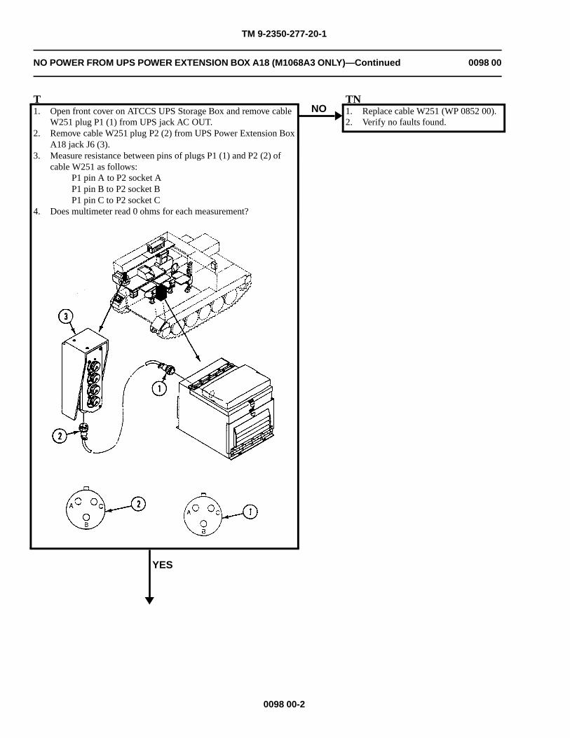
TM 9-2350-277-20-1
NO POWER FROM UPS POWER EXTENSION BOX A18 (M1068A3 ONLY)—Continued 0098 00
T1. Open front cover on ATCCS UPS Storage Box and remove cable
W251 plug P1 (1) from UPS jack AC OUT.2. Remove cable W251 plug P2 (2) from UPS Power Extension Box
A18 jack J6 (3).3. Measure resistance between pins of plugs P1 (1) and P2 (2) of
cable W251 as follows:P1 pin A to P2 socket AP1 pin B to P2 socket BP1 pin C to P2 socket C
4. Does multimeter read 0 ohms for each measurement?
YES
NOTN1. Replace cable W251 (WP 0852 00).2. Verify no faults found.
0098 00-2
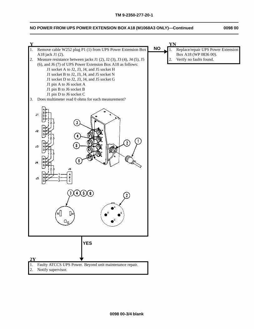
TM 9-2350-277-20-1
NO POWER FROM UPS POWER EXTENSION BOX A18 (M1068A3 ONLY)—Continued 0098 00
Y1. Remove cable W252 plug P1 (1) from UPS Power Extension Box
A18 jack J1 (2).2. Measure resistance between jacks J1 (2), J2 (3), J3 (4), J4 (5), J5
(6), and J6 (7) of UPS Power Extension Box A18 as follows:J1 socket A to J2, J3, J4, and J5 socket HJ1 socket B to J2, J3, J4, and J5 socket NJ1 socket D to J2, J3, J4, and J5 socket GJ1 pin A to J6 socket AJ1 pin B to J6 socket BJ1 pin D to J6 socket C
3. Does multimeter read 0 ohms for each measurement?
YES
NOYN1. Replace/repair UPS Power Extension
Box A18 (WP 0836 00).2. Verify no faults found.
2Y1. Faulty ATCCS UPS Power. Beyond unit maintenance repair.2. Notify supervisor.
0098 00-3/4 blank

TM 9-2350-277-20-1
NO POWER FROM CURBSIDE UPS POWER EXTENSION BOX A19(M1068A3 ONLY)
0099 00
INITIAL SETUP:
Maintenance LevelUnit
Tools and Special ToolsGeneral Mechanic’s Tool Kit (WP 0926 00, Item 65)Digital Multimeter (WP 0926 00, Item 30)
Personnel RequiredPower-Generation Equipment Repairer 52D10Helper (H)
References
See your -10TM 11-7010-256-12&P
Equipment Condition
Engine stopped (see your -10)
Carrier blocked (see your -10)
WARNING
HIGH VOLTAGE is used in the operation of this equipment.
DEATH ON CONTACT may result if personnel fail to observe safety precautions.
NEVER work on equipment unless at least one other person familiar with the operation andhazards of the equipment is nearby. That person should also be familiar with giving first aid.When an operator helps a mechanic, that operator must be warned about dangerous areas.
SHUT OFF POWER supply to equipment before beginning work. Make sure all external poweris off/disconnected.
BE CAREFUL not to contact high-voltage connections when installing or operating thisequipment.
0099 00-1
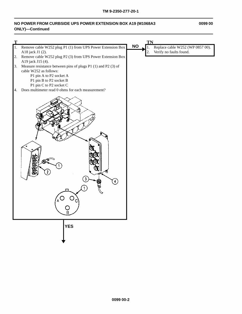
TM 9-2350-277-20-1
NO POWER FROM CURBSIDE UPS POWER EXTENSION BOX A19 (M1068A3ONLY)—Continued
0099 00
T1. Remove cable W252 plug P1 (1) from UPS Power Extension Box
A18 jack J1 (2).2. Remove cable W252 plug P2 (3) from UPS Power Extension Box
A19 jack J15 (4).3. Measure resistance between pins of plugs P1 (1) and P2 (3) of
cable W252 as follows:P1 pin A to P2 socket AP1 pin B to P2 socket BP1 pin C to P2 socket C
4. Does multimeter read 0 ohms for each measurement?
YES
NOTN1. Replace cable W252 (WP 0857 00).2. Verify no faults found.
0099 00-2
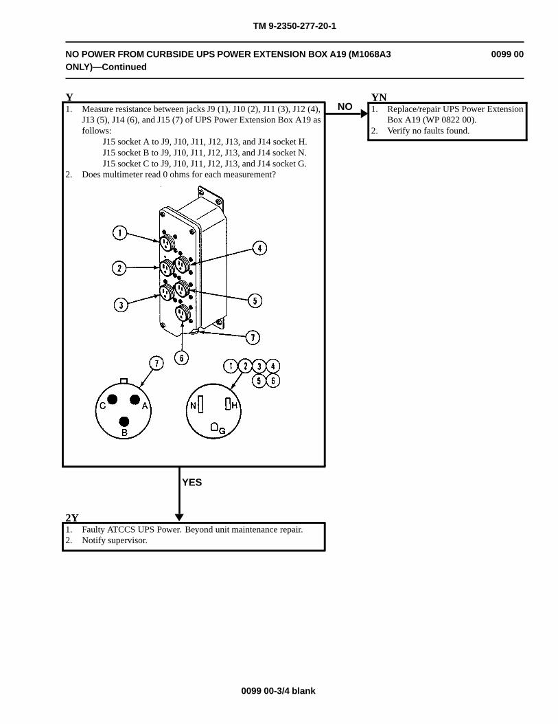
TM 9-2350-277-20-1
NO POWER FROM CURBSIDE UPS POWER EXTENSION BOX A19 (M1068A3ONLY)—Continued
0099 00
Y1. Measure resistance between jacks J9 (1), J10 (2), J11 (3), J12 (4),
J13 (5), J14 (6), and J15 (7) of UPS Power Extension Box A19 asfollows:
J15 socket A to J9, J10, J11, J12, J13, and J14 socket H.J15 socket B to J9, J10, J11, J12, J13, and J14 socket N.J15 socket C to J9, J10, J11, J12, J13, and J14 socket G.
2. Does multimeter read 0 ohms for each measurement?
YES
NOYN1. Replace/repair UPS Power Extension
Box A19 (WP 0822 00).2. Verify no faults found.
2Y1. Faulty ATCCS UPS Power. Beyond unit maintenance repair.2. Notify supervisor.
0099 00-3/4 blank


TM 9-2350-277-20-1
NO AC/DC INPUT TO ATCCS UPS POWER BOX (M1068A3 ONLY) 0100 00
INITIAL SETUP:
Maintenance Level
Unit
Tools and Special Tools
General Mechanic’s Tool Kit (WP 0926 00, Item 65)Digital Multimeter (WP 0926 00, Item 30)
Materials/Parts
Lockwasher (2)
Personnel Required
Power-Generation Equipment Repairer 52D10Helper (H)
References
See your -10TM 11-7010-256-12&P
Equipment Condition
Engine stopped (see your -10)Carrier blocked (see your -10)
WARNING
HIGH VOLTAGE is used in the operation of this equipment.
DEATH ON CONTACT may result if personnel fail to observe safety precautions.
NEVER work on equipment unless at least one other person familiar with the operation andhazards of the equipment is nearby. That person should also be familiar with giving first aid.When an operator helps a mechanic, that operator must be warned about dangerous areas.
SHUT OFF POWER supply to equipment before beginning work. Make sure all external poweris off/disconnected.
BE CAREFUL not to contact high-voltage connections when installing or operating thisequipment.
0100 00-1
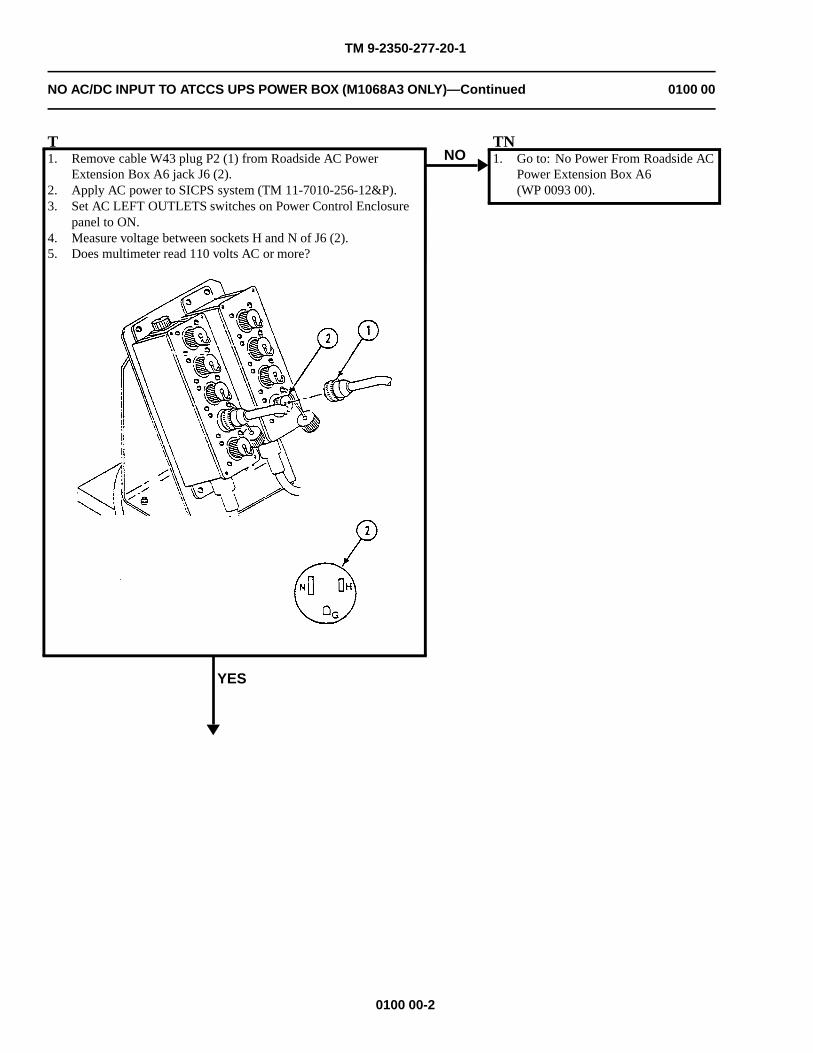
TM 9-2350-277-20-1
NO AC/DC INPUT TO ATCCS UPS POWER BOX (M1068A3 ONLY)—Continued 0100 00
T1. Remove cable W43 plug P2 (1) from Roadside AC Power
Extension Box A6 jack J6 (2).2. Apply AC power to SICPS system (TM 11-7010-256-12&P).3. Set AC LEFT OUTLETS switches on Power Control Enclosure
panel to ON.4. Measure voltage between sockets H and N of J6 (2).5. Does multimeter read 110 volts AC or more?
YES
NOTN1. Go to: No Power From Roadside AC
Power Extension Box A6(WP 0093 00).
0100 00-2
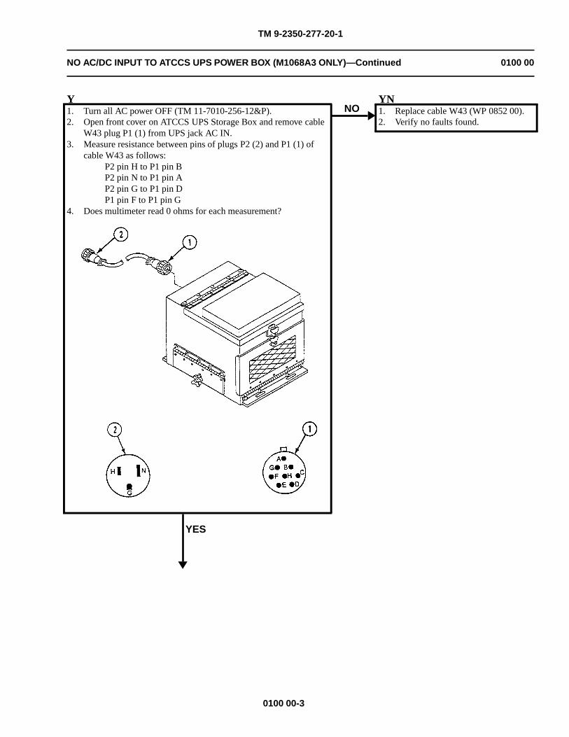
TM 9-2350-277-20-1
NO AC/DC INPUT TO ATCCS UPS POWER BOX (M1068A3 ONLY)—Continued 0100 00
Y1. Turn all AC power OFF (TM 11-7010-256-12&P).2. Open front cover on ATCCS UPS Storage Box and remove cable
W43 plug P1 (1) from UPS jack AC IN.3. Measure resistance between pins of plugs P2 (2) and P1 (1) of
cable W43 as follows:P2 pin H to P1 pin BP2 pin N to P1 pin AP2 pin G to P1 pin DP1 pin F to P1 pin G
4. Does multimeter read 0 ohms for each measurement?
YES
NOYN1. Replace cable W43 (WP 0852 00).2. Verify no faults found.
0100 00-3
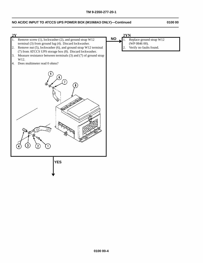
TM 9-2350-277-20-1
NO AC/DC INPUT TO ATCCS UPS POWER BOX (M1068A3 ONLY)—Continued 0100 00
2Y1. Remove screw (1), lockwasher (2), and ground strap W12
terminal (3) from ground lug (4). Discard lockwasher.2. Remove nut (5), lockwasher (6), and ground strap W12 terminal
(7) from ATCCS UPS storage box (8). Discard lockwasher.3. Measure resistance between terminals (3) and (7) of ground strap
W12.4. Does multimeter read 0 ohms?
YES
NO2YN1. Replace ground strap W12
(WP 0846 00).2. Verify no faults found.
0100 00-4
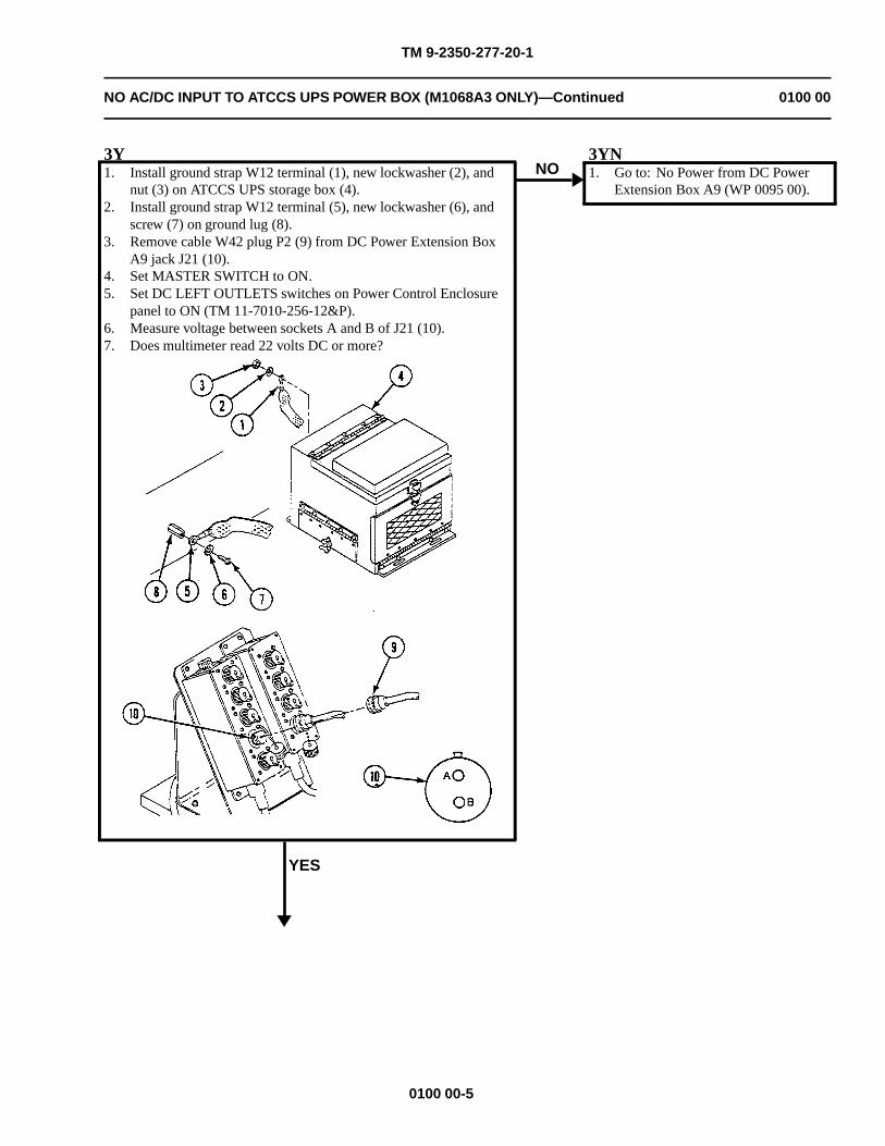
TM 9-2350-277-20-1
NO AC/DC INPUT TO ATCCS UPS POWER BOX (M1068A3 ONLY)—Continued 0100 00
3Y1. Install ground strap W12 terminal (1), new lockwasher (2), and
nut (3) on ATCCS UPS storage box (4).2. Install ground strap W12 terminal (5), new lockwasher (6), and
screw (7) on ground lug (8).3. Remove cable W42 plug P2 (9) from DC Power Extension Box
A9 jack J21 (10).4. Set MASTER SWITCH to ON.5. Set DC LEFT OUTLETS switches on Power Control Enclosure
panel to ON (TM 11-7010-256-12&P).6. Measure voltage between sockets A and B of J21 (10).7. Does multimeter read 22 volts DC or more?
YES
NO3YN1. Go to: No Power from DC Power
Extension Box A9 (WP 0095 00).
0100 00-5
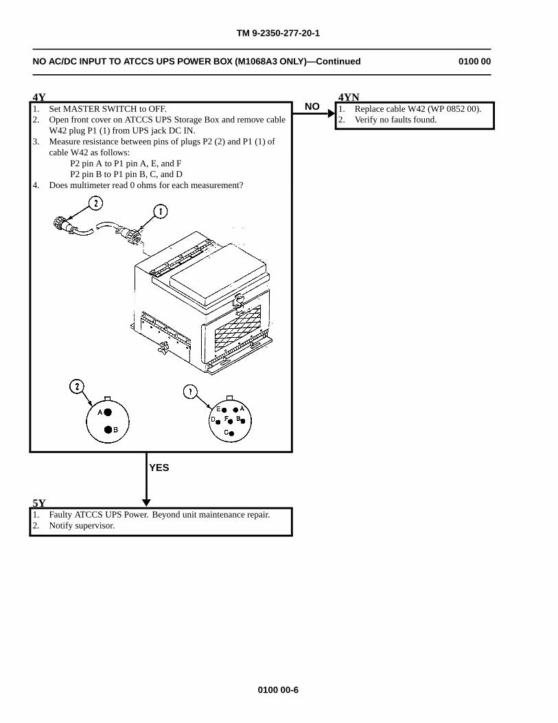
TM 9-2350-277-20-1
NO AC/DC INPUT TO ATCCS UPS POWER BOX (M1068A3 ONLY)—Continued 0100 00
4Y1. Set MASTER SWITCH to OFF.2. Open front cover on ATCCS UPS Storage Box and remove cable
W42 plug P1 (1) from UPS jack DC IN.3. Measure resistance between pins of plugs P2 (2) and P1 (1) of
cable W42 as follows:P2 pin A to P1 pin A, E, and FP2 pin B to P1 pin B, C, and D
4. Does multimeter read 0 ohms for each measurement?
YES
NO4YN1. Replace cable W42 (WP 0852 00).2. Verify no faults found.
5Y1. Faulty ATCCS UPS Power. Beyond unit maintenance repair.2. Notify supervisor.
0100 00-6
TM 9-2350-277-20-1
IN BLACKOUT MODE, FLUORESCENT LIGHTS OPERATE INCORRECTLY(M1068A3 ONLY)
0101 00
INITIAL SETUP:
Maintenance Level
Unit
Tools and Special Tools
General Mechanic’s Tool Kit (WP 0926 00, Item 65)Digital multimeter (WP 0926 00, Item 30)
Materials/Parts
Lockwasher (10)
Personnel Required
Power-Generation Equipment Repairer 52D10Helper (H)
References
See your -10
Equipment Condition
Engine stopped (see your -10)
Carrier blocked (see your -10)
All AC External and Internal Power is OFF (see TM710-256-12&P)
WARNING
HIGH VOLTAGE is used in the operation of this equipment.
DEATH ON CONTACT may result if personnel fail to observe safety precautions.
NEVER work on equipment unless at least one other person familiar with the operation andhazards of the equipment is nearby. That person should also be familiar with giving first aid.When an operator helps a mechanic, that operator must be warned about dangerous areas.
SHUT OFF POWER supply to equipment before beginning work. Make sure all external poweris off/disconnected.
BE CAREFUL not to contact high-voltage connections when installing or operating thisequipment.
0101 00-1
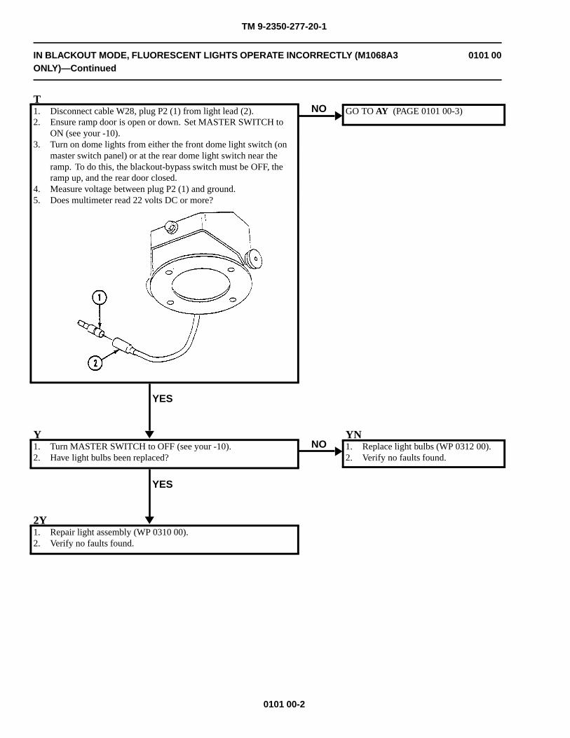
TM 9-2350-277-20-1
IN BLACKOUT MODE, FLUORESCENT LIGHTS OPERATE INCORRECTLY (M1068A3ONLY)—Continued
0101 00
T1. Disconnect cable W28, plug P2 (1) from light lead (2).2. Ensure ramp door is open or down. Set MASTER SWITCH to
ON (see your -10).3. Turn on dome lights from either the front dome light switch (on
master switch panel) or at the rear dome light switch near theramp. To do this, the blackout-bypass switch must be OFF, theramp up, and the rear door closed.
4. Measure voltage between plug P2 (1) and ground.5. Does multimeter read 22 volts DC or more?
YES
NO GO TO AY (PAGE 0101 00-3)
Y1. Turn MASTER SWITCH to OFF (see your -10).2. Have light bulbs been replaced?
YES
NOYN1. Replace light bulbs (WP 0312 00).2. Verify no faults found.
2Y1. Repair light assembly (WP 0310 00).2. Verify no faults found.
0101 00-2
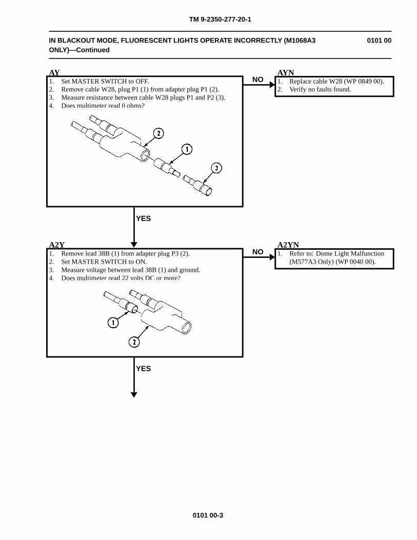
TM 9-2350-277-20-1
IN BLACKOUT MODE, FLUORESCENT LIGHTS OPERATE INCORRECTLY (M1068A3ONLY)—Continued
0101 00
AY1. Set MASTER SWITCH to OFF.2. Remove cable W28, plug P1 (1) from adapter plug P1 (2).3. Measure resistance between cable W28 plugs P1 and P2 (3).4. Does multimeter read 0 ohms?
YES
NOAYN1. Replace cable W28 (WP 0849 00).2. Verify no faults found.
A2Y1. Remove lead 38B (1) from adapter plug P3 (2).2. Set MASTER SWITCH to ON.3. Measure voltage between lead 38B (1) and ground.4. Does multimeter read 22 volts DC or more?
YES
NOA2YN1. Refer to: Dome Light Malfunction
(M577A3 Only) (WP 0040 00).
0101 00-3
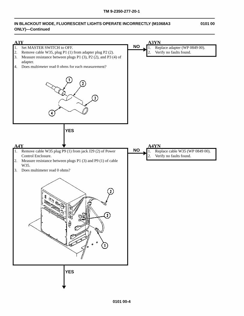
TM 9-2350-277-20-1
IN BLACKOUT MODE, FLUORESCENT LIGHTS OPERATE INCORRECTLY (M1068A3ONLY)—Continued
0101 00
A3Y1. Set MASTER SWITCH to OFF.2. Remove cable W35, plug P1 (1) from adapter plug P2 (2).3. Measure resistance between plugs P1 (3), P2 (2), and P3 (4) of
adapter.4. Does multimeter read 0 ohms for each measurement?
YES
NOA3YN1. Replace adapter (WP 0849 00).2. Verify no faults found.
A4Y1. Remove cable W35 plug P9 (1) from jack J29 (2) of Power
Control Enclosure.2. Measure resistance between plugs P1 (3) and P9 (1) of cable
W35.3. Does multimeter read 0 ohms?
YES
NOA4YN1. Replace cable W35 (WP 0849 00).2. Verify no faults found.
0101 00-4
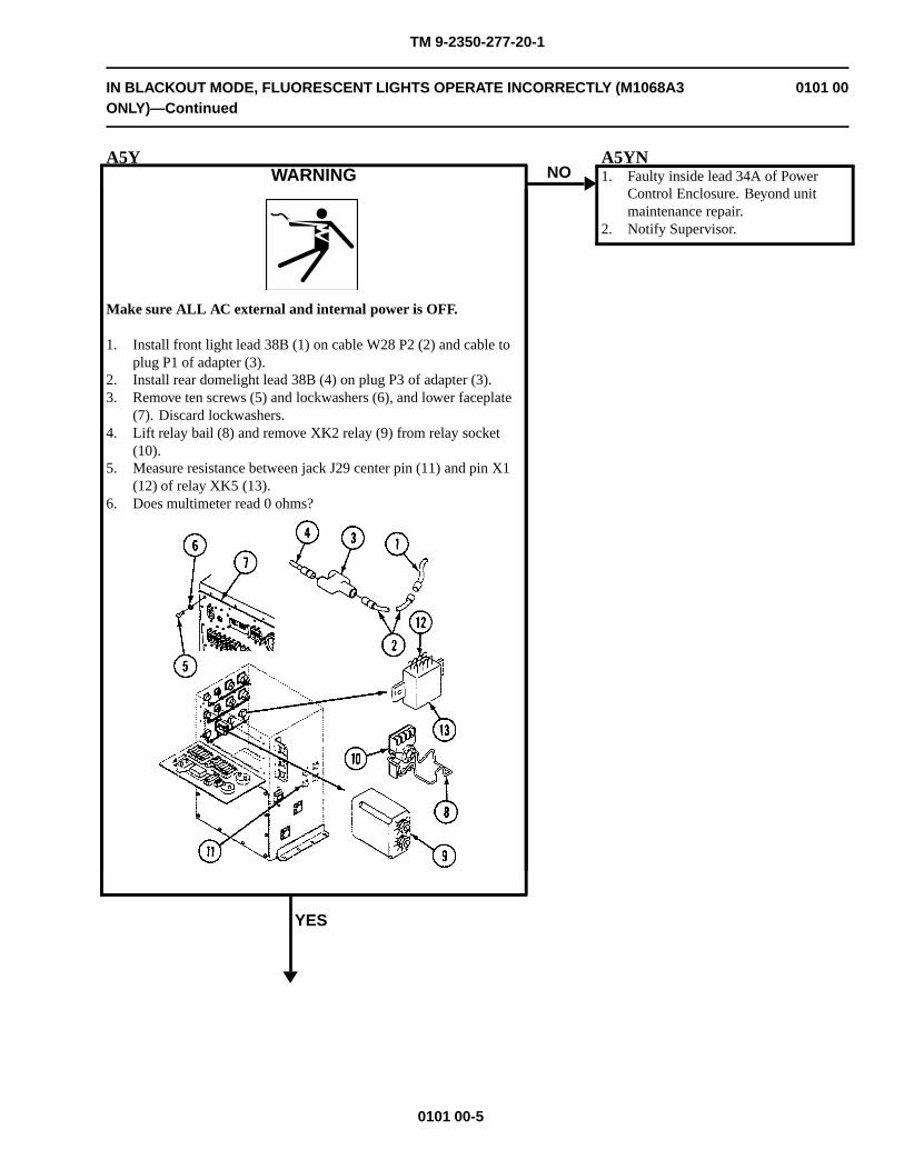
TM 9-2350-277-20-1
IN BLACKOUT MODE, FLUORESCENT LIGHTS OPERATE INCORRECTLY (M1068A3ONLY)—Continued
0101 00
A5YWARNING
Make sure ALL AC external and internal power is OFF.
1. Install front light lead 38B (1) on cable W28 P2 (2) and cable toplug P1 of adapter (3).
2. Install rear domelight lead 38B (4) on plug P3 of adapter (3).3. Remove ten screws (5) and lockwashers (6), and lower faceplate
(7). Discard lockwashers.4. Lift relay bail (8) and remove XK2 relay (9) from relay socket
(10).5. Measure resistance between jack J29 center pin (11) and pin X1
(12) of relay XK5 (13).6. Does multimeter read 0 ohms?
YES
NOA5YN1. Faulty inside lead 34A of Power
Control Enclosure. Beyond unitmaintenance repair.
2. Notify Supervisor.
0101 00-5
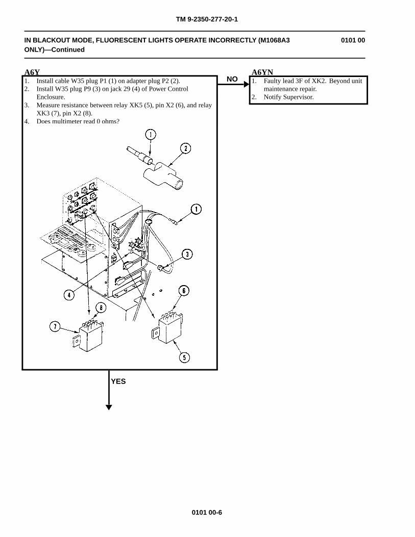
TM 9-2350-277-20-1
IN BLACKOUT MODE, FLUORESCENT LIGHTS OPERATE INCORRECTLY (M1068A3ONLY)—Continued
0101 00
A6Y1. Install cable W35 plug P1 (1) on adapter plug P2 (2).2. Install W35 plug P9 (3) on jack 29 (4) of Power Control
Enclosure.3. Measure resistance between relay XK5 (5), pin X2 (6), and relay
XK3 (7), pin X2 (8).4. Does multimeter read 0 ohms?
YES
NOA6YN1. Faulty lead 3F of XK2. Beyond unit
maintenance repair.2. Notify Supervisor.
0101 00-6
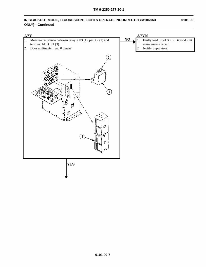
TM 9-2350-277-20-1
IN BLACKOUT MODE, FLUORESCENT LIGHTS OPERATE INCORRECTLY (M1068A3ONLY)—Continued
0101 00
A7Y1. Measure resistance between relay XK3 (1), pin X2 (2) and
terminal block E4 (3).2. Does multimeter read 0 ohms?
YES
NOA7YN1. Faulty lead 3E of XK3. Beyond unit
maintenance repair.2. Notify Supervisor.
0101 00-7
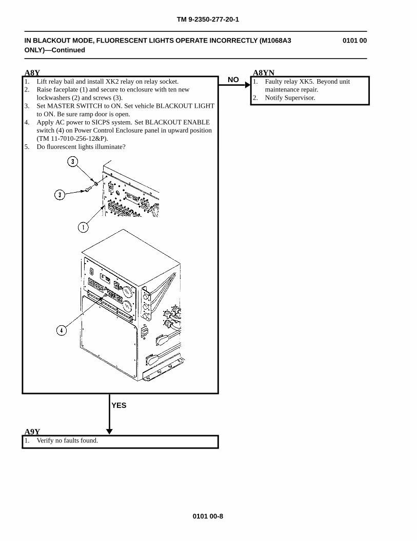
TM 9-2350-277-20-1
IN BLACKOUT MODE, FLUORESCENT LIGHTS OPERATE INCORRECTLY (M1068A3ONLY)—Continued
0101 00
A8Y1. Lift relay bail and install XK2 relay on relay socket.2. Raise faceplate (1) and secure to enclosure with ten new
lockwashers (2) and screws (3).3. Set MASTER SWITCH to ON. Set vehicle BLACKOUT LIGHT
to ON. Be sure ramp door is open.4. Apply AC power to SICPS system. Set BLACKOUT ENABLE
switch (4) on Power Control Enclosure panel in upward position(TM 11-7010-256-12&P).
5. Do fluorescent lights illuminate?
YES
NOA8YN1. Faulty relay XK5. Beyond unit
maintenance repair.2. Notify Supervisor.
A9Y1. Verify no faults found.
0101 00-8
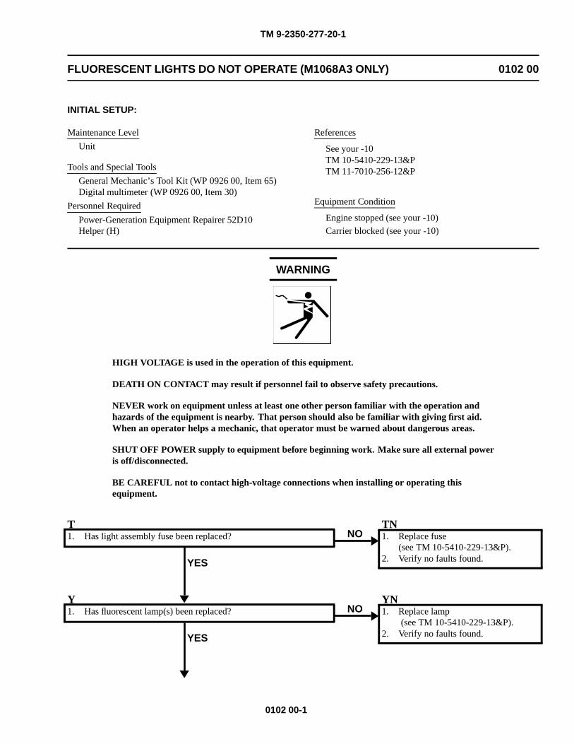
TM 9-2350-277-20-1
FLUORESCENT LIGHTS DO NOT OPERATE (M1068A3 ONLY) 0102 00
INITIAL SETUP:
Maintenance Level
Unit
Tools and Special Tools
General Mechanic’s Tool Kit (WP 0926 00, Item 65)Digital multimeter (WP 0926 00, Item 30)
Personnel Required
Power-Generation Equipment Repairer 52D10Helper (H)
References
See your -10TM 10-5410-229-13&PTM 11-7010-256-12&P
Equipment Condition
Engine stopped (see your -10)
Carrier blocked (see your -10)
WARNING
HIGH VOLTAGE is used in the operation of this equipment.
DEATH ON CONTACT may result if personnel fail to observe safety precautions.
NEVER work on equipment unless at least one other person familiar with the operation andhazards of the equipment is nearby. That person should also be familiar with giving first aid.When an operator helps a mechanic, that operator must be warned about dangerous areas.
SHUT OFF POWER supply to equipment before beginning work. Make sure all external poweris off/disconnected.
BE CAREFUL not to contact high-voltage connections when installing or operating thisequipment.
T1. Has light assembly fuse been replaced?
YES
NOTN1. Replace fuse
(see TM 10-5410-229-13&P).2. Verify no faults found.
Y1. Has fluorescent lamp(s) been replaced?
YES
NOYN1. Replace lamp
(see TM 10-5410-229-13&P).2. Verify no faults found.
0102 00-1
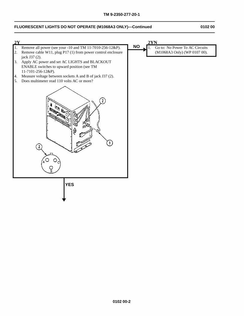
TM 9-2350-277-20-1
FLUORESCENT LIGHTS DO NOT OPERATE (M1068A3 ONLY)—Continued 0102 00
2Y1. Remove all power (see your -10 and TM 11-7010-256-12&P).2. Remove cable W11, plug P17 (1) from power control enclosure
jack J37 (2).3. Apply AC power and set AC LIGHTS and BLACKOUT
ENABLE switches to upward position (see TM11-7101-256-12&P).
4. Measure voltage between sockets A and B of jack J37 (2).5. Does multimeter read 110 volts AC or more?
YES
NO2YN1. Go to: No Power To AC Circuits
(M1068A3 Only) (WP 0107 00).
0102 00-2
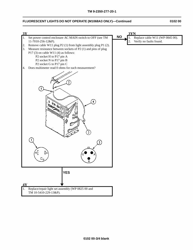
TM 9-2350-277-20-1
FLUORESCENT LIGHTS DO NOT OPERATE (M1068A3 ONLY)—Continued 0102 00
3Y1. Set power control enclosure AC MAIN switch to OFF (see TM
11-7010-256-12&P).2. Remove cable W11 plug P2 (1) from light assembly plug P1 (2).3. Measure resistance between sockets of P2 (1) and pins of plug
P17 (3) on cable W11 (4) as follows:P2 socket H to P17 pin AP2 socket N to P17 pin BP2 socket G to P17 pin C
4. Does multimeter read 0 ohms for each measurement?
YES
NO3YN1. Replace cable W11 (WP 0845 00).2. Verify no faults found.
4Y1. Replace/repair light set assembly (WP 0825 00 and
TM 10-5410-229-13&P).
0102 00-3/4 blank


TM 9-2350-277-20-1
VEHICLE BATTERIES DISCHARGE WITH EXTERNAL AC POWER APPLIED(M1068A3 ONLY)
0103 00
INITIAL SETUP:
Maintenance Level
Unit
Tools and Special Tools
General Mechanic’s Tool Kit (WP 0926 00, Item 65)Digital multimeter (WP 0926 00, Item 30)
Materials/Parts
Lockwashers (22)
Personnel Required
Power-generation Equipment Repairer 52D10Helper (H)
References
See your -10TM 11-7010-256-12&P
Equipment Condition
Engine stopped (see your -10)Carrier blocked (see your -10)
WARNING
HIGH VOLTAGE is used in the operation of this equipment.
DEATH ON CONTACT may result if personnel fail to observe safety precautions.
NEVER work on equipment unless at least one other person familiar with the operation andhazards of the equipment is nearby. That person should also be familiar with giving first aid.When an operator helps a mechanic, that operator must be warned about dangerous areas.
SHUT OFF POWER supply to equipment before beginning work. Make sure all external poweris off/disconnected.
BE CAREFUL not to contact high-voltage connections when installing or operating thisequipment.
0103 00-1
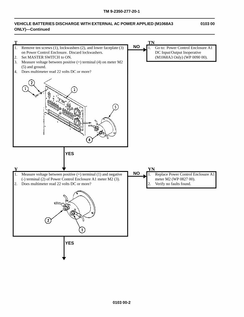
TM 9-2350-277-20-1
VEHICLE BATTERIES DISCHARGE WITH EXTERNAL AC POWER APPLIED (M1068A3ONLY)—Continued
0103 00
T1. Remove ten screws (1), lockwashers (2), and lower faceplate (3)
on Power Control Enclosure. Discard lockwashers.2. Set MASTER SWITCH to ON.3. Measure voltage between positive (+) terminal (4) on meter M2
(5) and ground.4. Does multimeter read 22 volts DC or more?
YES
NOTN1. Go to: Power Control Enclosure A1
DC Input/Output Inoperative(M1068A3 Only) (WP 0090 00).
Y1. Measure voltage between positive (+) terminal (1) and negative
(-) terminal (2) of Power Control Enclosure A1 meter M2 (3).2. Does multimeter read 22 volts DC or more?
YES
NOYN1. Replace Power Control Enclosure A1
meter M2 (WP 0827 00).2. Verify no faults found.
0103 00-2
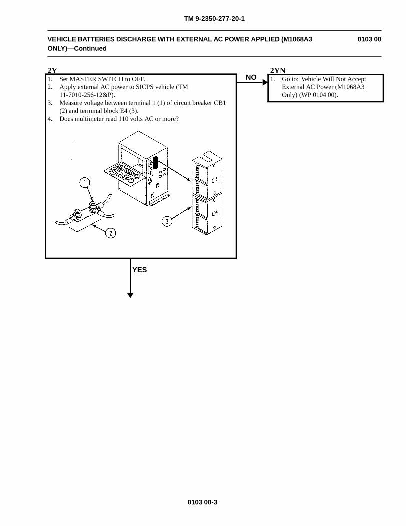
TM 9-2350-277-20-1
VEHICLE BATTERIES DISCHARGE WITH EXTERNAL AC POWER APPLIED (M1068A3ONLY)—Continued
0103 00
2Y1. Set MASTER SWITCH to OFF.2. Apply external AC power to SICPS vehicle (TM
11-7010-256-12&P).3. Measure voltage between terminal 1 (1) of circuit breaker CB1
(2) and terminal block E4 (3).4. Does multimeter read 110 volts AC or more?
YES
NO2YN1. Go to: Vehicle Will Not Accept
External AC Power (M1068A3Only) (WP 0104 00).
0103 00-3
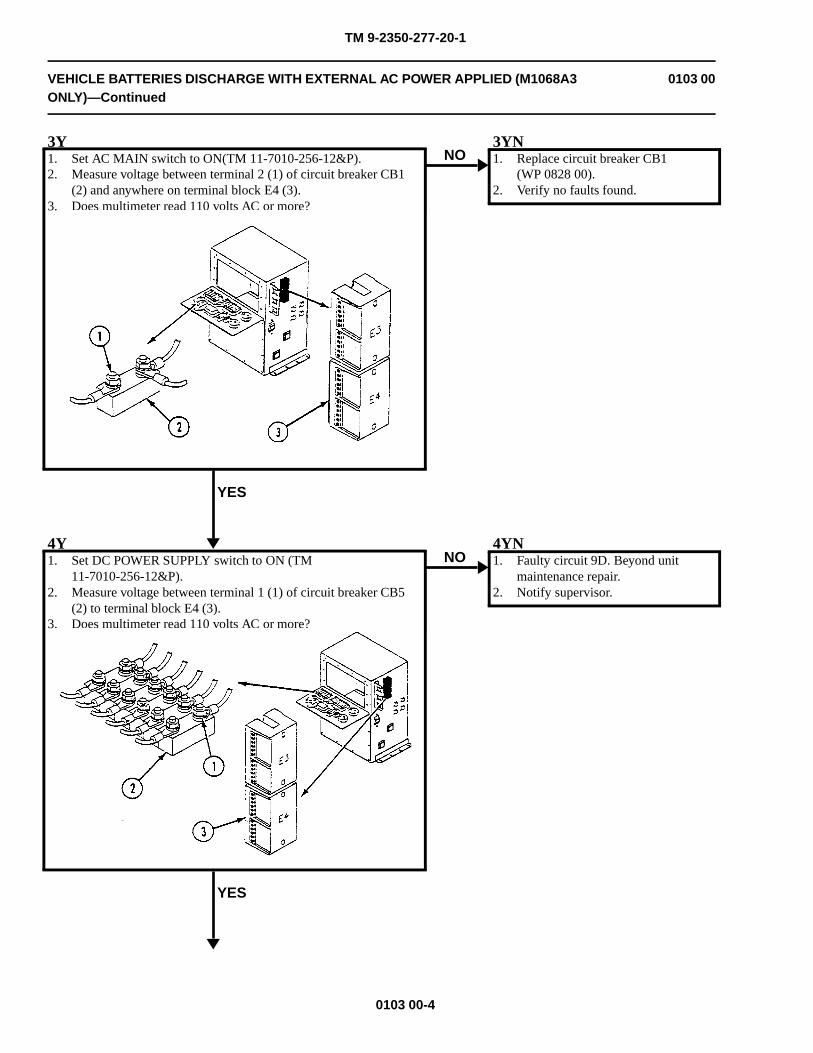
TM 9-2350-277-20-1
VEHICLE BATTERIES DISCHARGE WITH EXTERNAL AC POWER APPLIED (M1068A3ONLY)—Continued
0103 00
3Y1. Set AC MAIN switch to ON(TM 11-7010-256-12&P).2. Measure voltage between terminal 2 (1) of circuit breaker CB1
(2) and anywhere on terminal block E4 (3).3. Does multimeter read 110 volts AC or more?
YES
NO3YN1. Replace circuit breaker CB1
(WP 0828 00).2. Verify no faults found.
4Y1. Set DC POWER SUPPLY switch to ON (TM
11-7010-256-12&P).2. Measure voltage between terminal 1 (1) of circuit breaker CB5
(2) to terminal block E4 (3).3. Does multimeter read 110 volts AC or more?
YES
NO4YN1. Faulty circuit 9D. Beyond unit
maintenance repair.2. Notify supervisor.
0103 00-4
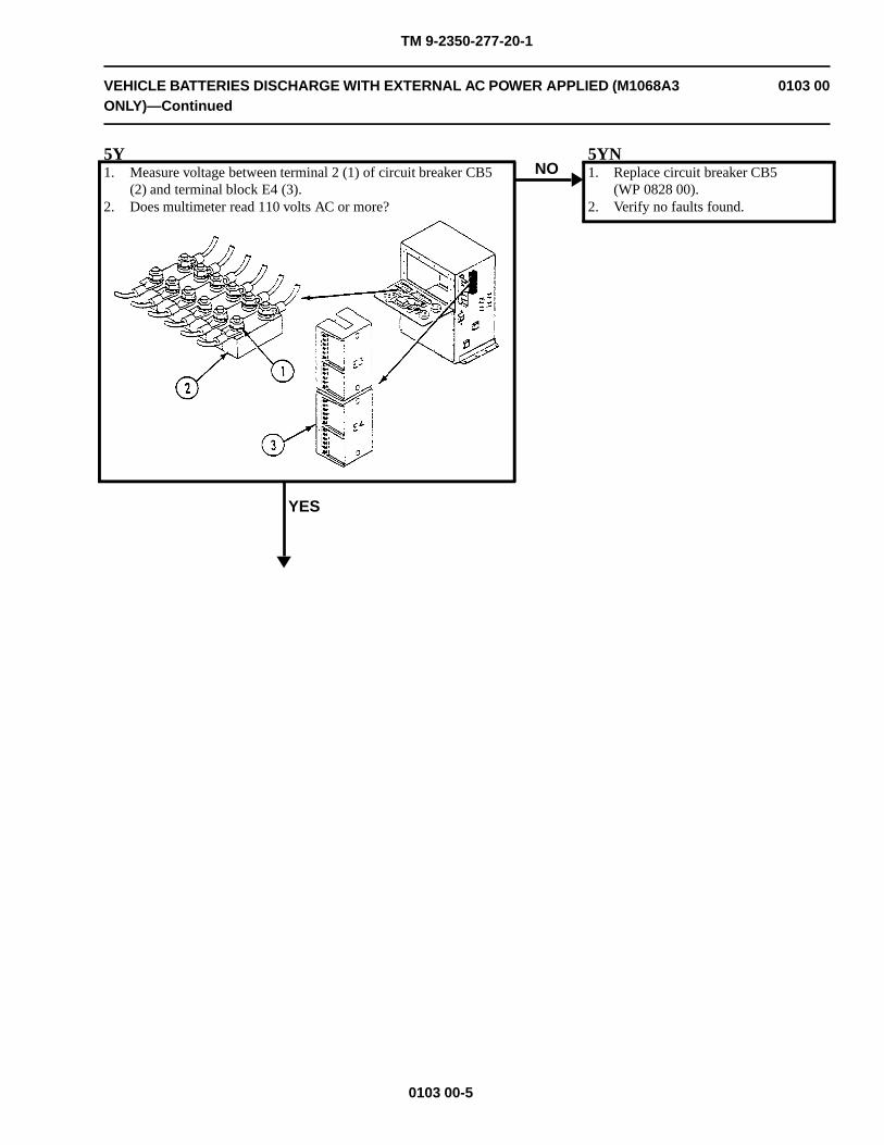
TM 9-2350-277-20-1
VEHICLE BATTERIES DISCHARGE WITH EXTERNAL AC POWER APPLIED (M1068A3ONLY)—Continued
0103 00
5Y1. Measure voltage between terminal 2 (1) of circuit breaker CB5
(2) and terminal block E4 (3).2. Does multimeter read 110 volts AC or more?
YES
NO5YN1. Replace circuit breaker CB5
(WP 0828 00).2. Verify no faults found.
0103 00-5
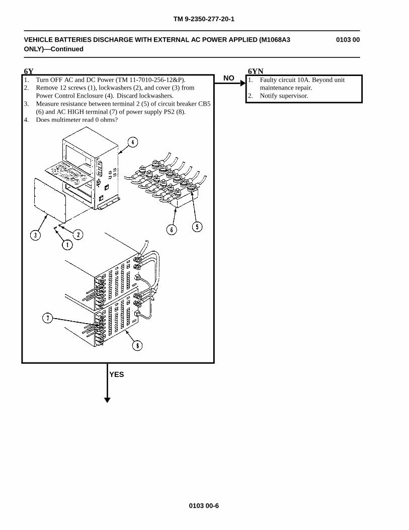
TM 9-2350-277-20-1
VEHICLE BATTERIES DISCHARGE WITH EXTERNAL AC POWER APPLIED (M1068A3ONLY)—Continued
0103 00
6Y1. Turn OFF AC and DC Power (TM 11-7010-256-12&P).2. Remove 12 screws (1), lockwashers (2), and cover (3) from
Power Control Enclosure (4). Discard lockwashers.3. Measure resistance between terminal 2 (5) of circuit breaker CB5
(6) and AC HIGH terminal (7) of power supply PS2 (8).4. Does multimeter read 0 ohms?
YES
NO6YN1. Faulty circuit 10A. Beyond unit
maintenance repair.2. Notify supervisor.
0103 00-6
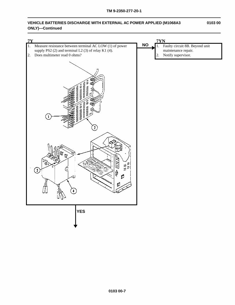
TM 9-2350-277-20-1
VEHICLE BATTERIES DISCHARGE WITH EXTERNAL AC POWER APPLIED (M1068A3ONLY)—Continued
0103 00
7Y1. Measure resistance between terminal AC LOW (1) of power
supply PS2 (2) and terminal L2 (3) of relay K1 (4).2. Does multimeter read 0 ohms?
YES
NO7YN1. Faulty circuit 8B. Beyond unit
maintenance repair.2. Notify supervisor.
0103 00-7
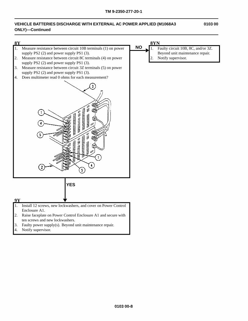
TM 9-2350-277-20-1
VEHICLE BATTERIES DISCHARGE WITH EXTERNAL AC POWER APPLIED (M1068A3ONLY)—Continued
0103 00
8Y1. Measure resistance between circuit 10B terminals (1) on power
supply PS2 (2) and power supply PS1 (3).2. Measure resistance between circuit 8C terminals (4) on power
supply PS2 (2) and power supply PS1 (3).3. Measure resistance between circuit 3Z terminals (5) on power
supply PS2 (2) and power supply PS1 (3).4. Does multimeter read 0 ohms for each measurement?
YES
NO8YN1. Faulty circuit 10B, 8C, and/or 3Z.
Beyond unit maintenance repair.2. Notify supervisor.
9Y1. Install 12 screws, new lockwashers, and cover on Power Control
Enclosure A1.2. Raise faceplate on Power Control Enclosure A1 and secure with
ten screws and new lockwashers.3. Faulty power supply(s). Beyond unit maintenance repair.4. Notify supervisor.
0103 00-8
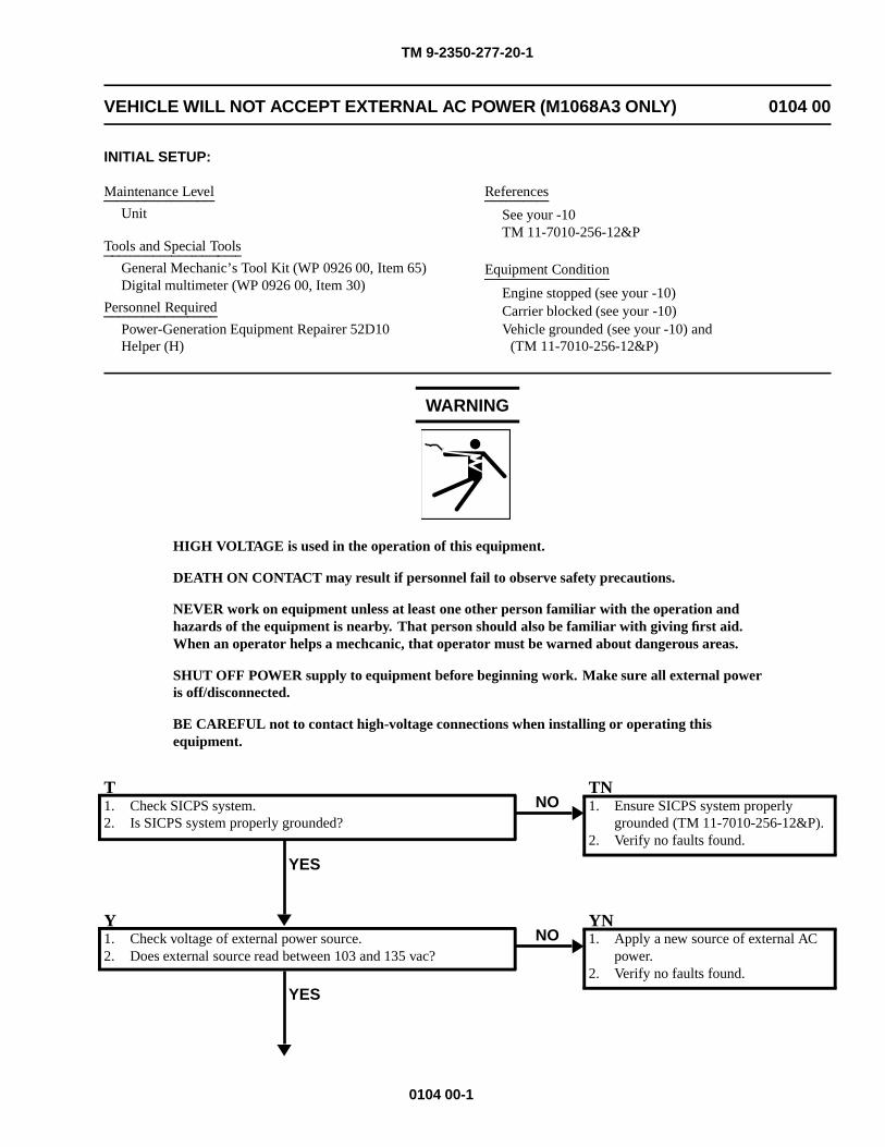
TM 9-2350-277-20-1
VEHICLE WILL NOT ACCEPT EXTERNAL AC POWER (M1068A3 ONLY) 0104 00
INITIAL SETUP:
Maintenance Level
Unit
Tools and Special Tools
General Mechanic’s Tool Kit (WP 0926 00, Item 65)Digital multimeter (WP 0926 00, Item 30)
Personnel Required
Power-Generation Equipment Repairer 52D10Helper (H)
References
See your -10TM 11-7010-256-12&P
Equipment Condition
Engine stopped (see your -10)Carrier blocked (see your -10)Vehicle grounded (see your -10) and
(TM 11-7010-256-12&P)
WARNING
HIGH VOLTAGE is used in the operation of this equipment.
DEATH ON CONTACT may result if personnel fail to observe safety precautions.
NEVER work on equipment unless at least one other person familiar with the operation andhazards of the equipment is nearby. That person should also be familiar with giving first aid.When an operator helps a mechcanic, that operator must be warned about dangerous areas.
SHUT OFF POWER supply to equipment before beginning work. Make sure all external poweris off/disconnected.
BE CAREFUL not to contact high-voltage connections when installing or operating thisequipment.
T1. Check SICPS system.2. Is SICPS system properly grounded?
YES
NOTN1. Ensure SICPS system properly
grounded (TM 11-7010-256-12&P).2. Verify no faults found.
Y1. Check voltage of external power source.2. Does external source read between 103 and 135 vac?
YES
NOYN1. Apply a new source of external AC
power.2. Verify no faults found.
0104 00-1
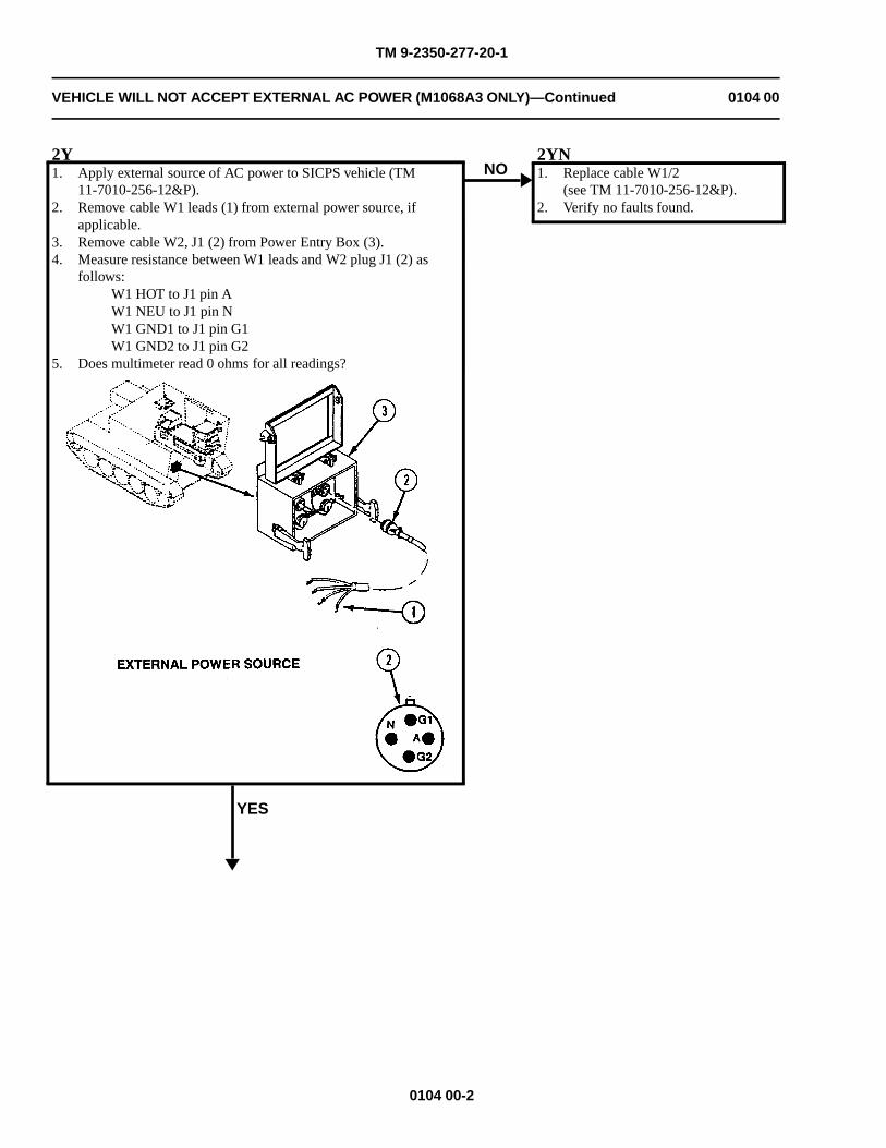
TM 9-2350-277-20-1
VEHICLE WILL NOT ACCEPT EXTERNAL AC POWER (M1068A3 ONLY)—Continued 0104 00
2Y1. Apply external source of AC power to SICPS vehicle (TM
11-7010-256-12&P).2. Remove cable W1 leads (1) from external power source, if
applicable.3. Remove cable W2, J1 (2) from Power Entry Box (3).4. Measure resistance between W1 leads and W2 plug J1 (2) as
follows:W1 HOT to J1 pin AW1 NEU to J1 pin NW1 GND1 to J1 pin G1W1 GND2 to J1 pin G2
5. Does multimeter read 0 ohms for all readings?
YES
NO2YN1. Replace cable W1/2
(see TM 11-7010-256-12&P).2. Verify no faults found.
0104 00-2
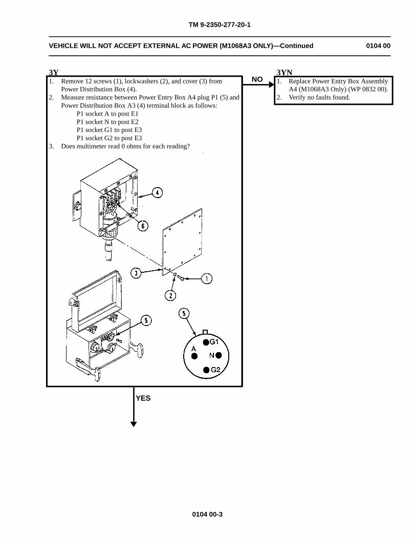
TM 9-2350-277-20-1
VEHICLE WILL NOT ACCEPT EXTERNAL AC POWER (M1068A3 ONLY)—Continued 0104 00
3Y1. Remove 12 screws (1), lockwashers (2), and cover (3) from
Power Distribution Box (4).2. Measure resistance between Power Entry Box A4 plug P1 (5) and
Power Distribution Box A3 (4) terminal block as follows:P1 socket A to post E1P1 socket N to post E2P1 socket G1 to post E3P1 socket G2 to post E3
3. Does multimeter read 0 ohms for each reading?
YES
NO3YN1. Replace Power Entry Box Assembly
A4 (M1068A3 Only) (WP 0832 00).2. Verify no faults found.
0104 00-3
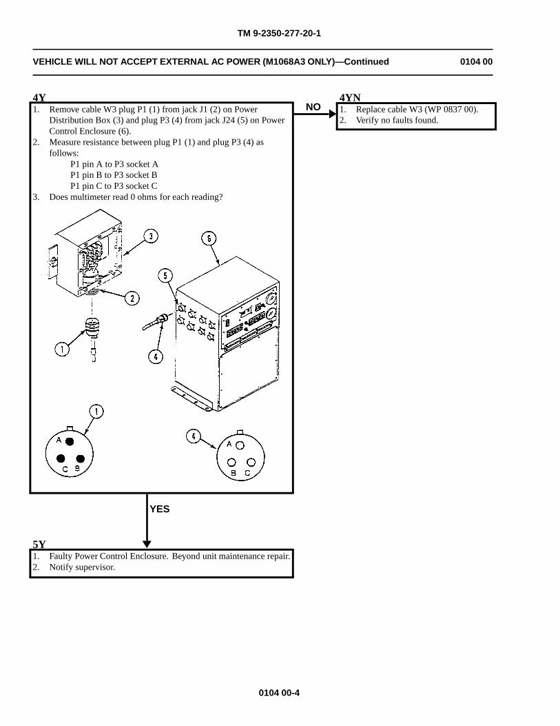
TM 9-2350-277-20-1
VEHICLE WILL NOT ACCEPT EXTERNAL AC POWER (M1068A3 ONLY)—Continued 0104 00
4Y1. Remove cable W3 plug P1 (1) from jack J1 (2) on Power
Distribution Box (3) and plug P3 (4) from jack J24 (5) on PowerControl Enclosure (6).
2. Measure resistance between plug P1 (1) and plug P3 (4) asfollows:
P1 pin A to P3 socket AP1 pin B to P3 socket BP1 pin C to P3 socket C
3. Does multimeter read 0 ohms for each reading?
YES
NO4YN1. Replace cable W3 (WP 0837 00).2. Verify no faults found.
5Y1. Faulty Power Control Enclosure. Beyond unit maintenance repair.2. Notify supervisor.
0104 00-4
TM 9-2350-277-20-1
VEHICLE WILL NOT ACCEPT INVERTER AC POWER (M1068A3 ONLY) 0105 00
INITIAL SETUP:
Maintenance LevelUnit
Tools and Special ToolsGeneral Mechanic’s Tool Kit (WP 0926 00, Item 65)Digital multimeter (WP 0926 00, Item 30)
Materials/PartsLockwasher (10)
Personnel RequiredPower-Generation Equipment Repairer 52D10Helper (H)
References
See your -10TM 11-7010-256-12&P
Equipment Condition
Engine stopped (see your -10)
Carrier blocked (see your -10)
Carrier grounded (see your -10) and(TM 11-7010-256-12&P)
WARNING
HIGH VOLTAGE is used in the operation of this equipment.
DEATH ON CONTACT may result if personnel fail to observe safety precautions.
NEVER work on equipment unless at least one other person familiar with the operation andhazards of the equipment is nearby. That person should also be familiar with giving first aid.When an operator helps a mechanic, that operator must be warned about dangerous areas.
SHUT OFF POWER supply to equipment before beginning work. Make sure all external poweris off/disconnected.
BE CAREFUL not to contact high-voltage connections when installing or operating thisequipment.
0105 00-1
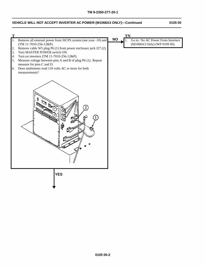
TM 9-2350-277-20-1
VEHICLE WILL NOT ACCEPT INVERTER AC POWER (M1068A3 ONLY)—Continued 0105 00
T1. Remove all external power from SICPS system (see your -10) and
(TM 11-7010-256-12&P).2. Remove cable W5 plug P6 (1) from power enclosure jack J27 (2).3. Turn MASTER POWER switch ON.4. Turn on inverters (TM 11-7010-256-12&P).5. Measure voltage between pins A and B of plug P6 (1). Repeat
measure for pins C and D.6. Does multimeter read 110 volts AC or more for both
measurements?
YES
NOTN1. Go to: No AC Power From Inverters
(M1068A3 Only) (WP 0109 00).
0105 00-2
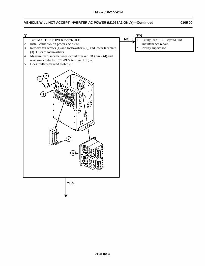
TM 9-2350-277-20-1
VEHICLE WILL NOT ACCEPT INVERTER AC POWER (M1068A3 ONLY)—Continued 0105 00
Y1. Turn MASTER POWER switch OFF.2. Install cable W5 on power enclosure.3. Remove ten screws (1) and lockwashers (2), and lower faceplate
(3). Discard lockwashers.4. Measure resistance between circuit breaker CB3 pin 2 (4) and
reversing contactor RC1-REV terminal L1 (5).5. Does multimeter read 0 ohms?
YES
NOYN1. Faulty lead 13A. Beyond unit
maintenance repair.2. Notify supervisor.
0105 00-3
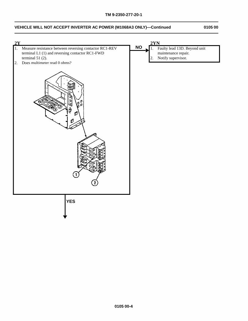
TM 9-2350-277-20-1
VEHICLE WILL NOT ACCEPT INVERTER AC POWER (M1068A3 ONLY)—Continued 0105 00
2Y1. Measure resistance between reversing contactor RC1-REV
terminal L1 (1) and reversing contactor RC1-FWDterminal 51 (2).
2. Does multimeter read 0 ohms?
YES
NO2YN1. Faulty lead 13D. Beyond unit
maintenance repair.2. Notify supervisor.
0105 00-4
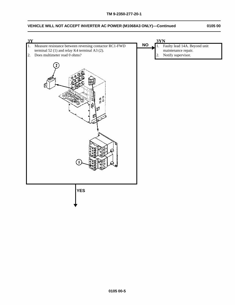
TM 9-2350-277-20-1
VEHICLE WILL NOT ACCEPT INVERTER AC POWER (M1068A3 ONLY)—Continued 0105 00
3Y1. Measure resistance between reversing contactor RC1-FWD
terminal 52 (1) and relay K4 terminal A3 (2).2. Does multimeter read 0 ohms?
YES
NO3YN1. Faulty lead 14A. Beyond unit
maintenance repair.2. Notify supervisor.
0105 00-5
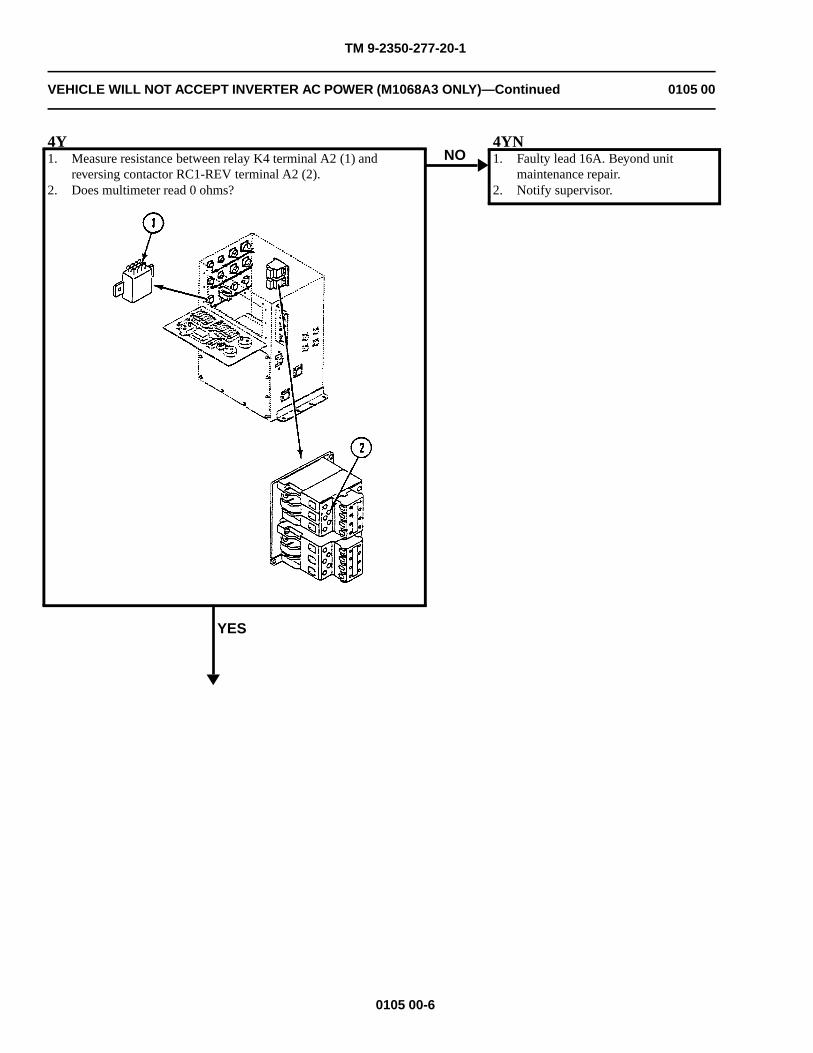
TM 9-2350-277-20-1
VEHICLE WILL NOT ACCEPT INVERTER AC POWER (M1068A3 ONLY)—Continued 0105 00
4Y1. Measure resistance between relay K4 terminal A2 (1) and
reversing contactor RC1-REV terminal A2 (2).2. Does multimeter read 0 ohms?
YES
NO4YN1. Faulty lead 16A. Beyond unit
maintenance repair.2. Notify supervisor.
0105 00-6
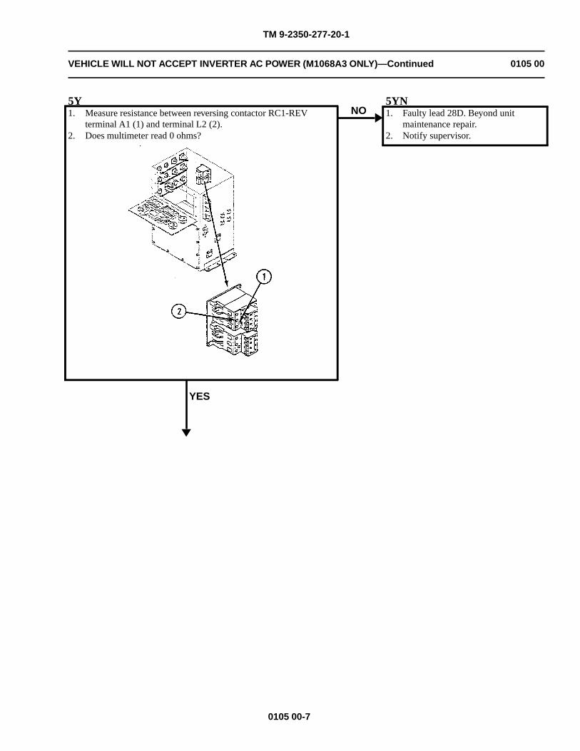
TM 9-2350-277-20-1
VEHICLE WILL NOT ACCEPT INVERTER AC POWER (M1068A3 ONLY)—Continued 0105 00
5Y1. Measure resistance between reversing contactor RC1-REV
terminal A1 (1) and terminal L2 (2).2. Does multimeter read 0 ohms?
YES
NO5YN1. Faulty lead 28D. Beyond unit
maintenance repair.2. Notify supervisor.
0105 00-7
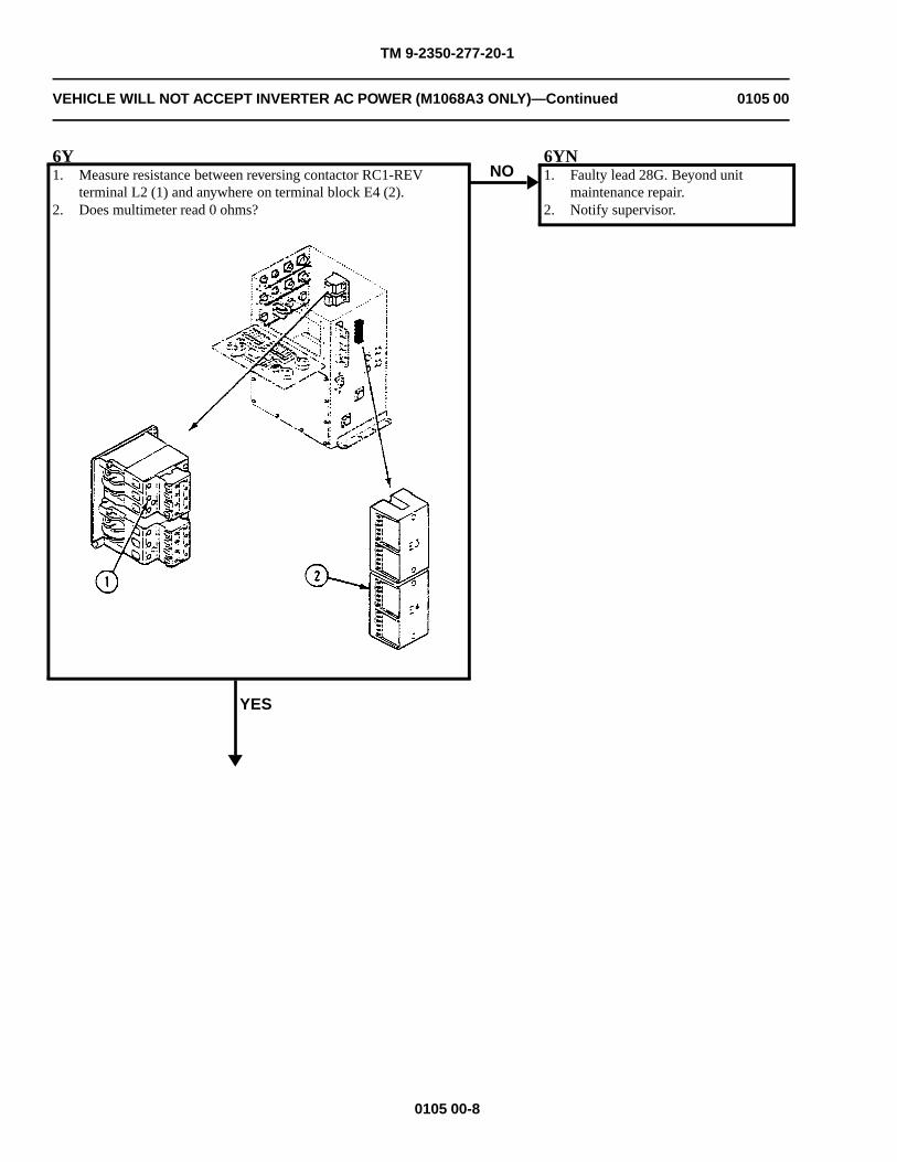
TM 9-2350-277-20-1
VEHICLE WILL NOT ACCEPT INVERTER AC POWER (M1068A3 ONLY)—Continued 0105 00
6Y1. Measure resistance between reversing contactor RC1-REV
terminal L2 (1) and anywhere on terminal block E4 (2).2. Does multimeter read 0 ohms?
YES
NO6YN1. Faulty lead 28G. Beyond unit
maintenance repair.2. Notify supervisor.
0105 00-8
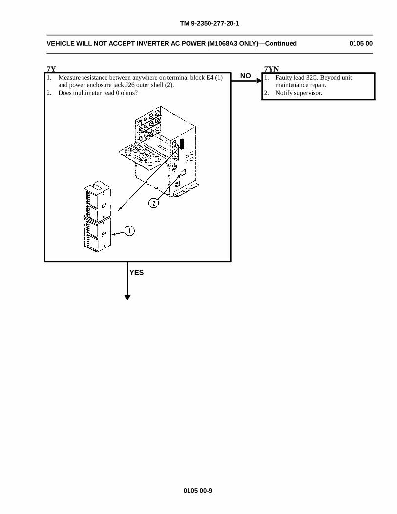
TM 9-2350-277-20-1
VEHICLE WILL NOT ACCEPT INVERTER AC POWER (M1068A3 ONLY)—Continued 0105 00
7Y1. Measure resistance between anywhere on terminal block E4 (1)
and power enclosure jack J26 outer shell (2).2. Does multimeter read 0 ohms?
YES
NO7YN1. Faulty lead 32C. Beyond unit
maintenance repair.2. Notify supervisor.
0105 00-9
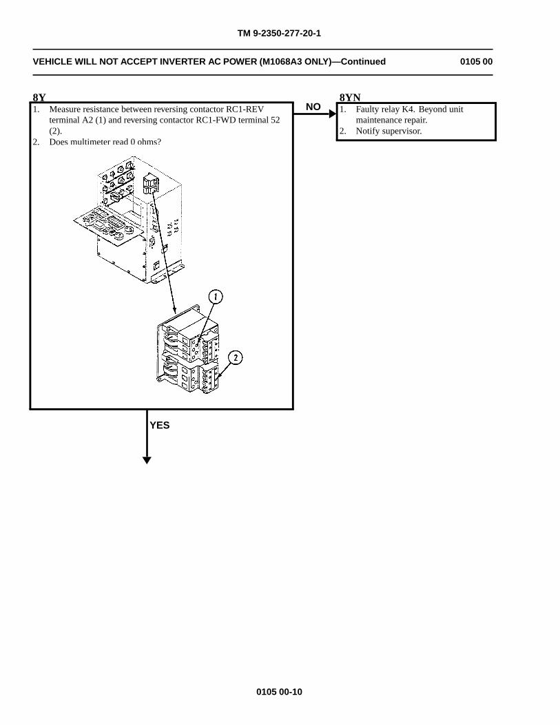
TM 9-2350-277-20-1
VEHICLE WILL NOT ACCEPT INVERTER AC POWER (M1068A3 ONLY)—Continued 0105 00
8Y1. Measure resistance between reversing contactor RC1-REV
terminal A2 (1) and reversing contactor RC1-FWD terminal 52(2).
2. Does multimeter read 0 ohms?
YES
NO8YN1. Faulty relay K4. Beyond unit
maintenance repair.2. Notify supervisor.
0105 00-10
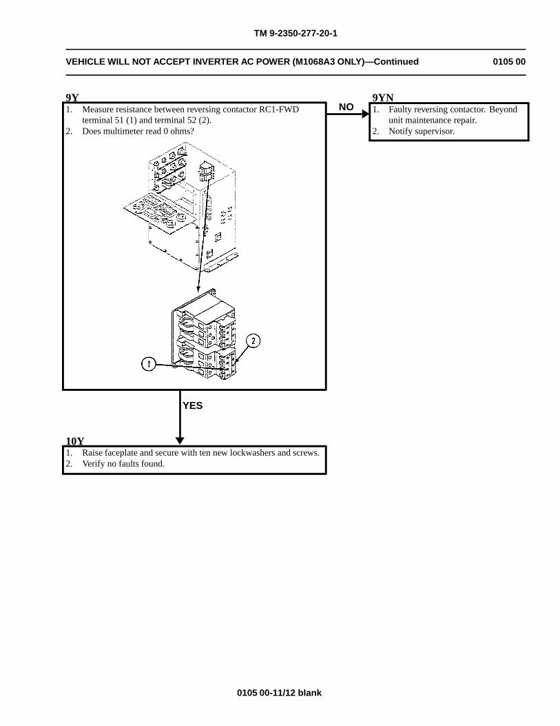
TM 9-2350-277-20-1
VEHICLE WILL NOT ACCEPT INVERTER AC POWER (M1068A3 ONLY)—Continued 0105 00
9Y1. Measure resistance between reversing contactor RC1-FWD
terminal 51 (1) and terminal 52 (2).2. Does multimeter read 0 ohms?
YES
NO9YN1. Faulty reversing contactor. Beyond
unit maintenance repair.2. Notify supervisor.
10Y1. Raise faceplate and secure with ten new lockwashers and screws.2. Verify no faults found.
0105 00-11/12 blank

TM 9-2350-277-20-1
NO POWER TO DC CIRCUITS (M1068A3 ONLY) 0106 00
INITIAL SETUP:
Maintenance LevelUnit
Tools and Special ToolsGeneral Mechanic’s Tool Kit (WP 0926 00, Item 65)Digital Multimeter (WP 0926 00, Item 30)
Materials/PartsLockwasher (22)
Personnel RequiredPower-Generation Equipment Repairer 52D10Helper (H)
ReferencesSee your -10TM 11-7010-256-12&P
Equipment ConditionEngine stopped (see your -10)Carrier blocked (see your -10)
WARNING
HIGH VOLTAGE is used in the operation of this equipment.
DEATH ON CONTACT may result if personnel fail to observe safety precautions.
NEVER work on equipment unless at least one other person familiar with the operation andhazards of the equipment is nearby. That person should also be familiar with giving first aid.When an operator helps a mechanic, that operator must be warned about dangerous areas.
SHUT OFF POWER supply to equipment before beginning work. Make sure all externalpower is off/disconnected.
BE CAREFUL not to contact high-voltage connections when installing or operating thisequipment.
0106 00-1 Change 4
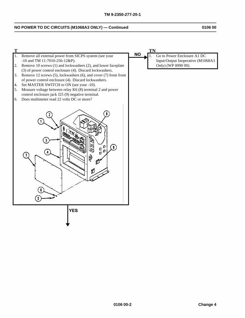
TM 9-2350-277-20-1
NO POWER TO DC CIRCUITS (M1068A3 ONLY) — Continued 0106 00
T1. Remove all external power from SICPS system (see your
-10 and TM 11-7010-256-12&P).2. Remove 10 screws (1) and lockwashers (2), and lower faceplate
(3) of power control enclosure (4). Discard lockwashers.3. Remove 12 screws (5), lockwashers (6), and cover (7) from front
of power control enclosure (4). Discard lockwashers.4. Set MASTER SWITCH to ON (see your -10).5. Measure voltage between relay K6 (8) terminal 2 and power
control enclosure jack J25 (9) negative terminal.6. Does multimeter read 22 volts DC or more?
TN1. Go to Power Enclosure A1 DC
Input/Output Inoperative (M1068A3Only) (WP 0090 00).
0106 00-2 Change 4
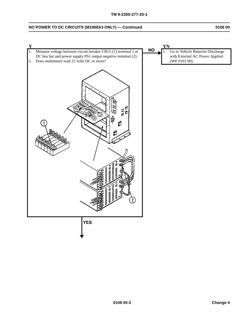
TM 9-2350-277-20-1
NO POWER TO DC CIRCUITS (M1068A3 ONLY) — Continued 0106 00
Y1. Measure voltage between circuit breaker CB15 (1) terminal 1 at
DC bus bar and power supply PS1 output negative terminal (2).2. Does multimeter read 22 volts DC or more?
YN1. Go to Vehicle Batteries Discharge
with External AC Power Applied(WP 0103 00).
0106 00-3 Change 4
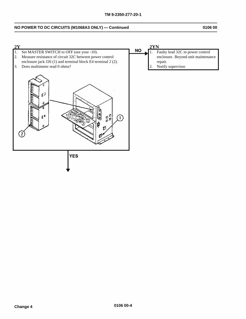
TM 9-2350-277-20-1
NO POWER TO DC CIRCUITS (M1068A3 ONLY) — Continued 0106 00
2Y1. Set MASTER SWITCH to OFF (see your -10).2. Measure resistance of circuit 32C between power control
enclosure jack J26 (1) and terminal block E4 terminal 2 (2).3. Does multimeter read 0 ohms?
2YN1. Faulty lead 32C in power control
enclosure. Beyond unit maintenancerepair.
2. Notify supervisor.
0106 00-4Change 4
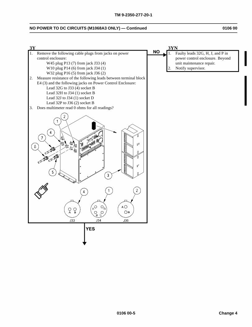
TM 9-2350-277-20-1
NO POWER TO DC CIRCUITS (M1068A3 ONLY) — Continued 0106 00
3Y1. Remove the following cable plugs from jacks on power
control enclosure:W45 plug P13 (7) from jack J33 (4)W10 plug P14 (6) from jack J34 (1)W32 plug P16 (5) from jack J36 (2)
2. Measure resistance of the following leads between terminal blockE4 (3) and the following jacks on Power Control Enclosure:
Lead 32G to J33 (4) socket BLead 32H to J34 (1) socket BLead 32J to J34 (1) socket DLead 32P to J36 (2) socket B
3. Does multimeter read 0 ohms for all readings?
3YN1. Faulty leads 32G, H, J, and P in
power control enclosure. Beyondunit maintenance repair.
2. Notify supervisor.
0106 00-5 Change 4
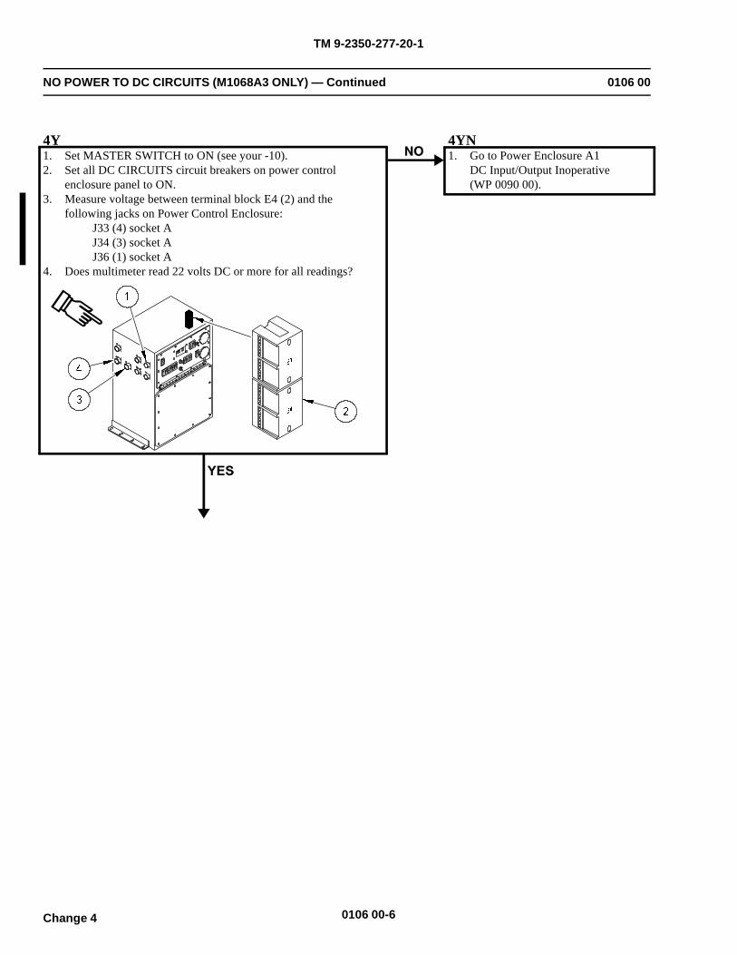
TM 9-2350-277-20-1
NO POWER TO DC CIRCUITS (M1068A3 ONLY) — Continued 0106 00
4Y1. Set MASTER SWITCH to ON (see your -10).2. Set all DC CIRCUITS circuit breakers on power control
enclosure panel to ON.3. Measure voltage between terminal block E4 (2) and the
following jacks on Power Control Enclosure:J33 (4) socket AJ34 (3) socket AJ36 (1) socket A
4. Does multimeter read 22 volts DC or more for all readings?
4YN1. Go to Power Enclosure A1
DC Input/Output Inoperative(WP 0090 00).
0106 00-6Change 4
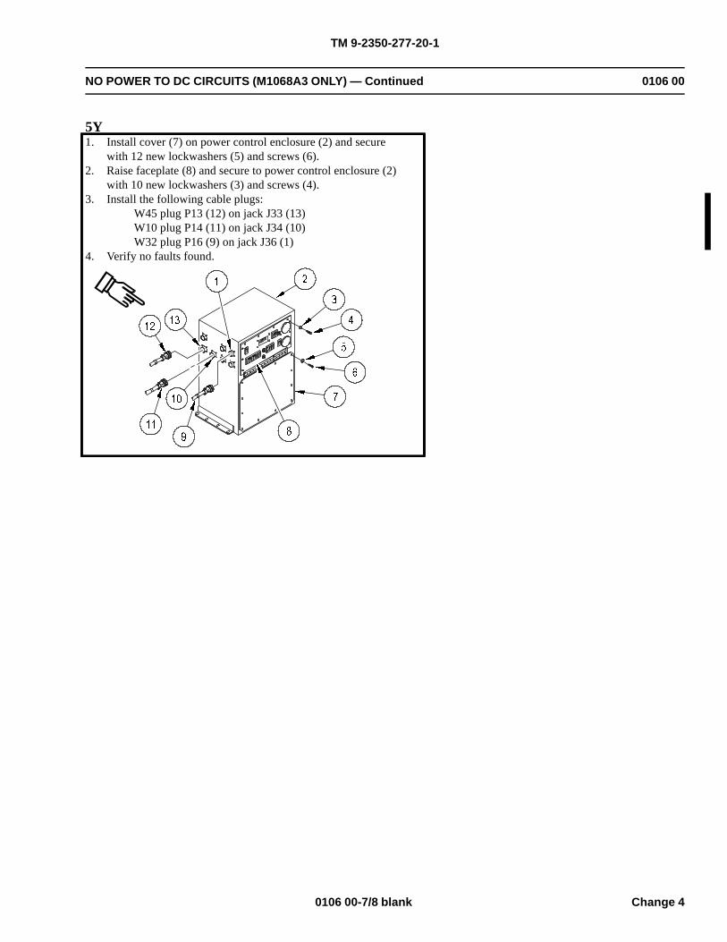
TM 9-2350-277-20-1
NO POWER TO DC CIRCUITS (M1068A3 ONLY) — Continued 0106 00
5Y1. Install cover (7) on power control enclosure (2) and secure
with 12 new lockwashers (5) and screws (6).2. Raise faceplate (8) and secure to power control enclosure (2)
with 10 new lockwashers (3) and screws (4).3. Install the following cable plugs:
W45 plug P13 (12) on jack J33 (13)W10 plug P14 (11) on jack J34 (10)W32 plug P16 (9) on jack J36 (1)
4. Verify no faults found.
0106 00-7/8 blank Change 4

TM 9-2350-277-20-1
NO POWER TO AC CIRCUITS (M1068A3 ONLY) 0107 00
INITIAL SETUP:
Maintenance Level
Unit
Tools and Special Tools
General Mechanic’s Tool Kit (WP 0926 00, Item 65)Digital Multimeter (WP 0926 00, Item 30)
Materials/Parts
Lockwasher (10)
Personnel Required
Power-Generation Equipment Repairer 52D10Helper (H)
References
See your -10TM 11-7010-256-12&P
Equipment Condition
Engine stopped (see your -10)Carrier blocked (see your -10)
WARNING
HIGH VOLTAGE is used in operation of this equipment.
DEATH ON CONTACT may result if personnel fail to observe safety precautions.
NEVER work on equipment unless at least one other person familiar with operation andhazards of equipment is nearby. That person should also be familiar with giving first aid. Whenan operator helps a mechanic, that operator must be warned about dangerous areas.
SHUT OFF POWER supply to equipment before beginning work. Make sure all external poweris OFF/disconnected.
BE CAREFUL not to touch high-voltage connections when installing or operating thisequipment.
0107 00-1
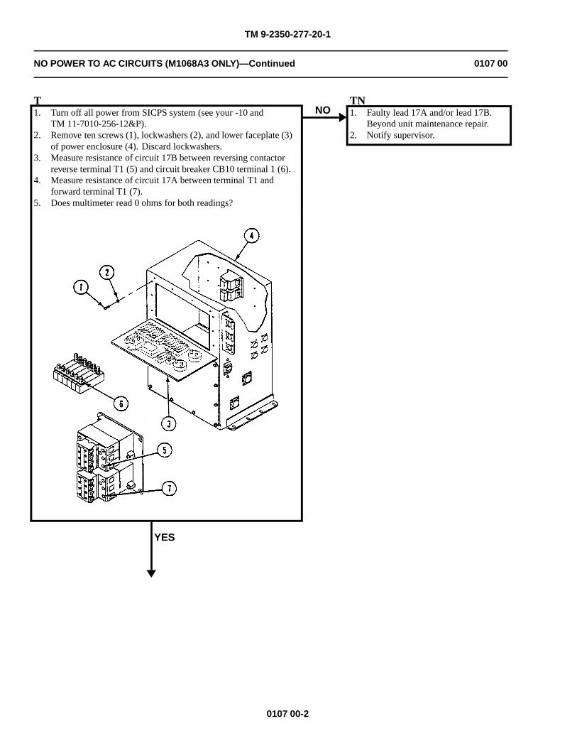
TM 9-2350-277-20-1
NO POWER TO AC CIRCUITS (M1068A3 ONLY)—Continued 0107 00
T1. Turn off all power from SICPS system (see your -10 and
TM 11-7010-256-12&P).2. Remove ten screws (1), lockwashers (2), and lower faceplate (3)
of power enclosure (4). Discard lockwashers.3. Measure resistance of circuit 17B between reversing contactor
reverse terminal T1 (5) and circuit breaker CB10 terminal 1 (6).4. Measure resistance of circuit 17A between terminal T1 and
forward terminal T1 (7).5. Does multimeter read 0 ohms for both readings?
YES
NOTN1. Faulty lead 17A and/or lead 17B.
Beyond unit maintenance repair.2. Notify supervisor.
0107 00-2
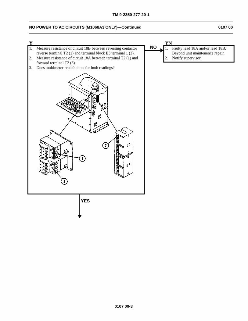
TM 9-2350-277-20-1
NO POWER TO AC CIRCUITS (M1068A3 ONLY)—Continued 0107 00
Y1. Measure resistance of circuit 18B between reversing contactor
reverse terminal T2 (1) and terminal block E3 terminal 1 (2).2. Measure resistance of circuit 18A between terminal T2 (1) and
forward terminal T2 (3).3. Does multimeter read 0 ohms for both readings?
YES
NOYN1. Faulty lead 18A and/or lead 18B.
Beyond unit maintenance repair.2. Notify supervisor.
0107 00-3
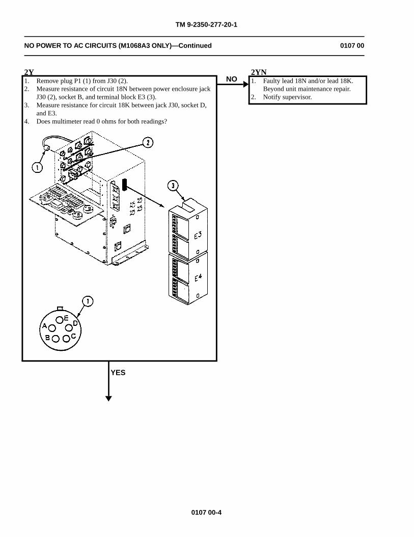
TM 9-2350-277-20-1
NO POWER TO AC CIRCUITS (M1068A3 ONLY)—Continued 0107 00
2Y1. Remove plug P1 (1) from J30 (2).2. Measure resistance of circuit 18N between power enclosure jack
J30 (2), socket B, and terminal block E3 (3).3. Measure resistance for circuit 18K between jack J30, socket D,
and E3.4. Does multimeter read 0 ohms for both readings?
YES
NO2YN1. Faulty lead 18N and/or lead 18K.
Beyond unit maintenance repair.2. Notify supervisor.
0107 00-4
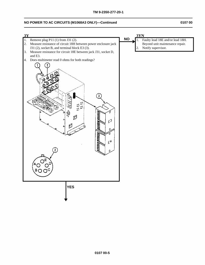
TM 9-2350-277-20-1
NO POWER TO AC CIRCUITS (M1068A3 ONLY)—Continued 0107 00
3Y1. Remove plug P11 (1) from J31 (2).2. Measure resistance of circuit 18H between power enclosure jack
J31 (2), socket B, and terminal block E3 (3).3. Measure resistance for circuit 18E between jack J31, socket D,
and E3.4. Does multimeter read 0 ohms for both readings?
YES
NO3YN1. Faulty lead 18E and/or lead 18H.
Beyond unit maintenance repair.2. Notify supervisor.
0107 00-5
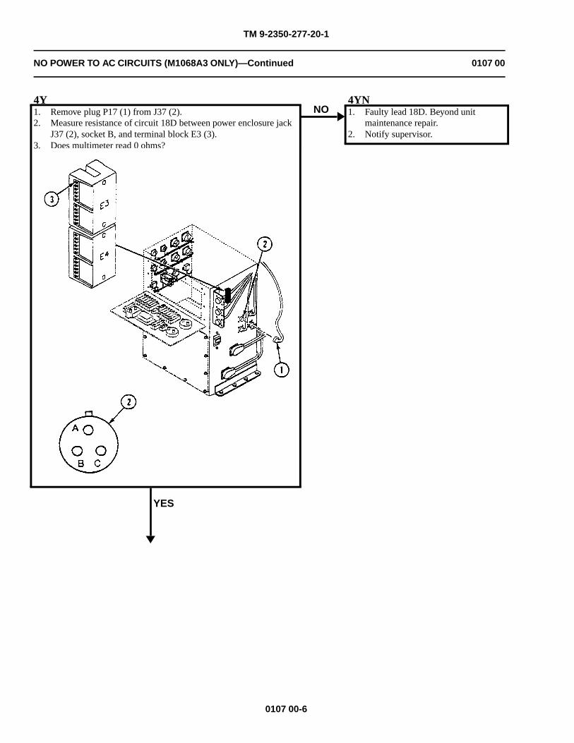
TM 9-2350-277-20-1
NO POWER TO AC CIRCUITS (M1068A3 ONLY)—Continued 0107 00
4Y1. Remove plug P17 (1) from J37 (2).2. Measure resistance of circuit 18D between power enclosure jack
J37 (2), socket B, and terminal block E3 (3).3. Does multimeter read 0 ohms?
YES
NO4YN1. Faulty lead 18D. Beyond unit
maintenance repair.2. Notify supervisor.
0107 00-6
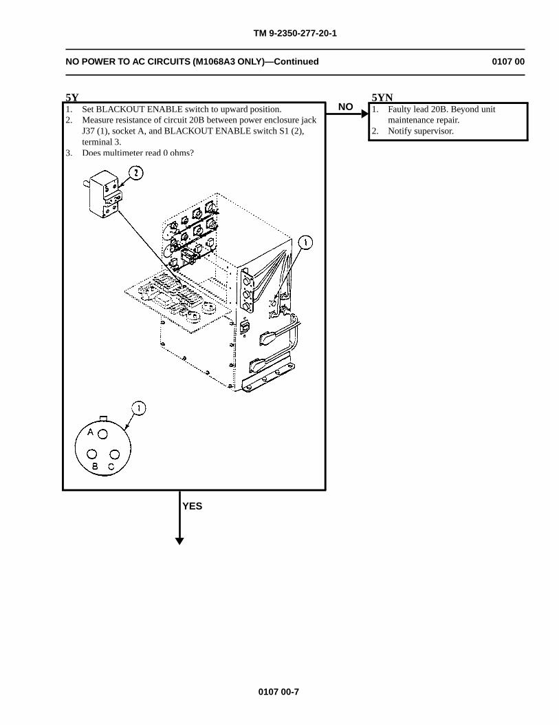
TM 9-2350-277-20-1
NO POWER TO AC CIRCUITS (M1068A3 ONLY)—Continued 0107 00
5Y1. Set BLACKOUT ENABLE switch to upward position.2. Measure resistance of circuit 20B between power enclosure jack
J37 (1), socket A, and BLACKOUT ENABLE switch S1 (2),terminal 3.
3. Does multimeter read 0 ohms?
YES
NO5YN1. Faulty lead 20B. Beyond unit
maintenance repair.2. Notify supervisor.
0107 00-7
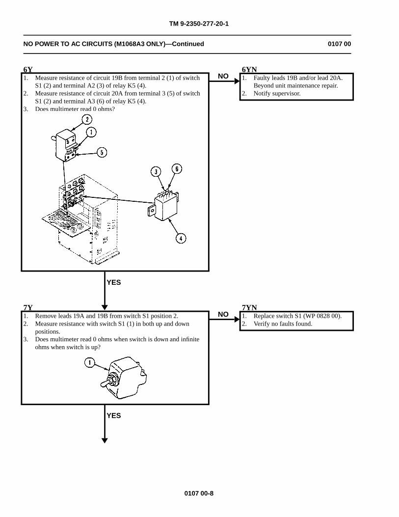
TM 9-2350-277-20-1
NO POWER TO AC CIRCUITS (M1068A3 ONLY)—Continued 0107 00
6Y1. Measure resistance of circuit 19B from terminal 2 (1) of switch
S1 (2) and terminal A2 (3) of relay K5 (4).2. Measure resistance of circuit 20A from terminal 3 (5) of switch
S1 (2) and terminal A3 (6) of relay K5 (4).3. Does multimeter read 0 ohms?
YES
NO6YN1. Faulty leads 19B and/or lead 20A.
Beyond unit maintenance repair.2. Notify supervisor.
7Y1. Remove leads 19A and 19B from switch S1 position 2.2. Measure resistance with switch S1 (1) in both up and down
positions.3. Does multimeter read 0 ohms when switch is down and infinite
ohms when switch is up?
YES
NO7YN1. Replace switch S1 (WP 0828 00).2. Verify no faults found.
0107 00-8
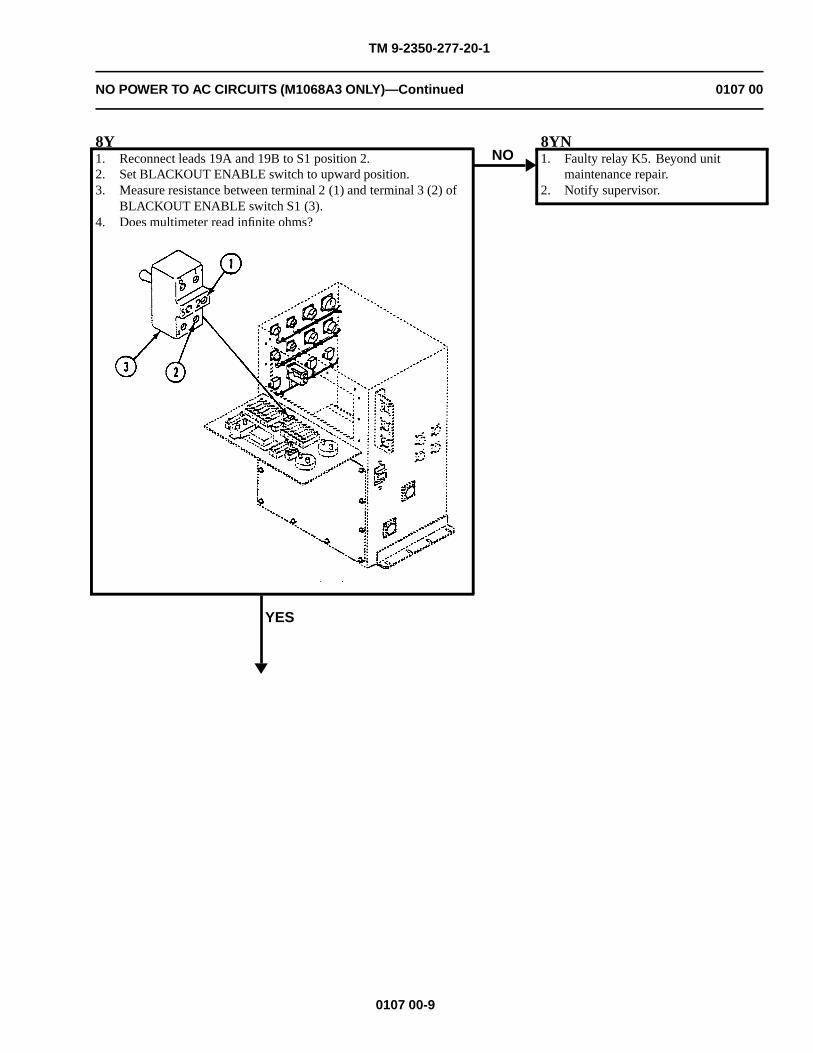
TM 9-2350-277-20-1
NO POWER TO AC CIRCUITS (M1068A3 ONLY)—Continued 0107 00
8Y1. Reconnect leads 19A and 19B to S1 position 2.2. Set BLACKOUT ENABLE switch to upward position.3. Measure resistance between terminal 2 (1) and terminal 3 (2) of
BLACKOUT ENABLE switch S1 (3).4. Does multimeter read infinite ohms?
YES
NO8YN1. Faulty relay K5. Beyond unit
maintenance repair.2. Notify supervisor.
0107 00-9
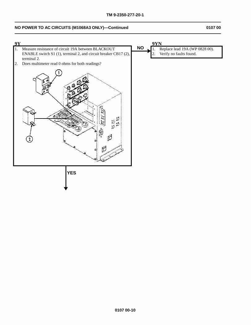
TM 9-2350-277-20-1
NO POWER TO AC CIRCUITS (M1068A3 ONLY)—Continued 0107 00
9Y1. Measure resistance of circuit 19A between BLACKOUT
ENABLE switch S1 (1), terminal 2, and circuit breaker CB17 (2),terminal 2.
2. Does multimeter read 0 ohms for both readings?
YES
NO9YN1. Replace lead 19A (WP 0828 00).2. Verify no faults found.
0107 00-10
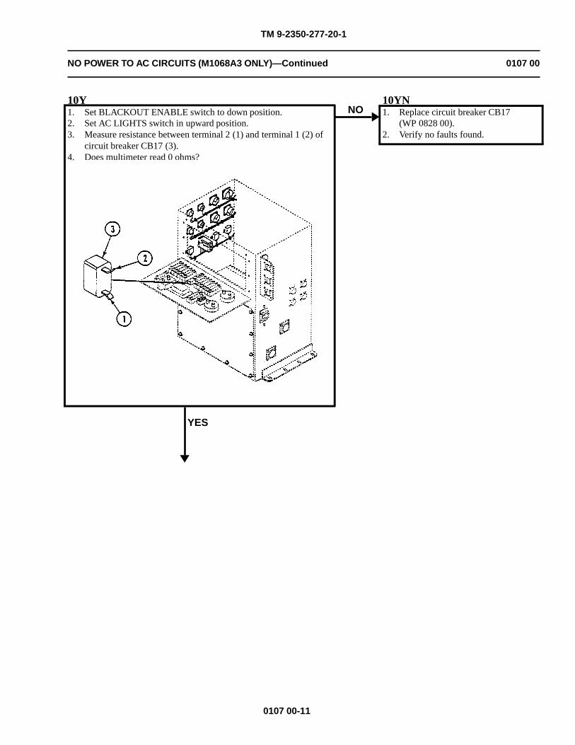
TM 9-2350-277-20-1
NO POWER TO AC CIRCUITS (M1068A3 ONLY)—Continued 0107 00
10Y1. Set BLACKOUT ENABLE switch to down position.2. Set AC LIGHTS switch in upward position.3. Measure resistance between terminal 2 (1) and terminal 1 (2) of
circuit breaker CB17 (3).4. Does multimeter read 0 ohms?
YES
NO10YN1. Replace circuit breaker CB17
(WP 0828 00).2. Verify no faults found.
0107 00-11
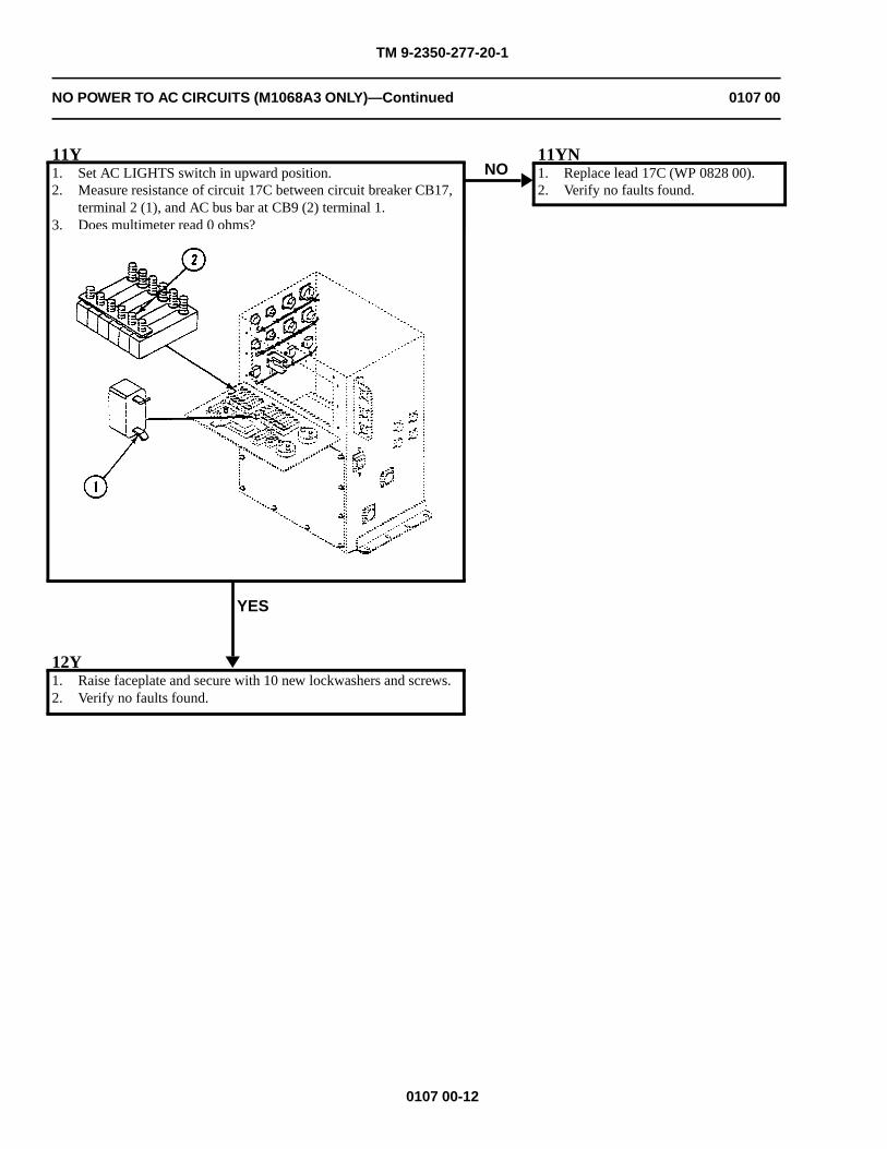
TM 9-2350-277-20-1
NO POWER TO AC CIRCUITS (M1068A3 ONLY)—Continued 0107 00
11Y1. Set AC LIGHTS switch in upward position.2. Measure resistance of circuit 17C between circuit breaker CB17,
terminal 2 (1), and AC bus bar at CB9 (2) terminal 1.3. Does multimeter read 0 ohms?
YES
NO11YN1. Replace lead 17C (WP 0828 00).2. Verify no faults found.
12Y1. Raise faceplate and secure with 10 new lockwashers and screws.2. Verify no faults found.
0107 00-12
TM 9-2350-277-20-1
NO DC OUTPUT FROM DC POWER SUPPLY (M1068A3 ONLY) 0108 00
INITIAL SETUP:
Maintenance Level
Unit
Tools and Special Tools
General Mechanic’s Tool Kit (WP 0926 00, Item 65)Digital Multimeter (WP 0926 00, Item 30)
Materials/Parts
Lockwasher (22)
Personnel Required
Power-Generation Equipment Repairer 52D10Helper (H)
References
See your -10TM 11-7010-256-12&P
Equipment Condition
Engine stopped (see your -10)Carrier blocked (see your -10)
WARNING
HIGH VOLTAGE is used in the operation of this equipment.
DEATH ON CONTACT may result if personnel fail to observe safety precautions.
NEVER work on equipment unless at least one other person familiar with the operation andhazards of the equipment is nearby. That person should also be familiar with giving first aid.When an operator helps a mechanic, that operator must be warned about dangerous areas.
SHUT OFF POWER supply to equipment before beginning work. Make sure all external poweris off/disconnected.
BE CAREFUL not to contact high-voltage connections when installing or operating thisequipment.
0108 00-1
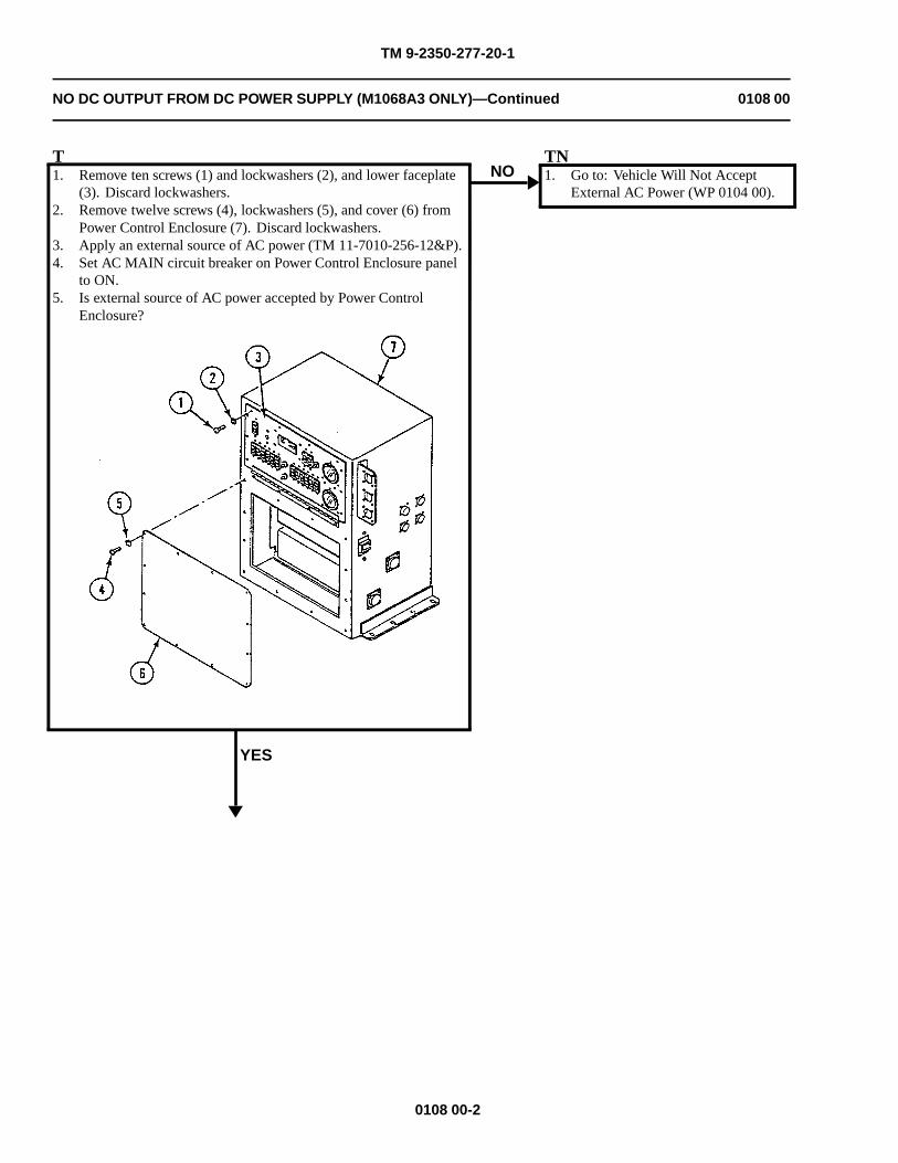
TM 9-2350-277-20-1
NO DC OUTPUT FROM DC POWER SUPPLY (M1068A3 ONLY)—Continued 0108 00
T1. Remove ten screws (1) and lockwashers (2), and lower faceplate
(3). Discard lockwashers.2. Remove twelve screws (4), lockwashers (5), and cover (6) from
Power Control Enclosure (7). Discard lockwashers.3. Apply an external source of AC power (TM 11-7010-256-12&P).4. Set AC MAIN circuit breaker on Power Control Enclosure panel
to ON.5. Is external source of AC power accepted by Power Control
Enclosure?
YES
NOTN1. Go to: Vehicle Will Not Accept
External AC Power (WP 0104 00).
0108 00-2
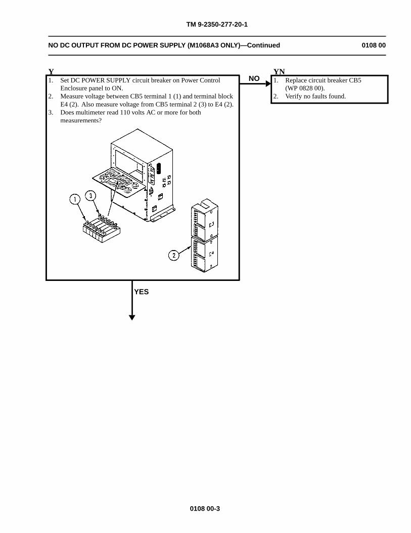
TM 9-2350-277-20-1
NO DC OUTPUT FROM DC POWER SUPPLY (M1068A3 ONLY)—Continued 0108 00
Y1. Set DC POWER SUPPLY circuit breaker on Power Control
Enclosure panel to ON.2. Measure voltage between CB5 terminal 1 (1) and terminal block
E4 (2). Also measure voltage from CB5 terminal 2 (3) to E4 (2).3. Does multimeter read 110 volts AC or more for both
measurements?
YES
NOYN1. Replace circuit breaker CB5
(WP 0828 00).2. Verify no faults found.
0108 00-3
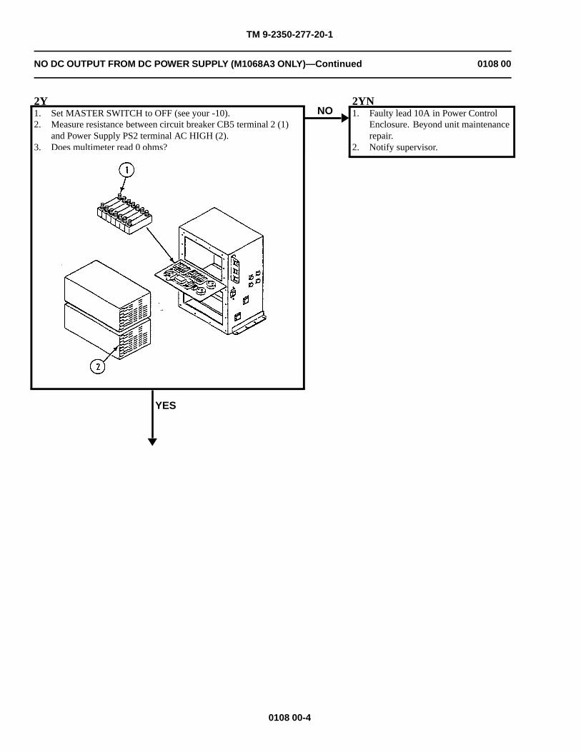
TM 9-2350-277-20-1
NO DC OUTPUT FROM DC POWER SUPPLY (M1068A3 ONLY)—Continued 0108 00
2Y1. Set MASTER SWITCH to OFF (see your -10).2. Measure resistance between circuit breaker CB5 terminal 2 (1)
and Power Supply PS2 terminal AC HIGH (2).3. Does multimeter read 0 ohms?
YES
NO2YN1. Faulty lead 10A in Power Control
Enclosure. Beyond unit maintenancerepair.
2. Notify supervisor.
0108 00-4
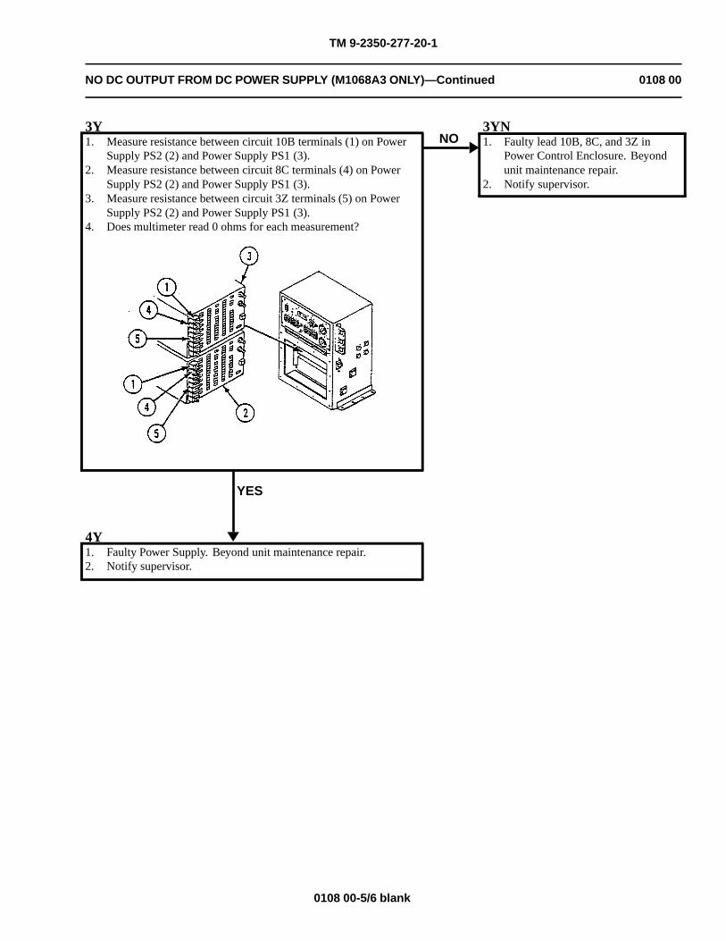
TM 9-2350-277-20-1
NO DC OUTPUT FROM DC POWER SUPPLY (M1068A3 ONLY)—Continued 0108 00
3Y1. Measure resistance between circuit 10B terminals (1) on Power
Supply PS2 (2) and Power Supply PS1 (3).2. Measure resistance between circuit 8C terminals (4) on Power
Supply PS2 (2) and Power Supply PS1 (3).3. Measure resistance between circuit 3Z terminals (5) on Power
Supply PS2 (2) and Power Supply PS1 (3).4. Does multimeter read 0 ohms for each measurement?
YES
NO3YN1. Faulty lead 10B, 8C, and 3Z in
Power Control Enclosure. Beyondunit maintenance repair.
2. Notify supervisor.
4Y1. Faulty Power Supply. Beyond unit maintenance repair.2. Notify supervisor.
0108 00-5/6 blank

TM 9-2350-277-20-1
NO AC POWER FROM INVERTERS (M1068A3 ONLY) 0109 00
INITIAL SETUP:
Maintenance Level
Unit
Tools and Special Tools
General Mechanic’s Tool Kit (WP 0926 00, Item 65)Digital Multimeter (WP 0926 00, Item 30)Inverter Test Solo Plug (WP 0927 00, Figure 0927 00-2)
Materials/Parts
Lockwasher (10)
Personnel Required
Power-Generation Equipment Repairer 52D10Helper (H)
References
See your -10TM 11-7010-256-12&P
Equipment Condition
Engine stopped (see your -10)
Carrier blocked (see your -10)
All external power disconnected(TM 11-7010-256-12&P)
WARNING
HIGH VOLTAGE is used in the operation of this equipment.
DEATH ON CONTACT may result if personnel do not observe safety precautions.
NEVER work on equipment unless at least one other person is nearby, familiar with theoperation and hazards of the equipment and is familiar with giving first aid. When an operatorhelps a mechanic, that operator must be warned about dangerous areas.
SHUT OFF POWER supply to equipment before beginning work. Make sure all external poweris off/disconnected.
BE CAREFUL not to contact high-voltage connections when installing or operating thisequipment.
0109 00-1
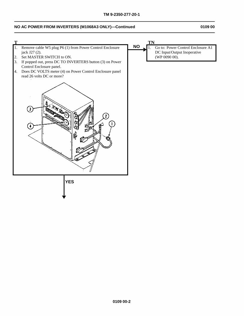
TM 9-2350-277-20-1
NO AC POWER FROM INVERTERS (M1068A3 ONLY)—Continued 0109 00
T1. Remove cable W5 plug P6 (1) from Power Control Enclosure
jack J27 (2).2. Set MASTER SWITCH to ON.3. If popped out, press DC TO INVERTERS button (3) on Power
Control Enclosure panel.4. Does DC VOLTS meter (4) on Power Control Enclosure panel
read 26 volts DC or more?
YES
NOTN1. Go to: Power Control Enclosure A1
DC Input/Output Inoperative(WP 0090 00).
0109 00-2
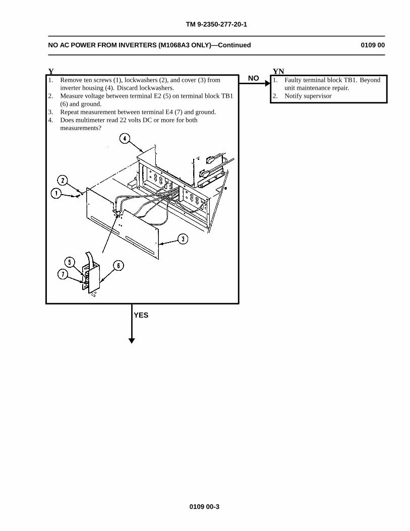
TM 9-2350-277-20-1
NO AC POWER FROM INVERTERS (M1068A3 ONLY)—Continued 0109 00
Y1. Remove ten screws (1), lockwashers (2), and cover (3) from
inverter housing (4). Discard lockwashers.2. Measure voltage between terminal E2 (5) on terminal block TB1
(6) and ground.3. Repeat measurement between terminal E4 (7) and ground.4. Does multimeter read 22 volts DC or more for both
measurements?
YES
NOYN1. Faulty terminal block TB1. Beyond
unit maintenance repair.2. Notify supervisor
0109 00-3
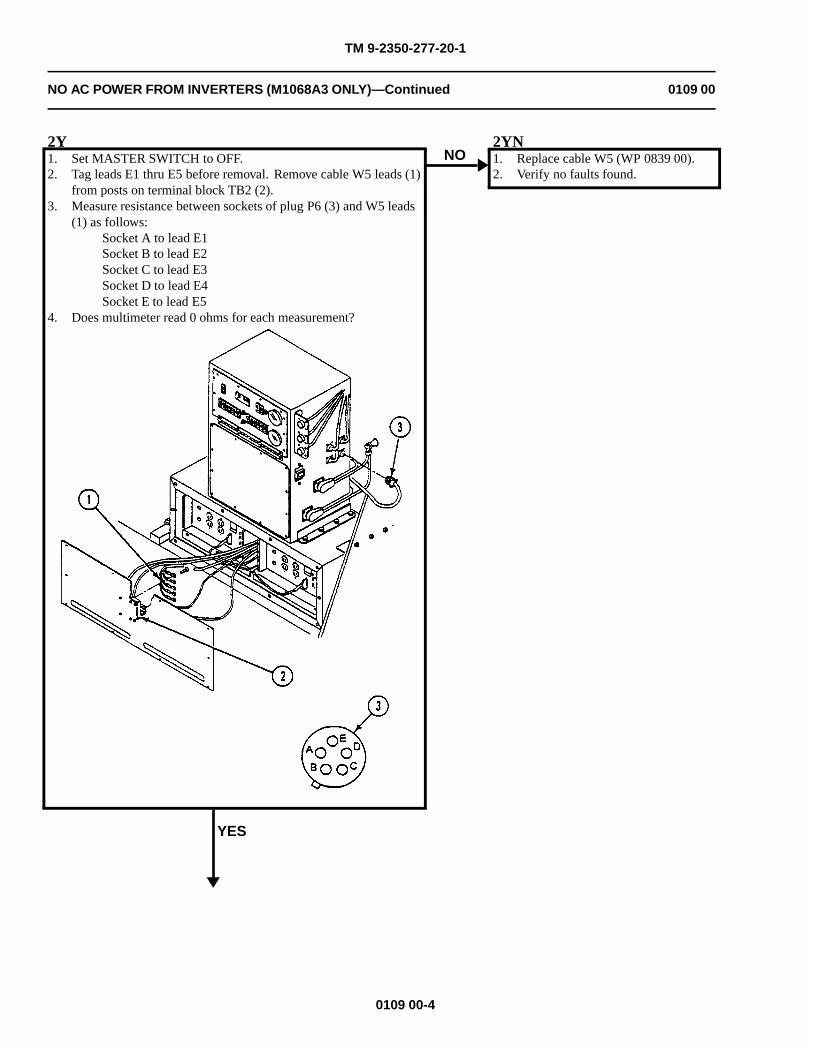
TM 9-2350-277-20-1
NO AC POWER FROM INVERTERS (M1068A3 ONLY)—Continued 0109 00
2Y1. Set MASTER SWITCH to OFF.2. Tag leads E1 thru E5 before removal. Remove cable W5 leads (1)
from posts on terminal block TB2 (2).3. Measure resistance between sockets of plug P6 (3) and W5 leads
(1) as follows:Socket A to lead E1Socket B to lead E2Socket C to lead E3Socket D to lead E4Socket E to lead E5
4. Does multimeter read 0 ohms for each measurement?
YES
NO2YN1. Replace cable W5 (WP 0839 00).2. Verify no faults found.
0109 00-4
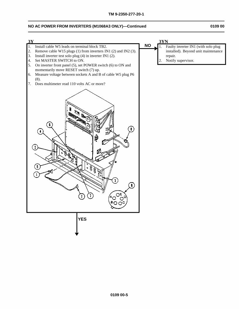
TM 9-2350-277-20-1
NO AC POWER FROM INVERTERS (M1068A3 ONLY)—Continued 0109 00
3Y1. Install cable W5 leads on terminal block TB2.2. Remove cable W15 plugs (1) from inverters IN1 (2) and IN2 (3).3. Install inverter test solo plug (4) in inverter IN1 (2).4. Set MASTER SWITCH to ON.5. On inverter front panel (5), set POWER switch (6) to ON and
momentarily move RESET switch (7) up.6. Measure voltage between sockets A and B of cable W5 plug P6
(8).7. Does multimeter read 110 volts AC or more?
YES
NO3YN1. Faulty inverter IN1 (with solo plug
installed). Beyond unit maintenancerepair.
2. Notify supervisor.
0109 00-5
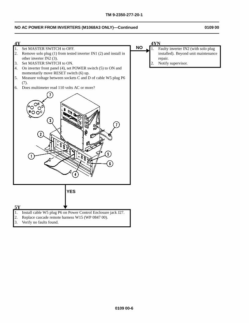
TM 9-2350-277-20-1
NO AC POWER FROM INVERTERS (M1068A3 ONLY)—Continued 0109 00
4Y1. Set MASTER SWITCH to OFF.2. Remove solo plug (1) from tested inverter IN1 (2) and install in
other inverter IN2 (3).3. Set MASTER SWITCH to ON.4. On inverter front panel (4), set POWER switch (5) to ON and
momentarily move RESET switch (6) up.5. Measure voltage between sockets C and D of cable W5 plug P6
(7).6. Does multimeter read 110 volts AC or more?
YES
NO4YN1. Faulty inverter IN2 (with solo plug
installed). Beyond unit maintenancerepair.
2. Notify supervisor.
5Y1. Install cable W5 plug P6 on Power Control Enclosure jack J27.2. Replace cascade remote harness W15 (WP 0847 00).3. Verify no faults found.
0109 00-6
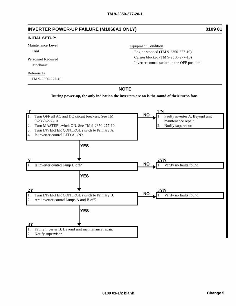
TM 9-2350-277-20-1
INVERTER POWER-UP FAILURE (M1068A3 ONLY) 0109 01
INITIAL SETUP:
Maintenance LevelUnit
Personnel RequiredMechanic
ReferencesTM 9-2350-277-10
Equipment ConditionEngine stopped (TM 9-2350-277-10)Carrier blocked (TM 9-2350-277-10)Inverter control switch in the OFF position
NOTEDuring power-up, the only indication the inverters are on is the sound of their turbo fans.
T1. Turn OFF all AC and DC circuit breakers. See TM
9-2350-277-10.2. Turn MASTER switch ON. See TM 9-2350-277-10.3. Turn INVERTER CONTROL switch to Primary A.4. Is inverter control LED A ON?
TN1. Faulty inverter A. Beyond unit
maintenance repair.2. Notify supervisor.
Y1. Is inverter control lamp B off?
2YN1. Verify no faults found.
2Y1. Turn INVERTER CONTROL switch to Primary B.2. Are inverter control lamps A and B off?
3YN1. Verify no faults found.
3Y1. Faulty inverter B. Beyond unit maintenance repair.2. Notify supervisor.
Change 50109 01-1/2 blank

TM 9-2350-277-20-1
NO DATA OUTPUT FROM DATA PANEL A12 (M1068A3 ONLY) 0110 00
INITIAL SETUP:
Maintenance LevelUnit
Tools and Special ToolsRadio equipment tool kit (WP 0926 00, Item 66)Multimeter (WP 0926 00, Item 30)
Personnel RequiredSignal Support System Specialist 31U10Helper (H)
References
See your -10TM 11-7010-256-12&P
Equipment Condition
Engine stopped (see your -10)
Carrier blocked (see your -10)
0110 00-1
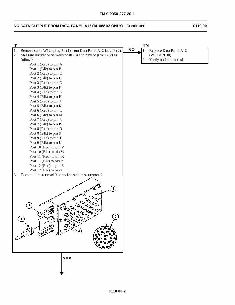
TM 9-2350-277-20-1
NO DATA OUTPUT FROM DATA PANEL A12 (M1068A3 ONLY)—Continued 0110 00
T1. Remove cable W124 plug P1 (1) from Data Panel A12 jack J3 (2).2. Measure resistance between posts (3) and pins of jack J3 (2) as
follows:Post 1 (Red) to pin APost 1 (Blk) to pin BPost 2 (Red) to pin CPost 2 (Blk) to pin DPost 3 (Red) to pin EPost 3 (Blk) to pin FPost 4 (Red) to pin GPost 4 (Blk) to pin HPost 5 (Red) to pin JPost 5 (Blk) to pin KPost 6 (Red) to pin LPost 6 (Blk) to pin MPost 7 (Red) to pin NPost 7 (Blk) to pin PPost 8 (Red) to pin RPost 8 (Blk) to pin SPost 9 (Red) to pin TPost 9 (Blk) to pin UPost 10 (Red) to pin VPost 10 (Blk) to pin WPost 11 (Red) to pin XPost 11 (Blk) to pin YPost 12 (Red) to pin ZPost 12 (Blk) to pin a
3. Does multimeter read 0 ohms for each measurement?
YES
NOTN1. Replace Data Panel A12
(WP 0819 00).2. Verify no faults found.
0110 00-2
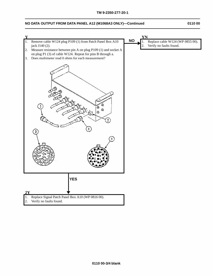
TM 9-2350-277-20-1
NO DATA OUTPUT FROM DATA PANEL A12 (M1068A3 ONLY)—Continued 0110 00
Y1. Remove cable W124 plug P109 (1) from Patch Panel Box A10
jack J140 (2).2. Measure resistance between pin A on plug P109 (1) and socket A
on plug P1 (3) of cable W124. Repeat for pins B through a.3. Does multimeter read 0 ohms for each measurement?
YES
NOYN1. Replace cable W124 (WP 0855 00).2. Verify no faults found.
2Y1. Replace Signal Patch Panel Box A10 (WP 0816 00).2. Verify no faults found.
0110 00-3/4 blank

TM 9-2350-277-20-1
NO LAN OUTPUT FROM DATA PANEL A12 (M1068A3 ONLY) 0111 00
INITIAL SETUP:
Maintenance Level
Unit
Tools and Special Tools
Radio equipment tool kit (WP 0926 00, Item 66)Multimeter (WP 0926 00, Item 30)
Personnel Required
Signal Support System Specialist 31U10Helper (H)
References
See your -10TM 11-7010-256-12&PSee M1068A3 Wiring Diagram (FO-7 and FO-8)
Equipment Condition
Engine stopped (see your -10)Carrier blocked (see your -10)
WARNING
HIGH VOLTAGE is used in the operation of this equipment.
DEATH ON CONTACT may result if personnel fail to observe safety precautions.
NEVER work on equipment unless at least one other person familiar with the operation andhazards of the equipment is nearby. That person should also be familiar with giving first aid.When an operator helps a mechanic, that operator must be warned about dangerous areas.
SHUT OFF POWER supply to equipment before beginning work. Make sure all external poweris off/disconnected.
BE CAREFUL not to contact high-voltage connections when installing or operating thisequipment.
0111 00-1
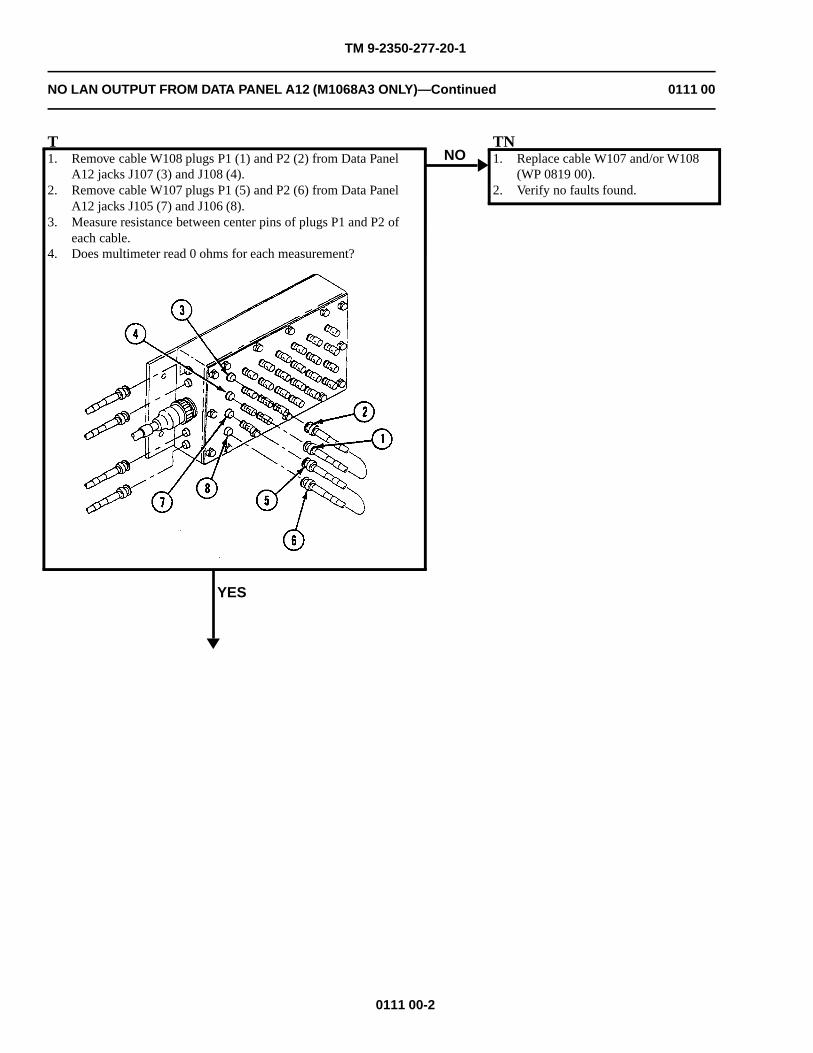
TM 9-2350-277-20-1
NO LAN OUTPUT FROM DATA PANEL A12 (M1068A3 ONLY)—Continued 0111 00
T1. Remove cable W108 plugs P1 (1) and P2 (2) from Data Panel
A12 jacks J107 (3) and J108 (4).2. Remove cable W107 plugs P1 (5) and P2 (6) from Data Panel
A12 jacks J105 (7) and J106 (8).3. Measure resistance between center pins of plugs P1 and P2 of
each cable.4. Does multimeter read 0 ohms for each measurement?
YES
NOTN1. Replace cable W107 and/or W108
(WP 0819 00).2. Verify no faults found.
0111 00-2
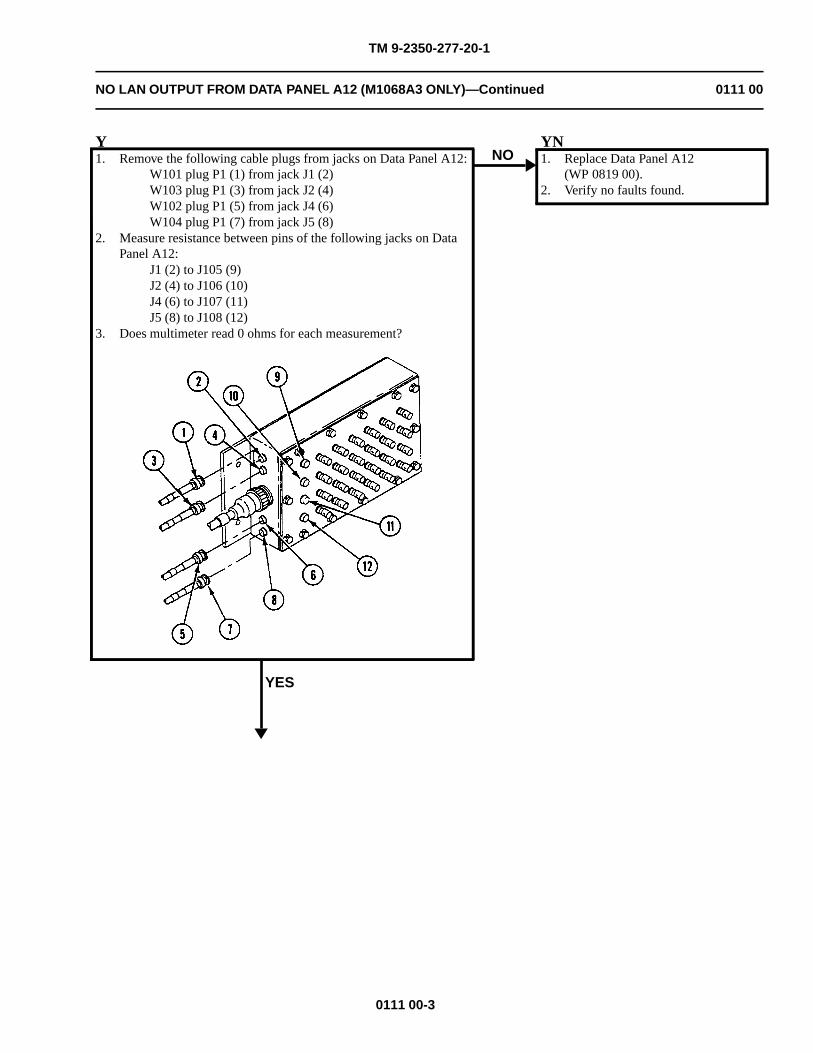
TM 9-2350-277-20-1
NO LAN OUTPUT FROM DATA PANEL A12 (M1068A3 ONLY)—Continued 0111 00
Y1. Remove the following cable plugs from jacks on Data Panel A12:
W101 plug P1 (1) from jack J1 (2)W103 plug P1 (3) from jack J2 (4)W102 plug P1 (5) from jack J4 (6)W104 plug P1 (7) from jack J5 (8)
2. Measure resistance between pins of the following jacks on DataPanel A12:
J1 (2) to J105 (9)J2 (4) to J106 (10)J4 (6) to J107 (11)J5 (8) to J108 (12)
3. Does multimeter read 0 ohms for each measurement?
YES
NOYN1. Replace Data Panel A12
(WP 0819 00).2. Verify no faults found.
0111 00-3
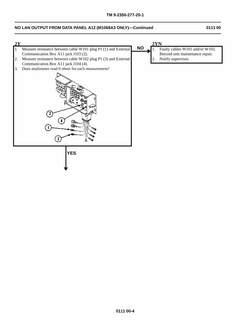
TM 9-2350-277-20-1
NO LAN OUTPUT FROM DATA PANEL A12 (M1068A3 ONLY)—Continued 0111 00
2Y1. Measure resistance between cable W101 plug P1 (1) and External
Communication Box A11 jack J103 (2).2. Measure resistance between cable W102 plug P1 (3) and External
Communication Box A11 jack J104 (4).3. Does multimeter read 0 ohms for each measurement?
YES
NO2YN1. Faulty cables W101 and/or W102.
Beyond unit maintenance repair.2. Notify supervisor.
0111 00-4
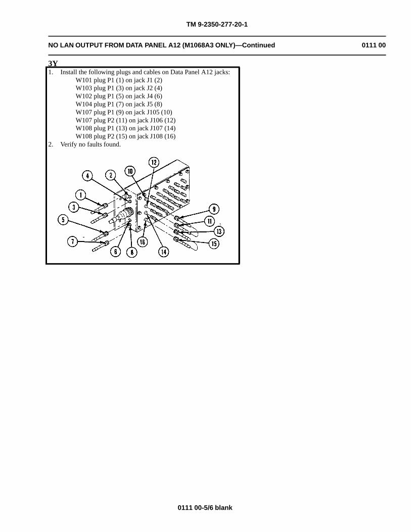
TM 9-2350-277-20-1
NO LAN OUTPUT FROM DATA PANEL A12 (M1068A3 ONLY)—Continued 0111 00
3Y1. Install the following plugs and cables on Data Panel A12 jacks:
W101 plug P1 (1) on jack J1 (2)W103 plug P1 (3) on jack J2 (4)W102 plug P1 (5) on jack J4 (6)W104 plug P1 (7) on jack J5 (8)W107 plug P1 (9) on jack J105 (10)W107 plug P2 (11) on jack J106 (12)W108 plug P1 (13) on jack J107 (14)W108 plug P2 (15) on jack J108 (16)
2. Verify no faults found.
0111 00-5/6 blank

TM 9-2350-277-20-1
NO DATA OUTPUT FROM DATA PANEL A13 (M1068A3 ONLY) 0112 00
INITIAL SETUP:
Maintenance Level
Unit
Tools and Special Tools
Radio equipment tool kit (WP 0926 00, Item 66)Multimeter (WP 0926 00, Item 30)
Personnel Required
Signal Support System Specialist 31U10Helper (H)
References
See your -10TM 11-7010-256-12&PSee M1068A3 Wiring Diagram (FO-7 and FO-8)
Equipment Condition
Engine stopped (see your -10)Carrier blocked (see your -10)
0112 00-1
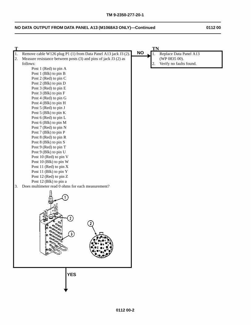
TM 9-2350-277-20-1
NO DATA OUTPUT FROM DATA PANEL A13 (M1068A3 ONLY)—Continued 0112 00
T1. Remove cable W126 plug P1 (1) from Data Panel A13 jack J3 (2).2. Measure resistance between posts (3) and pins of jack J3 (2) as
follows:Post 1 (Red) to pin APost 1 (Blk) to pin BPost 2 (Red) to pin CPost 2 (Blk) to pin DPost 3 (Red) to pin EPost 3 (Blk) to pin FPost 4 (Red) to pin GPost 4 (Blk) to pin HPost 5 (Red) to pin JPost 5 (Blk) to pin KPost 6 (Red) to pin LPost 6 (Blk) to pin MPost 7 (Red) to pin NPost 7 (Blk) to pin PPost 8 (Red) to pin RPost 8 (Blk) to pin SPost 9 (Red) to pin TPost 9 (Blk) to pin UPost 10 (Red) to pin VPost 10 (Blk) to pin WPost 11 (Red) to pin XPost 11 (Blk) to pin YPost 12 (Red) to pin ZPost 12 (Blk) to pin a
3. Does multimeter read 0 ohms for each measurement?
YES
NOTN1. Replace Data Panel A13
(WP 0835 00).2. Verify no faults found.
0112 00-2
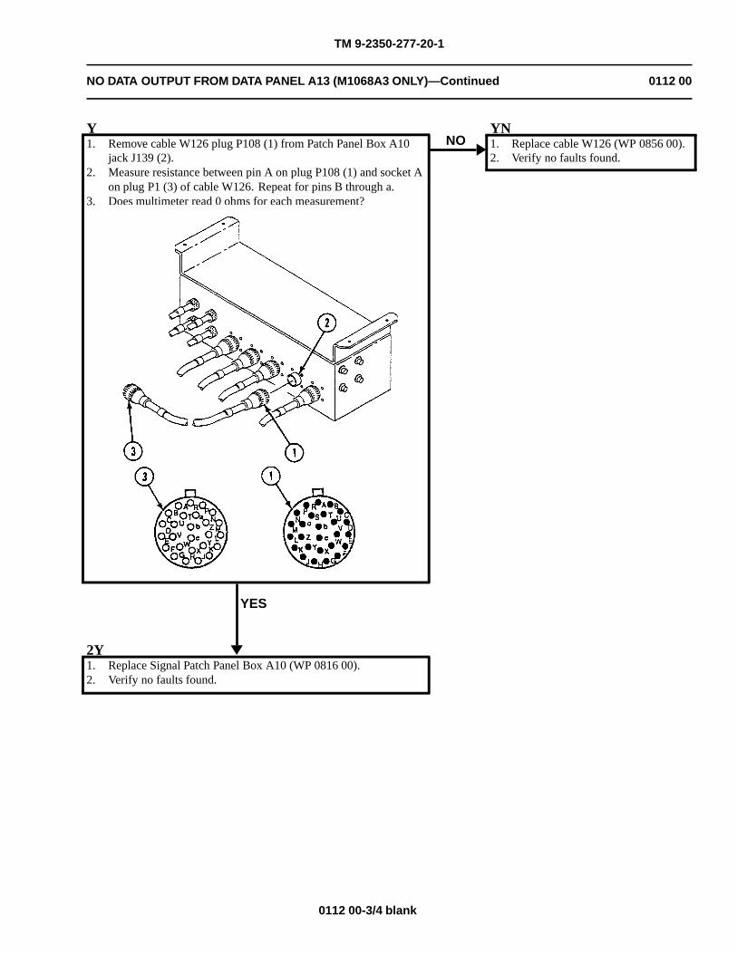
TM 9-2350-277-20-1
NO DATA OUTPUT FROM DATA PANEL A13 (M1068A3 ONLY)—Continued 0112 00
Y1. Remove cable W126 plug P108 (1) from Patch Panel Box A10
jack J139 (2).2. Measure resistance between pin A on plug P108 (1) and socket A
on plug P1 (3) of cable W126. Repeat for pins B through a.3. Does multimeter read 0 ohms for each measurement?
YES
NOYN1. Replace cable W126 (WP 0856 00).2. Verify no faults found.
2Y1. Replace Signal Patch Panel Box A10 (WP 0816 00).2. Verify no faults found.
0112 00-3/4 blank


TM 9-2350-277-20-1
NO LAN OUTPUT FROM DATA PANEL A13 (M1068A3 ONLY) 0113 00
INITIAL SETUP:
Maintenance Level
Unit
Tools and Special Tools
Radio equipment tool kit (WP 0926 00, Item 66)Multimeter (WP 0926 00, Item 30)
Personnel Required
Signal Support System Specialist 31U10Helper (H)
References
See your -10TM 11-7010-256-12&PSee M1068A3 Wiring Diagram(FO-7 and FO-8)
Equipment Condition
Engine stopped (see your -10)Carrier blocked (see your -10)
WARNING
HIGH VOLTAGE is used in the operation of this equipment.
DEATH ON CONTACT may result if personnel fail to observe safety precautions.
NEVER work on equipment unless at least one other person familiar with the operation andhazards of the equipment is nearby. That person should also be familiar with giving first aid.When an operator helps a mechanic, that operator must be warned about dangerous areas.
SHUT OFF POWER supply to equipment before beginning work. Make sure all external poweris off/disconnected.
BE CAREFUL not to contact high-voltage connections when installing or operating thisequipment.
0113 00-1
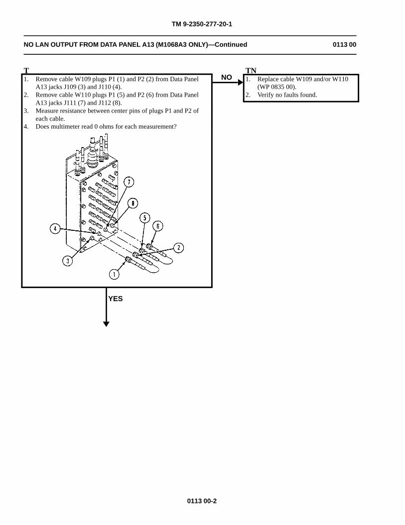
TM 9-2350-277-20-1
NO LAN OUTPUT FROM DATA PANEL A13 (M1068A3 ONLY)—Continued 0113 00
T1. Remove cable W109 plugs P1 (1) and P2 (2) from Data Panel
A13 jacks J109 (3) and J110 (4).2. Remove cable W110 plugs P1 (5) and P2 (6) from Data Panel
A13 jacks J111 (7) and J112 (8).3. Measure resistance between center pins of plugs P1 and P2 of
each cable.4. Does multimeter read 0 ohms for each measurement?
YES
NOTN1. Replace cable W109 and/or W110
(WP 0835 00).2. Verify no faults found.
0113 00-2
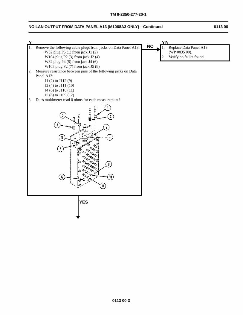
TM 9-2350-277-20-1
NO LAN OUTPUT FROM DATA PANEL A13 (M1068A3 ONLY)—Continued 0113 00
Y1. Remove the following cable plugs from jacks on Data Panel A13:
W32 plug P5 (1) from jack J1 (2)W104 plug P2 (3) from jack J2 (4)W32 plug P4 (5) from jack J4 (6)W103 plug P2 (7) from jack J5 (8)
2. Measure resistance between pins of the following jacks on DataPanel A13:
J1 (2) to J112 (9)J2 (4) to J111 (10)J4 (6) to J110 (11)J5 (8) to J109 (12)
3. Does multimeter read 0 ohms for each measurement?
YES
NOYN1. Replace Data Panel A13
(WP 0835 00).2. Verify no faults found.
0113 00-3
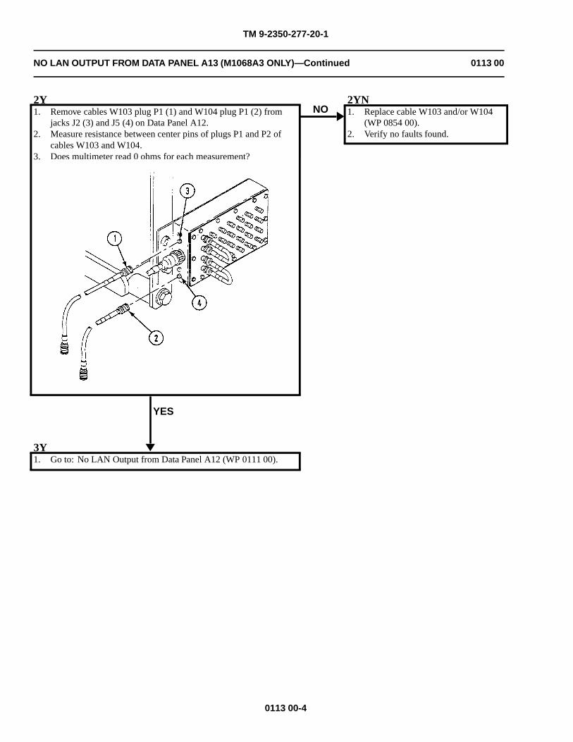
TM 9-2350-277-20-1
NO LAN OUTPUT FROM DATA PANEL A13 (M1068A3 ONLY)—Continued 0113 00
2Y1. Remove cables W103 plug P1 (1) and W104 plug P1 (2) from
jacks J2 (3) and J5 (4) on Data Panel A12.2. Measure resistance between center pins of plugs P1 and P2 of
cables W103 and W104.3. Does multimeter read 0 ohms for each measurement?
YES
NO2YN1. Replace cable W103 and/or W104
(WP 0854 00).2. Verify no faults found.
3Y1. Go to: No LAN Output from Data Panel A12 (WP 0111 00).
0113 00-4
TM 9-2350-277-20-1
PHONE EXTENSION BOX A14 POST(S) INOPERATIVE (M1068A3 ONLY) 0114 00
INITIAL SETUP:
Maintenance Level
Unit
Tools and Special Tools
Radio Equipment Tool Kit (WP 0926 00, Item 66)Digital Multimeter (WP 0926 00, Item 30)
Personnel Required
Signal Support System Specialist 31U10Helper (H)
References
See your -10TM 11-7010-256-12&PSee M1068A3 Wiring Diagram (FO-7 and FO-8)
Equipment Condition
Engine stopped (see your -10)Carrier blocked (see your -10)
WARNING
HIGH VOLTAGE is used in the operation of this equipment.
DEATH ON CONTACT may result if personnel fail to observe safety precautions.
NEVER work on equipment unless at least one other person familiar with the operation andhazards of the equipment is nearby. That person should also be familiar with giving first aid.When an operator helps a mechanic, that operator must be warned about dangerous areas.
SHUT OFF POWER supply to equipment before beginning work. Make sure all external poweris off/disconnected.
BE CAREFUL not to contact high-voltage connections when installing or operating thisequipment.
0114 00-1
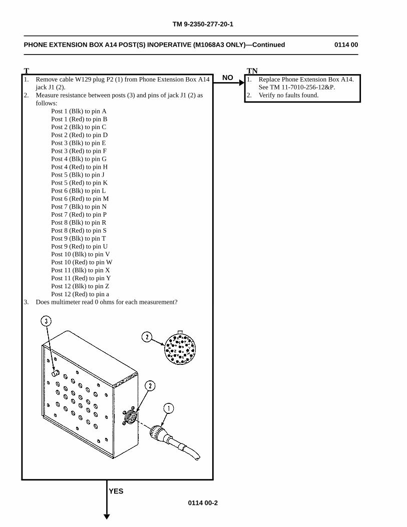
TM 9-2350-277-20-1
PHONE EXTENSION BOX A14 POST(S) INOPERATIVE (M1068A3 ONLY)—Continued 0114 00
T1. Remove cable W129 plug P2 (1) from Phone Extension Box A14
jack J1 (2).2. Measure resistance between posts (3) and pins of jack J1 (2) as
follows:Post 1 (Blk) to pin APost 1 (Red) to pin BPost 2 (Blk) to pin CPost 2 (Red) to pin DPost 3 (Blk) to pin EPost 3 (Red) to pin FPost 4 (Blk) to pin GPost 4 (Red) to pin HPost 5 (Blk) to pin JPost 5 (Red) to pin KPost 6 (Blk) to pin LPost 6 (Red) to pin MPost 7 (Blk) to pin NPost 7 (Red) to pin PPost 8 (Blk) to pin RPost 8 (Red) to pin SPost 9 (Blk) to pin TPost 9 (Red) to pin UPost 10 (Blk) to pin VPost 10 (Red) to pin WPost 11 (Blk) to pin XPost 11 (Red) to pin YPost 12 (Blk) to pin ZPost 12 (Red) to pin a
3. Does multimeter read 0 ohms for each measurement?
YES
NOTN1. Replace Phone Extension Box A14.
See TM 11-7010-256-12&P.2. Verify no faults found.
0114 00-2
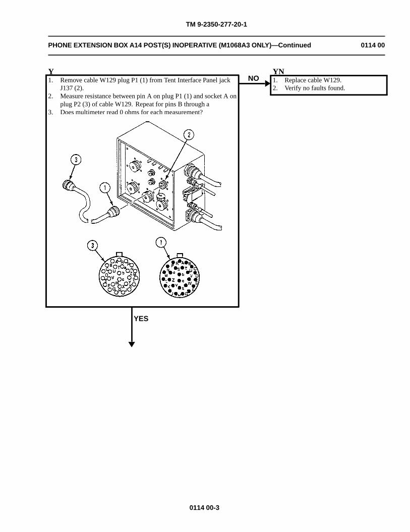
TM 9-2350-277-20-1
PHONE EXTENSION BOX A14 POST(S) INOPERATIVE (M1068A3 ONLY)—Continued 0114 00
Y1. Remove cable W129 plug P1 (1) from Tent Interface Panel jack
J137 (2).2. Measure resistance between pin A on plug P1 (1) and socket A on
plug P2 (3) of cable W129. Repeat for pins B through a3. Does multimeter read 0 ohms for each measurement?
YES
NOYN1. Replace cable W129.2. Verify no faults found.
0114 00-3
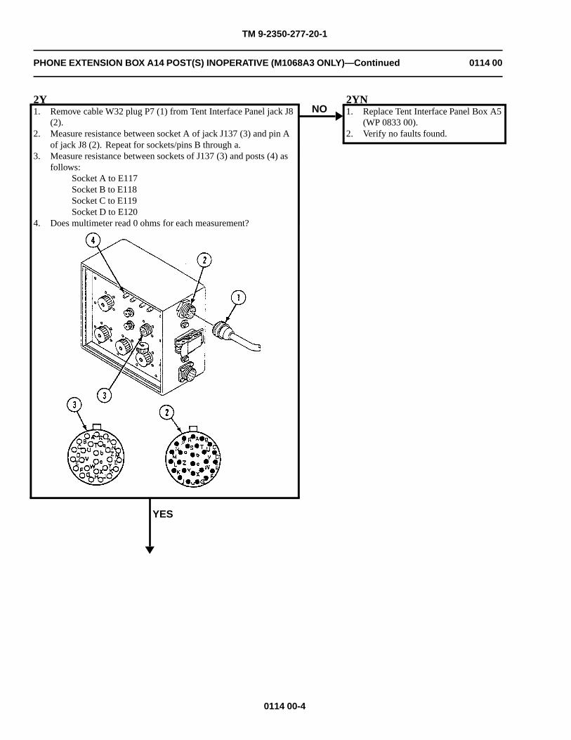
TM 9-2350-277-20-1
PHONE EXTENSION BOX A14 POST(S) INOPERATIVE (M1068A3 ONLY)—Continued 0114 00
2Y1. Remove cable W32 plug P7 (1) from Tent Interface Panel jack J8
(2).2. Measure resistance between socket A of jack J137 (3) and pin A
of jack J8 (2). Repeat for sockets/pins B through a.3. Measure resistance between sockets of J137 (3) and posts (4) as
follows:Socket A to E117Socket B to E118Socket C to E119Socket D to E120
4. Does multimeter read 0 ohms for each measurement?
YES
NO2YN1. Replace Tent Interface Panel Box A5
(WP 0833 00).2. Verify no faults found.
0114 00-4
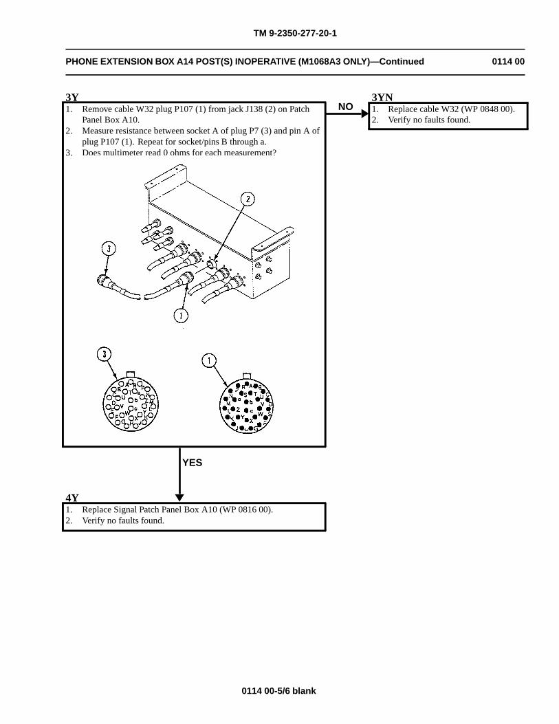
TM 9-2350-277-20-1
PHONE EXTENSION BOX A14 POST(S) INOPERATIVE (M1068A3 ONLY)—Continued 0114 00
3Y1. Remove cable W32 plug P107 (1) from jack J138 (2) on Patch
Panel Box A10.2. Measure resistance between socket A of plug P7 (3) and pin A of
plug P107 (1). Repeat for socket/pins B through a.3. Does multimeter read 0 ohms for each measurement?
YES
NO3YN1. Replace cable W32 (WP 0848 00).2. Verify no faults found.
4Y1. Replace Signal Patch Panel Box A10 (WP 0816 00).2. Verify no faults found.
0114 00-5/6 blank

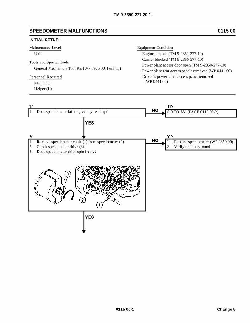
TM 9-2350-277-20-1
SPEEDOMETER MALFUNCTIONS 0115 00
INITIAL SETUP:
Maintenance LevelUnit
Tools and Special ToolsGeneral Mechanic’s Tool Kit (WP 0926 00, Item 65)
Personnel RequiredMechanicHelper (H)
Equipment ConditionEngine stopped (TM 9-2350-277-10)Carrier blocked (TM 9-2350-277-10)Power plant access door open (TM 9-2350-277-10)Power plant rear access panels removed (WP 0441 00)Driver’s power plant access panel removed
(WP 0441 00)
T1. Does speedometer fail to give any reading?
TNGO TO AY (PAGE 0115 00-2)
Y1. Remove speedometer cable (1) from speedometer (2).2. Check speedometer drive (3).3. Does speedometer drive spin freely?
YN1. Replace speedometer (WP 0859 00).2. Verify no faults found.
0115 00-1 Change 5
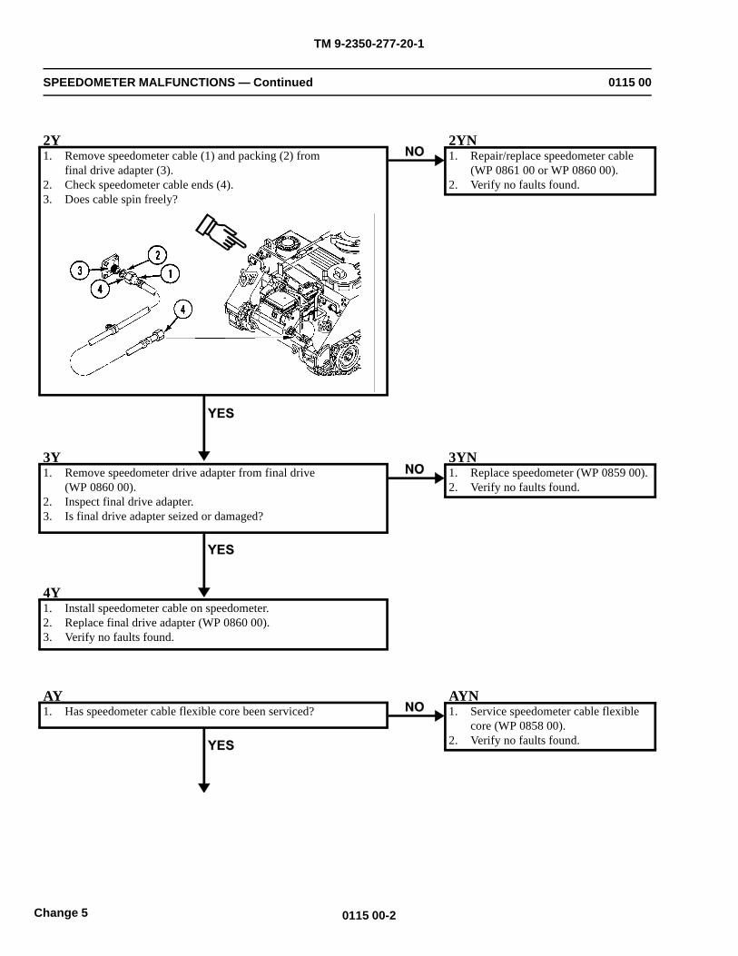
TM 9-2350-277-20-1
SPEEDOMETER MALFUNCTIONS — Continued 0115 00
2Y1. Remove speedometer cable (1) and packing (2) from
final drive adapter (3).2. Check speedometer cable ends (4).3. Does cable spin freely?
2YN1. Repair/replace speedometer cable
(WP 0861 00 or WP 0860 00).2. Verify no faults found.
3Y1. Remove speedometer drive adapter from final drive
(WP 0860 00).2. Inspect final drive adapter.3. Is final drive adapter seized or damaged?
3YN1. Replace speedometer (WP 0859 00).2. Verify no faults found.
4Y1. Install speedometer cable on speedometer.2. Replace final drive adapter (WP 0860 00).3. Verify no faults found.
AY1. Has speedometer cable flexible core been serviced?
AYN1. Service speedometer cable flexible
core (WP 0858 00).2. Verify no faults found.
0115 00-2Change 5
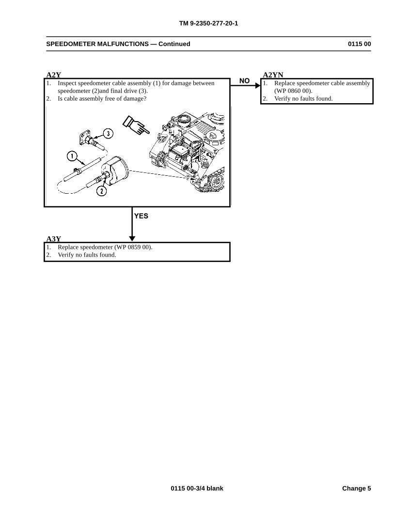
TM 9-2350-277-20-1
SPEEDOMETER MALFUNCTIONS — Continued 0115 00
A2Y1. Inspect speedometer cable assembly (1) for damage between
speedometer (2)and final drive (3).2. Is cable assembly free of damage?
A2YN1. Replace speedometer cable assembly
(WP 0860 00).2. Verify no faults found.
A3Y1. Replace speedometer (WP 0859 00).2. Verify no faults found.
0115 00-3/4 blank Change 5

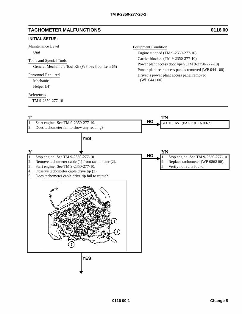
TM 9-2350-277-20-1
TACHOMETER MALFUNCTIONS 0116 00
INITIAL SETUP:
Maintenance LevelUnit
Tools and Special ToolsGeneral Mechanic’s Tool Kit (WP 0926 00, Item 65)
Personnel RequiredMechanicHelper (H)
ReferencesTM 9-2350-277-10
Equipment ConditionEngine stopped (TM 9-2350-277-10)Carrier blocked (TM 9-2350-277-10)Power plant access door open (TM 9-2350-277-10)Power plant rear access panels removed (WP 0441 00)Driver’s power plant access panel removed
(WP 0441 00)
T1. Start engine. See TM 9-2350-277-10.2. Does tachometer fail to show any reading?
TNGO TO AY (PAGE 0116 00-2)
Y1. Stop engine. See TM 9-2350-277-10.2. Remove tachometer cable (1) from tachometer (2).3. Start engine. See TM 9-2350-277-10.4. Observe tachometer cable drive tip (3).5. Does tachometer cable drive tip fail to rotate?
YN1. Stop engine. See TM 9-2350-277-10.2. Replace tachometer (WP 0862 00).3. Verify no faults found.
0116 00-1 Change 5
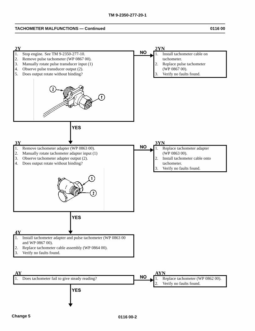
TM 9-2350-277-20-1
TACHOMETER MALFUNCTIONS — Continued 0116 00
2Y1. Stop engine. See TM 9-2350-277-10.2. Remove pulse tachometer (WP 0867 00).3. Manually rotate pulse transducer input (1)4. Observe pulse transducer output (2).5. Does output rotate without binding?
2YN1. Install tachometer cable on
tachometer.2. Replace pulse tachometer
(WP 0867 00).3. Verify no faults found.
3Y1. Remove tachometer adapter (WP 0863 00).2. Manually rotate tachometer adapter input (1)3. Observe tachometer adapter output (2).4. Does output rotate without binding?
3YN1. Replace tachometer adapter
(WP 0863 00).2. Install tachometer cable onto
tachometer.3. Verify no faults found.
4Y1. Install tachometer adapter and pulse tachometer (WP 0863 00
and WP 0867 00).2. Replace tachometer cable assembly (WP 0864 00).3. Verify no faults found.
AY1. Does tachometer fail to give steady reading?
AYN1. Replace tachometer (WP 0862 00).2. Verify no faults found.
0116 00-2Change 5
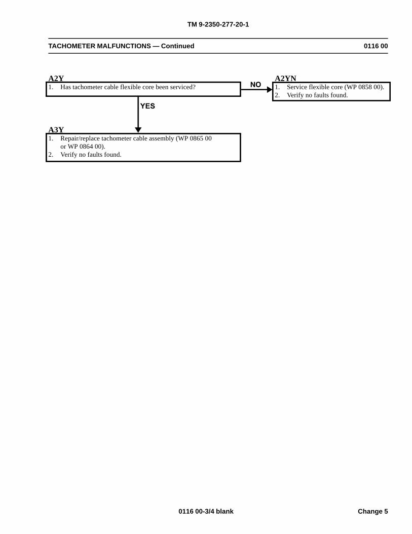
TM 9-2350-277-20-1
TACHOMETER MALFUNCTIONS — Continued 0116 00
A2Y1. Has tachometer cable flexible core been serviced?
A2YN1. Service flexible core (WP 0858 00).2. Verify no faults found.
A3Y1. Repair/replace tachometer cable assembly (WP 0865 00
or WP 0864 00).2. Verify no faults found.
0116 00-3/4 blank Change 5

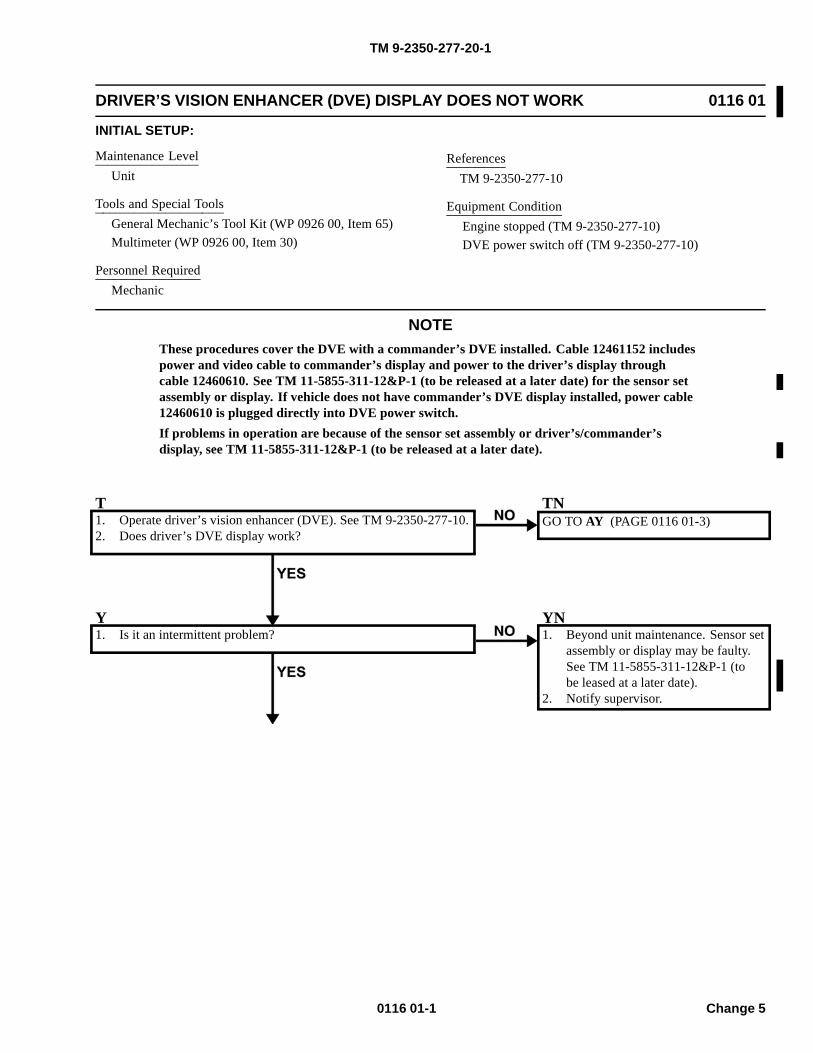
TM 9-2350-277-20-1
DRIVER’S VISION ENHANCER (DVE) DISPLAY DOES NOT WORK 0116 01
INITIAL SETUP:
Maintenance LevelUnit
Tools and Special ToolsGeneral Mechanic’s Tool Kit (WP 0926 00, Item 65)Multimeter (WP 0926 00, Item 30)
Personnel RequiredMechanic
ReferencesTM 9-2350-277-10
Equipment ConditionEngine stopped (TM 9-2350-277-10)DVE power switch off (TM 9-2350-277-10)
NOTEThese procedures cover the DVE with a commander’s DVE installed. Cable 12461152 includespower and video cable to commander’s display and power to the driver’s display throughcable 12460610. See TM 11-5855-311-12&P-1 (to be released at a later date) for the sensor setassembly or display. If vehicle does not have commander’s DVE display installed, power cable12460610 is plugged directly into DVE power switch.If problems in operation are because of the sensor set assembly or driver’s/commander’sdisplay, see TM 11-5855-311-12&P-1 (to be released at a later date).
T1. Operate driver’s vision enhancer (DVE). See TM 9-2350-277-10.2. Does driver’s DVE display work?
TNGO TO AY (PAGE 0116 01-3)
Y1. Is it an intermittent problem?
YN1. Beyond unit maintenance. Sensor set
assembly or display may be faulty.See TM 11-5855-311-12&P-1 (tobe leased at a later date).
2. Notify supervisor.
0116 01-1 Change 5
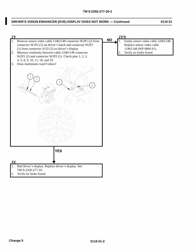
TM 9-2350-277-20-1
DRIVER’S VISION ENHANCER (DVE) DISPLAY DOES NOT WORK — Continued 0116 01
2Y1. Remove sensor video cable 12461148 connector W2P1 (2) from
connector W1P2 (1) on driver’s hatch and connector W2P2(1) from connector A1J2 (2) on driver’s display.
2. Measure continuity between cable 12461148 connectorW2P1 (2) and connector W2P2 (1). Check pins 1, 2, 3,4, 5, 8, 9, 10, 11, 18, and 19.
3. Does multimeter read 0 ohms?
2YN1. Faulty sensor video cable 12461148.
Replace sensor video cable12461148 (WP 0866 01).
2. Verify no faults found.
3Y1. Bad driver’s display. Replace driver’s display. See
TM 9-2350-277-10.2. Verify no faults found.
0116 01-2Change 5
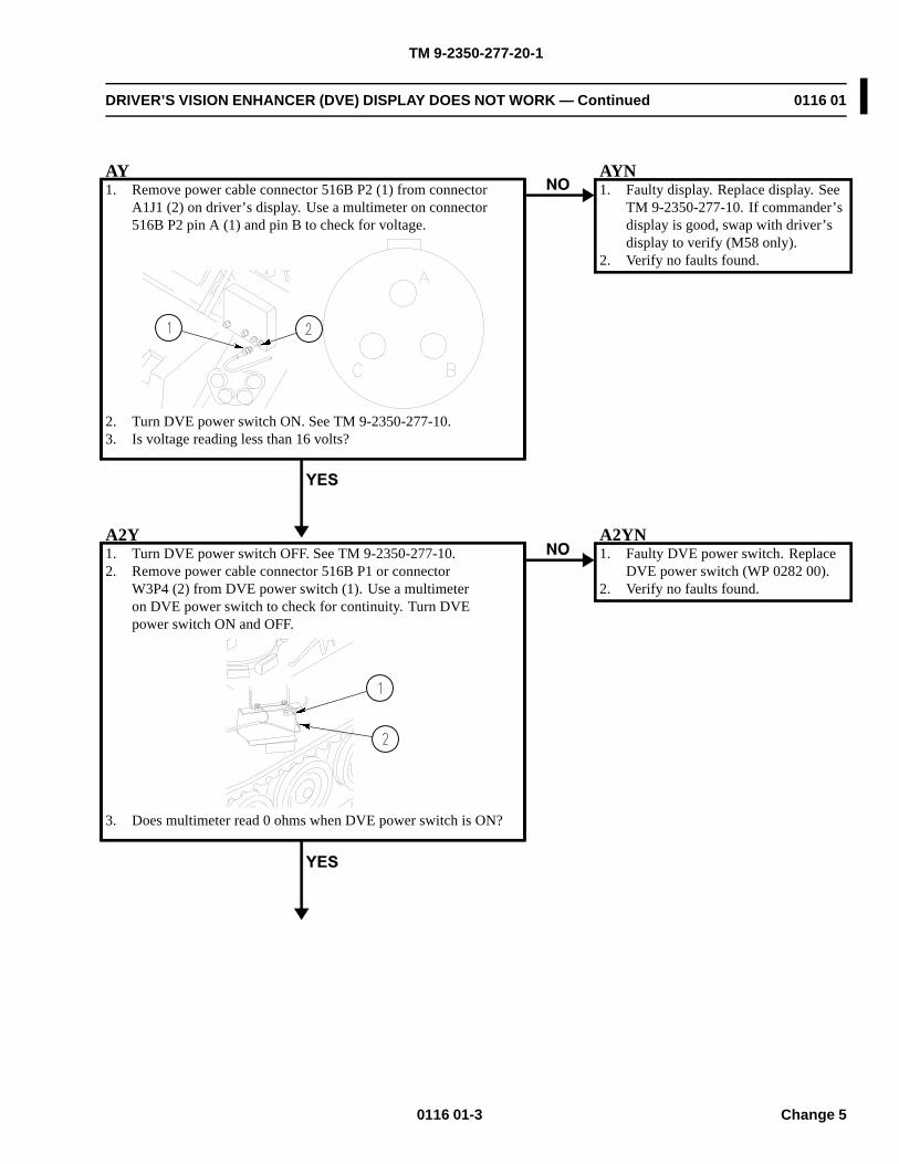
TM 9-2350-277-20-1
DRIVER’S VISION ENHANCER (DVE) DISPLAY DOES NOT WORK — Continued 0116 01
AY1. Remove power cable connector 516B P2 (1) from connector
A1J1 (2) on driver’s display. Use a multimeter on connector516B P2 pin A (1) and pin B to check for voltage.
2. Turn DVE power switch ON. See TM 9-2350-277-10.3. Is voltage reading less than 16 volts?
AYN1. Faulty display. Replace display. See
TM 9-2350-277-10. If commander’sdisplay is good, swap with driver’sdisplay to verify (M58 only).
2. Verify no faults found.
A2Y1. Turn DVE power switch OFF. See TM 9-2350-277-10.2. Remove power cable connector 516B P1 or connector
W3P4 (2) from DVE power switch (1). Use a multimeteron DVE power switch to check for continuity. Turn DVEpower switch ON and OFF.
3. Does multimeter read 0 ohms when DVE power switch is ON?
A2YN1. Faulty DVE power switch. Replace
DVE power switch (WP 0282 00).2. Verify no faults found.
0116 01-3 Change 5
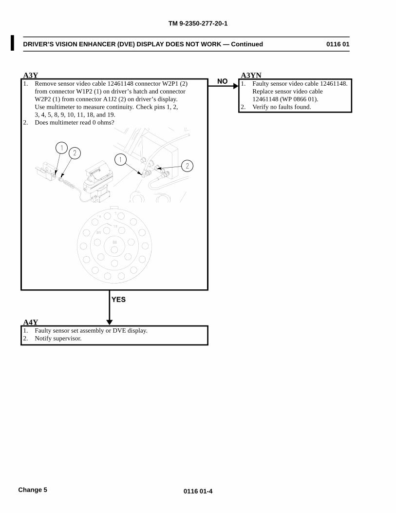
TM 9-2350-277-20-1
DRIVER’S VISION ENHANCER (DVE) DISPLAY DOES NOT WORK — Continued 0116 01
A3Y1. Remove sensor video cable 12461148 connector W2P1 (2)
from connector W1P2 (1) on driver’s hatch and connectorW2P2 (1) from connector A1J2 (2) on driver’s display.Use multimeter to measure continuity. Check pins 1, 2,3, 4, 5, 8, 9, 10, 11, 18, and 19.
2. Does multimeter read 0 ohms?
A3YN1. Faulty sensor video cable 12461148.
Replace sensor video cable12461148 (WP 0866 01).
2. Verify no faults found.
A4Y1. Faulty sensor set assembly or DVE display.2. Notify supervisor.
0116 01-4Change 5
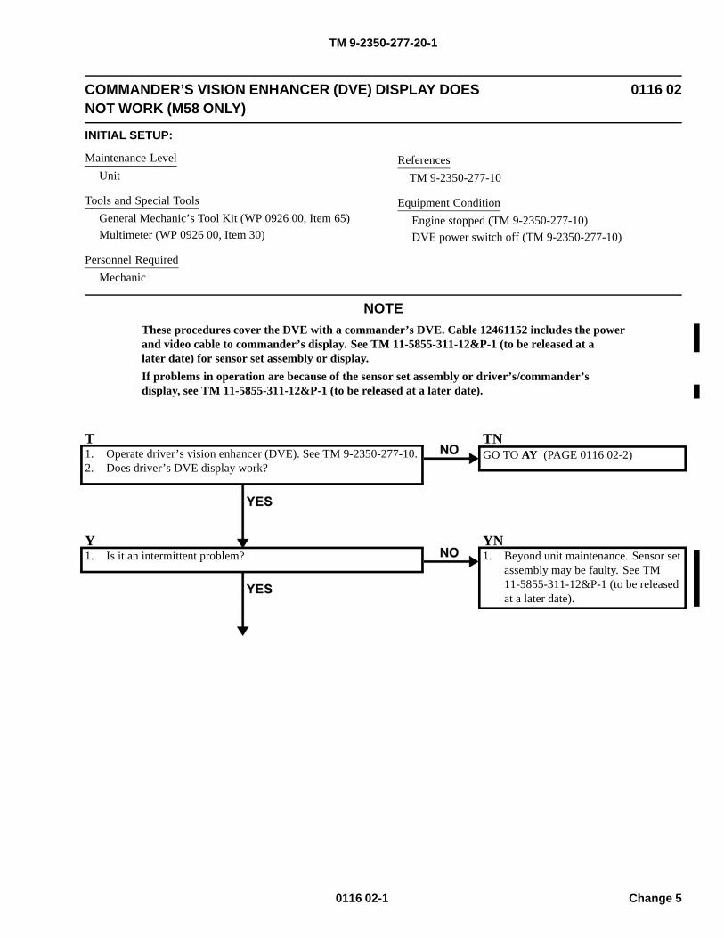
TM 9-2350-277-20-1
COMMANDER’S VISION ENHANCER (DVE) DISPLAY DOESNOT WORK (M58 ONLY)
0116 02
INITIAL SETUP:
Maintenance LevelUnit
Tools and Special ToolsGeneral Mechanic’s Tool Kit (WP 0926 00, Item 65)Multimeter (WP 0926 00, Item 30)
Personnel RequiredMechanic
ReferencesTM 9-2350-277-10
Equipment ConditionEngine stopped (TM 9-2350-277-10)DVE power switch off (TM 9-2350-277-10)
NOTEThese procedures cover the DVE with a commander’s DVE. Cable 12461152 includes the powerand video cable to commander’s display. See TM 11-5855-311-12&P-1 (to be released at alater date) for sensor set assembly or display.If problems in operation are because of the sensor set assembly or driver’s/commander’sdisplay, see TM 11-5855-311-12&P-1 (to be released at a later date).
T1. Operate driver’s vision enhancer (DVE). See TM 9-2350-277-10.2. Does driver’s DVE display work?
TNGO TO AY (PAGE 0116 02-2)
Y1. Is it an intermittent problem?
YN1. Beyond unit maintenance. Sensor set
assembly may be faulty. See TM11-5855-311-12&P-1 (to be releasedat a later date).
0116 02-1 Change 5
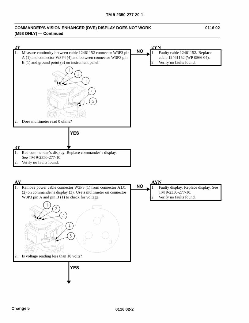
TM 9-2350-277-20-1
COMMANDER’S VISION ENHANCER (DVE) DISPLAY DOES NOT WORK(M58 ONLY) — Continued
0116 02
2Y1. Measure continuity between cable 12461152 connector W3P3 pin
A (1) and connector W3P4 (4) and between connector W3P3 pinB (1) and ground point (5) on instrument panel.
2. Does multimeter read 0 ohms?
2YN1. Faulty cable 12461152. Replace
cable 12461152 (WP 0866 04).2. Verify no faults found.
3Y1. Bad commander’s display. Replace commander’s display.
See TM 9-2350-277-10.2. Verify no faults found.
AY1. Remove power cable connector W3P3 (1) from connector A1J1
(2) on commander’s display (3). Use a multimeter on connectorW3P3 pin A and pin B (1) to check for voltage.
2. Is voltage reading less than 18 volts?
AYN1. Faulty display. Replace display. See
TM 9-2350-277-10.2. Verify no faults found.
0116 02-2Change 5
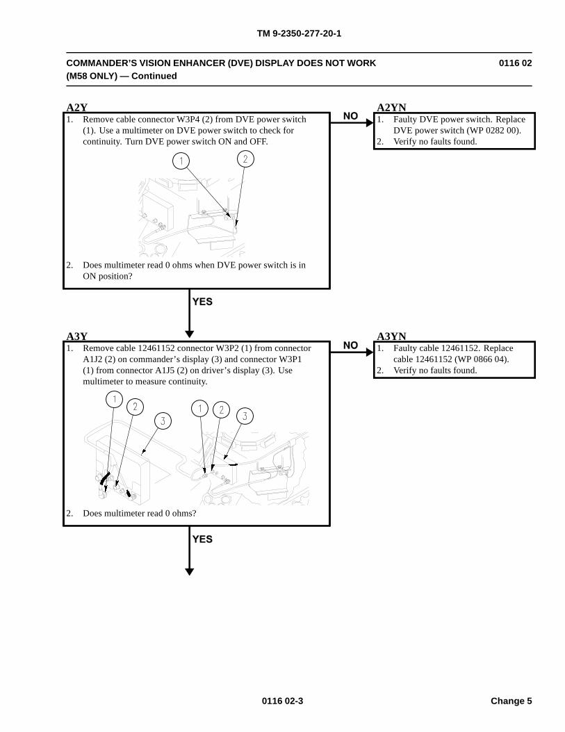
TM 9-2350-277-20-1
COMMANDER’S VISION ENHANCER (DVE) DISPLAY DOES NOT WORK(M58 ONLY) — Continued
0116 02
A2Y1. Remove cable connector W3P4 (2) from DVE power switch
(1). Use a multimeter on DVE power switch to check forcontinuity. Turn DVE power switch ON and OFF.
2. Does multimeter read 0 ohms when DVE power switch is inON position?
A2YN1. Faulty DVE power switch. Replace
DVE power switch (WP 0282 00).2. Verify no faults found.
A3Y1. Remove cable 12461152 connector W3P2 (1) from connector
A1J2 (2) on commander’s display (3) and connector W3P1(1) from connector A1J5 (2) on driver’s display (3). Usemultimeter to measure continuity.
2. Does multimeter read 0 ohms?
A3YN1. Faulty cable 12461152. Replace
cable 12461152 (WP 0866 04).2. Verify no faults found.
0116 02-3 Change 5
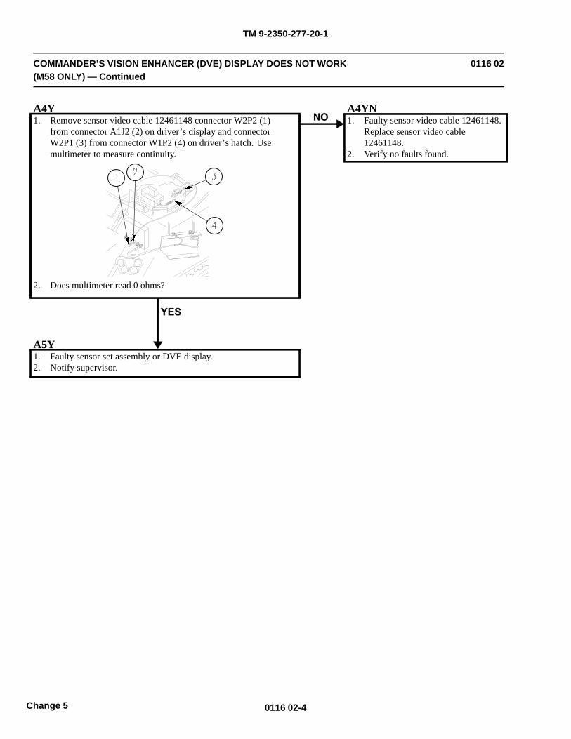
TM 9-2350-277-20-1
COMMANDER’S VISION ENHANCER (DVE) DISPLAY DOES NOT WORK(M58 ONLY) — Continued
0116 02
A4Y1. Remove sensor video cable 12461148 connector W2P2 (1)
from connector A1J2 (2) on driver’s display and connectorW2P1 (3) from connector W1P2 (4) on driver’s hatch. Usemultimeter to measure continuity.
2. Does multimeter read 0 ohms?
A4YN1. Faulty sensor video cable 12461148.
Replace sensor video cable12461148.
2. Verify no faults found.
A5Y1. Faulty sensor set assembly or DVE display.2. Notify supervisor.
0116 02-4Change 5
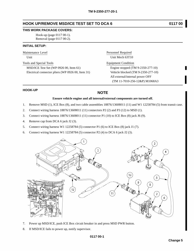
TM 9-2350-277-20-1
HOOK UP/REMOVE MSD/ICE TEST SET TO DCA 6 0117 00THIS WORK PACKAGE COVERS:
Hook-up (page 0117 00-1).Removal (page 0117 00-2).
INITIAL SETUP:
Maintenance LevelUnit
Tools and Special ToolsMSD/ICE Test Set (WP 0926 00, Item 61)Electrical connector pliers (WP 0926 00, Item 31)
Personnel RequiredUnit Mech 63T10
Equipment ConditionEngine stopped (TM 9-2350-277-10)Vehicle blocked (TM 9-2350-277-10)All external/internal power OFF
HOOK-UPNOTE
Ensure vehicle engine and all internal/external components are turned off.
1. Remove MSD (1), ICE Box (8), and two cable assemblies 18876/13608011 (11) and W1 12258784 (5) from transit case.
2. Connect wiring harness 18876/13608011 (11) connectors P2 (2) and P3 (12) to MSD (1).
3. Connect wiring harness 18876/13608011 (11) connector P1 (10) to ICE Box (8) jack J6 (9).
4. Remove cap from DCA 6 jack J2 (3).
5. Connect wiring harness W1 12258784 (5) connector P1 (6) to ICE Box (8) jack J1 (7).
6. Connect wiring harness W1 12258784 (5) connector P2 (4) to DCA 6 jack J2 (3).
7. Power up MSD/ICE, push ICE Box circuit breaker in and press MSD PWR button.
8. If MSD/ICE fails to power up, notify supervisor.
0117 00-1Change 5
(TM 11-7010-256-12&P) M1068A3
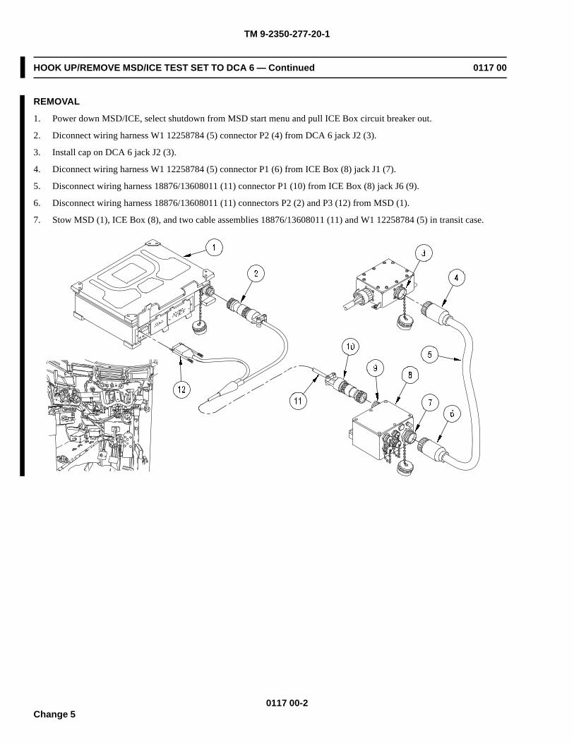
TM 9-2350-277-20-1
HOOK UP/REMOVE MSD/ICE TEST SET TO DCA 6 — Continued 0117 00
REMOVAL
1. Power down MSD/ICE, select shutdown from MSD start menu and pull ICE Box circuit breaker out.
2. Diconnect wiring harness W1 12258784 (5) connector P2 (4) from DCA 6 jack J2 (3).
3. Install cap on DCA 6 jack J2 (3).
4. Diconnect wiring harness W1 12258784 (5) connector P1 (6) from ICE Box (8) jack J1 (7).
5. Disconnect wiring harness 18876/13608011 (11) connector P1 (10) from ICE Box (8) jack J6 (9).
6. Disconnect wiring harness 18876/13608011 (11) connectors P2 (2) and P3 (12) from MSD (1).
7. Stow MSD (1), ICE Box (8), and two cable assemblies 18876/13608011 (11) and W1 12258784 (5) in transit case.
0117 00-2Change 5
TM 9-2350-277-20-1
MSD/ICE TEST 10 ENGINE RPM 0118 00THIS WORK PACKAGE COVERS:
Test (page 0118 00-1).
INITIAL SETUP:
Maintenance LevelUnit
Personnel RequiredUnit Mech 63T10
Equipment ConditionEngine stopped (TM 9-2350-277-10)Vehicle blocked (TM 9-2350-277-10)MSD/ICE hooked up to DCA 6 (WP 0117 00)
TEST
1. Select ICE Testing from programs menu.
2. Select button 1. Serial ICE
3. Select button 1. ICE Tests
NOTEAll M113A3 variants are covered under M113A3-M1068A3 APC vehicle selection
4. Select M113A3-M1068A3 APC, then select the OK button.
NOTEOnce MSD/ICE hook up screen OK button is selected, the MSD/ICE will perform a self test.If self test fails, notify supervisor.
5. Select OK button on the MSD/ICE hook up screen to proceed.
6. Select OK button after successful self test.
7. Follow on screen preparation for DCA offsets tests. Select OK button.
8. Use Tab and Shift-Tab to move from one list box to another.
9. Use spacebar to select/deselect the test.
10. Select 10 DCA Engine RPM from ENGINE list box. Select Run Test(s) button.
CONDITION ENGINE RPM
Cranking 100 Minimum
Idle 600-700
Governed speed (no load) 2900-3050
a. If error message appears, see TM 9-6625-2301-14&P.
11. Return to troubleshooting.
0118 00-1/2 blankChange 5

TM 9-2350-277-20-1
MSD/ICE TEST 24 FUEL SUPPLY PRESSURE 0119 00THIS WORK PACKAGE COVERS:
Test (page 0119 00-1).
INITIAL SETUP:
Maintenance LevelUnit
Personnel RequiredUnit Mech 63T10
ReferencesTM 9-2350-277-10WP 0155 00
Equipment ConditionEngine stopped (TM 9-2350-277-10)Vehicle blocked (TM 9-2350-277-10)MSD/ICE hooked up to DCA 6 (WP 0117 00)
TEST
1. Select ICE Testing from programs menu.
2. Select button 1. Serial ICE
3. Select button 1. ICE Tests
NOTEAll M113A3 variants are covered under M113A3-M1068A3 APC vehicle selection
4. Select M113A3-M1068A3 APC, then select the OK button.
NOTEOnce MSD/ICE hook up screen OK button is selected, the MSD/ICE will perform a self test.If self test fails, notify supervisor.
5. Select OK button on the MSD/ICE hook up screen to proceed.
6. Select OK button after successful self test.
7. Follow on screen preparation for DCA offsets tests. Select OK button.
8. Use Tab and Shift-Tab to move from one list box to another.
9. Use spacebar to select/deselect the test.
10. Select 24 Fuel Pressure from FUEL SYSTEM list box. Select Run Test(s) button.
11. Start engine and run at governed no load speed (WP 0155 00).
a. If MSD reads 55 (psi) or more, test passes.
b. If error message appears, see TM 9-6625-2301-14&P.
12. Stop engine. See TM 9-2350-277-10.
13. Return to troubleshooting.
0119 00-1/2 blankChange 5

TM 9-2350-277-20-1
MSD/ICE TEST 25 FUEL RETURN PRESSURE 0120 00THIS WORK PACKAGE COVERS:
Test (page 0120 00-1).
INITIAL SETUP:
Maintenance LevelUnit
Personnel RequiredUnit Mech 63T10
ReferencesTM 9-2350-277-10WP 0155 00
Equipment ConditionEngine stopped (TM 9-2350-277-10)Vehicle blocked (TM 9-2350-277-10)MSD/ICE hooked up to DCA 6 (WP 0117 00)
TEST
1. Select ICE Testing from programs menu.
2. Select button 1. Serial ICE
3. Select button 1. ICE Tests
NOTEAll M113A3 variants are covered under M113A3-M1068A3 APC vehicle selection
4. Select M113A3-M1068A3 APC, then select the OK button.
NOTEOnce MSD/ICE hook up screen OK button is selected, the MSD/ICE will perform a self test.If self test fails, notify supervisor.
5. Select OK button on the MSD/ICE hook up screen to proceed.
6. Select OK button after successful self test.
7. Follow on screen preparation for DCA offsets tests. Select OK button.
8. Use Tab and Shift-Tab to move from one list box to another.
9. Use spacebar to select/deselect the test.
10. Select 25 Fuel Return Press from FUEL SYSTEM list box. Select Run Test(s) button.
11. Start engine and run at governed no load speed (WP 0155 00).
a. If MSD reads 18 (psi) or more, test passes.
b. If error message appears, see TM 9-6625-2301-14&P.
12. Stop engine. See TM 9-2350-277-10.
13. Return to Troubleshooting.
0120 00-1/2 blankChange 5

TM 9-2350-277-20-1
MSD/ICE TEST 26 FUEL FILTER PRESSURE DROP 0121 00THIS WORK PACKAGE COVERS:
Test (page 0121 00-1).
INITIAL SETUP:
Maintenance LevelUnit
Personnel RequiredUnit Mech 63T10Helper
ReferencesTM 9-2350-277-10WP 0155 00
Equipment ConditionEngine stopped (TM 9-2350-277-10)Vehicle blocked (TM 9-2350-277-10)MSD/ICE hooked up to DCA 6 (WP 0117 00)
NOTEAfter testing should you want to re-test, press Alt F4 to re-establish serial connection.
1. Select ICE Testing from programs menu.
2. Select button 1. Serial ICE
3. Select button 1. ICE Tests
NOTEAll M113A3 variants are covered under M113A3-M1068A3 APC vehicle selection
4. Select M113A3-M1068A3 APC, then select the OK button.
NOTEOnce MSD/ICE hook up screen OK button is selected, the MSD/ICE will perform a self test.If self test fails, notify supervisor.
5. Select OK button on the MSD/ICE hook up screen to proceed.
6. Select OK button after successful self test.
7. Follow on screen preparation for DCA offsets tests. Select OK button.
8. Use Tab and Shift-Tab to move from one list box to another.
9. Use spacebar to select/deselect the test.
10. Select 26 Fuel Filter Press Drp from FUEL SYSTEM list box. Select Run Test(s) button.
11. Start engine. See TM 9-2350-277-10.
12. Perform road test (WP 0155 00).
13. When engine RPM reaches 2400 during road test, press enter to run test. Have helper assist.
14. MSD should display PASS or FAIL.
a. If error message appears, see TM 9-6625-2301-14&P.
15. Stop engine. See TM 9-2350-277-10.
16. Return to troubleshooting.
0121 00-1/2 blankChange 5

TM 9-2350-277-20-1
MSD/ICE TEST 30 TURBOCHARGER OUTLET PRESSURE 0122 00THIS WORK PACKAGE COVERS:
Test (page 0122 00-1).
INITIAL SETUP:
Maintenance LevelUnit
Personnel RequiredUnit Mech 63T10
ReferencesTM 9-2350-277-10WP 0155 00
Equipment ConditionEngine stopped (TM 9-2350-277-10)Vehicle blocked (TM 9-2350-277-10)MSD/ICE hooked up to DCA 6 (WP 0117 00)
TEST
1. Select ICE Testing from programs menu.
2. Select button 1. Serial ICE
3. Select button 1. ICE Tests
NOTEAll M113A3 variants are covered under M113A3-M1068A3 APC vehicle selection
4. Select M113A3-M1068A3 APC, then select the OK button.
NOTEOnce MSD/ICE hook up screen OK button is selected, the MSD/ICE will perform a self test.If self test fails, notify supervisor.
5. Select OK button on the MSD/ICE hook up screen to proceed.
6. Select OK button after successful self test.
7. Follow on screen preparation for DCA offsets tests. Select OK button.
8. Use Tab and Shift-Tab to move from one list box to another.
9. Use spacebar to select/deselect the test.
10. Select 30 Turbo Discharge Press from ENGINE list box. Select Run Test(s) button.
11. Start engine. See TM 9-2350-277-10.
12. Perform road test (run acceleration portion after warming up) (WP 0155 00).
a. If MSD reads 20 or more, test passes.
b. If error message appears, see TM 9-6625-2301-14&P.
13. Stop engine. See TM 9-2350-277-10.
14. Return to troubleshooting.
0122 00-1/2 blankChange 5

TM 9-2350-277-20-1
MSD/ICE TEST 32 AIR BOX PRESSURE 0123 00THIS WORK PACKAGE COVERS:
Test (page 0123 00-1).
INITIAL SETUP:
Maintenance LevelUnit
Personnel RequiredUnit Mech 63T10
ReferencesTM 9-2350-277-10WP 0155 00
Equipment ConditionEngine stopped (TM 9-2350-277-10)Vehicle blocked (TM 9-2350-277-10)MSD/ICE hooked up to DCA 6 (WP 0117 00)
TEST
1. Select ICE Testing from programs menu.
2. Select button 1. Serial ICE
3. Select button 1. ICE Tests
NOTEAll M113A3 variants are covered under M113A3-M1068A3 APC vehicle selection
4. Select M113A3-M1068A3 APC, then select the OK button.
NOTEOnce MSD/ICE hook up screen OK button is selected, the MSD/ICE will perform a self test.If self test fails, notify supervisor.
5. Select OK button on the MSD/ICE hook up screen to proceed.
6. Select OK button after successful self test.
7. Follow on screen preparation for DCA offsets tests. Select OK button.
8. Use Tab and Shift-Tab to move from one list box to another.
9. Use spacebar to select/deselect the test.
10. Select 32 Airbox Pressure from ENGINE list box. Select Run Test(s) button.
11. Start engine. See TM 9-2350-277-10.
12. Accelerate engine to governed no load speed (WP 0155 00). Record reading.
a. If MSD reads 6.0 or more at no load govermed RPM, test passes.
b. If error message appears, see TM 9-6625-2301-14&P.
13. Stop engine. See TM 9-2350-277-10.
14. Return to troubleshooting.
0123 00-1/2 blankChange 5

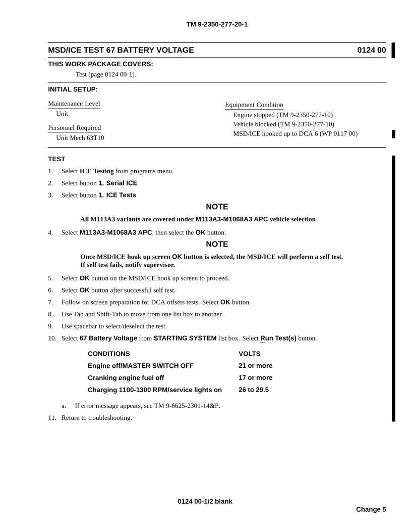
TM 9-2350-277-20-1
MSD/ICE TEST 67 BATTERY VOLTAGE 0124 00THIS WORK PACKAGE COVERS:
Test (page 0124 00-1).
INITIAL SETUP:
Maintenance LevelUnit
Personnel RequiredUnit Mech 63T10
Equipment ConditionEngine stopped (TM 9-2350-277-10)Vehicle blocked (TM 9-2350-277-10)MSD/ICE hooked up to DCA 6 (WP 0117 00)
TEST
1. Select ICE Testing from programs menu.
2. Select button 1. Serial ICE
3. Select button 1. ICE Tests
NOTEAll M113A3 variants are covered under M113A3-M1068A3 APC vehicle selection
4. Select M113A3-M1068A3 APC, then select the OK button.
NOTEOnce MSD/ICE hook up screen OK button is selected, the MSD/ICE will perform a self test.If self test fails, notify supervisor.
5. Select OK button on the MSD/ICE hook up screen to proceed.
6. Select OK button after successful self test.
7. Follow on screen preparation for DCA offsets tests. Select OK button.
8. Use Tab and Shift-Tab to move from one list box to another.
9. Use spacebar to select/deselect the test.
10. Select 67 Battery Voltage from STARTING SYSTEM list box. Select Run Test(s) button.
CONDITIONS VOLTS
Engine off/MASTER SWITCH OFF 21 or more
Cranking engine fuel off 17 or more
Charging 1100-1300 RPM/service lights on 26 to 29.5
a. If error message appears, see TM 9-6625-2301-14&P.
11. Return to troubleshooting.
0124 00-1/2 blankChange 5

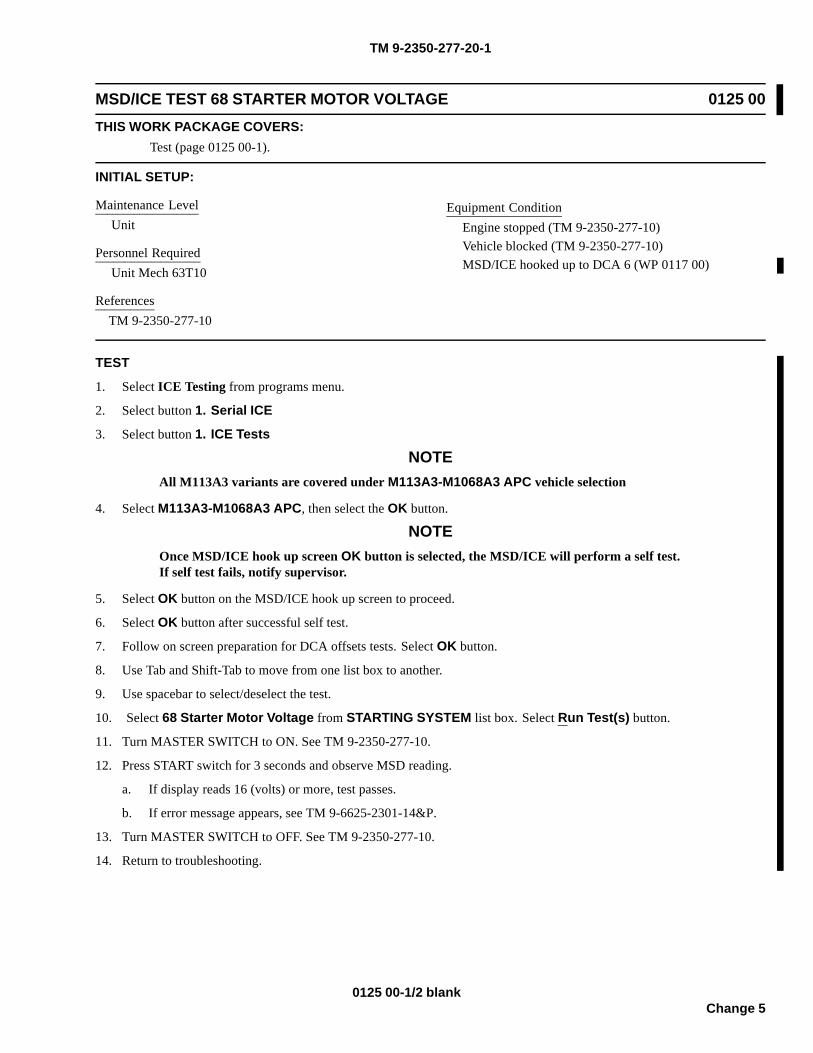
TM 9-2350-277-20-1
MSD/ICE TEST 68 STARTER MOTOR VOLTAGE 0125 00THIS WORK PACKAGE COVERS:
Test (page 0125 00-1).
INITIAL SETUP:
Maintenance LevelUnit
Personnel RequiredUnit Mech 63T10
ReferencesTM 9-2350-277-10
Equipment ConditionEngine stopped (TM 9-2350-277-10)Vehicle blocked (TM 9-2350-277-10)MSD/ICE hooked up to DCA 6 (WP 0117 00)
TEST
1. Select ICE Testing from programs menu.
2. Select button 1. Serial ICE
3. Select button 1. ICE Tests
NOTEAll M113A3 variants are covered under M113A3-M1068A3 APC vehicle selection
4. Select M113A3-M1068A3 APC, then select the OK button.
NOTEOnce MSD/ICE hook up screen OK button is selected, the MSD/ICE will perform a self test.If self test fails, notify supervisor.
5. Select OK button on the MSD/ICE hook up screen to proceed.
6. Select OK button after successful self test.
7. Follow on screen preparation for DCA offsets tests. Select OK button.
8. Use Tab and Shift-Tab to move from one list box to another.
9. Use spacebar to select/deselect the test.
10. Select 68 Starter Motor Voltage from STARTING SYSTEM list box. Select Run Test(s) button.
11. Turn MASTER SWITCH to ON. See TM 9-2350-277-10.
12. Press START switch for 3 seconds and observe MSD reading.
a. If display reads 16 (volts) or more, test passes.
b. If error message appears, see TM 9-6625-2301-14&P.
13. Turn MASTER SWITCH to OFF. See TM 9-2350-277-10.
14. Return to troubleshooting.
0125 00-1/2 blankChange 5

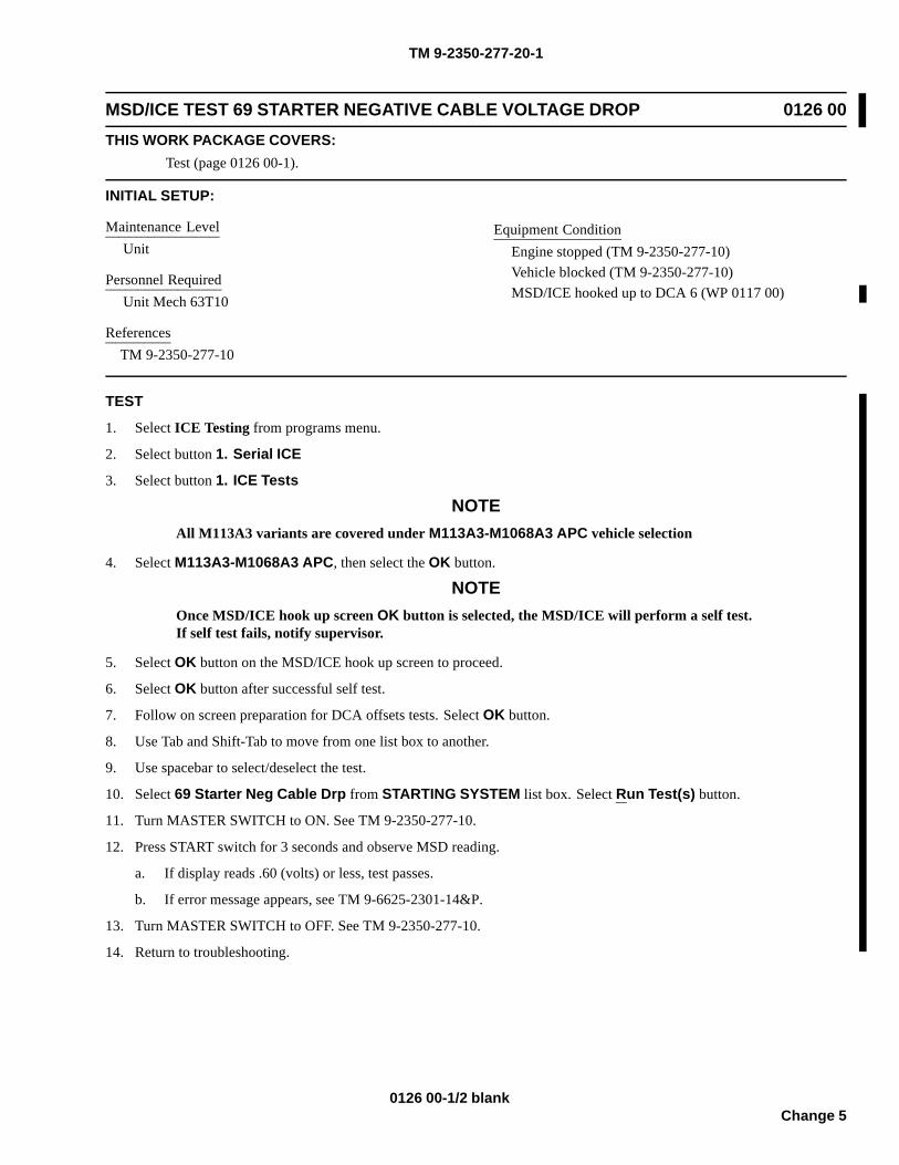
TM 9-2350-277-20-1
MSD/ICE TEST 69 STARTER NEGATIVE CABLE VOLTAGE DROP 0126 00THIS WORK PACKAGE COVERS:
Test (page 0126 00-1).
INITIAL SETUP:
Maintenance LevelUnit
Personnel RequiredUnit Mech 63T10
ReferencesTM 9-2350-277-10
Equipment ConditionEngine stopped (TM 9-2350-277-10)Vehicle blocked (TM 9-2350-277-10)MSD/ICE hooked up to DCA 6 (WP 0117 00)
TEST
1. Select ICE Testing from programs menu.
2. Select button 1. Serial ICE
3. Select button 1. ICE Tests
NOTEAll M113A3 variants are covered under M113A3-M1068A3 APC vehicle selection
4. Select M113A3-M1068A3 APC, then select the OK button.
NOTEOnce MSD/ICE hook up screen OK button is selected, the MSD/ICE will perform a self test.If self test fails, notify supervisor.
5. Select OK button on the MSD/ICE hook up screen to proceed.
6. Select OK button after successful self test.
7. Follow on screen preparation for DCA offsets tests. Select OK button.
8. Use Tab and Shift-Tab to move from one list box to another.
9. Use spacebar to select/deselect the test.
10. Select 69 Starter Neg Cable Drp from STARTING SYSTEM list box. Select Run Test(s) button.
11. Turn MASTER SWITCH to ON. See TM 9-2350-277-10.
12. Press START switch for 3 seconds and observe MSD reading.
a. If display reads .60 (volts) or less, test passes.
b. If error message appears, see TM 9-6625-2301-14&P.
13. Turn MASTER SWITCH to OFF. See TM 9-2350-277-10.
14. Return to troubleshooting.
0126 00-1/2 blankChange 5


TM 9-2350-277-20-1
MSD/ICE TEST 70 STARTER SOLENOID VOLTAGE 0127 00THIS WORK PACKAGE COVERS:
Test (page 0127 00-1).
INITIAL SETUP:
Maintenance LevelUnit
Personnel RequiredUnit Mech 63T10
ReferencesTM 9-2350-277-10
Equipment ConditionEngine stopped (TM 9-2350-277-10)Vehicle blocked (TM 9-2350-277-10)MSD/ICE hooked up to DCA 6 (WP 0117 00)
TEST
1. Select ICE Testing from programs menu.
2. Select button 1. Serial ICE
3. Select button 1. ICE Tests
NOTEAll M113A3 variants are covered under M113A3-M1068A3 APC vehicle selection
4. Select M113A3-M1068A3 APC, then select the OK button.
NOTEOnce MSD/ICE hook up screen OK button is selected, the MSD/ICE will perform a self test.If self test fails, notify supervisor.
5. Select OK button on the MSD/ICE hook up screen to proceed.
6. Select OK button after successful self test.
7. Follow on screen preparation for DCA offsets tests. Select OK button.
8. Use Tab and Shift-Tab to move from one list box to another.
9. Use spacebar to select/deselect the test.
10. Select 70 Starter Solenoid Volts from STARTING SYSTEM list box. Select Run Test(s) button.
11. Turn MASTER SWITCH to ON. See TM 9-2350-277-10.
12. Press START switch for 3 seconds and observe MSD reading.
a. If display reads 16 (volts) or more, test passes.
b. If error message appears, see TM 9-6625-2301-14&P.
13. Turn MASTER SWITCH to OFF. See TM 9-2350-277-10.
14. Return to troubleshooting.
0127 00-1/2 blankChange 5

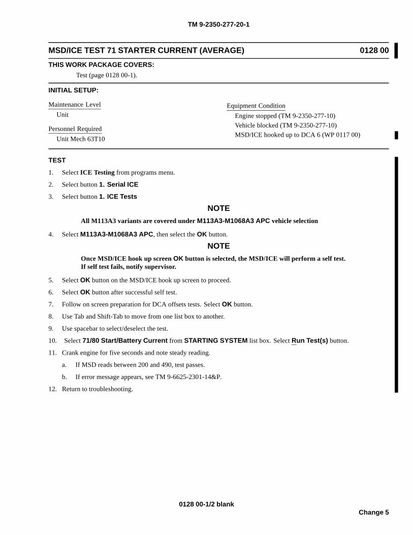
TM 9-2350-277-20-1
MSD/ICE TEST 71 STARTER CURRENT (AVERAGE) 0128 00THIS WORK PACKAGE COVERS:
Test (page 0128 00-1).
INITIAL SETUP:
Maintenance LevelUnit
Personnel RequiredUnit Mech 63T10
Equipment ConditionEngine stopped (TM 9-2350-277-10)Vehicle blocked (TM 9-2350-277-10)MSD/ICE hooked up to DCA 6 (WP 0117 00)
TEST
1. Select ICE Testing from programs menu.
2. Select button 1. Serial ICE
3. Select button 1. ICE Tests
NOTEAll M113A3 variants are covered under M113A3-M1068A3 APC vehicle selection
4. Select M113A3-M1068A3 APC, then select the OK button.
NOTEOnce MSD/ICE hook up screen OK button is selected, the MSD/ICE will perform a self test.If self test fails, notify supervisor.
5. Select OK button on the MSD/ICE hook up screen to proceed.
6. Select OK button after successful self test.
7. Follow on screen preparation for DCA offsets tests. Select OK button.
8. Use Tab and Shift-Tab to move from one list box to another.
9. Use spacebar to select/deselect the test.
10. Select 71/80 Start/Battery Current from STARTING SYSTEM list box. Select Run Test(s) button.
11. Crank engine for five seconds and note steady reading.
a. If MSD reads between 200 and 490, test passes.
b. If error message appears, see TM 9-6625-2301-14&P.
12. Return to troubleshooting.
0128 00-1/2 blankChange 5

TM 9-2350-277-20-1
MSD/ICE TEST 72 STARTER CURRENT (FIRST PEAK) 0129 00THIS WORK PACKAGE COVERS:
Test (page 0129 00-1).
INITIAL SETUP:
Maintenance LevelUnit
Personnel RequiredUnit Mech 63T10
Equipment ConditionEngine stopped (TM 9-2350-277-10)Vehicle blocked (TM 9-2350-277-10)MSD/ICE hooked up to DCA 6 (WP 0117 00)
TEST
1. Select ICE Testing from programs menu.
2. Select button 1. Serial ICE
3. Select button 1. ICE Tests
NOTEAll M113A3 variants are covered under M113A3-M1068A3 APC vehicle selection
4. Select M113A3-M1068A3 APC, then select the OK button.
NOTEOnce MSD/ICE hook up screen OK button is selected, the MSD/ICE will perform a self test.If self test fails, notify supervisor.
5. Select OK button on the MSD/ICE hook up screen to proceed.
6. Select OK button after successful self test.
7. Follow on screen preparation for DCA offsets tests. Select OK button.
8. Use Tab and Shift-Tab to move from one list box to another.
9. Use spacebar to select/deselect the test.
10. Select 72 DCA 1stPeak from SPECIAL TESTS list box. Select Run Test(s) button.
11. Crank engine for one second and note reading displayed on MSD.
a. If MSD reads between 900 and 1540, test passes.
b. If error message appears, see TM 9-6625-2301-14&P.
12. Return to troubleshooting.
0129 00-1/2 blankChange 5

TM 9-2350-277-20-1
MSD/ICE TEST 73 BATTERY RESISTANCE 0130 00THIS WORK PACKAGE COVERS:
Test (page 0130 00-1).
INITIAL SETUP:
Maintenance LevelUnit
Personnel RequiredUnit Mech 63T10
Equipment ConditionEngine stopped (TM 9-2350-277-10)Vehicle blocked (TM 9-2350-277-10)All electrical accessories turned off (TM 9-2350-277-10)Fuel OFF, engine must not start(TM 9-2350-277-10)MSD/ICE hooked up to DCA 6 (WP 0117 00)
TEST1. Select ICE Testing from programs menu.
2. Select button 1. Serial ICE3. Select button 1. ICE Tests
NOTEAll M113A3 variants are covered under M113A3-M1068A3 APC vehicle selection
4. Select M113A3-M1068A3 APC, then select the OK button.
NOTEOnce MSD/ICE hook up screen OK button is selected, the MSD/ICE will perform a self test.If self test fails, notify supervisor.
5. Select OK button on the MSD/ICE hook up screen to proceed.
6. Select OK button after successful self test.
7. Follow on screen preparation for DCA offsets tests. Select OK button.
8. Use Tab and Shift-Tab to move from one list box to another.
9. Use spacebar to select/deselect the test.
10. Select 73 1stPeak: TK current from SPECIAL TESTS list box. Select Run Test(s) button.
a. If MSD display is erratic or cannot be obtained, go to MSD/ICE DCA battery voltage diagnostic troubleshooting(WP 0141 00).
11. When GO appears , crank engine over for two seconds or until one of the following appears on display:
DISPLAY PERFORM/RESULT
OFF Stop cranking and wait for message to appear.
A number BATTERY RESISTANCE (go to Step 11)
.9.9.9.9 Beyond range of MSD cannot be measured
Error message See TM 9-6625-2301-14&P
(—) MSD lost power during test. Batteries may be too weak. Try powering MSDusing external source.
12. Observe MSD reading.
a. If MSD reading is 30 (milliohms) or less, test passes.
b. If MSD reading is more than 30 (milliohms), test fails.
0130 00-1/2 blankChange 5

TM 9-2350-277-20-1
MSD/ICE TEST 80 BATTERY CURRENT 0132 00THIS WORK PACKAGE COVERS:
Test (page 0132 00-1).
INITIAL SETUP:
Maintenance LevelUnit
Tools and Special ToolsElectrical connector pliers (WP 0926 00, Item 31)
Personnel RequiredUnit Mech 63T10
ReferencesTM 9-2350-277-10
Equipment ConditionEngine stopped (TM 9-2350-277-10)Vehicle blocked (TM 9-2350-277-10)All electrical accessories turned off (TM 9-2350-277-10)MSD/ICE hooked up to DCA 6 (WP 0117 00)
TEST
1. Select ICE Testing from programs menu.
2. Select button 1. Serial ICE
3. Select button 1. ICE Tests
NOTEAll M113A3 variants are covered under M113A3-M1068A3 APC vehicle selection
4. Select M113A3-M1068A3 APC, then select the OK button.
NOTEOnce MSD/ICE hook up screen OK button is selected, the MSD/ICE will perform a self test.If self test fails, notify supervisor.
5. Select OK button on the MSD/ICE hook up screen to proceed.
6. Select OK button after successful self test.
7. Follow on screen preparation for DCA offsets tests. Select OK button.
8. Use Tab and Shift-Tab to move from one list box to another.
9. Use spacebar to select/deselect the test.
10. Select 71/80 Start/Battery Current from STARTING SYSTEM list box. Select Run Test(s) button.
11. Turn MASTER SWITCH to ON. See TM 9-2350-277-10.
12. Depress START button for five seconds.
a. If MSD reads 0.0 or less, test passes.
b. If error message appears, see TM 9-6625-2301-14&P.
c. If engine cranks normally, but reading is erratic or cannot be obtained, go to MSD/ICE DCA current shuntdiagnostic troubleshooting (WP 0142 00).
13. Turn MASTER SWITCH to OFF. See TM 9-2350-277-10.
14. Return to troubleshooting.
0132 00-1/2 blankChange 5

TM 9-2350-277-20-1
MSD/ICE TEST 82 GENERATOR OUTPUT VOLTAGE 0133 00THIS WORK PACKAGE COVERS:
Test (page 0133 00-1).
INITIAL SETUP:
Maintenance LevelUnit
Personnel RequiredUnit Mech 63T10
ReferencesTM 9-2350-277-10
Equipment ConditionEngine stopped (TM 9-2350-277-10)Vehicle blocked (TM 9-2350-277-10)MSD/ICE hooked up to DCA 6 (WP 0117 00)
TEST
1. Select ICE Testing from programs menu.
2. Select button 1. Serial ICE
3. Select button 1. ICE Tests
NOTEAll M113A3 variants are covered under M113A3-M1068A3 APC vehicle selection
4. Select M113A3-M1068A3 APC, then select the OK button.
NOTEOnce MSD/ICE hook up screen OK button is selected, the MSD/ICE will perform a self test.If self test fails, notify supervisor.
5. Select OK button on the MSD/ICE hook up screen to proceed.
6. Select OK button after successful self test.
7. Follow on screen preparation for DCA offsets tests. Select OK button.
8. Use Tab and Shift-Tab to move from one list box to another.
9. Use spacebar to select/deselect the test.
10. Select 82 Alt/Gen Out Voltage from CHARGING SYSTEM list box. Select Run Test(s) button.
11. Start engine and run at 1400-1600 RPM. See TM 9-2350-277-10.
12. Turn MASTER LIGHT switch to SERV DRIVE.
13. Observe MSD reading.
a. If MSD reads between 26 to 29.5 (volts), test passes.
b. If error message appears, see TM 9-6625-2301-14&P.
c. If reading is erratic or cannot be obtained, go to MSD/ICE test 82 diagnostic troubleshooting (WP 0151 00).
14. Stop engine. See TM 9-2350-277-10.
15. Turn MASTER LIGHT switch to OFF.
16. Return to troubleshooting.
0133 00-1/2 blankChange 5


TM 9-2350-277-20-1
MSD/ICE TEST 83 GENERATOR FIELD VOLTAGE 0134 00THIS WORK PACKAGE COVERS:
Test (page 0134 00-1).
INITIAL SETUP:
Maintenance LevelUnit
Personnel RequiredUnit Mech 63T10
ReferencesTM 9-2350-277-10
Equipment ConditionEngine stopped (TM 9-2350-277-10)Vehicle blocked (TM 9-2350-277-10)MSD/ICE hooked up to DCA 6 (WP 0117 00)
TEST
1. Select ICE Testing from programs menu.
2. Select button 1. Serial ICE
3. Select button 1. ICE Tests
NOTEAll M113A3 variants are covered under M113A3-M1068A3 APC vehicle selection
4. Select M113A3-M1068A3 APC, then select the OK button.
NOTEOnce MSD/ICE hook up screen OK button is selected, the MSD/ICE will perform a self test.If self test fails, notify supervisor.
5. Select OK button on the MSD/ICE hook up screen to proceed.
6. Select OK button after successful self test.
7. Follow on screen preparation for DCA offsets tests. Select OK button.
8. Use Tab and Shift-Tab to move from one list box to another.
9. Use spacebar to select/deselect the test.
10. Select 83 Alt/Gen Field Voltage from CHARGING SYSTEM list box. Select Run Test(s) button.
11. Start engine and run at 1400-1600 RPM. See TM 9-2350-277-10.
12. Observe MSD display.
a. If MSD reads 26 to 29.5 (volts), test passes.
b. If error message appears, see TM 9-6625-2301-14&P.
c. If reading is erratic or cannot be obtained, go to MSD/ICE test 83 diagnostic troubleshooting (WP 0152 00).
13. Stop engine. See TM 9-2350-277-10.
14. Return to troubleshooting.
0134 00-1/2 blankChange 5

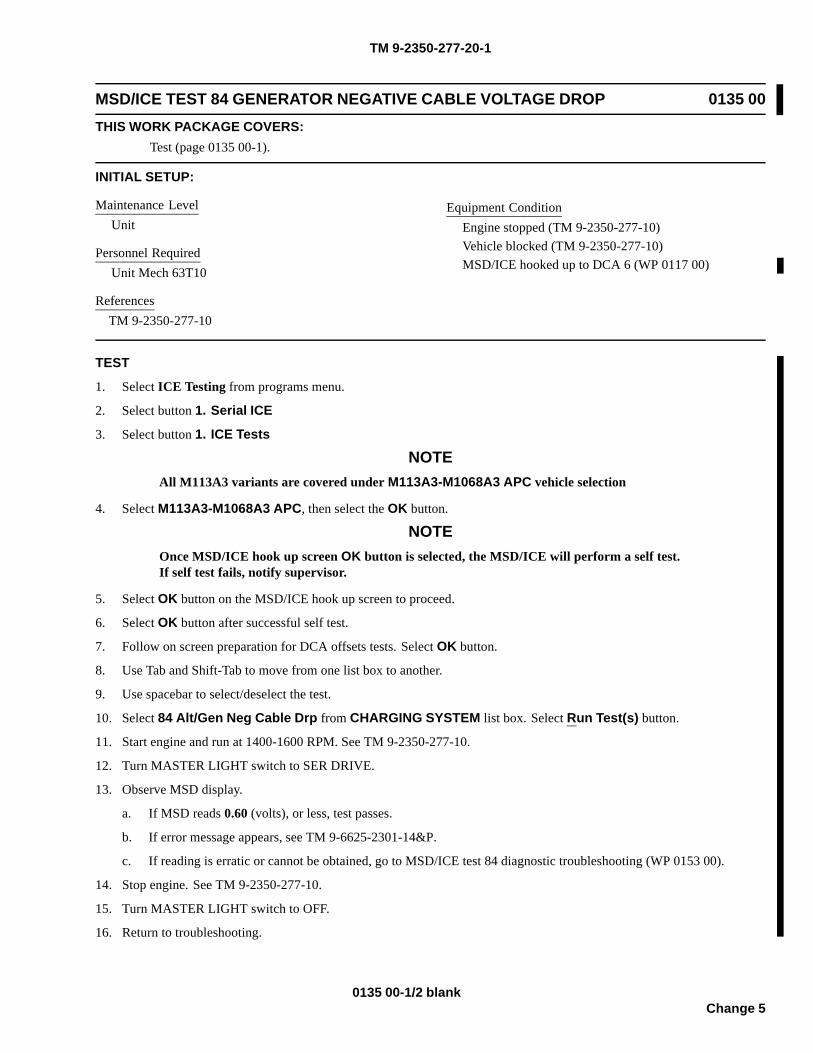
TM 9-2350-277-20-1
MSD/ICE TEST 84 GENERATOR NEGATIVE CABLE VOLTAGE DROP 0135 00THIS WORK PACKAGE COVERS:
Test (page 0135 00-1).
INITIAL SETUP:
Maintenance LevelUnit
Personnel RequiredUnit Mech 63T10
ReferencesTM 9-2350-277-10
Equipment ConditionEngine stopped (TM 9-2350-277-10)Vehicle blocked (TM 9-2350-277-10)MSD/ICE hooked up to DCA 6 (WP 0117 00)
TEST
1. Select ICE Testing from programs menu.
2. Select button 1. Serial ICE
3. Select button 1. ICE Tests
NOTEAll M113A3 variants are covered under M113A3-M1068A3 APC vehicle selection
4. Select M113A3-M1068A3 APC, then select the OK button.
NOTEOnce MSD/ICE hook up screen OK button is selected, the MSD/ICE will perform a self test.If self test fails, notify supervisor.
5. Select OK button on the MSD/ICE hook up screen to proceed.
6. Select OK button after successful self test.
7. Follow on screen preparation for DCA offsets tests. Select OK button.
8. Use Tab and Shift-Tab to move from one list box to another.
9. Use spacebar to select/deselect the test.
10. Select 84 Alt/Gen Neg Cable Drp from CHARGING SYSTEM list box. Select Run Test(s) button.
11. Start engine and run at 1400-1600 RPM. See TM 9-2350-277-10.
12. Turn MASTER LIGHT switch to SER DRIVE.
13. Observe MSD display.
a. If MSD reads 0.60 (volts), or less, test passes.
b. If error message appears, see TM 9-6625-2301-14&P.
c. If reading is erratic or cannot be obtained, go to MSD/ICE test 84 diagnostic troubleshooting (WP 0153 00).
14. Stop engine. See TM 9-2350-277-10.
15. Turn MASTER LIGHT switch to OFF.
16. Return to troubleshooting.
0135 00-1/2 blankChange 5

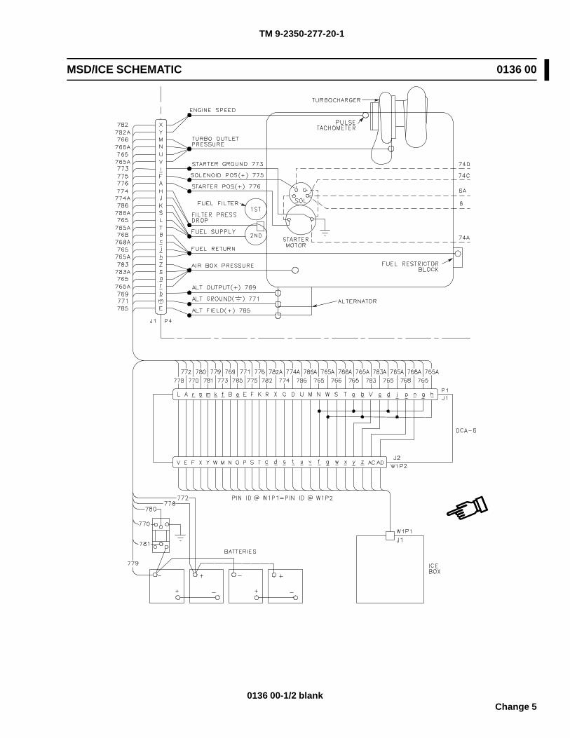
TM 9-2350-277-20-1
MSD/ICE SCHEMATIC 0136 00
0136 00-1/2 blankChange 5

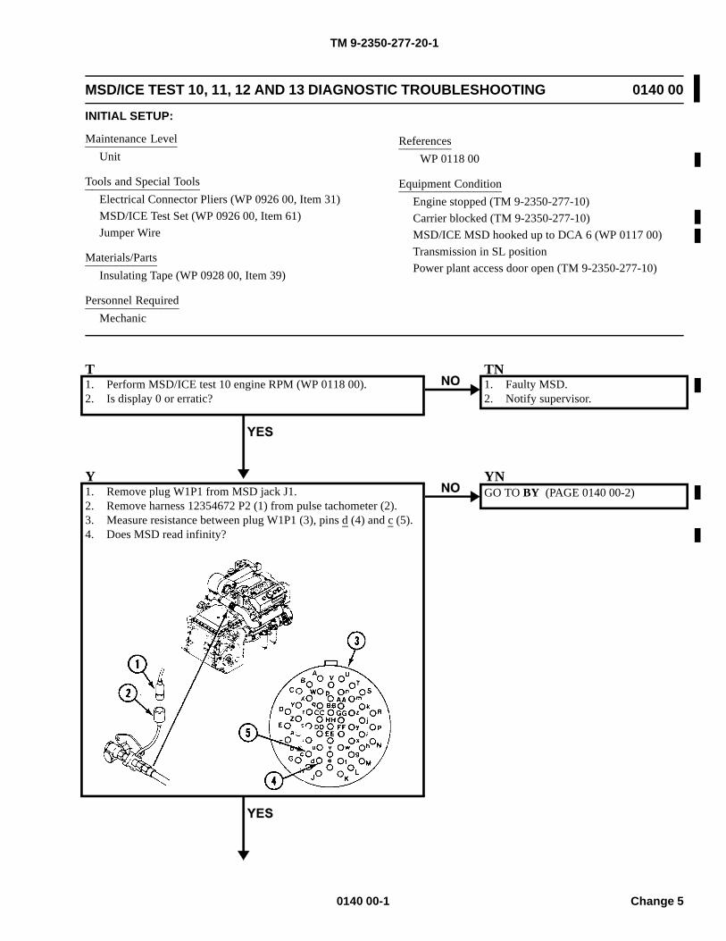
TM 9-2350-277-20-1
MSD/ICE TEST 10, 11, 12 AND 13 DIAGNOSTIC TROUBLESHOOTING 0140 00
INITIAL SETUP:
Maintenance LevelUnit
Tools and Special ToolsElectrical Connector Pliers (WP 0926 00, Item 31)MSD/ICE Test Set (WP 0926 00, Item 61)Jumper Wire
Materials/PartsInsulating Tape (WP 0928 00, Item 39)
Personnel RequiredMechanic
ReferencesWP 0118 00
Equipment ConditionEngine stopped (TM 9-2350-277-10)Carrier blocked (TM 9-2350-277-10)MSD/ICE MSD hooked up to DCA 6 (WP 0117 00)Transmission in SL positionPower plant access door open (TM 9-2350-277-10)
T1. Perform MSD/ICE test 10 engine RPM (WP 0118 00).2. Is display 0 or erratic?
TN1. Faulty MSD.2. Notify supervisor.
Y1. Remove plug W1P1 from MSD jack J1.2. Remove harness 12354672 P2 (1) from pulse tachometer (2).3. Measure resistance between plug W1P1 (3), pins d (4) and c (5).4. Does MSD read infinity?
YNGO TO BY (PAGE 0140 00-2)
0140 00-1 Change 5
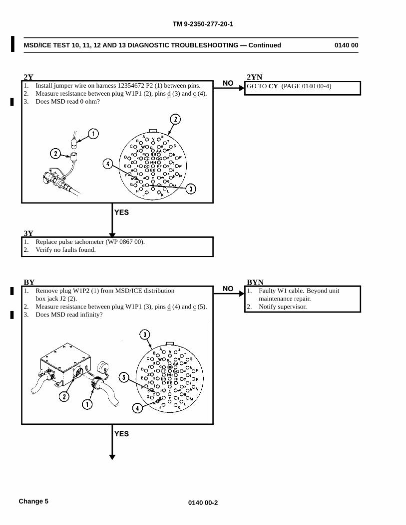
TM 9-2350-277-20-1
MSD/ICE TEST 10, 11, 12 AND 13 DIAGNOSTIC TROUBLESHOOTING — Continued 0140 00
2Y1. Install jumper wire on harness 12354672 P2 (1) between pins.2. Measure resistance between plug W1P1 (2), pins d (3) and c (4).3. Does MSD read 0 ohm?
2YNGO TO CY (PAGE 0140 00-4)
3Y1. Replace pulse tachometer (WP 0867 00).2. Verify no faults found.
BY1. Remove plug W1P2 (1) from MSD/ICE distribution
box jack J2 (2).2. Measure resistance between plug W1P1 (3), pins d (4) and c (5).3. Does MSD read infinity?
BYN1. Faulty W1 cable. Beyond unit
maintenance repair.2. Notify supervisor.
0140 00-2Change 5
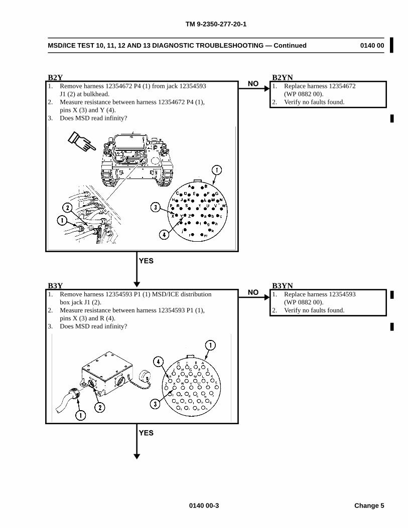
TM 9-2350-277-20-1
MSD/ICE TEST 10, 11, 12 AND 13 DIAGNOSTIC TROUBLESHOOTING — Continued 0140 00
B2Y1. Remove harness 12354672 P4 (1) from jack 12354593
J1 (2) at bulkhead.2. Measure resistance between harness 12354672 P4 (1),
pins X (3) and Y (4).3. Does MSD read infinity?
B2YN1. Replace harness 12354672
(WP 0882 00).2. Verify no faults found.
B3Y1. Remove harness 12354593 P1 (1) MSD/ICE distribution
box jack J1 (2).2. Measure resistance between harness 12354593 P1 (1),
pins X (3) and R (4).3. Does MSD read infinity?
B3YN1. Replace harness 12354593
(WP 0882 00).2. Verify no faults found.
0140 00-3 Change 5
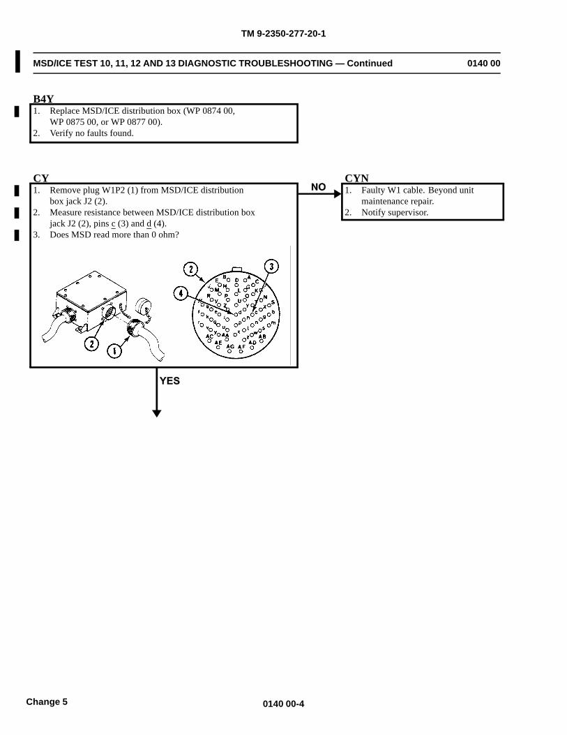
TM 9-2350-277-20-1
MSD/ICE TEST 10, 11, 12 AND 13 DIAGNOSTIC TROUBLESHOOTING — Continued 0140 00
B4Y1. Replace MSD/ICE distribution box (WP 0874 00,
WP 0875 00, or WP 0877 00).2. Verify no faults found.
CY1. Remove plug W1P2 (1) from MSD/ICE distribution
box jack J2 (2).2. Measure resistance between MSD/ICE distribution box
jack J2 (2), pins c (3) and d (4).3. Does MSD read more than 0 ohm?
CYN1. Faulty W1 cable. Beyond unit
maintenance repair.2. Notify supervisor.
0140 00-4Change 5
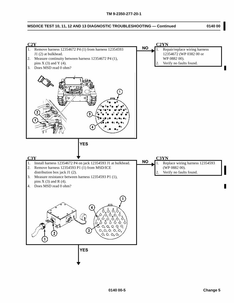
TM 9-2350-277-20-1
MSD/ICE TEST 10, 11, 12 AND 13 DIAGNOSTIC TROUBLESHOOTING — Continued 0140 00
C2Y1. Remove harness 12354672 P4 (1) from harness 12354593
J1 (2) at bulkhead.2. Measure continuity between harness 12354672 P4 (1),
pins X (3) and Y (4).3. Does MSD read 0 ohm?
C2YN1. Repair/replace wiring harness
12354672 (WP 0382 00 orWP 0882 00).
2. Verify no faults found.
C3Y1. Install harness 12354672 P4 on jack 12354593 J1 at bulkhead.2. Remove harness 12354593 P1 (1) from MSD/ICE
distribution box jack J1 (2).3. Measure resistance between harness 12354593 P1 (1),
pins X (3) and R (4).4. Does MSD read 0 ohm?
C3YN1. Replace wiring harness 12354593
(WP 0882 00).2. Verify no faults found.
0140 00-5 Change 5

TM 9-2350-277-20-1
MSD/ICE TEST 10, 11, 12 AND 13 DIAGNOSTIC TROUBLESHOOTING — Continued 0140 00
C4Y1. Replace MSD/ICE distribution box (WP 0874 00,
WP 0875 00, or WP 0877 00).2. Verify no faults found.
0140 00-6Change 5
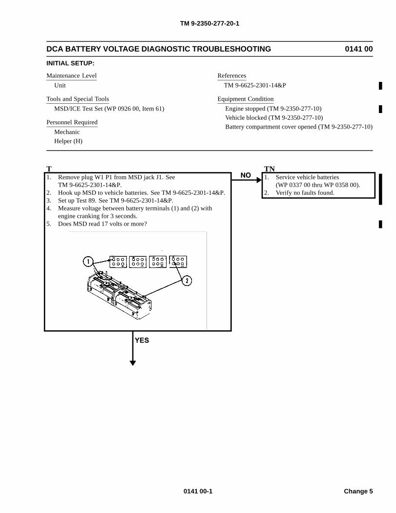
TM 9-2350-277-20-1
DCA BATTERY VOLTAGE DIAGNOSTIC TROUBLESHOOTING 0141 00
INITIAL SETUP:
Maintenance LevelUnit
Tools and Special ToolsMSD/ICE Test Set (WP 0926 00, Item 61)
Personnel RequiredMechanicHelper (H)
ReferencesTM 9-6625-2301-14&P
Equipment ConditionEngine stopped (TM 9-2350-277-10)Vehicle blocked (TM 9-2350-277-10)Battery compartment cover opened (TM 9-2350-277-10)
T1. Remove plug W1 P1 from MSD jack J1. See
TM 9-6625-2301-14&P.2. Hook up MSD to vehicle batteries. See TM 9-6625-2301-14&P.3. Set up Test 89. See TM 9-6625-2301-14&P.4. Measure voltage between battery terminals (1) and (2) with
engine cranking for 3 seconds.5. Does MSD read 17 volts or more?
TN1. Service vehicle batteries
(WP 0337 00 thru WP 0358 00).2. Verify no faults found.
0141 00-1 Change 5
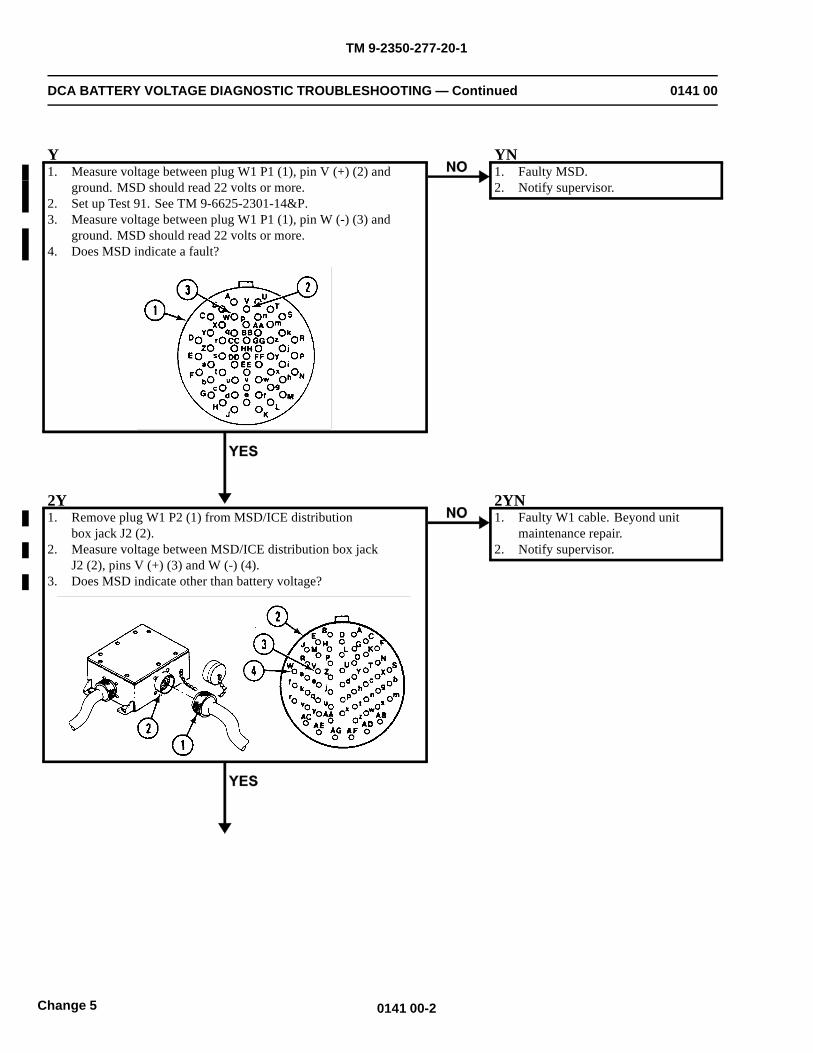
TM 9-2350-277-20-1
DCA BATTERY VOLTAGE DIAGNOSTIC TROUBLESHOOTING — Continued 0141 00
Y1. Measure voltage between plug W1 P1 (1), pin V (+) (2) and
ground. MSD should read 22 volts or more.2. Set up Test 91. See TM 9-6625-2301-14&P.3. Measure voltage between plug W1 P1 (1), pin W (-) (3) and
ground. MSD should read 22 volts or more.4. Does MSD indicate a fault?
YN1. Faulty MSD.2. Notify supervisor.
2Y1. Remove plug W1 P2 (1) from MSD/ICE distribution
box jack J2 (2).2. Measure voltage between MSD/ICE distribution box jack
J2 (2), pins V (+) (3) and W (-) (4).3. Does MSD indicate other than battery voltage?
2YN1. Faulty W1 cable. Beyond unit
maintenance repair.2. Notify supervisor.
0141 00-2Change 5
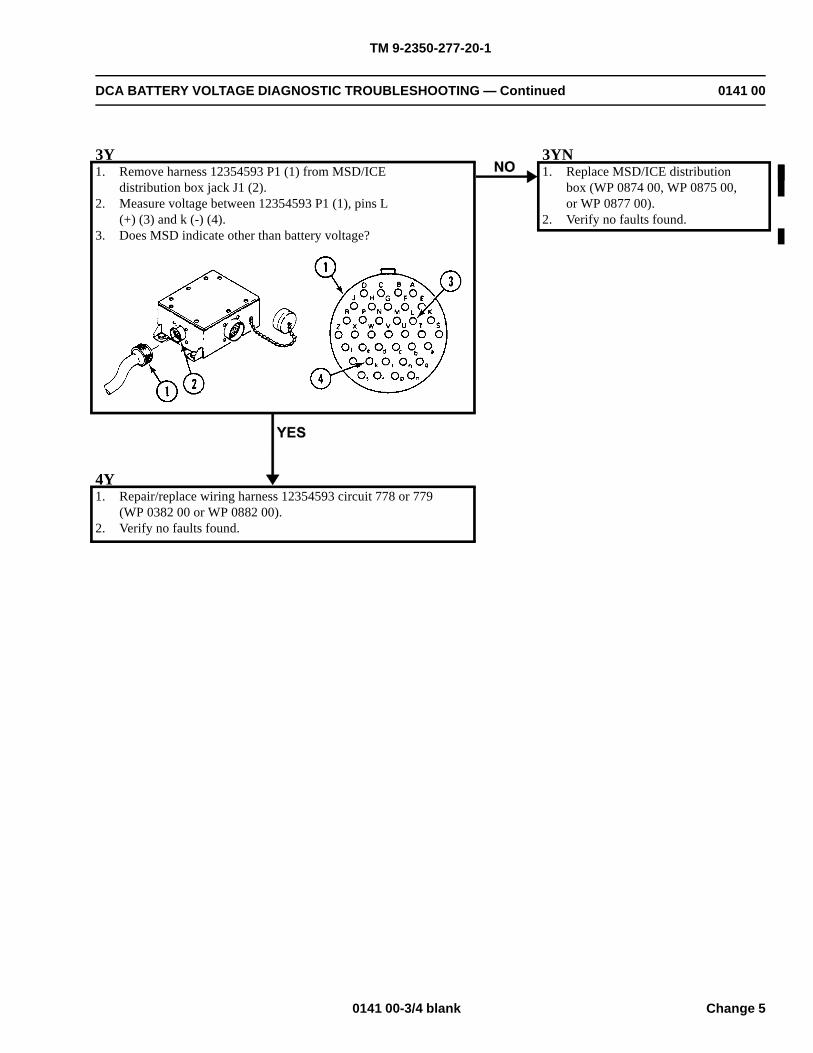
TM 9-2350-277-20-1
DCA BATTERY VOLTAGE DIAGNOSTIC TROUBLESHOOTING — Continued 0141 00
3Y1. Remove harness 12354593 P1 (1) from MSD/ICE
distribution box jack J1 (2).2. Measure voltage between 12354593 P1 (1), pins L
(+) (3) and k (-) (4).3. Does MSD indicate other than battery voltage?
3YN1. Replace MSD/ICE distribution
box (WP 0874 00, WP 0875 00,or WP 0877 00).
2. Verify no faults found.
4Y1. Repair/replace wiring harness 12354593 circuit 778 or 779
(WP 0382 00 or WP 0882 00).2. Verify no faults found.
0141 00-3/4 blank Change 5

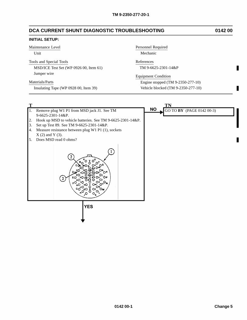
TM 9-2350-277-20-1
DCA CURRENT SHUNT DIAGNOSTIC TROUBLESHOOTING 0142 00
INITIAL SETUP:
Maintenance LevelUnit
Tools and Special ToolsMSD/ICE Test Set (WP 0926 00, Item 61)Jumper wire
Materials/PartsInsulating Tape (WP 0928 00, Item 39)
Personnel RequiredMechanic
ReferencesTM 9-6625-2301-14&P
Equipment ConditionEngine stopped (TM 9-2350-277-10)Vehicle blocked (TM 9-2350-277-10)
T1. Remove plug W1 P1 from MSD jack J1. See TM
9-6625-2301-14&P.2. Hook up MSD to vehicle batteries. See TM 9-6625-2301-14&P.3. Set up Test 89. See TM 9-6625-2301-14&P.4. Measure resistance between plug W1 P1 (1), sockets
X (2) and Y (3).5. Does MSD read 0 ohms?
TNGO TO BY (PAGE 0142 00-3)
0142 00-1 Change 5
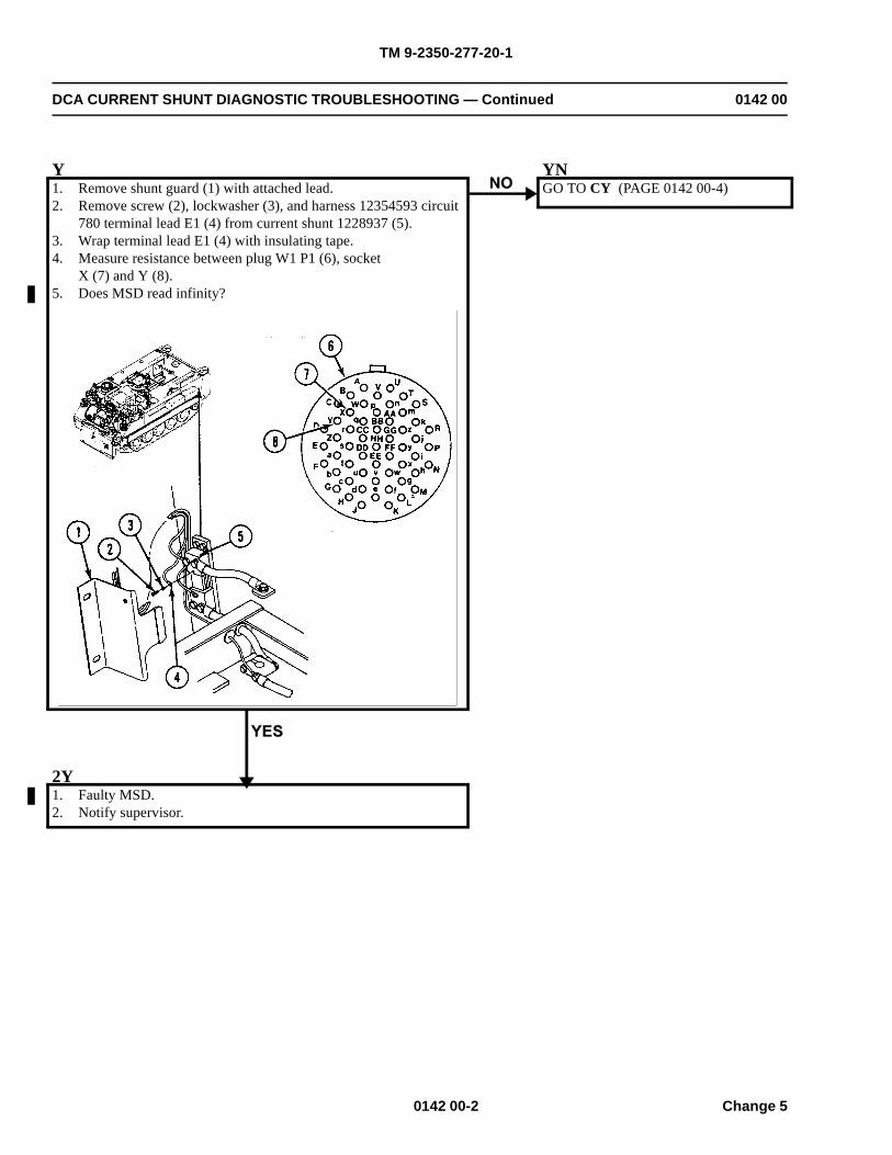
TM 9-2350-277-20-1
DCA CURRENT SHUNT DIAGNOSTIC TROUBLESHOOTING — Continued 0142 00
Y1. Remove shunt guard (1) with attached lead.2. Remove screw (2), lockwasher (3), and harness 12354593 circuit
780 terminal lead E1 (4) from current shunt 1228937 (5).3. Wrap terminal lead E1 (4) with insulating tape.4. Measure resistance between plug W1 P1 (6), socket
X (7) and Y (8).5. Does MSD read infinity?
YNGO TO CY (PAGE 0142 00-4)
2Y1. Faulty MSD.2. Notify supervisor.
0142 00-2 Change 5
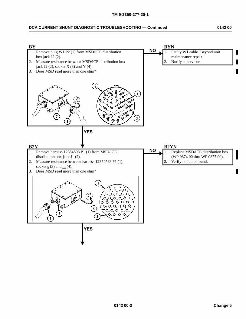
TM 9-2350-277-20-1
DCA CURRENT SHUNT DIAGNOSTIC TROUBLESHOOTING — Continued 0142 00
BY1. Remove plug W1 P2 (1) from MSD/ICE distribution
box jack J2 (2).2. Measure resistance between MSD/ICE distribution box
jack J2 (2), socket X (3) and Y (4).3. Does MSD read more than one ohm?
BYN1. Faulty W1 cable. Beyond unit
maintenance repair.2. Notify supervisor.
B2Y1. Remove harness 12354593 P1 (1) from MSD/ICE
distribution box jack J1 (2).2. Measure resistance between harness 12354593 P1 (1),
socket s (3) and m (4).3. Does MSD read more than one ohm?
B2YN1. Replace MSD/ICE distribution box
(WP 0874 00 thru WP 0877 00).2. Verify no faults found.
0142 00-3 Change 5
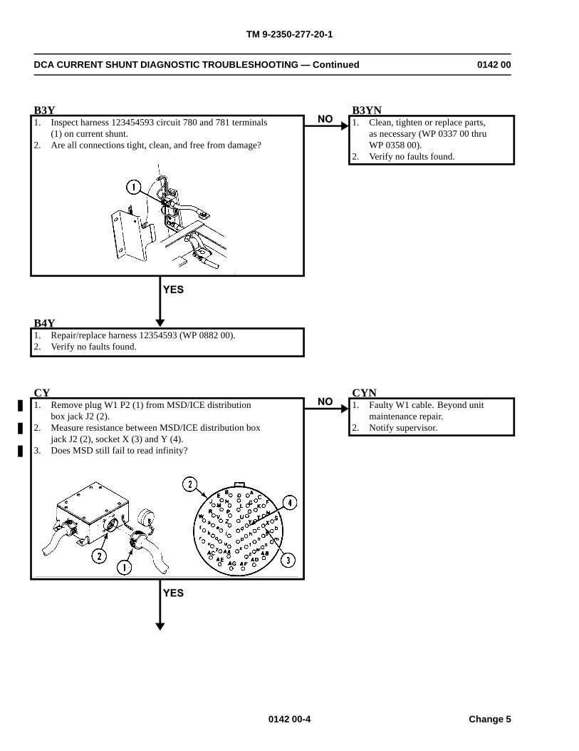
TM 9-2350-277-20-1
DCA CURRENT SHUNT DIAGNOSTIC TROUBLESHOOTING — Continued 0142 00
B3Y1. Inspect harness 123454593 circuit 780 and 781 terminals
(1) on current shunt.2. Are all connections tight, clean, and free from damage?
B3YN1. Clean, tighten or replace parts,
as necessary (WP 0337 00 thruWP 0358 00).
2. Verify no faults found.
B4Y1. Repair/replace harness 12354593 (WP 0882 00).2. Verify no faults found.
CY1. Remove plug W1 P2 (1) from MSD/ICE distribution
box jack J2 (2).2. Measure resistance between MSD/ICE distribution box
jack J2 (2), socket X (3) and Y (4).3. Does MSD still fail to read infinity?
CYN1. Faulty W1 cable. Beyond unit
maintenance repair.2. Notify supervisor.
0142 00-4 Change 5
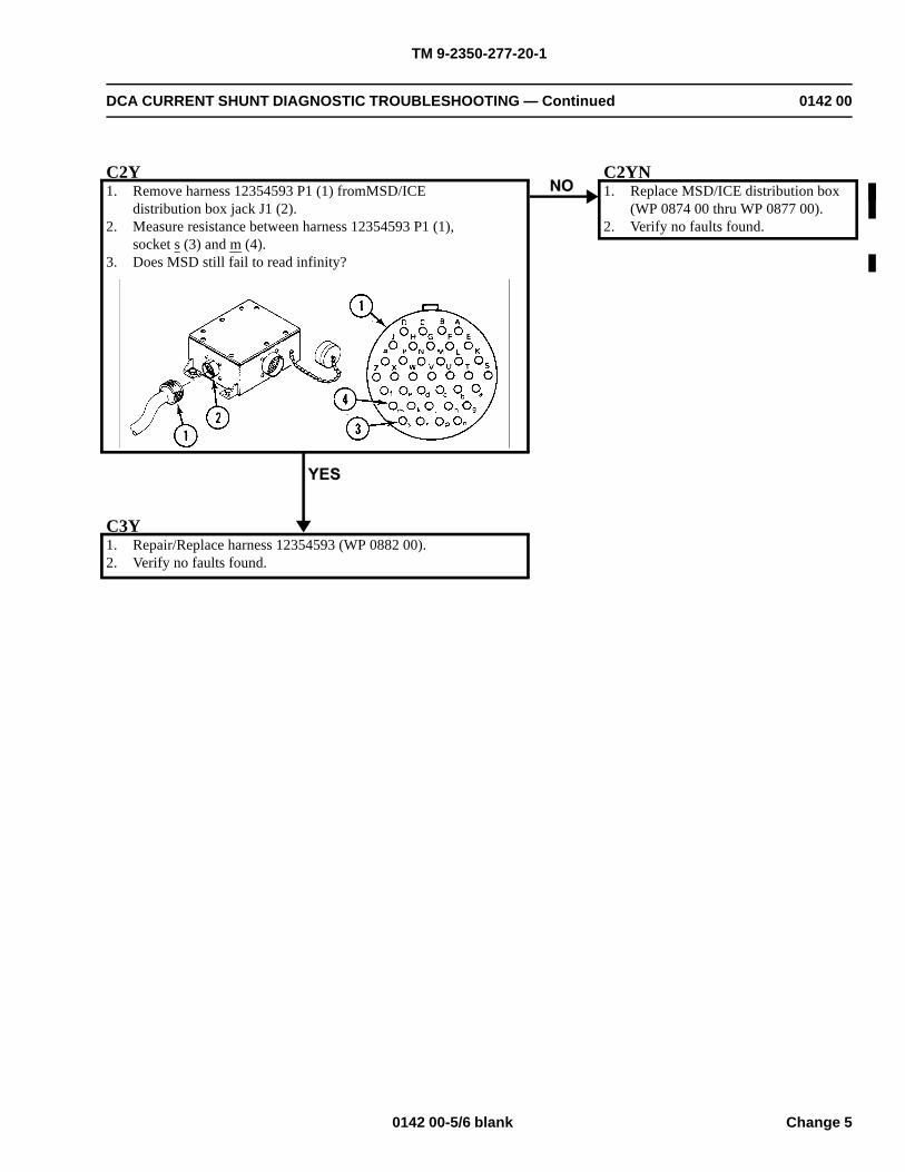
TM 9-2350-277-20-1
DCA CURRENT SHUNT DIAGNOSTIC TROUBLESHOOTING — Continued 0142 00
C2Y1. Remove harness 12354593 P1 (1) fromMSD/ICE
distribution box jack J1 (2).2. Measure resistance between harness 12354593 P1 (1),
socket s (3) and m (4).3. Does MSD still fail to read infinity?
C2YN1. Replace MSD/ICE distribution box
(WP 0874 00 thru WP 0877 00).2. Verify no faults found.
C3Y1. Repair/Replace harness 12354593 (WP 0882 00).2. Verify no faults found.
0142 00-5/6 blank Change 5

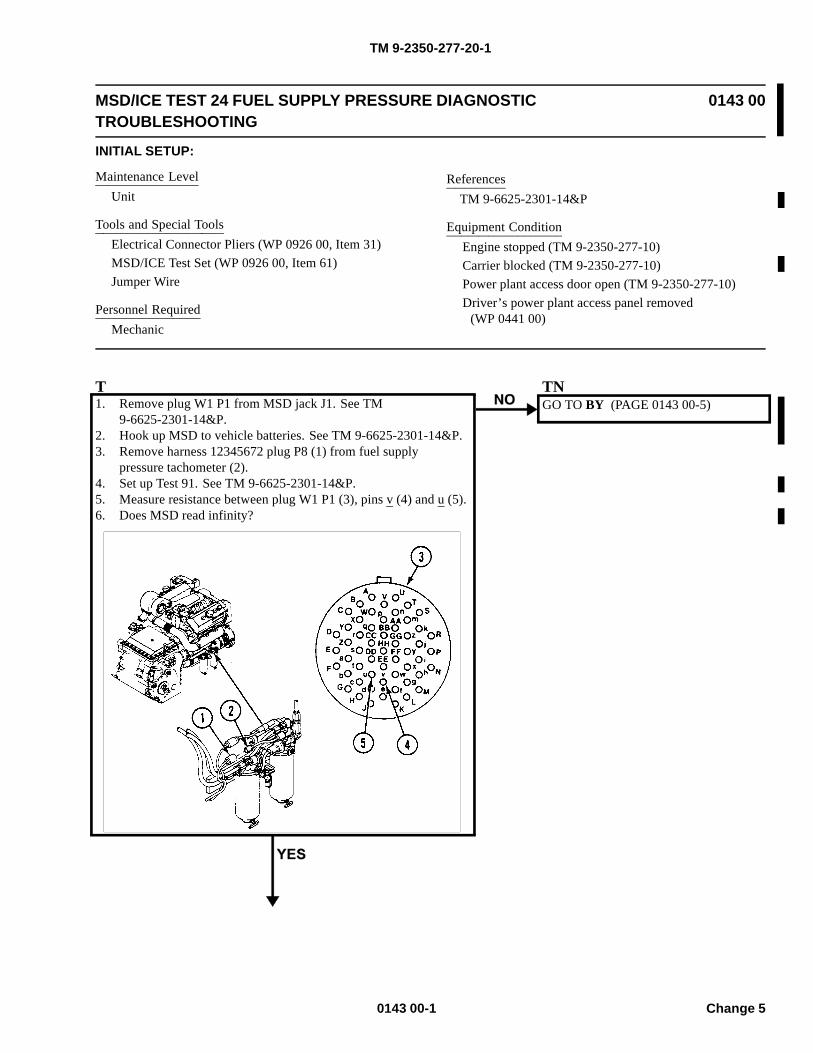
TM 9-2350-277-20-1
MSD/ICE TEST 24 FUEL SUPPLY PRESSURE DIAGNOSTICTROUBLESHOOTING
0143 00
INITIAL SETUP:
Maintenance LevelUnit
Tools and Special ToolsElectrical Connector Pliers (WP 0926 00, Item 31)MSD/ICE Test Set (WP 0926 00, Item 61)Jumper Wire
Personnel RequiredMechanic
ReferencesTM 9-6625-2301-14&P
Equipment ConditionEngine stopped (TM 9-2350-277-10)Carrier blocked (TM 9-2350-277-10)Power plant access door open (TM 9-2350-277-10)Driver’s power plant access panel removed
(WP 0441 00)
T1. Remove plug W1 P1 from MSD jack J1. See TM
9-6625-2301-14&P.2. Hook up MSD to vehicle batteries. See TM 9-6625-2301-14&P.3. Remove harness 12345672 plug P8 (1) from fuel supply
pressure tachometer (2).4. Set up Test 91. See TM 9-6625-2301-14&P.5. Measure resistance between plug W1 P1 (3), pins v (4) and u (5).6. Does MSD read infinity?
TNGO TO BY (PAGE 0143 00-5)
0143 00-1 Change 5
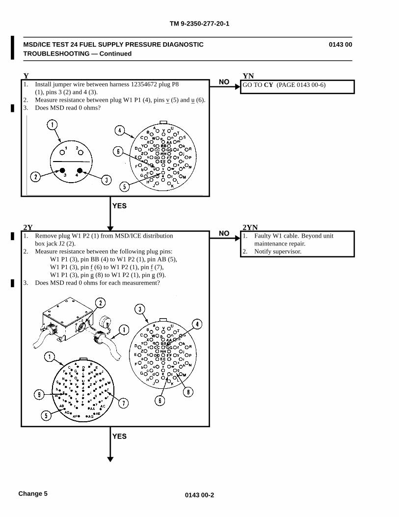
TM 9-2350-277-20-1
MSD/ICE TEST 24 FUEL SUPPLY PRESSURE DIAGNOSTICTROUBLESHOOTING — Continued
0143 00
Y1. Install jumper wire between harness 12354672 plug P8
(1), pins 3 (2) and 4 (3).2. Measure resistance between plug W1 P1 (4), pins v (5) and u (6).3. Does MSD read 0 ohms?
YNGO TO CY (PAGE 0143 00-6)
2Y1. Remove plug W1 P2 (1) from MSD/ICE distribution
box jack J2 (2).2. Measure resistance between the following plug pins:
W1 P1 (3), pin BB (4) to W1 P2 (1), pin AB (5),W1 P1 (3), pin f (6) to W1 P2 (1), pin f (7),W1 P1 (3), pin g (8) to W1 P2 (1), pin g (9).
3. Does MSD read 0 ohms for each measurement?
2YN1. Faulty W1 cable. Beyond unit
maintenance repair.2. Notify supervisor.
0143 00-2Change 5
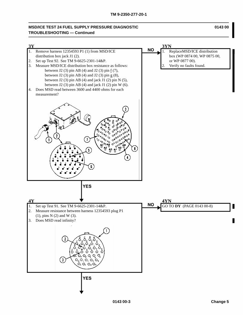
TM 9-2350-277-20-1
MSD/ICE TEST 24 FUEL SUPPLY PRESSURE DIAGNOSTICTROUBLESHOOTING — Continued
0143 00
3Y1. Remove harness 12354593 P1 (1) from MSD/ICE
distribution box jack J1 (2).2. Set up Test 92. See TM 9-6625-2301-14&P.3. Measure MSD/ICE distribution box resistance as follows:
between J2 (3) pin AB (4) and J2 (3) pin f (7),between J2 (3) pin AB (4) and J2 (3) pin g (8),between J2 (3) pin AB (4) and jack J1 (2) pin N (5),between J2 (3) pin AB (4) and jack J1 (2) pin W (6).
4. Does MSD read between 3600 and 4400 ohms for eachmeasurement?
3YN1. ReplaceMSD/ICE distribution
box (WP 0874 00, WP 0875 00,or WP 0877 00).
2. Verify no faults found.
4Y1. Set up Test 91. See TM 9-6625-2301-14&P.2. Measure resistance between harness 12354593 plug P1
(1), pins N (2) and W (3).3. Does MSD read infinity?
4YNGO TO DY (PAGE 0143 00-8)
0143 00-3 Change 5
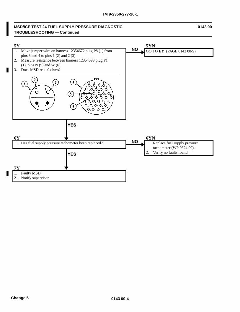
TM 9-2350-277-20-1
MSD/ICE TEST 24 FUEL SUPPLY PRESSURE DIAGNOSTICTROUBLESHOOTING — Continued
0143 00
5Y1. Move jumper wire on harness 12354672 plug P8 (1) from
pins 3 and 4 to pins 1 (2) and 2 (3).2. Measure resistance between harness 12354593 plug P1
(1), pins N (5) and W (6).3. Does MSD read 0 ohms?
5YNGO TO EY (PAGE 0143 00-9)
6Y1. Has fuel supply pressure tachometer been replaced?
6YN1. Replace fuel supply pressure
tachometer (WP 0324 00).2. Verify no faults found.
7Y1. Faulty MSD.2. Notify supervisor.
0143 00-4Change 5
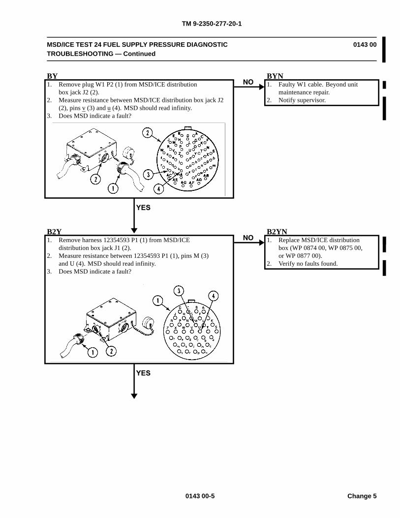
TM 9-2350-277-20-1
MSD/ICE TEST 24 FUEL SUPPLY PRESSURE DIAGNOSTICTROUBLESHOOTING — Continued
0143 00
BY1. Remove plug W1 P2 (1) from MSD/ICE distribution
box jack J2 (2).2. Measure resistance between MSD/ICE distribution box jack J2
(2), pins v (3) and u (4). MSD should read infinity.3. Does MSD indicate a fault?
BYN1. Faulty W1 cable. Beyond unit
maintenance repair.2. Notify supervisor.
B2Y1. Remove harness 12354593 P1 (1) from MSD/ICE
distribution box jack J1 (2).2. Measure resistance between 12354593 P1 (1), pins M (3)
and U (4). MSD should read infinity.3. Does MSD indicate a fault?
B2YN1. Replace MSD/ICE distribution
box (WP 0874 00, WP 0875 00,or WP 0877 00).
2. Verify no faults found.
0143 00-5 Change 5
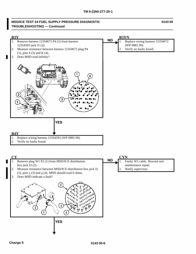
TM 9-2350-277-20-1
MSD/ICE TEST 24 FUEL SUPPLY PRESSURE DIAGNOSTICTROUBLESHOOTING — Continued
0143 00
B3Y1. Remove harness 12354672 P4 (1) from harness
12354593 jack J1 (2).2. Measure resistance between harness 12354672 plug P4
(1), pins S (3) and K (4).3. Does MSD read infinity?
B3YN1. Replace wiring harness 12354672
(WP 0882 00).2. Verify no faults found.
B4Y1. Replace wiring harness 12354593 (WP 0882 00).2. Verify no faults found.
CY1. Remove plug W1 P2 (1) from MSD/ICE distribution
box jack J2 (2).2. Measure resistance between MSD/ICE distribution box jack J2
(2), pins v (3) and u (4). MSD should read 0 ohms.3. Does MSD indicate a fault?
CYN1. Faulty W1 cable. Beyond unit
maintenance repair.2. Notify supervisor.
0143 00-6Change 5
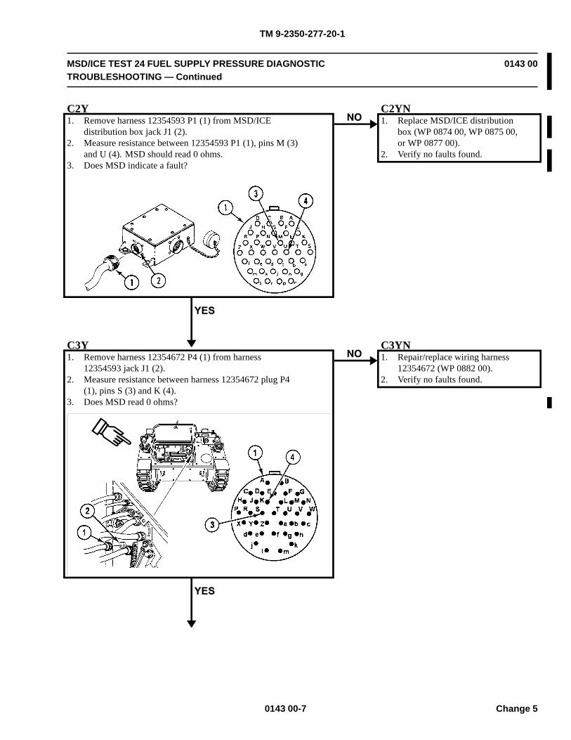
TM 9-2350-277-20-1
MSD/ICE TEST 24 FUEL SUPPLY PRESSURE DIAGNOSTICTROUBLESHOOTING — Continued
0143 00
C2Y1. Remove harness 12354593 P1 (1) from MSD/ICE
distribution box jack J1 (2).2. Measure resistance between 12354593 P1 (1), pins M (3)
and U (4). MSD should read 0 ohms.3. Does MSD indicate a fault?
C2YN1. Replace MSD/ICE distribution
box (WP 0874 00, WP 0875 00,or WP 0877 00).
2. Verify no faults found.
C3Y1. Remove harness 12354672 P4 (1) from harness
12354593 jack J1 (2).2. Measure resistance between harness 12354672 plug P4
(1), pins S (3) and K (4).3. Does MSD read 0 ohms?
C3YN1. Repair/replace wiring harness
12354672 (WP 0882 00).2. Verify no faults found.
0143 00-7 Change 5
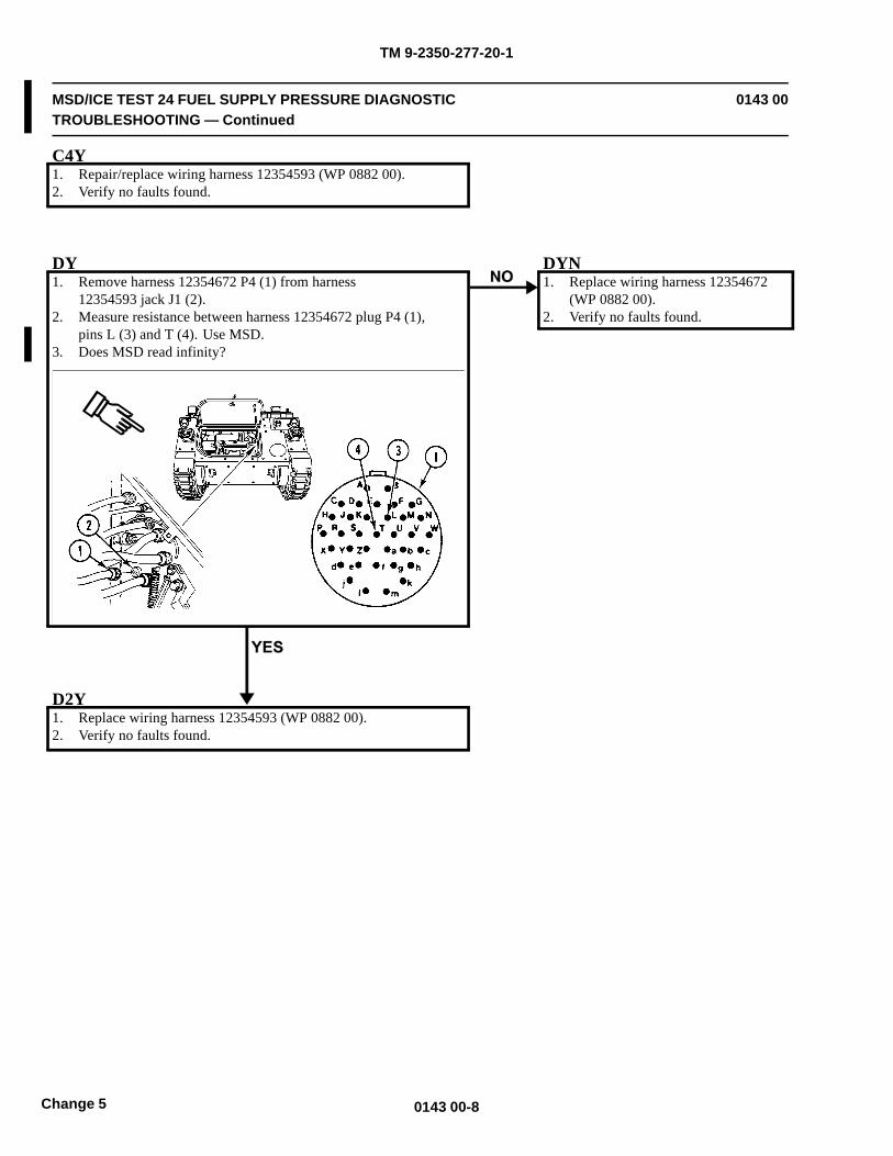
TM 9-2350-277-20-1
MSD/ICE TEST 24 FUEL SUPPLY PRESSURE DIAGNOSTICTROUBLESHOOTING — Continued
0143 00
C4Y1. Repair/replace wiring harness 12354593 (WP 0882 00).2. Verify no faults found.
DY1. Remove harness 12354672 P4 (1) from harness
12354593 jack J1 (2).2. Measure resistance between harness 12354672 plug P4 (1),
pins L (3) and T (4). Use MSD.3. Does MSD read infinity?
DYN1. Replace wiring harness 12354672
(WP 0882 00).2. Verify no faults found.
D2Y1. Replace wiring harness 12354593 (WP 0882 00).2. Verify no faults found.
0143 00-8Change 5

TM 9-2350-277-20-1
MSD/ICE TEST 24 FUEL SUPPLY PRESSURE DIAGNOSTICTROUBLESHOOTING — Continued
0143 00
EY1. Remove harness 12354672 P4 (1) from harness
12354593 jack J1 (2).2. Measure resistance between harness 12354672 plug P4
(1), pins L (3) and T (4).3. Does MSD read 0 ohms?
EYN1. Replace wiring harness 12354672
(WP 0882 00).2. Verify no faults found.
E2Y1. Replace wiring harness 12354593 (WP 0882 00).2. Verify no faults found.
0143 00-9/10 blank Change 5

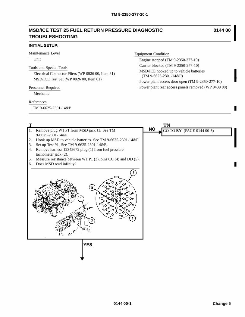
TM 9-2350-277-20-1
MSD/ICE TEST 25 FUEL RETURN PRESSURE DIAGNOSTICTROUBLESHOOTING
0144 00
INITIAL SETUP:
Maintenance LevelUnit
Tools and Special ToolsElectrical Connector Pliers (WP 0926 00, Item 31)MSD/ICE Test Set (WP 0926 00, Item 61)
Personnel RequiredMechanic
ReferencesTM 9-6625-2301-14&P
Equipment ConditionEngine stopped (TM 9-2350-277-10)Carrier blocked (TM 9-2350-277-10)MSD/ICE hooked up to vehicle batteries
(TM 9-6625-2301-14&P)Power plant access door open (TM 9-2350-277-10)Power plant rear access panels removed (WP 0439 00)
T1. Remove plug W1 P1 from MSD jack J1. See TM
9-6625-2301-14&P.2. Hook up MSD to vehicle batteries. See TM 9-6625-2301-14&P.3. Set up Test 91. See TM 9-6625-2301-14&P.4. Remove harness 12345672 plug (1) from fuel pressure
tachometer jack (2).5. Measure resistance between W1 P1 (3), pins CC (4) and DD (5).6. Does MSD read infinity?
TNGO TO BY (PAGE 0144 00-5)
0144 00-1 Change 5
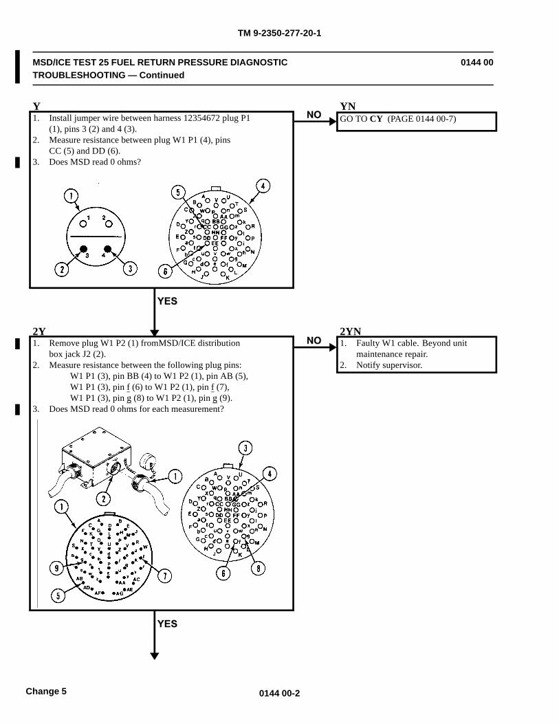
TM 9-2350-277-20-1
MSD/ICE TEST 25 FUEL RETURN PRESSURE DIAGNOSTICTROUBLESHOOTING — Continued
0144 00
Y1. Install jumper wire between harness 12354672 plug P1
(1), pins 3 (2) and 4 (3).2. Measure resistance between plug W1 P1 (4), pins
CC (5) and DD (6).3. Does MSD read 0 ohms?
YNGO TO CY (PAGE 0144 00-7)
2Y1. Remove plug W1 P2 (1) fromMSD/ICE distribution
box jack J2 (2).2. Measure resistance between the following plug pins:
W1 P1 (3), pin BB (4) to W1 P2 (1), pin AB (5),W1 P1 (3), pin f (6) to W1 P2 (1), pin f (7),W1 P1 (3), pin g (8) to W1 P2 (1), pin g (9).
3. Does MSD read 0 ohms for each measurement?
2YN1. Faulty W1 cable. Beyond unit
maintenance repair.2. Notify supervisor.
0144 00-2Change 5
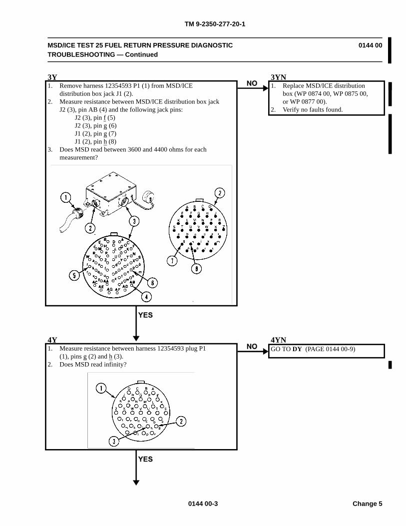
TM 9-2350-277-20-1
MSD/ICE TEST 25 FUEL RETURN PRESSURE DIAGNOSTICTROUBLESHOOTING — Continued
0144 00
3Y1. Remove harness 12354593 P1 (1) from MSD/ICE
distribution box jack J1 (2).2. Measure resistance between MSD/ICE distribution box jack
J2 (3), pin AB (4) and the following jack pins:J2 (3), pin f (5)J2 (3), pin g (6)J1 (2), pin g (7)J1 (2), pin h (8)
3. Does MSD read between 3600 and 4400 ohms for eachmeasurement?
3YN1. Replace MSD/ICE distribution
box (WP 0874 00, WP 0875 00,or WP 0877 00).
2. Verify no faults found.
4Y1. Measure resistance between harness 12354593 plug P1
(1), pins g (2) and h (3).2. Does MSD read infinity?
4YNGO TO DY (PAGE 0144 00-9)
0144 00-3 Change 5
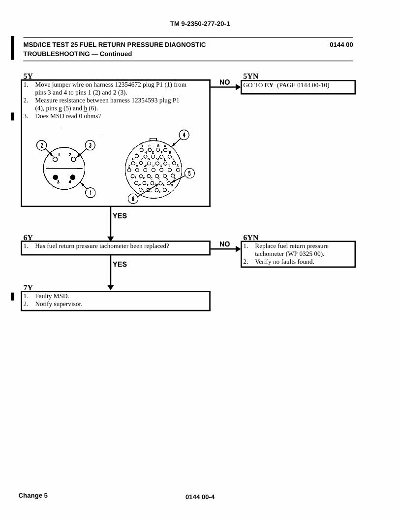
TM 9-2350-277-20-1
MSD/ICE TEST 25 FUEL RETURN PRESSURE DIAGNOSTICTROUBLESHOOTING — Continued
0144 00
5Y1. Move jumper wire on harness 12354672 plug P1 (1) from
pins 3 and 4 to pins 1 (2) and 2 (3).2. Measure resistance between harness 12354593 plug P1
(4), pins g (5) and h (6).3. Does MSD read 0 ohms?
5YNGO TO EY (PAGE 0144 00-10)
6Y1. Has fuel return pressure tachometer been replaced?
6YN1. Replace fuel return pressure
tachometer (WP 0325 00).2. Verify no faults found.
7Y1. Faulty MSD.2. Notify supervisor.
0144 00-4Change 5
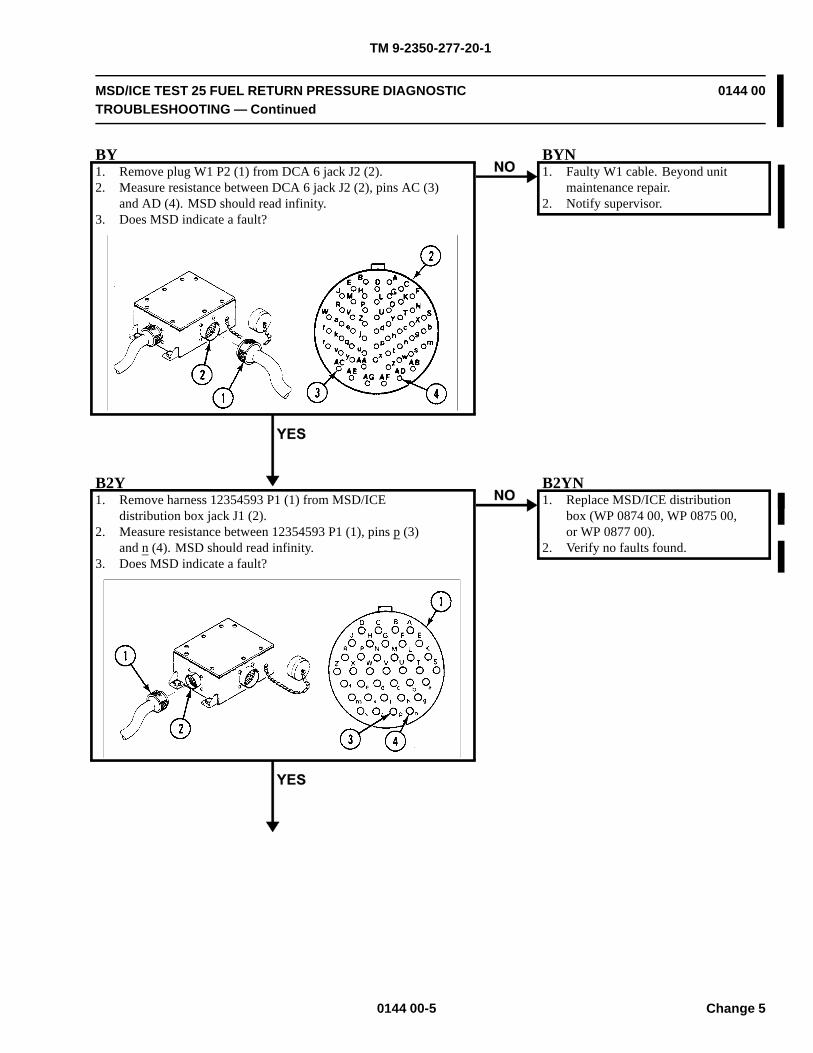
TM 9-2350-277-20-1
MSD/ICE TEST 25 FUEL RETURN PRESSURE DIAGNOSTICTROUBLESHOOTING — Continued
0144 00
BY1. Remove plug W1 P2 (1) from DCA 6 jack J2 (2).2. Measure resistance between DCA 6 jack J2 (2), pins AC (3)
and AD (4). MSD should read infinity.3. Does MSD indicate a fault?
BYN1. Faulty W1 cable. Beyond unit
maintenance repair.2. Notify supervisor.
B2Y1. Remove harness 12354593 P1 (1) from MSD/ICE
distribution box jack J1 (2).2. Measure resistance between 12354593 P1 (1), pins p (3)
and n (4). MSD should read infinity.3. Does MSD indicate a fault?
B2YN1. Replace MSD/ICE distribution
box (WP 0874 00, WP 0875 00,or WP 0877 00).
2. Verify no faults found.
0144 00-5 Change 5

TM 9-2350-277-20-1
MSD/ICE TEST 25 FUEL RETURN PRESSURE DIAGNOSTICTROUBLESHOOTING — Continued
0144 00
B3Y1. Remove harness 12354672 P4 (1) from harness
12354593 jack J1 (2).2. Measure resistance between harness 12354672 plug P4
(1), pins b (3) and c (4).3. Does MSD read infinity?
B3YN1. Replace wiring harness 12354672
(WP 0882 00).2. Verify no faults found.
B4Y1. Replace wiring harness 12354593 (WP 0882 00).2. Verify no faults found.
0144 00-6Change 5
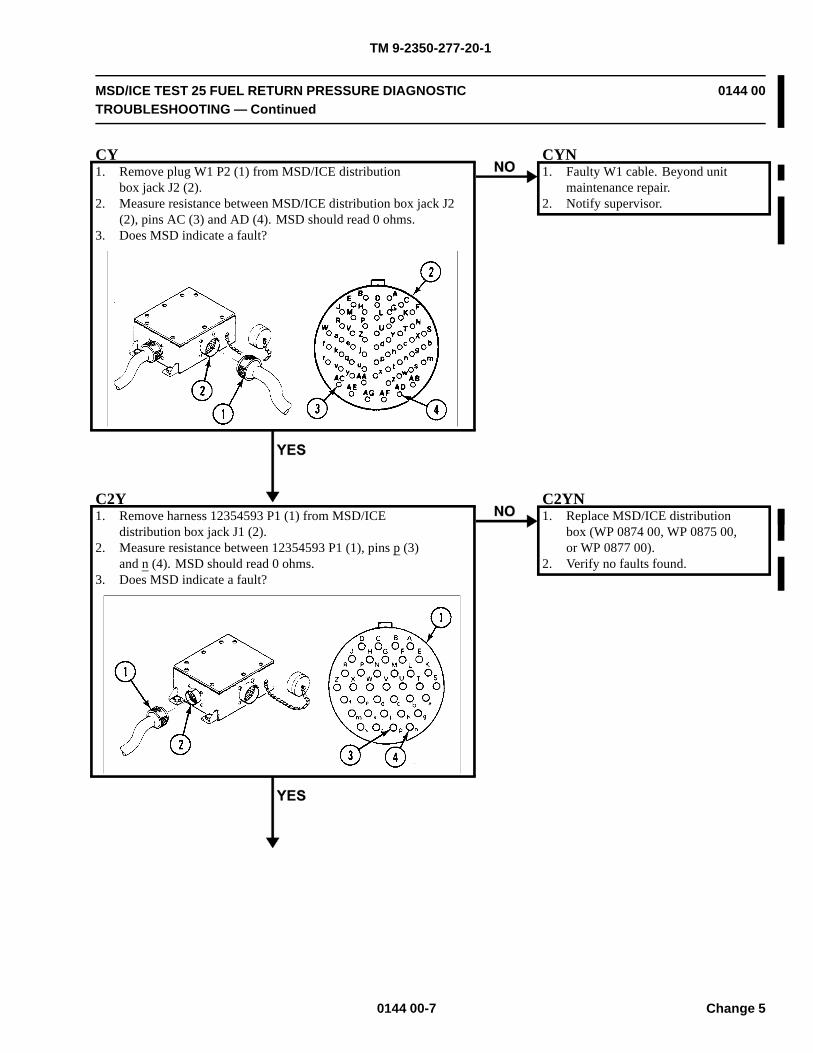
TM 9-2350-277-20-1
MSD/ICE TEST 25 FUEL RETURN PRESSURE DIAGNOSTICTROUBLESHOOTING — Continued
0144 00
CY1. Remove plug W1 P2 (1) from MSD/ICE distribution
box jack J2 (2).2. Measure resistance between MSD/ICE distribution box jack J2
(2), pins AC (3) and AD (4). MSD should read 0 ohms.3. Does MSD indicate a fault?
CYN1. Faulty W1 cable. Beyond unit
maintenance repair.2. Notify supervisor.
C2Y1. Remove harness 12354593 P1 (1) from MSD/ICE
distribution box jack J1 (2).2. Measure resistance between 12354593 P1 (1), pins p (3)
and n (4). MSD should read 0 ohms.3. Does MSD indicate a fault?
C2YN1. Replace MSD/ICE distribution
box (WP 0874 00, WP 0875 00,or WP 0877 00).
2. Verify no faults found.
0144 00-7 Change 5
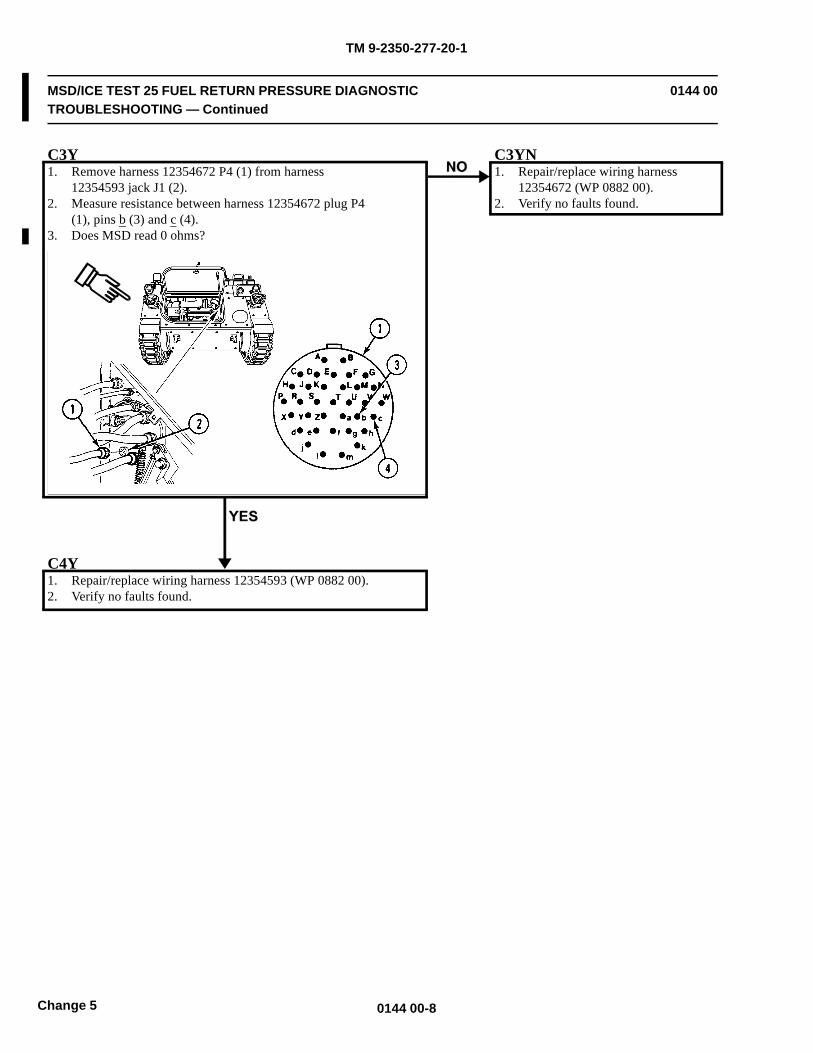
TM 9-2350-277-20-1
MSD/ICE TEST 25 FUEL RETURN PRESSURE DIAGNOSTICTROUBLESHOOTING — Continued
0144 00
C3Y1. Remove harness 12354672 P4 (1) from harness
12354593 jack J1 (2).2. Measure resistance between harness 12354672 plug P4
(1), pins b (3) and c (4).3. Does MSD read 0 ohms?
C3YN1. Repair/replace wiring harness
12354672 (WP 0882 00).2. Verify no faults found.
C4Y1. Repair/replace wiring harness 12354593 (WP 0882 00).2. Verify no faults found.
0144 00-8Change 5
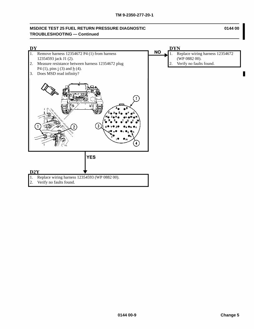
TM 9-2350-277-20-1
MSD/ICE TEST 25 FUEL RETURN PRESSURE DIAGNOSTICTROUBLESHOOTING — Continued
0144 00
DY1. Remove harness 12354672 P4 (1) from harness
12354593 jack J1 (2).2. Measure resistance between harness 12354672 plug
P4 (1), pins j (3) and h (4).3. Does MSD read infinity?
DYN1. Replace wiring harness 12354672
(WP 0882 00).2. Verify no faults found.
D2Y1. Replace wiring harness 12354593 (WP 0882 00).2. Verify no faults found.
0144 00-9 Change 5
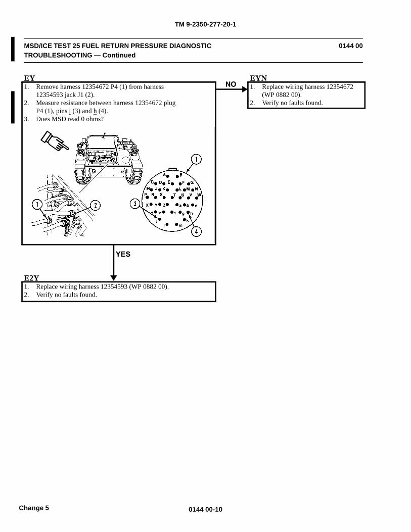
TM 9-2350-277-20-1
MSD/ICE TEST 25 FUEL RETURN PRESSURE DIAGNOSTICTROUBLESHOOTING — Continued
0144 00
EY1. Remove harness 12354672 P4 (1) from harness
12354593 jack J1 (2).2. Measure resistance between harness 12354672 plug
P4 (1), pins j (3) and h (4).3. Does MSD read 0 ohms?
EYN1. Replace wiring harness 12354672
(WP 0882 00).2. Verify no faults found.
E2Y1. Replace wiring harness 12354593 (WP 0882 00).2. Verify no faults found.
0144 00-10Change 5

TM 9-2350-277-20-1
MSD/ICE TEST 26 FUEL FILTER PRESSURE DROP DIAGNOSTICTROUBLESHOOTING
0145 00
INITIAL SETUP:
Maintenance LevelUnit
Tools and Special ToolsElectrical Connector Pliers (WP 0926 00, Item 31)MSD/ICE Test Set (WP 0926 00, Item 61)Jumper Wire
Personnel RequiredMechanic
ReferencesTM 9-6625-2301-14&P
Equipment ConditionEngine stopped (TM 9-2350-277-10)Carrier blocked (TM 9-2350-277-10)Power plant access door open (TM 9-2350-277-10)Driver’s power plant access panel removed
(WP 0441 00)
T1. Remove plug W1 P1 from MSD jack J1. See TM
9-6625-2301-14&P.2. Hook up MSD to vehicle batteries. See TM 9-6625-2301-14&P.3. Set up Test 91. See TM 9-6625-2301-14&P.4. Measure resistance between W1 P1 (1), pins s (2) and t (3).5. Does MSD read 0 ohms?
TNGO TO 2Y (PAGE 0145 00-2)
0145 00-1 Change 5
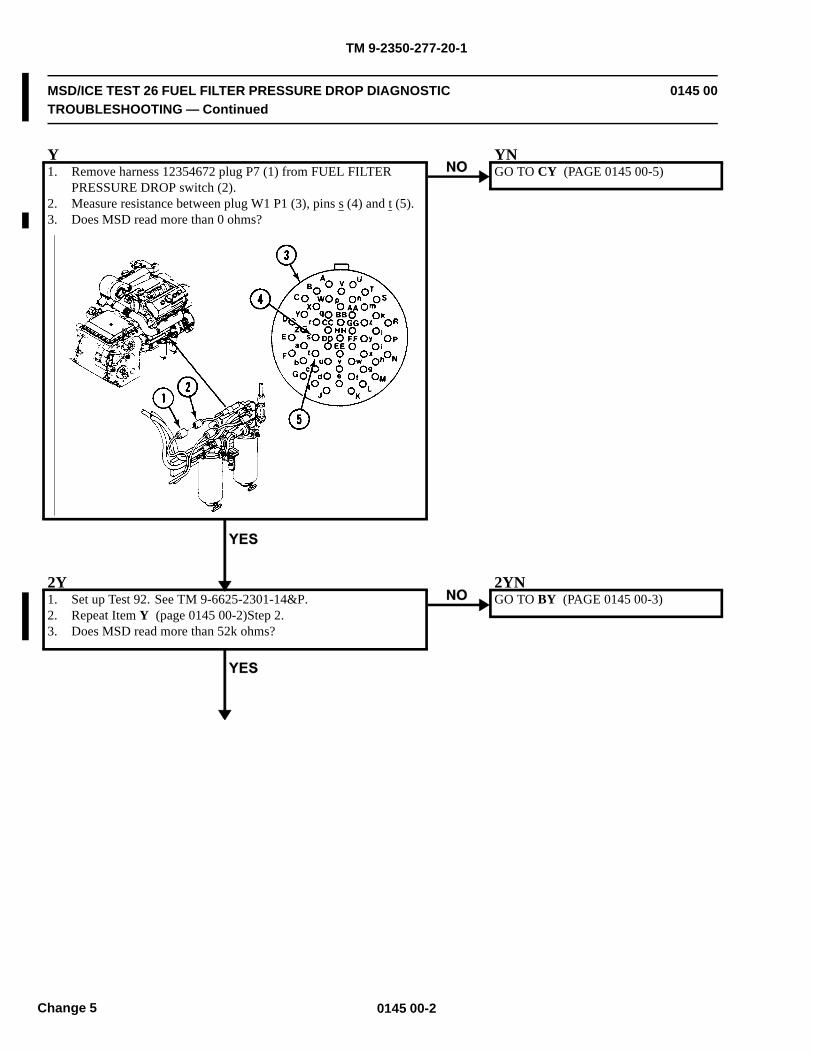
TM 9-2350-277-20-1
MSD/ICE TEST 26 FUEL FILTER PRESSURE DROP DIAGNOSTICTROUBLESHOOTING — Continued
0145 00
Y1. Remove harness 12354672 plug P7 (1) from FUEL FILTER
PRESSURE DROP switch (2).2. Measure resistance between plug W1 P1 (3), pins s (4) and t (5).3. Does MSD read more than 0 ohms?
YNGO TO CY (PAGE 0145 00-5)
2Y1. Set up Test 92. See TM 9-6625-2301-14&P.2. Repeat Item Y (page 0145 00-2)Step 2.3. Does MSD read more than 52k ohms?
2YNGO TO BY (PAGE 0145 00-3)
0145 00-2Change 5
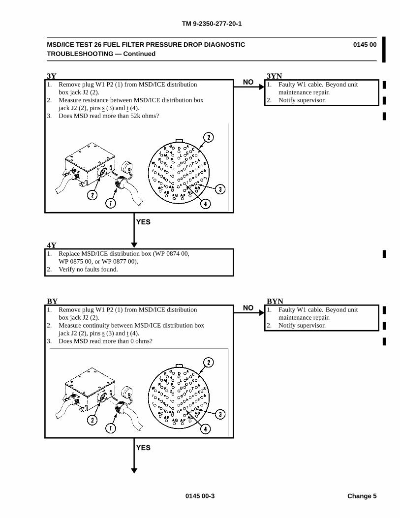
TM 9-2350-277-20-1
MSD/ICE TEST 26 FUEL FILTER PRESSURE DROP DIAGNOSTICTROUBLESHOOTING — Continued
0145 00
3Y1. Remove plug W1 P2 (1) from MSD/ICE distribution
box jack J2 (2).2. Measure resistance between MSD/ICE distribution box
jack J2 (2), pins s (3) and t (4).3. Does MSD read more than 52k ohms?
3YN1. Faulty W1 cable. Beyond unit
maintenance repair.2. Notify supervisor.
4Y1. Replace MSD/ICE distribution box (WP 0874 00,
WP 0875 00, or WP 0877 00).2. Verify no faults found.
BY1. Remove plug W1 P2 (1) from MSD/ICE distribution
box jack J2 (2).2. Measure continuity between MSD/ICE distribution box
jack J2 (2), pins s (3) and t (4).3. Does MSD read more than 0 ohms?
BYN1. Faulty W1 cable. Beyond unit
maintenance repair.2. Notify supervisor.
0145 00-3 Change 5
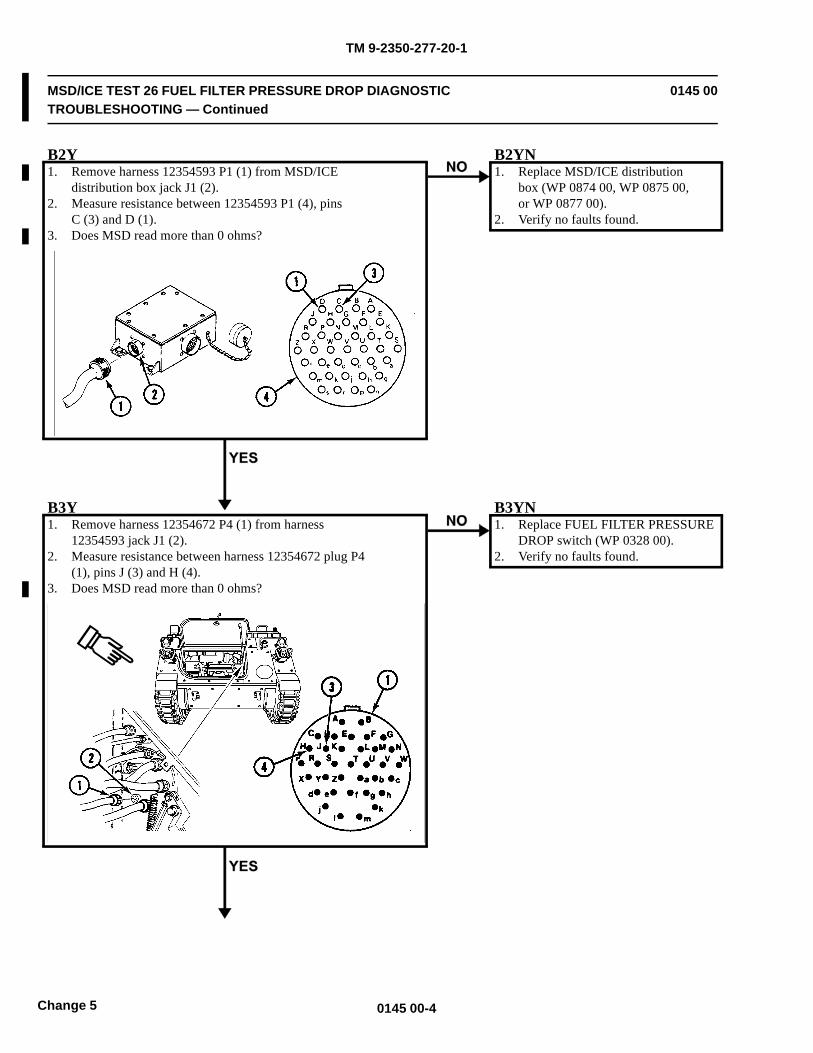
TM 9-2350-277-20-1
MSD/ICE TEST 26 FUEL FILTER PRESSURE DROP DIAGNOSTICTROUBLESHOOTING — Continued
0145 00
B2Y1. Remove harness 12354593 P1 (1) from MSD/ICE
distribution box jack J1 (2).2. Measure resistance between 12354593 P1 (4), pins
C (3) and D (1).3. Does MSD read more than 0 ohms?
B2YN1. Replace MSD/ICE distribution
box (WP 0874 00, WP 0875 00,or WP 0877 00).
2. Verify no faults found.
B3Y1. Remove harness 12354672 P4 (1) from harness
12354593 jack J1 (2).2. Measure resistance between harness 12354672 plug P4
(1), pins J (3) and H (4).3. Does MSD read more than 0 ohms?
B3YN1. Replace FUEL FILTER PRESSURE
DROP switch (WP 0328 00).2. Verify no faults found.
0145 00-4Change 5
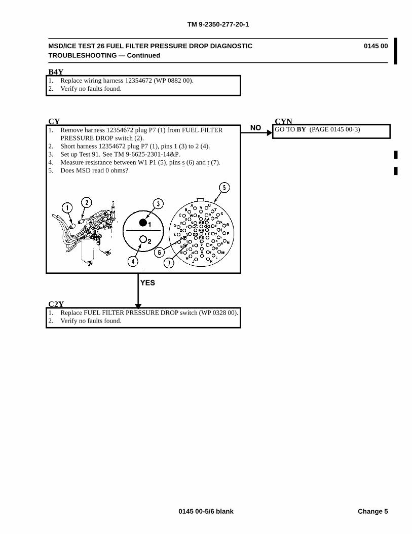
TM 9-2350-277-20-1
MSD/ICE TEST 26 FUEL FILTER PRESSURE DROP DIAGNOSTICTROUBLESHOOTING — Continued
0145 00
B4Y1. Replace wiring harness 12354672 (WP 0882 00).2. Verify no faults found.
CY1. Remove harness 12354672 plug P7 (1) from FUEL FILTER
PRESSURE DROP switch (2).2. Short harness 12354672 plug P7 (1), pins 1 (3) to 2 (4).3. Set up Test 91. See TM 9-6625-2301-14&P.4. Measure resistance between W1 P1 (5), pins s (6) and t (7).5. Does MSD read 0 ohms?
CYNGO TO BY (PAGE 0145 00-3)
C2Y1. Replace FUEL FILTER PRESSURE DROP switch (WP 0328 00).2. Verify no faults found.
0145 00-5/6 blank Change 5

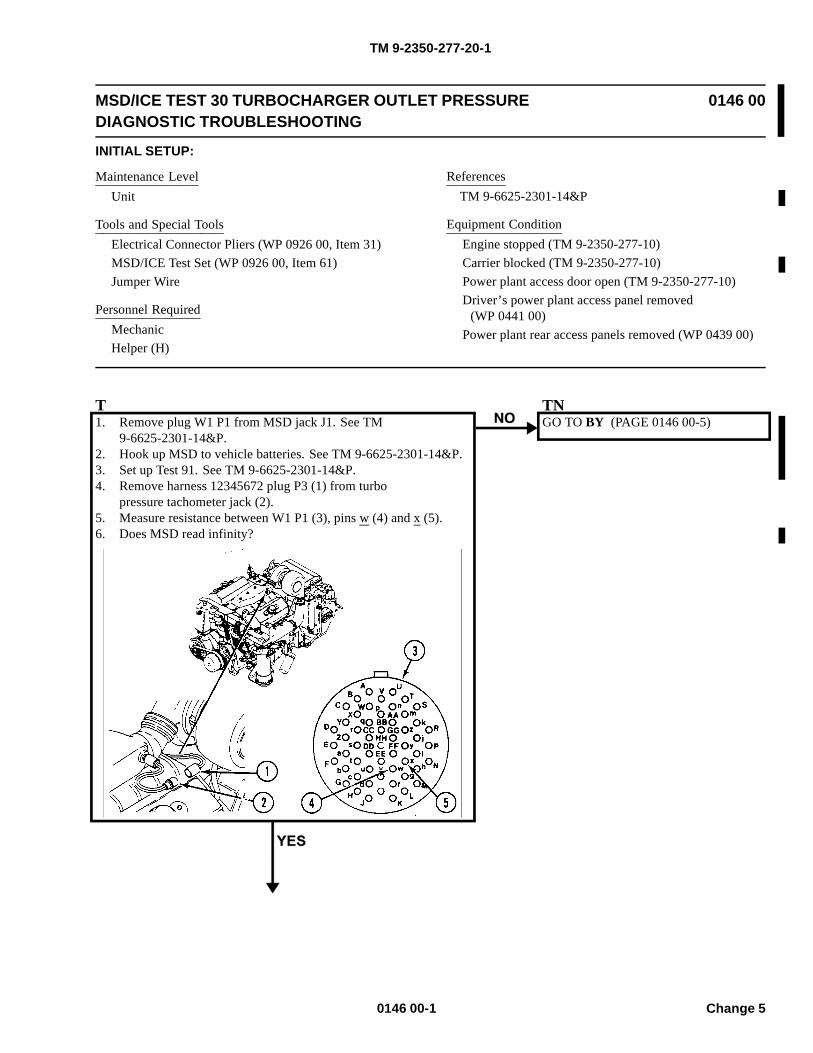
TM 9-2350-277-20-1
MSD/ICE TEST 30 TURBOCHARGER OUTLET PRESSUREDIAGNOSTIC TROUBLESHOOTING
0146 00
INITIAL SETUP:
Maintenance LevelUnit
Tools and Special ToolsElectrical Connector Pliers (WP 0926 00, Item 31)MSD/ICE Test Set (WP 0926 00, Item 61)Jumper Wire
Personnel RequiredMechanicHelper (H)
ReferencesTM 9-6625-2301-14&P
Equipment ConditionEngine stopped (TM 9-2350-277-10)Carrier blocked (TM 9-2350-277-10)Power plant access door open (TM 9-2350-277-10)Driver’s power plant access panel removed
(WP 0441 00)Power plant rear access panels removed (WP 0439 00)
T1. Remove plug W1 P1 from MSD jack J1. See TM
9-6625-2301-14&P.2. Hook up MSD to vehicle batteries. See TM 9-6625-2301-14&P.3. Set up Test 91. See TM 9-6625-2301-14&P.4. Remove harness 12345672 plug P3 (1) from turbo
pressure tachometer jack (2).5. Measure resistance between W1 P1 (3), pins w (4) and x (5).6. Does MSD read infinity?
TNGO TO BY (PAGE 0146 00-5)
0146 00-1 Change 5
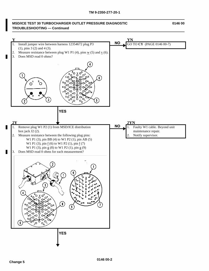
TM 9-2350-277-20-1
MSD/ICE TEST 30 TURBOCHARGER OUTLET PRESSURE DIAGNOSTICTROUBLESHOOTING — Continued
0146 00
Y1. Install jumper wire between harness 12354672 plug P3
(1), pins 3 (2) and 4 (3).2. Measure resistance between plug W1 P1 (4), pins w (5) and x (6).3. Does MSD read 0 ohms?
YNGO TO CY (PAGE 0146 00-7)
2Y1. Remove plug W1 P2 (1) from MSD/ICE distribution
box jack J2 (2).2. Measure resistance between the following plug pins:
W1 P1 (3), pin BB (4) to W1 P2 (1), pin AB (5)W1 P1 (3), pin f (6) to W1 P2 (1), pin f (7)W1 P1 (3), pin g (8) to W1 P2 (1), pin g (9)
3. Does MSD read 0 ohms for each measurement?
2YN1. Faulty W1 cable. Beyond unit
maintenance repair.2. Notify supervisor.
0146 00-2Change 5
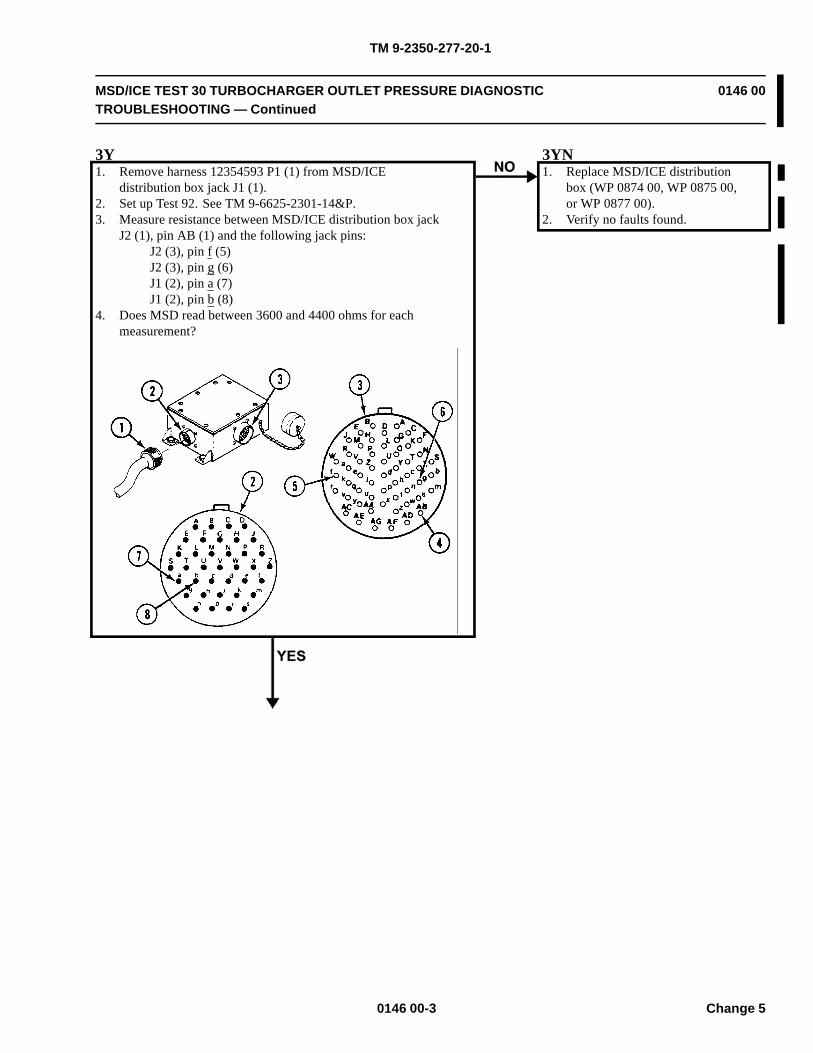
TM 9-2350-277-20-1
MSD/ICE TEST 30 TURBOCHARGER OUTLET PRESSURE DIAGNOSTICTROUBLESHOOTING — Continued
0146 00
3Y1. Remove harness 12354593 P1 (1) from MSD/ICE
distribution box jack J1 (1).2. Set up Test 92. See TM 9-6625-2301-14&P.3. Measure resistance between MSD/ICE distribution box jack
J2 (1), pin AB (1) and the following jack pins:J2 (3), pin f (5)J2 (3), pin g (6)J1 (2), pin a (7)J1 (2), pin b (8)
4. Does MSD read between 3600 and 4400 ohms for eachmeasurement?
3YN1. Replace MSD/ICE distribution
box (WP 0874 00, WP 0875 00,or WP 0877 00).
2. Verify no faults found.
0146 00-3 Change 5
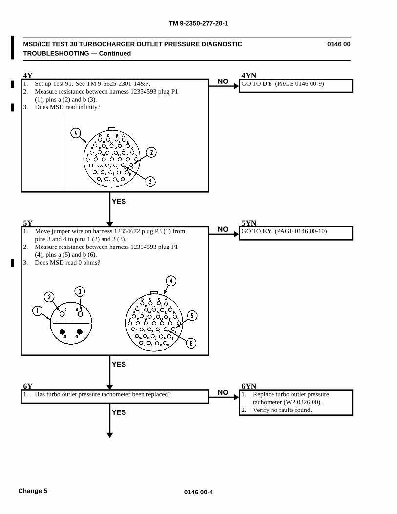
TM 9-2350-277-20-1
MSD/ICE TEST 30 TURBOCHARGER OUTLET PRESSURE DIAGNOSTICTROUBLESHOOTING — Continued
0146 00
4Y1. Set up Test 91. See TM 9-6625-2301-14&P.2. Measure resistance between harness 12354593 plug P1
(1), pins a (2) and b (3).3. Does MSD read infinity?
4YNGO TO DY (PAGE 0146 00-9)
5Y1. Move jumper wire on harness 12354672 plug P3 (1) from
pins 3 and 4 to pins 1 (2) and 2 (3).2. Measure resistance between harness 12354593 plug P1
(4), pins a (5) and b (6).3. Does MSD read 0 ohms?
5YNGO TO EY (PAGE 0146 00-10)
6Y1. Has turbo outlet pressure tachometer been replaced?
6YN1. Replace turbo outlet pressure
tachometer (WP 0326 00).2. Verify no faults found.
0146 00-4Change 5
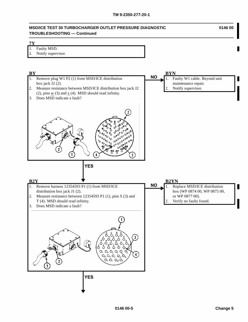
TM 9-2350-277-20-1
MSD/ICE TEST 30 TURBOCHARGER OUTLET PRESSURE DIAGNOSTICTROUBLESHOOTING — Continued
0146 00
7Y1. Faulty MSD.2. Notify supervisor.
BY1. Remove plug W1 P2 (1) from MSD/ICE distribution
box jack J2 (2).2. Measure resistance between MSD/ICE distribution box jack J2
(2), pins w (3) and x (4). MSD should read infinity.3. Does MSD indicate a fault?
BYN1. Faulty W1 cable. Beyond unit
maintenance repair.2. Notify supervisor.
B2Y1. Remove harness 12354593 P1 (1) from MSD/ICE
distribution box jack J1 (2).2. Measure resistance between 12354593 P1 (1), pins S (3) and
T (4). MSD should read infinity.3. Does MSD indicate a fault?
B2YN1. Replace MSD/ICE distribution
box (WP 0874 00, WP 0875 00,or WP 0877 00).
2. Verify no faults found.
0146 00-5 Change 5

TM 9-2350-277-20-1
MSD/ICE TEST 30 TURBOCHARGER OUTLET PRESSURE DIAGNOSTICTROUBLESHOOTING — Continued
0146 00
B3Y1. Remove harness 12354672 P4 (1) from harness
12354593 jack J1 (2).2. Measure resistance between harness 12354672 plug P4
(1), pins M (3) and N (4).3. Does MSD read infinity?
B3YN1. Replace wiring harness 12354672
(WP 0882 00).2. Verify no faults found.
B4Y1. Replace wiring harness 12354593 (WP 0882 00).2. Verify no faults found.
0146 00-6Change 5
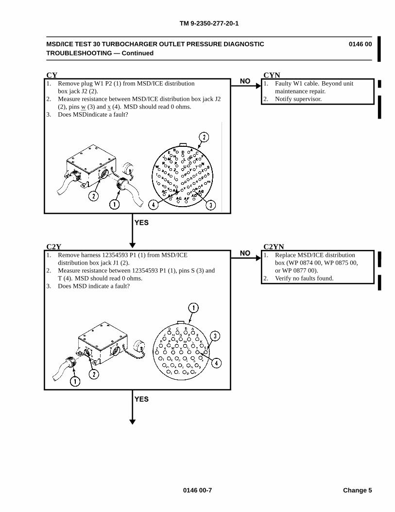
TM 9-2350-277-20-1
MSD/ICE TEST 30 TURBOCHARGER OUTLET PRESSURE DIAGNOSTICTROUBLESHOOTING — Continued
0146 00
CY1. Remove plug W1 P2 (1) from MSD/ICE distribution
box jack J2 (2).2. Measure resistance between MSD/ICE distribution box jack J2
(2), pins w (3) and x (4). MSD should read 0 ohms.3. Does MSDindicate a fault?
CYN1. Faulty W1 cable. Beyond unit
maintenance repair.2. Notify supervisor.
C2Y1. Remove harness 12354593 P1 (1) from MSD/ICE
distribution box jack J1 (2).2. Measure resistance between 12354593 P1 (1), pins S (3) and
T (4). MSD should read 0 ohms.3. Does MSD indicate a fault?
C2YN1. Replace MSD/ICE distribution
box (WP 0874 00, WP 0875 00,or WP 0877 00).
2. Verify no faults found.
0146 00-7 Change 5
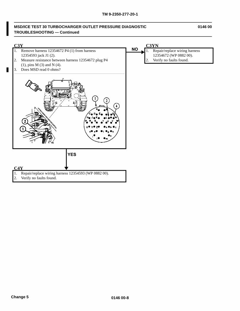
TM 9-2350-277-20-1
MSD/ICE TEST 30 TURBOCHARGER OUTLET PRESSURE DIAGNOSTICTROUBLESHOOTING — Continued
0146 00
C3Y1. Remove harness 12354672 P4 (1) from harness
12354593 jack J1 (2).2. Measure resistance between harness 12354672 plug P4
(1), pins M (3) and N (4).3. Does MSD read 0 ohms?
C3YN1. Repair/replace wiring harness
12354672 (WP 0882 00).2. Verify no faults found.
C4Y1. Repair/replace wiring harness 12354593 (WP 0882 00).2. Verify no faults found.
0146 00-8Change 5
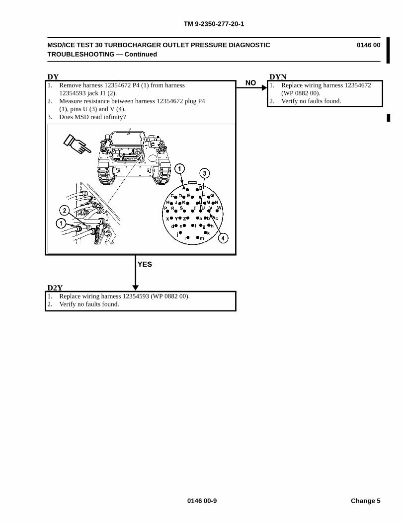
TM 9-2350-277-20-1
MSD/ICE TEST 30 TURBOCHARGER OUTLET PRESSURE DIAGNOSTICTROUBLESHOOTING — Continued
0146 00
DY1. Remove harness 12354672 P4 (1) from harness
12354593 jack J1 (2).2. Measure resistance between harness 12354672 plug P4
(1), pins U (3) and V (4).3. Does MSD read infinity?
DYN1. Replace wiring harness 12354672
(WP 0882 00).2. Verify no faults found.
D2Y1. Replace wiring harness 12354593 (WP 0882 00).2. Verify no faults found.
0146 00-9 Change 5
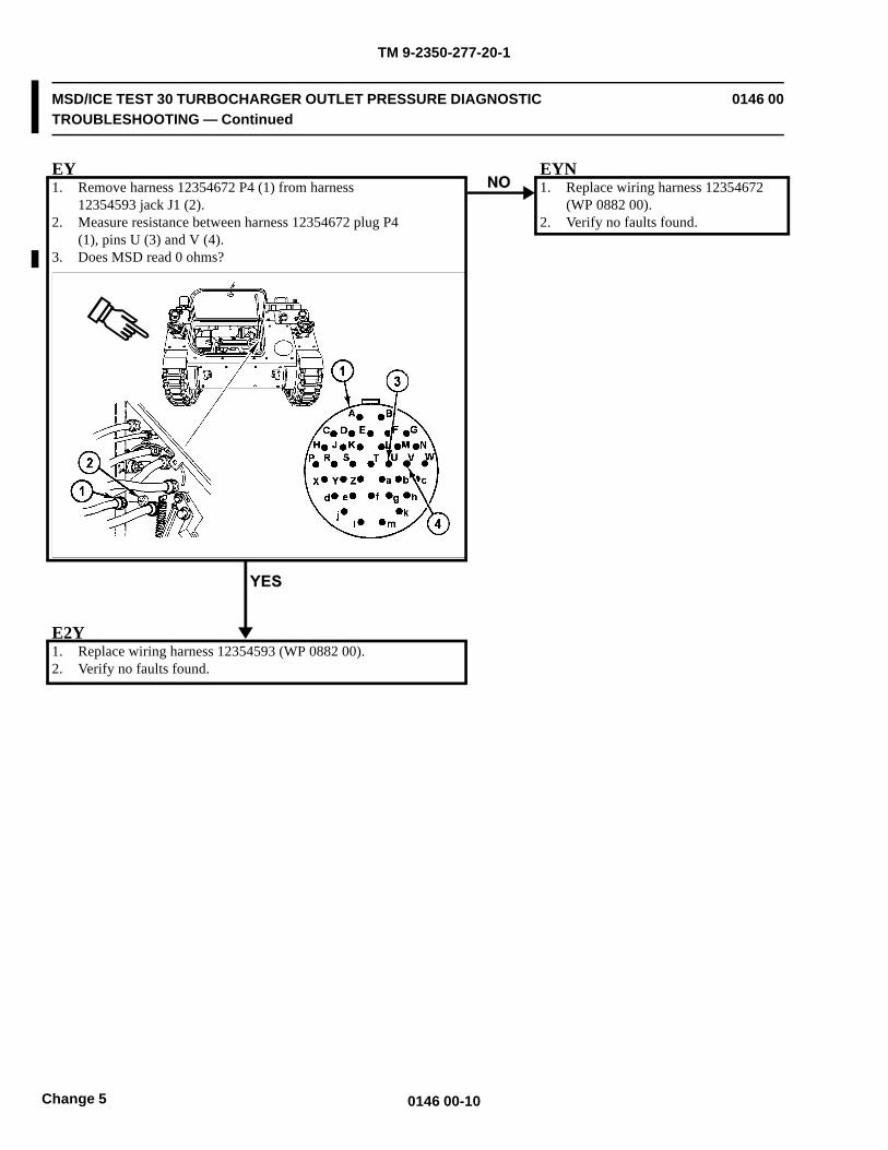
TM 9-2350-277-20-1
MSD/ICE TEST 30 TURBOCHARGER OUTLET PRESSURE DIAGNOSTICTROUBLESHOOTING — Continued
0146 00
EY1. Remove harness 12354672 P4 (1) from harness
12354593 jack J1 (2).2. Measure resistance between harness 12354672 plug P4
(1), pins U (3) and V (4).3. Does MSD read 0 ohms?
EYN1. Replace wiring harness 12354672
(WP 0882 00).2. Verify no faults found.
E2Y1. Replace wiring harness 12354593 (WP 0882 00).2. Verify no faults found.
0146 00-10Change 5
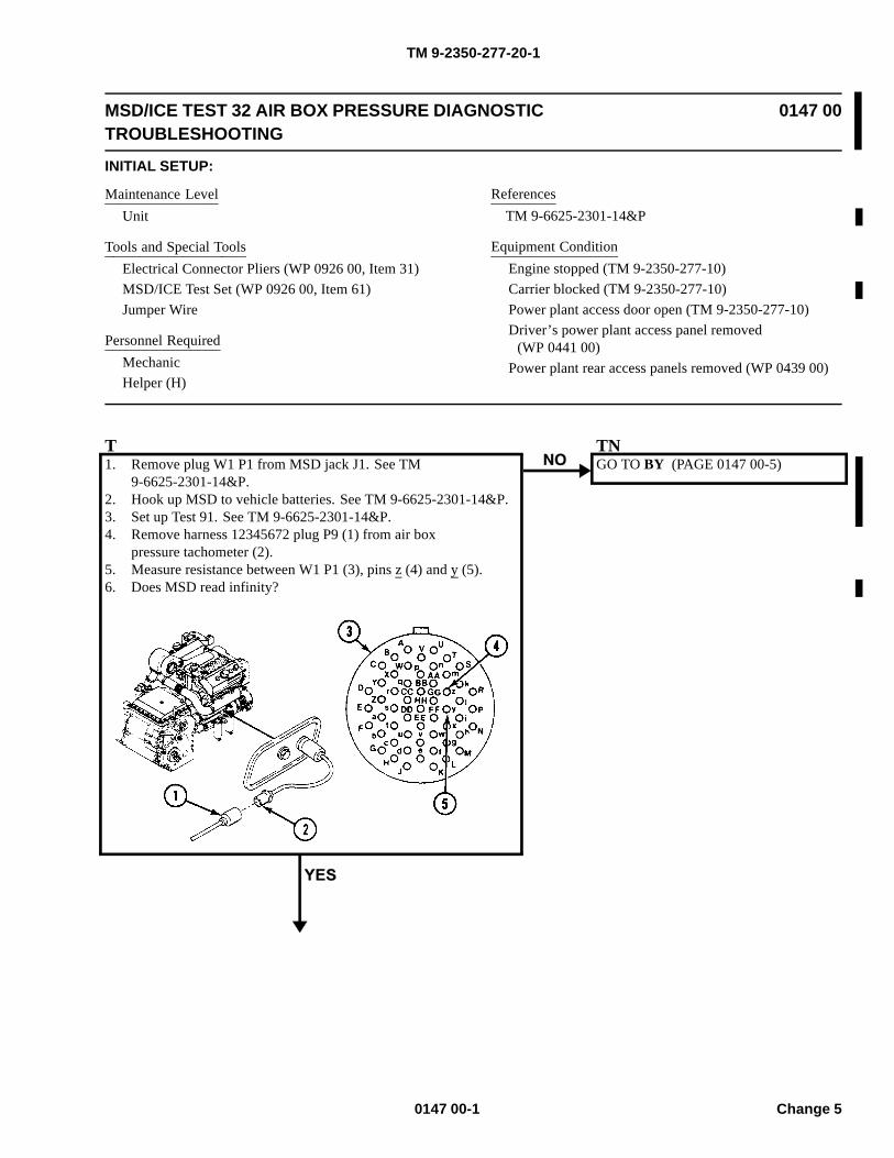
TM 9-2350-277-20-1
MSD/ICE TEST 32 AIR BOX PRESSURE DIAGNOSTICTROUBLESHOOTING
0147 00
INITIAL SETUP:
Maintenance LevelUnit
Tools and Special ToolsElectrical Connector Pliers (WP 0926 00, Item 31)MSD/ICE Test Set (WP 0926 00, Item 61)Jumper Wire
Personnel RequiredMechanicHelper (H)
ReferencesTM 9-6625-2301-14&P
Equipment ConditionEngine stopped (TM 9-2350-277-10)Carrier blocked (TM 9-2350-277-10)Power plant access door open (TM 9-2350-277-10)Driver’s power plant access panel removed
(WP 0441 00)Power plant rear access panels removed (WP 0439 00)
T1. Remove plug W1 P1 from MSD jack J1. See TM
9-6625-2301-14&P.2. Hook up MSD to vehicle batteries. See TM 9-6625-2301-14&P.3. Set up Test 91. See TM 9-6625-2301-14&P.4. Remove harness 12345672 plug P9 (1) from air box
pressure tachometer (2).5. Measure resistance between W1 P1 (3), pins z (4) and y (5).6. Does MSD read infinity?
TNGO TO BY (PAGE 0147 00-5)
0147 00-1 Change 5
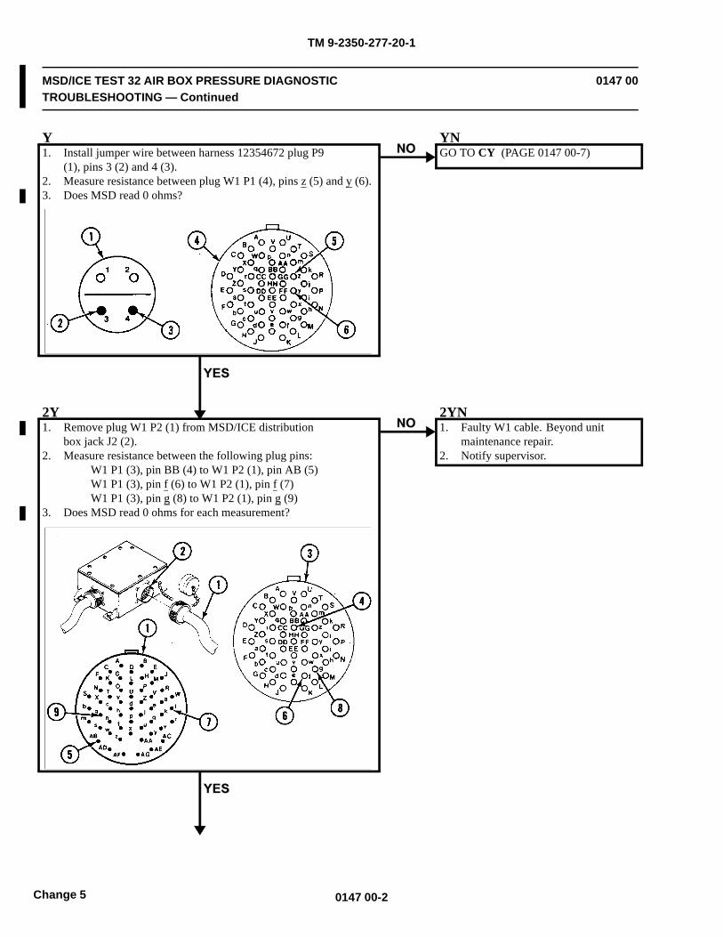
TM 9-2350-277-20-1
MSD/ICE TEST 32 AIR BOX PRESSURE DIAGNOSTICTROUBLESHOOTING — Continued
0147 00
Y1. Install jumper wire between harness 12354672 plug P9
(1), pins 3 (2) and 4 (3).2. Measure resistance between plug W1 P1 (4), pins z (5) and y (6).3. Does MSD read 0 ohms?
YNGO TO CY (PAGE 0147 00-7)
2Y1. Remove plug W1 P2 (1) from MSD/ICE distribution
box jack J2 (2).2. Measure resistance between the following plug pins:
W1 P1 (3), pin BB (4) to W1 P2 (1), pin AB (5)W1 P1 (3), pin f (6) to W1 P2 (1), pin f (7)W1 P1 (3), pin g (8) to W1 P2 (1), pin g (9)
3. Does MSD read 0 ohms for each measurement?
2YN1. Faulty W1 cable. Beyond unit
maintenance repair.2. Notify supervisor.
0147 00-2Change 5
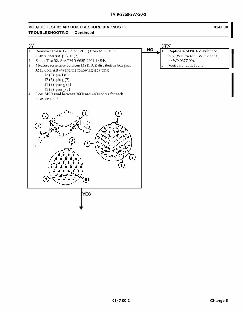
TM 9-2350-277-20-1
MSD/ICE TEST 32 AIR BOX PRESSURE DIAGNOSTICTROUBLESHOOTING — Continued
0147 00
3Y1. Remove harness 12354593 P1 (1) from MSD/ICE
distribution box jack J1 (2).2. Set up Test 92. See TM 9-6625-2301-14&P.3. Measure resistance between MSD/ICE distribution box jack
J2 (3), pin AB (4) and the following jack pins:J2 (5), pin f (6)J2 (5), pin g (7)J1 (2), pins d (8)J1 (2), pins j (9)
4. Does MSD read between 3600 and 4400 ohms for eachmeasurement?
3YN1. Replace MSD/ICE distribution
box (WP 0874 00, WP 0875 00,or WP 0877 00).
2. Verify no faults found.
0147 00-3 Change 5
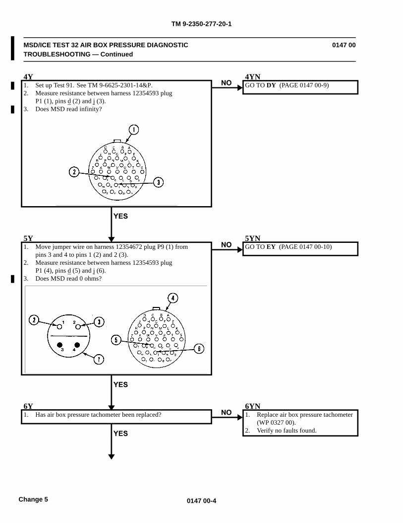
TM 9-2350-277-20-1
MSD/ICE TEST 32 AIR BOX PRESSURE DIAGNOSTICTROUBLESHOOTING — Continued
0147 00
4Y1. Set up Test 91. See TM 9-6625-2301-14&P.2. Measure resistance between harness 12354593 plug
P1 (1), pins d (2) and j (3).3. Does MSD read infinity?
4YNGO TO DY (PAGE 0147 00-9)
5Y1. Move jumper wire on harness 12354672 plug P9 (1) from
pins 3 and 4 to pins 1 (2) and 2 (3).2. Measure resistance between harness 12354593 plug
P1 (4), pins d (5) and j (6).3. Does MSD read 0 ohms?
5YNGO TO EY (PAGE 0147 00-10)
6Y1. Has air box pressure tachometer been replaced?
6YN1. Replace air box pressure tachometer
(WP 0327 00).2. Verify no faults found.
0147 00-4Change 5
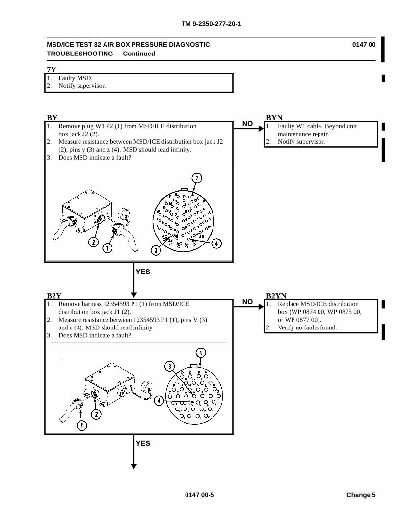
TM 9-2350-277-20-1
MSD/ICE TEST 32 AIR BOX PRESSURE DIAGNOSTICTROUBLESHOOTING — Continued
0147 00
7Y1. Faulty MSD.2. Notify supervisor.
BY1. Remove plug W1 P2 (1) from MSD/ICE distribution
box jack J2 (2).2. Measure resistance between MSD/ICE distribution box jack J2
(2), pins y (3) and z (4). MSD should read infinity.3. Does MSD indicate a fault?
BYN1. Faulty W1 cable. Beyond unit
maintenance repair.2. Notify supervisor.
B2Y1. Remove harness 12354593 P1 (1) from MSD/ICE
distribution box jack J1 (2).2. Measure resistance between 12354593 P1 (1), pins V (3)
and c (4). MSD should read infinity.3. Does MSD indicate a fault?
B2YN1. Replace MSD/ICE distribution
box (WP 0874 00, WP 0875 00,or WP 0877 00).
2. Verify no faults found.
0147 00-5 Change 5
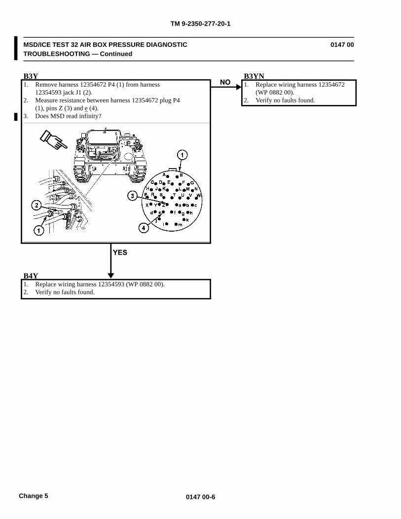
TM 9-2350-277-20-1
MSD/ICE TEST 32 AIR BOX PRESSURE DIAGNOSTICTROUBLESHOOTING — Continued
0147 00
B3Y1. Remove harness 12354672 P4 (1) from harness
12354593 jack J1 (2).2. Measure resistance between harness 12354672 plug P4
(1), pins Z (3) and e (4).3. Does MSD read infinity?
B3YN1. Replace wiring harness 12354672
(WP 0882 00).2. Verify no faults found.
B4Y1. Replace wiring harness 12354593 (WP 0882 00).2. Verify no faults found.
0147 00-6Change 5
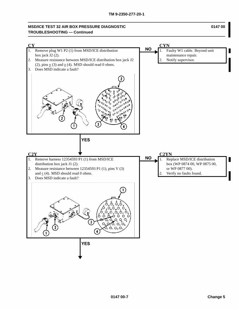
TM 9-2350-277-20-1
MSD/ICE TEST 32 AIR BOX PRESSURE DIAGNOSTICTROUBLESHOOTING — Continued
0147 00
CY1. Remove plug W1 P2 (1) from MSD/ICE distribution
box jack J2 (2).2. Measure resistance between MSD/ICE distribution box jack J2
(2), pins y (3) and z (4). MSD should read 0 ohms.3. Does MSD indicate a fault?
CYN1. Faulty W1 cable. Beyond unit
maintenance repair.2. Notify supervisor.
C2Y1. Remove harness 12354593 P1 (1) from MSD/ICE
distribution box jack J1 (2).2. Measure resistance between 12354593 P1 (1), pins V (3)
and c (4). MSD should read 0 ohms.3. Does MSD indicate a fault?
C2YN1. Replace MSD/ICE distribution
box (WP 0874 00, WP 0875 00,or WP 0877 00).
2. Verify no faults found.
0147 00-7 Change 5
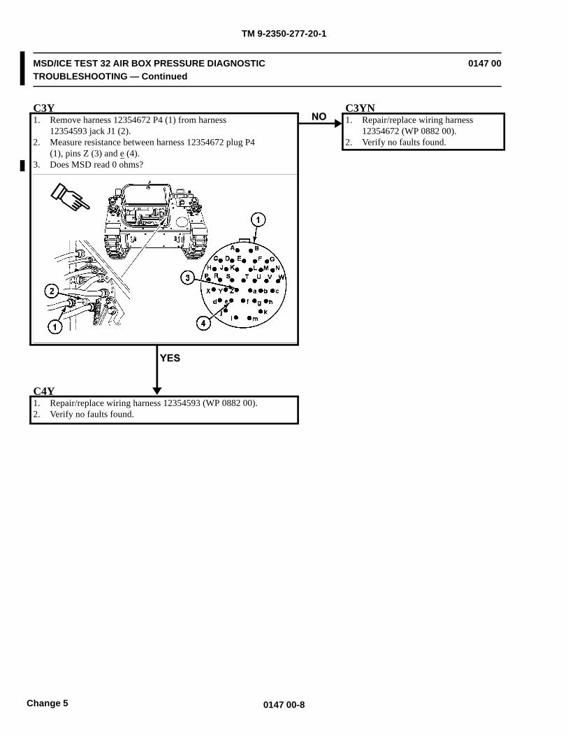
TM 9-2350-277-20-1
MSD/ICE TEST 32 AIR BOX PRESSURE DIAGNOSTICTROUBLESHOOTING — Continued
0147 00
C3Y1. Remove harness 12354672 P4 (1) from harness
12354593 jack J1 (2).2. Measure resistance between harness 12354672 plug P4
(1), pins Z (3) and e (4).3. Does MSD read 0 ohms?
C3YN1. Repair/replace wiring harness
12354672 (WP 0882 00).2. Verify no faults found.
C4Y1. Repair/replace wiring harness 12354593 (WP 0882 00).2. Verify no faults found.
0147 00-8Change 5
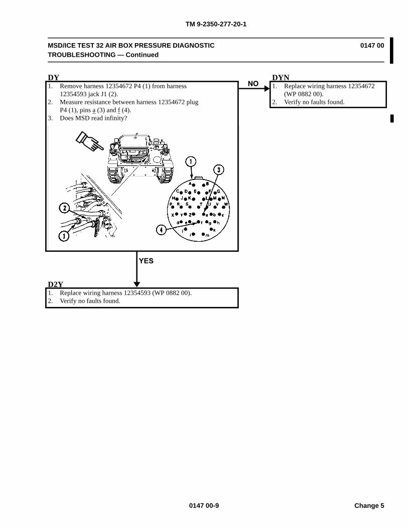
TM 9-2350-277-20-1
MSD/ICE TEST 32 AIR BOX PRESSURE DIAGNOSTICTROUBLESHOOTING — Continued
0147 00
DY1. Remove harness 12354672 P4 (1) from harness
12354593 jack J1 (2).2. Measure resistance between harness 12354672 plug
P4 (1), pins a (3) and f (4).3. Does MSD read infinity?
DYN1. Replace wiring harness 12354672
(WP 0882 00).2. Verify no faults found.
D2Y1. Replace wiring harness 12354593 (WP 0882 00).2. Verify no faults found.
0147 00-9 Change 5
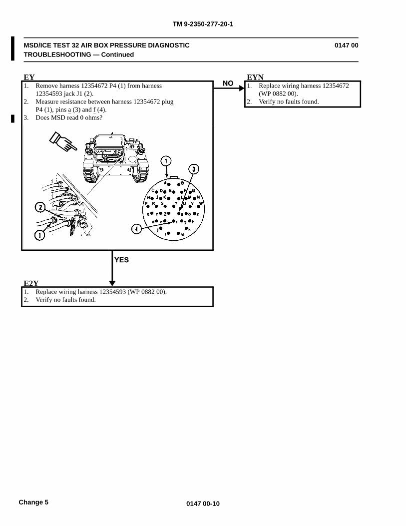
TM 9-2350-277-20-1
MSD/ICE TEST 32 AIR BOX PRESSURE DIAGNOSTICTROUBLESHOOTING — Continued
0147 00
EY1. Remove harness 12354672 P4 (1) from harness
12354593 jack J1 (2).2. Measure resistance between harness 12354672 plug
P4 (1), pins a (3) and f (4).3. Does MSD read 0 ohms?
EYN1. Replace wiring harness 12354672
(WP 0882 00).2. Verify no faults found.
E2Y1. Replace wiring harness 12354593 (WP 0882 00).2. Verify no faults found.
0147 00-10Change 5
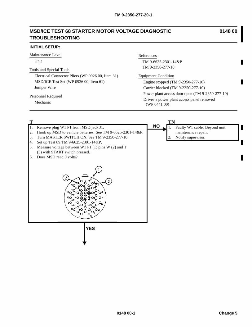
TM 9-2350-277-20-1
MSD/ICE TEST 68 STARTER MOTOR VOLTAGE DIAGNOSTICTROUBLESHOOTING
0148 00
INITIAL SETUP:
Maintenance LevelUnit
Tools and Special ToolsElectrical Connector Pliers (WP 0926 00, Item 31)MSD/ICE Test Set (WP 0926 00, Item 61)Jumper Wire
Personnel RequiredMechanic
ReferencesTM 9-6625-2301-14&PTM 9-2350-277-10
Equipment ConditionEngine stopped (TM 9-2350-277-10)Carrier blocked (TM 9-2350-277-10)Power plant access door open (TM 9-2350-277-10)Driver’s power plant access panel removed
(WP 0441 00)
T1. Remove plug W1 P1 from MSD jack J1.2. Hook up MSD to vehicle batteries. See TM 9-6625-2301-14&P.3. Turn MASTER SWITCH ON. See TM 9-2350-277-10.4. Set up Test 89 TM 9-6625-2301-14&P.5. Measure voltage between W1 P1 (1) pins W (2) and T
(3) with START switch pressed.6. Does MSD read 0 volts?
TN1. Faulty W1 cable. Beyond unit
maintenance repair.2. Notify supervisor.
0148 00-1 Change 5
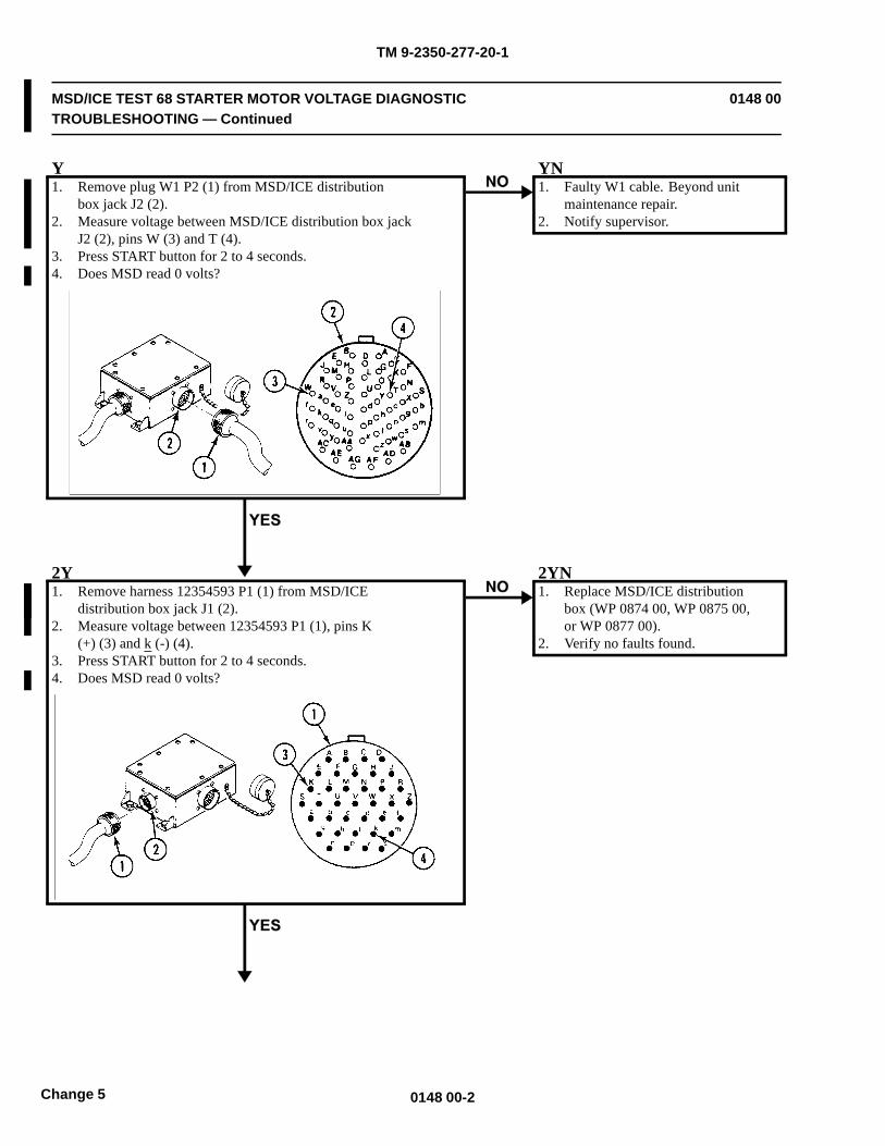
TM 9-2350-277-20-1
MSD/ICE TEST 68 STARTER MOTOR VOLTAGE DIAGNOSTICTROUBLESHOOTING — Continued
0148 00
Y1. Remove plug W1 P2 (1) from MSD/ICE distribution
box jack J2 (2).2. Measure voltage between MSD/ICE distribution box jack
J2 (2), pins W (3) and T (4).3. Press START button for 2 to 4 seconds.4. Does MSD read 0 volts?
YN1. Faulty W1 cable. Beyond unit
maintenance repair.2. Notify supervisor.
2Y1. Remove harness 12354593 P1 (1) from MSD/ICE
distribution box jack J1 (2).2. Measure voltage between 12354593 P1 (1), pins K
(+) (3) and k (-) (4).3. Press START button for 2 to 4 seconds.4. Does MSD read 0 volts?
2YN1. Replace MSD/ICE distribution
box (WP 0874 00, WP 0875 00,or WP 0877 00).
2. Verify no faults found.
0148 00-2Change 5
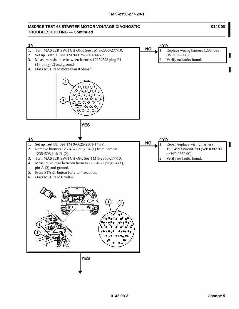
TM 9-2350-277-20-1
MSD/ICE TEST 68 STARTER MOTOR VOLTAGE DIAGNOSTICTROUBLESHOOTING — Continued
0148 00
3Y1. Turn MASTER SWITCH OFF. See TM 9-2350-277-10.2. Set up Test 91. See TM 9-6625-2301-14&P.3. Measure resistance between harness 12354593 plug P1
(1), pin k (2) and ground.4. Does MSD read more than 0 ohms?
3YN1. Replace wiring harness 12354593
(WP 0882 00).2. Verify no faults found.
4Y1. Set up Test 89. See TM 9-6625-2301-14&P.2. Remove harness 12354672 plug P4 (1) from harness
12354593 jack J1 (2).3. Turn MASTER SWITCH ON. See TM 9-2350-277-10.4. Measure voltage between harness 12354672 plug P4 (1),
pin A (3) and ground.5. Press START button for 2 to 4 seconds.6. Does MSD read 0 volts?
4YN1. Repair/replace wiring harness
12354593 circuit 799 (WP 0382 00or WP 0882 00).
2. Verify no faults found.
0148 00-3 Change 5

TM 9-2350-277-20-1
MSD/ICE TEST 68 STARTER MOTOR VOLTAGE DIAGNOSTICTROUBLESHOOTING — Continued
0148 00
5Y1. Repair/replace wiring harness 12354672 circuit 776
(WP 0382 00 or WP 0882 00).2. Verify no faults found.
0148 00-4Change 5
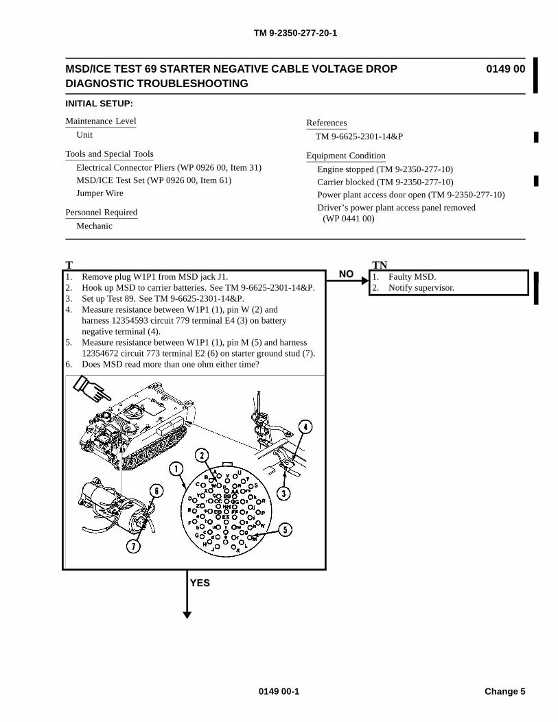
TM 9-2350-277-20-1
MSD/ICE TEST 69 STARTER NEGATIVE CABLE VOLTAGE DROPDIAGNOSTIC TROUBLESHOOTING
0149 00
INITIAL SETUP:
Maintenance LevelUnit
Tools and Special ToolsElectrical Connector Pliers (WP 0926 00, Item 31)MSD/ICE Test Set (WP 0926 00, Item 61)Jumper Wire
Personnel RequiredMechanic
ReferencesTM 9-6625-2301-14&P
Equipment ConditionEngine stopped (TM 9-2350-277-10)Carrier blocked (TM 9-2350-277-10)Power plant access door open (TM 9-2350-277-10)Driver’s power plant access panel removed
(WP 0441 00)
T1. Remove plug W1P1 from MSD jack J1.2. Hook up MSD to carrier batteries. See TM 9-6625-2301-14&P.3. Set up Test 89. See TM 9-6625-2301-14&P.4. Measure resistance between W1P1 (1), pin W (2) and
harness 12354593 circuit 779 terminal E4 (3) on batterynegative terminal (4).
5. Measure resistance between W1P1 (1), pin M (5) and harness12354672 circuit 773 terminal E2 (6) on starter ground stud (7).
6. Does MSD read more than one ohm either time?
TN1. Faulty MSD.2. Notify supervisor.
0149 00-1 Change 5
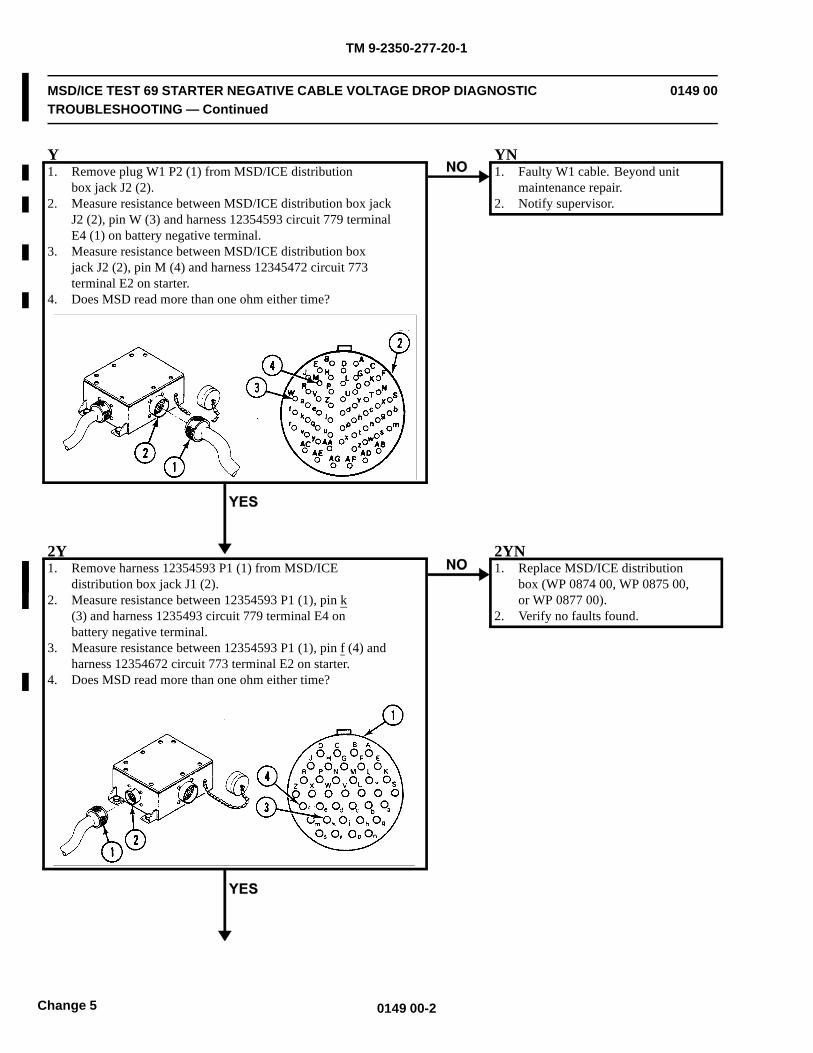
TM 9-2350-277-20-1
MSD/ICE TEST 69 STARTER NEGATIVE CABLE VOLTAGE DROP DIAGNOSTICTROUBLESHOOTING — Continued
0149 00
Y1. Remove plug W1 P2 (1) from MSD/ICE distribution
box jack J2 (2).2. Measure resistance between MSD/ICE distribution box jack
J2 (2), pin W (3) and harness 12354593 circuit 779 terminalE4 (1) on battery negative terminal.
3. Measure resistance between MSD/ICE distribution boxjack J2 (2), pin M (4) and harness 12345472 circuit 773terminal E2 on starter.
4. Does MSD read more than one ohm either time?
YN1. Faulty W1 cable. Beyond unit
maintenance repair.2. Notify supervisor.
2Y1. Remove harness 12354593 P1 (1) from MSD/ICE
distribution box jack J1 (2).2. Measure resistance between 12354593 P1 (1), pin k
(3) and harness 1235493 circuit 779 terminal E4 onbattery negative terminal.
3. Measure resistance between 12354593 P1 (1), pin f (4) andharness 12354672 circuit 773 terminal E2 on starter.
4. Does MSD read more than one ohm either time?
2YN1. Replace MSD/ICE distribution
box (WP 0874 00, WP 0875 00,or WP 0877 00).
2. Verify no faults found.
0149 00-2Change 5
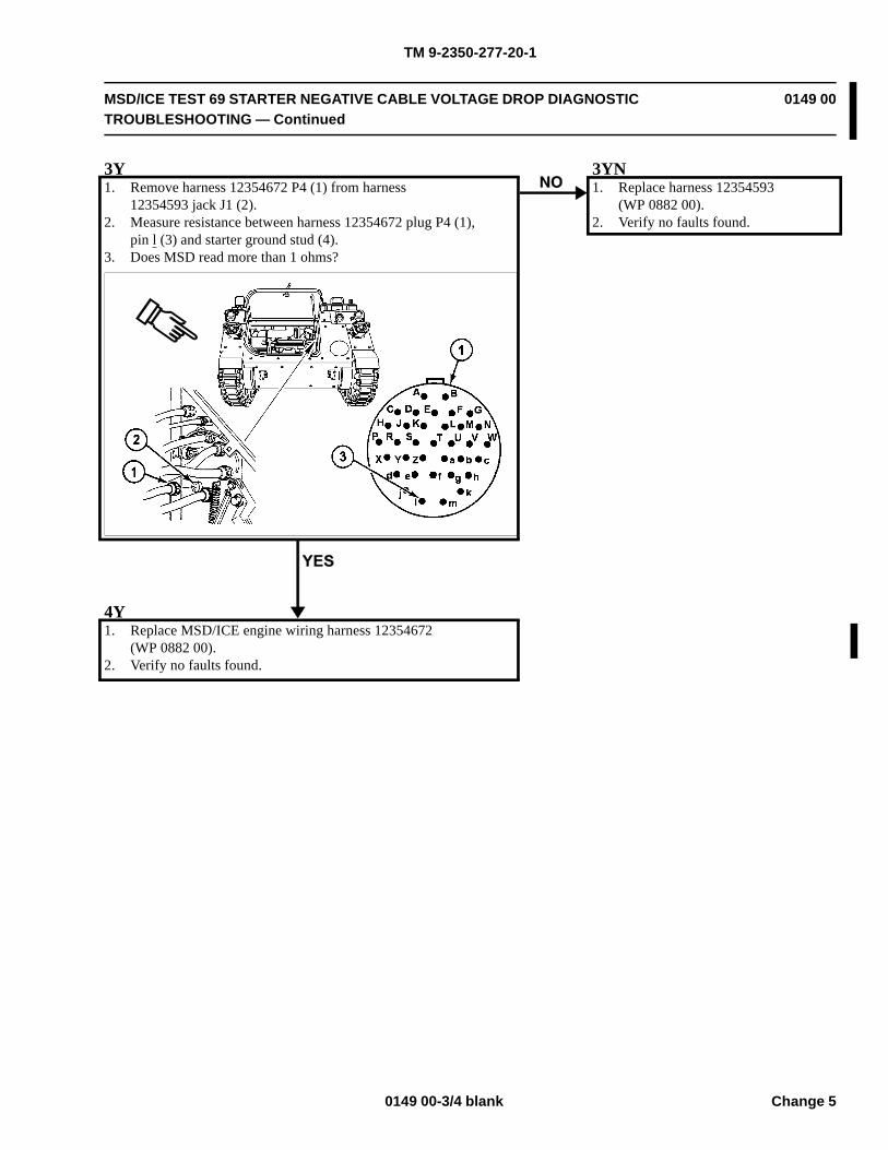
TM 9-2350-277-20-1
MSD/ICE TEST 69 STARTER NEGATIVE CABLE VOLTAGE DROP DIAGNOSTICTROUBLESHOOTING — Continued
0149 00
3Y1. Remove harness 12354672 P4 (1) from harness
12354593 jack J1 (2).2. Measure resistance between harness 12354672 plug P4 (1),
pin l (3) and starter ground stud (4).3. Does MSD read more than 1 ohms?
3YN1. Replace harness 12354593
(WP 0882 00).2. Verify no faults found.
4Y1. Replace MSD/ICE engine wiring harness 12354672
(WP 0882 00).2. Verify no faults found.
0149 00-3/4 blank Change 5

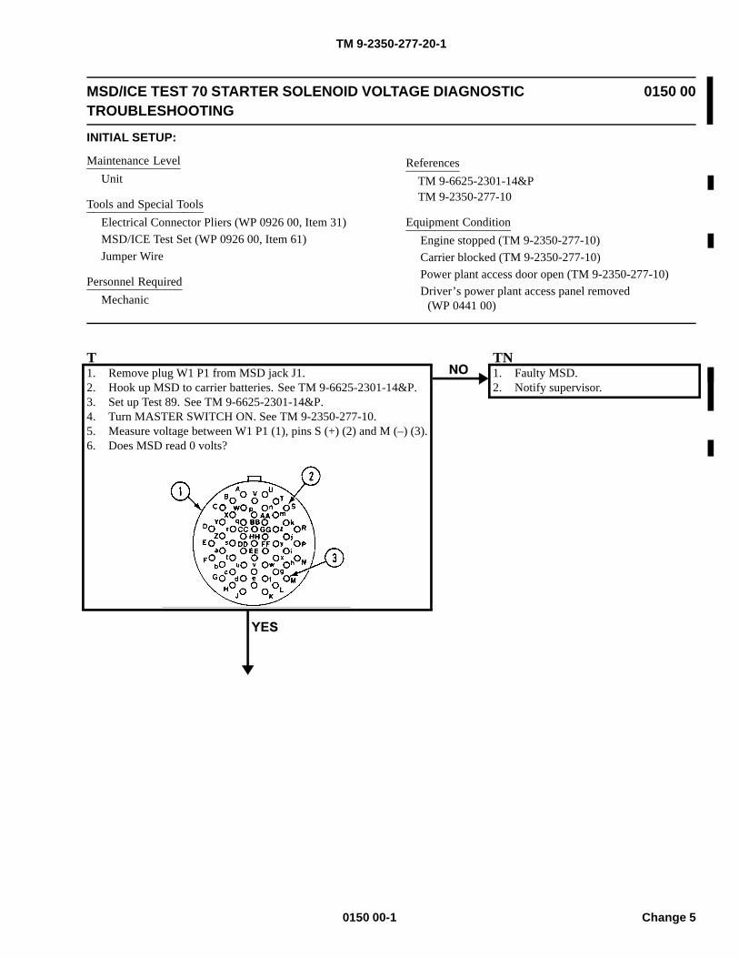
TM 9-2350-277-20-1
MSD/ICE TEST 70 STARTER SOLENOID VOLTAGE DIAGNOSTICTROUBLESHOOTING
0150 00
INITIAL SETUP:
Maintenance LevelUnit
Tools and Special ToolsElectrical Connector Pliers (WP 0926 00, Item 31)MSD/ICE Test Set (WP 0926 00, Item 61)Jumper Wire
Personnel RequiredMechanic
ReferencesTM 9-6625-2301-14&PTM 9-2350-277-10
Equipment ConditionEngine stopped (TM 9-2350-277-10)Carrier blocked (TM 9-2350-277-10)Power plant access door open (TM 9-2350-277-10)Driver’s power plant access panel removed
(WP 0441 00)
T1. Remove plug W1 P1 from MSD jack J1.2. Hook up MSD to carrier batteries. See TM 9-6625-2301-14&P.3. Set up Test 89. See TM 9-6625-2301-14&P.4. Turn MASTER SWITCH ON. See TM 9-2350-277-10.5. Measure voltage between W1 P1 (1), pins S (+) (2) and M (–) (3).6. Does MSD read 0 volts?
TN1. Faulty MSD.2. Notify supervisor.
0150 00-1 Change 5
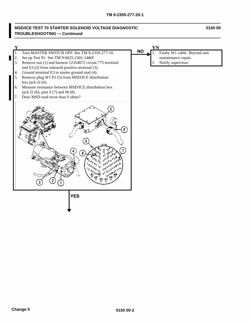
TM 9-2350-277-20-1
MSD/ICE TEST 70 STARTER SOLENOID VOLTAGE DIAGNOSTICTROUBLESHOOTING — Continued
0150 00
Y1. Turn MASTER SWITCH OFF. See TM 9-2350-277-10.2. Set up Test 91. See TM 9-6625-2301-14&P.3. Remove nut (1) and harness 12354672 circuit 775 terminal
end E3 (2) from solenoid positive terminal (3).4. Ground terminal E3 to starter ground stud (4).5. Remove plug W1 P2 (5) from MSD/ICE distribution
box jack J2 (6).6. Measure resistance between MSD/ICE distribution box
jack J2 (6), pins S (7) and M (8).7. Does MSD read more than 0 ohms?
YN1. Faulty W1 cable. Beyond unit
maintenance repair.2. Notify supervisor.
0150 00-2Change 5
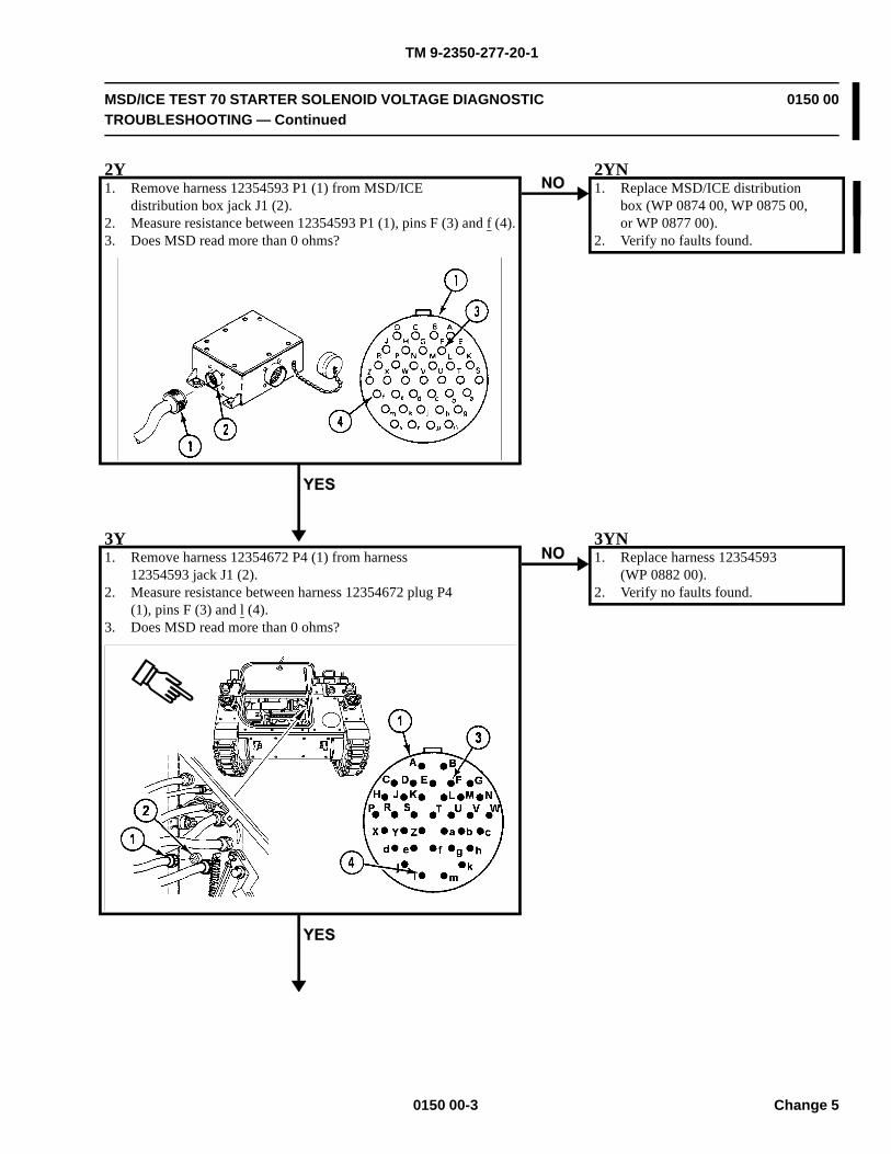
TM 9-2350-277-20-1
MSD/ICE TEST 70 STARTER SOLENOID VOLTAGE DIAGNOSTICTROUBLESHOOTING — Continued
0150 00
2Y1. Remove harness 12354593 P1 (1) from MSD/ICE
distribution box jack J1 (2).2. Measure resistance between 12354593 P1 (1), pins F (3) and f (4).3. Does MSD read more than 0 ohms?
2YN1. Replace MSD/ICE distribution
box (WP 0874 00, WP 0875 00,or WP 0877 00).
2. Verify no faults found.
3Y1. Remove harness 12354672 P4 (1) from harness
12354593 jack J1 (2).2. Measure resistance between harness 12354672 plug P4
(1), pins F (3) and l (4).3. Does MSD read more than 0 ohms?
3YN1. Replace harness 12354593
(WP 0882 00).2. Verify no faults found.
0150 00-3 Change 5

TM 9-2350-277-20-1
MSD/ICE TEST 70 STARTER SOLENOID VOLTAGE DIAGNOSTICTROUBLESHOOTING — Continued
0150 00
4Y1. Replace MSD/ICE engine wiring harness 12354672
(WP 0882 00).2. Verify no faults found.
0150 00-4Change 5
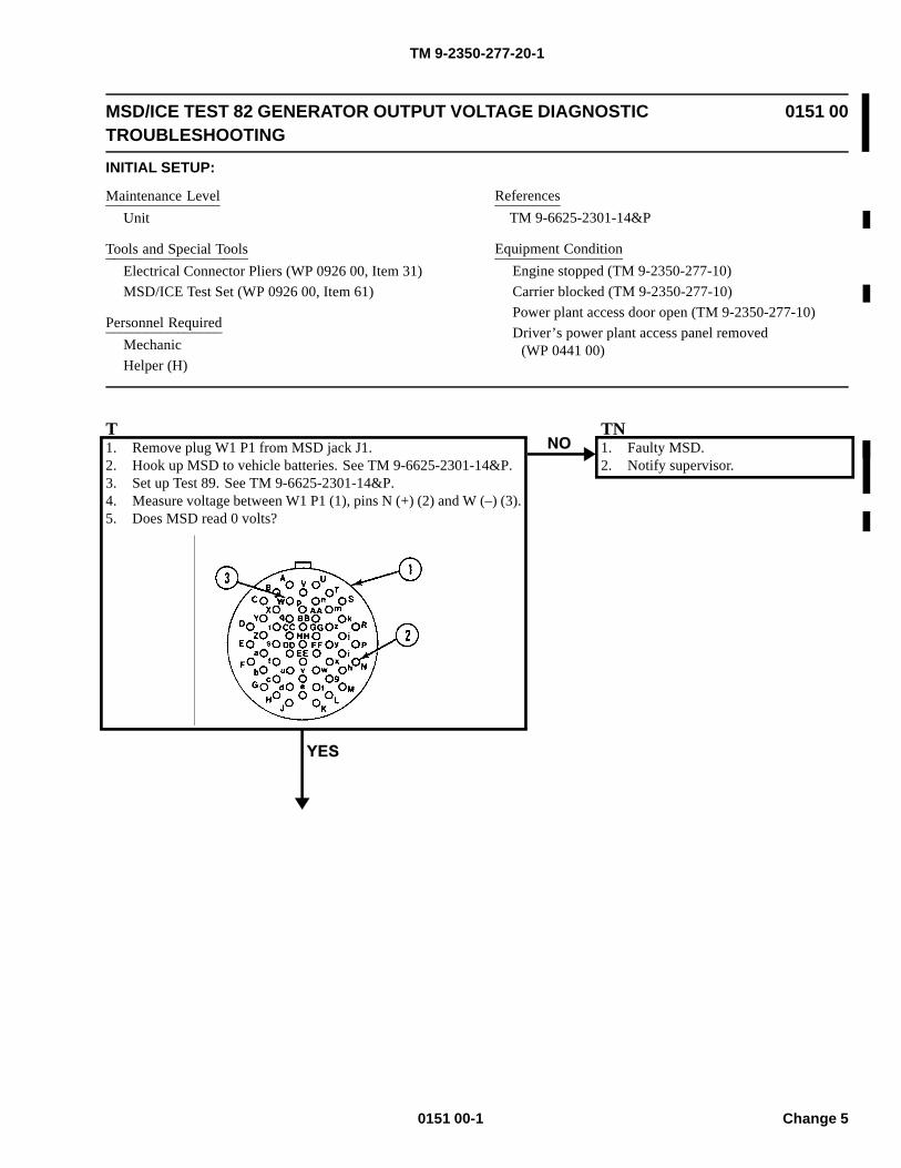
TM 9-2350-277-20-1
MSD/ICE TEST 82 GENERATOR OUTPUT VOLTAGE DIAGNOSTICTROUBLESHOOTING
0151 00
INITIAL SETUP:
Maintenance LevelUnit
Tools and Special ToolsElectrical Connector Pliers (WP 0926 00, Item 31)MSD/ICE Test Set (WP 0926 00, Item 61)
Personnel RequiredMechanicHelper (H)
ReferencesTM 9-6625-2301-14&P
Equipment ConditionEngine stopped (TM 9-2350-277-10)Carrier blocked (TM 9-2350-277-10)Power plant access door open (TM 9-2350-277-10)Driver’s power plant access panel removed
(WP 0441 00)
T1. Remove plug W1 P1 from MSD jack J1.2. Hook up MSD to vehicle batteries. See TM 9-6625-2301-14&P.3. Set up Test 89. See TM 9-6625-2301-14&P.4. Measure voltage between W1 P1 (1), pins N (+) (2) and W (–) (3).5. Does MSD read 0 volts?
TN1. Faulty MSD.2. Notify supervisor.
0151 00-1 Change 5
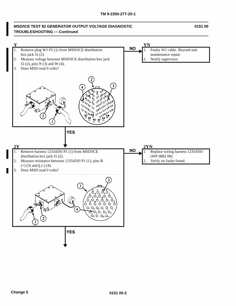
TM 9-2350-277-20-1
MSD/ICE TEST 82 GENERATOR OUTPUT VOLTAGE DIAGNOSTICTROUBLESHOOTING — Continued
0151 00
Y1. Remove plug W1 P2 (1) from MSD/ICE distribution
box jack J2 (2).2. Measure voltage between MSD/ICE distribution box jack
J2 (2), pins N (3) and W (4).3. Does MSD read 0 volts?
YN1. Faulty W1 cable. Beyond unit
maintenance repair.2. Notify supervisor.
2Y1. Remove harness 12354593 P1 (1) from MSD/ICE
distribution box jack J1 (2).2. Measure resistance between 12354593 P1 (1), pins B
(+) (3) and k (-) (4).3. Does MSD read 0 volts?
2YN1. Replace wiring harness 12354593
(WP 0882 00).2. Verify no faults found.
0151 00-2Change 5
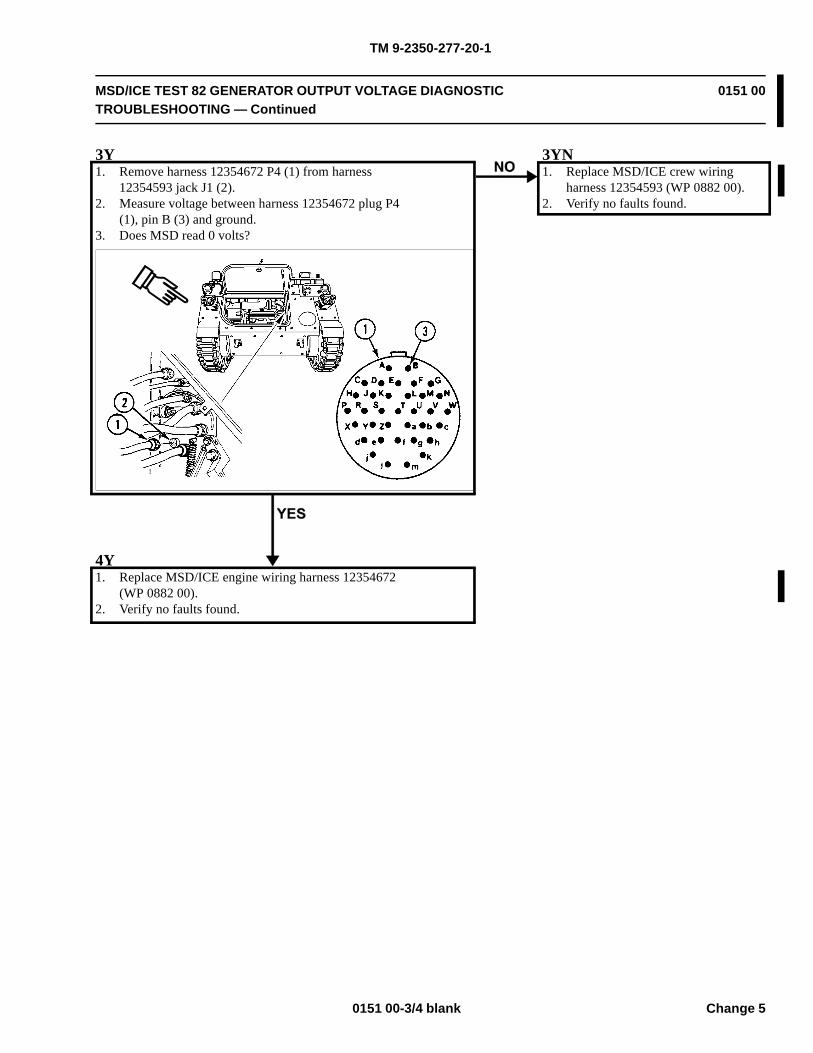
TM 9-2350-277-20-1
MSD/ICE TEST 82 GENERATOR OUTPUT VOLTAGE DIAGNOSTICTROUBLESHOOTING — Continued
0151 00
3Y1. Remove harness 12354672 P4 (1) from harness
12354593 jack J1 (2).2. Measure voltage between harness 12354672 plug P4
(1), pin B (3) and ground.3. Does MSD read 0 volts?
3YN1. Replace MSD/ICE crew wiring
harness 12354593 (WP 0882 00).2. Verify no faults found.
4Y1. Replace MSD/ICE engine wiring harness 12354672
(WP 0882 00).2. Verify no faults found.
0151 00-3/4 blank Change 5

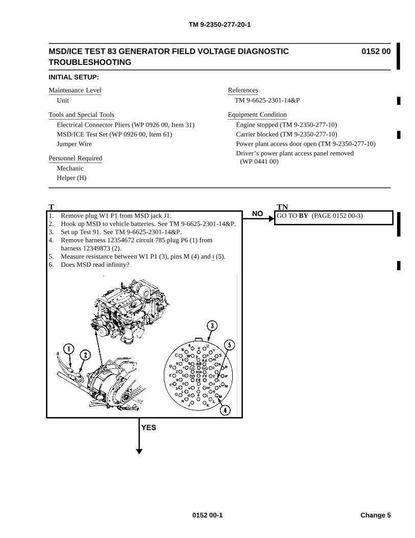
TM 9-2350-277-20-1
MSD/ICE TEST 83 GENERATOR FIELD VOLTAGE DIAGNOSTICTROUBLESHOOTING
0152 00
INITIAL SETUP:
Maintenance LevelUnit
Tools and Special ToolsElectrical Connector Pliers (WP 0926 00, Item 31)MSD/ICE Test Set (WP 0926 00, Item 61)Jumper Wire
Personnel RequiredMechanicHelper (H)
ReferencesTM 9-6625-2301-14&P
Equipment ConditionEngine stopped (TM 9-2350-277-10)Carrier blocked (TM 9-2350-277-10)Power plant access door open (TM 9-2350-277-10)Driver’s power plant access panel removed
(WP 0441 00)
T1. Remove plug W1 P1 from MSD jack J1.2. Hook up MSD to vehicle batteries. See TM 9-6625-2301-14&P.3. Set up Test 91. See TM 9-6625-2301-14&P.4. Remove harness 12354672 circuit 785 plug P6 (1) from
harness 12349873 (2).5. Measure resistance between W1 P1 (3), pins M (4) and i (5).6. Does MSD read infinity?
TNGO TO BY (PAGE 0152 00-3)
0152 00-1 Change 5
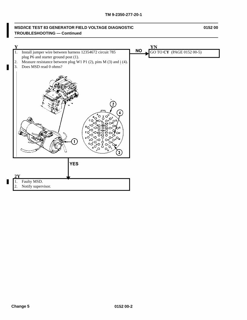
TM 9-2350-277-20-1
MSD/ICE TEST 83 GENERATOR FIELD VOLTAGE DIAGNOSTICTROUBLESHOOTING — Continued
0152 00
Y1. Install jumper wire between harness 12354672 circuit 785
plug P6 and starter ground post (1).2. Measure resistance between plug W1 P1 (2), pins M (3) and i (4).3. Does MSD read 0 ohms?
YNGO TO CY (PAGE 0152 00-5)
2Y1. Faulty MSD.2. Notify supervisor.
0152 00-2Change 5
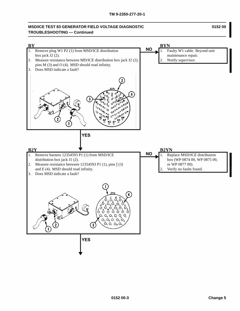
TM 9-2350-277-20-1
MSD/ICE TEST 83 GENERATOR FIELD VOLTAGE DIAGNOSTICTROUBLESHOOTING — Continued
0152 00
BY1. Remove plug W1 P2 (1) from MSD/ICE distribution
box jack J2 (2).2. Measure resistance between MD/ICE distribution box jack J2 (2),
pins M (3) and O (4). MSD should read infinity.3. Does MSD indicate a fault?
BYN1. Faulty W1 cable. Beyond unit
maintenance repair.2. Notify supervisor.
B2Y1. Remove harness 12354593 P1 (1) from MSD/ICE
distribution box jack J1 (2).2. Measure resistance between 12354593 P1 (1), pins f (3)
and E (4). MSD should read infinity.3. Does MSD indicate a fault?
B2YN1. Replace MSD/ICE distribution
box (WP 0874 00, WP 0875 00,or WP 0877 00).
2. Verify no faults found.
0152 00-3 Change 5
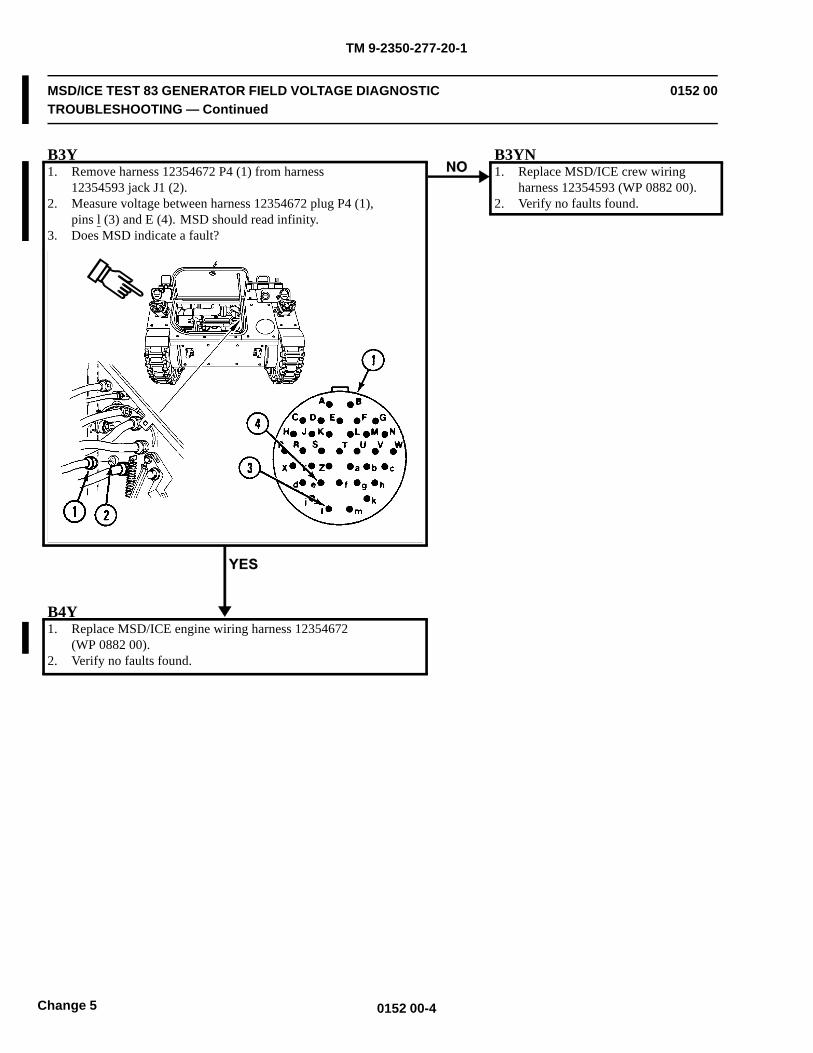
TM 9-2350-277-20-1
MSD/ICE TEST 83 GENERATOR FIELD VOLTAGE DIAGNOSTICTROUBLESHOOTING — Continued
0152 00
B3Y1. Remove harness 12354672 P4 (1) from harness
12354593 jack J1 (2).2. Measure voltage between harness 12354672 plug P4 (1),
pins l (3) and E (4). MSD should read infinity.3. Does MSD indicate a fault?
B3YN1. Replace MSD/ICE crew wiring
harness 12354593 (WP 0882 00).2. Verify no faults found.
B4Y1. Replace MSD/ICE engine wiring harness 12354672
(WP 0882 00).2. Verify no faults found.
0152 00-4Change 5
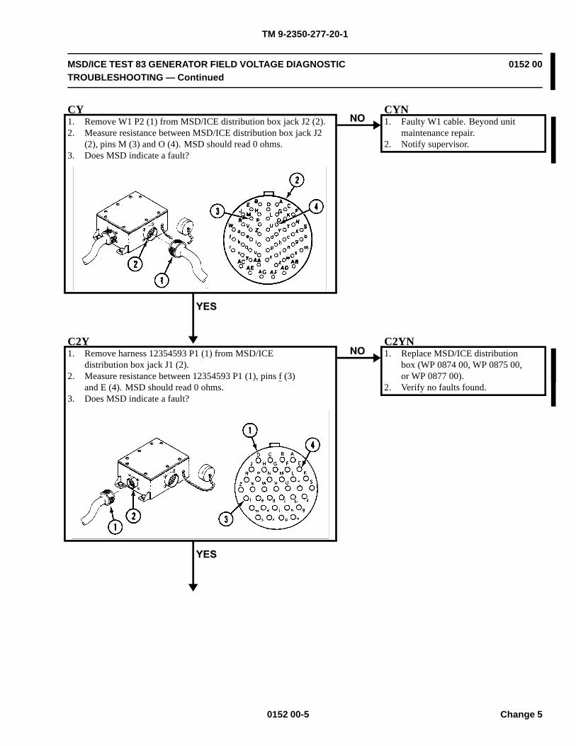
TM 9-2350-277-20-1
MSD/ICE TEST 83 GENERATOR FIELD VOLTAGE DIAGNOSTICTROUBLESHOOTING — Continued
0152 00
CY1. Remove W1 P2 (1) from MSD/ICE distribution box jack J2 (2).2. Measure resistance between MSD/ICE distribution box jack J2
(2), pins M (3) and O (4). MSD should read 0 ohms.3. Does MSD indicate a fault?
CYN1. Faulty W1 cable. Beyond unit
maintenance repair.2. Notify supervisor.
C2Y1. Remove harness 12354593 P1 (1) from MSD/ICE
distribution box jack J1 (2).2. Measure resistance between 12354593 P1 (1), pins f (3)
and E (4). MSD should read 0 ohms.3. Does MSD indicate a fault?
C2YN1. Replace MSD/ICE distribution
box (WP 0874 00, WP 0875 00,or WP 0877 00).
2. Verify no faults found.
0152 00-5 Change 5
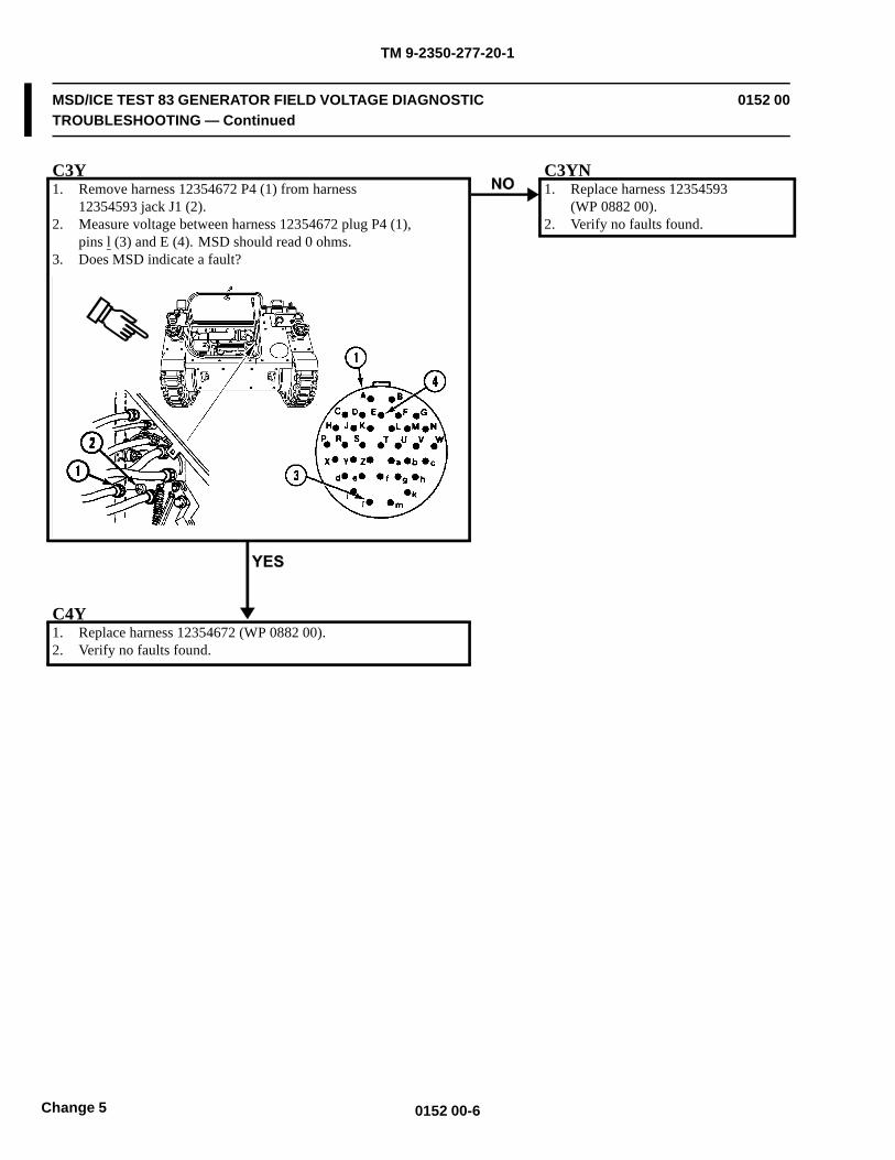
TM 9-2350-277-20-1
MSD/ICE TEST 83 GENERATOR FIELD VOLTAGE DIAGNOSTICTROUBLESHOOTING — Continued
0152 00
C3Y1. Remove harness 12354672 P4 (1) from harness
12354593 jack J1 (2).2. Measure voltage between harness 12354672 plug P4 (1),
pins l (3) and E (4). MSD should read 0 ohms.3. Does MSD indicate a fault?
C3YN1. Replace harness 12354593
(WP 0882 00).2. Verify no faults found.
C4Y1. Replace harness 12354672 (WP 0882 00).2. Verify no faults found.
0152 00-6Change 5
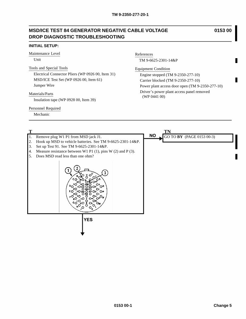
TM 9-2350-277-20-1
MSD/ICE TEST 84 GENERATOR NEGATIVE CABLE VOLTAGEDROP DIAGNOSTIC TROUBLESHOOTING
0153 00
INITIAL SETUP:
Maintenance LevelUnit
Tools and Special ToolsElectrical Connector Pliers (WP 0926 00, Item 31)MSD/ICE Test Set (WP 0926 00, Item 61)Jumper Wire
Materials/PartsInsulation tape (WP 0928 00, Item 39)
Personnel RequiredMechanic
ReferencesTM 9-6625-2301-14&P
Equipment ConditionEngine stopped (TM 9-2350-277-10)Carrier blocked (TM 9-2350-277-10)Power plant access door open (TM 9-2350-277-10)Driver’s power plant access panel removed
(WP 0441 00)
T1. Remove plug W1 P1 from MSD jack J1.2. Hook up MSD to vehicle batteries. See TM 9-6625-2301-14&P.3. Set up Test 91. See TM 9-6625-2301-14&P.4. Measure resistance between W1 P1 (1), pins W (2) and P (3).5. Does MSD read less than one ohm?
TNGO TO BY (PAGE 0153 00-3)
0153 00-1 Change 5
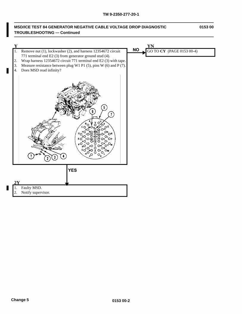
TM 9-2350-277-20-1
MSD/ICE TEST 84 GENERATOR NEGATIVE CABLE VOLTAGE DROP DIAGNOSTICTROUBLESHOOTING — Continued
0153 00
Y1. Remove nut (1), lockwasher (2), and harness 12354672 circuit
771 terminal end E2 (3) from generator ground stud (4).2. Wrap harness 12354672 circuit 771 terminal end E2 (3) with tape.3. Measure resistance between plug W1 P1 (5), pins W (6) and P (7).4. Does MSD read infinity?
YNGO TO CY (PAGE 0153 00-4)
2Y1. Faulty MSD.2. Notify supervisor.
0153 00-2Change 5
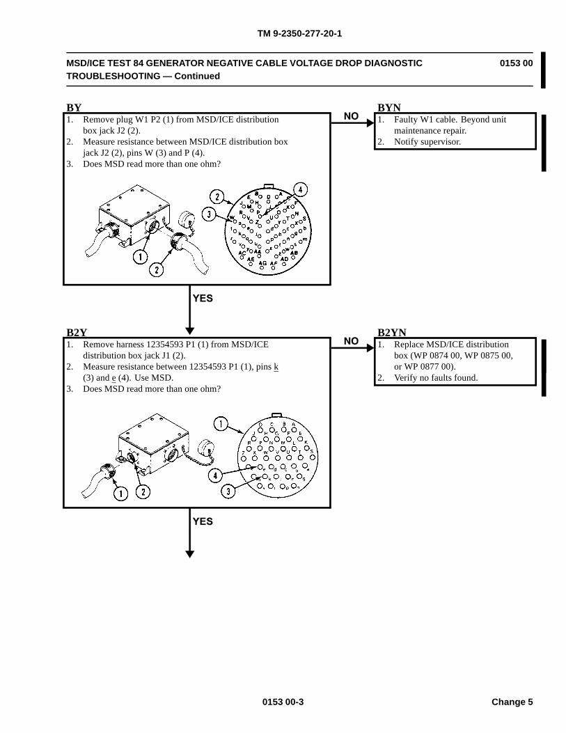
TM 9-2350-277-20-1
MSD/ICE TEST 84 GENERATOR NEGATIVE CABLE VOLTAGE DROP DIAGNOSTICTROUBLESHOOTING — Continued
0153 00
BY1. Remove plug W1 P2 (1) from MSD/ICE distribution
box jack J2 (2).2. Measure resistance between MSD/ICE distribution box
jack J2 (2), pins W (3) and P (4).3. Does MSD read more than one ohm?
BYN1. Faulty W1 cable. Beyond unit
maintenance repair.2. Notify supervisor.
B2Y1. Remove harness 12354593 P1 (1) from MSD/ICE
distribution box jack J1 (2).2. Measure resistance between 12354593 P1 (1), pins k
(3) and e (4). Use MSD.3. Does MSD read more than one ohm?
B2YN1. Replace MSD/ICE distribution
box (WP 0874 00, WP 0875 00,or WP 0877 00).
2. Verify no faults found.
0153 00-3 Change 5
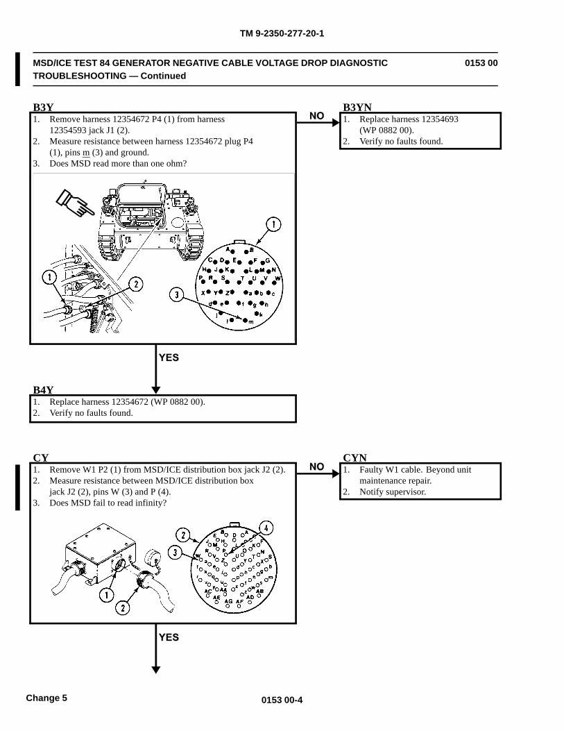
TM 9-2350-277-20-1
MSD/ICE TEST 84 GENERATOR NEGATIVE CABLE VOLTAGE DROP DIAGNOSTICTROUBLESHOOTING — Continued
0153 00
B3Y1. Remove harness 12354672 P4 (1) from harness
12354593 jack J1 (2).2. Measure resistance between harness 12354672 plug P4
(1), pins m (3) and ground.3. Does MSD read more than one ohm?
B3YN1. Replace harness 12354693
(WP 0882 00).2. Verify no faults found.
B4Y1. Replace harness 12354672 (WP 0882 00).2. Verify no faults found.
CY1. Remove W1 P2 (1) from MSD/ICE distribution box jack J2 (2).2. Measure resistance between MSD/ICE distribution box
jack J2 (2), pins W (3) and P (4).3. Does MSD fail to read infinity?
CYN1. Faulty W1 cable. Beyond unit
maintenance repair.2. Notify supervisor.
0153 00-4Change 5
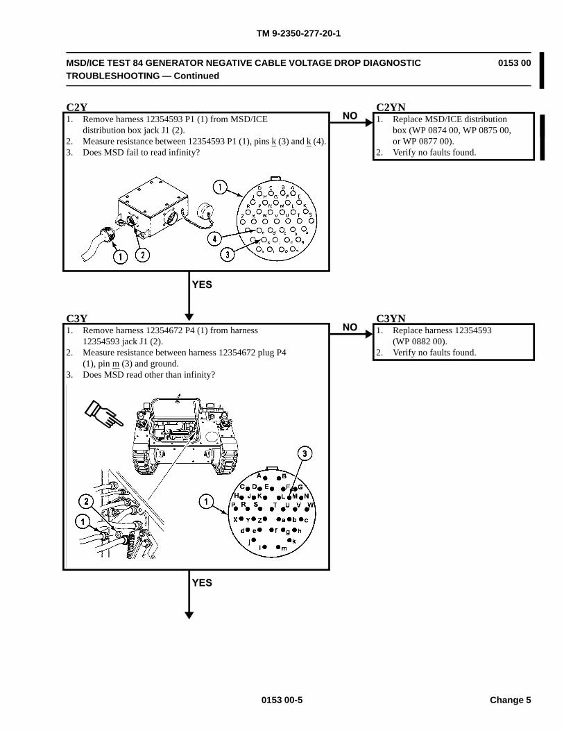
TM 9-2350-277-20-1
MSD/ICE TEST 84 GENERATOR NEGATIVE CABLE VOLTAGE DROP DIAGNOSTICTROUBLESHOOTING — Continued
0153 00
C2Y1. Remove harness 12354593 P1 (1) from MSD/ICE
distribution box jack J1 (2).2. Measure resistance between 12354593 P1 (1), pins k (3) and k (4).3. Does MSD fail to read infinity?
C2YN1. Replace MSD/ICE distribution
box (WP 0874 00, WP 0875 00,or WP 0877 00).
2. Verify no faults found.
C3Y1. Remove harness 12354672 P4 (1) from harness
12354593 jack J1 (2).2. Measure resistance between harness 12354672 plug P4
(1), pin m (3) and ground.3. Does MSD read other than infinity?
C3YN1. Replace harness 12354593
(WP 0882 00).2. Verify no faults found.
0153 00-5 Change 5

TM 9-2350-277-20-1
MSD/ICE TEST 84 GENERATOR NEGATIVE CABLE VOLTAGE DROP DIAGNOSTICTROUBLESHOOTING — Continued
0153 00
C4Y1. Replace harness 12354672 (WP 0882 00).2. Verify no faults found.
0153 00-6Change 5
TM 9-2350-277-20-1
INDEX
Subject WP Sequence No.-Page No.5.0 kW Auxiliary Power Unit
Installation . . . . . . . . . . . . . . . . . . . . . . . . . . . . . . . . . . . . . . . . . . . . . . . . . . . . . . . . . . . . . . 0675 01-4Removal . . . . . . . . . . . . . . . . . . . . . . . . . . . . . . . . . . . . . . . . . . . . . . . . . . . . . . . . . . . . . . . . 0675 01-2
5.0 kW Auxiliary Power UnitRepair . . . . . . . . . . . . . . . . . . . . . . . . . . . . . . . . . . . . . . . . . . . . . . . . . . . . . . . . . . . . . . . . . 0675 00-1
AAC Cable Assembly, W252
Installation . . . . . . . . . . . . . . . . . . . . . . . . . . . . . . . . . . . . . . . . . . . . . . . . . . . . . . . . . . . . . . 0857 00-3Removal . . . . . . . . . . . . . . . . . . . . . . . . . . . . . . . . . . . . . . . . . . . . . . . . . . . . . . . . . . . . . . . . 0857 00-1
AC Light Cable, W11Installation . . . . . . . . . . . . . . . . . . . . . . . . . . . . . . . . . . . . . . . . . . . . . . . . . . . . . . . . . . . . . . 0845 00-2Removal . . . . . . . . . . . . . . . . . . . . . . . . . . . . . . . . . . . . . . . . . . . . . . . . . . . . . . . . . . . . . . . . 0845 00-2
AC Power Extension BoxA19
Installation . . . . . . . . . . . . . . . . . . . . . . . . . . . . . . . . . . . . . . . . . . . . . . . . . . . . . . . . . . . . 0822 00-2Removal . . . . . . . . . . . . . . . . . . . . . . . . . . . . . . . . . . . . . . . . . . . . . . . . . . . . . . . . . . . . . . 0822 00-1
A6Installation . . . . . . . . . . . . . . . . . . . . . . . . . . . . . . . . . . . . . . . . . . . . . . . . . . . . . . . . . . . . 0834 00-3Removal . . . . . . . . . . . . . . . . . . . . . . . . . . . . . . . . . . . . . . . . . . . . . . . . . . . . . . . . . . . . . . 0834 00-1
A7Installation . . . . . . . . . . . . . . . . . . . . . . . . . . . . . . . . . . . . . . . . . . . . . . . . . . . . . . . . . . . . 0815 00-2Removal . . . . . . . . . . . . . . . . . . . . . . . . . . . . . . . . . . . . . . . . . . . . . . . . . . . . . . . . . . . . . . 0815 00-1
AC Power Extension CableW7
Installation . . . . . . . . . . . . . . . . . . . . . . . . . . . . . . . . . . . . . . . . . . . . . . . . . . . . . . . . . . . . 0842 00-3Removal . . . . . . . . . . . . . . . . . . . . . . . . . . . . . . . . . . . . . . . . . . . . . . . . . . . . . . . . . . . . . . 0842 00-1
W8Installation . . . . . . . . . . . . . . . . . . . . . . . . . . . . . . . . . . . . . . . . . . . . . . . . . . . . . . . . . . . . 0843 00-2Removal . . . . . . . . . . . . . . . . . . . . . . . . . . . . . . . . . . . . . . . . . . . . . . . . . . . . . . . . . . . . . . 0843 00-1
AcceleratorLinkage
Adjustment . . . . . . . . . . . . . . . . . . . . . . . . . . . . . . . . . . . . . . . . . . . . . . . . . . . . . . . . . . . . 0214 00-1Pedal
LowerInstallation . . . . . . . . . . . . . . . . . . . . . . . . . . . . . . . . . . . . . . . . . . . . . . . . . . . . . . . . . . 0215 00-3Removal . . . . . . . . . . . . . . . . . . . . . . . . . . . . . . . . . . . . . . . . . . . . . . . . . . . . . . . . . . . . 0215 00-1
UpperInstallation . . . . . . . . . . . . . . . . . . . . . . . . . . . . . . . . . . . . . . . . . . . . . . . . . . . . . . . . . . 0216 00-3Removal . . . . . . . . . . . . . . . . . . . . . . . . . . . . . . . . . . . . . . . . . . . . . . . . . . . . . . . . . . . . 0216 00-1
Access CoverBattery Box
Installation . . . . . . . . . . . . . . . . . . . . . . . . . . . . . . . . . . . . . . . . . . . . . . . . . . . . . . . . . . . . 0352 00-2Removal . . . . . . . . . . . . . . . . . . . . . . . . . . . . . . . . . . . . . . . . . . . . . . . . . . . . . . . . . . . . . . 0352 00-1
Index-1 Change 5
TM 9-2350-277-20-1
INDEX, cont’d
Subject WP Sequence No.-Page No.
Installation . . . . . . . . . . . . . . . . . . . . . . . . . . . . . . . . . . . . . . . . . . . . . . . . . . . . . . . . . . 0187 00-2Removal . . . . . . . . . . . . . . . . . . . . . . . . . . . . . . . . . . . . . . . . . . . . . . . . . . . . . . . . . . . . 0187 00-1
M577A3 and M1068A3Installation . . . . . . . . . . . . . . . . . . . . . . . . . . . . . . . . . . . . . . . . . . . . . . . . . . . . . . . . . . 0188 00-2Removal . . . . . . . . . . . . . . . . . . . . . . . . . . . . . . . . . . . . . . . . . . . . . . . . . . . . . . . . . . . . 0188 00-1
Hull FrontInstallation . . . . . . . . . . . . . . . . . . . . . . . . . . . . . . . . . . . . . . . . . . . . . . . . . . . . . . . . . . . . 0449 00-2Removal . . . . . . . . . . . . . . . . . . . . . . . . . . . . . . . . . . . . . . . . . . . . . . . . . . . . . . . . . . . . . . 0449 00-1
Power Plant BottomCleaning . . . . . . . . . . . . . . . . . . . . . . . . . . . . . . . . . . . . . . . . . . . . . . . . . . . . . . . . . . . . . . 0450 00-2Installation . . . . . . . . . . . . . . . . . . . . . . . . . . . . . . . . . . . . . . . . . . . . . . . . . . . . . . . . . . . . 0450 00-3Removal . . . . . . . . . . . . . . . . . . . . . . . . . . . . . . . . . . . . . . . . . . . . . . . . . . . . . . . . . . . . . . 0450 00-1
Access Door, TurbineGasket
Installation . . . . . . . . . . . . . . . . . . . . . . . . . . . . . . . . . . . . . . . . . . . . . . . . . . . . . . . . . . . . 0486 00-1Removal . . . . . . . . . . . . . . . . . . . . . . . . . . . . . . . . . . . . . . . . . . . . . . . . . . . . . . . . . . . . . . 0486 00-1
HingesInstallation . . . . . . . . . . . . . . . . . . . . . . . . . . . . . . . . . . . . . . . . . . . . . . . . . . . . . . . . . . . . 0487 00-3Removal . . . . . . . . . . . . . . . . . . . . . . . . . . . . . . . . . . . . . . . . . . . . . . . . . . . . . . . . . . . . . . 0487 00-2
Installation . . . . . . . . . . . . . . . . . . . . . . . . . . . . . . . . . . . . . . . . . . . . . . . . . . . . . . . . . . . . . . 0485 00-2Removal . . . . . . . . . . . . . . . . . . . . . . . . . . . . . . . . . . . . . . . . . . . . . . . . . . . . . . . . . . . . . . . . 0485 00-2
Access Panel, Driver’s Power PlantInstallation . . . . . . . . . . . . . . . . . . . . . . . . . . . . . . . . . . . . . . . . . . . . . . . . . . . . . . . . . . . . . . 0441 00-3Removal . . . . . . . . . . . . . . . . . . . . . . . . . . . . . . . . . . . . . . . . . . . . . . . . . . . . . . . . . . . . . . . . 0441 00-1
Access Plate, Adapter, Smoke GeneratorInstallation . . . . . . . . . . . . . . . . . . . . . . . . . . . . . . . . . . . . . . . . . . . . . . . . . . . . . . . . . . . . . . 0766 00-3Removal . . . . . . . . . . . . . . . . . . . . . . . . . . . . . . . . . . . . . . . . . . . . . . . . . . . . . . . . . . . . . . . . 0766 00-1
AdapterAN/VAS-5 Driver’s Vision Enhancer (DVE) Sensor Set Assembly
Installation . . . . . . . . . . . . . . . . . . . . . . . . . . . . . . . . . . . . . . . . . . . . . . . . . . . . . . . . . . . . 0866 05-2Removal . . . . . . . . . . . . . . . . . . . . . . . . . . . . . . . . . . . . . . . . . . . . . . . . . . . . . . . . . . . . . . 0866 05-1
SpeedometerInstallation . . . . . . . . . . . . . . . . . . . . . . . . . . . . . . . . . . . . . . . . . . . . . . . . . . . . . . . . . . . . 0860 00-3Removal . . . . . . . . . . . . . . . . . . . . . . . . . . . . . . . . . . . . . . . . . . . . . . . . . . . . . . . . . . . . . . 0860 00-1
TachometerInstallation . . . . . . . . . . . . . . . . . . . . . . . . . . . . . . . . . . . . . . . . . . . . . . . . . . . . . . . . . . . . 0863 00-3Removal . . . . . . . . . . . . . . . . . . . . . . . . . . . . . . . . . . . . . . . . . . . . . . . . . . . . . . . . . . . . . . 0863 00-1
Adjuster, Track TensionInstallation . . . . . . . . . . . . . . . . . . . . . . . . . . . . . . . . . . . . . . . . . . . . . . . . . . . . . . . . . . . . . . 0419 00-2Removal . . . . . . . . . . . . . . . . . . . . . . . . . . . . . . . . . . . . . . . . . . . . . . . . . . . . . . . . . . . . . . . . 0419 00-1
Air Box Drain, Left and Right, Check Valve and TubesInstallation . . . . . . . . . . . . . . . . . . . . . . . . . . . . . . . . . . . . . . . . . . . . . . . . . . . . . . . . . . . . . . 0159 00-4Removal . . . . . . . . . . . . . . . . . . . . . . . . . . . . . . . . . . . . . . . . . . . . . . . . . . . . . . . . . . . . . . . . 0159 00-1
Index-2Change 5
Fuel TankAll Except M577A3 and M1068A3
TM 9-2350-277-20-1
INDEX, cont’d
Subject WP Sequence No.-Page No.
Ignition CoilInstallation . . . . . . . . . . . . . . . . . . . . . . . . . . . . . . . . . . . . . . . . . . . . . . . . . . . . . . . . . . . . 0208 00-3Removal . . . . . . . . . . . . . . . . . . . . . . . . . . . . . . . . . . . . . . . . . . . . . . . . . . . . . . . . . . . . . . 0208 00-1
Ignition WireInstallation . . . . . . . . . . . . . . . . . . . . . . . . . . . . . . . . . . . . . . . . . . . . . . . . . . . . . . . . . . . . 0204 00-2Removal . . . . . . . . . . . . . . . . . . . . . . . . . . . . . . . . . . . . . . . . . . . . . . . . . . . . . . . . . . . . . . 0204 00-1
Lower Fuel LineInstallation . . . . . . . . . . . . . . . . . . . . . . . . . . . . . . . . . . . . . . . . . . . . . . . . . . . . . . . . . . . . 0206 00-3Removal . . . . . . . . . . . . . . . . . . . . . . . . . . . . . . . . . . . . . . . . . . . . . . . . . . . . . . . . . . . . . . 0206 00-2
Wiring HarnessInstallation . . . . . . . . . . . . . . . . . . . . . . . . . . . . . . . . . . . . . . . . . . . . . . . . . . . . . . . . . . . . 0205 00-5Removal . . . . . . . . . . . . . . . . . . . . . . . . . . . . . . . . . . . . . . . . . . . . . . . . . . . . . . . . . . . . . . 0205 00-1
Air Box Pressure TransducerInstallation . . . . . . . . . . . . . . . . . . . . . . . . . . . . . . . . . . . . . . . . . . . . . . . . . . . . . . . . . . . . . . 0327 00-2Removal . . . . . . . . . . . . . . . . . . . . . . . . . . . . . . . . . . . . . . . . . . . . . . . . . . . . . . . . . . . . . . . . 0327 00-1
Air CleanerAir Intake Elbow
Installation . . . . . . . . . . . . . . . . . . . . . . . . . . . . . . . . . . . . . . . . . . . . . . . . . . . . . . . . . . . . 0173 00-2Removal . . . . . . . . . . . . . . . . . . . . . . . . . . . . . . . . . . . . . . . . . . . . . . . . . . . . . . . . . . . . . . 0173 00-1
AssemblyAssembly . . . . . . . . . . . . . . . . . . . . . . . . . . . . . . . . . . . . . . . . . . . . . . . . . . . . . . . . . . . . . 0169 01-2Disassembly . . . . . . . . . . . . . . . . . . . . . . . . . . . . . . . . . . . . . . . . . . . . . . . . . . . . . . . . . . . 0169 01-1
DoorInstallation . . . . . . . . . . . . . . . . . . . . . . . . . . . . . . . . . . . . . . . . . . . . . . . . . . . . . . . . . . . . 0169 00-2Removal . . . . . . . . . . . . . . . . . . . . . . . . . . . . . . . . . . . . . . . . . . . . . . . . . . . . . . . . . . . . . . 0169 00-1
ElbowInstallation . . . . . . . . . . . . . . . . . . . . . . . . . . . . . . . . . . . . . . . . . . . . . . . . . . . . . . . . . . . . 0168 00-7Removal . . . . . . . . . . . . . . . . . . . . . . . . . . . . . . . . . . . . . . . . . . . . . . . . . . . . . . . . . . . . . . 0168 00-2
Filter ElementServicing . . . . . . . . . . . . . . . . . . . . . . . . . . . . . . . . . . . . . . . . . . . . . . . . . . . . . . . . . . . . . 0167 00-1
Grill Air Intake Elbow and HoseInstallation . . . . . . . . . . . . . . . . . . . . . . . . . . . . . . . . . . . . . . . . . . . . . . . . . . . . . . . . . . . . 0174 00-2Removal . . . . . . . . . . . . . . . . . . . . . . . . . . . . . . . . . . . . . . . . . . . . . . . . . . . . . . . . . . . . . . 0174 00-1
Restriction IndicatorInstallation . . . . . . . . . . . . . . . . . . . . . . . . . . . . . . . . . . . . . . . . . . . . . . . . . . . . . . . . . . . . 0171 00-2Removal . . . . . . . . . . . . . . . . . . . . . . . . . . . . . . . . . . . . . . . . . . . . . . . . . . . . . . . . . . . . . . 0171 00-1
Restriction Indicator HoseInstallation . . . . . . . . . . . . . . . . . . . . . . . . . . . . . . . . . . . . . . . . . . . . . . . . . . . . . . . . . . . . 0172 00-3Removal . . . . . . . . . . . . . . . . . . . . . . . . . . . . . . . . . . . . . . . . . . . . . . . . . . . . . . . . . . . . . . 0172 00-1
RetainerInstallation . . . . . . . . . . . . . . . . . . . . . . . . . . . . . . . . . . . . . . . . . . . . . . . . . . . . . . . . . . . . 0170 00-2Removal . . . . . . . . . . . . . . . . . . . . . . . . . . . . . . . . . . . . . . . . . . . . . . . . . . . . . . . . . . . . . . 0170 00-1
Air CompressorAssembly
Installation . . . . . . . . . . . . . . . . . . . . . . . . . . . . . . . . . . . . . . . . . . . . . . . . . . . . . . . . . . . . 0762 00-3Removal . . . . . . . . . . . . . . . . . . . . . . . . . . . . . . . . . . . . . . . . . . . . . . . . . . . . . . . . . . . . . . 0762 00-1
Electrical Cable AssemblyInstallation . . . . . . . . . . . . . . . . . . . . . . . . . . . . . . . . . . . . . . . . . . . . . . . . . . . . . . . . . . . . 0758 00-4
Index-3 Change 5
Air Box Heater
Removal . . . . . . . . . . . . . . . . . . . . . . . . . . . . . . . . . . . . . . . . . . . . . . . . . . . . . . . . . . . . . . 0758 00-2
TM 9-2350-277-20-1
INDEX, cont’d
Subject WP Sequence No.-Page No.
Air HoseAdapter Access Plate to Cover Assembly, Smoke Generator
Installation . . . . . . . . . . . . . . . . . . . . . . . . . . . . . . . . . . . . . . . . . . . . . . . . . . . . . . . . . . . . 0768 00-2Removal . . . . . . . . . . . . . . . . . . . . . . . . . . . . . . . . . . . . . . . . . . . . . . . . . . . . . . . . . . . . . . 0768 00-1
Compressor Reservoir to Access Plate, Smoke GeneratorInstallation . . . . . . . . . . . . . . . . . . . . . . . . . . . . . . . . . . . . . . . . . . . . . . . . . . . . . . . . . . . . 0767 00-3Removal . . . . . . . . . . . . . . . . . . . . . . . . . . . . . . . . . . . . . . . . . . . . . . . . . . . . . . . . . . . . . . 0767 00-1
Air Purifier and FrameM13
Installation . . . . . . . . . . . . . . . . . . . . . . . . . . . . . . . . . . . . . . . . . . . . . . . . . . . . . . . . . . . . 0779 00-3Removal . . . . . . . . . . . . . . . . . . . . . . . . . . . . . . . . . . . . . . . . . . . . . . . . . . . . . . . . . . . . . . 0779 00-1
NBCInstallation . . . . . . . . . . . . . . . . . . . . . . . . . . . . . . . . . . . . . . . . . . . . . . . . . . . . . . . . . . . . 0914 00-2Removal . . . . . . . . . . . . . . . . . . . . . . . . . . . . . . . . . . . . . . . . . . . . . . . . . . . . . . . . . . . . . . 0914 00-1
Air Ventilator, Rear CompartmentInstallation . . . . . . . . . . . . . . . . . . . . . . . . . . . . . . . . . . . . . . . . . . . . . . . . . . . . . . . . . . . . . . 0454 00-2Removal . . . . . . . . . . . . . . . . . . . . . . . . . . . . . . . . . . . . . . . . . . . . . . . . . . . . . . . . . . . . . . . . 0454 00-1
AlarmChemical Agent Automatic Alarm Kit
Installation . . . . . . . . . . . . . . . . . . . . . . . . . . . . . . . . . . . . . . . . . . . . . . . . . . . . . . . . . . . . 0918 00-1Removal . . . . . . . . . . . . . . . . . . . . . . . . . . . . . . . . . . . . . . . . . . . . . . . . . . . . . . . . . . . . . . 0918 00-8
Chemical Alarm Junction BoxInstallation . . . . . . . . . . . . . . . . . . . . . . . . . . . . . . . . . . . . . . . . . . . . . . . . . . . . . . . . . . . . 0920 00-3Removal . . . . . . . . . . . . . . . . . . . . . . . . . . . . . . . . . . . . . . . . . . . . . . . . . . . . . . . . . . . . . . 0920 00-1
Chemical Alarm Junction Box/Power Cable/Alarm CableInspection-Acceptance and Rejection Criteria . . . . . . . . . . . . . . . . . . . . . . . . . . . . . . . . . . . 0919 00-6Installation . . . . . . . . . . . . . . . . . . . . . . . . . . . . . . . . . . . . . . . . . . . . . . . . . . . . . . . . . . . . 0919 00-8Removal . . . . . . . . . . . . . . . . . . . . . . . . . . . . . . . . . . . . . . . . . . . . . . . . . . . . . . . . . . . . . . 0919 00-2Repair or Replacement . . . . . . . . . . . . . . . . . . . . . . . . . . . . . . . . . . . . . . . . . . . . . . . . . . . . 0919 00-7
M43 Unit Interface Wiring HarnessInspection-Acceptance and Rejection Criteria . . . . . . . . . . . . . . . . . . . . . . . . . . . . . . . . . . . 0923 00-4Installation . . . . . . . . . . . . . . . . . . . . . . . . . . . . . . . . . . . . . . . . . . . . . . . . . . . . . . . . . . . . 0923 00-4Removal . . . . . . . . . . . . . . . . . . . . . . . . . . . . . . . . . . . . . . . . . . . . . . . . . . . . . . . . . . . . . . 0923 00-1Repair or Replacement . . . . . . . . . . . . . . . . . . . . . . . . . . . . . . . . . . . . . . . . . . . . . . . . . . . . 0923 00-4
Refill Tray BracketInstallation . . . . . . . . . . . . . . . . . . . . . . . . . . . . . . . . . . . . . . . . . . . . . . . . . . . . . . . . . . . . 0922 00-2Removal . . . . . . . . . . . . . . . . . . . . . . . . . . . . . . . . . . . . . . . . . . . . . . . . . . . . . . . . . . . . . . 0922 00-1
Spare Battery BracketInstallation . . . . . . . . . . . . . . . . . . . . . . . . . . . . . . . . . . . . . . . . . . . . . . . . . . . . . . . . . . . . 0921 00-3Removal . . . . . . . . . . . . . . . . . . . . . . . . . . . . . . . . . . . . . . . . . . . . . . . . . . . . . . . . . . . . . . 0921 00-1Repair or Replacement . . . . . . . . . . . . . . . . . . . . . . . . . . . . . . . . . . . . . . . . . . . . . . . . . . . . 0921 00-2
Ammunition RackHorizontal
Assembly . . . . . . . . . . . . . . . . . . . . . . . . . . . . . . . . . . . . . . . . . . . . . . . . . . . . . . . . . . . . . 0607 00-4Cleaning . . . . . . . . . . . . . . . . . . . . . . . . . . . . . . . . . . . . . . . . . . . . . . . . . . . . . . . . . . . . . . 0607 00-4
Index-4Change 5
TM 9-2350-277-20-1
INDEX, cont’d
Subject WP Sequence No.-Page No.
Disassembly . . . . . . . . . . . . . . . . . . . . . . . . . . . . . . . . . . . . . . . . . . . . . . . . . . . . . . . . . . . 0607 00-1Inspection-Acceptance and Rejection Criteria . . . . . . . . . . . . . . . . . . . . . . . . . . . . . . . . . . . 0607 00-4Installation . . . . . . . . . . . . . . . . . . . . . . . . . . . . . . . . . . . . . . . . . . . . . . . . . . . . . . . . . . . . 0606 00-2Removal . . . . . . . . . . . . . . . . . . . . . . . . . . . . . . . . . . . . . . . . . . . . . . . . . . . . . . . . . . . . . . 0606 00-1
VerticalInstallation . . . . . . . . . . . . . . . . . . . . . . . . . . . . . . . . . . . . . . . . . . . . . . . . . . . . . . . . . . . . 0608 00-3Removal . . . . . . . . . . . . . . . . . . . . . . . . . . . . . . . . . . . . . . . . . . . . . . . . . . . . . . . . . . . . . . 0608 00-1
Amplifier, IntercomInstallation . . . . . . . . . . . . . . . . . . . . . . . . . . . . . . . . . . . . . . . . . . . . . . . . . . . . . . . . . . . . . . 0888 00-2Removal . . . . . . . . . . . . . . . . . . . . . . . . . . . . . . . . . . . . . . . . . . . . . . . . . . . . . . . . . . . . . . . . 0888 00-1
Anchor, Torsion BarInstallation . . . . . . . . . . . . . . . . . . . . . . . . . . . . . . . . . . . . . . . . . . . . . . . . . . . . . . . . . . . . . . 0414 00-3Removal . . . . . . . . . . . . . . . . . . . . . . . . . . . . . . . . . . . . . . . . . . . . . . . . . . . . . . . . . . . . . . . . 0414 00-1
AntennaAS3916/VRC
Installation . . . . . . . . . . . . . . . . . . . . . . . . . . . . . . . . . . . . . . . . . . . . . . . . . . . . . . . . . . . . 0887 00-2Removal . . . . . . . . . . . . . . . . . . . . . . . . . . . . . . . . . . . . . . . . . . . . . . . . . . . . . . . . . . . . . . 0887 00-1
CoverInstallation . . . . . . . . . . . . . . . . . . . . . . . . . . . . . . . . . . . . . . . . . . . . . . . . . . . . . . . . . . . . 0576 00-2Removal . . . . . . . . . . . . . . . . . . . . . . . . . . . . . . . . . . . . . . . . . . . . . . . . . . . . . . . . . . . . . . 0576 00-1
GuardInstallation . . . . . . . . . . . . . . . . . . . . . . . . . . . . . . . . . . . . . . . . . . . . . . . . . . . . . . . . . . . . 0575 00-2Removal . . . . . . . . . . . . . . . . . . . . . . . . . . . . . . . . . . . . . . . . . . . . . . . . . . . . . . . . . . . . . . 0575 00-1
Mast Bracket Assembly, Taillight Wiring Harness, and BracketInstallation . . . . . . . . . . . . . . . . . . . . . . . . . . . . . . . . . . . . . . . . . . . . . . . . . . . . . . . . . . . . 0625 00-7Removal . . . . . . . . . . . . . . . . . . . . . . . . . . . . . . . . . . . . . . . . . . . . . . . . . . . . . . . . . . . . . . 0625 00-1
SupportInstallation . . . . . . . . . . . . . . . . . . . . . . . . . . . . . . . . . . . . . . . . . . . . . . . . . . . . . . . . . . . . 0602 00-2Removal . . . . . . . . . . . . . . . . . . . . . . . . . . . . . . . . . . . . . . . . . . . . . . . . . . . . . . . . . . . . . . 0602 00-2
APIU Rack, Mount and BracketInstallation . . . . . . . . . . . . . . . . . . . . . . . . . . . . . . . . . . . . . . . . . . . . . . . . . . . . . . . . . . . . . . 0813 00-2Removal . . . . . . . . . . . . . . . . . . . . . . . . . . . . . . . . . . . . . . . . . . . . . . . . . . . . . . . . . . . . . . . . 0813 00-1
ArmIdler Wheel
Bearings and SealsCleaning . . . . . . . . . . . . . . . . . . . . . . . . . . . . . . . . . . . . . . . . . . . . . . . . . . . . . . . . . . . . 0418 00-2Installation . . . . . . . . . . . . . . . . . . . . . . . . . . . . . . . . . . . . . . . . . . . . . . . . . . . . . . . . . . 0418 00-2Removal . . . . . . . . . . . . . . . . . . . . . . . . . . . . . . . . . . . . . . . . . . . . . . . . . . . . . . . . . . . . 0418 00-1
Installation . . . . . . . . . . . . . . . . . . . . . . . . . . . . . . . . . . . . . . . . . . . . . . . . . . . . . . . . . . . . 0417 00-2Removal . . . . . . . . . . . . . . . . . . . . . . . . . . . . . . . . . . . . . . . . . . . . . . . . . . . . . . . . . . . . . . 0417 00-1
Road Wheel SupportInstallation . . . . . . . . . . . . . . . . . . . . . . . . . . . . . . . . . . . . . . . . . . . . . . . . . . . . . . . . . . . . 0415 00-4Removal . . . . . . . . . . . . . . . . . . . . . . . . . . . . . . . . . . . . . . . . . . . . . . . . . . . . . . . . . . . . . . 0415 00-2
Index-5 Change 5
TM 9-2350-277-20-1
INDEX, cont’d
Subject WP Sequence No.-Page No.
Left FrontInstallation . . . . . . . . . . . . . . . . . . . . . . . . . . . . . . . . . . . . . . . . . . . . . . . . . . . . . . . . . . 0447 00-2Removal . . . . . . . . . . . . . . . . . . . . . . . . . . . . . . . . . . . . . . . . . . . . . . . . . . . . . . . . . . . . 0447 00-1
Right FrontInstallation . . . . . . . . . . . . . . . . . . . . . . . . . . . . . . . . . . . . . . . . . . . . . . . . . . . . . . . . . . 0448 00-3Removal . . . . . . . . . . . . . . . . . . . . . . . . . . . . . . . . . . . . . . . . . . . . . . . . . . . . . . . . . . . . 0448 00-1
Shields, Commander’s CupolaInstallation . . . . . . . . . . . . . . . . . . . . . . . . . . . . . . . . . . . . . . . . . . . . . . . . . . . . . . . . . . . . 0747 00-3Removal . . . . . . . . . . . . . . . . . . . . . . . . . . . . . . . . . . . . . . . . . . . . . . . . . . . . . . . . . . . . . . 0747 00-1
Smoke GeneratorInstallation . . . . . . . . . . . . . . . . . . . . . . . . . . . . . . . . . . . . . . . . . . . . . . . . . . . . . . . . . . . . 0771 00-2Removal . . . . . . . . . . . . . . . . . . . . . . . . . . . . . . . . . . . . . . . . . . . . . . . . . . . . . . . . . . . . . . 0771 00-1
Armor KitInstallation . . . . . . . . . . . . . . . . . . . . . . . . . . . . . . . . . . . . . . . . . . . . . . . . . . . . . . . . . . . . . . 0751 01-1Removal . . . . . . . . . . . . . . . . . . . . . . . . . . . . . . . . . . . . . . . . . . . . . . . . . . . . . . . . . . . . . . . . 0751 01-3
Auxiliary Power (Slave) ReceptacleGround Lead
Installation . . . . . . . . . . . . . . . . . . . . . . . . . . . . . . . . . . . . . . . . . . . . . . . . . . . . . . . . . . . . 0379 00-3Removal . . . . . . . . . . . . . . . . . . . . . . . . . . . . . . . . . . . . . . . . . . . . . . . . . . . . . . . . . . . . . . 0379 00-1
Lead (Circuit 50) to Master SwitchInspection-Acceptance and Rejection Criteria . . . . . . . . . . . . . . . . . . . . . . . . . . . . . . . . . . . 0268 00-2Installation . . . . . . . . . . . . . . . . . . . . . . . . . . . . . . . . . . . . . . . . . . . . . . . . . . . . . . . . . . . . 0268 00-3Removal . . . . . . . . . . . . . . . . . . . . . . . . . . . . . . . . . . . . . . . . . . . . . . . . . . . . . . . . . . . . . . 0268 00-1
M113A3, M1059A3, M1064A3, and M58Installation . . . . . . . . . . . . . . . . . . . . . . . . . . . . . . . . . . . . . . . . . . . . . . . . . . . . . . . . . . . . 0263 00-2Removal . . . . . . . . . . . . . . . . . . . . . . . . . . . . . . . . . . . . . . . . . . . . . . . . . . . . . . . . . . . . . . 0263 00-1
M577A3 and M1068A3Installation . . . . . . . . . . . . . . . . . . . . . . . . . . . . . . . . . . . . . . . . . . . . . . . . . . . . . . . . . . . . 0264 00-3Removal . . . . . . . . . . . . . . . . . . . . . . . . . . . . . . . . . . . . . . . . . . . . . . . . . . . . . . . . . . . . . . 0264 00-2
Auxiliary Power UnitFuel Shutoff Valve
Installation . . . . . . . . . . . . . . . . . . . . . . . . . . . . . . . . . . . . . . . . . . . . . . . . . . . . . . . . . . . . 0676 00-3Removal . . . . . . . . . . . . . . . . . . . . . . . . . . . . . . . . . . . . . . . . . . . . . . . . . . . . . . . . . . . . . . 0676 00-2
Installation . . . . . . . . . . . . . . . . . . . . . . . . . . . . . . . . . . . . . . . . . . . . . . . . . . . . . . . . . . . . . . 0675 01-4Removal . . . . . . . . . . . . . . . . . . . . . . . . . . . . . . . . . . . . . . . . . . . . . . . . . . . . . . . . . . . . . . . . 0675 01-2Repair . . . . . . . . . . . . . . . . . . . . . . . . . . . . . . . . . . . . . . . . . . . . . . . . . . . . . . . . . . . . . . . . . 0675 00-1Valve-to-Bulkhead Fuel Supply Hoses
Installation . . . . . . . . . . . . . . . . . . . . . . . . . . . . . . . . . . . . . . . . . . . . . . . . . . . . . . . . . . . . 0677 00-4Removal . . . . . . . . . . . . . . . . . . . . . . . . . . . . . . . . . . . . . . . . . . . . . . . . . . . . . . . . . . . . . . 0677 00-2
Auxiliary TankFluid Level Detector
Installation . . . . . . . . . . . . . . . . . . . . . . . . . . . . . . . . . . . . . . . . . . . . . . . . . . . . . . . . . . . . 0329 00-2Removal . . . . . . . . . . . . . . . . . . . . . . . . . . . . . . . . . . . . . . . . . . . . . . . . . . . . . . . . . . . . . . 0329 00-1
Installation . . . . . . . . . . . . . . . . . . . . . . . . . . . . . . . . . . . . . . . . . . . . . . . . . . . . . . . . . . . . . . 0230 00-2Removal . . . . . . . . . . . . . . . . . . . . . . . . . . . . . . . . . . . . . . . . . . . . . . . . . . . . . . . . . . . . . . . . 0230 00-1
Index-6Change 5
ArmorPlate
TM 9-2350-277-20-1
INDEX, cont’d
Subject WP Sequence No.-Page No.
Installation . . . . . . . . . . . . . . . . . . . . . . . . . . . . . . . . . . . . . . . . . . . . . . . . . . . . . . . . . . . . . . 0489 00-2Removal . . . . . . . . . . . . . . . . . . . . . . . . . . . . . . . . . . . . . . . . . . . . . . . . . . . . . . . . . . . . . . . . 0489 00-1
BBackrest
Personnel SeatM1059A3 Only
Installation . . . . . . . . . . . . . . . . . . . . . . . . . . . . . . . . . . . . . . . . . . . . . . . . . . . . . . . . . . 0549 00-3Removal . . . . . . . . . . . . . . . . . . . . . . . . . . . . . . . . . . . . . . . . . . . . . . . . . . . . . . . . . . . . 0549 00-1
M1064A3 OnlyInstallation . . . . . . . . . . . . . . . . . . . . . . . . . . . . . . . . . . . . . . . . . . . . . . . . . . . . . . . . . . 0550 00-3Removal . . . . . . . . . . . . . . . . . . . . . . . . . . . . . . . . . . . . . . . . . . . . . . . . . . . . . . . . . . . . 0550 00-1
Balance HoseInstallation . . . . . . . . . . . . . . . . . . . . . . . . . . . . . . . . . . . . . . . . . . . . . . . . . . . . . . . . . . . . . . 0234 00-1Removal . . . . . . . . . . . . . . . . . . . . . . . . . . . . . . . . . . . . . . . . . . . . . . . . . . . . . . . . . . . . . . . . 0234 00-1
Base Extension, Right SideAdjustment . . . . . . . . . . . . . . . . . . . . . . . . . . . . . . . . . . . . . . . . . . . . . . . . . . . . . . . . . . . . . . 0623 00-4Installation . . . . . . . . . . . . . . . . . . . . . . . . . . . . . . . . . . . . . . . . . . . . . . . . . . . . . . . . . . . . . . 0623 00-3Removal . . . . . . . . . . . . . . . . . . . . . . . . . . . . . . . . . . . . . . . . . . . . . . . . . . . . . . . . . . . . . . . . 0623 00-1Supports
Installation . . . . . . . . . . . . . . . . . . . . . . . . . . . . . . . . . . . . . . . . . . . . . . . . . . . . . . . . . . . . 0624 00-3Removal . . . . . . . . . . . . . . . . . . . . . . . . . . . . . . . . . . . . . . . . . . . . . . . . . . . . . . . . . . . . . . 0624 00-1
BatteriesM1064A3 Only
Clean and Inspect . . . . . . . . . . . . . . . . . . . . . . . . . . . . . . . . . . . . . . . . . . . . . . . . . . . . . . . 0349 00-2Installation . . . . . . . . . . . . . . . . . . . . . . . . . . . . . . . . . . . . . . . . . . . . . . . . . . . . . . . . . . . . 0349 00-3Removal . . . . . . . . . . . . . . . . . . . . . . . . . . . . . . . . . . . . . . . . . . . . . . . . . . . . . . . . . . . . . . 0349 00-1
M113A3 and M1059A3Clean and Inspect . . . . . . . . . . . . . . . . . . . . . . . . . . . . . . . . . . . . . . . . . . . . . . . . . . . . . . . 0346 00-3Installation . . . . . . . . . . . . . . . . . . . . . . . . . . . . . . . . . . . . . . . . . . . . . . . . . . . . . . . . . . . . 0346 00-4Removal . . . . . . . . . . . . . . . . . . . . . . . . . . . . . . . . . . . . . . . . . . . . . . . . . . . . . . . . . . . . . . 0346 00-1
M577A3 and M1068A3Clean and Inspect . . . . . . . . . . . . . . . . . . . . . . . . . . . . . . . . . . . . . . . . . . . . . . . . . . . . . . . 0347 00-3Installation . . . . . . . . . . . . . . . . . . . . . . . . . . . . . . . . . . . . . . . . . . . . . . . . . . . . . . . . . . . . 0347 00-3Removal . . . . . . . . . . . . . . . . . . . . . . . . . . . . . . . . . . . . . . . . . . . . . . . . . . . . . . . . . . . . . . 0347 00-1
M58 OnlyAssembly . . . . . . . . . . . . . . . . . . . . . . . . . . . . . . . . . . . . . . . . . . . . . . . . . . . . . . . . . . . . . 0348 00-7Cleaning . . . . . . . . . . . . . . . . . . . . . . . . . . . . . . . . . . . . . . . . . . . . . . . . . . . . . . . . . . . . . . 0348 00-6Disassembly . . . . . . . . . . . . . . . . . . . . . . . . . . . . . . . . . . . . . . . . . . . . . . . . . . . . . . . . . . . 0348 00-5Installation . . . . . . . . . . . . . . . . . . . . . . . . . . . . . . . . . . . . . . . . . . . . . . . . . . . . . . . . . . . . 0348 00-8Removal . . . . . . . . . . . . . . . . . . . . . . . . . . . . . . . . . . . . . . . . . . . . . . . . . . . . . . . . . . . . . . 0348 00-1
BatteryDrawer
Clean and Inspect . . . . . . . . . . . . . . . . . . . . . . . . . . . . . . . . . . . . . . . . . . . . . . . . . . . . . . . 0353 00-3Installation . . . . . . . . . . . . . . . . . . . . . . . . . . . . . . . . . . . . . . . . . . . . . . . . . . . . . . . . . . . . 0353 00-4
Index-7 Change 5
Azimuth Lock, Commander’s Cupola
TM 9-2350-277-20-1
INDEX, cont’d
Subject WP Sequence No.-Page No.
Cleaning . . . . . . . . . . . . . . . . . . . . . . . . . . . . . . . . . . . . . . . . . . . . . . . . . . . . . . . . . . . . 0719 00-2Inspection-Acceptance and Rejection Criteria . . . . . . . . . . . . . . . . . . . . . . . . . . . . . . . . . 0719 00-2Installation . . . . . . . . . . . . . . . . . . . . . . . . . . . . . . . . . . . . . . . . . . . . . . . . . . . . . . . . . . 0719 00-2Removal . . . . . . . . . . . . . . . . . . . . . . . . . . . . . . . . . . . . . . . . . . . . . . . . . . . . . . . . . . . . 0719 00-1
Removal . . . . . . . . . . . . . . . . . . . . . . . . . . . . . . . . . . . . . . . . . . . . . . . . . . . . . . . . . . . . . . 0353 00-1Ground Strap
M113A3, M1059A3, M1064A3, and M58Connect . . . . . . . . . . . . . . . . . . . . . . . . . . . . . . . . . . . . . . . . . . . . . . . . . . . . . . . . . . . . . 0337 00-2Disconnect . . . . . . . . . . . . . . . . . . . . . . . . . . . . . . . . . . . . . . . . . . . . . . . . . . . . . . . . . . 0337 00-1
M577A3 and M1068A3Connect . . . . . . . . . . . . . . . . . . . . . . . . . . . . . . . . . . . . . . . . . . . . . . . . . . . . . . . . . . . . . 0338 00-3Disconnect . . . . . . . . . . . . . . . . . . . . . . . . . . . . . . . . . . . . . . . . . . . . . . . . . . . . . . . . . . 0338 00-1
Leads and TerminalsM1064A3 Only (Left Side)
Cleaning . . . . . . . . . . . . . . . . . . . . . . . . . . . . . . . . . . . . . . . . . . . . . . . . . . . . . . . . . . . . 0343 00-5Installation . . . . . . . . . . . . . . . . . . . . . . . . . . . . . . . . . . . . . . . . . . . . . . . . . . . . . . . . . . 0343 00-5Removal . . . . . . . . . . . . . . . . . . . . . . . . . . . . . . . . . . . . . . . . . . . . . . . . . . . . . . . . . . . . 0343 00-1
M1064A3 Only (Right Side)Cleaning . . . . . . . . . . . . . . . . . . . . . . . . . . . . . . . . . . . . . . . . . . . . . . . . . . . . . . . . . . . . 0344 00-3Installation . . . . . . . . . . . . . . . . . . . . . . . . . . . . . . . . . . . . . . . . . . . . . . . . . . . . . . . . . . 0344 00-4Removal . . . . . . . . . . . . . . . . . . . . . . . . . . . . . . . . . . . . . . . . . . . . . . . . . . . . . . . . . . . . 0344 00-1
M113A3 and M1059A3Clean and Inspect . . . . . . . . . . . . . . . . . . . . . . . . . . . . . . . . . . . . . . . . . . . . . . . . . . . . . . 0340 00-3Installation . . . . . . . . . . . . . . . . . . . . . . . . . . . . . . . . . . . . . . . . . . . . . . . . . . . . . . . . . . 0340 00-4Removal . . . . . . . . . . . . . . . . . . . . . . . . . . . . . . . . . . . . . . . . . . . . . . . . . . . . . . . . . . . . 0340 00-1
M577A3 and M1068A3Clean and Inspect . . . . . . . . . . . . . . . . . . . . . . . . . . . . . . . . . . . . . . . . . . . . . . . . . . . . . . 0341 00-3Installation . . . . . . . . . . . . . . . . . . . . . . . . . . . . . . . . . . . . . . . . . . . . . . . . . . . . . . . . . . 0341 00-4Removal . . . . . . . . . . . . . . . . . . . . . . . . . . . . . . . . . . . . . . . . . . . . . . . . . . . . . . . . . . . . 0341 00-1
M58 OnlyCleaning . . . . . . . . . . . . . . . . . . . . . . . . . . . . . . . . . . . . . . . . . . . . . . . . . . . . . . . . . . . . 0345 00-3Installation . . . . . . . . . . . . . . . . . . . . . . . . . . . . . . . . . . . . . . . . . . . . . . . . . . . . . . . . . . 0345 00-4Removal . . . . . . . . . . . . . . . . . . . . . . . . . . . . . . . . . . . . . . . . . . . . . . . . . . . . . . . . . . . . 0345 00-1
Battery BoxAccess Cover
Installation . . . . . . . . . . . . . . . . . . . . . . . . . . . . . . . . . . . . . . . . . . . . . . . . . . . . . . . . . . . . 0352 00-2Removal . . . . . . . . . . . . . . . . . . . . . . . . . . . . . . . . . . . . . . . . . . . . . . . . . . . . . . . . . . . . . . 0352 00-1
Insulation and Heat ExchangerInstallation . . . . . . . . . . . . . . . . . . . . . . . . . . . . . . . . . . . . . . . . . . . . . . . . . . . . . . . . . . . . 0718 00-2Removal . . . . . . . . . . . . . . . . . . . . . . . . . . . . . . . . . . . . . . . . . . . . . . . . . . . . . . . . . . . . . . 0718 00-1
M1064A3 Only (Right Side)Clean and Inspect . . . . . . . . . . . . . . . . . . . . . . . . . . . . . . . . . . . . . . . . . . . . . . . . . . . . . . . 0354 00-2Installation . . . . . . . . . . . . . . . . . . . . . . . . . . . . . . . . . . . . . . . . . . . . . . . . . . . . . . . . . . . . 0354 00-3Removal . . . . . . . . . . . . . . . . . . . . . . . . . . . . . . . . . . . . . . . . . . . . . . . . . . . . . . . . . . . . . . 0354 00-1
M113A3 and M1059A3Clean and Inspect . . . . . . . . . . . . . . . . . . . . . . . . . . . . . . . . . . . . . . . . . . . . . . . . . . . . . . . 0350 00-3Installation . . . . . . . . . . . . . . . . . . . . . . . . . . . . . . . . . . . . . . . . . . . . . . . . . . . . . . . . . . . . 0350 00-4Removal . . . . . . . . . . . . . . . . . . . . . . . . . . . . . . . . . . . . . . . . . . . . . . . . . . . . . . . . . . . . . . 0350 00-1
M577A3 and M1068A3Clean and Inspect . . . . . . . . . . . . . . . . . . . . . . . . . . . . . . . . . . . . . . . . . . . . . . . . . . . . . . . 0351 00-2Installation . . . . . . . . . . . . . . . . . . . . . . . . . . . . . . . . . . . . . . . . . . . . . . . . . . . . . . . . . . . . 0351 00-2
Index-8
Insulation and Heat Exchanger
Removal . . . . . . . . . . . . . . . . . . . . . . . . . . . . . . . . . . . . . . . . . . . . . . . . . . . . . . . . . . . . . . 0351 00-2
Change 5
TM 9-2350-277-20-1
INDEX, cont’d
Subject WP Sequence No.-Page No.
M58 OnlyAssembly . . . . . . . . . . . . . . . . . . . . . . . . . . . . . . . . . . . . . . . . . . . . . . . . . . . . . . . . . . . . . 0348 00-7Cleaning . . . . . . . . . . . . . . . . . . . . . . . . . . . . . . . . . . . . . . . . . . . . . . . . . . . . . . . . . . . . . . 0348 00-6Disassembly . . . . . . . . . . . . . . . . . . . . . . . . . . . . . . . . . . . . . . . . . . . . . . . . . . . . . . . . . . . 0348 00-5Installation . . . . . . . . . . . . . . . . . . . . . . . . . . . . . . . . . . . . . . . . . . . . . . . . . . . . . . . . . . . . 0348 00-8Removal . . . . . . . . . . . . . . . . . . . . . . . . . . . . . . . . . . . . . . . . . . . . . . . . . . . . . . . . . . . . . . 0348 00-1
Vent FittingInstallation . . . . . . . . . . . . . . . . . . . . . . . . . . . . . . . . . . . . . . . . . . . . . . . . . . . . . . . . . . . . 0355 00-3Removal . . . . . . . . . . . . . . . . . . . . . . . . . . . . . . . . . . . . . . . . . . . . . . . . . . . . . . . . . . . . . . 0355 00-1
Bearing HousingFan Drive Shaft
Installation . . . . . . . . . . . . . . . . . . . . . . . . . . . . . . . . . . . . . . . . . . . . . . . . . . . . . . . . . . . . 0248 00-3Removal . . . . . . . . . . . . . . . . . . . . . . . . . . . . . . . . . . . . . . . . . . . . . . . . . . . . . . . . . . . . . . 0248 00-1
BearingsIdler Wheel Arm
Cleaning . . . . . . . . . . . . . . . . . . . . . . . . . . . . . . . . . . . . . . . . . . . . . . . . . . . . . . . . . . . . . . 0418 00-2Installation . . . . . . . . . . . . . . . . . . . . . . . . . . . . . . . . . . . . . . . . . . . . . . . . . . . . . . . . . . . . 0418 00-2Removal . . . . . . . . . . . . . . . . . . . . . . . . . . . . . . . . . . . . . . . . . . . . . . . . . . . . . . . . . . . . . . 0418 00-1
Road Wheel SupportInstallation . . . . . . . . . . . . . . . . . . . . . . . . . . . . . . . . . . . . . . . . . . . . . . . . . . . . . . . . . . . . 0415 00-4Removal . . . . . . . . . . . . . . . . . . . . . . . . . . . . . . . . . . . . . . . . . . . . . . . . . . . . . . . . . . . . . . 0415 00-2
Tow Start Control AssemblyInstallation . . . . . . . . . . . . . . . . . . . . . . . . . . . . . . . . . . . . . . . . . . . . . . . . . . . . . . . . . . . . 0391 00-5Removal . . . . . . . . . . . . . . . . . . . . . . . . . . . . . . . . . . . . . . . . . . . . . . . . . . . . . . . . . . . . . . 0391 00-2
BeltCoolant Pump
Adjustment . . . . . . . . . . . . . . . . . . . . . . . . . . . . . . . . . . . . . . . . . . . . . . . . . . . . . . . . . . . . 0239 00-1Generator Drive
Adjustment . . . . . . . . . . . . . . . . . . . . . . . . . . . . . . . . . . . . . . . . . . . . . . . . . . . . . . . . . . . . 0252 00-2Installation . . . . . . . . . . . . . . . . . . . . . . . . . . . . . . . . . . . . . . . . . . . . . . . . . . . . . . . . . . . . 0253 00-1Removal . . . . . . . . . . . . . . . . . . . . . . . . . . . . . . . . . . . . . . . . . . . . . . . . . . . . . . . . . . . . . . 0253 00-1
PersonnelM1059A3 Only
Installation . . . . . . . . . . . . . . . . . . . . . . . . . . . . . . . . . . . . . . . . . . . . . . . . . . . . . . . . . . 0549 00-3Removal . . . . . . . . . . . . . . . . . . . . . . . . . . . . . . . . . . . . . . . . . . . . . . . . . . . . . . . . . . . . 0549 00-1
M1064A3 OnlyInstallation . . . . . . . . . . . . . . . . . . . . . . . . . . . . . . . . . . . . . . . . . . . . . . . . . . . . . . . . . . 0550 00-3Removal . . . . . . . . . . . . . . . . . . . . . . . . . . . . . . . . . . . . . . . . . . . . . . . . . . . . . . . . . . . . 0550 00-1
M113A3 OnlyInstallation . . . . . . . . . . . . . . . . . . . . . . . . . . . . . . . . . . . . . . . . . . . . . . . . . . . . . . . . . . 0546 00-2Removal . . . . . . . . . . . . . . . . . . . . . . . . . . . . . . . . . . . . . . . . . . . . . . . . . . . . . . . . . . . . 0546 00-1
M577A3 OnlyInstallation . . . . . . . . . . . . . . . . . . . . . . . . . . . . . . . . . . . . . . . . . . . . . . . . . . . . . . . . . . 0547 00-3Removal . . . . . . . . . . . . . . . . . . . . . . . . . . . . . . . . . . . . . . . . . . . . . . . . . . . . . . . . . . . . 0547 00-1
Bilge PumpCircuit Breakers
Index-9 Change 5
Installation . . . . . . . . . . . . . . . . . . . . . . . . . . . . . . . . . . . . . . . . . . . . . . . . . . . . . . . . . . . . 0275 00-2Removal . . . . . . . . . . . . . . . . . . . . . . . . . . . . . . . . . . . . . . . . . . . . . . . . . . . . . . . . . . . . . . 0275 00-1
TM 9-2350-277-20-1
INDEX, cont’d
Subject WP Sequence No.-Page No.
FrontInstallation . . . . . . . . . . . . . . . . . . . . . . . . . . . . . . . . . . . . . . . . . . . . . . . . . . . . . . . . . . . . 0632 00-3Removal . . . . . . . . . . . . . . . . . . . . . . . . . . . . . . . . . . . . . . . . . . . . . . . . . . . . . . . . . . . . . . 0632 00-1
PipesFront
Installation . . . . . . . . . . . . . . . . . . . . . . . . . . . . . . . . . . . . . . . . . . . . . . . . . . . . . . . . . . 0631 00-3Removal . . . . . . . . . . . . . . . . . . . . . . . . . . . . . . . . . . . . . . . . . . . . . . . . . . . . . . . . . . . . 0631 00-1
RearInstallation . . . . . . . . . . . . . . . . . . . . . . . . . . . . . . . . . . . . . . . . . . . . . . . . . . . . . . . . . . 0634 00-2Removal . . . . . . . . . . . . . . . . . . . . . . . . . . . . . . . . . . . . . . . . . . . . . . . . . . . . . . . . . . . . 0634 00-1
RearInstallation . . . . . . . . . . . . . . . . . . . . . . . . . . . . . . . . . . . . . . . . . . . . . . . . . . . . . . . . . . . . 0635 00-3Removal . . . . . . . . . . . . . . . . . . . . . . . . . . . . . . . . . . . . . . . . . . . . . . . . . . . . . . . . . . . . . . 0635 00-1
Schematic . . . . . . . . . . . . . . . . . . . . . . . . . . . . . . . . . . . . . . . . . . . . . . . . . . . . . . . . . . . . . . . 0078 00-1
Blackout CurtainInstallation . . . . . . . . . . . . . . . . . . . . . . . . . . . . . . . . . . . . . . . . . . . . . . . . . . . . . . . . . . . . . . 0629 00-2Removal . . . . . . . . . . . . . . . . . . . . . . . . . . . . . . . . . . . . . . . . . . . . . . . . . . . . . . . . . . . . . . . . 0629 00-1
Blackout HeadlightAssembly . . . . . . . . . . . . . . . . . . . . . . . . . . . . . . . . . . . . . . . . . . . . . . . . . . . . . . . . . . . . . . . 0306 00-2Disassembly . . . . . . . . . . . . . . . . . . . . . . . . . . . . . . . . . . . . . . . . . . . . . . . . . . . . . . . . . . . . . 0306 00-1Installation . . . . . . . . . . . . . . . . . . . . . . . . . . . . . . . . . . . . . . . . . . . . . . . . . . . . . . . . . . . . . . 0305 00-2Removal . . . . . . . . . . . . . . . . . . . . . . . . . . . . . . . . . . . . . . . . . . . . . . . . . . . . . . . . . . . . . . . . 0305 00-1
Blackout Marker LightAssembly . . . . . . . . . . . . . . . . . . . . . . . . . . . . . . . . . . . . . . . . . . . . . . . . . . . . . . . . . . . . . . . 0308 00-2Disassembly . . . . . . . . . . . . . . . . . . . . . . . . . . . . . . . . . . . . . . . . . . . . . . . . . . . . . . . . . . . . . 0308 00-1Installation . . . . . . . . . . . . . . . . . . . . . . . . . . . . . . . . . . . . . . . . . . . . . . . . . . . . . . . . . . . . . . 0307 00-2Removal . . . . . . . . . . . . . . . . . . . . . . . . . . . . . . . . . . . . . . . . . . . . . . . . . . . . . . . . . . . . . . . . 0307 00-1
Blower SwitchInstallation . . . . . . . . . . . . . . . . . . . . . . . . . . . . . . . . . . . . . . . . . . . . . . . . . . . . . . . . . . . . . . 0278 00-3Removal . . . . . . . . . . . . . . . . . . . . . . . . . . . . . . . . . . . . . . . . . . . . . . . . . . . . . . . . . . . . . . . . 0278 00-1
Box Assembly A5, Tent Interface PanelInstallation . . . . . . . . . . . . . . . . . . . . . . . . . . . . . . . . . . . . . . . . . . . . . . . . . . . . . . . . . . . . . . 0833 00-3Removal . . . . . . . . . . . . . . . . . . . . . . . . . . . . . . . . . . . . . . . . . . . . . . . . . . . . . . . . . . . . . . . . 0833 00-1
BracketAntenna Mast
Installation . . . . . . . . . . . . . . . . . . . . . . . . . . . . . . . . . . . . . . . . . . . . . . . . . . . . . . . . . . . . 0625 00-7Removal . . . . . . . . . . . . . . . . . . . . . . . . . . . . . . . . . . . . . . . . . . . . . . . . . . . . . . . . . . . . . . 0625 00-1
Chemical Alarm Refill TrayInstallation . . . . . . . . . . . . . . . . . . . . . . . . . . . . . . . . . . . . . . . . . . . . . . . . . . . . . . . . . . . . 0922 00-2Removal . . . . . . . . . . . . . . . . . . . . . . . . . . . . . . . . . . . . . . . . . . . . . . . . . . . . . . . . . . . . . . 0922 00-1
Chemical Alarm Spare BatteryInstallation . . . . . . . . . . . . . . . . . . . . . . . . . . . . . . . . . . . . . . . . . . . . . . . . . . . . . . . . . . . . 0921 00-3Removal . . . . . . . . . . . . . . . . . . . . . . . . . . . . . . . . . . . . . . . . . . . . . . . . . . . . . . . . . . . . . . 0921 00-1
Index-10Change 5
Repair or Replacement . . . . . . . . . . . . . . . . . . . . . . . . . . . . . . . . . . . . . . . . . . . . . . . . . . . . 0921 00-2
TM 9-2350-277-20-1
INDEX, cont’d
Subject WP Sequence No.-Page No.
Coolant Heater and PumpInstallation . . . . . . . . . . . . . . . . . . . . . . . . . . . . . . . . . . . . . . . . . . . . . . . . . . . . . . . . . . . . 0732 00-1Removal . . . . . . . . . . . . . . . . . . . . . . . . . . . . . . . . . . . . . . . . . . . . . . . . . . . . . . . . . . . . . . 0732 00-1
Forward Spall LinerInstallation . . . . . . . . . . . . . . . . . . . . . . . . . . . . . . . . . . . . . . . . . . . . . . . . . . . . . . . . . . . . 0507 00-3Removal . . . . . . . . . . . . . . . . . . . . . . . . . . . . . . . . . . . . . . . . . . . . . . . . . . . . . . . . . . . . . . 0507 00-1
Fuel Filter, Primary and SecondaryInstallation . . . . . . . . . . . . . . . . . . . . . . . . . . . . . . . . . . . . . . . . . . . . . . . . . . . . . . . . . . . . 0203 00-3Removal . . . . . . . . . . . . . . . . . . . . . . . . . . . . . . . . . . . . . . . . . . . . . . . . . . . . . . . . . . . . . . 0203 00-2
GeneratorInstallation . . . . . . . . . . . . . . . . . . . . . . . . . . . . . . . . . . . . . . . . . . . . . . . . . . . . . . . . . . . . 0255 00-4Removal . . . . . . . . . . . . . . . . . . . . . . . . . . . . . . . . . . . . . . . . . . . . . . . . . . . . . . . . . . . . . . 0255 00-1
Glow Plug Controller MountingInstallation . . . . . . . . . . . . . . . . . . . . . . . . . . . . . . . . . . . . . . . . . . . . . . . . . . . . . . . . . . . . 0212 00-2Removal . . . . . . . . . . . . . . . . . . . . . . . . . . . . . . . . . . . . . . . . . . . . . . . . . . . . . . . . . . . . . . 0212 00-1
M13 OrificeInstallation . . . . . . . . . . . . . . . . . . . . . . . . . . . . . . . . . . . . . . . . . . . . . . . . . . . . . . . . . . . . 0781 00-2Removal . . . . . . . . . . . . . . . . . . . . . . . . . . . . . . . . . . . . . . . . . . . . . . . . . . . . . . . . . . . . . . 0781 00-1
Mortar Base StowageInstallation . . . . . . . . . . . . . . . . . . . . . . . . . . . . . . . . . . . . . . . . . . . . . . . . . . . . . . . . . . . . 0615 00-3Removal . . . . . . . . . . . . . . . . . . . . . . . . . . . . . . . . . . . . . . . . . . . . . . . . . . . . . . . . . . . . . . 0615 00-1
MufflerInstallation . . . . . . . . . . . . . . . . . . . . . . . . . . . . . . . . . . . . . . . . . . . . . . . . . . . . . . . . . . . . 0224 00-2Removal . . . . . . . . . . . . . . . . . . . . . . . . . . . . . . . . . . . . . . . . . . . . . . . . . . . . . . . . . . . . . . 0224 00-1
Oil CanInstallation . . . . . . . . . . . . . . . . . . . . . . . . . . . . . . . . . . . . . . . . . . . . . . . . . . . . . . . . . . . . 0574 00-1Removal . . . . . . . . . . . . . . . . . . . . . . . . . . . . . . . . . . . . . . . . . . . . . . . . . . . . . . . . . . . . . . 0574 00-1
Parking BrakeClean and Inspect . . . . . . . . . . . . . . . . . . . . . . . . . . . . . . . . . . . . . . . . . . . . . . . . . . . . . . . 0331 00-3Installation . . . . . . . . . . . . . . . . . . . . . . . . . . . . . . . . . . . . . . . . . . . . . . . . . . . . . . . . . . . . 0331 00-3Removal . . . . . . . . . . . . . . . . . . . . . . . . . . . . . . . . . . . . . . . . . . . . . . . . . . . . . . . . . . . . . . 0331 00-1
Personnel Heater Control Box and Intercom BoxInstallation . . . . . . . . . . . . . . . . . . . . . . . . . . . . . . . . . . . . . . . . . . . . . . . . . . . . . . . . . . . . 0617 00-2Removal . . . . . . . . . . . . . . . . . . . . . . . . . . . . . . . . . . . . . . . . . . . . . . . . . . . . . . . . . . . . . . 0617 00-1
Power Extension Box A18Installation . . . . . . . . . . . . . . . . . . . . . . . . . . . . . . . . . . . . . . . . . . . . . . . . . . . . . . . . . . . . 0836 00-2Removal . . . . . . . . . . . . . . . . . . . . . . . . . . . . . . . . . . . . . . . . . . . . . . . . . . . . . . . . . . . . . . 0836 00-1
RampInstallation . . . . . . . . . . . . . . . . . . . . . . . . . . . . . . . . . . . . . . . . . . . . . . . . . . . . . . . . . . . . 0516 00-1Removal . . . . . . . . . . . . . . . . . . . . . . . . . . . . . . . . . . . . . . . . . . . . . . . . . . . . . . . . . . . . . . 0516 00-1
Ramp Door StopInstallation . . . . . . . . . . . . . . . . . . . . . . . . . . . . . . . . . . . . . . . . . . . . . . . . . . . . . . . . . . . . 0517 00-1Removal . . . . . . . . . . . . . . . . . . . . . . . . . . . . . . . . . . . . . . . . . . . . . . . . . . . . . . . . . . . . . . 0517 00-1
RifleInstallation . . . . . . . . . . . . . . . . . . . . . . . . . . . . . . . . . . . . . . . . . . . . . . . . . . . . . . . . . . . . 0573 00-2Removal . . . . . . . . . . . . . . . . . . . . . . . . . . . . . . . . . . . . . . . . . . . . . . . . . . . . . . . . . . . . . . 0573 00-1
Roadside Data Panel Assembly A13Installation . . . . . . . . . . . . . . . . . . . . . . . . . . . . . . . . . . . . . . . . . . . . . . . . . . . . . . . . . . . . 0835 00-2Removal . . . . . . . . . . . . . . . . . . . . . . . . . . . . . . . . . . . . . . . . . . . . . . . . . . . . . . . . . . . . . . 0835 00-1
SteeringInstallation . . . . . . . . . . . . . . . . . . . . . . . . . . . . . . . . . . . . . . . . . . . . . . . . . . . . . . . . . . . . 0432 00-5
Index-11 Change 5
Removal . . . . . . . . . . . . . . . . . . . . . . . . . . . . . . . . . . . . . . . . . . . . . . . . . . . . . . . . . . . . . . 0432 00-1
TM 9-2350-277-20-1
INDEX, cont’d
Subject WP Sequence No.-Page No.
Transmission Oil Drain TubesInstallation . . . . . . . . . . . . . . . . . . . . . . . . . . . . . . . . . . . . . . . . . . . . . . . . . . . . . . . . . . . . 0384 00-2Removal . . . . . . . . . . . . . . . . . . . . . . . . . . . . . . . . . . . . . . . . . . . . . . . . . . . . . . . . . . . . . . 0384 00-1
Transmission Range ControllerCable-Activated Steering Lock
Installation . . . . . . . . . . . . . . . . . . . . . . . . . . . . . . . . . . . . . . . . . . . . . . . . . . . . . . . . . . 0387 00-3Removal . . . . . . . . . . . . . . . . . . . . . . . . . . . . . . . . . . . . . . . . . . . . . . . . . . . . . . . . . . . . 0387 00-1
Solenoid-Activated Steering LockInstallation . . . . . . . . . . . . . . . . . . . . . . . . . . . . . . . . . . . . . . . . . . . . . . . . . . . . . . . . . . 0386 00-3Removal . . . . . . . . . . . . . . . . . . . . . . . . . . . . . . . . . . . . . . . . . . . . . . . . . . . . . . . . . . . . 0386 00-1
Windshield StowageInstallation . . . . . . . . . . . . . . . . . . . . . . . . . . . . . . . . . . . . . . . . . . . . . . . . . . . . . . . . . . . . 0614 00-2Removal . . . . . . . . . . . . . . . . . . . . . . . . . . . . . . . . . . . . . . . . . . . . . . . . . . . . . . . . . . . . . . 0614 00-1
Brackets and Mounts, Right Equipment RackInstallation . . . . . . . . . . . . . . . . . . . . . . . . . . . . . . . . . . . . . . . . . . . . . . . . . . . . . . . . . . . . . . 0814 00-2Removal . . . . . . . . . . . . . . . . . . . . . . . . . . . . . . . . . . . . . . . . . . . . . . . . . . . . . . . . . . . . . . . . 0814 00-1
BrakeCommander’s Cupola
Installation . . . . . . . . . . . . . . . . . . . . . . . . . . . . . . . . . . . . . . . . . . . . . . . . . . . . . . . . . . . . 0492 00-1Removal . . . . . . . . . . . . . . . . . . . . . . . . . . . . . . . . . . . . . . . . . . . . . . . . . . . . . . . . . . . . . . 0492 00-1
ParkingAdjustment . . . . . . . . . . . . . . . . . . . . . . . . . . . . . . . . . . . . . . . . . . . . . . . . . . . . . . . . . . . . 0408 00-1Cable Control Assembly
Installation . . . . . . . . . . . . . . . . . . . . . . . . . . . . . . . . . . . . . . . . . . . . . . . . . . . . . . . . . . 0411 00-4Removal . . . . . . . . . . . . . . . . . . . . . . . . . . . . . . . . . . . . . . . . . . . . . . . . . . . . . . . . . . . . 0411 00-1
Control Lever AssemblyInstallation . . . . . . . . . . . . . . . . . . . . . . . . . . . . . . . . . . . . . . . . . . . . . . . . . . . . . . . . . . 0412 00-3Removal . . . . . . . . . . . . . . . . . . . . . . . . . . . . . . . . . . . . . . . . . . . . . . . . . . . . . . . . . . . . 0412 00-1
ServiceControl Linkage
Adjustment . . . . . . . . . . . . . . . . . . . . . . . . . . . . . . . . . . . . . . . . . . . . . . . . . . . . . . . . . . 0407 00-1Installation . . . . . . . . . . . . . . . . . . . . . . . . . . . . . . . . . . . . . . . . . . . . . . . . . . . . . . . . . . 0410 00-7Removal . . . . . . . . . . . . . . . . . . . . . . . . . . . . . . . . . . . . . . . . . . . . . . . . . . . . . . . . . . . . 0410 00-2
Pedal, Upper and LowerInstallation . . . . . . . . . . . . . . . . . . . . . . . . . . . . . . . . . . . . . . . . . . . . . . . . . . . . . . . . . . 0409 00-6Removal . . . . . . . . . . . . . . . . . . . . . . . . . . . . . . . . . . . . . . . . . . . . . . . . . . . . . . . . . . . . 0409 00-1
TransmissionAdjust Left-Hand Brake . . . . . . . . . . . . . . . . . . . . . . . . . . . . . . . . . . . . . . . . . . . . . . . . . . . 0394 00-1Adjust Right-Hand Brake . . . . . . . . . . . . . . . . . . . . . . . . . . . . . . . . . . . . . . . . . . . . . . . . . . 0394 00-5Check Adjustment . . . . . . . . . . . . . . . . . . . . . . . . . . . . . . . . . . . . . . . . . . . . . . . . . . . . . . . 0406 00-1
Breather Hose, Ramp CylinderAll Except M1064A3
Installation . . . . . . . . . . . . . . . . . . . . . . . . . . . . . . . . . . . . . . . . . . . . . . . . . . . . . . . . . . . . 0666 00-3Removal . . . . . . . . . . . . . . . . . . . . . . . . . . . . . . . . . . . . . . . . . . . . . . . . . . . . . . . . . . . . . . 0666 00-1
M1064A3 OnlyInstallation . . . . . . . . . . . . . . . . . . . . . . . . . . . . . . . . . . . . . . . . . . . . . . . . . . . . . . . . . . . . 0667 00-3Removal . . . . . . . . . . . . . . . . . . . . . . . . . . . . . . . . . . . . . . . . . . . . . . . . . . . . . . . . . . . . . . 0667 00-2
Index-12Change 5
TM 9-2350-277-20-1
INDEX, cont’d
Subject WP Sequence No.-Page No.
Bulkhead Connection Hose to Fuel PumpInstallation . . . . . . . . . . . . . . . . . . . . . . . . . . . . . . . . . . . . . . . . . . . . . . . . . . . . . . . . . . . . . . 0691 00-2Removal . . . . . . . . . . . . . . . . . . . . . . . . . . . . . . . . . . . . . . . . . . . . . . . . . . . . . . . . . . . . . . . . 0691 00-1
Bumper, Driver’s HatchM113A3, M1059A3, M1064A3, and M58
Installation . . . . . . . . . . . . . . . . . . . . . . . . . . . . . . . . . . . . . . . . . . . . . . . . . . . . . . . . . . . . 0532 00-2Removal . . . . . . . . . . . . . . . . . . . . . . . . . . . . . . . . . . . . . . . . . . . . . . . . . . . . . . . . . . . . . . 0532 00-1
M577A3 and M1068A3Cleaning . . . . . . . . . . . . . . . . . . . . . . . . . . . . . . . . . . . . . . . . . . . . . . . . . . . . . . . . . . . . . . 0533 00-2Installation . . . . . . . . . . . . . . . . . . . . . . . . . . . . . . . . . . . . . . . . . . . . . . . . . . . . . . . . . . . . 0533 00-3Removal . . . . . . . . . . . . . . . . . . . . . . . . . . . . . . . . . . . . . . . . . . . . . . . . . . . . . . . . . . . . . . 0533 00-1Repair or Replacement . . . . . . . . . . . . . . . . . . . . . . . . . . . . . . . . . . . . . . . . . . . . . . . . . . . . 0533 00-2
Buzzer and Switch, AdmittanceInspection-Acceptance and Rejection Criteria . . . . . . . . . . . . . . . . . . . . . . . . . . . . . . . . . . . . . 0334 00-2Installation . . . . . . . . . . . . . . . . . . . . . . . . . . . . . . . . . . . . . . . . . . . . . . . . . . . . . . . . . . . . . . 0334 00-2Removal . . . . . . . . . . . . . . . . . . . . . . . . . . . . . . . . . . . . . . . . . . . . . . . . . . . . . . . . . . . . . . . . 0334 00-1
Bypass Plug, Pressure Switch and DifferentialInstallation . . . . . . . . . . . . . . . . . . . . . . . . . . . . . . . . . . . . . . . . . . . . . . . . . . . . . . . . . . . . . . 0401 00-2Removal . . . . . . . . . . . . . . . . . . . . . . . . . . . . . . . . . . . . . . . . . . . . . . . . . . . . . . . . . . . . . . . . 0401 00-1
CCable
Artillery Communication, InsideInstallation . . . . . . . . . . . . . . . . . . . . . . . . . . . . . . . . . . . . . . . . . . . . . . . . . . . . . . . . . . . . 0746 00-2Removal . . . . . . . . . . . . . . . . . . . . . . . . . . . . . . . . . . . . . . . . . . . . . . . . . . . . . . . . . . . . . . 0746 00-1
Commander’s Intercommunication SetInstallation . . . . . . . . . . . . . . . . . . . . . . . . . . . . . . . . . . . . . . . . . . . . . . . . . . . . . . . . . . . . 0893 00-2Removal . . . . . . . . . . . . . . . . . . . . . . . . . . . . . . . . . . . . . . . . . . . . . . . . . . . . . . . . . . . . . . 0893 00-1
Driver’s Intercommunication SetInstallation . . . . . . . . . . . . . . . . . . . . . . . . . . . . . . . . . . . . . . . . . . . . . . . . . . . . . . . . . . . . 0892 00-2Removal . . . . . . . . . . . . . . . . . . . . . . . . . . . . . . . . . . . . . . . . . . . . . . . . . . . . . . . . . . . . . . 0892 00-1
Driver’s Night Vision (DNV) AN/VVS-2 Power SupplyInstallation . . . . . . . . . . . . . . . . . . . . . . . . . . . . . . . . . . . . . . . . . . . . . . . . . . . . . . . . . . . . 0368 00-3Removal . . . . . . . . . . . . . . . . . . . . . . . . . . . . . . . . . . . . . . . . . . . . . . . . . . . . . . . . . . . . . . 0368 00-1
Driver’s Vision Enhancer (DVE) Power SupplyInstallation . . . . . . . . . . . . . . . . . . . . . . . . . . . . . . . . . . . . . . . . . . . . . . . . . . . . . . . . . . . . 0866 04-2Removal . . . . . . . . . . . . . . . . . . . . . . . . . . . . . . . . . . . . . . . . . . . . . . . . . . . . . . . . . . . . . . 0866 04-1
Driver’s Vision Enhancer (DVE) Sensor Set Assembly PowerInstallation . . . . . . . . . . . . . . . . . . . . . . . . . . . . . . . . . . . . . . . . . . . . . . . . . . . . . . . . . . . . 0866 01-2Removal . . . . . . . . . . . . . . . . . . . . . . . . . . . . . . . . . . . . . . . . . . . . . . . . . . . . . . . . . . . . . . 0866 01-1Test and Inspection . . . . . . . . . . . . . . . . . . . . . . . . . . . . . . . . . . . . . . . . . . . . . . . . . . . . . . 0866 01-1
Hand Throttle ControlInstallation . . . . . . . . . . . . . . . . . . . . . . . . . . . . . . . . . . . . . . . . . . . . . . . . . . . . . . . . . . . . 0219 00-4Removal . . . . . . . . . . . . . . . . . . . . . . . . . . . . . . . . . . . . . . . . . . . . . . . . . . . . . . . . . . . . . . 0219 00-1
Intervehicle PowerAssembly . . . . . . . . . . . . . . . . . . . . . . . . . . . . . . . . . . . . . . . . . . . . . . . . . . . . . . . . . . . . . 0381 00-2
Index-13 Change 5
Disassembly . . . . . . . . . . . . . . . . . . . . . . . . . . . . . . . . . . . . . . . . . . . . . . . . . . . . . . . . . . . 0381 00-1
TM 9-2350-277-20-1
INDEX, cont’d
Subject WP Sequence No.-Page No.
Operator’s Intercommunication SetInstallation . . . . . . . . . . . . . . . . . . . . . . . . . . . . . . . . . . . . . . . . . . . . . . . . . . . . . . . . . . . . 0894 00-2Removal . . . . . . . . . . . . . . . . . . . . . . . . . . . . . . . . . . . . . . . . . . . . . . . . . . . . . . . . . . . . . . 0894 00-1
Reel Holder AssemblyAssembly . . . . . . . . . . . . . . . . . . . . . . . . . . . . . . . . . . . . . . . . . . . . . . . . . . . . . . . . . . . . . 0604 00-2Disassembly . . . . . . . . . . . . . . . . . . . . . . . . . . . . . . . . . . . . . . . . . . . . . . . . . . . . . . . . . . . 0604 00-1Installation . . . . . . . . . . . . . . . . . . . . . . . . . . . . . . . . . . . . . . . . . . . . . . . . . . . . . . . . . . . . 0603 00-2Removal . . . . . . . . . . . . . . . . . . . . . . . . . . . . . . . . . . . . . . . . . . . . . . . . . . . . . . . . . . . . . . 0603 00-1
Smoke Generator, InternalInstallation . . . . . . . . . . . . . . . . . . . . . . . . . . . . . . . . . . . . . . . . . . . . . . . . . . . . . . . . . . . . 0760 00-3Removal . . . . . . . . . . . . . . . . . . . . . . . . . . . . . . . . . . . . . . . . . . . . . . . . . . . . . . . . . . . . . . 0760 00-1
SpeedometerAssembly . . . . . . . . . . . . . . . . . . . . . . . . . . . . . . . . . . . . . . . . . . . . . . . . . . . . . . . . . . . . . 0861 00-1Disassembly . . . . . . . . . . . . . . . . . . . . . . . . . . . . . . . . . . . . . . . . . . . . . . . . . . . . . . . . . . . 0861 00-1Inspection . . . . . . . . . . . . . . . . . . . . . . . . . . . . . . . . . . . . . . . . . . . . . . . . . . . . . . . . . . . . . 0861 00-1Installation . . . . . . . . . . . . . . . . . . . . . . . . . . . . . . . . . . . . . . . . . . . . . . . . . . . . . . . . . . . . 0860 00-3Removal . . . . . . . . . . . . . . . . . . . . . . . . . . . . . . . . . . . . . . . . . . . . . . . . . . . . . . . . . . . . . . 0860 00-1
Speedometer/Tachometer Flexible CoreInstallation . . . . . . . . . . . . . . . . . . . . . . . . . . . . . . . . . . . . . . . . . . . . . . . . . . . . . . . . . . . . 0858 00-5Removal . . . . . . . . . . . . . . . . . . . . . . . . . . . . . . . . . . . . . . . . . . . . . . . . . . . . . . . . . . . . . . 0858 00-1
TachometerAssembly . . . . . . . . . . . . . . . . . . . . . . . . . . . . . . . . . . . . . . . . . . . . . . . . . . . . . . . . . . . . . 0865 00-2Disassembly . . . . . . . . . . . . . . . . . . . . . . . . . . . . . . . . . . . . . . . . . . . . . . . . . . . . . . . . . . . 0865 00-1Inspection . . . . . . . . . . . . . . . . . . . . . . . . . . . . . . . . . . . . . . . . . . . . . . . . . . . . . . . . . . . . . 0865 00-1Installation . . . . . . . . . . . . . . . . . . . . . . . . . . . . . . . . . . . . . . . . . . . . . . . . . . . . . . . . . . . . 0864 00-4Removal . . . . . . . . . . . . . . . . . . . . . . . . . . . . . . . . . . . . . . . . . . . . . . . . . . . . . . . . . . . . . . 0864 00-1
Tow Start ControlAdjustment . . . . . . . . . . . . . . . . . . . . . . . . . . . . . . . . . . . . . . . . . . . . . . . . . . . . . . . . . . . . 0390 00-1
W10, DC Power ExtensionInstallation . . . . . . . . . . . . . . . . . . . . . . . . . . . . . . . . . . . . . . . . . . . . . . . . . . . . . . . . . . . . 0844 00-3Removal . . . . . . . . . . . . . . . . . . . . . . . . . . . . . . . . . . . . . . . . . . . . . . . . . . . . . . . . . . . . . . 0844 00-1
W103/W104, LAN A or BInstallation . . . . . . . . . . . . . . . . . . . . . . . . . . . . . . . . . . . . . . . . . . . . . . . . . . . . . . . . . . . . 0854 00-3Removal . . . . . . . . . . . . . . . . . . . . . . . . . . . . . . . . . . . . . . . . . . . . . . . . . . . . . . . . . . . . . . 0854 00-1
W11, AC LightInstallation . . . . . . . . . . . . . . . . . . . . . . . . . . . . . . . . . . . . . . . . . . . . . . . . . . . . . . . . . . . . 0845 00-2Removal . . . . . . . . . . . . . . . . . . . . . . . . . . . . . . . . . . . . . . . . . . . . . . . . . . . . . . . . . . . . . . 0845 00-2
W124Installation . . . . . . . . . . . . . . . . . . . . . . . . . . . . . . . . . . . . . . . . . . . . . . . . . . . . . . . . . . . . 0855 00-3Removal . . . . . . . . . . . . . . . . . . . . . . . . . . . . . . . . . . . . . . . . . . . . . . . . . . . . . . . . . . . . . . 0855 00-1
W126Installation . . . . . . . . . . . . . . . . . . . . . . . . . . . . . . . . . . . . . . . . . . . . . . . . . . . . . . . . . . . . 0856 00-3Removal . . . . . . . . . . . . . . . . . . . . . . . . . . . . . . . . . . . . . . . . . . . . . . . . . . . . . . . . . . . . . . 0856 00-1
W251Installation . . . . . . . . . . . . . . . . . . . . . . . . . . . . . . . . . . . . . . . . . . . . . . . . . . . . . . . . . . . . 0852 00-3Removal . . . . . . . . . . . . . . . . . . . . . . . . . . . . . . . . . . . . . . . . . . . . . . . . . . . . . . . . . . . . . . 0852 00-1
W252Installation . . . . . . . . . . . . . . . . . . . . . . . . . . . . . . . . . . . . . . . . . . . . . . . . . . . . . . . . . . . . 0857 00-3Removal . . . . . . . . . . . . . . . . . . . . . . . . . . . . . . . . . . . . . . . . . . . . . . . . . . . . . . . . . . . . . . 0857 00-1
W28Installation . . . . . . . . . . . . . . . . . . . . . . . . . . . . . . . . . . . . . . . . . . . . . . . . . . . . . . . . . . . . 0849 00-3
Index-14Change 5
Removal . . . . . . . . . . . . . . . . . . . . . . . . . . . . . . . . . . . . . . . . . . . . . . . . . . . . . . . . . . . . . . 0849 00-1
TM 9-2350-277-20-1
INDEX, cont’d
Subject WP Sequence No.-Page No.
W29Installation . . . . . . . . . . . . . . . . . . . . . . . . . . . . . . . . . . . . . . . . . . . . . . . . . . . . . . . . . . . . 0850 00-3Removal . . . . . . . . . . . . . . . . . . . . . . . . . . . . . . . . . . . . . . . . . . . . . . . . . . . . . . . . . . . . . . 0850 00-1
W3, Power DistrubutionInstallation . . . . . . . . . . . . . . . . . . . . . . . . . . . . . . . . . . . . . . . . . . . . . . . . . . . . . . . . . . . . 0837 00-3Removal . . . . . . . . . . . . . . . . . . . . . . . . . . . . . . . . . . . . . . . . . . . . . . . . . . . . . . . . . . . . . . 0837 00-1
W35Installation . . . . . . . . . . . . . . . . . . . . . . . . . . . . . . . . . . . . . . . . . . . . . . . . . . . . . . . . . . . . 0849 00-3Removal . . . . . . . . . . . . . . . . . . . . . . . . . . . . . . . . . . . . . . . . . . . . . . . . . . . . . . . . . . . . . . 0849 00-1
W38Installation . . . . . . . . . . . . . . . . . . . . . . . . . . . . . . . . . . . . . . . . . . . . . . . . . . . . . . . . . . . . 0850 00-3Removal . . . . . . . . . . . . . . . . . . . . . . . . . . . . . . . . . . . . . . . . . . . . . . . . . . . . . . . . . . . . . . 0850 00-1
W4, DC BatteryInstallation . . . . . . . . . . . . . . . . . . . . . . . . . . . . . . . . . . . . . . . . . . . . . . . . . . . . . . . . . . . . 0838 00-3Removal . . . . . . . . . . . . . . . . . . . . . . . . . . . . . . . . . . . . . . . . . . . . . . . . . . . . . . . . . . . . . . 0838 00-1
W4/W6Assembly . . . . . . . . . . . . . . . . . . . . . . . . . . . . . . . . . . . . . . . . . . . . . . . . . . . . . . . . . . . . . 0841 00-2Disassembly . . . . . . . . . . . . . . . . . . . . . . . . . . . . . . . . . . . . . . . . . . . . . . . . . . . . . . . . . . . 0841 00-1
W40, Single Point LANInstallation . . . . . . . . . . . . . . . . . . . . . . . . . . . . . . . . . . . . . . . . . . . . . . . . . . . . . . . . . . . . 0851 00-3Removal . . . . . . . . . . . . . . . . . . . . . . . . . . . . . . . . . . . . . . . . . . . . . . . . . . . . . . . . . . . . . . 0851 00-1
W42Installation . . . . . . . . . . . . . . . . . . . . . . . . . . . . . . . . . . . . . . . . . . . . . . . . . . . . . . . . . . . . 0852 00-3Removal . . . . . . . . . . . . . . . . . . . . . . . . . . . . . . . . . . . . . . . . . . . . . . . . . . . . . . . . . . . . . . 0852 00-1
W43Installation . . . . . . . . . . . . . . . . . . . . . . . . . . . . . . . . . . . . . . . . . . . . . . . . . . . . . . . . . . . . 0852 00-3Removal . . . . . . . . . . . . . . . . . . . . . . . . . . . . . . . . . . . . . . . . . . . . . . . . . . . . . . . . . . . . . . 0852 00-1
W45Installation . . . . . . . . . . . . . . . . . . . . . . . . . . . . . . . . . . . . . . . . . . . . . . . . . . . . . . . . . . . . 0853 00-3Removal . . . . . . . . . . . . . . . . . . . . . . . . . . . . . . . . . . . . . . . . . . . . . . . . . . . . . . . . . . . . . . 0853 00-1
W5, Inverter ACInstallation . . . . . . . . . . . . . . . . . . . . . . . . . . . . . . . . . . . . . . . . . . . . . . . . . . . . . . . . . . . . 0839 00-3Removal . . . . . . . . . . . . . . . . . . . . . . . . . . . . . . . . . . . . . . . . . . . . . . . . . . . . . . . . . . . . . . 0839 00-1
W6, Inverter DCInstallation . . . . . . . . . . . . . . . . . . . . . . . . . . . . . . . . . . . . . . . . . . . . . . . . . . . . . . . . . . . . 0840 00-3Removal . . . . . . . . . . . . . . . . . . . . . . . . . . . . . . . . . . . . . . . . . . . . . . . . . . . . . . . . . . . . . . 0840 00-1
W7, AC Power ExtensionInstallation . . . . . . . . . . . . . . . . . . . . . . . . . . . . . . . . . . . . . . . . . . . . . . . . . . . . . . . . . . . . 0842 00-3Removal . . . . . . . . . . . . . . . . . . . . . . . . . . . . . . . . . . . . . . . . . . . . . . . . . . . . . . . . . . . . . . 0842 00-1
W8, AC Power ExtensionInstallation . . . . . . . . . . . . . . . . . . . . . . . . . . . . . . . . . . . . . . . . . . . . . . . . . . . . . . . . . . . . 0843 00-2Removal . . . . . . . . . . . . . . . . . . . . . . . . . . . . . . . . . . . . . . . . . . . . . . . . . . . . . . . . . . . . . . 0843 00-1
Cable Assembly, Remote (Outback Only)
Removal . . . . . . . . . . . . . . . . . . . . . . . . . . . . . . . . . . . . . . . . . . . . . . . . . . . . . . . . . . . . . . . . 0847 01-1
Cables and Switch Assembly, M14Installation . . . . . . . . . . . . . . . . . . . . . . . . . . . . . . . . . . . . . . . . . . . . . . . . . . . . . . . . . . . . . . 0799 00-3Removal . . . . . . . . . . . . . . . . . . . . . . . . . . . . . . . . . . . . . . . . . . . . . . . . . . . . . . . . . . . . . . . . 0799 00-1
Index-15 Change 5
Installation . . . . . . . . . . . . . . . . . . . . . . . . . . . . . . . . . . . . . . . . . . . . . . . . . . . . . . . . . . . . . . 0847 01-8
TM 9-2350-277-20-1
INDEX, cont’d
Subject WP Sequence No.-Page No.
Cargo HatchCover
Installation . . . . . . . . . . . . . . . . . . . . . . . . . . . . . . . . . . . . . . . . . . . . . . . . . . . . . . . . . . . . 0479 00-3Removal . . . . . . . . . . . . . . . . . . . . . . . . . . . . . . . . . . . . . . . . . . . . . . . . . . . . . . . . . . . . . . 0479 00-2
Hold-Open Hook and BumpersInstallation . . . . . . . . . . . . . . . . . . . . . . . . . . . . . . . . . . . . . . . . . . . . . . . . . . . . . . . . . . . . 0474 00-3Removal . . . . . . . . . . . . . . . . . . . . . . . . . . . . . . . . . . . . . . . . . . . . . . . . . . . . . . . . . . . . . . 0474 00-2
Interior LatchAdjustment . . . . . . . . . . . . . . . . . . . . . . . . . . . . . . . . . . . . . . . . . . . . . . . . . . . . . . . . . . . . 0475 00-5Installation . . . . . . . . . . . . . . . . . . . . . . . . . . . . . . . . . . . . . . . . . . . . . . . . . . . . . . . . . . . . 0475 00-3Removal . . . . . . . . . . . . . . . . . . . . . . . . . . . . . . . . . . . . . . . . . . . . . . . . . . . . . . . . . . . . . . 0475 00-1
SealsInstallation . . . . . . . . . . . . . . . . . . . . . . . . . . . . . . . . . . . . . . . . . . . . . . . . . . . . . . . . . . . . 0478 00-1Removal . . . . . . . . . . . . . . . . . . . . . . . . . . . . . . . . . . . . . . . . . . . . . . . . . . . . . . . . . . . . . . 0478 00-1
Cascade Remote HarnessInstallation . . . . . . . . . . . . . . . . . . . . . . . . . . . . . . . . . . . . . . . . . . . . . . . . . . . . . . . . . . . . . . 0847 00-3Removal . . . . . . . . . . . . . . . . . . . . . . . . . . . . . . . . . . . . . . . . . . . . . . . . . . . . . . . . . . . . . . . . 0847 00-1
Chain Assembly, Litter KitAssembly . . . . . . . . . . . . . . . . . . . . . . . . . . . . . . . . . . . . . . . . . . . . . . . . . . . . . . . . . . . . . . . 0745 00-4Disassembly . . . . . . . . . . . . . . . . . . . . . . . . . . . . . . . . . . . . . . . . . . . . . . . . . . . . . . . . . . . . . 0745 00-1Installation . . . . . . . . . . . . . . . . . . . . . . . . . . . . . . . . . . . . . . . . . . . . . . . . . . . . . . . . . . . . . . 0744 00-2Removal . . . . . . . . . . . . . . . . . . . . . . . . . . . . . . . . . . . . . . . . . . . . . . . . . . . . . . . . . . . . . . . . 0744 00-1
Chemical AlarmAutomatic Alarm Kit
Installation . . . . . . . . . . . . . . . . . . . . . . . . . . . . . . . . . . . . . . . . . . . . . . . . . . . . . . . . . . . . 0918 00-1Removal . . . . . . . . . . . . . . . . . . . . . . . . . . . . . . . . . . . . . . . . . . . . . . . . . . . . . . . . . . . . . . 0918 00-8
Junction BoxInstallation . . . . . . . . . . . . . . . . . . . . . . . . . . . . . . . . . . . . . . . . . . . . . . . . . . . . . . . . . . . . 0920 00-3Removal . . . . . . . . . . . . . . . . . . . . . . . . . . . . . . . . . . . . . . . . . . . . . . . . . . . . . . . . . . . . . . 0920 00-1
Junction Box/Power Cable/Alarm CableInspection-Acceptance and Rejection Criteria . . . . . . . . . . . . . . . . . . . . . . . . . . . . . . . . . . . 0919 00-6Installation . . . . . . . . . . . . . . . . . . . . . . . . . . . . . . . . . . . . . . . . . . . . . . . . . . . . . . . . . . . . 0919 00-8Removal . . . . . . . . . . . . . . . . . . . . . . . . . . . . . . . . . . . . . . . . . . . . . . . . . . . . . . . . . . . . . . 0919 00-2Repair or Replacement . . . . . . . . . . . . . . . . . . . . . . . . . . . . . . . . . . . . . . . . . . . . . . . . . . . . 0919 00-7
M43 Unit Interface Wiring HarnessInspection-Acceptance and Rejection Criteria . . . . . . . . . . . . . . . . . . . . . . . . . . . . . . . . . . . 0923 00-4Installation . . . . . . . . . . . . . . . . . . . . . . . . . . . . . . . . . . . . . . . . . . . . . . . . . . . . . . . . . . . . 0923 00-4Removal . . . . . . . . . . . . . . . . . . . . . . . . . . . . . . . . . . . . . . . . . . . . . . . . . . . . . . . . . . . . . . 0923 00-1Repair or Replacement . . . . . . . . . . . . . . . . . . . . . . . . . . . . . . . . . . . . . . . . . . . . . . . . . . . . 0923 00-4
Refill Tray BracketInstallation . . . . . . . . . . . . . . . . . . . . . . . . . . . . . . . . . . . . . . . . . . . . . . . . . . . . . . . . . . . . 0922 00-2Removal . . . . . . . . . . . . . . . . . . . . . . . . . . . . . . . . . . . . . . . . . . . . . . . . . . . . . . . . . . . . . . 0922 00-1
Spare Battery BracketInstallation . . . . . . . . . . . . . . . . . . . . . . . . . . . . . . . . . . . . . . . . . . . . . . . . . . . . . . . . . . . . 0921 00-3Removal . . . . . . . . . . . . . . . . . . . . . . . . . . . . . . . . . . . . . . . . . . . . . . . . . . . . . . . . . . . . . . 0921 00-1Repair or Replacement . . . . . . . . . . . . . . . . . . . . . . . . . . . . . . . . . . . . . . . . . . . . . . . . . . . . 0921 00-2
Index-16Change 5
TM 9-2350-277-20-1
INDEX, cont’d
Subject WP Sequence No.-Page No.
Circuit BreakerBilge Pump
Installation . . . . . . . . . . . . . . . . . . . . . . . . . . . . . . . . . . . . . . . . . . . . . . . . . . . . . . . . . . . . 0275 00-2Removal . . . . . . . . . . . . . . . . . . . . . . . . . . . . . . . . . . . . . . . . . . . . . . . . . . . . . . . . . . . . . . 0275 00-1
Dome LightInstallation . . . . . . . . . . . . . . . . . . . . . . . . . . . . . . . . . . . . . . . . . . . . . . . . . . . . . . . . . . . . 0316 00-3Removal . . . . . . . . . . . . . . . . . . . . . . . . . . . . . . . . . . . . . . . . . . . . . . . . . . . . . . . . . . . . . . 0316 00-1
Installation . . . . . . . . . . . . . . . . . . . . . . . . . . . . . . . . . . . . . . . . . . . . . . . . . . . . . . . . . . . . . . 0280 00-2Rear Utility Receptacle
Inspection-Acceptance and Rejection Criteria . . . . . . . . . . . . . . . . . . . . . . . . . . . . . . . . . . . 0276 00-2Installation . . . . . . . . . . . . . . . . . . . . . . . . . . . . . . . . . . . . . . . . . . . . . . . . . . . . . . . . . . . . 0276 00-3Removal . . . . . . . . . . . . . . . . . . . . . . . . . . . . . . . . . . . . . . . . . . . . . . . . . . . . . . . . . . . . . . 0276 00-1
Removal . . . . . . . . . . . . . . . . . . . . . . . . . . . . . . . . . . . . . . . . . . . . . . . . . . . . . . . . . . . . . . . . 0280 00-1
Clamps, TentInstallation . . . . . . . . . . . . . . . . . . . . . . . . . . . . . . . . . . . . . . . . . . . . . . . . . . . . . . . . . . . . . . 0627 00-2Removal . . . . . . . . . . . . . . . . . . . . . . . . . . . . . . . . . . . . . . . . . . . . . . . . . . . . . . . . . . . . . . . . 0627 00-1
Combat Lock, Power Plant DoorInstallation . . . . . . . . . . . . . . . . . . . . . . . . . . . . . . . . . . . . . . . . . . . . . . . . . . . . . . . . . . . . . . 0473 00-3Removal . . . . . . . . . . . . . . . . . . . . . . . . . . . . . . . . . . . . . . . . . . . . . . . . . . . . . . . . . . . . . . . . 0473 00-1
Commander’s CupolaArmor Shields
Installation . . . . . . . . . . . . . . . . . . . . . . . . . . . . . . . . . . . . . . . . . . . . . . . . . . . . . . . . . . . . 0747 00-3Removal . . . . . . . . . . . . . . . . . . . . . . . . . . . . . . . . . . . . . . . . . . . . . . . . . . . . . . . . . . . . . . 0747 00-1
Azimuth LockInstallation . . . . . . . . . . . . . . . . . . . . . . . . . . . . . . . . . . . . . . . . . . . . . . . . . . . . . . . . . . . . 0489 00-2Removal . . . . . . . . . . . . . . . . . . . . . . . . . . . . . . . . . . . . . . . . . . . . . . . . . . . . . . . . . . . . . . 0489 00-1
Brake AssemblyInstallation . . . . . . . . . . . . . . . . . . . . . . . . . . . . . . . . . . . . . . . . . . . . . . . . . . . . . . . . . . . . 0492 00-1Removal . . . . . . . . . . . . . . . . . . . . . . . . . . . . . . . . . . . . . . . . . . . . . . . . . . . . . . . . . . . . . . 0492 00-1
CoverInstallation . . . . . . . . . . . . . . . . . . . . . . . . . . . . . . . . . . . . . . . . . . . . . . . . . . . . . . . . . . . . 0493 00-3Removal . . . . . . . . . . . . . . . . . . . . . . . . . . . . . . . . . . . . . . . . . . . . . . . . . . . . . . . . . . . . . . 0493 00-2
Cushioning Pad and HandleInstallation . . . . . . . . . . . . . . . . . . . . . . . . . . . . . . . . . . . . . . . . . . . . . . . . . . . . . . . . . . . . 0488 00-2Removal . . . . . . . . . . . . . . . . . . . . . . . . . . . . . . . . . . . . . . . . . . . . . . . . . . . . . . . . . . . . . . 0488 00-1
Hold-Open Hook and BumperInstallation . . . . . . . . . . . . . . . . . . . . . . . . . . . . . . . . . . . . . . . . . . . . . . . . . . . . . . . . . . . . 0494 00-2Removal . . . . . . . . . . . . . . . . . . . . . . . . . . . . . . . . . . . . . . . . . . . . . . . . . . . . . . . . . . . . . . 0494 00-1
Interior LatchInstallation . . . . . . . . . . . . . . . . . . . . . . . . . . . . . . . . . . . . . . . . . . . . . . . . . . . . . . . . . . . . 0496 00-2Removal . . . . . . . . . . . . . . . . . . . . . . . . . . . . . . . . . . . . . . . . . . . . . . . . . . . . . . . . . . . . . . 0496 00-1
Machine Gun MountAssembly . . . . . . . . . . . . . . . . . . . . . . . . . . . . . . . . . . . . . . . . . . . . . . . . . . . . . . . . . . . . . 0498 00-2Disassembly . . . . . . . . . . . . . . . . . . . . . . . . . . . . . . . . . . . . . . . . . . . . . . . . . . . . . . . . . . . 0498 00-1Installation . . . . . . . . . . . . . . . . . . . . . . . . . . . . . . . . . . . . . . . . . . . . . . . . . . . . . . . . . . . . 0497 00-1Removal . . . . . . . . . . . . . . . . . . . . . . . . . . . . . . . . . . . . . . . . . . . . . . . . . . . . . . . . . . . . . . 0497 00-1
Machine Gun Mount StopsInstallation . . . . . . . . . . . . . . . . . . . . . . . . . . . . . . . . . . . . . . . . . . . . . . . . . . . . . . . . . . . . 0499 00-3
Index-17 Change 5
Removal . . . . . . . . . . . . . . . . . . . . . . . . . . . . . . . . . . . . . . . . . . . . . . . . . . . . . . . . . . . . . . 0499 00-1
TM 9-2350-277-20-1
INDEX, cont’d
Subject WP Sequence No.-Page No.
Vision Block Locks and SealsM1064A3 Only
Installation . . . . . . . . . . . . . . . . . . . . . . . . . . . . . . . . . . . . . . . . . . . . . . . . . . . . . . . . . . 0491 00-3Removal . . . . . . . . . . . . . . . . . . . . . . . . . . . . . . . . . . . . . . . . . . . . . . . . . . . . . . . . . . . . 0491 00-1
M113A3, M1059A3, and M58Installation . . . . . . . . . . . . . . . . . . . . . . . . . . . . . . . . . . . . . . . . . . . . . . . . . . . . . . . . . . 0490 00-3Removal . . . . . . . . . . . . . . . . . . . . . . . . . . . . . . . . . . . . . . . . . . . . . . . . . . . . . . . . . . . . 0490 00-1
Commander’s HatchCover
Installation . . . . . . . . . . . . . . . . . . . . . . . . . . . . . . . . . . . . . . . . . . . . . . . . . . . . . . . . . . . . 0503 00-3Removal . . . . . . . . . . . . . . . . . . . . . . . . . . . . . . . . . . . . . . . . . . . . . . . . . . . . . . . . . . . . . . 0503 00-2
Cushioning Pad and HandleClean, Inspect, and Repair . . . . . . . . . . . . . . . . . . . . . . . . . . . . . . . . . . . . . . . . . . . . . . . . . 0500 00-2Installation . . . . . . . . . . . . . . . . . . . . . . . . . . . . . . . . . . . . . . . . . . . . . . . . . . . . . . . . . . . . 0500 00-2Removal . . . . . . . . . . . . . . . . . . . . . . . . . . . . . . . . . . . . . . . . . . . . . . . . . . . . . . . . . . . . . . 0500 00-1
Hook and BumperInstallation . . . . . . . . . . . . . . . . . . . . . . . . . . . . . . . . . . . . . . . . . . . . . . . . . . . . . . . . . . . . 0501 00-4Removal . . . . . . . . . . . . . . . . . . . . . . . . . . . . . . . . . . . . . . . . . . . . . . . . . . . . . . . . . . . . . . 0501 00-2
Interior LatchAdjustment . . . . . . . . . . . . . . . . . . . . . . . . . . . . . . . . . . . . . . . . . . . . . . . . . . . . . . . . . . . . 0502 00-2Installation . . . . . . . . . . . . . . . . . . . . . . . . . . . . . . . . . . . . . . . . . . . . . . . . . . . . . . . . . . . . 0502 00-2Removal . . . . . . . . . . . . . . . . . . . . . . . . . . . . . . . . . . . . . . . . . . . . . . . . . . . . . . . . . . . . . . 0502 00-1
Commander’s Intercommunication Set CableInstallation . . . . . . . . . . . . . . . . . . . . . . . . . . . . . . . . . . . . . . . . . . . . . . . . . . . . . . . . . . . . . . 0893 00-2Removal . . . . . . . . . . . . . . . . . . . . . . . . . . . . . . . . . . . . . . . . . . . . . . . . . . . . . . . . . . . . . . . . 0893 00-1
Commander’s Interface Bracket AssemblyM1064A3 Only
Installation . . . . . . . . . . . . . . . . . . . . . . . . . . . . . . . . . . . . . . . . . . . . . . . . . . . . . . . . . . . . 0812 03-3Removal . . . . . . . . . . . . . . . . . . . . . . . . . . . . . . . . . . . . . . . . . . . . . . . . . . . . . . . . . . . . . . 0812 03-2Repair . . . . . . . . . . . . . . . . . . . . . . . . . . . . . . . . . . . . . . . . . . . . . . . . . . . . . . . . . . . . . . . . 0812 03-3
M577A3 OnlyInstallation . . . . . . . . . . . . . . . . . . . . . . . . . . . . . . . . . . . . . . . . . . . . . . . . . . . . . . . . . . . . 0812 02-3Removal . . . . . . . . . . . . . . . . . . . . . . . . . . . . . . . . . . . . . . . . . . . . . . . . . . . . . . . . . . . . . . 0812 02-1Repair . . . . . . . . . . . . . . . . . . . . . . . . . . . . . . . . . . . . . . . . . . . . . . . . . . . . . . . . . . . . . . . . 0812 02-3
Commander’s Jump SeatInstallation . . . . . . . . . . . . . . . . . . . . . . . . . . . . . . . . . . . . . . . . . . . . . . . . . . . . . . . . . . . . . . 0563 00-3Removal . . . . . . . . . . . . . . . . . . . . . . . . . . . . . . . . . . . . . . . . . . . . . . . . . . . . . . . . . . . . . . . . 0563 00-1
Commander’s PlatformM113A3, M1059A3, M1064A3, and M58
Assembly . . . . . . . . . . . . . . . . . . . . . . . . . . . . . . . . . . . . . . . . . . . . . . . . . . . . . . . . . . . . . 0559 00-4Disassembly . . . . . . . . . . . . . . . . . . . . . . . . . . . . . . . . . . . . . . . . . . . . . . . . . . . . . . . . . . . 0559 00-2Installation . . . . . . . . . . . . . . . . . . . . . . . . . . . . . . . . . . . . . . . . . . . . . . . . . . . . . . . . . . . . 0559 00-6Removal . . . . . . . . . . . . . . . . . . . . . . . . . . . . . . . . . . . . . . . . . . . . . . . . . . . . . . . . . . . . . . 0559 00-1
Index-18Change 5
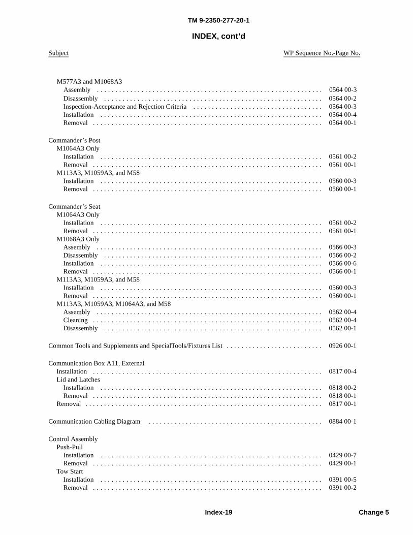
TM 9-2350-277-20-1
INDEX, cont’d
Subject WP Sequence No.-Page No.
Disassembly . . . . . . . . . . . . . . . . . . . . . . . . . . . . . . . . . . . . . . . . . . . . . . . . . . . . . . . . . . . 0564 00-2Inspection-Acceptance and Rejection Criteria . . . . . . . . . . . . . . . . . . . . . . . . . . . . . . . . . . . 0564 00-3Installation . . . . . . . . . . . . . . . . . . . . . . . . . . . . . . . . . . . . . . . . . . . . . . . . . . . . . . . . . . . . 0564 00-4Removal . . . . . . . . . . . . . . . . . . . . . . . . . . . . . . . . . . . . . . . . . . . . . . . . . . . . . . . . . . . . . . 0564 00-1
Commander’s PostM1064A3 Only
Installation . . . . . . . . . . . . . . . . . . . . . . . . . . . . . . . . . . . . . . . . . . . . . . . . . . . . . . . . . . . . 0561 00-2Removal . . . . . . . . . . . . . . . . . . . . . . . . . . . . . . . . . . . . . . . . . . . . . . . . . . . . . . . . . . . . . . 0561 00-1
M113A3, M1059A3, and M58Installation . . . . . . . . . . . . . . . . . . . . . . . . . . . . . . . . . . . . . . . . . . . . . . . . . . . . . . . . . . . . 0560 00-3Removal . . . . . . . . . . . . . . . . . . . . . . . . . . . . . . . . . . . . . . . . . . . . . . . . . . . . . . . . . . . . . . 0560 00-1
Commander’s SeatM1064A3 Only
Installation . . . . . . . . . . . . . . . . . . . . . . . . . . . . . . . . . . . . . . . . . . . . . . . . . . . . . . . . . . . . 0561 00-2Removal . . . . . . . . . . . . . . . . . . . . . . . . . . . . . . . . . . . . . . . . . . . . . . . . . . . . . . . . . . . . . . 0561 00-1
M1068A3 OnlyAssembly . . . . . . . . . . . . . . . . . . . . . . . . . . . . . . . . . . . . . . . . . . . . . . . . . . . . . . . . . . . . . 0566 00-3Disassembly . . . . . . . . . . . . . . . . . . . . . . . . . . . . . . . . . . . . . . . . . . . . . . . . . . . . . . . . . . . 0566 00-2Installation . . . . . . . . . . . . . . . . . . . . . . . . . . . . . . . . . . . . . . . . . . . . . . . . . . . . . . . . . . . . 0566 00-6Removal . . . . . . . . . . . . . . . . . . . . . . . . . . . . . . . . . . . . . . . . . . . . . . . . . . . . . . . . . . . . . . 0566 00-1
M113A3, M1059A3, and M58Installation . . . . . . . . . . . . . . . . . . . . . . . . . . . . . . . . . . . . . . . . . . . . . . . . . . . . . . . . . . . . 0560 00-3Removal . . . . . . . . . . . . . . . . . . . . . . . . . . . . . . . . . . . . . . . . . . . . . . . . . . . . . . . . . . . . . . 0560 00-1
M113A3, M1059A3, M1064A3, and M58Assembly . . . . . . . . . . . . . . . . . . . . . . . . . . . . . . . . . . . . . . . . . . . . . . . . . . . . . . . . . . . . . 0562 00-4Cleaning . . . . . . . . . . . . . . . . . . . . . . . . . . . . . . . . . . . . . . . . . . . . . . . . . . . . . . . . . . . . . . 0562 00-4Disassembly . . . . . . . . . . . . . . . . . . . . . . . . . . . . . . . . . . . . . . . . . . . . . . . . . . . . . . . . . . . 0562 00-1
Common Tools and Supplements and SpecialTools/Fixtures List . . . . . . . . . . . . . . . . . . . . . . . . . . 0926 00-1
Communication Box A11, ExternalInstallation . . . . . . . . . . . . . . . . . . . . . . . . . . . . . . . . . . . . . . . . . . . . . . . . . . . . . . . . . . . . . . 0817 00-4Lid and Latches
Installation . . . . . . . . . . . . . . . . . . . . . . . . . . . . . . . . . . . . . . . . . . . . . . . . . . . . . . . . . . . . 0818 00-2Removal . . . . . . . . . . . . . . . . . . . . . . . . . . . . . . . . . . . . . . . . . . . . . . . . . . . . . . . . . . . . . . 0818 00-1
Removal . . . . . . . . . . . . . . . . . . . . . . . . . . . . . . . . . . . . . . . . . . . . . . . . . . . . . . . . . . . . . . . . 0817 00-1
Communication Cabling Diagram . . . . . . . . . . . . . . . . . . . . . . . . . . . . . . . . . . . . . . . . . . . . . . . 0884 00-1
Control AssemblyPush-Pull
Installation . . . . . . . . . . . . . . . . . . . . . . . . . . . . . . . . . . . . . . . . . . . . . . . . . . . . . . . . . . . . 0429 00-7Removal . . . . . . . . . . . . . . . . . . . . . . . . . . . . . . . . . . . . . . . . . . . . . . . . . . . . . . . . . . . . . . 0429 00-1
Tow StartInstallation . . . . . . . . . . . . . . . . . . . . . . . . . . . . . . . . . . . . . . . . . . . . . . . . . . . . . . . . . . . . 0391 00-5Removal . . . . . . . . . . . . . . . . . . . . . . . . . . . . . . . . . . . . . . . . . . . . . . . . . . . . . . . . . . . . . . 0391 00-2
Index-19 Change 5
M577A3 and M1068A3Assembly . . . . . . . . . . . . . . . . . . . . . . . . . . . . . . . . . . . . . . . . . . . . . . . . . . . . . . . . . . . . . 0564 00-3
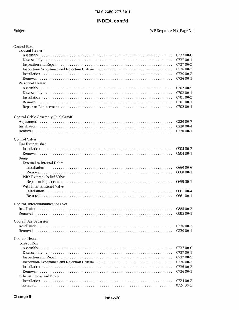
TM 9-2350-277-20-1
INDEX, cont’d
Subject WP Sequence No.-Page No.
Coolant HeaterAssembly . . . . . . . . . . . . . . . . . . . . . . . . . . . . . . . . . . . . . . . . . . . . . . . . . . . . . . . . . . . . . 0737 00-6Disassembly . . . . . . . . . . . . . . . . . . . . . . . . . . . . . . . . . . . . . . . . . . . . . . . . . . . . . . . . . . . 0737 00-1Inspection and Repair . . . . . . . . . . . . . . . . . . . . . . . . . . . . . . . . . . . . . . . . . . . . . . . . . . . . 0737 00-5Inspection-Acceptance and Rejection Criteria . . . . . . . . . . . . . . . . . . . . . . . . . . . . . . . . . . . 0736 00-2Installation . . . . . . . . . . . . . . . . . . . . . . . . . . . . . . . . . . . . . . . . . . . . . . . . . . . . . . . . . . . . 0736 00-2Removal . . . . . . . . . . . . . . . . . . . . . . . . . . . . . . . . . . . . . . . . . . . . . . . . . . . . . . . . . . . . . . 0736 00-1
Personnel HeaterAssembly . . . . . . . . . . . . . . . . . . . . . . . . . . . . . . . . . . . . . . . . . . . . . . . . . . . . . . . . . . . . . 0702 00-5Disassembly . . . . . . . . . . . . . . . . . . . . . . . . . . . . . . . . . . . . . . . . . . . . . . . . . . . . . . . . . . . 0702 00-1Installation . . . . . . . . . . . . . . . . . . . . . . . . . . . . . . . . . . . . . . . . . . . . . . . . . . . . . . . . . . . . 0701 00-3Removal . . . . . . . . . . . . . . . . . . . . . . . . . . . . . . . . . . . . . . . . . . . . . . . . . . . . . . . . . . . . . . 0701 00-1Repair or Replacement . . . . . . . . . . . . . . . . . . . . . . . . . . . . . . . . . . . . . . . . . . . . . . . . . . . . 0702 00-4
Control Cable Assembly, Fuel CutoffAdjustment . . . . . . . . . . . . . . . . . . . . . . . . . . . . . . . . . . . . . . . . . . . . . . . . . . . . . . . . . . . . . . 0220 00-7Installation . . . . . . . . . . . . . . . . . . . . . . . . . . . . . . . . . . . . . . . . . . . . . . . . . . . . . . . . . . . . . . 0220 00-4Removal . . . . . . . . . . . . . . . . . . . . . . . . . . . . . . . . . . . . . . . . . . . . . . . . . . . . . . . . . . . . . . . . 0220 00-1
Control ValveFire Extinguisher
Installation . . . . . . . . . . . . . . . . . . . . . . . . . . . . . . . . . . . . . . . . . . . . . . . . . . . . . . . . . . . . 0904 00-3Removal . . . . . . . . . . . . . . . . . . . . . . . . . . . . . . . . . . . . . . . . . . . . . . . . . . . . . . . . . . . . . . 0904 00-1
RampExternal to Internal Relief
Installation . . . . . . . . . . . . . . . . . . . . . . . . . . . . . . . . . . . . . . . . . . . . . . . . . . . . . . . . . . 0660 00-6Removal . . . . . . . . . . . . . . . . . . . . . . . . . . . . . . . . . . . . . . . . . . . . . . . . . . . . . . . . . . . . 0660 00-1
With External Relief ValveRepair or Replacement . . . . . . . . . . . . . . . . . . . . . . . . . . . . . . . . . . . . . . . . . . . . . . . . . . 0659 00-1
With Internal Relief ValveInstallation . . . . . . . . . . . . . . . . . . . . . . . . . . . . . . . . . . . . . . . . . . . . . . . . . . . . . . . . . . 0661 00-4Removal . . . . . . . . . . . . . . . . . . . . . . . . . . . . . . . . . . . . . . . . . . . . . . . . . . . . . . . . . . . . 0661 00-1
Control, Intercommunications SetInstallation . . . . . . . . . . . . . . . . . . . . . . . . . . . . . . . . . . . . . . . . . . . . . . . . . . . . . . . . . . . . . . 0885 00-2Removal . . . . . . . . . . . . . . . . . . . . . . . . . . . . . . . . . . . . . . . . . . . . . . . . . . . . . . . . . . . . . . . . 0885 00-1
Coolant Air SeparatorInstallation . . . . . . . . . . . . . . . . . . . . . . . . . . . . . . . . . . . . . . . . . . . . . . . . . . . . . . . . . . . . . . 0236 00-3Removal . . . . . . . . . . . . . . . . . . . . . . . . . . . . . . . . . . . . . . . . . . . . . . . . . . . . . . . . . . . . . . . . 0236 00-1
Coolant HeaterControl Box
Assembly . . . . . . . . . . . . . . . . . . . . . . . . . . . . . . . . . . . . . . . . . . . . . . . . . . . . . . . . . . . . . 0737 00-6Disassembly . . . . . . . . . . . . . . . . . . . . . . . . . . . . . . . . . . . . . . . . . . . . . . . . . . . . . . . . . . . 0737 00-1Inspection and Repair . . . . . . . . . . . . . . . . . . . . . . . . . . . . . . . . . . . . . . . . . . . . . . . . . . . . 0737 00-5Inspection-Acceptance and Rejection Criteria . . . . . . . . . . . . . . . . . . . . . . . . . . . . . . . . . . . 0736 00-2Installation . . . . . . . . . . . . . . . . . . . . . . . . . . . . . . . . . . . . . . . . . . . . . . . . . . . . . . . . . . . . 0736 00-2Removal . . . . . . . . . . . . . . . . . . . . . . . . . . . . . . . . . . . . . . . . . . . . . . . . . . . . . . . . . . . . . . 0736 00-1
Exhaust Elbow and PipesInstallation . . . . . . . . . . . . . . . . . . . . . . . . . . . . . . . . . . . . . . . . . . . . . . . . . . . . . . . . . . . . 0724 00-2
Index-20Change 5
Removal . . . . . . . . . . . . . . . . . . . . . . . . . . . . . . . . . . . . . . . . . . . . . . . . . . . . . . . . . . . . . . 0724 00-1
Control Box

TM 9-2350-277-20-1
INDEX, cont’d
Subject WP Sequence No.-Page No.
Flame Detector SwitchAdjustment . . . . . . . . . . . . . . . . . . . . . . . . . . . . . . . . . . . . . . . . . . . . . . . . . . . . . . . . . . . . 0727 00-1Inspection-Acceptance and Rejection Criteria . . . . . . . . . . . . . . . . . . . . . . . . . . . . . . . . . . . 0734 00-1Installation . . . . . . . . . . . . . . . . . . . . . . . . . . . . . . . . . . . . . . . . . . . . . . . . . . . . . . . . . . . . 0734 00-2Removal . . . . . . . . . . . . . . . . . . . . . . . . . . . . . . . . . . . . . . . . . . . . . . . . . . . . . . . . . . . . . . 0734 00-1
Fuel FilterCleaning . . . . . . . . . . . . . . . . . . . . . . . . . . . . . . . . . . . . . . . . . . . . . . . . . . . . . . . . . . . . . . 0708 00-1Installation . . . . . . . . . . . . . . . . . . . . . . . . . . . . . . . . . . . . . . . . . . . . . . . . . . . . . . . . . . . . 0708 00-2Removal . . . . . . . . . . . . . . . . . . . . . . . . . . . . . . . . . . . . . . . . . . . . . . . . . . . . . . . . . . . . . . 0708 00-1
Fuel Inlet Hose and FittingsInstallation . . . . . . . . . . . . . . . . . . . . . . . . . . . . . . . . . . . . . . . . . . . . . . . . . . . . . . . . . . . . 0712 00-3Removal . . . . . . . . . . . . . . . . . . . . . . . . . . . . . . . . . . . . . . . . . . . . . . . . . . . . . . . . . . . . . . 0712 00-1
Fuel PumpAssembly . . . . . . . . . . . . . . . . . . . . . . . . . . . . . . . . . . . . . . . . . . . . . . . . . . . . . . . . . . . . . 0709 00-2Cleaning . . . . . . . . . . . . . . . . . . . . . . . . . . . . . . . . . . . . . . . . . . . . . . . . . . . . . . . . . . . . . . 0709 00-2Disassembly . . . . . . . . . . . . . . . . . . . . . . . . . . . . . . . . . . . . . . . . . . . . . . . . . . . . . . . . . . . 0709 00-1Installation . . . . . . . . . . . . . . . . . . . . . . . . . . . . . . . . . . . . . . . . . . . . . . . . . . . . . . . . . . . . 0723 00-3Removal . . . . . . . . . . . . . . . . . . . . . . . . . . . . . . . . . . . . . . . . . . . . . . . . . . . . . . . . . . . . . . 0723 00-1
Fuel Shutoff ValveInstallation . . . . . . . . . . . . . . . . . . . . . . . . . . . . . . . . . . . . . . . . . . . . . . . . . . . . . . . . . . . . 0720 00-3Removal . . . . . . . . . . . . . . . . . . . . . . . . . . . . . . . . . . . . . . . . . . . . . . . . . . . . . . . . . . . . . . 0720 00-1
Heater and Pump BracketInstallation . . . . . . . . . . . . . . . . . . . . . . . . . . . . . . . . . . . . . . . . . . . . . . . . . . . . . . . . . . . . 0732 00-1Removal . . . . . . . . . . . . . . . . . . . . . . . . . . . . . . . . . . . . . . . . . . . . . . . . . . . . . . . . . . . . . . 0732 00-1
Heater to Engine Elbow HoseInstallation . . . . . . . . . . . . . . . . . . . . . . . . . . . . . . . . . . . . . . . . . . . . . . . . . . . . . . . . . . . . 0715 00-2Removal . . . . . . . . . . . . . . . . . . . . . . . . . . . . . . . . . . . . . . . . . . . . . . . . . . . . . . . . . . . . . . 0715 00-1
HoseEngine to Battery Box
Installation . . . . . . . . . . . . . . . . . . . . . . . . . . . . . . . . . . . . . . . . . . . . . . . . . . . . . . . . . . 0714 00-4Removal . . . . . . . . . . . . . . . . . . . . . . . . . . . . . . . . . . . . . . . . . . . . . . . . . . . . . . . . . . . . 0714 00-2
Filter ValveInstallation . . . . . . . . . . . . . . . . . . . . . . . . . . . . . . . . . . . . . . . . . . . . . . . . . . . . . . . . . . 0716 00-2Removal . . . . . . . . . . . . . . . . . . . . . . . . . . . . . . . . . . . . . . . . . . . . . . . . . . . . . . . . . . . . 0716 00-1
Fuel PumpInstallation . . . . . . . . . . . . . . . . . . . . . . . . . . . . . . . . . . . . . . . . . . . . . . . . . . . . . . . . . . 0711 00-2Removal . . . . . . . . . . . . . . . . . . . . . . . . . . . . . . . . . . . . . . . . . . . . . . . . . . . . . . . . . . . . 0711 00-1
Heater to Surge TankInstallation . . . . . . . . . . . . . . . . . . . . . . . . . . . . . . . . . . . . . . . . . . . . . . . . . . . . . . . . . . 0725 00-1Removal . . . . . . . . . . . . . . . . . . . . . . . . . . . . . . . . . . . . . . . . . . . . . . . . . . . . . . . . . . . . 0725 00-1
Pump to Battery BoxInstallation . . . . . . . . . . . . . . . . . . . . . . . . . . . . . . . . . . . . . . . . . . . . . . . . . . . . . . . . . . 0713 00-3Removal . . . . . . . . . . . . . . . . . . . . . . . . . . . . . . . . . . . . . . . . . . . . . . . . . . . . . . . . . . . . 0713 00-1
Inspection-Acceptance and Rejection Criteria . . . . . . . . . . . . . . . . . . . . . . . . . . . . . . . . . . . . . 0729 00-1Installation . . . . . . . . . . . . . . . . . . . . . . . . . . . . . . . . . . . . . . . . . . . . . . . . . . . . . . . . . . . . . . 0729 00-2Pump
Installation . . . . . . . . . . . . . . . . . . . . . . . . . . . . . . . . . . . . . . . . . . . . . . . . . . . . . . . . . . . . 0731 00-2Removal . . . . . . . . . . . . . . . . . . . . . . . . . . . . . . . . . . . . . . . . . . . . . . . . . . . . . . . . . . . . . . 0731 00-1
Pump UnitInspection-Acceptance and Rejection Criteria . . . . . . . . . . . . . . . . . . . . . . . . . . . . . . . . . . . 0728 00-5Installation . . . . . . . . . . . . . . . . . . . . . . . . . . . . . . . . . . . . . . . . . . . . . . . . . . . . . . . . . . . . 0728 00-5
Index-21 Change 5
Removal . . . . . . . . . . . . . . . . . . . . . . . . . . . . . . . . . . . . . . . . . . . . . . . . . . . . . . . . . . . . . . 0728 00-1Removal . . . . . . . . . . . . . . . . . . . . . . . . . . . . . . . . . . . . . . . . . . . . . . . . . . . . . . . . . . . . . . . . 0729 00-1
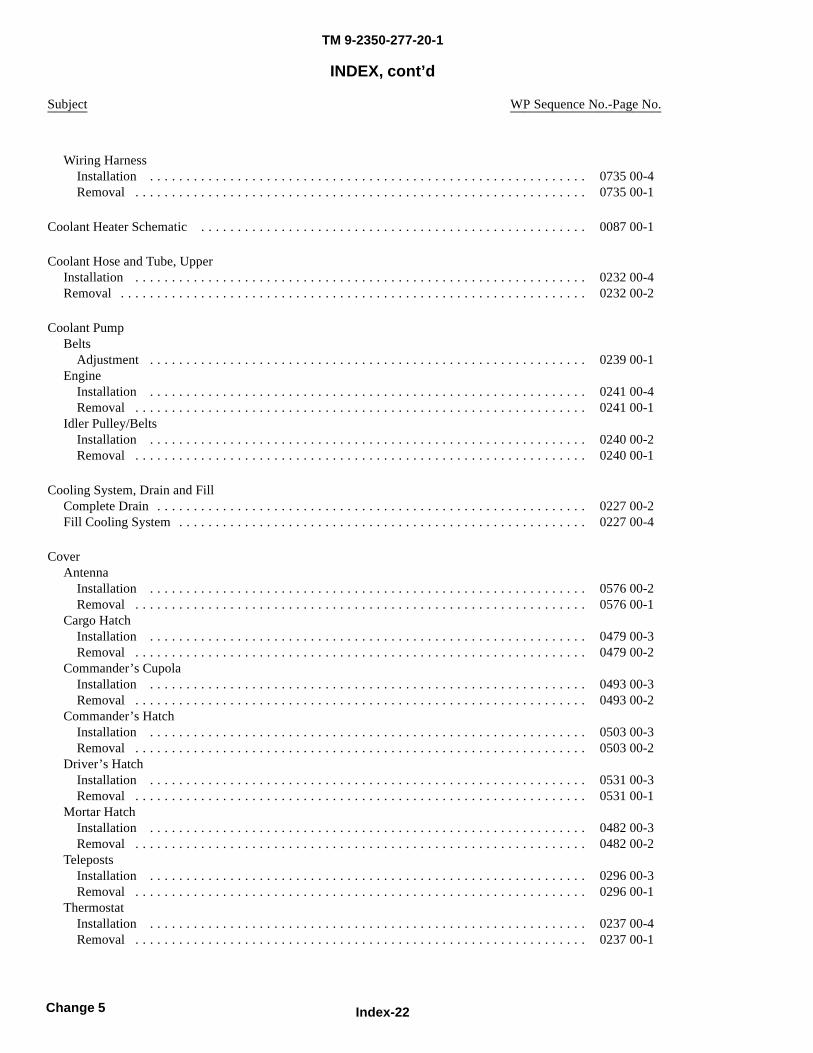
TM 9-2350-277-20-1
INDEX, cont’d
Subject WP Sequence No.-Page No.
Wiring HarnessInstallation . . . . . . . . . . . . . . . . . . . . . . . . . . . . . . . . . . . . . . . . . . . . . . . . . . . . . . . . . . . . 0735 00-4Removal . . . . . . . . . . . . . . . . . . . . . . . . . . . . . . . . . . . . . . . . . . . . . . . . . . . . . . . . . . . . . . 0735 00-1
Coolant Heater Schematic . . . . . . . . . . . . . . . . . . . . . . . . . . . . . . . . . . . . . . . . . . . . . . . . . . . . . 0087 00-1
Coolant Hose and Tube, UpperInstallation . . . . . . . . . . . . . . . . . . . . . . . . . . . . . . . . . . . . . . . . . . . . . . . . . . . . . . . . . . . . . . 0232 00-4Removal . . . . . . . . . . . . . . . . . . . . . . . . . . . . . . . . . . . . . . . . . . . . . . . . . . . . . . . . . . . . . . . . 0232 00-2
Coolant PumpBelts
Adjustment . . . . . . . . . . . . . . . . . . . . . . . . . . . . . . . . . . . . . . . . . . . . . . . . . . . . . . . . . . . . 0239 00-1Engine
Installation . . . . . . . . . . . . . . . . . . . . . . . . . . . . . . . . . . . . . . . . . . . . . . . . . . . . . . . . . . . . 0241 00-4Removal . . . . . . . . . . . . . . . . . . . . . . . . . . . . . . . . . . . . . . . . . . . . . . . . . . . . . . . . . . . . . . 0241 00-1
Idler Pulley/BeltsInstallation . . . . . . . . . . . . . . . . . . . . . . . . . . . . . . . . . . . . . . . . . . . . . . . . . . . . . . . . . . . . 0240 00-2Removal . . . . . . . . . . . . . . . . . . . . . . . . . . . . . . . . . . . . . . . . . . . . . . . . . . . . . . . . . . . . . . 0240 00-1
Cooling System, Drain and FillComplete Drain . . . . . . . . . . . . . . . . . . . . . . . . . . . . . . . . . . . . . . . . . . . . . . . . . . . . . . . . . . . 0227 00-2Fill Cooling System . . . . . . . . . . . . . . . . . . . . . . . . . . . . . . . . . . . . . . . . . . . . . . . . . . . . . . . . 0227 00-4
CoverAntenna
Installation . . . . . . . . . . . . . . . . . . . . . . . . . . . . . . . . . . . . . . . . . . . . . . . . . . . . . . . . . . . . 0576 00-2Removal . . . . . . . . . . . . . . . . . . . . . . . . . . . . . . . . . . . . . . . . . . . . . . . . . . . . . . . . . . . . . . 0576 00-1
Cargo HatchInstallation . . . . . . . . . . . . . . . . . . . . . . . . . . . . . . . . . . . . . . . . . . . . . . . . . . . . . . . . . . . . 0479 00-3Removal . . . . . . . . . . . . . . . . . . . . . . . . . . . . . . . . . . . . . . . . . . . . . . . . . . . . . . . . . . . . . . 0479 00-2
Commander’s CupolaInstallation . . . . . . . . . . . . . . . . . . . . . . . . . . . . . . . . . . . . . . . . . . . . . . . . . . . . . . . . . . . . 0493 00-3Removal . . . . . . . . . . . . . . . . . . . . . . . . . . . . . . . . . . . . . . . . . . . . . . . . . . . . . . . . . . . . . . 0493 00-2
Commander’s HatchInstallation . . . . . . . . . . . . . . . . . . . . . . . . . . . . . . . . . . . . . . . . . . . . . . . . . . . . . . . . . . . . 0503 00-3Removal . . . . . . . . . . . . . . . . . . . . . . . . . . . . . . . . . . . . . . . . . . . . . . . . . . . . . . . . . . . . . . 0503 00-2
Driver’s HatchInstallation . . . . . . . . . . . . . . . . . . . . . . . . . . . . . . . . . . . . . . . . . . . . . . . . . . . . . . . . . . . . 0531 00-3Removal . . . . . . . . . . . . . . . . . . . . . . . . . . . . . . . . . . . . . . . . . . . . . . . . . . . . . . . . . . . . . . 0531 00-1
Mortar HatchInstallation . . . . . . . . . . . . . . . . . . . . . . . . . . . . . . . . . . . . . . . . . . . . . . . . . . . . . . . . . . . . 0482 00-3Removal . . . . . . . . . . . . . . . . . . . . . . . . . . . . . . . . . . . . . . . . . . . . . . . . . . . . . . . . . . . . . . 0482 00-2
TelepostsInstallation . . . . . . . . . . . . . . . . . . . . . . . . . . . . . . . . . . . . . . . . . . . . . . . . . . . . . . . . . . . . 0296 00-3Removal . . . . . . . . . . . . . . . . . . . . . . . . . . . . . . . . . . . . . . . . . . . . . . . . . . . . . . . . . . . . . . 0296 00-1
ThermostatInstallation . . . . . . . . . . . . . . . . . . . . . . . . . . . . . . . . . . . . . . . . . . . . . . . . . . . . . . . . . . . . 0237 00-4Removal . . . . . . . . . . . . . . . . . . . . . . . . . . . . . . . . . . . . . . . . . . . . . . . . . . . . . . . . . . . . . . 0237 00-1
Index-22Change 5
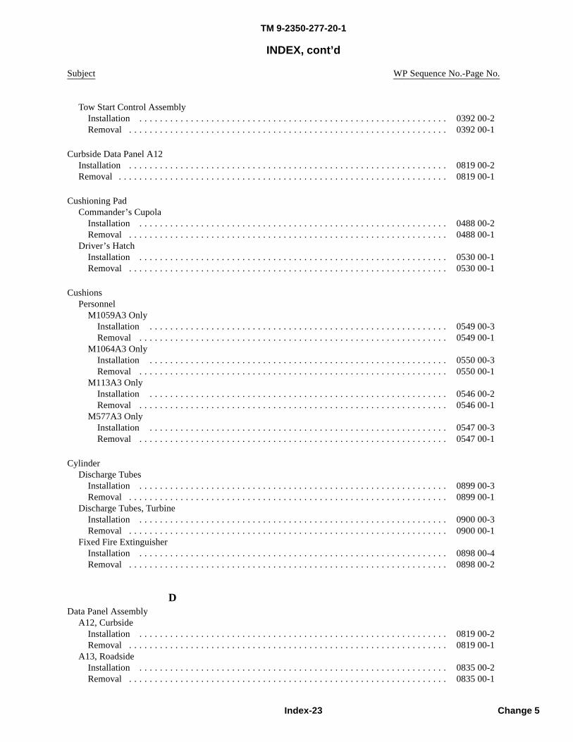
TM 9-2350-277-20-1
INDEX, cont’d
Subject WP Sequence No.-Page No.
Tow Start Control AssemblyInstallation . . . . . . . . . . . . . . . . . . . . . . . . . . . . . . . . . . . . . . . . . . . . . . . . . . . . . . . . . . . . 0392 00-2Removal . . . . . . . . . . . . . . . . . . . . . . . . . . . . . . . . . . . . . . . . . . . . . . . . . . . . . . . . . . . . . . 0392 00-1
Curbside Data Panel A12Installation . . . . . . . . . . . . . . . . . . . . . . . . . . . . . . . . . . . . . . . . . . . . . . . . . . . . . . . . . . . . . . 0819 00-2Removal . . . . . . . . . . . . . . . . . . . . . . . . . . . . . . . . . . . . . . . . . . . . . . . . . . . . . . . . . . . . . . . . 0819 00-1
Cushioning PadCommander’s Cupola
Installation . . . . . . . . . . . . . . . . . . . . . . . . . . . . . . . . . . . . . . . . . . . . . . . . . . . . . . . . . . . . 0488 00-2Removal . . . . . . . . . . . . . . . . . . . . . . . . . . . . . . . . . . . . . . . . . . . . . . . . . . . . . . . . . . . . . . 0488 00-1
Driver’s HatchInstallation . . . . . . . . . . . . . . . . . . . . . . . . . . . . . . . . . . . . . . . . . . . . . . . . . . . . . . . . . . . . 0530 00-1Removal . . . . . . . . . . . . . . . . . . . . . . . . . . . . . . . . . . . . . . . . . . . . . . . . . . . . . . . . . . . . . . 0530 00-1
CushionsPersonnel
M1059A3 OnlyInstallation . . . . . . . . . . . . . . . . . . . . . . . . . . . . . . . . . . . . . . . . . . . . . . . . . . . . . . . . . . 0549 00-3Removal . . . . . . . . . . . . . . . . . . . . . . . . . . . . . . . . . . . . . . . . . . . . . . . . . . . . . . . . . . . . 0549 00-1
M1064A3 OnlyInstallation . . . . . . . . . . . . . . . . . . . . . . . . . . . . . . . . . . . . . . . . . . . . . . . . . . . . . . . . . . 0550 00-3Removal . . . . . . . . . . . . . . . . . . . . . . . . . . . . . . . . . . . . . . . . . . . . . . . . . . . . . . . . . . . . 0550 00-1
M113A3 OnlyInstallation . . . . . . . . . . . . . . . . . . . . . . . . . . . . . . . . . . . . . . . . . . . . . . . . . . . . . . . . . . 0546 00-2Removal . . . . . . . . . . . . . . . . . . . . . . . . . . . . . . . . . . . . . . . . . . . . . . . . . . . . . . . . . . . . 0546 00-1
M577A3 OnlyInstallation . . . . . . . . . . . . . . . . . . . . . . . . . . . . . . . . . . . . . . . . . . . . . . . . . . . . . . . . . . 0547 00-3Removal . . . . . . . . . . . . . . . . . . . . . . . . . . . . . . . . . . . . . . . . . . . . . . . . . . . . . . . . . . . . 0547 00-1
CylinderDischarge Tubes
Installation . . . . . . . . . . . . . . . . . . . . . . . . . . . . . . . . . . . . . . . . . . . . . . . . . . . . . . . . . . . . 0899 00-3Removal . . . . . . . . . . . . . . . . . . . . . . . . . . . . . . . . . . . . . . . . . . . . . . . . . . . . . . . . . . . . . . 0899 00-1
Discharge Tubes, TurbineInstallation . . . . . . . . . . . . . . . . . . . . . . . . . . . . . . . . . . . . . . . . . . . . . . . . . . . . . . . . . . . . 0900 00-3Removal . . . . . . . . . . . . . . . . . . . . . . . . . . . . . . . . . . . . . . . . . . . . . . . . . . . . . . . . . . . . . . 0900 00-1
Fixed Fire ExtinguisherInstallation . . . . . . . . . . . . . . . . . . . . . . . . . . . . . . . . . . . . . . . . . . . . . . . . . . . . . . . . . . . . 0898 00-4Removal . . . . . . . . . . . . . . . . . . . . . . . . . . . . . . . . . . . . . . . . . . . . . . . . . . . . . . . . . . . . . . 0898 00-2
DData Panel Assembly
A12, CurbsideInstallation . . . . . . . . . . . . . . . . . . . . . . . . . . . . . . . . . . . . . . . . . . . . . . . . . . . . . . . . . . . . 0819 00-2Removal . . . . . . . . . . . . . . . . . . . . . . . . . . . . . . . . . . . . . . . . . . . . . . . . . . . . . . . . . . . . . . 0819 00-1
A13, RoadsideInstallation . . . . . . . . . . . . . . . . . . . . . . . . . . . . . . . . . . . . . . . . . . . . . . . . . . . . . . . . . . . . 0835 00-2Removal . . . . . . . . . . . . . . . . . . . . . . . . . . . . . . . . . . . . . . . . . . . . . . . . . . . . . . . . . . . . . . 0835 00-1
Index-23 Change 5
TM 9-2350-277-20-1
INDEX, cont’d
Subject WP Sequence No.-Page No.
Data Plates, Stencils, Markers, and DecalsCleaning . . . . . . . . . . . . . . . . . . . . . . . . . . . . . . . . . . . . . . . . . . . . . . . . . . . . . . . . . . . . . . . . 0654 00-2Installation . . . . . . . . . . . . . . . . . . . . . . . . . . . . . . . . . . . . . . . . . . . . . . . . . . . . . . . . . . . . . . 0654 00-3Removal . . . . . . . . . . . . . . . . . . . . . . . . . . . . . . . . . . . . . . . . . . . . . . . . . . . . . . . . . . . . . . . . 0654 00-2
Dataplates, Decals, and MarkersAll Models . . . . . . . . . . . . . . . . . . . . . . . . . . . . . . . . . . . . . . . . . . . . . . . . . . . . . . . . . . . . . . 0644 00-1M1059A3 Only . . . . . . . . . . . . . . . . . . . . . . . . . . . . . . . . . . . . . . . . . . . . . . . . . . . . . . . . . . . 0651 00-1M1064A3 Only . . . . . . . . . . . . . . . . . . . . . . . . . . . . . . . . . . . . . . . . . . . . . . . . . . . . . . . . . . . 0652 00-1M113A3 and M1059A3 . . . . . . . . . . . . . . . . . . . . . . . . . . . . . . . . . . . . . . . . . . . . . 0645 00-1, 0647 00-1M113A3, M1059A3, and M58 . . . . . . . . . . . . . . . . . . . . . . . . . . . . . . . . . . . . . . . . . . . . . . . . 0646 00-1M577A3 and M1068A3 . . . . . . . . . . . . . . . . . . . . . . . . . . . . . . . . . . . . . . . . . . . . . . . . . . . . . 0648 00-1M58 Only . . . . . . . . . . . . . . . . . . . . . . . . . . . . . . . . . . . . . . . . . . . . . . . . . . . . . . . . . . . . . . . 0653 00-1
DC Battery Cable (W4)Installation . . . . . . . . . . . . . . . . . . . . . . . . . . . . . . . . . . . . . . . . . . . . . . . . . . . . . . . . . . . . . . 0838 00-3Removal . . . . . . . . . . . . . . . . . . . . . . . . . . . . . . . . . . . . . . . . . . . . . . . . . . . . . . . . . . . . . . . . 0838 00-1
DC Power ExtensionBox A9
Installation . . . . . . . . . . . . . . . . . . . . . . . . . . . . . . . . . . . . . . . . . . . . . . . . . . . . . . . . . . . . 0834 00-3Removal . . . . . . . . . . . . . . . . . . . . . . . . . . . . . . . . . . . . . . . . . . . . . . . . . . . . . . . . . . . . . . 0834 00-1
W10 CableInstallation . . . . . . . . . . . . . . . . . . . . . . . . . . . . . . . . . . . . . . . . . . . . . . . . . . . . . . . . . . . . 0844 00-3Removal . . . . . . . . . . . . . . . . . . . . . . . . . . . . . . . . . . . . . . . . . . . . . . . . . . . . . . . . . . . . . . 0844 00-1
Diagram, Communication Cabling . . . . . . . . . . . . . . . . . . . . . . . . . . . . . . . . . . . . . . . . . . . . . . . 0884 00-1
Differential Pressure SwitchBypass Plug
Installation . . . . . . . . . . . . . . . . . . . . . . . . . . . . . . . . . . . . . . . . . . . . . . . . . . . . . . . . . . . . 0401 00-2Removal . . . . . . . . . . . . . . . . . . . . . . . . . . . . . . . . . . . . . . . . . . . . . . . . . . . . . . . . . . . . . . 0401 00-1
Fuel FilterInstallation . . . . . . . . . . . . . . . . . . . . . . . . . . . . . . . . . . . . . . . . . . . . . . . . . . . . . . . . . . . . 0328 00-5Removal . . . . . . . . . . . . . . . . . . . . . . . . . . . . . . . . . . . . . . . . . . . . . . . . . . . . . . . . . . . . . . 0328 00-1
DipstickFinal Drive
Installation . . . . . . . . . . . . . . . . . . . . . . . . . . . . . . . . . . . . . . . . . . . . . . . . . . . . . . . . . . . . 0402 00-3Removal . . . . . . . . . . . . . . . . . . . . . . . . . . . . . . . . . . . . . . . . . . . . . . . . . . . . . . . . . . . . . . 0402 00-1
Transmission Oil LevelX200-4 Only
Installation . . . . . . . . . . . . . . . . . . . . . . . . . . . . . . . . . . . . . . . . . . . . . . . . . . . . . . . . . . 0395 00-3Removal . . . . . . . . . . . . . . . . . . . . . . . . . . . . . . . . . . . . . . . . . . . . . . . . . . . . . . . . . . . . 0395 00-1
X200-4A OnlyInstallation . . . . . . . . . . . . . . . . . . . . . . . . . . . . . . . . . . . . . . . . . . . . . . . . . . . . . . . . . . 0396 00-4Removal . . . . . . . . . . . . . . . . . . . . . . . . . . . . . . . . . . . . . . . . . . . . . . . . . . . . . . . . . . . . 0396 00-1
Index-24Change 5
TM 9-2350-277-20-1
INDEX, cont’d
Subject WP Sequence No.-Page No.
Installation . . . . . . . . . . . . . . . . . . . . . . . . . . . . . . . . . . . . . . . . . . . . . . . . . . . . 0269 00-4, 0270 00-5Removal . . . . . . . . . . . . . . . . . . . . . . . . . . . . . . . . . . . . . . . . . . . . . . . . . . . . . . 0269 00-2, 0270 00-2
M577A3 and M1068A3Installation . . . . . . . . . . . . . . . . . . . . . . . . . . . . . . . . . . . . . . . . . . . . . . . . . . . . . . . . . . . . 0271 00-3Removal . . . . . . . . . . . . . . . . . . . . . . . . . . . . . . . . . . . . . . . . . . . . . . . . . . . . . . . . . . . . . . 0271 00-1
MSD/ICEM1064A3 Only
Installation . . . . . . . . . . . . . . . . . . . . . . . . . . . . . . . . . . . . . . . . . . . . . . . . . . . . . . . . . . 0877 00-3Removal . . . . . . . . . . . . . . . . . . . . . . . . . . . . . . . . . . . . . . . . . . . . . . . . . . . . . . . . . . . . 0877 00-1
M113A3 and M1059A3Installation . . . . . . . . . . . . . . . . . . . . . . . . . . . . . . . . . . . . . . . . . . . . . . . . . . . . . . . . . . 0874 00-3Removal . . . . . . . . . . . . . . . . . . . . . . . . . . . . . . . . . . . . . . . . . . . . . . . . . . . . . . . . . . . . 0874 00-1
M577A3 and M1068A3Installation . . . . . . . . . . . . . . . . . . . . . . . . . . . . . . . . . . . . . . . . . . . . . . . . . . . . . . . . . . 0875 00-2Removal . . . . . . . . . . . . . . . . . . . . . . . . . . . . . . . . . . . . . . . . . . . . . . . . . . . . . . . . . . . . 0875 00-1
Dome LightAll Except M577A3 and M1068A3
Assembly . . . . . . . . . . . . . . . . . . . . . . . . . . . . . . . . . . . . . . . . . . . . . . . . . . . . . . . . . . . . . 0310 00-3Disassembly . . . . . . . . . . . . . . . . . . . . . . . . . . . . . . . . . . . . . . . . . . . . . . . . . . . . . . . . . . . 0310 00-1Installation . . . . . . . . . . . . . . . . . . . . . . . . . . . . . . . . . . . . . . . . . . . . . . . . . . . . . . . . . . . . 0309 00-2Removal . . . . . . . . . . . . . . . . . . . . . . . . . . . . . . . . . . . . . . . . . . . . . . . . . . . . . . . . . . . . . . 0309 00-1
Circuit BreakerInstallation . . . . . . . . . . . . . . . . . . . . . . . . . . . . . . . . . . . . . . . . . . . . . . . . . . . . . . . . . . . . 0316 00-3Removal . . . . . . . . . . . . . . . . . . . . . . . . . . . . . . . . . . . . . . . . . . . . . . . . . . . . . . . . . . . . . . 0316 00-1
LensInstallation . . . . . . . . . . . . . . . . . . . . . . . . . . . . . . . . . . . . . . . . . . . . . . . . . . . . . . . . . . . . 0313 00-3Removal . . . . . . . . . . . . . . . . . . . . . . . . . . . . . . . . . . . . . . . . . . . . . . . . . . . . . . . . . . . . . . 0313 00-1
M577A3 and M1068A3Assembly . . . . . . . . . . . . . . . . . . . . . . . . . . . . . . . . . . . . . . . . . . . . . . . . . . . . . . . . . . . . . 0312 00-3Disassembly . . . . . . . . . . . . . . . . . . . . . . . . . . . . . . . . . . . . . . . . . . . . . . . . . . . . . . . . . . . 0312 00-1Installation . . . . . . . . . . . . . . . . . . . . . . . . . . . . . . . . . . . . . . . . . . . . . . . . . . . . . . . . . . . . 0311 00-3Removal . . . . . . . . . . . . . . . . . . . . . . . . . . . . . . . . . . . . . . . . . . . . . . . . . . . . . . . . . . . . . . 0311 00-1
SwitchFront
Installation . . . . . . . . . . . . . . . . . . . . . . . . . . . . . . . . . . . . . . . . . . . . . . . . . . . . . . . . . . 0314 00-3Removal . . . . . . . . . . . . . . . . . . . . . . . . . . . . . . . . . . . . . . . . . . . . . . . . . . . . . . . . . . . . 0314 00-1
RearInstallation . . . . . . . . . . . . . . . . . . . . . . . . . . . . . . . . . . . . . . . . . . . . . . . . . . . . . . . . . . 0315 00-2Removal . . . . . . . . . . . . . . . . . . . . . . . . . . . . . . . . . . . . . . . . . . . . . . . . . . . . . . . . . . . . 0315 00-1
DoorPower Plant
Adjustment . . . . . . . . . . . . . . . . . . . . . . . . . . . . . . . . . . . . . . . . . . . . . . . . . . . . . . . . . . . . 0472 00-2All Except M113A3
Installation . . . . . . . . . . . . . . . . . . . . . . . . . . . . . . . . . . . . . . . . . . . . . . . . . . . . . . . . . . 0471 00-2Removal . . . . . . . . . . . . . . . . . . . . . . . . . . . . . . . . . . . . . . . . . . . . . . . . . . . . . . . . . . . . 0471 00-1
Assembly . . . . . . . . . . . . . . . . . . . . . . . . . . . . . . . . . . . . . . . . . . . . . . . . . . . . . . . . . . . . . 0472 00-2Disassembly . . . . . . . . . . . . . . . . . . . . . . . . . . . . . . . . . . . . . . . . . . . . . . . . . . . . . . . . . . . 0472 00-1
Index-25 Change 5
Distribution BoxM113A3, M1059A3, M1064A3, and M58
TM 9-2350-277-20-1
INDEX, cont’d
Subject WP Sequence No.-Page No.
Removal . . . . . . . . . . . . . . . . . . . . . . . . . . . . . . . . . . . . . . . . . . . . . . . . . . . . . . . . . . . . 0470 00-1Turbine Access
Installation . . . . . . . . . . . . . . . . . . . . . . . . . . . . . . . . . . . . . . . . . . . . . . . . . . . . . . . . . . . . 0485 00-2Removal . . . . . . . . . . . . . . . . . . . . . . . . . . . . . . . . . . . . . . . . . . . . . . . . . . . . . . . . . . . . . . 0485 00-2
Drain Check Valve and Tubes, Left and Right Air BoxInstallation . . . . . . . . . . . . . . . . . . . . . . . . . . . . . . . . . . . . . . . . . . . . . . . . . . . . . . . . . . . . . . 0159 00-4Removal . . . . . . . . . . . . . . . . . . . . . . . . . . . . . . . . . . . . . . . . . . . . . . . . . . . . . . . . . . . . . . . . 0159 00-1
Drain Cock and HoseInstallation . . . . . . . . . . . . . . . . . . . . . . . . . . . . . . . . . . . . . . . . . . . . . . . . . . . . . . . . . . . . . . 0235 00-1Removal . . . . . . . . . . . . . . . . . . . . . . . . . . . . . . . . . . . . . . . . . . . . . . . . . . . . . . . . . . . . . . . . 0235 00-1
Drain PlugFinal Drive Hull
Installation . . . . . . . . . . . . . . . . . . . . . . . . . . . . . . . . . . . . . . . . . . . . . . . . . . . . . . . . . . . . 0452 00-2Removal . . . . . . . . . . . . . . . . . . . . . . . . . . . . . . . . . . . . . . . . . . . . . . . . . . . . . . . . . . . . . . 0452 00-1
Fuel TankInstallation . . . . . . . . . . . . . . . . . . . . . . . . . . . . . . . . . . . . . . . . . . . . . . . . . . . . . . . . . . . . 0187 00-2Removal . . . . . . . . . . . . . . . . . . . . . . . . . . . . . . . . . . . . . . . . . . . . . . . . . . . . . . . . . . . . . . 0187 00-1
HullInstallation . . . . . . . . . . . . . . . . . . . . . . . . . . . . . . . . . . . . . . . . . . . . . . . . . . . . . . . . . . . . 0451 00-2Removal . . . . . . . . . . . . . . . . . . . . . . . . . . . . . . . . . . . . . . . . . . . . . . . . . . . . . . . . . . . . . . 0451 00-1
RampInstallation . . . . . . . . . . . . . . . . . . . . . . . . . . . . . . . . . . . . . . . . . . . . . . . . . . . . . . . . . . . . 0515 00-1Removal . . . . . . . . . . . . . . . . . . . . . . . . . . . . . . . . . . . . . . . . . . . . . . . . . . . . . . . . . . . . . . 0515 00-1
Drive BeltGenerator
Adjustment . . . . . . . . . . . . . . . . . . . . . . . . . . . . . . . . . . . . . . . . . . . . . . . . . . . . . . . . . . . . 0252 00-2Installation . . . . . . . . . . . . . . . . . . . . . . . . . . . . . . . . . . . . . . . . . . . . . . . . . . . . . . . . . . . . 0253 00-1Removal . . . . . . . . . . . . . . . . . . . . . . . . . . . . . . . . . . . . . . . . . . . . . . . . . . . . . . . . . . . . . . 0253 00-1
Ventilating FanAdjustment . . . . . . . . . . . . . . . . . . . . . . . . . . . . . . . . . . . . . . . . . . . . . . . . . . . . . . . . . . . . 0242 00-1Installation . . . . . . . . . . . . . . . . . . . . . . . . . . . . . . . . . . . . . . . . . . . . . . . . . . . . . . . . . . . . 0243 00-2Removal . . . . . . . . . . . . . . . . . . . . . . . . . . . . . . . . . . . . . . . . . . . . . . . . . . . . . . . . . . . . . . 0243 00-1
Drive Pulley, Ventilating FanInstallation . . . . . . . . . . . . . . . . . . . . . . . . . . . . . . . . . . . . . . . . . . . . . . . . . . . . . . . . . . . . . . 0244 00-1Removal . . . . . . . . . . . . . . . . . . . . . . . . . . . . . . . . . . . . . . . . . . . . . . . . . . . . . . . . . . . . . . . . 0244 00-1
Drive Sprocket Wheel AssemblyT130 Track
Assembly . . . . . . . . . . . . . . . . . . . . . . . . . . . . . . . . . . . . . . . . . . . . . . . . . . . . . . . . . . . . . 0421 00-1Disassembly . . . . . . . . . . . . . . . . . . . . . . . . . . . . . . . . . . . . . . . . . . . . . . . . . . . . . . . . . . . 0421 00-1Installation . . . . . . . . . . . . . . . . . . . . . . . . . . . . . . . . . . . . . . . . . . . . . . . . . . . . . . . . . . . . 0420 00-2Removal . . . . . . . . . . . . . . . . . . . . . . . . . . . . . . . . . . . . . . . . . . . . . . . . . . . . . . . . . . . . . . 0420 00-1
T150 TrackInstallation . . . . . . . . . . . . . . . . . . . . . . . . . . . . . . . . . . . . . . . . . . . . . . . . . . . . . . . . . . . . 0420 01-2Removal . . . . . . . . . . . . . . . . . . . . . . . . . . . . . . . . . . . . . . . . . . . . . . . . . . . . . . . . . . . . . . 0420 01-1
Index-26Change 5
M113A3 OnlyInstallation . . . . . . . . . . . . . . . . . . . . . . . . . . . . . . . . . . . . . . . . . . . . . . . . . . . . . . . . . . 0470 00-3
TM 9-2350-277-20-1
INDEX, cont’d
Subject WP Sequence No.-Page No.
Driver’s Compartment Floor PlatesCleaning . . . . . . . . . . . . . . . . . . . . . . . . . . . . . . . . . . . . . . . . . . . . . . . . . . . . . . . . . . . . . . . . 0453 00-2Installation . . . . . . . . . . . . . . . . . . . . . . . . . . . . . . . . . . . . . . . . . . . . . . . . . . . . . . . . . . . . . . 0453 00-2Removal . . . . . . . . . . . . . . . . . . . . . . . . . . . . . . . . . . . . . . . . . . . . . . . . . . . . . . . . . . . . . . . . 0453 00-1
Driver’s FootrestInstallation . . . . . . . . . . . . . . . . . . . . . . . . . . . . . . . . . . . . . . . . . . . . . . . . . . . . . . . . . . . . . . 0558 00-1Removal . . . . . . . . . . . . . . . . . . . . . . . . . . . . . . . . . . . . . . . . . . . . . . . . . . . . . . . . . . . . . . . . 0558 00-1
Driver’s HatchCover
Installation . . . . . . . . . . . . . . . . . . . . . . . . . . . . . . . . . . . . . . . . . . . . . . . . . . . . . . . . . . . . 0531 00-3Removal . . . . . . . . . . . . . . . . . . . . . . . . . . . . . . . . . . . . . . . . . . . . . . . . . . . . . . . . . . . . . . 0531 00-1
Cushioning PadInstallation . . . . . . . . . . . . . . . . . . . . . . . . . . . . . . . . . . . . . . . . . . . . . . . . . . . . . . . . . . . . 0530 00-1Removal . . . . . . . . . . . . . . . . . . . . . . . . . . . . . . . . . . . . . . . . . . . . . . . . . . . . . . . . . . . . . . 0530 00-1
Exterior LockInstallation . . . . . . . . . . . . . . . . . . . . . . . . . . . . . . . . . . . . . . . . . . . . . . . . . . . . . . . . . . . . 0531 00-3Removal . . . . . . . . . . . . . . . . . . . . . . . . . . . . . . . . . . . . . . . . . . . . . . . . . . . . . . . . . . . . . . 0531 00-1
Hold-Open Hook and BumperM113A3, M1059A3, M1064A3, and M58
Installation . . . . . . . . . . . . . . . . . . . . . . . . . . . . . . . . . . . . . . . . . . . . . . . . . . . . . . . . . . 0532 00-2Removal . . . . . . . . . . . . . . . . . . . . . . . . . . . . . . . . . . . . . . . . . . . . . . . . . . . . . . . . . . . . 0532 00-1
M577A3 and M1068A3Cleaning . . . . . . . . . . . . . . . . . . . . . . . . . . . . . . . . . . . . . . . . . . . . . . . . . . . . . . . . . . . . 0533 00-2Installation . . . . . . . . . . . . . . . . . . . . . . . . . . . . . . . . . . . . . . . . . . . . . . . . . . . . . . . . . . 0533 00-3Removal . . . . . . . . . . . . . . . . . . . . . . . . . . . . . . . . . . . . . . . . . . . . . . . . . . . . . . . . . . . . 0533 00-1Repair or Replacement . . . . . . . . . . . . . . . . . . . . . . . . . . . . . . . . . . . . . . . . . . . . . . . . . . 0533 00-2
Interior Lock and LatchAdjustment . . . . . . . . . . . . . . . . . . . . . . . . . . . . . . . . . . . . . . . . . . . . . . . . . . . . . . . . . . . . 0534 00-3Installation . . . . . . . . . . . . . . . . . . . . . . . . . . . . . . . . . . . . . . . . . . . . . . . . . . . . . . . . . . . . 0534 00-2Removal . . . . . . . . . . . . . . . . . . . . . . . . . . . . . . . . . . . . . . . . . . . . . . . . . . . . . . . . . . . . . . 0534 00-1
Night Vision GuardAll Except M58
Installation . . . . . . . . . . . . . . . . . . . . . . . . . . . . . . . . . . . . . . . . . . . . . . . . . . . . . . . . . . 0536 00-1Removal . . . . . . . . . . . . . . . . . . . . . . . . . . . . . . . . . . . . . . . . . . . . . . . . . . . . . . . . . . . . 0536 00-1
M58 OnlyInstallation . . . . . . . . . . . . . . . . . . . . . . . . . . . . . . . . . . . . . . . . . . . . . . . . . . . . . . . . . . 0536 01-2Removal . . . . . . . . . . . . . . . . . . . . . . . . . . . . . . . . . . . . . . . . . . . . . . . . . . . . . . . . . . . . 0536 01-1
Night Vision MountInstallation . . . . . . . . . . . . . . . . . . . . . . . . . . . . . . . . . . . . . . . . . . . . . . . . . . . . . . . . . . . . 0537 01-3Removal . . . . . . . . . . . . . . . . . . . . . . . . . . . . . . . . . . . . . . . . . . . . . . . . . . . . . . . . . . . . . . 0537 01-2
Vision Block Locks and SealsClean, Inspect, and Repair . . . . . . . . . . . . . . . . . . . . . . . . . . . . . . . . . . . . . . . . . . . . . . . . . 0535 00-3Installation . . . . . . . . . . . . . . . . . . . . . . . . . . . . . . . . . . . . . . . . . . . . . . . . . . . . . . . . . . . . 0535 00-3Removal . . . . . . . . . . . . . . . . . . . . . . . . . . . . . . . . . . . . . . . . . . . . . . . . . . . . . . . . . . . . . . 0535 00-1
Driver’s Intercommunication Set CableInstallation . . . . . . . . . . . . . . . . . . . . . . . . . . . . . . . . . . . . . . . . . . . . . . . . . . . . . . . . . . . . . . 0892 00-2Removal . . . . . . . . . . . . . . . . . . . . . . . . . . . . . . . . . . . . . . . . . . . . . . . . . . . . . . . . . . . . . . . . 0892 00-1
Index-27 Change 5
TM 9-2350-277-20-1
INDEX, cont’d
Subject WP Sequence No.-Page No.
Driver’s Night VisionAN/VVS-2 Power Supply Cable Assembly
Installation . . . . . . . . . . . . . . . . . . . . . . . . . . . . . . . . . . . . . . . . . . . . . . . . . . . . . . . . . . . . 0368 00-3Removal . . . . . . . . . . . . . . . . . . . . . . . . . . . . . . . . . . . . . . . . . . . . . . . . . . . . . . . . . . . . . . 0368 00-1
MountInstallation . . . . . . . . . . . . . . . . . . . . . . . . . . . . . . . . . . . . . . . . . . . . . . . . . . . . . . . . . . . . 0537 00-2Removal . . . . . . . . . . . . . . . . . . . . . . . . . . . . . . . . . . . . . . . . . . . . . . . . . . . . . . . . . . . . . . 0537 00-1
StowageInstallation . . . . . . . . . . . . . . . . . . . . . . . . . . . . . . . . . . . . . . . . . . . . . . . . . . . . . . . . . . . . 0572 00-2Removal . . . . . . . . . . . . . . . . . . . . . . . . . . . . . . . . . . . . . . . . . . . . . . . . . . . . . . . . . . . . . . 0572 00-1
Driver’s SeatAssembly . . . . . . . . . . . . . . . . . . . . . . . . . . . . . . . . . . . . . . . . . . . . . . . . . . . . . . . . . . . . . . . 0552 00-2Back Assembly
Assembly . . . . . . . . . . . . . . . . . . . . . . . . . . . . . . . . . . . . . . . . . . . . . . . . . . . . . . . . . . . . . 0554 00-1Disassembly . . . . . . . . . . . . . . . . . . . . . . . . . . . . . . . . . . . . . . . . . . . . . . . . . . . . . . . . . . . 0554 00-1Installation . . . . . . . . . . . . . . . . . . . . . . . . . . . . . . . . . . . . . . . . . . . . . . . . . . . . . . . . . . . . 0553 00-2Removal . . . . . . . . . . . . . . . . . . . . . . . . . . . . . . . . . . . . . . . . . . . . . . . . . . . . . . . . . . . . . . 0553 00-1
Disassembly . . . . . . . . . . . . . . . . . . . . . . . . . . . . . . . . . . . . . . . . . . . . . . . . . . . . . . . . . . . . . 0552 00-1Impact Absorber
Installation . . . . . . . . . . . . . . . . . . . . . . . . . . . . . . . . . . . . . . . . . . . . . . . . . . . . . . . . . . . . 0555 00-1Removal . . . . . . . . . . . . . . . . . . . . . . . . . . . . . . . . . . . . . . . . . . . . . . . . . . . . . . . . . . . . . . 0555 00-1
Installation . . . . . . . . . . . . . . . . . . . . . . . . . . . . . . . . . . . . . . . . . . . . . . . . . . . . . . . . . . . . . . 0551 00-2Post Assembly
Assembly . . . . . . . . . . . . . . . . . . . . . . . . . . . . . . . . . . . . . . . . . . . . . . . . . . . . . . . . . . . . . 0557 00-4Disassembly . . . . . . . . . . . . . . . . . . . . . . . . . . . . . . . . . . . . . . . . . . . . . . . . . . . . . . . . . . . 0557 00-1Installation . . . . . . . . . . . . . . . . . . . . . . . . . . . . . . . . . . . . . . . . . . . . . . . . . . . . . . . . . . . . 0556 00-2Removal . . . . . . . . . . . . . . . . . . . . . . . . . . . . . . . . . . . . . . . . . . . . . . . . . . . . . . . . . . . . . . 0556 00-1
Removal . . . . . . . . . . . . . . . . . . . . . . . . . . . . . . . . . . . . . . . . . . . . . . . . . . . . . . . . . . . . . . . . 0551 00-1
Driver’s Vision Enhancer (DVE)Commander’s Display Mounting Bracket
Installation . . . . . . . . . . . . . . . . . . . . . . . . . . . . . . . . . . . . . . . . . . . . . . . . . . . . . . . . . . . . 0866 06-5Removal . . . . . . . . . . . . . . . . . . . . . . . . . . . . . . . . . . . . . . . . . . . . . . . . . . . . . . . . . . . . . . 0866 06-1
Driver’s Display Mounting BracketInstallation . . . . . . . . . . . . . . . . . . . . . . . . . . . . . . . . . . . . . . . . . . . . . . . . . . . . . . . . . . . . 0866 02-5Removal . . . . . . . . . . . . . . . . . . . . . . . . . . . . . . . . . . . . . . . . . . . . . . . . . . . . . . . . . . . . . . 0866 02-1
Power Supply CableInstallation . . . . . . . . . . . . . . . . . . . . . . . . . . . . . . . . . . . . . . . . . . . . . . . . . . . . . . . . . . . . 0866 04-2Removal . . . . . . . . . . . . . . . . . . . . . . . . . . . . . . . . . . . . . . . . . . . . . . . . . . . . . . . . . . . . . . 0866 04-1
Sensor Set AssemblyInstallation . . . . . . . . . . . . . . . . . . . . . . . . . . . . . . . . . . . . . . . . . . . . . . . . . . . . . . . . . . . . 0866 05-2Removal . . . . . . . . . . . . . . . . . . . . . . . . . . . . . . . . . . . . . . . . . . . . . . . . . . . . . . . . . . . . . . 0866 05-1
Sensor Set Assembly Power CableInstallation . . . . . . . . . . . . . . . . . . . . . . . . . . . . . . . . . . . . . . . . . . . . . . . . . . . . . . . . . . . . 0866 01-2Removal . . . . . . . . . . . . . . . . . . . . . . . . . . . . . . . . . . . . . . . . . . . . . . . . . . . . . . . . . . . . . . 0866 01-1Test and Inspection . . . . . . . . . . . . . . . . . . . . . . . . . . . . . . . . . . . . . . . . . . . . . . . . . . . . . . 0866 01-1
Stowage BracketInstallation . . . . . . . . . . . . . . . . . . . . . . . . . . . . . . . . . . . . . . . . . . . . . . . . . . . . . . . . . . . . 0866 03-3Removal . . . . . . . . . . . . . . . . . . . . . . . . . . . . . . . . . . . . . . . . . . . . . . . . . . . . . . . . . . . . . . 0866 03-1
Index-28Change 5
TM 9-2350-277-20-1
INDEX, cont’d
Subject WP Sequence No.-Page No.
Driver’s WindshieldInstallation . . . . . . . . . . . . . . . . . . . . . . . . . . . . . . . . . . . . . . . . . . . . . . . . . . . . . . . . . . . . . . 0739 00-2Removal . . . . . . . . . . . . . . . . . . . . . . . . . . . . . . . . . . . . . . . . . . . . . . . . . . . . . . . . . . . . . . . . 0739 00-1Stowage Bag, Straps, and Decal
Installation . . . . . . . . . . . . . . . . . . . . . . . . . . . . . . . . . . . . . . . . . . . . . . . . . . . . . . . . . . . . 0740 00-2Removal . . . . . . . . . . . . . . . . . . . . . . . . . . . . . . . . . . . . . . . . . . . . . . . . . . . . . . . . . . . . . . 0740 00-1Repair or Replacement . . . . . . . . . . . . . . . . . . . . . . . . . . . . . . . . . . . . . . . . . . . . . . . . . . . . 0740 00-2
EElbow
Air CleanerInstallation . . . . . . . . . . . . . . . . . . . . . . . . . . . . . . . . . . . . . . . . . . . . . . . . . . . . . . . . . . . . 0168 00-7Removal . . . . . . . . . . . . . . . . . . . . . . . . . . . . . . . . . . . . . . . . . . . . . . . . . . . . . . . . . . . . . . 0168 00-2
Air Cleaner Air IntakeInstallation . . . . . . . . . . . . . . . . . . . . . . . . . . . . . . . . . . . . . . . . . . . . . . . . . . . . . . . . . . . . 0173 00-2Removal . . . . . . . . . . . . . . . . . . . . . . . . . . . . . . . . . . . . . . . . . . . . . . . . . . . . . . . . . . . . . . 0173 00-1
Coolant Heater ExhaustInstallation . . . . . . . . . . . . . . . . . . . . . . . . . . . . . . . . . . . . . . . . . . . . . . . . . . . . . . . . . . . . 0724 00-2Removal . . . . . . . . . . . . . . . . . . . . . . . . . . . . . . . . . . . . . . . . . . . . . . . . . . . . . . . . . . . . . . 0724 00-1
Engine Exhaust, Left/RightInstallation . . . . . . . . . . . . . . . . . . . . . . . . . . . . . . . . . . . . . . . . . . . . . . . . . . . . . . . . . . . . 0225 00-2Removal . . . . . . . . . . . . . . . . . . . . . . . . . . . . . . . . . . . . . . . . . . . . . . . . . . . . . . . . . . . . . . 0225 00-1
Grill Air IntakeInstallation . . . . . . . . . . . . . . . . . . . . . . . . . . . . . . . . . . . . . . . . . . . . . . . . . . . . . . . . . . . . 0174 00-2Removal . . . . . . . . . . . . . . . . . . . . . . . . . . . . . . . . . . . . . . . . . . . . . . . . . . . . . . . . . . . . . . 0174 00-1
Electrical Cable AssemblyAir Compressor
Installation . . . . . . . . . . . . . . . . . . . . . . . . . . . . . . . . . . . . . . . . . . . . . . . . . . . . . . . . . . . . 0758 00-4Removal . . . . . . . . . . . . . . . . . . . . . . . . . . . . . . . . . . . . . . . . . . . . . . . . . . . . . . . . . . . . . . 0758 00-2
Fog Oil PumpInstallation . . . . . . . . . . . . . . . . . . . . . . . . . . . . . . . . . . . . . . . . . . . . . . . . . . . . . . . . . . . . 0759 00-3Removal . . . . . . . . . . . . . . . . . . . . . . . . . . . . . . . . . . . . . . . . . . . . . . . . . . . . . . . . . . . . . . 0759 00-1
Smoke Generator, Adapter Access Plate to GeneratorInstallation . . . . . . . . . . . . . . . . . . . . . . . . . . . . . . . . . . . . . . . . . . . . . . . . . . . . . . . . . . . . 0761 00-3Removal . . . . . . . . . . . . . . . . . . . . . . . . . . . . . . . . . . . . . . . . . . . . . . . . . . . . . . . . . . . . . . 0761 00-1
Electrical Schematic . . . . . . . . . . . . . . . . . . . . . . . . . . . . . . . . . . . . . . . . . . . . . . . . . . . . . . . . . 0027 00-1
Electrode, Air HeaterInstallation . . . . . . . . . . . . . . . . . . . . . . . . . . . . . . . . . . . . . . . . . . . . . . . . . . . . . . . . . . . . . . 0207 00-2Removal . . . . . . . . . . . . . . . . . . . . . . . . . . . . . . . . . . . . . . . . . . . . . . . . . . . . . . . . . . . . . . . . 0207 00-1
ElementAir Cleaner Filter
Servicing . . . . . . . . . . . . . . . . . . . . . . . . . . . . . . . . . . . . . . . . . . . . . . . . . . . . . . . . . . . . . 0167 00-1Fuel Filter, Primary and Secondary
Installation . . . . . . . . . . . . . . . . . . . . . . . . . . . . . . . . . . . . . . . . . . . . . . . . . . . . . . . . . . . . 0202 00-6Removal . . . . . . . . . . . . . . . . . . . . . . . . . . . . . . . . . . . . . . . . . . . . . . . . . . . . . . . . . . . . . . 0202 00-2
Index-29 Change 5
TM 9-2350-277-20-1
INDEX, cont’d
Subject WP Sequence No.-Page No.
Installation . . . . . . . . . . . . . . . . . . . . . . . . . . . . . . . . . . . . . . . . . . . . . . . . . . . . . . . . . . . . 0398 00-3Removal . . . . . . . . . . . . . . . . . . . . . . . . . . . . . . . . . . . . . . . . . . . . . . . . . . . . . . . . . . . . . . 0398 00-1
Enclosure, Generator SetInstallation . . . . . . . . . . . . . . . . . . . . . . . . . . . . . . . . . . . . . . . . . . . . . . . . . . . . . . . . . . . . . . 0674 00-3Removal . . . . . . . . . . . . . . . . . . . . . . . . . . . . . . . . . . . . . . . . . . . . . . . . . . . . . . . . . . . . . . . . 0674 00-2
EngineAir Box Heater Schematic . . . . . . . . . . . . . . . . . . . . . . . . . . . . . . . . . . . . . . . . . . . . . . . . . . . 0013 00-1Block Fitting and Hardware
Installation . . . . . . . . . . . . . . . . . . . . . . . . . . . . . . . . . . . . . . . . . . . . . . . . . . . . . . . . . . . . 0717 00-3Removal . . . . . . . . . . . . . . . . . . . . . . . . . . . . . . . . . . . . . . . . . . . . . . . . . . . . . . . . . . . . . . 0717 00-1
Charging System Schematic . . . . . . . . . . . . . . . . . . . . . . . . . . . . . . . . . . . . . . . . . . . . . . . . . . 0007 00-1Coolant Heater System
Drain . . . . . . . . . . . . . . . . . . . . . . . . . . . . . . . . . . . . . . . . . . . . . . . . . . . . . . . . . . . . . . . . 0710 00-1Fill . . . . . . . . . . . . . . . . . . . . . . . . . . . . . . . . . . . . . . . . . . . . . . . . . . . . . . . . . . . . . . . . . . 0710 00-3
Coolant PumpInstallation . . . . . . . . . . . . . . . . . . . . . . . . . . . . . . . . . . . . . . . . . . . . . . . . . . . . . . . . . . . . 0241 00-4Removal . . . . . . . . . . . . . . . . . . . . . . . . . . . . . . . . . . . . . . . . . . . . . . . . . . . . . . . . . . . . . . 0241 00-1
Exhaust Elbows and Double Flex JointInstallation . . . . . . . . . . . . . . . . . . . . . . . . . . . . . . . . . . . . . . . . . . . . . . . . . . . . . . . . . . . . 0221 00-3Removal . . . . . . . . . . . . . . . . . . . . . . . . . . . . . . . . . . . . . . . . . . . . . . . . . . . . . . . . . . . . . . 0221 00-1
Exhaust Elbows, Left/RightInstallation . . . . . . . . . . . . . . . . . . . . . . . . . . . . . . . . . . . . . . . . . . . . . . . . . . . . . . . . . . . . 0225 00-2Removal . . . . . . . . . . . . . . . . . . . . . . . . . . . . . . . . . . . . . . . . . . . . . . . . . . . . . . . . . . . . . . 0225 00-1
Fuel PumpCleaning . . . . . . . . . . . . . . . . . . . . . . . . . . . . . . . . . . . . . . . . . . . . . . . . . . . . . . . . . . . . . . 0166 00-3Inspection-Acceptance and Rejection Criteria . . . . . . . . . . . . . . . . . . . . . . . . . . . . . . . . . . . 0166 00-3Installation . . . . . . . . . . . . . . . . . . . . . . . . . . . . . . . . . . . . . . . . . . . . . . . . . . . . . . . . . . . . 0166 00-4Removal . . . . . . . . . . . . . . . . . . . . . . . . . . . . . . . . . . . . . . . . . . . . . . . . . . . . . . . . . . . . . . 0166 00-1Repair or Replacement . . . . . . . . . . . . . . . . . . . . . . . . . . . . . . . . . . . . . . . . . . . . . . . . . . . . 0166 00-3
Fuel Return HoseInstallation . . . . . . . . . . . . . . . . . . . . . . . . . . . . . . . . . . . . . . . . . . . . . . . . . . . . . . . . . . . . 0201 00-3Removal . . . . . . . . . . . . . . . . . . . . . . . . . . . . . . . . . . . . . . . . . . . . . . . . . . . . . . . . . . . . . . 0201 00-1
Fuel Supply HoseInstallation . . . . . . . . . . . . . . . . . . . . . . . . . . . . . . . . . . . . . . . . . . . . . . . . . . . . . . . . . . . . 0200 00-3Removal . . . . . . . . . . . . . . . . . . . . . . . . . . . . . . . . . . . . . . . . . . . . . . . . . . . . . . . . . . . . . . 0200 00-1
Fuel System SchematicAll Except M577A3 and M1068A3 . . . . . . . . . . . . . . . . . . . . . . . . . . . . . . . . . . . . . . . . . . . 0009 00-1M577A3 and M1068A3 . . . . . . . . . . . . . . . . . . . . . . . . . . . . . . . . . . . . . . . . . . . . . . . . . . 0010 00-1
Lifting BracketInstallation . . . . . . . . . . . . . . . . . . . . . . . . . . . . . . . . . . . . . . . . . . . . . . . . . . . . . . . . . . . . 0161 00-2Removal . . . . . . . . . . . . . . . . . . . . . . . . . . . . . . . . . . . . . . . . . . . . . . . . . . . . . . . . . . . . . . 0161 00-1
MountsInstallation . . . . . . . . . . . . . . . . . . . . . . . . . . . . . . . . . . . . . . . . . . . . . . . . . . . . . . . . . . . . 0158 00-2Removal . . . . . . . . . . . . . . . . . . . . . . . . . . . . . . . . . . . . . . . . . . . . . . . . . . . . . . . . . . . . . . 0158 00-1
Oil Filler CapInstallation . . . . . . . . . . . . . . . . . . . . . . . . . . . . . . . . . . . . . . . . . . . . . . . . . . . . . . . . . . . . 0162 00-2Removal . . . . . . . . . . . . . . . . . . . . . . . . . . . . . . . . . . . . . . . . . . . . . . . . . . . . . . . . . . . . . . 0162 00-1
Oil Low Pressure Transmitter and HardwareInstallation . . . . . . . . . . . . . . . . . . . . . . . . . . . . . . . . . . . . . . . . . . . . . . . . . . . . . . . . . . . . 0320 00-3Removal . . . . . . . . . . . . . . . . . . . . . . . . . . . . . . . . . . . . . . . . . . . . . . . . . . . . . . . . . . . . . . 0320 00-1
Index-30Change 5
Transmission Oil and Filter
TM 9-2350-277-20-1
INDEX, cont’d
Subject WP Sequence No.-Page No.
Oil Sampling Valve and HoseInstallation . . . . . . . . . . . . . . . . . . . . . . . . . . . . . . . . . . . . . . . . . . . . . . . . . . . . . . . . . . . . 0163 00-2Removal . . . . . . . . . . . . . . . . . . . . . . . . . . . . . . . . . . . . . . . . . . . . . . . . . . . . . . . . . . . . . . 0163 00-1
Start SwitchInstallation . . . . . . . . . . . . . . . . . . . . . . . . . . . . . . . . . . . . . . . . . . . . . . . . . . . . . . . . . . . . 0284 00-2Removal . . . . . . . . . . . . . . . . . . . . . . . . . . . . . . . . . . . . . . . . . . . . . . . . . . . . . . . . . . . . . . 0284 00-1
Starter Circuit Schematic . . . . . . . . . . . . . . . . . . . . . . . . . . . . . . . . . . . . . . . . . . . . . . . . . . . . 0011 00-1Tachometer Adapter
Installation . . . . . . . . . . . . . . . . . . . . . . . . . . . . . . . . . . . . . . . . . . . . . . . . . . . . . . . . . . . . 0863 00-3Removal . . . . . . . . . . . . . . . . . . . . . . . . . . . . . . . . . . . . . . . . . . . . . . . . . . . . . . . . . . . . . . 0863 00-1
Wiring HarnessClean, Inspect, and Repair . . . . . . . . . . . . . . . . . . . . . . . . . . . . . . . . . . . . . . . . . . . . . . . . . 0359 00-8Installation . . . . . . . . . . . . . . . . . . . . . . . . . . . . . . . . . . . . . . . . . . . . . . . . . . . . . . . . . . . . 0359 00-8Removal . . . . . . . . . . . . . . . . . . . . . . . . . . . . . . . . . . . . . . . . . . . . . . . . . . . . . . . . . . . . . . 0359 00-2
Equipment DescriptionCapabilities and Features . . . . . . . . . . . . . . . . . . . . . . . . . . . . . . . . . . . . . . . . . . . . . . . . . . . . 0002 00-1Differences Between Carriers . . . . . . . . . . . . . . . . . . . . . . . . . . . . . . . . . . . . . . . . . . . . . . . . . 0002 00-5Equipment Data . . . . . . . . . . . . . . . . . . . . . . . . . . . . . . . . . . . . . . . . . . . . . . . . . . . . . . . . . . 0002 00-6
Exhaust Joint, Double FlexInstallation . . . . . . . . . . . . . . . . . . . . . . . . . . . . . . . . . . . . . . . . . . . . . . . . . . . . . . . . . . . . . . 0222 00-1Removal . . . . . . . . . . . . . . . . . . . . . . . . . . . . . . . . . . . . . . . . . . . . . . . . . . . . . . . . . . . . . . . . 0222 00-1
Exhaust Muffler and BracketInstallation . . . . . . . . . . . . . . . . . . . . . . . . . . . . . . . . . . . . . . . . . . . . . . . . . . . . . . . . . . . . . . 0224 00-2Removal . . . . . . . . . . . . . . . . . . . . . . . . . . . . . . . . . . . . . . . . . . . . . . . . . . . . . . . . . . . . . . . . 0224 00-1
Exhaust Pipe Heat Shield, Turbo, Left/RightInstallation . . . . . . . . . . . . . . . . . . . . . . . . . . . . . . . . . . . . . . . . . . . . . . . . . . . . . . . . . . . . . . 0226 00-3Removal . . . . . . . . . . . . . . . . . . . . . . . . . . . . . . . . . . . . . . . . . . . . . . . . . . . . . . . . . . . . . . . . 0226 00-1
Exhaust, Evacuator Valve and ConnectorInstallation . . . . . . . . . . . . . . . . . . . . . . . . . . . . . . . . . . . . . . . . . . . . . . . . . . . . . . . . . . . . . . 0175 00-2Removal . . . . . . . . . . . . . . . . . . . . . . . . . . . . . . . . . . . . . . . . . . . . . . . . . . . . . . . . . . . . . . . . 0175 00-1
Expendable/Durable Supplies and Materials List . . . . . . . . . . . . . . . . . . . . . . . . . . . . . . . . . . . . . 0928 00-1
Extender Assembly, Tow PintleAdjustment . . . . . . . . . . . . . . . . . . . . . . . . . . . . . . . . . . . . . . . . . . . . . . . . . . . . . . . . . . . . . . 0811 02-6Assembly . . . . . . . . . . . . . . . . . . . . . . . . . . . . . . . . . . . . . . . . . . . . . . . . . . . . . . . . . . . . . . . 0811 02-4Disassembly . . . . . . . . . . . . . . . . . . . . . . . . . . . . . . . . . . . . . . . . . . . . . . . . . . . . . . . . . . . . . 0811 02-3Installation . . . . . . . . . . . . . . . . . . . . . . . . . . . . . . . . . . . . . . . . . . . . . . . . . . . . . . . . . . . . . . 0811 02-5Removal . . . . . . . . . . . . . . . . . . . . . . . . . . . . . . . . . . . . . . . . . . . . . . . . . . . . . . . . . . . . . . . . 0811 02-1Stow . . . . . . . . . . . . . . . . . . . . . . . . . . . . . . . . . . . . . . . . . . . . . . . . . . . . . . . . . . . . . . . . . . 0811 02-6
Extender Kit, Tow PintleAdjustment . . . . . . . . . . . . . . . . . . . . . . . . . . . . . . . . . . . . . . . . . . . . . . . . . . . . . . . . . . . . . . 0811 01-3Installation . . . . . . . . . . . . . . . . . . . . . . . . . . . . . . . . . . . . . . . . . . . . . . . . . . . . . . . . . . . . . . 0811 01-1Stow . . . . . . . . . . . . . . . . . . . . . . . . . . . . . . . . . . . . . . . . . . . . . . . . . . . . . . . . . . . . . . . . . . 0811 01-3
Index-31 Change 5
TM 9-2350-277-20-1
INDEX, cont’d
Subject WP Sequence No.-Page No.
Extension Box, AC PowerA19
Installation . . . . . . . . . . . . . . . . . . . . . . . . . . . . . . . . . . . . . . . . . . . . . . . . . . . . . . . . . . . . 0822 00-2Removal . . . . . . . . . . . . . . . . . . . . . . . . . . . . . . . . . . . . . . . . . . . . . . . . . . . . . . . . . . . . . . 0822 00-1
A6Installation . . . . . . . . . . . . . . . . . . . . . . . . . . . . . . . . . . . . . . . . . . . . . . . . . . . . . . . . . . . . 0834 00-3Removal . . . . . . . . . . . . . . . . . . . . . . . . . . . . . . . . . . . . . . . . . . . . . . . . . . . . . . . . . . . . . . 0834 00-1
A7Installation . . . . . . . . . . . . . . . . . . . . . . . . . . . . . . . . . . . . . . . . . . . . . . . . . . . . . . . . . . . . 0815 00-2Removal . . . . . . . . . . . . . . . . . . . . . . . . . . . . . . . . . . . . . . . . . . . . . . . . . . . . . . . . . . . . . . 0815 00-1
External Cable TubeInstallation . . . . . . . . . . . . . . . . . . . . . . . . . . . . . . . . . . . . . . . . . . . . . . . . . . . . . . . . . . . . . . 0905 00-5Removal . . . . . . . . . . . . . . . . . . . . . . . . . . . . . . . . . . . . . . . . . . . . . . . . . . . . . . . . . . . . . . . . 0905 00-2
External Communication Box A11Installation . . . . . . . . . . . . . . . . . . . . . . . . . . . . . . . . . . . . . . . . . . . . . . . . . . . . . . . . . . . . . . 0817 00-4Removal . . . . . . . . . . . . . . . . . . . . . . . . . . . . . . . . . . . . . . . . . . . . . . . . . . . . . . . . . . . . . . . . 0817 00-1
External HandleFire Extinguisher Control Valve
Installation . . . . . . . . . . . . . . . . . . . . . . . . . . . . . . . . . . . . . . . . . . . . . . . . . . . . . . . . . . . . 0904 00-3Removal . . . . . . . . . . . . . . . . . . . . . . . . . . . . . . . . . . . . . . . . . . . . . . . . . . . . . . . . . . . . . . 0904 00-1
ShieldM1064A3 Only
Inspection-Acceptance and Rejection Criteria . . . . . . . . . . . . . . . . . . . . . . . . . . . . . . . . . 0903 00-3Installation . . . . . . . . . . . . . . . . . . . . . . . . . . . . . . . . . . . . . . . . . . . . . . . . . . . . . . . . . . 0903 00-3Removal . . . . . . . . . . . . . . . . . . . . . . . . . . . . . . . . . . . . . . . . . . . . . . . . . . . . . . . . . . . . 0903 00-1
M113A3 and M1059A3Installation . . . . . . . . . . . . . . . . . . . . . . . . . . . . . . . . . . . . . . . . . . . . . . . . . . . . . . . . . . 0901 00-2Removal . . . . . . . . . . . . . . . . . . . . . . . . . . . . . . . . . . . . . . . . . . . . . . . . . . . . . . . . . . . . 0901 00-1
M577A3 and M1068A3Installation . . . . . . . . . . . . . . . . . . . . . . . . . . . . . . . . . . . . . . . . . . . . . . . . . . . . . . . . . . 0902 00-1Removal . . . . . . . . . . . . . . . . . . . . . . . . . . . . . . . . . . . . . . . . . . . . . . . . . . . . . . . . . . . . 0902 00-1
FFabricated Tools . . . . . . . . . . . . . . . . . . . . . . . . . . . . . . . . . . . . . . . . . . . . . . . . . . . . . . . . . . . . 0927 00-1
FanDrive Pulley Access Cover
Installation . . . . . . . . . . . . . . . . . . . . . . . . . . . . . . . . . . . . . . . . . . . . . . . . . . . . . . . . . . . . 0440 00-2Removal . . . . . . . . . . . . . . . . . . . . . . . . . . . . . . . . . . . . . . . . . . . . . . . . . . . . . . . . . . . . . . 0440 00-1
Drive ShaftInstallation . . . . . . . . . . . . . . . . . . . . . . . . . . . . . . . . . . . . . . . . . . . . . . . . . . . . . . . . . . . . 0248 00-3Removal . . . . . . . . . . . . . . . . . . . . . . . . . . . . . . . . . . . . . . . . . . . . . . . . . . . . . . . . . . . . . . 0248 00-1
Flat Pulleys and BearingsInstallation . . . . . . . . . . . . . . . . . . . . . . . . . . . . . . . . . . . . . . . . . . . . . . . . . . . . . . . . . . . . 0245 00-3Removal . . . . . . . . . . . . . . . . . . . . . . . . . . . . . . . . . . . . . . . . . . . . . . . . . . . . . . . . . . . . . . 0245 00-1
Index-32Change 5
TM 9-2350-277-20-1
INDEX, cont’d
Subject WP Sequence No.-Page No.
ControllerInstallation . . . . . . . . . . . . . . . . . . . . . . . . . . . . . . . . . . . . . . . . . . . . . . . . . . . . . . . . . . 0250 01-1Removal . . . . . . . . . . . . . . . . . . . . . . . . . . . . . . . . . . . . . . . . . . . . . . . . . . . . . . . . . . . . 0250 01-1
Fan Drive AssemblyAdjustment . . . . . . . . . . . . . . . . . . . . . . . . . . . . . . . . . . . . . . . . . . . . . . . . . . . . . . . . . . 0249 01-3Installation . . . . . . . . . . . . . . . . . . . . . . . . . . . . . . . . . . . . . . . . . . . . . . . . . . . . . . . . . . 0249 01-3Removal . . . . . . . . . . . . . . . . . . . . . . . . . . . . . . . . . . . . . . . . . . . . . . . . . . . . . . . . . . . . 0249 01-2
Installation . . . . . . . . . . . . . . . . . . . . . . . . . . . . . . . . . . . . . . . . . . . . . . . . . . . . . . . . . . . . 0249 00-3Removal . . . . . . . . . . . . . . . . . . . . . . . . . . . . . . . . . . . . . . . . . . . . . . . . . . . . . . . . . . . . . . 0249 00-2
VentilationInstallation . . . . . . . . . . . . . . . . . . . . . . . . . . . . . . . . . . . . . . . . . . . . . . . . . . . . . . . . . . . . 0383 00-3Removal . . . . . . . . . . . . . . . . . . . . . . . . . . . . . . . . . . . . . . . . . . . . . . . . . . . . . . . . . . . . . . 0383 00-1
Filler Cap, Strainer PartsAll Except M577A3 and M1068A3
Installation . . . . . . . . . . . . . . . . . . . . . . . . . . . . . . . . . . . . . . . . . . . . . . . . . . . . . . . . . . . . 0184 00-3Removal . . . . . . . . . . . . . . . . . . . . . . . . . . . . . . . . . . . . . . . . . . . . . . . . . . . . . . . . . . . . . . 0184 00-2
M577A3 and M1068A3Installation . . . . . . . . . . . . . . . . . . . . . . . . . . . . . . . . . . . . . . . . . . . . . . . . . . . . . . . . . . . . 0185 00-2Removal . . . . . . . . . . . . . . . . . . . . . . . . . . . . . . . . . . . . . . . . . . . . . . . . . . . . . . . . . . . . . . 0185 00-1
Filler Cover and LockCombat
Installation . . . . . . . . . . . . . . . . . . . . . . . . . . . . . . . . . . . . . . . . . . . . . . . . . . . . . . . . . . . . 0466 00-2Removal . . . . . . . . . . . . . . . . . . . . . . . . . . . . . . . . . . . . . . . . . . . . . . . . . . . . . . . . . . . . . . 0466 00-1
Fuel TankAll Except M577A3 and M1068A3
Installation . . . . . . . . . . . . . . . . . . . . . . . . . . . . . . . . . . . . . . . . . . . . . . . . . . . . . . . . . . 0182 00-2Removal . . . . . . . . . . . . . . . . . . . . . . . . . . . . . . . . . . . . . . . . . . . . . . . . . . . . . . . . . . . . 0182 00-1
M577A3 and M1068A3Installation . . . . . . . . . . . . . . . . . . . . . . . . . . . . . . . . . . . . . . . . . . . . . . . . . . . . . . . . . . 0183 00-2Removal . . . . . . . . . . . . . . . . . . . . . . . . . . . . . . . . . . . . . . . . . . . . . . . . . . . . . . . . . . . . 0183 00-1
Filler Flange, Fuel TankInstallation . . . . . . . . . . . . . . . . . . . . . . . . . . . . . . . . . . . . . . . . . . . . . . . . . . . . . . . . . . . . . . 0189 00-2Removal . . . . . . . . . . . . . . . . . . . . . . . . . . . . . . . . . . . . . . . . . . . . . . . . . . . . . . . . . . . . . . . . 0189 00-1
Filler TubeFinal Drive
Installation . . . . . . . . . . . . . . . . . . . . . . . . . . . . . . . . . . . . . . . . . . . . . . . . . . . . . . . . . . . . 0402 00-3Removal . . . . . . . . . . . . . . . . . . . . . . . . . . . . . . . . . . . . . . . . . . . . . . . . . . . . . . . . . . . . . . 0402 00-1
Transmission Oil LeverX200-4 Only
Installation . . . . . . . . . . . . . . . . . . . . . . . . . . . . . . . . . . . . . . . . . . . . . . . . . . . . . . . . . . 0395 00-3Removal . . . . . . . . . . . . . . . . . . . . . . . . . . . . . . . . . . . . . . . . . . . . . . . . . . . . . . . . . . . . 0395 00-1
X200-4A OnlyInstallation . . . . . . . . . . . . . . . . . . . . . . . . . . . . . . . . . . . . . . . . . . . . . . . . . . . . . . . . . . 0396 00-4Removal . . . . . . . . . . . . . . . . . . . . . . . . . . . . . . . . . . . . . . . . . . . . . . . . . . . . . . . . . . . . 0396 00-1
Index-33 Change 5
Variable Speed Drive

TM 9-2350-277-20-1
INDEX, cont’d
Subject WP Sequence No.-Page No.
Removal . . . . . . . . . . . . . . . . . . . . . . . . . . . . . . . . . . . . . . . . . . . . . . . . . . . . . . . . . . . . . . . . 0398 00-1
Filter, FuelInstallation . . . . . . . . . . . . . . . . . . . . . . . . . . . . . . . . . . . . . . . . . . . . . . . . . . . . . . . . . . . . . . 0726 00-2Removal . . . . . . . . . . . . . . . . . . . . . . . . . . . . . . . . . . . . . . . . . . . . . . . . . . . . . . . . . . . . . . . . 0726 00-1
Final DriveClean, Inspect, and Repair . . . . . . . . . . . . . . . . . . . . . . . . . . . . . . . . . . . . . . . . . . . . . . . . . . . 0403 00-2Differential Oil Seal
Installation . . . . . . . . . . . . . . . . . . . . . . . . . . . . . . . . . . . . . . . . . . . . . . . . . . . . . . . . . . . . 0404 00-2Removal . . . . . . . . . . . . . . . . . . . . . . . . . . . . . . . . . . . . . . . . . . . . . . . . . . . . . . . . . . . . . . 0404 00-1
Filler Tube and DipstickInstallation . . . . . . . . . . . . . . . . . . . . . . . . . . . . . . . . . . . . . . . . . . . . . . . . . . . . . . . . . . . . 0402 00-3Removal . . . . . . . . . . . . . . . . . . . . . . . . . . . . . . . . . . . . . . . . . . . . . . . . . . . . . . . . . . . . . . 0402 00-1
Hull Drain PlugsInstallation . . . . . . . . . . . . . . . . . . . . . . . . . . . . . . . . . . . . . . . . . . . . . . . . . . . . . . . . . . . . 0452 00-2Removal . . . . . . . . . . . . . . . . . . . . . . . . . . . . . . . . . . . . . . . . . . . . . . . . . . . . . . . . . . . . . . 0452 00-1
Installation . . . . . . . . . . . . . . . . . . . . . . . . . . . . . . . . . . . . . . . . . . . . . . . . . . . . . . . . . . . . . . 0403 00-3Removal . . . . . . . . . . . . . . . . . . . . . . . . . . . . . . . . . . . . . . . . . . . . . . . . . . . . . . . . . . . . . . . . 0403 00-1
Fire ExtinguisherControl Valve and External Handle
Installation . . . . . . . . . . . . . . . . . . . . . . . . . . . . . . . . . . . . . . . . . . . . . . . . . . . . . . . . . . . . 0904 00-3Removal . . . . . . . . . . . . . . . . . . . . . . . . . . . . . . . . . . . . . . . . . . . . . . . . . . . . . . . . . . . . . . 0904 00-1
FixedCylinder and Mount
Installation . . . . . . . . . . . . . . . . . . . . . . . . . . . . . . . . . . . . . . . . . . . . . . . . . . . . . . . . . . 0898 00-4Removal . . . . . . . . . . . . . . . . . . . . . . . . . . . . . . . . . . . . . . . . . . . . . . . . . . . . . . . . . . . . 0898 00-2
Cylinder Discharge TubesInstallation . . . . . . . . . . . . . . . . . . . . . . . . . . . . . . . . . . . . . . . . . . . . . . . . . . . . . . . . . . 0899 00-3Removal . . . . . . . . . . . . . . . . . . . . . . . . . . . . . . . . . . . . . . . . . . . . . . . . . . . . . . . . . . . . 0899 00-1
Turbine Cylinder Discharge TubesInstallation . . . . . . . . . . . . . . . . . . . . . . . . . . . . . . . . . . . . . . . . . . . . . . . . . . . . . . . . . . 0900 00-3Removal . . . . . . . . . . . . . . . . . . . . . . . . . . . . . . . . . . . . . . . . . . . . . . . . . . . . . . . . . . . . 0900 00-1
PortableInspection-Acceptance and Rejection Criteria . . . . . . . . . . . . . . . . . . . . . . . . . . . . . . . . . . . 0896 00-3Installation . . . . . . . . . . . . . . . . . . . . . . . . . . . . . . . . . . . . . . . . . . . . . . . . . . . . . . . . . . . . 0896 00-3Mount (All Except M1068A3)
Installation . . . . . . . . . . . . . . . . . . . . . . . . . . . . . . . . . . . . . . . . . . . . . . . . . . . . . . . . . . 0895 00-3Removal . . . . . . . . . . . . . . . . . . . . . . . . . . . . . . . . . . . . . . . . . . . . . . . . . . . . . . . . . . . . 0895 00-1
Mount (M1068A3 Only)Assembly . . . . . . . . . . . . . . . . . . . . . . . . . . . . . . . . . . . . . . . . . . . . . . . . . . . . . . . . . . . 0897 00-4Disassembly . . . . . . . . . . . . . . . . . . . . . . . . . . . . . . . . . . . . . . . . . . . . . . . . . . . . . . . . . 0897 00-3Installation . . . . . . . . . . . . . . . . . . . . . . . . . . . . . . . . . . . . . . . . . . . . . . . . . . . . . . . . . . 0897 00-5Removal . . . . . . . . . . . . . . . . . . . . . . . . . . . . . . . . . . . . . . . . . . . . . . . . . . . . . . . . . . . . 0897 00-1
Removal . . . . . . . . . . . . . . . . . . . . . . . . . . . . . . . . . . . . . . . . . . . . . . . . . . . . . . . . . . . . . . 0896 00-1
FittingsCoolant Heater Fuel Inlet
Installation . . . . . . . . . . . . . . . . . . . . . . . . . . . . . . . . . . . . . . . . . . . . . . . . . . . . . . . . . . . . 0712 00-3Removal . . . . . . . . . . . . . . . . . . . . . . . . . . . . . . . . . . . . . . . . . . . . . . . . . . . . . . . . . . . . . . 0712 00-1
Index-34Change 5
Filter Element, Transmission OilInstallation . . . . . . . . . . . . . . . . . . . . . . . . . . . . . . . . . . . . . . . . . . . . . . . . . . . . . . . . . . . . . . 0398 00-3
TM 9-2350-277-20-1
INDEX, cont’d
Subject WP Sequence No.-Page No.
Fuel ReturnM1064A3 Only
Installation . . . . . . . . . . . . . . . . . . . . . . . . . . . . . . . . . . . . . . . . . . . . . . . . . . . . . . . . . . 0197 00-9Removal . . . . . . . . . . . . . . . . . . . . . . . . . . . . . . . . . . . . . . . . . . . . . . . . . . . . . . . . . . . . 0197 00-1
M113A3, M1059A3, and M58Installation . . . . . . . . . . . . . . . . . . . . . . . . . . . . . . . . . . . . . . . . . . . . . . . . . . . . . . . . . . 0195 00-8Removal . . . . . . . . . . . . . . . . . . . . . . . . . . . . . . . . . . . . . . . . . . . . . . . . . . . . . . . . . . . . 0195 00-2
M577A3 and M1068A3Installation . . . . . . . . . . . . . . . . . . . . . . . . . . . . . . . . . . . . . . . . . . . . . . . . . . . . . . . . . . 0196 00-4Removal . . . . . . . . . . . . . . . . . . . . . . . . . . . . . . . . . . . . . . . . . . . . . . . . . . . . . . . . . . . . 0196 00-1
Fuel VentInstallation . . . . . . . . . . . . . . . . . . . . . . . . . . . . . . . . . . . . . . . . . . . . . . . . . . . . . . . . . . . . 0198 00-4Removal . . . . . . . . . . . . . . . . . . . . . . . . . . . . . . . . . . . . . . . . . . . . . . . . . . . . . . . . . . . . . . 0198 00-1
Personnel HeaterM1064A3 Only
Installation . . . . . . . . . . . . . . . . . . . . . . . . . . . . . . . . . . . . . . . . . . . . . . . . . . . . . . . . . . 0688 00-5Removal . . . . . . . . . . . . . . . . . . . . . . . . . . . . . . . . . . . . . . . . . . . . . . . . . . . . . . . . . . . . 0688 00-1
M577A3 and M1068A3Installation . . . . . . . . . . . . . . . . . . . . . . . . . . . . . . . . . . . . . . . . . . . . . . . . . . . . . . . . . . 0700 00-3Removal . . . . . . . . . . . . . . . . . . . . . . . . . . . . . . . . . . . . . . . . . . . . . . . . . . . . . . . . . . . . 0700 00-2
Ramp Control ValveExternal to Internal Relief
Installation . . . . . . . . . . . . . . . . . . . . . . . . . . . . . . . . . . . . . . . . . . . . . . . . . . . . . . . . . . 0660 00-6Removal . . . . . . . . . . . . . . . . . . . . . . . . . . . . . . . . . . . . . . . . . . . . . . . . . . . . . . . . . . . . 0660 00-1
With External Relief ValveRepair or Replacement . . . . . . . . . . . . . . . . . . . . . . . . . . . . . . . . . . . . . . . . . . . . . . . . . . 0659 00-1
With Internal Relief ValveInstallation . . . . . . . . . . . . . . . . . . . . . . . . . . . . . . . . . . . . . . . . . . . . . . . . . . . . . . . . . . 0661 00-4Removal . . . . . . . . . . . . . . . . . . . . . . . . . . . . . . . . . . . . . . . . . . . . . . . . . . . . . . . . . . . . 0661 00-1
Flame Detector Switch, Coolant HeaterAdjustment . . . . . . . . . . . . . . . . . . . . . . . . . . . . . . . . . . . . . . . . . . . . . . . . . . . . . . . . . . . . . . 0727 00-1Inspection-Acceptance and Rejection Criteria . . . . . . . . . . . . . . . . . . . . . . . . . . . . . . . . . . . . . 0734 00-1Installation . . . . . . . . . . . . . . . . . . . . . . . . . . . . . . . . . . . . . . . . . . . . . . . . . . . . . . . . . . . . . . 0734 00-2Removal . . . . . . . . . . . . . . . . . . . . . . . . . . . . . . . . . . . . . . . . . . . . . . . . . . . . . . . . . . . . . . . . 0734 00-1
Floor PlatesDriver’s Compartment
Cleaning . . . . . . . . . . . . . . . . . . . . . . . . . . . . . . . . . . . . . . . . . . . . . . . . . . . . . . . . . . . . . . 0453 00-2Installation . . . . . . . . . . . . . . . . . . . . . . . . . . . . . . . . . . . . . . . . . . . . . . . . . . . . . . . . . . . . 0453 00-2Removal . . . . . . . . . . . . . . . . . . . . . . . . . . . . . . . . . . . . . . . . . . . . . . . . . . . . . . . . . . . . . . 0453 00-1
M1059A3 OnlyInstallation . . . . . . . . . . . . . . . . . . . . . . . . . . . . . . . . . . . . . . . . . . . . . . . . . . . . . . . . . . . . 0542 00-2Removal . . . . . . . . . . . . . . . . . . . . . . . . . . . . . . . . . . . . . . . . . . . . . . . . . . . . . . . . . . . . . . 0542 00-1
M1064A3 OnlyInstallation . . . . . . . . . . . . . . . . . . . . . . . . . . . . . . . . . . . . . . . . . . . . . . . . . . . . . . . . . . . . 0543 00-2Removal . . . . . . . . . . . . . . . . . . . . . . . . . . . . . . . . . . . . . . . . . . . . . . . . . . . . . . . . . . . . . . 0543 00-1
M1068A3 OnlyInstallation . . . . . . . . . . . . . . . . . . . . . . . . . . . . . . . . . . . . . . . . . . . . . . . . . . . . . . . . . . . . 0544 00-3Removal . . . . . . . . . . . . . . . . . . . . . . . . . . . . . . . . . . . . . . . . . . . . . . . . . . . . . . . . . . . . . . 0544 00-1
Index-35 Change 5
TM 9-2350-277-20-1
INDEX, cont’d
Subject WP Sequence No.-Page No.
Installation . . . . . . . . . . . . . . . . . . . . . . . . . . . . . . . . . . . . . . . . . . . . . . . . . . . . . . . . . . . . 0539 00-2Removal . . . . . . . . . . . . . . . . . . . . . . . . . . . . . . . . . . . . . . . . . . . . . . . . . . . . . . . . . . . . . . 0539 00-1
M58 OnlyInstallation . . . . . . . . . . . . . . . . . . . . . . . . . . . . . . . . . . . . . . . . . . . . . . . . . . . . . . . . . . . . 0545 00-2Removal . . . . . . . . . . . . . . . . . . . . . . . . . . . . . . . . . . . . . . . . . . . . . . . . . . . . . . . . . . . . . . 0545 00-1
Fluorescent Light AssembliesInstallation . . . . . . . . . . . . . . . . . . . . . . . . . . . . . . . . . . . . . . . . . . . . . . . . . . . . . . . . . . . . . . 0825 00-2Removal . . . . . . . . . . . . . . . . . . . . . . . . . . . . . . . . . . . . . . . . . . . . . . . . . . . . . . . . . . . . . . . . 0825 00-1
Fog OilPump Assembly
Installation . . . . . . . . . . . . . . . . . . . . . . . . . . . . . . . . . . . . . . . . . . . . . . . . . . . . . . . . . . . . 0763 00-2Removal . . . . . . . . . . . . . . . . . . . . . . . . . . . . . . . . . . . . . . . . . . . . . . . . . . . . . . . . . . . . . . 0763 00-1
Pump, Electrical Cable AssemblyInstallation . . . . . . . . . . . . . . . . . . . . . . . . . . . . . . . . . . . . . . . . . . . . . . . . . . . . . . . . . . . . 0759 00-3Removal . . . . . . . . . . . . . . . . . . . . . . . . . . . . . . . . . . . . . . . . . . . . . . . . . . . . . . . . . . . . . . 0759 00-1
Quick Disconnect to Adapter Access Plate HoseInstallation . . . . . . . . . . . . . . . . . . . . . . . . . . . . . . . . . . . . . . . . . . . . . . . . . . . . . . . . . . . . 0769 00-2Removal . . . . . . . . . . . . . . . . . . . . . . . . . . . . . . . . . . . . . . . . . . . . . . . . . . . . . . . . . . . . . . 0769 00-1
Quick Disconnect to Adapter Access Plate Hose, Cover AssemblyInstallation . . . . . . . . . . . . . . . . . . . . . . . . . . . . . . . . . . . . . . . . . . . . . . . . . . . . . . . . . . . . 0770 00-2Removal . . . . . . . . . . . . . . . . . . . . . . . . . . . . . . . . . . . . . . . . . . . . . . . . . . . . . . . . . . . . . . 0770 00-1
Tank ModuleInstallation . . . . . . . . . . . . . . . . . . . . . . . . . . . . . . . . . . . . . . . . . . . . . . . . . . . . . . . . . . . . 0753 00-4Removal . . . . . . . . . . . . . . . . . . . . . . . . . . . . . . . . . . . . . . . . . . . . . . . . . . . . . . . . . . . . . . 0753 00-1
Footrest, Driver’sInstallation . . . . . . . . . . . . . . . . . . . . . . . . . . . . . . . . . . . . . . . . . . . . . . . . . . . . . . . . . . . . . . 0558 00-1Removal . . . . . . . . . . . . . . . . . . . . . . . . . . . . . . . . . . . . . . . . . . . . . . . . . . . . . . . . . . . . . . . . 0558 00-1
Forward Table, RightInstallation . . . . . . . . . . . . . . . . . . . . . . . . . . . . . . . . . . . . . . . . . . . . . . . . . . . . . . . . . . . . . . 0581 00-3Removal . . . . . . . . . . . . . . . . . . . . . . . . . . . . . . . . . . . . . . . . . . . . . . . . . . . . . . . . . . . . . . . . 0581 00-1
Frame, Blackout CurtainInstallation . . . . . . . . . . . . . . . . . . . . . . . . . . . . . . . . . . . . . . . . . . . . . . . . . . . . . . . . . . . . . . 0629 00-2Removal . . . . . . . . . . . . . . . . . . . . . . . . . . . . . . . . . . . . . . . . . . . . . . . . . . . . . . . . . . . . . . . . 0629 00-1
Front Bilge ValveInstallation . . . . . . . . . . . . . . . . . . . . . . . . . . . . . . . . . . . . . . . . . . . . . . . . . . . . . . . . . . . . . . 0633 00-2Removal . . . . . . . . . . . . . . . . . . . . . . . . . . . . . . . . . . . . . . . . . . . . . . . . . . . . . . . . . . . . . . . . 0633 00-1
Fuel Can Lid Assembly, Smoke GeneratorInstallation . . . . . . . . . . . . . . . . . . . . . . . . . . . . . . . . . . . . . . . . . . . . . . . . . . . . . . . . . . . . . . 0764 00-2Removal . . . . . . . . . . . . . . . . . . . . . . . . . . . . . . . . . . . . . . . . . . . . . . . . . . . . . . . . . . . . . . . . 0764 00-1
Fuel Cap Vent and Filter ScreenCleaning . . . . . . . . . . . . . . . . . . . . . . . . . . . . . . . . . . . . . . . . . . . . . . . . . . . . . . . . . . . . . . . . 0176 00-1
Index-36Change 5
M113A3 and M577A3
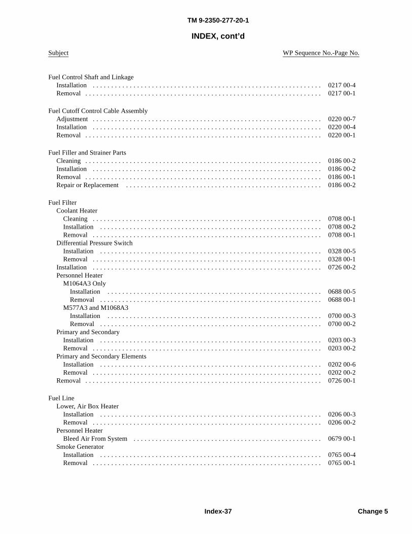
TM 9-2350-277-20-1
INDEX, cont’d
Subject WP Sequence No.-Page No.
Fuel Control Shaft and LinkageInstallation . . . . . . . . . . . . . . . . . . . . . . . . . . . . . . . . . . . . . . . . . . . . . . . . . . . . . . . . . . . . . . 0217 00-4Removal . . . . . . . . . . . . . . . . . . . . . . . . . . . . . . . . . . . . . . . . . . . . . . . . . . . . . . . . . . . . . . . . 0217 00-1
Fuel Cutoff Control Cable AssemblyAdjustment . . . . . . . . . . . . . . . . . . . . . . . . . . . . . . . . . . . . . . . . . . . . . . . . . . . . . . . . . . . . . . 0220 00-7Installation . . . . . . . . . . . . . . . . . . . . . . . . . . . . . . . . . . . . . . . . . . . . . . . . . . . . . . . . . . . . . . 0220 00-4Removal . . . . . . . . . . . . . . . . . . . . . . . . . . . . . . . . . . . . . . . . . . . . . . . . . . . . . . . . . . . . . . . . 0220 00-1
Fuel Filler and Strainer PartsCleaning . . . . . . . . . . . . . . . . . . . . . . . . . . . . . . . . . . . . . . . . . . . . . . . . . . . . . . . . . . . . . . . . 0186 00-2Installation . . . . . . . . . . . . . . . . . . . . . . . . . . . . . . . . . . . . . . . . . . . . . . . . . . . . . . . . . . . . . . 0186 00-2Removal . . . . . . . . . . . . . . . . . . . . . . . . . . . . . . . . . . . . . . . . . . . . . . . . . . . . . . . . . . . . . . . . 0186 00-1Repair or Replacement . . . . . . . . . . . . . . . . . . . . . . . . . . . . . . . . . . . . . . . . . . . . . . . . . . . . . 0186 00-2
Fuel FilterCoolant Heater
Cleaning . . . . . . . . . . . . . . . . . . . . . . . . . . . . . . . . . . . . . . . . . . . . . . . . . . . . . . . . . . . . . . 0708 00-1Installation . . . . . . . . . . . . . . . . . . . . . . . . . . . . . . . . . . . . . . . . . . . . . . . . . . . . . . . . . . . . 0708 00-2Removal . . . . . . . . . . . . . . . . . . . . . . . . . . . . . . . . . . . . . . . . . . . . . . . . . . . . . . . . . . . . . . 0708 00-1
Differential Pressure SwitchInstallation . . . . . . . . . . . . . . . . . . . . . . . . . . . . . . . . . . . . . . . . . . . . . . . . . . . . . . . . . . . . 0328 00-5Removal . . . . . . . . . . . . . . . . . . . . . . . . . . . . . . . . . . . . . . . . . . . . . . . . . . . . . . . . . . . . . . 0328 00-1
Installation . . . . . . . . . . . . . . . . . . . . . . . . . . . . . . . . . . . . . . . . . . . . . . . . . . . . . . . . . . . . . . 0726 00-2Personnel Heater
M1064A3 OnlyInstallation . . . . . . . . . . . . . . . . . . . . . . . . . . . . . . . . . . . . . . . . . . . . . . . . . . . . . . . . . . 0688 00-5Removal . . . . . . . . . . . . . . . . . . . . . . . . . . . . . . . . . . . . . . . . . . . . . . . . . . . . . . . . . . . . 0688 00-1
M577A3 and M1068A3Installation . . . . . . . . . . . . . . . . . . . . . . . . . . . . . . . . . . . . . . . . . . . . . . . . . . . . . . . . . . 0700 00-3Removal . . . . . . . . . . . . . . . . . . . . . . . . . . . . . . . . . . . . . . . . . . . . . . . . . . . . . . . . . . . . 0700 00-2
Primary and SecondaryInstallation . . . . . . . . . . . . . . . . . . . . . . . . . . . . . . . . . . . . . . . . . . . . . . . . . . . . . . . . . . . . 0203 00-3Removal . . . . . . . . . . . . . . . . . . . . . . . . . . . . . . . . . . . . . . . . . . . . . . . . . . . . . . . . . . . . . . 0203 00-2
Primary and Secondary ElementsInstallation . . . . . . . . . . . . . . . . . . . . . . . . . . . . . . . . . . . . . . . . . . . . . . . . . . . . . . . . . . . . 0202 00-6Removal . . . . . . . . . . . . . . . . . . . . . . . . . . . . . . . . . . . . . . . . . . . . . . . . . . . . . . . . . . . . . . 0202 00-2
Removal . . . . . . . . . . . . . . . . . . . . . . . . . . . . . . . . . . . . . . . . . . . . . . . . . . . . . . . . . . . . . . . . 0726 00-1
Fuel LineLower, Air Box Heater
Installation . . . . . . . . . . . . . . . . . . . . . . . . . . . . . . . . . . . . . . . . . . . . . . . . . . . . . . . . . . . . 0206 00-3Removal . . . . . . . . . . . . . . . . . . . . . . . . . . . . . . . . . . . . . . . . . . . . . . . . . . . . . . . . . . . . . . 0206 00-2
Personnel HeaterBleed Air From System . . . . . . . . . . . . . . . . . . . . . . . . . . . . . . . . . . . . . . . . . . . . . . . . . . . 0679 00-1
Smoke GeneratorInstallation . . . . . . . . . . . . . . . . . . . . . . . . . . . . . . . . . . . . . . . . . . . . . . . . . . . . . . . . . . . . 0765 00-4Removal . . . . . . . . . . . . . . . . . . . . . . . . . . . . . . . . . . . . . . . . . . . . . . . . . . . . . . . . . . . . . . 0765 00-1
Index-37 Change 5
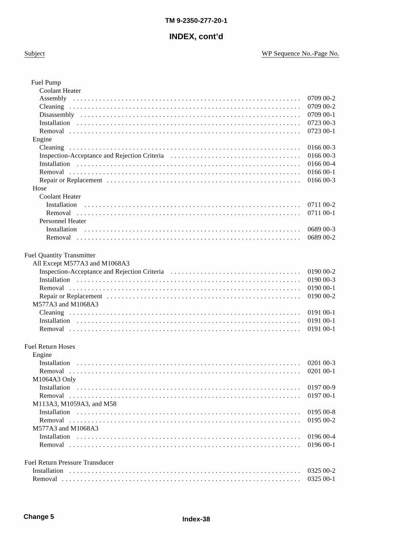
TM 9-2350-277-20-1
INDEX, cont’d
Subject WP Sequence No.-Page No.
Assembly . . . . . . . . . . . . . . . . . . . . . . . . . . . . . . . . . . . . . . . . . . . . . . . . . . . . . . . . . . . . . 0709 00-2Cleaning . . . . . . . . . . . . . . . . . . . . . . . . . . . . . . . . . . . . . . . . . . . . . . . . . . . . . . . . . . . . . . 0709 00-2Disassembly . . . . . . . . . . . . . . . . . . . . . . . . . . . . . . . . . . . . . . . . . . . . . . . . . . . . . . . . . . . 0709 00-1Installation . . . . . . . . . . . . . . . . . . . . . . . . . . . . . . . . . . . . . . . . . . . . . . . . . . . . . . . . . . . . 0723 00-3Removal . . . . . . . . . . . . . . . . . . . . . . . . . . . . . . . . . . . . . . . . . . . . . . . . . . . . . . . . . . . . . . 0723 00-1
EngineCleaning . . . . . . . . . . . . . . . . . . . . . . . . . . . . . . . . . . . . . . . . . . . . . . . . . . . . . . . . . . . . . . 0166 00-3Inspection-Acceptance and Rejection Criteria . . . . . . . . . . . . . . . . . . . . . . . . . . . . . . . . . . . 0166 00-3Installation . . . . . . . . . . . . . . . . . . . . . . . . . . . . . . . . . . . . . . . . . . . . . . . . . . . . . . . . . . . . 0166 00-4Removal . . . . . . . . . . . . . . . . . . . . . . . . . . . . . . . . . . . . . . . . . . . . . . . . . . . . . . . . . . . . . . 0166 00-1Repair or Replacement . . . . . . . . . . . . . . . . . . . . . . . . . . . . . . . . . . . . . . . . . . . . . . . . . . . . 0166 00-3
HoseCoolant Heater
Installation . . . . . . . . . . . . . . . . . . . . . . . . . . . . . . . . . . . . . . . . . . . . . . . . . . . . . . . . . . 0711 00-2Removal . . . . . . . . . . . . . . . . . . . . . . . . . . . . . . . . . . . . . . . . . . . . . . . . . . . . . . . . . . . . 0711 00-1
Personnel HeaterInstallation . . . . . . . . . . . . . . . . . . . . . . . . . . . . . . . . . . . . . . . . . . . . . . . . . . . . . . . . . . 0689 00-3Removal . . . . . . . . . . . . . . . . . . . . . . . . . . . . . . . . . . . . . . . . . . . . . . . . . . . . . . . . . . . . 0689 00-2
Fuel Quantity TransmitterAll Except M577A3 and M1068A3
Inspection-Acceptance and Rejection Criteria . . . . . . . . . . . . . . . . . . . . . . . . . . . . . . . . . . . 0190 00-2Installation . . . . . . . . . . . . . . . . . . . . . . . . . . . . . . . . . . . . . . . . . . . . . . . . . . . . . . . . . . . . 0190 00-3Removal . . . . . . . . . . . . . . . . . . . . . . . . . . . . . . . . . . . . . . . . . . . . . . . . . . . . . . . . . . . . . . 0190 00-1Repair or Replacement . . . . . . . . . . . . . . . . . . . . . . . . . . . . . . . . . . . . . . . . . . . . . . . . . . . . 0190 00-2
M577A3 and M1068A3Cleaning . . . . . . . . . . . . . . . . . . . . . . . . . . . . . . . . . . . . . . . . . . . . . . . . . . . . . . . . . . . . . . 0191 00-1Installation . . . . . . . . . . . . . . . . . . . . . . . . . . . . . . . . . . . . . . . . . . . . . . . . . . . . . . . . . . . . 0191 00-1Removal . . . . . . . . . . . . . . . . . . . . . . . . . . . . . . . . . . . . . . . . . . . . . . . . . . . . . . . . . . . . . . 0191 00-1
Fuel Return HosesEngine
Installation . . . . . . . . . . . . . . . . . . . . . . . . . . . . . . . . . . . . . . . . . . . . . . . . . . . . . . . . . . . . 0201 00-3Removal . . . . . . . . . . . . . . . . . . . . . . . . . . . . . . . . . . . . . . . . . . . . . . . . . . . . . . . . . . . . . . 0201 00-1
M1064A3 OnlyInstallation . . . . . . . . . . . . . . . . . . . . . . . . . . . . . . . . . . . . . . . . . . . . . . . . . . . . . . . . . . . . 0197 00-9Removal . . . . . . . . . . . . . . . . . . . . . . . . . . . . . . . . . . . . . . . . . . . . . . . . . . . . . . . . . . . . . . 0197 00-1
M113A3, M1059A3, and M58Installation . . . . . . . . . . . . . . . . . . . . . . . . . . . . . . . . . . . . . . . . . . . . . . . . . . . . . . . . . . . . 0195 00-8Removal . . . . . . . . . . . . . . . . . . . . . . . . . . . . . . . . . . . . . . . . . . . . . . . . . . . . . . . . . . . . . . 0195 00-2
M577A3 and M1068A3Installation . . . . . . . . . . . . . . . . . . . . . . . . . . . . . . . . . . . . . . . . . . . . . . . . . . . . . . . . . . . . 0196 00-4Removal . . . . . . . . . . . . . . . . . . . . . . . . . . . . . . . . . . . . . . . . . . . . . . . . . . . . . . . . . . . . . . 0196 00-1
Fuel Return Pressure TransducerInstallation . . . . . . . . . . . . . . . . . . . . . . . . . . . . . . . . . . . . . . . . . . . . . . . . . . . . . . . . . . . . . . 0325 00-2Removal . . . . . . . . . . . . . . . . . . . . . . . . . . . . . . . . . . . . . . . . . . . . . . . . . . . . . . . . . . . . . . . . 0325 00-1
Index-38Change 5
Fuel PumpCoolant Heater
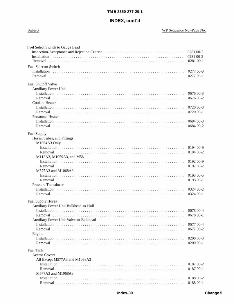
TM 9-2350-277-20-1
INDEX, cont’d
Subject WP Sequence No.-Page No.
Fuel Selector SwitchInstallation . . . . . . . . . . . . . . . . . . . . . . . . . . . . . . . . . . . . . . . . . . . . . . . . . . . . . . . . . . . . . . 0277 00-3Removal . . . . . . . . . . . . . . . . . . . . . . . . . . . . . . . . . . . . . . . . . . . . . . . . . . . . . . . . . . . . . . . . 0277 00-1
Fuel Shutoff ValveAuxiliary Power Unit
Installation . . . . . . . . . . . . . . . . . . . . . . . . . . . . . . . . . . . . . . . . . . . . . . . . . . . . . . . . . . . . 0676 00-3Removal . . . . . . . . . . . . . . . . . . . . . . . . . . . . . . . . . . . . . . . . . . . . . . . . . . . . . . . . . . . . . . 0676 00-2
Coolant HeaterInstallation . . . . . . . . . . . . . . . . . . . . . . . . . . . . . . . . . . . . . . . . . . . . . . . . . . . . . . . . . . . . 0720 00-3Removal . . . . . . . . . . . . . . . . . . . . . . . . . . . . . . . . . . . . . . . . . . . . . . . . . . . . . . . . . . . . . . 0720 00-1
Personnel HeaterInstallation . . . . . . . . . . . . . . . . . . . . . . . . . . . . . . . . . . . . . . . . . . . . . . . . . . . . . . . . . . . . 0684 00-3Removal . . . . . . . . . . . . . . . . . . . . . . . . . . . . . . . . . . . . . . . . . . . . . . . . . . . . . . . . . . . . . . 0684 00-2
Fuel SupplyHoses, Tubes, and Fittings
M1064A3 OnlyInstallation . . . . . . . . . . . . . . . . . . . . . . . . . . . . . . . . . . . . . . . . . . . . . . . . . . . . . . . . . . 0194 00-9Removal . . . . . . . . . . . . . . . . . . . . . . . . . . . . . . . . . . . . . . . . . . . . . . . . . . . . . . . . . . . . 0194 00-2
M113A3, M1059A3, and M58Installation . . . . . . . . . . . . . . . . . . . . . . . . . . . . . . . . . . . . . . . . . . . . . . . . . . . . . . . . . . 0192 00-9Removal . . . . . . . . . . . . . . . . . . . . . . . . . . . . . . . . . . . . . . . . . . . . . . . . . . . . . . . . . . . . 0192 00-2
M577A3 and M1068A3Installation . . . . . . . . . . . . . . . . . . . . . . . . . . . . . . . . . . . . . . . . . . . . . . . . . . . . . . . . . . 0193 00-5Removal . . . . . . . . . . . . . . . . . . . . . . . . . . . . . . . . . . . . . . . . . . . . . . . . . . . . . . . . . . . . 0193 00-1
Pressure TransducerInstallation . . . . . . . . . . . . . . . . . . . . . . . . . . . . . . . . . . . . . . . . . . . . . . . . . . . . . . . . . . . . 0324 00-2Removal . . . . . . . . . . . . . . . . . . . . . . . . . . . . . . . . . . . . . . . . . . . . . . . . . . . . . . . . . . . . . . 0324 00-1
Fuel Supply HosesAuxiliary Power Unit Bulkhead-to-Hull
Installation . . . . . . . . . . . . . . . . . . . . . . . . . . . . . . . . . . . . . . . . . . . . . . . . . . . . . . . . . . . . 0678 00-4Removal . . . . . . . . . . . . . . . . . . . . . . . . . . . . . . . . . . . . . . . . . . . . . . . . . . . . . . . . . . . . . . 0678 00-1
Auxiliary Power Unit Valve-to-BulkheadInstallation . . . . . . . . . . . . . . . . . . . . . . . . . . . . . . . . . . . . . . . . . . . . . . . . . . . . . . . . . . . . 0677 00-4Removal . . . . . . . . . . . . . . . . . . . . . . . . . . . . . . . . . . . . . . . . . . . . . . . . . . . . . . . . . . . . . . 0677 00-2
EngineInstallation . . . . . . . . . . . . . . . . . . . . . . . . . . . . . . . . . . . . . . . . . . . . . . . . . . . . . . . . . . . . 0200 00-3Removal . . . . . . . . . . . . . . . . . . . . . . . . . . . . . . . . . . . . . . . . . . . . . . . . . . . . . . . . . . . . . . 0200 00-1
Fuel TankAccess Covers
All Except M577A3 and M1068A3Installation . . . . . . . . . . . . . . . . . . . . . . . . . . . . . . . . . . . . . . . . . . . . . . . . . . . . . . . . . . 0187 00-2Removal . . . . . . . . . . . . . . . . . . . . . . . . . . . . . . . . . . . . . . . . . . . . . . . . . . . . . . . . . . . . 0187 00-1
M577A3 and M1068A3Installation . . . . . . . . . . . . . . . . . . . . . . . . . . . . . . . . . . . . . . . . . . . . . . . . . . . . . . . . . . 0188 00-2Removal . . . . . . . . . . . . . . . . . . . . . . . . . . . . . . . . . . . . . . . . . . . . . . . . . . . . . . . . . . . . 0188 00-1
Index-39 Change 5
Removal . . . . . . . . . . . . . . . . . . . . . . . . . . . . . . . . . . . . . . . . . . . . . . . . . . . . . . . . . . . . . . . . 0281 00-1
Fuel Select Switch to Gauge LeadInspection-Acceptance and Rejection Criteria . . . . . . . . . . . . . . . . . . . . . . . . . . . . . . . . . . . . . 0281 00-2Installation . . . . . . . . . . . . . . . . . . . . . . . . . . . . . . . . . . . . . . . . . . . . . . . . . . . . . . . . . . . . . . 0281 00-2
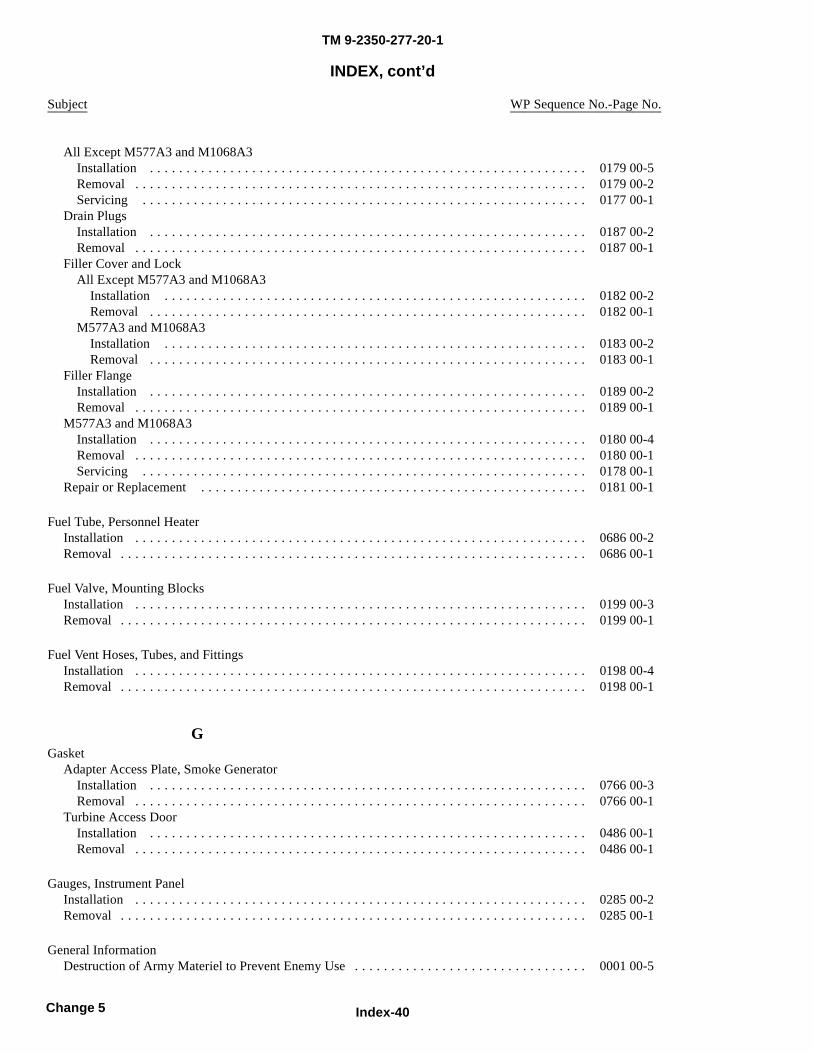
TM 9-2350-277-20-1
INDEX, cont’d
Subject WP Sequence No.-Page No.
All Except M577A3 and M1068A3Installation . . . . . . . . . . . . . . . . . . . . . . . . . . . . . . . . . . . . . . . . . . . . . . . . . . . . . . . . . . . . 0179 00-5Removal . . . . . . . . . . . . . . . . . . . . . . . . . . . . . . . . . . . . . . . . . . . . . . . . . . . . . . . . . . . . . . 0179 00-2Servicing . . . . . . . . . . . . . . . . . . . . . . . . . . . . . . . . . . . . . . . . . . . . . . . . . . . . . . . . . . . . . 0177 00-1
Drain PlugsInstallation . . . . . . . . . . . . . . . . . . . . . . . . . . . . . . . . . . . . . . . . . . . . . . . . . . . . . . . . . . . . 0187 00-2Removal . . . . . . . . . . . . . . . . . . . . . . . . . . . . . . . . . . . . . . . . . . . . . . . . . . . . . . . . . . . . . . 0187 00-1
Filler Cover and LockAll Except M577A3 and M1068A3
Installation . . . . . . . . . . . . . . . . . . . . . . . . . . . . . . . . . . . . . . . . . . . . . . . . . . . . . . . . . . 0182 00-2Removal . . . . . . . . . . . . . . . . . . . . . . . . . . . . . . . . . . . . . . . . . . . . . . . . . . . . . . . . . . . . 0182 00-1
M577A3 and M1068A3Installation . . . . . . . . . . . . . . . . . . . . . . . . . . . . . . . . . . . . . . . . . . . . . . . . . . . . . . . . . . 0183 00-2Removal . . . . . . . . . . . . . . . . . . . . . . . . . . . . . . . . . . . . . . . . . . . . . . . . . . . . . . . . . . . . 0183 00-1
Filler FlangeInstallation . . . . . . . . . . . . . . . . . . . . . . . . . . . . . . . . . . . . . . . . . . . . . . . . . . . . . . . . . . . . 0189 00-2Removal . . . . . . . . . . . . . . . . . . . . . . . . . . . . . . . . . . . . . . . . . . . . . . . . . . . . . . . . . . . . . . 0189 00-1
M577A3 and M1068A3Installation . . . . . . . . . . . . . . . . . . . . . . . . . . . . . . . . . . . . . . . . . . . . . . . . . . . . . . . . . . . . 0180 00-4Removal . . . . . . . . . . . . . . . . . . . . . . . . . . . . . . . . . . . . . . . . . . . . . . . . . . . . . . . . . . . . . . 0180 00-1Servicing . . . . . . . . . . . . . . . . . . . . . . . . . . . . . . . . . . . . . . . . . . . . . . . . . . . . . . . . . . . . . 0178 00-1
Repair or Replacement . . . . . . . . . . . . . . . . . . . . . . . . . . . . . . . . . . . . . . . . . . . . . . . . . . . . . 0181 00-1
Fuel Tube, Personnel HeaterInstallation . . . . . . . . . . . . . . . . . . . . . . . . . . . . . . . . . . . . . . . . . . . . . . . . . . . . . . . . . . . . . . 0686 00-2Removal . . . . . . . . . . . . . . . . . . . . . . . . . . . . . . . . . . . . . . . . . . . . . . . . . . . . . . . . . . . . . . . . 0686 00-1
Fuel Valve, Mounting BlocksInstallation . . . . . . . . . . . . . . . . . . . . . . . . . . . . . . . . . . . . . . . . . . . . . . . . . . . . . . . . . . . . . . 0199 00-3Removal . . . . . . . . . . . . . . . . . . . . . . . . . . . . . . . . . . . . . . . . . . . . . . . . . . . . . . . . . . . . . . . . 0199 00-1
Fuel Vent Hoses, Tubes, and FittingsInstallation . . . . . . . . . . . . . . . . . . . . . . . . . . . . . . . . . . . . . . . . . . . . . . . . . . . . . . . . . . . . . . 0198 00-4Removal . . . . . . . . . . . . . . . . . . . . . . . . . . . . . . . . . . . . . . . . . . . . . . . . . . . . . . . . . . . . . . . . 0198 00-1
GGasket
Adapter Access Plate, Smoke GeneratorInstallation . . . . . . . . . . . . . . . . . . . . . . . . . . . . . . . . . . . . . . . . . . . . . . . . . . . . . . . . . . . . 0766 00-3Removal . . . . . . . . . . . . . . . . . . . . . . . . . . . . . . . . . . . . . . . . . . . . . . . . . . . . . . . . . . . . . . 0766 00-1
Turbine Access DoorInstallation . . . . . . . . . . . . . . . . . . . . . . . . . . . . . . . . . . . . . . . . . . . . . . . . . . . . . . . . . . . . 0486 00-1Removal . . . . . . . . . . . . . . . . . . . . . . . . . . . . . . . . . . . . . . . . . . . . . . . . . . . . . . . . . . . . . . 0486 00-1
Gauges, Instrument PanelInstallation . . . . . . . . . . . . . . . . . . . . . . . . . . . . . . . . . . . . . . . . . . . . . . . . . . . . . . . . . . . . . . 0285 00-2Removal . . . . . . . . . . . . . . . . . . . . . . . . . . . . . . . . . . . . . . . . . . . . . . . . . . . . . . . . . . . . . . . . 0285 00-1
General InformationDestruction of Army Materiel to Prevent Enemy Use . . . . . . . . . . . . . . . . . . . . . . . . . . . . . . . . 0001 00-5
Index-40Change 5
TM 9-2350-277-20-1
INDEX, cont’d
Subject WP Sequence No.-Page No.
List of Abbreviations/Acronyms . . . . . . . . . . . . . . . . . . . . . . . . . . . . . . . . . . . . . . . . . . . . . . . 0001 00-7Maintenance Forms, Records, and Reports . . . . . . . . . . . . . . . . . . . . . . . . . . . . . . . . . . . . . . . 0001 00-5Metric Equivalents . . . . . . . . . . . . . . . . . . . . . . . . . . . . . . . . . . . . . . . . . . . . . . . . . . . . . . . . 0001 00-8Nomenclature Cross-Reference . . . . . . . . . . . . . . . . . . . . . . . . . . . . . . . . . . . . . . . . . . . . . . . 0001 00-5Preparation for Storage or Shipment . . . . . . . . . . . . . . . . . . . . . . . . . . . . . . . . . . . . . . . . . . . . 0001 00-5Reporting Equipment Improvement Recommendations (EIR) . . . . . . . . . . . . . . . . . . . . . . . . . . 0001 00-5Safety, Care, and Handling . . . . . . . . . . . . . . . . . . . . . . . . . . . . . . . . . . . . . . . . . . . . . . . . . . . 0001 00-9Scope . . . . . . . . . . . . . . . . . . . . . . . . . . . . . . . . . . . . . . . . . . . . . . . . . . . . . . . . . . . . . . . . . . 0001 00-1
GeneratorDrive Belt
Adjustment . . . . . . . . . . . . . . . . . . . . . . . . . . . . . . . . . . . . . . . . . . . . . . . . . . . . . . . . . . . . 0252 00-2Installation . . . . . . . . . . . . . . . . . . . . . . . . . . . . . . . . . . . . . . . . . . . . . . . . . . . . . . . . . . . . 0253 00-1Removal . . . . . . . . . . . . . . . . . . . . . . . . . . . . . . . . . . . . . . . . . . . . . . . . . . . . . . . . . . . . . . 0253 00-1
Field Pressure SwitchInspection-Acceptance and Rejection Criteria . . . . . . . . . . . . . . . . . . . . . . . . . . . . . . . . . . . 0323 00-1Installation . . . . . . . . . . . . . . . . . . . . . . . . . . . . . . . . . . . . . . . . . . . . . . . . . . . . . . . . . . . . 0323 00-2Removal . . . . . . . . . . . . . . . . . . . . . . . . . . . . . . . . . . . . . . . . . . . . . . . . . . . . . . . . . . . . . . 0323 00-1
Installation . . . . . . . . . . . . . . . . . . . . . . . . . . . . . . . . . . . . . . . . . . . . . . . . . . . . . . . . . . . . . . 0255 00-4Removal . . . . . . . . . . . . . . . . . . . . . . . . . . . . . . . . . . . . . . . . . . . . . . . . . . . . . . . . . . . . . . . . 0255 00-1Turnbuckle Parts
Installation . . . . . . . . . . . . . . . . . . . . . . . . . . . . . . . . . . . . . . . . . . . . . . . . . . . . . . . . . . . . 0254 00-2Removal . . . . . . . . . . . . . . . . . . . . . . . . . . . . . . . . . . . . . . . . . . . . . . . . . . . . . . . . . . . . . . 0254 00-1
Variable Speed DriveInstallation . . . . . . . . . . . . . . . . . . . . . . . . . . . . . . . . . . . . . . . . . . . . . . . . . . . . . . . . . . . . 0249 00-3Removal . . . . . . . . . . . . . . . . . . . . . . . . . . . . . . . . . . . . . . . . . . . . . . . . . . . . . . . . . . . . . . 0249 00-2
Generator Set, EnclosureInstallation . . . . . . . . . . . . . . . . . . . . . . . . . . . . . . . . . . . . . . . . . . . . . . . . . . . . . . . . . . . . . . 0674 00-3Removal . . . . . . . . . . . . . . . . . . . . . . . . . . . . . . . . . . . . . . . . . . . . . . . . . . . . . . . . . . . . . . . . 0674 00-2
Glow PlugCable Assembly, Smoke Generator
Installation . . . . . . . . . . . . . . . . . . . . . . . . . . . . . . . . . . . . . . . . . . . . . . . . . . . . . . . . . . . . 0772 00-4Removal . . . . . . . . . . . . . . . . . . . . . . . . . . . . . . . . . . . . . . . . . . . . . . . . . . . . . . . . . . . . . . 0772 00-2
ControllerInstallation . . . . . . . . . . . . . . . . . . . . . . . . . . . . . . . . . . . . . . . . . . . . . . . . . . . . . . . . . . . . 0210 00-3Removal . . . . . . . . . . . . . . . . . . . . . . . . . . . . . . . . . . . . . . . . . . . . . . . . . . . . . . . . . . . . . . 0210 00-1
Controller Mounting BracketInstallation . . . . . . . . . . . . . . . . . . . . . . . . . . . . . . . . . . . . . . . . . . . . . . . . . . . . . . . . . . . . 0212 00-2Removal . . . . . . . . . . . . . . . . . . . . . . . . . . . . . . . . . . . . . . . . . . . . . . . . . . . . . . . . . . . . . . 0212 00-1
Harness and Glow PlugsInstallation . . . . . . . . . . . . . . . . . . . . . . . . . . . . . . . . . . . . . . . . . . . . . . . . . . . . . . . . . . . . 0209 00-3Removal . . . . . . . . . . . . . . . . . . . . . . . . . . . . . . . . . . . . . . . . . . . . . . . . . . . . . . . . . . . . . . 0209 00-1
Power HarnessInstallation . . . . . . . . . . . . . . . . . . . . . . . . . . . . . . . . . . . . . . . . . . . . . . . . . . . . . . . . . . . . 0211 00-2Removal . . . . . . . . . . . . . . . . . . . . . . . . . . . . . . . . . . . . . . . . . . . . . . . . . . . . . . . . . . . . . . 0211 00-1
Governor AssemblyInstallation . . . . . . . . . . . . . . . . . . . . . . . . . . . . . . . . . . . . . . . . . . . . . . . . . . . . . . . . . . . . . . 0397 00-2Removal . . . . . . . . . . . . . . . . . . . . . . . . . . . . . . . . . . . . . . . . . . . . . . . . . . . . . . . . . . . . . . . . 0397 00-1
Index-41 Change 5
TM 9-2350-277-20-1
INDEX, cont’d
Subject WP Sequence No.-Page No.
Grenade Stowage BoxInstallation . . . . . . . . . . . . . . . . . . . . . . . . . . . . . . . . . . . . . . . . . . . . . . . . . . . . . . . . . . . . . . 0610 00-1Removal . . . . . . . . . . . . . . . . . . . . . . . . . . . . . . . . . . . . . . . . . . . . . . . . . . . . . . . . . . . . . . . . 0610 00-1
GrillAir Intake Elbow and Hose
Installation . . . . . . . . . . . . . . . . . . . . . . . . . . . . . . . . . . . . . . . . . . . . . . . . . . . . . . . . . . . . 0174 00-2Removal . . . . . . . . . . . . . . . . . . . . . . . . . . . . . . . . . . . . . . . . . . . . . . . . . . . . . . . . . . . . . . 0174 00-1
Power PlantInstallation . . . . . . . . . . . . . . . . . . . . . . . . . . . . . . . . . . . . . . . . . . . . . . . . . . . . . . . . . . . . 0465 00-3Lower . . . . . . . . . . . . . . . . . . . . . . . . . . . . . . . . . . . . . . . . . . . . . . . . . . . . . . . . . . . . . . . . 0464 00-9Raise . . . . . . . . . . . . . . . . . . . . . . . . . . . . . . . . . . . . . . . . . . . . . . . . . . . . . . . . . . . . . . . . 0464 00-2Removal . . . . . . . . . . . . . . . . . . . . . . . . . . . . . . . . . . . . . . . . . . . . . . . . . . . . . . . . . . . . . . 0465 00-1
Support ArmInstallation . . . . . . . . . . . . . . . . . . . . . . . . . . . . . . . . . . . . . . . . . . . . . . . . . . . . . . . . . . . . 0467 00-2Removal . . . . . . . . . . . . . . . . . . . . . . . . . . . . . . . . . . . . . . . . . . . . . . . . . . . . . . . . . . . . . . 0467 00-1
Ground LeadAuxiliary Power (Slave) Receptacle
Installation . . . . . . . . . . . . . . . . . . . . . . . . . . . . . . . . . . . . . . . . . . . . . . . . . . . . . . . . . . . . 0379 00-3Removal . . . . . . . . . . . . . . . . . . . . . . . . . . . . . . . . . . . . . . . . . . . . . . . . . . . . . . . . . . . . . . 0379 00-1
HornInstallation . . . . . . . . . . . . . . . . . . . . . . . . . . . . . . . . . . . . . . . . . . . . . . . . . . . . . . . . . . . . 0336 00-3Removal . . . . . . . . . . . . . . . . . . . . . . . . . . . . . . . . . . . . . . . . . . . . . . . . . . . . . . . . . . . . . . 0336 00-1
Ground Strap, W12Installation . . . . . . . . . . . . . . . . . . . . . . . . . . . . . . . . . . . . . . . . . . . . . . . . . . . . . . . . . . . . . . 0846 00-2Removal . . . . . . . . . . . . . . . . . . . . . . . . . . . . . . . . . . . . . . . . . . . . . . . . . . . . . . . . . . . . . . . . 0846 00-1
GuardAntenna
Installation . . . . . . . . . . . . . . . . . . . . . . . . . . . . . . . . . . . . . . . . . . . . . . . . . . . . . . . . . . . . 0575 00-2Removal . . . . . . . . . . . . . . . . . . . . . . . . . . . . . . . . . . . . . . . . . . . . . . . . . . . . . . . . . . . . . . 0575 00-1
Driver’s Hatch Night VisionAll Except M58
Installation . . . . . . . . . . . . . . . . . . . . . . . . . . . . . . . . . . . . . . . . . . . . . . . . . . . . . . . . . . 0536 00-1Removal . . . . . . . . . . . . . . . . . . . . . . . . . . . . . . . . . . . . . . . . . . . . . . . . . . . . . . . . . . . . 0536 00-1
M58 OnlyInstallation . . . . . . . . . . . . . . . . . . . . . . . . . . . . . . . . . . . . . . . . . . . . . . . . . . . . . . . . . . 0536 01-2Removal . . . . . . . . . . . . . . . . . . . . . . . . . . . . . . . . . . . . . . . . . . . . . . . . . . . . . . . . . . . . 0536 01-1
HeadlightInstallation . . . . . . . . . . . . . . . . . . . . . . . . . . . . . . . . . . . . . . . . . . . . . . . . . . . . . . . . . . . . 0446 00-2Removal . . . . . . . . . . . . . . . . . . . . . . . . . . . . . . . . . . . . . . . . . . . . . . . . . . . . . . . . . . . . . . 0446 00-1
Stoplight-TaillightInstallation . . . . . . . . . . . . . . . . . . . . . . . . . . . . . . . . . . . . . . . . . . . . . . . . . . . . . . . . . . . . 0298 00-4Removal . . . . . . . . . . . . . . . . . . . . . . . . . . . . . . . . . . . . . . . . . . . . . . . . . . . . . . . . . . . . . . 0298 00-1
Index-42Change 5
TM 9-2350-277-20-1
INDEX, cont’d
Subject WP Sequence No.-Page No.
Installation . . . . . . . . . . . . . . . . . . . . . . . . . . . . . . . . . . . . . . . . . . . . . . . . . . . . . . . . . . . . . . 0219 00-4Removal . . . . . . . . . . . . . . . . . . . . . . . . . . . . . . . . . . . . . . . . . . . . . . . . . . . . . . . . . . . . . . . . 0219 00-1
Handle and Arms, Ramp LockInstallation . . . . . . . . . . . . . . . . . . . . . . . . . . . . . . . . . . . . . . . . . . . . . . . . . . . . . . . . . . . . . . 0524 00-2Removal . . . . . . . . . . . . . . . . . . . . . . . . . . . . . . . . . . . . . . . . . . . . . . . . . . . . . . . . . . . . . . . . 0524 00-1
HarnessCascade Remote
Installation . . . . . . . . . . . . . . . . . . . . . . . . . . . . . . . . . . . . . . . . . . . . . . . . . . . . . . . . . . . . 0847 00-3Removal . . . . . . . . . . . . . . . . . . . . . . . . . . . . . . . . . . . . . . . . . . . . . . . . . . . . . . . . . . . . . . 0847 00-1
W32Installation . . . . . . . . . . . . . . . . . . . . . . . . . . . . . . . . . . . . . . . . . . . . . . . . . . . . . . . . . . . . 0848 00-4Removal . . . . . . . . . . . . . . . . . . . . . . . . . . . . . . . . . . . . . . . . . . . . . . . . . . . . . . . . . . . . . . 0848 00-1
Hatch, Mortar, Interior Release MechanismInstallation . . . . . . . . . . . . . . . . . . . . . . . . . . . . . . . . . . . . . . . . . . . . . . . . . . . . . . . . . . . . . . 0481 00-3Removal . . . . . . . . . . . . . . . . . . . . . . . . . . . . . . . . . . . . . . . . . . . . . . . . . . . . . . . . . . . . . . . . 0481 00-1
HeadlightBlackout
Assembly . . . . . . . . . . . . . . . . . . . . . . . . . . . . . . . . . . . . . . . . . . . . . . . . . . . . . . . . . . . . . 0306 00-2Disassembly . . . . . . . . . . . . . . . . . . . . . . . . . . . . . . . . . . . . . . . . . . . . . . . . . . . . . . . . . . . 0306 00-1Installation . . . . . . . . . . . . . . . . . . . . . . . . . . . . . . . . . . . . . . . . . . . . . . . . . . . . . . . . . . . . 0305 00-2Removal . . . . . . . . . . . . . . . . . . . . . . . . . . . . . . . . . . . . . . . . . . . . . . . . . . . . . . . . . . . . . . 0305 00-1
GuardInstallation . . . . . . . . . . . . . . . . . . . . . . . . . . . . . . . . . . . . . . . . . . . . . . . . . . . . . . . . . . . . 0446 00-2Removal . . . . . . . . . . . . . . . . . . . . . . . . . . . . . . . . . . . . . . . . . . . . . . . . . . . . . . . . . . . . . . 0446 00-1
High Beam Selector SwitchInstallation . . . . . . . . . . . . . . . . . . . . . . . . . . . . . . . . . . . . . . . . . . . . . . . . . . . . . . . . . . . . 0333 00-2Removal . . . . . . . . . . . . . . . . . . . . . . . . . . . . . . . . . . . . . . . . . . . . . . . . . . . . . . . . . . . . . . 0333 00-1
ServiceAssembly . . . . . . . . . . . . . . . . . . . . . . . . . . . . . . . . . . . . . . . . . . . . . . . . . . . . . . . . . . . . . 0304 00-3Disassembly . . . . . . . . . . . . . . . . . . . . . . . . . . . . . . . . . . . . . . . . . . . . . . . . . . . . . . . . . . . 0304 00-2Inspection . . . . . . . . . . . . . . . . . . . . . . . . . . . . . . . . . . . . . . . . . . . . . . . . . . . . . . . . . . . . . 0304 00-1Installation . . . . . . . . . . . . . . . . . . . . . . . . . . . . . . . . . . . . . . . . . . . . . . . . . . . . . . . . . . . . 0303 00-2Removal . . . . . . . . . . . . . . . . . . . . . . . . . . . . . . . . . . . . . . . . . . . . . . . . . . . . . . . . . . . . . . 0303 00-1
Wiring Harness, RightInspect and Repair . . . . . . . . . . . . . . . . . . . . . . . . . . . . . . . . . . . . . . . . . . . . . . . . . . . . . . . 0373 00-3Installation . . . . . . . . . . . . . . . . . . . . . . . . . . . . . . . . . . . . . . . . . . . . . . . . . . . . . . . . . . . . 0373 00-3Removal . . . . . . . . . . . . . . . . . . . . . . . . . . . . . . . . . . . . . . . . . . . . . . . . . . . . . . . . . . . . . . 0373 00-1
Heat ExchangerBattery Box
Installation . . . . . . . . . . . . . . . . . . . . . . . . . . . . . . . . . . . . . . . . . . . . . . . . . . . . . . . . . . . . 0718 00-2Removal . . . . . . . . . . . . . . . . . . . . . . . . . . . . . . . . . . . . . . . . . . . . . . . . . . . . . . . . . . . . . . 0718 00-1
Battery DrawerCleaning . . . . . . . . . . . . . . . . . . . . . . . . . . . . . . . . . . . . . . . . . . . . . . . . . . . . . . . . . . . . . . 0719 00-2Inspection-Acceptance and Rejection Criteria . . . . . . . . . . . . . . . . . . . . . . . . . . . . . . . . . . . 0719 00-2Installation . . . . . . . . . . . . . . . . . . . . . . . . . . . . . . . . . . . . . . . . . . . . . . . . . . . . . . . . . . . . 0719 00-2Removal . . . . . . . . . . . . . . . . . . . . . . . . . . . . . . . . . . . . . . . . . . . . . . . . . . . . . . . . . . . . . . 0719 00-1
Index-43 Change 5
HHand Throttle Control Cable
TM 9-2350-277-20-1
INDEX, cont’d
Subject WP Sequence No.-Page No.
Heat Shield, Turbo Exhaust Pipe, Left/RightInstallation . . . . . . . . . . . . . . . . . . . . . . . . . . . . . . . . . . . . . . . . . . . . . . . . . . . . . . . . . . . . . . 0226 00-3Removal . . . . . . . . . . . . . . . . . . . . . . . . . . . . . . . . . . . . . . . . . . . . . . . . . . . . . . . . . . . . . . . . 0226 00-1
Heater, Water/Ration Mount BracketInstallation . . . . . . . . . . . . . . . . . . . . . . . . . . . . . . . . . . . . . . . . . . . . . . . . . . . . . . . . . . . . . . 0811 00-2Removal . . . . . . . . . . . . . . . . . . . . . . . . . . . . . . . . . . . . . . . . . . . . . . . . . . . . . . . . . . . . . . . . 0811 00-1
Hinges, Turbine Access DoorInstallation . . . . . . . . . . . . . . . . . . . . . . . . . . . . . . . . . . . . . . . . . . . . . . . . . . . . . . . . . . . . . . 0487 00-3Removal . . . . . . . . . . . . . . . . . . . . . . . . . . . . . . . . . . . . . . . . . . . . . . . . . . . . . . . . . . . . . . . . 0487 00-2
Hold-Open Hook and BumperCargo Hatch
Installation . . . . . . . . . . . . . . . . . . . . . . . . . . . . . . . . . . . . . . . . . . . . . . . . . . . . . . . . . . . . 0474 00-3Removal . . . . . . . . . . . . . . . . . . . . . . . . . . . . . . . . . . . . . . . . . . . . . . . . . . . . . . . . . . . . . . 0474 00-2
Commander’s CupolaInstallation . . . . . . . . . . . . . . . . . . . . . . . . . . . . . . . . . . . . . . . . . . . . . . . . . . . . . . . . . . . . 0494 00-2Removal . . . . . . . . . . . . . . . . . . . . . . . . . . . . . . . . . . . . . . . . . . . . . . . . . . . . . . . . . . . . . . 0494 00-1
Driver’s HatchM113A3, M1059A3, M1064A3, and M58
Installation . . . . . . . . . . . . . . . . . . . . . . . . . . . . . . . . . . . . . . . . . . . . . . . . . . . . . . . . . . 0532 00-2Removal . . . . . . . . . . . . . . . . . . . . . . . . . . . . . . . . . . . . . . . . . . . . . . . . . . . . . . . . . . . . 0532 00-1
M577A3 and M1068A3Cleaning . . . . . . . . . . . . . . . . . . . . . . . . . . . . . . . . . . . . . . . . . . . . . . . . . . . . . . . . . . . . 0533 00-2Installation . . . . . . . . . . . . . . . . . . . . . . . . . . . . . . . . . . . . . . . . . . . . . . . . . . . . . . . . . . 0533 00-3Removal . . . . . . . . . . . . . . . . . . . . . . . . . . . . . . . . . . . . . . . . . . . . . . . . . . . . . . . . . . . . 0533 00-1Repair or Replacement . . . . . . . . . . . . . . . . . . . . . . . . . . . . . . . . . . . . . . . . . . . . . . . . . . 0533 00-2
Hook and Bumper, Commander’s HatchInstallation . . . . . . . . . . . . . . . . . . . . . . . . . . . . . . . . . . . . . . . . . . . . . . . . . . . . . . . . . . . . . . 0501 00-4Removal . . . . . . . . . . . . . . . . . . . . . . . . . . . . . . . . . . . . . . . . . . . . . . . . . . . . . . . . . . . . . . . . 0501 00-2
Hopper HatchAdjustment . . . . . . . . . . . . . . . . . . . . . . . . . . . . . . . . . . . . . . . . . . . . . . . . . . . . . . . . . . . . . . 0484 00-4Installation . . . . . . . . . . . . . . . . . . . . . . . . . . . . . . . . . . . . . . . . . . . . . . . . . . . . . . . . . . . . . . 0484 00-3Lock Assembly
Adjustment . . . . . . . . . . . . . . . . . . . . . . . . . . . . . . . . . . . . . . . . . . . . . . . . . . . . . . . . . . . . 0483 00-2Assembly . . . . . . . . . . . . . . . . . . . . . . . . . . . . . . . . . . . . . . . . . . . . . . . . . . . . . . . . . . . . . 0483 00-2Disassembly . . . . . . . . . . . . . . . . . . . . . . . . . . . . . . . . . . . . . . . . . . . . . . . . . . . . . . . . . . . 0483 00-1
Removal . . . . . . . . . . . . . . . . . . . . . . . . . . . . . . . . . . . . . . . . . . . . . . . . . . . . . . . . . . . . . . . . 0484 00-1
Horizontal Ammunition RackAssembly . . . . . . . . . . . . . . . . . . . . . . . . . . . . . . . . . . . . . . . . . . . . . . . . . . . . . . . . . . . . . . . 0607 00-4Cleaning . . . . . . . . . . . . . . . . . . . . . . . . . . . . . . . . . . . . . . . . . . . . . . . . . . . . . . . . . . . . . . . . 0607 00-4Disassembly . . . . . . . . . . . . . . . . . . . . . . . . . . . . . . . . . . . . . . . . . . . . . . . . . . . . . . . . . . . . . 0607 00-1Inspection-Acceptance and Rejection Criteria . . . . . . . . . . . . . . . . . . . . . . . . . . . . . . . . . . . . . 0607 00-4Installation . . . . . . . . . . . . . . . . . . . . . . . . . . . . . . . . . . . . . . . . . . . . . . . . . . . . . . . . . . . . . . 0606 00-2Removal . . . . . . . . . . . . . . . . . . . . . . . . . . . . . . . . . . . . . . . . . . . . . . . . . . . . . . . . . . . . . . . . 0606 00-1
Index-44Change 5
TM 9-2350-277-20-1
INDEX, cont’d
Subject WP Sequence No.-Page No.
HornGround Lead
Installation . . . . . . . . . . . . . . . . . . . . . . . . . . . . . . . . . . . . . . . . . . . . . . . . . . . . . . . . . . . . 0336 00-3Removal . . . . . . . . . . . . . . . . . . . . . . . . . . . . . . . . . . . . . . . . . . . . . . . . . . . . . . . . . . . . . . 0336 00-1
SwitchAll Except M58
Installation . . . . . . . . . . . . . . . . . . . . . . . . . . . . . . . . . . . . . . . . . . . . . . . . . . . . . . . . . . 0293 00-2Removal . . . . . . . . . . . . . . . . . . . . . . . . . . . . . . . . . . . . . . . . . . . . . . . . . . . . . . . . . . . . 0293 00-1
M58 OnlyInstallation . . . . . . . . . . . . . . . . . . . . . . . . . . . . . . . . . . . . . . . . . . . . . . . . . . . . . . . . . . 0293 01-2Removal . . . . . . . . . . . . . . . . . . . . . . . . . . . . . . . . . . . . . . . . . . . . . . . . . . . . . . . . . . . . 0293 01-1
HoseAuxiliary Power Unit Bulkhead-to-Hull Fuel Supply
Installation . . . . . . . . . . . . . . . . . . . . . . . . . . . . . . . . . . . . . . . . . . . . . . . . . . . . . . . . . . . . 0678 00-4Removal . . . . . . . . . . . . . . . . . . . . . . . . . . . . . . . . . . . . . . . . . . . . . . . . . . . . . . . . . . . . . . 0678 00-1
Battery Plate to Battery PlateInstallation . . . . . . . . . . . . . . . . . . . . . . . . . . . . . . . . . . . . . . . . . . . . . . . . . . . . . . . . . . . . 0722 00-2Removal . . . . . . . . . . . . . . . . . . . . . . . . . . . . . . . . . . . . . . . . . . . . . . . . . . . . . . . . . . . . . . 0722 00-1
Bulkhead to Ramp CylinderInstallation . . . . . . . . . . . . . . . . . . . . . . . . . . . . . . . . . . . . . . . . . . . . . . . . . . . . . . . . . . . . 0665 00-2Removal . . . . . . . . . . . . . . . . . . . . . . . . . . . . . . . . . . . . . . . . . . . . . . . . . . . . . . . . . . . . . . 0665 00-1
Coolant HeaterEngine to Battery Box
Installation . . . . . . . . . . . . . . . . . . . . . . . . . . . . . . . . . . . . . . . . . . . . . . . . . . . . . . . . . . 0714 00-4Removal . . . . . . . . . . . . . . . . . . . . . . . . . . . . . . . . . . . . . . . . . . . . . . . . . . . . . . . . . . . . 0714 00-2
Filter ValveInstallation . . . . . . . . . . . . . . . . . . . . . . . . . . . . . . . . . . . . . . . . . . . . . . . . . . . . . . . . . . 0716 00-2Removal . . . . . . . . . . . . . . . . . . . . . . . . . . . . . . . . . . . . . . . . . . . . . . . . . . . . . . . . . . . . 0716 00-1
Fuel InletInstallation . . . . . . . . . . . . . . . . . . . . . . . . . . . . . . . . . . . . . . . . . . . . . . . . . . . . . . . . . . 0712 00-3Removal . . . . . . . . . . . . . . . . . . . . . . . . . . . . . . . . . . . . . . . . . . . . . . . . . . . . . . . . . . . . 0712 00-1
Fuel PumpInstallation . . . . . . . . . . . . . . . . . . . . . . . . . . . . . . . . . . . . . . . . . . . . . . . . . . . . . . . . . . 0711 00-2Removal . . . . . . . . . . . . . . . . . . . . . . . . . . . . . . . . . . . . . . . . . . . . . . . . . . . . . . . . . . . . 0711 00-1
Pump to Battery BoxInstallation . . . . . . . . . . . . . . . . . . . . . . . . . . . . . . . . . . . . . . . . . . . . . . . . . . . . . . . . . . 0713 00-3Removal . . . . . . . . . . . . . . . . . . . . . . . . . . . . . . . . . . . . . . . . . . . . . . . . . . . . . . . . . . . . 0713 00-1
Coolant Heater to Engine ElbowInstallation . . . . . . . . . . . . . . . . . . . . . . . . . . . . . . . . . . . . . . . . . . . . . . . . . . . . . . . . . . . . 0715 00-2Removal . . . . . . . . . . . . . . . . . . . . . . . . . . . . . . . . . . . . . . . . . . . . . . . . . . . . . . . . . . . . . . 0715 00-1
Coolant Heater to Surge TankInstallation . . . . . . . . . . . . . . . . . . . . . . . . . . . . . . . . . . . . . . . . . . . . . . . . . . . . . . . . . . . . 0725 00-1Removal . . . . . . . . . . . . . . . . . . . . . . . . . . . . . . . . . . . . . . . . . . . . . . . . . . . . . . . . . . . . . . 0725 00-1
EngineFuel Return
Installation . . . . . . . . . . . . . . . . . . . . . . . . . . . . . . . . . . . . . . . . . . . . . . . . . . . . . . . . . . 0201 00-3Removal . . . . . . . . . . . . . . . . . . . . . . . . . . . . . . . . . . . . . . . . . . . . . . . . . . . . . . . . . . . . 0201 00-1
Fuel SupplyInstallation . . . . . . . . . . . . . . . . . . . . . . . . . . . . . . . . . . . . . . . . . . . . . . . . . . . . . . . . . . 0200 00-3Removal . . . . . . . . . . . . . . . . . . . . . . . . . . . . . . . . . . . . . . . . . . . . . . . . . . . . . . . . . . . . 0200 00-1
Index-45 Change 5
TM 9-2350-277-20-1
INDEX, cont’d
Subject WP Sequence No.-Page No.
Fuel Pump Tee to ElbowInstallation . . . . . . . . . . . . . . . . . . . . . . . . . . . . . . . . . . . . . . . . . . . . . . . . . . . . . . . . . . . . 0721 00-3Removal . . . . . . . . . . . . . . . . . . . . . . . . . . . . . . . . . . . . . . . . . . . . . . . . . . . . . . . . . . . . . . 0721 00-1
Fuel Pump to Bulkhead ConnectionInstallation . . . . . . . . . . . . . . . . . . . . . . . . . . . . . . . . . . . . . . . . . . . . . . . . . . . . . . . . . . . . 0691 00-2Removal . . . . . . . . . . . . . . . . . . . . . . . . . . . . . . . . . . . . . . . . . . . . . . . . . . . . . . . . . . . . . . 0691 00-1
Fuel VentInstallation . . . . . . . . . . . . . . . . . . . . . . . . . . . . . . . . . . . . . . . . . . . . . . . . . . . . . . . . . . . . 0198 00-4Removal . . . . . . . . . . . . . . . . . . . . . . . . . . . . . . . . . . . . . . . . . . . . . . . . . . . . . . . . . . . . . . 0198 00-1
Personnel HeaterM1064A3 Only
Installation . . . . . . . . . . . . . . . . . . . . . . . . . . . . . . . . . . . . . . . . . . . . . . . . . . . . . . . . . . 0688 00-5Removal . . . . . . . . . . . . . . . . . . . . . . . . . . . . . . . . . . . . . . . . . . . . . . . . . . . . . . . . . . . . 0688 00-1
M577A3 and M1068A3Installation . . . . . . . . . . . . . . . . . . . . . . . . . . . . . . . . . . . . . . . . . . . . . . . . . . . . . . . . . . 0700 00-3Removal . . . . . . . . . . . . . . . . . . . . . . . . . . . . . . . . . . . . . . . . . . . . . . . . . . . . . . . . . . . . 0700 00-2
Personnel Heater Fuel PumpInstallation . . . . . . . . . . . . . . . . . . . . . . . . . . . . . . . . . . . . . . . . . . . . . . . . . . . . . . . . . . . . 0689 00-3Removal . . . . . . . . . . . . . . . . . . . . . . . . . . . . . . . . . . . . . . . . . . . . . . . . . . . . . . . . . . . . . . 0689 00-2
Quick Disconnect to Adapter Access Plate, Fog Oil TankInstallation . . . . . . . . . . . . . . . . . . . . . . . . . . . . . . . . . . . . . . . . . . . . . . . . . . . . . . . . . . . . 0769 00-2Removal . . . . . . . . . . . . . . . . . . . . . . . . . . . . . . . . . . . . . . . . . . . . . . . . . . . . . . . . . . . . . . 0769 00-1
Thermostat to Variable Speed Fan DriveInstallation . . . . . . . . . . . . . . . . . . . . . . . . . . . . . . . . . . . . . . . . . . . . . . . . . . . . . . . . . . . . 0250 00-4Removal . . . . . . . . . . . . . . . . . . . . . . . . . . . . . . . . . . . . . . . . . . . . . . . . . . . . . . . . . . . . . . 0250 00-2
Upper Coolant and TubeInstallation . . . . . . . . . . . . . . . . . . . . . . . . . . . . . . . . . . . . . . . . . . . . . . . . . . . . . . . . . . . . 0232 00-4Removal . . . . . . . . . . . . . . . . . . . . . . . . . . . . . . . . . . . . . . . . . . . . . . . . . . . . . . . . . . . . . . 0232 00-2
Variable Speed Drive Override SwitchInstallation . . . . . . . . . . . . . . . . . . . . . . . . . . . . . . . . . . . . . . . . . . . . . . . . . . . . . . . . . . . . 0251 01-2Removal . . . . . . . . . . . . . . . . . . . . . . . . . . . . . . . . . . . . . . . . . . . . . . . . . . . . . . . . . . . . . . 0251 01-1
Hose Assemblies, NBCInstallation . . . . . . . . . . . . . . . . . . . . . . . . . . . . . . . . . . . . . . . . . . . . . . . . . . . . . . . . . . . . . . 0915 00-3Removal . . . . . . . . . . . . . . . . . . . . . . . . . . . . . . . . . . . . . . . . . . . . . . . . . . . . . . . . . . . . . . . . 0915 00-1
Hoses, Tubes, and FittingsFuel Supply
M1064A3 OnlyInstallation . . . . . . . . . . . . . . . . . . . . . . . . . . . . . . . . . . . . . . . . . . . . . . . . . . . . . . . . . . 0194 00-9Removal . . . . . . . . . . . . . . . . . . . . . . . . . . . . . . . . . . . . . . . . . . . . . . . . . . . . . . . . . . . . 0194 00-2
M113A3, M1059A3, and M58Installation . . . . . . . . . . . . . . . . . . . . . . . . . . . . . . . . . . . . . . . . . . . . . . . . . . . . . . . . . . 0192 00-9Removal . . . . . . . . . . . . . . . . . . . . . . . . . . . . . . . . . . . . . . . . . . . . . . . . . . . . . . . . . . . . 0192 00-2
M577A3 and M1068A3Installation . . . . . . . . . . . . . . . . . . . . . . . . . . . . . . . . . . . . . . . . . . . . . . . . . . . . . . . . . . 0193 00-5Removal . . . . . . . . . . . . . . . . . . . . . . . . . . . . . . . . . . . . . . . . . . . . . . . . . . . . . . . . . . . . 0193 00-1
Hull, WeldingAluminum Castings . . . . . . . . . . . . . . . . . . . . . . . . . . . . . . . . . . . . . . . . . . . . . . . . . . . . . . . . 0529 00-1Fuel Tanks . . . . . . . . . . . . . . . . . . . . . . . . . . . . . . . . . . . . . . . . . . . . . . . . . . . . . . . . . . . . . . 0529 00-3
Index-46Change 5
TM 9-2350-277-20-1
INDEX, cont’d
Subject WP Sequence No.-Page No.
General Welding Instructions . . . . . . . . . . . . . . . . . . . . . . . . . . . . . . . . . . . . . . . . . . . . . . . . . 0529 00-4Magnesium Castings . . . . . . . . . . . . . . . . . . . . . . . . . . . . . . . . . . . . . . . . . . . . . . . . . . . . . . . 0529 00-2MIG Welding Method . . . . . . . . . . . . . . . . . . . . . . . . . . . . . . . . . . . . . . . . . . . . . . . . . . . . . . 0529 00-5Plastic Molding Material . . . . . . . . . . . . . . . . . . . . . . . . . . . . . . . . . . . . . . . . . . . . . . . . . . . . 0529 00-3Safety Precautions . . . . . . . . . . . . . . . . . . . . . . . . . . . . . . . . . . . . . . . . . . . . . . . . . . . . . . . . . 0529 00-1Welding Near Mortar Ring (M1064A3 Only) . . . . . . . . . . . . . . . . . . . . . . . . . . . . . . . . . . . . . 0529 00-4
Hydraulic Hoses, Power PlantInstallation . . . . . . . . . . . . . . . . . . . . . . . . . . . . . . . . . . . . . . . . . . . . . . . . . . . . . . . . . . . . . . 0668 00-3Removal . . . . . . . . . . . . . . . . . . . . . . . . . . . . . . . . . . . . . . . . . . . . . . . . . . . . . . . . . . . . . . . . 0668 00-1
Hydraulic Pump, RampInstallation . . . . . . . . . . . . . . . . . . . . . . . . . . . . . . . . . . . . . . . . . . . . . . . . . . . . . . . . . . . . . . 0655 00-3Removal . . . . . . . . . . . . . . . . . . . . . . . . . . . . . . . . . . . . . . . . . . . . . . . . . . . . . . . . . . . . . . . . 0655 00-2
Hydraulic ReservoirAssembly . . . . . . . . . . . . . . . . . . . . . . . . . . . . . . . . . . . . . . . . . . . . . . . . . . . . . . . . . . . . . . . 0672 00-3Breather
Cleaning . . . . . . . . . . . . . . . . . . . . . . . . . . . . . . . . . . . . . . . . . . . . . . . . . . . . . . . . . . . . . . 0670 00-2Installation . . . . . . . . . . . . . . . . . . . . . . . . . . . . . . . . . . . . . . . . . . . . . . . . . . . . . . . . . . . . 0670 00-2Removal . . . . . . . . . . . . . . . . . . . . . . . . . . . . . . . . . . . . . . . . . . . . . . . . . . . . . . . . . . . . . . 0670 00-1
Clean, Inspect, and Repair . . . . . . . . . . . . . . . . . . . . . . . . . . . . . . . . . . . . . . . . . . . . . . . . . . . 0669 00-2Disassembly . . . . . . . . . . . . . . . . . . . . . . . . . . . . . . . . . . . . . . . . . . . . . . . . . . . . . . . . . . . . . 0672 00-1Installation . . . . . . . . . . . . . . . . . . . . . . . . . . . . . . . . . . . . . . . . . . . . . . . . . . . . . . 0669 00-3, 0671 00-3Removal . . . . . . . . . . . . . . . . . . . . . . . . . . . . . . . . . . . . . . . . . . . . . . . . . . . . . . . . 0669 00-1, 0671 00-1
IIdler
ArmInstallation . . . . . . . . . . . . . . . . . . . . . . . . . . . . . . . . . . . . . . . . . . . . . . . . . . . . . . . . . . . . 0246 00-2Removal . . . . . . . . . . . . . . . . . . . . . . . . . . . . . . . . . . . . . . . . . . . . . . . . . . . . . . . . . . . . . . 0246 00-1
Pulley/Belts, Coolant PumpInstallation . . . . . . . . . . . . . . . . . . . . . . . . . . . . . . . . . . . . . . . . . . . . . . . . . . . . . . . . . . . . 0240 00-2Removal . . . . . . . . . . . . . . . . . . . . . . . . . . . . . . . . . . . . . . . . . . . . . . . . . . . . . . . . . . . . . . 0240 00-1
WheelInstallation . . . . . . . . . . . . . . . . . . . . . . . . . . . . . . . . . . . . . . . . . . . . . . . . . . . . . . . . . . . . 0425 00-2Removal . . . . . . . . . . . . . . . . . . . . . . . . . . . . . . . . . . . . . . . . . . . . . . . . . . . . . . . . . . . . . . 0425 00-1
Wheel Arm AssemblyInstallation . . . . . . . . . . . . . . . . . . . . . . . . . . . . . . . . . . . . . . . . . . . . . . . . . . . . . . . . . . . . 0417 00-2Removal . . . . . . . . . . . . . . . . . . . . . . . . . . . . . . . . . . . . . . . . . . . . . . . . . . . . . . . . . . . . . . 0417 00-1
Wheel Arm Bearings and SealsCleaning . . . . . . . . . . . . . . . . . . . . . . . . . . . . . . . . . . . . . . . . . . . . . . . . . . . . . . . . . . . . . . 0418 00-2Installation . . . . . . . . . . . . . . . . . . . . . . . . . . . . . . . . . . . . . . . . . . . . . . . . . . . . . . . . . . . . 0418 00-2Removal . . . . . . . . . . . . . . . . . . . . . . . . . . . . . . . . . . . . . . . . . . . . . . . . . . . . . . . . . . . . . . 0418 00-1
IgniterInspection-Acceptance and Rejection Criteria . . . . . . . . . . . . . . . . . . . . . . . . . . . . . . . . . . . . . 0730 00-2Installation . . . . . . . . . . . . . . . . . . . . . . . . . . . . . . . . . . . . . . . . . . . . . . . . . . . . . . . . . . . . . . 0730 00-2Removal . . . . . . . . . . . . . . . . . . . . . . . . . . . . . . . . . . . . . . . . . . . . . . . . . . . . . . . . . . . . . . . . 0730 00-1
Index-47 Change 5
TM 9-2350-277-20-1
INDEX, cont’d
Subject WP Sequence No.-Page No.
Ignition Coil, Air Box HeaterInstallation . . . . . . . . . . . . . . . . . . . . . . . . . . . . . . . . . . . . . . . . . . . . . . . . . . . . . . . . . . . . . . 0208 00-3Removal . . . . . . . . . . . . . . . . . . . . . . . . . . . . . . . . . . . . . . . . . . . . . . . . . . . . . . . . . . . . . . . . 0208 00-1
Indicator LightsInstallation . . . . . . . . . . . . . . . . . . . . . . . . . . . . . . . . . . . . . . . . . . . . . . . . . . . . . . . . . . . . . . 0286 00-3Removal . . . . . . . . . . . . . . . . . . . . . . . . . . . . . . . . . . . . . . . . . . . . . . . . . . . . . . . . . . . . . . . . 0286 00-1
Indicators Schematic . . . . . . . . . . . . . . . . . . . . . . . . . . . . . . . . . . . . . . . . . . . . . . . . . . . . . . . . . 0046 00-1
Instrument PanelGauges
Installation . . . . . . . . . . . . . . . . . . . . . . . . . . . . . . . . . . . . . . . . . . . . . . . . . . . . . . . . . . . . 0285 00-2Removal . . . . . . . . . . . . . . . . . . . . . . . . . . . . . . . . . . . . . . . . . . . . . . . . . . . . . . . . . . . . . . 0285 00-1
Mounts and Ground Lead (New Configuration)Installation . . . . . . . . . . . . . . . . . . . . . . . . . . . . . . . . . . . . . . . . . . . . . . . . . . . . . . . . . . . . 0295 01-2Removal . . . . . . . . . . . . . . . . . . . . . . . . . . . . . . . . . . . . . . . . . . . . . . . . . . . . . . . . . . . . . . 0295 01-1
Mounts and Ground Lead (Old Configuration)Installation . . . . . . . . . . . . . . . . . . . . . . . . . . . . . . . . . . . . . . . . . . . . . . . . . . . . . . . . . . . . 0295 00-4Removal . . . . . . . . . . . . . . . . . . . . . . . . . . . . . . . . . . . . . . . . . . . . . . . . . . . . . . . . . . . . . . 0295 00-2
New ConfigurationInstallation . . . . . . . . . . . . . . . . . . . . . . . . . . . . . . . . . . . . . . . . . . . . . . . . . . . . . . . . . . . . 0279 01-6Removal . . . . . . . . . . . . . . . . . . . . . . . . . . . . . . . . . . . . . . . . . . . . . . . . . . . . . . . . . . . . . . 0279 01-1
Old ConfigurationInstallation . . . . . . . . . . . . . . . . . . . . . . . . . . . . . . . . . . . . . . . . . . . . . . . . . . . . . . . . . . . . 0279 00-5Removal . . . . . . . . . . . . . . . . . . . . . . . . . . . . . . . . . . . . . . . . . . . . . . . . . . . . . . . . . . . . . . 0279 00-2
On-Off SwitchesInstallation . . . . . . . . . . . . . . . . . . . . . . . . . . . . . . . . . . . . . . . . . . . . . . . . . . . . . . . . . . . . 0282 00-3Removal . . . . . . . . . . . . . . . . . . . . . . . . . . . . . . . . . . . . . . . . . . . . . . . . . . . . . . . . . . . . . . 0282 00-1
Special Purpose CableInstallation . . . . . . . . . . . . . . . . . . . . . . . . . . . . . . . . . . . . . . . . . . . . . . . . . . . . . . . . . . . . 0290 00-5Removal . . . . . . . . . . . . . . . . . . . . . . . . . . . . . . . . . . . . . . . . . . . . . . . . . . . . . . . . . . . . . . 0290 00-1
Warning LightsInspection-Acceptance and Rejection Criteria . . . . . . . . . . . . . . . . . . . . . . . . . . . . . . . . . . . 0287 00-3Installation . . . . . . . . . . . . . . . . . . . . . . . . . . . . . . . . . . . . . . . . . . . . . . . . . . . . . . . . . . . . 0287 00-4Removal . . . . . . . . . . . . . . . . . . . . . . . . . . . . . . . . . . . . . . . . . . . . . . . . . . . . . . . . . . . . . . 0287 00-2
Instrument Warning Light PanelAll Except M58
Installation . . . . . . . . . . . . . . . . . . . . . . . . . . . . . . . . . . . . . . . . . . . . . . . . . . . . . . . . . . . . 0292 00-2Removal . . . . . . . . . . . . . . . . . . . . . . . . . . . . . . . . . . . . . . . . . . . . . . . . . . . . . . . . . . . . . . 0292 00-1
M58 OnlyInstallation . . . . . . . . . . . . . . . . . . . . . . . . . . . . . . . . . . . . . . . . . . . . . . . . . . . . . . . . . . . . 0288 00-2Removal . . . . . . . . . . . . . . . . . . . . . . . . . . . . . . . . . . . . . . . . . . . . . . . . . . . . . . . . . . . . . . 0288 00-1
Intercom AmplifierInstallation . . . . . . . . . . . . . . . . . . . . . . . . . . . . . . . . . . . . . . . . . . . . . . . . . . . . . . . . . . . . . . 0888 00-2Removal . . . . . . . . . . . . . . . . . . . . . . . . . . . . . . . . . . . . . . . . . . . . . . . . . . . . . . . . . . . . . . . . 0888 00-1
Intercommunications Set ControlInstallation . . . . . . . . . . . . . . . . . . . . . . . . . . . . . . . . . . . . . . . . . . . . . . . . . . . . . . . . . . . . . . 0885 00-2
Index-48Change 5
Removal . . . . . . . . . . . . . . . . . . . . . . . . . . . . . . . . . . . . . . . . . . . . . . . . . . . . . . . . . . . . . . . . 0885 00-1
TM 9-2350-277-20-1
INDEX, cont’d
Subject WP Sequence No.-Page No.
Interior LatchCargo Hatch
Adjustment . . . . . . . . . . . . . . . . . . . . . . . . . . . . . . . . . . . . . . . . . . . . . . . . . . . . . . . . . . . . 0475 00-5Installation . . . . . . . . . . . . . . . . . . . . . . . . . . . . . . . . . . . . . . . . . . . . . . . . . . . . . . . . . . . . 0475 00-3Removal . . . . . . . . . . . . . . . . . . . . . . . . . . . . . . . . . . . . . . . . . . . . . . . . . . . . . . . . . . . . . . 0475 00-1
Commander’s CupolaInstallation . . . . . . . . . . . . . . . . . . . . . . . . . . . . . . . . . . . . . . . . . . . . . . . . . . . . . . . . . . . . 0496 00-2Removal . . . . . . . . . . . . . . . . . . . . . . . . . . . . . . . . . . . . . . . . . . . . . . . . . . . . . . . . . . . . . . 0496 00-1
Commander’s HatchAdjustment . . . . . . . . . . . . . . . . . . . . . . . . . . . . . . . . . . . . . . . . . . . . . . . . . . . . . . . . . . . . 0502 00-2Installation . . . . . . . . . . . . . . . . . . . . . . . . . . . . . . . . . . . . . . . . . . . . . . . . . . . . . . . . . . . . 0502 00-2Removal . . . . . . . . . . . . . . . . . . . . . . . . . . . . . . . . . . . . . . . . . . . . . . . . . . . . . . . . . . . . . . 0502 00-1
Driver’s HatchInstallation . . . . . . . . . . . . . . . . . . . . . . . . . . . . . . . . . . . . . . . . . . . . . . . . . . . . . . . . . . . . 0534 00-2Removal . . . . . . . . . . . . . . . . . . . . . . . . . . . . . . . . . . . . . . . . . . . . . . . . . . . . . . . . . . . . . . 0534 00-1
InverterAC Cable (W5)
Installation . . . . . . . . . . . . . . . . . . . . . . . . . . . . . . . . . . . . . . . . . . . . . . . . . . . . . . . . . . . . 0839 00-3Removal . . . . . . . . . . . . . . . . . . . . . . . . . . . . . . . . . . . . . . . . . . . . . . . . . . . . . . . . . . . . . . 0839 00-1
Convert Primary to Slave . . . . . . . . . . . . . . . . . . . . . . . . . . . . . . . . . . . . . . . . . . . . . . . . . . . . 0830 01-1DC Cable (W6)
Installation . . . . . . . . . . . . . . . . . . . . . . . . . . . . . . . . . . . . . . . . . . . . . . . . . . . . . . . . . . . . 0840 00-3Removal . . . . . . . . . . . . . . . . . . . . . . . . . . . . . . . . . . . . . . . . . . . . . . . . . . . . . . . . . . . . . . 0840 00-1
Housing A2 Terminal Blocks TB1 and TB2Installation . . . . . . . . . . . . . . . . . . . . . . . . . . . . . . . . . . . . . . . . . . . . . . . . . . . . . . . . . . . . 0830 00-4Removal . . . . . . . . . . . . . . . . . . . . . . . . . . . . . . . . . . . . . . . . . . . . . . . . . . . . . . . . . . . . . . 0830 00-1
JJump Seat, Commander’s
Installation . . . . . . . . . . . . . . . . . . . . . . . . . . . . . . . . . . . . . . . . . . . . . . . . . . . . . . . . . . . . . . 0563 00-3Removal . . . . . . . . . . . . . . . . . . . . . . . . . . . . . . . . . . . . . . . . . . . . . . . . . . . . . . . . . . . . . . . . 0563 00-1
KKits
Armor (M1064A3 Only)Installation . . . . . . . . . . . . . . . . . . . . . . . . . . . . . . . . . . . . . . . . . . . . . . . . . . . . . . . . . . . . 0751 01-1Removal . . . . . . . . . . . . . . . . . . . . . . . . . . . . . . . . . . . . . . . . . . . . . . . . . . . . . . . . . . . . . . 0751 01-3
LitterInstallation . . . . . . . . . . . . . . . . . . . . . . . . . . . . . . . . . . . . . . . . . . . . . . . . . . . . . . . . . . . . 0741 00-1
Mine ArmorCover Armor Plate
Install . . . . . . . . . . . . . . . . . . . . . . . . . . . . . . . . . . . . . . . . . . . . . . . . . . . . . . . . . . . . . . 0752 00-4Remove . . . . . . . . . . . . . . . . . . . . . . . . . . . . . . . . . . . . . . . . . . . . . . . . . . . . . . . . . . . . . 0752 00-6
Mine Armor PlateInstall . . . . . . . . . . . . . . . . . . . . . . . . . . . . . . . . . . . . . . . . . . . . . . . . . . . . . . . . . . . . . . 0752 00-1Remove . . . . . . . . . . . . . . . . . . . . . . . . . . . . . . . . . . . . . . . . . . . . . . . . . . . . . . . . . . . . . 0752 00-6
Index-49 Change 5
TM 9-2350-277-20-1
INDEX, cont’d
Subject WP Sequence No.-Page No.
Sponson Armor PlateInstall . . . . . . . . . . . . . . . . . . . . . . . . . . . . . . . . . . . . . . . . . . . . . . . . . . . . . . . . . . . . . . 0752 00-5
LLamp, Transmission Range Controller
Installation . . . . . . . . . . . . . . . . . . . . . . . . . . . . . . . . . . . . . . . . . . . . . . . . . . . . . . . . . . . . . . 0388 00-2Removal . . . . . . . . . . . . . . . . . . . . . . . . . . . . . . . . . . . . . . . . . . . . . . . . . . . . . . . . . . . . . . . . 0388 00-1
LANCable (W40) Single Point
Installation . . . . . . . . . . . . . . . . . . . . . . . . . . . . . . . . . . . . . . . . . . . . . . . . . . . . . . . . . . . . 0851 00-3Removal . . . . . . . . . . . . . . . . . . . . . . . . . . . . . . . . . . . . . . . . . . . . . . . . . . . . . . . . . . . . . . 0851 00-1
Cable, A or B (W103/W104)Installation . . . . . . . . . . . . . . . . . . . . . . . . . . . . . . . . . . . . . . . . . . . . . . . . . . . . . . . . . . . . 0854 00-3Removal . . . . . . . . . . . . . . . . . . . . . . . . . . . . . . . . . . . . . . . . . . . . . . . . . . . . . . . . . . . . . . 0854 00-1
Ground Box Assembly A15Assembly . . . . . . . . . . . . . . . . . . . . . . . . . . . . . . . . . . . . . . . . . . . . . . . . . . . . . . . . . . . . . 0821 00-2Disassembly . . . . . . . . . . . . . . . . . . . . . . . . . . . . . . . . . . . . . . . . . . . . . . . . . . . . . . . . . . . 0821 00-1Installation . . . . . . . . . . . . . . . . . . . . . . . . . . . . . . . . . . . . . . . . . . . . . . . . . . . . . . . . . . . . 0820 00-2Removal . . . . . . . . . . . . . . . . . . . . . . . . . . . . . . . . . . . . . . . . . . . . . . . . . . . . . . . . . . . . . . 0820 00-1
Lanyard and Pin, Quick Release, Steering WheelInstallation . . . . . . . . . . . . . . . . . . . . . . . . . . . . . . . . . . . . . . . . . . . . . . . . . . . . . . . . . . . . . . 0431 00-2Removal . . . . . . . . . . . . . . . . . . . . . . . . . . . . . . . . . . . . . . . . . . . . . . . . . . . . . . . . . . . . . . . . 0431 00-1
LeadCircuit 44A, Power Control Enclosure
Installation . . . . . . . . . . . . . . . . . . . . . . . . . . . . . . . . . . . . . . . . . . . . . . . . . . . . . . . . . . . . 0829 00-3Removal . . . . . . . . . . . . . . . . . . . . . . . . . . . . . . . . . . . . . . . . . . . . . . . . . . . . . . . . . . . . . . 0829 00-1
Circuit 49, Master Switch to Distribution BoxM113A3, M1059A3, M1064A3, and M58
Inspection-Acceptance and Rejection Criteria . . . . . . . . . . . . . . . . . . . . . . . . . . . . . . . . . 0266 00-2Installation . . . . . . . . . . . . . . . . . . . . . . . . . . . . . . . . . . . . . . . . . . . . . . . . . . . . . . . . . . 0266 00-3Removal . . . . . . . . . . . . . . . . . . . . . . . . . . . . . . . . . . . . . . . . . . . . . . . . . . . . . . . . . . . . 0266 00-1
M577A3 and M1068A3Inspection-Acceptance and Rejection Criteria . . . . . . . . . . . . . . . . . . . . . . . . . . . . . . . . . 0267 00-2Installation . . . . . . . . . . . . . . . . . . . . . . . . . . . . . . . . . . . . . . . . . . . . . . . . . . . . . . . . . . 0267 00-3Removal . . . . . . . . . . . . . . . . . . . . . . . . . . . . . . . . . . . . . . . . . . . . . . . . . . . . . . . . . . . . 0267 00-1
Circuit 50, Master Switch to Auxiliary Power ReceptacleInspection-Acceptance and Rejection Criteria . . . . . . . . . . . . . . . . . . . . . . . . . . . . . . . . . . . 0268 00-2Installation . . . . . . . . . . . . . . . . . . . . . . . . . . . . . . . . . . . . . . . . . . . . . . . . . . . . . . . . . . . . 0268 00-3Removal . . . . . . . . . . . . . . . . . . . . . . . . . . . . . . . . . . . . . . . . . . . . . . . . . . . . . . . . . . . . . . 0268 00-1
Circuit 6, Battery to Master SwitchM1064A3 Only
Installation . . . . . . . . . . . . . . . . . . . . . . . . . . . . . . . . . . . . . . . . . . . . . . . . . . . . . . . . . . 0358 00-5Removal . . . . . . . . . . . . . . . . . . . . . . . . . . . . . . . . . . . . . . . . . . . . . . . . . . . . . . . . . . . . 0358 00-1
M113A3 and M1059A3Installation . . . . . . . . . . . . . . . . . . . . . . . . . . . . . . . . . . . . . . . . . . . . . . . . . . . . . . . . . . 0356 00-4Removal . . . . . . . . . . . . . . . . . . . . . . . . . . . . . . . . . . . . . . . . . . . . . . . . . . . . . . . . . . . . 0356 00-1
Index-50Change 5
TM 9-2350-277-20-1
INDEX, cont’d
Subject WP Sequence No.-Page No.
Installation . . . . . . . . . . . . . . . . . . . . . . . . . . . . . . . . . . . . . . . . . . . . . . . . . . . . . . . . . . 0357 00-4Removal . . . . . . . . . . . . . . . . . . . . . . . . . . . . . . . . . . . . . . . . . . . . . . . . . . . . . . . . . . . . 0357 00-1
Utility Outlet AssemblyInspect and Repair . . . . . . . . . . . . . . . . . . . . . . . . . . . . . . . . . . . . . . . . . . . . . . . . . . . . . . . 0377 00-2Installation . . . . . . . . . . . . . . . . . . . . . . . . . . . . . . . . . . . . . . . . . . . . . . . . . . . . . . . . . . . . 0377 00-2Removal . . . . . . . . . . . . . . . . . . . . . . . . . . . . . . . . . . . . . . . . . . . . . . . . . . . . . . . . . . . . . . 0377 00-1
Lead Assembly, Master Switch Panel Dome LightsInstallation . . . . . . . . . . . . . . . . . . . . . . . . . . . . . . . . . . . . . . . . . . . . . . . . . . . . . . . . . . . . . . 0380 00-3Removal . . . . . . . . . . . . . . . . . . . . . . . . . . . . . . . . . . . . . . . . . . . . . . . . . . . . . . . . . . . . . . . . 0380 00-1
Leads and Terminals, BatteryM1064A3 Only (Left Side)
Cleaning . . . . . . . . . . . . . . . . . . . . . . . . . . . . . . . . . . . . . . . . . . . . . . . . . . . . . . . . . . . . . . 0343 00-5Installation . . . . . . . . . . . . . . . . . . . . . . . . . . . . . . . . . . . . . . . . . . . . . . . . . . . . . . . . . . . . 0343 00-5Removal . . . . . . . . . . . . . . . . . . . . . . . . . . . . . . . . . . . . . . . . . . . . . . . . . . . . . . . . . . . . . . 0343 00-1
M1064A3 Only (Right Side)Cleaning . . . . . . . . . . . . . . . . . . . . . . . . . . . . . . . . . . . . . . . . . . . . . . . . . . . . . . . . . . . . . . 0344 00-3Installation . . . . . . . . . . . . . . . . . . . . . . . . . . . . . . . . . . . . . . . . . . . . . . . . . . . . . . . . . . . . 0344 00-4Removal . . . . . . . . . . . . . . . . . . . . . . . . . . . . . . . . . . . . . . . . . . . . . . . . . . . . . . . . . . . . . . 0344 00-1
M113A3 and M1059A3Clean and Inspect . . . . . . . . . . . . . . . . . . . . . . . . . . . . . . . . . . . . . . . . . . . . . . . . . . . . . . . 0340 00-3Installation . . . . . . . . . . . . . . . . . . . . . . . . . . . . . . . . . . . . . . . . . . . . . . . . . . . . . . . . . . . . 0340 00-4Removal . . . . . . . . . . . . . . . . . . . . . . . . . . . . . . . . . . . . . . . . . . . . . . . . . . . . . . . . . . . . . . 0340 00-1
M577A3 and M1068A3Clean and Inspect . . . . . . . . . . . . . . . . . . . . . . . . . . . . . . . . . . . . . . . . . . . . . . . . . . . . . . . 0341 00-3Installation . . . . . . . . . . . . . . . . . . . . . . . . . . . . . . . . . . . . . . . . . . . . . . . . . . . . . . . . . . . . 0341 00-4Removal . . . . . . . . . . . . . . . . . . . . . . . . . . . . . . . . . . . . . . . . . . . . . . . . . . . . . . . . . . . . . . 0341 00-1
M58 OnlyCleaning . . . . . . . . . . . . . . . . . . . . . . . . . . . . . . . . . . . . . . . . . . . . . . . . . . . . . . . . . . . . . . 0345 00-3Installation . . . . . . . . . . . . . . . . . . . . . . . . . . . . . . . . . . . . . . . . . . . . . . . . . . . . . . . . . . . . 0345 00-4Removal . . . . . . . . . . . . . . . . . . . . . . . . . . . . . . . . . . . . . . . . . . . . . . . . . . . . . . . . . . . . . . 0345 00-1
Left Side Rack BaseInstallation . . . . . . . . . . . . . . . . . . . . . . . . . . . . . . . . . . . . . . . . . . . . . . . . . . . . . . . . . . . . . . 0616 00-3Removal . . . . . . . . . . . . . . . . . . . . . . . . . . . . . . . . . . . . . . . . . . . . . . . . . . . . . . . . . . . . . . . . 0616 00-1
Lens, Dome LightInstallation . . . . . . . . . . . . . . . . . . . . . . . . . . . . . . . . . . . . . . . . . . . . . . . . . . . . . . . . . . . . . . 0313 00-3Removal . . . . . . . . . . . . . . . . . . . . . . . . . . . . . . . . . . . . . . . . . . . . . . . . . . . . . . . . . . . . . . . . 0313 00-1
Lever and Cable, Ramp LockCleaning, Inspect, and Repair . . . . . . . . . . . . . . . . . . . . . . . . . . . . . . . . . . . . . . . . . . . . . . . . . 0525 00-3Installation . . . . . . . . . . . . . . . . . . . . . . . . . . . . . . . . . . . . . . . . . . . . . . . . . . . . . . . . . . . . . . 0525 00-3Removal . . . . . . . . . . . . . . . . . . . . . . . . . . . . . . . . . . . . . . . . . . . . . . . . . . . . . . . . . . . . . . . . 0525 00-1
Lid and Latches, External Communication Box A11Installation . . . . . . . . . . . . . . . . . . . . . . . . . . . . . . . . . . . . . . . . . . . . . . . . . . . . . . . . . . . . . . 0818 00-2Removal . . . . . . . . . . . . . . . . . . . . . . . . . . . . . . . . . . . . . . . . . . . . . . . . . . . . . . . . . . . . . . . . 0818 00-1
Index-51 Change 5
M577A3 and M1068A3
TM 9-2350-277-20-1
INDEX, cont’d
Subject WP Sequence No.-Page No.
Lifting EyeInstallation . . . . . . . . . . . . . . . . . . . . . . . . . . . . . . . . . . . . . . . . . . . . . . . . . . . . . . . . . . . . . . 0444 00-1Removal . . . . . . . . . . . . . . . . . . . . . . . . . . . . . . . . . . . . . . . . . . . . . . . . . . . . . . . . . . . . . . . . 0444 00-1
LightBlackout Marker
Assembly . . . . . . . . . . . . . . . . . . . . . . . . . . . . . . . . . . . . . . . . . . . . . . . . . . . . . . . . . . . . . 0308 00-2Disassembly . . . . . . . . . . . . . . . . . . . . . . . . . . . . . . . . . . . . . . . . . . . . . . . . . . . . . . . . . . . 0308 00-1Installation . . . . . . . . . . . . . . . . . . . . . . . . . . . . . . . . . . . . . . . . . . . . . . . . . . . . . . . . . . . . 0307 00-2Removal . . . . . . . . . . . . . . . . . . . . . . . . . . . . . . . . . . . . . . . . . . . . . . . . . . . . . . . . . . . . . . 0307 00-1
DomeAll Except M577A3 and M1068A3
Assembly . . . . . . . . . . . . . . . . . . . . . . . . . . . . . . . . . . . . . . . . . . . . . . . . . . . . . . . . . . . 0310 00-3Disassembly . . . . . . . . . . . . . . . . . . . . . . . . . . . . . . . . . . . . . . . . . . . . . . . . . . . . . . . . . 0310 00-1Installation . . . . . . . . . . . . . . . . . . . . . . . . . . . . . . . . . . . . . . . . . . . . . . . . . . . . . . . . . . 0309 00-2Removal . . . . . . . . . . . . . . . . . . . . . . . . . . . . . . . . . . . . . . . . . . . . . . . . . . . . . . . . . . . . 0309 00-1
M577A3 and M1068A3Assembly . . . . . . . . . . . . . . . . . . . . . . . . . . . . . . . . . . . . . . . . . . . . . . . . . . . . . . . . . . . 0312 00-3Disassembly . . . . . . . . . . . . . . . . . . . . . . . . . . . . . . . . . . . . . . . . . . . . . . . . . . . . . . . . . 0312 00-1Installation . . . . . . . . . . . . . . . . . . . . . . . . . . . . . . . . . . . . . . . . . . . . . . . . . . . . . . . . . . 0311 00-3Removal . . . . . . . . . . . . . . . . . . . . . . . . . . . . . . . . . . . . . . . . . . . . . . . . . . . . . . . . . . . . 0311 00-1
Instrument Panel WarningInspection-Acceptance and Rejection Criteria . . . . . . . . . . . . . . . . . . . . . . . . . . . . . . . . . . . 0287 00-3Installation . . . . . . . . . . . . . . . . . . . . . . . . . . . . . . . . . . . . . . . . . . . . . . . . . . . . . . . . . . . . 0287 00-4Removal . . . . . . . . . . . . . . . . . . . . . . . . . . . . . . . . . . . . . . . . . . . . . . . . . . . . . . . . . . . . . . 0287 00-2
Left Stoplight-TaillightAssembly . . . . . . . . . . . . . . . . . . . . . . . . . . . . . . . . . . . . . . . . . . . . . . . . . . . . . . . . . . . . . 0300 00-2Disassembly . . . . . . . . . . . . . . . . . . . . . . . . . . . . . . . . . . . . . . . . . . . . . . . . . . . . . . . . . . . 0300 00-1Installation . . . . . . . . . . . . . . . . . . . . . . . . . . . . . . . . . . . . . . . . . . . . . . . . . . . . . . . . . . . . 0299 00-2Removal . . . . . . . . . . . . . . . . . . . . . . . . . . . . . . . . . . . . . . . . . . . . . . . . . . . . . . . . . . . . . . 0299 00-1
Right Stoplight-TaillightAssembly . . . . . . . . . . . . . . . . . . . . . . . . . . . . . . . . . . . . . . . . . . . . . . . . . . . . . . . . . . . . . 0302 00-2Disassembly . . . . . . . . . . . . . . . . . . . . . . . . . . . . . . . . . . . . . . . . . . . . . . . . . . . . . . . . . . . 0302 00-1Installation . . . . . . . . . . . . . . . . . . . . . . . . . . . . . . . . . . . . . . . . . . . . . . . . . . . . . . . . . . . . 0301 00-2Removal . . . . . . . . . . . . . . . . . . . . . . . . . . . . . . . . . . . . . . . . . . . . . . . . . . . . . . . . . . . . . . 0301 00-1
Switch, MainInstallation . . . . . . . . . . . . . . . . . . . . . . . . . . . . . . . . . . . . . . . . . . . . . . . . . . . . . . . . . . . . 0283 00-2Removal . . . . . . . . . . . . . . . . . . . . . . . . . . . . . . . . . . . . . . . . . . . . . . . . . . . . . . . . . . . . . . 0283 00-1
Warning PanelAll Except M58
Installation . . . . . . . . . . . . . . . . . . . . . . . . . . . . . . . . . . . . . . . . . . . . . . . . . . . . . . . . . . 0294 00-3Removal . . . . . . . . . . . . . . . . . . . . . . . . . . . . . . . . . . . . . . . . . . . . . . . . . . . . . . . . . . . . 0294 00-1
M58 OnlyInspection-Acceptance and Rejection Criteria . . . . . . . . . . . . . . . . . . . . . . . . . . . . . . . . . 0294 01-2Installation . . . . . . . . . . . . . . . . . . . . . . . . . . . . . . . . . . . . . . . . . . . . . . . . . . . . . . . . . . 0294 01-3Removal . . . . . . . . . . . . . . . . . . . . . . . . . . . . . . . . . . . . . . . . . . . . . . . . . . . . . . . . . . . . 0294 01-2
LinkageAccelerator
Adjustment . . . . . . . . . . . . . . . . . . . . . . . . . . . . . . . . . . . . . . . . . . . . . . . . . . . . . . . . . . . . 0214 00-1Fuel Control
Installation . . . . . . . . . . . . . . . . . . . . . . . . . . . . . . . . . . . . . . . . . . . . . . . . . . . . . . . . . . . . 0217 00-4
Index-52Change 5
Removal . . . . . . . . . . . . . . . . . . . . . . . . . . . . . . . . . . . . . . . . . . . . . . . . . . . . . . . . . . . . . . 0217 00-1
TM 9-2350-277-20-1
INDEX, cont’d
Subject WP Sequence No.-Page No.
RampM1064A3 Only
Inspect and Repair . . . . . . . . . . . . . . . . . . . . . . . . . . . . . . . . . . . . . . . . . . . . . . . . . . . . . 0528 00-3Installation . . . . . . . . . . . . . . . . . . . . . . . . . . . . . . . . . . . . . . . . . . . . . . . . . . . . . . . . . . 0528 00-3Removal . . . . . . . . . . . . . . . . . . . . . . . . . . . . . . . . . . . . . . . . . . . . . . . . . . . . . . . . . . . . 0528 00-1
M113A3 and M1059A3Installation . . . . . . . . . . . . . . . . . . . . . . . . . . . . . . . . . . . . . . . . . . . . . . . . . . . . . . . . . . 0526 00-3Removal . . . . . . . . . . . . . . . . . . . . . . . . . . . . . . . . . . . . . . . . . . . . . . . . . . . . . . . . . . . . 0526 00-1
M577A3 and M1068A3Clean, Inspect, and Repair . . . . . . . . . . . . . . . . . . . . . . . . . . . . . . . . . . . . . . . . . . . . . . . 0527 00-3Installation . . . . . . . . . . . . . . . . . . . . . . . . . . . . . . . . . . . . . . . . . . . . . . . . . . . . . . . . . . 0527 00-3Removal . . . . . . . . . . . . . . . . . . . . . . . . . . . . . . . . . . . . . . . . . . . . . . . . . . . . . . . . . . . . 0527 00-1
Service Brake ControlAdjustment . . . . . . . . . . . . . . . . . . . . . . . . . . . . . . . . . . . . . . . . . . . . . . . . . . . . . . . . . . . . 0407 00-1Installation . . . . . . . . . . . . . . . . . . . . . . . . . . . . . . . . . . . . . . . . . . . . . . . . . . . . . . . . . . . . 0410 00-7Removal . . . . . . . . . . . . . . . . . . . . . . . . . . . . . . . . . . . . . . . . . . . . . . . . . . . . . . . . . . . . . . 0410 00-2
Steering WheelAdjustment . . . . . . . . . . . . . . . . . . . . . . . . . . . . . . . . . . . . . . . . . . . . . . . . . . . . . . . . . . . . 0427 00-1Installation . . . . . . . . . . . . . . . . . . . . . . . . . . . . . . . . . . . . . . . . . . . . . . . . . . . . . . . . . . . . 0430 00-6Removal . . . . . . . . . . . . . . . . . . . . . . . . . . . . . . . . . . . . . . . . . . . . . . . . . . . . . . . . . . . . . . 0430 00-1
Litter KitChain Assembly
Assembly . . . . . . . . . . . . . . . . . . . . . . . . . . . . . . . . . . . . . . . . . . . . . . . . . . . . . . . . . . . . . 0745 00-4Disassembly . . . . . . . . . . . . . . . . . . . . . . . . . . . . . . . . . . . . . . . . . . . . . . . . . . . . . . . . . . . 0745 00-1Installation . . . . . . . . . . . . . . . . . . . . . . . . . . . . . . . . . . . . . . . . . . . . . . . . . . . . . . . . . . . . 0744 00-2Removal . . . . . . . . . . . . . . . . . . . . . . . . . . . . . . . . . . . . . . . . . . . . . . . . . . . . . . . . . . . . . . 0744 00-1
Installation . . . . . . . . . . . . . . . . . . . . . . . . . . . . . . . . . . . . . . . . . . . . . . . . . . . . . . . . . . . . . . 0741 00-1
Lock, RampM1064A3 Only
Adjust Ramp Lock . . . . . . . . . . . . . . . . . . . . . . . . . . . . . . . . . . . . . . . . . . . . . . . . . . . . . . . 0523 00-1M113A3 and M1059A3
Ramp Lock Adjustment . . . . . . . . . . . . . . . . . . . . . . . . . . . . . . . . . . . . . . . . . . . . . . . . . . . 0521 00-2Ramp Lock Test . . . . . . . . . . . . . . . . . . . . . . . . . . . . . . . . . . . . . . . . . . . . . . . . . . . . . . . . 0521 00-1Ramp Seal Test . . . . . . . . . . . . . . . . . . . . . . . . . . . . . . . . . . . . . . . . . . . . . . . . . . . . . . . . . 0521 00-1
M577A3 and M1068A3Adjust Ramp Lock . . . . . . . . . . . . . . . . . . . . . . . . . . . . . . . . . . . . . . . . . . . . . . . . . . . . . . . 0522 00-1
MM13
Air Purifier and FrameInstallation . . . . . . . . . . . . . . . . . . . . . . . . . . . . . . . . . . . . . . . . . . . . . . . . . . . . . . . . . . . . 0779 00-3Removal . . . . . . . . . . . . . . . . . . . . . . . . . . . . . . . . . . . . . . . . . . . . . . . . . . . . . . . . . . . . . . 0779 00-1
Filter SwitchInstallation . . . . . . . . . . . . . . . . . . . . . . . . . . . . . . . . . . . . . . . . . . . . . . . . . . . . . . . . . . . . 0805 00-2Removal . . . . . . . . . . . . . . . . . . . . . . . . . . . . . . . . . . . . . . . . . . . . . . . . . . . . . . . . . . . . . . 0805 00-1
Index-53 Change 5
TM 9-2350-277-20-1
INDEX, cont’d
Subject WP Sequence No.-Page No.
Installation . . . . . . . . . . . . . . . . . . . . . . . . . . . . . . . . . . . . . . . . . . . . . . . . . . . . . . . . . . 0789 00-4Removal . . . . . . . . . . . . . . . . . . . . . . . . . . . . . . . . . . . . . . . . . . . . . . . . . . . . . . . . . . . . 0789 00-1
M577A3 OnlyInstallation . . . . . . . . . . . . . . . . . . . . . . . . . . . . . . . . . . . . . . . . . . . . . . . . . . . . . . . . . . 0786 00-8Removal . . . . . . . . . . . . . . . . . . . . . . . . . . . . . . . . . . . . . . . . . . . . . . . . . . . . . . . . . . . . 0786 00-2
HeaterInstallation . . . . . . . . . . . . . . . . . . . . . . . . . . . . . . . . . . . . . . . . . . . . . . . . . . . . . . . . . . . . 0798 00-4Removal . . . . . . . . . . . . . . . . . . . . . . . . . . . . . . . . . . . . . . . . . . . . . . . . . . . . . . . . . . . . . . 0798 00-1
HosesInstallation . . . . . . . . . . . . . . . . . . . . . . . . . . . . . . . . . . . . . . . . . . . . . . . . . . . . . . . . . . . . 0790 00-6Removal . . . . . . . . . . . . . . . . . . . . . . . . . . . . . . . . . . . . . . . . . . . . . . . . . . . . . . . . . . . . . . 0790 00-2
Orifice Connector Assembly, Bracket, and Quick Coupling HalfInstallation . . . . . . . . . . . . . . . . . . . . . . . . . . . . . . . . . . . . . . . . . . . . . . . . . . . . . . . . . . . . 0781 00-2Removal . . . . . . . . . . . . . . . . . . . . . . . . . . . . . . . . . . . . . . . . . . . . . . . . . . . . . . . . . . . . . . 0781 00-1
Wiring HarnessM1068A3 Only
Installation . . . . . . . . . . . . . . . . . . . . . . . . . . . . . . . . . . . . . . . . . . . . . . . . . . . . . . . . . . 0809 00-6Removal . . . . . . . . . . . . . . . . . . . . . . . . . . . . . . . . . . . . . . . . . . . . . . . . . . . . . . . . . . . . 0809 00-2
M577A3 OnlyInstallation . . . . . . . . . . . . . . . . . . . . . . . . . . . . . . . . . . . . . . . . . . . . . . . . . . . . . . . . . . 0808 00-4Removal . . . . . . . . . . . . . . . . . . . . . . . . . . . . . . . . . . . . . . . . . . . . . . . . . . . . . . . . . . . . 0808 00-2
M14Cables and Switch Assembly
Installation . . . . . . . . . . . . . . . . . . . . . . . . . . . . . . . . . . . . . . . . . . . . . . . . . . . . . . . . . . . . 0799 00-3Removal . . . . . . . . . . . . . . . . . . . . . . . . . . . . . . . . . . . . . . . . . . . . . . . . . . . . . . . . . . . . . . 0799 00-1
Hoses and BracketsInstallation . . . . . . . . . . . . . . . . . . . . . . . . . . . . . . . . . . . . . . . . . . . . . . . . . . . . . . . . . . . . 0783 00-4Removal . . . . . . . . . . . . . . . . . . . . . . . . . . . . . . . . . . . . . . . . . . . . . . . . . . . . . . . . . . . . . . 0783 00-1
Wiring HarnessInstallation . . . . . . . . . . . . . . . . . . . . . . . . . . . . . . . . . . . . . . . . . . . . . . . . . . . . . . . . . . . . 0807 00-4Removal . . . . . . . . . . . . . . . . . . . . . . . . . . . . . . . . . . . . . . . . . . . . . . . . . . . . . . . . . . . . . . 0807 00-1
M3Control Box
M1068A3 OnlyInstallation . . . . . . . . . . . . . . . . . . . . . . . . . . . . . . . . . . . . . . . . . . . . . . . . . . . . . . . . . . 0793 00-3Removal . . . . . . . . . . . . . . . . . . . . . . . . . . . . . . . . . . . . . . . . . . . . . . . . . . . . . . . . . . . . 0793 00-1
Control Box, Regulator, and BracketM113A3 Only
Installation . . . . . . . . . . . . . . . . . . . . . . . . . . . . . . . . . . . . . . . . . . . . . . . . . . . . . . . . . . 0791 00-4Removal . . . . . . . . . . . . . . . . . . . . . . . . . . . . . . . . . . . . . . . . . . . . . . . . . . . . . . . . . . . . 0791 00-1
Heaters and ControllersM1059A3 Only
Installation . . . . . . . . . . . . . . . . . . . . . . . . . . . . . . . . . . . . . . . . . . . . . . . . . . . . . . . . . . 0797 00-6Removal . . . . . . . . . . . . . . . . . . . . . . . . . . . . . . . . . . . . . . . . . . . . . . . . . . . . . . . . . . . . 0797 00-1
M113A3 Ambulance OnlyInstallation . . . . . . . . . . . . . . . . . . . . . . . . . . . . . . . . . . . . . . . . . . . . . . . . . . . . . . . . . . 0795 00-4Removal . . . . . . . . . . . . . . . . . . . . . . . . . . . . . . . . . . . . . . . . . . . . . . . . . . . . . . . . . . . . 0795 00-1
M113A3 OnlyInstallation . . . . . . . . . . . . . . . . . . . . . . . . . . . . . . . . . . . . . . . . . . . . . . . . . . . . . . . . . . 0794 00-4Removal . . . . . . . . . . . . . . . . . . . . . . . . . . . . . . . . . . . . . . . . . . . . . . . . . . . . . . . . . . . . 0794 00-2
Index-54Change 5
Filters and HosesM1068A3 Only
TM 9-2350-277-20-1
INDEX, cont’d
Subject WP Sequence No.-Page No.
Hoses and FittingsM1059A3 Only
Installation . . . . . . . . . . . . . . . . . . . . . . . . . . . . . . . . . . . . . . . . . . . . . . . . . . . . . . . . . . 0788 00-5Removal . . . . . . . . . . . . . . . . . . . . . . . . . . . . . . . . . . . . . . . . . . . . . . . . . . . . . . . . . . . . 0788 00-1
M113A3 Ambulance OnlyInstallation . . . . . . . . . . . . . . . . . . . . . . . . . . . . . . . . . . . . . . . . . . . . . . . . . . . . . . . . . . 0784 00-4Removal . . . . . . . . . . . . . . . . . . . . . . . . . . . . . . . . . . . . . . . . . . . . . . . . . . . . . . . . . . . . 0784 00-1
M113A3 OnlyInstallation . . . . . . . . . . . . . . . . . . . . . . . . . . . . . . . . . . . . . . . . . . . . . . . . . . . . . . . . . . 0782 00-4Removal . . . . . . . . . . . . . . . . . . . . . . . . . . . . . . . . . . . . . . . . . . . . . . . . . . . . . . . . . . . . 0782 00-1
Wiring HarnessInstallation . . . . . . . . . . . . . . . . . . . . . . . . . . . . . . . . . . . . . . . . . . . . . . . . . . . . . . . . . . . . 0806 00-3Removal . . . . . . . . . . . . . . . . . . . . . . . . . . . . . . . . . . . . . . . . . . . . . . . . . . . . . . . . . . . . . . 0806 00-1
M8A3Hoses and Brackets
Installation . . . . . . . . . . . . . . . . . . . . . . . . . . . . . . . . . . . . . . . . . . . . . . . . . . . . . . . . . . . . 0787 00-4Removal . . . . . . . . . . . . . . . . . . . . . . . . . . . . . . . . . . . . . . . . . . . . . . . . . . . . . . . . . . . . . . 0787 00-1
M8A3/M14 Orifice Connector Assembly, Support, and Quick Coupling HalfInstallation . . . . . . . . . . . . . . . . . . . . . . . . . . . . . . . . . . . . . . . . . . . . . . . . . . . . . . . . . . . . . . 0780 00-4Removal . . . . . . . . . . . . . . . . . . . . . . . . . . . . . . . . . . . . . . . . . . . . . . . . . . . . . . . . . . . . . . . . 0780 00-1
M8A3/M3Filter Switch
Installation . . . . . . . . . . . . . . . . . . . . . . . . . . . . . . . . . . . . . . . . . . . . . . . . . . . . . . . . . . . . 0804 00-3Removal . . . . . . . . . . . . . . . . . . . . . . . . . . . . . . . . . . . . . . . . . . . . . . . . . . . . . . . . . . . . . . 0804 00-1
Machine Gun MountCommander’s Cupola
Assembly . . . . . . . . . . . . . . . . . . . . . . . . . . . . . . . . . . . . . . . . . . . . . . . . . . . . . . . . . . . . . 0498 00-2Disassembly . . . . . . . . . . . . . . . . . . . . . . . . . . . . . . . . . . . . . . . . . . . . . . . . . . . . . . . . . . . 0498 00-1Installation . . . . . . . . . . . . . . . . . . . . . . . . . . . . . . . . . . . . . . . . . . . . . . . . . . . . . . . . . . . . 0497 00-1Removal . . . . . . . . . . . . . . . . . . . . . . . . . . . . . . . . . . . . . . . . . . . . . . . . . . . . . . . . . . . . . . 0497 00-1
StopsInstallation . . . . . . . . . . . . . . . . . . . . . . . . . . . . . . . . . . . . . . . . . . . . . . . . . . . . . . . . . . . . 0499 00-3Removal . . . . . . . . . . . . . . . . . . . . . . . . . . . . . . . . . . . . . . . . . . . . . . . . . . . . . . . . . . . . . . 0499 00-1
Maintenance Allocation Chart (MAC) . . . . . . . . . . . . . . . . . . . . . . . . . . . . . . . . . . . . . . . . . . . . . 0925 00-1
Map BoardM1068A3 Only
Installation . . . . . . . . . . . . . . . . . . . . . . . . . . . . . . . . . . . . . . . . . . . . . . . . . . . . . . . . . . . . 0618 00-3Removal . . . . . . . . . . . . . . . . . . . . . . . . . . . . . . . . . . . . . . . . . . . . . . . . . . . . . . . . . . . . . . 0618 00-1
M577A3 OnlyInstallation . . . . . . . . . . . . . . . . . . . . . . . . . . . . . . . . . . . . . . . . . . . . . . . . . . . . . . . . . . . . 0580 00-2Removal . . . . . . . . . . . . . . . . . . . . . . . . . . . . . . . . . . . . . . . . . . . . . . . . . . . . . . . . . . . . . . 0580 00-1
Map Storage BoxAssembly . . . . . . . . . . . . . . . . . . . . . . . . . . . . . . . . . . . . . . . . . . . . . . . . . . . . . . . . . . . . . . . 0620 00-2
Index-55 Change 5
TM 9-2350-277-20-1
INDEX, cont’d
Subject WP Sequence No.-Page No.
Disassembly . . . . . . . . . . . . . . . . . . . . . . . . . . . . . . . . . . . . . . . . . . . . . . . . . . . . . . . . . . . . . 0620 00-1Installation . . . . . . . . . . . . . . . . . . . . . . . . . . . . . . . . . . . . . . . . . . . . . . . . . . . . . . . . . . . . . . 0619 00-2Removal . . . . . . . . . . . . . . . . . . . . . . . . . . . . . . . . . . . . . . . . . . . . . . . . . . . . . . . . . . . . . . . . 0619 00-1
Master SwitchInstallation . . . . . . . . . . . . . . . . . . . . . . . . . . . . . . . . . . . . . . . . . . . . . . . . . . . . . . . . . . . . . . 0262 00-3Removal . . . . . . . . . . . . . . . . . . . . . . . . . . . . . . . . . . . . . . . . . . . . . . . . . . . . . . . . . . . . . . . . 0262 00-1
Master Switch Panel AssemblyM113A3, M1059A3, M1064A3, and M58
Installation . . . . . . . . . . . . . . . . . . . . . . . . . . . . . . . . . . . . . . . . . . . . . . . . . . . . . . . . . . . . 0260 00-4Removal . . . . . . . . . . . . . . . . . . . . . . . . . . . . . . . . . . . . . . . . . . . . . . . . . . . . . . . . . . . . . . 0260 00-1
M577A3 and M1068A3Installation . . . . . . . . . . . . . . . . . . . . . . . . . . . . . . . . . . . . . . . . . . . . . . . . . . . . . . . . . . . . 0261 00-4Removal . . . . . . . . . . . . . . . . . . . . . . . . . . . . . . . . . . . . . . . . . . . . . . . . . . . . . . . . . . . . . . 0261 00-1
Master Switch Panel, Dome Lights Lead AssemblyInstallation . . . . . . . . . . . . . . . . . . . . . . . . . . . . . . . . . . . . . . . . . . . . . . . . . . . . . . . . . . . . . . 0380 00-3Removal . . . . . . . . . . . . . . . . . . . . . . . . . . . . . . . . . . . . . . . . . . . . . . . . . . . . . . . . . . . . . . . . 0380 00-1
Master Switch to Auxiliary Power Receptacle Lead, Circuit 50Inspection-Acceptance and Rejection Criteria . . . . . . . . . . . . . . . . . . . . . . . . . . . . . . . . . . . . . 0268 00-2Installation . . . . . . . . . . . . . . . . . . . . . . . . . . . . . . . . . . . . . . . . . . . . . . . . . . . . . . . . . . . . . . 0268 00-3Removal . . . . . . . . . . . . . . . . . . . . . . . . . . . . . . . . . . . . . . . . . . . . . . . . . . . . . . . . . . . . . . . . 0268 00-1
Master Switch to Distribution Box Lead, Circuit 49M113A3, M1059A3, M1064A3, and M58
Inspection-Acceptance and Rejection Criteria . . . . . . . . . . . . . . . . . . . . . . . . . . . . . . . . . . . 0266 00-2Installation . . . . . . . . . . . . . . . . . . . . . . . . . . . . . . . . . . . . . . . . . . . . . . . . . . . . . . . . . . . . 0266 00-3Removal . . . . . . . . . . . . . . . . . . . . . . . . . . . . . . . . . . . . . . . . . . . . . . . . . . . . . . . . . . . . . . 0266 00-1
M577A3 and M1068A3Inspection-Acceptance and Rejection Criteria . . . . . . . . . . . . . . . . . . . . . . . . . . . . . . . . . . . 0267 00-2Installation . . . . . . . . . . . . . . . . . . . . . . . . . . . . . . . . . . . . . . . . . . . . . . . . . . . . . . . . . . . . 0267 00-3Removal . . . . . . . . . . . . . . . . . . . . . . . . . . . . . . . . . . . . . . . . . . . . . . . . . . . . . . . . . . . . . . 0267 00-1
Mine Armor KitCover Armor Plate
Install . . . . . . . . . . . . . . . . . . . . . . . . . . . . . . . . . . . . . . . . . . . . . . . . . . . . . . . . . . . . . . . . 0752 00-4Remove . . . . . . . . . . . . . . . . . . . . . . . . . . . . . . . . . . . . . . . . . . . . . . . . . . . . . . . . . . . . . . 0752 00-6
Mine Armor PlateInstall . . . . . . . . . . . . . . . . . . . . . . . . . . . . . . . . . . . . . . . . . . . . . . . . . . . . . . . . . . . . . . . . 0752 00-1Remove . . . . . . . . . . . . . . . . . . . . . . . . . . . . . . . . . . . . . . . . . . . . . . . . . . . . . . . . . . . . . . 0752 00-6
Sponson Armor PlateInstall . . . . . . . . . . . . . . . . . . . . . . . . . . . . . . . . . . . . . . . . . . . . . . . . . . . . . . . . . . . . . . . . 0752 00-5
Mortar Base Stowage BracketInstallation . . . . . . . . . . . . . . . . . . . . . . . . . . . . . . . . . . . . . . . . . . . . . . . . . . . . . . . . . . . . . . 0615 00-3Removal . . . . . . . . . . . . . . . . . . . . . . . . . . . . . . . . . . . . . . . . . . . . . . . . . . . . . . . . . . . . . . . . 0615 00-1
Index-56Change 5

TM 9-2350-277-20-1
INDEX, cont’d
Subject WP Sequence No.-Page No.
M1064A3 OnlyInstallation . . . . . . . . . . . . . . . . . . . . . . . . . . . . . . . . . . . . . . . . . . . . . . . . . . . . . . . . . . 0812 03-3Removal . . . . . . . . . . . . . . . . . . . . . . . . . . . . . . . . . . . . . . . . . . . . . . . . . . . . . . . . . . . . 0812 03-2Repair . . . . . . . . . . . . . . . . . . . . . . . . . . . . . . . . . . . . . . . . . . . . . . . . . . . . . . . . . . . . . . 0812 03-3
M577A3 OnlyInstallation . . . . . . . . . . . . . . . . . . . . . . . . . . . . . . . . . . . . . . . . . . . . . . . . . . . . . . . . . . 0812 02-3Removal . . . . . . . . . . . . . . . . . . . . . . . . . . . . . . . . . . . . . . . . . . . . . . . . . . . . . . . . . . . . 0812 02-1Repair . . . . . . . . . . . . . . . . . . . . . . . . . . . . . . . . . . . . . . . . . . . . . . . . . . . . . . . . . . . . . . 0812 02-3
DAGR Holder Mounting Bracket and Shock IsolatorInstallation . . . . . . . . . . . . . . . . . . . . . . . . . . . . . . . . . . . . . . . . . . . . . . . . . . . . . . . . . . . . 0812 16-2Removal . . . . . . . . . . . . . . . . . . . . . . . . . . . . . . . . . . . . . . . . . . . . . . . . . . . . . . . . . . . . . . 0812 16-1
General Maintenance . . . . . . . . . . . . . . . . . . . . . . . . . . . . . . . . . . . . . . . . . . . . . . . . . . . . . . . 0812 01-1Gunner’s Display, Alternate Location
Installation . . . . . . . . . . . . . . . . . . . . . . . . . . . . . . . . . . . . . . . . . . . . . . . . . . . . . . . . . . . . 0812 15-2Removal . . . . . . . . . . . . . . . . . . . . . . . . . . . . . . . . . . . . . . . . . . . . . . . . . . . . . . . . . . . . . . 0812 15-1
M1064A3 OnlyCables
Installation . . . . . . . . . . . . . . . . . . . . . . . . . . . . . . . . . . . . . . . . . . . . . . . . . . . . . . . . . 0812 14-14Removal . . . . . . . . . . . . . . . . . . . . . . . . . . . . . . . . . . . . . . . . . . . . . . . . . . . . . . . . . . . . 0812 14-1Repair . . . . . . . . . . . . . . . . . . . . . . . . . . . . . . . . . . . . . . . . . . . . . . . . . . . . . . . . . . . . . 0812 14-13
Driver’s Display Assembly (M1064 Only)Disassembly . . . . . . . . . . . . . . . . . . . . . . . . . . . . . . . . . . . . . . . . . . . . . . . . . . . . . . . . . 0812 10-2Installation . . . . . . . . . . . . . . . . . . . . . . . . . . . . . . . . . . . . . . . . . . . . . . . . . . . . . . . . . . 0812 10-6Removal . . . . . . . . . . . . . . . . . . . . . . . . . . . . . . . . . . . . . . . . . . . . . . . . . . . . . . . . . . . . 0812 10-1Repair or Replacement . . . . . . . . . . . . . . . . . . . . . . . . . . . . . . . . . . . . . . . . . . . . . . . . . . 0812 10-3
Driver’s Display Exterior Mounting BallInstallation . . . . . . . . . . . . . . . . . . . . . . . . . . . . . . . . . . . . . . . . . . . . . . . . . . . . . . . . . . 0812 11-2Removal . . . . . . . . . . . . . . . . . . . . . . . . . . . . . . . . . . . . . . . . . . . . . . . . . . . . . . . . . . . . 0812 11-1Repair . . . . . . . . . . . . . . . . . . . . . . . . . . . . . . . . . . . . . . . . . . . . . . . . . . . . . . . . . . . . . . 0812 11-1
Power Distribution AssemblyInstallation . . . . . . . . . . . . . . . . . . . . . . . . . . . . . . . . . . . . . . . . . . . . . . . . . . . . . . . . . . 0812 05-3Removal . . . . . . . . . . . . . . . . . . . . . . . . . . . . . . . . . . . . . . . . . . . . . . . . . . . . . . . . . . . . 0812 05-2Repair . . . . . . . . . . . . . . . . . . . . . . . . . . . . . . . . . . . . . . . . . . . . . . . . . . . . . . . . . . . . . . 0812 05-2
Precision Lightweight GPS Receiver (PLGR) and BracketInstallation . . . . . . . . . . . . . . . . . . . . . . . . . . . . . . . . . . . . . . . . . . . . . . . . . . . . . . . . . . 0812 08-3Removal . . . . . . . . . . . . . . . . . . . . . . . . . . . . . . . . . . . . . . . . . . . . . . . . . . . . . . . . . . . . 0812 08-1Repair . . . . . . . . . . . . . . . . . . . . . . . . . . . . . . . . . . . . . . . . . . . . . . . . . . . . . . . . . . . . . . 0812 08-2
Precision Lightweight GPS Receiver (PLGR) Antenna and Antenna BracketInstallation . . . . . . . . . . . . . . . . . . . . . . . . . . . . . . . . . . . . . . . . . . . . . . . . . . . . . . . . . . 0812 09-2Removal . . . . . . . . . . . . . . . . . . . . . . . . . . . . . . . . . . . . . . . . . . . . . . . . . . . . . . . . . . . . 0812 09-1Repair . . . . . . . . . . . . . . . . . . . . . . . . . . . . . . . . . . . . . . . . . . . . . . . . . . . . . . . . . . . . . . 0812 09-2
Travel Lock AdapterInstallation . . . . . . . . . . . . . . . . . . . . . . . . . . . . . . . . . . . . . . . . . . . . . . . . . . . . . . . . . . 0812 13-2Removal . . . . . . . . . . . . . . . . . . . . . . . . . . . . . . . . . . . . . . . . . . . . . . . . . . . . . . . . . . . . 0812 13-1Repair . . . . . . . . . . . . . . . . . . . . . . . . . . . . . . . . . . . . . . . . . . . . . . . . . . . . . . . . . . . . . . 0812 13-2
Vehicle Motion Sensor AssemblyInstallation . . . . . . . . . . . . . . . . . . . . . . . . . . . . . . . . . . . . . . . . . . . . . . . . . . . . . . . . . . 0812 12-3Removal . . . . . . . . . . . . . . . . . . . . . . . . . . . . . . . . . . . . . . . . . . . . . . . . . . . . . . . . . . . . 0812 12-1Repair . . . . . . . . . . . . . . . . . . . . . . . . . . . . . . . . . . . . . . . . . . . . . . . . . . . . . . . . . . . . . . 0812 12-2
Index-57 Change 5
Mortar Fire Control SystemCommander’s Interface Bracket Assembly
TM 9-2350-277-20-1
INDEX, cont’d
Subject WP Sequence No.-Page No.
Removal . . . . . . . . . . . . . . . . . . . . . . . . . . . . . . . . . . . . . . . . . . . . . . . . . . . . . . . . . . . . 0812 06-1Repair . . . . . . . . . . . . . . . . . . . . . . . . . . . . . . . . . . . . . . . . . . . . . . . . . . . . . . . . . . . . . . 0812 06-1
M577A3 OnlyInstallation . . . . . . . . . . . . . . . . . . . . . . . . . . . . . . . . . . . . . . . . . . . . . . . . . . . . . . . . . . . . 0812 07-6Power Distribution Assembly
Installation . . . . . . . . . . . . . . . . . . . . . . . . . . . . . . . . . . . . . . . . . . . . . . . . . . . . . . . . . . 0812 04-3Removal . . . . . . . . . . . . . . . . . . . . . . . . . . . . . . . . . . . . . . . . . . . . . . . . . . . . . . . . . . . . 0812 04-2Repair . . . . . . . . . . . . . . . . . . . . . . . . . . . . . . . . . . . . . . . . . . . . . . . . . . . . . . . . . . . . . . 0812 04-3
Removal . . . . . . . . . . . . . . . . . . . . . . . . . . . . . . . . . . . . . . . . . . . . . . . . . . . . . . . . . . . . . . 0812 07-1Repair . . . . . . . . . . . . . . . . . . . . . . . . . . . . . . . . . . . . . . . . . . . . . . . . . . . . . . . . . . . . . . . . 0812 07-5
Mortar HatchCover
Installation . . . . . . . . . . . . . . . . . . . . . . . . . . . . . . . . . . . . . . . . . . . . . . . . . . . . . . . . . . . . 0482 00-3Removal . . . . . . . . . . . . . . . . . . . . . . . . . . . . . . . . . . . . . . . . . . . . . . . . . . . . . . . . . . . . . . 0482 00-2
Exterior Catches and BumpersAdjustment . . . . . . . . . . . . . . . . . . . . . . . . . . . . . . . . . . . . . . . . . . . . . . . . . . . . . . . . . . . . 0480 00-5Installation . . . . . . . . . . . . . . . . . . . . . . . . . . . . . . . . . . . . . . . . . . . . . . . . . . . . . . . . . . . . 0480 00-4Removal . . . . . . . . . . . . . . . . . . . . . . . . . . . . . . . . . . . . . . . . . . . . . . . . . . . . . . . . . . . . . . 0480 00-1
Interior Release MechanismsInstallation . . . . . . . . . . . . . . . . . . . . . . . . . . . . . . . . . . . . . . . . . . . . . . . . . . . . . . . . . . . . 0481 00-3Removal . . . . . . . . . . . . . . . . . . . . . . . . . . . . . . . . . . . . . . . . . . . . . . . . . . . . . . . . . . . . . . 0481 00-1
MountAC and DC Power Extension Boxes A6 and A9
Installation . . . . . . . . . . . . . . . . . . . . . . . . . . . . . . . . . . . . . . . . . . . . . . . . . . . . . . . . . . . . 0834 00-3Removal . . . . . . . . . . . . . . . . . . . . . . . . . . . . . . . . . . . . . . . . . . . . . . . . . . . . . . . . . . . . . . 0834 00-1
Commander’s Cupola Machine GunInstallation . . . . . . . . . . . . . . . . . . . . . . . . . . . . . . . . . . . . . . . . . . . . . . . . . . . . . . . . . . . . 0497 00-1Removal . . . . . . . . . . . . . . . . . . . . . . . . . . . . . . . . . . . . . . . . . . . . . . . . . . . . . . . . . . . . . . 0497 00-1
Dome LightAssembly . . . . . . . . . . . . . . . . . . . . . . . . . . . . . . . . . . . . . . . . . . . . . . . . . . . . . . . . . . . . . 0312 00-3Disassembly . . . . . . . . . . . . . . . . . . . . . . . . . . . . . . . . . . . . . . . . . . . . . . . . . . . . . . . . . . . 0312 00-1Installation . . . . . . . . . . . . . . . . . . . . . . . . . . . . . . . . . . . . . . . . . . . . . . . . . . . . . . . . . . . . 0311 00-3Removal . . . . . . . . . . . . . . . . . . . . . . . . . . . . . . . . . . . . . . . . . . . . . . . . . . . . . . . . . . . . . . 0311 00-1
Driver’s Hatch Night VisionInstallation . . . . . . . . . . . . . . . . . . . . . . . . . . . . . . . . . . . . . . . . . . . . . . . . . . . . . . . . . . . . 0537 01-3Removal . . . . . . . . . . . . . . . . . . . . . . . . . . . . . . . . . . . . . . . . . . . . . . . . . . . . . . . . . . . . . . 0537 01-2
Driver’s Night VisionInstallation . . . . . . . . . . . . . . . . . . . . . . . . . . . . . . . . . . . . . . . . . . . . . . . . . . . . . . . . . . . . 0537 00-2Removal . . . . . . . . . . . . . . . . . . . . . . . . . . . . . . . . . . . . . . . . . . . . . . . . . . . . . . . . . . . . . . 0537 00-1
EngineInstallation . . . . . . . . . . . . . . . . . . . . . . . . . . . . . . . . . . . . . . . . . . . . . . . . . . . . . . . . . . . . 0158 00-2Removal . . . . . . . . . . . . . . . . . . . . . . . . . . . . . . . . . . . . . . . . . . . . . . . . . . . . . . . . . . . . . . 0158 00-1
Fixed Fire ExtinguisherInstallation . . . . . . . . . . . . . . . . . . . . . . . . . . . . . . . . . . . . . . . . . . . . . . . . . . . . . . . . . . . . 0898 00-4Removal . . . . . . . . . . . . . . . . . . . . . . . . . . . . . . . . . . . . . . . . . . . . . . . . . . . . . . . . . . . . . . 0898 00-2
Portable Fire ExtinguisherAll Except M1068A3
Installation . . . . . . . . . . . . . . . . . . . . . . . . . . . . . . . . . . . . . . . . . . . . . . . . . . . . . . . . . . 0895 00-3Removal . . . . . . . . . . . . . . . . . . . . . . . . . . . . . . . . . . . . . . . . . . . . . . . . . . . . . . . . . . . . 0895 00-1
Index-58Change 5
M577A3Cable Hanger
Installation . . . . . . . . . . . . . . . . . . . . . . . . . . . . . . . . . . . . . . . . . . . . . . . . . . . . . . . . . . 0812 06-2
TM 9-2350-277-20-1
INDEX, cont’d
Subject WP Sequence No.-Page No.
Inspection-Acceptance and Rejection Criteria . . . . . . . . . . . . . . . . . . . . . . . . . . . . . . . . . 0896 00-3Installation . . . . . . . . . . . . . . . . . . . . . . . . . . . . . . . . . . . . . . . . . . . . . . . . . . . . . . . . . . 0896 00-3Removal . . . . . . . . . . . . . . . . . . . . . . . . . . . . . . . . . . . . . . . . . . . . . . . . . . . . . . . . . . . . 0896 00-1
M1068A3 OnlyAssembly . . . . . . . . . . . . . . . . . . . . . . . . . . . . . . . . . . . . . . . . . . . . . . . . . . . . . . . . . . . 0897 00-4Disassembly . . . . . . . . . . . . . . . . . . . . . . . . . . . . . . . . . . . . . . . . . . . . . . . . . . . . . . . . . 0897 00-3Installation . . . . . . . . . . . . . . . . . . . . . . . . . . . . . . . . . . . . . . . . . . . . . . . . . . . . . . . . . . 0897 00-5Removal . . . . . . . . . . . . . . . . . . . . . . . . . . . . . . . . . . . . . . . . . . . . . . . . . . . . . . . . . . . . 0897 00-1
PrinterInstallation . . . . . . . . . . . . . . . . . . . . . . . . . . . . . . . . . . . . . . . . . . . . . . . . . . . . . . . . . . . . 0823 00-3Removal . . . . . . . . . . . . . . . . . . . . . . . . . . . . . . . . . . . . . . . . . . . . . . . . . . . . . . . . . . . . . . 0823 00-1
Ramp Door SwitchAdjustment . . . . . . . . . . . . . . . . . . . . . . . . . . . . . . . . . . . . . . . . . . . . . . . . . . . . . . . . . . . . 0335 00-4Inspection-Acceptance and Rejection Criteria . . . . . . . . . . . . . . . . . . . . . . . . . . . . . . . . . . . 0335 00-2Installation . . . . . . . . . . . . . . . . . . . . . . . . . . . . . . . . . . . . . . . . . . . . . . . . . . . . . . . . . . . . 0335 00-3Removal . . . . . . . . . . . . . . . . . . . . . . . . . . . . . . . . . . . . . . . . . . . . . . . . . . . . . . . . . . . . . . 0335 00-1
Shock AbsorberInstallation . . . . . . . . . . . . . . . . . . . . . . . . . . . . . . . . . . . . . . . . . . . . . . . . . . . . . . . . . . . . 0436 00-2Removal . . . . . . . . . . . . . . . . . . . . . . . . . . . . . . . . . . . . . . . . . . . . . . . . . . . . . . . . . . . . . . 0436 00-1
TransmissionInstallation . . . . . . . . . . . . . . . . . . . . . . . . . . . . . . . . . . . . . . . . . . . . . . . . . . . . . . . . . . . . 0385 00-3Removal . . . . . . . . . . . . . . . . . . . . . . . . . . . . . . . . . . . . . . . . . . . . . . . . . . . . . . . . . . . . . . 0385 00-1
Mount and Bracket, APIU RackInstallation . . . . . . . . . . . . . . . . . . . . . . . . . . . . . . . . . . . . . . . . . . . . . . . . . . . . . . . . . . . . . . 0813 00-2Removal . . . . . . . . . . . . . . . . . . . . . . . . . . . . . . . . . . . . . . . . . . . . . . . . . . . . . . . . . . . . . . . . 0813 00-1
Mounting Blocks, Fuel ValveInstallation . . . . . . . . . . . . . . . . . . . . . . . . . . . . . . . . . . . . . . . . . . . . . . . . . . . . . . . . . . . . . . 0199 00-3Removal . . . . . . . . . . . . . . . . . . . . . . . . . . . . . . . . . . . . . . . . . . . . . . . . . . . . . . . . . . . . . . . . 0199 00-1
Mounting BracketCommander’s Display (DVE)
Installation . . . . . . . . . . . . . . . . . . . . . . . . . . . . . . . . . . . . . . . . . . . . . . . . . . . . . . . . . . . . 0866 06-5Removal . . . . . . . . . . . . . . . . . . . . . . . . . . . . . . . . . . . . . . . . . . . . . . . . . . . . . . . . . . . . . . 0866 06-1
Driver’s Display (DVE)Installation . . . . . . . . . . . . . . . . . . . . . . . . . . . . . . . . . . . . . . . . . . . . . . . . . . . . . . . . . . . . 0866 02-5Removal . . . . . . . . . . . . . . . . . . . . . . . . . . . . . . . . . . . . . . . . . . . . . . . . . . . . . . . . . . . . . . 0866 02-1
NBC FilterInstallation . . . . . . . . . . . . . . . . . . . . . . . . . . . . . . . . . . . . . . . . . . . . . . . . . . . . . . . . . . . . 0803 00-3Removal . . . . . . . . . . . . . . . . . . . . . . . . . . . . . . . . . . . . . . . . . . . . . . . . . . . . . . . . . . . . . . 0803 00-2
NBC Orifice Connector AssemblyInstallation . . . . . . . . . . . . . . . . . . . . . . . . . . . . . . . . . . . . . . . . . . . . . . . . . . . . . . . . . . . . 0916 00-5Removal . . . . . . . . . . . . . . . . . . . . . . . . . . . . . . . . . . . . . . . . . . . . . . . . . . . . . . . . . . . . . . 0916 00-1
Water/Ration HeaterInstallation . . . . . . . . . . . . . . . . . . . . . . . . . . . . . . . . . . . . . . . . . . . . . . . . . . . . . . . . . . . . 0811 00-2Removal . . . . . . . . . . . . . . . . . . . . . . . . . . . . . . . . . . . . . . . . . . . . . . . . . . . . . . . . . . . . . . 0811 00-1
Mounts and Ground Lead, Instrument PanelNew Configuration
Installation . . . . . . . . . . . . . . . . . . . . . . . . . . . . . . . . . . . . . . . . . . . . . . . . . . . . . . . . . . . . 0295 01-2
Index-59 Change 5
Removal . . . . . . . . . . . . . . . . . . . . . . . . . . . . . . . . . . . . . . . . . . . . . . . . . . . . . . . . . . . . . . 0295 01-1
M1059A3 Only
TM 9-2350-277-20-1
INDEX, cont’d
Subject WP Sequence No.-Page No.
Old ConfigurationInstallation . . . . . . . . . . . . . . . . . . . . . . . . . . . . . . . . . . . . . . . . . . . . . . . . . . . . . . . . . . . . 0295 00-4Removal . . . . . . . . . . . . . . . . . . . . . . . . . . . . . . . . . . . . . . . . . . . . . . . . . . . . . . . . . . . . . . 0295 00-2
MSD/ICECrew Wiring Harness
M1064A3 OnlyInspection-Acceptance and Rejection Criteria . . . . . . . . . . . . . . . . . . . . . . . . . . . . . . . . . 0881 00-4Installation . . . . . . . . . . . . . . . . . . . . . . . . . . . . . . . . . . . . . . . . . . . . . . . . . . . . . . . . . . 0881 00-4Removal . . . . . . . . . . . . . . . . . . . . . . . . . . . . . . . . . . . . . . . . . . . . . . . . . . . . . . . . . . . . 0881 00-1Repair or Replacement . . . . . . . . . . . . . . . . . . . . . . . . . . . . . . . . . . . . . . . . . . . . . . . . . . 0881 00-4
M113A3 and M1059A3Inspection-Acceptance and Rejection Criteria . . . . . . . . . . . . . . . . . . . . . . . . . . . . . . . . . 0878 00-4Installation . . . . . . . . . . . . . . . . . . . . . . . . . . . . . . . . . . . . . . . . . . . . . . . . . . . . . . . . . . 0878 00-4Removal . . . . . . . . . . . . . . . . . . . . . . . . . . . . . . . . . . . . . . . . . . . . . . . . . . . . . . . . . . . . 0878 00-1Repair or Replacement . . . . . . . . . . . . . . . . . . . . . . . . . . . . . . . . . . . . . . . . . . . . . . . . . . 0878 00-4
M577A3 and M1068A3Inspection-Acceptance and Rejection Criteria . . . . . . . . . . . . . . . . . . . . . . . . . . . . . . . . . 0879 00-4Installation . . . . . . . . . . . . . . . . . . . . . . . . . . . . . . . . . . . . . . . . . . . . . . . . . . . . . . . . . . 0879 00-5Removal . . . . . . . . . . . . . . . . . . . . . . . . . . . . . . . . . . . . . . . . . . . . . . . . . . . . . . . . . . . . 0879 00-1Repair or Replacement . . . . . . . . . . . . . . . . . . . . . . . . . . . . . . . . . . . . . . . . . . . . . . . . . . 0879 00-5
Distribution BoxM1064A3 Only
Installation . . . . . . . . . . . . . . . . . . . . . . . . . . . . . . . . . . . . . . . . . . . . . . . . . . . . . . . . . . 0877 00-3Removal . . . . . . . . . . . . . . . . . . . . . . . . . . . . . . . . . . . . . . . . . . . . . . . . . . . . . . . . . . . . 0877 00-1
M113A3 and M1059A3Installation . . . . . . . . . . . . . . . . . . . . . . . . . . . . . . . . . . . . . . . . . . . . . . . . . . . . . . . . . . 0874 00-3Removal . . . . . . . . . . . . . . . . . . . . . . . . . . . . . . . . . . . . . . . . . . . . . . . . . . . . . . . . . . . . 0874 00-1
M577A3 and M1068A3Installation . . . . . . . . . . . . . . . . . . . . . . . . . . . . . . . . . . . . . . . . . . . . . . . . . . . . . . . . . . 0875 00-2Removal . . . . . . . . . . . . . . . . . . . . . . . . . . . . . . . . . . . . . . . . . . . . . . . . . . . . . . . . . . . . 0875 00-1
Engine Wiring HarnessInspection-Acceptance and Rejection Criteria . . . . . . . . . . . . . . . . . . . . . . . . . . . . . . . . . . . 0882 00-4Installation . . . . . . . . . . . . . . . . . . . . . . . . . . . . . . . . . . . . . . . . . . . . . . . . . . . . . . . . . . . . 0882 00-5Removal . . . . . . . . . . . . . . . . . . . . . . . . . . . . . . . . . . . . . . . . . . . . . . . . . . . . . . . . . . . . . . 0882 00-1Repair or Replacement . . . . . . . . . . . . . . . . . . . . . . . . . . . . . . . . . . . . . . . . . . . . . . . . . . . . 0882 00-5
Pulse TachometerInstallation . . . . . . . . . . . . . . . . . . . . . . . . . . . . . . . . . . . . . . . . . . . . . . . . . . . . . . . . . . . . 0867 00-3Removal . . . . . . . . . . . . . . . . . . . . . . . . . . . . . . . . . . . . . . . . . . . . . . . . . . . . . . . . . . . . . . 0867 00-1
Schematic . . . . . . . . . . . . . . . . . . . . . . . . . . . . . . . . . . . . . . . . . . . . . . . . . . . . . . . . . . . . . . . 0136 00-1Shunt
M1064A3 OnlyInstallation . . . . . . . . . . . . . . . . . . . . . . . . . . . . . . . . . . . . . . . . . . . . . . . . . . . . . . . . . . 0873 00-3Removal . . . . . . . . . . . . . . . . . . . . . . . . . . . . . . . . . . . . . . . . . . . . . . . . . . . . . . . . . . . . 0873 00-1
M113A3 and M1059A3Installation . . . . . . . . . . . . . . . . . . . . . . . . . . . . . . . . . . . . . . . . . . . . . . . . . . . . . . . . . . 0870 00-4Removal . . . . . . . . . . . . . . . . . . . . . . . . . . . . . . . . . . . . . . . . . . . . . . . . . . . . . . . . . . . . 0870 00-1
M577A3 and M1068A3Installation . . . . . . . . . . . . . . . . . . . . . . . . . . . . . . . . . . . . . . . . . . . . . . . . . . . . . . . . . . 0871 00-3Removal . . . . . . . . . . . . . . . . . . . . . . . . . . . . . . . . . . . . . . . . . . . . . . . . . . . . . . . . . . . . 0871 00-2
Index-60Change 5
TM 9-2350-277-20-1
INDEX, cont’d
Subject WP Sequence No.-Page No.
Cleaning . . . . . . . . . . . . . . . . . . . . . . . . . . . . . . . . . . . . . . . . . . . . . . . . . . . . . . . . . . . . . . 0868 00-3Installation . . . . . . . . . . . . . . . . . . . . . . . . . . . . . . . . . . . . . . . . . . . . . . . . . . . . . . . . . . . . 0868 00-3Removal . . . . . . . . . . . . . . . . . . . . . . . . . . . . . . . . . . . . . . . . . . . . . . . . . . . . . . . . . . . . . . 0868 00-1
MufflerExhaust and Bracket
Installation . . . . . . . . . . . . . . . . . . . . . . . . . . . . . . . . . . . . . . . . . . . . . . . . . . . . . . . . . . . . 0224 00-2Removal . . . . . . . . . . . . . . . . . . . . . . . . . . . . . . . . . . . . . . . . . . . . . . . . . . . . . . . . . . . . . . 0224 00-1
Extension and CapInstallation . . . . . . . . . . . . . . . . . . . . . . . . . . . . . . . . . . . . . . . . . . . . . . . . . . . . . . . . . . . . 0223 00-3Removal . . . . . . . . . . . . . . . . . . . . . . . . . . . . . . . . . . . . . . . . . . . . . . . . . . . . . . . . . . . . . . 0223 00-1
NNBC
Air Purifier and FrameM1059A3 Only
Installation . . . . . . . . . . . . . . . . . . . . . . . . . . . . . . . . . . . . . . . . . . . . . . . . . . . . . . . . . . 0777 00-2Removal . . . . . . . . . . . . . . . . . . . . . . . . . . . . . . . . . . . . . . . . . . . . . . . . . . . . . . . . . . . . 0777 00-1
M1059A3 Only with M3 HeaterInstallation . . . . . . . . . . . . . . . . . . . . . . . . . . . . . . . . . . . . . . . . . . . . . . . . . . . . . . . . . . 0778 00-3Removal . . . . . . . . . . . . . . . . . . . . . . . . . . . . . . . . . . . . . . . . . . . . . . . . . . . . . . . . . . . . 0778 00-1
M113A3 OnlyInstallation . . . . . . . . . . . . . . . . . . . . . . . . . . . . . . . . . . . . . . . . . . . . . . . . . . . . . . . . . . 0775 00-2Removal . . . . . . . . . . . . . . . . . . . . . . . . . . . . . . . . . . . . . . . . . . . . . . . . . . . . . . . . . . . . 0775 00-1
M577A3 OnlyInstallation . . . . . . . . . . . . . . . . . . . . . . . . . . . . . . . . . . . . . . . . . . . . . . . . . . . . . . . . . . 0776 00-2Removal . . . . . . . . . . . . . . . . . . . . . . . . . . . . . . . . . . . . . . . . . . . . . . . . . . . . . . . . . . . . 0776 00-1
M58 OnlyInstallation . . . . . . . . . . . . . . . . . . . . . . . . . . . . . . . . . . . . . . . . . . . . . . . . . . . . . . . . . . 0914 00-2Removal . . . . . . . . . . . . . . . . . . . . . . . . . . . . . . . . . . . . . . . . . . . . . . . . . . . . . . . . . . . . 0914 00-1
Cable AssemblyM113A3 Only
Installation . . . . . . . . . . . . . . . . . . . . . . . . . . . . . . . . . . . . . . . . . . . . . . . . . . . . . . . . . . 0800 00-3Removal . . . . . . . . . . . . . . . . . . . . . . . . . . . . . . . . . . . . . . . . . . . . . . . . . . . . . . . . . . . . 0800 00-1
M58 OnlyInstallation . . . . . . . . . . . . . . . . . . . . . . . . . . . . . . . . . . . . . . . . . . . . . . . . . . . . . . . . . . 0917 00-3Removal . . . . . . . . . . . . . . . . . . . . . . . . . . . . . . . . . . . . . . . . . . . . . . . . . . . . . . . . . . . . 0917 00-1
Filter SwitchM1059A3 Only
Installation . . . . . . . . . . . . . . . . . . . . . . . . . . . . . . . . . . . . . . . . . . . . . . . . . . . . . . . . . . 0804 00-3Removal . . . . . . . . . . . . . . . . . . . . . . . . . . . . . . . . . . . . . . . . . . . . . . . . . . . . . . . . . . . . 0804 00-1
M1068A3 OnlyInstallation . . . . . . . . . . . . . . . . . . . . . . . . . . . . . . . . . . . . . . . . . . . . . . . . . . . . . . . . . . 0805 00-2Removal . . . . . . . . . . . . . . . . . . . . . . . . . . . . . . . . . . . . . . . . . . . . . . . . . . . . . . . . . . . . 0805 00-1
M113A3 OnlyInstallation . . . . . . . . . . . . . . . . . . . . . . . . . . . . . . . . . . . . . . . . . . . . . . . . . . . . . . . . . . 0802 00-3Removal . . . . . . . . . . . . . . . . . . . . . . . . . . . . . . . . . . . . . . . . . . . . . . . . . . . . . . . . . . . . 0802 00-1
M577A3 OnlyInstallation . . . . . . . . . . . . . . . . . . . . . . . . . . . . . . . . . . . . . . . . . . . . . . . . . . . . . . . . . . 0803 00-3Removal . . . . . . . . . . . . . . . . . . . . . . . . . . . . . . . . . . . . . . . . . . . . . . . . . . . . . . . . . . . . 0803 00-2
Index-61 Change 5
Shunt Guard
TM 9-2350-277-20-1
INDEX, cont’d
Subject WP Sequence No.-Page No.
M1059A3 OnlyInstallation . . . . . . . . . . . . . . . . . . . . . . . . . . . . . . . . . . . . . . . . . . . . . . . . . . . . . . . . . . 0797 00-6Removal . . . . . . . . . . . . . . . . . . . . . . . . . . . . . . . . . . . . . . . . . . . . . . . . . . . . . . . . . . . . 0797 00-1
M113A3 Ambulance OnlyInstallation . . . . . . . . . . . . . . . . . . . . . . . . . . . . . . . . . . . . . . . . . . . . . . . . . . . . . . . . . . 0795 00-4Removal . . . . . . . . . . . . . . . . . . . . . . . . . . . . . . . . . . . . . . . . . . . . . . . . . . . . . . . . . . . . 0795 00-1
M113A3 OnlyInstallation . . . . . . . . . . . . . . . . . . . . . . . . . . . . . . . . . . . . . . . . . . . . . . . . . . . . . . . . . . 0794 00-4Removal . . . . . . . . . . . . . . . . . . . . . . . . . . . . . . . . . . . . . . . . . . . . . . . . . . . . . . . . . . . . 0794 00-2
Heaters and MountsM577A3 Only
Installation . . . . . . . . . . . . . . . . . . . . . . . . . . . . . . . . . . . . . . . . . . . . . . . . . . . . . . . . . . 0796 00-4Removal . . . . . . . . . . . . . . . . . . . . . . . . . . . . . . . . . . . . . . . . . . . . . . . . . . . . . . . . . . . . 0796 00-2
HosesM1068A3 Only
Installation . . . . . . . . . . . . . . . . . . . . . . . . . . . . . . . . . . . . . . . . . . . . . . . . . . . . . . . . . . 0790 00-6Removal . . . . . . . . . . . . . . . . . . . . . . . . . . . . . . . . . . . . . . . . . . . . . . . . . . . . . . . . . . . . 0790 00-2
M113A3 Ambulance OnlyInstallation . . . . . . . . . . . . . . . . . . . . . . . . . . . . . . . . . . . . . . . . . . . . . . . . . . . . . . . . . . 0783 00-4Removal . . . . . . . . . . . . . . . . . . . . . . . . . . . . . . . . . . . . . . . . . . . . . . . . . . . . . . . . . . . . 0783 00-1
M58 OnlyInstallation . . . . . . . . . . . . . . . . . . . . . . . . . . . . . . . . . . . . . . . . . . . . . . . . . . . . . . . . . . 0915 00-3Removal . . . . . . . . . . . . . . . . . . . . . . . . . . . . . . . . . . . . . . . . . . . . . . . . . . . . . . . . . . . . 0915 00-1
M13 Filters and HosesM1068A3 Only
Installation . . . . . . . . . . . . . . . . . . . . . . . . . . . . . . . . . . . . . . . . . . . . . . . . . . . . . . . . . . 0789 00-4Removal . . . . . . . . . . . . . . . . . . . . . . . . . . . . . . . . . . . . . . . . . . . . . . . . . . . . . . . . . . . . 0789 00-1
M577A3 OnlyInstallation . . . . . . . . . . . . . . . . . . . . . . . . . . . . . . . . . . . . . . . . . . . . . . . . . . . . . . . . . . 0786 00-8Removal . . . . . . . . . . . . . . . . . . . . . . . . . . . . . . . . . . . . . . . . . . . . . . . . . . . . . . . . . . . . 0786 00-2
M13 HeaterInstallation . . . . . . . . . . . . . . . . . . . . . . . . . . . . . . . . . . . . . . . . . . . . . . . . . . . . . . . . . . . . 0798 00-4Removal . . . . . . . . . . . . . . . . . . . . . . . . . . . . . . . . . . . . . . . . . . . . . . . . . . . . . . . . . . . . . . 0798 00-1
M14 Air Purifier and FrameM113A3 Only
Installation . . . . . . . . . . . . . . . . . . . . . . . . . . . . . . . . . . . . . . . . . . . . . . . . . . . . . . . . . . 0774 00-2Removal . . . . . . . . . . . . . . . . . . . . . . . . . . . . . . . . . . . . . . . . . . . . . . . . . . . . . . . . . . . . 0774 00-1
M3 Control Box, Regulator, and BracketInstallation . . . . . . . . . . . . . . . . . . . . . . . . . . . . . . . . . . . . . . . . . . . . . . . . . . . . . . . . . . . . 0791 00-4Removal . . . . . . . . . . . . . . . . . . . . . . . . . . . . . . . . . . . . . . . . . . . . . . . . . . . . . . . . . . . . . . 0791 00-1
M3 Heater Control BoxM1068A3 Only
Installation . . . . . . . . . . . . . . . . . . . . . . . . . . . . . . . . . . . . . . . . . . . . . . . . . . . . . . . . . . 0793 00-3Removal . . . . . . . . . . . . . . . . . . . . . . . . . . . . . . . . . . . . . . . . . . . . . . . . . . . . . . . . . . . . 0793 00-1
M3 Hoses and FittingsM1059A3 Only
Installation . . . . . . . . . . . . . . . . . . . . . . . . . . . . . . . . . . . . . . . . . . . . . . . . . . . . . . . . . . 0788 00-5Removal . . . . . . . . . . . . . . . . . . . . . . . . . . . . . . . . . . . . . . . . . . . . . . . . . . . . . . . . . . . . 0788 00-1
M113A3 Ambulance OnlyInstallation . . . . . . . . . . . . . . . . . . . . . . . . . . . . . . . . . . . . . . . . . . . . . . . . . . . . . . . . . . 0784 00-4Removal . . . . . . . . . . . . . . . . . . . . . . . . . . . . . . . . . . . . . . . . . . . . . . . . . . . . . . . . . . . . 0784 00-1
Index-62Change 5
Heaters and Controllers
TM 9-2350-277-20-1
INDEX, cont’d
Subject WP Sequence No.-Page No.
Installation . . . . . . . . . . . . . . . . . . . . . . . . . . . . . . . . . . . . . . . . . . . . . . . . . . . . . . . . . . 0782 00-4Removal . . . . . . . . . . . . . . . . . . . . . . . . . . . . . . . . . . . . . . . . . . . . . . . . . . . . . . . . . . . . 0782 00-1
M8A3 Hoses and BracketsInstallation . . . . . . . . . . . . . . . . . . . . . . . . . . . . . . . . . . . . . . . . . . . . . . . . . . . . . . . . . . . . 0787 00-4Removal . . . . . . . . . . . . . . . . . . . . . . . . . . . . . . . . . . . . . . . . . . . . . . . . . . . . . . . . . . . . . . 0787 00-1
Orifice Connector Assembly, Mounting Bracket, and SwitchInstallation . . . . . . . . . . . . . . . . . . . . . . . . . . . . . . . . . . . . . . . . . . . . . . . . . . . . . . . . . . . . 0916 00-5Removal . . . . . . . . . . . . . . . . . . . . . . . . . . . . . . . . . . . . . . . . . . . . . . . . . . . . . . . . . . . . . . 0916 00-1
Wiring HarnessM1059A3 Only
Installation . . . . . . . . . . . . . . . . . . . . . . . . . . . . . . . . . . . . . . . . . . . . . . . . . . . . . . . . . . 0806 00-3Removal . . . . . . . . . . . . . . . . . . . . . . . . . . . . . . . . . . . . . . . . . . . . . . . . . . . . . . . . . . . . 0806 00-1
M1068A3 OnlyInstallation . . . . . . . . . . . . . . . . . . . . . . . . . . . . . . . . . . . . . . . . . . . . . . . . . . . . . . . . . . 0809 00-6Removal . . . . . . . . . . . . . . . . . . . . . . . . . . . . . . . . . . . . . . . . . . . . . . . . . . . . . . . . . . . . 0809 00-2
M113A3 Ambulance OnlyInstallation . . . . . . . . . . . . . . . . . . . . . . . . . . . . . . . . . . . . . . . . . . . . . . . . . . . . . . . . . . 0807 00-4Removal . . . . . . . . . . . . . . . . . . . . . . . . . . . . . . . . . . . . . . . . . . . . . . . . . . . . . . . . . . . . 0807 00-1
M577A3 OnlyInstallation . . . . . . . . . . . . . . . . . . . . . . . . . . . . . . . . . . . . . . . . . . . . . . . . . . . . . . . . . . 0808 00-4Removal . . . . . . . . . . . . . . . . . . . . . . . . . . . . . . . . . . . . . . . . . . . . . . . . . . . . . . . . . . . . 0808 00-2
Night Vision Guard, Driver’s HatchAll Except M58
Installation . . . . . . . . . . . . . . . . . . . . . . . . . . . . . . . . . . . . . . . . . . . . . . . . . . . . . . . . . . . . 0536 00-1Removal . . . . . . . . . . . . . . . . . . . . . . . . . . . . . . . . . . . . . . . . . . . . . . . . . . . . . . . . . . . . . . 0536 00-1
M58 OnlyInstallation . . . . . . . . . . . . . . . . . . . . . . . . . . . . . . . . . . . . . . . . . . . . . . . . . . . . . . . . . . . . 0536 01-2Removal . . . . . . . . . . . . . . . . . . . . . . . . . . . . . . . . . . . . . . . . . . . . . . . . . . . . . . . . . . . . . . 0536 01-1
Non-Skid PlatesInstallation . . . . . . . . . . . . . . . . . . . . . . . . . . . . . . . . . . . . . . . . . . . . . . . . . . . . . . . . . . . . . . 0738 00-2Removal . . . . . . . . . . . . . . . . . . . . . . . . . . . . . . . . . . . . . . . . . . . . . . . . . . . . . . . . . . . . . . . . 0738 00-1
OOil Can Bracket
Installation . . . . . . . . . . . . . . . . . . . . . . . . . . . . . . . . . . . . . . . . . . . . . . . . . . . . . . . . . . . . . . 0574 00-1Removal . . . . . . . . . . . . . . . . . . . . . . . . . . . . . . . . . . . . . . . . . . . . . . . . . . . . . . . . . . . . . . . . 0574 00-1
Oil Cooler Hoses, Fittings, and Mounting (Transmission)Installation . . . . . . . . . . . . . . . . . . . . . . . . . . . . . . . . . . . . . . . . . . . . . . . . . . . . . . . . . . . . . . 0399 00-8Removal . . . . . . . . . . . . . . . . . . . . . . . . . . . . . . . . . . . . . . . . . . . . . . . . . . . . . . . . . . . . . . . . 0399 00-1
Oil Filter ElementCleaning . . . . . . . . . . . . . . . . . . . . . . . . . . . . . . . . . . . . . . . . . . . . . . . . . . . . . . . . . . . . . . . . 0165 00-1Installation . . . . . . . . . . . . . . . . . . . . . . . . . . . . . . . . . . . . . . . . . . . . . . . . . . . . . . . . . . . . . . 0165 00-2Removal . . . . . . . . . . . . . . . . . . . . . . . . . . . . . . . . . . . . . . . . . . . . . . . . . . . . . . . . . . . . . . . . 0165 00-1
Index-63 Change 5
M113A3 Only
TM 9-2350-277-20-1
INDEX, cont’d
Subject WP Sequence No.-Page No.
Removal . . . . . . . . . . . . . . . . . . . . . . . . . . . . . . . . . . . . . . . . . . . . . . . . . . . . . . . . . . . . . . . . 0164 00-1
On-Off Switches, Instrument PanelInstallation . . . . . . . . . . . . . . . . . . . . . . . . . . . . . . . . . . . . . . . . . . . . . . . . . . . . . . . . . . . . . . 0282 00-3Removal . . . . . . . . . . . . . . . . . . . . . . . . . . . . . . . . . . . . . . . . . . . . . . . . . . . . . . . . . . . . . . . . 0282 00-1
Operator’s Intercommunication Set CableInstallation . . . . . . . . . . . . . . . . . . . . . . . . . . . . . . . . . . . . . . . . . . . . . . . . . . . . . . . . . . . . . . 0894 00-2Removal . . . . . . . . . . . . . . . . . . . . . . . . . . . . . . . . . . . . . . . . . . . . . . . . . . . . . . . . . . . . . . . . 0894 00-1
Operator’s SeatAssembly . . . . . . . . . . . . . . . . . . . . . . . . . . . . . . . . . . . . . . . . . . . . . . . . . . . . . . . . . . . . . . . 0567 00-3Disassembly . . . . . . . . . . . . . . . . . . . . . . . . . . . . . . . . . . . . . . . . . . . . . . . . . . . . . . . . . . . . . 0567 00-2Installation . . . . . . . . . . . . . . . . . . . . . . . . . . . . . . . . . . . . . . . . . . . . . . . . . . . . . . . . . . . . . . 0567 00-4Removal . . . . . . . . . . . . . . . . . . . . . . . . . . . . . . . . . . . . . . . . . . . . . . . . . . . . . . . . . . . . . . . . 0567 00-1
Orifice Connector Assembly, Support, and Quick Coupling Half, M8A3/M14Installation . . . . . . . . . . . . . . . . . . . . . . . . . . . . . . . . . . . . . . . . . . . . . . . . . . . . . . . . . . . . . . 0780 00-4Removal . . . . . . . . . . . . . . . . . . . . . . . . . . . . . . . . . . . . . . . . . . . . . . . . . . . . . . . . . . . . . . . . 0780 00-1
OutletRear Utility Receptacle
Inspect and Repair . . . . . . . . . . . . . . . . . . . . . . . . . . . . . . . . . . . . . . . . . . . . . . . . . . . . . . . 0378 00-2Installation . . . . . . . . . . . . . . . . . . . . . . . . . . . . . . . . . . . . . . . . . . . . . . . . . . . . . . . . . . . . 0378 00-2Removal . . . . . . . . . . . . . . . . . . . . . . . . . . . . . . . . . . . . . . . . . . . . . . . . . . . . . . . . . . . . . . 0378 00-1
PPad
CushioningInstallation . . . . . . . . . . . . . . . . . . . . . . . . . . . . . . . . . . . . . . . . . . . . . . . . . . . . . . . . . . . . 0570 00-1Removal . . . . . . . . . . . . . . . . . . . . . . . . . . . . . . . . . . . . . . . . . . . . . . . . . . . . . . . . . . . . . . 0570 00-1
Track ShoeT130
Installation . . . . . . . . . . . . . . . . . . . . . . . . . . . . . . . . . . . . . . . . . . . . . . . . . . . . . . . . . . 0424 00-2Removal . . . . . . . . . . . . . . . . . . . . . . . . . . . . . . . . . . . . . . . . . . . . . . . . . . . . . . . . . . . . 0424 00-1
T150Installation . . . . . . . . . . . . . . . . . . . . . . . . . . . . . . . . . . . . . . . . . . . . . . . . . . . . . . . . . . 0424 01-2Removal . . . . . . . . . . . . . . . . . . . . . . . . . . . . . . . . . . . . . . . . . . . . . . . . . . . . . . . . . . . . 0424 01-1
Pamphlet Bag MountingInstallation . . . . . . . . . . . . . . . . . . . . . . . . . . . . . . . . . . . . . . . . . . . . . . . . . . . . . . . . . . . . . . 0442 00-2Removal . . . . . . . . . . . . . . . . . . . . . . . . . . . . . . . . . . . . . . . . . . . . . . . . . . . . . . . . . . . . . . . . 0442 00-1
PanelDriver’s Power Plant Access
Installation . . . . . . . . . . . . . . . . . . . . . . . . . . . . . . . . . . . . . . . . . . . . . . . . . . . . . . . . . . . . 0441 00-3Removal . . . . . . . . . . . . . . . . . . . . . . . . . . . . . . . . . . . . . . . . . . . . . . . . . . . . . . . . . . . . . . 0441 00-1
LightsInstallation . . . . . . . . . . . . . . . . . . . . . . . . . . . . . . . . . . . . . . . . . . . . . . . . . . . . . . . . . . . . 0286 00-3Removal . . . . . . . . . . . . . . . . . . . . . . . . . . . . . . . . . . . . . . . . . . . . . . . . . . . . . . . . . . . . . . 0286 00-1
Index-64Change 5
Oil Gauge Rod/TubeInstallation . . . . . . . . . . . . . . . . . . . . . . . . . . . . . . . . . . . . . . . . . . . . . . . . . . . . . . . . . . . . . . 0164 00-2
TM 9-2350-277-20-1
INDEX, cont’d
Subject WP Sequence No.-Page No.
Panel AssemblyInstrument (New Configuration)
Installation . . . . . . . . . . . . . . . . . . . . . . . . . . . . . . . . . . . . . . . . . . . . . . . . . . . . . . . . . . . . 0279 01-6Removal . . . . . . . . . . . . . . . . . . . . . . . . . . . . . . . . . . . . . . . . . . . . . . . . . . . . . . . . . . . . . . 0279 01-1
Instrument (Old Configuration)Installation . . . . . . . . . . . . . . . . . . . . . . . . . . . . . . . . . . . . . . . . . . . . . . . . . . . . . . . . . . . . 0279 00-5Removal . . . . . . . . . . . . . . . . . . . . . . . . . . . . . . . . . . . . . . . . . . . . . . . . . . . . . . . . . . . . . . 0279 00-2
Parking BrakeAdjustment . . . . . . . . . . . . . . . . . . . . . . . . . . . . . . . . . . . . . . . . . . . . . . . . . . . . . . . . . . . . . . 0408 00-1Control Cable Assembly
Installation . . . . . . . . . . . . . . . . . . . . . . . . . . . . . . . . . . . . . . . . . . . . . . . . . . . . . . . . . . . . 0411 00-4Removal . . . . . . . . . . . . . . . . . . . . . . . . . . . . . . . . . . . . . . . . . . . . . . . . . . . . . . . . . . . . . . 0411 00-1
Control Lever AssemblyInstallation . . . . . . . . . . . . . . . . . . . . . . . . . . . . . . . . . . . . . . . . . . . . . . . . . . . . . . . . . . . . 0412 00-3Removal . . . . . . . . . . . . . . . . . . . . . . . . . . . . . . . . . . . . . . . . . . . . . . . . . . . . . . . . . . . . . . 0412 00-1
Switch/BracketClean and Inspect . . . . . . . . . . . . . . . . . . . . . . . . . . . . . . . . . . . . . . . . . . . . . . . . . . . . . . . 0331 00-3Installation . . . . . . . . . . . . . . . . . . . . . . . . . . . . . . . . . . . . . . . . . . . . . . . . . . . . . . . . . . . . 0331 00-3Removal . . . . . . . . . . . . . . . . . . . . . . . . . . . . . . . . . . . . . . . . . . . . . . . . . . . . . . . . . . . . . . 0331 00-1
Periscope Stowage BoxInstallation . . . . . . . . . . . . . . . . . . . . . . . . . . . . . . . . . . . . . . . . . . . . . . . . . . . . . . . . . . . . . . 0611 00-2Removal . . . . . . . . . . . . . . . . . . . . . . . . . . . . . . . . . . . . . . . . . . . . . . . . . . . . . . . . . . . . . . . . 0611 00-1
Personnel HeaterAir Intake and Exhaust Pipes
All Except M1064A3Installation . . . . . . . . . . . . . . . . . . . . . . . . . . . . . . . . . . . . . . . . . . . . . . . . . . . . . . . . . . 0682 00-3Removal . . . . . . . . . . . . . . . . . . . . . . . . . . . . . . . . . . . . . . . . . . . . . . . . . . . . . . . . . . . . 0682 00-1
M1064A3 OnlyInstallation . . . . . . . . . . . . . . . . . . . . . . . . . . . . . . . . . . . . . . . . . . . . . . . . . . . . . . . . . . 0683 00-3Removal . . . . . . . . . . . . . . . . . . . . . . . . . . . . . . . . . . . . . . . . . . . . . . . . . . . . . . . . . . . . 0683 00-1
All Except M1064A3Installation . . . . . . . . . . . . . . . . . . . . . . . . . . . . . . . . . . . . . . . . . . . . . . . . . . . . . . . . . . . . 0703 00-4Removal . . . . . . . . . . . . . . . . . . . . . . . . . . . . . . . . . . . . . . . . . . . . . . . . . . . . . . . . . . . . . . 0703 00-1
Control BoxAssembly . . . . . . . . . . . . . . . . . . . . . . . . . . . . . . . . . . . . . . . . . . . . . . . . . . . . . . . . . . . . . 0702 00-5Disassembly . . . . . . . . . . . . . . . . . . . . . . . . . . . . . . . . . . . . . . . . . . . . . . . . . . . . . . . . . . . 0702 00-1Installation . . . . . . . . . . . . . . . . . . . . . . . . . . . . . . . . . . . . . . . . . . . . . . . . . . . . . . . . . . . . 0701 00-3Removal . . . . . . . . . . . . . . . . . . . . . . . . . . . . . . . . . . . . . . . . . . . . . . . . . . . . . . . . . . . . . . 0701 00-1Repair or Replacement . . . . . . . . . . . . . . . . . . . . . . . . . . . . . . . . . . . . . . . . . . . . . . . . . . . . 0702 00-4
Control Box and Intercom Box BracketInstallation . . . . . . . . . . . . . . . . . . . . . . . . . . . . . . . . . . . . . . . . . . . . . . . . . . . . . . . . . . . . 0617 00-2Removal . . . . . . . . . . . . . . . . . . . . . . . . . . . . . . . . . . . . . . . . . . . . . . . . . . . . . . . . . . . . . . 0617 00-1
DuctInstallation . . . . . . . . . . . . . . . . . . . . . . . . . . . . . . . . . . . . . . . . . . . . . . . . . . . . 0706 00-3, 0707 00-2Removal . . . . . . . . . . . . . . . . . . . . . . . . . . . . . . . . . . . . . . . . . . . . . . . . . . . . . . 0706 00-2, 0707 00-1
Fuel FilterClean, Inspection, and Repair . . . . . . . . . . . . . . . . . . . . . . . . . . . . . . . . . . . . . . . . . . . . . . . 0680 00-3
Index-65 Change 5
TM 9-2350-277-20-1
INDEX, cont’d
Subject WP Sequence No.-Page No.
Installation . . . . . . . . . . . . . . . . . . . . . . . . . . . . . . . . . . . . . . . . . . . . . . . . . . . . . . . . . . . . 0680 00-3Removal . . . . . . . . . . . . . . . . . . . . . . . . . . . . . . . . . . . . . . . . . . . . . . . . . . . . . . . . . . . . . . 0680 00-2
Fuel Filter/BracketInstallation . . . . . . . . . . . . . . . . . . . . . . . . . . . . . . . . . . . . . . . . . . . . . . . . . . . . . . . . . . . . 0698 00-2Removal . . . . . . . . . . . . . . . . . . . . . . . . . . . . . . . . . . . . . . . . . . . . . . . . . . . . . . . . . . . . . . 0698 00-1
Fuel LineBleed Air From System . . . . . . . . . . . . . . . . . . . . . . . . . . . . . . . . . . . . . . . . . . . . . . . . . . . 0679 00-1
Fuel PumpAssembly . . . . . . . . . . . . . . . . . . . . . . . . . . . . . . . . . . . . . . . . . . . . . . . . . . . . . . . . . . . . . 0681 00-2Cleaning . . . . . . . . . . . . . . . . . . . . . . . . . . . . . . . . . . . . . . . . . . . . . . . . . . . . . . . . . . . . . . 0681 00-2Disassembly . . . . . . . . . . . . . . . . . . . . . . . . . . . . . . . . . . . . . . . . . . . . . . . . . . . . . . . . . . . 0681 00-2M1064A3 Only
Installation . . . . . . . . . . . . . . . . . . . . . . . . . . . . . . . . . . . . . . . . . . . . . . . . . . . . . . . . . . 0697 00-3Removal . . . . . . . . . . . . . . . . . . . . . . . . . . . . . . . . . . . . . . . . . . . . . . . . . . . . . . . . . . . . 0697 00-1
M113A3, M1059A3, and M58Installation . . . . . . . . . . . . . . . . . . . . . . . . . . . . . . . . . . . . . . . . . . . . . . . . . . . . . . . . . . 0695 00-2Removal . . . . . . . . . . . . . . . . . . . . . . . . . . . . . . . . . . . . . . . . . . . . . . . . . . . . . . . . . . . . 0695 00-1
M577A3 and M1068A3Installation . . . . . . . . . . . . . . . . . . . . . . . . . . . . . . . . . . . . . . . . . . . . . . . . . . . . . . . . . . 0696 00-4Removal . . . . . . . . . . . . . . . . . . . . . . . . . . . . . . . . . . . . . . . . . . . . . . . . . . . . . . . . . . . . 0696 00-1
Fuel Pump HoseInstallation . . . . . . . . . . . . . . . . . . . . . . . . . . . . . . . . . . . . . . . . . . . . . . . . . . . . . . . . . . . . 0689 00-3Removal . . . . . . . . . . . . . . . . . . . . . . . . . . . . . . . . . . . . . . . . . . . . . . . . . . . . . . . . . . . . . . 0689 00-2
Fuel Supply HosesInstallation . . . . . . . . . . . . . . . . . . . . . . . . . . . . . . . . . . . . . . . . . . . . . . . . . . . . . . . . . . . . 0685 00-3Removal . . . . . . . . . . . . . . . . . . . . . . . . . . . . . . . . . . . . . . . . . . . . . . . . . . . . . . . . . . . . . . 0685 00-2
Fuel TubeInstallation . . . . . . . . . . . . . . . . . . . . . . . . . . . . . . . . . . . . . . . . . . . . . . . . . . . . . . . . . . . . 0686 00-2Removal . . . . . . . . . . . . . . . . . . . . . . . . . . . . . . . . . . . . . . . . . . . . . . . . . . . . . . . . . . . . . . 0686 00-1
Heater AssemblyRepair or Replacement . . . . . . . . . . . . . . . . . . . . . . . . . . . . . . . . . . . . . . . . . . . . . . . . . . . . 0705 00-1
HoseFuel Pump to Bulkhead Connection
Installation . . . . . . . . . . . . . . . . . . . . . . . . . . . . . . . . . . . . . . . . . . . . . . . . . . . . . . . . . . 0692 00-3Removal . . . . . . . . . . . . . . . . . . . . . . . . . . . . . . . . . . . . . . . . . . . . . . . . . . . . . . . . . . . . 0692 00-2
Fuel Pump to Fuel Shutoff ValveInstallation . . . . . . . . . . . . . . . . . . . . . . . . . . . . . . . . . . . . . . . . . . . . . . . . . . . . . . . . . . 0694 00-3Removal . . . . . . . . . . . . . . . . . . . . . . . . . . . . . . . . . . . . . . . . . . . . . . . . . . . . . . . . . . . . 0694 00-1
Fuel Tank to Fuel PumpInstallation . . . . . . . . . . . . . . . . . . . . . . . . . . . . . . . . . . . . . . . . . . . . . . . . . . . . . . . . . . 0690 00-3Removal . . . . . . . . . . . . . . . . . . . . . . . . . . . . . . . . . . . . . . . . . . . . . . . . . . . . . . . . . . . . 0690 00-2
M1064A3 OnlyInstallation . . . . . . . . . . . . . . . . . . . . . . . . . . . . . . . . . . . . . . . . . . . . . . . . . . . . . . . . . . . . 0704 00-5Removal . . . . . . . . . . . . . . . . . . . . . . . . . . . . . . . . . . . . . . . . . . . . . . . . . . . . . . . . . . . . . . 0704 00-2
Schematic . . . . . . . . . . . . . . . . . . . . . . . . . . . . . . . . . . . . . . . . . . . . . . . . . . . . . . . . . . . . . . . 0085 00-1Tube, Bulkhead Connection to Heater
Installation . . . . . . . . . . . . . . . . . . . . . . . . . . . . . . . . . . . . . . . . . . . . . . . . . . . . . . . . . . . . 0687 00-3Removal . . . . . . . . . . . . . . . . . . . . . . . . . . . . . . . . . . . . . . . . . . . . . . . . . . . . . . . . . . . . . . 0687 00-1
Wiring Harness GuideInstallation . . . . . . . . . . . . . . . . . . . . . . . . . . . . . . . . . . . . . . . . . . . . . . . . . . . . . . . . . . . . 0707 01-3Removal . . . . . . . . . . . . . . . . . . . . . . . . . . . . . . . . . . . . . . . . . . . . . . . . . . . . . . . . . . . . . . 0707 01-1
Index-66Change 5
TM 9-2350-277-20-1
INDEX, cont’d
Subject WP Sequence No.-Page No.
Personnel Seats, Backrests, Cushions, and BeltsM1059A3 Only
Installation . . . . . . . . . . . . . . . . . . . . . . . . . . . . . . . . . . . . . . . . . . . . . . . . . . . . . . . . . . . . 0549 00-3Removal . . . . . . . . . . . . . . . . . . . . . . . . . . . . . . . . . . . . . . . . . . . . . . . . . . . . . . . . . . . . . . 0549 00-1
M1064A3 OnlyInstallation . . . . . . . . . . . . . . . . . . . . . . . . . . . . . . . . . . . . . . . . . . . . . . . . . . . . . . . . . . . . 0550 00-3Removal . . . . . . . . . . . . . . . . . . . . . . . . . . . . . . . . . . . . . . . . . . . . . . . . . . . . . . . . . . . . . . 0550 00-1
Personnel Seats, Cushions, and BeltsM113A3 Only
Installation . . . . . . . . . . . . . . . . . . . . . . . . . . . . . . . . . . . . . . . . . . . . . . . . . . . . . . . . . . . . 0546 00-2Removal . . . . . . . . . . . . . . . . . . . . . . . . . . . . . . . . . . . . . . . . . . . . . . . . . . . . . . . . . . . . . . 0546 00-1
M577A3 OnlyInstallation . . . . . . . . . . . . . . . . . . . . . . . . . . . . . . . . . . . . . . . . . . . . . . . . . . . . . . . . . . . . 0547 00-3Removal . . . . . . . . . . . . . . . . . . . . . . . . . . . . . . . . . . . . . . . . . . . . . . . . . . . . . . . . . . . . . . 0547 00-1
PinShock Absorber
Installation . . . . . . . . . . . . . . . . . . . . . . . . . . . . . . . . . . . . . . . . . . . . . . . . . . . . . . . . . . . . 0437 00-2Removal . . . . . . . . . . . . . . . . . . . . . . . . . . . . . . . . . . . . . . . . . . . . . . . . . . . . . . . . . . . . . . 0437 00-1
Spall Liner Quick ReleaseInstallation . . . . . . . . . . . . . . . . . . . . . . . . . . . . . . . . . . . . . . . . . . . . . . . . . . . . . . . . . . . . 0506 00-3Removal . . . . . . . . . . . . . . . . . . . . . . . . . . . . . . . . . . . . . . . . . . . . . . . . . . . . . . . . . . . . . . 0506 00-1
Steering Wheel Quick ReleaseInstallation . . . . . . . . . . . . . . . . . . . . . . . . . . . . . . . . . . . . . . . . . . . . . . . . . . . . . . . . . . . . 0431 00-2Removal . . . . . . . . . . . . . . . . . . . . . . . . . . . . . . . . . . . . . . . . . . . . . . . . . . . . . . . . . . . . . . 0431 00-1
Pintle, TowingAssembly . . . . . . . . . . . . . . . . . . . . . . . . . . . . . . . . . . . . . . . . . . . . . . . . . . . . . . . . . . . . . . . 0434 00-2Disassembly . . . . . . . . . . . . . . . . . . . . . . . . . . . . . . . . . . . . . . . . . . . . . . . . . . . . . . . . . . . . . 0434 00-1Installation . . . . . . . . . . . . . . . . . . . . . . . . . . . . . . . . . . . . . . . . . . . . . . . . . . . . . . . . . . . . . . 0433 00-2Removal . . . . . . . . . . . . . . . . . . . . . . . . . . . . . . . . . . . . . . . . . . . . . . . . . . . . . . . . . . . . . . . . 0433 00-1
PipesCoolant Heater Exhaust
Installation . . . . . . . . . . . . . . . . . . . . . . . . . . . . . . . . . . . . . . . . . . . . . . . . . . . . . . . . . . . . 0724 00-2Removal . . . . . . . . . . . . . . . . . . . . . . . . . . . . . . . . . . . . . . . . . . . . . . . . . . . . . . . . . . . . . . 0724 00-1
Front Bilge PumpInstallation . . . . . . . . . . . . . . . . . . . . . . . . . . . . . . . . . . . . . . . . . . . . . . . . . . . . . . . . . . . . 0631 00-3Removal . . . . . . . . . . . . . . . . . . . . . . . . . . . . . . . . . . . . . . . . . . . . . . . . . . . . . . . . . . . . . . 0631 00-1
Rear Bilge PumpInstallation . . . . . . . . . . . . . . . . . . . . . . . . . . . . . . . . . . . . . . . . . . . . . . . . . . . . . . . . . . . . 0634 00-2Removal . . . . . . . . . . . . . . . . . . . . . . . . . . . . . . . . . . . . . . . . . . . . . . . . . . . . . . . . . . . . . . 0634 00-1
PlatesDriver’s Compartment Floor
Cleaning . . . . . . . . . . . . . . . . . . . . . . . . . . . . . . . . . . . . . . . . . . . . . . . . . . . . . . . . . . . . . . 0453 00-2Installation . . . . . . . . . . . . . . . . . . . . . . . . . . . . . . . . . . . . . . . . . . . . . . . . . . . . . . . . . . . . 0453 00-2Removal . . . . . . . . . . . . . . . . . . . . . . . . . . . . . . . . . . . . . . . . . . . . . . . . . . . . . . . . . . . . . . 0453 00-1
Non-SkidInstallation . . . . . . . . . . . . . . . . . . . . . . . . . . . . . . . . . . . . . . . . . . . . . . . . . . . . . . . . . . . . 0738 00-2
Index-67 Change 5
Removal . . . . . . . . . . . . . . . . . . . . . . . . . . . . . . . . . . . . . . . . . . . . . . . . . . . . . . . . . . . . . . 0738 00-1
TM 9-2350-277-20-1
INDEX, cont’d
Subject WP Sequence No.-Page No.
Rear TiedownInstallation . . . . . . . . . . . . . . . . . . . . . . . . . . . . . . . . . . . . . . . . . . . . . . . . . . . . . . . . . . . . 0445 00-2Removal . . . . . . . . . . . . . . . . . . . . . . . . . . . . . . . . . . . . . . . . . . . . . . . . . . . . . . . . . . . . . . 0445 00-1
Spall LinerInstallation . . . . . . . . . . . . . . . . . . . . . . . . . . . . . . . . . . . . . . . . . . . . . . . . . . . . . . . . . . . . 0506 00-3Removal . . . . . . . . . . . . . . . . . . . . . . . . . . . . . . . . . . . . . . . . . . . . . . . . . . . . . . . . . . . . . . 0506 00-1
Platform, Commander’sM113A3, M1059A3, M1064A3, and M58
Assembly . . . . . . . . . . . . . . . . . . . . . . . . . . . . . . . . . . . . . . . . . . . . . . . . . . . . . . . . . . . . . 0559 00-4Disassembly . . . . . . . . . . . . . . . . . . . . . . . . . . . . . . . . . . . . . . . . . . . . . . . . . . . . . . . . . . . 0559 00-2Installation . . . . . . . . . . . . . . . . . . . . . . . . . . . . . . . . . . . . . . . . . . . . . . . . . . . . . . . . . . . . 0559 00-6Removal . . . . . . . . . . . . . . . . . . . . . . . . . . . . . . . . . . . . . . . . . . . . . . . . . . . . . . . . . . . . . . 0559 00-1
M577A3 and M1068A3Assembly . . . . . . . . . . . . . . . . . . . . . . . . . . . . . . . . . . . . . . . . . . . . . . . . . . . . . . . . . . . . . 0564 00-3Disassembly . . . . . . . . . . . . . . . . . . . . . . . . . . . . . . . . . . . . . . . . . . . . . . . . . . . . . . . . . . . 0564 00-2Inspection-Acceptance and Rejection Criteria . . . . . . . . . . . . . . . . . . . . . . . . . . . . . . . . . . . 0564 00-3Installation . . . . . . . . . . . . . . . . . . . . . . . . . . . . . . . . . . . . . . . . . . . . . . . . . . . . . . . . . . . . 0564 00-4Removal . . . . . . . . . . . . . . . . . . . . . . . . . . . . . . . . . . . . . . . . . . . . . . . . . . . . . . . . . . . . . . 0564 00-1
PlugFinal Drive Hull Drain
Installation . . . . . . . . . . . . . . . . . . . . . . . . . . . . . . . . . . . . . . . . . . . . . . . . . . . . . . . . . . . . 0452 00-2Removal . . . . . . . . . . . . . . . . . . . . . . . . . . . . . . . . . . . . . . . . . . . . . . . . . . . . . . . . . . . . . . 0452 00-1
Hull DrainInstallation . . . . . . . . . . . . . . . . . . . . . . . . . . . . . . . . . . . . . . . . . . . . . . . . . . . . . . . . . . . . 0451 00-2Removal . . . . . . . . . . . . . . . . . . . . . . . . . . . . . . . . . . . . . . . . . . . . . . . . . . . . . . . . . . . . . . 0451 00-1
PostCommander’s
Assembly . . . . . . . . . . . . . . . . . . . . . . . . . . . . . . . . . . . . . . . . . . . . . . . . . . . . . . . . . . . . . 0564 00-3Disassembly . . . . . . . . . . . . . . . . . . . . . . . . . . . . . . . . . . . . . . . . . . . . . . . . . . . . . . . . . . . 0564 00-2Inspection-Acceptance and Rejection Criteria . . . . . . . . . . . . . . . . . . . . . . . . . . . . . . . . . . . 0564 00-3Installation . . . . . . . . . . . . . . . . . . . . . . . . . . . . . . . . . . . . . . . . . . . . . . . . . . . . . . . . . . . . 0564 00-4M1064A3 Only
Installation . . . . . . . . . . . . . . . . . . . . . . . . . . . . . . . . . . . . . . . . . . . . . . . . . . . . . . . . . . 0561 00-2Removal . . . . . . . . . . . . . . . . . . . . . . . . . . . . . . . . . . . . . . . . . . . . . . . . . . . . . . . . . . . . 0561 00-1
M113A3, M1059A3, and M58Installation . . . . . . . . . . . . . . . . . . . . . . . . . . . . . . . . . . . . . . . . . . . . . . . . . . . . . . . . . . 0560 00-3Removal . . . . . . . . . . . . . . . . . . . . . . . . . . . . . . . . . . . . . . . . . . . . . . . . . . . . . . . . . . . . 0560 00-1
Removal . . . . . . . . . . . . . . . . . . . . . . . . . . . . . . . . . . . . . . . . . . . . . . . . . . . . . . . . . . . . . . 0564 00-1Driver’s Seat
Assembly . . . . . . . . . . . . . . . . . . . . . . . . . . . . . . . . . . . . . . . . . . . . . . . . . . . . . . . . . . . . . 0557 00-4Disassembly . . . . . . . . . . . . . . . . . . . . . . . . . . . . . . . . . . . . . . . . . . . . . . . . . . . . . . . . . . . 0557 00-1Installation . . . . . . . . . . . . . . . . . . . . . . . . . . . . . . . . . . . . . . . . . . . . . . . . . . . . . . . . . . . . 0556 00-2Removal . . . . . . . . . . . . . . . . . . . . . . . . . . . . . . . . . . . . . . . . . . . . . . . . . . . . . . . . . . . . . . 0556 00-1
Post AssemblyAssembly . . . . . . . . . . . . . . . . . . . . . . . . . . . . . . . . . . . . . . . . . . . . . . . . . . . . . . . . . . . . . . . 0743 00-2Disassembly . . . . . . . . . . . . . . . . . . . . . . . . . . . . . . . . . . . . . . . . . . . . . . . . . . . . . . . . . . . . . 0743 00-1
Index-68Change 5
TM 9-2350-277-20-1
INDEX, cont’d
Subject WP Sequence No.-Page No.
Installation . . . . . . . . . . . . . . . . . . . . . . . . . . . . . . . . . . . . . . . . . . . . . . . . . . . . . . . . . . . . . . 0742 00-3Removal . . . . . . . . . . . . . . . . . . . . . . . . . . . . . . . . . . . . . . . . . . . . . . . . . . . . . . . . . . . . . . . . 0742 00-1
Power CableDriver’s Vision Enhancer (DVE) Sensor Set Assembly
Installation . . . . . . . . . . . . . . . . . . . . . . . . . . . . . . . . . . . . . . . . . . . . . . . . . . . . . . . . . . . . 0866 01-2Removal . . . . . . . . . . . . . . . . . . . . . . . . . . . . . . . . . . . . . . . . . . . . . . . . . . . . . . . . . . . . . . 0866 01-1Test and Inspection . . . . . . . . . . . . . . . . . . . . . . . . . . . . . . . . . . . . . . . . . . . . . . . . . . . . . . 0866 01-1
IntervehicleAssembly . . . . . . . . . . . . . . . . . . . . . . . . . . . . . . . . . . . . . . . . . . . . . . . . . . . . . . . . . . . . . 0381 00-2Disassembly . . . . . . . . . . . . . . . . . . . . . . . . . . . . . . . . . . . . . . . . . . . . . . . . . . . . . . . . . . . 0381 00-1
Water/Ration HeaterInstallation . . . . . . . . . . . . . . . . . . . . . . . . . . . . . . . . . . . . . . . . . . . . . . . . . . . . . . . . . . . . 0810 00-3Removal . . . . . . . . . . . . . . . . . . . . . . . . . . . . . . . . . . . . . . . . . . . . . . . . . . . . . . . . . . . . . . 0810 00-1
Power Control EnclosureAC and DC Meters and Light Indicators
Installation . . . . . . . . . . . . . . . . . . . . . . . . . . . . . . . . . . . . . . . . . . . . . . . . . . . . . . . . . . . . 0827 00-4Removal . . . . . . . . . . . . . . . . . . . . . . . . . . . . . . . . . . . . . . . . . . . . . . . . . . . . . . . . . . . . . . 0827 00-1
Circuit 44A LeadInstallation . . . . . . . . . . . . . . . . . . . . . . . . . . . . . . . . . . . . . . . . . . . . . . . . . . . . . . . . . . . . 0829 00-3Removal . . . . . . . . . . . . . . . . . . . . . . . . . . . . . . . . . . . . . . . . . . . . . . . . . . . . . . . . . . . . . . 0829 00-1
Faceplate and BracketAssembly . . . . . . . . . . . . . . . . . . . . . . . . . . . . . . . . . . . . . . . . . . . . . . . . . . . . . . . . . . . . . 0828 00-7Disassembly . . . . . . . . . . . . . . . . . . . . . . . . . . . . . . . . . . . . . . . . . . . . . . . . . . . . . . . . . . . 0828 00-1
Power Control Enclosure Assembly, A1Installation . . . . . . . . . . . . . . . . . . . . . . . . . . . . . . . . . . . . . . . . . . . . . . . . . . . . . . . . . . . . . . 0826 00-3Removal . . . . . . . . . . . . . . . . . . . . . . . . . . . . . . . . . . . . . . . . . . . . . . . . . . . . . . . . . . . . . . . . 0826 00-1
Power DistributionBox A3
Assembly . . . . . . . . . . . . . . . . . . . . . . . . . . . . . . . . . . . . . . . . . . . . . . . . . . . . . . . . . . . . . 0831 00-3Disassembly . . . . . . . . . . . . . . . . . . . . . . . . . . . . . . . . . . . . . . . . . . . . . . . . . . . . . . . . . . . 0831 00-3Installation . . . . . . . . . . . . . . . . . . . . . . . . . . . . . . . . . . . . . . . . . . . . . . . . . . . . . . . . . . . . 0831 00-4Removal . . . . . . . . . . . . . . . . . . . . . . . . . . . . . . . . . . . . . . . . . . . . . . . . . . . . . . . . . . . . . . 0831 00-1
Cable (W3)Installation . . . . . . . . . . . . . . . . . . . . . . . . . . . . . . . . . . . . . . . . . . . . . . . . . . . . . . . . . . . . 0837 00-3Removal . . . . . . . . . . . . . . . . . . . . . . . . . . . . . . . . . . . . . . . . . . . . . . . . . . . . . . . . . . . . . . 0837 00-1
Power Entry Box Assembly A4Installation . . . . . . . . . . . . . . . . . . . . . . . . . . . . . . . . . . . . . . . . . . . . . . . . . . . . . . . . . . . . . . 0832 00-3Removal . . . . . . . . . . . . . . . . . . . . . . . . . . . . . . . . . . . . . . . . . . . . . . . . . . . . . . . . . . . . . . . . 0832 00-1
Power Extension Box A18 and BracketInstallation . . . . . . . . . . . . . . . . . . . . . . . . . . . . . . . . . . . . . . . . . . . . . . . . . . . . . . . . . . . . . . 0836 00-2Removal . . . . . . . . . . . . . . . . . . . . . . . . . . . . . . . . . . . . . . . . . . . . . . . . . . . . . . . . . . . . . . . . 0836 00-1
Index-69 Change 5
TM 9-2350-277-20-1
INDEX, cont’d
Subject WP Sequence No.-Page No.
Jacking . . . . . . . . . . . . . . . . . . . . . . . . . . . . . . . . . . . . . . . . . . . . . . . . . . . . . . . . . . . . . . . 0157 00-1Bottom Access Cover
Cleaning . . . . . . . . . . . . . . . . . . . . . . . . . . . . . . . . . . . . . . . . . . . . . . . . . . . . . . . . . . . . . . 0450 00-2Installation . . . . . . . . . . . . . . . . . . . . . . . . . . . . . . . . . . . . . . . . . . . . . . . . . . . . . . . . . . . . 0450 00-3Removal . . . . . . . . . . . . . . . . . . . . . . . . . . . . . . . . . . . . . . . . . . . . . . . . . . . . . . . . . . . . . . 0450 00-1
DoorAdjustment . . . . . . . . . . . . . . . . . . . . . . . . . . . . . . . . . . . . . . . . . . . . . . . . . . . . . . . . . . . . 0472 00-2All Except M113A3
Installation . . . . . . . . . . . . . . . . . . . . . . . . . . . . . . . . . . . . . . . . . . . . . . . . . . . . . . . . . . 0471 00-2Removal . . . . . . . . . . . . . . . . . . . . . . . . . . . . . . . . . . . . . . . . . . . . . . . . . . . . . . . . . . . . 0471 00-1
Assembly . . . . . . . . . . . . . . . . . . . . . . . . . . . . . . . . . . . . . . . . . . . . . . . . . . . . . . . . . . . . . 0472 00-2Disassembly . . . . . . . . . . . . . . . . . . . . . . . . . . . . . . . . . . . . . . . . . . . . . . . . . . . . . . . . . . . 0472 00-1M113A3 Only
Installation . . . . . . . . . . . . . . . . . . . . . . . . . . . . . . . . . . . . . . . . . . . . . . . . . . . . . . . . . . 0470 00-3Removal . . . . . . . . . . . . . . . . . . . . . . . . . . . . . . . . . . . . . . . . . . . . . . . . . . . . . . . . . . . . 0470 00-1
Door Combat LockInstallation . . . . . . . . . . . . . . . . . . . . . . . . . . . . . . . . . . . . . . . . . . . . . . . . . . . . . . . . . . . . 0473 00-3Removal . . . . . . . . . . . . . . . . . . . . . . . . . . . . . . . . . . . . . . . . . . . . . . . . . . . . . . . . . . . . . . 0473 00-1
GrillInstallation . . . . . . . . . . . . . . . . . . . . . . . . . . . . . . . . . . . . . . . . . . . . . . . . . . . . . . . . . . . . 0465 00-3Lower . . . . . . . . . . . . . . . . . . . . . . . . . . . . . . . . . . . . . . . . . . . . . . . . . . . . . . . . . . . . . . . . 0464 00-9Raise . . . . . . . . . . . . . . . . . . . . . . . . . . . . . . . . . . . . . . . . . . . . . . . . . . . . . . . . . . . . . . . . 0464 00-2Removal . . . . . . . . . . . . . . . . . . . . . . . . . . . . . . . . . . . . . . . . . . . . . . . . . . . . . . . . . . . . . . 0465 00-1
Grill ScreenInstallation . . . . . . . . . . . . . . . . . . . . . . . . . . . . . . . . . . . . . . . . . . . . . . . . . . . . . . . . . . . . 0468 00-1Removal . . . . . . . . . . . . . . . . . . . . . . . . . . . . . . . . . . . . . . . . . . . . . . . . . . . . . . . . . . . . . . 0468 00-1
Grill Support ArmInstallation . . . . . . . . . . . . . . . . . . . . . . . . . . . . . . . . . . . . . . . . . . . . . . . . . . . . . . . . . . . . 0467 00-2Removal . . . . . . . . . . . . . . . . . . . . . . . . . . . . . . . . . . . . . . . . . . . . . . . . . . . . . . . . . . . . . . 0467 00-1
Rear Access PanelsInstallation . . . . . . . . . . . . . . . . . . . . . . . . . . . . . . . . . . . . . . . . . . . . . . . . . . . . . . . . . . . . 0439 00-2Removal . . . . . . . . . . . . . . . . . . . . . . . . . . . . . . . . . . . . . . . . . . . . . . . . . . . . . . . . . . . . . . 0439 00-1
SlingPeriodic Check . . . . . . . . . . . . . . . . . . . . . . . . . . . . . . . . . . . . . . . . . . . . . . . . . . . . . . . . . 0673 00-2Preoperative Check . . . . . . . . . . . . . . . . . . . . . . . . . . . . . . . . . . . . . . . . . . . . . . . . . . . . . . 0673 00-8
Power Plant AssemblyInstallation . . . . . . . . . . . . . . . . . . . . . . . . . . . . . . . . . . . . . . . . . . . . . . . . . . . . . . . . . . . . . 0156 00-13Removal . . . . . . . . . . . . . . . . . . . . . . . . . . . . . . . . . . . . . . . . . . . . . . . . . . . . . . . . . . . . . . . . 0156 00-1
Power SupplyCable, Driver’s Vision Enhancer (DVE) AN/VAS-5
Installation . . . . . . . . . . . . . . . . . . . . . . . . . . . . . . . . . . . . . . . . . . . . . . . . . . . . . . . . . . . . 0866 04-2Removal . . . . . . . . . . . . . . . . . . . . . . . . . . . . . . . . . . . . . . . . . . . . . . . . . . . . . . . . . . . . . . 0866 04-1
Storage Box AssemblyAssembly . . . . . . . . . . . . . . . . . . . . . . . . . . . . . . . . . . . . . . . . . . . . . . . . . . . . . . . . . . . . . 0824 00-5Disassembly . . . . . . . . . . . . . . . . . . . . . . . . . . . . . . . . . . . . . . . . . . . . . . . . . . . . . . . . . . . 0824 00-3Installation . . . . . . . . . . . . . . . . . . . . . . . . . . . . . . . . . . . . . . . . . . . . . . . . . . . . . . . . . . . . 0824 00-7Removal . . . . . . . . . . . . . . . . . . . . . . . . . . . . . . . . . . . . . . . . . . . . . . . . . . . . . . . . . . . . . . 0824 00-2
Index-70Change 5
Power PlantBlock
TM 9-2350-277-20-1
INDEX, cont’d
Subject WP Sequence No.-Page No.
Differential, Bypass PlugInstallation . . . . . . . . . . . . . . . . . . . . . . . . . . . . . . . . . . . . . . . . . . . . . . . . . . . . . . . . . . . . 0401 00-2Removal . . . . . . . . . . . . . . . . . . . . . . . . . . . . . . . . . . . . . . . . . . . . . . . . . . . . . . . . . . . . . . 0401 00-1
Transmission Oil Sampling ValveInstallation . . . . . . . . . . . . . . . . . . . . . . . . . . . . . . . . . . . . . . . . . . . . . . . . . . . . . . . . . . . . 0400 00-2Removal . . . . . . . . . . . . . . . . . . . . . . . . . . . . . . . . . . . . . . . . . . . . . . . . . . . . . . . . . . . . . . 0400 00-1
Preventive Maintenance Checks and Services (PMCS), Including Lubrication InstructionsAnnual . . . . . . . . . . . . . . . . . . . . . . . . . . . . . . . . . . . . . . . . . . . . . . . . . . . . . . . . . . . . . . . . . 0155 00-1Semi-Annual . . . . . . . . . . . . . . . . . . . . . . . . . . . . . . . . . . . . . . . . . . . . . . . . . . . . . . . . . . . . 0155 00-1
Printer MountInstallation . . . . . . . . . . . . . . . . . . . . . . . . . . . . . . . . . . . . . . . . . . . . . . . . . . . . . . . . . . . . . . 0823 00-3Removal . . . . . . . . . . . . . . . . . . . . . . . . . . . . . . . . . . . . . . . . . . . . . . . . . . . . . . . . . . . . . . . . 0823 00-1
Propeller Shaft and Universal JointsInstallation . . . . . . . . . . . . . . . . . . . . . . . . . . . . . . . . . . . . . . . . . . . . . . . . . . . . . . . . . . . . . . 0405 00-3Removal . . . . . . . . . . . . . . . . . . . . . . . . . . . . . . . . . . . . . . . . . . . . . . . . . . . . . . . . . . . . . . . . 0405 00-1
Pulse Tachometer, MSD/ICEInstallation . . . . . . . . . . . . . . . . . . . . . . . . . . . . . . . . . . . . . . . . . . . . . . . . . . . . . . . . . . . . . . 0867 00-3Removal . . . . . . . . . . . . . . . . . . . . . . . . . . . . . . . . . . . . . . . . . . . . . . . . . . . . . . . . . . . . . . . . 0867 00-1
PumpCoolant Heater
Installation . . . . . . . . . . . . . . . . . . . . . . . . . . . . . . . . . . . . . . . . . . . . . . . . . . . . . . . . . . . . 0731 00-2Removal . . . . . . . . . . . . . . . . . . . . . . . . . . . . . . . . . . . . . . . . . . . . . . . . . . . . . . . . . . . . . . 0731 00-1
Engine CoolantInstallation . . . . . . . . . . . . . . . . . . . . . . . . . . . . . . . . . . . . . . . . . . . . . . . . . . . . . . . . . . . . 0241 00-4Removal . . . . . . . . . . . . . . . . . . . . . . . . . . . . . . . . . . . . . . . . . . . . . . . . . . . . . . . . . . . . . . 0241 00-1
Hydraulic, RampInstallation . . . . . . . . . . . . . . . . . . . . . . . . . . . . . . . . . . . . . . . . . . . . . . . . . . . . . . . . . . . . 0655 00-3Removal . . . . . . . . . . . . . . . . . . . . . . . . . . . . . . . . . . . . . . . . . . . . . . . . . . . . . . . . . . . . . . 0655 00-2
Pump Assembly, Fog OilInstallation . . . . . . . . . . . . . . . . . . . . . . . . . . . . . . . . . . . . . . . . . . . . . . . . . . . . . . . . . . . . . . 0763 00-2Removal . . . . . . . . . . . . . . . . . . . . . . . . . . . . . . . . . . . . . . . . . . . . . . . . . . . . . . . . . . . . . . . . 0763 00-1
Pump Unit, Coolant HeaterInspection-Acceptance and Rejection Criteria . . . . . . . . . . . . . . . . . . . . . . . . . . . . . . . . . . . . . 0728 00-5Installation . . . . . . . . . . . . . . . . . . . . . . . . . . . . . . . . . . . . . . . . . . . . . . . . . . . . . . . . . . . . . . 0728 00-5Removal . . . . . . . . . . . . . . . . . . . . . . . . . . . . . . . . . . . . . . . . . . . . . . . . . . . . . . . . . . . . . . . . 0728 00-1
Push-Pull Control Assembly, Bracket, Links, and PinsInstallation . . . . . . . . . . . . . . . . . . . . . . . . . . . . . . . . . . . . . . . . . . . . . . . . . . . . . . . . . . . . . . 0429 00-7Removal . . . . . . . . . . . . . . . . . . . . . . . . . . . . . . . . . . . . . . . . . . . . . . . . . . . . . . . . . . . . . . . . 0429 00-1
Index-71 Change 5
Pressure Switch
TM 9-2350-277-20-1
INDEX, cont’d
Subject WP Sequence No.-Page No.
M13 OrificeInstallation . . . . . . . . . . . . . . . . . . . . . . . . . . . . . . . . . . . . . . . . . . . . . . . . . . . . . . . . . . . . 0781 00-2Removal . . . . . . . . . . . . . . . . . . . . . . . . . . . . . . . . . . . . . . . . . . . . . . . . . . . . . . . . . . . . . . 0781 00-1
M8A3/M14 Orifice SupportInstallation . . . . . . . . . . . . . . . . . . . . . . . . . . . . . . . . . . . . . . . . . . . . . . . . . . . . . . . . . . . . 0780 00-4Removal . . . . . . . . . . . . . . . . . . . . . . . . . . . . . . . . . . . . . . . . . . . . . . . . . . . . . . . . . . . . . . 0780 00-1
Quick ReleasePin and Lanyard, Steering Wheel
Installation . . . . . . . . . . . . . . . . . . . . . . . . . . . . . . . . . . . . . . . . . . . . . . . . . . . . . . . . . . . . 0431 00-2Removal . . . . . . . . . . . . . . . . . . . . . . . . . . . . . . . . . . . . . . . . . . . . . . . . . . . . . . . . . . . . . . 0431 00-1
Pins, Spall LinerInstallation . . . . . . . . . . . . . . . . . . . . . . . . . . . . . . . . . . . . . . . . . . . . . . . . . . . . . . . . . . . . 0506 00-3Removal . . . . . . . . . . . . . . . . . . . . . . . . . . . . . . . . . . . . . . . . . . . . . . . . . . . . . . . . . . . . . . 0506 00-1
RRack
RadioM58 Only
Installation . . . . . . . . . . . . . . . . . . . . . . . . . . . . . . . . . . . . . . . . . . . . . . . . . . . . . . . . . . 0891 00-3Removal . . . . . . . . . . . . . . . . . . . . . . . . . . . . . . . . . . . . . . . . . . . . . . . . . . . . . . . . . . . . 0891 00-1
Radio StowageLeft Bulkhead
Installation . . . . . . . . . . . . . . . . . . . . . . . . . . . . . . . . . . . . . . . . . . . . . . . . . . . . . . . . . . 0577 00-2Removal . . . . . . . . . . . . . . . . . . . . . . . . . . . . . . . . . . . . . . . . . . . . . . . . . . . . . . . . . . . . 0577 00-1
M1064A3 OnlyInstallation . . . . . . . . . . . . . . . . . . . . . . . . . . . . . . . . . . . . . . . . . . . . . . . . . . . . . . . . . . 0609 00-1Removal . . . . . . . . . . . . . . . . . . . . . . . . . . . . . . . . . . . . . . . . . . . . . . . . . . . . . . . . . . . . 0609 00-1
Right FrontInstallation . . . . . . . . . . . . . . . . . . . . . . . . . . . . . . . . . . . . . . . . . . . . . . . . . . . . . . . . . . 0579 00-1Removal . . . . . . . . . . . . . . . . . . . . . . . . . . . . . . . . . . . . . . . . . . . . . . . . . . . . . . . . . . . . 0579 00-1
Right Side BaseInstallation . . . . . . . . . . . . . . . . . . . . . . . . . . . . . . . . . . . . . . . . . . . . . . . . . . . . . . . . . . . . 0622 00-3Removal . . . . . . . . . . . . . . . . . . . . . . . . . . . . . . . . . . . . . . . . . . . . . . . . . . . . . . . . . . . . . . 0622 00-1
RadiatorAccess Door
Installation . . . . . . . . . . . . . . . . . . . . . . . . . . . . . . . . . . . . . . . . . . . . . . . . . . . . . . . . . . . . 0469 00-1Removal . . . . . . . . . . . . . . . . . . . . . . . . . . . . . . . . . . . . . . . . . . . . . . . . . . . . . . . . . . . . . . 0469 00-1
Cleaning . . . . . . . . . . . . . . . . . . . . . . . . . . . . . . . . . . . . . . . . . . . . . . . . . . . . . . . . . . . . . . . . 0228 00-1Installation . . . . . . . . . . . . . . . . . . . . . . . . . . . . . . . . . . . . . . . . . . . . . . . . . . . . . . . . . . . . . . 0229 00-4Outlet Tube and Hoses
Installation . . . . . . . . . . . . . . . . . . . . . . . . . . . . . . . . . . . . . . . . . . . . . . . . . . . . . . . . . . . . 0233 00-2Removal . . . . . . . . . . . . . . . . . . . . . . . . . . . . . . . . . . . . . . . . . . . . . . . . . . . . . . . . . . . . . . 0233 00-1
Removal . . . . . . . . . . . . . . . . . . . . . . . . . . . . . . . . . . . . . . . . . . . . . . . . . . . . . . . . . . . . . . . . 0229 00-2
Radio Operator’s SeatAssembly . . . . . . . . . . . . . . . . . . . . . . . . . . . . . . . . . . . . . . . . . . . . . . . . . . . . . . . . . . . . . . . 0568 00-5Disassembly . . . . . . . . . . . . . . . . . . . . . . . . . . . . . . . . . . . . . . . . . . . . . . . . . . . . . . . . . . . . . 0568 00-3Installation . . . . . . . . . . . . . . . . . . . . . . . . . . . . . . . . . . . . . . . . . . . . . . . . . . . . . . . . . . . . . . 0568 00-7
Index-72Change 5
Removal . . . . . . . . . . . . . . . . . . . . . . . . . . . . . . . . . . . . . . . . . . . . . . . . . . . . . . . . . . . . . . . . 0568 00-2
QQuick Coupling Half
TM 9-2350-277-20-1
INDEX, cont’d
Subject WP Sequence No.-Page No.
Radio Rack (M58 Only)Installation . . . . . . . . . . . . . . . . . . . . . . . . . . . . . . . . . . . . . . . . . . . . . . . . . . . . . . . . . . . . . . 0891 00-3Removal . . . . . . . . . . . . . . . . . . . . . . . . . . . . . . . . . . . . . . . . . . . . . . . . . . . . . . . . . . . . . . . . 0891 00-1
Radio Stowage RackLeft Bulkhead
Installation . . . . . . . . . . . . . . . . . . . . . . . . . . . . . . . . . . . . . . . . . . . . . . . . . . . . . . . . . . . . 0577 00-2Removal . . . . . . . . . . . . . . . . . . . . . . . . . . . . . . . . . . . . . . . . . . . . . . . . . . . . . . . . . . . . . . 0577 00-1
M1064A3 OnlyInstallation . . . . . . . . . . . . . . . . . . . . . . . . . . . . . . . . . . . . . . . . . . . . . . . . . . . . . . . . . . . . 0609 00-1Removal . . . . . . . . . . . . . . . . . . . . . . . . . . . . . . . . . . . . . . . . . . . . . . . . . . . . . . . . . . . . . . 0609 00-1
Right FrontInstallation . . . . . . . . . . . . . . . . . . . . . . . . . . . . . . . . . . . . . . . . . . . . . . . . . . . . . . . . . . . . 0579 00-1Removal . . . . . . . . . . . . . . . . . . . . . . . . . . . . . . . . . . . . . . . . . . . . . . . . . . . . . . . . . . . . . . 0579 00-1
RampBracket
Installation . . . . . . . . . . . . . . . . . . . . . . . . . . . . . . . . . . . . . . . . . . . . . . . . . . . . . . . . . . . . 0516 00-1Removal . . . . . . . . . . . . . . . . . . . . . . . . . . . . . . . . . . . . . . . . . . . . . . . . . . . . . . . . . . . . . . 0516 00-1
Control ValveExternal to Internal Relief
Installation . . . . . . . . . . . . . . . . . . . . . . . . . . . . . . . . . . . . . . . . . . . . . . . . . . . . . . . . . . 0660 00-6Removal . . . . . . . . . . . . . . . . . . . . . . . . . . . . . . . . . . . . . . . . . . . . . . . . . . . . . . . . . . . . 0660 00-1
Hose and ElbowInstallation . . . . . . . . . . . . . . . . . . . . . . . . . . . . . . . . . . . . . . . . . . . . . . . . . . . . . . . . . . 0663 00-3Removal . . . . . . . . . . . . . . . . . . . . . . . . . . . . . . . . . . . . . . . . . . . . . . . . . . . . . . . . . . . . 0663 00-1
With External Relief ValveRepair or Replacement . . . . . . . . . . . . . . . . . . . . . . . . . . . . . . . . . . . . . . . . . . . . . . . . . . 0659 00-1
With Internal Relief ValveInstallation . . . . . . . . . . . . . . . . . . . . . . . . . . . . . . . . . . . . . . . . . . . . . . . . . . . . . . . . . . 0661 00-4Removal . . . . . . . . . . . . . . . . . . . . . . . . . . . . . . . . . . . . . . . . . . . . . . . . . . . . . . . . . . . . 0661 00-1
CylinderCleaning . . . . . . . . . . . . . . . . . . . . . . . . . . . . . . . . . . . . . . . . . . . . . . . . . . . . . . . . . . . . . . 0656 00-2Installation . . . . . . . . . . . . . . . . . . . . . . . . . . . . . . . . . . . . . . . . . . . . . . . . . . . . . . . . . . . . 0656 00-3Removal . . . . . . . . . . . . . . . . . . . . . . . . . . . . . . . . . . . . . . . . . . . . . . . . . . . . . . . . . . . . . . 0656 00-2
Cylinder Breather HoseAll Except M1064A3
Installation . . . . . . . . . . . . . . . . . . . . . . . . . . . . . . . . . . . . . . . . . . . . . . . . . . . . . . . . . . 0666 00-3Removal . . . . . . . . . . . . . . . . . . . . . . . . . . . . . . . . . . . . . . . . . . . . . . . . . . . . . . . . . . . . 0666 00-1
M1064A3 OnlyInstallation . . . . . . . . . . . . . . . . . . . . . . . . . . . . . . . . . . . . . . . . . . . . . . . . . . . . . . . . . . 0667 00-3Removal . . . . . . . . . . . . . . . . . . . . . . . . . . . . . . . . . . . . . . . . . . . . . . . . . . . . . . . . . . . . 0667 00-2
DoorHandles and Shaft
Adjustment . . . . . . . . . . . . . . . . . . . . . . . . . . . . . . . . . . . . . . . . . . . . . . . . . . . . . . . . . . 0519 00-3Installation . . . . . . . . . . . . . . . . . . . . . . . . . . . . . . . . . . . . . . . . . . . . . . . . . . . . . . . . . . 0519 00-2Removal . . . . . . . . . . . . . . . . . . . . . . . . . . . . . . . . . . . . . . . . . . . . . . . . . . . . . . . . . . . . 0519 00-1
Hook and SpringInstallation . . . . . . . . . . . . . . . . . . . . . . . . . . . . . . . . . . . . . . . . . . . . . . . . . . . . . . . . . . 0518 00-2
Index-73 Change 5
Removal . . . . . . . . . . . . . . . . . . . . . . . . . . . . . . . . . . . . . . . . . . . . . . . . . . . . . . . . . . . . 0518 00-1
TM 9-2350-277-20-1
INDEX, cont’d
Subject WP Sequence No.-Page No.
SealInstallation . . . . . . . . . . . . . . . . . . . . . . . . . . . . . . . . . . . . . . . . . . . . . . . . . . . . . . . . . . 0520 00-2Removal . . . . . . . . . . . . . . . . . . . . . . . . . . . . . . . . . . . . . . . . . . . . . . . . . . . . . . . . . . . . 0520 00-1
Stop BracketInstallation . . . . . . . . . . . . . . . . . . . . . . . . . . . . . . . . . . . . . . . . . . . . . . . . . . . . . . . . . . 0517 00-1Removal . . . . . . . . . . . . . . . . . . . . . . . . . . . . . . . . . . . . . . . . . . . . . . . . . . . . . . . . . . . . 0517 00-1
Switch and MountAdjustment . . . . . . . . . . . . . . . . . . . . . . . . . . . . . . . . . . . . . . . . . . . . . . . . . . . . . . . . . . 0335 00-4Inspection-Acceptance and Rejection Criteria . . . . . . . . . . . . . . . . . . . . . . . . . . . . . . . . . 0335 00-2Installation . . . . . . . . . . . . . . . . . . . . . . . . . . . . . . . . . . . . . . . . . . . . . . . . . . . . . . . . . . 0335 00-3Removal . . . . . . . . . . . . . . . . . . . . . . . . . . . . . . . . . . . . . . . . . . . . . . . . . . . . . . . . . . . . 0335 00-1
Drain PlugsInstallation . . . . . . . . . . . . . . . . . . . . . . . . . . . . . . . . . . . . . . . . . . . . . . . . . . . . . . . . . . . . 0515 00-1Removal . . . . . . . . . . . . . . . . . . . . . . . . . . . . . . . . . . . . . . . . . . . . . . . . . . . . . . . . . . . . . . 0515 00-1
Hydraulic PumpInstallation . . . . . . . . . . . . . . . . . . . . . . . . . . . . . . . . . . . . . . . . . . . . . . . . . . . . . . . . . . . . 0655 00-3Removal . . . . . . . . . . . . . . . . . . . . . . . . . . . . . . . . . . . . . . . . . . . . . . . . . . . . . . . . . . . . . . 0655 00-2
LinkageM1064A3 Only
Inspect and Repair . . . . . . . . . . . . . . . . . . . . . . . . . . . . . . . . . . . . . . . . . . . . . . . . . . . . . 0528 00-3Installation . . . . . . . . . . . . . . . . . . . . . . . . . . . . . . . . . . . . . . . . . . . . . . . . . . . . . . . . . . 0528 00-3Removal . . . . . . . . . . . . . . . . . . . . . . . . . . . . . . . . . . . . . . . . . . . . . . . . . . . . . . . . . . . . 0528 00-1
M113A3 and M1059A3Installation . . . . . . . . . . . . . . . . . . . . . . . . . . . . . . . . . . . . . . . . . . . . . . . . . . . . . . . . . . 0526 00-3Removal . . . . . . . . . . . . . . . . . . . . . . . . . . . . . . . . . . . . . . . . . . . . . . . . . . . . . . . . . . . . 0526 00-1
M577A3 and M1068A3Clean, Inspect, and Repair . . . . . . . . . . . . . . . . . . . . . . . . . . . . . . . . . . . . . . . . . . . . . . . 0527 00-3Installation . . . . . . . . . . . . . . . . . . . . . . . . . . . . . . . . . . . . . . . . . . . . . . . . . . . . . . . . . . 0527 00-3Removal . . . . . . . . . . . . . . . . . . . . . . . . . . . . . . . . . . . . . . . . . . . . . . . . . . . . . . . . . . . . 0527 00-1
LockM1064A3 Only
Adjust Ramp Lock . . . . . . . . . . . . . . . . . . . . . . . . . . . . . . . . . . . . . . . . . . . . . . . . . . . . . 0523 00-1M113A3 and M1059A3
Ramp Lock Adjustment . . . . . . . . . . . . . . . . . . . . . . . . . . . . . . . . . . . . . . . . . . . . . . . . . 0521 00-2Ramp Lock Test . . . . . . . . . . . . . . . . . . . . . . . . . . . . . . . . . . . . . . . . . . . . . . . . . . . . . . . 0521 00-1Ramp Seal Test . . . . . . . . . . . . . . . . . . . . . . . . . . . . . . . . . . . . . . . . . . . . . . . . . . . . . . . 0521 00-1
M577A3 and M1068A3Adjust Ramp Lock . . . . . . . . . . . . . . . . . . . . . . . . . . . . . . . . . . . . . . . . . . . . . . . . . . . . . 0522 00-1
Lock Handle and ArmsInstallation . . . . . . . . . . . . . . . . . . . . . . . . . . . . . . . . . . . . . . . . . . . . . . . . . . . . . . . . . . . . 0524 00-2Removal . . . . . . . . . . . . . . . . . . . . . . . . . . . . . . . . . . . . . . . . . . . . . . . . . . . . . . . . . . . . . . 0524 00-1
Lock Lever and CableCleaning, Inspect, and Repair . . . . . . . . . . . . . . . . . . . . . . . . . . . . . . . . . . . . . . . . . . . . . . . 0525 00-3Installation . . . . . . . . . . . . . . . . . . . . . . . . . . . . . . . . . . . . . . . . . . . . . . . . . . . . . . . . . . . . 0525 00-3Removal . . . . . . . . . . . . . . . . . . . . . . . . . . . . . . . . . . . . . . . . . . . . . . . . . . . . . . . . . . . . . . 0525 00-1
Lower Inoperable/Unsafe Ramp . . . . . . . . . . . . . . . . . . . . . . . . . . . . . . . . . . . . . . . . . . . . . . . 0513 00-7Raise Inoperable/Unsafe Ramp . . . . . . . . . . . . . . . . . . . . . . . . . . . . . . . . . . . . . . . . . . . . . . . . 0513 00-2Schematic . . . . . . . . . . . . . . . . . . . . . . . . . . . . . . . . . . . . . . . . . . . . . . . . . . . . . . . . . . . . . . . 0081 00-1Seal
Installation . . . . . . . . . . . . . . . . . . . . . . . . . . . . . . . . . . . . . . . . . . . . . . . . . . . . . . . . . . . . 0514 00-2Removal . . . . . . . . . . . . . . . . . . . . . . . . . . . . . . . . . . . . . . . . . . . . . . . . . . . . . . . . . . . . . . 0514 00-1
Index-74Change 5
TM 9-2350-277-20-1
INDEX, cont’d
Subject WP Sequence No.-Page No.
Vision Port and ShieldCleaning . . . . . . . . . . . . . . . . . . . . . . . . . . . . . . . . . . . . . . . . . . . . . . . . . . . . . . . . . . . . . . 0586 00-2Installation . . . . . . . . . . . . . . . . . . . . . . . . . . . . . . . . . . . . . . . . . . . . . . . . . . . . . . . . . . . . 0586 00-3Removal . . . . . . . . . . . . . . . . . . . . . . . . . . . . . . . . . . . . . . . . . . . . . . . . . . . . . . . . . . . . . . 0586 00-2
Ramp Wire RopeCleaning . . . . . . . . . . . . . . . . . . . . . . . . . . . . . . . . . . . . . . . . . . . . . . . . . . . . . . . . . . . . . . . . 0656 01-1Inspection . . . . . . . . . . . . . . . . . . . . . . . . . . . . . . . . . . . . . . . . . . . . . . . . . . . . . . . . . . . . . . . 0656 01-2Lubrication . . . . . . . . . . . . . . . . . . . . . . . . . . . . . . . . . . . . . . . . . . . . . . . . . . . . . . . . . . . . . . 0656 01-7
Rear Access Panels, Power PlantInstallation . . . . . . . . . . . . . . . . . . . . . . . . . . . . . . . . . . . . . . . . . . . . . . . . . . . . . . . . . . . . . . 0439 00-2Removal . . . . . . . . . . . . . . . . . . . . . . . . . . . . . . . . . . . . . . . . . . . . . . . . . . . . . . . . . . . . . . . . 0439 00-1
Rear Compartment Air VentilatorInstallation . . . . . . . . . . . . . . . . . . . . . . . . . . . . . . . . . . . . . . . . . . . . . . . . . . . . . . . . . . . . . . 0454 00-2Removal . . . . . . . . . . . . . . . . . . . . . . . . . . . . . . . . . . . . . . . . . . . . . . . . . . . . . . . . . . . . . . . . 0454 00-1
Rear External Stowage FrameInstallation . . . . . . . . . . . . . . . . . . . . . . . . . . . . . . . . . . . . . . . . . . . . . . . . . . . . . . . . . . . . . . 0626 00-2Removal . . . . . . . . . . . . . . . . . . . . . . . . . . . . . . . . . . . . . . . . . . . . . . . . . . . . . . . . . . . . . . . . 0626 00-1
Rear Main Wiring HarnessM1064A3 Only
Inspect and Repair . . . . . . . . . . . . . . . . . . . . . . . . . . . . . . . . . . . . . . . . . . . . . . . . . . . . . . 0364 00-13Installation . . . . . . . . . . . . . . . . . . . . . . . . . . . . . . . . . . . . . . . . . . . . . . . . . . . . . . . . . . . 0364 00-13Removal . . . . . . . . . . . . . . . . . . . . . . . . . . . . . . . . . . . . . . . . . . . . . . . . . . . . . . . . . . . . . . 0364 00-1
M1068A3 OnlyInspect and Repair . . . . . . . . . . . . . . . . . . . . . . . . . . . . . . . . . . . . . . . . . . . . . . . . . . . . . . 0365 00-14Installation . . . . . . . . . . . . . . . . . . . . . . . . . . . . . . . . . . . . . . . . . . . . . . . . . . . . . . . . . . . 0365 00-15Removal . . . . . . . . . . . . . . . . . . . . . . . . . . . . . . . . . . . . . . . . . . . . . . . . . . . . . . . . . . . . . . 0365 00-2
M113A3, M1059A3, and M58Inspect and Repair . . . . . . . . . . . . . . . . . . . . . . . . . . . . . . . . . . . . . . . . . . . . . . . . . . . . . . 0362 00-21Installation . . . . . . . . . . . . . . . . . . . . . . . . . . . . . . . . . . . . . . . . . . . . . . . . . . . . . . . . . . . 0362 00-21Removal . . . . . . . . . . . . . . . . . . . . . . . . . . . . . . . . . . . . . . . . . . . . . . . . . . . . . . . . . . . . . . 0362 00-2
M577A3 OnlyInspect and Repair . . . . . . . . . . . . . . . . . . . . . . . . . . . . . . . . . . . . . . . . . . . . . . . . . . . . . . 0363 00-15Installation . . . . . . . . . . . . . . . . . . . . . . . . . . . . . . . . . . . . . . . . . . . . . . . . . . . . . . . . . . . 0363 00-15Removal . . . . . . . . . . . . . . . . . . . . . . . . . . . . . . . . . . . . . . . . . . . . . . . . . . . . . . . . . . . . . . 0363 00-2
Rear Tiedown PlatesInstallation . . . . . . . . . . . . . . . . . . . . . . . . . . . . . . . . . . . . . . . . . . . . . . . . . . . . . . . . . . . . . . 0445 00-2Removal . . . . . . . . . . . . . . . . . . . . . . . . . . . . . . . . . . . . . . . . . . . . . . . . . . . . . . . . . . . . . . . . 0445 00-1
ReceptacleAuxiliary Power (Slave)
Ground LeadInstallation . . . . . . . . . . . . . . . . . . . . . . . . . . . . . . . . . . . . . . . . . . . . . . . . . . . . . . . . . . 0379 00-3Removal . . . . . . . . . . . . . . . . . . . . . . . . . . . . . . . . . . . . . . . . . . . . . . . . . . . . . . . . . . . . 0379 00-1
Index-75 Change 5
TM 9-2350-277-20-1
INDEX, cont’d
Subject WP Sequence No.-Page No.
Installation . . . . . . . . . . . . . . . . . . . . . . . . . . . . . . . . . . . . . . . . . . . . . . . . . . . . . . . . . . 0263 00-2Removal . . . . . . . . . . . . . . . . . . . . . . . . . . . . . . . . . . . . . . . . . . . . . . . . . . . . . . . . . . . . 0263 00-1
M577A3 and M1068A3Installation . . . . . . . . . . . . . . . . . . . . . . . . . . . . . . . . . . . . . . . . . . . . . . . . . . . . . . . . . . 0264 00-3Removal . . . . . . . . . . . . . . . . . . . . . . . . . . . . . . . . . . . . . . . . . . . . . . . . . . . . . . . . . . . . 0264 00-2
Rear Utility Circuit BreakersInspection-Acceptance and Rejection Criteria . . . . . . . . . . . . . . . . . . . . . . . . . . . . . . . . . . . 0276 00-2Installation . . . . . . . . . . . . . . . . . . . . . . . . . . . . . . . . . . . . . . . . . . . . . . . . . . . . . . . . . . . . 0276 00-3Removal . . . . . . . . . . . . . . . . . . . . . . . . . . . . . . . . . . . . . . . . . . . . . . . . . . . . . . . . . . . . . . 0276 00-1
Rear Utility OutletInspect and Repair . . . . . . . . . . . . . . . . . . . . . . . . . . . . . . . . . . . . . . . . . . . . . . . . . . . . . . . 0378 00-2Installation . . . . . . . . . . . . . . . . . . . . . . . . . . . . . . . . . . . . . . . . . . . . . . . . . . . . . . . . . . . . 0378 00-2Removal . . . . . . . . . . . . . . . . . . . . . . . . . . . . . . . . . . . . . . . . . . . . . . . . . . . . . . . . . . . . . . 0378 00-1
Utility OutletInspection-Acceptance and Rejection Criteria . . . . . . . . . . . . . . . . . . . . . . . . . . . . . . . . . . . 0265 00-2Installation . . . . . . . . . . . . . . . . . . . . . . . . . . . . . . . . . . . . . . . . . . . . . . . . . . . . . . . . . . . . 0265 00-2Removal . . . . . . . . . . . . . . . . . . . . . . . . . . . . . . . . . . . . . . . . . . . . . . . . . . . . . . . . . . . . . . 0265 00-1
Reel Holder Assembly, CableAssembly . . . . . . . . . . . . . . . . . . . . . . . . . . . . . . . . . . . . . . . . . . . . . . . . . . . . . . . . . . . . . . . 0604 00-2Disassembly . . . . . . . . . . . . . . . . . . . . . . . . . . . . . . . . . . . . . . . . . . . . . . . . . . . . . . . . . . . . . 0604 00-1Installation . . . . . . . . . . . . . . . . . . . . . . . . . . . . . . . . . . . . . . . . . . . . . . . . . . . . . . . . . . . . . . 0603 00-2Removal . . . . . . . . . . . . . . . . . . . . . . . . . . . . . . . . . . . . . . . . . . . . . . . . . . . . . . . . . . . . . . . . 0603 00-1
ReferencesForms . . . . . . . . . . . . . . . . . . . . . . . . . . . . . . . . . . . . . . . . . . . . . . . . . . . . . . . . . . . . . . . . . . 0924 00-4Lubrication Orders . . . . . . . . . . . . . . . . . . . . . . . . . . . . . . . . . . . . . . . . . . . . . . . . . . . . . . . . 0924 00-4Other Publications . . . . . . . . . . . . . . . . . . . . . . . . . . . . . . . . . . . . . . . . . . . . . . . . . . . . . . . . . 0924 00-4Technical Manuals . . . . . . . . . . . . . . . . . . . . . . . . . . . . . . . . . . . . . . . . . . . . . . . . . . . . . . . . 0924 00-1
Regulator AssemblyInspection-Acceptance and Rejection Criteria . . . . . . . . . . . . . . . . . . . . . . . . . . . . . . . . . . . . . 0257 00-2Installation . . . . . . . . . . . . . . . . . . . . . . . . . . . . . . . . . . . . . . . . . . . . . . . . . . . . . . . . . . . . . . 0257 00-3Removal . . . . . . . . . . . . . . . . . . . . . . . . . . . . . . . . . . . . . . . . . . . . . . . . . . . . . . . . . . . . . . . . 0257 00-1
Regulator, VoltageAdjustment . . . . . . . . . . . . . . . . . . . . . . . . . . . . . . . . . . . . . . . . . . . . . . . . . . . . . . . . . . . . . . 0256 00-1
Remote Cable Assembly (Outback Only)Installation . . . . . . . . . . . . . . . . . . . . . . . . . . . . . . . . . . . . . . . . . . . . . . . . . . . . . . . . . . . . . . 0847 01-8Removal . . . . . . . . . . . . . . . . . . . . . . . . . . . . . . . . . . . . . . . . . . . . . . . . . . . . . . . . . . . . . . . . 0847 01-1
Repair Parts, Special Tools, TMDE, and Support EquipmentCommon Tools and Equipment . . . . . . . . . . . . . . . . . . . . . . . . . . . . . . . . . . . . . . . . . . . . . . . 0004 00-1Repair Parts . . . . . . . . . . . . . . . . . . . . . . . . . . . . . . . . . . . . . . . . . . . . . . . . . . . . . . . . . . . . . 0004 00-1Special Tools, TMDE, and Support Equipment . . . . . . . . . . . . . . . . . . . . . . . . . . . . . . . . . . . . 0004 00-1
Index-76 Change 5
M113A3, M1059A3, M1064A3, and M58
TM 9-2350-277-20-1
INDEX, cont’d
Subject WP Sequence No.-Page No.
RetainerAir Cleaner
Installation . . . . . . . . . . . . . . . . . . . . . . . . . . . . . . . . . . . . . . . . . . . . . . . . . . . . . . . . . . . . 0170 00-2Removal . . . . . . . . . . . . . . . . . . . . . . . . . . . . . . . . . . . . . . . . . . . . . . . . . . . . . . . . . . . . . . 0170 00-1
BatteriesM1064A3 Only
Clean and Inspect . . . . . . . . . . . . . . . . . . . . . . . . . . . . . . . . . . . . . . . . . . . . . . . . . . . . . . 0349 00-2Installation . . . . . . . . . . . . . . . . . . . . . . . . . . . . . . . . . . . . . . . . . . . . . . . . . . . . . . . . . . 0349 00-3Removal . . . . . . . . . . . . . . . . . . . . . . . . . . . . . . . . . . . . . . . . . . . . . . . . . . . . . . . . . . . . 0349 00-1
M113A3 and M1059A3Clean and Inspect . . . . . . . . . . . . . . . . . . . . . . . . . . . . . . . . . . . . . . . . . . . . . . . . . . . . . . 0346 00-3Installation . . . . . . . . . . . . . . . . . . . . . . . . . . . . . . . . . . . . . . . . . . . . . . . . . . . . . . . . . . 0346 00-4Removal . . . . . . . . . . . . . . . . . . . . . . . . . . . . . . . . . . . . . . . . . . . . . . . . . . . . . . . . . . . . 0346 00-1
M577A3 and M1068A3Clean and Inspect . . . . . . . . . . . . . . . . . . . . . . . . . . . . . . . . . . . . . . . . . . . . . . . . . . . . . . 0347 00-3Installation . . . . . . . . . . . . . . . . . . . . . . . . . . . . . . . . . . . . . . . . . . . . . . . . . . . . . . . . . . 0347 00-3Removal . . . . . . . . . . . . . . . . . . . . . . . . . . . . . . . . . . . . . . . . . . . . . . . . . . . . . . . . . . . . 0347 00-1
Rifle BracketsInstallation . . . . . . . . . . . . . . . . . . . . . . . . . . . . . . . . . . . . . . . . . . . . . . . . . . . . . . . . . . . . . . 0573 00-2Removal . . . . . . . . . . . . . . . . . . . . . . . . . . . . . . . . . . . . . . . . . . . . . . . . . . . . . . . . . . . . . . . . 0573 00-1
Rifle RackInstallation . . . . . . . . . . . . . . . . . . . . . . . . . . . . . . . . . . . . . . . . . . . . . . . . . . . . . . . . . . . . . . 0612 00-2Removal . . . . . . . . . . . . . . . . . . . . . . . . . . . . . . . . . . . . . . . . . . . . . . . . . . . . . . . . . . . . . . . . 0612 00-1
Right Equipment Rack, Brackets and MountsInstallation . . . . . . . . . . . . . . . . . . . . . . . . . . . . . . . . . . . . . . . . . . . . . . . . . . . . . . . . . . . . . . 0814 00-2Removal . . . . . . . . . . . . . . . . . . . . . . . . . . . . . . . . . . . . . . . . . . . . . . . . . . . . . . . . . . . . . . . . 0814 00-1
Road WheelHub
Cleaning . . . . . . . . . . . . . . . . . . . . . . . . . . . . . . . . . . . . . . . . . . . . . . . . . . . . . . . . . . . . . . 0416 00-2Installation . . . . . . . . . . . . . . . . . . . . . . . . . . . . . . . . . . . . . . . . . . . . . . . . . . . . . . . . . . . . 0416 00-3Removal . . . . . . . . . . . . . . . . . . . . . . . . . . . . . . . . . . . . . . . . . . . . . . . . . . . . . . . . . . . . . . 0416 00-2
Support Arm, Bearings, and SealsInstallation . . . . . . . . . . . . . . . . . . . . . . . . . . . . . . . . . . . . . . . . . . . . . . . . . . . . . . . . . . . . 0415 00-4Removal . . . . . . . . . . . . . . . . . . . . . . . . . . . . . . . . . . . . . . . . . . . . . . . . . . . . . . . . . . . . . . 0415 00-2
T130 TrackInspection and Repair . . . . . . . . . . . . . . . . . . . . . . . . . . . . . . . . . . . . . . . . . . . . . . . . . . . . 0426 00-2Installation . . . . . . . . . . . . . . . . . . . . . . . . . . . . . . . . . . . . . . . . . . . . . . . . . . . . . . . . . . . . 0426 00-3Removal . . . . . . . . . . . . . . . . . . . . . . . . . . . . . . . . . . . . . . . . . . . . . . . . . . . . . . . . . . . . . . 0426 00-1
T150 TrackInspection . . . . . . . . . . . . . . . . . . . . . . . . . . . . . . . . . . . . . . . . . . . . . . . . . . . . . . . . . . . . . 0426 01-1Installation . . . . . . . . . . . . . . . . . . . . . . . . . . . . . . . . . . . . . . . . . . . . . . . . . . . . . . . . . . . . 0426 01-3Removal . . . . . . . . . . . . . . . . . . . . . . . . . . . . . . . . . . . . . . . . . . . . . . . . . . . . . . . . . . . . . . 0426 01-1
Index-77 Change 5
Restriction IndicatorHose
Installation . . . . . . . . . . . . . . . . . . . . . . . . . . . . . . . . . . . . . . . . . . . . . . . . . . . . . . . . . . . . 0172 00-3Removal . . . . . . . . . . . . . . . . . . . . . . . . . . . . . . . . . . . . . . . . . . . . . . . . . . . . . . . . . . . . . . 0172 00-1
Installation . . . . . . . . . . . . . . . . . . . . . . . . . . . . . . . . . . . . . . . . . . . . . . . . . . . . . . . . . . . . . . 0171 00-2Removal . . . . . . . . . . . . . . . . . . . . . . . . . . . . . . . . . . . . . . . . . . . . . . . . . . . . . . . . . . . . . . . . 0171 00-1
TM 9-2350-277-20-1
INDEX, cont’d
Subject WP Sequence No.-Page No.
Installation . . . . . . . . . . . . . . . . . . . . . . . . . . . . . . . . . . . . . . . . . . . . . . . . . . . . . . . . . . . . . . 0835 00-2Removal . . . . . . . . . . . . . . . . . . . . . . . . . . . . . . . . . . . . . . . . . . . . . . . . . . . . . . . . . . . . . . . . 0835 00-1
SSafety Pin Stowage Block, Commander’s Cupola
Installation . . . . . . . . . . . . . . . . . . . . . . . . . . . . . . . . . . . . . . . . . . . . . . . . . . . . . . . . . . . . . . 0495 00-1Removal . . . . . . . . . . . . . . . . . . . . . . . . . . . . . . . . . . . . . . . . . . . . . . . . . . . . . . . . . . . . . . . . 0495 00-1
Safety Relief ValveTube, Hose, and Fittings
Repair or Replacement . . . . . . . . . . . . . . . . . . . . . . . . . . . . . . . . . . . . . . . . . . . . . . . . . . . . 0662 00-1
Sampling Valve, Transmission OilInstallation . . . . . . . . . . . . . . . . . . . . . . . . . . . . . . . . . . . . . . . . . . . . . . . . . . . . . . . . . . . . . . 0400 00-2Removal . . . . . . . . . . . . . . . . . . . . . . . . . . . . . . . . . . . . . . . . . . . . . . . . . . . . . . . . . . . . . . . . 0400 00-1
SchematicBilge Pump . . . . . . . . . . . . . . . . . . . . . . . . . . . . . . . . . . . . . . . . . . . . . . . . . . . . . . . . . . . . . 0078 00-1Coolant Heater . . . . . . . . . . . . . . . . . . . . . . . . . . . . . . . . . . . . . . . . . . . . . . . . . . . . . . . . . . . 0087 00-1Electrical . . . . . . . . . . . . . . . . . . . . . . . . . . . . . . . . . . . . . . . . . . . . . . . . . . . . . . . . . . . . . . . 0027 00-1Engine Air Box Heater . . . . . . . . . . . . . . . . . . . . . . . . . . . . . . . . . . . . . . . . . . . . . . . . . . . . . 0013 00-1Engine Charging System . . . . . . . . . . . . . . . . . . . . . . . . . . . . . . . . . . . . . . . . . . . . . . . . . . . . 0007 00-1Engine Fuel System
All Except M577A3 and M1068A3 . . . . . . . . . . . . . . . . . . . . . . . . . . . . . . . . . . . . . . . . . . . 0009 00-1M577A3 and M1068A3 . . . . . . . . . . . . . . . . . . . . . . . . . . . . . . . . . . . . . . . . . . . . . . . . . . 0010 00-1
Engine Starter Circuit . . . . . . . . . . . . . . . . . . . . . . . . . . . . . . . . . . . . . . . . . . . . . . . . . . . . . . 0011 00-1Indicators . . . . . . . . . . . . . . . . . . . . . . . . . . . . . . . . . . . . . . . . . . . . . . . . . . . . . . . . . . . . . . . 0046 00-1MSD/ICE . . . . . . . . . . . . . . . . . . . . . . . . . . . . . . . . . . . . . . . . . . . . . . . . . . . . . . . . . . . . . . . 0136 00-1Personnel Heater . . . . . . . . . . . . . . . . . . . . . . . . . . . . . . . . . . . . . . . . . . . . . . . . . . . . . . . . . . 0085 00-1Ramp . . . . . . . . . . . . . . . . . . . . . . . . . . . . . . . . . . . . . . . . . . . . . . . . . . . . . . . . . . . . . . . . . . 0081 00-1Steering Lock
Cable-Activated Lock . . . . . . . . . . . . . . . . . . . . . . . . . . . . . . . . . . . . . . . . . . . . . . . . . . . . 0075 00-1Solenoid-Activated Lock . . . . . . . . . . . . . . . . . . . . . . . . . . . . . . . . . . . . . . . . . . . . . . . . . . 0074 00-1
Transmission System . . . . . . . . . . . . . . . . . . . . . . . . . . . . . . . . . . . . . . . . . . . . . . . . . . . . . . . 0060 00-1
SealCargo Hatch
Installation . . . . . . . . . . . . . . . . . . . . . . . . . . . . . . . . . . . . . . . . . . . . . . . . . . . . . . . . . . . . 0478 00-1Removal . . . . . . . . . . . . . . . . . . . . . . . . . . . . . . . . . . . . . . . . . . . . . . . . . . . . . . . . . . . . . . 0478 00-1
Idler Wheel ArmCleaning . . . . . . . . . . . . . . . . . . . . . . . . . . . . . . . . . . . . . . . . . . . . . . . . . . . . . . . . . . . . . . 0418 00-2Installation . . . . . . . . . . . . . . . . . . . . . . . . . . . . . . . . . . . . . . . . . . . . . . . . . . . . . . . . . . . . 0418 00-2Removal . . . . . . . . . . . . . . . . . . . . . . . . . . . . . . . . . . . . . . . . . . . . . . . . . . . . . . . . . . . . . . 0418 00-1
Oil, Final Drive DifferentialInstallation . . . . . . . . . . . . . . . . . . . . . . . . . . . . . . . . . . . . . . . . . . . . . . . . . . . . . . . . . . . . 0404 00-2Removal . . . . . . . . . . . . . . . . . . . . . . . . . . . . . . . . . . . . . . . . . . . . . . . . . . . . . . . . . . . . . . 0404 00-1
RampInstallation . . . . . . . . . . . . . . . . . . . . . . . . . . . . . . . . . . . . . . . . . . . . . . . . . . . . . . . . . . . . 0514 00-2Removal . . . . . . . . . . . . . . . . . . . . . . . . . . . . . . . . . . . . . . . . . . . . . . . . . . . . . . . . . . . . . . 0514 00-1
Index-78 Change 5
Roadside Data Panel A13
TM 9-2350-277-20-1
INDEX, cont’d
Subject WP Sequence No.-Page No.
Installation . . . . . . . . . . . . . . . . . . . . . . . . . . . . . . . . . . . . . . . . . . . . . . . . . . . . . . . . . . . . 0520 00-2Removal . . . . . . . . . . . . . . . . . . . . . . . . . . . . . . . . . . . . . . . . . . . . . . . . . . . . . . . . . . . . . . 0520 00-1
Road Wheel SupportInstallation . . . . . . . . . . . . . . . . . . . . . . . . . . . . . . . . . . . . . . . . . . . . . . . . . . . . . . . . . . . . 0415 00-4Removal . . . . . . . . . . . . . . . . . . . . . . . . . . . . . . . . . . . . . . . . . . . . . . . . . . . . . . . . . . . . . . 0415 00-2
SeatCommander’s
M1064A3 OnlyInstallation . . . . . . . . . . . . . . . . . . . . . . . . . . . . . . . . . . . . . . . . . . . . . . . . . . . . . . . . . . 0561 00-2Removal . . . . . . . . . . . . . . . . . . . . . . . . . . . . . . . . . . . . . . . . . . . . . . . . . . . . . . . . . . . . 0561 00-1
M1068A3 OnlyAssembly . . . . . . . . . . . . . . . . . . . . . . . . . . . . . . . . . . . . . . . . . . . . . . . . . . . . . . . . . . . 0566 00-3Disassembly . . . . . . . . . . . . . . . . . . . . . . . . . . . . . . . . . . . . . . . . . . . . . . . . . . . . . . . . . 0566 00-2Installation . . . . . . . . . . . . . . . . . . . . . . . . . . . . . . . . . . . . . . . . . . . . . . . . . . . . . . . . . . 0566 00-6Removal . . . . . . . . . . . . . . . . . . . . . . . . . . . . . . . . . . . . . . . . . . . . . . . . . . . . . . . . . . . . 0566 00-1
M113A3, M1059A3, and M58Installation . . . . . . . . . . . . . . . . . . . . . . . . . . . . . . . . . . . . . . . . . . . . . . . . . . . . . . . . . . 0560 00-3Removal . . . . . . . . . . . . . . . . . . . . . . . . . . . . . . . . . . . . . . . . . . . . . . . . . . . . . . . . . . . . 0560 00-1
M113A3, M1059A3, M1064A3, and M58Assembly . . . . . . . . . . . . . . . . . . . . . . . . . . . . . . . . . . . . . . . . . . . . . . . . . . . . . . . . . . . 0562 00-4Cleaning . . . . . . . . . . . . . . . . . . . . . . . . . . . . . . . . . . . . . . . . . . . . . . . . . . . . . . . . . . . . 0562 00-4Disassembly . . . . . . . . . . . . . . . . . . . . . . . . . . . . . . . . . . . . . . . . . . . . . . . . . . . . . . . . . 0562 00-1
Commander’s JumpInstallation . . . . . . . . . . . . . . . . . . . . . . . . . . . . . . . . . . . . . . . . . . . . . . . . . . . . . . . . . . . . 0563 00-3Removal . . . . . . . . . . . . . . . . . . . . . . . . . . . . . . . . . . . . . . . . . . . . . . . . . . . . . . . . . . . . . . 0563 00-1
Driver’sAssembly . . . . . . . . . . . . . . . . . . . . . . . . . . . . . . . . . . . . . . . . . . . . . . . . . . . . . . . . . . . . . 0552 00-2Back Assembly
Assembly . . . . . . . . . . . . . . . . . . . . . . . . . . . . . . . . . . . . . . . . . . . . . . . . . . . . . . . . . . . 0554 00-1Disassembly . . . . . . . . . . . . . . . . . . . . . . . . . . . . . . . . . . . . . . . . . . . . . . . . . . . . . . . . . 0554 00-1Installation . . . . . . . . . . . . . . . . . . . . . . . . . . . . . . . . . . . . . . . . . . . . . . . . . . . . . . . . . . 0553 00-2Removal . . . . . . . . . . . . . . . . . . . . . . . . . . . . . . . . . . . . . . . . . . . . . . . . . . . . . . . . . . . . 0553 00-1
Disassembly . . . . . . . . . . . . . . . . . . . . . . . . . . . . . . . . . . . . . . . . . . . . . . . . . . . . . . . . . . . 0552 00-1Impact Absorber
Installation . . . . . . . . . . . . . . . . . . . . . . . . . . . . . . . . . . . . . . . . . . . . . . . . . . . . . . . . . . 0555 00-1Removal . . . . . . . . . . . . . . . . . . . . . . . . . . . . . . . . . . . . . . . . . . . . . . . . . . . . . . . . . . . . 0555 00-1
Installation . . . . . . . . . . . . . . . . . . . . . . . . . . . . . . . . . . . . . . . . . . . . . . . . . . . . . . . . . . . . 0551 00-2Removal . . . . . . . . . . . . . . . . . . . . . . . . . . . . . . . . . . . . . . . . . . . . . . . . . . . . . . . . . . . . . . 0551 00-1
PersonnelM1059A3 Only
Installation . . . . . . . . . . . . . . . . . . . . . . . . . . . . . . . . . . . . . . . . . . . . . . . . . . . . . . . . . . 0549 00-3Removal . . . . . . . . . . . . . . . . . . . . . . . . . . . . . . . . . . . . . . . . . . . . . . . . . . . . . . . . . . . . 0549 00-1
M1064A3 OnlyInstallation . . . . . . . . . . . . . . . . . . . . . . . . . . . . . . . . . . . . . . . . . . . . . . . . . . . . . . . . . . 0550 00-3Removal . . . . . . . . . . . . . . . . . . . . . . . . . . . . . . . . . . . . . . . . . . . . . . . . . . . . . . . . . . . . 0550 00-1
M113A3 OnlyInstallation . . . . . . . . . . . . . . . . . . . . . . . . . . . . . . . . . . . . . . . . . . . . . . . . . . . . . . . . . . 0546 00-2Removal . . . . . . . . . . . . . . . . . . . . . . . . . . . . . . . . . . . . . . . . . . . . . . . . . . . . . . . . . . . . 0546 00-1
Index-79 Change 5
Ramp Door
TM 9-2350-277-20-1
INDEX, cont’d
Subject WP Sequence No.-Page No.
Removal . . . . . . . . . . . . . . . . . . . . . . . . . . . . . . . . . . . . . . . . . . . . . . . . . . . . . . . . . . . . 0547 00-1Radio Operator’s
Assembly . . . . . . . . . . . . . . . . . . . . . . . . . . . . . . . . . . . . . . . . . . . . . . . . . . . . . . . . . . . . . 0568 00-5Disassembly . . . . . . . . . . . . . . . . . . . . . . . . . . . . . . . . . . . . . . . . . . . . . . . . . . . . . . . . . . . 0568 00-3Installation . . . . . . . . . . . . . . . . . . . . . . . . . . . . . . . . . . . . . . . . . . . . . . . . . . . . . . . . . . . . 0568 00-7Removal . . . . . . . . . . . . . . . . . . . . . . . . . . . . . . . . . . . . . . . . . . . . . . . . . . . . . . . . . . . . . . 0568 00-2
Sensors and SwitchesVariable Speed Drive
Installation . . . . . . . . . . . . . . . . . . . . . . . . . . . . . . . . . . . . . . . . . . . . . . . . . . . . . . . . . . . . 0321 01-2Removal . . . . . . . . . . . . . . . . . . . . . . . . . . . . . . . . . . . . . . . . . . . . . . . . . . . . . . . . . . . . . . 0321 01-1
Service BrakeControl Linkage
Adjustment . . . . . . . . . . . . . . . . . . . . . . . . . . . . . . . . . . . . . . . . . . . . . . . . . . . . . . . . . . . . 0407 00-1Installation . . . . . . . . . . . . . . . . . . . . . . . . . . . . . . . . . . . . . . . . . . . . . . . . . . . . . . . . . . . . 0410 00-7Removal . . . . . . . . . . . . . . . . . . . . . . . . . . . . . . . . . . . . . . . . . . . . . . . . . . . . . . . . . . . . . . 0410 00-2
Pedal, Upper and LowerInstallation . . . . . . . . . . . . . . . . . . . . . . . . . . . . . . . . . . . . . . . . . . . . . . . . . . . . . . . . . . . . 0409 00-6Removal . . . . . . . . . . . . . . . . . . . . . . . . . . . . . . . . . . . . . . . . . . . . . . . . . . . . . . . . . . . . . . 0409 00-1
Service HeadlightAssembly . . . . . . . . . . . . . . . . . . . . . . . . . . . . . . . . . . . . . . . . . . . . . . . . . . . . . . . . . . . . . . . 0304 00-3Disassembly . . . . . . . . . . . . . . . . . . . . . . . . . . . . . . . . . . . . . . . . . . . . . . . . . . . . . . . . . . . . . 0304 00-2Inspection . . . . . . . . . . . . . . . . . . . . . . . . . . . . . . . . . . . . . . . . . . . . . . . . . . . . . . . . . . . . . . . 0304 00-1Installation . . . . . . . . . . . . . . . . . . . . . . . . . . . . . . . . . . . . . . . . . . . . . . . . . . . . . . . . . . . . . . 0303 00-2Removal . . . . . . . . . . . . . . . . . . . . . . . . . . . . . . . . . . . . . . . . . . . . . . . . . . . . . . . . . . . . . . . . 0303 00-1
Service Upon Receipt . . . . . . . . . . . . . . . . . . . . . . . . . . . . . . . . . . . . . . . . . . . . . . . . . . . . . . . . 0154 00-1
Shaft, Fuel ControlInstallation . . . . . . . . . . . . . . . . . . . . . . . . . . . . . . . . . . . . . . . . . . . . . . . . . . . . . . . . . . . . . . 0217 00-4Removal . . . . . . . . . . . . . . . . . . . . . . . . . . . . . . . . . . . . . . . . . . . . . . . . . . . . . . . . . . . . . . . . 0217 00-1
Shelf AssemblyAlternate Right Side
Installation . . . . . . . . . . . . . . . . . . . . . . . . . . . . . . . . . . . . . . . . . . . . . . . . . . . . . . . . . . . . 0621 01-3Removal . . . . . . . . . . . . . . . . . . . . . . . . . . . . . . . . . . . . . . . . . . . . . . . . . . . . . . . . . . . . . . 0621 01-2
Right SideInstallation . . . . . . . . . . . . . . . . . . . . . . . . . . . . . . . . . . . . . . . . . . . . . . . . . . . . . . . . . . . . 0621 00-3Removal . . . . . . . . . . . . . . . . . . . . . . . . . . . . . . . . . . . . . . . . . . . . . . . . . . . . . . . . . . . . . . 0621 00-1
ShieldArmor, Commander’s Cupola
Installation . . . . . . . . . . . . . . . . . . . . . . . . . . . . . . . . . . . . . . . . . . . . . . . . . . . . . . . . . . . . 0747 00-3Removal . . . . . . . . . . . . . . . . . . . . . . . . . . . . . . . . . . . . . . . . . . . . . . . . . . . . . . . . . . . . . . 0747 00-1
External HandleM1064A3 Only
Inspection-Acceptance and Rejection Criteria . . . . . . . . . . . . . . . . . . . . . . . . . . . . . . . . . 0903 00-3Installation . . . . . . . . . . . . . . . . . . . . . . . . . . . . . . . . . . . . . . . . . . . . . . . . . . . . . . . . . . 0903 00-3Removal . . . . . . . . . . . . . . . . . . . . . . . . . . . . . . . . . . . . . . . . . . . . . . . . . . . . . . . . . . . . 0903 00-1
Index-80 Change 5
M577A3 OnlyInstallation . . . . . . . . . . . . . . . . . . . . . . . . . . . . . . . . . . . . . . . . . . . . . . . . . . . . . . . . . . 0547 00-3
TM 9-2350-277-20-1
INDEX, cont’d
Subject WP Sequence No.-Page No.
M113A3 and M1059A3Installation . . . . . . . . . . . . . . . . . . . . . . . . . . . . . . . . . . . . . . . . . . . . . . . . . . . . . . . . . . 0901 00-2Removal . . . . . . . . . . . . . . . . . . . . . . . . . . . . . . . . . . . . . . . . . . . . . . . . . . . . . . . . . . . . 0901 00-1
M577A3 and M1068A3Installation . . . . . . . . . . . . . . . . . . . . . . . . . . . . . . . . . . . . . . . . . . . . . . . . . . . . . . . . . . 0902 00-1Removal . . . . . . . . . . . . . . . . . . . . . . . . . . . . . . . . . . . . . . . . . . . . . . . . . . . . . . . . . . . . 0902 00-1
Ramp Vision PortCleaning . . . . . . . . . . . . . . . . . . . . . . . . . . . . . . . . . . . . . . . . . . . . . . . . . . . . . . . . . . . . . . 0586 00-2Installation . . . . . . . . . . . . . . . . . . . . . . . . . . . . . . . . . . . . . . . . . . . . . . . . . . . . . . . . . . . . 0586 00-3Removal . . . . . . . . . . . . . . . . . . . . . . . . . . . . . . . . . . . . . . . . . . . . . . . . . . . . . . . . . . . . . . 0586 00-2
Shock AbsorberInstallation . . . . . . . . . . . . . . . . . . . . . . . . . . . . . . . . . . . . . . . . . . . . . . . . . . . . . . . . . . . . . . 0435 00-4Mount
Installation . . . . . . . . . . . . . . . . . . . . . . . . . . . . . . . . . . . . . . . . . . . . . . . . . . . . . . . . . . . . 0436 00-2Removal . . . . . . . . . . . . . . . . . . . . . . . . . . . . . . . . . . . . . . . . . . . . . . . . . . . . . . . . . . . . . . 0436 00-1
PinInstallation . . . . . . . . . . . . . . . . . . . . . . . . . . . . . . . . . . . . . . . . . . . . . . . . . . . . . . . . . . . . 0437 00-2Removal . . . . . . . . . . . . . . . . . . . . . . . . . . . . . . . . . . . . . . . . . . . . . . . . . . . . . . . . . . . . . . 0437 00-1
Removal . . . . . . . . . . . . . . . . . . . . . . . . . . . . . . . . . . . . . . . . . . . . . . . . . . . . . . . . . . . . . . . . 0435 00-1
Signal Patch Panel Box A10Installation . . . . . . . . . . . . . . . . . . . . . . . . . . . . . . . . . . . . . . . . . . . . . . . . . . . . . . . . . . . . . . 0816 00-2Removal . . . . . . . . . . . . . . . . . . . . . . . . . . . . . . . . . . . . . . . . . . . . . . . . . . . . . . . . . . . . . . . . 0816 00-1
Sling, Power PlantPeriodic Check . . . . . . . . . . . . . . . . . . . . . . . . . . . . . . . . . . . . . . . . . . . . . . . . . . . . . . . . . . . 0673 00-2Preoperative Check . . . . . . . . . . . . . . . . . . . . . . . . . . . . . . . . . . . . . . . . . . . . . . . . . . . . . . . . 0673 00-8
Smoke GeneratorAdapter Access Plate and Gasket
Installation . . . . . . . . . . . . . . . . . . . . . . . . . . . . . . . . . . . . . . . . . . . . . . . . . . . . . . . . . . . . 0766 00-3Removal . . . . . . . . . . . . . . . . . . . . . . . . . . . . . . . . . . . . . . . . . . . . . . . . . . . . . . . . . . . . . . 0766 00-1
Adapter Access Plate to Cover Assembly Air HoseInstallation . . . . . . . . . . . . . . . . . . . . . . . . . . . . . . . . . . . . . . . . . . . . . . . . . . . . . . . . . . . . 0768 00-2Removal . . . . . . . . . . . . . . . . . . . . . . . . . . . . . . . . . . . . . . . . . . . . . . . . . . . . . . . . . . . . . . 0768 00-1
ArmorInstallation . . . . . . . . . . . . . . . . . . . . . . . . . . . . . . . . . . . . . . . . . . . . . . . . . . . . . . . . . . . . 0771 00-2Removal . . . . . . . . . . . . . . . . . . . . . . . . . . . . . . . . . . . . . . . . . . . . . . . . . . . . . . . . . . . . . . 0771 00-1
Breather Hose AssemblyInstallation . . . . . . . . . . . . . . . . . . . . . . . . . . . . . . . . . . . . . . . . . . . . . . . . . . . . . . . . . . . . 0754 00-3Removal . . . . . . . . . . . . . . . . . . . . . . . . . . . . . . . . . . . . . . . . . . . . . . . . . . . . . . . . . . . . . . 0754 00-1
Compressor Reservoir to Access Plate Air HoseInstallation . . . . . . . . . . . . . . . . . . . . . . . . . . . . . . . . . . . . . . . . . . . . . . . . . . . . . . . . . . . . 0767 00-3Removal . . . . . . . . . . . . . . . . . . . . . . . . . . . . . . . . . . . . . . . . . . . . . . . . . . . . . . . . . . . . . . 0767 00-1
Control Panel AssemblyInstallation . . . . . . . . . . . . . . . . . . . . . . . . . . . . . . . . . . . . . . . . . . . . . . . . . . . . . . . . . . . . 0756 00-2Removal . . . . . . . . . . . . . . . . . . . . . . . . . . . . . . . . . . . . . . . . . . . . . . . . . . . . . . . . . . . . . . 0756 00-1
Electrical Cable Assembly, Adapter Access Plate to GeneratorInstallation . . . . . . . . . . . . . . . . . . . . . . . . . . . . . . . . . . . . . . . . . . . . . . . . . . . . . . . . . . . . 0761 00-3Removal . . . . . . . . . . . . . . . . . . . . . . . . . . . . . . . . . . . . . . . . . . . . . . . . . . . . . . . . . . . . . . 0761 00-1
Index-81 Change 5

TM 9-2350-277-20-1
INDEX, cont’d
Subject WP Sequence No.-Page No.
Fuel Can Lid AssemblyInstallation . . . . . . . . . . . . . . . . . . . . . . . . . . . . . . . . . . . . . . . . . . . . . . . . . . . . . . . . . . . . 0764 00-2Removal . . . . . . . . . . . . . . . . . . . . . . . . . . . . . . . . . . . . . . . . . . . . . . . . . . . . . . . . . . . . . . 0764 00-1
Fuel Filter/Water SeparatorInstallation . . . . . . . . . . . . . . . . . . . . . . . . . . . . . . . . . . . . . . . . . . . . . . . . . . . . . . . . . . . . 0773 00-3Removal . . . . . . . . . . . . . . . . . . . . . . . . . . . . . . . . . . . . . . . . . . . . . . . . . . . . . . . . . . . . . . 0773 00-1Repair or Replacement . . . . . . . . . . . . . . . . . . . . . . . . . . . . . . . . . . . . . . . . . . . . . . . . . . . . 0773 00-2
Fuel Lines and GuardsInstallation . . . . . . . . . . . . . . . . . . . . . . . . . . . . . . . . . . . . . . . . . . . . . . . . . . . . . . . . . . . . 0765 00-4Removal . . . . . . . . . . . . . . . . . . . . . . . . . . . . . . . . . . . . . . . . . . . . . . . . . . . . . . . . . . . . . . 0765 00-1
Glow Plug Cable AssemblyInstallation . . . . . . . . . . . . . . . . . . . . . . . . . . . . . . . . . . . . . . . . . . . . . . . . . . . . . . . . . . . . 0772 00-4Removal . . . . . . . . . . . . . . . . . . . . . . . . . . . . . . . . . . . . . . . . . . . . . . . . . . . . . . . . . . . . . . 0772 00-2
Installation . . . . . . . . . . . . . . . . . . . . . . . . . . . . . . . . . . . . . . . . . . . . . . . . . . . . . . . . . . . . . . 0755 00-3Internal Cable Assembly
Installation . . . . . . . . . . . . . . . . . . . . . . . . . . . . . . . . . . . . . . . . . . . . . . . . . . . . . . . . . . . . 0760 00-3Removal . . . . . . . . . . . . . . . . . . . . . . . . . . . . . . . . . . . . . . . . . . . . . . . . . . . . . . . . . . . . . . 0760 00-1
Power Supply Cable AssemblyInstallation . . . . . . . . . . . . . . . . . . . . . . . . . . . . . . . . . . . . . . . . . . . . . . . . . . . . . . . . . . . . 0757 00-2Removal . . . . . . . . . . . . . . . . . . . . . . . . . . . . . . . . . . . . . . . . . . . . . . . . . . . . . . . . . . . . . . 0757 00-1
Removal . . . . . . . . . . . . . . . . . . . . . . . . . . . . . . . . . . . . . . . . . . . . . . . . . . . . . . . . . . . . . . . . 0755 00-1
Smoke Grenade LauncherGuard, Plate, and Base
Installation . . . . . . . . . . . . . . . . . . . . . . . . . . . . . . . . . . . . . . . . . . . . . . . . . . . . . . . . . . . . 0455 00-3Removal . . . . . . . . . . . . . . . . . . . . . . . . . . . . . . . . . . . . . . . . . . . . . . . . . . . . . . . . . . . . . . 0455 00-1
Wiring HarnessInspect and Repair . . . . . . . . . . . . . . . . . . . . . . . . . . . . . . . . . . . . . . . . . . . . . . . . . . . . . . . 0366 00-7Installation . . . . . . . . . . . . . . . . . . . . . . . . . . . . . . . . . . . . . . . . . . . . . . . . . . . . . . . . . . . . 0366 00-8Removal . . . . . . . . . . . . . . . . . . . . . . . . . . . . . . . . . . . . . . . . . . . . . . . . . . . . . . . . . . . . . . 0366 00-1
Spall LinerCargo Hatch Cover
Installation . . . . . . . . . . . . . . . . . . . . . . . . . . . . . . . . . . . . . . . . . . . . . . . . . . . . . . . . . . . . 0509 00-2Removal . . . . . . . . . . . . . . . . . . . . . . . . . . . . . . . . . . . . . . . . . . . . . . . . . . . . . . . . . . . . . . 0509 00-1
Forward and BracketInstallation . . . . . . . . . . . . . . . . . . . . . . . . . . . . . . . . . . . . . . . . . . . . . . . . . . . . . . . . . . . . 0507 00-3Removal . . . . . . . . . . . . . . . . . . . . . . . . . . . . . . . . . . . . . . . . . . . . . . . . . . . . . . . . . . . . . . 0507 00-1
Forward Upper Right and Left SideInstallation . . . . . . . . . . . . . . . . . . . . . . . . . . . . . . . . . . . . . . . . . . . . . . . . . . . . . . . . . . . . 0508 00-2Removal . . . . . . . . . . . . . . . . . . . . . . . . . . . . . . . . . . . . . . . . . . . . . . . . . . . . . . . . . . . . . . 0508 00-1
Left SideInstallation . . . . . . . . . . . . . . . . . . . . . . . . . . . . . . . . . . . . . . . . . . . . . . . . . . . . . . . . . . . . 0505 00-4Removal . . . . . . . . . . . . . . . . . . . . . . . . . . . . . . . . . . . . . . . . . . . . . . . . . . . . . . . . . . . . . . 0505 00-1
On RampInstallation . . . . . . . . . . . . . . . . . . . . . . . . . . . . . . . . . . . . . . . . . . . . . . . . . . . . . . . . . . . . 0512 00-2Removal . . . . . . . . . . . . . . . . . . . . . . . . . . . . . . . . . . . . . . . . . . . . . . . . . . . . . . . . . . . . . . 0512 00-1
On Ramp DoorInstallation . . . . . . . . . . . . . . . . . . . . . . . . . . . . . . . . . . . . . . . . . . . . . . . . . . . . . . . . . . . . 0511 00-2Removal . . . . . . . . . . . . . . . . . . . . . . . . . . . . . . . . . . . . . . . . . . . . . . . . . . . . . . . . . . . . . . 0511 00-1
Rear Upper HullInstallation . . . . . . . . . . . . . . . . . . . . . . . . . . . . . . . . . . . . . . . . . . . . . . . . . . . . . . . . . . . . 0510 00-2
Index-82 Change 5
Removal . . . . . . . . . . . . . . . . . . . . . . . . . . . . . . . . . . . . . . . . . . . . . . . . . . . . . . . . . . . . . . 0510 00-1
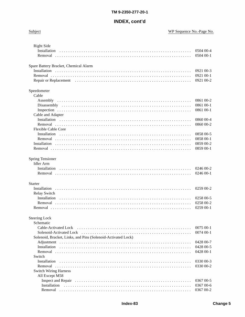
TM 9-2350-277-20-1
INDEX, cont’d
Subject WP Sequence No.-Page No.
Right SideInstallation . . . . . . . . . . . . . . . . . . . . . . . . . . . . . . . . . . . . . . . . . . . . . . . . . . . . . . . . . . . . 0504 00-4Removal . . . . . . . . . . . . . . . . . . . . . . . . . . . . . . . . . . . . . . . . . . . . . . . . . . . . . . . . . . . . . . 0504 00-1
Spare Battery Bracket, Chemical AlarmInstallation . . . . . . . . . . . . . . . . . . . . . . . . . . . . . . . . . . . . . . . . . . . . . . . . . . . . . . . . . . . . . . 0921 00-3Removal . . . . . . . . . . . . . . . . . . . . . . . . . . . . . . . . . . . . . . . . . . . . . . . . . . . . . . . . . . . . . . . . 0921 00-1Repair or Replacement . . . . . . . . . . . . . . . . . . . . . . . . . . . . . . . . . . . . . . . . . . . . . . . . . . . . . 0921 00-2
SpeedometerCable
Assembly . . . . . . . . . . . . . . . . . . . . . . . . . . . . . . . . . . . . . . . . . . . . . . . . . . . . . . . . . . . . . 0861 00-2Disassembly . . . . . . . . . . . . . . . . . . . . . . . . . . . . . . . . . . . . . . . . . . . . . . . . . . . . . . . . . . . 0861 00-1Inspection . . . . . . . . . . . . . . . . . . . . . . . . . . . . . . . . . . . . . . . . . . . . . . . . . . . . . . . . . . . . . 0861 00-1
Cable and AdapterInstallation . . . . . . . . . . . . . . . . . . . . . . . . . . . . . . . . . . . . . . . . . . . . . . . . . . . . . . . . . . . . 0860 00-4Removal . . . . . . . . . . . . . . . . . . . . . . . . . . . . . . . . . . . . . . . . . . . . . . . . . . . . . . . . . . . . . . 0860 00-2
Flexible Cable CoreInstallation . . . . . . . . . . . . . . . . . . . . . . . . . . . . . . . . . . . . . . . . . . . . . . . . . . . . . . . . . . . . 0858 00-5Removal . . . . . . . . . . . . . . . . . . . . . . . . . . . . . . . . . . . . . . . . . . . . . . . . . . . . . . . . . . . . . . 0858 00-1
Installation . . . . . . . . . . . . . . . . . . . . . . . . . . . . . . . . . . . . . . . . . . . . . . . . . . . . . . . . . . . . . . 0859 00-2Removal . . . . . . . . . . . . . . . . . . . . . . . . . . . . . . . . . . . . . . . . . . . . . . . . . . . . . . . . . . . . . . . . 0859 00-1
Spring TensionerIdler Arm
Installation . . . . . . . . . . . . . . . . . . . . . . . . . . . . . . . . . . . . . . . . . . . . . . . . . . . . . . . . . . . . 0246 00-2Removal . . . . . . . . . . . . . . . . . . . . . . . . . . . . . . . . . . . . . . . . . . . . . . . . . . . . . . . . . . . . . . 0246 00-1
StarterInstallation . . . . . . . . . . . . . . . . . . . . . . . . . . . . . . . . . . . . . . . . . . . . . . . . . . . . . . . . . . . . . . 0259 00-2Relay Switch
Installation . . . . . . . . . . . . . . . . . . . . . . . . . . . . . . . . . . . . . . . . . . . . . . . . . . . . . . . . . . . . 0258 00-5Removal . . . . . . . . . . . . . . . . . . . . . . . . . . . . . . . . . . . . . . . . . . . . . . . . . . . . . . . . . . . . . . 0258 00-2
Removal . . . . . . . . . . . . . . . . . . . . . . . . . . . . . . . . . . . . . . . . . . . . . . . . . . . . . . . . . . . . . . . . 0259 00-1
Steering LockSchematic
Cable-Activated Lock . . . . . . . . . . . . . . . . . . . . . . . . . . . . . . . . . . . . . . . . . . . . . . . . . . . . 0075 00-1Solenoid-Activated Lock . . . . . . . . . . . . . . . . . . . . . . . . . . . . . . . . . . . . . . . . . . . . . . . . . . 0074 00-1
Solenoid, Bracket, Links, and Pins (Solenoid-Activated Lock)Adjustment . . . . . . . . . . . . . . . . . . . . . . . . . . . . . . . . . . . . . . . . . . . . . . . . . . . . . . . . . . . . 0428 00-7Installation . . . . . . . . . . . . . . . . . . . . . . . . . . . . . . . . . . . . . . . . . . . . . . . . . . . . . . . . . . . . 0428 00-5Removal . . . . . . . . . . . . . . . . . . . . . . . . . . . . . . . . . . . . . . . . . . . . . . . . . . . . . . . . . . . . . . 0428 00-1
SwitchInstallation . . . . . . . . . . . . . . . . . . . . . . . . . . . . . . . . . . . . . . . . . . . . . . . . . . . . . . . . . . . . 0330 00-3Removal . . . . . . . . . . . . . . . . . . . . . . . . . . . . . . . . . . . . . . . . . . . . . . . . . . . . . . . . . . . . . . 0330 00-2
Switch Wiring HarnessAll Except M58
Inspect and Repair . . . . . . . . . . . . . . . . . . . . . . . . . . . . . . . . . . . . . . . . . . . . . . . . . . . . . 0367 00-5Installation . . . . . . . . . . . . . . . . . . . . . . . . . . . . . . . . . . . . . . . . . . . . . . . . . . . . . . . . . . 0367 00-6
Index-83 Change 5
Removal . . . . . . . . . . . . . . . . . . . . . . . . . . . . . . . . . . . . . . . . . . . . . . . . . . . . . . . . . . . . 0367 00-2
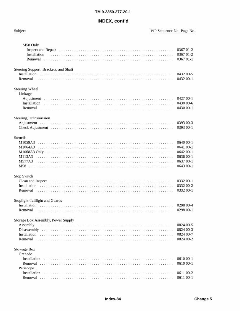
TM 9-2350-277-20-1
INDEX, cont’d
Subject WP Sequence No.-Page No.
M58 OnlyInspect and Repair . . . . . . . . . . . . . . . . . . . . . . . . . . . . . . . . . . . . . . . . . . . . . . . . . . . . . 0367 01-2Installation . . . . . . . . . . . . . . . . . . . . . . . . . . . . . . . . . . . . . . . . . . . . . . . . . . . . . . . . . . 0367 01-2Removal . . . . . . . . . . . . . . . . . . . . . . . . . . . . . . . . . . . . . . . . . . . . . . . . . . . . . . . . . . . . 0367 01-1
Steering Support, Brackets, and ShaftInstallation . . . . . . . . . . . . . . . . . . . . . . . . . . . . . . . . . . . . . . . . . . . . . . . . . . . . . . . . . . . . . . 0432 00-5Removal . . . . . . . . . . . . . . . . . . . . . . . . . . . . . . . . . . . . . . . . . . . . . . . . . . . . . . . . . . . . . . . . 0432 00-1
Steering WheelLinkage
Adjustment . . . . . . . . . . . . . . . . . . . . . . . . . . . . . . . . . . . . . . . . . . . . . . . . . . . . . . . . . . . . 0427 00-1Installation . . . . . . . . . . . . . . . . . . . . . . . . . . . . . . . . . . . . . . . . . . . . . . . . . . . . . . . . . . . . 0430 00-6Removal . . . . . . . . . . . . . . . . . . . . . . . . . . . . . . . . . . . . . . . . . . . . . . . . . . . . . . . . . . . . . . 0430 00-1
Steering, TransmissionAdjustment . . . . . . . . . . . . . . . . . . . . . . . . . . . . . . . . . . . . . . . . . . . . . . . . . . . . . . . . . . . . . . 0393 00-3Check Adjustment . . . . . . . . . . . . . . . . . . . . . . . . . . . . . . . . . . . . . . . . . . . . . . . . . . . . . . . . . 0393 00-1
StencilsM1059A3 . . . . . . . . . . . . . . . . . . . . . . . . . . . . . . . . . . . . . . . . . . . . . . . . . . . . . . . . . . . . . . . 0640 00-1M1064A3 . . . . . . . . . . . . . . . . . . . . . . . . . . . . . . . . . . . . . . . . . . . . . . . . . . . . . . . . . . . . . . . 0641 00-1M1068A3 Only . . . . . . . . . . . . . . . . . . . . . . . . . . . . . . . . . . . . . . . . . . . . . . . . . . . . . . . . . . . 0642 00-1M113A3 . . . . . . . . . . . . . . . . . . . . . . . . . . . . . . . . . . . . . . . . . . . . . . . . . . . . . . . . . . . . . . . . 0636 00-1M577A3 . . . . . . . . . . . . . . . . . . . . . . . . . . . . . . . . . . . . . . . . . . . . . . . . . . . . . . . . . . . . . . . . 0637 00-1M58 . . . . . . . . . . . . . . . . . . . . . . . . . . . . . . . . . . . . . . . . . . . . . . . . . . . . . . . . . . . . . . . . . . . 0643 00-1
Stop SwitchClean and Inspect . . . . . . . . . . . . . . . . . . . . . . . . . . . . . . . . . . . . . . . . . . . . . . . . . . . . . . . . . 0332 00-1Installation . . . . . . . . . . . . . . . . . . . . . . . . . . . . . . . . . . . . . . . . . . . . . . . . . . . . . . . . . . . . . . 0332 00-2Removal . . . . . . . . . . . . . . . . . . . . . . . . . . . . . . . . . . . . . . . . . . . . . . . . . . . . . . . . . . . . . . . . 0332 00-1
Stoplight-Taillight and GuardsInstallation . . . . . . . . . . . . . . . . . . . . . . . . . . . . . . . . . . . . . . . . . . . . . . . . . . . . . . . . . . . . . . 0298 00-4Removal . . . . . . . . . . . . . . . . . . . . . . . . . . . . . . . . . . . . . . . . . . . . . . . . . . . . . . . . . . . . . . . . 0298 00-1
Storage Box Assembly, Power SupplyAssembly . . . . . . . . . . . . . . . . . . . . . . . . . . . . . . . . . . . . . . . . . . . . . . . . . . . . . . . . . . . . . . . 0824 00-5Disassembly . . . . . . . . . . . . . . . . . . . . . . . . . . . . . . . . . . . . . . . . . . . . . . . . . . . . . . . . . . . . . 0824 00-3Installation . . . . . . . . . . . . . . . . . . . . . . . . . . . . . . . . . . . . . . . . . . . . . . . . . . . . . . . . . . . . . . 0824 00-7Removal . . . . . . . . . . . . . . . . . . . . . . . . . . . . . . . . . . . . . . . . . . . . . . . . . . . . . . . . . . . . . . . . 0824 00-2
Stowage BoxGrenade
Installation . . . . . . . . . . . . . . . . . . . . . . . . . . . . . . . . . . . . . . . . . . . . . . . . . . . . . . . . . . . . 0610 00-1Removal . . . . . . . . . . . . . . . . . . . . . . . . . . . . . . . . . . . . . . . . . . . . . . . . . . . . . . . . . . . . . . 0610 00-1
PeriscopeInstallation . . . . . . . . . . . . . . . . . . . . . . . . . . . . . . . . . . . . . . . . . . . . . . . . . . . . . . . . . . . . 0611 00-2Removal . . . . . . . . . . . . . . . . . . . . . . . . . . . . . . . . . . . . . . . . . . . . . . . . . . . . . . . . . . . . . . 0611 00-1
Index-84 Change 5
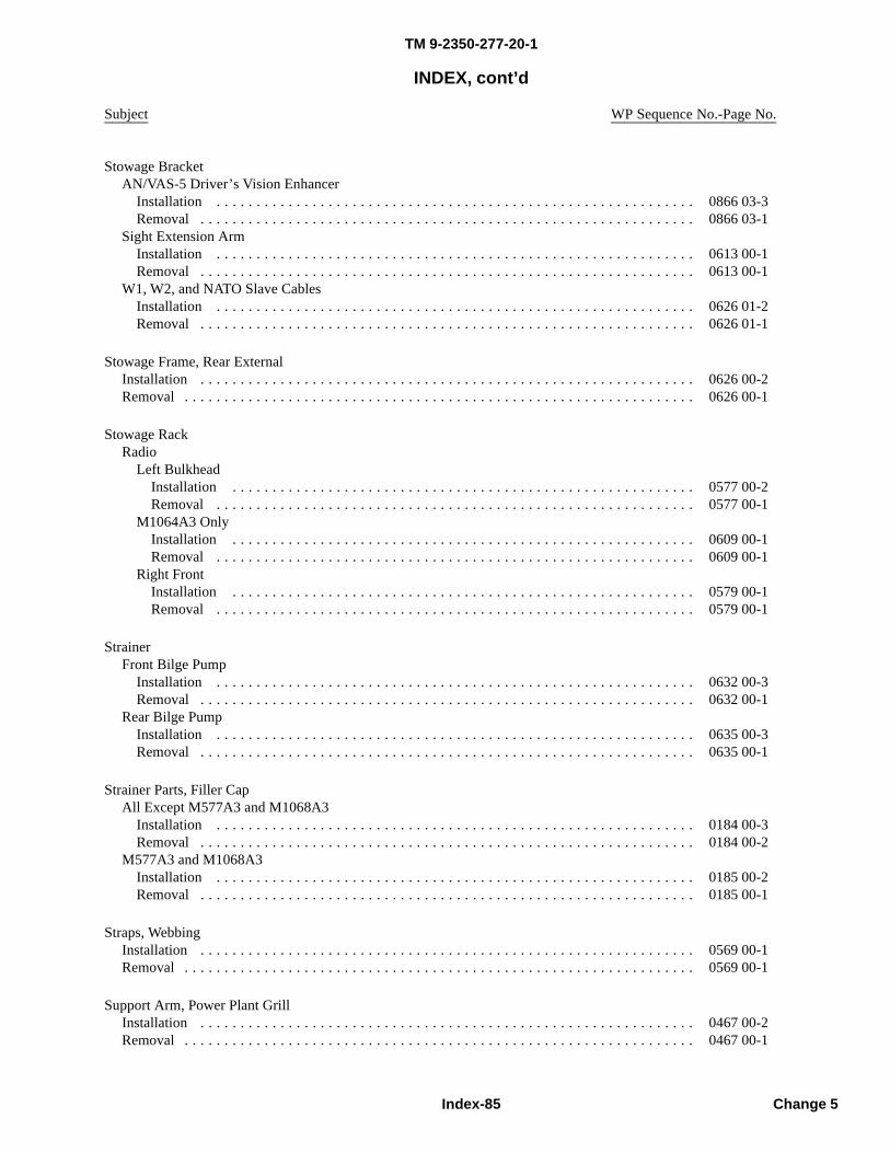
TM 9-2350-277-20-1
INDEX, cont’d
Subject WP Sequence No.-Page No.
Stowage BracketAN/VAS-5 Driver’s Vision Enhancer
Installation . . . . . . . . . . . . . . . . . . . . . . . . . . . . . . . . . . . . . . . . . . . . . . . . . . . . . . . . . . . . 0866 03-3Removal . . . . . . . . . . . . . . . . . . . . . . . . . . . . . . . . . . . . . . . . . . . . . . . . . . . . . . . . . . . . . . 0866 03-1
Sight Extension ArmInstallation . . . . . . . . . . . . . . . . . . . . . . . . . . . . . . . . . . . . . . . . . . . . . . . . . . . . . . . . . . . . 0613 00-1Removal . . . . . . . . . . . . . . . . . . . . . . . . . . . . . . . . . . . . . . . . . . . . . . . . . . . . . . . . . . . . . . 0613 00-1
W1, W2, and NATO Slave CablesInstallation . . . . . . . . . . . . . . . . . . . . . . . . . . . . . . . . . . . . . . . . . . . . . . . . . . . . . . . . . . . . 0626 01-2Removal . . . . . . . . . . . . . . . . . . . . . . . . . . . . . . . . . . . . . . . . . . . . . . . . . . . . . . . . . . . . . . 0626 01-1
Stowage Frame, Rear ExternalInstallation . . . . . . . . . . . . . . . . . . . . . . . . . . . . . . . . . . . . . . . . . . . . . . . . . . . . . . . . . . . . . . 0626 00-2Removal . . . . . . . . . . . . . . . . . . . . . . . . . . . . . . . . . . . . . . . . . . . . . . . . . . . . . . . . . . . . . . . . 0626 00-1
Stowage RackRadio
Left BulkheadInstallation . . . . . . . . . . . . . . . . . . . . . . . . . . . . . . . . . . . . . . . . . . . . . . . . . . . . . . . . . . 0577 00-2Removal . . . . . . . . . . . . . . . . . . . . . . . . . . . . . . . . . . . . . . . . . . . . . . . . . . . . . . . . . . . . 0577 00-1
M1064A3 OnlyInstallation . . . . . . . . . . . . . . . . . . . . . . . . . . . . . . . . . . . . . . . . . . . . . . . . . . . . . . . . . . 0609 00-1Removal . . . . . . . . . . . . . . . . . . . . . . . . . . . . . . . . . . . . . . . . . . . . . . . . . . . . . . . . . . . . 0609 00-1
Right FrontInstallation . . . . . . . . . . . . . . . . . . . . . . . . . . . . . . . . . . . . . . . . . . . . . . . . . . . . . . . . . . 0579 00-1Removal . . . . . . . . . . . . . . . . . . . . . . . . . . . . . . . . . . . . . . . . . . . . . . . . . . . . . . . . . . . . 0579 00-1
StrainerFront Bilge Pump
Installation . . . . . . . . . . . . . . . . . . . . . . . . . . . . . . . . . . . . . . . . . . . . . . . . . . . . . . . . . . . . 0632 00-3Removal . . . . . . . . . . . . . . . . . . . . . . . . . . . . . . . . . . . . . . . . . . . . . . . . . . . . . . . . . . . . . . 0632 00-1
Rear Bilge PumpInstallation . . . . . . . . . . . . . . . . . . . . . . . . . . . . . . . . . . . . . . . . . . . . . . . . . . . . . . . . . . . . 0635 00-3Removal . . . . . . . . . . . . . . . . . . . . . . . . . . . . . . . . . . . . . . . . . . . . . . . . . . . . . . . . . . . . . . 0635 00-1
Strainer Parts, Filler CapAll Except M577A3 and M1068A3
Installation . . . . . . . . . . . . . . . . . . . . . . . . . . . . . . . . . . . . . . . . . . . . . . . . . . . . . . . . . . . . 0184 00-3Removal . . . . . . . . . . . . . . . . . . . . . . . . . . . . . . . . . . . . . . . . . . . . . . . . . . . . . . . . . . . . . . 0184 00-2
M577A3 and M1068A3Installation . . . . . . . . . . . . . . . . . . . . . . . . . . . . . . . . . . . . . . . . . . . . . . . . . . . . . . . . . . . . 0185 00-2Removal . . . . . . . . . . . . . . . . . . . . . . . . . . . . . . . . . . . . . . . . . . . . . . . . . . . . . . . . . . . . . . 0185 00-1
Straps, WebbingInstallation . . . . . . . . . . . . . . . . . . . . . . . . . . . . . . . . . . . . . . . . . . . . . . . . . . . . . . . . . . . . . . 0569 00-1Removal . . . . . . . . . . . . . . . . . . . . . . . . . . . . . . . . . . . . . . . . . . . . . . . . . . . . . . . . . . . . . . . . 0569 00-1
Support Arm, Power Plant GrillInstallation . . . . . . . . . . . . . . . . . . . . . . . . . . . . . . . . . . . . . . . . . . . . . . . . . . . . . . . . . . . . . . 0467 00-2Removal . . . . . . . . . . . . . . . . . . . . . . . . . . . . . . . . . . . . . . . . . . . . . . . . . . . . . . . . . . . . . . . . 0467 00-1
Index-85 Change 5

TM 9-2350-277-20-1
INDEX, cont’d
Subject WP Sequence No.-Page No.
Support, AntennaInstallation . . . . . . . . . . . . . . . . . . . . . . . . . . . . . . . . . . . . . . . . . . . . . . . . . . . . . . . . . . . . . . 0602 00-2Removal . . . . . . . . . . . . . . . . . . . . . . . . . . . . . . . . . . . . . . . . . . . . . . . . . . . . . . . . . . . . . . . . 0602 00-2
SwitchBlower
Installation . . . . . . . . . . . . . . . . . . . . . . . . . . . . . . . . . . . . . . . . . . . . . . . . . . . . . . . . . . . . 0278 00-3Removal . . . . . . . . . . . . . . . . . . . . . . . . . . . . . . . . . . . . . . . . . . . . . . . . . . . . . . . . . . . . . . 0278 00-1
Differential Pressure, Fuel FilterInstallation . . . . . . . . . . . . . . . . . . . . . . . . . . . . . . . . . . . . . . . . . . . . . . . . . . . . . . . . . . . . 0328 00-5Removal . . . . . . . . . . . . . . . . . . . . . . . . . . . . . . . . . . . . . . . . . . . . . . . . . . . . . . . . . . . . . . 0328 00-1
Dome Blackout Light BypassInstallation . . . . . . . . . . . . . . . . . . . . . . . . . . . . . . . . . . . . . . . . . . . . . . . . . . . . . . . . . . . . 0317 00-2Removal . . . . . . . . . . . . . . . . . . . . . . . . . . . . . . . . . . . . . . . . . . . . . . . . . . . . . . . . . . . . . . 0317 00-1
Dome LightFront
Installation . . . . . . . . . . . . . . . . . . . . . . . . . . . . . . . . . . . . . . . . . . . . . . . . . . . . . . . . . . 0314 00-3Removal . . . . . . . . . . . . . . . . . . . . . . . . . . . . . . . . . . . . . . . . . . . . . . . . . . . . . . . . . . . . 0314 00-1
RearInstallation . . . . . . . . . . . . . . . . . . . . . . . . . . . . . . . . . . . . . . . . . . . . . . . . . . . . . . . . . . 0315 00-2Removal . . . . . . . . . . . . . . . . . . . . . . . . . . . . . . . . . . . . . . . . . . . . . . . . . . . . . . . . . . . . 0315 00-1
Engine StartInstallation . . . . . . . . . . . . . . . . . . . . . . . . . . . . . . . . . . . . . . . . . . . . . . . . . . . . . . . . . . . . 0284 00-2Removal . . . . . . . . . . . . . . . . . . . . . . . . . . . . . . . . . . . . . . . . . . . . . . . . . . . . . . . . . . . . . . 0284 00-1
Flame Detector, Coolant HeaterAdjustment . . . . . . . . . . . . . . . . . . . . . . . . . . . . . . . . . . . . . . . . . . . . . . . . . . . . . . . . . . . . 0727 00-1Inspection-Acceptance and Rejection Criteria . . . . . . . . . . . . . . . . . . . . . . . . . . . . . . . . . . . 0734 00-1Installation . . . . . . . . . . . . . . . . . . . . . . . . . . . . . . . . . . . . . . . . . . . . . . . . . . . . . . . . . . . . 0734 00-2Removal . . . . . . . . . . . . . . . . . . . . . . . . . . . . . . . . . . . . . . . . . . . . . . . . . . . . . . . . . . . . . . 0734 00-1
Fuel SelectorInstallation . . . . . . . . . . . . . . . . . . . . . . . . . . . . . . . . . . . . . . . . . . . . . . . . . . . . . . . . . . . . 0277 00-3Removal . . . . . . . . . . . . . . . . . . . . . . . . . . . . . . . . . . . . . . . . . . . . . . . . . . . . . . . . . . . . . . 0277 00-1
Generator Field PressureInspection-Acceptance and Rejection Criteria . . . . . . . . . . . . . . . . . . . . . . . . . . . . . . . . . . . 0323 00-1Installation . . . . . . . . . . . . . . . . . . . . . . . . . . . . . . . . . . . . . . . . . . . . . . . . . . . . . . . . . . . . 0323 00-2Removal . . . . . . . . . . . . . . . . . . . . . . . . . . . . . . . . . . . . . . . . . . . . . . . . . . . . . . . . . . . . . . 0323 00-1
Headlight, High Beam SelectorInstallation . . . . . . . . . . . . . . . . . . . . . . . . . . . . . . . . . . . . . . . . . . . . . . . . . . . . . . . . . . . . 0333 00-2Removal . . . . . . . . . . . . . . . . . . . . . . . . . . . . . . . . . . . . . . . . . . . . . . . . . . . . . . . . . . . . . . 0333 00-1
HornAll Except M58
Installation . . . . . . . . . . . . . . . . . . . . . . . . . . . . . . . . . . . . . . . . . . . . . . . . . . . . . . . . . . 0293 00-2Removal . . . . . . . . . . . . . . . . . . . . . . . . . . . . . . . . . . . . . . . . . . . . . . . . . . . . . . . . . . . . 0293 00-1
M58 OnlyInstallation . . . . . . . . . . . . . . . . . . . . . . . . . . . . . . . . . . . . . . . . . . . . . . . . . . . . . . . . . . 0293 01-2Removal . . . . . . . . . . . . . . . . . . . . . . . . . . . . . . . . . . . . . . . . . . . . . . . . . . . . . . . . . . . . 0293 01-1
Main LightInstallation . . . . . . . . . . . . . . . . . . . . . . . . . . . . . . . . . . . . . . . . . . . . . . . . . . . . . . . . . . . . 0283 00-2Removal . . . . . . . . . . . . . . . . . . . . . . . . . . . . . . . . . . . . . . . . . . . . . . . . . . . . . . . . . . . . . . 0283 00-1
NBC Orifice Connector AssemblyInstallation . . . . . . . . . . . . . . . . . . . . . . . . . . . . . . . . . . . . . . . . . . . . . . . . . . . . . . . . . . . . 0916 00-5Removal . . . . . . . . . . . . . . . . . . . . . . . . . . . . . . . . . . . . . . . . . . . . . . . . . . . . . . . . . . . . . . 0916 00-1
Index-86 Change 5
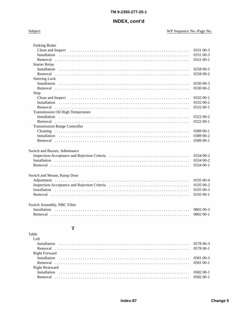
TM 9-2350-277-20-1
INDEX, cont’d
Subject WP Sequence No.-Page No.
Parking BrakeClean and Inspect . . . . . . . . . . . . . . . . . . . . . . . . . . . . . . . . . . . . . . . . . . . . . . . . . . . . . . . 0331 00-3Installation . . . . . . . . . . . . . . . . . . . . . . . . . . . . . . . . . . . . . . . . . . . . . . . . . . . . . . . . . . . . 0331 00-3Removal . . . . . . . . . . . . . . . . . . . . . . . . . . . . . . . . . . . . . . . . . . . . . . . . . . . . . . . . . . . . . . 0331 00-1
Starter RelayInstallation . . . . . . . . . . . . . . . . . . . . . . . . . . . . . . . . . . . . . . . . . . . . . . . . . . . . . . . . . . . . 0258 00-5Removal . . . . . . . . . . . . . . . . . . . . . . . . . . . . . . . . . . . . . . . . . . . . . . . . . . . . . . . . . . . . . . 0258 00-2
Steering LockInstallation . . . . . . . . . . . . . . . . . . . . . . . . . . . . . . . . . . . . . . . . . . . . . . . . . . . . . . . . . . . . 0330 00-3Removal . . . . . . . . . . . . . . . . . . . . . . . . . . . . . . . . . . . . . . . . . . . . . . . . . . . . . . . . . . . . . . 0330 00-2
StopClean and Inspect . . . . . . . . . . . . . . . . . . . . . . . . . . . . . . . . . . . . . . . . . . . . . . . . . . . . . . . 0332 00-1Installation . . . . . . . . . . . . . . . . . . . . . . . . . . . . . . . . . . . . . . . . . . . . . . . . . . . . . . . . . . . . 0332 00-2Removal . . . . . . . . . . . . . . . . . . . . . . . . . . . . . . . . . . . . . . . . . . . . . . . . . . . . . . . . . . . . . . 0332 00-1
Transmission Oil High TemperatureInstallation . . . . . . . . . . . . . . . . . . . . . . . . . . . . . . . . . . . . . . . . . . . . . . . . . . . . . . . . . . . . 0322 00-2Removal . . . . . . . . . . . . . . . . . . . . . . . . . . . . . . . . . . . . . . . . . . . . . . . . . . . . . . . . . . . . . . 0322 00-1
Transmission Range ControllerCleaning . . . . . . . . . . . . . . . . . . . . . . . . . . . . . . . . . . . . . . . . . . . . . . . . . . . . . . . . . . . . . . 0389 00-1Installation . . . . . . . . . . . . . . . . . . . . . . . . . . . . . . . . . . . . . . . . . . . . . . . . . . . . . . . . . . . . 0389 00-2Removal . . . . . . . . . . . . . . . . . . . . . . . . . . . . . . . . . . . . . . . . . . . . . . . . . . . . . . . . . . . . . . 0389 00-1
Switch and Buzzer, AdmittanceInspection-Acceptance and Rejection Criteria . . . . . . . . . . . . . . . . . . . . . . . . . . . . . . . . . . . . . 0334 00-2Installation . . . . . . . . . . . . . . . . . . . . . . . . . . . . . . . . . . . . . . . . . . . . . . . . . . . . . . . . . . . . . . 0334 00-2Removal . . . . . . . . . . . . . . . . . . . . . . . . . . . . . . . . . . . . . . . . . . . . . . . . . . . . . . . . . . . . . . . . 0334 00-1
Switch and Mount, Ramp DoorAdjustment . . . . . . . . . . . . . . . . . . . . . . . . . . . . . . . . . . . . . . . . . . . . . . . . . . . . . . . . . . . . . . 0335 00-4Inspection-Acceptance and Rejection Criteria . . . . . . . . . . . . . . . . . . . . . . . . . . . . . . . . . . . . . 0335 00-2Installation . . . . . . . . . . . . . . . . . . . . . . . . . . . . . . . . . . . . . . . . . . . . . . . . . . . . . . . . . . . . . . 0335 00-3Removal . . . . . . . . . . . . . . . . . . . . . . . . . . . . . . . . . . . . . . . . . . . . . . . . . . . . . . . . . . . . . . . . 0335 00-1
Switch Assembly, NBC FilterInstallation . . . . . . . . . . . . . . . . . . . . . . . . . . . . . . . . . . . . . . . . . . . . . . . . . . . . . . . . . . . . . . 0802 00-3Removal . . . . . . . . . . . . . . . . . . . . . . . . . . . . . . . . . . . . . . . . . . . . . . . . . . . . . . . . . . . . . . . . 0802 00-1
TTable
LeftInstallation . . . . . . . . . . . . . . . . . . . . . . . . . . . . . . . . . . . . . . . . . . . . . . . . . . . . . . . . . . . . 0578 00-3Removal . . . . . . . . . . . . . . . . . . . . . . . . . . . . . . . . . . . . . . . . . . . . . . . . . . . . . . . . . . . . . . 0578 00-1
Right ForwardInstallation . . . . . . . . . . . . . . . . . . . . . . . . . . . . . . . . . . . . . . . . . . . . . . . . . . . . . . . . . . . . 0581 00-3Removal . . . . . . . . . . . . . . . . . . . . . . . . . . . . . . . . . . . . . . . . . . . . . . . . . . . . . . . . . . . . . . 0581 00-1
Right RearwardInstallation . . . . . . . . . . . . . . . . . . . . . . . . . . . . . . . . . . . . . . . . . . . . . . . . . . . . . . . . . . . . 0582 00-1Removal . . . . . . . . . . . . . . . . . . . . . . . . . . . . . . . . . . . . . . . . . . . . . . . . . . . . . . . . . . . . . . 0582 00-1
Index-87 Change 5
TM 9-2350-277-20-1
INDEX, cont’d
Subject WP Sequence No.-Page No.
CableAssembly . . . . . . . . . . . . . . . . . . . . . . . . . . . . . . . . . . . . . . . . . . . . . . . . . . . . . . . . . . . . . 0865 00-2Disassembly . . . . . . . . . . . . . . . . . . . . . . . . . . . . . . . . . . . . . . . . . . . . . . . . . . . . . . . . . . . 0865 00-1Inspection . . . . . . . . . . . . . . . . . . . . . . . . . . . . . . . . . . . . . . . . . . . . . . . . . . . . . . . . . . . . . 0865 00-1Installation . . . . . . . . . . . . . . . . . . . . . . . . . . . . . . . . . . . . . . . . . . . . . . . . . . . . . . . . . . . . 0864 00-4Removal . . . . . . . . . . . . . . . . . . . . . . . . . . . . . . . . . . . . . . . . . . . . . . . . . . . . . . . . . . . . . . 0864 00-2
Engine AdapterInstallation . . . . . . . . . . . . . . . . . . . . . . . . . . . . . . . . . . . . . . . . . . . . . . . . . . . . . . . . . . . . 0863 00-3Removal . . . . . . . . . . . . . . . . . . . . . . . . . . . . . . . . . . . . . . . . . . . . . . . . . . . . . . . . . . . . . . 0863 00-1
Flexible Cable CoreInstallation . . . . . . . . . . . . . . . . . . . . . . . . . . . . . . . . . . . . . . . . . . . . . . . . . . . . . . . . . . . . 0858 00-5Removal . . . . . . . . . . . . . . . . . . . . . . . . . . . . . . . . . . . . . . . . . . . . . . . . . . . . . . . . . . . . . . 0858 00-1
Installation . . . . . . . . . . . . . . . . . . . . . . . . . . . . . . . . . . . . . . . . . . . . . . . . . . . . . . . . . . . . . . 0862 00-2MSD/ICE Pulse
Installation . . . . . . . . . . . . . . . . . . . . . . . . . . . . . . . . . . . . . . . . . . . . . . . . . . . . . . . . . . . . 0867 00-3Removal . . . . . . . . . . . . . . . . . . . . . . . . . . . . . . . . . . . . . . . . . . . . . . . . . . . . . . . . . . . . . . 0867 00-1
Removal . . . . . . . . . . . . . . . . . . . . . . . . . . . . . . . . . . . . . . . . . . . . . . . . . . . . . . . . . . . . . . . . 0862 00-1
TankAuxiliary
Installation . . . . . . . . . . . . . . . . . . . . . . . . . . . . . . . . . . . . . . . . . . . . . . . . . . . . . . . . . . . . 0230 00-2Removal . . . . . . . . . . . . . . . . . . . . . . . . . . . . . . . . . . . . . . . . . . . . . . . . . . . . . . . . . . . . . . 0230 00-1
Module, Fog OilInstallation . . . . . . . . . . . . . . . . . . . . . . . . . . . . . . . . . . . . . . . . . . . . . . . . . . . . . . . . . . . . 0753 00-4Removal . . . . . . . . . . . . . . . . . . . . . . . . . . . . . . . . . . . . . . . . . . . . . . . . . . . . . . . . . . . . . . 0753 00-1
Teleposts and CoverInstallation . . . . . . . . . . . . . . . . . . . . . . . . . . . . . . . . . . . . . . . . . . . . . . . . . . . . . . . . . . . . . . 0296 00-3Removal . . . . . . . . . . . . . . . . . . . . . . . . . . . . . . . . . . . . . . . . . . . . . . . . . . . . . . . . . . . . . . . . 0296 00-1
TentFrame Mounts
Installation . . . . . . . . . . . . . . . . . . . . . . . . . . . . . . . . . . . . . . . . . . . . . . . . . . . . . . . . . . . . 0628 00-3Removal . . . . . . . . . . . . . . . . . . . . . . . . . . . . . . . . . . . . . . . . . . . . . . . . . . . . . . . . . . . . . . 0628 00-1
Installation . . . . . . . . . . . . . . . . . . . . . . . . . . . . . . . . . . . . . . . . . . . . . . . . . . . . . . . . . . . . . . 0627 00-2Interface Panel Box Assembly A5
Installation . . . . . . . . . . . . . . . . . . . . . . . . . . . . . . . . . . . . . . . . . . . . . . . . . . . . . . . . . . . . 0833 00-3Removal . . . . . . . . . . . . . . . . . . . . . . . . . . . . . . . . . . . . . . . . . . . . . . . . . . . . . . . . . . . . . . 0833 00-1
Light AssemblyInstallation . . . . . . . . . . . . . . . . . . . . . . . . . . . . . . . . . . . . . . . . . . . . . . . . . . . . . . . . . . . . 0318 00-3Removal . . . . . . . . . . . . . . . . . . . . . . . . . . . . . . . . . . . . . . . . . . . . . . . . . . . . . . . . . . . . . . 0318 00-1
Removal . . . . . . . . . . . . . . . . . . . . . . . . . . . . . . . . . . . . . . . . . . . . . . . . . . . . . . . . . . . . . . . . 0627 00-1
Terminal Blocks TB1 and TB2, Inverter Housing A2Installation . . . . . . . . . . . . . . . . . . . . . . . . . . . . . . . . . . . . . . . . . . . . . . . . . . . . . . . . . . . . . . 0830 00-4Removal . . . . . . . . . . . . . . . . . . . . . . . . . . . . . . . . . . . . . . . . . . . . . . . . . . . . . . . . . . . . . . . . 0830 00-1
Terminals and Leads, BatteryM1064A3 Only (Left Side)
Cleaning . . . . . . . . . . . . . . . . . . . . . . . . . . . . . . . . . . . . . . . . . . . . . . . . . . . . . . . . . . . . . . 0343 00-5Installation . . . . . . . . . . . . . . . . . . . . . . . . . . . . . . . . . . . . . . . . . . . . . . . . . . . . . . . . . . . . 0343 00-5
Index-88 Change 5
Tachometer
Removal . . . . . . . . . . . . . . . . . . . . . . . . . . . . . . . . . . . . . . . . . . . . . . . . . . . . . . . . . . . . . . 0343 00-1
TM 9-2350-277-20-1
INDEX, cont’d
Subject WP Sequence No.-Page No.
M1064A3 Only (Right Side)Cleaning . . . . . . . . . . . . . . . . . . . . . . . . . . . . . . . . . . . . . . . . . . . . . . . . . . . . . . . . . . . . . . 0344 00-3Installation . . . . . . . . . . . . . . . . . . . . . . . . . . . . . . . . . . . . . . . . . . . . . . . . . . . . . . . . . . . . 0344 00-4Removal . . . . . . . . . . . . . . . . . . . . . . . . . . . . . . . . . . . . . . . . . . . . . . . . . . . . . . . . . . . . . . 0344 00-1
M113A3 and M1059A3Clean and Inspect . . . . . . . . . . . . . . . . . . . . . . . . . . . . . . . . . . . . . . . . . . . . . . . . . . . . . . . 0340 00-3Installation . . . . . . . . . . . . . . . . . . . . . . . . . . . . . . . . . . . . . . . . . . . . . . . . . . . . . . . . . . . . 0340 00-4Removal . . . . . . . . . . . . . . . . . . . . . . . . . . . . . . . . . . . . . . . . . . . . . . . . . . . . . . . . . . . . . . 0340 00-1
M577A3 and M1068A3Clean and Inspect . . . . . . . . . . . . . . . . . . . . . . . . . . . . . . . . . . . . . . . . . . . . . . . . . . . . . . . 0341 00-3Installation . . . . . . . . . . . . . . . . . . . . . . . . . . . . . . . . . . . . . . . . . . . . . . . . . . . . . . . . . . . . 0341 00-4Removal . . . . . . . . . . . . . . . . . . . . . . . . . . . . . . . . . . . . . . . . . . . . . . . . . . . . . . . . . . . . . . 0341 00-1
M58 OnlyCleaning . . . . . . . . . . . . . . . . . . . . . . . . . . . . . . . . . . . . . . . . . . . . . . . . . . . . . . . . . . . . . . 0345 00-3Installation . . . . . . . . . . . . . . . . . . . . . . . . . . . . . . . . . . . . . . . . . . . . . . . . . . . . . . . . . . . . 0345 00-4Removal . . . . . . . . . . . . . . . . . . . . . . . . . . . . . . . . . . . . . . . . . . . . . . . . . . . . . . . . . . . . . . 0345 00-1
Theory of OperationAuxiliary Automotive System . . . . . . . . . . . . . . . . . . . . . . . . . . . . . . . . . . . . . . . . . . . . . . . . 0003 00-2Power Plant . . . . . . . . . . . . . . . . . . . . . . . . . . . . . . . . . . . . . . . . . . . . . . . . . . . . . . . . . . . . . 0003 00-1Scope . . . . . . . . . . . . . . . . . . . . . . . . . . . . . . . . . . . . . . . . . . . . . . . . . . . . . . . . . . . . . . . . . . 0003 00-1Special Equipment . . . . . . . . . . . . . . . . . . . . . . . . . . . . . . . . . . . . . . . . . . . . . . . . . . . . . . . . 0003 00-3Winterization Equipment . . . . . . . . . . . . . . . . . . . . . . . . . . . . . . . . . . . . . . . . . . . . . . . . . . . . 0003 00-3
ThermostatInstallation . . . . . . . . . . . . . . . . . . . . . . . . . . . . . . . . . . . . . . . . . . . . . . . . . . . . . . . . . . . . . . 0237 00-4Removal . . . . . . . . . . . . . . . . . . . . . . . . . . . . . . . . . . . . . . . . . . . . . . . . . . . . . . . . . . . . . . . . 0237 00-1Tube/Hoses
Installation . . . . . . . . . . . . . . . . . . . . . . . . . . . . . . . . . . . . . . . . . . . . . . . . . . . . . . . . . . . . 0238 00-2Removal . . . . . . . . . . . . . . . . . . . . . . . . . . . . . . . . . . . . . . . . . . . . . . . . . . . . . . . . . . . . . . 0238 00-1
Thermostatic Fan Speed SwitchInstallation . . . . . . . . . . . . . . . . . . . . . . . . . . . . . . . . . . . . . . . . . . . . . . . . . . . . . . . . . . . . . . 0231 00-3Removal . . . . . . . . . . . . . . . . . . . . . . . . . . . . . . . . . . . . . . . . . . . . . . . . . . . . . . . . . . . . . . . . 0231 00-1
Throttle Valve (TV)Modulator
Adjustment . . . . . . . . . . . . . . . . . . . . . . . . . . . . . . . . . . . . . . . . . . . . . . . . . . . . . . . . . . . . 0213 00-1Field Operational Test . . . . . . . . . . . . . . . . . . . . . . . . . . . . . . . . . . . . . . . . . . . . . . . . . . . . 0213 00-5
Modulator and LeverInstallation . . . . . . . . . . . . . . . . . . . . . . . . . . . . . . . . . . . . . . . . . . . . . . . . . . . . . . . . . . . . 0218 00-4Removal . . . . . . . . . . . . . . . . . . . . . . . . . . . . . . . . . . . . . . . . . . . . . . . . . . . . . . . . . . . . . . 0218 00-1
Tool Box LoopsInstallation . . . . . . . . . . . . . . . . . . . . . . . . . . . . . . . . . . . . . . . . . . . . . . . . . . . . . . . . . . . . . . 0571 00-2Removal . . . . . . . . . . . . . . . . . . . . . . . . . . . . . . . . . . . . . . . . . . . . . . . . . . . . . . . . . . . . . . . . 0571 00-1
Torsion BarAnchor
Installation . . . . . . . . . . . . . . . . . . . . . . . . . . . . . . . . . . . . . . . . . . . . . . . . . . . . . . . . . . . . 0414 00-3
Index-89 Change 5
Removal . . . . . . . . . . . . . . . . . . . . . . . . . . . . . . . . . . . . . . . . . . . . . . . . . . . . . . . . . . . . . . 0414 00-1Installation . . . . . . . . . . . . . . . . . . . . . . . . . . . . . . . . . . . . . . . . . . . . . . . . . . . . . . . . . . . . . . 0413 00-4Removal . . . . . . . . . . . . . . . . . . . . . . . . . . . . . . . . . . . . . . . . . . . . . . . . . . . . . . . . . . . . . . . . 0413 00-1
TM 9-2350-277-20-1
INDEX, cont’d
Subject WP Sequence No.-Page No.
Tow PintleAssembly . . . . . . . . . . . . . . . . . . . . . . . . . . . . . . . . . . . . . . . . . . . . . . . . . . . . . . . . . . . . . . . 0434 00-2Disassembly . . . . . . . . . . . . . . . . . . . . . . . . . . . . . . . . . . . . . . . . . . . . . . . . . . . . . . . . . . . . . 0434 00-1Extender Assembly
Adjustment . . . . . . . . . . . . . . . . . . . . . . . . . . . . . . . . . . . . . . . . . . . . . . . . . . . . . . . . . . . . 0811 02-6Assembly . . . . . . . . . . . . . . . . . . . . . . . . . . . . . . . . . . . . . . . . . . . . . . . . . . . . . . . . . . . . . 0811 02-4Disassembly . . . . . . . . . . . . . . . . . . . . . . . . . . . . . . . . . . . . . . . . . . . . . . . . . . . . . . . . . . . 0811 02-3Installation . . . . . . . . . . . . . . . . . . . . . . . . . . . . . . . . . . . . . . . . . . . . . . . . . . . . . . . . . . . . 0811 02-5Removal . . . . . . . . . . . . . . . . . . . . . . . . . . . . . . . . . . . . . . . . . . . . . . . . . . . . . . . . . . . . . . 0811 02-1Stow . . . . . . . . . . . . . . . . . . . . . . . . . . . . . . . . . . . . . . . . . . . . . . . . . . . . . . . . . . . . . . . . . 0811 02-6
Extender KitAdjustment . . . . . . . . . . . . . . . . . . . . . . . . . . . . . . . . . . . . . . . . . . . . . . . . . . . . . . . . . . . . 0811 01-3Installation . . . . . . . . . . . . . . . . . . . . . . . . . . . . . . . . . . . . . . . . . . . . . . . . . . . . . . . . . . . . 0811 01-1Stow . . . . . . . . . . . . . . . . . . . . . . . . . . . . . . . . . . . . . . . . . . . . . . . . . . . . . . . . . . . . . . . . . 0811 01-3
Installation . . . . . . . . . . . . . . . . . . . . . . . . . . . . . . . . . . . . . . . . . . . . . . . . . . . . . . . . . . . . . . 0433 00-2Removal . . . . . . . . . . . . . . . . . . . . . . . . . . . . . . . . . . . . . . . . . . . . . . . . . . . . . . . . . . . . . . . . 0433 00-1
Tow Start ControlAssembly and Bearing
Installation . . . . . . . . . . . . . . . . . . . . . . . . . . . . . . . . . . . . . . . . . . . . . . . . . . . . . . . . . . . . 0391 00-5Removal . . . . . . . . . . . . . . . . . . . . . . . . . . . . . . . . . . . . . . . . . . . . . . . . . . . . . . . . . . . . . . 0391 00-2
Cable AssemblyAdjustment . . . . . . . . . . . . . . . . . . . . . . . . . . . . . . . . . . . . . . . . . . . . . . . . . . . . . . . . . . . . 0390 00-1
CoverInstallation . . . . . . . . . . . . . . . . . . . . . . . . . . . . . . . . . . . . . . . . . . . . . . . . . . . . . . . . . . . . 0392 00-2Removal . . . . . . . . . . . . . . . . . . . . . . . . . . . . . . . . . . . . . . . . . . . . . . . . . . . . . . . . . . . . . . 0392 00-1
Towing Hook and EyeInstallation . . . . . . . . . . . . . . . . . . . . . . . . . . . . . . . . . . . . . . . . . . . . . . . . . . . . . . . . . . . . . . 0443 00-2Removal . . . . . . . . . . . . . . . . . . . . . . . . . . . . . . . . . . . . . . . . . . . . . . . . . . . . . . . . . . . . . . . . 0443 00-1
TrackCover
Installation . . . . . . . . . . . . . . . . . . . . . . . . . . . . . . . . . . . . . . . . . . . . . . . . . . . . . . . . . . . . 0438 00-2Removal . . . . . . . . . . . . . . . . . . . . . . . . . . . . . . . . . . . . . . . . . . . . . . . . . . . . . . . . . . . . . . 0438 00-1
T130Clean, Inspect, and Repair . . . . . . . . . . . . . . . . . . . . . . . . . . . . . . . . . . . . . . . . . . . . . . . . . 0422 00-2Drive Sprocket Wheel Assembly
Assembly . . . . . . . . . . . . . . . . . . . . . . . . . . . . . . . . . . . . . . . . . . . . . . . . . . . . . . . . . . . 0421 00-1Disassembly . . . . . . . . . . . . . . . . . . . . . . . . . . . . . . . . . . . . . . . . . . . . . . . . . . . . . . . . . 0421 00-1Installation . . . . . . . . . . . . . . . . . . . . . . . . . . . . . . . . . . . . . . . . . . . . . . . . . . . . . . . . . . 0420 00-2Removal . . . . . . . . . . . . . . . . . . . . . . . . . . . . . . . . . . . . . . . . . . . . . . . . . . . . . . . . . . . . 0420 00-1
Installation . . . . . . . . . . . . . . . . . . . . . . . . . . . . . . . . . . . . . . . . . . . . . . . . . . . . . . . . . . . . 0422 00-3Removal . . . . . . . . . . . . . . . . . . . . . . . . . . . . . . . . . . . . . . . . . . . . . . . . . . . . . . . . . . . . . . 0422 00-1
T150Drive Sprocket Wheel Assembly
Installation . . . . . . . . . . . . . . . . . . . . . . . . . . . . . . . . . . . . . . . . . . . . . . . . . . . . . . . . . . 0420 01-2
Index-90 Change 5
Removal . . . . . . . . . . . . . . . . . . . . . . . . . . . . . . . . . . . . . . . . . . . . . . . . . . . . . . . . . . . . 0420 01-1Installation . . . . . . . . . . . . . . . . . . . . . . . . . . . . . . . . . . . . . . . . . . . . . . . . . . . . . . . . . . . . 0422 01-2Removal . . . . . . . . . . . . . . . . . . . . . . . . . . . . . . . . . . . . . . . . . . . . . . . . . . . . . . . . . . . . . . 0422 01-1Reverse Drive Sprocket and Track Assemblies
Installation . . . . . . . . . . . . . . . . . . . . . . . . . . . . . . . . . . . . . . . . . . . . . . . . . . . . . . . . . . 0419 01-2Removal . . . . . . . . . . . . . . . . . . . . . . . . . . . . . . . . . . . . . . . . . . . . . . . . . . . . . . . . . . . . 0419 01-1
TM 9-2350-277-20-1
INDEX, cont’d
Subject WP Sequence No.-Page No.
Tension Adjuster and MountInstallation . . . . . . . . . . . . . . . . . . . . . . . . . . . . . . . . . . . . . . . . . . . . . . . . . . . . . . . . . . . . 0419 00-2Removal . . . . . . . . . . . . . . . . . . . . . . . . . . . . . . . . . . . . . . . . . . . . . . . . . . . . . . . . . . . . . . 0419 00-1
Track ShoePad
T130Installation . . . . . . . . . . . . . . . . . . . . . . . . . . . . . . . . . . . . . . . . . . . . . . . . . . . . . . . . . . 0424 00-2Removal . . . . . . . . . . . . . . . . . . . . . . . . . . . . . . . . . . . . . . . . . . . . . . . . . . . . . . . . . . . . 0424 00-1
T150Installation . . . . . . . . . . . . . . . . . . . . . . . . . . . . . . . . . . . . . . . . . . . . . . . . . . . . . . . . . . 0424 01-2Removal . . . . . . . . . . . . . . . . . . . . . . . . . . . . . . . . . . . . . . . . . . . . . . . . . . . . . . . . . . . . 0424 01-1
Stowage BracketInstallation . . . . . . . . . . . . . . . . . . . . . . . . . . . . . . . . . . . . . . . . . . . . . . . . . . . . . . . . . . . . 0575 01-2Removal . . . . . . . . . . . . . . . . . . . . . . . . . . . . . . . . . . . . . . . . . . . . . . . . . . . . . . . . . . . . . . 0575 01-1
T130Repair or Replacement . . . . . . . . . . . . . . . . . . . . . . . . . . . . . . . . . . . . . . . . . . . . . . . . . . . . 0423 00-1
T150Installation . . . . . . . . . . . . . . . . . . . . . . . . . . . . . . . . . . . . . . . . . . . . . . . . . . . . . . . . . . . . 0423 01-2Removal . . . . . . . . . . . . . . . . . . . . . . . . . . . . . . . . . . . . . . . . . . . . . . . . . . . . . . . . . . . . . . 0423 01-1
Trailer HarnessInspection-Acceptance and Rejection Criteria . . . . . . . . . . . . . . . . . . . . . . . . . . . . . . . . . . . . . 0375 00-2Installation . . . . . . . . . . . . . . . . . . . . . . . . . . . . . . . . . . . . . . . . . . . . . . . . . . . . . . . . . . . . . . 0375 00-3Removal . . . . . . . . . . . . . . . . . . . . . . . . . . . . . . . . . . . . . . . . . . . . . . . . . . . . . . . . . . . . . . . . 0375 00-1
TransducerAir Box Pressure
Installation . . . . . . . . . . . . . . . . . . . . . . . . . . . . . . . . . . . . . . . . . . . . . . . . . . . . . . . . . . . . 0327 00-2Removal . . . . . . . . . . . . . . . . . . . . . . . . . . . . . . . . . . . . . . . . . . . . . . . . . . . . . . . . . . . . . . 0327 00-1
Fuel Return PressureInstallation . . . . . . . . . . . . . . . . . . . . . . . . . . . . . . . . . . . . . . . . . . . . . . . . . . . . . . . . . . . . 0325 00-2Removal . . . . . . . . . . . . . . . . . . . . . . . . . . . . . . . . . . . . . . . . . . . . . . . . . . . . . . . . . . . . . . 0325 00-1
Fuel Supply PressureInstallation . . . . . . . . . . . . . . . . . . . . . . . . . . . . . . . . . . . . . . . . . . . . . . . . . . . . . . . . . . . . 0324 00-2Removal . . . . . . . . . . . . . . . . . . . . . . . . . . . . . . . . . . . . . . . . . . . . . . . . . . . . . . . . . . . . . . 0324 00-1
Turbo Outlet PressureInstallation . . . . . . . . . . . . . . . . . . . . . . . . . . . . . . . . . . . . . . . . . . . . . . . . . . . . . . . . . . . . 0326 00-2Removal . . . . . . . . . . . . . . . . . . . . . . . . . . . . . . . . . . . . . . . . . . . . . . . . . . . . . . . . . . . . . . 0326 00-1
TransmissionBrake
Adjust Left-Hand Brake . . . . . . . . . . . . . . . . . . . . . . . . . . . . . . . . . . . . . . . . . . . . . . . . . . . 0394 00-1Adjust Right-Hand Brake . . . . . . . . . . . . . . . . . . . . . . . . . . . . . . . . . . . . . . . . . . . . . . . . . . 0394 00-5Check Brake Adjustment . . . . . . . . . . . . . . . . . . . . . . . . . . . . . . . . . . . . . . . . . . . . . . . . . . 0406 00-1
Index-91 Change 5
Controller Wiring HarnessInspect and Repair . . . . . . . . . . . . . . . . . . . . . . . . . . . . . . . . . . . . . . . . . . . . . . . . . . . . . . . 0361 00-4Installation . . . . . . . . . . . . . . . . . . . . . . . . . . . . . . . . . . . . . . . . . . . . . . . . . . . . . . . . . . . . 0361 00-5Removal . . . . . . . . . . . . . . . . . . . . . . . . . . . . . . . . . . . . . . . . . . . . . . . . . . . . . . . . . . . . . . 0361 00-1

TM 9-2350-277-20-1
INDEX, cont’d
Subject WP Sequence No.-Page No.
MountsInstallation . . . . . . . . . . . . . . . . . . . . . . . . . . . . . . . . . . . . . . . . . . . . . . . . . . . . . . . . . . . . 0385 00-3Removal . . . . . . . . . . . . . . . . . . . . . . . . . . . . . . . . . . . . . . . . . . . . . . . . . . . . . . . . . . . . . . 0385 00-1
Oil and Filter ElementInstallation . . . . . . . . . . . . . . . . . . . . . . . . . . . . . . . . . . . . . . . . . . . . . . . . . . . . . . . . . . . . 0398 00-3Removal . . . . . . . . . . . . . . . . . . . . . . . . . . . . . . . . . . . . . . . . . . . . . . . . . . . . . . . . . . . . . . 0398 00-1
Oil Cooler Hoses, Fittings, and MountingInstallation . . . . . . . . . . . . . . . . . . . . . . . . . . . . . . . . . . . . . . . . . . . . . . . . . . . . . . . . . . . . 0399 00-8Removal . . . . . . . . . . . . . . . . . . . . . . . . . . . . . . . . . . . . . . . . . . . . . . . . . . . . . . . . . . . . . . 0399 00-1
Oil Drain Tubes and BracketInstallation . . . . . . . . . . . . . . . . . . . . . . . . . . . . . . . . . . . . . . . . . . . . . . . . . . . . . . . . . . . . 0384 00-2Removal . . . . . . . . . . . . . . . . . . . . . . . . . . . . . . . . . . . . . . . . . . . . . . . . . . . . . . . . . . . . . . 0384 00-1
Oil High Temperature SwitchInstallation . . . . . . . . . . . . . . . . . . . . . . . . . . . . . . . . . . . . . . . . . . . . . . . . . . . . . . . . . . . . 0322 00-2Removal . . . . . . . . . . . . . . . . . . . . . . . . . . . . . . . . . . . . . . . . . . . . . . . . . . . . . . . . . . . . . . 0322 00-1
Oil Level Dipstick, Filler Tube, and AdapterX200-4 Only
Installation . . . . . . . . . . . . . . . . . . . . . . . . . . . . . . . . . . . . . . . . . . . . . . . . . . . . . . . . . . 0395 00-3Removal . . . . . . . . . . . . . . . . . . . . . . . . . . . . . . . . . . . . . . . . . . . . . . . . . . . . . . . . . . . . 0395 00-1
X200-4A OnlyInstallation . . . . . . . . . . . . . . . . . . . . . . . . . . . . . . . . . . . . . . . . . . . . . . . . . . . . . . . . . . 0396 00-4Removal . . . . . . . . . . . . . . . . . . . . . . . . . . . . . . . . . . . . . . . . . . . . . . . . . . . . . . . . . . . . 0396 00-1
Oil Sampling Valve and Pressure SwitchInstallation . . . . . . . . . . . . . . . . . . . . . . . . . . . . . . . . . . . . . . . . . . . . . . . . . . . . . . . . . . . . 0400 00-2Removal . . . . . . . . . . . . . . . . . . . . . . . . . . . . . . . . . . . . . . . . . . . . . . . . . . . . . . . . . . . . . . 0400 00-1
Oil Supply and Return HosesInstallation . . . . . . . . . . . . . . . . . . . . . . . . . . . . . . . . . . . . . . . . . . . . . . . . . . . . . . . . . . . . 0251 00-5Removal . . . . . . . . . . . . . . . . . . . . . . . . . . . . . . . . . . . . . . . . . . . . . . . . . . . . . . . . . . . . . . 0251 00-1
Range Controller LampInstallation . . . . . . . . . . . . . . . . . . . . . . . . . . . . . . . . . . . . . . . . . . . . . . . . . . . . . . . . . . . . 0388 00-2Removal . . . . . . . . . . . . . . . . . . . . . . . . . . . . . . . . . . . . . . . . . . . . . . . . . . . . . . . . . . . . . . 0388 00-1
Range Controller SwitchCleaning . . . . . . . . . . . . . . . . . . . . . . . . . . . . . . . . . . . . . . . . . . . . . . . . . . . . . . . . . . . . . . 0389 00-1Installation . . . . . . . . . . . . . . . . . . . . . . . . . . . . . . . . . . . . . . . . . . . . . . . . . . . . . . . . . . . . 0389 00-2Removal . . . . . . . . . . . . . . . . . . . . . . . . . . . . . . . . . . . . . . . . . . . . . . . . . . . . . . . . . . . . . . 0389 00-1
Range Controller/BracketCable-Activated Steering Lock
Installation . . . . . . . . . . . . . . . . . . . . . . . . . . . . . . . . . . . . . . . . . . . . . . . . . . . . . . . . . . 0387 00-3Removal . . . . . . . . . . . . . . . . . . . . . . . . . . . . . . . . . . . . . . . . . . . . . . . . . . . . . . . . . . . . 0387 00-1
Solenoid-Activated Steering LockInstallation . . . . . . . . . . . . . . . . . . . . . . . . . . . . . . . . . . . . . . . . . . . . . . . . . . . . . . . . . . 0386 00-3Removal . . . . . . . . . . . . . . . . . . . . . . . . . . . . . . . . . . . . . . . . . . . . . . . . . . . . . . . . . . . . 0386 00-1
Schematic . . . . . . . . . . . . . . . . . . . . . . . . . . . . . . . . . . . . . . . . . . . . . . . . . . . . . . . . . . . . . . . 0060 00-1Steering
Adjustment . . . . . . . . . . . . . . . . . . . . . . . . . . . . . . . . . . . . . . . . . . . . . . . . . . . . . . . . . . . . 0393 00-3Check Adjustment . . . . . . . . . . . . . . . . . . . . . . . . . . . . . . . . . . . . . . . . . . . . . . . . . . . . . . . 0393 00-1
Wiring HarnessInspect and Repair . . . . . . . . . . . . . . . . . . . . . . . . . . . . . . . . . . . . . . . . . . . . . . . . . . . . . . . 0360 00-2
Index-92 Change 5
Installation . . . . . . . . . . . . . . . . . . . . . . . . . . . . . . . . . . . . . . . . . . . . . . . . . . . . . . . . . . . . 0360 00-2Removal . . . . . . . . . . . . . . . . . . . . . . . . . . . . . . . . . . . . . . . . . . . . . . . . . . . . . . . . . . . . . . 0360 00-1
TM 9-2350-277-20-1
INDEX, cont’d
Subject WP Sequence No.-Page No.
TransmitterCoolant Temperature
Installation . . . . . . . . . . . . . . . . . . . . . . . . . . . . . . . . . . . . . . . . . . . . . . . . . . . . . . . . . . . . 0321 00-2Removal . . . . . . . . . . . . . . . . . . . . . . . . . . . . . . . . . . . . . . . . . . . . . . . . . . . . . . . . . . . . . . 0321 00-1
Fuel QuantityAll Except M577A3 and M1068A3
Inspection-Acceptance and Rejection Criteria . . . . . . . . . . . . . . . . . . . . . . . . . . . . . . . . . 0190 00-2Installation . . . . . . . . . . . . . . . . . . . . . . . . . . . . . . . . . . . . . . . . . . . . . . . . . . . . . . . . . . 0190 00-3Removal . . . . . . . . . . . . . . . . . . . . . . . . . . . . . . . . . . . . . . . . . . . . . . . . . . . . . . . . . . . . 0190 00-1Repair or Replacement . . . . . . . . . . . . . . . . . . . . . . . . . . . . . . . . . . . . . . . . . . . . . . . . . . 0190 00-2
M577A3 and M1068A3Cleaning . . . . . . . . . . . . . . . . . . . . . . . . . . . . . . . . . . . . . . . . . . . . . . . . . . . . . . . . . . . . 0191 00-1Installation . . . . . . . . . . . . . . . . . . . . . . . . . . . . . . . . . . . . . . . . . . . . . . . . . . . . . . . . . . 0191 00-1Removal . . . . . . . . . . . . . . . . . . . . . . . . . . . . . . . . . . . . . . . . . . . . . . . . . . . . . . . . . . . . 0191 00-1
TroubleshootingIntroduction How to Use Troubleshooting . . . . . . . . . . . . . . . . . . . . . . . . . . . . . . . . . . . . . . . . 0005 00-1Malfunction/Symptom Index WP . . . . . . . . . . . . . . . . . . . . . . . . . . . . . . . . . . . . . . . . . . . . . . 0006 00-1
TubeCylinder Discharge
Installation . . . . . . . . . . . . . . . . . . . . . . . . . . . . . . . . . . . . . . . . . . . . . . . . . . . . . . . . . . . . 0899 00-4Removal . . . . . . . . . . . . . . . . . . . . . . . . . . . . . . . . . . . . . . . . . . . . . . . . . . . . . . . . . . . . . . 0899 00-2
Fuel ReturnM1064A3 Only
Installation . . . . . . . . . . . . . . . . . . . . . . . . . . . . . . . . . . . . . . . . . . . . . . . . . . . . . . . . . . 0197 00-9Removal . . . . . . . . . . . . . . . . . . . . . . . . . . . . . . . . . . . . . . . . . . . . . . . . . . . . . . . . . . . . 0197 00-1
M113A3, M1059A3, and M58Installation . . . . . . . . . . . . . . . . . . . . . . . . . . . . . . . . . . . . . . . . . . . . . . . . . . . . . . . . . . 0195 00-8Removal . . . . . . . . . . . . . . . . . . . . . . . . . . . . . . . . . . . . . . . . . . . . . . . . . . . . . . . . . . . . 0195 00-2
M577A3 and M1068A3Installation . . . . . . . . . . . . . . . . . . . . . . . . . . . . . . . . . . . . . . . . . . . . . . . . . . . . . . . . . . 0196 00-4Removal . . . . . . . . . . . . . . . . . . . . . . . . . . . . . . . . . . . . . . . . . . . . . . . . . . . . . . . . . . . . 0196 00-1
Fuel VentInstallation . . . . . . . . . . . . . . . . . . . . . . . . . . . . . . . . . . . . . . . . . . . . . . . . . . . . . . . . . . . . 0198 00-4Removal . . . . . . . . . . . . . . . . . . . . . . . . . . . . . . . . . . . . . . . . . . . . . . . . . . . . . . . . . . . . . . 0198 00-1
Personnel HeaterInstallation . . . . . . . . . . . . . . . . . . . . . . . . . . . . . . . . . . . . . . . . . . . . . . . . . . . . . . . . . . . . 0700 00-3Removal . . . . . . . . . . . . . . . . . . . . . . . . . . . . . . . . . . . . . . . . . . . . . . . . . . . . . . . . . . . . . . 0700 00-2
Ramp Control Valve to BulkheadInstallation . . . . . . . . . . . . . . . . . . . . . . . . . . . . . . . . . . . . . . . . . . . . . . . . . . . . . . . . . . . . 0664 00-3Removal . . . . . . . . . . . . . . . . . . . . . . . . . . . . . . . . . . . . . . . . . . . . . . . . . . . . . . . . . . . . . . 0664 00-1
Transmission Oil DrainInstallation . . . . . . . . . . . . . . . . . . . . . . . . . . . . . . . . . . . . . . . . . . . . . . . . . . . . . . . . . . . . 0384 00-2Removal . . . . . . . . . . . . . . . . . . . . . . . . . . . . . . . . . . . . . . . . . . . . . . . . . . . . . . . . . . . . . . 0384 00-1
Turbine Cylinder DischargeInstallation . . . . . . . . . . . . . . . . . . . . . . . . . . . . . . . . . . . . . . . . . . . . . . . . . . . . . . . . . . . . 0900 00-3Removal . . . . . . . . . . . . . . . . . . . . . . . . . . . . . . . . . . . . . . . . . . . . . . . . . . . . . . . . . . . . . . 0900 00-1
Index-93 Change 5
TM 9-2350-277-20-1
INDEX, cont’d
Subject WP Sequence No.-Page No.
TurbineAccess Door
Installation . . . . . . . . . . . . . . . . . . . . . . . . . . . . . . . . . . . . . . . . . . . . . . . . . . . . . . . . . . . . 0485 00-2Removal . . . . . . . . . . . . . . . . . . . . . . . . . . . . . . . . . . . . . . . . . . . . . . . . . . . . . . . . . . . . . . 0485 00-2
Access Door HingesInstallation . . . . . . . . . . . . . . . . . . . . . . . . . . . . . . . . . . . . . . . . . . . . . . . . . . . . . . . . . . . . 0487 00-3Removal . . . . . . . . . . . . . . . . . . . . . . . . . . . . . . . . . . . . . . . . . . . . . . . . . . . . . . . . . . . . . . 0487 00-2
Turbo Outlet Pressure TransducerInstallation . . . . . . . . . . . . . . . . . . . . . . . . . . . . . . . . . . . . . . . . . . . . . . . . . . . . . . . . . . . . . . 0326 00-2Removal . . . . . . . . . . . . . . . . . . . . . . . . . . . . . . . . . . . . . . . . . . . . . . . . . . . . . . . . . . . . . . . . 0326 00-1
UUniversal Joints
Installation . . . . . . . . . . . . . . . . . . . . . . . . . . . . . . . . . . . . . . . . . . . . . . . . . . . . . . . . . . . . . . 0405 00-3Removal . . . . . . . . . . . . . . . . . . . . . . . . . . . . . . . . . . . . . . . . . . . . . . . . . . . . . . . . . . . . . . . . 0405 00-1
Utility OutletLead Assembly
Inspect and Repair . . . . . . . . . . . . . . . . . . . . . . . . . . . . . . . . . . . . . . . . . . . . . . . . . . . . . . . 0377 00-2Installation . . . . . . . . . . . . . . . . . . . . . . . . . . . . . . . . . . . . . . . . . . . . . . . . . . . . . . . . . . . . 0377 00-2Removal . . . . . . . . . . . . . . . . . . . . . . . . . . . . . . . . . . . . . . . . . . . . . . . . . . . . . . . . . . . . . . 0377 00-1
Rear ReceptacleInspect and Repair . . . . . . . . . . . . . . . . . . . . . . . . . . . . . . . . . . . . . . . . . . . . . . . . . . . . . . . 0378 00-2Installation . . . . . . . . . . . . . . . . . . . . . . . . . . . . . . . . . . . . . . . . . . . . . . . . . . . . . . . . . . . . 0378 00-2Removal . . . . . . . . . . . . . . . . . . . . . . . . . . . . . . . . . . . . . . . . . . . . . . . . . . . . . . . . . . . . . . 0378 00-1
ReceptacleInspection-Acceptance and Rejection Criteria . . . . . . . . . . . . . . . . . . . . . . . . . . . . . . . . . . . 0265 00-2Installation . . . . . . . . . . . . . . . . . . . . . . . . . . . . . . . . . . . . . . . . . . . . . . . . . . . . . . . . . . . . 0265 00-2Removal . . . . . . . . . . . . . . . . . . . . . . . . . . . . . . . . . . . . . . . . . . . . . . . . . . . . . . . . . . . . . . 0265 00-1
VValve
Front BilgeInstallation . . . . . . . . . . . . . . . . . . . . . . . . . . . . . . . . . . . . . . . . . . . . . . . . . . . . . . . . . . . . 0633 00-2Removal . . . . . . . . . . . . . . . . . . . . . . . . . . . . . . . . . . . . . . . . . . . . . . . . . . . . . . . . . . . . . . 0633 00-1
Fuel Shutoff, Coolant HeaterInstallation . . . . . . . . . . . . . . . . . . . . . . . . . . . . . . . . . . . . . . . . . . . . . . . . . . . . . . . . . . . . 0720 00-3Removal . . . . . . . . . . . . . . . . . . . . . . . . . . . . . . . . . . . . . . . . . . . . . . . . . . . . . . . . . . . . . . 0720 00-1
Fuel Shutoff, Personnel HeaterInstallation . . . . . . . . . . . . . . . . . . . . . . . . . . . . . . . . . . . . . . . . . . . . . . . . . . . . . . . . . . . . 0684 00-3Removal . . . . . . . . . . . . . . . . . . . . . . . . . . . . . . . . . . . . . . . . . . . . . . . . . . . . . . . . . . . . . . 0684 00-2
Variable Speed Fan DriveAdjustment . . . . . . . . . . . . . . . . . . . . . . . . . . . . . . . . . . . . . . . . . . . . . . . . . . . . . . . . . . . . . . 0249 01-3Controller
Installation . . . . . . . . . . . . . . . . . . . . . . . . . . . . . . . . . . . . . . . . . . . . . . . . . . . . . . . . . . . . 0250 01-1Removal . . . . . . . . . . . . . . . . . . . . . . . . . . . . . . . . . . . . . . . . . . . . . . . . . . . . . . . . . . . . . . 0250 01-1
Index-94 Change 5
TM 9-2350-277-20-1
INDEX, cont’d
Subject WP Sequence No.-Page No.
Fan and GeneratorInstallation . . . . . . . . . . . . . . . . . . . . . . . . . . . . . . . . . . . . . . . . . . . . . . . . . . . . . . . . . . . . 0249 00-3Removal . . . . . . . . . . . . . . . . . . . . . . . . . . . . . . . . . . . . . . . . . . . . . . . . . . . . . . . . . . . . . . 0249 00-2
Installation . . . . . . . . . . . . . . . . . . . . . . . . . . . . . . . . . . . . . . . . . . . . . . . . . . . . . . . . . . . . . . 0249 01-3Removal . . . . . . . . . . . . . . . . . . . . . . . . . . . . . . . . . . . . . . . . . . . . . . . . . . . . . . . . . . . . . . . . 0249 01-2Sensors and Switches
Installation . . . . . . . . . . . . . . . . . . . . . . . . . . . . . . . . . . . . . . . . . . . . . . . . . . . . . . . . . . . . 0321 01-2Removal . . . . . . . . . . . . . . . . . . . . . . . . . . . . . . . . . . . . . . . . . . . . . . . . . . . . . . . . . . . . . . 0321 01-1
Valve and Override SwitchInstallation . . . . . . . . . . . . . . . . . . . . . . . . . . . . . . . . . . . . . . . . . . . . . . . . . . . . . . . . . . . . 0231 01-3Removal . . . . . . . . . . . . . . . . . . . . . . . . . . . . . . . . . . . . . . . . . . . . . . . . . . . . . . . . . . . . . . 0231 01-2
Ventilating FanDrive Belt
Adjustment . . . . . . . . . . . . . . . . . . . . . . . . . . . . . . . . . . . . . . . . . . . . . . . . . . . . . . . . . . . . 0242 00-1Installation . . . . . . . . . . . . . . . . . . . . . . . . . . . . . . . . . . . . . . . . . . . . . . . . . . . . . . . . . . . . 0243 00-2Removal . . . . . . . . . . . . . . . . . . . . . . . . . . . . . . . . . . . . . . . . . . . . . . . . . . . . . . . . . . . . . . 0243 00-1
Drive PulleyInstallation . . . . . . . . . . . . . . . . . . . . . . . . . . . . . . . . . . . . . . . . . . . . . . . . . . . . . . . . . . . . 0244 00-1Removal . . . . . . . . . . . . . . . . . . . . . . . . . . . . . . . . . . . . . . . . . . . . . . . . . . . . . . . . . . . . . . 0244 00-1
Installation . . . . . . . . . . . . . . . . . . . . . . . . . . . . . . . . . . . . . . . . . . . . . . . . . . . . . . . . . . . . . . 0383 00-3Removal . . . . . . . . . . . . . . . . . . . . . . . . . . . . . . . . . . . . . . . . . . . . . . . . . . . . . . . . . . . . . . . . 0383 00-1
Ventilating Fan AssemblyInstallation . . . . . . . . . . . . . . . . . . . . . . . . . . . . . . . . . . . . . . . . . . . . . . . . . . . . . . . . . . . . . . 0247 00-3Removal . . . . . . . . . . . . . . . . . . . . . . . . . . . . . . . . . . . . . . . . . . . . . . . . . . . . . . . . . . . . . . . . 0247 00-2
Vertical Ammunition RackInstallation . . . . . . . . . . . . . . . . . . . . . . . . . . . . . . . . . . . . . . . . . . . . . . . . . . . . . . . . . . . . . . 0608 00-3Removal . . . . . . . . . . . . . . . . . . . . . . . . . . . . . . . . . . . . . . . . . . . . . . . . . . . . . . . . . . . . . . . . 0608 00-1
Vision Block Locks and SealsCommander’s Cupola
M1064A3 OnlyInstallation . . . . . . . . . . . . . . . . . . . . . . . . . . . . . . . . . . . . . . . . . . . . . . . . . . . . . . . . . . 0491 00-3Removal . . . . . . . . . . . . . . . . . . . . . . . . . . . . . . . . . . . . . . . . . . . . . . . . . . . . . . . . . . . . 0491 00-1
M113A3, M1059A3, and M58Installation . . . . . . . . . . . . . . . . . . . . . . . . . . . . . . . . . . . . . . . . . . . . . . . . . . . . . . . . . . 0490 00-3Removal . . . . . . . . . . . . . . . . . . . . . . . . . . . . . . . . . . . . . . . . . . . . . . . . . . . . . . . . . . . . 0490 00-1
Driver’s HatchClean, Inspect, and Repair . . . . . . . . . . . . . . . . . . . . . . . . . . . . . . . . . . . . . . . . . . . . . . . . . 0535 00-3Installation . . . . . . . . . . . . . . . . . . . . . . . . . . . . . . . . . . . . . . . . . . . . . . . . . . . . . . . . . . . . 0535 00-3Removal . . . . . . . . . . . . . . . . . . . . . . . . . . . . . . . . . . . . . . . . . . . . . . . . . . . . . . . . . . . . . . 0535 00-1
Voltage RegulatorAdjustment . . . . . . . . . . . . . . . . . . . . . . . . . . . . . . . . . . . . . . . . . . . . . . . . . . . . . . . . . . . . . . 0256 00-1
Index-95 Change 5
TM 9-2350-277-20-1
INDEX, cont’d
Subject WP Sequence No.-Page No.
All Except M58Installation . . . . . . . . . . . . . . . . . . . . . . . . . . . . . . . . . . . . . . . . . . . . . . . . . . . . . . . . . . 0292 00-2Removal . . . . . . . . . . . . . . . . . . . . . . . . . . . . . . . . . . . . . . . . . . . . . . . . . . . . . . . . . . . . 0292 00-1
M58 OnlyInstallation . . . . . . . . . . . . . . . . . . . . . . . . . . . . . . . . . . . . . . . . . . . . . . . . . . . . . . . . . . 0288 00-2Removal . . . . . . . . . . . . . . . . . . . . . . . . . . . . . . . . . . . . . . . . . . . . . . . . . . . . . . . . . . . . 0288 00-1
Warning Light Panel AssemblyInstallation . . . . . . . . . . . . . . . . . . . . . . . . . . . . . . . . . . . . . . . . . . . . . . . . . . . . . . . . . . . . . . 0291 00-2Removal . . . . . . . . . . . . . . . . . . . . . . . . . . . . . . . . . . . . . . . . . . . . . . . . . . . . . . . . . . . . . . . . 0291 00-1
Warning Panel LightsAll Except M58
Installation . . . . . . . . . . . . . . . . . . . . . . . . . . . . . . . . . . . . . . . . . . . . . . . . . . . . . . . . . . . . 0294 00-3Removal . . . . . . . . . . . . . . . . . . . . . . . . . . . . . . . . . . . . . . . . . . . . . . . . . . . . . . . . . . . . . . 0294 00-1
M58 OnlyInspection-Acceptance and Rejection Criteria . . . . . . . . . . . . . . . . . . . . . . . . . . . . . . . . . . . 0294 01-2Installation . . . . . . . . . . . . . . . . . . . . . . . . . . . . . . . . . . . . . . . . . . . . . . . . . . . . . . . . . . . . 0294 01-3Removal . . . . . . . . . . . . . . . . . . . . . . . . . . . . . . . . . . . . . . . . . . . . . . . . . . . . . . . . . . . . . . 0294 01-2
Water/Ration HeaterMount Bracket
Installation . . . . . . . . . . . . . . . . . . . . . . . . . . . . . . . . . . . . . . . . . . . . . . . . . . . . . . . . . . . . 0811 00-2Removal . . . . . . . . . . . . . . . . . . . . . . . . . . . . . . . . . . . . . . . . . . . . . . . . . . . . . . . . . . . . . . 0811 00-1
Power CableInstallation . . . . . . . . . . . . . . . . . . . . . . . . . . . . . . . . . . . . . . . . . . . . . . . . . . . . . . . . . . . . 0810 00-3Removal . . . . . . . . . . . . . . . . . . . . . . . . . . . . . . . . . . . . . . . . . . . . . . . . . . . . . . . . . . . . . . 0810 00-1
Webbing StrapsInstallation . . . . . . . . . . . . . . . . . . . . . . . . . . . . . . . . . . . . . . . . . . . . . . . . . . . . . . . . . . . . . . 0569 00-1Removal . . . . . . . . . . . . . . . . . . . . . . . . . . . . . . . . . . . . . . . . . . . . . . . . . . . . . . . . . . . . . . . . 0569 00-1
Welding, Hull RepairAluminum Castings . . . . . . . . . . . . . . . . . . . . . . . . . . . . . . . . . . . . . . . . . . . . . . . . . . . . . . . . 0529 00-1Fuel Tanks . . . . . . . . . . . . . . . . . . . . . . . . . . . . . . . . . . . . . . . . . . . . . . . . . . . . . . . . . . . . . . 0529 00-3General Welding Instructions . . . . . . . . . . . . . . . . . . . . . . . . . . . . . . . . . . . . . . . . . . . . . . . . . 0529 00-4Magnesium Castings . . . . . . . . . . . . . . . . . . . . . . . . . . . . . . . . . . . . . . . . . . . . . . . . . . . . . . . 0529 00-2MIG Welding Method . . . . . . . . . . . . . . . . . . . . . . . . . . . . . . . . . . . . . . . . . . . . . . . . . . . . . . 0529 00-5Plastic Molding Material . . . . . . . . . . . . . . . . . . . . . . . . . . . . . . . . . . . . . . . . . . . . . . . . . . . . 0529 00-3Safety Precautions . . . . . . . . . . . . . . . . . . . . . . . . . . . . . . . . . . . . . . . . . . . . . . . . . . . . . . . . . 0529 00-1Welding Near Mortar Ring (M1064A3 Only) . . . . . . . . . . . . . . . . . . . . . . . . . . . . . . . . . . . . . 0529 00-4
WindshieldDriver’s
Installation . . . . . . . . . . . . . . . . . . . . . . . . . . . . . . . . . . . . . . . . . . . . . . . . . . . . . . . . . . . . 0739 00-2Removal . . . . . . . . . . . . . . . . . . . . . . . . . . . . . . . . . . . . . . . . . . . . . . . . . . . . . . . . . . . . . . 0739 00-1Stowage Bag, Straps, and Decal
Installation . . . . . . . . . . . . . . . . . . . . . . . . . . . . . . . . . . . . . . . . . . . . . . . . . . . . . . . . . . 0740 00-2Removal . . . . . . . . . . . . . . . . . . . . . . . . . . . . . . . . . . . . . . . . . . . . . . . . . . . . . . . . . . . . 0740 00-1Repair or Replacement . . . . . . . . . . . . . . . . . . . . . . . . . . . . . . . . . . . . . . . . . . . . . . . . . . 0740 00-2
Index-96 Change 5
WWarning Light Panel
Instrument
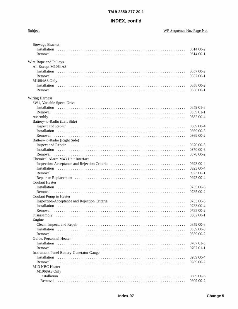
TM 9-2350-277-20-1
INDEX, cont’d
Subject WP Sequence No.-Page No.
Installation . . . . . . . . . . . . . . . . . . . . . . . . . . . . . . . . . . . . . . . . . . . . . . . . . . . . . . . . . . . . 0614 00-2Removal . . . . . . . . . . . . . . . . . . . . . . . . . . . . . . . . . . . . . . . . . . . . . . . . . . . . . . . . . . . . . . 0614 00-1
Wire Rope and PulleysAll Except M1064A3
Installation . . . . . . . . . . . . . . . . . . . . . . . . . . . . . . . . . . . . . . . . . . . . . . . . . . . . . . . . . . . . 0657 00-2Removal . . . . . . . . . . . . . . . . . . . . . . . . . . . . . . . . . . . . . . . . . . . . . . . . . . . . . . . . . . . . . . 0657 00-1
M1064A3 OnlyInstallation . . . . . . . . . . . . . . . . . . . . . . . . . . . . . . . . . . . . . . . . . . . . . . . . . . . . . . . . . . . . 0658 00-2Removal . . . . . . . . . . . . . . . . . . . . . . . . . . . . . . . . . . . . . . . . . . . . . . . . . . . . . . . . . . . . . . 0658 00-1
Wiring Harness3W1, Variable Speed Drive
Installation . . . . . . . . . . . . . . . . . . . . . . . . . . . . . . . . . . . . . . . . . . . . . . . . . . . . . . . . . . . . 0359 01-3Removal . . . . . . . . . . . . . . . . . . . . . . . . . . . . . . . . . . . . . . . . . . . . . . . . . . . . . . . . . . . . . . 0359 01-1
Assembly . . . . . . . . . . . . . . . . . . . . . . . . . . . . . . . . . . . . . . . . . . . . . . . . . . . . . . . . . . . . . . . 0382 00-4Battery-to-Radio (Left Side)
Inspect and Repair . . . . . . . . . . . . . . . . . . . . . . . . . . . . . . . . . . . . . . . . . . . . . . . . . . . . . . . 0369 00-4Installation . . . . . . . . . . . . . . . . . . . . . . . . . . . . . . . . . . . . . . . . . . . . . . . . . . . . . . . . . . . . 0369 00-5Removal . . . . . . . . . . . . . . . . . . . . . . . . . . . . . . . . . . . . . . . . . . . . . . . . . . . . . . . . . . . . . . 0369 00-2
Battery-to-Radio (Right Side)Inspect and Repair . . . . . . . . . . . . . . . . . . . . . . . . . . . . . . . . . . . . . . . . . . . . . . . . . . . . . . . 0370 00-5Installation . . . . . . . . . . . . . . . . . . . . . . . . . . . . . . . . . . . . . . . . . . . . . . . . . . . . . . . . . . . . 0370 00-6Removal . . . . . . . . . . . . . . . . . . . . . . . . . . . . . . . . . . . . . . . . . . . . . . . . . . . . . . . . . . . . . . 0370 00-2
Chemical Alarm M43 Unit InterfaceInspection-Acceptance and Rejection Criteria . . . . . . . . . . . . . . . . . . . . . . . . . . . . . . . . . . . 0923 00-4Installation . . . . . . . . . . . . . . . . . . . . . . . . . . . . . . . . . . . . . . . . . . . . . . . . . . . . . . . . . . . . 0923 00-4Removal . . . . . . . . . . . . . . . . . . . . . . . . . . . . . . . . . . . . . . . . . . . . . . . . . . . . . . . . . . . . . . 0923 00-1Repair or Replacement . . . . . . . . . . . . . . . . . . . . . . . . . . . . . . . . . . . . . . . . . . . . . . . . . . . . 0923 00-4
Coolant HeaterInstallation . . . . . . . . . . . . . . . . . . . . . . . . . . . . . . . . . . . . . . . . . . . . . . . . . . . . . . . . . . . . 0735 00-6Removal . . . . . . . . . . . . . . . . . . . . . . . . . . . . . . . . . . . . . . . . . . . . . . . . . . . . . . . . . . . . . . 0735 00-2
Coolant Pump to HeaterInspection-Acceptance and Rejection Criteria . . . . . . . . . . . . . . . . . . . . . . . . . . . . . . . . . . . 0733 00-3Installation . . . . . . . . . . . . . . . . . . . . . . . . . . . . . . . . . . . . . . . . . . . . . . . . . . . . . . . . . . . . 0733 00-4Removal . . . . . . . . . . . . . . . . . . . . . . . . . . . . . . . . . . . . . . . . . . . . . . . . . . . . . . . . . . . . . . 0733 00-2
Disassembly . . . . . . . . . . . . . . . . . . . . . . . . . . . . . . . . . . . . . . . . . . . . . . . . . . . . . . . . . . . . . 0382 00-1Engine
Clean, Inspect, and Repair . . . . . . . . . . . . . . . . . . . . . . . . . . . . . . . . . . . . . . . . . . . . . . . . . 0359 00-8Installation . . . . . . . . . . . . . . . . . . . . . . . . . . . . . . . . . . . . . . . . . . . . . . . . . . . . . . . . . . . . 0359 00-8Removal . . . . . . . . . . . . . . . . . . . . . . . . . . . . . . . . . . . . . . . . . . . . . . . . . . . . . . . . . . . . . . 0359 00-2
Guide, Personnel HeaterInstallation . . . . . . . . . . . . . . . . . . . . . . . . . . . . . . . . . . . . . . . . . . . . . . . . . . . . . . . . . . . . 0707 01-3Removal . . . . . . . . . . . . . . . . . . . . . . . . . . . . . . . . . . . . . . . . . . . . . . . . . . . . . . . . . . . . . . 0707 01-1
Instrument Panel Battery-Generator GaugeInstallation . . . . . . . . . . . . . . . . . . . . . . . . . . . . . . . . . . . . . . . . . . . . . . . . . . . . . . . . . . . . 0289 00-4Removal . . . . . . . . . . . . . . . . . . . . . . . . . . . . . . . . . . . . . . . . . . . . . . . . . . . . . . . . . . . . . . 0289 00-2
M13 NBC HeaterM1068A3 Only
Installation . . . . . . . . . . . . . . . . . . . . . . . . . . . . . . . . . . . . . . . . . . . . . . . . . . . . . . . . . . 0809 00-6Removal . . . . . . . . . . . . . . . . . . . . . . . . . . . . . . . . . . . . . . . . . . . . . . . . . . . . . . . . . . . . 0809 00-2
Index-97 Change 5
Stowage Bracket
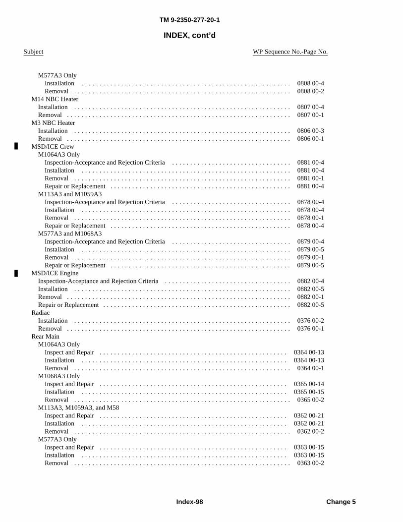
TM 9-2350-277-20-1
INDEX, cont’d
Subject WP Sequence No.-Page No.
M577A3 OnlyInstallation . . . . . . . . . . . . . . . . . . . . . . . . . . . . . . . . . . . . . . . . . . . . . . . . . . . . . . . . . . 0808 00-4Removal . . . . . . . . . . . . . . . . . . . . . . . . . . . . . . . . . . . . . . . . . . . . . . . . . . . . . . . . . . . . 0808 00-2
M14 NBC HeaterInstallation . . . . . . . . . . . . . . . . . . . . . . . . . . . . . . . . . . . . . . . . . . . . . . . . . . . . . . . . . . . . 0807 00-4Removal . . . . . . . . . . . . . . . . . . . . . . . . . . . . . . . . . . . . . . . . . . . . . . . . . . . . . . . . . . . . . . 0807 00-1
M3 NBC HeaterInstallation . . . . . . . . . . . . . . . . . . . . . . . . . . . . . . . . . . . . . . . . . . . . . . . . . . . . . . . . . . . . 0806 00-3Removal . . . . . . . . . . . . . . . . . . . . . . . . . . . . . . . . . . . . . . . . . . . . . . . . . . . . . . . . . . . . . . 0806 00-1
MSD/ICE CrewM1064A3 Only
Inspection-Acceptance and Rejection Criteria . . . . . . . . . . . . . . . . . . . . . . . . . . . . . . . . . 0881 00-4Installation . . . . . . . . . . . . . . . . . . . . . . . . . . . . . . . . . . . . . . . . . . . . . . . . . . . . . . . . . . 0881 00-4Removal . . . . . . . . . . . . . . . . . . . . . . . . . . . . . . . . . . . . . . . . . . . . . . . . . . . . . . . . . . . . 0881 00-1Repair or Replacement . . . . . . . . . . . . . . . . . . . . . . . . . . . . . . . . . . . . . . . . . . . . . . . . . . 0881 00-4
M113A3 and M1059A3Inspection-Acceptance and Rejection Criteria . . . . . . . . . . . . . . . . . . . . . . . . . . . . . . . . . 0878 00-4Installation . . . . . . . . . . . . . . . . . . . . . . . . . . . . . . . . . . . . . . . . . . . . . . . . . . . . . . . . . . 0878 00-4Removal . . . . . . . . . . . . . . . . . . . . . . . . . . . . . . . . . . . . . . . . . . . . . . . . . . . . . . . . . . . . 0878 00-1Repair or Replacement . . . . . . . . . . . . . . . . . . . . . . . . . . . . . . . . . . . . . . . . . . . . . . . . . . 0878 00-4
M577A3 and M1068A3Inspection-Acceptance and Rejection Criteria . . . . . . . . . . . . . . . . . . . . . . . . . . . . . . . . . 0879 00-4Installation . . . . . . . . . . . . . . . . . . . . . . . . . . . . . . . . . . . . . . . . . . . . . . . . . . . . . . . . . . 0879 00-5Removal . . . . . . . . . . . . . . . . . . . . . . . . . . . . . . . . . . . . . . . . . . . . . . . . . . . . . . . . . . . . 0879 00-1Repair or Replacement . . . . . . . . . . . . . . . . . . . . . . . . . . . . . . . . . . . . . . . . . . . . . . . . . . 0879 00-5
MSD/ICE EngineInspection-Acceptance and Rejection Criteria . . . . . . . . . . . . . . . . . . . . . . . . . . . . . . . . . . . 0882 00-4Installation . . . . . . . . . . . . . . . . . . . . . . . . . . . . . . . . . . . . . . . . . . . . . . . . . . . . . . . . . . . . 0882 00-5Removal . . . . . . . . . . . . . . . . . . . . . . . . . . . . . . . . . . . . . . . . . . . . . . . . . . . . . . . . . . . . . . 0882 00-1Repair or Replacement . . . . . . . . . . . . . . . . . . . . . . . . . . . . . . . . . . . . . . . . . . . . . . . . . . . . 0882 00-5
RadiacInstallation . . . . . . . . . . . . . . . . . . . . . . . . . . . . . . . . . . . . . . . . . . . . . . . . . . . . . . . . . . . . 0376 00-2Removal . . . . . . . . . . . . . . . . . . . . . . . . . . . . . . . . . . . . . . . . . . . . . . . . . . . . . . . . . . . . . . 0376 00-1
Rear MainM1064A3 Only
Inspect and Repair . . . . . . . . . . . . . . . . . . . . . . . . . . . . . . . . . . . . . . . . . . . . . . . . . . . . 0364 00-13Installation . . . . . . . . . . . . . . . . . . . . . . . . . . . . . . . . . . . . . . . . . . . . . . . . . . . . . . . . . 0364 00-13Removal . . . . . . . . . . . . . . . . . . . . . . . . . . . . . . . . . . . . . . . . . . . . . . . . . . . . . . . . . . . . 0364 00-1
M1068A3 OnlyInspect and Repair . . . . . . . . . . . . . . . . . . . . . . . . . . . . . . . . . . . . . . . . . . . . . . . . . . . . 0365 00-14Installation . . . . . . . . . . . . . . . . . . . . . . . . . . . . . . . . . . . . . . . . . . . . . . . . . . . . . . . . . 0365 00-15Removal . . . . . . . . . . . . . . . . . . . . . . . . . . . . . . . . . . . . . . . . . . . . . . . . . . . . . . . . . . . . 0365 00-2
M113A3, M1059A3, and M58Inspect and Repair . . . . . . . . . . . . . . . . . . . . . . . . . . . . . . . . . . . . . . . . . . . . . . . . . . . . 0362 00-21Installation . . . . . . . . . . . . . . . . . . . . . . . . . . . . . . . . . . . . . . . . . . . . . . . . . . . . . . . . . 0362 00-21Removal . . . . . . . . . . . . . . . . . . . . . . . . . . . . . . . . . . . . . . . . . . . . . . . . . . . . . . . . . . . . 0362 00-2
M577A3 OnlyInspect and Repair . . . . . . . . . . . . . . . . . . . . . . . . . . . . . . . . . . . . . . . . . . . . . . . . . . . . 0363 00-15Installation . . . . . . . . . . . . . . . . . . . . . . . . . . . . . . . . . . . . . . . . . . . . . . . . . . . . . . . . . 0363 00-15Removal . . . . . . . . . . . . . . . . . . . . . . . . . . . . . . . . . . . . . . . . . . . . . . . . . . . . . . . . . . . . 0363 00-2
Index-98 Change 5
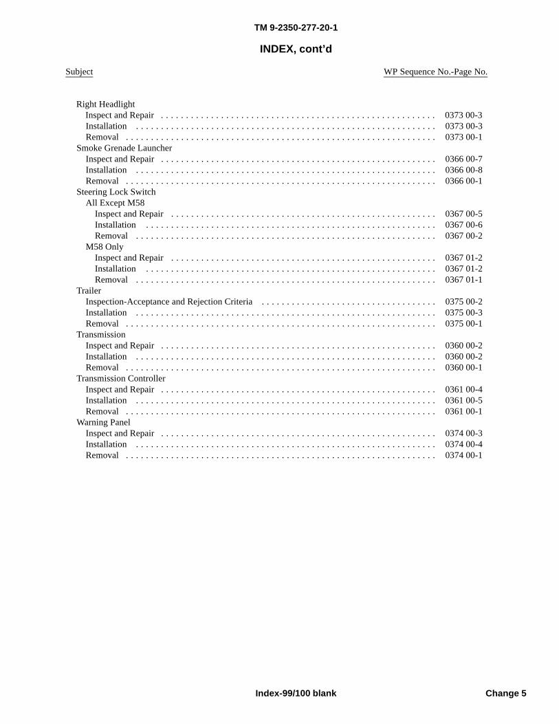
TM 9-2350-277-20-
INDEX, cont’d
Subject WP Sequence No.-Page No.
Installation . . . . . . . . . . . . . . . . . . . . . . . . . . . . . . . . . . . . . . . . . . . . . . . . . . . . . . . . . . . . 0373 00-3Removal . . . . . . . . . . . . . . . . . . . . . . . . . . . . . . . . . . . . . . . . . . . . . . . . . . . . . . . . . . . . . . 0373 00-1
Smoke Grenade LauncherInspect and Repair . . . . . . . . . . . . . . . . . . . . . . . . . . . . . . . . . . . . . . . . . . . . . . . . . . . . . . . 0366 00-7Installation . . . . . . . . . . . . . . . . . . . . . . . . . . . . . . . . . . . . . . . . . . . . . . . . . . . . . . . . . . . . 0366 00-8Removal . . . . . . . . . . . . . . . . . . . . . . . . . . . . . . . . . . . . . . . . . . . . . . . . . . . . . . . . . . . . . . 0366 00-1
Steering Lock SwitchAll Except M58
Inspect and Repair . . . . . . . . . . . . . . . . . . . . . . . . . . . . . . . . . . . . . . . . . . . . . . . . . . . . . 0367 00-5Installation . . . . . . . . . . . . . . . . . . . . . . . . . . . . . . . . . . . . . . . . . . . . . . . . . . . . . . . . . . 0367 00-6Removal . . . . . . . . . . . . . . . . . . . . . . . . . . . . . . . . . . . . . . . . . . . . . . . . . . . . . . . . . . . . 0367 00-2
M58 OnlyInspect and Repair . . . . . . . . . . . . . . . . . . . . . . . . . . . . . . . . . . . . . . . . . . . . . . . . . . . . . 0367 01-2Installation . . . . . . . . . . . . . . . . . . . . . . . . . . . . . . . . . . . . . . . . . . . . . . . . . . . . . . . . . . 0367 01-2Removal . . . . . . . . . . . . . . . . . . . . . . . . . . . . . . . . . . . . . . . . . . . . . . . . . . . . . . . . . . . . 0367 01-1
TrailerInspection-Acceptance and Rejection Criteria . . . . . . . . . . . . . . . . . . . . . . . . . . . . . . . . . . . 0375 00-2Installation . . . . . . . . . . . . . . . . . . . . . . . . . . . . . . . . . . . . . . . . . . . . . . . . . . . . . . . . . . . . 0375 00-3Removal . . . . . . . . . . . . . . . . . . . . . . . . . . . . . . . . . . . . . . . . . . . . . . . . . . . . . . . . . . . . . . 0375 00-1
TransmissionInspect and Repair . . . . . . . . . . . . . . . . . . . . . . . . . . . . . . . . . . . . . . . . . . . . . . . . . . . . . . . 0360 00-2Installation . . . . . . . . . . . . . . . . . . . . . . . . . . . . . . . . . . . . . . . . . . . . . . . . . . . . . . . . . . . . 0360 00-2Removal . . . . . . . . . . . . . . . . . . . . . . . . . . . . . . . . . . . . . . . . . . . . . . . . . . . . . . . . . . . . . . 0360 00-1
Transmission ControllerInspect and Repair . . . . . . . . . . . . . . . . . . . . . . . . . . . . . . . . . . . . . . . . . . . . . . . . . . . . . . . 0361 00-4Installation . . . . . . . . . . . . . . . . . . . . . . . . . . . . . . . . . . . . . . . . . . . . . . . . . . . . . . . . . . . . 0361 00-5Removal . . . . . . . . . . . . . . . . . . . . . . . . . . . . . . . . . . . . . . . . . . . . . . . . . . . . . . . . . . . . . . 0361 00-1
Warning PanelInspect and Repair . . . . . . . . . . . . . . . . . . . . . . . . . . . . . . . . . . . . . . . . . . . . . . . . . . . . . . . 0374 00-3Installation . . . . . . . . . . . . . . . . . . . . . . . . . . . . . . . . . . . . . . . . . . . . . . . . . . . . . . . . . . . . 0374 00-4Removal . . . . . . . . . . . . . . . . . . . . . . . . . . . . . . . . . . . . . . . . . . . . . . . . . . . . . . . . . . . . . . 0374 00-1
Index-99/100 blank Change 5
Right HeadlightInspect and Repair . . . . . . . . . . . . . . . . . . . . . . . . . . . . . . . . . . . . . . . . . . . . . . . . . . . . . . . 0373 00-3
1

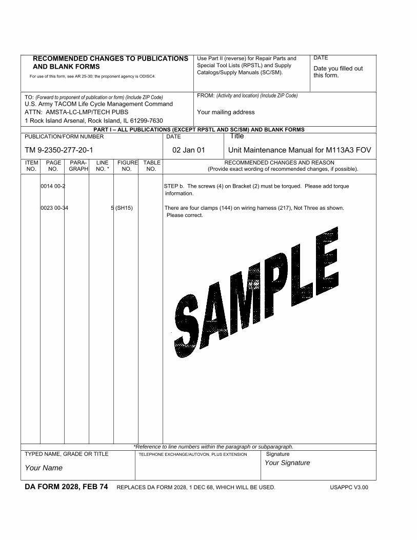
RECOMMENDED CHANGES TO PUBLICATIONS AND BLANK FORMS
For use of this form, see AR 25-30; the proponent agency is ODISC4.
Use Part II (reverse) for Repair Parts and Special Tool Lists (RPSTL) and Supply Catalogs/Supply Manuals (SC/SM).
DATE
Date you filled out this form.
TO: (Forward to proponent of publication or form) (Include ZIP Code) U.S. Army TACOM Life Cycle Management Command ATTN: AMSTA-LC-LMP/TECH PUBS 1 Rock Island Arsenal, Rock Island, IL 61299-7630
FROM: (Activity and location) (Include ZIP Code)
Your mailing address
PART I – ALL PUBLICATIONS (EXCEPT RPSTL AND SC/SM) AND BLANK FORMS PUBLICATION/FORM NUMBER DATE Title TM 9-2350-277-20-1 02 Jan 01 Unit Maintenance Manual for M113A3 FOV ITEMNO.
PAGENO.
PARA-GRAPH
LINENO. *
FIGURENO.
TABLENO.
RECOMMENDED CHANGES AND REASON (Provide exact wording of recommended changes, if possible).
*Reference to line numbers within the paragraph or subparagraph. TYPED NAME, GRADE OR TITLE
Your Name
TELEPHONE EXCHANGE/AUTOVON, PLUS EXTENSION Signature
Your Signature
DA FORM 2028, FEB 74 REPLACES DA FORM 2028, 1 DEC 68, WHICH WILL BE USED. USAPPC V3.00
0014 00-2 STEP b. The screws (4) on Bracket (2) must be torqued. Please add torque information. 0023 00-34 5 (SH15) There are four clamps (144) on wiring harness (217), Not Three as shown. Please correct.
TO: (Forward direct to addressee listed in publication) U. S. Army TACOM Life Cycle Management Command ATTN: AMSTA-LC-LMPP/TECH PUBS 1 Rock Island Arsenal, Rock Island, IL 61299-7630
FROM: (Activity and location) (Include ZIP Code)
Your address DATEDate you filled out this form
PART II – REPAIR PARTS AND SPECIAL TOOL LISTS AND SUPPLY CATALOGS/SUPPLY MANUALS PUBLICATION NUMBER DATE TITLE
PAGENO.
COLMNO.
LINENO.
NATIONAL STOCK NUMBER
REFERENCENO.
FIGURENO.
ITEMNO.
TOTAL NO.OF MAJOR
ITEMSSUPPORTED
RECOMMENDED ACTION
PART III – REMARKS (Any general remarks or recommendations, or suggestions for improvement of publications and blank forms. Additional blank sheets may be used if more space is needed.)
TYPED NAME, GRADE OR TITLE
Your Name
TELEPHONE EXCHANGE/AUTOVON, PLUS EXTENSION SIGNATURE
Your Signature
USAPPC V3.00
SAMPLE
TM 9-2350-277-20-1 02 Jan 01 Unit Maintenance Manual for M113A3 FOV
RECOMMENDED CHANGES TO PUBLICATIONS AND BLANK FORMS
For use of this form, see AR 25-30; the proponent agency is ODISC4.
Use Part II (reverse) for Repair Parts and Special Tool Lists (RPSTL) and Supply Catalogs/Supply Manuals (SC/SM).
DATE
U.S. Army TACOM Life Cycle Management Command ATTN: AMSTA-LC-LMPP/TECH PUBS 1 Rock Island Arsenal, Rock Island, IL 61299-7630
FROM: (Activity and location) (Include ZIP Code)
PART I – ALL PUBLICATIONS (EXCEPT RPSTL AND SC/SM) AND BLANK FORMS PUBLICATION/FORM NUMBER DATE TITLE
TM 9-2350-277-20-1 02 Jan 01 Unit Maintenance Manual for M113A3 FOV ITEMNO.
PAGENO.
PARA-GRAPH
LINENO. *
FIGURENO.
TABLENO.
RECOMMENDED CHANGES AND REASON (Provide exact wording of recommended changes, if possible).
*Reference to line numbers within the paragraph or subparagraph.
TYPED NAME, GRADE OR TITLE TELEPHONE EXCHANGE/AUTOVON, PLUS EXTENSION
SIGNATURE
DA FORM 2028, FEB 74 REPLACES DA FORM 2028, 1 DEC 68, WHICH WILL BE USED. USAPPC V3.00
TO: (Forward to proponent of publication or form)(Include ZIP Code)
TO: (Forward direct to addressee listed in publication) U. S. Army TACOM Life Cycle Management Command ATTN: AMSTA-LC-LMPP/TECH PUBS1 Rock Island Arsenal, Rock Island, IL 61299-7630
FROM: (Activity and location) (Include ZIP Code) DATE
PART II – REPAIR PARTS AND SPECIAL TOOL LISTS AND SUPPLY CATALOGS/SUPPLY MANUALS
PUBLICATION NUMBER DATE TITLE
PAGENO.
COLMNO.
LINENO.
NATIONAL STOCK NUMBER
REFERENCENO.
FIGURENO.
ITEMNO.
TOTAL NO.OF MAJOR
ITEMSSUPPORTED
RECOMMENDED ACTION
PART III – REMARKS (Any general remarks or recommendations, or suggestions for improvement of publications and blank forms. Additional blank sheets may be used if more space is needed.)
TYPED NAME, GRADE OR TITLE TELEPHONE EXCHANGE/AUTOVON, PLUS EXTENSION SIGNATURE
USAPPC V3.00
TM 9-2350-277-20-1 02 Jan 01 Unit Maintenance Manual for M113A3 FOV
RECOMMENDED CHANGES TO PUBLICATIONS AND BLANK FORMS
For use of this form, see AR 25-30; the proponent agency is ODISC4.
Use Part II (reverse) for Repair Parts and Special Tool Lists (RPSTL) and Supply Catalogs/Supply Manuals (SC/SM).
DATE
TO: (Forward to proponent of publication or form) (Include ZIP Code) U. S. Army TACOM Life Cycle Management Command ATTN: AMSTA-LC-LMPP/TECH PUBS 1 Rock Island Arsenal, Rock Island, IL 61299-7630
FROM: (Activity and location) (Include ZIP Code)
PUBLICATION/FORM NUMBER DATE TITLE TM 9-2350-277-20-1 02 Jan 01 Unit Maintenance Manual for M113A3 FOV
ITEM NO.
PAGENO.
PARA-GRAPH
LINE NO. *
FIGURENO.
TABLENO.
RECOMMENDED CHANGES AND REASON (Provide exact wording of recommended changes, if possible).
*Reference to line numbers within the paragraph or subparagraph.
TYPED NAME, GRADE OR TITLE TELEPHONE EXCHANGE/AUTOVON, PLUS EXTENSION
SIGNATURE
DA FORM 2028, FEB 74 REPLACES DA FORM 2028, 1 DEC 68, WHICH WILL BE USED. USAPPC V3.00
TO: (Forward direct to addressee listed in publication)U. S. Army TACOM Life Cycle Management Command ATTN: AMSTA-LC-LMPP/TECH PUBS1 Rock Island Arsenal, Rock Island, IL 61299-7630
FROM: (Activity and location) (Include ZIP Code) DATE
PART II – REPAIR PARTS AND SPECIAL TOOL LISTS AND SUPPLY CATALOGS/SUPPLY MANUALS
PUBLICATION NUMBER DATE TITLE TM 9-2350-277-20-1 02 Jan 01 Unit Maintenance Manual for M113A3 FOV
PAGENO.
COLMNO.
LINENO.
NATIONAL STOCK NUMBER
REFERENCENO.
FIGURENO.
ITEMNO.
TOTAL NO.OF MAJOR
ITEMSSUPPORTED
RECOMMENDED ACTION
PART III – REMARKS (Any general remarks or recommendations, or suggestions for improvement of publications and blank forms. Additional blank sheets may be used if more space is needed.)
TYPED NAME, GRADE OR TITLE TELEPHONE EXCHANGE/AUTOVON, PLUS EXTENSION SIGNATURE
USAPPC V3.00
9913202 DISTRIBUTION: To be distributed in accordance with the initial distribution requirements for IDN: 371205, requirements for TM 9-2350-277-20-1.
By Order of the Secretary of the Army:
ERIC K. SHINSEKI General, United States Army
Chief of Staff Official:
JOEL B. HUDSON Administrative Assistant to the
Secretary of the Army

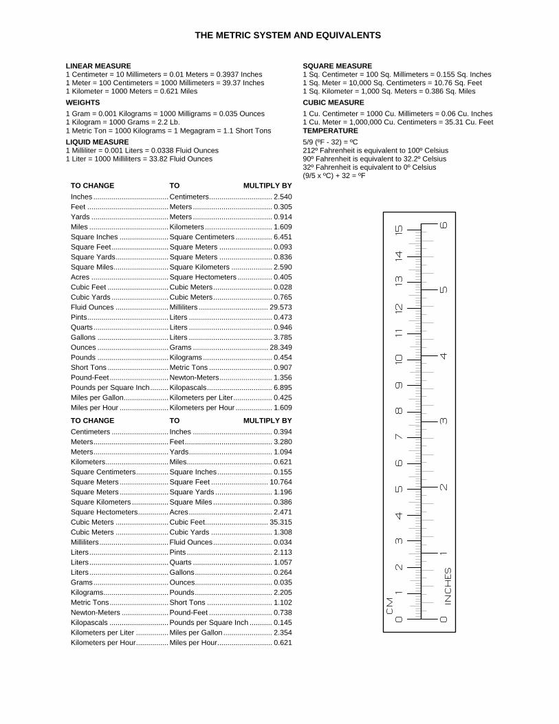
THE METRIC SYSTEM AND EQUIVALENTS
LINEAR MEASURE SQUARE MEASURE 1 Centimeter = 10 Millimeters = 0.01 Meters = 0.3937 Inches 1 Sq. Centimeter = 100 Sq. Millimeters = 0.155 Sq. Inches 1 Meter = 100 Centimeters = 1000 Millimeters = 39.37 Inches 1 Sq. Meter = 10,000 Sq. Centimeters = 10.76 Sq. Feet 1 Kilometer = 1000 Meters = 0.621 Miles 1 Sq. Kilometer = 1,000 Sq. Meters = 0.386 Sq. Miles
WEIGHTS CUBIC MEASURE 1 Gram = 0.001 Kilograms = 1000 Milligrams = 0.035 Ounces 1 Cu. Centimeter = 1000 Cu. Millimeters = 0.06 Cu. Inches 1 Kilogram = 1000 Grams = 2.2 Lb. 1 Cu. Meter = 1,000,000 Cu. Centimeters = 35.31 Cu. Feet 1 Metric Ton = 1000 Kilograms = 1 Megagram = 1.1 Short Tons TEMPERATURE
LIQUID MEASURE 5/9 (ºF - 32) = ºC 1 Milliliter = 0.001 Liters = 0.0338 Fluid Ounces 212º Fahrenheit is equivalent to 100º Celsius 1 Liter = 1000 Milliliters = 33.82 Fluid Ounces 90º Fahrenheit is equivalent to 32.2º Celsius 32º Fahrenheit is equivalent to 0º Celsius (9/5 x ºC) + 32 = ºF
TO CHANGE TO MULTIPLY BY Inches ..................................... Centimeters............................... 2.540 Feet ........................................ Meters ....................................... 0.305 Yards ...................................... Meters ....................................... 0.914 Miles ....................................... Kilometers ................................. 1.609 Square Inches ........................ Square Centimeters .................. 6.451 Square Feet............................ Square Meters .......................... 0.093 Square Yards.......................... Square Meters .......................... 0.836 Square Miles........................... Square Kilometers .................... 2.590 Acres ...................................... Square Hectometers ................. 0.405 Cubic Feet .............................. Cubic Meters............................. 0.028 Cubic Yards ............................ Cubic Meters............................. 0.765 Fluid Ounces .......................... Milliliters .................................. 29.573 Pints........................................ Liters ......................................... 0.473 Quarts..................................... Liters ......................................... 0.946 Gallons ................................... Liters ......................................... 3.785 Ounces ................................... Grams ..................................... 28.349 Pounds ................................... Kilograms .................................. 0.454 Short Tons .............................. Metric Tons ............................... 0.907 Pound-Feet............................. Newton-Meters.......................... 1.356 Pounds per Square Inch......... Kilopascals................................ 6.895 Miles per Gallon...................... Kilometers per Liter................... 0.425 Miles per Hour ........................ Kilometers per Hour .................. 1.609
TO CHANGE TO MULTIPLY BY Centimeters ............................ Inches ....................................... 0.394 Meters..................................... Feet........................................... 3.280 Meters..................................... Yards......................................... 1.094 Kilometers............................... Miles.......................................... 0.621 Square Centimeters................ Square Inches........................... 0.155 Square Meters ........................ Square Feet ............................ 10.764 Square Meters ........................ Square Yards ............................ 1.196 Square Kilometers .................. Square Miles ............................. 0.386 Square Hectometers............... Acres......................................... 2.471 Cubic Meters .......................... Cubic Feet............................... 35.315 Cubic Meters .......................... Cubic Yards .............................. 1.308 Milliliters.................................. Fluid Ounces............................. 0.034 Liters....................................... Pints .......................................... 2.113 Liters....................................... Quarts ....................................... 1.057 Liters....................................... Gallons...................................... 0.264 Grams..................................... Ounces...................................... 0.035 Kilograms................................ Pounds...................................... 2.205 Metric Tons............................. Short Tons ................................ 1.102 Newton-Meters ....................... Pound-Feet ............................... 0.738 Kilopascals ............................. Pounds per Square Inch ........... 0.145 Kilometers per Liter ................ Miles per Gallon ........................ 2.354 Kilometers per Hour................ Miles per Hour........................... 0.621

PIN: 062444-000

This fine document...
Was brought to you by me:
Liberated Manuals -- free army and government manuals
Why do I do it? I am tired of sleazy CD-ROM sellers, who take publicly available information, slap “watermarks” and other junk on it, and sell it. Those masters of search engine manipulation make sure that their sites that sell free information, come up first in search engines. They did not create it... They did not even scan it... Why should they get your money? Why are not letting you give those free manuals to your friends?
I am setting this document FREE. This document was made by the US Government and is NOT protected by Copyright. Feel free to share, republish, sell and so on.
I am not asking you for donations, fees or handouts. If you can, please provide a link to liberatedmanuals.com, so that free manuals come up first in search engines:
<A HREF=http://www.liberatedmanuals.com/>Free Military and Government Manuals</A>
– SincerelyIgor Chudovhttp://igor.chudov.com/
– Chicago Machinery Movers
Related Documents