TM 9-2350-238-20P TECHNICAL MANUAL ORGANIZATIONAL MAINTENANCE REPAIR PARTS AND SPECIAL TOOLS LIST FOR RECOVERY VEHICLE, FULL TRACKED: LIGHT, ARMORED, M578 (NSN 2350-00-439-6242) PART I HULL AND RELATED COMPONENTS PART II CRANE (CAB) COMPONENTS HEADQUARTERS, DEPARTMENT OF THE ARMY 15 APRIL 1982

Welcome message from author
This document is posted to help you gain knowledge. Please leave a comment to let me know what you think about it! Share it to your friends and learn new things together.
Transcript

TM 9-2350-238-20P
TECHNICAL MANUAL
ORGANIZATIONALMAINTENANCEREPAIR PARTS ANDSPECIAL TOOLS LIST
FOR
RECOVERY VEHICLE,FULL TRACKED:
LIGHT, ARMORED, M578(NSN 2350-00-439-6242)
PART IHULL AND RELATED COMPONENTS
PART IICRANE (CAB) COMPONENTS
HEADQUARTERS, DEPARTMENT OF THE ARMY15 APRIL 1982
*TM 9-2350-238-20P
TECHNICAL MANUAL HEADQUARTERSDEPARTMENT OF THE ARMY
NO. 9-2350-238-20P Washington, DC, 15 April 1982
ORGANIZATIONAL MAINTENANCE
REPAIR PARTS AND SPECIAL TOOLS LIST
FOR
RECOVERY VEHICLE, FULL TRACKED:
LIGHT, ARMORED, M578
(NSN 2350-00-439-6242)
REPORTING OF ERRORS
You can help improve this manual. If you find any mistake or if you know of a way toimprove the procedures, please let us know. Mail your letter, DA Form 2028(Recommended Changes to Publications and Blank Forms), or DA Form 2028-2 locatedin the back of this manual direct to: Commander, US Army Armament Materiel ReadinessCommand, ATTN: DRSAR-MAS, Rock Island, IL 61299. A reply will be furnished to you.
Illus.Page Figure
Section I. INTRODUCTION .............................................................................................................1 - 4
PART I HULL AND RELATED COMPONENTS
II. REPAIR PARTS LIST (Part I) ...........................................................................................7
Group 01 Engine
0100 Engine Mount .........................................................................................................7 10105 Rocker Cover .........................................................................................................8 20106 Oil Filter Assembly - 5126546 ..................................................................................10, 11 30106 Oil Cooler ...............................................................................................................12 40106 Crankcase Engine Breather.....................................................................................13 50106 Oil Level Gage........................................................................................................14 60106 Oil Pan...................................................................................................................15 70106 External Oil Lines and Fittings (upper engine)...........................................................16, 17 80106 External Oil Lines and Fittings (lower engine), and scavenger reservoir......................18, 19 9
03 Fuel
0302 Fuel Pump..............................................................................................................20 100302 Fuel Lines ..............................................................................................................21 110304 Engine Air Cleaner System......................................................................................22,23 120304 Engine Intake Air Ducts...........................................................................................24 130305 Turbocharger Lines and Fittings...............................................................................25 14
*This manual supersedes TM 9-2350-238-20P, 13 April 1972.i

TM 9-2350-238-20P
Illus.Page Figure
0305 Turbocharger Regulator ..........................................................................................26 150305 Turbocharger Air Intake Ducts .................................................................................27 160305 Engine Blower Air Intake Duct .................................................................................28 170306 Fabric fuel cells installation ......................................................................................29 180306 Fuel lines and fittings (low pressure) couplings to engine...........................................30, 31 190306 Fuel lines and fittings (low pressure) couplings to fuel cells........................................32, 33 200309 Fuel strainer and filter (primary) ...............................................................................34, 35 210309 Fuel strainer and filter (secondary)...........................................................................36, 37 220311 Fuel and purge-and-prime lines and fittings ..............................................................38 230312 Throttle and accelerator controls and linkage (driver's compartment)..........................39 240312 Throttle and accelerator controls and linkage (engine compartment)...........................40, 41 25
Group 04 Exhaust0401 Exhaust system......................................................................................................42 26
05 Cooling0501 Radiator and related parts .......................................................................................44, 45 270501 Radiator support beam and related parts..................................................................46 280501 Surge tank and related parts....................................................................................47 290503 Coolant by-pass and cross-over tube .......................................................................48 300503 Cooling system hoses, pipes and related parts .........................................................50, 51 310503 Thermostat housing ................................................................................................52 320503 Aeration detector ....................................................................................................53 330504 Engine coolant pump...............................................................................................54 340505 Cooling system fan, tensioner and related parts.......................................................56, 57 35
06 Electrical0601 Generator and cooling air intake system...................................................................58, 59 360602 Voltage regulator and related parts ..........................................................................60 370603 Engine starter . .......................................................................................................61 380603 Starter relay and related parts..................................................................................62 390606 Neutral position switch and related parts . ................................................................63 400607 Driver's instrument panels installation.......................................................................64 410607 Driver's instrument panel assembly (switch) - 10904806............................................66, 67 420607 Driver's instrument panel assembly (gage and indicator) - 10892415..........................68, 69 430607 Indicator light assembly - 11592992.........................................................................70 440607 Indication light assembly - 8376499..........................................................................71 450607 Indicator light assembly - 8376500 ...........................................................................72 460607 Air box heater controls bracket assembly..................................................................73 470608 Miscellaneous electrical components .......................................................................74 480608 Electrical accessories panel assembly - 11675629....................................................76, 77 490609 Headlamp, dome light, and stop light-taillight installation............................................78, 79 500609 Dual headlamp assembly - 7972325 ........................................................................80, 81 510609 Left vehicular stop light-taillight assembly - 8378785 .................................................82 520609 Right vehicular stop light-taillight assembly - 8378786 ...............................................83 530609 Dome light assembly - 7064671...............................................................................84, 85 540610 Sending units, warning switches and light .................................................................86, 87 550610 Low engine coolant warning light assembly - 11675565.............................................88 560611 Audible warning horn and related parts. ...................................................................89 570612 Batteries, electrical leads and related parts...............................................................90 580613 Electrical wiring - hull aft ..........................................................................................91 590613 Bulkhead disconnect to switch panel wiring harness - 10881944...............................92 600613 Bulkhead disconnect to engine components and warning units
wiring harness - 10882032.................................................................................94, 95 610613 Bulkhead disconnect to driver's control switches wiring harness - 10882033...............96, 97 62
ii
TM 9-2350-238-20P
Illus.Page Figure
0613 Suspension lockout system warning light and horn ground electricallead - 10892526................................................................................................98 63
0613 Line connection to right headlamp disconnect wiring harness - 10901827...................99 640613 Trailer receptacle assembly to disconnect wiring harness - 10901829 ........................100 650613 Battery to circuit breaker electrical lead - 10901835...................................................101 660613 Bulkhead disconnect to generator armature electrical lead - 10901840.......................102 670613 Bulkhead disconnect to starter electrical lead - 10901842..........................................103 680613 Bulkhead to bulkhead generator circuit electrical lead - 10901844..............................104 690613 Bulkhead disconnect to voltage regulator assembly wiring harness - 10901852 ..........106, 107 700613 Floor disconnect to bulkhead disconnect wiring harness - 10901855 ..........................108 710613 Bulkhead disconnect to magnetic clutch electrical lead - 10901856............................109 720613 Bulkhead disconnect to circuit breaker panel wiring harness - 10904973....................110 730613 Hull disconnect to slip ring electrical lead - 10904974 ................................................111 740613 Blower to ground electrical lead - 10914828..............................................................112 750613 Intercom circuit bulkhead to disconnect to slip ring wiring harness - 10914906............113 760613 Horn to warning relay wiring harness - 10919885......................................................114 770613 Generator control circuits to bracket disconnect wiring harness - 10919889................115 780613 Disconnect to instrument panel wiring harness - 10934573........................................116 790613 Disconnect to forward air cleaner blower motor electrical lead - 10934867..................117 800613 Bulkhead disconnect to trailer receptacle disconnect, aft blower motor and
taillights wiring harness - 10956785....................................................................118, 119 810613 Lighting switch to vehicle accessories and disconnect wiring harness - 11592728.......120, 121 820613 Battery to bulkhead disconnect electrical lead - 11592730.........................................122 830613 Bulkhead to bulkhead starter circuit electrical lead - 11592731...................................123 840613 Disconnect to headlamp wiring harness - 11592755..................................................124 850613 Relay to starter and neutral position switch wiring harness - 11643129.......................125 860613 Fuel purge-and-prime switch to solenoid electrical lead - 11675547 ...........................126 870613 Warning light low coolant detector to bulkhead disconnect wiring harness - 11675566.127 880613 Aeration detector connector assembly - 11675567 ....................................................128 890613 Low coolant warning light to bulkhead disconnect wiring harness - 11675568.............129 900613 Master relay to bulkhead disconnect electrical lead - 11675625 .................................130 910613 Voltage regulator to bulkhead disconnects, slave receptacle and accessories
panel cable assembly - 11675627 ......................................................................132, 133 920615 Radio static suppression spring................................................................................134 93
Group 07 Transmission
0710 Transmission components.......................................................................................135 940714 Transmission plugs .................................................................................................136 950721 Transmission oil filter and gage rod..........................................................................137 96
08 Transfer and final drive assemblies
0801 Transfer and final drive assemblies ..........................................................................138 970801 Right and left output drives ......................................................................................139 980801 Auxiliary drive installation ........................................................................................140, 141 990801 Auxiliary drive assembly - 11675634 (clutch) ............................................................142, 143 1000801 Oil fill tube assembly - 10934580 .............................................................................144 1010801 Oil drain tube assembly - 10902501-1 ......................................................................145 1020803 Shifting control and linkage......................................................................................146, 147 1030804 Impact wrench control hydraulic lines and fittings ......................................................148, 149 1040804 Hydraulic power supply lines and fittings (forward section).........................................150, 151 1050804 Hydraulic power supply lines and fittings (aft section) ................................................152, 153 1060804 Hydraulic pressure line filter - MS28895-12...............................................................154, 155 107
iii

TM 9-2350-238-20P
Illus.Page Figure
Group 09 Propeller and Propeller Shafts
0900 Auxiliary drive shafts, universal joints and related parts .............................................156, 157 108
12 Brakes1201 Parking brake control and linkage ............................................................................158 1091201 Parking brake assembly - 10902170 ........................................................................159 1101206 Mechanical brake control and linkage.......................................................................160, 161 111
13 Wheels and Track
1301 Torsion bars and sockets ........................................................................................162, 163 1121301 Roadwheel arm and hub assembly and attaching parts .............................................164, 165 1131301 Roadwheel arm and hub assembly - 10891653.........................................................166, 167 1141301 Roadwheel hub assembly - 11631593......................................................................168 1151301 Roadwheel wheel....................................................................................................169 1161303 Idler wheel arm and hub assembly and attaching parts..............................................170, 171 1171303 Idler wheel arm and hub assembly - 10891675 .........................................................172, 173 1181303 Idler wheel hub assembly -10891677 .......................................................................174 1191303 Idler wheel and left lubrication tube ..........................................................................175 1201304 Drive hub, sprockets and related parts .....................................................................176 1211305 Track installation.....................................................................................................177 1221305 Track shoe assembly - 10934639.............................................................................178 123
14 Steering
1401 Steering controls and linkage...................................................................................180, 181 124
15 Frame towing attachments
1503 Towing pintle assembly - 8710630 ...........................................................................182 1251503 Tow hook and related parts .....................................................................................183 126
16 Springs and shock absorbers
1604 Lockout cylinder and related parts............................................................................184 1271604 Suspension lockout system control valve and associated parts..................................186, 187 1281604 Suspension system hydraulic lines and fittings ..........................................................188, 189 129
18 Hull
1801 Hull covers, doors, and plates ..................................................................................190, 191, 192 1301801 Hull decks and miscellaneous components...............................................................194, 195 1311802 Mud guard, fender extensions and attaching parts ....................................................196 1321803 Driver's hatch cover and related parts ......................................................................198, 199 1331804 Hull drain plugs, valves and related parts .................................................................200, 201 1341806 Driver's seat and associated parts............................................................................202, 203 1351806 Driver's seat assembly - 10901351...........................................................................204, 205 1361808 Hull stowage clamps, retainers and associated parts.................................................206, 207 137
20 Power take-off and spade
2005 Spade and related parts ..........................................................................................208, 209 1382005 Spade hydraulic control valves, lines and fittings .......................................................210, 211 139
iv

TM 9-2350-238-20P
Illus.Page Figure
Group 22 Data Plates2210 Vehicle data plates ..................................................................................................212, 213 140
33 Special Purpose Kits3303 Hull heater kit - 11643540 - coolant and driver's heaters and exhaust lines .................214, 215 1413303 Hull heater kit - 11643540 - battery box supports & related parts................................216, 217 1423303 Hull heater kit - 11643540 - battery box and covers ...................................................218, 219 1433303 Hull heater kit - 11643540 - hoses and fittings...........................................................220, 221 1443303 Hull heater kit - 11643540 - fuel lines and fittings ......................................................222, 223 1453303 Hull heater kit - 11643540 - driver's heater air hoses .................................................224 1463303 Hull heater kit - 11643540 - air intake blower, fuel filter heaters and
connecting harness...........................................................................................225 1473303 Hull heater kit - 11643540- electrical components and wiring .....................................226, 227 1483303 Hull heater kit - 11643540 - air intake covers, plates and related parts........................228, 229 1493303 Battery positive terminal to circuit breaker electrical lead - 10934557..........................230 1503303 Coolant heater circuit breaker to line disconnect electrical lead - 11643550 ................231 1513303 Heater control box to driver's heater wiring harness - 11643582.................................232 1523303 Bulkhead disconnects to master relay and circuit breakers electrical lead - 11643585 .233 1533303 Bulkhead disconnect to circuit breakers and electrical components wiring
harness- 11643591 ...........................................................................................234, 235 1543303 Engine compartment wiring harness - 11643592.......................................................236, 237 1553303 Filter mounting plate assembly - 11643577...............................................................238 1563303 Pyrometer panel assembly - 11643533.....................................................................240, 214 1573303 Driver's heater control box assembly - 10885798......................................................242 1583303 Coolant heater assembly - 11643561.......................................................................244, 245, 246 1593303 Coolant heater control box assembly - 10885798......................................................247 1603303 Heater control box to coolant heater wiring harness - 11617762.................................248 1613303 Coolant heater assembly - 11601698.......................................................................250, 251 1623303 Driver's heater assembly - 11643581 .......................................................................252, 253 1633303 Driver's heater assembly - 11601697 .......................................................................254, 255 1643303 Driver's enclosure kit - 11643510 - electrical wiring ...................................................256, 257 1653303 Driver's enclosure kit - 11643510 - enclosure............................................................258, 259 1663303 Windshield assembly - 11643497.............................................................................260, 261 1673303 Window assembly - 11643494.................................................................................262, 263 1683303 Wiper motor and defroster lead disconnects to ground electrical lead - 11643498.......264 1693303 Circuit breaker to wiper mot or and defroster switch electrical lead - 11643499............265 1703303 Defroster switch to defroster lead disconnect electrical lead - 11643501.....................266 1713303 Defroster to switch and ground lead disconnects electrical lead - 11643576-1 and
11643576-2 . ....................................................................................................267 1723303 Wiper motor to ground lead disconnect electrical lead - 11643607 .............................268 1733303 Wiper motor to switch electrical lead - 11643608.......................................................269 1743303 Oil reservoir heater kit - 11643609 ...........................................................................270, 271 1753303 Relay to heating element electrical lead - 10934763..................................................272 1763303 Overheat thermostat to relay wiring harness -10934764 ............................................273 1773303 Relay and disconnect to slave receptacle electrical lead - 11592924 ..........................274 1783303 Heating element to slave receptacle electrical lead - 11643584..................................275 1793303 Cab heater kit - 11643610 - boots, plugs, trays and related parts ...............................276, 277 1803303 Cab heater kit - 11643610 - heater and related parts.................................................278, 279 1813303 Circuit breaker to heater control box electrical lead - 10934483..................................280 1823303 Heater assembly -11643611....................................................................................282, 283 1833303 Cab heater control box assembly - 10885798 ...........................................................284, 285 1843303 Heater control box to heater wiring harness - 10934482 ............................................286 1853303 Heater assembly - 11668862 ...................................................................................288, 289 1863303 Crane operator's enclosure kit - 11643520 - electrical wiring......................................290 1873303 Crane operator's enclosure kit - 11643520 - enclosure ..............................................292, 293 1883303 Windshield assembly - 11643497.............................................................................294, 295 1893303 Window assembly - 11643521.................................................................................296, 297 190
v

TM 9-2350-238-20P
Illus.Page Figure
3303 Base assembly - 11643519 .....................................................................................298 1913303 Defroster switch to defroster lead disconnect electrical lead - 11643501.....................299 1923303 Wiper motor and defroster lead disconnects to ground electrical lead - 11643522.......300 1933303 Circuit breaker to wiper motor and defroster switch electrical lead - 11643523............301 1943303 Defroster to switch and ground lead disconnects electrical lead -
11643576-1 and 11643576-2.............................................................................302 1953303 Wiper motor to ground lead disconnect electrical lead - 11643607 .............................303 1963303 Wiper motor to switch electrical lead - 11643608.......................................................304 1973307 Arctic traction kit .....................................................................................................305 198
Group 47 Gages (non-electrical)
4701 Speedometer, tachometer and related parts .............................................................306 1994701 Tachometer drive....................................................................................................307 200
76 Fire Fighting Equipment
7639 Fixed fire extinguisher control system.......................................................................308 2017639 Fixed fire extinguishers, connecting lines and fittings.................................................309 2027639 Fixed fire extinguisher forward nozzle lines and fittings..............................................310 2037639 Fixed fire extinguisher rear nozzle lines and fittings ...................................................311 2047639 Fire extinguisher straps ...........................................................................................312 205
91 Chemical, Biological and Radiological (CBR) Equipment
9111 12 C.F.M. four-man tank, gas-particulate filter unit M8A3..........................................313 2069111 M2A2 air purifier assembly and spring clip................................................................314 2079111 Hose assemblies ....................................................................................................316, 317 2089111 Cable assemblies and connecting hardware.............................................................318 2099111 Clamp assemblies...................................................................................................319 2109111 Frame and shock mount assemblies ........................................................................320 2119112 Circuit breaker and switch assembly ........................................................................321 212
95 General Use Standardized Parts
9501 Bulk materials list....................................................................................................322, 323 BULK
Section III. SPECIAL TOOLS LIST (PART I)
Group 26 Special Tools
2604 Special tools...........................................................................................................324, 325 2132604 Special tools...........................................................................................................326, 327 2142604 Special tools...........................................................................................................328, 329 215
Section IV. NATIONAL STOCK NUMBER AND PART NUMBER INDEX (PART I)...............................330 - 367
PART II CRANE (CAB) COMPONENTS
II. REPAIR PARTS LIST (PART II).......................................................................................371
Group 0100 Armament
0101 Machine gun mount .................................................................................................371 1
vi
TM 9-2350-238-20P
Illus.Page Figure
Group 0200 Boom Related parts0200 Boom related parts - wiring clamps, level wind and block...........................................372 20200 Boom related parts - floodlight, block tray, straps and boom pins...............................374, 375 30201 Boom and tow winch cables ....................................................................................376 40204 Electric floodlight - 8739551.....................................................................................377 50204 Floodlight to ground electrical lead - 10904969 .........................................................378 6
0300 Cupolas and seats0301 Operator cupola......................................................................................................380, 381 70302 Rigger's cupola assembly - 11592757......................................................................382, 383, 384 80303 Operator's and rigger's seat .....................................................................................385 9
0400 12 C.F.M. Tank Gas Particulate Filter Unit M8A3 or M8A20400 12 C.F.M. tank gas-particulate filter unit M8A3 or M8A2............................................386 100402 M2A2 Air purifier assembly and spring clip................................................................387 110403 Hose assemblies ....................................................................................................388 120404 Frame assembly .....................................................................................................389 130405 Clamp assemblies...................................................................................................390 140406 Cable assemblies ...................................................................................................391 150407 Switch assembly.....................................................................................................392 16
0500 Electrical (cab)0501 Slip ring to circuit breakers and radio power disconnect wiring
harness - 10882041 . ........................................................................................394, 395 170501 Grounded 24-volt feed to capacitors, electrical lead - 10892513.................................396 180501 Headlight, flasher control bracket and switch electrical assembly - 10904966..............397 190501 Switch to cab floodlight electrical lead - 10904967....................................................398 200501 Cab floodlight to boom floodlight electrical lead - 10904968......................................399 210501 Floodlight to ground electrical lead - 10904969 .........................................................400 220501 Dome light feed electrical lead - 10904971 . .............................................................401 230501 Circuit breaker to floodlight switch electrical - 10908309 ............................................402 240501 Indicator light to circuit breaker and differential pressure switch
wiring harness - 10909073.................................................................................403 250501 Level wind switch to sensing switches electrical lead assembly - 11592794................404 260501 Level wind solenoid to sensing switch and rectifier right electrical
lead assembly - 11592795.................................................................................405 270501 Level wind switch to circuit breaker electrical lead assembly - 11592796....................406 280501 Rectifier to flow divider relief valve electrical lead assembly - 11592797 .....................407 290501 Level wind solenoid to sensing switch and rectifier left electrical
lead -11593007.................................................................................................408 300502 Cab electrical components ......................................................................................410, 411 310503 Electric floodlight - 8739551 ....................................................................................412 320504 Flasher headlight-8741562......................................................................................413 330505 Dome light- 7064671...............................................................................................414 340506 Flasher control bracket ............................................................................................416, 417 350507 Hydraulic filter bypass indicator light - 11592992.......................................................418 36
0600 Doors, plates, covers, straps, floors, racks, boxes and related parts0601 Cab exterior stowage racks, boxes and straps . ......................................................420, 421 370601 Vehicle tool locker - 10914910 .................................................................................422 380601 Pioneer Tools Bracket - 7346922 .............................................................................423 39
vii

TM 9-2350-238-20P
Illus.Page Figure
0602 Cab covers, doors and related parts.........................................................................424, 425 400602 Boom winch cover and related parts.........................................................................426 410602 Tow winch access door and related parts .................................................................427 420603 Cab interior stowage brackets, racks, boxes, straps and related parts ........................428 - 431 430604 Cab stowage compartment doors.............................................................................432, 433 440605 Cab floors, plates and associated parts ....................................................................434 450605 Cab interior covers, plates and associated parts .......................................................435 46
Group 0700 Boom Cylinder
0701 Boom elevating hydraulic lines and fittings - manifold to three-spool valve ..................436 470701 Boom cylinder hydraulic lines and fittings - manifold to cylinders ................................438, 439 48
0800 Boom Winch
0801 Boom winch three-spool valve hydraulic lines and fittings ..........................................440, 441 490801 Boom winch counterbalance manifold lines and fittings..............................................442, 443 50
0900 Tow Winch
0901 Tow winch three-spool valve hydraulic lines and fittings.............................................444, 445 510901 Tow winch counterbalance manifold hydraulic lines and fittings..................................446 52
1000 Traversing Power Unit
1002 Traversing system control valve hydraulic lines and fittings ........................................447 531002 Traversing system solenoid valves hydraulic lines and fittings....................................448, 449 541002 Traversing system power unit hydraulic lines and fittings ...........................................450, 451 551003 Traversing drive installation .....................................................................................452 561004 Cab traversing power unit - 10904849 ......................................................................454, 455 57
1100 Manifolds with Valves and Hand Pump
1101 Hydraulic lines and fittings- slip ring, flow divider manifold and control valve ...............456, 457 581101 Hydraulic drain lines, fittings and components...........................................................458, 459,460 59
1200 Hydraulic Reservoir and Lines
1201 Hydraulic reservoir lines and fittings, filter and strainer...............................................462, 463,464 60
1300 Control Valve and Controls
1301 Boom elevating, boom and tow winch controls and linkage ........................................466, 467 61
9999 General Use Standardized Parts9999 Bulk materials list....................................................................................................468 BULK
Section III. SPECIAL TOOLS LIST (Not Applicable)
IV. NATIONAL STOCK NUMBER AND PART NUMBER INDEX (PART II)..............................469 - 479
viii
TM 9-2350-238-20PSection I. INTRODUCTION
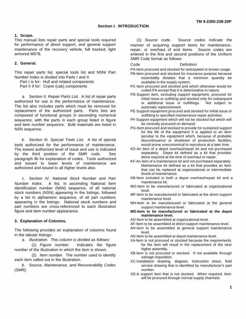
1. Scope.This manual lists repair parts and special tools requiredfor performance of direct support, and general supportmaintenance of the recovery vehicle, full tracked; lightarmored M578.
2. General.
This repair parts list, special tools list and NSN/ PartNumber Index is divided into Parts I and II.
Part I is for: Hull and related componentsPart II if for: Crane (cab) components
a. Section II, Repair Parts List. A list of repair partsauthorized for use in the performance of maintenance.The list also includes parts which must be removed forreplacement of the authorized parts. Parts lists arecomposed of functional groups in ascending numericalsequence, with the parts in each group listed in figureand item number sequence. Bulk materials are listed inNSN sequence.
b. Section III, Special Tools List. A list of specialtools authorized for the performance of maintenance.The lowest authorized level of issue and use is indicatedby the third position of the SMR code. Seeparagraph 3b for explanation of codes. Tools authorizedand issued to lower levels of maintenance areauthorized and issued to all higher levels also.
c. Section IV, National Stock Number and PartNumber Index. A list, in ascending National itemidentification number (NIIN) sequence, of all nationalstock numbers (NSN) appearing in the listings, followedby a list in alphameric sequence, of all part numbersappearing in the listings. National stock numbers andpart numbers are cross-referenced to each illustrationfigure and item number appearance.
3. Explanation of Columns.
The following provides an explanation of columns foundin the tabular listings:
a. Illustration. This column is divided as follows:(1) Figure number. Indicates the figure
number of the illustration in which the item is shown.(2) Item number. The number used to identify
each item called out in the illustration.b. Source, Maintenance, and Recoverability Codes
(SMR).
(1) Source code. Source codes indicate themanner of acquiring support items for maintenance,repair, or overhaul of end items. Source codes areentered in the first and second positions of the UniformSMR Code format as follows:Code DefinitionPA-Item procured and stocked for anticipated or known usage.PB-Item procured and stocked for insurance purpose because
essentiality dictates that a minimum quantity beavailable in the supply system.
PC-Item procured and stocked and which otherwise would becoded PA except that it Is deteriorative in nature.
PD-Support item, excluding support equipment, procured forinitial Issue or outfitting and stocked only for subsequentor additional issue or outfittings. Not subject toautomatic replenishment.
PE-Support equipment procured and stocked for initial issue oroutfitting to specified maintenance repair activities.
PF-Support equipment which will not be stocked but which willbe centrally procured on demand.
PG-Item procured and stocked to provide for sustained supportfor the life of the equipment It is applied to an itempeculiar to the equipment which, because of probablediscontinuance or shutdown of production facilities,would prove uneconomical to reproduce at a later time.
KD-An item of a depot overhaul/repair kit and not purchasedseparately. Depot kit defined as a kit that providesitems required at the time of overhaul or repair.
KF-An item of a maintenance kit and not purchased separately.Maintenance kit defined as a kit that provides an itemthat can be replaced at organizational or intermediatelevels of maintenance.
KB-Item included in both a depot overhaul/repair kit and amaintenance kit.
MO-Item to be manufactured or fabricated at organizationallevel.
MF-ltem to be manufactured or fabricated at the direct supportmaintenance level.
MH-ltem to be manufactured or fabricated at the generalsupport maintenance level.
MD-Item to be manufactured or fabricated at the depotmaintenance level.
AO-ltem to be assembled at organizational level.AF-Item to be assembled at direct support maintenance level.AH-item to be assembled at general support maintenance
level.AD-Item to be assembled at depot maintenance level.XA-ltem is not procured or stocked because the requirements
for the item will result in the replacement of the nexthigher assembly.
XB-ltem is not procured or stocked. If not available throughsalvage requisition.
XC-Installation drawing, diagram, instruction sheet, fieldservice drawing that is identified by manufacturer's partnumber.
XD-A support item that is not stocked. When required, itemwill be procured through normal supply channels.
1

TM 9-2350-238-20P
NOTECannibalization or salvage may beused as a source of supply for anyitems source coded above exceptthose coded XA and aircraft supportitems as restricted by AR 700-42.
(2) Maintenance code. Maintenance codesare assigned to indicate the levels of maintenanceauthorized to USE and REPAIR support items. Themaintenance codes are entered in the third and fourthpositions of the Uniform SMR Code format as follows:
(a) The maintenance codes entered in thethird position will indicate the lowest maintenance levelauthorized to remove, replace, and use the support item.The maintenance code entered in the third position willindicate one of the following levels of maintenance:
Code Application/Explanation
C-Crew or operator maintenance performed withinorganizational maintenance.
O-Support item is removed, replaced, used at theorganizational level.
F-Support Item is removed, replaced, used at the directsupport level.
H-Support item is removed, replaced, used at the generalsupport level.
D-Support items that are removed, replaced, used at depot,mobile depot, specialized repair activity only.
(b) The maintenance code entered in thefourth position indicates whether the item is to berepaired and identifies the lowest maintenance level withthe capability to perform complete repair (i.e., allauthorized maintenance functions). This position willcontain one of the following maintenance codes:
Code Application/Explanation
O-The lowest maintenance level capable of complete repair ofthe support Item is the organizational level.
F-The lowest maintenance level capable of complete repair ofthe support item is the direct support level.
H-The lowest maintenance level capable of complete repair ofthe support item is the general support level.
D-The lowest maintenance level capable of complete repair ofthe support item is the depot level, performed by depot,mobile depot or specialized repair activity.
L-Repair restricted to designated specialized repairactivity.
Z-Nonreparable. No repair is authorized.B-No repair is authorized. The item may be
reconditioned by adjusting, lubricating, etc., at theuser level. No parts or special tools are procuredfor the maintenance of this item.
(3) Recoverability code. Recoverability codesare assigned to support items to indicate the dispositionaction on unserviceable items. The recoverability codeis entered in the fifth position of the Uniform SMR Codeformat as follows:RecoverabilityCodes DefinitionZ-Nonreparable item. When unserviceable, condemn and
dispose at the level indicated in position 3.O-Reparable item. When uneconomically reparable, condemn
and dispose at organizational level.F-Reparable item. When uneconomically reparable, condemn
and dispose at the direct support level.H-Reparable level. When uneconomically reparable, condemn
and dispose at the general support level.D-Reparable item. When beyond lower level repair capability,
return to depot. Condemnation and disposal notauthorized below depot level.
L-Reparable item. Repair, condemnation and disposal notauthorized below depot/specialized repair activity level.
A-Item requires special handling or condemnation proceduresbecause of specific reasons (i.e., precious metalcontent, high dollar value, critical material or hazardousmaterial). Refer to appropriate manuals/directives forspecific instructions.
c. National Stock Number. indicates the Nationalstock number assigned to the item and will be used forrequisitioning purposes.
d. Part Number. Indicates the primary numberused by the manufacturer (individual, company, firm,corporation, or Government activity), which controls thedesign and characteristics of the item by means of itsengineering drawings, specifications standards, andinspection requirements, to identify an item or range oritems.
NOTEWhen a stock numbered item isrequisitioned, the item received mayhave a different part number than thepart being replaced.
e. Federal Supply Code for Manufacturer (FSCM).The FSCM is a 5-digit numeric code listed in SB 708-42which is used to identify the manufacturer, distributor, orGovernment agency, etc.
f. Description. Indicates the Federal item nameand, if required, a minimum description to identify theitem. Items that are included in kits and sets are listedbelow the name of the kit or set with the quantity of eachitem in the kit or set indicated in the quantityincorporated in unit column.
g. Unit of Measure (U/M). Indicates the standardof the basic quantity of the listed item as used inperforming the actual maintenance function. Thismeasure is expressed by a two-character alphabeticalabbreviation (e.g., in, per, etc.). When the unit
2
TM 9-2350-238-20P
of measure differs from the unit of issue, the lowest unitof issue that will satisfy the required units of measure willbe requisitioned.
h. Quantity Incorporated in Unit. Indicates thequantity of the item used in the breakout shown on theillustration figure, which is prepared for a functionalgroup, subfunctional group, or an assembly. A "V"appearing in this column in lieu of a quantity indicatesthat no specific quantity is applicable, (e.g., shims,spacers, etc.).4. Special Information.
a. Detailed manufacturing instructions for itemssource coded to be manufactured or fabricated arefound in TM 9-2350-238-20 maintenance manual. Bulkmaterials required to manufacture items are listed in theBulk Material Group of this manual.
b. Detailed assembly instructions for items sourcecoded to be assembled are found in TM 92350-238-20maintenance manual. Assembly components are listedimmediately following the item to be assembled.
c. Repair parts kits and gasket sets appear as thelast entries in the repair parts listing for the figure inwhich its parts are listed as repair parts.
NOTE"P" source coded items with missingNational stock numbers are itemswhich are not recorded in the Armymaster data file (AMDF) and cannotbe requisitioned from the supplysystem. When these stock numbersare broadcast in the AMDF, they willbe provided by a change to themanual. If justified, these items maybe requisitioned on an exceptionbasis using the Army part number ormanufacturer's part number andcode.
d. The following publications pertain to M578vehicle and its components:LO 9-2350-238-12
Lubrication OrderTM 9-2350-238-10
Operator's ManualTM 9-2350-238-20
Organizational Maintenance ManualTM 9-2350-238-34-1
Direct and General Support Maintenance Manual:Hull and Related Components
TM 9-2350-238-34-2Direct and General Support Maintenance Manual:Crane (cab) Components
TM 9-2350-238-34P-1Direct Support and General Support MaintenanceRepair Parts and Special Tools Lists (IncludingDepot Maintenance Repair Parts and Special Tools):Hull and Related Components
TM 9-2350-238-34P/2Direct Support and General Support MaintenanceRepair Parts and Special Tools Lists (IncludingDepot Maintenance Repair Parts and Special Tools):Crane (cab) Components
TM 9-2520-234-34PDirect Support and General Support MaintenanceRepair Parts and Special Tools List (Including DepotMaintenance Allowances) for Power Train Assembly(8351100) (Allison Model XTG-411-2A)
TM 9-2520-234-35Field and Depot Maintenance Manual for PowerTrain Assembly (8351100) (Allison Model XTG-411-2A)
TM 9-2815-202-34&PDirect Support and General Support MaintenanceManual Including Repair Parts and Special ToolsList (Including Depot Maintenance Allowances) forEngine, Diesel, Turbocharged, Fuel Injected, Liquid -Cooled, "V" Type, 8-Cylinder, W/Container,Assembly Detroit Diesel GMC Series 8V71T Model7083-7398 and Detroit Diesel-GMC Series 8V71Tmodel 7083-7399
TM 9-2920-224-35Field and Depot Maintenance Manual (IncludingField and Depot Maintenance Repair Parts Lists):Generator, Engine Assembly (300-Amp)
5. How to Locate Repair Parts.a. When National Stock Number or Part Number is
Unknown:(1) First. Using the table of contents,
determine the functional subgroup within which therepair part belongs. This is necessary since illustrationsare prepared for functional subgroups, and listings aredivided into the same groups.
(2) Second. Find the illustration covering thesubgroup to which the repair part belongs.
(3) Third. Identify the repair part on theillustration and note the illustration figure and itemnumber of the repair part.
(4) Fourth. Using the Repair Parts Lising, findthe figure and item number noted on the illustration.
b. When National Stock Number Part is Known:(1) First. Using the Index of National Stock
Numbers and Part Numbers, find the pertinent nationalstock number or part number. This index
3
TM 9-2350-238-20P
is in ascending NIIN sequence, followed by a list of partnumbers in ascending alphameric sequence, cross-referenced to the illustration figure number and itemnumber.
(2) Second. After finding the figure and itemnumber, locate the figure and item number in the repartslist.
6. Abbreviations.The abbreviations used in this publication are commonin trade practice and MIL-STD-12, Military standardabbreviations for use on drawings, specifications,standards and in technical documents.
Abbreviation/Explanation
ARR Arrangement NC National CoarseASSY Assembly NF National FineCONT Contact NO NumberCOP Copper NOM NominalCS Carbon Steel NPTF Tight JointsCSK Countersink NS Near SideCSKH Countersink Head OA Over-AllCTSK Countersunk OD Outside DiameterCU FT Cubic Foot OVS OversizeCYL Cylinder PLSTC PlasticDEG Degree PSI Pounds Per SquareDIA Diameter InchELEC Electric PT PointELEC Electrical RAD RadiusELECT Electrical RBR RubberEXTL External RD RoundFILH Fillister Head RGLR RegularFL Flat RH Right HandFTF Flared Tube Fitting RLVD RelievedGA Gage RS Right SideGR Grade RTNG RetainingGS General Support SKT SocketH High SLTD SlottedHD Head SQ SquareHDLS Headless STD StandardHEX Hexagon STK StockHEX SCH Hexagon Socket STL SteelHEX SKT Hexagon Socket STR StraightID Inside Diameter SYNTH SyntheticIN Inch THD ThreadINT Internal THK ThickINTL Internal TPG TappingLG Length TRAV TraversingLH Left Hand UN UnifiedLT Light UNC Unified CoarseLTHR Leather ThreadLUBE Lubrication UNF Unified Fine ThreadLUBT Lubricant UNIV UniversalLWR Lower V VoltageMACH Machine V VariableMECH Mechanical W WideMFD Manufactured W/ WithMM Millimeter WG Wire Gage
4
TM 9-2350-238-20P
PART IHULL AND RELATED COMPONENTS
5(6 blank)

(1)ILLUSTRATION
(2) (3) (4) (5) (6) (7) (8)
(a) (b) NATIONAL DESCRIPTION QTYFIG ITEM SMR STOCK PART U/M INCNO. NO. CODE NUMBER FSCM NUMBER IN
USABLE ON CODES UNIT
TM 9-2350-238-20P
Section II. REPAIR PARTS LIST (PART I)
Figure 1. Engine Mount.
GROUP 01 ENGINE
GROUP 0100 ENGINE MOUNT
1 1 PAOZZ 2805-00-420-5043 19207 11631501 MOUNT, ENGINE SUPPOR......................................................................... EA 1
1 2 PAOZZ 5310-00-637-9541 96906 MS35338-46 WASHER, LOCK 3/8 NOM SIZE.................................................................. EA 12
1 3 PAOZZ 5350-00-060-0511 96906 MS90728-62 SCREW, CAP, HEXAGON H 3/8-16UNC X 1.250............................................ EA 12
1 4 PAOZZ 2815-00-937-1322 19207 10898445 TUBE, SPACER, MOUNT, P SPACER . ....................................................... EA 1
1 5 PAOZZ 2990-00-980-1737 19207 10882021 MOUNT, ENGINE SHOCK, ENGINE MOUNT................................................. EA 2
1 6 PAOZZ 2805-00-221-9182 19207 10882022 WASHER, ENGINE MOUNT LOCK WIRE PLATE ........................................... EA 1
1 7 PAOZZ 5305-00-904-4003 96906 MS51096-513 SCREW, CAP, HEXAGON H 1.0-12UNF X 3.00.............................................. EA 1
1 8 MOOZZ 96906 MS20995C91AR WIRE, NONELECTRICAL, MFD FROM 9505-00-825-7579 .............................. FT V
7

(1)ILLUSTRATION
(2) (3) (4) (5) (6) (7) (8)
(a) (b) NATIONAL DESCRIPTION QTYFIG ITEM SMR STOCK PART U/M INCNO. NO. CODE NUMBER FSCM NUMBER IN
USABLE ON CODES UNIT
TM 9-2350-238-20P
Figure 2. Rocker Cover.
GROUP 0105 POCKER COVER
2 1 PAOZZ 2815-00-735-4292 72582 5117362 CAP,FILLER OPENINIG OIL FILLER,ENGINE............................................... EA 1
2 2 PAOZZ 5310-00-950-1310 21450 218322 WASHER,FLAT 1.8 ID X 5/16 ...................................................................... EA 2
2 3 PAOZZ 5315-00-187-9370 96906 MS24665-172 PIN,COTTER 1/16 DIA 3/4 LG .................................................................... EA 2
2 4 PAOZZ 3805-00-900-2577 72582 5117365 CHAIN,OIL FILLER TO 0IL FILTER............................................................... EA 1
8
TM 9-2350-238-20P
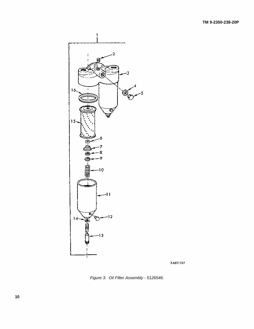
Figure 3. Oil Filter Assembly - 5126546.
10
(1)ILLUSTRATION
(2) (3) (4) (5) (6) (7) (8)
(a) (b) NATIONAL DESCRIPTION QTYFIG ITEM SMR STOCK PART U/M INCNO. NO. CODE NUMBER FSCM NUMBER IN
USABLE ON CODES UNIT
TM 9-2350-238-20P
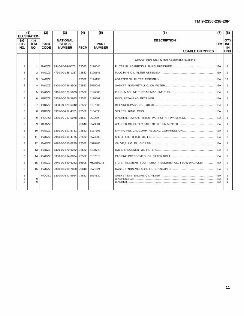
GROUP 0106 OIL FILTER ASSEMBLY-5126546
3 1 PAOZZ 2940-00-82-9675 72582 5126546 FILTER,FLUID,PRESSU FLUID,PRESSURE................................................. EA 1
3 2 PAOZZ 4730-00-965-1257 72582 5126546 PLUG,PIPE OIL FILTER ASSEMBLY ............................................................ EA 2
3 3 XAOZZ 72582 5124138 ADAPTER OIL FILTER ASSEMBLY .............................................................. EA 11
3 4 PAOZZ 5330-00-736-3508 72582 5575086 GASKET NON-METALLIC, OIL FILTER........................................................ EA 1
3 5 PAOZZ 5365-00-579-5983 72582 5126686 PLUG, MACHINE THREAD MACHINE THD................................................... EA 1
3 6 PBOZZ 5365-00-579-5983 72582 5120602 RING, RETAINING RETAINER.................................................................... EA 1
3 7 PBOZZ 5330-00-629-6340 72582 5187309 RETAINER,PACKING LUB OIL................................................................... EA 1
3 8 PBOZZ 5365-00-262-4701 72582 5154538 SPACER, RING RING................................................................................ EA 1
3 9 POOZZ 5310-00-297-6078 24617 853269 WASHER,FLAT OIL FILTER PART OF KIT P/N 5574130 ................................ EA 1
3 9 KFOZZ 70040 5573801 WASHER OIL FILTER PART OF KIT P/N 5574130.......................................... EA 1
3 10 PAOZZ 5360-00-801-8731 72582 5187308 SPRING,HELICAL,COMP HELICAL, COMPRESSION .................................... EA 2
3 11 PAOZZ 2940-00-019-4775 72582 5574008 SHELL, OIL FILTER OIL FILTER ................................................................. EA 2
3 12 PAOZZ 4820-00-360-8299 72582 5570480 VALVE,PLUG PLUG,DRAIN ....................................................................... EA 1
3 13 PAOZZ 5306-00-870-6222 72582 5120740 BOLT, SHOULDER OIL FILTER .................................................................. EA 2
3 14 PAOZZ 5330-00-604-8094 72582 5187310 PACKING,PREFORMED OIL FILTER BOLT.................................................. EA 2
3 15 PAOZZ 2940-00-580-6283 96906 MS35802-3 FILTER ELEMENT, FLUI FLUID PRESSURE,FULL FLOW W/GASKET............. EA 2
3 16 PAOZZ 5330-00-290-7860 70040 5571024 GASKET NON-METALLIC,FILTER ADAPTER ............................................... EA 2
3 POOZZ 5330-00-841-5964 72582 5574130 GASKET SET ENGINE OIL FILTER ............................................................. EA 13 9 WASHER,FLAT.......................................................................................... EA 13 9 WASHER .................................................................................................. EA 1
11

(1)ILLUSTRATION
(2) (3) (4) (5) (6) (7) (8)
(a) (b) NATIONAL DESCRIPTION QTYFIG ITEM SMR STOCK PART U/M INCNO. NO. CODE NUMBER FSCM NUMBER IN
USABLE ON CODES UNIT
TM 9-2350-238-20P
Figure 4. Oil Cooler.
GROUP 0106 OIL COOLER
4 1 PAOZZ 4720-00-080-6583 19207 11594525 HOSE, NONMETALLIC OIL COOLER TO WATER PUMP . .............................. EA 1
4 2 PA0ZZ 4730-00-720-1503 19207 7612732 CLAMP, HOSE INLET WATER HOSE,OIL COOLER ...................................... EA 2
4 3 PAOZZ 2815-00-933-7636 72582 5127904 ELBOW, ENGINE OIL CO ENGINE OIL ........................................................ EA 1
4 4 PAOZZ 5305-00-543-2419 19207 7418028 SCREW, CAP, HEXAGON H ENGINE OIL ELBOW......................................... EA 4
4 5 PAOZZ 5310-00-637-9541 96906 MS35338-46 WASHER, LOCK 3/8 NOM SIZE.................................................................. EA 4
4 6 PAOZZ 5330-00-844-2903 72582 5124822 GASKET WATFR INLET,ELBOW TO OIL COOLER ........................................ EA 1
4 7 PAOZZ 4820-00-849-1220 96906 MS35782-5 COCK, DRAIN ........................................................................................... EA 1
12

(1)ILLUSTRATION
(2) (3) (4) (5) (6) (7) (8)
(a) (b) NATIONAL DESCRIPTION QTYFIG ITEM SMR STOCK PART U/M INCNO. NO. CODE NUMBER FSCM NUMBER IN
USABLE ON CODES UNIT
TM 9-2350-238-20P
Figure 5. Crankcase Engine Breather
GROUP 3136 CRANKCASE ENGINE BREATHER
5 1 XBOZZ 210501 19092 SCREW, CAP , HEXAGON, HD, 3/B-24JNF X 4.7........................................... EA 3
5 2 PAOZZ 5340-00-325-4965 72582 5184291 CLAMP ,LOOP, BREATHER, PIPE............................................................... EA 2
5 3 XROZZ 72582 5108452 PIPE, BREATHER ...................................................................................... EA 1
5 4 PAOZZ 5305-00-269-3211 96906 M1590125-60 SCREW, CAP HEXAGON H 318-16U4C X 1.00 .............................................. EA 2
5 5 PAOZZ 5310-00-637-9541 96906 4S35338-46 WASHER, LOCK 3/8 NOM SIZE .................................................................. EA 2
5 6 PAOZZ 5330-00-276-1842 72582 512189 GASKET, BREATHER, PIPE........................................................................ EA 1
13
Related Documents


