TM 9-2320-211-34-2-3 T.O. 36A12-1C-422-2-2 TECHNICAL MANUAL Chapter 17 VOLUME 2 OF 2 Winch, Hoist, Crane and PART 3 OF 4 Power Takeoff Assemblies Group Maintenance MAINTENANCE DIRECT SUPPORT AND GENERAL SUPPORT LEVEL 5-TON, 6X6, M39 SERIES TRUCKS (MULTIFUEL) TRUCK, CHASSIS: M40A2C, M61A2, M63A2; TRUCK, CARGO: M54A2, M54A2C, M55A2; TRUCK, DUMP: M51A2; TRUCK, TRACTOR: M52A2; TRUCK, WRECKER, MEDIUM: M543A2 THE STYLE OF THIS TM IS EXPERIMENTAL. IT IS BEING TRIED BY THE ARMY ONLY ON A LIMITED BASIS DEPARTMENTS OF THE ARMY AND THE AIR FORCE FEBRUARY 1981 NOTE:

Welcome message from author
This document is posted to help you gain knowledge. Please leave a comment to let me know what you think about it! Share it to your friends and learn new things together.
Transcript

TM 9-2320-211-34-2-3T.O. 36A12-1C-422-2-2
TECHNICAL MANUAL Chapter 17VOLUME 2 OF 2 Winch, Hoist, Crane and
PART 3 OF 4Power Takeoff AssembliesGroup Maintenance
MAINTENANCEDIRECT SUPPORT AND GENERAL SUPPORT LEVEL
5-TON, 6X6, M39 SERIES TRUCKS
(MULTIFUEL)
TRUCK, CHASSIS: M40A2C,
M61A2, M63A2; TRUCK, CARGO:
M54A2, M54A2C, M55A2; TRUCK,
DUMP: M51A2; TRUCK, TRACTOR:
M52A2; TRUCK, WRECKER, MEDIUM: M543A2
THE STYLE OF THIS TM ISEXPERIMENTAL. IT IS BEING TRIED
BY THE ARMY ONLY ONA LIMITED BASIS
DEPARTMENTS OF THE ARMY AND THE AIR FORCE
FEBRUARY 1981
N O T E :


WARNING
EXHAUST GASES CAN BE DEADLY
Exposure to exhaust gases produces symptoms of headache, dizziness, loss of mus-cular control, apparent drowsiness, and coma. Permanent brain damage or deathcan result from severe exposure.
Carbon monoxide occurs in the exhaust fumes of fueI burning heaters and internalcombustion engines, and becomes dangerously concentrated under conditions of in-adequate ventilation. The following precautions must be observed to insure thesafety of personnel whenever fuel burning heater(s) or engine of any vehicle isoperated for maintenance purposes or tactical use.
Do not operate heater or engine of vehicle in an enclosed area unless it is adequatelyventilated.
Do not idle engine for long periods without maintaining adequate ventilation in per-sonnel compartments.
Do not drive any vehicle with inspection plates or cover plates removed unless neces-sary for maintenance purposes.
Be alert at all times during vehicle operation for exhaust odors and exposuresymptoms. If either are present, immediately ventilate personnel compartments. Ifsymptoms persist, remove affected personnel from vehicle and treat as follows:expose to fresh air; keep warm; do not permit physical exercise; i f necessary,administer artificial respiration.
If exposed, seek prompt medical attention for possible delayed onset of acute lungcongest ion . Administer oxygen if available.
The best defense against exhaust gas poisoning is adequate ventilation.
WARNING
Serious or fatal injury to personnel may resultif the following instructions are not complied with.
Dry cleaning solvent is flammable. Do not use near an open flame. Keep a fire ex-tinguisher nearby when solvent is used. Use only in well-ventilated places.Failure to do this may result in injury to personnel and damage to equipment.
Eye shields must be worn when using compressed sir. Eye injury can occur if eyeshields are not used.
Do not dry bearings with compressed air. Spinning bearings may explode, causinginjury to personnel and damage to equipment.
Be careful when handling boom elevating cylinder. Cylinder is heavy, and if it fallscan cause injury to personnel and damage to equipment.
The boom assembly is very heavy and bulky. Tie inner boom to outer boom withchain or other suitable means. Do this to stop inner boom from drawing out when theassembly is lifted, which could cause injury to personnel.
a
WARNING - Cont
Boom assembly must be guided during hoisting so that it does not swing free. Ifboom assembly swings free it can injure personnel and damage equipment.
Inner boom must be held up at sheave end when pulling it out of outer boom. Ifthis is not done, outer boom can tilt and cause injury.
Always wear gloves when handling wire cable. Never let the cable run through barehands . Broken wires can cause painful injuries.
Do not use a wire brush or compressed air to clean winch brake drum. There may beasbestos dust on the drum which can be dangerous to your health if you breathe iti n .
Be careful when raising and positioning hoist winch on boom. If winch drops it cancause injury to personnel or damage to equipment.
The hoist winch motor assembly is heavy. When replacing assembly tension must bekept on rope sling supporting assembly to keep it from falling. If assembly falls, itcan cause serious injury to personnel and damage to equipment.
Be careful when taking off crane turntable gear and bearing assembly. If assemblydrops or swings free it can cause injury to personnel and damage to equipment.
b

TECHNICAL MANUALNO. 9-2320-21-34-2-3TECHNICAL ORDERNO. 36A12-1C-422-2-2
Model
Truck, Chassis
Truck, Cargo
Truck, Dump
T r u c k , T r a c t o r
Truck, WreckerMedium
*TM 9-2320-211-34-2-3T.O. 36A12-1C-422-2-2
DEPARTMENTS OF THE ARMYAND
THE AIR FORCEWASHINGTON, DC, 25 Feburary 1981
TECHNICAL MANUAL
VOLUME 2 OF 2
PART 3 OF 4
MAINTENANCEDIRECT SUPPORT AND GENERAL SUPPORT LEVEL
5-TON, 6X6, M39 SERIES TRUCKS(MULTIFUEL)
M40A2CM61A2M63A2
M54A2M54A2CM55A2
M51A2
M52A2
M543A2
NSN without Winch
2320-00-969-41142320-00-055-92642320-00-226-6251
2320-00-055-92662320-00-926-08742320-00-073-8476
2320-00-055-9262
2320-00-055-9260
Current as of 25 Jul 80.
NSN with Winch
2320-00-965-03212320-00-285-3757
2320-00-055-92652320-00-926-08742320-00-055-9259
2320-00-055-9263
2320-00-055-9261
2320-00-055-9258
*This manual together with TM 9-2320-211-34-1, 25 February 1981; TM 9-2320-211-34-2-1, 25 February 1981TM 9-2320-211-34-2-2, 25 February 1981 and TM 9-2320-211-34-2-4, 25 February 1981 supersedes so much ofTM 9-2320-211-35, 13 September 1964 as pertains to multifuel vehicles including all changes.

TM 9-2320-211-34-2-3
REPORTING OF ERRORS AND RECOMMENDING IMPROVEMENTS
You can help improve this manual. If you find any mistakes or if you know of a way to improvethe procedure, please let us know. Mail your letter, DA Form 2028 (Recommended Changes toPublications and Blank Forms), or DA Form 2028-2 located in the back of this manual direct to:Commander, US Army Tank-Automotive Command, ATTN: DRSTA-MB, Warren,Michigan 48090. A reply will be furnished to you.
TABLE OF CONTENTS
Paragraph Page
CHAPTER 17. WINCH , HOIST, CRANE AND POWERTAKEOFF ASSEMBLIES GROUP MAINTENANCE
Section I. Scope . . . . . . . . . . . . . . . . . . . . . . . . . . . . . . . . . . . . .Equipment Items Covered . . . . . . . . . . . . . . . . . . .Equipment Items Not Covered . . . . . . . . . . . . . . .
Section 11. Winch, Hoist, and Crane Assemblies . . . . . . . . . . .Front Winch Roller AssemblyRemoval, Repair and Replacement . . . . . . . . . . . .Preliminary Procedure . . . . . . . . . . . . . . . . . . . . . .Removal . . . . . . . . . . . . . . . . . . . . . . . . . . . . . . . . . . .Disassembly . . . . . . . . . . . . . . . . . . . . . . . . . . . . . . . .Cleaning . . . . . . . . . . . . . . . . . . . . . . . . . . . . . . . . . .Inspection and Repair . . . . . . . . . . . . . . . . . . . . .Assembly . . . . . . . . . . . . . . . . . . . . . . . . . . . . . . . .Replacement . . . . . . . . . . . . . . . . . . . . . . . . . . . . . .
Front Winch Tensioner AssemblyRemoval and Replacement . . . . . . . . . . . . . . . . .Preliminary Procedure . . . . . . . . . . . . . . . . . . . . . .Removal . . . . . . . . . . . . . . . . . . . . . . . . . . . . . . . . . . .Replacement . . . . . . . . . . . . . . . . . . . . . . . . . . . . . . .
Front Winch Sheave and Trolley (LevelWind) Repair (Truck M543A2) . . . . . . . . . . . . . . .Disassembly . . . . . . . . . . . . . . . . . . . . . . . . . . . . .Cleaning . . . . . . . . . . . . . . . . . . . . . . . . . . . . . . . . . .Inspection and Repair . . . . . . . . . . . . . . . . . . . . . .Assembly . . . . . . . . . . . . . . . . . . . . . . . . . . . . . . . . .
Front Level Wind Removal andReplacement (Truck M543A2) . . . . . . . . . ... .Preliminary Procedure . . . . . . . . . . . . . . . . . . . . .Removal . . . . . . . . . . . . . . . . . . . . . . . . . . . . . . . . . . . .Replacement . . . . . . . . . . . . . . . . . . . . . . . . . . . . . .
Front Winch Tension Sheave AssemblyRepair (Truck M543A2) . . . . . . . . . . . . . . . . . . . . .Disassembly . . . . . . . . . . . . . . . . . . . . . . . . . . . . . . . .Cleaning . . . . . . . . . . . . . . . . . . . . . . . . . . . . . . . . . . .Inspection and Repair . . . . . . . . . . . . . . . . . . . . . .Assembly . . . . . . . . . . . . . . . . . . . . . . . . . . . . . . . . .
17-117-2
17-317-3a17-3b17-3c17-3d17-3e17-3f17-3g
17-417-4a17-4b17-4c
17-517-5a17-5b17-5c17-5d
17-617-6a17-6b17-6c
17-717-7a17-7b17-7c17-7d
17-117-117-117-1
17-117-117-217-317-517-517-617-8
17-917-917-917-10
17-1117-1217-1817-1817-19
17-2517-2517-2517-27
17-2917-2917-3517-3517-36
ii
TM 9-2320-211-34-2-3
TABLE OF CONTENTS-CONT
Front Winch Automatic Brake Removal,Replacement, and Adjustment . . . . . . . . . . . . .Removal . . . . . . . . . . . . . . . . . . . . . . . . . . . . . .Replacement and Adjustment . . . . . . . . . . . . . .
Front Winch Level Wind Removal andReplacement (Truck M542A1) . . . . . . . . . . . . . .Removal . . . . . . . . . . . . . . . . . . . . . . . . . . . . . . .Replacement . . . . . . . . . . . . . . . .. . . . . . . . . . .
Front Winch Assembly Repair . . . . . . . . . . . . .Preliminary Procedures . . . . . . . . . . . . . . . . . . . .Disassembly . . . . . . . . . . . . . . . . . . . . . . . . . . . .Cleaning . . . . . . . . . . . . . . . . . . . . . . . . . . . . .Inspection . . . . . . . . . . . . . . . . . . . . . . . . . . . . . .Repair . . . . . . . . . . . . . . . . . . . . . . . . . . . . . . .Assembly . . . . . . . . . . . . . . . . . . . . . . . . . . . . .
Rear Winch Sheave and Trolley (LevelWind) Removal and Replacement(Truck M543A2) . . . . . . . . . . . . . . . . . . . . . . . . . . .Removal . . . . . . . . . . . . . . . . . . . . . . . . . . . . . . .Replacement . . . . . . . . . . . . . . . . . . . . . . . . . . .
Rear Winch Tension Sheave AssemblyRemoval and Replacement(Truck M543A2) . . . . . . . . . . . . . . . . . . . . . . . . .Preliminary Procedure . . . . . . . . . . . . . . . . . . .Removal . . . . . . . . . . . . . . . . . . . . . . . . . . . . . . . . . .Replacement . . . . . . . . . . . . . . . . . . . . . . . . . .
Rear Winch Cable Tensioner BrakeChamber Assembly Removal andReplacement (Truck M543A2) . . . . . . . . . . . . . . .Removal . . . . . . . . . . . . . . . . . . . . . . . . . . . . . . . . . .Replacement . . . . . . . . . . . . . . . . . . . . . . . . . . . .
Rear Winch Cable Tensioner AssemblyRepair (Truck M543A2) . . . . . . . . . . . . . . . . . . . . .Disassembly . . . . . . . . . . . . . . . . . . . . . . . . . . . . .Cleaning . . . . . . . . . . . . . . . . . . . . . . . . . . . . . . .Inspection and Repair . . . . . . . . . . . . . . . . . . .Replacement . . . . . . . . . . . . . . . . . . . . . . . . . . . .
Rear Winch Sheave and Trolley (LevelWind) Repair (Truck M543A2) . . . . . . . . . . . . .Disassembly . . . . . . . . . . . . . . . . . . . . . . . . . . . .Cleaning . . . . . . . . . . . . . . . . . . . . . . . . . . . . . . .Inspection and Repair . . . . . . . . . . . . . . . . . . . . .Assembly . . . . . . . . . . . . . . . . . . . . . . . . . . . . . . .
Rear Winch Assembly Repair(Truck M543A2) . . . . . . . . . . . . . . . . . . . . . . . . . . .Preliminary Procedures . . . . . . . . . . . . . . . . .Disassembly . . . . . . . . . . . . . . . . . . . . . . . . . . . .
Cleaning . . . . . . . . . . . . . . . . . . . . . . . . . . . . . . .
Paragraph
17-817-8a17-8b
17-917-9a17-9b17-1017-10a17-10b17-10c17-10d17-10e17-10f
17-1117-11a17-11b
17-1217-12a17-12b17-12c
17-1317-13a17-13b
17-1417-14a17-14b17-14c17-14d
17-1517-15a17-15b17-15c17-15d
17-1617-16a17-16b17-16c
Page
17-4217-4217-45
17-4917-4917-5117-5317-5317-5417-7017-7117-7317-73
17-8917-8917-90
17-9117-9117-9117-95
17-9817-9817-99
17-10017-10017-10417-10417-104
17-10817-10817-11317-11317-114
17-11917-11917-11917-141
iii
TM 9-2320-211-34-2-3
T A B L E O F C O N T E N T S - C O N T
Inspection . . . . . . . . . . . . . . . . . . . . . . . .Repair . . . . . . . . . . . . . . . . . . .Assembly . . . . . . . . . . . . . . . . . .
Hoist Winch Motor Assembly Removal,Repair, and Replacement(Truck M543A2) . . . . . . . . . . . . . . .Removal . . . . . . . . . . . . . . . . . . . .Disassembly . . . . . . . . . . . . . . . . . .Cleaning . . . . . . . . . . . . . . . . . . . .Inspection . . . . . . . . . . . . . . . . . . . . . . . . . . . . . . .Repa ir . . . . . . . . . . . . . . . . . . . . . .Assembly . . . . . . . . . . . . . . . . . . . .Replacement . . . . . . . . . . . . . . . . . . . . . . . . . . . . .
Hoist Winch Removal, Repair, andReplacement (Truck M543A2) . . . . . . . . . . . .Preliminary Procedures . . . . . . . . . . . . Removal . . . . . . . . . . . . . . . . . . . . . . . . . . . . . . . .Disassembly . . . . . . . . . . . . . . . . . . . . . . . . . . . . .Cleaning . . . . . . . . . . . . . . . . . . . .Inspection and Repair . . . . . . . . . . . . . . . . . . . .Assembly . . . . . . . . . . . . . . . . . . . . . . . . . . . . . . . .Replacement . . . . . . . . . . . . . . . . . . . . . . . . . . . . .
Dump Body Control Valve Adapter -Assembly Removal, Repair andReplacement (Truck M51A2) . . . . . . . . . . . . . . .Preliminary Procedures . . . . . . . . . . . . . . . . . . .Removal . . . . . . . . . . . . . . . . . . . . .Disassembly . . . . . . . . . . . . . . . . . . .Cleaning, Inspection, and Repair . . . . . . . . . .Assembly . . . . . . . . . . . . . . . . . . . . . . . . . . . . . . . .Replacement . . . . . . . . . . . . . . . . . . . . . . . . . . . . .
Hoist Control Box Assembly Removal,Repair, and Replacement (Truck M51A2) . . .Preliminary Procedures . . . . . . . . . . . . . . . . . .Removal . . . . . . . . . . . . . . . . . . . .Disassembly . . . . . . . . . . . . . . . . . . . .Cleaning . . . . . . . . . . . . . . . . . . . .Inspection and Repair . . . . . . . . . . . . . . . . . . . .Assembly . . . . . . . . . . . . . . . . . . . . . . . . . . . . . . . .Replacement . . . . . . . . . . . . . . . . . . . .
Control Valve Assembly Repair(Truck M51A2) . . . . . . . . . . . . . . . . . . . . . . . . . . .Preliminary Procedures . . . . . . . . . . . . . . . . . . .Disassembly . . . . . . . . . . . . . . . . . . .Cleaning . . . . . . . . . . . . . . . . . . . . . . . . . . . . . . . .Inspection and Repair . . . . . . . . . . . . . . . . . . . .Assembly . . . . . . . . . . . . . . . . . . . . . . . . . . . . . . . .
Paragraph
17-16d17-16e17-16f
17-1717-17a17-17b17-17c17-17d17-17e17-17f17-17g
17-1817-18a17-18b17-18c17-18d17-18e17-18f17-18g
17-1917-19a17-19b17-19c17-19d17-19e17-19f
17-2017-20a17-20b17-20c17-20d17-20e17-20f17-20g
17-2117-21a17-21b17-21c17-21d17-21e
Page
17-14217-14917-150
17-17717-17817-18017-18717-18817-19017-19017-198
17-20017-20017-20117-20217-21517-21617-21917-236
17-23817-23817-23917-24017-24117-24317-244
17-24517-24517-24617-24917-25417-25517-25617-262
17-26617-26617-26617-26917-27017-271
iv
TM 9-2320-211-34-2-3
TABLE OF CONTENTS-CONT
Hoist Control Linkage Removal,Repair and Replacement(Truck M51A2) . . . . . . . . . . . . . . . . . . .Removal . . . . . . . . . . . . . . . . . . . . .Disassembly . . . . . . . . . . . . . . . . . . . .Cleaning . . . . . . . . . . . . . . . . . . . . .Inspection and Repair . . . . . . . . . . . . . .Assembly . . . . . . . . . . . . . . . . . . . .Replacement . . . . . . . . . . . . . . . . . . .
Dump Body Hoist Frame AssemblyRemoval, Repair and Replacement(Truck M51A2) . . . . . . . . . . . . . . . . . . .Preliminary Procedures . . . . . . . . . . . . . . . . . . . . . .Removal . . . . . . . . . . . . . . . . . . . . . .Cleaning . . . . . . . . . . . . . . . . . . . . . . . . . . . . . . . . . . .Inspection and Repair . . . . . . . . . . . . . .Replacement . . . . . . . . . . . . . . . . . . . .
Dump Body Hoist Cylinder Removal,Repair and Replacement (Truck M51A2) . . . . . .Preliminary Procedure . . . . . . . . . . . . . . . . . . . . . .Removal . . . . . . . . . . . . . . . . . . . . . .Disassembly . . . . . . . . . . . . . . . . . . . .Cleaning . . . . . . . . . . . . . . . . . . . . .Inspection . . . . . . . . . . . . . . . . . . . .Repair . . . . . . . . . . . . . . . . . . . . . .Assembly . . . . . . . . . . . . . . . . . . . .Replacement . . . . . . . . . . . . . . . . . . . .
Hoist Pump Repair (Truck M51A2) . . . . . . . . . . . .Preliminary Procedures . . . . . . . . . . . . . . . . . . . . .Disassembly . . . . . . . . . . . . . . . . . . .Cleaning . . . . . . . . . . . . . . . . . . . . .Inspection . . . . . . . . . . . . . . . . . . . .Repair . . . . . . . . . . . . . . . . . . . . . . .Assembly . . . . . . . . . . . . . . . . . . . . .
Hoist Cylinder Packing Removal andReplacement . . . . . . . . . . . . . . . . . . . .Preliminary Procedures . . . . . . . . . . . . .Removal . . . . . . . . . . . . . . . . . . . . . . . . . . . . . . . . . . .Replacement . . . . . . . . . . . . . . . . . . . .
Hoist Cable Upper Boom Head andUpper Boom Foot Sheaves andGuard Removal and Replacement(Truck M543A2) . . . . . . . . . . . . . . . . . .Preliminary Procedure . . . . . . . . . . . . . . . .Removal . . . . . . . . . . . . . . . . . . . . . .Disassembly . . . . . . . . . . . . . . . . . . . . . .Cleaning . . . . . . . . . . . . . . . . . . . . . .
Paragraph
17-2217-22a17-22b17-22c17-22d17-22e17-22f
17-2317-23a17-23b17-23c17-23d17-23e
17-2417-24a17-24b17-24c17-24d17-24e17-24f17-24g17-24h17-2517-25a17-25b17-25c17-25d17-25e17-25f
17-2617-26a17-26b17-26c
17-2717-27a17-27b17-27c17-27d
17-27517-27517-28117-28417-28417-28417-288
17-29417-29417-29517-29817-29817-299
17-30217-30217-30317-30517-30917-30917-31017-31017-31517-31817-31817-31917-32217-32317-32417-324
17-32717-32717-32817-329
17-33017-33017-33017-33317-334
v
P a g e

TM 9-2320-211-34-2-3
TABLE OF CONTENTS-CONT
Inspection and Repair . . . . . . . . . . . . .Assembly . . . . . . . . . . . . . . . . . . . . .Replacement . . . . . . . . . . . . . . . . . . .
Hoist Roller Arm Assembly Removal,Repair and Replacement(Truck M51A2) . . . . . . . . . . . . . . . . .Preliminary Procedure . . . . . . . . . . . . .Removal . . . . . . . . . . . . . . . . . . . . .Disassembly . . . . . . . . . . . . . . . . .Cleaning . . . . . . . . . . . . . . . . . . . . . Inspection and Repair . . . . . . . . . . . . . . . . . . . . .Assembly . . . . . . . . . . . . . . . . . . .Replacement . . . . . . . . . . . . . . . . . . .
Crane Swinger Gearcase AssemblyRemoval and Replacement (Truck M543A2) . . .Preliminary Procedure . . . . . . . . . . . . .Removal . . . . . . . . . . . . . . . . . . . . . .Replacement . . . . . . . . . . . . . . . . . . .
Crane Swinger Gearcase Assembly Repair(Truck M543A2) . . . . . . . . . . . . . . . . . . . .Preliminary Procedure . . . . . . . . . . . . .Disassembly . . . . . . . . . . . . . . . . . .Cleaning . . . . . . . . . . . . . . . . . . . Inspection . . . . . . . . . . . . . . . . . . .Repa ir . . . . . . . . . . . . . . . . . . . . . .Assembly . . . . . . . . . . . . . . . . . . . .
Bevel Gearcase Pump Drive ShaftLead and Ring Assembly Removal,Repair, and Replacement (Truck M543A2) . . .Preliminary Procedures . . . . . . . . . . . . Removal . . . . . . . . . . . . . . . . . . . . .Cleaning . . . . . . . . . . . . . . . . . . .Inspection and Repair . . . . . . . . . . . . . . Replacement . . . . . . . . . . . . . . . . .
Bevel Gearcase Driveshaft SealRemoval and Replacement (Truck M543A2) . . .Pre l iminary Procedures . . . . . . . . . . .Removal . . . . . . . . . . . . . . . . . . . .Replacement . . . . . . . . . . . . . . . . . . .
Crane Turntable Assembly Removal, Repairand Replacement (Truck M543A2) . . . . . . . . . . .Preliminary Procedures . . . . . . . . . . . . . . . . . . . .Removal . . . . . . . . . . . . . . . . . . . .Disassembly . . . . . . . . . . . . . . . . . .Cleaning . . . . . . . . . . . . . . . . . . .Inspection . . . . . . . . . . . . . . . . . .Repa ir . . . . . . . . . . . . . . . . . . . . . .Assembly . . . . . . . . . . . . . . . . . . . .Replacement . . . . . . . . . . . . . . . . . .
Paragraph
17-27e17-27f17-27g
17-2817-28a17-28b17-28c17-28d17-28e17-28f17-28g
17-2917-29a17-29b17-29c
17-3017-30a17-30b17-30c17-30d17-30e17-30f
17-3117-31a17-31b17-31c17-31d17-31e
17-3217-32a17-32b17-32c
17-3317-33a17-33b17-33c17-33d17-33e17-33f17-33g17-33h
Page
17-33417-33517-336
17-34017-34117-34217-34317-34417-34417-34517-346
17-34917-34917-34917-351
17-35317-35317-35417-36017-36017-36217-362
17-37017-37017-37017-37417-37517-376
17-38217-38217-38217-386
17-39017-39017-39117-39717-40217-40217-40317-40317-408
vi

TM 9-2320-211-34-2-3
TABLE OF CONTENTS-CONT
Turntable Bevel Gear Gearcase AssemblyRemoval, Repair, and Replacement(Truck M543A2) . . . . . . . . . . . . . . . . . .Preliminary Procedures . . . . . . . . . . . . . . . . . . . .Removal . . . . . . . . . . . . . . . . . . . . . .Disassembly . . . . . . . . . . . . . . . . . . .Cleaning . . . . . . . . . . . . . . . . . . . .Inspection and Repair . . . . . . . . . . . . . . . . . . . . .Assembly . . . . . . . . . . . . . . . . . . . .Replacement . . . . . . . . . . . . . . . . . . .
Hydraulic Turntable Pump AssemblyRemoval, Repair and Replacement(Truck M543A2) . . . . . . . . . . . . . . . .Preliminary Procedures . . . . . . . . . . . . . . . . . .Removal . . . . . . . . . . . . . . . . . . . .Disassembly . . . . . . . . . . . . . . . . . . .Cleaning . . . . . . . . . . . . . . . . . . . .Inspection . . . . . . . . . . . . . . . . . . .Repa ir . . . . . . . . . . . . . . . . . . .Assembly . . . . . . . . . . . . . . . . . . . . . . . . . . . . . . . . .Replacement . . . . . . . . . . . . . . . . . . .
Swing Hydraulic Motor Assembly Removal,Repair and Replacement (Truck M543A2) . . . .Removal . . . . . . . . . . . . . . . . . . . . . .Disassembly . . . . . . . . . . . . . . . . . . . . . . . . . . . . . . .Cleaning . . . . . . . . . . . . . . . . . . . . .Inspection . . . . . . . . . . . . . . . . . . .Repa ir . . . . . . . . . . . . . . . . . . . . . .Assembly . . . . . . . . . . . . . . . . . .Replacement . . . . . . . . . . . . . . . . . . . . . . . . . . . . . . .
Hydraulic Oil Reservoir Repair(Truck M543A2) . . . . . . . . . . . . . . . . . .Preliminary Procedure . . . . . . . . . . . . . . . . . . . . .Removal . . . . . . . . . . . . . . . . . . . . .Disassembly . . . . . . . . . . . . . . . . . .Cleaning . . . . . . . . . . . . . . . . . . . .Inspection . . . . . . . . . . . . . . . . . . .Repair . . . . . . . . . . . . . . . . . . . . .Assembly . . . . . . . . . . . . . . . . . . . . . . .Replacement . . . . . . . . . . . . . . . . . . .
Boom and Shipper Roller AssembliesRepair (Truck M543A2) . . . . . . . . . . . .Removal . . . . . . . . . . . . . . . . . . . . .Disassembly . . . . . . . . . . . . . . . . . . .Cleaning . . . . . . . . . . . . . . . . . . . .Inspection and Repair . . . . . . . . . . . . .Assembly . . . . . . . . . . . . . . . . . . . . .Replacement . . . . . . . . . . . . . . . . . .
Paragraph Page
17-3417-34a17-34b17-34c17-34d17-34e17-34f17-34g
17-3517-35a17-35b17-35c17-35d17-35e17-35f17-35g17-35h
17-3617-36a17-36b17-36c17-36d17-36e17-36f17-36g
17-3717-37a17-37b17-37c17-37d17-37e17-37f17-37g17-37h
17-3817-38a17-38b17-38c17-38d17-38e17-38f
17-41517-41517-41617-41817-42617-42717-42917-439
17-44117-44117-44217-44417-44917-44917-45217-45217-459
17-46117-46217-46417-47017-47117-47317-47317-480
17-48217-48217-48217-48717-49017-49117-49319-49317-497
17-50217-50317-50417-50617-50717-50817-510
vii

TM 9-2320-211-34-2-3
TABLE OF CONTENTS-CONT
Boom Crowd Cylinder PackingRemoval and Replacement . . . . . . . . . . . . . . . .Preliminary Procedures . . . . . . . . . . .Removal . . . . . . . . . . . . . . . . . . .Replacement . . . . . . . . . . . . . . . . . . . . . . . . . . . . .
Boom Elevating Cylinder Piston RodPacking Removal and Replacement(Truck M543A2) . . . . . . . . . . . . . . . . .Preliminary Procedures . . . . . . . . . . .Removal . . . . . . . . . . . . . . . . . . .Replacement . . . . . . . . . . . . . . . . .
Boom Crowd Cylinder Removal, Repairand Replacement (Truck M543A2) . . . . . . . . . .Preliminary Procedures . . . . . . . . . . . . . . . . . . .Removal . . . . . . . . . . . . . . . . . . .Disassembly . . . . . . . . . . . . . . . . . . . . . . . . . . . . . .Cleaning . . . . . . . . . . . . . . . . . . . .Inspection and Repair . . . . . . . . . . . . . . . . . . . .Assembly . . . . . . . . . . . . . . . . . . . . . . . . . . . . . . . .Replacement . . . . . . . . . . . . . . . . . .
Crane Boom Elevating Cylinder Repair(Truck M543A2) . . . . . . . . . . . . . . . .Preliminary Procedures . . . . . . . . . . . . . . . . . . .Removal . . . . . . . . . . . . . . . . . . . .Disassembly . . . . . . . . . . . . . . . . . . . . . . . . . . . . . .Cleaning . . . . . . . . . . . . . . . . . . . . . . . . . . . . . . . .Inspection . . . . . . . . . . . . . . . . . . . .Repa ir . . . . . . . . . . . . . . . . . . . .Assembly . . . . . . . . . . . . . . . . . . . . . . . . . . . . . . .Replacement . . . . . . . . . . . . . . . . . . .
Lower Boom Foot Sheave Removaland Replacement(Truck M543A2) . . . . . . . . . . . . . . . . . . . . . . . . . .Preliminary Procedures . . . . . . . . . . . . . . . . . .Removal . . . . . . . . . . . . . . . . . . . . . . . . . . . . . . . . .Cleaning . . . . . . . . . . . . . . . . . . . . . . . . . . . . . . . . .Inspection and Repair . . . . . . . . . . . . . . . . . . . .Replacement . . . . . . . . . . . . . . . . . . . . . . . . . . . . .
Boom Assembly Removal, Repair andand Replacement (Truck M543A2) . . . . . . . . . .Preliminary Procedures . . . . . . . . . . . . . . . . . . .Removal . . . . . . . . . . . . . . . . . . . .Replacement . . . . . . . . . . . . . . . . . . . . . . . . . . . . .
Crane Outer Boom Repair (Truck M543A2) . . .Preliminary Procedures . . . . . . . . . . . . . . . . . . .Removal of Inner Boom . . . . . . . . . . . . . . . . . . .Disassembly . . . . . . . . . . . . . . . . . . .Cleaning . . . . . . . . . . . . . . . . . . . .
Paragraph
17-3917-39a17-39b17-39c
17-4017-40a17-40b17-40c
17-4117-41a17-41b17-41c17-41d17-41e17-41f17-41g
17-4217-42a17-42b17-42c17-42d17-42e17-42f17-42g17-42h
17-4317-43a17-43b17-43c17-43d17-43e
17-4417-44a17-44b17-44c17-4517-45a17-45b17-45c17-45d
Page
17-51117-51117-51217-513
17-51417-51417-51517-516
17-51717-51717-51817-51917-52217-52317-52417-527
17-52817-52817-52917-53317-53617-53617-53717-53717-540
17-54317-54317-54417-54617-54617-547
17-54817-54817-54817-55817-56917-56917-57017-57217-579
viii

TM 9-2320-211-34-2-3
TABLE OF CONTENTS-CONT
Inspection . . . . . . . . . . . . . . . . . . .
Repa ir . . . . . . . . . . . . . . . . . . .
Assembly . . . . . . . . . . . . . . . . . . .
Replacement of Inner Boom . . . . . . . . . . . . . . .Crane Inner Boom Repair (Truck M543A2) . . .
Preliminary Procedures . . . . . . . . . . . . . . . . . . . .Disassembly . . . . . . . . . . . . . . . . . . .
Cleaning . . . . . . . . . . . . . . . . . . . .
Inspection . . . . . . . . . . . . . . . . . . .Repa ir . . . . . . . . . . . . . . . . . . . .Assembly . . . . . . . . . . . . . . . . . . .
Rotochamber Removal and Replacement(Truck M543A2) . . . . . . . . . . . . . . . . .Preliminary Procedure . . . . . . . . . . . . . . . . . . . .Removal . . . . . . . . . . . . . . . . . . . .Replacement . . . . . . . . . . . . . . . . . .
Snatch Block Assembly (Double)Repair (Truck M543A2) . . . . . . . . . . . .Preliminary Procedure . . . . . . . . . . . . . . . . . . . .Disassembly . . . . . . . . . . . . . . . . . . .Cleaning . . . . . . . . . . . . . . . . . . .Inspection and Repair . . . . . . . . . . . . . . . . . . . .Assembly . . . . . . . . . . . . . . . . . . .
Snatch Block Assembly (Single)Repair (Truck M543A2) . . . . . . . . . . . .Preliminary Procedure . . . . . . . . . . . . . . . . . . . .Disassembly . . . . . . . . . . . . . . . . . . .Cleaning . . . . . . . . . . . . . . . . . . . . .Inspection and Repair . . . . . . . . . . . . .Assembly . . . . . . . . . . . . . . . . . . . .
Operator Guard Repair (Truck M543A2) . . . . .Removal . . . . . . . . . . . . . . . . . . . . .Cleaning, Inspection and Repair . . . . . . . . . .Replacement . . . . . . . . . . . . . . . . . .
Control Valve Bank Repair(Truck M543A2) . . . . . . . . . . . . . . . .Preliminary Procedures . . . . . . . . . . . . . . . . . . .Disassembly into Subassemblies . . . . . . . . . . .Disassembly of Subassemblies . . . . . . . . . . . .Cleaning . . . . . . . . . . . . . . . . . . . .Inspection and Repair . . . . . . . . . . . . . . . . . . . .Assembly of Subassemblies . . . . . . . . . .Assembly of Control Valve Bank . . . . . .
Gondola Wrecker Assembly Removal,Repair, and Replacement(Truck M543A2) . . . . . . . . . . . . . . .Preliminary Procedures . . . . . . . . . . . . . . . . . . .Removal . . . . . . . . . . . . . . . . . . . .
Paragraph
17-45e17-45f17-45g17-45h17-4617-46a17-46b17-46c17-46d17-46e17-46f
17-4717-47a17-47b17-47c
17-4817-48a17-48b17-48c17-48d17-48e
17-4917-49a17-49b17-49c17-49d17-49e17-5017-50a17-50b17-50c
17-5117-51a17-51b17-51c17-51d17-51e17-51f17-51g
17-5217-52a17-52b
Page
17-57917-58117-58117-58817-59017-59017-59117-59417-59517-59617-596
17-59917-59917-59917-601
17-60317-60317-60317-60617-60617-607
17-61017-61017-61017-61317-61317-61417-61717-61717-61817-619
17-62017-62017-62117-62517-63317-63417-63717-645
17-64917-64917-650
ix
TM 9-2320-211-34-2-3
TABLE OF CONTENTS-CONT
Disassembly . . . . . . . . . . . . . . . . . .Cleaning, Inspection, andR e p a i r . . . . . . . . . . . . . . . . . . .
Assembly . . . . . . . . . . . . . . . . . . .Replacement . . . . . . . . . . . . . . . . .
Power Divider Control LinkageRemoval, Repair and Replacement(Truck M543A2) . . . . . . . . . . . . . . . .Preliminary Procedure . . . . . . . . . . . . . . . . . . . .Removal . . . . . . . . . . . . . . . . . . . . . . . . . . . . . . . . . .Cleaning, Inspection, and Repair . . . . . . . . .Replacement . . . . . . . . . . . . . . . . . . . . . . . . . . . . .
Power Divider Assembly Removal,Repair, and Replacement(Truck M543A2) . . . . . . . . . . . . . . . . .Preliminary Procedures . . . . . . . . . . . . . . . . . . .Removal . . . . . . . . . . . . . . . . . . . . . . . . . . . . . . . . . .Disassembly . . . . . . . . . . . . . . . . . .Cleaning . . . . . . . . . . . . . . . . . . . .Inspection . . . . . . . . . . . . . . . . . . .Repa ir . . . . . . . . . . . . . . . . . . . . .Assembly . . . . . . . . . . . . . . . . . . .Replacement . . . . . . . . . . . . . . . . . .
Power Divider Governor Valve Removal,Replacement, Adjustment (Truck M543A2) . .Preliminary Procedure . . . . . . . . . . . . . . . . . . . .Removal . . . . . . . . . . . . . . .Replacement . . . . . . . . . . . . . . . . . . . . . . . . . . . . . .Adjustment . . . . . . . . . . . . . . . . . .
Section III. Power Takeoff Assembly . . . . . . . . . . . . . . . . . . . .Transmission Transfer Power TakeoffRemoval, Repair and Replacement(Truck M543A2) . . . . . . . . . . . . . . . . .Preliminary Procedures . . . . . . . . . . . . . . . . . . .Removal . . . . . . . . . . . . . . . . . . .Disassembly . . . . . . . . . . . . . . . . .Cleaning . . . . . . . . . . . . . . . . . . . . . . . . . . . . . . . .Inspection . . . . . . . . . . . . . . . . . . .Repair . . . . . . . . . . . . . . . . . . . . .Assembly . . . . . . . . . . . . . . . . . . . . . . . . . . . . . . .Replacement . . . . . . . . . . . . . . . . .
Transmission Power Takeoff Seal Removaland Replacement (All Trucks ExceptM51A2) . . . . . . . . . . . . . . . . . . . . . . . . . . . . . . . . .Preliminary Procedures . . . . . . . . . . . . . . . . . . .Removal . . . . . . . . . . . . . . . . . . . .Replacement . . . . . . . . . . . . . . . . .
Paragraph
17-52c
17-52d17-52e17-52f
17-5317-53a17-53b17-53c17-53d
17-5417-54a17-54b17-54c17-54d17-54e17-54f17-54g17-54h
17-5517-55a17-55b17-55c17-55d
17-5617-56a17-56b17-56c17-56d17-56e17-56f17-56g17-56h
17-5717-57a17-57b17-57c
Page
17-659
17-66117-66217-664
17-67517-67517-67617-69417-695
17-71417-71417-71517-71617-73617-73617-74417-74417-770
17-77117-77117-77117-77217-77317-774
17-77417-77417-77417-77717-78417-78417-78517-78517-791
17-79417-79417-79417-795
x
TM 9-2320-211-34-2-3
TABLE OF CONTENTS-CONT
Transmission Power Takeoff SealRemoval and Replacement(Truck M51A2) . . . . . . . . . . . . . . . . . . . . . . . . .
Preliminary Procedures . . . . . . . . . . . . . . . . .Removal . . . . . . . . . . . . . . . . . . . . . . . . . . . . . . . .Replacement . . . . . . . . . . . . . . . . . . . . . . .
Transmission Power TakeoffControls and Linkages Removal,Repair, and Replacement . . . . . . . . . . . . . . .
Removal . . . . . . . . . . . . . . . . . . . . .Cleaning . . . . . . . . . . . . . . . . . . . . . . . . . . . . . . .Inspection and Repair . . . . . . . . . . . .Replacement . . . . . . . . . . . . . . . . . . . . . . . . . . .
Transmission Power TakeoffRemoval, Repair, andReplacement . . . . . . . . . . . . . . . . . . . . . . . . . . . . .
Preliminary Procedures . . . . . . . . . . . . . . . . .Removal . . . . . . . . . . . . . . . . . . . . . . . . . . . . . . . .Disassembly . . . . . . . . . . . . . . . . . . . . . . . . . . . .Cleaning . . . . . . . . . . . . . . . . . . . . . . . . . . . . . . .Inspection and Repair . . . . . . . . . . . . . . . . . .Assembly . . . . . . . . . . . . . . . . . . . . . . . . . . . . . .Replacement . . . . . . . . . . . . . . . . . . . . . . . . . . . .
Swivel Valve Removal, Repair, andReplacement (Truck M543A2) . . . . . . . . . . . . .
Preliminary Procedure . . . . . . . . . . . . . . . . . .Removal . . . . . . . . . . . . . . . . . . . . . . . . . . . . . . . .Disassembly . . . . . . . . . . . . . . . . . . .Cleaning . . . . . . . . . . . . . . . . . . . . . .Inspection and Repair . . . . . . . . . . . . . . . . . . .Assembly . . . . . . . . . . . . . . . . . . . . . . . . . . . . . .Replacement . . . . . . . . . . . . . . . . . . . . . . . . . . .
Paragraph
17-5817-58a17-58b17-58c
17-5917-59a17-59b17-59c17-59d
17-6017-60a17-60b17-60c17-60d17-60e17-60f17-60g
17-6117-61a17-61b17-61c17-61d17-61e17-61f17-61g
Page
17-79617-79617-79717-799
17-80117-80117-80617-80617-807
17-81217-81217-81317-81417-82517-82517-82917-844
17-84517-84517-84617-84917-85227-85217-85317-857
xi

TM 9-2320-211-34-2-3
Number
17-1
17-217-3
17-4
17-5
17-617-717-817-917-1017-11
LIST OF TABLES
Title
Cable Drum Bushing and End Frame BushingWear Limits . . . . . . . . . . . . . . . . . . . . . . . . . . . . . . . . . . . . . . . . . . . . . . .
Drum Shaft and Gearcase Bushing Wear Limits . . . . . . . . . . . . . .Drum Shaft Bushing, End Frame Bushing,Sleeve and Drum Shaft Wear Limits . . . . . . . . . . . . . . . . . . . . . . . .
Drive Worm Bearing, Drum Shaft Bushing, andDrive Worm Gear Wear Limits . . . . . . . . . . . . . . . . . . . . . . . . . .
Gearcase Bores and Gearcase Cover BoreWear Limits . . . . . . . . . . . . . . . . . . . . . . . . . . . . . . . . . . . . . . . . . . . . . . .
Control Valve Adapter Wear Limits . . . . . . . . . . . . . . . . . . . . . . . . .Bearing Wear Limits . . . . . . . . . . . . . . . . . . . . . . . . . . . . . . . . . . .Bearing Journal Wear Limits . . . . . . . . . . . . . . . . . . . . . . . . . . . . . . . .Bearing Bore Wear Limits . . . . . . . . . . . . . . . . . . . . . . . . . . . . . . . . . .Spring Wear Limits . . . . . . . . . . . . . . . . . . . . . . . . . . . . . . . . . . . . . . . .Detent Spring Wear Limits . . . . . . . . . . . . . . . . . . . . . . . . . . . . . . . . .
Page
17-7117-72
17-148
17-148
17-14817-24217-73717-73817-74117-74217-743
xii

TM 9-2320-211-34-2-3
CHAPTER 17
WINCH, HOIST, CRANE AND POWER TAKEOFF
GROUP MAINTENANCE
ASSEMBLIES
Section 1. SCOPE
17-1. EQUIPMENT ITEMS COVERED. This chapter gives equipment maintenanceprocedures for winch, hoist., crane, and power takeoff assemblies for which there areauthorized corrective maintenance tasks at the direct and general support maintenanceleve ls .
17-2. EQUIPMENT ITEMSmaintenance is authorizedcovered in this chapter.
Section II.
NOT COVERED.at the direct and
WINCH, HOIST,
All equipment items for which correctivegeneral support maintenance
AND CRANE ASSEMBLIES
17-3. FRONT WINCH ROLLER ASSEMBLY REMOVAL, REPAIR, ANDREPLACEMENT.
TOOLS: No special tools required
SUPPLIES: None
PERSONNEL: T w o
levels are
EQUIPMENT CONDITION: Truck parked, engine off , handbrake set.
a . Preliminary Procedure. Remove front winch. Refer to TM 9-2320-211-20.
17-1

TM 9-2320-211-34-2-3
b . Removal.
FRAME 1
Soldier A
Soldier B
SoldiersA and B
1. Place cable (1) as shown.
2. Take out six capscrews (2) and washers (3) from each side oftension roller assembly (4).
3. Hold roller assembly in place (4).
CAUTION
When taking out roller assembly (4), the right sidebracket may fall off.
4. Take off roller assembly (4).
END OF TASK
17-2
TM 9-2320-211-34-2-3
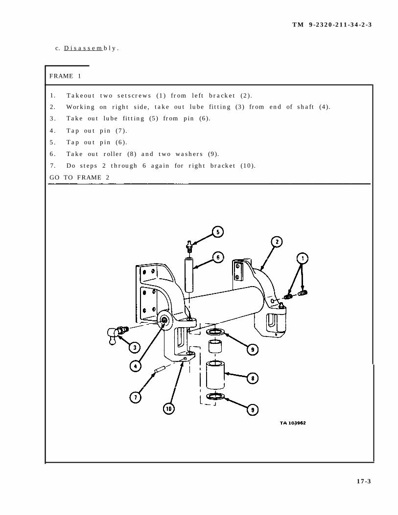
c. D i s a s s e m b l y .
FRAME 1
1. Takeout two setscrews (1) from left bracket (2) .
2. Working on right side, take out lube fitting (3) from end of shaft (4).
3. Take out lube fitting (5) from pin (6).
4. Tap out pin (7) .
5. Tap out pin (6) .
6. Take out roller (8) and two washers (9).
7. Do steps 2 through 6 again for right bracket (10).
GO TO FRAME 2
17-3

TM 9-2320-211-34-2-3
F R A M E 2
1. Pull left bracket (1) off shaft (2).
2. Slide off washer (3) , felt washer (4) , and bearing (5) .
3. Pull roller (6) off shaft (2). Take felt washers (4) out of each end of roller( 6 ) .
4. Do steps 1 and 2 again for right bracket (7).
END OF TASK
1 7 - 4
TM 9-2320-211-34-2-3
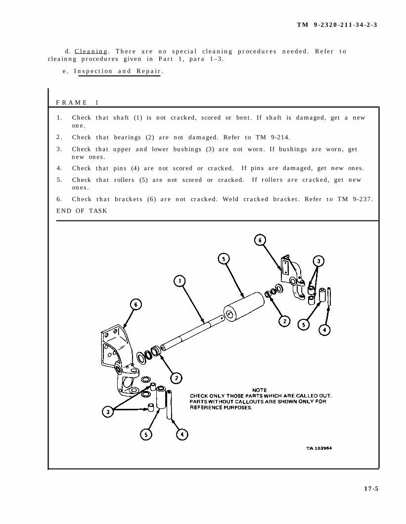
d. Cleaning . There are no special cleaning procedures needed. Refer tocleainng procedures given in Part 1, para 1–3.
e . Inspect ion and Repair .
F R A M E 1
1. Check that shaft (1) is not cracked, scored or bent. If shaft is damaged, get a newone.
2. Check that bearings (2) are not damaged. Refer to TM 9-214.
3. Check that upper and lower bushings (3) are not worn. If bushings are worn, getnew ones.
4. Check that pins (4) are not scored or cracked. If pins are damaged, get new ones.
5. Check that rollers (5) are not scored or cracked. If rollers are cracked, get newones.
6. Check that brackets (6) are not cracked. Weld cracked bracket. Refer to TM 9-237.
END OF TASK
17-5
TM 9-2320-211-34-2-3
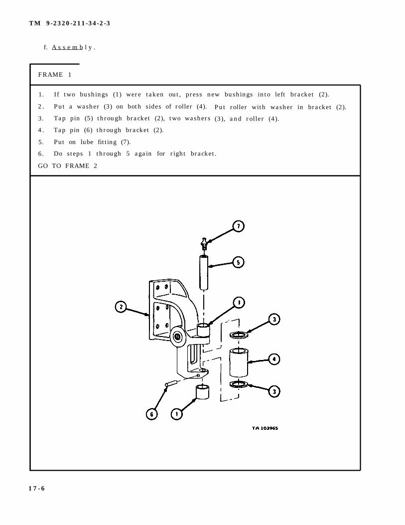
f. A s s e m b l y .
FRAME 1
1. If two bushings (1) were taken out, press new bushings into left bracket (2).
2 . Put a washer (3) on both sides of roller (4).
3. Tap pin (5) through bracket (2), two washers
4. Tap pin (6) through bracket (2).
5. Put on lube fitting (7).
Put roller with washer in bracket (2).
(3), and roller (4).
6. Do steps 1 through 5 again for right bracket.
GO TO FRAME 2
1 7 - 6

TM 9-2320-211-34-2-3
F R A M E 2
1 . Press bearings (1) into roller (2).
2. Put
3. Put
4. Put
5. Put
6. Put
shaft (3) into roller (2).
two felt washers (4) and two washers (5) on shaft (3).
NOTE
Shaft (3) is drilled for setscrew (7) and must go into leftbracket (6).
shaft (3) into left bracket (6) and put in setscrew (7) and lockscrew (8).
bracket (9) on shaft (3).
in lube fittings (10).
END OF TASK
17-7

TM 9-2320-211-34-2-3
g. R e p l a c e m e n t .
F R A M E 1
S o l d i e r s 1 . Put roller assembly in place on winch.A and B
S o l d i e r A 2 . Screw in six capscrews (1) with six washers (2).
3. Do step 2 again on right side of winch.
NOTE
Follow-on Maintenance Action Required:
1. Replace front winch assembly. Refer to TM 9-2320-211-20.2. Grease shaft and rollers. Refer to LO 9-2320-211-12.
END OF TASK
1 7 - 8
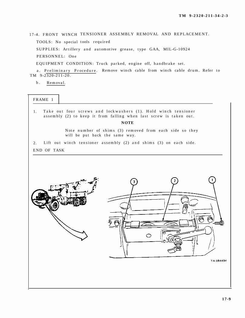
17-4. FRONT WINCH
TOOLS: No special
TM 9-2320-211-34-2-3
TENSIONER ASSEMBLY REMOVAL AND REPLACEMENT.
tools required
SUPPLIES: Artillery and automotive grease, type GAA, MIL-G-10924
PERSONNEL: One
EQUIPMENT CONDITION: Truck parked, engine off, handbrake set.
a. Preliminary Procedure. Remove winch cable from winch cable drum. Refer toTM 9-2320-211-20.
b . Removal.
FRAME 1
1. Take out four screws and lockwashers (1). Hold winch tensionerassembly (2) to keep it from falling when last screw is taken out.
NOTE
Note number of shims (3) removed from each side so theywill be put back the same way.
2. Lift out winch tensioner assembly (2) and shims (3) on each side.
END OF TASK
17-9

TM 9-2320-211-34-2-3
c . Replacement.
F R A M E 1
1.
2.
3.
4.
Put a coat of grease on shims (1) to keep them from falling while putting themb a c k .
Put winch tensioner assembly (2) and shims (1) in place as noted.
Using two punches, aline holes in winch tensioner assembly (2) andshims (1).
Put in four screws (3) with lockwashers (4).
NOTE
Follow-on Maintenance Action Required:
1. Replace winch cable back on winch drum. Refer toTM 9-2320-211-20.
2. Grease and oil winch tensioner assembly. Refer toLO 9-2320-211-12.
END OF TASK
17-10

TM 9-2320-211-34-2-3
17-5. FRONT WINCH SHEAVE AND TROLLEY (LEVEL WIND) REPAIR(TRUCK M543A2).
TOOLS : No special tools required
SUPPLIES : Solvent, dry cleaning, type II (SD-2), Fed. Spec P-D-680Clean dry ragsCrocus clothCotter pinFelt washer, swivel sheave bearing (2)Felt ring, trolleyTrolley wheel bearing packing wit h ret airierSheave frame shaft bearing preformed felt, mechanical (1 each)
PERSONNEL: One
EQUIPMENT CONDITION: Level wind assembly on workbench.
17-11

TM 9-2320-211-34-2-3
a . Disassembly.
F R A M E 1
1.
2.
3.
4.
5.
6.
7.
Take off nut (1) . Take out stop bolt (2).
Do step 1 again on other side.
Slide trolley assembly (3) to one side of track (4). Take out fourscrews and washers (5) through holes in track.
Lift out trolley assembly (3).
Take out two nuts (6) and lever (7).
Take out nut (8) and spring (9).
Take out screw (10).
GO TO FRAME 2
17-12
TM 9-2320-211-34-2-3
F R A M E 2
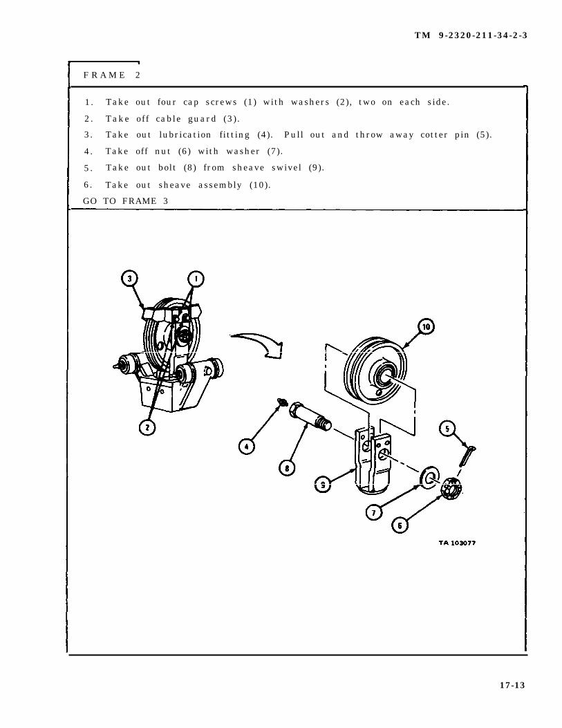
1. Take out four cap screws (1) with washers (2), two on each side.
2 . Take off cable guard (3) .
3. Take out lubrication fitting (4). Pull out and throw away cotter pin (5).
4. Take off nut (6) with washer (7).
5 . Take out bolt (8) from sheave swivel (9).
6. Take out sheave assembly (10).
GO TO FRAME 3
17-13
TM 9-2320-211-34-2-3
FRAME 3
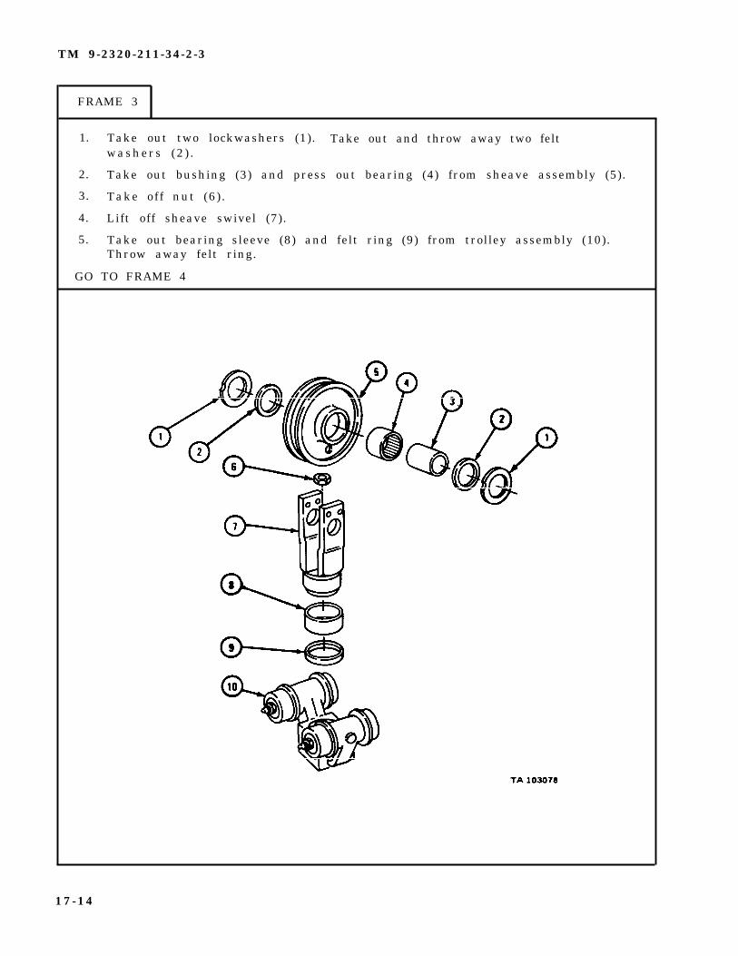
1. Take out two lockwashers (1). Take out and throw away two feltwashers (2 ) .
2. Take out bushing (3) and press out bearing (4) from sheave assembly (5).
3. Take off nut (6) .
4. Lift off sheave swivel (7).
5. Take out bearing sleeve (8) and felt ring (9) from trolley assembly (10).Throw away felt ring.
GO TO FRAME 4
17-14

TM 9-2320-211-34-2-3
FRAME 4
1. Take out nut (1), washer (2), and preformed felt packing (3). Throwaway preformed felt packing.
2. Take out shaft (4) .
3. Take off outer bearing cup (5).
4. Take out 26 bearing balls (6).
5. Take out inner bearing cup (7) from trolley assembly (8).
NOTE
Do not take out bearing (8) unless it is damaged.Refer to para 17-5c for inspection procedures.
6. Take out bearing (9).
GO TO FRAME 5
17-15
TM 9-2320-211-34-2-3
FRAME 5
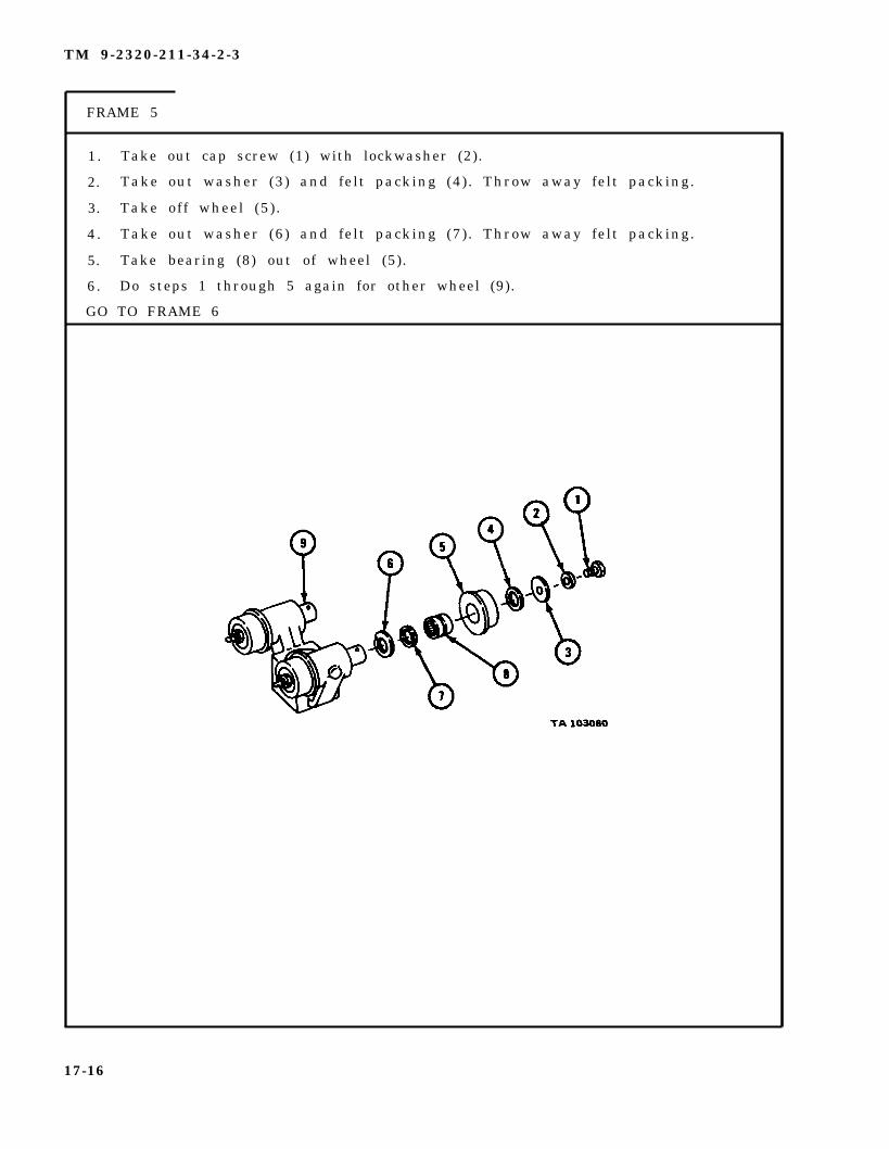
1. Take out cap screw (1) with lockwasher (2).
2. Take out washer (3) and felt packing (4). Throw away felt packing.
3. Take off wheel (5) .
4 . Take out washer (6) and felt packing (7). Throw away felt packing.
5. Take bearing (8) out of wheel (5).
6. Do steps 1 through 5 again for other wheel (9).
GO TO FRAME 6
17-16
TM 9-2320-211-34-2-3
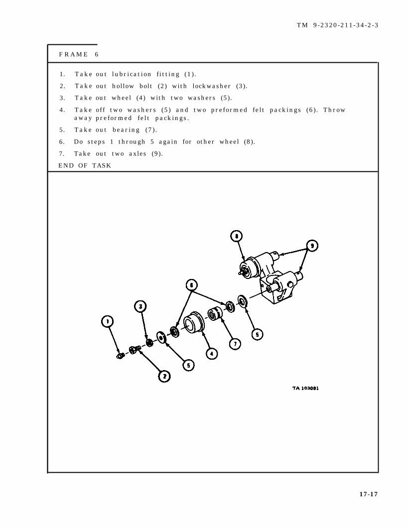
F R A M E 6
1. Take
2. Take
3. Take
4. Takeaway
5. Take
out lubrication fitting (1).
out hollow bolt (2) with lockwasher (3).
out wheel (4) with two washers (5).
off two washers (5) and two preformed felt packings (6) . Throwpreformed felt packings.
out bearing (7) .
6. Do steps 1 through 5 again for other wheel (8).
7. Take out two axles (9).
END OF TASK
17-17

TM 9-2320-211-34-2-3
WARNING
Dry cleaning solvent is flammable. Do not usenear an open flame. Keep a fire extinguishernearby when solvent is used. Use only in well-ventilated places. Failure to do this may resultin injury to personnel and damage to equipment.
b . Cleaning. Clean all metal parts with dry cleaning solvent. Dry with cleand r y r a g s .-
C. Inspection and Repair.
(1) Check that all bearings are not damaged. Refer to Part 1, para 7-7.If bearings are damaged, get new ones.
(2) Check that axles and shafts have no scoring, burrs or cracks.Polish” burrs with crocus cloth. If axles or shafts are bent or cracked get new ones.
(3) Check that axle housing, swivel frame, and track have no cracks, bendsor burrs . Repair cracks by welding. Refer to TM 9-237. Polish burrs with a finemill file.
(4) Check that cable sheave has no bends or cracks. Repair cracks bywelding. Refer to TM 9-237. If sheave is bent, get a new one.
(5) Check that ball bearing cups are not damaged. Refer to Part 1,para 7-7. If bearing cups are damaged, get new ones.
17-18

TM 9-2320-211-34-2-3
d. A s s e m b l y .
F R A M E 1
1.
2.
3.
4.
5.
GO
Put in two shafts (1).
Put bearing (2) in wheel (3). Put two preformed felt packings (4) inwheel. Put two washers (5) in wheel.
Slide wheel assembly (3) over shaft (1). Put in hollow bolt (6) withwasher (7 ) .
Put in lubrication fitting (8).
Do steps 2 through 4 again for other shaft (1).
TO FRAME 2
17-19
TM 9-2320-211-34-2-3
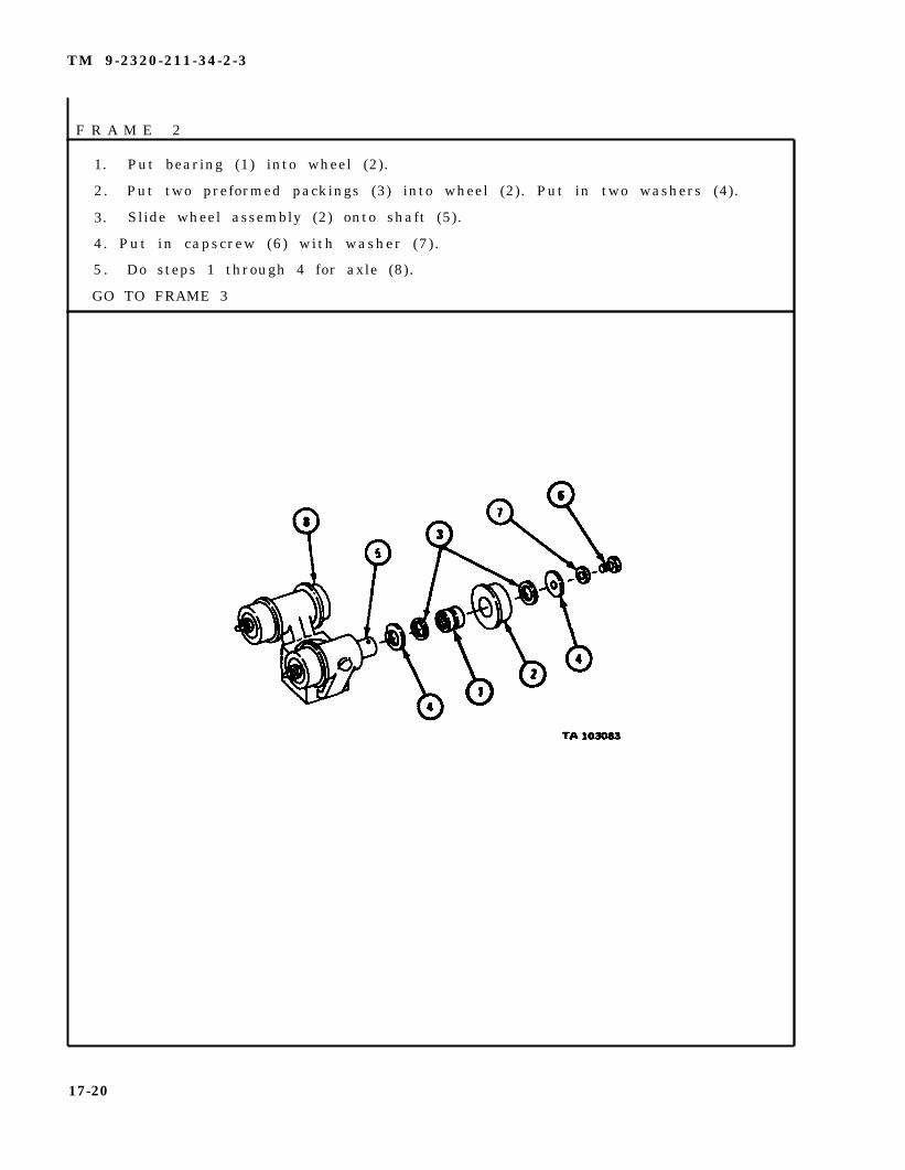
F R A M E 2
1. Put bearing (1) into wheel (2).
2. Put two preformed packings (3) into wheel (2). Put in two washers (4).
3. Slide wheel assembly (2) onto shaft (5).
4. Put in capscrew (6) with washer (7).
5 . Do steps 1 through 4 for axle (8).
GO TO FRAME 3
17-20

TM 9-2320-211-34-2-3
FRAME 3
1. Put in inner bearing cup (1). Put in 26 bearing balls (2).
2. Put on outer bearing cup (3). Put in bearing (4).
3. Put in shaft (5). Put on preformed felt packing (6).
4 . Put on washer (7). Put nut (8) on trolley assembly (9).
GO TO FRAME 4
17-21

TM 9~2320-211-34-2-3
F R A M E 4
1 .
2.
3.
4.
5 .
6 .
7 .
8.
Put in felt ring (1).
Put in bearing sleeve (2).
Put on sheave swivel (3).
Put nut (4) on trolley assembly (5).
Press bearing (6) into sheave (7) .
Put in bushing (8).
Put in two felt washers (9).
Put in two lockwashers (10).
GO TO FRAME 5
17-22

TM 9-2320-211-34-2-3
FRAME 5
1.
2.
3.
4.
5.
6.
GO TO FRAME 6
Put sheave assembly (1) into swivel (2).
Put in bolt (3).
Put on washer (4) and nut (5).
Put in cotter pin (6).
Put on cable guard (7) with four capscrews (8) and washers (9), two oneach side.
Put in lubrication fitting (10).
17-23

TM 9-2320-211-34-2-3
FRAME 6
1. Put capscrew (1 ) in track (2 ) .
2. Put spr ing (3 ) , nut (4 ) , l ever (5 ) , and two nuts (6 ) on capscrew (1 ) .
3. Set trolley assembly (7) in track (2).
4. Put in four screws with washers (8) through holes in track (2).
5. Put in stop bolts (9) and nuts (10).
6. Do step 5 on other side of track.
NOTE
Follow-on Maintenance Action
Lubricate sheave bolt and wheelto LO 9-2320-211-12.
END OF TASK
Required :
ax les . Re fer
17-24

TM 9-2320-211-34-2-3
17-6. FRONT LEVEL WIND REMOVAL AND REPLACEMENT (TRUCK M543A2).
TOOLS: No special tools required
SUPPLIES: None
PERSONNEL: One
EQUIPMENT CONDITION: Truck parked, engine off, handbrake set.
Preliminary Procedure. Free winch cable from stowed position. Refer toTM 9--2320-211-10.
b. Removal.
F R A M E 1
WARNING
Always wear leather gloves when handling winch cable. Donot let cable run through hands. Rusty or broken wires cancause serious injury to personnel.
1. Take out four screws and lockwashers (1).
2. Lift off guard (2).
3. Lift cable (3) off sheave (4) and move cable out of the way.
GO TO FRAME 2
17-25

TM 9-2320-211-34-2-3
FRAME 2
1. Take out four screws and lockwashers (1).
2. Lift off sheave assembly (2).
END OF TASK
17-26
TM 9-2320-211-34-2-3
c. R e p l a c e m e n t .
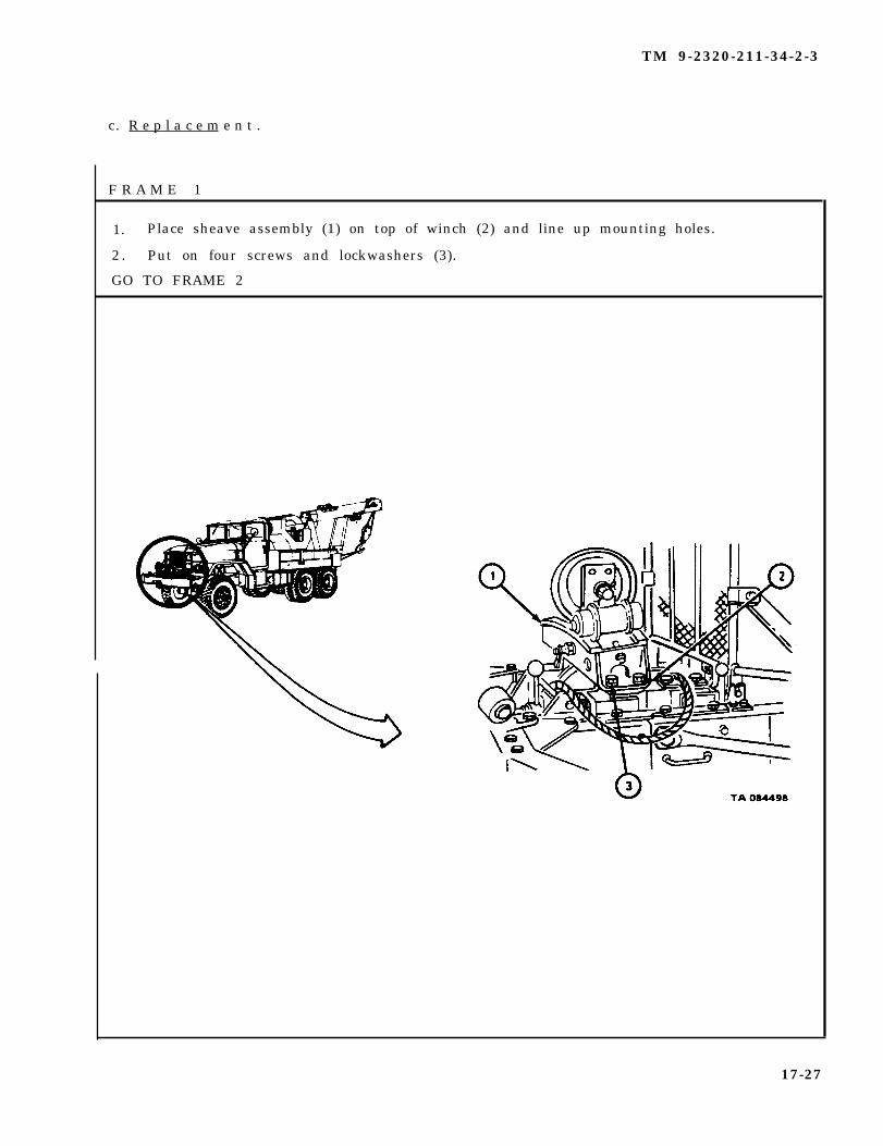
F R A M E 1
1. Place sheave assembly (1) on top of winch (2) and line up mounting holes.
2 . Put on four screws and lockwashers (3).
GO TO FRAME 2
17-27

TM 9-2320-211-34-2-3
FRAME 2
1. Put
2. Put
3. Put
WARNING
Always wear leather gloves when handling winch cable.Do not let cable run through hands. Broken or rustywires can cause serious injury to personnel.
cable (1) in groove of sheave (2).
guard (3) on frame (4).
in four screws and lockwashers (5).
NOTE
Follow-on Maintenance Action Required:
Put cable back into stowed position. Refer to TM 9-2320-211-10.
END OF TASK
17-28

TM 9-2320-211-34-2-3
17-7. FRONT WINCH TENSION SHEAVE ASSEMBLY REPAIR (TRUCK M543A2).
TOOLS: No special tools required
SUPPLIES: Solvent, dry cleaning, type II (SD-2), Fed. Spec P-D-680Lint-free clothCrocus cloth
PERSONNEL: One
EQUIPMENT CONDITION: Tension sheave assembly removed from truck.
a . Disassembly.
FRAME 1
1. Unscrew nut (1) and take out tensioner lever latch assembly (2).
2. Take out setscrew (3) and take off tension lever (4).
3. Take out two lubrication fittings (5).
GO TO FRAME 2
17-29

TM 9-2320-211-34-2-3
FRAME 2
1.
2.
3.
GO
Takeout woodruf f key (1 ) .
Take out four screws (2) with
Take off block (4) .
TO FRAME 3
lockwashers (3 ) .
17-30
TM 9-2320-211-34-2-3
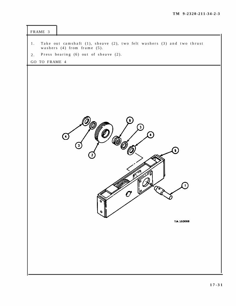
FRAME 3
1. Take out camshaft (1) , sheave (2), two felt washers (3) and two thrustwashers (4) from frame (5).
2. Press bearing (6) out of sheave (2) .
GO TO FRAME 4
1 7 - 3 1
TM 9-2320-211-34-2-3
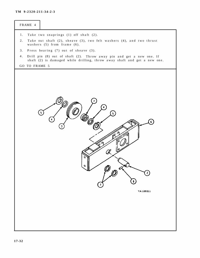
FRAME 4
1. Take two snaprings (1) off shaft (2) .
2. Take out shaft (2) , sheave (3), two felt washers (4), and two thrustwashers (5) from frame (6).
3. Press bearing (7) out of sheave (3) .
4 . Drill pin (8) out of shaft (2). Throw away pin and get a new one. Ifshaft (2) is damaged while drilling, throw away shaft and get a new one.
GO TO FRAME 5
17-32

TM 9-2320-211-34-2-3
FRAME 5
1. Press bearing sleeve (1) out of frame (2) and throw it away.
2. Press bearing sleeve (3) out of block (4) and throw it away.
GO TO FRAME 6
17-33

TM 9-2320-211-34-2-3
F R A M E 6
1. Clamp tensioner sheave lever lock poppet (1) in vise with soft jaw caps.
2. Take off nut (2) . Take off latch (3). Take of nut (4) and spring (5).
3. Take poppet (1) out of vise.
END OF TASK
17-34
TM 9-2320-211-34-2-3
WARNING
Dry cleaning solvent is flammable. Do not usenear an open flame. Keep a fire extinguishernearby when solvent is used. Use only in well-ventilated places. Failure to do this may resultin injury to personnel and damage to equipment.
b . Cleaning. Wash all metal parts with dry cleaning solvent. Wipe with cleandry rags .
c . Inspection and Repair.
(1) Check that all bearings are not damaged. Refer to Part 1, para 7-7. Ifbearings are damaged, get new ones.
(2) Check that sheave shafts have no wear, cracks or burrs. Polish burrswith crocus cloth. If shafts are cracked, get new ones.
(3) Check that sheaves have no cracks or bends. If sheaves are cracked,bent or worn, get new ones.
(4) Check that tension frame has no cracks or bends. Repair cracks byweld ing . Refer to TM 9-237.
(5) Check that operating lever has no cracks or bends. Repair cracks byweld ing . Refer to TM 9-237.
(6) Check that washers have no wear or scoring marks. If washers are wornor scored, get new ones.
17-35

TM 9-2320-211-34-2-3
d . Assembly .
FRAME 1
1. Clamp tension sheave lever lock poppet (1) in vise with soft jaw caps.
2. Put on spring (2) and nut (3).
3. Push down on nut (3) to compress spring (2) and put on latch (4).Hold down latch (4) and put on nut (5).
GO TO FRAME 2
17-36

TM 9-2320-211-34-2-3
FRAME 2
1. Press bearing sleeve (1) into frame (2).
2 . Press bearing sleeve (3) into block (4) .
GO TO FRAME 3
17-37

TM 9-2320-211-34-2-3
FRAME 3
1 . Put pin (1) into shaft (2).
2 . Press bearing (3) into sheave (4) .
3. Put sheave (4), two felt washers (5), and two thrust washers (6 )into frame (7), alining holes.
4. Aline pin (1) with slot in frame (7) and put in shaft (2).
5. Put two retaining rings (8) in grooves in shaft (2).
GO TO FRAME 4
17-38

TM 9-2320-211-34-2-3
F R A M E 4
1. Press bearing (1) into sheave (2) .
2. Put sheave (2), two felt washers (3), and two thrust washers (4) intoframe (5), alining holes.
3. Put in camshaft (6).
GO TO FRAME 5
17-39

TM 9-2320-211-34-2-3
FRAME 5
1 . Put block (1) in place on frame (2) with lever locking holes to theupper right and aline screw holes.
2. Put in four screws (3) with lockwashers (4).
3. Tap woodruff key (5) into keyway in camshaft (6).
GO TO FRAME 6
17-40

TM 9-2320-211-34-2-3
FRAME 6
1. Aline keyway in tensioner lever (1) with key on shaft (2). Put ontensioner lever.
2. Put in setscrew (3).
3. Put tension lever latch assembly (4) in place in lever and screw in andtighten retaining nut (5).
4. Screw in and tighten two lubrication fittings (6).
NOTE
Follow-on Maintenance Action Required:
Lubricate sheaves. Refer to LO 9-2320-211-12.
END OF TASK
17-41

TM 9-2320-211-34-2-3
17-8. FRONT WINCH AUTOMATIC BRAKE REMOVAL, REPLACEMENT, ANDADJUSTMENT.
TOOLS: No special tools required
SUPPLIES: End cover gasketPreformed packing
PERSONNEL: One
EQUIPMENT CONDITION: Truck parked, engine off , handbrake set.
a . Removal.
F R A M E 1
1. Take out six locking screws (1).
2. Take off brake case end cover (2) and gasket (3) . Throw away gasket.
3. Loosen screw (4).
4. Take out screw (5), washer (6), and preformed packing (7). Throw awaypreformed packing.
GO TO FRAME 2
17-42

TM 9-2320-211-34-2-3
1. Take out brake band assembly (1) and spring (2).
2. Check that braking surface of automatic brake drum (3) is not scored ordamaged in any other way.
IF AUTOMATIC BRAKE DRUM IS DAMAGED, GO TO FRAME 3.IF AUTOMATIC BRAKE DRUM IS NOT DAMAGED, END OF TASK
17-43

TM 9-2320-211-34-2-3
1. Take out screw (1), lockwasher (2), and flat washer (3).
2 . Pull off automatic brake drum (4). Throw away automatic brake drum and geta new one.
END OF TASK
17-44

TM 9-2320-211-34-2-3
b . Replacement and Adjustment.
FRAME 1
NOTE
If automatic brake drum (1) was not taken off duringdisassembly, go to frame 2.
1. Line up keyway in automatic brake drum (1) with key (2).
2. Tap automatic brake drum (1) onto shaft of worm gear (3) and key (2).
3 . Put in screw (4) with flat washer (5) and lockwasher (6).
GO TO FRAME 2
17-45

TM 9-2320-211-34-2-3
FRAME 2
1. Put brake band assembly (1) on automatic brake drum (2).
2 . Put spring (3) between screw holes in brake band assembly (1) and automaticbrake case (4).
3 . Put flat washer (5) and preformed packing (6) on screw (7), and put in screw.
4 . Draw up brake band assembly (1) partway.
GO TO FRAME 3
17-46

TM 9-2320-211-34-2-3
FRAME 3
1. Turn in screw (1) until gap in brake band assembly (2) is between 1 3/16 inchesand 1 1/4 inches as shown.
2 . Tighten screw (3).
GO TO FRAME 4
17-47

TM 9-2320-211-34-2-3
FRAME 4
1. Put gasket (1) and brake case end cover (2) on automatic brake case (3).
2 . Put in six locking screws (4).
END OF TASK
17-48

TM 9-2320-211-34-2-3
17-9. FRONT WINCH LEVEL WIND REMOVAL AND REPLACEMENT (TRUCK M542A2).
TOOLS: Torque wrench
S U P P L I E S : N o n e
PERSONNEL: T w o
EQUIPMENT CONDITION: Truck parked, engine off , handbrake set.
a . R e m o v a l .
FRAME 1
1.
2.
GO
Takeout four screws (1) and lockwashers (2). Take off cable guard (3).
Take cable (4) off swivel sheave (5) and lay cable over gearcase (6) so thatit is clear of level wind (7).
TO FRAME 2
17-49
TM 9-2320-211-34-2-3
FRAME 2
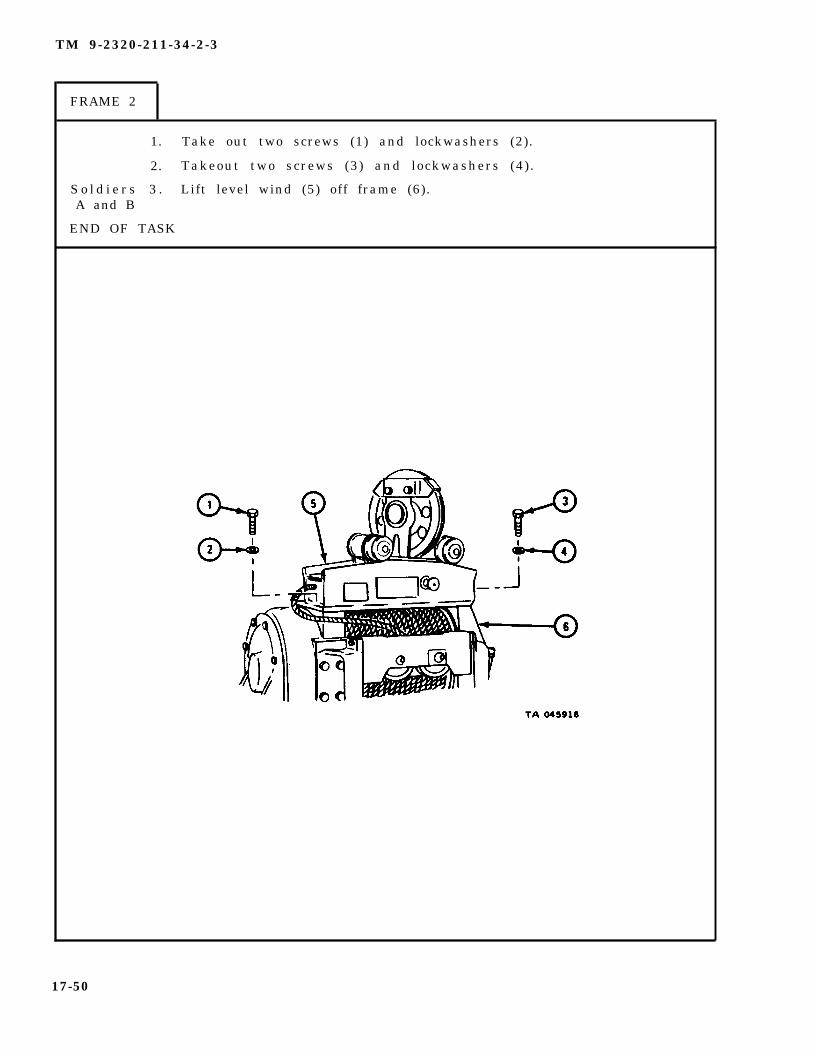
1. Take out two screws (1) and lockwashers (2).
2. Takeout two screws (3) and lockwashers (4).
S o l d i e r s 3 . Lift level wind (5) off frame (6).A and B
END OF TASK
17-50
TM 9-2320-211-34-2-3
b . Replacement.
FRAME 1
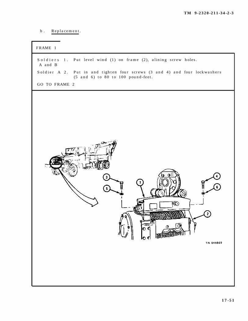
S o l d i e r s 1 . Put level wind (1) on frame (2), alining screw holes.A and B
S o l d i e r A 2 . Put in and tighten four screws (3 and 4) and four lockwashers(5 and 6) to 80 to 100 pound-feet.
GO TO FRAME 2
17-51
TM 9-2320-211-34-2-3
FRAME 2
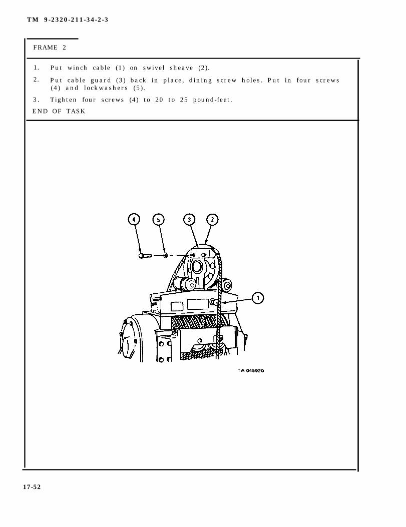
1. Put winch cable (1) on swivel sheave (2).
2. Put cable guard (3) back in place, dining screw holes. Put in four screws(4) and lockwashers (5) .
3 . Tighten four screws (4) to 20 to 25 pound-feet.
END OF TASK
17-52

17-10. FRONT WINCH ASSEMBLY REPAIR.
TOOLS: No
SUPPLIES:
special tools required
Gearcase cover gasket
TM 9-2320-211-34-2-3
Worm gear cap gasket (2)Worm gear cap sealAutomatic brake case cover gasketPreformed packingAutomatic brake case sealAutomatic brake case gasketSolvent, dry cleaning, type II (SD-2), Fed. Spec P-D-680
PERSONNEL: TWO
EQUIPMENT CONDITION: Truck parked, engine off, bandbrake set.
a. Pre l iminary Procedures .
(1) Remove cable and chain assembly. Refer to TM 9-2320-211-20.
(2) Remove winch assembly and remove mounting brackets from winch assembly.Refer to TM 9-2320-211-20.
(3) On truck M543A2, remove level wind assembly. Refer to para 17-6.
(4) Remove front winch roller assembly. Refer to para 17-3.
(5) Drain winch assembly. Refer to LO 9-2320-211-12.
17-53
TM 9-2320-211-34-2-3
b . Disassembly.
(1) Disassembly of frame assembly.
FRAME 1
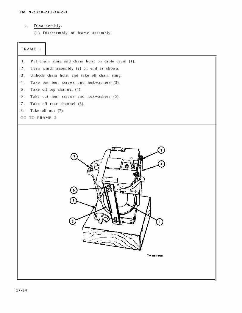
1. Put chain sling and chain hoist on cable drum (1).
2 . Turn winch assembly (2) on end as shown.
3 . Unhook chain hoist and take off chain sling.
4 . Take out four screws and lockwashers (3).
5 . Take off top channel (4).
6 . Take out four screws and lockwashers (5).
7 . Take off rear channel (6).
8 . Take off nut (7).
GO TO FRAME 2
17-54

TM 9-2320-211-34-2-3
1.
2 .
3 .
4 .
5 .
6 .
7 .
GO
Take out plugs (1 and 2).
Drive out pin (3).
Slowly pull out lever assembly (4) and take out catch ball (5) and spring (6).
Pull out shifter yoke (7).
Take out screw (6).
Pull off lever (9).
Tap out key (10).
TO FRAME 3
17-55

TM 9-2320-211-34-2-3
S o l d i e r s 1 . Pull off frame assembly (1) and take out thrust ring (2) and slidingA and B clutch (3).
2 . Take out drag brake brakeshoe (4) and spring (5).
NOTE
Do not take out seal (7) unless it is damaged. Refer topara 17-10d for inspection procedures.
3 . Using punch and hammer through hole (6) in frame, tap out seal (7).
GO TO FRAME 4
17-56

TM 9-2320-211-34-2-3
FRAME 4
1. Take out sleeve (1) with bushing (2).
NOTE
Do not press out bushing (2) unless it is damaged orworn. Refer to para 17-10d for inspection procedures.
2. Press out bushing (2).
GO TO FRAME 5
17-57

TM 9-2320-211-34-2-3
FRAME 5
NOTE
Before tapping out shaft (1), make sure that key (3) linedup with keyway in housing.
1. Tap shaft (1) out in direction of arrow, driving out plug (2). Take out shaftthrough plug hole.
2 . Tap out key (3).
GO TO FRAME 6
17-58

TM 9-2320-211-34-2-3
F R A M E 6
1. Unscrew nut (1) and take out drum lock assembly (2).
2 . Turn drum lock latch (3) to locked position to take tension off spring (4).
3. Put poppet (5) in vise with soft jaw caps.
4 . Take off two nuts (6).
5 . Take drum lock latch (3), nut (1), spring (4), and spacer (7) off poppet (5).
6 . Take poppet (5) out of vise.
GO TO FRAME 7
17-59

TM 9-2320-211-34-2-3
FRAME 7
1. Take out two screws and lockwashers (1).
2 . Take off shift lever lock assembly (2).
3 . Hook lip of seal (3) and pry it out.
4 . Take out drag brake adjusting screw (4).
5. Take out three plugs (5).
END OF TASK
17-60

TM 9-2320-211-34-2-3
(2) Disassembly of cable drum and gearcase assembly.
FRAME 1
1. Drive back end of key (1) into shaft (2), raising front end of key out of shaft.
2 . Drive front end of key (1) down and out of keyway.
3 . Slide off thrust ring (3).
4 . Pull cable drum (4) off gearcase (5).
GO TO FRAME 2
17-61
TM 9-2320-211-34-2-3
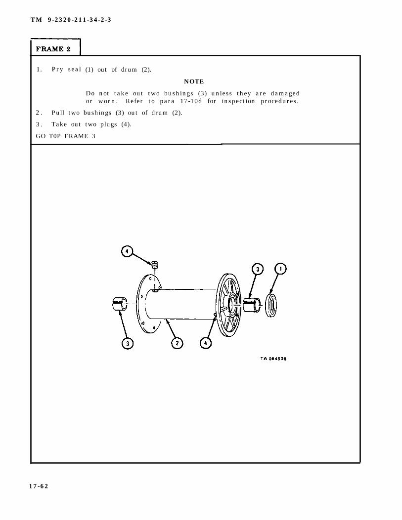
1. Pry seal (1) out of drum (2).
NOTE
Do not take out two bushings (3) unless they are damagedor worn. Refer to para 17-10d for inspection procedures.
2 . Pull two bushings (3) out of drum (2).
3 . Take out two plugs (4).
GO T0P FRAME 3
17-62

TM 9-2320-211-34-2-3
FRAME 3
1. Unscrew nut (1).
2. Take out rod (2).
3. Take out four screws (3).
4. Take off gearcase cover (4) with bushing (5) and gasket (6). Throw away gasket.
NOTE
Do not take out bushing (5) unless it is worn or damaged.Refer to para 17-10d for inspection procedures.
5. Pull out bushing (5).
GO TO FRAME 4
17-63

TM 9-2320-211-34-2-3
FRAME 4
1 . Take out four screws and lockwashers (1) from gearcase (2).
2 . Take off worm gear cap (3) with seal (4) and two gaskets (5). Throw awaygaskets .
3. Take seal (4) out of worm gear cap (3). Throw away seal.
GO TO FRAME 5
17-64
TM 9-2320-211-34-2-3
FRAME 5
1.
2 .
3 .
4 .
5 .
6 .
WARNING
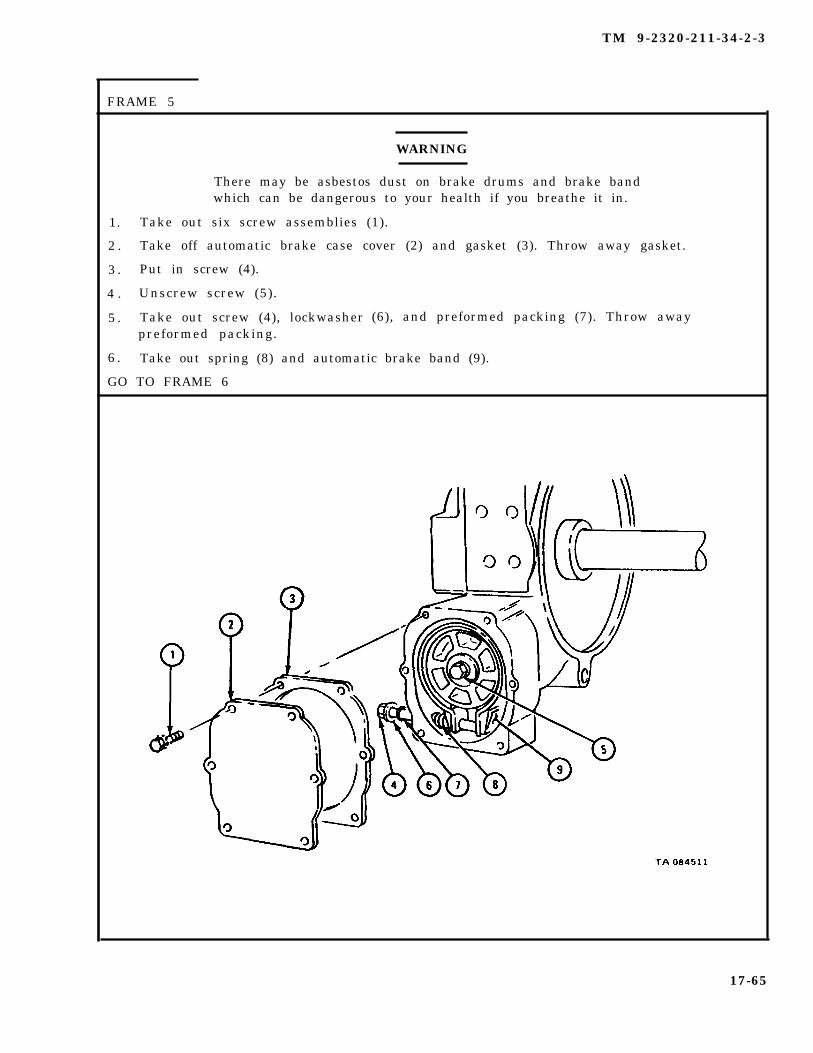
There may be asbestos dust on brake drums and brake bandwhich can be dangerous to your health if you breathe it in.
Take out six screw assemblies (1).
Take off automatic brake case cover (2) and gasket (3). Throw away gasket.
Put in screw (4).
Unscrew screw (5).
Take out screw (4), lockwasherpreformed packing.
(6), and preformed packing (7). Throw away
Take out spring (8) and automatic brake band (9).
GO TO FRAME 6
17-65

TM 9-2320-211-34-2-3
FRAME 6
1.
2 .
3 .
GO
WARNING
There may be asbestos dust on brake drum which can bedangerous to your health if you breathe it in.
Take out screw (1) with lockwasher (2) and spring washer (3).
Take off automatic brake drum (4).
Take out key (5).
TO FRAME 7
17-66

TM 9-2320-211-34-2-3
FRAME 7
1. Take out four screws (1) and lockwashers (2).
2 . Take off automatic brake case (3) with seal (4) and gasket (5). Throw away gasket.
3 . Take seal (4) out of automatic brake case (3). Throw away seal.
GO TO FRAME 8
17-67

TM 9-2320-211-34-2-3
FRAME 8
Soldier A
Soldier B
1 .
2 .
3 .
Tap worm gear (1) until worm gear drops down into gearcase (2).Turn worm gear until it is out of gearcase.
Hold shaft (3) so it will not fall.
Lift gearcase (2) off shaft (3).
CAUTION
4 .
5 .
6 .
Make sure gear (4) rests on hub when pressing out shaft (3).If gear rests on teeth, teeth can break.
Press shaft (3) out of gear (4).
Drive one end of two keys (5) into shaft (3).
Tap out keys (5) from raised end of key.
GO TO FRAME 9
17-68

TM 9-2320-211-34-2-3
1 . Press bearing (1) off worm gear (2).
2 . Press bearing (3) out of gearcase (4).
3 . Take out three plugs (5).
NOTE
Do not press out bushing (6) unless it is damaged orworn. Refer to para 17-10d for inspection procedures.
4 . Press out bushing (6).
END OF TASK
17-69

TM 9-2320-211-34-2-3
c . C l e n i n g .
(1) Clean bearings. Refer to Part 1, para 7-7.
(2) Wipe all seals and automatic brake band assembly with a clean rag.
WARNING
Dry cleaning solvent is flammable. Do not use near an openflame. Keep a fire extinguisher nearby when solvent is used.Use only in well-ventilated places. Failure to do this mayresult in injury to personnel and damage to equipment.
WARNING
Do not use a wire brush or compressed air to clean brakedrum. There may be asbestos dust on the drum which can bedangerous to your health if you breathe it in.
(3) Clean dust or mud from brake drum with a brush and water. Take off oil orgrease with solvent.
(4) Clean all other parts with solvent. Use stiff wire brush to clean off dirt andhardened grease and oil.
17-70

TM 9-2320-211-34-2-3
d. Inspect ion .
FRAME 1
1 .
2 .
3 .
4 .
5 .
6 .
7 .
NOTE
Readings must be within limits given in table 17-1. If read-ings are not within given limits, throw away part and get anew one.
Check that seals (1 and 2) are not cracked, burnt, too stiff or damaged in any otherway.
Check that three bushings (3) are not scored, chipped or damaged in any other way.Measure outer diameter of three bushings.
Check that thrust rings (4 and 5), sliding clutch (6), and shifter fork yoke (7) are notworn, broken or damaged in any other way.
Check that poppet (8) is not bent or broken.
Check that frame (9) is not cracked or damaged in any other way, and that it does nothave damaged threads.
Check that drag brake brakeshoe assembly (10) is not worn or oil soaked.
Check that winch cable and chain assembly has no frayed strands or other damage.
GO TO FRAME 2
Table 17-1. Cable Drum Bushing and End Frame Bushing Wear Limits
IndexItem/Point of Measurement
Wear LimitNumber (inches)
3 Cable drum bushing outer diameter 2.127 to 2.145
3 End frame bushing outer diameter 2.127 to 2.145
17-71

TM 9-2320-211-34-2-3
FRAME 2
1.
2 .
3 .
4 .
5 .
6 .
7 .
8 .
NOTE
Readings must be within limits given in table 17-2. If read-ings are not within given limits, throw away part and get anew one.
Check that two seals (1) are not cracked, burnt, too stiff, or show signs of leakage.If seals are damaged, get new ones in their place.
Check that two bearings (2) are not damaged. Refer to Part 1, para 7-7.
Check that worm gear (3) and gear (4) are not chipped or scored, and that they haveno broken teeth.
Check that drum shaft (5) is not bent or damaged in any other way. Measure outerdiameter of drum shaft.
Check that two bushings (6) are not damaged. Measure outer diameter of bushing.
Check that gearcase (7) is not cracked or damaged in any other way, and that itdoes not have damaged threads.
Check that automatic brake drum (8) is not cracked, and that braking surface is notscored or rough.
Check that automatic brake band assembly (9) is not worn or oil soaked.
END OF TASK
Table 17-2. Drum Shaft and Gearcase Bushing Wear Limits
Index Wear LimitNumber Item/Point of Measurement (inches)
5 Drum shaft outer diameter 2.121 to 2.125
6 Gearcase bushing outer diameter 2.127 to 2.138
17-72
e . R e p a i r .
(1) Using fine mill file, file nicks and burrs from machined surfaces, especially oilseal contact surfaces.
TM 9-2320-211-34-2-3
(2) Get new parts for all other damaged parts.
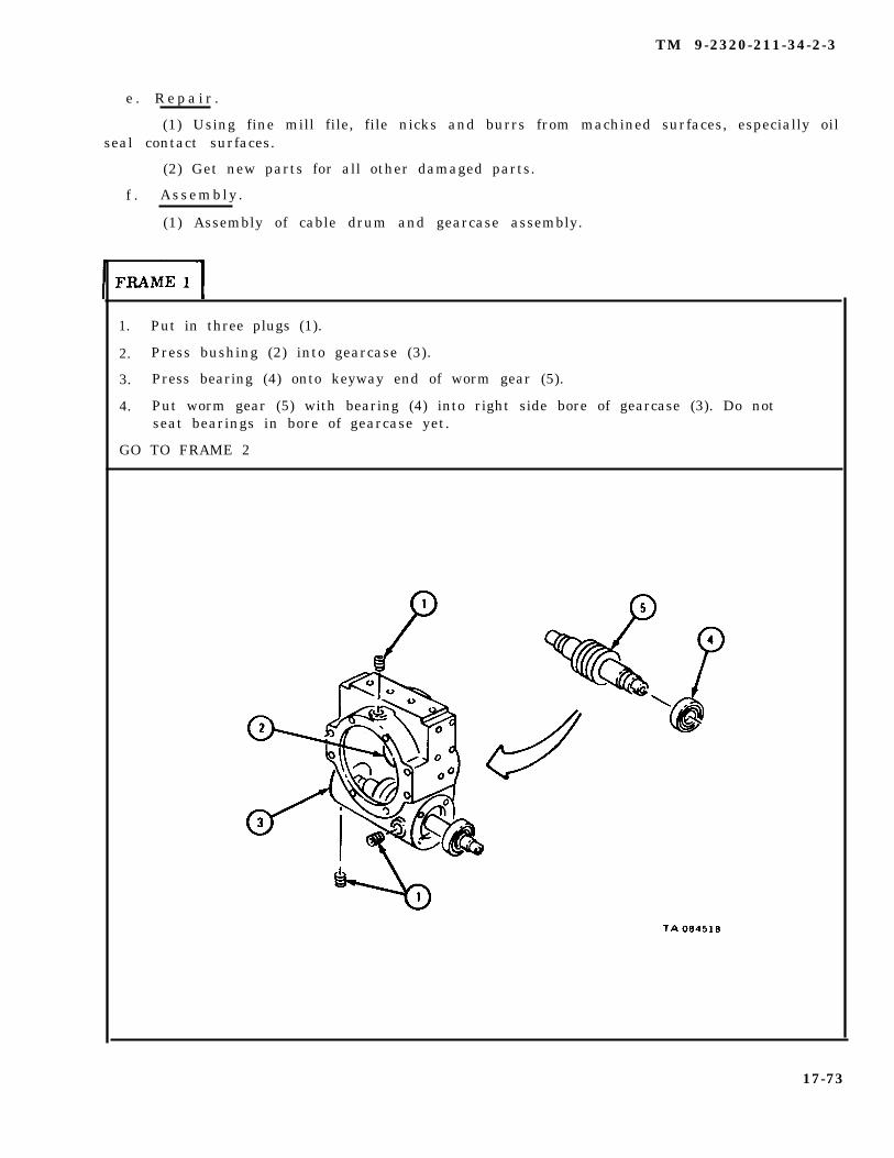
f . Assembly .
(1) Assembly of cable drum and gearcase assembly.
1. Put in three plugs (1).
2. Press bushing (2) into gearcase (3).
3. Press bearing (4) onto keyway end of worm gear (5).
4. Put worm gear (5) with bearing (4) into right side bore of gearcase (3). Do notseat bearings in bore of gearcase yet.
GO TO FRAME 2
17-73
TM 9-2320-211-34-2-3
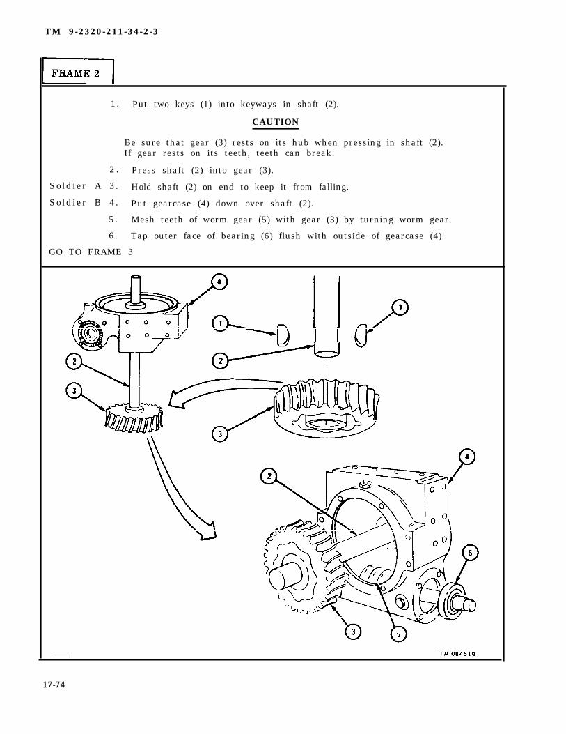
1. Put two keys (1) into keyways in shaft (2).
CAUTION
Be sure that gear (3) rests on its hub when pressing in shaft (2).If gear rests on its teeth, teeth can break.
2 . Press shaft (2) into gear (3).
So ld ier A 3 . Hold shaft (2) on end to keep it from falling.
So ld ier B 4 . Put gearcase (4) down over shaft (2).
5 . Mesh teeth of worm gear (5) with gear (3) by turning worm gear.
6 . Tap outer face of bearing (6) flush with outside of gearcase (4).
GO TO FRAME 3
17-74
TM 9-2320-211-34-2-3
FRAME 3
1 .
2 .
3 .
4 .
5 .
6 .
7 .
GO
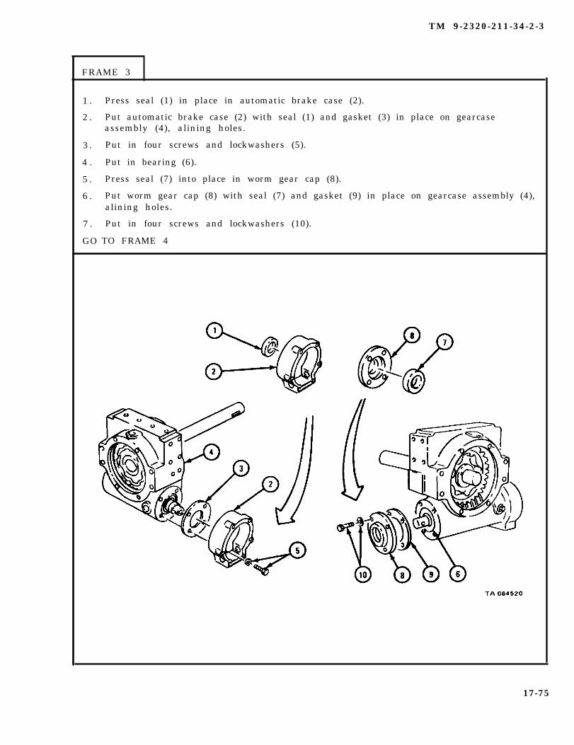
Press seal (1) in place in automatic brake case (2).
Put automatic brake case (2) with seal (1) and gasket (3) in place on gearcaseassembly (4), alining holes.
Put in four screws and lockwashers (5).
Put in bearing (6).
Press seal (7) into place in worm gear cap (8).
Put worm gear cap (8) with seal (7) and gasket (9) in place on gearcase assembly (4),alining holes.
Put in four screws and lockwashers (10).
TO FRAME 4
17-75
TM 9-2320-211-34-2-3
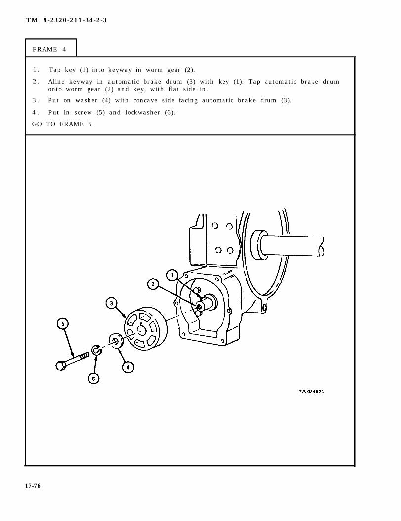
FRAME 4
1 . Tap key (1) into keyway in worm gear (2).
2 . Aline keyway in automatic brake drum (3) with key (1). Tap automatic brake drumonto worm gear (2) and key, with flat side in.
3 . Put on washer (4) with concave side facing automatic brake drum (3).
4 . Put in screw (5) and lockwasher (6).
GO TO FRAME 5
17-76

TM 9-2326-211-34-2-3
FRAME 5
1 .
2 .
3 .
4 .
GO
Put automatic brake band assembly (1) on automatic brake drum (2).
Put spring (3) between screw holes in automatic brake band assembly (1) andautomatic brake case (4) as shown.
Put flat washer (5) and preformed packing (6) on screw (7), and put screw throughholes in automatic brake case (4), spring (3), and automatic brake bandassembly (1).
Tighten screws (7 and 8).
TO FRAME 6
17-77
TM 9-2320-211-34-2-3
FRAME 6
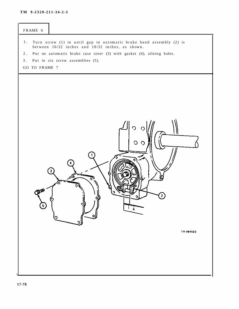
1 . Turn screw (1) in until gap in automatic brake band assembly (2) isbetween 16/32 inches and 18/32 inches, as shown.
2 . Put on automatic brake case cover (3) with gasket (4), alining holes.
3 . Put in six screw assemblies (5).
GO TO FRAME 7
17-78

TM 9-2320-211-34-2-3
FRAME 7
1. Press bushing (1) into gearcase cover (2).
2 . Put gearcase cover (2) with bushing (1) and gasket (3) on gearcase assembly (4),alining holes.
3 . Put in four screws (5).
4 . Put in rod assembly (6).
5 . Tighten nut (7) against gearcase assembly (4).
GO TO FRAME 8
17-79

TM 9-2320-211-34-2-3
FRAME 8
1 .
2*
3 .
S o l d i e r s 4 .A and B
5 .
GO TO FRAME 9
If two bushings (1) were taken out, press bushings into cable drum (2).
If seal (3) was taken out, press in seal.
Put gearcase (4) on end with shaft (5) up.
Pick up cable drum (2) with seal (3) side down and slide cable drumonto shaft (5).
Put in two plugs (6).
17-80

TM 9-2320-211-34-2-3
FRAME 9
1. Put thrust ring (1) onto shaft (2) with notches facing out.
2. Tap two keys (3) into keyways in shaft (2).
END OF TASK
17-81

TM 9-2320-211-34-2-3
(2) Assembly of frame assembly.
FRAME 1
1 . Put in three plugs (1).
2 . Put in drag brake adjusting screw (2).
3 . If seal (3) was taken out, press in seal.
4 . Put shift lever lock assembly (4) in place on frame (5).
5 . Put in two screws with lockwashers (6).
GO TO FRAME 2
17-82
TM 9-2320-211-34-2-3
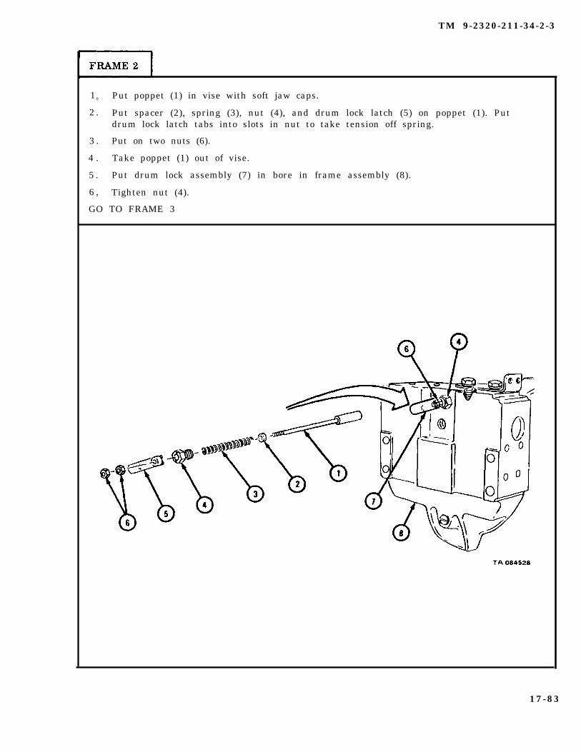
1 0 Put poppet (1) in vise with soft jaw caps.
2 . Put spacer (2), spring (3), nut (4), and drum lock latch (5) on poppet (1). Putdrum lock latch tabs into slots in nut to take tension off spring.
3 . Put on two nuts (6).
4 . Take poppet (1) out of vise.
5 . Put drum lock assembly (7) in bore in frame assembly (8).
6 , Tighten nut (4).
GO TO FRAME 3
17-83

TM 9-2320-211-34-2-3
FRAME 3
1 .
2 .
3 .
4 .
5 .
6 .
7 .
GO
Tap key (1) into keyway in shaft (2).
Put sleeve (3) with bushing (4) into frame (5).
Put shaft (2) partway into frame (5) through hole (6).
Put shifter fork yoke (7) into place in frame (5).
Aline key (1) with keyway in frame (5).
Tap in shaft (2).
Put spring (8) and drag brake brake shoe assembly (9) in bore of frame (5).
TO FRAME 4
17-84
TM 9-2320-211-34-2-3
FRAME 4
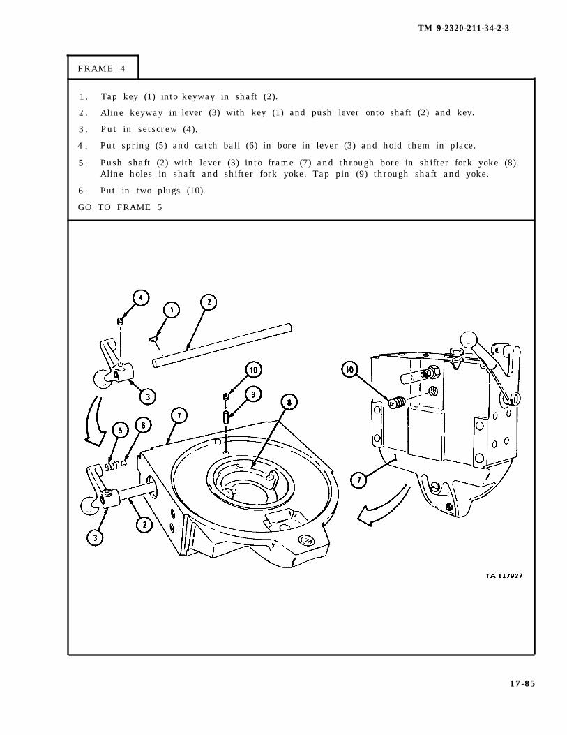
1. Tap key (1) into
2 . Aline keyway in
3 . Put in setscrew
keyway in shaft (2).
lever (3) with key (1) and push lever onto shaft (2) and key.
(4).
4 . Put spring (5) and catch ball (6) in bore in lever (3) and hold them in place.
5 . Push shaft (2) with lever (3) into frame (7) and through bore in shifter fork yoke (8).Aline holes in shaft and shifter fork yoke. Tap pin (9) through shaft and yoke.
6 . Put in two plugs (10).
GO TO FRAME 5
17-85
TM 9-2320-211-34-2-3
FRAME 5
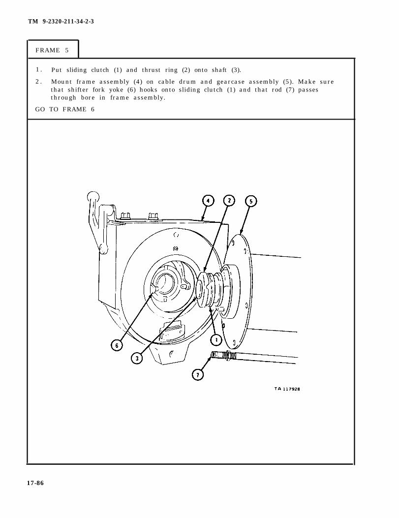
1 . Put sliding clutch (1) and thrust ring (2) onto shaft (3).
2 . Mount frame assembly (4) on cable drum and gearcase assembly (5). Make surethat shifter fork yoke (6) hooks onto sliding clutch (1) and that rod (7) passesthrough bore in frame assembly.
GO TO FRAME 6
17-86
TM 9-2320-211-34-2-3
F R A M E 6
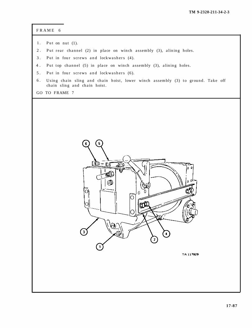
1. Put
2 . Put
3 . Put
4 . Put
5 . Put
on nut (1).
rear channel (2) in place on winch assembly (3), alining holes.
in four screws and lockwashers (4).
top channel (5) in place on winch assembly (3), alining holes.
in four screws and lockwashers (6).
6 . Using chain sling and chain hoist, lower winch assembly (3) to ground. Take offchain sling and chain hoist.
GO TO FRAME 7
17-87
TM 9-2320-211-34-2-3
FRAME 7
1.2.3.
4.
5 .
6.
END OF TASK
NOTE
Follow-on Maintenance Action Required:
Fill winch assembly. Refer to LO 9-2320-211-12.Replace tension roller assembly. Refer to para 17-3.For truck M543A2, replace level wind assembly. Referto para 17-6.Replace winch mounting brackets and replace winch ontruck. Refer to TM 9-2320-211-20.Replace cable and chain assembly. Refer toTM 9-2320-211-20.Check winch assembly for proper operation. Refer toTM 9-2320-211-10.
17-88
TM 9-2320-211-34-2-3
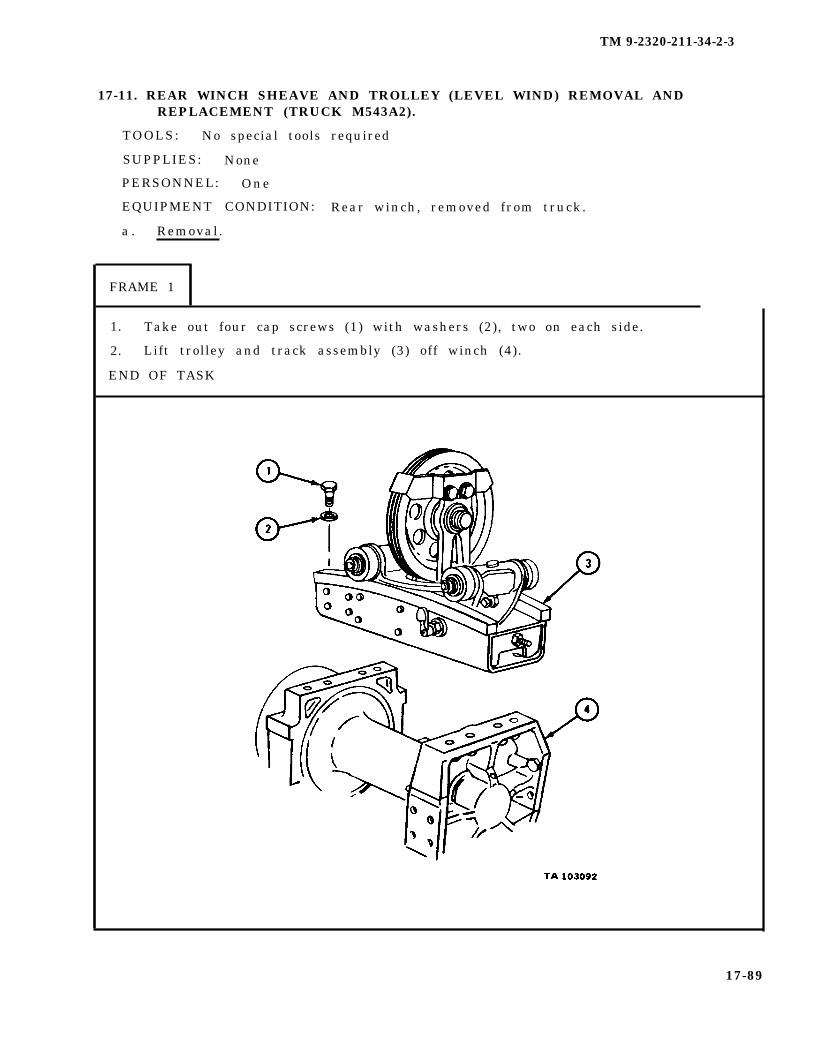
17-11. REAR WINCH SHEAVE AND TROLLEY (LEVEL WIND) REMOVAL ANDREPLACEMENT (TRUCK M543A2).
TOOLS: No special tools required
SUPPLIES: None
PERSONNEL: One
EQUIPMENT CONDITION: Rear winch, removed from truck.
a . Removal.
FRAME 1
1. Take out four cap screws (1) with washers (2), two on each side.
2. Lift trolley and track assembly (3) off winch (4).
END OF TASK
17-89

TM 9-2320-211-34-2-3
b . Replacement.
FRAME 1
1. Set trolley and track assembly (1) on top of winch (2).
2. Put in four cap screws (3) with washers (4), two on each side.
END OF TASK
17-90

TM 9-2320-211-34-2-3
17-12. REAR WINCH TENSION SHEAVE ASSEMBLY REMOVAL AND REPLACEMENT(TRUCK M543A2).
TOOLS: No special tools required
SUPPLIES: None
PERSONNEL: Two
EQUIPMENT CONDITION: Truck parked, engine off ,
a . Pre l iminary Procedure . Remove winch cable fromTM 9-2320-211-20.
b . Removal.
FRAME 1
handbrake set.
drum. Refer to
1 . On right side of winch, take out two cotter pins (1) and take out two pins (2).
2 . Move lever (3) out of way.
GO TO FRAME 2
17-91

TM 9-2320-211-34-2-3
FRAME 2
1. Take off two nuts with lockwashers (1) and take out two cap screws (2).
GO TO FRAME 3
17-92

TM 9-2320-211-34-2-3
FRAME 3
1. Take out four capscrews with four lockwashers (1).
2. Take off cable tensioner (2) .
GO TO FRAME 4
17-93

TM 9-2320-211-34-2-3
F R A M E 4
1. Takeoff two nuts with lockwashers (1). Takeout two capscrews (2).
2. Takeout two capscrews with lockwashers (3).
3. Take off bracket (4) .
END OF TASK
17-94

TM 9-2320-211-34-2-3
c. Replacement.
FRAME 1
1. Put bracket (1) in place and aline holes in bracket (1) with holes in winch (2).
2. Put in two capscrews (3) with two lockwashers (4).
3. Put in two capscrews (5). Put on two lockwashers (6) and two nuts (7).
GO TO FRAME 2
17-95
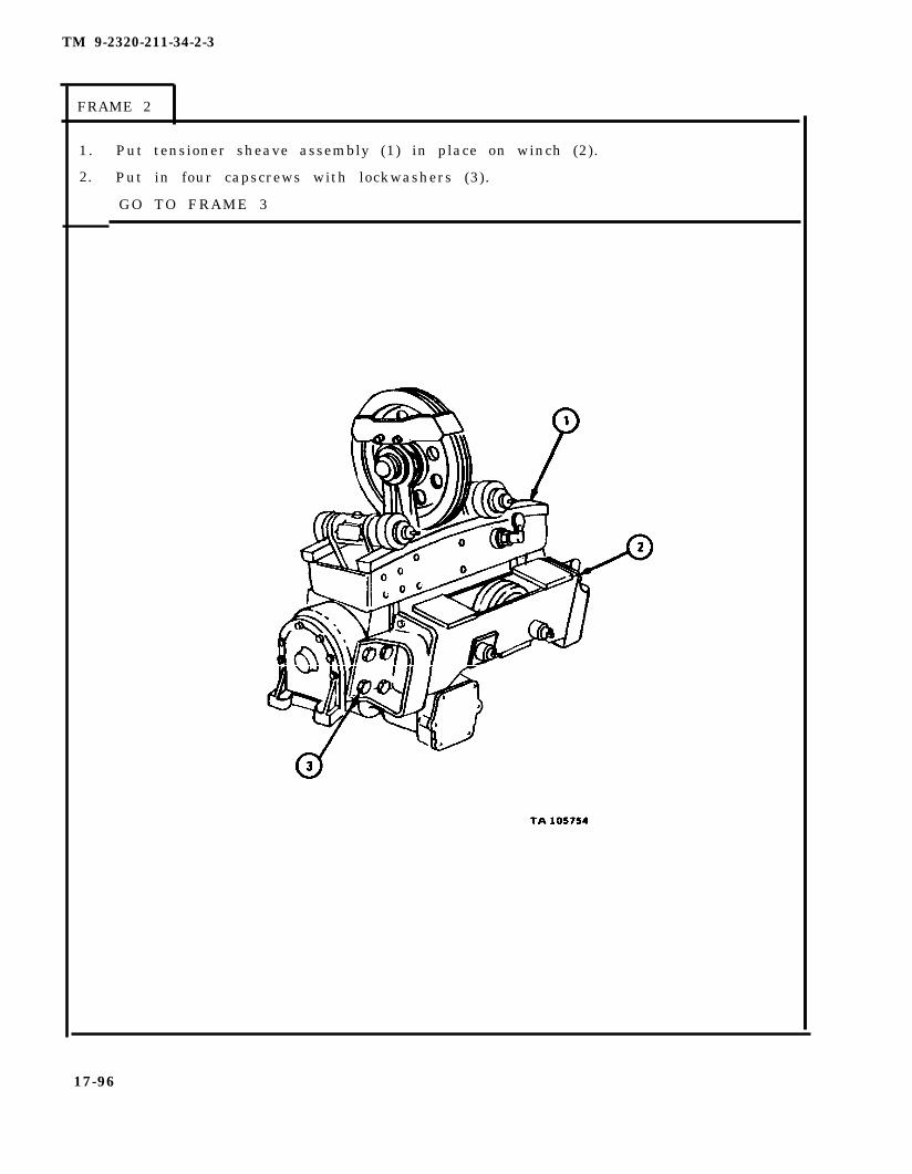
TM 9-2320-211-34-2-3
FRAME 2
1.
2.
Put tensioner sheave assembly (1) in place on winch (2).
Put in four capscrews with lockwashers (3).
GO TO FRAME 3
17-96
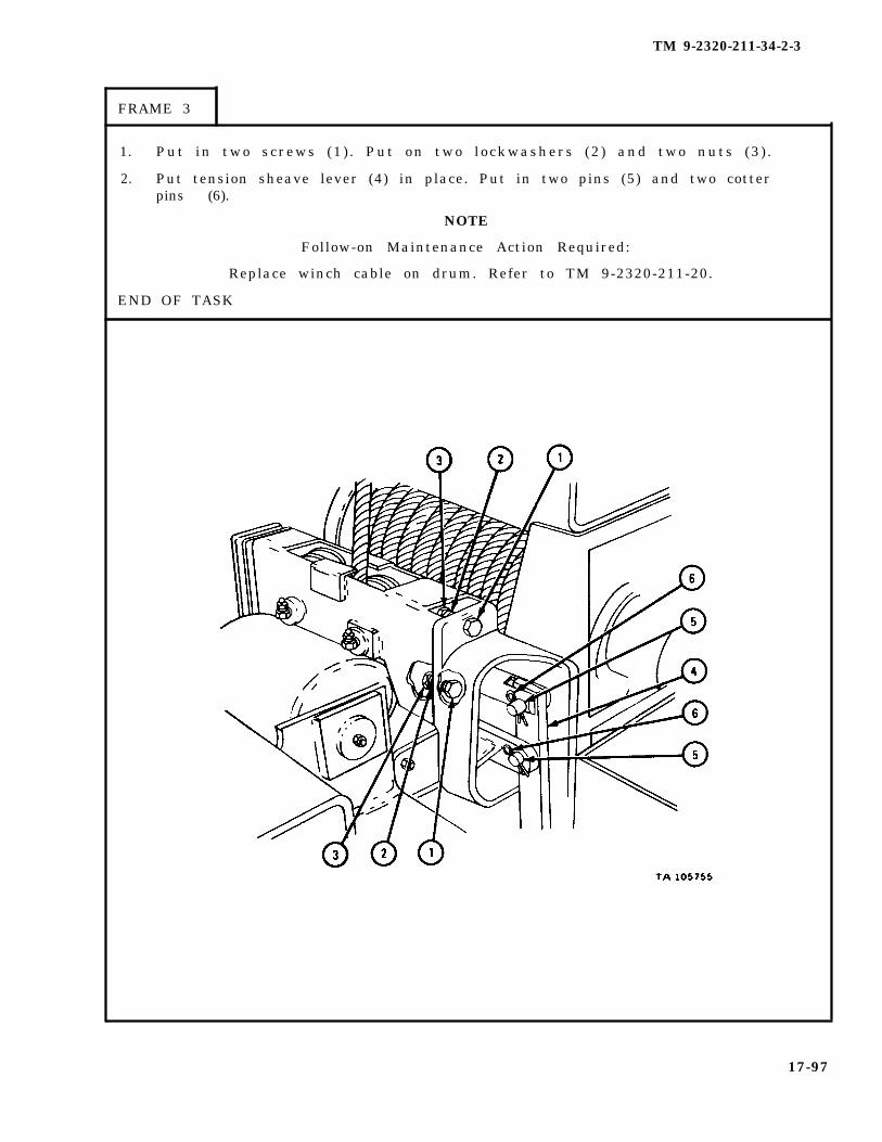
TM 9-2320-211-34-2-3
FRAME 3
1. Put in two screws (1 ) . Put on two lockwashers (2 ) and two nuts (3 ) .
2. Put tension sheave lever (4) in place. Put in two pins (5) and two cotterpins (6).
NOTE
Follow-on Maintenance Action Required:
Replace winch cable on drum. Refer to TM 9-2320-211-20.
END OF TASK
17-97

TM 9-2320-211-34-2-3
17-13. REAR WINCH CABLE TENSIONER BRAKE CHAMBER ASSEMBLY REMOVALAND REPLACEMENT (TRUCK M543A2).
TOOLS: No special tools required
SUPPLIES: None
PERSONNEL: One
EQUIPMENT CONDITION: Truck parked, engine off , handbrake set.
a . Removal.
F R A M E 1
1. Unscrew swivel nut (1) on air hose (2) from fitting on tensionerbrake chamber (3). Take off air hose.
2. Take out and throw away cotter pin (4).
3. Push out clevis pin (5).
4. Loosen locknut (6). Take off two nuts (7).
5. Tilt tensioner brake chamber (3) and take off clevis (8) and locknut (6).
6. Take off tensioner brake chamber (3).
END OF TASK
17-98
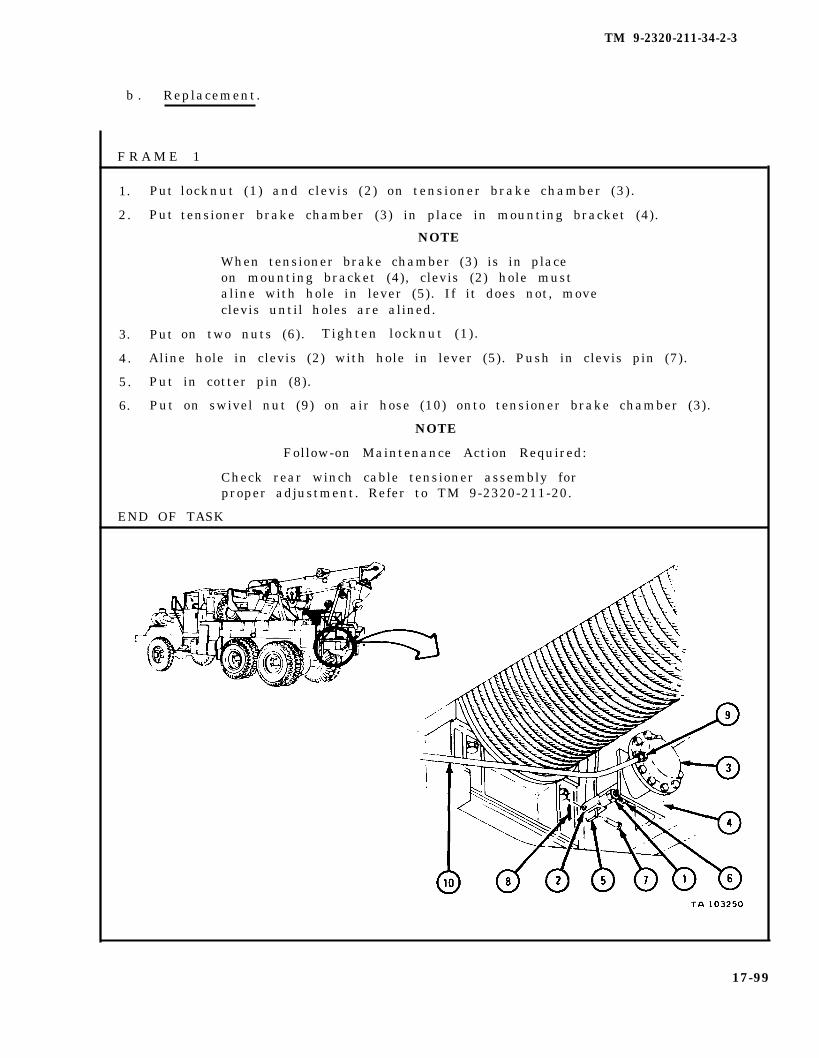
TM 9-2320-211-34-2-3
b . Replacement.
F R A M E 1
1. Put
2. Put
3. Put
locknut (1) and clevis (2) on tensioner brake chamber (3).
tensioner brake chamber (3) in place in mounting bracket (4).
NOTE
When tensioner brake chamber (3) is in placeon mounting bracket (4), clevis (2) hole mustaline with hole in lever (5). If it does not, moveclevis until holes are alined.
on two nuts (6). Tighten locknut (1).
4. Aline hole in clevis (2) with hole in lever (5). Push in clevis pin (7).
5. Put in cotter pin (8).
6. Put on swivel nut (9) on air hose (10) onto tensioner brake chamber (3).
NOTE
Follow-on Maintenance Action Required:
Check rear winch cable tensioner assembly forproper adjustment. Refer to TM 9-2320-211-20.
END OF TASK
17-99
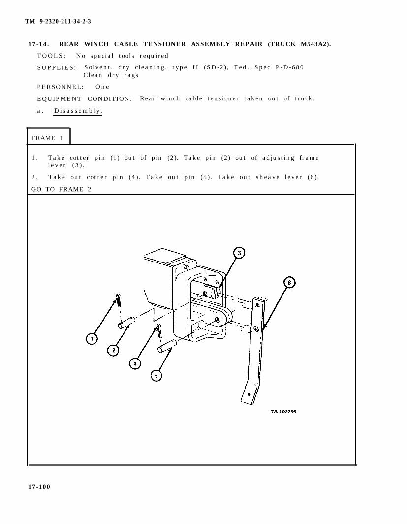
TM 9-2320-211-34-2-3
17-14. REAR WINCH CABLE TENSIONER ASSEMBLY REPAIR (TRUCK M543A2).
TOOLS: No special tools required
SUPPLIES: Solvent, dry cleaning, type II (SD-2), Fed. Spec P-D-680Clean dry rags
PERSONNEL: One
EQUIPMENT CONDITION: Rear winch cable tensioner taken out of truck.
a . Disassembly .
FRAME 1
1. Take cotter pin (1) out of pin (2). Take pin (2) out of adjusting framelever (3 ) .
2. Take out cotter pin (4). Take out pin (5). Take out sheave lever (6) .
GO TO FRAME 2
17-100
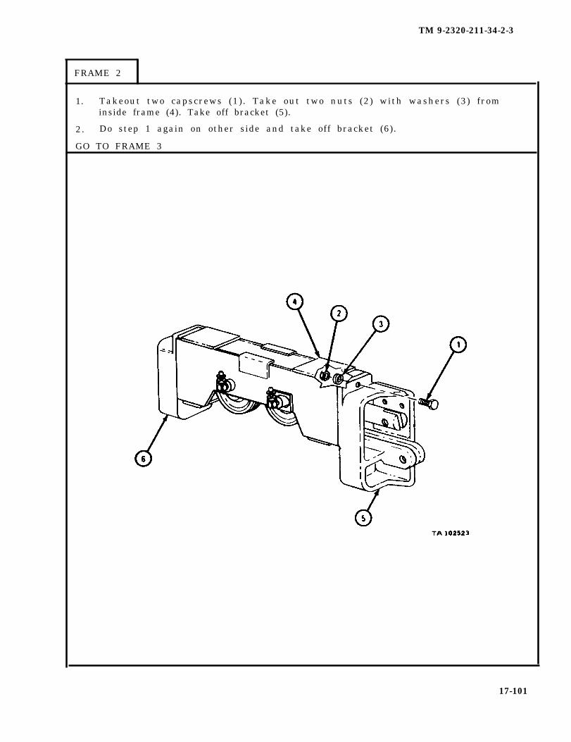
TM 9-2320-211-34-2-3
FRAME 2
1. Takeout two capscrews (1). Take out two nuts (2) with washers (3) frominside frame (4). Take off bracket (5).
2. Do step 1 again on other side and take off bracket (6).
GO TO FRAME 3
17-101

TM 9-2320-211-34-2-3
FRAME 3
1. Takeout lubr icat ion f i t t ing (1 ) . Takeout cot ter p in (2 ) . Dr ive p in (3 ) outof frame (4) .
2. Take out sheave (5) .
3. Take out two plain washers (6).
4. Take out two felt washers (7).
5. Do steps 1 through 4 again for other sheave.
GO TO FRAME 4
17-102

TM 9-2320-211-34-2-3
FRAME 4
1. Take tension sheave frame (1) out of tension sheave (2).
NOTE
Do not take two bearings (3) out of sheaves unlessthey are damaged. Refer to Part 1, para 7-7.
2 . Press two bearings (3) out of two sheaves (4).
END OF TASK
17-103
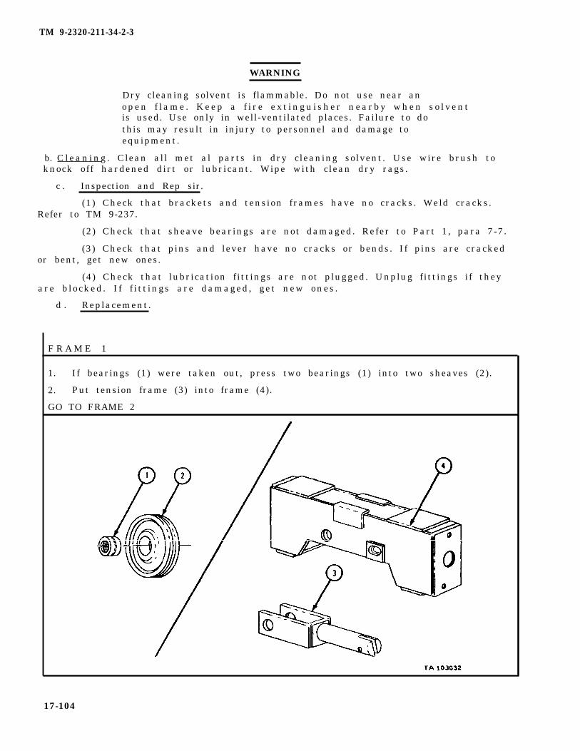
TM 9-2320-211-34-2-3
WARNING
Dry cleaning solvent is flammable. Do not use near ano p e n f l a m e . K e e p a f i r e e x t i n g u i s h e r n e a r b y w h e n s o l v e n tis used. Use only in well-ventilated places. Failure to dothis may result in injury to personnel and damage toequipment.
b. C l e a n i n g . Clean all met al parts in dry cleaning solvent. Use wire brush toknock off hardened dirt or lubricant. Wipe with clean dry rags.
c . Inspection and Rep sir.
(1) Check that brackets and tension frames have no cracks. Weld cracks.Refer to TM 9-237.
(2) Check that sheave bearings are not damaged. Refer to Part 1, para 7-7.
(3) Check that pins and lever have no cracks or bends. If pins are crackedor bent, get new ones.
(4) Check that lubrication fittings are not plugged. Unplug fittings if theyare b locked . I f f i t t ings are damaged , get new ones .
d . Replacement.
F R A M E 1
1. If bearings (1) were taken out, press two bearings (1) into two sheaves (2).
2. Put tension frame (3) into frame (4).
GO TO FRAME 2
17-104
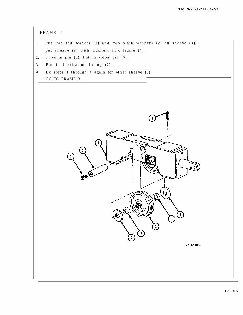
TM 9-2320-211-34-2-3
2.
3.
4.
Put two felt wahers (1) and two plain washers (2) on sheave (3).
put sheave (3) with washers into frame (4).
Drive in pin (5). Put in cotter pin (6).
Put in lubrication fitting (7).
Do steps 1 through 4 again for other sheave (3).
GO TO FRAME 3
17-105
FRAME 2
1.

TM 9-2320-211-34-2-3
FRAME 3
1.
2 .
3.
Put bracket (1) against frame (2). Put in two capscrews (3).
Put two nuts (4) with lockwashers (5) inside frame (2) on capscrews (3).
Do steps 1 and 2 again for bracket (6).
GO TO FRAME 4
17-106

TM 9-2320-211-34-2-3
1. Put in lever (1). Put in pin (2). Put in cotter pin (3).
2. Put in pin (4). Put in cotter pin (5).
NOTE
Follow-on Maintenance Action Required:
Lubricate sheave pins. Refer to LO 9-2320-211-12.
END OF TASK
17-107
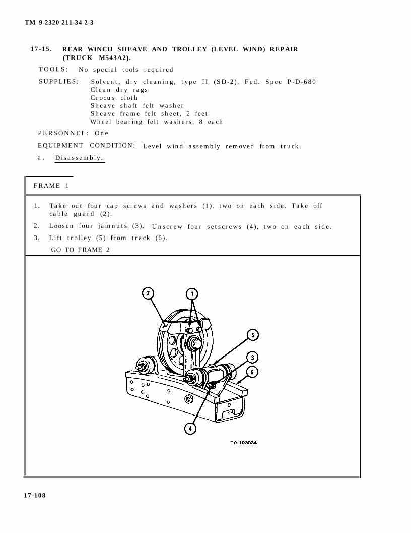
TM 9-2320-211-34-2-3
17-15. REAR WINCH SHEAVE AND TROLLEY (LEVEL WIND) REPAIR(TRUCK M543A2).
TOOLS: No special tools required
SUPPLIES: Solvent, dry cleaning, type II (SD-2), Fed. Spec P-D-680Clean dry ragsCrocus clothSheave shaft felt washerSheave frame felt sheet, 2 feetWheel bearing felt washers, 8 each
PERSONNEL: One
EQUIPMENT CONDITION: Level wind assembly removed from truck.
a . Disassembly.
FRAME 1
1.
2.
3.
Take out four cap screws and washers (1), two on each side. Take offcable guard (2) .
Loosen four jamnuts (3). Unscrew four setscrews (4), two on each side.
Lift trolley (5) from track (6).
GO TO FRAME 2
17-108
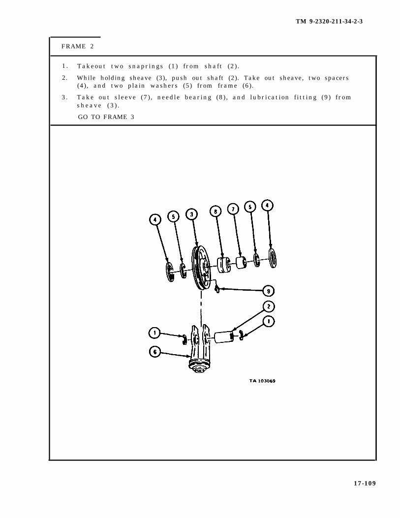
TM 9-2320-211-34-2-3
FRAME 2
1.
2.
3.
Takeout two snaprings (1) from shaft (2) .
While holding sheave (3), push out shaft (2). Take out sheave, two spacers(4), and two plain washers (5) from frame (6).
Take out sleeve (7) , needle bearing (8) , and lubrication fitting (9) fromsheave (3 ) .
GO TO FRAME 3
17-109
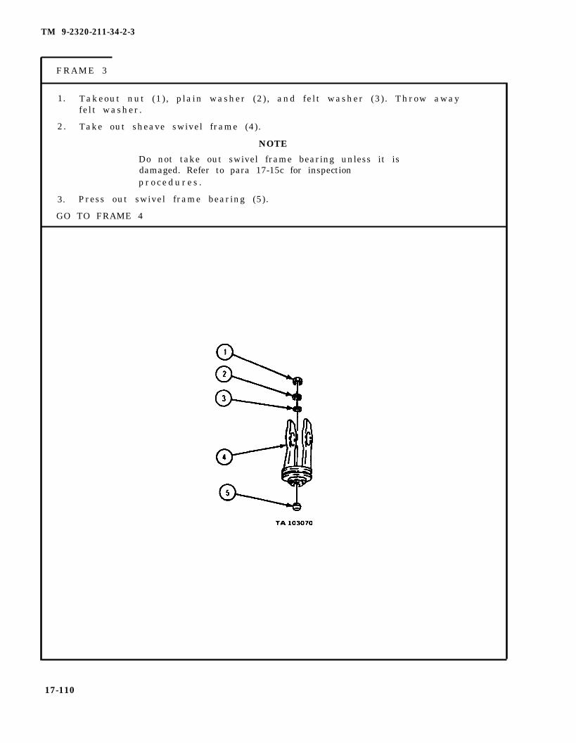
TM 9-2320-211-34-2-3
FRAME 3
1. Takeout nut (1), plain washer (2), and felt washer (3). Throw awayfelt washer.
2. Take out sheave swivel frame (4).
NOTE
Do not take out swivel frame bearing unless it isdamaged. Refer to para 17-15c for inspectionp r o c e d u r e s .
3. Press out swivel frame bearing (5).
GO TO FRAME 4
17-110
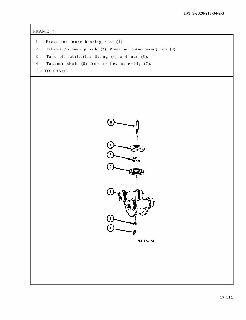
TM 9-2320-211-34-2-3
FRAME 4
1. Press out inner bearing race (1).
2. Takeout 45 bearing balls (2). Press out outer bering race (3).
3. Take off lubrication fitting (4) and nut (5).
4. Takeout shaft (6) from trolley assembly (7).
GO TO FRAME 5
17-111

TM 9-2320-211-34-2-3
FRAME 5
1. Take out lubrication fitting (1). Take out snapring (2). Take outplain washer (3) .
2. Take out and throw away felt washer (4). Slide off trolley wheel (5).
3. Take out felt washer (6). Take plain washer (7) and needle bearing (8) outof wheel (5). Throw away felft washer.
4. Do steps 1, 2, and 3 again for other three trolley wheels (9).
5. Press out two axles (10).
END OF TASK
17-112
TM 9-2320-211-34-2-3
WARNING
Dry cleaning solvent is flammable. Do not usenear an open flame. Keep a fire extinguishernearby at all times when solvent is used. Useonly in well-ventilated places. Failure to dothis may result in injury to personnel anddamage to equipment.
b . C l e a n i n g . Clean all parts with dry cleaning solvent. Dry with clean dryr a g s .
c . Inspect ion and Repair .
(1) Check that trolley frame and swivel frame and swivel frame have no cracks . Repair bywelding. Refer to TM 9-237.
(2) Check that all bearings are not damaged. Refer to Part 1, para 7-7.
(3) Check that shafts and axles have no burrs, cracks or scoring. Polishburrs with crocus cloth. If shafts are cracked or badly scored, get new ones.
(4) Check that bearing races have no cracks or uneven wear. If bearingraces are cracked or unevenly worn, get new ones.
17-113

TM 9-2320-211-34-2-3
d . Assembly .
FRAME 1
1. Put
2. Put
3. Put
4. Put
two axles (1) in trolley frame (2).
bearing (3) in trolley wheel (4). Put in two felt washers (5).
plain washer (6) on axle (1). Put trolley wheel (4) assembly on axle.
on plain washer (7). Put in snapring (8). Put in lubrication fitting (9).
5. Do steps 2 through 4 again for other three trolley wheels (4).
GO TO FRAME 2
17-114

TM 9-2320-211-34-2-3
F R A M E 2
1.
2.
3.
4.
Press outer race (1) into trolley frame (2).
Put shaft (3) into sheave swivel frame (4). Screw on nut (5) and lubricationf i t t ing (6 ) .
Put 45 bearing balls (7) into outer race (1). Put on inner race (8).
Put assembly into trolley frame (9).
GO TO FRAME 3
17-115

TM 9-2320-211-34-2-3
FRAME 3
1. Press bearing (1) into swivel frame (2).
2. Put swivel frame (2) over shaft (3).
3. Put felt washer (4), plain washer (5), and nut (6) on shaft (3) .
GO TO FRAME 4
17-116

TM 9-2320-211-34-2-3
FRAME 4
1. Put needle bear ing (1 ) into sheave (2 ) . Put in s leeve (3 ) . Put inlubrication fitting (4).
2. Put two p la in washers (5 ) on sheave (2 ) . Put on two spacers (6 ) .
3. Put sheave assembly (2) into swivel frame (7). Put in pin (8).
4. Put on two snaprings (9).
GO TO FRAME 5
17-117

TM 9-2320-211-34-2-3
FRAME 5
1. Put cable guard (1) on trolley assembly (2).
2. Put in two capscrews and washers.(3).
3. Do step 2 again on other side of cable guard (1).
4 . Put trolley assembly (2) into trolley frame (4).
5. Screw in four setscrews (5). Tighten four locknuts (6).
NOTE
Follow-on Maintenance Action Required:
Lubricate shaft and axles. Refer to LO 9-2320-211-12.
END OF TASK
17-118

TM 9-2320-211-34-2-3
17-16. REAR WINCH ASSEMBLY REPAIR (TRUCK M543A2).
TOOLS: No special tools required
SUPPLIES: Trolley swivel frame felt washerTrolley wheel bearing felt washer (8)3-inch cotter pin (2)3/4-inch cotter pin (4)1-inch cotter pinBrake adjusting screw gasketBrake case gasketGearcase cover gasketWorm gearcase cap gasket (2)Solvent, dry cleaning, type II (SD-2), Fed. Spec P-D-680Clean rags
PERSONNEL: TWO
EQUIPMENT CONDITION: Truck parked, engine off , handbrake set.
a . Preliminary Procedures.
(1) Remove winch, from truck. Refer to TM %2320-211-20.
(2) Remove winch cable and chain and hook assembly. Refer toTM 9-2320-211-20.
(3) Drain winch. Refer to LO 9-2320-211-12.
b . Disassemble.
NOTE
Do not take out any seals unless they are cracked,burned, too stiff, or damaged in any other way.Refer to para 17-16d for inspection procedures.
17-119
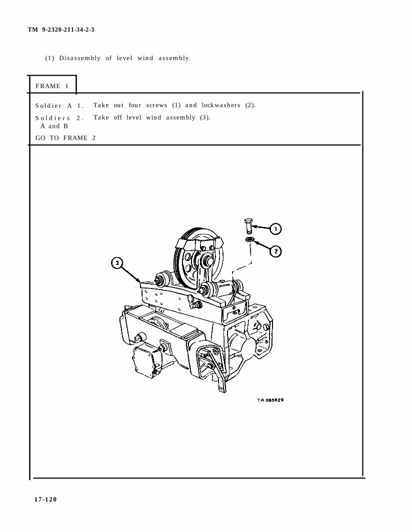
TM 9-2320-211-34-2-3
(1) Disassembly of level wind assembly.
FRAME 1
Sold ier A 1 . Take out four screws (1) and lockwashers (2).
S o l d i e r s 2 . Take off level wind assembly (3).A and B
GO TO FRAME 2
17-120

TM 9-2320-211-34-2-3
F R A M E 2
So ld ier A 1 . Hold trolley frame (1).
So ld ier B 2 . Loosen four nuts (2).
3. Loosen four screws (3) enough to clear lip of trolley track (4).
S o l d i e r s 4 . Take off trolley frame (1).A and B
Sold ier A 5 . Take off nut (5) with two nuts (6), latch (7), spring (8), and poppet (9).
6 . Hold nut(5) and take off two nuts(6).
7. Take off latch (7), nut (5), and spring (8).
GO TO FRAME 3
17-121

TM 9-2320-211-34-2-3
FRAME 3
Sold ier A 1 . Hold trolley frame (1).
So ld ier B 2 . Take off four screws (2) and lockwashers (3).
3. Take off cable guard (4).
GO TO FRAME 4
17-122
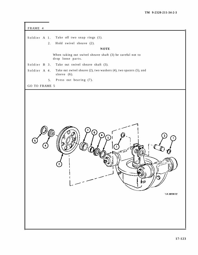
TM 9-2320-211-34-2-3
FRAME 4
Sold ier A 1 . Take off two snap rings (1).
2. Hold swivel sheave (2).
NOTE
When taking out swivel sheave shaft (3) be careful not todrop loose parts.
So ld ier B 3 .
So ld ier A 4 .
5.
GO TO FRAME 5
Take out swivel sheave shaft (3).
Take out swivel sheave (2), two washers (4), two spacers (5), andsleeve (6).
Press out bearing (7).
17-123

TM 9-2320-211-34-2-3
FRAME 5
S o l d i e r A 1 . Hold trolley frame (1).
S o l d i e r B 2 . Take off nut (2) .
3. Take off lockwasher (3) and felt washer (4) . Throw away feltwasher .
When taking off trolleyto drop loose parts.
NOTE
swivel frame (5), be careful not
4. Pull up and take off trolley swivel frame (5).
5. Take off shaft bearing (6), inner race (7), 45 balls (8), andouter race (9) .
GO TO FRAME 6
17-124
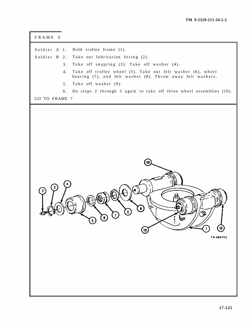
TM 9-2320-211-34-2-3
F R A M E 6
S o l d i e r A 1 . Hold trolley frame (1).
S o l d i e r B 2 . Take out lubrication fitting (2).
3. Take off snapring (3). Take off washer (4) .
4. Take off trolley wheel (5) . Take out felt washer (6) , wheelbearing (7), and felt washer (8). Throw away felt washers.
5. Take off washer (9) .
6. Do steps 2 through 5 again to take off three wheel assemblies (10).
GO TO FRAME 7
17-125

TM 9-2320-211-34-2-3
FRAME 7
1. Press out two trolley axles (1).
S o l d i e r A 2 . Hold trolley frame (2).
S o l d i e r B 3 . Take out two lubrication fittings (3).
END OF TASK
17-126
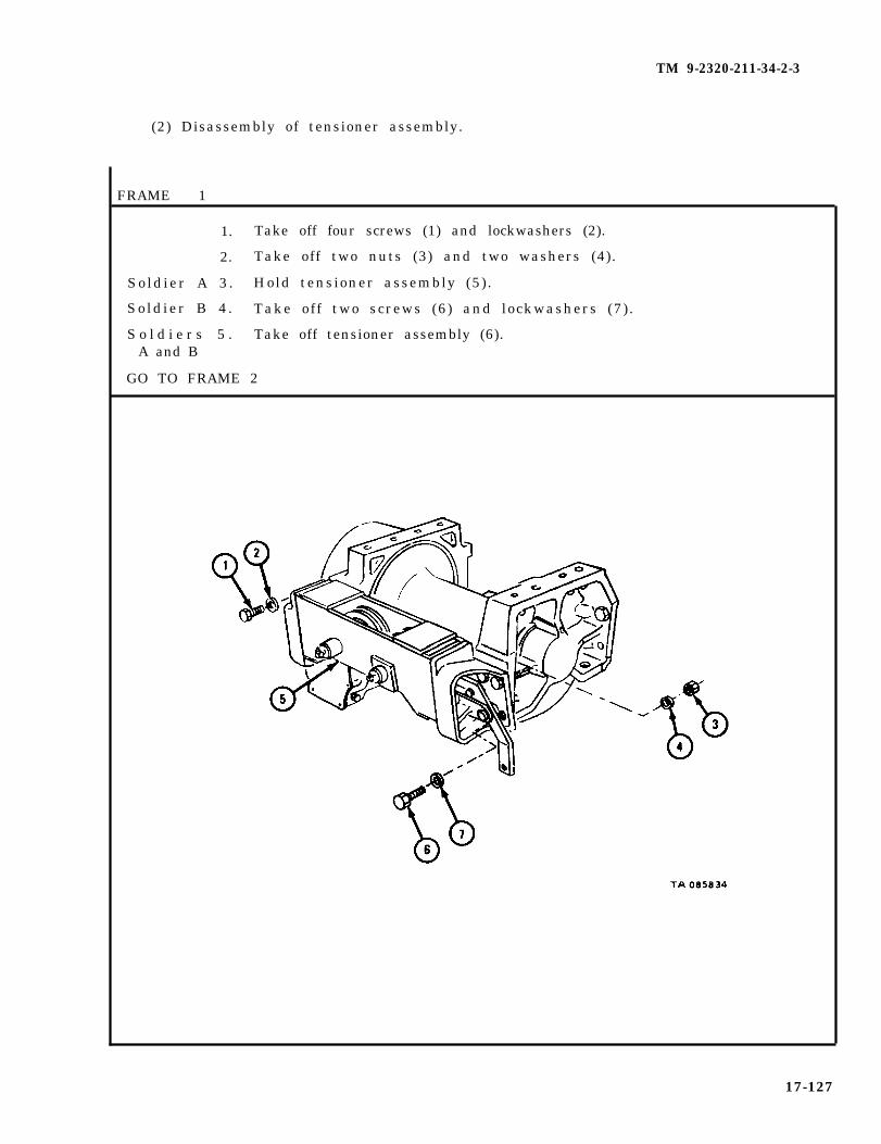
TM 9-2320-211-34-2-3
(2) Disassembly of tensioner assembly.
FRAME 1
1. Take off four screws (1) and lockwashers (2).
2. Take off two nuts (3) and two washers (4).
So ld ier A 3 . Hold tensioner assembly (5) .
So ld ier B 4 . Take off two screws (6) and lockwashers (7) .
S o l d i e r s 5 . Take off tensioner assembly (6).A and B
GO TO FRAME 2
17-127

TM 9-2320-211-34-2-3
FRAME 2
1. Take out and throw away two cotter pins (1).
2. Hold lever (2) and take out two pins (3 and 4).
3. Take off lever (2).
GO TO FRAME 3
17-128

TM 9-2320-211-34-2-3
FRAME 3
1. Take off two screws (1), nuts (2), and washers (3).
2. Take off tensioner bracket (4).
3. Do steps 1 and 2 again to take off tensioner bracket (5).
4 . Take out two screws (6) and washers (7) from tensioner bracket (4).
GO TO FRAME 4
17-129
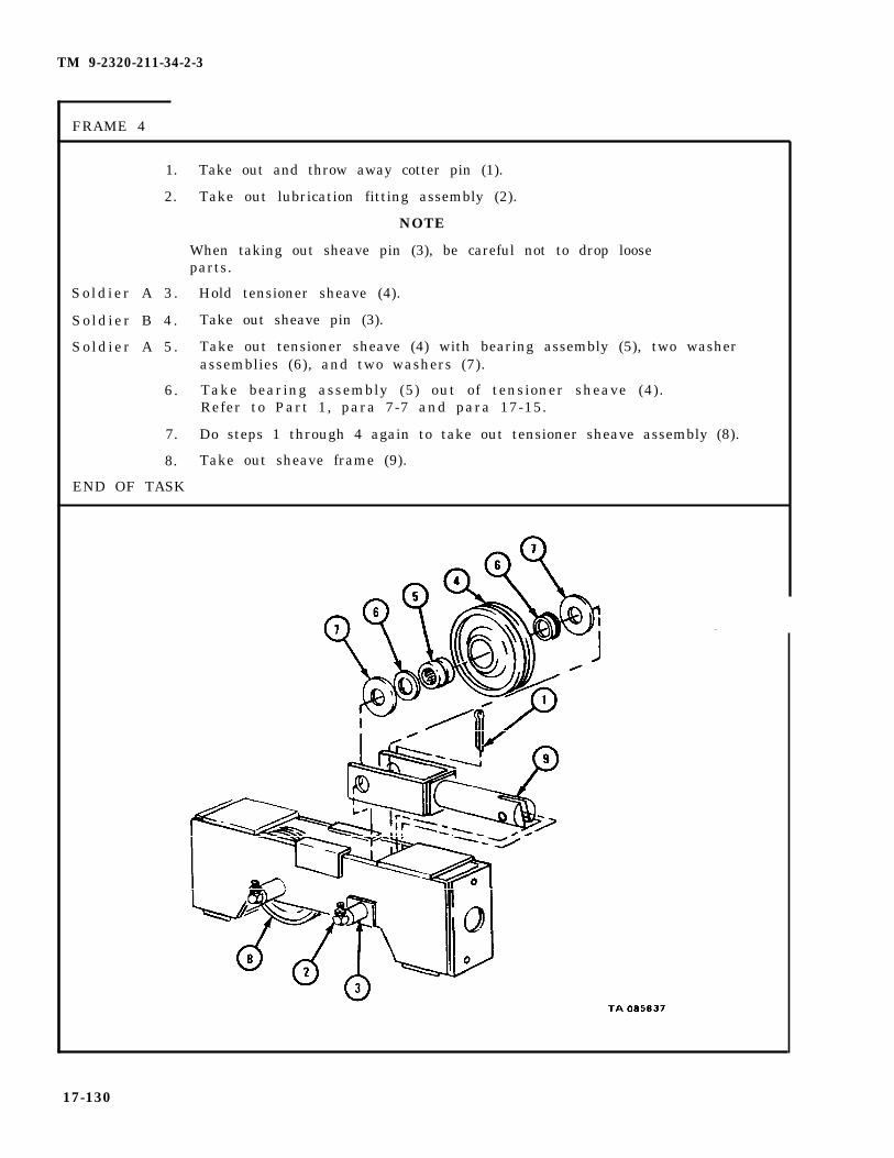
TM 9-2320-211-34-2-3
FRAME 4
1.
2.
So ld ier A 3 .
So ld ier B 4 .
So ld ier A 5 .
6.
7.
8.
END OF TASK
Take out and throw away cotter pin (1).
Take out lubrication fitting assembly (2).
NOTE
When taking out sheave pin (3), be careful not to drop looseparts.
Hold tensioner sheave (4).
Take out sheave pin (3).
Take out tensioner sheave (4) with bearing assembly (5), two washerassemblies (6), and two washers (7).
Take bearing assembly (5) out of tensioner sheave (4).Refer to Part 1, para 7-7 and para 17-15.
Do steps 1 through 4 again to take out tensioner sheave assembly (8).
Take out sheave frame (9).
17-130

TM 9-2320-211-34-2-3
(3) Disassembly of winch assembly.
FRAME 1
1. Takeout two p lugs (1 ) .
2. T a k e o u t p l u g ( 2 ) .
S o l d i e r A 3 . Hold channel (3) .
S o l d i e r B 4 . Takeoff four screws and lockwashers (4).
S o l d i e r A 5 . Takeof f channel (3 ) .
6 . Take off cotter pin (5). Take of spear pin (6). Take offsprocket (7 ) .
GO TO FRAME 2
17-131

TM 9-2320-211-34-2-3
FRAME 2
Soldier A 1. Put hoist chains (1) on cable drum (2). Using hoist, raise cable drum.
So ld ier B 2 . Pull off end frame (3).
3. Using seal puller and hammer, take off seal (4).
4. Take off thrust washer (5) and sleeve (6).
NOTE
Do not take out bushing (7) unless it is worn or damaged.Refer to para 17-16 d for inspection procedures.
5. Take out bushing (7).
S o l d i e r s 6 . Using hoist, lower cable drum (2) to working surface. Take off hoistA and B chains (1).
GO TO FRAME 3
17-132

TM 9-2320-211-34-2-3
FRAME 3
S o l d i e r s 1 . Rest gearcase (1) on end and put hoist chains (2) on cable drum (3) asA and B shown.
2. Using wood block and hammer, tap on shaft (4) and using hoist, take offcable drum (3).
So ld ier A 3 . Using seal puller and hammer, take out seal (5).
4 . Take out two square keys (6).
5. Take off thrust washer (7).
GO TO FRAME 4
17-133

TM 9-2320-211-34-2-3
FRAME 4
1. Take off four screws (1) and lockwashers (2). Take off worm gearcase cap (3) andgasket (4). Throw away gasket.
2. Take seal (5) out of worm gearcase cap (3).
GO TO FRAME 5
17-134

TM 9-2320-211-34-2-3
F R A M E 5
Soldier A 1. Take out two screws (l).
Soldier B 2. Hold gearcase cover (2).
Soldier A 3. Take off six screws (3) and lockwaahers (4).
Soldier B 4. Take off gearcase cover (2) and gasket (5). Throw away gasket.
NOTE
Take out bushing (6) only if it is damaged. Refer topara 17-16 d for inspection procedures.
Soldier A 5. Take out bushing (6).
6. Take off washer (7).
GO TO FRAME 6
TA 085842
17-135

TM 9-2320-211-34-2-3
FRAME 6
1. Take out two screws (l).
2. Take out four locking screws (2).
3. Take off brake drum case end cover (3) and gasket (4). Throw away gasket
4. Take out screw (5), washer (6), and preformed packing (7). Throw away performedpacking.
5. Take out spring (8) and brake band assembly (9).
GO TO FRAME 7
17-136
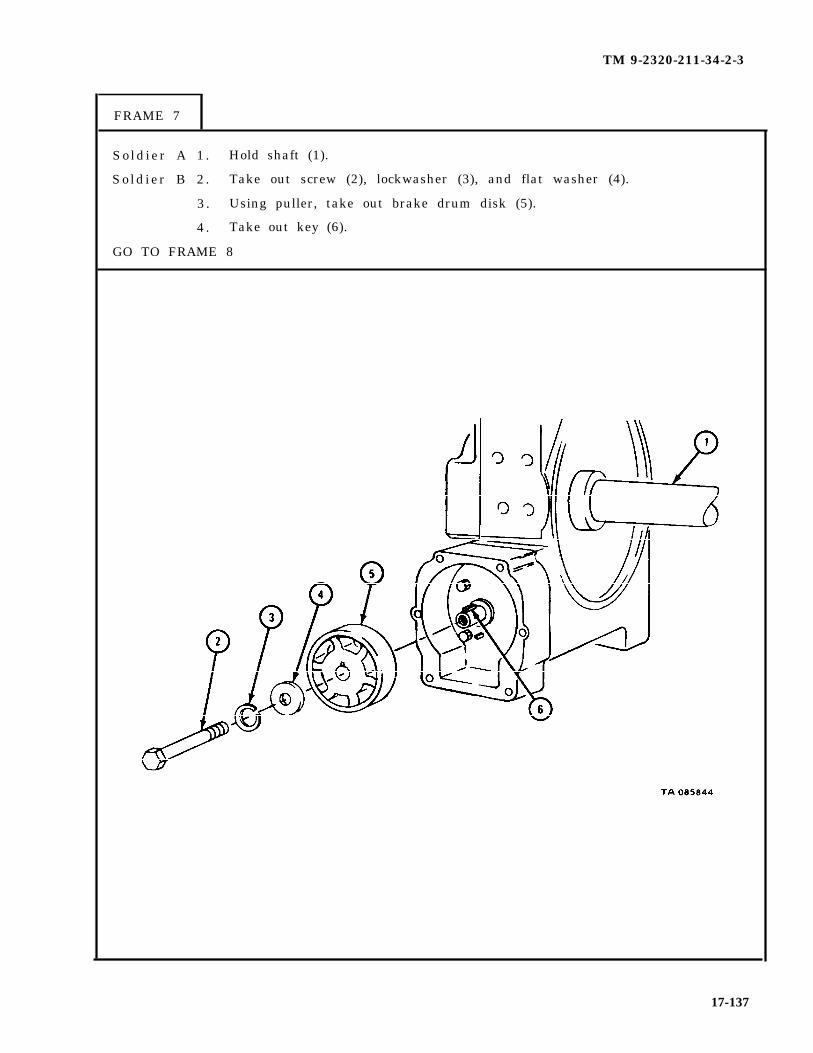
TM 9-2320-211-34-2-3
FRAME 7
Sold ier A 1 . Hold shaft (1).
So ld ier B 2 . Take out screw (2), lockwasher (3), and flat washer (4).
3 . Using puller, take out brake drum disk (5).
4 . Take out key (6).
GO TO FRAME 8
17-137

TM 9-2320-211-34-2-3
FRAME 8
1. Take out four screws (1) and lockwashers (2).
2. Take off brake case (3) with seal (4) and gasket(5). Throw away gasket.
3. Take seal (4) out of brake case (3).
GO TO FRAME 9
17-138
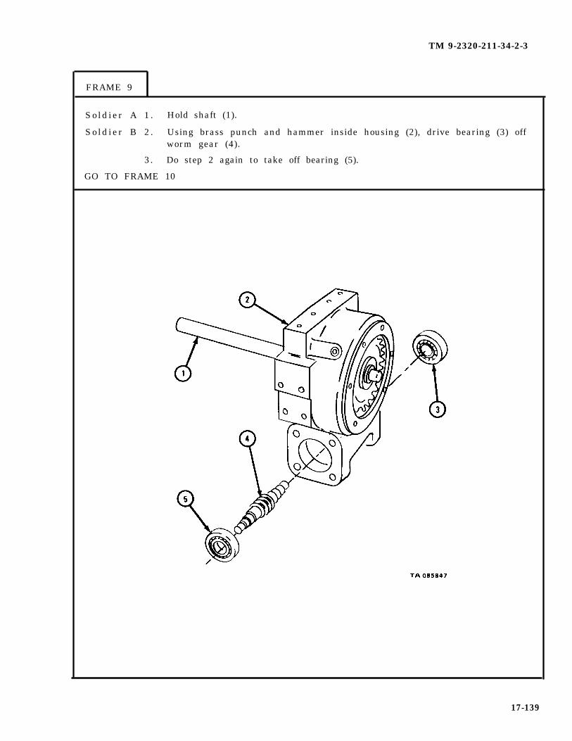
TM 9-2320-211-34-2-3
FRAME 9
Sold ier A 1 . Hold shaft (1).
So ld ier B 2 . Using brass punch and hammer inside housing (2), drive bearing (3) offworm gear (4).
3. Do step 2 again to take off bearing (5).
GO TO FRAME 10
17-139
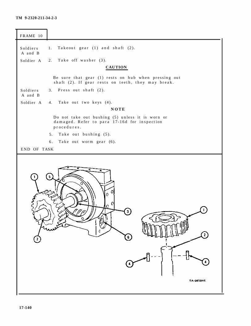
TM 9-2320-211-34-2-3
FRAME 10
SoldiersA and B
Soldier A
SoldiersA and B
Soldier A
1. Takeout gear (1) and shaft (2) .
2. Take off washer (3) .
CAUTION
Be sure that gear (1) rests on hub when pressing outshaft (2). If gear rests on teeth, they may break.
3. Press out shaft (2) .
4. Take out two keys (4).
NOTE
Do not take out bushing (5) unless it is worn ordamaged. Refer to para 17-16d for inspectionp r o c e d u r e s .
5. Take out bushing (5).
6. Take out worm gear (6).
END OF TASK
17-140

c. C l e a n i n g
TM 9-2320-211-34-2-3
WARNING
Dry cleaning solvent is flammable. Do not use nearan open flame. Keep a fire extinguisher nearby whensolvent is used. Use only in well-ventilated places.Failure to do this may result in injury to personneland damage to equipment.
(1) Clean bearings. Refer to Part 1, para 7-7.
(2) Wipe all seals and automatic brake band assembly with clean rag.
(3) Clean all other parts with solvent. Use stiff wire brush to clean off dirt,hardened grease, and oil.
(4) Let parts dry.
17-141
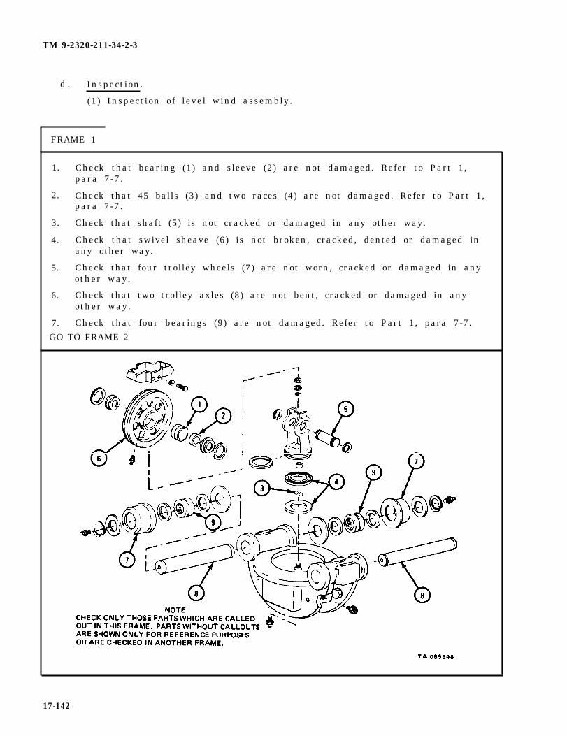
TM 9-2320-211-34-2-3
d . Inspection.
(1) Inspection of level wind assembly.
FRAME 1
1.
2.
3.
4.
5.
6.
7.
Check that bearing (1) and sleeve (2) are not damaged. Refer to Part 1,para 7-7.
Check that 45 balls (3) and two races (4) are not damaged. Refer to Part 1,para 7-7.
Check that shaft (5) is not cracked or damaged in any other way.
Check that swivel sheave (6) is not broken, cracked, dented or damaged inany other way.
Check that four trolley wheels (7) are not worn, cracked or damaged in anyother way.
Check that two trolley axles (8) are not bent, cracked or damaged in anyother way.
Check that four bearings (9) are not damaged. Refer to Part 1, para 7-7.
17-142
GO TO FRAME 2

TM 9-2320-211-34-2-3
FRAME 2
1. Check that poppet (1) is not bent, cracked or broken, and that it does not havedamaged threads.
2. Check that spring (2) is not bent, cracked or broken.
3. Check that trclley track (3) is not dented, cracked, broken or damaged in any otherway.
END OF TASK
17-143

TM 9-2320-211-34-2-3
(2) Inspection of tensioner assembly.
FRAME 1
1. Check that two bearings (1) are not damaged. Refer to Part 1, para 7-7.
2. Check that two tensioner sheaves (2) are not bent, cracked or damaged in any otherway.
3 . Check that sheave frame (3) is not bent, cracked, broken or damaged in any otherway.
4 . Check that two sheave pins (4) are not bent, cracked or damaged in any other way.
5. Check that tensioner frame (5) is not dented, cracked, bent or damaged in any otherway.
6. Check that lever (6) is not bent, cracked, broken or damaged in any other way.
END OF TASK
17-144

TM 9-2320-211-34-2-3
(3) Inspection of winch assembly.
F R A M E 1
1.
2.
3.
4.
5.
6.
7.
8.
NOTE
Readings must be within limits given in table 17-3.If readings are not within given limits, throw awaypart and get a new one.
Check that two seals (1) are not cracked, burned, too stiff or damaged inany other way.
Check that bushing (2) and sleeve (3) are not scored, chipped or damagedin any other way.
Measure bushing (2) and sleeve (3). Check wear limits. Refer totable 17-3.
Check that end frame (4) is not cracked and does not have damaged threadsor other damage.
Check that thrust washers (5 and 6) are not cracked, worn, broken ordamaged in any other way.
Check that shaft (7) is not cracked or scored.
Measure shaft (7) . Check wear limits. Refer to table 17-3.
Check that winch cable and chain and hook assembly has no broken orfrayed strands or other damage.
GO TO FRAME 2
17-145

TM 9-2320-211-34-2-3
FRAME 2
1.
2.
3.
4.
5.
6.
NOTE
Readings must be within limits given in table 17-4.If readings are not within given limits, throw awaypart and get a new one.
Check that two bearings (1) are not damaged. Refer to Part 1, para 7-7.Check that two bushings (2) are not scored, chipped or damaged in anyother way.
Measure two bearings (1) and two bushings (2). Check wear l imits. Referto table 17-4.
Check that seal (3) is not cracked, burned, too stiff or damaged in anyother way.
Check that worm gear (4) has no broken, chipped or scored teeth or anyother damage.
Measure worm gear (4). Check wear limits. Refer to table 17-4.
Check that gear (5) and sprocket (6) have no broken or chipped or scoredteeth or any other damage.
GO TO FRAME 3
17-146
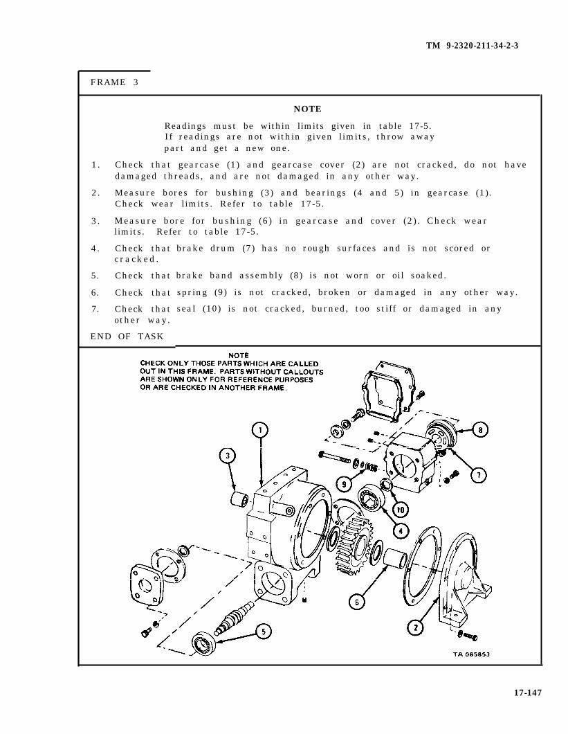
TM 9-2320-211-34-2-3
FRAME 3
1.
2.
3.
4.
5.
6.
7.
NOTE
Readings must be within limits given in table 17-5.If readings are not within given limits, throw awaypart and get a new one.
Check that gearcase (1) and gearcase cover (2) are not cracked, do not havedamaged threads, and are not damaged in any other way.
Measure bores for bushing (3) and bearings (4 and 5) in gearcase (1).Check wear limits. Refer to table 17-5.
Measure bore for bushing (6) in gearcase and cover (2) . Check wearlimits. Refer to table 17-5.
Check thatc r a c k e d .
Check that
Check that
Check thatother way.
END OF TASK
brake drum (7) has no rough surfaces and is not scored or
brake band assembly (8) is not worn or oil soaked.
spring (9) is not cracked, broken or damaged in any other way.
seal (10) is not cracked, burned, too stiff or damaged in any
17-147

TM 9-2320-211-34-2-3
Table 17-3. Drum Shaft Bushing, End Frame Bushing,Sleeve and Drum Shaft Wear Limits
Index Wear LimitsNumber Item /Point of Measurement ( inches )
2 Drum shaft bushing inside diameter 3.020 max
2 Drum shaft bushing outside diameter
3 End frame bushing sleeve inside diameter
0.020 min
3.250 to 3.251
7 Drum shaft outside diameter 2.983 min
Table 17-4. Drive Worm Bearing, Drum Shaft Bushing,and Drive Worm Gear Wear Limits
IndexNumber Item /Point of Measurement
1 Drive worm bearing inside diameter
1 Drive worm bearing outside diameter
2 Drum shaft bushing inside diameter
2 Drum shaft bushing outside diameter
4 Drive worm gear outside diameter
2.3616 to 2.3622
5.1173 to 5.1181
3.020 max
0.020 min
5.1173 to 5.1181
Table 17-5. Gearcase Bores and Gearcase Cover Bore Wear Limits
IndexNumber Item /Point of Measurement
1 Gearcase bore for bushing (3) (outsidediameter)
1 Gearcase bore for bearing (4) (outsidediameter)
1 Gearcase bore for bearing (5) (outsidediameter)
2 Gearcase cover bore for bushing (6) (outsidediameter)
Wear Limits( inches )
3.1491 to 3.1496
3.1491 to 3.1496
3.1491 to 3.1496
3.1491 to 3.1496
17-148
Wear Limit(inches)

TM 9-2320-211-34-2-3
e . Repair .
(1) Using fine mill file, file small nicks and burrs from machined surfaces,especially oil seal contact surfaces.
(2) Get new parts in place of all other damaged parts.
17-149

TM 9-2320-211-34-2-3
f . Assembly.
(1) Assembly of winch assembly.
F R A M E 1
S o l d i e r s 1 . Press bearing (1) on keyway end of worm gear (2). Refer to Part 1,A and B para 7-7.
So ld ier A 2 . Put worm gear (2) with bearing (1) into bore of gearcase (3)0 Do notseat bearing.
3 . Using brass hammer, tap bearing (4) onto worm gear (2).
GO TO FRAME 2
17-150
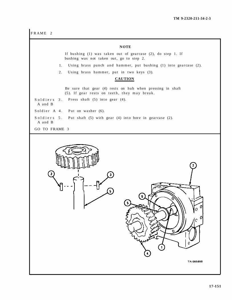
TM 9-2320-211-34-2-3
NOTE
If bushing (1) was taken out of gearcase (2), do step 1. Ifbushing was not taken out, go to step 2.
1. Using brass punch and hammer, put bushing (1) into gearcase (2).
2. Using brass hammer, put in two keys (3).
CAUTION
Be sure that gear (4) rests on hub when pressing in shaft(5). If gear rests on teeth, they may break.
S o l d i e r s 3 . Press shaft (5) into gear (4).A and B
Sold ier A 4 . Put on washer (6).
S o l d i e r s 5 . Put shaft (5) with gear (4) into bore in gearcase (2).A and B
GO TO FRAME 3
17-151
FRAME 2
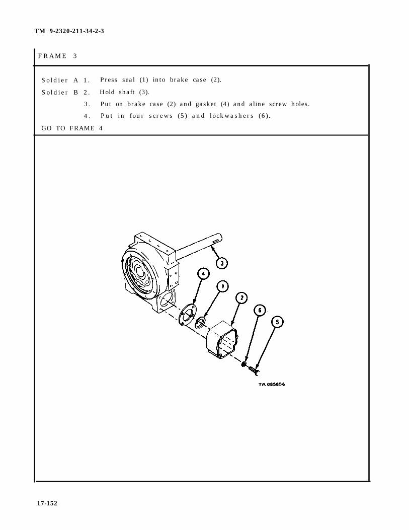
TM 9-2320-211-34-2-3
Sold ier A 1 . Press seal (1) into brake case (2).
So ld ier B 2 . Hold shaft (3).
3. Put on brake case (2) and gasket (4) and aline screw holes.
4 . Put in four screws (5) and lockwashers (6).
GO TO FRAME 4
17-152
F R A M E 3

TM 9-2320-211-34-2-3
FRAME 4
Sold ier A 1 .
2.
So ld ier B 3 .
4 .
GO TO FRAME
Press seal (1) into worm gearcase cap (2).
Hold shaft (3).
Put on worm gearcase cap (2) and gasket (4) and aline screwholes.
Put in four screws (5) and lockwashers (6).
5
17-153

TM 9-2320-211-34-2-3
FRAME 5
Soldier A 1.
So ld ier B 2 .
3 .
4 .
5.
Hold shaft (1).
Tap in key (2).
Aline keyway in brake drum disk (3) with key (2).
Using brass hammer, tap brake drum disk (3) onto worm gear (4) andkey (2).
Put in screw (5), lockwasher (6), and flat washer (7).
17-154
GO TO FRAME 6
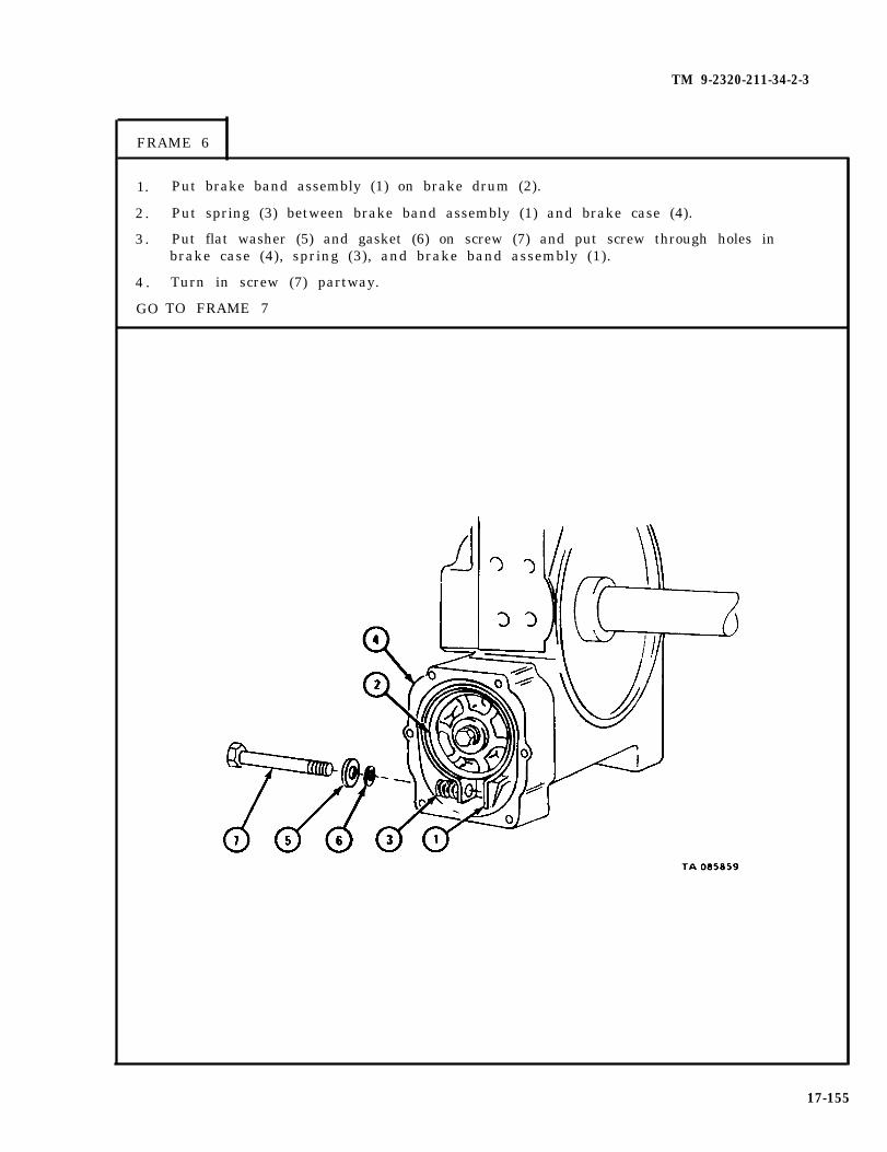
TM 9-2320-211-34-2-3
FRAME 6
1.
2 .
3 .
4 .
GO
Put brake band assembly (1) on brake drum (2).
Put spring (3) between brake band assembly (1) and brake case (4).
Put flat washer (5) and gasket (6) on screw (7) and put screw through holes inbrake case (4), spring (3), and brake band assembly (1).
Turn in screw (7) partway.
TO FRAME 7
17-155

TM 9-2320-211-34-2-3
F R A M E 7
1. Turn screw (1) until gap in brake band assembly (2) is between 3/16 inch and1/4 inch as shown.
2. Put on brake cover (3) and gasket (4) and aline screw holes.
3. Put in four screws (5).
4 . Put in two screws (6).
GO TO FRAME 8
17-156
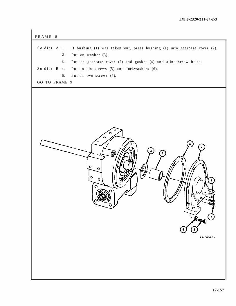
TM 9-2320-211-34-2-3
F R A M E 8
Sold ier A 1 . If bushing (1) was taken out, press bushing (1) into gearcase cover (2).
2. Put on washer (3).
3 . Put on gearcase cover (2) and gasket (4) and aline screw holes.
So ld ier B 4 . Put in six screws (5) and Iockwashers (6).
5. Put in two screws (7).
GO TO FRAME 9
17-157
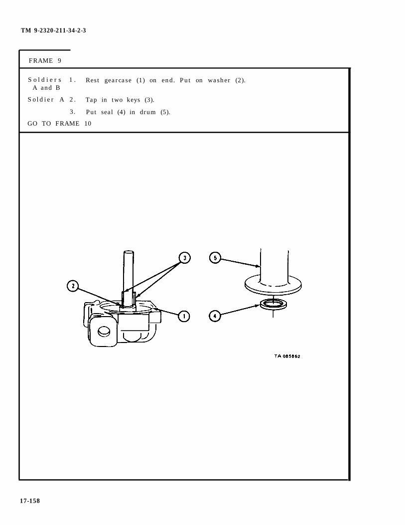
TM 9-2320-211-34-2-3
FRAME 9
S o l d i e r s 1 . Rest gearcase (1) on end. Put on washer (2).A and B
Sold ier A 2 . Tap in two keys (3).
3. Put seal (4) in drum (5).
GO TO FRAME 10
17-158

TM 9-2320-211-34-2-3
FRAME 10
S o l d i e r s 1 . Put chains (1) on drum (2) as shown.A and B
2. Using hoist, put on drum (2). Be sure two keyways on inside of drumare lined up with two keys (3).
3. Take off hoist chains.
So ld ier A 4 . Using wood block and hammer, seat drum (2).
GO TO FRAME 11
17-159

FRAME 11
S o l d i e r s 1 . Put hoist chains (1) on drum (2) as shown.A and B
2. Using hoist, raise drum (2).
So ld ier A 3 . Put on seal (3).
4. Put on washer (4).
GO TO FRAME 12
17-160
TM 9-2320-211-34-2-3

TM 9-2320-211-34-2-3
1. Drive bushing (1) into sleeve (2).
S o l d i e r s 2 . Press sleeve (2) into end frame (3).A and B
3. Put end frame (3) onto shaft (4).
So ld ier A 4 . Seat end frame (3).
S o l d i e r s 5 . Using hoist, lower drum (5)A and B
6 . Take off chains (6).
GO TO FRAME 13
17-161
FRAME 12

TM 9-2320-211-34-2-3
FRAME 13
S o l d i e r A 1 . Hold channel (1) in place and aline screw holes.
S o l d i e r B 2 . P u t
3. Put
4. Put
5. Putp in
END OF TASK
in four screws with lockwashers (2).
in two plugs (3).
in plug (4) .
on sprocket (5). Put in spear pin (6). Put in cotter( 7 ) .
17-162
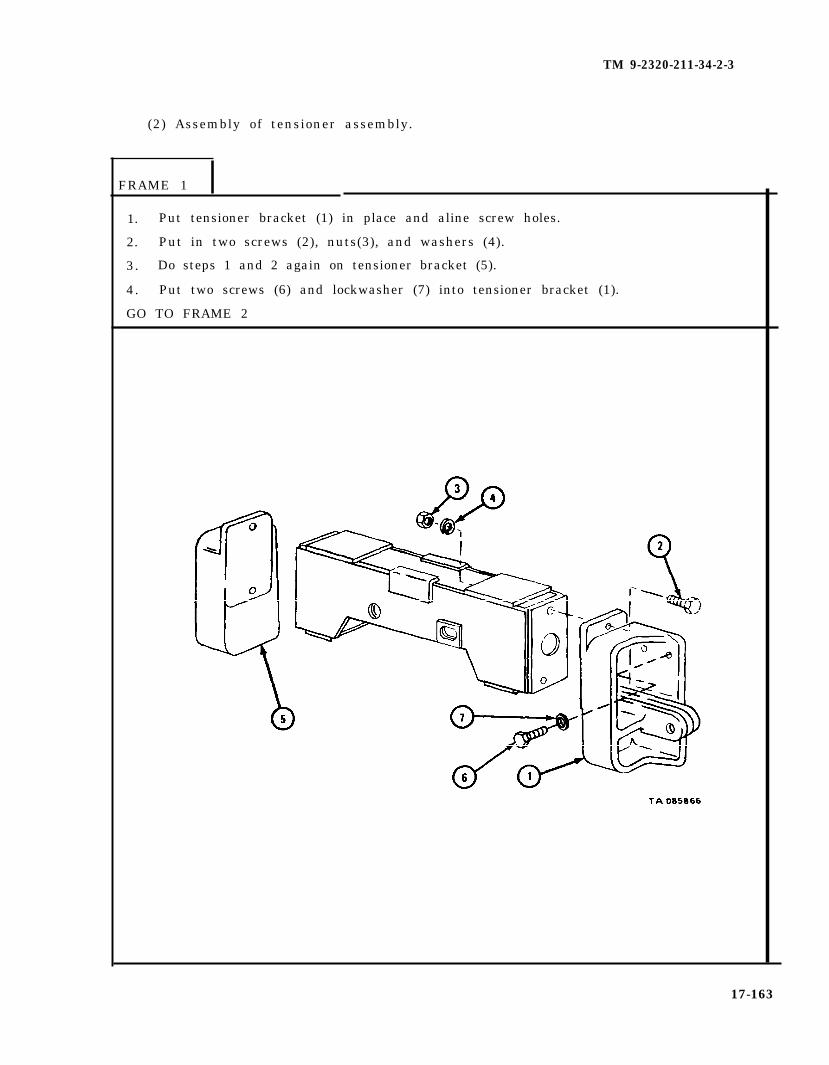
TM 9-2320-211-34-2-3
(2) Assembly of tensioner assembly.
FRAME 1
1. Put tensioner bracket (1) in place and aline screw holes.
2. Put in two screws (2), nuts(3), and washers (4).
3. Do steps 1 and 2 again on tensioner bracket (5).
4. Put two screws (6) and lockwasher (7) into tensioner bracket (1).
GO TO FRAME 2
17-163
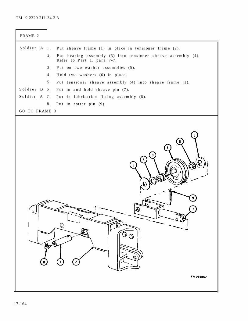
TM 9-2320-211-34-2-3
FRAME 2
S o l d i e r A 1 . Put sheave frame (1) in place in tensioner frame (2).
2. Put bearing assembly (3) into tensioner sheave assembly (4).Refer to Part 1, para 7-7.
3. Put on two washer assemblies (5).
4. Hold two washers (6) in place.
5. Put tensioner sheave assembly (4) into sheave frame (1).
S o l d i e r B 6 . Put in and hold sheave pin (7).
S o l d i e r A 7 . Put in lubrication fitting assembly (8).
8. Put in cotter pin (9).
GO TO FRAME 3
17-164
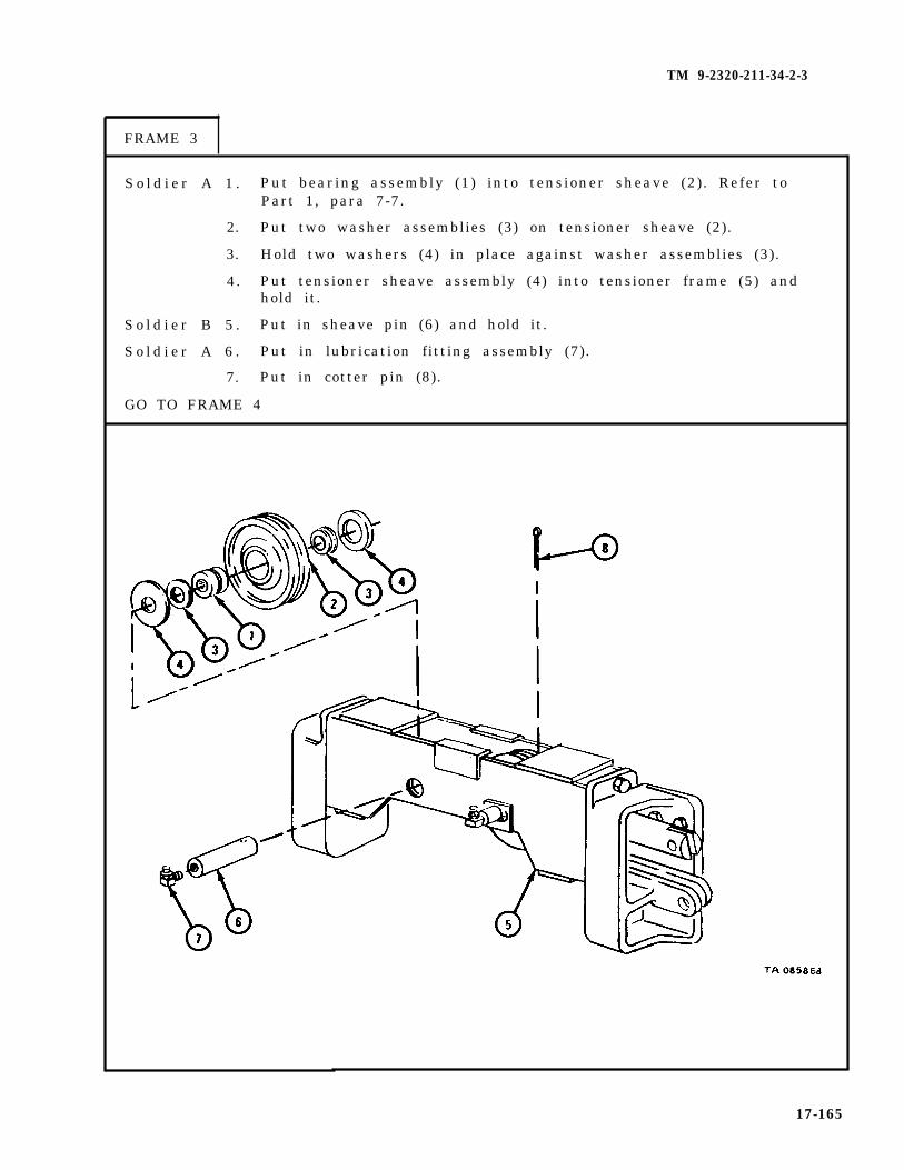
TM 9-2320-211-34-2-3
FRAME 3
S o l d i e r A 1 . Put bearing assembly (1) into tensioner sheave (2). Refer toPart 1, para 7-7.
2. Put two washer assemblies (3) on tensioner sheave (2).
3. Hold two washers (4) in place against washer assemblies (3).
4. Put tensioner sheave assembly (4) into tensioner frame (5) andhold it.
S o l d i e r B 5 . Put in sheave pin (6) and hold it.
S o l d i e r A 6 . Put in lubrication fitting assembly (7).
7. Put in cotter pin (8).
GO TO FRAME 4
17-165
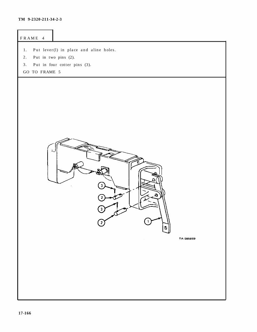
TM 9-2320-211-34-2-3
F R A M E 4
1. Put lever(l) in place and aline holes.
2. Put in two pins (2).
3. Put in four cotter pins (3).
GO TO FRAME 5
17-166

TM 9-2320-211-34-2-3
FRAME 5
Sold ier A 1 .
So ld ier B 2 .
3.
4 .
END OF TASK
Hold tensioner assembly (1) in place and aline screw holes.
Put in four screws (2) and lockwashers (3).
Put in two screws (4) and lockwashers (5).
Hold two screws (6) and put on two nuts (7) and lockwashers (8).
17-167

(3) Assembly of level wind assembly.
FRAME 1
1. Put in two lubrication fittings (1).
2. Put in two trolley axles (2).
GO TO FRAME 2
17-168
TM 9-2320-211-34-2-3

TM 9-2320-211-34-2-3
FRAME 2
Sold ier A 1 . Hold trolley frame (1).
So ld ier B 2 . Put on washer (2).
3. Put felt washer (3), wheel bearing (4), and felt washer (5) in trolleywheel (6).
4 . Put trolley wheel (6) on axle (7).
5. Put on washer (8).
6 . Put on snap ring (9).
7. Put in lubrication fitting (10).
8. Do steps 1 through 7 again to put on other three trolley wheels (6).
GO TO FRAME 3
17-169

TM 9-2320-211-34-2-3
1.
2.
3.
Put on outer race (1).
Put 45 balls (2) in outer race (1).
Put on inner race (3).
17-170
FRAME 3
GO TO FRAME 4

TM 9-2320-211-34-2-3
FRAME 4
1. Put on shaft bearing (1).
2. Put on trolley swivel frame (2), felt washer (3), and lockwasher (4).
3. Put on nut (5).
GO TO FRAME 5
17-171
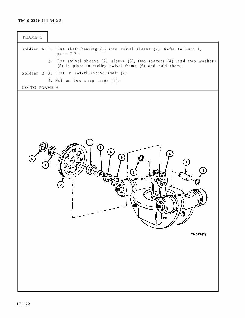
TM 9-2320-211-34-2-3
FRAME 5
S o l d i e r A 1 . Put shaft bearing (1) into swivel sheave (2). Refer to Part 1,para 7-7.
2. Put swivel sheave (2), sleeve (3) , two spacers (4) , and two washers(5) in place in trolley swivel frame (6) and hold them.
S o l d i e r B 3 . Put in swivel sheave shaft (7).
4. Put on two snap rings (8).
GO TO FRAME 6
17-172

TM 9-2320-211-34-2-3
FRAME 6
1. Put on cable guard (1).
2. Put in four screws (2) and lockwashers (3).
GO TO FRAME 7
17-173

TM 9-2320-211-34-2-3
FRAME 7
1. Put spring (1), nut (2), and latch (3) on poppet (4).
2. Put on two nuts (5).
3 . Put poppet (4) in trolley track (6).
4 . Put in nut (2).
GO TO FRAME 8
17-174
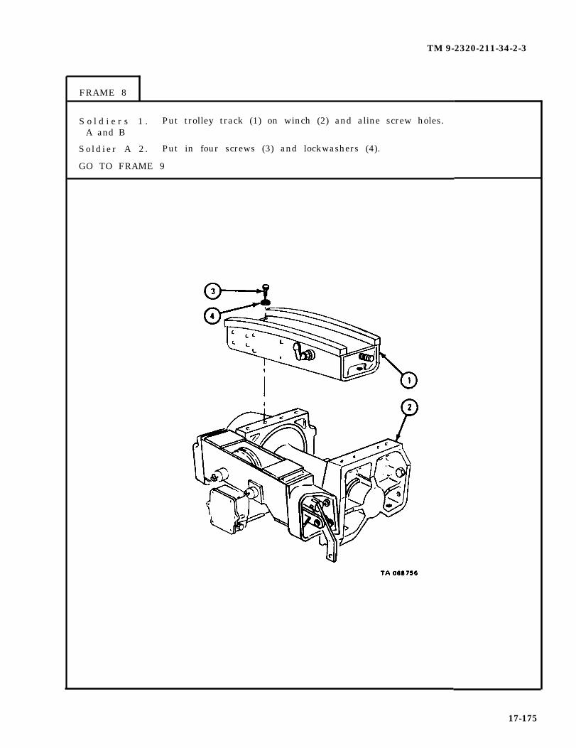
TM 9-2320-211-34-2-3
FRAME 8
S o l d i e r s 1 . Put trolley track (1) on winch (2) and aline screw holes.A and B
Sold ier A 2 . Put in four screws (3) and lockwashers (4).
GO TO FRAME 9
17-175
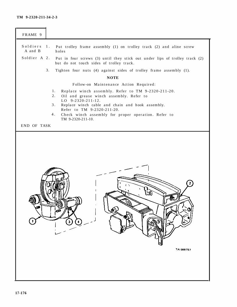
TM 9-2320-211-34-2-3
FRAME 9
S o l d i e r s 1 . Put trolley frame assembly (1) on trolley track (2) and aline screwA and B holes
So ld ier A 2 . Put in four screws (3) until they stick out under lips of trolley track (2)but do not touch sides of trolley track.
3. Tighten four nuts (4) against sides of trolley frame assembly (1).
NOTE
Follow-on Maintenance Action Required:
1. Replace winch assembly. Refer to TM 9-2320-211-20.2. Oil and grease winch assembly. Refer to
LO 9-2320-211-12.3. Replace winch cable and chain and hook assembly.
Refer to TM 9-2320-211-20.4 . Check winch assembly for proper operation. Refer to
TM 9-2320-211-10.
END OF TASK
17-176
TM 9-2320-211-34-2-3
17-17. HOIST WINCH MOTOR ASSEMBLY REMOVAL, REPAIR, AND REPLACEMENT(TRUCK M543A2).
TOOLS: No special tools required
SUPPLIES: Hoist winch motor gasketFront cover seal adapter preformed packing (2).Rear cover seal adapter preformed packing (2)Drive gear shaft retaining ring (2)Driven gear shaft retaining ring (2)Solvent, dry cleaning, type II (SD-2), Fed. Spec P-D-880Lubricating oil, ICE, OE/HDO-10, MIL-L-2104Wood blockCaps
PERSONNEL: Two
EQUIPMENT CONDITION: Truck parked, engine off, handbrake set.
17-177
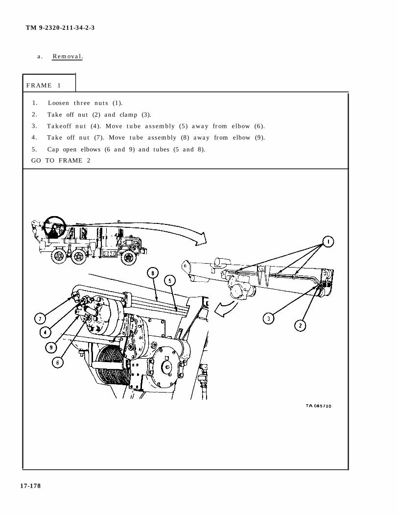
TM 9-2320-211-34-2-3
a. Removal.
FRAME 1
1. Loosen three nuts (1).
2. Take off nut (2) and clamp (3).
3. Takeoff nut (4). Move tube assembly (5) away from elbow (6).
4. Take off nut (7). Move tube assembly (8) away from elbow (9).
5. Cap open elbows (6 and 9) and tubes (5 and 8).
GO TO FRAME 2
17-178

TM 9-2320-211-34-2-3
FRAME 2
WARNING
The hoist winch motor assembly (1) is heavy. Becareful to keep tension on rope sling when screws (2)are taken out so that hoist winch motor assembly doesnot slip or fall. If motor assembly slips or falls, itcan cause serious injury to personnel and damage toequipment.
So ld ier A 1 .
So ld ier B 2 .
So ld ier A 3 .
4 .
So ld ier B 5 .
END OF TASK
Put rope sling on hoist winch motor assembly (1) and hook up hoist asshown. Tell soldier B when ready.
Using hoist, take slack out of rope sling.
Take out four capscrews with lockwashers (2).
Pull off hoist winch motor assembly (1). Guide motor assembly whilesoldier B moves it.
Move hoist winch motor assembly (1) to workbench.
17-179

TM 9-2320-211-34-2-3
b. Disassembly .
FRAME 1
1.
2.
3 .
Take rope sling off hoist and hoist winch motor assembly (1).
Take off and throw away gasket (2).
Take off coupling (3).
17-180
GO TO FRAME 2
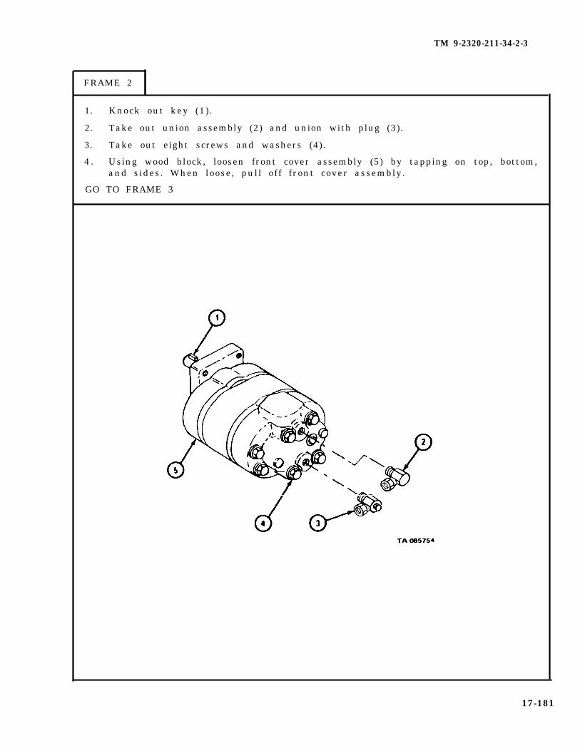
TM 9-2320-211-34-2-3
FRAME 2
1.
2.
3.
4 .
Knock out key (1).
Take out union assembly (2) and union with plug (3).
Take out eight screws and washers (4).
Using wood block, loosen front cover assembly (5) by tapping on top, bottom,and sides. When loose, pull off front cover assembly.
17-181
GO TO FRAME 3

TM 9-2320-211-34-2-3
FRAME 3
1.
2.
3.
4.
Take out two bearings (1) from front cover (2). Refer to Part 1, para 7-7.
Tag bearings (1) to make sure they will be put back in the same places.
Take out seal adapter (3) with preformed packings (4 and 5).
Take off preformed packings (4 and 5) from seal adapter (3). Throw awaypreformed packings.
17-182
GO TO FRAME 4

TM 9-2320-211-34-2-3
FRAME 4
1. Using wood block, loosen wear plate (1) by tapping on top, bottom, andsides. When loose, pull off wear plate.
2. Take out driven gear shaft assembly (2) and drive gear shaft assembly (3).
3. Using wood block, loosen rear cover assembly (4) and wear plate (5) bytapping on top, bottom and sides. When loose, pull off rear cover assemblyand wear plate.
4. Take out four locating pins (6).
GO TO FRAME 5
17-183
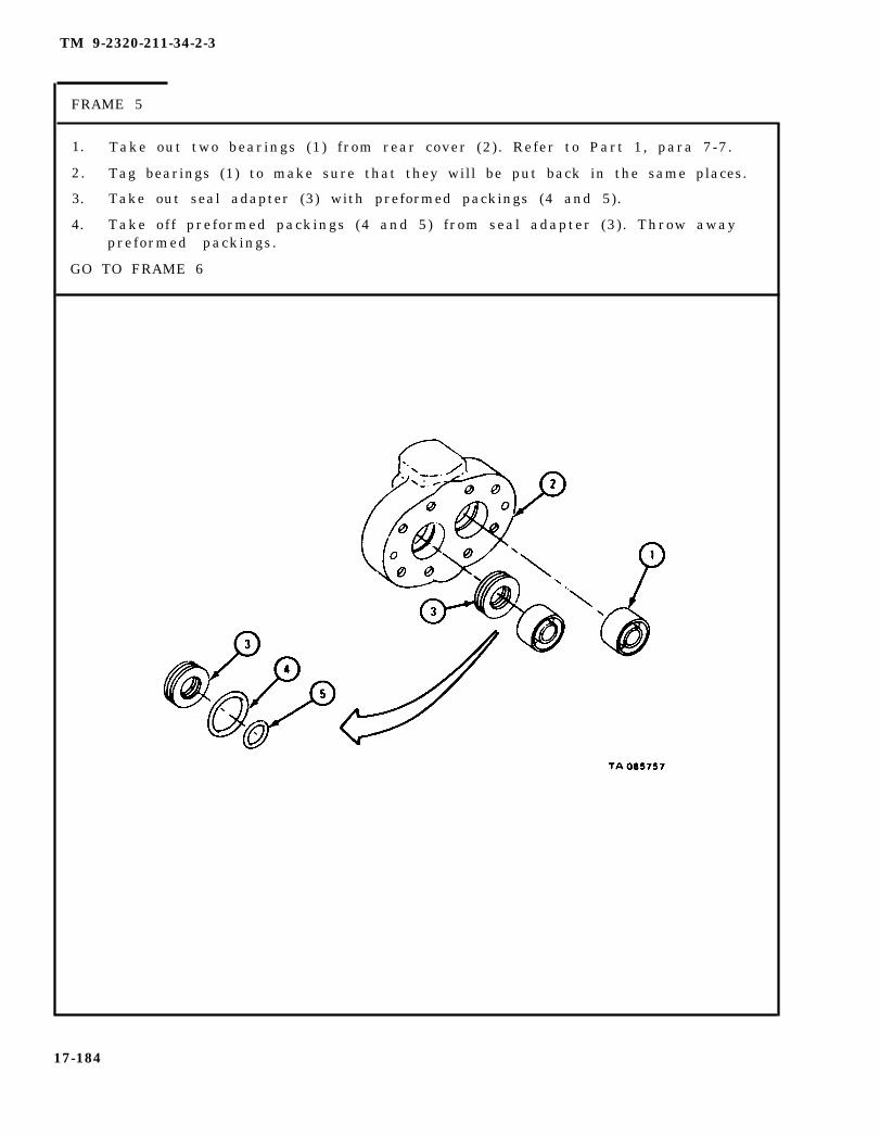
TM 9-2320-211-34-2-3
FRAME 5
1. Take out two bearings (1) from rear cover (2). Refer to Part 1, para 7-7.
2. Tag bearings (1) to make sure that they will be put back in the same places.
3. Take out seal adapter (3) with preformed packings (4 and 5).
4. Take off preformed packings (4 and 5) from seal adapter (3) . Throw awaypreformed packings.
GO TO FRAME 6
17-184

TM 9-2320-211-34-2-3
FRAME 6
1. Take off two retaining rings (1) from driven gear shaft (2) . Throw awayretaining rings.
2. Take off two bearing inner races (3) . Refer to Part 1, para 7-7.
3 . Tag bearing inner races (3) to make sure that they will be put back in thesame places.
4 . Take off two spacers (4) .
GO TO FRAME 7
17-185
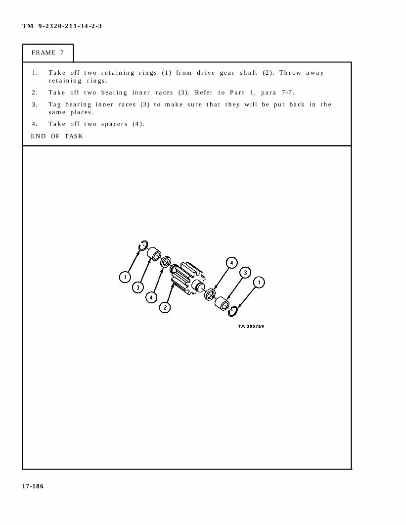
TM 9-2320-211-34-2-3
FRAME 7
1. Take off two retaining rings (1) from drive gear shaft (2) . Throw awayretaining rings.
2. Take off two bearing inner races (3). Refer to Part 1, para 7-7.
3. Tag bearing inner races (3) to make sure that they will be put back in thesame places.
4. Take off two spacers (4) .
END OF TASK
17-186

TM 9-2320-211-34-2-3
c . Cleaning.
WARNING
Dry cleaning solvent is flammable. Do not usenear an open flame. Keep a fire extinguishernearby when solvent is used. Use only in well-ventilated places. Failure to do this may resultin injury to personnel and damage to equipment.
(1) Clean bearings. Refer to Part 1, para 7-7.
(2) Clean all other parts in solvent.
(3) Put a coat of light oil on polished surfaces to stop rust.
17-187

TM 9-2320-211-34-2-3
d. Inspection.
F R A M E 1
1. Check that four bearings (1) and bearing inner races (2) are not damaged. Referto Part 1, para 7-7.
2. Check that driven gear shaft (3) and drive gear shaft (4) are not scratched, crackedor burred.
3 . Check that mating surfaces of front cover (5), motor body (6), and rear cover (7)are not scratched or burred and that bores are not scored.
4 . Check that four locating pins (8) are not bent.
GO TO FRAME 2
17-188

TM 9-2320-211-34-2-3
FRAME 2
1. Check that two wear plates (1) are not nicked, burred, dented or distorted.
2. Using micrometer, check that thickness of wear plates (1) at gear contactsurfaces (A) is within 0.003 inch of thickness at wear plate edges (B).
END OF TASK
17-189
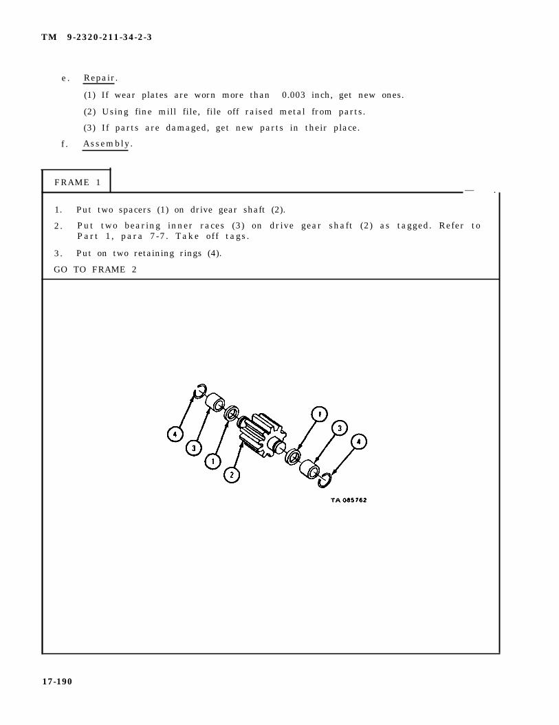
TM 9-2320-211-34-2-3
e . Repair.
(1) If wear plates are worn more than 0.003 inch, get new ones.
(2) Using fine mill file, file off raised metal from parts.
(3) If parts are damaged, get new parts in their place.
f . Assembly.
FRAME 1— .
1. Put two spacers (1) on drive gear shaft (2).
2. Put two bearing inner races (3) on drive gear shaft (2) as tagged. Refer toPart 1, para 7-7. Take off tags.
3. Put on two retaining rings (4).
GO TO FRAME 2
17-190

TM 9-2320-211-34-2-3
FRAME 2
1. Put two spacers (1) on driven gear shaft (2) .
2. Press on two bearing inner races (3) as tagged. Refer to Part 1, para 7-7.Take off tags.
3. Put on two retaining rings (4).
GO TO FRAME 3
17-191
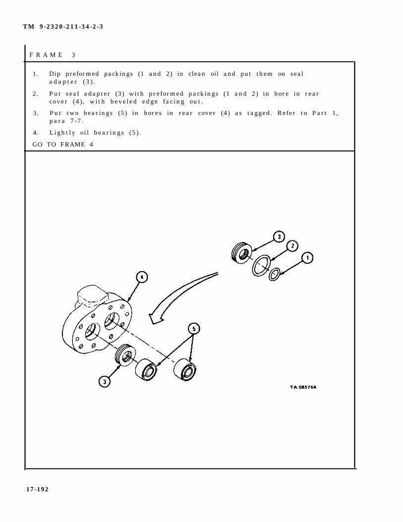
TM 9-2320-211-34-2-3
F R A M E 3
1. Dip preformed packings (1 and 2) in clean oil and put them on sealadapter (3 ) .
2. Put seal adapter (3) with preformed packings (1 and 2) in bore in rearcover (4) , with beveled edge facing out.
3. Put two bearings (5) in bores in rear cover (4) as tagged. Refer to Part 1,para 7-7.
4. Lightly oil bearings (5).
GO TO FRAME 4
17-192

TM 9-2320-211-34-2-3
FRAME 4
1 .
2.
3 .
GO
Put four locating pins (1) into motor body (2).
Put wear plate (3) on two locating pins (1) and push it in place against motorb o d y ( 2 ) . Be sure that groove (4) in wear plate faces out and that wearplate is on side of motor body with notch (5).
Put rear cover assembly (6) on two locating pins (1) and push it in placeagainst wear plate (3).
TO FRAME 5
1 7 - 1 9 3
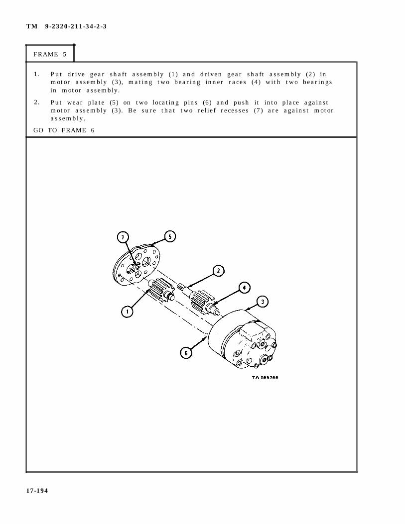
TM 9-2320-211-34-2-3
FRAME 5
1.
2.
GO
Put drive gear shaft assembly (1) and driven gear shaft assembly (2) inmotor assembly (3), mating two bearing inner races (4) with two bearingsin motor assembly.
Put wear plate (5) on two locating pins (6) and push it into place againstmotor assembly (3). Be sure that two relief recesses (7) are against motorassembly.
TO FRAME 6
17-194

TM 9-2320-211-34-2-3
FRAME 6
1. Dip preformed packings (1 and 2) in clean oil and put them on sealadapter (3 ) .
2. Put seal adapter (3) with preformed packings (1 and 2) in bore in frontcover (4) , with beveled edge facing out.
3. Put two bearings (5) in bores in front cover (4) as tagged. Refer to Part 1,para 7-7.
4. Lightly oil bearings (5).
GO TO FRAME 7
1 7 - 1 9 5

TM 9-2320-211-34-2-3
FRAME 7
1. Put front cover assembly (1) on locating pins (2) and push it in place onmotor assembly (3).
2. Put in eight screws and washers (4 and 5). Tighten screws a little at a timeuntil all screws are tightened.
3. Put in union assembly (6) and union with plug (7).
4. Put key (8) in place.
GO TO FRAME 8
1 7 - 1 9 6

TM 9-2320-211-34-2-3
FRAME 8
1. Aline keyway in coupling (1) with key (2) in shaft (3). Put uncoupling.
2 . Put on gasket (4).
END OF TASK
17-197

TM 9-2320-211-34-2-3
g . Replacement.
FRAME 1
WARNING
Soldier A
Soldier B
Soldier A
The hoist winch motor assembly (1) is heavy. Becareful to keep tension on rope sling when screwsare put in so that the hoist winch motor assemblydoes not slip or fall. If motor assembly slips orfalls, it can cause serious injury to personnel anddamage to equipment.
1.
2.
3.
4.
5.
Put rope sling on motor assembly (1) and hoist as shown. Tellsoldier B when ready. Guide motor assembly into place whilesoldier B lifts it.
GO TO FRAME 2
Using hoist, lift motor assembly (1). Keep tension on rope slinguntil motor assembly is in place.
Put gasket (2) on motor assembly (1). Aline keyway in coupling(3) with key in shaft (4).
Put in four cap screws with lockwashers (5).
Tell soldier B to put slack in rope sling. Take rope sling offmotor assembly (1) and hoist.
17-198

TM 9-2320-211-34-2-3
F R A M E 2
1.
2.
3.
4 .
5.
Take off all caps.
Put tube assembly (1) in place. Put on nut (2).
Put tube assembly (3) in place. Put on nut (4).
Tighten three nuts (5).
Put clamp (6) in place. Put on nut (7).
NOTE
Follow-on Maintenance Action Required:
1. Check level in hydraulic oil tank. If needed,fi l l tank. Refer to LO 9-2320-211-12.
2. Check hoist winch motor for proper operation.Refer to TM 9-2320-211-10.
END OF TASK
17-199

TM 9-2320-211-34-2-3
17-18. HOIST WINCH REMOVAL, REPAIR, AND REPLACEMENT (TRUCK M543A2).
TOOLS: No special tools required
SUPPLIES: Solvent, dry cleaning, type II (SD-2), Fed. Spec P-D-680End case sealBrake case sealWorm gearcase sealGearcase oil sealBrake case cover gasketBrake case gasketEnd case gasketGearcase cover gasketEnd case cover gasketEnd case motor adapter gasketExpansion plugShim (as needed)Packing
PERSONNEL: Two
EQUIPMENT CONDITION: Truck parked, engine off, handbrake set.
a . Pre l iminary Procedures .
(1) Remove winch cable. Refer to TM 9-2320-211-20.
(2) Remove hoist winch motor. Refer to para 17-17.
(3) Remove hoist winch roller assemblies. Refer to para 17-38.
17-200
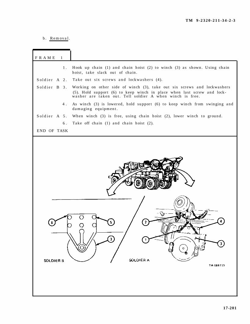
TM 9-2320-211-34-2-3
b. Removal.
F R A M E 1
1 .
So ld ier A 2 .
So ld ier B 3 .
4 .
So ld ier A 5 .
6 .
END OF TASK
Hook up chain (1) and chain hoist (2) to winch (3) as shown. Using chainhoist, take slack out of chain.
Take out six screws and lockwashers (4).
Working on other side of winch (3), take out six screws and lockwashers(5). Hold support (6) to keep winch in place when last screw and lock-washer are taken out. Tell soldier A when winch is free.
As winch (3) is lowered, hold support (6) to keep winch from swinging anddamaging equipment.
When winch (3) is free, using chain hoist (2), lower winch to ground.
Take off chain (1) and chain hoist (2).
17-201

TM 9-2320-211-34-2-3
c . D i s a s s e m b l y .
F R A M E 1
1 . Put one-gallon containers under gearcase (1) and end case (2).
2 . Take out two magnetic drain plugs (3). Let gear oil drain into containers.
3 . Take out containers and put gear oil in approved disposal area.
GO TO FRAME 2
17-202
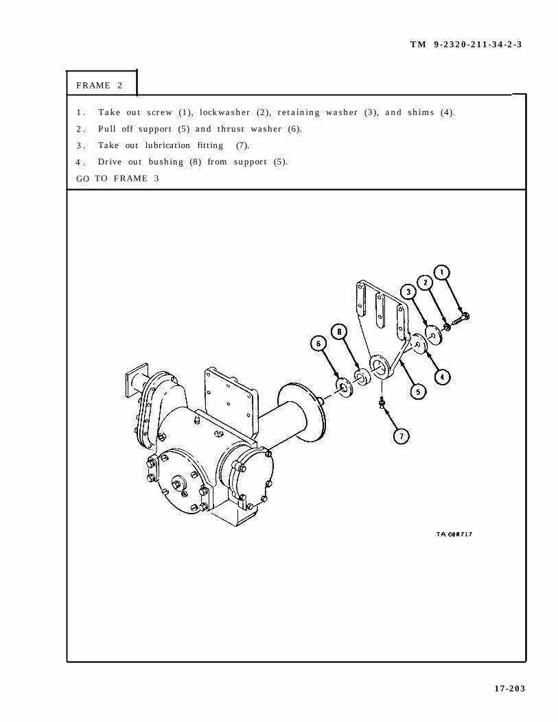
TM 9-2320-211-34-2-3
FRAME 2
1 .
2 .
3 .
4 .
GO
Take out screw (1), lockwasher (2), retaining washer (3), and shims (4).
Pull off support (5) and thrust washer (6).
Take out lubrication fitting (7).
Drive out bushing (8) from support (5).
TO FRAME 3
17-203

TM 9-2320-211-34-2-3
FRAME 3
1 .
2 .
3 .
4 .
5 .
6 .
7 .
Pull off drum (1).
Take out two keys (2).
Slide off spacer washer (3).
Take out screw (4).
Slide off support (5).
Take out lubrication fitting (6).
Drive out hushing (7) from support (5).
GO TO FRAME 4
17-204

TM 9-2320-211-34-2-3
FRAME 4
1 . Take out six locking screws (1).
2 . Pulloff brake case cover (2) and gasket (3). Throw away gasket.
3 . Loosen screw (4).
4 . Take out screw (5), flat washer (6), and packing (7). Throw away packing.
5 . Take out brake band assembly (8) and spring (9).
GO TO FRAME 5
17-205

TM 9-2320-211-34-2-3
FRAME 5
1 .
2 .
3 .
GO
Take out screw (1), lockwasher (2), and flat washer (3).
Pull off brake drum disk (4).
Take out key (5).
TO FRAME 6
17-206
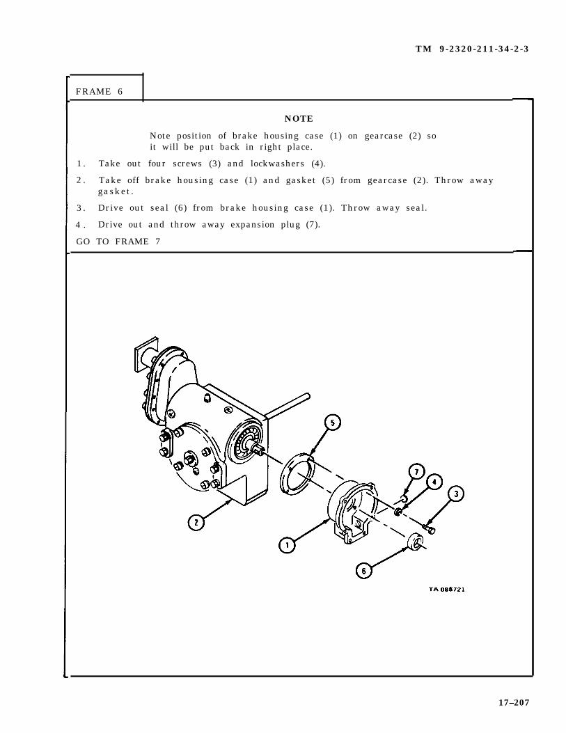
TM 9-2320-211-34-2-3
FRAME 6
NOTE
Note position of brake housing case (1) on gearcase (2) soit will be put back in right place.
1 . Take out four screws (3) and lockwashers (4).
2 . Take off brake housing case (1) and gasket (5) from gearcase (2). Throw awaygasket.
3 . Drive out seal (6) from brake housing case (1). Throw away seal.
4 . Drive out and throw away expansion plug (7).
GO TO FRAME 7
17–207

TM 9-2320-211-34-2-3
FRAME 7
1 . Take out four screws (1) and lockwashers (2).
2 . Take off motor adapter (3) and gasket (4). Throw away gasket.
3 . Take out key (5).
GO TO FRAME 8
17-208

TM 9-2320-211-34-2-3
FRAME 8
1 .
2 .
3 .
4 .
5 .
GO
Take out ten bolts (1) and lockwashers (2).
Pull off end case cover (3) and gasket (4). Throw away gasket.
Take out two pins (5) from end cover (3).
Press bearing (6) out of end cover (3).
Take out pipe plug (7).
TO FRAME 9
17-209

TM 9-2320-211-34-2-3
FRAME 9
1 .
2 .
3 .
4 .
5 .
6 .
7 .
Pull gearshaft (1) with gear (2) out of end case (3).
Pull gear (2) off gearshaft (1).
Take off retaining ring (4).
Drive worm gear (5) and bearing (6) out of gearcase (7) until end of shaft is free ofgear (8).
Take off gear (8).
Take out two keys (9) from shaft of worm gear (5) and take out worm gear and bearing(6) from gearcase (7).
Drive worm gear (5) out of bearing (6).
GO TO FRAME 10
17-210
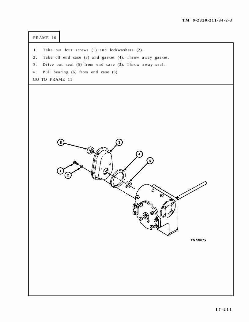
TM 9-2320-211-34-2-3
FRAME 10
1 .
2 .
3 .
4 .
GO
Take out four screws (1) and lockwashers (2).
Take off end case (3) and gasket (4). Throw away gasket.
Drive out seal (5) from end case (3). Throw away seal.
Pull bearing (6) from end case (3).
TO FRAME 11
1 7 - 2 1 1

TM 9-2320-211-34-2-3
FRAME 11
1. Take out screw (1), lockwasher (2), and retaining washer (3).
2. Take out pipe plug (4).
3. Take out four screws with lockwashers (5).
4. Take out four screws (6).
5. Pull off gearcase cover (7) and gasket (8). Throw away gasket.
6 . Press out seal (9) and bushing (10). Throw away seal.
GO TO FRAME 12
17-212

TM 9-2320-211-34-2-3
FRAME 12
1 . Drive shaft (1) with gear (2) out of gearcase (3).
2 . Press shaft (1) out of gear (2).
3 . Take out two keys (4) from shaft (1).
GO TO FRAME 13
17-213

TM 9-2320-211-34-2-3
FRAME 13
1 . Take out breather assembly (1).
2 . Take out pipe plug (2) from gearcase (3).
3 . Press out bearing (4), bushing (5), and seal (6).
END OF TASK
17-214

TM 9-2320-211-34-2-3
d. C l e a n i n g .
FRAME 1
1.
2 .
3 .
WARNING
Dry cleaning solvent is flammable. Do not use near anopen flame. Keep a fire extinguisher nearby when solventis used. Use only in well-ventilated places. Failure todo this may result in injury to personnel and damage toequipment.
Do not use compressed air to dry bearings or allow bear-ings to spin while drying. Spinning bearings may explode,causing injury to personnel and damage to equipment.
Clean bearings (1). Refer to Part 1, para 7-7.
Clean all parts except brake band assembly (2) with solvent. Make sure that greasepassages are open and clean.
Let all parts dry.
END OF TASK
17-215

TM 9-2320-211-34-2-3
e . Inspection and Repair.
FRAME 1
1. Check that two bushings (1) and two bushings (2) are not scored, pitted or cracked.
2 . Check that two bearings (3) and two bearings (4) are not damaged. Refer toPart 1, para 7-7.
3 . Check that gearshaft (5) is not scored or damaged in any other way.
4 . Check that gears (6 and 7) are not cracked and that they do not have damaged teeth.
GO TO FRAME 2
NOTECHECK ONLY THOSE PARTS WHICH ARE CALLEDOUT IN THIS FRAME. PARTS WITHOUT CALLOUTSARE SHOWN ONLY FOR REFERENCE PURPOSES OR ARE CHECKED IN ANOTHER FRAME.
TA 088730
17-216
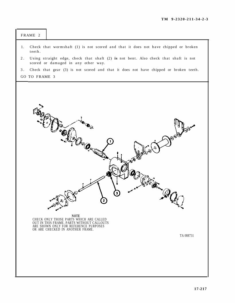
TM 9-2320-211-34-2-3
FRAME 2
1.
2 .
3 .
GO
Check that wormshaft (1) is not scored and that it does not have chipped or brokenteeth.
Using straight edge, check that shaft (2) is not bent. Also check that shaft is notscored or damaged in any other way.
Check that gear (3) is not scored and that it does not have chipped or broken teeth.
TO FRAME 3
NOTECHECK ONLY THOSE PARTS WHICH ARE CALLEDOUT IN THIS FRAME. PARTS WITHOUT CALLOUTSARE SHOWN ONLY FOR REFERENCE PURPOSESOR ARE CHECKED IN ANOTHER FRAME.
TA 088731
17-217

TM 9-2320-211-34-2-3
FRAME 3
1. Check that gearcase (1), gearcase cover (2), end case (3), and brake housing case (4)are not cracked, warped or broken, and that they do not have stripped screw threads.
2 . Check that brake band assembly (5) is not oil soaked or worn down to rivet heads.
3. Check that braking surface of brake drum disk (6) is not scored.
4 . Using fine mill file, file off small nicks and burrs from parts. If parts need morerepair, get new ones.
END OF TASK
NOTECHECK ONLY THOSE PARTS WHICH ARE CALLEDOUT IN THIS FRAME. PARTS WITHOUT CALLOUTSARE SHOWN ONLY FOR REFERENCE PURPOSESOR ARE CHECKED IN ANOTHER FRAME.
TA 088732
17-218

TM 9-2320-211-34-2-3
f . Assembly .
FRAME 1
1.
2 .
3 .
4 .
5 .
Press bushing (1) and seal (2) into gearcase (3).
Tap two keys (4) into slots in shaft (5).
Start shaft (5) into gear (6) and line up two keys (4) with keyway in gear.
CAUTION
Gear (6) must rest on its hub when pressing in shaft (5) orteeth may be damaged.
Press shaft (5) into gear (6).
Slide shaft (5) with gear (6) into bore of gearcase (3).
GO TO FRAME 2
17-219

TM 9-2320-211-34-2-3
FRAME 2
1.
2 .
3 .
4 .
5 .
6 .
GO
Put in breather assembly (1).
Put in two pipe plugs (2) and magnetic drain plug (3).
Press bearing (4) on tapped hole end of wormshaft (5).
Put assembled wormshaft (5) and bearing (4) into right side of gearcase (6) as shown.
Tap bearing (4) flush with gearcase (6).
Tap bearing (7) on other end of wormshaft (5) and tap bearing flush with gearcase (6).
TO FRAME 3
17-220
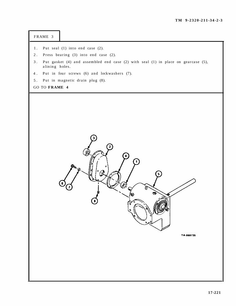
TM 9-2320-211-34-2-3
FRAME 3
1 . Put seal (1) into end case (2).
2 . Press bearing (3) into end case (2).
3 . Put gasket (4) and assembled end case (2) with seal (1) in place on gearcase (5),alining holes.
4 . Put in four screws (6) and lockwashers (7).
5 . Put in magnetic drain plug (8).
GO TO FRAME 4
17-221

TM 9-2320-211-34-2-3
FRAME 4
1. Tap two keys (1) into slot in wormshaft (2).
2 . Line up keyway in gear (3) with key (1) in wormshaft (2).
3* Tap gear (3) in place on wormshaft (2).
4 . Put retaining ring (4) in groove in wormshaft (2).
GO TO FRAME 5
17-222

TM 9-2320-211-34-2-3
FRAME 5
1. Put gearshaft (1) into bearing (2) in end case (3).
2 . Slide gear (4) into gearshaft (1) and mesh gear with gear (5).
GO TO FRAME 6
17-223
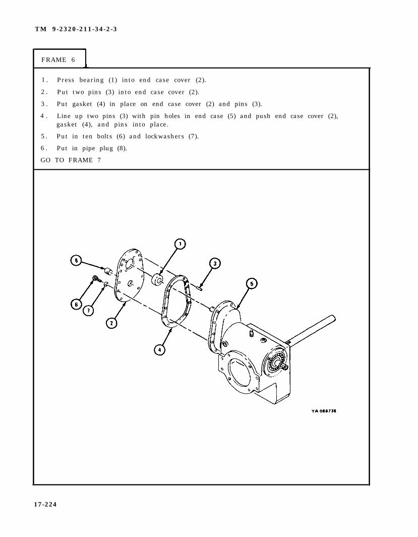
TM 9-2320-211-34-2-3
FRAME 6
1 . Press bearing (1) into end case cover (2).
2 . Put two pins (3) into end case cover (2).
3 . Put gasket (4) in place on end case cover (2) and pins (3).
4 . Line up two pins (3) with pin holes in end case (5) and push end case cover (2),gasket (4), and pins into place.
5 . Put in ten bolts (6) and lockwashers (7).
6 . Put in pipe plug (8).
GO TO FRAME 7
17-224

TM 9-2320-211-34-2-3
FRAME 7
1 . Tap key (1) into slot in gearshaft (2).
2 . Put gasket (3) and motor adapter (4) in place on end case cover (5), alining holes.
3 . Put in four screws (6) and lockwashers (7).
GO TO FRAME 8
17-225

TM 9-2320-211-34-2-3
FRAME 8
1 . Drive expansion plug (1) into right side of brake housing case (2) as shown.
2 . Press seal (3) into brake housing case (2).
NOTE
Be sure to put brake housing case (2) back in position as noted.
3 . Put gasket (4) and assembled brake housing case (2) with seal (3) in place ongearcase (5), alining holes.
4 . Put in four screws (6) and lockwashers (7).
GO TO FRAME 9
17-226

TM 9-2320-211-34-2-3
FRAME 9
1. Tap key (1) into slot in wormshaft (2).
2 . Line up keyway in brake drum disk (3) with key (1), with flat side of disk towardswormshaft (2).
3 . Tap brake drum disk (3) onto wormshaft (2) and key (1).
4 . Put in flat washer (4), lockwasher (5), and screw (6).
GO TO FRAME 10
17-227

TM 9-2320-211-34-2-3
FRAME 10
1. Put brake band assembly (1) on brake drum disk (2).
2 . Put spring (3) between screw holes in brake band assembly (1) and brake housingcase (4).
3 . Put flat washer (5) and packing (6) on screw (7) and put screw through brake housingcase (4), spring (3), and brake band assembly (1).
4 . Draw up brake band assembly (1) partway by turning in screw (7).
GO TO FRAME 11
17-228

TM 9-2320-211-34-2-3
FRAME 11
1 . Turn in screw (1) until gap in brake band assembly (2) is between 1 6/32 inches and1 8/32 inches as shown.
GO TO FRAME 12
17-229

TM 9-2320-211-34-2-3
FRAME 12
1. Put gasket (1) and end case cover (2) on brake housing case (3), alining holes.
2 . Put in six locking screws (4),
GO TO FRAME 13
17-230
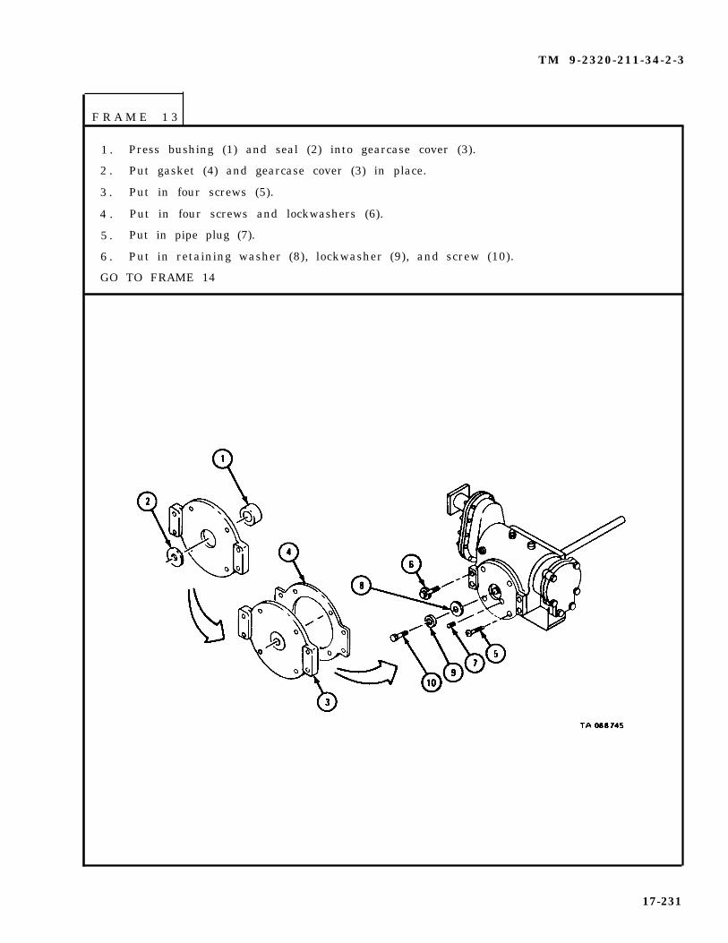
TM 9-2320-211-34-2-3
F R A M E 1 3
1 . Press bushing (1) and seal (2) into gearcase cover (3).
2 . Put gasket (4) and gearcase cover (3) in place.
3 . Put in four screws (5).
4 . Put in four screws and lockwashers (6).
5 . Put in pipe plug (7).
6 . Put in retaining washer (8), lockwasher (9), and screw (10).
GO TO FRAME 14
17-231

TM 9-2320-211-34-2-3
FRAME 14
1 . Press inrushing (1), with lubrication hole in bushing lined up with hole in support (2).
2 . Put in lubrication fitting (3).
3 . Slide support (2) on shaft (4).
4 . Put in screw (5) through support (2) and into gearcase (6).
5 . Slide spacer washer (7) on shaft (4).
6 . Tap two keys (8) into slots in shaft (4).
GO TO FRAME 15
17-232
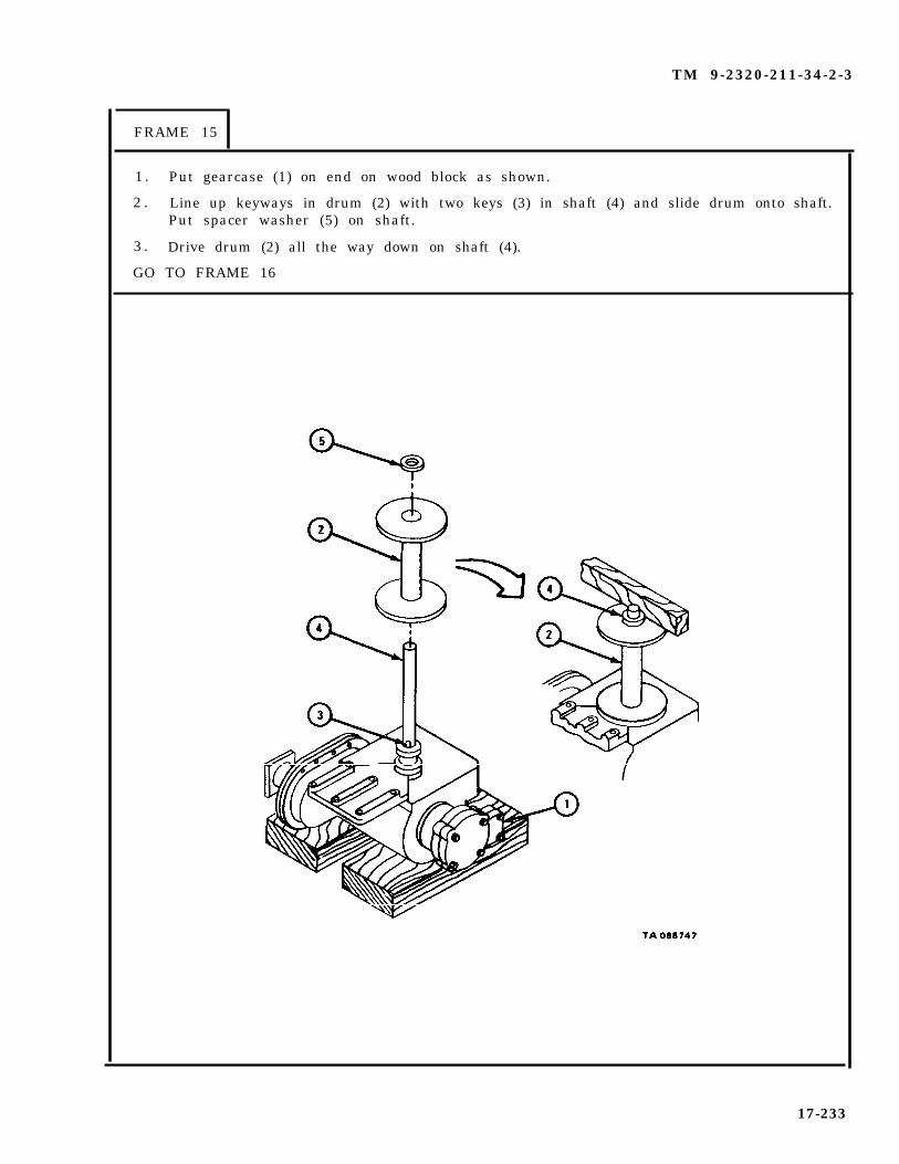
TM 9-2320-211-34-2-3
FRAME 15
1 . Put gearcase (1) on end on wood block as shown.
2 . Line up keyways in drum (2) with two keys (3) in shaft (4) and slide drum onto shaft.Put spacer washer (5) on shaft.
3 . Drive drum (2) all the way down on shaft (4).
GO TO FRAME 16
17-233
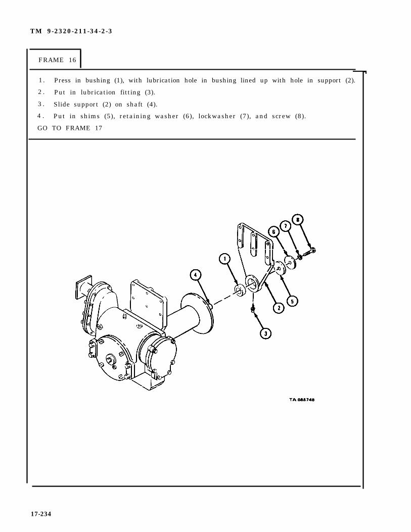
TM 9-2320-211-34-2-3
FRAME 16
1. Press in bushing (1), with lubrication hole in bushing lined up with hole in support (2).
2 . Put in lubrication fitting (3).
3 . Slide support (2) on shaft (4).
4 . Put in shims (5), retaining washer (6), lockwasher (7), and screw (8).
GO TO FRAME 17
17-234
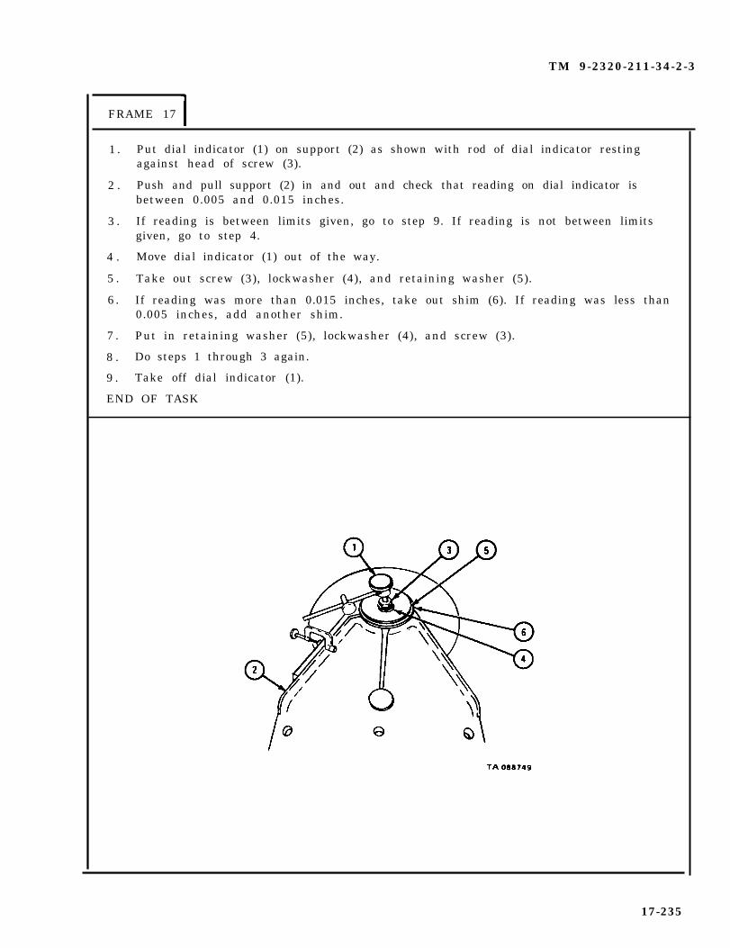
TM 9-2320-211-34-2-3
FRAME 17
1 .
2 .
3 .
4 .
5 .
6 .
7 .
8 .
9 .
Put dial indicator (1) on support (2) as shown with rod of dial indicator restingagainst head of screw (3).
Push and pull support (2) in and out and check that reading on dial indicator isbetween 0.005 and 0.015 inches.
If reading is between limits given, go to step 9. If reading is not between limitsgiven, go to step 4.
Move dial indicator (1) out of the way.
Take out screw (3), lockwasher (4), and retaining washer (5).
If reading was more than 0.015 inches, take out shim (6). If reading was less than0.005 inches, add another shim.
Put in retaining washer (5), lockwasher (4), and screw (3).
Do steps 1 through 3 again.
Take off dial indicator (1).
END OF TASK
17-235

TM 9-2320-211-34-2-3
g. Replacement.
FRAME 1
1 . Hook up chain (1) to hoist winch (2) as shown.
2 . Hook chain hoist (3) to chain (1) as shown.
GO TO FRAME 2
17-236

TM 9-2320-211-34-2-3
F R A M E 2
WARNING
Be careful when raising and positioning hoist winch on boomto prevent injury to personnel or damage to equipment.
So ld ier A 1 . Using chain hoist (1), raise winch (2) in position on boom (3).
So ld ier B 2 . As soldier A raises winch (2), hold support (4) and lift it into place.
3 . Put in six screws and lockwashers (5).
So ld ier A 4 . Put in six screws and lockwashers (6).
5 . Take off chain hoist (1) and chain (7).
NOTE
Follow-on Maintenance Action Required:
1 . Replace hoist winch motor on winch. Refer to para 17-17.2 . Oil and grease hoist winch assembly. Refer to
LO 9-2320-260-12.3 . Replace hoist winch roller assemblies on boom. Refer to
para 17-38.4 . Replace hoist winch cable on winch. Refer to
TM 9-2320-260-20.
END OF TASK
17-237

TM 9-2320-211-34-2-3
17-19. DUMP BODY CONTROL VALVE ADAPTER ASSEMBLY REMOVAL, REPAIR,AND REPLACEMENT (TRUCK M51A2).
TOOLS: No special tools required
SUPPLIES: Solvent, dry cleaning, type II (SD-2), Fed. Spec P-D-680Clean dry rags
PERSONNEL: One
EQUIPMENT CONDITION: Truck parked, engine off , handbrake set.
a . Preliminary Procedures .
(1) Drain hydraulic oil reservoir. Refer to LO 9-2320-211-12.
(2) Remove hydraulic hoist pump propeller shaft. Refer toTM 9-2320-211-20.
(3) Remove dump truck body hoist pump. Refer to TM 9-2320-211-20.
17-238

TM 9-2320-211-34-2-3
b . Removal.
F R A M E 1
1. Take out eight cap screws (1) with washers (2).
2. Take off valve adapter (3) and gasket (4) .
END OF TASK
17-239

TM 9-2320-211-34-2-3
c . D i s a s s e m b l y .
FRAME 1
1. Take out plug (1) and washer (2).
2. T a k e o u t s p r i n g ( 3 ) .
3. Takeout p lunger (4 ) .
END OF TASK
17-240

TM 9-2320-211-34-2-3
d. Cleaning, Inspection and Repair.
F R A M E 1
1.
2.
3 .
4.
WARNING
Cleaning solvent isflame. Keep a fireused. Use only in
flammable. Do not use near an openextinguisher nearby when solvent iswell-ventilated places. Failure to
do so may cause damage to equipment and injury topersonnel .
Clean all parts with dry cleaning solvent, type II (SD-2), Fed. Spec P- -D --6 8 0 .Dry with clean rags.
Check that valve adapter (1) is not cracked. If valve adapter is cracked, geta new one.
Check threads on plug (2). If plug is damaged, get a new one.
Check wear on plunger (3) and valve adapter (1).
NOTE
Readings must be within wear limits given in table 17-6.L indicates a loose fit. If parts are not within wearlimits, throw away plunger (3) and valve adapter (1)and get new ones.
END OF TASK
NOTECHECK ONLY THOSE PARTS WHICH ARE CALLED OUT.PARTS WITHOUT CAL LOUTS ARE SHOWN ONLY FORREFERENCE PURPOSES.
17-241

TM 9-2320-211-34-2-3
Table 17-6. Control Valve Adapter Wear Limits
Size and FitIndex of New Parts Wear Limit
Number Item /Point of Measurement ( inches ) ( i n c h e s )
1 Valve body 1.156 to 1.157 None
3 Plunger 1.154 to 1.155 None
1 and 2 Plunger in body 0.001L to 0.003L None
17-242

TM 9-2320-211-34-2-3
e . A s s e m b l y .
F R A M E 1
1. Put plunger (1) in valve adapter (2) .
2. Put spring (3) on top of plunger (1) .
3. Put washer (4) on plug (5). Put plug and washer into body.
END OF TASK
17-243

TM 9-2320-211-34-2-3
f . Replacement.
F R A M E 1
1. Put new gasket (1) against mount (2).
2. Hold valve adapter (3) against gasket (1).
3. Put in eight capscrews (4) with washers (5). Tighten capscrews.
NOTE
Follow-on Maintenance Action Required:
1. Replace dump truck body hoist pump. Refer toTM 9-2320-211-20.
2. Replace hydraulic hoist pump propeller shaft.Refer to TM 9-2320-211-20.
3. Check operation. Refer to TM 9-2320-211-10.
END OF TASK
17-244
TM 9-2320-211-34-2-3
17-20. HOIST CONTROL BOX ASSEMBLY REMOVAL, REPAIR, AND REPLACEMENT(TRUCK M51A2).
NOTE
There are two types of control boxes. One hasthe control valve lever on the left and the powertakeoff lever on the right. The other controlbox has the power takeoff lever on the left andthe control valve lever on the right. Since thetask is the same for both control boxes, onlythe control box with the control valve lever onthe left is shown.
TOOLS: No special tools required
SUPPLIES: Cover gasketSolvent, dry cleaning, type II (SD-2), Fed. Spec P-D-680
PERSONNEL: One
EQUIPMENT CONDITION: Truck parked, engine off , handbrake set.
a . Preliminary Procedures.
(1) Raise dump body as high as it will go. Refer to TM 9-2320-211-10.
(2) Lock hoist braces under dump body. Refer to TM 9-2320-211-20.
17-245
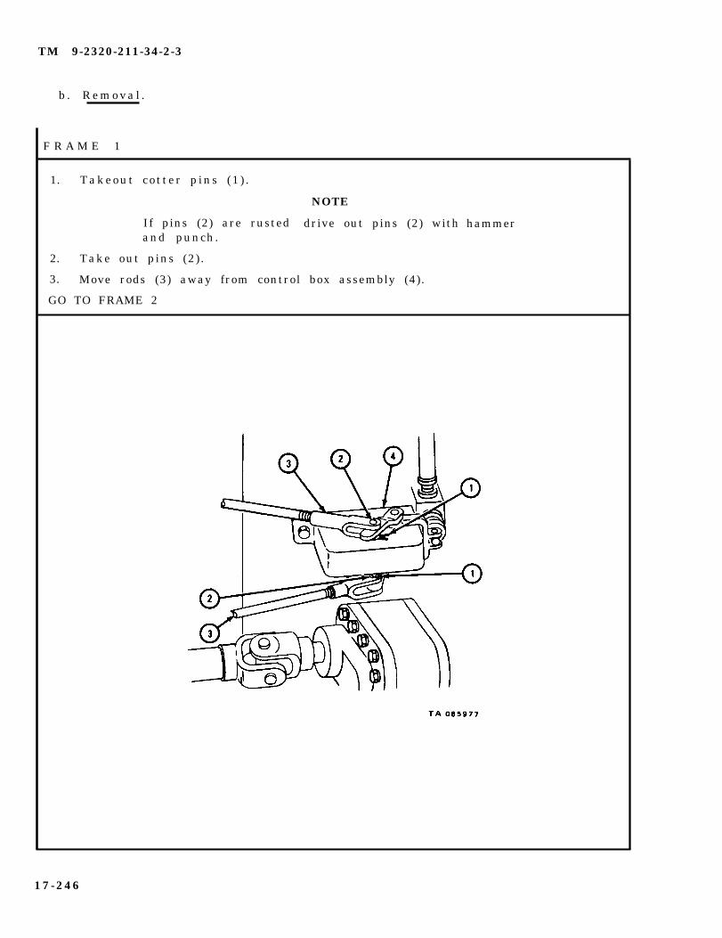
TM 9-2320-211-34-2-3
b . R e m o v a l .
F R A M E 1
1. Takeout cot ter p ins (1 ) .
If pins (2) are rustedand punch.
2. Take out pins (2) .
NOTE
drive out pins (2) with
3. Move rods (3) away from control box assembly (4).
GO TO FRAME 2
hammer
17-246

TM 9-2320-211-34-2-3
F R A M E 2
1. Take off nut (1), washer (2), take out screw (3) and take off lever arm (4).
GO TO FRAME 3
17-247

TM 9-2320-211-34-2-3
FRAME 3
NOTE
Hold control box assembly (6) when taking out screwso control box assembly will not fall.
1. Take off nut (1) and lockwasher (2).
2. Pull out screw (3) and take off control box levers (4).
3. Take off three screws (5).
4. Take off control box assembly (6).
END OF TASK
17-248

TM 9-2320-211-34-2-3
c . D i s a s s e m b l y .
FRAME 1
1. Take out woodruff keys (1 and 2).
GO TO FRAME 2
17-249
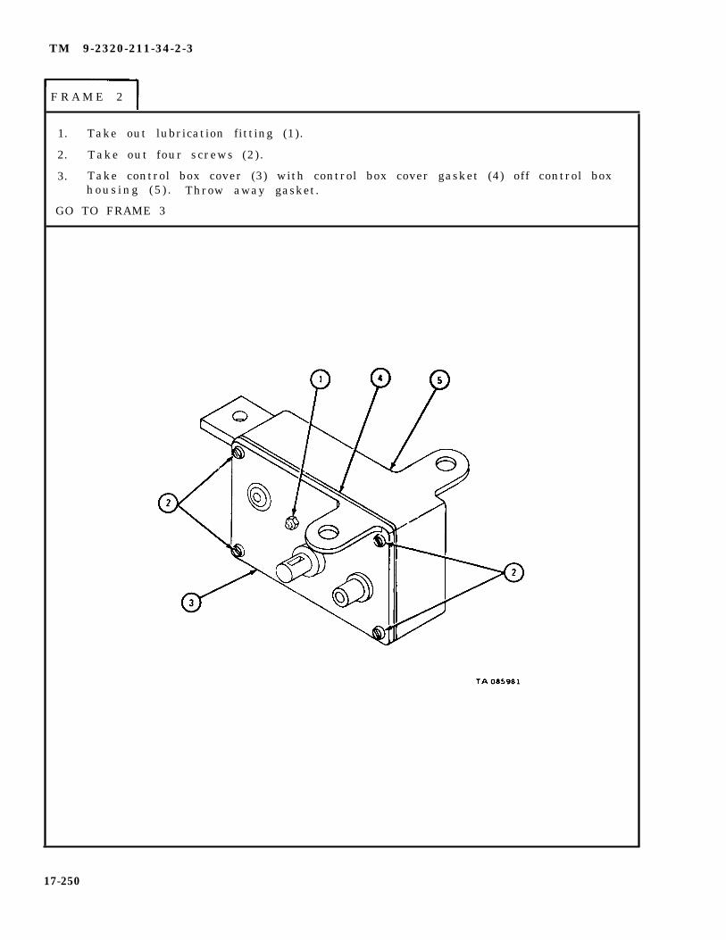
TM 9-2320-211-34-2-3
1. Take out lubrication fitting (1).
2. Take out four screws (2).
3. Take control box cover (3) with control box cover gasket (4) off control boxhous ing (5 ) . Throw away gasket.
GO TO FRAME 3
F R A M E 2
17-250
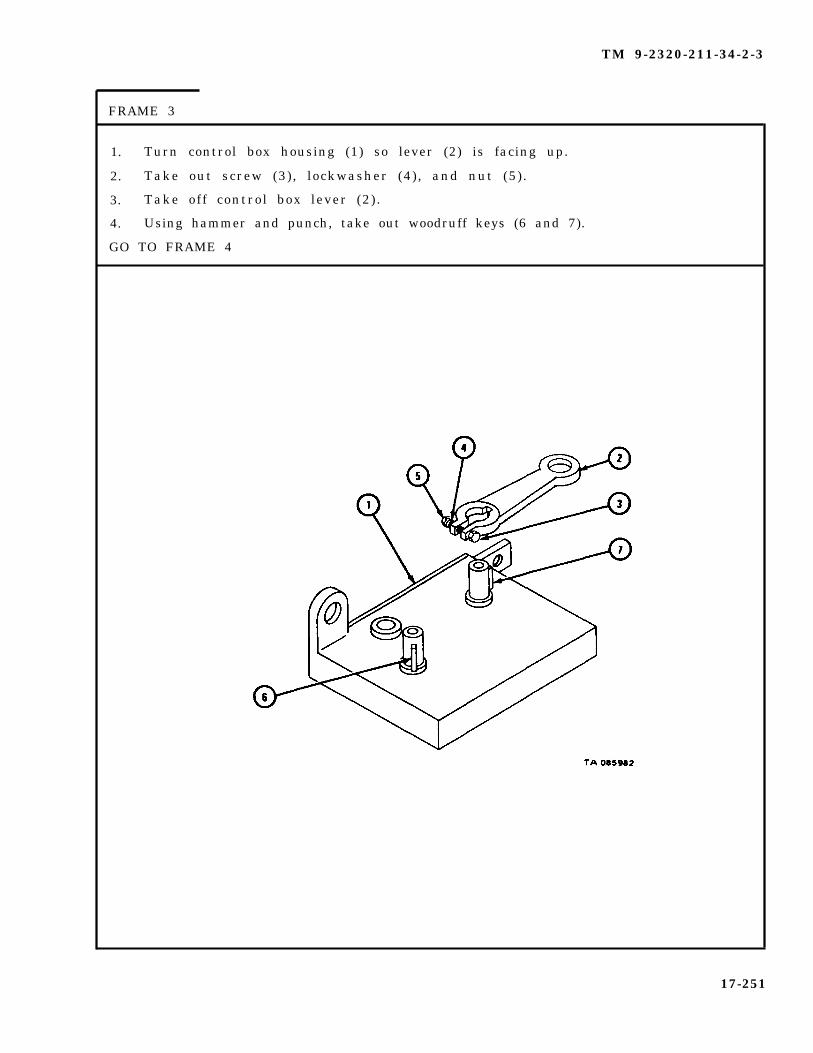
TM 9-2320-211-34-2-3
FRAME 3
1. Turn control box housing (1) so lever (2) is facing up.
2. Take out screw (3), lockwasher (4), and nut (5).
3. Take off control box lever (2) .
4. Using hammer and punch, take out woodruff keys (6 and 7).
GO TO FRAME 4
17-251

TM 9-2320-211-34-2-3
FRAME 4
1. Turn control box housing (1) so cam and shaft assemblies (2 and 3) andlever (4) can be seen.
2. Take out cam and shaft assembly (2).
3. Take out lever (3) and roller (5).
4. Take out cam and shaft assembly (5).
GO TO FRAME 5
17-252

TM 9-2320-211-34-2-3
FRAME 5
1. Take rollers (1 and 2) off control box lever (3).
END OF TASK
17-253

TM 9-2320-211-34-2-3
d . C l e a n i n g .
WARNING
Dry cleaning solvent is flammable. Do not use nearan open flame. Keep a fire extinguisher nearbywhen solvent is used. Use only in well-ventilatedplaces . Failure to do this may result in injury topersonnel and damage to equipment.
(1) Clean all parts with solvent.
(2 ) Let parts dry .
17-254

TM 9-2320-211-34-2-3
e . Inspect ion and Repair .
FRAME 1
1.
2.
3.
4.
5.
Check that shafts (1) and cams (2) have no worn or damaged areas, nicksor burrs . Throw away damaged parts and get new ones in their place.
Check that control box lever (3) and rollers (4) have no worn or damagedareas, nicks or burrs. Throw away damaged parts and get new ones intheir place.
Check that control box housing (5) and cover (6) are not cracked or damaged.Throw away damaged parts and get new ones in their place.
Check that control box levers (7) are not cracked, bent, or damaged in anyother way. If control box levers are damaged or bent, throw them awayand get new ones in their place.
Check that woodruff keys (8) are not damaged or worn. Replace keys withnew keys if damaged.
END OF TASK
17-255
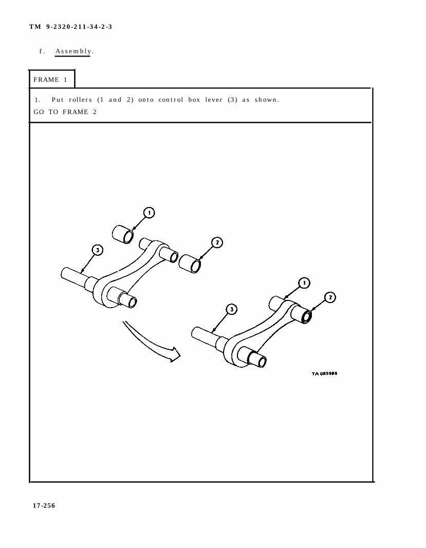
TM 9-2320-211-34-2-3
f . Assembly .
FRAME 1
1. Put rollers (1 and 2) onto control box lever (3) as shown.
GO TO FRAME 2
17-256

TM 9-2320-211-34-2-3
F R A M E 2
1. Put cam and shaft assembly (1) into control box housing (2) as shown withlarge lobe out._
2. Put control box lever (3) with rollers (4 and 5) into control box housing (2),putting roller (4) into notch of cam and shaft assembly (1).
GO TO FRAME 3
17-257
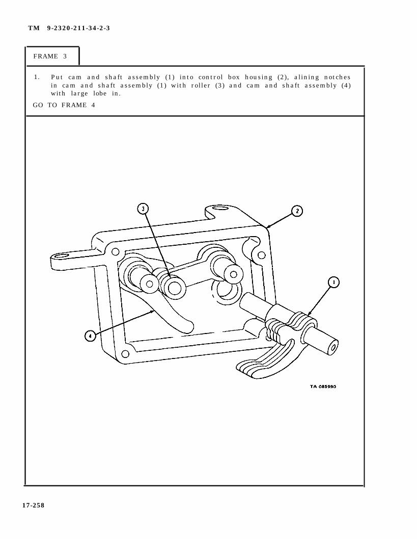
TM 9-2320-211-34-2-3
FRAME 3
1. Put cam and shaft assembly (1) into control box housing (2), alining notchesin cam and shaft assembly (1) with roller (3) and cam and shaft assembly (4)with large lobe in.
GO TO FRAME 4
17-258

TM 9-2320-211-34-2-3
FRAME 4
1. Aline four holes in control box cover (1) with holes in control box covergasket (2 ) .
2. Aline three holes in control box cover (1) with three shafts (3). Put controlbox cover gasket (2) on control box cover housing (4).
3. Put m four screws (5).
4. Put in lubrication fitting (6).
GO TO FRAME 5
17-259

TM 9-2320-211-34-2-3
FRAME 5
1. Using hammer and punch, tap woodruff keys (1 and 2) into shafts (3 and 4).
GO TO FRAME 6
17-260

TM 9-2320-211-34-2-3
FRAME 6
1. Turn control box housing (1) so shafts (2 and 3) are facing up.
2. Using hammer and punch, tap woodruff keys (4 and 5) into shafts (2 and 3).
3. Aline woodruff key (5) in shaft (3) with notch in lever (6).
4. Put lever (6) onto shaft (3) .
5. Put screw (7) into lever (6) and put on lockwasher (8) and nut (9).
END OF TASK
17-261

TM 9-2320-211-34-2-3
g. R e p l a c e m e n t .
F R A M E 1
1.
2.
GO
Aline holes in control box assembly (1) with holes in truck subframe assembly(2) and put control box assembly (1) on truck subframe (2).
Put in two screws (3).
TO FRAME 2
17-262
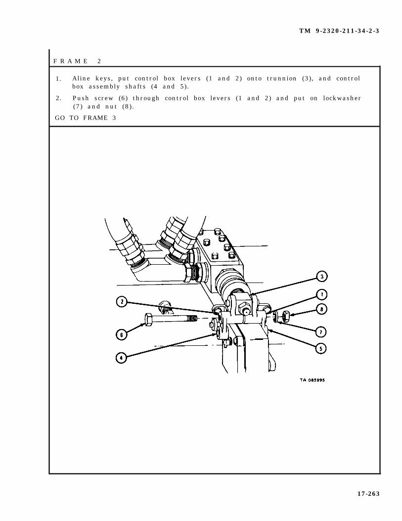
TM 9-2320-211-34-2-3
F R A M E 2
1. Aline keys, put control box levers (1 and 2) onto trunnion (3), and controlbox assembly shafts (4 and 5).
2. Push screw (6) through control box levers (1 and 2) and put on lockwasher(7) and nut (8) .
GO TO FRAME 3
17-263

TM 9-2320-211-34-2-3
F R A M E 3
1. Put lever (1) on control box, put screw (2) through lever (1).
2. Put on washer (3) and nut (4) and tighten.
GO TO FRAME 4
17-264

TM 9-2320-211-34-2-3
FRAME 4
1. Put in screw (1).
2. Aline hole in rod (2) with hole in control box lever (3) and put in pin (4).
3. Put cotter pin (5) into hole in end of pin (4).
4. Aline hole in rod (6) with hole in control box lever (7) and put in pin (8).
5. Put cotter pin (9) into hole in end of pin (7).
NOTE
Follow-on Maintenance Action Required:
1. Lubricate control box assembly. Refer toLO 9-2320-211-12.
2. Unlock and lower hoist braces under dump body.Refer to TM 9-2320-211-20.
3. Lower dump body. Refer to TM 9-2320-211-10.4 . Check dump body for proper operation. Refer
to TM 9-2320-211-10.
END OF TASK
17-265

TM 9-2320-211-34-2-3
17-21. CONTROL VALVE ASSEMBLY REPAIR (TRUCK M51A2).
TOOLS: No special tools required
SUPPLIES: Valve spool packingSolvent, dry cleaning, type II (SD-2), Fed. Spec P-D-680
PERSONNEL: One
EQUIPMENT CONDITION: Control valve assembly on bench.
a .
b .
Preliminary Procedures.
(1) Remove dump truck body hoist pump. Refer to TM 9-2320-211-20.
(2) Remove control valve assembly. Refer to TM 9-2320-211-20.
Disassembly.
F R A M E 1
1. Take out four flexible line unions (1).
2. Take out manifolds (2 and 3).
GO TO FRAME 2
17-266

TM 9-2320-211-34-2-3
F R A M E 2
1. Takeout pipe plug (1) , poppet ball spring (2) , and poppet ball (3) .
2. Takeout control valve end cap (4) and washer (5) .
GO TO FRAME 3
17-267
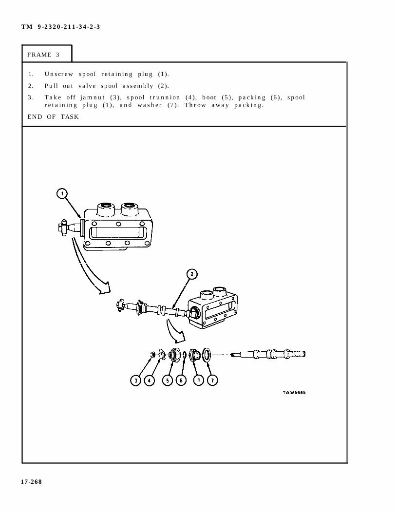
TM 9-2320-211-34-2-3
FRAME 3
1. Unscrew spool retaining plug (1).
2. Pull out valve spool assembly (2).
3. Take off jamnut (3), spool trunnion (4), boot (5) , packing (6), spoolretaining plug (1), and washer (7). Throw away packing.
END OF TASK
17-268
TM 9-2320-211-34-2-3
c. C l e a n i n g .
Dry cleaningnear an opennearby when
WARNING
solvent is flammable. Do not useflame. Keep a f ire extinguishersolvent is used. Use only in well-
ventilated places. Failure to do this may resultin injury to personnel and damage to equipment.
(1) Clean all parts in solvent. Make sure you do not damage valve spool
(2) Make sure all oil passages are open.
( 3 ) L e t p a r t s d r y .
17-269
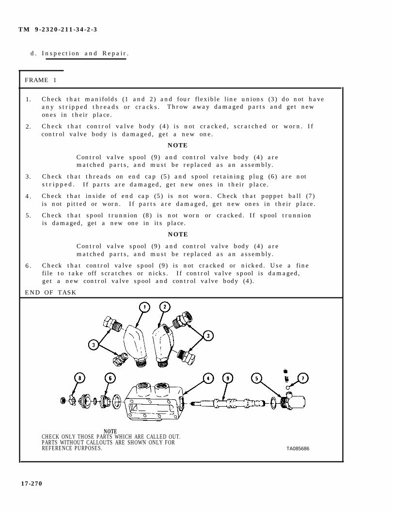
TM 9-2320-211-34-2-3
d. Inspect ion and Repair .
FRAME 1
1.
2.
3.
4.
5.
6 .
Check that manifolds (1 and 2) and four flexible line unions (3) do not haveany stripped threads or cracks. Throw away damaged parts and get newones in their place.
Check that control valve body (4) is not cracked, scratched or worn. Ifcontrol valve body is damaged, get a new one.
NOTE
Control valve spool (9) and control valve body (4) arematched parts, and must be replaced as an assembly.
Check that threads on end cap (5) and spool retaining plug (6)s tr ipped . If parts are damaged, get new ones in their place.
are not
Check that inside of end cap (5) is not worn. Check that poppet ball (7)is not pitted or worn. If parts are damaged, get new ones in their place.
Check that spool trunnion (8) is not worn or cracked. If spool trunnionis damaged, get a new one in its place.
NOTE
Control valve spool (9) and control valve body (4) arematched parts, and must be replaced as an assembly.
Check that control valve spool (9) is not cracked or nicked. Use a finefile to take off scratches or nicks. If control valve spool is damaged,get a new control valve spool and control valve body (4).
END OF TASK
NOTECHECK ONLY THOSE PARTS WHICH ARE CALLED OUT.PARTS WITHOUT CALLOUTS ARE SHOWN ONLY FORREFERENCE PURPOSES. TA085686
17-270

TM 9-2320-211-34-2-3
e . A s s e m b l y .
FRAME 1
1. Put washer (1) onto spool retaining plug (2).
2. Put spool retaining plug (2) with washer (1), packing (3), boot (4), andspool trunnion (5) onto threaded end of control valve spool (6).
3. Put on jamnut (7).
GO TO FRAME 2
17-271

TM 9-2320-211-34-2-3
FRAME 2
1. Push control valve spool (1) into bore of control valve body (2) as shown.
2. Screw spool retaining plug (3) into control valve body (2).
GO TO FRAME 3
17-272

TM 9-2320-211-34-2-3
F R A M E 3
1. Put washer (1) onto end cap (2).
2. Put end cap (2) with washer (1) into valve control body (3).
3. Put poppet ball (4), poppet ball spring (5), and pipe plug (6) into endc a p ( 2 ) .
GO TO FRAME 4
17-273

TM 9-2320-211-34-2-3
FRAME 4
1. Put manifolds (1 and 2) into control valve body (3).
2. Put four flexible line unions (4) into manifolds (1 and 2).
NOTE
Follow-on Maintenance Action Required:
1. Replace control valve assembly. Refer toTM 9-2320-211-20.
2. Replace dump truck body hoist pump.Refer to TM 9-2320-211-20.
3. Fill hydraulic reservoir. Refer toLO 9-2320-211-12.
4. Check operation of control valve assembly. Referto TM 9-2320-211-10.
END OF TASK
17-274

TM 9-2320-211-34-2-3
17-22. HOIST CONTROL LINKAGE REMOVAL, REPAIR, AND REPLACEMENT(TRUCK M51A2).
TOOLS: No special tools required
SUPPLIES: T a g s
PERSONNEL: TW O
EQUIPMENT CONDITION: Truck parked, engine off , handbrake set.
a. R e m o v a l .
F R A M E 1
1. Take out cotter pin (1).
NOTE
If clevis pin (2) is rusted in place, drive it out.
2. Take out clevis pin (2).
3. Do steps 1 and 2 again at rear end of hand lever rod assemblyout hand lever rod assembly.
GO TO FRAME 2
( 3 ) . T a k e
17-275

TM 9-2320-211-34-2-3
1. Takeout two cotter pins (1) .
NOTE
If clevis pins (2) are rusted in place, drive them out.
2. Take out two clevis pins (2).
3. Take out dump control box rod (3).
GO TO FRAME 3
17-276
F R A M E 2

TM 9-2320-211-34-2-3
F R A M E 3
1 . Take out two cotter pins (1).
NOTE
If clevis pins (2) are rusted in place, drive them out.
2. Take out two clevis pins (2).
3 . Take off dump control box rod assembly (3).
GO TO FRAME 4
17-277

TM 9-2320-211-34-2-3
FRAME 4
1.
2.
3.
4.
5.
6.
Takeout cot ter p in (1 ) .
NOTE
If clevis pins (2 and 3) are rusted in place, drivethem out.
Take out clevis pin (2).
Take out end of hand lever rod assembly (4).
Take out cotter pin (5).
Take out clevis pin (3).
Take out other end of hand lever rod assembly (4).
GO TO FRAME 5
17-278

TM 9-2320-211-34-2-3
F R A M E 5
S o l d i e r A 1 . Working from forward side of crossmember (1), hold four lock-n u t s ( 2 ) . Tell soldier B when ready.
S o l d i e r B 2 . Working from rear side of crossmember (1), take off four cap-Screws (3 ) .
3. Take off transfer motion rod assembly (4).
S o l d i e r s 4 . Do steps 1 and 2 again to take off power takeoff connecting rodA and B shaft assembly (5).
GO TO FRAME 6
17-279

TM 9-2320-211-34-2-3
FRAME 6
S o l d i e r A 1 . Working from left running board, hold four locknuts (1). Tellsoldier B when ready.
S o l d i e r B 2 . Working from behind driver's seat, take out four cap screws (2).
3. Unlock hand lever lock (3) and take out hand lever cross shaftassembly (4).
END OF TASK
17-280

TM 9-2320-211-34-2-3
b . Disassembly.
(1) Hand lever cross shaft assembly.
FRAME 1
1. Take off capscrew (1) and locknut (2) .
2. Tap off lever (3) .
3. Tap out woodruff key (4) .
4. Take off two support brackets (5) .
5. Take off lubrication fitting (6) from each support bracket (5).
6 . Take off locknut (7), washer (8), spring (9), and hand lever lock (10).
END OF TASK
17-281
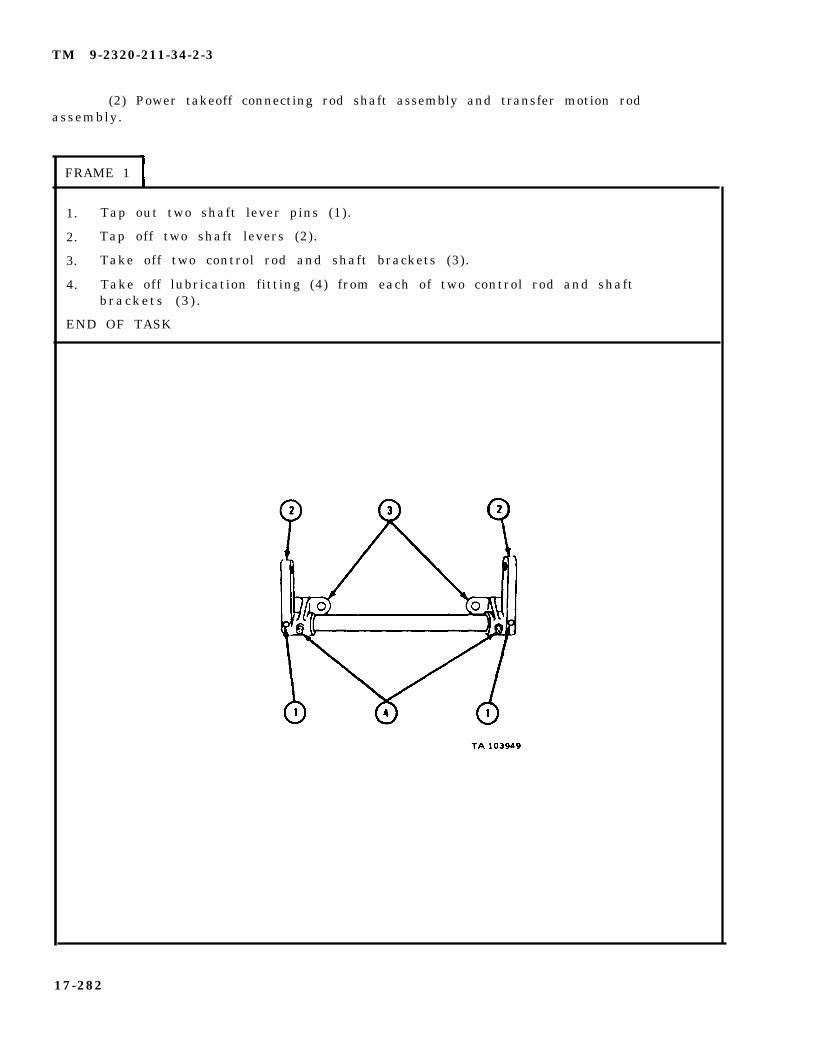
TM 9-2320-211-34-2-3
(2) Power takeoff connecting rod shaft assembly and transfer motion rodassembly.
FRAME 1
1. Tap out two shaft lever pins (1).
2. Tap off two shaft levers (2).
3. Take off two control rod and shaft brackets (3).
4. Take off lubrication fitting (4) from each of two control rod and shaftbrackets (3 ) .
END OF TASK
17-282
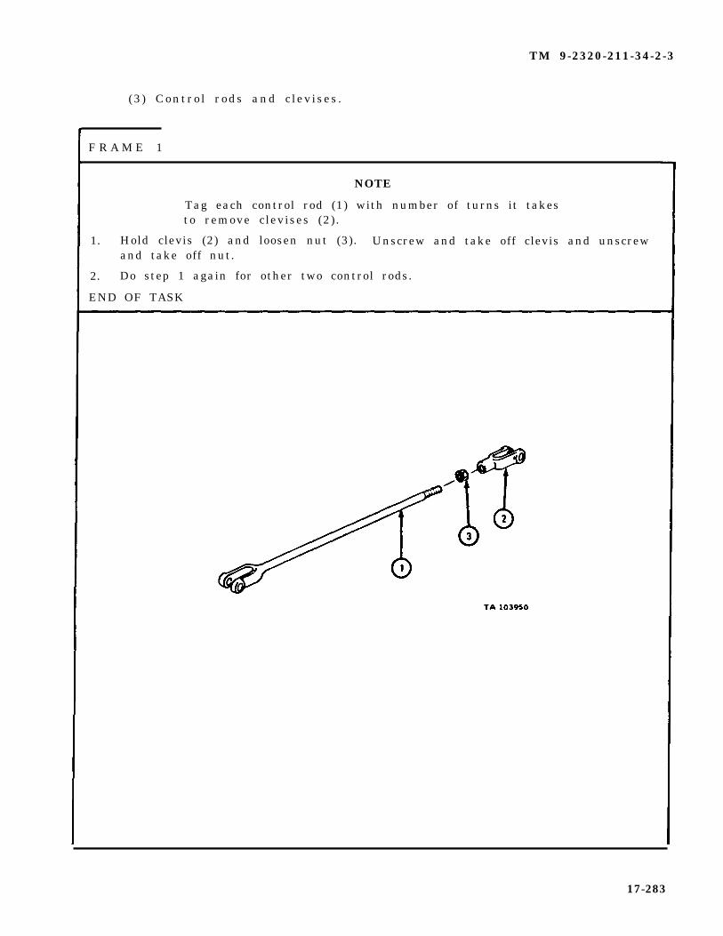
TM 9-2320-211-34-2-3
(3 ) Contro l rods and c lev ises .
F R A M E 1
NOTE
Tag each control rod (1) with number of turns it takesto remove clevises (2) .
1. Hold clevis (2) and loosen nut (3). Unscrew and take off clevis and unscrewand take off nut.
2. Do step 1 again for other two control rods.
END OF TASK
17-283

TM 9-2320-211-34-2-3
c. Cleaning. There are no special cleaning procedures needed. Refer tocleaning procedures given in Part 1, para 1-3.
d. I n s p e c t i o n a n d R e p a i r .
(1) Check that all threaded parts have no stripped or damaged threads.
(2) Check that all control rods have no bends or cracks.
(3) Check that all cross shafts are not bent, cracked, burred or worn.
(4) Check that all cross shaft support brackets have no cracks. Checkthat bores are not burred or worn.
(5) Throw away damaged parts and get new ones in their place. If controlrods or cross shafts are bent, repair by straightening. Refer to FM 43-2.
e. A s s e m b l y .
(1 ) Contro l rods and c lev ises .
F R A M E 1
1. Screw on nut (1).
2. Screw on clevis (2) with same number of turns as tagged. Take off tag.
3. Hold clevis (2) . Tighten nut (1) against clevis.
4. Do steps 1 through 3 again to put clevises (2) on other two control rods.
END OF TASK
17-284

TM 9-2320-211-34-2-3
(2) Power takoff connecting rod shaft assembly and transfer motion rodassembly.
FRAME 1
1. Put on two control rod and shaft brackets (1).
2. Tap shaft lever (2) on cross shaft (3) and aline pin holes.
3. Tap shaft lever pin (4) through shaft lever (2) and cross shaft (3) .
4. Do steps 2 and 3 again for shaft lever (2) on other end of cross shaft (3).
5. Screw in and tighten lubrication fitting (5) in each of two control rod andshaft brackets (1).
END OF TASK
17-285
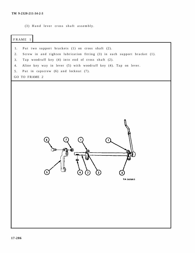
TM 9-2320-211-34-2-3
(3) Hand lever cross shaft assembly.
FRAME 1
1. Put two support brackets (1) on cross shaft (2).
2. Screw in and tighten lubrication fitting (3) in each support bracket (1).
3. Tap woodruff key (4) into end of cross shaft (2).
4. Aline key way in lever (5) with woodruff key (4). Tap on lever.
5. Put in capscrew (6) and locknut (7).
GO TO FRAME 2
17-286

TM 9-2320-211-34-2-3
FRAME 2
1. Put hand lever lock (1) through hand control lever (2).
2. Put spring (3) and washer (4) on hand lever lock (1).
3. Put on locknut (5).
END OF TASK
17-287

TM 9-2320-211-34-2-3
f . Replacement.
FRAME 1
S o l d i e r A 1 .
2.
S o l d i e r B 3 .
S o l d i e r A 4 .
Working from behind driver’s seat, put in hand lever cross shaftassembly (1). Make sure that hand lever (2) goes through seal( 3 ) .
Aline holes in support brackets (4) with holes in cab floor (5).Put in four capscrews (6).
Working from under truck, put on and hold four locknuts (7) onfour capscrews (6 ) . Tell soldier A when ready.
Tighten four capscrews (6). Put hand lever lock (8) in lockposition.
GO TO FRAME 2
17-288

TM 9-2320-211-34-2-3
F R A M E 2
S o l d i e r A 1 . Working from rear side of crossmember (1), put transfer motionrod assembly (2) in place and aline holes in crossmember andsupport brackets (3 ) .
2. Put in and hold four capscrews (4).
S o l d i e r B 3 . Working from forward side of crossmember (1), put on four lock-n u t s ( 5 ) .
S o l d i e r s 4 . Do steps 1 through 3 again to put on power takeoff shaftA and B connecting rod assembly (6).
GO TO FRAME 3
17-289

TM 9-2320-211-34-2-3
FRAME 3
1. Put adjustable clevis (1) of hand lever rod assembly (2) over power takeoffconnecting rod lever (3) and put in clevis pin (4).
2. Aline clevis (5) on other end of hand lever rod assembly (2) with powertakeoff (6) and put in clevis pin (7).
3. Put two cotter pins (8) through two clevis pins (4 and 7).
GO TO FRAME 4
17-290

TM 9-2320-211-34-2-3
FRAME 4
1.
2.
3.
GO
Aline adjustable clevis (1) of dump control box rod assembly (2) with powertakeoff relay lever (3) and put in clevis pin (4).
Aline clevis (5) on other end of dump control box rod assembly (2) withdump body actuating lever (6) and put in clevis pin (7).
Put two cotter pins (8) through two clevis pins (4 and 7).
TO FRAME 5
17-291

TM 9-2320-211-34-2-3
FRAME 5
1.
2.
3.
GO
Aline adjustable clevis (1) of dump control box rod assembly (2) with relaylever (3) and put in clevis pin (4).
Aline clevis (5) on other end of dump control box rod assembly (2) withmotion rod transfer shaft lever (6) and put in clevis pin (7).
Put two cotter pins (8) through two clevis pins (4 and 7).
TO FRAME 6
17-292
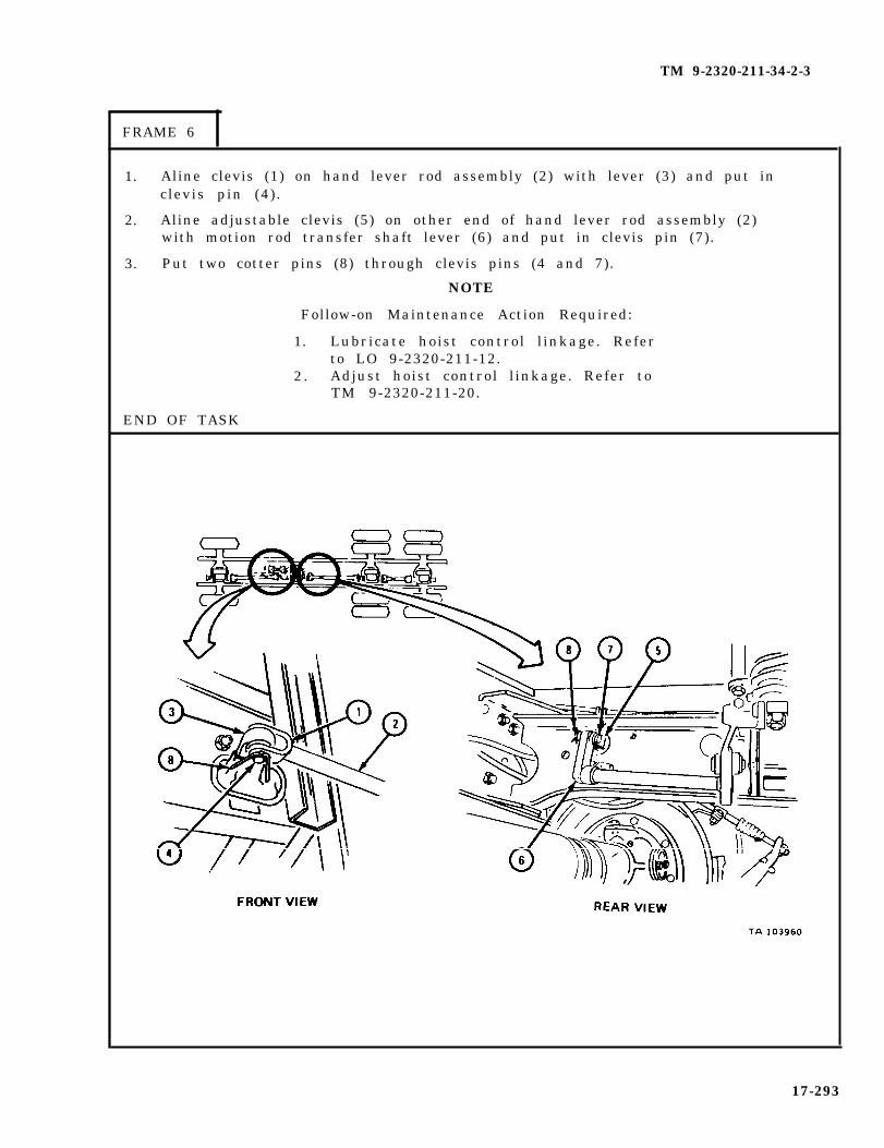
TM 9-2320-211-34-2-3
FRAME 6
1.
2.
3.
Aline clevis (1) on hand lever rod assembly (2) with lever (3) and put inclevis pin (4) .
Aline adjustable clevis (5) on other end of hand lever rod assembly (2)with motion rod transfer shaft lever (6) and put in clevis pin (7).
Put two cotter pins (8) through clevis pins (4 and 7).
NOTE
Follow-on Maintenance Action Required:
1. Lubricate hoist control l inkage. Referto LO 9-2320-211-12.
2 . Adjust hoist control l inkage. Refer toTM 9-2320-211-20.
END OF TASK
17-293

TM 9-2320-211-34-2-3
17-23. DUMP BODY HOIST FRAME ASSEMBLY REMOVAL, REPAIR, ANDREPLACEMENT (TRUCK M51A2).
TOOLS: No special tools required
SUPPLIES: None
PERSONNEL: TW O
EQUIPMENT CONDITION: Truck parked, engine off , handbrake set.
a . Pre l iminary Procedures .
(1) Drain hydraulic system. Refer to LO 9-2320-211-12.
(2) Take off hoist control l inkage from hoist. Refer to para 17-22.
( 3 ) R e m o v e
( 4 ) R e m o v e
( 5 ) R e m o v e
( 6 ) R e m o v e
dump truck body. Refer to Part 2, para 16-28.
hoist roller arms. Refer to para 17-28.
hoist hydraulic cylinders. Refer to para 17-24.
control valve. Refer to para 17-21.
17-294

TM 9-2320-211-34-2-3
b . Removal.
FRAME 1
1. Take outp i n s .
2. Take out
3. Do steps
two cotter pins (1), nuts (2), and washers (3). Throw away cotter
two bolts (4) , keepers (5) , and springs (6) .
1 and 2 again on right side of truck.
GO TO FRAME 2
17-295
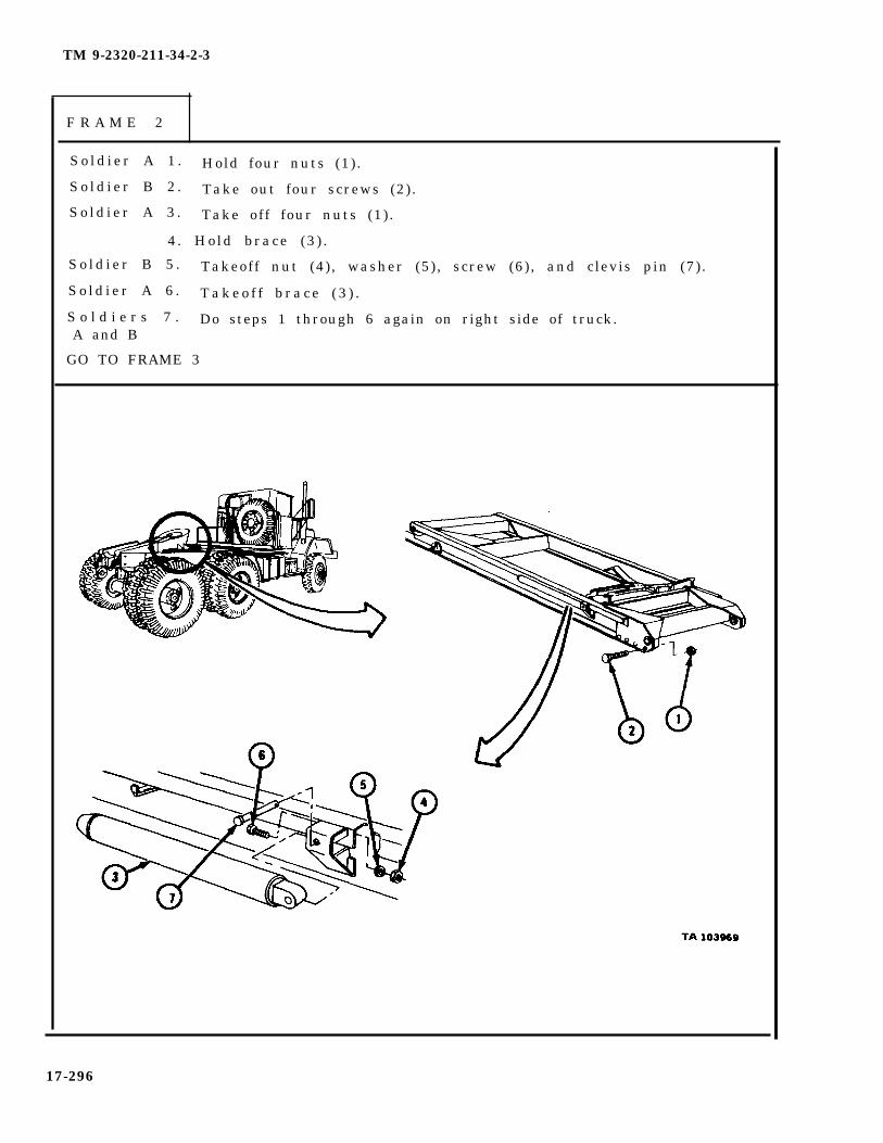
TM 9-2320-211-34-2-3
F R A M E 2
S o l d i e r A 1 . Hold four nuts (1) .
S o l d i e r B 2 . Take out four screws (2).
S o l d i e r A 3 . Take off four nuts (1) .
4 . Hold brace (3 ) .
S o l d i e r B 5 . Takeoff nut (4), washer (5), screw (6), and clevis pin (7).
S o l d i e r A 6 . T a k e o f f b r a c e ( 3 ) .
S o l d i e r s 7 . Do steps 1 through 6 again on right side of truck.A and B
GO TO FRAME 3
17-296
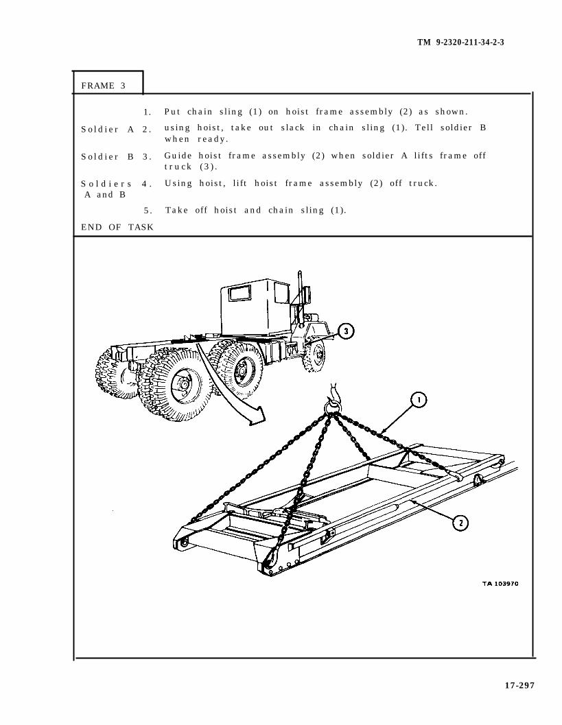
TM 9-2320-211-34-2-3
FRAME 3
1. Put chain sling (1) on hoist frame assembly (2) as shown.
S o l d i e r A 2 . using hoist, take out slack in chain sling (1). Tell soldier Bwhen ready.
S o l d i e r B 3 . Guide hoist frame assembly (2) when soldier A lifts frame offt r u c k ( 3 ) .
S o l d i e r s 4 . Using hoist, lift hoist frame assembly (2) off truck.A and B
5. Take off hoist and chain sling (1).
END OF TASK
17-297

TM 9-2320-211-34-2-3
c. Cleaning There are no special cleaning procedures needed. Refer tocleaning procedures given in Part 1, para 1-3.
d. Inspection and Repair. Check that hoist frame assembly has no cracks,elongated holes or bent or broken members. Repair is limited to straightening bentmembers and brazing or welding of cracks. Refer to FM 43-2 and TM 9-237. Ifmore repair is needed, get a new hoist frame assembly.
17-298

TM 9-2320-211-34-2-3
e . R e p l a c e m e n t .
FRAME 1
S o l d i e r A 1 . Put on hoist and chain sling (1) as shown.
S o l d i e r B 2 . Guide hoist frame assembly (2) when soldier A lifts it.
S o l d i e r A 3 . Lift hoist frame assembly (2) and put it on truck.
S o l d i e r s 4 . Take off hoist and chain sling (1).A and B
GO TO FRAME 2
17-299

TM 9-2320-211-34-2-3
FRAME 2
S o l d i e r A 1 . Hold brace (1) in place.
S o l d i e r B 2 . Put in clevis pin (2), screw (3), nut (4), and washer (5).
S o l d i e r A 3 . Put in and hold four screws (6).
S o l d i e r B 4 . Put on and tighten four nuts (7).
S o l d i e r s 5 . Do steps 1 through 4 on right side of truck.A and B
GO TO FRAME 3
17-300

TM 9-2320-211-34-2-3
FRAME 3
1.
2.
3.
4.
Put in two keepers (1) , springs (2), and bolts (3) .
Put on two washers (4) and nuts (5).
Put in two cotter pins (6).
Do steps 1 through 3 again on right side of truck.
N O T E
Follow-on Maintenance Action Required:
1. Replace control valve. Refer to para 17-21.2. Replace hoist hydraulic cylinders. Refer to
para 17-24.3. Replace hoist roller arms. Refer to para 17-28.4. Replace dump truck body. Refer to Part 2,
para 16-28.5. Replace hoist control l inkage. Refer to para 17-22.6 . Fill hydraulic system. Refer to LO 9-2320-211-12.
END OF TASK
17-301

TM 9-2320-211-34-2-3
17-24. DUMP BODY HOIST CYLINDER REMOVAL. REPAIR. AND REPLACEMENT(TRUCK M51A2).
NOTE
This task is the same for the left and righthoist cylinder assemblies. This task is shownfor the left hoist cylinder assembly.
TOOLS: No special tools required
SUPPLIES: Solvent, dry cleaning, type II (SD-2), Fed. Spec P-D-680Lubricating oil, ICE, OE/HDO 10, MIL-L-2104Cylinder headCylinder head
PERSONNEL : TW O
EQUIPMENT CONDITION :
a . Pre l iminary Procedure .
F R A M E 1
gland packingpreformed packing
Truck parked, engine off , handbrake set.
1.
2.
3.
Start engine and raise dump body (1). Refer to TM 9-2320-211-10.
Put two hoist braces (2), one on each side, in place under dump body (1).
Lower dump body (1) onto braces (2) and stop engine. Refer toTM 9-2320-211-10.
END OF TASK
17-302
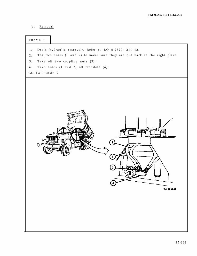
TM 9-2320-211-34-2-3
b . Removal.
FRAME 1
1. Drain hydraulic reservoir. Refer to LO 9-2320- 211–12.
2. Tag two hoses (1 and 2) to make sure they are put back in the right place.
3. Take off two coupling nuts (3).
4. Take hoses (1 and 2) off manifold (4).
GO TO FRAME 2
17-303
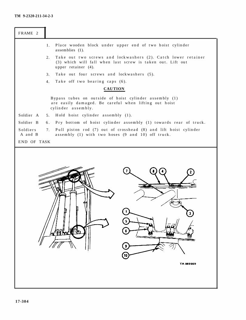
TM 9-2320-211-34-2-3
FRAME 2
1. Place wooden block under upper end of two hoist cylinderassemblies (1).
2. Take out two screws and lockwashers (2). Catch lower retainer(3) which will fall when last screw is taken out. Lift outupper retainer (4).
3. Take out four screws and lockwashers (5).
4. Take off two bearing caps (6) .
CAUTION
Soldier A
Soldier B
SoldiersA and B
Bypass tubes on outside of hoist cylinder assembly (1)are easily damaged. Be careful when lifting out hoistcylinder assembly.
5. Hold hoist cylinder assembly (1).
6 . Pry bottom of hoist cylinder assembly (1) towards rear of truck.
7. Pull piston rod (7) out of crosshead (8) and lift hoist cylinderassembly (1) with two hoses (9 and 10) off truck.
END OF TASK
17-304

TM 9-2320-211-34-2-3
c . D i s a s s e m b l y .
F R A M E 1
1.
2.
3.
4.
5.
6 .
Take out
Take outpacking .
Take out
three screws and lockwashers (1).
cylinder head and gland (2) and packing (3). Throw away
bolts and lockwashers (4) .
Take off cylinder head (5) with preformed packing (6) .
Take off and throw away preformed packing (6).
Slide piston rod assembly (7) out of tube assembly (8). Be careful not todamage bore of tube assembly.
GO TO FRAME 2
17-305

TM 9-2320-211-34-2-3
FRAME 2
1. Clamp piston rod (1) in vise with soft jaw caps.
2. Take out and throw away cotter pin (2).
3. Take off nut (3) .
4. Take off piston (4) .
5. Take piston rod (1) out of vise.
6 . Using piston ring remover, take three piston rings (5) off piston (4).
GO TO FRAME 3
17-306
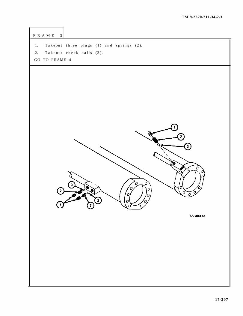
TM 9-2320-211-34-2-3
F R A M E 3
1. Takeout three plugs (1) and springs (2) .
2. Takeout check bal ls (3 ) .
GO TO FRAME 4
17-307
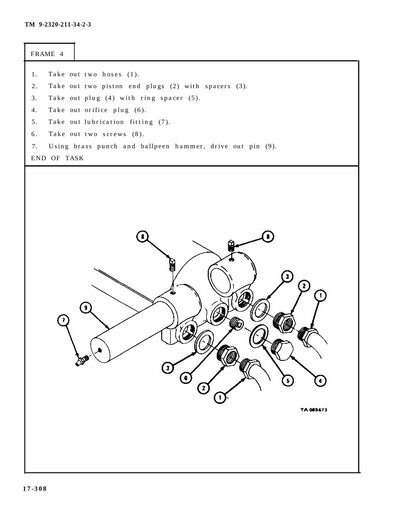
TM 9-2320-211-34-2-3
FRAME 4
1. Take out
2. Take out
3. Take out
4. Take out
5. Take out
6. Take out
two hoses (1) .
two piston end plugs (2) with spacers (3).
plug (4) with ring spacer (5).
orif ice plug (6) .
lubrication fitting (7).
two screws (8).
7. Using brass punch and ballpeen hammer, drive out pin (9).
END OF TASK
17-308

d . C l e a n i n g .are open.
e . Inspection.
FRAME 1
TM 9-2320-211-34-2-3
WARNING
Dry cleaning solvent is flammable. Do not usenear an open flame. Keep a fire extinguishernearby when solvent is used. Use only in well–ventilated places. Failure to do this may resultin injury to personnel and damage to equipment.
Clean all parts in solvent. Make sure grease and oil passages
1.
2.
3.
4.
5.
6 .
Check that tube assembly (1) is not cracked and does not have broken welds.Check that inner bore of tube assembly is not scratched or scored, and hasno badly worn surfaces.
Check that oil passages in tube assembly (1) are not clogged or burred.Check that screw threads are not burred, stripped or crossed.
Check that cylinder head (2) and gland (3) are not cracked or broken,and that bores are not burred.
Check that piston (4) and three piston rings (5) are not nicked, scratchedor cracked, and that they do not have worn surfaces.
Check that piston rod (6) is not bent, nicked or scratched, and that itdoes not have burred, stripped or crossed threads.
Check that pin (7) is not chipped or scored, and that it has no flat spots.
END OF TASK
17-309

TM 9-2320-211-34-2-3
f . Repair.
(1) Using thread fi le, f ix damaged threads.
(2) Get new parts for all other damaged parts.
g . Assembly .
FRAME 1
1. Using brass hammer, drive pin (1) into bore in tube assembly (2), untilit is centered.
2. Put in
3. Put in
4 . Put in
5. Put in
6 . Put in
7. Put in
two screws (3).
lubrication fitting (4).
orif ice plug (5) .
plug (6) with ring spacer (7).
two piston end plugs (8) with spacers (9).
two hoses (10) .
GO TO FRAME 2
17-310

TM 9-2320-211-34-2-3
1. Put three check balls (1) and springs (2) into bores in tube assembly (3).
2. Put in three plugs (4).
GO TO FRAME 3
17-311
F R A M E 2
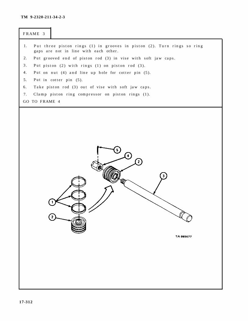
TM 9-2320-211-34-2-3
FRAME 3
1. Put three piston rings (1) in grooves in piston (2). Turn rings so ringgaps are not in line with each other.
2. Put
3. Put
4. Put
5. Put
grooved end of piston rod (3) in vise with soft jaw caps.
piston (2) with rings (1) on piston rod (3) .
on nut (4) and line up hole for cotter pin (5).
in cotter pin (5).
6. Take piston rod (3) out of vise with soft jaw caps.
7. Clamp piston ring compressor on piston rings (1).
GO TO FRAME 4
17-312

TM 9-2320-211-34-2-3
F R A M E 4
1.
2.
3.
4 .
5.
6 .
7.
8.
Put a coat of oil in bore of cylinder assembly (1).
Carefully clamp closed end of cylinder assembly (1) in vise with soft jawclamps.
Carefully push piston rod assembly (2) into bore of cylinder assembly (1).
Take off piston ring compressor.
Put preformed packing (3) in place on cylinder head (4).
Slide cylinder head (4) with preformed packing (3) onto piston rod assembly(2) and into place against cylinder assembly (1). Line up screw holes.
Put in 10 screws (5) and lockwashers (6).
Tighten screws (5) in the tightening order shown to 35 pound-feet.
GO TO FRAME 5
17-313
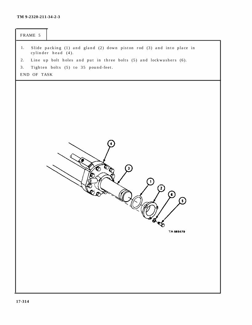
TM 9-2320-211-34-2-3
FRAME 5
1. Slide packing (1) and gland (2) down piston rod (3) and into place incylinder head (4) .
2. Line up bolt holes and put in three bolts (5) and lockwashers (6).
3. Tighten bolts (5) to 35 pound-feet.
END OF TASK
17-314

TM 9-2320-211-34-2-3
h . Replacement.
FRAME 1
CAUTION
SoldiersA and B
Soldier A
Soldier B
SoldiersA and B
Soldier A
Soldier B
1.
2.
3.
4.
5.
6 .
7.
8.
9.
Bypass tubes on outside of hoist cylinder assembly areeasily damaged. Be careful when replacing hoistcylinder assembly.
Lift hoist cylinder assembly (1) into place on truck. Seat pinof hoist cylinder assembly in two bearing seats (2).
Place wood block under end of cylinder assembly (1).
Put two bearing caps (3) in place.
Put in four screws and lockwashers (4).
Aline and slide piston rod (5) into bore in crosshead (6). Lineup groove in piston rod with slots in crosshead.
Hold hoist cylinder assembly (1) in place.
Put upper retainer (7) in slot in crosshead (6) and hold lowerretainer (8) in place in slot in crosshead.
Put in two screws and lockwashers (9).
Take out wood block from under cylinder assembly (1).
GO TO FRAME 2
17-315
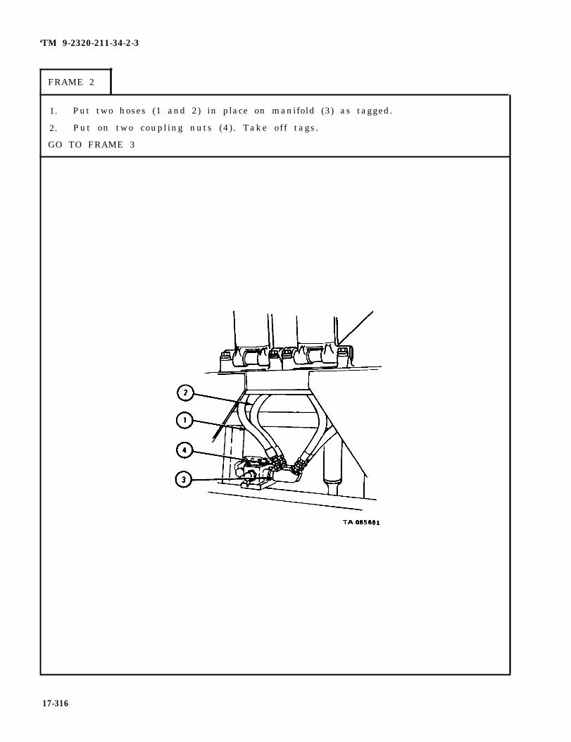
‘TM 9-2320-211-34-2-3
FRAME 2
1. Put two hoses (1 and 2) in place on manifold (3) as tagged.
2. Put on two coupling nuts (4). Take off tags.
GO TO FRAME 3
17-316

TM 9-2320-211-34-2-3
FRAME 3
1. Fill hydraulic reservoir. Refer to LO 9-2320-211-12.
2. Raise dump body (1) far enough to clear two hoist braces (2). Refer toTM 9-2320-211-10.
3. Swing hoist braces (2), one on each side, down to stowed position.
4. Lower dump body and stop engine. Refer to TM 9-2320-211-10.
N O T E
Follow-on Maintenance Action Required:
Check hoist assembly for proper operation. Refer toTM 9-2320-211-10.
END OF TASK
17-317
TM 9-2320-211-34-2-3
17-25. HOIST PUMP REPAIR (TRUCK M51A2).
TOOLS: No special tools required
SUPPLIES: Solvent, dry cleaning, type II (SD-2), Fed. Spec P-D-680Oil seal assembly
PERSONNEL: One
EQUIPMENT CONDITION: Truck parked, engine off , handbrake set.
a . Pre l iminary Procedures .
(1) Drain hydraulic reservoir. Refer to LO 9-2320-211-12.
(2) Take power take off propeller shaft off hydraulic hoist pump assembly.Refer to TM 9-2320-211-20.
(3) Remove hydraulic hoist pump assembly. Refer to TM 9-2320-211-20.
17-318

TM 9-2320-211-34-2-3
b . Disassembly.
FRAME 1
1.
2.
3.
4.
5.
6.
7.
Carefully clamp hoist pump assembly (1) in vise with soft jaw caps.
Take out key (2).
Take out eight screws and lockwashers (3).
Pull off front end cover (4) with two bearings (5), oil seal assembly (6),and two pins (7).
Take bearings (5) and oil seal assembly (6) out of front end cover (4).Refer to Part 1, para 7-7. Throw away oil seal assembly.
Pull out pins (7).
Take hoist pump assembly (1) out of vise.
GO TO FRAME 2
17-319
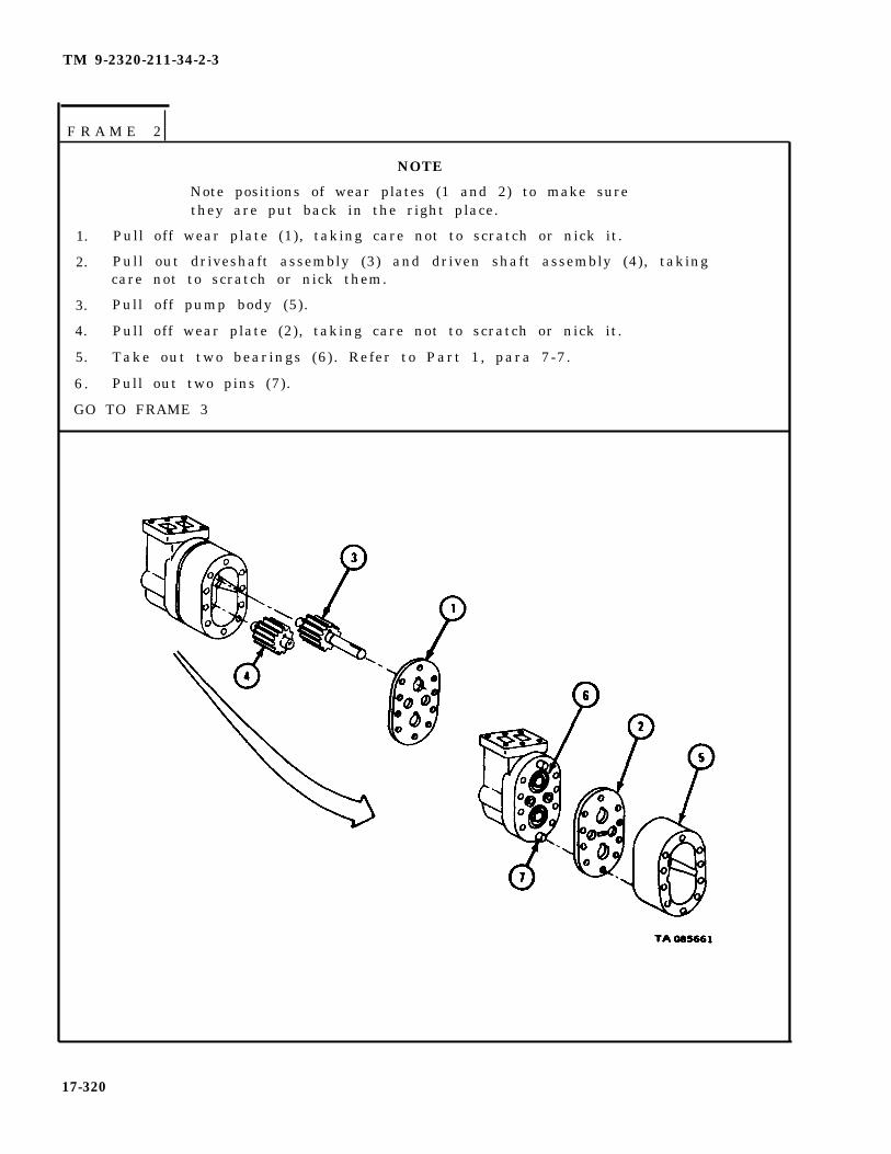
TM 9-2320-211-34-2-3
F R A M E 2
NOTE
Note positions of wear plates (1 and 2) to make surethey are put back in the right place.
1. Pull off wear plate (1), taking care not to scratch or nick it.
2. Pull out driveshaft assembly (3) and driven shaft assembly (4), takingcare not to scratch or nick them.
3. Pull off pump body (5).
4. Pull off wear plate (2), taking care not to scratch or nick it.
5. Take out two bearings (6). Refer to Part 1, para 7-7.
6 . Pull out two pins (7).
GO TO FRAME 3
17-320
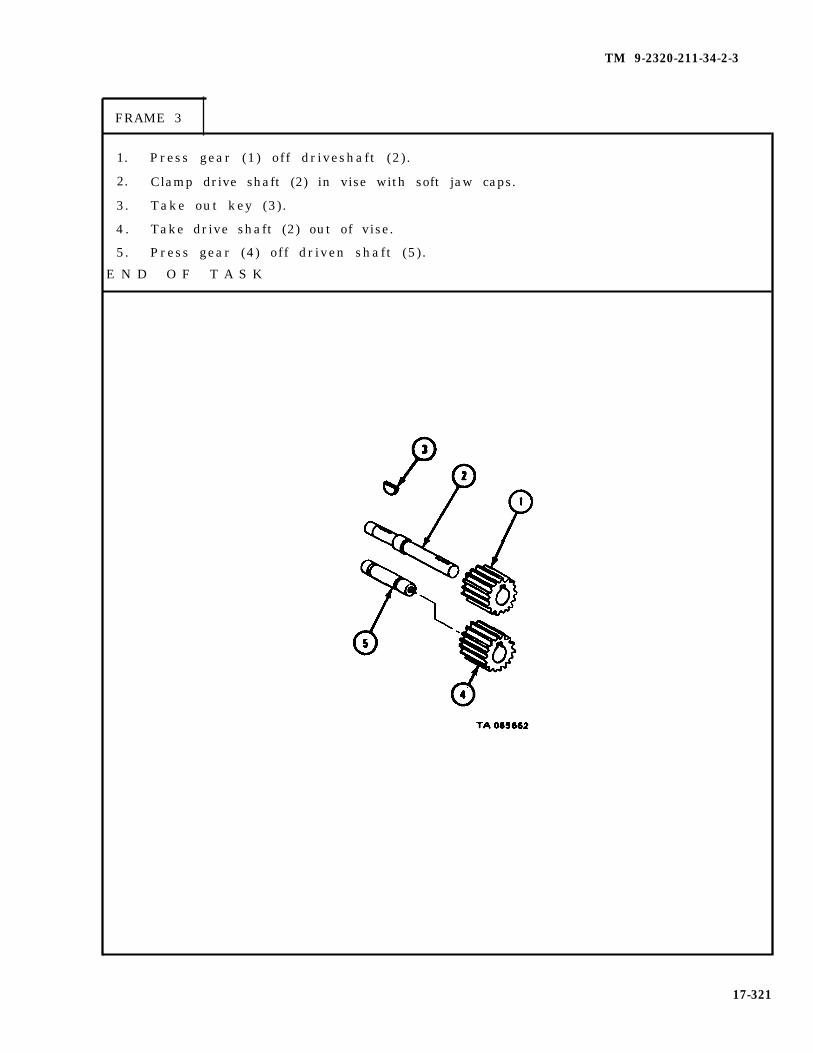
TM 9-2320-211-34-2-3
FRAME 3
1.
2.
3.
4 .
5.
Press gear (1) off driveshaft (2) .
Clamp drive shaft (2) in vise with soft jaw caps.
Take out key (3).
Take drive shaft (2) out of vise.
Press gear (4) off driven shaft (5) .
17-321
E N D O F T A S K

TM 9-2320-211-34-2-3
WARNING
Dry cleaning solvent is flammable. Do not usenear an open flame. Keep a fire extinguishernearby when solvent is used. Use only in well-ventilated places. Failure to do this may resultin injury to personnel and damage to equipment.
Do not dry bearings with compressed air. Spinningbearings may explode, causing injury to personneland damage to equipment.
c . Cleaning. Clean all parts with solvent.
17-322
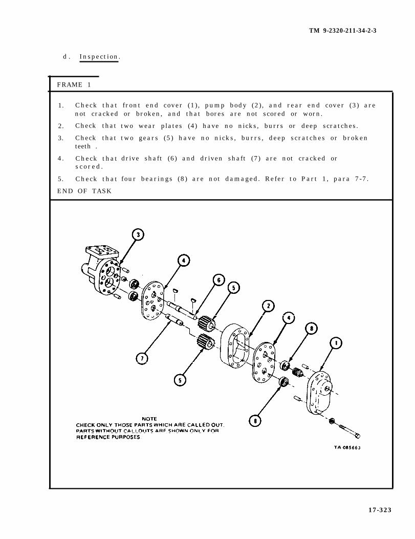
TM 9-2320-211-34-2-3
d . Inspection.
FRAME 1
1. Check that front end cover (1), pump body (2), and rear end cover (3) arenot cracked or broken, and that bores are not scored or worn.
2. Check that
3. Check thatteeth .
4. Check thats c o r e d .
5. Check that
END OF TASK
two wear plates (4) have no nicks, burrs or deep scratches.
two gears (5) have no nicks, burrs, deep scratches or broken
drive shaft (6) and driven shaft (7) are not cracked or
four bearings (8) are not damaged. Refer to Part 1, para 7-7.
17-323

TM 9-2320-211-34-2-3
e . Repair.
(1) Get new hoist pump assembly if front end cover, pump body or rearend cover are damaged.
(2) Use honing stone to smooth raised metal from gears. If gears cannotbe repaired with honing stone, get new ones in their place.
(3) Get new parts for all other damaged parts.
f . Assembly .
FRAME 1
1. Press gear (1) onto driven shaft (2) .
2. Tap key (3) into slot in driveshaft (4).
3. Line up keyway in gear (5) with key (3) in driveshaft (4).
4. Press gear (5) onto key (3) and driveshaft (4) .
GO TO FRAME 2
17-324

TM 9-2320-211-34-2-3
1.
2.
3.
4.
5.
6 .
NOTE
Be sure to put wear plates (1 and 2) back in positionsnoted in disassembly.
Tap two pins (3) into bores in rear end cover (4).
Press two bearings (5) into bores in rear end cover (4) . Refer to Part 1,para 7-7.
Put wear plate (1) on pins (3) and push it in place against rear end cover(4). Take care not to scratch or nick wear plate.
Put pump body (6) on pins (3) and push it in place against wear plate(1). Notch on pump body must be on same side as notch on rear endc o v e r ( 4 ) .
Put driveshaft assembly (7) and driven shaft assembly (8) into boresof bearings (5), taking care not to scratch or nick bearings or shafts.
Put wear plate (2) on driveshaft assembly (7) and driven shaft assembly(8) and push it in place against pump body (6). Take care not to scratchor nick wear plate.
GO TO FRAME 3
17-325
FRAME 2

TM 9-2320-211-34-2-3
FRAME 3
1.
2.
3.
4 .
5.
6 .
7.
8.
9.
Tap two pins (1) into front end cover (2).
Press oil seal assembly (3) and two bearings (4) into front end cover (2).Refer to Part 1, para 7-7.
Line up bearings (4) in front end cover (2) with drive shaft assembly (5)and driven shaft assembly (6).
Push front end cover (2) with pins (1), oil seal assembly (3), and bearings(4) into place against hoist pump assembly (7). Notch on front end covermust be on same side as notches on hoist pump assembly.
Carefully clamp hoist pump assembly (7) in vise with soft jaw caps.
Put in eight screws and lockwashers (8).
Tighten screws (8) to 30 to 40 pound-feet.
Tap key (9) into slot in driveshaft assembly (5).
Take hoist pump assembly (7) out of vise.
NOTE
Follow-on Maintenance Action Required:
1. Replace hoist pump assembly. Refer toTM 9-2320-211-20.
2. Replace power take off to hydraulic hoist pump.Refer to TM 9-2320-211-20.
3. Fill hydraulic reservoir. Refer toLO 9-2320-211-12.
4. Check hoist pump assembly for proper operation.Refer to TM 9-2320-211-10.
END OF TASK
17-326

TM 9-2320-211-34-2-3
17-26. HOIST CYLINDER PACKING REMOVAL AND REPLACEMENT.
NOTE
This task is the same for right and left hoistcylinder packings. This task is shown forthe right side hoist cylinder packing.
TOOLS: No special tools required
SUPPLIES: Preformed packing setArtillery and automotive grease, type GAA, MIL-G-10924
PERSONNEL: One
EQUIPMENT CONDITION: Truck parked, engine off , handbrake set.
a . Pre l iminary Procedures .
(1) Start engine and raise dump body. Refer to TM 9-2320-211-10.
(2) Put in safety brace. Refer to TM 9-2320-211-20.
(3) Stop engine. Refer to TM 9-2320-211-10.
17-327
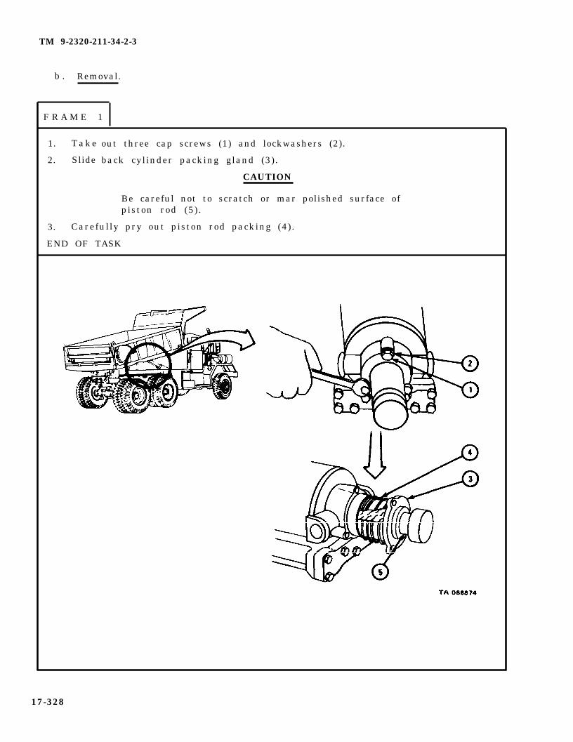
TM 9-2320-211-34-2-3
b . Removal.
F R A M E 1
1. T a k e
2. Slide
out three cap screws (1) and lockwashers (2).
back cylinder packing gland (3).
CAUTION
Be careful not to scratch or mar polished surface ofpiston rod (5) .
3. Carefully pry out piston rod packing (4).
END OF TASK
17-328

TM 9-2320-211-34-2-3
c . Replacement.
FRAME 1
1.
2.
3 .
4.
NOTE
Packing rings are split so they can be put on easily.Be sure to put joints around piston rod to make surethere is a tight seal.
Put a coat of grease on packing (1) and piston rod (2).
Carefully push packing (1) around piston rod (2) using block of wood orbrass bar .
Aline holes in cylinder packing gland (3) with holes (4).
Put in three cap screws (5) and lockwashers (6).
NOTE
Follow-on Maintenance Action Required:
1. Start engine. Refer to TM 9-2320-211-10.2. Take out safety braces. Refer to
TM 9-2320-211-20.3. Lower dump body and chink that there are no
leaks. Refer to TM 9-2320-211-10.4 . Stop engine. Refer to TM 9-2320-211-10.
END OF TASK
17-329

TM 9-2320-211-34-2-3
17-27. HOIST CABLE UPPER BOOM HEAD AND UPPER BOOM FOOT SHEAVESAND GUARD REMOVAL AND REPLACEMENT (TRUCK M543A2).
TOOLS: None
SUPPLIES: Solvent, dry cleaning, type II (SD-2), Fed. Spec P-D-680
PERSONNEL: One
EQUIPMENT CONDITION: Truck parked, engine off , handbrake set.
a. P r e l i m i n a r y P r o c e d u r e . Lower crane hook to f loor and slack off hoistcable. Refer to TM 9-2320-211-10.
b . Removal.
FRAME 1
1. On right side of truck, take out two capscrews with washers (1).
2. On left side of truck, take out two cap screws with washers (2).
3. Take off cable guard (3) .
GO TO FRAME 2
17-330
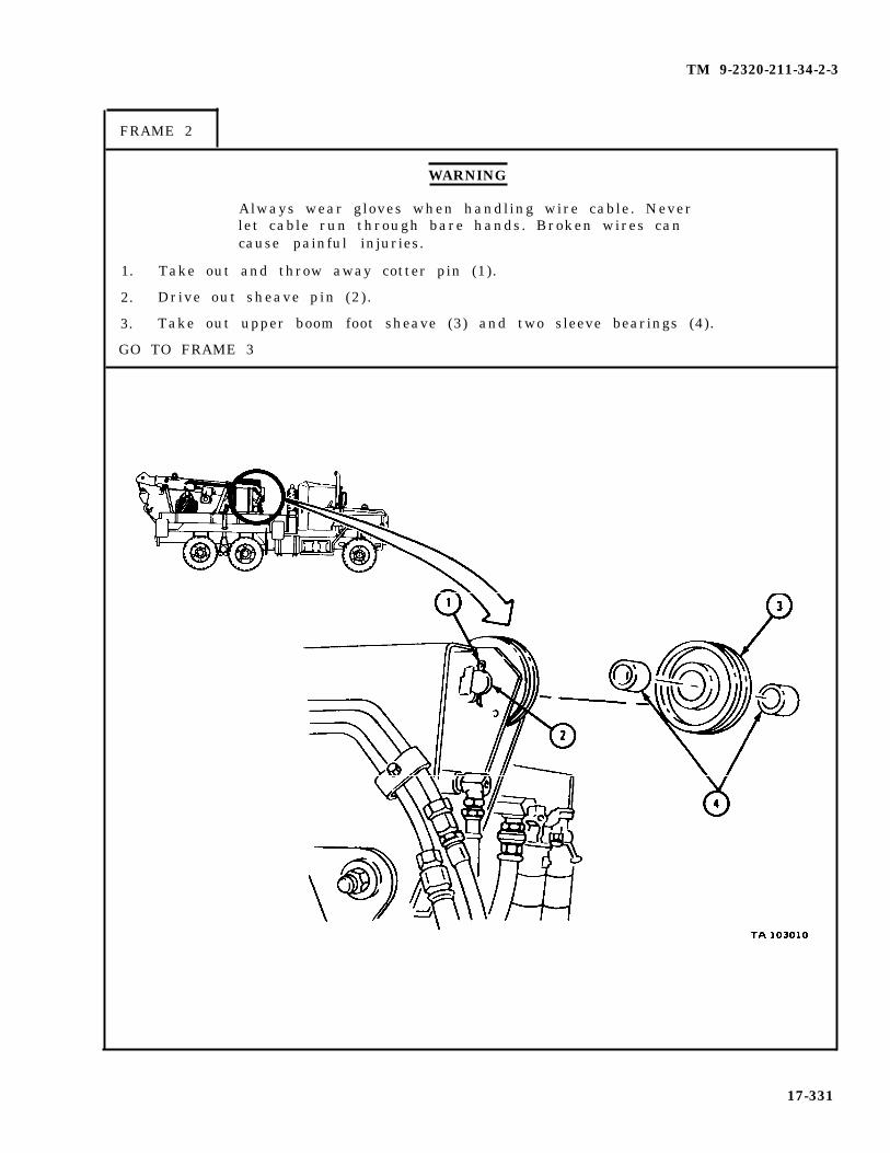
TM 9-2320-211-34-2-3
FRAME 2
WARNING
Always wear gloves when handling wire cable. Neverlet cable run through bare hands. Broken wires cancause painful injuries.
1. Take out and throw away cotter pin (1).
2. Drive out sheave pin (2) .
3. Take out upper boom foot sheave (3) and two sleeve bearings (4).
GO TO FRAME 3
17-331

TM 9-2320-211-34-2-3
FRAME 3
1. Take off lubrication fitting (1).
2. Take out and throw away cotter pin (2).
3. Drive out pin (3).
4. Take out two boom head sheaves (4), two thrust washers (5), and flatwasher (6 ) .
END OF TASK
17-332
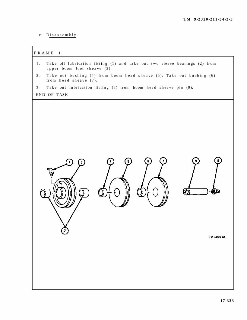
TM 9-2320-211-34-2-3
c . D i s a s s e m b l y .
F R A M E 1
1. Take off lubrication fitting (1) and take out two sleeve bearings (2) fromupper boom foot sheave (3) .
2. Take out bushing (4) from boom head sheave (5). Take out bushing (6)from head sheave (7) .
3. Take out lubrication fitting (8) from boom head sheave pin (9).
END OF TASK
17-333
TM 9-2320-211-34-2-3
WARNING
Dry cleaning solvent is flammable. Do not usenear an open flame. Keep a fire extinguishernearby when solvent is used. Use only in well-ventilated places. Failure to do this may resultin injury to personnel and damage to equipment.
d. C l e a n i n g . Using a stiff bristle brush, clean all parts with dry cleaningsolvent wipe dry with clean, l int-free cloth.
e . Inspect ion and Repair .
(1) Check cable sheaves for cracks, breaks or damaged cable grooves.
(2) Check cable bushings, washers, and bearings for wear and damage.
(3) Check boom head sheave pin for lubrication stoppage.
(4) Check upper boom front sheave and all lubrication fittings forlubrication stoppage.
(5) Replace all damaged parts.
17-334

TM 9-2320-211-34-2-3
f . Assembly .
FRAME 1
1. Put lubrication fitting (1) on upper boom foot sheave (2).
2. Put two sleeve bearings (3) in upper boom foot sheave (2).
3. Put bushing (4) in boom head sheave (5). Put bushing (6) in boom headsheave (7 ) .
END OF TASK
17-335

TM 9-2320-211-34-2-3
g . R e p l a c e m e n t .
F R A M E 1
WARNING
Always wear gloves when handling wire cable.Never let cable run through bare hands. Brokenwires can cause painful injuries.
1. On left side of truck, hold loop (1) of cable at top of boom head (2). Putcotter pin end of pin (3) in hole (4) and push pin half way to matching holeon other side of boom head (2).
2. Put thrust washer (5) on pin (3).
3. Put sheave (6) on pin (3). Put loop (1) of cable in groove of sheave (6).
4. Put flat washer (7) on pin (3).
GO TO FRAME 2
17-336

TM 9-2320-211-34-2-3
FRAME 2
1. Hold bend (1) of cable at top of boom head (2).
2. Hold sheave (3) in boom head (2) and put cable bend (1) in groove ofsheave (3 ) .
3. Aline hole of sheave (3) with pin (4) and tap pin (4) through sheave (3).
4 . Put thrust washer (5) on pin (4).
5. Aline flat side of pin (4) with flat side of hole (6) on left side of boomhead . Tap in pin (4).
6 . Put in cotter pin (7).
7. Put in lubrication fitting (8). Put in lubrication fitting (9).
GO TO FRAME 3
17-337

TM 9-2320-211-34-2-3
FRAME 3
1. On left side of truck, put cotter pin end of sheave pin (1) in sheave pinhole (2) . Push pin (1) half way to matching hole on other side of boom foot.
2. Put sleeve bearing (3) on pin (1).
3. Put upper boom foot sheave (4) on pin (1). Put cable (5) in groove ofsheave (4 ) .
4. Aline hole in sleeve bearing (6) with pin (1). Tap pin (1) through sleevebear ing (6 ) .
5. Aline flat side of pin (1) with flat side of hole (7) on right side of boom foot.Tap in pin (1).
6 . Put in cotter pin (8).
7. Lubricate upper boom foot sheave. Refer to LO 9-2320-211-12.
17-338
G O T O F R A M E 4
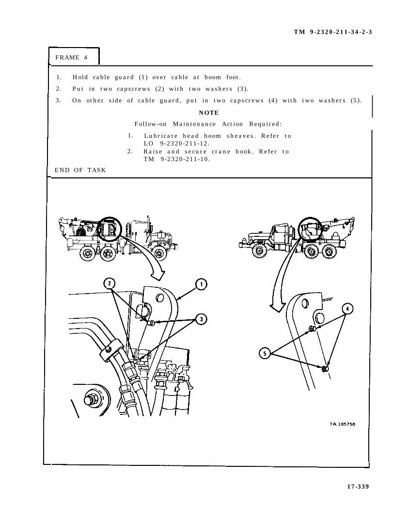
TM 9-2320-211-34-2-3
FRAME 4
1. Hold cable guard (1) over cable at boom foot.
2. Put in two capscrews (2) with two washers (3).
3. On other side of cable guard, put in two capscrews (4) with two washers (5).
NOTE
Follow-on Maintenance Action Required:
1. Lubricate head boom sheaves. Refer toLO 9-2320-211-12.
2. Raise and secure crane hook. Refer toTM 9-2320-211-10.
END OF TASK
17-339
TM 9-2320-211-34-2-3
17-28. HOIST ROLLER ARM ASSEMBLY REMOVAL, REPAIR, AND REPLACEMENT(TRUCK M51A2).
NOTE
This task is the same for the right and left rollerarm assemblies. This task is shown for the leftroller arm assembly.
TOOLS: No special tools required
SUPPLIES : Solvent, dry cleaning, type II (SD-2), Fed. Spec P-D-680Wooden block, 4 x 4 inches, 4 feet long
PERSONNEL : Two
EQUIPMENT CONDITION : Truck parked, engine off , handbrake set.
17-340

TM 9-2320-211-34-2-3
a. Pre l iminary Procedure .
FRAME 1
S o l d i e r A 1 . Start engine and raise dump body (1). Refer to TM 9-2320-211-10.
S o l d i e r B 2 . Swing two hoist braces (2), one on each side, into place underdump body (1) .
S o l d i e r A 3 . Lower dump body (1) onto hoist braces (2) and stop engine. Referto TM 9-2320-211-10.
END OF TASK
17-341
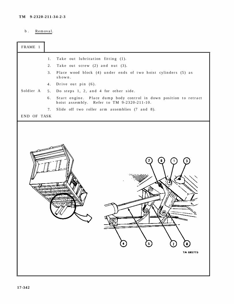
TM 9-2320-211-34-2-3
b . Removal.
FRAME 1
Soldier A
1.
2.
3.
4.
5.
6 .
7.
END OF TASK
Take out lubrication fitting (1).
Take out screw (2) and nut (3).
Place wood block (4) under ends of two hoist cylinders (5) asshown.
Drive out pin (6) .
Do steps 1, 2, and 4 for other side.
Start engine. Place dump body control in down position to retracthoist assembly. Refer to TM 9-2320-211-10.
Slide off two roller arm assemblies (7 and 8).
17-342

TM 9-2320-211-34-2-3
c. Disassembly.
F R A M E 1
1. Put roller assembly into vise.
2 . Take out two lubrication fittings (1).
3. Drive out two pins (2).
4 0 Drive out pin (3) .
5. Take out roller (4) .
6 . Press out two bushings (5).
END OF TASK
1 7 - 3 4 3
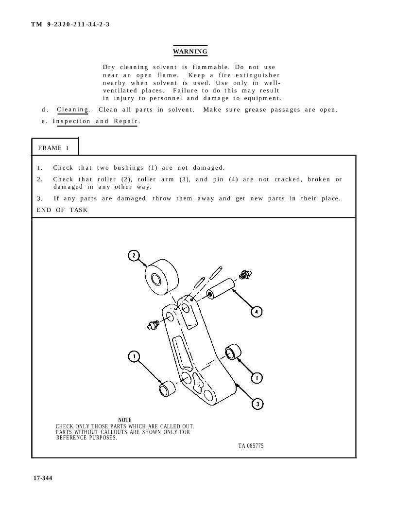
TM 9-2320-211-34-2-3
WARNING
Dry cleaning solvent is flammable. Do not usenear an open flame. Keep a f ire extinguishernearby when solvent is used. Use only in well-ventilated places. Failure to do this may resultin injury to personnel and damage to equipment.
d . Cleaning. Clean all parts in solvent. Make sure grease passages are open.
e . Inspect ion and Repair .
1. Check that two bushings (1) are not damaged.
2. Check that roller (2), roller arm (3), and pin (4) are not cracked, broken ordamaged in any other way.
3. If any parts are damaged, throw them away and get new parts in their place.
END OF TASK
NOTECHECK ONLY THOSE PARTS WHICH ARE CALLED OUT.PARTS WITHOUT CALLOUTS ARE SHOWN ONLY FORREFERENCE PURPOSES.
TA 085775
17-344
FRAME 1

TM 9-2320-211-34-2-3
f . Assembly .
F R A M E 1
1. Press two bushings (1) into roller arm (2).
2. Put roller arm (2) into vise.
3. Put roller (3) in place in slot in roller arm (2).
4 . Aline holes in pin (4) with holes in roller arm (2).
5. Drive pin (4) through holes in roller arm (2) and roller (3).
6 . Drive two pins (5) into roller arm (2) and pin (4).
7. Put in two lubrication fittings (6).
END OF TASK
17-345
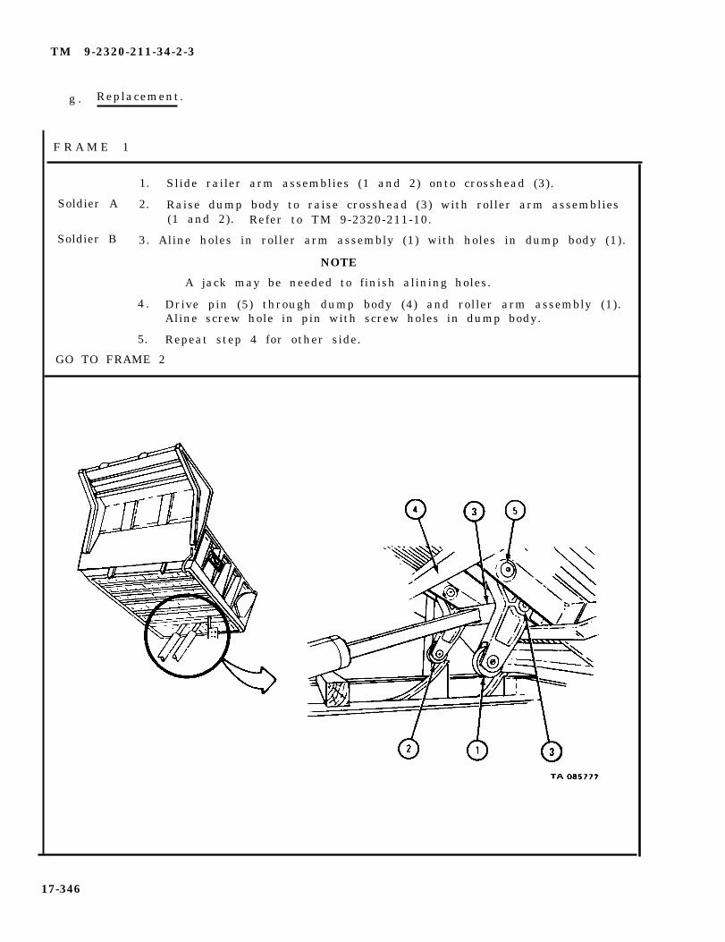
TM 9-2320-211-34-2-3
g . Replacement.
F R A M E 1
Soldier A
Soldier B
1. Slide railer arm assemblies (1 and 2) onto crosshead (3).
2. Raise dump body to raise crosshead (3) with roller arm assemblies(1 and 2). Refer to TM 9-2320-211-10.
3. Aline holes in roller arm assembly (1) with holes in dump body (1).
NOTE
A jack may be needed to finish alining holes.
4 . Drive pin (5) through dump body (4) and roller arm assembly (1).Aline screw hole in pin with screw holes in dump body.
5. Repeat step 4 for other side.
GO TO FRAME 2
17-346
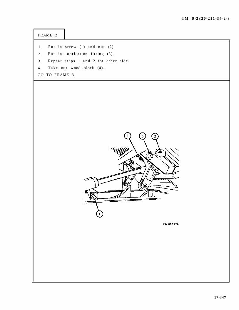
TM 9-2320-211-34-2-3
FRAME 2
1. Put in screw (1) and nut (2).
2. Put in lubrication fitting (3).
3. Repeat steps 1 and 2 for other side.
4 . Take out wood block (4).
GO TO FRAME 3
17-347

TM 9-2320-211-34-2-3
FRAME 3
1. Grease roller arm assemblies. Refer to LO 9-2320-211-12.
2. Raise dump body (1) far enough to free two hoist braces (2). Refer toTM 9-2320-211-10.
3. Swing hoist braces (2), one on each side, down to stowed position.
4. Lower dump body (1) and stop engine. Refer to TM 9-2320-211-10.
END OF TASK
17-348
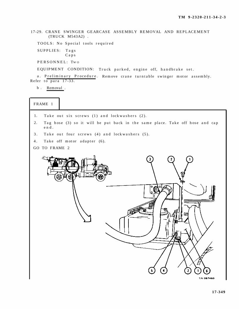
TM 9-2320-211-34-2-3
17-29. CRANE SWINGER GEARCASE ASSEMBLY REMOVAL AND REPLACEMENT(TRUCK M543A2) .
TOOLS: No Special tools required
SUPPLIES: T a g sCaps
PERSONNEL: TW O
EQUIPMENT CONDITION: Truck parked, engine off , handbrake set.
a . Pre l iminary Procedure . Remove crane turntable swinger motor assembly.Refer to para 17-33.
b . Removal .
FRAME 1
1. Take out six screws (1) and lockwashers (2).
2. Tag hose (3) so it will be put back in the same place. Take off hose and cape n d .
3 . Take out four screws (4) and lockwashers (5).
4 . Take off motor adapter (6).
GO TO FRAME 2
17-349

TM 9-2320-211-34-2-3
FRAME 2
1. Take off four screws (1) and lockwashers (2) .
2. Take off gearcase end cap (3) .
S o l d i e r s 3 . Pry under gearcase (4) and slide it off turntable (5).A and B
4 . Hook chain hoist to gearcase (4) and lift it off vehicle.
END OF TASK
17-350

TM 9-2320-211-34-2-3
c . Replacement.
FRAME 1
1. Hook chain hoist to gearcase assembly (1) and lift it onto vehicle.
S o l d i e r s 2 . Put swinger gearcase assembly (1) in place on turntable (2) andA and B aline holes.
3. Put gearcase end cap (3) in place on gearcase assembly (1) andaline holes.
4. Put in four screws (4) and lockwashers (5).
GO TO FRAME 2
17-351
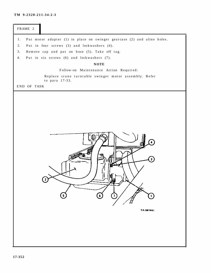
TM 9-2320-211-34-2-3
FRAME 2
1. Put motor adapter (1) in place on swinger gearcase (2) and aline holes.
2. Put in four screws (3) and lockwashers (4).
3. Remove cap and put on hose (5). Take off tag.
4. Put in six screws (6) and lockwashers (7).
NOTE
Follow-on Maintenance Action Required:
Replace crane turntable swinger motor assembly. Referto para 17-33.
END OF TASK
17-352

TM 9-2320-211-34-2-3
17-30. CRANE SWINGER GEARCASE ASSEMBLY REPAIR (TRUCK M543A2).
TOOLS: No special tools required
SUPPLIES: Solvent, dry cleaning, type II (SD-2), Fed. Spec P-D-680Gearcase cover gasketEnd cap gasket (2)Gearcase gear shaft seal
PERSONNEL: Two
EQUIPMENT CONDITION: Truck parked, engine off , handbrake set.
a. Preliminary Procedure. Remove crane swinger gearcase assembly. Refer topara 17-29.
17-353

TM 9-2320-211-34-2-3
b . Disassembly.
( 1 ) D i s a s s e m b l y o f g e a r s h a f t a s s e m b l y .
F R A M E 1
1.
2.
3.
4.
5.
6 .
7.
8 .
Place one-gallon container under gearcase assembly (1).
Take out magnetic drain plug (2) and let oil drain into container.
Take out two plugs (3).
Take out six screws (4) and lockwashers (5).
Put three screws (4) into jacking holes in gear case cover (6). Tighten screwsevenly to jack gearcase cover off gearcase assembly (1).
Take off gearcase cover (6) and gasket (7). Throw away gasket.
Take out three screws (4) from jacking holes in gearcase cover (6).
Take out container and put oil in approved disposal area.
GO TO FRAME 2
17-354
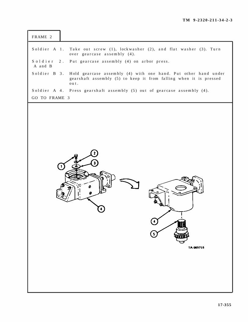
TM 9-2320-211-34-2-3
FRAME 2
S o l d i e r A 1 . Take out screw (1), lockwasher (2), and flat washer (3). Turnover gearcase assembly (4).
S o l d i e r 2 . Put gearcase assembly (4) on arbor press.A and B
S o l d i e r B 3 . Hold gearcase assembly (4) with one hand. Put other hand undergearshaft assembly (5) to keep it from falling when it is pressedo u t .
S o l d i e r A 4 . Press gearshaft assembly (5) out of gearcase assembly (4).
GO TO FRAME 3
17-355
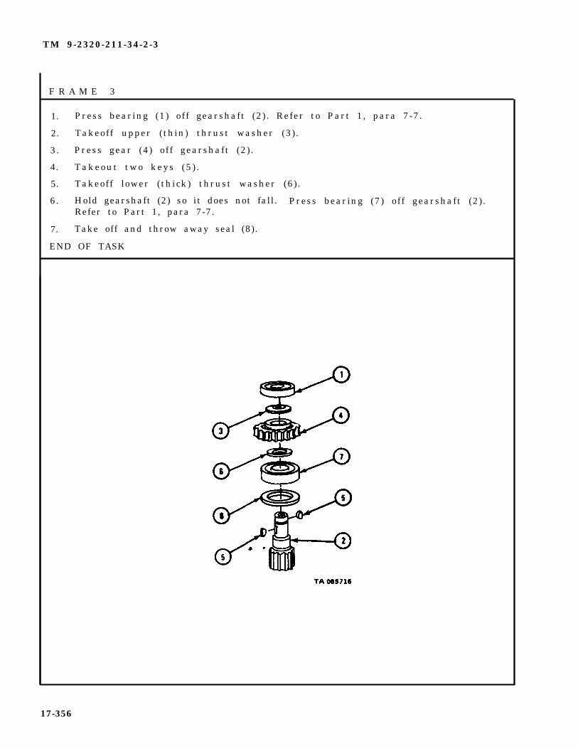
TM 9-2320-211-34-2-3
F R A M E 3
1. Press bearing (1) off gearshaft (2) . Refer to Part 1, para 7-7.
2. Takeoff upper (thin) thrust washer (3).
3. Press gear (4) off gearshaft (2) .
4. Takeout two keys (5 ) .
5. Takeoff lower (thick) thrust washer (6).
6. Hold gearshaft (2) so it does not fall. Press bearing (7) off gearshaft (2) .Refer to Part 1, para 7-7.
7. Take off and throw away seal (8).
END OF TASK
17-356

TM 9-2320-211-34-2-3
(2) Disassembly of worm and shaft assembly.
FRAME 1
1.
2.
3.
4 .
NOTE
Note position of motor mounting cap (1) on gearcase (2)to make sure it is put back on right end of gearcase.
Take out four screws (3) and lockwashers (4).
Take off motor mounting cap (1) and gasket (5). Throw away gasket.
Pull off coupling (6) .
Take out key (7).
GO TO FRAME 2
17-357

TM 9-2320-211-34-2-3
FRAME 2
S o l d i e r A 1 . Take out four screws (1) and lockwashers (2).
2. Take off bearing retaining cap (3) and gasket (4). Throw awaygasket .
S o l d i e r B 3 . Put gearcase (5) on arbor press.
4 . Hold gearcase (5) with one hand. With other hand, catch wormand shaft assembly (6) when it is pressed out.
S o l d i e r A 5 . Press worm and shaft assembly (6) out of gearcase (5).
GO TO FRAME 3
17-358

TM 9-2320-211-34-2-3
F R A M E 3
1. Press bearing (1) off shaft (2) . Refer to Part 1, para 7-7.
2. Press thrust bushing (3) out of bearing (1).
3. Take out key (4).
4. Slide off spacer (5) , retaining washer (6) , and spring (7).
5. Do steps 1 through 4 again on other side of shaft (2).
6 . Press shaft (2) out of worm (8).
END OF TASK
17-359

TM 9-2320-211-34-2-3
c. Cleaning . There are no spec ia l c leaning procedures needed . Re fer tocleaning procedures given in Part 1, para 1-3.
d . Inspection.
F R A M E 1
1. Check that four bearings (1 and 2) are not damaged. Refer to Part 1, para 7-7.
2. Check that upper (thin) thrust washer (3), lower (thick) thrust washer (4),and two thrust bushings (5) are not scored or damaged in any other way.
3. Check that two springs (6) are not broken.
GO TO FRAME 2
NOTECHECK ONLY THOSE PARTS WHICH ARE CALLEDOUT IN THIS FRAME. PARTS WITHOUT CALLOUTSARE SHOWN ONLY FOR REFERENCE PURPOSESOR ARE CHECKED IN ANOTHER FRAME.
17-360

TM 9-2320-211-34-2-3
FRAME 2
1. Check that shaft (1) is not bent, cracked or damaged in any other way.
2. Check that worm (2) is not cracked, broken or damaged in any other way.
3. Check that gear (3) does not have chipped or broken teeth or other damage.
4. Check that gearshaft (4) is not bent or cracked and does not have chippedor broken teeth.
5. Check that gearcase (5), gearcase cover (6), motor mounting cap (7), andbearing retaining cap (8) are not cracked, broken or damaged in any otherw a y .
END OF TASK
17-361
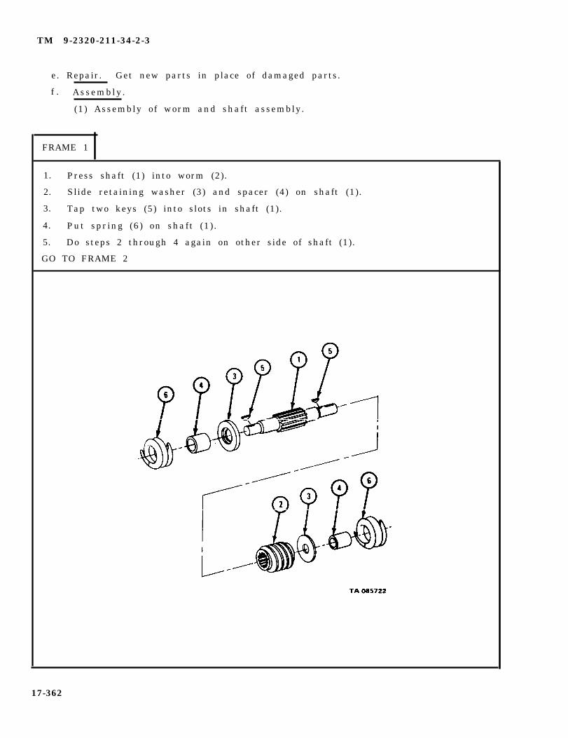
TM 9-2320-211-34-2-3
e. Repair. Get new parts in place of damaged parts.
f . Assembly .
(1) Assembly of worm and shaft assembly.
FRAME 1
1. Press shaft (1) into worm (2).
2. Slide retaining washer (3) and spacer (4) on shaft (1).
3. Tap two keys (5) into slots in shaft (1).
4. Put spring (6) on shaft (1) .
5. Do steps 2 through 4 again on other side of shaft (1).
GO TO FRAME 2
17-362
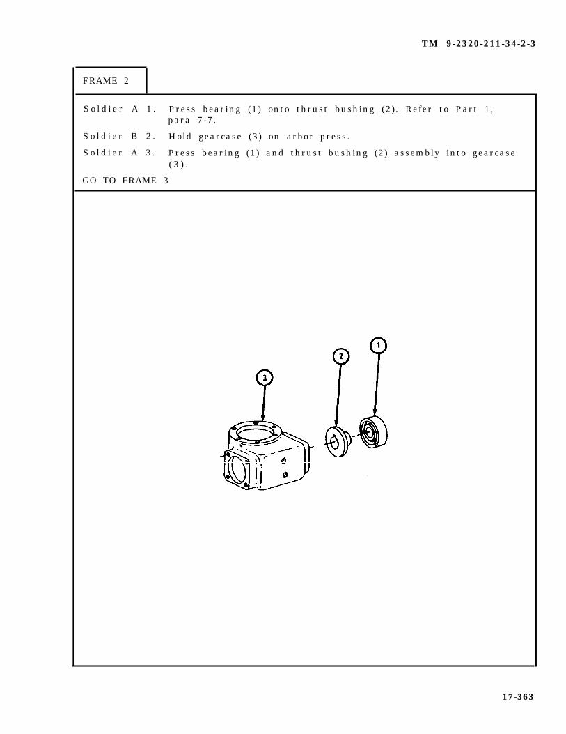
TM 9-2320-211-34-2-3
FRAME 2
S o l d i e r A 1 . Press bearing (1) onto thrust bushing (2). Refer to Part 1,para 7-7.
S o l d i e r B 2 . Hold gearcase (3) on arbor press.
S o l d i e r A 3 . Press bearing (1) and thrust bushing (2) assembly into gearcase( 3 ) .
GO TO FRAME 3
17-363

TM 9-2320-211-34-2-3
FRAME 3
S o l d i e r A 1 . Press bearing (1) onto thrust bushing (2). Refer to Part 1,para 7-7.
NOTE
Make sure shaft assembly (5) is pressed into gearcase(6) with long end of shaft at motor mounting cap end ofgearcase .
2. Line up keyway in thrust bearing assembly (3) with key (4)and press shaft assembly (5) into bores in gearcase (6).
Soldier B 3. Hold gearcase (6) and shaft assembly (5) on arbor press.
S o l d i e r A 4 . Line up keyway in thrust bearing assembly (7) with key (8) andpress thrust bearing assembly onto shaft assembly (5) and intogearcase (6 ) .
GO TO FRAME 4
17-364
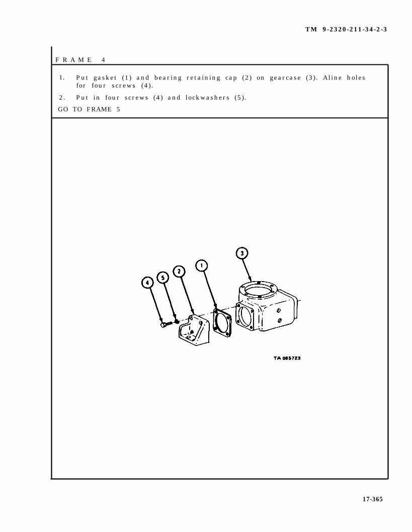
TM 9-2320-211-34-2-3
F R A M E 4
1. Put gasket (1) and bearing retaining cap (2) on gearcase (3). Aline holesfor four screws (4).
2. Put in four screws (4) and lockwashers (5).
GO TO FRAME 5
17-365
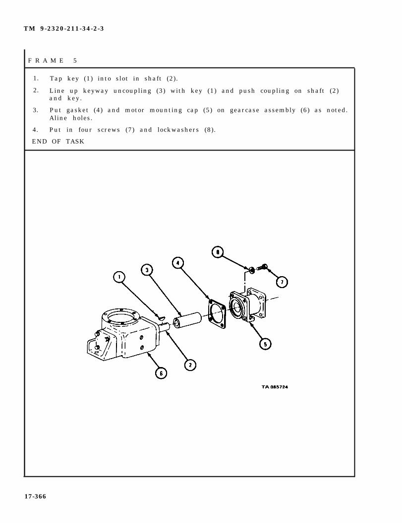
TM 9-2320-211-34-2-3
F R A M E 5
1. Tap key (1) into slot in shaft (2).
2. Line up keyway uncoupling (3) with key (1) and push coupling on shaft (2)and key.
3. Put gasket (4) and motor mounting cap (5) on gearcase assembly (6) as noted.Aline holes.
4. Put in four screws (7) and lockwashers (8).
END OF TASK
17-366
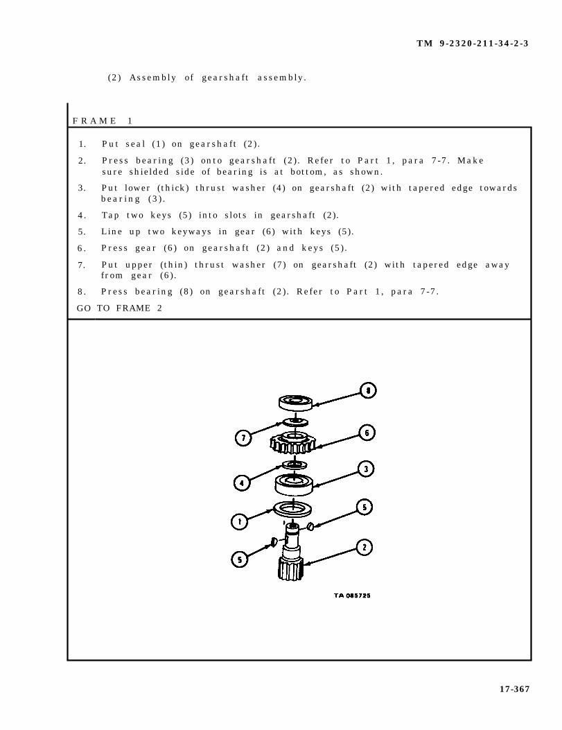
TM 9-2320-211-34-2-3
(2) Assembly of gearshaft assembly.
F R A M E 1
1.
2.
3.
4.
5.
6 .
7.
8.
GO
Put seal (1) on gearshaft (2) .
Press bearing (3) onto gearshaft (2). Refer to Part 1, para 7-7. Makesure shielded side of bearing is at bottom, as shown.
Put lower (thick) thrust washer (4) on gearshaft (2) with tapered edge towardsbear ing (3 ) .
Tap two keys (5) into slots in gearshaft (2).
Line up two keyways in gear (6) with keys (5).
Press gear (6) on gearshaft (2) and keys (5) .
Put upper (thin) thrust washer (7) on gearshaft (2) with tapered edge awayfrom gear (6) .
Press bearing (8) on gearshaft (2) . Refer to Part 1, para 7-7.
TO FRAME 2
17-367
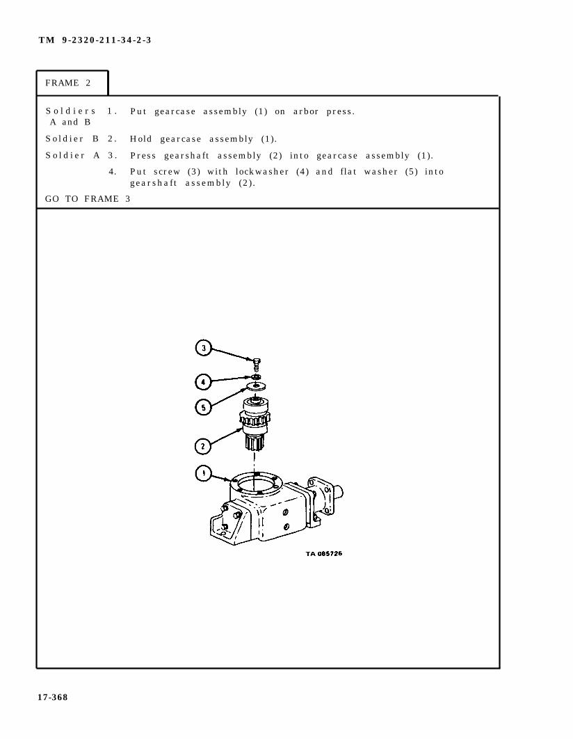
TM 9-2320-211-34-2-3
FRAME 2
S o l d i e r s 1 . Put gearcase assembly (1) on arbor press.A and B
S o l d i e r B 2 . Hold gearcase assembly (1).
S o l d i e r A 3 . Press gearshaft assembly (2) into gearcase assembly (1).
4. Put screw (3) with lockwasher (4) and flat washer (5) intogearshaft assembly (2).
GO TO FRAME 3
17-368
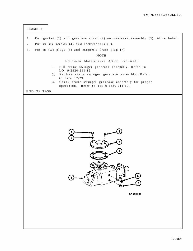
TM 9-2320-211-34-2-3
FRAME 3
1. Put gasket (1) and gearcase cover (2) on gearcase assembly (3). Aline holes.
2. Put in six screws (4) and lockwashers (5).
3 . Put in two plugs (6) and magnetic drain plug (7).
NOTE
Follow-on Maintenance Action Required:
1. Fill crane swinger gearcase assembly. Refer toLO 9-2320-211-12.
2. Replace crane swinger gearcase assembly. Referto para 17-29.
3. Check crane swinger gearcase assembly for properoperat ion . Refer to TM 9-2320-211-10.
END OF TASK
17-369

TM 9-2320-211-34-2-3
17-31. BEVEL GEARCASE PUMP DRIVE SHAFT LEAD AND RING ASSEMBLYREMOVAL, REPAIR, AND REPLACEMENT (TRUCK M543A2).
TOOLS: No special tools required
SUPPLIES: Solvent, dry cleaning, type II (SD-2) Fed. Spec P-D-680Electrical contact cleaner, pn MS230
PERSONNEL: One
EQUIPMENT CONDITION: Truck parked, engine off , handbrake set.
a . Preliminary Procedures.
(1) Remove hydraulic pump assembly. Refer to para 17-35.
(2) Remove contact brushes from brush plate assembly. Refer to SlipringContact Brushes, TM 9-2320-211-20.
(3) Raise boom and position shipper braces to maximum. Refer toTM 9-2320-211-10.
b . Removal.
F R A M E 1
1. Working below truck body, tag four electrical leads (1) to make sure theyare put back in the right place.
2. Take two male connectors (2) out of two female connectors (3).
GO TO FRAME 2
17-370

TM 9-2320-211-34-2-3
FRAME 2
1.
2.
3.
GO
Take out six screws and lockwashers (1).
Tag connectors (2, 3, and 4) to make sure they are put back in the rightplace. Unplug connectors from connectors (5, 6, and 7).
Lift off hydraulic pump support (8) .
TO FRAME 3
17-371
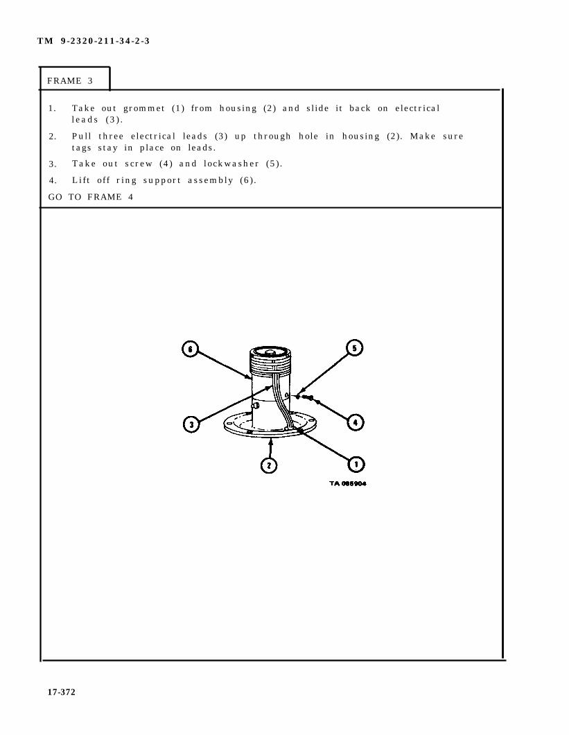
TM 9-2320-211-34-2-3
FRAME 3
1. Take out grommet (1) from housing (2) and slide it back on electricall eads (3 ) .
2. Pull three electrical leads (3) up through hole in housing (2). Make suretags stay in place on leads.
3. Take out screw (4) and lockwasher (5).
4. Lift off ring support assembly (6).
GO TO FRAME 4
17-372
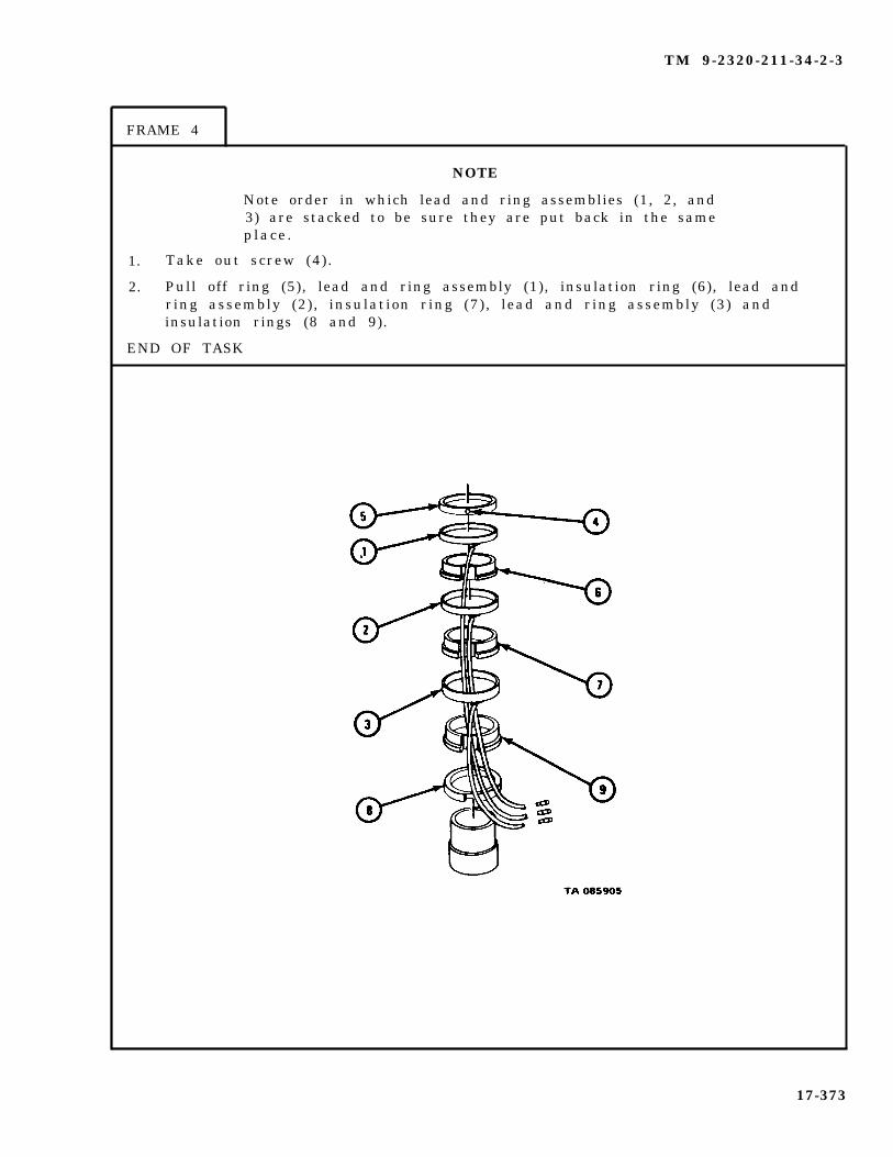
TM 9-2320-211-34-2-3
FRAME 4
NOTE
Note order in which lead and ring assemblies (1, 2, and3) are stacked to be sure they are put back in the sameplace .
1. Take out screw (4).
2. Pull off ring (5), lead and ring assembly (1), insulation ring (6), lead andring assembly (2), insulation ring (7), lead and ring assembly (3) andinsulation rings (8 and 9).
END OF TASK
17-373
TM 9-2320-211-34-2-3
c. C l e a n i n g .
WARNING
Dry cleaning solvent is flammable. Do not use near anopen flame. Keep a fire extinguisher nearby when sol-vent is used. Use only in well-ventilated places. Fail-ure to do this may result in injury to personnel anddamage to equipment.
NOTE
Make sure tags stay on leads.
(1) Clean all metal parts with solvent.
(2) Clean contacts on electrical leads with electrical contact cleaner.
17-374

TM 9-2320-211-34-2-3
d . Inspection and Repair.
FRAME 1
1. Check that lead and ring assemblies (1, 2, and 3) and insulation rings (4, 5,6, 7, and 8) have no cracks or glazed or worn areas. Throw away damagedparts and get new ones in their place.
2. Check that soldered connections (9) on lead and ring assemblies (1, 2, and3), are not damaged. If leads (10) are broken or not soldered to rings(1, 2, and 3), get new leads in their place or solder leads to rings.
3. Check that cable connectors (11) are not damaged or broken. If connectorsare damaged, throw them away and get new ones in their place.
END OF TASK
17-375

TM 9-2320-211-34-2-3
e. R e p l a c e m e n t .
F R A M E 1
1. Put
2. Put( 5 )
3. Put
insulation ring (1) on insulating ring support (2).
ring and lead assembly (3) onto insulating ring (4) as noted, with leadthrough notch (6) in insulating ring (4).
ring and lead assembly (3) and insulating ring (4) onto insulating ringsupper ; (2 ) . Pull lead (5) through notch (7) insulating ring (1).
GO TO FRAME 2
17-376

TM 9-2320-211-34-2-3
FRAME 2
1. Put lead and ring assembly (1) onto insulating ring (2) as noted, with lead(3) through notch (4) in insulating ring (2).
2. Put lead and ring assembly (1) an insulating ring (2) onto insulating ringsupport (5 ) . Pull lead (3) through notches in rings on insulating ringsupport (5 ) .
3. Put lead and ring assembly (6) onto insulating ring (7) as noted, with lead(8) through notch (9) in insulating
4. Put lead and ring assembly (6) andsupport (5 ) . Pull lead (8) throughsupport (5 ) .
GO TO FRAME 3
ring (6).
insulating ring (7) onto insulating ringnotches in rings on insulating ring
17-377

TM 9-2320-211-34-2-3
FRAME 3
1. Put insulation ring (1) on insulation ring support (2) and aline holes.
2. Put in screw and washer (3).
GO TO FRAME 4
17-378

TM 9-2320-211-34-2-3
F R A M E 4
1.
2.
3.
4 .
GO
Aline holes in ring support assembly (1) and pump driveshaft assembly (2).
Put in screw (3) and lockwasher (4).
Push three electrical leads (5) down through hole in housing (6). Make suretags on electrical leads stay in place.
Put grommet (7) into hole in housing (6).
TO FRAME 5
17-379

TM 9-2320-211-34-2-3
FRAME 5
1. Put hydraulic pump support (1) on pump driveshaft housing assembly (2)with hole for contact brush plate assembly
2. Aline holes in hydraulic pump support (1)assembly (2).
3. Put in six screws and lockwashers (3).
4. Plug three connectors on wires (4, 5, and(7, 8, and 9) as tagged. Take off tags.
GO TO FRAME 6
facing towards rear of truck.
and pump driveshaft
6) into connectors on
housing
wires
17-380

TM 9-2320-211-34-2-3
F R A M E 6
1. Working under truck, push two male connectors (1) into two femaleconnectors (2 ) as tagged . Take o f f tags .
1.
2.
3.
END OF TASK
NOTE
Follow-on Maintenance Action Required:
Replace hydraulic pump assembly. Refer to para17-35.Replace contact brushes in brush plate assembly.Refer to Slipring Contact Brushes, TM 9-2320-211-20.Check floodlight assemblies for proper operation.Refer to TM 9-2320-211-20.
17-381

TM 9-2320-211-34-2-3
17-32. BEVEL GEARCASE DRIVESHAFT SEAL REMOVAL AND REPLACEMENT(TRUCK M543A2).
TOOLS: No special tools required
SUPPLIES: Contact brush plate assembly gasketEnd cover gasketBevel gearcase drive shaft sealT a g s
PERSONNEL: One
EQUIPMENT CONDITION : Truck parked, engine off , handbrake set.
a . Preliminary Procedures.
(1) Remove hydraulic pump assembly from truck. Refer to para 17-35.
(2) Remove slipring brushes from brush plate assembly. Refer toSlipring Contact Brushes, TM 9-2320-211-20.
b . Removal.
FRAME 1
1. Working under truck, tag four electrical leads (1) so that they will be putback in the right places.
2. Take two male connectors (2) out of two female connectors (3).
GO TO FRAME 2
17-382

TM 9-2320-211-34-2-3
F R A M E 2
1. Take out four screws and lockwashers (1).
2. Take off contact brush plate assembly (2) and gasket (3). Throw away gasket.
3. Take out six screws and lockwashers (4).
4. Lift off hydraulic pump support (5) .
GO TO FRAME 3
17-383

TM 9-2320-211-34-2-3
F R A M E 3
1. Pull coupling (1) off pump drive shaft (2).
2. Pull three electrical leads (3) up through grommet (4). Make sure that tagson electrical leads stay in place.
3. Take out screw and lockwasher (5).
GO TO FRAME 4
17-384
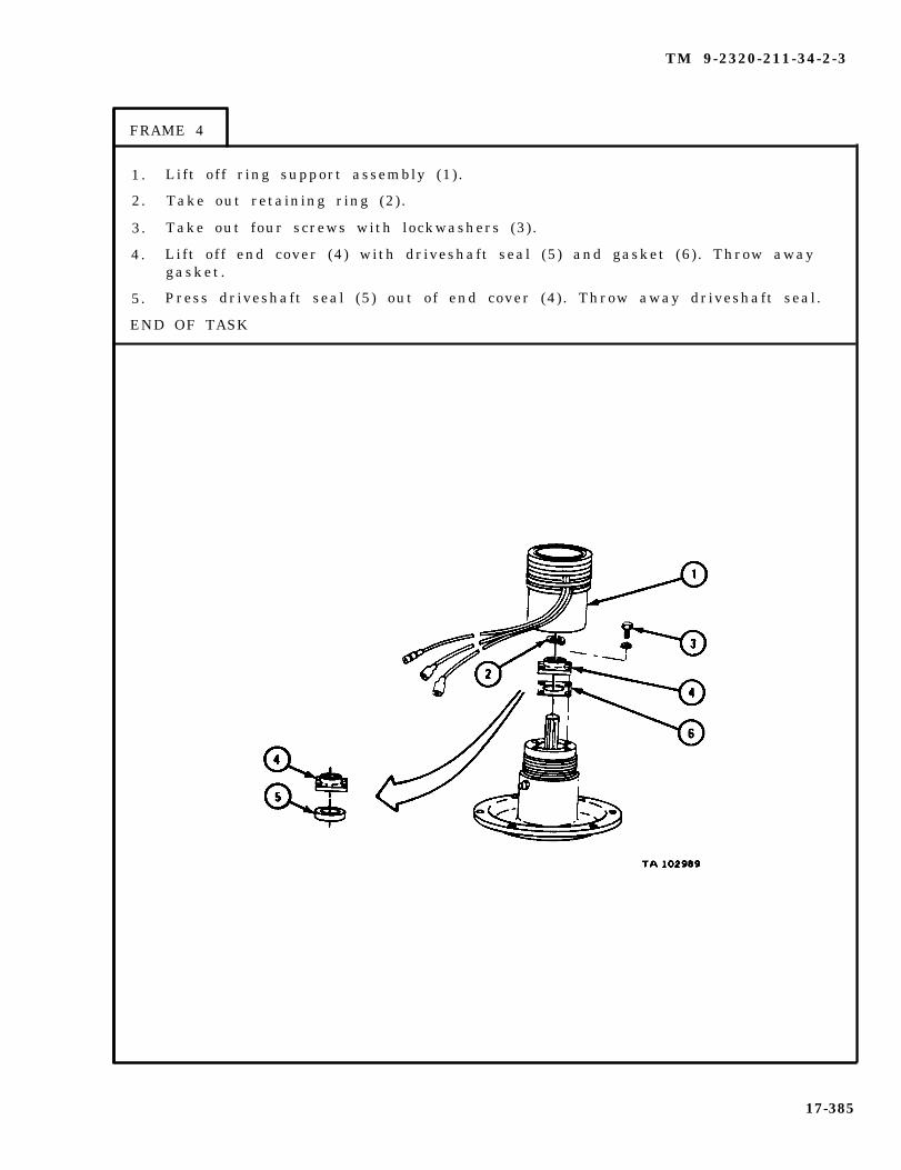
TM 9-2320-211-34-2-3
FRAME 4
1 . Lift off ring support assembly (1).
2. Take out retaining ring (2).
3. Take out four screws with lockwashers (3).
4 . Lift off end cover (4) with driveshaft seal (5) and gasket (6) . Throw awaygasket .
5. Press driveshaft seal (5) out of end cover (4) . Throw away driveshaft seal.
END OF TASK
17-385

TM 9-2320-211-34-2-3
c. Replacement.
1. Press driveshaft seal (1) into end cover (2) .
2. Put gasket (3) and end cover (2) with driveshaft seal (1) on driveshafthousing (4), alining holes.
3. Put in and tighten four screws with lockwashers (5).
4. Put retaining ring (6) in groove in end cover (2).
5. Put ring support assembly (7) in place on driveshaft housing (4).
GO TO FRAME 2
17-386
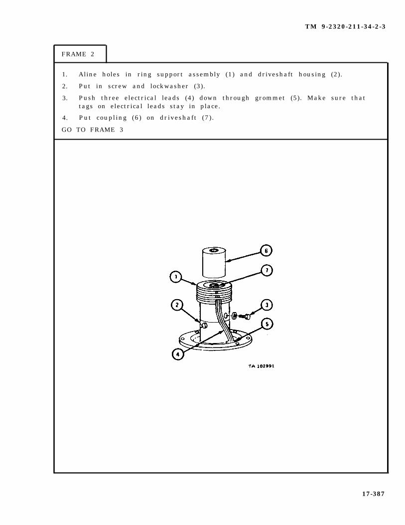
TM 9-2320-211-34-2-3
FRAME 2
1. Aline holes in ring support assembly (1) and driveshaft housing (2).
2. Put in screw and lockwasher (3).
3. Push three electrical leads (4) down through grommet (5). Make sure thattags on electrical leads stay in place.
4. Put coupling (6) on driveshaft (7) .
GO TO FRAME 3
17-387
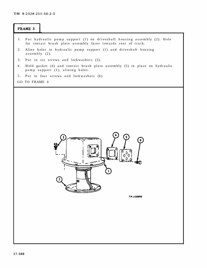
TM 9-2320-211-34-2-3
1. Put hydraulic pump support (1) on driveshaft housing assembly (2). Holefor contact brush plate assembly faces towards rear of truck.
2. Aline holes in hydraulic pump support (1) and driveshaft housingassembly (2).
3. Put in six screws and lockwashers (3).
4 . Hold gasket (4) and contact brush plate assembly (5) in place on hydraulicpump support (1) , alining holes.
5 . Put in four screws and lockwashers (6).
GO TO FRAME 4
17-388

TM 9-2320-211-34-2-3
FRAME 4
1. Working under truck, push two male connectors (1) into two female connectors(2 ) as tagged . Take o f f tags .
NOTE
Follow-on Maintenance Action Required:
1. Replace hydraulic pump assembly on truck. Referto para 17-35.
2. Replace slipring brushes in brush plate assembly.Refer to Slipring Contact Brushes, TM 9-2320-211-20.
END OF TASK
17-389

TM 9-2320-211-34-2-3
17-33. CRANE TURNTABLE ASSEMBLY REMOVAL, REPAIR AND REPLACEMENT(TRUCK M543A2).
TOOLS: No special tools required
SUPPLIES: Wooden block (4)Lubricating oil, ICE, OE/HDO 10, MIL-L-2104Solvent, dry cleaning, type II (SD-2), Fed. Spec P-D-6801/4-inch screwArtillery and automotive grease, type GAA, MIL-G-10924
PERSONNEL: TWO
EQUIPMENT CONDITION: Truck parked, engine off , handbrake set, wheelsc h o c k e d .
a . Preliminary Procedures.
( 1 )
(2 )
(3 )
(4 )
( 5 )
(6 )
( 7 )
( 8 )
(9 )
Remove hoist winch cable. Refer to TM 9-2320-211-20.
Remove boom assembly. Refer to para 17-44.
Remove hydraulic oil reservoir. Refer to para 17-37.
Remove boom elevating cylinders. Refer to para 17-42.
Remove gondola assembly operator ’s cab. Refer to para 17-52.
Remove crane swinger gearcase with swinger motor. Refer to para 17-29.
Remove hydraulic turntable pump assembly. Refer to para 17-35.
Remove slipring contact brushes. Refer to TM 9-2320-211-20.
Disconnect battery ground cable. Refer to TM 9-2320-211-20.
17-390

TM 9-2320-211-34-2-3
b. Removal.
FRAME 1
1. Pull out two male connectors (1) from two female connectors (2).
2. Take out six screws and lockwashers (3).
3. Lift off hydraulic pump support (4) with two electrical leads (5).
4 . Take out two screws (6).
5. Move cable assembly (7) away from boom support assembly (8).
GO TO FRAME 2
17-391

TM 9-2320-211-34-2-3
1. Hook up chain sling and hoist to boom support assembly (1).
2. Take out 18 screws (2) and nuts (3).
Soldier A 3. Guide boom support assembly (1) from truck when soldier B lifts it.
Soldier B 4. Using hoist, lift boom support assembly (1) up and off truck, and setit down on ground.
5. Take chain sling and hoist off boom support assembly (1).
GO TO FRAME 3
17-392

TM 9-2320-211-34-2-3
FRAME 3
1. Take out four screws (1).
2. Take off left guard assembly (2).
3. Take out four screws (3).
4. Take off right guard assembly (4).
GO TO FRAME 4
17-393

TM 9-2320-211-34-2-3
FRAME 4
1. Turn
2. Take
3. Take
turntable assembly (1) until access hole (2)
out two capscrews (3) and washers (4).
off stop block (5).
GO TO FRAME 5
is facing side of truck.
17-394

TM 9-2320-211-34-2-3
FRAME 5
1. Turn turntable assembly (1) so access hole (2) is over 18 outer screws (3),one at a time.
2. Take out 18 screws (3).
GO TO FRAME 6
17-395
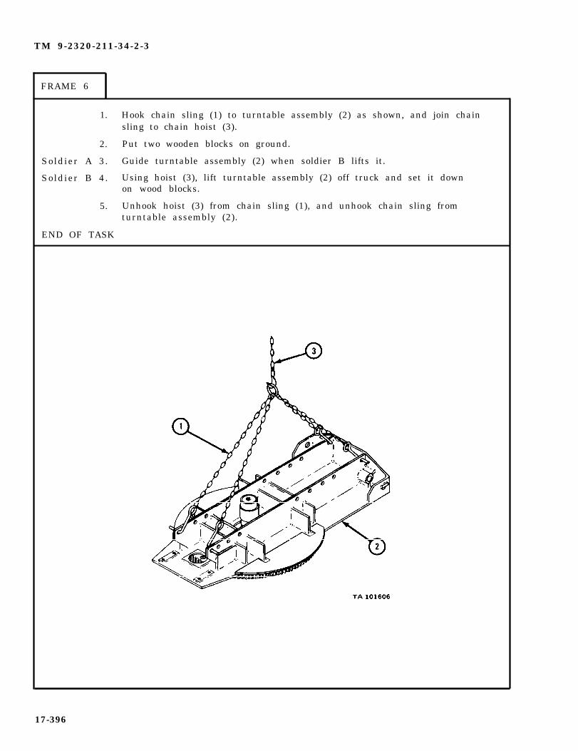
TM 9-2320-211-34-2-3
FRAME 6
1. Hook chain sling (1) to turntable assembly (2) as shown, and join chainsling to chain hoist (3).
2. Put two wooden blocks on ground.
Soldier A 3. Guide turntable assembly (2) when soldier B lifts it.
Soldier B 4. Using hoist (3), lift turntable assembly (2) off truck and set it downon wood blocks.
5. Unhook hoist (3) from chain sling (1), and unhook chain sling fromturntable assembly (2).
END OF TASK
17-396

TM 9-2320-211-34-2-3
Disassembly.
1. Hook chain sling (1) to one end of turntable assembly (2) as shown. Joinhoist (3) to chain sling.
Soldier A 2. Using hoist (3), raise turntable assembly (2), so that it stands up onone end.
Soldier B 3. When soldier A has raised turntable assembly (2), turn it overso that gear and bearing assembly (4) is facing up.
Soldier A 4. Using hoist (3), lower turntable assembly (2) to ground so that gearand bearing assembly (4) is facing up.
5. Take off hoist (3) and chain sling (1).
GO TO FRAME 2
17-397
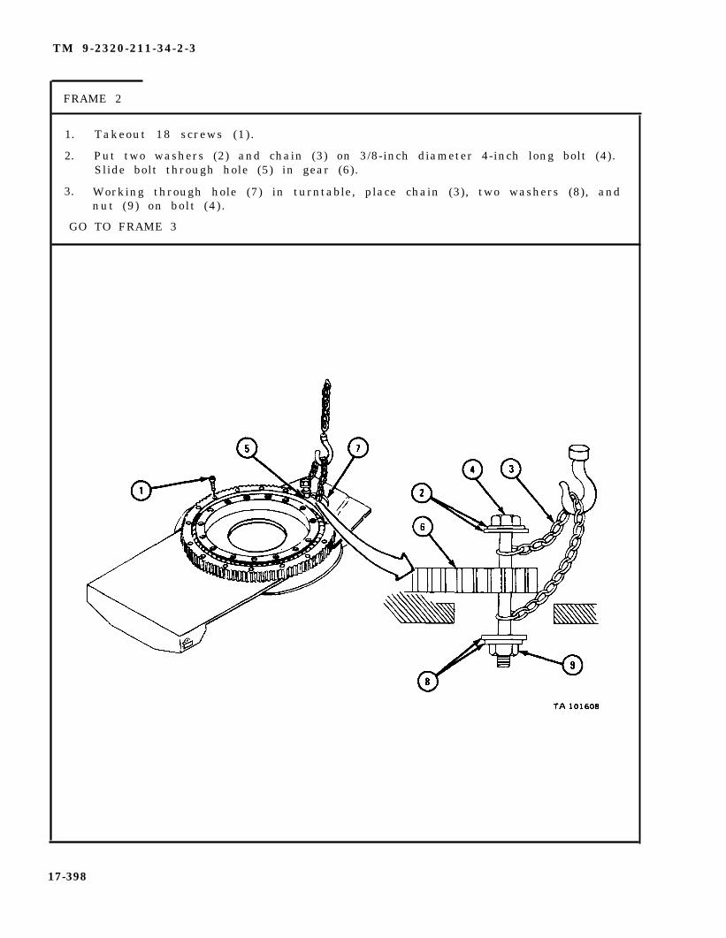
TM 9-2320-211-34-2-3
FRAME 2
1. Takeout 18 screws (1).
2. Put two washers (2) and chain (3) on 3/8-inch diameter 4-inch long bolt (4).Slide bolt through hole (5) in gear (6).
3. Working through hole (7) in turntable, place chain (3), two washers (8), andnut (9) on bolt (4) .
GO TO FRAME 3
17-398
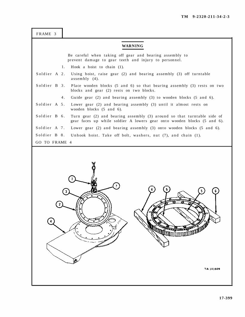
TM 9-2320-211-34-2-3
FRAME 3
WARNING
Be careful when taking off gear and bearing assembly toprevent damage to gear teeth and injury to personnel.
1.
So ld ier A 2 .
So ld ier B 3 .
4.
So ld ier A 5 .
So ld ier B 6 .
So ld ier A 7 .
So ld ier B 8 .
Hook a hoist to chain (1).
Using hoist, raise gear (2) and bearing assembly (3) off turntableassembly (4).
Place wooden blocks (5 and 6) so that bearing assembly (3) rests on twoblocks and gear (2) rests on two blocks.
Guide gear (2) and bearing assembly (3) to wooden blocks (5 and 6).
Lower gear (2) and bearing assembly (3) until it almost rests onwooden blocks (5 and 6).
Turn gear (2) and bearing assembly (3) around so that turntable side ofgear faces up while soldier A lowers gear onto wooden blocks (5 and 6).
Lower gear (2) and bearing assembly (3) onto wooden blocks (5 and 6).
Unhook hoist. Take off bolt, washers, nut (7), and chain (1).
GO TO FRAME 4
17-399

TM 9-2320-211-34-2-3
1. Tap taper pin (1) up and out of retaining plug (2) and gear and bearing assembly (3).
2. Put screw (4) into hole in retaining plug (2).
3. Pull out screw (4) and retaining plug (2).
4. Take screw (4) out of retaining plug (2).
GO TO FRAME 5
17-400

TM 9-2320-211-34-2-3
1. Push ball bearings (1) and spacer springs (2) toward retaining plug bore (3).
2. Working through pin hole (4), push out 54 ball bearings (1) and nine spacersprings (2).
3. Lift bearing race (5) out of gear (6).
END OF TASK
17-401

TM 9-2320-211-34-2-3
WARNING
Dry cleaning solvent is flammable. Do not usenear an open flame. Keep a fire extinguishernearby when solvent is used. Use only in well-ventilated places. Failure to do this may resultin injury to personnel and damage to equipment.
d. C l e a n i n g . There are no spec ia l c leaning procedures needed . Refer tocleaning procedures given in Part 1, para 1-3.
e . Inspection.
1.
2.
3.
4.
5.
Check that turntable base plate (1) has no cracks or broken welds and that itis not warped.
Check that teeth of gear (2) are not broken or damaged.
Check that 54 bearing balls (3) and ball bearing races of gear (2) and bearingrace (4) are not damaged. Refer to Part 1, para 7-7.
Check that nine spacer springs (5), pin (6), and plug (7) are not cracked orbroken.
Check that all screws and threaded holes are not stripped or damaged in anyother way.
END OF TASK
17-402

TM 9-2320-211-34-2-3
f . Repair.
(1) Weld small cracks or broken welds in turntable baseplate. Refer to TM 9-237.
(2) If turntable base plate is badly cracked or broken, get a new one.
(3) If bearing race, gear, bearing ball, springs, pin or plug are damaged,get a new turntable gear and bearing assembly.
(4) If any screws are damaged, get new ones in their place.
g. Assembly.
FRAME 1
1. Place gear (1) on wooden blocks (2).
2. Put bearing race (3) in place in gear (1) on wood blocks (4), with large flange facing up.
3. Put six bearing balls (5) into retaining plug bore (6).
4. Put one spacer spring (7) into retaining plug bore (6).
5. Push bearing balls (5) and spacer spring (7) away from retaining plug bore (6).
6. Do steps 3, 4, and 5 again until all 54 bearing balls (5) and nine space springs (7)are in bearing race (3).
GO TO FRAME 2
17-403
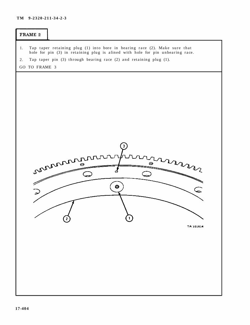
TM 9-2320-211-34-2-3
1. Tap taper retaining plug (1) into bore in bearing race (2). Make sure thathole for pin (3) in retaining plug is alined with hole for pin unbearing race.
2. Tap taper pin (3) through bearing race (2) and retaining plug (1).
GO TO FRAME 3
17-404

TM 9-2320-211-34-2-3
FRAME 3
1. Put two washers (1) and chain (2) on 3/8-inch diameter 4-inch bolt (3). Slidebolt through any outer hole in gear and bearing assembly (4).
2. Put other end of chain (2) on bolt
3. Join hoist to chain (2).
(3). Put on two washers (5) and nut (6).
WARNING
Be careful when putting back gear and bearing assembly(7) to avoid damaging gear teeth and injury to personnel.
Soldier A 4. Guide gear and bearing assembly (7) off wooden blocks to turntableassembly (8) when soldier B lifts it.
Soldier B 5. Using hoist, lift gear and bearing assembly (7) off wooden blocks andmove it over turntable assembly (8). Lower gear and bearing assemblyuntil it almost touches turntable assembly.
Soldier A 6. Turn gear and bearing assembly (7) so that bolt (3) goes into accesshole (9) when soldier B lowers gear and bearing assembly ontoturntable assembly (8).
Soldier B 7. Lower gear and bearing assembly (7) onto turntable assembly (8).GO TO FRAME 4
17-405

TM 9-2320-211-34-2-3
FRAME 4
1. Aline mounting holes in gear and bearing assembly (1) with holes in turntableassembly (2).
2. Unhook hoist. Working through access hole (3) in turntable assembly (2), take offnut (4), two washers (5), bolt (6), two washers (7), and chain (8).
3. Put in 18 screws (9).
GO TO FRAME 5
17-406

TM 9-2320-211-34-2-3
FRAME 5
1.
Soldier A 2.
Soldier B 3.
Soldier A 4.
5.
END OF TASK
Hook up chain sling (1) to end of turntable assembly (2) as shown.Join chain sling to hoist (3).
Using hoist (3), raise turntable assembly (2) so that it stands upon one end.
When Soldier A has raised turntable assembly (2), turn it around sothat gear and bearing assembly (4) is facing down.
Using hoist (3), lower turntable assembly (2) onto wooden blocks (5),with gear and bearing assembly (4) facing down.
Take hoist (3) off chain sling (1) and take chain sling off turntableassembly (2).
17-407
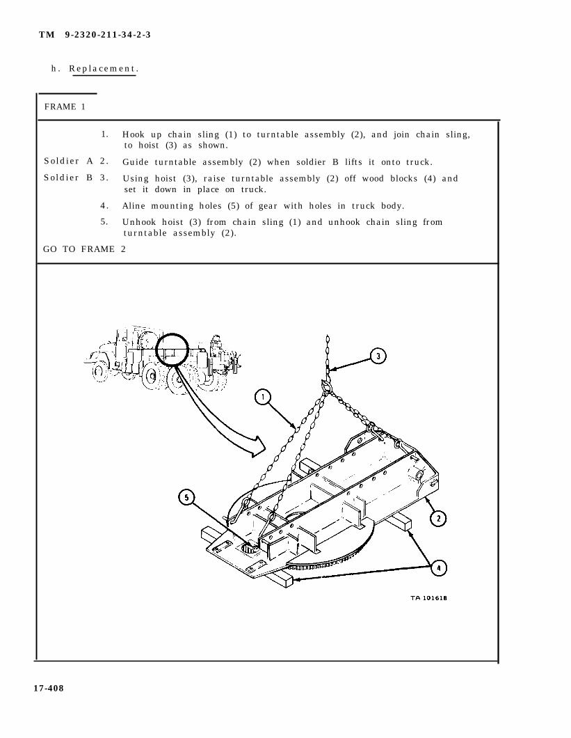
TM 9-2320-211-34-2-3
h. Replacement .
FRAME 1
1. Hook up chain sling (1) to turntable assembly (2), and join chain sling,to hoist (3) as shown.
Soldier A 2. Guide turntable assembly (2) when soldier B lifts it onto truck.
Soldier B 3. Using hoist (3), raise turntable assembly (2) off wood blocks (4) andset it down in place on truck.
4. Aline mounting holes (5) of gear with holes in truck body.
5. Unhook hoist (3) from chain sling (1) and unhook chain sling fromturntable assembly (2).
GO TO FRAME 2
17-408

TM 9-2320-211-34-2-3
FRAME 2
1. Turn turntable assembly (1) so that access hole (2) is over 18 outer screwholes, one at a time.
2. Put in 18 screws (3). Tighten screws to 170 to 180 pound-feet.
GO TO FRAME 3
17-409
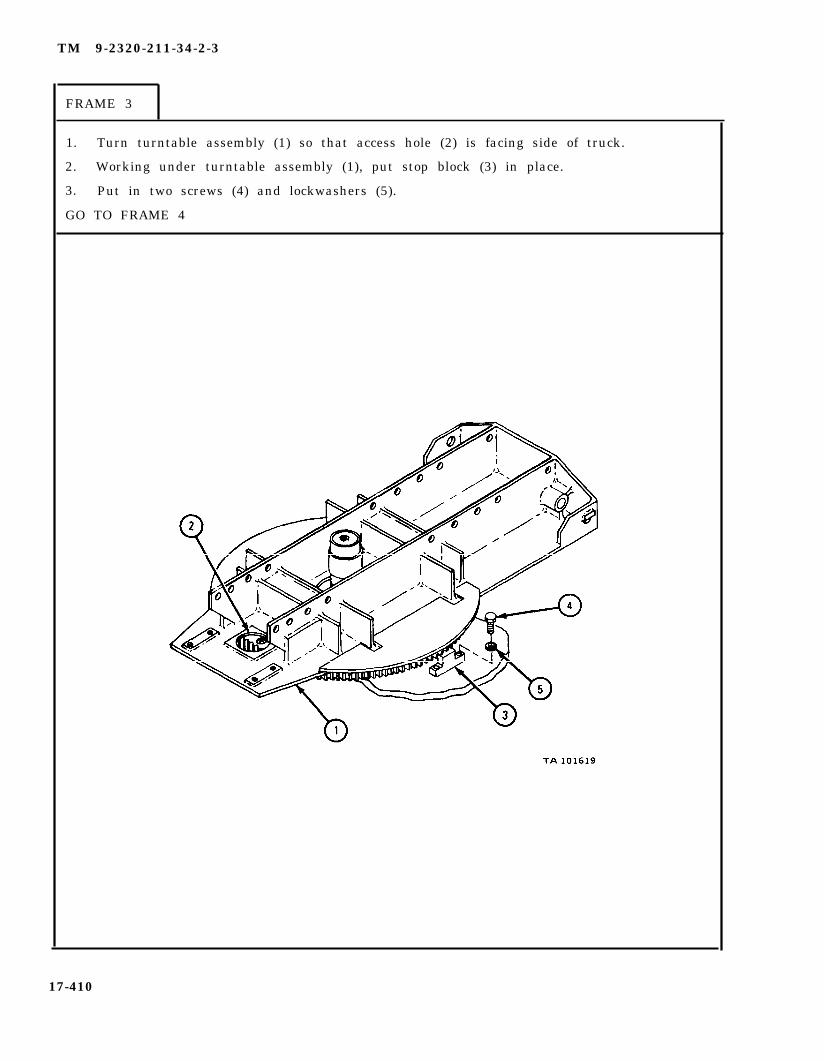
TM 9-2320-211-34-2-3
FRAME 3
1. Turn turntable assembly (1) so that access hole (2) is facing side of truck.
2. Working under turntable assembly (1), put stop block (3) in place.
3. Put in two screws (4) and lockwashers (5).
GO TO FRAME 4
17-410
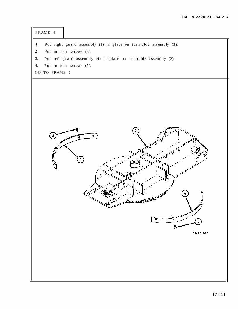
TM 9-2320-211-34-2-3
FRAME 4
1. Put right guard assembly (1) in place on turntable assembly (2).
2. Put in four screws (3).
3. Put left guard assembly (4) in place on turntable assembly (2).
4. Put in four screws (5).
GO TO FRAME 5
17-411

TM 9-2320-211-34-2-3
F R A M E 5
1. Hook up chain sling and hoist to boom support assembly (1) as shown.
Soldier A 2. Guide boom support assembly (1) into place on turntable assembly (2)when soldier B lifts it.
Soldier B 3. Using hoist, lift boom support assembly (1) up and set it down inplace on turntable assembly (2).
4. Put in 18 screws (3) and put on nuts (4).
5. Unhook chain sling and hoist from boom support assembly (1).
GO TO FRAME 6
17-412

TM 9-2320-211-34-2-3
FRAME 6
1. Put cable assembly (1) around boom support assembly (2) as shown,
2. Put in two screws (3) through two clamps (4) and turntable assembly (5).
3. Put hydraulic pump support (6) with two electrical leads (7) in place on turn-table assembly (5), alining holes.
4. Put in six screws and lockwashers (8).
5. Push two male connectors (9) into female connectors on electrical leads (7).
GO TO FRAME 7
17-413

TM 9-2320-211-34-2-3
F R A M E 7
NOTE
1.
2.
3.
4.
5.6.7.8.9.
10.
Follow-on Maintenance Action Required:
Replace slipring contact brushes. Refer toTM 9-2320-211-20.Replace hydraulic turntable pump assembly. Referto para 17-35.Replace crane swinger gearcase with crane swingermotor. Refer to para 17-29.Replace gondola assembly operator ’s cab. Refer topara 17-52.Replace boom elevating cylinders. Refer to para 17-42.Replace hydraulic oil reservoir. Refer to para 17-37.Replace boom assembly. Refer to para 17-44.Replace hoist winch cable. Refer to TM 9-2320-211-20.Check crane turntable assembly for proper operation.Refer to TM 9-2320-211-10.Reconnect battery ground cable. Refer toTM 9-2320-211-20.
END OF TASK
17-414

TM 9-2320-211-34-2-3
17-34. TURNTABLE BEVEL GEAR GEARCASE ASSEMBLY REMOVAL, REPAIR,AND REPLACEMENT (TRUCK M543A2).
TOOLS: No special tools required
SUPPLIES: 5-gallon containerSolvent, dry cleaning, type II (SD-2), Fed. Spec P-D-680Layout dyeGearcase housing gasketEnd cover gasketDrive housing gasketEnd cover sealT a g sBearing cover gasket
PERSONNEL: TWO
EQUIPMENT CONDITION: Truck parked, engine off , handbrake set.
a . Preliminary Procedures.
(1) Remove hoist winch cable. Refer to TM 9-2320-211-20.
(2) Remove boom assembly. Refer to para 17-44.
(3) Drain hydraulic oil reservoir. Refer to TM 9-2320-211-10.
(4) Remove hydraulic oil reservoir. Refer to para 17-37.
(5) Remove boom elevating cylinders. Refer to para 17-42.
(6) Remove gondola assembly. Refer to para 17-52.
(7) Remove hydraulic pump assembly. Refer to para 17-35.
(8) Remove crane swinger gearcase with crane swinger motor. Refer topara 17-29.
(9) Remove crane turntable assembly. Refer to para 17-33.
(10) Remove power divider to bevel gear case propeller shaft. Refer toTM 9-2320-211-20.
17-415

TM 9-2320-211-34-2-3
b . Removal.
FRAME 1
1.
2.
3.
4.
5.
GO
Put 5-gallon container under bevel gearcase housing assembly (1).
Take out two drain plugs (2) and let oil drain into container.
When oil has stopped draining, put back two drain plugs (2).
Tag four electrical leads (3)right places.
Pull two male connectors (4)
TO FRAME 2
to make sure
out of female
that they will be put back in the
connectors (5 ) .
17-416

TM 9-2320-211-34-2-3
F R A M E 2
S o l d i e r A 1 . Hold bevel gearcase housing assembly (1) while soldier B takesout six screws (2). Tell soldier B that you are ready.
S o l d i e r B 2 . Take out six screws and lockwashers (2).
S o l d i e r A 3 . Lower bevel gearcase housing assembly (1) and gasket (3) tog r o u n d . Throw away gasket.
S o l d i e r B 4 . Take out six screws and lockwashers (4).
5. Lift pump driveshaft housing assembly (5) off truck body.
END OF TASK
17-417
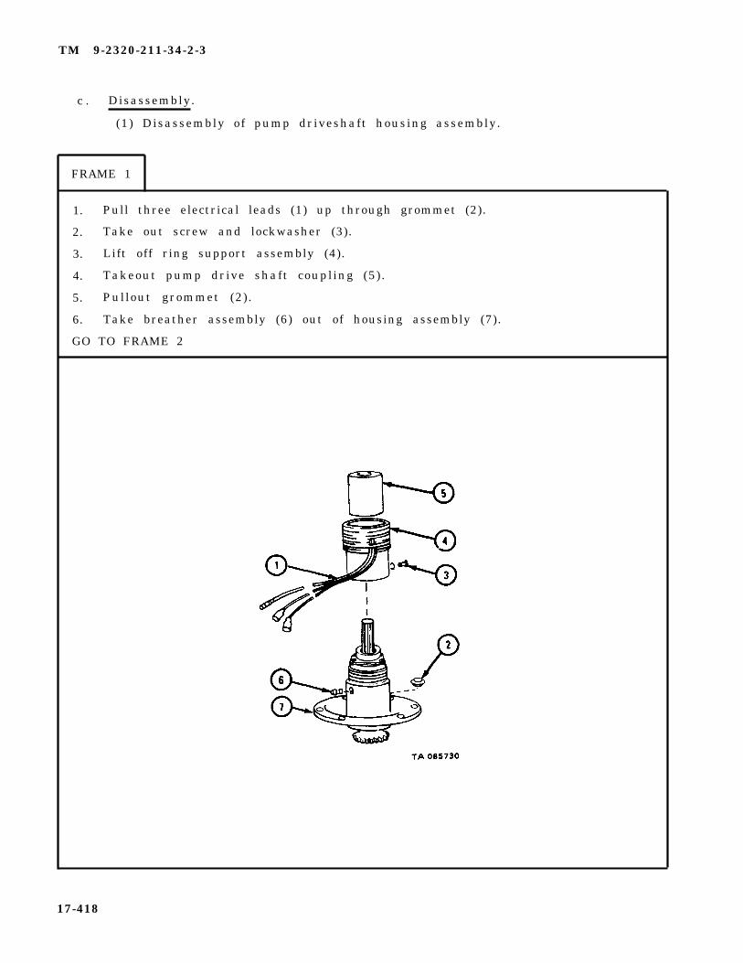
TM 9-2320-211-34-2-3
c . Disassembly.
(1) Disassembly of pump driveshaft housing assembly.
FRAME 1
1. Pull three electrical leads (1) up through grommet (2).
2. Take out screw and lockwasher (3).
3. Lift off ring support assembly (4).
4. Takeout pump drive shaft coupling (5).
5. Pullout grommet (2).
6. Take breather assembly (6) out of housing assembly (7).
GO TO FRAME 2
17-418

TM 9-2320-211-34-2-3
FRAME 2
1. Take out retaining ring (1).
2. Take out four screws (2) with lockwashers (3).
3. Lift off end cover (4) with seal (5) and gasket (6) . Throw away gasket.
4. Press seal (5) out of end cover (4) . Throw away seal.
GO TO FRAME 3
17-419

TM 9-2320-211-34-2-3
FRAME 3
1. Takeout screw (1), lockwasher (2), and flat washer (3).
2. T a k e o f f g e a r ( 4 ) .
NOTE
Tag gear (4) to make sure that it is put back on pumpdriveshaft, and not on input shaft.
3. Take out key (5).
GO TO FRAME 4
17-420

TM 9-2320-211-34-2-3
F R A M E 4
1. Take out retaining ring (1).
2. Pull out pump driveshaft (2) with bearings (3 and 4).
3. Press bearings (3 and 4) off pump driveshaft (2) . Refer to Part 1, para 7-7.
END OF TASK
17-421
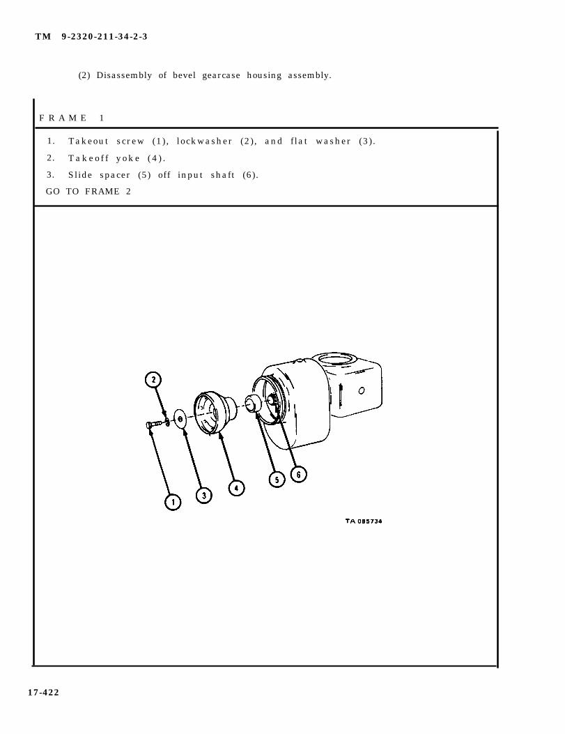
TM 9-2320-211-34-2-3
(2) Disassembly of bevel gearcase housing assembly.
F R A M E 1
1. Takeout screw (1), lockwasher (2), and flat washer (3).
2. T a k e o f f y o k e ( 4 ) .
3. Slide spacer (5) off input shaft (6).
GO TO FRAME 2
17-422
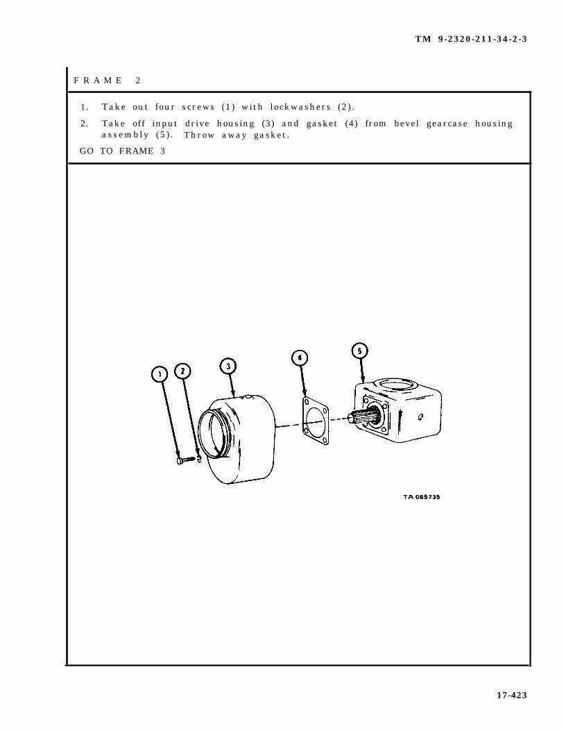
TM 9-2320-211-34-2-3
F R A M E 2
1. Take out four screws (1) with lockwashers (2).
2. Take off input drive housing (3) and gasket (4) from bevel gearcase housingassembly (5 ) . Throw away gasket.
GO TO FRAME 3
17-423
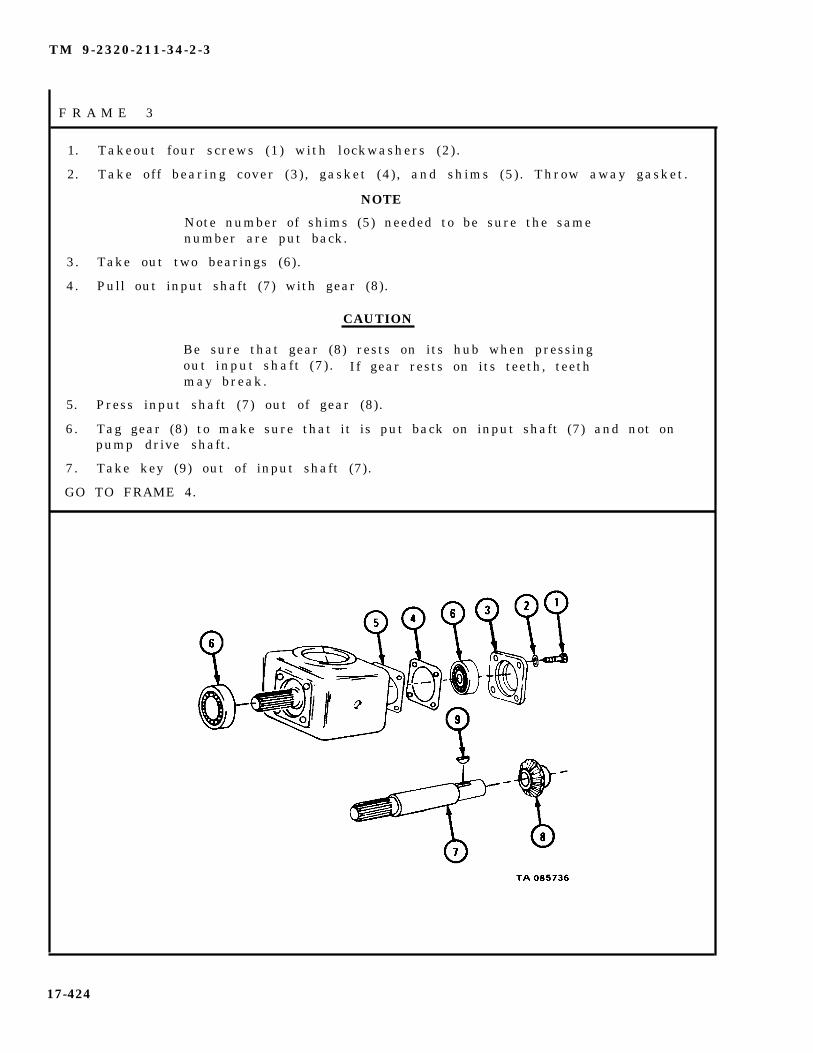
TM 9-2320-211-34-2-3
F R A M E 3
1. Takeout four screws (1) with lockwashers (2).
2. Take off bearing cover (3), gasket (4), and shims (5). Throw away gasket.
NOTE
Note number of shims (5) needed to be sure the samenumber are put back.
3. Take out two bearings (6).
4. Pull out input shaft (7) with gear (8).
CAUTION
Be sure that gear (8) rests on its hub when pressingout input shaft (7) . If gear rests on its teeth, teethmay break.
5. Press input shaft (7) out of gear (8).
6. Tag gear (8) to make sure that it is put back on input shaft (7) and not onpump drive shaft.
7. Take key (9) out of input shaft (7).
GO TO FRAME 4.
17-424
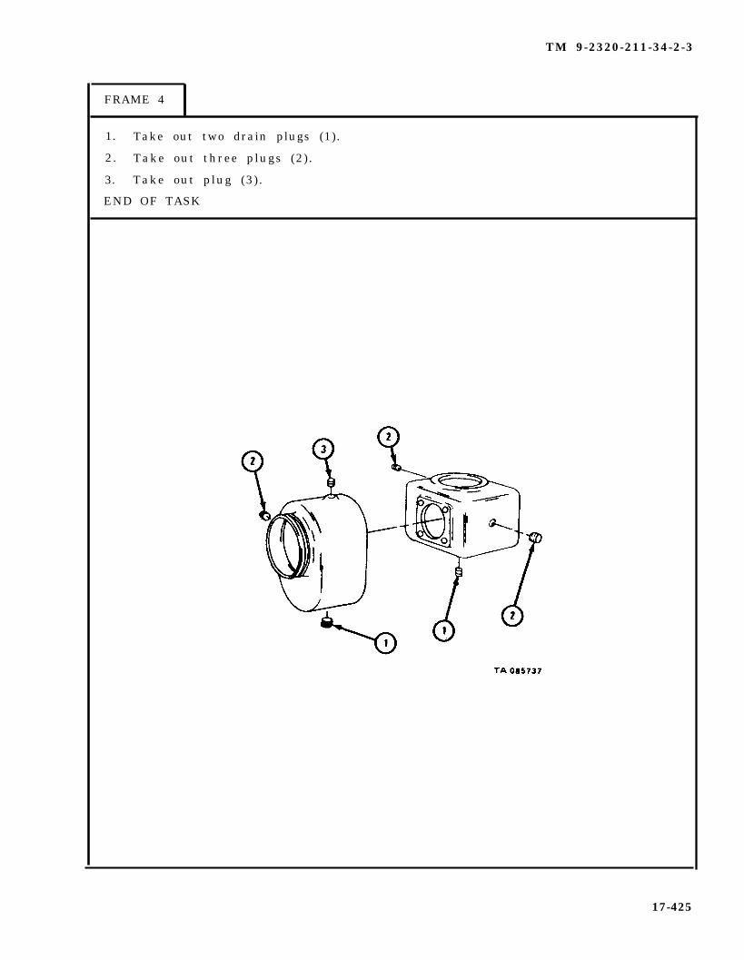
TM 9-2320-211-34-2-3
FRAME 4
1. Take out two drain plugs (1).
2. Take out three plugs (2).
3. Take out plug (3).
END OF TASK
17-425

TM 9-2320-211-34-2-3
d . Cleaning.
(1 ) Clean bear ings . Refer to Part 1, para 7-7.
WARNING
Dry cleaning solvent is flammable. Do not usenear an open flame. Keep a fire extinguishernearby when solvent is used. Use only in well-ventilated places. Failure to do this may resultin injury to personnel and damage to equipment.
(2) Clean all other metal parts with solvent. Let parts air dry.
(3) Clean rubber grommet with warm water. Dry with a clean rag.
17-426

TM 9-2320-211-34-2-3
F R A M E 1
1.
2.
3.
4.
GO
Check that bearings (1 and 2) and two bearings (3) are not damaged. Referto Part 1, para 7-7. If parts are damage, get new ones.
Check that pump drive shaft (4) and input shaft (5) are not chipped ortwisted and do not have damaged splines. If parts are damaged, get new ones.
Check that gears (6 and 7) are not chipped and do not show signs of wear.If parts are damaged, get new ones.
Check that lead and ring assemblies (8) are not damaged. If parts aredamaged, put in new ones.
TO FRAME 2
NOTECHECK ONLY THOSE PARTS WHICH ARE CALLEDOUT IN THIS FRAME, PARTS WITHOUT CALLOUTSARE SHOWN ONLY FOR REFERENCE PURPOSESOR ARE CHECKED IN ANOTHER FRAME.
17-427
e. Inspection and Repair.

TM 9-2320-211-34-2-3
FRAME 2
1. Check that hydraulic pump support (1), end cover (2), pump drive shafthousing (3), bearing cover (4), bevel gearcase housing (5), and input drivehousing (6) are not cracked or warped. If parts are damaged, get new ones.
END OF TASK
NOTECHECK ONLY THOSE PARTS WHICH ARE CALLEDOUT IN THIS FRAME. PARTS WITHOUT CALLOUTSARE SHOWN ONLY FOR REFERENCE PURPOSESOR ARE CHECKED IN ANOTHER FRAME.
17-428

f . Assembly .
(1) Assembly of bevel gearcase housing assembly.
TM 9-2320-211-34-2-3
FRAME 1
1. Put in two drain plugs (1).
2. Put in three plugs (2).
3. Put in plug (3).
GO TO FRAME 2
1 7 - 4 2 9

TM 9-2320-211-34-2-3
FRAME 2
1. put key (1) into keyway in input shaft (2).
CAUTION
Be sure that gear (3) rests on its hub when pressingin input shaft (2). If gear rests on its teeth, teethmay break.
NOTE
Be sure gear (3) tagged during disassembly is pressedback onto input shaft (2) . Take off tag.
2. Press input shaft (2) into gear (3).
3. Put input shaft (2) with gear (3) into bevel gearcase housing (4).
4. Drive two bearings (5) onto input shaft (2) and into bevel gearcase housing(4). Refer to Part 1, para 7-7.
5. Put noted number of shims (6), gasket (7), and bearing cover (8) in Place,alining holes.
6. Put in four screws (9) with lockwashers (10).
GO TO FRAME 3
17-430

TM 9-2320-211-34-2-3
FRAME 3
1. Put gasket (1) and input drive housing (2) on bevel gearcase housingassembly (3), alining holes.
2. Put in four screws (4) with lockwashers (5).
GO TO FRAME 4
17-431

TM 9-2320-211-34-2-3
FRAME 4
1. Slide spacer (1) and yoke (2) onto input shaft (3).
2. Clamp locking pliers on input shaft (3) through hole in top of bevel gearcasehous ing (4 ) .
3. Put in screw (5), lockwasher (6), and flat washer (7).
4. Take locking pliers off input shaft (3).
END OF TASK
17-432
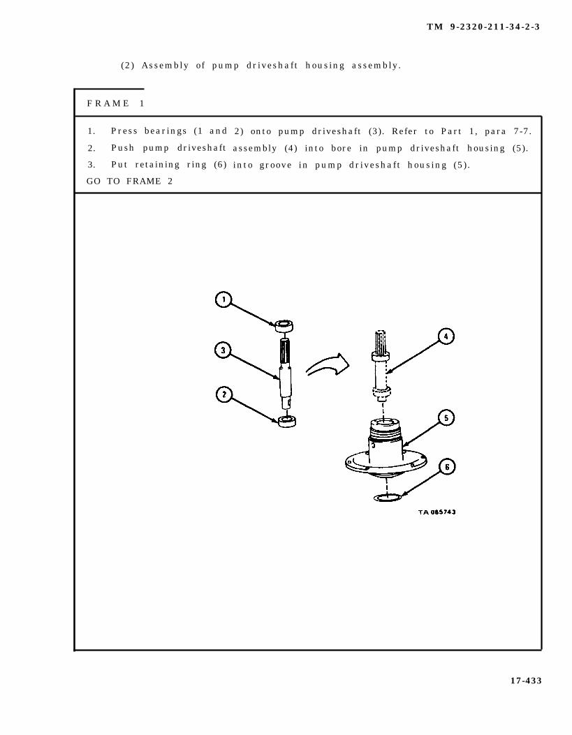
TM 9-2320-211-34-2-3
(2) Assembly of pump driveshaft housing assembly.
F R A M E 1
1. Press bearings (1 and
2. Push pump driveshaft
3. Put retaining ring (6)
GO TO FRAME 2
2) onto pump driveshaft (3). Refer to Part 1, para 7-7.
assembly (4) into bore in pump driveshaft housing (5).
into groove in pump driveshaft housing (5).
17-433
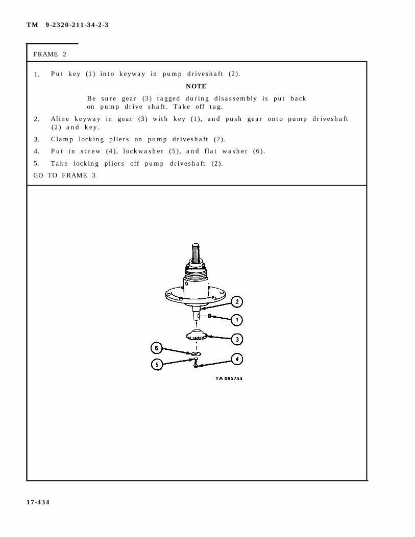
TM 9-2320-211-34-2-3
FRAME 2
1.
2.
3.
4.
5.
GO
Put key (1) into keyway in pump driveshaft (2).
NOTE
Be sure gear (3) tagged during disassembly is put backon pump drive shaft. Take off tag.
Aline keyway in gear (3) with key (1), and push gear onto pump driveshaft(2) and key.
Clamp locking pliers on pump driveshaft (2).
Put in screw (4), lockwasher (5), and flat washer (6).
Take locking pliers off pump driveshaft (2).
TO FRAME 3
17-434

TM 9-2320-211-34-2-3
FRAME 3
1.
2.
3.
4.
GO
Press seal (1) into end cover (2) .
Put end cover (2) with seal (1) and gasket (3) on pump drive shaft housingassembly (4), alining holes.
Put in four screws (5) with lockwashers (6).
Put retaining ring (7) in groove in end cover (2).
TO FRAME 4
17-435
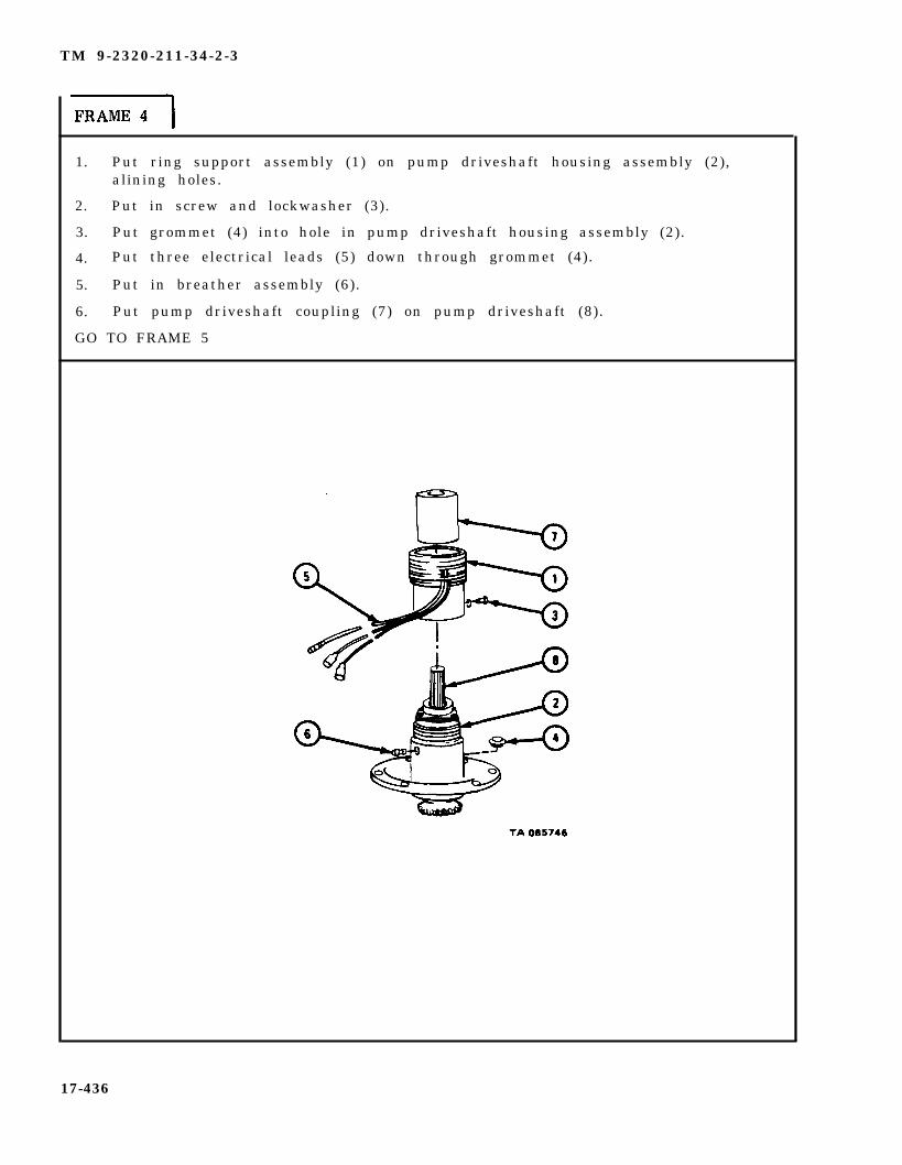
TM 9-2320-211-34-2-3
1. Put ring support assembly (1) on pump driveshaft housing assembly (2),alining holes.
2. Put in screw and lockwasher (3).
3. Put grommet (4) into hole in pump driveshaft housing assembly (2).
4. Put three electrical leads (5) down through grommet (4).
5. Put in breather assembly (6).
6. Put pump driveshaft coupling (7) on pump driveshaft (8).
GO TO FRAME 5
17-436

TM 9-2320-211-34-2-3
FRAME 5
1. Put layout dye on two or three teeth of gear (1).
2. Put pump driveshaft housing assembly (2) and gasket (3) bevel gearcasehousing (4), meshing gear (1) with gear (5).
3. Turn pump driveshaft coupling (6) 1/4-turn.
4. Take off pump driveshaft housing assembly (2) and gasket (3).
5. Look at layout dye pattern on gear (5). If pattern A is seen, gear backlashis correct .
IF PATTERN B OR C IS SEEN, GO TO FRAME 6.IF PATTERN A IS SEEN, END OF TASK
17-437

TM 9-2320-211-34-2-3
F R A M E 6
1. Takeout four screws and lockwashers (1).
2. Take off bearing cover (2) and gasket (3) .
3. If pattern B is seen on gear (4), add another shim (5).
4. If pattern C is seen on gear, take away a shim (5).
5. Put gasket (3) and bearing cover (2) in place, alining holes.
6. Put in four screws and lockwashers (1).
GO TO FRAME 5
17-438

TM 9-2320-211-34-2-3
g . Replacement.
1.
2.
S o l d i e r A 3 .
4.
S o l d i e r B 5 .
GO TO FRAME
Set pump driveshaft housing assembly (1) in place on truck body,alining holes.
Put in six screws (2) and lockwashers (3).
Put gasket (4) in place on bevel gearcase housing assembly (5),alining holes.
Lift bevel gearcase housing assembly (5) with gasket (4) into placebelow pump drive shaft housing assembly (1), alining holes.
Put on six screws (6) with lockwashers (7).
2
17-439

TM 9-2320-211-34-2-3
1. Push two male connectors (1) into two female connectors (2) as tagged. Takeoff tags.
1.
2.
3.
4.
5.6.7.
8.9.
10.11.12.
END OF TASK
NOTE
Follow-on Maintenance Action Required:
Fill bevel gear gearcase assembly. Refer toLO 9-2320-211-12.Replace power divider to bevel gearcase propellershaft. Refer to TM 9-2320-211-20.Replace crane turntable assembly. Refer to para17-33.Replace crane swinger gearcase with crane swingermotor. Refer to para 17-29.Replace hydaulic pump assembly. Refer to para 17-35.Replace gondola assembly. Refer to para 17-52.Replace boom elevating cylinders. Refer to para17-42.Replace hydraulic oil reservoir. Refer to para 17-37.Fill hydraulic oil reservoir. Refer to LO 9-2320-211-12.Replace boom assembly. Refer to para 17-44.Replace hoist winch cable. Refer to TM 9-2320-211-20.Check that bevel gear gearcase assembly and all linesand fittings removed and replaced during this taskare not leaking.
17-440

TM 9-2320-211-34-2-3
17-35. HYDRAULIC TURNTABLE PUMP ASSEMBLY REMOVAL, REPAIR ANDREPLACEMENT (TRUCK M543A2).
TOOLS: No special tools required
SUPPLIES: Solvent, dry cleaning, type II (SD-2), Fed. Spec P-D-680Lubricating oil, ICE, OE/HDO 10, MIL-L-2104Small block of woodCapsCrane pump inlet adapter preformed packingCrane pump outlet adapter preformed packingGear shaft bearing retainer ring (2)
PERSONNEL: One
EQUIPMENT CONDITION: Truck parked, engine off , handbrake set.
a . Preliminary Procedures.
(1 ) Drain hydraul i c o i l reservo ir . Refer to LO 9-2320-211-12 .
(2) Raise boom and put shipper braces in place. Refer to TM 9-2320-211-10.
17-441

TM 9-2320-211-34-2-3
b . Removal.
FRAME 1
1.
2.
3.
GO
Unscrew union nut (l) from fitting on hose (2). Takeoff hose.
Unscrew fitting on hose (2) from hydraulic pump assembly (3). Take off hose.
Cap open ports.
TO FRAME 2
17-442
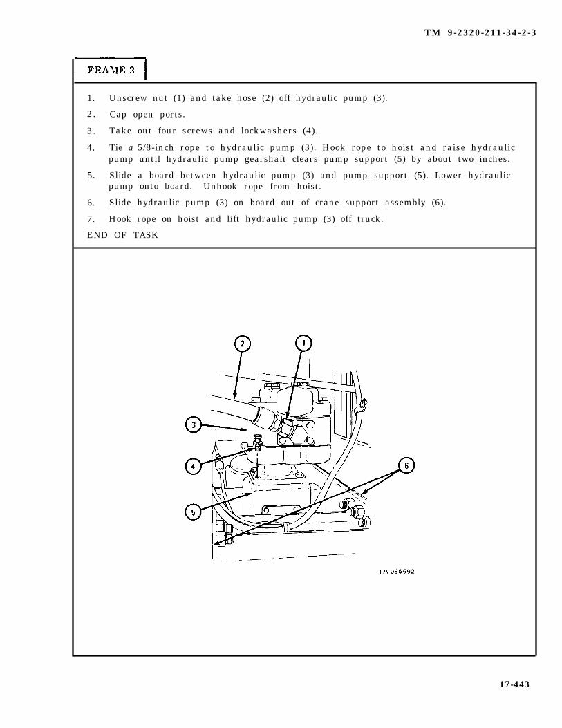
TM 9-2320-211-34-2-3
1. Unscrew nut (1) and take hose (2) off hydraulic pump (3).
2. Cap open ports.
3. Take out four screws and lockwashers (4).
4. Tie a 5/8-inch rope to hydraulic pump (3). Hook rope to hoist and raise hydraulicpump until hydraulic pump gearshaft clears pump support (5) by about two inches.
5. Slide a board between hydraulic pump (3) and pump support (5). Lower hydraulicpump onto board. Unhook rope from hoist.
6. Slide hydraulic pump (3) on board out of crane support assembly (6).
7. Hook rope on hoist and lift hydraulic pump (3) off truck.
END OF TASK
17-443

TM 9-2320-211-34-2-3
c . Disassembly.
F R A M E 1
Take
Take
Take
Take
Take
Take
Take
out union assembly (1).
out four screws and lockwashers (2).
off outlet adapter (3) with preformed packing (4).
and throw away preformed packing (4) from outlet adapter (3).
out four screws and lockwashers (5).
off inlet adapter (6) with preformed packing (7).
out and throw away preformed packing (7).
TO FRAME 2
1.
2.
3.
4.
5.
6.
7.
GO
17-444
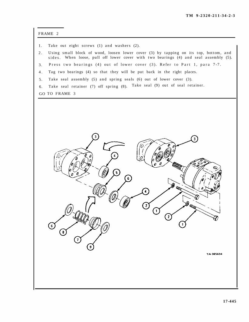
TM 9-2320-211-34-2-3
FRAME 2
1.
2.
3.
4 .
5.
6.
GO
Take out eight screws (1) and washers (2).
Using small block of wood, loosen lower cover (3) by tapping on its top, bottom, andsides. When loose, pull off lower cover with two bearings (4) and seal assembly (5).
Press two bearings (4) out of lower cover (3) . Refer to Part 1, para 7-7.
Tag two bearings (4) so that they will be put back in the right places.
Take seal assembly (5) and spring seals (6) out of lower cover (3).
Take seal retainer (7) off spring (8). Take seal (9) out of seal retainer.
TO FRAME 3
17-445

TM 9-2320-211-34-2-3
1. Using small block of wood, loosen wear plate (1) by tapping on its top, bottom, andsides. When loose, pull off wear plate.
2. Take out pump gearshaft assembly (2) and drive gearshaft assembly (3).
NOTE
Note position of upper cover assembly (4) to pump body (5)to make sure that it will be put back in the same position.
3. Using small block of wood, loosen upper cover assembly (4) and wear plate (6) bytapping on their tops, bottoms, and sides. When loose, pull off upper coverassembly and wear plate.
4. Take out four centering pins (7).
GO TO FRAME 4
17-446

TM 9-2320-211-34-2-3
FRAME 4
1. Take two bearings (1) out of upper cover (2) . Refer to Part 1, para 7-7.
2. Tag bearings (1) so that they will be put back in the right places.
3. Take out plug (3).
GO TO FRAME 5
17-447
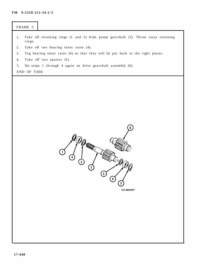
TM 9-2320-211-34-2-3
FRAME 5
1. Take off retaining rings (1 and 2) from pump gearshaft (3). Throw away retainingrings.
2. Take off two bearing inner races (4).
3. Tag bearing inner races (4) so that they will be put back in the right places.
4. Take off two spacers (5).
5. Do steps 1 through 4 again on drive gearshaft assembly (6).
END OF TASK
17-448

TM 9-2320-211-34-2-3
d . I n s p e c t i o n
FRAME 1
c. C l e a n i n g . There are no spec ia l c leaning procedures needed . Refer tocleaning procedures given in Part 1, para 1-3.
1. Check that four bearings (1) and four bearing inner races (2) are notdamaged. Refer to Part 1, para 7-7.
2. Check that pump gearshaft (3) and drive gearshaft (4) are not scratched,cracked, or burred .
GO TO FRAME 2
17-449
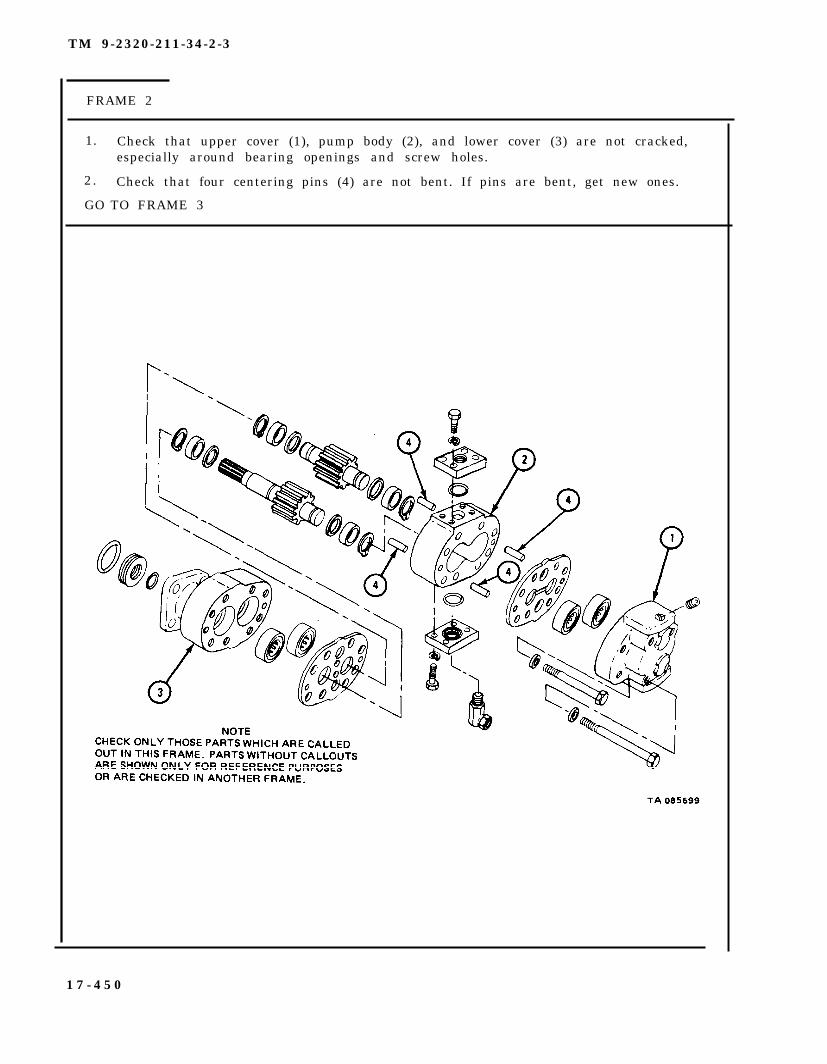
TM 9-2320-211-34-2-3
FRAME 2
1.
2.
GO
Check that upper cover (1), pump body (2), and lower cover (3) are not cracked,especially around bearing openings and screw holes.
Check that four centering pins (4) are not bent. If pins are bent, get new ones.
TO FRAME 3
1 7 - 4 5 0

TM 9-2320-211-34-2-3
FRAME 3
1. Check that two wear plates (1) are not nicked, burred, dented or distortied.
2. Using micrometer, check that thickness of wear plates (1) at gear contact surfaces(A) is within 0.003 inch of thickness at wear plate edges (B).
END OF TASK
17-451
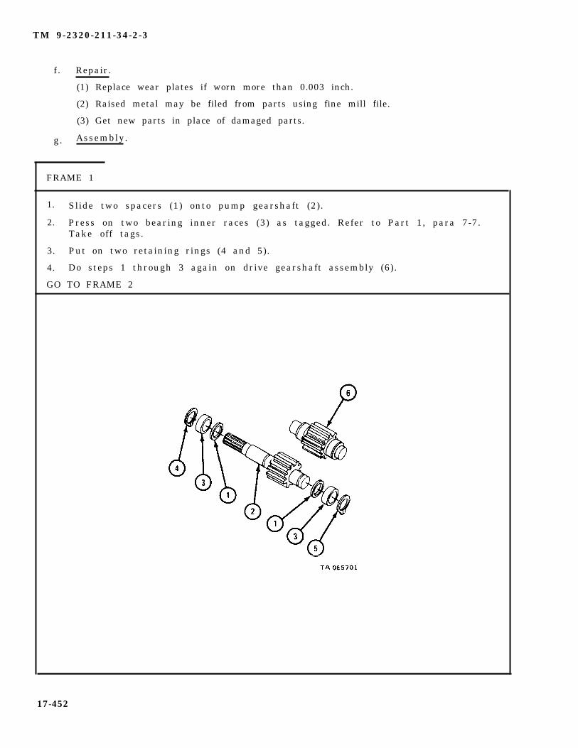
TM 9-2320-211-34-2-3
f . Repair.
(1) Replace wear plates if worn more than 0.003 inch.
(2) Raised metal may be filed from parts using fine mill file.
(3) Get new parts in place of damaged parts.
g. Assembly.
FRAME 1
1. Slide two spacers (1) onto pump gearshaft (2).
2. Press on two bearing inner races (3) as tagged. Refer to Part 1, para 7-7.Take off tags.
3. Put on two retaining rings (4 and 5).
4. Do steps 1 through 3 again on drive gearshaft assembly (6).
GO TO FRAME 2
17-452
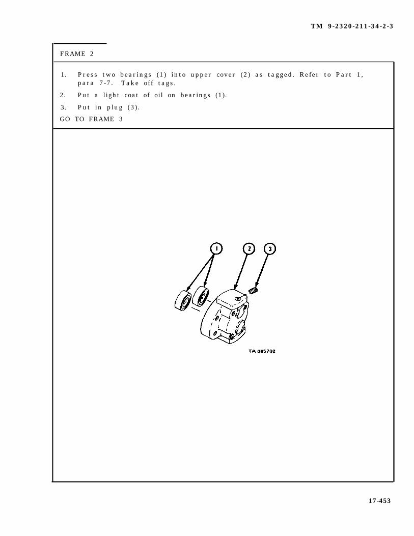
TM 9-2320-211-34-2-3
FRAME 2
1. Press two bearings (1) into upper cover (2) as tagged. Refer to Part 1,para 7-7. Take off tags.
2. Put a light coat of oil on bearings (1).
3. Put in plug (3).
GO TO FRAME 3
17-453

TM 9-2320-211-34-2-3
1. Put four centering pins (1) into pump body (2).
2. Put wear plate (3) on two centering pins (1) as shown and push it in placeagainst pump body (2) . Make sure that groove (4) in wear plate faces out.
3. Put upper cover assembly (5) on two centering pins (1) as noted and push itin place against wear plate (3).
GO TO FRAME 4
1 7 - 4 5 4
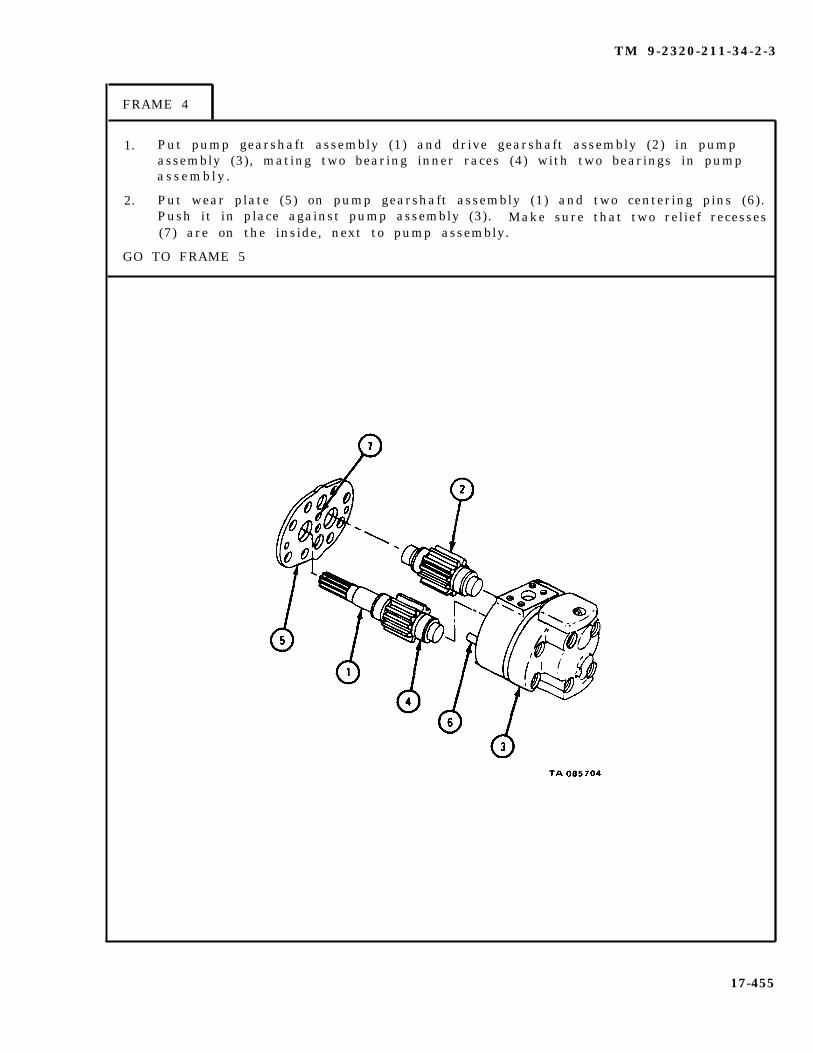
TM 9-2320-211-34-2-3
FRAME 4
1. Put pump gearshaft assembly (1) and drive gearshaft assembly (2) in pumpassembly (3), mating two bearing inner races (4) with two bearings in pumpassembly .
2. Put wear plate (5) on pump gearshaft assembly (1) and two centering pins (6).Push it in place against pump assembly (3). Make sure that two relief recesses(7) are on the inside, next to pump assembly.
GO TO FRAME 5
17-455

TM 9-2320-211-34-2-3
FRAME 5
1. Put seal (1) in place in seal retainer (2). Put seal retainer with seal into spring (3).
2 . Put spring seat (4) in lower cover (5). Put seal assembly (6) in lower cover. Put inspring seat (7).
3. Press two bearings (8) into lower cover (5). Refer to Part 1, para 7-7.
GO TO FRAME 6
17-456

TM 9-2320-211-34-2-3
FRAME 6
1.
2.
3.
4.
5.
GO
Aline lower cover assembly (1) with pump gearshaft (2) and two centeringpins (3 ) . Push cover assembly in place on pump assembly (4).
Clamp lower cover assembly (1) in vise with soft jaw caps.
Put in eight screws (5) and washers (6). Tighten screws a little at a time untilall screws are tightened.
Tighten eight screws (5) to 150 pound-feet.
Take lower cover assembly (1) out of vise.
TO FRAME 7
17-457

TM 9-2320-211-34-2-3
FRAME 7
1. Put preformed packing (1) in groove in inlet adapter (2),
2. Put inlet adapter (2) with preformed packing (1) on pump assembly (3), and alineholes.
3. Put in four screws (4) and lockwashers (5).
4. Put preformed packing (6) in groove in outlet adapter (7).
5. Put outlet adapter (7) with preformed packing (6) on pump assembly (3), aliningholes.
6. Put in four screws (8) and lockwashers (9).
7. Put in union assembly (10).
END OF TASK
17-458

TM 9-2320-211-34-2-3
h. Replacement .
FRAME 1
1.
2 .
3.
4 .
5.
6.
7.
8.
Place board on pump support (1) between crane support assembly (2).
Tie 5/8 -inch rope to pump assembly (3). Hook rope to hoist and lift pump assemblyonto board. Unhook rope from hoist.
Slide pump assembly (3) and board into place over pump support (1) between cranesupport assembly (2).
Hook rope to hoist and raise pump assembly (3) off board. Take out board.
Aline pump gearshaft (4) with coupling (5) and lower pump assembly (3) onto pumpsupport (1), alining holes.
Put in four screws and lockwashers (6).
Take off caps.
Put nut (7) on fitting on hose (8).
GO TO FRAME 2
17-459

TM 9-2320-211-34-2-3
FRAME 2
1. Take caps off fittings on hose (1).
2. Put fitting on hose (1) on hydraulic pump assembly (2).
3. Put on union nut
1. Fill
( 3 ) .
NOTE
Follow-on Maintenance Action Required:
hydraulic oil reservoir. Refer to LO 9-2320-211-12.2. Take shipper braces off boom and lower boom. Refer
to TM 9-2320-211-10.3. Operate crane and check hydraulic pump assembly for
proper operation and check that there are no leaks.Refer to TM 9-2320-211-10.
END OF TASK
17-460

TM 9-2320-211-34-2-3
17-36. SWING HYDRAULIC MOTOR ASSEMBLY REMOVAL, REPAIR, AND REPLACE-MENT (TRUCK M543A2).
TOOLS: No special tools required
SUPPLIES: Swinger motor gasketFront cover seal adapter preformed packing (2)Rear cover seal adapter performed packing (2)Driven gearshaft retaining ring (2)Drive gearshaft retaining ring (2)Solvent, dry cleaning, type II (SD-2), Fed. Spec P-D-680Lubricating oil , ICE, OD/HDO-10, MIL-L-2104Small block of woodCapsT a g s
PERSONNEL: TWO
EQUIPMENT CONDITION: Truck parked, engine off , handbrake set.
17-461
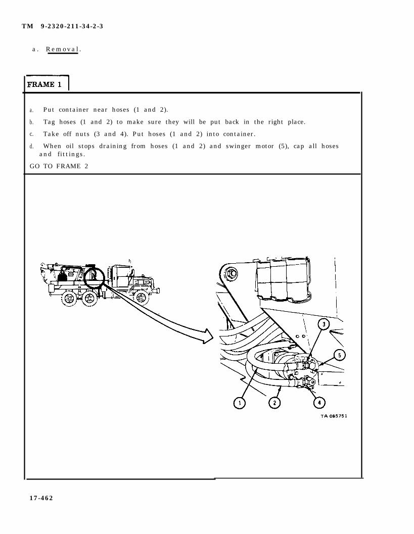
TM 9-2320-211-34-2-3
a . R e m o v a l .
a. Put container near hoses (1 and 2).
b. Tag hoses (1 and 2) to make sure they will be put back in the right place.
c. Take off nuts (3 and 4). Put hoses (1 and 2) into container.
d. When oil stops draining from hoses (1 and 2) and swinger motor (5), cap all hosesand fittings.
GO TO FRAME 2
17-462

TM 9-2320-211-34-2-3
FRAME 2
1. Takeout four screws (1) and lockwashers (2).
S o l d i e r s 2 . Take swinger motor (3) and gasket (4) off swinger drive gearcaseA and B (5) . Throw away gasket .
END OF TASK
14-463

TM 9-2320-211-34-2-3
b . D i s a s s e m b l y .
FRAME 1
1. Take out key (1).
2. Take out union assembly (2) and union with plug (3).
3. Takeout eight screws and washers (4).
4. Using small block of wood, loosen front cover assembly (5) by tapping on itstop, bottom, and sides. Pull off front cover assembly.
GO TO FRAME 2
P
1
1 7 - 4 6 4
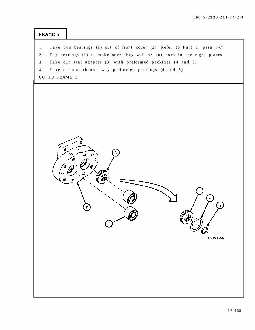
TM 9-2320-211-34-2-3
1. Take two bearings (1) out of front cover (2). Refer to Part 1, para 7-7.
2. Tag bearings (1) to make sure they will be put back in the right places.
3. Take out seal adapter (3) with preformed packings (4 and 5).
4. Take off and throw away preformed packings (4 and 5).
GO TO FRAME 3
17-465
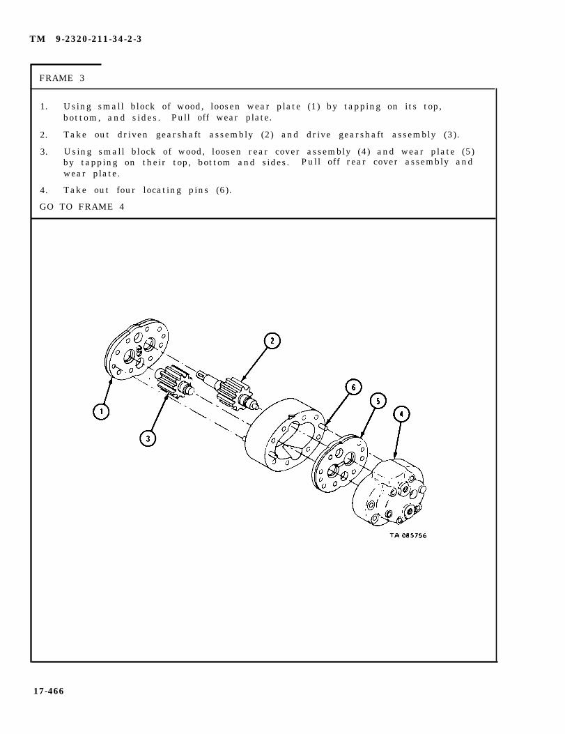
TM 9-2320-211-34-2-3
FRAME 3
1. Using small block of wood, loosen wear plate (1) by tapping on its top,bottom, and sides. Pull off wear plate.
2. Take out driven gearshaft assembly (2) and drive gearshaft assembly (3).
3. Using small block of wood, loosen rear cover assembly (4) and wear plate (5)by tapping on their top, bottom and sides. Pull off rear cover assembly andwear plate.
4. Take out four locating pins (6).
GO TO FRAME 4
17-466

TM 9-2320-211-34-2-3
FRAME 4
1. Take two bearings (1) out of rear cover (2). Refer to Part 1, para 7-7.
2. Tag bearings (1) to make sure they will be put back in the right places.
3. Take out seal adapter (3) with preformed packings (4 and 5).
4. Take off and throw away preformed packings (4 and 5).
GO TO FRAME 5
17-467

TM 9-2320-211-34-2-3
1. Take off and throw away two retaining rings (1) from driven gearshaft (2).
2. Take off two bearing inner races (3). Refer to Part 1, para 7-7.
3. Tag bearing inner races (3) to make sure they will be put back in the rightp laces .
4. Take off two spacers (4) .
GO TO FRAME 6
17-468
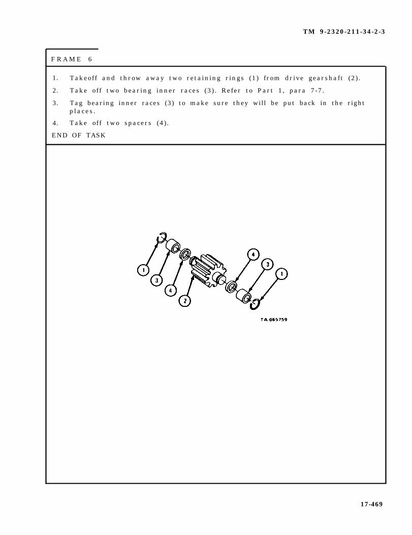
TM 9-2320-211-34-2-3
F R A M E 6
1. Takeoff and throw away two retaining rings (1) from drive gearshaft (2) .
2. Take off two bearing inner races (3) . Refer to Part 1, para 7-7.
3. Tag bearing inner races (3) to make sure they will be put back in the rightp laces .
4. Take off two spacers (4) .
END OF TASK
17-469

TM 9-2320-211-34-2-3
c . Cleaning.
( 1 ) C l e a n
( 2 ) C l e a n
( 3 ) P u t a
bear ings . Refer to Part 1, para 7-7.
Dry cleaning solvent is flammable. Do not use nearan open flame. Keep a fire extinguisher nearby whensolvent is used. Use only in well-ventilated places.Failure to do this may result in injury to personneland damage to equipment.
all other parts in solvent.
coat of light oil on polished surfaces.
17-470

TM 9-2320-211-34-2-3
d. Inspect ion .
FRAME 1
1. Check that four bearings (1) and bearing inner races (2) are not damaged.Refer to Part 1, para 7-7.
2 . Check that driven gearshaft (3) and drive gearshaft (4) are not scratched,cracked, or burred .
3 . Check that front cover (5), motor body (6), and rear cover (7) mating surfaces arenot scratched or burred, and that bores are not scored.
4 . Check that four locating pins (8) are not bent.
GO TO FRAME 2
17-471
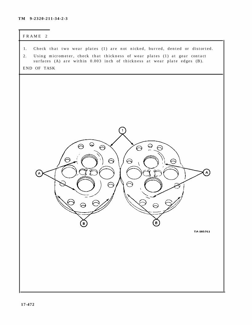
TM 9-2320-211-34-2-3
F R A M E 2
1. Check that two wear plates (1) are not nicked, burred, dented or distorted.
2. Using micrometer, check that thickness of wear plates (1) at gear contactsurfaces (A) are within 0.003 inch of thickness at wear plate edges (B).
END OF TASK
17-472
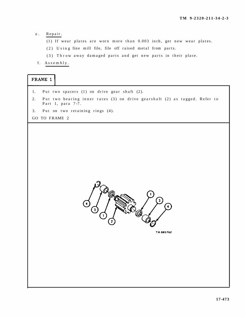
TM 9-2320-211-34-2-3
e . Repair.
(1) If wear plates are worn more than 0.003 inch, get new wear plates.
( 2 ) U s i n g
( 3 ) T h r o w
f . A s s e m b l y .
fine mill file, file off raised metal from parts.
away damaged parts and get new parts in their place.
1. Put two spacers (1) on drive gear shaft (2).
2. Put two bearing inner races (3) on drive gearshaft (2) as tagged. Refer toPart 1, para 7-7.
3. Put on two retaining rings (4).
GO TO FRAME 2
17-473
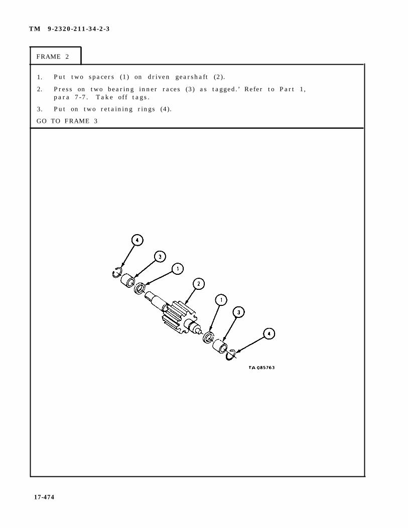
TM 9-2320-211-34-2-3
FRAME 2
1. Put two spacers (1) on driven gearshaft (2).
2. Press on two bearing inner races (3) as tagged.’ Refer to Part 1,para 7-7. Take off tags.
3. Put on two retaining rings (4).
GO TO FRAME 3
17-474

TM 9-2320-211-34-2-3
FRAME 3
1.
2.
3.
4.
GO
Dip preformed packings (1 and 2) in clean oil and put them on seal adapter( 3 ) .
Put seal adapter (3) with preformed packings (1 and 2) in bore in rear cover(4), with beveled edge facing out.
Put two bearings (5) in bores in rear cover (4) as tagged. Refer to Part 1,para 7 -7 . Take o f f tags .
Put a light coat of oil on bearings (5).
TO FRAME 4
17-475

TM 9-2320-211-34-2-3
FRAME 4
1.
2.
3.
GO
Put four locating pins (1) into motor body (2).
Put wear plate (3) on two locating pins (1) and push it in place against motorbody (2) . Be sure that groove (4) in wear plate faces out and that wearplate is on side of motor body with notch (5).
Put rear cover assembly (6) on two locating pins (1) and push it in placeagainst wear plate (3).
TO FRAME 5
17-476
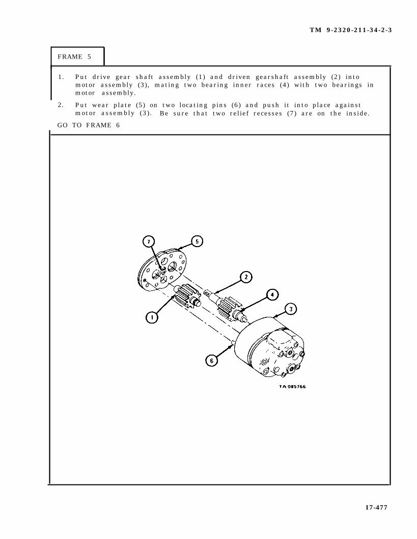
TM 9-2320-211-34-2-3
FRAME 5
1. Put drive gear shaft assembly (1) and driven gearshaft assembly (2) intomotor assembly (3), mating two bearing inner races (4) with two bearings inmotor assembly.
2. Put wear plate (5) on two locating pins (6) and push it into place againstmotor assembly (3). Be sure that two relief recesses (7) are on the inside.
GO TO FRAME 6
17-477
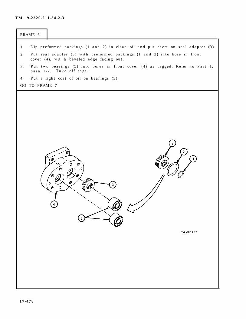
TM 9-2320-211-34-2-3
FRAME 6
1. Dip preformed packings (1 and 2) in clean oil and put them on seal adapter (3).
2. Put seal adapter (3) with preformed packings (1 and 2) into bore in frontcover (4), wit h beveled edge facing out.
3. Put two bearings (5) into bores in front cover (4) as tagged. Refer to Part 1,para 7-7. Take off tags.
4. Put a light coat of oil on bearings (5).
GO TO FRAME 7
17-478

TM 9-2320-211-34-2-3
F R A M E 7
1. Put front cover assembly (1) on locating pins (2) and push it in place onmotor assembly (3).
2. Put in eight screws and washers (4 and 5) and tighten screws a little at a timeuntil all screws are tightened.
3. Put in union assembly (6) and union with plug (7).
4. Put key (8) in place as shown.
END OF TASK
17-479
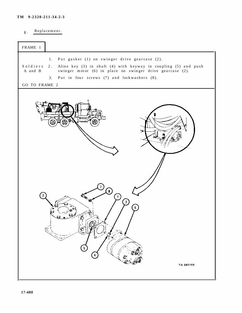
TM 9-2320-211-34-2-3
g . Replacement.
FRAME 1
1. Put gasket (1) on swinger drive gearcase (2).
S o l d i e r s 2 . Aline key (3) in shaft (4) with keyway in coupling (5) and pushA and B swinger motor (6) in place on swinger drive gearcase (2).
3. Put in four screws (7) and lockwashers (8).
GO TO FRAME 2
17-480

TM 9-2320-211-34-2-3
FRAME 2
NOTE
Take caps off hoses and fittings.
1. Put nuts (1 and 2) onto hoses (3 and 4) as tagged. Take
NOTE
Follow-on Maintenance Action Required:
off tags.
1. Operate crane and check swinger motor for properoperation and check that there are no leaks. Referto TM 9-2320-211-10.
2. Fill hydraulic oil reservoir as given in LO 9-2320-211-12.
END OF TASK
1 7 - 4 8 1
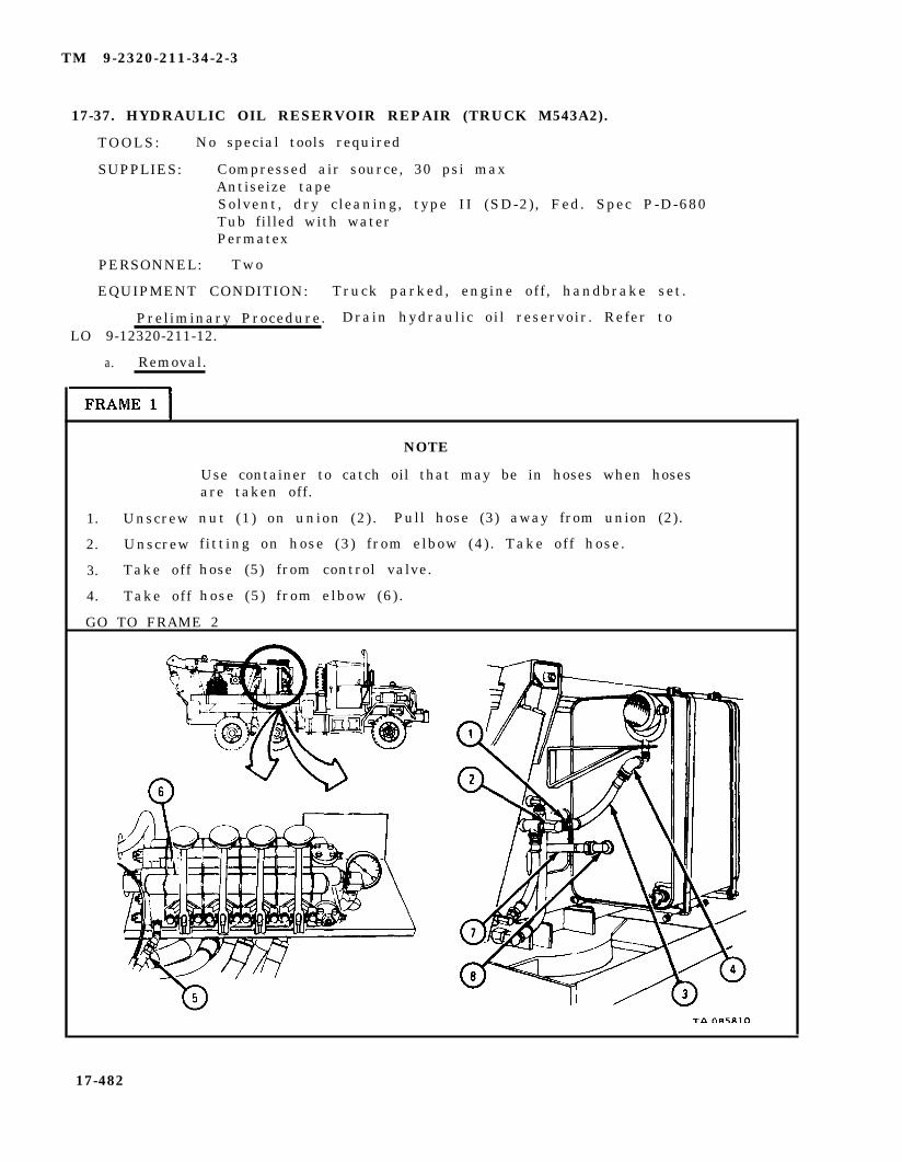
TM 9-2320-211-34-2-3
17-37. HYDRAULIC OIL RESERVOIR REPAIR (TRUCK M543A2).
TOOLS: No special tools required
SUPPLIES: Compressed air source, 30 psi maxAntiseize tapeSolvent, dry cleaning, type II (SD-2), Fed. Spec P-D-680Tub filled with waterPermatex
PERSONNEL: Two
EQUIPMENT CONDITION: Truck parked, engine off , handbrake set.
Preliminary Procedure. Drain hydraulic oil reservoir. Refer toLO 9-12320-211-12.
a. Removal.
1.
2.
3.
4.
Unscrew
Unscrew
Take off
Take off
NOTE
Use container to catch oil that may be in hoses when hosesare taken off.
nut (1) on union (2) . Pull hose (3) away from union (2).
f itting on hose (3) from elbow (4). Take off hose.
hose (5) from control valve.
hose (5) from elbow (6) .
GO TO FRAME 2
17-482
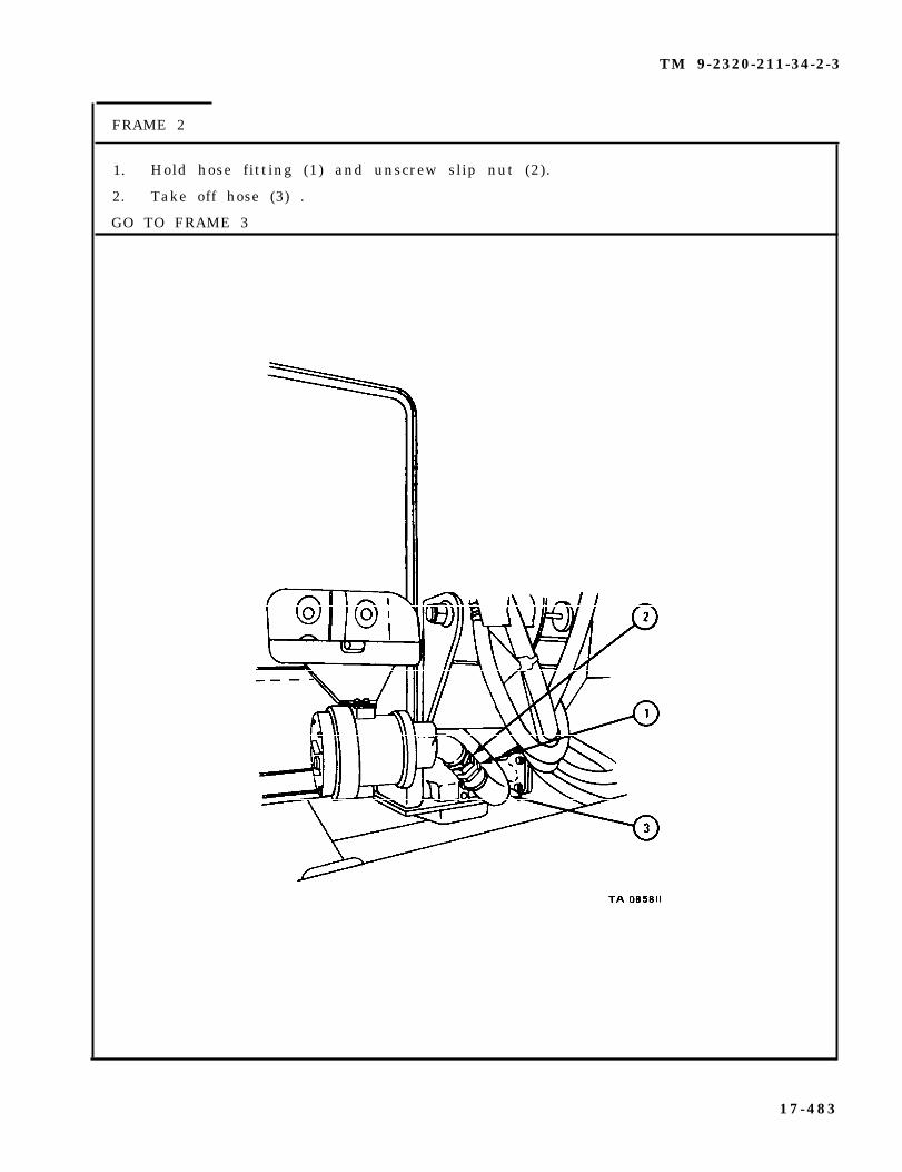
TM 9-2320-211-34-2-3
FRAME 2
1. Hold hose fitting (1) and unscrew slip nut (2).
2. Take off hose (3) .
GO TO FRAME 3
17-483
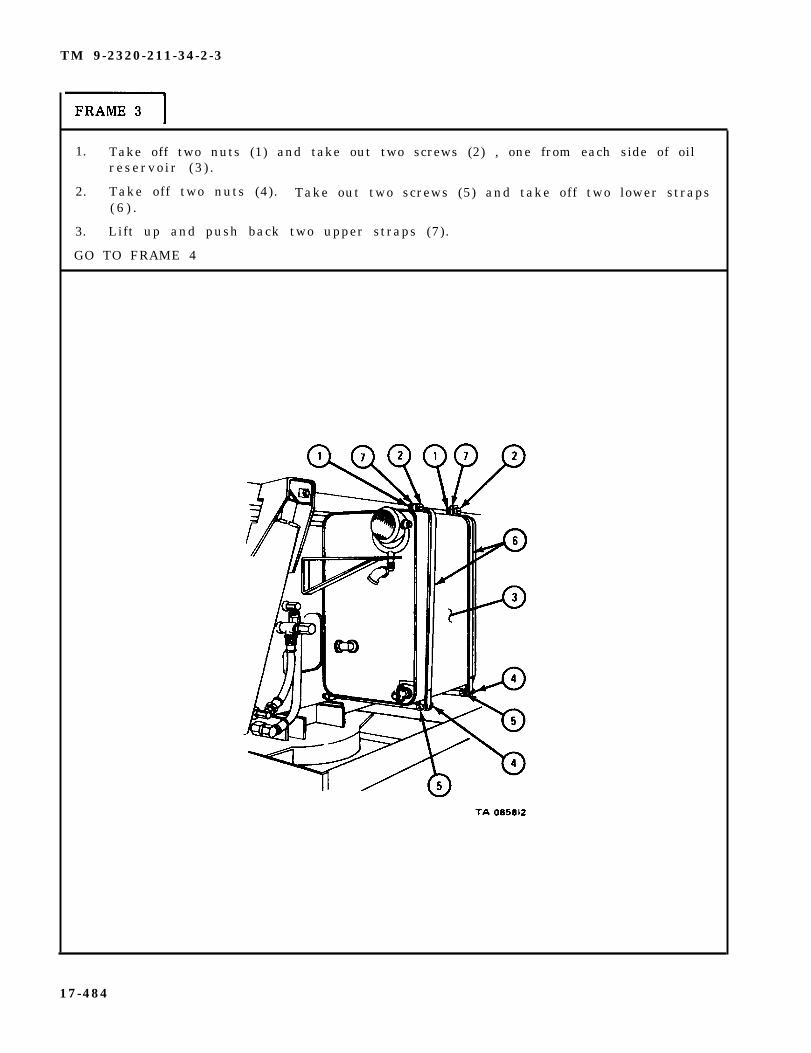
TM 9-2320-211-34-2-3
1. Take off two nuts (1) and take out two screws (2) , one from each side of oilreservo ir (3 ) .
2. Take off two nuts (4). Take out two screws (5) and take off two lower straps( 6 ) .
3. Lift up and push back two upper straps (7).
GO TO FRAME 4
17-484
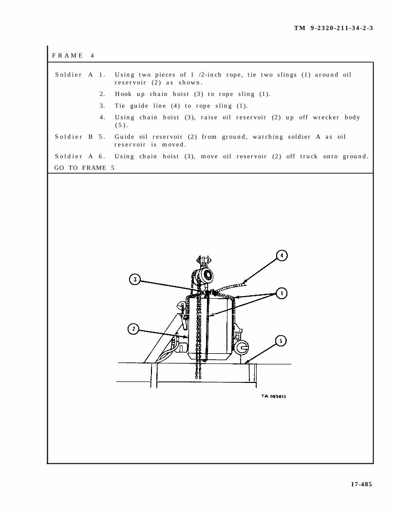
TM 9-2320-211-34-2-3
S o l d i e r A 1 . Using two pieces of 1 /2-inch rope, tie two slings (1) around oilreservoir (2) as shown.
2. Hook up chain hoist (3) to rope sling (1).
3. Tie guide line (4) to rope sling (1).
4. Using chain hoist (3), raise oil reservoir (2) up off wrecker body( 5 ) .
S o l d i e r B 5 . Guide oil reservoir (2) from ground, watching soldier A as oilreservoir is moved.
S o l d i e r A 6 . Using chain hoist (3), move oil reservoir (2) off truck onto ground.
GO TO FRAME 5
17-485
F R A M E 4

TM 9-2320-211-34-2-3
F R A M E 5
1. Takeout eight screws and lockwashers (1).
2. Take off two strap and support assemblies (2).
END OF TASK
17-486

TM 9-2320-211-34-2-3
NOTE
If truck is not equipped with fuel can brac-ket, take out screws (6) and washers (7)and go to frame 2.
c . D i s a s s e m b l y .
FRAME 1
1. Take out four screws (1) and nuts (2). Take off fuel can ret airier bracket( 3 ) .
2. Take out four screws (4) and nuts (5).
3. Take out two screws (6) and four washers (7). Take off fuel can mountingbracket (8 ) .
GO TO FRAME 2
17-487

TM 9-2320-211-34-2-3
FRAME 2
1.
S o l d i e r A 2 .
S o l d i e r B 3 .
S o l d i e r A 4 .
GO TO FRAME
Take out three screws (1) and nuts (2). Take off oil f i lter bracket( 3 ) .
Hold oil filter assembly (4)
Unscrew oil filter assemblyreservo ir (6 ) .
Take off oil filter assembly
3
with both hands.
(4) and oil filter flange (5) from oil
(4) and flange (5) .
17-488

TM 9-2320-211-34-2-3
FRAME 3
1 . Take out drain cock (1).
2 . Take out drain plug (2).
NOTE
Note position of two elbows (3) before taking them out so thatthey can be put back at same angle.
3 . Take off two elbows (3).
4 . Pull out gage assembly (4) and filter screen (5).
END OF TASK
17-489

TM 9-2320-211-34-2-3
d. Cleaning..
WARNING
Dry cleaning solvent is flammable. Do not use nearan open flame. Keep a fire extinguisher nearby whensolvent is used. Use only in well-ventilated places.Failure to do this may result in injury to personneland damage to equipment.
(1) Clean all metal parts in solvent. Let parts air dry.
(2) Flush inside of oil reservoir with an approved cleaning solvent. Refer toTM 9-247.
(3) Steam clean outside surface of oil reservoir.
17-490

TM 9-2320-211-34-2-3
e . Inspection.
F R A M E 1
1.
2.
3.
4.
5.
6.
GO
Using plug set, seal all openings (1) except filter inlet (2).
Put air hose (3) with proper fitting into filter inlet (2).
Put oil reservoir (4) into tub filled with water.
WARNING
Eye shields must be worn when using compressed air.Eye injury can occur if eye shields are not used.
Apply air pressure of f ive pounds per square inch. Bubbles will show anyleaks in oil reservoir (4). Mark leaking areas for repair.
Take oil reservoir (4) out of tub. Take out all seals and
Dry oil reservoir (4) with compressed air at 15 psi max.
TO FRAME 2
take away air hose.
17-491

TM 9-2320-211-34-2-3
1 . Check that housing of oil filter assembly (1) is not cracked or broken.
2 . Check that fuel can retainer bracket (2), fuel can mounting bracket (3), and oilfilter bracket (4) are not cracked or bent, and that they do not have broken weldsor damaged screw holes.
3 . Check that two strap and support assemblies (5) are not cracked, bent, or broken,and that insulating strips are not damaged.
4 . Check that screws and nuts do not have damaged threads.
END OF TASK
17-492
FRAME 2
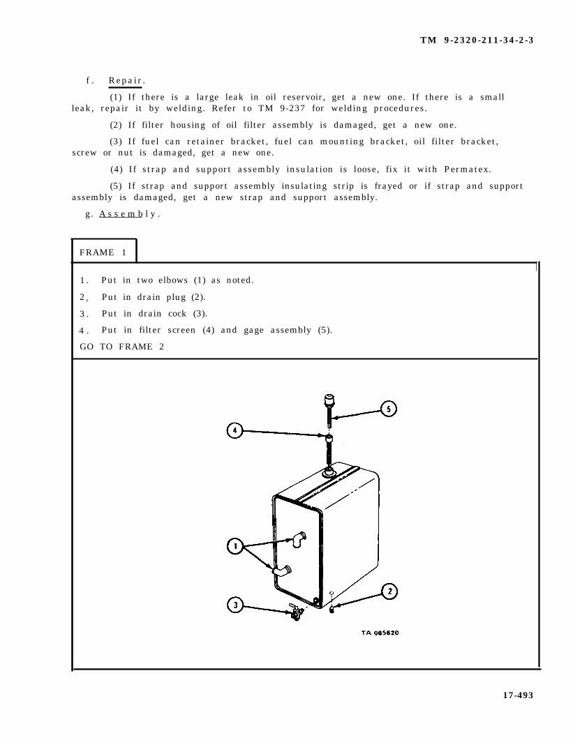
TM 9-2320-211-34-2-3
f . Repair.
(1) If there is a large leak in oil reservoir, get a new one. If there is a smallleak, repair it by welding. Refer to TM 9-237 for welding procedures.
(2) If filter housing of oil filter assembly is damaged, get a new one.
(3) If fuel can retainer bracket, fuel can mounting bracket, oil filter bracket,screw or nut is damaged, get a new one.
(4) If strap and support assembly insulation is loose, fix it with Permatex.
(5) If strap and support assembly insulating strip is frayed or if strap and supportassembly is damaged, get a new strap and support assembly.
g. A s s e m b l y .
FRAME 1
1 . Put in two elbows (1) as noted.
2 0 Put in drain plug (2).
3 . Put in drain cock (3).
4 . Put in filter screen (4) and gage assembly (5).
GO TO FRAME 2
17-493

TM 9-2320-211-34-2-3
FRAME 2
Sold ier A 1 .
S o l d i e r s 2 .A and B
Sold ier A 3 .
4 .
GO TO FRAME
Put oil filter assembly (1) and flange (2) in position on oil reservoir (3).
Screw oil filter assembly (1) and flange (2) into oil reservoir (3). Tightenflange in oil reservoir.
Put oil filter bracket (4) on oil reservoir (3) and aline three holes. Putthree screws (5) through holes.
Put on three nuts (6).
3
17-494

TM 9-2320-211-34-2-3
NOTE
If truck is not equipped with fuel can mount-in g bracket, END OF TASK.
F R A M E 3
1. Put fuel can mounting bracket (1) in position on oil reservoir (2) and put fourscrews (3) through holes. Put on four nuts (4).
2. Put in two screws (5) and four washers (6).
GO TO FRAME 4
17-495

TM 9-2320-211-34-2-3
F R A M E 4
1. Put fuel can retainer bracket (1) on fuel can mounting bracket (2) and put four screws(3) through holes.
2 . Put on four nuts (4).
END OF TASK
17-496

TM 9-2320-211-34-2-3
h. R e p l a c e m e n t .
FRAME 1
1 . Put two strap and support assemblies (1) in place on crane support assembly (2),alining holes.
2 . Put in eight screws and lockwashers (3).
GO TO FRAME 2
17-497

TM 9-2320-211-34-2-3
F R A M E 2
Sold ier A 1 . Using two pieces of l/2-inch rope, tie two slings (1) around oil reservoir(2) as shown.
2 . Hook up chain hoist (3) to rope sling (1).
3 . Tie guide line (4) to rope sling (1).
So ld ier B 4 . Guide oil reservoir (2) from ground, watching soldier A.
So ld ier A 5 . Using chain hoist (3), raise oil reservoir (2) up onto wrecker body (5).
So ld ier B 6 . From truck, guide oil reservoir (2) into position on wrecker body (5).Take off hoist (3) and rope sling (1).
GO TO FRAME 3
17-498
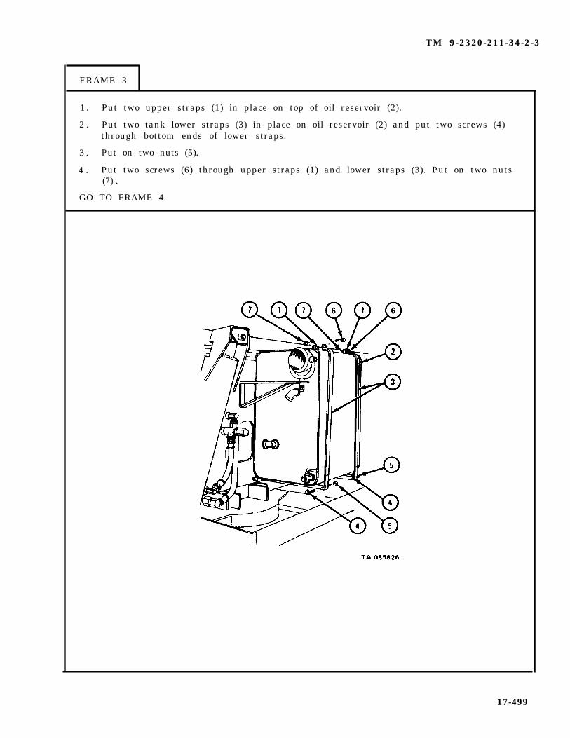
TM 9-2320-211-34-2-3
FRAME 3
1 . Put two upper straps (1) in place on top of oil reservoir (2).
2 . Put two tank lower straps (3) in place on oil reservoir (2) and put two screws (4)through bottom ends of lower straps.
3 . Put on two nuts (5).
4 . Put two screws (6) through upper straps (1) and lower straps (3). Put on two nuts(7) .
GO TO FRAME 4
17-499
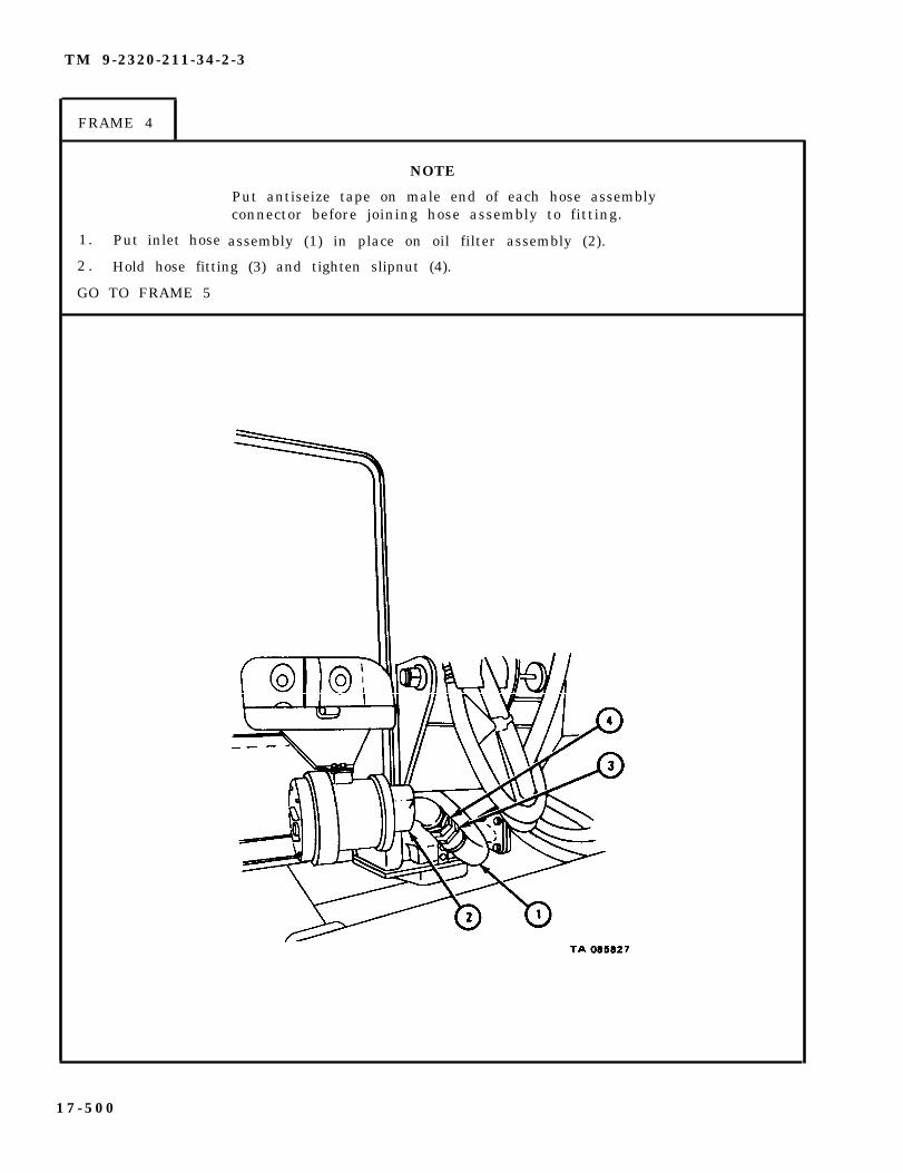
TM 9-2320-211-34-2-3
FRAME 4
1. Put inlet hose
NOTE
Put antiseize tape on male end of each hose assemblyconnector before joining hose assembly to fitting.
assembly (1) in place on oil filter assembly (2).
2 . Hold hose fitting (3) and tighten slipnut (4).
GO TO FRAME 5
1 7 - 5 0 0

TM 9-2320-211-34-2-3
F R A M E 5
1. Put hose assembly fitting
2. Put hose assembly fitting
3. Put hose assembly (5) on
4. Put hose assembly (5) on
(1) on elbow (2) . Tighten fitting (1).
(3) on union assembly (4) and tighten.
e lbow (6 ) .
control valve.
NOTE
Follow-on Maintenance Action Required:
Fill hydraulic oil reservoir. Refer to LO 9-2320-211-12.
END OF TASK
17-501

TM 9-2320-211-34-2-3
17-38. BOOM AND SHIPPER ROLLER ASSEMBLIES REPAIR (TRUCK M543A2).
NOTE
This task is the same for the boom and shipperroller assemblies. This task is shown for theboom roller assembly.
TOOLS: No special tools required
SUPPLIES: Solvent, dry cleaning, type II (SD-2), Fed. Spec P-D-680.
PERSONNEL: One
EQUIPMENT CONDITION: Truck parked, engine off , handbrake set.
17-502
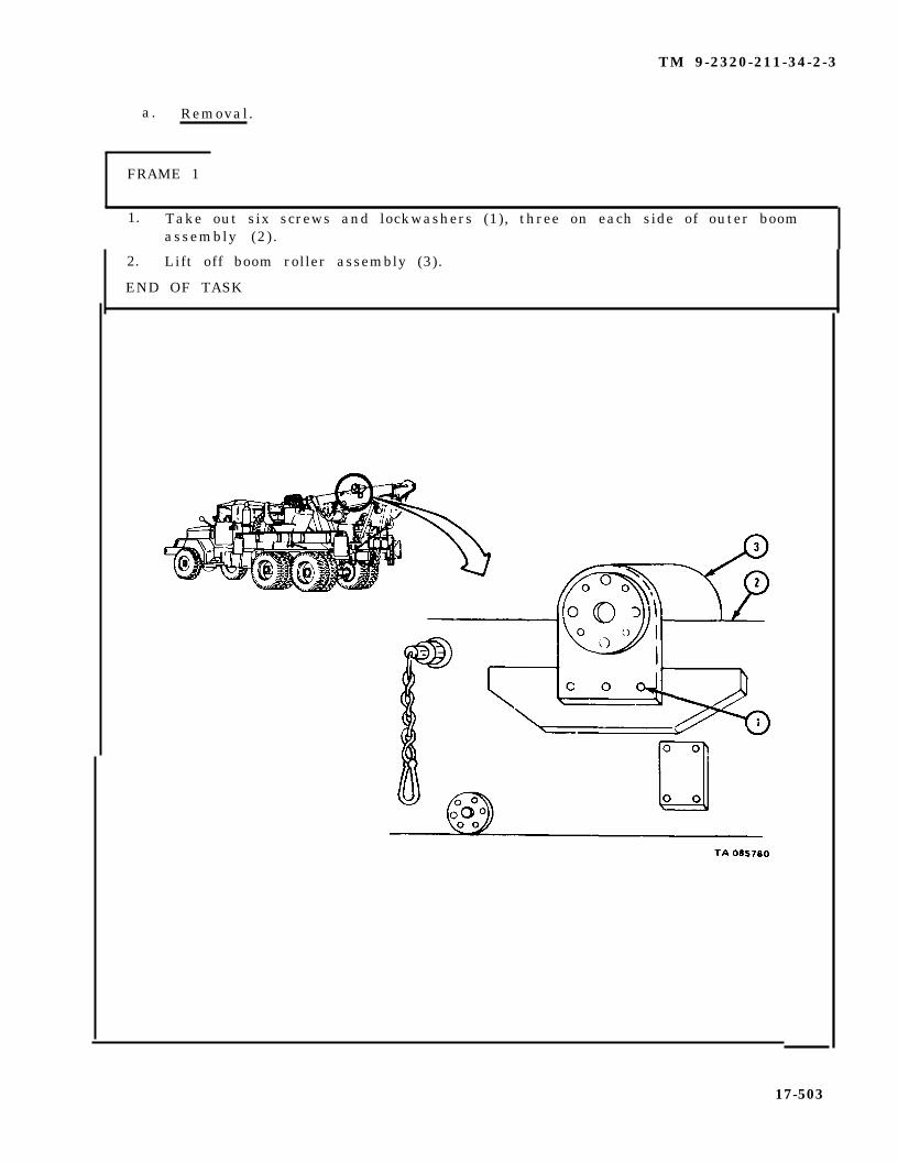
TM 9-2320-211-34-2-3
a. Removal.
FRAME 1
1. Take out six screws and lockwashers (1), three on each side of outer boomassembly (2).
2. Lift off boom roller assembly (3).
END OF TASK
17-503

TM 9-2320-211-34-2-3
b . Disassembly.
F R A M E 1
1. Take out eight screws (1) and lockwashers (2), four on each end of frame (3).
2. Drive end of shaft (4) 1/2-inch into bore in shaft support (5).
NOTE
Note positions and number of shims (6) to make surethey are put back in the right place.
3. Pull off shaft support (5) and shims (6).
4. Do steps 2 and 3 again on other end of shaft (4).
5. Take shaft (4) with two roller wheel assemblies (7) out of frame (3).
GO TO FRAME 2
17-504

TM 9-2320-211-34-2-3
FRAME 2
1. Take out two keys (1).
2. Pull off two assembled roller wheels (2) and bearings (3).
3. Working through pin holes in two roller wheels (2), drive out two bearings (3).
END OF TASK
17-505
TM 9-2320-211-34-2-3
c . Cleaning.
WARNING
Dry cleaning solvent is flammable. Do not usenear an open flame. Keep a fire extinguishernearby when solvent is used. Use only in well-ventilated places. Failure to do this may resultin injury to personnel and damage to equipment
Do not dry bearings with compressed air. Spin-ning bearings may explode, causing injury topersonnel and damage to equipment.
(1) Clean all parts with solvent.
(2 ) Let parts dry .
17-506
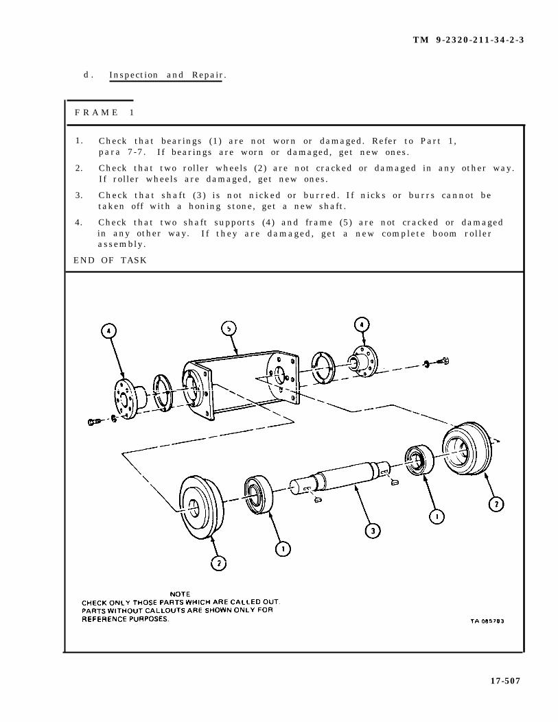
TM 9-2320-211-34-2-3
d . Inspection and Repair.
F R A M E 1
1.
2.
3.
4.
Check that bearings (1) are not worn or damaged. Refer to Part 1,para 7-7. If bearings are worn or damaged, get new ones.
Check that two roller wheels (2) are not cracked or damaged in any other way.If roller wheels are damaged, get new ones.
Check that shaft (3) is not nicked or burred. If nicks or burrs cannot betaken off with a honing stone, get a new shaft.
Check that two shaft supports (4) and frame (5) are not cracked or damagedin any other way. If they are damaged, get a new complete boom rollerassembly.
END OF TASK
17-507

TM 9-2320-211-34-2-3
e . Assembly .
F R A M E 1
1. Press two bearings (1) into two roller wheels (2). Refer to Part 1, para 7-7.
2. Press two assembled roller wheels (2) and bearings (1) on shaft (3) . Referto Part 1, para 7-7.
3. Put in two keys (4).
GO TO FRAME 2
17-508

TM 9-2320-211-34-2-3
FRAME 2
1. Put shaft (1) with two roller wheel assemblies (2) into frame (3).
2. Put needed number of shims (4) on two shaft supports (5) in position notedduring disassembly.
3. Put shaft supports (5) with shims (4) on shaft (1). Line up keyways in shaftsupports with keys (6) and push shaft supports into place.
4. Turn shaft supports (5) so that high sides of shaft supports are at closed endof frame (3) .
5. Put in eight screws (7) and lockwashers (8).
END OF TASK
17-509

TM 9-2320-211-34-2-3
f. Replacement.
F R A M E 1
1. Put boom roller assembly (1) in place on outer boom assembly (2).
2. Put in six screws and lockwashers (3), three on each side of outer boomassembly (2).
NOTE
Follow-on Maintenance Action Required:
Adjust crane inner and outer boom roller assemblies. Referto TM 9-2320-211-20.
END OF TASK
17-510
TM 9-2320-211-34-2-3
17-39. BOOM CROWD CYLINDER PACKING REMOVAL AND REPLACEMENT.
TOOLS: No special tools required
SUPPLIES: Preformed packingArtillery and automotive grease, type GAA, MIL-G-10924Brass bar
PERSONNEL: Two
EQUIPMENT CONDITION: Truck parked, engine off , handbrake set.
CAUTION
When operating the crowd control lever so as toextend the boom, be careful not to jam the craneblock into the boom sheaves. Pushing the crowdand hoist control levers away from the operatortogether will eliminate this possibility and will causethe cable hook to maintain a constant distance fromthe boom head as the boom is extended.
a . Preliminary Procedures.
(1 ) Start engine . Draw out inner boom until boom crowd cylinder packingnut can be seen. Refer to TM 9-2320-211-10.
(2 ) Stop eng ine . Move boom control lever back and forth to take hydraulicpressure o f f cy l inders . Refer to TM 9-2320-211-10.
17-511
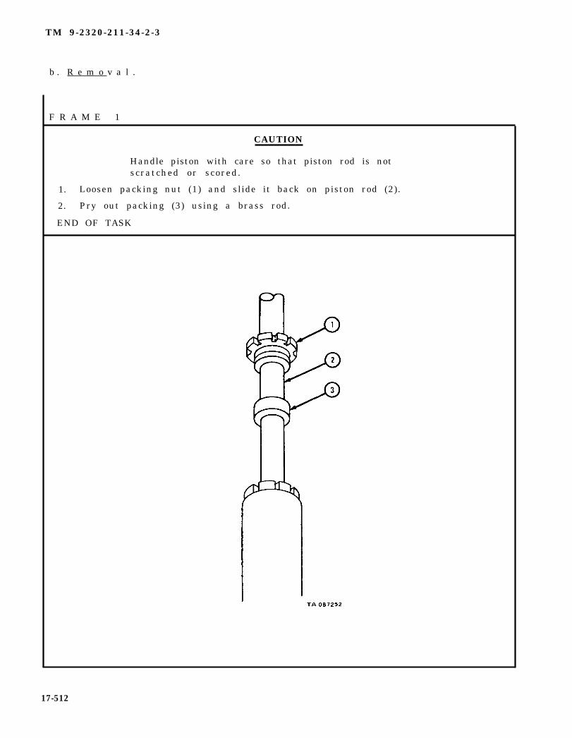
TM 9-2320-211-34-2-3
b . R e m o v a l .
F R A M E 1
CAUTION
Handle piston with care so that piston rod is notscratched or scored.
1. Loosen packing nut (1) and slide it back on piston rod (2).
2. Pry out packing (3) using a brass rod.
END OF TASK
17-512
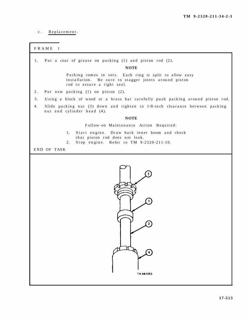
TM 9-2320-211-34-2-3
c . Replacement.
F R A M E 1
1.
2.
3.
4.
Put a coat of grease on packing (1) and piston rod (2).
NOTE
Packing comes in sets. Each ring is split to allow easyinstallation. Be sure to stagger joints around pistonrod to assure a tight seal.
Put new packing (1) on piston (2).
Using a block of wood or a brass bar carefully push packing around piston rod.
Slide packing nut (3) down and tighten to 1/8-inch clearance between packingnut and cylinder head (4).
Follow-on
1. Start engine.
NOTE
Maintenance Action Required:
Draw back inner boom and checkthat piston rod does not leak.
END OF TASK
2. Stop engine. Refer to TM 9-2320-211-10.
17-513
TM 9-2320-211-34-2-3
17-40. BOOM ELEVATING CYLINDER PISTON ROD PACKING REMOVAL ANDREPLACEMENT (TRUCK M543A2).
NOTE
This task is the same for right side and left sideboom elevating cylinder piston rod packings. Thistask is shown for the right side boom elevatingcylinder piston rod packing.
TOOLS: No special tools required
SUPPLIES: Artillery and automotive grease, type GAA, MIL-G-10924Packing
PERSONNEL: One
EQUIPMENT CONDITION: Truck parked, engine off , handbrake set.
a . Preliminary Procedures.
(1 ) Start engine . Raise boom assembly as far as it will go, and put boomjacks in place. Refer to TM 9-2320-211-10.
( 2 ) S t o p e n g i n e . Move BOOM control lever back and forth to take hydraulicpressure off boom elevating cylinders. Refer to TM 9-2320-211-10.
17-514
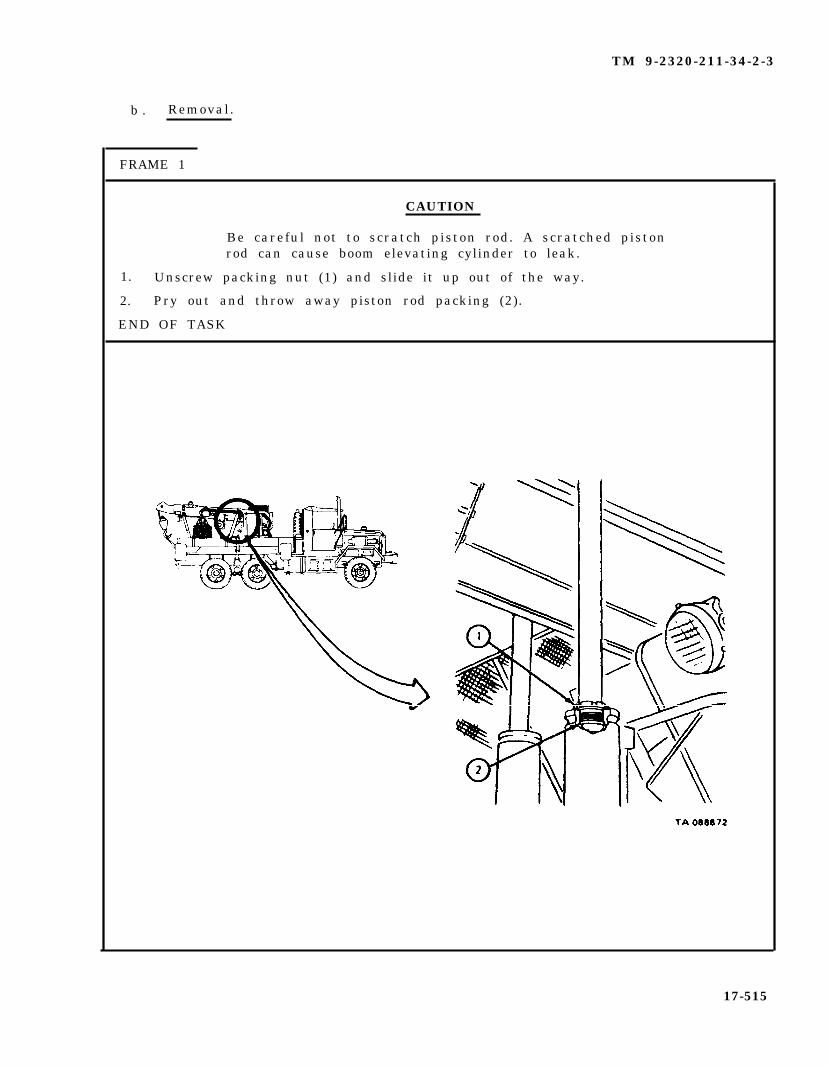
TM 9-2320-211-34-2-3
b . Removal.
FRAME 1
CAUTION
Be careful not to scratch piston rod. A scratched pistonrod can cause boom elevating cylinder to leak.
1. Unscrew packing nut (1) and slide it up out of the way.
2. Pry out and throw away piston rod packing (2).
END OF TASK
17-515

TM 9-2320-211-34-2-3
c . Replacement.
FRAME 1
1.
2.
3.
NOTE
Packing rings are split so that they can be put on easily.Make sure that joints are alined on piston rod so thatthere is a tight seal.
Coat packing (1) with grease and put packing into cylinder head (2).
Carefully push packing (1) around piston rod.
Slide down packing nut (3). Tighten nut until there is 1/8 inch clearance betweenpacking nut and cylinder head (2).
NOTE
Follow-on Maintenance Action Required:
1. Take off boom jacks. Refer to TM 9-2320-211-10.2. Start engine. Raise and lower boom assembly several
times and check that piston rod packing does not leak.Refer to TM 9-2320-211-10.
3. Stop engine. Refer to TM 9-2320-211-10.
END OF TASK
17-516
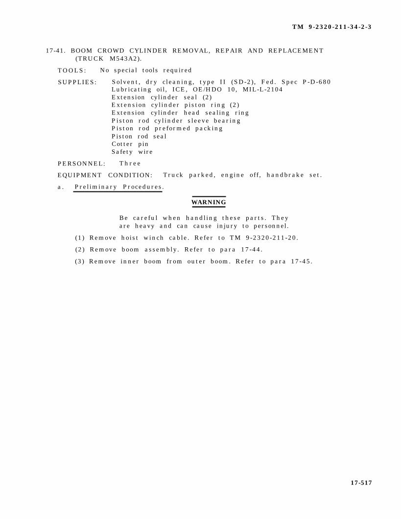
TM 9-2320-211-34-2-3
17-41. BOOM CROWD CYLINDER REMOVAL, REPAIR AND REPLACEMENT(TRUCK M543A2).
TOOLS: No special tools required
SUPPLIES: Solvent, dry cleaning, type II (SD-2), Fed. Spec P-D-680Lubricating oil, ICE, OE/HDO 10, MIL-L-2104Extension cylinder seal (2)Extension cylinder piston ring (2)Extension cylinder head sealing ringPiston rod cylinder sleeve bearingPiston rod preformed packingPiston rod sealCotter pinSafety wire
PERSONNEL: T h r e e
EQUIPMENT CONDITION: Truck parked, engine off , handbrake set.
a . Preliminary Procedures.
WARNING
Be careful when handling these parts. Theyare heavy and can cause injury to personnel.
(1) Remove hoist winch cable. Refer to TM 9-2320-211-20.
(2) Remove boom assembly. Refer to para 17-44.
(3) Remove inner boom from outer boom. Refer to para 17-45.
17-517
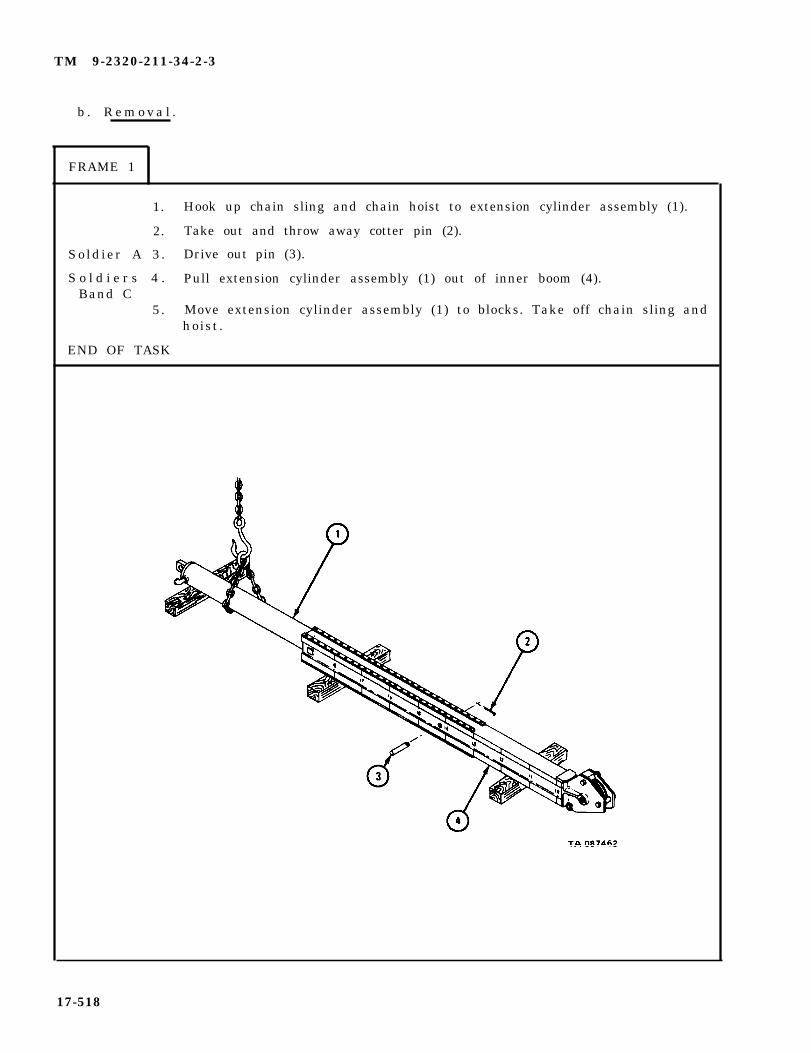
TM 9-2320-211-34-2-3
b . R e m o v a l .
FRAME 1
1. Hook up chain sling and chain hoist to extension cylinder assembly (1).
2. Take out and throw away cotter pin (2).
So ld ier A 3 . Drive out pin (3).
S o l d i e r s 4 . Pull extension cylinder assembly (1) out of inner boom (4).Band C
5. Move extension cylinder assembly (1) to blocks. Take off chain sling andhoist.
END OF TASK
17-518
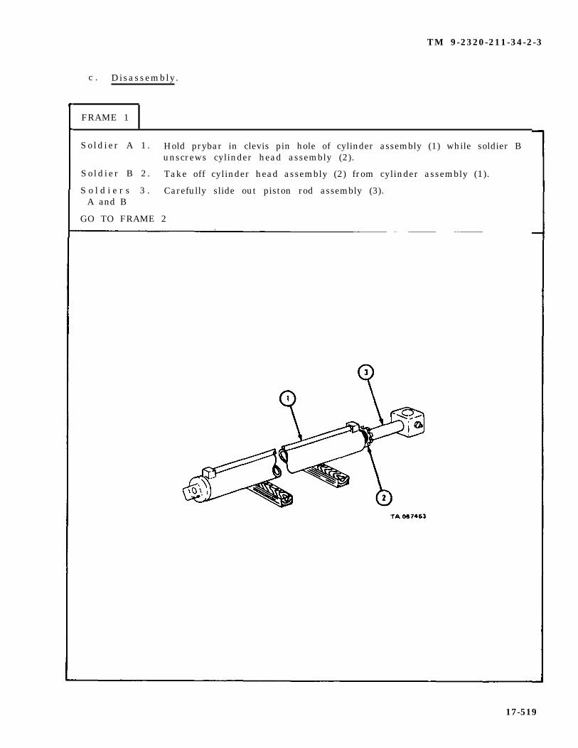
TM 9-2320-211-34-2-3
c . Disassembly.
FRAME 1
Sold ier A 1 . Hold prybar in clevis pin hole of cylinder assembly (1) while soldier Bunscrews cylinder head assembly (2).
So ld ier B 2 . Take off cylinder head assembly (2) from cylinder assembly (1).
S o l d i e r s 3 . Carefully slide out piston rod assembly (3).A and B
GO TO FRAME 2
17-519

TM 9-2320-211-34-2-3
F R A M E 2
1. Take off and throw away safety wire (l).
So ld ier A 2 . Hold prybar in clevis pin hole of piston rod (2) while soldier B unscrewsn u t ( 3 ) .
So ld ier B 3 . Take off nut (3).
4. Slide off retaining washer (4), seal washer (5), sealtwo piston rings (8), seal (9), and seal washer (10).
(6), piston (7) withThrow away seals.
5 . Take two piston rings (8) off piston (7). Throw away piston rings.
GO TO FRAME 3
17-520
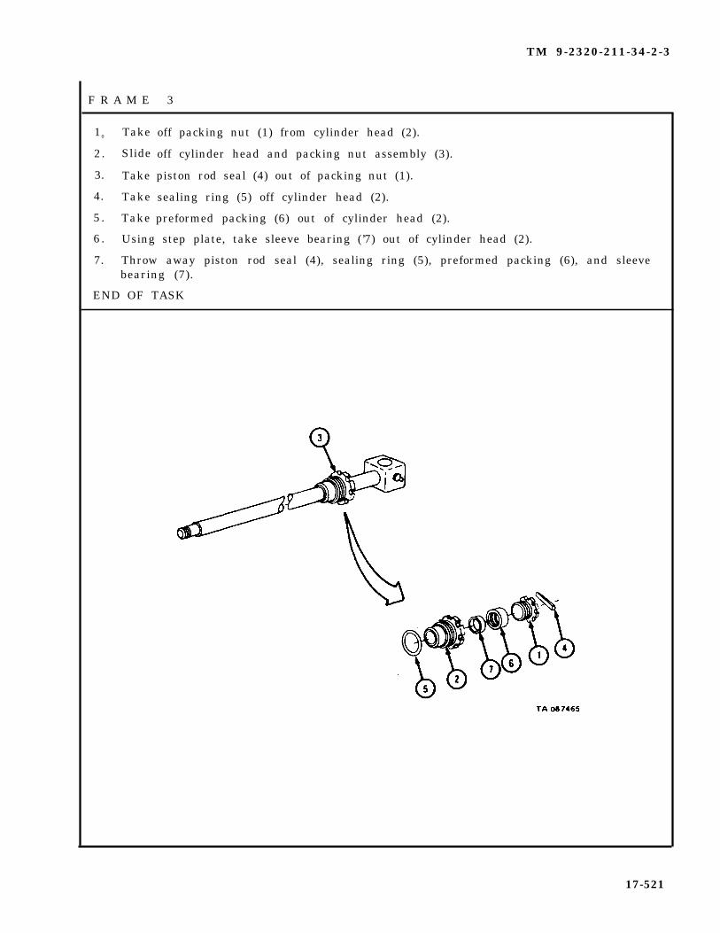
TM 9-2320-211-34-2-3
F R A M E 3
10 Take
2. Slide
3. Take
4. Take
5 . Take
off packing nut (1) from cylinder head (2).
off cylinder head and packing nut assembly (3).
piston rod seal (4) out of packing nut (1).
sealing ring (5) off cylinder head (2).
preformed packing (6) out of cylinder head (2).
6 . Using step plate, take sleeve bearing (’7) out of cylinder head (2).
7. Throw away piston rod seal (4), sealing ring (5), preformed packing (6), and sleevebearing (7).
END OF TASK
17-521

TM 9-2320-211-34-2-3
d . Cleaning.
WARNING
Dry cleaning solvent is flammable. Do not usenear an open flame. Keep a fire extinguishernearby when solvent is used. Use only in well-ventilated places. Failure to do this may resultin injury to personnel and damage to equipment.
(1) Clean all parts with solvent.
(2 ) Let parts dry .
17-522

TM 9-2320-211-34-2-3
e . Inspection and Repair.
F R A M E 1
1.
2.
3.
4.
Check that piston rod (1) is not bent, burred or scratched. If scratches orburrs cannot be filed off with a fine mill file, use a new piston rod.
Check that cylinder assembly (2) is not cracked and that cylinder head threadsare not damaged. Check that inside of cylinder assembly is not scored. Ifcylinder assembly is damaged, get a new one.
Check that piston (3) is not scored and does not show other signs of wear. Ifpiston is damaged, get a new one.
Check that packing nut (4), cylinder head (5), and nut (6) do not havedamaged threads. If they are damaged, get new ones.
END OF TASK
17-523

TM 9-2320-211-34-2-3
f . Assembly .
F R A M E 1
1. Using step plate, seat sleeve bearing (1) in cylinder head (2).
2. Soak preformed packing (3) in oil and put it in cylinder head (2).
3. Put sealing ring (4) in place on cylinder head (2).
4. Put piston rod seal (5) in groove in packing nut (6).
5. Slide packing nut (6) with piston rod seal (5) onto piston rod (7).
6. Slide cylinder head (2) with sleeve bearing (1), preformed packing (3), andsealing ring (4) onto piston rod (7).
7. Using spanner wrenches and 6-inch ruler, screw together packing nut (6) andcylinder head (2) until there is about 1/8-inch clearance between them.
GO TO FRAME 2
17-524

TM 9-2320-211-34-2-3
FRAME 2
1. Slide seal washer (1), seal (2), piston (3), seal (4), seal washer (3),and retaining washer (6) onto piston rod (7).
So ld ier A 2 . Hold prybar in clevis pin hole of piston rod (7) while soldier B screws onnut (8).
So ld ier B 3 . Put on nut (8).
4 . Put safety wire (9) through nut (8) and piston rod (7).
5 . Put two piston rings (10) on piston (3).
GO TO FRAME 3
17-525

TM 9-2320-211-34-2-3
F R A M E 3
1. Coat inside of cylinder assembly (1) with oil
S o l d i e r s 2 . Carefully slide piston rod assembly (2) about halfway into cylinderA and B assembly (1).
S o l d i e r A 3 . Hold prybar in clevis pin hole of cylinder assembly (1) whilesoldier B puts on cylinder head assembly (3).
S o l d i e r B 4 . Using spanner wrench, put on cylinder head assembly (3).
END OF TASK
17-526

TM 9-2320-211-34-2-3
g . Replacement.
FRAME 1
SoldiersA and B
Soldier C
1. Hook up chain sling and chain hoist to extension cylinderassembly (1).
NOTE
When putting extension cylinder (1) into inner boom (2),the grease fitting in piston rod (3) should be down.
2. Raise extension cylinder assembly (1) and guide it into place ininner boom (2).
3. Using brass punch, aline bore in piston rod (3) with bores in
4.
5.
1.2.3.4.5.
inner boom (2). Push in pin (4).
Put in cotter pin (5).
Take off chain sling and chain hoist.
NOTE
Follow-on Maintenance Action Required:
Replace inner boom in outer boom. Refer to para 17-45.Replace boom assembly. Refer to para 17-44.Replace hoist winch cable. Refer to TM 9-2320-211-20.Oil and grease boom assembly as given in LO 9-2320-211-12.Adjust crane inner and outer boom rollers. Refer toTM 9-2320-211-20.
END OF TASK
17-527

TM 9-2320-211-34-2-3
17-42. CRANE BOOM ELEVATING CYLINDER REPAIR (TRUCK M543A2).
T O O L S : N o
SUPPLIES:
PERSONNEL:
NOTE
This task is the same for the right and leftcrane boom elevating cylinders, except wherenoted . This task is shown for the right craneboom elevating cylinder.
special tools required
Lubricating oil, ICE, OE/HDO 10, MIL-L-2104Artillery and automotive grease, type GAA, MIL-G-10924Solvent, dry cleaning, type II (SD-2), Fed. Spec P-D-680Antiseize tapeT a g sCapsSafety wire
Two
EQUIPMENT CONDITION: Truck parked, engine off , handbrake set.
a . Preliminary Procedures.
(1) Free hoist cable hook from lifting sling. Refer to TM 9-2320-211-10.
(2) If working on left boom elevating cylinder, take off gondola guardassembly. Refer to para 17-50.
17-528
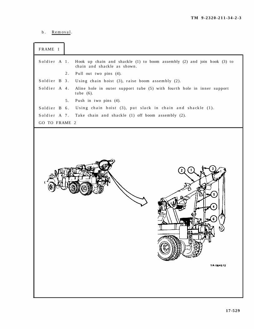
TM 9-2320-211-34-2-3
b . Removal.
FRAME 1
Sold ier A 1 . Hook up chain and shackle (1) to boom assembly (2) and join hook (3) tochain and shackle as shown.
2. Pull out two pins (4).
So ld ier B 3 . Using chain hoist (3), raise boom assembly (2).
So ld ier A 4 . Aline hole in outer support tube (5) with fourth hole in inner supporttube (6).
5. Push in two pins (4).
So ld ier B 6 . Using chain hoist (3), put slack in chain and shackle (1).
So ld ier A 7 . Take chain and shackle (1) off boom assembly (2).
GO TO FRAME 2
17-529

TM 9-2320-211-34-2-3
F R A M E 2
1. Tag hoses (1 and 2) so that they will be put back in the same places.
2. Put five-gallon container under hoses (1 and 2).
3. Unscrew nut
4. Cap hose (1)
5. Unscrew nut
6. Unscrew nut
7. Cap hose (2)
of fitting (3) and move hose (1) out of the way.
and fitting (3) .
(4) on hose (2).
(5) at snubber valve (6) and take off hose (2).
on both ends and cap snubber valve (6).
8. Take out container and put fluid in approved disposal area.
GO TO FRAME 3
17-530
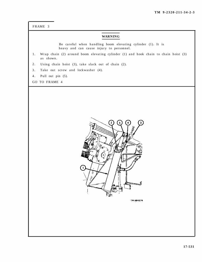
TM 9-2320-211-34-2-3
FRAME 3
1.
2.
3.
4.
WARNING
Be careful when handling boom elevating cylinder (1). It isheavy and can cause injury to personnel.
Wrap chain (2) around boom elevating cylinder (1) and hook chain to chain hoist (3)as shown.
Using chain hoist (3), take slack out of chain (2).
Take out screw and lockwasher (4).
Pull out pin (5).
GO TO FRAME 4
17-531
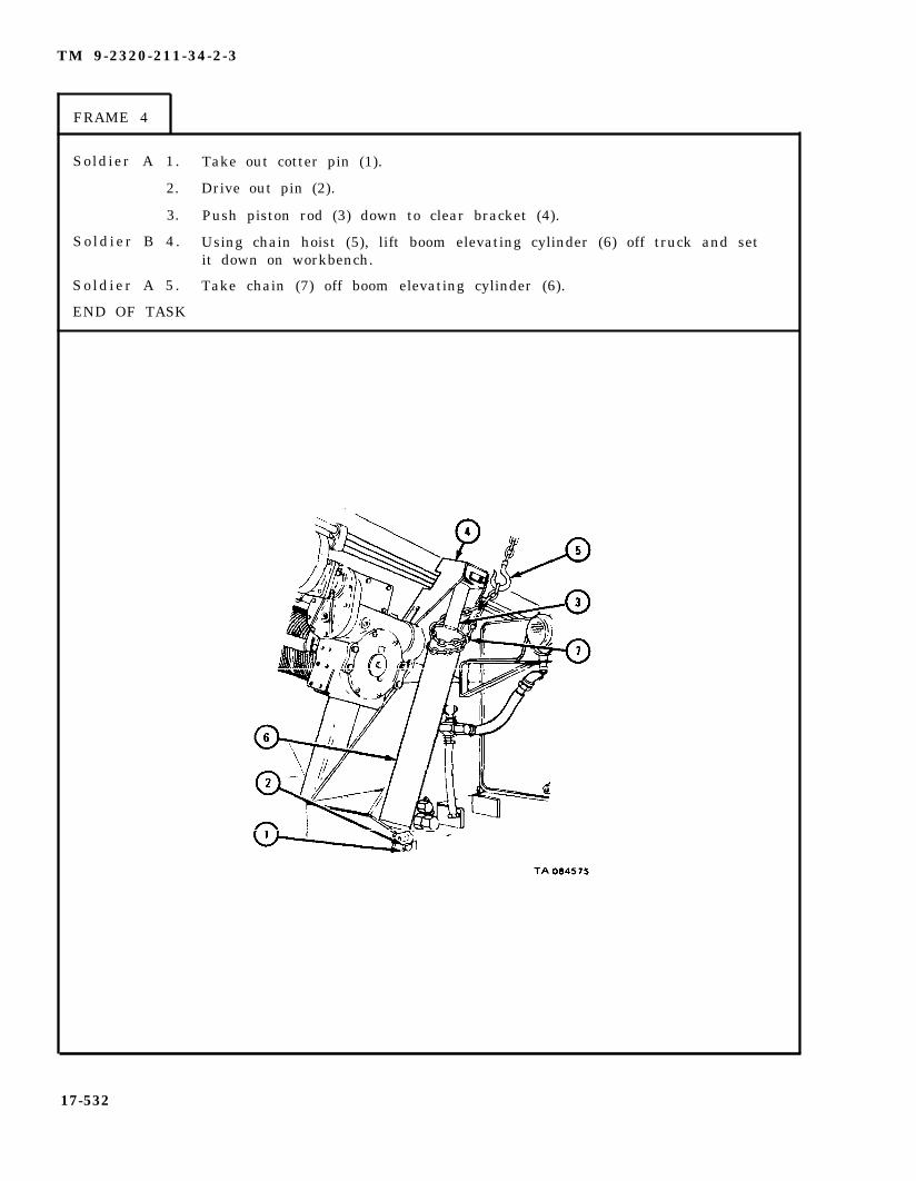
TM 9-2320-211-34-2-3
FRAME 4
Soldier A 1. Take out cotter pin (1).
2. Drive out pin (2).
3. Push piston rod (3) down to clear bracket (4).
So ld ier B 4 . Using chain hoist (5), lift boom elevating cylinder (6) off truck and setit down on workbench.
So ld ier A 5 . Take chain (7) off boom elevating cylinder (6).
END OF TASK
17-532
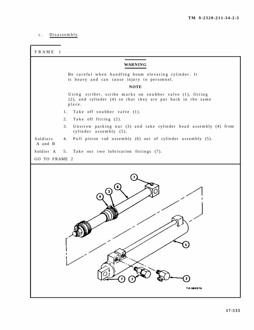
TM 9-2320-211-34-2-3
c . Disassembly.
F R A M E 1
SoldiersA and B
Soldier A
WARNING
Be careful when handling boom elevating cylinder. Itis heavy and can cause injury to personnel.
NOTE
Using scriber, scribe marks on snubber valve (1), f itting(2), and cylinder (4) so that they are put back in the sameplace .
1. Take off snubber valve (1) .
2. Take off f itting (2) .
3. Unscrew packing nut (3) and take cylinder head assemblycylinder assembly (5).
4. Pull piston rod assembly (6) out of cylinder assembly (5).
5. Take out two lubrication fittings (7).
(4) from
GO TO FRAME 2
17-533
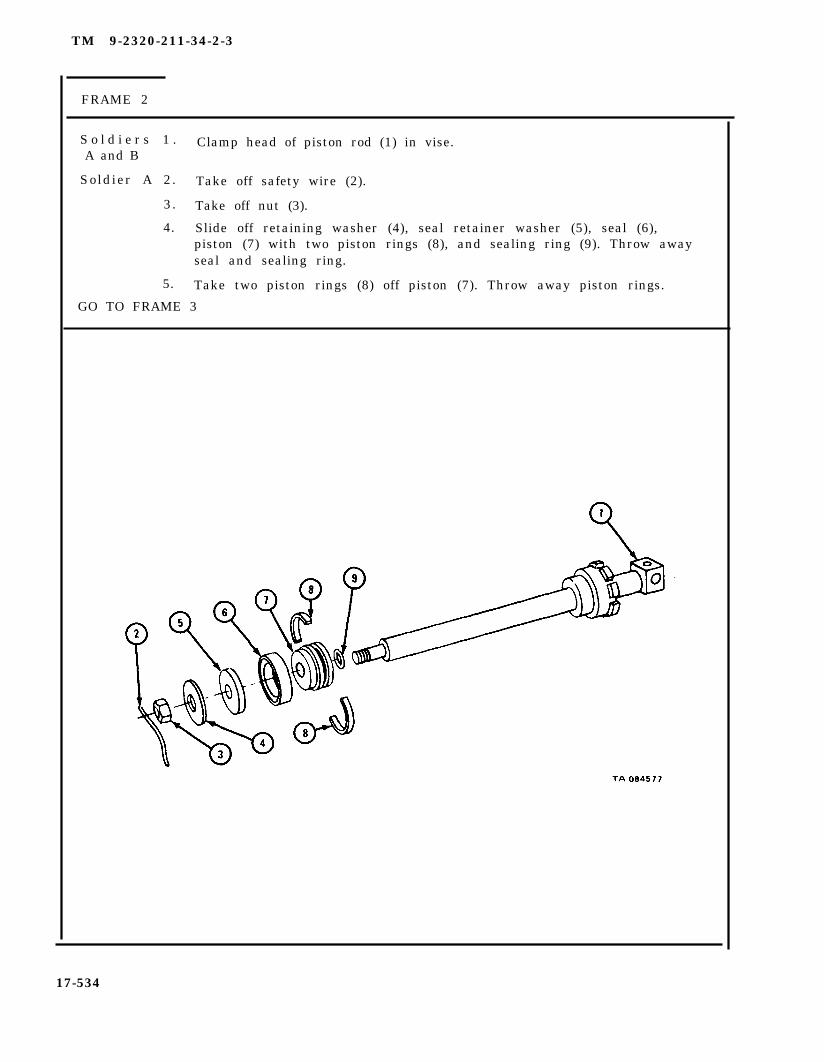
TM 9-2320-211-34-2-3
FRAME 2
S o l d i e r s 1 . Clamp head of piston rod (1) in vise.A and B
Soldier A 2. Take off safety wire (2).
3. Take off nut (3).
4. Slide off retaining washer (4), seal retainer washer (5), seal (6),piston (7) with two piston rings (8), and sealing ring (9). Throw awayseal and sealing ring.
5. Take two piston rings (8) off piston (7). Throw away piston rings.
GO TO FRAME 3
17-534

TM 9-2320-211-34-2-3
FRAME 3
1.
2.
3.
4.
5.
6.
7.
S o l d i e r s 8 .A and B
END OF TASK
Slide
Take
Take
Take
Take
cylinder head and packing nut assembly (1) off piston rod (2).
off packing nut (3) from cylinder head (4).
seal (5) out of packing nut (3).
sealing ring (6) off cylinder head (4).
out packing (7) from cylinder head (4).
Press sleeve bearing (8) out of cylinder head (4) from bottom to top.
Throw away seal (5), sealing ring (6), packing (7), and sleeve bearing (8).
Take piston rod (2) out of vise.
17-535
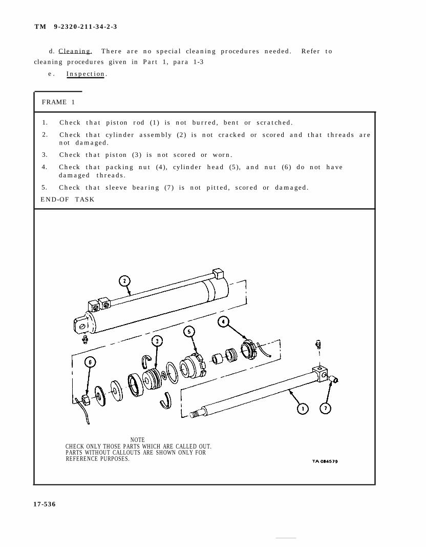
TM 9-2320-211-34-2-3
e . Inspection.
FRAME 1
1.
2.
3.
4.
5.
Check that piston rod (1) is not burred, bent or scratched.
Check that cylinder assembly (2) is not cracked or scored and that threads arenot damaged.
Check that piston (3) is not scored or worn.
Check that packing nut (4), cylinder head (5), and nut (6) do not havedamaged threads.
Check that sleeve bearing (7) is not pitted, scored or damaged.
END-OF TASK
NOTECHECK ONLY THOSE PARTS WHICH ARE CALLED OUT.PARTS WITHOUT CALLOUTS ARE SHOWN ONLY FORREFERENCE PURPOSES.
17-536
d. Cleaning. There are no special cleaning procedures needed. Refer to
cleaning procedures given in Part 1, para 1-3

TM 9-2320-211-34-2-3
f . R e p a i r . No repairs are to be made on these parts. Throw away all damagedparts and get new ones in their places. If cylinder assembly is damaged, replaceboom elevating cylinder assembly.
g . Assembly .
FRAME 1
1.
2.
3.
4.
5.
6.
7.
WARNING
Be careful when handling boom elevating cylinder. Itis heavy and can cause injury to personnel.
Put seal (1) in groove in packing nut (2).
Slide packing nut (2) with seal (1) onto piston rod (3).
Press sleeve bearing (4) into place in cylinder head (5).
Coat packing (6) with grease and put packing in place in cylinder head (5).
Put sealing ring (7) in place in groove in cylinder head (5).
Slide cylinder head (5) with sleeve bearing (4), packing (6), and sealing ring(7) onto piston rod (3) .
Put packing nut (2) into cylinder head (5) until there is about 1/8-inchclearance between them.
GO TO FRAME 2
17-537

TM 9-2320-211-34-2-3
FRAME 2
S o l d i e r s 1 . Put square head of piston rod (1) in vise.A and B
Soldier A 2. Put sealing ring (2), piston (3), seal (4), seal retainer washer (5), andretainer washer (6) on piston rod (1).
3. Put on nut (7).
4. Put safety wire (8) through holes in nut (7) and piston rod (1).
5. Put two piston rings (9) on piston (3).
GO TO FRAME 3
17-538
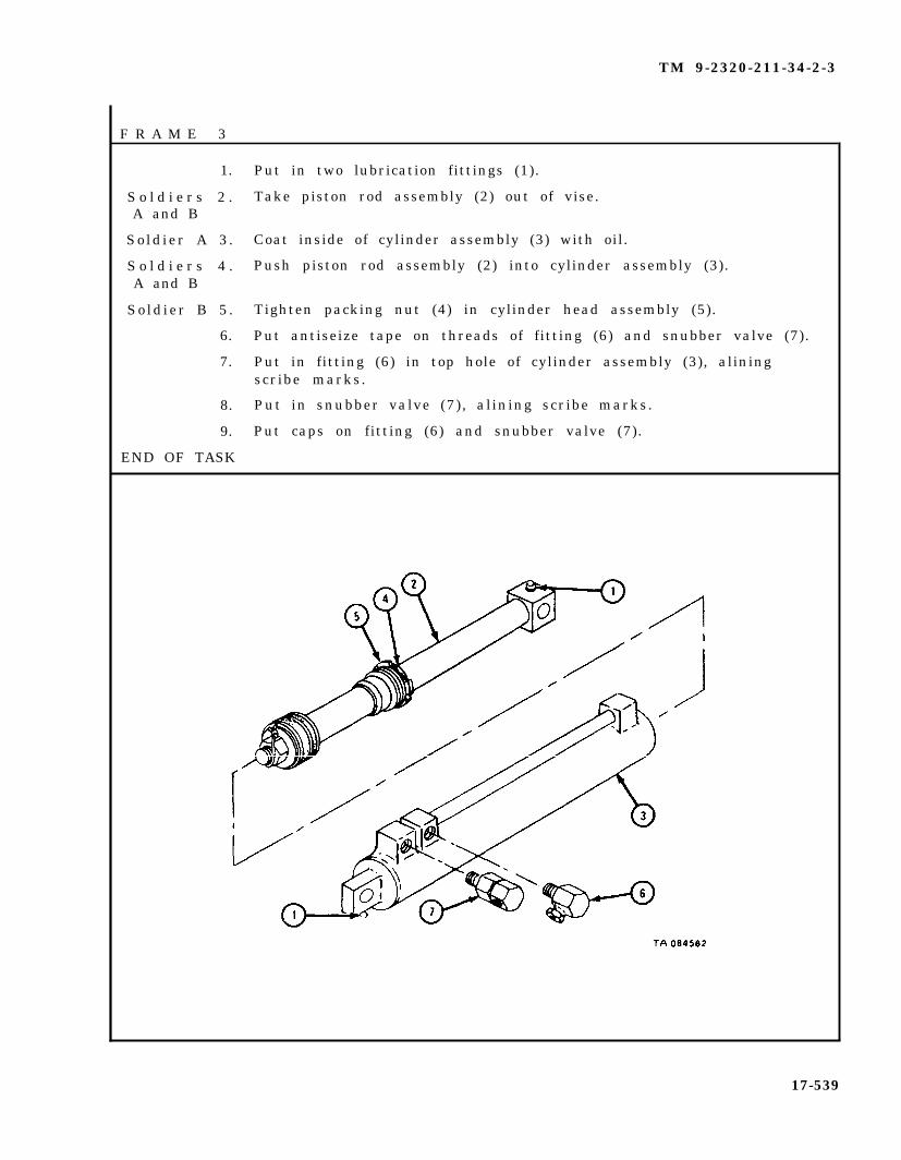
TM 9-2320-211-34-2-3
F R A M E 3
1.
S o l d i e r s 2 .A and B
Sold ier A 3 .
S o l d i e r s 4 .A and B
Sold ier B 5 .
6.
7.
8.
9.
END OF TASK
Put in two lubrication fittings (1).
Take piston rod assembly (2) out of vise.
Coat inside of cylinder assembly (3) with oil.
Push piston rod assembly (2) into cylinder assembly (3).
Tighten packing nut (4) in cylinder head assembly (5).
Put antiseize tape on threads of fitting (6) and snubber valve (7).
Put in fitting (6) in top hole of cylinder assembly (3), aliningscribe marks.
Put in snubber valve (7), alining scribe marks.
Put caps on fitting (6) and snubber valve (7).
17-539

TM 9-2320-211-34-2-3
h. Replacement.
FRAME 1
WARNING
Be careful when handling boom elevating cylinder (1). It isheavy and can cause injury to personnel.
Soldier A 1. Wrap chain (2) around boom elevating cylinder (1) and hook chain tochain hoist (3) as shown.
Soldier B 2. Using chain hoist (3), lift boom elevating cylinder (1) into place.
Soldier A 3. Aline holes in piston rod (4) and bracket (5) and push pin (6) throughbracket and piston rod.
4. Put in screw and lockwasher (7).
GO TO FRAME 2
17-540
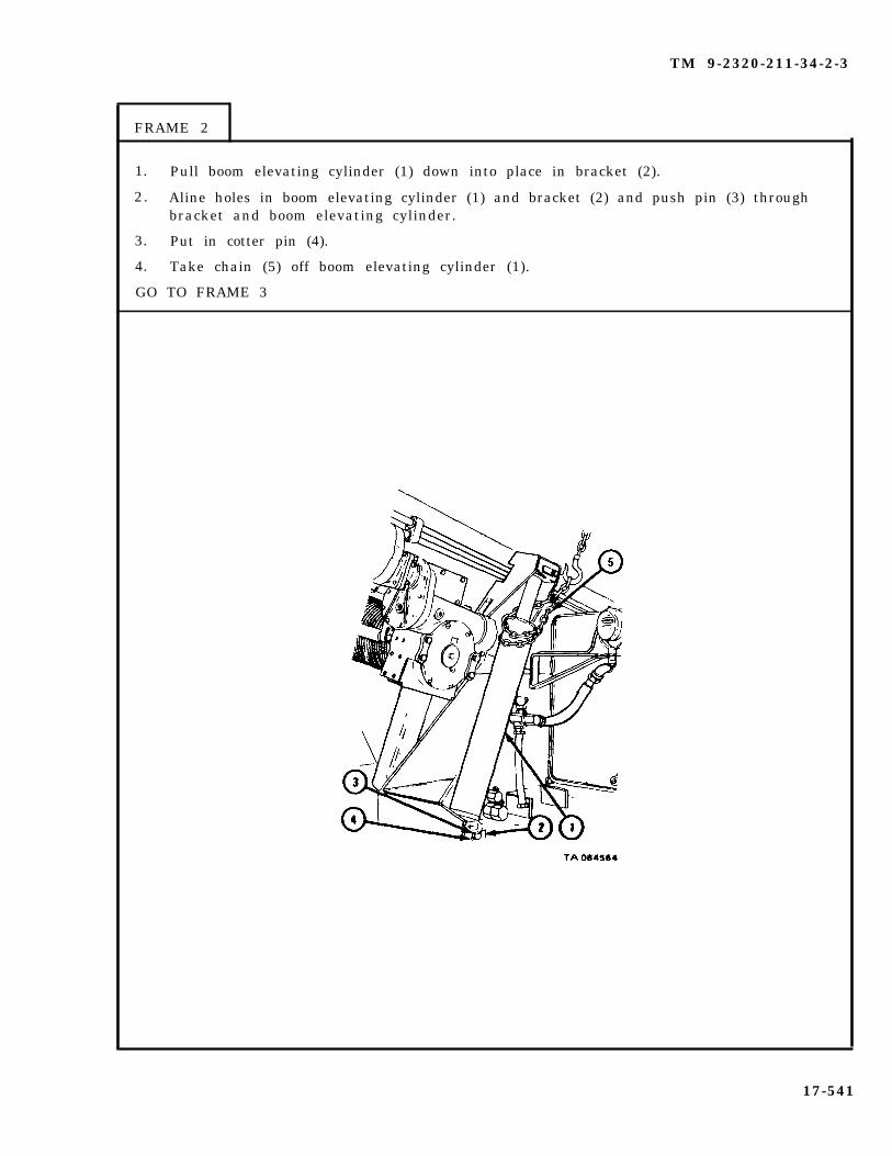
TM 9-2320-211-34-2-3
FRAME 2
1. Pull boom elevating cylinder (1) down into place in bracket (2).
2. Aline holes in boom elevating cylinder (1) and bracket (2) and push pin (3) throughbracket and boom elevating cylinder.
3. Put in cotter pin (4).
4. Take chain (5) off boom elevating cylinder (1).
GO TO FRAME 3
17-541

TM 9-2320-211-34-2-3
FRAME 3
1. Take caps off all fittings.
2. Put
3. Put
4. Put
5. Put
nut (1) onto f itting of hose (2) as tagged. Take off tag.
antiseize tape on threads of nut (3).
nut (3 ) into snubber va lve (4 ) .
nut (5) onto f itting (6) as tagged. Take off tag.
NOTE
Follow-on Maintenance Action Required:
1. Fill hydraulic oil reservoir and grease sleeve bearings.Refer to LO 9-2320-211-12.
2. Raise and lower boom assembly several times, checkingboom elevating cylinders for proper operation. Referto TM 9-2320-211-10.
3. Check level in hydraulic oil reservoir again. Refer toLO 9-2320-211-12.
4. Put boom assembly in travel position. Refer toTM 9-2320-211-10.
END OF TASK
17-542
TM 9-2320-211-34-2-3
17-43. LOWER BOOM FOOT SHEAVE REMOVAL AND REPLACEMENT (TRUCK M543A2).
TOOLS : No special tools required
SUPPLIES : Artillery and automotive grease, types GAA and MIL-G-10924Clean ragsSolvent, dry cleaning, type 11 (SD-2), Fed. Spec. P-D-680Gloves
PERSONNEL: Two
EQUIPMENT CONDITION: Truck parked, engine off , handbrake set.
a . Preliminary Procedures.
(1) Lower crane hook to ground in order to take tension off hoist cable.Refer to TM 9-2320-211-10.
(2) Take off sheave guard. Refer to paragraph 17-27.
17-543

TM 9-2320-211-34-2-3
b . Removal.
WARNING
This equipment is very heavy and bulky. Tie inner boomto outer boom with chain or other suitable means. Do thisto stop inner boom from drawing out when the assembly islifted, which could cause injury to personnel.
S o l d i e r A 1 . Using overhead hoist (1), lift boom assembly (2) until pressureis removed from pivot pin (3).
S o l d i e r B 2 . Check with soldier A when pressure is off pivot pin (3) and stop.
GO TO FRAME 2
17-544
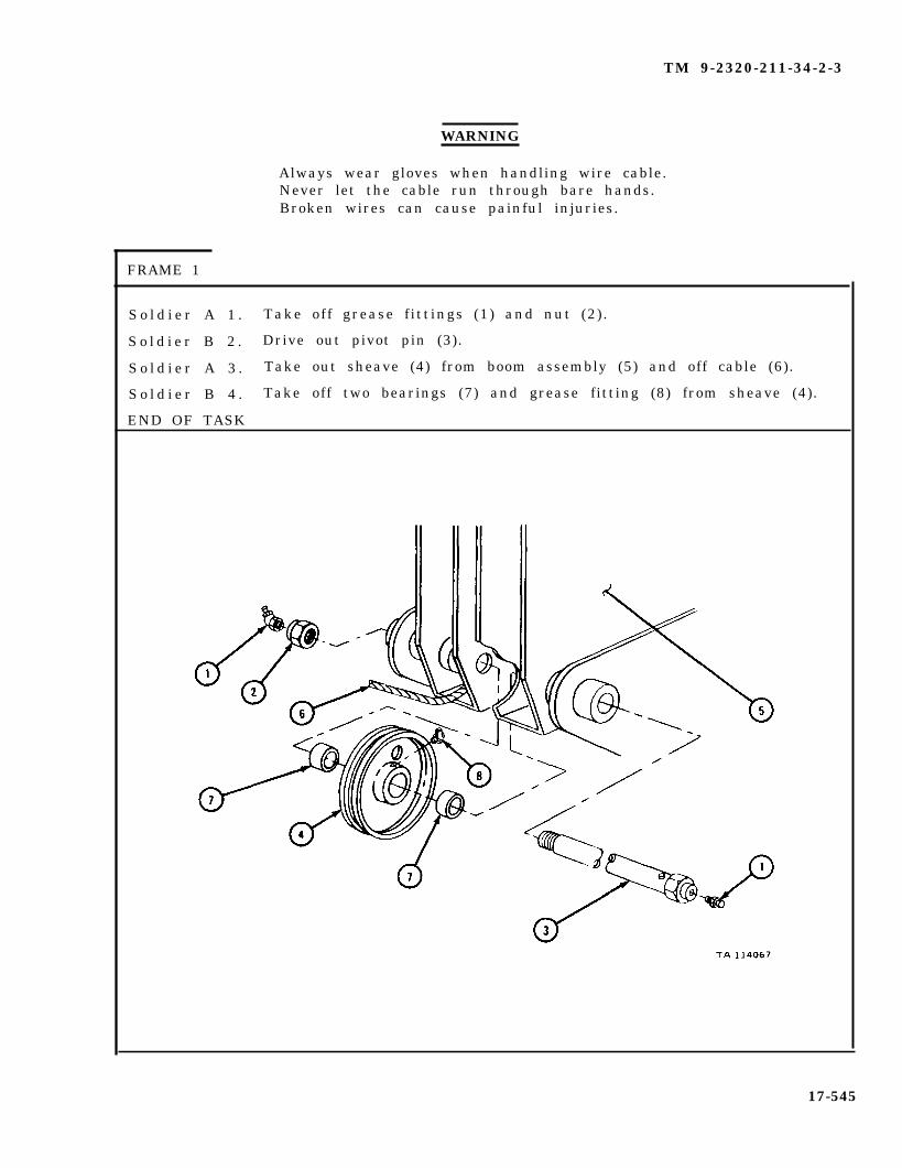
TM 9-2320-211-34-2-3
WARNING
Always wear gloves when handling wire cable.Never let the cable run through bare hands.Broken wires can cause painful injuries.
FRAME 1
S o l d i e r A 1 . Take off grease f ittings (1) and nut (2) .
S o l d i e r B 2 . Drive out pivot pin (3).
S o l d i e r A 3 . Take out sheave (4) from boom assembly (5) and off cable (6).
S o l d i e r B 4 . Take off two bearings (7) and grease fitting (8) from sheave (4).
END OF TASK
17-545

TM 9-2320-211-34-2-3
c . Cleaning. There are no special cleaning procedures required. Refer tocleaning procedures given in Part 1, para 1-3.
d . Inspection and Repair.
(1) Check that sheave, pivot pin, bearings, nut and grease fittings are notworn or damaged.
(2) If defective, throw away and get new parts.
17-546

TM 9-2320-211-34-2-3
e . Replacement.
F R A M E 1
Soldier A
Soldier B
Soldier A
Soldier B
Soldier A
Soldier B
SoldiersA and B
WARNING
Always wear gloves when handling wire cable. Neverlet the cable run through bare hands. Broken wires cancause painful injuries.
1. Put grease f itting (1) into sheave (2).
2 . Aline pivot pin (3) with holes in boom assembly (4).
3. Aline sheave (2) and two bearings (5) under cable (6) with boomassembly (4) and pivot pin (3) . Tell soldier B to drive pivot pinslowly through to other side.
4. Put nut (7) on pivot pin (3).
5 . Put two grease fittings (8) on each end of pivot pin (3).
6. Put grease into grease fittings (1) and (8).
7. Lower overhead hoist (9) and remove from boom.
Follow-on
1. Put on sheave
NOTE
Maintenance Action Required:
guard . Refer to paragraph 17-27.2. Raise crane hook and tie. Refer to TM 9-2320-211-10.
END OF TASK
17-547
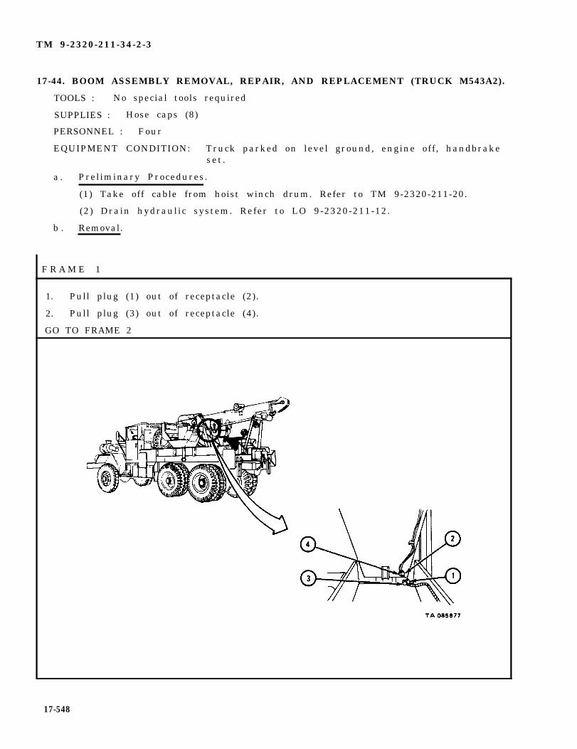
TM 9-2320-211-34-2-3
17-44. BOOM ASSEMBLY REMOVAL, REPAIR, AND REPLACEMENT (TRUCK M543A2).
TOOLS : No special tools required
SUPPLIES : Hose caps (8)
PERSONNEL : Four
EQUIPMENT CONDITION: Truck parked on level ground, engine off , handbrakeset .
a . Preliminary Procedures.
(1) Take off cable from hoist winch drum. Refer to TM 9-2320-211-20.
(2) Drain hydraulic system. Refer to LO 9-2320-211-12.
b . Removal.
F R A M E 1
1. Pull plug (1) out of receptacle (2).
2. Pull plug (3) out of receptacle (4).
GO TO FRAME 2
17-548

TM 9-2320-211-34-2-3
FRAME 2
1 . Take hydraulic hoses (1 through 4) off hydraulic lines (5 through 8). Tag hydrauliclines and hydraulic hoses so that they will be put back in the same places.
2 . Put caps on hydraulic hoses (1 through 4) and hydraulic lines (5 through 8).
GO TO FRAME 3
17-549

TM 9-2320-211-34-2-3
F R A M E 3
WARNING
1 .
G o
Inner boom (2) must be tied to outer boom (3) with a chainor heavy rope. This will stop inner boom from comingout and causing injury when taking off boom assembly.
Using 4-foot chain (1), tie inner boom (2) to outer boom (3). Tie 1/2-inch rope(4) on front of inner boom.
GO TO FRAME 4
17-550

TM 9-2320-211-34-2-3
FRAME 4
1 . Set uplifting sling (1) as follows:
(a) Put pin for short crosspiece (2) through POWER PACK hole.
(b) Put pin for long crosspiece (3) through ENG. AND DECK hole.
(c) Put pin for shackle assembly (4) through ENG. hole.
2 . Join hook (5) to shackle assembly (4).
GO T0 FRAME 5
17-551

TM 9-2320-211-34-2-3
FRAME 5
1 . Using hoist, position lifting sling (1) over boom assembly (2).
2 . Hook two short crosspiece chains (3) onto 3-foot chain (4) placed in front ofboom roller (5).
3 . Hook two long crosspiece chains (6) at rear of boom elevating cylinderbrackets (7).
GO TO FRAME 6
17-552

TM 9-2320-211-34-2-3
FRAME 6
1 . Using hoist, take weight of boom assembly (1) off two shipper braces (2).
2 . Take out two pins (3). Take shipper braces (2) off boom assembly (1) and laythem down.
GO TO FRAME 7
1 7 - 5 5 3
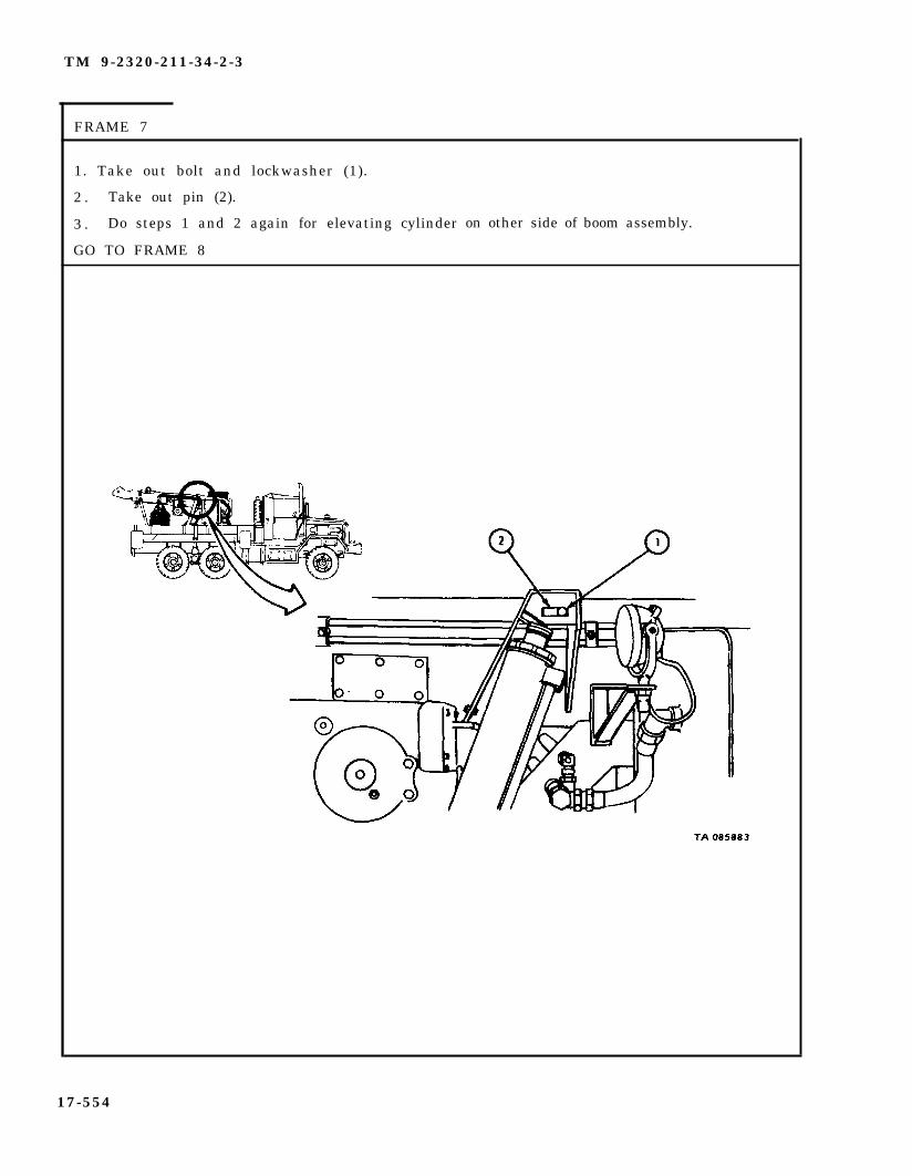
TM 9-2320-211-34-2-3
FRAME 7
1. Take out bolt and lockwasher (1).
2 . Take out pin (2).
3 . Do steps 1 and 2 again for elevating cylinder
GO TO FRAME 8
on other side of boom assembly.
17-554

TM 9-2320-211-34-2-3
FRAME 8
1 . Take out two grease fittings (1).
2 . Take off locknut (2).
Soldier A 3. Stand at hoist controls.
So ld ier B 4 . Check that pivot pin (3) turns freely. If pivot pin does not turn freely,tell soldier A to raise or lower boom assembly until it does.
5 . Drive out pivot pin (3). Take out sheave (4).
GO TO FRAME 9
17-555

TM 9-2320-211-34-2-3
FRAME 9
Sold ier A 1 . Stand at hoist controls (1).
So ld ier B 2 . Stand on wrecker next to left boom elevating cylinder (2).
So ld ier C 3 . Stand on wrecker next to right boom elevating cylinder (3).
Soldier D 4. Stand at rear of wrecker and hold guide rope (4).
So ld ier A 5 . When soldiers B, C, and D are ready, use hoist to lift boomassembly (5) clear of boom elevating cylinders (2 and 3).
S o l d i e r s 6 . Move boom elevating cylinders (2 and 3) away from boom assemblyB a n d C (5) and go to pivot pin end of boom assembly.
GO T’0 FRAME 10
17-556

TM 9-2320-211-34-2-3
FRAME 10
WARNING
Boom assembly (1) must be guided during hoisting so thatit does not injure personnel.
S o l d i e r s 1 . Tell soldiers A and D which way to move boom assembly (1) as it isB and C being lifted.
S o l d i e r s 2 . Using hoist and guide rope (2), lift and guide boom assembly (1)A and D off truck and onto boom assembly supports.
3 . Unhook two chains (3). Unhook two chains (4) from 3-foot chain (5)and take off 3-foot chain.
4 . Take off guide rope (2) and 4-foot chain (6).
END OF TASK
17-557

TM 9-2320-211-34-2-3
c. R e p l a c e m e n t .
F R A M E 1
WARNING
Inner boom (2) must be tied to outer boom (3) with chainor heavy rope (1). This will stop inner boom fromsliding out and causing injury when hoisting boomassembly.
1 . Using 4-foot chain (1), tie inner boom (2) to outer boom (3). Tie 1/2-inchrope (4) to front of inner boom.
GO TO FRAME 2
17-558
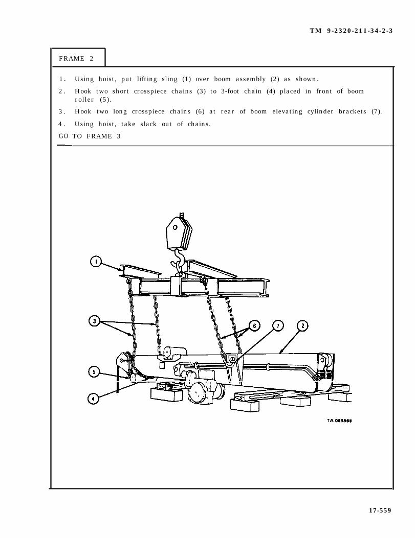
TM 9-2320-211-34-2-3
FRAME 2
1 .
2 .
3 .
4 .
GO
Using hoist, put lifting sling (1) over boom assembly (2) as shown.
Hook two short crosspiece chains (3) to 3-foot chain (4) placed in front of boomroller (5).
Hook two long crosspiece chains (6) at rear of boom elevating cylinder brackets (7).
Using hoist, take slack out of chains.
TO FRAME 3
17-559
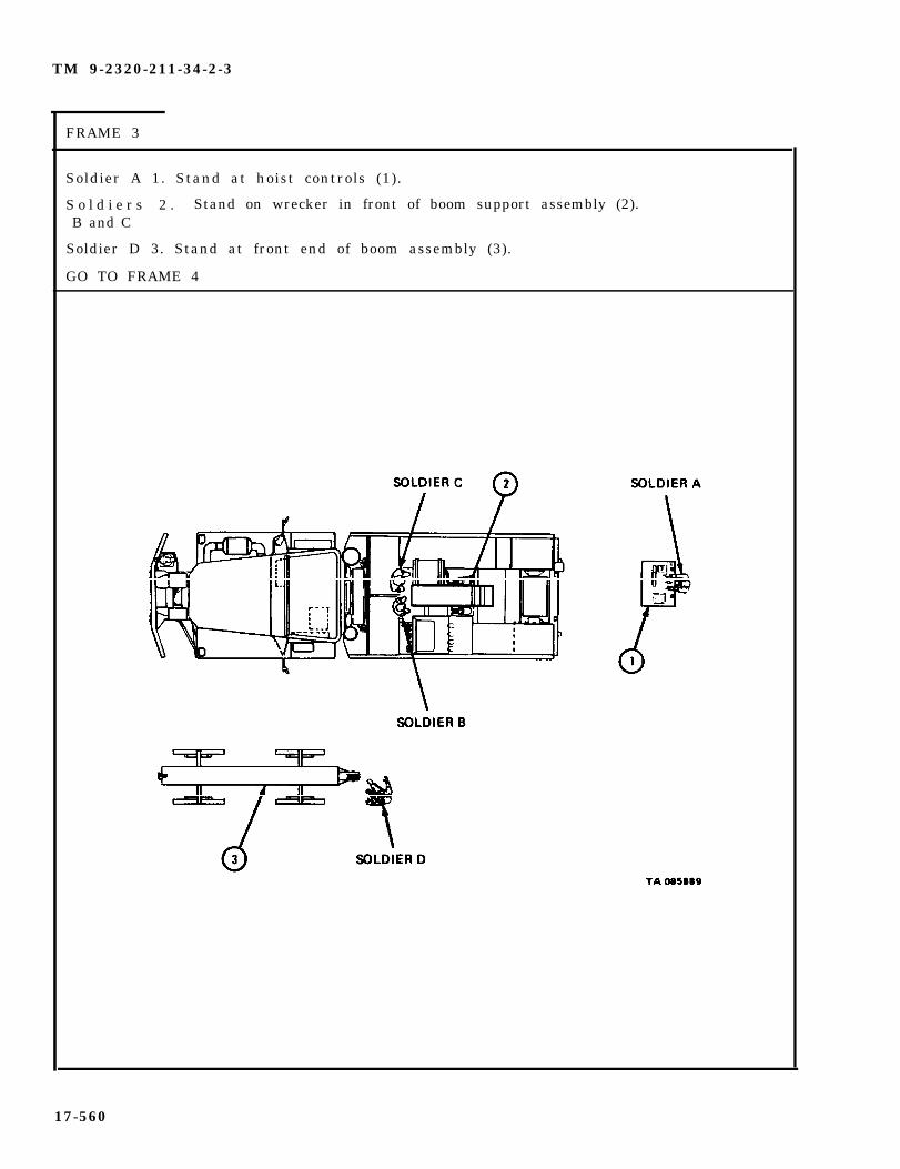
TM 9-2320-211-34-2-3
FRAME 3
Soldier A 1. Stand at hoist controls (1).
S o l d i e r s 2 . Stand on wrecker in front of boom support assembly (2).B and C
Soldier D 3. Stand at front end of boom assembly (3).
GO TO FRAME 4
17-560
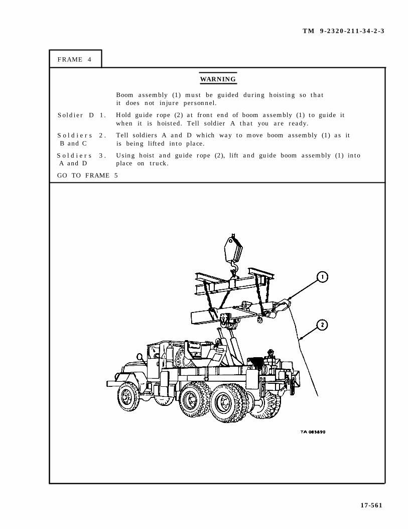
TM 9-2320-211-34-2-3
FRAME 4
WARNING
Boom assembly (1) must be guided during hoisting so thatit does not injure personnel.
Soldier D 1. Hold guide rope (2) at front end of boom assembly (1) to guide itwhen it is hoisted. Tell soldier A that you are ready.
S o l d i e r s 2 . Tell soldiers A and D which way to move boom assembly (1) as itB and C is being lifted into place.
S o l d i e r s 3 . Using hoist and guide rope (2), lift and guide boom assembly (1) intoA and D place on truck.
GO TO FRAME 5
17-561
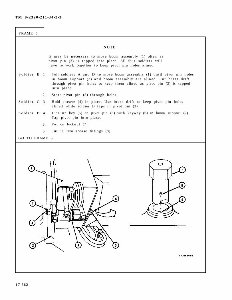
TM 9-2320-211-34-2-3
FRAME 5
Sold ier B 1 .
2 .
So ld ier C 3 .
So ld ier B 4 .
5 .
6 .
NOTE
It may be necessary to move boom assembly (1) often aspivot pin (3) is tapped into place. All four soldiers willhave to work together to keep pivot pin holes alined.
Tell soldiers A and D to move boom assembly (1) until pivot pin holesin boom support (2) and boom assembly are alined. Put brass driftthrough pivot pin holes to keep them alined as pivot pin (3) is tappedinto place.
Start pivot pin (3) through holes.
Hold sheave (4) in place. Use brass drift to keep pivot pin holesalined while soldier B taps in pivot pin (3).
Line up key (5) on pivot pin (3) with keyway (6) in boom support (2).Tap pivot pin into place.
Put on locknut (7).
Put in two grease fittings (8).
GO TO FRAME 6
17-562

TM 9-2320-211-34-2-3
F R A M E 6
Sold ier B 1 . Working on left boom elevating cylinder (1), guide it into bracket(2) as boom assembly (3) is lowered.
So ld ier C 2 . Working on right boom elevating cylinder (4), guide it into bracket(5) as boom assembly (3) is lowered.
So ld ier A 3 . Using hoist, lower boom assembly (3) until soldiers B and C tellyou that elevating cylinders (1 and 4) are inside brackets (2 and 5)
GO TO FRAME 7
17-563
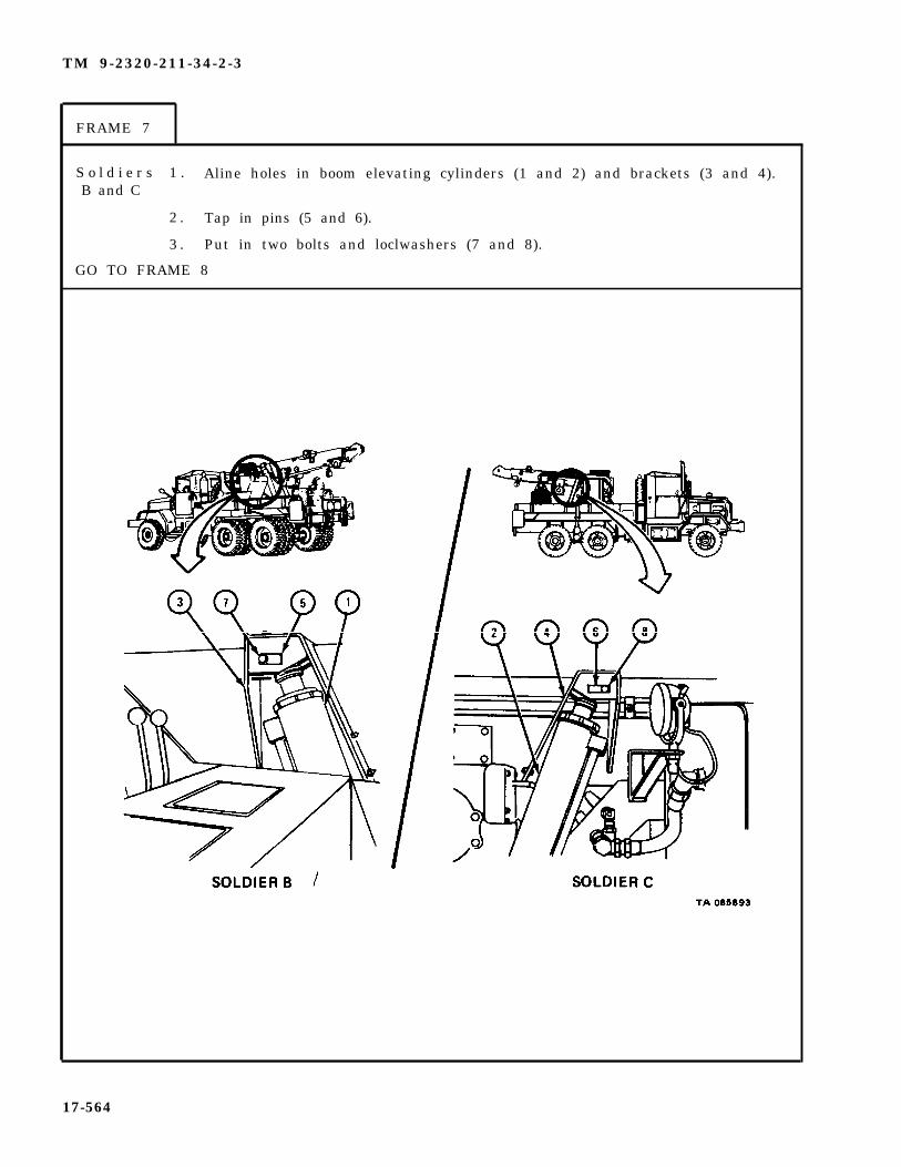
TM 9-2320-211-34-2-3
FRAME 7
S o l d i e r s 1 . Aline holes in boom elevating cylinders (1 and 2) and brackets (3 and 4).B and C
2 . Tap in pins (5 and 6).
3 . Put in two bolts and loclwashers (7 and 8).
GO TO FRAME 8
17-564

TM 9-2320-211-34-2-3
FRAME 8
1 . Put two shipper braces (1) in place on boom assembly (2). Put in two pins (3).
GO TO FRAME 9
17-565
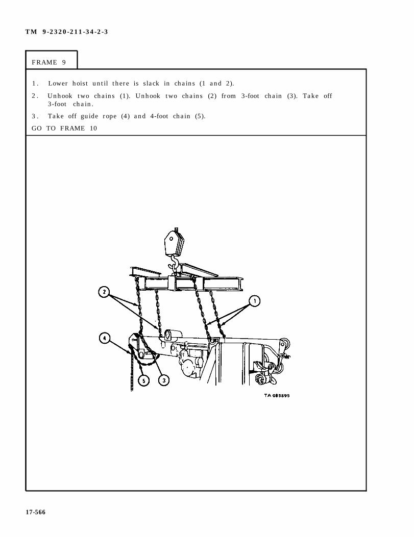
TM 9-2320-211-34-2-3
FRAME 9
1 . Lower hoist until there is slack in chains (1 and 2).
2 . Unhook two chains (1). Unhook two chains (2) from 3-foot chain (3). Take off3-foot chain.
3 . Take off guide rope (4) and 4-foot chain (5).
GO TO FRAME 10
17-566

TM 9-2320-211-34-2-3
F R A M E 1 0
NOTE
Take off caps from hydraulic lines and hoses before puttinglines and hoses in place.
1 . Tighten fitting on hydraulic hose (1) to hydraulic line (2) as tagged.
2 . Tighten fitting on hydraulic hose (3) to hydraulic line (4) as tagged.
3 . Tighten fitting on hydraulic hose (5) to hydraulic line (6) as tagged.
4 . Tighten fitting on hydraulic hose (7) to hydraulic line (8) as tagged.
5 . Take off all tags.
GO TO FRAME 11
17-567

TM 9-2320-211-34-2-3
F R A M E 1 1
1. Join plug (1) to
2. Join plug (3) to
1.2.
END OF TASK
PutFill
receptac le (2 ) .
receptac le (4 ) .
NOTE
Follow-on Maintenance Action Required:
cable on hoist winch drum. Refer to TM 9-2320-211-20.hydraulic system. Refer to LO 9-2320-211-12.
17-568

TM 9-2320-211-34-2-3
17-45. CRANE OUTER BOOM REPAIR (TRUCK M543A2).
TOOLS : No special tools required
SUPPLIES : Solvent, dry cleaning, type II (SD-2), Fed. Spec P-D-680CapsWooden blocksCotter pinsT a g s
PERSONNEL : T h r e e
EQUIPMENT CONDITION : Truck parked, engine off , handbrake set.
a . Preliminary Procedures.
(1) Remove hoist winch cable. Refer to TM 9-2320-211-20.
WARNING
Be careful when handling outer boom. It is heavyand can cause injury to personnel.
(2) Remove boom assembly. Refer to para 17-44.
17-569

TM 9-2320-211-34-2-3
b . Removal of Inner Boom.
F R A M E 1
WARNING
Soldier A
Soldier B
Inner boom (1) must be held up at sheave end whenpulling it out of outer boom (2). If this is not done,outer boom can tilt and cause injury.
1. Take out four screws and lockwashers (3).
2. Take off boom stop (4).
3. Do steps 1 and 2 again on other side of outer boom (2).
4. Put chain sling (5) in place on sheave end of inner boom (1) andjoin chain sling to chain hoist (6) on A-frame (7).
5. Take out cotter pin (8).
6. Using chain hoist (6), raise and lower inner boom (1) to keep ten -
sion off crowd cylinder clevis pin (9) .
7. Drive out crowd cylinder clevis pin (9).
GO TO FRAME 2
17-570

TM 9-2320-211-34-2-3
F R A M E 2
S o l d i e r s 1 .A and B
Sold ier C 2 .
3.
4.
5.
S o l d i e r s 6 .A and B
Sold ier C 7 .
8.
9.
END OF TASK
Walk inner boom (1) out of outer boom (2) until 18-FOOT MARKshows.
As soldiers A and B walk inner boom (1) out of outer boom (2),raise and lower inner boom to keep it from binding.
When 18-FOOT MARK shows, put safety jack under sheave end ofinner boom (1).
Lower inner boom (1) onto safety jack.
Move chain sling (3) to 12-FOOT MARK and 18-FOOT MARK oninner boom (1) as shown, and put in spreader bar (4).
Walk inner boom (1) out of outer boom (2).
As soldiers A and B walk inner boom (1) out of outer boom (2), raiseand lower inner boom to keep it from binding.
When inner boom (1) is out of outer boom (2) lower it onto woodenb l o c k s .
Take chain hoist off chain sling (3), and take chain sling andspreader bar (4) off inner boom (1).
17-571

TM 9-2320-211-34-2-3
c . Disassembly.
FRAME 1
1. Take out six screws and lockwashers (1).
2. Lift off upper boom roller assembly (2).
Soldier A 3. Hold lower boom roller assembly (3) while soldier B takes out-sixscrews and lockwashers (4).
Soldier B 4. Take out six screws and lockwashers (4).
Soldier A 5. Take off lower boom roller assembly (3).
GO TO FRAME 2
17-572

TM 9-2320-211-34-2-3
1. Pull two electrical leads (1) off two connectors (2).
2 . Take off two nuts (3), washer (4), floodlight assembly (5), and washer (6).
GO TO FRAME 3
17-573

TM 9-2320-211-34-2-3
F R A M E 3
Soldier A 1.
Soldier B 2.
Soldier A 3.
4.
5.
6.
7.
8.
Hold hoist winch roller assembly (1) to keep it from falling whensoldier B takes out last screw (2).
Take out four screws and locknuts (2), two from each side of outerboom (3).
Take off hoist winch roller assembly (1).
Take out lubrication fitting (4).
Using pliers, take out cotter pin (5).
Slide off two hangers (6) and roller tube (7) with two bushings (8) fromroller tube shaft (9).
Take out bushings (8) from roller tube (7).
Do steps 1 through 7 again on other hoist winch roller assembly (10).
GO TO FRAME 4
17-574
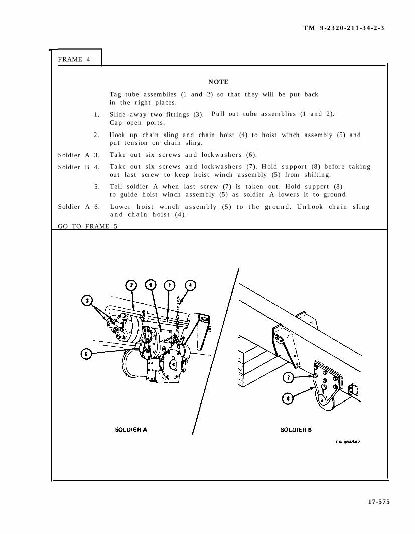
TM 9-2320-211-34-2-3
FRAME 4
1.
2.
Soldier A 3.
Soldier B 4.
5.
Soldier A 6.
NOTE
Tag tube assemblies (1 and 2) so that they will be put backin the right places.
Slide away two fittings (3). Pull out tube assemblies (1 and 2).Cap open ports.
Hook up chain sling and chain hoist (4) to hoist winch assembly (5) andput tension on chain sling.
Take out six screws and lockwashers (6).
Take out six screws and lockwashers (7). Hold support (8) before takingout last screw to keep hoist winch assembly (5) from shifting.
Tell soldier A when last screw (7) is taken out. Hold support (8)to guide hoist winch assembly (5) as soldier A lowers it to ground.
Lower hoist winch assembly (5) to the ground. Unhook chain slingand chain hoist (4) .
GO TO FRAME 5
17-575
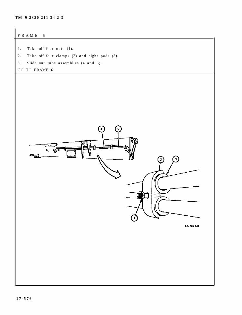
TM 9-2320-211-34-2-3
F R A M E 5
1. Take off four nuts (1).
2. Take off four clamps (2) and eight pads (3).
3. Slide out tube assemblies (4 and 5).
GO TO FRAME 6
1 7 - 5 7 6

TM 9-2320-211-34-2-3
FRAME 6
1. Take out cotter pin (1).
2 . Push out pin (2) and take out sheave assembly (3).
3. Take out lubrication fitting (4).
4. Take out two sheave assembly bearings (5). Refer to Part 1, para 7-7.
5. Do steps 3 and 4 again on sheave assembly taken off during boom assemblyremoval.
6. Take out two pivot pin bushings (6).
GO TO FRAME 7
17-577

TM 9-2320-211-34-2-3
F R A M E 7
1. Take out four screws and lockwashers (1).
2 . Pull out inner boom roller tube assembly (2).
3. Take out lubrication fitting (3).
4. Slide inner boom roller tube (4) with two sleeve bearings (5) off inner boomroller tube shaft (6).
5. Take sleeve bearings (5) out of inner boom roller tube (4). Refer to Part 1,para 7-7.
6. Take out cotter pin (7).
7. Pull inner boom roller tube shaft (6) out of shaft plate (8).
END OF TASK
17-578

TM 9-2320-211-34-2-3
WARNING
Dry cleaning solvent is flammable. Do not usenear an open flame. Keep a fire extinguishernearby when solvent is used. Use only in well-ventilated places. Failure to do this may resultin injury to personnel and damage to equipment.
d . Cleaning. Clean all parts with solvent. Make sure that grease passages areo p e n . Dry all parts well.
e . Inspection.
F R A M E 1
1.
2.
3.
4.
5.
GO
Check thatdamaged.
Check that
Check thatsheave pin
Check that
Check that
outer boom (1) has no broken welds, and that it is not bent or
boom sheave pin (2) is not bent or damaged.
two pivot pin bushings (3) are not damaged. Check that boom(2) turns freely but not loosely in pivot pin bushings.
two sheave assemblies (4) are not cracked, broken or damaged.
four sheave assembly bearings (5) are not damaged. Refer toPart 1, para 7-7.
TO FRAME 2
NOTECHECK ONLY THOSE PARTS WHICH ARE CALLEDOUT IN THIS FRAME. PARTS WITHOUT CALLOUTSARE SHOWN ONLY FOR REFERENCE PURPOSESOR ARE CHECKED IN ANOTHER FRAME.
17-579

TM 9-2320-211-34-2-3
FRAME 2
1. Check that two roller tubes (1) and roller tube shafts (2) are not bent or damaged.
2. Check that four bushings (3) are not damaged.
3. Check that inner boom roller tube (4) and inner boom roller tube shaft (5) are notbent or damaged.
4. Check that two sleeve bearings (6) are not damaged. Refer to Part 1, para 7-7.
END OF TASK
NOTECHECK ONLY THOSE PARTS WHICH ARE CALLEDOUT IN THIS FRAME. PARTS WITHOUT CALLOUTSARE SHOWN ONLY FOR REFERENCE PURPOSESOR ARE CHECKED IN ANOTHER FRAME.
17-580

TM 9-2320-211-34-2-3
f . Repair .
(1) If outer boomto TM 9-237.
(2 ) Re fer to para
(3) Refer to para
has broken welds, or is bent, weld or straighten it . Refer
17-38 for repair of upper and lower boom rollers.
17-18 for repair of hoist winch assembly.
(4) Throw away damaged parts and get new ones in their place.
g . Assembly .
F R A M E 1
1.
2.
3.
4.
5.
6 .
7 .
Put inner boom roller tube shaft (1) into bore in shaft plate (2) and line upcotter pin holes.
Put in cotter pin (3).
Put two sleeve bearings (4) into boom roller tube (5). Refer to Part 1,para 7-7.
Slide inner boom roller tube (5) with sleeve bearings (4) onto inner boomroller tube shaft (1) .
Put in lubrication fitting (6).
Put inner boom roller tube assembly (7) into bores in outer boom (8).
Put in four screws and lockwashers (9).
GO TO FRAME 2
17-581

TM 9-2320-211-34-2-3
1. Put two pivot pin bushings (1) into outer boom (2).
2. Put two sheave assembly bearings (3) into sheave (4). Refer to Part 1,para 7-7.
3. Put in lubrication fitting (5).
4. Do steps 2 and 3 again on other sheave.
5. Put sheave (4) with sheave assembly bearings (3) into place in outer boom(2) and line up pin holes.
6. Push in pin (6).
7. Put in cotter pin (7).
GO TO FRAME 3
17-582

TM 9-2320-211-34-2-3
F R A M E 3
1. Slide tube assemblies (1 and 2) through opening in elevating cylinder bracket(3). Make sure that tube assemblies are in position as tagged.
2. Put eight pads (4) and four clamps (5) in place.
3. Put on four nuts (6).
GO TO FRAME 4
1 7 - 5 8 3

TM 9-2320-211-34-2-3
FRAME 4
1.
Soldier A 2.
Soldier B 3.
4.
Soldier A 5.
6.
7.
8.
Hook up chain sling and chain hoist (1) to hoist winch assembly (2).
Raise hoist winch assembly (2) into position.
As soldier A raises hoist winch assembly (2), hold support (3) and guideit into position.
Put in six screws and lockwashers (4).
Put in six screws and lockwashers (5).
Take chain sling and chain hoist (1) off hoist winch assembly (2).
Take caps off tube assemblies (6 and 7). Put tube assemblies intoelbows (8 and 9) as tagged.
Tighten two fittings (10). Take tags off tube assemblies (6 and 7).
GO TO FRAME 5
17-584
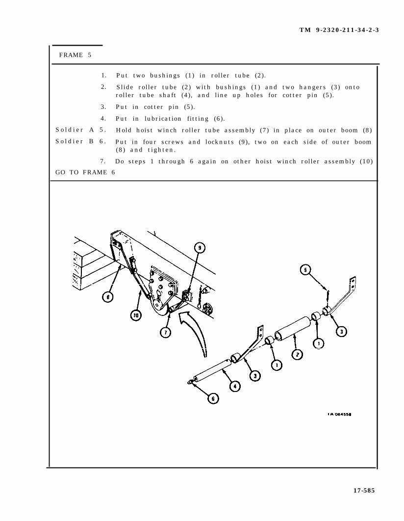
TM 9-2320-211-34-2-3
FRAME 5
1. Put two bushings (1) in roller tube (2).
2. Slide roller tube (2) with bushings (1) and two hangers (3) ontoroller tube shaft (4), and line up holes for cotter pin (5).
3. Put in cotter pin (5).
4. Put in lubrication fitting (6).
S o l d i e r A 5 . Hold hoist winch roller tube assembly (7) in place on outer boom (8)
S o l d i e r B 6 . Put in four screws and locknuts (9), two on each side of outer boom(8) and tighten.
7. Do steps 1 through 6 again on other hoist winch roller assembly (10)
GO TO FRAME 6
17-585
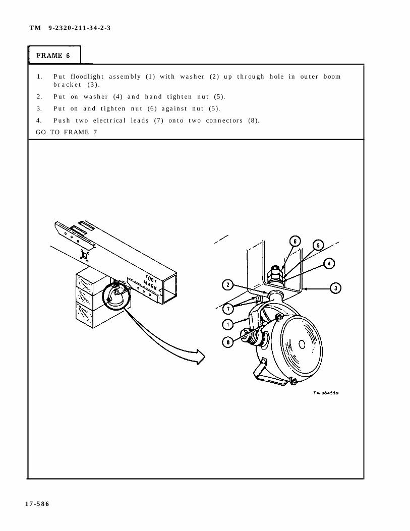
TM 9-2320-211-34-2-3
1. Put floodlight assembly (1) with washer (2) up through hole in outer boombracket (3 ) .
2. Put on washer (4) and hand tighten nut (5).
3. Put on and tighten nut (6) against nut (5).
4. Push two electrical leads (7) onto two connectors (8).
GO TO FRAME 7
17-586

TM 9-2320-211-34-2-3
F R A M E 7
Sold ier A 1 . Hold lower boom roller assembly (1) in place on outer boom (2), andline up screw holes.
So ld ier B 2 . Put in six screws and
3. Set upper boom rollerline up screw holes.
4. Put in six screws and
END OF TASK
lockwashers
assemby (4)
lockwashers
( 3 ) .
in place on outer boom (2), and
( 5 ) .
17-587
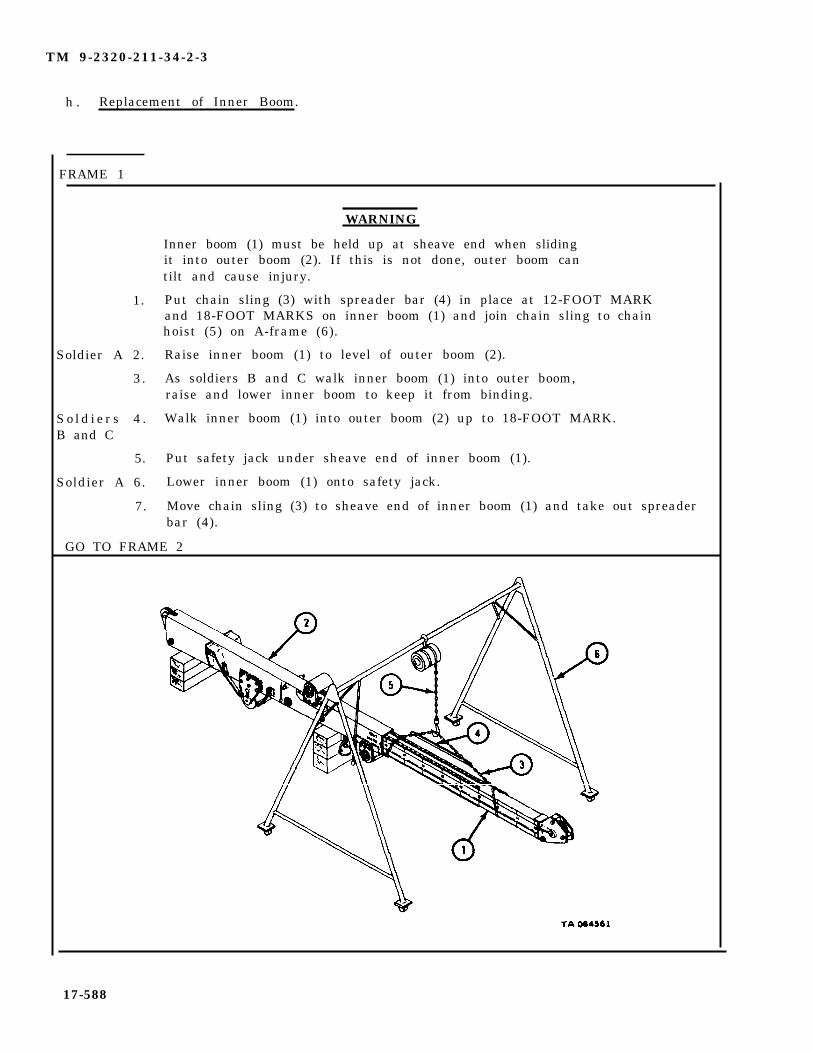
TM 9-2320-211-34-2-3
h . Replacement of Inner Boom.
FRAME 1
1.
Soldier A 2.
3.
S o l d i e r s 4 .B and C
5.
Soldier A 6.
7.
WARNING
Inner boom (1) must be held up at sheave end when slidingit into outer boom (2). If this is not done, outer boom cantilt and cause injury.
Put chain sling (3) with spreader bar (4) in place at 12-FOOT MARKand 18-FOOT MARKS on inner boom (1) and join chain sling to chainhoist (5) on A-frame (6).
Raise inner boom (1) to level of outer boom (2).
As soldiers B and C walk inner boom (1) into outer boom,raise and lower inner boom to keep it from binding.
Walk inner boom (1) into outer boom (2) up to 18-FOOT MARK.
Put safety jack under sheave end of inner boom (1).
Lower inner boom (1) onto safety jack.
Move chain sling (3) to sheave end of inner boom (1) and take out spreaderbar (4).
GO TO FRAME 2
17-588

TM 9-2320-211-34-2-3
F R A M E 2
S o l d i e r s 1 . Walk inner boom (1) all the way into outer boom (2).B and C
Sold ier A 2 . Raise or lower inner boom (1) to aline clevis pin hole in crowdcylinder (3) with clevis pin hole in outer boom (2).
3. Push crowd cylinder clevis pin (4) into place.
4. Put in cotter pin (5).
5. Put boom stop (6) in place.
6. Put in four screws and lockwashers (7).
7. Do steps 5 and 6 again on other side of outer boom (2).
8. Take chain hoist off chain sling (8) and take chain sling off innerboom (2 ) .
NOTE
Follow-on Maintenance Action Required:
1. Replace boom assembly. Refer to para 17-44.2. Replace hoist winch cable. Refer to TM 9-2320-211-20.3. Oil and grease boom assembly as given in
LO 9-2320-211-12.4. Adjust crane inner and outer boom rollers. Refer
to TM 9-2320-211-20.
END OF TASK
17-589
TM 9-2320-211-34-2-3
17-46. CRANE INNER BOOM REPAIR (TRUCK M543A2).
TOOLS: No special tools required
SUPPLIES: Solvent, dry cleaning, type II (SD-2), Fed. Spec P-D-680
PERSONNEL: T h r e e
EQUIPMENT CONDITION: Truck parked, engine off , handbrake set.
a . Preliminary Procedures.
(1) Remove hoist winch cable. Refer to TM 9-2320-211-20.
(2) Remove boom assembly. Refer to para 17-44.
(3) Remove inner boom from outer boom. Refer to para 17-45.
17-590

TM 9-2320-211-34-2-3
b . Disassembly.
WARNING
Be careful when handling inner boom. It is heavyand can cause injury to personnel.
FRAME 1
Sold ier A 1 . Hook up chain sling and chain hoist to crowd cylinder assembly (1).
2 . Take out cotter pin
3 . Drive out pin (3).
(2) .
NOTE
Pull crowd cylinder about two feet out of inner boom.
S o l d i e r s 4 . Using chain and chain hoist, pull crowd cylinder assembly (1) out ofB and C inner boom (4).
5 . Lower crowd cylinder assembly (1) onto wood blocks. Take off chainsling
S o l d i e r A 6 . T a k e
7 . Take
GO TO FRAME 2
and chain hoist.
off two nuts (5).
out two screws (6) and two spacers (7).
17-591
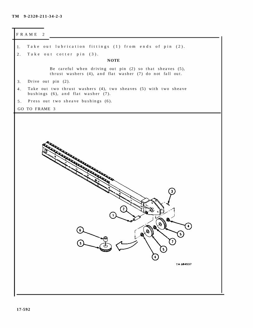
TM 9-2320-211-34-2-3
F R A M E 2
1. T a k e o u t l u b r i c a t i o n f i t t i n g s ( 1 ) f r o m e n d s o f p i n ( 2 ) .
2. T a k e o u t c o t t e r p i n ( 3 ) .
NOTE
Be careful when driving out pin (2) so that sheaves (5),thrust washers (4), and flat washer (7) do not fall out.
3. Drive out pin (2).
4 . Take out two thrust washers (4), two sheaves (5) with two sheavebushings (6), and flat washer (7).
5 . Press out two sheave bushings (6).
GO TO FRAME 3
17-592

TM 9-2320-211-34-2-3
Sold iers A , 1 .B a n d C
Soldier A 2.
Soldiers 3.B and C
Soldier A 4.
5.
Soldiers 6.A and B
Soldiers 7.A and B
END OF TASK
Hook up chain sling and chain hoist to inner boom (1).
Using chain sling and chain hoist, take up slack to support innerboom (1 ) .
Put prybar through center hole (2) in inner boom (1) and turninner boom on its side to work on two top roller tracks (3) andtwo bottom roller tracks (4).
Using chain hoist, lower inner boom (1) onto wood blocks.
Take off chain sling and chain hoist.
Take out 52 screws (5) and lift off two top roller tracks (3).
Take out 52 screws (6) and lift off two bottom roller tracks (4).
17-593

TM 9-2320-211-34-2-3
c . Cleaning.
WARNING
Dry cleaning solvent is flammable. Do not usenear an open flame. Keep a fire extinguishernearby when solvent is used. Use only in well-ventilated places. Failure to do this may resultin injury to personnel and damage to equipment.
(1) Clean all parts with solvent. Make sure that all grease passages areo p e n .
(2 ) Let parts dry .
17-594
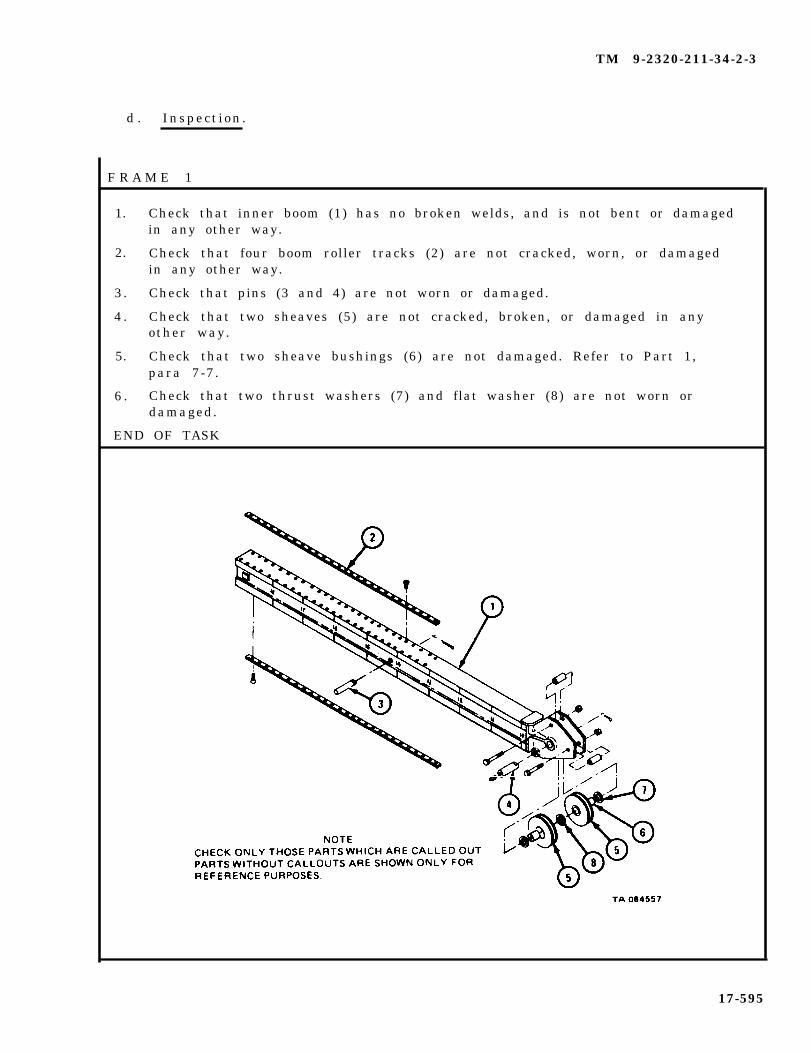
TM 9-2320-211-34-2-3
d . Inspect ion .
F R A M E 1
1.
2.
3 .
4 .
5.
6 .
Check that inner boom (1) has no broken welds, and is not bent or damagedin any other way.
Check that four boom roller tracks (2) are not cracked, worn, or damagedin any other way.
Check that pins (3 and 4) are not worn or damaged.
Check that two sheaves (5) are not cracked, broken, or damaged in anyother way.
Check that two sheave bushings (6) are not damaged. Refer to Part 1,para 7-7.
Check that two thrust washers (7) and flat washer (8) are not worn ordamaged.
END OF TASK
17-595

TM 9-2320-211-34-2-3
e . Repair.
(1) If inner boom has broken welds or is bent, straighten or weld it. Referto TM 9-237.
(2) Throw away all damaged parts and get new ones in their place.
f . Assembly.
F R A M E 1
Soldiers A, 1.B a n d C
SoldiersA and B
Soldier C
SoldiersA and B
SoldiersA and B
Soldier C
SoldiersA and B
Soldier A
SoldiersB and C
2.
3.
4.
5.
6.
7.
8.
9.
Put two top boom roller tracks (1) in place on inneralining holes in tracks and boom.
Hold two top boom roller tracks (1) in place at each
Put three center screws (3) in each top roller track
Put in other 49 screws (3).
boom (2 ) ,
e n d .
( 1 ) .
Put two bottom boom roller tracks (4) in place on inner boom (2),alining holes. H o l d t h e m i n p l a c e .
Put three center screws (5) in each bottom
Put in other 49 screws (5).
Using chain sling and chain hoist, take upboom (2) .
roller track (4).
slack to support inner
Using prybar, turn inner boom (2) over on wood blocks.
GO TO FRAME 2
17-596
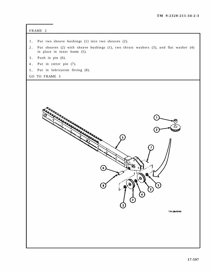
TM 9-2320-211-34-2-3
FRAME 2
1 . Put two sheave bushings (1) into two sheaves (2).
2 . Put sheaves (2) with sheave bushings (1), two thrust washers (3), and flat washer (4)in place in inner boom (5).
3 . Push in pin (6).
4 . Put in cotter pin (7).
5 . Put in lubrication fitting (8).
GO TO FRAME 3
17-597

TM 9-2320-211-34-2-3
F R A M E 3
1. Put two spacers (1) in place inner boom (2) and push two screws (3)through inner boom and spacers.
2 . Put two nuts (4) onto screws (3).
3 . Hook up chain sling and chain hoist to crowd cylinder assembly (5).
S o l d i e r s 4 . Using chain sling and chain hoist, raise crowd cylinder assembly (5)A and B and guide it into place in inner boom (2).
So ld ier C 5 . Aline bore in piston rod (6) with bore in inner boom (2). Push inpin (7).
6 . Put in cotter pin (8).
7 . Take off chain sling and chain hoist.
8 . Push crowd cylinder (5) all the way into inner boom (2).
NOTE
Follow-on Maintenance Action Required:
1. Replace inner boom in outer boom. Refer to para 17-45.2. Replace boom assembly. Refer to para 17-44.3. Replace hoist winch cable. Refer to TM 9-2320-211-20.4. Oil and grease boom assembly. Refer to
LO 9-2320-211-12.5. Adjust crane inner and outer boom rollers. Refer
END OF TASK to TM 2320-211-20.
17-598

TM 9-2320-211-34-2-3
17-47. ROTOCHAMBER REMOVAL AND REPLACEMENT (TRUCK M543A2).
TOOLS: No special tools required
SUPPLIES: None
PERSONNEL: One
EQUIPMENT CONDITION: Truck parked, engine off , handbrake set.
a . Preliminary Procedure. Remove cab tunnel. Refer to TM 9-2320-211-20.
b . Removal.
FRAME 1
1. Unscrew sleeve nut (1) and take out air line (2).
2. Take out cotter pin (3). Take out clevis pin (4).
3. Take out two screws (5) and lockwashers (6).
4. Take out rotochamber assembly (7).
5. Take out cotter pin (8). Take off washer (9) and lever (10).
GO TO FRAME 2
17-599

TM 9-2320-211-34-2-3
FRAME 2
1 . Loosen nut (1) and take out screw (2).
END OF TASK
17-600
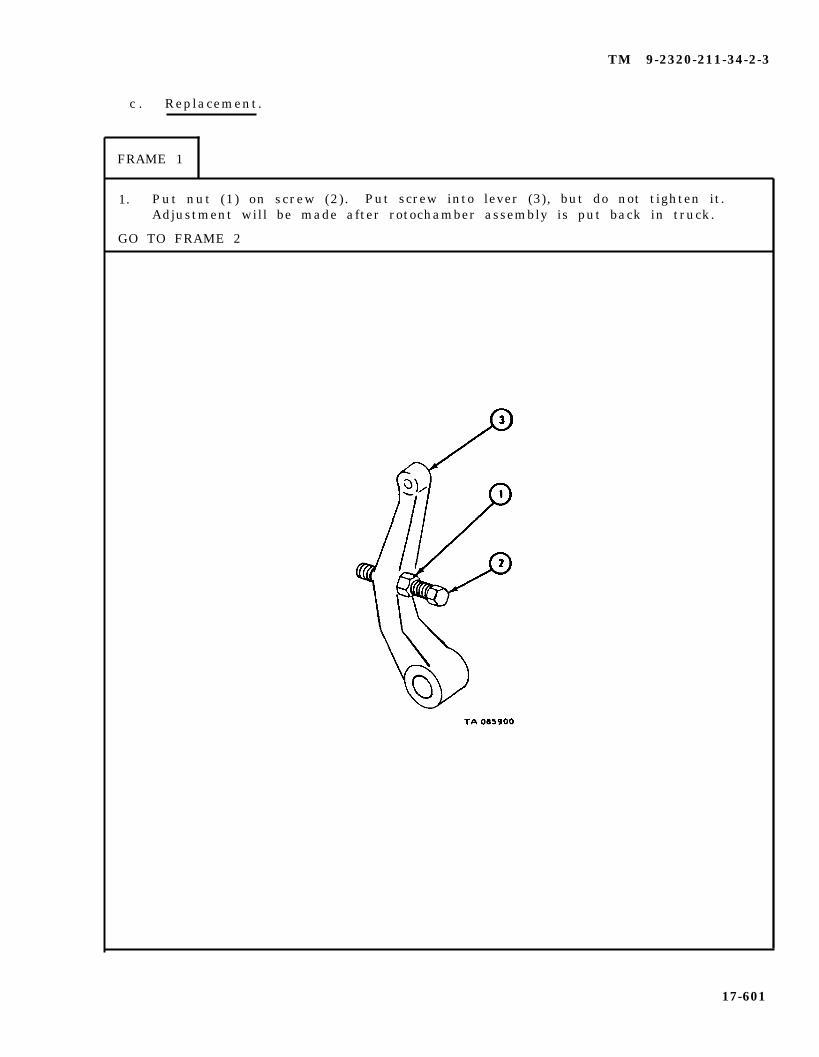
TM 9-2320-211-34-2-3
c . Replacement.
FRAME 1
1. Put nut (1) on screw (2). Put screw into lever (3), but do not tighten it.Adjustment will be made after rotochamber assembly is put back in truck.
GO TO FRAME 2
17-601
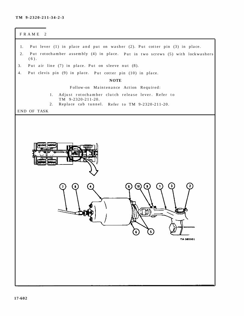
TM 9-2320-211-34-2-3
F R A M E 2
1. Put lever (1) in place and put on washer (2). Put cotter pin (3) in place.
2. Put rotochamber assembly (4) in place. Put in two screws (5) with lockwashers( 6 ) .
3. Put air line (7) in place. Put on sleeve nut (8).
4. Put clevis pin (9) in place. Put cotter pin (10) in place.
NOTE
Follow-on Maintenance Action Required:
1. Adjust rotochamber clutch release lever. Refer toTM 9-2320-211-20.
2. Replace cab tunnel. Refer to TM 9-2320-211-20.
END OF TASK
17-602

TM 9-2320-211-34-2-3
17-48. SNATCH BLOCK ASSEMBLY (DOUBLE) REPAIR (TRUCK M543A2).
TOOLS: No special tools required
SUPPLIES: Solvent, dry cleaning, type II (SD-2), Fed. Spec P-D-680
PERSONNEL: Two
a. P r e l i m i n a r y P r o c e d u r e . Remove snatch block from storage box on truck.Refer to TM 9-2320-211-10.
b . Disassembly.
F R A M E 1
1. Takeout lubrication fitting (1).
2. Take off three nuts (2) and takeout three screws (3).
3. Take out six spacers (4).
S o l d i e r A 4 . Hold nuts (5) .
S o l d i e r B 5 . T a k e o f f n u t s ( 6 ) .
GO TO FRAME 2
17-603

TM 9-2320-211-34-2-3
F R A M E 2
1. Take off side cover and bracket (1) .
2. Take off sheave (2) .
3. Take sheave screws (3) out of side cover (4) and sheave and bracket (5).
GO TO FRAME 3
17-604

TM 9-2320-211-34-2-3
F R A M E 3
1. Take spacer (1 ) out o f sheave bushing (2 ) .
2. If bushing (2) is damaged, press it out of sheave (3) .
3. Do steps 1 and 2 again for sheave (4) .
END OF TASK
17-605
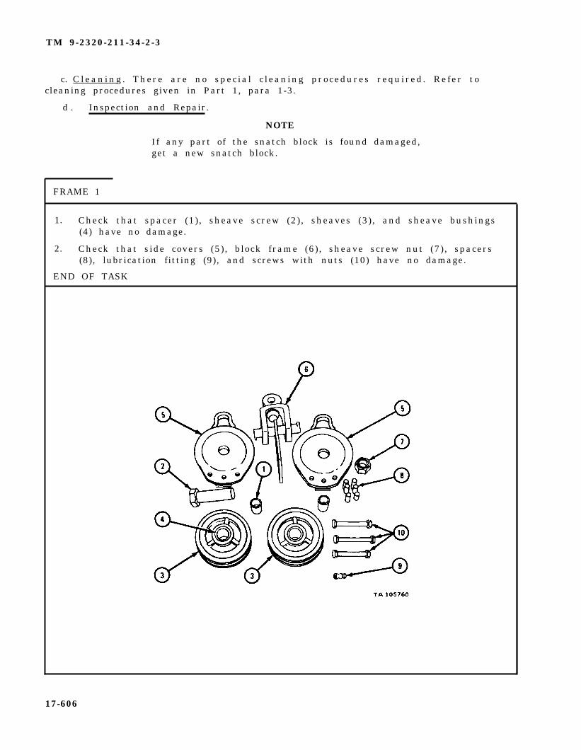
TM 9-2320-211-34-2-3
c. C l e a n i n g . There are no spec ia l c leaning procedures required . Refer tocleaning procedures given in Part 1, para 1-3.
d . Inspection and Repair.
NOTE
If any part of the snatch block is found damaged,get a new snatch block.
FRAME 1
1. Check that spacer (1), sheave screw (2), sheaves (3), and sheave bushings(4) have no damage.
2. Check that side covers (5), block frame (6), sheave screw nut (7), spacers(8), lubrication fitting (9), and screws with nuts (10) have no damage.
END OF TASK
17-606
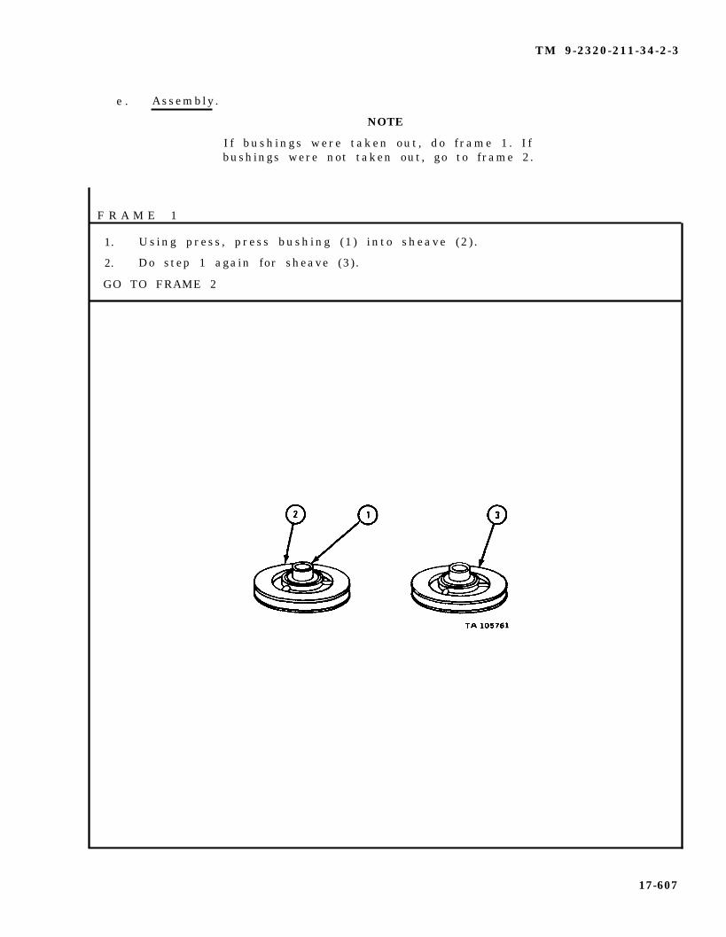
TM 9-2320-211-34-2-3
e . Assembly .
NOTE
I f bushings were taken out , do f rame 1 . I fbushings were not taken out, go to frame 2.
F R A M E 1
1. Using press , press bushing (1 ) into sheave (2 ) .
2. Do step 1 again for sheave (3) .
GO TO FRAME 2
17-607

TM 9-2320-211-34-2-3
FRAME 2
1. Put sheave screw (1) through bracket and side cover (2), sheave (3) withspacer, and through block frame (4).
2. Put sheave (5) with spacer onto sheave screw (1). Put on side cover (6)and bracket.
3. Put lubrication fitting (7) into end of sheave screw (1).
4. Put hatch (8) onto stud.
GO TO FRAME 3
17-608

TM 9-2320-211-34-2-3
F R A M E 3
1. Put in six spacers
2. Put on and tighten
S o l d i e r s 3 . Put on and tightenA and B
(1) and three screws (2) .
three nuts
nut (4 ) .
( 3 ) .
Follow-on Maintenance Action Required:
1. Grease snatch block. Refer to LO 9-2320-211-12.2. Put snatch block back in storage box on truck.
Refer to TM 9-2320-211-10.
END OF TASK
17-609
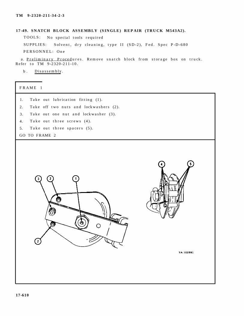
TM 9-2320-211-34-2-3
17-49. SNATCH BLOCK ASSEMBLY (SINGLE) REPAIR (TRUCK M543A2).
TOOLS: No special tools required
SUPPLIES: Solvent, dry cleaning, type II (SD-2), Fed. Spec P-D-680
PERSONNEL: One
a. Pre l iminary Procedures . Remove snatch block from storage box on truck.Refer to TM 9-2320-211-10.
b . Disassembly.
F R A M E 1
1. Take out lubrication fitting (1).
2. Take off two nuts and lockwashers (2).
3. Take out one nut and lockwasher (3).
4. Take out three screws (4).
5. Take out three spacers (5) .
GO TO FRAME 2
17-610
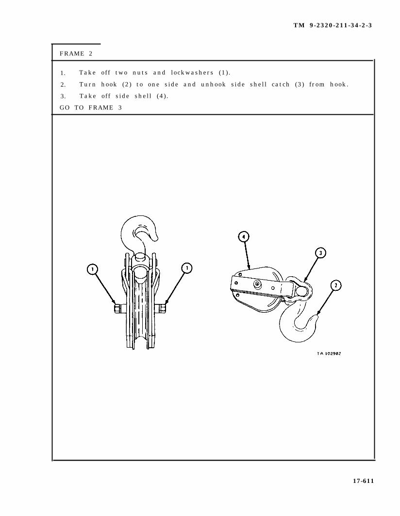
TM 9-2320-211-34-2-3
FRAME 2
1. Take off two nuts and lockwashers (1).
2. Turn hook (2) to one side and unhook side shell catch (3) from hook.
3. Take off side shell (4) .
GO TO FRAME 3
17-611

TM 9-2320-211-34-2-3
FRAME 3
1. Take off sheave (1) .
2. Take out sheave pin (2).
3. Press sheave bushing (3) out of sheave (1) .
END OF TASK
17-612
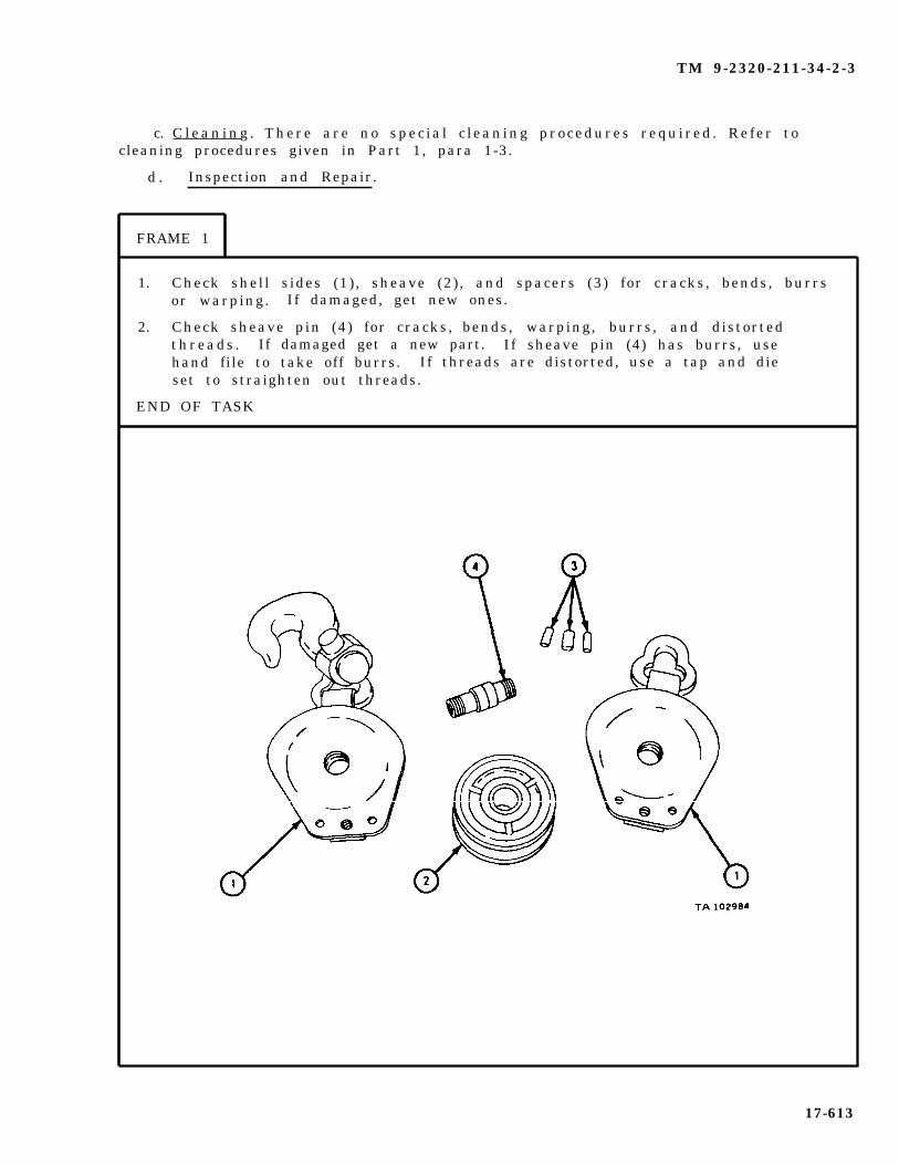
TM 9-2320-211-34-2-3
d . Inspection and Repair.
c. C l e a n i n g . There are no spec ia l c leaning procedures required . Refer tocleaning procedures given in Part 1, para 1-3.
FRAME 1
1. Check shell sides (1), sheave (2), and spacers (3) for cracks, bends, burrsor warping. If damaged, get new ones.
2. Check sheave pin (4) for cracks, bends, warping, burrs, and distortedthreads . If damaged get a new part. If sheave pin (4) has burrs, usehand file to take off burrs. If threads are distorted, use a tap and dieset to straighten out threads.
END OF TASK
17-613

TM 9-2320-211-34-2-3
e . Assembly .
FRAME 1
1. Press sheave bushing (1) into sheave (2).
GO TO FRAME 2
17-614
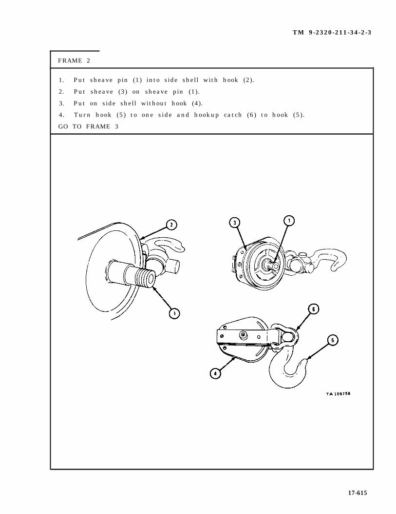
TM 9-2320-211-34-2-3
FRAME 2
1.
2.
3.
4.
GO
Put sheave pin (1) into side shell with hook (2).
Put sheave (3) on sheave pin (1).
Put on side shell without hook (4).
Turn hook (5) to one side and hookup catch (6) to hook (5) .
TO FRAME 3
17-615
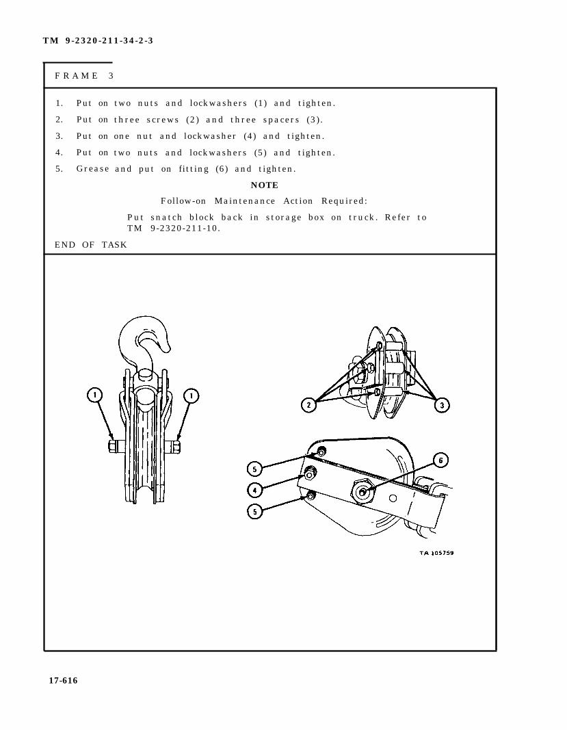
TM 9-2320-211-34-2-3
F R A M E 3
1. Put on
2. Put on
3. Put on
4. Put on
5. Grease
two nuts and lockwashers (1) and tighten.
three screws (2) and three spacers (3) .
one nut and lockwasher (4) and tighten.
two nuts and lockwashers (5) and tighten.
and put on fitting (6) and tighten.
NOTE
Follow-on Maintenance Action Required:
Put snatch block back in storage box on truck. Refer toTM 9-2320-211-10.
END OF TASK
17-616

TM 9-2320-211-34-2-3
17-50. OPERATOR GUARD REPAIR (TRUCK M543A2).
TOOLS: No special tools required
SUPPLIES: Solvent, dry cleaning, type II (SD-2), Fed. Spec P-D-680
PERSONNEL: One
EQUIPMENT CONDITION: Truck parked, engine off , handbrake set.
a . Removal.
FRAME 1
1. Lift guard (1) up and out of two gondola brackets (2).
END OF TASK
17-617

TM 9-2320-211-34-2-3
b. Cleaning , Inspect ion , a n d Repair .
FRAME 1
WARNING
Dry cleaning solvent is flammable. Do not usenear an open flame. Keep a fire extinguishernearby when solvent is used. Use only in well-ventilated places. Failure to do this may resultin injury to personnel and damage to equipment.
1. Clean operator guard with solvent.
2. Check that frame (1) has no cracks, bends or breaks. Repair by straighteningor welding. Refer to TM 9-237.
3. Check wire mesh (2) for holes or broken welds. Repair by welding. Refer toTM 9-237.
4. If frame (1) or wire mesh (2) cannot be fixed, get new operator guard.
END OF TASK
17-618

TM 9-2320-211-34-2-3
c . Replacement.
FRAME 1
1. Place two guard supports (1) into gondola brackets (2) and push down evenly untilguard (3) is seated.
END OF TASK
17-619

TM 9-2320-211-34-2-3
17-51. CONTROL VALVE BANK REPAIR (TRUCK M543A2).
TOOLS: No special tools required
SUPPLIES: Solvent , dry c leaning , type I I (SD-2) , Fed . Spec P-D-680Lubricating oil , ICE, OE/HDO 30, MIL-L-2104Clean ragsControl valve bank seal and preformed packing set3/32 x 5/8-inch cotter pins (8)1/16 x 1/2-inch cotter pins (16)
PERSONNEL: One
EQUIPMENT CONDITION: Control valve bank taken off vehicle and on work-b e n c h .
a. P r e l i n i n a r y P r o c e d u r e s .
( 1 ) Remove control valve bank assembly. Refer to TM 9-2320-211-20.
(2 ) C lean outs ide o f contro l va lve bank. Refer to para 17-51d .
17-620

TM 9-2320-211-34-2-3
b . Disassembly into Subassemblies.
FRAME 1
1. Unscrew and take out
2. Unscrew and take out
3. Unscrew and take out
4. Unscrew and t take out
GO TO FRAME 2
four nipples (1) from control valve bank (2).
two nipples (3) .
two nipples (4) and nipple (5).
pipe plug (6) and nipple (7) .
17-621

TM 9-2320-211-34-2-3
F R A M E 2
1. Take off five spring pins (1) from nuts (2).
2. Take off five nuts (2).
3. Take off mounting angle (3).
4. Push out five rods (4) from valve bank (5).
5. Take off mounting angle (6).
GO TO FRAME 3
NOTEPARTS WITHOUT CAL LOUTS ARE SHOWN ONLY FORREFERENCE PURPOSES.
17-622
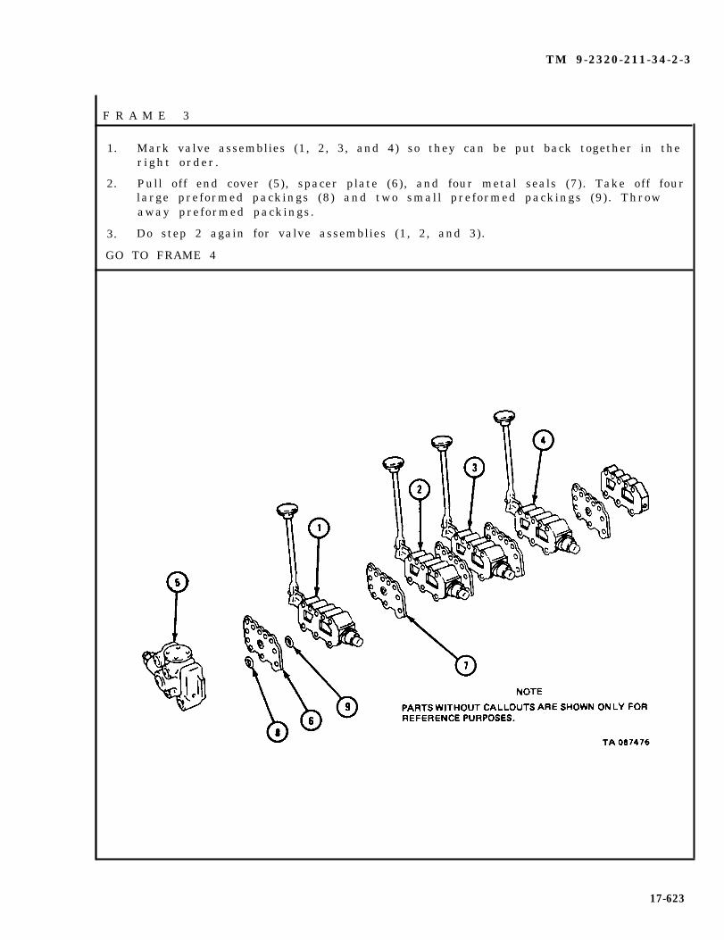
TM 9-2320-211-34-2-3
F R A M E 3
1. Mark valve assemblies (1, 2, 3, and 4) so they can be put back together in ther ight order .
2. Pull off end cover (5), spacer plate (6), and four metal seals (7). Take off fourlarge preformed packings (8) and two small preformed packings (9). Throwaway preformed packings.
3. Do step 2 again for valve assemblies (1, 2, and 3).
GO TO FRAME 4
17-623

TM 9-2320-211-34-2-3
F R A S M E 4
1. Takeoff valve assembly (1) . Takeout spr ing (2 ) , poppet (3 ) , and s leeve (4 )from valve assembly (1).
2. Take off spacer plate (5), three metal seals (6), four large preformed packings(7), and four small preformed packings (8). Throw away preformed packings.
END OF TASK
NOTEPARTS WITHOUT CALLOUTS ARE SHOWN ONLY FORREFERENCE PURPOSES.
17-624

TM 9-2320-211-34-2-3
c* Disassembly of Subassemblies.
(1 ) S ide p late .
FRAME 1
1. Unscrew and take out 1/4-inch pipe plug (1), 1/4-inch closure plug (2), and1 /8 - inch p lug (3 ) .
END OF TASK
17-625

TM 9-2320-211-34-2-3
( 2 )
FRAME 1
Crane valve assembly.
1. Take off nut (1) from valve assembly (2).
2. Take out adjusting screw (3), preformed packing (4), spring (5), and valve( 6 ) .
NOTE
Do not take out valve seat (7) unless found damagedduring inspection.
3. Take valve seat (7) out of valve assembly (2).
GO TO FRAME 2
17-626

TM 9-2320-211-34-2-3
FRAME 2
1. Take out four screws (1) and lockwashers (2) from body (3).
2. Take out two preformed packings (4) and preformed packing (5). Throw awaypreformed packings.
3. Take out spring (6).
4. Take out spool (7).
5. Take out seat (8) . Take off two preformed packings (9). Throw away pre-formed packings.
GO TO FRAME 3
17-627
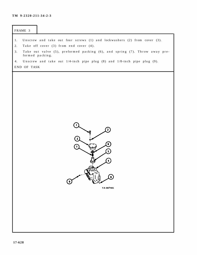
TM 9-2320-211-34-2-3
FRAME 3
1. Unscrew and take out four screws (1) and lockwashers (2) from cover (3).
2. Take off cover (3) from end cover (4) .
3. Take out valve (5), preformed packing (6), and spring (7). Throw away pre-formed packing.
4. Unscrew and take out 1/4-inch pipe plug (8) and 1/8-inch pipe plug (9).
END OF TASK
17-628
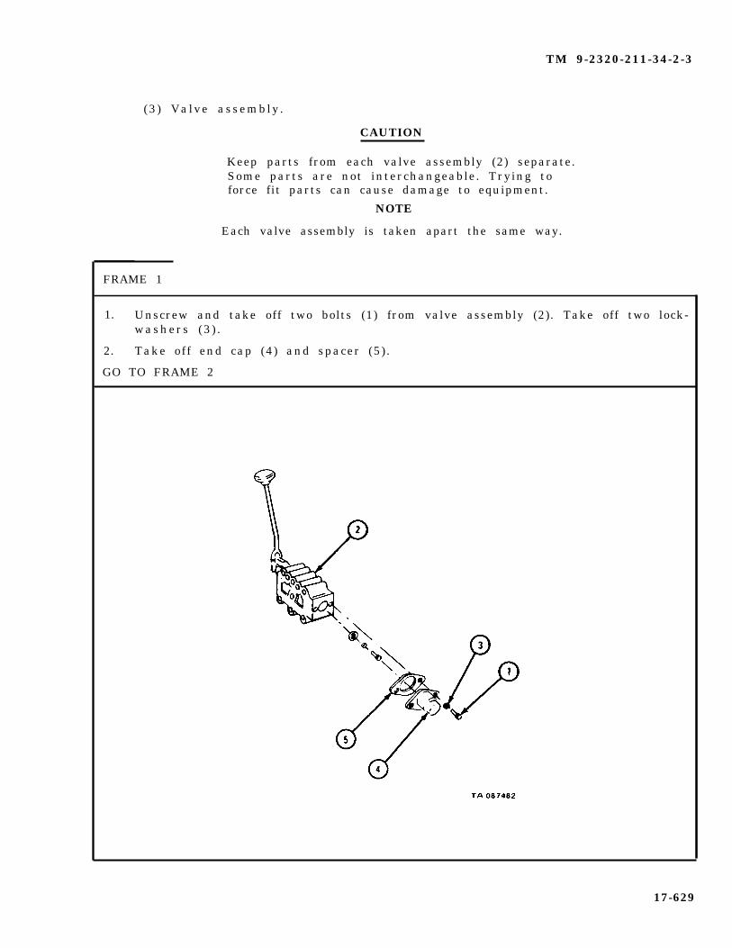
TM 9-2320-211-34-2-3
(3 ) Valve assembly .
CAUTION
Keep parts from each valve assembly (2) separate.Some parts are not interchangeable. Trying toforce fit parts can cause damage to equipment.
NOTE
Each valve assembly is taken apart the same way.
FRAME 1
1. Unscrew and take off two bolts (1) from valve assembly (2). Take off two lock-washers (3 ) .
2. Take off end cap (4) and spacer (5) .
GO TO FRAME 2
17-629

TM 9-2320-211-34-2-3
FRAME 2
1. Unscrew and takeout screw (1), lockwasher (2), and washer (3).
2. Take out two springs (4 and 5), washer (6), and preformed packing (7) fromvalve body (8) . Threw away preformed packing.
GO TO FRAME 3
17-630
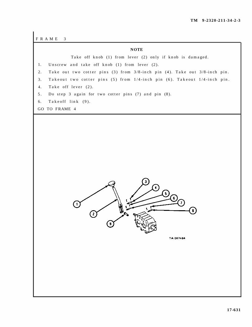
TM 9-2320-211-34-2-3
F R A M E 3
NOTE
Take off knob (1) from lever (2) only if knob is damaged.
1. Unscrew and take off knob (1) from lever (2).
2. Take out two cotter pins (3) from 3/8-inch pin (4). Take out 3/8-inch pin.
3. Takeout two cot ter p ins (5 ) f rom 1 /4 - inch p in (6 ) . Takeout 1 /4 - inch p in .
4. Take off lever (2) .
5. Do step 3 again for two cotter pins (7) and pin (8).
6. Takeof f l ink (9 ) .
GO TO FRAME 4
17-631

TM 9-2320-211-34-2-3
F R A M E 4
1. Takeout two screws (1) and lockwashers (2) from end cover (3) .
2. Takeof f end cover (3 ) , spacer (4 ) , and pre formed packing (5 ) . Throw awaypreformed packing.
3. Take out seal (6) from end cover (3) . Threw away seal.
4. Take out spool (7) from valve body (8).
5. Coat outside of spool (7) and inside of valve body (8) with a light coat oflubricating oil, ICE, OE/HDO 30, MIL-L-2104.
END OF TASK
17-632
TM 9-2320-211-34-2-3
d . Cleaning.
WARNING
Dry cleaning solvent is flammable. Do not use nearan open flame. Keep a fire extinguisher nearbywhen solvent is used. Use only in well-ventilatedplaces . Failure to do this may result in injuryto personnel and damage to equipment.
Eye shields must be worn when using compressedair. Eye injury can occur if eye shields are notu s e d .
(1) Clean all parts in solvent.
(2) Dry with compressed air.
(3) Put a light coat of lubricating oil on all highly polished parts.
17-633

TM 9-2320-211-34-2-3
e. I n s p e c t i o n a n d R e p a i r .
F R A M E 1
1. Check that spool assembly (1) and spool bore in relief valve (2) does not havedeep scratches or grooves.
2. Check that spool assembly (1) cannot be moved from side to side when in placein relief valve (2).
3. If damage or wear were found in steps 1 or 2, throw away relief valve assemblyand get a new one in its place.
GO TO FRAME 2
17-634

TM 9-2320-211-34-2-3
FRAME 2
1.
2.
3.
4.
5.
6 .
GO
Check that poppet (1) does not bind in cover and guide (2) .
Check that poppet (3) does not bind in body (4) .
If binding is found, throw away relief valve and get a new one in its place.
Check that valve poppets (1 and 3) and their seating faces in bores ofre l ie f va lve (5 ) , do not have grooves , scratches , or p i ts . If damage ismajor, throw away relief valve and get a new one in its place.
WARNING
Dry cleaning solvent is flammable. Do not usenear an open flame. Keep a f ire extinguishernearby when solvent is used. Use only in well-ventilated places. Failure to do this may resultin injury to personnel and damage to equipment.
Eye shields must be worn when using compressedair. Eye injury can occur if eye shields are notu s e d .
Using lapping compound, lap poppets (1 and 3) against their seating faces.Be very careful to keep poppets centered in bores of relief valve.
Using solvent, wash away all traces of lapping compound. Dry with com-pressed a i r .
TO FRAME 3
NOTECHECK ONLY THOSE PARTS WHICH ARE CALLED OUT,PARTS WITHOUT CALLOUTS ARE SHOWN ONLY FORREFERENCE PURPOSES.
17-635

TM 9-2320-211-34-2-3
NOTE
All valve assemblies are inspected and repairedthe same way.
FRAME 3
1. Check that spool assembly (1) and spool bore in valve (2) does not have deepscratches or grooves.
2. Check that spool assembly (1) cannot be moved from side to side when in placein swing control valve (2).
3. If damage or wear were found in steps 1 or 2, throw away valve assembly andget a new one in its place.
END OF TASK
17-636

TM 9-2320-211-34-2-3
f . Assembly of Subassemblies.
(1 ) S ide p late .
F R A M E 1
1. Screw in and tighten 1/4-inch pipe plug (1), 1/4-inch closure plug (2) and1/8-inch pipe plug (3) .
END OF TASK
17-637

TM 9-2320-211-34-2-3
(2) Relief valve assembly.
FRAME 1
1. Screw in and tighten 1/8-inch pipe (1) and 1/4-inch pipe plug (2) into endcover (3 ) .
2. Put new preformed packing (4) on valve (5). Put valve (5) in end cover (3) .Put in spring (6).
3. Put on cover (7). Put on four lockwashers (8). Screw in and tighten fourscrews (9 ) .
GO TO FRAME 2
17-638
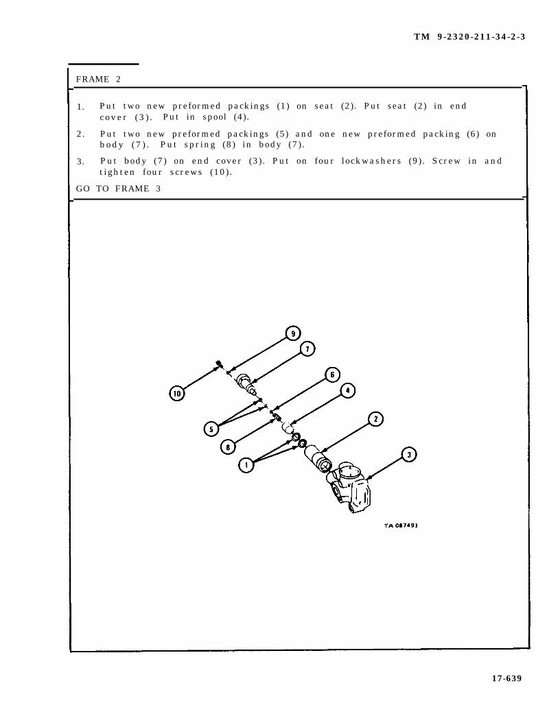
TM 9-2320-211-34-2-3
FRAME 2
1. Put two new preformed packings (1) on seat (2). Put seat (2) in endc o v e r ( 3 ) . Put in spool (4).
2. Put two new preformed packings (5) and one new preformed packing (6) onb o d y ( 7 ) . Put spring (8) in body (7).
3. Put body (7) on end cover (3). Put on four lockwashers (9). Screw in andtighten four screws (10).
GO TO FRAME 3
17-639
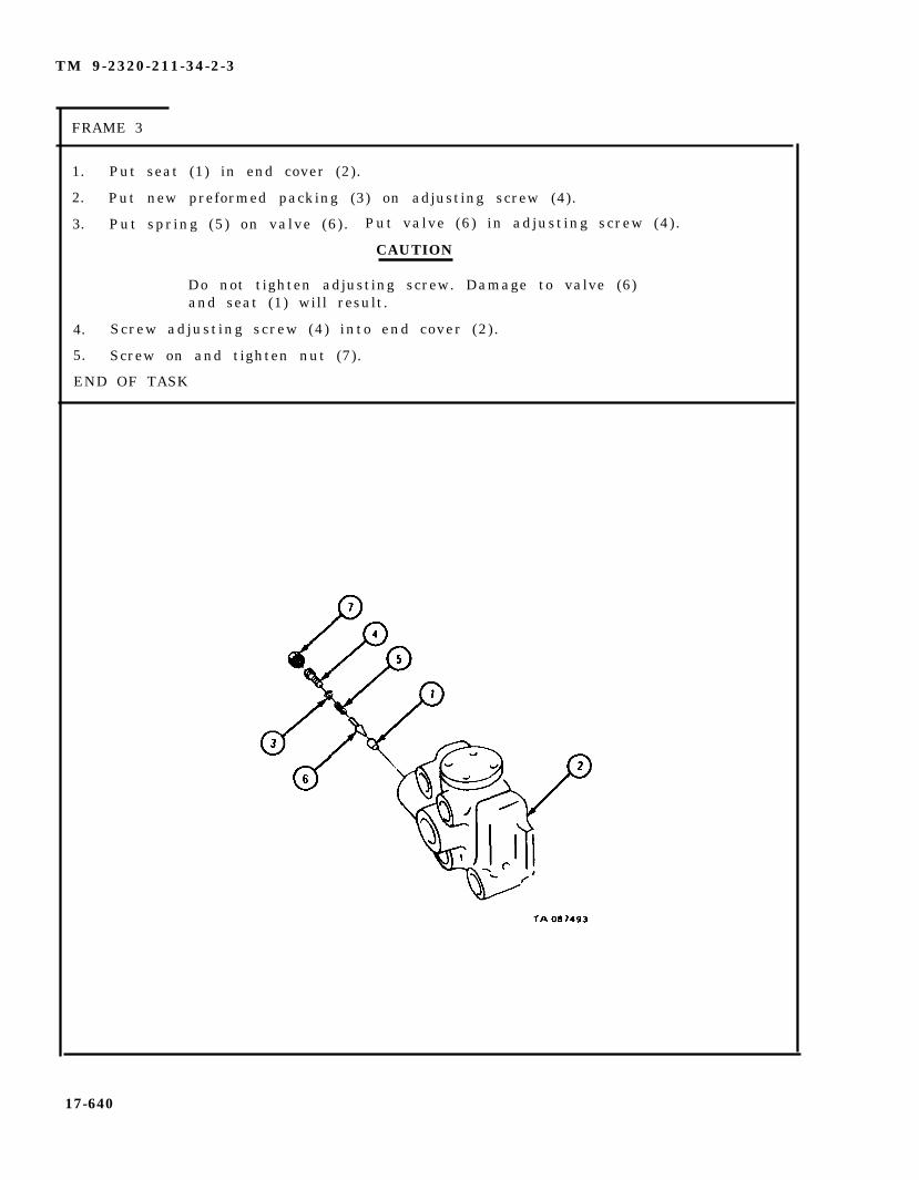
TM 9-2320-211-34-2-3
FRAME 3
1. Put seat (1) in end cover (2).
2. Put new preformed packing (3) on adjusting screw (4).
3. Put spring (5) on valve (6). Put valve (6) in adjusting screw (4).
CAUTION
Do not tighten adjusting screw. Damage to valve (6)and seat (1) will result.
4. Screw adjusting screw (4) into end cover (2) .
5. Screw on and tighten nut (7).
END OF TASK
17-640

TM 9-2320-211-34-2-3
(3 ) Valve assembly .
NOTE
Each valve assembly is put together the same way.
FRAME 1
1.
2.
3.
4.
GO
Put spool (1) in valve body (2).
Put new seal (3) in end cover (4).
Put new preformed packing (5) , spacer (6) , and end cover (4) over spool (1) .
Screw in and tighten two screws (7) and lockwashers (8) in end cover (4).
TO FRAME 2
17-641

TM 9-2320-211-34-2-3
F R A M E 2
1.
2.
3.
4.
5.
6.
7.
Put on link (1). Put in 1/4-inch by 1 1/8-inch long pin (2).
Put in two 1/16-inch cotter pins (3), one at each end of pin (2). Bend overends of cotter pins.
NOTE
Bend in lever (4) should bend away from valve body.
Put lever (4) on end of link (1). Put in 1/4-inch by 1 1/2-inch
Do step 2 again for two cotter pins (6).
Aline holes in lever (4) and end cover (7). Put in 3/8-inch pin
Do step 2 again for two 3/32-inch cotter pins (9).
Screw on and tighten by hand, knob (10) onto lever (4).
p in (5 ) .
( 8 ) .
GO TO FRAME 3
17-642

TM 9-2320-211-34-2-3
FRAME 3
1.
2.
3.
4.
GO
Put new preformed packing (1) in valve body (2).
Put washer (3), two springs (4 and 5) in valve body (2).
Put on washer (6) and lockwasher (7).
Screw in and tighten screw (8).
TO FRAME 4
17-643
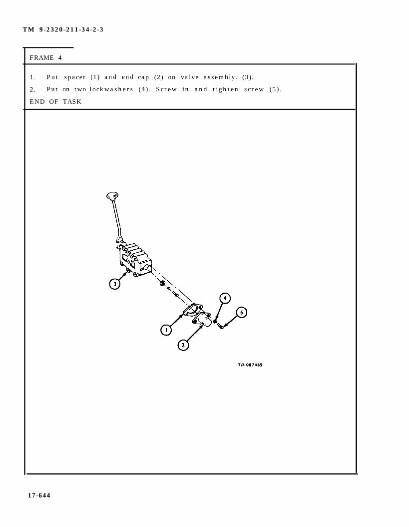
TM 9-2320-211-34-2-3
FRAME 4
1. Put spacer
2. Put on two
END OF TASK
(1) and end
lockwashers
cap (2) on valve assembly. (3).
(4) . Screw in and tighten screw (5).
17-644

TM 9-2320-211-34-2-3
g. Assembly o f Contro l Valve Bank.
NOTE
Be sure valve assemblies (6) are put back onin the same way that they were taken off.
F R A M E 1
1.
2.
3.
4.
5.
6.
GO
Push two rods (1) through two upper holes in side plate (2).
Put
Put
Put
Put
sleeve (3) , poppet (4) and spring (5) into valve assembly (6) .
three metal seals (7) on side plate (2).
spacer plate (8) over rods (1) and onto side plate (2).
four new large preformed packings (9) and four new small preformedpackings (10) into holes in spacer plate (8).
Hold spring (5) in place. Put valve assembly (6) over rods (1) and ontospacer plate.
TO FRAME 2
17-645
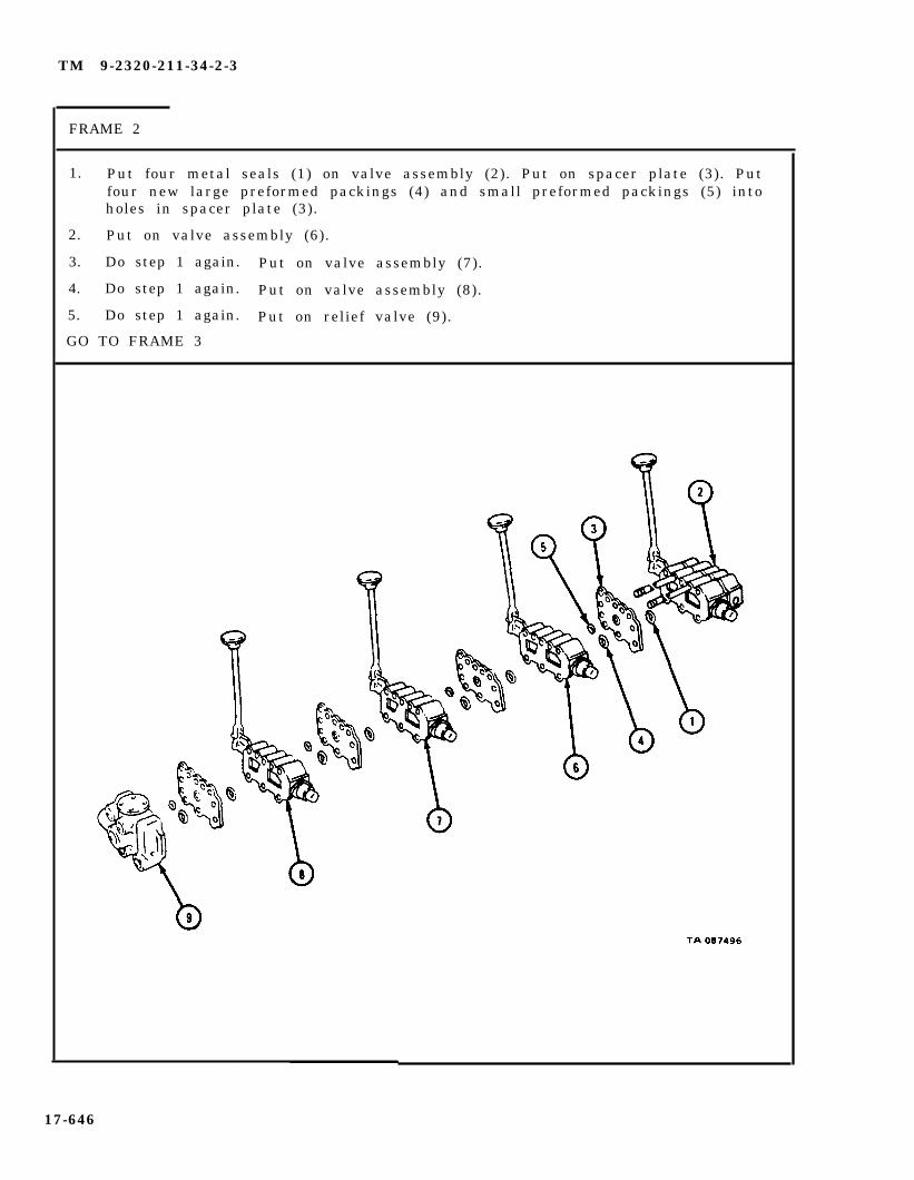
TM 9-2320-211-34-2-3
FRAME 2
1. Put four metal seals (1) on valve assembly (2). Put on spacer plate (3). Putfour new large preformed packings (4) and small preformed packings (5) intoholes in spacer plate (3).
2. Put on valve assembly (6).
3. Do step 1 again. Put on valve assembly (7).
4. Do step 1 again. Put on valve assembly (8).
5. Do step 1 again. Put on relief valve (9).
GO TO FRAME 3
17-646

TM 9-2320-211-34-2-3
FRAME 3
1.
2.
3.
4.
5.
6.
7.
8.
Put mounting angle (1) on control valve bank (2).
Push three rods (3) through control valve bank (2).
Put on mounting angle (4).
Screw on and hand tighten five nuts (5).
Tighten nuts (5) in order shown to 25 pound-feet.
Do step 5 again to 50 pound-feet.
NOTE
Be sure holes in rods (3) line up with slots in nuts(5) when final tightness is reached.
Do step 5 again to 75 pound-feet.
Put f ive spring pins (6) through nuts (5) and rods (3).
GO TO FRAME 4
17-647

TM 9-2320-211-34-2-3
FRAME 4
1.
2.
3.
4.
Screw in
Screw in
Screw in
Screw in
NOTE
Be sure nipples point in direction as shown. Hydrauliclines will not be able to be put on if this is not done.
and tighten nipple (1) and pipe plug (2).
and tighten two nipples (3) and nipple (4).
and tighten two nipples (5).
and tighten four nipples (6).
NOTE
Follow-on Maintenance
1. Replace control valve bankTM 9-2320-211-20.
Action Required:
assembly . Refer to
2. Adjust valve bank relief valve. Refer toTM 9-2320-211-20.
END OF TASK
17-648

TM 9-2320-211-34-2-3
17-52. GONDOLA WRECKER ASSEMBLY REMOVAL, REPAIR, AND REPLACEMENT(TRUCK M543A2).
TOOLS: No special tools required
SUPPLIES: Solvent , dry c leaning , type I I (SD-2) , Fed . Spec P-D-680
PERSONNEL: Two
EQUIPMENT CONDITION: Truck parked , engine o f f , handbrake set .
a. Preliminary Procedures.
(1) Drain hydraulic oil reservoir. Refer to LO 9-2320-211-12.
(2) Remove control valve bank cover. Refer to TM 9-2320-211-20.
(3) Remove gondola control valve assembly. Refer to TM 9-2320-211-20.
(4) Remove gondola f loodlight assembly. Refer to TM 9-2320-211-20.
(5) Remove gondola guard. Refer to para 17-50.
(6) Remove oilcan bracket. Refer to TM 9-2320-211-20.
(7) Remove operator seat and backrest. Refer to TM 9-2320-211-20.
17-649

TM 9-2320-211-34-2-3
b . Removal.
FRAME 1
1. Take out screw (1).
2. Pry open ends of clip (2) and take out cable (3).
3. Close clip (2) and hand tighten screw (1) through clip and into gondola (4).
4. Do steps 1 through 3 again for other two clips (5).
5. Coil loose cable (3) and move it out of the way.
GO TO FRAME 2
17-650
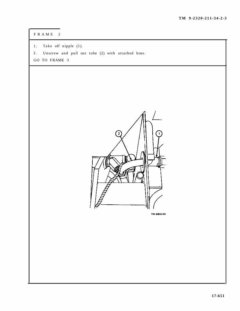
TM 9-2320-211-34-2-3
F R A M E 2
1 . Take off nipple (1).
2 . Unscrew and pull out tube (2) with attached hose.
GO TO FRAME 3
17-651

TM 9-2320-211-34-2-3
FRAME 3
1. Unscrew coupling (1) and take out tube (2).
2. Pull hose (3) out of hole in side of gondola (4).
GO TO FRAME 4
17-652

TM 9-2320-211-34-2-3
FRAME 4
1. Working outside rear of gondola, take off three nuts (1).
2. Takeoff three hose clamps (2) .
3 . Pul lback hoses (3 and 4 ) .
4. Takeoff three wooden brackets (5) from studs (6) .
GO TO FRAME 5
17-653

TM 9-2320-211-34-2-3
FRAME 5
1.
2.
3.
4.
Take off three nuts (1).
Take off three hose clamps (2).
Push six hoses (3) out through opening (4).
CAUTION
Be careful not to damage three wooden brackets (5). Crackedor chipped brackets will not hold hoses safely.
Take three wooden brackets (5) off studs (6).
GO TO FRAME 6
17-654
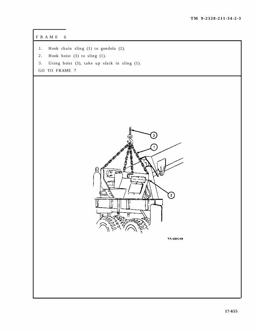
TM 9-2320-211-34-2-3
F R A M E 6
1. Hook chain sling (1) to gondola (2).
2. Hook hoist (3) to sling (1).
3. Using hoist (3), take up slack in sling (1).
GO TO FRAME 7
17-655

TM 9-2320-211-34-2-3
F R A M E 7
1. Take out two screws (1) and nuts (2).
GO TO FRAME 8
17-656

TM 9-2320-211-34-2-3
F R A M E 8
Soldier A
Soldier B
Soldier A
SoldiersA and B
Soldier A
Soldier B
Soldier A
SoldiersA and B
1.
2.
3.
4.
5.
6.
7.
8.
Working outside rear left side of gondola (1), hold nut (2). Tell soldier Bwhen ready.
Working inside rear left side of gondola (1), take out screw (3).
Take off nut (2).
Do steps 1 through 3 again for three nuts (4) and screws (5).
Working outside front left side of gondola (1), hold nut (6). Tellsoldier B when ready.
Working inside front left side of gondola (1), tak eout screw (7).
Take off nut (6).
Do steps 5 through 7 again for five nuts (8) and screws (9).
GO TO FRAME 9
17-657

TM 9-2320-211-34-2-3
FRAME 9
Sold ier A 1 . Put wood blocks in place or ground. Guide gondola (1) onto wood blocksas soldier B moves it off truck. Tell soldier B when ready.
Soldier B 2. Using hoist, take gondola (1) off truck and onto wood blocks.
Soldier A 3. Take off hoist and sling.
END OF TASK
17-658
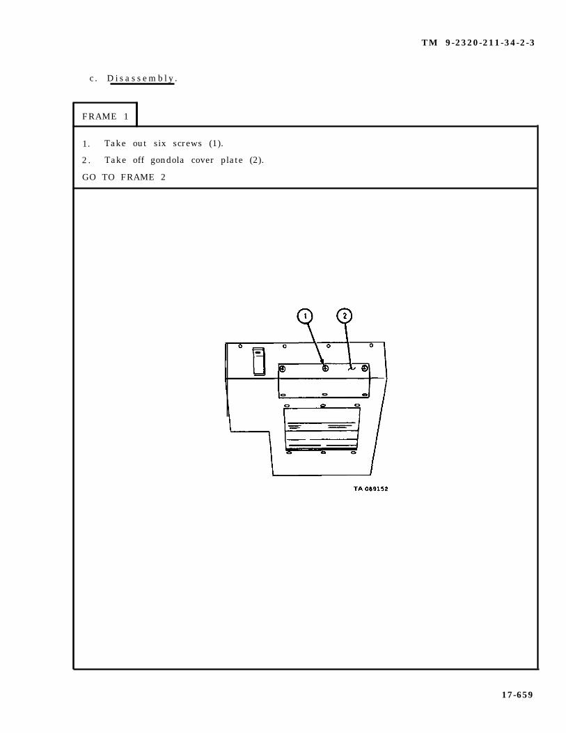
TM 9-2320-211-34-2-3
c . D i s a s s e m b l y .
FRAME 1
1. Take out six screws (1).
2 . Take off gondola cover plate (2).
GO TO FRAME 2
17-659

TM 9-2320-211-34-2-3
FRAME 2
1. Pull out three hydraulic line hole seals (1).
2. Pull out gondola body rubber seal (2).
END OF TASK
17-660
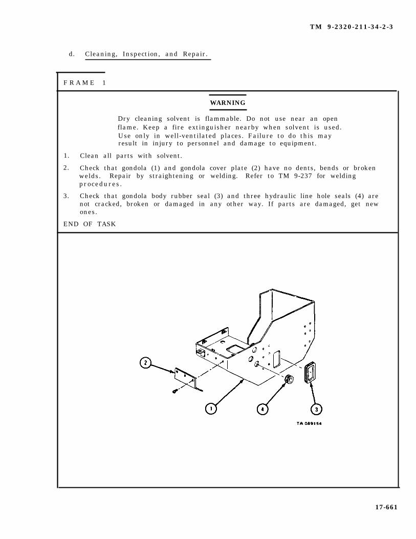
TM 9-2320-211-34-2-3
d. Cleaning, Inspection, and Repair.
F R A M E 1
WARNING
Dry cleaning solvent is flammable. Do not use near an openflame. Keep a fire extinguisher nearby when solvent is used.Use only in well-ventilated places. Failure to do this mayresult in injury to personnel and damage to equipment.
1. Clean all parts with solvent.
2. Check that gondola (1) and gondola cover plate (2) have no dents, bends or brokenwelds. Repair by straightening or welding. Refer to TM 9-237 for weldingprocedures.
3. Check that gondola body rubber seal (3) and three hydraulic line hole seals (4) arenot cracked, broken or damaged in any other way. If parts are damaged, get newones.
END OF TASK
17-661

TM 9-2320-211-34-2-3
e . A s s e m b l y .
FRAME 1
1. Put three hydraulic line hole seals (1) and gondola body rubber seal (2) in place ongondola body (3).
GO TO FRAME 2
17-662

TM 9-2320-211-34-2-3
FRAME 2
1. Put gondola cover plate (1) in place on gondola (2).
2 . Put in six screws (3).
END OF TASK
17-663
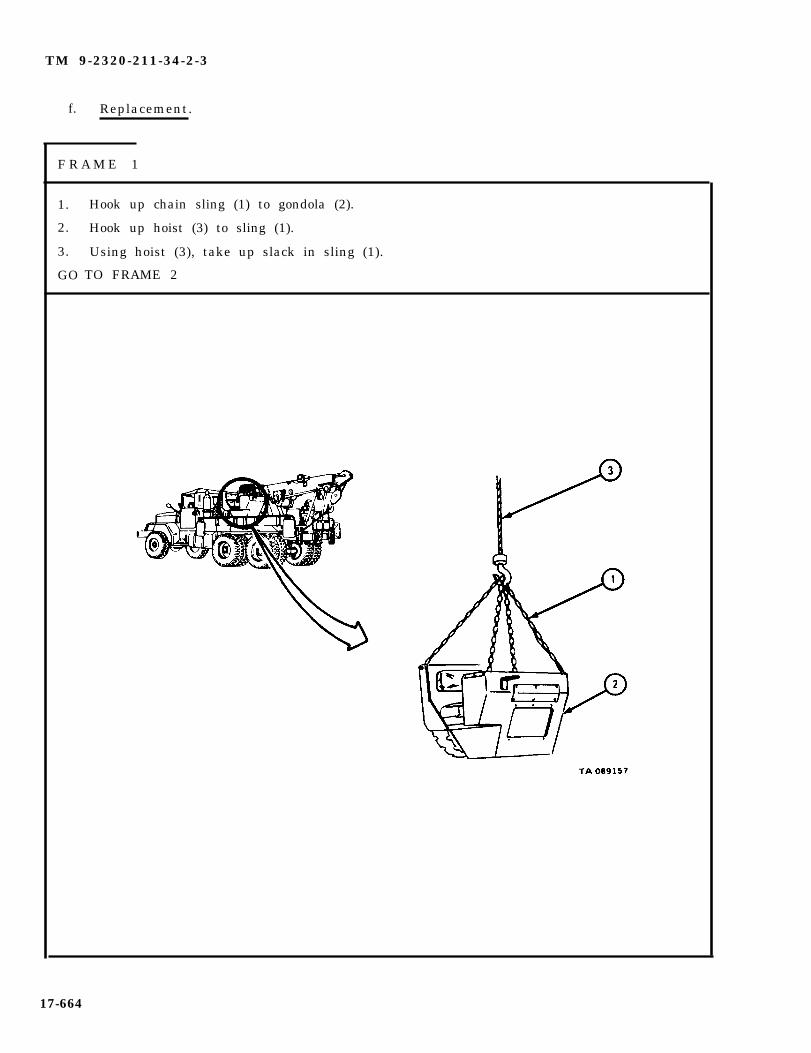
TM 9-2320-211-34-2-3
f. Replacement.
F R A M E 1
1.
2.
3.
GO
Hook up chain sling (1) to gondola (2).
Hook up hoist (3) to sling (1).
Using hoist (3), take up slack in sling (1).
TO FRAME 2
17-664
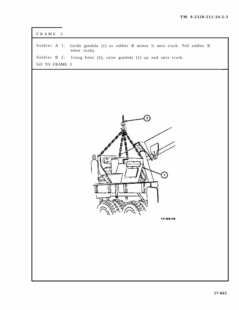
TM 9-2320-211-34-2-3
F R A M E 2
Sold ier A 1 . Guide gondola (1) as soldier B moves it onto truck. Tell soldier Bwhen ready.
So ld ier B 2 . Using hoist (2), raise gondola (1) up and onto truck.
GO TO FRAME 3
17-665

TM 9-2320-211-34-2-3
F R A M E 3
1. Put in two screws (1) and nuts (2).
GO TO FRAME 4
17-666

TM 9-2320-211-34-2-3
FRAME 4
Sold ier A 1 .
Soldier B 2.
Soldier A 3.
S o l d i e r s 4 .A and B
Soldier A 5.
Soldier B 6.
Soldier A 7.
S o l d i e r s 8 .A and B
GO TO FRAME
Working inside front left side of gondola (1), put screw (2) in place asshown and hold it. Tell soldier B when ready.
Working outside front left side of gondola (1), hand tighten nut (3) andhold it. Tell soldier A when ready.
Tighten screw (2).
Do steps 1 through 3 again for five screws (4) and nuts (5).
Working inside rear left side of gondola (1), put in screw (6) and hold it.Tell soldier B when ready.
Working outside rear left side of gondola (1) hand tighten nut (7), andhold it. Tell soldier A when ready.
Tighten screw (6).
Do steps 5 through 7 again for three screws (8) and nuts (9).
5
17-667

TM 9-2320-211-34-2-3
1. Unhook chain sling (1) from gondola (2).
2. Take away sling (1) and hoist (3).
GO TO FRAME 6
17-668

TM 9-2320-211-34-2-3
F R A M E 6
1. Working outside rear of gondola (1), put three wooden brackets (2) on three studs (3).
2 . Place six hoses (4) in wooden brackets (2).
3. Put three clamps (5) on studs (3). Put on three nuts (6).
GO TO FRAME 7
17-669

TM 9-2320-211-34-2-3
FRAME 7
1. Put three wooden brackets (1) on studs (2).
2. Pull six hoses (3) through opening in gondola (4) and put hoses on three woodenbrackets (1).
GO TO FRAME 8
17-670
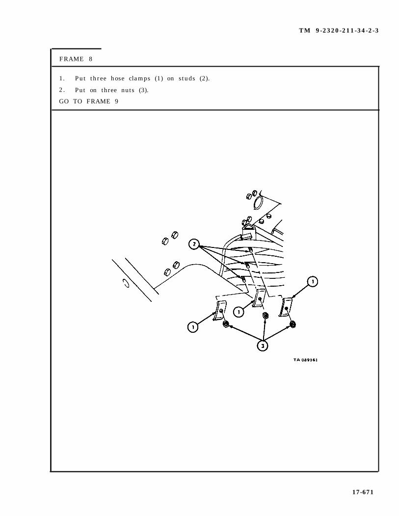
TM 9-2320-211-34-2-3
FRAME 8
1. Put three hose clamps (1) on studs (2).
2. Put on three nuts (3).
GO TO FRAME 9
17-671

TM 9-2320-211-34-2-3
FRAME 9
CAUTION
When joining hoses and tubes, do not overtighten couplings.Overtightening couplings may damage adapters or tubes andcause oil leaks.
1. Put hose (1) through hole in side of gondola (2).
2. Put tube (3) in place as shown and put hose (1) onto tube.
GO TO FRAME 10
17-672

TM 9-2320-211-34-2-3
FRAME 10
1. Push tube (1) with attached hose through opening (2) and into place on teefitting (3) as shown.
2. Put fitting of tube (1) onto tee fitting (3) and tighten.
3. Put nipple (4) in place on tee fitting (5) and tighten.
GO TO FRAME 11
17-673

TM 9-2320-211-34-2-3
F R A M E 1 1
1.
2.
3.
4.
Take out screw (1) with clip (2) and pry open ends of clip.
Uncoil and lay out cable (3). Put cable into clip (2) and close ends.
Put screw (1) through clip (2) and into hole in gondola (4).
Do steps 1 through 3 again for other two clips (5).
1.
2.
3.4.
5.
6.
7.
END OF TASK
NOTE
Follow-on Maintenance Action Required:
Replace operator seat and backrest. Refer toTM 9-2320-211-20.Replace oil can bracket. Refer toTM 9-2320-211-20.Replace gondola guard. Refer to para 17-50.Replace gondola floodlight assembly. Refer toTM 9-2320-211-20.Replace gondola control valve assembly. Referto TM 9-2320-211-20.Replace control valve bank cover. Refer toTM 9-2320-211-20.Fill hydraulic oil reservoir. Refer toLO 9-2320-211-12.
17-674

TM 9-2320-211-34-2-3
17-53. POWER DIVIDER CONTROL LINKAGE REMOVAL , REPAIR, AND REPLACE-MENT (TRUCK M543A2).
TOOLS: No special tools required
SUPPLIES: Solvent, dry cleaning, type II (SD-2), Fed. Spec P-D-680
PERSONNEL: Two
EQUIPMENT CONDITION: Truck parked, engine off , handbrake set.
a . Preliminary procedure. Remove driver ’s seat. Refer to TM 9-2320-211-20.
17-675
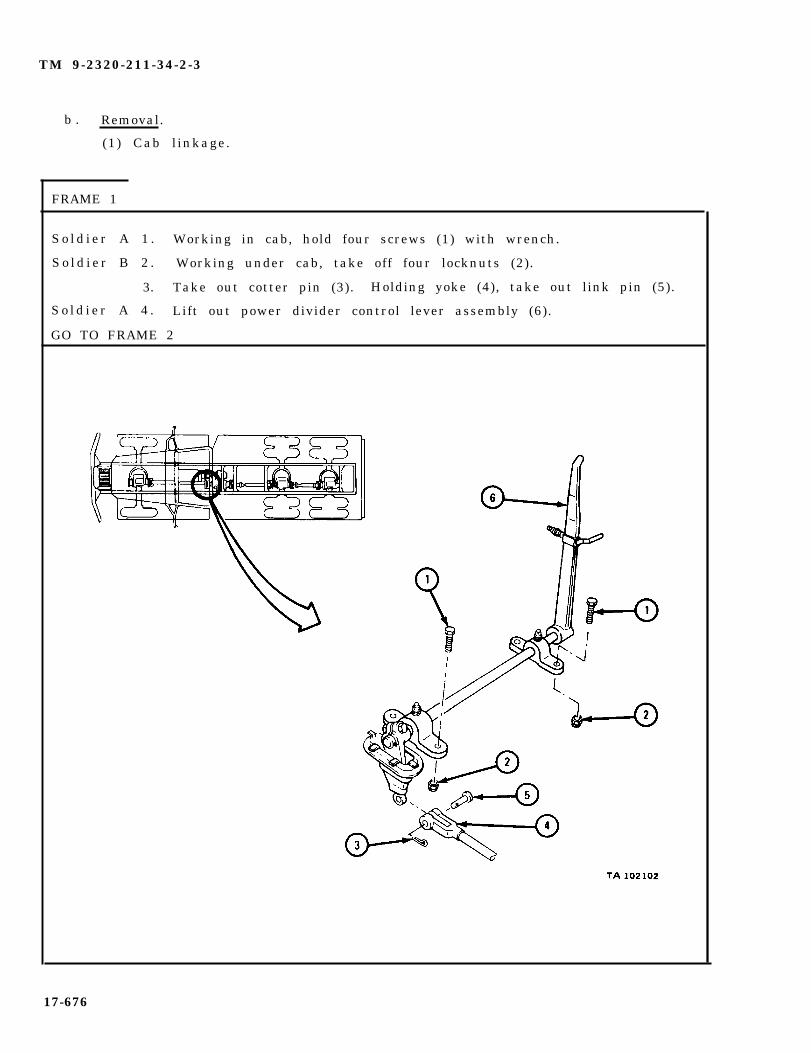
TM 9-2320-211-34-2-3
b . Removal.
(1) Cab linkage.
FRAME 1
S o l d i e r A 1 . Working in cab, hold four screws (1) with wrench.
S o l d i e r B 2 . Working under cab, take off four locknuts (2).
3. Take out cotter pin (3). Holding yoke (4), take out link pin (5).
S o l d i e r A 4 . Lift out power divider control lever assembly (6).
GO TO FRAME 2
17-676

TM 9-2320-211-34-2-3
F R A M E 2
1. Working out of vehicle, take off boot (1).
2. Take out two lube fittings (2).
3. Take out nut (3) and screw (4). Take off lever arm (5).
4. Take key (6) out of shaft (7) .
5. Slide two brackets (8) off shaft (7).
GO TO FRAME 3
17-677
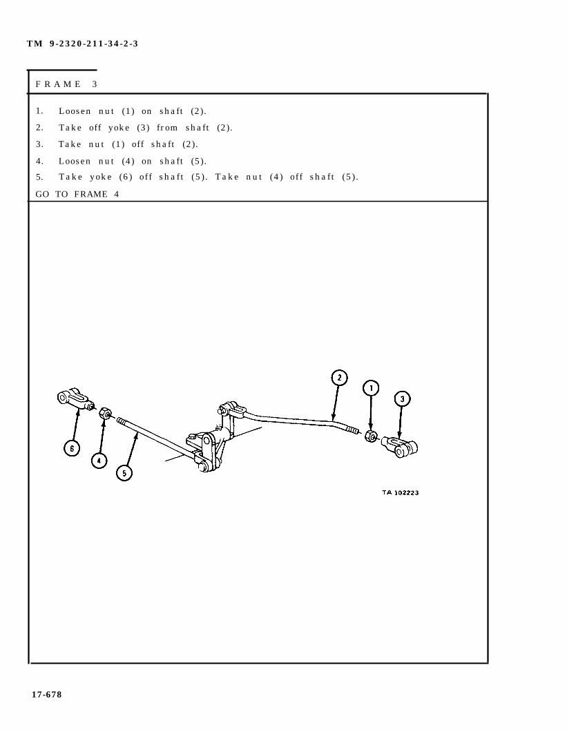
TM 9-2320-211-34-2-3
F R A M E 3
1. Loosen nut (1) on shaft (2).
2. Take off yoke (3) from shaft (2).
3. Take nut (1) off shaft (2).
4. Loosen nut (4) on shaft (5).
5. Take yoke (6) off shaft (5) . Take nut (4) off shaft (5) .
GO TO FRAME 4
17-678

TM 9-2320-211-34-2-3
FRAME 4
1. Tak eout cotter pin (1). Holding shaft (2), take out link pin (3) fromy o k e ( 4 ) . Lower shaft (2) .
2. Take out cotter pin (5). Holding shaft (6), take out link pin (7) fromy o k e ( 8 ) . Lower shaft (6) .
GO TO FRAME 5
17-679
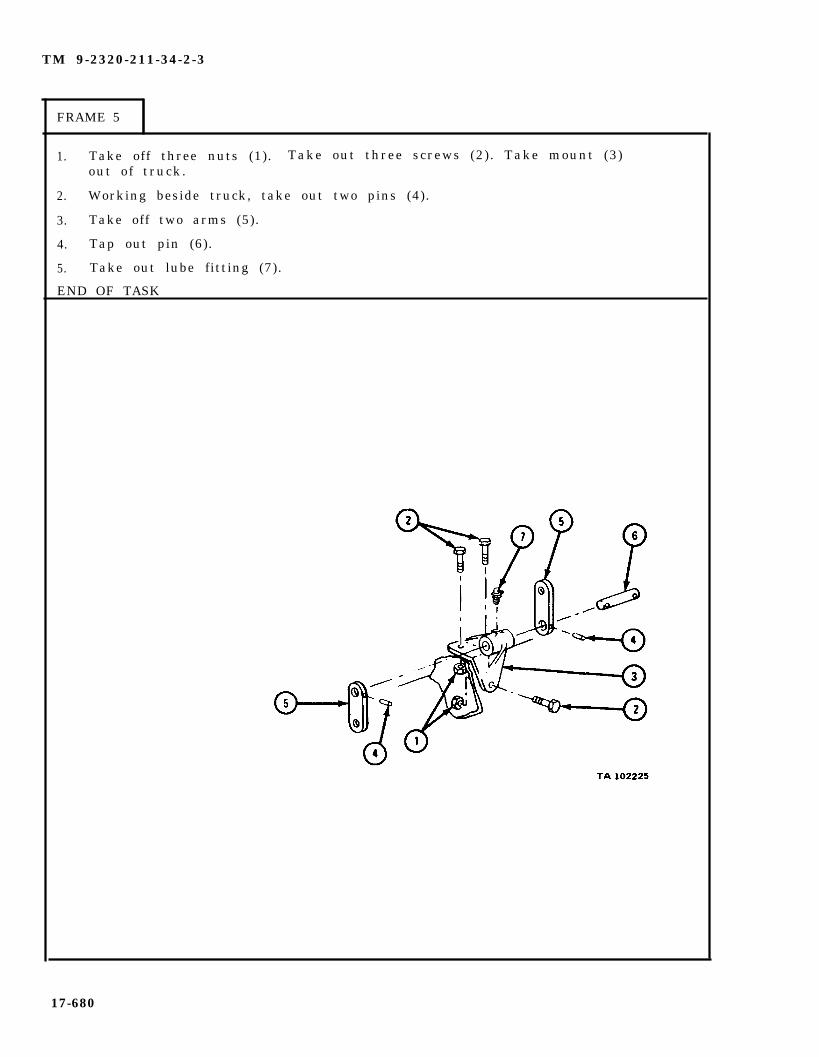
TM 9-2320-211-34-2-3
FRAME 5
1. Take off three nuts (1). Take out three screws (2). Take mount (3)out of truck.
2. Working beside truck, take out two pins (4).
3. Take off two arms (5).
4. Tap out pin (6).
5. Take out lube fitting (7).
END OF TASK
17-680

TM 9-2320-211-34-2-3
(2) Rear winch linkage.
F R A M E 1
1. Working in front ofin neutral position.
2. Put locking pin (2)
GO TO FRAME 2
rear winch controls, place rear winch shift lever (1)
in place.
17-681

TM 9-2320-211-34-2-3
FRAME 2
1.
2.
3.
GO
Working through deck plate on top of vehicle, take cotter pin (1)and link pin (2) out of yoke (3). Take yoke (3) off winch shiftl ever (4 ) .
Loosen nut (5) and take shaft (6) out of coupling (7).
Take shaft assembly out of truck bed. Take yoke (3), nut (5), andnut (8) off shaft (6) .
TO FRAME 3
17-682
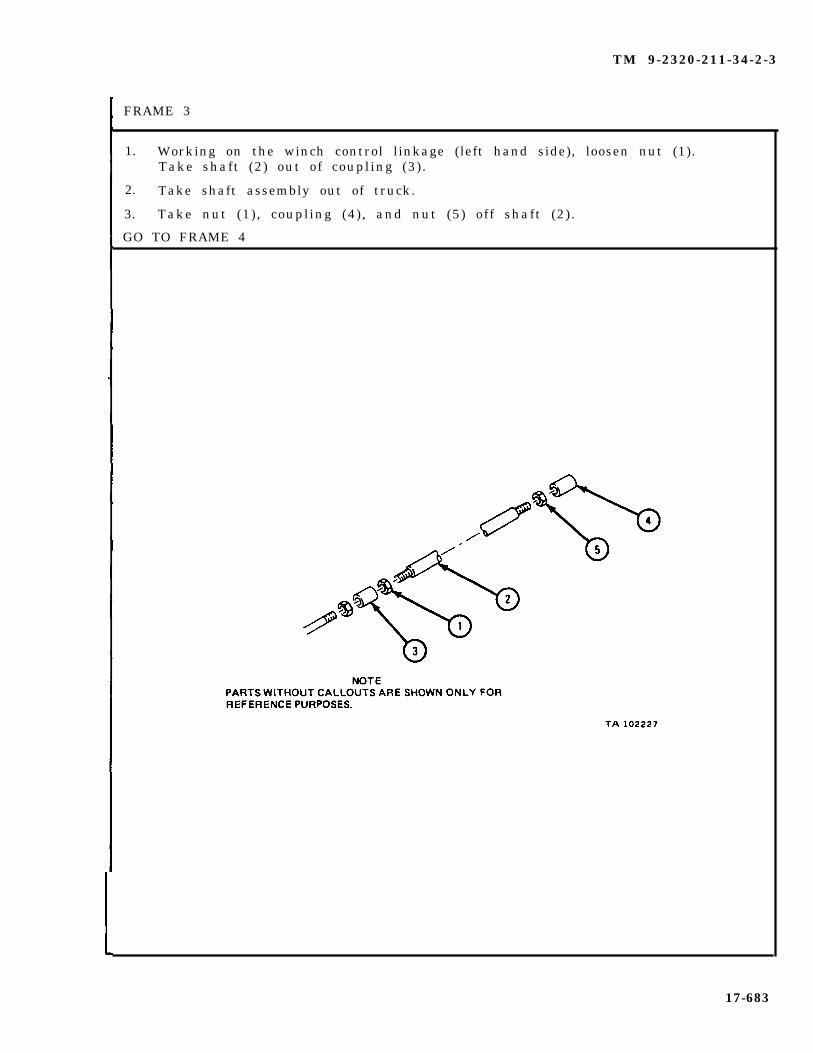
TM 9-2320-211-34-2-3
FRAME 3
1. Working on the winch control linkage (left hand side), loosen nut (1).Take shaft (2) out of coupling (3) .
2. Take shaft assembly out of truck.
3. Take nut (1) , coupling (4), and nut (5) off shaft (2) .
GO TO FRAME 4
17-683
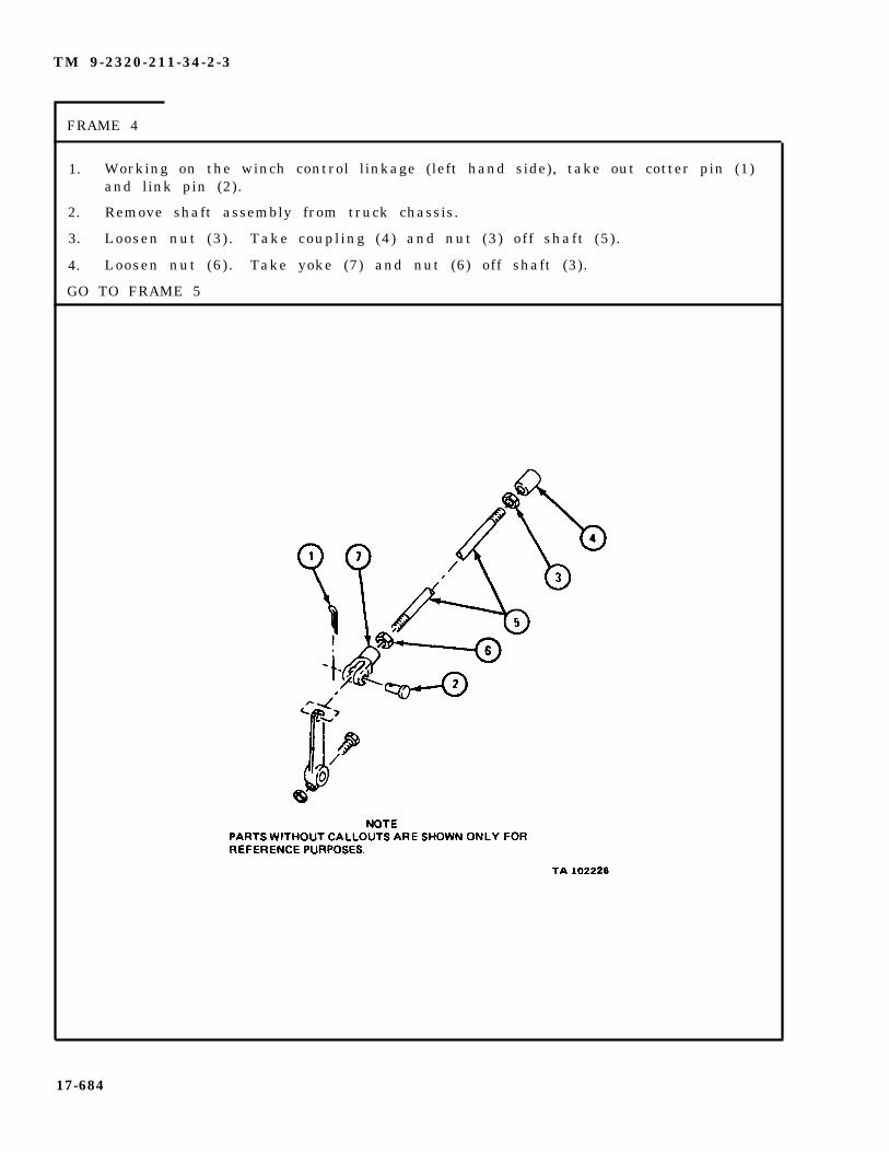
TM 9-2320-211-34-2-3
FRAME 4
1.
2.
3.
4.
GO
Working on the winch control linkage (left hand side), take out cotter pin (1)and link pin (2).
Remove shaft assembly from truck chassis.
Loosen nut (3) . Take coupling (4) and nut (3) off shaft (5) .
Loosen nut (6) . Take yoke (7) and nut (6) off shaft (3).
TO FRAME 5
17-684

TM 9-232-211-34-2-3
FRAME 5
1. Working through deck plate on top of vehicle, take cotter pin (1) and link pin(2) out of yoke (3) . Take yoke (3) off hydraulic power control lever (4) .
2. Loosen nut (5) and take shaft (6) out of coupling (7).
3. Take shaft assembly out of truck bed. Take yoke (3) and nut (5) offshaf t (6 ) .
GO TO FRAME 6
17-685
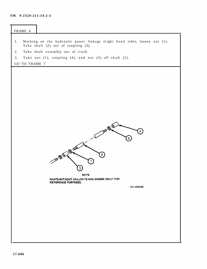
TM 9-2320-211-34-2-3
FRAME 6
1. Working on the hydraulic power linkage (right hand side), loosen nut (1).Take shaft (2) out of coupling (3).
2. Take shaft assembly out of truck.
3. Take nut (1) , coupling (4), and nut (5) off shaft (2) .
GO TO FRAME 7
17-686

TM 9-2320-211-34-2-3
F R A M E 7
1.
2.
3.
4.
GO
Working on the hydraulic power linkage (right hand side), take outcotter pin (1) and link pin (2).
Take shaft assembly out of truck chassis.
Loosen nut (3) . Take out yoke (4) and nut (3) from shaft (5).
Loosen nut (6) . Take off coupling (7) and nut (6) .
TO FRAME 8
17-687

TM 9-2320-211-34-2-3
FRAME 8
1. Working under the truck, take out cotter pin (1) and link pin (2).
2 . Holding shaft (3) , takeout cotter pin (4) and link pin (5).
3. Remove shaft (3) from power divider lever (6).
4 . Working by side of truck, loosen nut (7). Take off yoke (8) and nut (7) fromshaf t (3 ) .
GO TO FRAME 9
17-688
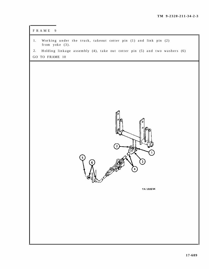
TM 9-2320-211-34-2-3
F R A M E 9
1. Working under the truck, takeout cotter pin (1) and link pin (2)from yoke (3) .
2. Holding linkage assembly (4), take out cotter pin (5) and two washers (6)
GO TO FRAME 10
17-689
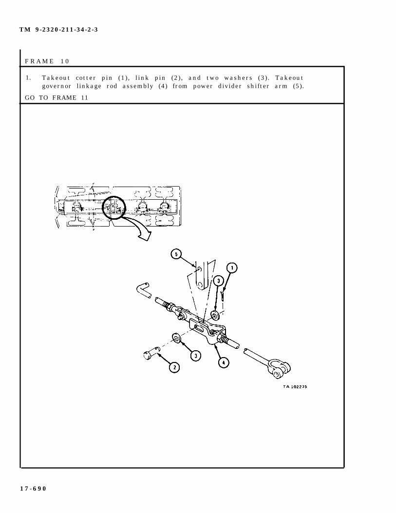
TM 9-2320-211-34-2-3
F R A M E 1 0
1. Takeout cotter pin (1), l ink pin (2), and two washers (3). Takeoutgovernor linkage rod assembly (4) from power divider shifter arm (5).
GO TO FRAME 11
1 7 - 6 9 0

TM 9-2320-211-34-2-3
F R A M E 1 1
1.
2.
3.
4.
GO
Working beside truck, take out cotter pin (1) and link pin (2).
Loosen nut (3) . Take off yoke (4) and nut (3) from crane controlgovernor rod (5 ) .
Take off nut (6) . Take out crane control power divider link rod (7).
Take off nut (8) .
TO FRAME 12
17-691

TM 9-2320-211-34-2-3
FRAME 12
1. Working under truck, take out two nuts (1) and two screws (2).
2. Take off winch control shaft lever (3) . Take out woodruff key (4).
3. Take off four nuts (5) . Take out four screws (6).
4. Take out shaft (7) and tube assembly (8) from truck.
GO TO FRAME 13
17-692

TM 9-2320-211-34-2-3
FRAME 13
1. Take shaft (1) out of tube assembly (2).
2. Takeout two cot ter p ins (3 ) . Takeof f washer (4 ) .
3. Take off plate (5) , washer (6) , and lever (7) .
4. Take woodruff key (8) out of shaft (1) .
END OF TASK
17-693

TM 9-2320-211-34-2-3
c . Cleaning, Inspection, and Repair.
WARNING
Dry cleaning solvent is flammable. Do not usenear an open flame. Keep a fire extinguishernearby when solvent is used. Use only in well-ventilated places. Failure to do this may resultin injury to personnel and damage to equipment.
( 1 )clean rag.
( 2 )
( 3 )
( 4 )TM 9-237.
( 5 )to FM 43-2.
Cleaning. Clean all parts with dry cleaning solvent. Dry with a
Check linkage yokes for cracks. Repair by welding. Refer to TM 9-237.
Check threads on linkage. If threads are damaged, get new parts.
Check links and mount for cracks. Repair by welding. Refer to
Check linkage rods for bends. Repair by straightening. Refer
17-694

TM 9-2320-211-34-2-3
d . Replacement.
(1) Rear winch linkage.
F R A M E 1
1. Seat woodruff key (1) in shaft (2) . Tap lever arm (3) on shaft (2) .Put in and spread apart cotter pin (4).
2. Put on washer (5), plate (6), and spacer (7). Put in cotter pin (8).Spread ends of cotter pin (8).
3. Put in screw (9). Put on and tighten nut (10).
GO TO FRAME 2
17-695
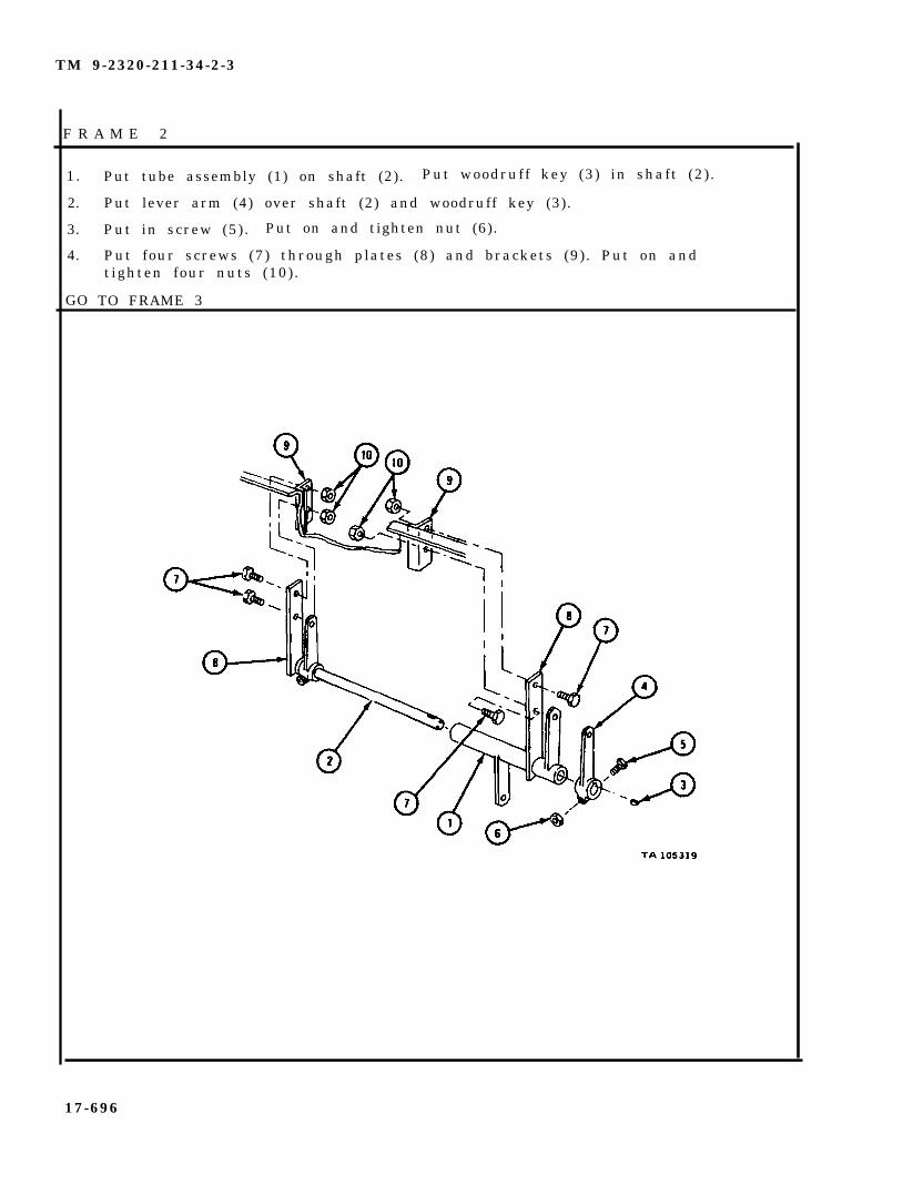
TM 9-2320-211-34-2-3
F R A M E 2
1.
2.
3.
4.
GO
Put tube assembly (1) on shaft (2). Put woodruff key (3) in shaft (2) .
Put lever arm (4) over shaft (2) and woodruff key (3).
Put in screw (5). Put on and tighten nut (6).
Put four screws (7) through plates (8) and brackets (9). Put on andtighten four nuts (10).
TO FRAME 3
17-696
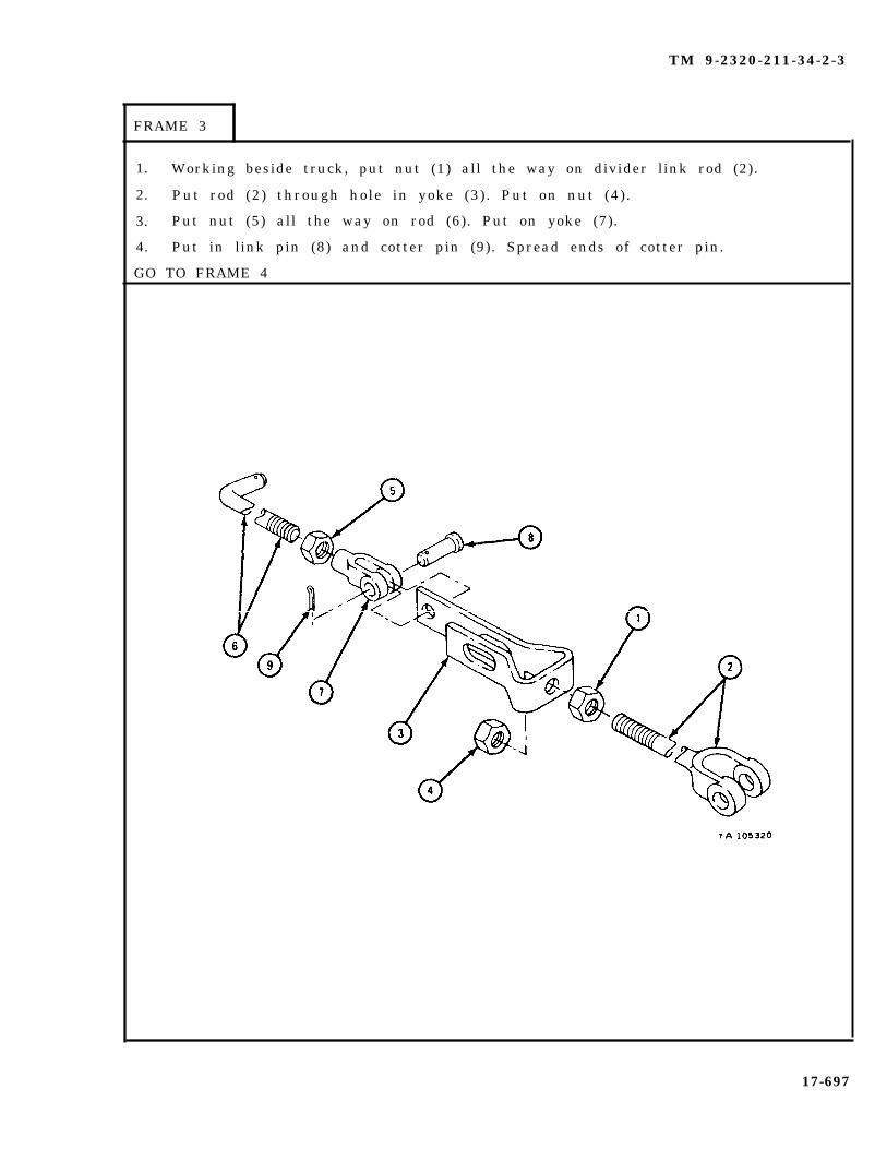
TM 9-2320-211-34-2-3
FRAME 3
1. Working beside truck, put nut (1) all the way on divider link rod (2).
2. Put rod (2) through hole in yoke (3). Put on nut (4).
3. Put nut (5) all the way on rod (6). Put on yoke (7).
4. Put in link pin (8) and cotter pin (9). Spread ends of cotter pin.
GO TO FRAME 4
17-697
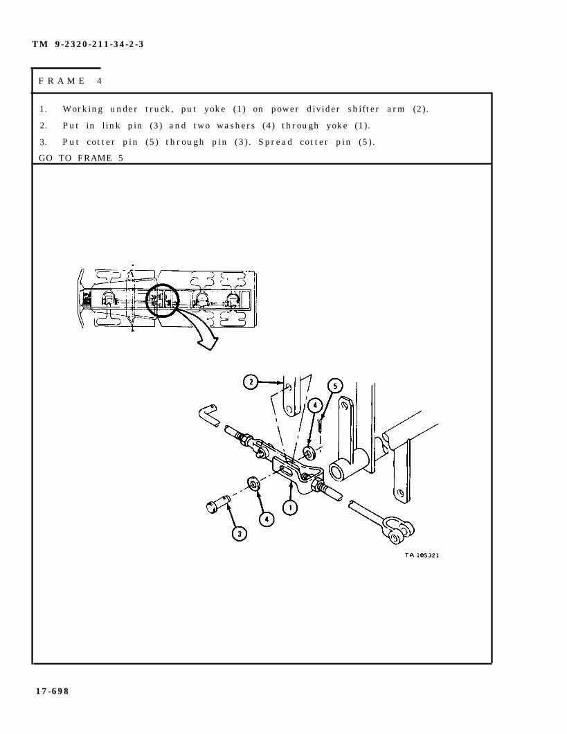
TM 9-2320-211-34-2-3
F R A M E 4
1.
2.
3.
Working under truck, put yoke (1) on power divider shifter arm (2).
Put in link pin (3) and two washers (4) through yoke (1).
Put cotter pin (5) through pin (3). Spread cotter pin (5).
GO TO FRAME 5
17-698

TM 9-2320-211-34-2-3
F R A M E 5
1. Put washer (1) on rod (2) . Put end of rod (2) through hole in governorcontrol valve arm (3).
2. Put washer (1) on end of rod (2). Put in cotter pin (4). Spread ends ofcotter pin.
3. Put link pin (5) through holes in yoke (6) and lever arm (7). Put incotter pin (8) . Spread ends of cotter pin (8).
4. Tighten nut (9). Tighten two adjusting nuts (10).
GO TO FRAME 6
17-699

TM 9-2320-211-34-2-3
FRAME 6
1. Put nut (1) all the way on shaft (2). Put yoke (3) on shaft (2).
2. Aline hole in yoke (4) with holes in operating lever (5).
3. Put l ink pin (6) through yoke (4). Put in cotter pin (7). Spread ends ofcotter pin.
4. Turn yoke (3) until holes in yoke (3) line up with holes in lever arm (8).
5. Put l ink pin (9) through yoke (3). Put in cotter pin (10). Spread ends ofcotter pin.
6. Tighten nut (1) against yoke (3).
GO TO FRAME 7
17-700

TM 9-2320-211-34-2-3
FRAME 7
1. Put nut (1) and nut (2) all the way on shaft (3).
2. Put yoke (4) and coupling (5) on shaft (3) .
3. Put shaft assembly (3) into position in truck bed.
4. Aline holes in yoke (4) with holes in lever arm (6). Put link pin (7) throughholes in yoke (4) . Put cotter pin (8) into link pin (7) and spread ends ofcotter pin (8) .
GO TO FRAME 8
17-701
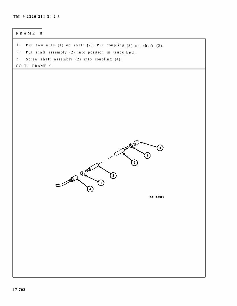
TM 9-2320-211-34-2-3
F R A M E 8
1.
2.
3.
GO
Put two nuts (1) on shaft (2). Put coupling
Put shaft assembly (2) into position in truck
Screw shaft assembly (2) into coupling (4).
TO FRAME 9
(3) on shaft (2) .
b e d .
17-702

TM 9-2320-211-34-2-3
FRAME 9
1. Working beside truck, put nut (1) and nut (2) on shaft (3).
2. Working under truck, put shaft assembly (3) into coupling (4).
3. Put yoke (5) on shaft assembly (3). Turn yoke (5) so that holesin yoke (5) aline with holes in shift lever (6).
4. Put in link pin (7) and cotter pin (8). Spread the ends of cotter pin (8).
GO TO FRAME 10
17-703
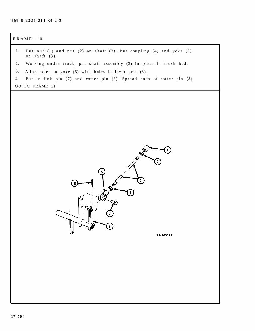
TM 9-2320-211-34-2-3
F R A M E 1 0
1. Put nut (1) and nut (2) on shaft (3). Put coupling (4) and yoke (5)on shaft (3) .
2. Working under truck, put shaft assembly (3) in place in truck bed.
3. Aline holes in yoke (5) with holes in lever arm (6).
4. Put in link pin (7) and cotter pin (8). Spread ends of cotter pin (8).
GO TO FRAME 11
17-704

TM 9-2320-211-34-2-3
FRAME 11
1. Working beside truck, put nut (1) and nut (2) on shaft (3). Putcoupling (4) on shaft (3) .
2. Working under truck, screw shaft (3) into coupling (5).
GO TO FRAME 12
17-705
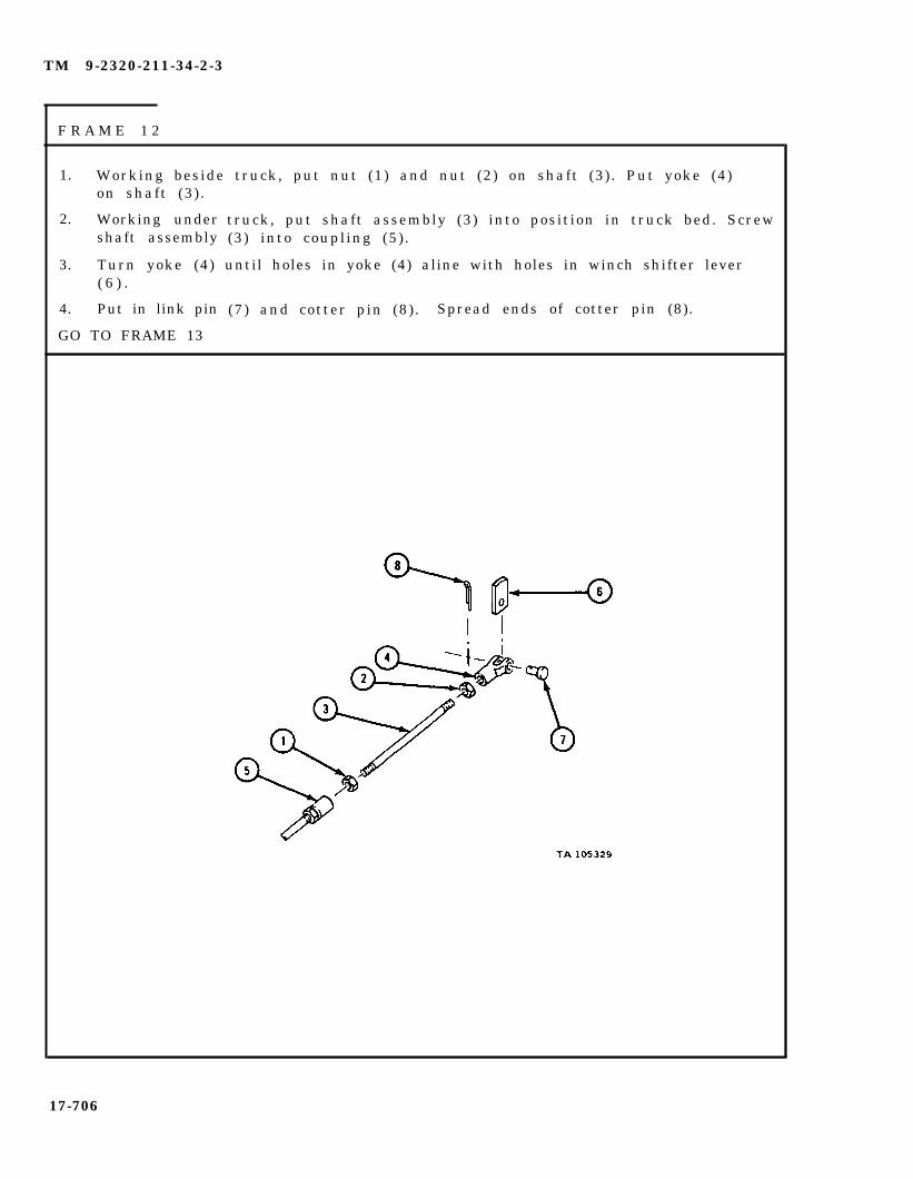
TM 9-2320-211-34-2-3
F R A M E 1 2
1. Working beside truck, put nut (1) and nut (2) on shaft (3). Put yoke (4)on shaft (3) .
2. Working undershaft assembly
3. Turn yoke (4)( 6 ) .
4. Put in link pin
GO TO FRAME 13
truck, put shaft assembly (3) into position in truck bed. Screw(3) into coupling (5) .
until holes in yoke (4) aline with holes in winch shifter lever
(7) and cotter pin (8) . Spread ends of cotter pin (8).
17-706

TM 9-2320-211-34-2-3
F R A M E 1 3
1. Reaching through access holes, tighten nuts (1) against yokes (2).
2. Tighten nuts (3) against couplings (4).
3. Tighten nuts (5) against couplings (6).
4. Tighten nuts (7) against yokes (8).
END OF TASK
17-707

TM 9-2320-211-34-2-3
( 2 ) C a b linkage.
F R A M E 1
1. Working beside truck, put in lube fitting (1) in mount (2).
2. Tap in pin (3).
3. Put on two arms (4). Tap in two pins (5).
4. Working under truck, put three screws (6) through mount (2).
5. Screw on and tighten three nuts (7).
GO TO FRAME 2
17-708

TM 9-2320-211-34-2-3
FRAME 2
1. Put nut (1) all the way on shaft (2).
2. Put yoke (3) on shaft (2) .
3. Put yoke (4) on arm (5). Put in link pin (6) and cotter pin (7).Open cotter pin (7) .
GO TO FRAME 3
17-709

TM 9-2320-211-34-2-3
FRAME 3
1. Put link pin (1) through yoke (2) and arm (3).
2. Put cotter pin (4) in link pin (1). Open cotter pin (4).
3. Put nut (5) all the way on shaft (6). Put yoke (7) on shaft (6).
GO TO FRAME 4
17-710

TM 9-2320-211-34-2-3
FRAME 4
1. Working under truck, put yoke (1) on power divider lever (2).
2. Put l ink pin (3) through yoke (1). Put in cotter pin (4). Opencotter pin (4) .
GO TO FRAME 5
17-711
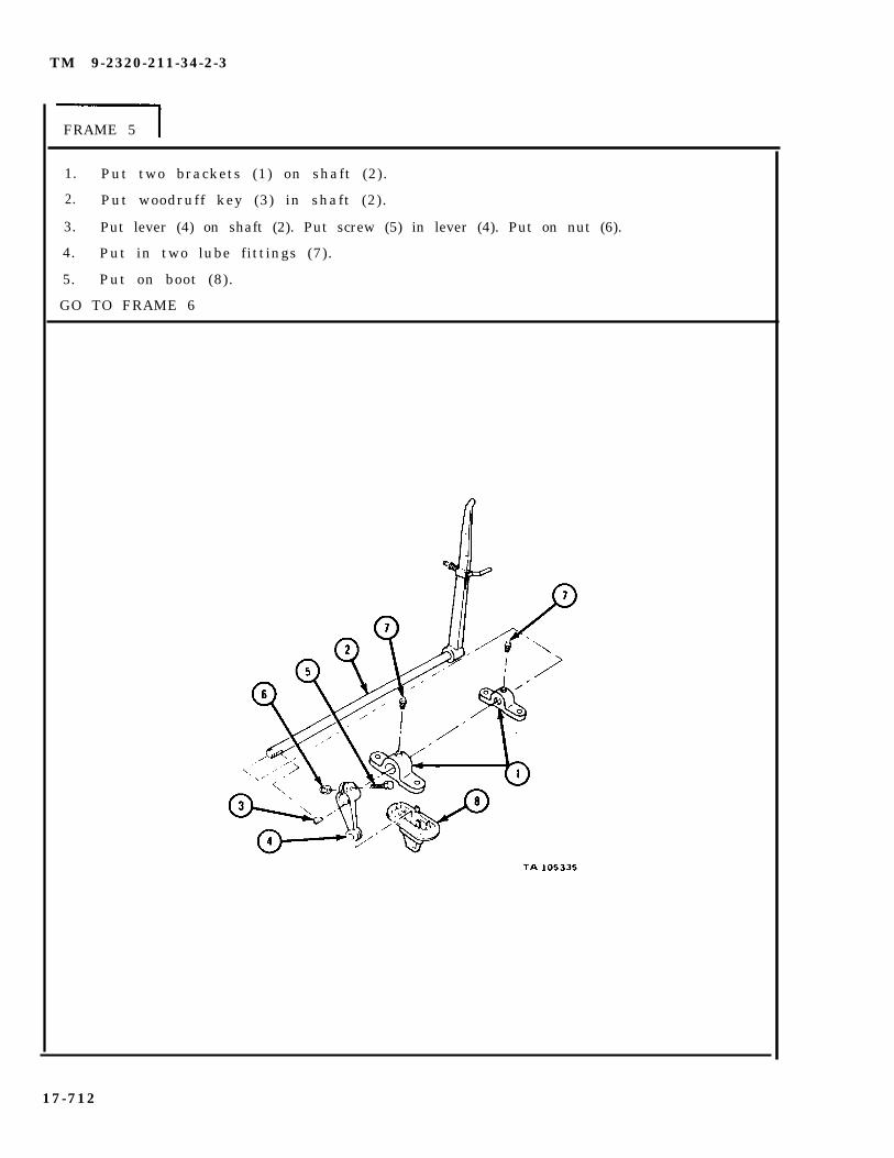
TM 9-2320-211-34-2-3
FRAME 5
1.
2.
3.
4.
5.
Put two brackets (1) on shaft (2).
Put woodruff key (3) in shaft (2).
Put lever (4) on shaft (2). Put screw (5) in lever (4). Put on nut (6).
Put in two lube fittings (7).
Put on boot (8).
GO TO FRAME 6
17-712

TM 9-2320-211-34-2-3
FRAME 6
Soldier A 1. Put
2. Put
Soldier B 3. Put
4. Put
5. Put
lever assembly (1) in left rear side of cab.
in and hold four screws (2).
on four nuts (3) .
l ink pin (4) through yoke (5).
cotter pin (6) through link pin (4). Open cotter pin (6).
NOTE
Follow-on Maintenance Action Required:
Replace driver ’s seat. Refer to TM 9-2320-211-20.
END OF TASK
17-713

TM 9-2320-211-34-2-3
17-54. POWER DIVIDER ASSEMBLY REMOVAL, REPAIR, AND REPLACEMENT(TRUCK M543A2).
T O O L S : N o
SUPPLIES:
PERSONNEL:
Special tools required
Crane drive housing assembly gasket (2)Cover gasket (4)Pump adapter housing gasketShifter cover gasket (2)Power divider governor adapter gasketCover plate gasketOutput shaft yoke gasketInput shaft yoke gasketPower divider governor drive gasketArtillery and automotive grease, type GAA, MIL-G-10924Gear lubricating oil, GO 80/90, MIL-L-2105Housing sealPump adapter sealPower divider pump adapter sealCrane power divider housing sealOil seal retainer cover sealSolvent, dry cleaning, type II (SD-2), Fed. Spec P-D-680
TWO
EQUIPMENT CONDITION: Truck parked, engine off , handbrake set.
a. Preliminary Procedures.
(1) Drain power divider assembly. Refer to LO 9-2320-211-12.
( 2 ) R e m o v eTM 9-2320-211-20.
( 3 ) R e m o v eTM 9-2320-211-20.
( 4 ) R e m o v eTM 9-2320-211-20.
( 5 ) R e m o v e
( 6 ) R e m o v e
power divider-to-hydraulic hoist pump propeller shaft. Refer to
power divider-to-transfer propeller shaft. Refer to
power divider-to-winch
power divider linkage.
control valve assembly.
prope l ler shaf t . Re fer to
Refer to para 17-53.
Refer to para 17-51.
17-714
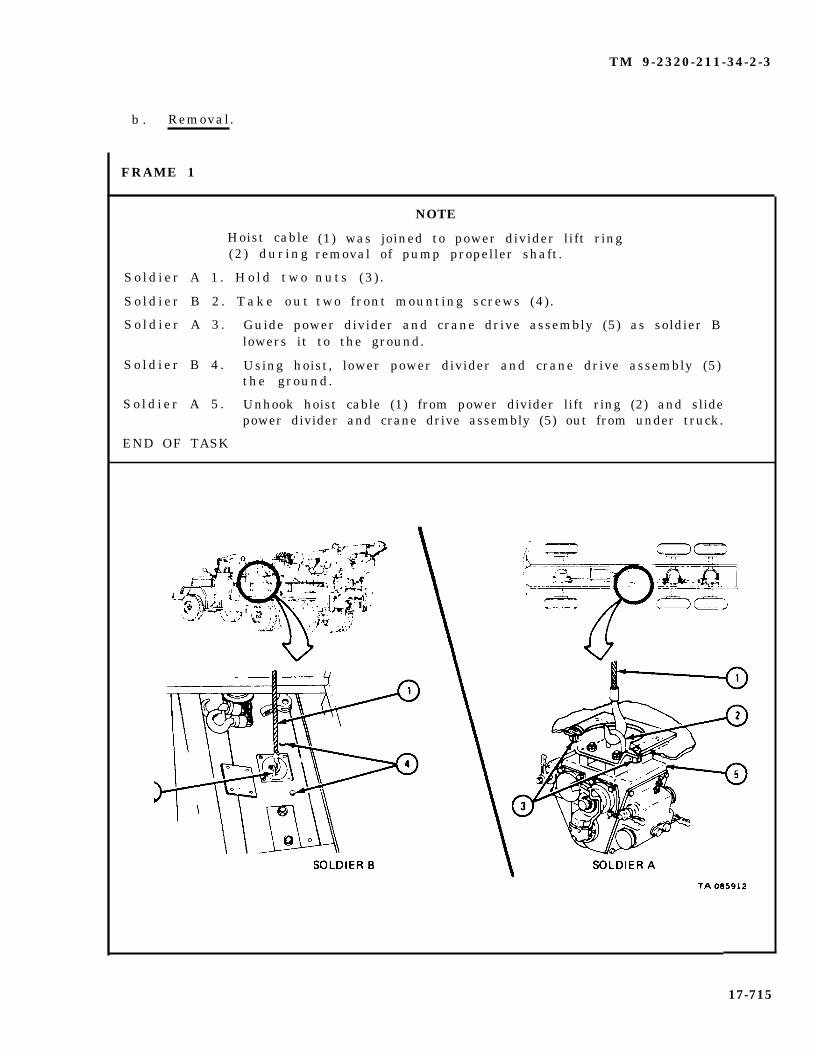
TM 9-2320-211-34-2-3
b . Removal.
Hoist cable(2 ) dur ing
S o l d i e r A 1 . H o l d t w o
S o l d i e r B 2 . T a k e o u t
NOTE
(1) was joined to power divider lift ringremoval of pump propeller shaft.
nuts (3 ) .
two front mounting screws (4).
S o l d i e r A 3 . Guide power divider and crane drive assembly (5) as soldier Blowers it to the ground.
S o l d i e r B 4 . Using hoist, lower power divider and crane drive assembly (5)the ground.
S o l d i e r A 5 . Unhook hoist cable (1) from power divider lift ring (2) and slidepower divider and crane drive assembly (5) out from under truck.
END OF TASK
17-715
FRAME 1
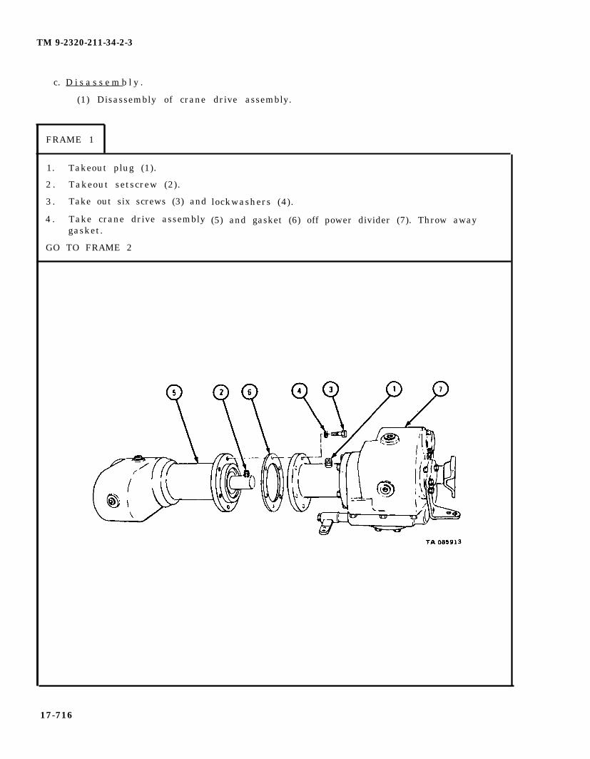
TM 9-2320-211-34-2-3
c. D i s a s s e m b l y .
(1) Disassembly of crane drive assembly.
FRAME 1
1. Takeout plug (1).
2 . Takeout setscrew (2).
3 . Take out six screws (3) and
4 . Take crane drive assemblygasket.
GO TO FRAME 2
lockwashers (4).
(5) and gasket (6) off power divider (7). Throw away
17-716

TM 9-2320-211-34-2-3
1. Hold shaft (1) at point shown and take out screws (2), lockwasher (3), andflat washer (4) .
2. Take out snapring (5).
3. Take shaft (1) and bearing (6) out of yoke (7) .
4. Mark shaft (1) before taking off coupling (8), so that coupling is put backin the same position.
5. Press shaft (1) out of bearing (6) and coupling (8) .
6. Take out two keys (9).
GO TO FRAME 3
17-717
F R A M E 2

TM 9-2320-211-34-2-3
F R A M E 3
1.
2 .
3 .
4 .
5 .
6 .
Take out four screws and lockwashers (1).
Take crane drive housing (2) and gasket (3) off output housing (4). Throw awaygasket.
Take out breather (5).
Take out two plugs (6).
Take out plug (7).
Take bearing (8) out of housing (2).
END OF TASK
17-718
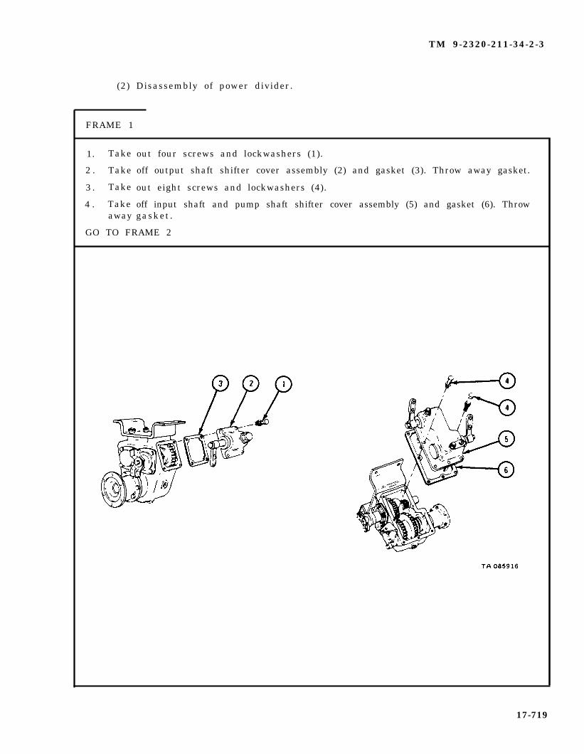
TM 9-2320-211-34-2-3
(2) Disassembly of power divider.
FRAME 1
1. Take
2 . Take
3 . Take
4 . Takeaway
out four screws and lockwashers (1).
off output shaft shifter cover assembly (2) and gasket (3). Throw away gasket.
out eight screws and lockwashers (4).
off input shaft and pump shaft shifter cover assembly (5) and gasket (6). Throwgasket.
GO TO FRAME 2
17-719

TM 9-2320-211-34-2-3
F R A M E 2
1. Hold yoke (1) and take out screw (2), lockwasher (3), flat washer (4), and gasket (5).Throw away gasket.
2 . Take off yoke (1).
GO TO FRAME 3
17-720

TM 9-2320-211-34-2-3
FRAME 3
1 . Take out four screws and lockwashers (1).
2 . Take off cap (2) with seal (3) and gasket (4). Throw away gasket.
3 . Press seal (3) out of cap (2). Throw away seal.
4 . Take out four screws and lockwashers (5).
5 . Take off cover (6) and gasket (7). Throw away gasket.
GO TO FRAME 4
17-721

TM 9-2320-211-34-2-3
FRAME 4
1. Using brass punch and hammer, tap on forward end of output shaft (1) andouter race of front bearing (2). Drive output shaft, together with frontbearing and rear bearing (3), towards rear of housing (4).
2 . Hold output gear (5) and front bearing (2), Using brass punch and hammer, driveoutput shaft (1) with rear bearing (3) out of output gear and front bearing.
3 . Take out output shaft (1) with rear bearing (3), output gear (5), and front bearing (2).
4 . Press rear bearing (3) off output shaft (1) . Refer to Part 1, para 7-7.
GO TO FRAME 5
17-722

TM 9-2320-211-34-2-3
FRAME 5
1 . Take out six screws and lockwashers (1).
2 . Take off pump adapter (2) and gasket (3). Throw away gasket.
GO TO FRAME 6
17-723
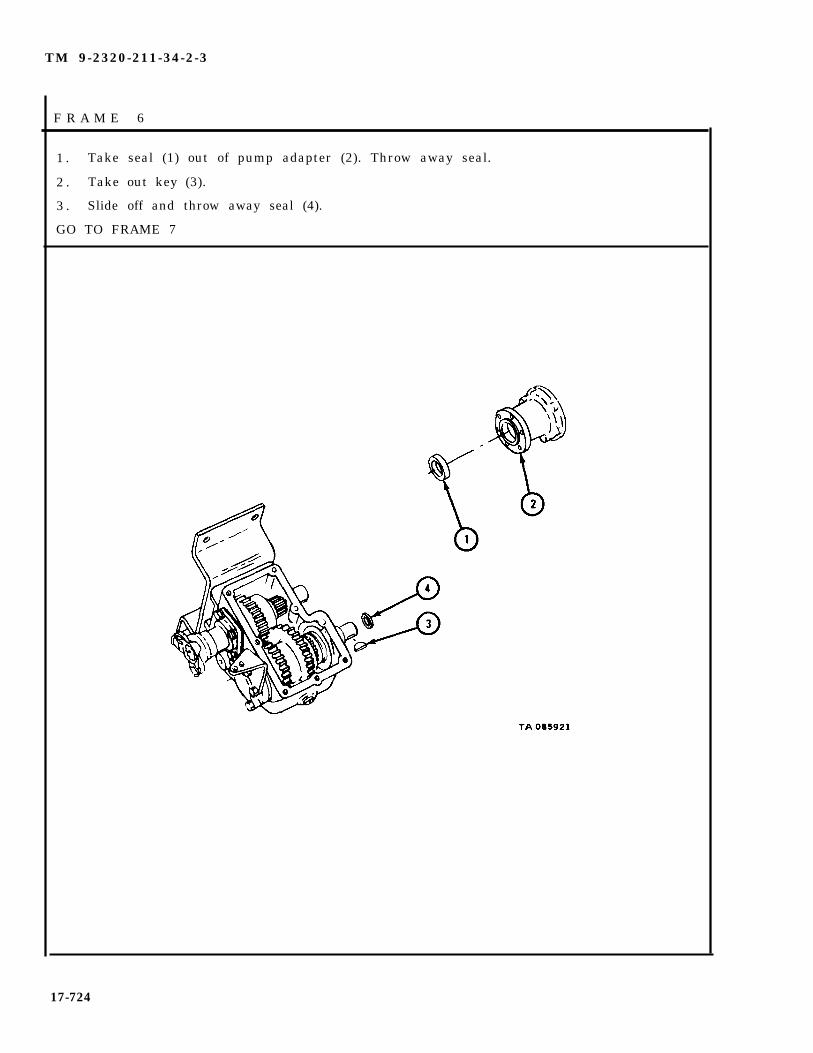
TM 9-2320-211-34-2-3
F R A M E 6
1 . Take seal (1) out of pump adapter (2). Throw away seal.
2 . Take out key (3).
3 . Slide off and throw away seal (4).
GO TO FRAME 7
17-724
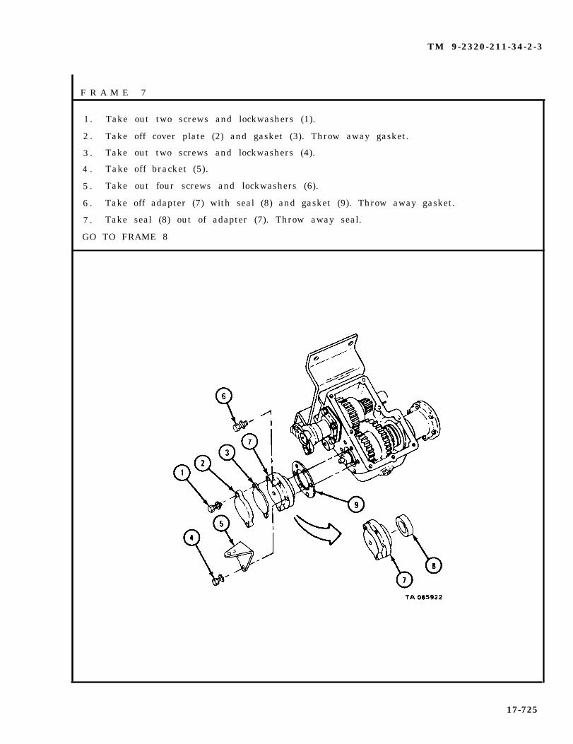
TM 9-2320-211-34-2-3
F R A M E 7
1. Take out two screws and lockwashers (1).
2 . Take off cover plate (2) and gasket (3). Throw away gasket.
3 . Take out two screws and lockwashers (4).
4 . Take off bracket (5).
5 . Take out four screws and lockwashers (6).
6 . Take off adapter (7) with seal (8) and gasket (9). Throw away gasket.
7 . Take seal (8) out of adapter (7). Throw away seal.
GO TO FRAME 8
17-725

TM 9-2320-211-34-2-3
FRAME 8
1 . Drive out shaft (1) and bearing (2) from front.
2 . Take gear assembly (3), clutch (4), two thrust washers (5), and bearing (6) out ofhousing (7).
3 . Take two bearings (8) and spacer (9) out of gear (3).
4. Take bearing (2) off shaft (1).
GO TO FRAME 9
17-726

TM 9-2320-211-34-2-3
FRAME 9
1 . Hold yoke (1) and take out screw (2), lockwasher (3), flat washer (4), and gasket (5).Throw away gasket.
2 . Pull off yoke (1).
GO TO FRAME 10
17-727

TM 9-2320-211-34-2-3
F R A M E 1 0
1. Take out four screws and lockwashers (1).
2. Takeoff cap (2) with seal (3) and gasket (4) . Throw away gasket.
3. Press seal (3) from cap (2). Throw away seal.
4. Take out four screws and lockwashers (5).
5. Takeof f cover (6 ) and gasket (7 ) . Throw away gasket .
GO TO FRAME 11
17-728

TM 9-2320-211-34-2-3
F R A M E 1 1
1 . Turn housing (1) on one side on wood blocks as shown so that input shaft canbe driven out of rear opening.
2. Using brass punch and hammer, tap on forward end of input shaft (2) andouter race of front bearing (3) . Drive input shaft together with front bearingand rear bearing (4) towards rear of housing (1).
3. Take out front bearing (3), input drive gear (5) with bearing (6), and twothrust washers (7).
4. Press bearing (6) out of input drive gear (5) . Refer to Part 1, para 7-7.
5. Press rear bearing (4) off input shaft (2) . Refer to Part 1, para 7-7.
GO TO FRAME 12
17-729

TM 9-2320-211-34-2-3
FRAME 12
1 0 Take
2 . Take
3 . Take
4 . Take
5 . Take
Out plugs (1 and 2).
out and throw away four cotter pins (3).
off four nuts (4).
off bracket (5).
out four studs (6).
END OF TASK
17-730

TM 9-2320-211-34-2-3
(3) Disassembly of input shaft and pump shaft shifter cover.
FRAME 1
1. Carefully clamp cover (1) in vise.
2 . Slowly unscrew and take out poppet (2), spring (3), and ball (4). Be careful not tolose spring and ball.
3 . Take out screw and lockwasher (5). Take off fork (6).
4 . Pull pin (7) out of fork (6).
5 . Slide out pump shaft and arm assembly (8).
6 . Do steps 2 through 5 again for input shaft and arm assembly (9).
GO TO FRAME 2
17-731

TM 9-2320-211-34-2-3
FRAME 2
1. Drive out two plugs (1).
2 . Take out two seals (2).
3 . Take out breather assembly (3).
4 . Take out coupling (4).
5 . Take out nipple (5).
6 . Take out plug (6).
7 . Take cover (7) out of vise.
GO TO FRAME 3
17-732

TM 9-2320-211-34-2-3
FRAME 3
1 . Clamp pump shaft (1) in vise.
2 . Take out screw and lockwasher (2).
3. Take off arm (3).
4 . Take pump shaft (1) out of vise.
5 . Do steps 1 through 4 again for input shaft and arm assembly (4).
END OF TASK
17-733
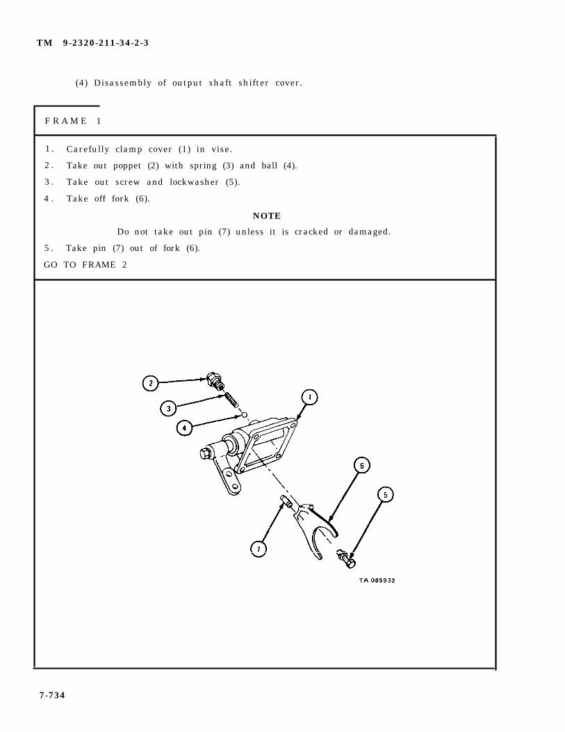
TM 9-2320-211-34-2-3
(4) Disassembly of output shaft shifter cover.
F R A M E 1
1 . Carefully clamp cover (1) in vise.
2 . Take out poppet (2) with spring (3) and ball (4).
3 . Take out screw and lockwasher (5).
4 . Take off fork (6).
NOTE
Do not take out pin (7) unless it is cracked or damaged.
5 . Take pin (7) out of fork (6).
GO TO FRAME 2
7-734

TM 9-2320-211-34-2-3
FRAME 2
1 . Slide out shaft (1) with arm (2).
2 . Take out two seals (3).
3 . Take cover (4) out of vise.
4 . Clamp shaft (1) in vise.
5 . Take out screw and lockwasher (5).
6 . Slide arm (2) off shaft (1).
7 . Take shaft (1) out of vise.
END OF TASK
17-735

TM 9-2320-211-34-2-3
d . Cleaning. There are no special cleaningcleaning procedures given in Part 1, para 1-3.
e . Inspection.
FRAME 1
procedures needed . Re fer to
1. Check that two bearings (1) are not damaged. Refer to Part 1, para 7-7.
2. Check that shaft (2) is not bent, twisted or damaged in any other way.
3. Check that yoke (3) is not cracked or broken and that it has no strippedscrew holes.
4. Check that crane drive housing (4) and output housing (5) are not cracked orbroken and that they have no s tr ipped screw ho les .
GO TO FRAME 2
17-736
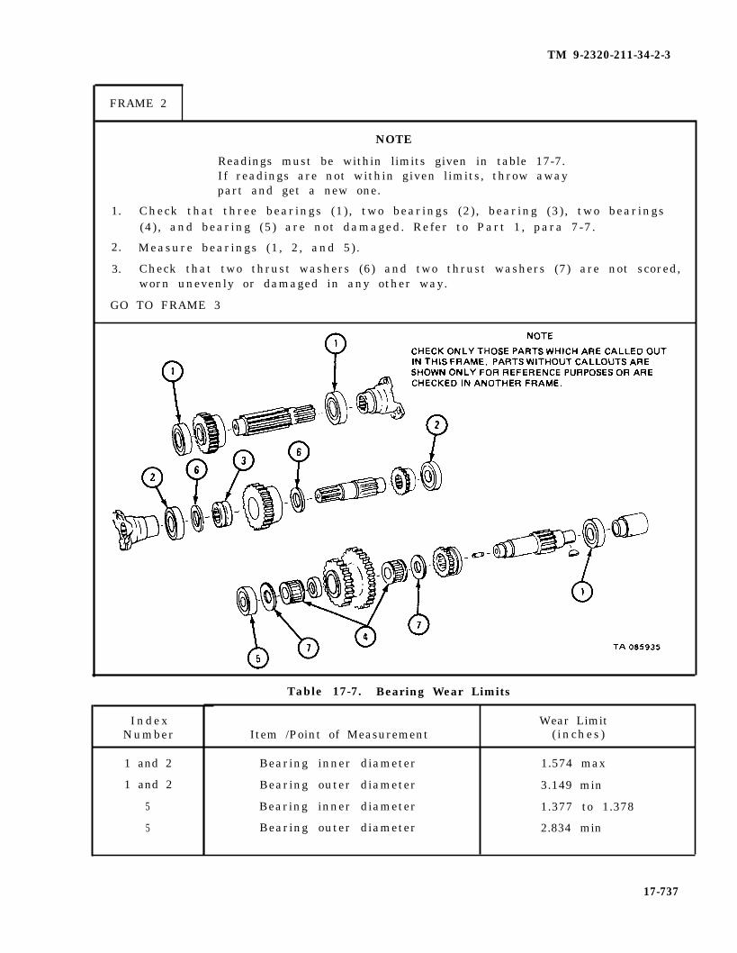
TM 9-2320-211-34-2-3
FRAME 2
NOTE
Readings must be within limits given in table 17-7.If readings are not within given limits, throw awaypart and get a new one.
1. Check that three bearings (1), two bearings (2), bearing (3), two bearings(4), and bearing (5) are not damaged. Refer to Part 1, para 7-7.
2. Measure bearings (1, 2, and 5).
3. Check that two thrust washers (6) and two thrust washers (7) are not scored,worn unevenly or damaged in any other way.
GO TO FRAME 3
IndexNumber
1 and 2
1 and 2
5
5
Table 17-7. Bearing Wear Limits
Wear LimitItem /Point of Measurement ( inches )
Bearing inner diameter 1.574 max
Bearing outer diameter 3.149 min
Bearing inner diameter 1.377 to 1.378
Bearing outer diameter 2.834 min
17-737
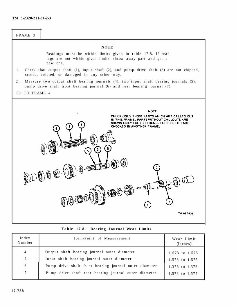
TM 9-2320-211-34-2-3
FRAME 3
NOTE
Readings must be within limits given in table 17-8. If read-ings are not within given limits, throw away part and get anew one.
1. Check that output shaft (1), input shaft (2), and pump drive shaft (3) are not chipped,scored, twisted, or damaged in any other way.
2 . Measure two output shaft bearing journals (4), two input shaft bearing journals (5),pump drive shaft front bearing journal (6) and rear bearing journal (7).
GO TO FRAME 4
Table 17-8. Bearing Journal Wear Limits
Index Item/Point of Measurement Wear LimitNumber (inches)
4 Output shaft bearing journal outer diameter 1.573 to 1.575
5 Input shaft bearing journal outer diameter 1.573 to 1.575
6 Pump drive shaft front bearing journal outer diameter 1.376 to 1.378
7 Pump drive shaft rear bearing journal outer diameter 1.573 to 1.575
17-738
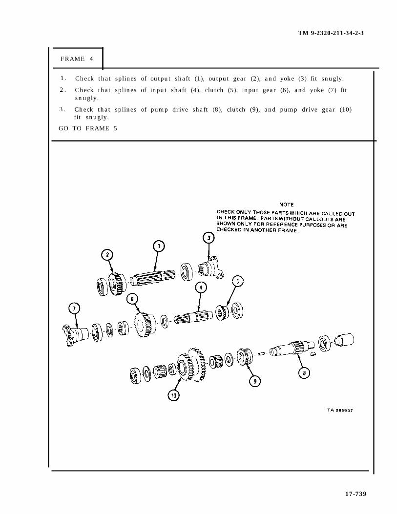
TM 9-2320-211-34-2-3
FRAME 4
1. Check that splines of output shaft (1), output gear (2), and yoke (3) fit snugly.
2 . Check that splines of input shaft (4), clutch (5), input gear (6), and yoke (7) fitsnugly.
3 . Check that splines of pump drive shaft (8), clutch (9), and pump drive gear (10)fit snugly.
GO TO FRAME 5
17-739

TM 9-2320-211-34-2-3
FRAME 5
1. Check that output gear (1), input gear (2), and pump drive gear (3) have no burred,chipped or broken teeth. Check that they are not damaged in any other way.
2 . Check that two clutches (4) are not burred, chipped or damaged in any other wav.
3 ..
Check that sealing surfaces of two yokes (5) are not worn and that threaded holes arenot damaged.
4 . Check that coupling (6) is not twisted or damaged in any other way.
(GO TO FRAME 6
17-740

TM 9-2320-211-34-2-3
F R A M E 6
NOTE
Readings must be within limits given in table 17-9. If read-ings are not within given limits, throw away part and get anew one.
1 . Check that housing (1), two caps (2), two covers (3), pump adapter (4), and adapter(5) are not cracked or warped.
2 . Check that threaded holes in housing (1) and pump adapter (4) are not darnaged.
3 . Measure two output shaft bearing bores (6), two input shaft bearing bores (7), pumpdrive shaft front bearing bore (8), and rear bearing bore (9).
GO TO FRAME 7
IndexNumber
6
7
8
9
Table 17-9. Bearing Bore Wear Limits
Item/Point of Measurement
Output shaft bearing bore inner diameter
Input shaft bearing bore inner diameter
Pump drive shaft bearing bore inner diameter
Pump drive shaft rear bearing bore inner diameter
Wear Limit(inches)
3.149 to 3.151
3.149 to 3.151
2.834 to 2.836
3.149 to 3.151
17-741

TM 9-2320-211-34-2-3
FRAME 7
NOTE
Readings must be within limits given in table 17-10.If readings are not within given limits, throw awaypart and get a new one.
1. Check that input shaft and pump shaft shifter cover (1) is not cracked orwarped, and that threaded holes are not damaged.
2. Check that two shafts (2 and 3) and two forks (4) are not cracked or broken.Check that forks fit well on shafts.
3. Measure two springs (5) .
GO TO FRAME 8
Table 17-10. Spring Wear Limits
Index Wear LimitNumber Item /Point of Measurement ( inches )
5 Spring free length 1 21/32
5 Spring length when compressed by 38-pound force 1
17-742
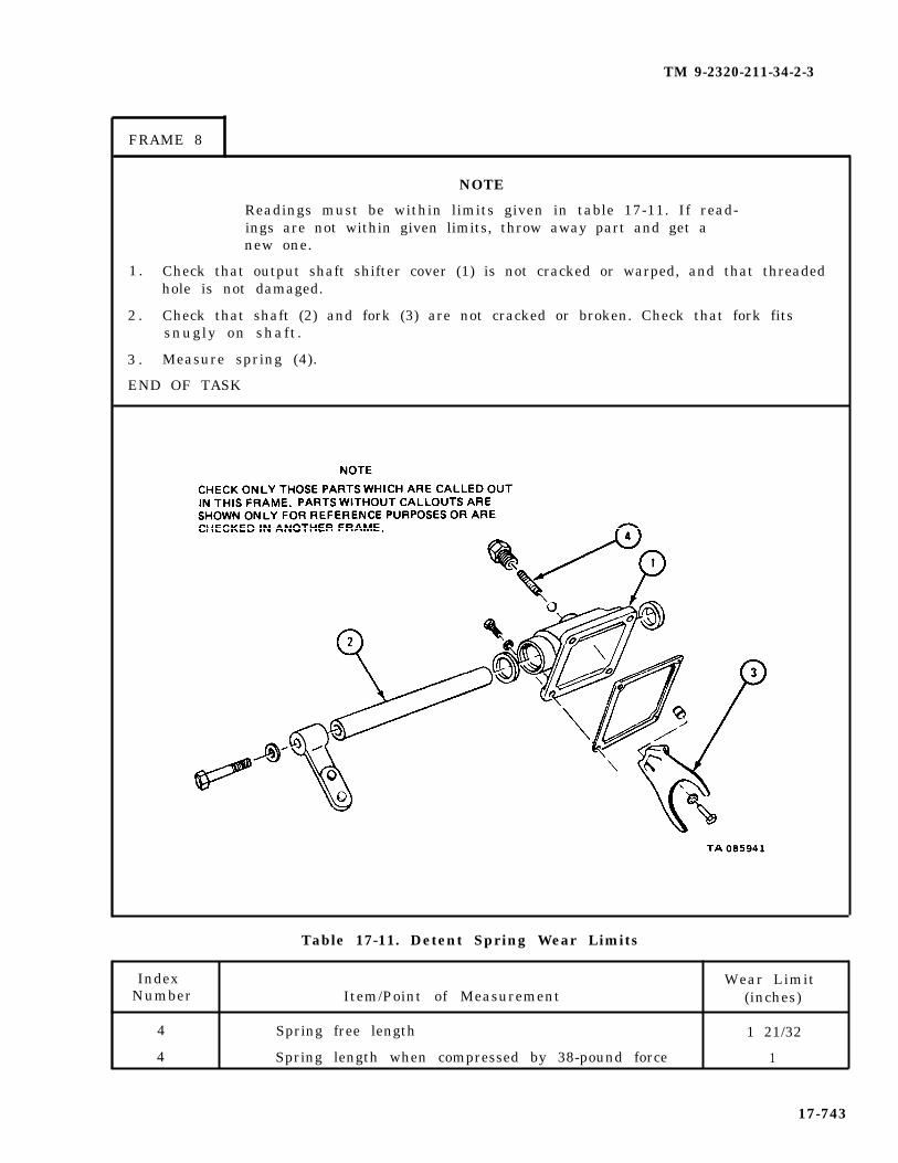
TM 9-2320-211-34-2-3
FRAME 8
NOTE
Readings must be within limits given in table 17-11. If read-ings are not within given limits, throw away part and get anew one.
1 . Check that output shaft shifter cover (1) is not cracked or warped, and that threadedhole is not damaged.
2 . Check that shaft (2) and fork (3) are not cracked or broken. Check that fork fitssnugly on shaft.
3 . Measure spring (4).
END OF TASK
Table 17-11. Detent Spring Wear Limits
Index Wear LimitNumber Item/Point of Measurement (inches)
4 Spring free length 1 21/32
4 Spring length when compressed by 38-pound force 1
17-743

TM 9-2320-211-34-2-3
f . Repair.
(1) Using fine mill file or soapstone, file small nicks and burrs from parts.
(2) Throw away damaged parts and get new ones in their place.
g . Assembly.
NOTE
Oil all bearings, shafts, and gears during assembly.
(1) Assembly of output shaft shifter cover.
FRAME 1
1. Clamp shaft (1) in vise and put arm (2) in place on end of shaft (1).
2 . Put in screw (3) and lockwasher (4).
3 . Take shaft (1) out of vise.
4 . Carefully clamp cover (5) in vise.
5 . Put in two seals (6).
6 . Slide shaft (1) through bores in cover (5). Be careful not to damage seals (6).
GO TO FRAME 2
17-744

TM 9-2320-211-34-2-3
FRAME 2
1 0 Push pin (1) into hole in fork (2).
2 . Put fork (2) with pin (1) in place on shaft (3).
3 . Put in screw and lockwasher (4).
4 . Put ball (5) and spring (6) in bore of cover (7).
5 . Put in poppet (8).
6 . Take cover (7) out of vise.
END OF TASK
17-745

TM 9-2320-211-34-2-3
(2) Assembly of input shaft and pump shaft shifter cover.
FRAME 1
1 . Clamp shaft (1) in vise.
2 . Put arm (2) on shaft (1).
3 . Put in screw (3) and lockwasher (4).
4 . Take shaft (1) out of vise.
5 . Do steps 1 through 4 again for input shaft and arm assembly (5).
GO TO FRAME 2
17-746
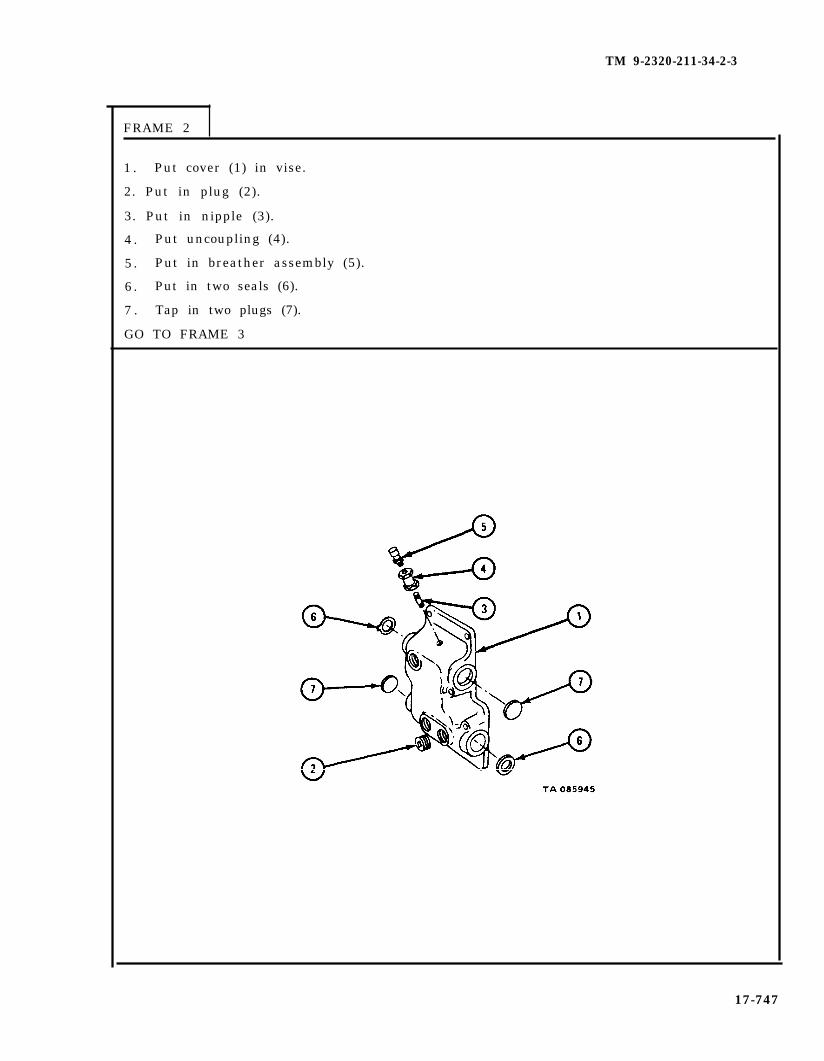
TM 9-2320-211-34-2-3
FRAME 2
1 . Put cover (1) in vise.
2. Put in plug (2).
3. Put in nipple (3).
4 . Put uncoupling (4).
5 . Put in breather assembly (5).
6 . Put in two seals (6).
7 . Tap in two plugs (7).
GO TO FRAME 3
17-747
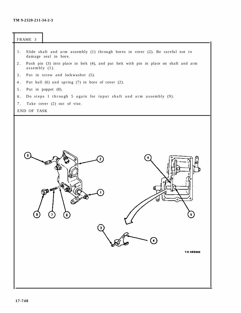
TM 9-2320-211-34-2-3
FRAME 3
1. Slide shaft and arm assembly (1) through bores in cover (2). Be careful not todamage seal in bore.
2 . Push pin (3) into place in fork (4), and put fork with pin in place on shaft and armassembly (1).
3 . Put in screw and lockwasher (5).
4 . Put ball (6) and spring (7) in bore of cover (2).
5 . Put in poppet (8).
6 . Do steps 1 through 5 again for input shaft and arm assembly (9).
7 . Take cover (2) out of vise.
END OF TASK
17-748
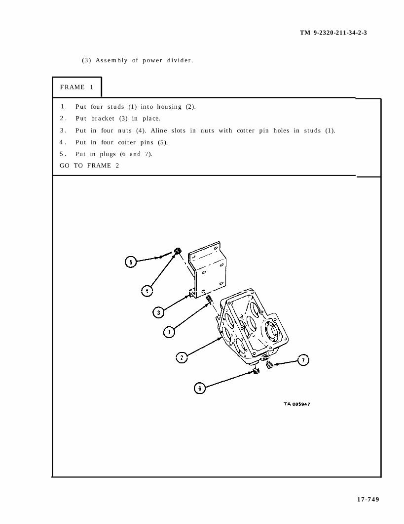
TM 9-2320-211-34-2-3
(3) Assembly of power divider.
FRAME 1
1. Put four studs (1) into housing (2).
2 . Put bracket (3) in place.
3 . Put in four nuts (4). Aline slots in nuts with cotter pin holes in studs (1).
4 . Put in four cotter pins (5).
5 . Put in plugs (6 and 7).
GO TO FRAME 2
17-749
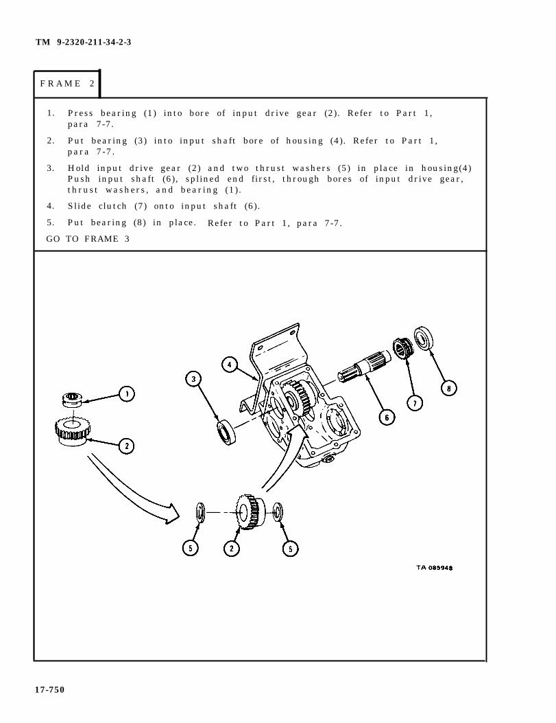
TM 9-2320-211-34-2-3
1. Press bearing (1) into bore of input drive gear (2). Refer to Part 1,para 7-7.
2. Put bearing (3) into input shaft bore of housing (4). Refer to Part 1,para 7-7.
3. Hold input drive gear (2) and two thrust washers (5) in place in housing(4)Push input shaft (6), splined end first, through bores of input drive gear,thrust washers, and bearing (1).
4. Slide clutch (7) onto input shaft (6).
5. Put bearing (8) in place. Refer to Part 1, para 7-7.
GO TO FRAME 3
17-750
F R A M E 2

TM 9-2320-211-34-2-3
FRAME 3
1.
2.
3.
4.
5.
6.
7.
8.
9.
10.
11.
12.
13.
14.
GO
Put gasket (1) and cover (2) in place.
Put in four screws (3) and lockwashers (4).
Press seal (5) into cap (6) .
Pack inside of cap (6) with grease.
Put gasket (7) and cap (6) with seal (5) in place.
Put in four screws (8) and lockwashers (9) .
Fasten dial indicator to housing (10) so that plunger of dial indicator is againstend of input shaft (11) as shown.
Push in and pull out input shaft (11) to check that end play is between 0.010inch and 0.033 inch.
Take off dial indicator.
If end play is not within limits given in step 8, do steps 11 through 14. Ifend play is within limits given, go to frame 4.
Take out four screws (8) and lockwashers (9) .
Take off cap (6) with seal (5) .
Put on another gasket (7) . Put cap (6) with seal (5) back in place.
Do steps 6 through 13 again until end play is within given limits.
TO FRAME 4
17-751
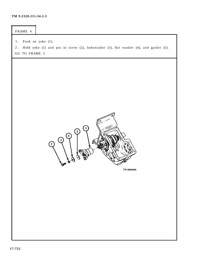
TM 9-2320-211-34-2-3
FRAME 4
1 . Push on yoke (1).
2 . Hold yoke (1) and put in screw (2), locksvasher (3), flat washer (4), and gasket (5).
GO TO FRAME 5
17-752

TM 9-2320-211-34-2-3
F R A M E 5
1 .
2 .
3 .
4 .
G o
Slide thrust washer (1) onto pump drive shaft (2).
Slide on bearing (3).
Slide on collar (4).
Slide on bearing (5).
TO FRAME 6
17-753
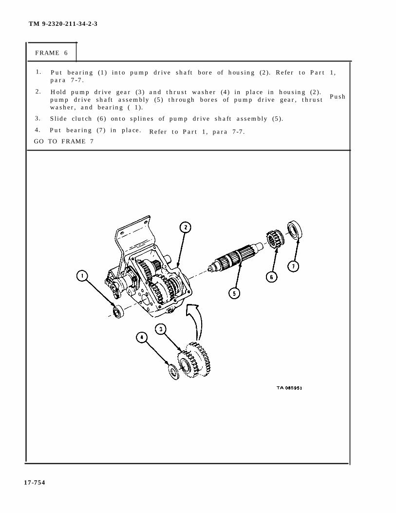
TM 9-2320-211-34-2-3
FRAME 6
1. Put bearing (1) into pump drive shaft bore of housing (2). Refer to Part 1,para 7-7.
2. Hold pump drive gear (3) and thrust washer (4) in place in housing (2).Pushpump drive shaft assembly (5) through bores of pump drive gear, thrust
washer, and bearing ( 1).
3. Slide clutch (6) onto splines of pump drive shaft assembly (5).
4. Put bearing (7) in place. Refer to Part 1, para 7-7.GO TO FRAME 7
17-754

TM 9-2320-211-34-2-3
FRAME 7
1 . Put seal (1) into adapter (2).
2 . Slide seal (3) onto pump drive shaft (4).
3 . Put in key (5).
GO TO FRAME 8
17-755

TM 9-2320-211-34-2-3
FRAME 8
1 . Put gasket (1) in place on pump adapter (2).
2 . Put in six screws and lockwashers (3).
GO TO FRAME 9
17-756

TM 2320-211-34-2-3
FRAME 9
1 . Press seal (1) into adapter (2).
2 . Put gasket (3) and seal (1) with adapter (2) in place.
3 . Put in four screws (4) and lockwashers (5).
4 . Fasten dial gage to housing (6) so that plunger of dial gage goes through bore inadapter (2) and rests against pin in end of pump drive shaft (7) as shown.
5 . Push in and pull out on coupling (8) to check that end play of pump driveshaft (7) is between 010 inch and 0.033 inch.
6 . Take off dial gage.
7 . If end play is not within limits given in step 5, do steps 8 through 11. If end play iswithin limits given in step 5, go to frame 10.
8 . Take out four screws (4) and lockwashers (5).
9 . Take off adapter (2) with seal (1).
10. Put on another gasket (3). Put adapter (2) with seal (1) back in place.
11. Do steps 3 through 10 again until end play is within given limits.
GO TO FRAME 10
17-757

TM 9-2320-211-34-2-3
F R A M E 1 0
1. Put gasket (1) and cover plate (2) in place.
2 . Put in two screws (3) and lockwashers (4).
3 . Put bracket (5) in place.
4 . Put in two screws (6) and lockwashers (7).
GO TO FRAME 11
17-758

TM 9-2320-211-34-2-3
FRAME 11
1. Put bearing (1) into output shaft bore of housing (2). Refer to Part 1,para 7-7.
2. Hold output gear (3) in place. Push output shaft (4), splined end first asshown, through bores of output gear and bearing (1).
3. Put bearing (5) in place. Refer to Part 1, para 7-7.
GO TO FRAME 12
17-759

TM 9-2320-211-34-2-3
FRAME 12
1 .
2 .
3 .
4 .
5 .
6 .
7 .
8 .
9 .
1 0.
11.
1 2.
1 3.
G o
Put gasket (1) and cover (2) in place.
Put in four screws (3) and lockswashers (4).
Press seal (5) into cap (6).
Put gasket (7) and cap (6) with seal (5) in place.
Put in four screws (8) and lockwashers (9).
Fasten dial indicator to housing (10) so that plunger of dial gage is against end ofoutput shaft (11) as shown.
Push in and pull out output shaft (11) to check that end play is between 0.010inch and 0.033 inch.
Take off dial indicator.
If end play is not within limits given in step 7, do steps 10 through 13. If end playis within given limits, go to frame 13.
Take out four screws (8) and lockwashers (9).
Take off cap (6) with seal (5).
Put on another gasket (7). Put cap (6) with seal (5) back in place.
Do steps 5 through 12 again until end play is within given limits.
TO FRAME 13
17-760

TM 9-2320-211-34-2-3
FRAME 13
1 . Push on yoke (1).
2 . Hold yoke (1) and put in screw (2), lockwasher (3), flat washer (4), and gasket (5).
GO TO FRAME 14
17-761

TM 9-2320-211-34-2-3
NOTE
This frame tells how to check backlash for allgears . Do this frame when measuring backlashfor each set of gears in frame 5.
FRAME 14
1.
2.
3.
4.
5.
6.
Mount dial indicator on housing and set stem against side of gear tooth (1) asshown.
NOTE
When measuring backlash makedoes not turn. If gear turns,will be wrong.
sure that gear (2)backlash readings
Turn gear (3) away from dial indicator until gear tooth (4) touches gear tooth(5) as shown in view A.
Set dial indicator to read 0.
Turn gear (3) towards dial indicator until gear tooth (6) touches other side ofgear tooth (5) as shown in view B.
Check that dial indicator readings are within wear limits given for each set ofgears .
Do steps 1 through 5 when measuring backlash for each set of gears.
GO TO FRAME 15
17-762

TM 9-2320-211-34-2-3
FRAME 15
1.
2.
3.
4.
5.
6.
7.
8.
9.
GO
NOTE
If backlash is greater than limits given for any of thefollowing checks, get a new power divider. Senddamaged power divider to depot level maintenance.
Mesh clutch (1) with input drive gear (2).
Using dial indicator, check that backlash between clutch (1) and input drivegear (2) is between 0.006 inch and 0.035 inch.
Mesh clutch (3) with pump drive gear (4).
Using dial indicator, check that backlash between clutch (3) and pump drivegear (4) is between 0.006 inch and 0.035 inch.
Using dial indicator, check that backlash between input drive gear (2) andpump drive gear (4) is between 0.006 inch and 0.035 inch.
Mesh pump drive gear (4) with output gear (5).
Using dial indicator, check that backlash between pump drive gear (4) andoutput gear (5) is between 0.006 inch and 0.035 inch.
Mesh input drive gear (2) and output gear (5).
Using dial indicator, check that backlash between input drive gear (2) andoutput gear (5) is between 0.006 inch and 0.035 inch.
TO FRAME 16
17-763

TM 9-2320-211-34-2-3
FRAME 16
1. Put gasket (1) and input shaft and pump shaft shifter cover assembly (2) inplace. Make sure that fork (3) alines with yoke of clutch (4) and that fork(5) alines with yoke of clutch (6).
2. Put in two screws (7), lockwashers (8), six screws (9), and lockwashers (10).
GO TO FRAME 17
17-764

TM 9-2320-211-34-2-3
FRAME 17
1. Put gasket (1) and output shaft shifter cover assembly (2) in place. Make sure thatfork (3) alines with yoke of gear (4).
2 . Put in four screws (5) and lockwashers (6).
END OF TASK
17-765

TM 9-2320-211-34-2-3
(4) Assembly of crane drive assembly.
FRAME 1
1. Put bearing (1) in housing (2).
2 . Put crane drive housing (2) and gasket (3) in place on output housing (4).
3 . Put in four screws (5) and lockwashers (6).
4 . Put in breather (7).
5 . Put in two plugs (8).
6 . Put in plug (9).
GO TO FRAME 2
17-766

TM 9-2320-211-34-2-3
FRAME 2
1 . Press two keys (1) in shaft (2).
2 . Press bearing (3) on shaft (2).
3 . Press coupling (4) on shaft (2) to position marked.
4 . Put bearing (3) and shaft assembly (2) in housing (5).
5 . Put snapring (6) in housing (5).
6 . Put on yoke (7) and put in screw (8), lockwasher (9), and flat washer (10).
GO TO FRAME 3
17-767

TM 9-2320-211-34-2-3
F R A M E 3
1 . Take out six screws and lockwashers (1) and take pump drive adapter (2) and gasket(3) off power divider (4).
2 . Put adapter (2) and gasket (5) on crane drive assembly (6) and put in six screws andlockwashers (7).
GO TO FRAME 4
17-768
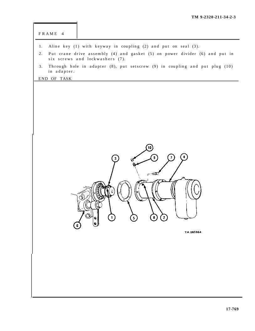
TM 9-2320-211-34-2-3
F R A M E 4
1. Aline key (1) with keyway in coupling (2) and put on seal (3).
2. Put crane drive assembly (4) and gasket (5) on power divider (6) and put insix screws and lockwashers (7).
3. Through hole in adapter (8), put setscrew (9) in coupling and put plug (10)in adapter.
END OF TASK
17-769
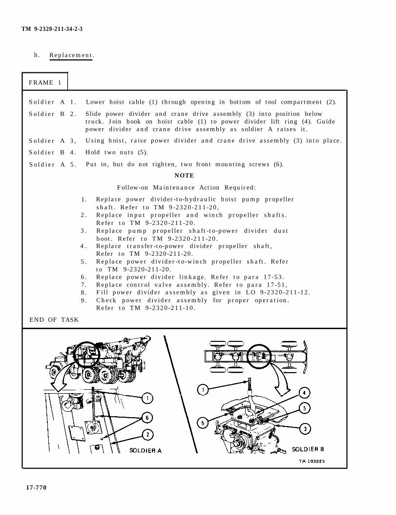
TM 9-2320-211-34-2-3
h. Replacement.
FRAME 1
So ld ier A 1 . Lower hoist cable (1) through opening in bottom of tool compartment (2).
So ld ier B 2 . Slide power divider and crane drive assembly (3) into position belowtruck. Join hook on hoist cable (1) to power divider lift ring (4). Guidepower divider and crane drive assembly as soldier A raises it.
So ld ier A 3 , Using hoist, raise power divider and crane drive assembly (3) into place.
So ld ier B 4 . Hold two nuts (5).
So ld ier A 5 . Put in, but do not tighten, two front mounting screws (6).
NOTE
Follow-on Maintenance Action Required:
1.
2 .
3 .
4 .
5 .
6.7.8.9.
END OF TASK
Replace power divider-to-hydraulic hoist pump propellershaft. Refer to TM 9-2320-211-20,Replace input propeller and winch propeller shafts.Refer to TM 9-2320-211-20.Replace pump propeller shaft-to-power divider dustboot. Refer to TM 9-2320-211-20.Replace transfer-to-power divider propeller shaft,Refer to TM 9-2320-211-20.Replace power divider-to-winch propeller shaft. Referto TM 9-2320-211-20.Replace power divider linkage. Refer to para 17-53.Replace control valve assembly. Refer to para 17-51,Fill power divider assembly as given in LO 9-2320-211-12.Check power divider assembly for proper operation.Refer to TM 9-2320-211-10.
17-770

TM 9-2320-211-34-2-3
17-55. POWER DIVIDER GOVERNOR VALVE REMOVAL, REPLACEMENT, ANDADJUSTMENT (TRUCK M543A2).
TOOLS: No special tools required
SUPPLIES: None
PERSONNEL: Two
EQUIPMENT CONDITION: Truck parked, engine off , handbrake set.
a. Preliminary p rocedure . Open drain cock on lower air reservoir. Refer toVenting Air System P ressure, TM 9-2320-211-20.
b . Removal.
S o I d i e r A 1 . Working under truck, take off air line (1).
2 . Hold nuts (2) on governor mounting bracket (3).
S o l d i e r B 3 . Working inside cab, take out two screws (4).
S o l d i e r A 4 . Take out governor (5) .
END OF TASK
F R A M E 1
17-771

TM 9-2320-211-34-2-3
c . Replacement.
FRAME 1
S o l d i e r A 1 . Working under truck, put governor (1) in place.
2. Hold two nuts (2) in place.
Soldier B 3. Inside cab, put in two screws (3).
S o l d i e r A 4 . Put on air l ine (4).
END OF TASK
17-772
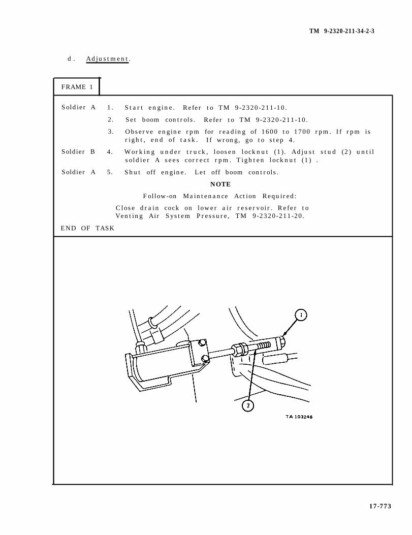
TM 9-2320-211-34-2-3
d . Adjustment.
FRAME 1
Soldier A
Soldier B
Soldier A
1.
2.
3.
4.
5.
Start engine. Refer to TM 9-2320-211-10.
Set boom controls. Refer to TM 9-2320-211-10.
Observe engine rpm for reading of 1600 to 1700 rpm. If rpm isright, end of task. If wrong, go to step 4.
Working under truck, loosen locknut (1). Adjust stud (2) untilsoldier A sees correct rpm. Tighten locknut (1) .
Shut off engine. Let off boom controls.
NOTE
Follow-on Maintenance Action Required:
Close drain cock on lower air reservoir. Refer toVenting Air System Pressure, TM 9-2320-211-20.
END OF TASK
17-773

TM 9-2320-211-34-2-3
Section III. POWER TAKEOFF AND SWIVEL VALVE ASSEMBLIES
17-56. TRANSMISSION TRANSFER POWER TAKEOFF REMOVAL, REPAIR , ANDREPLACEMENT (TRUCK M543A2).
TOOLS: No special tools required
SUPPLIES: Retaining cap gasketValve assembly gasketCheck valve screw gasketPower takeoff gasket
PERSONNEL: One
EQUIPMENT CONDITION: Truck parked, engine off , handbrake set.
a. Preliminary Procedures.
(1) Remove propeller shaft and yoke from power takeoff shaft. Refer toTM 9-2320-211-20.
(2) Remove handbrake brake drum. Refer to TM 9-2320-211-20.
(3 ) Drain transfer hous ing . Refer to LO 9-2320-211-12.
b . Removal.
FRAME 1
1. Take out screw (1) and flatwasher (2).
2. Loosen coupling nut (3) and take off driveshaft lube tube (4) from relief valvehous ing (5 ) .
GO TO FRAME 2
17-774

TM 9-2320-211-34-2-3
FRAME 2
1. Takeout four capscrews (1) and flat washers (2) .
2. Take off two nuts (3) and lockwashers (4).
3. Take off transfer transmission power takeoff(5) and gasket (6) . Throwaway gasket.
GO TO FRAME 3
17-775

TM 9-2320-211-34-2-3
FRAME 3
1. Loosen coupling nut (1) and take out driveshaft lubrication tube (2) andcoupl ing
2. Unscrew
nut (1 ) .
NOTE
Do not take out cap screw (3) when taking out checkvalve assembly (4).
check valve assembly (4).
END OF TASK
17-776

TM 9-2320-211-34-2-3
c . Disassembly.
FRAME 1
1. Take out connector (1).
2. Take out capscrew (2), gasket (3), check valve spring (4), andcheck valve ball (5) .
GO TO FRAME 2
17-777

TM 9-2320-211-34-2-3
FRAME 2
1. Take out four capscrews (1) and lockwashers (2) and slide out relief valveassembly (3) and gasket (4). Throw away gasket.
GO TO FRAME 3
17-778

TM 9-2320-211-34-2-3
FRAME 3
1. Take out relief valve plug (1), relief valve ball spring (2), and reliefvalve ball (3) .
2. Take out connector (4), relief valve ball spring (5), and relief valve ball (6).
GO TO FRAME 4
17-779
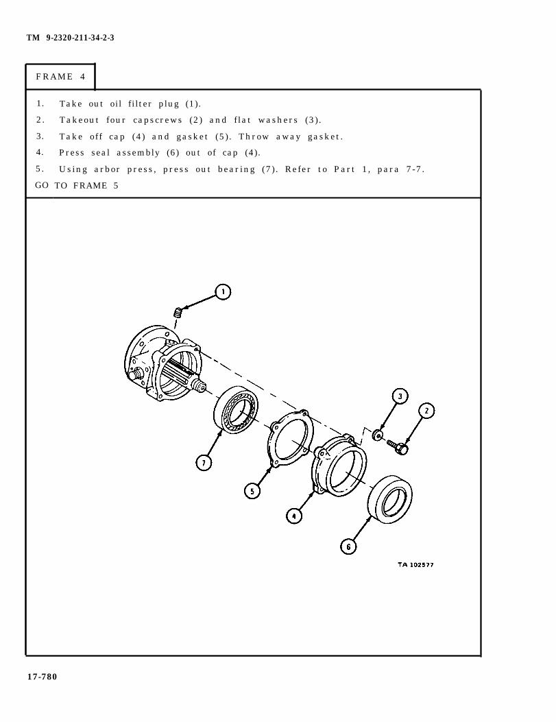
TM 9-2320-211-34-2-3
FRAME 4
1.
2.
3.
4.
5.
GO
Take out oil filter plug (1).
Takeout four capscrews (2) and flat washers (3) .
Take off cap (4) and gasket (5) . Throw away gasket.
Press seal assembly (6) out of cap (4).
Using arbor press, press out bearing (7). Refer to Part 1, para 7-7.
TO FRAME 5
17-780
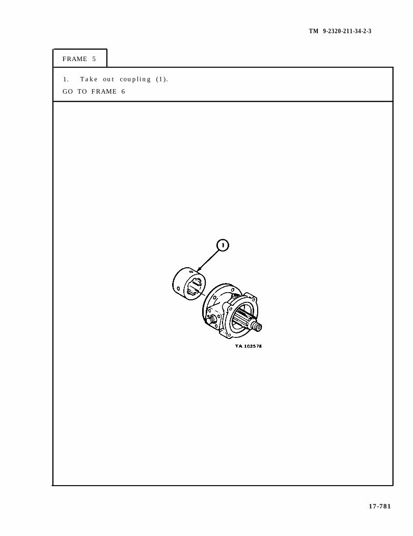
TM 9-2320-211-34-2-3
FRAME 5
1. Take out coupling (1).
GO TO FRAME 6
17-781
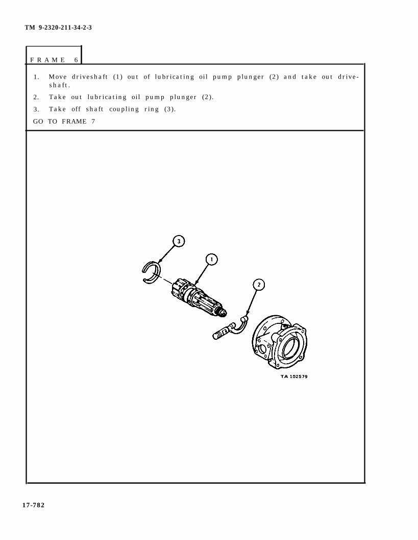
TM 9-2320-211-34-2-3
F R A M E 6
1. Move driveshaft (1) out of lubricating oil pump plunger (2) and take out drive-shaft.
2. Take out lubricating oil pump plunger (2).
3. Take off shaft coupling ring (3).
GO TO FRAME 7
17-782

TM 9-2320-211-34-2-3
1. Take off lubricating tube clamp (1).
2. Do not take out grommet (2) from lubricating tube (3).
END OF TASK
F R A M E 7
17-783

TM 9-2320-211-34-2-3
Dry cleaningnear an opennearby when
WARNING
solvent is flammable. Do not useflame. Keep a fire extinguishersolvent is used. Use only in well-
ventilated places. Failure to do this may resultin injury to personnel and damage to equipment.
d . C l e a n i n g . There are no special cleaning procedures needed. Referto clearnng procedures given in Part 1, para 1-3.
e . I n s p e c t i o n .
FRAME 1
1. Check that bearing (1) is not scored, chipped or cracked.
2. Check that housing (2) in not chipped, cracked or warped.
3. Check that shaft (3) and coupling (4) are not chipped, twisted or damaged.
4. Check that relief valve body (5) and lubricating oil pump plunger (6) arenot worn, chipped or cracked.
5. Check that retaining ring (7) in not scored or cracked.
END OF TASK
17-784

TM 9-2320-211-34-2-3
f. R e p a i r . Using fine mill f i le, f i le off slight nicks and burrs. Get new partsplace of all other damaged parts.
g. A s s e m b l y .
F R A M E 1
1. Put on lubricating tube clamp (1).
GO TO FRAME 2
17-785

TM 9-2320-211-34-2-3
F R A M E 2
1. Using arbor press, press bearing (1) into housing (2). Refer to Part 1,para 7-7.
2. Tilt lubricating oil pump plunger (3) and slide housing (2) over shaft andplunger so that plunger shaft (4) goes into housing bore (5).
3. Put retaining ring (6) on driveshaft (7).
4. Put lubricating oil pump plunger (3) on driveshaft (7).
5. Put coupling (8) on driveshaft (7) .
GO TO FRAME 3
17-786
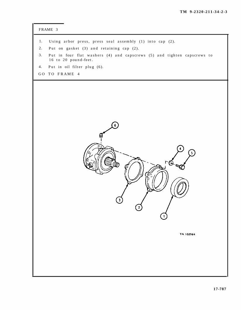
TM 9-2320-211-34-2-3
FRAME 3
1. Using arbor press, press seal assembly (1) into cap (2).
2. Put on gasket (3) and retaining cap (2).
3. Put in four flat washers (4) and capscrews (5) and tighten capscrews to16 to 20 pound-feet.
4. Put in oil filter plug (6).
G O T O F R A M E 4
17-787

TM 9-2320-211-34-2-3
F R A M E 4
1. Put in relief valve ball (1) and relief valve ball spring (2).
2. Put in relief valve plug (3).
3. Put in relief valve ball (4) and relief valve spring (5).
4. Put in connector (6).
GO TO FRAME 5
17-788

TM 9-2320-211-34-2-3
F R A M E 5
1. Put gasket (1) and relief valve assembly (2) in place.
2. Put in four lockwashers (3) and capscrews (4) and tighten capscrews to22 to 28 pound-feet.
GO TO FRAME 6
17-789
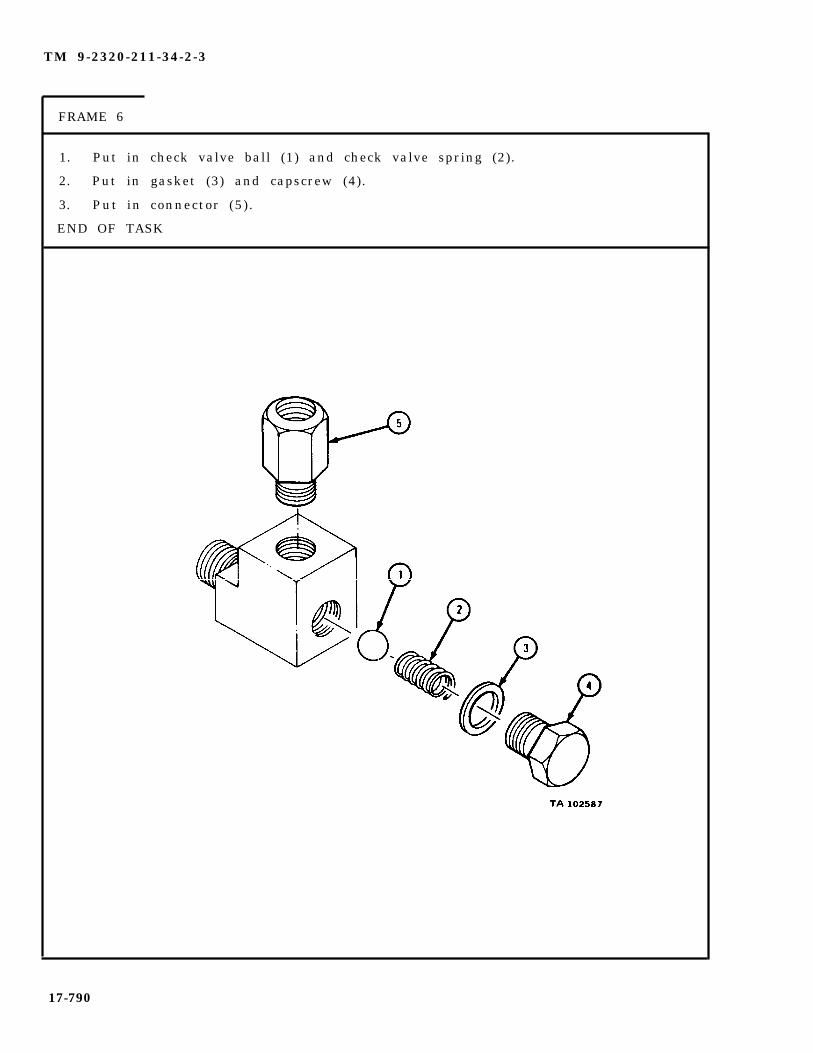
TM 9-2320-211-34-2-3
FRAME 6
1. Put in check valve ball (1) and check valve spring (2).
2. Put in gasket (3) and capscrew (4).
3. Put in connector (5).
END OF TASK
17-790

TM 9-2320-211-34-2-3
h. R e p l a c e m e n t
FRAME 1
1. Put in check valve assembly (1).
2. Put driveshaft lubricating tube (2) in place.
3. Put on coupling nut (3).
GO TO FRAME 2
17-791

TM 9-2320-211-34-2-3
FRAME 2
1.
2.
3.
GO
Put gasket (1) and power takeoff (2) in place.
Put on two lockwashers (3) and nuts (4) and tighten nuts to 53 to 67 pound-fee t .
Put in four flat washers (5) and capscrews (6) and tighten nuts and capscrewsto 53 to 67 pound-feet.
TO FRAME 3
17-792
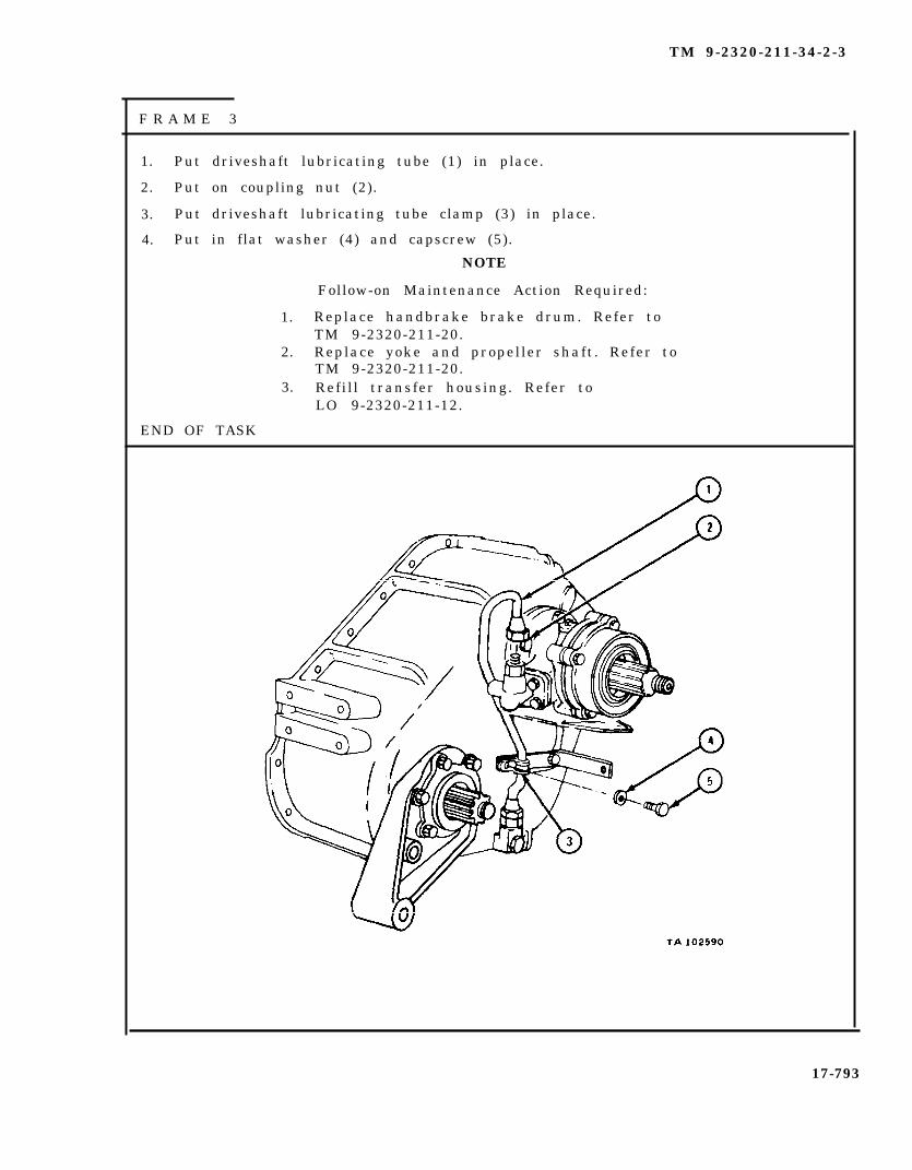
TM 9-2320-211-34-2-3
F R A M E 3
1. Put driveshaft lubricating tube (1) in place.
2. Put on coupling nut (2).
3. Put driveshaft lubricating tube clamp (3) in place.
4. Put in flat washer (4) and capscrew (5).
NOTE
Follow-on Maintenance Action Required:
1. Replace handbrake brake drum. Refer toTM 9-2320-211-20.
2. Replace yoke and propeller shaft. Refer toTM 9-2320-211-20.
3. Refill transfer housing. Refer toLO 9-2320-211-12.
END OF TASK
17-793

TM 9-2320-211-34-2-3
17-57. TRANSMISSION POWER TAKEOFF SEAL REMOVAL AND REPLACEMENT(ALL TRUCKS EXCEPT M51A2).
TOOLS: No special tools required
SUPPLIES: Oil sealBearing cap gasket
PERSONNEL: One
EQUIPMENT CONDITION: Truck parked, engine off , handbrake set.
a. Preliminary Procedures.
(1) Remove power takeoff-to-front winch propeller shaft from power takeoff .Refer to TM 9-2320-211-20.
(2) Remove universal joint yoke. Refer to TM 9-2320-211-20.
(3) Drain oil from power takeoff . Refer to LO 9-2320-211-12.
(4) Remove power takeoff from transmission. Refer to para 17-60.
b. R e m o v a l .
F R A M E 1
1. Takeout four capscrews (1) and starwashers (2).
NOTE
If front bearing cap (3) is stuck to power take-off housing case (4), tap sides of bearing capwith soft-faced hammer.
2. Takeoff front bearing cap (3) and gasket (5). Throw away gasket.
CAUTION
Be careful not to damage front bearing cap (3)when removing oil seal (6).
3. Using punch, drive out oil seal (6). Throw away seal.
END OF TASK
17-794

TM 9-2320-211-34-2-3
Replacement.
CAUTION
Be careful not to damage shaft when putting oilseal (1) into bearing cap (2) .
1. Put oil seal (1) into bearing cap (2).
2. Aline holes in gasket (3) and front bearing cap (2) with holes in housing case( 4 ) .
3. Put in four screws (5) and starwashers (6).
1.
2.
3.
4.
5.
END OF TASK
NOTE
Follow-on Maintenance Action Required:
Install power takeoff on transmission. Referto para 17-60.Replace universal joint yoke. Refer toTM 9-2320-211-20.Install power takeoff-to-front winch propeller shaft onpower takeoff . Refer to TM 9-2320-211-20.Make sure drain plug is tightened. Refer toLO 9-2320-211-12.Replace oil. Refer to LO 9-2320-211-12.
17-795
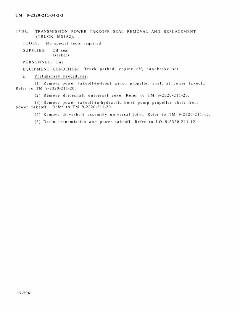
TM 9-2320-211-34-2-3
17-58. TRANSMISSION POWER TAKEOFF SEAL REMOVAL AND REPLACEMENT(TRUCK M51A2).
TOOLS: No special tools required
SUPPLIES: Oil sealGaskets
PERSONNEL: One
EQUIPMENT CONDITION: Truck parked, engine off , handbrake set.
a. Preliminary Procedures.
(1) Remove power takeoff-to-front winch propeller shaft at power takeoff .Refer to TM 9-2320-211-20.
(2) Remove driveshaft universal yoke. Refer to TM 9-2320-211-20.
(3) Remove power takeoff-to-hydraulic hoist pump propeller shaft frompower takeoff . Refer to TM 9-2320-211-20.
(4) Remove driveshaft assembly universal joint. Refer to TM 9-2320-211-12.
(5) Drain transmission and power takeoff . Refer to LO 9-2320-211-12.
17-796

TM 9-2320-211-34-2-3
b . Removal.
FRAME 1
1. Take out four capscrews (1) and starwashers (2).
NOTE
If front bearing cap (3) is stuck to power takeoff housing case(4), tap sides of bearing cap with soft-faced hammer.
2. Take off front bearing cap (3) and gasket (5). Throw away gasket.
CAUTION
Be careful not to damage shaft when taking out oil seal (6).
3. Using punch, drive out oil seal (6). Throw away seal.
GO TO FRAME 2
17-797
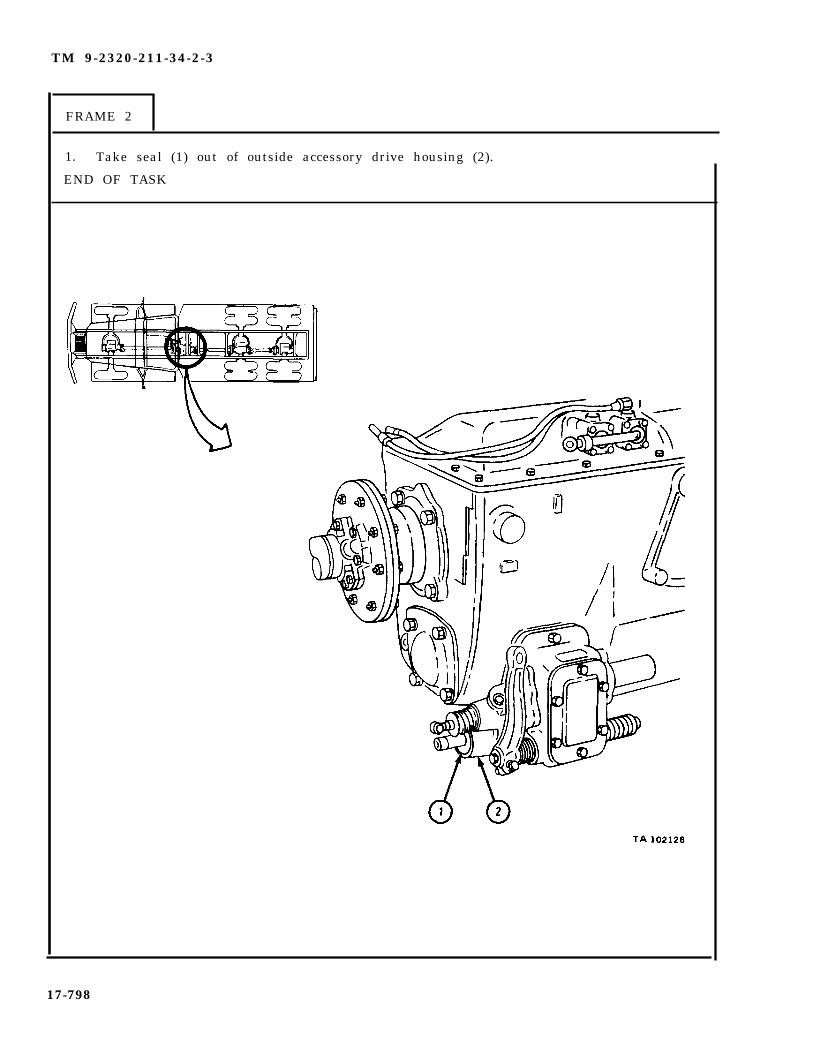
TM 9-2320-211-34-2-3
FRAME 2
1. Take seal (1) out of outside accessory drive housing (2).
END OF TASK
17-798
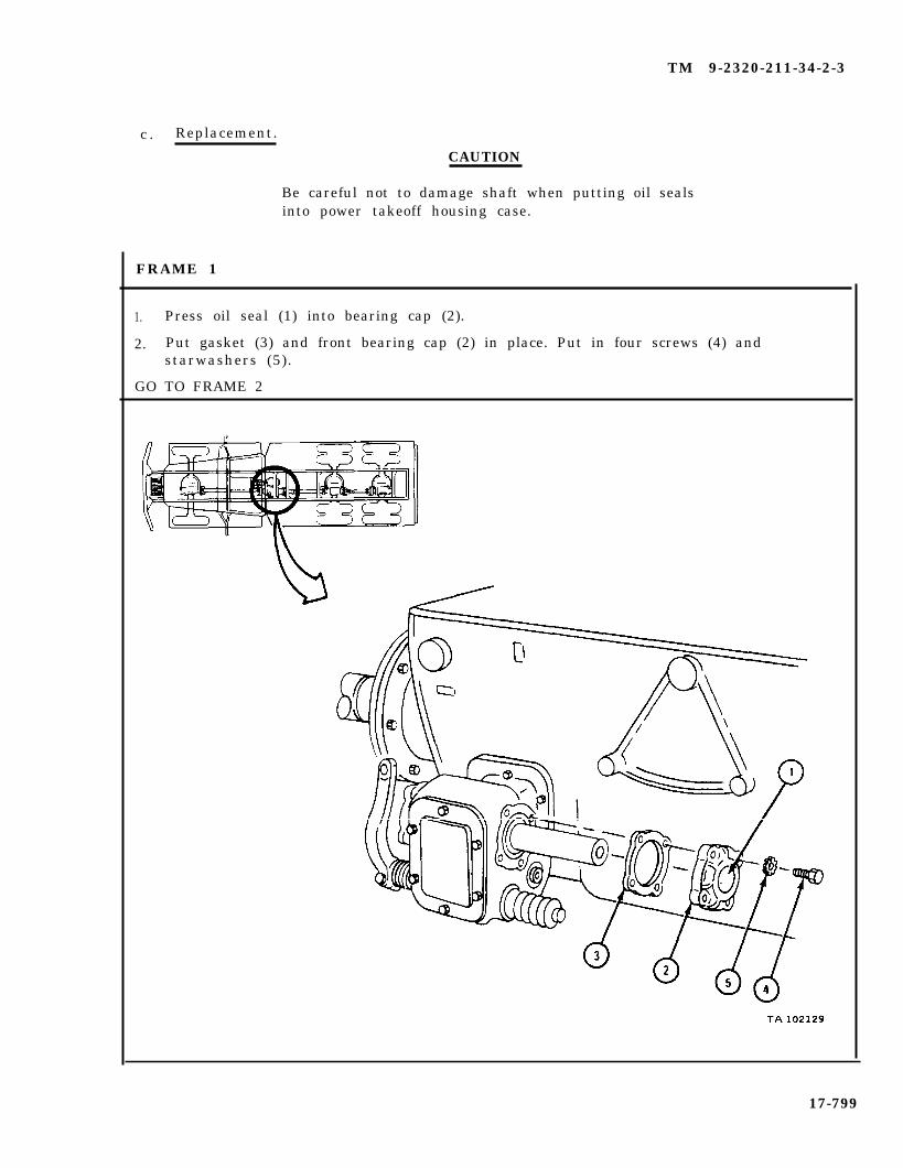
TM 9-2320-211-34-2-3
c . Replacement.
CAUTION
Be careful not to damage shaft when putting oil sealsinto power takeoff housing case.
1. Press oil seal (1) into bearing cap (2).
2. Put gasket (3) and front bearing cap (2) in place. Put in four screws (4) andstarwashers (5).
GO TO FRAME 2
17-799
FRAME 1

TM 9-2320-211-34-2-3
FRAME 2
1. Put seal (1) into accessory drive housing (2).
NOTE
Follow-on Maintenance Action Required:
1. Replace driveshaft assembly universal joint.Refer to TM 9-2320-211-20.
2. Replace power takeoff-to-front winch pro-peller shaft. Refer to TM 9-2320-211-20.
3. Replace driveshaft universal yoke. Referto TM 9-2320-211-20.
4. Replace power takeoff-to-hydraulic hoist pumppropeller shaft. Refer to TM 9-2320-211-20.
END OF TASK
17-800

TM 9-2320-211-34-2-3
17-59. TRANSMISSION POWER TAKEOFF CONTROLS AND LINKAGES REMOVAL,REPAIR, AND REPLACEMENT.
TOOLS: No special tools required
SUPPLIES: Cotter pinSolvent, dry cleaning, type II (SD-2), Fed. Spec P-D-680
PERSONNEL: One
EQUIPMENT CONDITION: Truck parked, engine off , handbrake set.
a . Removal.
FRAME 1
1. Lift up companion seat (1).
2. Take out 12 screws (2) and lockwashers (3) from front tunnel (4).
3. Lift up and slide off front tunnel (4).
4. Take out 8 screws (5) and lockwashers (6) from toeboard (7). Take off toe-b o a r d .
5. Take out six screws (8) and lockwashers (9). Lift up and slide off rear tunnel( 1 0 ) .
GO TO FRAME 2
17-801

TM 9-2320-211-34-2-3
FRAME 2
1 0
2 .
3 .
4 .
5 .
6 .
7 .
GO
CAUTION
Do not pull clevis pin (1) all the way out or spring and poppetball will fall out.
Working under truck, pull out clevis pin (1) from clevis (2) until you feel the detent.
Take out screw and washer (3).
Take off nut (4) and screw (5).
Take lever (6) off transmission power takeoff (7).
Take out and throw away cotter pin (8).
Take out clevis pin (9).
Take off linkage (10). Note number of threads showing on linkage.
TO FRAME 3
17-802
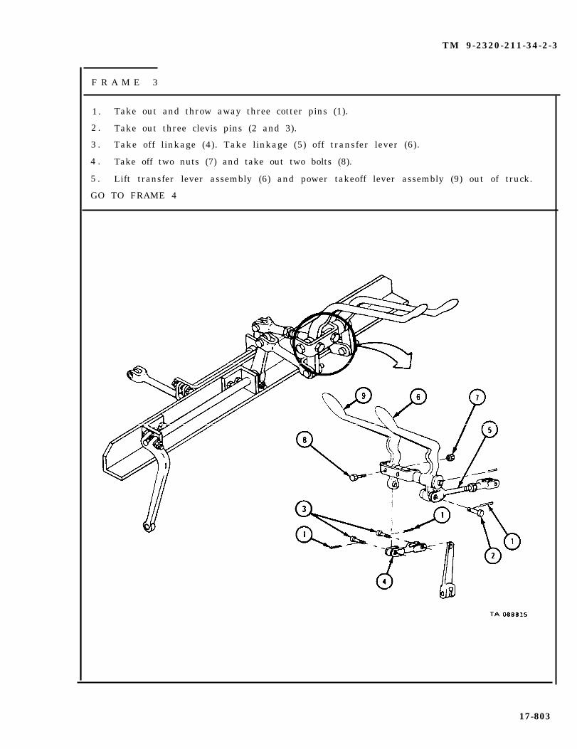
TM 9-2320-211-34-2-3
F R A M E 3
1.
2 .
3 .
4 .
5 .
Take out and throw away three cotter pins (1).
Take out three clevis pins (2 and 3).
Take off linkage (4). Take linkage (5) off transfer lever (6).
Take off two nuts (7) and take out two bolts (8).
Lift transfer lever assembly (6) and power takeoff lever assembly (9) out of truck.
GO TO FRAME 4
17-803
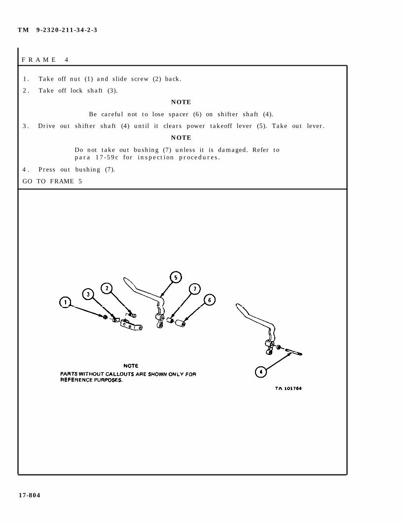
TM 9-2320-211-34-2-3
F R A M E 4
1 . Take off nut (1) and slide screw (2) back.
2 . Take off lock shaft (3).
NOTE
Be careful not to lose spacer (6) on shifter shaft (4).
3 . Drive out shifter shaft (4) until it clears power takeoff lever (5). Take out lever.
NOTE
Do not take out bushing (7) unless it is damaged. Refer topara 17-59c for inspection procedures.
4 . Press out bushing (7).
GO TO FRAME 5
17-804
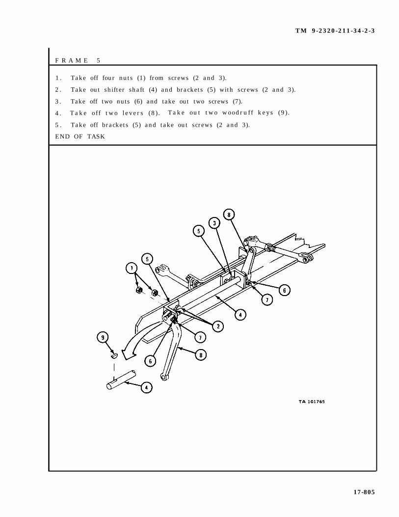
TM 9-2320-211-34-2-3
F R A M E 5
1 . Take off four nuts (1) from screws (2 and 3).
2 . Take out shifter shaft (4) and brackets (5) with screws (2 and 3).
3 . Take off two nuts (6) and take out two screws (7).
4 . Take off two levers (8) . Take out two woodruff keys (9) .
5 . Take off brackets (5) and take out screws (2 and 3).
END OF TASK
17-805
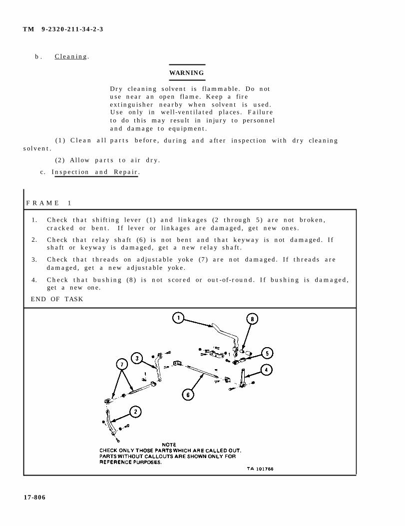
TM 9-2320-211-34-2-3
b . Cleaning.
(1 ) C lean a l lsolvent.
WARNING
Dry cleaning solvent is flammable. Do notuse near an open flame. Keep a fireextinguisher nearby when solvent is used.Use only in well-ventilated places. Failureto do this may result in injury to personneland damage to equipment.
parts before, during and after inspection with dry cleaning
(2) Allow parts to air dry.
c. Inspection and Repair.
F R A M E 1
1. Check that shifting lever (1) and linkages (2 through 5) are not broken,cracked or bent. If lever or linkages are damaged, get new ones.
2. Check that relay shaft (6) is not bent and that keyway is not damaged. Ifshaft or keyway is damaged, get a new relay shaft.
3. Check that threads on adjustable yoke (7) are not damaged. If threads aredamaged, get a new adjustable yoke.
4. Check that bushing (8) is not scored or out-of-round. If bushing is damaged,get a new one.
END OF TASK
17-806

TM 9-2320-211-34-2-3
d . Replacement.
FRAME 1
1.
2.
3.
4.
5.
6.
7.
Put
Put
Put
Put
Put
four screws (1 and 2) in two brackets (3).
shaft (4) through brackets (3) as shown.
two woodruff keys (5) into shaft (4) .
on levers (6 ) . Aline woodruff key (5) in shaft (4) with keyways in levers.
in two screws (7) and put on two nuts (8).
Aline holes in support (9) with screws (1 and 2). Put on brackets (3) withs c r e w s .
Put on four nuts (10).
GO TO FRAME 2
17-807
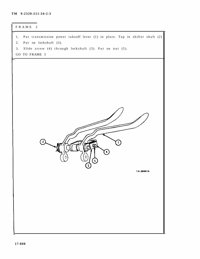
TM 9-2320-211-34-2-3
F R A M E 2
1. Put transmission power takeoff lever (1) in place. Tap in shifter shaft (2)
2. Put on lockshaft (3).
3. Slide screw (4) through lockshaft (3). Put on nut (5).
GO TO FRAME 3
17-808

TM 9-2320-211-34-2-3
F R A M E 3
1 .
2 .
3 .
4 .
GO
Put transfer lever (1), transmission power takeoff lever (2), and bracket (3) in placeon cab floor.
Put in two bolts (4) and put on two nuts (5).
Put linkage (6) in place on transfer lever (1). Put in clevis pin (7) and cotter pin (8).
Put linkage (9) in place. Put in two clevis pins (10) and cotter pins (11).
TO FRAME 4
17-809
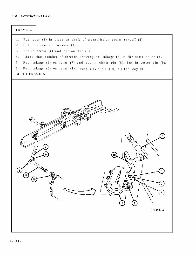
TM 9-2320-211-34-2-3
FRAME 4
1. Put lever (1) in place on shaft of transmission power takeoff (2).
2. Put in screw and washer (3).
3. Put in screw (4) and put on nut (5).
4. Check that number of threads showing on linkage (6) is the same as noted.
5. Put linkage (6) on lever (7) and put in clevis pin (8). Put in cotter pin (9).
6. Put linkage (6) on lever (1). Push clevis pin (10) all the way in.
GO TO FRAME 5
17-810

TM 9-2320-211-34-2-3
FRAME 5
1. Put toeboard (1) in place and aline holes. Put in 11 screws (2) and lock-washers (3 ) .
2. Slide rear tunnel (4) down into place and aline holes.
3. Put in six screws (5) and lockwashers (6).
4. Slide front tunnel (7) down over shift lever (8).
5. Aline holes in front tunnel (7) with holes in cab floor, toeboard (1), and reartunnel (4 ) .
6. Put in 12 screws (9) and lockwashers (10).
7. Put down companion seat (11).
END OF TASK
17-811

TM 9-2320-211-34-2-3
17-60. TRANSMISSION POWER TAKEOFF REMOVAL, REPAIR, AND REPLACEMENT.
TOOLS: No special tools required
SUPPLIES: Solvent, dry cleaning, type II (SD-2), Fed. Spec P-D-680Housing gasketCap gasket (2)Lint-free clothSafety wireCotter pinOil seal (2)Cover gasket
PERSONNEL: One
EQUIPMENT CONDITION: Truck parked, engine off , handbrake set.
a . Preliminary Procedures.
(1 ) Drain transmiss ion . Refer to LO 9-2320-211-12.
(2) On trucks with front winches, remove power takeoff-to-front winchpropeller shaft. Refer to TM 9-2320-211-20.
(3) On trucks with front winches, remove power takeoff control l inkages.Refer to para 17-59.
(4) On truck M51A2, remove power takeoff-to-hydraulic hoist pump pro-peller shaft. Refer to TM 9-2320-211-20.
(5) On truck M51A2, remove hoist control l inkage. Refer to para 17-22.
17-812

TM 9-2320-211-34-2-3
b . R e m o v a l .
FRAME 1
1. Takeout six capscrews (1) and washers (2).
2. Pull off power takeoff assembly (3).
3. Takeoff and throw away gasket (4) .
END OF TASK
17-813
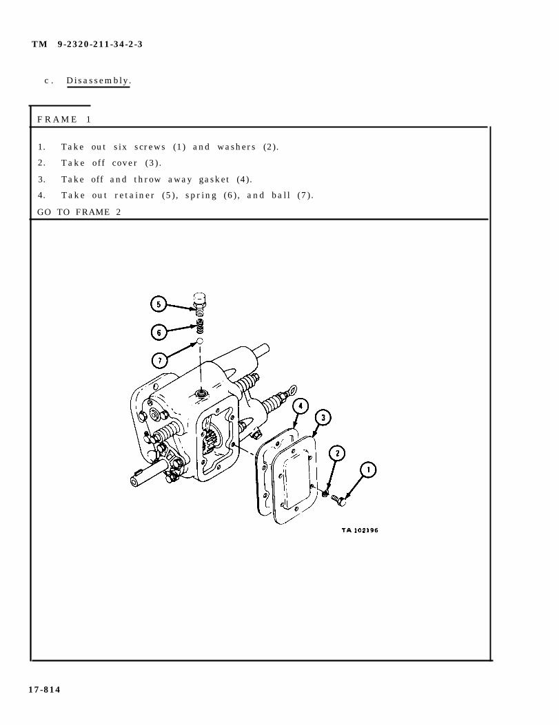
TM 9-2320-211-34-2-3
c . Disassembly.
F R A M E 1
1. Take out six screws (1) and washers (2).
2. Take off cover (3) .
3. Take off and throw away gasket (4).
4. Take out retainer (5), spring (6), and ball (7) .
GO TO FRAME 2
17-814
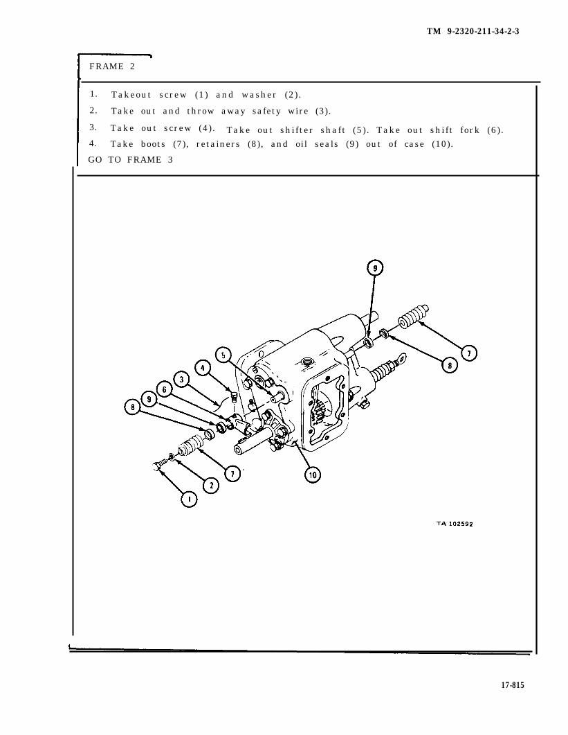
FRAME 2
1. Takeout screw (1) and washer (2) .
2. Take out and throw away safety wire (3).
3. Take out screw (4). Take out shifter shaft (5) . Take out shift fork (6).4. Take boots (7), retainers (8), and oil seals (9) out of case (10).
GO TO FRAME 3
TM 9-2320-211-34-2-3
17-815

TM 9-2320-211-34-2-3
FRAME 3
1. Pull out and throw away cotter pin (1).
2. Tap gear shaft (2) away from pin end (1). Tap until shaft comes out ofcase (3 ) .
3. Take out two thrust washers (4), input gear (5), and two bearings (6).
4. Take out two bearings (6) from gear (5).
IF WORKING ON DOUBLE OUTPUT POWER TAKEOFF, GO TO FRAME 4.IF WORKING ON SINGLE OUTPUT POWER TAKEOFF, GO TO FRAME 7
17-816

TM 9-2320-211-34-2-3
1. Takeout f ive screws (1) and washers (2) .
2. Take off housing (3) and spacer (4) .
3. Take off and throw away gasket (5).
4. Take out retainer (6), spring (7), and ball (8) .
5. Loosen nut (9) .
6. Take out eyebolt (10), nut and washer (9) .
GO TO FRAME 5
17-817
FRAME 4

TM 9-2320-211-34-2-3
FRAME 5
1. Take out and throw away safety wire (1).
2. Take out screw (2).
3. Take out shaft (3). Take off fork (4) out of drive housing (5).
4. Take off boot (6) and retainer (7).
5. Take out and throw away seal (8).
GO TO FRAME 6
17-818

TM 9-2320-211-34-2-3
F R A M E 6
1.
2.
3.
4.
5 .
6.
7.
8 .
GO
T a k e o u t k e y ( 1 ) .
Takeout sea l (2 ) .
Takeout snaprings (3 and 4).
Pull output shaft (5) with bearing (6) out from front of accessory drivehous ing (7 ) .
Take out clutch (8).
Take snapring (9) off shaft (5) .
Press bearing (6) off shaft (5) .
Take snapring (9) out of drive housing (7).
TO FRAME 8
17-819
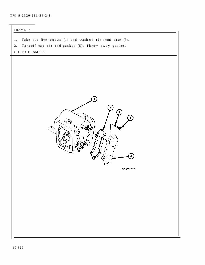
TM 9-2320-211-34-2-3
FRAME 7
1. Take out five screws (1) and washers (2) from case (3).
2. Takeof f cap (4 ) and-gasket (5 ) . Throw away gasket .
GO TO FRAME 8
17-820
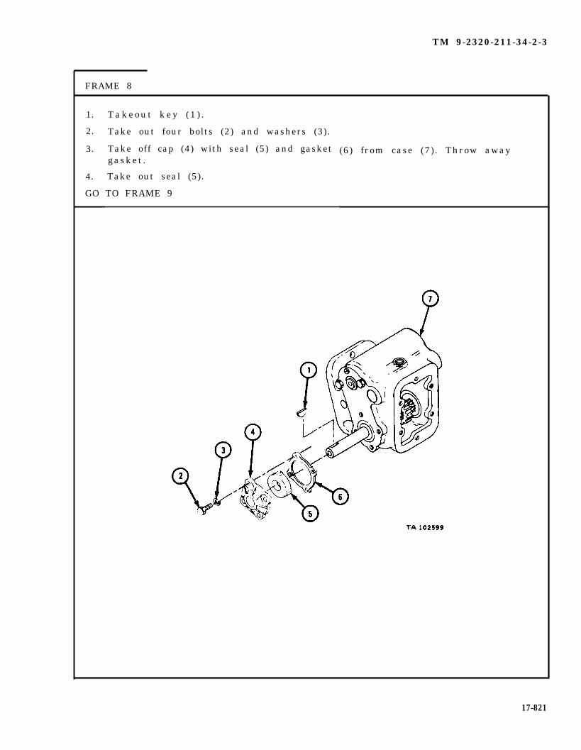
TM 9-2320-211-34-2-3
FRAME 8
1.
2.
3.
4.
GO
T a k e o u t k e y ( 1 ) .
Take out four bolts (2) and washers (3).
Take off cap (4) with seal (5) and gasketgasket .
Take out seal (5).
TO FRAME 9
(6) from case (7). Throw away
17-821

TM 9-2320-211-34-2-3
F R A M E 9
1.
2.
3.
4.
5.
GO
Tap short end of shaft (1) to front of case (2).
Take out bearing (3) and gear (4).
Pull front shaft (1) out through front of case (2).
Take off bearing (5) .
Take off snapring (6). Take off thrust washer (7), and gear (8).
TO FRAME 10
17-822

TM 9-2320-211-34-2-3
FRAME 10
1. Take out cotter pin (1) from clevis pin (2). Take out clevis pin.
2. Take out snapring (3).
3. Tap gearshaft assembly (4) toward closed bearing, forcing bearing (5) out ofcase (6). Take out gear (7) and two thrust washers (8).
GO TO FRAME 11
17-823
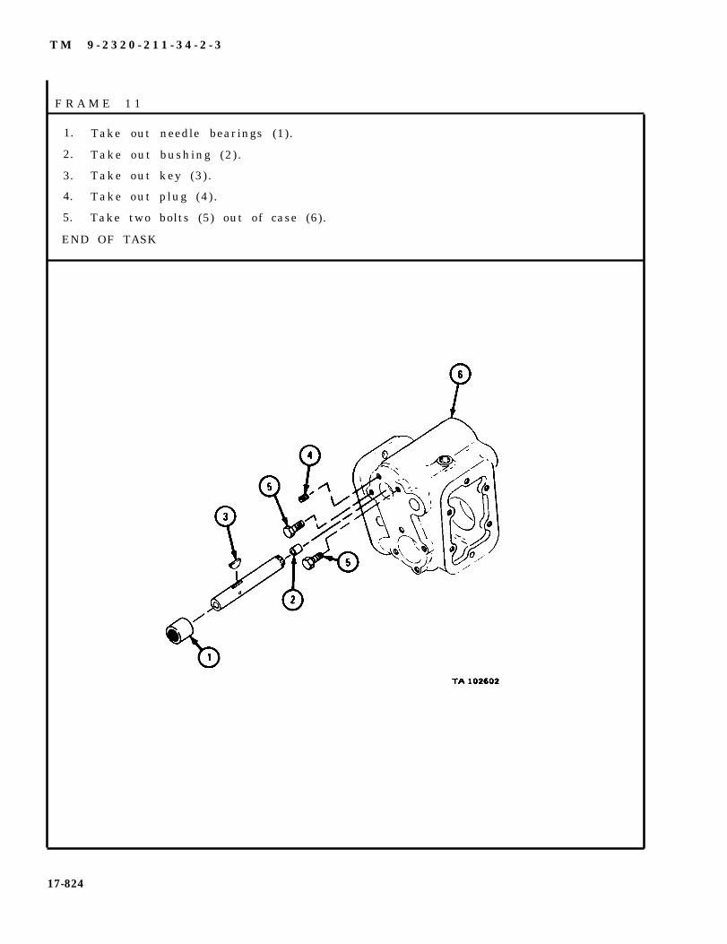
T M 9 - 2 3 2 0 - 2 1 1 - 3 4 - 2 - 3
F R A M E 1 1
1. Take out needle bearings (1).
2. Take out bushing (2).
3. Take out key (3).
4. Take out plug (4).
5. Take two bolts (5) out of case (6).
END OF TASK
17-824

TM 9-2320-211-34-2-3
d . Cleaning.
(1 ) Clean a l l bear ings . Refer to Part 1, para 7-7.
(2) Clean rubber boots with water. Dry well .
WARNING
Dry cleaning solvent is flammable. Do not use nearan open flame. Keep a fire extinguisher nearby whensolvent is used. Use only in well-ventilated places.Failure to do this may result in injury to personneland damage to equipment.
(3) Clean all other parts with solvent. Dry well .
F R A M E 1
1. Check that bearings (1 through 7) are not damaged. Refer to Part 1, para 7-7.
GO TO FRAME 2
17-825
e. Inspection and Repair.

TM 9-2320-211-34-2-3
F R A M E 2
1. Check that shafts (1 through 6) have no scoring, pitting or wear.
2. Check that shafts (1, 4, and 5) do not have twisted splines.
3. Check that gears (7, 8, 9, and 10) do not have chipped, cracked or brokenteeth . Check that bores of gears are not pitted or scored.
GO TO FRAME 3
17-826
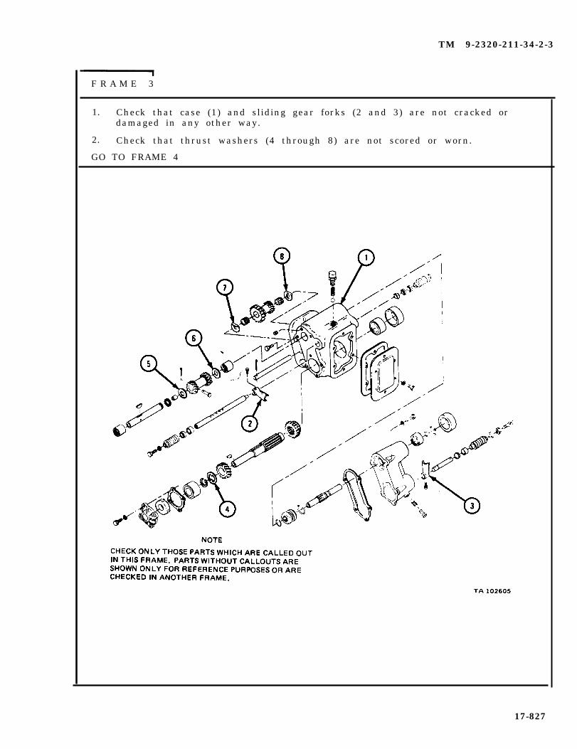
TM 9-2320-211-34-2-3
F R A M E 3
1. Check that case (1) and sliding gear forks (2 and 3) are not cracked ordamaged in any other way.
2. Check that thrust washers (4 through 8) are not scored or worn.
GO TO FRAME 4
17-827

TM 9-2320-211-34-2-3
FRAME 4
1. Check that seals (1 through 6) are not damaged.
2. Take out and throw away all damaged parts and get new ones in their place.
END OF TASK
17-828

TM 9-2320-211-34-2-3
f . Assembly .
F R A M E 1
1. Put key (1) and bushing (2) in place on reverse shaft (3). Put closed endbearing (4) into case (5) .
2. Put reverse shaft (3) through bore of case (5), smooth end first.
3. Put one thrust washer (6) on reverse shaft (3). Push reverse shaft throughreverse gear (7 ) .
4. Put other thrust washer (6) on end of reverse shaft (3). Push reverse shaftinto place.
5. Line up clevis hole in reverse gear (7) with clevis hole on reverse shaft (3).
6 . Put in two bolts (8).
7. Put in plug (9).
GO TO FRAME 2
17-829

TM 9-2320-211-34-2-3
FRAME 2
1. Put in clevis pin (1). Put cotter pin (2) in end of clevis pin and bend openends of cotter pin.
2. Put reverse gear shaft rear needle bearing (3) on reverse shaft (4) . Referto Part 1, para 7-7.
3. Put in woodruff key (5) .
4. Put on snapring (6).
GO TO FRAME 3
17-830

TM 9-2320-211-34-2-3
FRAME 3
1. Put gear (1) on shaft (2), with spiral end of gear toward front of case (3) asshown.
2. Put thrust washer (4) on shaft (2). Put on snapring (5).
3. Put bearing (6) on shaft (2) . Put shaft into case (3) with splined end towardfront of case. Put gear (7) on shaft with groove toward rear of case.
GO TO FRAME 4
17-831

TM 9-2320-211-34-2-3
F R A M E 4
1. Put bearing (1) on shaft (2) . Refer to Part 1, para 7-7.
2. Put gears (3) on shaft (2) .
3. Put oil seal (4) in cap (5).
4. Put gasket (6) and cap (5) in place.
5. Put in four screws (7) and washers (8).
6. Put key (9) into case (10).
GO TO FRAME 5
17-832

TM 9-2320-211-34-2-3
FRAME 5
1. Put two seals (1) in case (2) with lip of seals towards inside of case.
2. Slide shaft (3) into opening at rear of case (2), putting in end oppositestep-cut f i rs t .
3. Put fork (4) in case (2) on gear (5) and push shaft through fork until slotsin shaft can be seen through ball spring retainer opening (6) in case.
GO TO FRAME 6
17-833
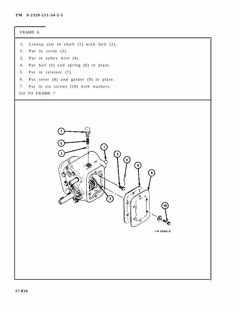
TM 9-2320-211-34-2-3
FRAME 6
1. Lineup slot in shaft (1) with fork (2).
2. Put in screw (3).
3. Put in safety wire (4).
4. Put ball (5) and spring (6) in place.
5. Put in retainer (7).
6. Put cover (8) and gasket (9) in place.
7. Put in six screws (10) with washers.
GO TO FRAME 7
17-834

TM 9-2320-211-34-2-3
FRAME 7
1. Put in six screws (1) and lockwashers (2).
2. Put on retainer (3) and boot (4).
3. Put in screw (5) and washer (6).
4. Put oil seal (7) at rear of shaft (8).
5. Put in retainer (9) and washer (10).
GO TO FRAME 8
17-835

TM 9-2320-211-34-2-3
FRAME 8
1. Put boot (1)
2. Put in screw
3. Put boot (3)
IF WORKING ONIF WORKING ON
in place.
and washer (2) .
in place.
DOUBLE OUTPUT POWER TAKEOFF, GO TO FRAME 9.SINGLE OUTPUT POWER TAKEOFF, GO TO FRAME 14
1 7 - 8 3 6
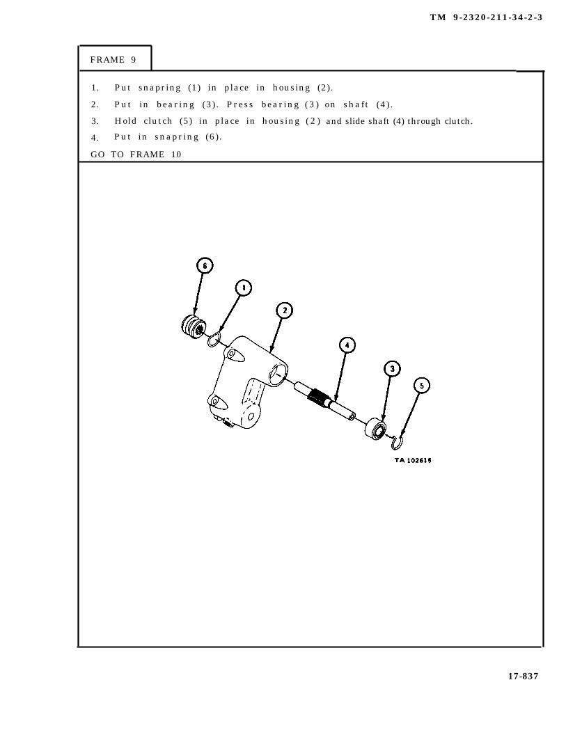
TM 9-2320-211-34-2-3
FRAME 9
1. Put snapring (1) in place in housing (2).
2. Put in bearing (3). Press bearing
3. Hold clutch (5) in place in housing
4. Put in snapring (6).
GO TO FRAME 10
( 3 )
( 2 )
on shaft (4) .
and slide shaft (4) through clutch.
17-837

TM 9-2320-211-34-2-3
FRAME 10
1. Put snapring (1) in place in housing (2).
2. Put in seal (3).
3. Put in key (4).
GO TO FRAME 11
17-838

TM 9-2320-211-34-2-3
FRAME 11
1. Put in seal (1).
2. Put fork (2) in place on shaft (3).
3. Slide smooth end of shaft (4) through fork (2) until slots in shaft line up withball retainer hole in housing (5).
4. Line up slot in shaft (4) with fork (2). Put in screw (6).
5. Put in safety wire (7).
GO TO FRAME 12
17-839
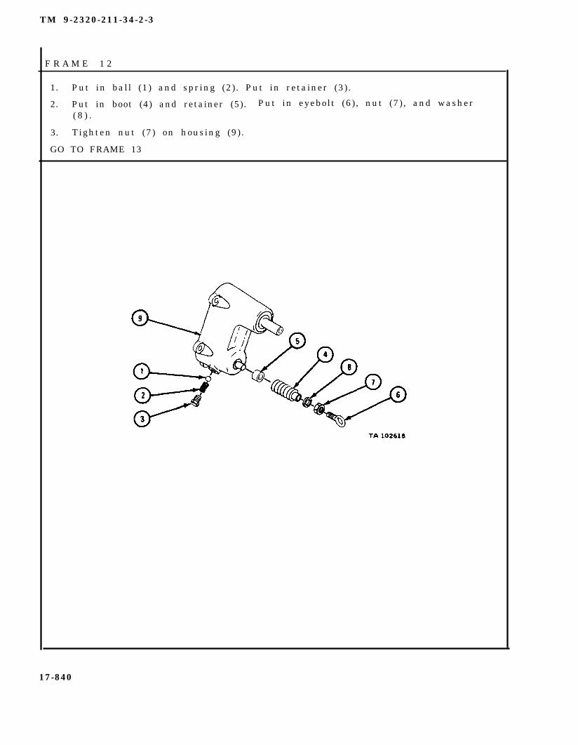
TM 9-2320-211-34-2-3
F R A M E 1 2
1. Put in ball (1) and spring (2). Put in retainer (3).
2. Put in boot (4) and retainer (5). Put in eyebolt (6) , nut (7), and washer( 8 ) .
3. Tighten nut (7) on housing (9).
GO TO FRAME 13
17-840

TM 9-2320-211-34-2-3
FRAME 13
1. Put gasket (1), spacer (2) and rear output housing assembly (3) in place oncase assembly (4).
2. Put in five screws (5) and lockwashers (6).
GO TO FRAME 15
17-841

TM 9-2320-211-34-2-3
FRAME 14
1. Put gasket (1) and rear cover (2) in place on case assembly (3).
2. Put in four screws (4) and lockwashers (5).
GO TO FRAME 15
17-842

TM 9-2320-211-34-2-3
FRAME 15
1. Put in two bearings (1). Refer to Part 1, para 7-7.
2. Press shaft (2) into case (3) . Put thrust washer (4) on shaft.
3. Press shaft through bearings (1) and gear (5). Put on thrust washer (6).
4. Press shaft all the way in.
5. Put in cotter pin (7).
END OF TASK
17-843
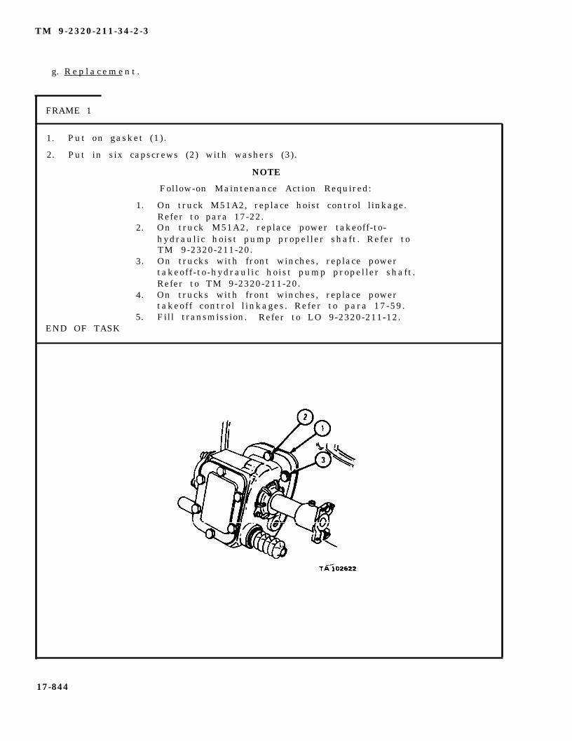
TM 9-2320-211-34-2-3
g. R e p l a c e m e n t .
FRAME 1
1. Put on gasket (1).
2. Put in six capscrews (2) with washers (3).
NOTE
Follow-on Maintenance Action Required:
1. On truck M51A2, replace hoist control linkage.Refer to para 17-22.
2. On truck M51A2, replace power takeoff-to-hydraulic hoist pump propeller shaft. Refer toTM 9-2320-211-20.
3. On trucks with front winches, replace powertakeoff-to-hydraulic hoist pump propeller shaft.Refer to TM 9-2320-211-20.
4. On trucks with front winches, replace powertakeoff control l inkages. Refer to para 17-59.
5. Fill transmission. Refer to LO 9-2320-211-12.END OF TASK
17-844

TM 9-2320-211-34-2-3
17-61. SWIVEL VALVE REMOVAL, REPAIR, AND REPLACEMENT (TRUCK M543A2).
TOOLS: No special tools required
SUPPLIES: Solvent, dry cleaning, type II (SD-2), Fed. Spec P-D-680Cable sealValve body oil sealCollector cap gasketValve cap gasket
PERSONNEL: TWO
EQUIPMENT CONDITION: Truck parked, engine off , handbrake set.
a . Preliminary Procedure. Raise boom to highest point of position cranesupports . Refer to TM 9-2320-211-10.
17-845

TM 9-2320-211-34-2-3
b . Removal.
NOTE
Tag all hydraulic lines so they will be putback in the same place.
FRAME 1
1. Unscrew four nuts (1) and take off four hydraulic l ines (2). Cap lines.
2. Unscrew nut (3) and take off hydraulic line (4). Cap line.
3. Unscrew nut (5) and take off hydraulic line (6). Cap line.
4. Unscrew and take out hydraulic tee (7).
GO TO FRAME 2
17-846
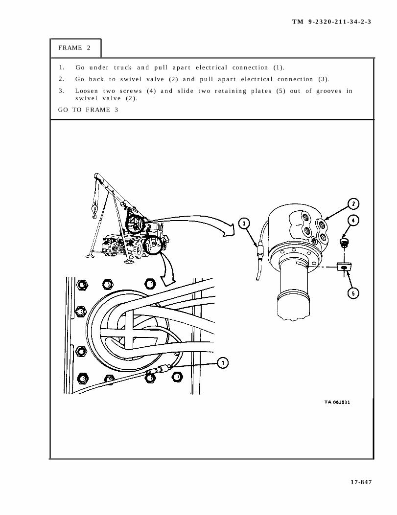
TM 9-2320-211-34-2-3
FRAME 2
1. Go under truck and pull apart electrical connection (1).
2. Go back to swivel valve (2) and pull apart electrical connection (3).
3. Loosen two screws (4) and slide two retaining plates (5) out of grooves inswivel valve (2) .
GO TO FRAME 3
17-847

TM 9-2320-211-34-2-3
F R A M E 3
Soldier A
Soldier B
Soldier A
1. Using short chain and chain hoist, lift out and hold swivelva lve (1 ) .
2. Unscrew four coupling nuts (2) and take off four hydrauliclines (3). Cap lines.
3. Unscrew coupling nut (4) and take off hydraulic line (5).Cap line.
4. Unscrew and take out two screws (6) . Take off two retainingplates (7 ) .
5. Take off two nipples (8) with couplings (9).
6. Using short chain and chain hoist, set swivel valve (1) down onwork bench.
END OF TASK
17-848
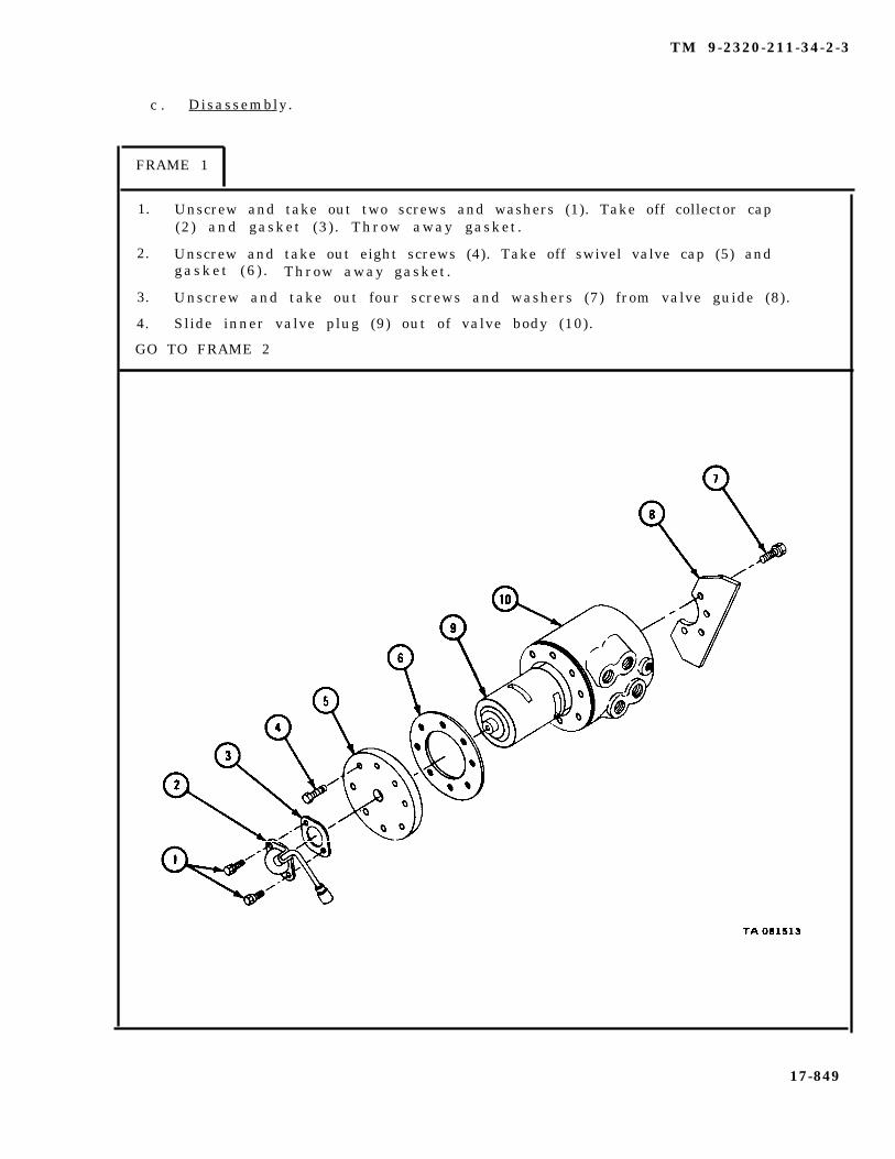
TM 9-2320-211-34-2-3
c . Disassembly.
FRAME 1
1. Unscrew and take out two screws and washers (1). Take off collector cap(2) and gasket (3). Throw away gasket.
2. Unscrew and take out eight screws (4). Take off swivel valve cap (5) andgasket (6 ) . Throw away gasket.
3. Unscrew and take out four screws and washers (7) from valve guide (8).
4. Slide inner valve plug (9) out of valve body (10).
GO TO FRAME 2
17-849

TM 9-2320-211-34-2-3
F R A M E 2
1. Unscrew and take out two screws (1) and washers (2) from inside collectorcap (3 ) .
2. Lift out insulator (4) and unscrew and take off nut (5) and washer (6).
3. Take out screw (7).
4. Take off insulator (4) .
5. Pull electrical lead (8) out of collector cap (3).
GO TO FRAME 3
17-850
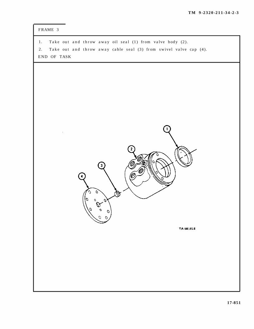
TM 9-2320-211-34-2-3
FRAME 3
1. Take out and throw away oil seal (1) from valve body (2).
2. Take out and throw away cable seal (3) from swivel valve cap (4).
END OF TASK
17-851

TM 9-2320-211-34-2-3
d . Cleaning.
WARNING
Dry cleaning solvent is flammable. Do not usenear an open flame. Keep a fire extinguishernearby when solvent is used. Use only in well-ventilated places. Failure to do this may resultin injury to personnel and damage to equipment.
Using solvent, clean all metal parts.
e . Inspection and Repair.
FRAME 1
1. Check that valve body (1) and inner valve plug (2) are not nicked, scratchedor burred .
2. Using soapstone, take off small nicks, scratches, and burrs as needed fromvalve body (1) and inner valve plug (2) . If valve body of inner valve plugis damaged in any other way, get a new one.
END OF TASK
17-852

TM 9-2320-211-34-2-3
f . Assembly .
F R A M E 1
1. Put cable seal (1) in swivel valve cap (2).
2. Put oil seal (3) in valve body (4).
GO TO FRAME 2
17-853

TM 9-2320-211-34-2-3
F R A M E 2
1. Slide electrical lead (1) into collector cap (2).
2. Put screw (3) through terminal of electrical lead (1) and insulator (4).
3. Screw on and tighten washer (5) and nut (6).
4. Put insulator (4) in place in collector cap (2).
5. Screw in and tighten two washers (7) and screws (8).
GO TO FRAME 3
17-854

TM 9-2320-211-34-2-3
FRAME 3
1. Slide inner valve plug (1) into valve body (2).
2. Put valve guide (3) on body and screw in and tighten four screws andlockwashers (4 ) .
3. Put gasket (5) and swivel valve cap (6) in place on valve body (2).
4. Screw in and tighten eight screws (7).
5. Put gasket (8) and collector cap (9) in place.
6. Screw in and tighten two screws and lockwashers (10).
GO TO FRAME 4
17-855

TM 9-2320-211-34-2-3
FRAME 4
Soldier A
Soldier B
Soldier A
1. Put two retaining plates (1) in place on
2. Screw in but do not tighten two screws
3. Using short chain and chain hoist, holdpivot post (2) .
pivot post (2) .
( 3 ) .
swivel valve (4) over
4. Uncap and hold hydraulic line (5) in place on swivel valve (4) astagged . Tighten coupling nut (6). Take off tag.
5. Screw in and tighten two pipe nipples with couplings (7).
6. Uncap and hold four hydraulic lines (8) in place as tagged.Tighten four coupling nuts (9). Take off tag.
END OF TASK
17-856

TM 9-2320-211-34-2-3
g. R e p l a c e m e n t .
S o l d i e r A 1 . Route electrical lead (1) through opening at bottom of pivot post (2).
S o l d i e r B 2 . Using chain hoist, put swivel valve (3) in place on pivot post (2).
GO TO FRAME 2
17-857
FRAME 1

TM 9-2320-211-34-2-3
FRAME 2
1. Put two retaining plates (1) in grooves in swivel valve (2).
2. Tighten two screws (3).
3. Plug electrical leads (4 and 5) together.
4. Go under truck and plug electrical leads (6 and 7) together.
GO TO FRAME 3
17-858

TM 9-2320-211-34-2-3
FRAME 3
1.
2.
3.
4.
5.
Go back to swivel valve (1).
Screw in and tighten connector (2).
Uncap and hold hydraulic line (3) in place on connectors (2) as tagged.Tighten coupling nut (4). Take off tag.
Uncap and hold hydraulic line (5) in place as tagged. Tighten couplingnut (6 ) . Take off tag.
Uncap and hold four hydraulic lines (7) in place as tagged. Tighten fourcoupl ing nuts (8 ) . Take o f f tags .
NOTE
Follow-on Maintenance Action Required:
1. Fill hydraulic reservoir. Refer to LO 9-2320-211-12.2. Check swivel valve for proper operation. Refer to
TM 9-2320-211-10.
END OF TASK
17-859/(17-860 blank)


TM 9-2320-211-34-2-3
By Order of the Secretaries of the Army and the Air Force:
Official:
J. C. PENNINGTONMajor General, United States Army
The Adjutant General
E. C. MEYERGeneral, United States Army
Chief of Staff
LEW ALLEN, JR., General, USAFChief of Staff
Official:
VAN L. CRAWFORD, JR., Colonel, USAFDirector of Administration
Distribution:
To be distributed in accordance with DA Form 12-38, Direct and General Support Maintenancerequirements for 5-Ton Truck Chassis: 5-Ton, 6x6, M39A2.
*U.S. GOVERNMENT PRINTING OFFICE: 1995 - 395-878/30719


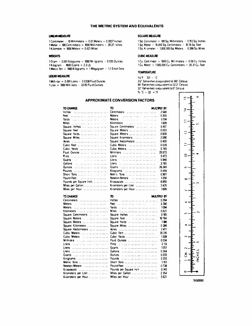

PIN : 048074-000
Related Documents