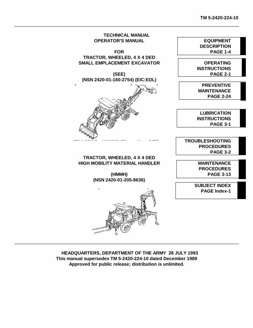
TM 5-2420-224-10 TECHNICAL MANUAL OPERATOR'S MANUAL EQUIPMENT DESCRIPTION FOR PAGE 1-4 TRACTOR, WHEELED, 4 X 4 DED SMALL EMPLACEMENT EXCAVATOR OPERATING INSTRUCTIONS (SEE) PAGE 2-1 (NSN 2420-01-160-2754) (EIC:EDL) PREVENTIVE MAINTENANCE PAGE 2-24 LUBRICATION INSTRUCTIONS PAGE 3-1 TROUBLESHOOTING PROCEDURES PAGE 3-2 TRACTOR, WHEELED, 4 X 4 DED HIGH MOBILITY MATERIAL HANDLER MAINTENANCE PROCEDURES (HMMH) PAGE 3-13 (NSN 2420-01-205-8636) SUBJECT INDEX PAGE Index-1 HEADQUARTERS, DEPARTMENT OF THE ARMY 28 JULY 1993 This manual supersedes TM 5-2420-224-10 dated December 1989 Approved for public release; distribution is unlimited.

Welcome message from author
This document is posted to help you gain knowledge. Please leave a comment to let me know what you think about it! Share it to your friends and learn new things together.
Transcript
TM 5-2420-224-10
TECHNICAL MANUALOPERATOR'S MANUAL EQUIPMENT
DESCRIPTIONFOR PAGE 1-4
TRACTOR, WHEELED, 4 X 4 DEDSMALL EMPLACEMENT EXCAVATOR OPERATING
INSTRUCTIONS(SEE) PAGE 2-1
(NSN 2420-01-160-2754) (EIC:EDL)PREVENTIVE
MAINTENANCEPAGE 2-24
LUBRICATIONINSTRUCTIONS
PAGE 3-1
TROUBLESHOOTINGPROCEDURES
PAGE 3-2TRACTOR, WHEELED, 4 X 4 DED
HIGH MOBILITY MATERIAL HANDLER MAINTENANCEPROCEDURES
(HMMH) PAGE 3-13(NSN 2420-01-205-8636)
SUBJECT INDEXPAGE Index-1
HEADQUARTERS, DEPARTMENT OF THE ARMY 28 JULY 1993This manual supersedes TM 5-2420-224-10 dated December 1989
Approved for public release; distribution is unlimited.

TM 5-2420-224-10
CHANGE HEADQUARTERS DEPARTMENT OF THE ARMY NO. 1 Washington, D.C., 6 February 2002
OPERATOR’S MANUAL
FOR
TRACTOR, WHEELED, 4 X 4 DED SMALL EMPLACEMENT EXCAVATOR (SEE)
(NSN 2420-01-160-2754) (EIC:EDL)
AND
TRACTOR, WHEELED, 4 X 4 DED HIGH MOBILITY MATERIAL HANDLER
(HMMH) (NSN 2420-01-205-8636)
TM 5-2420-224-10, dated 28 July 1993, is updated as follows: 1. File this sheet in front of the manual for reference. 2. New or changed material is indicated by a vertical bar adjacent to the material and/or change designators at
bottom of affected page. 3. New or changed illustrations are indicated by a miniature pointing hand adjacent to the updated area. 4. Remove old pages and insert new pages as indicated below. Remove Pages Insert Pages None A/(B Blank) c and d c and d g/(h Blank) g through i/(j Blank) i and ii i and ii 1-1 through 1-4 1-1 through 1-4 1-9/(1-10 Blank) 1-9/(1-10 Blank) 2-1 and 2-2 2-1 and 2-2 2-27 through 2-58 2-27 through 2-57/(2-58 Blank) 2-71 and 2-72 2-71 and 2-72 2-77 and 2-78 2-77 and 2-78 2-83 through 2-88 2-83 through 2-88 2-91 through 2-94 2-91 through 2-94 None 2-94.1/(2-94.2 Blank) 2-113 and 2-114 2-113 and 2-114 None 2-136.1 through 2-136.4 2-137 through 2-140 2-137 through 2-140 2-145/(2-146 Blank) 2-145 through 2-151/(2-152 Blank) B-3 through B-9/(B-10 Blank) B-3 through B-10 C-1 and C-2 C-1 and C-2 D-1 and D-2 D-1 and D-2 Index-1 and Index-2 Index-1 and Index-2 Index-5 through Index-8 Index-5 through Index-8 DA Form 2028 DA Form 2028

TM 5-2420-224-10
By Order of the Secretary of the Army:
ERIC K. SHINSEKI General, United States Army
Chief of Staff
Official:
JOEL B. HUDSON Administrative Assistant to the
Secretary of the Army 0134109
DISTRIBUTION:
To be distributed in accordance with the Initial Distribution Number (IDN) 380815 requirements for TM 5-2420-224-10.
TM 5-2420-224-10
WARNING
CARBON MONOXIDE POISONING CAN BE DEADLY
CARBON MONOXIDE IS A COLORLESS, ODORLESS, DEADLY POISONOUS GAS, WHICH, WHEN BREATHED,DEPRIVES THE BODY OF OXYGEN AND CAUSES SUFFOCATION. EXPOSURE TO AIR CONTAMINATED WITHCARBON MONOXIDE PRODUCES SYMPTOMS OF HEADACHE, DIZZINESS, LOSS OF MUSCULAR CONTROL,APPARENT DROWSINESS, OR COMA. PERMANENT BRAIN DAMAGE OR DEATH CAN RESULT FROM SEVEREEXPOSURE.
CARBON MONOXIDE OCCURS IN THE EXHAUST FUMES OF FUEL-BURNING HEATERS AND INTERNAL-COMBUSTION ENGINES AND BECOMES DANGEROUSLY CONCENTRATED UNDER CONDITIONS OFINADEQUATE VENTILATION. THE FOLLOWING PRECAUTIONS MUST BE OBSERVED TO ENSURE THE SAFETYOF PERSONNEL WHENEVER THE PERSONNEL HEATER, MAIN, OR AUXILIARY ENGINE OF ANY VEHICLE ISOPERATED FOR MAINTENANCE PURPOSES OR TACTICAL USE:
1. DO NOT operate engine of vehicle in an enclosed area unless it is ADEQUATELY VENTILATED.
2. DO NOT idle engine for long periods without maintaining ADEQUATE VENTILATION in the personnel compartments.
3. DO NOT drive any vehicle with inspection plates, cover plates, or engine compartment doors removed unless necessary for maintenance purposes.
4. BE ALERT at all times during vehicle operation for exhaust odors and exposure symptoms. If either is present, IMMEDIATELY VENTILATE personnel compartments. If symptoms persist, remove affected personnel from vehicle and treat as follows: expose to fresh air; keep warm, DO NOT PERMIT EXERCISE; if necessary, administer artificial respiration (see FM 21-11).
THE BEST DEFENSE AGAINST CARBON MONOXIDE POISONING IS ADEQUATE VENTILATION.
WARNING
COMPRESSED AIR
Compressed air used for cleaning purposes will not exceed 30 psi (207 kPa). Use only with effective chip guarding andpersonal protective equipment (goggles/shield, gloves, etc.). Failure to do so could result in serious injury to personnel.
a

TM 5-2420-224-10
WARNING
Read operating instructions and safety rules carefully in this manual. Important information is emphasized in eachrespective section. Failure to do so could result in personal injury.
WARNING
SEE only: When in transport position, use auxiliary headlights instead of vehicle headlights; during operation vehicleheadlights are blocked by bucket. HMMH only: Use auxiliary headlights when using forklift with a load that blocks vehicleheadlights. Failure to do so could result in personnel injury.
WARNING
Drycleaning solvent (P-D-680) is toxic and flammable. Wear protective goggles and gloves and use only in well-ventilated area. Avoid contact with skin, eyes, and clothes; do not breathe vapors. Do not use near open flame orexcessive heat. If you become dizzy while using drycleaning solvent, get fresh air immediately and get medical aid. Ifcontact with skin or clothing is made, flush with water. If contact with eyes is made, wash your eyes with water and getmedical aid immediately. Failure to follow these instructions could result in severe personal injury.
WARNING
Do not smoke or allow open flames in vicinity while checking or filling batteries. Battery generates hydrogen, a highlyexplosive gas. Failure to heed warning could result in severe personal injury.
WARNING
Ether is toxic and flammable. Use only in well-ventilated areas. Avoid contact with eyes, skin, and clothes. Do not useether or discard ether container near open flame, sparks, or heat. Failure to follow these instructions could result insevere personal injury. If injured, seek medical attention immediately.
WARNING
Never shift transmission into neutral when traveling downhill. Control of vehicle could be lost, resulting in seriouspersonal injury and/or damage to drivetrain when shifting back into gear.
b

TM 5-2420-224-10
c
WARNING
Before operating front loader/backhoe in area where your visibility is reduced (next to a building, etc.), install guard rail and warning signs to keep other personnel away from your machine. Failure to do so could result in personal injury.
WARNING Before operating digging implements, visually check digging site for utilities (gas lines, power lines, water mains, etc.). Failure to do so could result in personal injury.
WARNING Never work on front loader while boom arms are raised or while anyone is near equipment controls. To do so could cause personal injury.
WARNING Never mount or dismount rear of vehicle with HI/LO engine RPM switch in HI position. To do so could cause personal injury.
WARNING Keep clear of digging area to avoid being crushed by swinging boom. Operate backhoe from operator's seat only. Any other method could result in severe injury to operator or bystanders.
WARNING Do not dig around or under stabilizers. Reposition stabilizers to permit digging when necessary to avoid undermining that could cause vehicle to fall into excavation, resulting in serious personal injury.
WARNING Always lower front loader to ground surface when operating backhoe to increase stability. Failure to do so could result in personal injury.
WARNING
When operating backhoe on side of hill, dump earth from excavation on highest side of excavation to prevent vehicle from overturning. Failure to do so could result in serious personal injury.

TM 5-2420-224-10
d Change 1
WARNING
Do not allow personnel to perform maintenance on front loader or backhoe with buckets loaded and raised. Personnel outside vehicle must stand clear of implements whenever operator is near controls of either backhoe or front loader. Failure to do so could result in personal injury.
WARNING Lower load to ground if one of the stabilizers is raised above ground or there is any indication that stability of vehicle is reduced. Failure to do so could result in serious personal injury.
WARNING Never carry load greater than rated capacity 4,000 lb (2216 kg) of vehicle/forklift combination. To do so could cause personal injury.
WARNING Rotate load slowly in elevated positions. Rotating too fast will cause vehicle instability and possible loss of load and injury to personnel.
WARNING Never leave vehicle unattended without lowering load, setting hand brake, and stopping engine. To do so could result in personal injury.
WARNING Do not turn on incline. Always back down ramps or inclines when possible with backhoe in unstowed center position. Driving forward with load, down ramp or down incline, will reduce vehicle stability and cause possible injury to personnel.
WARNING Use ground guide during night operations over cross country or rough terrain when night vision goggles are used. Wearing goggles, operator can miss undulations in terrain, causing damage to equipment or injury to personnel.
WARNING At work site, park vehicle with grade. When cross-grade parking is necessary, restrict load to compensate for increased tipping risk. Failure to do so could result in severe personal injury.
WARNING Perform all stowage procedures using driver's side controls to prevent possible personal injury.
TM 5-2420-224-10
WARNING
Pavement breaker weighs 72 lb. (32.7 kg) and rock drill weighs 48 lb. (21.8 kg). Get assistance if needed to removetools from tool box. Failure to do so could result in personal injury.
WARNING
Do not touch bar or chain on chain saw. To do so could cause personal injury.
WARNING
Make sure hydraulic power source is off before removing or installing tool hoses to hose reel hoses. Failure to do socould result in personal injury from accidental activation of tool.
WARNING
Do not activate hydraulic tool circuit when hydraulic tools are disconnected from hose reel fittings. To do so will causeexcessive oil temperature resulting in damage to pump and possible personal injury.
WARNING
Never inspect or clean hydraulic tool with operating pressure at tool. Accidental engagement of tool can cause personalinjury.
WARNING
Always wear hearing protection, safety glasses or goggles, and steel toe shoes or metal shoe caps when operatinghydraulic tool. Failure to do so could result in personal injury.
WARNING
Do not operate chain saw that is damaged, improperly adjusted, or not completely and securely assembled. Make surechain stops when trigger is released. Failure to do so could result in personal injury.
WARNING
Use extreme caution when cutting small brush and saplings with chain saw. Slender material may catch chain, whippingchain toward operator or pulling operator off balance resulting in personal injury.
e

TM 5-2420-224-10
WARNING
Guard against kickback from chain saw. Kickback is upward motion of bar that occurs when chain at nose of barcontacts object. Kickback can lead to dangerous loss of control of chain saw resulting in personal injury.
WARNING
When operating impact wrench, always use sockets and accessories designed for impact-type applications. Do not usestandard sockets or accessories; they can crack or fracture during operation and cause personal injury.
WARNING
Starter fuel is highly flammable. Do not expose to high temperatures. Store refill bottles in cool place, especially duringsummer months. Failure to do so could result in serious personal injury.
WARNING
When engine is hot, remove reservoir cap slowly to relieve pressure. Wear gloves and protective clothing. Failure to doso could result in personal injury.
WARNING
Never rotate crane too fast with load. Cranes are equipped with overload protection system. In overload condition, nofunction will operate that will result in increase in operating radius. However, same' function may be operated in oppositedirection if it results in decrease in load. Overload protection system is not sensitive to carrier vehicle stability and is notsubstitute for good judgment. Always refer to capacity chart before attempting to lift load. Failure to do so could result inserious personal injury.
WARNING
Maintain clearance of at least 10 ft (3.04 m) between any part of crane, loadline or load, and any electrical line. Death orserious injury will result from contact or inadequate clearance.
WARNING
Never leave operator's station with load suspended in air. To do so could cause serious personnel injury.
f

TM 5-2420-224-10
Change 1 g
WARNING Wheel assembly weighs 170 lb (77.18 kg). Use a hoisting device or at least two personnel to lift wheel assembly to prevent personal injury.
WARNING When jacking up vehicle, make sure parking brake is set and that wheels not being lifted are blocked. Failure to do so could result in serious injury to personnel.
WARNING Never sharpen, replace, or adjust chain with operating pressure on tool. To do so could result in personal injury.
WARNING Chain cutters are sharp. Wear protective gloves when sharpening chain. Failure to do so could result in personal injury.
WARNING When performing parking brake test, make sure there are no obstacles or personnel in front of vehicle to prevent personnel injury.
WARNING Before starting engine and operating vehicle, be thoroughly familiar with information in this manual. Review all WARNINGS and safety precautions. Failure to do so could result in personal injury.
WARNING Clear all personnel from area around vehicle. Do not allow unauthorized personnel on vehicle. Failure to do so could result in personnel injury.
WARNING Hearting protection and protective headgear must be worn at all times when operating the vehicle.

TM 5-2420-224-10
h Change 1
WARNING
Cab seat belts MUST be worn at all times when driving the vehicle.
WARNING Caution MUST be exercised at all times when traveling or operating in off-road conditions.
WARNING NEVER approach slopes from an angle while operation in off-road conditions.
WARNING When operating the backhoe on slopes greater than 10%, NEVER raise the front bucket from the backhoe station or while an operator is in the backhoe operating position.
WARNING Inspect all hydraulic hoses frequently and replace them if wear/chafing is observed.
WARNING Caution MUST be exercised regarding physical contact with hydraulic system components when components are at operating temperature.
WARNING Normal (on/off road) backhoe travel position is stowed, however, the positioning of the backhoe in an unstowed center position can improve stability especially in rough and hilly terrain.
WARNING Do not exceed 15 mph (24 kph) when operating the vehicle off road.
TM 5-2420-224-10
Change 1 i/(j Blank)
WARNING Do not exceed 5 mph (8 kph) over rough or hilly off-road terrain.
WARNING Front loader operations in the construction mode, i.e., filling dump trucks and stockpiling, should be conducted on properly prepared worksites which are free of ruts and potholes, with grades and slopes not greater than 15%.
WARNING Always operate the backhoe to the uphill side of the worksite leveling the vehicle with the stabilizers.
WARNING During road and highway movement, front bucket must be empty and secured with the transport safety locks.
WARNING Do not exceed 17 degrees (30%) side slope. Personal injury and/or equipment damage may occur.


TM 5-2420-224-10
A/(B Blank)
LIST OF EFFECTIVE PAGES Dates of issue for original and changed pages are: Original ............................. 0 ........................................28 July 1993 Change............................. 1 ................................. 6 February 2002 TOTAL NUMBER OF PAGES IN THIS PUBLICATION IS 230, CONSISTING OF THE FOLLOWING:
Page No.
*Change No.
Front Cover 0 A Added 1 B Blank Added 1 a – c 0 d 1 e – f 0 g 1 h – i Added 1 j Blank Added 1 i – ii 1 iii – v 0 vi Blank 0 1-1 0 1-2 – 1-3 1 1-4 – 1-8 0 1-9 1 1-10 Blank 0 2-1 – 2-2 1 2-3 – 2-26 0 2-27 – 2-57 1 2-58 Blank 1 2-59 – 2-62 Deleted 1 2-63 – 2-70 Deleted 0 2-71 – 2-72 1 2-73 – 2-76 0 2-77 – 2-78 1 2-79 – 2-83 0 2-84 – 2-85 1 2-86 0 2-87 1 2-88 – 2-91 0 2-92 1 2-93 0 2-94 1 2-94.1 Added 1 2-94.2 Blank Added 1 2-95 – 2-113 0 2-114 1 2-115 – 2-136 0
Page No.
*ChangeNo.
2-136.1 – 2-136.4 Added 1 2-137 1 2-138 0 2-139 – 2-140 1 2-141 – 2-145 0 2-146 – 2-151 Added 1 2-152 Blank Added 1 3-1 – 3-19 0 3-20 Blank 0 A-1 0 A-2 Blank 0 B-1 – B-2 0 B-3 1 B-4 0 B-5 – B-6 1 B-7 0 B-8 – B-10 1 C-1 0 C-2 1 D-1 0 D-2 1 D-3 0 D-4 Blank 0 Index-1 0 Index-2 1 Index-3 – Index-4 0 Index-5 – Index-8 1 DA Form 2028 (front/back) 1 Metric chart 0 Back cover 0
*Zero in this column indicates an original page


TM 5-2420-224-10*
Change 1 i
TECHNICAL MANUAL HEADQUARTERS No. 5-2420-224-10 DEPARTMENT OF THE ARMY Washington D .C., 28 July 1993
OPERATOR'S MANUAL
FOR
TRACTOR, WHEELED, 4 X 4 DED SMALL EMPLACEMENT EXCAVATOR (SEE)
(NSN 2420-01-160-2754) (EIC:EDL)
AND
TRACTOR, WHEELED, 4 X 4 DED HIGH MOBILITY MATERIAL HANDLER (HMMH)
(NSN 2420-01-205-8636)
REPORTING ERRORS AND RECOMMENDING IMPROVEMENTS
You can help improve this publication. If you find any mistakes or if you know of a way to improve the procedures, please let us know. Submit your DA Form 2028-2 (Recommended Changes to Equipment Technical Publications), through the Internet, on the Army Electronic Product Support (AEPS) website. The Internet address is http://aeps.ria.army.mil. If you need a password, scroll down and click on “ACCESS REQUEST FORM”. The DA Form 2028 is located in the ONLINE FORMS PROCESSING section of the AEPS. Fill out the form and click on SUBMIT. Using this form on the AEPS will enable us to respond quicker to your comments and better manage the DA Form 2028 program. You may also mail, fax or E-mail your letter, DA Form 2028, or DA Form 2028-2 direct to: Commander, U.S. Army Tank-automotive and Armaments Command, ATTN: AMSTA-LC-CIP-WT, Rock Island, IL 61299-7630. The E-mail address is [email protected]. The fax number is DSN 793-0726 or Commercial (309) 782-0726.
Approved for public release; distribution is unlimited. *This manual supersedes TM 5-2420-224-10 dated July 1993.
TABLE OF CONTENTS
Page How To Use This Manual ...................................................................................... iii
CHAPTER 1 INTRODUCTION................................................................................................... 1-1
Section I General Information............................................................................................... 1-1
Section II Equipment Description ......................................................................................... 1-4
Section III Technical Principles of Operation.......................................................................... 1-9
CHAPTER 2 OPERATING INSTRUCTIONS ........................................................................... 2-1
Section I Description and Use of Operator's Controls and Indicators .................................. 2-2
Section II Preventive Maintenance Checks and Services (PMCS) ..................................... 2-24

TM 5-2420-224-10*
ii Change 1
Page
Section III Operation Under Usual Conditions ....................................................................... 2-71
Section IV Operation Under Unusual Conditions .................................................................. 2-138
Section V Quick Fix Combat Identification Program ............................................................. 2-147
CHAPTER 3 MAINTENANCE INSTRUCTIONS ....................................................................... 3-1
Section I Lubrication Instructions ........................................................................................ 3-1
Section II Troubleshooting ................................................................................................ 3-1
Section III Maintenance Procedures ..................................................................................... 3-13
APPENDIX A REFERENCES ..................................................................................................... A-1
APPENDIX B COMPONENTS OF END ITEM AND BASIC ISSUE ITEMS LISTS...................... B-1
APPENDIX C ADDITIONAL AUTHORIZATION LIST.................................................................. C-1
APPENDIX D EXPENDABLE/DURABLE SUPPLIES AND MATERIALS LIST............................ D-1
SUBJECT INDEX ............................................................................................... Index-1

TM 5-2420-224-10
HOW TO USE THIS MANUAL
This single volume manual is divided into chapters, sections, and paragraphs. For a specific chapter, section, orparagraph, refer to the Table of Contents (page i).
The Table of Contents lists the title of each chapter and section and the page number where each can be found. TheTable of Contents also lists the Appendices and Index for this manual.
Chapter 1 introduces and describes the Small Emplacement Excavator (SEE) and the High Mobility Material Handler(HMMH). It also provides General Information, Equipment Description, and Technical Principles of Operation.
Chapter 2 provides Operating Instructions for the SEE/HMMH in the following sections:
Description and Use of Operator's Controls and IndicatorsPreventive Maintenance Checks and Services (PMCS)Operation Under Usual ConditionsOperation Under Unusual Conditions
Chapter 3 provides Maintenance Instructions for the SEE/HMMH in the following sections:
Lubrication InstructionsTroubleshootingMaintenance Procedures
A feature of the Troubleshooting Section is the Symptom Index. This index provides an easy way to find thetroubleshooting procedure needed by looking up the symptom.
Appendices are located at the back of this manual to provide information on equipment, tools, and supplies needed tokeep the SEE/HMMH fully operational.
Before operating any part of the SEE/HMMH, always do the following:
Read and follow all WARNINGS inside the front cover.
Read the Equipment Description and Technical Principles of Operation located in Chapter 1.
Read completely through the Operating Instructions to familiarize yourself with the equipment before using it.
iii
TM 5-2420-224-10
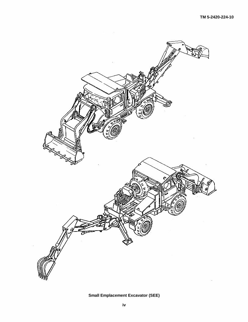
Small Emplacement Excavator (SEE)
iv

TM 5-2420-224-10
High Mobility Material Handler (HMMH)
v/(vi Blank)

TM 5-2420-224-10
CHAPTER 1 INTRODUCTION
Para Page
Section I. General Information .......................................................................... Scope ............................................................................................................. Maintenance Forms and Records ...............................................................… Hand Receipt (-HR) Manual ............................................................................ Reporting Equipment Improvement Recommendations (EIRs) ..................… Warranty Information ...................................................................................... Nomenclature Cross-Reference List .............................................................. List of Abbreviations .......................................................................................
Section II. Equipment Description ...................................................................... Equipment Characteristics, Capabilities, and Features ................................. Location and Description of Major Components.............................................. Equipment Differences..................................................................................... Equipment Data ..............................................................................................
Section III. Technical Principles of Operation ..................................................... Controls and Indicators ...................................................................................
1-1 1-1 1-2 1-2 1-3 1-3 1-3 1-3 1-4 1-4 1-5 1-7 1-7 1-9 1-9
1-1 1-2 1-3 1-4 1-5 1-6 1-7 1-8 1-9 1-101-11 1-12
Section I. GENERAL INFORMATION
WARNING Read operating instructions and safety rules carefully in this manual. Important information is emphasized in each respective section. Failure to do so could result in personal injury.
CAUTION To ensure long service life and reliable operation of engine and drivetrain in a new vehicle, do not operate at full load during first 50 hours [621 miles (1000 km)]. After this period, increase slowly to full speed of tractor. Failure to do so could result in equipment damage.
1-1. SCOPE
a. Type of Manual. This manual is designed to help you operate and maintain both the Small Emplacement Excavator (SEE) and the High Mobility Material Handler (HMMH).
•��� Chapter 1 contains general information, description, and data on the SEE/HMMH.
•��� Chapter 2 depicts and describes the controls and indicators, Preventive Maintenance Checks and Services (PMCS), and operation of the SEE/HMMH.
•��� Chapter 3 contains lubrication instructions, troubleshooting, and maintenance procedures.
•��� Appendices A through D list references, Components of End Item (COEI), Basic Issue Items (BII), Additional Authorization List (AAL), and Expendable Supplies and Materials List.
1-1
TM 5-2420-224-10
1-2 Change 1
b. Model Numbers and Equipment Names .
(1) Model No. FLU419 Tractor, Wheeled, 4 x 4 DED Small Emplacement Excavator (SEE) with attachments, NSN 2420-01-160-2754. (2) Model No. FLU10344 Tractor, Wheeled, 4 x 4 DED High Mobility Material Handler (HMMH) with
attachments, NSN 2420-01-205-8636. c. Purpose of Equipment. (1) The SEE is used for excavating, loading, lifting, and grading on various types of terrain with its
front loader and backhoe. The vehicle is equipped with a chain saw, pavement breaker, and hammer drill. It is capable of rapid deployment for constructing protective positions.
(2) The HMMH is equipped with a forklift and crane for material handling. The vehicle is equipped with
an impact wrench to assist in maintenance of other equipment and is capable of rapid deployment. d. Measurements and Dimensions. The equipment described herein is both metric and standard and requires both metric and standard tools. Instructions are provided in both units of measure. 1-2. MAINTENANCE FORMS AND RECORDS Every mission begins and ends with paperwork. There isn't much of it, but you have to keep it up. The forms and records you will fill out have several uses. They are a permanent record of the services, repairs, and modifications made on your vehicle. They are reports to unit maintenance and your commander; and they are a checklist for you when you want to know what was wrong with the vehicle after its last use, and whether those faults have been repaired. Department of the Army forms and procedures used for equipment maintenance will be those prescribed by DA Pam 738-750, The Army Maintenance Management System (TAMMS). 1-3. HAND RECEIPT (-HR) MANUAL This manual has a companion document with a TM number followed by "-HR". The TM 5-2420-224-10-HR consists of pre-printed hand receipts (DA Form 2062) that list end item related equipment (i.e., COEI, BII, and AAL) you must account for. As an aid to property accountability, additional -HR manuals may be requisitioned from the following source in accordance with procedures in Chapter 12, AR 25-30: The U.S. Army Adjutant General Publications Center ATTN: AGLD-QRA St. Louis, MO 63114

TM 5-2420-224-10
Change 1 1-3
1-4. REPORTING EQUIPMENT IMPROVEMENT RECOMMENDATIONS (EIRs) If your vehicle needs improvement, let us know. Send us an EIR. You, the user, are the only one who can tell us what you don't like about your equipment. Let us know why you don't like the design or performance. Put it on an SF 368 (QDR) and mail it to us at: U.S. Tank-automotive and Armaments Command ATTN: AMSTA-TR-E/PQDR MS 267 6501 E. 11 Mile Road Warren, MI 48397-5000 We’ll send you a reply. 1-5. WARRANTY INFORMATION The vehicles are warranted by Freightliner Corporation in accordance with TB 5-2420-224-14. Warranty starts on the date found in block 23, DA Form 2408-9 in the logbook. Report all defects in material or workmanship to your supervisor, who will take appropriate action through your unit maintenance shop. 1-6. NOMENCLATURE CROSS-REFERENCE LIST Common Name Official Nomenclature
Engine coolant .............................. Antifreeze, ethylene-glycol mixture
Cold start system.......................... Ether quick-start system
Gladhand ...................................... Quick-disconnect coupling
Suspension lockout system .......... Suspension lockout system 1-7. LIST OF ABBREVIATIONS Abbreviation Definition AAL ............................................................................................................................... Additional Authorization List
BII .................................................................................................................................................. Basic Issue Items
C .............................................................................................................................................. Centigrade or Celsius
cm ............................................................................................................................................................. centimeter
COEI ................................................................................................................................... Components of End Item
F ................................................................................................................................................................ Fahrenheit
FOPS ................................................................................................................ Falling Objects Protective Structure
kg ................................................................................................................................................................ kilogram
km .............................................................................................................................................................. kilometer
km/h ............................................................................................................................................ kilometers per hour
kPa ............................................................................................................................................................ kilopascal
kW ................................................................................................................................................................. kilowatt
l ........................................................................................................................................................................... liter
TM 5-2420-224-10
1-4
m ...................................................................................................................................................................... meter
MPT ...................................................................................................................................... Multiple Purpose Tires
N.m .................................................................................................................................................... Newton meter
PMCS ............................................................................................. Preventive Maintenance Checks and Services
PTO ................................................................................................................................................ Power Take-Off
QDR ................................................................................................................................. Quality Deficiency Report
ROPS ........................................................................................................................ Roll-Over Protective Structure
Section II. EQUIPMENT DESCRIPTION
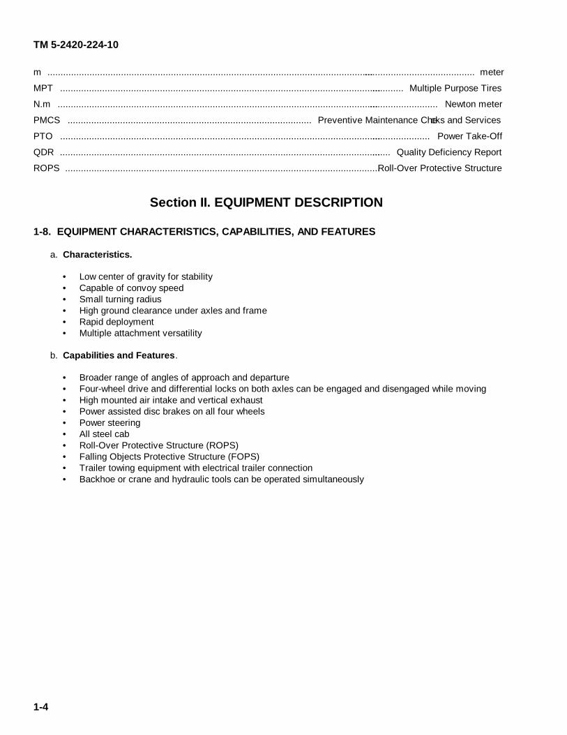
1-8. EQUIPMENT CHARACTERISTICS, CAPABILITIES, AND FEATURES a. Characteristics.
• Low center of gravity for stability • Capable of convoy speed • Small turning radius • High ground clearance under axles and frame • Rapid deployment • Multiple attachment versatility
b. Capabilities and Features.
• Broader range of angles of approach and departure • Four-wheel drive and differential locks on both axles can be engaged and disengaged while moving • High mounted air intake and vertical exhaust • Power assisted disc brakes on all four wheels • Power steering • All steel cab • Roll-Over Protective Structure (ROPS) • Falling Objects Protective Structure (FOPS) • Trailer towing equipment with electrical trailer connection • Backhoe or crane and hydraulic tools can be operated simultaneously

TM 5-2420-224-10
1-9. LOCATION AND DESCRIPTION OF MAJOR COMPONENTS
ROLL-OVER PROTECTIVE STRUCTURE (ROPS) (1). Protects cab if vehicle roll-over occurs.
STOWAGE (2). Hydraulic tools and equipment.
HYDRAULIC SYSTEM (3). Belt driven front system and Power Take-Off (PTO) driven rear system, rated to powerheavy implements and tools.
UTILITY PLATFORM (4). Solid base, access backhoe operations.
BASIC ISSUE ITEMS (BII) TOOLS (5). Stored behind cab in hydraulic accessory box.
VERTICAL EXHAUST (6). Mounted behind cab.
TRAILER TOWING EQUIPMENT (7). Tow pintle with air brake and electrical connections.
FOUR-WHEEL DRIVE (8). Four-wheel drive with differential lock, front and rear axles.
CHASSIS FRAME (9). Flexible, ladder-type, high-strength steel.
FRONT LOADER (10). Used for excavating and filling excavations.
BACKHOE (11). Digs excavations and trenches.
1-5

TM 5-2420-224-10
MULTIPLE PURPOSE TIRES (MPT) (12). Low-pressure high-traction radial ply with mounted spare.
SUSPENSION (13). Coil springs, shock absorbers, and suspension lockout cylinders on the HMMH.
POWER TAKE-OFF (PTO) (14). Supplies power to the rear hydraulic pump.
ENGINE (15). Four-stroke, six-cylinder diesel.
TRANSMISSION (16). Fully synchronized 16 forward, 8 reverse, and pneumatic preselect shift mechanism.
CAB (17). Two-person, all steel construction.
HIGH MOUNTED AIR INTAKE (18). Mounted on left front corner of cab.
FALLING OBJECTS PROTECTIVE STRUCTURE (FOPS) (19). Protects cab from falling objects.
HYDRAULIC TOOL COUPLINGS (20). Quick-disconnect type.
LEFT PLATFORM CONTROL PANEL (21). One-person operation.
FORKLIFT (22). Loads and unloads palletized material.
CRANE (23). Lifts material for maintenance and supply operations.
FIRE EXTINGUISHER (24). Mounted between seats.
1-6

TM 5-2420-224-10
1-10. EQUIPMENT DIFFERENCES
HMMH Tractor SEE Tractor
Suspension lockout system Front loader
Forklift Backhoe
Crane Chain saw
Impact wrench Hammer drill
Pavement breaker
1-11. EQUIPMENT DATA
DIMENSIONSSEE
Overall Length .............................................................................................................. 250 in. (6.35 m)Overall Height ............................................................................................................... 102 in. (2.60 m)Overall Width ................................................................................................................. 96 in. (2.44 m)Track . ............................................................................................................................. 64 in. (1.63 m)Wheel Base.................................................................................................................... 93.7 in. (2.39 m)Turning Circle Diameter.....................................................................................................35.8 ft (11.7 m)
HMMHOverall Length ................................. ............................................................................... 211 in. (5.36 m)Overall Height ................................. .............................................................................. 98.5 in. (2.50 m)Overall Width ............................................ ...................................................................... 94 in. (2.38 m)Track ....................................... ........................................................................................ 64 in. (1.63 m)Wheel Base . ................................................................................................................. 93.7 in. (2.39 m)Turning Circle Diameter ................................................................................................... 35.8 ft (11.7 m)
VEHICLE SPECIFICATIONSAngle of Approach (HMMH) ...........................................................................................................30 degreesAngle of Departure (HMMH) ......................................................................................................... 36 degreesAngle of Approach (SEE) ............................................................................................................. 40 degreesAngle of Departure (SEE) ... ...........................................................................................................32 degreesMaximum Highway Speed (SEE/HMMH) ......................................................................... 50 mph (80 km/h)Cross Country
Traverse Up/Down Inclines ............................................................................................. 60 percentTraverse Side Slopes ............................................................................................................. 30 percent
Fording Depth ........................................................................................................................ 30 in. (0.76 m)Ground Clearance .................................................................................................................. 17 in. (0.43 m)
ENGINEModel ................................................................................................................................................ OM 352Type .......................................................................................................... Four-stroke diesel, direct injectionCylinders ............................................................................................................................ Six, vertical in-lineBore...................................................................................................................................... 3.82 in. (97 mm)Stroke....................................... .......................................................................................... 5.04 in. (128 mm)Displacement .. ......................................................................................................... 346 cu in. (5675 cu cm)Compression Ratio .................................................................................................................................. 17:1Power Output ............................................................................................................... 110 hp (81 kW/1 min)Nominal Engine Speed .................................................................................................................... 2800 rpmMaximum Torque.............................................................................................................. 234 lb.-ft (318 N•m)Low Idle Speed ........................................................................................................................... 700-750 rpm
1-7

TM 5-2420-224-10
Injection Order .............................................................................................................................. 1-5-3-6-2-4Coolant Temperature .................................................................................................................. 203°F (95°C)Minimum Oil Pressure at Idle..................................................................................................... 9 psi (62 kPa)Normal Oil Pressure ................................................................................................ 29-73 psi (199-503 kPa)
WHEELS AND TIRESTire Size ..........................................................................................................................12.5 R20 X LPR 12Rim Size................................................................................................................................ 11.00 - 20
FRONT END LOADER (SEE)Bucket Width ....................................................................................................................... 81.5 in. (2.07 m)Lift Height ................................................................................................................................. 98 in. (2.5 m)Breakout Force ..................................................................................................................6,000 lb. (2722 kg)Lift Capacity.................................................................................................................... ..3,300 lb. (1497 kg)Bucket Capacity...................................................................................................................0.75 cu yd (573 1)
BACKHOE (SEE)Bucket Capacity ...................................................................................................................... 7 cu ft (1981 1)Digging Depth ....................................................................................................................... 14 ft (4.26 m)Digging Radius ................................................................................................................. 17 ft 8 in. (5.39 m)Loading Height .......................................................................................................................... 11 ft (3.35 m)Swing Arc .....................................................................................................................................180 degreesDigging Force ...................................................................................................................10,000 lb. (4536 kg)
FORKLIFT (HMMH)Lift Capacity....................................................................... 4,000 lb. (1818 kg) @ 24 in. (61 cm) load centerLift Height ........................................................................................................................... 106 in. (269 cm)Mast Rotation......................................................................................... 15 degrees CW, 15 degrees CCWMast Tilt .................................................................................................. 8 degrees forward, 10 degrees back
CRANE (HMMH)Lift Capacity ...................................................................................... 6,000 lb. (2727 kg) @ 8 ft (2.4 m) reachLift Height ........................................................................................................................... 26 ft 7 in. (8.1 m)Maximum Reach ............................................................................................................... 19 ft 2 in. (5.8 m)Rotation ......................................................................................................................................350 degrees
HYDRAULIC TOOLSChain Saw (SEE)
Power Output .......................................................................................................................... 8 hp (5.9 kW)Cut .................................................................................................................................... .15 in. (38.1 mm)Weight. ................................................................................................................................................. 3.2 kg)Hammer Drill (SEE)Bore ........................................................................................................................ 2 in. diameter (50.8 mm)Depth ................................................................................................................................... 30 in. (76.2 cm)Weight ..................................................................................................................................... 48 lb. (20.1 kg)
Pavement Breaker (SEE)Output .....................................................................................1,400 blows/min @ 82 lb.-ft (111 N•m.) approxWeight ............................................................................................................................ 72 lb. (31.7 kg)
Impact Wrench (HMMH)Drive ................................................................................................................................. 3/4 in. (19 mm)Torque .......................................................................................................................... 350 lb.-ft (474.6 N•m)Weight ...................................................................................................................................... 14 lb. (6.4 kg)
1-8

TM 5-2420-224-10
Change 1 1-9/(1-10 Blank)
TOWING Maximum Gross Permissible Towing Capacity .........................................................17,000 lb (7711 kg) CAPACITIES Fuel Tank ...................................................................................................................................30 gal (114 l) Engine with Oil Filter Maximum ..............................................................................................................................11.6 qt (11 l) Minimum....................................................................................................................................8.4 qt (8 l) Oil Filter .....................................................................................................................................1.05 qt (1.0 l) Engine Coolant, Total .....................................................................................................................24 qt (23 l) Antifreeze Protection to -13°F (-25°C) .............................................................................. 9.76 qt (9.25 l) Antifreeze Protection to -40°F (-40°C) ................................................................................. 12 qt (11.7 l) Anticorrosion Protection ............................................................................................. 8.5 fluid oz (0.25 l) Transmission ..................................................................................................................................7 qt (6.6 l) Axles Differential Housing .............................................................................................................2.4 qt (2.25 l) Hub Reduction Drive................................................................................................... 8.5 fluid oz (0.25 l) Differential Lock .................................................................................................... 0.034 fluid oz (0.001 l) Clutch Reservoir ........................................................................................................................0.2 qt (0.18 l) Brake Reservoir..........................................................................................................................0.8 qt (0.75 l) Steering Reservoir...........................................................................................................................3 qt (2.8 l) Compressed Air Antifreeze .......................................................................................................0.2 qt (0.19 l) Front Hydraulic Reservoir ...........................................................................................................44 qt (41.6 l) Rear Hydraulic Reservoir ............................................................................................................84 qt (79.4 l) Front Suspension Lockout System ...............................................................................................1 qt (0.94 l) Windshield Washer ......................................................................................................................2.5 qt (2.4 l) Tire Pressure (all tires, all missions) ......................................................................................40 psi (2.7 bar)
Section III. TECHNICAL PRINCIPLES OF OPERATION 1-12. CONTROLS AND INDICATORS Refer to paragraph 2-1 for details on controls and indicators, which includes the principles of operation.


TM 5-2420-224-10
CHAPTER 2 OPERATING INSTRUCTIONS
Para Page
Section I. Description and Use of Operator's Controls and Indicators ......................… 2-2 2-2 2-2 2-3 2-4 2-9 2-9 2-9 2-10 2-11 2-11 2-12 2-12 2-12 2-13 2-13 2-13 2-13 2-14 2-15 2-15 2-16 2-16 2-17 2-18 2-19 2-19 2-20 2-20 2-22 2-23 2-24 2-24 2-24 2-71 2-71 2-73 2-138 2-138 2-140 2-140 2-141 2-141 2-141 2-142 2-146 2-147 2-147 2-147 2-149
Instrument Panel .......................................................................................................…. 2-1 2-1a2-1b2-1c2-2 2-2a2-2b2-2c2-2d2-2e2-2f 2-2g2-2h2-2i 2-2j 2-3 2-3a2-3b2-3c2-3d2-3e2-3f 2-3g2-3h2-3i 2-3j 2-3k2-3l 2-3m2-3n 2-4 2-5 2-6 2-7 2-8 2-9 2-102-112-122-132-142-15 2-162-172-18
Instrument Cluster .................................................................................................... Indicator Lamps and Gages ..................................................................................... Switches ...................................................................................................................
Driver's Controls .......................................................................................................…. Steering Column Controls ........................................................................................ Foot Operated Controls ........................................................................................... Transmission Controls ............................................................................................. Front Loader Control Levers (SEE) ......................................................................... Forklift Control Levers (HMMH) ............................................................................... Throttle Lever ........................................................................................................... Parking Brake Lever ................................................................................................ Four-Wheel Drive and Differential Lock ................................................................... Trailer Supply Valve ................................................................................................. Master Disconnect Switch .......................................................................................
Operator's Controls ....................................................................................................... Heating and Ventilation System ............................................................................... Driver/Operator Dome Light ..................................................................................... Suspension Lockout Cylinder Activation Switch and Light (HMMH) ........................ Doors ...................................................................................................................…. Seats ........................................................................................................................ Hourmeter ................................................................................................................ Engine Oil Dipstick .................................................................................................. Hydraulic Tank Gages ............................................................................................. Compressed Air System Antifreeze Unit ................................................................. Backhoe/Crane Travel Lock Release Lever ............................................................ Left Platform Control Panel ...................................................................................... Backhoe Controls (SEE) .......................................................................................... Crane Controls (HMMH) .......................................................................................... Hydraulic Tools ........................................................................................................
Section II. Preventive Maintenance Checks and Services (PMCS) ............................. General .................................................................................................................... Operator/Crew Preventive Maintenance Checks and Services (PMCS) .................
Section III. Operation Under Usual Conditions ........................................................... Initial Adjustments, Daily Checks, and Self-Checks ................................................ Operating Procedures ..............................................................................................
Section IV. Operation Under Unusual Conditions ........................................................ Operation in Unusual Weather ................................................................................ Operation in Dust or Sand ....................................................................................... Operation in Saltwater Areas ................................................................................... Operation at High Altitudes ...................................................................................... Operation in Snow .................................................................................................... Fording ..................................................................................................................... Reposition Front Blackout Light for Blackout Operations (SEE) ............................. Tractor Trailer Operation.......................................................................................…
Section V. Quick Fix Combat Identification Program ................................................... Combat Identification Panel (CIP) System Description............................................ Combat Identification Panel (CIP) Daily Operational/Pre-Combat Inspections........ Combat Identification Panel (CIP) Mounting Instructions.........................................
Change 1 2-1
TM 5-2420-224-10
2-2 Change 1
Section I. DESCRIPTION AND USE OF OPERATOR'S CONTROLS
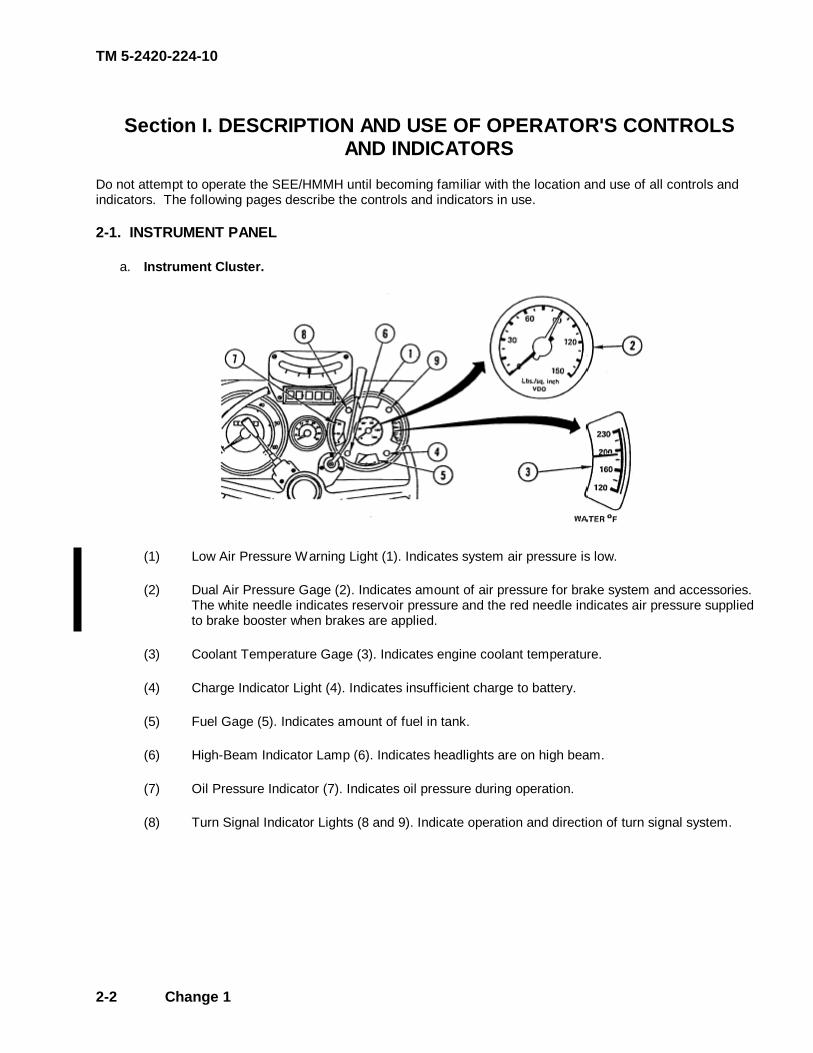
AND INDICATORS Do not attempt to operate the SEE/HMMH until becoming familiar with the location and use of all controls and indicators. The following pages describe the controls and indicators in use. 2-1. INSTRUMENT PANEL a. Instrument Cluster.
(1) Low Air Pressure Warning Light (1). Indicates system air pressure is low. (2) Dual Air Pressure Gage (2). Indicates amount of air pressure for brake system and accessories.
The white needle indicates reservoir pressure and the red needle indicates air pressure supplied to brake booster when brakes are applied.
(3) Coolant Temperature Gage (3). Indicates engine coolant temperature. (4) Charge Indicator Light (4). Indicates insufficient charge to battery. (5) Fuel Gage (5). Indicates amount of fuel in tank. (6) High-Beam Indicator Lamp (6). Indicates headlights are on high beam. (7) Oil Pressure Indicator (7). Indicates oil pressure during operation. (8) Turn Signal Indicator Lights (8 and 9). Indicate operation and direction of turn signal system.

TM 5-2420-224-10
b. Indicator Lamps and Gages.
(1) Power Take-Off (PTO) (1). Lights when PTO is engaged.
(2) Differential Lock Indicator Lamp (2). Lights when differentials are locked.
(3) Brake Indicator Lamp (3). Lights when brake fluid in either of the two reservoirs is low and/or parking brake is applied and/or front brake pads are worn.
(4) Air Cleaner Indicator Lamp (4). Lights when air flow from air cleaner becomes restricted and requires service.
(5) Intermediate Speeds Indicator Lamp (5). Lights when intermediate speed valve is in low range position.
(6) Speedometer (6). Indicates vehicle speed in miles per hour with a rotary counter for miles driven.
(7) Tachometer (7). Indicates engine speed in revolutions per minute.
(8) Voltmeter (8). Indicates charging of batteries and whether or not charging system is operating at the correct voltage.
(9) Inclinometer (9). Indicates limits for operating on a 30 percent slope/incline.
2-3
TM 5-2420-224-10
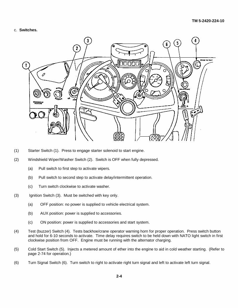
c. Switches.
(1) Starter Switch (1). Press to engage starter solenoid to start engine.
(2) Windshield Wiper/Washer Switch (2). Switch is OFF when fully depressed.
(a) Pull switch to first step to activate wipers.
(b) Pull switch to second step to activate delay/intermittent operation.
(c) Turn switch clockwise to activate washer.
(3) Ignition Switch (3). Must be switched with key only.
(a) OFF position: no power is supplied to vehicle electrical system.
(b) AUX position: power is supplied to accessories.
(c) ON position: power is supplied to accessories and start system.
(4) Test (buzzer) Switch (4). Tests backhoe/crane operator warning horn for proper operation. Press switch button and hold for 6-10 seconds to activate. Time delay requires switch to be held down with NATO light switch in first clockwise position from OFF. Engine must be running with the alternator charging.
(5) Cold Start Switch (5). Injects a metered amount of ether into the engine to aid in cold weather starting. (Refer topage 2-74 for operation.)
(6) Turn Signal Switch (6). Turn switch to right to activate right turn signal and left to activate left turn signal.
2-4

TM 5-2420-224-10
(7) Vehicular Light Switch (7). Five-position switch. Mechanical lock lever must be held in UNLOCK position (up) and tractor master disconnect switch must be ON before moving the vehicular light switch lever to any position.
(a) BO DRIVE position. Blackout taillights and blackout drive light lit. Blackout stop light will light when brakes are applied.
(b) BO MARKER position. Blackout tail lamps lit. Stop lamp will light when brakes are applied.
(c) OFF position. All lights off. Auxiliary switches disabled.
(d) STOP LIGHT position. Service brake lights will light when brake is applied.
(e) SER DRIVE position. Service taillight lit. Brake lights will light when brakes are applied. Front headlights lit. Front and rear service lights will light when front and rear service light switches are activated.
2-5
TM 5-2420-224-10
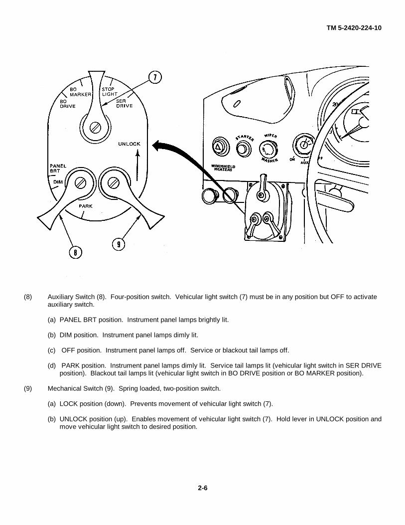
(8) Auxiliary Switch (8). Four-position switch. Vehicular light switch (7) must be in any position but OFF to activate auxiliary switch.
(a) PANEL BRT position. Instrument panel lamps brightly lit.
(b) DIM position. Instrument panel lamps dimly lit.
(c) OFF position. Instrument panel lamps off. Service or blackout tail lamps off.
(d) PARK position. Instrument panel lamps dimly lit. Service tail lamps lit (vehicular light switch in SER DRIVEposition). Blackout tail lamps lit (vehicular light switch in BO DRIVE position or BO MARKER position).
(9) Mechanical Switch (9). Spring loaded, two-position switch.
(a) LOCK position (down). Prevents movement of vehicular light switch (7).
(b) UNLOCK position (up). Enables movement of vehicular light switch (7). Hold lever in UNLOCK position andmove vehicular light switch to desired position.
2-6
TM 5-2420-224-10
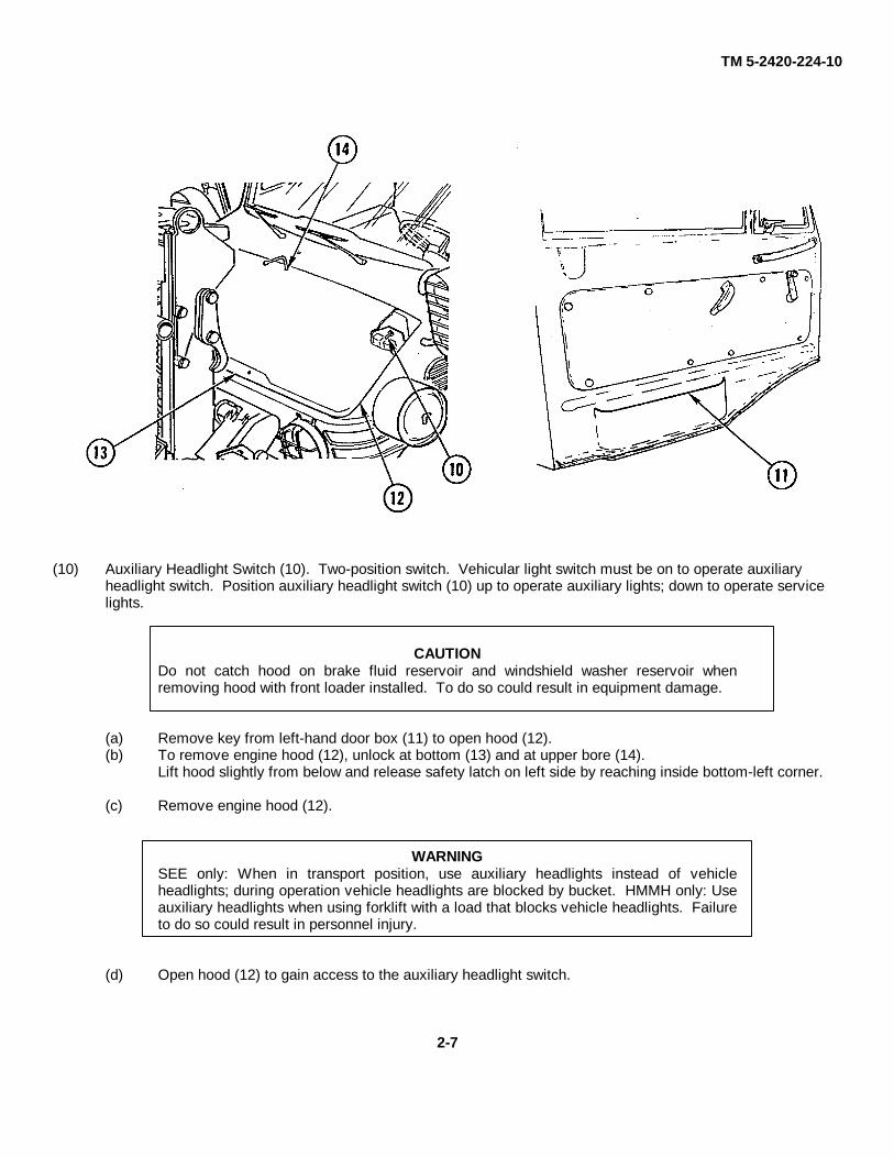
(10) Auxiliary Headlight Switch (10). Two-position switch. Vehicular light switch must be on to operate auxiliary headlight switch. Position auxiliary headlight switch (10) up to operate auxiliary lights; down to operate service lights.
CAUTIONDo not catch hood on brake fluid reservoir and windshield washer reservoir whenremoving hood with front loader installed. To do so could result in equipment damage.
(a) Remove key from left-hand door box (11) to open hood (12).(b) To remove engine hood (12), unlock at bottom (13) and at upper bore (14).
Lift hood slightly from below and release safety latch on left side by reaching inside bottom-left corner.
(c) Remove engine hood (12).
WARNINGSEE only: When in transport position, use auxiliary headlights instead of vehicleheadlights; during operation vehicle headlights are blocked by bucket. HMMH only: Useauxiliary headlights when using forklift with a load that blocks vehicle headlights. Failureto do so could result in personnel injury.
(d) Open hood (12) to gain access to the auxiliary headlight switch.
2-7
TM 5-2420-224-10
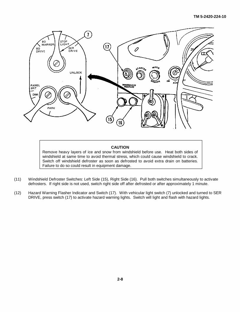
CAUTIONRemove heavy layers of ice and snow from windshield before use. Heat both sides ofwindshield at same time to avoid thermal stress, which could cause windshield to crack.Switch off windshield defroster as soon as defrosted to avoid extra drain on batteries.Failure to do so could result in equipment damage.
(11) Windshield Defroster Switches: Left Side (15), Right Side (16). Pull both switches simultaneously to activate defrosters. If right side is not used, switch right side off after defrosted or after approximately 1 minute.
(12) Hazard Warning Flasher Indicator and Switch (17). With vehicular light switch (7) unlocked and turned to SER DRIVE, press switch (17) to activate hazard warning lights. Switch will light and flash with hazard lights.
2-8

TM 5-2420-224-10
2-2. DRIVER'S CONTROLS
a. Steering Column Controls.
(1) Steering Wheel (1). Turn steering wheel clockwise to turn vehicle right and counterclockwise to turn vehicle left.
(2) Horn and Low Beam/High Beam Switch (2). Located on left side of steering wheel. Press end of switch in toward steering column to activate horn. Press lever toward instrument panel for high-beam headlights and pull back for low-beam headlights.
(3) Trailer Brake Valve Lever (3). Move lever clockwise as required to activate the trailer brake valve. Use when traveling downhill if using only vehicle engine speed for braking. The brake serves as an anti-jackknifedevice by releasing a regulated amount of air pressure for trailer brakes.
b. Foot Operated Controls.
(1) Accelerator Pedal (4). Used to increase and decrease engine speed with right foot.
(2) Brake Pedal (5). Used to slow and stop vehicle with right foot.
(3) Clutch Pedal (6). Used to engage and disengage the clutch with left foot. The clutch pedal must be pressed down all the way to activate starting circuit, intermediate speed control, and suspension lockout system on the HMMH.
2-9

TM 5-2420-224-10
c. Transmission Controls.
(1) Main Shift Lever (1). Shifts all speeds no matter what gear range or intermediate speeds are preselected. Clutch pedal must be fully depressed to engage.
(2) Intermediate Speed Control (2). Intermediate speeds are main transmission reduction speeds and can be engaged and disengaged while driving either forward or reverse. Versatility of the speed control in these ranges provides varied gear reductions on demand and, therefore, controls the speed of the vehicle. Clutch pedal must be fully depressed to engage.
(3) Group Shift Lever (3). The group shift selector has three shifting functions: Gear Range I-low group; Gear RangeII-high group; and R-reverse. Clutch pedal must be fully depressed to engage.
(4) Power Take-Off (PTO) Lever (4). Pull back to engage and push forward to disengage. Clutch pedal must be fully depressed to engage PTO. Engine should be at idle for smooth engagement. Indicator light on instrument panel is lit when PTO is engaged.
2-10

TM 5-2420-224-10
d. Front Loader Control Levers (SEE).
(1) Bucket Control Lever (1). Push down to curl bucket down; pull back to curl bucket up.
(2) Boom Control Lever (2). Push down to lower boom; push down past detent to activate float position; pull back to raise boom.
e. Forklift Control Levers (HMMH).
(1) Mast Control Lever (1). Push down to lower carriage; pull back to raise carriage.
(2) Tilt Control Lever (2). Push down to tilt mast forward; pull back to tilt mast back. Press button and push down on lever to rotate carriage clockwise. Press button and pull back on lever to rotate carriage counterclockwise.
2-11
TM 5-2420-224-10
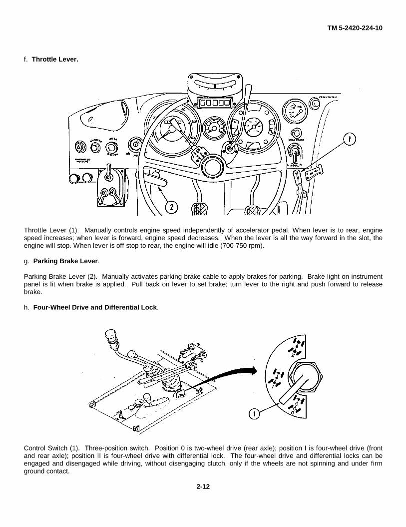
f. Throttle Lever.
Throttle Lever (1). Manually controls engine speed independently of accelerator pedal. When lever is to rear, enginespeed increases; when lever is forward, engine speed decreases. When the lever is all the way forward in the slot, theengine will stop. When lever is off stop to rear, the engine will idle (700-750 rpm).
g. Parking Brake Lever.
Parking Brake Lever (2). Manually activates parking brake cable to apply brakes for parking. Brake light on instrumentpanel is lit when brake is applied. Pull back on lever to set brake; turn lever to the right and push forward to releasebrake.
h. Four-Wheel Drive and Differential Lock.
Control Switch (1). Three-position switch. Position 0 is two-wheel drive (rear axle); position I is four-wheel drive (frontand rear axle); position II is four-wheel drive with differential lock. The four-wheel drive and differential locks can beengaged and disengaged while driving, without disengaging clutch, only if the wheels are not spinning and under firmground contact.
2-12

TM 5-2420-224-10
i. Trailer Supply Valve.
Trailer Supply Valve. Supplies constant air pressure to brake valve for trailer or towed vehicle. Do not use as a parkingdevice. Push down on knob (1) for a few seconds to supply air to trailer or towed vehicle and monitor air pressure beforemoving vehicle.
j. Master Disconnect Switch.
Master Disconnect Switch. Uses key (2) to supply electrical power to vehicle. Key must be turned ON to start vehicle.
2-3. OPERATOR'S CONTROLS
a. Heating and Ventilation System.
(1) Heating. Heated coolant is controlled with knob (1). Heated air is controlled with the two-position rocker blower switch (2).
(a) Position rocker blower switch (2) in left position for low, in center for off, and in right position for high.
2-13

TM 5-2420-224-10
(b) Front and lateral shutters (3 and 4) control heated air flow in cab.
(c) For faster windshield defrosting, close shutters (3 and 4) until adequate visibility is obtained.
(2) Ventilation. Fresh air flow is controlled by the two-position rocker blower switch (2) and vent (5). Knob (1) must be closed.
(3) Rotary Vent Valve (6). Valve on passenger's side may be opened for fresh air supply independent of heating system.
(4) Roof Vent Flap (7). Push flap up to open [opening is limited due to Falling Objects Protective Structure (FOPS)].
b. Driver/Operator Dome Light.
Driver/Operator Dome Light (1). Located above the center rear view mirror and operated by switch (2).
2-14
TM 5-2420-224-10
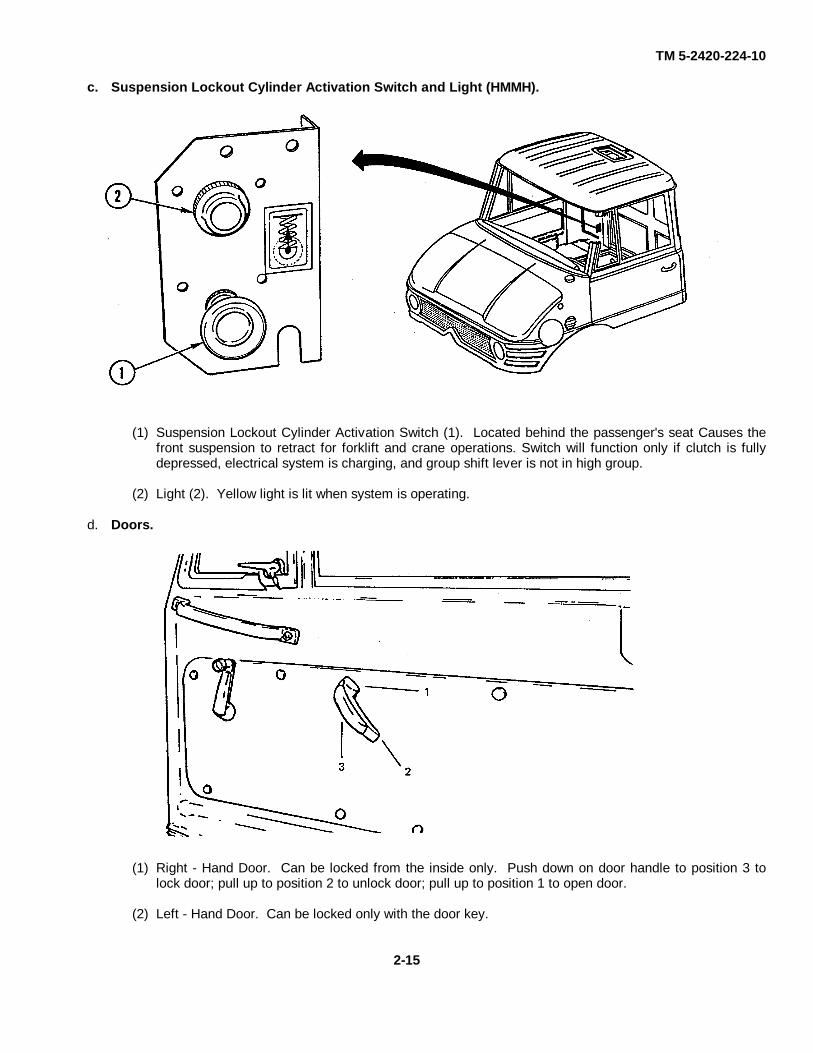
c. Suspension Lockout Cylinder Activation Switch and Light (HMMH).
(1) Suspension Lockout Cylinder Activation Switch (1). Located behind the passenger's seat Causes thefront suspension to retract for forklift and crane operations. Switch will function only if clutch is fullydepressed, electrical system is charging, and group shift lever is not in high group.
(2) Light (2). Yellow light is lit when system is operating.
d. Doors.
(1) Right - Hand Door. Can be locked from the inside only. Push down on door handle to position 3 tolock door; pull up to position 2 to unlock door; pull up to position 1 to open door.
(2) Left - Hand Door. Can be locked only with the door key.
2-15
TM 5-2420-224-10
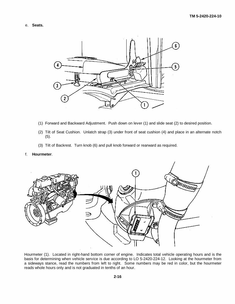
e. Seats.
(1) Forward and Backward Adjustment. Push down on lever (1) and slide seat (2) to desired position.
(2) Tilt of Seat Cushion. Unlatch strap (3) under front of seat cushion (4) and place in an alternate notch(5).
(3) Tilt of Backrest. Turn knob (6) and pull knob forward or rearward as required.
f. Hourmeter.
Hourmeter (1). Located in right-hand bottom corner of engine. Indicates total vehicle operating hours and is thebasis for determining when vehicle service is due according to LO 5-2420-224-12. Looking at the hourmeter froma sideways stance, read the numbers from left to right. Some numbers may be red in color, but the hourmeterreads whole hours only and is not graduated in tenths of an hour.
2-16

TM 5-2420-224-10
g. Engine Oil Dipstick.
(1) Make sure vehicle is on level ground.
(2 Disconnect five fasteners (1) and remove inside engine cover (2) through passenger side of vehicle.
(3) Before starting engine, check oil level. Then start (page 2-75) and stop (page 2-84) engine. Waitseveral minutes before rechecking oil level.
(4) With dipstick (3) wiped clean, recheck oil level. Oil level should be within operating range on dipstick.
(5 Install inside engine cover (2) and connect five fasteners (1).
2-17
TM 5-2420-224-10
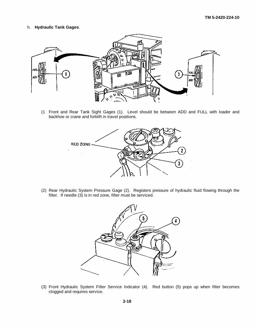
h. Hydraulic Tank Gages.
(1 Front and Rear Tank Sight Gages (1). Level should be between ADD and FULL with loader andbackhoe or crane and forklift in travel positions.
(2) Rear Hydraulic System Pressure Gage (2). Registers pressure of hydraulic fluid flowing through thefilter. If needle (3) is in red zone, filter must be serviced.
(3) Front Hydraulic System Filter Service Indicator (4). Red button (5) pops up when filter becomesclogged and requires service.
2-18

TM 5-2420-224-10
i. Compressed Air System Antifreeze Unit.
(1) Compressed Air System Antifreeze Unit (1). Located on right rear frame rail in front of tire. Should beused when outside temperatures drop below 410F (50C). Service by using ethyl alcohol, methanolalcohol, or denatured alcohol in reservoir (2).
NOTE• Vehicles are equipped with either a KNORR or WABCO antifreeze
unit.
• On both units the number 1 indicates open position and number 0 indicates closed position.
(2) Control Knob (3). Open (winter) and closed (summer) positions are found by turning control knob toposition 1 or 0.
j. Backhoe/Crane Travel Lock Release Lever.
Backhoe/Crane Travel Lock Release Lever (1). Pull cable to release travel lock for backhoe/crane. Pull lever (1)outward and hold until sure that latch has adequate clearance of bail, then release and unstop the backhoe/crane intoupright/work position.
2-19
TM 5-2420-224-10
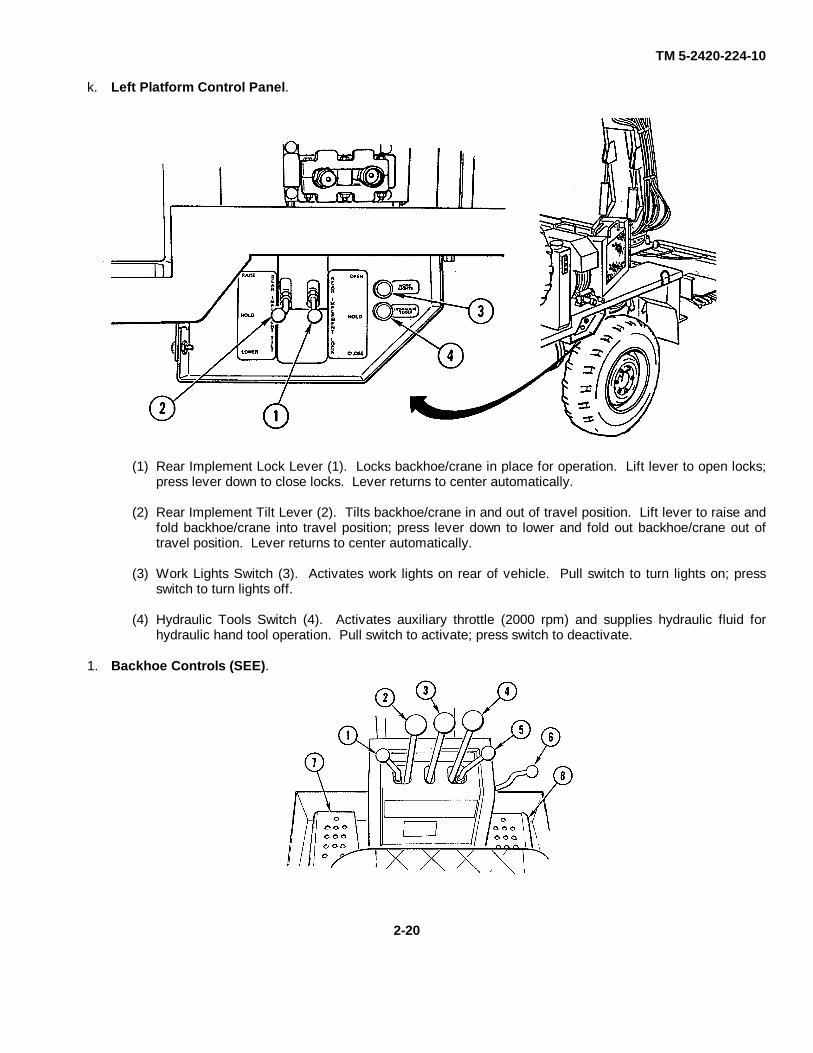
k. Left Platform Control Panel.
(1) Rear Implement Lock Lever (1). Locks backhoe/crane in place for operation. Lift lever to open locks;press lever down to close locks. Lever returns to center automatically.
(2) Rear Implement Tilt Lever (2). Tilts backhoe/crane in and out of travel position. Lift lever to raise andfold backhoe/crane into travel position; press lever down to lower and fold out backhoe/crane out oftravel position. Lever returns to center automatically.
(3) Work Lights Switch (3). Activates work lights on rear of vehicle. Pull switch to turn lights on; pressswitch to turn lights off.
(4) Hydraulic Tools Switch (4). Activates auxiliary throttle (2000 rpm) and supplies hydraulic fluid forhydraulic hand tool operation. Pull switch to activate; press switch to deactivate.
1. Backhoe Controls (SEE).
2-20
TM 5-2420-224-10
(1) Left Stabilizer Control Lever (1). Raises and lowers left stabilizer. Push lever to lower left stabilizer;pull lever to raise left stabilizer.
(2) Bucket Control Lever (2). Controls the pivot of the backhoe bucket. Pull lever to curl bucket inwardfor loading; push lever to curl bucket outward for dumping.
(3) Dipper Control Lever (3). Controls the pivot of the backhoe dipper. Pull lever to move dipper inward;push lever to move dipper outward.
(4) Boom Control Lever (4). Controls the pivot of the backhoe boom and places boom in travel lockposition. Pull lever to raise boom; push lever to lower boom.
(5) Right Stabilizer Control Lever (5). Raises and lowers right stabilizer. Push lever to lower rightstabilizer; pull lever to raise right stabilizer.
(6) Boom Lock Latch Lever (6). Disengages backhoe boom catch to place backhoe in operating position.With pin centered in catch, move lever right to lift catch above pin. Move boom forward until catchclears pin and release lever, allowing catch to be freed from pin.
(7) Left Swing Control Pedal (7). Controls left swing of boom. Press down on pedal to move boom to theleft; release pedal to stop movement of boom.
(8) Right Swing Control Pedal (8). Controls right swing of boom. Press down on pedal to move boom tothe right; release pedal to stop movement of boom.
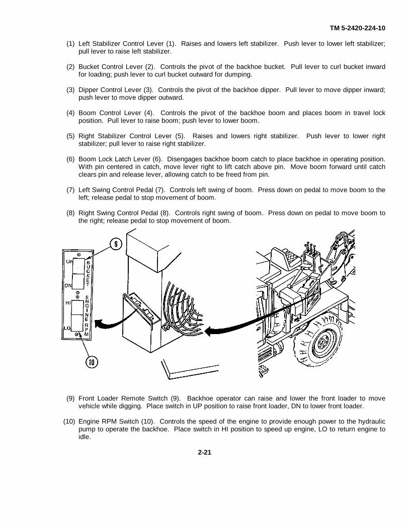
(9) Front Loader Remote Switch (9). Backhoe operator can raise and lower the front loader to movevehicle while digging. Place switch in UP position to raise front loader, DN to lower front loader.
(10) Engine RPM Switch (10). Controls the speed of the engine to provide enough power to the hydraulicpump to operate the backhoe. Place switch in HI position to speed up engine, LO to return engine toidle.
2-21
TM 5-2420-224-10
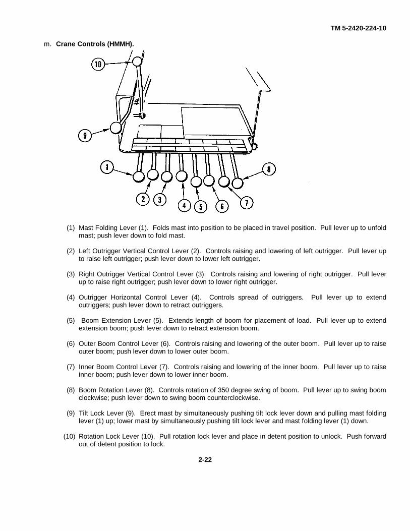
m. Crane Controls (HMMH).
(1) Mast Folding Lever (1). Folds mast into position to be placed in travel position. Pull lever up to unfoldmast; push lever down to fold mast.
(2) Left Outrigger Vertical Control Lever (2). Controls raising and lowering of left outrigger. Pull lever upto raise left outrigger; push lever down to lower left outrigger.
(3) Right Outrigger Vertical Control Lever (3). Controls raising and lowering of right outrigger. Pull leverup to raise right outrigger; push lever down to lower right outrigger.
(4) Outrigger Horizontal Control Lever (4). Controls spread of outriggers. Pull lever up to extendoutriggers; push lever down to retract outriggers.
(5) Boom Extension Lever (5). Extends length of boom for placement of load. Pull lever up to extendextension boom; push lever down to retract extension boom.
(6) Outer Boom Control Lever (6). Controls raising and lowering of the outer boom. Pull lever up to raiseouter boom; push lever down to lower outer boom.
(7) Inner Boom Control Lever (7). Controls raising and lowering of the inner boom. Pull lever up to raiseinner boom; push lever down to lower inner boom.
(8) Boom Rotation Lever (8). Controls rotation of 350 degree swing of boom. Pull lever up to swing boomclockwise; push lever down to swing boom counterclockwise.
(9) Tilt Lock Lever (9). Erect mast by simultaneously pushing tilt lock lever down and pulling mast foldinglever (1) up; lower mast by simultaneously pushing tilt lock lever and mast folding lever (1) down.
(10) Rotation Lock Lever (10). Pull rotation lock lever and place in detent position to unlock. Push forwardout of detent position to lock.
2-22

TM 5-2420-224-10
n. Hydraulic Tools.
(1) Chain Saw (SEE) (1). For debranching, pruning, and removal of trees and wood products. The 15-inch bar allows cutting of wood up to 30 inches in diameter. Squeezing trigger (2) controls speed ofchain.
(2) Pavement Breaker (SEE) (3). For breaking and chipping concrete, rock, pavement, and hard ground.The breaker uses moil point or spade attachments for breaking and chipping. Squeezing trigger (4)activates pavement breaker.
(3) Hammer Drill (SEE) (5). For drilling holes 3/4, 1, or 2 inches in diameter in rock, concrete, or asphalt.Switch (6) controls direction that bit operates. Squeezing trigger (7) activates and controls speed ofrock drill.
(4) Impact Wrench (HMMH) (8). For removing and installing hardware from containers and otherequipment. Lever (9) controls direction and trigger (10) controls speed of impact wrench.
2-23
TM 5-2420-224-10
Section II. PREVENTIVE MAINTENANCE CHECKS AND SERVICES(PMCS)
2-4. GENERAL
Your Preventive Maintenance Checks and Services (Table 2-1) lists the inspection and care of your equipment requiredto keep it in good operating condition. Every mission begins and ends with the paperwork. There isn't much of it, but youhave to keep it up. The forms and records you fill out have several uses. They are a permanent record of the services,repairs, and modifications made on your vehicle. They are also a checklist for you when you want to know what waswrong with the vehicle after its last use and whether those faults have been repaired. For the information you need onforms and records, see DA Pam 738-750.
2-5. OPERATOR/CREW PREVENTIVE MAINTENANCE CHECKS AND SERVICES (PMCS)
a. Do your before (B) PMCS just before you operate the vehicle.
b. Do your during (D) PMCS while the equipment and/or its component systems are in operation.
c. Do your after (A) PMCS right after operating the vehicle.
d. Do your weekly (W) PMCS once a week.
e. Do your monthly (M) PMCS once a month.
f. If something does not work, troubleshoot it with the instructions in this manual or notify your supervisor.
g. Always do your PMCS in the same order so it gets to be a habit. Once you've had some practice, you'll spotanything wrong in a hurry.
h. When you do your PMCS, take along a rag or two.
i. While performing PMCS, observe WARNINGS and CAUTIONS that could endanger your safety or result indamage to the equipment.
j. Your Preventive Maintenance Checks and Services (Table 2-1) is made up of four columns. It is important tofollow each column in order of the item being inspected/serviced.
(1) Column 1 indicates the item number of the inspection to be performed.
(2) Column 2 indicates at which interval the inspection is to be performed.
(3) Column 3 indicates the item to be inspected. It will tell you what to inspect/service and the requiredprocedures to complete the inspection.
(4) Column 4 indicates the readiness of the equipment based on the inspection/service. If there is an entry in thiscolumn, the problem must be solved before the vehicle can be used.
k. If anything looks wrong and you can't fix it, write it on your DA Form 2404. The Item No. column on the PMCStable is the source for item numbers used on the TM Number Column on DA Form 2404. If you find something seriouslywrong, report it to unit maintenance RIGHT NOW.
2-24

TM 5-2420-224-10
WARNINGDry-cleaning solvent (P-D-680) is toxic and flammable. Wear protective gogglesand gloves and use only in well-ventilated area. Avoid contact with skin, eyes,and clothes; do not breathe vapors. Do not use near open flame or excessiveheat. If you become dizzy while using dry-cleaning solvent, get fresh airimmediately and get medical aid. If contact with skin or clothing is made, flushwith water. If contact with eyes is made, wash your eyes with water and getmedical aid immediately. Failure to follow these instructions could result insevere personal injury.
(1) Keep it clean: Dirt, grease, oil, and debris only get in the way and may cover up a serious problem. Clean asyou work and as needed. Use dry-cleaning solvent (P-D-680) to clean metal surfaces. Use soap and waterwhen you clean rubber or plastic material.
(2) Bolts, nuts, and screws: Check that they are not loose,missing, bent, or broken. You cannot try them with a tool,of course, but look for chipped paint, bare metal, or rustaround bolt heads. Tighten any that you find loose.
(3) Welds: Look for loose or chipped paint, rust, or gapswhere parts are welded together. If you find a bad weld,report it to unit maintenance.
(4) Electrical wires and connectors: Look for cracked orbroken insulation, bare wires, and loose or brokenconnectors. Tighten loose connections and make surewires are in good condition.
(5) Hoses and fluid lines: Look for wear, damage, and leaks.Make sure clamps and fittings are tight. Wet spots showleaks. A stain around a fitting or connector can mean aleak. If a leak comes from a loose fitting or connector,tighten it. If something is broken or worn out, eithercorrect it or report it to unit maintenance.
(6) Data plates and decals: Check that they are not missingand are legible.
(7) Damage is defined as: Any condition that affects safety orwould render the vehicle unserviceable for missionrequirements.
1. It is necessary for you to know how fluid leaks affect the status of your equipment. The following are definitionsof the types/classes of leakage you need to know to be able to determine the status of your equipment. Learn and befamiliar with them. When in doubt, notify your supervisor.
2-25
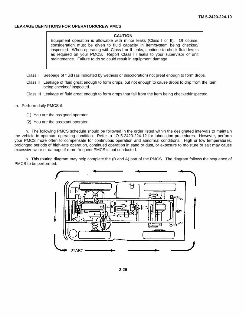
TM 5-2420-224-10
LEAKAGE DEFINITIONS FOR OPERATOR/CREW PMCS
CAUTIONEquipment operation is allowable with minor leaks (Class I or II). Of course,consideration must be given to fluid capacity in item/system being checked/inspected. When operating with Class I or II leaks, continue to check fluid levelsas required on your PMCS. Report Class III leaks to your supervisor or unitmaintenance. Failure to do so could result in equipment damage.
Class I Seepage of fluid (as indicated by wetness or discoloration) not great enough to form drops.
Class II Leakage of fluid great enough to form drops, but not enough to cause drops to drip from the item being checked/ inspected.
Class III Leakage of fluid great enough to form drops that fall from the item being checked/inspected.
m. Perform daily PMCS if:
(1) You are the assigned operator.
(2) You are the assistant operator.
n. The following PMCS schedule should be followed in the order listed within the designated intervals to maintainthe vehicle in optimum operating condition. Refer to LO 5-2420-224-12 for lubrication procedures. However, performyour PMCS more often to compensate for continuous operation and abnormal conditions. High or low temperatures,prolonged periods of high-rate operation, continued operation in sand or dust, or exposure to moisture or salt may causeexcessive wear or damage if more frequent PMCS is not conducted.
o. This routing diagram may help complete the (B and A) part of the PMCS. The diagram follows the sequence ofPMCS to be performed.
2-26
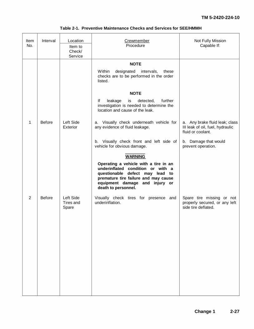
TM 5-2420-224-10
Change 1 2-27
Table 2-1. Preventive Maintenance Checks and Services for SEE/HMMH
Location ItemNo.
Interval Item to Check/
Crewmember Procedure
Not Fully Mission Capable If:
Service NOTE
Within designated intervals, these checks are to be performed in the order listed.
NOTE
If leakage is detected, further investigation is needed to determine the location and cause of the leak.
1 Before Left Side Exterior
a. Visually check underneath vehicle for any evidence of fluid leakage.
a. Any brake fluid leak; class III leak of oil, fuel, hydraulic fluid or coolant.
b. Visually check front and left side of vehicle for obvious damage.
b. Damage that would prevent operation.
WARNING
Operating a vehicle with a tire in an underinflated condition or with a questionable defect may lead to premature tire failure and may cause equipment damage and injury or death to personnel.
2 Before Left Side Tires and Spare
Visually check tires for presence and underinflation.
Spare tire missing or not properly secured, or any left side tire deflated.
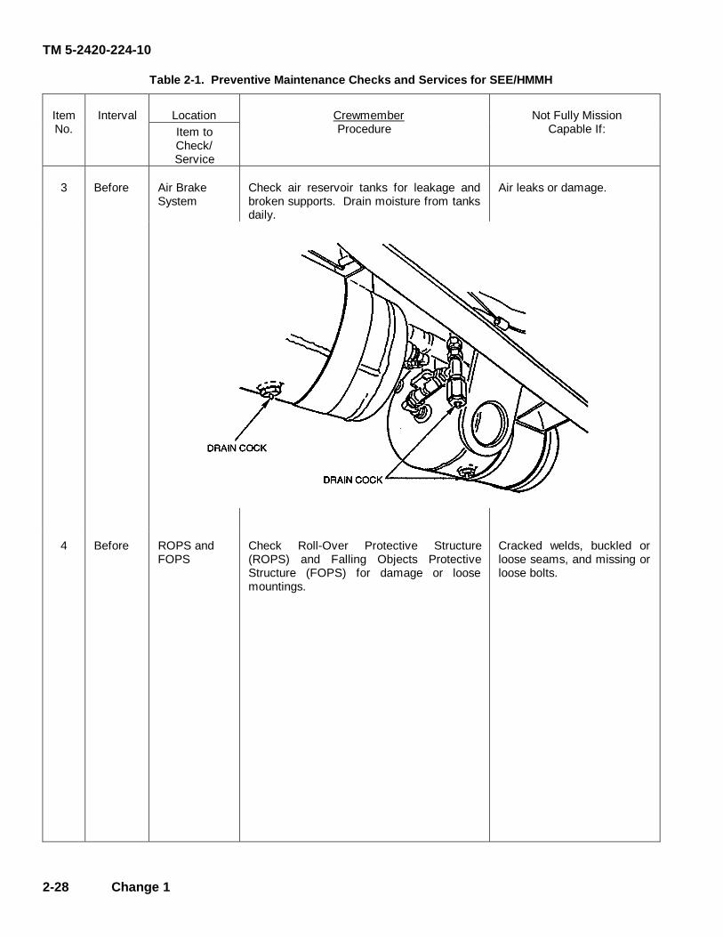
TM 5-2420-224-10
2-28 Change 1
Table 2-1. Preventive Maintenance Checks and Services for SEE/HMMH
Location ItemNo.
Interval Item to Check/
Crewmember Procedure
Not Fully Mission Capable If:
Service
3 Before Air Brake System
Check air reservoir tanks for leakage and broken supports. Drain moisture from tanks daily.
Air leaks or damage.
4 Before ROPS and
FOPS Check Roll-Over Protective Structure (ROPS) and Falling Objects Protective Structure (FOPS) for damage or loose mountings.
Cracked welds, buckled or loose seams, and missing or loose bolts.
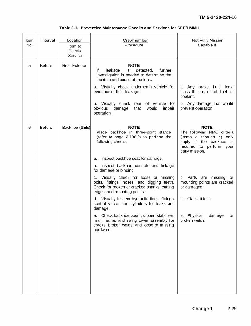
TM 5-2420-224-10
Change 1 2-29
Table 2-1. Preventive Maintenance Checks and Services for SEE/HMMH
Location ItemNo.
Interval Item to Check/
Crewmember Procedure
Not Fully Mission Capable If:
Service
5 Before Rear Exterior NOTE If leakage is detected, further investigation is needed to determine the location and cause of the leak.
a. Visually check underneath vehicle for evidence of fluid leakage.
a. Any brake fluid leak; class III leak of oil, fuel, or coolant.
b. Visually check rear of vehicle for obvious damage that would impair operation.
b. Any damage that would prevent operation.
6 Before Backhoe (SEE) NOTE Place backhoe in three-point stance (refer to page 2-136.2) to perform the following checks.
NOTE The following NMC criteria (items a through e) only apply if the backhoe is required to perform your daily mission.
a. Inspect backhoe seat for damage.
b. Inspect backhoe controls and linkage for damage or binding.
c. Visually check for loose or missing bolts, fittings, hoses, and digging teeth. Check for broken or cracked shanks, cutting edges, and mounting points.
c. Parts are missing or mounting points are cracked or damaged.
d. Visually inspect hydraulic lines, fittings, control valve, and cylinders for leaks and damage.
d. Class III leak.
e. Check backhoe boom, dipper, stabilizer, main frame, and swing tower assembly for cracks, broken welds, and loose or missing hardware.
e. Physical damage or broken welds.

TM 5-2420-224-10
2-30 Change 1
Table 2-1. Preventive Maintenance Checks and Services for SEE/HMMH
Location ItemNo.
Interval Item to Check/
Crewmember Procedure
Not Fully Mission Capable If:
Service
6 Before Backhoe (SEE) Continued
NOTE Place backhoe in travel position (refer to page 2-98) to perform the following check.
f. Verify all locking devices, safety pins, and latches are present and implements are securely locked in travel position.
f. Locking devices, safety pins are missing or damaged and latches are not locked.
7 Before Backhoe Bucket (SEE)
Check for loose or missing teeth, and broken or cracked bucket and welds.
Loose or missing teeth or damage that will impair operation.
8 Before Crane Assembly (HMMH)
NOTE Place crane in three-point stance (refer to page 2-136.2) to perform the following checks.
NOTE The following NMC criteria (items a through d) only apply if the crane is required to perform your daily mission.
a. Inspect crane controls and linkage for damage or binding.
b. Visually check for loose or missing bolts, fittings, and hoses, and secure mounting points.
b. Parts are missing or mounting points are cracked or damaged.
c. Verify and inspect operation of engine RPM and control switch, and proper RPM setting for crane assembly.
c. Switch is inoperative.
d. Visually inspect hydraulic lines, control valves, fittings, and all cylinders for leaks and damage.
d. Class III leak.

TM 5-2420-224-10
Change 1 2-31
Table 2-1. Preventive Maintenance Checks and Services for SEE/HMMH
Location ItemNo.
Interval Item to Check/
Crewmember Procedure
Not Fully Mission Capable If:
Service
8 Before Crane Assembly (HMMH) Continued
NOTE Place crane in travel position (refer to page 2-116) to perform the following checks. e. Inspect crane mast, boom, inner boom, outer boom, extension crane hook assembly, rear outrigger, and front outrigger for physical damage, and broken welds.
e. Broken welds or damage that would impair operation.
f. Verify all locking devices, safety pins, and latches are present and implements are securely locked in travel position.
f. Locking devices, safety pins are missing or damaged and latches are not locked.
9 Before Right Side Exterior
NOTE If leakage is detected, further investigation is needed to determine the location and cause of the leak.
a. Visually check underneath vehicle for evidence of fluid leakage.
a. Any brake fluid leak; class III leak of oil, fuel or coolant.
b. Visually check right side of vehicle for obvious damage.
b. Any damage that would prevent operation.
10 Before Right Side Tires
WARNING Operating a vehicle with a tire in an underinflated condition or with a questionable defect may lead to premature tire failure and may cause equipment damage and injury or death to personnel.
Visually check tires for presence and underinflation.
Any right side tire is de- flated.
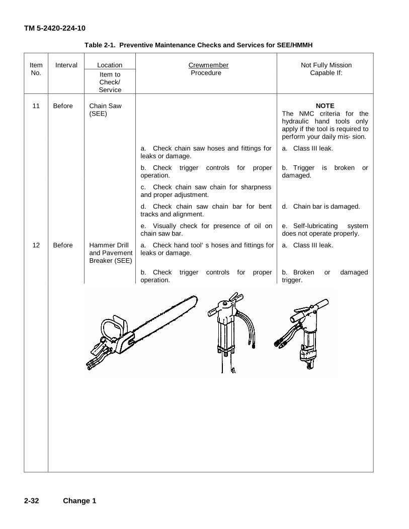
TM 5-2420-224-10
2-32 Change 1
Table 2-1. Preventive Maintenance Checks and Services for SEE/HMMH
Location ItemNo.
Interval Item to Check/
Crewmember Procedure
Not Fully Mission Capable If:
Service
11 Before Chain Saw (SEE)
NOTE The NMC criteria for the hydraulic hand tools only apply if the tool is required to perform your daily mis- sion.
a. Check chain saw hoses and fittings for leaks or damage.
a. Class III leak.
b. Check trigger controls for proper operation.
b. Trigger is broken or damaged.
c. Check chain saw chain for sharpness and proper adjustment.
d. Check chain saw chain bar for bent tracks and alignment.
d. Chain bar is damaged.
e. Visually check for presence of oil on chain saw bar.
e. Self-lubricating system does not operate properly.
12 Before Hammer Drill and Pavement Breaker (SEE)
a. Check hand tool’s hoses and fittings for leaks or damage.
a. Class III leak.
b. Check trigger controls for proper operation.
b. Broken or damaged trigger.
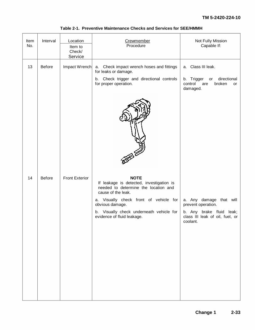
TM 5-2420-224-10
Change 1 2-33
Table 2-1. Preventive Maintenance Checks and Services for SEE/HMMH
Location ItemNo.
Interval Item to Check/
Crewmember Procedure
Not Fully Mission Capable If:
Service
13 Before Impact Wrench a. Check impact wrench hoses and fittings for leaks or damage.
a. Class III leak.
b. Check trigger and directional controls for proper operation.
b. Trigger or directional control are broken or damaged.
14 Before Front Exterior NOTE If leakage is detected, investigation is needed to determine the location and cause of the leak.
a. Visually check front of vehicle for obvious damage.
a. Any damage that will prevent operation.
b. Visually check underneath vehicle for evidence of fluid leakage.
b. Any brake fluid leak; class III leak of oil, fuel, or coolant.

TM 5-2420-224-10
2-34 Change 1
Table 2-1. Preventive Maintenance Checks and Services for SEE/HMMH
Location
Not Fully Mission Capable If:
ItemNo.
Interval
Item to Check/
Crewmember Procedure
Service
15 Before Front Loader (SEE)
NOTE The following NMC criteria (items a through c) only apply if the front loader is required to perform your daily mission.
a. Inspect front loader controls and linkage for loose, missing hardware or binding.
a. Front loader controls and linkage are binding.
b. Visually check for loose or missing bolts, fittings, hoses, digging teeth, and shanks. Check for cutting edges and mounting points.
b. Parts are missing or mounting points are cracked or damaged.
c. Check front loader frame assembly and lift arm assembly bucket for physical damage or broken welds.
c. Damage that will impair operation or broken welds.
d. Verify all safety travel bars, locking devices, safety pins, and latches are present and implements are securely locked in travel position (refer to page 2-87).
d. Travel bars, locking devices, safety pins are missing or damaged and latches are locked.
16 Before Forklift Assembly (HMMH)
NOTE The following NMC criteria (items a through c) only apply if the forklift is required to perform your daily mission.
a. Visually check for loose or missing bolts, fittings, and hoses. Check mounting points for security.
a. Parts are missing or mounting points are cracked or damaged.
b. Check and make sure rotator electrical harness is secured and properly connected.
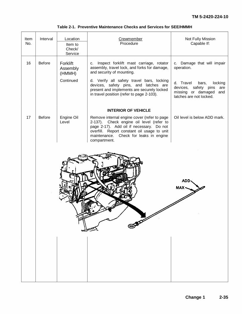
TM 5-2420-224-10
Change 1 2-35
Table 2-1. Preventive Maintenance Checks and Services for SEE/HMMH
Location ItemNo.
Interval Item to Check/
Crewmember Procedure
Not Fully Mission Capable If:
Service
16 Before Forklift Assembly (HMMH)
c. Inspect forklift mast carriage, rotator assembly, travel lock, and forks for damage, and security of mounting.
c. Damage that will impair operation.
Continued d. Verify all safety travel bars, locking devices, safety pins, and latches are present and implements are securely locked in travel position (refer to page 2-103).
d. Travel bars, locking devices, safety pins are missing or damaged and latches are not locked.
INTERIOR OF VEHICLE
17 Before Engine Oil Level
Remove internal engine cover (refer to page 2-137). Check engine oil level (refer to page 2-17). Add oil if necessary. Do not overfill. Report constant oil usage to unit maintenance. Check for leaks in engine compartment.
Oil level is below ADD mark.

TM 5-2420-224-10
2-36 Change 1
Table 2-1. Preventive Maintenance Checks and Services for SEE/HMMH
Location ItemNo.
Interval Item to Check/
Crewmember Procedure
Not Fully Mission Capable If:
Service
18 Before Fuel System Check fuel lines for broken or damaged fittings and make sure all lines and fittings are secure inside engine compartment.
Class III fuel leaks.
19 Before Cooling System
CAUTION Overheating, caused by lack of coolant, will cause engine damage.
a. Check hoses and clamps for secure connections.
b. Check coolant level; fill expansion tank to approximately half-full level.
NOTE If expansion tank is below half full, further investigation is required.
c. Install internal engine cover (refer to
page 2-137).

TM 5-2420-224-10
Change 1 2-37
Table 2-1. Preventive Maintenance Checks and Services for SEE/HMMH
Location
Not Fully Mission Capable If:
ItemNo.
Interval
Item to Check/
Crewmember Procedure
Service
20 Before Fire Extinguisher
NOTE The fire extinguisher is located between passenger and driver’s seat.
a. Check for missing or damaged fire extinguisher.
a. Fire extinguisher mis-sing or damaged.
b. Check for proper charge level or missing charge.
b. Not properly charged.
21 Before Seat and Seat Belts
NOTE Vehicle operation with inoperative seat belts may violate AR 385-55.
a. Check seat belts for proper operation.
b. Check operation of seat adjusting mechanism (driver’s seat only).
TM 5-2420-224-10
2-38 Change 1
Table 2-1. Preventive Maintenance Checks and Services for SEE/HMMH
Location
Not Fully Mission Capable If:
ItemNo.
Interval
Item to Check/
Crewmember Procedure
Service
22 During Exterior Lights
NOTE Vehicle operation with damaged or inoperable lights may violate AR 385-55.
Check for presence and operation of all exterior lights.
23 During Backhoe (SEE)
a. During continuous backhoe operation of at least one hour one of the hydraulic oil cooler fans must at a minimum operate intermittently to properly cool the hydraulic fluid. Ensure oil cooler fans operate properly.
a. Both hydraulic oil cooler fans fail.
b. Operate attachments and listen for unusual noises. Check for leaking cylinders and control valves and improper operation.
b. Class III leak.
24 During Crane (HMMH)
Operate attachments and listen for unusual noises. Check for leaking cylinders and control valves and improper operation. Check suspension lockout for proper operation.
Class III leak.
25 During Rear Hydraulic System Filter
With PTO engaged, check filter indicator gage (refer to page 2-18).
Needle reaches 36 psi or higher, or is in red zone on gage.
26 During Front Loader (SEE) and Forklift (HMMH)
Operate attachments and listen for unusual noises. Check for leaking cylinders and control valves and improper operation.
Class III leak.
27 During Front Hydraulic System Filter
Check Filter Service Indicator (refer to page 2-18).
Red indicator button is up.
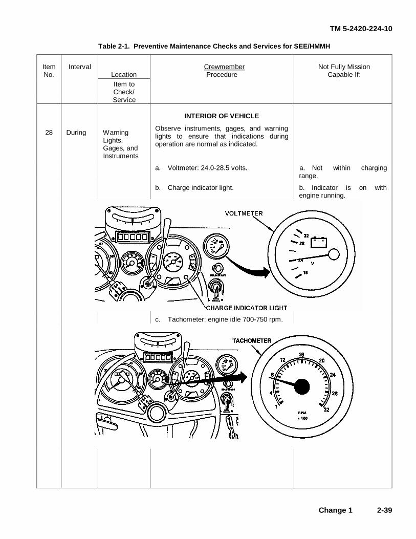
TM 5-2420-224-10
Change 1 2-39
Table 2-1. Preventive Maintenance Checks and Services for SEE/HMMH
Location
ItemNo.
Interval
Item to Check/
Crewmember Procedure
Not Fully Mission Capable If:
Service
INTERIOR OF VEHICLE
28 During Warning Lights, Gages, and Instruments
Observe instruments, gages, and warning lights to ensure that indications during operation are normal as indicated.
a. Voltmeter: 24.0-28.5 volts. a. Not within charging range.
b. Charge indicator light. b. Indicator is on with engine running.
c. Tachometer: engine idle 700-750 rpm.

TM 5-2420-224-10
2-40 Change 1
Table 2-1. Preventive Maintenance Checks and Services for SEE/HMMH
Location ItemNo.
Interval Item to Check/
Crewmember Procedure
Not Fully Mission Capable If:
Service
28 During Warning Lights, Gages, and Instruments
Continued
d. Oil pressure gage: idle, 9 psi; working, 29-73 psi.
Minimum oil pressure is not reached.
e. Engine temperature gage:
176º–194º F.
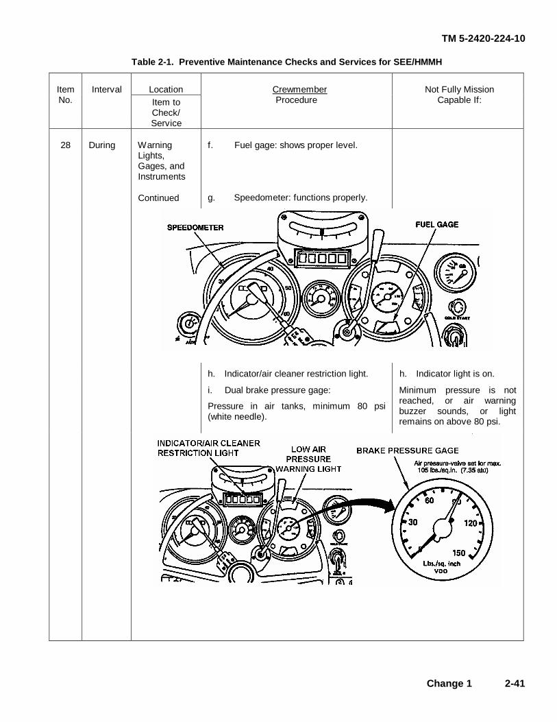
TM 5-2420-224-10
Change 1 2-41
Table 2-1. Preventive Maintenance Checks and Services for SEE/HMMH
Location ItemNo.
Interval Item to Check/
Crewmember Procedure
Not Fully Mission Capable If:
Service
28 During Warning Lights, Gages, and Instruments
Continued
f. Fuel gage: shows proper level.
g. Speedometer: functions properly.
h. Indicator/air cleaner restriction light. h. Indicator light is on.
i. Dual brake pressure gage:
Pressure in air tanks, minimum 80 psi (white needle).
Minimum pressure is not reached, or air warning buzzer sounds, or light remains on above 80 psi.
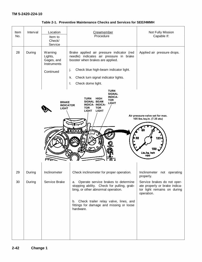
TM 5-2420-224-10
2-42 Change 1
Table 2-1. Preventive Maintenance Checks and Services for SEE/HMMH
Location ItemNo.
Interval Item to Check/
Crewmember Procedure
Not Fully Mission Capable If:
Service
28 During Warning Lights, Gages, and Instruments
Brake applied air pressure indicator (red needle) indicates air pressure in brake booster when brakes are applied.
Applied air pressure drops.
Continued j. Check blue high-beam indicator light.
k. Check turn signal indicator lights.
l. Check dome light.
� � � � �� � � � � � �� � �
� � �� � � � �� � � � � � � �� � �
� � �� � � �� � � � � � � �� � �
� � �� � � � �� � � � � � � �� � �
� � � � � � � � � � � � � � � � � � � � � � � � � � � � ! "# $ % � � & � " ' � ( " � ) " � * + " , % � � � � -
29 During Inclinometer Check inclinometer for proper operation. Inclinometer not operating properly.
30 During Service Brake a. Operate service brakes to determine stopping ability. Check for pulling, grab- bing, or other abnormal operation.
Service brakes do not oper- ate properly or brake indica- tor light remains on during operation.
b. Check trailer relay valve, lines, and fittings for damage and missing or loose hardware.
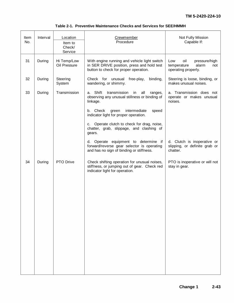
TM 5-2420-224-10
Change 1 2-43
Table 2-1. Preventive Maintenance Checks and Services for SEE/HMMH
Location ItemNo.
Interval Item to Check/
Crewmember Procedure
Not Fully Mission Capable If:
Service
31 During Hi Temp/Low Oil Pressure
With engine running and vehicle light switch in SER DRIVE position, press and hold test button to check for proper operation.
Low oil pressure/high temperature alarm not operating properly.
32 During Steering System
Check for unusual free-play, binding, wandering, or shimmy.
Steering is loose, binding, or makes unusual noises.
33 During Transmission a. Shift transmission in all ranges, observing any unusual stillness or binding of linkage.
a. Transmission does not operate or makes unusual noises.
b. Check green intermediate speed indicator light for proper operation.
c. Operate clutch to check for drag, noise, chatter, grab, slippage, and clashing of gears.
d. Operate equipment to determine if forward/reverse gear selector is operating and has no sign of binding or stiffness.
d. Clutch is inoperative or slipping, or definite grab or chatter.
34 During PTO Drive Check shifting operation for unusual noises, stiffness, or jumping out of gear. Check red indicator light for operation.
PTO is inoperative or will not stay in gear.

TM 5-2420-224-10
2-44 Change 1
Table 2-1. Preventive Maintenance Checks and Services for SEE/HMMH
Location ItemNo.
Interval Item to Check/
Crewmember Procedure
Not Fully Mission Capable If:
Service
35 During Driveline a. Listen for unusual noises, vibrations, clicking, or clunking noises which indicate worn U-joints or damaged propeller shafts.
a. Unusual noises or vibrations are present.
CAUTION Do not make sharp turns while in differential lock position. To do so could result in equipment damage.
b. Operate differential lock, listen for
unusual noises and air leaks, and check for proper operation.
b. Inoperative, or leaking air.
c. Check red differential lock indicator light for proper operation.
36 After Mirrors NOTE Vehicle operation with damaged or missing outside rearview mirrors may violate AR 385-55.
Check mirror for presence, cracks, and serviceability.
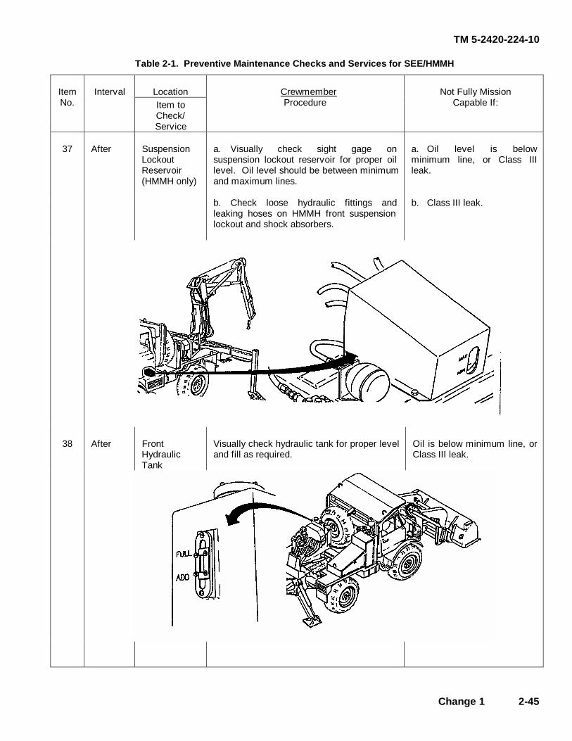
TM 5-2420-224-10
Change 1 2-45
Table 2-1. Preventive Maintenance Checks and Services for SEE/HMMH
Location ItemNo.
Interval Item to Check/
Crewmember Procedure
Not Fully Mission Capable If:
Service
37 After Suspension Lockout Reservoir (HMMH only)
a. Visually check sight gage on suspension lockout reservoir for proper oil level. Oil level should be between minimum and maximum lines.
a. Oil level is below minimum line, or Class III leak.
b. Check loose hydraulic fittings and leaking hoses on HMMH front suspension lockout and shock absorbers.
b. Class III leak.
38 After Front Hydraulic Tank
Visually check hydraulic tank for proper level and fill as required.
Oil is below minimum line, or Class III leak.

TM 5-2420-224-10
2-46 Change 1
Table 2-1. Preventive Maintenance Checks and Services for SEE/HMMH
Location ItemNo.
Interval Item to Check/
Crewmember Procedure
Not Fully Mission Capable If:
Service
39 After Hose Reel a. Check for proper extraction and retraction of hose assemblies.
b. Check hydraulic couplings and hoses for leaks and damage.
b. Class III leak.
40 After Hydraulic Oil Cooler
Check for loose or missing hardware, fitting oil leaks, and physical damage.
Class III leak. Physical damage which affects operation.
41 After Rear Hydraulic Tank
Visually check hydraulic tank for proper level and fill as required.
Oil is below minimum line, or Class III leak.
42 After Fuel System a. Check fuel tank for leaks, missing cap and strainer, and broken supports.
a. Damage or leaks. Cap missing.
b. Check fuel lines for broken or damaged fittings and make sure all lines and fittings are secure.
b. Class III leaks.
c. Check fuel pre-sediment bowl for contamination and leaks. Service, if required (refer to page 3-13).
c. Class III fuel leaks.

TM 5-2420-224-10
Change 1 2-47
Table 2-1. Preventive Maintenance Checks and Services for SEE/HMMH
Location ItemNo.
Interval Item to Check/
Crewmember Procedure
Not Fully Mission Capable If:
Service
43 After Front Bucket Check front bucket drain holes, to ensure they allow drainage.
44 After Clutch/Rear Brake System Reservoir Low Fluid Indicator
NOTE Chock wheels and release parking brake prior to performing the following:
Remove hood (refer to page 2-136.3).
With vehicle lights set to SER DRIVE and PANEL BRT positions, press test button in center of reservoir cap. Brake indicator light should be on (refer to page 2-3).
Brake indicator light fails to operate.
45 After Front Brake System Reservoir Low Fluid Indicator
NOTE Chock wheels and release parking brake prior to performing the following:
With vehicle lights set to SER DRIVE and PANEL BRT positions, press test button in center of reservoir cap. Brake indicator light should be on (refer to page 2-3).
Install hood (refer to page 2-136.3).
Brake indicator light fails to operate.
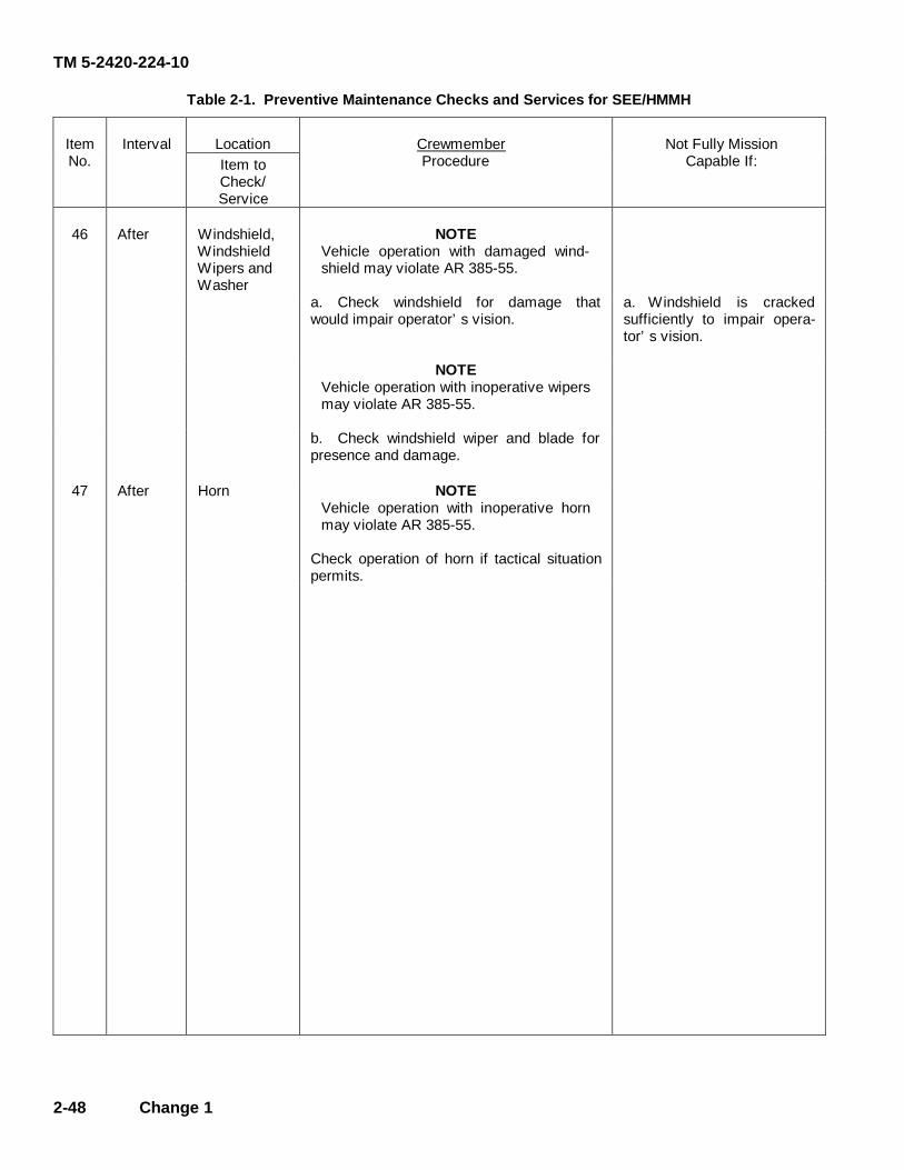
TM 5-2420-224-10
2-48 Change 1
Table 2-1. Preventive Maintenance Checks and Services for SEE/HMMH
Location ItemNo.
Interval Item to Check/
Crewmember Procedure
Not Fully Mission Capable If:
Service
46 After Windshield, Windshield Wipers and Washer
NOTE Vehicle operation with damaged wind- shield may violate AR 385-55.
a. Check windshield for damage that would impair operator’s vision.
a. Windshield is cracked sufficiently to impair opera- tor’s vision.
NOTE Vehicle operation with inoperative wipers may violate AR 385-55.
b. Check windshield wiper and blade for presence and damage.
47 After Horn NOTE Vehicle operation with inoperative horn may violate AR 385-55.
Check operation of horn if tactical situation permits.

TM 5-2420-224-10
Change 1 2-49
Table 2-1. Preventive Maintenance Checks and Services for SEE/HMMH
Location ItemNo.
Interval Item to Check/
Crewmember Procedure
Not Fully Mission Capable If:
Service INTERIOR OF VEHICLE
48 After Steering System
Remove internal engine cover (refer to page 2-137). Check fluid level in steering reservoir with engine running.
Fluid level is low. Class III leak.
49 After Throttle Control
Check accelerator and hand throttle linkage for proper operation.
Install internal engine cover (refer to page 2-137).
Not working properly.
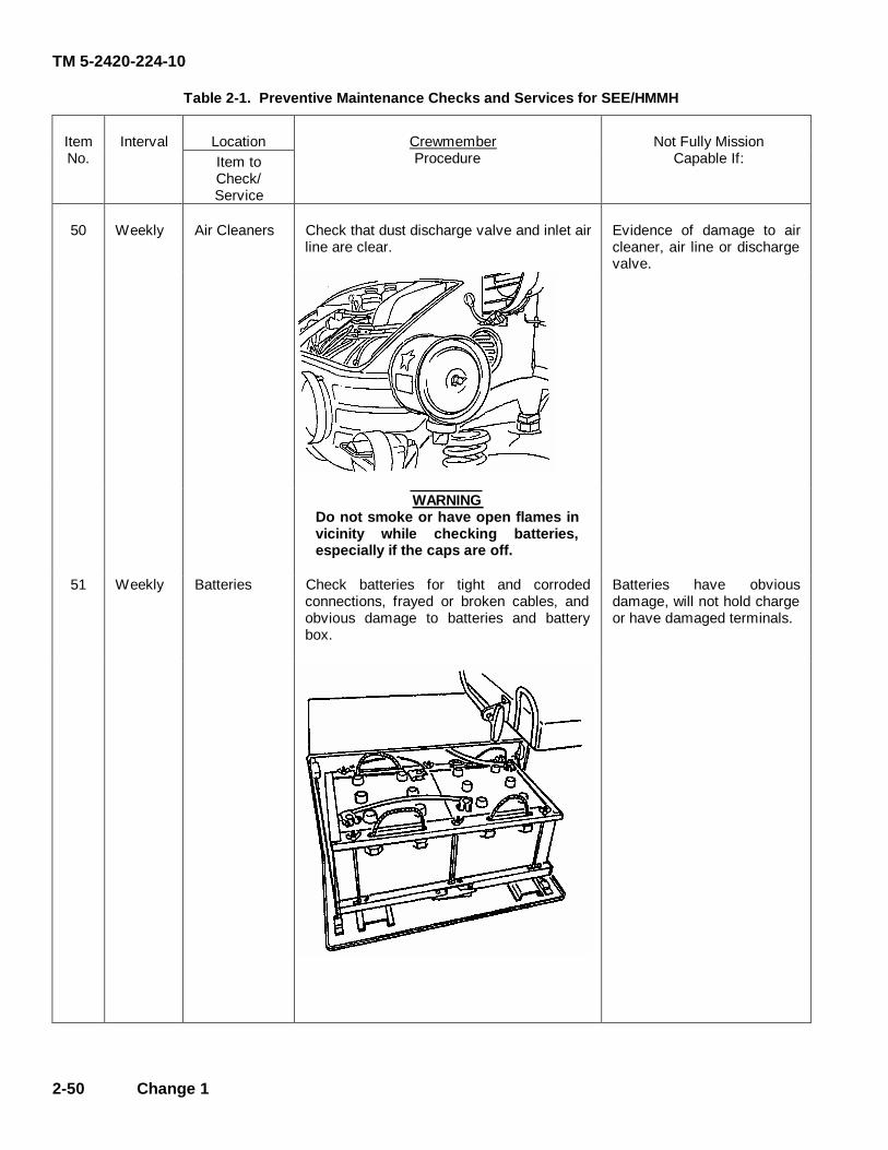
TM 5-2420-224-10
2-50 Change 1
Table 2-1. Preventive Maintenance Checks and Services for SEE/HMMH
Location ItemNo.
Interval Item to Check/
Crewmember Procedure
Not Fully Mission Capable If:
Service
50 Weekly Air Cleaners Check that dust discharge valve and inlet air line are clear.
Evidence of damage to air cleaner, air line or discharge valve.
WARNING Do not smoke or have open flames in vicinity while checking batteries, especially if the caps are off.
51 Weekly Batteries Check batteries for tight and corroded connections, frayed or broken cables, and obvious damage to batteries and battery box.
Batteries have obvious damage, will not hold charge or have damaged terminals.
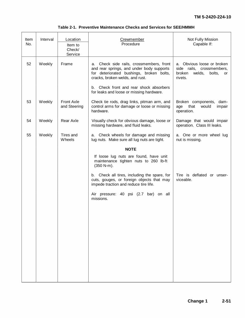
TM 5-2420-224-10
Change 1 2-51
Table 2-1. Preventive Maintenance Checks and Services for SEE/HMMH
Location ItemNo.
Interval Item to Check/
Crewmember Procedure
Not Fully Mission Capable If:
Service
52 Weekly Frame a. Check side rails, crossmembers, front and rear springs, and under body supports for deteriorated bushings, broken bolts, cracks, broken welds, and rust.
a. Obvious loose or broken side rails, crossmembers, broken welds, bolts, or rivets.
b. Check front and rear shock absorbers for leaks and loose or missing hardware.
53 Weekly Front Axle and Steering
Check tie rods, drag links, pitman arm, and control arms for damage or loose or missing hardware.
Broken components, dam- age that would impair operation.
54 Weekly Rear Axle Visually check for obvious damage, loose or missing hardware, and fluid leaks.
Damage that would impair operation. Class III leaks.
55 Weekly Tires and Wheels
a. Check wheels for damage and missing lug nuts. Make sure all lug nuts are tight.
a. One or more wheel lug nut is missing.
NOTE
If loose lug nuts are found, have unit maintenance tighten nuts to 260 lb-ft (350 N-m).
b. Check all tires, including the spare, for cuts, gouges, or foreign objects that may impede traction and reduce tire life.
Tire is deflated or unser- viceable.
Air pressure: 40 psi (2.7 bar) on all missions.
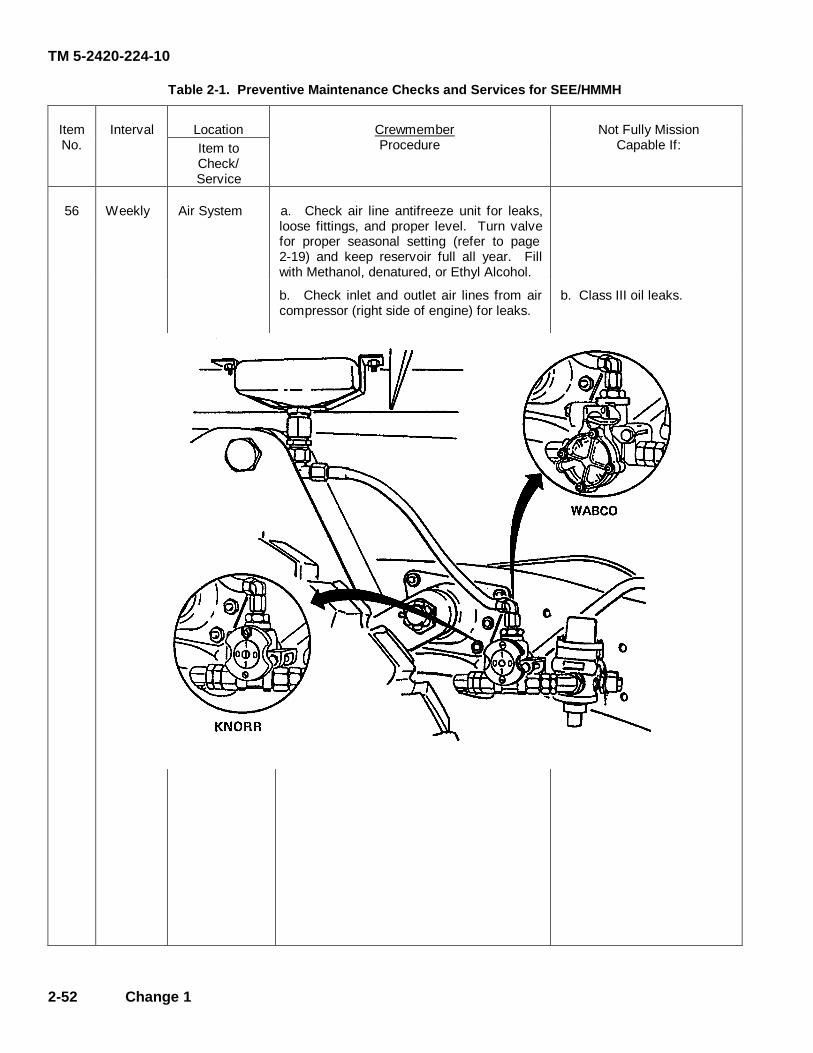
TM 5-2420-224-10
2-52 Change 1
Table 2-1. Preventive Maintenance Checks and Services for SEE/HMMH
Location ItemNo.
Interval Item to Check/
Crewmember Procedure
Not Fully Mission Capable If:
Service
56 Weekly Air System a. Check air line antifreeze unit for leaks, loose fittings, and proper level. Turn valve for proper seasonal setting (refer to page 2-19) and keep reservoir full all year. Fill with Methanol, denatured, or Ethyl Alcohol.
b. Check inlet and outlet air lines from air compressor (right side of engine) for leaks.
b. Class III oil leaks.
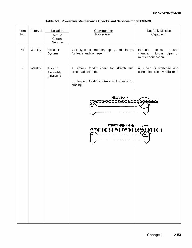
TM 5-2420-224-10
Change 1 2-53
Table 2-1. Preventive Maintenance Checks and Services for SEE/HMMH
Location ItemNo.
Interval Item to Check/
Crewmember Procedure
Not Fully Mission Capable If:
Service
57 Weekly Exhaust System
Visually check muffler, pipes, and clamps for leaks and damage.
Exhaust leaks around clamps. Loose pipe or muffler connection.
58 Weekly Forklift Assembly (HMMH)
a. Check forklift chain for stretch and proper adjustment.
a. Chain is stretched and cannot be properly adjusted.
b. Inspect forklift controls and linkage for binding.
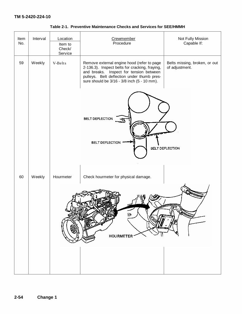
TM 5-2420-224-10
2-54 Change 1
Table 2-1. Preventive Maintenance Checks and Services for SEE/HMMH
Location ItemNo.
Interval Item to Check/
Crewmember Procedure
Not Fully Mission Capable If:
Service
59 Weekly V-Belts Remove external engine hood (refer to page 2-136.3). Inspect belts for cracking, fraying, and breaks. Inspect for tension between pulleys. Belt deflection under thumb pres- sure should be 3/16 - 3/8 inch (5 - 10 mm).
Belts missing, broken, or out of adjustment.
60 Weekly Hourmeter Check hourmeter for physical damage.
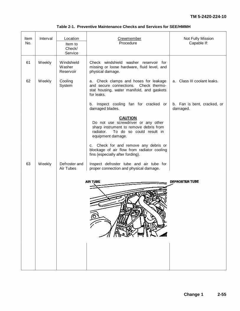
TM 5-2420-224-10
Change 1 2-55
Table 2-1. Preventive Maintenance Checks and Services for SEE/HMMH
Location ItemNo.
Interval Item to Check/
Crewmember Procedure
Not Fully Mission Capable If:
Service
61 Weekly Windshield Washer Reservoir
Check windshield washer reservoir for missing or loose hardware, fluid level, and physical damage.
62 Weekly Cooling System
a. Check clamps and hoses for leakage and secure connections. Check thermo- stat housing, water manifold, and gaskets for leaks.
a. Class III coolant leaks.
b. Inspect cooling fan for cracked or damaged blades.
b. Fan is bent, cracked, or damaged.
CAUTION Do not use screwdriver or any other sharp instrument to remove debris from radiator. To do so could result in equipment damage.
c. Check for and remove any debris or blockage of air flow from radiator cooling fins (especially after fording).
63 Weekly Defroster and Air Tubes
Inspect defroster tube and air tube for proper connection and physical damage.

TM 5-2420-224-10
2-56 Change 1
Table 2-1. Preventive Maintenance Checks and Services for SEE/HMMH
Location ItemNo.
Interval Item to Check/
Crewmember Procedure
Not Fully Mission Capable If:
Service
64 Weekly Air Intake Hoses
Check intake hoses for loose or missing clamps.
65 Weekly Fuses a. Check that fuse holders are secure.
b. Check for blown or missing fuses.
c. Install exterior engine hood (refer to page 2-136.3).
INTERIOR OF VEHICLE
66 Weekly Cab Heater and Defroster
a. Check cab heater for leaks and proper operation.
a. Heater leaks or does not operate properly and mission requires heater.
b. Check defroster fan air flow.
b. Air flow is restricted and mission required defroster.
67 Weekly Parking Brake
a. With vehicle lights set to SER DRIVE and PANEL BRT positions, test parking brake by first setting hand brake and engaging transmission. Vehicle should not move and indicator light should be on (refer to page 2-137).
a. Parking brake does not operate properly or indicator is not on.
b. With hand brake released, brake indicator light should be off.
b. Indicator remains on with hand brake released.
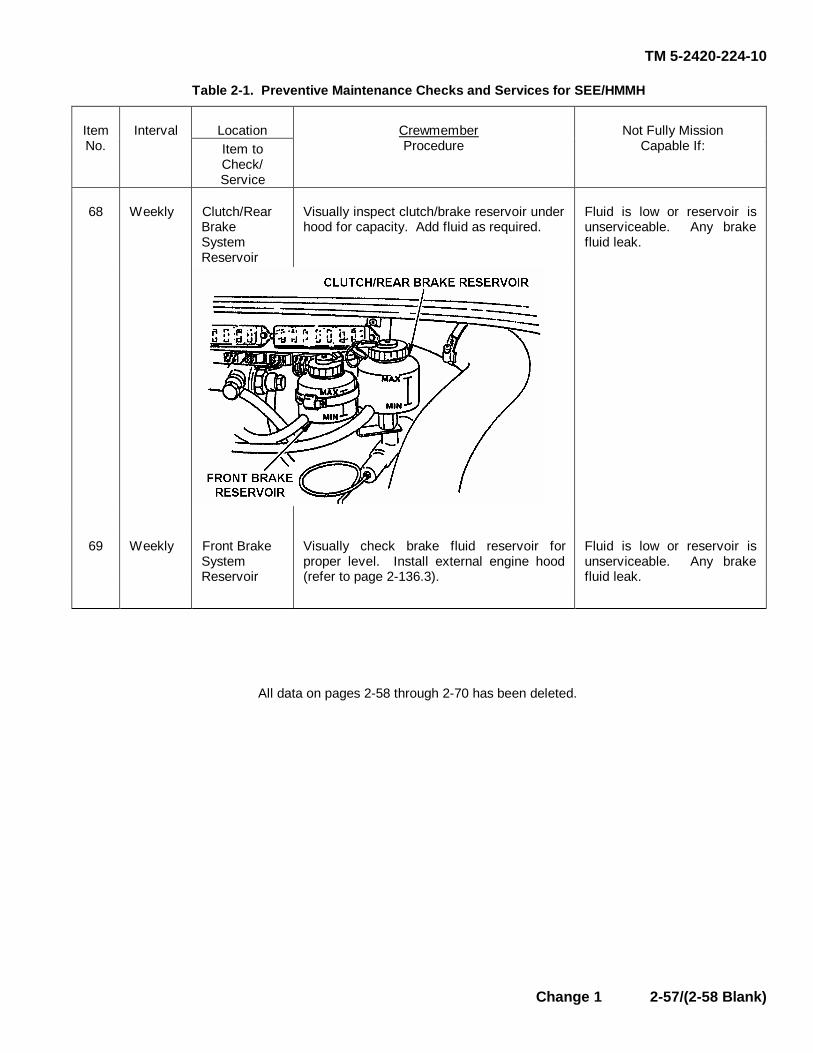
TM 5-2420-224-10
Change 1 2-57/(2-58 Blank)
Table 2-1. Preventive Maintenance Checks and Services for SEE/HMMH
Location ItemNo.
Interval Item to Check/
Crewmember Procedure
Not Fully Mission Capable If:
Service
68 Weekly Clutch/Rear Brake System Reservoir
Visually inspect clutch/brake reservoir under hood for capacity. Add fluid as required.
Fluid is low or reservoir is unserviceable. Any brake fluid leak.
69 Weekly Front Brake System Reservoir
Visually check brake fluid reservoir for proper level. Install external engine hood (refer to page 2-136.3).
Fluid is low or reservoir is unserviceable. Any brake fluid leak.
All data on pages 2-58 through 2-70 has been deleted.

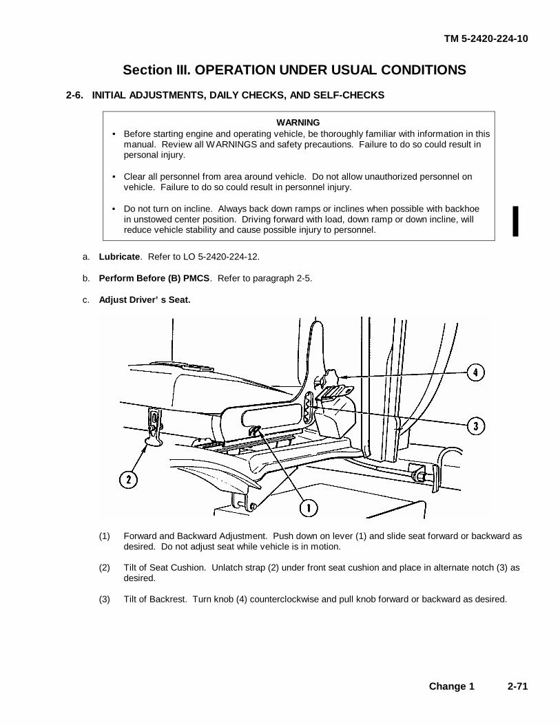
TM 5-2420-224-10
Change 1 2-71
Section III. OPERATION UNDER USUAL CONDITIONS
2-6. INITIAL ADJUSTMENTS, DAILY CHECKS, AND SELF-CHECKS
WARNING • Before starting engine and operating vehicle, be thoroughly familiar with information in this
manual. Review all WARNINGS and safety precautions. Failure to do so could result in personal injury.
• Clear all personnel from area around vehicle. Do not allow unauthorized personnel on
vehicle. Failure to do so could result in personnel injury. • Do not turn on incline. Always back down ramps or inclines when possible with backhoe
in unstowed center position. Driving forward with load, down ramp or down incline, will reduce vehicle stability and cause possible injury to personnel.
a. Lubricate. Refer to LO 5-2420-224-12. b. Perform Before (B) PMCS. Refer to paragraph 2-5. c. Adjust Driver’s Seat.
(1) Forward and Backward Adjustment. Push down on lever (1) and slide seat forward or backward as
desired. Do not adjust seat while vehicle is in motion. (2) Tilt of Seat Cushion. Unlatch strap (2) under front seat cushion and place in alternate notch (3) as
desired. (3) Tilt of Backrest. Turn knob (4) counterclockwise and pull knob forward or backward as desired.

TM 5-2420-224-10
2-72 Change 1
d. Fasten/Unfasten Seat Belt.
WARNING
Seat belt must be fastened at all times during operation of vehicle. Failure to do so could result in personal injury.
�
�
�
(1) Insert latch plate (1) into buckle (2) to fasten seat belt. (2) Push button (3) on buckle (2) to unfasten seat belt.
e. Adjust Rear View and Both Side Mirrors.
f. Test Backhoe/Crane Operator Warning Horn.
CAUTION If buzzer sounds during operation, stop operation and check engine oil pressure gage for low oil pressure reading, and engine coolant temperature gage for overheating indication. Failure to do so could result in equipment damage.
(1) Turn vehicular light switch lever (1) to first position from OFF and hold test button (2) down for time
delay with engine running and alternator charging. (2) Push and hold test button (2) for 6-10 seconds to actuate warning horn.

TM 5-2420-224-10
g. Tire Inflation.
(1) Attach tire inflation air hose to connector (1).
(2) Reduce system air pressure from both air tanks by pulling on cable attached to relief valves. Pressure mustbe reduced to 87 psi (6.0 bar).
(3) Keep vehicle engine running while inflating tires.
2-7. OPERATING PROCEDURES
a. Mounting and Dismounting the Vehicle.
WARNINGTo prevent personal injury, do not use steering wheel as a handhold; vehicle couldmove. Do not jump off vehicle.
CAUTIONBe careful not to damage control knobs and panels on heater when entering and leavingvehicle.
Face vehicle and use steps and grabhandles when mounting or dismounting vehicle.
2-73

TM 5-2420-224-10
b. Ether Start Aid.
Starting the engine at ambient temperatures below 320F (0°C) may require using the cold start system. Thissystem will facilitate engine starting even at extremely low temperatures.
WARNINGEther is toxic and flammable. Use only in well-ventilated areas. Avoid contact witheyes, skin, and clothes. Do not use ether or discard ether container near open flame,sparks, or heat. Failure to follow these instructions could result in severe personal injury.If injured, seek medical attention immediately.
CAUTIONExcessive use of ether will cause piston and ring damage. Use ether sparingly and onlyfor starting purposes in temperatures below freezing.
(1) Cold start system is activated by dash-mounted pull button switch (1). To start engine, set hand throttlecontrol to full throttle and begin cranking engine. Pull button switch (1) for 2 seconds and release.
(2) Starting fluid injection is at preset rate and quantity begins when button switch (1) is released. After enginestarts running on its own, another pull will aid to smooth running and minimize smoke.
2-74

TM 5-2420-224-10
c. Starting the Engine.
WARNINGMake sure parking brake is engaged before starting engine to prevent accidentalmovement of vehicle. Failure to do so could result in personal injury.
CAUTIONCheck engine oil before operating engine. Failure to do so could result in equipmentdamage.
(1) Place transmission main shift lever (1) and group shift lever (2) in neutral and PTO lever (3) in disengagedposition.
(2) Insert master disconnect switch key (4) and switch to ON.
2-75

TM 5-2420-224-10
(3) Set throttle lever (5) to idle position (700-750 rpm).
(4) Fully depress clutch pedal (6) to activate neutral safety switch.
(5) Insert key into ignition switch (7) and switch ON.
CAUTIONDo not crank engine for more than 30 seconds. Allow starter to cool for 2 minutes beforecranking again. Failure to do so could result in equipment damage.
(6) Press starter switch button (8) and release when engine starts.
(7) Observe oil pressure indicator (9). Do not rev engine as long as no oil pressure is indicated. If minimum oilpressure of 9 psi (0.6 bar) is not reached after 10 seconds, immediately stop engine and notify unitmaintenance.
d. Slave Starting the Engine.
(1) The starting receptacle (1) accepts booster cables with a mating (NATO) plug. Use a battery cart or anothervehicle as a power source of 24 volts.
(2) Make sure electrolyte in batteries is filled to level of split ring. If low, notify unit maintenance.
2-76
TM 5-2420-224-10
Change 1 2-77
(3) Position slave vehicle so that slave receptacles (1) are adjacent. (4) Make sure master disconnect switch, ignition switch, and all accessory switches in receiving vehicle
are OFF. (5) Start engine in slave vehicle and run engine at 1000 to 1200 rpm. (6) Remove cap from slave receptacle (1) and connect slave cable (2). (7) Start engine in receiving vehicle (page 2-75). If engine does not start, troubleshoot (refer to page
3-2). (8) Disconnect slave cable (2) and install cap on slave receptacle (1).
e. After Starting the Engine.
(1) Operate engine at low idle (700-750 rpm) until hydraulic oil is warm. When temperature is below 35°F (2°C), engage PTO and move all hydraulic controls slowly to help warm oil and control. Move each cylinder several times to warm it.
(2) Test hydraulic controls. Allow extra warm up time if controls are sluggish.

TM 5-2420-224-10
2-78 Change 1
f. Moving the Vehicle.
WARNING SEE only: When in transport position, use auxiliary headlights instead of vehicle headlights; during operation vehicle headlights are blocked by a bucket. HMMH only: Use auxiliary headlights when using forklift with a load that blocks vehicle headlights. Failure to do so could result in personnel injury.
CAUTION • Do not move vehicle while brake warning light or low air warning light in
instrument cluster is lit. To do so could result in equipment damage.
• Run engine not fully warmed up to operating temperature in medium speeds and under partial load range. Failure to do so could result in equipment damage.
• Run engine to full capacity only after attaining operating temperature of 176°F
(80°C). Failure to do so could result in equipment damage.
Close front loader shutoff valves before moving vehicle. Failure to do so could result in equipment damage.
(1) Place the SEE implements in travel positions as follows:
(a) Place backhoe in transport position (page 2-98). (b) Engage front loader travel locks (page 2-87). Close front loader shutoff valves
(page 2-86). (2) Place the HMMH implements in travel positions as follows:
(a) Place crane in stowage position (page 2-115). (b) Place forklift in transport position (page 2-103).
(3) Mount vehicle and fasten seat belt.
WARNING Clear all personnel from area before moving vehicle or operating implements to prevent personnel injury.
CAUTION PTO must be disengaged or pump will be damaged.
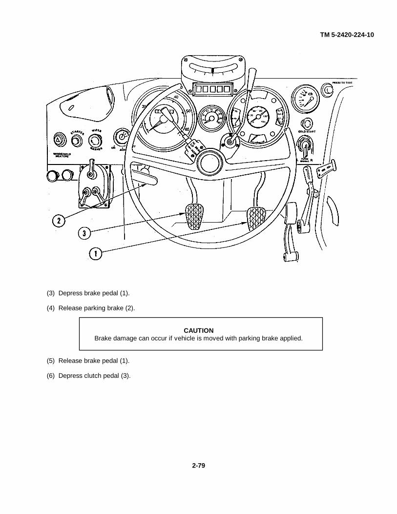
TM 5-2420-224-10
(3) Depress brake pedal (1).
(4) Release parking brake (2).
CAUTIONBrake damage can occur if vehicle is moved with parking brake applied.
(5) Release brake pedal (1).
(6) Depress clutch pedal (3).
2-79
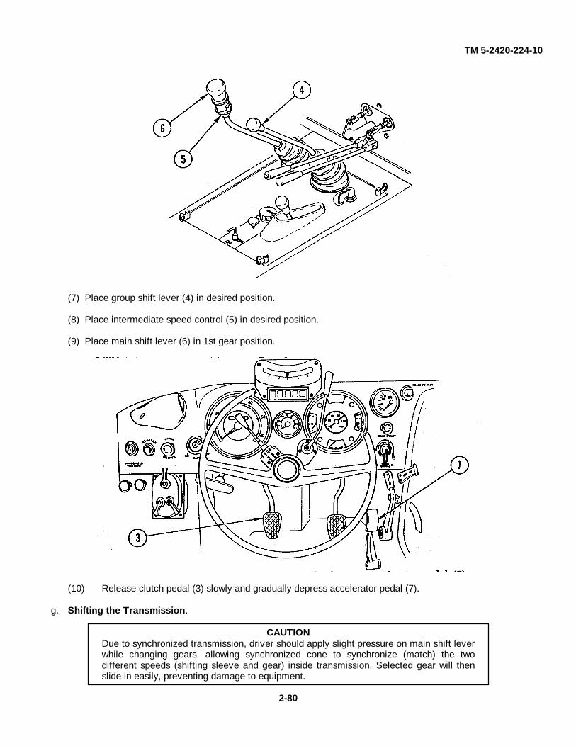
TM 5-2420-224-10
(7) Place group shift lever (4) in desired position.
(8) Place intermediate speed control (5) in desired position.
(9) Place main shift lever (6) in 1st gear position.
(10) Release clutch pedal (3) slowly and gradually depress accelerator pedal (7).
g. Shifting the Transmission.
CAUTIONDue to synchronized transmission, driver should apply slight pressure on main shift leverwhile changing gears, allowing synchronized cone to synchronize (match) the twodifferent speeds (shifting sleeve and gear) inside transmission. Selected gear will thenslide in easily, preventing damage to equipment.
2-80
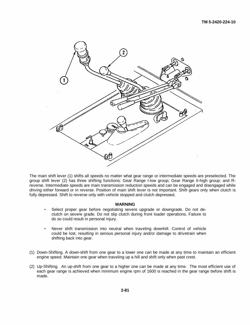
TM 5-2420-224-10
The main shift lever (1) shifts all speeds no matter what gear range or intermediate speeds are preselected. Thegroup shift lever (2) has three shifting functions: Gear Range I-low group; Gear Range II-high group; and R-reverse. Intermediate speeds are main transmission reduction speeds and can be engaged and disengaged whiledriving either forward or in reverse. Position of main shift lever is not important. Shift gears only when clutch isfully depressed. Shift to reverse only with vehicle stopped and clutch depressed.
WARNING• Select proper gear before negotiating severe upgrade or downgrade. Do not de-
clutch on severe grade. Do not slip clutch during front loader operations. Failure todo so could result in personal injury.
• Never shift transmission into neutral when traveling downhill. Control of vehiclecould be lost, resulting in serious personal injury and/or damage to drivetrain whenshifting back into gear.
(1) Down-Shifting. A down-shift from one gear to a lower one can be made at any time to maintain an efficientengine speed. Maintain one gear when traveling up a hill and shift only when past crest.
(2) Up-Shifting. An up-shift from one gear to a higher one can be made at any time. The most efficient use ofeach gear range is achieved when minimum engine rpm of 1600 is reached in the gear range before shift ismade.
2-81
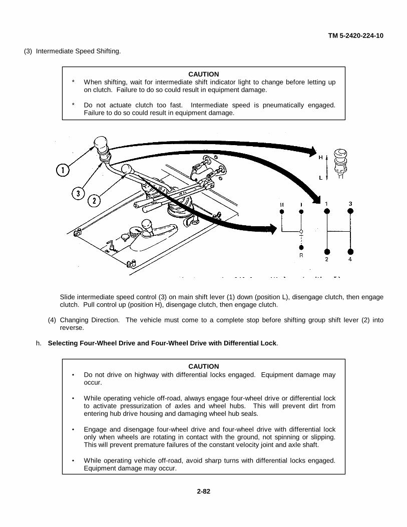
TM 5-2420-224-10
(3) Intermediate Speed Shifting.
CAUTION* When shifting, wait for intermediate shift indicator light to change before letting up
on clutch. Failure to do so could result in equipment damage.
* Do not actuate clutch too fast. Intermediate speed is pneumatically engaged.Failure to do so could result in equipment damage.
Slide intermediate speed control (3) on main shift lever (1) down (position L), disengage clutch, then engageclutch. Pull control up (position H), disengage clutch, then engage clutch.
(4) Changing Direction. The vehicle must come to a complete stop before shifting group shift lever (2) intoreverse.
h. Selecting Four-Wheel Drive and Four-Wheel Drive with Differential Lock.
CAUTION• Do not drive on highway with differential locks engaged. Equipment damage may
occur.
• While operating vehicle off-road, always engage four-wheel drive or differential lockto activate pressurization of axles and wheel hubs. This will prevent dirt fromentering hub drive housing and damaging wheel hub seals.
• Engage and disengage four-wheel drive and four-wheel drive with differential lockonly when wheels are rotating in contact with the ground, not spinning or slipping.This will prevent premature failures of the constant velocity joint and axle shaft.
• While operating vehicle off-road, avoid sharp turns with differential locks engaged.Equipment damage may occur.
2-82

TM 5-2420-224-10
2-83
(1) Position 0 is two-wheel drive (rear axle).
NOTE System air pressure must be maintained above 90 psi before selecting four-wheel drive and four-wheel drive with differential lock.
(2) Shifting into four-wheel drive (position I) is effected by means of a control cylinder on the
transmission. (3) The differential locks on both axles are added (position II). The four-wheel drive and the differential
locks can be engaged and disengaged while driving, without disengaging the clutch, if the wheels are not spinning and have contact with solid ground.
i. Stopping the Vehicle.
(1) Depress the clutch pedal (1).

TM 5-2420-224-10
2-84 Change 1
(2) Fully release accelerator pedal (2).
WARNING • Do not fan brakes by repeatedly depressing and releasing brake pedal. This can
reduce air pressure too low for stopping, resulting in personnel injury.
• If hand brake must be used to stop vehicle, prepare for sudden stop and brace yourself. Failure to do so could cause serious head, neck, and back injuries.
(3) Apply even pressure on brake pedal (3) until vehicle comes to complete stop. Shift main shift lever
(4) and group shift lever (5) into neutral position. (4) Apply parking brake (6).
j. Stopping the Engine.
CAUTION • Stopping engine immediately after vehicle has been under load could result in
overheating and accelerated wear.
• Do not turn off ignition switch or master disconnect switch before shutting off fuel, or damage to charging system could result.
(1) Park vehicle and operate engine at low idle for 5 minutes. (2) SEE only: Open front loader shutoff valves (page 2-86). Disengage travel locks (page 2-87) and
lower front loader to the ground surface.

TM 5-2420-224-10
Change 1 2-85
(3) Move throttle lever (1) to OFF position. (4) Turn off ignition switch (2). (5) Turn master disconnect switch key (3) to OFF. (6) Perform your after (A) PMCS. (Refer to paragraph 2-5.) (7) Fill fuel tank to filler neck if vehicle is to be parked for an extended length of time to avoid formation
of condensation. (8) When leaving vehicle, close and lock cab doors and windows.
k. Front Loader Operation (SEE).
(1) Boom Control Lever (1). Located to right of driver's seat. Pull lever to raise boom; push lever to
lower boom. Push past detent for float. (2) Bucket Control Lever (2). Located to right of driver's seat. Pull lever to curl bucket up; push lever
to curl bucket down.

TM 5-2420-224-10
2-86
(3) Front Loader Shutoff Valves.
(a) Turn levers (3) parallel to hydraulic line to open valve when front loader is in use. (b) Turn levers (3) 1/4 turn to close valve when front loader is stowed for travel.
(4) Lowering Bucket.
(a) Remove two retaining pins (4) from two travel lock plates (5). (b) Start vehicle and raise front loader so travel lock plates (5) release from retaining pins (4). (c) Lower front loader to ground and shut down vehicle. (d) Lock two travel lock plates (5) in stowed position by installing two retaining pins (4).
WARNING • Be careful at all times. Keep area clear of unauthorized personnel. Know
location of authorized personnel in area. Failure to do so could result in personnel injury.
• Before operating front loader in an area where your visibility is reduced (next to a building, etc.), install guard rail and warning signs to keep other personnel away from your machine. Failure to do so could result in personal injury.

TM 5-2420-224-10
Change 1 2-87
WARNING • Before operating front loader, visually check digging site for utilities (gas lines,
power lines, water mains, etc.). Failure to do so could result in personnel injury. • Never work on front loader while boom arms are raised or while anyone is near
equipment controls. To do so could cause personnel injury.
CAUTION • Do not operate front loader without bucket teeth. To do so could result in
equipment damage. • Do not operate front loader without rear attachment. To do so could result in
equipment damage. • Do not curl bucket forward and then raise lift arms. Always raise lift arms with
bucket in curled back position, which will prevent undue strain on rollback cylinders. Otherwise, cylinder mounting bracket could break, spilling the load and causing possible equipment damage.
• While loading bucket or pushing material, maintain proper gear range and
constant rate of speed. Failure to do so could result in engine running backward. Indications for engine running backward are exhaust smoke coming from air intake, oil pressure dropping to zero, lack of power, and transmission in reverse of normal. Should this happen, immediately shut engine off, wait a few seconds, and restart engine. Failure to shut engine off could cause damage to equipment.
(5) Bucket Loading and Unloading.
(a) Lower bucket to ground surface with teeth against earth. (b) Drive vehicle forward to fill bucket. (c) Curl bucket back when loaded. (d) Raise bucket to travel height, approximately 2 ft (0.66 m). Move vehicle to dumping site and
dump load. Bucket is self-leveling and will remain in its full curled position through entire lifting range.
CAUTION Travel in high position with load will cause unstable vehicle operation and possible damage to equipment.
(6) Travel Locks. Travel locks should be installed before traveling long distances or when front loader
is not in use. Once in place, the boom arms cannot lower and come in contact with ground surface while relocating the vehicle. Travel locks must be disengaged and stowed prior to operation.
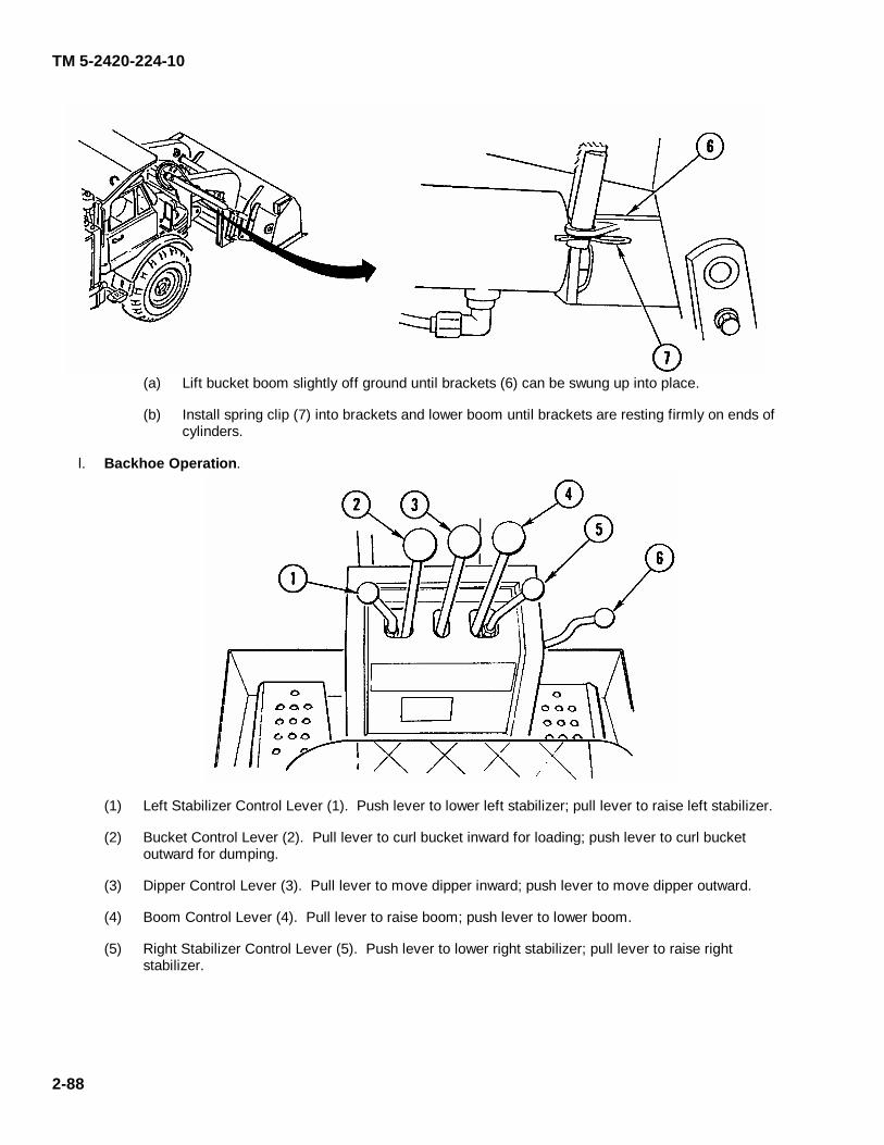
TM 5-2420-224-10
2-88
(a) Lift bucket boom slightly off ground until brackets (6) can be swung up into place. (b) Install spring clip (7) into brackets and lower boom until brackets are resting firmly on ends of
cylinders. l. Backhoe Operation.
(1) Left Stabilizer Control Lever (1). Push lever to lower left stabilizer; pull lever to raise left stabilizer. (2) Bucket Control Lever (2). Pull lever to curl bucket inward for loading; push lever to curl bucket
outward for dumping. (3) Dipper Control Lever (3). Pull lever to move dipper inward; push lever to move dipper outward. (4) Boom Control Lever (4). Pull lever to raise boom; push lever to lower boom. (5) Right Stabilizer Control Lever (5). Push lever to lower right stabilizer; pull lever to raise right
stabilizer.
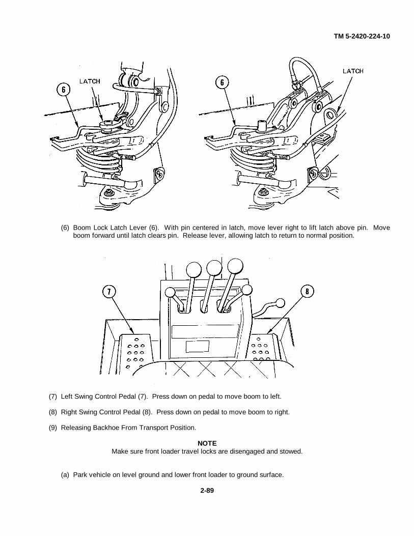
TM 5-2420-224-10
(6) Boom Lock Latch Lever (6). With pin centered in latch, move lever right to lift latch above pin. Moveboom forward until latch clears pin. Release lever, allowing latch to return to normal position.
(7) Left Swing Control Pedal (7). Press down on pedal to move boom to left.
(8) Right Swing Control Pedal (8). Press down on pedal to move boom to right.
(9) Releasing Backhoe From Transport Position.
NOTEMake sure front loader travel locks are disengaged and stowed.
(a) Park vehicle on level ground and lower front loader to ground surface.
2-89
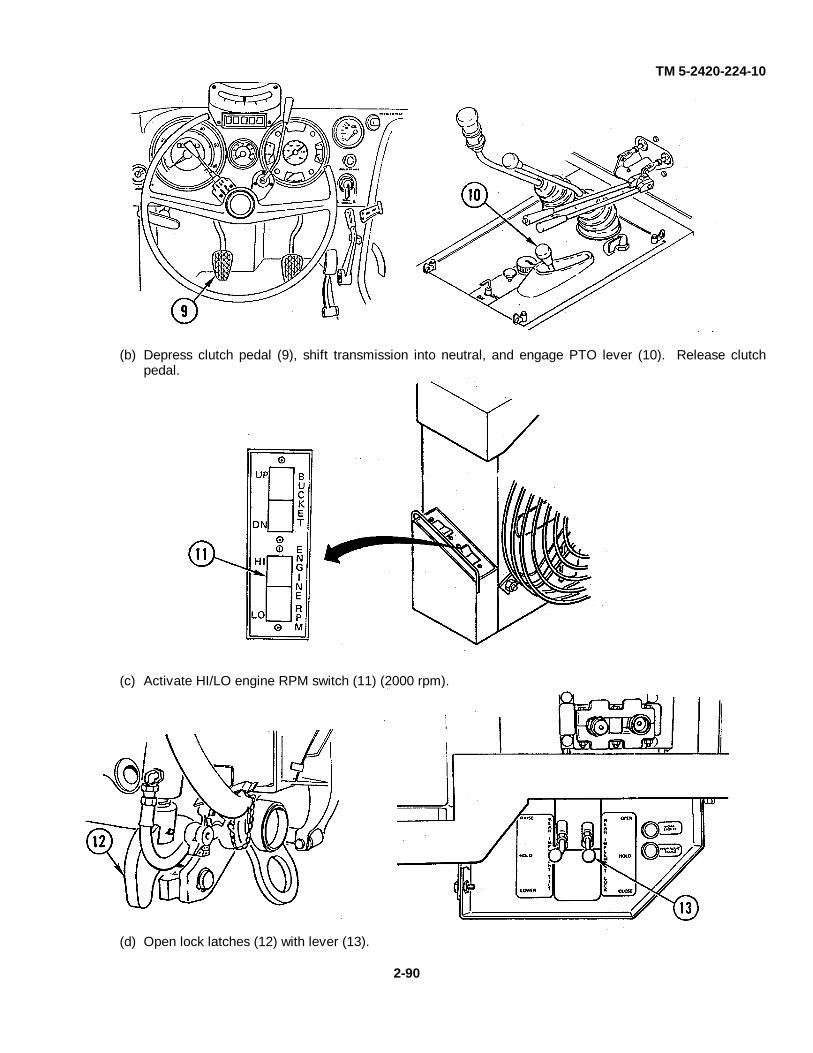
TM 5-2420-224-10
(b) Depress clutch pedal (9), shift transmission into neutral, and engage PTO lever (10). Release clutchpedal.
(c) Activate HI/LO engine RPM switch (11) (2000 rpm).
(d) Open lock latches (12) with lever (13).
2-90

TM 5-2420-224-10
2-91
(e) Release backhoe travel lock (14) and tilt backhoe into upright position with tilt control lever (15).
Close lock latches with lever (13) and switch off HI/LO engine RPM switch.
WARNING Never mount or dismount rear of vehicle with HI/LO engine RPM switch in HI position. To do so could result in personal injury.
CAUTION Do not grab backhoe control levers while mounting vehicle. To do so could cause equipment damage.
(f) Mount vehicle and adjust seat by pulling adjustment lever (16) out. Adjust forward or backward as
desired.

TM 5-2420-224-10
2-92 Change 1
CAUTION • Always position stabilizer pads for maximum stability when backhoe is not
operating next to unmovable object. Failure to do so could result in equipment damage.
• Exercise care when swinging backhoe completely to the side. In some positions,
backhoe can contact stabilizers and cause damage.
(g) Lower stabilizers with control levers (1 and 5) until stabilizers are extended and slightly lift rear of
vehicle. (h) Using swing control pedals (7 and 8), swing backhoe to center position. (i) Release tension on boom lock by moving boom control lever (4) out. Lift boom lock by pushing
boom lock latch lever (6) to the right. (j) Pull back on boom control lever (4). (k) Backhoe is ready for operation.
(10) Digging with Backhoe.
WARNING • Before starting work in new area, walk around and look for holes or obstructions.
Failure to find hidden holes or obstructions could result in an accident and injury.
• Before operating backhoe in area where your visibility is reduced (next to a building, etc.), install guard rail and warning signs to keep other personnel away from your machine. Failure to do so could result in personnel injury.

TM 5-2420-224-10
2-93
WARNING • Before operating backhoe, visually check digging site for utilities (gas lines,
power lines, water mains, etc.). Failure to do so could result in personnel injury.
• Keep clear of digging area to avoid being crushed by swinging boom.
Operate backhoe from operator's seat only. Any other method could result in injury to operator or bystanders.
• Do not dig around or under stabilizers. Reposition stabilizers to permit
digging when necessary to avoid undermining that could cause vehicle to fall into excavation, resulting in serious personal injury.
• When operating backhoe, keep both feet behind guards. Failure to do so
could result in personal injury.
• Backhoe boom has wide swing capability. Before swinging backhoe to either side, make sure area is clear of all personnel and obstructions to prevent personnel injury.
• Do not operate backhoe without bucket teeth to prevent personnel injury.
• Always lower front loader to ground surface when operating backhoe to
increase stability. Failure to do so could result in personal injury.
• When operating backhoe on side of hill, dump earth from excavation on highest side of excavation to prevent vehicle from overturning. Failure to do so could result in serious personal injury.
• Always face vehicle and use grabhandles and steps when mounting or
dismounting; do not jump from vehicle. Failure to do so could result in personal injury.
• Before operating earthmoving implements, make an operational check of all
controls in a clear area. Do not allow other personnel in area. Failure to do so could result in personnel injury.
• When operating basic tractor or earthmoving implements, know location of
all personnel at all times to prevent personnel injury.
• Do not allow personnel to perform maintenance on front loader or backhoe with buckets loaded and raised. Personnel outside vehicle must stand clear of implements whenever operator is near controls of either backhoe or front loader. Failure to do so could result in personal injury.
• Check all bolts daily before and after operation of earthmoving implements
to prevent personnel injury.

TM 5-2420-224-10
2-94 Change 1
(a) Activate HI/LO engine RPM switch (11). (b) Lower front loader to ground surface using front loader remote switch (17).
(c) Extend boom to 45 degree angle with boom control lever (4). (d) Using dipper control lever (3), start dig cycle. Halfway through dig cycle begin to curl bucket
with bucket control lever (2). If bucket stalls, lift boom slightly. (e) On completing dig cycle, curl bucket completely, extend dipper, and swing to dump site with
swing control pedals (7 and 8).
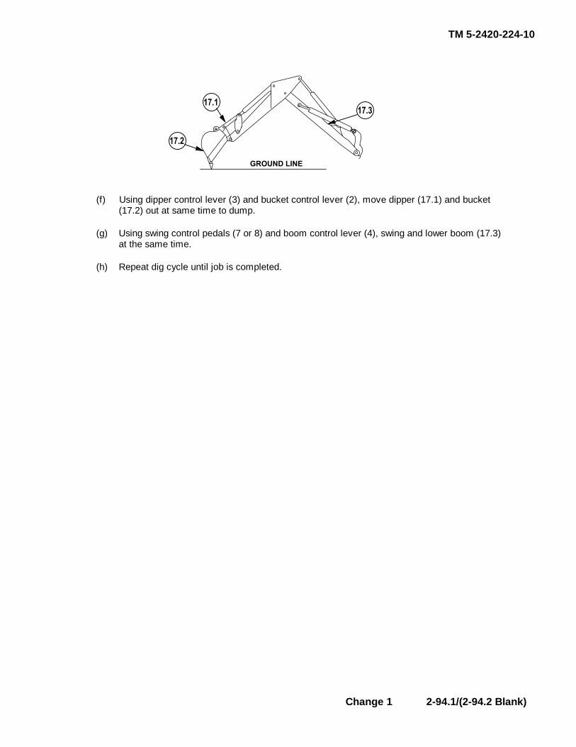
TM 5-2420-224-10
Change 1 2-94.1/(2-94.2 Blank)
� � � � � � � � �
� � � �
� � � �
� � � �
(f) Using dipper control lever (3) and bucket control lever (2), move dipper (17.1) and bucket
(17.2) out at same time to dump. (g) Using swing control pedals (7 or 8) and boom control lever (4), swing and lower boom (17.3)
at the same time. (h) Repeat dig cycle until job is completed.

TM 5-2420-224-10
(11) Moving Vehicle with Backhoe.
WARNINGDo not move vehicle with backhoe unless vehicle is on level ground. To do so couldresult in personal injury.
(a) Release parking brake.
(b) Make sure vehicle front wheels are straight forward.
(c) Raise front loader from ground surface using front loader remote switch.
(d) Decrease engine speed by deactivating HI/LO engine RPM switch.
(e) Raise boom and retract dipper. Move backhoe as required to place bucket teeth on firm ground.
(f) Raise both stabilizers off the ground enough to clear when vehicle is moved.
(g) Use boom and dipper to move vehicle. Slowly move dipper out and at the same time, lower boom.
(h) At new position, lower both stabilizers and front loader to ground surface.
(i) Increase engine speed by activating HI/LO engine RPM switch and resume excavating.
(12) Lifting with Backhoe.
WARNINGBackhoe is not a crane. Exercise caution when lifting load to prevent injury topersonnel.
Lower load to ground if one of the stabilizers is raised above ground or there is anyindication that stability of vehicle is reduced. Failure to do so could result in seriouspersonal injury.
(a) Lower front loader to ground surface.
(b) Attach hand line to load before lifting. Make sure person holding line is away from load.
(c) Position vehicle as close to load as possible without interfering with movement.
(d) Use suitable cable or sling to fasten load to end of dipper at bucket pivot pin.
(e) With backhoe, lift load 1-2 in. (25-50 mm) above ground.
(f) Move load slowly. Keep all persons away from elevated load until it is safely lowered to ground or stand.
2-95
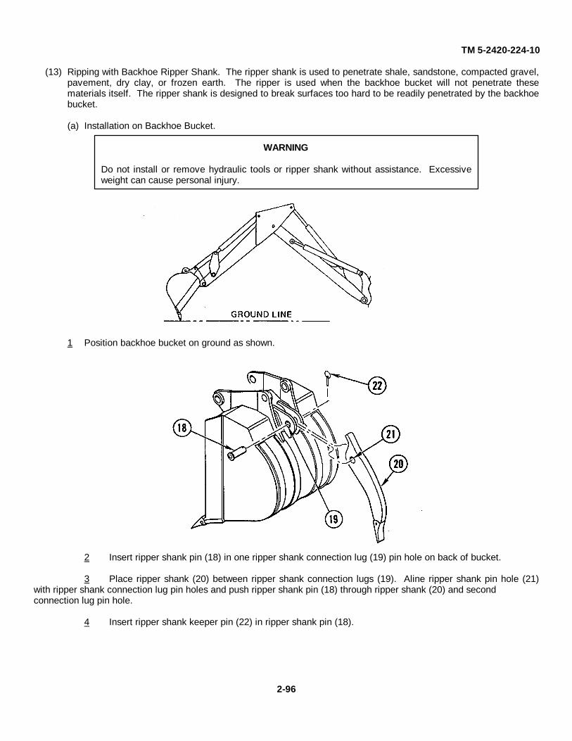
TM 5-2420-224-10
(13) Ripping with Backhoe Ripper Shank. The ripper shank is used to penetrate shale, sandstone, compacted gravel,pavement, dry clay, or frozen earth. The ripper is used when the backhoe bucket will not penetrate thesematerials itself. The ripper shank is designed to break surfaces too hard to be readily penetrated by the backhoebucket.
(a) Installation on Backhoe Bucket.
WARNING
Do not install or remove hydraulic tools or ripper shank without assistance. Excessiveweight can cause personal injury.
1 Position backhoe bucket on ground as shown.
2 Insert ripper shank pin (18) in one ripper shank connection lug (19) pin hole on back of bucket.
3 Place ripper shank (20) between ripper shank connection lugs (19). Aline ripper shank pin hole (21)with ripper shank connection lug pin holes and push ripper shank pin (18) through ripper shank (20) and secondconnection lug pin hole.
4 Insert ripper shank keeper pin (22) in ripper shank pin (18).
2-96
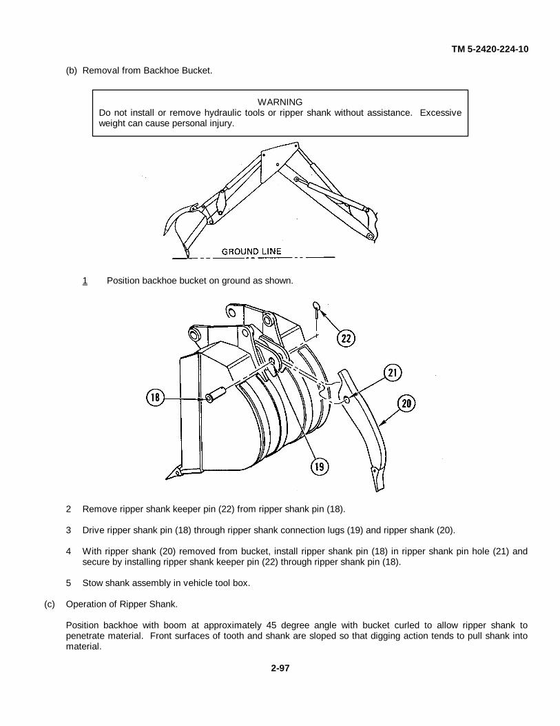
TM 5-2420-224-10
(b) Removal from Backhoe Bucket.
WARNINGDo not install or remove hydraulic tools or ripper shank without assistance. Excessiveweight can cause personal injury.
1 Position backhoe bucket on ground as shown.
2 Remove ripper shank keeper pin (22) from ripper shank pin (18).
3 Drive ripper shank pin (18) through ripper shank connection lugs (19) and ripper shank (20).
4 With ripper shank (20) removed from bucket, install ripper shank pin (18) in ripper shank pin hole (21) andsecure by installing ripper shank keeper pin (22) through ripper shank pin (18).
5 Stow shank assembly in vehicle tool box.
(c) Operation of Ripper Shank.
Position backhoe with boom at approximately 45 degree angle with bucket curled to allow ripper shank topenetrate material. Front surfaces of tooth and shank are sloped so that digging action tends to pull shank intomaterial.
2-97
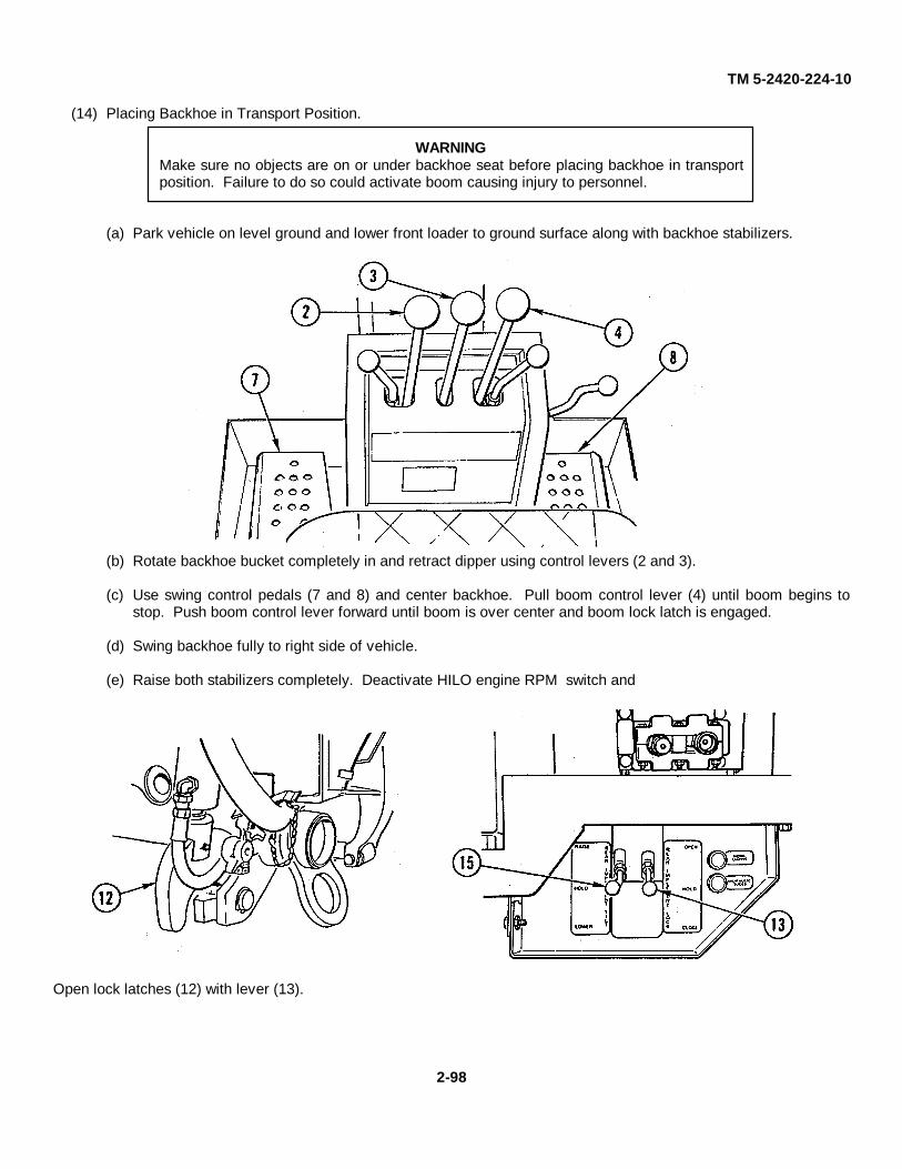
TM 5-2420-224-10
(14) Placing Backhoe in Transport Position.
WARNINGMake sure no objects are on or under backhoe seat before placing backhoe in transportposition. Failure to do so could activate boom causing injury to personnel.
(a) Park vehicle on level ground and lower front loader to ground surface along with backhoe stabilizers.
(b) Rotate backhoe bucket completely in and retract dipper using control levers (2 and 3).
(c) Use swing control pedals (7 and 8) and center backhoe. Pull boom control lever (4) until boom begins tostop. Push boom control lever forward until boom is over center and boom lock latch is engaged.
(d) Swing backhoe fully to right side of vehicle.
(e) Raise both stabilizers completely. Deactivate HILO engine RPM switch and
Open lock latches (12) with lever (13).
2-98
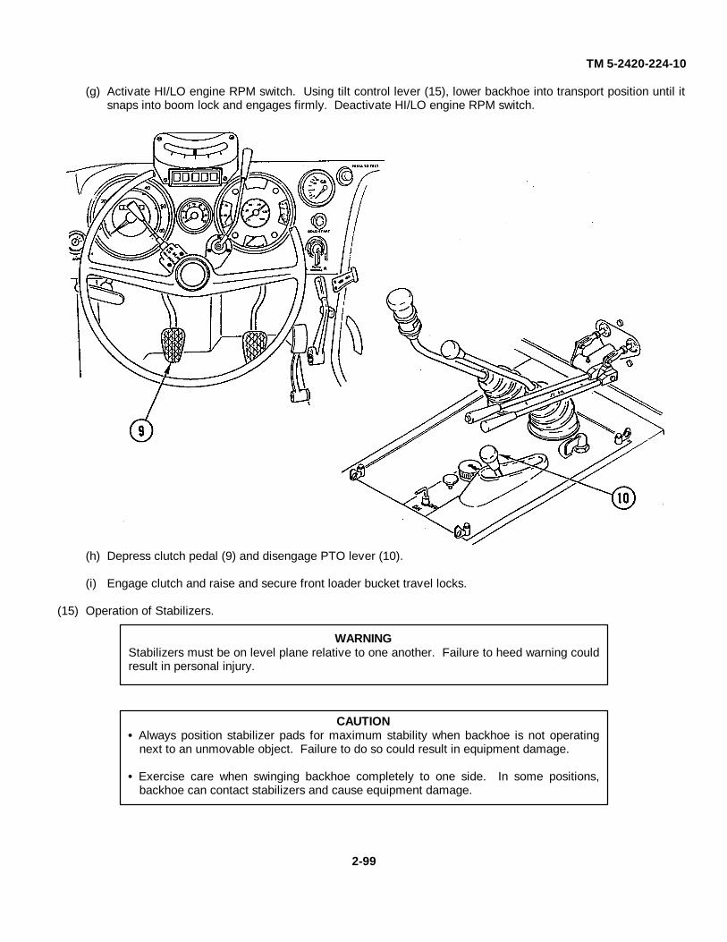
TM 5-2420-224-10
(g) Activate HI/LO engine RPM switch. Using tilt control lever (15), lower backhoe into transport position until itsnaps into boom lock and engages firmly. Deactivate HI/LO engine RPM switch.
(h) Depress clutch pedal (9) and disengage PTO lever (10).
(i) Engage clutch and raise and secure front loader bucket travel locks.
(15) Operation of Stabilizers.
WARNINGStabilizers must be on level plane relative to one another. Failure to heed warning couldresult in personal injury.
CAUTIONAlways position stabilizer pads for maximum stability when backhoe is not operatingnext to an unmovable object. Failure to do so could result in equipment damage.
Exercise care when swinging backhoe completely to one side. In some positions,backhoe can contact stabilizers and cause equipment damage.
2-99

TM 5-2420-224-10
Lower stabilizers with control levers (1 and 5) until stabilizers are extended and slightly lift rear of vehicle.
m. Forklift Operation (HMMH).
NOTEFor forklift operation, front suspension lockout system should be engaged (refer to page2-15).
(1) Mast Control Lever (1). Located to right of driver's seat. Pull lever to raise carriage; push lever to lowercarriage.
(2) Tilt Control Lever (2). Located to right of driver's seat. Pull lever to tilt mast backward; push lever to tilt mastforward.
(3) Carriage Rotation. Press button (3) and at same time push lever (2) to rotate carriage clockwise or pull lever torotate carriage counterclockwise.
2-100
TM 5-2420-224-10
WARNING
Never carry load greater than rated capacity 4,000 lb (2216 kg) of vehicle/forkliftcombination. To do so could cause personal injury.
Make sure total capacity of forks is equal to or greater than load to prevent personalinjury.
Rotate load slowly in elevated positions. Rotating too fast will cause vehicle instabilityand possible loss of load and injury to personnel.
Do not rotate loads in immediate area of any personnel. To do so could result inpersonnel injury.
Set loads down with forks parallel to ground. Failure to do so could result in personnelinjury.
Drive carefully and observe traffic rules. Be in full control of vehicle at all times.Avoid ruts, bumps, and other hazards that could cause vehicle to swerve or tipresulting in injury.
Never leave vehicle unattended without lowering load, setting hand brake, andstopping engine. To do so could result in personal injury.
Do not allow anyone to ride on forks. Never allow anyone under load or carriage.Never reach through mast. To do so could result in personnel injury.
Transport load with forks lowered 3-4 in. (7.6-10.1 cm) above ground and mast tiltedback. Failure to do so could result in personal injury.
Limit amount of vehicle maneuvering to minimum when high stacking load. Failure todo so could result in personal injury.
Do not turn on incline. Always back down ramps or inclines when possible. Drivingforward with load, down ramp or down incline, will reduce vehicle stability and causepossible injury to personnel.
Travel slowly around corners. Sound horn on blind corners. Be careful of overheadclearances. Watch where you are going, whether in forward or reverse. Avoid suddenstops and starts. Failure to do so could result in personnel injury.
2-101

TM 5-2420-224-10
(4) Picking Up Load with Forklift.
(a) Position vehicle in front of load, lower forks to ground, and raise forks slightly to avoid rubbing.
(b) Slowly drive vehicle forward and position forks under load. Make sure load is positioned evenly over forks.
(c) Tilt mast back to stabilize load against carriage.
(d) Raise load 3-4 in. (7.6-10.1 cm) from ground.
(5) Transporting Load with Forklift.
(a) Move vehicle slowly and know location of all other personnel during every minute of operation.
(b) Tilt load as required to clear obstacles and terrain. This should be done with vehicle stopped to avoidshifting load on forks.
(c) When moving around large obstacles, such as a building, use horn as tactical situation permits to alert otherpersonnel of your presence.
(6) Setting Down Load with Forklift.
(a) Position vehicle with load in front of stable surface.
(b) Tilt mast forward to bring forks parallel with ground.
(c) Lower load to ground until forks clear load, and back vehicle to clear load.
(7) Stacking with Forklift.
(a) When stacking load, raise carriage high enough for forks to clear top of loading surface.
(b) Tilt mast forward to bring forks parallel with loading surface.
(c) Center load and lower mast to clear forks, and back vehicle to clear load.
(8) Unstacking with Forklift.
(a) Position vehicle in front of load, and raise forks to lift point of load.
(b) Slowly drive vehicle forward and position forks under load. Make sure load is positioned evenly over forks.
(c) Tilt mast back to stabilize load against carriage.
(d) Back vehicle from stack and lower forks 3-4 in. (7.6-10.1 cm) from ground.
2-102

TM 5-2420-224-10
(9) Placing Forklift in Transport Position.
(a) Place forks on ground.
HIGHWAY POSITION
(b) Remove two lock pins (4) and both carriage restraints (5) from stowed position on mast.
(c) Install one carriage restraint (5) in upper position with end pointing down.
(d) Carefully raise mast carriage (6) to engage carriage restraint.
(e) Install other carriage restraint (5) on same mast pins with end pointing up to engage carriage.
(f) Install lock pins (4) to secure carriage restraints (5).
(g) Remove two fork lock pins (10) and stow lock pins in carriage channel.
(h) Remove two lock pins (7) and fork restraints (8) and slide over ends of forks.
(i) Manually raise forks, engage fork restraints (8) with carriage lock (9), and install lock pins (7).
2-103
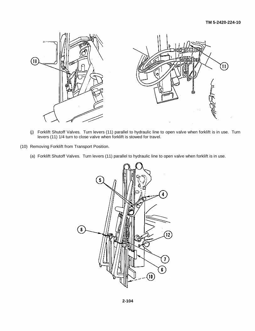
TM 5-2420-224-10
(j) Forklift Shutoff Valves. Turn levers (11) parallel to hydraulic line to open valve when forklift is in use. Turnlevers (11) 1/4 turn to close valve when forklift is stowed for travel.
(10) Removing Forklift from Transport Position.
(a) Forklift Shutoff Valves. Turn levers (11) parallel to hydraulic line to open valve when forklift is in use.
2-104
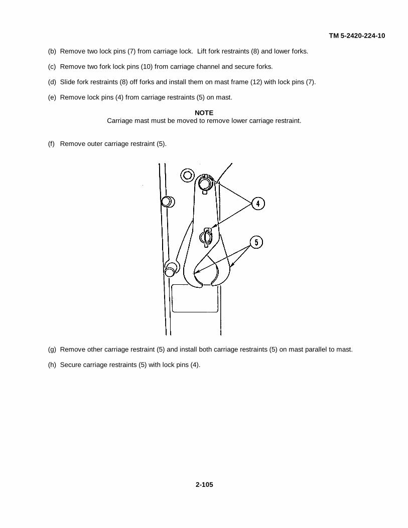
TM 5-2420-224-10
(b) Remove two lock pins (7) from carriage lock. Lift fork restraints (8) and lower forks.
(c) Remove two fork lock pins (10) from carriage channel and secure forks.
(d) Slide fork restraints (8) off forks and install them on mast frame (12) with lock pins (7).
(e) Remove lock pins (4) from carriage restraints (5) on mast.
NOTECarriage mast must be moved to remove lower carriage restraint.
(f) Remove outer carriage restraint (5).
(g) Remove other carriage restraint (5) and install both carriage restraints (5) on mast parallel to mast.
(h) Secure carriage restraints (5) with lock pins (4).
2-105

TM 5-2420-224-10
n. Crane Operation (HMMH).
(1) Mast Folding Lever (1). Pull lever up to unfold mast; press down to fold mast.
(2) Left Outrigger Vertical Control Lever (2). Pull lever up to raise outrigger; push down to lower outrigger.
(3) Right Outrigger Vertical Control Lever (3). Pull lever up to raise outrigger; push down to lower outrigger.
(4) Outrigger Horizontal Control Lever (4). Pull lever up to extend outriggers; push down to retract outriggers.
(5) Boom Extension Lever (5). Pull lever up to extend outer boom; push down to retract outer boom.
(6) Outer Boom Control Lever (6). Pull lever up to raise outer boom; push down to lower outer boom.
(7) Inner Boom Control Lever (7). Pull lever up to raise inner boom; push down to lower inner boom.
(8) Boom Rotation Lever (8). Pull lever up to swing boom clockwise; push down to swing boom counterclockwise.
(9) Tilt Lock Lever (9). Push lever down to engage and disengage tilt lock.
(10) Rotation Lock Lever (10). Pull lever into detent to disengage; release lever to engage.
2-106

TM 5-2420-224-10
WARNING
Daily inspect vehicle and crane operation prior to use. Failure to do so could result inpersonal injury.
At work site, park vehicle with grade. When cross-grade parking is necessary, restrictload to compensate for increased tipping risk. Failure to do so could result in severepersonal injury.
Do not attempt to handle load if outriggers are unable to make solid contact withground. To do so could result in personal injury.
Use equipment on solid, level surface with outriggers properly extended. Failure to doso could result in personal injury.
Avoid overhead obstructions on work side of unit as much as possible. Failure to doso could result in personal injury.
Always disengage PTO prior to moving carrier vehicle. Failure to do so could result inpersonal injury.
Before operating crane, refer to maximum load (capacity) chart on crane for operatingload limitations. Failure to do so could result in personal injury.
Never exceed rated lifting capacities. To do so could result in personal injury.
Never side load boom by dragging load from side. To do so could result in personalinjury.
Perform all stowage procedures using driver's side controls to prevent possiblepersonal injury.
Never rotate crane too fast with load. Cranes are equipped with overload protectionsystem. In overload condition, no function will operate that will result in increase inoperating radius. However, same function may be operated in opposite direction if itresults in decrease in load. Overload protection system is not sensitive to carriervehicle stability and is not substitute for good judgment. Always refer to capacity chartbefore attempting to lift load. Failure to do so could result in serious personal injury.
Never swing load over personnel. To do so could result in personnel injury.
Operate all controls slowly and smoothly to avoid damage to equipment or injury topersonnel.
Always have clear view of work area. Failure to do so could result in personnel injury.
Maintain clearance of at least 10 ft (3.04 m) between any part of crane, loadline orload, and any electrical line. Death or serious injury will result from contact orinadequate clearance.
2-107
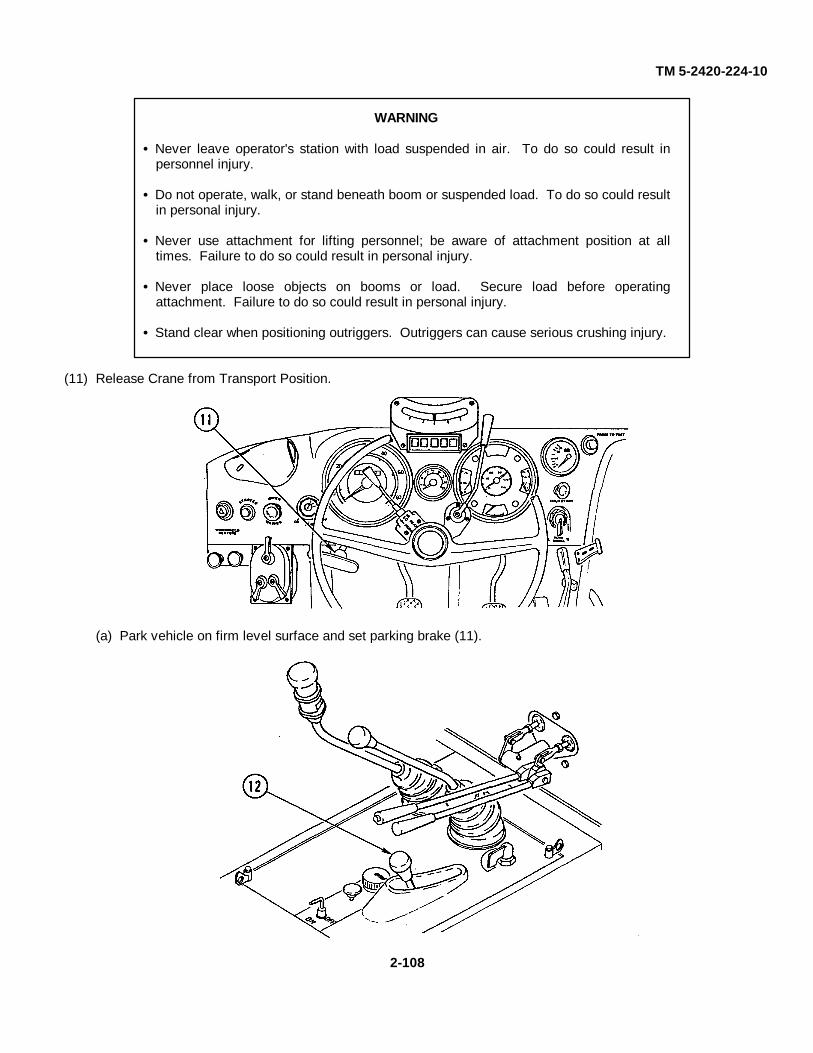
TM 5-2420-224-10
WARNING
Never leave operator's station with load suspended in air. To do so could result inpersonnel injury.
Do not operate, walk, or stand beneath boom or suspended load. To do so could resultin personal injury.
Never use attachment for lifting personnel; be aware of attachment position at alltimes. Failure to do so could result in personal injury.
Never place loose objects on booms or load. Secure load before operatingattachment. Failure to do so could result in personal injury.
Stand clear when positioning outriggers. Outriggers can cause serious crushing injury.
(11) Release Crane from Transport Position.
(a) Park vehicle on firm level surface and set parking brake (11).
2-108
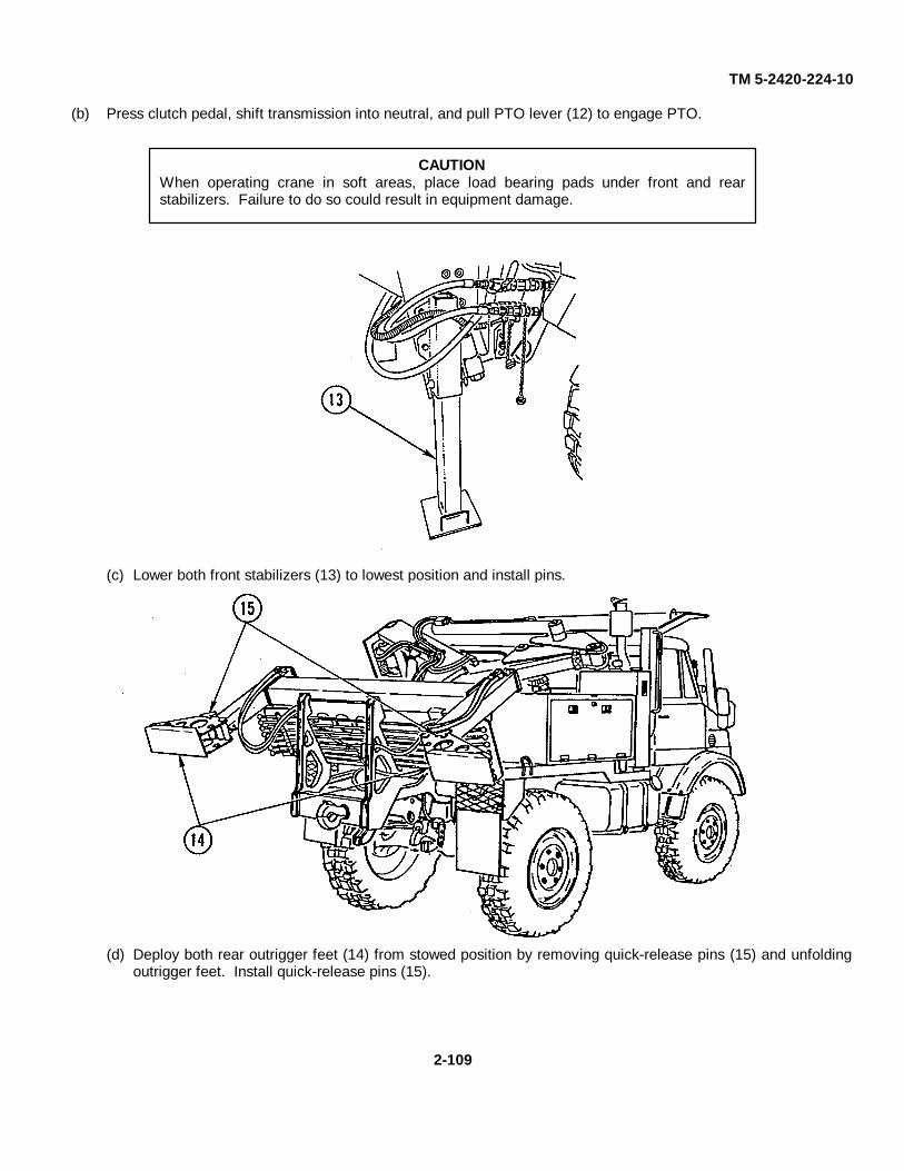
TM 5-2420-224-10
(b) Press clutch pedal, shift transmission into neutral, and pull PTO lever (12) to engage PTO.
CAUTIONWhen operating crane in soft areas, place load bearing pads under front and rearstabilizers. Failure to do so could result in equipment damage.
(c) Lower both front stabilizers (13) to lowest position and install pins.
(d) Deploy both rear outrigger feet (14) from stowed position by removing quick-release pins (15) and unfoldingoutrigger feet. Install quick-release pins (15).
2-109

TM 5-2420-224-10
(e) Activate front suspension lockout system by pulling switch (16) behind passenger seat and pressing clutchpedal at same time.
(f) Move engine speed switch (17) from idle position to crane position.
(g) Move rear implement lock lever (18) to OPEN position and make sure locks are fully retracted.
2-110

TM 5-2420-224-10
(h) Simultaneously pull travel latch handle (19) to release travel latch and hold rear implement tilt lever (20) inLOWER position until crane starts to move from stowed position. Release latch handle (19).
(i) Continue holding implement tilt lever (20) in LOWER position. Release lever (20) when crane has stopped inupright position.
(j) Move rear implement lock lever (18) to CLOSE position to engage locks.
(k) Fully extend rear outriggers (21) by pulling up outrigger horizontal control lever (4).
(l) Lower rear stabilizers separately by pushing down left and right outrigger vertical control levers (2 and 3) untilfirm contact is made and vehicle is level.
2-111

TM 5-2420-224-10
(12) Main Mast Setup.
(a) Make sure extension boom is fully retracted by pushing down boom extension lever (5). Make sure outerboom is fully retracted by pushing down outer boom control lever (6).
CAUTIONFailure to fully erect crane mast will cause damage to crane mast cylinders.
NOTETilt lock lever and mast folding lever must be used together to move mast.
(b) Erect mast by pushing down tilt lock lever (9) and pulling up mast folding lever (1) at same time until masthas stopped in upright position.
(c) Pull rotation lock lever (10) to detent position to release rotation lock.
(d) Raise inner boom to unfold crane by pulling up inner boom control lever (7).
(e) Raise outer boom to working position by pulling up outer boom control lever (6).
2-112
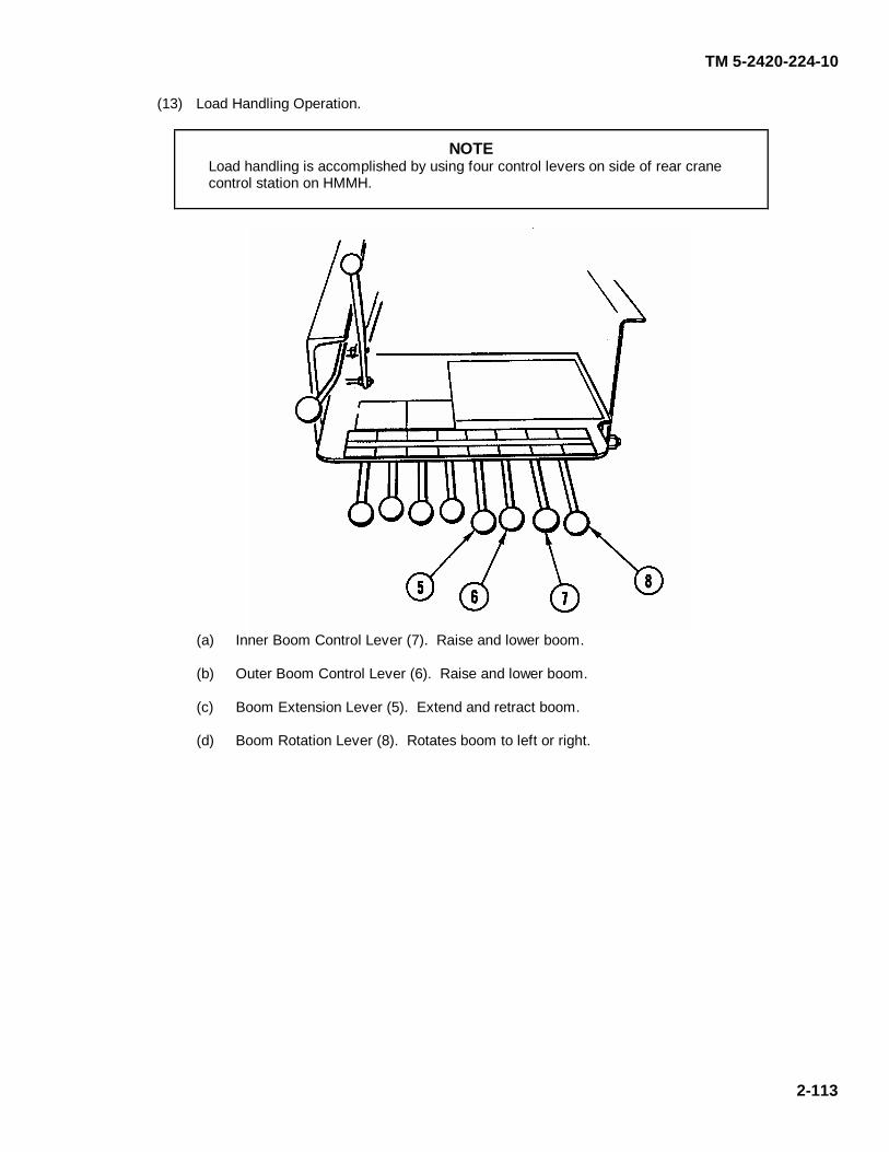
TM 5-2420-224-10
2-113
(13) Load Handling Operation.
NOTE Load handling is accomplished by using four control levers on side of rear crane control station on HMMH.
(a) Inner Boom Control Lever (7). Raise and lower boom. (b) Outer Boom Control Lever (6). Raise and lower boom. (c) Boom Extension Lever (5). Extend and retract boom. (d) Boom Rotation Lever (8). Rotates boom to left or right.
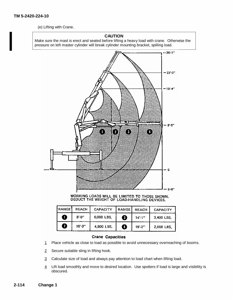
TM 5-2420-224-10
2-114 Change 1
(e) Lifting with Crane.
CAUTION Make sure the mast is erect and seated before lifting a heavy load with crane. Otherwise the pressure on left master cylinder will break cylinder mounting bracket, spilling load.
1 Place vehicle as close to load as possible to avoid unnecessary overreaching of booms. 2 Secure suitable sling in lifting hook. 3 Calculate size of load and always pay attention to load chart when lifting load. 4 Lift load smoothly and move to desired location. Use spotters if load is large and visibility is
obscured.

TM 5-2420-224-10
(14) Crane Stowage Instructions.
WARNINGClear personnel from area prior to starting procedure. Perform all stowage proceduresusing driver's side controls to prevent possible personal injury.
(a) Move engine speed switch (17) to crane position.
(b) Rotate crane using boom rotation lever (8) until turntable hole and rotation lock pin are alined; engagerotation lock pin by releasing rotation lock lever (10).
(c) Raise inner boom to angle of approximately 135 degrees to main mast by pulling inner boom control lever(7). Make sure extension boom is fully retracted.
(d) Push down outer boom control lever (6) to retract outer boom cylinder completely.
(e) Push down inner boom control lever (7) to retract inner boom cylinder completely to fold crane.
2-115
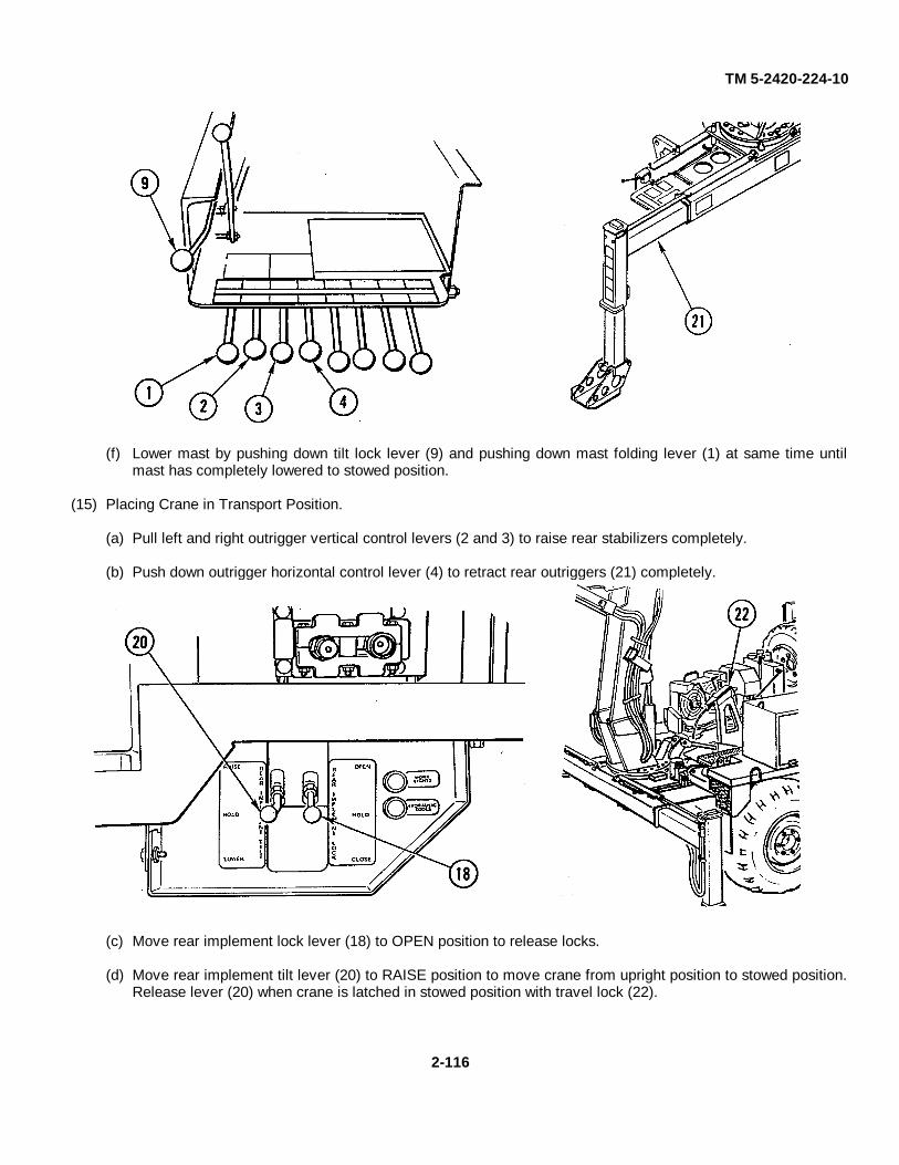
TM 5-2420-224-10
(f) Lower mast by pushing down tilt lock lever (9) and pushing down mast folding lever (1) at same time untilmast has completely lowered to stowed position.
(15) Placing Crane in Transport Position.
(a) Pull left and right outrigger vertical control levers (2 and 3) to raise rear stabilizers completely.
(b) Push down outrigger horizontal control lever (4) to retract rear outriggers (21) completely.
(c) Move rear implement lock lever (18) to OPEN position to release locks.
(d) Move rear implement tilt lever (20) to RAISE position to move crane from upright position to stowed position.Release lever (20) when crane is latched in stowed position with travel lock (22).
2-116

TM 5-2420-224-10
(e) Move engine speed switch (17) from crane position to idle position.
(f) Move rear outrigger feet (14) from operation position to stowed position.
(g) Raise both front stabilizers (13) and install pins when in stowed position.
(h) Push PTO lever (12) to disengage PTO, and push switch (16) to deactivate front suspension lockout system.
2-117
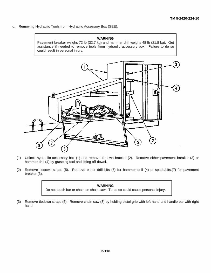
TM 5-2420-224-10
o. Removing Hydraulic Tools from Hydraulic Accessory Box (SEE).
WARNINGPavement breaker weighs 72 lb (32.7 kg) and hammer drill weighs 48 lb (21.8 kg). Getassistance if needed to remove tools from hydraulic accessory box. Failure to do socould result in personal injury.
(1) Unlock hydraulic accessory box (1) and remove tiedown bracket (2). Remove either pavement breaker (3) orhammer drill (4) by grasping tool and lifting off dowel.
(2) Remove tiedown straps (5). Remove either drill bits (6) for hammer drill (4) or spade/bits,(7) for pavementbreaker (3).
WARNINGDo not touch bar or chain on chain saw. To do so could cause personal injury.
(3) Remove tiedown straps (5). Remove chain saw (8) by holding pistol grip with left hand and handle bar with righthand.
2-118
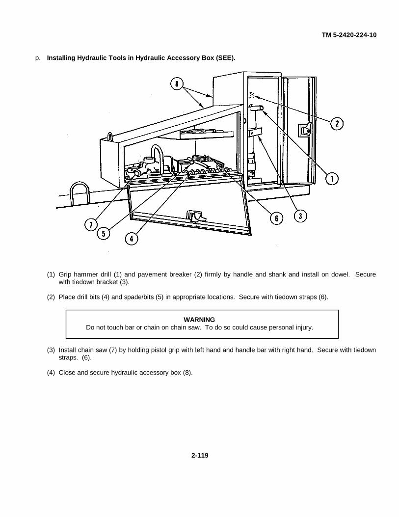
TM 5-2420-224-10
p. Installing Hydraulic Tools in Hydraulic Accessory Box (SEE).
(1) Grip hammer drill (1) and pavement breaker (2) firmly by handle and shank and install on dowel. Securewith tiedown bracket (3).
(2) Place drill bits (4) and spade/bits (5) in appropriate locations. Secure with tiedown straps (6).
WARNINGDo not touch bar or chain on chain saw. To do so could cause personal injury.
(3) Install chain saw (7) by holding pistol grip with left hand and handle bar with right hand. Secure with tiedownstraps. (6).
(4) Close and secure hydraulic accessory box (8).
2-119
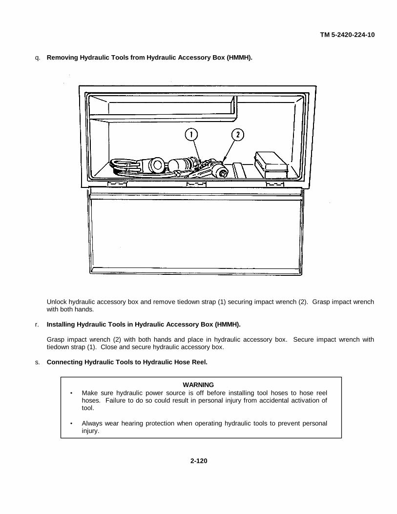
TM 5-2420-224-10
q. Removing Hydraulic Tools from Hydraulic Accessory Box (HMMH).
Unlock hydraulic accessory box and remove tiedown strap (1) securing impact wrench (2). Grasp impact wrenchwith both hands.
r. Installing Hydraulic Tools in Hydraulic Accessory Box (HMMH).
Grasp impact wrench (2) with both hands and place in hydraulic accessory box. Secure impact wrench withtiedown strap (1). Close and secure hydraulic accessory box.
s. Connecting Hydraulic Tools to Hydraulic Hose Reel.
WARNING• Make sure hydraulic power source is off before installing tool hoses to hose reel
hoses. Failure to do so could result in personal injury from accidental activation oftool.
• Always wear hearing protection when operating hydraulic tools to prevent personalinjury.
2-120

TM 5-2420-224-10
WARNING• Do not activate hydraulic tool circuit when hydraulic tools are disconnected from
hose reel fittings. To do so will cause excessive oil temperature resulting in damageto pump and possible personal injury.
• If tool quick disconnects were disconnected while under pressure, use BII (BasicIssue Items) tools and slowly loosen one hose fitting to free trapped pressure.Protect eyes from fluid spray. Failure to do so could result in personal injury.
CAUTIONWipe quick disconnects clean with lint-free cloth before attaching hoses. Damage tointernal parts of tools could result from dirt on couplings.
NOTEThe following procedures apply to all hydraulic tools.
(1) Lay tool on tarp or clean, dry surface.
(2) Pull hoses (1) from hose reel.
(3) Insert tool hose coupler into hose reel coupler. Turn tool hose coupler approximately 1/8 turn to lock inplace.
2-121
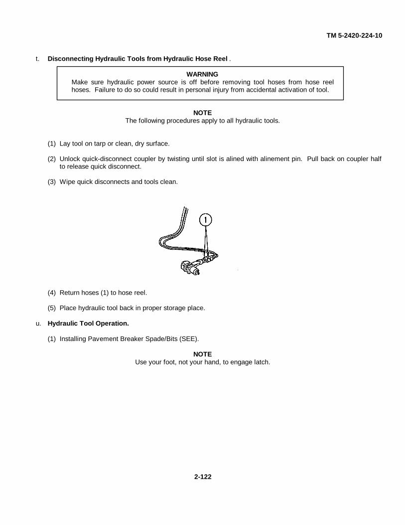
TM 5-2420-224-10
t. Disconnecting Hydraulic Tools from Hydraulic Hose Reel .
WARNINGMake sure hydraulic power source is off before removing tool hoses from hose reelhoses. Failure to do so could result in personal injury from accidental activation of tool.
NOTEThe following procedures apply to all hydraulic tools.
(1) Lay tool on tarp or clean, dry surface.
(2) Unlock quick-disconnect coupler by twisting until slot is alined with alinement pin. Pull back on coupler halfto release quick disconnect.
(3) Wipe quick disconnects and tools clean.
(4) Return hoses (1) to hose reel.
(5) Place hydraulic tool back in proper storage place.
u. Hydraulic Tool Operation.
(1) Installing Pavement Breaker Spade/Bits (SEE).
NOTEUse your foot, not your hand, to engage latch.
2-122
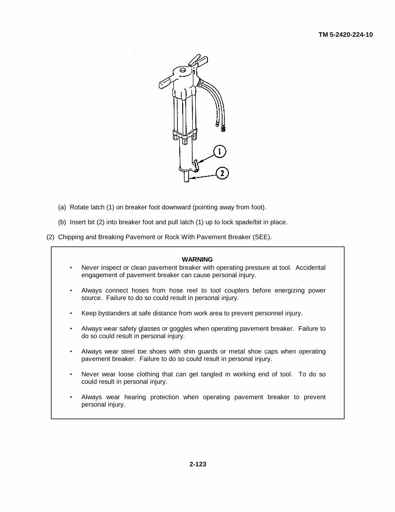
TM 5-2420-224-10
(a) Rotate latch (1) on breaker foot downward (pointing away from foot).
(b) Insert bit (2) into breaker foot and pull latch (1) up to lock spade/bit in place.
(2) Chipping and Breaking Pavement or Rock With Pavement Breaker (SEE).
WARNING• Never inspect or clean pavement breaker with operating pressure at tool. Accidental
engagement of pavement breaker can cause personal injury.
• Always connect hoses from hose reel to tool couplers before energizing powersource. Failure to do so could result in personal injury.
• Keep bystanders at safe distance from work area to prevent personnel injury.
• Always wear safety glasses or goggles when operating pavement breaker. Failure todo so could result in personal injury.
• Always wear steel toe shoes with shin guards or metal shoe caps when operatingpavement breaker. Failure to do so could result in personal injury.
• Never wear loose clothing that can get tangled in working end of tool. To do socould result in personal injury.
• Always wear hearing protection when operating pavement breaker to preventpersonal injury.
2-123
TM 5-2420-224-10
CAUTION• Hydraulic tools switch must be in off position when coupling or uncoupling hydraulic
tools. Failure to do so will result in damage to quick-disconnect couplers andoverheating of hydraulic system.
• If hydraulic hand tools are to be in operation during winter, couple two auxiliary hosereel ends together to preheat hoses and hydraulic oil and prevent equipmentdamage.
NOTE• Bite or width of broken material will vary with strength and thickness of material and
amount of reinforcement wire or rebar.
• Harder material and more reinforcement wire or rebar will require smaller bits. Todetermine most effective bit, start with 2-in. (50-mm) or smaller bits.
• Corners will require smaller bits because of greater support by surrounding material.
• When too large a bite is taken, sticking of steel occurs; steel drills into material andshank becomes trapped by surrounding material.
(a) Remove breaker from hydraulic accessory box.
(b) Install appropriate bits for the job.
(c) Connect breaker to hydraulic quick-disconnect couplers.
(d) Energize tool circuit.
(e) Place bit firmly on surface to be worked.
(f) Squeeze trigger to start breaker. Adequate downward pressure is very important. When point breaksthrough obstruction, or becomes bound, release trigger and reposition bit on material.
(g) To start an opening, break an opening (hole) in center of surface. Once hole is started, crack portions ofmaterial into original opening. If breaker bit is used in spiral pattern around original hole, progress will befaster because breaking off edges requires smaller bites.
2-124
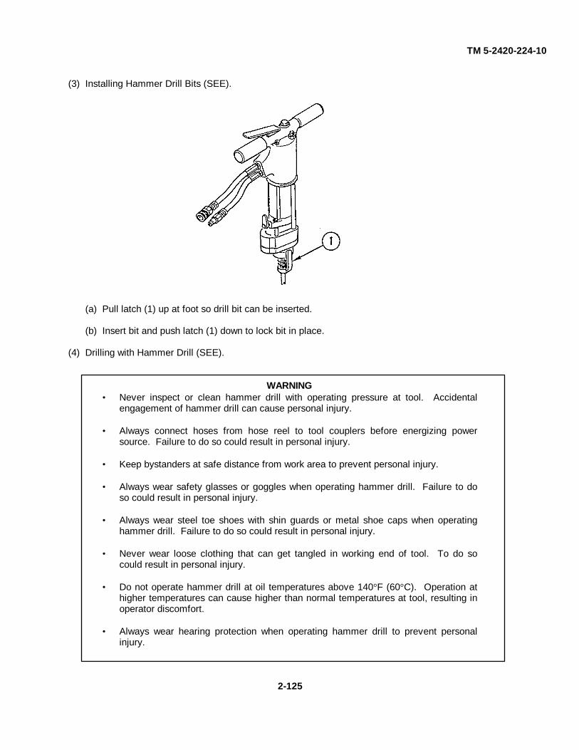
TM 5-2420-224-10
(3) Installing Hammer Drill Bits (SEE).
(a) Pull latch (1) up at foot so drill bit can be inserted.
(b) Insert bit and push latch (1) down to lock bit in place.
(4) Drilling with Hammer Drill (SEE).
WARNING• Never inspect or clean hammer drill with operating pressure at tool. Accidental
engagement of hammer drill can cause personal injury.
• Always connect hoses from hose reel to tool couplers before energizing powersource. Failure to do so could result in personal injury.
• Keep bystanders at safe distance from work area to prevent personal injury.
• Always wear safety glasses or goggles when operating hammer drill. Failure to doso could result in personal injury.
• Always wear steel toe shoes with shin guards or metal shoe caps when operatinghammer drill. Failure to do so could result in personal injury.
• Never wear loose clothing that can get tangled in working end of tool. To do socould result in personal injury.
• Do not operate hammer drill at oil temperatures above 140°F (60°C). Operation athigher temperatures can cause higher than normal temperatures at tool, resulting inoperator discomfort.
• Always wear hearing protection when operating hammer drill to prevent personalinjury.
2-125
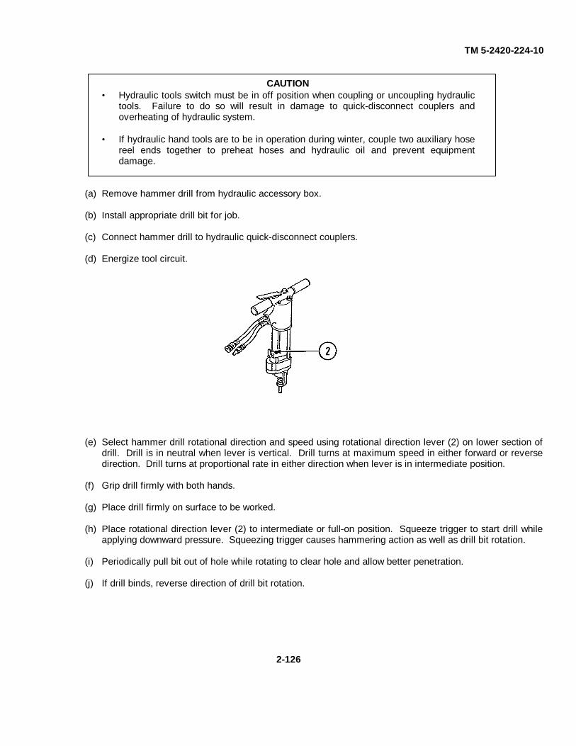
TM 5-2420-224-10
CAUTION• Hydraulic tools switch must be in off position when coupling or uncoupling hydraulic
tools. Failure to do so will result in damage to quick-disconnect couplers andoverheating of hydraulic system.
• If hydraulic hand tools are to be in operation during winter, couple two auxiliary hosereel ends together to preheat hoses and hydraulic oil and prevent equipmentdamage.
(a) Remove hammer drill from hydraulic accessory box.
(b) Install appropriate drill bit for job.
(c) Connect hammer drill to hydraulic quick-disconnect couplers.
(d) Energize tool circuit.
(e) Select hammer drill rotational direction and speed using rotational direction lever (2) on lower section ofdrill. Drill is in neutral when lever is vertical. Drill turns at maximum speed in either forward or reversedirection. Drill turns at proportional rate in either direction when lever is in intermediate position.
(f) Grip drill firmly with both hands.
(g) Place drill firmly on surface to be worked.
(h) Place rotational direction lever (2) to intermediate or full-on position. Squeeze trigger to start drill whileapplying downward pressure. Squeezing trigger causes hammering action as well as drill bit rotation.
(i) Periodically pull bit out of hole while rotating to clear hole and allow better penetration.
(j) If drill binds, reverse direction of drill bit rotation.
2-126
TM 5-2420-224-10
(5) Felling Tree with Chain Saw (SEE).
WARNING• Always be well rested and mentally alert before operating chain saw to avoid prevent
injury.
• Never inspect or clean chain saw with operating pressure at tool. Accidentalengagement of tool can cause personal injury.
• Always connect hoses from hose reel to tool couplers before energizing powersource. Failure to do so could result in personal injury.
• Keep bystanders at safe distance from work area to prevent personal injury.
• Always wear safety glasses or goggles when operating chain saw. Failure to do socould result in personal injury.
• Always wear hearing protection when operating chain saw to prevent personal injury.
• Always wear steel toe shoes with shin guards or metal shoe caps when operatingchain saw. Failure to do so could result in personal injury.
• Never wear loose clothing that can get tangled in working end of tool. To do socould result in personal injury.
• Do not operate chain saw in tree unless you have been trained to do so to preventpersonal injury.
• Do not allow other persons near chain saw when starting or cutting. Do not startcutting until you have clear work area, secure footing, and planned retreat path fromfalling tree. To do so could result in personal injury.
• Hold chain saw firmly with both hands when chain is in motion. Use firm grip withthumbs and fingers encircling chain saw handles. Failure to do so could result inpersonal injury.
• Keep body away from chain when chain saw is operating to prevent personal injury.
• Carry chain saw with unit deenergized and bar and chain to rear of body. Failure todo so could result in personal injury.
• Do not operate chain saw that is damaged, improperly adjusted, or not completelyand securely assembled. Make sure chain stops when trigger is released. Failure todo so could result in personal injury.
2-127

TM 5-2420-224-10
WARNING• Use extreme caution when cutting small brush and saplings with chain saw. Slender
material may catch chain, whipping chain toward operator or pulling operator offbalance resulting in personal injury.
• When cutting limb under tension, be alert for spring-back of limb. Failure to do socould result in personal injury.
• Keep hand grips dry, clean, and free of oil. Failure to do so could result in personalinjury.
• Guard against kickback. Kickback is upward motion of bar that occurs when chain atnose of bar contacts object. Kickback can lead to dangerous loss of control of chainsaw resulting in personal injury. Observe following procedures to avoid kickback:
Hold chain saw firmly with both hands.
Do not allow nose of bar to contact log, branch, ground, or any other obstruction.
Do not overreach.
Do not cut above shoulder height.
• Make sure chain tension is adjusted and automatic oiler is working properly. Failureto do so could result in personal injury or death. (Refer to page 3-18 for tensionadjustment.)
CAUTION• Hydraulic tools switch must be in off position when coupling or uncoupling hydraulic
tools. Failure to do so will result in damage to quick-disconnect couplers andoverheating of hydraulic system.
• If hydraulic hand tools are to be in operation during winter, couple two auxiliary hosereel ends together to preheat hoses and hydraulic oil and prevent equipmentdamage.
• Make sure vehicle is not within area of tree to be felled. Failure to do so could resultin equipment damage.
(a) Clear area to obtain good footing.
(b) Clear area where tree will fall.
(c) Clear area for retreat path.
(d) Remove chain saw from hydraulic accessory box.
(e) Connect chain saw to hydraulic quick-disconnect couplers.
(f) Energize tool circuit.
2-128
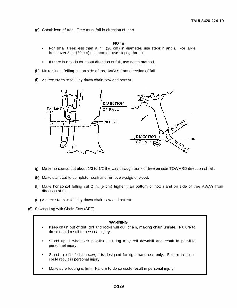
TM 5-2420-224-10
(g) Check lean of tree. Tree must fall in direction of lean.
NOTE• For small trees less than 8 in. (20 cm) in diameter, use steps h and i. For large
trees over 8 in. (20 cm) in diameter, use steps j thru m.
• If there is any doubt about direction of fall, use notch method.
(h) Make single felling cut on side of tree AWAY from direction of fall.
(i) As tree starts to fall, lay down chain saw and retreat.
(j) Make horizontal cut about 1/3 to 1/2 the way through trunk of tree on side TOWARD direction of fall.
(k) Make slant cut to complete notch and remove wedge of wood.
(I) Make horizontal felling cut 2 in. (5 cm) higher than bottom of notch and on side of tree AWAY fromdirection of fall.
(m) As tree starts to fall, lay down chain saw and retreat.
(6) Sawing Log with Chain Saw (SEE).
WARNING• Keep chain out of dirt; dirt and rocks will dull chain, making chain unsafe. Failure to
do so could result in personal injury.
• Stand uphill whenever possible; cut log may roll downhill and result in possiblepersonnel injury.
• Stand to left of chain saw; it is designed for right-hand use only. Failure to do socould result in personal injury.
• Make sure footing is firm. Failure to do so could result in personal injury.
2-129

TM 5-2420-224-10
WARNING• Grip chain saw firmly with both hands. Failure to do so could result in personal injury.
(a) Aline bar and place bucking cleat against work to be cut.
(b) In area A, cut down from top V3 the way. Finish by cutting up from bottom.
(c) In area B, cut down from top until cut is complete.
(7) Pruning and Debranching with Chain Saw (SEE).
WARNING• Make sure footing is firm. Failure to do so could result in personal injury.
• Grip chain saw firmly with both hands. Failure to do so could result in personalinjury.
• Do not work overhead with chain saw. Work at chest level or lower. Failure to do socould result in personal injury.
Place bucking cleat as close to work as possible to avoid kickback.
(8) Using Impact Wrench (HMMH).
WARNING• Before operating impact wrench, make operational check of controls. Failure to do
so could result in personal injury.
• Never inspect or clean wrench with power source operating or with operatingpressure at tool. Accidental engagement of tool can cause personal injury.
• Always connect hoses from hose reel to tool couplers before energizing powersource. Failure to do so could result in personal injury.
2-130
TM 5-2420-224-10
WARNING• Keep hand clear of spinning attachments on impact wrench at all times. Failure to
do so could result in personal injury.
• Be aware of location of all personnel in area of operation. Failure to do so couldresult in personnel injury.
• Do not overreach. Maintain proper footing and balance at all times. Failure to' do socould result in personal injury.
• Be attentive to keep body clear of tool operating components. Failure to do so couldresult in personal injury.
• Always wear steel toe shoes with shin guards or metal shoe caps when operatingimpact wrench. Failure to do so could result in personal injury.
• Always wear hearing protection when operating impact wrench to prevent personalinjury.
• Always wear safety glasses or goggles when operating impact wrench. Failure to doso could result in personal injury.
• Never wear loose clothing that can get tangled in working end of tool. To do socould result in personal injury.
• When operating impact wrench, always use sockets and accessories designed forimpact-type applications. Do not use standard sockets or accessories; they cancrack or fracture during operation and cause personal injury.
• Do not use impact wrench as hammer drill or for metal drilling. To do so could resultin personal injury.
• Only operate tool when attachment is securely installed. Failure to do so couldresult in personal injury.
• Keep hand grips dry, clean, and free of oil. Failure to do so could result in personalinjury.
CAUTION• Hydraulic circuit control valve must be set to OFF when coupling impact wrench.
Failure to do so could result in damage to quick-disconnect couplers and overheatingof hydraulic system.
• To avoid or minimize trapped pressure within impact wrench, always connecthydraulic return line first and disconnect it last. Failure to do so could result inequipment damage.
2-131
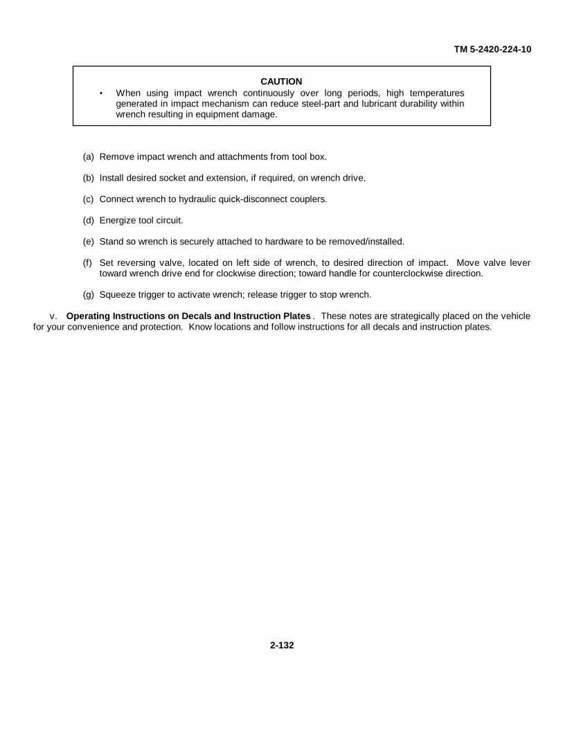
TM 5-2420-224-10
CAUTION• When using impact wrench continuously over long periods, high temperatures
generated in impact mechanism can reduce steel-part and lubricant durability withinwrench resulting in equipment damage.
(a) Remove impact wrench and attachments from tool box.
(b) Install desired socket and extension, if required, on wrench drive.
(c) Connect wrench to hydraulic quick-disconnect couplers.
(d) Energize tool circuit.
(e) Stand so wrench is securely attached to hardware to be removed/installed.
(f) Set reversing valve, located on left side of wrench, to desired direction of impact. Move valve levertoward wrench drive end for clockwise direction; toward handle for counterclockwise direction.
(g) Squeeze trigger to activate wrench; release trigger to stop wrench.
v. Operating Instructions on Decals and Instruction Plates . These notes are strategically placed on the vehiclefor your convenience and protection. Know locations and follow instructions for all decals and instruction plates.
2-132
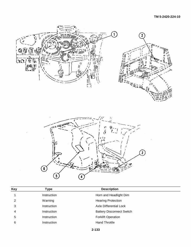
TM 5-2420-224-10
Key Type Description
1 Instruction Horn and Headlight Dim
2 Warning Hearing Protection
3 Instruction Axle Differential Lock
4 Instruction Battery Disconnect Switch
5 Instruction Forklift Operation
6 Instruction Hand Throttle
2-133
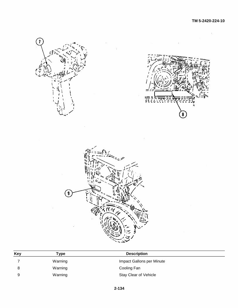
TM 5-2420-224-10
Key Type Description
7 Warning Impact Gallons per Minute
8 Warning Cooling Fan
9 Warning Stay Clear of Vehicle
2-134

TM 5-2420-224-10
Key Type Description
10 Warning Crane Folding
11 Warning Operating Dangers
12 Warning Operating Dangers
13 Warning Outrigger Safety
14 Warning Outrigger Safety
15 Instruction Crane Controls
16 Instruction Crane Folding
17 Instruction Tilt/Rotation
18 Warning Electrocution
19 Instruction Crane Controls
20 Warning Stowing/Unfolding
21 Warning Stowing/Unfolding
2-135

TM 5-2420-224-10
Key Type Description
22 Warning Lifting with Backhoe
23 Warning Operation
24 Instruction Controls, Upper
25 Instruction Controls, Lower
26 Warning Operation
27 Caution Boom Swing
2-136
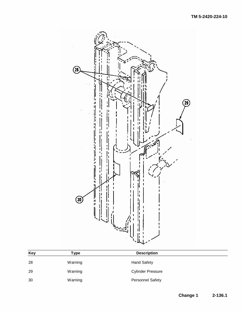
TM 5-2420-224-10
Change 1 2-136.1
Key Type Description 28 Warning Hand Safety 29 Warning Cylinder Pressure 30 Warning Personnel Safety
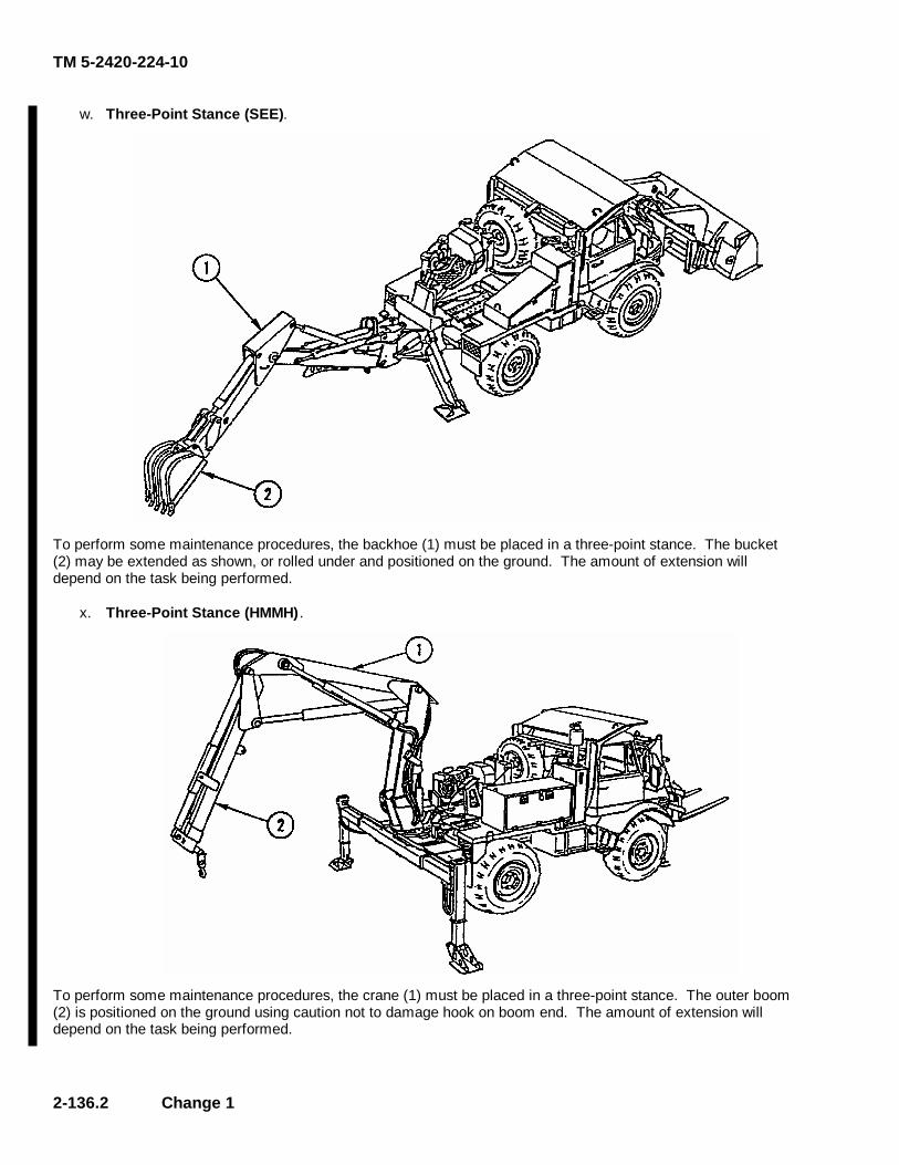
TM 5-2420-224-10
2-136.2 Change 1
w. Three-Point Stance (SEE).
To perform some maintenance procedures, the backhoe (1) must be placed in a three-point stance. The bucket (2) may be extended as shown, or rolled under and positioned on the ground. The amount of extension will depend on the task being performed.
x. Three-Point Stance (HMMH) .
To perform some maintenance procedures, the crane (1) must be placed in a three-point stance. The outer boom (2) is positioned on the ground using caution not to damage hook on boom end. The amount of extension will depend on the task being performed.

TM 5-2420-224-10
Change 1 2-136.3
y. Removal of the Engine Hood .
�
CAUTION Do not catch engine hood on brake fluid reservoir and windshield washer reservoir when removing engine hood with front loader installed. To do so could result in equipment damage.
(1) Remove key from left-hand door box (1) to open engine hood (2). (2) To remove engine hood (2), unlock at bottom (3) and at upper bore (4). Lift engine hood slightly
from below and release safety latch on left side by reaching inside bottom-left corner. (3) Remove engine hood (2) from engine compartment (5).
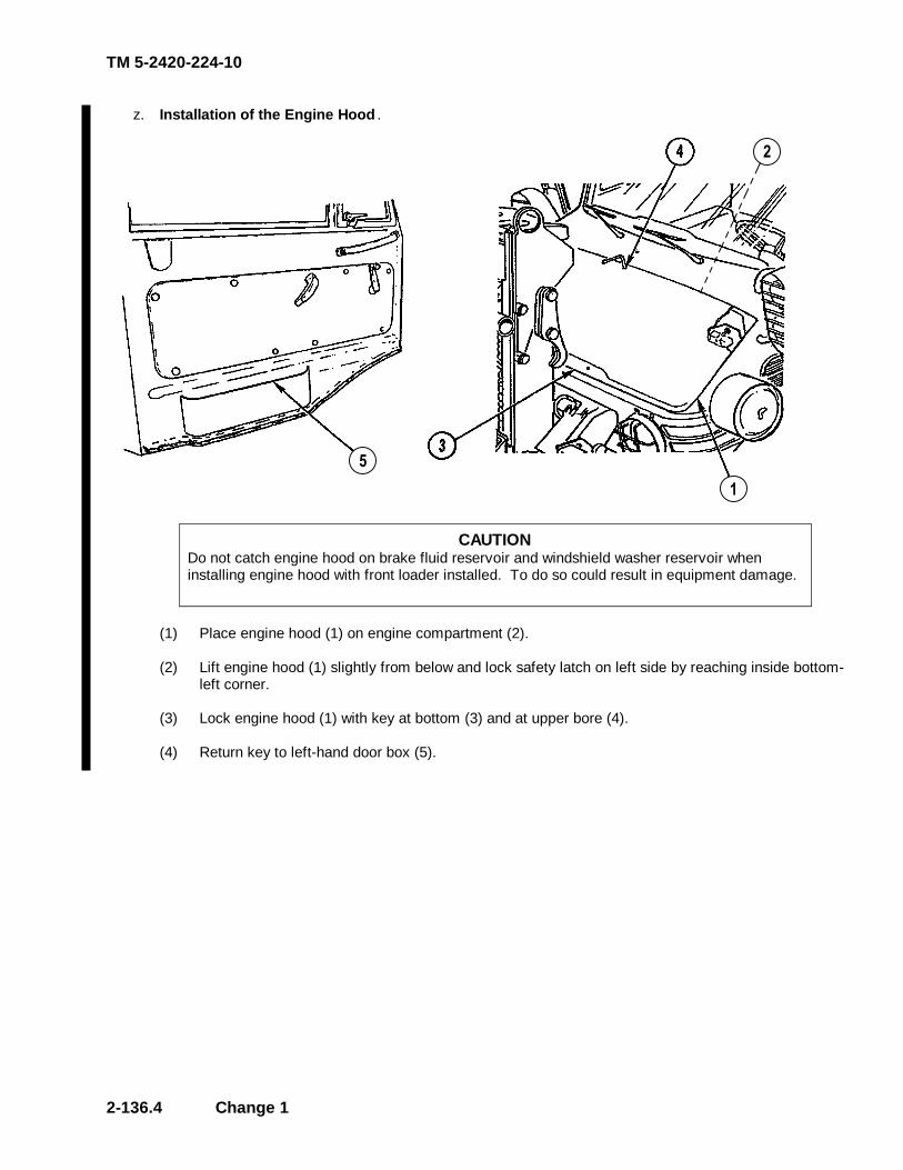
TM 5-2420-224-10
2-136.4 Change 1
z. Installation of the Engine Hood .
�
�
�
CAUTION Do not catch engine hood on brake fluid reservoir and windshield washer reservoir when installing engine hood with front loader installed. To do so could result in equipment damage.
(1) Place engine hood (1) on engine compartment (2). (2) Lift engine hood (1) slightly from below and lock safety latch on left side by reaching inside bottom-
left corner. (3) Lock engine hood (1) with key at bottom (3) and at upper bore (4). (4) Return key to left-hand door box (5).

TM 5-2420-224-10
Change 1 2-137
aa. Removal/Installation of the Inside Engine Cover .
(1) Disconnect five fasteners (1) and remove inside engine cover (2) through passenger side of
vehicle.
ab. Parking Brake Test.
WARNING Make sure there are no obstacles or personnel in front of vehicle to prevent personnel injury.
(1) Park vehicle on level surface. (2) Fasten seat belt. (3) Apply parking brake. (4) Place transmission in neutral. (5) Start vehicle. (6) Set hand throttle to 700-750 rpm (idle). (7) Disengage clutch. (8) Shift group shift lever to Gear Range I. (9) Shift main shift lever to 4th position and engage intermediate speed control in high position. (10) Slowly engage clutch; engine should stall. (11) If engine does not stall or vehicle moves, contact unit maintenance and adjust parking brake
according to TM 5-2420-224-20.

TM 5-2420-224-10
2-138
Section IV. OPERATION UNDER UNUSUAL CONDITIONS
2-8. OPERATION IN UNUSUAL WEATHER
a. Extreme Cold. (1) General. If operating backhoe (SEE) or crane (HMMH) in extreme cold, make sure proper operator
protection is worn. Extensive preparation of the vehicle is required for extremely cold weather. Extreme cold causes many problems:
• Lubricants thicken or congeal
• Batteries may freeze or lose electrical efficiency
• Fuel may not readily vaporize for combustion
• Various materials will become hard, brittle, and easily damaged
(2) Cooling System. Inspect for leaks and general condition. Make sure clamps are tight and there is
enough fluid in expansion tank. If system needs service, notify unit maintenance. (3) Fuel Tank. Do not allow fuel tank to remain partially empty for a long period in extremely cold
weather. Fill to filler neck after each work period to help avoid water condensation in the fuel tank. Remove all ice and snow from around filler neck before refueling.
(4) Electrical System.
(a) Inspect battery cables, wiring harnesses, and wiring. Notify unit maintenance if damaged. (b) Use lights and other electrical equipment as little as possible when system is not charging.
(5) Lubrication. Lubricate in accordance with LO 5-2420-224-12. (6) Engine Operation.
WARNING Starter fuel is highly flammable. Do not expose to high temperatures. Store refill bottles in cool place, especially during summer months. Failure to do so could result in serious personal injury.
CAUTION
Before starting, make sure fuel and oil in engine are thin enough to flow. If oil drips from dipstick, it is thin enough for engine to be started. Failure to observe this caution could result in damage to equipment.
(a) Use ether start aid.

TM 5-2420-224-10
Change 1 2-139
CAUTION
Low idling speed during extremely cold temperatures can result in incomplete combustion and formation of heavy deposits on valves.
(b) Run engine at reduced speed only long enough to circulate oil through engine, then increase
speed and warm up engine. (c) Cover front of radiator, if necessary, to bring engine up to operating temperature. Remove
cover after warmup to avoid overheating engine. (7) Vehicle Operation.
(a) Test brakes and equipment controls carefully. (b) Move all controls slowly to warm hydraulic oil. Cycle each control several times. Normal
warmup period is 3-10 minutes. (c) Operate under light load for first 5 minutes of operation. (d) Make sure compressed air antifreeze system is on.
(8) Parking and Non-Use.
(a) Park vehicle in sheltered place, if possible. Cover to protect engine, accessories, and controls from ice and snow.
(b) Run vehicle onto planks to prevent tires from freezing to ground. Block up bucket on SEE. (c) Clean wet snow or mud from tires and hydraulic cylinders before it freezes. (d) In extremely cold weather, notify unit maintenance to remove batteries and store in
moderately warm area. Have batteries installed just prior to starting engine. b. Extreme Heat.
(1) General. Check coolant temperature gage and warning light frequently for indication of overheating. Allow engine to idle slowly when it is overheated until temperature is reduced as indicated by normal condition of warning indicators. If indicators stay on after more than 10 minutes of reduced workload, or alarm sounds, stop vehicle and notify unit maintenance.
(2) Cooling System.
(a) Check coolant at frequent intervals and keep expansion tank cap tight. Notify unit maintenance if unusual coolant loss is noticed.
(b) Make sure radiator is free of any blockage and obstructions.
(3) Lubrication. Lubricate in accordance with LO 5-2420-224-12. (4) Air Cleaner. Check and clean air filter more frequently. Check air cleaner indicator frequently.
Clean dust discharge valve regularly and notify unit maintenance if filter needs replacement. (5) Parking and Non-Use. Park vehicle in a shaded area, if possible.
TM 5-2420-224-10
2-140 Change 1
c. Rainy or Humid Conditions .
(1) General.
(a) Protect vehicle from moisture. Keep operator’s compartment as dry as possible. (b) If vehicle cannot be parked under cover, protect backhoe operator’s station (SEE) and crane
operator’s controls (HMMH). (c) Whenever possible, park vehicle on raised or elevated area with good drainage.
(2) Fuel System. Keep fuel tank filled to filler neck to cut down on condensation in fuel tank. Protect
fuel tank filler opening when refilling in rainy conditions. (3) Lubrication. Lubricate in accordance with LO 5-2420-224-12.
2-9. OPERATION IN DUST OR SAND
WARNING Do not turn on incline. Always back down ramps or inclines when possible with backhoe in unstowed center position. Driving forward with load, down ramp or down incline, will reduce vehicle stability and cause possible injury to personnel.
General. Dust and sand are abrasive and can cause wear on many parts of the vehicle.
(1) Cooling System. Check radiator frequently for foreign matter blocking radiator. (2) Air Cleaner. Check air cleaner indicator light more frequently. Clean dust discharge valve regularly
and notify unit maintenance if the indicator light comes on. (3) Lubrication. Lubricate in accordance with LO 5-2420-224-12. Lubricate at more frequent intervals.
Take special care cleaning lubrication fittings and openings. Keep dust and dirt out of lubricants. (4) Parking and Non-Use. Make sure operator’s compartment doors, windows, and vents are tightly
closed. Protect engine compartment from windblown dust and sand. When vehicle is not in use, cover external operator’s controls and area to protect them from windblown dust or sand.
(5) Implements. Check hydraulic cylinders, levers, and linkage frequently. Do not allow dust, dirt, or
sand to collect on these surfaces.
2-10. OPERATION IN SALTWATER AREAS General.
(1) Corrosion. Keep vehicle as clean as possible. Wash with fresh clean water after use. Inspect wiring connections closely for signs of corrosion.
(2) Lubrication. Lubricate frequently in accordance with LO 5-2420-224-12.

TM 5-2420-224-10
2-11. OPERATION AT HIGH ALTITUDES
General.
Closely watch coolant level and engine instruments and indicators.
2-12. OPERATION IN SNOW
General.
(1) Keep fuel tank full at all times. Keep snow and ice away from fuel filler opening to avoid condensation in fueltank.
(2) Clean snow and ice away from exterior controls and indicators.
(3) Protect backhoe operator's compartment (SEE) when parked if shelter is not available.
2-13. FORDING
a. Before Fording.
(1) Check depth of water at deepest point. Make sure bottom is even enough for fording. Do not attempt to fordeven narrowest stream if more than 30 in. (76 cm) deep. Make sure engine is operating properly.
(2) Shift transmission into low and engage four-wheel drive and differential locks.
(3) Increase engine speed to reduce risk of stalling.
b. During Fording .
(1) All attachments must remain in transport position.
(2) Enter water slowly to minimize waves and backwash. Speed should not exceed 3-4 mph (4.8-6.4 kph).
(3) If stalling occurs, notify unit maintenance.
c. After Fording.
WARNINGCheck brakes for proper operation. Failure to do so could result in personal injury.
(1) Lubricate vehicle completely as soon as possible after fording in accordance with LO 5-2420-224-12.
(2) Check and clean radiator of any debris that may be blocking air flow.
2-141
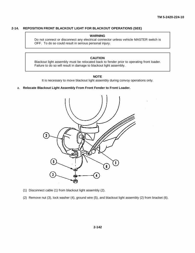
TM 5-2420-224-10
2-14. REPOSITION FRONT BLACKOUT LIGHT FOR BLACKOUT OPERATIONS (SEE)
WARNINGDo not connect or disconnect any electrical connector unless vehicle MASTER switch isOFF. To do so could result in serious personal injury.
CAUTIONBlackout light assembly must be relocated back to fender prior to operating front loader.Failure to do so will result in damage to blackout light assembly.
NOTEIt is necessary to move blackout light assembly during convoy operations only.
a. Relocate Blackout Light Assembly From Front Fender to Front Loader.
(1) Disconnect cable (1) from blackout light assembly (2).
(2) Remove nut (3), lock washer (4), ground wire (5), and blackout light assembly (2) from bracket (6).
2-142
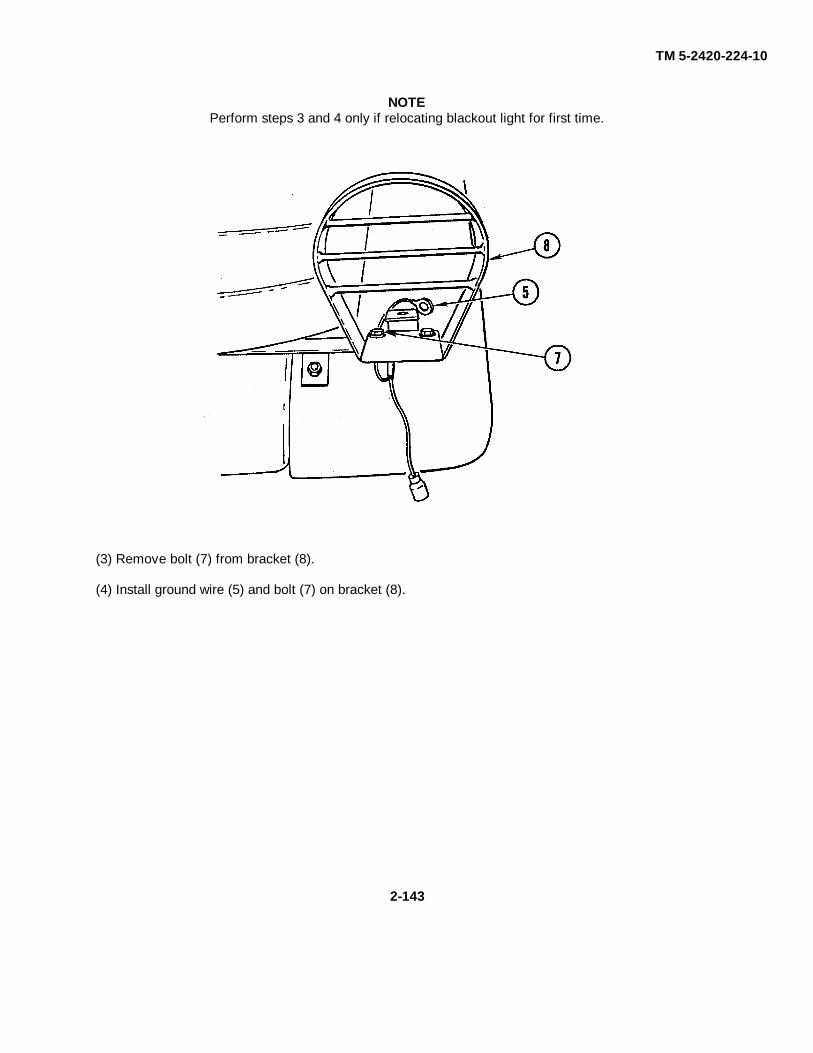
TM 5-2420-224-10
NOTEPerform steps 3 and 4 only if relocating blackout light for first time.
(3) Remove bolt (7) from bracket (8).
(4) Install ground wire (5) and bolt (7) on bracket (8).
2-143

TM 5-2420-224-10
(5) Install blackout light assembly (2), lock washer (4), and nut (3) on bracket (9).
(6) Connect cable (10) to blackout light assembly (2) and cable (1).
b. Relocate Blackout Light Assembly From Front Loader to Front Fender.
WARNINGDo not connect or disconnect any electrical connector unless vehicle MASTERswitch is OFF. To do so could result in serious personal injury.
2-144
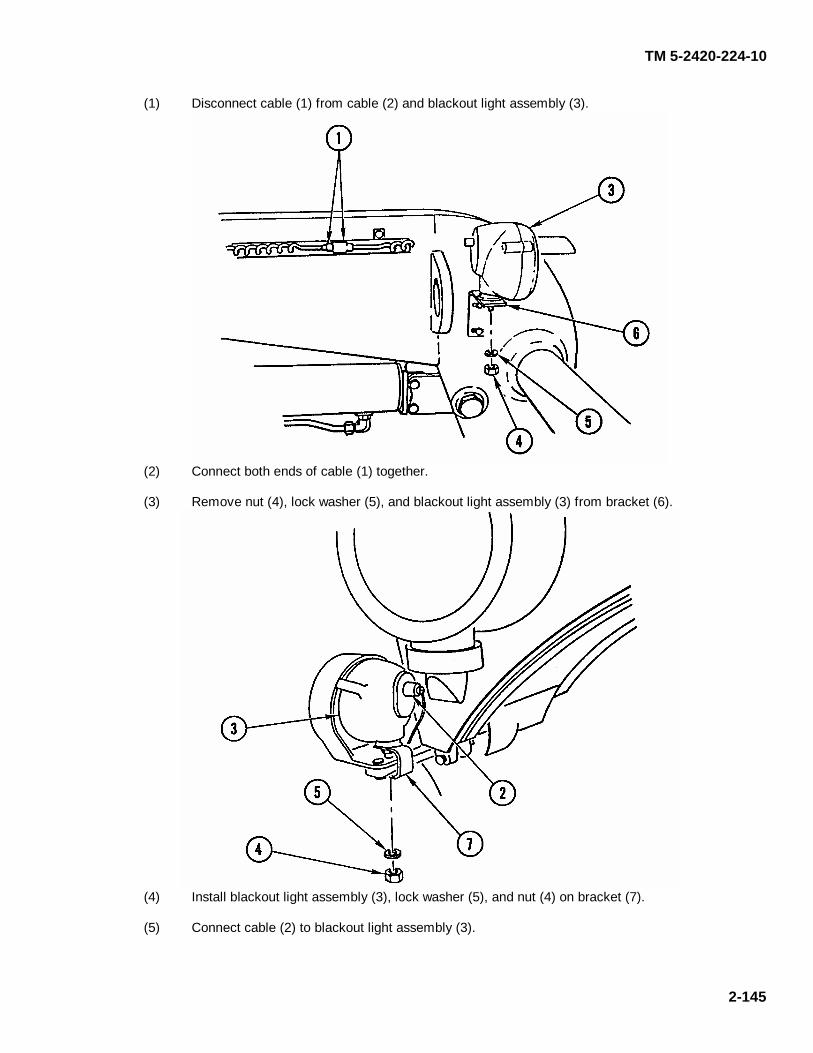
TM 5-2420-224-10
2-145
(1) Disconnect cable (1) from cable (2) and blackout light assembly (3).
(2) Connect both ends of cable (1) together. (3) Remove nut (4), lock washer (5), and blackout light assembly (3) from bracket (6).
(4) Install blackout light assembly (3), lock washer (5), and nut (4) on bracket (7). (5) Connect cable (2) to blackout light assembly (3).
TM 5-2420-224-10
2-146 Change 1
2-15. TRACTOR TRAILER OPERATION General. (1) When pulling a trailer, the tractor should be near maximum possible gross weight (16,000 lb). (2) When pulling a trailer off-highway, engage four wheel drive. (3) The maximum permissible gross towed trailer weight is 17,000 lb (7711 kg) when operating
on-highway or off-highway.

TM 5-2420-224-10
Change 1 2-147
Section V. QUICK FIX COMBAT IDENTIFICATION PROGRAM
2-16. COMBAT IDENTIFICATION PANEL (CIP) SYSTEM DESCRIPTION General. The Combat Identification Panel provides a combat identification capability to reduce fratricide. The CIP is designed to provide a contrasting “Cold Spot” on a hot target, when viewed through a Thermal Imaging Device (TID). CIPs have been designed for each vehicle so as to not interfere with vehicle operation on combat load. CIP provides a 360-degree aspect capability. The Combat Identification Panel (CIP) is approximately 24 in. by 30 in. (61 cm by 76 cm) and covered on one side with low emissivity thermal tape that requires no power source to work. The CIP is attached to the vehicle with bolts, Velcro or mounting frames. CIPs can be mounted in an operational mode (thermal tape out) or reversed to a non-operational mode (Chemical Agent Resistant Coating (CARC) paint side out). When viewed through FLIR thermal sensors, the CIP shows up as a contrasting cold spot on the target image. In the engagement process, a gunner would use this contrast to determine if the target vehicle is friendly or unknown. Tests show that the use of CIP affects the image gunners see through their thermal sights. The CIP is mounted to provide all aspect coverage. However, terrain features, such as trees and other vegetation, proper defilade firing positions, and other obstacles will break up the thermal imaging of any vehicle. Each vehicle has from three to five panels and each panel has its own part number and National Stock Number (NSN). Each vehicle has an overall set national stock number for the Green or Tan vehicle configuration. 2-17. COMBAT IDENTIFICATION PANEL (CIP) DAILY OPERATIONAL/PRE-COMBAT
INSPECTIONS The Combat Identification Panels should be given a higher priority of effort when conducting daily operational checks (DOCs), pre-combat inspections (PCIs), and preventive maintenance checks and services (PMCS). When employed properly, CIPs can significantly improve identification of friendly forces, reduce fratricide, and save lives. Inspection of the CIPs during the daily operational checks or pre-combat inspections requires a few simple steps: Before Operations: • Ensure that all CIPs are present and securely attached to the vehicle. • If a CIP is missing, inform your supervisor. • Ensure CIPs are in the operational mode. • Check all CIP brackets to ensure that they are present, are not bent, and allow the panel insert to be
removed with ease. • If a bracket, panel, or panel insert is bent, attempt to straighten. • If the bracket, panel, or panel insert cannot be corrected, a replacement assembly can be requested.
NOTE Do not attempt to paint the thermal tape.

TM 5-2420-224-10
2-148 Change 1
• If the painted surface on the brackets, panels, or panel inserts require additional paint, spot paint as required. Use the appropriate color of paint.
• Inspect the thermal tape surface for loose, missing, or peeling tape. • Reapply thermal tape if there are holes larger than your fist. (i.e., 2 in. by 3 in.) • If the loose or peeling thermal tape cannot be reapplied, completely replace the thermal tape on the
panel. • Clear all dirt, dust, mud, sand or other material from the surface of the thermal tape. • Use a soft, clean cloth free from oil or fuel for cleaning. • Inspect the Velcro to ensure that it is securely attached to the vehicle surface. • The Velcro should be clean, and free of debris. • If Velcro is too worn, it may cause the CIP to become loose and fall off. Replace any worn or missing
Velcro. During Operations When operational conditions allow, complete the following checks: • Ensure that all CIPs are present and securely attached to the vehicle. • Check if CIPs have been damaged. • If a CIP is missing or damaged beyond repair, inform your supervisor. • Replace any missing thermal tape. • Clear all dirt, dust, mud, sand, or other material from the surface of the thermal tape. • Use a soft, clean cloth free from oil, grease, or fuel, for cleaning. • During operations in dusty areas, increase the number of times the CIPs are cleaned to ensure a strong
signature. After Operations • Ensure that all CIPs are present and securely attached to the vehicle. • Check CIPs for damage. • If a CIP is missing or damaged beyond repair, inform your supervisor. • Repair any minor damage to the brackets, panels, or panel inserts. • Replace any missing or damaged thermal tape or Velcro.

TM 5-2420-224-10
Change 1 2-149
• Clear all dirt, dust, mud, sand, or other material from the surface of the thermal tape. • Use a soft, clean cloth free of oil, grease, or fuel, for cleaning. • Place all CIPs in non-operational mode. • Remove the CIPs when you wash your vehicle with high power hoses. The force of the water may knock
the CIPs off. The CIPs may be washed separately to remove any build up of dirt that can reduce the effectiveness of the CIPs at maximum ranges.
Before Combat • In addition to the above operational checks, perform the following:
• If the CIP is severely damaged or missing, apply the thermal tape directly on a slanted surface of the vehicle as a combat expedient. However, the thermal tape will always be in the “on” position and cannot be turned “off”. To turn “off” the thermal tape place a cover or canvas over the thermal tape. Field expedient panels can be made from plywood. The missing CIP can also be replaced by a cloth thermal panel.
NOTE To achieve the best results from the thermal tape, insure a 20 degree angle from vertical.
• Test Your System:
This can be accomplished by having another tactical vehicle, with a fixed or hand-held thermal viewer, turn on the thermal viewer and observe your vehicle. The vehicles should be at least 1500 meters apart. The observing vehicle should be able to identify the thermal signature of each panel. You may have to move the turret of the vehicle or change the position of your vehicle in order for the viewing vehicle to observe all panels. If the viewing vehicle can not see your panels, complete the pre-combat inspection checks again. If the viewing vehicle still can not identify your panels, inform your supervisor.
2-18. COMBAT IDENTIFICATION PANEL (CIP) MOUNTING INSTRUCTIONS The only tools required are chalk or another marking device. Supplies required are Ethyl Alcohol, tape adhesive primer, and thermal repair tape which are available from supply channels. National Stock Numbers OD Green Desert Tan
FLU419 2350-01-398-5161 2350-01-398-5163 Front Panel 2350-01-398-3838 2350-01-398-3837
Left Side Panel 2350-01-398-3836 2350-01-398-3835 Right Side Panel 2350-01-398-3836 2350-01-398-3835 Rear Panel 2350-01-398-1364 2350-01-398-3840 Thermal Tape 8135-01-390-7410 8135-01-392-2928

TM 5-2420-224-10
2-150 Change 1
a. Mounting Front Panel.
(1) Position the front panel assembly on the top of the Falling Object Protective Structure (FOPS) with
the thermal tape facing out. (2) When an acceptable position is obtained, mark the outline of the front panel assembly on the
FOPS. (3) Thoroughly clean marked area of the FOPS surface with Ethyl Alcohol (NSN 6810-00-127-4532)
and let dry. (4) Spray the vehicle area that will be covered by the Velcro Hook with tape adhesive primer (NSN
8040-00-938-6860). Remove the protective backing from the Velcro Hook which is attached to the Velcro Pile on the front panel.
(5) Position the front panel on the marked outline on the FOPS and firmly press into place. Allow a
period of 48 hours for adhesive on fastener tape to cure before installing the rear panel assembly.
NOTE After initial installation, the thermal tape side of the front panel will be exposed. To conceal the thermal tape side of the front panel, cover it with the rear panel assembly.
b. Mounting Rear Panel.
NOTE To turn off the rear panel assembly, hide the thermal tape by removing the assembly, reversing (top to bottom) and reinstalling it. The thermal tape is not exposed when you can read "this side off" and the tape surfaces face each other.

TM 5-2420-224-10
Change 1 2-151/(2-152 Blank)
(1) Position the rear panel assembly on the top of the front panel assembly with the thermal tape facing toward the rear.
c. Mounting Left Side Panel.
(1) Remove the left side panel from the frame assembly. (2) Position the frame on the left side door to the lower rear of the door. Frame opening should point
up. (3) When an acceptable position is obtained, mark the outline of the left side panel frame on the door. (4) Thoroughly clean marked area of the door with Ethyl Alcohol (NSN 6810-00-127-4532) and let dry. (5) Spray the door area that will be covered by the Velcro Hook with tape adhesive primer (NSN 8040-
00-938-6860). Remove the protective backing from the Velcro Hook which is attached to the Velcro Pile on the panel frame.
(6) Position the left side panel frame on the marked outline of the door and firmly press into place. (7) Install the louvered panel insert into the frame with the thermal tape on arrow facing away from the
vehicle. d. Mounting Right Side Panel .
NOTE To conceal the exposed thermal tape, remove the insert, reverse the insert, and reinstall insert into the frame. When installing insert with the thermal tape side exposed, insure the thermal tape arrow faces out.
(1) Repeat steps 1 - 7 above to install the right side panel.


TM 5-2420-224-10
CHAPTER 3MAINTENANCE INSTRUCTIONS
Para Page
Section I Lubrication Instructions.................................................................................................. 3-1Section II Troubleshooting............................................................................................................ 3-1
Troubleshooting Symptom Index............................................................................................. 3-1 3-1Troubleshooting Procedures ................................................................................................... 3-2 3-2
Section III Maintenance Procedures ............................................................................................. 3-13General................................................................................................................................... 3-3 3-13Fuel Filter Pre-Sediment Bowl Service.................................................................................... 3-4 3-13Priming and Bleeding Fuel System ......................................................................................... 3-5 3-14Spare Tire Replacement ......................................................................................................... 3-6 3-15Changing Wheel ..................................................................................................................... 3-7 3-16Chain Saw Chain Sharpening ................................................................................................ 3-8 3-17Chain Saw Chain Tension Adjustment .................................................................................... 3-9 3-18
Section I. LUBRICATION -INSTRUCTIONS
LO 5-2420-224-12 provides and illustrates the cleaning and lubricating procedures, as to locations and proper materials,for the SEE/HMMH. The order is issued with each vehicle and is to be carried with it at all times. Any special lubricatinginstructions, for specific mechanisms or parts, are contained in the specific section.
Section II. TROUBLESHOOTING
Paragraph 3-1 lists the common malfunctions you may find during the operation or maintenance of the vehicle or itscomponents. You should perform the Tests/Inspections and Corrective Actions in the order listed. This manual cannotlist all malfunctions that may occur, nor all tests or inspections and corrective actions. If a malfunction is not listed or isnot corrected by listed corrective actions, notify your supervisor or unit maintenance.
3-1. TROUBLESHOOTING SYMPTOM INDEX
Symptom Page
ENGINEStarter Fails to Crank Engine When Start Switch is Activated ............................................................ 3-2Engine Cranks but Fails to Start ................... .................................................................................... 3-2Engine Starts but Will Not Continue to Run or Shows Loss of Power .................................................. 3-3Engine Smokes Excessively After Normal Warmup............................................................................ 3-3Engine Overheats During Normal Operation ....................................................................................... 3-4Low Oil Pressure................................................................................................................................. 3-6
TRANSMISSIONTransmission Difficult to Shift ............................................................................................................ 3-6
3-1
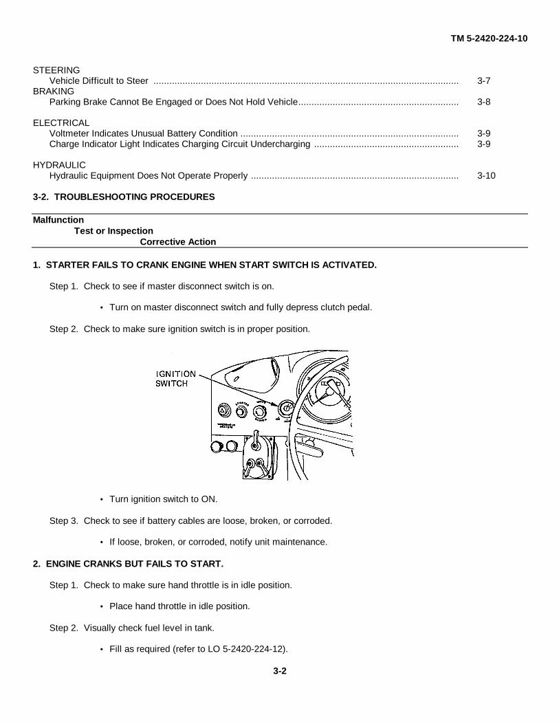
TM 5-2420-224-10
STEERINGVehicle Difficult to Steer .................................................................................................................... 3-7
BRAKINGParking Brake Cannot Be Engaged or Does Not Hold Vehicle............................................................. 3-8
ELECTRICALVoltmeter Indicates Unusual Battery Condition ................................................................................... 3-9Charge Indicator Light Indicates Charging Circuit Undercharging ....................................................... 3-9
HYDRAULICHydraulic Equipment Does Not Operate Properly ............................................................................... 3-10
3-2. TROUBLESHOOTING PROCEDURES
MalfunctionTest or Inspection
Corrective Action
1. STARTER FAILS TO CRANK ENGINE WHEN START SWITCH IS ACTIVATED.
Step 1. Check to see if master disconnect switch is on.
Turn on master disconnect switch and fully depress clutch pedal.
Step 2. Check to make sure ignition switch is in proper position.
Turn ignition switch to ON.
Step 3. Check to see if battery cables are loose, broken, or corroded.
If loose, broken, or corroded, notify unit maintenance.
2. ENGINE CRANKS BUT FAILS TO START.
Step 1. Check to make sure hand throttle is in idle position.
Place hand throttle in idle position.
Step 2. Visually check fuel level in tank.
Fill as required (refer to LO 5-2420-224-12).
3-2

TM 5-2420-224-10
MalfunctionTest or Inspection
Corrective Action
Step 3. Check that fuel shutoff valve is open.
Turn valve to open position (handle alined with fuel line).
Step 4. Check for broken, leaking, or kinked fuel lines and hoses.
If any of these conditions are present, notify unit maintenance.
Step 5. Check for contaminants in fuel filter pre-sediment bowl.
Remove pre-sediment bowl, clean filter, and install pre-sediment bowl (refer to page 3-13).
3. ENGINE STARTS BUT WILL NOT CONTINUE TO RUN OR SHOWS LOSS OF POWER.
Step 1. Check to make sure hand throttle is in idle position.
Place hand throttle in idle position.
Step 2. Check for broken, leaking, or kinked fuel lines and hoses.
If any of these conditions are present, notify unit maintenance.
Step 3. Check for contaminants in fuel filter pre-sediment bowl.
Remove pre-sediment bowl, clean filter, and install pre-sediment bowl (refer to page 3-13).
Step 4. Check air indicator warning light for clogged element.
If indicator light is on, notify unit maintenance.
4. ENGINE SMOKES EXCESSIVELY AFTER NORMAL WARMUP.
Step 1. Check air indicator warning light for clogged element.
If indicator light is on, notify unit maintenance.
3-3

TM 5-2420-224-10
MalfunctionTest or Inspection
Corrective Action
Step 2. Check for wrong grade of fuel.
Determine grade of fuel with fueling station. If necessary, have unit maintenance drain fuel tank andfill with correct grade of fuel (refer to LO 5-2420-224-12).
Step 3. Check coolant temperature gage for too low operating temperature after warmup period.
If temperature is below 1760F (800C), notify unit maintenance.
5. ENGINE OVERHEATS DURING NORMAL OPERATION.
Step 1. Check for low coolant level in reservoir.
WARNINGWhen engine is hot, remove reservoir cap slowly to relieve pressure.Wear gloves and protective clothing. Failure to do so could resultin personal injury.
Add coolant as required. Tighten any connections that may be subject to leaks.
Step 2. Check for debris blocking air flow through radiator.
CAUTIONDo not use screwdriver or any other sharp instrument to removedebris from radiator. To do so could result in equipment damage.
Remove debris from grille and radiator. If radiator cooling fins are plugged, notify unit maintenance.
3-4

TM 5-2420-224-10
MalfunctionTest or Inspection
Corrective Action
Step 3. Check for broken or slipping water pump belt.
Belt deflection under thumb pressure should be 3/16-3/8 in. (5-10 mm). If belt is frayed, broken, orloose, notify unit maintenance.
Step 4. Check for low engine oil level.
Add oil to proper level (refer to LO 5-2420-224-12).
3-5
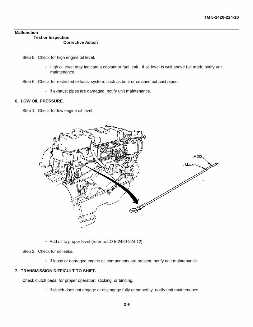
TM 5-2420-224-10
MalfunctionTest or Inspection
Corrective Action
Step 5. Check for high engine oil level.
High oil level may indicate a coolant or fuel leak. If oil level is well above full mark, notify unitmaintenance.
Step 6. Check for restricted exhaust system, such as bent or crushed exhaust pipes.
If exhaust pipes are damaged, notify unit maintenance.
6. LOW OIL PRESSURE.
Step 1. Check for low engine oil level.
Add oil to proper level (refer to LO 5-2420-224-12).
Step 2. Check for oil leaks.
If loose or damaged engine oil components are present, notify unit maintenance.
7. TRANSMISSION DIFFICULT TO SHIFT.
Check clutch pedal for proper operation, sticking, or binding.
If clutch does not engage or disengage fully or smoothly, notify unit maintenance.
3-6

TM 5-2420-224-10
MalfunctionTest or Inspection
Corrective Action
8. VEHICLE DIFFICULT TO STEER.
Step 1. Check to see if four-wheel drive control switch is in position II.
Place four-wheel drive control switch in position 0 or I.
Step 2. Visually check tires for proper inflation and wheels for damage.
Correct tire pressure should be 40 psi (2.7 bar) on all missions. Report any wheel damage to unitmaintenance.
Step 3. Check for damaged steering linkage.
If steering linkage is damaged, notify unit maintenance.
Step 4. Check power steering reservoir level with engine running.
If low, service in accordance with LO 5-2420-224-12.
3-7
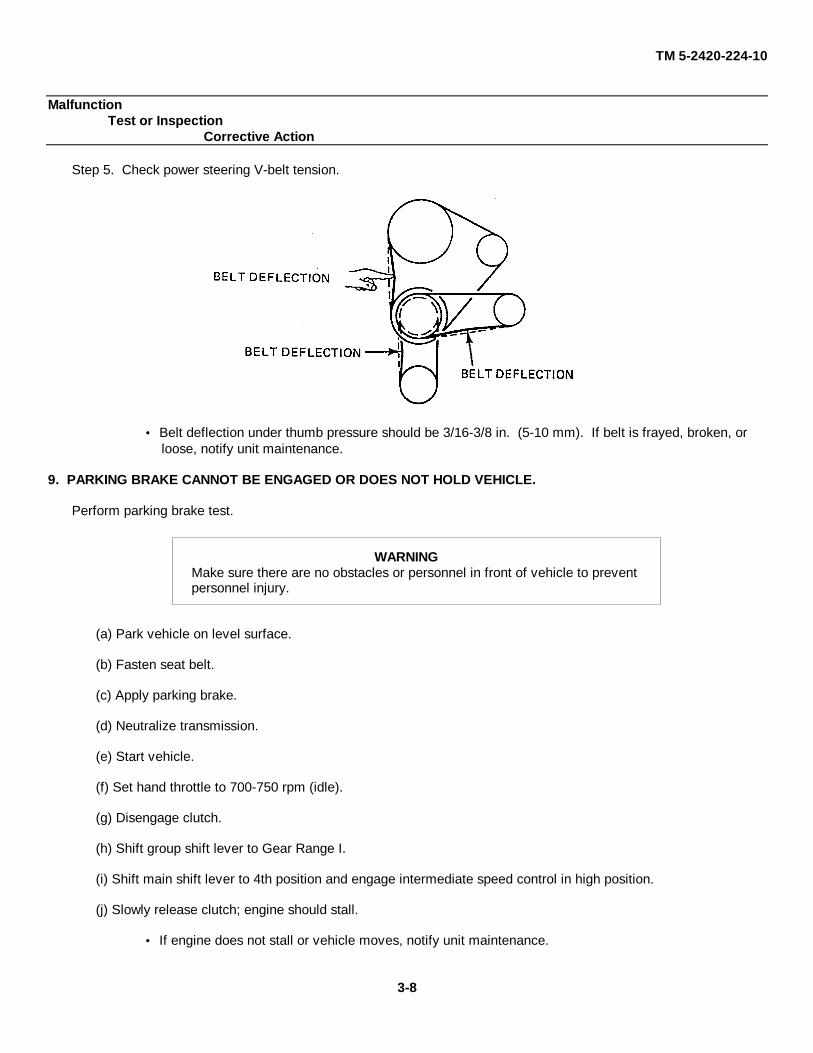
TM 5-2420-224-10
MalfunctionTest or Inspection
Corrective Action
Step 5. Check power steering V-belt tension.
Belt deflection under thumb pressure should be 3/16-3/8 in. (5-10 mm). If belt is frayed, broken, orloose, notify unit maintenance.
9. PARKING BRAKE CANNOT BE ENGAGED OR DOES NOT HOLD VEHICLE.
Perform parking brake test.
WARNINGMake sure there are no obstacles or personnel in front of vehicle to preventpersonnel injury.
(a) Park vehicle on level surface.
(b) Fasten seat belt.
(c) Apply parking brake.
(d) Neutralize transmission.
(e) Start vehicle.
(f) Set hand throttle to 700-750 rpm (idle).
(g) Disengage clutch.
(h) Shift group shift lever to Gear Range I.
(i) Shift main shift lever to 4th position and engage intermediate speed control in high position.
(j) Slowly release clutch; engine should stall.
If engine does not stall or vehicle moves, notify unit maintenance.
3-8
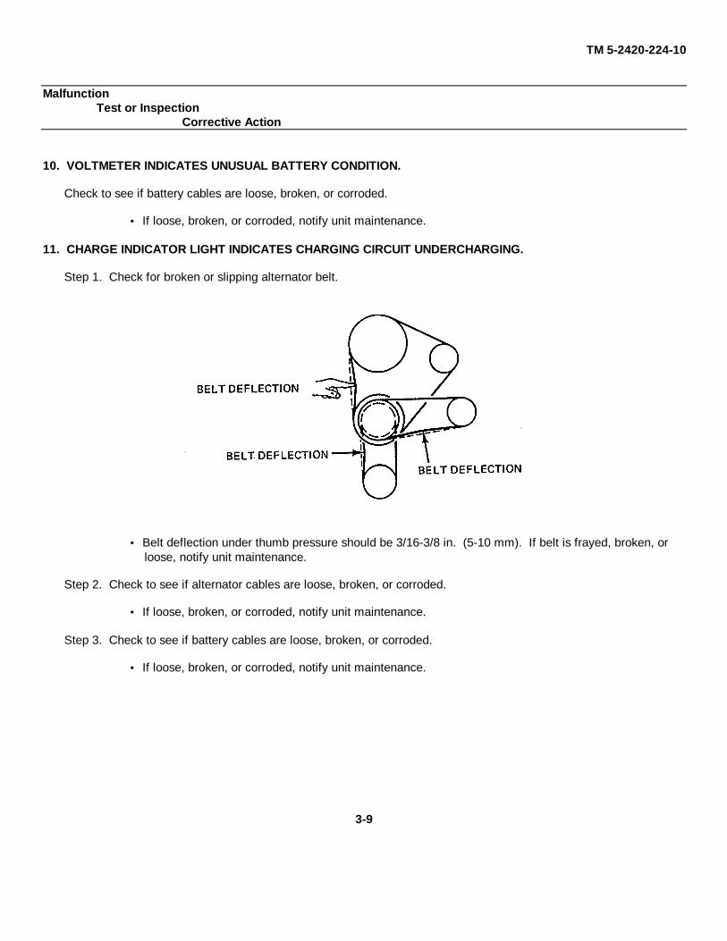
TM 5-2420-224-10
MalfunctionTest or Inspection
Corrective Action
10. VOLTMETER INDICATES UNUSUAL BATTERY CONDITION.
Check to see if battery cables are loose, broken, or corroded.
If loose, broken, or corroded, notify unit maintenance.
11. CHARGE INDICATOR LIGHT INDICATES CHARGING CIRCUIT UNDERCHARGING.
Step 1. Check for broken or slipping alternator belt.
Belt deflection under thumb pressure should be 3/16-3/8 in. (5-10 mm). If belt is frayed, broken, orloose, notify unit maintenance.
Step 2. Check to see if alternator cables are loose, broken, or corroded.
If loose, broken, or corroded, notify unit maintenance.
Step 3. Check to see if battery cables are loose, broken, or corroded.
If loose, broken, or corroded, notify unit maintenance.
3-9
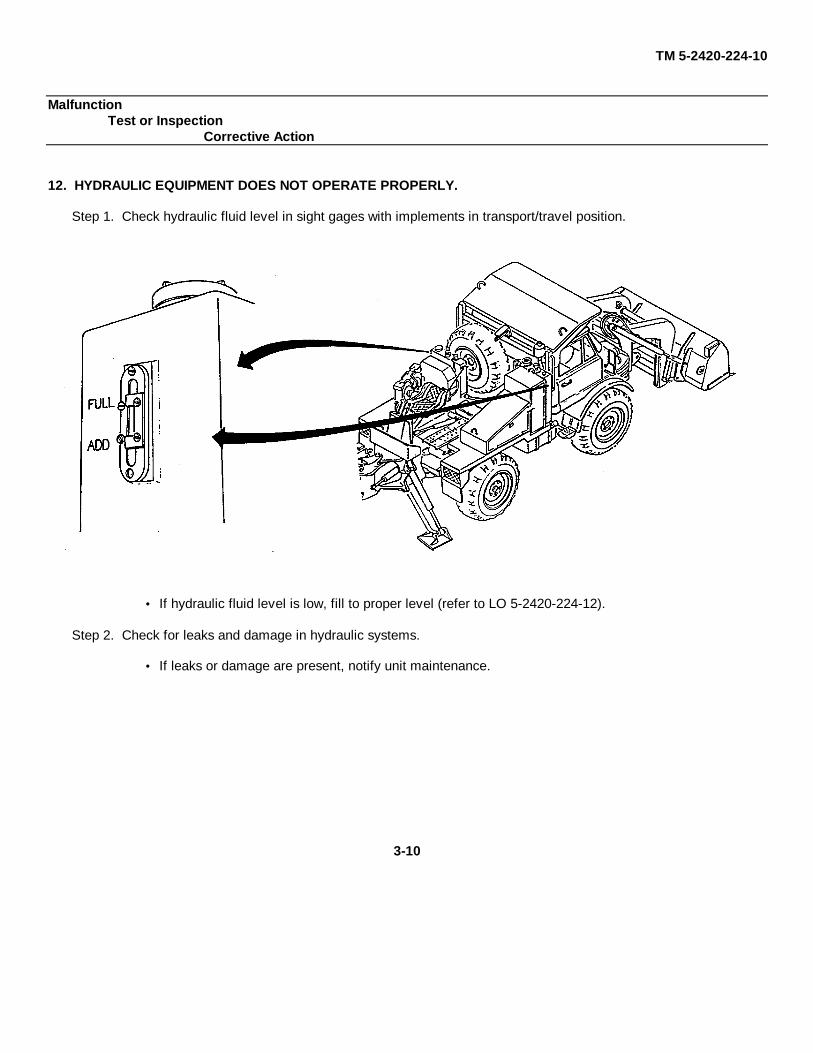
TM 5-2420-224-10
MalfunctionTest or Inspection
Corrective Action
12. HYDRAULIC EQUIPMENT DOES NOT OPERATE PROPERLY.
Step 1. Check hydraulic fluid level in sight gages with implements in transport/travel position.
If hydraulic fluid level is low, fill to proper level (refer to LO 5-2420-224-12).
Step 2. Check for leaks and damage in hydraulic systems.
If leaks or damage are present, notify unit maintenance.
3-10

TM 5-2420-224-10
MalfunctionTest or Inspection
Corrective Action
Step 3. Check hydraulic pressure gage located on top of right reservoir.
If gage does not read in green range, notify unit maintenance.
3-11
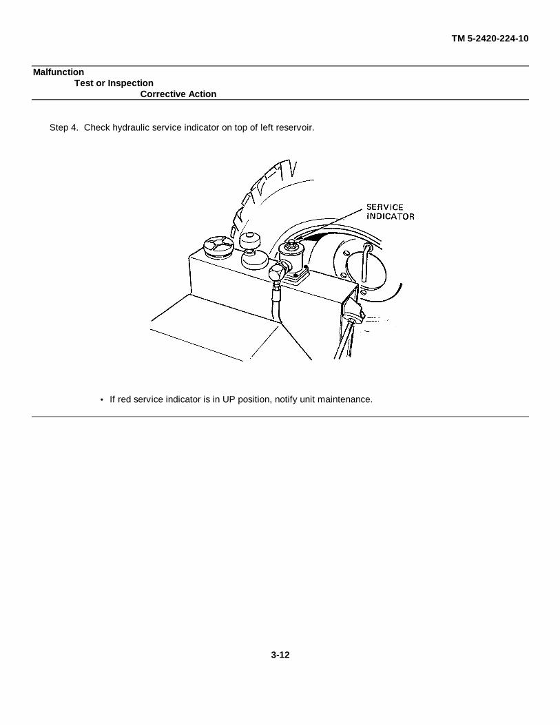
TM 5-2420-224-10
MalfunctionTest or Inspection
Corrective Action
Step 4. Check hydraulic service indicator on top of left reservoir.
If red service indicator is in UP position, notify unit maintenance.
3-12

TM 5-2420-224-10
Section III. MAINTENANCE PROCEDURES
3-3. GENERAL
This section illustrates and describes procedures for maintenance of the SEE/HMMH. A list of tasks contained in thissection is shown below.
Para Page
Fuel Filter Pre-Sediment Bowl Service.................................................................................... 3-4 3-13Priming and Bleeding Fuel System ........................................................................................ 3-5 3-14Spare Tire Replacement ........................................................................................................ 3-6 3-15Changing Wheel .................................................................................................................... 3-7 3-16Chain Saw Chain Sharpening ................................................................................................. 3-8 3-17Chain Saw Chain Tension Adjustment ................................................................................... 3-9 3-18
3-4. FUEL FILTER PRE-SEDIMENT BOWL SERVICE
CAUTIONAlways bleed fuel system after cleaning pre-sediment bowl filter. Failure to bleedcould permit air into fuel system and cause loss of fuel prime.
a. Make sure fuel tank contains fuel.
b. Close fuel shutoff valve (1) by turning handle 1/4 turn away from fuel line.
c. Loosen wing nut (2) and move clip (3) aside.
3-13

TM 5-2420-224-10
d. Remove bowl (4), strainer (5), and gasket (6).
e. Clean strainer (5) with clean diesel fuel.
f. Install gasket (6) and strainer (5).
g. Fill bowl (4) with clean diesel fuel and install.
h. Aline clip (3) and tighten wing nut (2).
i. Open fuel shutoff valve (1).
3-5. PRIMING AND BLEEDING FUEL SYSTEM
a. Remove engine hood (refer to page 2-7).
3-14

TM 5-2420-224-10
b. Open priming pump (1) by turning counterclockwise and lifting up.
c. Pump up and down until slight resistance is felt.
d. Unscrew front fuel filter bleeder screw (2) one or two turns.
e. Operate priming pump (1) until bubble-free fuel is observed from bleeder screw (2).
f. Tighten bleeder screw (2).
g. Repeat steps d thru f for rear fuel filter bleeder screw (2).
h. Secure priming pump (1) by pushing down and. turning clockwise.
i. Install engine hood.
3-6. SPARE TIRE REPLACEMENT
a. Removal.
WARNINGWheel assembly weighs 170 lb (77.18 kg). Use a hoisting device or at leasttwo personnel to lift wheel assembly to prevent personal injury.
Remove holder (1) and wheel (2).
b. Installation.
WARNINGWheel assembly weighs 170 lb (77.18 kg). Use a hoisting device or at leasttwo personnel to lift wheel assembly to prevent personal injury.
Install wheel (2) and holder (1).
LesleyFE
3-15
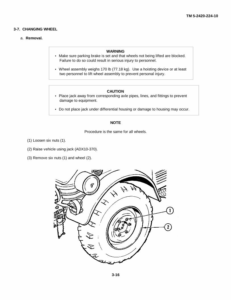
TM 5-2420-224-10
3-7. CHANGING WHEEL
a. Removal.
WARNING Make sure parking brake is set and that wheels not being lifted are blocked.
Failure to do so could result in serious injury to personnel.
Wheel assembly weighs 170 lb (77.18 kg). Use a hoisting device or at leasttwo personnel to lift wheel assembly to prevent personal injury.
CAUTION Place jack away from corresponding axle pipes, lines, and fittings to prevent
damage to equipment.
Do not place jack under differential housing or damage to housing may occur.
NOTE
Procedure is the same for all wheels.
(1) Loosen six nuts (1).
(2) Raise vehicle using jack (ADX10-370).
(3) Remove six nuts (1) and wheel (2).
3-16

TM 5-2420-224-10
b. Installation.
WARNING Make sure parking brake is set and that wheels not being lifted are blocked.
Failure to do so could result in serious injury to personnel.
Wheel assembly weighs 170 lb (77.18 kg). Use a hoisting device or at leasttwo personnel to lift wheel assembly to prevent personal injury.
NOTE
Procedure is the same for all wheels.
(1) Install wheel (2) and six nuts (1).
(2) Lower vehicle to ground level and remove jack (ADX10-370).
(3) Have unit maintenance tighten nuts (1) to 260 lb-ft (353 N•m).
3-8. CHAIN SAW CHAIN SHARPENING
WARNING Never sharpen chain with operating pressure on tool. To do so could result
in personal injury.
Chain cutters are sharp. Wear protective gloves when sharpening chain. Failureto do so could result in personal injury.
NOTE
File all cutters on side of chain opposite yourself.
a. Install round file (P/N 11268) and handle (P/N 11552) on holder (P/N 11551).
b. Press file holder so it rides on both cutter top plate and depth gage with guide marks in line with length of chain(1).
3-17
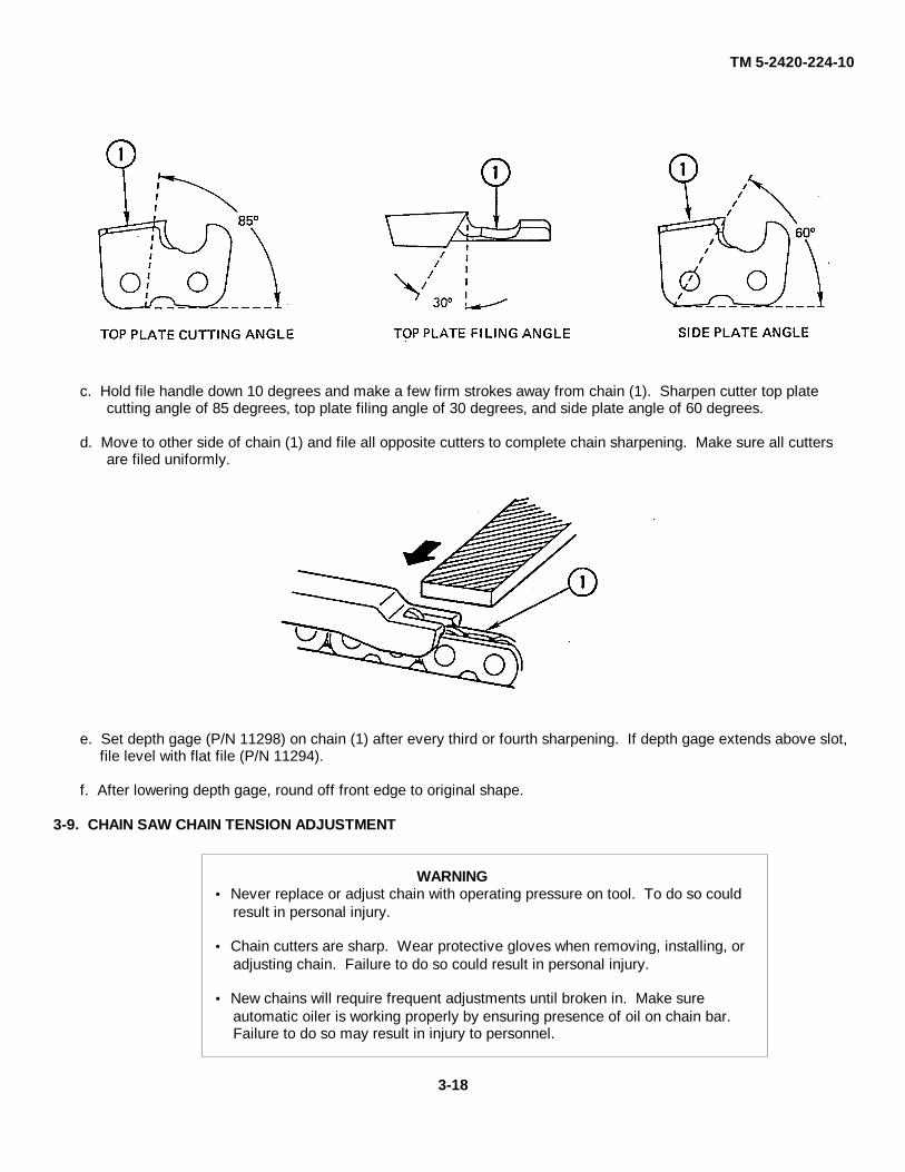
TM 5-2420-224-10
c. Hold file handle down 10 degrees and make a few firm strokes away from chain (1). Sharpen cutter top platecutting angle of 85 degrees, top plate filing angle of 30 degrees, and side plate angle of 60 degrees.
d. Move to other side of chain (1) and file all opposite cutters to complete chain sharpening. Make sure all cuttersare filed uniformly.
e. Set depth gage (P/N 11298) on chain (1) after every third or fourth sharpening. If depth gage extends above slot,file level with flat file (P/N 11294).
f. After lowering depth gage, round off front edge to original shape.
3-9. CHAIN SAW CHAIN TENSION ADJUSTMENT
WARNING Never replace or adjust chain with operating pressure on tool. To do so could
result in personal injury.
Chain cutters are sharp. Wear protective gloves when removing, installing, oradjusting chain. Failure to do so could result in personal injury.
New chains will require frequent adjustments until broken in. Make sureautomatic oiler is working properly by ensuring presence of oil on chain bar.Failure to do so may result in injury to personnel.
3-18

TM 5-2420-224-10
a. If removed, install chain (1) on bar (2) so chain is straight and secure in groove of bar.
CAUTIONDo not overtighten chain. To do so could result in equipment damage.
b. Loosen two nuts (3) and pull up on tip of bar (2). Tighten screw (4) until chain (1) just touches bottom midpoint ofbar (2).
c. Tighten nuts (3) while continuing to hold bar tip up.
d. Operate chain saw at low speed for several minutes, allowing automatic oiler to thoroughly lubricate bar (2).
e. If automatic oiler is not operating, notify unit maintenance.
f. Stop chain saw and recheck chain tension. If chain (1) has loosened, disconnect from power source and repeatsteps b and c.
3-19/(3-20 Blank)
TM 5-2420-224-10
APPENDIX AREFERENCES
A-1. SCOPE
This appendix lists all forms, field manuals, technical manuals, and miscellaneous publications referenced in this manual.
A-2. PUBLICATION INDEXES
Consolidated Index of Army Publications and Blank Forms.............................................. DA Pam 25-30
A-3. FORMS
Quality Deficiency Report................................................................................................. SF 368
Recommended Changes to Publications and Blank Forms............................................... DA Form 2028........................................................................................................................................ or 2028-2Equipment Control Record ............................................................................................... DA Form 2408-9
Refer to DA Pam 738-750, The Army Maintenance Management System (TAMMS), for instructions on the use ofmaintenance forms pertaining to the vehicle.
A-4. PUBLICATION REFERENCES
a. General.The Army Maintenance Management System (TAMMS ................................................... DA Pam 738-750
Air Transport .................................................................................................................... TM 55-420
Basic Cold Weather Manual............................................................................................. FM 31-70
First Aid for Soldiers......................................................................................................... FM 21-11
Hand Portable Fire Extinguishers Approved for Army Users............................................. TB 5-4200-200-10
Operator's, Organizational, DS, and GS Maintenance Manual:Storage Batteries, Lead-Acid Type ......................................................................... TM 9-6140-200-14
Preservation of Equipment for Shipment and Storage...................................................... TB 740-97-2
Procedures for Destruction of Equipment to Prevent Enemy Use ..................................... TM 750-244-3
Rail Transport .................................................................................................................. TM 55-2201-001-12
b. Vehicle.Lubrication Order for Tractor, Wheeled, 4 X 4 DED
Small Emplacement Excavator (SEE) (with Attachments)and Tractor, Wheeled, 4 X 4 DED High Mobility MaterialHandler (HMMH) (with Attachments............................................................. LO 5-2420-224-12
Hand Receipt Covering Contents ofComponents of End Item (COEI), Basic Issue Items (BII),and Additional Authorization List (AAL) for Tractor, Wheeled,4 X 4 DED Small Emplacement Excavator (SEE) and Tractor,Wheeled, 4 X 4 DED High Mobility Material Handler (HMMH)...................... TM 5-2420-224-10-HR
A-1/(A-2 Blank)
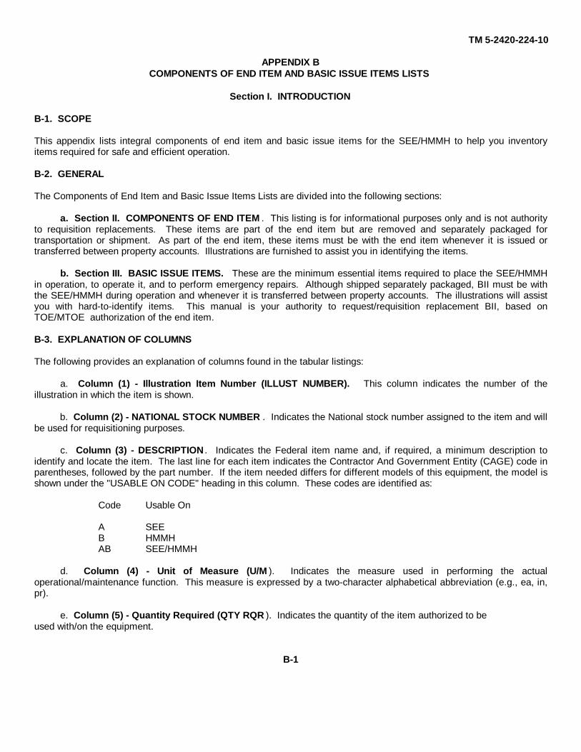
TM 5-2420-224-10
APPENDIX BCOMPONENTS OF END ITEM AND BASIC ISSUE ITEMS LISTS
Section I. INTRODUCTION
B-1. SCOPE
This appendix lists integral components of end item and basic issue items for the SEE/HMMH to help you inventoryitems required for safe and efficient operation.
B-2. GENERAL
The Components of End Item and Basic Issue Items Lists are divided into the following sections:
a. Section II. COMPONENTS OF END ITEM . This listing is for informational purposes only and is not authorityto requisition replacements. These items are part of the end item but are removed and separately packaged fortransportation or shipment. As part of the end item, these items must be with the end item whenever it is issued ortransferred between property accounts. Illustrations are furnished to assist you in identifying the items.
b. Section III. BASIC ISSUE ITEMS. These are the minimum essential items required to place the SEE/HMMHin operation, to operate it, and to perform emergency repairs. Although shipped separately packaged, BII must be withthe SEE/HMMH during operation and whenever it is transferred between property accounts. The illustrations will assistyou with hard-to-identify items. This manual is your authority to request/requisition replacement BII, based onTOE/MTOE authorization of the end item.
B-3. EXPLANATION OF COLUMNS
The following provides an explanation of columns found in the tabular listings:
a. Column (1) - Illustration Item Number (ILLUST NUMBER). This column indicates the number of theillustration in which the item is shown.
b. Column (2) - NATIONAL STOCK NUMBER . Indicates the National stock number assigned to the item and willbe used for requisitioning purposes.
c. Column (3) - DESCRIPTION . Indicates the Federal item name and, if required, a minimum description toidentify and locate the item. The last line for each item indicates the Contractor And Government Entity (CAGE) code inparentheses, followed by the part number. If the item needed differs for different models of this equipment, the model isshown under the "USABLE ON CODE" heading in this column. These codes are identified as:
Code Usable On
A SEEB HMMHAB SEE/HMMH
d. Column (4) - Unit of Measure (U/M ). Indicates the measure used in performing the actualoperational/maintenance function. This measure is expressed by a two-character alphabetical abbreviation (e.g., ea, in,pr).
e. Column (5) - Quantity Required (QTY RQR ). Indicates the quantity of the item authorized to beused with/on the equipment.
B-1
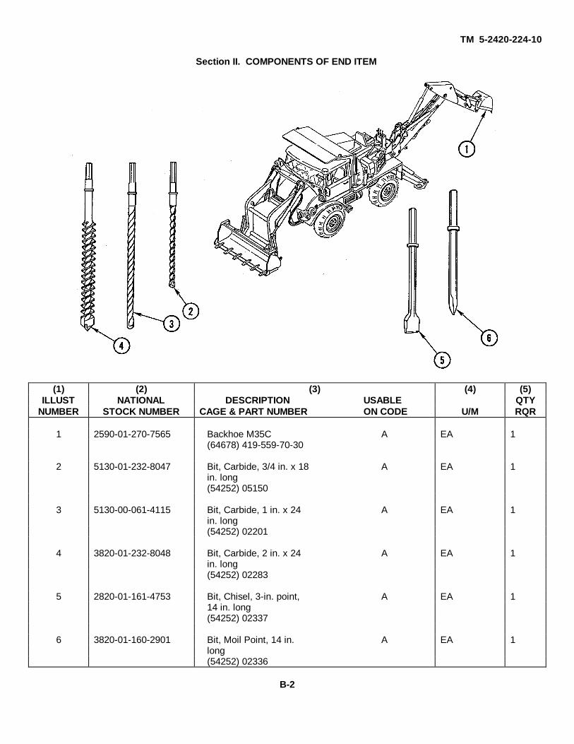
TM 5-2420-224-10
Section II. COMPONENTS OF END ITEM
(1) (2) (3) (4) (5)ILLUST NATIONAL DESCRIPTION USABLE QTY
NUMBER STOCK NUMBER CAGE & PART NUMBER ON CODE U/M RQR
1 2590-01-270-7565 Backhoe M35C A EA 1(64678) 419-559-70-30
2 5130-01-232-8047 Bit, Carbide, 3/4 in. x 18 A EA 1in. long(54252) 05150
3 5130-00-061-4115 Bit, Carbide, 1 in. x 24 A EA 1in. long(54252) 02201
4 3820-01-232-8048 Bit, Carbide, 2 in. x 24 A EA 1in. long(54252) 02283
5 2820-01-161-4753 Bit, Chisel, 3-in. point, A EA 114 in. long(54252) 02337
6 3820-01-160-2901 Bit, Moil Point, 14 in. A EA 1long(54252) 02336
B-2
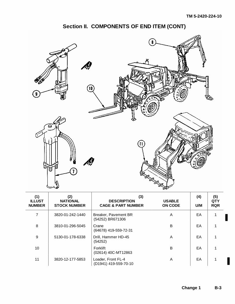
TM 5-2420-224-10
Change 1 B-3
Section II. COMPONENTS OF END ITEM (CONT)
(1) (2) (3) (4) (5)
ILLUST NUMBER
NATIONAL STOCK NUMBER
DESCRIPTION CAGE & PART NUMBER
USABLE ON CODE
U/M
QTY RQR
7 3820-01-242-1440 Breaker, Pavement BR (54252) BR671306
A EA 1
8 3810-01-296-5045 Crane (64678) 419-559-72-31
B EA 1
9 5130-01-178-6338 Drill, Hammer HD-45 (54252)
A EA 1
10 Forklift (02614) 40C-MT12863
B EA 1
11 3820-12-177-5853 Loader, Front FL-4 (D1941) 419-559-70-10
A EA 1
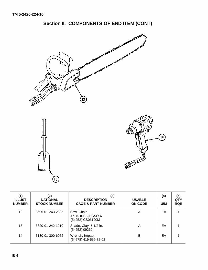
TM 5-2420-224-10
B-4
Section II. COMPONENTS OF END ITEM (CONT)
(1) (2) (3) (4) (5) ILLUST
NUMBER NATIONAL
STOCK NUMBER DESCRIPTION
CAGE & PART NUMBER USABLE ON CODE
U/M
QTY RQR
12 3695-01-243-2325 Saw, Chain 15-in. cut bar CSO-6 (54252) CS06120M
A EA 1
13 3820-01-242-1210 Spade, Clay, 5-1/2 in. (54252) 09262
A EA 1
14 5130-01-300-6052 Wrench, Impact (64678) 419-559-72-02
B EA 1

TM 5-2420-224-10
Change 1 B-5
Section III. BASIC ISSUE ITEMS
(1) (2) (3) (4) (5)
ILLUST NUMBER
NATIONAL STOCK NUMBER
DESCRIPTION CAGE & PART NUMBER
USABLE ON CODE
U/M
QTY RQR
1 5149-01-251-3771 Bag, Tool (64678) 385-585-01-01
AB EA 1
2 5120-01-355-2068 Bar, Pinch, 20-in. (55719) 2420
AB EA 1
2.1 4210-00-555-8837 Extinguisher, Fire (81349) MIL-E-52031
AB EA 1
3 5110-01-247-3784 File, Flat (54252) 11294
A EA 1
4 5210-01-247-0754 Gage, Depth (54252) 11298
A EA 1
5 4910-01-121-9847 Gage, Tire (55719) YA804
AB EA 1
6 3040-01-308-8809 Guide, Chain Wear (02614) 661923
B EA 1
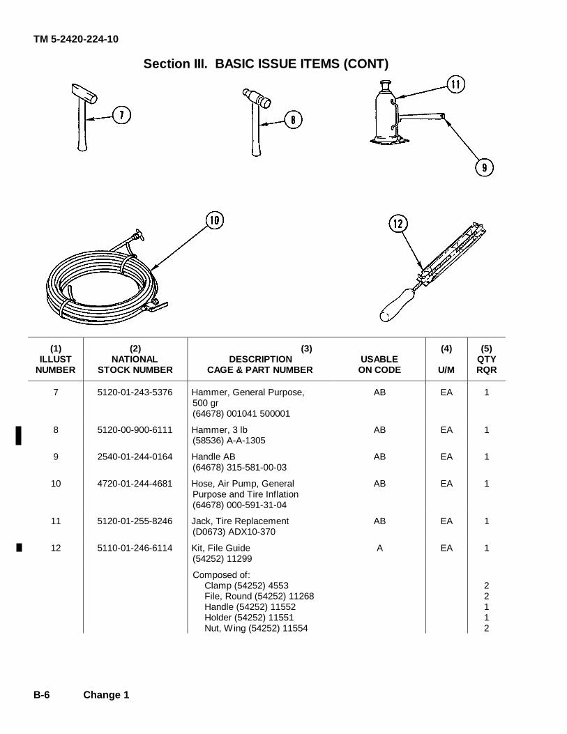
TM 5-2420-224-10
B-6 Change 1
Section III. BASIC ISSUE ITEMS (CONT)
(1) (2) (3) (4) (5) ILLUST
NUMBER NATIONAL
STOCK NUMBER DESCRIPTION
CAGE & PART NUMBER USABLE ON CODE
U/M
QTY RQR
7 5120-01-243-5376 Hammer, General Purpose, 500 gr (64678) 001041 500001
AB EA 1
8 5120-00-900-6111 Hammer, 3 lb (58536) A-A-1305
AB EA 1
9 2540-01-244-0164 Handle AB (64678) 315-581-00-03
AB EA 1
10 4720-01-244-4681 Hose, Air Pump, General Purpose and Tire Inflation (64678) 000-591-31-04
AB EA 1
11 5120-01-255-8246 Jack, Tire Replacement (D0673) ADX10-370
AB EA 1
12 5110-01-246-6114 Kit, File Guide (54252) 11299
A EA 1
Composed of: Clamp (54252) 4553 File, Round (54252) 11268 Handle (54252) 11552 Holder (54252) 11551 Nut, Wing (54252) 11554
2 2 1 1 2
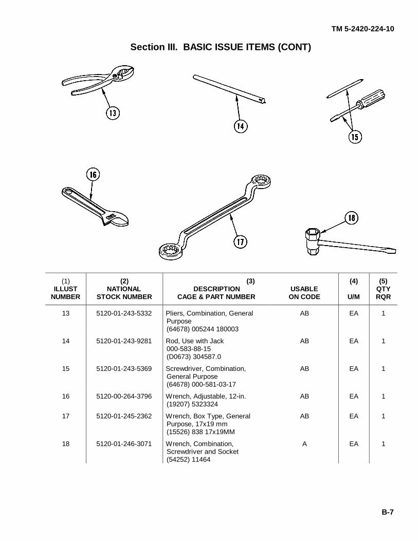
TM 5-2420-224-10
B-7
Section III. BASIC ISSUE ITEMS (CONT)
(1) (2) (3) (4) (5) ILLUST
NUMBER NATIONAL
STOCK NUMBER DESCRIPTION
CAGE & PART NUMBER USABLE ON CODE
U/M
QTY RQR
13 5120-01-243-5332 Pliers, Combination, General Purpose (64678) 005244 180003
AB EA 1
14 5120-01-243-9281 Rod, Use with Jack 000-583-88-15 (D0673) 304587.0
AB EA 1
15 5120-01-243-5369 Screwdriver, Combination, General Purpose (64678) 000-581-03-17
AB EA 1
16 5120-00-264-3796 Wrench, Adjustable, 12-in. (19207) 5323324
AB EA 1
17 5120-01-245-2362 Wrench, Box Type, General Purpose, 17x19 mm (15526) 838 17x19MM
AB EA 1
18 5120-01-246-3071 Wrench, Combination, Screwdriver and Socket (54252) 11464
A EA 1

TM 5-2420-224-10
B-8 Change 1
Section III. BASIC ISSUE ITEMS (CONT)
(1) (2) (3) (4) (5) ILLUST
NUMBER NATIONAL
STOCK NUMBER DESCRIPTION
CAGE & PART NUMBER USABLE ON CODE
U/M
QTY RQR
18.1 5120-01-235-2605 Key, Hood/Battery Box (64678) 435 581 00 02
AB EA 1
19 5120-01-243-5342 Wrench, General Purpose, 14x15 mm (64678) 000-581-13-24
AB EA 1
20 5120-01-243-5343 Wrench, General Purpose, 17x19 mm (64678) 000-581-14-24
AB EA 1
21 5320-01-243-5331 Wrench, Hex Key, General Purpose (64678) 000911 014006
AB EA 1
22 5120-01-242-7224 Wrench, Open End, General Purpose, 8x9 mm (15526) 3110 8x9MM
AB EA 1
23 5120-01-242-7225 Wrench, Open End, General Purpose, 10x11 mm (15526) 3110 10X11MM
AB EA 1

TM 5-2420-224-10
Change 1 B-9
Section III. BASIC ISSUE ITEMS (CONT)
(1) (2) (3) (4) (5) ILLUST
NUMBER NATIONAL
STOCK NUMBER DESCRIPTION
CAGE & PART NUMBER USABLE ON CODE
U/M
QTY RQR
24 5120-01-101-1192 Wrench, Open End, General Purpose, 12x13 mm (15526) 3110 10x11MM
AB EA 1
25 5120-01-102-4472 Wrench, Open End, General Purpose, 19x22 mm (15526) 3110 19X22MM
AB EA 1
26 5120-01-068-5645 Wrench, Open End, General Purpose, 24x27 mm (15526) 3110 24X27MM
AB EA 1
27 5120-01-242-7228 Wrench, Open End, General Purpose, 30x32 mm (15526) 3110 30X32MM
AB EA 1
28 5120-01-245-5268 Wrench, Socket, Wheel Lug (64678) 404-581-00-01
AB EA 1
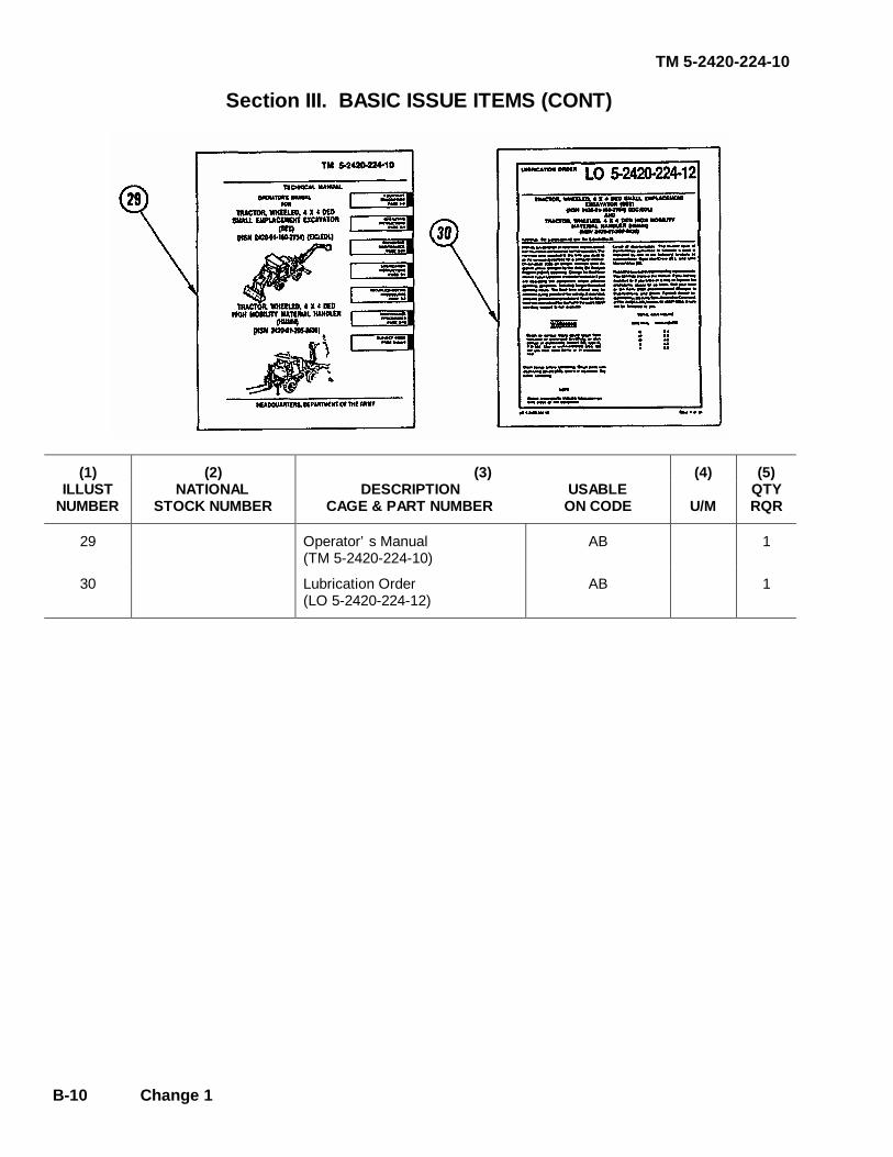
TM 5-2420-224-10
B-10 Change 1
Section III. BASIC ISSUE ITEMS (CONT)
(1) (2) (3) (4) (5) ILLUST
NUMBER NATIONAL
STOCK NUMBER DESCRIPTION
CAGE & PART NUMBER USABLE ON CODE
U/M
QTY RQR
29 Operator’s Manual (TM 5-2420-224-10)
AB 1
30 Lubrication Order (LO 5-2420-224-12)
AB 1

TM 5-2420-224-10
C-1
APPENDIX C ADDITIONAL AUTHORIZATION LIST
Section I. INTRODUCTION
C-1. SCOPE This appendix lists additional items you are authorized for the support of the SEE/HMMH. C-2. GENERAL This list identifies items that do not have to accompany the SEE/HMMH and that do not have to be turned in with it. These items are all authorized to you by CTA, MTOE, TDA, or JTA. C-3. EXPLANATION OF LISTING National stock numbers, descriptions, and quantities are provided to help you identify and request the additional items you require to support this equipment. The items are listed in alphabetical sequence by item name under the type of document (i.e., CTA, MTOE, TDA, or JTA) which authorizes the item(s) to you. If the item required differs for different models of this equipment, the model is shown under the "USABLE ON CODE" heading in the DESCRIPTION column. These codes are identified as: Code Usable On A SEE B HMMH AB SEE/HMMH

TM 5-2420-224-10
C-2 Change 1
Section II. ADDITIONAL AUTHORIZATION LIST
(1) (2) (3) (4)
NATIONAL STOCK
NUMBER
DESCRIPTION CAGE & PART NUMBER
USABLE ON CODE
U/M
QTY
AUTH
4930-00-288-1511 Adapter, Grease Gun Flex (81349) MIL-L-4387
AB EA 1
7520-00-559-9618 Case, Maintenance (81349) MIL-C-11743
AB EA 1
3950-00-329-3309 Come Along, Cable (2,000 lb lift) (06550) P12
AB EA 1
4240-00-052-3776 Goggles, Eye Protective (81348) GG-G-531
AB PR 1
4930-00-253-2478 Gun, Grease (81349) MIL-G-3859
AB EA 1
8415-00-889-3767 Helmet, Construction (w/clips) (58536) A-A-2271
AB EA 2
5130-01-300-6052 Impact Wrench (64678) 419 559 72 02
A EA 1
9909-00-565-6267 Kit, Sign, Vehicle (81349) MIL-S-40626
AB EA 1
3830-01-361-8209 Ripper, Bucket (12177) 020-189
A EA 1
2540-00-933-6922 Tire Chain Assembly (96906) MS 500055-24
AB PR 1
2540-00-933-6915 Tire Chain Repair; Cross Chains and Swivel Hooks (96906) MS 500057-7
AB EA 1
TM 5-2420-224-10
D-1
APPENDIX D EXPENDABLE/DURABLE SUPPLIES AND MATERIALS LIST
Section I. INTRODUCTION
D-1. SCOPE This appendix lists expendable supplies and materials you will need to operate and maintain the SEE/HMMH. These items are authorized to you by CTA 50-970, Expendable/Durable Items, (Except Medical, Class V, Repair Parts, and Heraldic Items) or CTA 8-100, Army Medical Department Expendable/Durable Items. D-2. EXPLANATION OF COLUMNS a. Column (1) - ITEM NUMBER. This number is assigned to the entry in the listing and is referenced in the narrative instructions to identify the material (e.g., "Use cleaning compound, item 11, App. D"). b. Column (2) - LEVEL. This column identifies the lowest level of maintenance that requires the listed item. C — Operator/Crew O — Unit Maintenance F — Direct Support Maintenance H — General Support Maintenance c. Column (3) - NATIONAL STOCK NUMBER. This is the National stock number assigned to the item; use it to request or requisition the item. d. Column (4) - DESCRIPTION. Indicates the Federal item name and, if required, a description to identify the item. The last line for each item indicates the Contractor and Government Entity (CAGE) code, in parentheses (if applicable), followed by the part number. e. Column (5) - Unit of Measure (U/M). Indicates the measure used in performing the actual maintenance function. This measure is expressed by a two-character alphabetical abbreviation (e.g., EA, IN, PR). If the unit of measure differs from the unit of issue, requisition the lowest unit of issue that will satisfy your requirements.
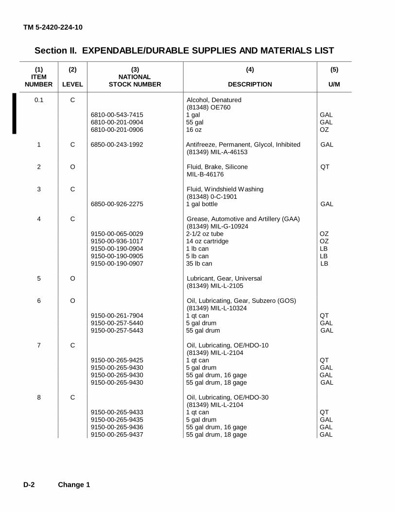
TM 5-2420-224-10
D-2 Change 1
Section II. EXPENDABLE/DURABLE SUPPLIES AND MATERIALS LIST
(1) ITEM
NUMBER
(2)
LEVEL
(3) NATIONAL
STOCK NUMBER
(4)
DESCRIPTION
(5)
U/M
0.1 C Alcohol, Denatured (81348) OE760
6810-00-543-7415 1 gal GAL 6810-00-201-0904 55 gal GAL 6810-00-201-0906 16 oz OZ
1 C 6850-00-243-1992 Antifreeze, Permanent, Glycol, Inhibited
(81349) MIL-A-46153
GAL
2 O Fluid, Brake, Silicone MIL-B-46176
QT
3 C Fluid, Windshield Washing (81348) 0-C-1901
6850-00-926-2275 1 gal bottle
GAL
4 C Grease, Automotive and Artillery (GAA) (81349) MIL-G-10924
9150-00-065-0029 2-1/2 oz tube OZ 9150-00-936-1017 14 oz cartridge OZ 9150-00-190-0904 1 lb can LB 9150-00-190-0905 5 lb can LB 9150-00-190-0907 35 lb can
LB
5 O Lubricant, Gear, Universal (81349) MIL-L-2105
6 O Oil, Lubricating, Gear, Subzero (GOS) (81349) MIL-L-10324
9150-00-261-7904 1 qt can QT 9150-00-257-5440 5 gal drum GAL 9150-00-257-5443 55 gal drum
GAL
7 C Oil, Lubricating, OE/HDO-10 (81349) MIL-L-2104
9150-00-265-9425 1 qt can QT 9150-00-265-9430 5 gal drum GAL 9150-00-265-9430 55 gal drum, 16 gage GAL 9150-00-265-9430 55 gal drum, 18 gage
GAL
8 C Oil, Lubricating, OE/HDO-30 (81349) MIL-L-2104
9150-00-265-9433 1 qt can QT 9150-00-265-9435 5 gal drum GAL 9150-00-265-9436 55 gal drum, 16 gage GAL 9150-00-265-9437 55 gal drum, 18 gage GAL

TM' 5-2420-224-10
Section II. EXPENDABLE/DURABLE SUPPLIES ANDMATERIALS LIST (CONT)
(1) (2) (3) (4) (5)ITEM NATIONA
LNUMBER LEVEL STOCK NUMBER DESCRIPTION U/M
9 C Oil, Lubricating, OE/HDO-50(81349) MIL-L-2104
9150-00-265-9864 1 qt can QT9150-00-265-9865 5 gal drum GAL9150-00-265-9866 55 gal drum, 16 gage GAL
10 0 Oil, Lubricating, ICE, Subzero (OEA)(81349) MIL-L-46167
9150-00-402-4478 1 qt can QT9150-00-402-2372 5 gal drum GAL9150-00-491-7197 55 gal drum, 16 gage GAL
11 C Oil, 15W40
1 qt can QT5 gal drum GAL55 gal drum, 16 gage GAL55 gal drum, 18 gage GAL
12 C Oil, Fuel, Diesel, DF-1, Winter(81348) VV-F-800
9140-00-286-5286 Bulk GAL9140-00-286-5287 5 gal can GAL9140-00-286-5288 55 gal drum, 16 gage GAL9140-00-286-5289 55 gal drum, 18 gage GAL
13 C Oil, Fuel, Diesel, DF-2, Regular(81348) VV-F-800
9140-00-286-5294 Bulk GAL9140-00-286-5295 5 gal can GAL9140-00-286-5296 55 gal drum, 16 gage GAL9140-00-286-5297 55 gal drum, 18 gage GAL
14 C Solvent, Dry-cleaning (SD), Type II(81348) P-D-680
6850-00-664-5685 1 qt can QT6850-00-281-1985 1 gal can GAL
D-3/(D-4 Blank)
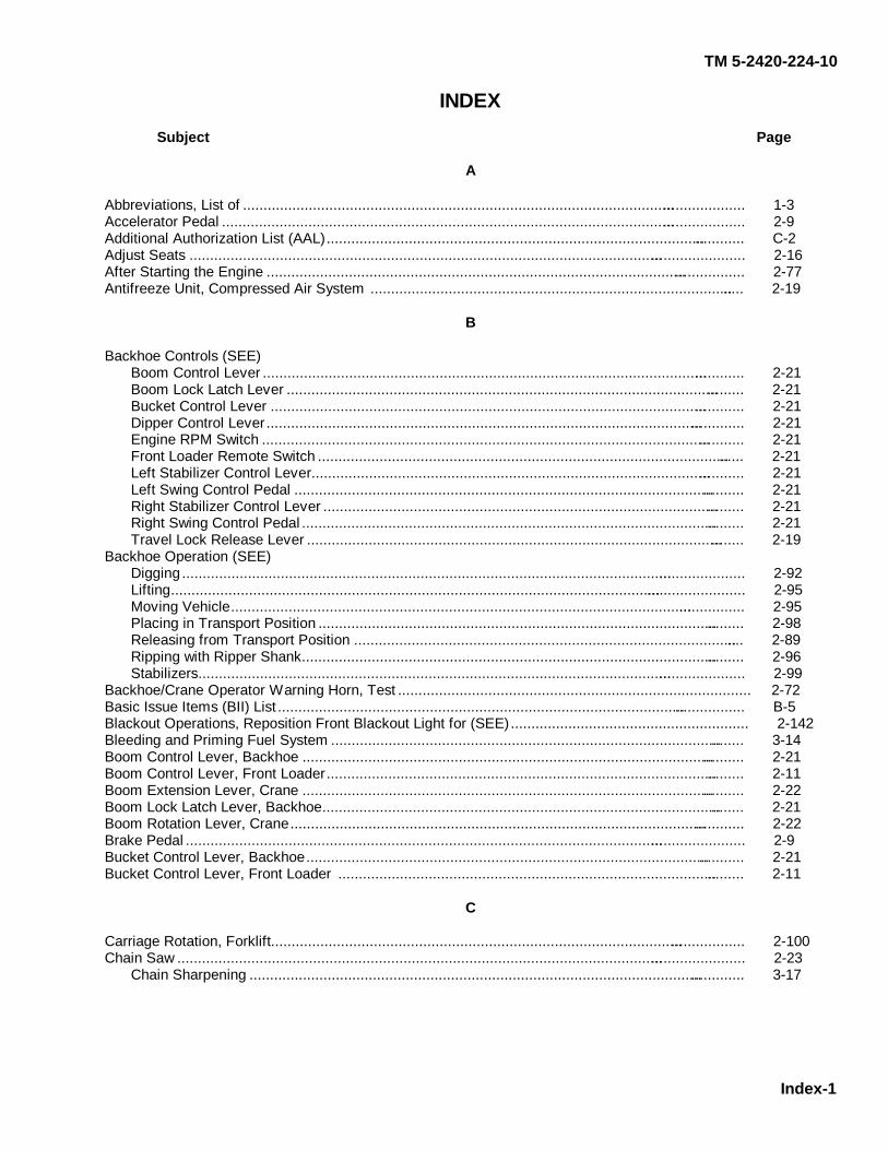
TM 5-2420-224-10
Index-1
INDEX
Subject Page
A Abbreviations, List of ............................................................................................................................. 1-3 Accelerator Pedal .................................................................................................................................. 2-9 Additional Authorization List (AAL)........................................................................................................ C-2 Adjust Seats .......................................................................................................................................... 2-16 After Starting the Engine ....................................................................................................................... 2-77 Antifreeze Unit, Compressed Air System ............................................................................................. 2-19
B
Backhoe Controls (SEE) Boom Control Lever ........................................................................................................................ 2-21 Boom Lock Latch Lever .................................................................................................................. 2-21 Bucket Control Lever ...................................................................................................................... 2-21 Dipper Control Lever....................................................................................................................... 2-21 Engine RPM Switch ........................................................................................................................ 2-21 Front Loader Remote Switch .......................................................................................................... 2-21 Left Stabilizer Control Lever............................................................................................................ 2-21 Left Swing Control Pedal ................................................................................................................ 2-21 Right Stabilizer Control Lever ......................................................................................................... 2-21 Right Swing Control Pedal .............................................................................................................. 2-21 Travel Lock Release Lever ............................................................................................................. 2-19 Backhoe Operation (SEE) Digging ............................................................................................................................................ 2-92 Lifting............................................................................................................................................... 2-95 Moving Vehicle................................................................................................................................ 2-95 Placing in Transport Position .......................................................................................................... 2-98 Releasing from Transport Position ................................................................................................. 2-89 Ripping with Ripper Shank.............................................................................................................. 2-96 Stabilizers........................................................................................................................................ 2-99 Backhoe/Crane Operator Warning Horn, Test ...................................................................................... 2-72 Basic Issue Items (BII) List .................................................................................................................... B-5 Blackout Operations, Reposition Front Blackout Light for (SEE).......................................................... 2-142 Bleeding and Priming Fuel System ....................................................................................................... 3-14 Boom Control Lever, Backhoe .............................................................................................................. 2-21 Boom Control Lever, Front Loader........................................................................................................ 2-11 Boom Extension Lever, Crane .............................................................................................................. 2-22 Boom Lock Latch Lever, Backhoe......................................................................................................... 2-21 Boom Rotation Lever, Crane................................................................................................................. 2-22 Brake Pedal ........................................................................................................................................... 2-9 Bucket Control Lever, Backhoe............................................................................................................. 2-21 Bucket Control Lever, Front Loader ..................................................................................................... 2-11
C
Carriage Rotation, Forklift...................................................................................................................... 2-100 Chain Saw ............................................................................................................................................. 2-23 Chain Sharpening ........................................................................................................................... 3-17
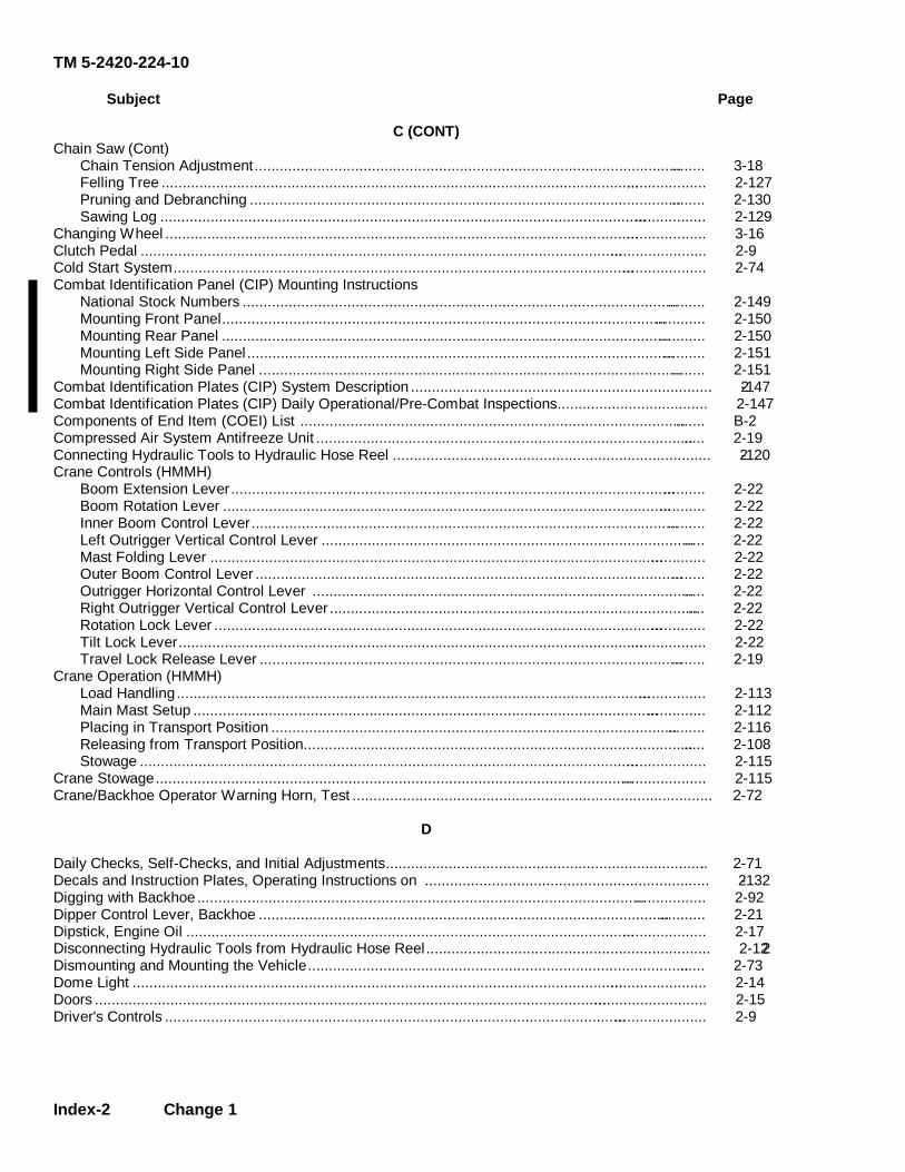
TM 5-2420-224-10
Index-2 Change 1
Subject Page
C (CONT) Chain Saw (Cont) Chain Tension Adjustment.............................................................................................................. 3-18 Felling Tree ..................................................................................................................................... 2-127 Pruning and Debranching ............................................................................................................... 2-130 Sawing Log ..................................................................................................................................... 2-129 Changing Wheel .................................................................................................................................... 3-16 Clutch Pedal .......................................................................................................................................... 2-9 Cold Start System.................................................................................................................................. 2-74 Combat Identification Panel (CIP) Mounting Instructions National Stock Numbers ................................................................................................................. 2-149 Mounting Front Panel...................................................................................................................... 2-150 Mounting Rear Panel ...................................................................................................................... 2-150 Mounting Left Side Panel................................................................................................................ 2-151 Mounting Right Side Panel ............................................................................................................. 2-151 Combat Identification Plates (CIP) System Description ........................................................................ 2-147 Combat Identification Plates (CIP) Daily Operational/Pre-Combat Inspections.................................... 2-147 Components of End Item (COEI) List ................................................................................................... B-2 Compressed Air System Antifreeze Unit ............................................................................................... 2-19 Connecting Hydraulic Tools to Hydraulic Hose Reel ............................................................................ 2-120 Crane Controls (HMMH) Boom Extension Lever.................................................................................................................... 2-22 Boom Rotation Lever ...................................................................................................................... 2-22 Inner Boom Control Lever............................................................................................................... 2-22 Left Outrigger Vertical Control Lever .............................................................................................. 2-22 Mast Folding Lever ......................................................................................................................... 2-22 Outer Boom Control Lever .............................................................................................................. 2-22 Outrigger Horizontal Control Lever ................................................................................................ 2-22 Right Outrigger Vertical Control Lever ............................................................................................ 2-22 Rotation Lock Lever ........................................................................................................................ 2-22 Tilt Lock Lever................................................................................................................................. 2-22 Travel Lock Release Lever ............................................................................................................. 2-19 Crane Operation (HMMH) Load Handling ................................................................................................................................. 2-113 Main Mast Setup ............................................................................................................................. 2-112 Placing in Transport Position .......................................................................................................... 2-116 Releasing from Transport Position.................................................................................................. 2-108 Stowage .......................................................................................................................................... 2-115 Crane Stowage...................................................................................................................................... 2-115 Crane/Backhoe Operator Warning Horn, Test ...................................................................................... 2-72
D Daily Checks, Self-Checks, and Initial Adjustments.............................................................................. 2-71 Decals and Instruction Plates, Operating Instructions on .................................................................... 2-132 Digging with Backhoe ............................................................................................................................ 2-92 Dipper Control Lever, Backhoe ............................................................................................................. 2-21 Dipstick, Engine Oil ............................................................................................................................... 2-17 Disconnecting Hydraulic Tools from Hydraulic Hose Reel.................................................................... 2-122 Dismounting and Mounting the Vehicle................................................................................................. 2-73 Dome Light ............................................................................................................................................ 2-14 Doors ..................................................................................................................................................... 2-15 Driver's Controls .................................................................................................................................... 2-9
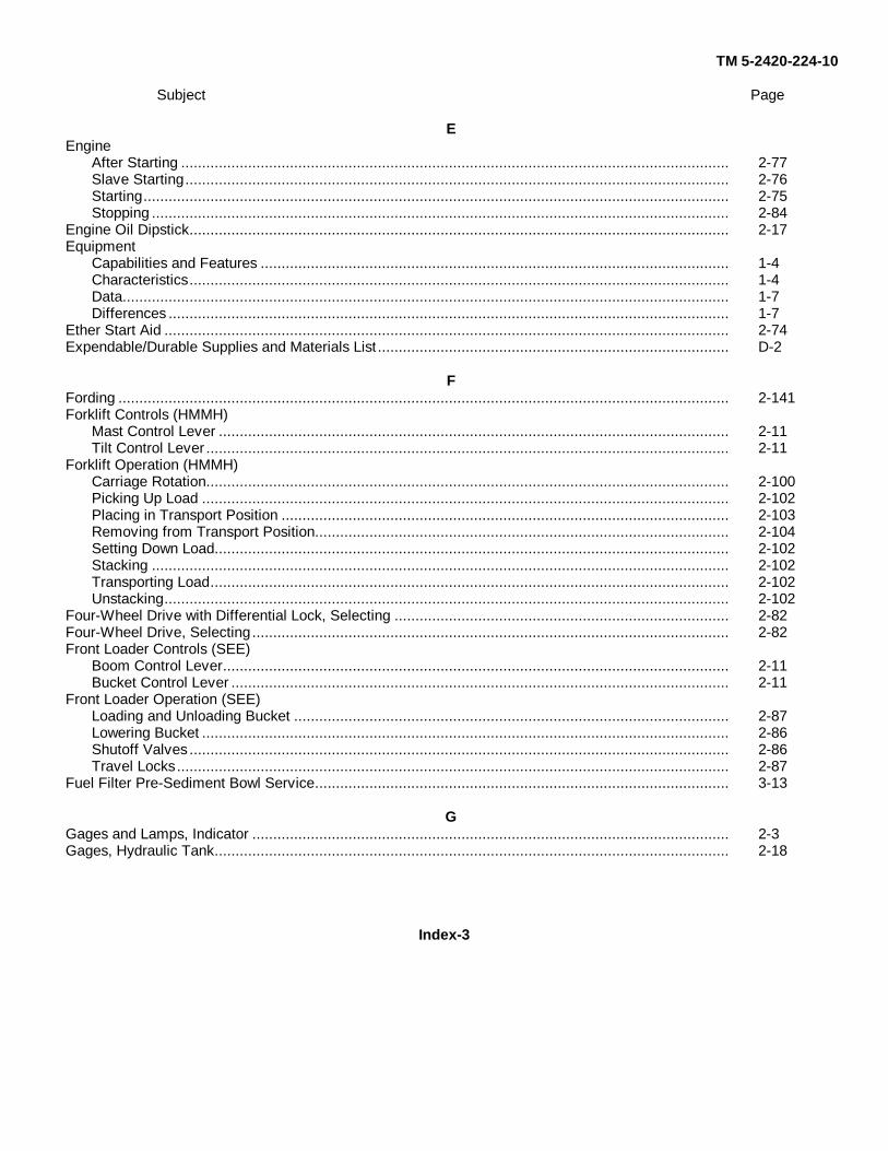
TM 5-2420-224-10
Subject Page
EEngine
After Starting ................................................................................................................................... 2-77Slave Starting.................................................................................................................................. 2-76Starting............................................................................................................................................ 2-75Stopping .......................................................................................................................................... 2-84
Engine Oil Dipstick................................................................................................................................. 2-17Equipment
Capabilities and Features ................................................................................................................ 1-4Characteristics................................................................................................................................. 1-4Data................................................................................................................................................. 1-7Differences ...................................................................................................................................... 1-7
Ether Start Aid ....................................................................................................................................... 2-74Expendable/Durable Supplies and Materials List .................................................................................... D-2
FFording .................................................................................................................................................. 2-141Forklift Controls (HMMH)
Mast Control Lever .......................................................................................................................... 2-11Tilt Control Lever ............................................................................................................................. 2-11
Forklift Operation (HMMH)Carriage Rotation............................................................................................................................. 2-100Picking Up Load .............................................................................................................................. 2-102Placing in Transport Position ........................................................................................................... 2-103Removing from Transport Position................................................................................................... 2-104Setting Down Load........................................................................................................................... 2-102Stacking .......................................................................................................................................... 2-102Transporting Load............................................................................................................................ 2-102Unstacking....................................................................................................................................... 2-102
Four-Wheel Drive with Differential Lock, Selecting ................................................................................ 2-82Four-Wheel Drive, Selecting .................................................................................................................. 2-82Front Loader Controls (SEE)
Boom Control Lever......................................................................................................................... 2-11Bucket Control Lever ....................................................................................................................... 2-11
Front Loader Operation (SEE)Loading and Unloading Bucket ........................................................................................................ 2-87Lowering Bucket .............................................................................................................................. 2-86Shutoff Valves ................................................................................................................................. 2-86Travel Locks .................................................................................................................................... 2-87
Fuel Filter Pre-Sediment Bowl Service................................................................................................... 3-13
GGages and Lamps, Indicator .................................................................................................................. 2-3Gages, Hydraulic Tank........................................................................................................................... 2-18
Index-3

TM 5-2420-224-10
Subject Page
H
Hammer Drill ......................................................................................................................................... 2-23Drilling ............................................................................................................................................. 2-125Installing Drill Bits ............................................................................................................................ 2-125
Hand Receipt (-HR) Manual ................................................................................................................... 1-2Heating and Ventilation System ............................................................................................................. 2-13Hourmeter.............................................................................................................................................. 2-16Hydraulic Accessory Box
Installing Hydraulic Tools in (HMMH ................................................................................................ 2-120Installing Hydraulic Tools in (SEE)................................................................................................... 2-119Removing Hydraulic Tools from (HMMH.......................................................................................... 2-120Removing Hydraulic Tools from (SEE) ............................................................................................ 2-118
Hydraulic Hose ReelConnecting Hydraulic Tools to ......................................................................................................... 2-120Disconnecting Hydraulic Tools from................................................................................................. 2-122
Hydraulic Tank GagesFront and Rear Tank Sight Gages.................................................................................................... 2-18Front Hydraulic System Filter Service Indicator ............................................................................... 2-18Rear Hydraulic System Pressure Gage............................................................................................ 2-18
Hydraulic Tool OperationChipping/Breaking Pavement or Rock with Pavement Breaker ........................................................ 2-123Drilling with Hammer Drill ................................................................................................................ 2-125Felling Tree with Chain Saw ............................................................................................................ 2-127Installing Hammer Drill Bits.............................................................................................................. 2-125Installing Pavement Breaker Spade/Bits .......................................................................................... 2-122Pruning/Debranching with Chain Saw .............................................................................................. 2-130Sawing Log with Chain Saw............................................................................................................. 2-129Using Impact Wrench ...................................................................................................................... 2-130
Hydraulic ToolsChain Saw (SEE.............................................................................................................................. 2-23Hammer Drill (SEE)......................................................................................................................... 2-23Impact Wrench (HMMH ................................................................................................................... 2-23Pavement Breaker (SEE) ................................................................................................................ 2-23
Impact Wrench ...................................................................................................................................... 2-23Using ............................................................................................................................................... 2-130
Indicator Lamps and GagesAir Cleaner Indicator Lamp .............................................................................................................. 2-3Brake Indicator Lamp....................................................................................................................... 2-3Brake System Warning Light .......................................................................................................... 2-2Charge Indicator Light...................................................................................................................... 2-2Coolant Temperature Gage ............................................................................................................. 2-2Differential Lock Indicator Lamp ...................................................................................................... 2-3Dual Brake Gage ............................................................................................................................. 2-2Fuel Gage........................................................................................................................................ 2-2Hazard Warning Flasher Indicator Light ........................................................................................... 2-8
Index-4
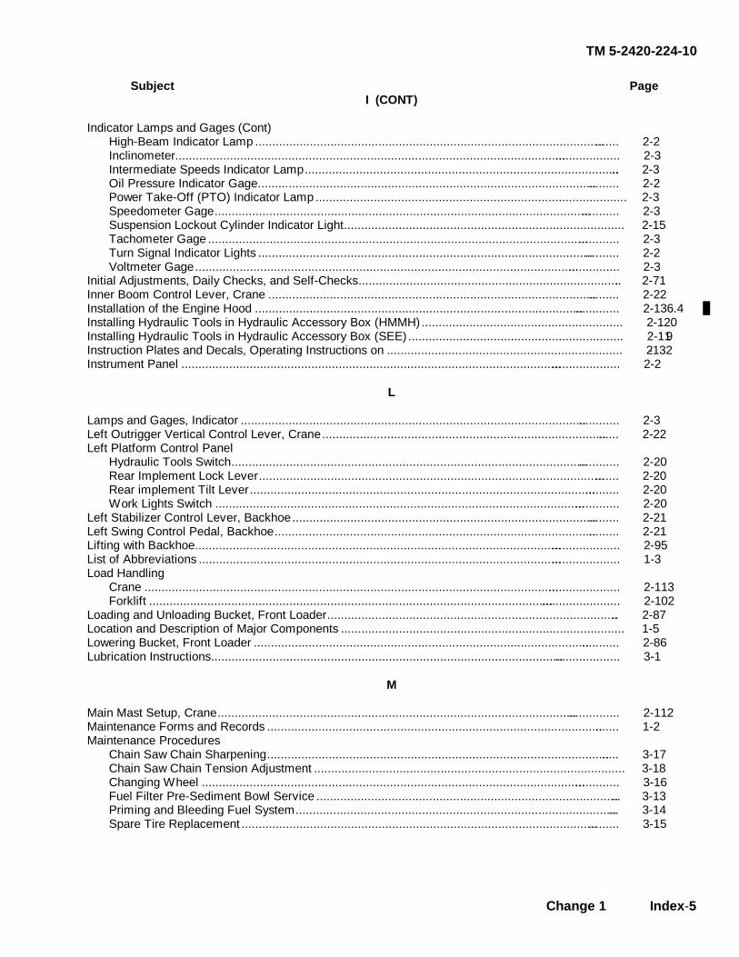
TM 5-2420-224-10
Change 1 Index-5
Subject Page
I (CONT)
Indicator Lamps and Gages (Cont) High-Beam Indicator Lamp ............................................................................................................. 2-2 Inclinometer..................................................................................................................................... 2-3 Intermediate Speeds Indicator Lamp.............................................................................................. 2-3 Oil Pressure Indicator Gage............................................................................................................ 2-2 Power Take-Off (PTO) Indicator Lamp ........................................................................................... 2-3 Speedometer Gage......................................................................................................................... 2-3 Suspension Lockout Cylinder Indicator Light.................................................................................. 2-15 Tachometer Gage ........................................................................................................................... 2-3 Turn Signal Indicator Lights ............................................................................................................ 2-2 Voltmeter Gage............................................................................................................................... 2-3 Initial Adjustments, Daily Checks, and Self-Checks.............................................................................. 2-71 Inner Boom Control Lever, Crane ......................................................................................................... 2-22 Installation of the Engine Hood ............................................................................................................. 2-136.4 Installing Hydraulic Tools in Hydraulic Accessory Box (HMMH) ........................................................... 2-120 Installing Hydraulic Tools in Hydraulic Accessory Box (SEE) ............................................................... 2-119 Instruction Plates and Decals, Operating Instructions on ..................................................................... 2-132 Instrument Panel ................................................................................................................................... 2-2
L Lamps and Gages, Indicator ................................................................................................................. 2-3 Left Outrigger Vertical Control Lever, Crane......................................................................................... 2-22 Left Platform Control Panel Hydraulic Tools Switch.................................................................................................................... 2-20 Rear Implement Lock Lever............................................................................................................ 2-20 Rear implement Tilt Lever............................................................................................................... 2-20 Work Lights Switch ......................................................................................................................... 2-20 Left Stabilizer Control Lever, Backhoe.................................................................................................. 2-21 Left Swing Control Pedal, Backhoe....................................................................................................... 2-21 Lifting with Backhoe............................................................................................................................... 2-95 List of Abbreviations .............................................................................................................................. 1-3 Load Handling Crane .............................................................................................................................................. 2-113 Forklift ............................................................................................................................................. 2-102 Loading and Unloading Bucket, Front Loader....................................................................................... 2-87 Location and Description of Major Components ................................................................................... 1-5 Lowering Bucket, Front Loader ............................................................................................................. 2-86 Lubrication Instructions.......................................................................................................................... 3-1
M Main Mast Setup, Crane........................................................................................................................ 2-112 Maintenance Forms and Records ......................................................................................................... 1-2 Maintenance Procedures Chain Saw Chain Sharpening......................................................................................................... 3-17 Chain Saw Chain Tension Adjustment ........................................................................................... 3-18 Changing Wheel ............................................................................................................................. 3-16 Fuel Filter Pre-Sediment Bowl Service ........................................................................................... 3-13 Priming and Bleeding Fuel System................................................................................................. 3-14 Spare Tire Replacement ................................................................................................................. 3-15

TM 5-2420-224-10
Index-6 Change 1
Subject Page
M (CONT)
Major Components, Location and Description ...................................................................................... 1-5 Mast Control Lever, Forklift ................................................................................................................... 2-11 Mast Folding Lever, Crane .................................................................................................................... 2-22 Mounting and Dismounting the Vehicle................................................................................................. 2-73 Moving the Vehicle ................................................................................................................................ 2-78 Moving the Vehicle with Backhoe.......................................................................................................... 2-95
N
Nomenclature Cross - Reference List ................................................................................................... 1-3
O
Operating Instructions on Decals and Instruction Plates ...................................................................... 2-132 Operation Under Unusual Conditions Dust or Sand ................................................................................................................................... 2-140 Extreme Cold .................................................................................................................................. 2-138 Extreme Heat .................................................................................................................................. 2-139 Fording ............................................................................................................................................ 2-141 High Altitudes .................................................................................................................................. 2-141 Rainy or Humid Conditions ............................................................................................................. 2-140 Saltwater Areas............................................................................................................................... 2-140 Snow ............................................................................................................................................... 2-141 Operation Under Usual Conditions........................................................................................................ 2-71 Outer Boom Control Lever, Crane......................................................................................................... 2-22 Outrigger Horizontal Control Lever, Crane............................................................................................ 2-22
P
Parking Brake Lever .............................................................................................................................. 2-12 Parking Brake Test ................................................................................................................................ 2-137 Pavement Breaker................................................................................................................................. 2-23 Chipping/Breaking Pavement or Rock............................................................................................ 2-123 Installing Breaker Spade/Bits.......................................................................................................... 2-122 Preventive Maintenance Checks and Services (PMCS) ....................................................................... 2-24 Priming and Bleeding Fuel System ....................................................................................................... 3-14
R
Rear Implement Lock Lever ................................................................................................................. 2-20 Rear Implement Tilt Lever .................................................................................................................... 2-20 References ............................................................................................................................................ A-1 Removal of the Engine Hood................................................................................................................. 2-136.3 Removal/Installation of the Inside Engine Cover .................................................................................. 2-137 Removing Hydraulic Tools From Hydraulic Accessory Box (HMMH) ................................................... 2-120 Removing Hydraulic Tools From Hydraulic Accessory Box (SEE) ....................................................... 2-118 Reporting Equipment Improvement Recommendations (EIRs) ............................................................ 1-3 Reposition Front Blackout Light for Blackout Operations (SEE) ........................................................... 2-142 Right Outrigger Vertical Control Lever, Crane....................................................................................... 2-22 Right Stabilizer Control Lever, Backhoe................................................................................................ 2-21

TM 5-2420-224-10
Change 1 Index-7
Subject Page
R (CONT)
Right Swing Control Pedal, Backhoe .................................................................................................... 2-21 Ripping with Backhoe Ripper Shank, Backhoe .................................................................................... 2-96 Rotation Lock Lever, Crane................................................................................................................... 2-22
S Seats...................................................................................................................................................... 2-16 Adjustment ...................................................................................................................................... 2-16 Selecting Four-Wheel Drive ................................................................................................................. 2-82 Selecting Four-Wheel Drive with Differential Lock ................................................................................ 2-82 Self-Checks, Daily Checks, and Initial Adjustments.............................................................................. 2-71 Shifting the Transmission ...................................................................................................................... 2-80 Shutoff Valves, Front Loader................................................................................................................. 2-86 Slave Starting the Engine...................................................................................................................... 2-76 Spare Tire Replacement........................................................................................................................ 3-15 Stabilizers, Backhoe.............................................................................................................................. 2-99 Stacking with Forklift.............................................................................................................................. 2-102 Starting the Engine ................................................................................................................................ 2-75 Steering Wheel ...................................................................................................................................... 2-9 Stopping the Engine .............................................................................................................................. 2-84 Stopping the Vehicle.............................................................................................................................. 2-83 Switches Auxiliary .......................................................................................................................................... 2-6 Auxiliary Headlight .......................................................................................................................... 2-7 Cold Start ........................................................................................................................................ 2-4 Engine RPM, Backhoe.................................................................................................................... 2-21 Four-Wheel Drive and Differential Lock Control ............................................................................. 2-12 Front Loader Remote, Backhoe...................................................................................................... 2-21 Hazard Warning Flasher ................................................................................................................. 2-8 Horn and Low Beam/High Beam .................................................................................................... 2-9 Hydraulic Tools ............................................................................................................................... 2-20 Ignition............................................................................................................................................. 2-4 Master Disconnect .......................................................................................................................... 2-13 Mechanical ...................................................................................................................................... 2-6 Starter ............................................................................................................................................ 2-4 Suspension Lockout Cylinder Activation (HMMH) .......................................................................... 2-15 Test (Buzzer)................................................................................................................................... 2-4 Turn Signal ..................................................................................................................................... 2-4 Vehicular Light ................................................................................................................................ 2-5 Windshield Defroster....................................................................................................................... 2-8 Windshield Wiper/Washer............................................................................................................... 2-4 Work Lights .................................................................................................................................... 2-20
T Technical Principles of Operation.......................................................................................................... 1-9 Test Backhoe/Crane Operator Warning Horn ....................................................................................... 2-72 Three-Point Stance (HMMH)................................................................................................................. 2-136.2 Three-Point Stance (SEE)..................................................................................................................... 2-136.2 Throttle Lever ....................................................................................................................................... 2-12

TM 5-2420-224-10
Index-8 Change 1
Subject Page
T (CONT)
Tilt Control Lever, Forklift ...................................................................................................................... 2-11 Tilt Lock Lever, Crane ........................................................................................................................... 2-22 Tire Inflation........................................................................................................................................... 2-73 Tractor Trailer Operation ....................................................................................................................... 2-146 Trailer Brake Valve Lever ..................................................................................................................... 2-9 Trailer Supply Valve .............................................................................................................................. 2-13 Transmission Controls Group Shift Lever ............................................................................................................................ 2-10 Intermediate Speed Control ............................................................................................................ 2-10 Main Shift Lever ............................................................................................................................. 2-10 Power Take-Off (PTO) Lever .......................................................................................................... 2-10 Transmission, Shifting ........................................................................................................................... 2-80 Transport Position Placing Backhoe in ......................................................................................................................... 2-98 Placing Crane in.............................................................................................................................. 2-116 Placing Forklift in............................................................................................................................. 2-103 Releasing Backhoe from................................................................................................................. 2-89 Releasing Crane from ..................................................................................................................... 2-108 Removing Forklift from.................................................................................................................... 2-104 Travel Lock Release Lever, Backhoe.................................................................................................... 2-19 Travel Lock Release Lever, Crane........................................................................................................ 2-19 Travel Locks, Operation, Front Loader.................................................................................................. 2-87 Troubleshooting..................................................................................................................................... 3-1 Troubleshooting Procedures ................................................................................................................. 3-2 Troubleshooting Symptom Index........................................................................................................... 3-1
U
Unloading and Loading Bucket, Front Loader....................................................................................... 2-87 Unstacking with Forklift.......................................................................................................................... 2-102
V
Ventilation and Heating System ............................................................................................................ 2-13
W
Warranty Information ............................................................................................................................ 1-3 Wheel, Changing ................................................................................................................................... 3-16
TM 5-2420-224-10
By Order of the Secretary of the Army:
GORDON R. SULLIVAN General, United States Army
Chief of Staff
Official:
MILTON H. HAMILTON Administrative Assistant to the
Secretary of the Army 04565
Distribution:
To be distributed in accordance with DA Form 12-38-E (Block 0815) requirements for TM 5-2420-224-10.

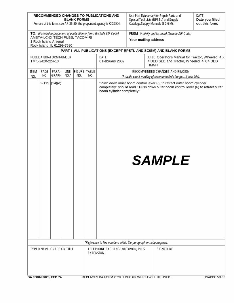
RECOMMENDED CHANGES TO PUBLICATIONS AND BLANK FORMS
For use of this form, see AR 25-30; the proponent agency is ODISC4.
Use Part II (reverse) for Repair Parts and Special Tool Lists (RPSTL) and Supply Catalogs/Supply Manuals (SC/SM).
DATE Date you filled out this form.
TO: (Forward to proponent of publication or form) (Include ZIP Code) AMSTA-LC-CI TECH PUBS, TACOM-RI 1 Rock Island Arsenal Rock Island, IL 61299-7630
FROM: (Activity and location) (Include ZIP Code)
Your mailing address
PART I- ALL PUBLICATIONS (EXCEPT RPSTL AND SC/SM) AND BLANK FORMS
PUBLICATION/FORM NUMBER TM 5-2420-224-10
DATE 6 February 2002
TITLE Operator's Manual for Tractor, Wheeled, 4 X 4 DED SEE and Tractor, Wheeled, 4 X 4 DED HMMH
ITEM NO.
PAGE NO.
PARA- GRAPH
LINENO.*
FIGURE NO.
TABLE NO.
RECOMMENDED CHANGES AND REASON (Provide exact wording of recommended changes, if possible).
2-115 (14)(d)
"Push down inner boom control lever (6) to retract outer boom cylinder completely" should read " Push down outer boom control lever (6) to retract outer boom cylinder completely"
SAMPLE
*Reference to line numbers within the paragraph or subparagraph.
TYPED NAME, GRADE OR TITLE
TELEPHONE EXCHANGE/AUTOVON, PLUS EXTENSION
SIGNATURE
DA FORM 2028, FEB 74 REPLACES DA FORM 2028, 1 DEC 68, WHICH WILL BE USED. USAPPC V3.00

TO: (Forward direct to addressee listed in publication) AMSTA-LC-CI TECH PUBS, TACOM-RI 1 Rock Island Arsenal Rock Island, IL 61299-7630
FROM: (Activity and location) (Include ZIP Code) DATE
PART II – REPAIR PARTS AND SPECIAL TOOL LISTS AND SUPPLY CATALOGS/SUPPLY MANUALS PUBLICATION NUMBER TM 5-2420-224-10
DATE 6 February 2002
TITLE Operator's Manual for Tractor, Wheeled, 4 X 4 DED SEE and Tractor, Wheeled, 4 X 4 DED HMMH
PAGE NO.
COLM
NO.
LINE NO.
NATIONAL STOCK
NUMBER
REFERENCE
NO.
FIGURE
NO.
ITEM NO.
TOTAL NO. OF MAJOR
ITEMS SUPPORTED
RECOMMENDED ACTION
PART III – REMARKS (Any general remarks or recommendations, or suggestions for improvement of publications and blank forms. Additional blank sheets may be used if more space is needed.)
TYPED NAME, GRADE OR TITLE TELEPHONE EXCHANGE/AUTOVON, PLUS EXTENSION SIGNATURE
UASPPC V3.00

RECOMMENDED CHANGES TO PUBLICATIONS AND BLANK FORMS
For use of this form, see AR 25-30; the proponent agency is ODISC4.
Use Part II (reverse) for Repair Parts and Special Tool Lists (RPSTL) and Supply Catalogs/Supply Manuals (SC/SM).
DATE
TO: (Forward to proponent of publication or form) (Include ZIP Code) AMSTA-LC-CI TECH PUBS, TACOM-RI 1 Rock Island Arsenal Rock Island, IL 61299-7630
FROM: (Activity and location) (Include ZIP Code)
PART I- ALL PUBLICATIONS (EXCEPT RPSTL AND SC/SM) AND BLANK FORMS
PUBLICATION/FORM NUMBER TM 5-2420-224-10
DATE 6 February 2002
TITLE Operator's Manual for Tractor, Wheeled, 4 X 4 DED SEE and Tractor, Wheeled, 4 X 4 DED HMMH
ITEM NO.
PAGE NO.
PARA- GRAPH
LINENO.*
FIGURE NO.
TABLE NO.
RECOMMENDED CHANGES AND REASON (Provide exact wording of recommended changes, if possible).
*Reference to line numbers within the paragraph or subparagraph.
TYPED NAME, GRADE OR TITLE
TELEPHONE EXCHANGE/AUTOVON, PLUS EXTENSION
SIGNATURE
DA FORM 2028, FEB 74 REPLACES DA FORM 2028, 1 DEC 68, WHICH WILL BE USED. USAPPC V3.00

067339-001
TO: (Forward direct to addressee listed in publication) AMSTA-LC-CI TECH PUBS, TACOM-RI 1 Rock Island Arsenal Rock Island, IL 61299-7630
FROM: (Activity and location) (Include ZIP Code) DATE
PART II – REPAIR PARTS AND SPECIAL TOOL LISTS AND SUPPLY CATALOGS/SUPPLY MANUALS PUBLICATION NUMBER TM 5-2420-224-10
DATE 6 February 2002
TITLE Operator's Manual for Tractor, Wheeled, 4 X 4 DED SEE and Tractor, Wheeled, 4 X 4 DED HMMH
PAGE NO.
COLM
NO.
LINE NO.
NATIONAL STOCK
NUMBER
REFERENCE
NO.
FIGURE
NO.
ITEM NO.
TOTAL NO. OF MAJOR
ITEMS SUPPORTED
RECOMMENDED ACTION
PART III – REMARKS (Any general remarks or recommendations, or suggestions for improvement of publications and blank forms. Additional blank sheets may be used if more space is needed.)
TYPED NAME, GRADE OR TITLE TELEPHONE EXCHANGE/AUTOVON, PLUS EXTENSION SIGNATURE
UASPPC V3.00
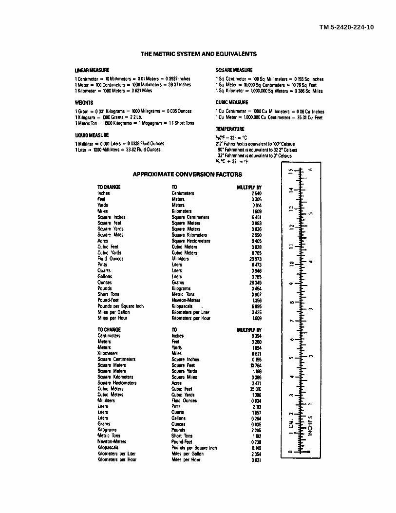
TM 5-2420-224-10

PIN: 067339-001
Related Documents


