l^~~~ t ft WAR DEPARTMENT TECHNICAL MANUAL PLOW, BOTTOM AND DISC TOWED-TYPE FOUR 14-INCH BOTTOMS DEERE MODEL 7 This is a reprint of TM 5-1088, Maintenance Manual and Parts Catalog, Plow, Tractor, Heavy Duty, 4 14-in. Bottoms, Model No. /, Dec-e & Co., 29 January 1943. No distribu tion wii) be made to personnel passessmg the original publication. WAR DEPARTMENT JANUARY 1943

TM 5-1088 ( Plow, Bottom and Disc Towed-Type Four 14-Inch B.pdf
Dec 29, 2015
Welcome message from author
This document is posted to help you gain knowledge. Please leave a comment to let me know what you think about it! Share it to your friends and learn new things together.
Transcript
l^~~~ t
ft
WAR DEPARTMENT TECHNICAL MANUAL
PLOW, BOTTOM AND
DISC TOWED-TYPE
FOUR 14-INCH BOTTOMS
DEERE MODEL 7
This is a reprint of TM 5-1088, Maintenance Manual and Parts Catalog, Plow, Tractor, Heavy Duty, 4 14-in. Bottoms, Model No. /, Dec-e & Co., 29 January 1943. No distribu tion wii) be made to personnel passessmg the original publication.
WAR DEPARTMENT JANUARY 1943

WAR DEPARTMENT TECHNICAL MANUAL
TM 5-1088
PLOW, BOTTOM AND
DISC TOWED-TYPE
FOUR 14-INCH BOTTOMS
DEERE MODEL 7
WAR DEPARTMENT JANUARY 1943
United Statet Government Printing Office
Washington: 104S
INDEXPage Nos. Paragraph
SECTION I INTRODUCTION.......................... 1SECTION II DESCRIPTION AND CHARACTERISTICS. 4-5
Axles............................................... 4 1Beams.............................................. 4 1Bottoms............................................. 4 1Connecting Bar..................................... 5 1General Description................................. 4 1Hitch............................................... 4 1Identification........................................ 4 1Levers.............................................. 4 1Lifting Springs...................................... 4 1Mobility............................................ 4 1Power Lift.......................................... 4 1Rolling Coulters..................................... 4 1Shipping Packages.................................. 5 1Specifications........................................ 5 1
PART 1, SECTION III SETTING UP INSTRUCTIONSAlemite Fittings..................................... 12 14Axles, Furrow....................................... 6 2Axle, Land.......................................... 7 4Axle, Rear.......................................... 9 7Beam............................................... 6 2Bottoms............................................. 10 10Check and Lubricate................................. 12 15Connecting Bar...................................... 9 8Coulters............................................. 11 11General............................................. 6 1Hitch............................................... 11 12Lever, Furrow....................................... 8 6Lever, Master....................................... 8 5Lubrication......................................... 12 15Power Lift.......................................... 7 4Removing Varnish................................... 12 16Rope............................................... 11 13Spring Release...................................... 11 12Springs, Lifting...................................... 10 9Wheel, Furrow...................................... 6 3Wheel, Land........................................ 7 4Wheel, Rear......................................... 9 7
PART I, SECTION IV OPERATING INSTRUCTIONS, ADJUSTMENT AND CONTROLS
Controls ............................................13-18 1Coulters............................................. 17 1Depth Adjustments.................................. 16 1Hitch............................................... 13 1Hitch Adjustments Horizontal....................... 13 1Hitch Adjustments Vertical......................... 13 1Levers.............................................. 15 1Lifting Springs................... P. ................. 17 1Opening up the Land................................ 13 1Rear Wheel......................................... 18 1Spring Release Hitch................................ 14 1Trip Rope................. ......................... 15 1
PART II, SECTION I MAINTENANCE MANUALAdjusting the Clutch................................. 20 7Coulter Bearings.................................... 19 5Hardening Soft Center Steel Shares................... 19 3Lubrication Instructions.............................. 21 8Plow Bottoms and Coulters.......................... 19 1Sharpening the Coulter Blade......... ............... 19 4Sharpening the Share................................ 19 2Wheel Bearings..... ................................ 19 6
PART III SPARE PARTS LIST.......................... 23

INDEX TO ILLUSTRATIONS
PART I—Operator's ManualPage Not. Figure No.
Adjusting Levers........................................... :. 5 21Adjusting Lifting Springs................................... .17 26Adjustment for Medium or Deep Plowing................... 16 24Adjustment for Shallow Plowing........................... 16 25Alemite Fittings........................................... 12 16Assembling Furrow Axle................................... 6 3Assembling Furrow Wheel ................................. 7 4Assembling Land Axle, Wheel and Power Lift .............. 7 5Assembling Rear Wheel.................................... 9 9Attaching Bottoms......................................... 10 12Attaching Furrow Lever.................................... 8 7Attaching Master Lever..................................... 8 6Attaching Rear Axle and Wheel............................ 9 8Attaching Rolling Coulters................................. 11 13Connecting Bar............................................ 9 10Clevis Jaw Adjustment..................................... 14 18ClutchRope............................................... 11 15Hitch Adjustments......................................... 13 17Hitch and Spring Release.................................. 11 14Improper Setting of Rolling Coulters....................... 17 30Landside View John Deere No. 7 Tractor Plow............ 3 2Lateral Adjustment of Rear Wheel.......................... 18 32Lateral Adjustment of Rolling Coulter....................... 17 27Lever Adjustment for Deep Plowing........................ 15 22Lever Adjustment for Shallow Plowiog...................... 16 23Lifting Springs............................................. 10 11Moldboard View.......................................... 2 1Proper Setting of Rolling Coulters.......................... 17 29Rolling Coulter Details..................................... 17 28Spring Release Hitch Closed.............................. 14 19Spring Release Hitch Released............................ 14 20Up and Down Adjustment of Rear Wheel................... 18 31
PART II—Maintenance ManualClutch Assembled and Disassembled........................ 20 33Lubrication Chart.......................................... 21 34
PART III—Spare Parts ListBeams and Braces.......................................... 24 35Connecting Bar............................................ 29 41Furrow Wheel and Axle.................................;.. 25 36Hitch and Spring Release.................................... 31 43Land Wheel, Axle and Power Lift........................... 26 37Lever and Lifting Springs.................................. 27 38Lifting Clutch.............................................. 30 42Plow Bottoms ............................................. 32 44Rear Axle ................................................. 28 39Rear Wheel................................................ 29 40Rolling Coulters........................................... 33 45Tools...................................................... 34 46

OPERATOR'S MANUAL Introduction
SECTION I
Introduction
1. PURPOSE AND SCOPE. These instruc tions are published for the information and guidance of the using arms charged with the operation, maintenance and repair of this ma terial. They contain descriptions of the major units and their function in relation to the other components of the plow, as well as instructions for operation, inspection and maintenance.
2. Any reference to "Right" and "Left", "Front" and "Rear" refer to the operator's "Right" and "Left", "Front" and "Rear" when facing in the same direction the plow will face when being used.
In the case of this particular model of plow, "Right" side is often referred to as "Moldboard" or "Furrow" side, and "Left" side as "Land- side".

N)
REAR
WH
EE
L A
XLE
PLO
W B
OTT
OM
FUR
RO
W A
XLE
LEV
ERM
ASTE
R L
EVER
LIF
TIN
G
SPRI
NG
FRO
NT
BE
AM
SEC
ON
D B
EA
M
BE
AM
BR
ACE
THIR
D B
EA
M
FOU
RTH
BE
AM
UR
RO
W W
HE
EL
AX
LE
CU
SHIO
N S
PRIN
G R
ELEA
SE
HIT
CH D
RAF
T LI
NK
'
FUR
RO
W
WH
EE
L
MO
LDB
OA
RD
HA
RE
FIG
UR
E 1—
MO
LDB
OA
RD
VIE
W (
RIG
HT
HA
ND
) JO
HN
DEE
RE N
o. 7
TR
AC
TO
R P
LOW

MA
STE
R
(DE
PTH
) LE
VER LA
ND
WH
EE
L A
XLE
CO
NN
EC
TIN
G B
AR
CO
ULT
ER
SH
AN
K
CO
ULT
ER
CLA
MP
FUR
RO
W L
EVER
LIF
TIN
G S
PRIN
G
PO
WE
R
LIFT
LUG
S
LAN
D W
HE
EL
LAN
DS
iDE
'
FIG
UR
E 2—
LAN
DSI
DE
VIE
W (
LEFT
HA
ND
) JO
HN
DEE
RE N
o. 7
TR
AC
TO
R P
LOW

Characteristics OPERATOR'S MANUAL
SECTION II
Description and Characteristics
1. GENERAL DESCRIPTION.—This Four-Bottom Tractor Plow is a heavy-duty moldboard plow designed for plowing in both medium or heavy conditions at a depth ranging from six to fourteen inches. It is equipped with an adjustable hitch permitting it to be pulled behind a variety of tractors or prime movers.
A. Identification.—-This implement is illustrated in Figures 1 and 2 and shows left (landside) and right (moldboard) views. No serial number is assigned to this plow. It is referred to by model as "No. 7 Four-Bottom Tractor Plow".
B. Mobility.—It is provided with three wheels which are in use both for transporting and plowing. When plowing, the right hand front wheel runs in the old furrow, the left hand wheel on the land, and the rear wheel in the new furrow.
C. Beams.—Beams are of Special No. 20 Beaded stock, heat treated, and are joined together with individual braces between the first, second and third.beams. The entire frame unit is joined together with a heavy square brace bar mounted above the beams. This gives added strength and provides great clearance for trash.
D. Axles.-—Three axles are mounted on the beams, one each for the Furrow Wheel, (right side) Land Wheel (left side) and Rear Wheel. Axles are attached to beams by means of bearings, collars and cotters.
E. Power Lift.—The power lift is mounted on the land axle (left side) and is of the enclosed type, housing all clutch parts in an oil tight case. When the clutch is tripped by means of a trip rope, the plow is lowered into the ground or lifted out. The clutch parts of the power lift are inactive except when lowering or lifting the plow.
F. Levers.—By means of two levers (one for the furrow axle and one for the land axle) the plow is leveled and set for the desired depth.
G. Lifting Springs.—Lifting springs prevent the plow from dropping too fast when the clutch is tripped, and assist the power lift in raising the plow out of the ground.
H. Plow Bottoms.—Plow bottoms are of the "deep tillage" type and will do good work at great depth. They cut a furrow 14" wide and all four bottoms will cut a total width of 56". The three main component parts of a bottom are the moldboard, share and landside.
/. Rolling Coulters.—Rolling coulters pivot on the shanks which are attached to the plow by means of clamps. One coulter is provided for each bottom, and cuts the land immediately in front to assist in turning over a clean furrow.
J. Hitch.—The hitch provides a wide range of adjustments both vertical and horizontal, adapting it to a variety of prime movers. Between the draft link which attaches the plow to the prime mover and the hitch,

Description and OPERATOR'S MANUAL Characteristics
two large coil springs are provided which serve not only as a cushion for the load, but also as a safety feature for the plow. When a solid rock or other obstruction is encountered by the plow, the coil spring com presses, releasing the draft link, and the plow becomes disconnected from prime mover. (See operator's instructions for adjusting.)
K. Connecting Bar.—The land axle and the rear wheel are connected to synchronize the lifting of the front and rear of the plow.
L. Specifications.—Depth Range: Approximately 6" to 14".Width of Cut: Four-Bottoms 14". Total Cut 56".Bottoms: DT-356 Deep Tillage Bottoms. Bottoms have replace
able chilled shin on moldboard and replaceable chilled heel on landside.
Beam: Beaded steel beams, No. 20 stock, heat treated. 23" clearance under beams. 20" fore-and-aft spacing.
Wheels: Furrow Wheel, 32" Diameter, 6" Wide. Land Wheel, 32" Diameter, 6" Wide. Rear Wheel, 19" Diameter, 3" Wide. All wheels revolve on steel sleeves on axle.
Hitch: Double cushion spring release hitch. Adjustable trip ping load.
Levers: For depth control and leveling—adjustable for length.Rolling Coulters: 18" Caster Rolling Coulters with 1-1/2"
shanks.M. Shipping Packages.—When packed for shipment, the No. 7
Plow is shipped in bundles which are partially assembled. This Four- Bottom Plow consists of the following bundles:
Approx. Weight
1—Beams, Furrow Axle, 2 Lifting Springs, Beam BraceBar, Connecting Bar and 4 Coulter Shanks........... .. 995 Ibs.
1—Land Axle, Clutch and Wheel..........................296 Ibs.1—Levers and Ratchets................................... 114 Ibs.1—JD1316 Furrow Wheel................................ 120 Ibs.1—No. 21558 Rear Wheel................................ 34 Ibs.1—Sack Clutch Rope and Grease Fittings.................. 1 Ib.4—S10432 Rolling Coulters.............................. 120 Ibs.4—DT-356 No. 8 Plow Bottoms..........................400 Ibs.I—No. 6 5 Cushion Spring Release Hitch....... .... ...... 15 5 Ibs.
Total Weight 2235 Ibs.
Setting-Up Instruction OPERATOR'S MANUAL
SECTION III
Setting-Up Instructions
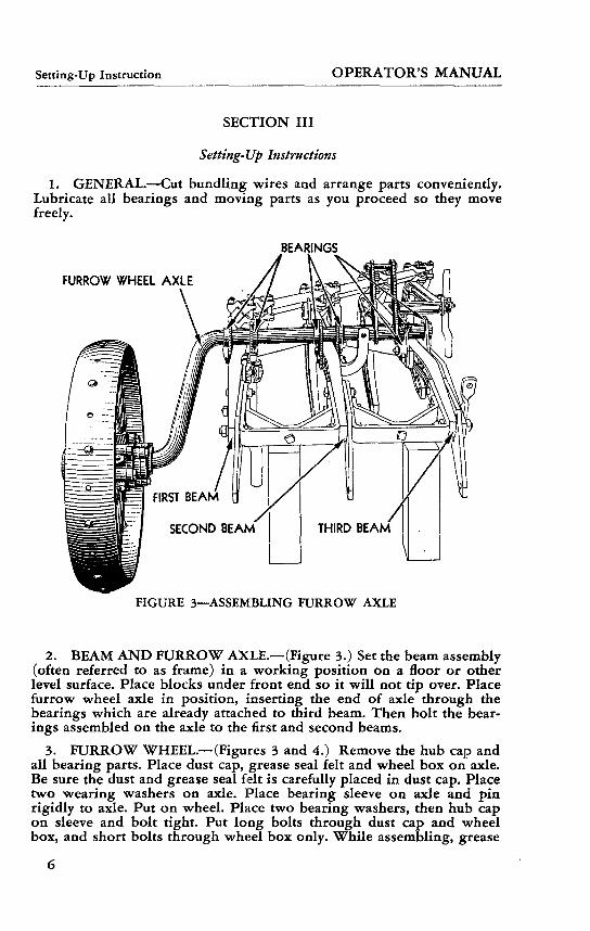
1. GENERAL.—Cut bundling wires and arrange parts conveniently. Lubricate all bearings and moving parts as you proceed so they move freely.
BEARINGS
FURROW WHEEL AXLE
FIGURE 3—ASSEMBLING FURROW AXLE
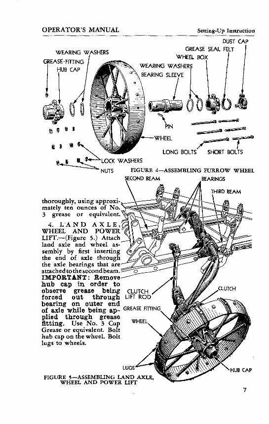
2. BEAM AND FURROW AXLE.—(Figure 3.) Set the beam assembly (often referred to as frame) in a working position on a floor or other level surface. Place blocks under front end so it will not tip over. Place furrow wheel axle in position, inserting the end of axle through the bearings which are already attached to third beam. Then bolt the bear ings assembled on the axle to the first and second beams.
3. FURROW WHEEL.—(Figures 3 and 4.) Remove the hub cap and all bearing parts. Place dust cap, grease seal felt and wheel box on axle. Be sure the dust and grease seal felt is carefully placed in dust cap. Place two wearing washers on axle. Place bearing sleeve on axle and pin rigidly to axle. Put on wheel. Place two bearing washers, then hub cap on sleeve and bolt tight. Put long bolts through dust cap and wheel box, and short bolts through wheel box only. While assembling, grease
OPERATOR'S MANUAL Setting-Up Instruction
WEARING WASHERS
GREASE- FITTING
HUB CAP
r <•
DUST CAP GREASE SEAL FELT
WHEEL BOX
WEARING WASHERS
BEARING SLEEVE
PIN
WHEEL
LONG BOLTS SHORT BOLTS
WASHERS
"NUTS FIGURE 4—ASSEMBLING FURROW WHEEL SECOND BEAM BEARINGS
THIRD BEAM
thoroughly, using approxi mately ten ounces of No. 3 grease or equivalent.
4. LAND AXLE, WHEEL AND POWER LIFT.—(Figure 5.) Attach land axle and wheel as sembly by first inserting the end of axle through the axle bearings that are attached to the second beam. IMPORTANT: Remove hub cap in order to observe grease being forced out through LIFT ROD bearing on outer end of axle while being ap- GREASE F1TTING. plied through grease fitting. Use No. 3 Cup Grease or equivalent. Bolt hub cap on the wheel. Bolt lugs to wheels.
LUGS
FIGURE 5—ASSEMBLING LAND AXLE, WHEEL AND POWER LIFT
HUB CAP
Setting-Up Instruction OPERATOR'S MANUAL
..TRIGGER LEVER LEVER DOG
DOG ROD CLAMPSRATCHET
THREADED ADJUSTMENT-'
CLUTCH LIFT ROD'
CLUTCH LIFTING CRANK
FIGURE 6—ATTACHING MASTER LEVER
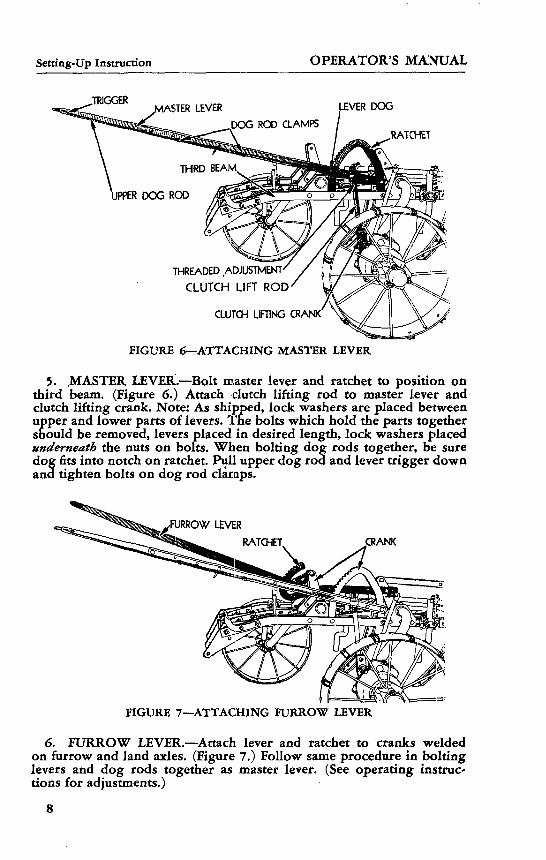
5. .MASTER LEVER.—Bolt master lever and ratchet to position on third beam. (Figure 6.) Attach clutch lifting rod to master lever and clutch lifting crank. Note: As shipped, lock washers are placed between upper and lower parts of levers. The bolts which hold the parts together should be removed, levers placed in desired length, lock washers placed underneath the nuts on bolts. When bolting dog rods together, be sure dog fits into notch on ratchet. Pull upper dog rod and lever trigger down and tighten bolts on dog rod clamps.
CRANK
FIGURE 7—ATTACHING FURROW LEVER
6. FURROW LEVER.—Attach lever and ratchet to cranks welded on furrow and land axles. (Figure 7.) Follow same procedure in bolting levers and dog rods together as master lever. (See operating instruc tions for adjustments.)

OPERATOR'S MANUAL Setting-Up Instruction
REAR AXLE
FOURTH BEAM
S REAR WHEEL
FIGURE 8—ATTACHING REAR AXLE AND WHEEL
7. REAR AXLE AND WHEEL.—Attach rear axle onto fourth beam. (Figure 8.) Place inside box with rear wheel on axle. (Figure 9.) Place wearing washer and bearing sleeve on axle and pin rigidly to axle. Grease wheel sleeve thoroughly with No. 3 Cup Grease or its equivalent. Place wearing washer and outside wheel box on axle and bolt tight.OUTSIDE WHEEL BOX
o i
INSIDE WHEEL BOX
i>
BOLTS
BEARING SLEEVE- FIGURE 9—ASSEMBLING REAR WHEEL
8. CONNECTING BAR.—Attach connecting bar to land axle crank and to the rear wheel arm. (Figure 10.) See operating instructions for adjusting.
Jer^-vflS *-« A i n>ADJUSTING CRANK
/ CONNECTING BAR FIGURE 10—CONNECTING BAR

Setting-Up Instruction OPERATOR'S MANUAL
SPRING POSTLEVER RATCHETS
LAND AXLE LIFTING SPRING HOOK
FURROW AXLE LIFTING SPRING
ADJUSTING NUT
FIGURE 11—LIFTING SPRINGS
9. LIFTING SPRINGS.—Pull both levers down into lowest setting on lever ratchets. Place plow in lifted position by moving trip lever forward on lifting clutch and pulling plow forward until the plow is lifted and clutch locks into posi ion. One revolution of the land wheel will lift the plow. Hook smaller lifting spring to crank on furrow axle. (Figure 11.) Put spring adjusting bolt through post on frame and ad just to medium tension. Attach larger lifting spring to eye in hook on land axle crank. Put spring adjusting bolt through post on second beam and adjust to medium tension. (See operating instructions for adjusting.)
10. BOTTOMS.—With the plow still in lifted position, attach all plow bottoms to beams. (Figure 12.) These bottoms are common and will fit on any of the beams. Start with the first beam, then the second, and so on. Be sure all bolts are tight ened securely. Use a large long handled wrench.
ATTACHING BOTTOMS
FIGURE 12—ATTACHING BOTTOMS10
OPERATOR'S MANUAL Setting-Up Instruction
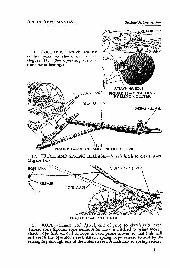
11. COULTERS.—Attach rolling coulter yoke to shank on beams. (Figure 13.) (See operating instruc tions for adjusting.)
CLEVIS JAWSATTACHING BOLT
FIGURE 13—ATTACHING ROLLING COULTER
SPRING RELEASE
HITCH FIGURE 14—HITCH AND SPRING RELEASE
12. HITCH AND SPRING RELEASE.—Attach hitch to clevis jaws.(Figure 14.)
CLUTCH TRIP LEVER
FIGURE 15—CLUTCH ROPE
13. ROPE.—(Figure 15.) Attach end of rope to clutch trip lever. Thread rope through rope guide. After plow is hitched to prime mover, attach rope link on end of rope toward prime mover so that link will just reach th.e operator's seat. Attach spring rope release to seat by in serting lug through one of the holes in seat. Attach link to spring release.
11
Setting-Up Instruction OPERATOR'S MANUAL
FIGURE 16—ALEMITE FITTINGS
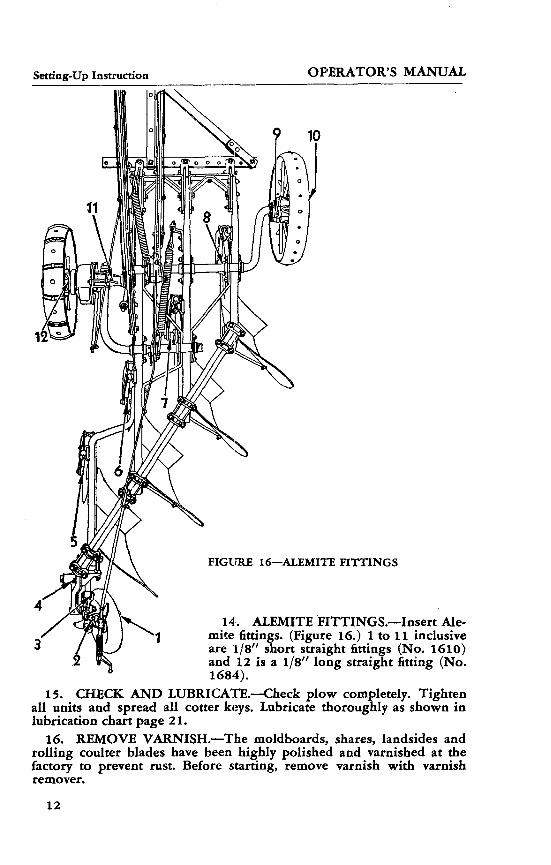
14. ALEMITE FITTINGS.—Insert Ale- mite finings. (Figure 16.) 1 to 11 inclusive are 1/8" short straight fittings (No. 1610) and 12 is a 1/8" long straight fitting (No. 1684).
15. CHECK AND LUBRICATE.—Check plow completely. Tighten all units and spread all cotter keys. Lubricate thoroughly as shown in lubrication chart page 21.
16. REMOVE VARNISH.—The moldboards, shares, landsides and rolling coulter blades have been highly polished and varnished at the factory to prevent rust. Before starting, remove varnish with varnish remover.
12

Operating Instructions OPERATOR'S MANUAL Adjustment and Control
SECTION IV
Operating Instructions, Adjustment and Control
1. CONTROLS.—The controls are employed to properly hitch the plow behind prime mover, regulate depth of plowing and uniform cut ting of furrow width; even penetration of plow bottoms (leveling) and lowering plow into ground and raising plow out of ground.
The operator must become thoroughly familiar with the location, use and adjustment of all control devices before attempting to operate the plow.
A. Hitch.—Attach draft link to hitch of prime mover. Drive ahead until plow is lined up with prime mover, and adjust hitch so drawbar is parallel to line of travel.
a. Opening up the land. The first time around the field, the land is "opened up". Then both furrow and land wheels run on top of the ground, and only the rear wheel runs in the furrow. After the first round, She front furrow wheel and the rear wheel run in the furrows, and the land wheel runs on top of the ground. After the land has been opened up, place the plow in working position with front furrow wheel in the furrow. Detach prime mover and place it in normal working position, adjust hitch so the front bottom cuts a furrow slice 14 inches wide and attach prime mover to pl<*w.
CLEVIS JAWS
DRAW BAR
STOP OFF PIN
"DIAGONAL BRACE BAR DRAFT LINK
FIGURE 17—HITCH ADJUSTMENTS
b. Horizontal hitch adjustment. This adjustment is provided so the plow can be hitched to pull straight and in proper working position with each bottom cutting a furrow slice 14 inches wide behind prime mover. Whether opening the land or doing regular plowing, the draw bar should always be approximately parallel to line of travel. To adjust drawbar, move right or left on cross bar, and then adjust diagonal brace bar to proper position, and lock with stop off pin. (Figure 17.)
c. Vertical hitch adjustment. This adjustment provides a means of raising or lowering the hitch on the clevis jaws of the plow so that
13
Operating Instructions Adjustment and Control OPERATOR'S MANUAL
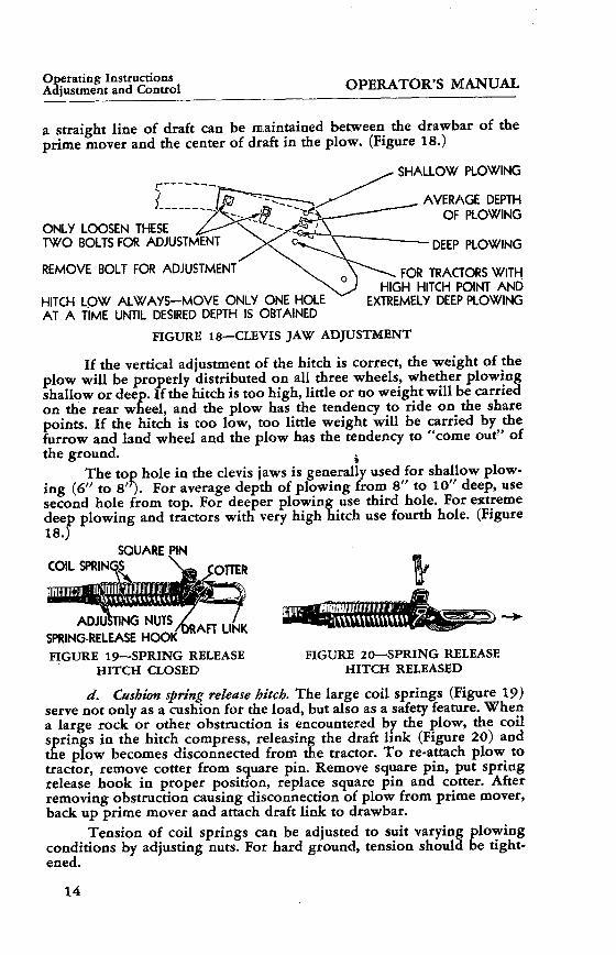
a straight line of draft can be maintained between the drawbar of the prime mover and the center of draft in the plow. (Figure 18.)
SHALLOW PLOWING
ONLY LOOSEN THESETWO BOLTS FOR ADJUSTMENT
REMOVE BOLT FOR ADJUSTMENT
HITCH LOW ALWAYS-MOVE ONLY ONE HOLE AT A TIME UNTIL DESIRED DEPTH IS OBTAINED
AVERAGE DEPTH OF PLOWING
DEEP PLOWING
FOR TRACTORS WITH HIGH HITCH POINT AND
EXTREMELY DEEP PLOWING
FIGURE 18—CLEVIS JAW ADJUSTMENT
If the vertical adjustment of the hitch is correct, the weight of the plow will be properly distributed on all three wheels, whether plowing shallow or deep. If the hitch is too high, little or no weight will be carried on the rear wheel, and the plow has the tendency to ride on the share points. If the hitch is too low, too little weight will be carried by the furrow and land wheel and the plow has the tendency to "come out" of the ground.
The toj ing (6" to 8'second hole from top. For deeper plowing use third hole. For extreme deep plowing and tractors with very high hitch use fourth hole. (Figure 18.J
op hole in the clevis jaws is generally used for shallow plow '0- For average depth of plowing from 8" to 10" deep, use
COIL SPRIISQUARE PIN
:OTTER
ADJSPRING-RELEASE FIGURE 19—SPRING RELEASE
HITCH CLOSEDFIGURE 20—SPRING RELEASE
HITCH RELEASED
d. Cushion spring release hitch. The large coil springs (Figure 19) serve not only as a cushion for the load, but also as a safety feature. When a large rock or other obstruction is encountered by the plow, the coil springs in the hitch compress, releasing the draft link (Figure 20) and the plow becomes disconnected from the tractor. To re-attach plow to tractor, remove cotter from square pin. Remove square pin, put spring release hook in proper position, replace square pin and cotter. After removing obstruction causing disconnection of plow from prime mover, back up prime mover and attach draft link to drawbar.
Tension of coil springs can be adjusted to suit varying plowing conditions by adjusting nuts. For hard ground, tension should be tight ened.
14
OPERATOR'S MANUAL Operating Instructions Adjustment and Control
B. Trip Rope.—Adjust clutch trip rope to proper length between plow and prime mover. To drop plow into ground, pull the clutch rope, with prime mover moving forward. To raise plow, pull same rope. In raising or lowering the plow, do not pull rope after clutch begins to operate or the clutch will repeat its operation.
BOLTS FOR ADJUSTING LENGTH OF LEVERS
DOG ROD CLAMPS
FIGURE 21—ADJUSTING LEVERS
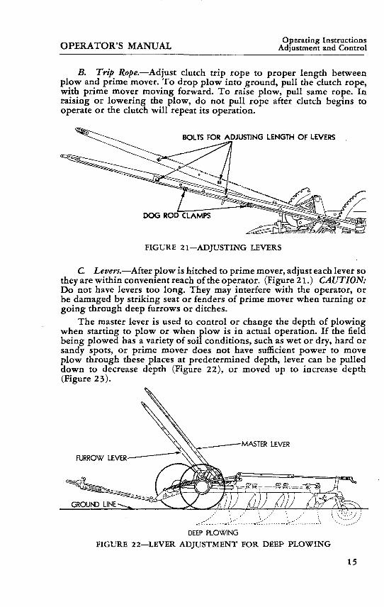
C. Levers.—After plow is hitched to prime mover, adjust each lever so they are within convenient reach of the operator. (Figure 21.) CAUTION: Do not have levers too long. They may interfere with the operator, or be damaged by striking seat or fenders of prime mover when turning or going through deep furrows or ditches.
The master lever is used to control or change the depth of plowing when starting to plow or when plow is in actual operation. If the field being plowed has a variety of soil conditions, such as wet or dry, hard or sandy spots, or prime mover does not have sufficient power to move plow through these places at predetermined depth, lever can be pulled down to decrease depth (Figure 22), or moved up to increase depth (Figure 23).
GROUND LINE
DEEP PLOWING FIGURE 22—LEVER ADJUSTMENT FOR DEEP PLOWING
15

Operating Instructions Adjustment and Control OPERATOR'S MANUAL
By means of the furrow lever, the furrow wheel is raised by pull ing lever down and lowered by moving lever up. The plow is leveled by raising or lowering the furrow wheel. Maintaining proper level permits each bottom to turn over the same thickness of furrow slice as all the others.
MASTER LEVER
GROUND LINE
SHALLOW PLOWING FIGURE 23—LEVER ADJUSTMENT FOR SHALLOW PLOWING
D. Additional Depth Adjustments.—When the plowing depth range provided in the levers is insufficient, a new depth range can be obtained on the lever ratchets by using the adjustment on the clutch lift rod, and the front furrow lever ratchet bar.
THREADED _X LEVER RATCHET ADJUSTMENT^ -———— BAR
THREADED ADJUSTMENT
LEVER RATCHET BAR
FIGURE 24—ADJUSTMENT FOR MEDIUM OR DEEP PLOWING
FIGURE 25—ADJUSTMENT FOR SHALLOW PLOWING
For medium or deep plowing, use inner hole in the clutch lifting crank and the rear hole on the ratchet bar. (Figure 24.)
For shallow plowing use outer hole in the clutch lifting crank, and front hole in the ratchet bar (Figure 25).
The threaded adjustment at the end of the clutch lifting crank can be turned down for deeper plowing and up for shallower plowing. Lock into position by tightening both nuts—tight.
16

OPERATOR'S MANUAL Operating Instructions Adjustment and Control
FIGURE 26—ADJUSTING LIFTING SPRING
E. Lifting Springs.—The lifting springs should have proper tension. If the springs do not have enough tension, the land wheel may slide be fore lifting the plow, and the hand levers will be difficult to adjust. If the springs are too tight, the plow will not drop quickly when the clutch is tripped, resulting in slow pene tration. To tighten, turn nuts on end, clockwise. Reverse movement to loosen (Figure 26).
.CLAMP"
FIGURE 27—LATERAL ADJUST MENT OF ROLLING COULTER
ATTACHING BOLT FIGURE 28—ROLLING COULTER
F. Rolling Coulters.—For all conditions the coulter must be set so that the blade will run from 1/2" to 5/8" to the left of the landside of the share (Figure 27). This adjustment is made by loosening the beam clamp bolts and turning shank in clamp (Figure 28).
In ordinary conditions, coulter should be set only deep enough to cut ground and trash (Figure 29). In hard ground they should not run so deep as they will prevent the plow from scouring properly. CAUTION: Do not set too deep as it will push trash instead of cutting through it. (Figure 30.)
FIGURE 29—PROPER SETTING OF ROLLING COULTER
FIGURE 30—IMPROPER SETTING OF ROLLING COULTER
17

Operating Instructions Adjustment and Control OPERATOR'S MANUAL
CRANK PIVOT PIN-SCREW CRANK
WASHERS
REAR WHEEL
FIGURE 31—UP AND DOWN ADJUSTMENT OF REAR WHEEL
REARBEARINGBOLTS
FIGURE 32—LATERAL ADJUST MENT OF REAR WHEEL
The coulter yoke is held to the shank with a set collar which must be adjusted so the coulter can swing an equal distance to the right or left of the line of travel. This will permit the coulter to pivot on the shank when the plow is being turned.
G. Rear Wheel.—The bottom of the rear wheel should be in line with the bottom of the heel of the landside.
To adjust rear wheel up or down, loosen rear axle bearing bolts on left side and adjust the two draw bolts on right side. Tightening nut on top bolt raises wheel. Tightening nut on bottom bolt lowers wheel. After satisfactory adjustment has been made, lock into position by tight ening both nuts on each adjusting bolt. Tighten axle bearing bolts. (Figures 31 and 32).
Lateral adjustment of the rear wheel is made by adjusting the large draw bolt on left side. First loosen rear axle bearing bolts. Tightening bolt moves wheel to left, loosening bolt moves wheel to right. The two draw bolts on right side must be adjusted proportionately. Lock all draw bolts into position by tightening all nuts.
To change the landing or line of travel in the rear wheel, add or deduct washers. Remove cotter from crank pivot pin, slide off lift crank, add or deduct washers as needed, replace lift crank and cotter.
The screw crank (Figure 32) should be adjusted so the rear wheel is locked in a fixed position when plowing, and locked out when the plow is lifted so the wheel may caster.
18
MAINTENANCE MANUAL Bottoms, Shares, Coulters
SECTION I
1. PLOW BOTTOMS AND COULTERS.—Protect the face of the mold board, share, and landslde from rust between plowing seasons or intermittent periods by greasing the polished surfaces with a coat of No. 3 Cup Grease or hard oil
2. SHARPENING THE SHARES.—Heat the point of the share to a low cherry red (not too hot) and hammer the top side until the point is sharp. Hammer at a cherry red only. Do not work the share at a high heat, as it destroys the quality of the steel. Draw the entire cutting edge from the underside until sharp. Heat at one time only as much as can be hammered. The body of the share should not be heated while sharpen ing, but should remain cool so as not to disturb the fitted edges.
Should the share get out of shape, or the fitted edges become warped, during the sharpening-process, put the blade in proper shape before hardening. This can be done best at a black heat. If share is too badly worn replace with new one.
3. HARDENING SOFT CENTER STEEL SHARES—Prepare the fire to heat the entire share uniformly to a cherry red. Care should be used in getting the heat uniform. Take the share from the fire and dip into a tub of clean, cold water. Put the share into the water with the cutting edge down. Keep the blade perpendicular during the process.
4. SHARPENING THE COULTER BLADE.—Remove the blade from the coulter yoke and grind the blade on an emery wheel until sharp. After repeated sharpenings, blade will be too small to do effective work. Replace with new one.
5. COULTER BEARINGS.—The coulter bearings are conical in shape and are adjustable for wear. To take up the bearing, loosen the lock nut on the bearing bolt. The bearing bolt is threaded into the coulter yoke. Tighten the bolt until the coulter bearings fit snugly. If bearings are worn to the extent where they cannot be properly adjusted, replace with new one.
6. WHEEL BEARINGS.—The wheel bearings are of hard chilled grey iron, and with proper lubrication there should be practically no wear on these bearings. In each wheel box there is one or more washers on each side of the collar. These washers take the end thrust, and at least once each season the wheel bearings should be disassembled and the washers checked and new washers put in if necessary.
19

Clutch ____ MAINTENANCE MANUAL
7. ADJUSTING THE CLUTCH.
COLLAR LAND WHEEL CAP
LINCH HN
FIGURE 33
The lifting clutch mechanism is completely enclosed and sealed to keep out dirt. It should be greased with an Alemite gun at the fittings provided in the land wheel box and land axle journal.
The adjustable collar (Figure 33) at the outer end of the stub axle provides a simple take-up adjustment, if end-play becomes apparent after a period of time. This adjustment can be made by simply removing the land wheel cap turning the collar, and locking with linch pin; it is not necessary to take the clutch apart.
IMPORTANT: The tension regulator bolt at the front of the clutch housing regulates the tension on the spring controlling the throw-out lever. Tension is properly adjusted when clutch is built, but should greater tension become necessary the bolt should be tightened by turn ing the bolthead one or two turns clockwise. Never loosen this bolt, or the spring inside the clutch housing may become disconnected.
Ordinarily the simple adjustments above will remedy most clutch difficulties. However, if the trouble cannot be corrected by making the above adjustments, check the following:
Inside clutch spring (No. 15 48A) may be broken. Clutch roller (No. 25936A) may be worn. Parts inside clutch may be broken.
Before clutch is reassembled, all parts should be thoroughly washed with gasoline. When reassembling, put one pound of light grease in side clutch. Use Maximus No. 1 or its equivalent which will adhere to the moving parts but not become fluid at any temperature.
KEEP NUTS TIGHT:Tighten all nuts. The nuts on the plow bottoms should be inspected
periodically. Replace bent bolts or bolts with stripped threads. Loose parts come off or bend easily.
20

MAINTENANCE MANUAL Lubrication
10
8. LUBRICATION INSTRUCTIONSAlemite Hydraulic lubrication fittings
are provided at all points numbered in the lubricating chart below.
The same grease gun which is used to lubricate the prime mover should be used to grease the plow. No. 3 Cup Grease or an equivalent grade of lubricant which has sufficient body to prevent dirt from work
ing into the bearings should be used.
All parts provided with grease fittings should be lubricated twice daily. The work ing parts on the levers, axle bearings on the beams, and other mov ing parts on the plow should be oiled twice daily with an oil can containing a good grade of lubricating oil.
FIGURE 34—LUBRICATION
21


2279
1A—
BRAC
E-1
D85
5A—
CAP
—8
JDP1
021-
BOLT
—16
No.
632—
BEAM
—1
No. 1
29-B
OLT
—5
2277
7 A—
BAR—
1
JDP1
042—
BOLT
—1
JDP1
041-
BOLT
— 1
No. 6
8—BO
LT—
3No
. 13
2-B
OLT
-3
JDP1
020—
BOLT
—7
No.
130—
BOLT
—1
JDP1
019—
BOLT
—1
2277
2A-B
RAC
E—2
JDP
1009
-BO
LT-2
2277
1A-J
AW
-3
JDP1
013-
BOLT
-2
JDP1
057—
RIVE
T—12
2277
4A—
BRAC
E—1
2277
3A—
BRAC
KET—
2
No. 6
30—
BEAM
—1
No. 6
6-B
OLT
-1
No.
129—
BOLT
-1
2279
3A-S
TRA
P-7
JD
P101
7-BO
LT-1
No. 6
34-B
EA
M-1
X
No.
631—
BEAM
—1
. 131
-BO
LT—
2FI
GU
RE
35—
BEA
MS
AN
D B
RACE
S

K)
2226
6A-W
AS
HE
R-2
D86
4A-B
OX
-1
JDP1
064-
COTT
ER-1
JD
P104
9-NU
T—1
2279
5A-B
EAR
ING
—2
2279
4A-B
.EAR
ING
-2No
. 16
2—BO
LT—
115
908A
-PIN
—i
JD13
16-W
HEE
L-1
« \
2226
6A-W
AS
HE
R-2
D860
A—CA
P—1
2281
3A—
FELT
—1
D86
5A-B
OX
-1
JD77
59-F
ITTI
NG—
2
2281
2A—
PIN—
1
D86
3A-S
LEEV
E-1
2279
6A
BEAR
ING
-2
2183
0A-W
AS
HE
R-1
NO65
6—AX
LE—
1
MD
P101
4-BO
LT-3
MD
P101
5-BO
LT-3
FIG
UR
E 36
—FU
RR
OW
WH
EEL
AN
D A
XLE

JDP1
030-
BOLT
—3
D97
7A-C
OLL
AR
-1
JD13
44-W
HEE
L-1
1916
9A-W
ASH
ER-1
D
976A
-CO
LLA
R-1
25
935A
—PI
N—1-
25
922A
—SE
AL—
1 D
980A
-CAP
—'
JDP1
053-
NU
T-1
2226
8A—
SPRI
NG—
1 CL
UTCH
ASS
EMBL
Y JD
7779
—FI
TTIN
G—1
JDP1
005-
BOLT
-12—
' /
2281
5A—
LUG
—12
——
—'
JD77
59-F
ITTI
NG
-1
No. 6
59-A
XLE
-1
2279
5A-B
EA
RIN
G-2
No
. 129
—BO
LT—
2
JDP1
011-
BOLT
-1JD
P101
0-BO
LT-1
D52
2A-B
USH
ING
-121
595A
-BU
SHIN
G-2
No. 7
59-A
XLE
-1JD
P106
8-CO
TTER
—1
JDP1
061-
WAS
HER
-1
/—
2407
7 A
—R
OD
—1
s/r
-——
JDP
1052
-NU
T-1
•Si^
*^
/r-24
078A
-SW
IVE
L-1
^^
//
JDP1
052-
NU
T-1
^// J
DP10
68-C
OTT
ER-1
22
801A
-HO
OK
-1 ®
\JD
P106
1-W
ASH
ER-1
JDP1
065—
COTT
ER—
1
1812
7A—
WAS
HER—
1 21
830A
—W
ASHE
R—1
2279
6A-B
EAR
ING
—2
K)
\J\
2279
3A—
STRA
PS—
2^
JDP1
063—
COTT
ER—
4 -
1590
8 A—
PIN—
2-
FIG
UR
E 37
—LA
ND
WH
EEL,
AX
LE A
ND
PO
WER
LIF
T
£ivi
- 12
9-B
OLT
—2

0\
JDP1
062-
COTT
ER—
2 22
808A
—ST
RAP—
1 JD
P106
3-CO
TTER
—1
JDP1
046—
NUT—
1 22
811A
-RAT
CH
ET-1
22
807A
-LE
VE
R-1
No
. 163
-BO
LT-1
JD
P10
07-B
OLT
-2
2162
6A—
ROD—
1 12
95A—
SPR
ING
-2
JDP
1059
-WA
SH
ER
-2
2162
5 A—
DO
G—
2 20
705A
—EY
EBO
LT—
2 D
859A
—C
RAN
K-1
2407
9A-R
ATC
HE
T-1
2408
0A—
STRA
P—1
JDP
1060
-WA
SH
ER
-2
2112
7A-S
PRIN
G—
1 J5
5A-S
PA
CE
R-1
22
215A
-EYE
BOLT
—1
J55A
-SP
AC
ER
-3
JDP1
027-
BOLT
-1
D86
6A-G
UID
E—1
198 3
1 A—
CLA
MP—
8
JDP1
024-
BOLT
—4
1982
9A—
ROD—
1
2070
7A—
SPRI
NG—
1 (-2
2215
A—EY
EBO
LT—
1
2278
8A—
POST
—1
JDP1
045—
NUT—
1
1611
7A—
BOX—
1 13
826A
—TR
IGG
ER—
1 22
803 A
—LE
VER—
1 JD
P102
6—BO
LT—
3 22
804A
—R
OD
—2
2280
5A—
LEVE
R—1
1382
6A—
TRIG
GER
—1
1611
7A—
BOX—
1
2280
3A—
LEVE
R—1
2280
6A—
STRA
P—1
JDP
1045
-NU
T-1
2278
9A—
POST
—1
FIG
UR
E 38
—LE
VER
S A
ND
LIF
TIN
G S
PRIN
GS

SPARE PARTS LIST Rear Axle
JD7759-FITTING-1
D919A—BEARING—1
JDP1001—BOLT—1
D727A-PIVOT—1
22784A—STRAP—1
JDP1055—RIVET—2
22783A—ARM—1
22785A—PIN—1
JD7759—FITTING—1
18257A-WASHER-8
D857A—CRANK—1
22786A—PIN—1
JDP1068—COTTER—1
D862A—ROLLER
JDP1070—COTTER—1
JDP1048—NUT
JDP1023-BOLT—1
/ 22959A-EYEBOLT-2
JDP1048—NUT—6
JDP1022—BOLT—1
JDP1070—COTTER-1
NO. 770-AXLE—1
19657A-WASHER—3
JDP1006-BOLT—1
JDP1000—BOLT—1
JD7759—FIHING—1
D989A-SLEEVE-1
22779A—SPINDLE—1
16311A-WASHER-1
FIGURE 39—REAR AXLE
27

SPARE PARTS LISTRear Wheel
Connecting Bar
D843A-8OX-1 •
JD7759—FITTING-^
r 21600A-WASHER-2
21212A—PIN—I—1 I
D842A-SLEEVE-1-
FIGURE 40—REAR WHEEL
21558A-WHEEL-1
D920A-BOX—1
22837A-WASHER-1
——— 11183A—SPRING—1
-JDP1029-BOLT—2
i1——————— 22782A—ROD—1
- D835A—CRANK—1 22780A—BAR—1 —I
FIGURE 41—CONNECTING BAR
28
SPARE PARTS LIST Lifting Clutch
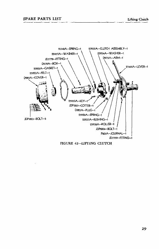
15548A-SPRING-1
22477A-WASHER-1
JD7779-F1TT1NG-1 D979A-BOX-1
25921A-GASKET-1 25923A-FELT-1
D982A-COVER-1
25932A-CLUTCH ASSEMBLY-1 25934A-WASHER-1
D975A-ARM-1
.27414A-LEVER-1
JDP1003-BOLT-5
25933A-KEY-1'
JDP1067-COTTER-1 D983A-PLUG-1'
25920A-SPRING-1 25937A-BUSHING-1
25936A-RCXLER-1
JDP1004-BOLT-1P601A-JOURNAL-1
JD7759-FITTING-1
FIGURE 42—LIFTING CLUTCH
29
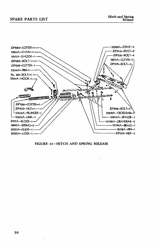
SPARE PARTS LIST Hitch and Spring Release
JDP1065-COTTER-119864A-CHAIN-112912A-S-HOOK-1JDP1008-BOLT-3JDPl069-COnER-123636A-PIN-1No. 160-BOLT-1D914A-HOOK-1
JDP1066-COTTER-1JDP1050-NUT-123634A-PLUNGER-1
—23635A-LINK-1D912A-BLOCK-118890A-SPRING-222221A-GUIDE-122222A-LOCK~1
22800A-STRAP-2 JDP1056—RIVET—2 JDP1016—BOLT—4
21831A--CLEVIS-3T JDP1019-BOLT-3-I
JDP1018-BOLT-1>
22839A-CROSSBAR-1^ M834A-SPACER-3
22798A-DRAWBAR-2———22799A-BRACE-1—————18598A-PIN-1————JDPI051—NUT-2
FIGURE 43—HITCH AND SPRING RELEASE
30

SPARE PARTS LIST Plow Bottom
JDP1033—BOLT-4 —
H325A—ADJUSTER—4
-JDP1058—WASHER—8
-8014—BRACE—4
rDT356—MOLDBOARD—4
tJDPl035—BOLT—4
-JDP1032-BOLT—4
-8015—BRACE—4
—8011—FROG—4
E769A-FILLER—16
8013—PLATE—4
JDP10.38—BOLT-8 -
JDP1037-BOLT—4,
JDP1039—BOLT—4-
JDP1040—BOLT—4
4DP1002—BOLT—4
V273A—FRAME—4 JDP1045—NUT—4
7747-DRAWBOLT-4
JDP1036—BOLT—4 JDP1031—BOLT—4-
V181A—SPOOL—4
8012—LANDSIDE—4\
V294A—HEEL—4 NO. 166-BOLT—8-1
JDP1033—BOLT-
V290A—SHIN—4
•JDP1034-BOLT-4
NO. 250-SHARE-4
FIGURE 44—PLOW BOTTOMS
31
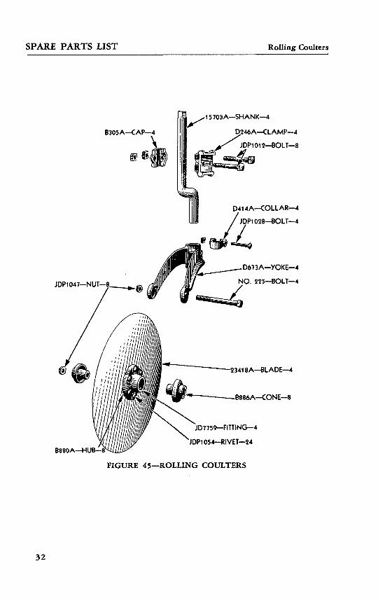
SPARE PARTS LIST Rolling Coulters
15703A—SHANK—4
B880A—HUB—a
D246A—CLAMP—4
JDP1012—BOLT—8
D414A—COLLAR—4
JDP1Q28—BOLT—4
D673A—YOKE—4
NO. 225—BOLT—4
23418A—BLADE—4
•B886A—CONE—8
JD7759—FITTING—4
'JDP1054—RIVET—24
FIGURE 45—ROLLING COULTERS
32

SPARE PARTS LIST Tools
16114 A—ROPE—1 22509A-S-WRENCH-1
16146A—RELEASE—1 D571A-STUD-1
18104A-LINK—1
FIGURE 46—TOOLS
33
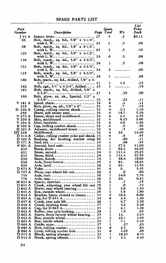
SPARE PARTS LIST
PartNumber
J5566
68
129
130
131
132
160
162163
166
V 181225
D 246250
V273V290V 294B 305H325
DT356D414D 522D 571P601
630631632634656659
D673D 727
759770
M834D835D842D843D854D855D857D859D 860D862D863D864D865D866B 880B 886D912D914
A
A
A
AAAAA
AAAA
AA
AAAAAAAAAAAAAAAAAA
Description 1Spacer, lever. .......................Bolt, mach., sq. hd., 5/8" x 3-1/4",
withL. W.........................Bolt, mach., sq. hd., 5/8" x 4-1/2",
with L.W.. .......................Bolt, mach., sq. hd., 5/8" x 3-1/2",
withL. W.........................Bolt, mach., sq. hd., 5/8" x 3-3/4",
withL. W.........................Bolt, mach., sq. hd., 5/8" x 4-1/4",
with L. W.. .......................Bolt, mach., sq. hd., 5/8" x 4-3/4",
with L. W.. .......................Bolt, mach., sq. hd., drilled, 7/8" x 4-
3/4"..............................Bolt, cge., 3/4" x 4-3/4", drilled. ....Bolt, mach., sq. hd., drilled, 5/8" x
2-1/4"............ \.. .............Bolt, plow, sq. nk., Special, 1/2" x
2-3/4"............................
Frame, share and moldboard .........Shin, moldboard ....................Heel, landside. ......................Cap, rolling coulter shank. ..........
Collar, rolling coulter yoke and shankBushing, for leveling ratchet strap
Journal, land axle. ..................Beam, front. ........................Beam, second. ......................
Beam, fourth. .......................Axle, front furrow ...................Axle, land. ..........................Yoke...............................Pivot, rear wheel lift rod .............Axle, stub ..........................Axle, rear. ..........................
Crank, adjusting, rear wheel lift rod
Box, outside wheel. .................Bracket, beam, riveted to beams. .....Cap, for D 8 54 A ....................
Crank, leveling lever. ................Cap, for D 865 A. ...................Roller, rear axle locking. ............Sleeve, front furrow wheel bearing . . .Box, outside wheel. .................Box, inside wheel. ..................Guide, rope. ........................
Cone, rolling coulter hub. ...........Block, spring plunger. ..............Hook, spring release. ...............
<"age27
24
24
24
24
24
24
3125
27
32323333323232323332323326343024242424252633282628312929292424282725282525252733333131
2«an.Used
4
1
3
6
1
2
3
11
1
8444444444441111111114111311148111111118811
Wt..2
.5
.5
.5
.5
1.2
.39
.22
.1.7
2.314.72.46.254.6
.9
.534.
.6
.09
.0827.592.4
111.4133.498.481.63.
9..6
24.820.
.7
.83.65.8
18.42.46.74.22.11.9
13.10.17.1
.272.51.05
10.255.4
List PriceEach$0.11
.09
.10
.08
.08
.09
.09
.35
.14
.09
.11
.11
.141.105.101.452.001.40.50.40
14.00.45.11.05
11.0016.0019.2522.5019-OO16.2513.503.45.60
7.706.25
.35
.551.101.808.001.303.302.301.20.65
3.453.002.10
.25
.85
.454.754.30
34
SPAB.E PARTS LIST
PartNumber
D 919 AD920 AD975 AD976 AD 977 AD979 AD980 AD982 AD983 AD989 A
JDP 1000
JDP 1001
JDP 1002JDP 1003
JDP 1004
JDP 1005
JDP 1006
JDP 1007
JDP 1008
JDP 1009
JDP 1010
JDP 1011
JDP 1012JDP 1013JDP 1014
JDP 1015
JDP 1016
JDP 1017
JDP 1018
JDP 1019
JDP 1020
JDP 1021
JDP 1022
JDP 1023
JDP 1024JDP 1025JDP 1026JDP 1027JDP 1028JDP 1029JDP 1030
Description .?Bearing, rear axle. ..................Box, inside wheel ...................Arm, trip lever. .....................Collar, linchpin .....................Collar, clutch cover ssad ............Box, land wheel and clutch drum. ....Cap, hub..................... .......Cover, lifting clutch .................Plug................................Sleeve, rear axle. ....................Bolt, mach., so. hd., 3/8" s 2", with
L. MP....... .......................Bolt, mach., sq. hd., 3/8" x 2-1/4",
with L. W.........................Bolt, mach., sq. hd., 7/16" x 1-1/8"Bolt, mach., 7/16" x 1-3/4", with L.
W.,sq.hd.. .......................Bolt, mach., sq. hd., 7/16" x 2-1/2",
no nut. ...........................Bolt, mach., sq. hd., 1/2" x 1", long
thread with L. W. (See 22815 A)...Bolt, mach., sq. hd., 1/2" x 1-3/4",
withL. W.........................Bolt, mach., sq. hd., 1/2" x 2", with
L. W..............................Bolt, mach., sq. hd., 1/2" x 2-3/4",
with L. W....... ..................Bolt, mach., sq. hd., 5/8" x 1-3/4",
withL. W..... ....................Bolt, mach., sq. hd., 5/8" x 2", with
L. W..............................Bolt, mach., sq. hd., 5/8" x 2-3/4",
withL. W.........................Bolt, mach., sq. hd., 5/8" x 4-1/4"Bolt, mach., sq. hd., 5/8" x 5" hard..Bolt, mach., so. hd., 5/8" x 8", with
L. W..............................Bolt, mach., sq. hd., 5/8" x 9-1/4",
withL. W.........................Bolt, mach., sq. hd., hard, 3/4" x
2-1/2", withL. W..................Bolt, mach., sq. hd., hard, 3/4" x
2-3/4", with L. W. .................Bolt, mach., sq. hd., hard, 3/4" x 3",
withL. W.........................Bolt, mach., sq. hd., hard, 3/4" x
3-1/4", withL. W..................Bolt, mach., sq. hd., hard, 3/4" x
3-1/2", withL. W.................Bolt, mach., sq. hd., hard, 3/4" x 4",
withL. W.. .......................Bolt, mach., sq. hd., hard, 3/4" x
6-1/4", with L. W.. ................Bolt, mach., sq. hd., hard, 3/4" x 7",
withL. W......... ................Bolt, cge., short neck, 5/16" x 7/8"...Bolt, cge., 7/16" x 1-1/2", with L. W.Bolt, cge., 1/2" x 2", with L. W. .....Bolt, cge., 1/2" x 2-1/4". ............Bolt, cge., 1/2" x 3-1/4". ............Bolt, cge., 5/8" x 1-3/4". ............Bolt, cge., 5/8" x 7-3/4", with L. W...
*age282930262630263C3028
28
2832
30
SO
26
28
27
31
24
26
263324
25
25
31
24
31
24
24
24
28
2827292727332926
Qttan.Used
11111i1111
1
14
5
1
12
1
2
3
2
1
182
3
3
4
1
1
4
7
16
1
14431413
Wt.25.
3.21.4.6
3.714.664.4
19.7.1
11.94
.1
.11
.09
.019
.21
.24
.86
.95
.65
.71
.75
1.11
1.19.04.12.19-19.25
ListPriceEach
$11.001.10.85.40
2.304.551.505.00.05
5.50
.02
.02
.03
.03
.02
.03
.04
.04
.04
.08
.08
.08
.09
.11
.12
.13
.13
.14
.14
.15
.15
.15
.18
.19
.01
.03
.03
.03
.03..06.12
35
SPARE PARTS LIST
PartNumber
JDP 1031JDP 1032JDP 1033JDP 1034JDP 1035JDP 1036JDP 1037JDP 1038JDP 1039JDP 1040
JDP 1041
JDP 1042
JDP 1043
JDP 1044JDP 1045
JDP 1046JDP 1047JDP 1048JDP 1049JDP 1050
JDP 1051 JDP 1052JDP 1053JDP 1054
JDP 1055JDP 1056JDP 1057
JDP 1058
JDP 1059
JDP 1060
JDP 1061JDP 1062JDP 1063JDP 1064
JDP 1065JDP 1066JDP 1067
JDP 1068JDP 1069JDP 1070
1295 AJD 1316
JD 13447747
JD 7759
JD 7779
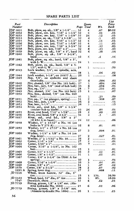
DescriptionPage
Bolt, plow, sq. nk., 3/8" x 1-1/4" .... 32Bolt, plow, rev. key, 7/16" x 1-1/4" 32Bolt, plow, rev. key, 7/16" x 1-3/8" 32Bolt, plow, sq. nk., 7/16" x 1-3/8". . . 32Bolt, plow, rev. key, 7/16" x 1-1/2" 32Bolt, plow, rev. key, 7/16" x 1-5/8" 32Bolt, plow, rev. key, 7/16" x 1-3/4" 32Bolt, plow, rev. key, 7/16" x 2". ..... 32Bolt, plow, sq. nk., 5/8" x 3", hard 32Bolt, plow, sq. nk., 5/8" x 3-1/4",
hard.............................. 32Bolt, plow, sq. nk., hard, 5/8" x 5",
with L. W. ........................ 24Bolt, plow, sq. nk., hard, 5/8" x 5-
1/2", with L. W.. ................. 24Lock washer, 3/4", on spindle, axle,
rear. ............................. 28Lock washer, 1-1/8", on 24077 A.... 26Nut, 5/8", on eyebolts and share
drawbolts. ........................ 27Nut, slotted, 5/8" (for No. 163 bolt). 27Nut, hex., jam, 5/8" (end of hub bolt) 33Nut, sq., 3/4". ...................... 28Nut, slotted, 3/4" (on No. 162 bolt) 25Nut, hex., slotted, 7/8" (on No. 160
bolt) ............................. 31Nut, sq., 1" (on plunger, spring) ..... 31 Nut, hex., jam, 1-1/8" ............... 26Nut, hex., 1-1/4". ................... 26Rivet, std., oval hd., 3/8" x 1-3/4"
Rivet, oval head, 7/16" x 1-5/8"... . . . 28Rivet, oval head, 5/8" x 2-1/2". ...... 31Rivet, std., oval hd., 5/8" x 3"
(D 854 A to beam)................ 24Washer, 1" x 15/32" x No. 16 (on
bolts in V 273 A) ................. 32Washer, 3/4" x 17/32" x No. 16 (on
dog, lever) ........................ :27Washer, 1-1/4" x 5/8" x No. 14 (on
dog, lever) ........................ 27Washer, 2" x 1-5/32" x No. 10. ..... 26Cotter, 3/16" x 3/4". ................ 27Cotter, 3/l6"x I" ................... 25Cotter, 3/16" x 1-1/4", in No. 162bolt.............................. 25
Cotter, 1/4" x 1-1/4". ............... 26Cotter, 1/4" x 1-1/2". . .............. 31Cotter, 1/4" x 2-1/4" (in D981 A for
spring) ........................... 30Cotter, 5/16" x 1-3/4". .............. 26Cotter, 3/8" x 2". ................... 31
Cotter, 3/8" x 2-1/2" ................ 28Spring, lever dog. ................... .27Wheel, front furrow, 32" dia., 6"
tire............................... 25Wheel, land, 32" dia., 6" tire ........ 26Drawbolt, share. .................... 32Fitting, grease, 1/8" x 1/4" strt. (Ale-
mite hydraulic No. 1610) ......... 25Fitting, grease, 1/8" x 2-5/8" strt.
(Alemite hydraulic No. 1684) ..... 26
Qaan.Used
44
24444484
4
1
1
11
618
- 71
12 21
2422
12
8
2
2227
121
13122
114
6
1
Wt..07.01.12.1.11.11.12.13.38
.4
.04
.094
.094
.094
.233
.25
.508
.05
.09
.3
.01
.004
.027
.02
.02
.04
.07
.07
.068
120.85.
.62
.02
ListPriceEach$0.02
.03
.03
.03
.03
.03
.03
.03
.14
.14
.19
.20
.02
.08
.02
.04
.03
.03
.07
.09
.07
.11
.15
.01
.02
.05
.06
.01
.01
.01
.03
.01
.01
.01
.01
.01
.01
.01
.02.02.11
26.5016.00
.25
.06
.23
36

SPARE PARTS LIST
PartNumber
80118012801380148015
11183 A12912 A13826 A15548 A15703 A15908 A16114 A16117 A16146 A16311 A18104 A18127 A
18257 A18598 A18890 A19169 A
19657 A19829 A19831 A19864 A20705 A20707 A21127 A21212 A21558 A21595 A
21600 A
21625 A21626 A21830 A21831 A22215 A22221 A22222 A22266 A22268 A22477 A22509 A22612 A22771 A22772 A22773 A22774 A
22777 A22779 A22780 A22782 A22783 A22784 A22785 A22786 A22788 A
Description 1Frog, steel. .........................Landside. ..........................Plate, landside extension .............Brace, frog. .........................Brace, moldboard. ..................Spring, rear wheel lift rod ...........S-hook, stop-off pin chain ............Trigger, lever. ......................Spring, inside clutch .................Shank rolling coulter. ...............Pin, land and furrow axles ...........Rope, 5/16" sisal, 16-ft.. ............Box, lever trigger. ..................Release, spring, for rope. ............Washer, on rear axle spindle. ........Link, rope. .........................Washer, on land axle, right side end,
outside. ..........................Washer, on lift crank pivot pin. ......Pin, stop-off. .......................Spring, hitch release. ................Washer, on land axle, between D 976 A
and D979 A. .....................Washer, on rear axle. ...............Rod, leveling lever lower dog. .......Clamp, dog rod .....................Chain, stop-off pin ..................Eyebolt, lever dog. ..................Spring, lift, for furrow axle. .........Spring, land axle lift. ................Pin, in rear wheel sleeve. ............Wheel, rear, pressed steel. ...........Bushing, for ratchet and rear wheel
lift bar ...........................Washer, 3" x 2-5/32", on rear wheel
sleeve. ............................Dog, lever. .........................
Washer, on land, furrow axles ........Clevis, drawbar hitch. ...............Eyebolt, lift spring. ..................Guide, hitch spring plunger. .........Lock, hitch spring plunger nut. ......Washer, 4-1/4" x 3-3/8".... .........Spring, nut lock, on land axle. .......Washer, between D 979 A and D98 1 AS-wrench ...........................Wrench, box, for 1-1/4" hex. nut. ....Jaw, clevis. .........................Brace, front beam. ..................Bracket, front beam brace. ...........Brace, center beam, first and second
beams. ...........................Bar, third beam reinforcing. .........Spindle, rear axle. ..................Bar, rear wheel lift rod ..............
Arm, lift crank. .....................Strap, lift crank arm. ................Pin, lift crank pivot. ................Pin, rear axle sleeve locking roller. . .Post, furrow axle lift spring. .........
°age32323232322931273033253427342834
26283131
26282727312727272929
26
29272725312731312526303434242424
24242829292828282827
Quan.Used
4444411214312111
1812
1318121111
2
22123211
N41111322
1111111111
Wt.21.13.4.1.11.9.74.031.29.134
10..5.39.06.06.08.15
.06
.06
.795.75
.14
.041
.38
.04
.13
.218.32
11.38.06
15.3
.02
.17
.45
.55
.092.81.21.8.13.09
1.75.3
2.064.
12.810.5
5.7
15.120.1
6.8.6.33.61.42.52.13.3
ListPriceEach$6.25
3.60.65.40.55.60.05.17.25
1.30.17.50.11.11.04.08
.04
.02
.302.90
.04
.03
.25
.05
.05
.172.853.75
.044.70
.03
.04
.25
.30
.06
.95
.30
.60
.11
.081.85.06.95.95
2.952.551.95
3.404.552.502.101.951.40.55
1.10.95
1.20
37

SPARE PARTS LIST
PartNumber
22789 A22791 A22793 A22794 A22795 A22796 A22798 A22799 A22800 A22801 A22803 A22804 A22805 A22806 A22807 A22808 A22811 A22812 A22813 A22815 A
22837 A22839 A22959 A
23418 A23634 A23635 A23636 A24076 A24077 A24078 A24079 A24080 A24132 A25920 A25921 A25922 A25923 A25932 A25933 A25934 A
25935 A25936 A25937 A
27414 A
Descriptionj
Post, land axle lift spring. ...........Brace, rear beam. ...................Straps, filler, under axle bearings. ....Bearing, furrow axle, right side. .....Bearing, axle ........................Bearing, axle. .......................Drawbar. ...........................Brace, drawbar. .....................Strap, drawbar brace. ...............
Lever, master and leveling, upper partRod, upper dog. ....................Lever, leveling, lower part. ..........Strap, leveling lever. ................Lever, master, lower part ............Strap, master lever. ..................Ratchet, master lever. ...............Pin, in D 863 A. ....................Felt strip, in D 860 A. ...............Lug, land wheel (with mach. bolt,
sq. hd., 1/2" x 1" JDP 1005— longthread, with L. W.) ................
Washer, 1/4" x 25/32". .............Crossbar, hitch. .....................Eyebolt, adjusting, right side, for
D919 A..........................
Plunger, hitch spring. ...............Link, draft. ..........................Pin, spring release hook stop. .......Eyebolt, adjusting, left side, for D 9 1 9 ARod, clutch lift. .....................Swivel, clutch lift rod ................Ratchet, leveling lever. ..............Strap, leveling lever ratchet. .........Filler, under 22959 A. ..............Spring, trip lever, with D 983 A plugGasket, between P 601 A and D 982 ASeal, dust, under D 980 A. ...........Belt strip, in D 982 A. ...............Clutch, lifting, assembly .............Key, for lifting clutch ................Washer, between clutch dog and
P601 A. .........................Linchpin, for D 976 A. ..............Roller, trip iever. ...................Bushing, trip lever roller, inside
25936 A..........................Lever, clutch trip ....................
Page27242425252531.3131.26272727272727272525
262931
2833313131282626272728303026303030
302630
3030
Quan.Used
1172442121221111111
1211
24111111112111111
111
11
Wt.4.2
90.91.34.14.44.7
19.320.9
3..84
9.1.68
16.310.721.714.211.1
.18.02
.36
.0930.
1.12.8.87.1.91.16.81.9
12.66.5
.2
.71.04.04.06
17.13.27
.6
.12
.95
.194.3
List PriceEach$1.8012.50
.351.251.301.403.853.75
.85
.402.60
.253.502.704.303.403.00.07.07
.20
.074.40
.553.302.352.30
.70
.552.00
.703.401.95.09.40.11.30.25
6.90.17
.09
.04
.50
.051.75
38
Related Documents


![Untitled-1 [img.staticmb.com] · 1343 sq.ft. 1088 sq.ft. 1088 sq.ft. 1820 sq.ft. 1770 sq.ft. 8 9 10 Ill 12 13 14 1088 sq.ft. 1088 sq.ft. 1100 sq.ft. 1100 sq.fi. 1088 sq.ft. 1088 sq.ft.](https://static.cupdf.com/doc/110x72/6084c55eec471b27a71a4bbb/untitled-1-img-1343-sqft-1088-sqft-1088-sqft-1820-sqft-1770-sqft-8.jpg)