TM 38-701 MCO P4030.21D NAVSUP PUB 503 AFPAM(I) 24-209 DLAI 4145.2 Packaging of Material Packing OCTOBER 2015 DISTRIBUTION RESTRICTION. Approved for public release; distribution is unlimited. Headquarters Department of the Army, the Navy, the Air force, and the Defense Logistics Agency. Publication of TM 38-701, supersedes FM 38-701, Packaging of Materiel Packing, 1 December 1999. This special conversion to the TM publishing medium/nomenclature has been accomplished to comply with TRADOC doctrine restructuring requirements. The title and content of TM 38-701 is identical to that of the superseded FM 38-701. For the status of official Department of the Army (DA) publications, consult DA Pam 25-30, Consolidated Index of Army Publications and Blank Forms, at http://armypubs.army.mil/2530.html. DA Pam 25-30 is updated as new and revised publications, as well as changes to publications are published. For the content/availability of specific subject matter, contact the appropriate proponent.

Welcome message from author
This document is posted to help you gain knowledge. Please leave a comment to let me know what you think about it! Share it to your friends and learn new things together.
Transcript
TM 38-701 MCO P4030.21D
NAVSUP PUB 503 AFPAM(I) 24-209
DLAI 4145.2
Packaging of Material Packing
OCTOBER 2015
DISTRIBUTION RESTRICTION. Approved for public release; distribution is unlimited.
Headquarters Department of the Army, the Navy, the Air force, and the Defense Logistics Agency.
Publication of TM 38-701, supersedes FM 38-701, Packaging of Materiel Packing, 1 December 1999. This
special conversion to the TM publishing medium/nomenclature has been accomplished to comply with
TRADOC doctrine restructuring requirements. The title and content of TM 38-701 is identical to that of the
superseded FM 38-701.
For the status of official Department of the Army (DA) publications, consult DA Pam 25-30, Consolidated Index
of Army Publications and Blank Forms, at http://armypubs.army.mil/2530.html. DA Pam 25-30 is updated as
new and revised publications, as well as changes to publications are published. For the content/availability of
specific subject matter, contact the appropriate proponent.

This publication is available at Army Knowledge Online (https://armypubs.us.army.mil/doctrine/index.html). To receive publishing updates, please subscribe at
http://www.apd.army.mil/AdminPubs/new_subscribe.asp
*TM 38-701 (FM 38-701)
MCO P4030.21D
NAVSUP PUB 503
AFPAM(I) 24-209
DLAI 4145.2
Distribution Restriction: Approved for public release; distribution is unlimited.
*This technical manual supersedes FM 38-701, Packaging of Material Packing dated 01 December 1999.
i
Headquarters
Departments of the Army, the Navy, the Air Force,
and the Defense Logistics Agency
27 October 2015
Packaging of Materiel Packing
Contents
Page
PREFACE............................................................................................................ xiii
INTRODUCTION ................................................................................................. xiv
Chapter 1 INTRODUCTION: PURPOSE AND SCOPE ...................................................... 1-1 Purpose .............................................................................................................. 1-1 Scope .................................................................................................................. 1-1 References ......................................................................................................... 1-7
Chapter 2 PACKING ........................................................................................................... 2-1 Packing Of General Supplies ............................................................................. 2-1 Packaging Of Hazardous Articles ....................................................................... 2-1 Sequence Of Packing Operation ........................................................................ 2-1 Determination Of Packing Requirements ........................................................... 2-3 Item Characteristics ............................................................................................ 2-3 Load Characteristics ........................................................................................... 2-7 Modes Of Transportation .................................................................................... 2-7 Storage Considerations ...................................................................................... 2-7 Destination And Field Conditions ....................................................................... 2-8 Functions And Selection Of Shipping Containers .............................................. 2-8 Arrangement Of Contents................................................................................... 2-8 Blocking And Bracing ......................................................................................... 2-9 Application Of Blocking And Bracing Materials ................................................ 2-10 Strapping Reinforcement For Containers. ........................................................ 2-29 Cushioning Defined .......................................................................................... 2-31 Packing Problems ............................................................................................. 2-43
Contents
ii TM 38-701 27 October 2015
Packing Small, Lightweight Items ..................................................................... 2-44 Packing Large Items ......................................................................................... 2-44 Weatherproofing The Pack ............................................................................... 2-45 Clearance Between Item And Container........................................................... 2-46 Weatherproofing (Case Liners, Wraps, And Shrouds) ..................................... 2-46 Purpose Of Testing Packs ................................................................................ 2-50 Marking Of Packs .............................................................................................. 2-57 Economy In Packing ......................................................................................... 2-57 Parcel Post ........................................................................................................ 2-60 Parcel Post Requirements ................................................................................ 2-60
Chapter 3 WOODEN CONTAINER AND PALLETS ........................................................... 3-1 Container Materials ............................................................................................. 3-1 Nailed And Lock-Corner Wood Boxes (ASTM-D-6880M) ................................... 3-6 Nailing Requirements ........................................................................................ 3-17 Cleated-Panel Boxes (General) ........................................................................ 3-25 Cleated Plywood Boxes (ASTM-D-6251) ......................................................... 3-28 Boxes, Wood-Cleated Panelboard .................................................................... 3-36 Wood-Cleated, Skidded, Load-Bearing Base Boxes (Astm D6256) ................. 3-37 Wirebound Wood Boxes (Ppp-B-585D) ............................................................ 3-44 Class 3 Military Oversea ................................................................................... 3-47 Pallets (General) ............................................................................................... 3-51 Four-Way Post Construction Pallets (MIL-DTL-15011K) .................................. 3-53 Four-Way (Partial) Stringer Construction Pallets (Nn-P-71) ............................. 3-54 Maintenance Of Pallets ..................................................................................... 3-54
Chapter 4 FIBERBOARD AND PAPERBOARD CONTAINERS ........................................ 4-1 Fiberboard Boxes ................................................................................................ 4-1 Triple-Wall Corrugated Fiberboard Boxes (Astm D 5168) ................................ 4-29
Chapter 5 BAGS AND SACKS ........................................................................................... 5-1 Need For Bags And Sacks .................................................................................. 5-1 Bags Defined ....................................................................................................... 5-1 Sacks Defined ..................................................................................................... 5-1 Shipping Bags And Sacks ................................................................................... 5-1 Cotton Mailing Bags ............................................................................................ 5-1 Procurement ........................................................................................................ 5-3 Cushioned Paper Shipping Sacks (A-A-160) ...................................................... 5-3 Cushioned With Post Consumer Recovered Material (A-A-160) ........................ 5-3 Cushioned With Closed Cell Plastic Film ............................................................ 5-4 Burlap Shipping Bags (A-A-881C) ...................................................................... 5-6
Chapter 6 PAILS AND DRUMS........................................................................................... 6-1 Description, Classification, And Selection Factors ............................................. 6-1 Metal Shipping And Storage Drums (Mil-DTL-6054G) ....................................... 6-2 Metal Drums (Standard) (Miscellaneous) ......................................................... 6-10 Fiber Drums (PPP-D-723J) ............................................................................... 6-12
Chapter 7 CRATES ............................................................................................................. 7-1 Introduction To Crates ........................................................................................ 7-1 Crate Materials .................................................................................................. 7-16
Contents
27 October 2015 TM 38-701 iii
Wood Crates, Open And Covered, ASTM-D-6039M (General) ....................... 7-26 Type I, Style A - Heavy Duty Crate (ASTM-D-6039M) ..................................... 7-31 Type I, Style B--Light Duty Crate (ASTM-D-6039M) ........................................ 7-31 Type Ii, Style A--Heavy Duty Crate (ASTM-D-6039M) ..................................... 7-33 Type Iii, Style B--Light Duty Crate (ASTM-D-6039M) ...................................... 7-36 Type Iv, Style A - Heavy Duty Crate (ASTM-D-6039M) ................................... 7-38 Type V, Style A - Heavy Duty (ASTM-D-6039M) ............................................. 7-39 Type V, Style B--Light Duty Crate (ASTM-D-6039M) ....................................... 7-42 Assembly Instructions (ASTM-D-6039M) ......................................................... 7-53 Open Wood Crates, MIL-C-3774B (General) ................................................... 7-54 Open Bolted Crates (MIL-C-3774B) design requirements ............................... 7-55 Open Nailed Crates (MIL-C-3774B) design requirements ............................... 7-66 Sheathed Wood Crates, ASTM-D-7478M (General) ........................................ 7-79 Assembly (Class 1 Crates) ............................................................................. 7-110 Crate, Slotted Angle, Steel Or Aluminum (Astm D6255) ................................ 7-135
Chapter 8 CONSOLIDATION AND UNITIZATION FOR SHIPMENT AND USE OF CARGO CONTAINERS .................................................................................................... 8-1 Consolidation And Unitization For Shipment ...................................................... 8-1 Palletizing Unit Loads (Mil STD-147E) ............................................................... 8-2 Shrink Film And Stretch Film Palletization ......................................................... 8-5 Consolidation Containers (General) ................................................................... 8-6 Boxes, Shipping Insert Consolidation, Mil-B-43666D (General) ........................ 8-6 Type I, Wood Cleated Plywood Consolidation Insert Box (Mil-B-43666D) ........ 8-7 Type Ii, Plywood Wirebound Consolidation Insert Box (Mil-B-43666D) ........... 8-10 Type Iii, Fiberboard Consolidation Insert Box (Mil-B-43666D) ......................... 8-11 Packing Consolidation Containers ................................................................... 8-12 Packing Semi-Perishable Subsistence Items ................................................... 8-13 Cargo Containers (General) ............................................................................. 8-15 Use Of Milvans And Seavans ........................................................................... 8-17 Shipment Of Hazardous Materials ................................................................... 8-19
GLOSSARY ............................................................................................ Glossary- ................................................................................................................................ 1
REFERENCES .................................................................................... References- ................................................................................................................................ 1
Figures
Figure 1-1, Examples of protection. ....................................................................................... 1-4
Figure 1-2. Types of loads ...................................................................................................... 1-6
Figure 2-1. Damaged items as a result of improper/inadequate packing. ............................. 2-2
Figure 2-2. Interior blocking for an irregular shaped item. ..................................................... 2-4
Figure 2-3. Use of corrugated fiberboard pads and liner. ...................................................... 2-4
Figure 2-4. Interior blocking to protect container against end thrust. ..................................... 2-5
Figure 2-5. Mounting facilities of item must be adequate. ...................................................... 2-6
Figure 2-6. Protection features of a reusable missile container. ............................................ 2-7

Contents
iv TM 38-701 27 October 2015
Figure 2-7. Container selection factors. ................................................................................. 2-9
Figure 2-8. Blocking and bracing to prevent movement. ..................................................... 2-10
Figure 2-9. Cells and trays made of corrugated fiberboard. ................................................ 2-11
Figure 2-10. Incorrect and correct direction of corrugation. ................................................. 2-12
Figure 2-11. Assembling of slotted fiberboard partitions. .................................................... 2-14
Figure 2-12. Application of wooden blocks and braces. ...................................................... 2-17
Figure 2-13. Types of loading (use with table 2-3). ............................................................. 2-18
Figure 2-14. Positioning load according to grain of wood .................................................... 2-19
Figure 2-15. Protection for barrier and item surfaces. ......................................................... 2-20
Figure 2-16. Uses of plywood for blocking and bracing. ...................................................... 2-21
Figure 2-17 Bolts for blocking and bracing. ......................................................................... 2-23
Figure 2-18. Vertical use of tie rods. .................................................................................... 2-23
Figure 2-19. Diagonal use of tie rods. .................................................................................. 2-24
Figure 2-20. Use of metal brackets, frames, and sleeves. .................................................. 2-26
Figure 2-21. Use of metal strapping for bracing and anchoring........................................... 2-28
Figure 2-22. Use of filament reinforced tape........................................................................ 2-31
Figure 2-23. Characteristics of cushioning compression set, resilience, and rate of recovery. ........................................................................................................... 2-35
Figure 2-24 Characteristics of cushioning dustiness, corrosiveness, and fungus resistance. ........................................................................................................ 2-36
Figure 2-25. Characteristics of cushioning abrasiveness, temperature performance and flammability. ............................................................................................... 2-38
Figure 2-26. Examples of fiberboard trays, opened end cells, pads, and die-cuts. ............. 2-39
Figure 2-27. Application of fiberboard die-cuts, open end cells, trays, and pads. ............... 2-40
Figure 2-28. Methods of cushioning ..................................................................................... 2-43
Figure 2-29. Waterproofing of individual packages. ............................................................ 2-45
Figure 2-30. Using and closing of high top case liner. ......................................................... 2-49
Figure 2-31. Double top pad closure case liner. .................................................................. 2-50
Figure 2-32. Examples of container test. ............................................................................. 2-52
Figure 2-33. Free fall drop test. ............................................................................................ 2-54
Figure 2-34. Edgewise-drop test. ......................................................................................... 2-54
Figure 2-35. Cornerwise-drop test. ...................................................................................... 2-55
Figure 2- 36. Impact test. ..................................................................................................... 2-56
Figure 2-37. Shipping container identification, address, and special markings. .................. 2-58
Figure 2-38. Savings achieved through crating of an item. ................................................. 2-59
Figure 2-39. Savings achieved by redesigning a container. ................................................ 2-60
Figure 2-40. Reusing packaging materials means economy. .............................................. 2-61
Figure 2-41. Post office measurement requirements. .......................................................... 2-63
Figure 3-1. Characteristics for the classifications of wood. .................................................... 3-2
Figure 3-2. Wood defects. ...................................................................................................... 3-3
Figure 3-3. Measuring knot diameters. .................................................................................. 3-4
Figure 3-4. Nails. .................................................................................................................... 3-6

Contents
27 October 2015 TM 38-701 v
Figure 3-5. Classes of nailed wood boxes. ............................................................................ 3-7
Figure 3-6. Styles of nailed woods boxes. .............................................................................. 3-8
Figure 3-7. Styles of nailed wood boxes. ............................................................................. 3-10
Figure 3-8. Style 7 nailed wood box. .................................................................................... 3-10
Figure 3-9. Shallow boxes. ................................................................................................... 3-11
Figure 3-10. Split board rules ............................................................................................... 3-11
Figure 3-11. Joined pieces of lumber. .................................................................................. 3-12
Figure 3-12. Style 2 reinforced box. ..................................................................................... 3-17
Figure 3-13. Nailing. ............................................................................................................. 3-20
Figure 3-14. Proper and improper nailing. ............................................................................ 3-21
Figure 3-15. Nail holding power............................................................................................ 3-22
Figure 3-16. Strapping of nailed wood boxes. ...................................................................... 3-24
Figure 3-17. Defects of nailed wood boxes. ......................................................................... 3-25
Figure 3-18. Oversea styles of cleated panel boxes. ........................................................... 3-26
Figure 3-19. Styles of cleated panel boxes. ......................................................................... 3-27
Figure 3-20. Top panel modification of un-nailed closure, ASTM-D-6251, style A box. ...... 3-30
Figure 3-21. Spacing of fasteners. ....................................................................................... 3-32
Figure 3-22. Acceptable plywood joints. ............................................................................... 3-32
Figure 3-23. Strapping of cleated panel boxes. .................................................................... 3-36
Figure 3-24. Spacing of intermediate cleats. ........................................................................ 3-37
Figure 3-25. Classes 1 and 2 bases for wood-cleated, skidded, load-bearing base boxes, ASTM D6256. ........................................................................................ 3-38
Figure 3-26. Styles A and B cleat arrangement for wood cleated, skidded, loadbearing base boxes. ................................................................................... 3-43
Figure 3-27. Attachment of joist supports for wood cleated, skidded, load bearing base boxes. ....................................................................................................... 3-43
Figure 3-28. Load distributions of skids. ............................................................................... 3-45
Figure 3-29. Components of wire bound wood boxes. ......................................................... 3-45
Figure 3-30. Styles of wire bound wood boxes. ................................................................... 3-48
Figure 3·31. Setting up of styles 1 and 2, wire bound wood boxes...................................... 3-49
Figure 3·32. Setting up of style 3 wire bound wood box. ..................................................... 3-50
Figure 3-33. Strapping of wire bound wood boxes. .............................................................. 3-50
Figure 3-34. Closing of style 1 wire bound wood box with special tools. ............................. 3-52
Figure 3-35. Closing of style 2 and 3 wire bound wood boxes. ............................................ 3-53
Figure 3-36. Examples of expandable pallets. ..................................................................... 3-53
Figure 3-37. Four-way entry post and (partial) four-stringer pallets. .................................... 3-54
Figure 4-1. Classification of fiberboard boxes. ....................................................................... 4-2
Figure 4-2. Sealing Method B. ................................................................................................ 4-5
Figure 4-3. Types and varieties of fiberboard. ........................................................................ 4-7
Figure 4-4. Corrugated fiberboard flutes. .............................................................................. 4-8
Figure 4-5. Body joints for fiberboard boxes. ....................................................................... 4-10
Figure 4-6. Styles of fiberboard boxes. ................................................................................ 4-13
Contents
vi TM 38-701 27 October 2015
Figure 4-7. Styles of fiberboard boxes. ................................................................................ 4-14
Figure 4-8. Styles of fiberboard boxes. ................................................................................ 4-15
Figure 4-9. Styles of fiberboard boxes. ................................................................................ 4-16
Figure 4-10. Cover assemblies. ........................................................................................... 4-17
Figure 4-11. Use of fiberboard sleeve. ................................................................................. 4-18
Figure 4-12. Use of fiberboard liner. .................................................................................... 4-18
Figure 4-13. Sample of box maker's certificate. ................................................................... 4-19
Figure 4-14. Closure of class weather-resistant and WWVR fiberboard boxes with adhesive and/or stitches. .................................................................................. 4-20
Figure 4-15. Closure methods of fiberboard boxes. ............................................................ 4-22
Figure 4-16. Closure methods for fiberboard boxes. ........................................................... 4-23
Figure 4-17. Closure methods for fiberboard boxes. ........................................................... 4-24
Figure 4-18. Closure methods of fiberboard boxes. ............................................................ 4-25
Figure 4-19. Closure methods of fiberboard boxes. ............................................................ 4-26
Figure 4-20. Strapping of fiberboard boxes. ........................................................................ 4-28
Figure 4-21. Styles A, B, and C triple-wall corrugated fiberboard boxes. ............................ 4-31
Figure 4-22. Styles D, E, and F, triple-wall corrugated fiberboard boxes. ........................... 4-32
Figure 4-23. Style G triple-wall corrugated fiberboard box. ................................................. 4-33
Figure 4-24. Types of ends to be used with styles A through D triple-wall corrugated fiberboard boxes. .............................................................................................. 4-33
Figure 4-25. Closure of styles A and B, triple-wall corrugated fiberboard boxes................. 4-36
Figure 4-26. Closure of styles C and D, triple-wall corrugated fiberboard boxes. ............... 4-37
Figure 4-27. Closure of style E, triple-wall fiberboard box. .................................................. 4-39
Figure 4-28. Closure of style F, triple-wall fiberboard box. .................................................. 4-40
Figure 4-29. Closure of G style triple-wall fiberboard box. Summary .................................. 4-41
Figure 6-1. Bolted ring and lever actuated type closures (MIL-DTL-6054G). ........................ 6-3
Figure 6-2. Internal locking rings in position (MIL-DTL-6054G). ............................................ 6-4
Figure 6-3. Use of internal locking ring (MIL-DTL-6054G). .................................................... 6-5
Figure 6-4. Cup-type metal insert (MIL-DTL-6054G). ............................................................ 6-6
Figure 6-5. Cup-type insert locked in place (MIL-DTL-6054G). ............................................. 6-7
Figure 6-6. Item installed in crate-type insert (MIL-DTL-6054G). .......................................... 6-8
Figure 6-7. Tapping locking ring while tightening bolt to insure an effective seal (MIL-DTL-6054G). ....................................................................................................... 6-9
Figure 6-8. Types of drum closures and typical markings for domestic drums (PPP-D-729E). ............................................................................................................... 6-11
Figure 6-9. Types of fiber drum closures (PPP-D-723J). ..................................................... 6-14
Figure 7-1. Open and sheathed crates. ................................................................................. 7-6
Figure 7-2. Styles of open crates (ASTM-D-6039M). ............................................................ 7-7
Figure 7-3. Styles of open crates (ASTM-D-6039M). ............................................................ 7-7
Figure 7-4. Assembly of open nailed crate (MIL-C-3774B). .................................................. 7-8
Figure 7-5. Assembly of open bolted crate (MIL-C-3774B). .................................................. 7-9
Figure 7-6. Sheathed crates. ............................................................................................... 7-10
Contents
27 October 2015 TM 38-701 vii
Figure 7-7. Special use crates. ............................................................................................. 7-10
Figure 7-8. Methods of anchoring contents in crates. .......................................................... 7-12
Figure 7-9. Sill base. ............................................................................................................. 7-13
Figure 7-10. Skid base. ........................................................................................................ 7-14
Figure 7-11. Resistance to forces. ....................................................................................... 7-16
Figure 7-12. Bolts, screws, and accessories. ....................................................................... 7-18
Figure 7-13. Nut sleeve assembly. ....................................................................................... 7-19
Figure 7-14. Tension and corner strapping. ......................................................................... 7-19
Figure 7-15. Lag bolt reinforcing strap. ................................................................................ 7-21
Figure 7-16. Use of metal hangers. ...................................................................................... 7-22
Figure 7-17. Application of strapping (sill base). .................................................................. 7-24
Figure 7-18. Crate liner. ........................................................................................................ 7-25
Figure 7-19. Interior shroud. ................................................................................................. 7-25
Figure 7-20. Crate inspection door. ...................................................................................... 7-26
Figure 7-21. Use of table to determine thickness of load bearing floorboards. .................... 7-27
Figure 7-22. Nailing patterns. (All widths nominal). Similar patterns shall be used when boards cross at angles other than 90. ..................................................... 7-29
Figure 7-23. Splicing of members: A, splice of 4 x 4 inch or 4 X 6 inch skids; B, splice of 2 inch member; C, splice of 1 inch member; D, lamination of skid. .............. 7-30
Figure 7-24. Type I, style A crate assembly (ASTM-D-6039M). .......................................... 7-32
Figure 7-25. Type I, style B crate assembly (ASTM-D-6039M). .......................................... 7-33
Figure 7-26. Type II, style A crate assembly (ASTM-D-6039M). ......................................... 7-34
Figure 7-27. Type II, crate with exterior side cleats. (A-complete crate, B- two panel, C- three panel, and D- four panel. .................................................................... 7-37
Figure 7-28. Type III, style B crate assembly (ASTM-D-6039M). ........................................ 7-38
Figure 7-29. Type IV, style A crate assembly (ASTM-D-6039M). ........................................ 7-39
Figure 7-30. Type V, style A crate assembly (ASTM-D-6039M). ......................................... 7-40
Figure 7-31. Bases for Type V, style B crates (ASTM-D-6039M). ....................................... 7-45
Figure 7-32. Simple panel sides for Type V, style B crates (ASTM-D-6039M): A, side of long crate; B, side of short crate; C, covered side. ....................................... 7-46
Figure 7-33. Double panel sides for Type V, style B crates for heights up to 96 inches (ASTM-D-6039M): A, open side; B, covered side. ............................................ 7-47
Figure 7-34. Triple panel sides for Type V, style B crates for heights over 96 inches (ASTM-D-6039M): A, open side; B, covered side. ............................................ 7-48
Figure 7-35. Ends for Type V, style B crates (ASTM-D-6039M): A, two panel horizontal; B, single panel covered; C, four panel; D, two panel vertical.......... 7-49
Figure 7-36. Ends for Type V, style B crates (ASTM-D-6039M): A, wide and narrow double-panel ends; B, wide and narrow triple-panel ends. ............................... 7-50
Figure 7-37. Tops for type V, style B crates (ASTM-D-6039M): A, narrow top; B, medium top; C, wide top. .................................................................................. 7-51
Figure 7-38. Type V, style B crate (ASTM-D-6039M), open and covered. .......................... 7-56
Figure 7-39. Skid base for bolted crate (MIL-C-3774B). ...................................................... 7-57
Figure 7-40. Side for bolted crate (MIL-C-3774B). ............................................................... 7-59
Contents
viii TM 38-701 27 October 2015
Figure 7-41. End for bolted crate (MIL-C-3774B). ............................................................... 7-61
Figure 7-42. Top for bolted crate (MIL-C-3774B). ............................................................... 7-62
Figure 7-43. Assembly details for bolted crates (MIL-C-3774B). ......................................... 7-64
Figure 7-44. Sill base for nailed crate (MIL-C-3774B). ........................................................ 7-68
Figure 7-45. Side or end panel for nailed crate (MIL-C-3774B). ......................................... 7-73
Figure 7-46. Types of top panels (MIL-C-3774B). ............................................................... 7-78
Figure 7-47. Assembly of open nailed crates (MIL-C-3774B). ............................................ 7-80
Figure 7-48. Assembly details for nailed crates (MIL-C-3774B). ......................................... 7-81
Figure 7-49. Ventilation end screening of sheathed crates. ................................................ 7-83
Figure 7-50. Nailing patterns. ............................................................................................... 7-84
Figure 7-51. Ventilation of lumber and plywood sheathed crates (ASTM-D-7478M). ......... 7-88
Figure 7-52. Skid base plywood flooring (ASTM-D-7478M). ............................................... 7-89
Figure 7-53. Skid base lumber flooring (ASTM-D-7478M). ................................................. 7-90
Figure 7-54. Splicing of members ........................................................................................ 7-91
Figure 7-55. Lamination of skid or sill members (ASTM-D-7478M). ................................... 7-92
Figure 7-56. Sill bases (ASTM-D-7478M). ........................................................................... 7-97
Figure 7-57. Attaching intermediate sills to side sills (ASTM-D-7478M). ............................ 7-98
Figure 7-58. Narrow tops (widths up to 54 inches) (ASTM-D-7478M). ............................. 7-101
Figure 7-59. Intermediate tops (widths over 54 inches to 60 inches) (ASTM-D-7478M)............................................................................................................ 7-102
Figure 7-60. Wide tops (widths over 60 inches to 120 inches) (ASTM-D-7478M). ........... 7-103
Figure 7-61. Fabrication of tops (narrow and intermediate) (ASTM-D-7478M). ................ 7-104
Figure 7-62. Fabrication of tops (wide top) (ASTM-D-7478M)........................................... 7-105
Figure 7-63. Sides type A panel (lumber) (heights over 24 inches to 60 inches) (ASTM-D-7478M). .......................................................................................... 7-106
Figure 7-64. Sides type B panel (lumber) (heights over 60 inches to 108 inches) (ASTM-D-7478M). .......................................................................................... 7-108
Figure 7-65. Sides type C panel (lumber) (heights over 108 inches to 144 inches) (ASTM-D-7478M). .......................................................................................... 7-109
Figure 7-66. Joist supports and gussets (ASTM-D-7478M). ............................................. 7-121
Figure 7-67. Fabrication nailing of lumber sheathing (ASTM-D-7478M). .......................... 7-122
Figure 7-68. Lag screw reinforcing strap for bolted crates (ASTM-D-7478M). .................. 7-123
Figure 7-69. End panels over 30 inches wide lumber sheathed crates (ASTM-D-7478M)............................................................................................................ 7-125
Figure 7-70. Narrow end panels (lumber sheathed crates) (ASTM-D-7478M).................. 7-126
Figure 7-71. Assembly of bolted crate (lumber or plywood sheathed) (ASTM-D-7478M)............................................................................................................ 7-127
Figure 7-72. Assembly of bolted crate (ASTM-D-7478M). ................................................. 7-128
Figure 7-73. Assembly of bolted crate (ASTM-D-7478M). ................................................. 7-129
Figure 7-74. Assembly of nailed crate, lumber or plywood sheathing (ASTM-D-7478M)............................................................................................................ 7-133
Figure 7-75. Corner and top strapping, (lumber or plywood sheathing (ASTM-D-7478M)............................................................................................................ 7-133

Contents
27 October 2015 TM 38-701 ix
Figure 7-76. Sill base strapping (ASTM-D-7478M). ........................................................... 7-134
Figure 7-77. Sides- type A panel (plywood) (heights over 24 inches to 60 inches) (ASTM-D-7478M). ........................................................................................... 7-135
Figure 7-78. Sides- type B panel (plywood) (heights over 60 inches to 96 inches) (ASTM-D-7478M). ........................................................................................... 7-136
Figure 7-79. Sides- type C panel (plywood) (heights over 96 inches to 144 inches) (ASTM-D-7478M). ........................................................................................... 7-137
Figure 7-80. Fabrication nailing plywood sheathing (ASTM-D-7478M). ............................ 7-138
Figure 7-81. End panel’s plywood sheathing crates (ASTM-D-7478M). ............................ 7-139
Figure 7-82. Joining of Intermediate members (ASTM D6255). ........................................ 7-143
Figure 7-83. Alternate methods of attaching members (ASTM D6255). ............................ 7-146
Figure 7-84. Methods of sheathing or covering crates (ASTM D6255). ............................. 7-149
Figure 7-85. Methods of attaching sheathing (ASTM D6255). ........................................... 7-149
Figure 7-86. Type I, style B crate (ASTM D6255). ............................................................. 7-150
Figure 7-87. Method of attaching push plates, skids, and headers (ASTM D6255). ......... 7-150
Figure 8-1. Advantages of cargo unitization. .......................................................................... 8-2
Figure 8-2. Types of pallets. ................................................................................................... 8-3
Figure 8-3. Pallet size limitations. ........................................................................................... 8-4
Figure 8-4. Examples of palletized load. ................................................................................ 8-5
Figure 8-5. Shrink film chamber used for heat shrinking film around palletized load............. 8-7
Figure 8-6. Type I, Style I, wood cleated plywood consolidation box (MIL-B-43666D).......... 8-9
Figure 8-7. Type II, plywood wire bound consolidation boxes (MIL-B-43666D). ................. 8-10
Figure 8-8. Type III, styles 3 and 4, fiberboard consolidation boxes (MIL-B-43666D). ........ 8-12
Figure 8-9. Blocking and bracing top voids. ......................................................................... 8-14
Figure 8-10. Sleeve and X bracing. ...................................................................................... 8-15
Figure 8-11. Blocking and bracing side voids. ...................................................................... 8-16
Figure 8-12. Blocking and bracing interior voids .................................................................. 8-16
Figure 8-13 MILVAN cargo containers coupled for transport ............................................... 8-18
Figure 8-14 SEAVAN loaded for highway movement .......................................................... 8-18
Tables
Table 2-1. Allowable loads for corrugated fiberboard. Columns loaded in the flute direction ............................................................................................................. 2-13
Table 2-2. Allowable loads for folded corner and flat pads of corrugated fiberboard........... 2-13
Table 2-3. The allowable load in pounds is for group II woods. ........................................... 2-17
Table 2-4. Allowable lateral loads for unclinched cement-coated or etched common wire nails when used for blocking or bracing. ................................................... 2-22
Table 2-5. Suggested allowable lateral loads for bolts-impact loading ................................ 2-24
Table 2-6. Maximum allowable loads and minimum sizes of wood-bearing washers for anchor or tiedown bolts. ............................................................................... 2-26
Table 2-7. Tape strips used in handling rigid materials1 ...................................................... 2-29
Contents
x TM 38-701 27 October 2015
Table 2-8. Application of weatherproofing barrier materials for packing ............................. 2-46
Table 2-9. Barrier materials for case liners, overwraps, and plastic bag liners ................... 2-48
Table 3-1. Boxes for domestic shipment, type 1 (easy) and type 2 (average) loads; thickness of sides, tops, bottoms, and ends, and thickness and width of cleats. ............................................................................................................... 3-12
Table 3-2. Boxes for domestic shipment, type 3 (difficult) loads; thickness of sides, top, bottoms, and ends, and thickness and width of cleats. ............................. 3-13
Table 3-3. Boxes for overseas shipment, type 1(easy) and type 2 (average) load; thickness of sides, tops, bottoms, and ends, and thickness and width of cleats. ............................................................................................................... 3-14
Table 3-4. Boxes for overseas shipment, type 3 (difficult) load; thickness of sides, tops, bottoms, and ends, and thickness and width of cleats. ........................... 3-15
Table 3-5. Number of Pieces in any Box Part. ..................................................................... 3-15
Table 3-6. Requirements for Additional Battens or Cleats................................................... 3-17
Table 3-7. Size of cement-coated or chemically-etched cooler, sinker, and standard box nails for boxes. ........................................................................................... 3-19
Table 3-8. Size of nails and spacing for nailing tops and bottoms to sides of boxes. ......... 3-19
Table 3-9. Spacing of cement-coated or chemically-etched nails for boxes. ...................... 3-19
Table 3-10. Minimum gage of round wire for various weights of boxes. ............................. 3-23
Table 3-11. Minimum sizes of flat metal bands for various weights of boxes. ..................... 3-24
Table 3-12. Comparison of cleated panel boxes. ................................................................ 3-27
Table 3-13. Plywood PS-1 and PS-51, commercial standards. ........................................... 3-28
Table 3-14. Domestic type, requirements for cleats and plywood (ASTM-D-6251). ........... 3-29
Table 3-15. Overseas type, requirements for cleats and plywood (ASTM-D-6251). ........... 3-29
Table 3-16. Domestic type, sizes and spacing of nails for fastening. .................................. 3-33
Table 3-17. Oversea type, sizes and spacing of nails for fastening together adjacent cleated panels. ................................................................................................. 3-33
Table 3-18. Diameter of round wire strapping. .................................................................... 3-33
Table 3-19. Size of flat metal bands. ................................................................................... 3-33
Table 3-20. Size of type III, twist-tied flat metal strapping. .................................................. 3-34
Table 3-21. Class 1 boxes: Requirements for paper overlaid veneer panel board and cleats. ............................................................................................................... 3-38
Table 3-22. Class 2 boxes: Requirements for paper overlaid veneer panel board and cleats ................................................................................................................ 3-39
Table 3-23. Selection of joists for wood cleated, skidded, load bearing base boxes (joists spaced 24 inches--center to center). ..................................................... 3-40
Table 3-24. Nominal sizes and maximum lengths of skids for wood cleated, skidded, load bearing base boxes. ................................................................................. 3-40
Table 3-25. Allowable load (pounds) per inch of width of load-bearing floor members ....... 3-42
Table 4-1. Type CF (Corrugated Fiberboard), Domestic ....................................................... 4-2
Table 4-2 Type CF (Corrugated Fiberboard), Weather-Resistant, and Water and Water Vapor Resistant Classes (WWVR) .......................................................... 4-3
Table 4-3 Type SF (Solid Fiberboard): Class Domestic, All Grades ..................................... 4-3
Table 4-4 Type SF, Class Weather-Resistant, All Grades .................................................... 4-4

Contents
27 October 2015 TM 38-701 xi
Table 4-5 Size and Weight Limitations for Types CFA and SFA Domestic Fiberboard Boxes .................................................................................................................. 4-5
Table 4-6 Size and Weight Limitations for Class Weather-Resistant (WR) and Water/Vapor ........................................................................................................ 4-6
Table 4-7 Number of 2 in. Crown Staples or Stitches for Regular Slotted Containers ........ 4-20
Table 4-8. Metallic and nonmetallic strapping requirements. In accordance with ASTM D 4675.................................................................................................... 4-26
Table 4-9. Required number of reinforcing bands ................................................................ 4-27
Table 5-1 Bag Component Test Requirements. ..................................................................... 5-2
Table 5-2 Fabricated Sack Weight and Test Volume ............................................................. 5-5
Table 5-3 Jute Burlap Bag Requirements .............................................................................. 5-7
Table 6-1. Specifications and Titles of Metal Drums. ........................................................... 6-11
Table 6-2. PPP-D-723J Fiber drums .................................................................................... 6-13
Table 7-1. Minimum Thickness and Width of Lumber .......................................................... 7-17
Table 7-2. Application of Lag bolts ....................................................................................... 7-18
Table 7-3. Classification of ASTM-D-6039M Crates ............................................................ 7-29
Table 7-4. Allowable Load Per Inch of Load-bearing Floorboard Width of Groups I and II Woods ..................................................................................................... 7-34
Table 7-5. Thickness of Ends ............................................................................................... 7-35
Table 7-6. Thickness of Sides .............................................................................................. 7-35
Table 7-7. Nailing Schedule for Assembly to Type II, Style A Crates .................................. 7-38
Table 7-8. Member Sizes and Spacing for Type III, Style B Crates ..................................... 7-53
Table 7-9. Frame Member Sizes for sides of Type V, Style B Crates.................................. 7-53
Table 7-10. Number and size of Lag Bolts Required to Assemble the Base (Demountable Base) of Type V, Style B Crates ............................................... 7-54
Classification of MIL-C-3774B Crates .................................................................................. 7-54
Table 7-12. Skid Sizes of Bolted MIL-C-3774B Crates ........................................................ 7-58
Table 7-13. Frame-member Sizes (Sides of Bolted Crates) ................................................ 7-58
Table 7-14. Spacing of Diagonals for MIL-C-3774B Crates ................................................. 7-60
Table 7-15. Joist Sizes ......................................................................................................... 7-63
Table 7-16. Number of Lag Bolts for Assembling Sides to Base of Bolted Crates; Where Nominal 1-inch Longitudinal Members Are Used in Sides and Nominal 4-inch Wide Skids Are Used ............................................................... 7-63
Table 7-17. Number of Lag Bolts for Assembling Sides to Base of Bolted Crates; Where Nominal 2-inch Longitudinal Members Are Used in Sides and Nominal 4-inch Wide Skids Are Used ............................................................... 7-65
Table 7-18. Skid Sizes for Nailed MIL-C-3774B Crates ....................................................... 7-65
Table 7-19. Size of Side and End Sills ................................................................................. 7-65
Table 7-20. Panel Member Selection (6,000, 8,000 and, and 10,000 Pounds Net Load) 1 .............................................................................................................. 7-69
Table 7-21. Panel-Member (Selection (12,000 Pound Net Load) 1 ..................................... 7-71
Table 7-22. Type of Tops (MIL-C-3774B) ............................................................................ 7-76
Table 7-23. Nailed Crate Assembly (MIL-C-3774B) ............................................................. 7-76
Contents
xii TM 38-701 27 October 2015
Table 7-24. Nailed Per Each 1,000-Pound Gross Load; Nailing Side Sheathing to Skids or Sills and End Sheathing to Headers and Sills .................................... 7-77
Table 7-25. Lag bolt lead hole sizes. ................................................................................... 7-86
Table 7-26. Ventilation holes and area required. ................................................................. 7-86
Table 7-27. Allowable minimum skid sizes .......................................................................... 7-87
Table 7-28. Required header sizes and carriage bolt sizes ................................................. 7-92
Table 7-29. Allowable load in pounds per inch of floorboard width groups I and II woods ............................................................................................................... 7-94
Table 7-30. Nominal size of side sills (in.) ........................................................................... 7-95
Table 7-31 Allowable load for intermediate sills (in lb per inch of sill width) ........................ 7-95
Table 7-32. Side panel types - class 1 crates .................................................................... 7-100
Table 7-33. End strut requirements ................................................................................... 7-100
Table 7-34. Panel member selection table for 1,000 lb. net load ...................................... 7-111
Table 7-35. Panel member selection table for 2,000 lb. net load ...................................... 7-112
Table 7-36. Panel member selection table for 4,000 lb. net load ...................................... 7-113
Table 7-37. Panel member selection table for 6,000 lb. net load ...................................... 7-114
Table 7-38. Panel member selection table for 8,000 lb. net load ...................................... 7-115
Table 7-39. Panel member selection table for 10,000 lb. net load. ................................... 7-116
Table 7-40. Panel member selection table for 15,000lb. net load ..................................... 7-117
Table 7-41. Panel member selection table for 20,000lb. net load ..................................... 7-118
Table 7-42. Panel member selection table for 25,000lb. net load ..................................... 7-119
Table 7-43. Panel member selection table for 30,000 lb. net load. ................................... 7-120
Table 7-44. Lag bolts required to assemble sides to base of bolted crates using lag bolt reinforcing strap (skids to be Group II, III, or IV woods). ......................... 7-124
Table 7-45. Assembly Nailing of Nailed Crate (ASTM-D-7478M)1 ................................... 7-131
Table 7-46. Number of nails per each 1,000 pound gross load (nailing sheathing to base around perimeter of nailed crate). ......................................................... 7-131
Table 7-47. Ventilation requirements ................................................................................. 7-141
Table 7-48. Allowable Load per inch of floorboard width for Groups II, III and IV woods ............................................................................................................. 7-143
Table 7-49. Load capacity of slotted angle steel beams. 1/ SLOTTED ANGLE STEEL - 2.6mm - 38mm X 76mm (12 GUAGE (0.014") - 1-1/2" x 3")........................ 7-143
Table 7-49a. Load capacity of slotted angle steel beams. 1/ SLOTTED ANGLE STEEL - 1.9mm - 38mm X 38mm (14 GUAGE (0.074") - 1-1/2" x 1-1/2") ..... 7-144
Table 7-49b. Load capacity of slotted angle steel beams. 1/ SLOTTED ANGLE STEEL - 1.9mm - 38mm X 38mm (14 GUAGE (0.074") - 1-1/2" x 1-1/2") ..... 7-144
Table 7-49c. Load capacity of slotted angle steel columns. 1/(Continued) SLOTTED ANGLE STEEL - 1.9mm - 38mm X 57mm (14 GUAGE (0.074") - 1-1/2" x 2-1/4") ............................................................................................................. 7-145
Table 7-49d. Load capacity of slotted angle aluminum configurations. 1/ slotted angle steel - 2.6mm - 38mm x 57mm (13 gauge (0.089") - 1-1/2" x 2-1/4") ............ 7-145
Table 8-1. Classification of unit loads of semi perishable subsistence items (DSCP 3507) ................................................................................................................. 8-14
27 October 2015 TM 38-701 xiii
Preface
TM 38-701, Packaging of Materiel, emphasizes the importance of packing of military supplies and equipment. It
contains detailed information concerning the requirements to accomplish packing operations. The requirements
include use of exterior shipping containers; the assembling of items or packs into the container; anchoring,
blocking, bracing, and cushioning of items or packages within the container; weatherproofing; strapping of
containers; the testing of exterior packs; palletization and unitization of loads; parcel post; and related subject
matter. General exterior marking in accordance with MIL-STD-129 is discussed.
The principal audience for TM 38-701 is all members of the profession of arms. Commanders and staffs of Army
headquarters serving as joint task force or multinational headquarters should also refer to applicable joint or
multinational doctrine concerning the range of military operations and joint or multinational forces. Trainers and
educators throughout the Army will also use this publication.
Commanders, staffs, and subordinates ensure that their decisions and actions comply with applicable United
States, international, and in some cases host-nation laws and regulations. Commanders at all levels ensure that
their Soldiers operate in accordance with the law of war and the rules of engagement. (See FM 27-10.)
TM 38-701 uses joint terms where applicable. Selected joint and Army terms and definitions appear in both the
glossary and the text. Terms for which TM 38-701 is the proponent publication (the authority) are italicized in
the text and are marked with an asterisk (*) in the glossary. Terms and definitions for which TM 38-701 is the
proponent publication are boldfaced in the text. For other definitions shown in the text, the term is italicized and
the number of the proponent publication follows the definition.
TM 38-701 applies to the Active Army, Army National Guard/Army National Guard of the United States, and
United States Army Reserve unless otherwise stated
The proponent and preparing agency of TM 38-701 is the Combined Arms Support Command, Concepts and
Doctrine Directorate. Send comments and recommendations on DA Form 2028 (Recommended Changes to
Publications and Blank Forms) to Commander, U.S. Combined Arms Support Command, ATTN; ATCL-CDC-
DJ(TM38-701)2221 Adams Ave, VA23801-2102 or e-mail Concepts&[email protected];
or submit an electronic DA Form 2028.

xiv TM 38-701 27 October 2015
Introduction
This publication contains information on the fundamental principles and approved methods and techniques
used in the protection of military supplies and equipment against deterioration and damage during shipment
and storage. It is published as an official document for use in operations and in the training of military and
civilian personnel from all segments of the Department of Defense (DOD) and supporting agencies, as well
as for interested industrial personnel. It contains information based on specifications, standards, and other
pertinent documents, current as of the date of preparation and coordination of the publication.
This manual emphasizes the importance of packing of military supplies and equipment. It contains detailed
information concerning the requirements to accomplish packing operations. The requirements include use
of exterior shipping containers; the assembling of items or packs into the container; anchoring, blocking,
bracing, and cushioning of items or packages within the container; weatherproofing; strapping of containers;
the testing of exterior packs; palletization and unitization of loads; parcel post; and related subject matter.
General exterior marking in accordance with MIL-STD-129 is discussed.
Users are encouraged to submit recommended changes or comments to improve this manual. Comments
should be keyed to the specific page, paragraph, and line of the text in which the change is
recommended. Reasons should be provided for each comment to insure understanding and complete
evaluation. Comments should be prepared using DA Form 2028 (Recommended Changes to Publications
and Blank Forms) or appropriate service form Navy and Marines, NAVMC 10772 (Recommended Changes
to Technical publications) or Air Force, AF form 847 Recommendation for Change of Publication and
forwarded direct to Commander, U.S. Combined Arms Support Command, ATTN; ATCL-CDC-DJ(TM38-
701)2221 Adams Ave, VA23801-2102 or e-mail Concepts&[email protected]
TM 38-701 contains eight chapters:
Chapter 1 emphasizes the importance of packing of military supplies and equipment. It contains detailed
information concerning the requirements to accomplish packing operations.
Chapter 2 this chapter relates to the packing of commodity items directly in shipping containers with
whatever protection is required to prevent damage in shipment, handling and storage.
Chapter 3 introduces the wooden containers and discusses the different groups of wood material used for
container construction.
Chapter 4 introduces the fiberboard and paperboard containers and discusses the different classification and
grades of fiberboard and paperboard material used for boxes and containers construction.
Chapter 5 introduces the usage for bags and sacks as shipping containers.
Chapter 6 discusses the difference between pails and drums, and the different ways to utilize them as a
shipping containers.
Chapter 7 introduces crate containers and discusses the different designs and constructions of the crate
containers.
Chapter 8 introduces the concept of consolidation and unitization for shipment and use of cargo containers.
27 October 2015 TM 38-701 1-1
Chapter 1
Introduction: Purpose and Scope
PURPOSE
1-1. This publication contains information on the fundamental principles and approved methods and
techniques used in the protection of military supplies and equipment against deterioration and damage during
shipment and storage. It is published as an official document for use in operations and in the training of
military and civilian personnel from all segments of the Department of Defense (DOD) and supporting
agencies, as well as for interested industrial personnel. It contains information based on specifications,
standards, and other pertinent documents, current as of the date of preparation and coordination of the
publication.
Note: For Air Force use, the publication is non-directive in nature.
SCOPE
1-2. This manual emphasizes the importance of packing of military supplies and equipment. It contains
detailed information concerning the requirements to accomplish packing operations. The requirements
include use of exterior shipping containers; the assembling of items or packs into the container; anchoring,
blocking, bracing, and cushioning of items or packages within the container; weatherproofing; strapping of
containers; the testing of exterior packs; palletization and unitization of loads; parcel post; and related subject
matter. General exterior marking in accordance with MIL-STD-129 is discussed.
CHANGES AND PROVISIONS
1-3. Changes or revisions to this manual are due to major changes in packing concepts, policies and
doctrine, and revision of specifications and other official publications, will be made on a continuing basis, as
required. Information contained herein is current as of June 1996.
1-4. Users are encouraged to submit recommended changes or comments to improve this manual.
Comments should be keyed to the specific page, paragraph, and line of the text in which the change is
recommended. Reasons should be provided for each comment to insure understanding and complete
evaluation. Comments should be prepared using DA Form 2028 (Recommended Changes to Publications
and Blank Forms) or appropriate service forms. Navy and Marines, NAVMC 10772 (Recommended Changes
to Technical publications) or Air Force, AF form 847 Recommendation for Change of Publication and
forwarded direct to Commander, U.S. Combined Arms Support Command, ATTN; ATCL-CDC-DJ(TM38-
701)2221 Adams Ave, VA23801-2102.
OBJECTIVES OF MILITARY PACKAGING
1-5. The objectives for achieving uniform packing of items of military supply are to:
Insure optimum life, utility and performance of materiel through prevention of deterioration or
damage.
Support the materiel readiness posture of DOD.
Provide for efficient receipt, storage, inventory, transfer and issue of materiel.
Assure that marking requirements are kept at the minimum necessary for effective identification,
handling, shipment and storage.

Chapter 1
1-2 TM 38-701 27 October 2015
Effect economies by requiring the use of packs which yield lowest overall cost to the total DOD
distribution system consistent with known or anticipated shipment handling and storage
conditions. Considerations will include:
Minimization of materials, methods of preservation, and documentation.
Accomplishment with optimum amount of automated operations.
Minimum weight and cube.
Use of modular containers.
Handling by unitized load configuration.
Use of containerization.
Exploitation of new materials, methods, and techniques.
Disposability of packaging materials.
HAZARDS ENCOUNTERED IN TRANSPORTATION, HANDLING, AND STORAGE
1-6. Military supplies and equipment must be protected against pilferage and damage due to force and
exposure, not only until they reach their ultimate destination, but until the items are placed into actual use or
service. Force and exposure will reduce the useful lifespan of the item or cause the item to be damaged
beyond repair. The objective of packing is to extend the lifespan of the item so that depreciation starts, not
when it leaves the manufacturing plant, but when it is placed into service.
FORCE
1-7. Damage may result from hazardous forces encountered in transportation, handling, and storage.
Transportation hazards involve forces encountered through rail, truck, boat, or air shipments. The damage
caused can result from abrupt starts, stops, vibration, and jolting.
1-8. Handling hazards involve those damaging forces received through loading, unloading, and handling
during storage operations. Examples of handling where damage often occurs are:
Manual handling--dropping and puncture.
Forklift truck handling--dropping and puncture.
Cargo nets--dropping, crushing, and wracking.
Grab hooks--crushing and puncture.
Slings--crushing, dropping, and wracking.
Conveyers--jarring, smashing, and dropping.
Storage hazards involve those forces resulting from the crushing effect of superimposed loads
through stacking.
EXPOSURE
1-9. Exposure to the different climatic conditions and weather hazards, such as high humidity, rain, salt
spray, extreme cold, dry intense heat, and the cycling of these weather conditions, will tend to accelerate the
breakdown or deterioration of unprotected items.
PILFERAGE
1-10. Theft of military supplies and equipment while in transit or storage is a significant problem for the
military. Small items of high value are especially vulnerable to pilferage and should be protected as much as
possible through packing techniques.
Countermeasures To Hazards Of Pack
1-11. Items which are packed properly will resist the damaging effects of force and exposure. Force is
counteracted by--
Using rigid shipping containers.
Immobilizing the item within the container through anchoring, blocking, and bracing.
Introduction: Purpose and Scope
27 October 2015 TM 38-701 1-3
Damping forces through the use of cushioning materials and devices.
Reinforcing shipping containers with metal and nonmetallic strapping or reinforcement tape as
appropriate.
Exposure is counteracted by the use of;
Weather-resistant shipping containers.
Waterproof barrier materials in various applications.
NECESSITY FOR A PACKAGING POLICY
1-12. To attain economy, efficiency, and uniformity in packing, and to provide a uniform procedure in
connection with procurement, the services and agencies of the Department of Defense must have a common
packing policy. This is provided by the Department of Defense (DOD) 4140.1-R, Materiel Management
Regulation.
MILITARY REGULATIONS
1-13. The Joint Regulation AR 700-15/NAVSUPINST 4030.28C/AFMAN 24-204/ MCO
4030.33D/DLAD4145.7, applies to all Department of Defense components (Army, Air Force, Navy,
Marine Corps, and the Defense Logistics Agency) responsible for packaging an item throughout its life
cycle.
1-14. This regulation on the packaging of materiel implements DOD 4140.1-R and covers packaging
requirements, American Society for Testing and Materials Standards (ASTM) specifications, levels of
protection along with policies and procedures for Performance Oriented Packaging and the protection of
electrostatic discharge sensitive items.
MILITARY PACKAGING LEVELS OF PROTECTION
1-15. 1-17. In regard to requirements for packing, the military services for many years relied heavily on the
terms "domestic" and "overseas". Experience proved that for military purposes, these words were vague
generalities with no clear-cut meaning to them. Suppliers were often perplexed when confronted with
overseas requirements for items destined for domestic installations. It was not apparent to them that the
domestic destinations were merely initial receiving points for projected overseas shipments, or that storage
and handling conditions were severe enough to justify an overseas type of packing regardless of destination.
Concept of Military Levels of Protection
1-16. To permit the military services to state their requirements more objectively, the concept of levels of
protection was adopted. As defined in MIL-STD-2073-1E, levels of protection are a means of specifying the
level of military preservation and packing that a given item requires to assure that it is not degraded during
shipment and storage (see figure 1-1 on page 1-4). Specific levels of protection are as follows:
Chapter 1
1-4 TM 38-701 27 October 2015
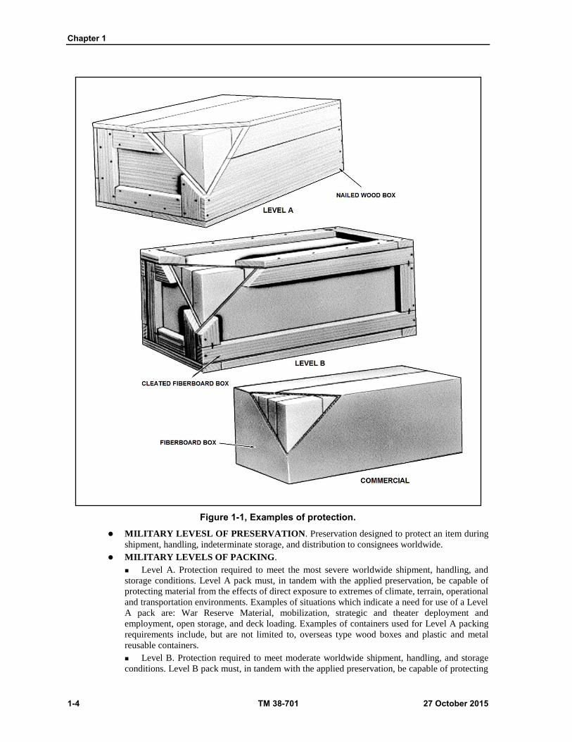
Figure 1-1, Examples of protection.
MILITARY LEVESL OF PRESERVATION. Preservation designed to protect an item during
shipment, handling, indeterminate storage, and distribution to consignees worldwide.
MILITARY LEVELS OF PACKING.
Level A. Protection required to meet the most severe worldwide shipment, handling, and
storage conditions. Level A pack must, in tandem with the applied preservation, be capable of
protecting material from the effects of direct exposure to extremes of climate, terrain, operational
and transportation environments. Examples of situations which indicate a need for use of a Level
A pack are: War Reserve Material, mobilization, strategic and theater deployment and
employment, open storage, and deck loading. Examples of containers used for Level A packing
requirements include, but are not limited to, overseas type wood boxes and plastic and metal
reusable containers.
Level B. Protection required to meet moderate worldwide shipment, handling, and storage
conditions. Level B pack must, in tandem with the applied preservation, be capable of protecting
Introduction: Purpose and Scope
27 October 2015 TM 38-701 1-5
material not directly exposed to extremes of climate, terrain, and operational transportation
environments. Examples of situations which indicate a need for use of a Level B pack are: security
assistance (e.g., Foreign Military Sales) and containerized overseas shipments. Examples of
containers used for Level B packing requirements include, but are not limited to, domestic wood
crates, weather-resistant fiberboard containers, fast pack containers, weather-resistant fiber drums,
and weather-resistant paper and multi-wall shipping sacks.
COMMERCIAL PACKAGING
1-17. Commercial packaging is defined as the materials and methods used by the supplier to meet the
requirements of the distribution systems serving both DOD and commercial consumers. The requirements
of MIL-STD-2073-1E shall only be applied to the packaging of items that are expected to enter the military
distribution system. Commercial packaging is to be used to the maximum extent possible for all other items.
Items not going into stock shall be packaged in accordance with ASTM D 3951, Standard Practice for
Commercial Packaging.
1-18. Commercial packaging will be acceptable for any level of protection when the technical design of the
package meets all conditions of the level of protection specified. It will be marked to the level it meets. Use
of commercial packaging is contingent upon no increase in packaging changes, size, weight, or delay in
delivery.
1-19. Bulk practices used in interplant and intraplant movements or shipments to jobbers are not acceptable
unless they are the usual trade practices for individual commodities such as coal, textiles. Petroleum and
subsistence.
1-20. The packaging details will be incorporated into standardization and acquisition documents when
applicable.
NORTH ATLANTIC TREATY ORGANIZATION STANDARDIZED AGREEMENT
(NATO-STANAG) 4280, NATO LEVELS OF PACKAGING
1-21. Participating nations agree to adopt the NATO levels of requirements - defined in this standardized
agreement as the basis for negotiation for the procurement of packaged materiel between nations. In defining
levels of requirements it is necessary to take into account: The characteristics of the environment and
constraints imposed by the environment; the technical considerations to define package tests; the four levels
of packaging used in NATO; and, it also shows comparison of these NATO levels against the nearest national
packaging requirement.
TYPES OF LOADS
1-22. The term "type of load" refers to the physical characteristics of the item, including the nature of the
item as it contributes to the support of, or damage to the container. The same kind of container can be designed
to provide adequate protection to various items by adjusting the constructional requirements. This may result
in a light, medium, or heavy-duty container, as necessary. The design of the shipping container to be used is
influenced by the type of load. There are three types of loads: Type 1, Type 2 and Type 3.
The types of loads will be mentioned under the various shipping containers and as shown in (figure 1-2 on
page 1-6).
Chapter 1
1-6 TM 38-701 27 October 2015
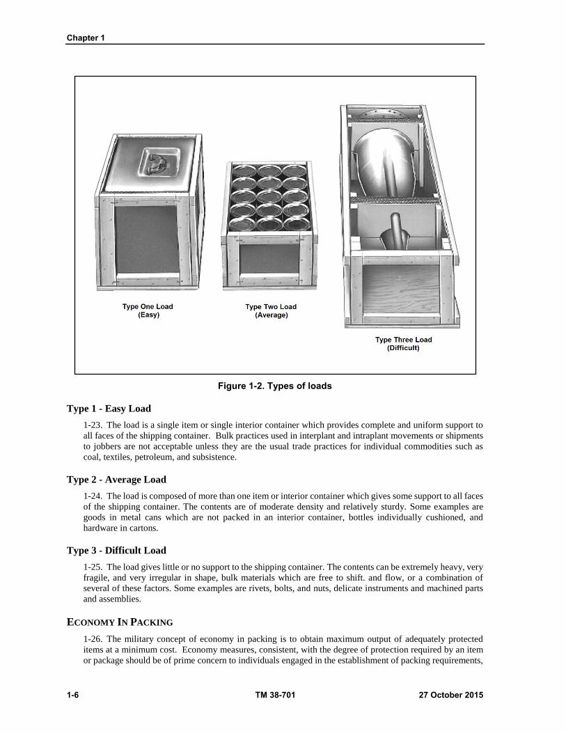
Figure 1-2. Types of loads
Type 1 - Easy Load
1-23. The load is a single item or single interior container which provides complete and uniform support to
all faces of the shipping container. Bulk practices used in interplant and intraplant movements or shipments
to jobbers are not acceptable unless they are the usual trade practices for individual commodities such as
coal, textiles, petroleum, and subsistence.
Type 2 - Average Load
1-24. The load is composed of more than one item or interior container which gives some support to all faces
of the shipping container. The contents are of moderate density and relatively sturdy. Some examples are
goods in metal cans which are not packed in an interior container, bottles individually cushioned, and
hardware in cartons.
Type 3 - Difficult Load
1-25. The load gives little or no support to the shipping container. The contents can be extremely heavy, very
fragile, and very irregular in shape, bulk materials which are free to shift. and flow, or a combination of
several of these factors. Some examples are rivets, bolts, and nuts, delicate instruments and machined parts
and assemblies.
ECONOMY IN PACKING
1-26. The military concept of economy in packing is to obtain maximum output of adequately protected
items at a minimum cost. Economy measures, consistent, with the degree of protection required by an item
or package should be of prime concern to individuals engaged in the establishment of packing requirements,

Introduction: Purpose and Scope
27 October 2015 TM 38-701 1-7
and to personnel in charge of, or performing packing operations. Significant savings can be accomplished by
reducing the tare weight, cubage, and packing cost of a commodity through proper reengineering of the unit
and exterior containers, use of newly developed materials, and employment of alternate methods and
techniques.
REFERENCES
1-27. Throughout this manual, packing materials, equipment, processes, methods, etc., are referred to by
their common names together with the appropriate specification, standard, or other publication symbols.
Copies of specifications and other documents required by activities of the Defense Logistics Agency, the
Department of the Army, Navy, and Air Force, and the Marine Corps are obtained from supply sources
through established channels. Copies of specifications, standards, and drawings required by contractor’s
connection with specific procurement functions should be obtained from the procuring activity or as directed
by the contracting officer. Military and Federal Specifications and Standards are available from:
Standardization Document Order Desk, 700 Robbins Avenue, Building #4, Section D, Philadelphia PA
19111-5094. Information pamphlet titled "A Guide for the Private Industry" provides more detailed
information and is available upon request.

This page intentionally left blank.
27 October 2015 TM 38-701 2-1
Chapter 2
Packing
PACKING OF GENERAL SUPPLIES
Some commodity items require preservation by procedures and materials described in this publication
which provide unit containers suitable for shipment without further packing. Other items may require further
packing in containers suitable for shipment. This chapter relates to the packing of commodity items directly
in shipping containers with whatever protection is required to prevent damage in shipment, handling and
storage. The container alone cannot always provide full protection for military items. Items must be properly
anchored, braced, blocked, or cushioned in the container to provide adequate protection. A container is often
blamed for damage to its contents when the cushioning, blocking, or bracing are at fault (fig.2-1). Every
packing operation, including the final closure, strapping, and marking of the container, must be carefully
planned and executed to ensure that the contents will arrive at its destination in a usable condition.
PACKAGING OF HAZARDOUS ARTICLES
Commodities classified as hazardous materials come within the scope of TITLE 49 Code of Federal
Regulations which incorporates Department of Transportation Regulation for the Transportation of
Explosives and other Hazardous Articles by all modes. International Shipments must be packaged in
accordance with the International Air Transport Associations Dangerous Goods Regulation and the
International Maritime Organization Dangerous Goods Code. In addition, hazardous materials which are to
be shipped via military aircraft must be packaged in accordance with the joint service manual AFMAN 24-
204/TM 38-250/NAVSUP PUB 505/MCO P4030.19/DLAM 4145.3, Preparing Hazardous Materials for
Military Air Shipments.
SEQUENCE OF PACKING OPERATION
The general sequence of military packing is divided into a series of basic operations which may include
some or all of the following steps, not necessarily in the order given below, failure to follow the below
procedures can result in damaged equipment as shown in (fig 2-1 on page 2-2):
Determine the Packing Requirements
Knowing the item characteristics helps to determine the protection required and the best way to provide
it through the use of an adequate container, suitable blocks, braces, and cushions, and appropriate barrier
materials. This study will include consideration of the characteristics of the item, its size, shape, fragility,
etc.; the types of loads (easy, average or difficult); the mode of transportation (rail, ship, truck, or aircraft);
the storage facilities (covered or uncovered); the destination (domestic or overseas in the arctic, temperate,
or tropic zones); and the levels of protection required.
Select The Container
Select and use an exterior container that will comply with the requirements outlined in applicable
chapters of this manual. This selection should consider all factors pertinent to giving adequate protection at
the minimum cost such as the characteristics and limitations of the container; its initial cost and upkeep
expenses; its weight and cube; its availability or obtainability in appropriate quantities; and its reusability.
Prepare Protective Barriers
Prepare an appropriate barrier to give weatherproofing protection not obtainable from the container
alone.

Chapter 2
2-2 TM 38-701 27 October 2015
Insert And Secure The Item To The Container
Insert the item and secure it to the container to control or prevent movement by means of adequate
cushioning, blocking, and bracing. The distinction between cushioning and blocking is that cushioning
permits controlled movement of the item within the container, while blocking and bracing usually is designed
to prevent movement of the item within the container.
Figure 2-1. Damaged items as a result of improper/inadequate packing.
Seal The Barrier If Used
Seal the barrier material by means of adhesives, heat seals, pressure seals, or sealing tape to provide
weatherproofness of the seams, joints, and closures equal to that of the barrier material itself.
Close The Container
Close the container following the detailed requirements outlined in the section of this manual which
describes the container selected.
Reinforce The Container
Reinforce the container with metal or plastic strapping or reinforced tape as appropriate and as required
for the container selected.

Packing
27 October 2015 TM 38-701 2-3
Mark The Shipping Container
Mark the container as appropriate to identify the contents and to ensure movement to its destination.
DETERMINATION OF PACKING REQUIREMENTS
The different types of items procured by the Department of Defense require a wide variety of packing
operations. Items vary from strong, rugged ones that fit the container well and require no cushioning, blocking
or bracing, to others that are irregular in shape, delicate, or fragile, and require special cushioning, blocking
or bracing.
BASIC FACTORS
To determine packing requirements, several basic factors must be considered, namely, the item
characteristics, the load characteristics, the mode of transportation, the storage and handling facilities, the
destination and field conditions.
BASIC REFERENCE
The basic reference for blocking, bracing, and cushioning is MIL-STD-1186, Cushioning, Anchoring,
Bracing, Blocking, and Waterproofing, with Appropriate Test Methods. This standard, approved by the
Department of Defense and mandatory for use by the Armed Forces, provides general requirements and
procedures concerning the arrangement of the contents within the shipping container for the prevention of
physical damage.
SCOPE OF MIL-STD-1186
The standard covers common packing requirements which may be omitted from detail specifications
for items or categories of items when this standard is referenced in the detail specification. It does not contain
requirements for shipping containers, themselves or for unit packing, both of which also provide physical
protection.
ITEM CHARACTERISTICS
The first step in any packaging operation is a careful study of the item to be packed. It is necessary to
consider the shape, size, weight, strength, and degree of fragility of the item in all directions. The availability
of mounting provisions, the degree of disassembly permissible for shipment, corrosion prevention
requirements and special use requirements which affect the packing operations must also be considered.
SHAPE
The shape of the item to be packed is an important factor to consider in designing blocking and bracing.
A regular-shaped item with rectangular surfaces requires a minimum of blocking, while irregular-shaped
items with uneven surfaces, including projections, often require an elaborate blocking system. Curved
surfaces require carefully fitted blocking to prevent damage caused by concentrated stresses at contact points,
and to distribute internal forces over a greater area of the faces of the container (fig 2-2 on page 2-4). Long,
slender items, particularly if heavy, exert a tremendous concentrated force on the ends of the container during
handling. This force may be counteracted by securely blocking the item to the sides, top, or bottom of the
container, and by increasing the thickness of the ends of the container (fig 2-3 on page 2-4). Relatively heavy,
irregular-shaped small items present a particularly difficult problem when they must be cushioned as well as
blocked. Generally, in solving this problem, it is desirable to even out the surfaces by means of pads and
blocking to increase the bearing area. This in turn decreases the load per unit area of bearing on the cushion
shown in (fig 2-4 on page 2-5).

Chapter 2
2-4 TM 38-701 27 October 2015
Figure 2-2. Interior blocking for an irregular shaped item.
Figure 2-3. Use of corrugated fiberboard pads and liner.

Packing
27 October 2015 TM 38-701 2-5
Figure 2-4. Interior blocking to protect container against end thrust.
SIZE AND WEIGHT
A large item may require more extensive blocking and larger amounts of cushioning than a smaller
one. The blocking may be necessary to bridge the relatively wide spans of the container faces, or it may be
required to distribute the cushioning over larger areas of the item. Since the impact force developed by the
abrupt stopping of a moving object is directly proportional to its weight, the weight of an item is very
important in considering the blocking and cushioning. In studying the item, consider the distribution of the
weight with respect to the size and bearing areas. Where the weight is concentrated, it may be necessary to
distribute it over a larger area. This may be done by transferring some of it from one container face to the
edges or corners of the container by the use of end blocks.
STRENGTH AND FRAGILITY
Some items are rugged enough to withstand greater stacking loads and handling forces than their
containers. Various components of vehicles and tanks, in particular, require little protection against shipping
hazards, but are placed in containers for ease of handling, stowage, and storage. On the other hand, there are
numerous items that require the maximum protection afforded by packing materials. Equipment is considered
rugged or highly resistant to shock when bracing and blocking within the container is all that is needed for
protection. Items that require cushioning for protection are considered to be fragile. The degree of fragility
of an item determines the amount and type of cushioning required to protect it from damage during handling
and shipment. Some items are inherently strong and rugged except for one or more fragile components. When
the fragile components cannot be removed for separate packing the entire item must be treated as fragile,
even though this may result in an unavoidably large, cumbersome pack.
AVAILABILITY OF MOUNTING PROVISIONS
An important factor to consider in packing is the availability of brackets and hold downs on the item
that can be used to mount it within the container. Frequently, it is possible to mount an item within the

Chapter 2
2-6 TM 38-701 27 October 2015
container by using the same brackets and hold-downs that are used for positioning and securing it in place
when it is permanently installed. Mounting facilities should be examined to determine if they are adequate,
especially if the container is likely to be tipped on end (fig 2-5). Compressors, engines, engine components,
generators, starters, and carburetors are often secured in this manner.
Figure 2-5. Mounting facilities of item must be adequate.
DISASSEMBLING OF AN ITEM
Items should be thoroughly investigated to determine if disassembly of simple parts can reduce the
size of the container required and/or simplify the packaging. Proper authorization must be obtained before
disassembling any portion of an item that would require technical skills or special tools to reassemble, realign,
or recalibrate. The disassembly of simple-to-remove components with standard tools (i.e.., handles, wheels)
does not require prior authorization.
Disassembled Parts
CAUTION
Proper authorization must be obtained before disassembling any portion of an item that would require technical skills or special tools to reassemble realign or recalibrate. Disassembly of simple- to-remove components such as handles, wheels, etc., requiring standard tools, does not need authorization.
When practicable, items should be disassembled to afford protection of components, attachments, and
accessories against damage and pilferage and to reduce cubage. Disassembled parts should be wrapped,
packaged, anchored, braced, blocked, or cushioned within the shipping container so that parts or protective
devices within the shipping container cannot be damaged by mutual contact. Disassembled parts should be
clearly and legibly marked as to identity and proper location on the assembled item. All fasteners removed
during disassembly should be secured in one of the mating parts. A part should not be removed from an
assembly unless it can be reassembled readily in the field without special tools.

Packing
27 October 2015 TM 38-701 2-7
SPECIAL PACKING REQUIREMENTS
Reusable and other special purpose containers usually require special consideration of the packing of
the contents in the container. For instance, in reusable containers, the blocking and cushioning must be
arranged so that it may be easily removed, and when replaced, it will adequately protect the contents.
However, reusable and special purpose containers should be considered for use, especially if their use results
in reduced weight, cube, or cost. For example, the reusable container for a missile nose cone, shown in figure
2-6 while expensive to procure, may more than pay for itself through its reusability and its designed
protection features.
LOAD CHARACTERISTICS
The proper selection of the shipping container for a given load is of the utmost importance. The kind
of container must be determined by the weight, size, shape, and fragility of the load. To aid in this selection,
the various loads have been classified as Type 1-Easy Load, Type 2-Average Load, and Type 3-Difficult
Load. (See figure 1-2 on page 1-6).
MODES OF TRANSPORTATION
The mode of transportation is an important factor in determining the packing requirements. The
hazards of handling and shipping vary greatly between motor, rail, ship, or aircraft. As an example, there
could be considerable difference in the amount of handling that an item being transshipped from truck to rail
to ship would receive, and the amount of handling an item delivered by air freight would receive. Likewise,
an item to be delivered by airdrop would require much more protection than one to be delivered by truck.
Figure 2-6. Protection features of a reusable missile container.
STORAGE CONSIDERATIONS
To assure serviceability of the contents after prolonged exposure to deteriorating elements, not only
the supplies, but the packing materials which enclose them must be protected. There may be a considerable
period from the time the material leaves the manufacturer until it is used. It may be stored outdoors in
domestic depots, and then shipped to staging areas or ports of embarkation to await transportation overseas.

Chapter 2
2-8 TM 38-701 27 October 2015
Finally arriving, it may again be stored in depots or supply areas which could be improvised shacks, native
huts, tents, caves, or even in the open. At oversea supply points, the packs are often broken open and smaller
intermediate packs distributed to forward areas. On the other hand, items may be shipped directly from the
supplier to the user with a minimum of delay. In this instance, the protection provided by the pack could be
considerably reduced from the amount required for the oversea pack.
DESTINATION AND FIELD CONDITIONS
The ultimate destination of items is generally unknown when they leave a packing facility. Some items
may be used domestically while the rest will eventually go overseas. They may be shipped to the arctic
regions, the islands of the seas, or the tropical jungles. They may be subjected to the cold, heat, humidity,
aridity, or the extreme temperature changes of the various regions, all of which must be considered in
planning the pack to assure adequate protection through the time of delivery and after arrival at destination
when they may be subjected to unfavorable field conditions.
FUNCTIONS AND SELECTION OF SHIPPING CONTAINERS
A shipping container is any exterior box, crate, drum, etc., which is required to enclose one or more
items during transit or storage. The shipping container is usually established by specifications, directives,
technical orders, or other authorized publications.
FUNCTIONS
The basic functions of a shipping container are to protect the contents and to provide for ease of
handling. Shipping containers assist in the handling of a number of items by consolidation, and of a single
item which is difficult to handle. The degree of protection derived from the shipping container depends upon
its type, the materials used in its fabrication, its construction features, its final destination, the nature of the
contents, and the anticipated hazards. Chapters 2 through 7 of this manual contain information on approved
containers for military shipments and should be consulted when making selection of the appropriate
containers.
SELECTION
Where a group of containers is authorized, or when the proper container is not specified, the packing
supervisor is responsible for the selection of the appropriate container. They must base their selection upon
the physical characteristics of the item; its destination; whether domestic or overseas; the level of protection
required; the type of load; the initial cost of the container; the weight and cube of the container; the simplicity,
economy and ease of assembly and closure; the availability; and need for reusability of the container shown
in (fig 2-7 on page 2-9). Nailed wood boxes or similar heavy wooden containers will not be used unless fully
justified by past experience or environmental, geographical, or security considerations.
ARRANGEMENT OF CONTENTS
The contents of a pack should be arranged within the shipping container so as to provide maximum
protection to its contents and the container. Where applicable, the arrangement should permit a container
fabricated of materials that will result in low tare weight, smallest practical cube, convenient handling, and
suitability for palletization. Contents should completely fill the container or be secured therein with suitable
clearance. Packs of like items should contain like quantities and should be uniform in size, shape, and weight.
MOVABLE PARTS AND PROJECTING PARTS
Articles with moving external parts or projecting parts that might become damaged by shock or
vibration encountered in shipment should have these parts made secure against movement by means of
blocking, bracing, tiedown, or other adequate provisions, or should be disassembled, if practicable.

Packing
27 October 2015 TM 38-701 2-9
Figure 2-7. Container selection factors.
SEGREGATION OF PACKED CONTENTS
So far as practicable, contents of shipping containers should be segregated in the following order: (a)
the order on the packing list; (b) items of the same contract; (c) items of the same National Stock Numbers;
and (d) items of the same Federal Supply Class.
CONVERSION OF TYPE 3 LOADS
Where practicable, type 3 loads should be converted to type 1 or type 2 loads.
BLOCKING AND BRACING
Blocking and bracing is the process of providing physical and mechanical protection to an item by
means of materials, other than cushioning materials, intended to prevent any free movement of the item
within the container, and distribute or transfer concentrated loads of the item to larger areas of other faces of
the container.
FUNCTIONS OF BLOCKING AND BRACING
Items which do not completely fill the shipping container should be blocked, braced, anchored, or
otherwise immobilized within the container. Blocking and bracing should be used to secure items or
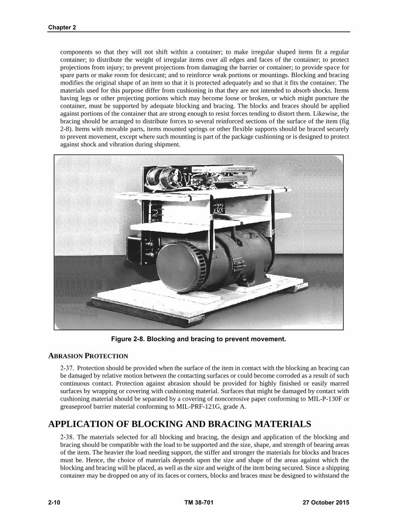
Chapter 2
2-10 TM 38-701 27 October 2015
components so that they will not shift within a container; to make irregular shaped items fit a regular
container; to distribute the weight of irregular items over all edges and faces of the container; to protect
projections from injury; to prevent projections from damaging the barrier or container; to provide space for
spare parts or make room for desiccant; and to reinforce weak portions or mountings. Blocking and bracing
modifies the original shape of an item so that it is protected adequately and so that it fits the container. The
materials used for this purpose differ from cushioning in that they are not intended to absorb shocks. Items
having legs or other projecting portions which may become loose or broken, or which might puncture the
container, must be supported by adequate blocking and bracing. The blocks and braces should be applied
against portions of the container that are strong enough to resist forces tending to distort them. Likewise, the
bracing should be arranged to distribute forces to several reinforced sections of the surface of the item (fig
2-8). Items with movable parts, items mounted springs or other flexible supports should be braced securely
to prevent movement, except where such mounting is part of the package cushioning or is designed to protect
against shock and vibration during shipment.
Figure 2-8. Blocking and bracing to prevent movement.
ABRASION PROTECTION
Protection should be provided when the surface of the item in contact with the blocking an bracing can
be damaged by relative motion between the contacting surfaces or could become corroded as a result of such
continuous contact. Protection against abrasion should be provided for highly finished or easily marred
surfaces by wrapping or covering with cushioning material. Surfaces that might be damaged by contact with
cushioning material should be separated by a covering of noncorrosive paper conforming to MIL-P-130F or
greaseproof barrier material conforming to MIL-PRF-121G, grade A.
APPLICATION OF BLOCKING AND BRACING MATERIALS
The materials selected for all blocking and bracing, the design and application of the blocking and
bracing should be compatible with the load to be supported and the size, shape, and strength of bearing areas
of the item. The heavier the load needing support, the stiffer and stronger the materials for blocks and braces
must be. Hence, the choice of materials depends upon the size and shape of the areas against which the
blocking and bracing will be placed, as well as the size and weight of the item being secured. Since a shipping
container may be dropped on any of its faces or corners, blocks and braces must be designed to withstand the

Packing
27 October 2015 TM 38-701 2-11
thrust and impact applied on any direction. The choice of materials used for blocking and bracing vary widely.
The chief materials used are corrugated fiberboard in cells, trays, pleated pads, and flat pads, for relatively
lightweight items or for supplementary primary blocking of heavy items. Wood, plywood, rigid plastic foams,
and metal are used as the primary blocking materials for large and heavy items.
FIBERBOARD
Open-end cells and trays of corrugated fiberboard. When used as blocking, corrugated fiberboard must
be designed to fit the bearing area of the item to support and evenly distribute the load. Common forms of
corrugated fiberboard blocking are die-cuts, open end cells, trays, pleated pads, and flat pads (fig 2-9).
Frequently, various combinations of these forms are employed. They can be used to provide spaces for, and
restrain the movement of, disassembled parts, as well as provide openings for bags of desiccant. Generally,
cells and trays should be held in shape with tape or staples.
Figure 2-9. Cells and trays made of corrugated fiberboard.
Those surfaces of the cell or tray which are perpendicular to the contacting surface of the item are
called bracing supports and are the load bearing members. No bracing support allowances should be made
for the other surfaces. To utilize all of the strength of these bracing supports, they should bear directly on the
item. The weight of the item must be exerted in the same direction as the corrugations. If not, the item is
inadequately supported and damage may result as shown in(fig 2-10 on page 2-12). Open-end cells and trays
should be used for blocking and bracing deep recesses; bridging long projections; providing spaces for
disassembling parts, accessories, and desiccants; and providing clearance between item and container.
Bracing supports should bear directly on the article. Allowable loads for bracing supports of open-end cells
loaded in the flute direction should be in accordance with table 2-1 on page 2-13. If flute direction is at right
angles to the direction of the load, the allowable loads should be 50 percent of the values of table 2-1. Trays
should be scored and folded parallel to the flute direction and should not exceed 4 inches in height.
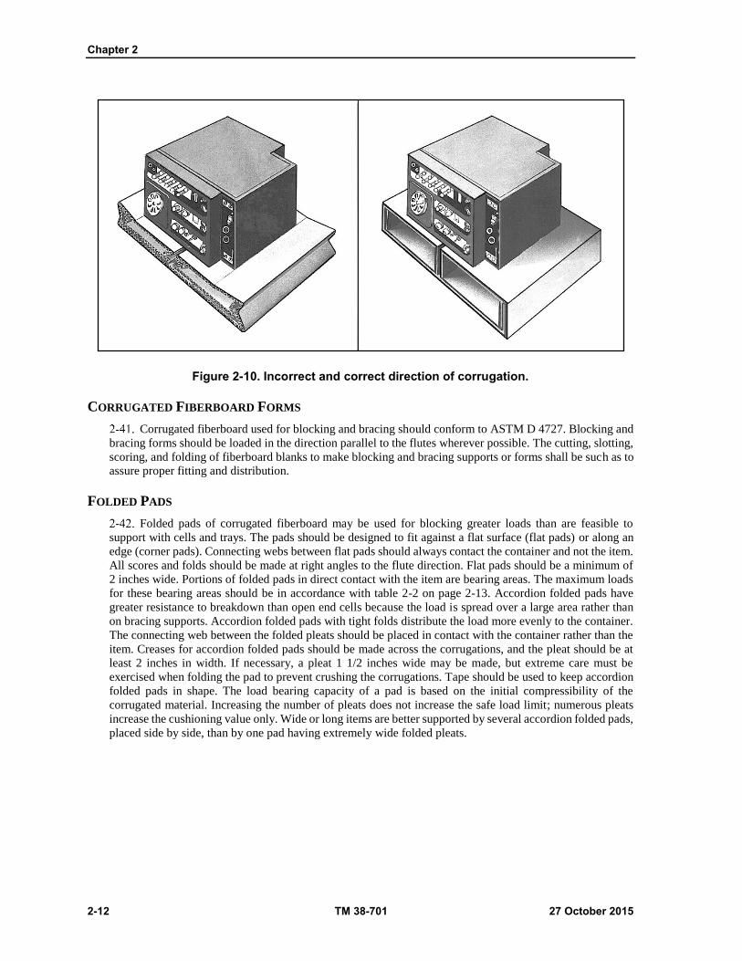
Chapter 2
2-12 TM 38-701 27 October 2015
Figure 2-10. Incorrect and correct direction of corrugation.
CORRUGATED FIBERBOARD FORMS
Corrugated fiberboard used for blocking and bracing should conform to ASTM D 4727. Blocking and
bracing forms should be loaded in the direction parallel to the flutes wherever possible. The cutting, slotting,
scoring, and folding of fiberboard blanks to make blocking and bracing supports or forms shall be such as to
assure proper fitting and distribution.
FOLDED PADS
Folded pads of corrugated fiberboard may be used for blocking greater loads than are feasible to
support with cells and trays. The pads should be designed to fit against a flat surface (flat pads) or along an
edge (corner pads). Connecting webs between flat pads should always contact the container and not the item.
All scores and folds should be made at right angles to the flute direction. Flat pads should be a minimum of
2 inches wide. Portions of folded pads in direct contact with the item are bearing areas. The maximum loads
for these bearing areas should be in accordance with table 2-2 on page 2-13. Accordion folded pads have
greater resistance to breakdown than open end cells because the load is spread over a large area rather than
on bracing supports. Accordion folded pads with tight folds distribute the load more evenly to the container.
The connecting web between the folded pleats should be placed in contact with the container rather than the
item. Creases for accordion folded pads should be made across the corrugations, and the pleat should be at
least 2 inches in width. If necessary, a pleat 1 1/2 inches wide may be made, but extreme care must be
exercised when folding the pad to prevent crushing the corrugations. Tape should be used to keep accordion
folded pads in shape. The load bearing capacity of a pad is based on the initial compressibility of the
corrugated material. Increasing the number of pleats does not increase the safe load limit; numerous pleats
increase the cushioning value only. Wide or long items are better supported by several accordion folded pads,
placed side by side, than by one pad having extremely wide folded pleats.

Packing
27 October 2015 TM 38-701 2-13
Table 2-1. Allowable loads for corrugated fiberboard. Columns loaded in the flute direction
Material
Allowable loads per lineal inch
of bracing support or column
Height up to
4 inches
Height over
4 inches
Pounds Pounds
Double-faced fiberboard
2
2.5
3
1
1.5
2
200-pound bursting strength
275-pound bursting strength
350-pound bursting strength
Double-wall fiberboard
2.5
3
5
1.5
2
2.5
275-pound bursting strength
350-pound bursting strength
500-pound bursting strength
Triple-wall fiberboard
5 4 1,100-pound bursting strength
Note. When a greater load is imposed than that permitted by the table, use wood blocking and
bracing.
FLAT PADS
Flat pads of corrugated fiberboard may be used to block very shallow projections, such as hinges or
slight offsets on surfaces; to level off projecting screw heads; to fill in the space between ends of inner flaps
of slotted fiberboard boxes to provide additional protection to contents at top and bottom of boxes; and to
separate items within a container. Allowable loads should be in accordance with table 2-2. Maximum
allowable loads per square inch of bearing area on a flat pad are the same as those for a pleated pad. Flat pads
can be slotted to form partitions, or they may be die cut or punched to fit items or irregular shape. Figure 2-
11 on page 2-14 shows the assembling of slotted fiberboard partitions.
Table 2-2. Allowable loads for folded corner and flat pads of corrugated fiberboard
Flute Design Maximum allowable load for bearing areas
Pounds per square inch
A-flute (36"3 corrugations per foot) 2.0
3.0
2.5
B-flute (50"3 corrugations per foot)
C-flute (42"3 corrugations per foot)
Note. The flat crush resistance of the corrugations shall determine the load that may be carried in
flat loading of corrugated fiberboard. This shall not be construed to meet the bursting strength of
the material.

Chapter 2
2-14 TM 38-701 27 October 2015
Figure 2-11. Assembling of slotted fiberboard partitions.
CORNER PADS
The use of corner pads made of multiple layers of corrugated fiberboard shall comply with the load
requirements of table 2-2. The pads shall provide required clearances and support for rectangular shaped
items or for an inner box in which items are packed.
TUBES
Fiberboard tubes should be used as blocking when items mounted on an auxiliary base are packed on
fiberboard boxes. The bottom of the tube shall contact the top of the auxiliary base and the top of the tube
shall contact the top inside surface of the container. The flutes shall be oriented in the top-to- bottom direction
of the tube. The weight of the item plus auxiliary base, in pounds, divided by the perimeter of the tube, in
inches, shall not exceed the appropriate values given in table 2-2 for column heights over 4 inches.
Packing
27 October 2015 TM 38-701 2-15
CORRUGATED FIBERBOARD LINERS
A liner is a continuous pad, bent to fully contact two or more inner faces of a container. Liners are used
to reinforce a container against crushing by forces imposed during stacking, or to take the place of two or
more flat pads. A liner may also be used as a holddown for base mounted items weighing not more than 20
pounds. The creases in a liner should be made parallel to the direction of the corrugations of the fiberboard,
in order that the resistance to forces ordinarily encountered in stacking be the greatest.
CORNER POSTS
Fiberboard corner posts should be used to reinforce the shipping container and provide blocking for
platform-mounted equipment. The flutes should be oriented in the top-to-bottom direction. The bottom end
of the corner post shall bear uniformly on the platform, and the top end of the corner post shall bear on the
inner flap of the container or top member of a crate. Corner posts, when installed, must so interlock with the
contents and other inner padding pieces in order not to become displaced during transportation.
WOOD OR PLYWOOD
Wood or plywood may be used alone or in combination for blocking and bracing. Wood or plywood
blocking and bracing members should bear against only those parts of the packed item capable of
withstanding the applied dynamic forces or should bear against blocking pads or pressure strips that
adequately distribute these forces. Wood or plywood blocking and bracing should be designed to permit easy
removal without damage to the item. Both wood and plywood are used for blocking and bracing because of
their high strength-weight ratio, general availability, and ease of cutting and fastening. Lumber has certain
weaknesses, such as low splitting resistance parallel with the grain, and a tendency to shrink or swell with
change in moisture content.
Plywood has high resistance to splitting and high dimensional stability with changes in moisture
content. Because they are more resistant to splitting than solid wood, plywood panels are more often used in
thinner dimensions than lumber, and are readily nailed or fastened with screws near the edges. Plywood is
more apt to have a lower moisture content than lumber because of the manner in which it is manufactured
and stored. Plywood, being constructed of alternate plies at right angles to each other possesses more
uniformly distributed strength properties than lumber. When considering lumber and plywood of comparable
sizes and quality, it is generally true that the strength properties of lumber parallel to the grain are greater
than the respective strength properties of plywood parallel to the grain of the face ply. It is also true that the
strength properties of lumber perpendicular to the grain are generally less than the respective strength
properties of plywood perpendicular to the grain of the face ply.
WOOD
Wood members of each size and type used in the blocking and bracing should be tested for moisture
content. Structural members (those subject to critical bending stresses) shall conform to class 1. All other
blocking and bracing members shall conform to class 3. Whenever possible, wood blocks or braces shall be
placed so that the load is applied against the end grain of the member. Ends of braces shall be socketed or
fitted and secured into appropriate notches in load-bearing members.
PLYWOOD
Plywood used for blocking and bracing should conform to A-A-55057B.
WOOD BLOCKING AND BRACING
The species of woods differ greatly in strength and related properties and, accordingly, have been
separated into four groups. Certain species, such as those of Group IV, excel in toughness and shock
resistance, but care must be exercised in nailing them to avoid splitting. Other species, such as southern
yellow pine and Douglas fir of Group II, are high in bending strength and stiffness; and nailing is a lesser
problem. The characteristics of the groups of wood may be used to advantage in various forms of blocking
and bracing shown in (fig 2-12 on page 2-17). Thin pieces of lumber split more easily than thick pieces;

Chapter 2
2-16 TM 38-701 27 October 2015
hence, thin pieces for blocking should be avoided if possible. If the dimensional limits of the item require
that the blocking be thin, it is preferable to use plywood.
MOISTURE CONTENT
The moisture content of lumber employed as blocking and bracing material should not exceed 19
percent nor be less than 12 percent of its oven dry weight at the time of fabrication. Shrinkage is objectionable
because it allows movement of the item and the item may actually break loose. Moisture in lumber is
objectionable because it is apt to evaporate into the pack, thus raising the humidity of the pack and causing
corrosion of metals or decay of organic materials.
CAUTION
Lumber, plywood, or other hygroscopic materials should never be placed in direct contact with critical metal surfaces since such materials tend to absorb and retain moisture next to the surfaces, finally causing corrosion. Provide always a water-vaporproof barrier between any critical metal surfaces and hygroscopic packing materials, and a waterproof or moisture-resistant barrier between all metal surfaces and hygroscopic materials.
DEFECTS IN BLOCKS AND BRACES
Wooden members used for blocking and bracing are often subjected to great stress and careful
consideration must be given to any weakening defects. If the member functions as a beam or column, defects
such as divergence of grain, knots, splits and decay should be avoided. This is especially important if the
defect is located near the center of the piece, because of the great reduction in shock resistance. If a piece
with a knot is used, the load is placed so that the knot is in compression as shown in (fig 2-12 on page 2-17).
Lumber having knots of a diameter exceeding one-fourth the width of the piece should not be used. The slope
of grain in each piece should not exceed 1 inch in 10 inches of length, or splitting is likely to occur. Decayed
wood is avoided under all circumstances because there is no way of determining how much the decay may
have weakened the wood. For additional information on wood knots, see chapter 4 and figure 4-3 on page 4-
7.
Size of Wood Braces of Holddowns
Braces or holddowns must be of sufficient size to withstand the shocks encountered. The size of a
brace varies with the weight of the item, the length of the brace, and the type of loading. Table 2-3 on page
2-17 used with (fig 2-13 on page 2-18) gives the recommended allowable load in pounds for the various sizes
of braces and the various types of loading. For example, assume that the weight of the item is 60 pounds, the
length of the brace is 24 inches, and the type of loading is the third type illustrated in (fig 2-13 on page 2-18)
(loading in the center 4/5 to 1/3 of the unsupported length of the brace). For this type of loading, multiply the
weight of the item by the factor 3/4, as shown in figure 2-13. Three-fourths times 60 equals 45. In the column
headed "Length of brace in inches", of table 2-3, find 24 inches and read to the right until a value near 45 is
found. The heading for this column shows that the proper size of member and direction of loading is a 1 x 2-
inch member used on edge, or a 1 x 4 inch member used flatwise.

Packing
27 October 2015 TM 38-701 2-17
Figure 2-12. Application of wooden blocks and braces.
Table 2-3. The allowable load in pounds is for group II woods.
Length of brace in inches
1x1 1x2 1x3 1x4 1x6 1x8 2x2 2x3 2x4
12 23 23 47 94 78 225 109 315 172 495 227 653 187 187 313 450 438 630
18 16 16 31 63 52 174 73 315 115 495 151 653 125 125 208 347 292 630
24 12 12 23 47 39 130 55 255 86 495 113 653 94 94 156 260 219 510
30 10 10 19 37 31 104 43 204 69 495 91 653 75 75 125 208 175 408
36 8 8 16 31 26 87 36 170 57 420 76 653 62 62 104 174 146 340
42 7 7 13 27 22 74 31 146 49 360 65 626 54 54 89 149 125 292
48 6 6 12 23 20 65 27 128 43 315 57 548 47 47 78 130 109 255
54 5 5 10 21 17 58 24 113 38 280 50 487 42 42 69 116 97 227
60 5 5 9 19 15 52 22 102 34 252 45 438 37 37 63 104 88 204
66 4 4 8 17 14 47 20 93 31 229 41 398 34 34 57 95 80 186
72 4 4 8 15 13 43 18 85 29 210 38 365 31 31 52 87 73 170
78 4 4 7 14 12 40 17 78 26 194 35 337 29 29 48 80 67 157
84 3 3 6 13 11 37 16 73 25 180 32 313 27 27 45 74 62 146
90 3 3 6 13 10 35 15 68 23 168 30 292 25 25 42 69 58 136
96 3 3 6 12 10 35 14 64 22 158 28 274 23 23 39 65 55 128
102 3 3 6 11 9 31 13 60 20 148 27 258 22 22 37 61 51 120
108 3 3 5 10 9 29 12 57 19 140 25 243 21 21 35 58 49 113
114 2 2 5 10 8 27 12 54 18 133 24 231 20 20 33 55 46 107
120 2 2 5 9 8 26 11 51 17 126 23 219 19 19 31 52 44 102

Chapter 2
2-18 TM 38-701 27 October 2015
Table 2-3. The allowable load in pounds is for group II woods. (Continued)
Length of brace in inches
2x6 2x8 3x3 3x4 3x6 3x8 4x4 4x6 4x8
12 688 990 906 1305
750 750 1050 1050 1650 1650 2175 2175 1470 1470 2310 2310 3045 3045
18 458 990 604 1305
579 579 810 1050 1273 1650 1678 2175 1470 1470 2310 2310 3045 3045
24 344 990 453 1305
434 434 608 851 955 1650 1259 2175 1191 1191 1872 2310 2467 3045
30 275 990 363 1305
347 347 486 681 764 1650 1007 2175 953 953 1497 2310 1974 3045
36 229 840 302 1305
289 289 405 567 637 1400 839 2175 794 794 1248 1961 1645 3045
42 196 720 259 1251
248 248 347 486 546 1200 719 2086 680 680 1069 1681 1409 2920
48 172 630 227 1095
217 217 304 425 477 1050 629 1825 595 595 936 1470 1234 2555
54 153 560 201 973 193 193 270 378 424 934 559 1622 529 529 832 1307 1096 2271
60 138 504 181 876 174 174 243 340 382 840 503 1460 476 476 749 1176 987 2044
66 125 458 165 796 158 158 221 309 347 764 458 1327 433 433 681 1069 897 1858
72 115 420 151 730 145 145 203 284 318 700 420 1217 397 397 624 980 822 1703
78 106 388 139 674 134 132 187 262 294 646 387 1123 366 366 576 905 759 1572
84 98 360 129 626 124 124 174 243 273 600 360 1043 340 340 535 840 705 1460
90 92 336 121 584 116 116 162 227 255 560 336 973 318 318 499 784 658 1362
96 86 315 113 548 109 109 152 213 239 525 315 913 298 298 468 735 616 1278
102 81 297 107 515 102 102 143 200 225 494 296 859 280 280 440 692 580 1202
108 76 280 101 487 96 96 135 189 212 467 280 811 265 265 416 654 548 1136
114 72 265 95 461 91 91 128 179 201 442 265 768 251 251 394 619 519 1075
120 69 252 91 438 87 87 122 170 191 420 252 730 238 238 374 588 493 1022
Lumber cross section sizes as shown in table are nominal the allowable load in pounds as shown are for actual or dressed sizes- example: 1 ½ x 3 ½ = 2x4 etc
Figure 2-13. Types of loading (use with table 2-3).

Packing
27 October 2015 TM 38-701 2-19
POSITIONING LOADS ON BLOCKS AND BRACES
When wood blocking and bracing is used to secure heavy items, place the block so that the load rests
on the end grain of the piece, whenever possible. If this cannot be done, the load should bear on the edge
grain. When so placed, the maximum strength of the brace is used (fig 2-14). Since wood is relatively stable
in dimension along the grain, there is little effect from shrinkage or swelling with a change in moisture
content. The brace should, if possible, have its narrow face against the item so that its maximum stiffness is
utilized. If a larger bearing area is required, and it becomes necessary to have the flat face of the brace against
the item, the size of the brace against the item, must be increased (see table 2-3). Lumber this is relatively
wide for its thickness must be reinforced throughout its length to prevent twisting or buckling.
USING LUMBER AS A MOUNTING BASE
If an item is to be secured to a base, and plywood is not available, use dimensional lumber. Bases of
dimensional lumber should be constructed with sufficient cleats at right angles to the grain of the baseboards,
and fastened with clinched nails to prevent the boards from splitting at the bolt holes. Strength of the bases
must be adequate to withstand any rough handling the pack may be likely to receive.
SECURING LUMBER BLOCKING
Securing lumber blocking properly is the most essential factor in blocking and bracing. Wooden braces
positioned between two faces of a container should never be secured with end grain nailing, toenailing, or
similar methods, nor should they ever be inserted into notches cut into the container faceboards. Instead, the
braces should be secured by cleats fastened to the faces of the container with a sufficient number of clinched
nails. When pressures are great or an increased nailing area is required, backup blocks are used to reinforce
the cleats and give increased nailing area. When pressure is from more than one direction, a pocket cleat
arrangement is used to hold the braces in position (3) figure 2-12. The backup blocks are positioned with
their end grain in contact with the brace in order to make use of the high strength property of wood in
compression parallel to the grain. The cleats and backup cleats (5) figure 2-12 are secured with clinched nails
properly staggered at intervals along their length. Sometimes, however, bolts are used to fasten these
members in place. This is especially desirable when the entire weight of the item thrusts against the block,
or when the cleat supports a framework attached to one or more faces of the container.
Figure 2-14. Positioning load according to grain of wood

Chapter 2
2-20 TM 38-701 27 October 2015
PLYWOOD BLOCKING AND BRACING
Plywood is used to distribute the load when the face of an item is flat but structurally weak and the
weakness prevents that face from being used as a bearing area. By covering the face of the item with a sheet
of plywood, so that the plywood bears on stronger portions of the face, the load of the item is distributed
uniformly against the container and injury to the weak face is prevented. The edges of the plywood sheet are
padded with felt, if necessary, to prevent the plywood from marring the surface of the item (figure 2-15).
Plywood can be used for making pressure strips to distribute the load of an item on the gaskets when a floating
water-vaporproof barrier is used. This method, which minimized the possibility of barrier damage during
shipment, is illustrated in figure 2-15. When it is not practical to block an irregular item to transfer the load
evenly to all faces of the container, it is wise to secure the item to a solid base which may in turn be blocked
to evenly distribute the load. If the container is of fiberboard, plywood serves as a good pallet to which the
item may be bolted or strapped. The plywood, in turn, is securely blocked into the container by a hold-down
or top pad. Thin plywood is used to advantage where the blocking must be flexible to conform to a curved
surface.
Figure 2-15. Protection for barrier and item surfaces.
COMBINED PLYWOOD AND LUMBER BLOCKING AND BRACING
Plywood and lumber, combined into a blocking and bracing assembly, unite the advantages of a strong,
lightweight sheet material with a material that is easily cut and nailed. Plywood is used as a sheet with wooden
blocks nailed to the sheet. The number, dimensions, and placement of the wooden blocks depend upon the
shape of the item, its depth, the position of any projections, and the loads to be supported at the various
bearing areas. The required thickness of the plywood depends upon the span between the blocks and the load
to be distributed. The sheet of plywood must be stiff enough to resist bending so as to evenly distribute the
weight of the item. Position the blocks upon the plywood sheet at places where the item can withstand
concentrated loads. Wherever possible, locate the blocks and braces against the stronger portions of the item.
Choose nails that are long enough to permit clinching after being driven through the wooden blocks and the
plywood sheets. If clinching is impractical, drive the nails through the thinner piece first. Cover all surfaces
of wood blocks contacting the item with felt and glue in place. Where the felt-covered blocks normally
contact critical surfaces of the item, use greaseproof or water-vaporproof barrier material between the felt
and the item. Eliminate time consuming construction of a framework at the time of packing by using
prefabricated blocking.
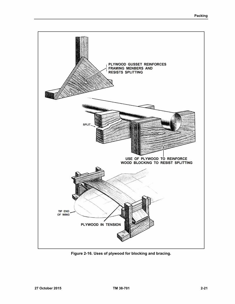
Packing
27 October 2015 TM 38-701 2-21
Figure 2-16. Uses of plywood for blocking and bracing.

Chapter 2
2-22 TM 38-701 27 October 2015
NAILS AND NAILING
Nails shall conform to the requirements of ASTM F 1667-05. All nails that are not clinched shall be
cement coated, etched or mechanically deformed (helically or annularly threaded). Unclinched nails shall be
as long as practicable without splitting the material, but not shorter than three times the thickness of the
member holding the nail head for ten penny nails and smaller, or not shorter than the thickness of the same
member plus 1 1/2 inches for twelve penny nails and larger. Nails loaded transversely to their length (lateral)
in blocking and bracing joints need not be clinched. End grain nailing in solid wood or edge nailing in
plywood shall not be permitted. Nails shall be driven through the thinner member into the thicker member
wherever possible. Nails shall not be subject to withdrawal stresses. Nails shall be driven not closer to the
end of a piece of lumber than the thickness of the piece and not closer to its side than one-half its thickness.
There shall be at least two nails in each joint. Lateral loading of nails for blocking and bracing shall be in
accordance with table 2-4. Ends of blocks and braces shall not be fastened to a wood container by end-grain
nailing methods. Blocking and bracing shall be applied against areas of item(s) that are of sufficient strength
and rigidity to resist damage. A description of the various types of nails and general requirements for their
use are given in chapter 3. Standard sinker and cooler nails are particularly well suited for use in blocking
and bracing and should be coated or chemically etched especially if the nails cannot be clinched. If nails fail
when subjected to forces of direct withdrawal, apply nails so that they are subjected to forces of lateral
displacement rather than direct withdrawal, that is, the direction of the nails is perpendicular to the direction
of the load, rather than in line with the direction of the load.
BOLTS AND BOLTING
Carriage or step bolts shall be used as fastenings for wood or plywood blocking and bracing where
necessary to facilitate disassembly for removal of container contents. Bolts shall also be used for fastening
blocking and bracing members that are too thick for proper fastening with nails. Bolt holes in wood or
plywood shall be of the same diameter as the bolts. Bolts commonly used for blocking and bracing are
machine bolts, carriage bolts, and step bolts.
Step bolts are preferred for this use because of their larger head diameter. J- or U-bolts are used for
special conditions where regular bolts cannot be applied (figure 2-17 on page 2-23). Tie rods and J-bolts are
actually extended bolts, applied in pairs either vertically (figure 2-18 on page 2-23) or diagonally (figure 2-
19 on page 2-24), and are used where standard length bolts would not apply. See table 2-5 on page 2-24 for
the suggested allowable load for the various sizes of bolts. The following precautions should be observed in
the use of bolts:
Items such as machines or subassemblies having bolt holes in parts which are sturdy enough to resist
breakage when rough handling should, if practical, be bolted to one face of the container. If non-precision
bolt holes are involved, the diameter of the bolt should be the nearest standard size consistent with the
diameter of the hole.
Table 2-4. Allowable lateral loads for unclinched cement-coated or etched common wire nails when used for blocking or bracing.
Species of wood Loads, pounds per nail
4d 6d 8d 10d
12d
16d
20d 30d 40d
White pine, ponderosa pine, spruce and other group I woods
17 17 21 25 26 29 38 42 48
Southern yellow pine, Douglas fir,
western larch, and other group II woods
21 26 32 39 40 45 58 65 73
Oak, maple, birch, beech, ash, and other
group III and IV woods
26 32 40 48 49 55 71 80 90

Packing
27 October 2015 TM 38-701 2-23
Figure 2-17 Bolts for blocking and bracing.
Figure 2-18. Vertical use of tie rods.
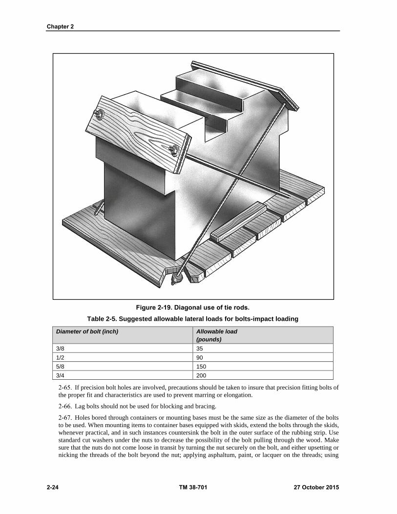
Chapter 2
2-24 TM 38-701 27 October 2015
Figure 2-19. Diagonal use of tie rods.
Table 2-5. Suggested allowable lateral loads for bolts-impact loading
Diameter of bolt (inch) Allowable load
(pounds)
3/8 35
1/2 90
5/8 150
3/4 200
If precision bolt holes are involved, precautions should be taken to insure that precision fitting bolts of
the proper fit and characteristics are used to prevent marring or elongation.
Lag bolts should not be used for blocking and bracing.
Holes bored through containers or mounting bases must be the same size as the diameter of the bolts
to be used. When mounting items to container bases equipped with skids, extend the bolts through the skids,
whenever practical, and in such instances countersink the bolt in the outer surface of the rubbing strip. Use
standard cut washers under the nuts to decrease the possibility of the bolt pulling through the wood. Make
sure that the nuts do not come loose in transit by turning the nut securely on the bolt, and either upsetting or
nicking the threads of the bolt beyond the nut; applying asphaltum, paint, or lacquer on the threads; using
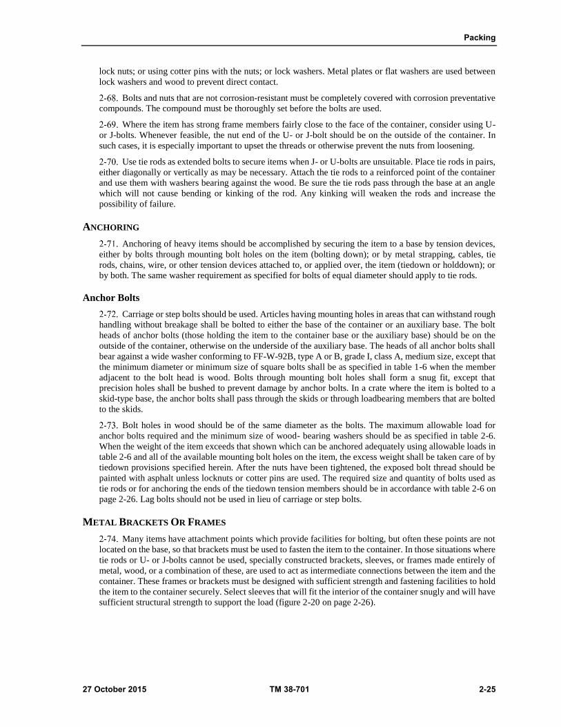
Packing
27 October 2015 TM 38-701 2-25
lock nuts; or using cotter pins with the nuts; or lock washers. Metal plates or flat washers are used between
lock washers and wood to prevent direct contact.
Bolts and nuts that are not corrosion-resistant must be completely covered with corrosion preventative
compounds. The compound must be thoroughly set before the bolts are used.
Where the item has strong frame members fairly close to the face of the container, consider using U-
or J-bolts. Whenever feasible, the nut end of the U- or J-bolt should be on the outside of the container. In
such cases, it is especially important to upset the threads or otherwise prevent the nuts from loosening.
Use tie rods as extended bolts to secure items when J- or U-bolts are unsuitable. Place tie rods in pairs,
either diagonally or vertically as may be necessary. Attach the tie rods to a reinforced point of the container
and use them with washers bearing against the wood. Be sure the tie rods pass through the base at an angle
which will not cause bending or kinking of the rod. Any kinking will weaken the rods and increase the
possibility of failure.
ANCHORING
Anchoring of heavy items should be accomplished by securing the item to a base by tension devices,
either by bolts through mounting bolt holes on the item (bolting down); or by metal strapping, cables, tie
rods, chains, wire, or other tension devices attached to, or applied over, the item (tiedown or holddown); or
by both. The same washer requirement as specified for bolts of equal diameter should apply to tie rods.
Anchor Bolts
Carriage or step bolts should be used. Articles having mounting holes in areas that can withstand rough
handling without breakage shall be bolted to either the base of the container or an auxiliary base. The bolt
heads of anchor bolts (those holding the item to the container base or the auxiliary base) should be on the
outside of the container, otherwise on the underside of the auxiliary base. The heads of all anchor bolts shall
bear against a wide washer conforming to FF-W-92B, type A or B, grade I, class A, medium size, except that
the minimum diameter or minimum size of square bolts shall be as specified in table 1-6 when the member
adjacent to the bolt head is wood. Bolts through mounting bolt holes shall form a snug fit, except that
precision holes shall be bushed to prevent damage by anchor bolts. In a crate where the item is bolted to a
skid-type base, the anchor bolts shall pass through the skids or through loadbearing members that are bolted
to the skids.
Bolt holes in wood should be of the same diameter as the bolts. The maximum allowable load for
anchor bolts required and the minimum size of wood- bearing washers should be as specified in table 2-6.
When the weight of the item exceeds that shown which can be anchored adequately using allowable loads in
table 2-6 and all of the available mounting bolt holes on the item, the excess weight shall be taken care of by
tiedown provisions specified herein. After the nuts have been tightened, the exposed bolt thread should be
painted with asphalt unless locknuts or cotter pins are used. The required size and quantity of bolts used as
tie rods or for anchoring the ends of the tiedown tension members should be in accordance with table 2-6 on
page 2-26. Lag bolts should not be used in lieu of carriage or step bolts.
METAL BRACKETS OR FRAMES
Many items have attachment points which provide facilities for bolting, but often these points are not
located on the base, so that brackets must be used to fasten the item to the container. In those situations where
tie rods or U- or J-bolts cannot be used, specially constructed brackets, sleeves, or frames made entirely of
metal, wood, or a combination of these, are used to act as intermediate connections between the item and the
container. These frames or brackets must be designed with sufficient strength and fastening facilities to hold
the item to the container securely. Select sleeves that will fit the interior of the container snugly and will have
sufficient structural strength to support the load (figure 2-20 on page 2-26).
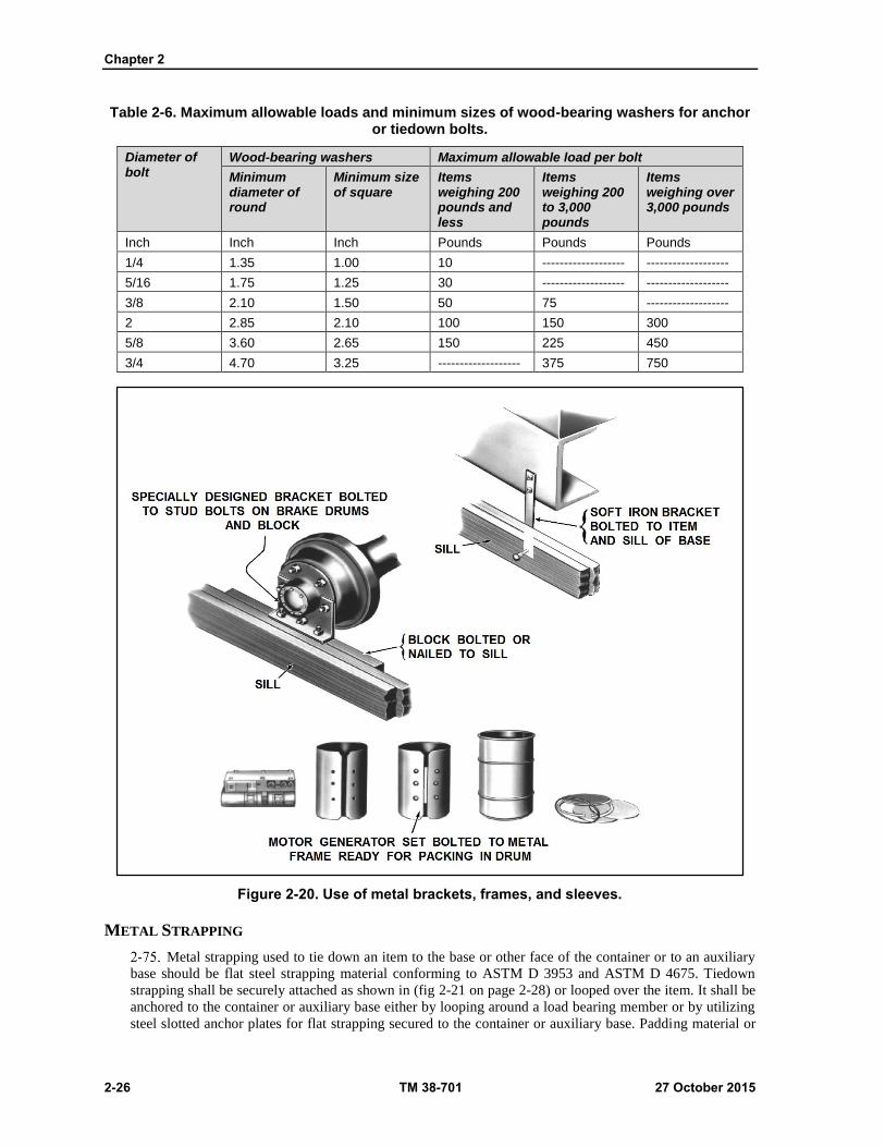
Chapter 2
2-26 TM 38-701 27 October 2015
Table 2-6. Maximum allowable loads and minimum sizes of wood-bearing washers for anchor or tiedown bolts.
Diameter of bolt
Wood-bearing washers Maximum allowable load per bolt
Minimum diameter of round
Minimum size of square
Items weighing 200 pounds and less
Items weighing 200 to 3,000 pounds
Items weighing over 3,000 pounds
Inch Inch Inch Pounds Pounds Pounds
1/4 1.35 1.00 10 ------------------- -------------------
5/16 1.75 1.25 30 ------------------- -------------------
3/8 2.10 1.50 50 75 -------------------
2 2.85 2.10 100 150 300
5/8 3.60 2.65 150 225 450
3/4 4.70 3.25 ------------------- 375 750
Figure 2-20. Use of metal brackets, frames, and sleeves.
METAL STRAPPING
Metal strapping used to tie down an item to the base or other face of the container or to an auxiliary
base should be flat steel strapping material conforming to ASTM D 3953 and ASTM D 4675. Tiedown
strapping shall be securely attached as shown in (fig 2-21 on page 2-28) or looped over the item. It shall be
anchored to the container or auxiliary base either by looping around a load bearing member or by utilizing
steel slotted anchor plates for flat strapping secured to the container or auxiliary base. Padding material or

Packing
27 October 2015 TM 38-701 2-27
suitable edge protectors, as applicable, shall be used under the straps to prevent damage to the item. Whenever
possible, all strands holding down an item shall be of approximately the same length. Maximum allowable
loads for each strand of tiedown strapping shall be in accordance with ASTM D 4675. Each tiedown strap
passed over an item should be considered as one strand. All tiedown strapping shall be tensioned and sealed
or tied securely.
STRAPPING PRECAUTIONS
Metal strapping may be the only convenient way in which an item or container can be secured or
reinforced (figure 2-21). Metal strapping may be flat steel material. Strapping is tensioned and preferably
sealed with specially designed tools. If this is not possible, flat strapping can be held in place with anchor
plates. General precautions on the use of metal strapping which applies to flat steel are as follows-
Where possible, the item and its support must be completely encircled. When it is impossible to do
this, anchor the two ends of the metal strapping as follows:
For flat strapping, anchor the two ends of the strap to the container base with anchor plates, or if
the strap is designed for nailing, nail the ends of the strap to the container base. Place the nails so
that the straps exert a pull at right angles to the nail axis. For round wire, anchor the two ends of
the round wire to the container with drives crews and staples. Loop the wire around the shank of
the drives crew and further anchor the wire by means of staples. Be sure the wood is thick enough
to hold the entire length of the drives crew and that the drives crew is of adequate gauge to carry
the load. When drives crews are used, place them so that the wire exerts a pull right angles to the
drives crews axis. Apply tension to the strap with a tension tool and seal the strap in the customary
manner. Use a one- piece strap wherever possible. Straps should be placed only on those strong
portions of the item which can withstand the impact load and weight of the item. Where strapping
passes over a sharp edge of the item, use corner protectors, if necessary, to prevent the strapping
from becoming fractured.
Protective materials should be used between the item and the strap if the strap is likely to scratch
or otherwise injure the item. Arrange strapping on the container, where possible, to further
reinforce blocking and bracing or anchoring of the item within the container. Use annealed
strapping only for lighter items, since it stretches more readily than the more highly tempered
tension strapping.
MINIMUM LENGTHS OF STRAPS
The minimum total length of straps shown in table 2-7 on page 2-29 does not include that portion of
material used to make a secure fastening at the ends of each strand but is the sum of, and does include, all
lengths of material between such fastenings. Overall lengths of each strand shall be adequate to permit
fastening as specified above.
MAXIMUM ALLOWABLE LOADS
The maximum allowable loads are based on available energy of 8,640 inch- pounds per cubic inch of
strap in tension and an assumed drop height of 30 inches, as established by ASTM D 3953. If greater loads
are to be tied down or if other sizes of strap are used, additional strapping shall be applied on the basis of 300
pounds of load per cubic inch of strap in tension.
Chapter 2
2-28 TM 38-701 27 October 2015
Figure 2-21. Use of metal strapping for bracing and anchoring

Packing
27 October 2015 TM 38-701 2-29
Table 2-7. Tape strips used in handling rigid materials1
Type III tape band width in inches (minimum)
Gross weight of bundle
Number of encirclements (Example: Three encirclements could refer to either three
separately located single wrapped bands or to one band which completely overlaps itself three
times)
Pounds 1 2 3 4 5 6 7 8 9 10
Up to 20 3/4 1/2 1/2 1/2 1/2 1/2 1/2 1/2 1/2 1/2
Over 20 to 40 1 3/4 1/2 1/2 1/2 1/2 1/2 1/2 1/2 1/2
Over 40 to 60 1 1/4 1 3/4 1/2 1/2 1/2 1/2 1/2 1/2 1/2
Over 60 to 80 1 1/2 1 1/4 1 3/4 3/4 1/2 1/2 1/2 1/2 1/2
Over 80 to 100 -------- 1 1/2 1 1/4 1 3/4 3/4 3/4 3/4 3/4 3/4
Over 100 to 150 -------- ------- 1 1/2 1 1/4 1 3/4 3/4 3/4 3/4 3/4
Over 150 to 200 -------- ------- ------- 1 1/2 1 1/4 1 3/4 3/4 3/4 3/4
Over 200 to 300 -------- ------- ------- ------- 1 1/2 1 1/4 1 3/4 3/4 3/4
Over 300 to 400 -------- ------- ------- ------- ------- 1 1/2 1 1/4 1 1 1
Over 400 to 500 -------- ------- ------- ------- ------- ------- ------- 1 1/2 1 1/4 1
1 If material to be bonded is somewhat flexible, tape widths may be reduced by 25 to 50 percent. In no case should less than 1/2 inch tape be used.
STRAPPING REINFORCEMENT FOR CONTAINERS.
In additions to the use of metal strapping as reinforcement for blocking or bracing, its widest use is for
reinforcement of exterior wooden containers.
Only tempered high tensile strength, flat steel strapping should be used as wood container
reinforcement, except in limited instances such as reinforcing of a crate corner where annealed nail-on-type
flat steel strapping is employed. For export shipments, bare metal strapping should not be used due to its lack
of corrosion resistance.
Each military and commercial container specification has a section or an appendix devoted to closure
and strapping. It is important that the instruction contained in these publications be observed.
WEB STRAPPING
The use of web strapping to tie down an item to a base, to other faces of the containers, or to a built up
frame, is NOT considered a good practice. Web strapping has a tendency to shrink or stretch with change in
moisture content, thereby losing its ability to hold the item firmly in place. It is hygroscopic, and may cause
corrosion to contacting metal surfaces, and it is often difficult to anchor properly.
REINFORCED TAPES FOR PACKING
Various kinds of tapes have been developed with longitudinal filament reinforcing strands to provide
high tensile strength. When such tapes are properly applied to containers or bundled items, significant
increases in resistance to rough handling are attained. These tapes consist of either a paper or plastic backing,
which has been coated on one side with an insoluble pressure-sensitive adhesive, or a gummed adhesive that
is activated by a solvent. The high tensile strength of the tape is produced by filaments of nylon, rayon, glass,
or other fibers that have been lineally aligned and embedded in the backing material. When the tape is applied
to the container so that the direction of the rough handling stresses are parallel to the embedded filaments of
the tape, considerable container strengthening results. Longitudinal tensile strength of these tapes may be
over 500 pounds per inch of width. Some of the advantages claimed for their use are that sufficient tensile

Chapter 2
2-30 TM 38-701 27 October 2015
strength and elastic properties are present to enable a package or pack to be highly resistant to shock loads.
The adhesive holds the tape to the area of application and thus prevents slippage during handling. These tapes
do not easily snag and do not interfere with stacking and handling of containers. No special equipment is
needed for their application. They provide a means of reducing pilferage.
REINFORCED PAPER, GUMMED TAPE A-A-1492B, A-A-1671B
There are three types and two classes available. Type I (reinforced, asphaltic laminated) and Type II
(reinforced, non-asphaltic laminated) are intended for use in so called single strip closure under the Uniform
Freight Classification Rule 41, section 7. Types I and II are used for closure of fiberboard boxes for domestic
shipment and storage and for securing wrappers of packages. Type II shall be used where the presence of
asphalt would have a deleterious effect on the contents, such as food products. Type III is intended for use in
general sealing of cartons, fiberboard boxes, and wrappers and for banding paper and paper products. Class
1 (strippable) is used when ease of opening and removal of the tape is desired. Class 2 (non-strippable) is
used when removal of the tape from boxes is not necessary for reuse.
FILAMENT REINFORCED, PRESSURE TAPE ASTM D 5330
These tapes are supplied in four types based on tensile strength. Type I (low tensile strength) has a
minimum tensile strength of 160 pounds per inch of width. Type II (medium tensile strength) has a minimum
tensile strength of 240 pounds per inch of width for Class A, and 300 pounds per inch of width for Class B.
Type III (high tensile strength) has a minimum tensile strength of 425 pounds per inch of width. Type IV
(high tensile strength, weather- resistant) has a minimum tensile strength of 400 pounds per inch of width.
Only Type II has two classes, based on the transparency of the tape. Class A is opaque or nontransparent,
and Class B is transparent enough to allow reading of printed matter through one layer of the tape. These
tapes are intended for use in securing packages and reinforcing bundles and containers.
REINFORCED TAPE APPLICATION GUIDELINES
Individual container specifications, and appropriate standards should be checked for the proper use of
reinforced tapes. Some basic rules that may be helpful are as follows:
Do not use a wide tape if a narrower tape is strong enough to accomplish the intended purpose.
If it is anticipated that high humidity conditions or excessive moisture will be encountered in
shipment or storage, use tapes with water insoluble adhesives.
The adhesion of tapes to the surface of a container will depend upon the condition of the surface.
Hence, in strip applications, the strips should be long enough to provide sufficient adhesion to take advantage
of the full potential strength of the tape. This should require at least 6 or more inches of good contact between
the tape and the container surface. The tape length should be equally divided over a seam, score line, or other
point of application. In using reinforced paper gummed tape (A-A-1492B, A-A-1671B) for sealing containers
shipped under the jurisdiction of the Interstate Commerce Commission, only the center seam of a container
needs to be sealed. This is accomplished by using a strip at least 3 inches wide which must extend no less
than 2 1/2 inches over each end of the container.
In using filament reinforced, pressure-sensitive tape ASTM D 5330; the following information will
serve as a guide in its use. It should be recognized that special conditions will necessitate occasional
deviations from these recommendations in the interest of economy or good practice. The filament reinforced,
pressure sensitive tapes are intended for use in reinforcing fiberboard or fiberboard surfaced containers,
strapping, bundling, and other miscellaneous applications. Type I, characterized by high elongation and low
tensile strength, is best suited for strip reinforcement of containers and anchoring moving parts. Type II with
lower elongation but high tensile strength, is also suited for closures. Type III, with higher tensile strength
and low elongation, is most effectively used in complete wraparounds such as bundling and other forms of
circumferential binding. Type IV should be used where weather resistance is required and should be used in
the same length as the type it replaces. These tapes should be applied in continuous strips. Typical
applications are shown in (fig 2-22 on page 2-31). Tape should be smoothly and firmly adhered to surfaces
which are relatively smooth and nominally free from dust, dirt, grease, and moisture. Care should be taken
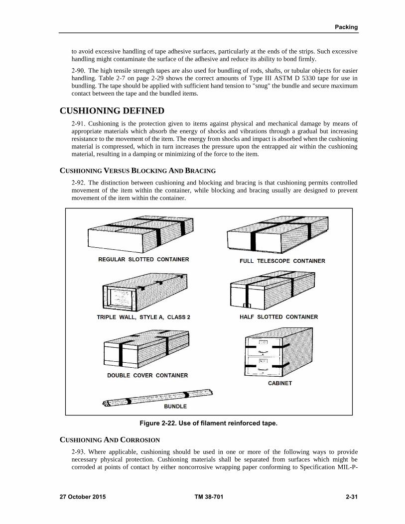
Packing
27 October 2015 TM 38-701 2-31
to avoid excessive handling of tape adhesive surfaces, particularly at the ends of the strips. Such excessive
handling might contaminate the surface of the adhesive and reduce its ability to bond firmly.
The high tensile strength tapes are also used for bundling of rods, shafts, or tubular objects for easier
handling. Table 2-7 on page 2-29 shows the correct amounts of Type III ASTM D 5330 tape for use in
bundling. The tape should be applied with sufficient hand tension to "snug" the bundle and secure maximum
contact between the tape and the bundled items.
CUSHIONING DEFINED
Cushioning is the protection given to items against physical and mechanical damage by means of
appropriate materials which absorb the energy of shocks and vibrations through a gradual but increasing
resistance to the movement of the item. The energy from shocks and impact is absorbed when the cushioning
material is compressed, which in turn increases the pressure upon the entrapped air within the cushioning
material, resulting in a damping or minimizing of the force to the item.
CUSHIONING VERSUS BLOCKING AND BRACING
The distinction between cushioning and blocking and bracing is that cushioning permits controlled
movement of the item within the container, while blocking and bracing usually are designed to prevent
movement of the item within the container.
Figure 2-22. Use of filament reinforced tape.
CUSHIONING AND CORROSION
Where applicable, cushioning should be used in one or more of the following ways to provide
necessary physical protection. Cushioning materials shall be separated from surfaces which might be
corroded at points of contact by either noncorrosive wrapping paper conforming to Specification MIL-P-
Chapter 2
2-32 TM 38-701 27 October 2015
130F or greaseproof barrier material conforming to Specification MIL-PRF-121G, grade A. If a noncorrosive
cushioning material is used, the wrap is not required. Cushioning materials containing asphalt shall not be
permitted to come in direct contact with highly finished, varnished, or lacquered surfaces.
FLOTATION OR SUSPENSION
Delicate or fragile items should be protected against shock and vibration by flotation or suspension
within the shipping container by suitable cushioning materials. These materials may be in sheet form applied
to give support at top, bottom, sides, and ends of the item. For items in sturdy cabinets, cases, consoles, or
packed in an inner box, the cushioning material may be in the form of prefabricated corner pads. Materials
shall be bound fiber conforming to PPP-C-1120D; fiberboard conforming to ASTM D 4727; cellulosic
material conforming to A-A-1898D; expanded polystyrene conforming to PPP-C-850D; prefoamed
polyurethane conforming to MIL-PRF-26514G; foam-in-place materials complying with MIL-PRF-83671B;
or such other materials as specified in the procurement documents.
ABRASION PROTECTION
Protection against abrasion should be provided for highly finished or easily marred surfaces by
wrapping or covering with cushioning material. Surfaces damaged by contact with cushioning material
should be separated by a covering of noncorrosive paper conforming to MIL-P-130F or MIL-DTL-17667E
or grease proof barrier material conforming to MIL-PRF-121G, Grade A.
COATINGS AND BARRIERS
Protection should be provided for strippable compound coatings and for grease proof, water proof, or
water/vapor proof barriers at points of contact with blocking, bracing or projecting members of containers.
Cushioning materials should be applied to reduce the static pressure at points of contact of 30 pounds or less
per square inch.
MOISTURE RESISTANCE
Unless otherwise specified in the product specification, cushioning material conforming to A-A-1898D
should be of the water resistant type.
DUSTING
Cushioning materials that are not dust producing should be used for packing items that are adversely
affected by dust, unless a dustproof barrier is used to prevent dust from reaching the item.
FACTORS INFLUENCE CUSHIONING SELECTION AND USE
Shock resulting from rough handling or dropping of a shipping container is the usual cause of
mechanical damage to the contents. The purpose of package or item cushioning is to reduce the intensity of
the shock reaching the packed item to a level which the item can withstand. Factors influencing cushion
design are the fragility and weight of the item, the load-bearing area of the cushion, the dynamic, force
deformation characteristics of the cushioning material, and the equivalent height of drop (usually 30 inches)
for which protection is desired. Among these, the fragility and weight of the item are fixed values for any
particular item. The load-bearing area of the cushion can be altered by suitable blocking or by packing the
item in an inner container, if desired.
CONCEPT OF CUSHIONING
Cushioning is the protection from physical and mechanical damage afforded an item by means of
compressible and resilient materials, known as cushioning materials, designed to absorb the energy of shocks
and vibration caused by external forces. Details on "Package Cushioning Design" may be obtained in MIL-
HDBK-304C.
Packing
27 October 2015 TM 38-701 2-33
FUNCTIONS OF CUSHIONING
In order to properly utilize the many cushioning materials available in the military supply system, it
is necessary to understand the functions of cushioning. Among these functions (figure 2-23) the more
important are:
Controls movement and prevents damage caused by vibration. Cushioning, when properly applied,
controls the movement of the item within the barrier or container and dampens vibration.
Protect fragile or delicate components. When fragile or delicate components form a part of an
otherwise rugged item, they may be disassembled and packaged separately. If disassembly is not
permitted and they must be left in place, cushioning is applied to give them protection.
Prevent rupture of barriers and containers. Many items have sharp corners or projections which
could puncture the barriers or containers in which they are packaged, resulting in the entry of
moisture or water. Cushioning is applied to these projections or corners to insure that waterproof
or water/vapor proof barriers are not rendered useless by such damage.
Distribute forces. Cushioning materials reduce the shock to an item by distributing forces over a
large area, thus lowering the stress concentration at any one point on the surface of the item.
Prevent abrasion. Items with highly finished surfaces which may be marred by blocking, strapping,
contact with container surfaces, or contact with other items in the container, must be protected
against abrasion by cushioning. Usually, lesser amounts and thickness of cushioning materials are
employed to accomplish this cushioning function.
Absorb shocks. Perhaps the most frequent and important use of cushioning is to absorb the energy
resulting when an impact shock strikes a container. This shock energy is absorbed as the
cushioning material is compressed by the impact.
MULTIPURPOSE CUSHIONING
The foregoing functions of cushioning should not be considered separately because cushioning is
often used for more than one purpose in the same package. Material selected to protect an item against shock
may at the same time minimize movement, prevent abrasion, protect barriers, and cover sharp projections.
Many cushioning materials also act as good insulation to protect items against drastic temperature changes.
Cushioning may be required to absorb liquids and consequently must have liquid-absorbing qualities to
prevent liquid flow in case of breakage of the containers.
REQUIREMENTS FOR THE USE OF CUSHIONING MATERIALS
In addition to the requirements established in cushioning specifications in regard to material quality,
construction, and performance, other important requirements must be met when cushioning materials are
used within waterproof or water/vapor proof barriers. Sound packaging design practices dictate placing only
the minimal required amount of cushioning material within water/vapor proof barriers, thereby minimizing
the barrier area and the desiccant requirements. in addition,
Cushioning shall be as dry as practicable.
If the item is coated with a preservative, the preserved item must first be wrapped in a barrier
conforming to MIL-PRF-121G, Grade A, QQ-A-1876, or MIL-PRF-22191F, Type I or II, before
applying the cushioning material.
CUSHIONING SELECTION FACTORS
There are several factors that must be considered in selecting the appropriate cushioning material
for a given application. The nature and physical limitations of the item, the favorable and unfavorable
characteristics of the cushioning material, the destination of the packages, and the means of transportation
must all be taken into consideration before an item can be properly cushioned.
Chapter 2
2-34 TM 38-701 27 October 2015
NATURE OF THE ITEM
In planning to cushion an item, the nature and physical limitations of the item must first be
considered. The shock resistance, size, weight, shape, surface finish, and the degree of disassembly permitted
will influence the way an item is to be cushioned (figure 2-24).
SHOCK RESISTANCE OR FRAGILITY
Fragility may be observed, but cannot be measured accurately by eye. The tendency is to overcushion
seemingly fragile items and to undercushion seemingly sturdy items. Fragility-the greatest amount of
dynamic force an item can withstand without destruction--can be measured with scientific instruments. The
term "G-factor" has been accepted as indicating the shock resistance of an item. This resistance is determined
by measuring the peak acceleration (deceleration) an item will withstand during impact and dividing this
acceleration value by the acceleration due to gravity (32.16ft/sec/sec). This is expressed as:
G-factor = Acceleration of the Item .
Acceleration due to Gravity
The G-factor values of many military items are being determined. In the absence of known G-factor
values, the selection of cushioning must be based on experience with previous shipments and testing of
similar items, or by assuming a G-factor for drop test purposes.
SIZE
A large item may require a thinner layer of cushioning than a smaller item of the same weight
because there is less load per square inch applied to the cushioning. This should be kept in mind when an
item is irregular in shape- more cushioning may be required at the small end than at the large end.
WEIGHT
Weight in motion results in force, and force can cause damage. Thus, the weight of an item controls
the thickness, quantity, and firmness of the cushioning material to be used. Generally, the heavier the item,
the firmer the cushioning must be.
SHAPE
A regular-shaped item will ordinarily fit snugly into a container with a minimum of cushioning,
while an irregular-shaped one may require a complicated arrangement of pads and cells or foamed-in-place
cushioning to bring it to a more regular shape. Light, small items which are irregular in shape can be made
regular and at the same time positioned and held in the container merely by a wrap of cushioning material.
Large, irregular items may make it impractical to use cushioning materials to make them regular. Blocking
and bracing will have to be employed to adequately protect such items.
SURFACE FINISH
An otherwise sturdy item may have highly finished surfaces which could be damaged by the rubbing
action of harsh abrasive cushioning material, or the surfaces may be corroded and pitted by chemical action
due to the presence of moisture and acidic or basic elements in the cushioning material.
CHARACTERISTICS OF CUSHIONING MATERIALS
The chemical and physical properties of cushioning materials are many and may display both
desirable and undesirable characteristics. These characteristics vary in importance for different applications.
What might be a highly desirable characteristic in one application may be detrimental in another. For
instance, high moisture absorbency is required for packaging liquids, but is not desirable when packaging
corrodible metal items.
Compression set (fig 2-23) is the difference between the original thickness of a cushioning material
and the thickness of the same material after having been released from compression under a standard load

Packing
27 October 2015 TM 38-701 2-35
for a given period of time. This is important in determining whether a cushioned item can remain in storage
for an extended period of time without causing the cushioning to lose its resiliency. Permanent compression
set is undesirable when it creates free-moving space in the container.
Resilience (fig 2-23) is the ability of a material to absorb a series of shocks and return to its original
shape and thickness after each shock. Few materials are completely resilient and this quality is often
greatly altered by changes in temperature. Rubber, for instance, is highly resilient in temperate zones,
but loses its resilience under extreme climatic conditions. Rate of recovery (fig 2-23), or the time it takes for
a cushioning material to return to its original shape after compression, is also important as some materials
have too rapid a rate of recovery and "spring back" so quickly that damage to the item may result.
Figure 2-23. Characteristics of cushioning compression set, resilience, and rate of recovery.
Dusting, which results from the breakdown and disintegration of certain materials used for
cushioning, allows small particles to become detached and work into crevices and critical working surfaces
of the cushioned item (fig 2-24).
The corrosive effect of some cushioning materials is undesirable when packaging items with critical
surfaces. When this cannot be avoided, the item must be shielded from such materials by a neutral wrap or
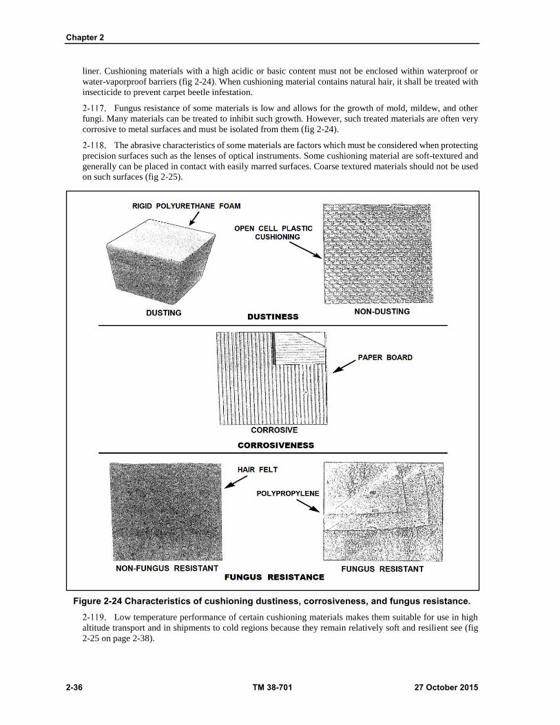
Chapter 2
2-36 TM 38-701 27 October 2015
liner. Cushioning materials with a high acidic or basic content must not be enclosed within waterproof or
water-vaporproof barriers (fig 2-24). When cushioning material contains natural hair, it shall be treated with
insecticide to prevent carpet beetle infestation.
Fungus resistance of some materials is low and allows for the growth of mold, mildew, and other
fungi. Many materials can be treated to inhibit such growth. However, such treated materials are often very
corrosive to metal surfaces and must be isolated from them (fig 2-24).
The abrasive characteristics of some materials are factors which must be considered when protecting
precision surfaces such as the lenses of optical instruments. Some cushioning material are soft-textured and
generally can be placed in contact with easily marred surfaces. Coarse textured materials should not be used
on such surfaces (fig 2-25).
Figure 2-24 Characteristics of cushioning dustiness, corrosiveness, and fungus resistance.
Low temperature performance of certain cushioning materials makes them suitable for use in high
altitude transport and in shipments to cold regions because they remain relatively soft and resilient see (fig
2-25 on page 2-38).

Packing
27 October 2015 TM 38-701 2-37
Other characteristics which should not be neglected in choosing cushioning materials are fire
resistance or flammability (figure 2-25), and the possibility of the materials causing skin irritation to
personnel who come in contact with it.
Destination Of The Item
The destination of the item is a factor in cushioning. Many cushioning materials change their
characteristics under extreme climatic conditions. Some materials become so rigid or brittle at extremely low
temperatures as to make them useless as cushioning materials. In tropical climates, some materials soften
and lose their cushioning qualities. In jungles or rainy locations, some materials will pick up excessive
moisture which will result in the loss of resilience and will lead to growth of fungus and accelerated corrosion.
Means Of Transportation.
The means of transportation must not be overlooked. Hazards and handling situations vary greatly
between air, motor, rail, and ship. For example, there may be considerable difference between the amount of
handling that an item being transshipped from truck, to rail, to ship would get and one that is being shipped
by air freight. Likewise, an item to be delivered by air drop would require different protection from one that
would be delivered by truck.
REPRESENTATIVE CUSHIONING MATERIALS
There are many types of cushioning materials used to package government goods.
Cushioning Material, Uncompressed Bound Fiber (PPP-C-1120D)
This material may consist of any suitable natural hair, vegetable fiber, or synthetic fiber bound with
an elastic material. Horsehair, sisal, and cactus fibers sprayed with latex are examples. It is furnished in five
types and two classes and three grades. Type I is soft, Type II is medium soft, Type III is medium firm, Type
IV is firm, and Type V is extra firm. When specified, each type shall be identified with a color matching as
closely as possible to colors shown in FED-STD-595C, as follows: Type I, brown; Type II yellow; Type III,
orange; Type IV, red; and Type V, black. Class A is water-resistant and Class B, a commercial class, is not
necessarily water-resistant. Grade 1 is a flame resistant material; Grade 2 provides low temperature
characteristics; and Grade 3 is a standard material. This material may be supplied as uncompressed sheets
and rolls and in molded shapes to fit the contours of the item. The materials have a high degree of resilience,
low compression set, fair damping quality, and do not disintegrate easily. They are neutral and have a low
water-soluble acidity so that their corrosive effects are slight. Moisture content and moisture absorption are
low temperature. They are intended to protect items against vibrational and impact shocks where resilient
and water-resistant cushions are required.
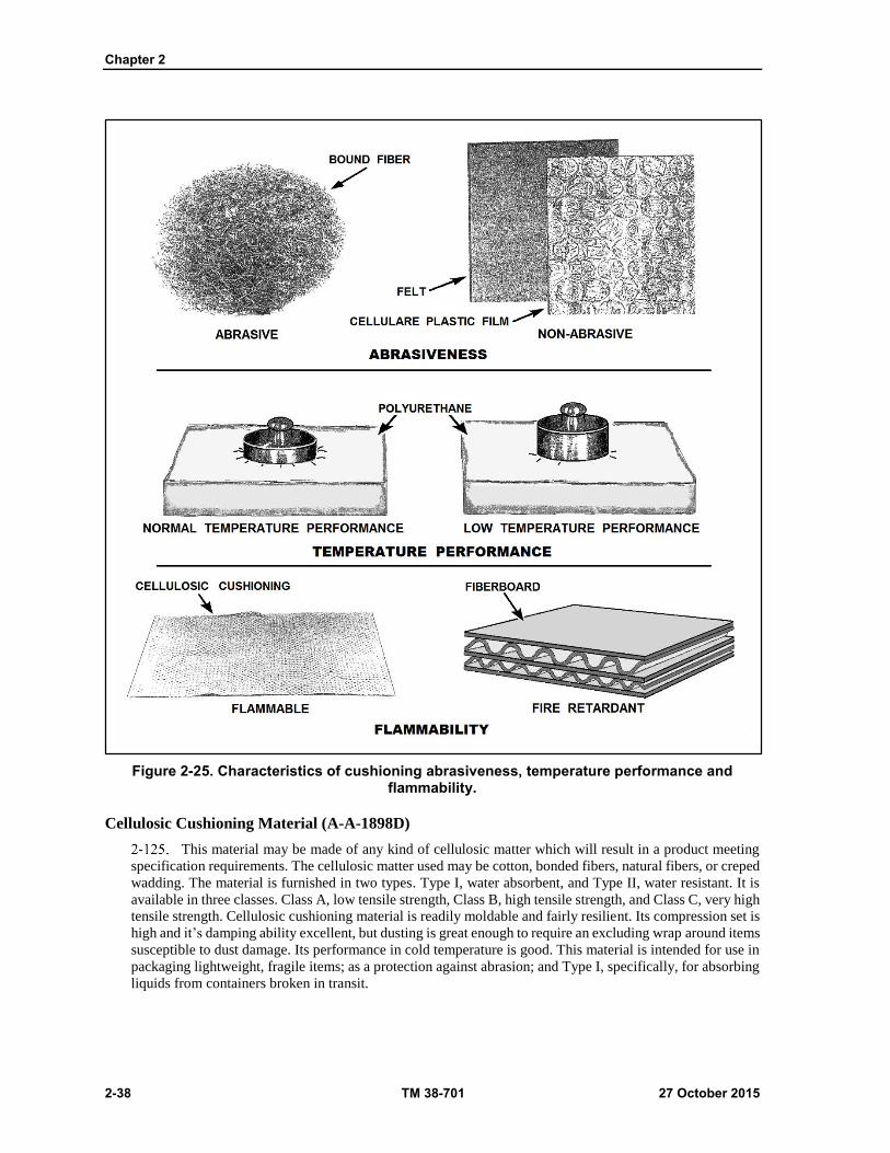
Chapter 2
2-38 TM 38-701 27 October 2015
Figure 2-25. Characteristics of cushioning abrasiveness, temperature performance and flammability.
Cellulosic Cushioning Material (A-A-1898D)
This material may be made of any kind of cellulosic matter which will result in a product meeting
specification requirements. The cellulosic matter used may be cotton, bonded fibers, natural fibers, or creped
wadding. The material is furnished in two types. Type I, water absorbent, and Type II, water resistant. It is
available in three classes. Class A, low tensile strength, Class B, high tensile strength, and Class C, very high
tensile strength. Cellulosic cushioning material is readily moldable and fairly resilient. Its compression set is
high and it’s damping ability excellent, but dusting is great enough to require an excluding wrap around items
susceptible to dust damage. Its performance in cold temperature is good. This material is intended for use in
packaging lightweight, fragile items; as a protection against abrasion; and Type I, specifically, for absorbing
liquids from containers broken in transit.

Packing
27 October 2015 TM 38-701 2-39
Solid and Corrugated Fiberboard (Astm D 4727)
Both solid and corrugated fiberboard are used in cushioning, but corrugated is more frequently used
because it has greater cushioning value. The most common forms of fiberboard applications are die-cuts,
open end cells trays, pleated pads, and flat pads (fig 2-26). Generally, cells and trays should be held in shape
with tape. Those surfaces of the cell or tray which are perpendicular to the contacting surface of the item are
called bracing supports and are load bearing members. To utilize all of the strength of these bracing supports,
they should bear directly on the item. Pleated pads have greater resistance to breakdown than open end cells
because the load is spread over a large area rather than bracing supports. Therefore, they should be used to
cushion heavier loads (up to 2 pounds per square inch). Flat pads are used to block shallow projections, to
level off projecting screw heads, and to separate items within a container. They can be slotted to form
partitions, or may be die-cut or punched to fit articles or irregular shape. Application of fiberboard cells,
trays, and pads is illustrated in (fig 2-27 on page 2-40).
Unicellular Polypropylene Foam (PPP-C-1797A)
This material is a low density, resilient, unicellular (closed cell) polypropylene foam material for
use in cushioning and packing applications in the form of rolls or flat sheets. Type I electrostatic discharge
is required. It is useful throughout a temperature range from minus 65 degrees Fahrenheit to 160 degrees
Fahrenheit. It is intended for use as a cushioning wrap for low density items. The foam can be laminated to
a wide range of products including paper, paperboard, and may be used for the protection for optical lenses,
equipment with critical surfaces, electrical and electronic equipment, glassware, ceramics, and magnetic tape
rolls. When stored in closed containers it produces no trapped volatiles which could cause fire or explosions.
Polypropylene, by its nature, is unaffected by most exposures to grease water and most acids, bases and
solvents. It contains no plasticizers, solvents, or lubricants.
Figure 2-26. Examples of fiberboard trays, opened end cells, pads, and die-cuts.

Chapter 2
2-40 TM 38-701 27 October 2015
Figure 2-27. Application of fiberboard die-cuts, open end cells, trays, and pads.
EXPANDED POLYSTYRENE (PPP-C-850D)
This resilient cushioning material consists of expanded polymers or copolymers of styrene for use
in packaging applications. It is furnished in two types. Type I is in sheet form and Type II is in roll form.
Both types come in four classes and two grades. Class 1 is soft, class 2-medium, class 3-firm, class 4-extra
firm. Grade SE is self-extinguishing. This cushioning material is used within packages to protect items from
damage due to shock, vibration, abrasion, and concentrated forces during handling and shipment. It is
especially suited where a high degree of energy absorption is required in a minimum space and with a
minimum weight of cushioning. It can also be used to provide temperature insulation or when cushioning
material must perform at extremely low temperature.

Packing
27 October 2015 TM 38-701 2-41
CUSHIONING, WRAPPING PAPERBOARD (A-A-1051C)
This is a paperboard composed of a corrugated sheet or a solid molded pulp sheet firmly cemented
to a backing flat sheet of unbleached sulfate fiber paper. The paperboard is furnished in two types--light and
heavy-duty, and in two styles. Style 1 material must have a backing sheet. The backing sheet is optional for
Style 2. It is furnished in sheets or rolls, as desired. Both styles are flexible in all directions. This material
has high compression, low resilience, excellent damping, and some dusting. The moisture content and
moisture absorption are high. The moisture is not neutral and hence has a high corrosion effect. Its
performance in cold weather is poor, and it is neither fungus nor flame resistant. Critical metal items must
first be wrapped in a chemically neutral or greaseproof barrier.
RIGID OR FLEXIBLE POLYURETHANE FOAM (MIL-PRF-26514G)
This material consists of both rigid and elastic types of foamed products obtained through the proper
blending of complex synthetic chemical compounds. By proper combinations, reaction mixtures can be
poured or pumped into various shaped cavities. Volatilization of the blowing agent causes rapidly stiffening
resin to expand, completely filling the space. The material then sets rapidly to a lightweight, cellular structure
that has excellent cushioning properties. The material is furnished in a form suitable for foaming in-place
application or it may be performed and supplied in rolls, sheets, or molded shapes. Strong rigid foams, tough
elastic foams, soft flexible foams, and spongy water absorbent foams can be obtained by the different choices
of ingredients. Foams with densities as low as 0.5 pounds per cubic foot may be obtained. These foams can
be adjusted to give a high or low compression set, excellent or poor damping, and high or low resilience. In
other words, the material can be tailor made to meet the requirement of any type of cushioning required.
There is no dusting problem; moisture content is negligible. The material is flame and fungus-resistant, and
it performs well in cold climates. For further details regarding procedures and equipment used with
polyurethane foam, see MIL-HDBK-775.
LATEX FOAM SPONGE RUBBERS
These materials are made by incorporating into the rubber an inflating agent such as baking soda
that gives off a gas which expands the mass during the vulcanization process. The rubber is made from slab
rubber into sheets, strips, molded or special shapes. These materials may be supplied in cored or uncored
types; soft, medium, firm, and extra firm, classes; and in flame resistant and nonflame-resistant grades. The
materials have a very high resilience, low compression set, fair damping properties, high moisture content,
and high moisture absorption. They produce some dusting. If kept dry, the corrosive effects are slight. Their
low temperature performance is poor. The materials have a high density and are expensive to use. The molded
forms are often used in conjunction with reusable containers and the initial cost is reduced by the amount of
reuse obtained.
PLASTIC FILM, HEAT SEALABLE, FLEXIBLE, CELLULAR (PPP-C-795D)
This material is constructed of a composite of two or more sheets of plastic film, one face having
uniformly distributed closed cells (bubbles), the other a flat surface. It is available in three classes: class 1-
regular; class 2-antistatic, tinted; and class 3-fire retardant. All are used as cushioning for packaging
applications. Material is furnished with various cell sizes (air bubbles). It is intended for use within packages
to protect items from damage due to shock, vibration, concentrated forces, corrosion, contamination, and
abrasion during handling and shipment and is especially suitable for use as inserts within transparent bags.
The use of class 1 material, due to its transparency, permits inspection of the contents without opening the
pack. The flexibility of the material permits it to be used as pads, bags, wraps, dunnage, or as filler. Class 2
material protects sensitive electronic devices from electrostatic discharge damage. When fire retardation
is required, class 3 material is selected.
Note: Many of the materials made under this specification are laminates of chlorinated plastic and
polyethylene. Chlorinated organic materials give off vapors of hydrogen chloride which can
combine with water to form highly corrosive hydrochloric acid.
Chapter 2
2-42 TM 38-701 27 October 2015
CUSHIONING MATERIAL, PACKAGING CLOSED CELL FOAM BLANK (A-A-59136)
This commercial Item description covers six types and four classes of cushioning material. Type
refers to the density range of the material. For example, type VII has a density of 0.9 to 2.0 pounds per cubic
foot while type V has a density range of 6.0 to 10.0 per cubic foot. The class generally describes the form the
material takes and may be solid or laminated planks, sheets, cut shapes, rounds, or molded shapes. In addition,
type VII, class 4, materials are antistatic. Temperature performance has a useful range of minus 65F to plus
165F. Compression set is low and the materials are noncorrosive, nonabrasive, and virtually dust free.
OPEN CELL PLASTIC CUSHIONING (A-A-3129C)
This material is made of one sheet of plastic film or a composite of two or more sheets of film,
formed into a network of uniformly distributed open cells. The cells may be a hexagonal or fluted shape,
depending upon whether a facing or reinforcing top film laminate is required. The hexagonal form is used
when a reinforcing top laminate is applied to the open face of the cells. The fluted form is used when a facing
is applied to the crowns of the formed cells. The resulting material is lightweight, transparent, flexible, and
heat sealable. There are three types; Type I, hexagonal; Type II, fluted; and Type III, hexagonal, electrostatic
free. The two styles describe whether or not the material has a top laminate or facing. All three types are
available with or without a top laminate or facing and are furnished in rolls or sheets. The material is
noncorrosive, nonabrasive, has low compression set, and performs well at low temperatures. The cushioning
is intended for use within packages as inserts within transparent bags, wraps, dunnage, and filler.
METHODS OF CUSHIONING
Cushioning is generally accomplished by one of the following methods:
Floated item. The item is floated in cushion material and placed within a unit container (figure 2-
28 on page 2-43). This is perhaps the method most commonly used for cushioning small,
lightweight, fragile items against shock, vibration, and abrasion. Dryness and non-corrosiveness
of cushioning materials are most important since both the item and the cushioning material will
be enclosed in the unit container. Greaseproof barriers are required if the item is preserved.
Cushioning materials must be secured about the item. Loose cushioning may result in either the
displacement of the material when the pack is subjected to shock, its disintegration under repeated
vibration, or the production of dust or loose particles which will be entrapped within the pack.
Since a container may be dropped on any of its faces, edges, or corners, the cushioning material
must be designed to withstand the full impact of the entire weight of the item in any direction.
Floated Pack. The item is packed in an interior container which in turn is floated in cushioning
materials (fig 2-28 on page 2-43). This method is generally used in connection with semi fragile
items of medium size and weight. The item is initially packed (which may include cushioning or
blocking) in an interior container, then floated in cushioning and placed into an exterior container.
In this method, the non-corrosiveness and moisture content of the cushioning materials are not
critical since the materials will not come in contact with the item. The use of absorbent cushioning
materials, when used in this method, should be governed as follows:
When both the interior and exterior containers are water-resistant, the cushioning material may be
simply placed between the two containers. When either container is not water-resistant, the cushioning
material must be placed in the form of packs wrapped in a water resistant barrier material. An alternative for
the second case is to provide the interior container with a sealed water- resistant wrap and the exterior
container with a sealed liner. The cushioning material is then placed between the two barriers.
SHOCK MOUNTS
The item is cushioned by means of shock mounts. This method is used to cushion fragile items and
sensitive instruments or mechanisms that can be damaged by shock and vibration. The weight and size of the
item may vary from light and small to heavy and large. The shock mounts may consist of elastomeric springs
or rubber blocks. This method of cushioning may be accomplished in four main ways.

Packing
27 October 2015 TM 38-701 2-43
The item may be suspended directly by means of elastomeric springs. The item may be blocked in
a cradle and the cradle suspended by means of elastomeric springs. The item may be boxed in an intermediate
container and the intermediate container suspended by means of elastomeric springs. The item may be boxed
in an intermediate container and the intermediate suspended by means of rubber shock mounts.
PACKING PROBLEMS
The basic reason for packing any item is to provide enough protection against the hazards it is likely
to encounter during shipment. This minimizes the chances that damage will occur during the interval between
the time the pack leaves the shipper and when the item is placed in use by the receiving activity. It is, of
course, an impossibility to evaluate all the hazards that might be encountered in transit, as there are too many
variables which can affect the condition in which an item may be found upon arrival at its destination. The
guidelines to packing presented herein have indicated the principles and practices that have been found
satisfactory in giving protection under average handling and storage conditions. If the solution of a specific
packing problem is not located in this section, the following procedures are recommended for shipment from
depots:
DOMESTIC SHIPMENTS
If an item is being shipped domestically, pack the item in a manner which closely duplicates the
pack in which the item was received.
Figure 2-28. Methods of cushioning
Chapter 2
2-44 TM 38-701 27 October 2015
OVERSEA SHIPMENTS
If shipment overseas is involved, and no previous history of a container in which the item had been
shipped to a similar destination is available, construct a pack embodying as many as possible of the principles
outlined in this section. This pack should be prepared exactly as it would be shipped including complete
preservation and interior packing. It is then tested by subjecting it to the applicable performance tests. The
tests are based upon the size as well as the gross weight of the container since both influence the amount of
rough handling the container will receive. Small, light packages are easier to move than the larger and heavier
packs, and consequently, they can be expected to receive a greater amount of handling. Performance tests are
required for the primary purpose of determining the adequacy of all the operations entering into preparation
of a pack. At the conclusion of the tests, performance is based on the condition of the container, its contents,
the blocking and bracing, cushioning, preservation, and other packing materials. The pack should be
examined for any damage, noting in particular any obviously weak points which might need to be
strengthened. Usually the container, if constructed according to specifications, will withstand the rough
handling. If, however, the container is damaged, a study should be made of the causes. Deficiencies in the
blocking and bracing may result in damage to the container, in which case these deficiencies should be
corrected. Other times the nature or shape of the item may cause the container to fail. Then, the container
should be reinforced. In any event, when deficiencies become obvious, either in the containers, the contents,
the blocking and bracing, cushioning, preservation, etc. the pack should be appropriately modified and the
test repeated until no damage occurs which affects the utility of the pack.
PACKING SMALL, LIGHTWEIGHT ITEMS
As previously pointed out, cushioning materials are frequently employed to block lightweight items.
In some instances, however, cushioning materials such as fiberboard, are primarily used for blocking. The
effectiveness of fiberboard as blocking and bracing depends upon its strength and its resistance to moisture
when not protected by suitable moisture barriers. The domestic class of fiberboards will rapidly absorb
moisture with a resulting loss of strength. The weather-resistant class on the other hand, retains a greater
proportion of its strength in the presence of moisture. Fiberboard is most frequently employed as blocking in
fiberboard containers because the items packed in them are usually small and lightweight and do not require
heavier types of blocking. Also, the container manufacturer can provide and fabricate pads, cells, trays, or
partitions of the same material a low cost.
Both solid and corrugated fiberboard are employed as blocking material, but the corrugated is used
more frequently because it has a greater cushioning value and because of its lower cost. Occasionally, a pack
will contain a comparatively large void which will necessitate blocking to prevent shifting of the item, in
such cases, a fiberboard carton may be used for blocking the item in place. The carton used for blocking
should be closed and sealed, and must be strong enough to provide adequate strength in all directions.
PACKING LARGE ITEMS
Large items require special attention to adequately secure them within the container. Such items are
anchored to the base of the container and blocked and braced into a secured position on the base. A clearance
of a least 1 inch is provided between the end, side, and top panels and the item is seldom blocked and braced
to these panels. Thus, the container must have a rigid base and the rest of it be must free to distort without
placing stresses directly on the contents.
ANCHORING TO BASE OF CONTAINERS
Crates for large and heavy items should have sturdy bases to which the items can be adequately
secured. Many ingenious methods have been developed to hold items to crate bases. For sill and skid type
crates, it is essential that the load be carried primarily by the outside skids or sills. This means that loads that
cannot be secured to the side sills or bases must be provided with load bearing members that transmit the
load to them.

Packing
27 October 2015 TM 38-701 2-45
WEATHERPROOFING THE PACK
At this point in the sequence of packing operations, it is assumed that a careful study has been made
of the item to be packed; a suitable container has been selected; blocking, bracing, and cushioning have been
designed; and the contents are ready to be placed into the container. The next step is to provide, when
necessary, a protective barrier in the form of a case liner, crate liner, shroud, wrap, or tarpaulin fabricated
from one of several materials. The barriers are intended to prevent deterioration of the item, and the
preservation and packing materials used to protect it, by excluding the entry of water, by limiting the entrance
of water vapor, or by diverting water from the materials which are subject to water damage. In addition,
barriers will afford protection from dust, dirt, and other foreign matter. Barriers designed to prevent the entry
of water (waterproof barriers) will not be used when the interior packs have been individually waterproofed
as shown in (fig 2-29), nor when the asphaltum in the barrier material or sealants may prove injurious to the
enclosed items. The water vapor proof protection afforded by case liners differs from that afforded by a
Method 50 package in that water absorbing desiccant is not used with case liners.
Figure 2-29. Waterproofing of individual packages.
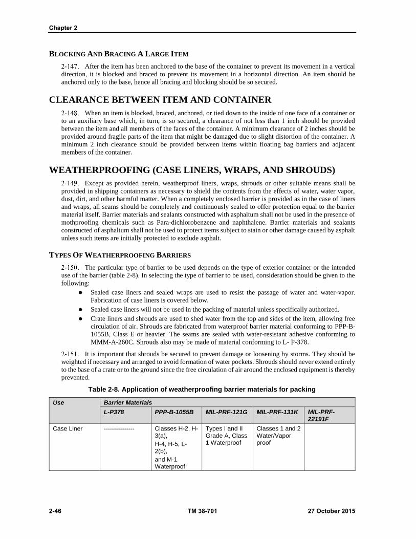
Chapter 2
2-46 TM 38-701 27 October 2015
BLOCKING AND BRACING A LARGE ITEM
After the item has been anchored to the base of the container to prevent its movement in a vertical
direction, it is blocked and braced to prevent its movement in a horizontal direction. An item should be
anchored only to the base, hence all bracing and blocking should be so secured.
CLEARANCE BETWEEN ITEM AND CONTAINER
When an item is blocked, braced, anchored, or tied down to the inside of one face of a container or
to an auxiliary base which, in turn, is so secured, a clearance of not less than 1 inch should be provided
between the item and all members of the faces of the container. A minimum clearance of 2 inches should be
provided around fragile parts of the item that might be damaged due to slight distortion of the container. A
minimum 2 inch clearance should be provided between items within floating bag barriers and adjacent
members of the container.
WEATHERPROOFING (CASE LINERS, WRAPS, AND SHROUDS)
Except as provided herein, weatherproof liners, wraps, shrouds or other suitable means shall be
provided in shipping containers as necessary to shield the contents from the effects of water, water vapor,
dust, dirt, and other harmful matter. When a completely enclosed barrier is provided as in the case of liners
and wraps, all seams should be completely and continuously sealed to offer protection equal to the barrier
material itself. Barrier materials and sealants constructed with asphaltum shall not be used in the presence of
mothproofing chemicals such as Para-dichlorobenzene and naphthalene. Barrier materials and sealants
constructed of asphaltum shall not be used to protect items subject to stain or other damage caused by asphalt
unless such items are initially protected to exclude asphalt.
TYPES OF WEATHERPROOFING BARRIERS
The particular type of barrier to be used depends on the type of exterior container or the intended
use of the barrier (table 2-8). In selecting the type of barrier to be used, consideration should be given to the
following:
Sealed case liners and sealed wraps are used to resist the passage of water and water-vapor.
Fabrication of case liners is covered below.
Sealed case liners will not be used in the packing of material unless specifically authorized.
Crate liners and shrouds are used to shed water from the top and sides of the item, allowing free
circulation of air. Shrouds are fabricated from waterproof barrier material conforming to PPP-B-
1055B, Class E or heavier. The seams are sealed with water-resistant adhesive conforming to
MMM-A-260C. Shrouds also may be made of material conforming to L- P-378.
It is important that shrouds be secured to prevent damage or loosening by storms. They should be
weighted if necessary and arranged to avoid formation of water pockets. Shrouds should never extend entirely
to the base of a crate or to the ground since the free circulation of air around the enclosed equipment is thereby
prevented.
Table 2-8. Application of weatherproofing barrier materials for packing
Use Barrier Materials
L-P378 PPP-B-1055B MIL-PRF-121G MIL-PRF-131K MIL-PRF-22191F
Case Liner --------------- Classes H-2, H-3(a),
H-4, H-5, L-2(b),
and M-1 Waterproof
Types I and II Grade A, Class 1 Waterproof
Classes 1 and 2 Water/Vapor proof
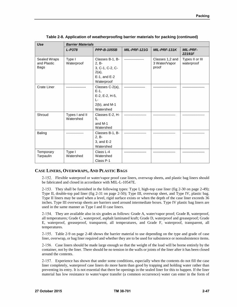
Packing
27 October 2015 TM 38-701 2-47
Table 2-8. Application of weatherproofing barrier materials for packing (continued)
Use Barrier Materials
L-P378 PPP-B-1055B MIL-PRF-121G MIL-PRF-131K MIL-PRF-22191F
Sealed Wraps and Plastic Bags
Type I Waterproof
Classes B-1, B-2, B-
3, C-1, C-2, C-2(a),
E-1, and E-2
Waterproof
----------------- Classes 1,2 and 3 Water/Vapor proof
Types II or III waterproof
Crate Liner ----------------- Classes C-2(a), E-1,
E-2, E-2, H-5, L-
2(b), and M-1
Watershed
------------------ -------------------- -------------------
Shroud Types I and II Watershed
Classes E-2, H-5,
and M-1 Watershed
------------------- ------------------- -------------------
Baling --------------- Classes B-1, B-2, B-
3, and E-2
Watershed
------------------- ------------------- -------------------
Temporary Tarpaulin
Type I Watershed
Class L-4 Watershed
Class P-1
------------------- ------------------- -------------------
CASE LINERS, OVERWRAPS, AND PLASTIC BAGS
Flexible waterproof or water/vapor proof case liners, overwrap sheets, and plastic bag liners should
be fabricated and closed in accordance with MIL-L-10547E.
They shall be furnished in the following types: Type I, high-top case liner (fig 2-30 on page 2-49);
Type II, double-top pad liner (fig 2-31 on page 2-50); Type III, overwrap sheet, and Type IV, plastic bag.
Type II liners may be used when a level, rigid surface exists or when the depth of the case liner exceeds 36
inches. Type III overwrap sheets are barriers used around intermediate boxes. Type IV plastic bag liners are
used in the same manner as Type I and II case liners.
They are available also in six grades as follows: Grade A, water/vapor proof; Grade B, waterproof,
all temperatures; Grade C, waterproof, asphalt laminated kraft; Grade D, waterproof and greaseproof; Grade
E, waterproof, greaseproof, transparent, all temperatures, and Grade F, waterproof, transparent, all
temperatures.
Table 2-9 on page 2-48 shows the barrier material to use depending on the type and grade of case
liner, overwrap, or bag liner required and whether they are to be used for subsistence or nonsubsistence items.
Case liners should be made large enough so that the weight of the load will be borne entirely by the
container, not by the liner. There should be no tension in the walls or joints of the liner after it has been closed
around the contents.
Experience has shown that under some conditions, especially when the contents do not fill the case
liner completely, waterproof case liners do more harm than good by trapping and holding water rather than
preventing its entry. It is not essential that there be openings in the sealed liner for this to happen. If the liner
material has low resistance to water/vapor transfer (a common occurrence) water can enter in the form of

Chapter 2
2-48 TM 38-701 27 October 2015
vapor and condense on items within the liner. At the end of an extended outdoor exposure period, sealed case
liners have been opened and found partially filled with water. When packed items need protection against
water, it is preferable to incorporate the protection in the individual unit packages in lieu of using case liners.
Linings for Drums, Kegs, Barrels, and Bags. Linings should be provided for drums, kegs, barrels, or
bags when their contents require protection not otherwise provided by the containers against sifting,
contamination, or free water. The lining material should conform to PPP-B-1055B or MIL-PRF-22191F.
Fabrication and closure seams should be heat sealed or sealed with adhesive conforming to MMM-A-260C,
as applicable.
WATERPROOF AND WATER/VAPOR PROOF WRAPS
Waterproof and water/vapor proof wraps shall be fabricated and sealed in accordance with MIL-L-
10547E.
UNSEALED WATERPROOF WRAPS
Unsealed waterproof wraps should be applied to shed water while permitting breathing and
circulation of air.
Table 2-9. Barrier materials for case liners, overwraps, and plastic bag liners
Use Liners, overwraps, and bag liner
Specification Barrier materials
Grades Types Classification
Subsistence item C
F
I, II, III
IV
PPP-B-1055B
A-A-3174
Classes H-2 thru H-5, M-1 Type I
Non subsistence
item
A
C
D
E
I, III
I, II, III
I, II
IV
MIL-PRF-131K
PPP-B-1055B
MIL-PRF-121G
MIL-PRF-22191F
Classes 1, 2 and 3
Classes E-1, E-2, H-
1 thru H-5, L-2, M-1
Types I and II,
grade A, class 1
Type II
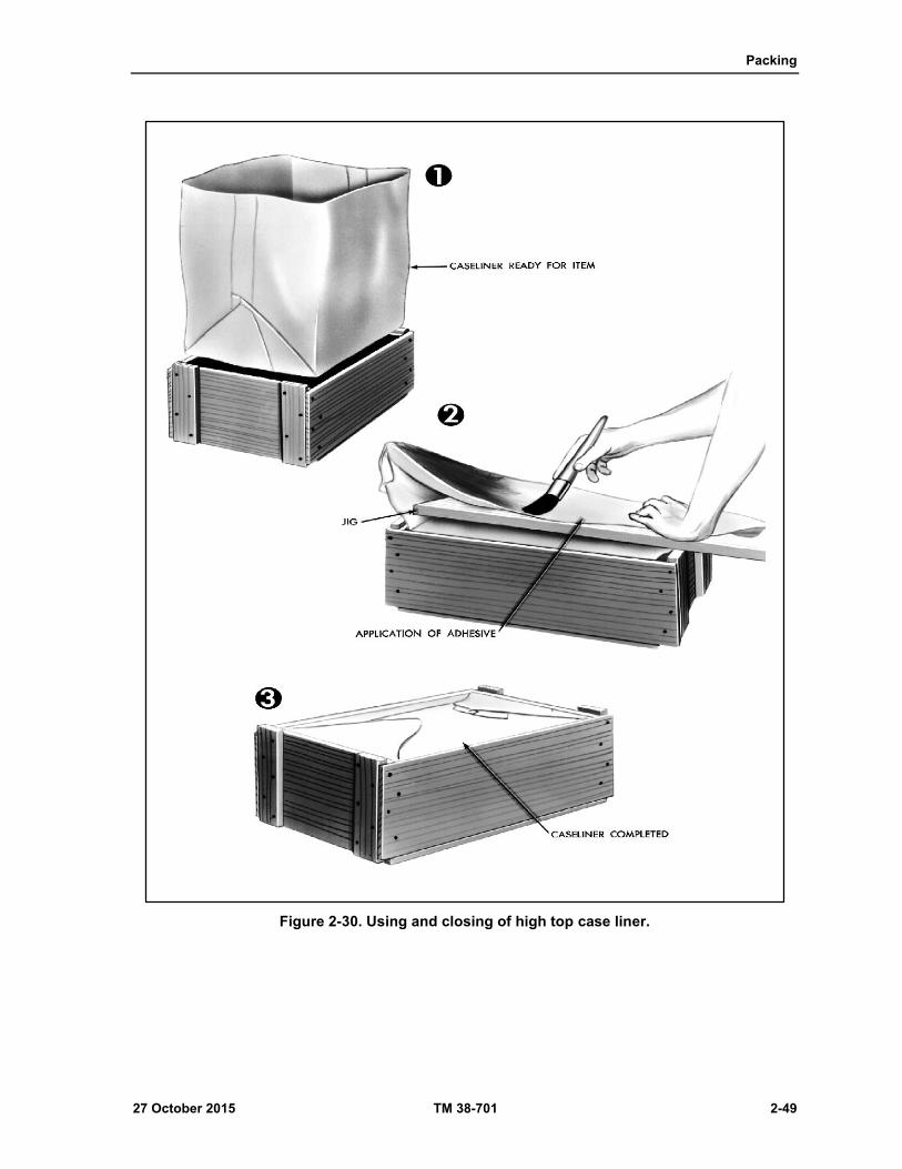
Packing
27 October 2015 TM 38-701 2-49
Figure 2-30. Using and closing of high top case liner.

Chapter 2
2-50 TM 38-701 27 October 2015
Figure 2-31. Double top pad closure case liner.
PURPOSE OF TESTING PACKS
The purpose of testing is to prove the adequacy of packaging design and the workmanship of
fabrication. Testing may be performed in the research and development phase or by tests at the operational
level. Since containers in the storage and shipment cycle are subjected to various and constantly changing
storage and shipping hazards, it is difficult to develop complete data for their design by merely observing the
containers in service. Examinations of failures will reveal the weaknesses and suggest the specific principles
of design to overcome such failures. Since service tests are not performed under controlled conditions,
laboratory tests are necessary to simulate field hazards. Each test is designed to reproduce one or more of the
stresses encountered in the field. During the test cycles the sequence of failures can be observed, classified,
and the weaknesses from which the failures result determined. By means of such tests any number of
containers can, in turn, be subjected to exactly the same actions, thus providing the data necessary to produce
balanced construction and workmanship. On the following pages are described a number of methods that
have been devised for subjecting containers to hazards similar to those encountered in the field. Both

Packing
27 October 2015 TM 38-701 2-51
laboratory and field testing are necessary since there are certain conditions inherent in each method of testing
that cannot be duplicated in the other.
TYPES OF TESTS
Development and testing of packs and containers should be started as soon as possible after initiation
of item development. Some of the tests most commonly used in proving design adequacy include the
vibration, rough handling, and cyclic exposure tests see (fig 2-32 on page 2-52). One or more of these tests
are usually applicable to the design of military packs. In many cases the technical activity having design
responsibility, has intervals tests and procedures that are applicable to a specific design problem. The
documents most generally used for test guidance are MIL- STD-1186. ASTM D 4169, Performance Testing
of Shipping Containers and Systems, and ASTM D 5276, Drop Test of Loaded Containers by Free-Fall,
should be referenced.
TESTING (MIL-STD-2073-1E)
After an item has been packed in accordance with one of the MIL-STD-2073-1E methods, tests are
conducted to determine the effectiveness of the pack. The types of tests conducted will depend on the
particular method used. The tests called for in MIL-STD-2073-1E are not all-inclusive, however, and
additional or different tests are sometimes required. The types of tests specified in MIL-STD-2073-1E for
proving the adequacy of unit protection are the leakage test, rough handling tests, cyclic exposure tests, and
the heat-seal seam tests.
TESTING (MIL-STD-1186)
When packs prepared for shipment in accordance with the detailed requirements of MIL-STD-1186
are tested for any rough handling required, there should be no settlement or shifting of contents. Further, the
testing should cause no damage to the contents and should not loosen, break, or displace the anchoring,
blocking, or bracing. The testing should not render the interior containers, wraps, liners, barriers, or
cushioning ineffectual in providing continued and adequate protection to the contents.
TYPES OF ROUGH HANDLING TESTS
The various types of rough handling tests include: free-fall drop test; cornerwise drop test; pendulum
impact test; incline-impact test; edgewise drop test; vibration test; and others. The particular tests employed
usually depend upon the size and shape of the package. Completed packages as prepared for shipment are
given a rough handling test when specified. When a rough handling test is required, it precedes applicable
tests specified to detect leaks and inadequate seals or closures and preservative retention.
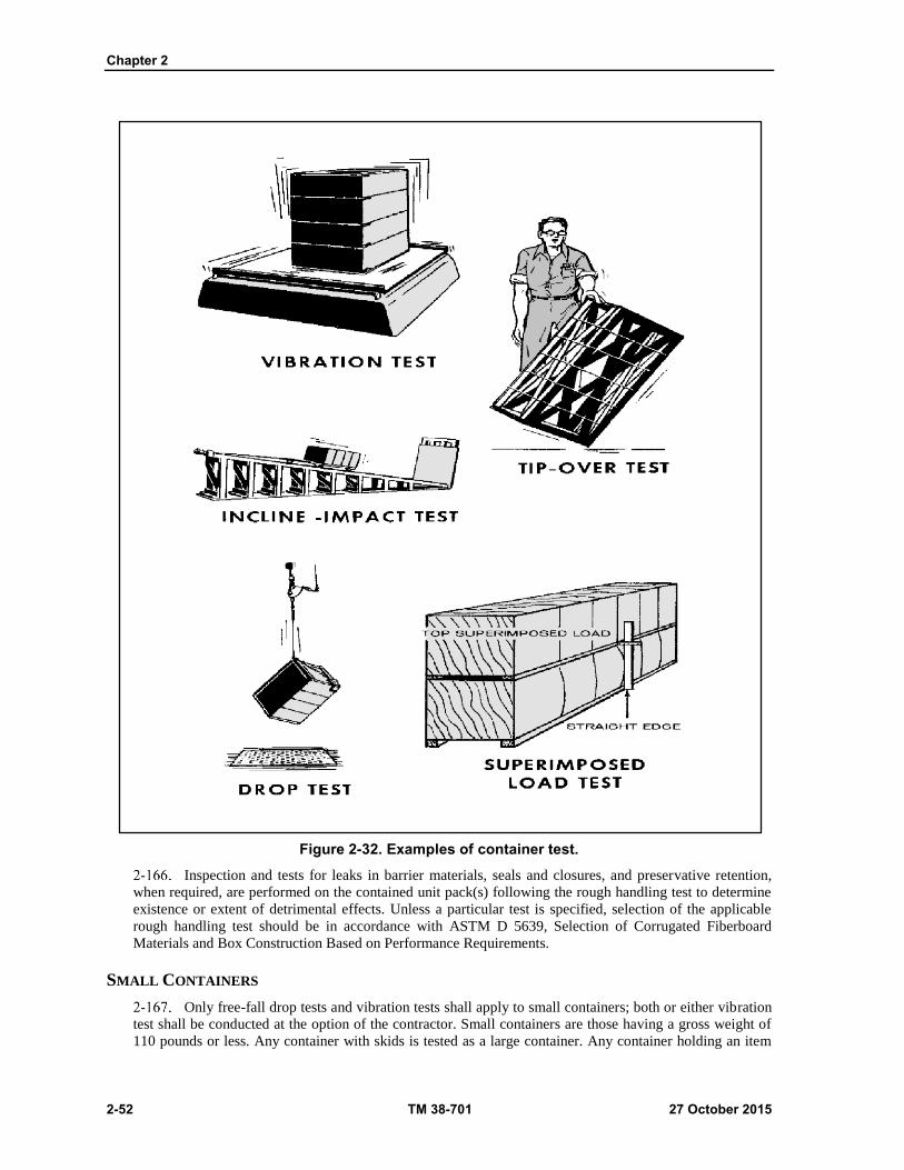
Chapter 2
2-52 TM 38-701 27 October 2015
Figure 2-32. Examples of container test.
Inspection and tests for leaks in barrier materials, seals and closures, and preservative retention,
when required, are performed on the contained unit pack(s) following the rough handling test to determine
existence or extent of detrimental effects. Unless a particular test is specified, selection of the applicable
rough handling test should be in accordance with ASTM D 5639, Selection of Corrugated Fiberboard
Materials and Box Construction Based on Performance Requirements.
SMALL CONTAINERS
Only free-fall drop tests and vibration tests shall apply to small containers; both or either vibration
test shall be conducted at the option of the contractor. Small containers are those having a gross weight of
110 pounds or less. Any container with skids is tested as a large container. Any container holding an item
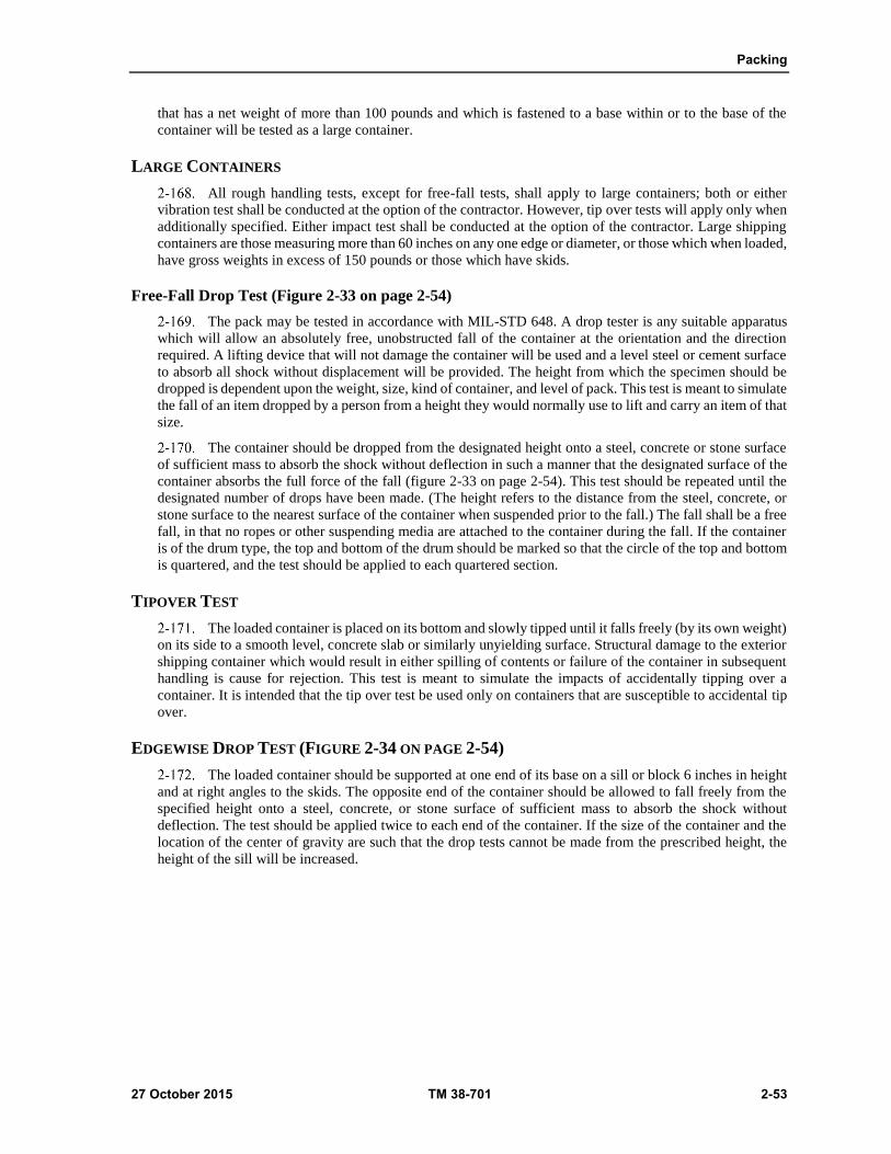
Packing
27 October 2015 TM 38-701 2-53
that has a net weight of more than 100 pounds and which is fastened to a base within or to the base of the
container will be tested as a large container.
LARGE CONTAINERS
All rough handling tests, except for free-fall tests, shall apply to large containers; both or either
vibration test shall be conducted at the option of the contractor. However, tip over tests will apply only when
additionally specified. Either impact test shall be conducted at the option of the contractor. Large shipping
containers are those measuring more than 60 inches on any one edge or diameter, or those which when loaded,
have gross weights in excess of 150 pounds or those which have skids.
Free-Fall Drop Test (Figure 2-33 on page 2-54)
The pack may be tested in accordance with MIL-STD 648. A drop tester is any suitable apparatus
which will allow an absolutely free, unobstructed fall of the container at the orientation and the direction
required. A lifting device that will not damage the container will be used and a level steel or cement surface
to absorb all shock without displacement will be provided. The height from which the specimen should be
dropped is dependent upon the weight, size, kind of container, and level of pack. This test is meant to simulate
the fall of an item dropped by a person from a height they would normally use to lift and carry an item of that
size.
The container should be dropped from the designated height onto a steel, concrete or stone surface
of sufficient mass to absorb the shock without deflection in such a manner that the designated surface of the
container absorbs the full force of the fall (figure 2-33 on page 2-54). This test should be repeated until the
designated number of drops have been made. (The height refers to the distance from the steel, concrete, or
stone surface to the nearest surface of the container when suspended prior to the fall.) The fall shall be a free
fall, in that no ropes or other suspending media are attached to the container during the fall. If the container
is of the drum type, the top and bottom of the drum should be marked so that the circle of the top and bottom
is quartered, and the test should be applied to each quartered section.
TIPOVER TEST
The loaded container is placed on its bottom and slowly tipped until it falls freely (by its own weight)
on its side to a smooth level, concrete slab or similarly unyielding surface. Structural damage to the exterior
shipping container which would result in either spilling of contents or failure of the container in subsequent
handling is cause for rejection. This test is meant to simulate the impacts of accidentally tipping over a
container. It is intended that the tip over test be used only on containers that are susceptible to accidental tip
over.
EDGEWISE DROP TEST (FIGURE 2-34 ON PAGE 2-54)
The loaded container should be supported at one end of its base on a sill or block 6 inches in height
and at right angles to the skids. The opposite end of the container should be allowed to fall freely from the
specified height onto a steel, concrete, or stone surface of sufficient mass to absorb the shock without
deflection. The test should be applied twice to each end of the container. If the size of the container and the
location of the center of gravity are such that the drop tests cannot be made from the prescribed height, the
height of the sill will be increased.

Chapter 2
2-54 TM 38-701 27 October 2015
Figure 2-33. Free fall drop test.
Figure 2-34. Edgewise-drop test.
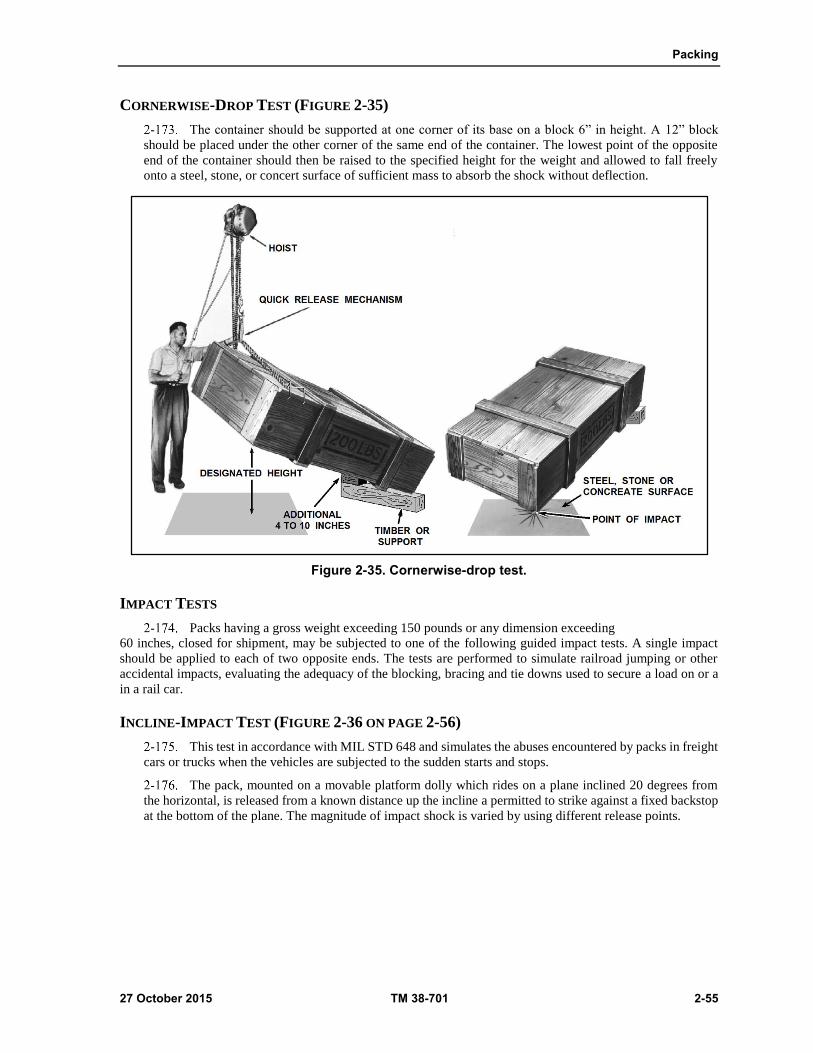
Packing
27 October 2015 TM 38-701 2-55
CORNERWISE-DROP TEST (FIGURE 2-35)
The container should be supported at one corner of its base on a block 6” in height. A 12” block
should be placed under the other corner of the same end of the container. The lowest point of the opposite
end of the container should then be raised to the specified height for the weight and allowed to fall freely
onto a steel, stone, or concert surface of sufficient mass to absorb the shock without deflection.
Figure 2-35. Cornerwise-drop test.
IMPACT TESTS
Packs having a gross weight exceeding 150 pounds or any dimension exceeding
60 inches, closed for shipment, may be subjected to one of the following guided impact tests. A single impact
should be applied to each of two opposite ends. The tests are performed to simulate railroad jumping or other
accidental impacts, evaluating the adequacy of the blocking, bracing and tie downs used to secure a load on or a
in a rail car.
INCLINE-IMPACT TEST (FIGURE 2-36 ON PAGE 2-56)
This test in accordance with MIL STD 648 and simulates the abuses encountered by packs in freight
cars or trucks when the vehicles are subjected to the sudden starts and stops.
The pack, mounted on a movable platform dolly which rides on a plane inclined 20 degrees from
the horizontal, is released from a known distance up the incline a permitted to strike against a fixed backstop
at the bottom of the plane. The magnitude of impact shock is varied by using different release points.
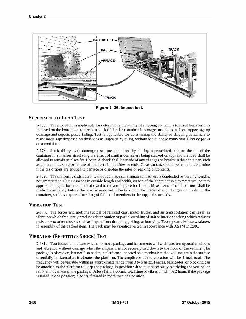
Chapter 2
2-56 TM 38-701 27 October 2015
Figure 2- 36. Impact test.
SUPERIMPOSED-LOAD TEST
The procedure is applicable for determining the ability of shipping containers to resist loads such as
imposed on the bottom container of a stack of similar container in storage, or on a container supporting top
dunnage and superimposed lading. Test is applicable for determining the ability of shipping containers to
resist loads superimposed on their tops as imposed by piling without top dunnage many small, heavy packs
on a container.
Stack-ability, with dunnage tests, are conducted by placing a prescribed load on the top of the
container in a manner simulating the effect of similar containers being stacked on top, and the load shall be
allowed to remain in place for 1 hour. A check shall be made of any changes or breaks in the container, such
as apparent buckling or failure of members in the sides or ends. Observations should be made to determine
if the distortions are enough to damage or dislodge the interior packing or contents.
The uniformly distributed, without dunnage superimposed load test is conducted by placing weights
not greater than 10 x 10 inches in outside length and width, on top of the container in a symmetrical pattern
approximating uniform load and allowed to remain in place for 1 hour. Measurements of distortions shall be
made immediately before the load is removed. Checks should be made of any changes or breaks in the
container, such as apparent buckling of failure of members in the top, sides or ends.
VIBRATION TEST
The forces and motions typical of railroad cars, motor trucks, and air transportation can result in
vibration which frequently produces deterioration or partial crushing of unit or interior packing which reduces
resistance to other shocks, such as impact from dropping, jolting, or bumping. Testing can disclose weakness
in assembly of the packed item. The pack may be vibration tested in accordance with ASTM D 3580.
VIBRATION (REPETITIVE SHOCK) TEST
Test is used to indicate whether or not a package and its contents will withstand transportation shocks
and vibration without damage when the shipment is not securely tied down to the floor of the vehicle. The
package is placed on, but not fastened to, a platform supported on a mechanism that will maintain the surface
essentially horizontal as it vibrates the platform. The amplitude of the vibration will be 1 inch total. The
frequency will be variable within as approximate range from 3 to 5 hertz. Fences, barricades, or blocking can
be attached to the platform to keep the package in position without unnecessarily restricting the vertical or
rational movement of the package. Unless failure occurs, total time of vibration will be 2 hours if the package
is tested in one position; 3 hours if tested in more than one position.
Packing
27 October 2015 TM 38-701 2-57
Vibration (Sinusoidal Motion) Test
Test in accordance with ASTM D 4169 is used to determine the adequacy of packages that contain
items susceptible to damage from vibration encountered during shipping and are tied down to the floor of the
carrier. The package is attached securely to a platform supported on a mechanism that will maintain the
surface essentially horizontal as it vibrates the platform vertically. Controls are provided to vary the
frequency form 2 to 500 hertz as specified. If the package might be shipped in more than one position, the
package will be tested in each position.
SIMULATED CONTENTS
Simulated contents of the same dimensions, weight, center of gravity, and physical properties as the
actual contents may be substituted in the tests described above. A shock-recording instrument of an
acceptable type should be appropriately installed within the shipping containers. This provision is intended
to avoid unnecessary damage or complete destruction of valuable commodities.
INTERPRETATION OF RESULTS
All materials and components shall be free from damage or evidence of displacement which affects
the utility of the pack. When specified, functional tests should be conducted on the items or equipment to
determine freedom from operational malfunction.
MARKING OF PACKS
Marking permits ready identification of military supplies and equipment for shipment and storage.
No matter how well an item is made or packed, it is valueless if it cannot be identified upon reaching its
destination.
ASTM D 996, Environments, Packaging and Distribution, defined marking as "the applications of
numbers, letters, labels, tags, symbols, or colors to provide identification and to expedite handling during
shipment and storage".
MIL-STD-129R Military Marking for Shipment and Storage, provides the minimum requirements
for uniform military marking for shipment and storage. Additional markings may be required by the contract
or the cognizant activity.
All required marking and any additional special marking which may be required depending upon
the item and container being shipped (figure 2-37 on page 2-58) can be found in MIL-STD-129.
ECONOMY IN PACKING
Economy in packing is the responsibility of everyone concerned with military supply. The Secretary
of Defense has established policies on packaging that must be followed. These policies emphasize that the
military services standardize their preservation, packaging, and packing. For example, the services, by using
packaging standards, assure the same requirements for the same type of items, thus reducing the number of
materials, methods, and procedures - whether these requirements are performed by the contractor or by the
depot.
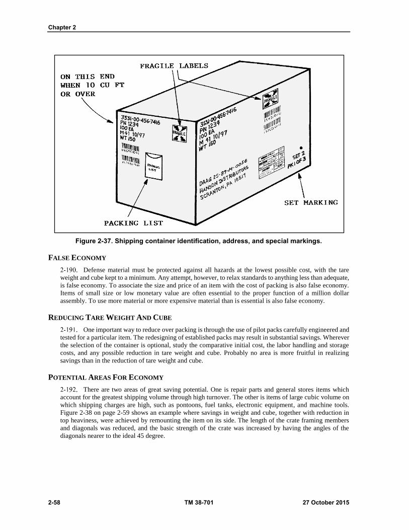
Chapter 2
2-58 TM 38-701 27 October 2015
Figure 2-37. Shipping container identification, address, and special markings.
FALSE ECONOMY
Defense material must be protected against all hazards at the lowest possible cost, with the tare
weight and cube kept to a minimum. Any attempt, however, to relax standards to anything less than adequate,
is false economy. To associate the size and price of an item with the cost of packing is also false economy.
Items of small size or low monetary value are often essential to the proper function of a million dollar
assembly. To use more material or more expensive material than is essential is also false economy.
REDUCING TARE WEIGHT AND CUBE
One important way to reduce over packing is through the use of pilot packs carefully engineered and
tested for a particular item. The redesigning of established packs may result in substantial savings. Wherever
the selection of the container is optional, study the comparative initial cost, the labor handling and storage
costs, and any possible reduction in tare weight and cube. Probably no area is more fruitful in realizing
savings than in the reduction of tare weight and cube.
POTENTIAL AREAS FOR ECONOMY
There are two areas of great saving potential. One is repair parts and general stores items which
account for the greatest shipping volume through high turnover. The other is items of large cubic volume on
which shipping charges are high, such as pontoons, fuel tanks, electronic equipment, and machine tools.
Figure 2-38 on page 2-59 shows an example where savings in weight and cube, together with reduction in
top heaviness, were achieved by remounting the item on its side. The length of the crate framing members
and diagonals was reduced, and the basic strength of the crate was increased by having the angles of the
diagonals nearer to the ideal 45 degree.
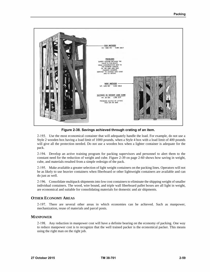
Packing
27 October 2015 TM 38-701 2-59
Figure 2-38. Savings achieved through crating of an item.
Use the most economical container that will adequately handle the load. For example, do not use a
Style 2 wooden box having a load limit of 1000 pounds, when a Style 4 box with a load limit of 400 pounds
will give all the protection needed. Do not use a wooden box when a lighter container is adequate for the
pack.
Develop an active training program for packing supervisors and personnel to alert them to the
constant need for the reduction of weight and cube. Figure 2-39 on page 2-60 shows how saving in weight,
cube, and materials resulted from a simple redesign of the pack.
Make available a greater selection of light weight containers on the packing lines. Operators will not
be as likely to use heavier containers when fiberboard or other lightweight containers are available and can
do just as well.
Consolidate multipack shipments into low cost containers to eliminate the shipping weight of smaller
individual containers. The wood, wire bound, and triple wall fiberboard pallet boxes are all light in weight,
are economical and suitable for consolidating materials for domestic and air shipments.
OTHER ECONOMY AREAS
There are several other areas in which economies can be achieved. Such as manpower,
mechanization, reuse of materials and parcel posts.
MANPOWER
Any reduction in manpower cost will have a definite bearing on the economy of packing. One way
to reduce manpower cost is to recognize that the well trained packer is the economical packer. This means
using the right man on the right job.

Chapter 2
2-60 TM 38-701 27 October 2015
MECHANIZATION
Savings of considerable importance can be derived from the proper use of mechanization. Powered
conveyor belts, mechanized handling systems, and automatic packing machinery, all help to reduce handling
and speed up operations.
REUSE OF MATERIALS
Another field in which savings can be effected is through the salvage and reuse of materials. Lumber,
cushioning, blocking and bracing materials, containers, and metal fasteners can be reused with a little careful
planning see (fig 2-40 on page 2-61).
PARCEL POST
One other area for achieving savings is the more efficient use of parcel post. Frequently, parcel post
reduces the need for documentation, allows a lowering of the level of protection, cuts down on marking
requirements, and permits faster delivery. Remember, to obtain the maximum value for each Defense dollar,
one must be awake to every new idea that may lead to the reduction in packing costs.
Figure 2-39. Savings achieved by redesigning a container.
PARCEL POST REQUIREMENTS
The following are the Military requirements for parcel post shipments.
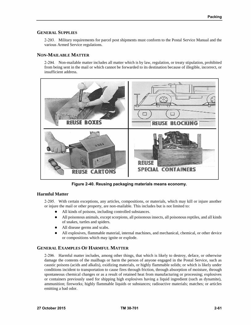
Packing
27 October 2015 TM 38-701 2-61
GENERAL SUPPLIES
Military requirements for parcel post shipments must conform to the Postal Service Manual and the
various Armed Service regulations.
NON-MAILABLE MATTER
Non-mailable matter includes all matter which is by law, regulation, or treaty stipulation, prohibited
from being sent in the mail or which cannot be forwarded to its destination because of illegible, incorrect, or
insufficient address.
Figure 2-40. Reusing packaging materials means economy.
Harmful Matter
With certain exceptions, any articles, compositions, or materials, which may kill or injure another
or injure the mail or other property, are non-mailable. This includes but is not limited to:
All kinds of poisons, including controlled substances.
All poisonous animals, except scorpions, all poisonous insects, all poisonous reptiles, and all kinds
of snakes, turtles and spiders.
All disease germs and scabs.
All explosives, flammable material, internal machines, and mechanical, chemical, or other device
or compositions which may ignite or explode.
GENERAL EXAMPLES OF HARMFUL MATTER
Harmful matter includes, among other things, that which is likely to destroy, deface, or otherwise
damage the contents of the mailbags or harm the person of anyone engaged in the Postal Service, such as
caustic poisons (acids and alkalis), oxidizing materials, or highly flammable solids; or which is likely under
conditions incident to transportation to cause fires through friction, through absorption of moisture, through
spontaneous chemical changes or as a result of retained heat from manufacturing or processing; explosives
or containers previously used for shipping high explosives having a liquid ingredient (such as dynamite),
ammunition; fireworks; highly flammable liquids or substances; radioactive materials; matches; or articles
emitting a bad odor.
Chapter 2
2-62 TM 38-701 27 October 2015
HARMFUL MATTER REQUIREMENTS
Harmful items should not be shipped parcel post without prior approval of the Postal Service.
Whenever there is doubt about the mail ability of a particular item, a request for a ruling should be made to
the local postmaster. Mail ability rulings may also be obtained from a nearby mail classification center or
from the Office of Mail Classification, US Postal Service, Washington DC 20260.
TYPES OF SHIPPING CONTAINERS
Postal regulations require containers strong enough to retain and protect their contents from the
weight of other mail.
Common Containers Used
The following containers, with applicable specification are most commonly used, depending on size,
weight, and nature of the article(s): Cotton Mailing Bags; Burlap Cotton and Waterproof Laminated Textile
Shipping Bags (A-A-881C); Folding Boxes (PPP-B-566E); Fiberboard Boxes (ASTM D5118) and Cans,
Fiber, Spirally-wound.
Mailbags
Mailbags may be used as containers for consolidated shipments of unbreakable or nonfragile items
going to the same location, provided projections are cushioned to prevent rupture of the bag during shipment.
Use of one of the three available sizes of mailbag should be based on volume of material going to individual
customers.
Used Containers
Used containers in good rigid condition with all flaps intact are acceptable. If a container of desired
size cannot be found, a large one may be cut down to meet the needs.
Size And Weight Of Container
The shipping containers must be of the proper size to accommodate the item(s) being shipped.
Sufficient space for cushioning material should be allowed at the time of container selection, avoiding both
the under packing and over packing of the item and remaining within the weight limitations. The size and
weight of packages mailed at most post offices is limited to 108 inches, length and girth combined, and 70
pounds.
Measurement
Compute the size of a parcel as follows see(Fig 2-41 on page 2-63):
Measure the longest side.
Measure the distance around the parcel at its thickest part (girth).
Add both measurements.
Some military post offices overseas have more restrictive size and weight requirements. The weight
of an addressed piece of parcel post must be 16 ounces or more.
Reusable Containers
The use of reusable containers may be determined by considering the following factors:
When the military characteristics of the item are such that a reusable type container is necessary.
When the container can serve a dual purpose of shipping container and case while the item is in
use. When the item is designated as recoverable-repairable item.
The cost of a reusable container is offset by multiple use as compared to the cost of single trip,
disposable containers.

Packing
27 October 2015 TM 38-701 2-63
When the cost of the item and/or its critical characteristics, or the need for periodic inspection or
exercising justifies the use of a reusable container.
Reusable drums with protruding closure devices, such as locking rings, shall be cushioned to prevent
injury to postal employees, equipment or other mail.
Outside Wrapping And Closure
When a box itself is an adequate shipping container, paper wraps should be omitted. If a paper wrap
is used as an outside cover for boxes, the paper should have at least 60 pounds basis weight. Closure and
reinforcement should be made by the use of tape.
Closure and reinforcement is accomplished by using gummed and pressure- sensitive tapes,
adhesive, strapping, and staples for boxes and bags. Various friction closures, screw caps and locking devices
for cans and similar containers. General purpose transparent mending tape and masking tape shall not be used
for closure or reinforcement, but may be used to augment adhesive closure on envelopes or to cover staples
on bags. Pressure sensitive filament reinforced tape or reinforced paper tape is recommended for closure and
reinforcement. Except for pressure sensitive filament tape, tapes used for closure and reinforcement shall be
not less than 2 inches wide.
When strapping is used for closure and reinforcement, it should encircle the length and girth of the
package at least once. Twine and cord should not be used. Loose strapping is not acceptable because it
presents a hazard to employees and equipment and does not reinforce the container.
Figure 2-41. Post office measurement requirements.
Marking of parcels and United States (U.S.) Mailbags
Parcels shall be marked to show the consignor; consignee; Transportation Control Number and
required delivery date, project code, and mark for, when specified.
Marking of U.S. mailbags shipped both domestically and overseas should be tagged in the space
located on the locking device to prevent possible opening in transit. Suggested wording of the tag is
"OFFICIAL MAIL FOR ORGANIZATION OF ADDRESS. DO NOT OPEN IN TRANSIT."
In addition to the postage tag located on the locking device of the mailing bag, an additional tag will
be attached. The tag will notify the local postal authorities that the bag is to be delivered intact to its
destination and will contain the complete address to which the bag is destined and the return address.

This page intentionally left blank.
27 October 2015 TM 38-701 3-1
Chapter 3
Wooden Containers and Pallets
CONTAINER MATERIALS
WOOD AS A CONTAINER MATERIAL
3-1. Wood is particularly valuable as a container material because of its high strength-weight ratio which
compares favorably with mild steel. Tests and experience have shown that the strength of a wooden container
depends largely upon the type of wood used in its construction. The durability of wood and its ability to
withstand shock and impact stresses are important properties in the selection of wood for containers. Military
Handbook MIL-HDBK-7B, "Lumber and Allied Products", provides a ready source of information on wood
products normally procured in considerable quantity for Department of Defense installations. This handbook
is not intended for reference in purchase specifications or other contractual documents. However, it will assist
materially with installation requisitioning, receiving, inspection, storage, and handling of container wood
materials. Also see ASTM D 6199, Quality of Wood Members for Containers and Pallets.
Wood Groups
3-2. All woods fall into two general categories: Either softwoods, which come from coniferous or needle-
bearing trees; or hardwoods, which come from broad- leafed trees. For purposes of container construction,
wood is divided into four groups based on nail holding power, tendency to split, comparative strength as a
beam, and shock resisting capacity (fig 3-1 on page 3-2). Over 90 percent of all wooden containers are made
from Group I and II woods however, the materials given in Section 3 of the applicable container specification
must be used. When a wood group is specified in the contract, any species in that group may be selected.
Group I
3-3. Includes the softer woods such as white fir, ponderosa pine, yellow poplar, cottonwood, cedar, and
others. These woods are relatively free from splitting when being nailed, have a moderate nail-holding power,
moderate strength as a beam, and moderate shock resisting capacity.
Group II
3-4. Includes the harder soft woods such as Douglas fir, southern pine, hemlock, and larch. They have
greater nail-holding power than the Group I woods, as well as greater strength and shock resisting capacity.
Group II woods are more inclined to split, the grain often deflects nails and causes them to run out at the side
of the piece.
Group III
3-5. Includes the medium density hardwoods. Ash, elm, and cherry are examples. These are similar to
Group II woods in nail-holding power and strength as a beam, but have less tendency to split and shatter
under impact.

Chapter 3
3-2 TM 38-701 27 October 2015
Figure 3-1. Characteristics for the classifications of wood.
Group IV
3-6. Includes the true hardwoods such as oak, hard maple, and hickory. These woods have the greatest
shock resistance and nail-holding power, are extremely strong, but are very susceptible to splitting. They are
the heaviest and hardest woods, and are difficult to work.
Wood Defects
3-7. All boards should be cut to the correct length and be free from all defects that materially weaken them,
expose the contents of the box to damage, or interfere with the prescribed fabrication or nailing (fig 3-2 on
page 3-3).
Knots.
3-8. Knots in wood are most weakening when located in the middle third of the length of the board. Across
the width of the board, the weakening effect is proportional to the effective diameter of the knots, measured
as shown in (fig 3-3 on page 3-4). No knot, or series of knots across the face of the board, within a length
equal to the width of the board, shall have a diameter or sum of diameters greater than one third the width of
the board. No knot will exceed 4 inches when measured across the width of the board.
Slope of grain.
3-9. Any board with a slope of grain steeper than a ratio of 1 in 10 of length is not permissible. (Fig3-2 on
page 3-3) shows the results of excessive slope or cross grain.
Moisture Content
3-10. It is important that the moisture content of lumber required by an applicable container specification be
followed. High moisture content in lumber will cause excessive tare weight. Shrinkage, due to the loss of
high moisture content in the boards of a nailed wood box will cause gaps between the pieces of lumber.
Shrinkage will also cause the loss of nail holding-power, splitting of the lumber at the nails, and the loosening
of straps. Moisture content is determined by the use of electric moisture meters.

Wooden Containers and Pallets
27 October 2015 TM 38-701 3-3
Moisture Meter Method
3-11. The moisture meter method is faster than the oven dry method, but less accurate. A moisture meter
consists essentially of an electrical device designed to measure the resistance or the capacitance of the wood
between two electrodes in contact with the sample. The values obtained will vary with the water content of
the wood. They will also vary as a result of a number of other factors, most important of which are they
temperature of the wood, its species, and density. Although correction tables are furnished with each
instrument which must be used for even approximations of true values, the readings obtained are still only
approximations because the effect of the other variables cannot be determined with scientific accuracy.
Instruments of this type cannot be used where an accuracy of plus or minus 1 percent is required. In view of
this, the moisture meter method is primarily usable for screening inspections of large lots of lumber, while
the oven dry method is almost always resorted to in the event of disputes. The meter used should be capable
of giving instantaneous readings of moisture content within a range of 7 to 20 percent, and should be equipped
with correction tables to permit the correction of meter readings for temperature, species, and density. The
meter should be adjusted prior to use in accordance with the manufacturer's instructions. When a series of
readings are being made, the adjustment should be checked periodically. Batteries should be replaced
whenever initial adjustment cannot be accomplished, or whenever it is obvious that inaccurate readings are
being obtained because of weak batteries. The following general precautions should be observed:
Figure 3-2. Wood defects.
The entire area of plate-type electrodes should be in contact with the wood. Do not use this type
of electrode on rough wood.
Drive the needle-type electrodes to their full depth and in such a manner that the flow of current
will be parallel to the wood grain. When wood splitting occurs discard the reading obtained. Where
the wood is over one inch thick, drive 1 1/4 to 1 1/2 inch nails, spaced the same distance apart as
the electrodes, straight into the wood to a depth equal to approximately one-fifth the thickness of
the piece. These nails must not be cement coated but may be either bright or chemically etched.
Never use the meter on wood whose surface is wet with rain, dew, or fog.
Never use the meter on the ends of a piece.
Never use the meter on a painted or otherwise finished piece.
Never use the meter on composite pieces where the current between the two electrodes will have
to pass through a glue joint.
Do not use the meter on a piece just removed from the kiln since the temperatures correction tables
(which are concerned with the temperature of the piece) will not be applicable.
On thin pieces, do not support the piece on another piece of lumber, metal, or other material which
may give false electrical readings.

Chapter 3
3-4 TM 38-701 27 October 2015
Figure 3-3. Measuring knot diameters.
Oven Dry Method
3-12. Use a drying oven capable of maintaining a constant temperature of 212°F. To 221°F and a scale that
is accurate to within one-half of 1 percent. To determine the moisture content, use the following procedure:
Cut off a least the first 12 inches of the piece in order to avoid the effects of end drying.
As soon as possible, cut off a piece approximately 1 inch the full thickness by the full width of the
piece.
Immediately after sawing, remove all loose splinters and determine the weight before drying (W).
Place the wood in the hot oven and leave overnight. The next day, weigh the specimen and replace
in the oven. Repeat at 2-hour intervals until the weight is the same at the end of two successive 2-
hour periods. This will occur after approximately 24 hours. If more than one, specimen must be
open-piled in the oven to allow free access of air to all parts of the pieces.
The final weight of the piece immediately after removal from the oven is (D), the oven dry weight.
Calculate the percentage of moisture content by using the following formula:
(W-D) / (W) X 100 = % Moisture
OTHER MATERIAL SKIDS USED IN CONTAINER CONSTRUCTION
3-13. The following additional materials are used in container construction as applicable.
Nails (Astm F 1667-05)
3-14. These may be box, corker, sinker, cooler, or common nails. Sinker and cooler nails are relatively
slender, can be driven into denser woods and withstand shocks well. The heads do not break off or pull
through the wood easily see (fig 3-4) on page 3-6. The resistance of nails to withdrawal varies with a number
of factors such as the hardness or density of the wood, surface condition of the nails and the shape and form
of nails. Dense woods hold nails much better than soft woods. To get the same nail strength with softer
woods, more nails or larger nails are required. The use of chemically etched or coated nails is particularly
important with soft woods. Resistance of nails to withdrawal also varies with the area of contact of the nail
with the wood, increasing directly with the diameter of the nail and the depth of penetration. Nails may be
subjected to forces which withdraw them directly, that is, in the direction of their length, or to forces which
displace them laterally. Nails offer greater resistance to lateral displacement than to direct withdrawal.
Cement coating or etching increases the resistance of nails in direct withdrawal more than in lateral
withdrawal, since the nail shank is distorted in lateral withdrawal about the same, whether coated or uncoated.
Etched nail surfaces have certain advantages over cement coated surfaces. The effect of etching in increasing
withdrawal resistance is relatively permanent, while cement coatings deteriorate a few months after nailing.
Etched nails are effective with woods of all densities, while cement coatings tend to rub off when nails are
driven into dense woods. Here is a simple procedure for etching nails. Prepare a 10 percent solution (by
weight) of commercial mono ammonium phosphate in water. Do not use metal container for preparing or
storing the solution. Keep the solution near room temperature (about 68 degrees Fahrenheit). Immerse the
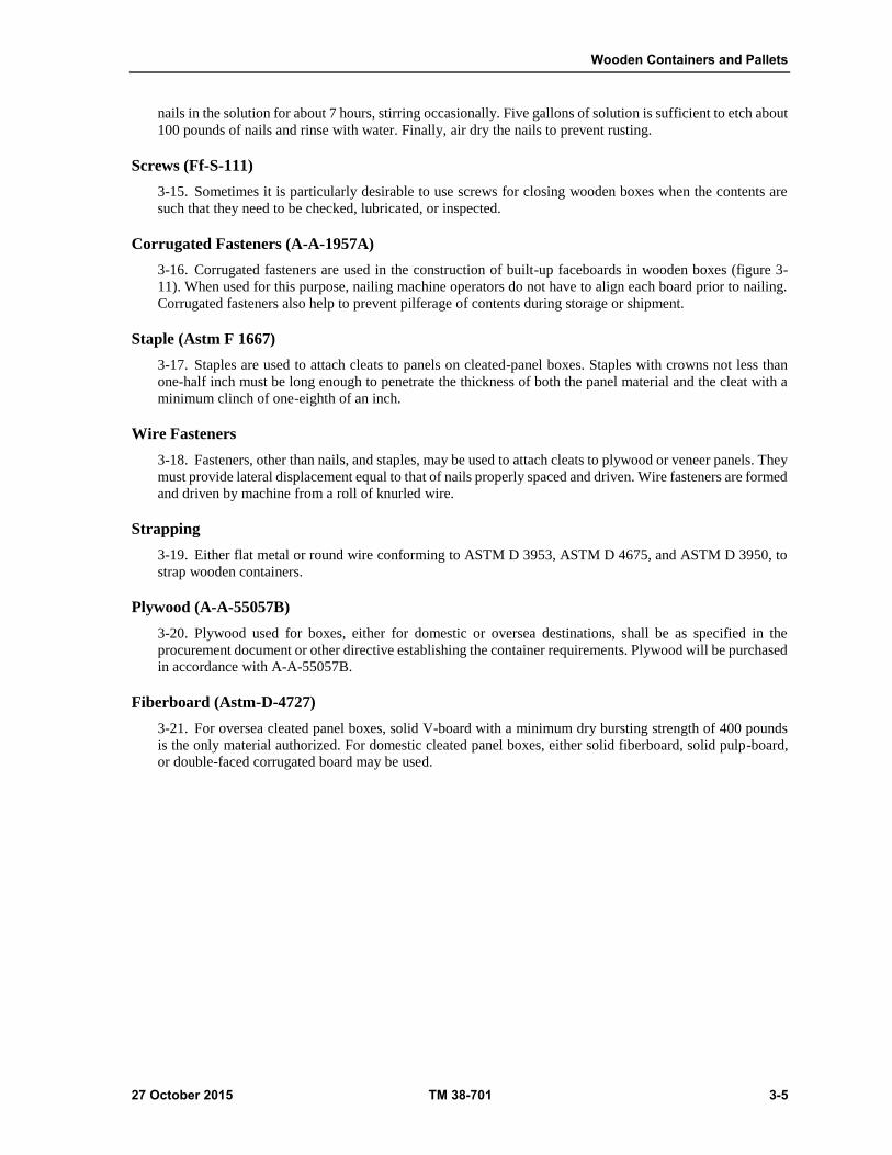
Wooden Containers and Pallets
27 October 2015 TM 38-701 3-5
nails in the solution for about 7 hours, stirring occasionally. Five gallons of solution is sufficient to etch about
100 pounds of nails and rinse with water. Finally, air dry the nails to prevent rusting.
Screws (Ff-S-111)
3-15. Sometimes it is particularly desirable to use screws for closing wooden boxes when the contents are
such that they need to be checked, lubricated, or inspected.
Corrugated Fasteners (A-A-1957A)
3-16. Corrugated fasteners are used in the construction of built-up faceboards in wooden boxes (figure 3-
11). When used for this purpose, nailing machine operators do not have to align each board prior to nailing.
Corrugated fasteners also help to prevent pilferage of contents during storage or shipment.
Staple (Astm F 1667)
3-17. Staples are used to attach cleats to panels on cleated-panel boxes. Staples with crowns not less than
one-half inch must be long enough to penetrate the thickness of both the panel material and the cleat with a
minimum clinch of one-eighth of an inch.
Wire Fasteners
3-18. Fasteners, other than nails, and staples, may be used to attach cleats to plywood or veneer panels. They
must provide lateral displacement equal to that of nails properly spaced and driven. Wire fasteners are formed
and driven by machine from a roll of knurled wire.
Strapping
3-19. Either flat metal or round wire conforming to ASTM D 3953, ASTM D 4675, and ASTM D 3950, to
strap wooden containers.
Plywood (A-A-55057B)
3-20. Plywood used for boxes, either for domestic or oversea destinations, shall be as specified in the
procurement document or other directive establishing the container requirements. Plywood will be purchased
in accordance with A-A-55057B.
Fiberboard (Astm-D-4727)
3-21. For oversea cleated panel boxes, solid V-board with a minimum dry bursting strength of 400 pounds
is the only material authorized. For domestic cleated panel boxes, either solid fiberboard, solid pulp-board,
or double-faced corrugated board may be used.

Chapter 3
3-6 TM 38-701 27 October 2015
Figure 3-4. Nails.
Paper Overlaid Veneer
3-22. This material, made of thin veneer covered on both faces with heavy kraft paper, is used as panelling
material for paper overlaid veneer boxes, conforming to ASTM-D-6251.
NAILED AND LOCK-CORNER WOOD BOXES (ASTM-D-6880M)
3-23. The nailed wood box is constructed of wood, assembled by fastening the top, sides, and bottom to the
ends with nails, or by gluing the lock-corners of the sides and ends and fastening them to the top and bottom
with nails. The placement of cleats on the ends or the lack of cleats determines the style of box. Nailed wood
boxes will not be used if fiberboard or less expensive light- weight boxes will provide adequate protection
for shipment and storage.
CHARACTERISTICS
3-24. Nailed wood boxes are satisfactory shipping containers for supplies and equipment, especially for
items that are susceptible to damage. These containers have the following favorable and unfavorable
characteristics.
Favorable characteristics.
Maximum protection to contents against damage due to puncture, distortion, and breakage.
Ability to support loads due to stacking during transit and storage.
Ability to contain difficult loads without undue distortion.
Adaptability to complex wood blocking and bracing.

Wooden Containers and Pallets
27 October 2015 TM 38-701 3-7
Adaptability to varying strengths by adjusting the style of box, thickness of materials, and group
of wood.
Easy workability and simple construction.
Unfavorable characteristics.
High tare weight and cube.
Not watertight.
Tendency to crack.
Class and Grades (Fig 3-5)
3-25. The classes of nailed wood boxes are--
Class 1
3-26. Domestic boxes. These boxes are subject to storage, re-handling, or shipment to domestic destinations
in which no sea transportation is involved. Net weight is limited to a maximum of 600 pounds (see tables 3-
1 and 3-2 on page 3-12 and 3-13).
Class 2
3-27. Oversea boxes. These boxes are subject to storage, re-handling, or reshipment to offshore and oversea
destinations. Net weight is limited to a maximum of 1,000 pounds. Class 2 boxes (all styles) shall be furnished
in the following grades, as specified. When no grade is specified in the contract, purchase order, or other
procurement document, Grade B shall be supplied (see tables 3-3 and 3-4 shown on page 3-14 and 3-15).
Grade A--With preservative treatment.
Grade B--Without preservative treatment.
Styles and Limitations
3-28. CLASS 1 and 2 boxes are described simultaneously, as applicable, in the coverage of the box styles.
Styles 1, 2, 2 1/2, 4, 4 1/2, 5, 6, and 7 are permitted for Class 1 (domestic) and Styles 2, 2 1/2, 4, 4 1/2, 5, and
7 are permitted for Class 2 (oversea) shipments. Weight limitations for each class, as applicable, are given
under the description of each style of box.
Style 1 Box (Fig 3-6)
3-29. Style 1 box is identified by lack of cleats on the end faceboards and single line nailing of sides to ends,
and of top and bottom to ends and sides. Style 1 box is intended for domestic shipments only. It is restricted
to Type 1 and 2 loads. Style 1 box may not exceed a load limit of 50 pounds for two-piece sides and 100
pounds for one-piece sides. Direction of the grain on Style 1 box must run in the direction of the greatest
dimension. This box is limited to a height of 10 inches and total dimensions (length, width, and depth) of 50
inches.
Figure 3-5. Classes of nailed wood boxes.

Chapter 3
3-8 TM 38-701 27 October 2015
Style 2 Box (Fig 3-6)
3-30. Style 2 box is identified by two vertical and two horizontal cleats on each end. Vertical cleats are
positioned at right angles to the grain of the end. They are one-eighth of an inch shorter than the edge of the
end at the top and bottom. Horizontal cleats, which are placed parallel to the grain of end, are butt-joined to
the vertical cleats and are flush with the top and bottom edges of the box. The top, bottom, and sides extend
over the ends and cleats and are nailed in a staggered pattern. Thus, there is some side-grain nailing on all
edges. The cleat pattern provides ease of handling. Weight limitation for Style 2, Class 1 box (domestic) is
600 pounds. Weight limitation for Style 2, Class 2 (oversea) box is 1,000 pounds.
Figure 3-6. Styles of nailed woods boxes.
Style 2 1/2 box (fig. 3-6)
3-31. Style 2 1/2 box is identified by two vertical notched cleats and two horizontal cleats on each end. It
has the same advantages as the Style 2 box but is slightly higher in cost. Vertical cleats are notched
approximately one-fourth to three-eighths inch to support the horizontal cleats. Vertical cleats are positioned
one-eighth inch above the bottom edge of the end. Weight limitation for Style 2 1/2, Class 1 box (domestic)
is 600 pounds. Weight limitation for Style 2 1/2, Class 2 box (oversea) is 1,000 pounds.
Style 4 Box (Fig 3-7)
3-32. Style 4 box is identified by two vertical cleats on each end. Vertical cleats, which are positioned at
right angles to the grain of the end, are one-eighth inch shorter than the outside surfaces of the top and bottom
of the box. The top and bottom cover the sides. They fit between the cleats and are attached to the ends by
straight-line, side-grain nailing. The sides overlap the ends and cleats, providing for a staggered nailing
pattern. Weight limitation for Style 4, Class 1 box (domestic) is 250 pounds. Weight limitation for Style 4,
Class 2 box (oversea) is 400 pounds. See (fig 3-7 on page 3-10).
Style 4 1/2 Box (Fig 3-7)
3-33. Style 4 1/2 box is identified by two horizontal end cleats. Horizontal cleats, which are positioned at
right angles to the grain of the end, are one-eighth inch shorter than the outside surface of the sides. The sides
extend over the ends, and provide for straight-line, side-grain nailing. The top and bottom extend over the
ends and cleats, and provide for both side- and end-grain nailing. Weight limitations for both classes of boxes
are the same as for Style 4 boxes.

Wooden Containers and Pallets
27 October 2015 TM 38-701 3-9
Style 5 Box (Fig 3-7)
3-34. Style 5 box is identified by interior vertical cleats. The cleats extend to within one-eight inch from the
top and bottom edges of the end of the box. Other than the placement of cleats, construction and nailing
pattern for this container is the same as for Style 4 box. The interior cleats may be rectangular or triangular,
provided the cross section area of the triangular cleat is not less than that of the required rectangular cleat.
Weight limitation for Style 5, Class 1 box (domestic) is 250 pounds. Weight limitation for Style5, Class 2
box (oversea) is 400 pounds.
Style 6 Box (Fig 3-7)
3-35. Style 6 box is identified by the lock corner construction which is glued. This box has about the same
advantages and disadvantages as Style 1 box. Style 6 box is intended for domestic shipments only and Type
1 and 2 loads. This box has a weight limitation of 50 pounds, but may go to 100 pounds if the box has one-
piece sides.
Style 7 Box (Fig 3-8 on page 3-10)
3-36. Style 7 box is an internally reinforced box consisting of a skidded base with a separate hood assembled
from the top, sides and ends. Style 7 boxes are for contents ranging from 100 to 1,000 pounds. The contents
must readily permit attachment to the skids. The base is assembled to 2 X 4 inch skids to facilitate mounting
to a skid base. The skids are positioned across the extreme ends of the bottom pieces to permit attachment of
all end pieces to the skid edges. Vertical and horizontal framing members and reinforcing members in the
form of a rectangle, and cross diagonals, as applicable, are attached to the interior surfaces of the prefabricated
box panels. Framing members are required when contents exceeds 250 pounds or when side length is greater
than end length.
3-37. End panels are identified by vertical sheathing which extends within one- eighth of an inch of each
skid bottom. The hood assembly is placed over the item mounted to the base, then nailing and strapping is
accomplished. Style 7 boxes are intended for both Class 1 and Class 2 use.
Shallow Box (Fig 3-9)
3-38. When the inside depth of a box is five inches or less, cleats are not used. If cleats were applied to
shallow boxes, they would be so small that in attaching them to the ends they would split. The end of the box
may be made of one piece, or if the end is approximately square, it may be made of two pieces placed so that
the grain runs in opposite directions. For Style 2, 2 1/2, 3, 4, and 4 1/2 boxes, the thickness of the ends shall
be not less than the combined thickness of the end and cleat, as specified. Slides overlap the ends. Top and
bottom overlap the sides and ends. Top, bottom, and sides are attached to the ends by staggered nailing.
Weight limitation is 1,000 pounds for oversea shipments. See (fig 3-9 on page 3-11) for example
Construction Details
3-39. When nailed wood boxes are built locally, use the following information for constructing and closing
the various styles. If purchased and received in shook form, the sides, top, and bottom will be ready to be
attached to the constructed ends. Figure 3-10 on page 3-11 shows the amount of acceptable splitting allowed
in the component parts.

Chapter 3
3-10 TM 38-701 27 October 2015
Figure 3-7. Styles of nailed wood boxes.
Figure 3-8. Style 7 nailed wood box.

Wooden Containers and Pallets
27 October 2015 TM 38-701 3-11
Figure 3-9. Shallow boxes.
Figure 3-10. Split board rules

Chapter 3
3-12 TM 38-701 27 October 2015
Construction of Built-Up Faceboard Pieces (Fig 3-11)
3-40. The number of pieces in any side, top, bottom, or end will be chosen so that no single solid piece or
built-up piece shall be less than 2 1/2 inches in width measured across the face, and will not exceed the
number given in (table 3-5 on page 3-15). Built-up face-board pieces may be constructed according to the
following conditions:
The Linderman joint when glued.
Butt joints glued under pressure.
Tongued and grooved joints glued under pressure.
Tongued and grooved joints glued with two or more corrugated fasteners driven from one side.
Tongued and grooved unglued joints with two or more corrugated fasteners driven from alternate
sides.
Figure 3-11. Joined pieces of lumber.
Table 3-1. Boxes for domestic shipment, type 1 (easy) and type 2 (average) loads; thickness of sides, tops, bottoms, and ends, and thickness and width of cleats.
Weight of contents Style
Of
Box6
Groups I and II woods1 Groups III and IV woods2
Exceeding Not
exceeding
Thickness of sides, tops. and bottoms
Thickness of ends
Thickness and width of cleats
Thickness of sides, tops. and bottoms
Thickness of ends
Thickness and width of cleats3
Pounds Pounds Inch Inch Inches Inch inch Inches
-- 50 1 3/8 1/2 -- 1/4 1/2 --
-- 50 4,4-1/2,5 3/8 1/2 1/2 by 2 1/4 1/2 1/2 by 1-3/4
-- 50 2 3/8 3/8 3/8 by 2 1/4 3/8 3/8 by 1-3/4
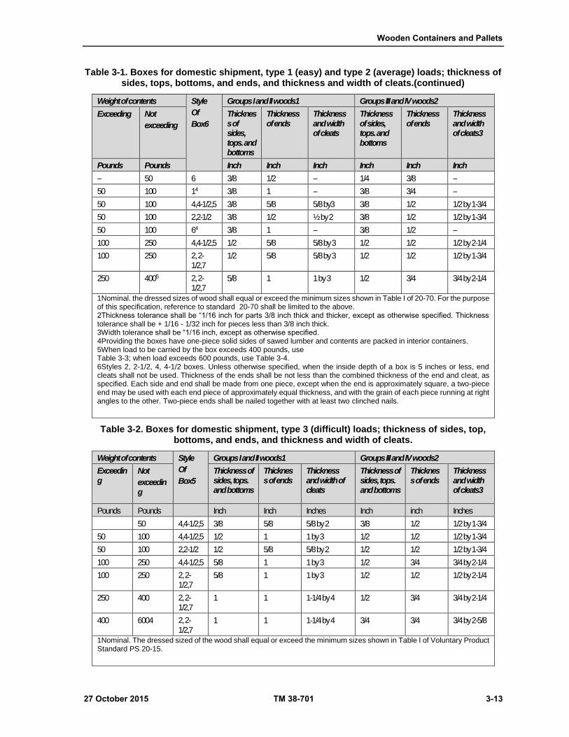
Wooden Containers and Pallets
27 October 2015 TM 38-701 3-13
Table 3-1. Boxes for domestic shipment, type 1 (easy) and type 2 (average) loads; thickness of sides, tops, bottoms, and ends, and thickness and width of cleats.(continued)
Weight of contents Style
Of
Box6
Groups I and II woods1 Groups III and IV woods2
Exceeding Not
exceeding
Thickness of sides, tops. and bottoms
Thickness of ends
Thickness and width of cleats
Thickness of sides, tops. and bottoms
Thickness of ends
Thickness and width of cleats3
Pounds Pounds Inch Inch Inch Inch Inch Inch
-- 50 6 3/8 1/2 -- 1/4 3/8 --
50 100 14 3/8 1 -- 3/8 3/4 --
50 100 4,4-1/2,5 3/8 5/8 5/8 by3 3/8 1/2 1/2 by 1-3/4
50 100 2,2-1/2 3/8 1/2 ½ by 2 3/8 1/2 1/2 by 1-3/4
50 100 64 3/8 1 -- 3/8 1/2 --
100 250 4,4-1/2,5 1/2 5/8 5/8 by 3 1/2 1/2 1/2 by 2-1/4
100 250 2, 2-1/2,7
1/2 5/8 5/8 by 3 1/2 1/2 1/2 by 1-3/4
250 4005 2, 2-1/2,7
5/8 1 1 by 3 1/2 3/4 3/4 by 2-1/4
1Nominal. the dressed sizes of wood shall equal or exceed the minimum sizes shown in Table I of 20-70. For the purpose of this specification, reference to standard 20-70 shall be limited to the above. 2Thickness tolerance shall be “1/16 inch for parts 3/8 inch thick and thicker, except as otherwise specified. Thickness tolerance shall be + 1/16 - 1/32 inch for pieces less than 3/8 inch thick. 3Width tolerance shall be “1/16 inch, except as otherwise specified. 4Providing the boxes have one-piece solid sides of sawed lumber and contents are packed in interior containers. 5When load to be carried by the box exceeds 400 pounds, use Table 3-3; when load exceeds 600 pounds, use Table 3-4. 6Styles 2, 2-1/2, 4, 4-1/2 boxes. Unless otherwise specified, when the inside depth of a box is 5 inches or less, end cleats shall not be used. Thickness of the ends shall be not less than the combined thickness of the end and cleat, as specified. Each side and end shall be made from one piece, except when the end is approximately square, a two-piece end may be used with each end piece of approximately equal thickness, and with the grain of each piece running at right angles to the other. Two-piece ends shall be nailed together with at least two clinched nails.
Table 3-2. Boxes for domestic shipment, type 3 (difficult) loads; thickness of sides, top, bottoms, and ends, and thickness and width of cleats.
Weight of contents Style
Of
Box5
Groups I and II woods1 Groups III and IV woods2
Exceeding
Not
exceeding
Thickness of sides, tops. and bottoms
Thickness of ends
Thickness and width of cleats
Thickness of sides, tops. and bottoms
Thickness of ends
Thickness and width of cleats3
Pounds Pounds Inch Inch Inches Inch inch Inches
50 4,4-1/2,5 3/8 5/8 5/8 by 2 3/8 1/2 1/2 by 1-3/4
50 100 4,4-1/2,5 1/2 1 1 by 3 1/2 1/2 1/2 by 1-3/4
50 100 2,2-1/2 1/2 5/8 5/8 by 2 1/2 1/2 1/2 by 1-3/4
100 250 4,4-1/2,5 5/8 1 1 by 3 1/2 3/4 3/4 by 2-1/4
100 250 2, 2-1/2,7
5/8 1 1 by 3 1/2 1/2 1/2 by 2-1/4
250 400 2, 2-1/2,7
1 1 1-1/4 by 4 1/2 3/4 3/4 by 2-1/4
400 6004 2, 2-1/2,7
1 1 1-1/4 by 4 3/4 3/4 3/4 by 2-5/8
1Nominal. The dressed sized of the wood shall equal or exceed the minimum sizes shown in Table I of Voluntary Product Standard PS 20-15.
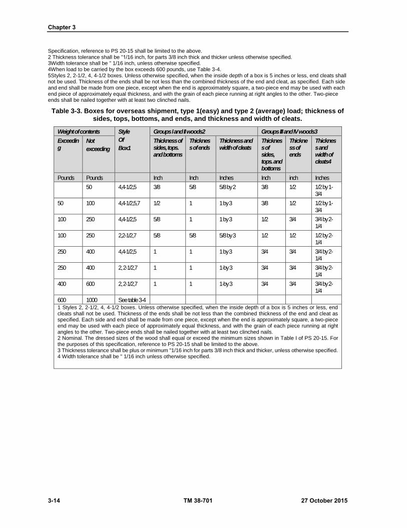
Chapter 3
3-14 TM 38-701 27 October 2015
Specification, reference to PS 20-15 shall be limited to the above. 2 Thickness tolerance shall be “1/16 inch, for parts 3/8 inch thick and thicker unless otherwise specified. 3Width tolerance shall be " 1/16 inch, unless otherwise specified. 4When load to be carried by the box exceeds 600 pounds, use Table 3-4. 5Styles 2, 2-1/2, 4, 4-1/2 boxes. Unless otherwise specified, when the inside depth of a box is 5 inches or less, end cleats shall not be used. Thickness of the ends shall be not less than the combined thickness of the end and cleat, as specified. Each side and end shall be made from one piece, except when the end is approximately square, a two-piece end may be used with each end piece of approximately equal thickness, and with the grain of each piece running at right angles to the other. Two-piece ends shall be nailed together with at least two clinched nails.
Table 3-3. Boxes for overseas shipment, type 1(easy) and type 2 (average) load; thickness of sides, tops, bottoms, and ends, and thickness and width of cleats.
Weight of contents Style
Of
Box1
Groups I and II woods2 Groups III and IV woods3
Exceeding
Not
exceeding
Thickness of sides, tops. and bottoms
Thickness of ends
Thickness and width of cleats
Thickness of sides, tops. and bottoms
Thickness of ends
Thickness and width of cleats4
Pounds Pounds Inch Inch Inches Inch inch Inches
50 4,4-1/2,5 3/8 5/8 5/8 by 2 3/8 1/2 1/2 by 1-3/4
50 100 4,4-1/2,5,7 1/2 1 1 by 3 3/8 1/2 1/2 by 1-3/4
100 250 4,4-1/2,5 5/8 1 1 by 3 1/2 3/4 3/4 by 2-1/4
100 250 2,2-1/2,7 5/8 5/8 5/8 by 3 1/2 1/2 1/2 by 2-1/4
250 400 4,4-1/2,5 1 1 1 by 3 3/4 3/4 3/4 by 2-1/4
250 400 2, 2-1/2,7 1 1 1-by 3 3/4 3/4 3/4 by 2-1/4
400 600 2, 2-1/2,7 1 1 1-by 3 3/4 3/4 3/4 by 2-1/4
600 1000 See table 3-4
1 Styles 2, 2-1/2, 4, 4-1/2 boxes. Unless otherwise specified, when the inside depth of a box is 5 inches or less, end cleats shall not be used. Thickness of the ends shall be not less than the combined thickness of the end and cleat as specified. Each side and end shall be made from one piece, except when the end is approximately square, a two-piece end may be used with each piece of approximately equal thickness, and with the grain of each piece running at right angles to the other. Two-piece ends shall be nailed together with at least two clinched nails. 2 Nominal. The dressed sizes of the wood shall equal or exceed the minimum sizes shown in Table I of PS 20-15. For the purposes of this specification, reference to PS 20-15 shall be limited to the above. 3 Thickness tolerance shall be plus or minimum "1/16 inch for parts 3/8 inch thick and thicker, unless otherwise specified. 4 Width tolerance shall be " 1/16 inch unless otherwise specified.

Wooden Containers and Pallets
27 October 2015 TM 38-701 3-15
Table 3-4. Boxes for overseas shipment, type 3 (difficult) load; thickness of sides, tops, bottoms, and ends, and thickness and width of cleats.
Weight of contents Style
Of
Box1
Groups I and II woods2 Groups III and IV woods3
Exceeding Not
exceeding
Thickness of sides, tops. and bottoms2
Thickness of ends2
Thickness and width of cleats2
Thickness of sides, tops. and bottoms
Thickness of ends
Thickness and width of cleats4
Pounds Pounds Inch Inch Inches Inch inch Inches
100 4,4-1/2,5 1/2 1 1 by 3 1/2 1/2 1/2 by 1-3/4
100 4,4-1/2,5,7 1/2 5/8 5/8 by 3 1/2 1/2 1/2 by 1-3/4
100 250 4,4-1/2,5 5/8 1 1 by 3 1/2 3/4 3/4 by 2-1/4
100 250 2,2-1/2,7 5/8 5/8 1 by 3 1/2 3/4 1/2 by 2-1/4
250 400 4,4-1/2,5 1 1-1/4 1-1/4 by 4 3/4 7/8 7/8 by 2-5/8
250 400 2, 2-1/2,7 1 1 1-1/4 by 4 3/4 3/4 3/4 by 2-5/8
400 600 2, 2-1/2,7 1 1 1-1/4 by 4 3/4 7/8 7/8 by 2-5/8
600 800 2, 2-1/2,7 1 1-1/4 1-1/4 by 4 3/4 7/8 7/8 by 2-5/8
800 1000 2, 2-1/2,7 1-1/4 1-1/2 1-1/2 by 5 7/8 1-3/8 1-3/8 by 3-1/4
1 Styles 2, 2-1/2, 4, 4-1/2 boxes. Unless otherwise specified, when the inside depth of a box is 5 inches or less, end cleats shall not be used. Thickness of the ends shall be not less than the combined thickness of the end and cleat as specified. Each side and end shall be made from one piece, except when the end is approximately square, a two-piece end may be used with each piece of approximately equal thickness, and with the grain of each piece running at right angles to the other. Two-piece ends shall be nailed together with at least two clinched nails. 2 Nominal. The dressed sizes of the wood shall equal or exceed the minimum sizes shown in Table I of PS 20-15. For the purposes of this specification, reference to PS 20-15 shall be limited to the above. 3 Thickness tolerance shall be plus or minimum 1/16 inch for parts 3/8 inch thick and thicker, unless otherwise specified. 4 Width tolerance shall be " 1/16 inch unless otherwise specified.
Table 3-5. Number of Pieces in any Box Part.
Width of box part Maximum number of pieces single solid or built-up Exceeding Not exceeding
Inches Inches
0 2-1/2 1
2-1/2 5 2
5 7-1/2 3
7-1/2 12 4
12 0 (See note)
Note: The width of pieces in box parts exceeding 12 inches the average width of pieces shall be not less than 3 inches. No single solid or built-up piece shall be less than 2-1/2 inches in width across the space.
Additional Cleats And Battens
3-41. Additional cleats will be made of the same size lumber as the regular cleats. They are placed on the
ends of a box when required, according to length of unsupported span (table 3-6 page 3-17). Additional cleats
applied to ends run across the grain of the end (right angle to grain direction) and midway between the regular
Chapter 3
3-16 TM 38-701 27 October 2015
cleats. Battens are made of the same size lumber as regular cleats. Battens are used on the sides, top, and
bottom when the limit of unsupported span is exceeded (table 3-6 page 3-17). Wherever possible, and without
increasing the size of the container, battens should be placed inside the box. When battens are required to be
placed on the outside of a box without skids, not less than two sets shall be attached across the sides, top, and
bottom. They shall be applied so that those on the top and bottom extend over the ends of the side battens.
They shall be located not less than 2 1/2 inches nor more than one- sixth the length of the box with respect
to each box end. However, that distance and the interval between sets of battens shall be not more than
maximum span specified in table 3-6. Exterior battens shall be applied to boxes with skids in the same manner
as required for interior battens except that the bottom battens shall be fabricated from one piece of lumber a
minimum of 2 1/2 inches high and 3 1/2 inches wide.
Diagonals (Fig 3-12)
3-42. Sometimes diagonal reinforcing members are added to the interior or exterior surfaces of the box.
Diagonals used on both the end and side panels are the same width and thickness as required for cleats and
are nailed in the same manner. The presence of intermediate battens or cleats, required by (table 3-6),
determine the number of single diagonals on each panel. Single diagonals in each of two adjacent areas of
one panel are arranged to peak at the center and bear at the upper end of the intermediate batten. Three or
more diagonals in adjacent areas of one panel are arranged in a zigzag manner. When a 24-inch minimum
strapping interval is required, the inner surface of the exterior diagonals must be notched slightly to permit
the strapping to pass under each diagonal.
Skids
3-43. Boxes (except style 7) with items packed therein, having a gross weight in excess of 200 pounds, or
containers with length and width dimensions of 48 inches by 24 inches or more and weighing more than 100
pounds, shall be provided with a minimum of two skids. The skids shall be fabricated from one piece of 2
1/2 inches high and 3 1/2 inches wide. Skids shall replace exterior battens on box bottoms when battens are
required in table 3-6. Skids shall be placed parallel to and extend the full width of the box and shall be
positioned not closer than 2 1/2 inches nor more than one sixth the length of the box from each end of the
box. The distance between skids, measured between the inside edges, shall not exceed the distance between
battens, and when battens are not required, shall not exceed 48 inches. Additional skid(s), as required, shall
be positioned so as to divide the distance between the end skids into units of equal length. When bolt fastening
is provided for the item being packed, additional skids, as needed, shall be located on the box bottom so as
to enable the item to be bolted through the skids. The skids shall be notched as applicable to provide clearance
for either girth wise or lengthwise strapping. When 4-way fork entry is required, skids shall be a minimum
of 3 1/2 inches high and 3 1/2 inches wide, cut out a minimum of 2 inches, in depth and of such width as to
accommodate forks and slings for handling, and may be placed lengthwise flush with the box sides. The skids
shall be secured to the box by nails. The nails shall be driven from the inside through the bottom into the
skids and be clinched not less than 1/8 inch. Alternative to clinching, nails conforming to Type II, style 18
of ASTM F 1667-05 may be used of such length as to penetrate a minimum of 3/4 the thickness of the skids
and shall not protrude through the skid. The nails shall be arranged in two rows in a staggered pattern, with
space between nails in each row not to exceed 6 inches. Nails shall not be located less than 1/2 inch from
edges of the skid nor less than approximately 1 1/2 inches from ends of the skid. Variation in specified
thickness of skids may be plus or minus 1/8 inch and the variation in specified width of skids may be plus or
minus 1/4 inch. When skids are specified and box requires 2 or more inside battens (table 3-6), the inside
bottom battens need not be applied. However, a skid shall be attached to the outside of the box bottom placed
in alignment with each side batten.
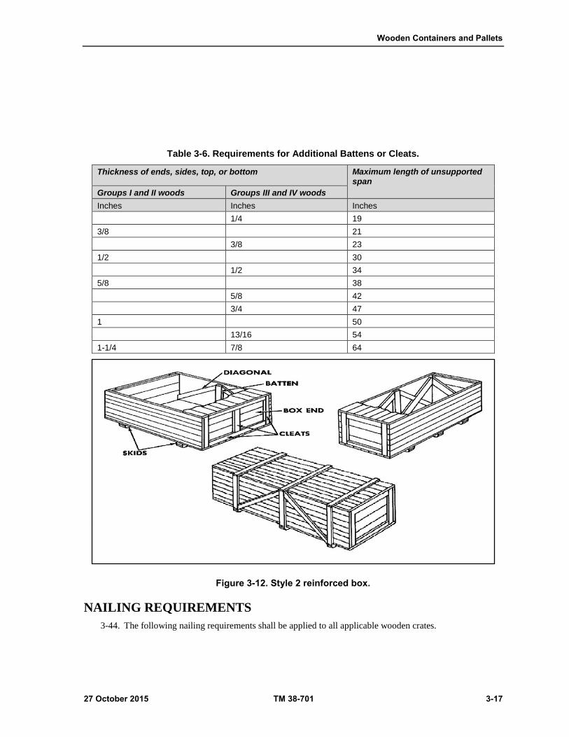
Wooden Containers and Pallets
27 October 2015 TM 38-701 3-17
Table 3-6. Requirements for Additional Battens or Cleats.
Thickness of ends, sides, top, or bottom Maximum length of unsupported span
Groups I and II woods Groups III and IV woods
Inches Inches Inches
1/4 19
3/8 21
3/8 23
1/2 30
1/2 34
5/8 38
5/8 42
3/4 47
1 50
13/16 54
1-1/4 7/8 64
Figure 3-12. Style 2 reinforced box.
NAILING REQUIREMENTS
3-44. The following nailing requirements shall be applied to all applicable wooden crates.
Chapter 3
3-18 TM 38-701 27 October 2015
SPACING AND SIZES
3-45. Nail spacing and sizes will conform to (tables 3-8 and 3-9 on page 3-19).
NAILING OF TOP AND BOTTOM
3-46. When specified, the top and bottom should be nailed to the box sides.
NAIL SIZES
3-47. Sizes of nails are determined from the following information:
Nail sizes for fastening sides, top, and bottom to ends and cleats are determined by the group of
wood and thickness of the pieces being fastened together (table 3-7 on page 3-19).
Nail sizes to secure top and bottom to the sides are determined from the group of wood being used
and the thickness of the side (table 3-8 on page 3-19).
Nails to fasten cleats to the ends will be long enough to penetrate both the cleat and the end and
be clinched at least one-eighth of an inch. However, when eight penny nails or smaller are used,
they may be clinched not more than three-eighths inch.
If correct nail size is not available, or splitting is encountered, one size smaller is used, and the
spacing will be one-fourth of an inch closer.
NAIL SPACING
3-48. The spacing of nails is determined from the following:
Nail spacing for fastening sides, top, and bottom to the ends will depend on the size of nails used,
and whether driven into side-grain or end-grain. If nails are driven into both side- and end-grain,
the spacing is the same as for end-grain nailing (table 3-9 on page 3-19).
Nail spacing for fastening the top and bottom to the sides of the box is determined from the
thickness of sides. If the thickness of the sides is less than three-fourths of an inch, no nailing is
permitted. There is a minimum and maximum spacing (table 3-8 on page 3-19).
3-49. When attaching cleats and battens, the nails are driven in two parallel rows spaced alternately as given
in (table 3-9 on page 3-19), so that the end nails are not less than three-fourths of an inch from the end of the
cleat or batten. All nails shall pass through both the cleat and the end (or batten and side, top and bottom)
and be clinched. Nails are driven approximately three-eighths of an inch from the edge when the cleat or
batten is 2 inches or under in width, and one-half of an inch when it is over 2 inches in width.
NAILING RULES
3-50. It is imperative that poor nailing practices be avoided and correct nailing procedures be followed. Both
are shown in (figures 3-13 and 3-14 on pages 3-20 and 3-21) , and stressed in the following rules:
Each single solid piece or built-up piece in the sides, top, or bottom will have at least two nails or
other acceptable fastener at each end.
Each single piece or built-up piece is fastened to each vertical cleat or batten with not less than
two nails or other acceptable fastener.
Wherever possible, side-grain nailing should be accomplished. In nailing to both the end and the
cleats, at least half of the nails are driven into the cleat.
Where a cleat is attached to an end, at least one end nail will be adjacent to the inside edge of the
cleat.
Nails are clinched across the grain of the wood, if possible.
Nails must be driven so that neither the head nor the point will project above the surface of the
wood.
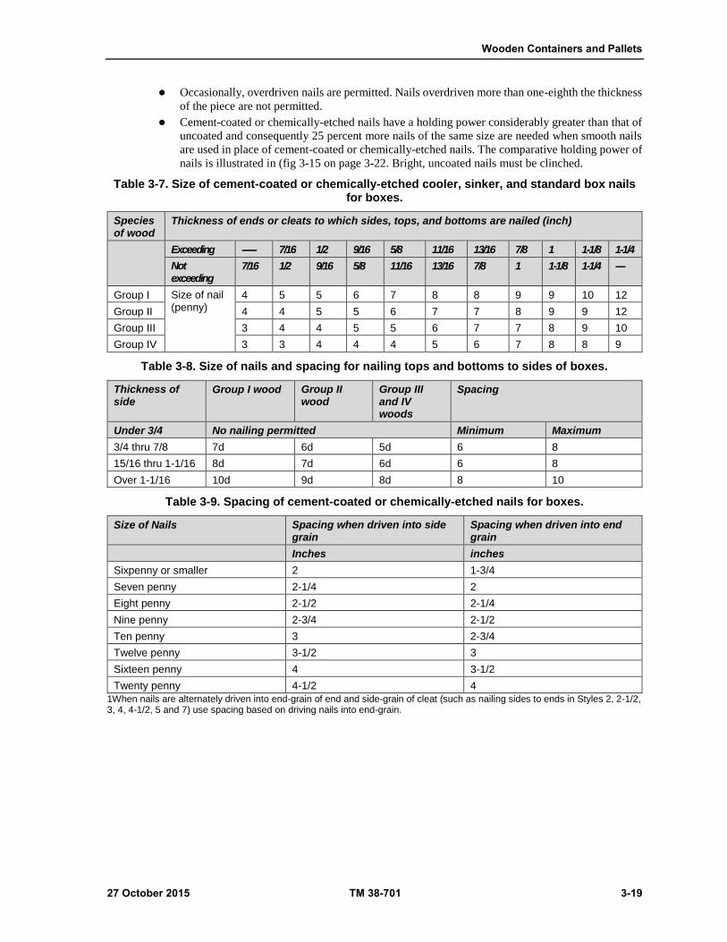
Wooden Containers and Pallets
27 October 2015 TM 38-701 3-19
Occasionally, overdriven nails are permitted. Nails overdriven more than one-eighth the thickness
of the piece are not permitted.
Cement-coated or chemically-etched nails have a holding power considerably greater than that of
uncoated and consequently 25 percent more nails of the same size are needed when smooth nails
are used in place of cement-coated or chemically-etched nails. The comparative holding power of
nails is illustrated in (fig 3-15 on page 3-22. Bright, uncoated nails must be clinched.
Table 3-7. Size of cement-coated or chemically-etched cooler, sinker, and standard box nails for boxes.
Species of wood
Thickness of ends or cleats to which sides, tops, and bottoms are nailed (inch)
Exceeding ------ 7/16 1/2 9/16 5/8 11/16 13/16 7/8 1 1-1/8 1-1/4
Not exceeding
7/16 1/2 9/16 5/8 11/16 13/16 7/8 1 1-1/8 1-1/4 ----
Group I Size of nail (penny)
4 5 5 6 7 8 8 9 9 10 12
Group II 4 4 5 5 6 7 7 8 9 9 12
Group III 3 4 4 5 5 6 7 7 8 9 10
Group IV 3 3 4 4 4 5 6 7 8 8 9
Table 3-8. Size of nails and spacing for nailing tops and bottoms to sides of boxes.
Thickness of side
Group I wood Group II wood
Group III and IV woods
Spacing
Under 3/4 No nailing permitted Minimum Maximum
3/4 thru 7/8 7d 6d 5d 6 8
15/16 thru 1-1/16 8d 7d 6d 6 8
Over 1-1/16 10d 9d 8d 8 10
Table 3-9. Spacing of cement-coated or chemically-etched nails for boxes.
Size of Nails Spacing when driven into side grain
Spacing when driven into end grain
Inches inches
Sixpenny or smaller 2 1-3/4
Seven penny 2-1/4 2
Eight penny 2-1/2 2-1/4
Nine penny 2-3/4 2-1/2
Ten penny 3 2-3/4
Twelve penny 3-1/2 3
Sixteen penny 4 3-1/2
Twenty penny 4-1/2 4
1When nails are alternately driven into end-grain of end and side-grain of cleat (such as nailing sides to ends in Styles 2, 2-1/2, 3, 4, 4-1/2, 5 and 7) use spacing based on driving nails into end-grain.

Chapter 3
3-20 TM 38-701 27 October 2015
Figure 3-13. Nailing.
SETTING UP OF STYLE 1 AND 6 BOXES
3-51. The setting up of these styles is accomplished in the following order:
Select nails and glue.
Size of coated and etched nails and proper spacing is determined from (tables 3-7, 3-8, and 3-9).
Glue for securing sides to ends of Style 6, lock-corner box, is any commercially available water-
resistant glue.
Fasten the sides to the ends by straight-line nailing, using cement- coated or chemically-etched
nails.
Apply glue to both surfaces of the sides and ends of the lock- corners of Style 6 boxes.
Nail the top and bottom.
Use nails and proper spacing determined above.
Secure the bottom of the box by nailing into the ends.
After the load is inserted, secure the top of the box in the same manner as the bottom.

Wooden Containers and Pallets
27 October 2015 TM 38-701 3-21
Figure 3-14. Proper and improper nailing.
SETTING UP OF STYLE 2 AND 2 1/2 BOXES
3-52. The setting up of these styles is accomplished in the following order:
Select nails and proper spacing.
Select proper size and spacing of coated or etched, and bright, uncoated nails from tables 3-7 and
3-8 on page 3-19.
Fasten the cleats to the ends.
Nail cleats to end, using a staggered nailing pattern.
Nails for nailing cleats to ends may be bright, uncoated, but must be clinched.
Position the vertical cleats on the end at right angles to the grain of the end.
Fasten the sides to the ends.
Lap the sides over the ends and cleats.
Nail the sides to the ends and cleats with coated or etched nails in a staggered pattern.
Nail the top and bottom.
Lap the top and bottom over the ends and cleats.
Nail the top and bottom to the ends and cleats with coated or etched nails in a staggered pattern.

Chapter 3
3-22 TM 38-701 27 October 2015
Figure 3-15. Nail holding power.
SETTING UP OF STYLE 4, 4 1/2, 5, AND SHALLOW BOXES
3-53. The setting up of these styles is accomplished in the following order:
Select nails and proper spacing. Select the proper size and spacing of coated or etched, and bright,
uncoated nails from tables 3-7, 3-8, and 3-9 on page 3-19.
Fasten the cleats to the ends.
Nail the cleats to the end using a staggering nailing pattern.
Nails for nailing the cleats to the ends may be bright, uncoated, but must be clinched.
Fasten the sides to the ends.
Lap the sides over the ends and cleats on Style 4 and 5 boxes.
Fasten the sides to the ends and cleats in a staggering nailing pattern.
Lap the sides of Style 4 1/2 and shallow box over the ends.
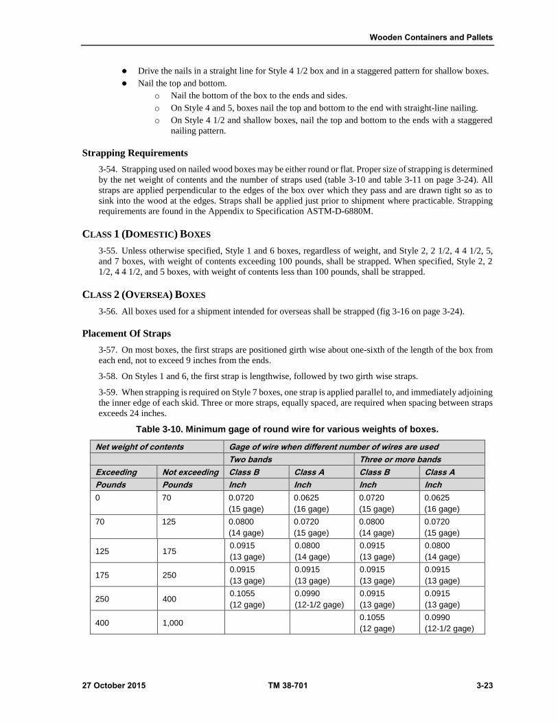
Wooden Containers and Pallets
27 October 2015 TM 38-701 3-23
Drive the nails in a straight line for Style 4 1/2 box and in a staggered pattern for shallow boxes.
Nail the top and bottom.
o Nail the bottom of the box to the ends and sides.
o On Style 4 and 5, boxes nail the top and bottom to the end with straight-line nailing.
o On Style 4 1/2 and shallow boxes, nail the top and bottom to the ends with a staggered
nailing pattern.
Strapping Requirements
3-54. Strapping used on nailed wood boxes may be either round or flat. Proper size of strapping is determined
by the net weight of contents and the number of straps used (table 3-10 and table 3-11 on page 3-24). All
straps are applied perpendicular to the edges of the box over which they pass and are drawn tight so as to
sink into the wood at the edges. Straps shall be applied just prior to shipment where practicable. Strapping
requirements are found in the Appendix to Specification ASTM-D-6880M.
CLASS 1 (DOMESTIC) BOXES
3-55. Unless otherwise specified, Style 1 and 6 boxes, regardless of weight, and Style 2, 2 1/2, 4 4 1/2, 5,
and 7 boxes, with weight of contents exceeding 100 pounds, shall be strapped. When specified, Style 2, 2
1/2, 4 4 1/2, and 5 boxes, with weight of contents less than 100 pounds, shall be strapped.
CLASS 2 (OVERSEA) BOXES
3-56. All boxes used for a shipment intended for overseas shall be strapped (fig 3-16 on page 3-24).
Placement Of Straps
3-57. On most boxes, the first straps are positioned girth wise about one-sixth of the length of the box from
each end, not to exceed 9 inches from the ends.
3-58. On Styles 1 and 6, the first strap is lengthwise, followed by two girth wise straps.
3-59. When strapping is required on Style 7 boxes, one strap is applied parallel to, and immediately adjoining
the inner edge of each skid. Three or more straps, equally spaced, are required when spacing between straps
exceeds 24 inches.
Table 3-10. Minimum gage of round wire for various weights of boxes.
Net weight of contents Gage of wire when different number of wires are used
Two bands Three or more bands
Exceeding Not exceeding Class B Class A Class B Class A
Pounds Pounds Inch Inch Inch Inch
0 70 0.0720
(15 gage)
0.0625
(16 gage)
0.0720
(15 gage)
0.0625
(16 gage)
70 125 0.0800
(14 gage)
0.0720
(15 gage)
0.0800
(14 gage)
0.0720
(15 gage)
125 175 0.0915
(13 gage)
0.0800
(14 gage)
0.0915
(13 gage)
0.0800
(14 gage)
175 250 0.0915
(13 gage)
0.0915
(13 gage)
0.0915
(13 gage)
0.0915
(13 gage)
250 400 0.1055
(12 gage)
0.0990
(12-1/2 gage)
0.0915
(13 gage)
0.0915
(13 gage)
400 1,000 0.1055
(12 gage)
0.0990
(12-1/2 gage)
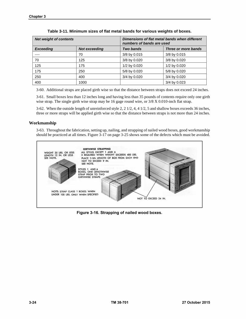
Chapter 3
3-24 TM 38-701 27 October 2015
Table 3-11. Minimum sizes of flat metal bands for various weights of boxes.
Net weight of contents Dimensions of flat metal bands when different numbers of bands are used
Exceeding Not exceeding Two bands Three or more bands
---- 70 3/8 by 0.015 3/8 by 0.015
70 125 3/8 by 0.020 3/8 by 0.020
125 175 1/2 by 0.020 1/2 by 0.020
175 250 5/8 by 0.020 5/8 by 0.020
250 400 3/4 by 0.020 3/4 by 0.020
400 1000 3/4 by 0.023
3-60. Additional straps are placed girth wise so that the distance between straps does not exceed 24 inches.
3-61. Small boxes less than 12 inches long and having less than 35 pounds of contents require only one girth
wise strap. The single girth wise strap may be 16 gage round wire, or 3/8 X 0.010-inch flat strap.
3-62. When the outside length of unreinforced style 2, 2 1/2, 4, 4 1/2, 5 and shallow boxes exceeds 36 inches,
three or more straps will be applied girth wise so that the distance between straps is not more than 24 inches.
Workmanship
3-63. Throughout the fabrication, setting up, nailing, and strapping of nailed wood boxes, good workmanship
should be practiced at all times. Figure 3-17 on page 3-25 shows some of the defects which must be avoided.
Figure 3-16. Strapping of nailed wood boxes.

Wooden Containers and Pallets
27 October 2015 TM 38-701 3-25
Figure 3-17. Defects of nailed wood boxes.
Preservation
3-64. When specified, each ASTM-D-6880M box or all of the finished wood parts shall be preserved by
immersing for a minimum of one minute in one of the following wood preservative solutions: 2 percent
copper naphthenate, 3 percent zinc naphthenate, or 1.8 percent copper-8-quinolinolate. These three chemicals
exhibit characteristics which are acceptable for DOD-wide use provided handling instructions prescribed by
the manufacturer are followed. After the dip treatment, the boxes or wood parts must be air dried (or dried
for an appropriate time in a kiln or oven) for a period of 24 hours minimum in a well- ventilated area allowing
full air circulation around all surfaces of the individual wood box or wood part. The boxes or parts must be
dried prior to shipment. Dryness can be determined by the absence of discoloration of the red oil soluble dye
when tested as specified in ASTM-D-6880M.
CLEATED-PANEL BOXES (GENERAL)
3-65. Cleated-panel boxes are made by attaching wood cleats to sheets of plywood, fiberboard, or paper-
overlaid veneer to form panels that are later fastened together at the cleats to form a container. When plywood
is used as panel material, they are called wood-cleated plywood boxes, ASTM-D-6251; when fiberboard is
used, they are called wood-cleated fiberboard boxes, specification ASTM-D-6251; and when paper-overlaid
veneer is used, they are called wood-cleated, paper-overlaid veneer boxes. In each type of box, the cleats act
to reinforce the edges and to aid in nailing.
CHARACTERISTICS
3-66. The chief characteristics of cleated-panel boxes are: Lightweight, high resistance to diagonal distortion,
resistance to corner damage, and ability to withstand severe tumbling and dropping. They are easy to mark
and handle, almost dustproof, and lend themselves to easy fabrication. Panels may be bought in large
quantities in the knocked-down form, which can be easily stored in a minimum of space. These boxes afford
three choices of cleated panel boxes for use in the shipping of military supplies and equipment. Selection of

Chapter 3
3-26 TM 38-701 27 October 2015
the panel material for the box is based upon the destination of the shipment, the minimum protection required,
the weight of the item, and the container limitations.
Intended Uses and Limitations
3-67. The styles of boxes permitted for domestic and oversea shipments, with limitations for cleated
plywood, cleated fiberboard, and cleated paper overlaid veneer boxes are cited in table 3-12 on page 3-27.
Oversea Type Boxes (See Figure 3-18)
3-68. Styles A and B are the only ones permitted, for cleated fiberboard and veneer. Cleated plywood boxes
permit Styles A, B, I, and J. Plywood and paper- overlaid boxes will take all three types of loads. Cleated
fiberboard boxes will take Type 1 and 2 loads only. Style A lends itself to ease of assembly and opening.
Style B has greater strength, but is more difficult to open. The designs of these boxes and their load limit for
oversea shipments are given in the respective container specifications.
Figure 3-18. Oversea styles of cleated panel boxes.
Domestic Type Boxes (See Figure 3-19)
3-69. Domestic boxes are intended f or normal use when the additional strength of the oversea type is not
required. The selection of the style depends largely on the nature and weight of the item, and how it is to be
supported. Styles B, D, E, and G have 3-way corners and are satisfactory if the boxes are not to be opened
for inspection and reclosed. If the boxes are to be opened and reclosed, Style A and K are preferred. The full-
cleated Styles A and B are the strongest and most suitable for heavy items, if the weight can be applied over
the entire area of any face. Styles A and B require only one size of nails for assembling the box, whereas,
two sizes of nails are required for Styles C and K, inclusive. Paper-overlaid veneer boxes are only available
in Styles A and B for domestic shipment. All three types of loads are permitted.

Wooden Containers and Pallets
27 October 2015 TM 38-701 3-27
Figure 3-19. Styles of cleated panel boxes.
Table 3-12. Comparison of cleated panel boxes.
Items of comparison Cleated plywood (ASTM-D-6251)
Paper overlaid veneer (ASTM-D-6251)
Styles A, B, I and J A and B
Class of use Domestic and overseas 1 and 2
Styles of overseas A, B, I and J A and B
Styles of domestic A, B, I and J A and B
Weight limit vs. styles Overseas
A, B, I and J 1,000# A and B 350#
Domestic A, B, I, and J 1,000# A and B 400#
Types of load vs. weight 1, 2, and 3 Type 1- 2 Domestic 400#
Type 3 Domestic 300#
Type 1 -2 Overseas 350#
Type 3 – Overseas 250#
Unsupported span for intermediate cleats, maximum
Type 1 and 2 loads-24”
Type 3 load-20”
Type 3 load, Class 2 use -20”
All other -24”
Size limit overseas No size limit No size limit
Domestic No size limit No size limit
Strapping Styles A and B 2 lengthwise straps, and strap over all intermediate cleats, except cleats located on ends of plywood containers
All class 2 boxes and class 1 when over 150#
Styles C thru K Consult Appendix of Specifications
Stapels 4” maximum from corners, approximately 6” apart thereafter (except over bands on bottom of box for plywood)

Chapter 3
3-28 TM 38-701 27 October 2015
CLEATED PLYWOOD BOXES (ASTM-D-6251)
3-70. . Cleated- plywood boxes are classified as Grade A, with preservative treatment, and Grade B, without
preservative treatment. Plywood and cleats for Grade A boxes shall be treated with water-repellant
CONSTRUCTION OF PANELS
3-71. Plywood will conform to the minimum commercial standard grades in table 3-13 shown below.
Plywood for domestic boxes will conform to HPMA-HP-1, Type III, Grade 3-4, and PS-1, standard interior.
Plywood for oversea boxes will conform to HPMA-HP-1, Type I, Grade 3-4, and PS-1, standard interior with
exterior glue (see tables 3-14, 3-15 on page 3-29). If it is known that the boxes will not be exposed to the
weather during storage and handling to its final oversea destination, plywood as specified for domestic type
boxes should be specified. Cleated- plywood boxes are classified as Grade A, with preservative treatment,
and Grade B, without preservative treatment. Plywood and cleats for Grade A boxes shall be treated with
water-repellant preservative conforming to the following: 2% copper naphthenate, 3% zinc naphthenate, and
1.8% copper-8- quinolone. Treated boxes shall be dried before shipment. Shipments of subsistence and
clothing shall not be made in boxes fabricated from toxic treated plywood. If smooth finish for sanded panels
are required, appropriate sanded grades should be specified. The minimum thickness of the plywood and size
of cleats should be as shown in tables 3-14 or 3-15 on page 3-29, as applicable. The plywood is attached to
the cleats in the following manner:
Table 3-13. Plywood PS-1 and PS-51, commercial standards.
Box type PS-51 PS-1
Domestic Type III, grade 3-4 veneers C-D
Overseas Type I, grade 3-4 veneers C-D with exterior
1 Plywood is furnished un sanded. If smooth finish or sanded panels are required, appropriated sanded grades should be specified in the contract or order. 2 End grain butt joints shall be prohibited for grade 4 veneers.
Arrange the Cleats
3-72. Each panel for styles A and B will have two through cleats and filler cleats. Position the through cleats
opposite each other at the edges of the panel material; then position the filler cleats between the through
cleats at the edges. Style A and B boxes may have the top panel modified. When specified, style A shall have
edge cleats and filler edge cleats placed on the underside of the top panel (fig 3-20 on page 3-30). Style B
boxes are modified by providing through edge cleats only on the underside of the panel. These underside
cleats shall be of the same width and thickness as the outer cleats.
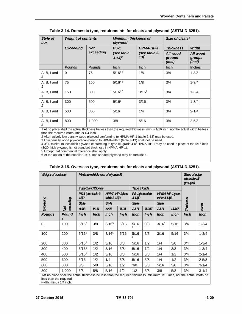
Wooden Containers and Pallets
27 October 2015 TM 38-701 3-29
Table 3-14. Domestic type, requirements for cleats and plywood (ASTM-D-6251).
Style of box
Weight of contents Minimum thickness of plywood
Size of cleats1
Exceeding Not exceeding
PS-1
(see table
3-13)2
HPMA-HP-1
(see table 3-13)3
Thickness Width
All wood groups (incl)
All wood groups (incl)
Pounds Pounds Inch Inch Inch Inches
A, B, I and J
0 75 5/164 6 1/8 3/4 1-3/8
A, B, I and J
75 150 5/164 6 1/8 3/4 1-3/4
A, B, I and J
150 300 5/164 6 3/164 3/4 1-3/4
A, B, I and J
300 500 5/166 3/16 3/4 1-3/4
A, B, I and J
500 800 5/16 1/4 3/4 2-1/4
A, B, I and J
800 1,000 3/8 5/16 3/4 2-5/8
1 At no place shall the actual thickness be less than the required thickness, minus 1/16 inch, nor the actual width be less than the required width, minus 1/4 inch. 2 Alternatively low density wood plywood conforming to HPMA-HP-1 (table 3-13) may be used. 3 Low density wood plywood conforming to HPMA-HP-1 (table 3-13) shall not be used. 4 3/30 minimum inch thick plywood conforming to type III, grade 4 of HPMA-HP-1 may be used in place of the 5/16 inch (3/20 thick plywood is not standard thickness in HPMA-HP-1). 5 Except that commercial tolerance shall apply. 6 At the option of the supplier, 1/14-inch sanded plywood may be furnished.
Table 3-15. Overseas type, requirements for cleats and plywood (ASTM-D-6251).
Weight of contents Minimum thickness of plywood6 Sizes of edge cleats for all groups1
Exc
eedin
g
Not
exce
edin
g
Type 1 and 2 loads Type 3 loads Thic
knes
s
Wid
th
PS-1 (see table 3-13)2
HPMA-HP-1 (see table 3-13)3
PS-1 (see table 3-13)2
HPMA-HP-1 (see table 3-13)3
Style Style Style Style
A&B I&J4 A&B I&J4 A&B I&J47 A&B I&J47
Pounds Pounds
Inch Inch Inch Inch Inch Inch Inch Inch Inch Inch
0 100 5/168 3/8 3/165 5/16 5/168
3/8 3/165 5/16 3/4 1-3/4
100 200 5/168 3/8 3/165 5/16 5/168
3/8 3/16 5/16 3/4 1-3/4
200 300 5/168 1/2 3/16 3/8 5/16 1/2 1/4 3/8 3/4 1-3/4
300 400 5/168 1/2 3/16 3/8 5/16 1/2 1/4 3/8 3/4 1-3/4
400 500 5/168 1/2 3/16 3/8 5/16 5/8 1/4 1/2 3/4 2-1/4
500 600 5/16 1/2 1/4 3/8 5/16 5/8 1/4 1/2 3/4 2-5/8
600 800 3/8 5/8 5/16 1/2 3/8 5/8 5/16 5/8 3/4 3-1/4
800 1,000 3/8 5/8 5/16 1/2 1/2 5/8 3/8 5/8 3/4 3-1/4
1At no place shall the actual thickness be less than the required thickness, minimum 1/16 inch, not the actual width be less than the required width, minus 1/4 inch.

Chapter 3
3-30 TM 38-701 27 October 2015
2Alternatively low density wood plywood conforming to HPMA-HP-1 (table 3-13) may be used. 3Low density wood plywood conforming to HPMA-HP-1 (table 3-13) shall not be used. 4Top and bottom panels of I and J boxes only, all other panels as specified for styles A and B. 5Minimum 3/20 inch thick plywood conforming to type I, grade 4 of HPMA-HP-1 may be used in place of the 3/16 inch thick plywood. (3/20 inch thick plywood is not a standard thickness in HPMA-HP-1). 6Except that commercial tolerance shall apply. 7The maximum weight of contents for Air Force shipments for style I and shall be 150 lbs. 8At the option of the supplier, 1/4 inch sanded plywood may be furnished.
Figure 3-20. Top panel modification of un-nailed closure, ASTM-D-6251, style A box.
3-73. Unless otherwise specified filler edge cleats shall be either the same length as the distance between the
through edge cleats or approximately one-eighth inch shorter.
3-74. Filler edge cleats on top and bottom panels, except on top only when the box is provided with skids,
shall be either the same length as the distance between the through edge cleats or approximately one-fourth
inch shorter for oversea type boxes.
3-75. When the filler cleats are the same length as the distance between through edge cleats, each end shall
be either cut at an angle or notched to provide a drainage area between the filler cleat and the plywood of
approximately one- fourth inch by one-fourth inch. Drainage areas are not applicable on the underside cleats
of the top panels of the un-nailed closure Style A box.
Each cleat shall be a single unjointed piece.
Fasten the panel material to the cleats (fig 3-21 shown on page 3-32).
3-76. Nails, staples, wire stitches, or other fasteners positioned lengthwise of a cleat are staggered in two
parallel rows, approximately three-eighths inch from the edge of the cleat.
3-77. The distance between the nearest edge of a fastener and the edge of a cleat shall not be less than three-
eighths of an inch and not closer than three-fourths of an inch nor more than 1 inch from the end of the cleat.

Wooden Containers and Pallets
27 October 2015 TM 38-701 3-31
3-78. Space the nails not more than 6 inches apart lengthwise in each row. Usually, nail or staple through
the plywood and then cleat and clinch. Reversal of this sequence is permitted only for nails.
Construction Of Plywood Joints
3-79. In the construction of large cleated plywood boxes, it frequently becomes necessary to join sheets of
panel material. Bottom panels of boxes not exceeding 72 inches in length or 48 inches in width, and top and
bottom panels of Style I boxes shall consist of a single piece of plywood. All other panels shall consist of
one or two pieces of plywood joined by either a lap or butt joint (see fig 3-22 on page 3-32) as specified
below. Each piece of plywood in two-piece panels shall be not less than 24 inches in length or width. Plywood
joints in adjacent panels should not be closer than 12 inches of being in line.
Lap Joint
3-80. Overlap two pieces of panel material at least 3 inches. Fasten the sheet together with metal stitches
through the overlap and clinch. Use not less than two parallel rows of stitches. Space stitches not less than 2
inches apart. The average spacing of stitches in each row must not exceed 4 inches. The maximum thickness
of plywood to be used for this type of joint shall be 3/16 inch.
Butt Joint
3-81. Butt two pieces of plywood at the mid width of a joint cleat. Fasten each piece of plywood to the joint
cleat. The thickness of a joint cleat will be the same as an edge cleat. The width of a joint cleat for a domestic
box will be no less than 2 1/4 inches. If the edge cleat is more than 2 1/4 inches wide, the joint cleat will be
of the same width. For oversea type boxes, the joint cleat will be not less than 1 1/3 times the required width
of the edge cleats or never less than 2 1/4 inches.
Determine The Requirements
3-82. Additional wood cleats, of the same width and thickness as the edge cleat, are applied to an unframed
area which exceeds 24 inches in any dimension or 20 inches for oversea type boxes with Type 3 loads.
Additional cleats are applied to any face of a box having a load concentration near the center of the unframed
area.
Fasten The Cleats
3-83. Apply cleats perpendicular to the greater of the two dimensions between edge cleats. Space and drive
fastenings in the same manner as for edge cleats.
ASSEMBLY OF BOXES
3-84. The assembly of the boxes depends on the style.
STYLE A (OVERSEAS)
3-85. Style A( overseas boxes) are constructed as follows.
Assembly of the Panels
3-86. Arrange the panels so that one through cleat and one filler cleat forms each edge of the box. Arrange
the cleats to form a standard box corner (fig 3-18 on page 3-26). Arrange the top and bottom panels to overlap
the sides and ends.
Nailing the Panels Together
3-87. Nail all panels to each other by single line nailing. Use either mechanically deformed, cement coated
or chemically-etched nails. Space the nails in accordance with the type of load and the thickness of cleats
(tables’ 3-16 and 3-17 on page 3-33).

Chapter 3
3-32 TM 38-701 27 October 2015
Figure 3-21. Spacing of fasteners.
Figure 3-22. Acceptable plywood joints.
Strapping Requirements
3-88. Strapping requirements are found in the appendix to ASTM-D-6251. The sizes of round wire and flat
metal straps are found in table 3-18, 3-19 and 3-20 found on page’s 3-33 and 3-34. Styles A or B boxes that
have modified tops will be closed with flat steel strapping. Other means are prohibited.

Wooden Containers and Pallets
27 October 2015 TM 38-701 3-33
Table 3-16. Domestic type, sizes and spacing of nails for fastening.
Cleats Thickness
Maximum spacing of nails all wood groups
Size of nails for wood groups1
Type 1&2 loads
Type 3 loads
I II III IV
3/4 inch 5 inches 4 inches 7 penny 7 penny 7 penny 6 penny
1 If the nail protrudes through the last edge clear or splits cleat, then the next smaller size penny nail shall be used.
Table 3-17. Oversea type, sizes and spacing of nails for fastening together adjacent cleated panels.
Cleats Thickness
Maximum spacing of nails all wood groups
Size of nails for wood groups1
Type 1&2 loads
Type 3 loads
I II III IV
3/4 inch 5 inches 4 inches 9 penny 8 penny 7 penny 6 penny
1 If the nail protrudes through the last edge cleat or if it splits the cleat, then the next smaller size penny nail shall be used.
Table 3-18. Diameter of round wire strapping.
Weight of contents
Diameter of round wire strapping
2 wires 3 or more wires
100,000 psi tensile strength
140,000 psi tensile strength
100,000 psi tensile strength
100,000 psi tensile strength
Pounds Inch Inch Inch Inch
Up to 70, 0.0720 (15 gage) 0.0720 (15 gage) 0.0720 (15 gage) 0.0720 (15 gage)
71 to 125, 0.0800 (14 gage) 0.0720 (15 gage) 0.0800 (14 gage) 0.0720 (15 gage)
126 to 175, 0.0915 (13 gage) 0.0800 (15 gage) 0.0915 (13 gage) 0.0800 (14 gage)
176 to 250, 0.0915 (13 gage) 0.0915 (13 gage) 0.0915 (13 gage) 0.0915 (13 gage)
251 to 400, 0.0915 (13 gage) 0.0915 (13 gage)
401 to 1,000, 0.1055 (12 gage) 0.0990 (12-1/2 gage)
PSI Pounds Per Square Inch
Table 3-19. Size of flat metal bands.
Weight of contents
not exceeding
Dimension of flat metal bands when different numbers of
bands are used
2 bands 3 or more bands 2 bands 3 or more bands
Pounds Inch Inch
Up to 70, 3/8 by 0.020 3/8 to 0.020
71 to 125, 3/8 by .020 3/8 by .202
126 to 175, 1/2 by .020 1/2 by .020
176 to 250, 5/8 by .020 5/8 by .020
251 to 400, 3/4 by .020
401 to 1000, 3/4 by .023
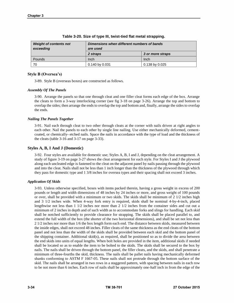
Chapter 3
3-34 TM 38-701 27 October 2015
Table 3-20. Size of type III, twist-tied flat metal strapping.
Weight of contents not
exceeding
Dimensions when different numbers of bands
are used
2 straps 3 or more straps
Pounds Inch Inch
70 0.140 by 0.031 0.138 by 0.025
Style B (Oversea’s)
3-89. Style B (overseas boxes) are constructed as follows.
Assembly Of The Panels
3-90. Arrange the panels so that one through cleat and one filler cleat forms each edge of the box. Arrange
the cleats to form a 3-way interlocking corner (see fig 3-18 on page 3-26). Arrange the top and bottom to
overlap the sides; then arrange the ends to overlap the top and bottom and, finally, arrange the sides to overlap
the ends.
Nailing The Panels Together
3-91. Nail each through cleat to two other through cleats at the corner with nails driven at right angles to
each other. Nail the panels to each other by single line nailing. Use either mechanically deformed, cement-
coated, or chemically- etched nails. Space the nails in accordance with the type of load and the thickness of
the cleats (table 3-16 and 3-17 on page 3-33).
Styles A, B, I And J (Domestic)
3-92. Four styles are available for domestic use; Styles A, B, I and J, depending on the cleat arrangement. A
study of figure 3-19 on page 3-27 shows the cleat arrangement for each style. For Styles I and J the plywood
along each uncleated edge is fastened to the cleat on the adjacent panel by nails passing through the plywood
and into the cleat. Nails shall not be less than 1 inch longer than the thickness of the plywood through which
they pass for domestic type and 1 3/8 inches for oversea types and their spacing shall not exceed 3 inches.
Application Of Skids
3-93. Unless otherwise specified, boxes with items packed therein, having a gross weight in excess of 200
pounds or length and width dimensions of 48 inches by 24 inches or more, and gross weight of 100 pounds
or over, shall be provided with a minimum or two skids. The skids shall be minimum of 2 1/2 inches high
and 3 1/2 inches wide. When 4-way fork entry is required, skids shall be nominal 4-by-4-inch, placed
lengthwise not less than 1 1/2 inches nor more than 2 1/2 inches from the container sides and cut out a
minimum of 2 inches in depth and of such width as to accommodate forks and slings for handling. Each skid
shall be notched sufficiently to provide clearance for strapping. The skids shall be placed parallel to, and
extend the full width of the box (the shorter of the two horizontal dimensions), and shall be set not less than
2 1/2 inches nor more than 1/6 the box length form each end. The distance between skids, measured between
the inside edges, shall not exceed 48 inches. Filler cleats of the same thickness as the end cleats of the bottom
panel and not less than the width of the skids shall be provided between each skid and the bottom panel of
the shipping container. Additional skid(s), as required, shall be positioned so as to divide the area between
the end skids into units of equal lengths. When bolt holes are provided in the item, additional skids if needed
shall be located so as to enable the item to be bolted to the skids. The skids shall be secured to the box by
nails. The nails shall be driven through the bottom panel, the filler cleats, and the skids, and shall penetrate a
minimum of three-fourths the skid, thickness. The nails shall be pallet nails having mechanically deformed
shanks conforming to ASTM F 1667-05. These nails shall not protrude through the bottom surface of the
skid. The nails shall be arranged in two rows in a staggered pattern, with spacing between nails in each row
to be not more than 6 inches. Each row of nails shall be approximately one-half inch in from the edge of the

Wooden Containers and Pallets
27 October 2015 TM 38-701 3-35
skid and the nailing pattern shall begin and end approximately 1 1/2 inches in from the end of each skid and
shall not be nailed through the strap notch.
Closure
3-94. The top panel shall be positioned and nailed. The size and spacing of nails shall be shown in tables 3-
16 and 3-17. Drive nails straight to prevent them from protruding.
Strapping Requirements
3-95. Strapping requirements are found in the appendix to ASTM-D-6251. The sizes of round wire and flat
metal straps are found in table 3-18, 3-19 and 3-20. Styles A or B boxes that have modified tops will be
closed with flat steel strapping. Other means are prohibited
Styles A, B, I And J (Oversea)
3-96. Strap Styles A, B, I and J, unless otherwise specified (see figure 3-23 on page 3-36). On Styles A and
B, apply two lengthwise straps on the edge cleats over the ends, top, and bottom. On Styles I and J, apply
two lengthwise straps on the edge cleats over the ends and sides. Place a girth wise strap over intermediate
cleats, when required, on the sides, top and bottom (fig 3-24 on page 3-37). Draw strapping tightly so as to
sink into the edges of the cleats. Fasten strapping to the cleats with staples spaced approximately 6 inches
apart, and within 4 inches from the edge of the box over which the strap passes (except over bands on the
bottom of the box and bands applied over filler cleats on the top). Staples shall be applied just prior to
shipment where practicable. Strapping used for un nailed closure boxes shall not be stapled. Alternately, each
lengthwise and girth wise strap may be replaced by four corner straps each 8 inches long and secured to the
box with three staples on each leg pneumatically driven through the strap into the cleat. However, corner
straps shall not be used on un nailed closure boxes. Exercise care in strapping domestic styles so that the
straps do not pass over voids between cleats and thus become susceptible to snagging.
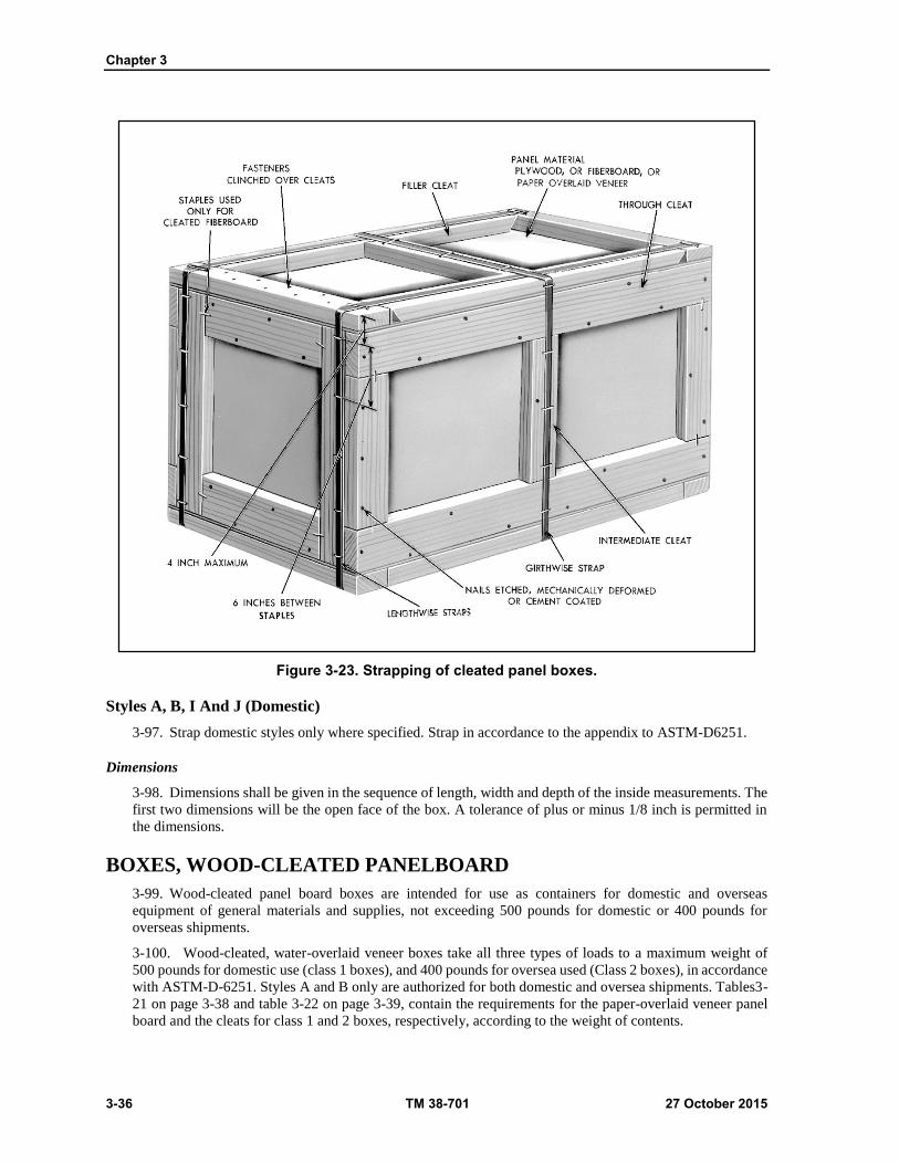
Chapter 3
3-36 TM 38-701 27 October 2015
Figure 3-23. Strapping of cleated panel boxes.
Styles A, B, I And J (Domestic)
3-97. Strap domestic styles only where specified. Strap in accordance to the appendix to ASTM-D6251.
Dimensions
3-98. Dimensions shall be given in the sequence of length, width and depth of the inside measurements. The
first two dimensions will be the open face of the box. A tolerance of plus or minus 1/8 inch is permitted in
the dimensions.
BOXES, WOOD-CLEATED PANELBOARD
3-99. Wood-cleated panel board boxes are intended for use as containers for domestic and overseas
equipment of general materials and supplies, not exceeding 500 pounds for domestic or 400 pounds for
overseas shipments.
3-100. Wood-cleated, water-overlaid veneer boxes take all three types of loads to a maximum weight of
500 pounds for domestic use (class 1 boxes), and 400 pounds for oversea used (Class 2 boxes), in accordance
with ASTM-D-6251. Styles A and B only are authorized for both domestic and oversea shipments. Tables3-
21 on page 3-38 and table 3-22 on page 3-39, contain the requirements for the paper-overlaid veneer panel
board and the cleats for class 1 and 2 boxes, respectively, according to the weight of contents.

Wooden Containers and Pallets
27 October 2015 TM 38-701 3-37
3-101. Skids are attached to the bottom of boxes having a gross weight of more than 200 pounds, or when
the length and width dimensions are 48 inches by 24 inches or over and the gross weight is 100 pounds or
over. The skids shall be a minimum of 2 1/2 inches high and 3 1/2 inches wide and may be fabricated from
more than one piece of lumber to make up the required height. The skids shall be set not less than 2 1/2 inches
not more than 4 inches in from each end. Filler cleats of the same thickness as the edge cleats and the same
width as the skids and the bottom panel of the box.
WOOD-CLEATED, SKIDDED, LOAD-BEARING BASE BOXES (ASTM
D6256)
3-102. These boxes may be used for the shipment of items which can be secured to a load-bearing base.
The sides, tops, and ends are of cleated panel construction. Panels may be plywood, fiberboard, or paper-
overlaid veneer and comply with the applicable requirements of ASTM-D-6251. Styles A, B, and C are used
for Type I, domestic, and Type II, oversea shipments. The bases are fabricated as Class 1, plywood base, and
Class 2, lumber base (see fig 3-25 on page 3-38).
INTENDED USE
3-103. Boxes covered by ASTM D6256 are intended to be used for items which can be attached to a load-
bearing base. It is intended that the entire load be carried on the base. The super-structure (tops, ends, and
sides) provides only for superimposed loads and protection against the elements. It is not intended for the
box to be lifted or moved other than by the base. The super-structure may be removed when it is not required.
Figure 3-24. Spacing of intermediate cleats.
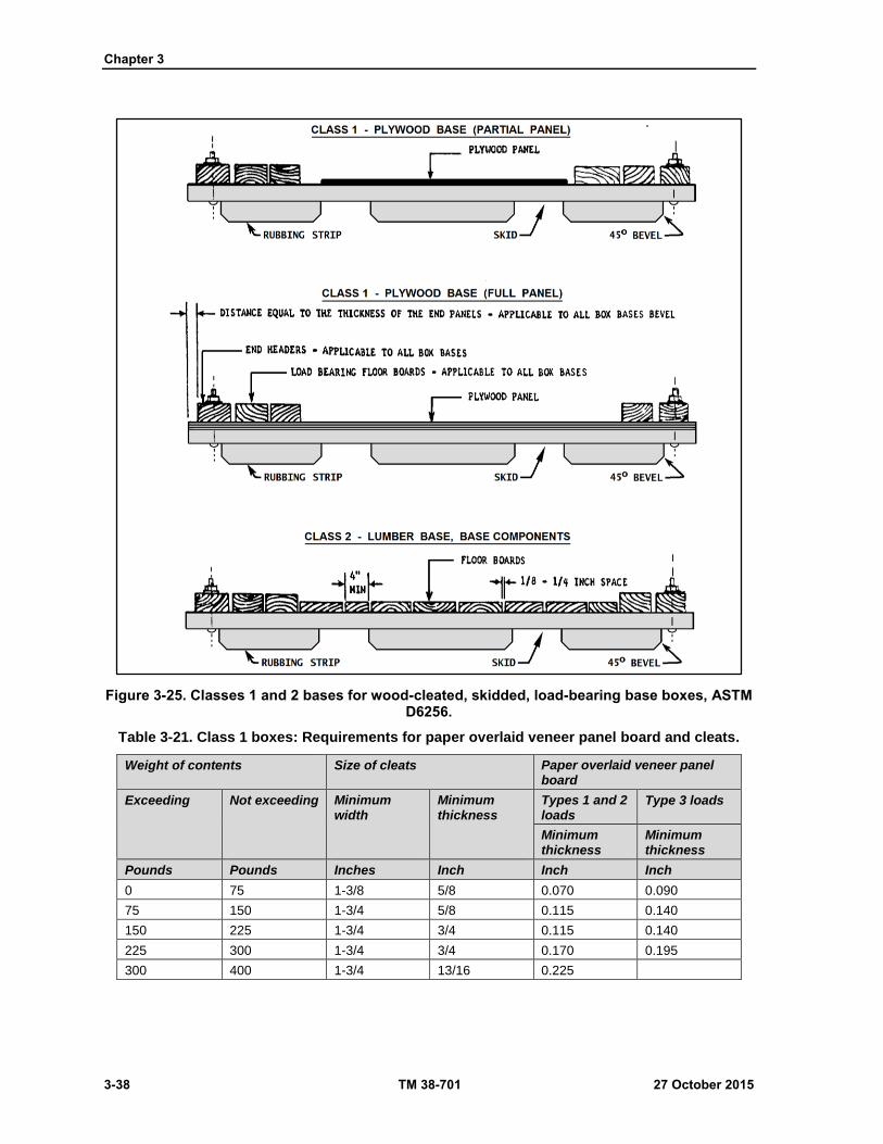
Chapter 3
3-38 TM 38-701 27 October 2015
Figure 3-25. Classes 1 and 2 bases for wood-cleated, skidded, load-bearing base boxes, ASTM D6256.
Table 3-21. Class 1 boxes: Requirements for paper overlaid veneer panel board and cleats.
Weight of contents Size of cleats Paper overlaid veneer panel board
Exceeding Not exceeding Minimum width
Minimum thickness
Types 1 and 2 loads
Type 3 loads
Minimum thickness
Minimum thickness
Pounds Pounds Inches Inch Inch Inch
0 75 1-3/8 5/8 0.070 0.090
75 150 1-3/4 5/8 0.115 0.140
150 225 1-3/4 3/4 0.115 0.140
225 300 1-3/4 3/4 0.170 0.195
300 400 1-3/4 13/16 0.225

Wooden Containers and Pallets
27 October 2015 TM 38-701 3-39
Table 3-22. Class 2 boxes: Requirements for paper overlaid veneer panel board and cleats
Weight of contents Size of cleats Paper overlaid veneer panel board
Exceeding Not exceeding Minimum width
Minimum thickness
Types 1 and 2 loads
Type 3 loads
Minimum thickness
Minimum thickness
Pounds Pounds Inches Inch Inch Inch
0 100 1-3/4 5/8 0.070 0.120
100 250 1-3/4 3/4 0.140 0.180
250 350 1-3/4 13/16 0.225 0.195
Fabrication of Panels
3-104. When panels are fabricated locally, they are made according to information contained in table 3-13
on page 3-28 and HPMA-HP-1. Also see ASTM-D-6251 construction of panels. Even filler cleat tolerance
and drainage shall be in accordance with ASTM-D-6251. Cleat arrangement on top panels is illustrated in
figure 3-26 on page 3-43. When joists are required for the super-structure to hold superimposed loads, they
are selected in accordance with table 3-23 on page 3-40. Joist supports are required to be placed beneath each
joist (see fig 3-27 on page 3-43). The vertical and material supports shall comply with the material
requirements for the cleat stock, except that the thickness shall not be less than one inch for container loads
up to 1,000 pounds. For loads in excess of 1,000 pounds, the supports shall be not less than 2 inches. The
vertical joist supports shall be nailed to the side panels with nails long enough to pass through the clinch of
1/8 inch for Groups II, III, and IV woods and 1/4 inch clinch for Group I woods.
Fabrication Of Base Components
3-105. See figure 3-24.
Skids
3-106. Skids will be made of Group II, III, or IV lumber. The cross section and length of skids are chosen
from table 3-28, based upon weight of contents and load conditions, as illustrated in (fig 3-27 on page 3-43).
For boxes whose outside width exceeds 36 inches, a third skid conforming to fig 3-28 on page 3-45 is added.
The third skid is placed equidistant between the outer skids. At the ends of each skid, the lower half is beveled
approximately 45 degrees.
Load Bearing Members
3-107. Load bearing members will be free of defects which could materially weaken them. They are
selected in accordance with (tables 3-24 and 3-25 on page 3-40 and 3-42). The cross section of load bearing
members for a particular load is determined either by assuming a total width of such load bearing members
and determining the thickness necessary, or by assuming a thickness and determining a total width of load
bearing members.
Lumber Flooring
3-108. Lumber flooring will be a minimum of 1-inch thick, and not less than 4 inches wide. Lumber is laid
at right angles to the skids. The boards are separated one-eighth to one-fourth of an inch to allow for swelling
and drainage. The board ends are placed flush with the outer edge of the skids.
Plywood Flooring
3-109. Unless otherwise specified, plywood used for Type I boxes shall conform to HPMA-HP-1, Type II,
Grade 3-4, PS1, standard interior. The minimum thickness shall be three-eighths of an inch. See table 3-13
on page 3-28. It may be the full length and width of the base, or it may be a centrally located square piece
with the length equal to the base width. When a full piece of plywood is used, a drainage hole one-half inch
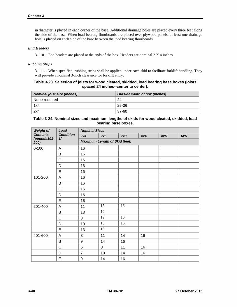
Chapter 3
3-40 TM 38-701 27 October 2015
in diameter is placed in each corner of the base. Additional drainage holes are placed every three feet along
the side of the base. When load bearing floorboards are placed over plywood panels, at least one drainage
hole is placed on each side of the base between the load bearing floorboards.
End Headers
3-110. End headers are placed at the ends of the box. Headers are nominal 2 X 4 inches.
Rubbing Strips
3-111. When specified, rubbing strips shall be applied under each skid to facilitate forklift handling. They
will provide a nominal 3-inch clearance for forklift entry.
Table 3-23. Selection of joists for wood cleated, skidded, load bearing base boxes (joists spaced 24 inches--center to center).
Nominal joist size (Inches) Outside width of box (Inches)
None required 24
1x4 25-36
2x4 37-60
Table 3-24. Nominal sizes and maximum lengths of skids for wood cleated, skidded, load bearing base boxes.
Weight of Contents (pounds101-200)
Load Condition 1/
Nominal Sizes
2x4 2x6 2x8 4x4 4x6 6x6
Maximum Length of Skid (feet)
0-100 A 16
B 16
C 16
D 16
E 16
101-200 A 16
B 16
C 16
D 16
E 16
201-400 A 11 15 16
B 13 16
C 8 12 16
D 10 15 16
E 13 16
401-600 A 8 11 14 16
B 9 14 16
C 5 8 11 16
D 7 10 14 16
E 9 14 16

Wooden Containers and Pallets
27 October 2015 TM 38-701 3-41
Table 3-24. Nominal sizes and maximum lengths of skids for wood cleated, skidded, load bearing base boxes. (Continued)
Weight of Contents (pounds101-200)
Load Condition 1/
Nominal Sizes
2x4 2x6 2x8 4x4 4x6 6x6
Maximum Length of Skid (feet)
601-800 A 7 9 11 16
B 7 10 14 16
C 4 6 8 16
D 5 8 10 16
E 7 10 14 16
801-1000 A 6 8 10 16
B 5 8 11 16
C 3 5 7 16
D 4 6 8 16
E 5 8 11 16
1001-1200 A 6 7 8 16
B 4 7 9 16
C 3 4 5 13 16
D 3 5 7 16
E 4 7 9 16
1201-1400 A 5 7 8 14 16
B 5 6 8 16
C 0 4 5 11 16
D 3 4 6 14 16
E 5 6 8 16
1401-1600 A 5 6 7 13 16
B 3 5 7 16
C 0 3 4 18 15 16
D 3 4 5 12 16
E 3 5 7 16
1601-1800 A 5 6 7 12 16
B 3 5 6 15 16
C 0 3 4 9 14 16
D 0 3 4 11 16
E 3 5 6 15 16
1801-2000 A 4 5 6 11 15 16
B 3 4 5 13 16
C 0 0 3 8 12 16
D 0 3 4 10 15 16
E 3 4 5 13 16
2001-2220 A 4 5 6 10 14 16
B 0 4 5 12 16
C 0 0 3 7 11 16

Chapter 3
3-42 TM 38-701 27 October 2015
Table 3-24. Nominal sizes and maximum lengths of skids for wood cleated, skidded, load bearing base boxes. (Continued)
Weight of Contents (pounds101-200)
Load Condition 1/
Nominal Sizes
2x4 2x6 2x8 4x4 4x6 6x6
Maximum Length of Skid (feet)
D 0 3 4 9 14 16
E 0 4 5 12 16
2201-2400 A 4 5 6 10 13 16
B 0 3 4 11 16 16
C 0 0 3 78 10 16
D 0 0 3 8 13 16
E 0 3 4 11 16
2401-2500 A 4 5 6 9 13 16
B 0 3 4 10 16
C 0 0 3 6 10 16
D 0 0 3 8 12 16
E 0 3 4 10 16
Table 3-25. Allowable load (pounds) per inch of width of load-bearing floor members
Length between outside skids (inches)
Nominal 1 inch thick boards (lbs per inch)
Nominal 2 inch thick boards (lbs per inch)
Nominal 3 inch thick boards (lbs per inch)
Wood Groups Wood Groups Wood Groups
I or II III or IV I or II III or IV I or II III or IV
12 38 46 176 211 459 551
18 26 31 118 142 306 367
24 19 23 88 106 230 276
30 15 18 70 84 183 220
36 13 16 58 70 154 185
42 11 13 52 62 131 157
48 10 12 44 53 115 138
54 9 11 39 47 102 122
60 7 8 35 42 92 110
lbs = pounds

Wooden Containers and Pallets
27 October 2015 TM 38-701 3-43
Figure 3-26. Styles A and B cleat arrangement for wood cleated, skidded, loadbearing base boxes.
Figure 3-27. Attachment of joist supports for wood cleated, skidded, load bearing base boxes.
Chapter 3
3-44 TM 38-701 27 October 2015
Assembly of the Base
3-112. Depending upon the weight of the item, load condition, size and length of skids, and whether it is a
Class 1 or Class 2 base, the base parts are cut to size for fabrication. The nailing of plywood and lumber
flooring to the skids is illustrated in figure 3-25 on page 3-38.
3-113. Load bearing floor members over 2 inches thick and up to 4 inches in width are bolted to the skids
with one carriage bolt at each end. Two carriage bolts are used at each end of load bearing floor members
when they exceed two inches in thickness and 4 inches in width. The load bearing floor members are fastened
to skids with 3/8-inch carriage bolts. Load bearing members less than 2 inches in thickness are nailed to the
skids. Nails shall be as large as practicable without splitting the piece. The end headers are fastened to the
skids with 3/8-inch carriage bolts.
Assembly of the Superstructure
3-114. The assembly of the cleated plywood, cleated fiberboard, and cleated paper- overlaid veneer panels
into the superstructure shall comply with the applicable requirements of the specifications already described.
Assembly of the Superstructure to the Base
3-115. The end and side panels are assembled to the base with lag bolts (sometimes referred to as "lag
screws"). One 3 inch lag bolt, three-eighths inch in diameter, is placed through the lower longitudinal cleat
of the side panel and into the skid, at a distance not less than 2 inches from the end of the cleat. The distance
between additional lag bolts shall not exceed 12 inches. In attaching the end to the header, one lag bolt is
placed through the lower filler and into the end header, at a distance not less than 2 inches, not more than 3
inches from the end of the filler cleat. A minimum of two lag bolts are required through each end filler cleat.
CAUTION
Lag bolts shall not be driven with a hammer except to start them. They shall be turned in their holes the full distance. If the threads become stripped in the wood, the lag bolt is to be removed and inserted in a new hole near the old position. A washer is placed under the head of each lag bolt. Countersinking of lag bolts is not permitted.
WIREBOUND WOOD BOXES (PPP-B-585D)
3-116. A wire bound wood box is a resilient engineered structure deriving both strength and economy from
the substitution of steel wires for a considerable portion of wood. The sides, top, and bottom of this container
are stapled to several binding wires and are fastened to a framework of cleats at each end by staples driven
astride the end binding wires. The ends are nailed, stapled, or wired to the cleat framework to form the
container.
Description Of Box Components
3-117. See figure 3-29 on page 3-45
Blank
3-118. A blank is the assembled parts of a wire bound wood box. The wood faceboards of the box are held
together by wires which are stapled to them. Blanks are "set up" to form a box.
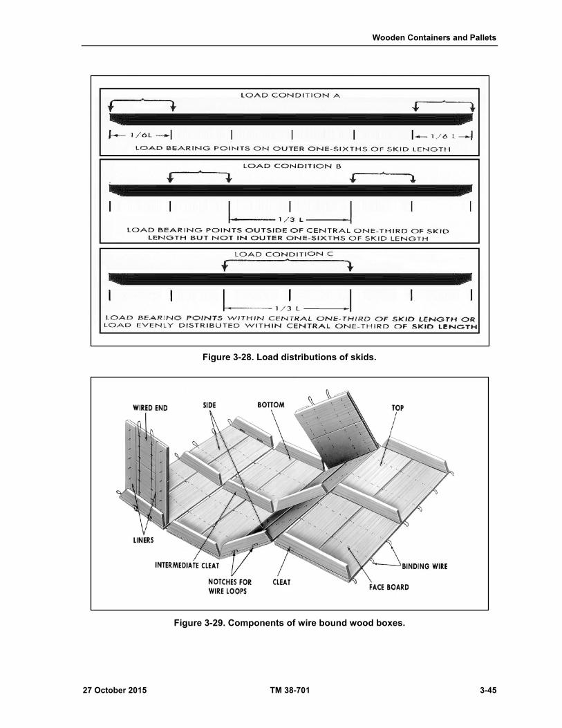
Wooden Containers and Pallets
27 October 2015 TM 38-701 3-45
Figure 3-28. Load distributions of skids.
Figure 3-29. Components of wire bound wood boxes.

Chapter 3
3-46 TM 38-701 27 October 2015
Cleats
3-119. Cleats form the framework to which the ends of the faceboards or slats are fastened. They are made
with mitered or mortised and tenoned ends (tongued-and-grooved). Intermediate rows of cleats may be
required to reinforce unsupported spans.
Faceboards
3-120. Faceboards are the thin boards that form the six faces of the box. They are made of veneer, resawn
lumber, plywood, or paper-overlaid veneer. Their chief function is to hold the contents of the box in place.
Binding Wires
3-121. They hold the faces of the box together and carry most of the weight in the box.
Staples
3-122. They hold the faceboards and cleats to the binding wires.
Ends
3-123. The ends may be either plain, linered, or battened, according to the type of materials used, the weight
of contents, and type of load. Only ends made from plywood are plain.
Battens
3-124. They are pieces of wood used on the ends of wire bound wood boxes to reinforce the ends, to
reinforce the cleats, and to increase the strength of the box so that it may carry heavy stacking loads.
Liners
3-125. They are thinner pieces of boards stapled to the ends in order to tie all parts together and to strengthen
the fastening section. The grain of the liner is placed at right angles to the grain of the end face board. They
are stapled to either the outside or inside face of the ends. Liners for Styles 1 and 2 boxes are always vertical;
liners for Style 3 boxes are always horizontal.
Skids
3-126. A wire bound box has two skids added when it carries a gross weight in excess of 200 pounds or
when the gross weight exceeds 100 pounds, but the length and width are 48 inches by 24 inches or more.
Additional skids are added if the distance between them exceed 48 inches. They are secured by two rows of
nails in a staggered pattern. PPP-B-585D stipulates other requirements concerning the addition of skids.
Classes
3-127. There are three different classes
Class 1 Domestic
3-128. For domestic shipments not involving sea transportation, but subject to storage, rehandling, or
reshipment to domestic destinations. Weight limitation is 500 pounds.
Class 2 Normal Oversea
3-129. For off-shore and oversea shipments contemplating projected storage and commercial-type
handling. Weight limitation is 400 pounds.
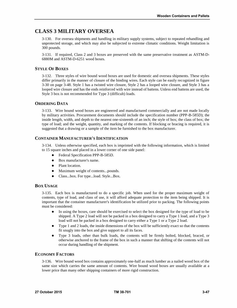
Wooden Containers and Pallets
27 October 2015 TM 38-701 3-47
CLASS 3 MILITARY OVERSEA
3-130. For oversea shipments and handling in military supply systems, subject to repeated rehandling and
unprotected storage, and which may also be subjected to extreme climatic conditions. Weight limitation is
300 pounds.
3-131. If required, Class 2 and 3 boxes are preserved with the same preservative treatment as ASTM-D-
6880M and ASTM-D-6251 wood boxes.
STYLE OF BOXES
3-132. Three styles of wire bound wood boxes are used for domestic and oversea shipments. These styles
differ primarily in the manner of closure of the binding wires. Each style can be easily recognized in figure
3-30 on page 3-48. Style 1 has a twisted wire closure, Style 2 has a looped wire closure, and Style 3 has a
looped wire closure and has the ends reinforced with wire instead of battens. Unless end battens are used, the
Style 3 box is not recommended for Type 3 (difficult) loads.
ORDERING DATA
3-133. Wire bound wood boxes are engineered and manufactured commercially and are not made locally
by military activities. Procurement documents should include the specification number (PPP-B-585D); the
inside length, width, and depth to the nearest one-sixteenth of an inch; the style of box; the class of box; the
type of load; and the weight, quantity, and marking of the contents. If blocking or bracing is required, it is
suggested that a drawing or a sample of the item be furnished to the box manufacturer.
CONTAINER MANUFACTURER'S IDENTIFICATION
3-134. Unless otherwise specified, each box is imprinted with the following information, which is limited
to 15 square inches and placed in a lower corner of one side panel:
Federal Specification PPP-B-585D.
Box manufacturer's name.
Plant location.
Maximum weight of contents...pounds.
Class...box. For type...load. Style...Box.
BOX USAGE
3-135. Each box is manufactured to do a specific job. When used for the proper maximum weight of
contents, type of load, and class of use, it will afford adequate protection to the item being shipped. It is
important that the container manufacturer's identification be utilized prior to packing. The following points
must be considered:
In using the boxes, care should be exercised to select the box designed for the type of load to be
shipped. A Type 2 load will not be packed in a box designed to carry a Type 1 load, and a Type 3
load will not be packed in a box designed to carry either a Type 1 or a Type 2 load.
Type 1 and 2 loads, the inside dimensions of the box will be sufficiently exact so that the contents
fit snugly into the box and give support to all its faces.
Type 3 loads, other than bulk loads, the contents will be firmly bolted, blocked, braced, or
otherwise anchored to the frame of the box in such a manner that shifting of the contents will not
occur during handling of the shipment.
ECONOMY FACTORS
3-136. Wire bound wood box contains approximately one-half as much lumber as a nailed wood box of the
same size which carries the same amount of contents. Wire bound wood boxes are usually available at a
lower price than many other shipping containers of more rigid construction.
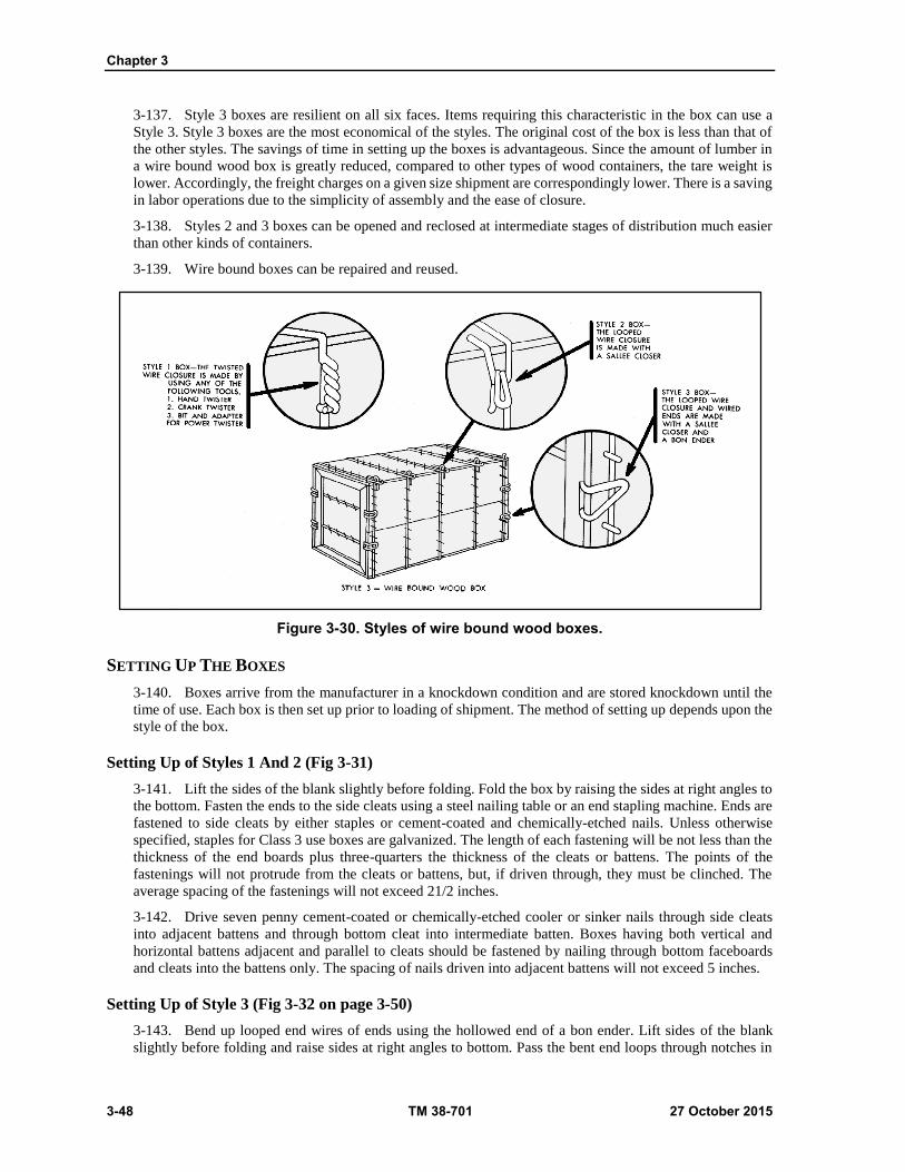
Chapter 3
3-48 TM 38-701 27 October 2015
3-137. Style 3 boxes are resilient on all six faces. Items requiring this characteristic in the box can use a
Style 3. Style 3 boxes are the most economical of the styles. The original cost of the box is less than that of
the other styles. The savings of time in setting up the boxes is advantageous. Since the amount of lumber in
a wire bound wood box is greatly reduced, compared to other types of wood containers, the tare weight is
lower. Accordingly, the freight charges on a given size shipment are correspondingly lower. There is a saving
in labor operations due to the simplicity of assembly and the ease of closure.
3-138. Styles 2 and 3 boxes can be opened and reclosed at intermediate stages of distribution much easier
than other kinds of containers.
3-139. Wire bound boxes can be repaired and reused.
Figure 3-30. Styles of wire bound wood boxes.
SETTING UP THE BOXES
3-140. Boxes arrive from the manufacturer in a knockdown condition and are stored knockdown until the
time of use. Each box is then set up prior to loading of shipment. The method of setting up depends upon the
style of the box.
Setting Up of Styles 1 And 2 (Fig 3-31)
3-141. Lift the sides of the blank slightly before folding. Fold the box by raising the sides at right angles to
the bottom. Fasten the ends to the side cleats using a steel nailing table or an end stapling machine. Ends are
fastened to side cleats by either staples or cement-coated and chemically-etched nails. Unless otherwise
specified, staples for Class 3 use boxes are galvanized. The length of each fastening will be not less than the
thickness of the end boards plus three-quarters the thickness of the cleats or battens. The points of the
fastenings will not protrude from the cleats or battens, but, if driven through, they must be clinched. The
average spacing of the fastenings will not exceed 21/2 inches.
3-142. Drive seven penny cement-coated or chemically-etched cooler or sinker nails through side cleats
into adjacent battens and through bottom cleat into intermediate batten. Boxes having both vertical and
horizontal battens adjacent and parallel to cleats should be fastened by nailing through bottom faceboards
and cleats into the battens only. The spacing of nails driven into adjacent battens will not exceed 5 inches.
Setting Up of Style 3 (Fig 3-32 on page 3-50)
3-143. Bend up looped end wires of ends using the hollowed end of a bon ender. Lift sides of the blank
slightly before folding and raise sides at right angles to bottom. Pass the bent end loops through notches in

Wooden Containers and Pallets
27 October 2015 TM 38-701 3-49
the cleats. Using the tapered end of the bon ender, bend back the looped wire over and around the binding
wire of the side.
3-144. When battens are used on the ends of style 3 boxes, battens adjacent to batten cleats are nailed by
driving seven penny cement-coated or chemically-etched cooler or sinker nails through the bottom boards,
through the cleat and into the adjacent batten. Spacing of nails will not exceed 5 inches. Intermediate battens
are secured by driving one seven penny cement-coated or chemically- etched cooler and sinker nail through
the board and cleat into the end of the intermediate batten.
Strapping Requirements
3-145. Where strapping is required, the top cleats shall be brought in contact with the side cleats and the
strapping is applied before the wires at the closing edges are twisted or looped. This eliminates occasional
slack which may develop when strapping is applied after closure is made. Strapping is placed as indicated in
figure 3-33 on page 3-50, wire strapping cannot be smaller than 13-gauge. Flat strapping cannot be less than
5/8 X 0.020 inch.
Figure 3·31. Setting up of styles 1 and 2, wire bound wood boxes.

Chapter 3
3-50 TM 38-701 27 October 2015
Figure 3·32. Setting up of style 3 wire bound wood box.
Figure 3-33. Strapping of wire bound wood boxes.
Wooden Containers and Pallets
27 October 2015 TM 38-701 3-51
Closure of The Boxes
3-146. The closure method used depends on the style of the box.
Closure Of Style 1
3-147. Style 1 boxes are closed by using special tools (fig 3-34 on page 3-52). When intermediate battens
are used on the ends of the box, one seven penny cement-coated or chemically-etched sinker or cooler nail is
driven through the top board and cleats and into the end of each intermediate batten. This is done prior to
making the closures of the binding wires.
Closure Of Styles 2 And 3
3-148. These styles are closed by using a Sallee closer. Perform the steps, as shown in figure 3-35 on page
3-53. Insert the Sallee closer through the side loop and catch the top loop in the notch on the end of the tool.
Raise the handle of the Sallee closer to slightly beyond a vertical position and push the top loop down against
the side of the box. Complete closing by swinging the handle of the Sallee closer down as far as possible.
Drive a nail through the top cleat into each intermediate batten. Do not nail into the ends of the battens that
are adjacent to the cleats.
Note. The applicable tools for making closures are illustrated in figure 3-34 on page 3-52 and
figure 3-35 on page 3-53. Correct tools are available from box manufacturer. Do not use screw
drivers, pliers, etc., because an adequate closure cannot be made and their use is time-consuming
and may be a safety hazard.
PALLETS (GENERAL)
3-149. A pallet is a portable platform on which material is placed to facilitate handling and transportation.
This platform is generally a two-deck structure which permits mechanical handling and tiering of unit loads
of supplies and equipment.
TYPES OF PALLETS
3-150. Pallets are classified as expendable and permanent. They are also classes as general purpose and
special purpose.
Expendable Pallets
3-151. Expendable pallets are designed generally for one shipment and then discarded. Their construction
is usually of wood, fiberboard, or a combination of the two. In order to be effective as one-trip pallets, they
must be lightweight and low in cost. When the cost of using them is equaled or exceeded by the savings
realized during a single trip, they are truly expendable pallets. Examples of expendable pallets are illustrated
in figure 3-36 on page 3-53.
Permanent Pallets
3-152. Permanent pallets are termed as general purpose and special purpose pallets.
General Purpose Pallets
3-153. The general purpose pallets are constructed of hard wood and are normally 40 inches by 48 inches
in size. They fit economically into railroad and, motor vehicles, and trailers. Two general purpose pallets are
the 4-way entry post pallet and the 4-way (partial) four-stringer pallet (fig 3-37 on page 3-54).
Special Purpose Pallets
3-154. Pallets made of metal, which are suitable for certain heavy duty usage, are special purpose pallets.
They are more rugged and will stand more abuse than wood pallets. There are no fasteners to work loose and

Chapter 3
3-52 TM 38-701 27 October 2015
cause damage to flexible containers and their contents. Pallets made of aluminum have been developed that
are light in weight. The initial cost of metal pallets is high in comparison to pallets made of wood.
Figure 3-34. Closing of style 1 wire bound wood box with special tools.
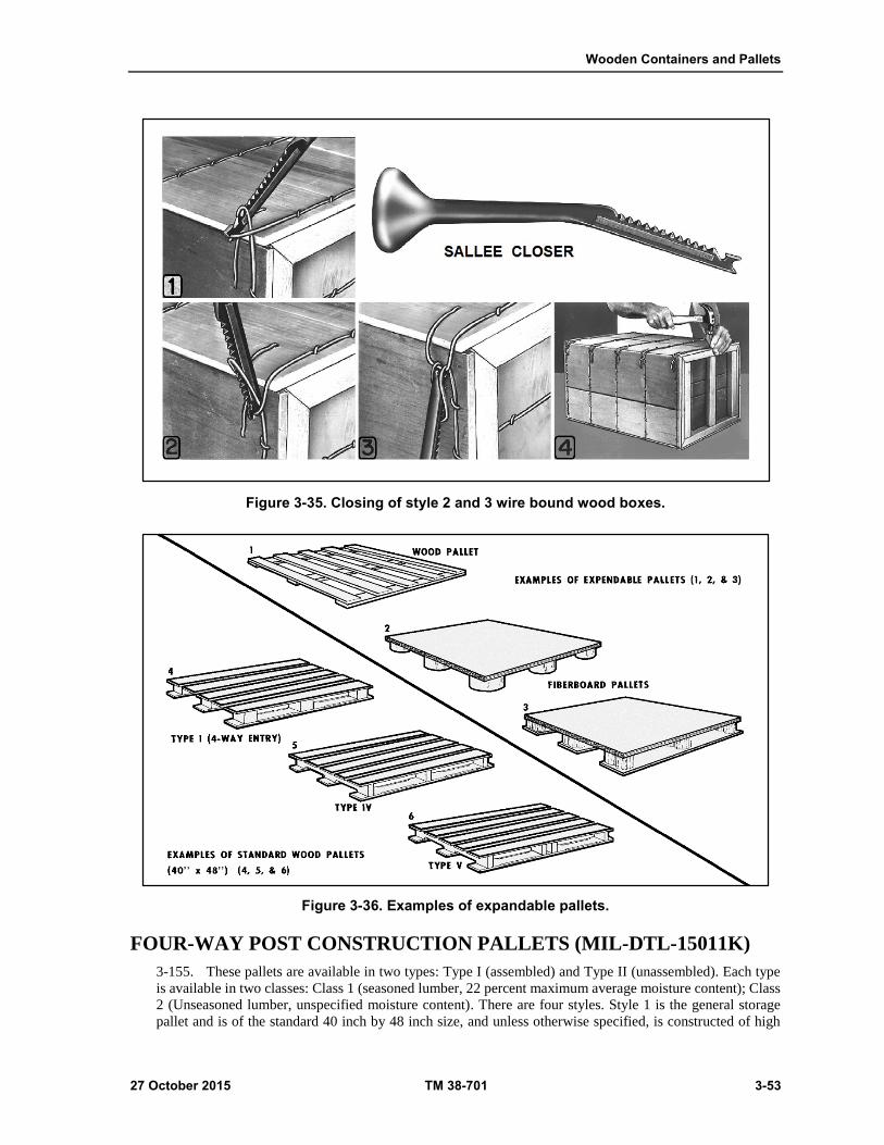
Wooden Containers and Pallets
27 October 2015 TM 38-701 3-53
Figure 3-35. Closing of style 2 and 3 wire bound wood boxes.
Figure 3-36. Examples of expandable pallets.
FOUR-WAY POST CONSTRUCTION PALLETS (MIL-DTL-15011K)
3-155. These pallets are available in two types: Type I (assembled) and Type II (unassembled). Each type
is available in two classes: Class 1 (seasoned lumber, 22 percent maximum average moisture content); Class
2 (Unseasoned lumber, unspecified moisture content). There are four styles. Style 1 is the general storage
pallet and is of the standard 40 inch by 48 inch size, and unless otherwise specified, is constructed of high
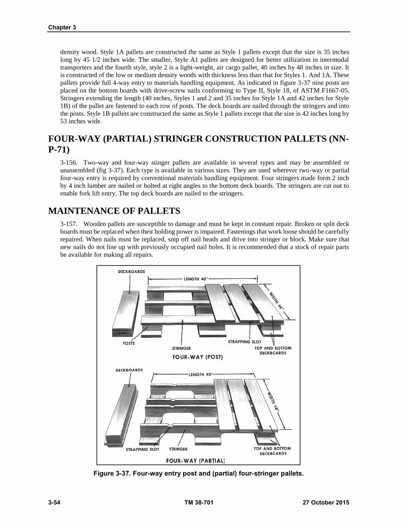
Chapter 3
3-54 TM 38-701 27 October 2015
density wood. Style 1A pallets are constructed the same as Style 1 pallets except that the size is 35 inches
long by 45 1/2 inches wide. The smaller, Style A1 pallets are designed for better utilization in intermodal
transporters and the fourth style, style 2 is a light-weight, air cargo pallet, 40 inches by 48 inches in size. It
is constructed of the low or medium density woods with thickness less than that for Styles 1. And 1A. These
pallets provide full 4-way entry to materials handling equipment. As indicated in figure 3-37 nine posts are
placed on the bottom boards with drive-screw nails conforming to Type II, Style 18, of ASTM F1667-05.
Stringers extending the length (40 inches, Styles 1 and 2 and 35 inches for Style 1A and 42 inches for Style
1B) of the pallet are fastened to each row of posts. The deck boards are nailed through the stringers and into
the posts. Style 1B pallets are constructed the same as Style 1 pallets except that the size is 42 inches long by
53 inches wide.
FOUR-WAY (PARTIAL) STRINGER CONSTRUCTION PALLETS (NN-
P-71)
3-156. Two-way and four-way stinger pallets are available in several types and may be assembled or
unassembled (fig 3-37). Each type is available in various sizes. They are used wherever two-way or partial
four-way entry is required by conventional materials handling equipment. Four stringers made form 2 inch
by 4 inch lumber are nailed or bolted at right angles to the bottom deck boards. The stringers are cut out to
enable fork lift entry. The top deck boards are nailed to the stringers.
MAINTENANCE OF PALLETS
3-157. Wooden pallets are susceptible to damage and must be kept in constant repair. Broken or split deck
boards must be replaced when their holding power is impaired. Fastenings that work loose should be carefully
repaired. When nails must be replaced, snip off nail heads and drive into stringer or block. Make sure that
new nails do not line up with previously occupied nail holes. It is recommended that a stock of repair parts
be available for making all repairs.
Figure 3-37. Four-way entry post and (partial) four-stringer pallets.

Wooden Containers and Pallets
27 October 2015 TM 38-701 3-55
This page intentionally left blank.

This page intentionally left blank.
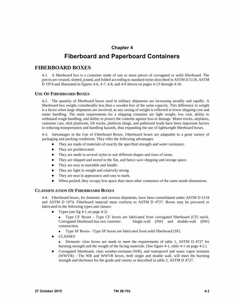
27 October 2015 TM 38-701 4-1
Chapter 4
Fiberboard and Paperboard Containers
FIBERBOARD BOXES
4-1. A fiberboard box is a container made of one or more pieces of corrugated or solid fiberboard. The
pieces are creased, slotted, joined, and folded according to standard styles described in ASTM D 5118, ASTM
D 1974 and illustrated in figures 4-6, 4-7, 4-8, and 4-9 shown on pages 4-13 through 4-16.
USE OF FIBERBOARD BOXES
4-2. The quantity of fiberboard boxes used in military shipments are increasing steadily and rapidly. A
fiberboard box weighs considerably less than a wooden box of the same capacity. This difference in weight
is a factor when large shipments are involved, as any saving of weight is reflected in lower shipping cost and
easier handling. The main requirements for a shipping container are light weight, low cost, ability to
withstand rough handling, and ability to protect the contents against loss or damage. Motor trucks, airplanes,
container cars, skid platforms, lift trucks, platform slings, and palletized loads have been important factors
in reducing transportation and handling hazards, thus expanding the use of lightweight fiberboard boxes.
4-3. Advantages in the Use of Fiberboard Boxes. Fiberboard boxes are adaptable to a great variety of
packaging and packing conditions. They offer the following advantages:
They are made of materials of exactly the specified strength and water resistance.
They are prefabricated.
They are made in several styles to suit different shapes and sizes of items.
They are shipped and stored in the flat, and hence save shipping and storage space.
They are easy to assemble and handle.
They are light in weight and relatively strong.
They are neat in appearance and easy to mark.
When packed, they occupy less space than most other containers of the same inside dimensions.
CLASSIFICATION OF FIBERBOARD BOXES
4-4. Fiberboard boxes, for domestic and oversea shipments, have been consolidated under ASTM D 5118
and ASTM D 1974. Fiberboard material must conform to ASTM D 4727. Boxes may be procured or
fabricated in the following types and classes:
Types (see fig 4-1 on page 4-2)
Type CF Boxes - Type CF boxes are fabricated from corrugated fiberboard (CF) stock.
Corrugated fiberboard has two varieties: Single-wall (SW) and double-wall (DW)
construction.
Type SF Boxes - Type SF boxes are fabricated from solid fiberboard (SF).
CLASSES
Domestic class boxes are made to meet the requirements of table 1, ASTM D 4727 for
bursting strength and the weight of the facing materials. (See figure 4-1, table 4-1 on page 4-2.)
Corrugated fiberboard, class weather-resistant (WR), and waterproof and water vapor resistant
(WWVR) - The WR and WWVR boxes, both single and double wall, will meet the bursting
strength and thickness for the grade and variety as described in table 2, ASTM D 4727.
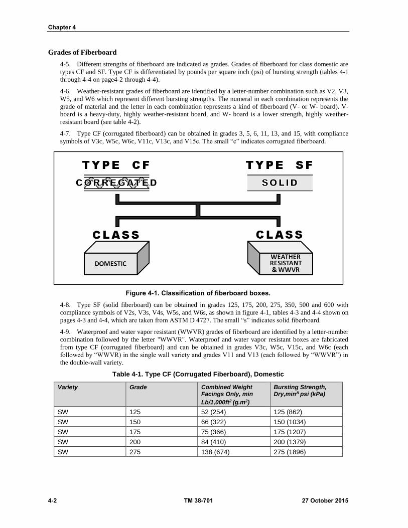
Chapter 4
4-2 TM 38-701 27 October 2015
Grades of Fiberboard
4-5. Different strengths of fiberboard are indicated as grades. Grades of fiberboard for class domestic are
types CF and SF. Type CF is differentiated by pounds per square inch (psi) of bursting strength (tables 4-1
through 4-4 on page4-2 through 4-4).
4-6. Weather-resistant grades of fiberboard are identified by a letter-number combination such as V2, V3,
W5, and W6 which represent different bursting strengths. The numeral in each combination represents the
grade of material and the letter in each combination represents a kind of fiberboard (V- or W- board). V-
board is a heavy-duty, highly weather-resistant board, and W- board is a lower strength, highly weather-
resistant board (see table 4-2).
4-7. Type CF (corrugated fiberboard) can be obtained in grades 3, 5, 6, 11, 13, and 15, with compliance
symbols of V3c, W5c, W6c, V11c, V13c, and V15c. The small “c” indicates corrugated fiberboard.
Figure 4-1. Classification of fiberboard boxes.
4-8. Type SF (solid fiberboard) can be obtained in grades 125, 175, 200, 275, 350, 500 and 600 with
compliance symbols of V2s, V3s, V4s, W5s, and W6s, as shown in figure 4-1, tables 4-3 and 4-4 shown on
pages 4-3 and 4-4, which are taken from ASTM D 4727. The small “s” indicates solid fiberboard.
4-9. Waterproof and water vapor resistant (WWVR) grades of fiberboard are identified by a letter-number
combination followed by the letter "WWVR". Waterproof and water vapor resistant boxes are fabricated
from type CF (corrugated fiberboard) and can be obtained in grades V3c, W5c, V15c, and W6c (each
followed by “WWVR) in the single wall variety and grades V11 and V13 (each followed by “WWVR”) in
the double-wall variety.
Table 4-1. Type CF (Corrugated Fiberboard), Domestic
Variety Grade Combined Weight Facings Only, min
Lb/1,000ft2 (g.m2)
Bursting Strength, Dry,minA psi (kPa)
SW 125 52 (254) 125 (862)
SW 150 66 (322) 150 (1034)
SW 175 75 (366) 175 (1207)
SW 200 84 (410) 200 (1379)
SW 275 138 (674) 275 (1896)

Fiberboard and Paperboard Containers
27 October 2015 TM 38-701 4-3
Table 4-1. Type CF (Corrugated Fiberboard), Domestic (continued)
Variety Grade Combined Weight Facings Only,in pounds
/1,000ft2 (g.m2)
Bursting Strength, Dry,minA psi (kPa)
Single wall 350 180 (879) 350 (2413)
Double wall 200 92 (449) 200 (1379)
Double wall 275 110 (537) 275 (1896)
Double wall 350 126 (615) 350 (2413)
Double wall 500 222 (1084) 500 (3447)
Double wall 600 270 (1318) 600 (4137)
Puncture
lbs / inches of
tear
(J)
Triple wall 1100 264 (1289) (33) A Only one burst of the initial six may fall beneath the minimum required. Domestic board failing to pass this test will be accepted if, in a retest consisting of 24 bursts (12 from each side of the board), not more than 4 bursts fall below the minimum value required
lb= pound / min= minimum / psi- pounds per square inch
Table 4-2 Type CF (Corrugated Fiberboard), Weather-Resistant, and Water and Water Vapor Resistant Classes (WWVR)
Thickness, in. (millimeter)B Bursting Strength, psi (kPa), minimum average
Variety GradeA,C Corrugating Medium
Outer Facings Dry WetD
Single wall V3c 0.010(0.254) 0.023(0.584) 400(2758) 150(1034)
Single wall W5c 0.010(0.254) 0.016(0.406) 275(1896) 100(689)
Single wall W6c 0.010(0.254) 0.010(0.254) 175(1207) 50(345)
Double wall V11c 0.010(0.254) 0.023(0.584) 600(4137) 300(2068)
Double wall V13c 0.010(0.254) 0.016(0.406) 400(2758) 200(1379)
Double wall V15c 0.010(0.254) 0.010(0.254) 300(2068) 100(689) A Includes WWVR grades. B A - r%, or unlimited plus tolerance shall be permitted. C For double wall fiberboard, the inner facing shall be the same thickness as the outer facing. D After 24 h immersion (see 9.2.1)
Psi- pounds per square inch
Table 4-3 Type SF (Solid Fiberboard): Class Domestic, All Grades
Grade Combined Weight of Plies Before Lamination, lb/1,000 ft2(g/m2), min
Bursting Strength, psi (kPa),minA
125 114 (557) 125 (862)
175 149 (727) 175 (1207)
200 190 (928) 200 (1379)
275 237 (1157) 275 (1896)
350 283 (1382) 350 (2413)
500 330 (1611) 500 (3347)
600 360 (1758) 600 (4137)
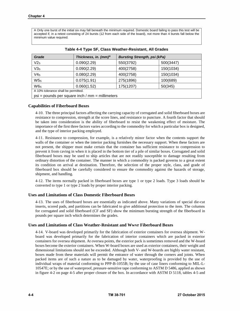
Chapter 4
4-4 TM 38-701 27 October 2015
A Only one burst of the initial six may fall beneath the minimum required. Domestic board failing to pass this test will be accepted if, in a retest consisting of 24 bursts (12 from each side of the board), not more than 4 bursts fall below the minimum value required.
Table 4-4 Type SF, Class Weather-Resistant, All Grades
Grade Thickness, in. (mm)A Bursting Strength, psi (kPa)
V2S 0.090(2.29) 550(3792) 500(3447)
V3S 0.090(2.29) 400(2758) 150(1034)
V4S 0.080(2.29) 400(2758) 150(1034)
W5S 0.075(1.91) 275(1896) 100(689)
W6S 0.060(1.52) 175(1207) 50(345) A 10% tolerance shall be permitted.
psi = pounds per square inch / mm = millimeters
Capabilities of Fiberboard Boxes
4-10. The three principal factors affecting the carrying capacity of corrugated and solid fiberboard boxes are
resistance to compression, strength at the score lines, and resistance to puncture. A fourth factor that should
be taken into consideration is the ability of fiberboard to resist the weakening effect of moisture. The
importance of the first three factors varies according to the commodity for which a particular box is designed,
and the type of interior packing employed.
4-11. Resistance to compression, for example, is a relatively minor factor when the contents support the
walls of the container or when the interior packing furnishes the necessary support. When these factors are
not present, the shipper must make certain that the container has sufficient resistance to compression to
prevent it from caving in when it is placed in the bottom tier of a pile of similar boxes. Corrugated and solid
fiberboard boxes may be used to ship articles that are not readily susceptible to damage resulting from
ordinary distortion of the container. The manner in which a commodity is packed governs to a great extent
its condition on arrival at destination. Therefore, the selection of the proper style, class, and grade of
fiberboard box should be carefully considered to ensure the commodity against the hazards of storage,
shipment, and handling.
4-12. The items normally packed in fiberboard boxes are type 1 or type 2 loads. Type 3 loads should be
converted to type 1 or type 2 loads by proper interior packing.
Uses and Limitations of Class Domestic Fiberboard Boxes
4-13. The uses of fiberboard boxes are essentially as indicated above. Many variations of special die-cut
inserts, scored pads, and partitions can be fabricated to give additional protection to the item. The columns
for corrugated and solid fiberboard (CF and SF) show the minimum bursting strength of the fiberboard in
pounds per square inch which determines the grades.
Uses and Limitations of Class Weather-Resistant and Wwvr Fiberboard Boxes
4-14. V-board was developed primarily for the fabrication of exterior containers for oversea shipment. W-
board was developed primarily for the fabrication of interior containers which are packed in exterior
containers for oversea shipment. At oversea points, the exterior pack is sometimes removed and the W-board
boxes become the exterior containers. When W-board boxes are used as exterior containers, their weight and
dimensional limitations should not be exceeded. Although both V- and W-boards are highly water resistant,
boxes made from these materials will permit the entrance of water through the corners and joints. When
packed items are of such a nature as to be damaged by water, waterproofing is provided by the use of
individual wraps of material conforming to PPP-B-1055B; by the use of case liners conforming to MIL-L-
10547E; or by the use of waterproof, pressure-sensitive tape conforming to ASTM D 5486, applied as shown
in figure 4-2 on page 4-5 after proper closure of the box. In accordance with ASTM D 5118, tables 4-5 and
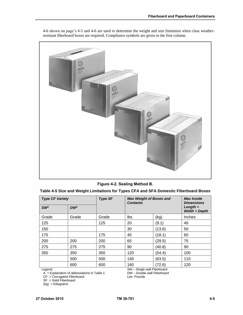
Fiberboard and Paperboard Containers
27 October 2015 TM 38-701 4-5
4-6 shown on page’s 4-5 and 4-6 are used to determine the weight and size limitation when class weather-
resistant fiberboard boxes are required. Compliance symbols are given in the first column.
Figure 4-2. Sealing Method B.
Table 4-5 Size and Weight Limitations for Types CFA and SFA Domestic Fiberboard Boxes
Type CF Variety Type SF Max Weight of Boxes and Contents
Max Inside Dimensions Length + Width + Depth
SW4 DW4
Grade Grade Grade lbs (kg) Inches
125 125 20 (9.1) 40
150 30 (13.6) 50
175 175 40 (18.1) 60
200 200 200 65 (29.5) 75
275 275 275 90 (40.8) 90
350 350 350 120 (54.4) 100
500 500 140 (63.5) 110
600 600 160 (72.6) 120 Legend: A = Explanation of abbreviations in Table 1 CF = Corrugated Fiberboard SF = Solid Fiberboard (kg) = Kiliograms
SW – Single wall Fiberboard DW – Double wall Fiberboard Lbs- Pounds
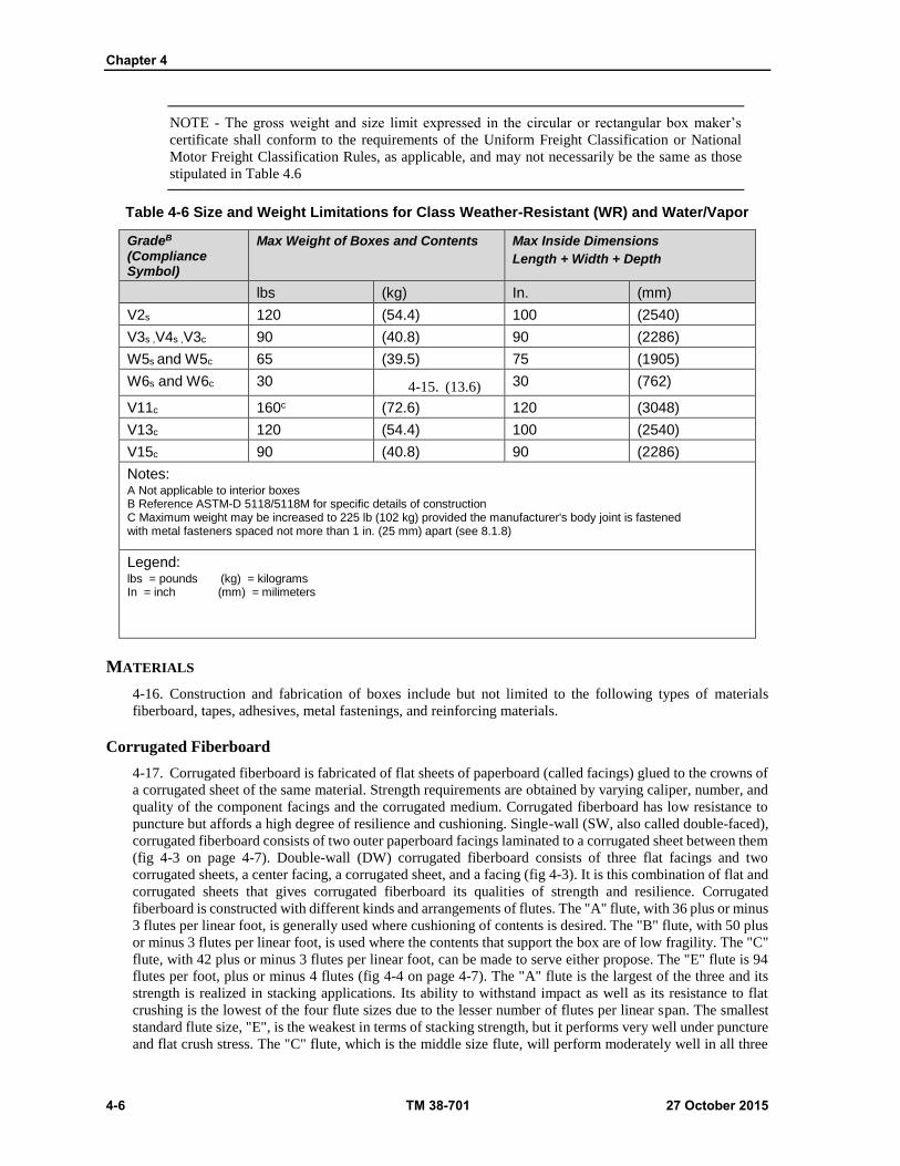
Chapter 4
4-6 TM 38-701 27 October 2015
NOTE - The gross weight and size limit expressed in the circular or rectangular box maker’s
certificate shall conform to the requirements of the Uniform Freight Classification or National
Motor Freight Classification Rules, as applicable, and may not necessarily be the same as those
stipulated in Table 4.6
Table 4-6 Size and Weight Limitations for Class Weather-Resistant (WR) and Water/Vapor
GradeB (Compliance Symbol)
Max Weight of Boxes and Contents Max Inside Dimensions
Length + Width + Depth
lbs (kg) In. (mm)
V2s 120 (54.4) 100 (2540)
V3s ,V4s ,V3c 90 (40.8) 90 (2286)
W5s and W5c 65 (39.5) 75 (1905)
W6s and W6c 30 4-15. (13.6) 30 (762)
V11c 160c (72.6) 120 (3048)
V13c 120 (54.4) 100 (2540)
V15c 90 (40.8) 90 (2286)
Notes: A Not applicable to interior boxes B Reference ASTM-D 5118/5118M for specific details of construction C Maximum weight may be increased to 225 lb (102 kg) provided the manufacturer's body joint is fastened with metal fasteners spaced not more than 1 in. (25 mm) apart (see 8.1.8)
Legend: lbs = pounds (kg) = kilograms In = inch (mm) = milimeters
MATERIALS
4-16. Construction and fabrication of boxes include but not limited to the following types of materials
fiberboard, tapes, adhesives, metal fastenings, and reinforcing materials.
Corrugated Fiberboard
4-17. Corrugated fiberboard is fabricated of flat sheets of paperboard (called facings) glued to the crowns of
a corrugated sheet of the same material. Strength requirements are obtained by varying caliper, number, and
quality of the component facings and the corrugated medium. Corrugated fiberboard has low resistance to
puncture but affords a high degree of resilience and cushioning. Single-wall (SW, also called double-faced),
corrugated fiberboard consists of two outer paperboard facings laminated to a corrugated sheet between them
(fig 4-3 on page 4-7). Double-wall (DW) corrugated fiberboard consists of three flat facings and two
corrugated sheets, a center facing, a corrugated sheet, and a facing (fig 4-3). It is this combination of flat and
corrugated sheets that gives corrugated fiberboard its qualities of strength and resilience. Corrugated
fiberboard is constructed with different kinds and arrangements of flutes. The "A" flute, with 36 plus or minus
3 flutes per linear foot, is generally used where cushioning of contents is desired. The "B" flute, with 50 plus
or minus 3 flutes per linear foot, is used where the contents that support the box are of low fragility. The "C"
flute, with 42 plus or minus 3 flutes per linear foot, can be made to serve either propose. The "E" flute is 94
flutes per foot, plus or minus 4 flutes (fig 4-4 on page 4-7). The "A" flute is the largest of the three and its
strength is realized in stacking applications. Its ability to withstand impact as well as its resistance to flat
crushing is the lowest of the four flute sizes due to the lesser number of flutes per linear span. The smallest
standard flute size, "E", is the weakest in terms of stacking strength, but it performs very well under puncture
and flat crush stress. The "C" flute, which is the middle size flute, will perform moderately well in all three

Fiberboard and Paperboard Containers
27 October 2015 TM 38-701 4-7
areas--stacking, puncture, and flat crush. It is used where maximum strength in any one area is not required,
but where weakness in no area can be tolerated.
Figure 4-3. Types and varieties of fiberboard.

Chapter 4
4-8 TM 38-701 27 October 2015
Figure 4-4. Corrugated fiberboard flutes.
Domestic Fiberboard Boxes
4-18. Variety SW fiberboard used to fabricate type CF boxes will be A, B, C, or E flute at the option of the
supplier. Variety DW fiberboard used to fabricate type CF boxes will be any combination of A, B, C, or E
flutes, except they shall not be BB, EE, or BE flute. Type CF boxes, fabricated from variety SW or DW
fiberboard shall have the flutes running perpendicular to the scores of the box openings. When specified, the
flutes for variety SW or DW fiberboard will run horizontal to the scores of the box openings for boxes of a
size that the top and bottom openings are on the smallest panels.
Weather-Resistant And Wwvr Fiberboard Boxes
4-19. Variety SW fiberboard used to fabricate type CF boxes will be either A, B, or C flute as specified.
Conventional slotted type CF boxes shall have the flutes run perpendicular to the scores of the box openings.
When specified, the flutes for these boxes shall run horizontal to the scores of the box openings for boxes of
a size and style that the top and bottom openings are on the smallest panel. For double cover boxes and
interlocking double cover boxes (fig 4-7 on page 4-14), they shall have the flutes run the depth of the box
perpendicular to the opening.
Solid Fiberboard, Type SF
4-20. Solid fiberboard consists of two or more flat plies of paperboard laminated together with an adhesive
applied over the entire area of contact between the sheets (fig 4-3). The combined material is solid, hard, and
rigid, and boxes fabricated from it resist puncture to a high degree but offer little cushioning to their contents.
They do, however, offer greater resistance to rough handling and wear, and are better adapted for use in
shipping heavier and less fragile items than those shipped in corrugated fiberboard boxes. If the weight of
the box and contents does not exceed 40 pounds, the fiberboard will not be less than two-ply. If the weight
exceeds 40 pounds, the fiberboard will be not less than three-ply.
Tapes
4-21. Among the tapes most commonly used for closing and sealing fiberboard boxes are—
ASTM D 5486, a pressure-sensitive water-resistant, paper-backed tape, normally used to close
interior containers. ASTM D 5486 is also a pressure-sensitive waterproof tape, used to close and
waterproof interior and exterior fiberboard boxes.
A-A-1492B, A-A-1671B, a reinforced, paper-gummed tape, used for sealing fiberboard containers
for domestic shipment and storage.
Fiberboard and Paperboard Containers
27 October 2015 TM 38-701 4-9
Adhesive
4-22. Adhesive used for closing fiberboard boxes will conform to commercial item description,A-A-59692.
Metal Fastenings
4-23. Metal fastening for securing the manufacturer's joint and closing class weather-resistant and WWVR
fiberboard boxes, will be commercially preformed staples or staples from commercial steel stitching wire.
The staples will be treated with a commercially applied coating of zinc or copper wash to resist corrosion.
ASTM D 5118 and ASTM D 1974 specifies the sizes of staples to use.
Reinforcing Materials
4-24. Flat steel strapping ASTM D 3953; nonmetallic strapping, ASTM D 3950; or pressure-sensitive,
filament-reinforced tape ASTM D 5530 are used to reinforce packed and closed fiberboard boxes. Another
document to reference is ASTM D 4675, Standard Guide for Selection and Use of Flat Strapping Materials.
Fabrication of the Boxes
4-25. Cutting, scoring, and slotting. Special machines are used to cut, score, and slot the fiberboard material
so that it can be made into a box.
Body Joint (Manufacture's Joint)
4-26. Domestic boxes, types CF and SF. The body joint (manufacture's joint) of domestic, corrugated
fiberboard boxes will be either overlapped or butted, as specified (fig 4-5 on page 4-9). The type SF joint
shall be overlapped.
Overlapped Joint (Joint Tab)
4-27. The joint shall be made with fiberboard joint tab overlap not less than 1 1/4 in. (32 millimeters (mm))
wide with the length of the overlap equal to the inside depth of the box. The joint tab may be an extension of
either the end or side panel of the box. When specified the joint tab may extend into the flap area and be
secured. The joint tab shall be fastened either inside or outside the adjoining panel and the top and bottom
edges of the front tab shall be no more than 3/16 in. (5 mm) below the top or above the bottom score line of
this panel. The overlapped joint of type CF boxes shall be fastened with adhesive. The toxicity requirement
may be waived when packing items other than food. When adhesive is used it shall be applied so as to cover
the full area between the joint tab and the adjoining panel. The adhesive shall substantially extend to all edges
of the overlap. The overlapped joint of type SF boxes shall be fastened with metal fasteners. Metal fasteners
for the type CF and type SF boxes having a depth dimension of 18 in. (457 mm) or less shall be spaced not
more than 3 in. (76 mm) apart center to center.
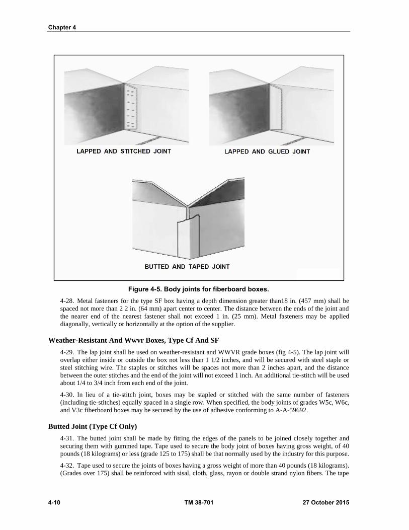
Chapter 4
4-10 TM 38-701 27 October 2015
Figure 4-5. Body joints for fiberboard boxes.
4-28. Metal fasteners for the type SF box having a depth dimension greater than18 in. (457 mm) shall be
spaced not more than 2 2 in. (64 mm) apart center to center. The distance between the ends of the joint and
the nearer end of the nearest fastener shall not exceed 1 in. (25 mm). Metal fasteners may be applied
diagonally, vertically or horizontally at the option of the supplier.
Weather-Resistant And Wwvr Boxes, Type Cf And SF
4-29. The lap joint shall be used on weather-resistant and WWVR grade boxes (fig 4-5). The lap joint will
overlap either inside or outside the box not less than 1 1/2 inches, and will be secured with steel staple or
steel stitching wire. The staples or stitches will be spaces not more than 2 inches apart, and the distance
between the outer stitches and the end of the joint will not exceed 1 inch. An additional tie-stitch will be used
about 1/4 to 3/4 inch from each end of the joint.
4-30. In lieu of a tie-stitch joint, boxes may be stapled or stitched with the same number of fasteners
(including tie-stitches) equally spaced in a single row. When specified, the body joints of grades W5c, W6c,
and V3c fiberboard boxes may be secured by the use of adhesive conforming to A-A-59692.
Butted Joint (Type Cf Only)
4-31. The butted joint shall be made by fitting the edges of the panels to be joined closely together and
securing them with gummed tape. Tape used to secure the body joint of boxes having gross weight, of 40
pounds (18 kilograms) or less (grade 125 to 175) shall be that normally used by the industry for this purpose.
4-32. Tape used to secure the joints of boxes having a gross weight of more than 40 pounds (18 kilograms).
(Grades over 175) shall be reinforced with sisal, cloth, glass, rayon or double strand nylon fibers. The tape

Fiberboard and Paperboard Containers
27 October 2015 TM 38-701 4-11
shall be not less than 2 in. (51 mm) in width for boxes having a gross weight of 65 lb (30 kg) or less (grade
200 and below) and not less than 3 in (76 mm) in width for boxes having a gross weight over 65 lb (30 kg)
(grade above 200). The tape shall be centered on the joint and extend its full length, or within 3/8 in (10 mm)
or full length be centered on the joint and shall adhere over not less than 90% to the entire area of contact
with the fiberboard.
Styles Of Fiberboard Boxes
4-33. The styles covered in figures 4-6, 4-7, and 4-8 located on pages 4-12 through 4-14 are the basic styles
of domestic, weather-resistant, and WWVR fiberboard boxes.
Regular Slotted Box (RSC) (Figure 4-6)
4-34. In this design, all the flaps (inner and outer) are of equal length. The outer flaps meet in the center
when closed. This style is the most commonly used.
Special Full Flap Slotted Box (Figure 4-6)
4-35. In this design the inner flaps meet in the center of the box. A one-fourth inch gap is permitted.
Full Overlap Slotted Box (Figure 4-6)
4-36. In this design, the length of the outer flaps shall be not less than the inside width of the box minus 1
inch. This design results in a container with at least two thicknesses of fiberboard covering the entire top and
bottom surfaces.
Overlap Slotted Box (Figure 4-6)
4-37. In this box, when closed, the inner flaps must not overlap, and the outer flaps will overlap the distance
specified in the order or invitation for bids. The inner flaps will be of the same length as the outer flaps,
except when the relation of width to length would cause the inner flaps to overlap. In such a case, the inner
flaps will be cut to meet in the center of the box.
Center Special Slotted Box (Figure 4-7)
4-38. This box is designed so that the inner and outer flaps meet in the center giving a double thickness for
top and bottom.
Center Special Overlap Slotted Box (Figure 4-7)
4-39. This box is designed the same as the Center Special Slotted Box (CSSC) except the outer flaps are the
same length as the inner flaps and may overlap. No flap cutting is required.
Half Slotted Box With Cover (Figure 4-7)
4-40. This box consists of a box body and a cover. The body is formed from fiberboard, scored, slotted, and
stitched to form a tube having four flaps of equal length, approximately half the width of the box, on the
bottom only. Unless otherwise specified the cover shall be a Type I. When specified the cover shall be a Type
II. The depth of the cover is 3 in. unless otherwise specified.
Double Cover Box (Figure 4-7)
4-41. This box consists of a body tube and two covers. Unless otherwise specified Type I covers, three inches
deep, are to be used.
Interlocking Double Cover Box (Figure 4-7)
4-42. This box consists of a body table with top and bottom flanges and two interlocking covers. The body
shall be SW or DW fiberboard, scored, slotted, and stitched to form a tube having double scored short flanges
Chapter 4
4-12 TM 38-701 27 October 2015
which form a lock with the flanges of the cover (fig 4-10 on page 4-16). The top and bottom covers shall be
secured with horizontal straps. Unless otherwise specified the flanges shall be 3 in. wide for boxes made with
single-wall fiberboard and 4 in. wide for boxes made with double-wall fiberboard.
Full Telescope Box (Figure 4-8)
4-43. The box consists of a body and a snug fitting cover. The flaps of both may be positioned in one of 3
possible combinations. This style of box, when closed, has a triple thickness of fiberboard on all four corners,
affording good stacking strength.
4-44. Type CF (corrugated fiberboard) can be obtained in grades 3, 5, 6, 11, 13, and 15, with compliance
symbols of V3c, W5c, W6c, V11c, V13c, and V15c. The small “c” indicates corrugated fiberboard.
Full Telescope Half Slotted Box (Figure 4-8)
4-45. The box consists of a body and a telescoping cover, each constructed of one piece of scored and slotted
fiberboard. The box dimensions shall be the inside measurements of the assembled box body. The cover shall
be a snug fit on the body. The flaps along the longer edge of the box openings are the outer flaps and those
along the shorter edge are the inner flaps. Flaps shall not project beyond an edge of the box. All flaps shall
be of equal length with the outer flaps meeting in the center of the box but shall not overlap. A gap not to
exceed 1/4 in. (6m.m.) will be permitted unless otherwise specified.
One-Piece Folder Box (Figure 4-8)
4-46. When this box is closed, the outer flaps must meet. Unless otherwise specified, the inner flaps will not
be less than 2 inches long for folders under 18 inches and over in width. This style is also known as a book
wrapper.
Triple-Slide Box (Figure 4-9 on page 4-15)
4-47. This design, made from corrugated fiberboard only, is identified by the arrangement of corrugations
in which all corrugations run at right angles to the score lines in all parts of the box. It consists of three slides,
each of one piece of corrugated fiberboard, scored so as to cover completely four faces of the box. The joint
of the inner slide will be left open. The middle slide will be taped at the body joint and will be a sliding fit
on the assembled inner and middle slides.
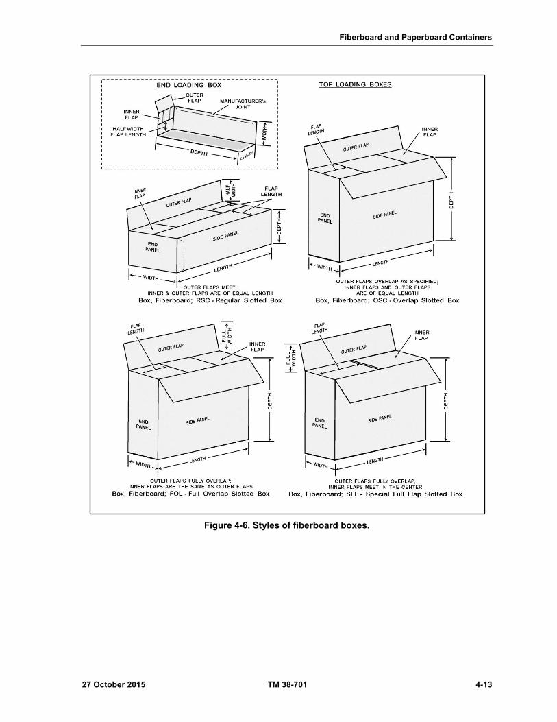
Fiberboard and Paperboard Containers
27 October 2015 TM 38-701 4-13
Figure 4-6. Styles of fiberboard boxes.
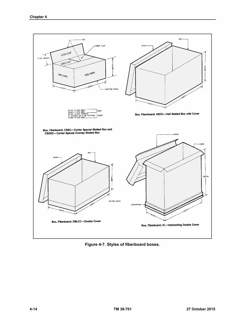
Chapter 4
4-14 TM 38-701 27 October 2015
Figure 4-7. Styles of fiberboard boxes.
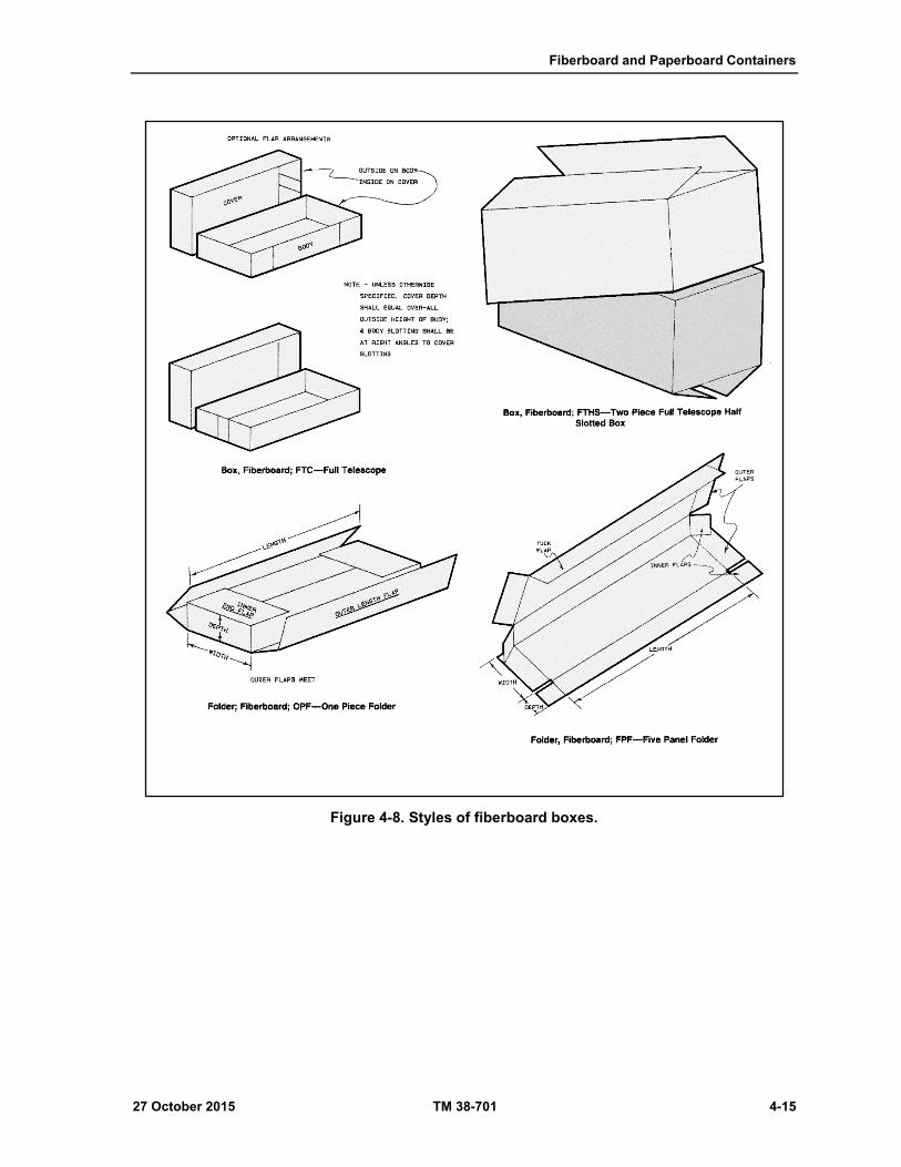
Fiberboard and Paperboard Containers
27 October 2015 TM 38-701 4-15
Figure 4-8. Styles of fiberboard boxes.
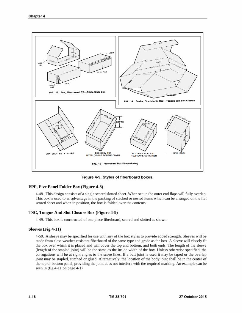
Chapter 4
4-16 TM 38-701 27 October 2015
Figure 4-9. Styles of fiberboard boxes.
FPF, Five Panel Folder Box (Figure 4-8)
4-48. This design consists of a single scored slotted sheet. When set up the outer end flaps will fully overlap.
This box is used to an advantage in the packing of stacked or nested items which can be arranged on the flat
scored sheet and when in position, the box is folded over the contents.
TSC, Tongue And Slot Closure Box (Figure 4-9)
4-49. This box is constructed of one piece fiberboard, scored and slotted as shown.
Sleeves (Fig 4-11)
4-50. A sleeve may be specified for use with any of the box styles to provide added strength. Sleeves will be
made from class weather-resistant fiberboard of the same type and grade as the box. A sleeve will closely fit
the box over which it is placed and will cover the top and bottom, and both ends. The length of the sleeve
(length of the stapled joint) will be the same as the inside width of the box. Unless otherwise specified, the
corrugations will be at right angles to the score lines. If a butt joint is used it may be taped or the overlap
joint may be stapled, stitched or glued. Alternatively, the location of the body joint shall be in the center of
the top or bottom panel, providing the joint does not interfere with the required marking. An example can be
seen in (fig 4-11 on page 4-17

Fiberboard and Paperboard Containers
27 October 2015 TM 38-701 4-17
Liners (Fig 4-12)
4-51. Liners are made from one piece of fiberboard. They are scored to cover the end and side panels of the
boxes. The height of the liners shall be the full inside depth of the boxes for which they are intended and the
ends of the liners shall be about in the center of the side panels of the boxes.
4-52. Unless otherwise specified, liners for class domestic boxes shall be constructed for double-wall
fiberboard, grade 275. The joints shall be secured with minimum 2 inch wide tape conforming to A-A-1492B,
A-A-1671B. Liners shall be constructed from the same class of material as the boxes themselves.
4-53. Unless otherwise specified liners for class weather-resistant boxes shall be constructed of V15c
fiberboard. When specified grade W5c, W6c, V3c, or V13c shall be used. Liners fabricated from single-wall
fiberboard shall be A or C flute and liners fabricated from double-wall fiberboard shall be any combination
of A, B, or C flutes, except BB flutes shall not be used. The flutes shall be perpendicular to the box openings
(as shown in fig 4-12). The joints shall be secured with minimum 2-inch wide tape running not less than three
quarters the length of the joint.
Figure 4-10. Cover assemblies.
BOX MAKER'S CERTIFICATE (FIG 4-13 ON PAGE 4-18)
4-54. Each fiberboard box will be plainly marked with the box maker's certificate, signifying compliance
with the requirements of the applicable freight classification rules. Type CF and type SF, class domestic
boxes are not required to be marked as being in compliance with ASTMs. There is no objection to marking
boxes that are manufactured in compliance with the specification. Types CF and SF, class weather-resistant
boxes, in addition to the box maker's name, will be marked with the date of manufacture expressed in month
and year, such as 7-93; the identification symbol, such as V3s; and the specification compliance data and the
minimum average bursting strength guaranteed in excess of....PSI. The figure to be inserted should be that
corresponding to the dry mullen requirements in ASTM D 4727 for the particular grade of fiberboard used.
For shipments to Government agencies include the national stock number, inside dimensions and outside
cube marked below the specification data on all exterior boxes procured as an item of supply.

Chapter 4
4-18 TM 38-701 27 October 2015
Figure 4-11. Use of fiberboard sleeve.
Figure 4-12. Use of fiberboard liner.

Fiberboard and Paperboard Containers
27 October 2015 TM 38-701 4-19
Figure 4-13. Sample of box maker's certificate.
Closure Requirements
4-55. All boxes should be securely closed. Inner and outer flaps of slotted style boxes should be drawn
together as closely as possible to insure proper closure. The lengthwise flaps should meet on (RSC, CSSC,
DSC) or overlap on (OSC, CSOSC, FOL, SFF), as specified. The flaps should not project over the side or
end edges, and the application of adhesive or metal stitches should be such as to prevent lifting of free edges
and corners of outer flaps on assembled boxes. ASTM D 1974, standard practice for methods of closing,
sealing, and reinforcing fiberboard shipping containers describes several methods to close seal and reinforce
solid and corrugated (excluding triple wall) fiberboard.
4-56. Solid and corrugated fiberboard (excluding triple wall) boxes will use the methods for closure, sealing,
and reinforcing which are described in ASTM D 1974, Standard Practice for Methods of Closing, Sealing
and Reinforcing Fiberboard Shipping Containers. The ASTM lists, by box style, the appropriate closure
method use of adhesives, tape, stitches/staples. For each methods listed, details concerning the amount of
adhesive required, or the type and size of tape used, or the number pattern of stitches/staples for that methods
are indicated. For example, to close a 12" wide (inside width) RSC container for government use, using
stitches/staples, ASTM D 1974 indicates a closure method 2D3 may be used. The staples must have a 1/2"
crown and be evenly distributed where the inner and outer flaps overlay each other. The number of 1/2"
staples required to close the container is taken from the ASTM D 1974 table one referenced in the 2D3
method. (See table 4-7). The left column of the ASTM D 1974 table indicates the inside width of the box -
in our example 12". Read to the right from our box width until it intersects with the column for closure
method 2D3. Ten 1/2" staples or fasteners are required for each end of the box. The pattern required for even
distribution per closure method 2D3 is indicated in figure 4-14. Figures 4-15 through 4-19 provide examples
of the closure methods for fiberboard boxes on pages 4-19 through 4-25.
4-57. There are four methods of box sealing, Methods A through D (fig 4-19 on page 4-25). They are
described in section 7 of ASTM D 1974. Within each sealing method, the type of material authorized, its
size, and its location on the box are specified.
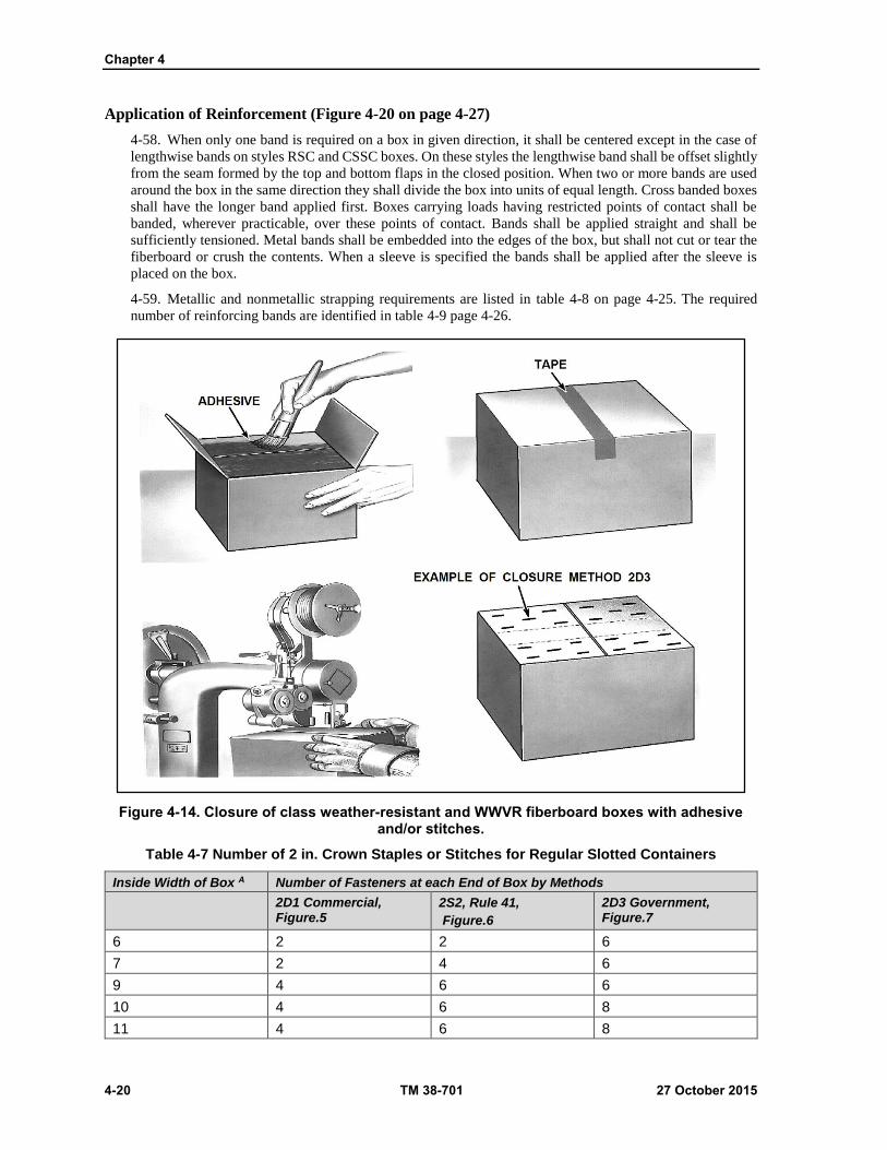
Chapter 4
4-20 TM 38-701 27 October 2015
Application of Reinforcement (Figure 4-20 on page 4-27)
4-58. When only one band is required on a box in given direction, it shall be centered except in the case of
lengthwise bands on styles RSC and CSSC boxes. On these styles the lengthwise band shall be offset slightly
from the seam formed by the top and bottom flaps in the closed position. When two or more bands are used
around the box in the same direction they shall divide the box into units of equal length. Cross banded boxes
shall have the longer band applied first. Boxes carrying loads having restricted points of contact shall be
banded, wherever practicable, over these points of contact. Bands shall be applied straight and shall be
sufficiently tensioned. Metal bands shall be embedded into the edges of the box, but shall not cut or tear the
fiberboard or crush the contents. When a sleeve is specified the bands shall be applied after the sleeve is
placed on the box.
4-59. Metallic and nonmetallic strapping requirements are listed in table 4-8 on page 4-25. The required
number of reinforcing bands are identified in table 4-9 page 4-26.
Figure 4-14. Closure of class weather-resistant and WWVR fiberboard boxes with adhesive and/or stitches.
Table 4-7 Number of 2 in. Crown Staples or Stitches for Regular Slotted Containers
Inside Width of Box A Number of Fasteners at each End of Box by Methods
2D1 Commercial, Figure.5
2S2, Rule 41,
Figure.6
2D3 Government, Figure.7
6 2 2 6
7 2 4 6
9 4 6 6
10 4 6 8
11 4 6 8
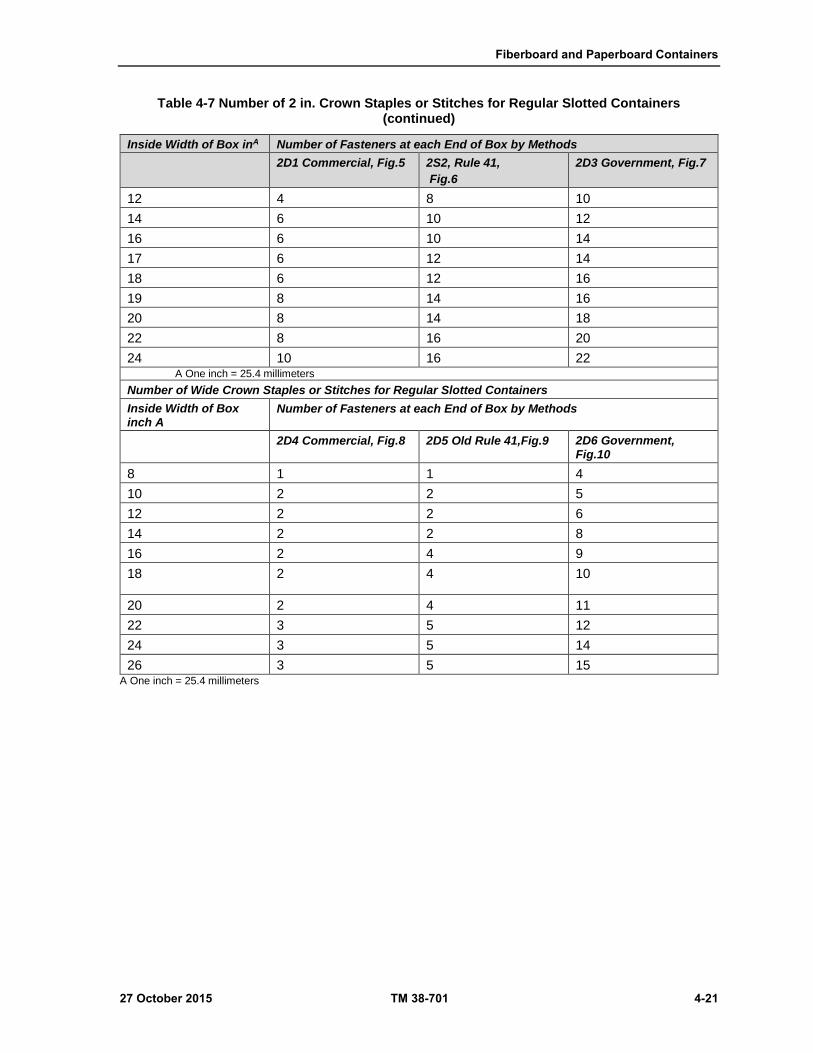
Fiberboard and Paperboard Containers
27 October 2015 TM 38-701 4-21
Table 4-7 Number of 2 in. Crown Staples or Stitches for Regular Slotted Containers (continued)
Inside Width of Box inA Number of Fasteners at each End of Box by Methods
2D1 Commercial, Fig.5 2S2, Rule 41,
Fig.6
2D3 Government, Fig.7
12 4 8 10
14 6 10 12
16 6 10 14
17 6 12 14
18 6 12 16
19 8 14 16
20 8 14 18
22 8 16 20
24 10 16 22 A One inch = 25.4 millimeters
Number of Wide Crown Staples or Stitches for Regular Slotted Containers
Inside Width of Box inch A
Number of Fasteners at each End of Box by Methods
2D4 Commercial, Fig.8 2D5 Old Rule 41,Fig.9 2D6 Government, Fig.10
8 1 1 4
10 2 2 5
12 2 2 6
14 2 2 8
16 2 4 9
18 2 4 10
20 2 4 11
22 3 5 12
24 3 5 14
26 3 5 15 A One inch = 25.4 millimeters
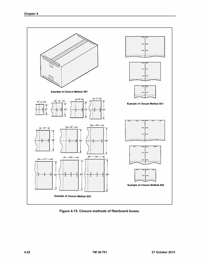
Chapter 4
4-22 TM 38-701 27 October 2015
Figure 4-15. Closure methods of fiberboard boxes.
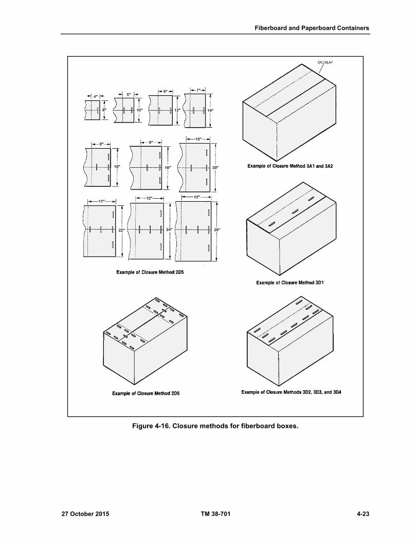
Fiberboard and Paperboard Containers
27 October 2015 TM 38-701 4-23
Figure 4-16. Closure methods for fiberboard boxes.
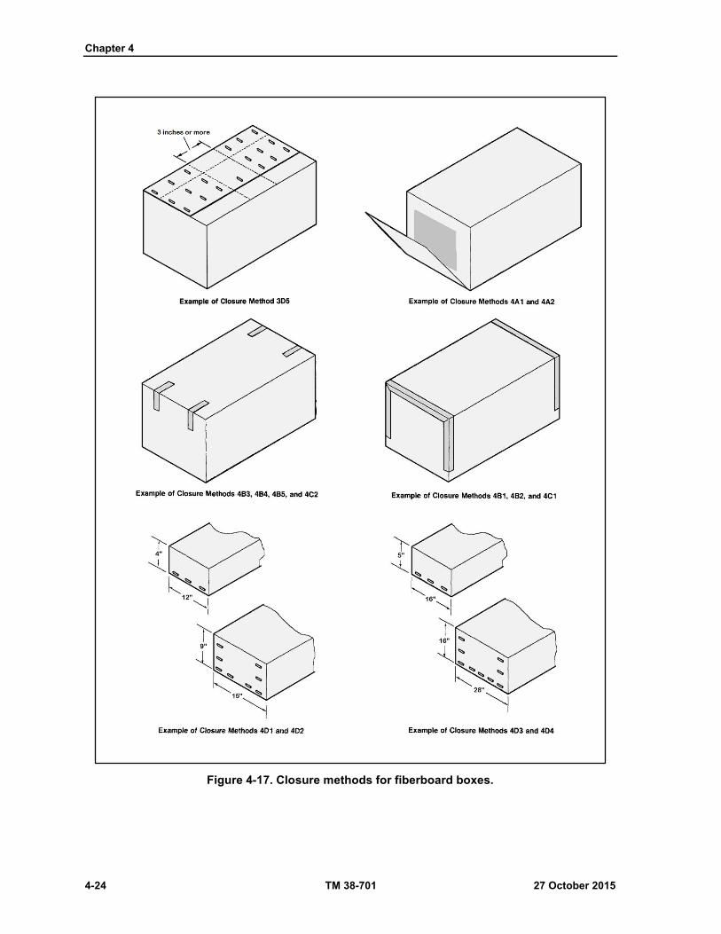
Chapter 4
4-24 TM 38-701 27 October 2015
Figure 4-17. Closure methods for fiberboard boxes.

Fiberboard and Paperboard Containers
27 October 2015 TM 38-701 4-25
Figure 4-18. Closure methods of fiberboard boxes.

Chapter 4
4-26 TM 38-701 27 October 2015
Figure 4-19. Closure methods of fiberboard boxes.
Table 4-8. Metallic and nonmetallic strapping requirements. In accordance with ASTM D 4675.
Gross weight of
container and contents
ASTM D3953/
ASTM D4675
ASTM D3950 Nonmetallic B ASTM D3853 Zinc Galvanized
(Pounds) Type I Type II Type III Grade 1 Grade 2
Up to 35 1/4 x 0.015
5/16 x 0.012
5/8 x 0.010
3/8 x 0.015
3/8 x 0.018
1/4 x 0.025
1/4 x 0.027
7/16 x 0.017
1/2 x 0.015
16-1/2 16-1/2

Fiberboard and Paperboard Containers
27 October 2015 TM 38-701 4-27
Table 4-8. Metallic and nonmetallic strapping requirements. In accordance with ASTM D 4675. (Continued)
Gross weight of
container and contents
ASTM D3953/
ASTM D4675
ASTM D3950 Nonmetallic B ASTM D3853 Zinc Galvanized
(Pounds) Type I Type II Type III Grade 1 Grade 2
Over 35 to 70, incl.
3/8 x 0.015A 3/8 x 0.015
3/8 x 0.024
1/4 x 0.025 1/4 x 0.027
7/16 x0.025
7/16 x 0.017
1/2 x 0.015
16 15
Over 70 to 110, incl.
3/8 x 0.020
1/2 x 0.015
1/2 x 0.015
3/8 x 0.020
7/16 x 0.025
1/2 x 0.022
1/2 x 0.015
7/16 x 0.017
14 13
Over 110 to 225 incl.
1/2 x 0.020
5/8 x 0.015
1/2 x 0.020
5/8 x 0.015
7/16 x 0.025
7/16 x 0.023
1/2 x 0.020
13
A Size 1/4 by 0.015 in strap may used for Type 1 loads and FTC boxes of frozen foods. B/ Other type and sizes may be applicable.
ASTM= American Society For Testing And Materials Standards
Table 4-9. Required number of reinforcing bands
Direction of Bands1
Lengthwise Girthwise Horizontal2
Outside width of box in inches
Number of bands (min)3
Outside length of box in inches
Number of bands (min)3
Outside depth of box in inches
Number of bands (min)3
Up to 9 none Up to 20 1 Up to 18 none
Over 9 to 18 1 20 to 30 2 18 to 30 1
Over 18 to 30 2 Over 30 to 48 3 Over 30 to 48 2
Over 30 to 48 3 Over 48 to 60 4
Over 48 Over 604 Over 484
1 Lengthwise--Encircling top, bottom, and ends, Girth wise--Encircling top, bottom, and sides. Horizontal--Encircling sides and ends. Note that the location of the openings determines the designation of the panels, rather than normal storage position. 2 Horizontal bands are only occasionally required. Where contents exert severe pressure on vertical score lines, they should be used. 3 Full telescope-style boxes, having corners not otherwise sealed to bodies, will usually require use of one or more additional bands, both lengthwise and girth wise when dimensions approach the upper range of the size brackets listed in above table. Additional bands, when required, will be specified by the procuring agency. 4 As directed by the procuring agency.
NOTE
Reinforcement may be omitted from class weather-resistant boxes containing non-perishable
subsistence items and clothing which are to be palletized or containerized an exception to this is
nonperishable subsistence materiel consigned to the Naval Supply Center at Norfolk and Oakland
for subsequent transfer at sea.
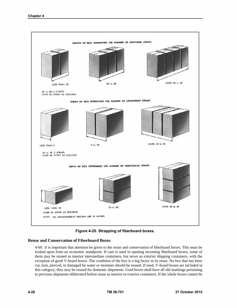
Chapter 4
4-28 TM 38-701 27 October 2015
Figure 4-20. Strapping of fiberboard boxes.
Reuse and Conservation of Fiberboard Boxes
4-60. It is important that attention be given to the reuse and conservation of fiberboard boxes. This must be
looked upon from an economic standpoint. If care is used in opening incoming fiberboard boxes, some of
them may be reused as interior intermediate containers, but never as exterior shipping containers, with the
exception of good V-board boxes. The condition of the box is a big factor in its reuse. No box that has been
cut, torn, pierced, or damaged by water or moisture should be reused. If used, V-board boxes are included in
this category, they may be reused for domestic shipments. Used boxes shall have all old markings pertaining
to previous shipments obliterated before reuse as interior or exterior containers. If the whole boxes cannot be
Fiberboard and Paperboard Containers
27 October 2015 TM 38-701 4-29
reused, consideration should be given to the use of clean, sound fiberboard as material for one of the following
applications:
4-61. Fabrication of blocking and bracing. Blocking and bracing are used to prevent movement of the item
within the container, contact of items among themselves (when more than one is packed in a shipping
container), or contact of an item with the faces of the container.
4-62. Fabrication of die-cuts, cells, trays, pads, etc., for cushioning purposes. Triple-wall Corrugated
Fiberboard Boxes (ASTM D 5168)
TRIPLE-WALL CORRUGATED FIBERBOARD BOXES (ASTM D
5168)
4-63. A triple-wall corrugated fiberboard box is a container made of triple-wall corrugated fiberboard in
accordance with ASTM D 5168.Triple-wall corrugated fiberboard consists of three corrugated sheets
laminated to four flat facings (fig. 4-3 on page 4-7) resulting in a thick, relatively sturdy structural material.
Boxes made of this material have the following characteristics:
They are especially suited for difficult, heavy loads that require exceptionally large containers.
They are extremely resistant to sudden forces such as those encountered when the box is dropped.
They have a high resistance to compression and can sustain heavy loads for long periods of time.
They are lighter in weight and smaller in cube than wooden containers made for the same items.
They have certain inherent cushioning characteristics due to the corrugated stock from which they
are made.
4-64. The fire-retardant requirements of boxes are intended to reduce losses due to fire destruction.
4-65. Classes and Styles. Triple-wall, corrugated fiberboard boxes are furnished in the following classes,
styles, and types of ends:
Nonweather resistant.
Weather resistant.
Fire-retardant.
STYLE A.
4-66. One-piece fiberboard, five-panel, with one of four types of ends, and with ends inserted in box body
see (fig 4-21 on page 4-30).
STYLE B
4-67. One-piece fiberboard, five-panel, with one of four types of ends, and with ends inserted in box body
overlapped on box ends (fig 4-21).
STYLE C
4-68. Two-piece fiberboard, three-panel, with one of four types of ends, and with ends inserted in box body
overlapped on the box ends (fig 4-21).
STYLE D
4-69. Two-piece fiberboard, three-panel, with one of four types of ends, and with ends inserted with outside
edges of the box body overlapped on box ends see (fig 4-22 on page 4-31).
STYLE E
4-70. A regular slotted fiberboard box conforming to ASTM D 5118 standards. The body (manufacturer's)
joint should be 2 inches wide, crushed, and stapled on a slant not more than 1 inch apart (fig 4-22). The
corrugations of that portion of the side panel in which the body joints overlap shall also be crushed. Style E
Chapter 4
4-30 TM 38-701 27 October 2015
boxes may also be made with a 1 1/2-inch crushed overlap on the top and bottom panel of the box. This is
called an alternate style E box.
STYLE F
4-71. A full telescopic fiberboard box, consisting of a body and a cover each of one-piece slotted and scored
triple-wall fiberboard. The inside depth of the cover shall be the overall depth of the body (fig 4-22).
STYLE G
4-72. Half regular slotted box with short top flaps and cover. Style G box is similar to style F, except that all
the top flaps are 4 inches long and are crushed-rolled 1 1/2-inches at the edges. A cover, at least 6 inches
deep, forms the top of the container. The cover may be constructed so that the end and side flanges form a
butt joint at each of the four corners see (fig 4-23 on page 4-32), or it may be made with end or side flaps
which are stapled to the adjacent flange of the top.
WOOD ENDS
4-73. There are four types of wood or wood-cleated panel ends that can be used with styles A, B, C, and D
triple-wall, corrugated fiberboard boxes. The wood used to fabricate the ends must conform to wood groups
I and II as set forth in ASTM-D-6880M. The ends are of the following designs see (fig 4-24 on page 4-32).
Number 1 End
4-74. A single piece of nominal 2-inch lumber.
Number 2 End
4-75. Two thicknesses of nominal 1-inch lumber with the grain at right angles, the two thicknesses securely
joined by clinched nails, and no piece less than 2 1/2 inches in width.
Number 3 End
4-76. Nominal 1-inch material with a nominal 1-inch thick cleat minimum width of 2 1/4 inches, securely
joined by clinched nailing.
Number 4 End
4-77. Cleated panel ends consisting of two sets of overlapped cleats with a panel of triple-wall corrugated
fiberboard. The cleats shall be nominal 1-inch thick, 2 1/4 inches wide, and shall be assembled with clinched
nailing. The fiberboard shall be fastened to the inside of the cleats with either nails or staples.
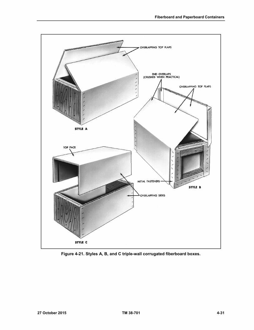
Fiberboard and Paperboard Containers
27 October 2015 TM 38-701 4-31
Figure 4-21. Styles A, B, and C triple-wall corrugated fiberboard boxes.

Chapter 4
4-32 TM 38-701 27 October 2015
Figure 4-22. Styles D, E, and F, triple-wall corrugated fiberboard boxes.

Fiberboard and Paperboard Containers
27 October 2015 TM 38-701 4-33
Figure 4-23. Style G triple-wall corrugated fiberboard box.
Figure 4-24. Types of ends to be used with styles A through D triple-wall corrugated fiberboard boxes.
Chapter 4
4-34 TM 38-701 27 October 2015
Limitations
4-78. Maximum weight and size limitations for triple-wall corrugated fiberboard boxes are not given in
ASTM D 5168. When triple-wall, corrugated fiberboard boxes are to be used for commodities covered in
Rule 41 of the Uniform Freight Classification and item 222 of the National Motor Freight Classification, the
sum of the inside length, width, and depth shall not exceed 125 inches. Containers exceeding these limitations
must be made under a special package permit.
Sealing
4-79. When sealing against the entry of water or dust is required, all seams and joints of the boxes shall be
covered with minimum 2-inch tape conforming to ASTM D 5486, Type V. Closure of slotted boxes is
frequently done prior to sealing.
Closure
4-80. The kinds of closure for triple-wall, corrugated fiberboard boxes will depend on the style of box to be
used, and may be made by means of nails, staples, steel straps, filament-reinforced tape, or a combination of
these materials. When nails are used for closure or for fastening blocking and bracing members to the interior
of the boxes, it is recommended that each nail should pass through an oversize washer, piece of banding, or
clips designed to prevent pulling of the nail heads through the triple-wall material. Whenever reinforcing
needed, DOD personnel may use ASTM D 3950, ASTM D 3953, or ASTM D 4675.
Closure of Style A Boxes
4-81. This style may be closed with zinc-coated or copper-washed staples, with divergent points and
minimum dimensions of 14 gauge wire, 3/4 inch crown, and 1 1/4 inch legs; with flat, Type I, Class A or B,
5/8 inch wide and 0.018 inch thick steel straps conforming to ASTM D 3953 or with nonmetal strapping in
accordance with ASTM D 3950, Type I or II (when Type I is used it shall be Grade B) with a nominal width
of 5/8 inch; or with pressure- sensitive, filament-reinforced tape meeting the requirements of ASTM D 5330,
Type III, 1/2-inch wide, except for Styles E and F, which shall be 1 inch wide. On weather-resistant boxes,
the ASTM D 5330 tape shall be Type IV, 3/4 inch wide, except for Styles E and F, which shall be 1 inch
wide.
Using Nails For Closure of Style A Boxes
4-82. When nails or staples are used, they shall be spaced not more than 2 inches apart and staggered as
permitted by the thickness of the ends of the box. The nails or staples shall extend through each thickness of
fiberboard and into the wood ends. If the box is 24 inches long, a strip of filament-reinforced tape shall be
placed at the center of the outside top flap so as to extend onto the top flap 5 inches and onto the side panel
5 inches. For length greater than 24 inches, one such strip will be added for each additional 18 inch increment
of length greater than 24 inches. The total number of strips will be spaced evenly (fig 4-25 on page 4-35).
Using Straps For Closure of Style A Boxes
4-83. When steel or nonmetal straps are used, one band will be placed at each end of the box to encircle the
top, sides, and bottom of the box. The straps will be placed not more than 3 inches in from the ends to bear
evenly on the wood ends. If the box is 24 inches long, a strap will be added at the center.
4-84. Filament-reinforced tape may be used in lieu of this additional strap. For lengths greater than 24 inches,
one such strap will be added for each additional 18 inches of length and placed so that they are evenly spaced
(fig 4-25 on page 4-35).
Using Tape For Closure of Style A Boxes
4-85. When filament-reinforced tape is used, a 10-inch strip will be placed 2 inches in from each end of the
box. For boxes 24 inches long and over, additional strip requirement are the same as for steel strapping. All
the tape strips will be applied perpendicular to the joint formed by the top flap and the side wall of the box.

Fiberboard and Paperboard Containers
27 October 2015 TM 38-701 4-35
They will be centered over the joint and extend 5 inches onto the top flap and 5 inches on the side wall (fig
4-25).
Closure of Style B Boxes
4-86. Style B boxes may be closed with nails or staples in the same manner as Style A boxes; but, in addition,
a staggered row of nails or staples, spaced not more than 2 inches apart, must be driven through the overlap
portion of the top flap into the face of the wood ends. When using steel straps or filament- reinforced tape
for closure, the same requirements as given for Style A boxes also apply to Style B (fig 4-25).
Closure of Style C Boxes
4-87. This style of box will be closed along the top and sides by means of nails, staples, or steel straps as
specified for Style A boxes, except when using nails or staples they will be spaced not more than 2 inches
apart and staggered and driven through the top one-half of the box into the wooden ends along the two end
edges of each side panel and both end edges of the top panel (fig 4-26 on page 4-36).
Closure of Style D Boxes
4-88. This style of box shall be closed along the top and sides by means of nails, staples, or steel straps as
specified for style A. In addition, a staggered row of nails or staples shall be driven through the overlapping
top flaps into the face of the wooden ends. For boxes 24 inches long and longer, strips of tape will be applied
as for style A box (fig 4-26).
Closure of Style E Boxes
4-89. Style E boxes may be closed by the use of staples, steel or nonmetallic strapping, or with tape.
Closure With Staples
4-90. Staples will not be used for boxes fabricated with class weather-resistant fiberboard. Staples are placed
not more than 1 1/2 inches, or less than 1 inch, from the free edge of the flap. Spacing around the edge of
each flap is not more than 5 inches, center-to-center of the staples. Additional staples are so spaced within
the boundaries outlined by the edge staples so that no area will have a diameter greater than 4 inches without
a staple, with a minimum number of eight staples in each flap. Staples are flat wire, 0.050 inch thick, 0.085
inch wide, with a 1 1/4-inch crown (fig 4-27 on page 4-38).

Chapter 4
4-36 TM 38-701 27 October 2015
Figure 4-25. Closure of styles A and B, triple-wall corrugated fiberboard boxes.
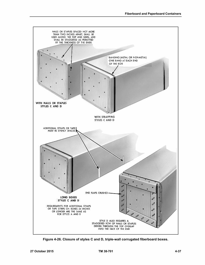
Fiberboard and Paperboard Containers
27 October 2015 TM 38-701 4-37
Figure 4-26. Closure of styles C and D, triple-wall corrugated fiberboard boxes.

Chapter 4
4-38 TM 38-701 27 October 2015
Closure With Metal or Nonmetallic Strapping
4-91. The requirements for closure with strapping is the same as for style A boxes, except that a lengthwise
strap may be applied to hold the girth wise strap flat (fig 4-27 on page 4-38).
Closure With Tape
4-92. A 12-inch strip is applied to each end of the two top and bottom flaps so that 6 inches of each strip is
attached to the flap and 6 inches of each strip is attached the end panel. The strips are located adjacent to the
inner length edge of the flaps, approximately 2 inches from this edge. The use of additional strips will be
specified for style A boxes.
Closure of Style F Boxes
4-93. This style may be closed with steel or nonmetallic straps or filament- reinforced tape. When straps are
used, they will be applied as described for style E boxes. When tape is used, one strip will be used on each
side and each end. The strips will be not less than 12 inches long and will be applied at the center of the side
and end panels and extend to the bottom of the box. When the length of the box is 24 inches, an additional
strip will be added to each side and the two will be evenly spaced. Additional strips as required for length
will be added to the ends when the box is 24 inches or greater in width (fig 4-28 on page 4-39).
Closure of Style G Boxes
4-94. When this box is used in conjunction with a pallet, closure and sealing will be as specified by the
procuring activity. Without a pallet, an additional strip will be added to each side and the box will be closed
with straps. One strap will be centrally located around the top, ends, and bottom. Two straps will be applied
around the top, sides, and bottom, at a distance from the ends equal to three-fourths the length of the inner
flaps. If the distance between the straps exceeds 24 inches, additional straps will be spaced not more than 24
inches apart (fig 4-29 on page 4-40).
Paperboard Boxes
4-95. Paperboard boxes are mainly used for interior packing. They are available in various types, styles, and
sizes, and must conform to requirements of PPP-B-566E, and PPP-B-676E. In many instances, depending
upon the item, a paperboard box may be used in packing when utilizing parcel post. For further details on
paperboard boxes, see TM 38-700.

Fiberboard and Paperboard Containers
27 October 2015 TM 38-701 4-39
Figure 4-27. Closure of style E, triple-wall fiberboard box.

Chapter 4
4-40 TM 38-701 27 October 2015
Figure 4-28. Closure of style F, triple-wall fiberboard box.

Fiberboard and Paperboard Containers
27 October 2015 TM 38-701 4-41
Figure 4-29. Closure of G style triple-wall fiberboard box. Summary

This page intentionally left blank.

27 October 2015 TM 38-701 5-1
Chapter 5
Bags and Sacks
NEED FOR BAGS AND SACKS
5-1. While a considerable amount of the materiel furnished to the military services is shipped in fiberboard,
metal, or wooden containers, there are many supplies which can be most economically shipped in bulk
quantities in bags and sacks. Items such as food products, building materials, some chemicals and minerals
are effectively shipped in bags and sacks. Bags and sacks possess the inherent advantages of having low tare
weight ratio (that is, the ratio of the weight of the container to the weight of the contents); being flexible;
providing ease in filling and handling; requiring a minimum storage space; and being constructed of low cost
materials.
BAGS DEFINED
5-2. A bag is a preformed container made of flexible material, generally closed on all sides except one
which forms an opening that may or may not be sealed after filling. It may be made of a single ply or multiple
plies of flexible material, or a combination of two or more materials such as paper, metal foil, cellulose, and
plastic films and textiles, any of which may be coated, laminated, or treated to provide the properties required
for packaging, storing, and distributing the commodity.
SACKS DEFINED
5-3. A sack often used as a synonym for a bag, generally refers to heavier duty or shipping bags. No exact
line of separation can be drawn between what is referred to as heavy duty bag and shipping sack. In this
section, both bags and sacks are discussed and may be employed to handle the same weights and kinds of
commodities. Usually, a container designed to carry over 50 pounds is considered a shipping sack.
SHIPPING BAGS AND SACKS
5-4. For shipping military supplies, there are flexible containers that are approved for use by the DOD.
These containers are: cotton mailing bags cushioned paper shipping sacks (A-A-160); and shipping bags (A-
A-881C).
COTTON MAILING BAGS
5-5. This description covers cloth mailing bags with a drawstring closure. Cotton mailing bags are intended
for packaging and mailing small miscellaneous items.
Classification
5-6. Bags shall be of the following types and sizes:
Type 1 – Regular.
Type 2 - Fire Retardant.
Size A - 3 inches wide X 4 inches high.
Size B - 3 inches wide X 5 inches high.
Size C - 4 inches wide X 9 inches high.
Size D - 4-1/2 inches wide X 8 inches high.
Size E - 5-1/2 inches wide X 14 inches high.
Size F - 6 inches wide X 9 inches high.
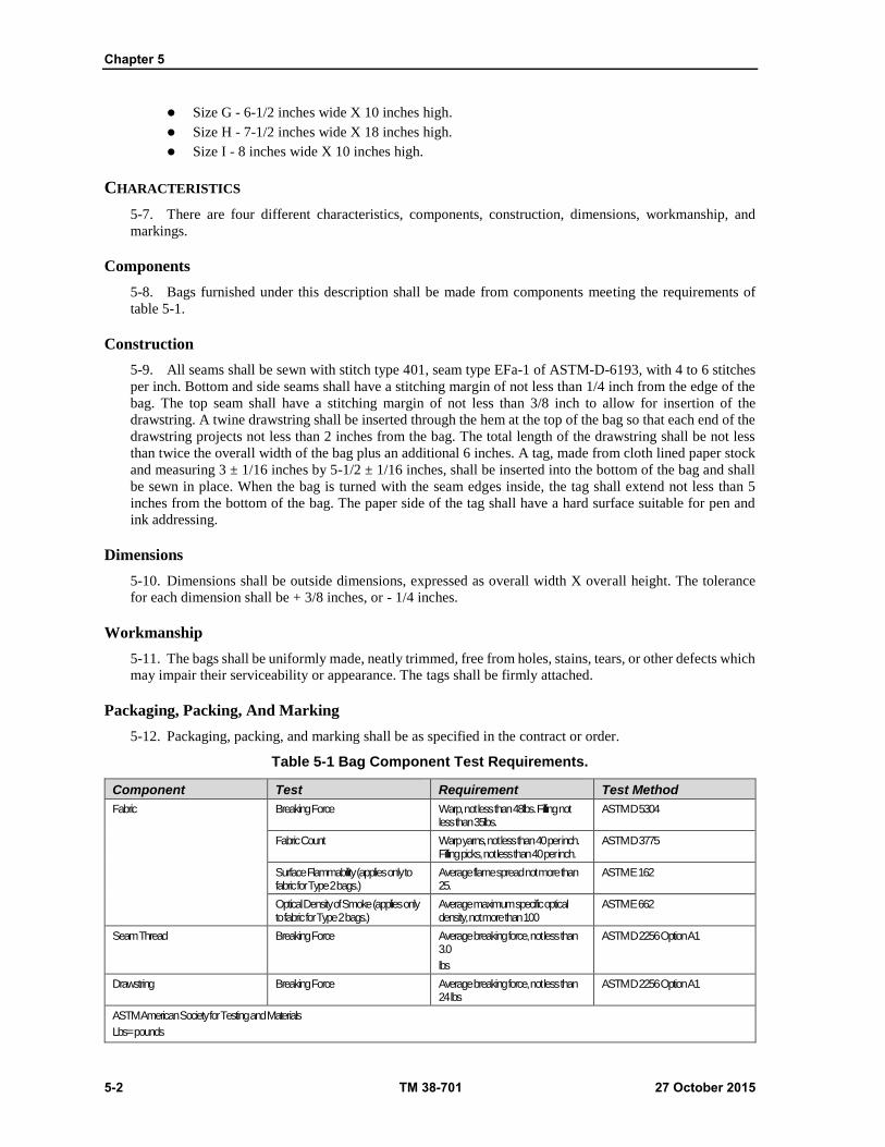
Chapter 5
5-2 TM 38-701 27 October 2015
Size G - 6-1/2 inches wide X 10 inches high.
Size H - 7-1/2 inches wide X 18 inches high.
Size I - 8 inches wide X 10 inches high.
CHARACTERISTICS
5-7. There are four different characteristics, components, construction, dimensions, workmanship, and
markings.
Components
5-8. Bags furnished under this description shall be made from components meeting the requirements of
table 5-1.
Construction
5-9. All seams shall be sewn with stitch type 401, seam type EFa-1 of ASTM-D-6193, with 4 to 6 stitches
per inch. Bottom and side seams shall have a stitching margin of not less than 1/4 inch from the edge of the
bag. The top seam shall have a stitching margin of not less than 3/8 inch to allow for insertion of the
drawstring. A twine drawstring shall be inserted through the hem at the top of the bag so that each end of the
drawstring projects not less than 2 inches from the bag. The total length of the drawstring shall be not less
than twice the overall width of the bag plus an additional 6 inches. A tag, made from cloth lined paper stock
and measuring 3 ± 1/16 inches by 5-1/2 ± 1/16 inches, shall be inserted into the bottom of the bag and shall
be sewn in place. When the bag is turned with the seam edges inside, the tag shall extend not less than 5
inches from the bottom of the bag. The paper side of the tag shall have a hard surface suitable for pen and
ink addressing.
Dimensions
5-10. Dimensions shall be outside dimensions, expressed as overall width X overall height. The tolerance
for each dimension shall be + 3/8 inches, or - 1/4 inches.
Workmanship
5-11. The bags shall be uniformly made, neatly trimmed, free from holes, stains, tears, or other defects which
may impair their serviceability or appearance. The tags shall be firmly attached.
Packaging, Packing, And Marking
5-12. Packaging, packing, and marking shall be as specified in the contract or order.
Table 5-1 Bag Component Test Requirements.
Component Test Requirement Test Method
Fabric Breaking Force Warp, not less than 48lbs. Filling not less than 35lbs.
ASTM D 5304
Fabric Count Warp yarns, not less than 40 per inch. Filling picks, not less than 40 per inch.
ASTM D 3775
Surface Flammability (applies only to fabric for Type 2 bags.)
Average flame spread not more than 25.
ASTM E 162
Optical Density of Smoke (applies only to fabric for Type 2 bags.)
Average maximum specific optical density, not more than 100
ASTM E 662
Seam Thread Breaking Force Average breaking force, not less than 3.0
lbs
ASTM D 2256 Option A1
Drawstring Breaking Force Average breaking force, not less than 24 lbs
ASTM D 2256 Option A1
ASTM American Society for Testing and Materials
Lbs= pounds
Bags and Sacks
27 October 2015 TM 38-701 5-3
PROCUREMENT
5-13. Buyers shall specify the following:
Type and size required;
Preservation, packaging, packing, labeling, and marking required.
Item Identifiers/Reference Part Number System. (For cataloging use only.)
Size A - 3 inches wide X 4 inches high
Size B - 3 inches wide X 5 inches high
Size C - 4 inches wide X 9 inches high
Size D - 4-1/2 inches wide X 8 inches high.
Size E - 5-1/2 inches wide X 14 inches high.
Size F - 6 inches wide X 9 inches high.
Size G - 6-1/2 inches wide X 10 inches high.
Size H - 7-1/2 inches wide X 18 inches high.
Size I - 8 inches wide X 10 inches high
Type 1 - Regular
Type 2 - Fire Retardant
CUSHIONED PAPER SHIPPING SACKS (A-A-160)
5-14. Cushioned paper shipping sacks are made of two sheets of Kraft paper separated by an evenly
distributed cushioning medium. They may be used for interior or exterior packaging where insulation, water
resistance, or light cushioning effect is required for items weighing not more than 10 pounds.
CUSHIONED WITH POST CONSUMER RECOVERED MATERIAL (A-
A-160)
5-15. The walls of the sack shall consist of 2 layers of Kraft paper with a cushioned medium such as
macerated paper inserted between the layers. The outer layer of Kraft paper shall be water resistant. The
fabricated sacks shall pass the water resistance test and the impact resistance test. The edge of the inside seam
shall be located not more than 1 inch from the side of the sack.
Dimensions
5-16. Dimensions of the sacks shall be outside measurements, expressed as width by length. Dimensions
shall be as specified with a tolerance of ± 1/4 inch. Sack opening shall be on the short side.
Workmanship
5-17. Sacks shall be uniformly constructed and free from holes, tears, cuts, splits, or other defects which
might impair their usefulness.
QUALITY ASSURANCE
5-18. Sacks shall be tested in accordance with the methods listed below. The sample unit shall be one sack.
Examination Of The End Item For Dimensions And Workmanship
5-19. The Inspection Level shall be S-2 with an Acceptable Quality Level (AQL) of 2.5 percent defective
in accordance with the American National Standards Institute (ANSI) and American Society of Quality
Control (ASQC Z) 1.4-2013.
Chapter 5
5-4 TM 38-701 27 October 2015
Testing Of The End Item For Water Resistance And Impact Resistance
5-20. The Inspection Level shall be S-1 with an Acceptable Quality Level (AQL) of 2.5 percent defective in
accordance with MIL-STD-1916.
Water Resistance Test
5-21. Two drops of water shall be placed on the outside of the sack and covered with a watch glass. The
water shall remain on the outside of the sack without being absorbed for not less than 30 minutes.
Impact Resistance Test
5-22. Determine the cubic capacity of the sack by multiplying the three factors F1, F2, and F3, together:
Cubic capacity = F1 x F2 x F3
F1 = specified length
F2 = 90% of specified width
F3 = 10% of specified width
5-23. Fill a graduated cylinder or similar volumetric device to 75 percent of the cubic capacity of the sack
with dry, unpopped, popcorn. Transfer the popcorn to the sack and seal the open end of the sack with
packaging tape. Drop each sack six times from a height of 36 inches onto a hard, unyielding surface such as
uncarpeted concrete. The sack shall be dropped once on each face and once on each side. If any popcorn
spills from the sack, the sack does not pass the impact resistance test.
Examination Of Packaging, Packing And Marking
5-24. The sample unit for this examination shall be one fully prepared shipping container. The Inspection
Level shall be S-2 with an Acceptable Quality Level (AQL) of 4.0 percent defective in accordance with MIL-
STD-1916.
REGULATORY REQUIREMENTS
5-25. The manufacturer/contractor shall certify that the craft paper used to make the sacks contains not less
than 5 percent post-consumer recovered material. The Government reserves the right to require proof of such
content prior to the first delivery and thereafter as may be provided for under the provisions of the contract.
Post-consumer recovered material is defined as paper, paperboard and fibrous wastes from factories, retail
stores, office buildings, homes, etc., which has passed through an end use as a consumer item, including:
Used corrugated boxes, old newspapers, old magazines, mixed waste paper, tabulating cards, used cordage;
and all paper, paperboard, or fibrous waste collected from municipal solid waste.
PACKAGING, PACKING AND MARKING
5-26. Packaging, packing, and marking shall be as specified in the contract or order.
CUSHIONED WITH CLOSED CELL PLASTIC FILM
5-27. Sacks shall be fabricated from a composite material consisting of Kraft paper bonded to closed cell
plastic film cushioning material. The composite material shall have a thickness of not less than 0.131 inches.
The sacks shall be fabricated so that the Kraft paper forms the outside surface of the sack. The open end of
the sack shall be provided with an adhesive sealing flap extending the entire width of the sack. The sealing
flap shall have a strip of pressure sensitive adhesive, protected by a liner, extending across the entire width
of the flap. The weight and test volume for each size sack shall be as specified in table 5-2 on page 5-5. The
fabricated sacks shall pass the impact resistance test and the creep test.
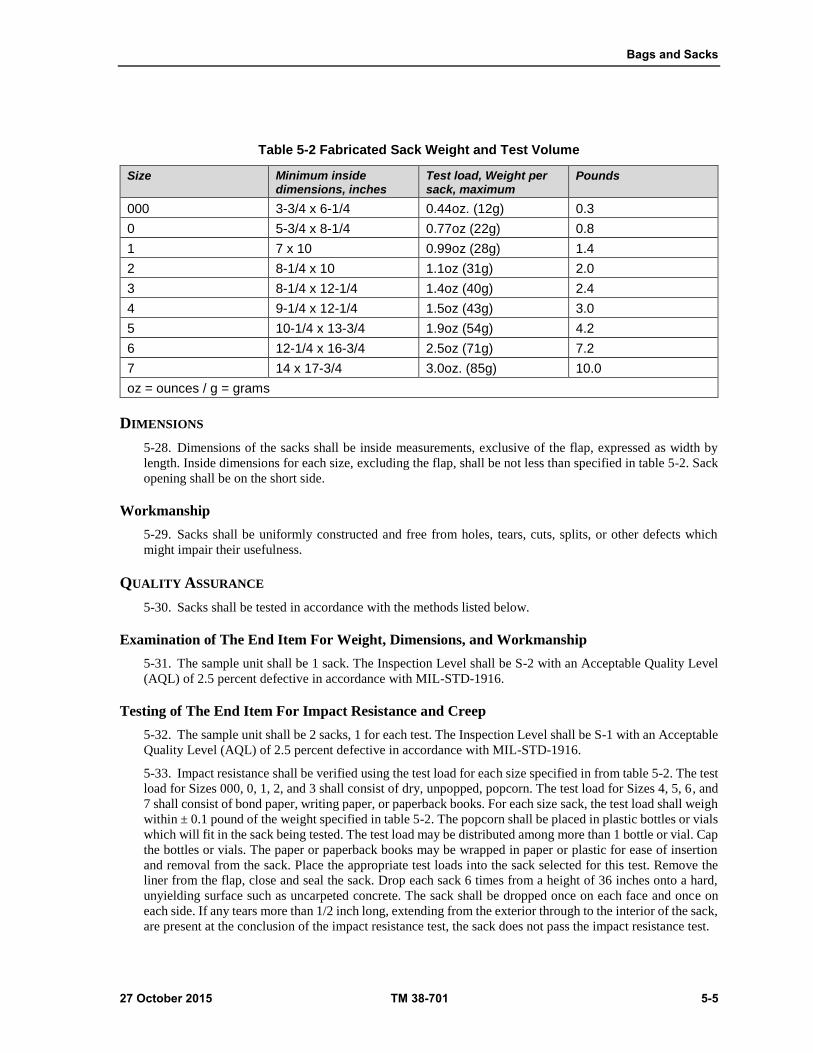
Bags and Sacks
27 October 2015 TM 38-701 5-5
Table 5-2 Fabricated Sack Weight and Test Volume
Size Minimum inside dimensions, inches
Test load, Weight per sack, maximum
Pounds
000 3-3/4 x 6-1/4 0.44oz. (12g) 0.3
0 5-3/4 x 8-1/4 0.77oz (22g) 0.8
1 7 x 10 0.99oz (28g) 1.4
2 8-1/4 x 10 1.1oz (31g) 2.0
3 8-1/4 x 12-1/4 1.4oz (40g) 2.4
4 9-1/4 x 12-1/4 1.5oz (43g) 3.0
5 10-1/4 x 13-3/4 1.9oz (54g) 4.2
6 12-1/4 x 16-3/4 2.5oz (71g) 7.2
7 14 x 17-3/4 3.0oz. (85g) 10.0
oz = ounces / g = grams
DIMENSIONS
5-28. Dimensions of the sacks shall be inside measurements, exclusive of the flap, expressed as width by
length. Inside dimensions for each size, excluding the flap, shall be not less than specified in table 5-2. Sack
opening shall be on the short side.
Workmanship
5-29. Sacks shall be uniformly constructed and free from holes, tears, cuts, splits, or other defects which
might impair their usefulness.
QUALITY ASSURANCE
5-30. Sacks shall be tested in accordance with the methods listed below.
Examination of The End Item For Weight, Dimensions, and Workmanship
5-31. The sample unit shall be 1 sack. The Inspection Level shall be S-2 with an Acceptable Quality Level
(AQL) of 2.5 percent defective in accordance with MIL-STD-1916.
Testing of The End Item For Impact Resistance and Creep
5-32. The sample unit shall be 2 sacks, 1 for each test. The Inspection Level shall be S-1 with an Acceptable
Quality Level (AQL) of 2.5 percent defective in accordance with MIL-STD-1916.
5-33. Impact resistance shall be verified using the test load for each size specified in from table 5-2. The test
load for Sizes 000, 0, 1, 2, and 3 shall consist of dry, unpopped, popcorn. The test load for Sizes 4, 5, 6, and
7 shall consist of bond paper, writing paper, or paperback books. For each size sack, the test load shall weigh
within ± 0.1 pound of the weight specified in table 5-2. The popcorn shall be placed in plastic bottles or vials
which will fit in the sack being tested. The test load may be distributed among more than 1 bottle or vial. Cap
the bottles or vials. The paper or paperback books may be wrapped in paper or plastic for ease of insertion
and removal from the sack. Place the appropriate test loads into the sack selected for this test. Remove the
liner from the flap, close and seal the sack. Drop each sack 6 times from a height of 36 inches onto a hard,
unyielding surface such as uncarpeted concrete. The sack shall be dropped once on each face and once on
each side. If any tears more than 1/2 inch long, extending from the exterior through to the interior of the sack,
are present at the conclusion of the impact resistance test, the sack does not pass the impact resistance test.
Chapter 5
5-6 TM 38-701 27 October 2015
Creep Test
5-34. Four test specimens, each 3" 1/8 inches square, shall be cut from each sack selected for the creep test.
Two specimens shall be cut from the front face of the sack, and 2 from the rear face of the sack. The specimens
shall be evenly stacked on a piece of glass approximately 3-1/2 inches square. The bottom specimen shall be
placed bubble side up, the second specimen bubble side down, the third specimen bubble side up, and the top
specimen bubble side down. A second 3-1/2 inch square piece of glass shall be placed on top of the stack and
a weight sufficient to exert a pressure of 1.0 " 0.1 pound per square inch on the test specimens shall be placed
on the top piece of glass. After 60 " 5 minutes, the vertical distance between the glass plates shall be measured
at each of the 4 corners of the stack with an instrument capable of measuring to 0.001 inch. The measurements
shall be taken carefully so as not to disturb the stack. The average of these 4 measurements shall be recorded
as the initial stack thickness. The initial stack thickness divided by 4 shall be recorded as the thickness of the
composite material. The weight shall be kept on the stack for a total of 168 " 2 hours, then the distance
between the glass plates shall be measured and averaged in the same way as was done for the initial stack
thickness. This measurement shall be recorded as the final stack thickness. The final stack thickness shall be
not less than 80 percent of the initial stack thickness.
5-35. Examination of packaging, packing and marking. The sample unit for this examination shall be one
fully prepared shipping container. The Inspection Level shall be S-2 with an Acceptable Quality Level (AQL)
of 4.0 percent defective in accordance with MIL-STD-1916.
REGULATORY REQUIREMENTS
5-36. The manufacturer/contractor shall certify that the Kraft paper used to make the sacks contains not less
than 5 percent post-consumer recovered material. The Government reserves the right to require proof of such
content prior to the first delivery and thereafter as may be provided for under the provisions of the contract.
Post-consumer recovered material is defined as paper, paperboard and fibrous wastes from factories, retail
stores, office buildings, homes, etc., which has passed through an end use as a consumer item, including:
Used corrugated boxes, old newspapers, old magazines, mixed waste paper, tabulating cards, used cordage;
and all paper, paperboard, or fibrous waste collected from municipal solid waste.
PACKAGING, PACKING, AND MARKING
5-37. Packaging, packing, and marking shall be as specified in the contract or order.
PROCUREMENT
5-38. Buyer shall specify:
Size, as listed in table 5-2 on page 5-5.
Packaging, packing, and marking required.
BURLAP SHIPPING BAGS (A-A-881C)
5-39. This description covers standard new or used burlap bags for use in domestic and overseas shipment
of supplies and materials.
CLOTH CHARACTERISTICS
5-40. The bags shall be fabricated from jute burlap cloth conforming to the requirements in table 5-3 on page
5-7.
Construction
5-41. Bags shall be furnished new or used, as specified. The bags shall have open-mouth tops and shall have
bottom and/or side seams. The minimum average number of stitches shall be 3.0 to the inch, machine sewn
and of stitch type 301 or 401 of ASTM-D-6193. The raw edges of the bag shall be sewn with export seams,
such as those in ASTM-D-6193. Seams shall have a breaking load of not less than 80 percent of the breaking

Bags and Sacks
27 October 2015 TM 38-701 5-7
load of the burlap from which the bags are made. Raw top edges of bags shall be hemmed. Salvaged edges
shall be sewn with flat seams, and raw edges with export seams.
5-42. The size or capacity of the bags shall be as specified in the contract order. When specified, bags shall
be suitable for subsistence items. Each bag shall be furnished with a polyethylene liner inserted. The liner
shall have a Water Vapor Transmission Rate of now more than 15g per m2 per day. The liner shall extend
not less than 3 inches beyond the top of the burlap.
Table 5-3 Jute Burlap Bag Requirements
Fabric Count Minimum Yarns per inch maximum
Weight, per linear yard by 40 inch width (+8, -2percent)
Warp 8 11 7.5 ounces
Filling 8 11
Workmanship
5-43. Bags shall be clean, dry, and free of holes, tears, frayed threads, objectionable odors, or foreign matter
impregnated in or adhering to the sides of the bags. The bags shall be free from other defects which may
affect serviceability. If mended, there shall be no more than two mends per bag, and the maximum size of
each mend shall not be more than 2 inches.
QUALITY ASSURANCE AND TESTING OF BURLAP CLOTH
5-44. The burlap cloth shall be tested in accordance with the methods listed below. The sample unit shall be
one roll of cloth. The Inspection Level shall be S-2 with an Acceptable Quality Level (AQL) of 2.5 percent
defective in accordance with MIL-STD-1916.
TESTS METHODS
Fabric Count ASTM D 3775
Weight ASTM D 3776
Breaking Load ASTM D 5034 (Grab Test)
ASTM = American Society for Testing and Materials
Testing Of Polyethylene
5-45. The polyethylene shall be tested in accordance with ASTM-E-96M, Water Vapor Transmission Rate.
The sample unit shall be one roll of polyethylene. The Inspection Level shall be S-2 with an Acceptable
Quality Level (AQL) of 2.5 percent defective in accordance with MIL-STD-1916.
5-46. Examination of the end item for defects in workmanship, size, or capacity. The sample unit shall be
one bag. The Inspection Level shall be S-2 with an Acceptable Quality Level (AQL) of 2.5 percent defective
in accordance with MIL-STD-1916.
Testing Of The End Item For Seam Strength
5-47. The sample unit shall be one bag. The Inspection Level shall be S-1 with an Acceptable Quality Level
(AQL) of 2.5 percent defective in accordance with MIL-STD-1916. Each seam of the sample unit shall be
tested in accordance with ASTM-D5034 and ASTM-D5035, Grab Test. The test specimens shall be cut so
that the seam to be tested is in the middle of the specimen, parallel to the 4 inch sides. One determination
shall be made on each seam of the sample unit. Breaks in the fabric outside the seam area, including jaw
breaks, are acceptable provided they yield breaking loads in excess of 80 percent of the breaking load of the
burlap. Any seam which has a breaking load less than 80 percent of the breaking load of the burlap from
which the bags are made is a defect.
Chapter 5
5-8 TM 38-701 27 October 2015
Examination Of Packaging, Packing And Marking
5-48. The sample unit for this examination shall be one fully prepared shipping container. The Inspection
Level shall be S-2 with an Acceptable Quality Level (AQL) of 4.0 percent defective in accordance with MIL-
STD-1916.
REGULATORY REQUIREMENTS
5-49. The manufacturer/contractor is encouraged to use recovered material in accordance with Public Law
94-580 to the maximum extent practicable.
PACKAGING, PACKING AND MARKING
5-50. Packaging, packing, and marking shall be as specified in the contract or order.
27 October 2015 TM 38-701 6-1
Chapter 6
Pails and Drums
DESCRIPTION, CLASSIFICATION, AND SELECTION FACTORS
DESCRIPTION
Pails
6-1. Pails are cylindrical containers made of metal or plastic, with or without a bail handle. They have a
capacity of 1 to 12 gallons. Metal pails are constructed of 20 gage or heavier metal. The sides and bottoms
of the plastic pails are integral units having a minimum thickness of 0.045 inches and designed so they can
be easily stacked. Pails may have fixed heads employing pour spouts of various designs or have full
removable heads.
Drums
6-2. Drums are cylindrical, straight-walled containers made of metal plastic fiber or plywood, or a
combination of these materials. Drums may be provided with rolling hoops pressed or expanded from the
body of the drum, or I bars welded to the body. Drums have fixed or removable heads.
Note. Cans are lightweight containers made of metal, paperboard, pulpboard, or a combination of
metal and paperboard or pulpboard. Since cans usually are associated with unit packaging,
information concerning them is found in TM 38-700 Packaging of material Preservation.
Classification
6-3. Pails and drums are classified as to usage, that is, interior or exterior containers, and reusable and non-
reusable containers. They are also classified as to composition--metal and nonmetal.
Interior
6-4. Interior containers are covered in TM 38-700.
Exterior
6-5. These containers consist of pails, reusable type metal containers, and drums. Exterior containers are
designed to withstand rough usage. They may be palletized for convenience in handling.
Reusable
6-6. Certain metal containers and drums are designed for reuse. The reusable type is very convenient for
the return shipment of repairable items. This feature is particularly advantageous in cases where repairable
instruments or accessories can be packed for shipment to the maintenance overhaul activity in the container
in which the replacement item was received.
6-7. Multiple trip pails and drums may, under certain conditions, be refilled and reused for the shipment of
liquid, powdered or granular commodities.
Nonreusable
6-8. Single-trip containers usually are discarded after their first use. One type, the strippable drum, is filled
with a hot liquid which solidifies after cooling. At destination, the drum is torn away from the enclosed
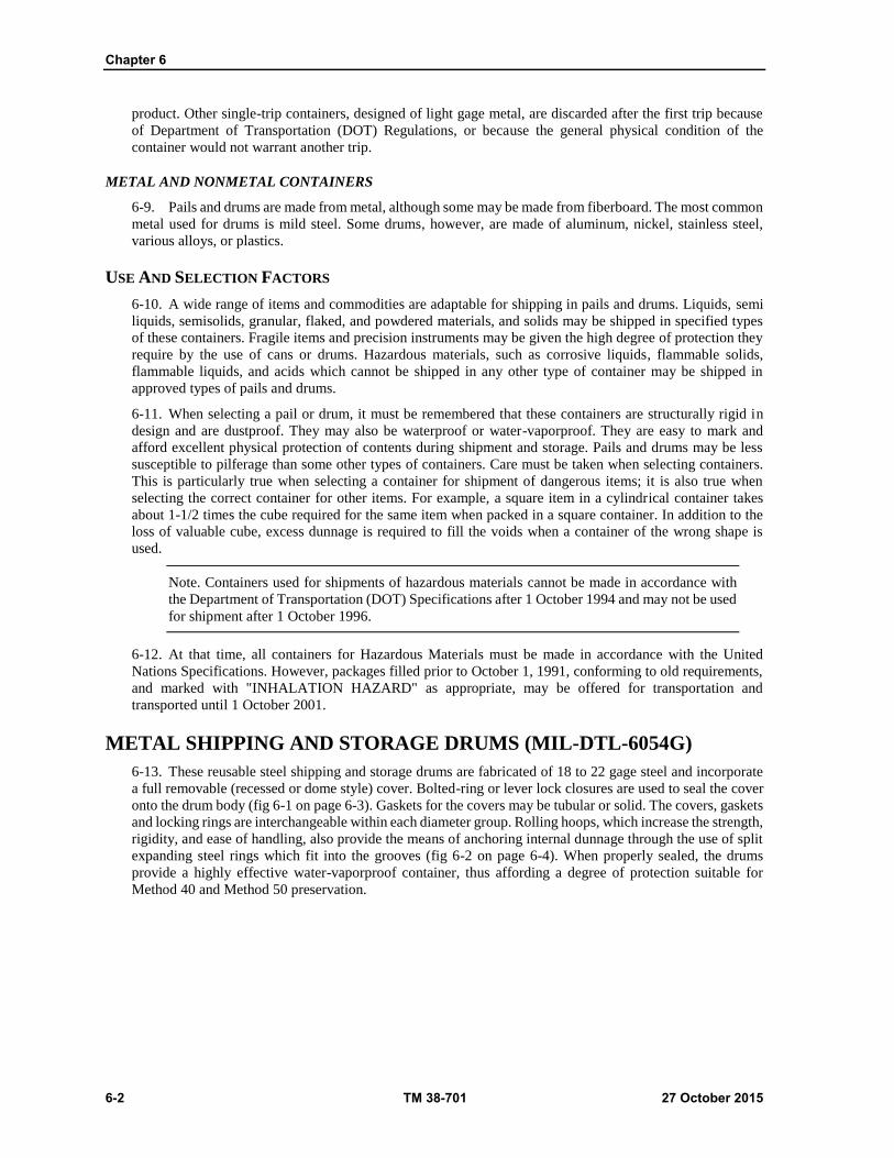
Chapter 6
6-2 TM 38-701 27 October 2015
product. Other single-trip containers, designed of light gage metal, are discarded after the first trip because
of Department of Transportation (DOT) Regulations, or because the general physical condition of the
container would not warrant another trip.
METAL AND NONMETAL CONTAINERS
6-9. Pails and drums are made from metal, although some may be made from fiberboard. The most common
metal used for drums is mild steel. Some drums, however, are made of aluminum, nickel, stainless steel,
various alloys, or plastics.
USE AND SELECTION FACTORS
6-10. A wide range of items and commodities are adaptable for shipping in pails and drums. Liquids, semi
liquids, semisolids, granular, flaked, and powdered materials, and solids may be shipped in specified types
of these containers. Fragile items and precision instruments may be given the high degree of protection they
require by the use of cans or drums. Hazardous materials, such as corrosive liquids, flammable solids,
flammable liquids, and acids which cannot be shipped in any other type of container may be shipped in
approved types of pails and drums.
6-11. When selecting a pail or drum, it must be remembered that these containers are structurally rigid in
design and are dustproof. They may also be waterproof or water-vaporproof. They are easy to mark and
afford excellent physical protection of contents during shipment and storage. Pails and drums may be less
susceptible to pilferage than some other types of containers. Care must be taken when selecting containers.
This is particularly true when selecting a container for shipment of dangerous items; it is also true when
selecting the correct container for other items. For example, a square item in a cylindrical container takes
about 1-1/2 times the cube required for the same item when packed in a square container. In addition to the
loss of valuable cube, excess dunnage is required to fill the voids when a container of the wrong shape is
used.
Note. Containers used for shipments of hazardous materials cannot be made in accordance with
the Department of Transportation (DOT) Specifications after 1 October 1994 and may not be used
for shipment after 1 October 1996.
6-12. At that time, all containers for Hazardous Materials must be made in accordance with the United
Nations Specifications. However, packages filled prior to October 1, 1991, conforming to old requirements,
and marked with "INHALATION HAZARD" as appropriate, may be offered for transportation and
transported until 1 October 2001.
METAL SHIPPING AND STORAGE DRUMS (MIL-DTL-6054G)
6-13. These reusable steel shipping and storage drums are fabricated of 18 to 22 gage steel and incorporate
a full removable (recessed or dome style) cover. Bolted-ring or lever lock closures are used to seal the cover
onto the drum body (fig 6-1 on page 6-3). Gaskets for the covers may be tubular or solid. The covers, gaskets
and locking rings are interchangeable within each diameter group. Rolling hoops, which increase the strength,
rigidity, and ease of handling, also provide the means of anchoring internal dunnage through the use of split
expanding steel rings which fit into the grooves (fig 6-2 on page 6-4). When properly sealed, the drums
provide a highly effective water-vaporproof container, thus affording a degree of protection suitable for
Method 40 and Method 50 preservation.

Pails and Drums
27 October 2015 TM 38-701 6-3
Figure 6-1. Bolted ring and lever actuated type closures (MIL-DTL-6054G).
CLASSIFICATION
6-14. The drums are available in various capacities ranging from 3 to 80 gallons, and from 40 to 250 pounds
gross weight. The drums are available with inside diameters ranging from 10.5 inches to 30 inches, and inside
usable heights ranging from 8.08 to 41.12 inches. The capacities and dimensions, which are available in
different combinations, are specified in Military Drawing MS27683C and MS27684C.
USE
6-15. These metal drums are intended to be used for storage and shipment of military material. Drums are
required by test to withstand internal pressure of 15.0 pounds per square inch (psi), which will allow them to
be used for packing of hazardous materials for transportation by military aircraft. These drums are also used
as over packs for shipments by air of containers which will not meet 15 psi. All size drums are suitable for
all methods of preservation where a rigid container is specified. The use of drums are affected by the
following factors:
Size And Capacity
6-16. There is no specified rule for the selection of a container for a particular item. it is obvious, however,
that a container will be selected which will be adequate to contain the item and its blocking and cushioning,
yet allow sufficient clearance between the item and the container, or between the blocking and the container
walls, to prevent damage to the item when the drum is handled roughly. The container must not be too large,
as this will involve the use of extra space and weight. This is a disadvantage when a large number of such
drums are to be shipped or stored.
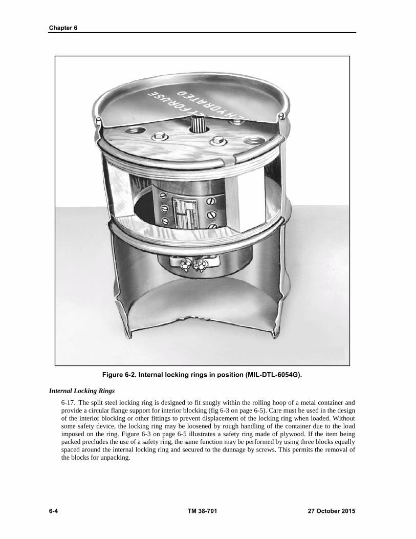
Chapter 6
6-4 TM 38-701 27 October 2015
Figure 6-2. Internal locking rings in position (MIL-DTL-6054G).
Internal Locking Rings
6-17. The split steel locking ring is designed to fit snugly within the rolling hoop of a metal container and
provide a circular flange support for interior blocking (fig 6-3 on page 6-5). Care must be used in the design
of the interior blocking or other fittings to prevent displacement of the locking ring when loaded. Without
some safety device, the locking ring may be loosened by rough handling of the container due to the load
imposed on the ring. Figure 6-3 on page 6-5 illustrates a safety ring made of plywood. If the item being
packed precludes the use of a safety ring, the same function may be performed by using three blocks equally
spaced around the internal locking ring and secured to the dunnage by screws. This permits the removal of
the blocks for unpacking.

Pails and Drums
27 October 2015 TM 38-701 6-5
Cup-Type Inserts
6-18. The cup-type metal insert was developed primarily as a mount for generators and starters for metal
container packing, but it may be adapted to other items, see (Figure 6-4 on page 6-6) shows the metal cup,
with plywood fastened to the two ends to aid in blocking, while (figure 6-5 on page 6-7) shows the cup in
position, anchored between the locking ring and the container cover. The numerous bolt holes through the
cup allow it to be bolted to various items as required.
Figure 6-3. Use of internal locking ring (MIL-DTL-6054G).
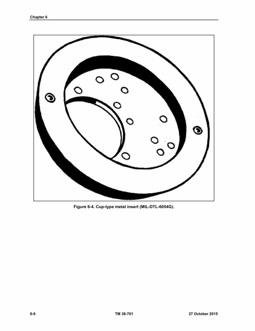
Chapter 6
6-6 TM 38-701 27 October 2015
Figure 6-4. Cup-type metal insert (MIL-DTL-6054G).

Pails and Drums
27 October 2015 TM 38-701 6-7
Figure 6-5. Cup-type insert locked in place (MIL-DTL-6054G).
Crate-Type Inserts
6-19. The crate-type metal insert is shown in figure 6-6. In use, the item being packed is bolted to two
adjacent side members. Plywood disks on the ends of the insert provide some cushioning. The base of the
item packed will be insulated from the insert with barrier material conforming to MIL-PRF-121G, Grade A,
to prevent the possibility of corrosion from reaction of two dissimilar metals. The maximum weight of the
packed item should not exceed 25 pounds for the 10-1/2 inch diameter insert, or 30 pounds for the 13 13/16
inch insert.

Chapter 6
6-8 TM 38-701 27 October 2015
Figure 6-6. Item installed in crate-type insert (MIL-DTL-6054G).
Closure
6-20. There are two styles of closure for these drums. They are the bolted ring closure and the lever activated
locking closure. Closures are made in one of the following manners:
Bolted-ring closure. The closure may be made in two ways. A device may be used which encircles
the locking ring and applies pressure uniformly around the circumference of the ring. The
closure is effected by tightening the bolt and nut after uniform pressure is applied at all points
around the ring. Care should be taken that the gasket is properly seated in the groove of the cover
prior to closure. Alternately, closure may be made by tightening the closure bolt (fig 6-7 on page
6-9). The locking ring is tapped at various points about the closure ring while the closure bolt is
being tightened. The tightening is continued until at least a minimum torque of 6 foot-pounds plus
or minus one- half is applied. In lieu of the specified torque indicating device, closure of an
exterior metal container having a slotted-head bolt may be accomplished by using a common
screwdriver having an overall length of approximately 17 inches. If this procedure is followed, a
spot check of torque with a torque indicating device should be made to assure adequate tensioning.
Drums used for shipping commodities by Parcel Post will have the bolt end and protruding edges
of the closure ring wrapped, taped, cushioned or otherwise securely covered to prevent damage to
postal employees, mail bags, and other containers during shipment.
Containers shall be over packed in fiberboard boxes when this extra precaution is considered
necessary. When over packed, containers shall be secured within the fiberboard box with
fiberboard or other suitable dunnage.

Pails and Drums
27 October 2015 TM 38-701 6-9
Figure 6-7. Tapping locking ring while tightening bolt to insure an effective seal (MIL-DTL-6054G).
Lever actuated locking closure. When specified in the contract or purchase order a lever actuated
type locking ring may be used instead of the nut and bolt type locking ring. Use may be made of
a device which encircles the locking ring and applies pressure uniformly about the circumference
of the locking ring. The closure is then affected by closing the locking lever and then the wire and
lead seal lever which locks the locking lever in position. When the encircling device is not
available for use, tension is applied by the locking lever and the ring is tapped repeatedly around
the circumference until the ring is seated and the lever is in a locking position. The lever is then
locked into place by the wire and lead seal lever lock.
Sealing
6-21. Sealing of the container is effected by means of a wire and metal seal which is applied after the closure
is complete. Drill 3/32 inch diameter holes in each locking ring lug if they are not already predrilled. The
sealing wire is inserted through the holes and the loose ends are twisted together tightly, after which the seal
is crimped over the twisted ends of the wire.
Chapter 6
6-10 TM 38-701 27 October 2015
Repair And Reuse
6-22. The components of the metal shipping and storage drums are repaired and reused as follows:
Containers, cover, ring, and gasket. Due to the welded construction of an exterior type metal
container, dents are considered repairable even though a seam or joint is involved. Dents are
removed, painted surfaces retouched, and the container reused or returned to stock. If the container
is distorted beyond practical repair, or has a dented or otherwise damaged sealing lip, it is unfit
for further use and should be handled accordingly.
Metal inserts and dunnage. It is not normally considered advisable to repair metal inserts or
dunnage, due to the fact that once distorted or deformed, the metal insert would probably be
weaker if bent back into the original shape, and thus be incapable of affording the necessary
protection. If bent back and reinforced, the spring rate of the material might be greatly changed,
thus transmitting any shock directly to the part to be packed and causing damage. However, in an
emergency they may be repaired under competent engineering supervision. Immediately
upon removal of an item from a metal insert type mount, the interior locking rings and metal
inserts must be returned to stock, unless required for immediate reuse. Al inserts and interior
locking rings are stocked and handled as separate items, and never as component parts of the
container assembly.
METAL DRUMS (STANDARD) (MISCELLANEOUS)
6-23. Metal drums are cylindrical, single-wall shipping containers with a capacity which usually ranges from
12 to 110 gallons, 55 gallons being the most common capacity. Metal drums are equipped with rolling hoops
which provide additional strength to the side wall and provide for ease of handling. The rolling hoops may
be parallel to each other or be offset to facilitate closer nesting for palletization and car loading. Metal drums
may have full removable heads or tight heads (fixed) as shown in (fig 6-8 on page 6-11). A drum with a tight
head is provided with a 2 inch diameter bung and 3/4 inch diameter vent hole for filling and emptying. These
openings may be on the drum head or in the drum body. Drums may be unlined or lined with lacquer, varnish,
enamel and plastics, rubber, lead, or aluminum.
CLASSIFICATION
6-24. The DOD uses many kinds of drums for the shipment of various materials. Listed in table 6-1 is the
Federal specification number and title (PPP-D-729E) and the DOT specification number and title. Figure 6-
8 shows the type of drum classified in Federal Specification PPP-D-729E and the corresponding DOT-5B.
DOT designates the DOT 17E and DOT-37A drums as single-trip containers.
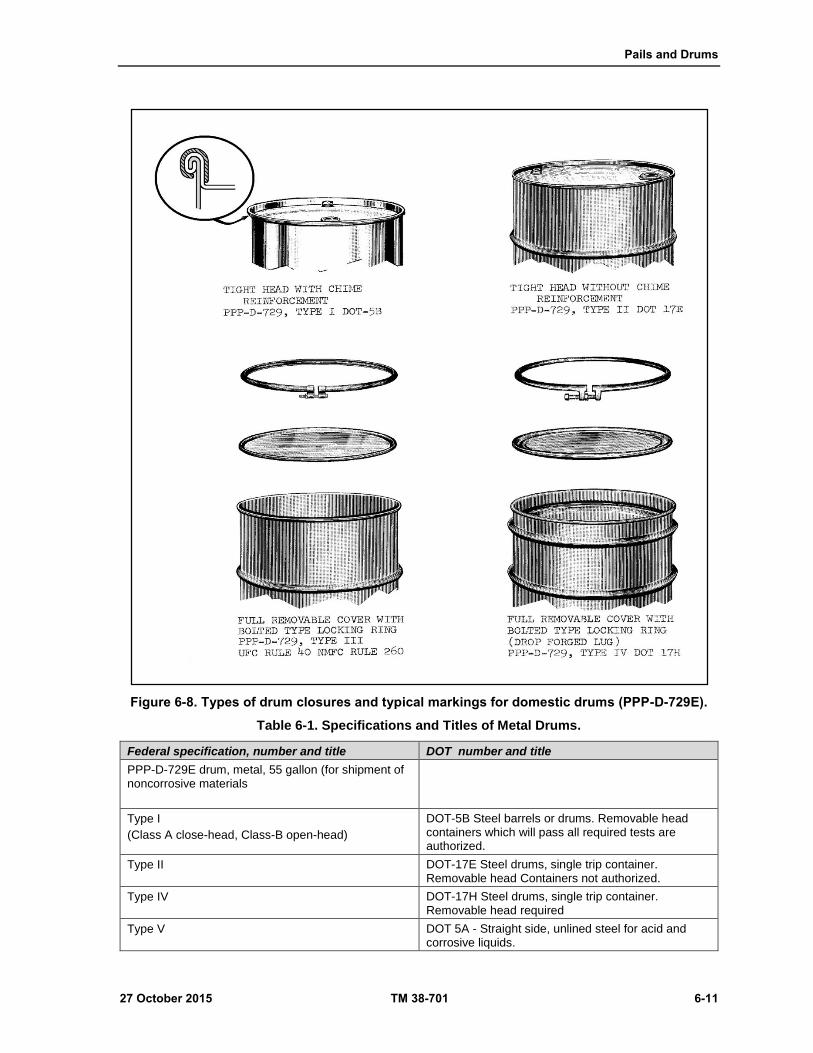
Pails and Drums
27 October 2015 TM 38-701 6-11
Figure 6-8. Types of drum closures and typical markings for domestic drums (PPP-D-729E).
Table 6-1. Specifications and Titles of Metal Drums.
Federal specification, number and title DOT number and title
PPP-D-729E drum, metal, 55 gallon (for shipment of noncorrosive materials
Type I
(Class A close-head, Class-B open-head)
DOT-5B Steel barrels or drums. Removable head containers which will pass all required tests are authorized.
Type II DOT-17E Steel drums, single trip container. Removable head Containers not authorized.
Type IV DOT-17H Steel drums, single trip container. Removable head required
Type V DOT 5A - Straight side, unlined steel for acid and corrosive liquids.

Chapter 6
6-12 TM 38-701 27 October 2015
Table 6-1. Specifications and Titles of Metal Drums. (Continued)
Federal specification, number and title DOT number and title
Type VI DOT 5C - Straight side, corrosion-resistant steel for acid and corrosive liquids
Type VII DOT 5D – Close head straight side, lined steel for acid and corrosive liquids
USE
6-25. The tight (fixed) head drums are primarily used for the shipment of liquids. Emptying may be through
either the filler or vent hole, although the filler hole is most commonly utilized. A spout may be affixed to
the threaded portion of the hole to facilitate emptying. A pump, either hand or hydraulically operated, may
be utilized in the hole. Greases, dry powdered, flaked or granular materials, etc., may be shipped in a full
removable head drum. The full removable head drum provides the easiest access to the contents.
REUSE
6-26. Most metal drums are initially filled at the manufacturer's plant and are reusable except for single-trip
containers. When empty, the drums may be returned to destination for refilling. If refilling is done by the
initial user, care should be taken not to reuse drums which have been used to ship hazardous materials, until
such drums are cleaned and tested in accordance with United Nations recommendations. Failure to do so may
create a serious health hazard. When filling drums with dangerous materials, only United Nation’s
recommended type drums may be used for that commodity. The drum specification number, the name, initial,
or symbol of the manufacturer; the letters "U.S." to indicate that the drum is the property of the Government;
the letters "STC" if the drum is a single-trip container; and a numerical indication of the thinnest gage of
metal used in the construction, the capacity of the drum in gallons, and the year of manufacture are embossed
on the bottom of the drum (fig 6-8). For example, 18-55-74 means that drum is 18 gage metal, 55-gallon
capacity, and was made in 1974. When filling the drums, the contents may not exceed the marked capacity
minus 2 percent for outage.
FIBER DRUMS (PPP-D-723J)
6-27. Fiber drums are cylindrical shipping containers with bodies made of fiberboard. Fiber drums are either
lapped or parallel wound (convolutely) in the form of a hollow cylinder. They may be either single unit or
telescopic body type. The heads are of metal, wood, plywood, or fiberboard.
CLASSIFICATION
6-28. There are many characteristics of fiber drums which give them advantages over other types of
containers. Included among these are cleanliness, durability, low uniform tare weight, retard temperature
fluctuation, easy opening and closing, water and moisture resistance, stack ability, easy handling, product
protection and wide range of diameters and heights. Fiber drums are easily opened and reclosed. Fiber drums
are available in the types, grades, and classes shown in table 6-2 on page 6-13.
USE
6-29. The intended uses are shown in table 6-2. The other factors covered by this paragraph must also be
observed.
Domestic Type (Type I)
6-30. Fiberboard drums covered by this specification are intended for use as domestic shipping containers.
Grade A drums are for dry or solid materials. Class 1 regular construction should normally be used; class 2
foil laminated should be used for highly hygroscopic materials needing a barrier, such as desiccants. Use of
grade B drums should be limited to semisolid materials having a consistency similar to asphalt, lubricating
grease, petrolatum, refractory cement, caulking compounds, roof coatings, adhesives, textile sizing, and food
Pails and Drums
27 October 2015 TM 38-701 6-13
products such as jellies and fondants. The consistency of asphalt materials and lubricating greases should not
exceed 350 units when measured in accordance with method 311.6 of FED-STD-791D (ASTM D 217). Class
2 is normally used when high moisture barrier is required or when the type I, grade A, class 2 is supplemental
by the aluminum liners it may be used to deter electrostatic charges and prevent explosion. Grade C drums
are for hot-poured materials that solidify on cooling and should be limited to materials poured at temperature
not exceeding 400 degrees F. Grade E drums are for nonregulated liquids or articles in liquids.
Type I, Grade D
6-31. This is also intended for normal overseas shipment. When substituted for type II drums, the drums
shall be marked type II, overseas type (nonweather resistant).
Type Ii Overseas (Nonweather Resistant)
6-32. Fiberboard drums covered by this specification are intended for use for normal overseas shipment
where numerous handling and storage at destination are not anticipated.
Type Iii Overseas (Weather Resistant)
6-33. Fiberboard drums covered by this specification are intended for unprotected weather exposure usage
for added protection in high humidity or outdoor storage environment.
Exceptional Requirement
6-34. Exceptional commodities, especially dangerous articles (hazardous material), may require better
material and construction requirements than are covered by this specification.
Compliance Marking
6-35. In addition and adjacent to the drum manufacturer's markings required by Uniform Freight
Classification, National Motor Freight Classification or DOT rules or regulations, each drum is stamped or
printed in black capital letters not less than 3/16 inch in height with information concerning the type, class,
grade, specification number, etc. For example, the information for the Type I drum is shown below:
Type I
(DOMESTIC TYPE)
COMPLIES WITH FED. SPEC. PPP-D-723J
FOR DOMESTIC SHIPMENT_______________
GRADE ____________CLASS_______________
MAX. WT. OF CONTENTS______________LBS.
MAX. CAPACITY OF CONTENTS____________GAL
In addition, Grade D drums shall have stenciled or printed on the cover and side wall in letters not less than 3/4
inch in height, the following precautionary markings:
STAND ON END
KEEP COOL AND DRY
Only contents of the type, grade, and class as indicated in the compliance markings are to be placed in these
drums. The weight and capacity must also conform to these requirements.
Table 6-2. PPP-D-723J Fiber drums
Types, grades, and classes. Fiber drums covered by this specification
shall be of the following types, grades, and classes, as specified.
Type I Domestic (non-weather resistant)
Type II - Overseas (non-weather resistant)
Type III - Overseas (weather resistant)
Grade A For dry and solid material (applicable to all types)

Chapter 6
6-14 TM 38-701 27 October 2015
Table 6-2. PPP-D-723J Fiber drums (continued)
Types, grades, and classes. Fiber drums covered by this specification
shall be of the following types, grades, and classes, as specified.
Grade B - For semiliquid material (applicable to all types)
Grade C - For hot poured materials that solidify on cooling (applicable to types I and II only)
Grade D - For rolled or cylindrical items (applicable to types I and II only)
Grade E - For liquids or articles in liquid - nonregulated (applicable to all types)
Class 1 Regular construction (applicable to only types I and III grade A drums)
Class 2 - Foil laminated construction (applicable to only types I and III grade A drums)
Class 3 - Integral plastic lining (applicable to only grade E drums)
Class 4 - Semi-rigid plastic component (open head loose liner applicable to only grade E drums
Class 5 - Molded rigid one-piece plastic component (closed head liner) applicable to only grade E drums
Closure
6-36. The closure of fiber drums must be such that they may be opened and reclosed by hand or simple tools.
These are three types of closures which are commonly used. They are the friction-type or telescopic slip on
covers, which are secured with pressure sensitive tape, lever-activated locking bands, and the metal clip or
lug closure (fig 6-9).
Figure 6-9. Types of fiber drum closures (PPP-D-723J).
27 October 2015 TM 38-701 7-1
Chapter 7
Crates
INTRODUCTION TO CRATES
NOMENCLATURE AND RELATED TERMS
7-1. Crates are rigid containers constructed of structural members fastened together to protect the contents.
Crate design involves numerous names and terms which must be defined if the construction of crates is to be
explained without confusion. When the names of the separate components are known, although they differ
in various specifications and drawings, their functions and relationship to each other are more easily
understood. In order that both general and detail design requirements may be clearly understood, reference
to items described in ASTM D 996 and below is recommended.
Nomenclature
7-2. Below is a list of commonly used nomenclatures and there definition.
Baffle
7-3. A piece of plywood, wood, or metal placed over ventilation holes to deflect air or water entering the
crate.
Bottom Sheathing
7-4. Boards nailed to the bottom surface of the frame members of a sill base. Also known as flooring.
Bridging
7-5. Members of the same depth as joists or sills placed at right angles to the intermediate longitudinal or
crosswise sills or headers to prevent lateral turning or buckling of the joists or sills.
Cleats
7-6. Auxiliary reinforcements for plywood panels placed between vertical struts to strengthen the panel.
Covered Crate
7-7. A crate with open-type frame with an outside covering of plywood or paper- overlaid veneer.
Crate Base
7-8. The bottom load bearing unit of a crate.
Crate Covering
7-9. A lightweight material fastened to the frame of an open crate to give more positive weatherproofing
than is offered by an open crate and shroud.
Diagonals
7-10. Frame members positioned between parallel frame members and placed at angles of nearly 45? to the
latter.
Chapter 7
7-2 TM 38-701 27 October 2015
Diagonal Floorboards
7-11. Usually 1-inch boards, cut at 45 degree angle to the skids and placed between the forklift areas.
End Frame Members
7-12. Members of the top panel of an open crate, placed crosswise at each end of the top.
End Sills
7-13. Members forming the ends of a sill frame.
Filler Strips
7-14. Boards placed across the ends of thin, nonload bearing floorboards which fill the space below the lower
frame member of the sides.
Floor Members
7-15. Boards and timbers nailed or bolted to the top of the skids forming a platform for the contents and a
bottom closure for the crates.
Forklift Area
7-16. Area extending 42 inches in from each end of the crate, usually floored with 2-inch boards.
Frame Members
7-17. Those wood members which form the fundamental structure of the crate.
Gusset Plate
7-18. A square piece, usually plywood, placed at the junction of the diagonals for reinforcement.
Hanger, Metal
7-19. Metal strapping formed in a manner to support intermediate sills on a sill- type crate or joists of the
top.
Headers Or End Cross Members (Open Crate)
7-20. Cross members attached at the end of the skids which hold the skids together. Also longitudinal
members at each end of top joists.
Horizontal Braces
7-21. Members positioned between struts and parallel to upper and lower frame members of the sides or
ends.
Horizontal Top Bracing Joist Support
7-22. Horizontal member attached to the frame members in which the top joists rest.
Intermediate Crosswise Sills
7-23. Full length members located between the end sills and parallel to them.
Intermediate Frame Members
7-24. Members of the top panel of an open crate located between and parallel to the side frames of the top.
Crates
27 October 2015 TM 38-701 7-3
Intermediate Longitudinal Sills
7-25. Full length members located between the side sills and parallel to them.
Intermediate Skids
7-26. Full length beams located between and parallel to the skids.
Joists
7-27. Members extending across the crate that support the top and prevent crushing when grab hooks are
used.
Joists Supports
7-28. Members, usually 2 x 4, nailed to the frame under each joist and extending to the floor.
Kick Blocks
7-29. Short members attached at the junction of the corner post and upper or lower edge member. They are
used on end panels having no braces or those with a single diagonal brace.
Lag Bolt Reinforcing Strap
7-30. Galvanized strapping drilled to take lag bolts and nailed to the inner face of the sheathing at the center
line of the skid and header.
Load Bearing Floor Members
7-31. Heavier or reinforced floorboards used to hold the concentrated weight of the crate load.
Lower Frame Member
7-32. Horizontal frame member at the lower edge of the side and end panels. Formerly called lower edge
member.
Open Crate
7-33. A crate formed of frame members only, without exterior sheathing attached.
Reinforced Straps
7-34. Metal strapping applied at the corners or base corners to reinforce and fasten the panels together.
Rubbing Strips
7-35. Boards nailed to the underside of skids or bottom sheathing.
Sheathed Crate
7-36. A crate in which the frame members are completely covered with sheathing.
Sheathing
7-37. Material such as plywood, lumber, or fiberboard nailed to the frame of a crate across all openings to
add strength to the crate, or to prevent loss of contents, pilferage, or entry of dirt, water, etc., into the crate.
Side Frame Members
7-38. Members of the top panel of an open crate, placed lengthwise of each side of the top.
Chapter 7
7-4 TM 38-701 27 October 2015
Side Sills
7-39. The members forming the sides of a sill base crate.
Sills
7-40. The continuous frame members of a sill base.
Sill Base
7-41. A crate which has its frame members (sills) built on the inside of the crate to which the bottom
sheathing is attached.
Sill Bridging
7-42. Members of the same depth as the sills placed at right angles to the intermediate lengthwise or
crosswise sills of a sill base to prevent twisting or buckling.
Skids
7-43. The outside longer beams of a skid base which support the weight of the crate and contents.
Skid Base
7-44. A crate base which has its longer beams on the outside.
Sleeper
7-45. Reinforcing members secured to the underside of the floorboards, at right angles to the floorboards to
provide secure anchorage for the item.
Spacers
7-46. Members which position the ends of joist or sills.
Spreaders
7-47. Members placed at right angles to the floorboards, between the item and the floorboards, to distribute
the load over a wider area.
Sling Notches
7-48. Open spaces between the ends of the rubbing strips and the ends of the crate, or cutaway sections at
the ends of the skids.
Struts
7-49. Vertical frame members between the upper and lower frame members.
Top Joist Spacers
7-50. Short members nailed between the top joists, to the inside face of the upper frame members, which act
as end bridging.
Top Sheathing
7-51. Board or plywood forming the closure of the top.
Upper Frame Member or Upper Edge Member
7-52. Horizontal frame member at the upper edge of the side and end panels.
Crates
27 October 2015 TM 38-701 7-5
Related Terms
7-53. Commonly used related terms are decribed below.
Actual Size Lumber
7-54. The true dimension of a piece of lumber as measured with a scale.
Center of Balance
7-55. The point along the length of a crate at which it would balance on a fulcrum, placed at right angles to
the skids of sills.
End Grain Nailing
7-56. Nails driven parallel to the grain of the wood.
Gross Weight
7-57. Total weight of the crate and its contents when ready for shipment.
Holddowns
7-58. Devices constructed of wood or metal, used to secure the item to the base of the crate.
Liner
7-59. Waterproof barrier material placed between the frame and the sheathing.
Net Weight
7-60. The weight of the item alone, excluding dunnage, wrappings, or containers.
Nominal Size Lumber
7-61. Dimension of lumber before it is dressed.
Overdriving
7-62. Driving nails into wood so that the heads sink below the surface of the wood.
Side Grain Nailing
7-63. Nails driven at right angles to the grain of the wood.
Tare Weight
7-64. The weight of the crate, including dunnage, holddowns, and packing materials.
Underdriving
7-65. Driving nails into wood so that the heads protrude above the surface of the wood.
CLASSIFICATION OF CRATES
7-66. Crates are grouped into several categories. They may be open or sheathed (fig 7-1 on page 7-6).Crates
may be nondemountable, single trip crates of nailed construction, or bolted, reusable, demountable crates.
Crates may be designed for domestic use only, or for both domestic and oversea shipments. Some crates are
designed for general use and others are constructed in accordance with a specification for a particular item.
Of course, the classification of a crate may include a combination of several of the above factors.
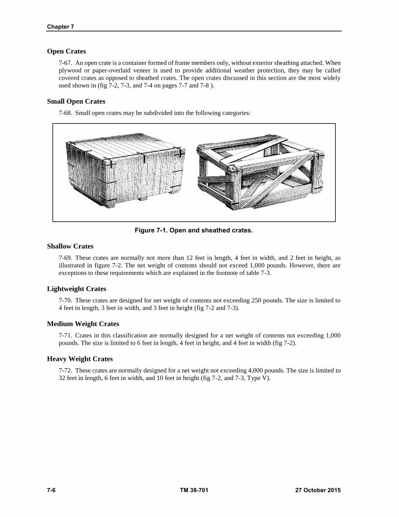
Chapter 7
7-6 TM 38-701 27 October 2015
Open Crates
7-67. An open crate is a container formed of frame members only, without exterior sheathing attached. When
plywood or paper-overlaid veneer is used to provide additional weather protection, they may be called
covered crates as opposed to sheathed crates. The open crates discussed in this section are the most widely
used shown in (fig 7-2, 7-3, and 7-4 on pages 7-7 and 7-8 ).
Small Open Crates
7-68. Small open crates may be subdivided into the following categories:
Figure 7-1. Open and sheathed crates.
Shallow Crates
7-69. These crates are normally not more than 12 feet in length, 4 feet in width, and 2 feet in height, as
illustrated in figure 7-2. The net weight of contents should not exceed 1,000 pounds. However, there are
exceptions to these requirements which are explained in the footnote of table 7-3.
Lightweight Crates
7-70. These crates are designed for net weight of contents not exceeding 250 pounds. The size is limited to
4 feet in length, 3 feet in width, and 3 feet in height (fig 7-2 and 7-3).
Medium Weight Crates
7-71. Crates in this classification are normally designed for a net weight of contents not exceeding 1,000
pounds. The size is limited to 6 feet in length, 4 feet in height, and 4 feet in width (fig 7-2).
Heavy Weight Crates
7-72. These crates are normally designed for a net weight not exceeding 4,000 pounds. The size is limited to
32 feet in length, 6 feet in width, and 10 feet in height (fig 7-2, and 7-3, Type V).
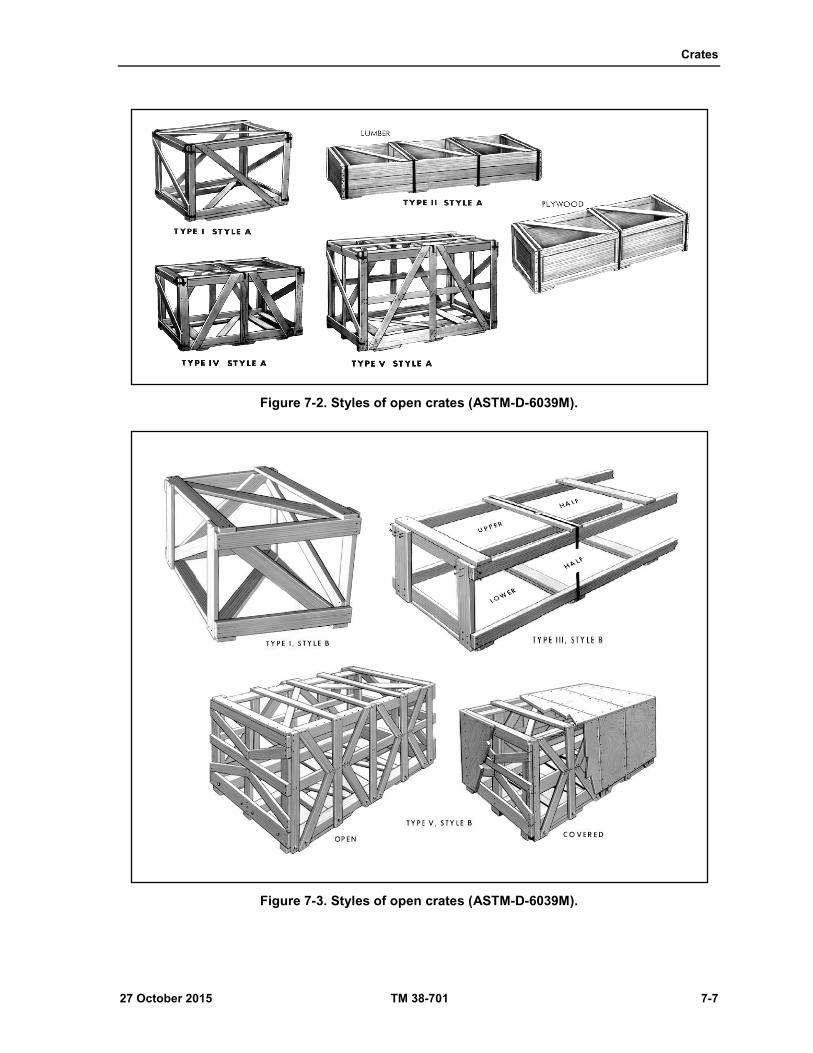
Crates
27 October 2015 TM 38-701 7-7
Figure 7-2. Styles of open crates (ASTM-D-6039M).
Figure 7-3. Styles of open crates (ASTM-D-6039M).
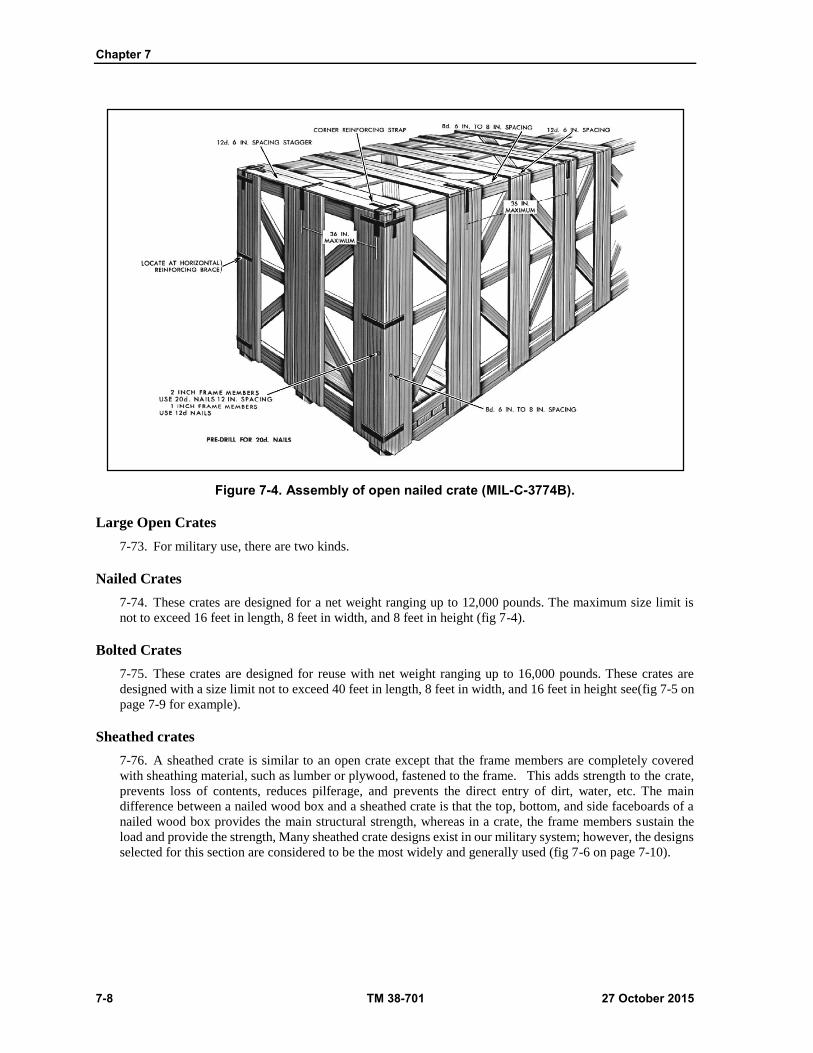
Chapter 7
7-8 TM 38-701 27 October 2015
Figure 7-4. Assembly of open nailed crate (MIL-C-3774B).
Large Open Crates
7-73. For military use, there are two kinds.
Nailed Crates
7-74. These crates are designed for a net weight ranging up to 12,000 pounds. The maximum size limit is
not to exceed 16 feet in length, 8 feet in width, and 8 feet in height (fig 7-4).
Bolted Crates
7-75. These crates are designed for reuse with net weight ranging up to 16,000 pounds. These crates are
designed with a size limit not to exceed 40 feet in length, 8 feet in width, and 16 feet in height see(fig 7-5 on
page 7-9 for example).
Sheathed crates
7-76. A sheathed crate is similar to an open crate except that the frame members are completely covered
with sheathing material, such as lumber or plywood, fastened to the frame. This adds strength to the crate,
prevents loss of contents, reduces pilferage, and prevents the direct entry of dirt, water, etc. The main
difference between a nailed wood box and a sheathed crate is that the top, bottom, and side faceboards of a
nailed wood box provides the main structural strength, whereas in a crate, the frame members sustain the
load and provide the strength, Many sheathed crate designs exist in our military system; however, the designs
selected for this section are considered to be the most widely and generally used (fig 7-6 on page 7-10).

Crates
27 October 2015 TM 38-701 7-9
Figure 7-5. Assembly of open bolted crate (MIL-C-3774B).
Sheathed Nailed Crates
7-77. These crates are not designed for reuse and are constructed in the same manner as bolted crates with
minor exceptions. The crates should not exceed 30 feet in length, 9 feet in width, and 10 feet in height. The
net weight of contents may range up to 30,000 pounds. These limitations may be exceeded, however, when
the size and weight of the item require a larger crate.
Sheathed Bolted Crates
7-78. All bolted crates are designed for reuse. The size and weight limitations are the same as for the nailed
crates.
Special Use Crates
7-79. Crates in this classification are of special design for specific items. These crates may be fabricated of
metal or wood, either open, sheathed, nailed, or bolted. Crate dimensions and weight will vary depending
upon the size, weight, and characteristics of the contents. Examples of special crates are illustrated in figure
7-7 on page 7-10. The slotted angle crate (ASTM D6255) is an example of special metal crate which may be
either open (Type I) or sheathed (Type II with either plywood, paper-overlaid veneer, or fiberboard. It may
be fabricated without skids (Style A), or with skid blocks or skids with rubbing strips (Style B). Both the
open and sheathed Style A slotted angle crates are restricted to items not to exceed 200 pounds, with
dimensions not to exceed 80 inches in length, 30 inches in width, and 48 inches in height, except when a
specific design has been approved by the contracting activity. Both the open and the sheathed Style B carry
up to 3,000 pounds and are limited to not over 30 feet in length, 4 feet in width, and 7 feet in height.

Chapter 7
7-10 TM 38-701 27 October 2015
Figure 7-6. Sheathed crates.
Figure 7-7. Special use crates.

Crates
27 October 2015 TM 38-701 7-11
Criteria For Crate Design
7-80. Crates are selected instead of boxes for several reasons. The item may be too large to be shipped in a
box. The weight of the item may exceed the weight limitations of a box specification. The item may not
require complete enclosure for protection, yet it may require crating to facilitate storage and handling. Crates
provide better facilities for clearances, blocking, bracing, and anchoring of the item. To select the proper
crate for the item or items to be packed, it is necessary to consider certain basic factors that may influence
the selection.
Size and Weight
7-81. Basically, it is desirable to design a crate not to exceed 30 feet in length, 9 feet in width, and 10 feet in
height, with a weight limitation not to exceed 11,200 pounds. This maximum size and weight is indicated
because the length of 30 feet will permit lowering the crate through the average ship's hatch without excessive
tilting. The 9-foot width and 10-foot height is designed for the average width and clearance limits for
transporting by rail on a standard flat car. Taking the weight factor into consideration will permit ease of
handling by the average ship's hoisting facilities.
Degree of Disassembly
7-82. When determining the size, weight, shape, and strength, considerations should be given to partial
disassembly of the item or its components to reduce the overall size of the crate. However, do not disassemble
the item to the point where special tools or personnel are needed to reassemble it.
Weight Distribution
7-83. In designing crates over 5 feet in length, weight distribution becomes an important factor. Whenever
possible, the center of gravity of the contents should coincide with the geometrical center (center of balance)
of the loaded crate.
Anchoring of the Contents
7-84. A thorough study of the contents should be made in order to insure that provisions are made for
anchoring the contents within the crate to prevent damage during handling and shipment. When necessary,
use cushioning and padding at points on the item where blocking, bracing, or strapping is used to prevent
movement. Bolts, steel strapping, iron bands, rods and lumber holddowns are acceptable methods for
anchoring and supporting the contents (fig 7-8 on page 7-12). Some items are designed with packing and
shipping in mind and are provided with holddown features. If the item does not have these characteristics,
utilize the stronger areas of the item for anchoring.
Clearance
7-85. Normally, a minimum of one-inch clearance is required between the contents and the nearest framing
member of the sides, ends, and top. This clearance allows for the distortion and vibration to which the crate
may be subjected during rough handling and transit. Items that are fragile in nature, or items within floating
bag barriers (sub methods 53 and 43) require from 2 to 4 inches of clearance. Additional clearance may be
required for shock mounted items. Through careful design, it is often possible to allow protruding points of
the item to extend between the joists, or the joists may be spaced, within specified limits, to accommodate
these protrusions.
Types Of Bases
7-86. The selection of a skid or a sill base will depend on the physical characteristics of the item to be crated.
Sill Bases
7-87. Sill bases (fig 7-9 on page 7-13) are designed for items that can be supported above their lowest point.
Examples are transmission housing engines and vehicles with brake drums projecting below the frame or
axles.

Chapter 7
7-12 TM 38-701 27 October 2015
Figure 7-8. Methods of anchoring contents in crates.

Crates
27 October 2015 TM 38-701 7-13
Figure 7-9. Sill base.
Skid Bases
7-88. Skid bases are designed to accommodate loads that can be supported on their lowest portion, or items
that are made to rest flat on their bases. Skid-type bases are preferred in most cases; however, when the item
must be supported above its lowest point, the use of a sill base will reduce the overall height of the crate.
Savings in height should be more than 6 inches before substituting a sill base for a skid base (fig 7-10 on
page 7-14).

Chapter 7
7-14 TM 38-701 27 October 2015
Engineering Factors in Crate Design
7-89. A crate is an engineered container. The use of sound engineering principles and actual tests of crates
with contents has resulted in the following design requirements.
Figure 7-10. Skid base.
Tops
7-90. The top of a sheathed crate is designed to carry a uniform, well-distributed, superimposed load of 50
pounds per square foot. Top loading plus the span or width of the crate will determine the kind of top and the
size of joist required to transfer the load to the sides.
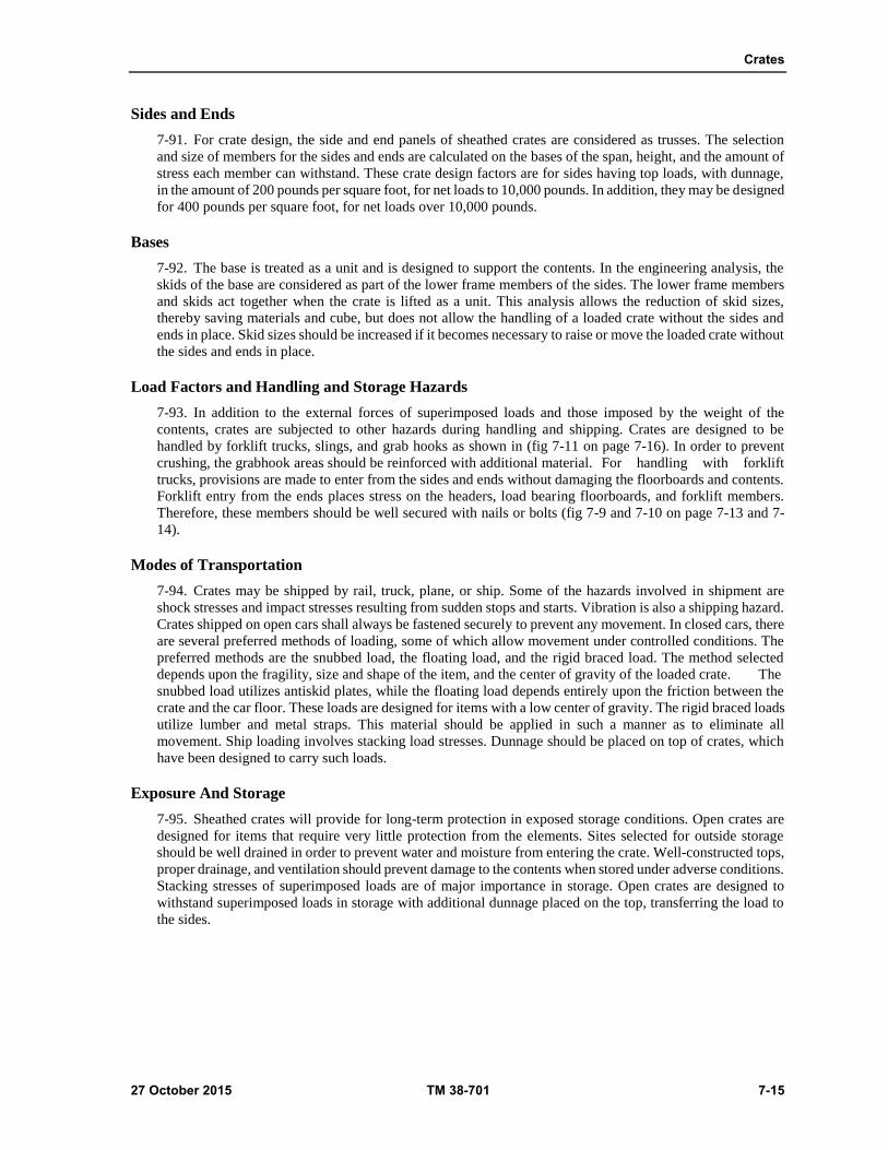
Crates
27 October 2015 TM 38-701 7-15
Sides and Ends
7-91. For crate design, the side and end panels of sheathed crates are considered as trusses. The selection
and size of members for the sides and ends are calculated on the bases of the span, height, and the amount of
stress each member can withstand. These crate design factors are for sides having top loads, with dunnage,
in the amount of 200 pounds per square foot, for net loads to 10,000 pounds. In addition, they may be designed
for 400 pounds per square foot, for net loads over 10,000 pounds.
Bases
7-92. The base is treated as a unit and is designed to support the contents. In the engineering analysis, the
skids of the base are considered as part of the lower frame members of the sides. The lower frame members
and skids act together when the crate is lifted as a unit. This analysis allows the reduction of skid sizes,
thereby saving materials and cube, but does not allow the handling of a loaded crate without the sides and
ends in place. Skid sizes should be increased if it becomes necessary to raise or move the loaded crate without
the sides and ends in place.
Load Factors and Handling and Storage Hazards
7-93. In addition to the external forces of superimposed loads and those imposed by the weight of the
contents, crates are subjected to other hazards during handling and shipping. Crates are designed to be
handled by forklift trucks, slings, and grab hooks as shown in (fig 7-11 on page 7-16). In order to prevent
crushing, the grabhook areas should be reinforced with additional material. For handling with forklift
trucks, provisions are made to enter from the sides and ends without damaging the floorboards and contents.
Forklift entry from the ends places stress on the headers, load bearing floorboards, and forklift members.
Therefore, these members should be well secured with nails or bolts (fig 7-9 and 7-10 on page 7-13 and 7-
14).
Modes of Transportation
7-94. Crates may be shipped by rail, truck, plane, or ship. Some of the hazards involved in shipment are
shock stresses and impact stresses resulting from sudden stops and starts. Vibration is also a shipping hazard.
Crates shipped on open cars shall always be fastened securely to prevent any movement. In closed cars, there
are several preferred methods of loading, some of which allow movement under controlled conditions. The
preferred methods are the snubbed load, the floating load, and the rigid braced load. The method selected
depends upon the fragility, size and shape of the item, and the center of gravity of the loaded crate. The
snubbed load utilizes antiskid plates, while the floating load depends entirely upon the friction between the
crate and the car floor. These loads are designed for items with a low center of gravity. The rigid braced loads
utilize lumber and metal straps. This material should be applied in such a manner as to eliminate all
movement. Ship loading involves stacking load stresses. Dunnage should be placed on top of crates, which
have been designed to carry such loads.
Exposure And Storage
7-95. Sheathed crates will provide for long-term protection in exposed storage conditions. Open crates are
designed for items that require very little protection from the elements. Sites selected for outside storage
should be well drained in order to prevent water and moisture from entering the crate. Well-constructed tops,
proper drainage, and ventilation should prevent damage to the contents when stored under adverse conditions.
Stacking stresses of superimposed loads are of major importance in storage. Open crates are designed to
withstand superimposed loads in storage with additional dunnage placed on the top, transferring the load to
the sides.

Chapter 7
7-16 TM 38-701 27 October 2015
Figure 7-11. Resistance to forces.
CRATE MATERIALS
7-96. The most important materials used in constructing crates are wood in its various forms and the fasteners
used for fabrication and assembly.
7-97. Sound crate design criteria and proper use of materials will result in a crate that combines maximum
strength with minimum materials.
LUMBER
7-98. Lumber used in crate construction must meet the same rigid requirements as for other wooden
containers. Lumber used in crate construction shall be free of defects that would materially weaken the
container. Knots and divergence of grain (cross-grain) are probably the most common defects in lumber used
for framing members, and will affect the strength of these members more than the sheathing boards. Knots
or knot clusters that exceed one-fourth the width of a structural member or that exceed one-third the width
of a sheathing board, are prohibited.
7-99. Moisture content of lumber is an important factor and shall be not less than 12 percent nor more than
19 percent of its oven dry weight. Otherwise, shrinkage may occur and nail holding power may be reduced.
Divergence of grain (cross-grain) more than 1 inch in 10 inches in the length of a piece is prohibited.
7-100. The width and thickness of lumber used in fabricating crates are always minimum from a design
standpoint. When nominal sizes are given in a crate specification, the actual minimum sizes will be as
indicated in table 7-1 on page 7-17.
Note. All lumber dimensions referenced in this section are nominal. Actual dimensions are so
indicated when actual sizes are required.

Crates
27 October 2015 TM 38-701 7-17
Table 7-1. Minimum Thickness and Width of Lumber
Thickness in inches (smaller dimension) Width in inches (larger dimension)
Nominal size Minimum (actual) Nominal size Minimum (actual)
1 3/4 2 1-1/2
2 1-1/2 3 2-1/2
3 2-1/2 4 3-1/2
4 3-1/2 5 4-1/2
5 4-1/2 6 5-1/2
6 5-1/2 8 7-1/2
7 6-1/2 10 9-1/2
8 7-1/2 12 11-1/2
Plywood (A-A-55057B)
7-101. Plywood is used in crate construction for sheathing, for nonload bearing flooring, for tops, and gusset
plates. While plywood is usually more expensive than lumber, it required no diagonals or crate liner material
when used as sheathing, and a lighter, more economical crate may result from its use. Tests have shown that
plywood is actually stronger than lumber, the dimensions being the same. When using plywood, select the
standard size sheet stock that conforms closest to the crate dimensions, otherwise waste of material will
result. The type of plywood selected will be on the basis of its intended use. Where prolonged exposure to
the elements or attack by micro- organisms (mold, fungi, etc.) is expected, materials, must be selected that
will withstand the extreme conditions.
Nails (ASTM F 1667-05)
7-102. Nails are used in the fabrication of the components for both nailed and bolted crates. They are also
used in the assembly of nailed crates. The preferred types of nails used for crate assembly are the sinker,
corker, or common. If these nails are not available, coolers or standard box nails may be used. Nails used for
fastening plywood should be 14-gage with heads no less than 7/32-inch diameter.
Staples (ASTM F 1667-05)
7-103. Staples are sometimes used to fasten plywood sheathing to the framing members. When used for this
purpose, staples should be made of 16-gage wire with a crown not less than one-half inch.
Bolts, Nuts, and Washers
7-104. Many types of bolts are used in crate construction. The most common types used are standard steel
carriage, step, and machine bolts (fig 7-12 on page 7-18). Bolt holes should be drilled the same size as the
shank of the bolt. Plain washers should be used under the heads of the machine bolts and under all nuts.
Special holding plates have been designed for use under the heads of square shank bolts to prevent turning.
The use of plates is not mandatory. Counter- sinking of bolt heads is prohibited. The bolt threads projecting
beyond the nut after tightening should be painted with hard drying preservative, un-thinned paint or other
similar material to prevent loosening.
Lag Bolts
7-105. Lag bolts are sometimes referred to as "lag screws". There are three types of lag bolts, Gimlet Point;
Cone Point; and Cone Point, Fetter Drive (fig 7-12 on page 7-18). There are two different types of heads,
Hex head and Square head. Lag bolts are used to assemble the sides, ends, and tops of demountable crates.
These bolts are prohibited for use as holddowns or to tie the headers and the floorboards to the skids. When
using lag bolts for assembly, drill the lead hole to the same diameter as the shank, although the threaded
portion may be larger than the shank. The size of the lead hole for the threaded portion will depend upon the
group of wood used. When using lag bolts in soft woods, make smaller lead holes. Use plain washers under
the heads and tighten firmly against the washer (table 7-2 on page 7-18).

Chapter 7
7-18 TM 38-701 27 October 2015
Note. Lag bolts should never be driven with a hammer. When power wrench is used, care must be
taken that the bolts are not overdriven.
Nut Sleeve Assembly
7-106. A nut sleeve assembly, as illustrated in (fig 7-13 on page 7-19) , may be used as an alternate for lag
bolts in demountable crates. These bolts must be the same size as the fasteners they replace and are spaced
the same distance apart.
Metal Strapping (ASTM D 3953 and ASTM D 4169)
7-107. Metal strapping is used for reinforcing crate corners, sill bases, securing tops, as lag bolts reinforcing
straps for demountable crates, and for strengthening sill and load bearing headers for sill-type bases. It is also
used to reinforce crate corners and the tops of open crates. Metal straps used for this purpose shall be Class
1 Type I or II, and not less than 3/4 x 0.028-inch (fig 7-14 on page 7-19).
Figure 7-12. Bolts, screws, and accessories.
Table 7-2. Application of Lag bolts
Diameter of threaded portion of lag bolts
Diameter of lead hole
Groups I, II and III wood Group IV wood
Inch Inch Inch
1/4 3/16 3/16
5/16 1/4 1/4
3/8 1/4 5/16
1/2 3/8 7/16
5/8 3/8 1/2
3/4 1/2 5/8

Crates
27 October 2015 TM 38-701 7-19
Figure 7-13. Nut sleeve assembly.
Figure 7-14. Tension and corner strapping.
Corner Straps
7-108. Metal strapping used for reinforcing tops, corners, and sill-type bases is usually annealed and
predrilled for ease of application. This type of strapping is used on all nailed crates and on bolted crates with
net loads over 3,000 pounds. The legs of the corner straps are usually 8 inches in length. They are nailed to
the frame members with a minimum of three galvanized roofing nails, 1 1/4 to 1 1/2 inches long. The straps
are spaced no more than 36 inches apart.
Tension Straps
7-109. Tensions straps are used to secure the top to the sides of the crate by anchor plates, which are nailed
to the frame members. The straps are drawn tight with a tensioning device and held in tension with two seals.
Tensions straps are spaced no more than 6 feet apart.
Chapter 7
7-20 TM 38-701 27 October 2015
Lag Bolt Reinforcing Straps
7-110. This strap is fabricated from galvanized steel and is used on the side and end panels of many
demountable crates to prevent the lag screws from tearing through the sheathing as the crate is lifted. The
strapping material is pre punched or predrilled. Lag bolts 3/8 inch in length require 1 1/4 X 0.035 inch straps.
For 1/2 inch and 5/8 inch lag screws, 2 X 0.050 inch straps are needed. Nail these straps to the lower inner
face of the sheathing between the lower edge of the bottom frame member and the bottom of the sheathing.
Locate them to coincide with the center of the skids and headers. Use clout or similar nails to secure the
strapping. Space the nails a maximum of 2 inches on center and clinch at least three-fourths of an inch (fig
7-15 on page 7-21).
Metal Hanger
7-111. Metal hangers are used for reinforcing joists of tops, load bearing headers, and intermediate sills on
sill-type bases. Hangers are fabricated from steel straps 1 1/4 X 0.035-inch. The strapping material is pre
punched or predrilled. When used to reinforce load bearing headers or intermediate sills, eight penny nails
are used to secure straps in place, followed by driving from two to four twenty penny nails into the end-grain
of the holding member (fig 7-16 on page 7-22).

Crates
27 October 2015 TM 38-701 7-21
Figure 7-15. Lag bolt reinforcing strap.

Chapter 7
7-22 TM 38-701 27 October 2015
Figure 7-16. Use of metal hangers.

Crates
27 October 2015 TM 38-701 7-23
Sill Base Straps
7-112. In addition to the straps applied to other areas of the crate, sill bases must be reinforced with 3/4 X
0.028-inch metal straps (fig 7-17 on page 7-24). Use a minimum of three galvanized roofing nails 1 1/4 to 1
1/2-inch long in each leg of the strap. Locate all nails to penetrate a framing member.
Waterproof Liners and Shrouds (PPP-B-1055B)
7-113. This waterproof barrier material is made by laminating layers of craft paper with asphalt. Seven
different classes of materials may be used for crate liners. The most common classes used are E-1, E-2, and
C-2. This material, when used as a liner, is placed horizontally between the sheathing and the frame members
of the sides and ends. If more than one width of material is required, use a minimum of 4-inch shingle lap for
proper drainage. The barrier should cover the entire framed area (fig 7-18 and 7-19 shown on page 7-
25).When vertical joints are required, the 4 inch lap will be located at a vertical member. Liners are not
required for plywood sheathed crates. Interior shrouds, large bags, or envelopes fabricated from waterproof
barrier material are used in open crates to cover items which require additional protection. All sharp
projections of the item should be cushioned or padded to prevent puncturing the material. The class of
material to use is optional, although the most common class is E-2. All joints in the material are made by
using MMM-A-260C adhesive. Shrouds should hang free of the item to provide proper ventilation and should
extend to within 6 inches of the bottom of crate. Material conforming to A-A-3174 may also be used for
interior shrouds. This material is constructed of polyethylene and does not contain asphalt (fig 7-18 and 7-19
on page 7-25).
Roofing Felt
7-114. Roofing felt is used in the construction of tops for sheathed crates. This material should have a smooth
uncoated surface with a minimum weight of 45 pounds per square (a square is an area of 10 feet by 10 feet,
or 100 square feet). The material is placed between the outer lumber sheathing and inner plywood sheathing
of the top as illustrated in (fig 7-60 on page 7-102). When a joint is required, overlap the felt 4 inches and
seal with a non-hardening caulk or mastic compound. As an alternative, polyethylene film, not less than 4
mils thick, may be used in place of roofing felt.
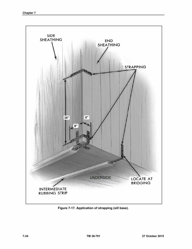
Chapter 7
7-24 TM 38-701 27 October 2015
Figure 7-17. Application of strapping (sill base).

Crates
27 October 2015 TM 38-701 7-25
Figure 7-18. Crate liner.
Figure 7-19. Interior shroud.
Screens And Ventilators
7-115. Screens are fabricated from heavy rust-resisting wire of 1/4 or 3/8 inch mesh and used over ventilating
and drainage holes to prevent entry of birds, insects, rodents, or other animals. Ventilators fabricated from
metal are sometimes used over ventilating holes. Some of the most common methods are illustrated in (fig
7-49 on page 7-82)
Inspection Doors
7-116. When inspection doors are required, they are made without cutting into the framing members.
Doors are fabricated form the same material as the sheathing. Hinge at the top and fasten with lag bolts
or wood screws at the sides and bottom (fig 7-20 on page 7-26). Make cleats and stops from 1-inch material.
Drill holes through the door and adjacent frame member to provide for a seal wire and lead seal bearing the
inspector's stamp. The size and location of the doors will vary with the nature of the item.

Chapter 7
7-26 TM 38-701 27 October 2015
Figure 7-20. Crate inspection door.
WOOD CRATES, OPEN AND COVERED, ASTM-D-6039M (GENERAL)
7-117. Open wood crates described in this section are designed for general use and are employed for both
domestic and oversea shipments. Only items which are not readily damaged from outside forces and which
require limited protection should be shipped in open crates.

Crates
27 October 2015 TM 38-701 7-27
CRATE DESIGN
7-118. When there are a variety of items to be shipped, each crate will be designed for each item with the
necessary clearance for blocking, bracing, and cushioning (fig 7-21).
Figure 7-21. Use of table to determine thickness of load bearing floorboards.
Classification
7-119. Crates fabricated or procured under ASTM-D-6039M on the basis of weight, size, and construction
features, as indicated in table 7-3 on page 7-29.
Wood Requirements
7-120. The divergence of grain (cross-grain) should not exceed one inch in ten inches of length. Plywood,
when used, will conform to A-A-55057B.
Nails and Nailing
7-121. Nails used shall be sinkers, coolers, corkers, or common. For fastening covering materials to members,
nails shall be not less than 1 inch long but shall not exceed the sum of the thickness of the covering material
and member. Nails sizes specified for the fabrication of the various crates are based on Groups I and II woods.
7-122. When group III or IV woods are used, nail sizes may be onepenny size smaller than those specified.
The patterns to be used for the nailing of two flat pieces of lumber shall conform to the details shown in
figure (7-22 on page 7-29). Unless otherwise specified herein, the following requirements shall determine
size, placement, and quantity of nails.
All adjacent crate members shall be securely fastened to each other, either directly or by means of
the covering.
All nails that are not to be clinched shall be cement coated or mechanically deformed (spiral or
round threaded).
Chapter 7
7-28 TM 38-701 27 October 2015
Nails shall be driven through thinner member into the thicker member wherever possible.
When the flat faces of pieces of lumber are nailed together and the combined thickness is 3 inches
or less (except for top joints and covering material), nails shall be long enough to pass through
both thicknesses and shall be clinched not less than 1/4 inch nor more than
3/8 inch.
When the flat faces of lumber are nailed together and the combined thickness is more than 3 inches
or when the flat face of one or more pieces is nailed to the edge or end face of another, nails shall
not be clinched. The portion of the nail in the thicker piece shall not be less than 2 times the length
of the nail in the thinner pieces for ten penny nails and smaller, and not less than 1 1/2 inches for
twelve penny nails and larger.
When splitting occurs with the use of diamond point nails, the nails shall be slightly blunted. When
blunting does not prevent the splitting, holes slightly smaller than the diameter of the nail shall be
drilled for each nail.
Nails shall be driven so that neither the head nor the point projects above the surface of the wood.
Occasional overdriving will be permitted, but nails shall not be over-driven more than one-eighth
the thickness of the piece holding the head.
Nails shall be positioned not less than the thickness of the piece from the side end nor less than
one-half the thickness of the piece from the edge of the lumber whenever possible. Nails driven
into the side edge of the lumber shall be centered on the side edge.
When two members having parallel grain are attached, the number of rows of nails shall be
determined by the nominal width of the surfaces in contact, one row for widths up to and including
2 inches, two rows for widths greater than 2 inches but not greater than 6 inches, and three rows
for widths over 6 inches.
When plywood is nailed to cleats, nails shall be spaced not more than 4 inches apart on centers
placed in staggered rows which are less than 1 3/4 inches apart or less than 3/4 inches from the
edge of the cleat.
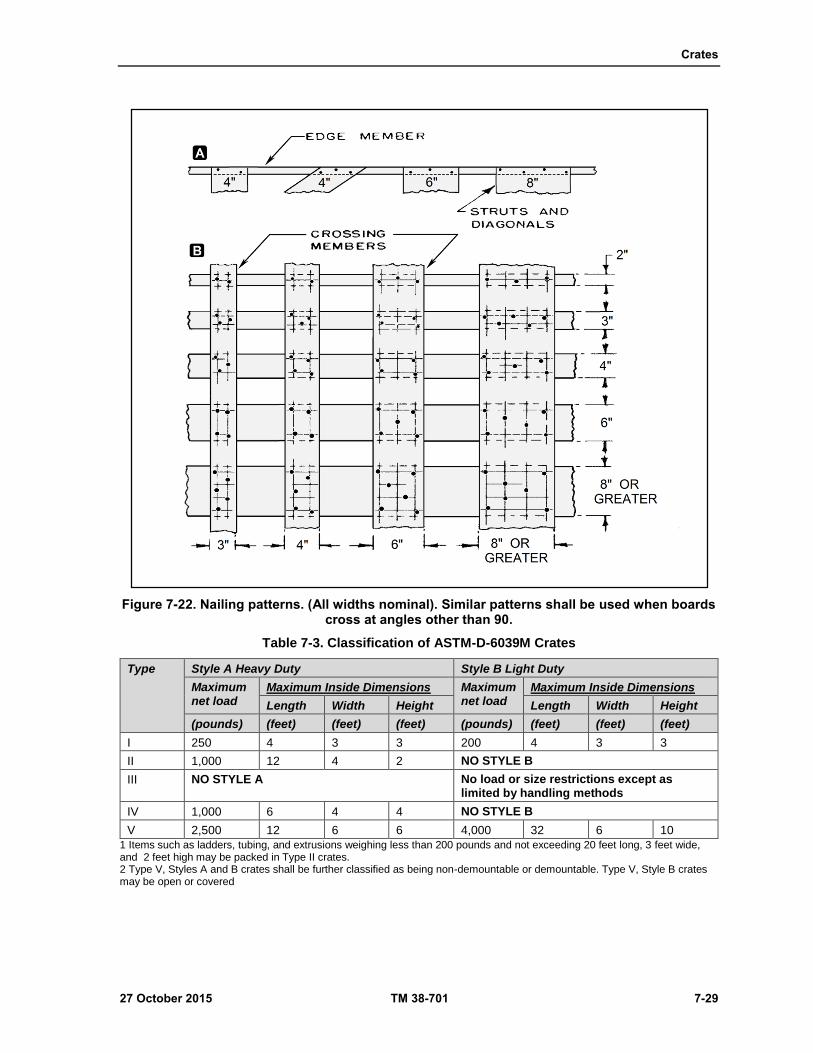
Crates
27 October 2015 TM 38-701 7-29
Figure 7-22. Nailing patterns. (All widths nominal). Similar patterns shall be used when boards cross at angles other than 90.
Table 7-3. Classification of ASTM-D-6039M Crates
Type Style A Heavy Duty Style B Light Duty
Maximum net load
Maximum Inside Dimensions Maximum net load
Maximum Inside Dimensions
Length Width Height Length Width Height
(pounds) (feet) (feet) (feet) (pounds) (feet) (feet) (feet)
I 250 4 3 3 200 4 3 3
II 1,000 12 4 2 NO STYLE B
III NO STYLE A No load or size restrictions except as limited by handling methods
IV 1,000 6 4 4 NO STYLE B
V 2,500 12 6 6 4,000 32 6 10
1 Items such as ladders, tubing, and extrusions weighing less than 200 pounds and not exceeding 20 feet long, 3 feet wide, and 2 feet high may be packed in Type II crates. 2 Type V, Styles A and B crates shall be further classified as being non-demountable or demountable. Type V, Style B crates may be open or covered
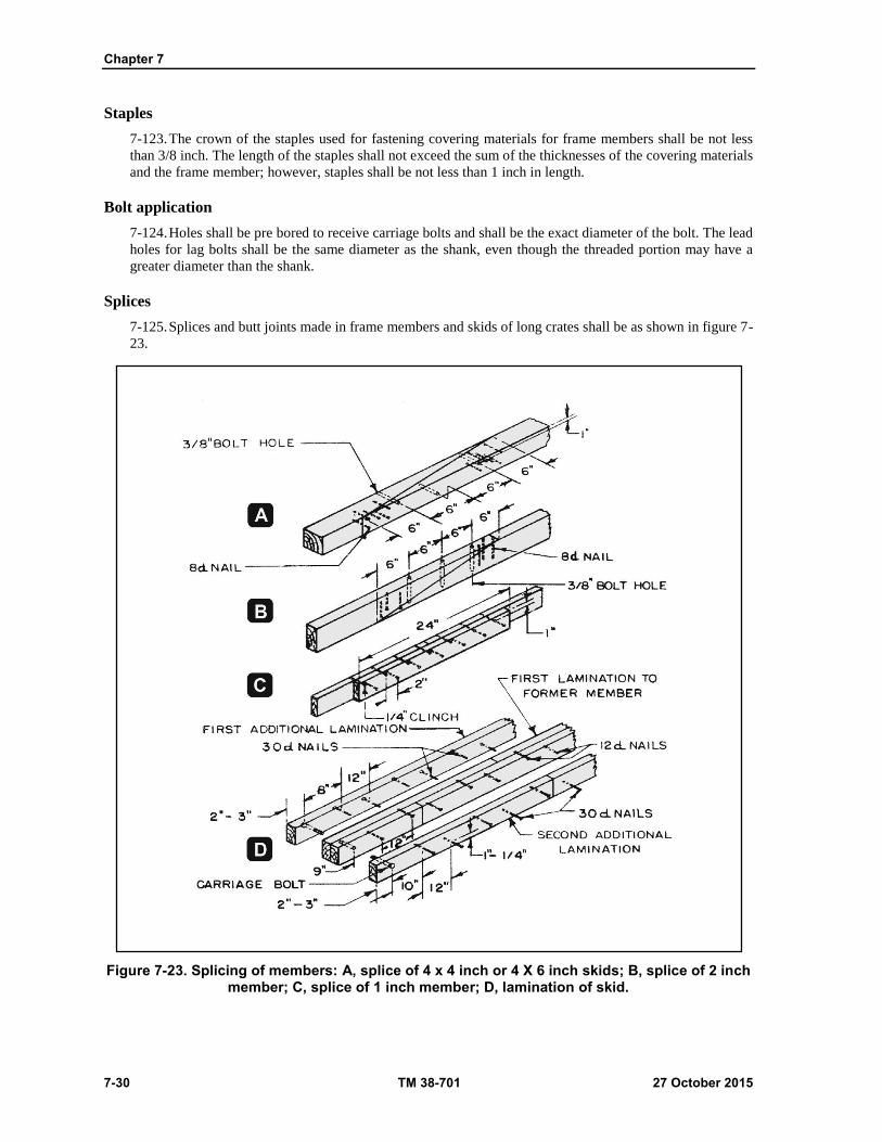
Chapter 7
7-30 TM 38-701 27 October 2015
Staples
7-123. The crown of the staples used for fastening covering materials for frame members shall be not less
than 3/8 inch. The length of the staples shall not exceed the sum of the thicknesses of the covering materials
and the frame member; however, staples shall be not less than 1 inch in length.
Bolt application
7-124. Holes shall be pre bored to receive carriage bolts and shall be the exact diameter of the bolt. The lead
holes for lag bolts shall be the same diameter as the shank, even though the threaded portion may have a
greater diameter than the shank.
Splices
7-125. Splices and butt joints made in frame members and skids of long crates shall be as shown in figure 7-
23.
Figure 7-23. Splicing of members: A, splice of 4 x 4 inch or 4 X 6 inch skids; B, splice of 2 inch member; C, splice of 1 inch member; D, lamination of skid.
Crates
27 October 2015 TM 38-701 7-31
TYPE I, STYLE A - HEAVY DUTY CRATE (ASTM-D-6039M)
7-126. The limitations shall be as specified in table 7-3.
7-127. Nailing shall be shown in figure 7-22.
Load and Size Limitations
7-128. Limitations shall be as specified in table 7-3. Style A crates shall be used only for items forming a
Type I load and weighing not more than 250 pounds.
Base
7-129. The base consists of skids, diagonals, end floor members and rubbing strips.
Skids
7-130. The skids shall be 2 by 4 inch lumber.
Diagonals
7-131. Diagonals shall be 1 by 4 inches in size.
End Floor Members
7-132. End floor members shall be the same thickness and width as the skids except when used as loadbearing
members; their size shall be as specified in table 7-4 on page 7-34. End floor members shall be bolted to each
skid with 3/8-inch diameter carriage bolts.
Rubbing Strips
7-133. Single piece rubbing strips used on each skid shall be a minimum 3 by 4 inches in size and beveled at
each end at an angle of 45 degrees for at least one-half their thickness. The length shall be less than the skid
length to allow open space at each end for sling and fork lift handling. The open space shall be not less than
4 inches and not more than 10 inches long. On crates over 36 inches long, the rubbing strip length shall be
adjusted to provide a distance of not more than 28 inches between end openings.
Side, End and Top Panels
7-134. All members of the side, end and top panels shall be 1 by 4 inch lumber. Nailing patterns shall be as
specified in (fig 7-22 on page 7-29).
ASSEMBLY
7-135. Assembly of the crates shall be as shown in figure 7-24 on page 7-32 and as specified herein. The
sides shall be fastened to the base by nailing the extensions of the vertical struts and diagonals to the skids
with eight penny nails. The ends shall be fastened to the base by nailing the lower edge member of the panels
to the end floor member with eight penny nails spaced 6 to 8 inches apart. The sides shall be fastened to the
ends by nailing the end vertical struts of the sides to the vertical struts of the ends with eight penny nails
spaced 8 to 10 inches apart. The sides shall be fastened to the top nailing the extensions of the diagonals and
vertical struts of the sides to the longitudinal members of the top with eight penny nails. The top shall be
fastened to the ends by nailing the extensions of the longitudinal and diagonal members of the top to the
upper edge member of the ends with eight penny sinker nails. The upper edge members of the ends shall be
nailed to the edge lateral members of the top with eight penny sinker nails spaced 8 to 10 inches apart.
Type I, Style B--Light Duty Crate (ASTM-D-6039M)
7-136. Design requirements and limitations shall be as specified in table (7-3 shown on page 7-29).
7-137. Nailing shall be shown in figure (7-22 page 7-29).

Chapter 7
7-32 TM 38-701 27 October 2015
Load and Size Limitations
7-138. Limitations shall be as specified in table 7-3. Style B crates shall be used only for items forming a type
I load and weighing not more than 200 pounds.
Frame Member Size
7-139. All frame members shall be 1 by 3 inches in size for net loads up to 100 pounds by 1 by 4 inches in
size for loads between 100 to 200 pounds.
Figure 7-24. Type I, style A crate assembly (ASTM-D-6039M).
Assembly
7-140. Assembly of the crates shall be as shown in figure 7-25. Diagonals, struts, cross members, and
longitudinal members shall be nailed together in patterns as shown in figure 7-22 with sixpenny nails.

Crates
27 October 2015 TM 38-701 7-33
Figure 7-25. Type I, style B crate assembly (ASTM-D-6039M).
TYPE II, STYLE A--HEAVY DUTY CRATE (ASTM-D-6039M)
7-141. Design Requirements The limitations shall be as specified in table 7-3 on page 7-29.
7-142. Nailing shall be shown in figure 7-22 on page 7-29.
Load and Size Limitations
7-143. Limitations shall be as specified in table 7-3.
Ends
7-144. The ends shall be of lumber or cleated-plywood as shown in figure 7-26 on page 7-34. The cleats shall
be fastened to the end boards or to the plywood with two rows of nails spaced 4 inches apart in each row,
staggered and clinched. The minimum thickness of the end boards and plywood and the size of the end cleats
shall be as shown in table 7-5 on page 7-35. Additional vertical filler cleats shall be used in the ends when
the unsupported span between outside cleats is greater than 3 feet.
Sides
7-145. The sides of the crates shall be of lumber or cleated-plywood as shown in figure 7-26 on page 7-34.
The sides will be constructed of lumber meeting the thickness requirements of table 7-6 on page 7-35.
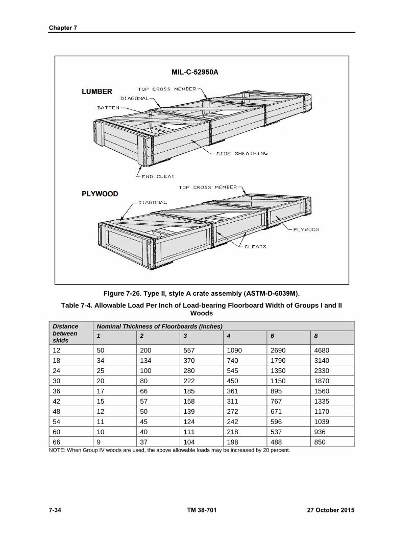
Chapter 7
7-34 TM 38-701 27 October 2015
Figure 7-26. Type II, style A crate assembly (ASTM-D-6039M).
Table 7-4. Allowable Load Per Inch of Load-bearing Floorboard Width of Groups I and II Woods
Distance between skids
Nominal Thickness of Floorboards (inches)
1 2 3 4 6 8
12 50 200 557 1090 2690 4680
18 34 134 370 740 1790 3140
24 25 100 280 545 1350 2330
30 20 80 222 450 1150 1870
36 17 66 185 361 895 1560
42 15 57 158 311 767 1335
48 12 50 139 272 671 1170
54 11 45 124 242 596 1039
60 10 40 111 218 537 936
66 9 37 104 198 488 850 NOTE: When Group IV woods are used, the above allowable loads may be increased by 20 percent.

Crates
27 October 2015 TM 38-701 7-35
Table 7-5. Thickness of Ends
Maximum Net Load Plywood Lumber Size of end cleats
(pounds) (inches) (inches) (inches)
100 1/4 3/4 3/4 by 2-3/4
250 3/8 3/4 3/4 by 3-1/2
500 1/2 1-1/16 1-1/16 by 3-1/2
1,000 1/2 1-5/16 1-1/2 by 3-1/2
Table 7-6. Thickness of Sides
Maximum Net Load Plywood Lumber Size of end cleats
(pounds) (inches) (inches) (inches)
100 1/4 3/4 3/4 by 2-3/4
250 3/8 3/4 3/4 by 2-3/4
500 1/2 1-1/16 7/8 by 3-1/2
1,000 1/2 1-5/16 7/8 by 3-1/2
7-146. When lumber is used, the sides shall be constructed of not more than 3 pieces for heights of 1 foot 3
inches or more, not more than 2 pieces for heights between 7 1/2 inches and 1 foot 3 inches, and one piece
for heights 7 1/2 inches or less.
7-147. The minimum thickness of lumber and plywood, and the minimum size of cleats for plywood sides
shall be as shown in table 7-6.
7-148. When lumber sides are composed of two or more pieces, cleats that are the same thickness and width
as the top and bottom cross members shall extend the full depth of the side and shall be fastened to the inside
surfaces of the sides as shown in figure 7-26. The cleats on the sides shall be placed to coincide with the cross
members of the top, and spacing shall be no greater than 3 feet. Cleats shall be fastened to the side boards or
plywood with two rows of nails spaced 4 inches apart in each row, staggered, and clinched. When the overall
length of the crate exceeds 14 feet, pieces of lumber used in the construction of the sides shall be either the
required full length or shall be made up of two pieces which together make up the full length. The joint of
such pieces shall abut on a full depth cleat, and both pieces shall be nailed to the bottom.
7-149. When plywood is used, the sides shall be constructed on one-piece material for width requirements.
Butt jointing of plywood at an intermediate cleat location will be permitted when two lengths of plywood are
required for crates in excess of 8 feet in length.
7-150. Crates may be one of the following combinations of sides and end panels, as specified:
Lumber ends and sides.
Cleated-plywood ends and sides.
Lumber ends and cleat-plywood sides.
Top and Bottom Members
7-151. The top and bottom members shall be 1 X 4-inch lumber for all crates up to and including 2 feet 6
inches in width and 1 X 6 inch lumber for crates more than 2 feet 6 inches in width. The angle between
diagonals and side shall be between 30 and 60, but cross members shall be placed not more than 3 feet apart
in line with battens or cleats of the sides. The cross members of the top and bottom shall be directly opposite
each other and the bottom diagonals shall be in reverse direction with the top diagonals as shown in figure 7-
26.
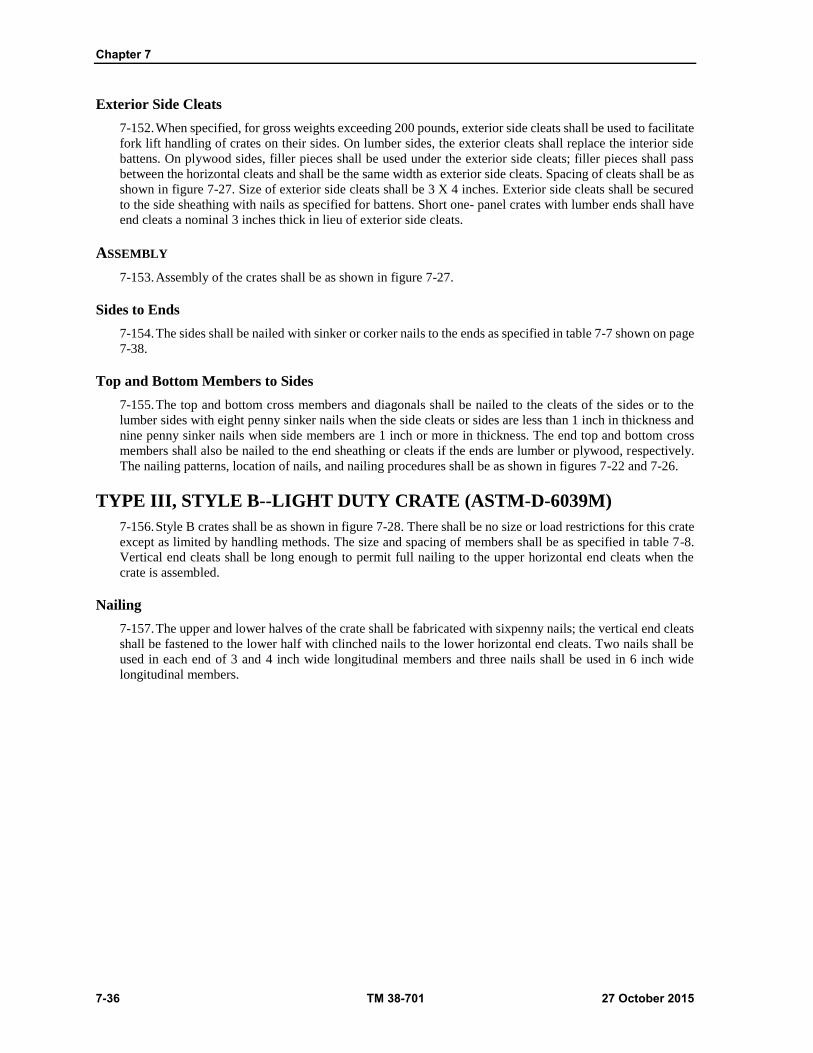
Chapter 7
7-36 TM 38-701 27 October 2015
Exterior Side Cleats
7-152. When specified, for gross weights exceeding 200 pounds, exterior side cleats shall be used to facilitate
fork lift handling of crates on their sides. On lumber sides, the exterior cleats shall replace the interior side
battens. On plywood sides, filler pieces shall be used under the exterior side cleats; filler pieces shall pass
between the horizontal cleats and shall be the same width as exterior side cleats. Spacing of cleats shall be as
shown in figure 7-27. Size of exterior side cleats shall be 3 X 4 inches. Exterior side cleats shall be secured
to the side sheathing with nails as specified for battens. Short one- panel crates with lumber ends shall have
end cleats a nominal 3 inches thick in lieu of exterior side cleats.
ASSEMBLY
7-153. Assembly of the crates shall be as shown in figure 7-27.
Sides to Ends
7-154. The sides shall be nailed with sinker or corker nails to the ends as specified in table 7-7 shown on page
7-38.
Top and Bottom Members to Sides
7-155. The top and bottom cross members and diagonals shall be nailed to the cleats of the sides or to the
lumber sides with eight penny sinker nails when the side cleats or sides are less than 1 inch in thickness and
nine penny sinker nails when side members are 1 inch or more in thickness. The end top and bottom cross
members shall also be nailed to the end sheathing or cleats if the ends are lumber or plywood, respectively.
The nailing patterns, location of nails, and nailing procedures shall be as shown in figures 7-22 and 7-26.
TYPE III, STYLE B--LIGHT DUTY CRATE (ASTM-D-6039M)
7-156. Style B crates shall be as shown in figure 7-28. There shall be no size or load restrictions for this crate
except as limited by handling methods. The size and spacing of members shall be as specified in table 7-8.
Vertical end cleats shall be long enough to permit full nailing to the upper horizontal end cleats when the
crate is assembled.
Nailing
7-157. The upper and lower halves of the crate shall be fabricated with sixpenny nails; the vertical end cleats
shall be fastened to the lower half with clinched nails to the lower horizontal end cleats. Two nails shall be
used in each end of 3 and 4 inch wide longitudinal members and three nails shall be used in 6 inch wide
longitudinal members.
Crates
27 October 2015 TM 38-701 7-37
Figure 7-27. Type II, crate with exterior side cleats. (A-complete crate, B- two panel, C- three panel, and D- four panel.
Rubbing Strips
7-158. Beveled rubbing strips, of sizes shown in table 7-8, shall be attached to the undersurface of each lower
cross member to facilitate fork truck handling. Rubbing strips shall be fastened to the cross members with
sixteen penny nails placed in two rows and spaced 5 inches apart applied to each row and clinched. Rubbing
strips shall be applied at time of crate packing after strapping has been secured to cross members.
Assembly
7-159. Assembly of the crates shall be as shown in figure 7-28 on page 7-38. After items have been nested in
the lower half of the crate, the upper half shall be positioned and strapping shall be applied. The upper ends
of the vertical end cleats shall be nailed to the upper horizontal end cleats with four penny nails. The upper
longitudinal members of the sides shall be nailed to the vertical end cleats with eight penny nails.

Chapter 7
7-38 TM 38-701 27 October 2015
Figure 7-28. Type III, style B crate assembly (ASTM-D-6039M).
Table 7-7. Nailing Schedule for Assembly to Type II, Style A Crates
Cleated Plywood Sides to Plywood or lumber Ends
Lumber Sides to Lumber Ends
Plywood thickness
Nail size Nail spacing Thickness of sides
Nail size Nail spacing
1/4 8 3 3/4 8 2-1/2
3/8 10 3-1/4 1-1/16 10 2-3/4
1/2 12 3-1/2 1-5/16 12 3 NOTE: 1/ Nails shall be staggered when ends are lumber.
TYPE IV, STYLE A - HEAVY DUTY CRATE (ASTM-D-6039M)
7-160. The limitations shall be as specified in table 7-3.
Base
7-161. Skids shall be 2 X 4 inch lumber for loads through 500 pounds and 2 X 6 inch lumber for over 500
pounds.
7-162. The size of the load-bearing floor member shall be as specified in table 6-4.Floorboards over 2 inches
in nominal thickness shall be bolted to the skids with 3/8-inch diameter carriage bolts. Diagonals shall be 1
X 6 inches.
7-163. The placement of end floor members and rubbing strips shall be as shown in figure 7-29. On crates
over 5 feet long, the rubbing strips shall be in three pieces, with the center piece 16 inches long, the fork
openings 12 inches long, and the end pieces of a length which will allow end sling openings of 4 inches.

Crates
27 October 2015 TM 38-701 7-39
Side, End, and Top Panels
7-164. All the members of the side, end and top panels shall be 1 X 6 inch lumber. Three vertical struts shall
be used in the side panels when the length of the crate is greater than 4 feet or greater than 1 1/2 times the
height. The lateral members of the top panel shall coincide with the vertical struts of the side panels and shall
be equal in number. Nailing patterns shall be as shown in figure 7-22.
Assembly
7-165. Assembly of the crates shall be as shown in figure 7-29. The longitudinal members of the top
shall bear on the upper frame members of the sides and. the end lateral members of the top shall be
adjacent to the upper member of the ends.
TYPE V, STYLE A - HEAVY DUTY (ASTM-D-6039M)
7-166. See examples in figure 7-30 on page 7-40.
7-167. The limitations shall be as specified in table 7-3.
7-168. Nailing shall be shown in figure 7-22.
Figure 7-29. Type IV, style A crate assembly (ASTM-D-6039M).

Chapter 7
7-40 TM 38-701 27 October 2015
Figure 7-30. Type V, style A crate assembly (ASTM-D-6039M).
Base
7-169. The base construction is as follows.
Skids
7-170. The skids shall consist of 4 X 4 inch lumber. An intermediate 4 X 4 inch skid shall be used when the
distance between the outer skids is greater than 36 inches.
Load-bearing Floor Members
7-171. The size of the load-bearing floor members shall be as specified in table 7-4. Floorboards over 2 inches
in nominal thickness shall be bolted to each outside skid with 3/8 inch carriage bolts.
Crates
27 October 2015 TM 38-701 7-41
Diagonals
7-172. The diagonals shall be 1 X 6 inch lumber and the angle between the skid and the diagonal shall be
between 30 degrees and 60 degrees, except that when the angle of a single diagonal is less than 30 degrees,
two diagonals and a 1 X 6 inch center cross member shall be used.
Crossmembers
7-173. End cross members shall be 2 X 6 inch lumber for crates not greater than 4 feet in width and 4 X 4
inch lumber for crates over 4 feet in width. End cross members shall be bolted to each skid with 3/8-inch
diameter carriage bolts.
Rubbing Strips
7-174. Rubbing strips shall be as described previously.
Ends
7-175. Vertical struts shall be 2 X 4 inch lumber. An intermediate strut shall be used when the width of the
crate is greater than 3 feet. All struts shall coincide with the skids and shall bear upon the end cross members
of the base. The upper and lower frame members of the ends shall be 1 X 6 inch lumber except that a 1 X 8
inch lower member shall be used when the end cross members of the base are 4 X 4 inches. The diagonals of
the ends shall be 1- X 6-inch lumber.
Sides
7-176. All side framing members, struts, and diagonals shall be 1 X 6 inch lumber. Intermediate struts shall
be placed so that diagonals form an angle of between 30 and 60 degrees with the lower frame member. Struts
shall have a maximum spacing of 42 inches. A horizontal intermediate frame member is required when the
height of the side exceeds 4 feet. Diagonals shall be used between each two adjacent struts.
Top
7-177. All members of the top shall be 2 X 4 inch lumber. The longitudinal members shall coincide with the
vertical struts of the ends. An intermediate longitudinal member is required when the width of the crate is
greater than 3 feet and shall coincide with the intermediate struts of the ends. The joists shall be placed flat.
Joists shall coincide with each strut of the side but shall be spaced not more than 40 inches apart for crates
up to 3 feet wide and not more than 30 inches apart for crates more than 3 feet wide. The diagonals shall be
nailed to the longitudinal members. When more than three joists are used, only each end panel of the top
assembly shall be braced as shown in figure 7-30.
Non-demountable Crate Assembly
7-178. The assembly shall be reinforced by the application of metal straps as shown in figure 7-30.
Sides to Base
7-179. The sides shall be fastened to the base by nailing the overlap of the vertical struts and diagonals to the
skids with twelve penny nails. The nailing patterns shall follow those shown in figure 7-22.
Ends to Base
7-180. The ends shall be fastened to the base by nailing the lower frame member of the end panels to the end
cross members of the base with twelve penny sinker nails spaced 6 to 8 inches apart.
Chapter 7
7-42 TM 38-701 27 October 2015
Sides to Ends and Ends to Sides
7-181. The edge struts of the sides shall be fastened to the edge struts of the ends with eight penny sinker
nails spaced 8 to 10 inches apart. The extensions of the upper and lower frame members and the diagonals
of the end shall be nailed to the edge struts of the side with eight penny sinker nails as shown in figure 7-22.
Top to Sides and Ends
7-182. The top shall be fastened to the sides and ends by nailing the upper frame members of the ends and
the extensions of the vertical struts and diagonals of the sides to the adjacent edge members of the top with
eight penny sinker nails as shown in figure 7-22.
Demountable Crate Assembly
7-183. All demountable crates shall be assembled with lag bolts. Lead holes shall be used for all lag bolts.
When specified as an alternate, the top, side, and end panels may be nailed to each other and the unit may be
fastened to the skids and end cross members of the base by means of lag bolts for demountable crates.
Sides to Base
7-184. Lag bolts, 3/4 by 3 1/2 inches, shall be used to fasten the sides to the skids. Diagonals shall be arranged
to provide the maximum number of fastening points to the base near the center of the skids. The minimum
number of lag bolts shall correspond to the following tabulation. Not less than one edge bolt shall be placed
in each strut and diagonal.
Gross Load (crate and content pounds) Minimum Number of 3/8-inch lag bolts for each side of crate
1,000 4
2,000 5
3,000 8
Ends to Base, sides to Ends, and Ends to Top
7-185. Lag bolts, 5/16 by 3 inches, spaced 12 to 14 inches apart, shall be used to fasten: the lower edge
members of the ends to the end cross members of the base; the end vertical struts of the sides to the edge
struts of the ends; and the upper edge members of the end to the edge joists of the top.
Sides to Top
7-186. One 5/16 by 3-inch lag bolt shall be used to fasten each strut and diagonal of the sides to the edge
longitudinal member of the top.
TYPE V, STYLE B--LIGHT DUTY CRATE (ASTM-D-6039M)
7-187. The limitations shall be as specified in table 7-3. They shall be open, or covered, and demountable or
non-demountable as specified. Nailing shall be as shown in figure 7-22, and as specified herein.
BASE AND SKIDS
7-188. Skid sizes shall conform to the following tabulation
Net load (pounds) Skid Size (Nominal
2 Skids (inches) 3 Skids (inches)
Up to 500 2X4 (flat) 2X4 (flat)
501 to 2,000 3X4 (flat) 3X4 (flat)
2,001 to 3,000 4X4 3X4 (flat)
3,001 to 4,000 4X4 4X4

Crates
27 October 2015 TM 38-701 7-43
Crates Over 42 Inches Wide Shall Have Three Skids
7-189. Splices shall be located no further from the ends than one-third of the length of the skids, and splice
locations shall be alternated in adjacent skids. All 4 X 4 members may also consist of two 2 X 4's placed on
edge and laminated in accordance with figure 7-23.
Rubbing Strips
7-190. Rubbing strips shall be a minimum of 3 X 4 inches in size. The strips shall be positioned as shown in
figure 7-31 on page 7-45. They shall be nailed to the skids with two rows of nails spaced 1 foot apart in each
row in a staggered pattern; nail sizes shall be sixteen penny when skids are 2 X 4 inches and twenty penny
for 3 X 4 and 4 X 4 inch skids.
End Headers
7-191. Two headers spaced 2 feet apart shall be bolted to each end of the skids as shown in figure 7-31 with
3/8-inch diameter carriage bolts. The end headers shall be the same cross section as the skids. When crate
ends have 2 X 4 inch struts, bolts in the outer headers shall be placed to clear the struts.
Load-bearing Floorboards
7-192. When concentrated loads occur, load-bearing floorboards shall be used to transfer the load to skids.
The sizes shall be as specified in table 7-4. When end headers are used as load-bearing member, the end
header size shall be chosen from the load-bearing floorboard width specified in table 7-4. Floorboards 2
inches or less in thickness shall be nailed to each skid in patterns as shown in figure 7-22 and floorboards
over 2 inches thick shall be bolted to each skid with 3/8-inch diameter carriage bolts. Two bolts shall be used
for floorboards over 6 inches wide.
Diagonals and Floorboards
7-193. Diagonals shall be used between headers and load-bearing floorboards or other crossmembers and
shall be placed at an angle as close to 45 degrees as possible. Diagonals and floorboards other than load-
bearing floorboards shall be 1- by 4-inch members for net loads up to 500 pounds and outside widths not
exceeding 3 feet, and shall be 1- by 6-inch members for all other conditions.
Sides
7-194. Sides shall be as shown in figures 7-32, 7-33, and 7-34 shown on pages 7-46 thru 7-48 Single-panel
sides shall be used for heights over 6 feet. An intermediate longitudinal member shall be added for heights
over 4 feet. Double-panel sides shall be used for heights over 6 feet and through 8 feet. Triple-panel sides
shall be used for heights over 8 feet. Longitudinal members shall be in single pieces for lengths not exceeding
16 feet, and may be spliced as shown in figure 7-24 for lengths greater than 16 feet. Splice locations shall be
alternated. Member sizes and spacing shall be as specified in table 7-8 and 7-9 on page 7-53.
Ends
7-195. Ends shall be as shown in figures 7-35 and 7-36 on pages 7-49 and 7-50. All members shall be 1 by 4
inches in size for net loads up to 500 pounds, and 1 by 6 inches for net loads over 500 pounds, with the
following exceptions.
Struts shall be 2 by 4 inches in size when the crate height is over 5 feet.
The lower frame member shall be 1 by 6 inches in size when the end headers of the base are 2-
inch thick members and 1 by 8 inches in size when larger end headers are used.
Top
7-196. The top shall be as shown in figure 7-37 on page 7-51. The spacing of the cross members shall be the
same as the spacing of the side struts. Diagonals shall be nailed to the inner faces of the cross members. The
longitudinal members shall be 1 by 4 inches in size for loads up to 500 pounds and widths to 4 feet, and 1 by
Chapter 7
7-44 TM 38-701 27 October 2015
6 inches for all other conditions cross members and diagonals shall be 1 by 4 inches for loads to 1,000 pounds
and widths to 4 feet, and 1 by 6 inches for all other conditions. Splicing of longitudinal members shall be as
shown in figure 7-23.
Top Reinforcing Joists
7-197. When the gross weight of the crate is over 500 pounds or the inside width is over 3 feet 6 inches, a 2-
by 4-inch top-reinforcing joist shall be nailed to the top at the loaded center of balance as shown in figure 7-
37 to prevent the top of the crate from being crushed when the crate is lifted with a single set of grab hooks.
The joist shall be placed flat and the ends shall contact the inner face of the upper longitudinal members of
the side when the crate is assembled. The joist shall be fastened to the longitudinal and diagonal members of
the top with seven penny nails placed as shown in figure 7-22 and to the upper longitudinal members of the
sides with two ten penny nails in each end.
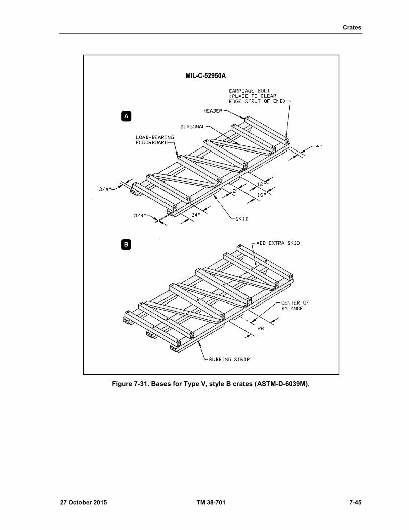
Crates
27 October 2015 TM 38-701 7-45
Figure 7-31. Bases for Type V, style B crates (ASTM-D-6039M).

Chapter 7
7-46 TM 38-701 27 October 2015
Figure 7-32. Simple panel sides for Type V, style B crates (ASTM-D-6039M): A, side of long crate; B, side of short crate; C, covered side.
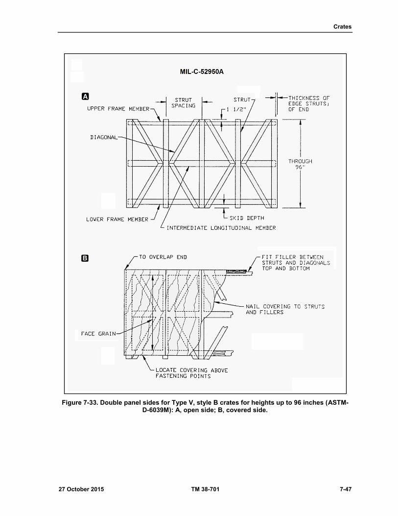
Crates
27 October 2015 TM 38-701 7-47
Figure 7-33. Double panel sides for Type V, style B crates for heights up to 96 inches (ASTM-D-6039M): A, open side; B, covered side.
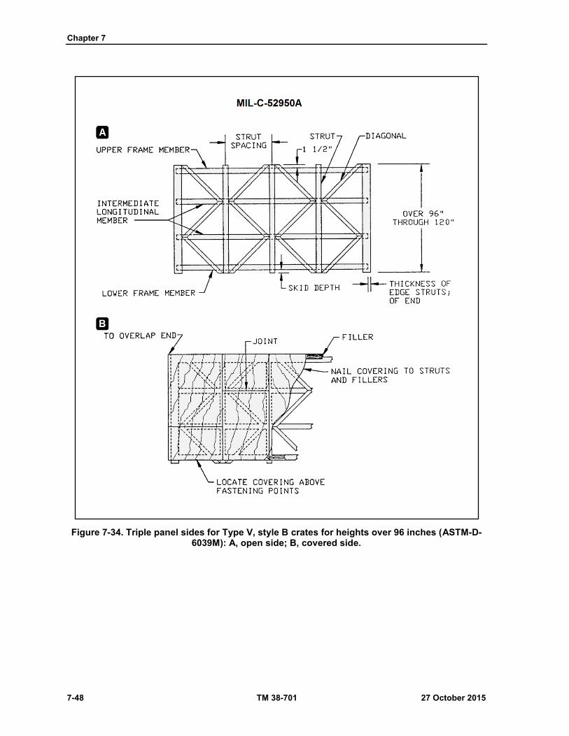
Chapter 7
7-48 TM 38-701 27 October 2015
Figure 7-34. Triple panel sides for Type V, style B crates for heights over 96 inches (ASTM-D-6039M): A, open side; B, covered side.

Crates
27 October 2015 TM 38-701 7-49
Figure 7-35. Ends for Type V, style B crates (ASTM-D-6039M): A, two panel horizontal; B, single panel covered; C, four panel; D, two panel vertical.
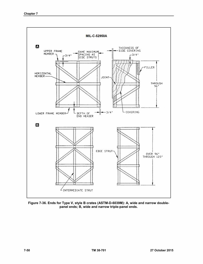
Chapter 7
7-50 TM 38-701 27 October 2015
Figure 7-36. Ends for Type V, style B crates (ASTM-D-6039M): A, wide and narrow double-panel ends; B, wide and narrow triple-panel ends.

Crates
27 October 2015 TM 38-701 7-51
Figure 7-37. Tops for type V, style B crates (ASTM-D-6039M): A, narrow top; B, medium top; C, wide top.
Chapter 7
7-52 TM 38-701 27 October 2015
Assembly
7-198. Unless demount-ability is specified, the crate shall be assembled by nailing. When demount-ability is
specified, the sides, ends, and top as a unit shall be secured to the base with lag bolts. Eight penny nails,
spaced 8 to 10 inches apart, shall be used to fasten:
the edge struts of the sides to the sides to the edge struts of the ends;
the longitudinal members of the top to the upper frame members of the sides;
the end cross members of the top to the upper frame members of the ends;
the lower frame members of the ends to the end header of the base.
7-199. Eight penny nails as shown in figure 7-22 nailing patterns shall be used to fasten:
the upper ends of the side struts and diagonals to the longitudinal members of the top;
the ends of upper and lower frame members, horizontal members, and diagonals of the ends to the
edge struts of the sides.
7-200. The bottom ends of struts and diagonals of the sides shall be secured to the skids with eight penny
nails as follows: A minimum of three nails shall be used for each 3 and 4 inch wide member, four nails for
each 6 inch wide member, and five nails for each 8 inch and wider member. Nails shall be staggered and
shall be placed in two rows whenever possible. For demountable crates, each strut and diagonal of the sides
shall be fastened to the skids with a minimum of one lag bolt. The size of lag bolts and the total number
required shall be not less than that specified in table 7-10 on page 7-54. When more than one lag bolt is
required in each strut or diagonal, the additional lag bolts shall be placed in the wider members, near the
load-bearing points, and in a staggered pattern when possible. One-half the total number of lag bolts required
shall be used for each side. For demountable crates, the lower frame members of the ends shall be fastened
to the end headers of the base with 5/16 X 3 inch lag bolts, spaced 12 inches apart.
Covered Crates
7-201. The structural framework of the covered crates shall be as shown in figure 7-32 and 7-33. The covered
crates shall also be as shown in figures 7-32 through 7-38 on pages 7-46 thru 7-56. Unless otherwise specified,
the covering shall consist of plywood or paper-overlaid veneer with a minimum thickness of 1/8 inch. When
joints are required in the covering they shall butt over the centerline of struts or cross members. Covering
shall be fastened with two rows of nails or staples, spaced 8 inches apart in each row, staggered, and clinched.
Filler pieces between struts, diagonals, and cross members of sides, ends, and top shall be fastened with two
rows of nails, spaced 10 inches apart in each row, staggered, and clinched. Filler pieces shall be the same
thickness as adjacent panel framing members.
Sides
7-202. Four-inch wide filler pieces shall be fastened to the upper and lower frame members between the struts
and diagonals. Filler shall extend beyond the edge of the upper frame member so as to be flush with the ends
of the struts and diagonals. The lower edges of the fillers shall be flush with the bottom edge of the
Ends
7-203. Three-inch wide filler pieces shall be nailed to the edge struts as shown in figures 7-35 and 7-36. When
specified, end ventilation shall be provided in accordance with ASTM-D-7478M.
Tops
7-204. Two-inch wide filler pieces shall be fastened to the longitudinal members. The covering of the top
shall be extended to overlap the covering of the sides and ends. During nailing, a 4-inch wide strip of
waterproof barrier material conforming to PPP-B-1055B, class suitable for crate liners, shall be placed under
each covering joint. The strip shall extend across the full width of the top.
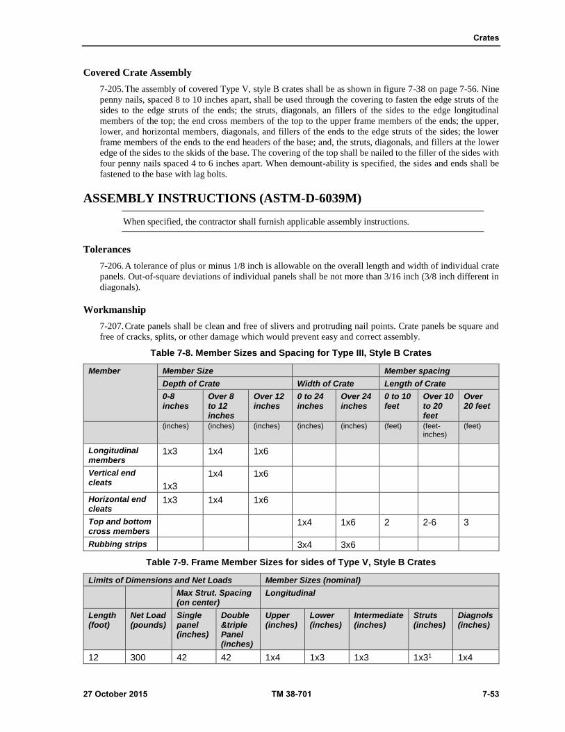
Crates
27 October 2015 TM 38-701 7-53
Covered Crate Assembly
7-205. The assembly of covered Type V, style B crates shall be as shown in figure 7-38 on page 7-56. Nine
penny nails, spaced 8 to 10 inches apart, shall be used through the covering to fasten the edge struts of the
sides to the edge struts of the ends; the struts, diagonals, an fillers of the sides to the edge longitudinal
members of the top; the end cross members of the top to the upper frame members of the ends; the upper,
lower, and horizontal members, diagonals, and fillers of the ends to the edge struts of the sides; the lower
frame members of the ends to the end headers of the base; and, the struts, diagonals, and fillers at the lower
edge of the sides to the skids of the base. The covering of the top shall be nailed to the filler of the sides with
four penny nails spaced 4 to 6 inches apart. When demount-ability is specified, the sides and ends shall be
fastened to the base with lag bolts.
ASSEMBLY INSTRUCTIONS (ASTM-D-6039M)
When specified, the contractor shall furnish applicable assembly instructions.
Tolerances
7-206. A tolerance of plus or minus 1/8 inch is allowable on the overall length and width of individual crate
panels. Out-of-square deviations of individual panels shall be not more than 3/16 inch (3/8 inch different in
diagonals).
Workmanship
7-207. Crate panels shall be clean and free of slivers and protruding nail points. Crate panels be square and
free of cracks, splits, or other damage which would prevent easy and correct assembly.
Table 7-8. Member Sizes and Spacing for Type III, Style B Crates
Member Member Size Member spacing
Depth of Crate Width of Crate Length of Crate
0-8 inches
Over 8 to 12 inches
Over 12 inches
0 to 24 inches
Over 24 inches
0 to 10 feet
Over 10 to 20 feet
Over 20 feet
(inches) (inches) (inches) (inches) (inches) (feet) (feet-inches)
(feet)
Longitudinal members
1x3 1x4 1x6
Vertical end cleats 1x3
1x4 1x6
Horizontal end cleats
1x3 1x4 1x6
Top and bottom cross members
1x4 1x6 2 2-6 3
Rubbing strips 3x4 3x6
Table 7-9. Frame Member Sizes for sides of Type V, Style B Crates
Limits of Dimensions and Net Loads Member Sizes (nominal)
Max Strut. Spacing (on center)
Longitudinal
Length (foot)
Net Load (pounds)
Single panel (inches)
Double &triple Panel (inches)
Upper (inches)
Lower (inches)
Intermediate (inches)
Struts (inches)
Diagnols (inches)
12 300 42 42 1x4 1x3 1x3 1x31 1x4

Chapter 7
7-54 TM 38-701 27 October 2015
Table 7-9. Frame Member Sizes for sides of Type V, Style B Crates (continued
Limits of Dimensions and Net Loads Member Sizes (nominal)
Max Strut. Spacing (on center)
Longitudinal
Length (foot)
Net Load (pounds)
Single panel (inches)
Double &triple Panel (inches)
Upper (inches)
Lower (inches)
Intermediate (inches)
Struts (inches)
Diagnols (inches)
32 500 48 54 1x6 1x4 1x4 1x41 1x4
28 1,000 42 54 1x6 1x4 1x4 1x41 1x4
24 2,000 36 48 1x6 1x6 1x6 1x6 1x6
20 3,000 36 48 1x8 1x6 1x6 1x62 1x6
16 4,000 36 42 1x8 1x8 1x8 1x8 1x8 1 For edge struts use 1 x 4 except that 1 x 6 members shall be used when edge struts of ends are 2 x 4 inches in size. 2 For edge struts use 1 X 8 members
Table 7-10. Number and size of Lag Bolts Required to Assemble the Base (Demountable Base) of Type V, Style B Crates
Total Minimum Number of Lag Bolts
Size of Both Each Skid Size
Gross Weight (Crate and Contents)measured in pounds
5/16X3 inch bolt for 2X3 or 2X4 skid (flat)
3/8X3 inch bolt for 3X3 skid
1/2X3-1/2 inch lag bolt for 4X4 inch or 2X4 inch skids (on edge and laminated
1000 8 8 6
2000 14 10 10
3000 18 16 12
4000 24 20 14
5000 30 26 18
OPEN WOOD CRATES, MIL-C-3774B (GENERAL)
7-208. The open crates covered by MIL-C-3774B consist of framing members partially sheathed in specified
areas. This sheathing is applied to protect the enclosed item and acts as a reinforcement to the sides, ends,
and top of the crate. These crates are designed to carry large or heavy items. A minimum of 1- inch clearance
is required between the item and the nearest framing member of the sides, ends, and top.
Classification
7-209. Crates designed under this specification may be either bolted or nailed see Table 7-11.
Classification of MIL-C-3774B Crates
Assembly Maximum net load (lb)
Maximum dimensions
Length Width Height
Type I nailed1 12,000 16 8 8
Type II Bolted2 16,000 40 8 16 1 Nailed assembly – non demountable. 2 Bolted assembly - demountable

Crates
27 October 2015 TM 38-701 7-55
Open Bolted Crates (Demountable)
7-210. These crates are designed to withstand a superimposed load of 200 pounds per square foot on the top,
including dunnage. These crates may be used as reusable containers.
Open Nailed Crates (Nondemountable)
7-211. Crates designed under this classification are considered to be "one trip" containers. This type may be
constructed with a skid-or sill-type base.
Lumber Requirements
Lumber
7-212. Lumber used in crate construction must meet the same rigid requirements as for other wooden
containers. Lumber used in crate construction shall be free of defects that would materially weaken the
container.
Plywood
7-213. Requirements for plywood are stated in A-A-55057B.
Fasteners
7-214. Nails, strapping, bolts, etc., are commonly used.
OPEN BOLTED CRATES (MIL-C-3774B) DESIGN REQUIREMENTS
7-215. Demountable crates are designed and constructed so that the major components may be readily
assembled or disassembled without damage to the component parts. This is accomplished through the use of
lag bolts or bolts (fig 7-5).
Fabrication of Open Bolted Crates
7-216. The size of the skids is based upon the net load and the outside length of the crate, as stated in table 7-
12 on page 7-58. The number of skids are dictated by the item being packed. However, the clear distance
between any adjacent skids are limited to 48 inches center to center (fig 7-39). To prevent splitting, place one
carriage bolt crosswise to two to three inches back from each end of the skid (fig 7-39). When necessary,
splice and laminate skids according to the details shown on figure 7-55.
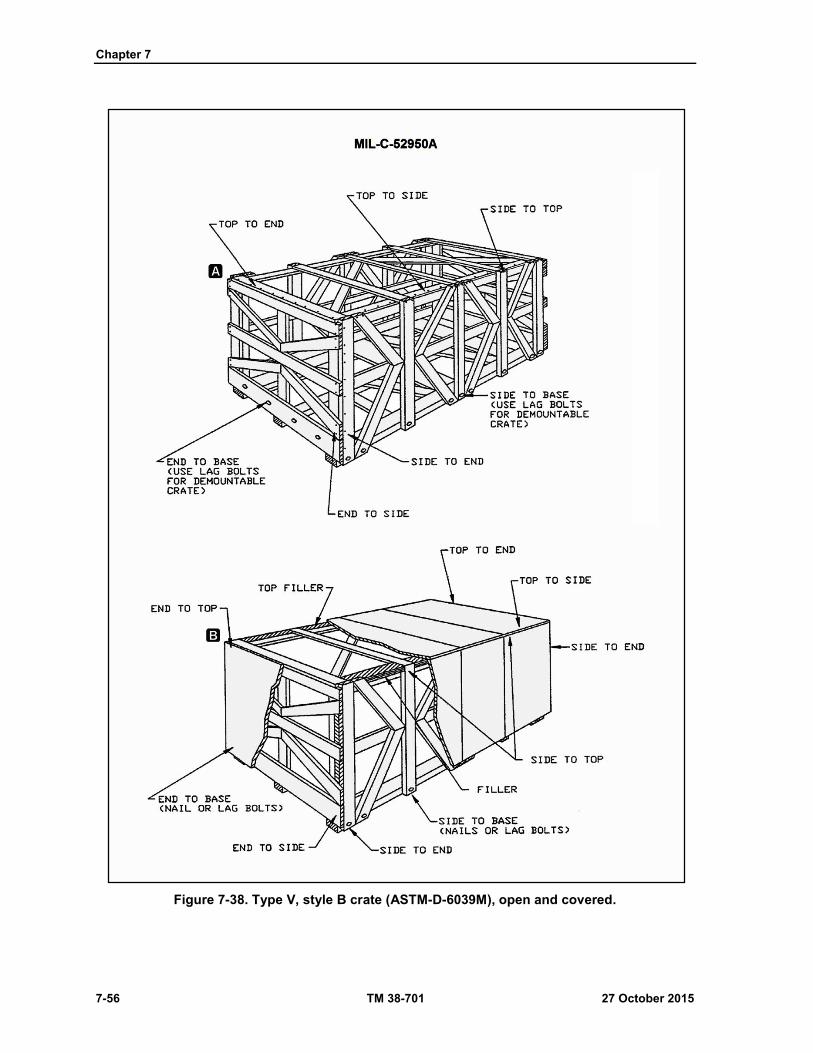
Chapter 7
7-56 TM 38-701 27 October 2015
Figure 7-38. Type V, style B crate (ASTM-D-6039M), open and covered.
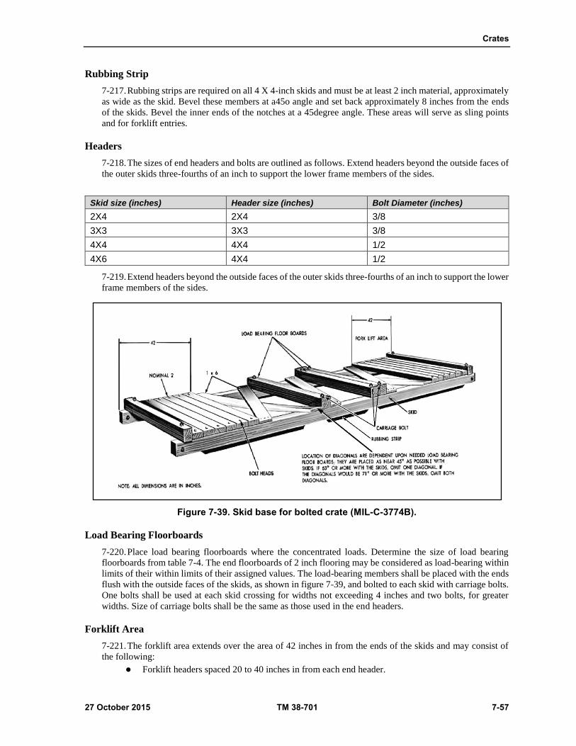
Crates
27 October 2015 TM 38-701 7-57
Rubbing Strip
7-217. Rubbing strips are required on all 4 X 4-inch skids and must be at least 2 inch material, approximately
as wide as the skid. Bevel these members at a45o angle and set back approximately 8 inches from the ends
of the skids. Bevel the inner ends of the notches at a 45degree angle. These areas will serve as sling points
and for forklift entries.
Headers
7-218. The sizes of end headers and bolts are outlined as follows. Extend headers beyond the outside faces of
the outer skids three-fourths of an inch to support the lower frame members of the sides.
Skid size (inches) Header size (inches) Bolt Diameter (inches)
2X4 2X4 3/8
3X3 3X3 3/8
4X4 4X4 1/2
4X6 4X4 1/2
7-219. Extend headers beyond the outside faces of the outer skids three-fourths of an inch to support the lower
frame members of the sides.
Figure 7-39. Skid base for bolted crate (MIL-C-3774B).
Load Bearing Floorboards
7-220. Place load bearing floorboards where the concentrated loads. Determine the size of load bearing
floorboards from table 7-4. The end floorboards of 2 inch flooring may be considered as load-bearing within
limits of their within limits of their assigned values. The load-bearing members shall be placed with the ends
flush with the outside faces of the skids, as shown in figure 7-39, and bolted to each skid with carriage bolts.
One bolts shall be used at each skid crossing for widths not exceeding 4 inches and two bolts, for greater
widths. Size of carriage bolts shall be the same as those used in the end headers.
Forklift Area
7-221. The forklift area extends over the area of 42 inches in from the ends of the skids and may consist of
the following:
Forklift headers spaced 20 to 40 inches in from each end header.
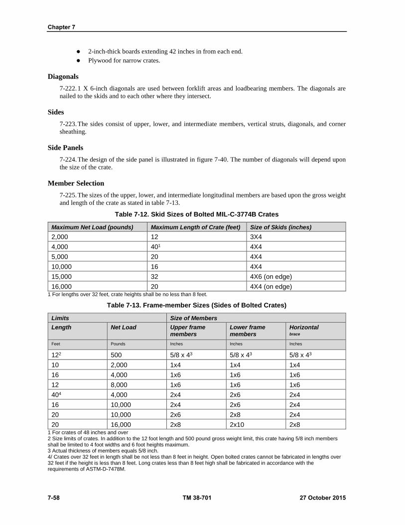
Chapter 7
7-58 TM 38-701 27 October 2015
2-inch-thick boards extending 42 inches in from each end.
Plywood for narrow crates.
Diagonals
7-222. 1 X 6-inch diagonals are used between forklift areas and loadbearing members. The diagonals are
nailed to the skids and to each other where they intersect.
Sides
7-223. The sides consist of upper, lower, and intermediate members, vertical struts, diagonals, and corner
sheathing.
Side Panels
7-224. The design of the side panel is illustrated in figure 7-40. The number of diagonals will depend upon
the size of the crate.
Member Selection
7-225. The sizes of the upper, lower, and intermediate longitudinal members are based upon the gross weight
and length of the crate as stated in table 7-13.
Table 7-12. Skid Sizes of Bolted MIL-C-3774B Crates
Maximum Net Load (pounds) Maximum Length of Crate (feet) Size of Skids (inches)
2,000 12 3X4
4,000 401 4X4
5,000 20 4X4
10,000 16 4X4
15,000 32 4X6 (on edge)
16,000 20 4X4 (on edge) 1 For lengths over 32 feet, crate heights shall be no less than 8 feet.
Table 7-13. Frame-member Sizes (Sides of Bolted Crates)
Limits Size of Members
Length Net Load Upper frame members
Lower frame members
Horizontal brace
Feet Pounds Inches Inches Inches
122 500 5/8 x 43 5/8 x 43 5/8 x 43
10 2,000 1x4 1x4 1x4
16 4,000 1x6 1x6 1x6
12 8,000 1x6 1x6 1x6
404 4,000 2x4 2x6 2x4
16 10,000 2x4 2x6 2x4
20 10,000 2x6 2x8 2x4
20 16,000 2x8 2x10 2x8 1 For crates of 48 inches and over 2 Size limits of crates. In addition to the 12 foot length and 500 pound gross weight limit, this crate having 5/8 inch members shall be limited to 4 foot widths and 6 foot heights maximum. 3 Actual thickness of members equals 5/8 inch. 4/ Crates over 32 feet in length shall be not less than 8 feet in height. Open bolted crates cannot be fabricated in lengths over 32 feet if the height is less than 8 feet. Long crates less than 8 feet high shall be fabricated in accordance with the requirements of ASTM-D-7478M.
Crates
27 October 2015 TM 38-701 7-59
Figure 7-40. Side for bolted crate (MIL-C-3774B).
Diagonals
7-226. Use 5/8 X 6 inch diagonals for crates not exceeding 12 feet in length, 4 feet in width and 6 feet in
height, with a maximum net load of 500 pounds. Use 1 X8 inch for crates exceeding 32 feet in length and 12
feet in height. Use 1 X 6- inch for all other conditions. See table 7-14 on page 7-60 for the spacing of the
diagonals. One-half of the diagonals shall be nailed to the outside of the longitudinal frame members and the
other half shall be nailed to the inside of the same members, sloped in the opposite direction. The points of
fastening of the diagonals, except at the end ones, to the longitudinal members shall be the same for inside
and outside diagonals to permit the same lag bolts or bolts to pass through both diagonals. At the ends of the
upper and lower frame members where no diagonal is present on the inside surface of the member, a filler
block 12 inches long, the same thickness as one diagonal and the same width as the frame member, shall be
used to provide continuous bearing. The number of diagonals is determined by the spacing of the diagonals.
7-227. Both inner and outer diagonals shall be nailed to each 2-inch horizontal member with seven penny
nails in patterns as shown on figure 7-50.
7-228. The outer diagonals shall be nailed to each 1-inch horizontal member with six nails, three driven from
each side, and clinched.
7-229. The inner diagonals shall be nailed to each horizontal member with seven penny nails as shown on
figure 7-40. When 5/8-inch frame members are used, the nail sizes shall be reduced as required.
Vertical Struts or Corner Posts
7-230. Fabricate these members from not less than 3 X 3-inch material. These pieces must be continuous
from the upper longitudinal frame member of the side to both the lower longitudinal frame member of the
side and the end floorboard member. Notch the members when the top of the end floorboard does not come
even with the top of the lower longitudinal member of the side. Corner posts or vertical struts are designed
to receive the lag bolts from the ends of the crate.
Chapter 7
7-60 TM 38-701 27 October 2015
Corner Sheathing
7-231. Locate this material on the outside at each corner of the crate. Boards used at each end of the sides
must be at least 1 X 8-inch pieces, except when diagonals and are 5/8-inch-thick, the sheathing is 5/8 X 8-
inch material. Nail sheathing boards to the vertical struts and corner posts with two rows (staggered pattern)
of nine penny nails. Space 8 inches apart within each row. Nail sheathing boards to 2-inch longitudinal
members with clinched eight penny nails, five at each joint. Secure to 1-inch longitudinal members with
clinched nails. Use pattern shown in figure 7-50.
Ends
7-232. The ends consist of the upper, lower and intermediate longitudinal members which are the same size
as the corresponding members of the sides (fig 7-41). Intermediate longitudinal members are required only
when crates are 48 inches high or higher. Vertical struts of the ends are one continuous piece. All diagonal
members of the ends are not less than 1 X 6-inch material. An X frame pattern is required when the width of
the crate is not more than 1 1/2 times the height. When this limit is exceeded, a two-X frame pattern is
required.
Partial Sheathing (Corner)
7-233. The outside vertical sheathing boards are not less than 1 X 6 inch for net loads up to 3,000 pounds,
and not less than 1 X 8 inch boards for net loads over 3,000 pounds. Nail the corner board to the struts with
two rows of sixpenny nails (staggered pattern). Space them 8 inches apart in each row and clinch.
Top Panels (fig 7-42 on page 7-62)
7-234. Determine the number of panels to use by the length and width of the crate. Place the diagonal frame
members as near to 45 degree angles as possible.
Frame Members
7-235. Use 2 X 4-inch (one edge) or 3 X 3 inch members for contents up to 4,000 pounds. Over 4,000 pounds,
use 4 X 4 inch pieces. Nail 2-inch crosswise end members with twelve penny nails, three at each joint. Nail
through the side grain of the edge member into the end grain of the end member. Nail 3 X 3- inch and 4 X 4
inch crosswise end members with twelve penny nails, three at each joint, toenailed from the edge member
into the crosswise end member.
Diagonal Members
7-236. All diagonal members are 1 X 6 inch boards. Nail diagonals to longitudinal members with eight penny
nails. Where diagonals cross each other, use seven penny nails, five at each crossing, and clinch.
End Sheathing Boards
7-237. All end sheathing boards of the top are 1 X 8 inch in size. Nail the end sheathing boards to the frame
member of the top with two rows of eight penny nails spaced 4 inches apart in a single line for 2 X 4 inch
frame members. For larger members the nails are staggered. Nail sheathing boards to longitudinal members
with eight penny nails.
Table 7-14. Spacing of Diagonals for MIL-C-3774B Crates
Maximum Spacing
(inches)
Thickness of longitudinal members
(inches)
Crate Size
Height
(feet)
Width
(feet)
24 2 0 to 6 0 to 6
18 2 6 to 12 6 to 8
181 2 12 to 16 0 to 5
Crates
27 October 2015 TM 38-701 7-61
Table 7-14. Spacing of Diagonals for MIL-C-3774B Crates continued)
Maximum Spacing
(inches)
Thickness of longitudinal members
(inches)
Crate Size
Height
(feet)
Width
(feet)
24 1 0 to 6 0 to 4
18 1 6 to 12 4 to 8 1 For crates over 32 feet in length.
Figure 7-41. End for bolted crate (MIL-C-3774B).
Chapter 7
7-62 TM 38-701 27 October 2015
Figure 7-42. Top for bolted crate (MIL-C-3774B).
Filler Strips
7-238. Fabricate filler strips from 1 X 4-inch material. Place them between the diagonals and nail. This will
level the top in order to accommodate superimposed loads. Secure these strips with sixpenny nails spaced 6
inches apart.
Top Joists
7-239. Determine the size of the top joists by the width of the crate and the net weight of contents as specified
in table 7-15. A single joist shall be placed between the longitudinal frame members and at the center of
balance. For long crates or for crates over 10,000 pounds in weight, two sets of joists shall be used and placed
not more than 43 inches on each side of the center of balance. Nail through the 2 inch longitudinal members
into the end grain of the top joist with twelve penny coated nails, three in each joist. For 4 inch joist, use five
nails. Toenail joist with twelve penny coated nails.
ASSEMBLY OF BOLTED CRATES
7-240. Assembly of bolted crates shall be as shown in figure 7-43
Requirements for Lag Bolts or Bolts
7-241. Lag bolts may be used as fasteners for assembling the various panels of a bolted crate (fig 7-5). When
a single diagonal occurs on the inside of a longitudinal member, use a three-fourths inch shorter lag bolt or
bolt. When the diagonal is on the outside of the frame member, use a 3/4-inch filler strip between the frame
member and the member to which the part is being fastened (fig 7-41). If bolts are used, they must be machine
bolts with washers placed under both the head and the nut. Use washers under the heads of all lag bolts. Space
3/8-inch lag bolts or bolts not more than 24 inches apart. Space 1/2-inch lag bolts or bolts not more than 30
inches apart. Space 5/8-inch lag bolts or bolts more than 36 inches apart. Assembly of the panels (fig 7-43
on page 7-64).
Fastening the Sides to the Base
7-242. The size and number of lag bolts used to fasten the side panels to the base are determined by the weight
contents, the wood group used, and the width and thickness of the members as specified in table 7-13. The

Crates
27 October 2015 TM 38-701 7-63
number of lag bolts or bolts specified in the tables are given for both side panels, one-half the number to be
used on each side.
7-243. Connector plates may be used between the diagonals and skids. When used, use only half the number
of lag bolts or bolts specified in tables 7-20 and 7-21. As an example, if the gross load is 8,000 pounds, use
the number of bolts required in tables for 4,000 pounds. Use the correct diameter and length of fasteners
specified in tables 7-16 or 7-17 on pages 7-63 and 7-65, through each pair of diagonals, through the lower
longitudinal member of the side, and into the sides of the skids.
Fastening the Side Panels to the Top
7-244. Determine the size and number of lag bolts or bolts used to fasten the side panels to the top from the
thickness of the diagonals and top frame members of the side, and the width of the longitudinal frame member
of the top. Use1/2-inch lag bolts or bolts when the combined thickness of the diagonals, the upper edge
member of the side, and the longitudinal member of the top, is 4-3/4 inches or more; use 3/8-inch fasteners
when the sum is less.
7-245. The length of the lag bolt should be approximately equal to the sum of the three or four thicknesses.
Bolts should be long enough to accommodate the nut and washers (under head and nut).
7-246. Secure the side panel to the top by using a lag bolt or bolt through each pair of diagonals and upper
longitudinal member of the side, and into the longitudinal member of the top. This is required around the
perimeter of the crate (fig 7-5).
Table 7-15. Joist Sizes
Size of Joist
(inches)
Limits
Gross Load
(pounds)
Length (crate width)
(inches)
2x4 1,000 72
2x4 2,000 60
2x4 3,000 48
2x4 5,000 36
4x4 10,000 961
4x42 15,000 96 1 Use two joists for greater widths of top. 2 Use two joists.
Table 7-16. Number of Lag Bolts for Assembling Sides to Base of Bolted Crates; Where Nominal 1-inch Longitudinal Members Are Used in Sides and Nominal 4-inch Wide Skids Are
Used
Net Load 1/ pounds
1/2 by 6 inch lag 1/2 by 5-1/2 inch lag 3/8 by 6 inch lag 3/8 by 5-1/2 inch lag
G1
I
G
II
G
III
G
IV
G
I
G
II
G
III
G
IV
G
I
G
II
G
III
G
IV
G
I
G
II
G
III
G
IV
8,000 28 24 22 18 32 28 24 22 32 28 26 22 36 32 30 26
7,000 24 22 18 16 28 24 22 18 28 24 22 20 32 28 26 22
6,000 20 18 16 14 24 20 18 16 24 22 18 16 28 24 22 18
5,000 18 16 14 12 20 18 16 14 20 18 16 14 22 20 18 16
4,000 14 12 10 10 16 14 12 10 16 14 12 10 18 16 14 12
3,000 10 10 8 6 12 10 10 8 12 10 10 8 14 12 10 10
1/2 by 5 inch lag 3/8 by 4-1/2 inch lag
3,000 18 16 14 12 20 18 16 14

Chapter 7
7-64 TM 38-701 27 October 2015
Net Load 1/ pounds
1/2 by 6 inch lag 1/2 by 5-1/2 inch lag 3/8 by 6 inch lag 3/8 by 5-1/2 inch lag
G1
I
G
II
G
III
G
IV
G
I
G
II
G
III
G
IV
G
I
G
II
G
III
G
IV
G
I
G
II
G
III
G
IV
2,500 14 12 12 10 16 14 12 10 Note. Refers to the wood group and applies to the skids. If bolts are used, they shall be the same number and diameter as given for lag bolts.
Figure 7-43. Assembly details for bolted crates (MIL-C-3774B).
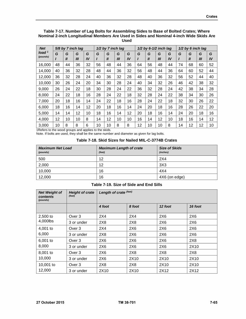
Crates
27 October 2015 TM 38-701 7-65
Table 7-17. Number of Lag Bolts for Assembling Sides to Base of Bolted Crates; Where Nominal 2-inch Longitudinal Members Are Used in Sides and Nominal 4-inch Wide Skids Are
Used
Net load 1
(pounds)
5/8 by 7 inch lag 1/2 by 7 inch lag 1/2 by 6-1/2 inch lag 1/2 by 6 inch lag
G
I
G
II
G
III
G
IV
G
I
G
II
G
III
G
IV
G
I
G
II
G
III
G
IV
G
I
G
II
G
III
G
IV
16,000 48 44 36 32 56 48 44 36 64 56 48 44 74 68 60 52
14,000 40 36 32 28 48 44 36 32 56 48 44 36 64 60 52 44
12,000 36 32 28 24 40 36 32 28 48 40 36 32 56 52 44 40
10,000 30 26 24 20 34 30 28 24 40 34 32 26 46 42 38 32
9,000 26 24 22 18 30 28 24 22 36 32 28 24 42 38 34 28
8,000 24 22 18 16 28 24 22 18 32 28 24 22 38 34 30 26
7,000 20 18 16 14 24 22 18 16 28 24 22 18 32 30 26 22
6,000 18 16 14 12 20 18 16 14 24 20 18 16 28 26 22 20
5,000 14 14 12 10 18 16 14 12 20 18 16 14 24 20 18 16
4,000 12 10 10 8 14 12 10 10 16 14 12 10 18 16 14 12
3,000 10 8 8 6 10 10 8 8 12 10 10 8 14 12 12 10 1Refers to the wood groups and applies to the skids. Note. If bolts are used, they shall be the same number and diameter as given for lag bolts.
Table 7-18. Skid Sizes for Nailed MIL-C-3774B Crates
Maximum Net Load (pounds)
Maximum Length of crate (feet)
Size of Skids (inches)
500 12 2X4
2,000 12 3X3
10,000 16 4X4
12,000 16 4X6 (on edge)
Table 7-19. Size of Side and End Sills
Net Weight of contents (pounds)
Height of crate (feet)
Length of crate (feet)
4 foot 8 foot 12 foot 16 foot
2,500 to 4,000lbs
Over 3 2X4 2X4 2X6 2X6
3 or under 2X8 2X8 2X6 2X6
4,001 to
6,000
Over 3 2X4 2X6 2X6 2X6
3 or under 2X8 2X6 2X6 2X6
6,001 to
8,000
Over 3 2X6 2X6 2X6 2X8
3 or under 2X6 2X6 2X6 2X10
8,001 to
10,000
Over 3 2X6 2X8 2X8 2X8
3 or under 2X6 2X10 2X10 2X10
10,001 to
12,000
Over 3 2X8 2X8 2X10 2X10
3 or under 2X10 2X10 2X12 2X12

Chapter 7
7-66 TM 38-701 27 October 2015
Fastening the End Panels
7-247. The diameter and length of the lag bolts or bolts for fastening the ends of the crate to the top, bottom,
and sides, is determined in a manner similar to that for fastening the sides to the top.
End Panels to the Top
7-248. The size and length of fastener will depend upon the thickness of one or two diagonals or fillers, the
top horizontal frame member of the end, and the width of the crosswise frame member to the top.
End Panels to the Base
7-249. The size and length of fasteners for securing the end panels to the base is the same as above.
End Panels to the Side Panels
7-250. The size and length of fasteners to secure the end panels to the side panels is as specified for fastening
the sides to the top. For 5/8-inch frame in the end, for loads not exceeding 500 pounds, use 5/16-inch diameter
lag screws or bolts.
Corner Strapping
7-251. Use corner strapping on all nailed and bolted crates carrying a net load of 3,000 pounds or over, to
reinforce the corners and to reinforce the crate at the junction of the panel (fig 7-4). Fabricate all corner straps
from 1-1/4 X .035- inch steel banding, 12 inches in length.
7-252. Apply three straps on each of the four upper corners of the crate and secure to the frame members with
sixpenny nails, four in each leg of the strap. Space approximately 2 inches center to center.
7-253. Apply single straps at 36-inch intervals from the corners in all directions and nail to the frame
members.
OPEN NAILED CRATES (MIL-C-3774B) DESIGN REQUIREMENTS
7-254. Non demountable crates may be designed with either a sill or skid-type base, depending upon the
requirements for the item being packed. For additional information on assembly of crate see table 7-23 on
page 7-76
Skid Bases
7-255. Skid bases for open nailed crates are constructed almost identical to the bases used for bolted crates
(fig 7-39).
Skid Sizes
7-256. The size of skids depends upon the net load and the length of the crate (table 7-18).
Headers
7-257. Headers are bolted to the skids with carriage bolts. The sizes of end headers and bolt sizes are as
follows:
Skid size (inches) Header size (inches) Bolt diameter (inch)
2X4 2X4 3/8
3X3 3X3 3/8
4X4 4X4 1/2
4X6 (on edge) 4X4 1/2
7-258. Set the headers or end floorboards back from the ends of the skids the thickness of the end sheathing.
When necessary, notch the headers at their ends down flush with the top of the floorboards. These notches

Crates
27 October 2015 TM 38-701 7-67
will then accommodate and support the lower edge members of the sides. Extend the headers to the outside
faces of the outer skids. The end of the base will be similar to the base of the ASTM-D-7478M crate (fig 7-
53).
Load Bearing Floorboards
7-259. See table 7-4 for sizes.
Forklift Area
7-260. Refer to the requirements stated in bolted crate section. Non-load Bearing Floorboards (Diagonals)
Refer to the requirements stated in bolted crate section.
Sill Bases
7-261. Sill bases are designed for loads to be transmitted to the sides by means of intermediate sills or by the
end sills. The size of the side sills is based upon the weight of the contents and the length of the crate.
However, sill spacing shall not exceed 48 inches center to center, whether required for transmitting loads or
for bracing (fig 7-44).
Side and End Sills
7-262. The size of the side sills is obtained from table 7-19. End sills are the same size as the side sills.
Overlap the side sills over the end sills and nail at the corners using twenty penny coated nails. When
necessary, laminate the sills.
Intermediate Sills
7-263. Apply intermediate sills either crosswise or lengthwise of the crate. These members are always
required when the width of the crate exceeds 48 inches. Determine the size by the length of the sill and the
actual weight supported by the sill. Refer to table 7-31 to calculate the intermediate sill size.
Bridging
7-264. Attach intermediate sills at their ends to the side or end sills by a combination of nailing and metal
hangers (strap or stirrup) (figure 7-16). Metal hangers are not required for fastening non-load bearing
intermediate sills. Use bridging to prevent the sills from buckling and to strengthen the base. Bridge
intermediate sills at their ends, except when positioned on their flat faces, with 1 inch lumber of the same
depth. Nail to the inner face. Reinforce spans 5 feet or over (either length or width of the crate) with 2 inch
lumber the same depth as the sills. Position the reinforcing members at right angles to the sills.
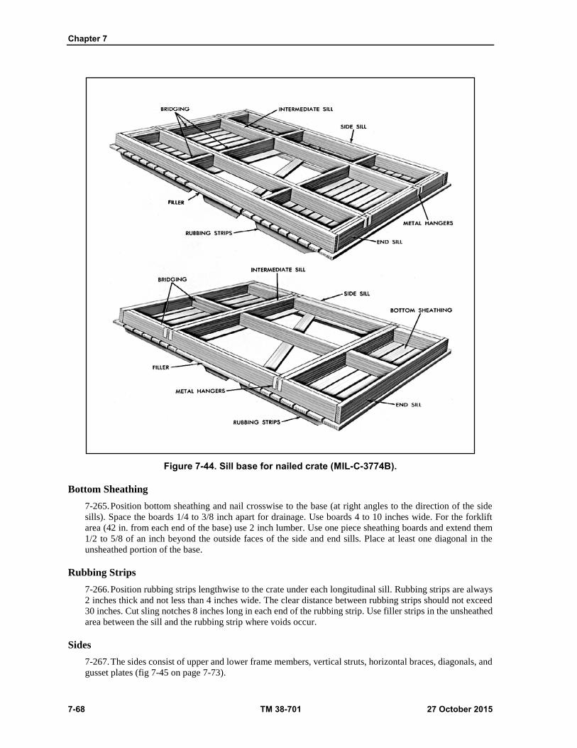
Chapter 7
7-68 TM 38-701 27 October 2015
Figure 7-44. Sill base for nailed crate (MIL-C-3774B).
Bottom Sheathing
7-265. Position bottom sheathing and nail crosswise to the base (at right angles to the direction of the side
sills). Space the boards 1/4 to 3/8 inch apart for drainage. Use boards 4 to 10 inches wide. For the forklift
area (42 in. from each end of the base) use 2 inch lumber. Use one piece sheathing boards and extend them
1/2 to 5/8 of an inch beyond the outside faces of the side and end sills. Place at least one diagonal in the
unsheathed portion of the base.
Rubbing Strips
7-266. Position rubbing strips lengthwise to the crate under each longitudinal sill. Rubbing strips are always
2 inches thick and not less than 4 inches wide. The clear distance between rubbing strips should not exceed
30 inches. Cut sling notches 8 inches long in each end of the rubbing strip. Use filler strips in the unsheathed
area between the sill and the rubbing strip where voids occur.
Sides
7-267. The sides consist of upper and lower frame members, vertical struts, horizontal braces, diagonals, and
gusset plates (fig 7-45 on page 7-73).

Crates
27 October 2015 TM 38-701 7-69
Design of the Side Panels
7-268. Determine the design of the side panel from the inside length and inside height of the crate. For crates
up to 48 inches inside height use an X type frame and for crates with an inside height of over 48 inches use
a HK type frame.
Member Selection
7-269. Determine the sizes of the upper and lower members, struts, and diagonals from table 7-20 and 7-21
on page 7-71with the exception of the end strut or corner post. Loads referred to in the table are based on the
net weight of the contents and the inside dimensions of the crate. If the exact size of the crate is not given in
the table, use the member size for the crate of the next longer length, the neat greater width, and next smaller
height.
7-270. Use 1 X 4 inch lumber for members and diagonals and 2 X 4 inch lumber for upper edge members
when the height of the crate is 6 feet or less and the load does not exceed 4,000 pounds. Use 1 inch lumber
for the lower edge members, struts and diagonals, and 2 inch lumber for the upper edge members and end
struts when the height of the crate is under 6 feet and the load is over 4,000 pounds. Use 2 X 4 inch lumber
for the upper and lower edge members, struts and diagonals, when the height of the crate is over 6 feet.
Upper, Lower, and Intermediate Members
7-271. The members are required to be a single continuous piece. If splicing is required, splice the members
according to the details shown in figure 7-54. All splicing should be made under or over a strut whenever
possible. Splicing1 inch material is not permitted. The size of these members is based upon the gross weight
and length of the crate. Intermediate members (horizontal braces) are used only for crates of the HK type.
Table 7-20. Panel Member Selection (6,000, 8,000 and, and 10,000 Pounds Net Load) 1
Length
(feet)
Members Net
Load
lbs
4 foot width 6 foot width 8 foot width
Height (feet) Height (feet) Height (feet)
2 4 6 8 2 4 6 8 2 4 6 8
6 Upper frame
6000 2x4 2x4 2x4 2x4 2x4 2x4 2x4 2x4 2x4 2x4 2x4 2x4
Lower frame
6000 2x4 2x4 2x4
Struts 6000 2x4 2x4 2x4
Diagonals 6000 2x4 2x4 2x4
8 Upper frame
6000 2x4 2x4 2x4 2x4 2x4 2x4 2x4 2x4 2x4 2x4 2x4 2x4
Lower frame
6000 2x4 2x4 2x4
Struts 6000 2x4 2x4 2x4
Diagonals 6000 2x4 2x4 2x4
10 Upper frame
6000 2x4 2x4 2x4 2x4 2x4 2x4 2x4 2x4 2x4 2x4 2x4 2x4
Lower frame
6000 2x4 2x4 2x4
Struts 6000 2x4 2x4 2x4
Diagonals 6000 2x4 2x4 2x4
12 Upper frame
6000 2x4 2x4 2x4 2x4 2x4 2x4 2x4 2x4 2x4 2x4 2x4 2x4

Chapter 7
7-70 TM 38-701 27 October 2015
Table 7-20. Panel Member Selection (6,000, 8,000 and, and 10,000 Pounds Net Load) 1 (continued)
Length
(feet)
Members Net
Load
lbs
4 foot width 6 foot width 8 foot width
Height (feet) Height (feet) Height (feet)
2 4 6 8 2 4 6 8 2 4 6 8
Lower frame
6000 2x4 2x4 2x4
Struts 6000 2x4 2x4 2x4
Diagonals 6000 2x4 2x4 2x4
16 Upper frame
6000 2x6 2x4 2x4 2x4 2x6 2x4 2x4 2x4 2x6 2x4 2x4 2x4
Lower frame
6000 2x4 2x4 2x4
Struts 6000 2x4 2x4 2x4
Diagonals 6000 2x4 2x4 2x4
6 Upper frame
8000 2x4 2x4 2x4 2x4 2x4 2x4 2x4 2x4 2x4 2x4 2x4 2x4
Lower frame
8000 2x4 2x4 2x4
Struts 8000 2x4 2x4 2x4
Diagonals 8000 1x6 2x4 1x6 2x4 1x6 2x4
8 Upper frame
8000 2x4 2x4 2x4 2x4 2x4 2x4 2x4 2x4 2x4 2x4 2x4 2x4
Lower frame
8000 2x4 2x4 2x4
Struts 8000 2x4 2x4 2x4
Diagonals 8000 1x6 2x4 1x6 2x4 2x4 2x4
10 Upper frame
8000 2x4 2x4 2x4 2x4 2x4 2x4 2x4 2x4 2x4 2x4 2x4 2x4
Lower frame
8000 2x4 2x4 2x4
Struts 8000 2x4 2x4 2x4
Diagonals 8000 1x6 2x4 1x6 2x4 1x6 2x4
12 Upper frame
8000 2x6 2x4 2x4 2x4 2x6 2x4 2x4 2x4 2x6 2x4 2x4 2x4
Lower frame
8000 2x4 2x4 2x4
Struts 8000 2x4 2x4 2x4
Diagonals 8000 1x6 2x4 1x6 2x4 1x6 2x4
16 Upper frame
8000 2x4 2x4 2x4 2x4 2x4 2x4 2x4 2x4 2x4 2x4 2x4 2x4
Lower frame
8000 2x4 2x4 2x4
Struts 8000 2x4 2x4 2x4
Diagonals 8000 1x6 2x4 1x6 2x4 1x6 2x4
6 Upper frame
10000 2x4 2x4 2x4 2x4 2x4 2x4 2x4 2x4 2x4 2x4 2x4 2x4
Lower frame
10000 2x4 2x4 2x4 2x4
Struts 10000 2x4 1x6 2x4 1x6 2x4 2x4
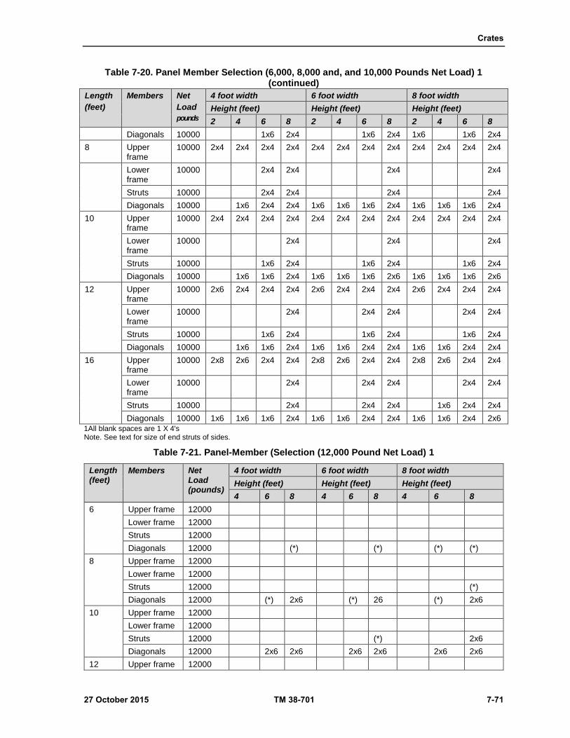
Crates
27 October 2015 TM 38-701 7-71
Table 7-20. Panel Member Selection (6,000, 8,000 and, and 10,000 Pounds Net Load) 1 (continued)
Length
(feet)
Members Net
Load
pounds
4 foot width 6 foot width 8 foot width
Height (feet) Height (feet) Height (feet)
2 4 6 8 2 4 6 8 2 4 6 8
Diagonals 10000 1x6 2x4 1x6 2x4 1x6 1x6 2x4
8 Upper frame
10000 2x4 2x4 2x4 2x4 2x4 2x4 2x4 2x4 2x4 2x4 2x4 2x4
Lower frame
10000 2x4 2x4 2x4 2x4
Struts 10000 2x4 2x4 2x4 2x4
Diagonals 10000 1x6 2x4 2x4 1x6 1x6 1x6 2x4 1x6 1x6 1x6 2x4
10 Upper frame
10000 2x4 2x4 2x4 2x4 2x4 2x4 2x4 2x4 2x4 2x4 2x4 2x4
Lower frame
10000 2x4 2x4 2x4
Struts 10000 1x6 2x4 1x6 2x4 1x6 2x4
Diagonals 10000 1x6 1x6 2x4 1x6 1x6 1x6 2x6 1x6 1x6 1x6 2x6
12 Upper frame
10000 2x6 2x4 2x4 2x4 2x6 2x4 2x4 2x4 2x6 2x4 2x4 2x4
Lower frame
10000 2x4 2x4 2x4 2x4 2x4
Struts 10000 1x6 2x4 1x6 2x4 1x6 2x4
Diagonals 10000 1x6 1x6 2x4 1x6 1x6 2x4 2x4 1x6 1x6 2x4 2x4
16 Upper frame
10000 2x8 2x6 2x4 2x4 2x8 2x6 2x4 2x4 2x8 2x6 2x4 2x4
Lower frame
10000 2x4 2x4 2x4 2x4 2x4
Struts 10000 2x4 2x4 2x4 1x6 2x4 2x4
Diagonals 10000 1x6 1x6 1x6 2x4 1x6 1x6 2x4 2x4 1x6 1x6 2x4 2x6
1All blank spaces are 1 X 4's Note. See text for size of end struts of sides.
Table 7-21. Panel-Member (Selection (12,000 Pound Net Load) 1
Length (feet)
Members Net Load (pounds)
4 foot width 6 foot width 8 foot width
Height (feet) Height (feet) Height (feet)
4 6 8 4 6 8 4 6 8
6 Upper frame 12000
Lower frame 12000
Struts 12000
Diagonals 12000 (*) (*) (*) (*)
8 Upper frame 12000
Lower frame 12000
Struts 12000 (*)
Diagonals 12000 (*) 2x6 (*) 26 (*) 2x6
10 Upper frame 12000
Lower frame 12000
Struts 12000 (*) 2x6
Diagonals 12000 2x6 2x6 2x6 2x6 2x6 2x6
12 Upper frame 12000

Chapter 7
7-72 TM 38-701 27 October 2015
Table 7-21. Panel-Member (Selection (12,000 Pound Net Load) 1(continued)
Length (feet)
Members Net Load (pounds)
4 foot width 6 foot width 8 foot width
Height (feet) Height (feet) Height (feet)
4 6 8 4 6 8 4 6 8
Lower frame 12000
Struts 12000
Diagonals 12000
16 Upper frame 12000
Lower frame 12000
Struts 12000 2x6 2x6
Diagonals 12000 2x6 2x6 2x6 2x6 2x6
NOTES: 1. All blank spaces are 2/4's.* The above sizes are for uniform loads but apply also to concentrated loads where an asterisk is shown. When asterisk isshown, increase the member size to 2x6 for concentrated load.

Crates
27 October 2015 TM 38-701 7-73
Figure 7-45. Side or end panel for nailed crate (MIL-C-3774B).
Vertical Struts and Diagonals
7-272. All vertical struts and diagonals are continuous from the lower frame member to the upper frame
member. Cut the diagonal and horizontal braces to fit between the vertical struts.
Chapter 7
7-74 TM 38-701 27 October 2015
End Struts or Corner Posts
7-273. The end vertical strut or corner post of the side is not less than 2 inches in thickness in order to provide
sufficient nailing space when fastening the ends.
Partial Sheathing Boards
7-274. Always apply the sheathing boards vertically. These boards are located at the corners and at various
intervals based upon the design of the crate.
Lumber Sheathing
7-275. The sheathing boards are of one piece material, 1 inch thick, and from 4 to 10 inches wide. All end
boards are at least 6 inches wide, preferably wider. Ten percent of the boards may be 4 inches wide, but no
narrow boards may be adjacent to each other.
Plywood Sheathing
7-276. Plywood strips, three or five ply material, may be substituted for lumber sheathing in the sides, ends,
or tops. This material must be the same width as the lumber sheathing. For loads up to 5,000 pounds, use
7/16 inch plywood of group I woods; 3/8 inch of group II woods; 5/16 inch of group III and IV woods. For
loads over 5,000 pounds, use 1/2 inch plywood of group I woods; 7/16 inch of group II woods; 3/8 inch of
group III and IV woods.
Gusset Plates
7-277. Gusset plates are required for crates using 1 inch frame members. Place the gusset plates where the
diagonals, struts, or horizontal braces intersect. Plywood gusset plates are not required when plywood
sheathing is used. Use12 X 12 X 1/4 inch gusset plate for 1 X 4 inch frame members. Use 18 X 18 X 1/4
inch gusset plate for 1 X 6 inch frame members. Secure the gusset plates to frame members using seven
penny nails and clinch (figure 7-45).
Nailing Lumber Sheathing
7-278. Nail 4 to 6 inches wide sheathing boards of horizontal and diagonal members with three rows of nine
penny clinched nails. Use three nails in sheathing boards 4 to 6 inches wide and four nails in wider boards.
Nail sheathing boards over 6 inches wide to horizontal and diagonal members with four rows of nine penny
clinched nails. Nail sheathing boards 4 to 6 inches wide to vertical struts with two rows of nine penny nails,
spaced 6 inches apart in each row and clinch.
Nailing Plywood Sheathing
7-279. Nail plywood sheathing to 4 inch wide frame members with two rows of nails, spaced 6 inches apart
in each row, and clinch. Use three rows in frame members over 4 inches wide. The nailing requirements are
identical to those illustrated in figure 7-5 except for the spacing.
Ends
7-280. The end frame members are identical to those of the sides. The design of the end panels is also based
upon the inside length and inside height of the crate. The panel design will be either X or HK framing (figure
7-45).
Member Selection
7-281. The frame members of the ends are the same size as the corresponding members of the sides.

Crates
27 October 2015 TM 38-701 7-75
Top Panels
7-282. The top panels consist of framing members, partial sheathing boards, gusset plates and joists. Tops are
classified according to types (table 7-22 on page 7-76 and figure 7-46 on page 7-78).
Number of Panels
7-283. To determine the number of panels for N, X or HK type of top, divide the crate length by the crate
width and use the nearest whole number.
Frame Members
7-284. All top frame members are 1 X 6 inch material. When the width of the top is24 inches or less uses 1
X 4 inch material.
Gusset Plates
7-285. Use gusset plates at the intersection of the frame members of the top. They are the same size and nailed
in the same manner as those for the side and end panels.
Top Joists
7-286. Determine the size of the joists by the weight of the contents and the length of the joists (table 7-15).
Space the joists not more than 48 inches center to center. Extend all joists from the upper longitudinal member
of one side to the upper longitudinal member of the other side. Fasten each joist with three twelve penny
coated sinkers through the upper edge members of the side into the end of the joist when the framing is one
inch thick. Use three twenty penny nails per joint for 2-inch upper frame members. This nailing is
accomplished as the crate is being assembled.
FABRICATION OF OPEN NAILED CRATES
7-287. There are different types of fabrications.
Sheathing to the Horizontal and Diagonal Frame Members
7-288. Use nails for securing the sheathing to the frame members (up to and including 2-inch thickness) long
enough to permit clinching at least one- fourth of an inch. Use three rows of nails to secure the sheathing.
Use a minimum of three nails in each sheathing board up to 6 inches wide. Use not less than four nails in
wider boards.
Sheathing to the Vertical Frame Members
7-289. Use two rows of nails, placed on 6-inch centers, in each row and stagger (table 7-24 on page 7-77 and
figure 7-46 on page 7-78).
Plywood Sheathing to the Frame Members
7-290. The nails for fastening plywood to framing members shall be long enough to pass through the plywood
and the frame member and be clinched not less than one-fourth of an inch. Stagger all nails in two parallel
rows in each frame member up to 3-5/8 inches wide, and in three rows in wider frame members. Place the
nails not less than one-half of an inch from the edge of the frame members. The distance between rows of
nails is not less than 1 inch, and the distance between adjacent nails in any row is not to exceed 6 inches.
Sheathing to the Side Frame Members of the Top
7-291. Use two rows of nails. One row three-fourths of an inch from the inside edge of the frame member,
and one row three-fourths of an inch from the outside edge. Stagger the nails between rows with a minimum
of two clinched nails in each sheathing board at each longitudinal member.

Chapter 7
7-76 TM 38-701 27 October 2015
Sheathing to the End Frame Members of the Top
7-292. Place one row of nails in three-fourths of an inch from the inside edge of the frame member. Place the
other row in the center of the frame members. Space the nails 9 inches apart in each row and clinch.
Sheathing to the Longitudinal and Diagonal Members of the Top
7-293. Use three rows of nails, with not less than three nails in sheathing boards 6 inches wide. Use not less
than four nails in wider boards.
Sheathing to the Struts of the Top
7-294. Two rows of nails are required not less than three-fourths inch from the edges of both the frame
members and the sheathing. Space the nails on 9- inch centers in each row and clinch.
Plywood Sheathing to the Frame Members of the Top
7-295. If plywood is substituted for lumber, stagger the nails in two parallel rows and space them 6 inches
apart in each row. Position the nails three-fourths inch from the edge of the frame members. The nails must
be long enough to penetrate both the members and be clinched at least three-fourths of an inch.
Table 7-22. Type of Tops (MIL-C-3774B)
Type framing pattern Width of top (inches)
N Up to 40
X Over 40 through 60
HK Over 60 through 96
Table 7-23. Nailed Crate Assembly (MIL-C-3774B)
Fasten Size type of nail Maximum spacing Notes
Part To part
Corner strut of end (1 inch member)
Corner of strut of the side
12 penny 12 inches
Corner strut of end (2 inch member
Corner of strut of the side
20 penny 12 inches
Sheathing of side Corner strut of the end
8 penny 6 to 8 inches Predrill through sheathing of end and corner strut of end
Edge frame member of top (through sheathing)
Upper frame member of sides
12 penny 6 inches center to center
Stagger
Edge frame member of top
Upper frame member of sides
8 penny 6 to 8 inches Space nails between top sheathing
End strut of top Upper frame member of end
12 penny 6 inches Stagger
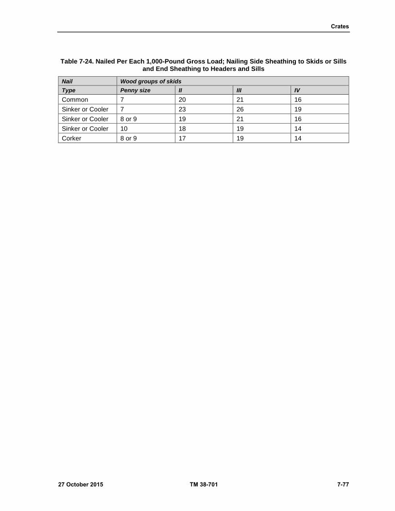
Crates
27 October 2015 TM 38-701 7-77
Table 7-24. Nailed Per Each 1,000-Pound Gross Load; Nailing Side Sheathing to Skids or Sills and End Sheathing to Headers and Sills
Nail Wood groups of skids
Type Penny size II III IV
Common 7 20 21 16
Sinker or Cooler 7 23 26 19
Sinker or Cooler 8 or 9 19 21 16
Sinker or Cooler 10 18 19 14
Corker 8 or 9 17 19 14
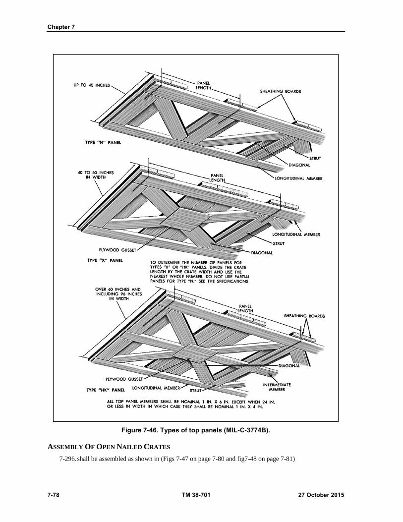
Chapter 7
7-78 TM 38-701 27 October 2015
Figure 7-46. Types of top panels (MIL-C-3774B).
ASSEMBLY OF OPEN NAILED CRATES
7-296. shall be assembled as shown in (Figs 7-47 on page 7-80 and fig7-48 on page 7-81)
Crates
27 October 2015 TM 38-701 7-79
Nailing Requirements
7-297. The nailing requirements for fastening the base, sides, ends, and top together are found in tables 7-23
and 7-24.
Nailing Procedures
7-298. When attaching the sides and ends to the skids, use one row of nails (staggered) for 2 inch-deep skids,
two rows for 3 and 4 inch-deep sills and three rows for deeper members. Secure the corner struts of the end
to the corner struts of the side with twenty penny nails spaced 12 inches apart. Nail the partial sheathing of
the side to the corner strut of the end using eight penny nails, spaced 6 to 8 inches apart, and staggered. Nail
through the top sheathing into the upper edge members using twelve penny nails spaced 6 inches apart, center
to center. Nail the top sheathing to the top joists using twelve penny nails, spaced 8 inches apart.
Corner strappings
7-299. See (figures 7-4 and 7-18)
SHEATHED WOOD CRATES, ASTM-D-7478M (GENERAL)
7-300. ASTM-D-7478M covers requirements for two types and two classes of sheathed crates each of which
may have two styles of bases. The crates are designed for net loads not exceeding 30,000 pounds and to
withstand the most severe overseas shipping and storage conditions.
CLASSIFICATION
7-301. Eight crate designs are possible through the combination of the following types, classes and styles.
These crates are available in different type, classes, and styles. For example a type I (nailed), class 2 (plywood
sheathed), Style A (skid base) crate may be used.
Type I - Nailed
Type II - Bolted
Class 1 - Lumber sheathed Class 2 - Plywood sheathed Style a - Skid base
Style b - Sill base
Weight Limitations
7-302. The gross weight of these crates should not be more than 11,200 pounds whenever practical. This
weight is recommended in order to permit handling with ship’s gear. However, when this limitation is not
possible, the gross weight may be greater than 11,200 pounds but less than 20,000 pounds for crates with
Style B (sill) bases, or 30,000 pounds for crates with Style A (skid) bases.
Dimension Limitations
7-303. The exterior dimensions of the crate shall not exceed the following limitations, unless specified, for
overseas shipment for which dimensions of the International Loading Gauge shall apply.
7-304. Length - 30 feet Width - 9 feet Height - 10 feet
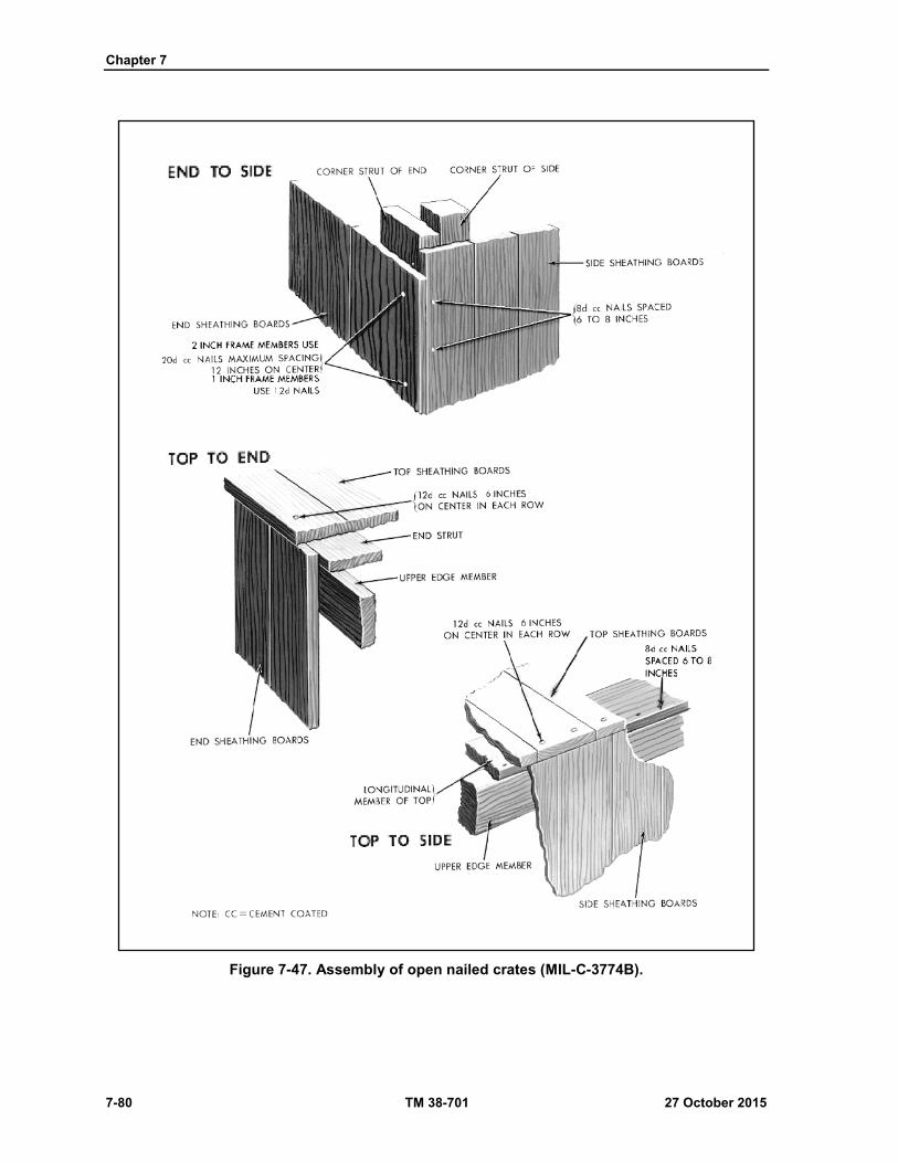
Chapter 7
7-80 TM 38-701 27 October 2015
Figure 7-47. Assembly of open nailed crates (MIL-C-3774B).
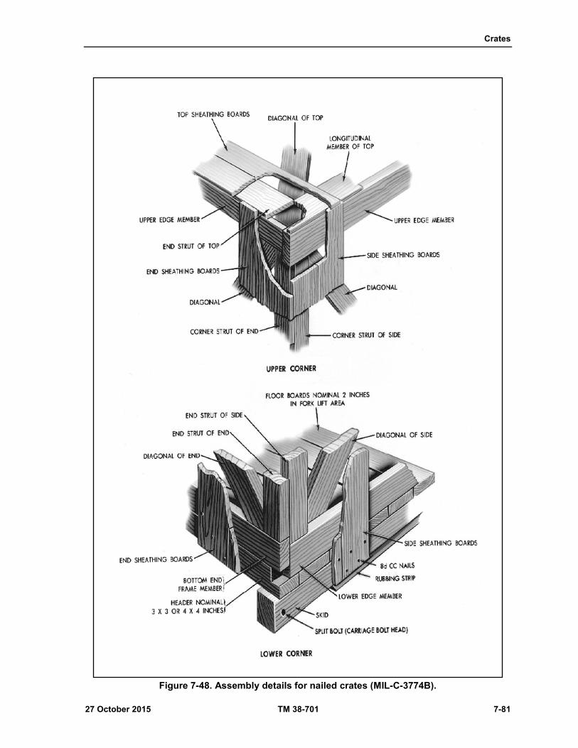
Crates
27 October 2015 TM 38-701 7-81
Figure 7-48. Assembly details for nailed crates (MIL-C-3774B).
Chapter 7
7-82 TM 38-701 27 October 2015
Interior Clearance
7-305. A clearance of not less than 1 inch shall be allowed between the item and the closest member of the
sides, ends, and top of the crate. Fragile items or items within floating bag barriers shall be protected with
clearances of not less than 2 inches. Additional clearances may be provided for shock mounted items.
Protruding parts at the top may be allowed to extend between joists; spacing of joists may be adjusted slightly
to accommodate projections.
MATERIAL REQUIREMENTS
7-306. Material shall be as specified herein. Materials not specified shall be selected by the contractor and
shall be subject to all provisions of ASTM-D-7478M specification.
Lumber
7-307. Lumber components shall conform to woods commonly used.
Plywood
7-308. Plywood shall conform to A-A-55057B Type A or B. Plywood (type A or B) shall comply with PS1
and PS2.
Nails and Staples
7-309. Nails and staples shall be steel and shall conform to ASTM F 1667-05.
Nuts, and Washers
7-310. Nuts shall conform to FF-N-836, Type I or II, style 1 or 4. Washers shall conform to FF-W-92B, Type
A, Grade I, Class A.
Strapping
7-311. Strapping shall conform to ASTM D 3953, Type 1 or 2 as applicable. Finish shall be A, B, or C.
Barrier Material
7-312. Barrier material, for crate liners, shall conforms to PPP-B-1055B, class as appropriate for crate liners.
NAILING PROCEDURE
7-313. Nails used shall be sinkers, coolers, corkers, or common. Nails sizes specified for the fabrication of
the various crates are based on Groups I and II woods. When Groups III or IV woods are used, nails sizes
may be one penny size smaller than those specified. The patterns to be used for the nailing of two flat pieces
of lumber shall conform to the details shown in figure 7-50 on page 7-84). Unless otherwise specified herein,
the following requirements shall determine size, placement, and quantity of nails:
All adjacent crate members shall be securely fastened to each other, either directly or by means of
the covering.
All nails that are not to be clinched shall be cement-coated.
Nails shall be driven through the thinner member into the thicker member wherever possible.

Crates
27 October 2015 TM 38-701 7-83
Figure 7-49. Ventilation end screening of sheathed crates.
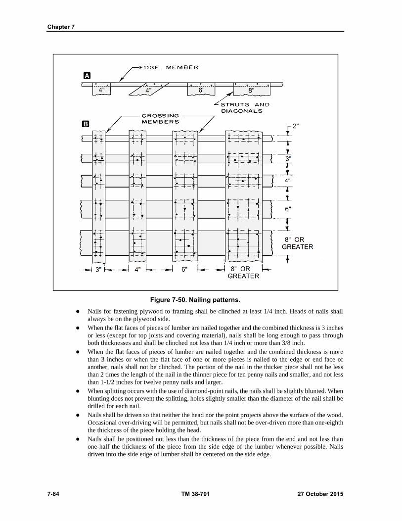
Chapter 7
7-84 TM 38-701 27 October 2015
Figure 7-50. Nailing patterns.
Nails for fastening plywood to framing shall be clinched at least 1/4 inch. Heads of nails shall
always be on the plywood side.
When the flat faces of pieces of lumber are nailed together and the combined thickness is 3 inches
or less (except for top joists and covering material), nails shall be long enough to pass through
both thicknesses and shall be clinched not less than 1/4 inch or more than 3/8 inch.
When the flat faces of pieces of lumber are nailed together and the combined thickness is more
than 3 inches or when the flat face of one or more pieces is nailed to the edge or end face of
another, nails shall not be clinched. The portion of the nail in the thicker piece shall not be less
than 2 times the length of the nail in the thinner piece for ten penny nails and smaller, and not less
than 1-1/2 inches for twelve penny nails and larger.
When splitting occurs with the use of diamond-point nails, the nails shall be slightly blunted. When
blunting does not prevent the splitting, holes slightly smaller than the diameter of the nail shall be
drilled for each nail.
Nails shall be driven so that neither the head nor the point projects above the surface of the wood.
Occasional over-driving will be permitted, but nails shall not be over-driven more than one-eighth
the thickness of the piece holding the head.
Nails shall be positioned not less than the thickness of the piece from the end and not less than
one-half the thickness of the piece from the side edge of the lumber whenever possible. Nails
driven into the side edge of lumber shall be centered on the side edge.
Crates
27 October 2015 TM 38-701 7-85
Nails securing plywood sheathing to frame members shall be spaced as shown in figure 7-51.
Machine driven nails having a definite head may be used for securing plywood sheathing
providing they meet size requirements specified herein.
Stapling
7-314. Staples may be used to fasten sheathing to frame members. They shall not be used for fabrication of
bases, fastening of framing members to each other, or for assembly of crates. Staples shall have crowns of
not less than 3/8 inch wide and shall have a wire diameter of not less than 0.062 inch (16 gage). Straight leg
staples shall be long enough to provide a minimum 1/4-inch clinch. Divergent point staples shall not be less
than 1 inch long. Spacing of staples shall be the same as for nails. Staples shall always be driven from the
plywood side.
Bolt Application
7-315. Holes shall be pre bored to receive carriage bolts and shall be the exact diameter of the bolt. The lead
holes for lag bolts shall be the same diameter as the shank, even though the threaded portion may have a
greater diameter than the shank, and shall be as shown in table 7-25 on page 7-86.
7-316. Lag bolts shall be placed by being turned in their holes the full length of the bolt and shall not be
driven in with a hammer or by any similar means. If, for any reason, the thread in the wood is stripped when
the lag bolts are placed, the lag bolt shall be removed and placed in a new hole near the old position. A flat
washer shall be used under the head of each lag bolt and under the nut of each carriage bolt. After the nut is
placed, the thread of the carriage bolt projecting beyond the nut shall be painted with a suitable metal primer
or similar material.
Ventilation (figs 7-49 and 7-51)
7-317. All crates shall be provided with ventilating holes or slots which shall be located at each end or at ends
and sides of lumber and plywood sheathed crates, or around the perimeter of plywood and lumber sheathed
crates. These ventilating holes or slots shall be located immediately below the top frame member and be
provided with a baffle as shown in figure 7-51 when slots are used in plywood sheathed crates or when holes
are in clusters in lumber sheathed crates. Single holes drilled without baffles shall be sloped at 45 degrees to
drain outward. No holes or slots shall be cut in any frame member.
Class 1 Crates
7-318. Class 1 crates shall be provided with ventilation holes, 3/4 inch in diameter. The crate liner shall be
removed from the ventilating area and all splinters and chips shall be removed from the holes.
End Ventilation
7-319. Ventilating holes shall be provided in each end in one or more clusters, placed near the upper frame
members, provided with a baffle, and spaced 2 inches on center as shown in figure 7-51. In small crates,
holes may be located so that diagonals or struts can be utilized in part for cleats. In crates over 10 feet in
length, the ventilating holes shall be divided equally between the sides and ends with a baffle provided for
each group of holes. The clusters of holes shall be located as near the midpoint of the side and end as practical.
The number of holes shall comply with table 7-26 on page 7-86.
Perimeter Ventilation
7-320. As an alternate to end ventilation, the 3/4 inch ventilating holes may be spaced evenly around the
perimeter of the crate just under the top frame member and drilled at a 45 degree angle to drain outward (fig
7-49). The total number of holes shall comply with table 7-26 on page 7-86.

Chapter 7
7-86 TM 38-701 27 October 2015
Table 7-25. Lag bolt lead hole sizes.
Diameter of Threaded portion of Lag Bolt (inch)
Diameter of Lead Hole (inch)
Group I, II, and III Woods Group IV Woods
1/4 3/16 3/16
5/16 1/4 1/4
3/8 1/4 5/16
1/2 3/8 7/16
5/8 3/8 1/2
3/4 1/2 5/8
Table 7-26. Ventilation holes and area required.
Lumber-sheathed crates Plywood-sheathed crates
Volume of crate
(Cubic Feet.)
End ventilation
minimum number of 3/4
inch diameter holes
required in each end
(place in cluster and use
baffle)
Perimeter ventilation
(alternate) Total minimum
number of 3/4 inch diameter
holes required around
perimeter (space evenly and
slope to drain out)
Area required in each
end
(Use baffle and screen)
(Square inch.)
0-100 3 6 7
100-150 4 8 10
150-200 5 10 14
200-400 9 18 27
400-600 14 27 40
600-800 18 36 52
800-1000 22 44 66
1000-1200 27 54 80
1200 and over 33 66 100 Note. In large crates, where a large ventilating area is required, two or more slots or clusters of holes may be used in each panel.
CLASS 2 CRATES
7-321. Class 2 crates shall be provided with a horizontal slot in each end. The ventilation slots shall be
provided with baffles and screens as shown in figure7-51 on page 7-88. The required ventilating area shall
comply with table 7-26. In crates over 10 feet in length, the ventilation area shall be divided equally between
the sides and ends of the crate with baffle and screen provided for each ventilating area. The ventilating area
shall be placed as near the midpoints of the sides and ends as practical. In small crates, 3/4 inch diameter
holes may be substituted for the slots in the proportion of two holes for each square inch of required area.
CLASS 1 CRATES
7-322. Class 1 crates may be either bolted or nailed. Bolted crates shall be so designed that the major
components of base, sides, ends, and top may be assembled to each other with lag bolts in order that the crate
can be readily disassembled and, if desired, reassembled without major damage to the parts. Nailed crates

Crates
27 October 2015 TM 38-701 7-87
are assembled with nails and straps, are not easily demountable, and because of probable damage during
disassembly, are not generally reused. A combination of top, side, and end panels may be fabricated and
assembled to each other as specified for nailed crates, and the unit fastened to the base as specified for bolted
crates.
Bases
7-323. Bases shall be designed to support the weight of the crated article only when the sides and ends are
fastened in place.
Skid Type (Style a)
7-324. Style a bases shall consist of longitudinal skids and rubbing strips, headers, load-bearing floorboards,
and flooring as shown on figures 7-52 on page 7-89 and fig 7-53 on page 7-90. Details of construction shall
be the same for bolted and nailed crates. The minimum size of skids shall conform to table 7-27.
Table 7-27. Allowable minimum skid sizes
Maximum net load (lbs) Maximum length of crate (ft) Nominal sizer of skids (in)
300 16 2x4 (flat)1/
1,000 12 2x4 (flat)1/
2,000 20 3x3 or 3x4 (flat) 2/
10,000 32 4x4
30,000 20 4x6 (on edge) 1/ for nailed crates only. 2/ for crates with 2-inch-thick lower frame member or 2-inch end struts.
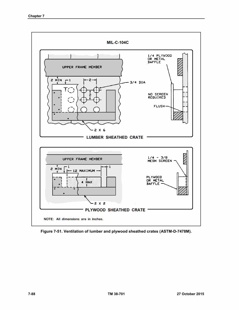
Chapter 7
7-88 TM 38-701 27 October 2015
Figure 7-51. Ventilation of lumber and plywood sheathed crates (ASTM-D-7478M).
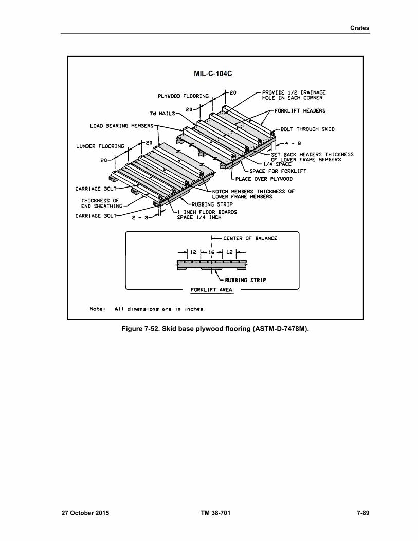
Crates
27 October 2015 TM 38-701 7-89
Figure 7-52. Skid base plywood flooring (ASTM-D-7478M).
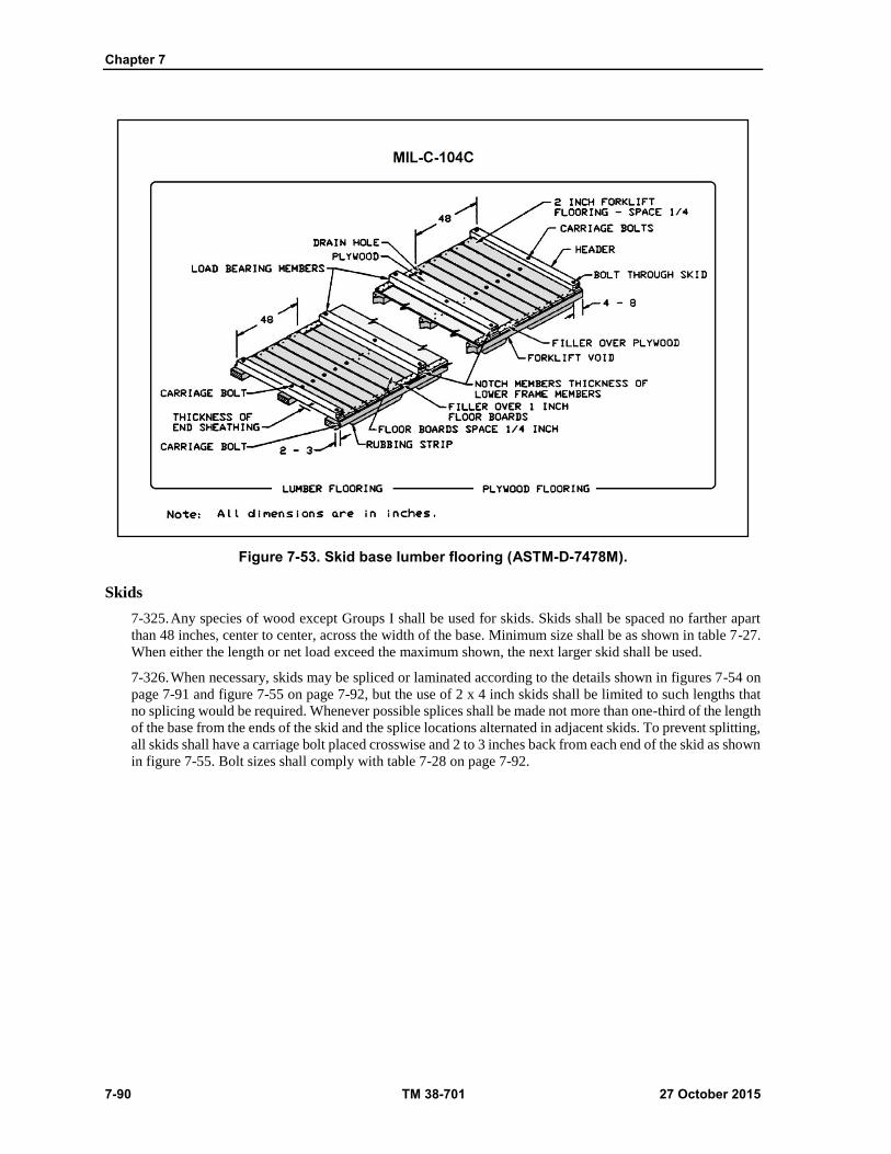
Chapter 7
7-90 TM 38-701 27 October 2015
Figure 7-53. Skid base lumber flooring (ASTM-D-7478M).
Skids
7-325. Any species of wood except Groups I shall be used for skids. Skids shall be spaced no farther apart
than 48 inches, center to center, across the width of the base. Minimum size shall be as shown in table 7-27.
When either the length or net load exceed the maximum shown, the next larger skid shall be used.
7-326. When necessary, skids may be spliced or laminated according to the details shown in figures 7-54 on
page 7-91 and figure 7-55 on page 7-92, but the use of 2 x 4 inch skids shall be limited to such lengths that
no splicing would be required. Whenever possible splices shall be made not more than one-third of the length
of the base from the ends of the skid and the splice locations alternated in adjacent skids. To prevent splitting,
all skids shall have a carriage bolt placed crosswise and 2 to 3 inches back from each end of the skid as shown
in figure 7-55. Bolt sizes shall comply with table 7-28 on page 7-92.
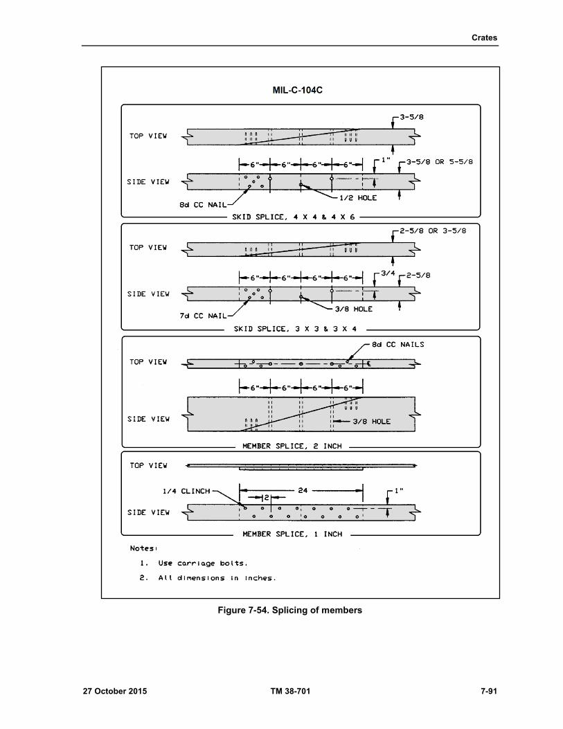
Crates
27 October 2015 TM 38-701 7-91
Figure 7-54. Splicing of members
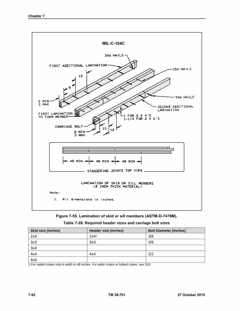
Chapter 7
7-92 TM 38-701 27 October 2015
Figure 7-55. Lamination of skid or sill members (ASTM-D-7478M).
Table 7-28. Required header sizes and carriage bolt sizes
Skid size (inches) Header size (inches) Bolt Diameter (inches)
2x4 2x41 3/8
3x3 3x3 3/8
3x4
4x4 4x4 1/2
4x6 1 For nailed crates only in width to 48 inches. For wider crates or bolted crates, use 3X3.
Crates
27 October 2015 TM 38-701 7-93
Rubbing Strip for Skids
7-327. Rubbing strips of 3-inch thick lumber, the same width as the skids, shall be attached to the skids with
two staggered rows of nails spaced 12 inches apart in each row The nails shall be driven through the rubbing
strip into the skid, shall be of such length as to penetrate a minimum of approximately 70 percent of the skid
thickness, and shall not protrude through the skid. The strips shall be beveled full depth at an angle of 45
degrees at sling and forklift openings. Openings in the rubbing strips for forklift-truck access shall be 12
inches in length, 28 inches center to center, and positioned to straddle the center of balance of the loaded
crate. Sling openings not less than 4 inches in length, and preferably 8 inches, shall be provided at the ends
of the rubbing strip where permitted by the length of the crate and by the location of the forklift-truck access
openings. No center pieces of the rubbing strips shall be less than 16 inches in length. On crates 5 feet and
less in length, the forklift openings shall be omitted; end sling openings shall not be less than 6 inches long
and shall serve as both forklift and sling openings.
Headers
7-328. Headers shall be placed at each end of the base and shall be bolted to each skid with one carriage bolt.
Sizes of headers and bolts shall be as shown in table 7-28.
Forklift Members
7-329. The forklift members shall consist of the header and two members of equal size, spaced 20 to 40 inches
(on center) from each end of the skids and bolted as shown in figure 7-52. Where the form of the item to be
crated makes it impractical to use these members, or when crates are short or narrow, 2 inch- thick lumber
shall be used in the 48-inch end areas as shown in figure 7-52. When 2-inch lumber is used in the forklift
area and intermediate skids are required because of the width of the base, the 2-inch forklift members shall
be bolted to the intermediate skids. Forklift members shall be notched or set back a specified for headers. If
loaded containers center of balance is other than the center of the base, the space for forklift entry shall be
positioned so that the center of balance is centered in between forklift openings.
7-330. Headers shall be of a single piece and not built up to two or more pieces to meet the dimension
requirements. Headers shall be placed atop the plywood when plywood flooring is used. Headers shall be
placed a distance back from the ends of the skids equal to the thickness of the end sheathing. The ends of the
headers shall be notched for bases floored with lumber; ends of headers for plywood floored bases shall be
set back from the outside edges of the outer skids (see figures 7-52 and 7-53). The notched and set back
distances shall be equal to the thickness of the lower frame members of the skids.
Load-bearing Floorboards
7-331. Load-bearing floorboards shall be placed where the concentrated loads of the contents occur. The cross
section shall be determined from table 7-29 on page 7-94. The forklift members and any 1 or 2 inch flooring
may be considered as load- bearing within limits of their assigned values. The ends of load-bearing
floorboards shall be notched or set back from the edge of the base in the same manner as described for headers
(see figures 7-52 and 7-53). Load-bearing floorboards 4 inches wide shall be bolted to each skid with one
carriage bolt, and load-bearing floorboards over 4 inches wide shall be bolted to each skid with two carriage
bolts, and the intermediate skid where one is required. Bolt diameters shall be the same as specified for
corresponding skid sizes.
Lumber Flooring
7-332. Lumber floorboards shall be neither less than 1 inch thick not less than 4 inches wide, and shall be
placed at right angles to the skids. Boards shall be spaced 1/4 inch apart for drainage and the ends placed
flush with the outside face of the skids. When a large area of the base is floored with 2-inch thick lumber, the
use of filler strips 2 inches wide shall be used along each side over he thinner flooring to equal the thickness
of the 2 inch flooring as shown in figure 7-53. The filler strips shall be nailed to the flooring with two
staggered rows of sixpenny nails spaced 10 inches apart. Nailing of floorboards to skids shall be as shown
on figure 7-50.
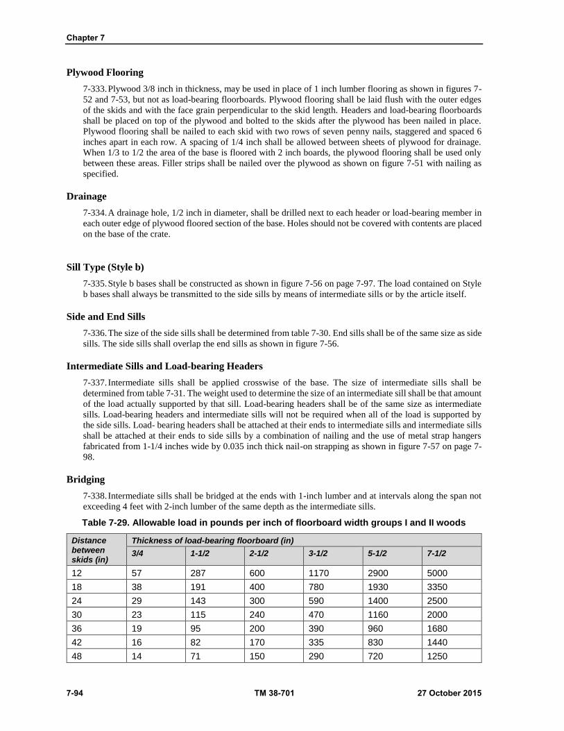
Chapter 7
7-94 TM 38-701 27 October 2015
Plywood Flooring
7-333. Plywood 3/8 inch in thickness, may be used in place of 1 inch lumber flooring as shown in figures 7-
52 and 7-53, but not as load-bearing floorboards. Plywood flooring shall be laid flush with the outer edges
of the skids and with the face grain perpendicular to the skid length. Headers and load-bearing floorboards
shall be placed on top of the plywood and bolted to the skids after the plywood has been nailed in place.
Plywood flooring shall be nailed to each skid with two rows of seven penny nails, staggered and spaced 6
inches apart in each row. A spacing of 1/4 inch shall be allowed between sheets of plywood for drainage.
When 1/3 to 1/2 the area of the base is floored with 2 inch boards, the plywood flooring shall be used only
between these areas. Filler strips shall be nailed over the plywood as shown on figure 7-51 with nailing as
specified.
Drainage
7-334. A drainage hole, 1/2 inch in diameter, shall be drilled next to each header or load-bearing member in
each outer edge of plywood floored section of the base. Holes should not be covered with contents are placed
on the base of the crate.
Sill Type (Style b)
7-335. Style b bases shall be constructed as shown in figure 7-56 on page 7-97. The load contained on Style
b bases shall always be transmitted to the side sills by means of intermediate sills or by the article itself.
Side and End Sills
7-336. The size of the side sills shall be determined from table 7-30. End sills shall be of the same size as side
sills. The side sills shall overlap the end sills as shown in figure 7-56.
Intermediate Sills and Load-bearing Headers
7-337. Intermediate sills shall be applied crosswise of the base. The size of intermediate sills shall be
determined from table 7-31. The weight used to determine the size of an intermediate sill shall be that amount
of the load actually supported by that sill. Load-bearing headers shall be of the same size as intermediate
sills. Load-bearing headers and intermediate sills will not be required when all of the load is supported by
the side sills. Load- bearing headers shall be attached at their ends to intermediate sills and intermediate sills
shall be attached at their ends to side sills by a combination of nailing and the use of metal strap hangers
fabricated from 1-1/4 inches wide by 0.035 inch thick nail-on strapping as shown in figure 7-57 on page 7-
98.
Bridging
7-338. Intermediate sills shall be bridged at the ends with 1-inch lumber and at intervals along the span not
exceeding 4 feet with 2-inch lumber of the same depth as the intermediate sills.
Table 7-29. Allowable load in pounds per inch of floorboard width groups I and II woods
Distance between skids (in)
Thickness of load-bearing floorboard (in)
3/4 1-1/2 2-1/2 3-1/2 5-1/2 7-1/2
12 57 287 600 1170 2900 5000
18 38 191 400 780 1930 3350
24 29 143 300 590 1400 2500
30 23 115 240 470 1160 2000
36 19 95 200 390 960 1680
42 16 82 170 335 830 1440
48 14 71 150 290 720 1250

Crates
27 October 2015 TM 38-701 7-95
Table 7-29. Allowable load lbs. per inch of floorboard width groups I and II woods (continued)
Distance between skids (inch)
Thickness of load-bearing floorboard (in)
3/4 1-1/2 2-1/2 3-1/2 5-1/2 7-1/2
54 12 63 130 260 645 1120
60 11 57 120 234 580 1000
66 10 52 110 212 525 910
72 9 48 100 195 480 840
84 8 41 85 140 360 710
96 8 35 75 167 300 630
108 7 34 66 130 233 560
120 7 30 60 117 210 500
Table 7-30. Nominal size of side sills (in.)
Gross weight of crate
Length of crate (feet)
(pounds) 4 8 12 16 20 24 28 32
To 2,000 2x4 2x4 2x4 2x4 2x4 2x6 2x6 2x6
2,001 - 4,000
2x4 2x4 2x4 2x4 2x6 2x6 2x6 2x8
4,001 - 6,000
2x4 2x4 2x4 2x6 2x6 2x6 2x8 2x8
6,001 - 8,000
2x4 2x6 2x6 2x6 2x8 2x8 2x8
8,001 - 10,000
2x6 2x6 2x6 2x6 2x8 2x8 2x10
10,001 - 12,000
2x6 2x6 2x8 2x8 2x8 2x10 2x10
12,001 - 14,000
2x6 2x8 2x8 2x8 2x10 2x10 2x10
14,001 - 16,000
2x8 2x8 2x8 2x10 2x10 2x10 2x8
16,001 - 18,000
2x8 2x8 2x10 2x10 2x10 2-2x8 2-2x8
18,001 - 20,000
2x8 2x10 2x10 2x10 2-2x8 2-2x8 2-2x8
* The above sizes are for crates with a height of 3 feet or less. For heights of over 3 feet, increase 2X4 sizesto 2X6; increase 2X6 to 2X8; increase 2X8 to 2X10; and increase 2- 2X8 to 2- 2X10.
Table 7-31 Allowable load for intermediate sills (in lb per inch of sill width)
Length if sill
Sill depth (inch)
Groups I and II woods
(feet) 1-1/2 2-1/2 3-1/2 5-1/2 7-1/2 9-1/2 11-1/2
4 71 150 290 720 1,250 2,000 3,000
5 57 120 234 580 1,000 1,640 2,400
6 48 100 195 480 840 1,320 2,020
7 41 85 167 399 710 1,170 1,730

Chapter 7
7-96 TM 38-701 27 October 2015
Table 7-31 Allowable load for intermediate sills (in lb per inch of sill width)( continued)
Length if sill (feet)
Sill depth (inch)
Groups I and II woods
8 35 75 140 350 630 1,020 1,500
9 34 66 130 300 560 910 1,350
10 30 60 117 270 500 820 1,200
Bottom Sheathing
7-339. Style b bases shall be sheathed on the bottom with lumber securely nailed to the bottom surface of the
sills at right angles to the direction of the side sills. Boards shall be 4 to 10 inches wide and of not less than
1 inch material for spans of less than 30 inches between longitudinal members and of not less than 2-inch
material for spans of 30 inches or more. Bottom sheathing shall be flush with the outside face of all side and
end sills and be spaced 1/4 inch apart for drainage. One-inch boards shall be nailed with eight penny nails, 2
inch boards with twelve penny nails, and nailing shall be as shown in figure
Rubbing strips
7-340. Style b bases shall have rubbing strips 3 inch thick material, the width of which shall not be less than
4 inches. The rubbing strips shall always be applied lengthwise of the base and positioned under each
longitudinal member. When require, intermediate rubbing strips of the same size are located so that the clear
distance between rubbing strips does not exceed 36 inches.

Crates
27 October 2015 TM 38-701 7-97
Figure 7-56. Sill bases (ASTM-D-7478M).

Chapter 7
7-98 TM 38-701 27 October 2015
Figure 7-57. Attaching intermediate sills to side sills (ASTM-D-7478M).
Tops
7-341. Tops shall be double sheathed and shall be:
narrow, widths through 54 inches;
intermediate, widths over 54 inches through 60 inches;
wide, over 60 through 120 inches in width.
7-342. Plywood sheathing 1/4 inch thick, shall be attached to the lumber framing with its face grain parallel
with the width of the top and its edges flush with the outside edges of the framing. All joints of the plywood
sheathing shall be made over joists or other frame members. Roofing felt, or polyethylene film not less than
4 mils thick, shall be applied over the plywood with a minimum4-inch overlap at joints. A non-hardening
caulk or mastic shall be applied in the overlap area. Top sheathing boards not less than 4 inches wide shall

Crates
27 October 2015 TM 38-701 7-99
be placed over the plywood sheathing and waterproof barrier and shall extend beyond the outer edges of the
top framing by an amount equal to the thickness of side and end panel sheathing less 1/8 inch. Headers joining
the joists together shall be 1 inch thick by the depth of the joists for intermediate and wide tops.
Narrow Tops
7-343. Narrow tops shall be framed on 2 X 4 inch members as shown in figure 7-58. Top sheathing board
shall be applied parallel to the width of the top and shall be of single pieces. At plywood joints on the inside
of the top, 2 X 3 inch pieces shall be used as shown in figure 7-58 on page 7-101.
Intermediate Tops
7-344. Intermediate tops shall be framed on 2-inch joists placed flat and headers 1 inch by the thickness of
the joists. The top sheathing boards shall be placed parallel to the length of the top (see figure 7-59 on page
7-102). When the crate length is over 10 feet, end joints will be permitted in top sheathing board. All joints
shall be made over joists, two joints shall be adjacent to each other, and not more than one-third of the joints
shall be made over any one joist.
Wide Tops
7-345. Wide tops shall be constructed similar to intermediate tops except that the wide tops shall be framed
in joists and headers placed on edge as shown in figure 7-60 on page 7-103.
Fabrication Nailing
7-346. Fabrication nailing of tops shall be as shown in figures 7-61 and 7-62 on pages 7-104/105. All plywood
members shall be nailed on at least three edges.
Alternate Plywood Sheathed Top
7-347. For tops not exceeding 96 inches wide, single sheathing of 1/2-inch thick plywood may be used in lieu
of the double sheathed top. Face grain of the plywood shall be parallel with the width of the top. When joists
do not coincide with plywood joints, a joint cover of 1 X 4 inch lumber shall be used on the inside of the top.
Prior to securing the plywood to the joists or joint covers, caulking of a non- hardening type shall be applied
at three places at each joint - between the plywood panels at their butt joint, and between the plywood and
joint cover or joist on either side of the butt joint. The caulk shall be applied as a continuous bead and may
be either performed or applied with a gun.
Number and Type of Panels
7-348. Sides shall be constructed as shown in figures 7-63, 7-64, and 7-65 on pages7-106 thru 7-109. In crates
with style b bases, the sheathing of sides and ends shall reach below the lower horizontal frame member a
distance equal to the depth of the sills plus floor thickness, less 1/8 inch. The type of side panels shall vary
with the inside crate height as specified in table 7-32 on page 7-100. The number of panels for each full
length side shall be computed by dividing the inside crate length by the inside height, and using the nearest
whole number.
Member Selection
7-349. The sizes of the upper and lower frame members, struts, and diagonals shall be determined from tables
7-34 to 7-43 on page 7-111 thru 7-120, except as otherwise specified. Loads referred to in the tables are the
net loads and the dimensions are the inside measurements of the crate. The member sizes shall be based on
Group II woods. If the exact size of the crate is not given in the tables, member sizes for the crate of the next
greater length and width, and the next smaller height shall be used.
Upper and Lower Frame Members
7-350. Except where vertical joist supports are required, upper frame members for crates over 54 inches wide
shall always be 2 inches thick and a minimum of 2

Chapter 7
7-100 TM 38-701 27 October 2015
7-351. X 4 inches in size. Splicing of upper or lower frame members shall be done over or under a strut and
shall be as shown in figure 7-64.
Vertical Struts
7-352. Vertical struts shall be continuous from the lower frame member to the upper frame member and the
diagonal and horizontal braces shall be cut in between. The end struts shall be as shown in table 7-33.
Horizontal braces
7-353. Horizontal braces for Types B and C panels (figures 7-64 and 7-65) shall be the same thickness as the
struts and 4 inches wide.
Diagonals
7-354. Size of diagonals shall be as specified in the member selection tables 7-34 to
7-355. 7-43 and shall be located as shown in figures 7-63, 7-64 and 7-65. When frame members are 1 inch
thick, gusset plates shall be cut from 1/4-inch plywood and shall be 12 inches minimum, in the shortest
dimension. The corners shall coincide with the center line of the diagonals as shown in figure
Joist Supports
7-356. The upper frame members shall serve as supports for tops. When crates are 6 feet wide and 12 feet
high or 8 feet wide and 10 feet high (tables 7-34 to 7-43) and when the struts are 1 inch thick, vertical joist
supports shall be provided as shown in figure 7-66 on page 7-121. These shall consist of 2 by 4 inch members
placed on and nailed to the frame members of the side and extending under each interior joist to the floor.
Table 7-32. Side panel types - class 1 crates
Inside Height of crate (inches) Type of Panel Reference Figure No.
Over 24 to 60 A 13
Over 60 to 108 B 14
Over 108 to 144 C 15
Table 7-33. End strut requirements
Net load (pounds) Nominal size of end struts
Bolted Crate (inches) Nailed Crate (inches)
1,000 or under 2x4 2x4
Over 1,000 but under 5,000 3x3 2x4
5,000 and over 4x4 2x4

Crates
27 October 2015 TM 38-701 7-101
Figure 7-58. Narrow tops (widths up to 54 inches) (ASTM-D-7478M).
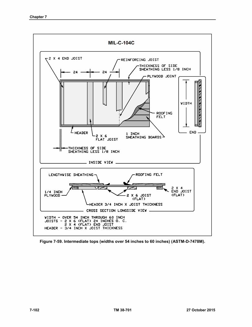
Chapter 7
7-102 TM 38-701 27 October 2015
Figure 7-59. Intermediate tops (widths over 54 inches to 60 inches) (ASTM-D-7478M).
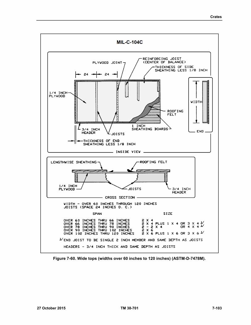
Crates
27 October 2015 TM 38-701 7-103
Figure 7-60. Wide tops (widths over 60 inches to 120 inches) (ASTM-D-7478M).
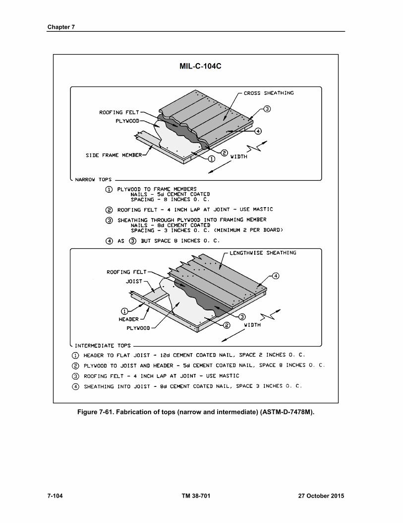
Chapter 7
7-104 TM 38-701 27 October 2015
Figure 7-61. Fabrication of tops (narrow and intermediate) (ASTM-D-7478M).
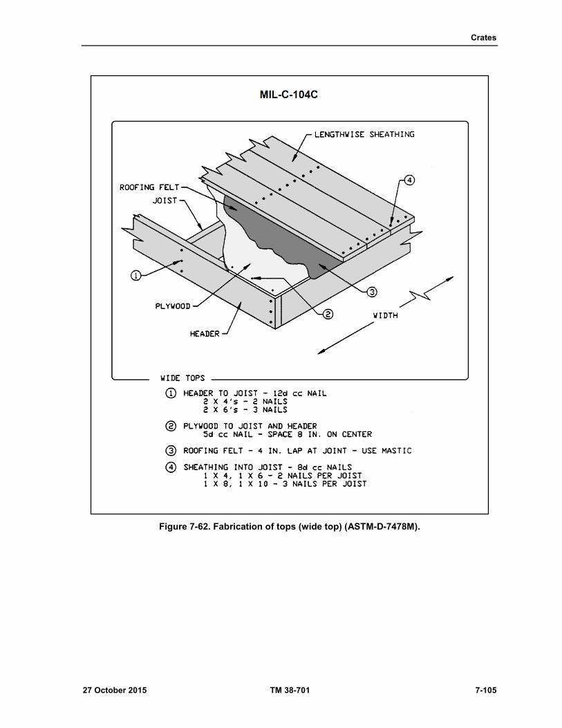
Crates
27 October 2015 TM 38-701 7-105
Figure 7-62. Fabrication of tops (wide top) (ASTM-D-7478M).
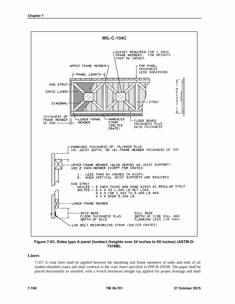
Chapter 7
7-106 TM 38-701 27 October 2015
Figure 7-63. Sides type A panel (lumber) (heights over 24 inches to 60 inches) (ASTM-D-7478M).
Liners
7-357. A crate liner shall be applied between the sheathing and frame members of sides and ends of all
lumber-sheathed crates and shall conform to the crate liners specified in PPP-B-1055B. The paper shall be
placed horizontally as unrolled, with a 4-inch minimum shingle lap applied for proper drainage and shall
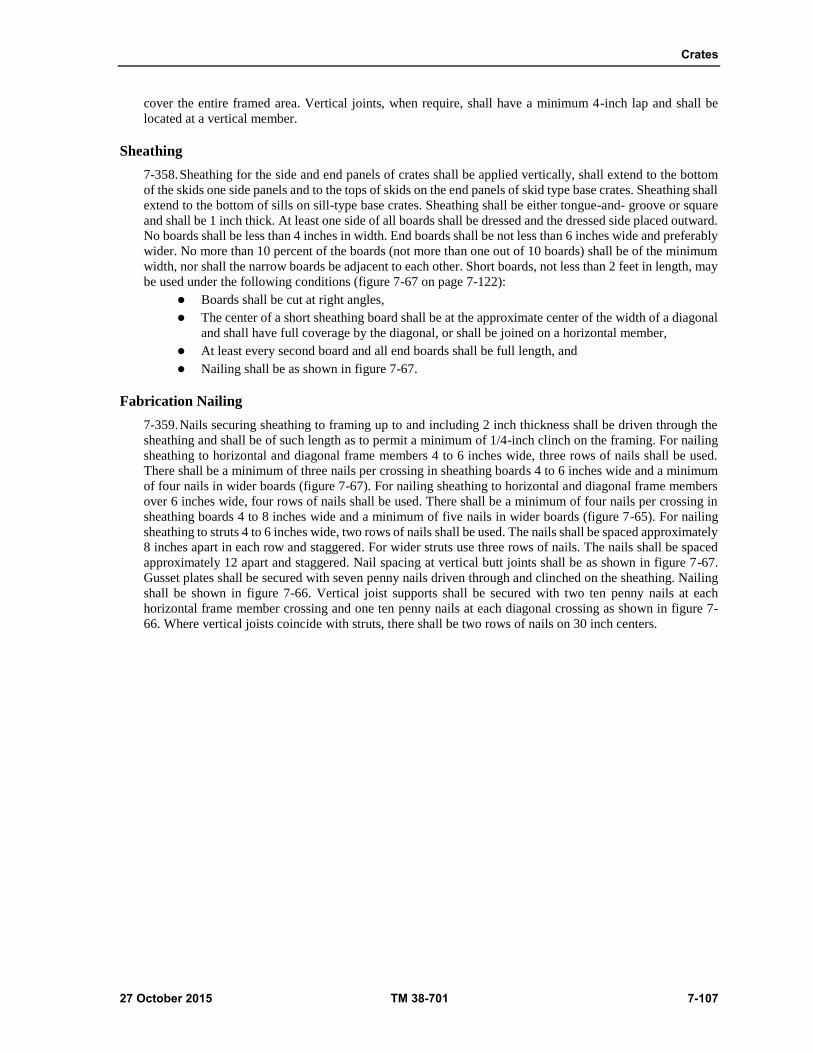
Crates
27 October 2015 TM 38-701 7-107
cover the entire framed area. Vertical joints, when require, shall have a minimum 4-inch lap and shall be
located at a vertical member.
Sheathing
7-358. Sheathing for the side and end panels of crates shall be applied vertically, shall extend to the bottom
of the skids one side panels and to the tops of skids on the end panels of skid type base crates. Sheathing shall
extend to the bottom of sills on sill-type base crates. Sheathing shall be either tongue-and- groove or square
and shall be 1 inch thick. At least one side of all boards shall be dressed and the dressed side placed outward.
No boards shall be less than 4 inches in width. End boards shall be not less than 6 inches wide and preferably
wider. No more than 10 percent of the boards (not more than one out of 10 boards) shall be of the minimum
width, nor shall the narrow boards be adjacent to each other. Short boards, not less than 2 feet in length, may
be used under the following conditions (figure 7-67 on page 7-122):
Boards shall be cut at right angles,
The center of a short sheathing board shall be at the approximate center of the width of a diagonal
and shall have full coverage by the diagonal, or shall be joined on a horizontal member,
At least every second board and all end boards shall be full length, and
Nailing shall be as shown in figure 7-67.
Fabrication Nailing
7-359. Nails securing sheathing to framing up to and including 2 inch thickness shall be driven through the
sheathing and shall be of such length as to permit a minimum of 1/4-inch clinch on the framing. For nailing
sheathing to horizontal and diagonal frame members 4 to 6 inches wide, three rows of nails shall be used.
There shall be a minimum of three nails per crossing in sheathing boards 4 to 6 inches wide and a minimum
of four nails in wider boards (figure 7-67). For nailing sheathing to horizontal and diagonal frame members
over 6 inches wide, four rows of nails shall be used. There shall be a minimum of four nails per crossing in
sheathing boards 4 to 8 inches wide and a minimum of five nails in wider boards (figure 7-65). For nailing
sheathing to struts 4 to 6 inches wide, two rows of nails shall be used. The nails shall be spaced approximately
8 inches apart in each row and staggered. For wider struts use three rows of nails. The nails shall be spaced
approximately 12 apart and staggered. Nail spacing at vertical butt joints shall be as shown in figure 7-67.
Gusset plates shall be secured with seven penny nails driven through and clinched on the sheathing. Nailing
shall be shown in figure 7-66. Vertical joist supports shall be secured with two ten penny nails at each
horizontal frame member crossing and one ten penny nails at each diagonal crossing as shown in figure 7-
66. Where vertical joists coincide with struts, there shall be two rows of nails on 30 inch centers.

Chapter 7
7-108 TM 38-701 27 October 2015
Figure 7-64. Sides type B panel (lumber) (heights over 60 inches to 108 inches) (ASTM-D-7478M).
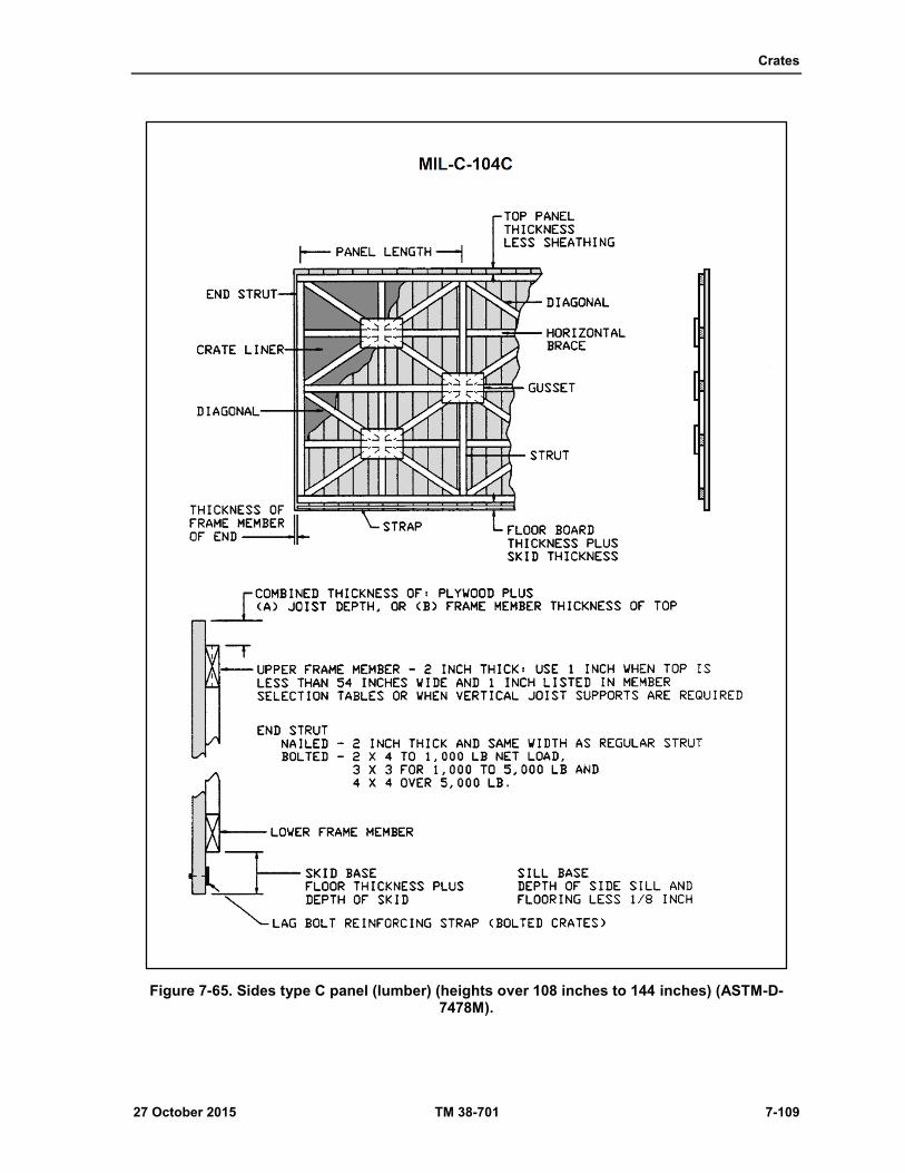
Crates
27 October 2015 TM 38-701 7-109
Figure 7-65. Sides type C panel (lumber) (heights over 108 inches to 144 inches) (ASTM-D-7478M).
Chapter 7
7-110 TM 38-701 27 October 2015
Lag Screw Reinforcing Strap for Bolted Crates
7-360. Reinforcing strap shall be used on side and end panels of all demountable crates as shown in figures
7-68, 7-69 and 7-70 on pages 7-123,7-125 and 7-126. Galvanized steel strap, punched or drilled, 1-1/4 inches
by 0.035 inch of 3/4 inch lag screws, and 2 inches by 0.050 inch for 1/2 and 5/8 inch lag screws, shall be
nailed to the inner face of the sheathing between the lower edge of the bottom frame member and the bottom
of the sheathing as shown in figure 7-68. The strap shall be located to coincide with the center of the skid or
header and shall be nailed on maximum 2 inch centers to the sheathing with clout or similar nails. Nails shall
be clinched at least 3/8 inch.
Ends
7-361. End types and size of members for ends in crates over 30 inches wide shall be determined in a manner
similar to the sides, except that in all cases the thickness of the upper and lower frame members shall be the
same as the struts specified in tables 7-34 thru 7-43 on pages7-11 thru 7-120 . The member arrangement shall
conform, to the details shown in figure 7-81. For crates less than 30 inches wide, single diagonals only are
required and all frame members shall be 1 by4 inches in size as shown in figure 7-81.
ASSEMBLY (CLASS 1 CRATES)
7-362. Type II (bolted) crates shall be assembled with lag bolts. Lead holes shall be used for lag bolts.
Fastening Sides to Base
7-363. The sides shall be secured to the skids with lag bolts. For 3 X 4 inch skids, 3/8 inch diameter by 3-
inch long lag bolts shall be used; for 4 X 4 inch skids, 1/2 inch diameter by 4 inch long lag bolts shall be
used. The number of lag bolts shall be as specified in table 7-44 on page 7-124. One-half the number shall
be used on each side and the spacing shall be uniform along the skid. Maximum spacing shall be 16 inches
for 3/8-inch lag bolts and 20 inches for 1/2 inch lag bolts. Lead holes shall be drilled in line with and through
the center of the metal reinforcing strap, as well as through the sheathing and into the skid. Assembly and
placement details shall be as shown on figures 7-71 and 7-72 on pages 7-127 and 7-128.
Fastening Sides to Top
7-364. Lag bolts, 3/8 inch diameter by 3-1/2 inches long, shall be used to fasten the sides to the top. These
lag bolts shall be placed so that there is one in the end of each joist at the approximate center (figure 7-73 on
page 7-129). For tops without joists, lag bolts shall be placed at the approximate center of the side frame
member of the top and spaced no greater than 24 inches apart.
Fastening Ends to Top, Sides, and Base
7-365. Lag bolts for fastening ends to tops shall be 3/8 inch in diameter by 2-1/2 inches long. Lag bolts for
fastening ends to sides shall be 3/8 inch diameter by 3-1/2 inches long. Placement and other assembly details
shall be as shown in figure 7-71 and 7-73. Lag bolts for fastening ends to base shall be the same size. Location
and spacing shall be as shown in figures 7-71 and 7-72. Lead holes shall be centered on the reinforcing strap.

Crates
27 October 2015 TM 38-701 7-111
Table 7-34. Panel member selection table for 1,000 lb. net load
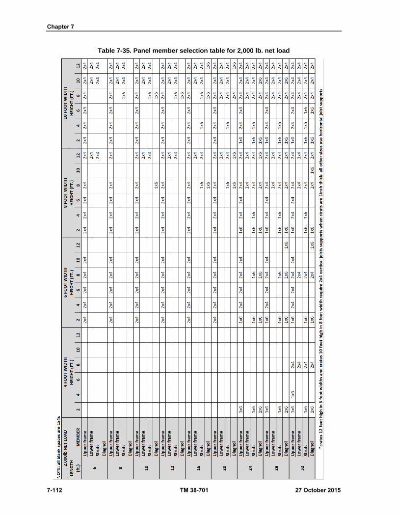
Chapter 7
7-112 TM 38-701 27 October 2015
Table 7-35. Panel member selection table for 2,000 lb. net load
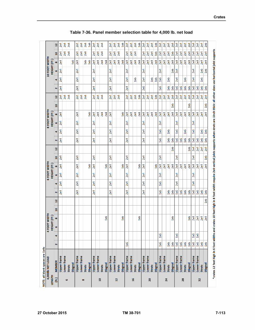
Crates
27 October 2015 TM 38-701 7-113
Table 7-36. Panel member selection table for 4,000 lb. net load
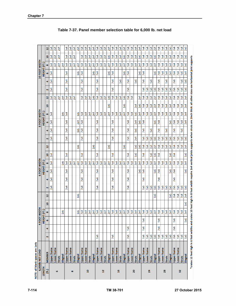
Chapter 7
7-114 TM 38-701 27 October 2015
Table 7-37. Panel member selection table for 6,000 lb. net load
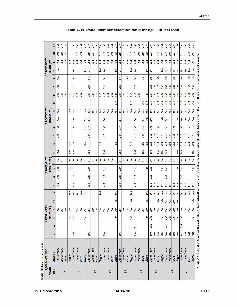
Crates
27 October 2015 TM 38-701 7-115
Table 7-38. Panel member selection table for 8,000 lb. net load
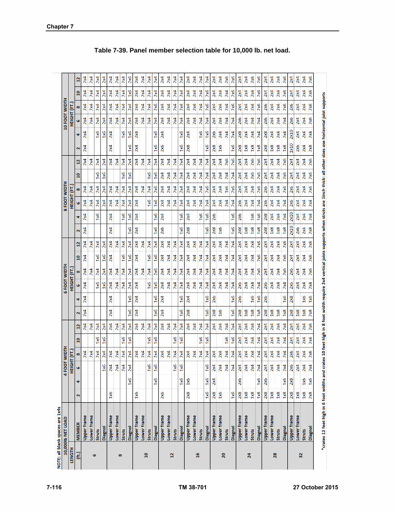
Chapter 7
7-116 TM 38-701 27 October 2015
Table 7-39. Panel member selection table for 10,000 lb. net load.

Crates
27 October 2015 TM 38-701 7-117
Table 7-40. Panel member selection table for 15,000lb. net load

Chapter 7
7-118 TM 38-701 27 October 2015
Table 7-41. Panel member selection table for 20,000lb. net load

Crates
27 October 2015 TM 38-701 7-119
Table 7-42. Panel member selection table for 25,000lb. net load

Chapter 7
7-120 TM 38-701 27 October 2015
Table 7-43. Panel member selection table for 30,000 lb. net load.
Crates
27 October 2015 TM 38-701 7-121
Figure 7-66. Joist supports and gussets (ASTM-D-7478M).

Chapter 7
7-122 TM 38-701 27 October 2015
Figure 7-67. Fabrication nailing of lumber sheathing (ASTM-D-7478M).

Crates
27 October 2015 TM 38-701 7-123
Figure 7-68. Lag screw reinforcing strap for bolted crates (ASTM-D-7478M).

Chapter 7
7-124 TM 38-701 27 October 2015
Table 7-44. Lag bolts required to assemble sides to base of bolted crates using lag bolt reinforcing strap (skids to be Group II, III, or IV woods).
Weight of crate and contents (pounds)
Size of Lag Bolts
3/8 x 3-inch
(3x3 or 3x4 skids)
1/2 x 4-inch
(4x4 inch skids)
5/8 x 4-inch
(4x6 inch skids)
2,000 6 6 6
3,000 10 6 6
4,000 14 8 6
6,000 20 12 8
8,000 16 10
10,000 18 12
12,000 22 14
14,000 26 16
16,000 30 18
18,000 32 22
20,000 36 24
24,000 28
28,000 32
32,000 36
36,000 42
40,000 46 * Use one-half the number on each side:Maximum spacing - 3/8 x 3 - 16 inches on center 1/2 x 4 - 20 inches on center 5/8 x 4 - 20 inches on center Minimum number - 3 per side, 2 per end

Crates
27 October 2015 TM 38-701 7-125
Figure 7-69. End panels over 30 inches wide lumber sheathed crates (ASTM-D-7478M).
Chapter 7
7-126 TM 38-701 27 October 2015
Figure 7-70. Narrow end panels (lumber sheathed crates) (ASTM-D-7478M).

Crates
27 October 2015 TM 38-701 7-127
Figure 7-71. Assembly of bolted crate (lumber or plywood sheathed) (ASTM-D-7478M).
Chapter 7
7-128 TM 38-701 27 October 2015
Figure 7-72. Assembly of bolted crate (ASTM-D-7478M).

Crates
27 October 2015 TM 38-701 7-129
Figure 7-73. Assembly of bolted crate (ASTM-D-7478M).
NAILED CRATE
General
7-366. Type I crates shall be assembled with nails and metal straps. General rules for crate assembly shall be
as shown in table 7-45 on page 7-131 and figures 7-74 and 7-75 on page 7-133.
Fastening Sides and Ends to Base
7-367. Sides and ends shall be nailed to the skids and headers with cement-coated nails (figure 7-74). Two
rows of nails shall be used for 2 by 4 inch, 3 by 3 inch, 3 by 4 inch and 4 by 4 inch skids or headers and for
Chapter 7
7-130 TM 38-701 27 October 2015
style b bases. The number of nails required for the perimeter of the crate shall be as shown in table 7-46, and
based on the gross load. Nail spacing shall be no greater than 6 inches in each row, and not less than two
nails shall be used in each sheathing board.
Fastening Ends to Sides and Sides to Ends
7-368. The end panels shall be nailed to the side panels with twentypenny cement- coated nails spaced 12
inches apart as shown in table 7-45 and figure 7-74. The nails shall pass through the sheathing and the edge
struts of the ends into the edge of the corner struts of the sides. Predrilling shall be used for these nails to
prevent splitting and the bit for drilling shall be approximately 75 percent of the diameter of the nail shank.
The edge sheathing boards of the side panels shall be nailed to the edge struts of the ends with eightpenny
cement-coated nails spaced 6 to 8 inches apart (figure 7-74).
Fastening Top to Sides and Ends
7-369. Tops shall be fastened to sides and ends with corner reinforcing straps and tensioned straps with anchor
plates as shown in figure 7-75. Corner straps shall be of such length as to allow nailing into framing of sides
and ends.
Strapping
7-370. Strapping shall be used as shown in figure 7-75 on page 7-133 on all bolted crates with net loads over
3,000 lb and for all nailed crates. Tensioned metal strapping and corner straps shall conform to ASTM D
3953, Type 1 or 3, Zinc-Coated finish, Grade 2, not less than 3/4 inch wide by 0.028 inch thick. Corner
strapping shall be pre-punched or drilled. In addition, on crates with style b bases, corner reinforcing straps
shall be applied at the bottom corners as shown in figure 7-76 on page 7-134. Nails shall be 1-1/4 to 1-1/2
inch galvanized roofing nails. A minimum of three nails shall be used for each strap leg and strapping shall
be located so that nailing is in a frame member.
CLASS 2 CRATES
7-371. Class 2 crates shall be Type I or II as specified and shall have the same use limitations as described
for lumber-sheathed.
Bases
7-372. The construction of bases shall conform to bases of Class 1 crates.
Tops
7-373. The construction of tops for Class 2 crates is identical to that described for Class 1 tops.
Sides (see figures 7-77 thru 7-79 on pages 7-134 thru 7-137)
Number and Type of Panels
7-374. Type B panels include a horizontal brace and Type C panels have two horizontal braces. These shall
be located so as to equally divide the space between upper and lower frame members. For all types of side
panels, struts shall be spaced 24 inches on centers except at one or both ends so that 48 inch-wide plywood
can be utilized with a minimum of waste. Sides shall be constructed as shown in figures7-80 to 7-81 on pages
7-138 and 7-139. In crates with Style b bases, the sheathing of sides and ends shall reach below the horizontal
frame member a distance equal to the depths of the sills.

Crates
27 October 2015 TM 38-701 7-131
Table 7-45. Assembly Nailing of Nailed Crate (ASTM-D-7478M)1
Fasten Nail size and spacing Notes
Part To part Lumber sheathing Plywood sheathing
Sheathing of side and end
Skid and end header(skid base)
Eight penny minimumsize3-inch maximum spacing
Seven penny minimum size 3-inch maximum spacing.
See table 6-40 for number of nails required
End and side sills
(sill base)
Two rows up to
4 x 4 skids
Two rows up to 4 x 4 skids
Three rows for 4 x 6 skid
(on edge)
Three rows for 4 x 6 skid
(on edge)
Predrill holes for twenty
penny nails, 75 percent of
shank diameter
Corner strut
of end
Corner strut of side Twenty penny-predrill 12-
inch spacing
Twelve penny 12 inch
spacing
Sheathing of
side
Corner strut of end Eight penny minimum
size 6- to 8-inch spacing
Seven penny minimum
size 6- to 8-inch spacing
1For fastening top to sides and ends use strapping.
Table 7-46. Number of nails per each 1,000 pound gross load (nailing sheathing to base around perimeter of nailed crate).
Type of nail Size of nail
(penny)
Wood Group of skid
II III IV
Sinker or
Cooler
7 23 26 19
8 or 9 19 21 16
10 18 19 14
12 15 16 12
Corker 7 24 26 19
8 or 9 17 19 14
10 15 16 12
12 15 16 12 *Nails shall not be less than 2 per board (lumber sheathing) and shall neither be more than 3 inches apart not less than 1-1/2inches apart.
Member Selection
7-375. The sizes of the upper and lower frame members and struts shall be determined from tables 7-34 to 7-
43, except as otherwise specified. Loads referred to in the tables shall be the inside measurements of the
Chapter 7
7-132 TM 38-701 27 October 2015
crate. The member sizes shall be based on Groups II woods. If the exact size of the crate is not given in the
tables, member sizes for the crate of the nest greater length and width, and smaller height, shall be used.
Upper and Lower Frame Members
7-376. The requirements for upper and lower frame members shall comply with those described for lumber-
sheathed side panels in and listed by size in tables 7-34 to 7-43.
Vertical Struts
7-377. The requirements for struts shall comply with those described for lumber- sheather side panels and
listed by sizes in table 7-34 to 7-43.
Diagonals
7-378. No diagonals are required for Class 2 crates.
Joist Supports
7-379. The joist supports shall comply with those described for class 1 side panels.
Liners
7-380. No liners are required for Class 2 crates.
Sheathing
7-381. Plywood sheathing shall be 3/8 inch thick for net loads up to 10,000 lb, and 1/2 inch of net loads over
10,000 lb, and shall be applied so that the face grain is vertical. Face grain may be horizontal for crates 4 feet
or less in height. Vertical joints in plywood sheathing shall be made over the center of a strut. Horizontal
joints in plywood sheathing shall not be permitted in Type C panels. All horizontal joints shall be made over
the center of a horizontal brace.
Fabrication Nailing
7-382. Nailing plywood sheathing to frame members of various widths shall be as shown in figure 7-80. For
all fabrication, nails shall be driven through the plywood and clinched a minimum of 1/4 inch. Staples may
be used to fasten plywood sheathing to framing members.
Lag-screw Reinforcing Strap for Bolted Crates
7-383. Reinforcing straps shall be used on side and end panels of all bolted crates as shown in figures 7-77 to
7-79.
Ends
7-384. Panel types and sizes of members for ends shall be determined in a manner similar to the sides, except
that in all cases, the thickness of the upper and lower frame members shall be the same as the struts specified
in table 7-34 to 7-43. The member arrangement shall be as shown in figure 7-81. Fabrication shall be as
shown on figure 7-80.

Crates
27 October 2015 TM 38-701 7-133
Figure 7-74. Assembly of nailed crate, lumber or plywood sheathing (ASTM-D-7478M).
Figure 7-75. Corner and top strapping, (lumber or plywood sheathing (ASTM-D-7478M).

Chapter 7
7-134 TM 38-701 27 October 2015
Figure 7-76. Sill base strapping (ASTM-D-7478M).
ASSEMBLY (CLASS 2 CRATES)
Bolted-crate Assembly
7-385. The assembly of plywood-sheathed nailed crates shall comply with the details specified for Class 1
crates except for size of nails which shall be as specified in table 7-45.
Reinforcing Straps
7-386. The reinforcing straps shall be as specified for Class 1 crates.
Tolerances
7-387. A tolerance of plus or minus 1/8 inch is allowable on the overall length and width of individual
completed crate panels. Out-of-square deviation of individual panels shall be not more than 3/16 inch (3/8
inch difference in diagonals).

Crates
27 October 2015 TM 38-701 7-135
Workmanship
7-388. Crate panels shall be clean and free of slivers and protruding fastener points. Crate panels shall be
square and free of cracks, splits, or other damage which would prevent easy and correct assembly and
adversely affect the performance of assembled crates.
Fire Retardant
7-389. When specified, all lumber and plywood shall be treated in accordance with MIL- L-19140. Special
markings shall be used to indicate the lumber and plywood have been treated with non-leachable fire retardant
materials.
CRATE, SLOTTED ANGLE, STEEL OR ALUMINUM (ASTM D6255)
7-390. The slotted angle crate is designed to permit rapid fabrication of a crate through assembly of slotted
angle steel or aluminum with nuts, bolts, and lock washers and disassembly and reuse of component material.
CLASSIFICATION
7-391. The following classifications have been established for this crate. Types and Styles
Type I - crate, slotted angle, steel or aluminum, open.
Type II - crate, slotted angle, steel or aluminum, full enclosed or sheathed with solid material.
Style A - crate, slotted, angle, steel, or aluminum, without skids or rubbing strips.
Style B - crate, slotted angle, steel, with skid blocks or skids with rubbing strips and provisions
for forklift truck handling.
Figure 7-77. Sides- type A panel (plywood) (heights over 24 inches to 60 inches) (ASTM-D-7478M).
Chapter 7
7-136 TM 38-701 27 October 2015
Figure 7-78. Sides- type B panel (plywood) (heights over 60 inches to 96 inches) (ASTM-D-7478M).

Crates
27 October 2015 TM 38-701 7-137
Figure 7-79. Sides- type C panel (plywood) (heights over 96 inches to 144 inches) (ASTM-D-7478M).
Chapter 7
7-138 TM 38-701 27 October 2015
Figure 7-80. Fabrication nailing plywood sheathing (ASTM-D-7478M).

Crates
27 October 2015 TM 38-701 7-139
Figure 7-81. End panel’s plywood sheathing crates (ASTM-D-7478M).
Grades
7-392. Grade 1 - Crate for domestic and oversea shipments intended for outside or indeterminate storage.
7-393. Grade 2 - Crate for domestic and oversea shipments intended for inside or protected storage.
Chapter 7
7-140 TM 38-701 27 October 2015
Use
7-394. These crates are suitable for:
Packing lightweight, bulky items, including airframe components.
Oversea and domestic air and surface shipments.
Packing items requiring rigid blocking and bracing assemblies, such as support panels, cushioned
saddles, solid and slat cradles, specially designed brackets, yoke panel assemblies, etc.
Adaptation of suspension systems or shock mounts for shock absorption.
Packing repairable, returnable items where a desirable light-weight, reusable container is
specified.
Materials
Slotted Metal Angles
7-395. This material comes in either steel or aluminum. There are three different sizes of slotted metal angles,
variations being based on the size of the flanges and the thickness of the metal used in fabricating the angles.
The slotted angle material shall conform to Specification MIL-S-21041C, as a guide for the selection of
slotted angle based on size of crate and weight of load.
7-396. Steel slotted angle material for Grade 1 crates shall have a zinc protective coating. Steel slotted angle
material for Grade 2 crates shall be treated with a primer or a phosphatized base and a baked-on synthetic
enamel of high grade commercial quality. The color shall be DOD Gray, unless otherwise specified, in
accordance with Federal Standard (FED-STD-595C).
7-397. The hole pattern for the 1-1/2-inch by 1-1/2-inch angle shall be of such a design as to provide one line
of holes or slots in each flange. The 1-1/2-inch by 2-1/4-inch angle shall have one line of holes or slots in the
narrow flange and two lines of holes or slots in the wide flange. The 1-1/2-inch by 3-inch angle shall have
one line of holes or slots in the narrow flange and three lines of holes or slots in the wide flange. The hole
pattern shall be of continual repetition and shall be visually indexed at 3-inch intervals.
7-398. Occasionally, it may be necessary to splice pieces. When this occurs, either the lap or butt splice may
be made.
Bolts and Nuts
7-399. Bolts and nuts used in joining slotted angle frame members of the crate shall conform to Specification
MIL-S-21041C, except that nuts shall conform to MS51922 with the exception that 5/16 nuts shall be .551
to .564 inches across the flats.
7-400. Bolts and nuts used in attaching sheathing and wood members of the crate (and any wood blocking
and bracing therein) shall be fastened to a slotted angle material with not less than two bolts on each panel
edge, with additional bolts being employed, if necessary, to maintain the interval between bolts at not more
than 12 inches. When sheathing is attached to the top by nailing to a wooden strip which is secured to the
slotted angle portion of the crate by bolts spaced not less than 24 inches apart, the nailing strip will be at least
1 by 2 inches and the nails will be at least sixpenny in size, spaced not more than 5 inches apart.
Ventilation
7-401. Crates completely enclosed or sheathed with plywood or paper-overlaid veneer will be ventilated.
Ventilation will be accomplished by means of holes or slots in the ends or ends and sides around the perimeter
of the crate. They shall be place immediately below the tip frame members of the ends and sides. When crates
are over 10 feet in length, the ventilation holes or slots will be divided equally between both ends and both
sides and located as near the midpoint of the sides and ends as practicable. Place baffles or shields inside the
crate to deflect the water blowing into the crate, thus preventing the water from coming in contact with the
contents. The following table establishes the area of the holes or slots required to provide ventilation for
graduated range of volume for a crate (table 7-47 on page 7-143).
Crates
27 October 2015 TM 38-701 7-141
Panels for Marking Open Crates
7-402. To provide sufficient area for placing required markings on open crates, a panel of 1/4-inch plywood
will be bolted to the crate.
SPECIFIC CRATES
7-403. Specific crates are categorized by Type and Style.
Type 1, Style A
7-404. This crate is of simple construction, usually consisting of one panel in each section, requiring
minimum bracing and used for light, bulky, and small items not exceeding 200 pounds. Either the slotted
angle aluminum or the smaller slotted angle steel is usually strong enough of this crate. Unless specifically
accepted, it is limited to maximum dimensions of 80 inches in width.
Table 7-47. Ventilation requirements
Area of holes or slots for ventilation
Volume of crate in Cubic Feet Cumulative are in Square Inches of ventilation holes or slots
0-106 7
106-141 10
141-176 13
176-388 27
388-600 33
600-777 54
777-989 66
989-1236 81
1236 and Over 101
Sides
7-405. The metal angle used for the side rails (horizontal members) should be positioned with the wider flange
parallel to the plane or surface of the side. The bottom rail should be positioned so that the wide flange points
up, while the top rail should have the wide flange pointing down. Vertical members (struts) should be equal
in length and be positioned so that they are within horizontal rails when the crate is assembled. Vertical
members should not exceed 48 inches in length and distance between vertical members (struts and
intermediate struts) shall not exceed 1-1/3 the height of the crate. Where greater side strength or special
mounting provisions are required along the side of the crate, extra vertical members may be added with the
wide flange against the wide flange of the horizontal members (side rails) of the crate. Additional or
intermediate vertical members should be added where the length-to-height ratio dictates.
Ends
7-406. The crate ends shall consist of slotted angle cross members joining the two crate sides. Additional
cross members joining the two crate sides. Additional cross members or intermediate struts to provide
mounting or attaching points within the crate for specific items may be added to crate end as required. The
distance between the lateral members (cross members and intermediate struts) shall not exceed 1/1/3 the
width of the crate.
Base
7-407. The base is not a separate panel which is bolted to the sides and ends, but is formed by the addition,
as necessary, of cross members, (loadbearing members, flooring, and braces).
Chapter 7
7-142 TM 38-701 27 October 2015
Flooring
7-408. The crate will be sufficiently floored to protect the contained item. The flooring need not be continuous
throughout the base; however, it will be placed in such locations that will provide protection to the areas of
the contained item that are subject to damage by forklift trucks or other material handling equipment.
Plywood flooring (except loadbearing floorboards) will be a minimum of 1/4 inch thick for crates through
12 inches wide 3/8, inch for crates over 12 inches wide and through 24 inches wide, and 3/4 inch thick for
crates over 24 inches wide. Flooring will be cut to fit snugly in place and securely bolted to the lower side
rails of the crate. Each piece of flooring shall be bolted in place with a minimum of two bolts in each lower
side rail. The distance between bolts used to secure the flooring shall not exceed 12 inches. When the flooring
is 3/8 inch or less in thickness it is reinforced on top by an additional strip of wood 1 X 2, through which the
holddown bolt will pass. Bolts used of securing floorboards shall not be less than 5/16 inch in diameter.
Loadbearing Members
7-409. Loadbearing members shall be located within the crate base to carry the load of the contained item,
except when suspensions systems are used or when the item is attached to the side structure. The size of wood
members shall be determined from table 7-48 on page 7-145. The size of steel members shall be determined
from table 7-49 thru 7-49d on page 7-145 thru 7-147.
Crossmembers
7-410. Cross members will be of the same strength and quality as the slotted angle used of the side rails and
struts. Cross members in the base will be spaced not more than 24 inches apart. If loadbearing members are
employed, they should be included in the considerations for base cross members.
Braces
7-411. The base should be reinforced with braces of the same slotted angle as the cross members. These
braces should be used in un-floored areas of the crate. When one-third of the base is floored with 12-inch or
wider floor panels, braces are not required.
Crate Top
7-412. The top, like the base, is not a separate panel which is attached to the sides and ends. It is formed by
cross members, crossties members, and braces installed between the two crate sides. The cross members are
placed perpendicular to the sides and are placed at each point where a vertical strut is bolted to the side rail,
being bolted as shown in figure 7-82 on page 7 143. Alternate methods of attaching members are shown in
figure 7-83 on page 7-146. The crosstie members are slotted angle members placed at intermediate points
between, and parallel to, cross members with the distance between the cross members and crossties not
exceeding 1-1/3 the width of the crate. Braces of the same type slotted angle material as that used for cross
members are placed diagonally in the rectangle formed by the side rails and the cross members and crossties.
The ends will be cut at an angle to give maximum contact of the flanges being bolted together.
Crates
27 October 2015 TM 38-701 7-143
Figure 7-82. Joining of Intermediate members (ASTM D6255).
Table 7-48. Allowable Load per inch of floorboard width for Groups II, III and IV woods
Distance between outside skids
Actual thickness of floorboards (inches)
3/4 1-1/2 2-1/2 3-1/2
(inches) (pounds) (pounds) (pounds) (pounds)
12 48 220 574 1,095
18 32 147 382 731
24 24 110 287 548
30 19 88 229 438
36 16 73 192 365
42 14 63 164 313
46 12 55 144 274
59 9 44 115 219
72 8 37 96 182 If groups III or IV woods are used, the above allowable loads may be increases 20 percent.
Table 7-49. Load capacity of slotted angle steel beams. 1/ SLOTTED ANGLE STEEL - 2.6mm - 38mm X 76mm (12 GUAGE (0.014") - 1-1/2" x 3")
Length of beam in cubic meter (feet) - load in kilograms (pounds))
60 (2) 90 (3) 120 (4) 150 (5) 180 (6)
Recommended Load
659(1450) 445(980) 336(740) 227(500) 150(350)
Recommended Load
2045(4500) 1409(3100) 954(2100) 545(1200) 454(1000)

Chapter 7
7-144 TM 38-701 27 October 2015
Table 7-49. Load capacity of slotted angle steel beams. 1/ SLOTTED ANGLE STEEL - 2.6mm - 38mm X 76mm (12 GUAGE (0.014") - 1-1/2" x 3") (continued)
Length of beam in cubic meter (feet) - load in kilogram (pounds))
60(2) 90 (3) 120 (4) 150 (5) 180 (6)
Recommended Load
4727(10400) 3409(7500) 2409(5300) 1977(4350) 1590(3500)
Recommended Load
704(1550) 454(1000) 345(760) 263(580) 222(490)
SLOTTED ANGLE STEEL - 1.9mm - 38mm X 57mm(14 GUAGE (0.074") - 2-1/2" x 2-1/4")
(Length of beam in cubic meter (feet) - load in kilogram (pounds))
60 (2) 90 (3) 120 (4) 150 (5) 180 (6)
Recommended Load
572(1260) 386(850) 277(610) 181(400) 90(200)
Recommended Load
1090(2400) 772(1700) 522(1150) 372(820) 284(625)
Recommended Load
2359(5190) 1522(3350) 1227(2700) 954(2100) 772(1700)
Recommended Load
363(800) 231(510) 177(390) 136(300) 113(250)
1/ Table 49 is usable for slotted angle steel with flange dimensions that are plus or minus 3mm (1/8 inch) the flange sizes stated
Table 7-49a. Load capacity of slotted angle steel beams. 1/ SLOTTED ANGLE STEEL - 1.9mm - 38mm X 38mm (14 GUAGE (0.074") - 1-1/2" x 1-1/2")
Length of beam in cubic meter (feet) - load in kilogram (pounds))
90 (3) 120 (4) 150 (5) 180 (6)
Recommended Load
225(495) 122(270) 86(190) 65(145)
Recommended Load
268(590) 179(395) 134(295) 86(190)
Recommended Load
606(1335) 470(1035) 313(690) 245(540)
1/ Table 49a is usable for slotted angle steel with flange dimensions that are plus or minus 3mm (1/8 inch) the flange sizes stated.
Table 7-49b. Load capacity of slotted angle steel beams. 1/ SLOTTED ANGLE STEEL - 1.9mm - 38mm X 38mm (14 GUAGE (0.074") - 1-1/2" x 1-1/2")
Length of beam in cubic meter (feet) - load in kilogram (pounds))
90 (3) 120 (4) 150 (5) 180 (6)
Recommended Load
672(1480) 536(1180) 427(940) 336(740)
Recommended Load
1740(3830) 1579(3475) 1350(2970) 1125(2475)
Recommended Load
1772(3900) 1620(3565) 1440(3170) 1190(2620)
1/ Table 49b is usable for slotted angle steel with flange dimensions that are plus or minus 3mm (1/8 inch) the flange sizes stated.

Crates
27 October 2015 TM 38-701 7-145
Table 7-49c. Load capacity of slotted angle steel columns. 1/(Continued) SLOTTED ANGLE STEEL - 1.9mm - 38mm X 57mm (14 GUAGE (0.074") - 1-1/2" x 2-1/4")
Length of beam in cubic meter (feet) - load in kilogram (pounds))
90 (3) 120 (4) 150 (5) 180 (6) 210 (7)
Recommended Load
1131(2490) 840(1850) 695(1530) 581(1280) 427(940)
Recommended Load
2500(5500) 2272(5000) 1977(4350) 1727(3800) 1522(3350)
Recommended Load
2545(5600) 2450(5390) 2272(5000) 2036(4480) 1186(4150)
SLOTTED ANGLE STEEL - 2.6mm - 38mm X 76mm(12 GUAGE (0.104") - 1-1/2" x 3")
(Length of beam in cubic meter (feet) - load in kilogram (pounds))
90 (3) 120 (4) 150 (5) 180 (6) 210 (7)
Recommended Load
1568(3450) 1304(2870) 1072(2360) 759(1670) 522(1150)
Recommended Load
3618(7960) 3200(7040) 2836(6240) 2454(5400) 2045(4500)
Recommended Load
4045(8900) 3609(7940) 3045 (6700) 2636(5800) 2113(4650)
1/ Table 6-49c is usable for slotted angle steel with flange dimensions that are plus or minus 3mm (1/8 inch) the flange sizes stated.
Table 7-49d. Load capacity of slotted angle aluminum configurations. 1/ slotted angle steel - 2.6mm - 38mm x 57mm (13 gauge (0.089") - 1-1/2" x 2-1/4")
(Length of beam in cubic meter (feet) - load in kilogram (pounds))
90 (3) 120 (4) 150 (5) 180 (6)
Recommended Load
204(450) 159(350) 118(260) 81(180)
Recommended Load
431(950) 272(600) 181(400)2 159(350)2
Recommended Load
100(2200) 727(1600) 563(1240) 427(940)
SLOTTED ANGLE STEEL - 1.9mm - 38mm X 57mm (13 GUAGE (0.089") - 1-1/2" x 2-1/4")
(Length of beam in cubic meter (feet) - load in kilogram (pounds))
90 (3) 120 (4) 150 (5) 180 (6) 210 (7)
Recommended Load
454(1000) 409(900) 318(700) 272(600)
Recommended Load
1409(3100) 1240(2730) 1104(2430) 986(2170) 795(1750)
Recommended Load
1590(3500) 1409(3100) 1227(2700) 1090(2400) 954(2100)
1/ Table 6-49d is usable for slotted angle aluminum with flange dimensions that are plus or minus 3mm (1/8inch) the flange sizes stated. 2/ On spans of this length, cross bracing gives a better structure, higher recommended load.

Chapter 7
7-146 TM 38-701 27 October 2015
Use of Corner Braces For Light Crates
7-413. Where crates are intended for net loads not in excess of 200 pounds and limited to the maximum
dimensions of 60 inches in length, 30 inches in width, and 48 inches in height, corner bracing may be utilized
in lieu of full diagonal bracing.
Type II, Style A Crate
7-414. This crate is identical to the Type I, Style A crate, except that it is fully closed or sheathed using
plywood, paper-overlaid veneer, or fiberboard, as specified above. Sheathing should be added.
Type I, Style B Crate
7-415. The Style B (skidded) crate is intended for use in crating larger and/or heavier items, employing a
skidded base; braced sides, ends and top; loadbearing and attaching members; and provisions for truck and
cargo sling handling. Only slotted angle steel (not aluminum) will be used in fabricating this style crate.
7-416. Unless specific approval is given for a larger size crate, the maximum dimensions are 360 inches in
height (see figure 7-86 on page 7-150 for a typical crate).
Sides
7-417. Crate sides consist of horizontal members (side rails), vertical members (struts), and full diagonal
braces.
Figure 7-83. Alternate methods of attaching members (ASTM D6255).
Crates
27 October 2015 TM 38-701 7-147
Intermediate Horizontal Members
7-418. When a crate exceeds 48 inches in height, and intermediate horizontal member should be placed
between the top and bottom side rails and should run the full length of the crate. In addition to the requirement
for additional intermediate horizontal members because of the height, extra strength requirements may
demand additional horizontal members.
Intermediate Vertical Struts
7-419. Intermediate struts shall be evenly and systematically spaced throughout the length of the crate side
between the end or corner vertical struts. The spacing of intermediate struts for crates with sides not provided
with an intermediate horizontal member shall be determined by the height and length. The distance between
the vertical struts shall not exceed 1-1/4 the height of the crate. The spacing of intermediate struts for crates
with sides provided with intermediate horizontal member shall be determined by the same method as above,
except that the height shall be considered as the distance between the two adjacent horizontal members.
Ends
7-420. The ends are not assembled panels which are bolted to the sides but are formed by the upper and lower
cross members, intermediate cross members, and braces which join the sides. In addition to the upper and
lower cross members, intermediate cross members are required when the height of the crate exceeds 48 inches
or when the height of the crate exceeds 1-1/4 width of the crate. The maximum interval between any two
adjacent cross members is 48 inches. Intermediate cross members shall be installed with the wider flange of
the angle in a vertical position. Intermediate vertical members may be added to the ends for special mountings
and special blocking and bracing. Bracing of the ends may be done either with slotted angle materials equal
to that used for side bracing or with flat steel strapping (as above). When a crate is in excess of 60 inches
long, 18 inches wide, or subject to being pushed by forklifts or other equipment, it should be equipped with
push plates to protect the crate and contents (figure 7-87 on page 7-150). The push plates are positioned
across the lower part of the end panel with the lower part of plate flush with top of the skids and shall be
bolted to the corner struts with a minimum of two bolts in each end of the plate. Group II, III, or IV wood or
plywood may be used for crates having a gross weight up to 500 pounds. They shall be Group III or IV wood
when the gross weight exceeds 500 pounds. When push plates are made from wood they shall be a minimum
1-5/8 inches thick and 7-1/2 inches wide. Plywood push plates shall be a minimum 3/4 inch thick and 12
inches wide.
Top
7-421. The top, like the ends, if formed by joining the two sides together, through the use of cross members,
crossties, and braces of slotted angle material. The end cross members serve also as the top cross members
of the ends. Additional cross members are bolted as shown in figure 7-84 on page 7-149, the wider flange
being vertical and the narrow flange at the top. Figure 7-84 and 7-85 on page 7-149 show methods which
may be used in sheathing or covering crates. When the distance between the cross members is greater than
1-1/4 times the width of the crate, intermediate cross members (crossties) should be used, pacing them
equidistant between the cross members. Sufficient crossties should be used to maintain an interval not in
excess of 1-1/4 times the width of the crate between any two adjacent cross members and/or crossties. Full
diagonal braces should be used in the interval between adjacent cross members and/or crossties. Tension
braces of steel strapping may be used in lieu of slotted angle material.
Base
7-422. Cross members and crossties tying the side panels together at the bottom of the crate plus required
loadbearing members, forklift handling members, skid blocks, full skids, headers, and flooring comprise the
base.
Skid Blocks and Full Skids
7-423. When the load contained by the crate exceeds 500 pounds, full skids running the length of the crate
shall be used. Full length skids may be used for lesser contained weights, but are not mandatory. Full length

Chapter 7
7-148 TM 38-701 27 October 2015
skids shall be fabricated from minimum nominal 2 X 4 inch lumber for net loads up to 1,000 pounds and 4X
4 inch lumber for net loads exceeding 1,000 pounds. They shall be provided with 2 X 4 inch rubbing strips.
When full length skids are not used, 2 X 4 inch skid blocks 16 inches long are used. Skids and skid blocks
shall be beveled 45 degrees on each end. Skid blocks located at the ends of the crate shall be set 2-1/2 to 4
inches from each crate end to permit the use of slings. Rubbing strips on full length skids shall be set back
an equal distance from each crate end. Intermediate skid blocks shall be placed in locations that will support
loads transferred to the lower side rails by loadbearing members and struts. The center of balance of the
loaded crate shall be the determining factor in locating intermediate skid blocks to provide the forklift entry.
The maximum distance between skid blocks shall not exceed 48 inches. Skid blocks, skids, and rubbing strips
shall be bolted to the lower side rails with minimum 5/16 inch diameter bolts.
Loadbearing Members
7-424. To provide direct support to loads resting on the base, loadbearing members are used. These members
may be either wood, plywood, metal, or a combination of wood and metal are placed at right angles to the
length of the crate, being bolted to both of the lower side members. See tables 7-47 and 7-48 for tabulated
data to be used in determining the size, etc., of material for loadbearing members.
Flooring
7-425. Flooring may be lumber or plywood and need not be continuous throughout the base; however, it shall
be placed in such locations as will provide protection to the areas of the contained item that is subject to
damage by forklift trucks or other material handling equipment. The flooring should be cut to fit snugly in
place and should be bolted to both of the lower side each end of each piece of flooring with a minimum of
two bolts to a rail. Plywood flooring shall have a minimum thickness of 3/8 inch for crates through 12 inches
wide, 1/2 inch for crates 12 to 24 inches wide, and 3/4 inch for crates over 24 inches wide. Lumber flooring
shall have a minimum thickness of 3/4 inch.
Forklift Handling Members
7-426. Forklift handling members of lumber of metal, the side of which is based on strength required as
applied to the data shown in tables 7-47 and 7-48, will be placed 24 inches from each end of the crate and at
right angles to the length, being bolted to both of the lower side rails. When the crate is in excess of 36 inches
in width, forklift handling members should be placed at the location provided for side entry of forklifts and,
if the crate is over 8 feet in length, they should be in addition to those placed 24 inches form the end.
Loadbearing members, if suitably located, may serve as forklift handling members.
Type II, Style B Crate
7-427. Except for the sheathing, this crate is fabricated in the same manner as the Type I, Style B crate. The
sheathing is accomplished in the manner described above.
Crossties and Headers
7-428. When the distance between loadbearing members exceeds the width of the crate and the flooring is
less than 3/4 inch thick, intermediate crossties should be installed, being bolted to both of the flanges of both
lower side rails (figure 7-82).
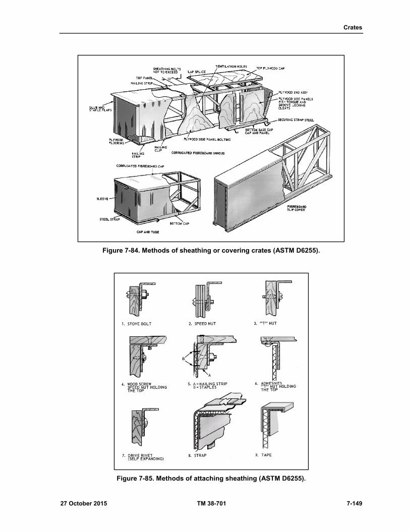
Crates
27 October 2015 TM 38-701 7-149
Figure 7-84. Methods of sheathing or covering crates (ASTM D6255).
Figure 7-85. Methods of attaching sheathing (ASTM D6255).

Chapter 7
7-150 TM 38-701 27 October 2015
Figure 7-86. Type I, style B crate (ASTM D6255).
Figure 7-87. Method of attaching push plates, skids, and headers (ASTM D6255).

27 October 2015 TM 38-701 8-1
Chapter 8
Consolidation and Unitization for Shipment and Use of Cargo Containers
CONSOLIDATION AND UNITIZATION FOR SHIPMENT
8-1. Consolidation is the bringing together of like or unlike items for shipment. Once the items are
assembled, they must be kept together as a single unit until they reach a break-bulk point or the ultimate
consignee. Unitization results in economy through reduction in handling and documentation, one unit taking
the place of several units.
ADVANTAGES
8-2. Figure 8-1 shown on page 8-2 gives advantages of unitizing loads which are as follows:
Eliminates laborious and expensive manual handling of individual items.
Reduces damage to items by eliminating manual handling.
Permits savings in handling costs.
Reduces personnel accidents by eliminating manual handling and lifting.
Simplifies inventorying and reduces inaccuracies.
Utilizes storage heights not possible by manual means.
Reduces pilferage because of unitization of items by steel straps and other bonding methods.
Permits faster movement of supplies and equipment. Reduces marking requirements on individual
containers.

Chapter 8
8-2 TM 38-701 27 October 2015
Figure 8-1. Advantages of cargo unitization.
METHODS OF UNITIZATION
8-3. The two basic forms of unitization are--
Palletization. Palletization is the placing of a number of packages on a low, portable platform
constructed of wood, metal, or fiberboard, or a combination of these materials.
Containerization. Containerization is the placement of a number of packages into an intermodal
container, which not only reduces the number of units and documentation, but provides additional
protection to the packages.
PALLETIZING UNIT LOADS (MIL STD-147E)
8-4. MIL-STD-147E gives the palletized unit load requirements for Department of Defense material using
the pallets discussed in chapter 3. The standard establishes loading patterns for various types of commodities,
listing the pattern for stacking containers and the methods of unitizing to be used.
TYPES OF PALLETS
8-5. NN-P-71. Types I (2-way entry), and III of NN-P-71 are intended for use in storage operations. Types
IV and V of NN-P-71 are for use in storage and shipment worldwide regardless of mode of transportation.
8-6. MIL-DTL-15011K. Type I (4-way entry) of MIL-DTL-15011K should be used for the palletization of
military supplies whenever 4-way entry is required in the storage and distribution system and in support of
NATO forces. Nonstandard 4-way entry 40- by 48-inch pallets should be reused for the storage and shipment
of materiel to continental United States consignees.as shown in (fig 8-2)
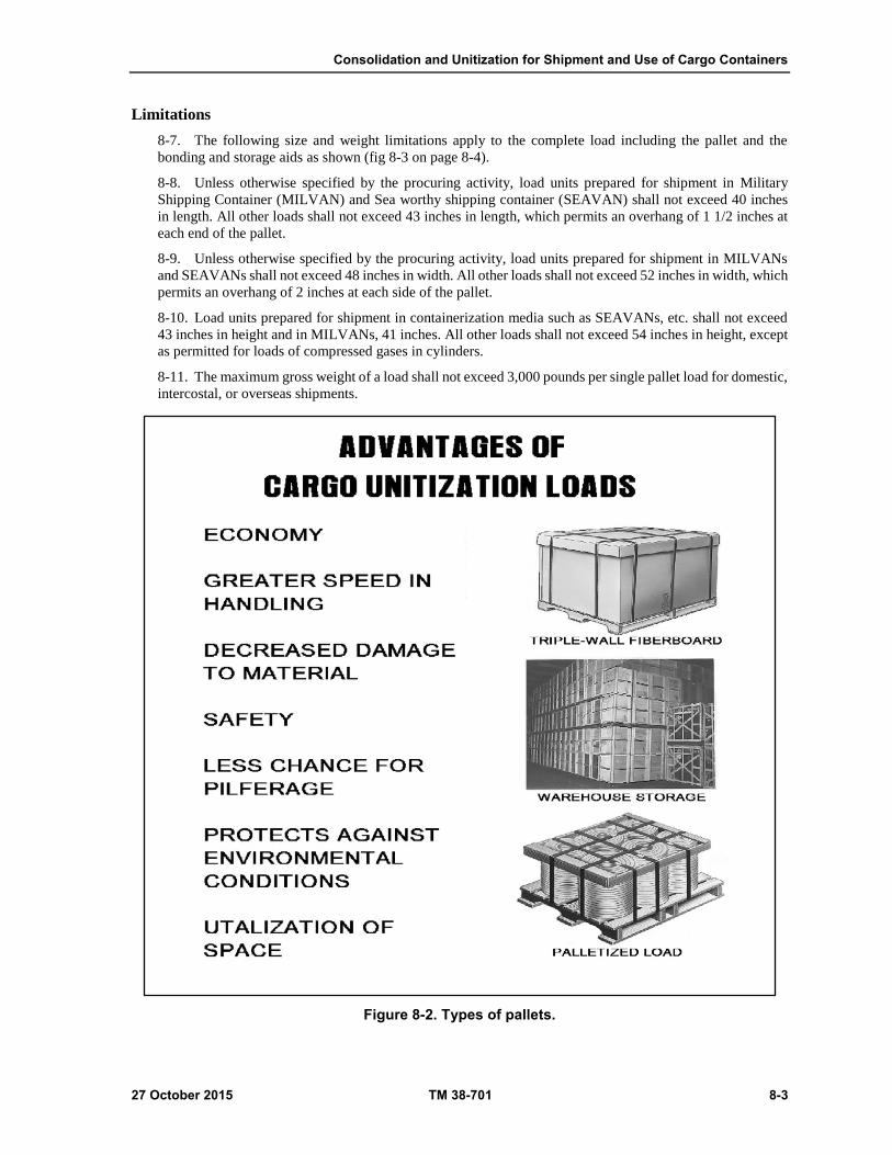
Consolidation and Unitization for Shipment and Use of Cargo Containers
27 October 2015 TM 38-701 8-3
Limitations
8-7. The following size and weight limitations apply to the complete load including the pallet and the
bonding and storage aids as shown (fig 8-3 on page 8-4).
8-8. Unless otherwise specified by the procuring activity, load units prepared for shipment in Military
Shipping Container (MILVAN) and Sea worthy shipping container (SEAVAN) shall not exceed 40 inches
in length. All other loads shall not exceed 43 inches in length, which permits an overhang of 1 1/2 inches at
each end of the pallet.
8-9. Unless otherwise specified by the procuring activity, load units prepared for shipment in MILVANs
and SEAVANs shall not exceed 48 inches in width. All other loads shall not exceed 52 inches in width, which
permits an overhang of 2 inches at each side of the pallet.
8-10. Load units prepared for shipment in containerization media such as SEAVANs, etc. shall not exceed
43 inches in height and in MILVANs, 41 inches. All other loads shall not exceed 54 inches in height, except
as permitted for loads of compressed gases in cylinders.
8-11. The maximum gross weight of a load shall not exceed 3,000 pounds per single pallet load for domestic,
intercostal, or overseas shipments.
Figure 8-2. Types of pallets.

Chapter 8
8-4 TM 38-701 27 October 2015
TYPES OF PALLETIZED LOADS
8-12. Types of supplies that can be palletized are--
Items which are identical and identified by the same stock number.
Items uneconomical or impractical to pack.
Rugged and durable items that require minimum physical protection.
Boxed items uniform in size requiring additional protection.
Items that are moved in large quantities.
Figure 8-3. Pallet size limitations.
LOAD ARRANGEMENT
8-13. The arrangement of items to the pallet must provide a rigid, compact, uniform size load, strongly
secured to prevent shifting, and capable of resisting impact, vibration, racking, and compression encountered
during handling, storage, and shipment. Basic principles for arranging and securing loads to pallets are--
Items should be interlocked, nested, or bundled whenever possible.
The load pattern should eliminate or reduce void space.
Wood separators or spacers are placed in voids between rows and layers of irregular-shaped items
to insure a firm and stable load.
8-14. The top surface of the loading pallet must be level, or made level for stacking purposes. This can be
accomplished by applying a wood top frame or leveling boards with a supporting framework.
8-15. Loads difficult to stabilize or which are compressible and not sufficiently firm to support superimposed
loads, will be reinforced with a supporting framework.
8-16. Boxed items are arranged on the pallet so that the markings on individual containers do not show on
two adjacent sides of the palletized load. This will provide clear areas for unit load marking.
8-17. The load is secured to the pallet, using ASTM D 3950 requirements for applying lengthwise and
crosswise strapping. Horizontal strapping is the width and thickness size as the tie-down strap size. The gross
weight of the load, divided by the total number of tie-down straps to be used, determines the weight which
must be borne by each strap. Non-metallic strapping is not authorized for the strapping of palletized loads of
wooden, plywood, or metal shipping containers.
8-18. Strapping is applied in a manner that will eliminate any possibility of slippage. Wood cleats, tie blocks,
or braces are used under straps when necessary to insure stability or to bridge unsupported spans.
Loading
8-19. To properly load a pallet, consideration must be given to the type of item, its weight, and destination.
It is recommended that MIL-STD-147E be followed when loading 40- by 48-inch pallets. Figure 8-4 shows
one type of palletized load illustrated in the standard.

Consolidation and Unitization for Shipment and Use of Cargo Containers
27 October 2015 TM 38-701 8-5
Figure 8-4. Examples of palletized load.
SHRINK FILM AND STRETCH FILM PALLETIZATION
8-20. Shrink Film and Stretch film are used to protect products and shipments from exterior elements. They
can help prevent scattered loads and reduce damaged shipments.
SHRINK FILM
8-21. Plastic films such as polyethylene are now being used in accordance with the requirements of MIL-
STD-147E as a means of bonding palletized loads. The plastic film is stretched in the manufacturing process;
this is called "orientation". The stretched film shrinks when subjected to a controlled flow of heat air. The
heated air is supplied by the use of a heat shrink cannon or a shrink film chamber shown in (fig 8-5 on page
8-7). The heat causes the film to shrink, conforming to the contour of the load. For this reason, it can be used
for pallet loads containing a variety of items which form irregular shaped configurations that could not be
palletized by conventional means. The tightly adhering film immobilizes the contents and provides
stability. It also provides some weather protection for exposed cargo. Shrink film palletization provides a
reduction of labor and material cost by the use of automatic equipment and eliminates the problem of damage
caused by strapping containers too tight.
Stretch Film
8-22. Stretch films can be used as a means of bonding palletized loads for many commodities shipped in the
Continental United States or when shipped containerized. The stretch films are polyethylene, polyvinyl
chloride or ethyl vinyl acetate. The film is wrapped around the load in multiple layers from the top of the
bottom deck board to not less than two inches above the height of the load. The required thickness of the
wrap is determined by the kind of film being used and the weight of the load. Additional bonding strength
can be provided by placing a sheet of weather-resistant fiberboard, the same size as the top dimensions of the
load, on top of the load prior to stretch wrapping.
Chapter 8
8-6 TM 38-701 27 October 2015
CONSOLIDATION CONTAINERS (GENERAL)
8-23. Consolidation containers may be constructed of fiberboard, paper-overlaid veneer, plywood, or
lumber. They may be demountable or non-demountable. They are usually secured to a pallet base or a skid
base for handling purposes. Some containers are intended to be expendable, while others are intended to be
reusable. Some consolidation containers are designed to be compatible with the requirements of the 463L
Materials Handling System of the Air Force. Others are designed to be used as inserts in transporters such as
MILVANs, or to be used as separate shipping containers.
BOXES, SHIPPING INSERT CONSOLIDATION, MIL-B-43666D
(GENERAL)
8-24. These boxes are constructed of wood cleated plywood, plywood wire bound, double-wall fiberboard,
or triple-wall fiberboard. They are mounted on pallet- type bases for ease of handling. Their construction
varies widely depending upon the materials used. The sizes are such that they are modular in concept.
General Use
8-25. These boxes are intended for use as inserts in cargo transporters such as MILVANs, or as separate
exterior containers. They are to be used for Level A or B shipments.
Classification
8-26. There are three types of consolidation insert containers. Type I is of wood cleated plywood construction
and has two styles depending upon the style of pallet base used. Type II is of plywood wire bound
construction of the pallet base. Type III is constructed of double-wall or triple-wall fiberboard. Type III has
four styles depending upon the construction features of the box.
Marking
8-27. The marking for shipment will be in accordance with MIL-STD-129.
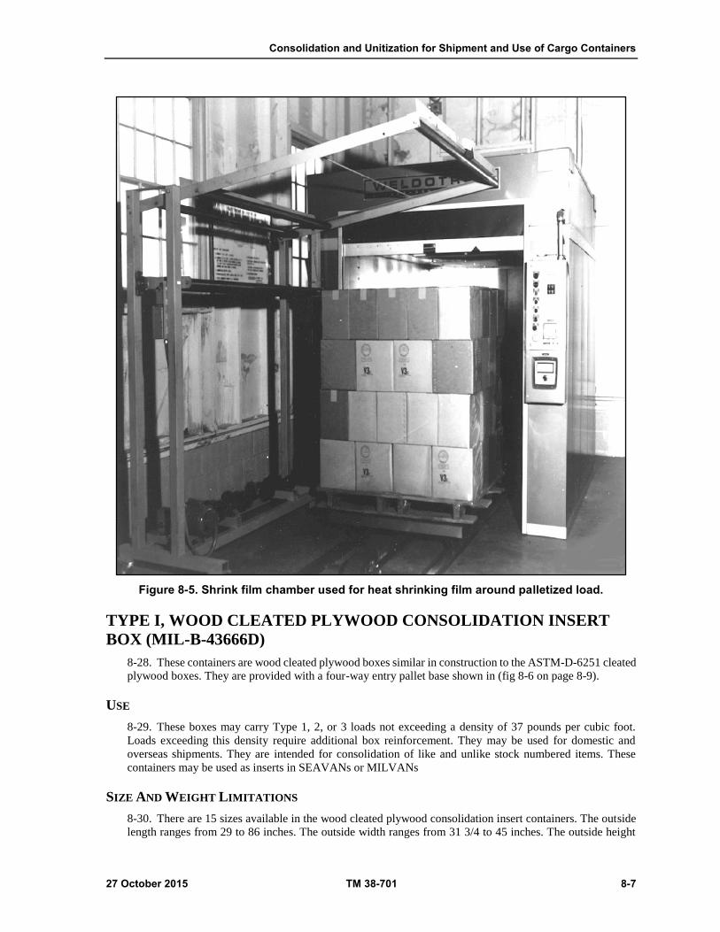
Consolidation and Unitization for Shipment and Use of Cargo Containers
27 October 2015 TM 38-701 8-7
Figure 8-5. Shrink film chamber used for heat shrinking film around palletized load.
TYPE I, WOOD CLEATED PLYWOOD CONSOLIDATION INSERT
BOX (MIL-B-43666D)
8-28. These containers are wood cleated plywood boxes similar in construction to the ASTM-D-6251 cleated
plywood boxes. They are provided with a four-way entry pallet base shown in (fig 8-6 on page 8-9).
USE
8-29. These boxes may carry Type 1, 2, or 3 loads not exceeding a density of 37 pounds per cubic foot.
Loads exceeding this density require additional box reinforcement. They may be used for domestic and
overseas shipments. They are intended for consolidation of like and unlike stock numbered items. These
containers may be used as inserts in SEAVANs or MILVANs
SIZE AND WEIGHT LIMITATIONS
8-30. There are 15 sizes available in the wood cleated plywood consolidation insert containers. The outside
length ranges from 29 to 86 inches. The outside width ranges from 31 3/4 to 45 inches. The outside height

Chapter 8
8-8 TM 38-701 27 October 2015
ranges from 20 to 52 1/2 inches. For MILVAN shipments, the overall height shall be not more than 41 inches.
The weight capacity for the various sizes ranges from 1,000 to 2,600 pounds. Table I and II of MIL-B-
43666D specifies the length, width, height, and weight combinations for each of the 15 sizes.
CLOSURE
8-31. Nail the top to the top cleats of the sides and ends using sixpenny cement-coated, chemically etched,
or mechanically deformed nails spaced three inches apart. Do not drive the nails into the end grain of the
vertical cleats.
STRAPPING REQUIREMENTS
8-32. Each vertical corner shall be reinforced with two 8-inch pieces of 3/4-inch flat steel strapping 0.023
inches thick. The strapping will be attached to the cleats with pneumatically driven galvanized staples 7/16
inches long or with 1-inch long nails pneumatically driven. As an alternate, 3/4-inch wide flat, nail-on
strapping, 0.025 or 0.028-inch in thickness, may be used. This strapping, which is perforated with holes
spaced 1/2 to 1 3/4 inches apart, may be secured with large headed galvanized roofing nails, zinc coated steel
roofing nails, or 1-inch mechanically driven nails. Each strap will be secured with four fasteners. Two will
be driven into the through cleat on the end of the box and two will be driven into the filler cleat on the side
of the box.
On boxes 41 inches high, strapping will be placed 13 to 26 inches from the top of the box.
One boxes 20 inches high, strapping will be placed 2 and 15 inches from the top of the box.
On box sizes 5 and 10, which are 43 inches wide, an additional strap shall be placed to the center
of each corner formed by the bottom and end panels.
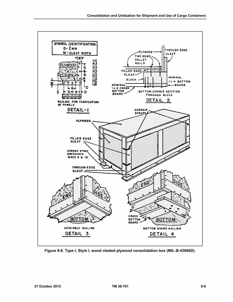
Consolidation and Unitization for Shipment and Use of Cargo Containers
27 October 2015 TM 38-701 8-9
Figure 8-6. Type I, Style I, wood cleated plywood consolidation box (MIL-B-43666D).

Chapter 8
8-10 TM 38-701 27 October 2015
TYPE II, PLYWOOD WIREBOUND CONSOLIDATION INSERT BOX
(MIL-B-43666D)
8-33. The body and top of these boxes are constructed of plywood panels bound together with binding wires.
The bottom panel is fabricated from 1/2-inch plywood which is secured to either a skid base or a pallet base
as seen in (fig 8-7).
Figure 8-7. Type II, plywood wire bound consolidation boxes (MIL-B-43666D).
USE
8-34. The use of Type II plywood wire bound boxes is the same as Type I wood cleated plywood boxes.
CLASSIFICATION
8-35. There are two styles of boxes available under the Type II classification:
Style 1 box utilizes a double-wing, block-type pallet base (fig 8-6).
Style 2 box utilizes a skid base having three lengthwise skids which are cut out to facilitate side
entry by forklift trucks.
SIZE AND WEIGHT LIMITATIONS
8-36. There are several sizes available in the plywood wire bound consolidation containers. The range of
outside dimensions and weight limitations are the same as those specified for the Type I, cleated plywood
boxes. Tables I, and II, of MIL- B-43666 specify the length, width, and height combinations for each of the
sizes.
CLOSURE
8-37. After the box body is assembled by securing the wire loops with a sallee closure hand tool, or similar
suitable alternate tool, and nailed to the base, make the closure by nailing the plywood top to the top cleats
with three penny nails. Space the nails 4 1/2 inches apart. Complete the closure by applying lengthwise and
girth wise straps.
STRAPPING REQUIREMENTS
8-38. Requirements for the size, number, and location of straps vary for each style and size of Type II
containers. Consult the Appendix of MIL-B-43666D for detailed requirements for reinforcing the particular
plywood wire bound container being used.
Consolidation and Unitization for Shipment and Use of Cargo Containers
27 October 2015 TM 38-701 8-11
TYPE III, FIBERBOARD CONSOLIDATION INSERT BOX (MIL-B-
43666D)
8-39. These boxes are made of double-wall or triple-wall fiberboard. The box design and construction differs
for each of the four designated styles. Unless otherwise specified, they are furnished with a pallet base.
USE
8-40. Type III fiberboard insert boxes should be restricted to MILVAN, or SEAVAN when used for level A
overseas shipments. They may be used as shipping containers for Level B overseas shipments and as domestic
consolidation containers. Style 3 should be used for items of assorted stock numbers to be loaded at origin as
inserts only for shipment in MILVAN, and SEAVAN to a single consignee address code. Style 5 should be
used for unit loads of nonperishable subsistence as required by DSCP 3507 and sized (in height) depending
on the anticipated height of the contents.
CLASSIFICATION
8-41. There are four styles of boxes available under Type III classification:
Style 3, regular slotted box (RSC), is the same as the alternate construction of the Style E ASTM
D5168 fiberboard box with a 1 1/2-inch overlap of the outer flaps (fig 8-8 on page 8-12). The box
may be furnished with or without a pallet base. When a pallet base is used, it may be either a
double-wing block-type or double-wing notched runner-type.
Style 4 half slotted container (HSC) with telescoping sleeve and cap, consists of a half slotted
container bottom section without top flaps, a sleeve (with stiffening flaps) which fits over the
bottom section, and a top cap which extends down six inches over the sleeve (fig 8-8). The
requirements for the pallet base are the same as for Style 1.
Style 5 flanged bottom tube with cap, pad, and pallet, consists of a fiberboard tube with 4-inch
bottom flanges, a bottom pad, and a top cap which fits down over the body tube (fig 8-8). This
type is furnished with a stringer type pallet base.
Style 6, half slotted container (HSC) with cap and pallet base, consists of a body having a regular
slotted bottom and a flanged top, and a top cap (fig 8-9 on page 8-14). Unless otherwise specified,
it is furnished with a pallet base.
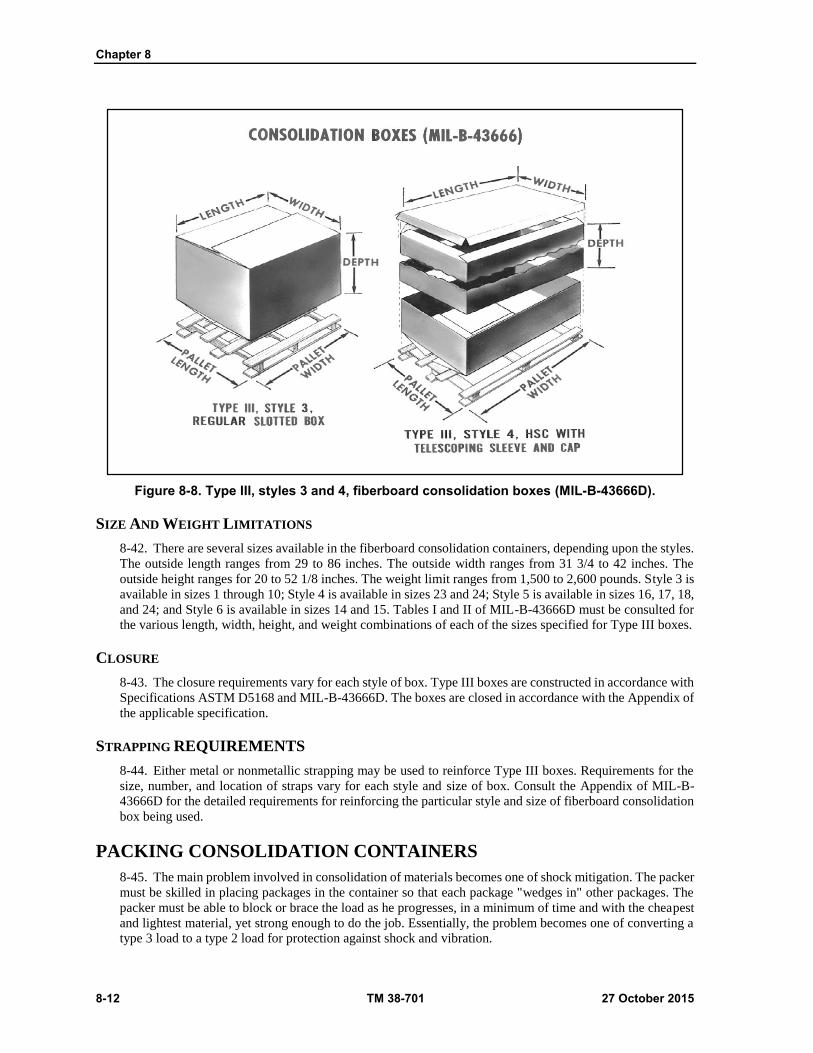
Chapter 8
8-12 TM 38-701 27 October 2015
Figure 8-8. Type III, styles 3 and 4, fiberboard consolidation boxes (MIL-B-43666D).
SIZE AND WEIGHT LIMITATIONS
8-42. There are several sizes available in the fiberboard consolidation containers, depending upon the styles.
The outside length ranges from 29 to 86 inches. The outside width ranges from 31 3/4 to 42 inches. The
outside height ranges for 20 to 52 1/8 inches. The weight limit ranges from 1,500 to 2,600 pounds. Style 3 is
available in sizes 1 through 10; Style 4 is available in sizes 23 and 24; Style 5 is available in sizes 16, 17, 18,
and 24; and Style 6 is available in sizes 14 and 15. Tables I and II of MIL-B-43666D must be consulted for
the various length, width, height, and weight combinations of each of the sizes specified for Type III boxes.
CLOSURE
8-43. The closure requirements vary for each style of box. Type III boxes are constructed in accordance with
Specifications ASTM D5168 and MIL-B-43666D. The boxes are closed in accordance with the Appendix of
the applicable specification.
STRAPPING REQUIREMENTS
8-44. Either metal or nonmetallic strapping may be used to reinforce Type III boxes. Requirements for the
size, number, and location of straps vary for each style and size of box. Consult the Appendix of MIL-B-
43666D for the detailed requirements for reinforcing the particular style and size of fiberboard consolidation
box being used.
PACKING CONSOLIDATION CONTAINERS
8-45. The main problem involved in consolidation of materials becomes one of shock mitigation. The packer
must be skilled in placing packages in the container so that each package "wedges in" other packages. The
packer must be able to block or brace the load as he progresses, in a minimum of time and with the cheapest
and lightest material, yet strong enough to do the job. Essentially, the problem becomes one of converting a
type 3 load to a type 2 load for protection against shock and vibration.
Consolidation and Unitization for Shipment and Use of Cargo Containers
27 October 2015 TM 38-701 8-13
SHOCK MITIGATION
8-46. In order to meet the problem of shock mitigation relative to consolidation containers, there are certain
basic procedures to follow:
Try to maintain level layers.
Fill all internal voids as the load progresses.
Keep the center of gravity low and centered by placing heavy items in the bottom portion of the
container and centering them in the container as much as possible.
Block and brace the interior load adequately to prevent movement caused by shock and vibration.
BLOCKING AND BRACING THE LOAD
8-47. The ideal conditions for full utilization of consolidation containers is to tailor a container to the size of
uniform interior packages. Of course, the required consolidation containers are generally of standard
dimension and are not related to product package sizes.
8-48. These ideal conditions are not always present at the depot or base level, but with a variety of package
sizes to place in consolidation containers most of the available space can be utilized in some instances.
8-49. Voids that occur at the top of the pack are probably the most usual (fig 8-10 on page 8-15). In order to
provide hold-down media for the load, first cover the packs with pad(s) and then place cells between the pads
and the container cover. The use of adhesives will hold the cells between the pads and the container cover.
Cells should be located where strapping will be placed. Where feasible, the corners of the container may be
split down to the top of the load and the excess portion of each side panel, above the top of the load, may be
folded in, thus eliminating the need for cells.
8-50. Voids that occur at the sides of the pack can be blocked with pads and cells, the same as top blocking
and bracing (fig 8-11 on page 8-16).
8-51. Interior voids (fig 8-12 on page 8-16) are the hardest to cope with and the most time- consuming. All
voids that would permit shifting of the packages should be filled with cells or foamed-in-place materials as
the layers progress. If the packages are uniform, one sleeve may fill the void for several layers or packages.
8-52. Compound voids (top and side, two sides, etc. may take a little more skill, but pads and cells can be
used to block and brace the same as previously discussed.
PACKING SEMI-PERISHABLE SUBSISTENCE ITEMS
8-53. Unit loads of semi-perishable items shall be prepared in conformance with DSCP 3507, Loads. Unit:
Preparation of Semi-perishable Subsistence Items: Clothing, Personal Equipment, Equipage; General
specification. This specification establishes patterns, methods, materials, and techniques applicable to the
preparation of unit loads of nonperishable subsistence items by loading the shipping containers onto a pallet
or within a consolidation container for shipment. The choice of unit load type and class based upon the level
of protection provided can be determined by DSCP 3507. The types and classes of unit loads are shown in
(table 8-1 on page 8-14).
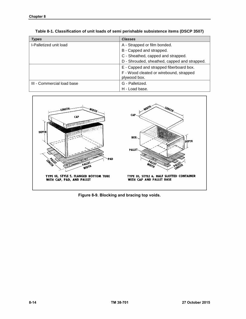
Chapter 8
8-14 TM 38-701 27 October 2015
Table 8-1. Classification of unit loads of semi perishable subsistence items (DSCP 3507)
Types Classes
I-Palletized unit load A - Strapped or film bonded.
B - Capped and strapped.
C - Sheathed, capped and strapped.
D - Shrouded, sheathed, capped and strapped.
E - Capped and strapped fiberboard box.
F - Wood cleated or wirebound, strapped plywood box.
III - Commercial load base G - Palletized.
H - Load base.
Figure 8-9. Blocking and bracing top voids.

Consolidation and Unitization for Shipment and Use of Cargo Containers
27 October 2015 TM 38-701 8-15
Figure 8-10. Sleeve and X bracing.
CARGO CONTAINERS (GENERAL)
8-54. The following definitions apply:
Transporter - A cargo container is a large shipping container in which packed or unpacked material is
placed for movement to a break-bulk point or to an ultimate consignee.
MILVAN -Government-owned or leased shipping container. The MILVAN is a noncollapsible,
reusable cargo container capable of being coupled to another container of like description. The
MILVAN can be lifted by top or bottom corner fittings; can be used either singly or coupled together;
and can be carried by highway, rail or water modes of transportation.
SEAVAN -Commercial/Government owned/leased shipping container the SEAVAN comes in various
sizes and configurations which may be leased to the Government for the consolidation movement of
material by highway, rail or water modes of transportation.
Note - Cargo that is hard to handle in closed vans, such a large, heavy or bulky items, or machinery,
may be shipped in flat racks.
AIR/LAND - The M2 AIR/LAND container is a lightweight intermodal container that permits land
and air freight transportation without rehandling of the contents. The container is 8 feet in height, 8
feet in width, and 20 feet in length. They have a gross weight capacity of approximately 45,000
pounds. The container and its contents must not exceed the structural limitations of the transporting
aircraft.

Chapter 8
8-16 TM 38-701 27 October 2015
Figure 8-11. Blocking and bracing side voids.
Figure 8-12. Blocking and bracing interior voids
Consolidation and Unitization for Shipment and Use of Cargo Containers
27 October 2015 TM 38-701 8-17
PURPOSE AND ADVANTAGES OF LARGE CONTAINERS
8-55. The purpose of cargo containers reduce the number of miscellaneous small package shipments to unit
loads of the best possible size for the direct application of mechanical handling equipment.
Advantages
8-56. The use of mechanical handling procedures increases the speed, security, accuracy, flexibility, and
economy of supply and transportation operations:
Use of cargo containers reduces the cost of handling and re handling many small packages.
Loss due to damage to containers and supplies during handling and shipping is reduced.
Loss due to pilfer aging and misplacement or misrouting of individual packs is reduced.
The consolidation of packs within cargo containers reduces the need for marking and
documentation of individual packs destined for one consignee.
Savings are realized through the elimination or reduction of heavy or expensive shipping
containers.
USE OF MILVANS AND SEAVANS
8-56. The MILVAN provides a capability of handling up to 20 long tons of general cargo. It is used to
transport and temporarily store military cargo. The MILVAN dimensions are 8' x 8' x 20', weighs 4770
pounds when empty, and has an internal volume of 1,060 cubic feet. The MILVAN is designed to ANSI/ISO
standards. The container is of steel construction with hardwood flooring and the walls are lined with plywood.
(See figure 8-13 on page 8-18)
8-57. SEAVANS vary from approximately 20 to 40 feet in length. The standard length utilized by the
military is 40 feet. SEAVANs are 8’x8’x20’. They have a maximum gross weight capacity of 67,200 pounds.
They are compatible for movement by motor and rail and may be stored for shipment on specially
containerized ships. They may be transported on a semitrailer chassis and are lifted easily and loaded, minus
the chassis, by modern materials-handling equipment.(see fig 8-14 on page 8-18)
8-58. There are four general types and three specialized types of SEAVANs.
8-59. General type containers are Dry-Cargo, Dry Cargo Canvas Top, Flatrack, and Refrigerator container.
8-60. Specialized containers consist of insulated, car carrier and tank containers.
Dry Cargo Container
8-61. The dry cargo container is weatherproof and is designed to protect the cargo from water. It is ideally
suited for shipping items packed in domestic packs and any commodities susceptible to water damage. The
dry cargo container is completely enclosed and must be loaded and unloaded by hand or forklift truck.
Dry Cargo--Canvas Top Container
8-62. The canvas, or so-called "rag" top container, is similar to the dry cargo container, but has a removable
canvas top. With the top removed, the cargo can be loaded and unloaded by crane as well as forklift. Canvas
top containers are not 100 percent weatherproof; therefore, all items loaded in such containers must be in
waterproof packs or otherwise be susceptible to water damage.
Flatrack Container
8-63. The flat rack container resembles a flatbed truck with varying styles of side bracing and corner posts
and corner posts and comes in a variety of sizes. Generally, the flat rack has about two-thirds the cubic
capacity of a dry cargo container, but with the same weight capacity. It is designed to carry high density and
oddly shaped cargo that require little protection against the elements, although some are equipped with fabric
covers. Brackets on the sides of the bed facilitate efficient tiedown or banding of heavy items to the bed of
the container. Removable sides facilitate the loading and unloading by crane or forklift truck.

Chapter 8
8-18 TM 38-701 27 October 2015
Reefer (Refrigerator) Container
8-64. Perishable cargo that must be refrigerated or frozen must be transported in a refer container. Most of
the commercial reefers have standard refrigeration units that are fuel operated for road use and electrically
operated for storage or ocean transit. The standard container can refrigerate or freeze from ambient
temperature to -10 degree Fahrenheit.
Figure 8-13 MILVAN cargo containers coupled for transport
Figure 8-14 SEAVAN loaded for highway movement
Insulated Container
8-65. This is a specialized container. It is used for cargo that should not be subjected to rapid temperature
changes. It should be used when extreme changes in ambient temperatures are indicated.
Car-Carrier
8-66. This specialized container is designed to carry two or four privately-owned vehicles for ocean
transportation. The container which carries four vehicles is 35 feet long and has double-deck frames. Due to
its additional height, the four vehicle container has one and one-half times the cube capacity of a dry cargo
container.

Consolidation and Unitization for Shipment and Use of Cargo Containers
27 October 2015 TM 38-701 8-19
Tank Container
8-67. This also is a specialized container. It is a small tank, enclosed in a framework that can be used for
small lot shipments of bulk liquids.
Weight Distribution
8-68. Distribute the load evenly throughout the container with heavier items on the bottom.
Cargo Must be Compatible With The Size of the Container
8-69. When the density of one commodity is not compatible with the container size, select an adequate
commodity mix that will yield the best cube utilization. At least 80 percent of the cube should be used.
Weight Limitations
8-70. There are two overall transporter-weight: First, the rated capacity of MILVANs and SEAVANs; and
second, the road-weight limitation imposed by the States over which the container must travel by motor
vehicle.
SHIPMENT OF HAZARDOUS MATERIALS
8-71. Hazardous materials must be compatible with the remainder of the load. Do not stuff food or medical
supplies in the same container as insecticides, chemical products, radioactive materials, biological materials,
poisons, or toxic materials.
8-72. Do not ship non-compatible hazardous materials together.
8-73. Pack, mark, label, and placard hazardous materials in strict accordance with Department of
Transportation and International Maritime Organization regulations.
8-74. The U. S. Coast Guard regulations prohibit certain explosives and other hazardous materials from being
shipped in cargo containers.
GENERAL RULES FOR STUFFING MILVANS AND SEAVANS
8-75. The general rules discussed below concern the stuffing of general cargo into
8-76. MILVANs and dry cargo type SEAVANs.
8-77. Place heavy items on the bottom of the load, maintaining an even distribution of weight throughout the
cargo container.
8-78. When stuffing standard 43-inch high modular containers, double-tier them whenever possible. If
double-tiering is not possible, top off the load with "fluff cargo" of low density. "Fluff cargo", which must
be man-handled, should not exceed 200 pounds per item or pack.
8-79. Leave several inches of head space between the top of the load and the top of the cargo container so
that the load can be removed easily with a forklift truck.
8-80. Pack the load as tightly as practicable. Do not wedge the load or pack it so tightly that problems will
occur during un stuffing operations.
8-81. Always position palletized or skidded loads to rest on their pallets or skids. Face pallet access slots
toward the doors to minimize forklift maneuvering during un stuffing operations.
8-82. Never place a heavy crate or box so that it rests on top of, and inside the four corners of the box beneath
it. Place dunnage over the lower level of containers when dense loads in the upper tier may cause damage to
the containers below.
8-83. Place boxes, crates, and cartons, which contain liquids that may leak, on the bottom of the load
whenever practicable.
Chapter 8
8-20 TM 38-701 27 October 2015
8-84. Keep drums that contain petroleum products separated from general cargo. Stow drums with their
bungs on top. Pack the drums tightly. When possible, pelletize drums. When not palletized, place strips of
dunnage between tiers of drums. Use lumber, burlap, fiberboard or paper, as applicable, to prevent it from
shifting during transit. Use dunnage when it is available for filling spacing between large boxes or crates.
8-85. A load checker should keep a running account of the weight of individual items being stuffed to ensure
the correct total net weight. Enter the overall load weight and cube on the loading list or the Transportation
Control Movement Document. Brace cargo of average or high density to prevent it from falling out when the
container doors are opened.
Closing and Sealing Milvans and Seavans
8-86. Place the shipping documents in the space provided on the door. Make sure that both rear doors on
MILVANs and SEAVANs are closed by sliding the closure bolts into the holes provided in the body of the
cargo containers. Position the door handles over the latches in the doors and attach a numbered railway car
seal. MILVANs require that both door latches are provided with a seal.
8-87. Make sure that the serial numbers on the seals correspond with the numbers on the shipping documents.
Thread the seals through the latches on the doors and snap the seals into the seal locking devices. Use
padlocks of approved design on cargo container containing classified material. Be sure that key control
measures are provided.
Marking of Milvans and Seavans
8-88. Shipment units and shipment units in consolidation will be address marked in accordance with Military
Standard MIL-STD-129, Standard Practice for Military Marking. The address markings for MILVANs and
SEAVANs shall be accomplished by attaching a waterproofed Military Shipping Label (DD Form 1387)
adjacent to the seal, if required, or at the rear of the van. Data for the label will be in conformance with DTR
4500.9-R, Cargo Movement and MIL-STD-129.

27 October 2015 TM 38-701 Glossary-1
Glossary
SECTION I – ACRONYMS AND ABBREVIATIONS
ANSI American National Standards Institute
AQL acceptable quality level
ASQC American Society of Quality Control
ASTM American Society For Testing And Materials Standards
CF corrugated fiberboard
CSSC center special slotted box
DA Department of the Army
DOD Department of Defence
DOT Department of Transportation
DW double wall
kg kiligrams
lb pounds
MIL-HDBK Military hand book
MIL-STD Military Standard
MILVAN Military Shipping Container
mm milimeter
NATO North Atlantic Treaty Organisation
psi pounds per square inch
RSC regular slotted box
SEAVAN sea worthy shipping container
SF solid fiberboard
STD standard
SW single wall
TM technical manual
U.S. United States
WR weather resistant
WWVR waterproof and water vapor resistant

This page intentionally left blank.

27 October 2015 TM 38-701 References-1
References
REQUIRED PUBLICATIONS These documents must be available to intended users of this publication. These pubs are available
online at http://www.apd.army.mil/.
ADRP 1-02, Terms and Military Symbols, 02 February 2015.
DA PAM 25-30, Consolidated Index of Army Publications & Blank Forms.
FM 27-10, The Law of Land Warfare 18 July 1956
JP 1-02, Department of Defense Dictionary of Military and Associated Terms, 8 November 2010.
RELATED PUBLICATIONS
AMERICAN SOCIETY FOR TESTING AND MATERIAL STANDARDS
These documents contain relevant supplemental information. They can all be found at
http://www.astm.org
ASTM-D-217, Standard test Method for Cone Penetration of Lubricating Grease 15 April 1994.
ASTM-D-996, Environments, Packaging and Distribution 15 June 1994.
ASTM-D-1974, Standard Practice for Methods of Closing, Sealing, and Reinforcing Fiberboard
Boxes 22 December 2010.
ASTM-D-2256, Standard Test Methods for Tensile Properties of Yarns by the Single Strand Method
03 October 1994.
ASTM-D-3580, Standard Test Methods for Vibration (Vertical Linear Motion) Test of Products 2015
ASTM-D-3775, Standard Test Method for Warp (End) and Filling (Pick) Count of Woven Fabrics 03
October 1994.
ASTM-D-3776, Standard Test Methods for Mass Per Unit Area (Weight) of Fabric 03 October 1994.
ASTM-D-3950, Standard Specification for Strapping, Nonmetallic (and Joining Methods) 27 July
1990.
ASTM-D-3951, Standard Practice for commercial packaging 21 December 1990.
ASTM-D-3953, Standard Specification for Strapping, Flat Steel and Seals 25 January 1991.
ASTM-D-4169, Standard Practice for Performance Testing of Shipping Containers and Systems 15
November 1993.
ASTM-D-4675, Standard Guide for Selection and Use of Flat Strapping Materials 27 March 1987.
ASTM-D-4727, Standard Specifications for Corrugated and Solid Fiberboard Sheet Stock (container
grade) and Cut Shapes 15 August 1991.
ASTM-D-5034, Standard Test Method for Breaking Strength and Elongation of Textile Fabrics (Grab
Test) 2013.
ASTM-D-5035, Standard Test Method for Breaking Force and Elongation of Textile Fabrics (Strip
Method) 2013
ASTM-D-5118, Standard Practice for Fabrication of Fiberboard Shipping Boxes 01 March 1994.
ASTM-D-5168, Standard Practice for Fabrication and Closure of Triple-Wall Corrugated Fiberboard
Containers 15 September 1991.
ASTM-D 5276, Standard Test Method for Drop Test of Loaded Containers by Free Fall 2009.
ASTM-D-5304, Standard Test Method for Assessing Middle Distillate Fuel Storage Stability by
Oxygen Overpressure 20 August 1992.
ASTM-D-5330, Standard Specification for Pressure-Sensitive Tape for Packaging, Filament-
Reinforced 11 January 1996.

References
References-2 TM 38-701 27 October 2015
ASTM-D-5530, Standard Test Method for Total Moisture of Hazardous Waste Fuel by Karl Fischer
Titimetry 2009.
ASTM-D-5486, Standard Specification for Pressure-Sensitive Tape for Packaging, Box Closure, and
Sealing 01 December 1995.
ASTM-D-5639, Standard Practice for Selection of Corrugated Fiberboard Materials and Box
Construction Based on Performance Requirements 01 October 2009.
ASTM-D-6039M, Standard Specification for Open and Covered Wood Crates 2011.
ASTM-D-6193, Standard Practice for Stitches and Seams 15 January 2009.
ASTM-D 6199, Standard Practice for Quality of Wood Members for Containers and Pallets 29 July
1998.
ASTM-D-6251, Standard Specification for Wood-Cleated Panel-board Shipping Boxes 01 April 2011.
ASTM-D-6255, Standard Specification for Steel or Aluminum Slotted Angle Crates 29 June 2007.
ASTM-D-6256, Standard Specification for Wood-Cleated Shipping Boxes and Skidded, Load-Bearing
Bases 29 June 2007.
ASTM-D-6880M, Standard Specification for Wood Boxes 2011.
ASTM-D-7478M, Standard Specification for Heavy Duty Sheathed Wood Crates 2011.
ASTM-E-96M, Standard Test Methods for Water Vapor Transmission of Materials 15 October 2014.
ASTM-E-162, Standard Test Method for Surface Flammability of Materials Using a Radiant Heat
Energy Source 26 October 1990.
ASTM-E-662, Standard Test Method for Specific Optical Density of Smoke Generated by Solid
Materials 03 October 1994.
ASTM-F-1667-05, Specification for Driven Fasteners: Nails, Spikes and Staples 13 September 1996.
COMMERCIAL ITEM DESCRIPTIONS
These documents contain relevant supplemental information. They can all be found at
http://www.everyspec.com unless otherwise stated
A-A-160, Sacks, Shipping, paper (Cushioned) 24 July 1997. http://bagssacks.emilspec.com
A-A-881C, Bags, Shipping, Burlap 07 September 1999.
A-A-1051C, Paperboard, Wrapping and Cushioning 19 November 2007.
A-A-1492B, Tape, Gummed, Paper, Plain 16 November 1999.
A-A-1671B, Tape, Gummed (Paper, Reinforced, Asphalt Laminated 16 November 2004.
A-A-1898D, Cushioning Material, Cellulosic, Packaging 15 October 2012.
A-A-1957A, Fasteners, Wood Joint, Corrugated 12 June 2008.
A-A-3129C, Cushioning Material, Flexible Open Cell Plastic Film (For Packaging Applications) 18
September 2014.
A-A-3174, Plastic Sheet, Polyolefin 13 June 2007.
A-A-55057B, Panels, Wood / Wood based: Construction and Decorative 15 December 2010.
A-A-59136, Cushioning Material, Packaging, Closed Cell Foam Plank 28 October 1997.
A-A-59692, Adhesive, Water-Resistant (For Closure of Fiberboard Boxes) 21 November 2001.
DETAIL SPECIFICATIONS
These documents contain relevant supplemental information. They can all be found at
http://www.everyspec.com
MIL-DTL-6054G, Drum, Metal-Shipping and Storage 04 September 2007.
MIL-DTL-15011K, Pallets, Material Handling, Wood Post Construction, 4-Way Entry 09 April 2013.
MIL-DTL-17667E, Paper, Wrapping, Chemically Neutral (Non-Corrosive) 21 April 2005.
References
27 October 2015 TM 38-701 References-3
FEDERAL SPECIFICATIONS
These documents contain relevant supplemental information. They can all be found at
http://www.everyspec.com
FF-W-92B, Washer, Flat (Plain) 16 May 2003.
MMM-A-260C, Adhesive, Water-Resistant, (For Sealing Waterproofed Paper) 29 March 1991.
PPP-B-566E, Boxes, Folding, Paperboard 25 January 1983.
PPP-B-585D, Boxes, Wood, Wire-bound 26 February 2001.
PPP-B-676E, Boxes, Setup 31 December 1992.
PPP-B-1055B, Barrier Material, Waterproof, Flexible 26 February 2001.
PPP-D-729E, Drums, Shipping and Storage, Steel, 55-Gallon 30 December 1983.
PPP-C-795D, Cushioning Material, Packaging (Flexible Closed Cell Plastic Film, For Long
Distribution Cycles) 23 January 2004.
PPP-C-850D, Cushioning material, Polystyrene Expanded, Resilient (For Packaging Uses) 06
November 2000.
PPP-C-1120D, Cushioning Material, Uncompressed Bound Fiber for Packaging 15 October 2012.
PPP-C-1797A, Cushioning Material, Resilient, Low Density, Unicellular, Polypropylene Foam 07
September 2005.
PPP-D-723J, Drum, Fiber
PPP-D-729E, Drums, Shipping and Storage, Steel, 55-Gallon 30 December 1983.
QQ-A-1876, Aluminum Foil 16 August 1990.
MILITARY HANDBOOKS
These documents contain relevant supplemental information. They can all be found at
http://www.everyspec.com
MIL HDBK 7B, Lumber and Allied Products 20 March 2007.
MIL HDBK 304C, Package Cushioning Design 25 October 2013.
MIL-HDBK-775, Department of Defense Handbook: Foam in Place Packaging Procedures 19 April
1996.
MILITARY SPECIFICATIONS
These documents contain relevant supplemental information. They can all be found at
http://www.everyspec.com
MIL-B-43666D, Boxes, Shipping, Consolidation 26 September 1997.
MIL-C-3774B, Crates, Wood; Open 12,000 and 16,000 pound Capacity 14 June 1991.
MIL-L-10547E, Liners, Case, and Sheet, Overwrap; Water-Vaporproof or Waterproof, Flexible 09
April 1998.
MIL-P-130F, Paper, Wrapping, Laminated and Creped 29 December 1997.
MILITARY STANDARDS
These documents contain relevant supplemental information. They can all be found at
http://www.everyspec.com
MIL-S-21041C, Military Standard: Slotted Metal Framing, Angles and Panels 06 January 1975.
MIL-STD-129, Military Marking for Shipment and Storage 18 February 2014.
MIL-STD-147E, Department of Defense Standard Practice: Palletized Unit Loads 23 December 2013.
MIL-STD-648, Specialized Shipping Containers 10 April 2008.

References
References-4 TM 38-701 27 October 2015
MIL-STD-1186, Cushioning, Anchoring, Bracing, Blocking and Waterproofing 05 May 1998.
MIL-STD-1916, DoD Preferred Methods for Acceptance of Product 01 April 1996.
MIL-STD-2073-1E, Standard Practice for Military Packing Requirements 07 January 2011.
PERFORMANCE SPECIFICATIONS
These documents contain relevant supplemental information. They can all be found at
http://www.everyspec.com
MIL PRF 121G, Barrier Materials, Greaseproof, Waterproof, Flexible, Heat-Sealable 30 April 2001.
MIL-PRF-131K, Barrier Materials, Water Vaporproof, Greaseproof, Flexible, Heat-Sealable 18
August 2005.
MIL-PRF-22191F, Barrier Materials, Transparent, Flexible, Heat-Sealable 26 October 2009.
MIL PRF 26514G, Polyurethane Foam, Rigid or Flexible, For Packaging 01 August 1995.
MIL PRF 83671B, Foam in Place Packaging Materials, General Specifications 03 February 1997.
MISCELLANEOUS
ANSI/ASQ Z1.4-2003(R2013), Sampling Procedures and Tables for Inspection by Attributes.
http://asq.org
Box Makers Certificate http://www.ups.com/
Code of Federal Regulation Title 49CFR Transportation. http://www.ecfr.gov/
DoD 4000.25-1-M, Military Standard Requisitioning and Issue Procedures 13 June 2013.
http://www.dla.mil
DoD 4000.25-2-M, Military Standard Transaction Reporting and Accountability Procedures 13 June
2013. http://www.dla.mil
DoD 4140.1-R, DoD Supply Chain Material Management Procedures 10 February 2014.
http://www.everyspec.com
DSCP 3507, Loads, Unit: Preparation of Semi perishable Subsistence Items 01 April 2014.
http://www.dla.mil
DTR 4500.9-R Part II, Cargo Movement June 2015. http://www.transcom.mil/dtr/dtrHome//
FED-STD-595C, Colors used in Government Procurement 31 July 2008. http://www.everyspec.com
FED-STD-791D, Testing Methods of Lubricants, Liquid Fuels, and Related Products 06 November
2007.
HPMA-HP-1 Hardwood and Decorative Plywood Hardwood, Plywood, and Veneer Association 01
January 2009. https://www.document-center.com
MS27683C, MS Drawing: Drum, Metal-Shipping and Storage 16 to 18 Gallons 07 March 2002.
http://www.everyspec.com
MS27684C, MS Drawing: Drum, Metal-Shipping and Storage 3 to 12 Gallons 07 March 2002.
http://www.everyspec.com
National Motor Freight Classification http://www.nmfta.org//
NATO-STANAG 4280 NATO Levels of Packaging 08 January 1999. http://standards.globalspec.com
PS 20-15, American Softwood Lumber Standard April 2015: www.alsc.org/
Public Law 94-580 Resource Conservation and Recovery Act of 1976 http://www.epw.senate.gov/
Uniform Freight Classification Code http://www.nmfta.org//
ARMY PUBLICATIONS
“Most Army doctrinal publications are available online: http://www.apd.army.mil”
AR 700-15, Packaging of material. 12 January 2004.
TM 38-700, Packaging of material Preservation.
References
27 October 2015 TM 38-701 References-5
AIR FORCE PUBLICATIONS
AFMAN 24-204/TM38-250/NAVSUP 505/MCO P4030.19/ DLAM 4145.3, Preparing Hazardous
Materials for Military Air Shipments 03 December 2012. http://www.e-publishing.af.mil/
RECOMMENDED READINGS JP 3-0, Joint Operations, 11 August 2011. http://www.apd.army.mil/
AR 25-30, Army Publishing Program, 03 June 2015. http://www.apd.army.mil/
PRESCRIBED FORMS This section contains no entries.
REFERENCED FORMS “Unless otherwise indicated, DA Forms are available on the Army Publishing Directorate (APD) web
site: www.apd.army.mil” and DD forms are available on the OSD web site
http://www.dtic.mil/whs/directives/infomgt/forms/
DA Form 2028, Recommended Changes to Publication and Blank Forms.
DD Form 1387, Military Shipping Label.
AF form 847, Recommendation for Change of Publication. http://www.e-publishing.af.mil/
NAVMC 10772, Recommended Changes to Technical Publication.
https://navalforms.documentservices.dla.mil/web/public/home

This page intentionally left blank.
By Order of the Secretary of the Army:
MARK A. MILLEY General, United States Army
Chief of Staff
Official:
GERALD B. O’KEEFE Administrative Assistant to the
Secretary of the Army 1528701
DISTRIBUTION: Active Army, Army National Guard, and United States Army Reserve: Distributed in electronic media only (EMO).
TM 38-70127 October 2015

PIN: 105686-000
Related Documents