TM 11-6130-266-15 TECHNICAL MANUAL OPERATOR'S ORGANIZATIONAL, DS, GS, AND DEPOT MAINTENANCE MANUAL INCLUDING REPAIR PARTS AND SPECIAL TOOLS LISTS POWER SUPPLY PP-6224/U HEADQUARTERS, DEPARTMENT OF THE ARMY SEPTEMBER 1971

Welcome message from author
This document is posted to help you gain knowledge. Please leave a comment to let me know what you think about it! Share it to your friends and learn new things together.
Transcript

TM 11-6130-266-15
TECHNICAL MANUAL
OPERATOR'S ORGANIZATIONAL, DS, GS, AND
DEPOT MAINTENANCE MANUAL INCLUDING
REPAIR PARTS AND SPECIAL TOOLS LISTS
POWER SUPPLY PP-6224/U
HEADQUARTERS, DEPARTMENT OF THE ARMYSEPTEMBER 1971

TM 11-6130-266-15
WARNING
High voltages and currents exist in this equipment.
DO NOT TAKE CHANCES!
Power Supply PP-6224/U should be used only with a 3-wire grounded ac power source. To avoid possibleelectrical shock, a 2-wire adapter must not be used.
CAUTION
ACID CONTAMINATES NICKEL-CADMIUM BATTERIES
Every effort must be made to keep nickel-cadmium batteries as far away as possible from lead-acid batteriesbecause lead-acid batteries contain sulphuric acid. Do not use the same tools and materials, such asscrewdrivers, wrenches, syringes, hydrometers, and gloves for both types of batteries. Any trace of acid or acidfumes will permanently damage nickel-cadmium batteries on contact.

TM 11-6130-266-15C4
CHANGE HEADQUARTERSDEPARTMENT OF THE ARMY
No. 4 Washington, DC, 1 June 1983
OPERATOR'S, ORGANIZATIONAL, DIRECT SUPPORT, GENERALSUPPORT AND DEPOT MAINTENANCE MANUAL INCLUDING REPAIR
PARTS AND SPECIAL TOOLS LISTS
POWER SUPPLY PP-6224/U ANDPOWER SUPPLY PP-6224A / U
(NSN 6130-00-133-5879)
TM 11-6130-266-15, 23 September 1971, is changed as follows:
1. Remove and insert pages as indicated in the page list below:
Remove pages Insert pages5-7 and 5-8 5-7 and 5-8
2. File this change sheet in front of the manual for reference purposes.
By Order of the Secretary of the Army:
EDWARD C. MEYERGeneral, United States Army
Official: Chief of Staff
ROBERT M. JOYCEMajor General, United States Army
The Adjutant General
DISTRIBUTION:
To be distributed in accordance with DA Form 12-51, Operator's Maintenance requirements for RT-246/VRC.
TM 11-6130-266-15C3
CHANGE HEADQUARTERSDEPARTMENT OF THE ARMY
No. 3 WASHINGTON, DC, 21 June 1978
Operator's, Organizational, Direct Support, GeneralSupport, and Depot Maintenance Manual Including Repair
Parts and Special Tools Lists for PP-6224/U
POWER SUPPLY PP-6224/U ANDPOWER SUPPLY PP-6224A/U
(NSN 6130-00-133-5879)
TM 11-6130-266-15, 23 September 1971, is changed as follows:1. Title of manual is changed as shown above.2. Remove and insert pages as indicated in the page list below:
Remove pages Insert pagesi and ii ................................................................................i and ii1-1 and 1-2.........................................................................1-1 and 1-23-1 through 3-3 ...................................................................3-1 through 3-34-3 .....................................................................................4-35-1 through 5-8 ...................................................................5-1 through 5-8.25-9 and 5-10.......................................................................5-9 and 5-106-1 and 6-2.........................................................................6-1 and 6-2Appendix B.........................................................................Appendix BNone..................................................................................Figure 8-4
3. File this change sheet in front of the manual for reference purposes.
By Order of the Secretary of the Army:
BERNARD W. ROGERSGeneral, United States Army
Official: Chief of Staff
J.C. PENNINGTONBrigadier General, United States Army
The Adjutant General
Distribution:To be distributed in accordance with DA Form 12-51, Operator TM literature requirements for RT-246/VRC and RT-
524/VRC.

TM 11-6130-266-15C2
CHANGE HEADQUARTERSDEPARTMENT OF THE ARMY
No. 2 WASHINGTON, DC, 22 April 1975
Operator's, Organizational, Direct Support,General Support, and Depot Maintenance Manual
Including Repair Parts and Special Tools ListsPOWER SUPPLY PP-6224/U
TM 11-6130-266-15, 23 September 1971, is changed as follows:
1. Remove and insert information as indicated below:
Remove Insert
Warning notice on inside Warning notice (Added)front cover (Deleted)
2. File this change sheet in front of the manual for reference purposes.
By Order of the Secretary of the Army:
FRED C. WEYANDGeneral, United States Army
Official: Chief of Staff
VERNE L. BOWERSMajor General, United States ArmyThe Adjutant General
Distribution:To be distributed in accordance with DA Form 12-51, Operator maintenance Requirements for RT-246/VRC and RT-524/VRC.

TM 11-6130-266-15
WARNING
DANGEROUS CHEMICALS ARE USED IN NICKEL-CADMIUM BATTERIES
The electrolyte used in nickel-cadmium batteries contains potassium hydroxide (KOH), which is a caustic chemical agent.Serious and deep burns of body tissue will result if the electrolyte comes in contact with the eyes or any part of the body.Use rubber gloves, rubber apron, and protective goggles when handling the electrolyte. If accidental contact with theelectrolyte is made, use ONLY clean water and immediately (seconds count) flush contaminated areas. Continue flushingwith large quantities of clean water for at least 15 minutes. Seek medical attention without delay.
EXPLOSIVE GASES ARE GENERATED BY NICKEL-CADMIUM BATTERIES
Hydrogen and oxygen gases are generated in explosive proportions while the nickel-cadmium battery is being charged.Charge the nickel-cadmium battery in a well-ventilated area to reduce concentrations of explosive gases. Turn off thebattery charger before connecting or disconnecting the nickel-cadmium battery to prevent arcing. Do not use matches oran open flame in the charging area. Arcs, flames, or sparks in the charging area will ignite the gases and cause anexplosion. The battery box cover must be removed and the battery case vent plug (if used) must be open when charging.
DO NOT MIX SULPHURIC ACID AND KOH
The electrolyte used in nickel-cadmium batteries reacts violently to the sulphuric acid used in the more common lead-acidtypes of batteries. DO NOT add sulphuric acid electrolyte to the battery; the mixing of the acid and KOH electrolytes twillcause a violent reaction which could result in the splattering of the mixture into the eyes and onto the skin.
¶¶U.S. GOVERNMENT PRINTING OFFICE: 1975-665141/949
Change 2
TM 11-6130-266-15C1
CHANGE HEADQUARTERSDEPARTMENT OF THE ARMY
No. 1 WASHINGTON, D.C., 15 February 1973
Operator's, Organizational, Direct Support, General
Support, and Depot Maintenance Manual Including
Repair Parts and Special Tools Lists
POWER SUPPLY PP-6224/U
TM 11-6130-266-15, 23 September 1971, is changed as follows:
1. Remove and insert pages as indicated in the page list below.
Remove pages- Insert pages-
1-1 and 1-2..............................................1-1 and 1-2
4-1 through 4-3 ........................................4-1 through 4-3
5-3 through 5-6 ........................................5-3 through 5-6
C-5 through C-8 ......................................C-5 through C-8
C-25 and C-26 .........................................C-25 and C-26
C-31 through C-34 ...................................C-31 through C-34
................................................................C-56.1
Figures 8-2 and 8-3..................................Figures 8-2 and 8-3
2. File this change sheet in front of the publication for reference purposes.

TM 11-6130-266-15
By Order of the Secretary of the Army:
CREIGHTON W. ABRAMSGeneral, United States Army
Official: Chief of Staff
VERNE L. BOWERSMajor General, United States ArmyThe Adjutant General
Distribution:To be distributed in accordance with DA Form 12-51. Operator's Maintenance requirements for RT-246 VRC and RT-
524. VRC Equipment.

TM 11-6130-266-15
TECHNICAL MANUAL HEADQUARTERSDEPARTMENT OF THE ARMY
No. 11-6130-266-15 WASHINGTON, D.C., 23 September 1971
Operator's, Organizational, DS, GS, and Depot Maintenance Manual
Including Repair Parts and Special Tools List for PP-6224/U
POWER SUPPLY PP-6224/U AND
POWER SUPPLY PP-6224A/U
(NSN 6130-00-133-5879)
REPORTING OF ERRORS
You can help improve this manual by calling attention to errors andrecommending improvements and stating your reasons for therecommendations. Your letter or DA Dorm 2028 (RecommendedChanges to Publications and Blank Forms) should be mailed direct toCommander, US Army Communications and Electronics MaterielReadiness Command, ATTN: DRSEL-MA-Q, Fort Monmouth, NJ 07703.A reply will be furnished direct to you.
Paragraph Page
CHAPTER 1. INTRODUCTIONSection I. General
Scope ...........................................................................................................1-1 1-1Indexes of publications ...................................................................................1-2 1-1Forms and records .........................................................................................1-3 1-1
II. Description and DataPurpose and use............................................................................................1-4 1-1Technical characteristics ................................................................................1-5 1-2Components..................................................................................................1-6 1-2Description ...................................................................................................1-7 1-2Auxiliary cable assemblies .............................................................................1-8 1-2
CHAPTER 2. INSTALLATION AND OPERATING INSTRUCTIONSSection I. Installation
Packaging data..............................................................................................2-1 2-1Unpacking and checking.................................................................................2-2 2-1
II. Operating instructionsControls, indicators, and connectors................................................................2-3 2-2Damage from improper settings ......................................................................2-4 2-3Preliminary operation .....................................................................................2-5 2-3Operation......................................................................................................2-6 2-5Emergency operation.....................................................................................2-7 2-6Shutoff .........................................................................................................2-8 2-6
Change 3 i

TM 11-6130-266-15
Paragraph Page
CHAPTER 3. OPERA TOR AND ORGANIZATIONAL MAINTENANCEScope of maintenance..........................................................................................3-1 3-1Preventive maintenance.......................................................................................3-2 3-1Preventive maintenance checks and services periods ............................................3-3 3-1Operator's daily preventive maintenance checks and services chart ........................3-4 3-1Operator's weekly preventive maintenance checks and services chart.....................3-6 3-2Organizational monthly preventative maintenance checks and services chart ..........3-6 3-2Organizational quarterly preventive maintenance checks and services chart ............3-7 3-2Cleaning..............................................................................................................3-8 3-2Touchup painting instructions ...............................................................................3-9 3-3Organizational troubleshooting..............................................................................3-10 3-3Replacement of indicator lamps ............................................................................3-11 3-3
4. FUNCTIONINGBlock diagram......................................................................................................4-1 4-1Circuit description ................................................................................................4-2 4-2
5. DIRECT SUPPORT AND GENERAL SUPPORT MAINTENANCEScope of direct support and general support maintenance......................................5-1 5-1Organization of troubleshooting procedures ...........................................................5-2 5-1Test equipment required.......................................................................................5-3 5-1Checking for shorts . ............................................................................................5-4 5-2Localizing troubles ...............................................................................................5-5 5-2Isolating troubles within assemblies.......................................................................5-6 5-4Resistance of transformers, inductors, and relays ..................................................5-7 5-5Voltage and resistance chart.................................................................................5-8 5-8General parts replacement techniques ..................................................................5-9 5-8.2Use of heat sink...................................................................................................5-10 5-9Disassembly and reassembly ...............................................................................5-11 5-9Equipment adjustments........................................................................................5-12 5-9
CHAPTER 6. GENERAL SUPPORT TESTING PROCEDURESGeneral ...............................................................................................................6-1 6-1Test equipment, tools, and materials .....................................................................6-2 6-1Physical tests and inspection ...............................................................................6-3 6-1Output range test.................................................................................................6-4 6-2Regulation and ripple test.....................................................................................6-5 6-4Power transfer test...............................................................................................6-6 6-6Overload protection test .......................................................................................6-7 6-8Test data summary .............................................................................................6-8 6-8
7. DEPOT OVERHAUL STANDARDSApplicability of depot overhaul standards ...............................................................7-1 7-1Applicable references...........................................................................................7-2 7-1Test equipment required.......................................................................................7-3 7-1Tests ..................................................................................................................7-4 7-1
8. SHIPMENT, LIMITED STORAGE, AND DEMOLITION TO PREVENTENEMY USE
Packaging for shipment ........................................................................................8-1 8-1Authority for Demolition. .......................................................................................8-2 8-1Methods of destruction ........................................................................................8-3 8-1
APPENDIX A. REFERENCES .................................................................................................... A-1
B. MAINTENANCE ALLOCATION- ........................................................................... B-1
C. ORGANIZATIONAL, DIRECT SUPPORT, GENERAL SUPPORT, AND DEPOTMAINTENANCE REPAIR PARTS AND SPECIAL TOOLS LISTS ......................... C-1
ii Change 3
TM 11-6130-266-15
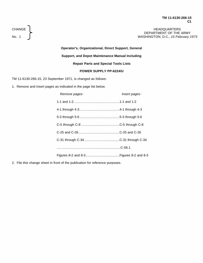
Figure 1-1. Power Supply PP-6224/U.
1-0

TM 11-6130-266-15
CHAPTER 1
INTRODUCTION
Section I. GENERAL
1-1. Scope
a. This manual describes Power Supply PP-6224/U and PP-6224A/U (fig. 1-1) and covers itsinstallation, operation. function, and maintenance. Itincludes operation under usual and unusual conditions,cleaning and inspection of the equipment, andreplacement of parts available to each category ofmaintenance
b. Unless otherwise indicated, all informationprovided for Power Supply PP-6224/U is also applicableto Power Supply PP-6224A/U.
c. Throughout this manual, Power Supply PP-6224/U; Cable Assembly, Power, Electrical CX-11979/U;and Cable Assembly, Power, Electrical CX-12342/VRCwill be referred to as power supply, ac power cord, anddc power cord, respectively.
d. Appendix A contains a list of publicationsapplicable to this equipment. Appendix B contains themaintenance allocation and repair operations to beperformed at the appropriate maintenance categories.Appendix C contains repair parts and tool lists (RPSTL)for the PP-6224/U only. The RPSTL for the PP-6224A/Uis contained in TM 11-6130-266-24P-2.
NOTE
Appendix C is current as of 31 May 1972.
1-2. Indexes of Publications
a. DA Pam 310-4. Refer to DA Pain 310-4 todetermine whether there are new editions, changes, oradditional publications pertaining to the equipment.
b. DA Pam 310-7. Refer to DA Pam 310-7 todetermine whether there are modification work orders(MWO's) pertaining to the equipment.
1-3. Forms and Records
a. Reports of Maintenance and UnsatisfactoryEquipment. Use equipment forms and records inaccordance with instructions TM 38-750.
b. Report of Packaging and Handling Deficiencies.Fill out and forward DD Form 6 (Report of Packagingand Handling Deficiencies) as prescribed in AR 700-58(Army) NAVSUP PUB 378 (Navy)/AFR 71-4 (Air Force)and MCO P4030.29 (Marine Corps).
c. Discrepancy in Shipment Report (DISREP) (SF361). Fill out and forward Discrepancy in ShipmentReport (DISREP) (SF 361) as prescribed in AR 55-38(Army) NAVSUP PUB 459 (Navy)/AFM 75-34 (Air Force)and MCO P4610.19 (Marine Corps).
d. Reporting Equipment ImprovementRecommendations (EIR). EIR's will be prepared usingDA Form 2407 (Maintenance Request). Instructions forpreparing EIR's are provided in TM 38-750, The ArmyMaintenance Management System. EIR's should bemailed direct to Commander, US Army Communicationsand Electronics Materiel Readiness Command, ATTN:DRSEL-MA-Q, Fort Monmouth, New Jersey 07703.
e. Administrative Storage. For procedures, formsand records, and inspection requirement; duringadministrative storage of equipment. refer to Chapter 8.
Section II. DESCRIPTION AND DATA1-4. Purpose and Use
a. Power Supply PP-6224/U converts 115 or 230volt, single phase, 50, 60, or 400 hertz (Hz) to 24 to 32volts de (local load) or 24 to 29 volts dc (remote load) at25 amperes maximum. This power is used as a
general-purpose, de power source and includes batterycharging. Typically, the power supply can be used topower one or two Receiver-Transmitters RT-246 VRC-12 or one or two Receiver-Transmitters RT-524, VRC-12with their auxiliary equipment.
Change 3 1-1

TM 11-6130-266-15
b. During local operation, the power supply isconnected directly to the load through the dc power cord.If the load must be connected to the power supply at aremote point, a four-conductor cable makes it possible toobtain regulated dc power of 24 to 29 volts at the remoteload terminals. The remote load may be placed up to adistance of 25 feet from the power supply.
c. If a failure or undervoltage condition shouldoccur in the ac power source, the power supply iscapable of transferring the load to an external battery.The only limitations affecting battery-supplied power arethe absence of voltage regulation and the lack ofcomplete circuit protection. Circuit protection availablein this case is limited to the dc circuit breaker located onthe front panel.
1-5. Technical Characteristics
a. Electrical Characteristics
(1) Ac input voltage 115/230 volts ±10%(2) Ac input frequency 50, 60, or 400 Hz
±5%(3) Dc output voltage
(a) Local load 24.0 to 32.0 volts at1% regulation
(b) Remote load 24.0 to 29.0 volts at1% regulation
(4) Dc output current 25 amperes maximum(5) Ripple (Rms voltage) Less than 0.5%(6) Ambient temperature
operating -40°F to +150°F(-40°C to +66'C)°
b. Weight and Dimensions(1) Weight:
(a) Unpacked............94 pounds(b) Packed................120 pounds
(2) PP-6224/U Dimensions:(a) Depth..................16 inches(b) Width..................16 inches(c) Height .................7 inches
1-6. Components
Item National stock Height width Depth Length WeightNo. Quantity No. Component (in.) (in.) (in.) (ft.) (lb.)
1 1 6130-00-133-5879 Power Supply PP-6224/U 7 16 16 94or 1A 1 6130-00-133-5879 Power Supply PP-6224A/U 7 16 16 94
2 1 6150-00-135-4555 Cable Assembly, PowerElectrical CX-11979/U 15
3 1 5995-00-466-0217 Cable Assembly, PowerElectrical CX-12342/VRC 3
1-7. Description
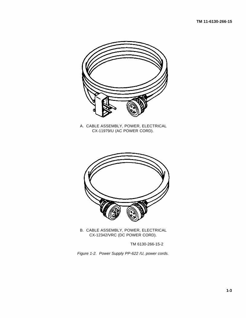
The power supply is housed in a watertight case. Circuitbeakers to protect the power supply during overloadsare mounted on the front panel. A combinationvoltmeter-ammeter enables the operator to monitoreither output voltage or output current, All controls andreceptacles, except the J7 DC OUT, J8 BAT, IN, and J9DC OUT receptacles, are mounted on the front panel.Receptacles 37 DC OUT, J8 BAT, IN, and J9 DC OUTare mounted on the rear panel. Ac and dc power cordsfurnished with the power supply are illustrated infigure 1-2.
1-8. Auxiliary Cable Assemblies
Cable assemblies required but not supplied with thepower supply are as follows:
a. Twenty five feet in length, 4-conductor cableassembly required to connect the power supply to a setof remote load terminals.
b. Cable assembly required to connect the powersupply to the external battery.
1-9. Differences in Models
Differences between Power Supplies PP-6224/U andPP-6224A/U are the result of certain EMI improvementswhich have been incorporated into the PP-6224A/U.Unless otherwise indicated, all information provided forPP-6224/U is also applicable to PP-6224A/U.
1-2 Change 3
TM 11-6130-266-15
A. CABLE ASSEMBLY, POWER, ELECTRICALCX-11979/U (AC POWER CORD).
B. CABLE ASSEMBLY, POWER, ELECTRICALCX-12342/VRC (DC POWER CORD).
TM 6130-266-15-2
Figure 1-2. Power Supply PP-622 /U, power cords.
1-3
TM 11-6130-266-15
CHAPTER 2
INSTALLATION AND OPERATING INSTRUCTIONS
Section I. INSTALLATION
2-1. Packaging Data
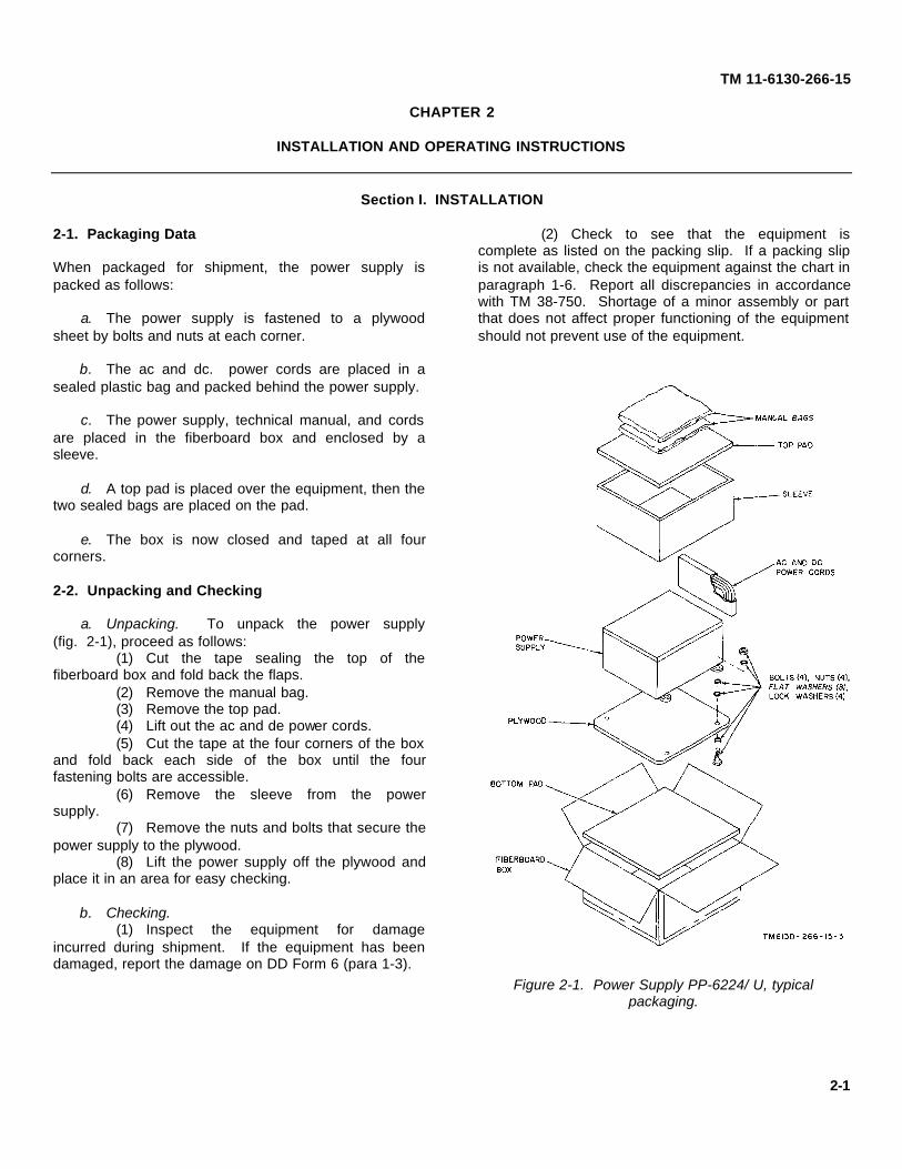
When packaged for shipment, the power supply ispacked as follows:
a. The power supply is fastened to a plywoodsheet by bolts and nuts at each corner.
b. The ac and dc. power cords are placed in asealed plastic bag and packed behind the power supply.
c. The power supply, technical manual, and cordsare placed in the fiberboard box and enclosed by asleeve.
d. A top pad is placed over the equipment, then thetwo sealed bags are placed on the pad.
e. The box is now closed and taped at all fourcorners.
2-2. Unpacking and Checking
a. Unpacking. To unpack the power supply(fig. 2-1), proceed as follows:
(1) Cut the tape sealing the top of thefiberboard box and fold back the flaps.
(2) Remove the manual bag.(3) Remove the top pad.(4) Lift out the ac and de power cords.(5) Cut the tape at the four corners of the box
and fold back each side of the box until the fourfastening bolts are accessible.
(6) Remove the sleeve from the powersupply.
(7) Remove the nuts and bolts that secure thepower supply to the plywood.
(8) Lift the power supply off the plywood andplace it in an area for easy checking.
b. Checking.(1) Inspect the equipment for damage
incurred during shipment. If the equipment has beendamaged, report the damage on DD Form 6 (para 1-3).
(2) Check to see that the equipment iscomplete as listed on the packing slip. If a packing slipis not available, check the equipment against the chart inparagraph 1-6. Report all discrepancies in accordancewith TM 38-750. Shortage of a minor assembly or partthat does not affect proper functioning of the equipmentshould not prevent use of the equipment.
Figure 2-1. Power Supply PP-6224/ U, typicalpackaging.
2-1

TM 11-6130-266-15
(3) If the equipment has been used orreconditioned, see whether it has been changed by amodification work order (MWO). If the equipment hasbeen modified, the MWO number will appear on the frontpanel near the nomenclature plate. Check to see thatany operational changes resulting from the modificationhave been entered in the equipment manual.
NOTE
Current MWO's applicable to theequipment are listed in DA Pam310-7.
Section II. OPERATING INSTRUCTIONS
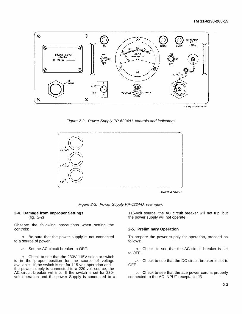
2-3. Controls, Indicators, and ConnectorsThe following chart lists controls, indicators, andconnectors located on the front (fig. 2-2) and rear(fig. 2-3)
panels of the power supply. Except for the DC OUT andBAT IN connectors, all items are located on the frontpanel.
Control, connector, or indicator Function
AC circuit breaker Protects the ac input circuit against overcurrent and also serves as the ac on-off switch.AC indicator lamp (amber) Lights to indicate that the AC circuit breaker is ON and that the line voltage is applied
to the power supply.230V-115V selector switch Sw. position Function
(2-position toggle switch) 230V Connects input circuit for 230-volt input power operation.115V Connects input circuit for 115-volt input power operation.
AC INPUT receptacle (J3) Connects the power supply to an external 115- or 230-volt ac power source through theac power cord.
NORM indicator lamp (green) During local and remote operation, the lamp indicates that a dc output voltage is beingproduced.
EMER indicator lamp (red) Indicates an undervoltage condition or loss of power in the ac power source, providingthe power supply is connected to an external battery. For an input of 115 volts ac, adrop below 80 volts ac causes an undervoltage condition; for an input of 230 volts ac,a drop below 160 volts ac causes an undervoltage condition. Normal operation resumeswhere the ac input voltage reaches 100 volts ac or 200 volts ac, respectively.
DC OUTPUT receptacle (J6, Connects the power supply to a remote load through a suitable 4-conductor cable. Maxi-front) mum dc output voltage obtainable at the end of the 25-foot connecting cable is 29.0
volts.DC OUT receptacle (J7, Connects the power supply to a local load through the de power cord. Also connects the
rear) power supply to an external battery, enabling the power supply to function as abattery charger. The DC OUT receptacle (J7) is connected in parallel with the DCOUT receptacle J9.
BAT IN receptacle (J8, rear) Connects the power supply to a standby battery. When ac input power fails or anundervoltage condition develops, the load is automatically transferred to this battery.
DC OUT receptacle (J9, rear) Connects the power supply to a local load through the de power cord. Also connects thepower supply to an external battery, enabling the power supply to function as abattery charger. The DC OUT receptacle (J9) is connected in parallel with DC OUTreceptacle J7.
DC circuit breaker a. Protects the power supply against overloads in case of failure of the overcurrentlimiter. The DC circuit breaker is set to trip when the output current reaches 28.0amperes. Also protects the power supply against reverse polarity when functioningas a battery charger.
b. Serves as the dc on-off switch by connecting the dc power to the load.c. Connects the power supply to an external battery.d. Protects the power supply against overcurrent when the load is transferred to the
external battery during emergency operation.VOLTAGE-CURRENT selector Sw. position Function
switch (2-position toggle VOLTAGE Connects OUTPUT METER to measure dc voltage.switch (spring-loaded in CURRENT Connects OUTPUT METER to measure de current.VOLTAGE position)
OUTPUT METER Indicates power supply output voltage or current, depending on the setting of theVOLTAGE-CURRENT selector switch. Also indicates battery voltage when theload has been transferred to the external battery.
DC OUTPUT ADJ Adjusts the power supply output voltage from a minimum of 24.0 volts to a maximumpotentiometer of 29.0 volts in remote operation, and to 32.0 volts in local operation.
2-2
TM 11-6130-266-15
Figure 2-2. Power Supply PP-6224/U, controls and indicators.
Figure 2-3. Power Supply PP-6224/U, rear view.
2-4. Damage from Improper Settings(fig. 2-2)
Observe the following precautions when setting thecontrols:
a. Be sure that the power supply is not connectedto a source of power.
b. Set the AC circuit breaker to OFF.
c. Check to see that the 230V-115V selector switchis in the proper position for the source of voltageavailable. If the switch is set for 115-volt operation andthe power supply is connected to a 220-volt source, theAC circuit breaker will trip. If the switch is set for 230-volt operation and the power Supply is connected to a
115-volt source, the AC circuit breaker will not trip, butthe power supply will not operate.
2-5. Preliminary Operation
To prepare the power supply for operation, proceed asfollows:
a. Check, to see that the AC circuit breaker is setto OFF.
b. Check to see that the DC circuit breaker is set toOFF.
c. Check to see that the ace power cord is properlyconnected to the AC INPUT receptacle J3
2-3

TM 11-6130-266-15
and then connect the ac power cord to a 3-wiregrounded ac power source. (To avoid possible electricalshock, 2-wire adapters must not be used).
NOTE
Loads may be connectedsimultaneously to DC OUTPUTreceptacle J6 and DC OUTreceptacles J7 and J9 providing thetotal output current drain is less than25 amperes.
d. Determine whether local or remote operation isrequired. Each type of operation is described below:
(1) Local. Use the dc power cord to connectthe load directly to DC OUT receptacle J7 or J9 on thereal panel (pin A (-), pin B (+) ).
(2) Remote. Use a 4-conductor cable (notsupplied) to connect the remote load terminals to DCOUTPUT receptacle J6 on the front panel. Connect theload leads (power) to pins D (+) and B (-). Connect thesensing leads to pins C (-) and A (+) (fig. 2-4).
NOTE
At the load, be sure that the positivesensing lead is connected to thepositive terminal and the negativesensing lead is connected to thenegative terminal.
e. Check to see that the standby battery isconnected to BAT IN receptacle J8 on the rear panel.
f. If a battery is to be charged, disconnect andremove the standby battery connected to
Figure 2-4. Power Supply PP-6224/U, remote cabling.
2-4

TM 11-6130-266-15
J8 and refer to paragraph 2-6c for charging instructions.
g. Check to see that the 230V-115V selector switchis in a position that corresponds to the rating of the acpower source.
2-6. Operation
The power supply is used as a general purpose powersupply or to charge a battery. The power supply isoperated in a similar manner for both functions. Afterperforming the procedures given in paragraph 2-5,operate the power supply as follows:
a. Set the AC circuit breaker to ON. The AC lamplights.
b. Remove the cap from the DC OUTPUT ADJpotentiometer.
c. For battery charging, proceed as follows:(1) Determine the constant charging voltage
value for the battery to be charged.(2) Set the DC circuit breaker to ON. The
NORM lamp lights.(3) Remove the protective cap over the DC
OUTPUT ADJ potentiometer. Unlock and rotate the DCOUTPUT ADJ potentiometer for the required constantcharging voltage value as indicated on the OUTPUTMETER. Lock the DC OUTPUT ADJ potentiometer.
(4) Set the DC circuit breaker to OFF.(5) Connect the battery to be charged to
either DC OUT receptacle J7 or J9.(6) Set the DC circuit breaker to ON. (It is
normal for the indicated charging voltage to dropbecause of the current limiting circuit. After the batteryhas received a portion of recharge, the indicated voltagewill be the voltage value obtained in (3) above.
(7) When the battery is fully charged, set theDC circuit breaker to OFF.
d. For power supply operation, proceed as follows :(1) Set the AC circuit breaker to ON.(2) With the equipment to be powered set to
OFF, set the DC circuit breaker to ON.
NOTE
The desired dc output voltage valueof the power supply when poweringRadio Set AN/VRC-12, AN/VRC-44,AN/ VRC-45, AN /VRC-47, or AN/VRC -9 is 25.5 volts. For best performanceof equipment, be sure to adjust theoutput voltage of the power supply to25.5 volts when powering Radio SetAN/VRC-12, AN/VRC-44, AN/VRC-45,AN/VRC-47, or AN/VRC-49.
(3) Remove the protective cap over the DCOUTPUT ADJ potentiometer. Unlock and rotate the DCOUTPUT ADJ potentiometer for the desired voltagevalue as indicated on the OUTPUT METER. Lock theDC OUTPUT ADJ potentiometer.
(4) Set the equipment to be powered to ON.Monitor the current by holding the VOLTAGE-CURRENTSWITCH in the CURRENT position and observing theOUTPUT METER reading.
(5) Release the VOLTAGE-CURRENTswitch.
2-7. Emergency Operation
An emergency condition is indicated by the on-offcombinations of the three front panel indicator lamps andthe OUTPUT METER indication. The following chartlists various combinations which indicate a different typeof emergency condition. Except where it is so stated,normal operation continues because the load isimmediately transferred to the external battery. The loadis transferred back to the power supply when theemergency condition no longer exists.
Emergency condition EMER indicator lamp AC indicator lamp NORM indicator lamp OUTPUT METER
Low ac input voltage Lights Goes out Goes out Indicates external bat-(or dims) tery voltage.
Surges in ac input Lights Goes out Gees out Indicates external bat-voltage tery voltage.
Note.This condition trips the
AC circuit breaker. Itmust be reset manuallybefore the load is trans-ferred back to thepower supply.
2-5

TM 11-6130-266-15
Emergency condition EMER indicator lamp AC indicator lamp NORM indicator lamp OUTPUT METER
Complete failure of ac in- Lights Goes out Goes out Indicates external bat-put voltage tery voltage.
Overload (short) Goes out Lights Lights if circuit Complete loss of oper-breaker doesn't ating voltage.trip. Goes outif circuitbreaker trips.
Note.There is no provision for
transferring the load tothe external battery.
Overheating Goes out Lights Goes out Initial loss of operat-ing voltage until tem-perature falls.
NOTE
Different types of failures willproduce various symptoms. Refer tochapter 3 for additional information.
2-8. Shutoff
To shut off the power supply, proceed as follows:
a. Set the DC circuit breaker to OFF. The NORMindicator lamp will go out.
b. Set the AC circuit breaker to OFF. The ACindicator lamp will go out.
2-6

TM 11-6130-266-15
CHAPTER 3
OPERATOR AND ORGANIZATIONAL MAINTENANCE
3-1. Scope of Maintenance
The maintenance duties assigned to the operator andorganizational repairman of the equipment are listedbelow, together with references to the paragraphscovering the specific maintenance functions. The toolsand test equipment required are listed in appendix B.
a. Operator's daily preventive maintenance checksand services (para 3-4).
b. Operator's weekly preventive maintenancechecks and services (para 3-5).
c. Organizational monthly preventive maintenancechecks and services (para 3-6).
d. Organizational quarterly preventive maintenancechecks and services (para 3-7).
e. Cleaning (para 3-8).
f. Touchup painting (para 3-9).
g. Troubleshooting (para 3-10).
h. Replacement of indicator lamps (para 3-11).
3-2. Preventive Maintenance
Preventive maintenance is the systematic care,servicing, and inspection of equipment to prevent theoccurrence of trouble, to reduce downtime, and toassure that the equipment is serviceable.
a. Systematic Care. The procedures given inparagraphs 3-4 through 3-8 cover routine systematic
care and cleaning essential to proper upkeep andoperation of the equipment.
b. Preventive Maintenance Checks and Services.The preventive maintenance checks and services charts(para 3-4 through 3-7) outline functions to be performedat specific intervals. These checks and services are tomaintain Army electronic equipment in a combat-serviceable condition; that is, in good general (physical)condition and in good operating condition. To assistoperators in maintaining combat serviceability, the chartindicates what to check, how to check, and what thenormal conditions are. The references column lists theparagraphs, figures, or manuals that contain detailedrepair or replacement procedures. If the defect cannotbe remedied by the corrective actions listed, highercategory of maintenance or repair is required. Recordsand reports of these checks and services must be madein accordance with the requirements set forth inTM 38-750.
3-3. Preventive Maintenance Checks and ServicesPeriods
Preventive maintenance checks and services of theequipment are required daily, weekly, monthly, andquarterly.
a. Paragraph 3-4 specifies the checks and servicesthat must be accomplished daily (or at least once eachweek if the equipment is maintained in standbycondition).
b. Paragraphs 3-5, 3-6, and 3-7 specify additionalchecks and services that must be performed on aweekly, monthly, and quarterly basis, respectively.
3-4. Operator's Daily Preventive Maintenance Checks and Services Chart
Sequence No. Item to be inspected Procedure Reference1 Completeness......................Check to see that the equipment is complete..................Para 1-6.2 Exterior surfaces .................Clean the exterior surfaces, including the panel meter Para 3-8.
glasses. Check meter glass and indicator lenses forcracks.
3 Connectors ..........................Check the tightness of all connectors.4 Controls and indicators ........While making the operating checks (sequence No. 5
below), check to see that the mechanical action of
3-1

TM 11-6130-266-15
Sequence No. Item to be inspected Procedure Reference
each switch is smooth and free of external or in-ternal binding and that there is no excessive loose-ness. Also, check the meter for sticking or bentpointer.
5 Operation.............................During operation, be alert for any abnormal indica- Para 2-5tions. through 2-8.
3-5. Operator's Weekly Preventive Maintenance Checks and Services Chart
Sequence No. Item to be inspected Procedure Reference
1 Cables .................................Inspect cables for chaffed, cracked, or frayed insulation.2 Metal surfaces......................Inspect exposed metal surfaces for rust and corrosion.
3-6. Organizational Monthly Preventive Maintenance Checks and Services Chart
Sequence No. Item to be inspected Procedure Reference
1 Transformer terminals...........Inspect the terminals on the power transformer(s). Allnuts must be tight. There should be no evidence ofdirt or corrosion.
2 Resistors .............................Inspect resistors for cracks, blistering, or other de-fects.
3 Gaskets and insulators ........Inspect gaskets, insulators, bushings, and sleeves forcracks, chipping, and excessive wear.
4 Terminal block......................Inspect the terminal block for loose terminals, cracks,and other defects.
5 Interior.................................Clean the interior of the chassis and cabinet ...................Para 3-8.6 Metal surfaces......................Inspect the equipment to determine that it is free of Para 3-9.
bare spots, rust, and corrosion.
3-7. Organizational Quarterly Preventive Maintenance Checks and Services Chart
Sequence No. Item to be inspected Procedure Reference
1 Publications .........................Check to see that all publications are complete, service- DA Pam 310-4.able, and current.
2 Modifications........................Check DA Pam 310-4 to determine whether new ap- TM 38-750 andplicable MWO's have been published. ALL URGENT DA Pam 310-4.MWO's must be applied immediately. All NORMALMWO's must be scheduled.
3-8. Cleaning
WARNING
The fumes of TRICHLOROETHANEare toxic. Provide thoroughventilation whenever it is used; avoidprolonged or repeated breathing ofvapor. Do not use near an openflame or hot surface; trichloroethaneis nonflammable but heat convertsthe fumes to a highly toxic phosgenegas the inhalation of which couldresult in serious injury or death.Prolonged or repeated skin contactwith trichloroethane can cause skininflammation. When necessary, usegloves, sleeves and aprons which thesolvent cannot penetrate.
Inspect the exterior of the equipment. The exteriorsurfaces should be free of dirt, grease, and fungus.
a. Remove dust and other loose dirt with a cleansoft cloth.
b. Remove grease, fungus, and ground-in dirt fromthe case; use a cloth dampened (not wet) withtrichloroethane O-T-620, Type I.
c. Remove dirt from plugs and jacks with a brush.
CAUTION
Do not press on the meter face(glass) when cleaning; the meter maybecome damaged.
3-2 Change 3

TM 11-6130-266-15
d. Clean the front panel, meter, and switches; usea soft clean cloth. If necessary, dampen the cloth withwater; mild soap may be used for more effectivecleaning.
3-9. Touchup Painting Instructions
Remove rust and corrosion from metal surfaces bylightly sanding them with fine sandpaper. Brush two thincoats of paint on the hare metal to protect it from furthercorrosion. Refer to the applicable cleaning andrefinishing practices specified in TB 746-10.
3-10. Organizational Troubleshooting
a. General. The troubleshooting chart (b. below)will help locate trouble in the power supply. Only thosecorrective measures are given which the unit repairmancan accomplish. If the corrective measure does notrestore normal equipment performance, higher categoryof maintenance is required.
b. Troubleshooting Chart.
Sequence No. Symptom Probable trouble Corrective measure
1 When operating on 115 or 230 volts ac, the AC or NORM lamp fails to Defective Replacelight, but there is a voltage indication on the OUTPUT METER. AC or defective
NORM lamp.indicatorlamp
3-11. Replacement of Indicator Lamps(fig. 2-2)
a. Unscrew the indicator lens.
b. Remove the defective lamp and replace it with a new one; make certain it is of the correct type. Replace the "O"ring seal (after lubricating with clear silicone grease) and indicator lens.
Change 3 3-3

TM 11-6130-266-15
CHAPTER 4
FUNCTIONING
4-1. Block Diagram(fig. 8-2)
a. The power supply provides a regulated 24 to 32-volt dc output required to operate an electronicequipment or to charge an external battery. The powersupply will maintain a constant output voltage within 1percent. The operating power for the power supply is115 or 230 volts at a frequency of 50, 60, or 400 Hertz.
b. The ac input voltage is applied, through AC inputcircuit breaker CB1, to main transformer T1. Theoutputs at the secondary windings of transformer T1 arefed to both the power regulator switch (in preregulatorassembly A4) and to the auxiliary power supply (inauxiliary supply and control assembly A1). Also, ACindicator lamp DS1 is lighted.
c. The preregulator provides high efficiencyisolation between the series pass element and any inputline variations. The preregulator circuit consists of twosilicon controlled rectifiers A4Q1 and A4Q2, pulse-widthcontrolled by phase angle control A4A1L1 (part ofmagnetic amplifier A4A1). Gating signals for phaseangle control A4A1L1 are provided by gate generatorA4A2, A4A1T1. The control windings are referenced tothe series pass element drop of the post regulator by thecomparator. Any change in the series pass elementdrop results in a proportional error current in the controlwindings and automatically corrects the series passelement drop to the preset level. The transientsuppressor provides means for dissipating excessenergy in filter capacitors A8C2 through A8C5 when adrive signal is received from the comparator.
d. The auxiliary power supply provides theregulated +16 and -16 volts dc necessary to meet thelow-level power requirements of the preregulator and thepost regulator. In addition, a full wave bridge rectifiercircuit in auxiliary supply and control assembly Alprovides an unregulated nominal +32 volts dc foroperation of the transfer control circuit. This circuitsenses input line conditions.
e. The output of the preregulator switch isintegrated by a filter composed of inductor L1 andcapacitors A8C2 through A8C5 to provide a low-levelripple dc voltage which enables high efficiency operationof the pass element. The filtered output is applied to theseries pass element.
f. The post regulator comprises a conventionalpass element control gate for controlling the outputvoltage. This gate is controlled by voltage regulatingamplifier A2Q3 (balanced differential amplifier).Changes in output voltage result in a proportional errorvoltage change to the amplifier. The resulting errorvoltage will correct the output to its preset level. Theoutput of the series pass element is fed to energystorage capacitor A8C6 where high frequency transientsare reduced and the regulator stability is improved.
g. The post regulator also contains output currentsensor resistor A6R1 and current regulating amplifierA2A1 which limit the load current to a safepredetermined level. The load step compensatordifferentiates the output of A2A1 so that in the event of astep load, it provides a large turn-on pulse for phaseangle control A4AL1. This large pulse eliminates thedrooping response characteristic inherent in a magneticamplifier.
h. The output circuit includes power transfer relayA6K1 which connects the output termination to anexternal battery in the event of a drop in line voltage.Sensing transfer relay A1K2 disconnects remotesensing, while relay A1K1 is used for the standbycondition. The DC circuit breaker CB2 connects the dcoutput voltage to the load and also serves as aprotective device. The DC OUTPUT ADJ potentiometerR3 is used to adjust the output voltage of the powersupply. Indicator lamps DS2 (NORM) and DS3 (EMER)are also provided to indicate the operational status of theunit. OUTPUT METER M1 indicates both voltage andcurrent of the post regulator, as determined by thesetting of VOLTAGE-CURRENT selector switch S2, oronly the voltage of an external battery supply.
4-1

TM 11-6130-266-15
The voltage of a battery to be charged is indicated priorto the application of ac power. The post regulator isdesigned so that if the ac power is turned on afterconnecting the output to a reverse polarity source(exceeding 8 volts), the transfer control will lock out, andno output current will flow. Filter network FL2 is used toeliminate radio-frequency interference.
4-2. Circuit Description(fig. 8-3)
a. Input Power. The power supply receives 115 or230-volts ac power from the line via AC INPUTreceptacle J3 and AC circuit breaker CB1. The ac isthen routed through 230V-115V selector switch S1 totransformer T1. Secondary winding 9-10 energizes ACindicator lamp DS1. From secondary winding 9-11, 42Vac is fed to auxiliary supply and control assembly Alwhere it is converted to 16 and 32 volts do. The 32V deoutput of Al energizes relay A1K1 which, in turn applies :32V de to the coil of transfer relay A6K1 via closedcontacts 7-10 of A1K1. Energizing A6K1 connects theoutput of the power supply, via contacts 2-4 of A6K1, toDC OUTPUT receptacle J6 and DC OUT receptacle J7.Simultaneously, NORM indicator lamp DS2, which isconnected across the coil of AGK1, goes on indicatingthe power supply is producing a normal do outputvoltage.
b. Transfer Control. A Schmitt trigger, comprisinginput level detectors A1Q5 and A1Q7, senses linevoltage through auxiliary power supply rectifier diodesA1CR1 through A1CR4. Switching occurs when the acinput power fails completely or when the input voltagefalls to 90 volts rms nominal (or 180 volts rms nominalfor a 230-volt input).Relay driver A1Q9 is cut off causing relay A1K1 to dropand deenergize relay A6K1. Deenergized contacts 4-1of A6K1 then switch the load to the external batteryconnected at BATTERY in receptacle J8, and EMERindicator lamp DS3 is energized. This action insuresthat there is no interruption of de power being furnishedto the load.Both the AC and NORM indicator lamps go out as soonas battery power is connected to the load.EMER indicator lamp DS3 remains on until normal acinput power is restored, at which time the load isautomatically returned to the power supply.
c. Preregulator and Control. The preregulatorcircuit isolates the series pass element from input linevariations. To maintain high efficiency, the voltage dropacross the series pass element is maintained at 2.5 volts(nominal) under all loaded output voltage or currentconditions. The net de voltage in filter
capacitors A8C2 through A8C5 is controlled by varyingthe firing angle of SCR's A4Q1 and A4Q2. This isaccomplished by interposing self-saturating magneticamplifier A4A1L1 between gate generator A4A2,A4A1T1, and the SCR gates. Net dc control windingcurrent determines the phase angle. A short circuitstabilizing winding provides magnetic amplifier gainrelatively independent of core characteristics(temperature). This shunting reduces the frequencydependence over the range of 47 to 450 Hz to aninsignificant level. The series pass element voltage dropis compared to a 2.0-volt dc reference, closing the loop.Free-wheeling diode A3CR4 and choke L1 prevent inputcurrent spiking, high-peak voltages, and excessivecapacitor ripple current, while diode A3CR6 providesovervoltage protection when the voltage exceeds 36volts.
d. Series Pass Element. The series pass element,comprising pass driver A3Q1 and series pass stagesA3Q2 and A3Q3, maintains a constant voltage or currentoutput by receiving inputs from the voltage and currentsensing circuits. The dc voltage from the preregulatorpasses through a conventional triple Darlington seriesregulator element, consisting of pass driver A3Q1, seriespass A3Q2, and pass driver A2Q1, before reaching theoutput. The series pass element is programmed by thevoltage and current controls. Since the series passelement acts as a variable resistor, changes in the acinput voltage are reflected across the element, enablingit to maintain a constant output voltage.
e. Temperature Control. Temperature sensingswitch A3S1 controls the ac line voltage applied totransformer A4A1T1 winding 1-2. This in turn, suppliesthe ac power required to operate squaring gateassembly A4A2. If the operating temperature of thepower supply exceeds a maximum safe value, thesensing switch opens and disconnects power to A4A2.This action shuts down the power supply.Although AC indicator lamp DS1 remains on, the NORMindicator lamp DS2 goes out, indicating there is no dcoutput. The sensing switch closes automatically whenthe operating temperature falls to a safe value.
f. Comparator. The transient suppressorcomparator stage is A5Q3. The comparator has thefollowing functions: it compares the voltage drop acrossthe series pass element to a reference within thecomparator to maintain the 2.5-volt drop across theseries pass element; it furnishes a compensation signalto magnetic amplifier A4A1L1 so that the 2.5 voltagedrop across the series pass element may be increasedto 4 volts, when a no-load condition is indicated
4-2 Change 1

TM 11-6130-266-15
by a negative signal from current regulating amplifierA2A1: and it provides the turn-on drive for the transientsuppressor if the series pass element drop exceedsapproximately 6 volts.
g. Voltage and Current Control. The output voltageis compared by voltage regulating amplifier A2Q3(differential amplifier) through a sensing divider to a 9.0-volt, stable, temperature-compensated zener reference,diode A2CR1. Any error voltage is amplified, inverted byA2Q2, and applied to the pass element base, closing theloop. The output voltage is adjusted by varying thesensing divider ratio between preset limits, using DCOUTPUT ADJ potentiometer R3. The output current issensed by low-voltage series shunt resistor A6R1. Avoltage analog of the output current is developed bycurrent regulating amplifier A2A1. The reference acrossCURRENT LIMIT ADJ potentiometer A2R15 is chosenso that 26.5-ampere output current opens gate diodeA2CR4, providing constant current operation for anylower value of system load impedance.
h. Sensing Circuits. Both the voltage and currentsensing circuits are controlled by sensing transfer relayA1K2. If the load has been transferred to an externalbattery because of ac input failure, relay A1K2 trips andcuts off voltage sensing signals. This action deactivatesthe entire sensing circuit. Sensing is automaticallyresumed when normal ac input power is restored.During the period normal ac power is applied to thepower supply, 32 volts de furnished by the transfercontrol is used to energize A1K1. This, in turn, connectsdc power to power transfer relay A6K1. Once A6K1 ismade, it applies the output of the power supply to DCOUTPUT receptacle J6 and DC OUT receptacle J7 andJ59. The output of the power supply is filtered forradiofrequency by A2L1-A2L6, A2C8-A2C13, C10-C13,and FL2.
(1) Voltage sensing. The voltage sensingcircuit consists of DC OUTPUT ADJ potentiometer R3,voltage regulating amplifier A2Q3, current mode gateA2Q4, and pass driver A2Q1. (A2Q4 and A2Q1 are alsopart of the current sensing circuit.) The voltage sensingsignal is routed to A2Q3 via relay A1K2 and DCOUTPUT ADJ potentiometer R3. The potentiometer, in
conjunction with a voltage divider network, develops thedifference or error signal between the actual (sensed)output voltage and the desired output voltage. (Thedesired output voltage is determined by the setting ofR3). The error signal is then amplified before being fedto pass driver A2Q1 via current mode gate A2Q4. FromA2Q1, the error signal is applied to the series passelement, allowing it to compensate for the change inoutput voltage.
(2) Current sensing. The current sensingcircuit consists of output current sensor A6R1, currentregulating amplifier A2A1, current mode gate A2Q4, andpass driver A2Q1. (A2Q4 and A2Q1 are also part of thevoltage sensing circuit.) The current sensing signal isapplied to A2A1 via relay A1K2 and resistor A6R1. Thedifference or error signal developed across A6R1 isapplied to A2A1. The amplified error signal is then fed toA2Q1 via A2Q4. The output of A2Q1 is applied to theseries pass element, enabling it to provide accurate loadcurrent regulation.
i. Differences Between Models. In addition to thecircuit descriptions provided previously in paragraphs a.through h., Power Supply PP-6224 A/U also includes thefollowing circuit changes for EMl reduction: (Refer toschematic diagram, fig. 8-4.).
(1) Input power. Input and output powerswitching is similar to that described in para. a exceptthat relay A6K1 utilizes dual-contacts for reducedcontact bounce, greater reliability and current-carryingcapability. The output of the power supply is connectedvia paired contacts B1-B2 and C1-C2 to DC OUTreceptacles J6-D and J7-B. Further, additional outputfiltering and transient suppression for J6 is provided byFL2 (C1 through C6) and output line shielding.
(2) Transfer Control. Switching operations forconnecting the external battery to the load in the event ofa power reduction or failure are as described in para. bexcept that switching is accomplished via normally-closed A6K1 contacts A2-A3, B2-B3.
Change 3 43
TM 11-6130-266-15
CHAPTER 5
DIRECT SUPPORT AND GENERAL SUPPORT MAINTENANCE
WARNING
When servicing the power supply, be extremely careful of the ac power line voltageterminals (115 or 230 volts). Serious injury or death may result from contact withthese terminals.
5-1. Scope of Direct Support and General SupportMaintenance
Troubleshooting at the direct support and generalsupport levels include all the techniques outlined fororganizational maintenance and any special or additionaltechniques required to isolate a defective part.Paragraphs 5-2 through 5-8 provide troubleshootingprocedures to be used to localize and isolate faults.
5-2. Organization of Troubleshooting Procedures
a. General. The first step in servicing a defectivepower supply is to localize the fault. Localization meanstracing the fault to a defective stage or circuitresponsible for the abnormal condition. The second stepis isolation. Isolation means locating the defective partor parts. Some defective parts, such as burned resistorsand arcing transformers, can often be located by sight,smell, or sound. Most defective parts, however, must beisolated by checking voltages and resistances.
b. Localization. The tests listed below will aid inisolating the trouble. The first step in tracking trouble isto localize the defective state by one of the followingmethods:
(1) Visual inspection. The purpose of visualinspection is to localize faults without testing ormeasuring circuit voltages or resistances. Through thisinspection, the repairman frequently can discovertroubles or determine the circuit in which the troubleexists. This inspection is valuable in avoiding additionaldamage which might occur through improper servicingmethods, and in preventing future failures.
CAUTION
This equipment is transistorized;make voltage measurements only asspecified in the voltage andresistance chart (para 5-8).
(2) Voltage and resistance measurements.When measuring voltages, use tape or sleeving toinsulate the entire test prod, except for the extreme tip.A momentary short circuit can damage a transistor. (Forexample, if the bias resistor of a transistor is shorted out,excessive current between the emitter and the basewould damage the transistor.) Use the voltage andresistance chart to find the normal readings, andcompare them with the readings taken.
(3) Trouble shooting chart. The indicationslisted in the chart of paragraph 5-5d will aid in localizingthe trouble to a component part or to an assembly.
(4) Intermittent troubles. In all these tests, thepossibility of intermittent troubles should not beoverlooked. If present, this type of trouble may be madeto reappear by tapping or jarring the equipment. Checkthe internal wiring and connections for looseness.
5-3. Test Equipment Required
The following chart lists the test equipment required andthe associated technical manuals for troubleshooting thepower supply.
NOTE
Use tools and test equipment listedbelow until the tools and testequipment listed in Appendix Bbecome available.
Test equipment Technical manualMultimeter TS-352R/U TM 11-6625-366-15Test Set, Transistor TS-1836.'U TM 11-6625-539-15Tool Kit, Electronic Equipment None
TK-100/GResistor, Variable, Wire Wound None
0- to 7.5-ohm, 1000-watt,(FSN 5905-195-,1496)
Oscilloscope AN/USM-281A TM 11 0625-1703-15Transformer. Variable TF-171A None
Change 3 5-1

TM 11-6130-266-15
CAUTIONRead the instructions in paragraph 5-9 before attempting to remove orreplace parts.
5-4. Checking for Shortsa. When to Check . Check the power supply when
the AC or DC circuit breaker trips without the loadconnected, or when there is no dc output.
b. Conditions for Tests.
(1) Disconnect the power supply from thepower source.
(2) Disconnect the load connected to DCOUT receptacle J7 or J9, or DC OUTPUT receptacle J6.Disconnect the standby battery.
c. Resistance Measurements. Make theresistance measurements indicated in paragraph 5-7.
CAUTION
Do not make any resistancemeasurements on the power supplyother than those specified. Tilemultimeter battery can destroy thetransistors by excessive currentflowing through them if themultimeter is not connectedaccording to directions.
5-5. Localizing Troubles
a. General. In the troubleshooting chart thatfollows, the procedures are outlined for localizingtroubles to a part or an assembly. The parts locationsare shown in figures 5-1 through 5-9. Depending on thenature of the operational symptoms, one or more of thelocalizing procedures will l) e necessary. When troublehas been localized to a particular assembly, use voltageand resistance measurements to isolate the trouble to aparticular part.
b. Use of Chart. The troubleshooting chart (dbelow) supplements the troubleshooting chart inparagraph 3-10. If previous operational checks haveresulted in reference to a particular item of the chart in dbelow, refer directly to the referenced item. If nooperational symptoms are known, begin with item 1 ofthe troubleshooting chart and proceed until a symptomof the trouble is found.
CAUTIONIf the operational symptoms are notknown, or if they indicate thepossibility of internal short circuits,make the short-circuit checksdescribed in paragraph 5-4 beforeapplying power.
c. Conditions for Tests. All checks outlined in thetroubleshooting chart are to be conducted with the powersupply connected to the ac power source and with thedummy load across DC OUT receptacle J7.
d. Troubleshooting Chart.
NOTE
Perform the steps in theorganizational troubleshooting chartin paragraph 310 before using thischart, unless the trouble has alreadybeen localized.
CAUTION
In-circuit measurements made at thetest points or terminals on A1, A2 orA5 must be performed with the aid ofthe Extender Test Board, SM-D-943415 (fig. 5-9). To avoidequipment damage, be sure to shutoff power supply when extenderboard is being inserted or removed.
Item No. Trouble symptom Probable cause Corrective action1 AC indicator lamp DS1 fails to a. No ac power is reaching AC IN- a. Check continuity of the ac power
light when AC circuit breaker PUT receptacle J3. cord and repair or replace ifCB1 is set to ON. (230V-115V necessary.selector switch S1 set to prop- b. AC circuit breaker CB1 defective. b. Check CB1 and replace if neces-er position.) sary.
c. 230V-115V selector switch S1 de- c. Check S1 and replace if necessary.fective.
d. Transformer T1 defective. d. Check T1 and replace if necessary.2 NORM indicator lamp DS2 fails a. Resistor A6A1R4 defective. a. Check and replace A6A1R4 if nec-
to light. (AC indicator lamp essary.DS1 is lighted.) b. Auxiliary supply and control as- b. Check for +32V de between pin 11
sembly A1 defective. and pin 17 of A1. Replace A1 ifnecessary.
5-2 Change 3
TM 6130-266-15-C1-4
TM 11-6130-266-15
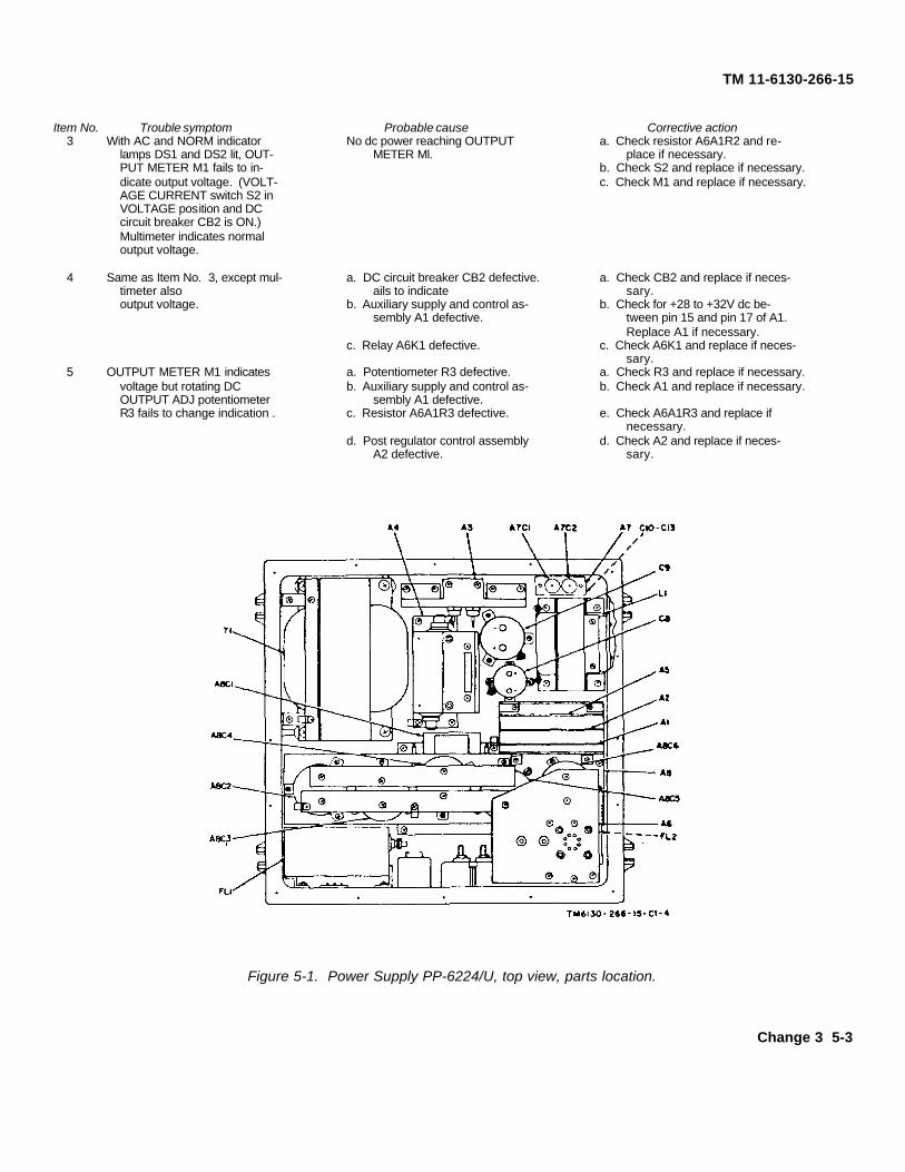
Item No. Trouble symptom Probable cause Corrective action3 With AC and NORM indicator No dc power reaching OUTPUT a. Check resistor A6A1R2 and re-
lamps DS1 and DS2 lit, OUT- METER Ml. place if necessary.PUT METER M1 fails to in- b. Check S2 and replace if necessary.dicate output voltage. (VOLT- c. Check M1 and replace if necessary.AGE CURRENT switch S2 inVOLTAGE position and DCcircuit breaker CB2 is ON.)Multimeter indicates normaloutput voltage.
4 Same as Item No. 3, except mul- a. DC circuit breaker CB2 defective. a. Check CB2 and replace if neces-timeter also ails to indicate sary.output voltage. b. Auxiliary supply and control as- b. Check for +28 to +32V dc be-
sembly A1 defective. tween pin 15 and pin 17 of A1.Replace A1 if necessary.
c. Relay A6K1 defective. c. Check A6K1 and replace if neces-sary.
5 OUTPUT METER M1 indicates a. Potentiometer R3 defective. a. Check R3 and replace if necessary.voltage but rotating DC b. Auxiliary supply and control as- b. Check A1 and replace if necessary.OUTPUT ADJ potentiometer sembly A1 defective.R3 fails to change indication . c. Resistor A6A1R3 defective. e. Check A6A1R3 and replace if
necessary.d. Post regulator control assembly d. Check A2 and replace if neces-
A2 defective. sary.
Figure 5-1. Power Supply PP-6224/U, top view, parts location.
Change 3 5-3

TM 11-6130-266-15
Figure 5-1.1. Power supply PP-6224A/U, top view, parts location.
5-6. Isolating Trouble Within Assemblies
a. When trouble has been localized to an assemblyduring the operational checks listed in thetroubleshooting chart (para 5-5d), isolate the trouble to acomponent level by voltage measurements at thetransistor terminals and other significant points.
b. Use the schematic (fig. 8-3 or 8-4) to trace
the circuits and isolate the faulty components.Figure 8-1 (located in back of manual) is the resistor andcapacitor color code diagram.
c. The transistor terminal voltage readings weremade with Multimeter TS-352B/U. A measurement thatdiffers widely from that in the voltage and resistancechart can localize the trouble when used with theschematic diagram.
5-4 Change 3
TM 6130-266-15-9
TM 11-6130-266-15
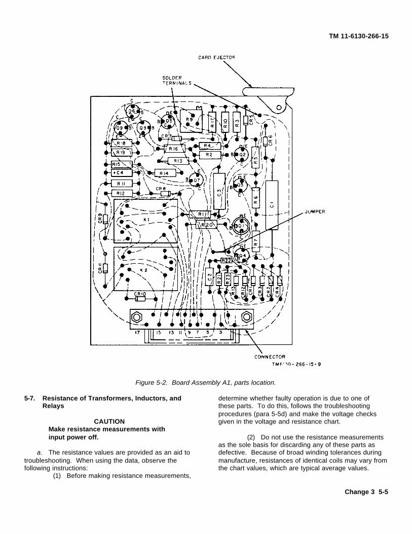
Figure 5-2. Board Assembly A1, parts location.
5-7. Resistance of Transformers, Inductors, andRelays
CAUTIONMake resistance measurements withinput power off.
a. The resistance values are provided as an aid totroubleshooting. When using the data, observe thefollowing instructions:
(1) Before making resistance measurements,
determine whether faulty operation is due to one ofthese parts. To do this, follows the troubleshootingprocedures (para 5-5d) and make the voltage checksgiven in the voltage and resistance chart.
(2) Do not use the resistance measurementsas the sole basis for discarding any of these parts asdefective. Because of broad winding tolerances duringmanufacture, resistances of identical coils may vary fromthe chart values, which are typical average values.
Change 3 5-5

TM 11-6130-266-15
Figure 5-3. Post regular control assembly 12, parts location.
(3) The normal resistance of replacement parts Measured between Dc resistancemay differ slightly from the values given in the Part terminals (ohms)
A2L3 1-2 Less than 1.A2L4 1-2 Less than 1.A2L5 1-2 Less than 1.
b. The resistances of the coils are listed below: A2L6 1-2 Less than 1.A4A1L1 10-11 400
Measured between DC resistance 12-13 150Part terminals (ohms) 12-13 150L1 1-2 Less than 1. 14-15 2
3-9 9 16-17 10T1 9-11 Less than 10. 18-19 10
12-14 Less than 1. A4A1T1 1-2 56A1K1 1-16 650 3-5 5.8A1K2 1-16 650 6-7 1.26A2L1 1-2 Less than 1. 8-9 1.26A2L2 1-2 Less than 1. A6K1 3-6 428(PP-6224/U)
X1-X2 *260(PP-6224A/U)* Measure with DS2 NORM indicator lamp pulled out
5-6 Change 3

TM 11-6130-266-15
Figure 5-4. Transistor assembly A3, parts location.
Figure 5-5. Preregular assembly A4, parts location.
Figure 5-6. Preregulator assembly A5, parts location.
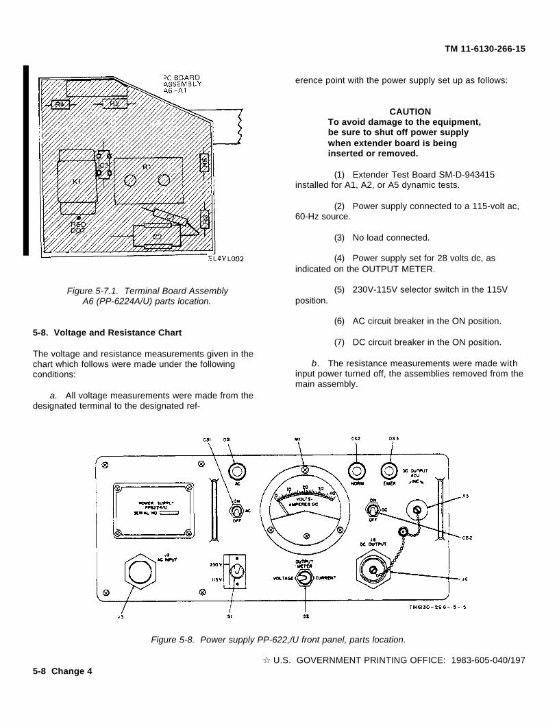
Figure 5-7. Terminal Board Assembly A6, (PP-6224/U)parts location.
Change 4 5-7
TM 11-6130-266-15
Figure 5-7.1. Terminal Board AssemblyA6 (PP-6224A/U) parts location.
5-8. Voltage and Resistance Chart
The voltage and resistance measurements given in thechart which follows were made under the followingconditions:
a. All voltage measurements were made from thedesignated terminal to the designated ref-
erence point with the power supply set up as follows:
CAUTIONTo avoid damage to the equipment,be sure to shut off power supplywhen extender board is beinginserted or removed.
(1) Extender Test Board SM-D-943415installed for A1, A2, or A5 dynamic tests.
(2) Power supply connected to a 115-volt ac,60-Hz source.
(3) No load connected.
(4) Power supply set for 28 volts dc, asindicated on the OUTPUT METER.
(5) 230V-115V selector switch in the 115Vposition.
(6) AC circuit breaker in the ON position.
(7) DC circuit breaker in the ON position.
b. The resistance measurements were made withinput power turned off, the assemblies removed from themain assembly.
Figure 5-8. Power supply PP-622,/U front panel, parts location.
I U.S. GOVERNMENT PRINTING OFFICE: 1983-605-040/1975-8 Change 4

TM 11-6130-266-15
Figure 5-9. Extender Test Board. SM-D-9 13115.
c. Where two resistance readings betweenterminals are given, the top reading is the resistancemeasured with the positive multimeter lead connected tothe base. The bottom reading is the resistancemeasured with the negative multimeter lead connectedto the base. Be sure to check the actual polarity of themultimeter leads before making measurements.
d. Resistances measured at points shunted bylarge capacitors must be read after the multimeterceases to drift.
Ref des VE VB VC Voltage ref pt RRE RBC
A1Q1 +16.0 +16.5 +28.0 Pin 17 5K 4.K900 750
A1Q2 +9.0 +9.6 +16.5 Pin 17 4.7K 5.6K900 800
A1Q3 0.0 -0.4 -16.5 Pin 17 1.K 1.1K850 30K
A1Q4 -16.0 -16.5 -34.0 Pin 17 1.1K 1.1K
A1Q5 +11.0 +11.5 +11.2 Pin 17 850 5.5K850 750
A1Q6 0.0 0.0 +11.5 Pin 17 2.8K 2.2K850 750
A1Q7 +11.0 +10.0 +12.0 Pin 17 14K 7.5K900 800
Change 3 5-8.1

TM 11-6130-266-15
Ref des VE VB VC Voltage ref pt RRE RBC
A1Q8 +12.0 +11.2 +3.0 Pin 17 1K 9502K 10K
A1Q9 +2.2 +3.0 +2.6 Pin 17 4K ∞880 800
A2Q1 +1.0 +1.70 +10.0 Pin 8 30K ∞900 825
A2Q2 -0.1 -0.7 -19.0 Pin 3 1K 1.1K4K ∞
A2Q3A a +8.8 +9.1 +13.0 Pin 2 800 9K1.1K 1K
A2Q3B a +8.5 +9.1 +15.0 Pin 2 800 7K1.1K 950
A2Q4 0.0 0.0 +16.0 Pin 2 1.1K 10K800 800
A2A1 b V2 V3 V4 Pin 20.0 0.0 -16.0 Pin 2 -- --
V5 V6 V1 Pin 2 -- ---15.0 -5.2 +16.0 Pin 2 -- --
A3Q5 e 0.0 0.0 32.5 A8C2 (-) 100 200100 200 (d)
A3Q6 e 0.0 0.0 32.5 A8C2 (-) 100 200100 200 (d)
A5Q1 0.0 0.0 +15.5 Pin 14 950 ∞800 800
A5Q2 0.0 0.0 +15.5 Pin 14 3.8K ∞900 800
A5Q3 0.0 -0.05 +32.5 Pin 8 400 ∞400 800
SCR’s only • Gate Cath Anode Voltage ref pt RGK RAK
A4Q1 -0.25 0.0 -32.5 A4A2P1-10 100-1K ∞100-1K ∞
A4Q2 -0.25 0.0 -32.5 A4A2P1-10 100-1K ∞100-1K ∞
a A2Q3A and, A2Q3B are in 1 caseb Resistance data not validc RBE and RBC measurements made with A3 in circuitd Voltage is average of square wavee SCR voltages are waveform averages
5-9. General Parts Replacement TechniquesAll the parts of the power supply can be replaced withoutspecial procedures. The following precautions applyspecifically to this equipment.
a. Do not disturb the setting of any potentiometer.b. The power supply is transistorized. Use a
pencil-type soldering iron with a 25-watt maxi mumcapacity. If the iron must be used with ac use an
isolating transformer between the iron the line. Use ahigher wattage soldering iron for heavier duty soldering.
CAUTIONDo not use a soldering gun;damaging voltage can be inducedinto components.
5-8.2 Change 3

TM 11-6130-266-15
c. Use the cross tip screwdriver(FSN 5120-529-3101) to loosen or tighten Phillips headscrews. Use hand screw starter (FSN 5120-832221) toremove loosened Phillips head screws or to hold andstart Phillips head screws. Use the magnetic retrievingtool (FSN 5120-545-4268) Remove lockwashers underPhillips head screws at are not removed with the screws.
5-10. Use of Heat SinkSolder transistor leads quickly; whenever wiring permits,use a heat sink (such as long-nosed pliers) between thesoldered joint and the transistor. Use approximately thesame length and dress of transistor leads as usedoriginally.
5-11. Disassembly and ReassemblyThe steps necessary to disassemble and reassemblethe power supply are obvious, and no specialinstructions are required. However, certain proceduresand precautions must be observed prior to, and during,reassembly.
a. Make sure that all mating machine surfaces areabsolutely clean.
b. Use thermal compound (Astrodyne 829) ontransformer T1, inductor L1, assemblies A3 and A4, andbetween all semiconductor and mounting surfaces.
c. Lubricate all rubber seals with clear siliconegrease. See that the rubber seals have not cracked,flattened, or deteriorated.
d. Make sure that no hardware, such as nuts, bolts,and washers, have fallen inside the power supply.
e. Apply the correct amount of torque to theattaching hardware, as indicated below, when installingthe following parts:
Part TorqueA3CR1 12 in.-lbA3CR2 12 in.-lbA3CR3 12 in.-lbA3CR4 25 in.-lbA3CR5 25 in.-lbA3CR6 12 in.-lbA4Q1 10 ft-lbA4Q2 10 ft-lb
5-12. Equipment Adjustments
The following adjustments must be performed afterreplacing a defective part or as a result of
troubleshooting. The cover of the power supply must beremoved to gain access to these adjustments.
a. High Voltage Limit Adj Potentiometer A2-R10.To adjust A2R10, proceed as follows:
(1) Set the 230V-115V selector switch to115V.
(2) Connect 115-volt ac, 60 Hz power to ACINPUT receptacle J3 using the ac power cord.
(3) Set the AC circuit breaker to ON. The ACindicator lamp lights.
(4) Set the DC circuit breaker to ON.
(5) Rotate DC OUTPUT ADJ potentiometerR3 fully clockwise.
(6) With no load connected, adjust A2R10until the OUTPUT METER indicates between 32 and 34volts.
b. Current Limit Adj Potentiometer A2R15. Toadjust A2R15, proceed as follows:
(1) Perform the procedures given in (1)through (4) above.
(2) Connect DC OUT receptacle J7 to load.
(3) While holding the VOLTAGE-CURRENTswitch in the CURRENT position, adjust A2R15 until theOUTPUT METER indicates 27 amperes.
c. Transfer Point Adj Potentiometer A1R9. Toadjust A1R9, proceed as follows:
(1) Set the 230V-115V selector switch to115V.
(2) Connect a variable 115-volt ac, 60 Hzpower source to AC INPUT receptacle J3 using the acpower cord and Transformer, variable TF-171A.
(3) Set the AC circuit breaker to ON. The ACand NORM indicator lamps light.
(4) Set the DC circuit breaker to ON.
(5) With no load connected, simultaneouslyadjust the ac input line voltage and A1R9 until transferoccurs with an input of between 80 and 100 volts ac.This is indicated when the NORM indicator lamp goesout and the EMER indicator lamp lights at 80 volts ac.At 100 volts ac, the EMER indicator lamp goes out andthe NORM indicator lamp lights.
d. Preregulator Voltage Adj Potentiometer A5-R9.
Change 3 5-9
TM 11-6130-266-15
To adjust A5R9, proceed as follows:(1) Set the 230V-115V selector switch to
115V.
(2) Connect 103.5 volts ac, 60 Hz power toAC INPUT receptacle J3 using the ac power cord andTransformer, Variable TF-171A.
(3) Set the AC circuit breaker to ON. The ACand NORM indicator lamps light.
(4) Set the DC circuit breaker to ON.
(5) Set the PP-6224/U for 25 amperes outputcurrent at 32 volts output voltage.
(6) Connect the negative lead of TS-352B/Uto the negative terminal (-) of A8C5.
(7) Connect the positive lead of TS-352B/U tothe negative terminal (-) of A8C6.
(8) Adjust A5R9 until TS-352B/U indicates 2.0volts.
e. DC OUTPUT ADJ Potentiometer R3. To adjustR3, proceed as follows:
(1) Perform the procedures given in (1)through (4) above.
(2) With no load connected, rotate DCOUTPUT ADJ potentiometer R3 until the OUTPUTMETER indicates 25.5 volts. Lock R3 at this setting.
5-10 Change 3
TM 11-6130-266-15
CHAPTER 6
GENERAL SUPPORT TESTING PROCEDURES
6-1. Generala. Test procedures are prepared for use by
Electronics Field Maintenance Shops and ElectronicService Organizations responsible for general supportmaintenance of electronic equipment to determine theacceptability of repaired equipment. These proceduresset forth specific requirements that repaired equipmentmust meet before it is returned to the using organization.A summary of the performance standards is given inparagraph 6-8.
b. Comply with the instructions preceding eachchart before proceeding to the chart. Perform each stepin sequence. Do not vary the sequence. For each step,perform all the actions required in the Control settingscolumn; then perform each specific test procedure andverify it against its performance standard.
6-2. Test Equipment, Tools, and Materials
NOTE
Use tools and test equipment listedbelow until the tools and testequipment listed in Appendix Abecome available.
All test equipment, tools, materials, and other equipmentrequired to perform the test procedures given in thischapter are listed in a, b and c below.
a. Test Equipment.
(1) Digital, Voltmeter AN/GSM-64.
(2) Voltmeter, Meter ME-30A/V.
(3) Multimeter, Weston Instruments Model281.
(4) Multimeter TS-352B/U.
b. Tools. The only tools necessary for thesechecks are those contained in Tool Kit, ElectronicEquipment TK-100/G.
c. Other Equipment.
(1) Transformer Variable TF-171A.
(2) Simulator, Battery Variable Load Bank(FMC63743, Type K48149).
(3) Connector, Electrical, 2 required(FSN 5935-921-3398).
6-3. Physical Tests and Inspection
a. Test Equipment and Materials. None required.
b. Test Connections and Conditions.
(1) No connections necessary.
(2) Remove panels and covers as necessaryfor visual and actual access to all components.
Change 3 6-1

TM 11-6130-266-15
Control SettingsStep No. Test procedure Performance standard
Test equipment Equipment under test
1 None Controls may be in any a. Inspect case and chassis for damage or miss- a. No damage evident or parts missing. Externalposition. ing parts, and for condition of paint. surfaces to be painted must not show bare
metal. Panel lettering must be legible.Note. Touchup painting is recommended in
place of refinishing when-ever practicable; do notpaint or polish screwheads, binding posts, recep-tacles, and other plated parts with abrasives.b. Inspect all controls and mechanical assemblies b. Screws, bolts, and nuts must be tight; none
for loose or missing screws, bolts, and nuts missing.c. Inspect all connectors, sockets, and receptacles c. No loose parts or damage.
for looseness, damage,' or missing parts.2 None Controls may be in any a. Rotate all panel controls throughout their a. Controls must rotate freely, without binding
position. limits of travel. or excessive looseness.b. Operate all switches. b. Switches must operate properly.
6-4. Output Range Test
a. Test Equipment and Materials. No test equipment or materials are required for this test, other than a 115-volt, 60 Hz power source.b. Test Connections and Conditions . To perform this test, the following connections and conditions must be accomplished:
(1) 11 5-volt, 60 Hz power source connected to AC INPUT receptacle J3 with the ac. power cord.(2) No load connected.
c. Procedure.
Control SettingsStep No. Test procedure Performance standard
Test equipment Equipment under test
1 None a. 230V-115V switch to Adjust DC OUTPUT ADJ potentiometer fully OUTPUT METER indicates more than 32 volts115V. clockwise. dc.
b . AC circuit breaker toON.
c. DC circuit breaker toON.
2 None Adjust DC OUTPUT ADJ potentiometer fully OUTPUT METER indicates less than 24 voltscounterclockwise. dc.
6-2

TM 6130-266-15-18
TM 11-6130-266-15
Figure 6-1. Test setup for regulation and ripple test.
6-3
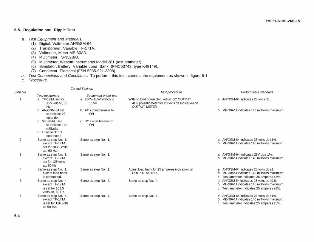
TM 11-6130-266-15
6-5. Regulation and Ripple Test
a. Test Equipment and Materials.(1) Digital, Voltmeter AN/GSM-64.(2) Transformer, Variable TF-171A.(3) Voltmeter, Meter ME-30A/U.(4) Multimeter TS-352B/U.(5) Multimeter, Weston Instruments Model 281 (test ammeter).(6) Simulator, Battery Variable Load Bank (FMC63743, type K48149).(7) Connector, Electrical (FSN 5935-921-3398).
b. Test Connections and Conditions . To perform this test, connect the equipment as shown in figure 6-1.c. Procedure.
Control SettingsStep No. Test procedure Performance standard
Test equipment Equipment under test1 a. TF-171A set for a. 230V-115V switch to With no load connected, adjust DC OUTPUT a. AN/GSM-64 indicates 28 volts dc.
115 volt ac, 60 115V. ADJ potentiometer for 28 volts de indication onHz. OUTPUT METER
b. AN/GSM-64 set b. AC circuit breaker to b. ME-30A/U indicates 140 millivolts maximum.to indicate 28 ON.volts de.
c. ME-30A/U set c. DC circuit breaker toto indicate 140 ON.millivolts
d. Load bank notconnected.
2 Same as step No. 1, Same as step No. 1. a. AN/GSM-64 indicates 28 volts dc ±1%.except TF-171A b. ME-30A/U indicates 140 millivolts maximum.set for 103.5 voltsac, 60 Hz.
3 Same as step No. 1, Same as step No. 1. a. AN/GSM-64 indicates 28V dc ± 1%.except TF-171A b. ME-30A/U indicates 140 millivolts maximum.set for 126 voltsac, 60 Hz.
4 Same as step No. 1, Same as step No. 1. Adjust load bank for 25 amperes indication on a. AN/GSM-64 indicates 28 volts dc ±1.except load bank OUTPUT METER. b. ME-30A/U indicates 140 millivolts maximum.is connected. c. Test ammeter indicates 25 amperes ±3%.
5 Same as step No. 4 Same as step No. 4. Same as step No. 4. a. AN/GSM-64 indicates 28 volts de ±1%.except TF-171A b. ME-30A/U indicates 140 millivolts maximum.is set for 103.5 c. Test ammeter indicates 25 amperes ±3%.volts ac, 60 Hz.
6 Same as step No. 5, Same as step No. 5. Same as step No. 5. a. AN/GSM-64 indicates 28 volts dc ±1%.except TF-171A b. ME-30A/U indicates 140 millivolts maximum.is set for 126 volts c. Test ammeter indicates 25 amperes ±3%.ac 60 Hz.
6-4

TM 6130-266-15-19
TM 11-6130-266-15
Figure 6-2. Test setup for power transfer test.
6-5
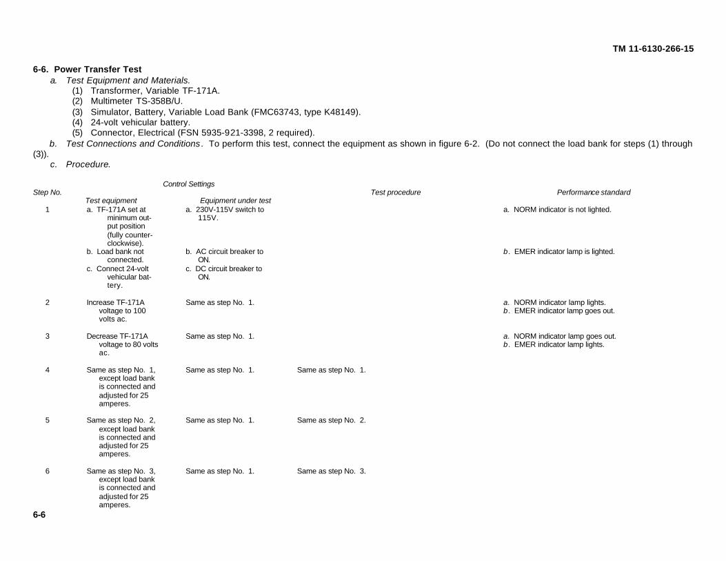
TM 11-6130-266-15
6-6. Power Transfer Testa. Test Equipment and Materials.
(1) Transformer, Variable TF-171A.(2) Multimeter TS-358B/U.(3) Simulator, Battery, Variable Load Bank (FMC63743, type K48149).(4) 24-volt vehicular battery.(5) Connector, Electrical (FSN 5935-921-3398, 2 required).
b. Test Connections and Conditions . To perform this test, connect the equipment as shown in figure 6-2. (Do not connect the load bank for steps (1) through(3)).
c. Procedure.
Control SettingsStep No. Test procedure Performance standard
Test equipment Equipment under test1 a. TF-171A set at a. 230V-115V switch to a. NORM indicator is not lighted.
minimum out- 115V.put position(fully counter-clockwise).
b. Load bank not b. AC circuit breaker to b. EMER indicator lamp is lighted.connected. ON.
c. Connect 24-volt c. DC circuit breaker tovehicular bat- ON.tery.
2 Increase TF-171A Same as step No. 1. a. NORM indicator lamp lights.voltage to 100 b. EMER indicator lamp goes out.volts ac.
3 Decrease TF-171A Same as step No. 1. a. NORM indicator lamp goes out.voltage to 80 volts b. EMER indicator lamp lights.ac.
4 Same as step No. 1, Same as step No. 1. Same as step No. 1.except load bankis connected andadjusted for 25amperes.
5 Same as step No. 2, Same as step No. 1. Same as step No. 2.except load bankis connected andadjusted for 25amperes.
6 Same as step No. 3, Same as step No. 1. Same as step No. 3.except load bankis connected andadjusted for 25amperes.
6-6
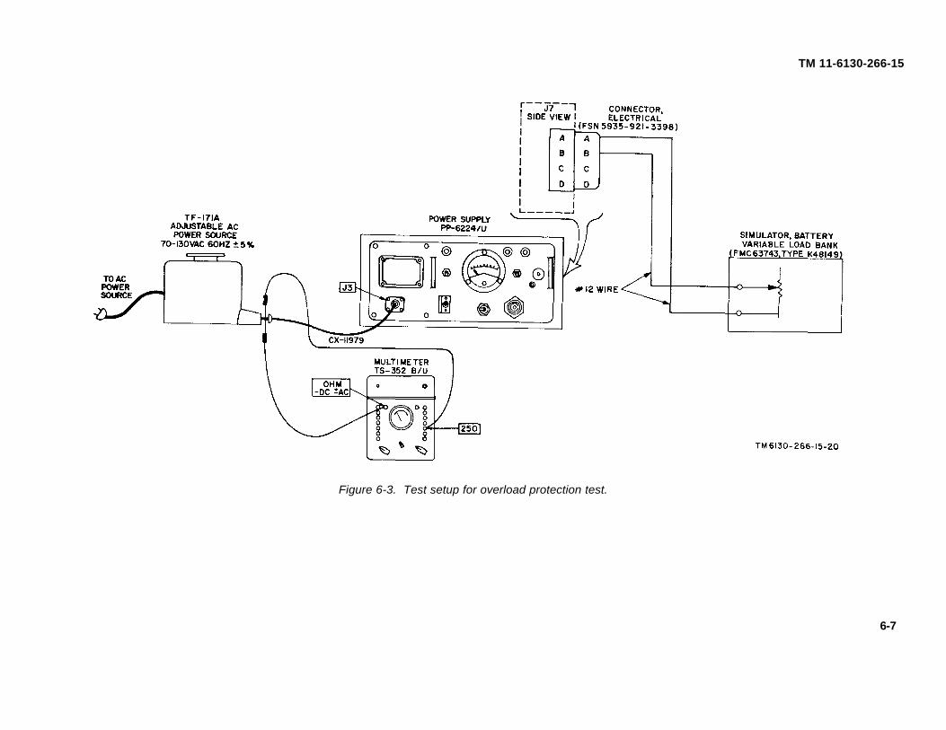
TM 6130-266-15-20
TM 11-6130-266-15
Figure 6-3. Test setup for overload protection test.
6-7

TM 11-6130-266-15
6-7. Overload Protection Testa. Test Equipment and Materials.
(1) Transformer, Variable TF-171A.(2) Multimeter TS-352B/U.(3) Simulator Battery Variable Load Bank (FMC63743, Type K48149).(4) Connector, Electrical (FSN 5935-921-3398).
b. Test Connections and Conditions . To perform this test, connect the equipment as shown in figure 6-3.c. Procedure.
Control SettingsStep No. Test procedure Performance standard
Test equipment Equipment under test1 a. TF-171A set for a. 230V-115V switch to With DC output ADJ control set for 28.5 volts, Dc ammeter indicates less than 27 amperes.
115 volts ac, 60 115V. gradually reduce the resistance of the loadHz. b. AC circuit breaker to bank until the load bank resistance is less thanON. 0.5 ohm.
e. DC circuit breaker toON.
6-8. Test Data SummaryThe test data are summarized as follows:
a. The 25.5-volt output must remain constant within 1 percent when the AC power source voltage is varied from 103.5 to 126.5 voltsAC and the load varies from 0 to 25 amperes.
b. The output current must not exceed 27 amperes regardless of the load.
6-8

TM 11-6130-266-15
CHAPTER 7
DEPOT OVERHAUL STANDARDS
7-1. Applicability of Depot Overhaul Standards
The tests outlined in this chapter are designed tomeasure the performance capability of a repairedequipment. Equipment that is to be returned to stockshould meet the standards given in these tests.
7-2. Applicable References
a. Repair Standards. Applicable procedures ofdepots which perform these tests, and the generalstandards for repaired electronic equipment given in TBSig 355-1, TB Sig 355-2, and TB Sig 355-3 form a partof the requirements for testing this equipment.
b. Modification Work Orders. Perform allapplicable modification work orders applicable to this
equipment before making the tests specified. DA Pam310-7 lists all available MWO'S.
7-3. Test Equipment Required
The test equipment and materials required indetermining compliance with the requirements of thisspecific standard are given in paragraph 6.
7-4. Tests
The depot overhaul standards test procedures are thesame as those given for general support (para 6-3through 6-7). Equipment that meets the performancestandards stated in these tests will furnish satisfactoryoperation equivalent to that of new equipment.
7-1

TM 11-6130-266-15
CHAPTER 8
SHIPMENT, LIMITED STORAGE, AND DEMOLITION
TO PREVENT ENEMY USE
8-1. Packaging for Shipment
The exact procedure for packaging the equipment forshipment and storage depends on materials availableand conditions under which the equipment is to beshipped or stored. If the original packaging materials areavailable, package the equipment as shown in figure2-1. If the original packaging materials are not available,use sturdy cartons and barrier material to protect theequipment.
8-2. Authority for Demolition
Demolition of the equipment will be accomplished onlyupon order of the commander. The destructionprocedures given in paragraph 8-3 will be used toprevent further use of the equipment.
8-3. Methods of Demolition
Use any of the methods of destruction given below. Thetime available for destruction is the major factor indetermining the method of destruction.
a. Smash. Smash the cabinet, meters, andcontrols. Use sledges, axes, hammers, crowbars, andother heavy tool available. Remove the top panel, andsmash the internal components.
b. Cut. Cut the wiring of the PP-6224/U. Useaxes, handaxes, or machetes.
WARNING
Be extremely careful with explosivesand incendiary devices. Use theseitems only when the need is urgent.
c. Burn. Burn the technical manuals first. Burn asmuch of the equipment as is flammable; use gasoline,oil, flamethrowers, and similar materials. Pour gasolineon the cut cables and internal wiring and ignite them.Use a flamethrower to burn the spare parts, or pourgasoline on spares and ignite them. Use incendiarygrenades to complete the destruction of the unit.
d. Dispose. Bury or scatter destroyed parts, orthrow them into nearby waterways.
Figure 8-1. Color code marking for resistors andcapacitors.
(Located in back of manual.)
Figure 8-2. Power Supply PP-6624/U, block diagram(Located in back of manual.)
Figure 8-3. Power Supply PP-6624/U, schematic diagram.(Located in back of manual.)
8-1
TM 11-6130-266-15
APPENDIX A
REFERENCES
DA Pam 310-4 Index of Technical Manuals, Technical Bulletins, Supply Manuals (Types7, 8, and 9), Supply Bulletins, and Lubrication Orders.
DA Pam 310-7 U.S. Army Index of Modification Work Orders.SB 38-100 Preservation, Packaging, Packing and Marking Materials, Supplies, and
Equipment Used by the Army.TB 746-10 Field Instructions for Painting and Preserving Electronics Command
Equipment.TM 9-213 Painting Instructions for Field Use.TM 11-6625-203-12 Operator and Organizational Maintenance Manual: Multimeter AN/URM-
105, including Multimeter ME-77/U.TM 11-6625-320-12 Operator and Organizational Maintenance Manual: Voltmeter, Meter
ME-30A/U and Voltmeters, Electronic ME-30B/U and ME-30C/U,and ME-30E/U.
TM 11-6625-366-1.5 Organizational, DS, GS, and Depot Maintenance Manual: MultimeterTS-352B/U.
TM 11-6625-539-15 Operator, Organizational, Field and Depot Maintenance Manual: Trans-istor Test Set TS-1836/U.
TM 11-6625-1703-15 Operator, Organizational, DS, GS, and Depot Maintenance Manual, includ-ing Repair Parts and Special Tools Lists: Oscilloscope AN/USM-281A.
TM 38-750 The Army Maintenance Management Systems (TAMMS).TM 740-90-1 Administrative Storage of Equipment.
A-1
TM 11-6130-266-15APPENDIX B
MAINTENANCE ALLOCATION
Section I. INTRODUCTION
B-1. General
This appendix provides a summary of themaintenance operations for POWER SUPPLY PP-6224/U AND PP-6224A/U. It authorizes categories ofmaintenance for specific maintenance functions onrepairable items and components and the tools andequipment required to perform each function. Thisappendix may be used as an. aid in planningmaintenance operations.
B-2. Maintenance Function
Maintenance functions will be limited to and definedas follows:
a. Inspect. To determine the serviceability of anitem by comparing its physical, mechanical, and/orelectrical characteristics with established standardsthrough examination.
b. Test. To verify serviceability and to detectincipient failure by measuring the mechanical orelectrical characteristics of an item and comparing thosecharacteristics with prescribed standards.
c. Service. Operations required periodically tokeep an item in proper operating condition, i.e., to clean(decontaminate), to preserve, to drain, to paint, or toreplenish fuel, lubricants, hydraulic fluids, or compressedair supplies.
d. Adjust. To maintain, within prescribed limits, bybringing into proper or exact position, or by setting theoperating characteristics to the specified parameters.
e. Align. To adjust specified variable elements ofan item to bring about optimum or desired performance.
f. Calibrate. To determine and cause correctionsto be made or to be adjusted on instruments or testmeasuring and diagnostic equipments used in precisionmeasurement. Consists of comparisons of twoinstruments, one of which is a certified standard ofknown accuracy, to detect and adjust any discrepancy inthe accuracy of the instrument being compared.
g. Install. The act of emplacing, seating, or fixinginto position an item, part, module (component orassembly) in a manner to allow theproper functioning ofthe equipment or system.
h. Replace. The act of substituting a serviceablelike type part, subassembly, or module (component orassembly) for an unserviceable counterpart.
i. Repair. The application of maintenanceservices (inspect, test, service, adjust, align, calibrate,replace) or other maintenance actions (yielding, grinding,riveting, straightening, facing, remachining, orresurfacing) to restore serviceability to an item bycorrecting specific damage, fault, malfunction, or failurein a part, subassembly, module (component orassembly), end item, or system.
j. Overhaul. That maintenance effort(service/action) necessary to restore an item to acompletely serviceable/operational condition asprescribed by maintenance standards (i.e., DMWR) inappropriate technical publications. Overhaul is normallythe highest degree of maintenance performed by theArmy. Overhaul does not normally return an item to likenew condition.
k. Rebuild. Consists of those services/actionsnecessary for the restoration of unserviceable equipmentto a like new condition in accordance with originalmanufacturing standards. Rebuild is the highest degreeof materiel maintenance applied to Army equipment.The rebuild operation includes the act of returning tozero those age measurements (hours, miles, etc.)considered in classifying Army equipments/components.
B-3. Column Entries
a. Column 1, Group Number. Column 1 lists groupnumbers, the purpose of which is to identifycomponents, assemblies, subassemblies, and moduleswith the next higher assembly.
b. Column 2, ,Component/Assembly. Column 2contains the noun names of components, assemblies,subassemblies, and modules for which maintenance isauthorized.
c. Column 3, Maintenance Functions. Column 3lists the functions to be performed on the item listed incolumn 2. When items are listed without maintenancefunctions, it is solely for purpose of having the groupnumbers in the MAC and RPSTL coincide.
Change 3 B-1

TM 11-6130-266-15
d. Column 4, Maintenance Category. Column 4specifies, by the listing of a "worktime" figure in theappropriate subcolumn(s), the lowest level ofmaintenance authorized to perform the function listed incolumn 3. This figure represents the active timerequired to perform that maintenance function at theindicated category of maintenance. If the number orcomplexity of the tasks within the listed maintenancefunction vary at different maintenance categories,appropriate "worktime" figures will be shown for eachcategory. The number of task-hours specified by the"worktime" figure represents the average time requiredto restore an item (assembly, subassembly, component,module, end item or system) to a serviceable conditionunder typical field operating conditions. This timeincludes preparation time, troubleshooting time, andquality assurance/quality control time in addition to thetime required to perform the specific tasks identified forthe maintenance functions authorized in themaintenance allocation chart. Subcolumns of column 4are as follows:
C-Operator/CrewO-OrganizationalF-Direct SupportH-General SupportD-Depot
e. Column 5, Tools and Equipment. Column 5specifies by code, those common tool sets (notindividual tools) and special tools, test, and supportequipment required to perform the designated function.
f. Column 6, Remarks. Column 6 contains analphabetic code which leads to the remark in section IV,Remarks, which is pertinent to the item opposite theparticular code.
B-4. Tool and Test Equipment Requirements (sec III)
a. Tool or Test Equipment Reference Code. Thenumbers in this column coincide with the numbers usedin the tools and equipment column of the MAC. Thenumbers indicate the applicable tool or test equipmentfor the maintenance functions.
b. Maintenance Category. The codes in thiscolumn indicate the maintenance category allocated thetool or test equipment.
c. Nomenclature. This column lists the noun nameand nomenclature of the tools and test equipmentrequired to perform the maintenance functions.
d. National/NATO Stock Number. This column liststhe National/NATO stock number of the specific tool ortest equipment.
e. Tool Number. This column lists themanufacturer's part number of the tool followed by theFederal Supply Code for manufacturers (5 digit) inparentheses.
B-5. Remarks (sec IV)
a. Reference Code. This code refers to theappropriate item in section II, column 6.
b. Remarks. This column provides the requiredexplanatory information necessary to clarify itemsappearing in section II.
(Next printed page is B-3.)
B-2 Change 3

(1)
GROUPNUMBER
(2)
COMPONENT/ASSEMBLY
(3)
MAINTENANCEFUNCTION
(4)
MAINTENANCE CATEGORY
(5)TOOLS
ANDEQPT
(6)
REMARKS
C O F H D
TM 11-6130-266-15
SECTION II. MAINTENANCE ALLOCATION CHARTFOR
POWER SUPPLY PP-6224/U & PP-6224A/U
00 POWER SUPPLY PP-6624/U AND Inspect 0.1 A PP-6224A/U Service 0.2 A
Inspect 0.5 1 BTest 0.2 2 CService 0.5 1 BAdjust 0.1 1 DReplace 0.2 1 ETest 0.5 5 FAdjust 0.1 3 GReplace 0.6 3, 4 HRepair 1.0 3, 4 ITest 1.0 5 thru 17Repair 1.0 3, 4Overhaul 40.0 3 thru 18
01 BOARD ASSY, AUXILIARY SUPPLY (A1) Replace 0.2 3 SM-D-667850 Test 1.0 5 thru 8,
15,16Repair 1.0 3
02 POST REGULATOR CONTROL ASSY, (A2) Replace 0.2 3 SM-D-667858 Test 1.0 5 thru 8
15, 16Repair 1.0 3
03 HEAT SINK ASSY (A3) SM-D-667867 Replace 0.2 3Test 1.0 5 thru 8
15Repair 1.0 3
04 MAGNETIC AMPLIFIER ASSY (A4) Replace 0.2 3 SM-D-667881 Test 1.0 5 thru 8,
15Repair 1.0 3
05 BOARD ASSY, PRE-REGULATOR Replace 0.2 3 CONTROL (A5) SM-D-667863 Test 1.0 5 thru 18,
15,16Repair 1.0 3
06 TERMINAL BOARD ASSY (A6) Replace 0.2 3 SM-D-667894 Test 1.0 5 thru 8,
15Repair 1.0 3
Change 3 B-3

TM 11-6130-266-15
SECTION III. TOOL AND TEST EQUIPMENT REQUIREMENTSFOR
POWER SUPPLY PP-6624/U & PP-6624A/U
TOOL OR TESTEQUIPMENTREF CODE
MAINTENANCECATEGORY NOMENCLATURE NATIONAL/NATO
STOCK NUMBER TOOL NUMBER
1 O TOOL KIT, ELECTRONIC EQUIPMENT TK-101/G 5180-00-064-5178
2 O MULTIMETER, AN/URM-105 6625-00-581-2036
3 F, H, D TOOL KIT, ELECTRONIC EQUIPMENT TK-105/G 5180-00-610-8177
4 F, H, D RETRIEVING TOOL, MAGNETIC 5120-00-545-4268
5 F, H, D MULTIMETER, AN/USM-223/U (RS TS-352B/U) 6625-00-999-7465
6 H, D OSCILLOSCOPE, AN/USM-281 6625-00-228-2201
7 H, D TEST SET, SEMICONDUCTOR TS-1836( )/U 6625-00-159-2263
8 H, D VOLTMETER, DIGITAL AN/GSM-64 6625-00-022-7894
9 H, D MULTIMETER, ME-452/U (RS WESTON INSTR 281) 6625-00-519-2493
10 H, D VOLTMETER, ELECTRONIC AN/USM-265 (RS ME-30/U) 6625-00-054-3487
11 H, D CONNECTOR, ELECTRICAL (MW10M(M)A17) 5935-00-921-3398
12 H, D DUMMY LOAD, ELECTRICAL DA-638/U 6625-00-422-2111
13 H, D RESISTOR, VARIABLE, 0-7 1/2 OHM, 1000W 5905-00-195-4496
14 H, D TRANSFORMER, VARIABLE POWER TF-510/U 6120-00-054-7794
15 H, D POWER SUPPLY, PP-6224( )/U 6130-00-133-5879
16 H, D EXTENDER TEST BOARD (SM-D943415) *
17 H, D BATTERY, STORAGE BB-297( )/U (4HN) 6140-00-059-3528
18 H, D KEY SOCKET HEAD SCREW 5120-00-508-5544
*The National Stock Number that is Missing from this list hasbeen requested and will be added by a change to the list uponreceipt.
DRESEL-MA Form HISA-FM 2132-771 Oct 77 6013 (Edition of 1 Oct 74 may be used until exhausted)
B-4 Change 3

TM 11-6130-266-15
SECTION IV. REMARKS
REFERENCECODE
REMARKS
A EXTERIOR
B INTERIOR
C OPERATIONAL; INPUT & OUTPUT VOLTAGE
D OUTPUT VOLTAGE LEVEL
E CABLES, LAMPS & LENS
F TO FAULT ISOLATE TO REPLACEABLE ASSEMBLY
G INTERNAL POTENTIONMETERS
H ASSEMBLIES A1 THRU A6
I ALL EXCEPT ASSEMBLIES A1 THRU A6, CHOKE L1, FILTER FL1, & POWER TRANS\FORMER T1
IU.S. GOVERNMENT PRINTING OFFICE 1978-703-128/242
Change 3 B-5

TM 11-6130-266-15
APPENDIX C
ORGANIZATIONAL, DIRECT SUPPORT, GENERAL SUPPORT,
AND DEPOT MAINTENANCE REPAIR PARTS AND SPECIAL
TOOLS LIST
Section I. INTRODUCTION
C-1. Scope
This appendix lists repair parts required for theperformance of organizational, direct support, generalsupport, and depot maintenance of the PP-6224/U.
NOTE
No special tools, test, and supportequipment are required.
C-2. General
This Repair Parts List is divided into the followingsections:
a. Prescribed Load Allowance (PLA) -Section II. Acomposite listing of repair parts having quantitativeallowances for initial stockage at the organizational level.
b. Repair Parts for Organizational Maintenance -Section III. A list of repair parts authorized for theperformance of maintenance at the organizational level.
c. Repair Parts for Direct Support, GeneralSupport, and Depot Maintenance-Section IV. A list ofrepair parts authorized for the performance ofmaintenance at the direct support, general support, anddepot level.
d. Index-Federal Stock Number or ReferenceNumber Cross-Reference to Figure and Item Number orReference Designation-Section V. A list of Federal stocknumbers in ascending numerical sequence (section V.1)followed by a list of reference numbers appearing inascending alphanumeric sequence (section V.2) cross-referenced to the illustration figure number andreference designation.
e. Index-Reference Designation Cross-Referenceto Page Number-Section VI. A list of referencedesignations cross-referenced to page numbers.
C-3. Explanation of Columns
The following provides an explanation of columns in thetabular lists:
a. Source, Maintenance, and Recoverability Codes(SMR).
(1) Source code indicates the selection statusand source for the listed item. Source codes are:
Code Explanation
P –Repair parts which are stocked in or supplied fromthe GSA/DSA, or Army supply system andauthorized for use at indicated maintenancecategories.
P2 –Repair parts which are procured and stocked forinsurance purposes because the combat ormilitary essentiality of the end item dictates thata minimum quantity be available .in the supplysystem.
P9 –Assigned to items which are NSA designcontrolled: unique repair parts, special tools,test, measuring and diagnostic equipment,which are stocked and supplied by the ArmyCOMSEC logistic system, and which are notsubject to the provisions of AR 380-41.
P10 –Assigned to items which are NSA designcontrolled: special tools, test, measuring anddiagnostic equipment for COMSEC support,which are accountable under the provisions ofAR 380-41, and which are stocked andsupplied by the Army COMSEC logistic system.
M –Repair parts which are not procured or stocked,but are to be manufactured in indicatedmaintenance levels.
A –Assemblies which are not procured or stocked assuch, but are made up of two or more units.Such component units carry individual stocknumbers and descriptions, are procured andstocked separately and can be assembled toform the required assembly at indicatedmaintenance categories.
C-1
TM 11-6130-266-15
Code ExplanationX –Parts and assemblies which are no-t procured or stocked
and the mortality of which normally is below that ofthe applicable end item or component. The failure ofsuch part or assembly should result in retirement ofthe end item from the supply system.
X1 –Repair parts which are not procured or stocked. Therequirement for such items will be filled by use of thenext higher assembly or component.
X2 –Repair parts which are not stocked, The indicatedmaintenance category requiring such repair parts willattempt to obtain same through cannibalization.Where such repair parts are not obtainable throughcannibalization. Where such repair parts are notobtainable through cannibalization, requirements willbe requisitioned, with accompanying justification,through normal supply channels.
G –Major assemblies that are procured with PEMA funds forinitial issue only as exchange assemblies at DSU andGSU level. These assemblies will not he stockedabove DS and GS level or returned to depot supplylevel.(2) Maintenance code indicates the lowest
category of maintenance authorized to install the listeditem, The maintenance level codes are:
Code ExplanationC----------------------- Operator/CrewO ---------------------- Organizational MaintenanceF----------------------- Direct Support MaintenanceH----------------------- General Support MaintenanceD----------------------- Depot Maintenance
(3) Recoverability code indicates whetherunserviceable items should be returned for recovery orsalvage. Items not coded are expendable.Recoverability codes are:
Code ExplanationR–Repair parts and assemblies that are economically
repairable at DSU and GSU activities and normallyare furnished by supply on an exchange basis.
S –Repair parts and assemblies that are economicallyrepairable at DSU and GSU activities and whichnormally are furnished by supply on an exchangebasis. When items are determined by GSU to b euneconomically reparable, they will be evacuated to adepot for evaluation and analysis before activities.
T –High dollar value recoverable repair parts which aresubject to special handling and are issued on anexchange basis. Such repair parts normally arerepaired or overhauled at depot maintenanceactivities.
U–Repair parts specifically selected for salvage byreclamation units because of precious metal content,critical materials, or high dollar value reusable casingor castings.
b. Federal Stock Number. Indicates the Federalstock number assigned to the item and will be used forrequisitioning purposes..
c. Description. Indicates the Federal item nameand any additional description of the item required. Theindex number has been included as “same as” items. Apart number or other reference number is followed bythe applicable five digit Federal supply code formanufacturers in parentheses.
d. Unit of Measure(U/M). A two characteralphabetic abbreviation indicating the amount or quantityof the item upon which the allowances are based, e.g.ft, ea, pr, etc.
e. Quantity Incorporated in Unit. Indicates quantityof the item used in the PP-6624/U. Subsequentappearances of the same item in the same assembly areindicated by the letters “REF.”
f. 15-day Organizational Maintenance Allowances.
(1) The allowance columns are divided intofour subcolumns. Indicated in each subcolumn, oppositethe first appearance of each item, is the total quantity ofitems authorized for the number of equipmentssupported. Subsequent appearances of the same itemwill have the letters “REF” in the allowance columns.Items authorized for use as required, but not for initialstocakage, are identified with and asterisk in theallowance column.
(2) The quantitive allowances fororganizational level of maintenance represents one initialprescribed load for a 15-day period for the number ofequipments supported. Units and organizationsauthorized additional prescribed loads authorized by thequantity of repair parts reflected in the appropriatedensity column to obtain the total quantity of repair partsauthorized.
(3) Organizational units providingmaintenance for more than 100 of these equipmentsshall determine the total quantity of parts required bycoverting the equipment quantity to a decimal factor byplacing a decimal point before the next to last digit of thenumber to indicate hundredths, and multiplying thedecimal factor by the parts and quantity authorized in the51-100 allowance column. Example, authorizedallowance for 51-100 equipments is 12: for 140equipments multiply 12 by 1.40 or 16.80 rounded off to17 parts required.
(4) Subsequent changes to allowances will belimited as follows: No change in the range of items isauthorized. If additional items are considerednecessary, recommendation should be
C-2
TM 11-6130-266-15
forwarded to Commanding General, U.S. ArmyElectronics Command, ATTN: AMSEL-ME-NMP-EM,Fort Monmouth, N.J., 07703 for exception or revision tothe allowance list. Revisions to the range of itemsauthorized will be made by the USAECOM NationalMaintenance Point based upon engineering experience,demand data, or TAERS information.
g. 30-Day DS/GS Maintenance Allowances.
NOTE
Allowances in GS Column are for GSmaintenance only.
(1) The allowance columns are divided intothree subcolumns. Indicated in each subcolumn,opposite the first appearance of each item, is the totalquantity of items authorized for the number ofequipments supported. Subsequent appearances of thesame item will have the letters "REF" in the applicableallowance columns. Items authorized for use asrequired, but not for initial stockage, are identified withan asterisk in the allowance column.
(2) The quantitative allowances for DS/GSlevels of maintenance will represent initial stockage for a30-day period for the number of equipments supported.
(3) Determination of the total quantity of partsrequired for maintenance of more than 100 of theseequipments can be accomplished by converting theequipment quantity to a decimal factor by placing adecimal point before the next to last digit of the numberto indicate hundredths, and multiplying the decimalfactor by the parts quantity authorized in the 51-100allowance column. Example, authorized allowance for51-100 equipments is 40; for 150 equipments multiply 40by 1.50 or 60 parts required.
h. 1-Year Allowances Per 100Equipments/Contingency Planning Purposes . Indicatesopposite the first appearance of each item the totalquantity required for distribution and contingencyplanning purposes. The range of items indicates totalquantities of all authorized items required to provide foradequate support of 100 equipments for one year.
i. Depot Maintenance Allowance Per 100Equipments. Indicates opposite the first appearance ofeach item the total quantity authorized for depotmaintenance of 100 equipments. Subsequentappearances of the same item will have the letters"REF" in the allowance column. Items authorized foruse as required but not for initial
stockage are identified with an asterisk in the allowancecolumn.
j. Illustrations.
(1) Figure number. Indicates the figurenumber of the illustration in which the item is shown.
(2) Item number or reference designation.Indicates the reference designation used to identify theitem in the illustration.
C-4. Special information
Repair parts mortality is computed from failure ratesderived from experience factors with ,the individual partsin a variety of equipments. Variations in the specificapplication and periods of use of electronics equipment,the fragility of electronic piece parts, plus intangiblematerial and quality factors intrinsic to the manufactureof electronic parts, do not permit mortality to be basedon hours of end item use. However, long periods ofcontinuous use under adverse conditions are likely toincrease repair parts mortality.
C-5. Location of Repair Parts
a. This appendix contains two cross referenceindexes (see V. and see VI) to be used to locate arepair part when either the Federal stock number,reference number (manufacturer's part number), orreference designation is known. The first column ineach index is prepared in numerical or alphanumericsequence in ascending order. Where a Federal stocknumber is listed, refer to section V.1. Where a Federalstock number is not listed, refer to section V.2.
b. When the Federal stock number or referencenumber is known, follow the procedures given in (1.) and(2) below.
(1) Refer to section V.1 (index of Federalstock numbers) or section V.2 (index of referencenumbers) and note the applicable figure and referencedesignation.
(2) When the reference designation isdetermined, refer to the reference designation index (secVI). The reference designations are listed inalphanumeric ascending order and are cross referencedto the page number on which they appear in the repairparts lists (sec III and see IV). Refer to the page numbernoted in the index and locate the reference designationin the repair parts list (col. 7b, Repair Parts forOrganizational Maintenance or co]. 10b, Repair Partsfor Direct Support, General Support and Depot Main-
C-3
TM 11-6130-266-15
tenance). If the Description column indicates that it is a"SAME AS" item, locate the first appearance of the itemby the index number referenced.
c. When the reference designation is known, followthe procedures given in b(2) above.
d. When neither the Federal stock number,reference number, nor reference designation is known,identify the part in the illustration and follow directionsgiven in c above or scrutinize column 3 of the repairparts lists (sec III and sec IV).
C-6. Federal Supply Code for Manufacturers
Code Manufacturer’s name
06540---------------------Amatom Electronic Hardware Div ofNite Corp
Code Manufacturer’s name
07601---------------------Ceramaseal Inc08289---------------------Blinn Delbert Co Inc The15605---------------------Culterhammer Inc18038---------------------Digital Electronics Inc70318---------------------Allmetal Screw Products Co Inc71279---------------------Cambridge Thermionic Corp75247---------------------Kelley D N and Son Inc77820---------------------Bendix Corp Electrical Components Div79963---------------------Zierick Mfg Co80063---------------------Army Electronics Command81349---------------------Mil. Spec. Promulgated by Std. Div
Dir. of Logistics Serv DSA81350---------------------Joint Army Navy Spec. Prom by Std
Div Dir of Logistics Serv DSA88044---------------------Aeronautical Standards Group Dept of
Navy and Air Force96906---------------------Mil. STd. Promulgated by Std. Div Dir.
of Logistics Serv DSA99392---------------------S T M Corp
C-4
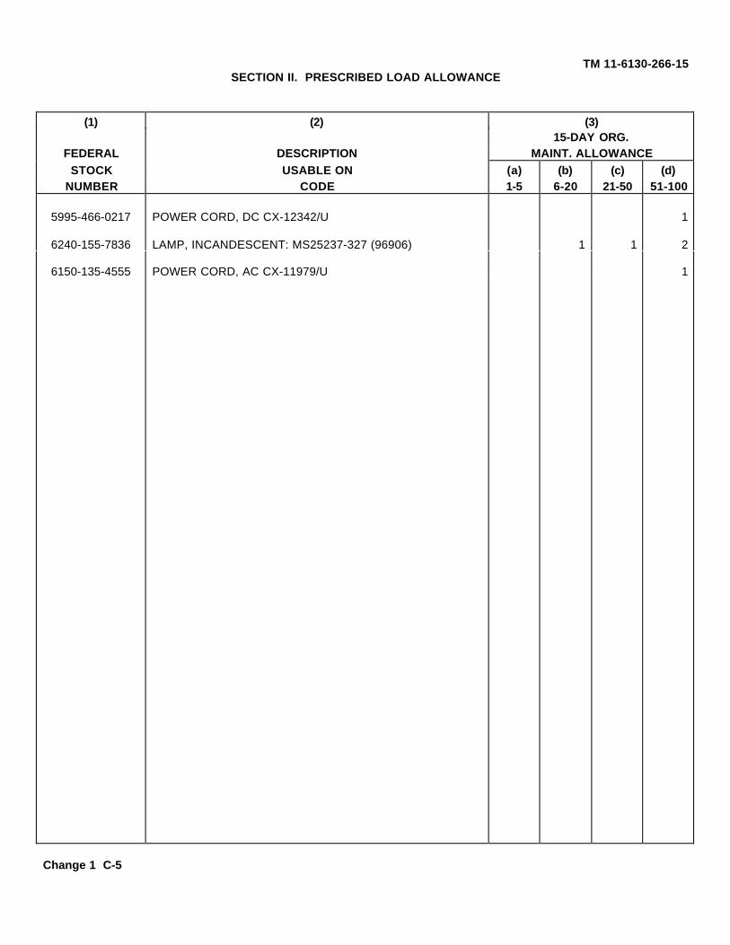
TM 11-6130-266-15SECTION II. PRESCRIBED LOAD ALLOWANCE
(1) (2) (3)15-DAY ORG.
FEDERAL DESCRIPTION MAINT. ALLOWANCESTOCK USABLE ON (a) (b) (c) (d)
NUMBER CODE 1-5 6-20 21-50 51-100
5995-466-0217 POWER CORD, DC CX-12342/U 1
6240-155-7836 LAMP, INCANDESCENT: MS25237-327 (96906) 1 1 2
6150-135-4555 POWER CORD, AC CX-11979/U 1
Change 1 C-5
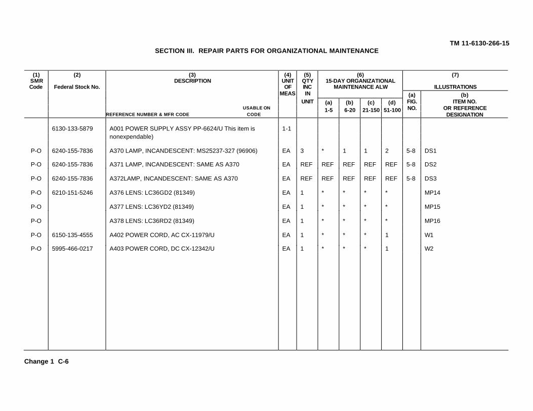
TM 11-6130-266-15SECTION III. REPAIR PARTS FOR ORGANIZATIONAL MAINTENANCE
(3)DESCRIPTION
(4)UNITOF
(5)QTYINC
(6)15-DAY ORGANIZATIONAL
MAINTENANCE ALW
(7)
ILLUSTRATIONSIN (a) (b)
UNIT FIG. ITEM NO.USABLE ON NO. OR REFERENCE
(1)SMRCode
(2)
Federal Stock No.
REFERENCE NUMBER & MFR CODE CODE
MEAS
(a)1-5
(b)6-20
(c)21-150
(d)51-100
DESIGNATION
6130-133-5879 A001 POWER SUPPLY ASSY PP-6624/U This item is 1-1nonexpendable)
P-O 6240-155-7836 A370 LAMP, INCANDESCENT: MS25237-327 (96906) EA 3 * 1 1 2 5-8 DS1
P-O 6240-155-7836 A371 LAMP, INCANDESCENT: SAME AS A370 EA REF REF REF REF REF 5-8 DS2
P-O 6240-155-7836 A372LAMP, INCANDESCENT: SAME AS A370 EA REF REF REF REF REF 5-8 DS3
P-O 6210-151-5246 A376 LENS: LC36GD2 (81349) EA 1 * * * * MP14
P-O A377 LENS: LC36YD2 (81349) EA 1 * * * * MP15
P-O A378 LENS: LC36RD2 (81349) EA 1 * * * * MP16
P-O 6150-135-4555 A402 POWER CORD, AC CX-11979/U EA 1 * * * 1 W1
P-O 5995-466-0217 A403 POWER CORD, DC CX-12342/U EA 1 * * * 1 W2
Change 1 C-6

(3)DESCRIPTION
(10)ILLUSTRATIONS
(6)30-DAY DS MAINT
ALLOWANCE
(7)30-DAY GS MAINT
ALLOWANCE
(1)SMRCODE
(2)FEDERALSTOCK
NUMBER
USABLE ONREFERENCE NUMBER & MFR/ CODE CODE
(4)UNITOF
MEAS
(5)QTY
INC INUNIT
(a)1-20
(b)21-50
(c)51-100
(a)1-20
(b)21-50
(c)51-100
(8)1-YRALWPER
EQUIPCNTGCY
(9)DEPOTMAINTALWPER100
EQUIP
(a)FIG.NO.
(b)ITEM NO. ORREFERENCE
DESIGNATION
TM 11-6130-266-15
SECTION IV. REPAIR PARTS FOR DIRECT SUPPORT, GENERAL SUPPORT, AND DEPOT MAINTENANCE
6130-133-5879 A1 POWER SUPPLY ASSY 1-1PP-6224/u(THIS ITEM IS NONEXPENDABLE)
H-D A2 BRACKET, ANGLE: EA 1 MP1C8263 (18038)
X2-D A3 SCREW, MACHINE: EA 3 H3MS3212-53 (96906)
X2-D A4 BOLT, MACHINE: EA 3 H3MS35303-7 (96906)
X2-D 53104-09-4058 A5 WASHER, FLAT: EA 3 H3MS27183-10 (96906)
X2-D 5310-582-5965 A6 WASHER, DOCK: EA 3 H3MS35338-44 (96906)
M-D A7 BRACKET, BOARD SUPPORT: ER 1 MP28186 (18038)
X2-D 5305-984-6191 A8 SCREW, MACHINE: EA 1 H1MS35206-243 (96906)
X2-D 5310-045-3299 A9 WASHER, LOCK: EA 1 H1MS35338-42 (96906)
X2-D 5310-803-8544 A10 WASHER, FLAT: EA 1 H1MS27183-7 (96906)
P-P 5910-822-5683 A10A CAPACITOR, FIXED: EA 4 * * * * * * * * 5-1 C10CK63AW103M (81349)
P-F 5910-822-5683 A10B CAPACITOR, FIXED: EA REF REF REF REF REF REF REF REF REF 5-1 C11SAME AS A10A
P-F 5910-822-5683 A10C CAPACITOR, FIXED: EA REF RE F REF REF REF REF REF REF REF 5-1 C12SAME AS A10A
P-F 5910-822-5683 A10E CAPACITOR, FIXED: EA REF REF REF REF REF REF REF REF REF 5-1 C13SAME AS A10A
P-F A11 CAP, RECEPTACLE: EA 1 * * * * * * 4 5 MP310-101960-14-3 (07601)
X2-D 5305-984-4988 A12 SCREW, MACHINE: EA 1 H1MS35206-228 (96906)
Change 1 C-7

(10)ILLUSTRATIONS
(6)30-DAY DS MAINT
ALLOWANCE
(7)30-DAY GS MAINT
ALLOWANCE
(1)SMR
CODE
(2)FEDERALSTOCK
NUMBER
(3)DESCRIPTION
USABLE ONREFERENCE NUMBER & MFR CODE CODE
(4)UNITOF
MEAS
(5)QTY
INC INUNIT
(a)1-20
(b)21-50
(c)51-100
(a)1-20
(b)21-50
(c)51-100
(8)1 YR.ALWPER
EQUIPCNTGCY
(9)DEPTMAIN
ALW PER100
EQUIP
(a)FIG.NO.
(b)ITEM NO. OR
REFERENCEDESIGNATION
TM 11-6130-266-15
SECTION IV. REPAIR PARTS FOR DIRECT SUPPORT, GENERAL SUPPORT, AND DEPOT MAINTENANCE
X2-D 5310-045-4007 A13 WASHER, LOCK: EA 1 H1MS35338-41 (96906)
A-H A14 CAPACITOR ASSEMBLY: EA 1 A7C8108 11803B)
X2-D A15 SCREW, MACHINE; EA 2 H2MS3212-25 (96906)
X2-D 5310-596-7693 A16 WASHER, LOCK: EA 2 H2MS35335-31 (96906)
X2-D 5310-934-9757 A17 NUT, PLAINS HEXAGON: EA 2 H2MS35649-282 (96906)
M-D A18 BRACKET, MOUNTING: EA 1 A7MP1C8169 (18038)
P-F A19 CAPACITOR, FIXED, PAPER: EA 2 * 1 1 * 1 1 16 10 5-1 A7C1CP13A3KB105K1 (81349)
X2-D 5310-687-6398 A20 NUT, PLAIN. HEXAGON: EA 1 A7H1MS25082-5 (96906)
X2-D 5310-167-0721 A21 WASHER, LOCK: EA 1 A7H1M535333-41 (96906)
P-F A22 CAPACITOR, FIXED, PAPER: EA REF REF REF REF REF REF REF REF REF 5-1 A7C2SAME AS A19
X2-D 5310-687-6398 A23 NUT, PLAIN, HEXAGON: EA 1 A7H1SAME A5 A20
X2-D 5310-167-0721 A24 WASHER, LOCK: EA 1 A7H1SAME AS A21
C-8

(10)ILLUSTRATIONS
(6)30-DAY DS MAINT
ALLOWANCE
(7)30-DAY GS MAINT
ALLOWANCE
(1)SMR
CODE
(2)FEDERALSTOCK
NUMBER
(3)DESCRIPTION
USABLE ONREFERENCE NUMBER & MFR CODE CODE
(4)UNITOF
MEAS
(5)QTY
INC INUNIT
(a)1-20
(b)21-50
(c)51-100
(a)1-20
(b)21-50
(c)51-100
(8)1 YR.ALWPER
EQUIPCNTGCY
(9)DEPTMAIN
ALW PER100
EQUIP
(a)FIG.NO.
(b)ITEM NO. OR
REFERENCEDESIGNATION
TM 11-6130-266-15SECTION IV. REPAIR PARTS FOR DIRECT SUPPORT, GENERAL SUPPORT, AND DEPOT MAINTENANCE
P-F A-25 TERMINAL, STANDOFF: EA 2 * * 2 * * 2 10 8 A7E14079-1-05-19 (71279)
P-F A-26 TERMINAL, STANDOFF: EA REF REF REF REF REF REF REF REF REF A7E2SAME AS A25
A-H A-27 CAPAClTOR ASSEMBLY: EA 1 A8D8117 (18038)
X2-D 5305-94-6193 A28 SCREW, MACHINE: EA 8 H8MS35206245 (96906)
X2-D 5310-045-3299 A29 WASHER, LOCK: EA 8 H8SAME AS A9
M-D A30 BUSS BAR: EA 4 A8MP1B8152 (18038)
X2-D 5305-989-6265 A31 SCREW, MACHINE: EA 4 A8H4MS35207-262 (96906)
X2-D 5310-045-3296 A32 WASHER, LOCK: EA 4 A8H4MS535338-43 (96906)
P-F A33 CAPACITOR, FIXED: EA 1 * * * * * * 5 10 5-1 A8C1CH08A1NC126J (81349)
P-F A34 CAPACITOR, FIXED, EA 5 2 2 3 2 2 3 40 25 5-1 A8C2ELECTROLYTIC:20000-50-8AMPS (99392)1
X2-D 5305-889-3000 A35 SCREW, MACHINE: EA 1 A8H1MS35206-230 (96906)
X2-D 5310-209-0788 A36 WASHER, LOCK: EA 1 A8H1MS35335-30 (96906)
AMSEL-ME Form 1 Nov 68 6048 (Previous edition is obsolete) PP-6224/U ESC-FM 4534-68
C-9

(10)ILLUSTRATIONS
(6)30-DAY DS MAINT
ALLOWANCE
(7)30-DAY GS MAINT
ALLOWANCE
(1)SMR
CODE
(2)FEDERALSTOCK
NUMBER
(3)DESCRIPTION
USABLE ONREFERENCE NUMBER & MFR CODE CODE
(4)UNITOF
MEAS
(5)QTY
INC INUNIT
(a)1-20
(b)21-50
(c)51-100
(a)1-20
(b)21-50
(c)51-100
(8)1 YR.ALWPER
EQUIPCNTGCY
(9)DEPTMAIN
ALW PER100
EQUIP
(a)FIG.NO.
(b)ITEM NO. OR
REFERENCEDESIGNATION
TM 11-6130-266-15
SECTION IV. REPAIR PARTS FOR DIRECT SUPPORT, GENERAL SUPPORT, AND DEPOT MAINTENANCE
X2-D 5310-934-9747 A37 NUT, PLAIN, HEXAGON: EA 1 A8H1MS35649-262 (96906)
P-F A38 CAPACITOR, FIXED, EA REF REF REF REF REF REF REF REF REF 5-1 A8C3ELECTROLYTIC: SAME AS A34
X2-D 5305-889-3000 A39 SCREW, MACHINE: EA 1 A8H1SAME AS A35
X2-D 5310-209-0788 A40 WASHER, LOCK: EA 1 A8H1SAME AS A36
X2-D 5310-934-9747 A41 NUT, PLAIN, HEXAGON: EA 1 A8H1SAME AS A37
P-F A42 CAPACITOR, FIXED, EA REF REF REF REF REF REF REF REF REF 5-1 A8C4ELECTROLYTIC; SAME AS A34
X2-D 5305-889-3000 A43 SCREW, MACHINE: EA 1 A8H1SAME AS A35
X2-D 5310-209-0788 A44 WASHER, LOCK: EA 1 A8H1SAME AS A36
X2-D 5310-934-9747 A45 NUT, PLAIN, HEXAGON: EA 1 A8H1SAME AS A37
P-F A46 CAPACITOR, FIXED, EA REF REF REF REF REF REF REP REF REF 5-1 A8C5ELECTROLYTIC: SAME AS A34
X2-D 5305-889-3000 A47 SCREW, MACHINE: EA 1 A8H1SAME AS A35
X2-D 5310-209-0788 A48 WASHER, LOCK: EA 1 A8H1SAME AS A36
AMSEL-ME Form 1 Nov 68 6048 (Previous edition is obsolete) PP-6224/U ESC-FM 4534-68
C-10

(10)ILLUSTRATIONS
(6)30-DAY DS MAINT
ALLOWANCE
(7)30-DAY GS MAINT
ALLOWANCE
(1)SMR
CODE
(2)FEDERALSTOCK
NUMBER
(3)DESCRIPTION
USABLE ONREFERENCE NUMBER & MFR CODE CODE
(4)UNITOF
MEAS
(5)QTY
INC INUNIT
(a)1-20
(b)21-50
(c)51-100
(a)1-20
(b)21-50
(c)51-100
(8)1 YR.ALWPER
EQUIPCNTGCY
(9)DEPTMAIN
ALW PER100
EQUIP
(a)FIG.NO.
(b)ITEM NO. OR
REFERENCEDESIGNATION
TM 11-6130-266-15
SECTION IV. REPAIR PARTS FOR DIRECT SUPPORT, GENERAL SUPPORT, AND DEPOT MAINTENANCE
X2-D 5310-934-9747 A49 NUT, PLAIN, HEXAGON: EA 1 A8H1SAME AS A37
P-F A50 CAPACITOR, FIXED, EA REF REF REF REF REF REF REF REF REF 5-1 A8C6ELECTROLYTIC: SAME AS A34
X2-D 5305-889-3000 A51 SCREW, MACHINE: EA 1 A8H1SAME AS A35
X2-D 5310-209-0788 A52 WASHER, LOCK: EA 1 A8H1SAME AS A36
X2-D 5310-934-9747 A53 NUT, PLAIN, HEXAGON: EA 1 A8H1SAME AS A37
M-D A54 CAPACITOR MTG BRACKET EA 1 A8H1ASSEMBLY: D8162 (18038)
M-D 5340-951-1532 A57 CLIP, COMPONENT: EA 1 A8A1A1MP2M517160-36 (96906)
X2-D 5320-117-6815 A58 RIVET: EA 2 A8A1A1H2MS20470AD3-4 (96906)
P-D A59 FASTENER: EA 19 95 A8A1AMP3SMB169134 (80063)
P-D A60 FASTENER: EA REF REF A8A1A1MP4SAME AS A59
P-D A61 FASTENER: EA REF REF A8A1A1MP5SAME AS A59
P-D A62 FASTENER: EA REF REF APA1A1MP6SAME AS A59
AMSEL-ME Form 1 Nov 68 6048 (Previous edition is obsolete) PP-6224/U ESC-FM 4534-68
C-11

(10)ILLUSTRATIONS
(6)30-DAY DS MAINT
ALLOWANCE
(7)30-DAY GS MAINT
ALLOWANCE
(1)SMR
CODE
(2)FEDERALSTOCK
NUMBER
(3)DESCRIPTION
USABLE ONREFERENCE NUMBER & MFR CODE CODE
(4)UNITOF
MEAS
(5)QTY
INC INUNIT
(a)1-20
(b)21-50
(c)51-100
(a)1-20
(b)21-50
(c)51-100
(8)1 YR.ALWPER
EQUIPCNTGCY
(9)DEPTMAIN
ALW PER100
EQUIP
(a)FIG.NO.
(b)ITEM NO. OR
REFERENCEDESIGNATION
TM 11-6130-266-15
SECTION IV. REPAIR PARTS FOR DIRECT SUPPORT, GENERAL SUPPORT, AND DEPOT MAINTENANCE
P-D A63 FASTENER: EA REF REF A8A1A 1MP7SAME AS A59
P-D A64 FASTENER: EA REF REF A8A1A1MP8SAME AS A59
P-D A65 FASTENER: EA REF REF A8A1A1MP9SAME AS A59
P-D A66 FASTENER: EA REF REF A8A1A1MP10SAME AS A59
P-D A67 FASTENER: EA REF REF A8A1A1MP11SAME AS A59
P-D A68 FASTENER: EA REP REF A8A1A1MP12SAME AS A59
P-D A69 FASTENER: EA REF REF A8A1A1MP13SAME AS A59
P-D A76 FASTENER: EA REF REF A8A1A1MP14SAME AS A59
P-D A71 FASTENER: EA REF REF A8A1A1MP15SAME AS A59
P-D A72 FASTENER: EA REF REF A8A1A1MP16SAME AS A59
P-D A73 FASTENER: EA REF REF A8A1A1MP17SAME AS A59
P-D A74 FASTENER: EA REF REF A8A1A1MP18SAME AS A59
AMSEL-ME Form 1 Nov 68 6048 (Previous edition is obsolete) PP-6224/U ESC-FM 4534-68
C-12

(10)ILLUSTRATIONS
(6)30-DAY DS MAINT
ALLOWANCE
(7)30-DAY GS MAINT
ALLOWANCE
(1)SMR
CODE
(2)FEDERALSTOCK
NUMBER
(3)DESCRIPTION
USABLE ONREFERENCE NUMBER & MFR CODE CODE
(4)UNITOF
MEAS
(5)QTY
INC INUNIT
(a)1-20
(b)21-50
(c)51-100
(a)1-20
(b)21-50
(c)51-100
(8)1 YR.ALWPER
EQUIPCNTGCY
(9)DEPTMAIN
ALW PER100
EQUIP
(a)FIG.NO.
(b)ITEM NO. OR
REFERENCEDESIGNATION
TM 11-6130-266-15
SECTION IV. REPAIR PARTS FOR DIRECT SUPPORT, GENERAL SUPPORT, AND DEPOT MAINTENANCE
P-C A15 FASTENER: EA REF REF A8A1A1MP19SAME AS A59
P-D A76 FASTENER: EA REF REF A8A1A1MP20SAME AS A59
P-D A77 FASTENER: EA REF REF ABA1A1MP21SAME AS A59
M-D A78 CLAMP: EA A8MP2SMB450392 (80063)
X2-D 5305-889-3000 A79 SCREW, MACHINE: EA 3 A8H3SAME AS A35
X2-D 5310-045-4007 A80 WASHER, LOCK: EA 3 A8H3SAME AS A13
X2-D 5310-082-1404 A81 WASHER, FLAT: EA 3 A8H3M527183-6 (96906)
M-D A82 CLAMP: EA REF A8MP3SAME AS A78
X2-D 5305-889-3000 A83 SCREW, MACHINE: EA 3 A8H3
SAME AS A35
X2-3 5310-C45-4007 A84 WASHER, LOCK: EA 3 A8H3SAME AS A13
X2-D 5310-C82-1404 A85 WASHER, FLAT: EA 3 A8H3SAME AS A81
M-D A86 CLAMP: EA REF A8MP4SAME AS A78
AMSEL-ME Form 1 Nov 68 6048 (Previous edition is obsolete) PP-6224/U ESC-FM 4534-68
C-13

(10)ILLUSTRATIONS
(6)30-DAY DS MAINT
ALLOWANCE
(7)30-DAY GS MAINT
ALLOWANCE
(1)SMR
CODE
(2)FEDERALSTOCK
NUMBER
(3)DESCRIPTION
USABLE ONREFERENCE NUMBER & MFR CODE CODE
(4)UNITOF
MEAS
(5)QTY
INC INUNIT
(a)1-20
(b)21-50
(c)51-100
(a)1-20
(b)21-50
(c)51-100
(8)1 YR.ALWPER
EQUIPCNTGCY
(9)DEPTMAIN
ALW PER100
EQUIP
(a)FIG.NO.
(b)ITEM NO. OR
REFERENCEDESIGNATION
TM 11-6130-266-15
SECTION IV. REPAIR PARTS FOR DIRECT SUPPORT, GENERAL SUPPORT, AND DEPOT MAINTENANCE
X2-D 5305-889-3000 A87 SCREW, MACHINE; EA 3 A8H3SAME AS A59
X2-D 5310-045-4007 A88 WASHER, LOCK: EA 3 A8H3SAME AS A13
X2-D 5310-082-1404 A89 WASHER, FLAT: EA 3 A8H3SAME AS A81
M-D A9 CLAMP: EA REF A8MP5SAME AS A78
X2-D 5305-889-3000 A91 SCREW, MACHINE; EA 3 A8H3SAME AS A35
X2-D 5310-045-4007 A92 WASHER, LOCK: EA 3 A8H3SAME AS A13
X2-D 5310-082-1404 A93 WASHER, FLAT: EA 3 A8H3SAME AS A81
M-D A94 CLAMP: EA REF A8MP6SAME AS A78
X2-D 5305-889-3000 A95 SCREW, MACHINE: EA 3 A8H3SAME AS A35
X2-D 5310-045-4007 A96 WASHER, LOCK; EA 3 A8H3SAME AS A13
X2-D 5310-082-1404 A97 WASHER, FLAT: EA 3 A8H3SAME AS A81
P-F A98 TERMINAL, INSULATED; EA 2 * * 2 * * 2 10 10 A8E1MILT55155-21-3 (81349)
AMSEL-ME Form 1 Nov 68 6048 (Previous edition is obsolete) PP-6224/U ESC-FM 4534-68
C-14
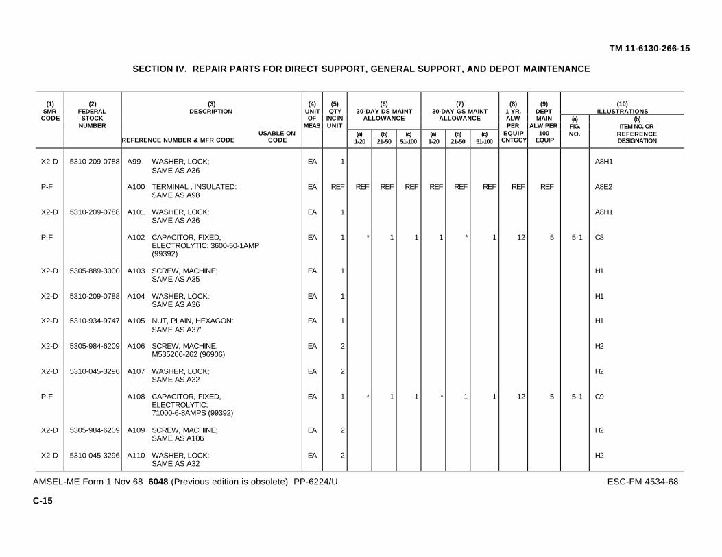
(10)ILLUSTRATIONS
(6)30-DAY DS MAINT
ALLOWANCE
(7)30-DAY GS MAINT
ALLOWANCE
(1)SMR
CODE
(2)FEDERALSTOCK
NUMBER
(3)DESCRIPTION
USABLE ONREFERENCE NUMBER & MFR CODE CODE
(4)UNITOF
MEAS
(5)QTY
INC INUNIT
(a)1-20
(b)21-50
(c)51-100
(a)1-20
(b)21-50
(c)51-100
(8)1 YR.ALWPER
EQUIPCNTGCY
(9)DEPTMAIN
ALW PER100
EQUIP
(a)FIG.NO.
(b)ITEM NO. OR
REFERENCEDESIGNATION
TM 11-6130-266-15
SECTION IV. REPAIR PARTS FOR DIRECT SUPPORT, GENERAL SUPPORT, AND DEPOT MAINTENANCE
X2-D 5310-209-0788 A99 WASHER, LOCK; EA 1 A8H1SAME AS A36
P-F A100 TERMINAL , INSULATED: EA REF REF REF REF REF REF REF REF REF A8E2SAME AS A98
X2-D 5310-209-0788 A101 WASHER, LOCK: EA 1 A8H1SAME AS A36
P-F A102 CAPACITOR, FIXED, EA 1 * 1 1 1 * 1 12 5 5-1 C8ELECTROLYTIC: 3600-50-1AMP(99392)
X2-D 5305-889-3000 A103 SCREW, MACHINE; EA 1 H1SAME AS A35
X2-D 5310-209-0788 A104 WASHER, LOCK: EA 1 H1SAME AS A36
X2-D 5310-934-9747 A105 NUT, PLAIN, HEXAGON: EA 1 H1SAME AS A37'
X2-D 5305-984-6209 A106 SCREW, MACHINE; EA 2 H2M535206-262 (96906)
X2-D 5310-045-3296 A107 WASHER, LOCK; EA 2 H2SAME AS A32
P-F A108 CAPACITOR, FIXED, EA 1 * 1 1 * 1 1 12 5 5-1 C9ELECTROLYTIC;71000-6-8AMPS (99392)
X2-D 5305-984-6209 A109 SCREW, MACHINE; EA 2 H2SAME AS A106
X2-D 5310-045-3296 A110 WASHER, LOCK: EA 2 H2SAME AS A32
AMSEL-ME Form 1 Nov 68 6048 (Previous edition is obsolete) PP-6224/U ESC-FM 4534-68
C-15

(10)ILLUSTRATIONS
(6)30-DAY DS MAINT
ALLOWANCE
(7)30-DAY GS MAINT
ALLOWANCE
(1)SMR
CODE
(2)FEDERALSTOCK
NUMBER
(3)DESCRIPTION
USABLE ONREFERENCE NUMBER & MFR CODE CODE
(4)UNITOF
MEAS
(5)QTY
INC INUNIT
(a)1-20
(b)21-50
(c)51-100
(a)1-20
(b)21-50
(c)51-100
(8)1 YR.ALWPER
EQUIPCNTGCY
(9)DEPTMAIN
ALW PER100
EQUIP
(a)FIG.NO.
(b)ITEM NO. OR
REFERENCEDESIGNATION
TM 11-6130-266-15
SECTION IV. REPAIR PARTS FOR DIRECT SUPPORT, GENERAL SUPPORT, AND DEPOT MAINTENANCE
X2-D 53C5-889-300 A111 SCREW, MACHINE: EA 1 H1SAME AS P35
X2-D 5310-209-0788 A112 WASHER, LOCK: E 1 H1SAME AS A36
X2-D 5310-934-9747 A113 NUT, PLAIN, HEXAGON: EA H1SAME AS A37
P-D A114 CARD RACK ASSEMBLY: EA 1 3 A11D8219 (18038)
X2-D 5305-984-4983 A115 SCREW, MACHINE EA 4 H4MS35206-226 (96906)
X2-D 5310-045-4007 A116 WASHER, LOCK: EA 4 H4SAME AS A13
P-H A117 CONNECTOR, RECEPTACLE, EA 3 * 1 1 16 20 A11J1ELEC: MILC21097-4-01(81349)
X2-D 5305-984-4976 A118 SCREW, MACHINE; EA 2 A11H2MS35206-219 (96906)
X2-D 5310-543-2410 A119 WASHER, LOCK: EA 2 A11H2MS535338-40 (96906)
X2-D 5310-934-9739 A120 NUT, PLAIN, HEXAG: EA 2 A11H2M535649-242 (96906)
P-H A121 CONNECTOR, RECEPTACLE EA REF REF REF REF REF REF A11J2ELEC: SAME AS A117
X2-D 5305-984-4976 A122 SCREW, MACHINE EA 2 A11H2
AMSEL-ME Form 1 Nov 68 6048 (Previous edition is obsolete) PP-6224/U ESC-FM 4534-68
C-16

(10)ILLUSTRATIONS
(6)30-DAY DS MAINT
ALLOWANCE
(7)30-DAY GS MAINT
ALLOWANCE
(1)SMR
CODE
(2)FEDERALSTOCK
NUMBER
(3)DESCRIPTION
USABLE ONREFERENCE NUMBER & MFR CODE CODE
(4)UNITOF
MEAS
(5)QTY
INC INUNIT
(a)1-20
(b)21-50
(c)51-100
(a)1-20
(b)21-50
(c)51-100
(8)1 YR.ALWPER
EQUIPCNTGCY
(9)DEPTMAIN
ALW PER100
EQUIP
(a)FIG.NO.
(b)ITEM NO. OR
REFERENCEDESIGNATION
TM 11-6130-266-15
SECTION IV. REPAIR PARTS FOR DIRECT SUPPORT, GENERAL SUPPORT, AND DEPOT MAINTENANCE
X2-D 5310-543-2410 A123 WASHER, LOCK: EA 22 A11H2SAME AS Al19
X2-D 5310-934-9739 A124 NUT, PLAIN, HEXAGON; EA 22 A11H2SAME AS A120
P-H 5935 A125 CONNECTOR, RECEPTACLE, EA REF REF REF REF REF REF A11J5ELEC: SAME AS A117
X2-D 5305-984-4976 A126 SCREW, MACHINE: EA 2 A11H2SAME AS Al18
X2-D 5310-543-2410 A127 WASHER, LOCK: EA 2 A11H2SAME AS Al19
X2-D 5310-934-9739 A128 NUT, PLAIN, HEXAGON: EA 2 A11H2SAME AS A120
P-H A161 CHOKE: EA 1 * * * 4 5 5-1 L1SMD667924 (18038)
X2-D 5305-983-6659 A162 SCREW, MACHINE: EA 4 H4MS16998-42 (96906)
X2-D 5310-582-5965 A163 WASHER, LOCK: EA 4 H4SAME AS A6
X2-D 5310-809-4058 A164 WASHER, FLAT: EA 4 H4SAME AS A5
P-F A165 CIRCUIT BREAKER: EA 1 * * 1 * * 1 8 7 5-8 CB1SMC667918 (18038)
P-F A166 CIRCUIT BREAKER: EA 1 * * 1 * * 1 8 7 5-8 CB2SMC667919 (18038)
AMSEL-ME Form 1 Nov 68 6048 (Previous edition is obsolete) PP-6224/U ESC-FM 4534-68
C-17

(10)ILLUSTRATIONS
(6)30-DAY DS MAINT
ALLOWANCE
(7)30-DAY GS MAINT
ALLOWANCE
(1)SMR
CODE
(2)FEDERALSTOCK
NUMBER
(3)DESCRIPTION
USABLE ONREFERENCE NUMBER & MFR CODE CODE
(4)UNITOF
MEAS
(5)QTY
INC INUNIT
(a)1-20
(b)21-50
(c)51-100
(a)1-20
(b)21-50
(c)51-100
(8)1 YR.ALWPER
EQUIPCNTGCY
(9)DEPTMAIN
ALW PER100
EQUIP
(a)FIG.NO.
(b)ITEM NO. OR
REFERENCEDESIGNATION
TM 11-6130-266-15
SECTION IV. REPAIR PARTS FOR DIRECT SUPPORT, GENERAL SUPPORT, AND DEPOT MAINTENANCE
M-D A167 CLAMP, CAPACITOR: EA MP4SMB450423 (80063)
X2-D 5305-984-4983 A168 SCREW, MACHINE; EA 2 H2SAME AS A115
X2-D 5310-045-4007 A169 WASHER, LOCK: EA 2 H2SAME AS A13
X2-D 5310-983-8483 A170 WASHER. FLAT: EA 2 H2MS27183-5 (96906)
M-D A171 CLAMP CAPACITOR: EA 1 MP5SM8667955 (18038)
X2-D 5305-984-4983 A172 SCREW, MACHINE: EA 3 H3SAME AS A115
X2-D 5310-045-4007 A173 WASHER, LOCK: EA 3 H3SAME AS A13
X2-D 5310-983-8483 A174 WASHER, FLAT: EA 3 H3SAME AS A170
P-F A175 CLAMP, CABLE; EA 3 * * 1 * * 1 8 9 MP6MS21919-4 (96906)
X2-D 5305-984-6191 A176 SCREW, MACHINE: EA 1 H1SAME AS A8
X2-D 5310-045-3299 A177 WASHER, LOCK: EA 1 H1SAME AS A9
P-F A178 CLAMP, CABLE: EA REF REF REP REF REF REP REF REF REF MP7SAME AS A175
AMSEL-ME Form 1 Nov 68 6048 (Previous edition is obsolete) PP-6224/U ESC-FM 4534-68
C-18

(10)ILLUSTRATIONS
(6)30-DAY DS MAINT
ALLOWANCE
(7)30-DAY GS MAINT
ALLOWANCE
(1)SMR
CODE
(2)FEDERALSTOCK
NUMBER
(3)DESCRIPTION
USABLE ONREFERENCE NUMBER & MFR CODE CODE
(4)UNITOF
MEAS
(5)QTY
INC INUNIT
(a)1-20
(b)21-50
(c)51-100
(a)1-20
(b)21-50
(c)51-100
(8)1 YR.ALWPER
EQUIPCNTGCY
(9)DEPTMAIN
ALW PER100
EQUIP
(a)FIG.NO.
(b)ITEM NO. OR
REFERENCEDESIGNATION
TM 11-6130-266-15
SECTION IV. REPAIR PARTS FOR DIRECT SUPPORT, GENERAL SUPPORT, AND DEPOT MAINTENANCE
X2-D 5305-984-6191 A179 SCREW, MACHINE EA 1 H1SAME AS A8
X2-D 5310-045-3299 A180 WASHER, LOCK: EA 1 H1SAME AS A9
P-F A181 CLAMP, CABLE: EA REF REF REF REF REF REF REF REF REF MP8SAME AS A175
X2-D 5305-984-6191 PA182 SCREW, MACHINE; EA 1 H1SAME AS A8
X2-D 5310-045-3299 A183 WASHER, LOCK: EA 1 H1SAME AS A9
P-F A184 CLAMP, CABLE: EA 1 * * * * * * 4 3 MP9MS21919-5 (96906)
X2-D 5305-889-6000 A185 SCREW, MACHINE: EA 1 H1SAME AS A35
X2-D 5310-045-4007 A186 WASHER, LOCK: EA 1 H1SAME AS A13
X2-D 5310-983-8483 A187 WASHER, FLAT: EA 1 H1SAME AS A170
A-H A189 COMPONENT BOARD ASSEMBLY; EA 1 5-2 A1SMC667850 (18038)
P-F 5910-078-8110 A190 CAPACITOR, FIXED, EA 1 * 1 1 * 1 1 12 10 5-2 A1C1ELECTROLYTIC: C125BJ600TP3(81349)
AMSEL-ME Form 1 Nov 68 6048 (Previous edition is obsolete) PP-6224/U ESC-FM 4534-68
C-19

(10)ILLUSTRATIONS
(6)30-DAY DS MAINT
ALLOWANCE
(7)30-DAY GS MAINT
ALLOWANCE
(1)SMR
CODE
(2)FEDERALSTOCK
NUMBER
(3)DESCRIPTION
USABLE ONREFERENCE NUMBER & MFR CODE CODE
(4)UNITOF
MEAS
(5)QTY
INC INUNIT
(a)1-20
(b)21-50
(c)51-100
(a)1-20
(b)21-50
(c)51-100
(8)1 YR.ALWPER
EQUIPCNTGCY
(9)DEPTMAIN
ALW PER100
EQUIP
(a)FIG.NO.
(b)ITEM NO. OR
REFERENCEDESIGNATION
TM 11-6130-266-15SECTION IV. REPAIR PARTS FOR DIRECT SUPPORT, GENERAL SUPPORT, AND DEPOT MAINTENANCE
P-F 5910-082-4925 A191 CAPACITOR, FIXED, EA 1 1 1 2 1 1 2 27 30 5-2 A1C3ELECTROLYTIC: C513BF476K(81349)
P-P 5910-644-6164 A192 CAPACITOR, FIXED, PLASTIC: EA 1 * 1 1 * 1 1 12 15 5-2 A1C2CP09A1KB104K1 (81349)
P-H 5935 A193 CONNECTOR, PLUG, ELECTRICAL: EA 1 * 1 1 16 20 A1P1MILC21097-5-01 (81349)
X2-D A194 SCREW, MACHINE: EA 2 A1H2M535206-323 (96906)
X2-D 5310-543-2410 A195 WASHER, LOCK: EA 2 A1H2SAME AS A119
X2-D 5310-934-9739 A196 NUT, PLAIN, HEXAGON: EA 2 A1H2SAME AS A120
P-F 6625-929-3950 A197 EJECTOR, CARD: EA 1 * 1 1 * 1 1 13 15 A1MP2SMB667855 (18677)
P-F A199 HEAT SINK: EA 1 * * * * * * 5 3 A1MP121115B (75247)
P-F A200 PAD, TRANSISTOR: EA 9 1 3 5 1 3 5 53 68 A1MP37717-5DAP (75247)
P-F A201 PAD, TRANSISTOR: EA REF REF REF REF REF REF REF REF REF A1MP4SAME AS A200
P-F A202 PAD, TRANSISTOR: EA REF REF REF REF REF REF REF REF REF A1MP5SAME AS 4200
P-F A203 PAD, TRANSISTOR: EA REF REF REF RED REF REF REF REF REF A1MP6SAME AS A200
P-F A204 PAD, TRANSISTOR: EA REF REF REF REP REF REF REF REF REF A1MP7SAME AS A200
AMSEL-ME Form 1 Nov 68 6048 (Previous edition is obsolete) PP-6224/U ESC-FM 4534-68
C-20

(10)ILLUSTRATIONS
(6)30-DAY DS MAINT
ALLOWANCE
(7)30-DAY GS MAINT
ALLOWANCE
(1)SMR
CODE
(2)FEDERALSTOCK
NUMBER
(3)DESCRIPTION
USABLE ONREFERENCE NUMBER & MFR CODE CODE
(4)UNITOF
MEAS
(5)QTY
INC INUNIT
(a)1-20
(b)21-50
(c)51-100
(a)1-20
(b)21-50
(c)51-100
(8)1 YR.ALWPER
EQUIPCNTGCY
(9)DEPTMAIN
ALW PER100
EQUIP
(a)FIG.NO.
(b)ITEM NO. OR
REFERENCEDESIGNATION
TM 11-6130-266-15
SECTION IV. REPAIR PARTS FOR DIRECT SUPPORT, GENERAL SUPPORT, AND DEPOT MAINTENANCE
P-F A205 PAD, TRANSISTOR: EA REF REF REF REF REF REF REF REF REF A1MP8SAME AS A200
P-F A206 PAD, TRANSISTOR: EA REF REF REF REF REF REF REF REF REF A1MP9SAME AS A200
P-F A207 PAD, TRANSISTOR; EA REF REF REF REF REF REF REF REF REF A1MP10SAME AS A200
P-F A208 PAD, TRANSISTOR; EA REF REF REF REF REF REF REF REF REF A1MP11SAME AS A200
P-D A209 PRINTED CIRCUIT BOARD: EA 1 4 A1MP1SMD667852 (18038)
P-F A210 RELAY: EA 2 * * * * * * 10 10 5-2 A1K1MILR5757-29A008 (81349)
P-F A211 RELAY: EA REF REF REF REF REF REF REF REP REF 5-2 A1K2SAME AS A210
P-F 5905-882-0061 A212 RESISTOR, FIXED, FILM: EA 1 * * * * * * 4 3 5-2 A1R1RL20S472J (81349)
P-F 5905-835-6424 A213 RESISTOR, FIXED, FILM: EA 1 * * * * * * 4 3 5-2 A1R2RN60C3831F (81349)
P-F 5905-833-8355 A214 RESISTOR, FIXED, FILM: EA 1 * * * * * * 4 3 5-2 A1R3RN60C5901F (81349)
P-F 5905-717-3342 A215 RESISTOR, FIXED, FILM: EA 2 * * 1 * * 1 8 9 5-2 A1R4RL205182J (81349)
P-F 5905-717-3342 A216 RESISTOR, FIXED, FILM: EA REF REF REF REF REF REF REF REF REF 5-2 A1R13SAME AS A215
P-F 5905-836-2859 A217 RESISTOR, FIXED, FILM.: EA 1 * * * * * * 4 3 5-2 A1R5RN60C9761F (81349)
P-F 5905-810-7778 A218 RESISTOR, FIXED, FILM: EA 1 * * * * * * 4 3 5-2 A1P6RN60C1542F (81349)
AMSEL-ME Form 1 Nov 68 6048 (Previous edition is obsolete) PP-6224/U ESC-FM 4534-68
C-21
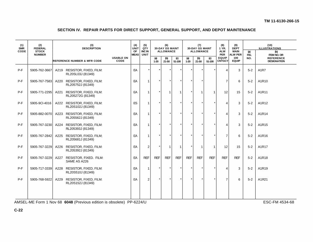
(10)ILLUSTRATIONS
(6)30-DAY DS MAINT
ALLOWANCE
(7)30-DAY GS MAINT
ALLOWANCE
(1)SMR
CODE
(2)FEDERALSTOCK
NUMBER
(3)DESCRIPTION
USABLE ONREFERENCE NUMBER & MFR CODE CODE
(4)UNITOF
MEAS
(5)QTY
INC INUNIT
(a)1-20
(b)21-50
(c)51-100
(a)1-20
(b)21-50
(c)51-100
(8)1 YR.ALWPER
EQUIPCNTGCY
(9)DEPTMAIN
ALW PER100
EQUIP
(a)FIG.NO.
(b)ITEM NO. OR
REFERENCEDESIGNATION
TM 11-6130-266-15
SECTION IV. REPAIR PARTS FOR DIRECT SUPPORT, GENERAL SUPPORT, AND DEPOT MAINTENANCE
P-F 5905-762-3667 A219 RESISTOR, FIXED, FILM: EA * * * * * * * 4 3 5-2 A1R7RL20SL03J (81349)
P-F 5905-767-7583 A220 RESISTOR, FIXED, FILM: EA 1 * * * * * 7 6 5-2 A1R10RL205752J (81349)
P-F 5905-771-2295 A221 RESISTOR, FIXED, FILM: EA 1 * 1 1 * 1 1 12 15 5-2 A1R11RL205272G (81349)
P-F 5905-9Cl-4016 A222 RESISTOR, FIXED, FILM: ES 1 * * * * * * 4 3 5-2 A1R12RL20S102J (81349)
P-F 5905-882-0070 A223 RESISTOR, FIXED, FILM: EA 1 * * * * * * 4 3 5-2 A1R14RL205562J (81349)
P-F 5905-767-3230 A224 RESISTOR, FIXED, FILM: EA 1 * * * * * * 4 3 5-2 A1R15RL205393J (81349)
P-F 5905-767-2842 A225 RESISTOR, FIXED, FILM; EA 1 * * * * * * 7 6 5-2 A1R16RL205681J (81349)
P-F 5905-767-3229 A226 RESISTOR, FIXED, FILM: EA 2 * 1 1 * 1 1 12 15 5-2 A1R17RL205392J (81349)
P-F 5905-767-3229 A227 RESISTOR, FIXED. FILM: EA REF REF REF REF REF REF REF REF REF 5-2 A1R18SAME AS A226
P-F 5905-717-3339 A228 RESISTOR, FIXED, FILM: EA 1 * * * * * * 4 3 5-2 A1R19RL20S510J (81349)
P-F 5905-768-5922 A229 RESISTOR, FIXED, FILM: EA 2 * * * * * * 7 6 5-2 A1R21RL20S152J (81349)
AMSEL-ME Form 1 Nov 68 6048 (Previous edition is obsolete) PP-6224/U ESC-FM 4534-68
C-22
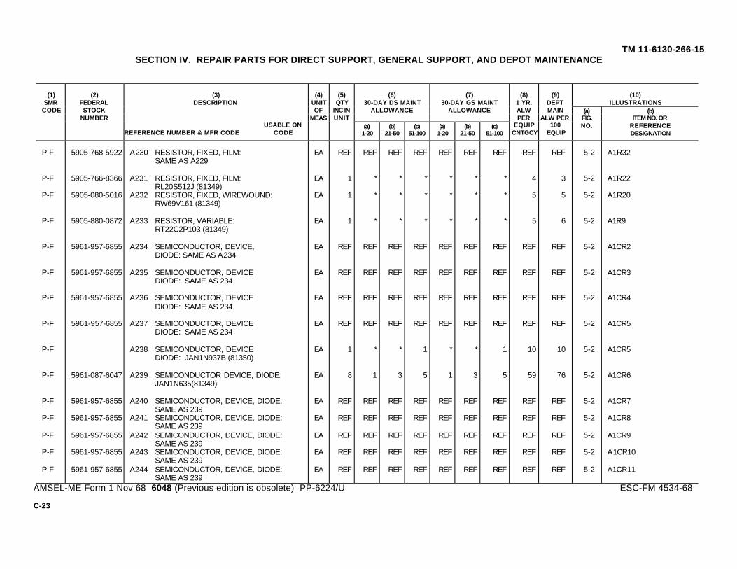
(10)ILLUSTRATIONS
(6)30-DAY DS MAINT
ALLOWANCE
(7)30-DAY GS MAINT
ALLOWANCE
(1)SMR
CODE
(2)FEDERALSTOCK
NUMBER
(3)DESCRIPTION
USABLE ONREFERENCE NUMBER & MFR CODE CODE
(4)UNITOF
MEAS
(5)QTY
INC INUNIT
(a)1-20
(b)21-50
(c)51-100
(a)1-20
(b)21-50
(c)51-100
(8)1 YR.ALWPER
EQUIPCNTGCY
(9)DEPTMAIN
ALW PER100
EQUIP
(a)FIG.NO.
(b)ITEM NO. OR
REFERENCEDESIGNATION
TM 11-6130-266-15SECTION IV. REPAIR PARTS FOR DIRECT SUPPORT, GENERAL SUPPORT, AND DEPOT MAINTENANCE
P-F 5905-768-5922 A230 RESISTOR, FIXED, FILM: EA REF REF REF REF REF REF REF REF REF 5-2 A1R32SAME AS A229
P-F 5905-766-8366 A231 RESISTOR, FIXED, FILM: EA 1 * * * * * * 4 3 5-2 A1R22RL20S512J (81349)
P-F 5905-080-5016 A232 RESISTOR, FIXED, WIREWOUND: EA 1 * * * * * * 5 5 5-2 A1R20RW69V161 (81349)
P-F 5905-880-0872 A233 RESISTOR, VARIABLE: EA 1 * * * * * * 5 6 5-2 A1R9RT22C2P103 (81349)
P-F 5961-957-6855 A234 SEMICONDUCTOR, DEVICE, EA REF REF REF REF REF REF REF REF REF 5-2 A1CR2DIODE: SAME AS A234
P-F 5961-957-6855 A235 SEMICONDUCTOR, DEVICE EA REF REF REF REF REF REF REF REF REF 5-2 A1CR3DIODE: SAME AS 234
P-F 5961-957-6855 A236 SEMICONDUCTOR, DEVICE EA REF REF REF REF REF REF REF REF REF 5-2 A1CR4DIODE: SAME AS 234
P-F 5961-957-6855 A237 SEMICONDUCTOR, DEVICE EA REF REF REF REF REF REF REF REF REF 5-2 A1CR5DIODE: SAME AS 234
P-F A238 SEMICONDUCTOR, DEVICE EA 1 * * 1 * * 1 10 10 5-2 A1CR5DIODE: JAN1N937B (81350)
P-F 5961-087-6047 A239 SEMICONDUCTOR DEVICE, DIODE: EA 8 1 3 5 1 3 5 59 76 5-2 A1CR6JAN1N635(81349)
P-F 5961-957-6855 A240 SEMICONDUCTOR, DEVICE, DIODE: EA REF REF REF REF REF REF REF REF REF 5-2 A1CR7SAME AS 239
P-F 5961-957-6855 A241 SEMICONDUCTOR, DEVICE, DIODE: EA REF REF REF REF REF REF REF REF REF 5-2 A1CR8SAME AS 239
P-F 5961-957-6855 A242 SEMICONDUCTOR, DEVICE, DIODE: EA REF REF REF REF REF REF REF REF REF 5-2 A1CR9SAME AS 239
P-F 5961-957-6855 A243 SEMICONDUCTOR, DEVICE, DIODE: EA REF REF REF REF REF REF REF REF REF 5-2 A1CR10SAME AS 239
P-F 5961-957-6855 A244 SEMICONDUCTOR, DEVICE, DIODE: EA REF REF REF REF REF REF REF REF REF 5-2 A1CR11SAME AS 239
AMSEL-ME Form 1 Nov 68 6048 (Previous edition is obsolete) PP-6224/U ESC-FM 4534-68
C-23

(10)ILLUSTRATIONS
(6)30-DAY DS MAINT
ALLOWANCE
(7)30-DAY GS MAINT
ALLOWANCE
(1)SMR
CODE
(2)FEDERALSTOCK
NUMBER
(3)DESCRIPTION
USABLE ONREFERENCE NUMBER & MFR CODE CODE
(4)UNITOF
MEAS
(5)QTY
INC INUNIT
(a)1-20
(b)21-50
(c)51-100
(a)1-20
(b)21-50
(c)51-100
(8)1 YR.ALWPER
EQUIPCNTGCY
(9)DEPTMAIN
ALW PER100
EQUIP
(a)FIG.NO.
(b)ITEM NO. OR
REFERENCEDESIGNATION
TM 11-6130-266-15
SECTION IV. REPAIR PARTS FOR DIRECT SUPPORT, GENERAL SUPPORT, AND DEPOT MAINTENANCE
P-F 5961-087-6047 A245 SEMICONDUCTOR DEVICE, EA REF REF REF REF REF REF REF REF REF 5-2 A1CR12DIODE: SAME AS A239
P-F i5961-087-6047 A246 SEMICONDUCTOR DEV ICE, EA REF REF REF REF REF REF REF REF REF 5-2 A1CR13DIODE: SAME AS A239
P2-F 5940-280-0601 A247 TERMINAL, STUD: EA 2 A1TP12027-2 (71279)
X2-D 5940-280-0601 A248 TERMINAL, STUD: EA REF A1TP2SAME AS A247
P-F 5961-853-2601 249 TRANSISTOR: EA 6 1 2 3 1 2 3 40 52 5-2 A1Q1JAN2NL893 (81350)
P-F 5961-853-2601 A250 TRANSISTOR: EA REF REF REF REF REF REF REF REF REF 5-2 A2Q2SAME AS A249
P-F 5961-853-2601 A251 TRANSISTOR: EA REF REF REF REF REF REF REF REF REF 5-2 A2Q9SAME AS A249
P-F 5961-853-2601 A252 TRANSISTOR EA REF REF REF REF REF REF REF REF REF 5-2 A2Q5SAME AS A249
P-F 5961-853D-260i1A253 TRANSISTOR; EA REF REF REF REF REF REF REF REF REF 5-2 A2Q6SAME AS A249
P-F 5961-853-2601 A254 TRANSISTOR; EA REF REF REF REF REF REF REF REF REF 5-2 A2Q7SAME AS A249
P-F 5961-880-4779 A255 TRANSISTOR: EA 3 * 1 1 * 1 1 16 20 5-2 A1Q3JAN2N2905 (81350)
P-F 5961-880-4779 A256 TRANSISTOR; EA REF REF REF REF REF REF REF REF REF 5-2 A1Q4SAME AS A255
AMSEL-ME Form 1 Nov 68 6048 (Previous edition is obsolete) PP-6224/U ESC-FM 4534-68
C-24

(3)DESCRIPTION
(10)ILLUSTRATIONS
(6)30-DAY DS MAINT
ALLOWANCE
(7)30-DAY GS MAINT
ALLOWANCE
(2)FEDERALSTOCK
NUMBER
(2)FEDERALSTOCK
NUMBER
USABLE ONREFERENCE NUMBER & MFR/ CODE CODE
(4)UNITOF
MEAS
(5)QTY
INC INUNIT
(a)1-20
(b)21-50
(c)51-100
(a)1-20
(b)21-50
(c)51-100
(8)1-YRALWPER
EQUIPCNTGCY
(9)DEPOTMAINTALWPER100
EQUIP
(a)FIG.NO.
(b)ITEM NO. ORREFERENCE
DESIGNATION
TM 11-6130-266-15SECTION IV. REPAIR PARTS FOR DIRECT SUPPORT, GENERAL SUPPORT, AND DEPOT MAINTENANCE
(CONTINUED)
P-F 5961-880-4779 A257 TRANSISTOR: EA REF REF REF REF REF REF REF REF REF 5-2 A1Q8SAME AS A255
A-H A258 COMPONENT BOARD ASSEMBLY: EA 1 5-3 A2SMC667858 (18038)
P-F 5910-109-1987 A258A CAPACITOR, FIXED: EA 6 * * * * * * * * 5-3 A2C8CK63AY103M (81349)
P-F 5910-109-1987 A258B CAPACITOR, FIXED: EA REF REF REF REF REF REF REF REF REF 5-3 A2C9SAME AA A258A
P-F 5910-109-1987 A258C CAPACITOR, FIXED: EA REF REF REF REF REF REF REF REF REF 5-3 A2C10SAME AS A258A
P-F 5910-109-1987 A258E CAPACITOR, FIXED: EA REF REF REF REF REF REF REF REF REF 5-3 A2C11SAME AS A258A
P-F 5910-109-1987 A258F CAPACITOR, FIXED: EA REF REF REF REF REF REF REF REF REF 5-3 A2C12SAME AS A258A
P-F 5910-109-1987 A258G CAPACITOR, FIXED: EA REF REF REF REF REF REF REF REF REF 5-3 A2C13SAME AS A258A
P-F 5910-881-8945 A259 CAPACITOR, FIXED, CERAMIC: EA 1 * * * * * * 4 5 5-3 A2C1CK06BX222K (81349)
P-F 5910-988-4415 A260 CAPACITOR, FIXED, CERAMIC: EA 1 * * * * * * 4 5 5-3 A2C3CK05BX470K (81349)
P-F 5910-644-6164 A261 CAPACITOR, FIXED, PAPER: EA 3 REF REF REF REF REF REF REF REF 5-3 A2C2SAME AS A192
P-F 5910-644-6164 A262 CAPACITOR, FIXED, PAPER: EA REF REF REF REF REF REF REF REF REF 5-3 A2C4SAME AS A192
P-F 5910-644-6164 A263 CAPACITOR, FIXED, PAPER: EA REF REF REF REF REF REF REF REF REF 5-3 A2C5SAME AS A192
P-F 5910-642-6275 A264 CAPACITOR, FIXED, PAPER: EA 1 * * * * * * 4 5 5-3 A2C7CP09A1KC223K1 (81349)
P-F 5905-059-3903 A264A COIL, RF: EA 6 * * * * * * * * 5-3 A2L1MS75008-22 (96906)
P-F 5905-059-3903 A264B COIL, RF: EA REF REF REF REF REF REF REF REF REF 5-3 A2L2SAME AS A264A
P-F 5905-059-3903 A264C COIL, RF: EA REF REF REF REF REF REF REF REF REF 5-3 A2L3SAME AS A264A
P-F 5905-059-3903 .A264E COIL, RF: EA REF REF REF REF REF REF REF REF REF 5-3 A2L4SAME AS A264A
P-F 5905-059-3903 A264F COIL, RF: EA REF REF REF REF REF REF REF REF REF 5-3 A2L5SAME AS A264A
P-F 5905-059-3903 A264G COIL, RF: EA REF REF REF REF REF REF REF REF REF 5-3 A2L6SAME AS A264A
P-F A265 CONNECTOR, PLUG: EA 1 REF REF REF REF REF REF REF REF A2P1SAME AS A193
X2-D A266 SCREW, MACHINE: EA 2 A2H2SAME AS A194
X2-D 5310-543-2410 A267 WASHER, LOCK: EA 2 A2H2SAME AS A119
X2-D 5310-934-9739 A268 NUT, PLAIN, HEXAGON: EA 2 A2H2SAME AS A120
Change 1 C-25

(10)ILLUSTRATIONS
(6)30-DAY DS MAINT
ALLOWANCE
(7)30-DAY GS MAINT
ALLOWANCE
(1)SMR
CODE
(2)FEDERALSTOCK
NUMBER
(3)DESCRIPTION
USABLE ONREFERENCE NUMBER & MFR CODE CODE
(4)UNITOF
MEAS
(5)QTY
INC INUNIT
(a)1-20
(b)21-50
(c)51-100
(a)1-20
(b)21-50
(c)51-100
(8)1 YR.ALWPER
EQUIPCNTGCY
(9)DEPTMAIN
ALW PER100
EQUIP
(a)FIG.NO.
(b)ITEM NO. OR
REFERENCEDESIGNATION
TM 11-6130-266-15SECTION IV. REPAIR PARTS FOR DIRECT SUPPORT, GENERAL SUPPORT, AND DEPOT MAINTENANCE
P-F 6625-929-3950 A269 EJECTOR, CARD: EA 1 REF REF REF REF REF REF REF REF A2MP2SAME AS A197
P-F A271 INTEGRATED CIRCUIT; EA 1 * * 1 * * 1 10 7 A2A1AMPLIFIER: SMD667862(18038)
P-F A272 PAD, TRANSISTOR: EA 2 REF REF REF REF REF REF REF REF A2MP3SAME AS A200
P-F A273 PAD, TRANSISTOR: EA REF REF REF REF REF REF REF REF REF A2MP4SAME AS A200
P-D A274 PRINTED CIRCUIT BOARD: EA 1 3 A2MP1SMD667860 (18038)
P-F A275 RESISTOR, FIXED, FILM: EA 1 * * * * * * 4 5 5-3 A2R1RL20S223J (81349)
P-F A276 RESISTOR, FIXED, FILM: EA 1 * * * * * * 4 5 5-3 A2R2RL20S122J (81349)
P-F 5905-765-5628 A277 RESISTOR, FIXED, FILM: EA 1 * * * * * * 7 6 5-3 A2R3RL20S752G (81349)
P-F 5905-900-2089 A278 RESISTOR, FIXED, FILM: EA 2 * 1 1 * 1 1 16 16 5-3 A2R4RL20S101J (81349)
P-F 5905-900-2089 A279 RESISTOR, FIXED, FILM; EA REF REF REF REF REF REF REF REF REF 5-3 A2R5SAME AS A278
P-F 5905-767-3229 A280 RESISTOR, FIXED, FILM: EA 1 REF REF REF REF REF REF REF REF 5-3 A2R6SAME AS A226
P-F 5905-771-2295 A281 RESISTOR, FIXED, FILM: EA 3 REF REF REF REF REF REF REF REF 5-3 A2R7SAME AS A221
C-26
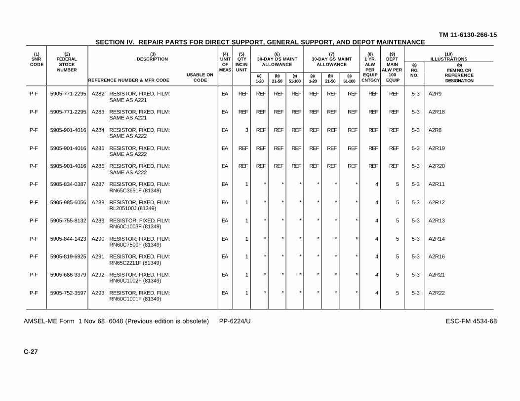
(10)ILLUSTRATIONS
(6)30-DAY DS MAINT
ALLOWANCE
(7)30-DAY GS MAINT
ALLOWANCE
(1)SMR
CODE
(2)FEDERALSTOCK
NUMBER
(3)DESCRIPTION
USABLE ONREFERENCE NUMBER & MFR CODE CODE
(4)UNITOF
MEAS
(5)QTY
INC INUNIT
(a)1-20
(b)21-50
(c)51-100
(a)1-20
(b)21-50
(c)51-100
(8)1 YR.ALWPER
EQUIPCNTGCY
(9)DEPTMAIN
ALW PER100
EQUIP
(a)FIG.NO.
(b)ITEM NO. OR
REFERENCEDESIGNATION
TM 11-6130-266-15SECTION IV. REPAIR PARTS FOR DIRECT SUPPORT, GENERAL SUPPORT, AND DEPOT MAINTENANCE
P-F 5905-771-2295 A282 RESISTOR, FIXED, FILM: EA REF REF REF REF REF REF REF REF REF 5-3 A2R9SAME AS A221
P-F 5905-771-2295 A283 RESISTOR, FIXED, FILM: EA REF REF REF REF REF REF REF REF REF 5-3 A2R18SAME AS A221
P-F 5905-901-4016 A284 RESISTOR, FIXED, FILM: EA 3 REF REF REF REF REF REF REF REF 5-3 A2R8SAME AS A222
P-F 5905-901-4016 A285 RESISTOR, FIXED, FILM: EA REF REF REF REF REF REF REF REF REF 5-3 A2R19SAME AS A222
P-F 5905-901-4016 A286 RESISTOR, FIXED, FILM: EA REF REF REF REF REF REF REF REF REF 5-3 A2R20SAME AS A222
P-F 5905-834-0387 A287 RESISTOR, FIXED, FILM: EA 1 * * * * * * 4 5 5-3 A2R11RN65C3651F (81349)
P-F 5905-985-6056 A288 RESISTOR, FIXED, FILM: EA 1 * * * * * * 4 5 5-3 A2R12RL205100J (81349)
P-F 5905-755-8132 A289 RESISTOR, FIXED, FILM: EA 1 * * * * * * 4 5 5-3 A2R13RN60C1003F (81349)
P-F 5905-844-1423 A290 RESISTOR, FIXED, FILM: EA 1 * * * * * * 4 5 5-3 A2R14RN60C7500F (81349)
P-F 5905-819-6925 A291 RESISTOR, FIXED, FILM: EA 1 * * * * * * 4 5 5-3 A2R16RN65C2211F (81349)
P-F 5905-686-3379 A292 RESISTOR, FIXED, FILM: EA 1 * * * * * * 4 5 5-3 A2R21RN60C1002F (81349)
P-F 5905-752-3597 A293 RESISTOR, FIXED, FILM: EA 1 * * * * * * 4 5 5-3 A2R22RN60C1001F (81349)
AMSEL-ME Form 1 Nov 68 6048 (Previous edition is obsolete) PP-6224/U ESC-FM 4534-68
C-27

(10)ILLUSTRATIONS
(6)30-DAY DS MAINT
ALLOWANCE
(7)30-DAY GS MAINT
ALLOWANCE
(1)SMR
CODE
(2)FEDERALSTOCK
NUMBER
(3)DESCRIPTION
USABLE ONREFERENCE NUMBER & MFR CODE CODE
(4)UNITOF
MEAS
(5)QTY
INC INUNIT
(a)1-20
(b)21-50
(c)51-100
(a)1-20
(b)21-50
(c)51-100
(8)1 YR.ALWPER
EQUIPCNTGCY
(9)DEPTMAIN
ALW PER100
EQUIP
(a)FIG.NO.
(b)ITEM NO. OR
REFERENCEDESIGNATION
TM 11-6130-266-15SECTION IV. REPAIR PARTS FOR DIRECT SUPPORT, GENERAL SUPPORT, AND DEPOT MAINTENANCE
P-F 5905-061-2089 A294 RESISTOR, FIXED, EA 1 * * 1 * * 1 10 10 5-3 A2R17WIREWOUND: RW69V510(81349)
P-F 5905-067-9079 A295 RESISTOR, VARIABLE: EA 2 * 1 1 * 1 1 13 15 5-3 A2R10RT22C2P102 (81349)
P-F 5905-067-9079 A296 RESISTOR, VARIABLE: EA REF REF REF REF REF REF REF REF REF 5-3 A2R15SAME AS A295
P-F A299 SEMICONDUCTOR DEVICE, EA 1 REF REF REF REF REF REF REF REF 5-3 A2CR1DIODE: SAME AS A238
P-F 5961-087-6047 A300 SEMICONDUCTOR, DEVICE, EA 4 REF REF REF REF REF REF REF REF 5-3 A2CR2DIODE: SAME AS A239
P-F 5961-087-6047 A301 SEMICONDUCTOR DEVICE, EA REF REF REF REF REF REF REF REF REF 5-3 A2CR3DIODE: SAME AS A239
P-F 5961-087-6047 A302 SEMICONDUCTOR DEVICE, EA REF REF REF REF REF REF REF REF REF 5-3 A2CR4DIODE: SAME AS A239
P-F 5961-087-6047 A303 SEMICONDUCTOR DEVICE, EA REF REF REF REF REF REF REF REF REF 5-3 A2CR7DIODE: SAME AS A239
P-F 5961-957-6855 A304 SEMICONDUCTOR, DEVICE, EA 1 REF REF REF REF REF REF REF REF 5-3 A2CR6DIODE: SAME AS A234
P-F 5940-280-0601 A305 TERMINAL, STUD: EA 1 REF REF REF REF REF REF REF REF A2TP1SAME AS A247
P-F 5961-853-2601 A306 TRANSISTOR: EA 2 REF REF REF REF REF REF REF REF 5-3 A2Q1SAME AS A249
P-F 5961-853-2601 A307 TRANSISTOR: EA REF REF REF REF REF REF REF REF REF 5-3 A2Q4SAME AS A249
AMSEL-ME Form 1 Nov 68 6048 (Previous edition is obsolete) PP-6624/U ESC-FM 4534-68
C-28

(10)ILLUSTRATIONS
(6)30-DAY DS MAINT
ALLOWANCE
(7)30-DAY GS MAINT
ALLOWANCE
(1)SMR
CODE
(2)FEDERALSTOCK
NUMBER
(3)DESCRIPTION
USABLE ONREFERENCE NUMBER & MFR CODE CODE
(4)UNITOF
MEAS
(5)QTY
INC INUNIT
(a)1-20
(b)21-50
(c)51-100
(a)1-20
(b)21-50
(c)51-100
(8)1 YR.ALWPER
EQUIPCNTGCY
(9)DEPTMAIN
ALW PER100
EQUIP
(a)FIG.NO.
(b)ITEM NO. OR
REFERENCEDESIGNATION
TM 11-6130-266-15SECTION IV. REPAIR PARTS FOR DIRECT SUPPORT, GENERAL SUPPORT, AND DEPOT MAINTENANCE
P-F 5961-880-4779 A308 TRANSISTOR: EA 1 REF REF REF REF REF REF REF REF 5-3 A2Q2SAME AS A255
P-F 5961-104-8378 A309 TRANSISTOR: EA 1 * * * * * * 10 10 5-3 A2Q32N2920 (81349)
A-H A310 COMPONENT BOARD ASSEMBLY: EA 1 5-6 A5SMC667863 (18038)
P-F 5910-644-6164 A311 CAPACITOR, FIXED, PAPER: EA 1 REF REF REF REF REF REF REF REF 5-6 A5C2SAME AS A192
P-F A312 CAPACITOR, FIXED, PLASTIC: EA 1 * * * * * * 5 5 5-6 A5C1CH08A1RA475M (81349)
P-H A313 CONNECTOR, RECEPTACLE, EA 1 REF REF REF REF REF A5J1ELEC; SAME AS A193
X2-D A314 SCREW, MACHINE, EA 2 A5H2SAME AS A194
X2-D 5310-543-2410 A315 WASHER, LOCK; EA 2 A5H2SAME AS A119
X2-D 5310-934-9739 A316 NUT, PLAIN, HEXAGON: EA 2 A5H3SAME AS A120
P-H 6225-929-3950 A317 EJECTOR, CARD: EA 1 REF REF REF REF REF A5MP2SAME AS A197
P-F A319 PAD, TRANSISTOR: EA 4 REF REF REF REF REF REF REF REF A5MP3SAME AS A200
P-F A320 PAD, TRANSISTOR: EA REF REF REF REF REF REF REF REF REF A5MP4SAME AS A200
AMSEL-ME Form 1 Nov 68 6048 (Previous edition is obsolete) PP-6624/U ESC-FM 4534-68
C-29
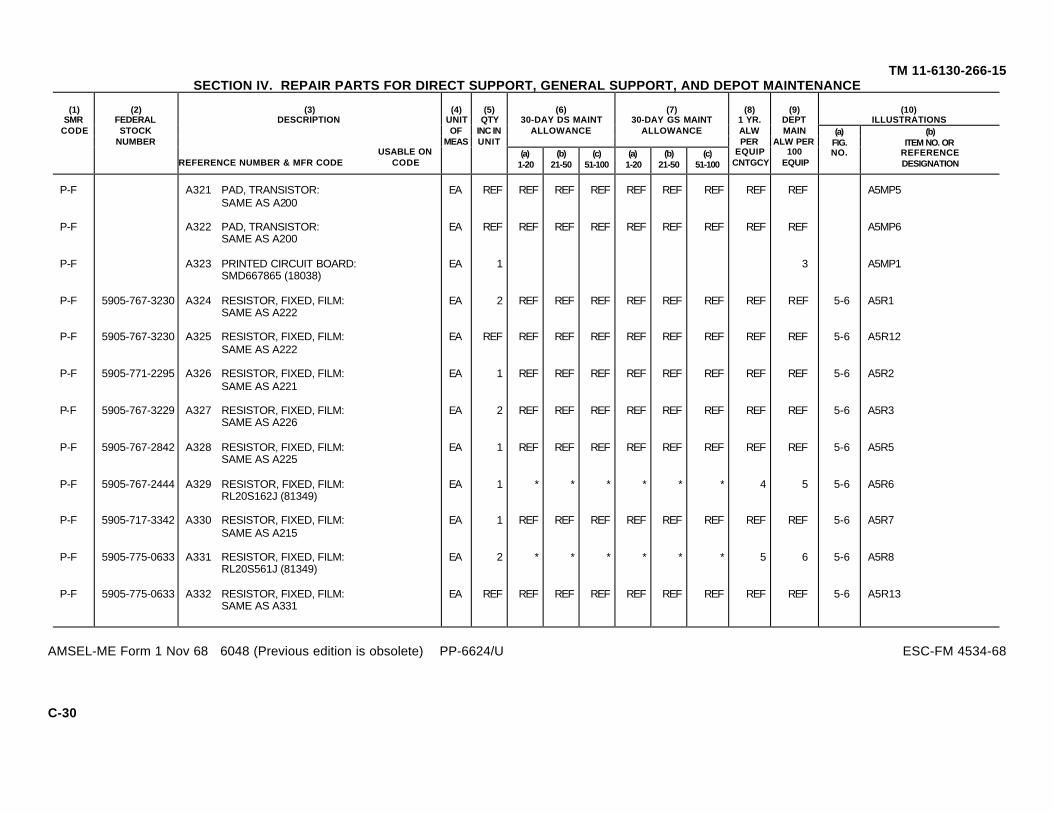
(10)ILLUSTRATIONS
(6)30-DAY DS MAINT
ALLOWANCE
(7)30-DAY GS MAINT
ALLOWANCE
(1)SMR
CODE
(2)FEDERALSTOCK
NUMBER
(3)DESCRIPTION
USABLE ONREFERENCE NUMBER & MFR CODE CODE
(4)UNITOF
MEAS
(5)QTY
INC INUNIT
(a)1-20
(b)21-50
(c)51-100
(a)1-20
(b)21-50
(c)51-100
(8)1 YR.ALWPER
EQUIPCNTGCY
(9)DEPTMAIN
ALW PER100
EQUIP
(a)FIG.NO.
(b)ITEM NO. OR
REFERENCEDESIGNATION
TM 11-6130-266-15SECTION IV. REPAIR PARTS FOR DIRECT SUPPORT, GENERAL SUPPORT, AND DEPOT MAINTENANCE
P-F A321 PAD, TRANSISTOR: EA REF REF REF REF REF REF REF REF REF A5MP5SAME AS A200
P-F A322 PAD, TRANSISTOR: EA REF REF REF REF REF REF REF REF REF A5MP6SAME AS A200
P-F A323 PRINTED CIRCUIT BOARD: EA 1 3 A5MP1SMD667865 (18038)
P-F 5905-767-3230 A324 RESISTOR, FIXED, FILM: EA 2 REF REF REF REF REF REF REF REF 5-6 A5R1SAME AS A222
P-F 5905-767-3230 A325 RESISTOR, FIXED, FILM: EA REF REF REF REF REF REF REF REF REF 5-6 A5R12SAME AS A222
P-F 5905-771-2295 A326 RESISTOR, FIXED, FILM: EA 1 REF REF REF REF REF REF REF REF 5-6 A5R2SAME AS A221
P-F 5905-767-3229 A327 RESISTOR, FIXED, FILM: EA 2 REF REF REF REF REF REF REF REF 5-6 A5R3SAME AS A226
P-F 5905-767-2842 A328 RESISTOR, FIXED, FILM: EA 1 REF REF REF REF REF REF REF REF 5-6 A5R5SAME AS A225
P-F 5905-767-2444 A329 RESISTOR, FIXED, FILM: EA 1 * * * * * * 4 5 5-6 A5R6RL20S162J (81349)
P-F 5905-717-3342 A330 RESISTOR, FIXED, FILM: EA 1 REF REF REF REF REF REF REF REF 5-6 A5R7SAME AS A215
P-F 5905-775-0633 A331 RESISTOR, FIXED, FILM: EA 2 * * * * * * 5 6 5-6 A5R8RL20S561J (81349)
P-F 5905-775-0633 A332 RESISTOR, FIXED, FILM: EA REF REF REF REF REF REF REF REF REF 5-6 A5R13SAME AS A331
AMSEL-ME Form 1 Nov 68 6048 (Previous edition is obsolete) PP-6624/U ESC-FM 4534-68
C-30

(10)ILLUSTRATIONS
(6)30-DAY DS MAINT
ALLOWANCE
(7)30-DAY GS MAINT
ALLOWANCE
(1)SMR
CODE
(2)FEDERALSTOCK
NUMBER
(3)DESCRIPTION
USABLE ONREFERENCE NUMBER & MFR CODE CODE
(4)UNITOF
MEAS
(5)QTY
INC INUNIT
(a)1-20
(b)21-50
(c)51-100
(a)1-20
(b)21-50
(c)51-100
(8)1 YR.ALWPER
EQUIPCNTGCY
(9)DEPTMAIN
ALW PER100
EQUIP
(a)FIG.NO.
(b)ITEM NO. OR
REFERENCEDESIGNATION
TM 11-6130-266-15SECTION IV. REPAIR PARTS FOR DIRECT SUPPORT, GENERAL SUPPORT, AND DEPOT MAINTENANCE
P-F 5905-767-3229 A333 RESISTOR, FIXED, FILM: EA REF REF REF REF REF REF REF REF REF 5-6 A5R10SAME AS A226
P-F 5905-067-9079 A334 RESISTOR, VARIABLE: EA 1 REF REF REF REF REF REF REF REF 5-6 A5R9SAME AS A295
P-F 5961-087-6047 A335 SEMICONDUCTOR DEVICE, EA 3 REF REF REF REF REF REF REF REF 5-6 A5CR1DIODE: SAME AS A239
P-F 5961-087-6047 A336 SEMICONDUCTOR DEVICE, EA REF REF REF REF REF REF REF REF REF 5-6 A5CR2DIODE: SAME AS A239
P-F 5961-087-6047 A337 SEMICONDUCTOR DEVICE, EA REF REF REF REF REF REF REF REF REF 5-6 A5CR4DIODE: SAME AS A239
P-F 5961-836-0382 A338 SEMICONDUCTOR DEVICE, EA 1 * * * * * * 5 5 5-6 A5CR3DIODE: JAN1N3022B (81350)
X2-D 5940-280-0601 A339 TERMINAL, STUD: EA 1 A5TP1SAME AS A247
P-F 5961-853-2601 A340 TRANSISTOR: EA 3 REF REF REF REF REF REF REF REF 5-6 A5Q1SAME AS A249
P-F 5961-853-2601 A341 TRANSISTOR: EA REF REF REF REF REF REF REF REF REF 5-6 A5Q2SAME AS A249
P-F 5961-853-2601 A342 TRANSISTOR: EA REF REF REF REF REF REF REF REF REF 5-6 A5Q3SAME AS A249
A-H A343 COVER ASSEMBLY: EA 1 A9SMD667930 (18038)
P-D A344 COVER: EA 1 2 A9MP1SMD667931 (18038)
C-31

(10)ILLUSTRATIONS
(6)30-DAY DS MAINT
ALLOWANCE
(7)30-DAY GS MAINT
ALLOWANCE
(1)SMR
CODE
(2)FEDERALSTOCK
NUMBER
(3)DESCRIPTION
USABLE ONREFERENCE NUMBER & MFR CODE CODE
(4)UNITOF
MEAS
(5)QTY
INC INUNIT
(a)1-20
(b)21-50
(c)51-100
(a)1-20
(b)21-50
(c)51-100
(8)1 YR.ALWPER
EQUIPCNTGCY
(9)DEPTMAIN
ALW PER100
EQUIP
(a)FIG.NO.
(b)ITEM NO. OR
REFERENCEDESIGNATION
TM 11-6130-266-15SECTION IV. REPAIR PARTS FOR DIRECT SUPPORT, GENERAL SUPPORT, AND DEPOT MAINTENANCE
X2-D 5305-985-3674 A345 SCREW, CAPTIVE; EA 16 A9H166235SS0632 (06540)
X2-D 5310-531-9514 A346 WASHER, FLAT: EA 16 A9H16AN960C6 (88044)
M-D A347 GASKET, RUBBER EA 1 A9MP2SMD667932 (18038)
M-H A348 LABEL, IDENTIFICATION: EA 1 A9MP3SMD667933 (18038)
M-H A349 LABEL, IDENTIFICATION: EA 1 A9MP4SMD667934 (18038)
M-H A350 PAD, SHOCK: EA 2 A9MP5SMB667940 (18038)
M-H A351 PAD, SHOCK: EA REF A9MP6SAME AS A350
X2-D A355 CLAMP, CABLE: EA 1 MP11MS21919-WG-11 (96906)
X2-D 5305-984-6191 A356 SCREW, MACHINE; EA 1 H1SAME AS A8
X2-D 5310-045-3299 A357 WASHER, LOCK: EA 1 H1SAME AS A9
P-H A358 CONNECTOR, RECEPTACLE, EA 1 * * * 4 5 J3ELEC: PT07C14-5P (77820)
A359D
Change 1 C-32
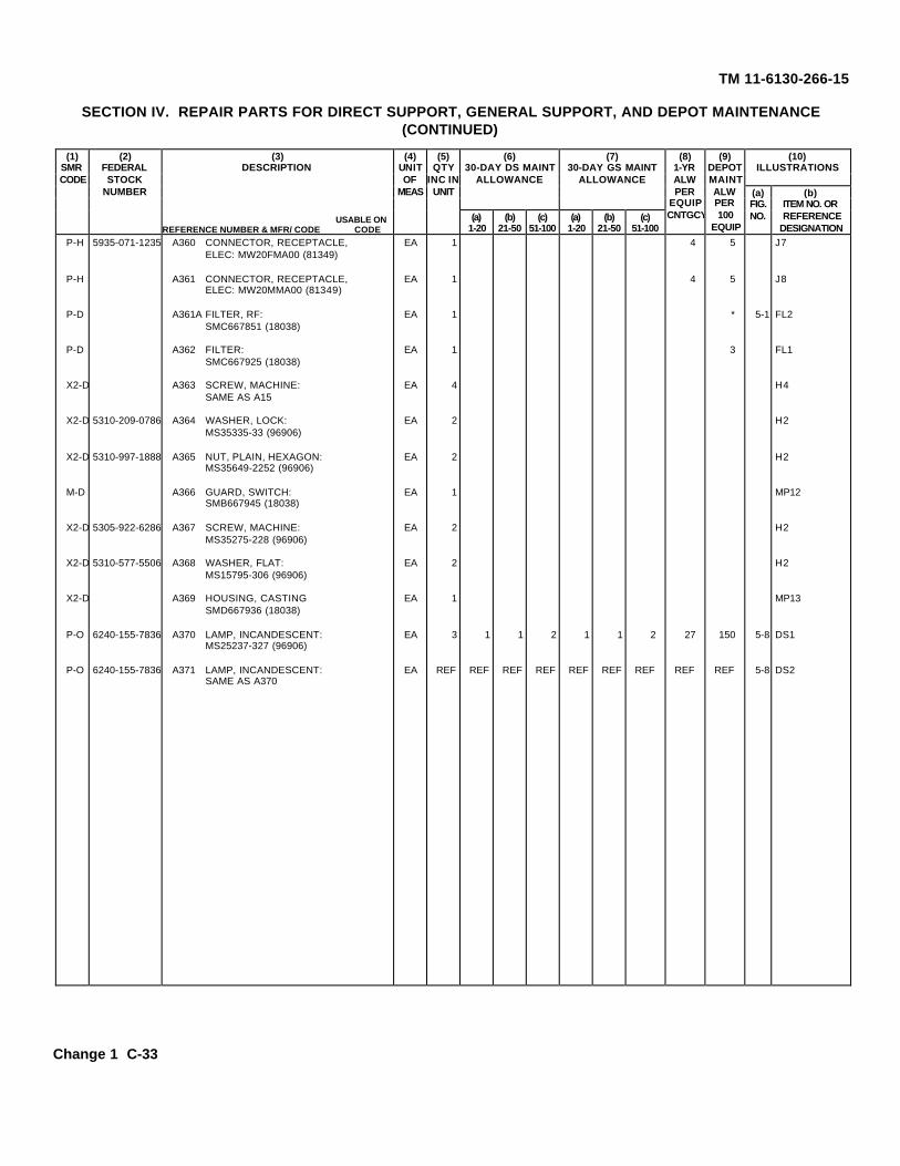
(3)DESCRIPTION
(10)ILLUSTRATIONS
(6)30-DAY DS MAINT
ALLOWANCE
(7)30-DAY GS MAINT
ALLOWANCE
(1)SMRCODE
(2)FEDERALSTOCK
NUMBER
USABLE ONREFERENCE NUMBER & MFR/ CODE CODE
(4)UNITOF
MEAS
(5)QTY
INC INUNIT
(a)1-20
(b)21-50
(c)51-100
(a)1-20
(b)21-50
(c)51-100
(8)1-YRALWPER
EQUIPCNTGCY
(9)DEPOTMAINTALWPER100
EQUIP
(a)FIG.NO.
(b)ITEM NO. ORREFERENCE
DESIGNATION
TM 11-6130-266-15
SECTION IV. REPAIR PARTS FOR DIRECT SUPPORT, GENERAL SUPPORT, AND DEPOT MAINTENANCE(CONTINUED)
P-H 5935-071-1235 A360 CONNECTOR, RECEPTACLE, EA 1 4 5 J7ELEC: MW20FMA00 (81349)
P-H A361 CONNECTOR, RECEPTACLE, EA 1 4 5 J8ELEC: MW20MMA00 (81349)
P-D A361A FILTER, RF: EA 1 * 5-1 FL2SMC667851 (18038)
P-D A362 FILTER: EA 1 3 FL1SMC667925 (18038)
X2-D A363 SCREW, MACHINE: EA 4 H4SAME AS A15
X2-D 5310-209-0786 A364 WASHER, LOCK: EA 2 H2MS35335-33 (96906)
X2-D 5310-997-1888 A365 NUT, PLAIN, HEXAGON: EA 2 H2MS35649-2252 (96906)
M-D A366 GUARD, SWITCH: EA 1 MP12SMB667945 (18038)
X2-D 5305-922-6286 A367 SCREW, MACHINE: EA 2 H2MS35275-228 (96906)
X2-D 5310-577-5506 A368 WASHER, FLAT: EA 2 H2MS15795-306 (96906)
X2-D A369 HOUSING, CASTING EA 1 MP13SMD667936 (18038)
P-O 6240-155-7836 A370 LAMP, INCANDESCENT: EA 3 1 1 2 1 1 2 27 150 5-8 DS1MS25237-327 (96906)
P-O 6240-155-7836 A371 LAMP, INCANDESCENT: EA REF REF REF REF REF REF REF REF REF 5-8 DS2SAME AS A370
Change 1 C-33

(10)ILLUSTRATIONS
(6)30-DAY DS MAINT
ALLOWANCE
(7)30-DAY GS MAINT
ALLOWANCE
(1)SMR
CODE
(2)FEDERALSTOCK
NUMBER
(3)DESCRIPTION
USABLE ONREFERENCE NUMBER & MFR CODE CODE
(4)UNITOF
MEAS
(5)QTY
INC INUNIT
(a)1-20
(b)21-50
(c)51-100
(a)1-20
(b)21-50
(c)51-100
(8)1 YR.ALWPER
EQUIPCNTGCY
(9)DEPTMAIN
ALW PER100
EQUIP
(a)FIG.NO.
(b)ITEM NO. OR
REFERENCEDESIGNATION
TM 11-6130-266-15SECTION IV. REPAIR PARTS FOR DIRECT SUPPORT, GENERAL SUPPORT, AND DEPOT MAINTENANCE
P-O 6240-155-7836 A372 LAMP, INCANDESCENT: EA REF REF REF REF REF REF REF REF REF 5-8 DS3SAME AS A370
P-F 6210-176-4928 A373 LAMPHOLDER: EA 3 * * 1 * * 1 8 15 XDS1LH89-1 (81349)
P-F 6210-176-4928 A374 LAMPHOLDER: EA REF REF REF REF REF REF REF REF REF XDS2SAME AS A373
P-F 6210-176-4928 A375 LAMPHOLDER: EA REF REF REF REF REF REF REF REF REF XDS3SAME AS A373
P-O 6210-151-5246 A376 LENS: EA 1 * * * * * * 4 5 MP14LC36GD2 (81349)
P-O A377 LENS: EA 1 * * * * * * 4 5 MP15LC36YD2 (81349)
P-O A378 LENS: EA 1 * * * * * * 4 5 MP16LC36RD2 (81349)
P-F A379 LOCK ASSEMBLY: EA 1 * * * * * * 4 3 A10SMB667949 (18038)
P-F A383 METER: EA 1 * * * * * * 4 6 5-8 M1SMC667920 (18038)
X2-D 5305-054-6656 A386 SCREW, MACHINE: EA 3 H3MS51957-32 (96906)
X2-D 5310-929-6395 A387 WASHER, LOCK: EA 3 H3MS35338-136 (96906)
X2-D 5310-934-9751 A388 NUT, PLAIN, HEXAGON: EA 6 H6MS35650-302 (96906)
C-34
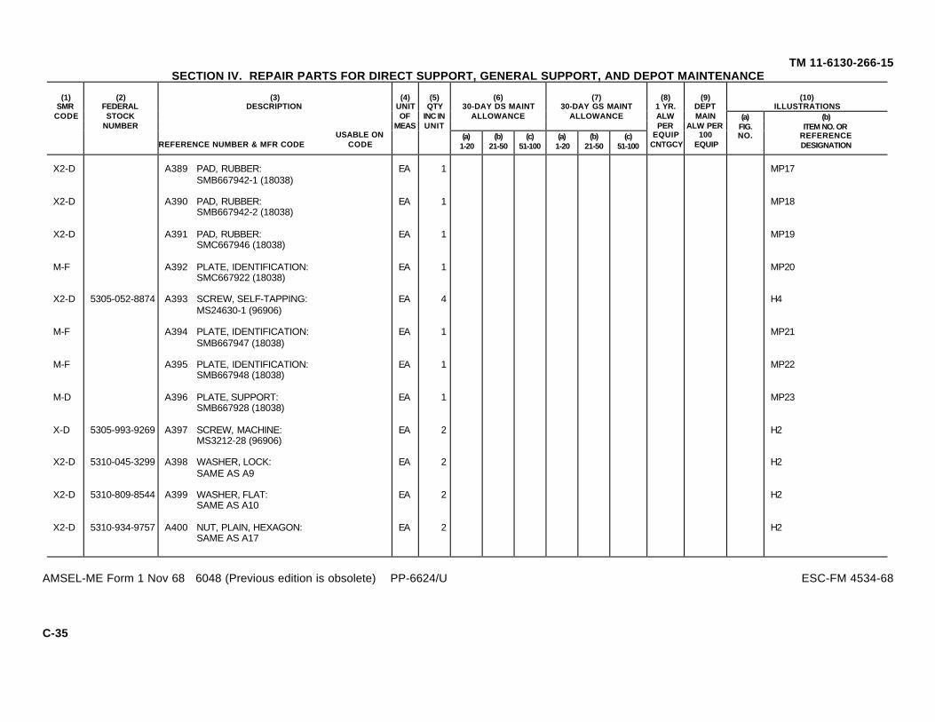
(10)ILLUSTRATIONS
(6)30-DAY DS MAINT
ALLOWANCE
(7)30-DAY GS MAINT
ALLOWANCE
(1)SMR
CODE
(2)FEDERALSTOCK
NUMBER
(3)DESCRIPTION
USABLE ONREFERENCE NUMBER & MFR CODE CODE
(4)UNITOF
MEAS
(5)QTY
INC INUNIT
(a)1-20
(b)21-50
(c)51-100
(a)1-20
(b)21-50
(c)51-100
(8)1 YR.ALWPER
EQUIPCNTGCY
(9)DEPTMAIN
ALW PER100
EQUIP
(a)FIG.NO.
(b)ITEM NO. OR
REFERENCEDESIGNATION
TM 11-6130-266-15SECTION IV. REPAIR PARTS FOR DIRECT SUPPORT, GENERAL SUPPORT, AND DEPOT MAINTENANCE
X2-D A389 PAD, RUBBER: EA 1 MP17SMB667942-1 (18038)
X2-D A390 PAD, RUBBER: EA 1 MP18SMB667942-2 (18038)
X2-D A391 PAD, RUBBER: EA 1 MP19SMC667946 (18038)
M-F A392 PLATE, IDENTIFICATION: EA 1 MP20SMC667922 (18038)
X2-D 5305-052-8874 A393 SCREW, SELF-TAPPING: EA 4 H4MS24630-1 (96906)
M-F A394 PLATE, IDENTIFICATION: EA 1 MP21SMB667947 (18038)
M-F A395 PLATE, IDENTIFICATION: EA 1 MP22SMB667948 (18038)
M-D A396 PLATE, SUPPORT: EA 1 MP23SMB667928 (18038)
X-D 5305-993-9269 A397 SCREW, MACHINE: EA 2 H2MS3212-28 (96906)
X2-D 5310-045-3299 A398 WASHER, LOCK: EA 2 H2SAME AS A9
X2-D 5310-809-8544 A399 WASHER, FLAT: EA 2 H2SAME AS A10
X2-D 5310-934-9757 A400 NUT, PLAIN, HEXAGON: EA 2 H2SAME AS A17
AMSEL-ME Form 1 Nov 68 6048 (Previous edition is obsolete) PP-6624/U ESC-FM 4534-68
C-35

(10)ILLUSTRATIONS
(6)30-DAY DS MAINT
ALLOWANCE
(7)30-DAY GS MAINT
ALLOWANCE
(1)SMR
CODE
(2)FEDERALSTOCK
NUMBER
(3)DESCRIPTION
USABLE ONREFERENCE NUMBER & MFR CODE CODE
(4)UNITOF
MEAS
(5)QTY
INC INUNIT
(a)1-20
(b)21-50
(c)51-100
(a)1-20
(b)21-50
(c)51-100
(8)1 YR.ALWPER
EQUIPCNTGCY
(9)DEPTMAIN
ALW PER100
EQUIP
(a)FIG.NO.
(b)ITEM NO. OR
REFERENCEDESIGNATION
TM 11-6130-266-15SECTION IV. REPAIR PARTS FOR DIRECT SUPPORT, GENERAL SUPPORT, AND DEPOT MAINTENANCE
P-F A401 PLUG, PROTECTIVE: EA 1 * * * * * * 4 5 MP261-8 NPTF (70318)
P-O A402 POWER CORD, AC: EA 1 * 1 1 * 1 1 12 15 W1CX-11979/U (81349)
P-O 5995-466-0217 A403 POWER CORD, DC: EA 1 * 1 1 * 1 1 12 15 W2CX-12342/U (81349)
A-H A404 POWER TRANSFER ASSEMBLY: EA 1 5-7 A6SMD667894 (18038)
X2-D 5305-984-6209 A405 SCREW, MACHINE: EA 4 H4SAME AS A106
X2-D 5305-984-6210 A406 SCREW, MACHINE: EA 3 H3MS35206-263 (96906)
X2-D 5310-045-3296 A407 WASHER, LOCK: EA 7 H7SAME AS A32
A-H A408 COMPONENT BOARD ASSEMBLY: EA 1 5-7 A6A1SMD667899 (18038)
P-F 5910-082-4767 A409 CAPACITOR, FIXED, ELECT: EA 1 * * * * * * 4 5 5-7 A6A1C1CL23CD100UN3 (81349)
X2-D A410 PLATE, CONTACT: EA 1 A6A1E6SMB667902 (18038)
X2-D A411 SCREW, MACHINE: EA 2 A6A1H2AN508-6-4 (88044)
P-D A412 PRINTED CIRCUIT BOARD: EA 1 3 A6A1MP1SMD667900 (18038)
AMSEL-ME Form 1 Nov 68 6048 (Previous edition is obsolete) PP-6624/U ESC-FM 4534-68
C-36

(10)ILLUSTRATIONS
(6)30-DAY DS MAINT
ALLOWANCE
(7)30-DAY GS MAINT
ALLOWANCE
(1)SMR
CODE
(2)FEDERALSTOCK
NUMBER
(3)DESCRIPTION
USABLE ONREFERENCE NUMBER & MFR CODE CODE
(4)UNITOF
MEAS
(5)QTY
INC INUNIT
(a)1-20
(b)21-50
(c)51-100
(a)1-20
(b)21-50
(c)51-100
(8)1 YR.ALWPER
EQUIPCNTGCY
(9)DEPTMAIN
ALW PER100
EQUIP
(a)FIG.NO.
(b)ITEM NO. OR
REFERENCEDESIGNATION
TM 11-6130-266-15SECTION IV. REPAIR PARTS FOR DIRECT SUPPORT, GENERAL SUPPORT, AND DEPOT MAINTENANCE
P-F 5905-230-7713 A413 RESISTOR, FIXED, FILM: EA 1 * * * * * * 4 3 5-7 A6A1R2RN70C3972B (81349)
P-F 5905-061-5355 A414 RESISTOR, FIXED, FILM: EA 1 * * * * * * 4 3 5-7 A6A1R3RN65C9091F (81349)
P-F 5905-087-0545 A415 RESISTOR, FIXED, EA 1 * * * * * * 7 6 5-7 A6A1R5WIREWOUND: RW69V102(81349)
P-F 5905-061-2089 A416 RESISTOR, FIXED, EA 1 REF REF REF REF REF REF REF REF 5-7 A6A1R4WIREWOUND: SAME AS A294
X2-D 5940-280-0601 A417 TERMINAL, STUD: EA 6 A6A1E1SAME AS A247
X2-D 5940-280-0601 A418 TERMINAL, STUD; EA REF A6A1E2SAME AS A247
X2-D 5940-280-0601 A419 TERMINAL, STUD: EA REF A6A1E4SAME AS A247
X2-D 5940-280-0601 A420 TERMINAL, STUD: EA REF A6A1E5SAME AS A247
X2-D 5940-280-0601 A421 TERMINAL, STUD: EA REF A6A1E11SAME AS A247
X2-D 5940-280-0601 A422 TERMINAL, STUD: EA REF A6A1E12SAME AS A247
X2-D A423 TERMINAL, STANDOFF: EA 4 A6A1E79573BB1032-14 (06540)
X2-D A424 TERMINAL, STANDOFF: EA REF A6A1E8SAME AS A423
AMSEL-ME Form 1 Nov 68 6048 (Previous edition is obsolete) PP-6624/U ESC-FM 4534-68
C-37

(10)ILLUSTRATIONS
(6)30-DAY DS MAINT
ALLOWANCE
(7)30-DAY GS MAINT
ALLOWANCE
(1)SMR
CODE
(2)FEDERALSTOCK
NUMBER
(3)DESCRIPTION
USABLE ONREFERENCE NUMBER & MFR CODE CODE
(4)UNITOF
MEAS
(5)QTY
INC INUNIT
(a)1-20
(b)21-50
(c)51-100
(a)1-20
(b)21-50
(c)51-100
(8)1 YR.ALWPER
EQUIPCNTGCY
(9)DEPTMAIN
ALW PER100
EQUIP
(a)FIG.NO.
(b)ITEM NO. OR
REFERENCEDESIGNATION
TM 11-6130-266-15SECTION IV. REPAIR PARTS FOR DIRECT SUPPORT, GENERAL SUPPORT, AND DEPOT MAINTENANCE
X2-D A425 TERMINAL, STANDOFF: EA REF A6A1E9SAME AS A423
X2-D A426 TERMINAL, STANDOFF: EA REF A6A1E10SAME AS A423
M-D A427 PLATE, SUPPORT: EA 1 A6MP1C8157 (18038)
P-F A428 RELAY: EA 1 * * * * * * 5 7 5-7 A6K1SMB667898 (18038)
X2-D 5310-934-9747 A429 NUT, PLAIN, HEXAGON: EA 4 A6H4SAME AS A37
X2-D 5310-209-0788 A430 WASHER, LOCK: EA 4 A6H4SAME AS A36
P-F A431 RESISTOR, SHUNT: EA 1 * * * * * * 2 3 5-7 A6R1SMC667897 (18038)
X2-D 5305-637-1124 A432 SCREW, MACHINE: EA 2 A6H2MS35229-43 (96906)
X2-D 5310-576-0546 A433 WASHER, LOCK: EA 2 A6H2MS35338-99 (96906)
X2-D 5310-209-0786 A434 WASHER, LOCK: EA 2 A6H2SAME AS A364
X2-D A435 WASHER, FLAT: EA 2 A6H2MS15795-607 (96906)
X2-D A436 NUT, PLAIN, HEXAGON: EA 4 A6H4MS35691-431 (96906)
AMSEL-ME Form 1 Nov 68 6048 (Previous edition is obsolete) PP-6624/U ESC-FM 4534-68
C-38

(10)ILLUSTRATIONS
(6)30-DAY DS MAINT
ALLOWANCE
(7)30-DAY GS MAINT
ALLOWANCE
(1)SMR
CODE
(2)FEDERALSTOCK
NUMBER
(3)DESCRIPTION
USABLE ONREFERENCE NUMBER & MFR CODE CODE
(4)UNITOF
MEAS
(5)QTY
INC INUNIT
(a)1-20
(b)21-50
(c)51-100
(a)1-20
(b)21-50
(c)51-100
(8)1 YR.ALWPER
EQUIPCNTGCY
(9)DEPTMAIN
ALW PER100
EQUIP
(a)FIG.NO.
(b)ITEM NO. OR
REFERENCEDESIGNATION
TM 11-6130-266-15SECTION IV. REPAIR PARTS FOR DIRECT SUPPORT, GENERAL SUPPORT, AND DEPOT MAINTENANCE
A-H A437 PRE-REGULATOR ASSEMBLY: EA 1 5-5 A4SMD667881 (18038)
X2-D 5305-984-6193 A438 SCREW, MACHINE: EA 4 H4SAME AS A28
X2-D 5310-045-3299 A439 WASHER, LOCK: EA 4 H4SAME AS A9
M-D A440 BRACKET, MOUNTING: EA 2 A4MP1SMB667887 (18038)
M-D A441 BRACKET, MOUNTING: EA REF A4MP2SAME AS A440
A2-D 5305-993-2738 A451 SCREW, MACHINE: EA 1 A4H1MS35207-280 (96906)
X2-D 5310-209-0786 A452 WASHER, LOCK: EA 1 A4H1SAME AS A364
X2-D 5310-043-0520 A453 NUT, PLAIN, HEXAGON: EA 1 A4H1MS35650-3252 (96906)
A-H A457 COMPONENT BOARD ASSY, EA 1 5-5 A4H2GATE: C8107 (18038)
X2-D 5305-984-4988 A458 SCREW, MACHINE: EA 2 A4H2SAME AS A12
X2-D 5310-045-4007 A459 WASHER, LOCK: EA 2 A4H2SAME AS A13
X2-D 5310-983-8483 A460 WASHER, FLAT: EA 2 A4H2SAME AS A170
P-F 5910-904-3983 A461 CAPACITOR, FXD, EA 2 * 1 2 * 1 2 19 20 5-5 A4A2C1ELECTROLYTIC: CS13BF226M(81349)
AMSEL-ME Form 1 Nov 68 6048 (Previous edition is obsolete) PP-6624/U ESC-FM 4534-68
C-39

(10)ILLUSTRATIONS
(6)30-DAY DS MAINT
ALLOWANCE
(7)30-DAY GS MAINT
ALLOWANCE
(1)SMR
CODE
(2)FEDERALSTOCK
NUMBER
(3)DESCRIPTION
USABLE ONREFERENCE NUMBER & MFR CODE CODE
(4)UNITOF
MEAS
(5)QTY
INC INUNIT
(a)1-20
(b)21-50
(c)51-100
(a)1-20
(b)21-50
(c)51-100
(8)1 YR.ALWPER
EQUIPCNTGCY
(9)DEPTMAIN
ALW PER100
EQUIP
(a)FIG.NO.
(b)ITEM NO. OR
REFERENCEDESIGNATION
TM 11-6130-266-15SECTION IV. REPAIR PARTS FOR DIRECT SUPPORT, GENERAL SUPPORT, AND DEPOT MAINTENANCE
P-F 5910-904-3983 A462 CAPACITOR, FXD, EA REF REF REF REF REF REF REF REF REF 5-5 A4A2C2ELECTROLYTIC: SAME AS A461
P-F 5910-082-4925 A463 CAPACITOR, FIXED, EA 2 REF REF REF REF REF REF REF REF 5-5 A4A2C3ELECTROLYTIC: SAME AS A191
P-F 5910-082-4925 A464 CAPACITOR, FIXED, EA REF REF REF REF REF REF REF REF REF 5-5 A4A2C4ELECTROLYTIC: SAME AS A191
P-D A465 CONNECTOR, PLUG, EA 1 REF A4A2P1ELECTRICAL: SAME AS A193
X2-D A466 SCREW, MACHINE: EA 2 A4A2H2SAME AS A194
X2-D 5310-543-2410 A467 WASHER, LOCK: EA 2 A4A2H2SAME AS A119
X2-D 5310-934-9739 A468 NUT, PLAIN, HEXAGON: EA 2 A4A2H2SAME AS A120
P-F A469 PAD, TRANSISTOR: EA 2 REF REF REF REF REF REF REF REF A4A2MP1SAME AS A200
P-F A470 PAD, TRANSISTOR: EA REF REF REF REF REF REF REF REF REF A4A2MP2SAME AS A200
P-D A471 PRINTED CIRCUIT BOARD: EA 1 3 A4A2MP3SMD667891 (18038)
P-F 5905-900-2089 A472 RESISTOR, FIXED, FILM: EA 4 * * 1 * * 1 13 18 5-5 A4A2R1RL205101J (81349)
P-F 5905-900-2089 A473 RESISTOR, FIXED, FILM: EA REF REF REF REF REF REF REF REF REF 5-5 A4A2R2SAME AS A472
AMSEL-ME Form 1 Nov 68 6048 (Previous edition is obsolete) PP-6624/U ESC-FM 4534-68
C-40
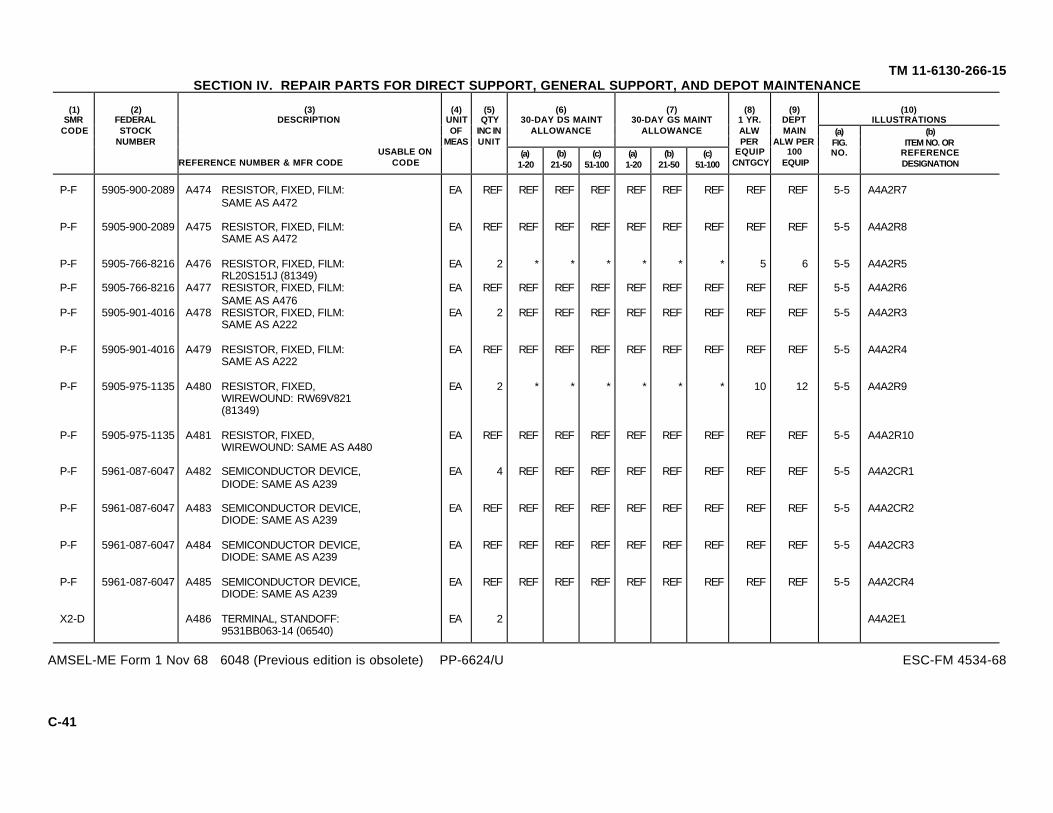
(10)ILLUSTRATIONS
(6)30-DAY DS MAINT
ALLOWANCE
(7)30-DAY GS MAINT
ALLOWANCE
(1)SMR
CODE
(2)FEDERALSTOCK
NUMBER
(3)DESCRIPTION
USABLE ONREFERENCE NUMBER & MFR CODE CODE
(4)UNITOF
MEAS
(5)QTY
INC INUNIT
(a)1-20
(b)21-50
(c)51-100
(a)1-20
(b)21-50
(c)51-100
(8)1 YR.ALWPER
EQUIPCNTGCY
(9)DEPTMAIN
ALW PER100
EQUIP
(a)FIG.NO.
(b)ITEM NO. OR
REFERENCEDESIGNATION
TM 11-6130-266-15SECTION IV. REPAIR PARTS FOR DIRECT SUPPORT, GENERAL SUPPORT, AND DEPOT MAINTENANCE
P-F 5905-900-2089 A474 RESISTOR, FIXED, FILM: EA REF REF REF REF REF REF REF REF REF 5-5 A4A2R7SAME AS A472
P-F 5905-900-2089 A475 RESISTOR, FIXED, FILM: EA REF REF REF REF REF REF REF REF REF 5-5 A4A2R8SAME AS A472
P-F 5905-766-8216 A476 RESISTOR, FIXED, FILM: EA 2 * * * * * * 5 6 5-5 A4A2R5RL20S151J (81349)
P-F 5905-766-8216 A477 RESISTOR, FIXED, FILM: EA REF REF REF REF REF REF REF REF REF 5-5 A4A2R6SAME AS A476
P-F 5905-901-4016 A478 RESISTOR, FIXED, FILM: EA 2 REF REF REF REF REF REF REF REF 5-5 A4A2R3SAME AS A222
P-F 5905-901-4016 A479 RESISTOR, FIXED, FILM: EA REF REF REF REF REF REF REF REF REF 5-5 A4A2R4SAME AS A222
P-F 5905-975-1135 A480 RESISTOR, FIXED, EA 2 * * * * * * 10 12 5-5 A4A2R9WIREWOUND: RW69V821(81349)
P-F 5905-975-1135 A481 RESISTOR, FIXED, EA REF REF REF REF REF REF REF REF REF 5-5 A4A2R10WIREWOUND: SAME AS A480
P-F 5961-087-6047 A482 SEMICONDUCTOR DEVICE, EA 4 REF REF REF REF REF REF REF REF 5-5 A4A2CR1DIODE: SAME AS A239
P-F 5961-087-6047 A483 SEMICONDUCTOR DEVICE, EA REF REF REF REF REF REF REF REF REF 5-5 A4A2CR2DIODE: SAME AS A239
P-F 5961-087-6047 A484 SEMICONDUCTOR DEVICE, EA REF REF REF REF REF REF REF REF REF 5-5 A4A2CR3DIODE: SAME AS A239
P-F 5961-087-6047 A485 SEMICONDUCTOR DEVICE, EA REF REF REF REF REF REF REF REF REF 5-5 A4A2CR4DIODE: SAME AS A239
X2-D A486 TERMINAL, STANDOFF: EA 2 A4A2E19531BB063-14 (06540)
AMSEL-ME Form 1 Nov 68 6048 (Previous edition is obsolete) PP-6624/U ESC-FM 4534-68
C-41

(10)ILLUSTRATIONS
(6)30-DAY DS MAINT
ALLOWANCE
(7)30-DAY GS MAINT
ALLOWANCE
(1)SMR
CODE
(2)FEDERALSTOCK
NUMBER
(3)DESCRIPTION
USABLE ONREFERENCE NUMBER & MFR CODE CODE
(4)UNITOF
MEAS
(5)QTY
INC INUNIT
(a)1-20
(b)21-50
(c)51-100
(a)1-20
(b)21-50
(c)51-100
(8)1 YR.ALWPER
EQUIPCNTGCY
(9)DEPTMAIN
ALW PER100
EQUIP
(a)FIG.NO.
(b)ITEM NO. OR
REFERENCEDESIGNATION
TM 11-6130-266-15SECTION IV. REPAIR PARTS FOR DIRECT SUPPORT, GENERAL SUPPORT, AND DEPOT MAINTENANCE
X2-D A487 TERMINAL, STANDOFF: EA REF A4A2E2SAME AS A486
P-F 5961-853-2601 A488 TRANSISTOR: EA 2 REF REF REF REF REF REF REF REF 5-5 A4A2Q1SAME AS A249
P-F 5961-853-2601 A489 TRANSISTOR: EA REF REF REF REF REF REF REF REF REF 5-5 A4A2Q2SAME AS A249
P-D A490 CONNECTOR, RECEPTACLE, EA 1 REF A4J1ELEC: SAME AS A117
X2-D 5305-983-6730 A491 SCREW, MACHINE; EA 2 A4H2MS35206-218 (96906)
X2-D 5310-543-2410 A492 WASHER, LOCK; EA 2 A4H2SAME AS A119
X2-D 5310-934-9739 A493 NUT, PLAIN, HEXAGON; EA 2 A4H2SAME AS A120
M-D A494 INSEPARABLE ASSY BOARD EA 1 A4A3SUPPORT: C8150 (18038)
X2-D 5310-934-9747 A495 NUT, PLAIN, HEXAGON: EA 4 A4H4SAME AS A37
X2-D 5310-045-4007 A496 WASHER, LOCK: EA 4 A4H4SAME AS A13
P-H A499 MAGNETIC AMPLIFIER EA 1 * * * 4 5 A4A1ASSEMBLY: SMD667883(18038)
AMSEL-ME Form 1 Nov 68 6048 (Previous edition is obsolete) PP-6624/U ESC-FM 4534-68
C-42

(10)ILLUSTRATIONS
(6)30-DAY DS MAINT
ALLOWANCE
(7)30-DAY GS MAINT
ALLOWANCE
(1)SMR
CODE
(2)FEDERALSTOCK
NUMBER
(3)DESCRIPTION
USABLE ONREFERENCE NUMBER & MFR CODE CODE
(4)UNITOF
MEAS
(5)QTY
INC INUNIT
(a)1-20
(b)21-50
(c)51-100
(a)1-20
(b)21-50
(c)51-100
(8)1 YR.ALWPER
EQUIPCNTGCY
(9)DEPTMAIN
ALW PER100
EQUIP
(a)FIG.NO.
(b)ITEM NO. OR
REFERENCEDESIGNATION
TM 11-6130-266-15SECTION IV. REPAIR PARTS FOR DIRECT SUPPORT, GENERAL SUPPORT, AND DEPOT MAINTENANCE
M-D A500 PLATE, MOUNTING: EA 1 A4MP3SMB667884 (18038)
X2-D 5310-934-9747 A501 NUT, PLAIN, HEXAGON: EA 2 A4H2SAME AS A37
X2-D 5310-045-4007 A502 WASHER, LOCK: EA 2 A4H2SAME AS A13
P-H 5961-060-5778 A503 SEMICONDUCTOR DEVICE, EA 2 * * 1 10 10 A4Q1DIODE: JAN2N1913 (81350)
X2-D 5310-113-3757 A504 NUT, PLAIN, HEXAGON: EA 1 A4H1MS35650-3392 (96906)
X2-D 5310-194-1483 A505 WASHER, LOCK; EA 1 A4H1MS35333-44 (96906)
X2-D 5310-809-5998 A506 WASHER, FLAT: EA 1 A4H1MS27183-18 (96906)
P-H A507 WASHER, INSULATING: EA 2 * 1 1 16 16 A4H1MW1375-526 (08289)
P-H A508 BUSHING, INSULATING: EA 1 * * * 5 6 A4H1TW510-570 (08289)
X2-D 5305-984-4988 A509 SCREW, MACHINE: EA 1 A4H1SAME AS A12
X2-D 5310-934-9747 A510 WASHER, LOCK: EA 1 A4H1SAME AS A36
P-H 5961-060-5778 A511 SEMICONDUCTOR DEVICE, EA REF REF REF REF REF REF 5-5 A4Q2DIODE: SAME AS A503
AMSEL-ME Form 1 Nov 68 6048 (Previous edition is obsolete) PP-6624/U ESC-FM 4534-68
C-43

(10)ILLUSTRATIONS
(6)30-DAY DS MAINT
ALLOWANCE
(7)30-DAY GS MAINT
ALLOWANCE
(1)SMR
CODE
(2)FEDERALSTOCK
NUMBER
(3)DESCRIPTION
USABLE ONREFERENCE NUMBER & MFR CODE CODE
(4)UNITOF
MEAS
(5)QTY
INC INUNIT
(a)1-20
(b)21-50
(c)51-100
(a)1-20
(b)21-50
(c)51-100
(8)1 YR.ALWPER
EQUIPCNTGCY
(9)DEPTMAIN
ALW PER100
EQUIP
(a)FIG.NO.
(b)ITEM NO. OR
REFERENCEDESIGNATION
TM 11-6130-266-15SECTION IV. REPAIR PARTS FOR DIRECT SUPPORT, GENERAL SUPPORT, AND DEPOT MAINTENANCE
X2-D 5310-113-3757 A512 NUT, PLAIN, HEXAGON: EA 1 A4H1SAME AS A504
X2-D 5310-194-1483 A513 WASHER, LOCK: EA 1 A4H1SAME AS A505
X2-D 5310-809-5998 A514 WASHER, FLAT: EA 1 A4H1SAME AS A506
P-H A515 WASHER, INSULATING: EA 2 REF REF REF REF REF A4H2SAME AS A507
P-H A516 BUSHING, INSULATING: EA 1 REF REF REF REF REF A4H1SAME AS A508
X2-D 5305-984-4988 A517 SCREW, MACHINE; EA 1 A4H1SAME AS A12
X2-D 5310-209-0788 A518 WASHER, LOCK: EA 1 A4H1SAME AS A36
P-H 5940-681-9772 A519 TERMINAL BOARD: EA 1 * * * 5 4 A4MP425TB9 (81349)
X2-D 5310-934-9747 A520 NUT, PLAIN, HEXAGON: EA 2 A4H2SAME AS A37
X2-D 5310-045-4007 A521 WASHER, LOCK; EA 2 A4H2SAME AS A13
X2-D 5310-983-8483 A522 WASHER, FLAT: EA 2 A4H2SAME AS A170
P-F 5905-807-0832 A523 RESISTOR, VARIABLE: EA 1 * * * * * * 6 5 5-8 R3RA20SASD252A (81349)
AMSEL-ME Form 1 Nov 68 6048 (Previous edition is obsolete) PP-6624/U ESC-FM 4534-68
C-44

(10)ILLUSTRATIONS
(6)30-DAY DS MAINT
ALLOWANCE
(7)30-DAY GS MAINT
ALLOWANCE
(1)SMR
CODE
(2)FEDERALSTOCK
NUMBER
(3)DESCRIPTION
USABLE ONREFERENCE NUMBER & MFR CODE CODE
(4)UNITOF
MEAS
(5)QTY
INC INUNIT
(a)1-20
(b)21-50
(c)51-100
(a)1-20
(b)21-50
(c)51-100
(8)1 YR.ALWPER
EQUIPCNTGCY
(9)DEPTMAIN
ALW PER100
EQUIP
(a)FIG.NO.
(b)ITEM NO. OR
REFERENCEDESIGNATION
TM 11-6130-266-15SECTION IV. REPAIR PARTS FOR DIRECT SUPPORT, GENERAL SUPPORT, AND DEPOT MAINTENANCE
X2-D 5310-595-7237 A524 WASHER, LOCK: EA 1 H1MS35333-42 (96906)
P-F A525 LOCK, SHAFT: EA 1 * * * * * * 4 5 MP2612Z72015 (18038)
X2-D 5305-984-6191 A526 SCREW, MACHINE; EA 2 H2SAME AS A8
X2-D 5305-984-6209 A527 SCREW, MACHINE: EA 6 H6SAME AS A106
P-F 5930-660-3954 A528 SWITCH, TOGGLE: EA 1 * * * * * * 5 6 5-8 S1MS24525-23 (96906)
X2-D 5310-616-2973 A529 NUT, PLAIN, HEXAGON: EA 1 H1MS25082-8 (96906)
X2-D 5310-905-5454 A530 WASHER, LOCK EA 2 H2MS35333-121 (96906)
X2-D 5310-924-5968 A531 WASHER LOCK: EA 1 H1MS25081-4 (96906)
P-F 5330-574-6704 A532 BUSHING, SEAL: EA 1 * * 1 * * 1 13 15 H132-341 (15605)
P-F 5930-655-4245 A533 SWITCH, TOGGLE: EA 1 * * * * * * 5 6 5-8 S2MS24524-26 (96906)
X2-D 5310-616-2973 A534 NUT, PLAIN, HEXAGON: EA 1 H1SAME AS A529
X2-D 5310-905-5454 A535 WASHER, LOCK: EA 2 * * * * H2SAME AS A530
AMSEL-ME Form 1 Nov 68 6048 (Previous edition is obsolete) PP-6624/U ESC-FM 4534-68
C-45
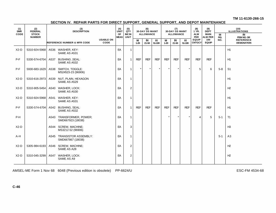
(10)ILLUSTRATIONS
(6)30-DAY DS MAINT
ALLOWANCE
(7)30-DAY GS MAINT
ALLOWANCE
(1)SMR
CODE
(2)FEDERALSTOCK
NUMBER
(3)DESCRIPTION
USABLE ONREFERENCE NUMBER & MFR CODE CODE
(4)UNITOF
MEAS
(5)QTY
INC INUNIT
(a)1-20
(b)21-50
(c)51-100
(a)1-20
(b)21-50
(c)51-100
(8)1 YR.ALWPER
EQUIPCNTGCY
(9)DEPTMAIN
ALW PER100
EQUIP
(a)FIG.NO.
(b)ITEM NO. OR
REFERENCEDESIGNATION
TM 11-6130-266-15SECTION IV. REPAIR PARTS FOR DIRECT SUPPORT, GENERAL SUPPORT, AND DEPOT MAINTENANCE
X2-D 5310-924-5968 A536 WASHER, KEY: EA 1 H1SAME AS A531
P-F 5330-574-6704 A537 BUSHING ,SEAL: EA 1 REF REF REF REF REF REF REF REF H1SAME AS A532
P-F 5930-683-1629 A538 SWITCH, TOGGLE: EA 1 * * * * * * 5 6 5-8 S1MS24523-23 (96906)
X2-D 5310-616-2973 A539 NUT, PLAIN, HEXAGON EA 1 H1SAME AS A529
X2-D 5310-905-5454 A540 WASHER, LOCK: EA 2 H2SAME AS A530
X2-D 5310-924-5968 A541 WASHER, KEY: EA 1 H1SAME AS A531
P-F 5330-574-6704 A542 BUSHING, SEAL: EA 1 REF REF REF REF REF REF REF REF H1SAME AS A532
P-H A543 TRANSFORMER, POWER; EA 1 * * * 4 5 5-1 T1SMD667923 (18038)
X2-D A544 SCREW, MACHINE; EA 3 H3MS3212-52 (96906)
A-H A545 TRANSISTOR ASSEMBLY: EA 1 5-1 A3SMD667867 (18038)
X2-D 5305-984-6193 A546 SCREW, MACHINE; EA 2 H2SAME AS A28
X2-D 5310-045-3299 A547 WASHER, LOCK: EA 2 H2SAME AS A9
AMSEL-ME Form 1 Nov 68 6048 (Previous edition is obsolete) PP-6624/U ESC-FM 4534-68
C-46

(10)ILLUSTRATIONS
(6)30-DAY DS MAINT
ALLOWANCE
(7)30-DAY GS MAINT
ALLOWANCE
(1)SMR
CODE
(2)FEDERALSTOCK
NUMBER
(3)DESCRIPTION
USABLE ONREFERENCE NUMBER & MFR CODE CODE
(4)UNITOF
MEAS
(5)QTY
INC INUNIT
(a)1-20
(b)21-50
(c)51-100
(a)1-20
(b)21-50
(c)51-100
(8)1 YR.ALWPER
EQUIPCNTGCY
(9)DEPTMAIN
ALW PER100
EQUIP
(a)FIG.NO.
(b)ITEM NO. OR
REFERENCEDESIGNATION
TM 11-6130-266-15SECTION IV. REPAIR PARTS FOR DIRECT SUPPORT, GENERAL SUPPORT, AND DEPOT MAINTENANCE
X2-D 5305-984-6210 A548 SCREW, MACHINE: EA 4 H4SAME AS A406
X2-D 5310-045-3296 A549 WASHER, LOCK: EA 4 H4SAME AS A32
M-D A550 BRACKET, HEAT SINK: EA 1 A3MP1SMC667868 (18038)
M-D A551 BRACKET, MOUNTING: EA 2 A3MP2SMC667874 (18038)
X2-D 5305-889-3000 A552 SCREW, MACHINE: EA 2 A3H2SAME AS A35
X2-D 5310-045-4007 A553 WASHER, LOCK: EA 2 A3H2SAME AS A13
M-D A554 BRACKET, MOUNTING: EA REF A3MP3SAME AS A551
X2-D 5305-889-3000 A555 SCREW, MACHINE; EA 2 A3H2SAME AS A35
X2-D 5310-045-4007 A556 WASHER, LOCK: EA 2 A3H2SAME AS A13
A-H A557 COMPONENT ASSEMBLY: EA 1 A3A1SMD667876 (18038)
X2-D 5305-984-4988 A558 SCREW, MACHINE: EA 1 A3H1SAME AS A12
X2-D 5310-045-4007 A559 WASHER, LOCK: EA 1 A3H1SAME AS A13
AMSEL-ME Form 1 Nov 68 6048 (Previous edition is obsolete) PP-6624/U ESC-FM 4534-68
C-47

(10)ILLUSTRATIONS
(6)30-DAY DS MAINT
ALLOWANCE
(7)30-DAY GS MAINT
ALLOWANCE
(1)SMR
CODE
(2)FEDERALSTOCK
NUMBER
(3)DESCRIPTION
USABLE ONREFERENCE NUMBER & MFR CODE CODE
(4)UNITOF
MEAS
(5)QTY
INC INUNIT
(a)1-20
(b)21-50
(c)51-100
(a)1-20
(b)21-50
(c)51-100
(8)1 YR.ALWPER
EQUIPCNTGCY
(9)DEPTMAIN
ALW PER100
EQUIP
(a)FIG.NO.
(b)ITEM NO. OR
REFERENCEDESIGNATION
TM 11-6130-266-15SECTION IV. REPAIR PARTS FOR DIRECT SUPPORT, GENERAL SUPPORT, AND DEPOT MAINTENANCE
X2-D 5310-209-0788 A560 NUT, PLAIN, HEXAGON: EA 1 * A3H1SAME AS A37
P-D A561 PRINTED CIRCUIT, BOARD: EA 1 3 5-4 A3A1MP1SMC667877 (18038)
P-F 5905-900-2089 A562 RESISTOR, FIXED, FILM: EA 2 REF REF REF REF REF REF REF REF 5-4 A3A1R1SAME AS A472
P-F 5905-900-2089 A563 RESISTOR FIXED, FILM: EA REF REF REF REF REF REF REF REF REF 5-4 A3A1R5SAME AS A472
P-F A564 RESISTOR, FIXED, EA 4 * 1 1 * 1 1 16 20 5-4 A3A1R2WIREWOUND: RW69VR50(81349)
P-F A565 RESISTOR, FIXED, EA REF REF REF REF REF REF REF REF REF 5-4 A3A1R3WIREWOUND: SAME AS A564
P-F A566 RESISTOR, FIXED, EA REF REF REF REF REF REF REF REF REF 5-4 A3A1R6WIREWOUND: SAME AS A564
P-F A567 RESISTOR, FIXED, EA REF REF REF REF REF REF REF REF REF 5-4 A3A1R7WIREWOUND: SAME AS A564
P-F 5905-994-7230 A568 RESISTOR, FIXED, EA 1 * * * * * * 4 10 5-4 A3A1R4WIREWOUND: RW69V8R2(81349)
X2-D A569 TERMINAL, STANDOFF: EA 1 A3A1E79574BB1032-14 (06540)
X2-D 5940-280-0601 A570 TERMINAL, STANDOFF: EA 5 A3A1E1SAME AS A247
AMSEL-ME Form 1 Nov 68 6048 (Previous edition is obsolete) PP-6624/U ESC-FM 4534-68
C-48

(10)ILLUSTRATIONS
(6)30-DAY DS MAINT
ALLOWANCE
(7)30-DAY GS MAINT
ALLOWANCE
(1)SMR
CODE
(2)FEDERALSTOCK
NUMBER
(3)DESCRIPTION
USABLE ONREFERENCE NUMBER & MFR CODE CODE
(4)UNITOF
MEAS
(5)QTY
INC INUNIT
(a)1-20
(b)21-50
(c)51-100
(a)1-20
(b)21-50
(c)51-100
(8)1 YR.ALWPER
EQUIPCNTGCY
(9)DEPTMAIN
ALW PER100
EQUIP
(a)FIG.NO.
(b)ITEM NO. OR
REFERENCEDESIGNATION
TM 11-6130-266-15SECTION IV. REPAIR PARTS FOR DIRECT SUPPORT, GENERAL SUPPORT, AND DEPOT MAINTENANCE
X2-D 5940-280-0601 A571 TERMINAL, STANDOFF: EA REF A3A1E2SAME AS A247
X2-D 5940-280-0601 A572 TERMINAL, STANDOFF: EA REF A3A1E4SAME AS A247
X2-D 5940-280-0601 A573 TERMINAL, STANDOFF: EA REF A3A1E6SAME AS A247
X2-D 5940-280-0601 A574 TERMINAL, STANDOFF: EA REF A3A1E8SAME AS A247
X2-D A575 TERMINAL, STANDOFF: EA 2 A3A1E31798-2 (71279)
X2-D A576 TERMINAL, STANDOFF: EA REF A3A1E5SAME AS A575
P-F A577 RESISTOR, FIXED, EA 1 * * * * * * 4 10 5-4 A3R8WIREWOUND: RW21V1R0(81349)
P-F 5905-978-9326 A578 RESISTOR, FIXED, EA 1 * * * * * * 4 10 5-4 A3R9WIREWOUND: RW21V101(81349)
X2-D 5305-984-6198 A579 SCREW, MACHINE EA 2 A3H2MS35206-250 (96906)
X2-D 5310-045-3299 A580 WASHER, LOCK: EA 2 A3H2SAME AS A9
X2-D 5310-809-8544 A581 WASHER, FLAT: EA 2 A3H2SAME AS A10
X2-D 5310-934-9757 A582 NUT, PLAIN, HEXAGON: EA 2 A3H2SAME AS A17
AMSEL-ME Form 1 Nov 68 6048 (Previous edition is obsolete) PP-6624/U ESC-FM 4534-68
C-49

(10)ILLUSTRATIONS
(6)30-DAY DS MAINT
ALLOWANCE
(7)30-DAY GS MAINT
ALLOWANCE
(1)SMR
CODE
(2)FEDERALSTOCK
NUMBER
(3)DESCRIPTION
USABLE ONREFERENCE NUMBER & MFR CODE CODE
(4)UNITOF
MEAS
(5)QTY
INC INUNIT
(a)1-20
(b)21-50
(c)51-100
(a)1-20
(b)21-50
(c)51-100
(8)1 YR.ALWPER
EQUIPCNTGCY
(9)DEPTMAIN
ALW PER100
EQUIP
(a)FIG.NO.
(b)ITEM NO. OR
REFERENCEDESIGNATION
TM 11-6130-266-15SECTION IV. REPAIR PARTS FOR DIRECT SUPPORT, GENERAL SUPPORT, AND DEPOT MAINTENANCE
P-F 5961-811-5799 A583 SEMICONDUCTOR, DEVICE, EA 3 * 1 1 * 1 1 13 15 5-4 A3CR1DIODE: JAN1N1202 (81350)
X2-D 5310-934-9751 A584 NUT, PLAIN, HEXAGON: EA 1 A3H1SAME AS A388
X2-D 5310-576-5752 A585 WASHER, LOCK; EA 1 A3H1MS35333-39 (96906)
P-F A586 WASHER, INSULATING: EA 1 * 1 2 * 1 2 16 20 A3H1MW562-203 (08289)
P-F 5310-062-0906 A587 BUSHING, INSULATING: EA 1 * * 1 * * 1 10 16 A3H1TW516-10 (08289)
P-F 5961-811-5799 A588 SEMICONDUCTOR, DEVICE, EA REF REF REF REF REF REF REF REF REF 5-4 A3CR2DIODE: SAME AS A583
X2-D 5310-934-9751 A589 NUT, PLAIN, HEXAGON: EA 1 A3H1SAME AS A388
X2-D 5310-576-5752 A590 WASHER, LOCK: EA 1 A3H1SAME AS A585
P-F A591 WASHER, INSULATING: EA 1 REF REF REF REF REF REF REF REF A3H1SAME AS A586
P-F 5310-062-0906 A592 BUSHING, INSULATING: EA 1 REF REF REF REF REF REF REF REF A3H1SAME AS A587
P-F 5961-811-5799 A593 SEMICONDUCTOR, DEVICE, EA REF REF REF REF REF REF REF REF REF 5-4 A3CR3DIODE: SAME AS A583
X2-D 5310-934-9751 A594 NUT, PLAIN, HEXAGON: EA 1 A3H1SAME AS A388
AMSEL-ME Form 1 Nov 68 6048 (Previous edition is obsolete) PP-6624/U ESC-FM 4534-68
C-50
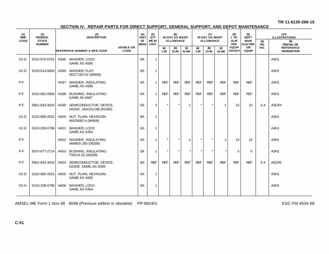
(10)ILLUSTRATIONS
(6)30-DAY DS MAINT
ALLOWANCE
(7)30-DAY GS MAINT
ALLOWANCE
(1)SMR
CODE
(2)FEDERALSTOCK
NUMBER
(3)DESCRIPTION
USABLE ONREFERENCE NUMBER & MFR CODE CODE
(4)UNITOF
MEAS
(5)QTY
INC INUNIT
(a)1-20
(b)21-50
(c)51-100
(a)1-20
(b)21-50
(c)51-100
(8)1 YR.ALWPER
EQUIPCNTGCY
(9)DEPTMAIN
ALW PER100
EQUIP
(a)FIG.NO.
(b)ITEM NO. OR
REFERENCEDESIGNATION
TM 11-6130-266-15SECTION IV. REPAIR PARTS FOR DIRECT SUPPORT, GENERAL SUPPORT, AND DEPOT MAINTENANCE
X2-D 5310-576-5752 A595 WASHER, LOCK: EA 1 A3H1SAME AS A585
X2-D 5310-014-5850 A596 WASHER, FLAT: EA 1 A3H1MS27183-42 (96906)
P-F A597 WASHER, INSULATING; EA 1 REF REF REF REF REF REF REF REF A3H1SAME AS A586
P-F 5310-062-0906 A598 BUSHING, INSULATING: EA 1 REF REF REF REF REF REF REF REF A3H1SAME A5 A587
P-F 5961-833-3042 A599 SEMICONDUCTOR, DEVICE, EA 2 * * 1 * * 1 10 10 5-4 A3CR4DIODE: JAN1N1186 (81350)
X2-D 5310-685-2631 A600 NUT, PLAIN, HEXAGON: EA 1 A3H1MS25082-4 (96906)
X2-D 5310-209-0786 A601 WASHER, LOCK: EA 1 A3H1SAME AS A364
P-F A602 WASHER, INSULATING: EA 1 * * 1 * * 1 10 10 A3H1MW855-260 (08289)
P-F 5970-977-2714 A603 BUSHING, INSULATING: EA 1 * * * * * * 5 6 A3H1TW516-25 (08289)
P-F 5961-833-3042 A604 SEMICONDUCTOR, DEVICE, EA REF REF REF REF REF REF REF REF REF 5-4 A3CR5DIODE: SAME AS A599
X2-D 5310-685-2631 A605 NUT, PLAIN, HEXAGON; EA 1 A3H1SAME AS A600
X2-H 5310-209-0786 A606 WASHER, LOCK: EA 1 A3H1SAME AS A364
AMSEL-ME Form 1 Nov 68 6048 (Previous edition is obsolete) PP-6624/U ESC-FM 4534-68
C-51

(10)ILLUSTRATIONS
(6)30-DAY DS MAINT
ALLOWANCE
(7)30-DAY GS MAINT
ALLOWANCE
(1)SMR
CODE
(2)FEDERALSTOCK
NUMBER
(3)DESCRIPTION
USABLE ONREFERENCE NUMBER & MFR CODE CODE
(4)UNITOF
MEAS
(5)QTY
INC INUNIT
(a)1-20
(b)21-50
(c)51-100
(a)1-20
(b)21-50
(c)51-100
(8)1 YR.ALWPER
EQUIPCNTGCY
(9)DEPTMAIN
ALW PER100
EQUIP
(a)FIG.NO.
(b)ITEM NO. OR
REFERENCEDESIGNATION
TM 11-6130-266-15SECTION IV. REPAIR PARTS FOR DIRECT SUPPORT, GENERAL SUPPORT, AND DEPOT MAINTENANCE
P-F A607 WASHER, INSULATING: EA 1 REF REF REF REF REF REF REF REF A3H1SAME AS A602
P-F 5970-977-2714 A608 BUSHING, INSULATING: EA 1 REF REF REF REF REF REF REF REF A3H1SAME AS A603
P-F 5961-950-4399 A609 SEMICONDUCTOR, DEVICE EA 1 * * * * * * 5 5 5-4 A3CR6DIODE: JAN1N2991RB (81350)
X2-D 5310-934-9751 A610 NUT, PLAIN, HEXAGON: EA 1 H6SAME AS A388
X2-D 5310-576-5752 A611 WASHER, LOCK: EA 1 A3H1SAME AS A585
P-F A612 WASHER, INSULATING: EA 1 REF REF REF REF REF REF REF REF A3H1SAME AS A586
P-F 5310-062-0906 A613 BUSHING, INSULATING: EA 1 REF REF REF REF REF REF REF REF A3H1SAME AS A587
X2-D 5940-283-5280 A614 TERMINAL, LUG: EA 3 A3MP5MS25036-106 (96906)
X2-D 5940-283-5280 A615 TERMINAL, LUG: EA REF A3MP6SAME AS A614
X2-D 5940-283-5280 A616 TERMINAL, LUG: EA REF A3MP7SAME AS A614
X2-D 5940-230-0515 A617 TERMINAL, LUG: EA 1 A3MP8MS25036-154 (96906)
X2-D 5940-143-4794 A618 TERMINAL, LUG: EA 1 A3MP9MS25036-112 (96906)
AMSEL-ME Form 1 Nov 68 6048 (Previous edition is obsolete) PP-6624/U ESC-FM 4534-68
C-52

(10)ILLUSTRATIONS
(6)30-DAY DS MAINT
ALLOWANCE
(7)30-DAY GS MAINT
ALLOWANCE
(1)SMR
CODE
(2)FEDERALSTOCK
NUMBER
(3)DESCRIPTION
USABLE ONREFERENCE NUMBER & MFR CODE CODE
(4)UNITOF
MEAS
(5)QTY
INC INUNIT
(a)1-20
(b)21-50
(c)51-100
(a)1-20
(b)21-50
(c)51-100
(8)1 YR.ALWPER
EQUIPCNTGCY
(9)DEPTMAIN
ALW PER100
EQUIP
(a)FIG.NO.
(b)ITEM NO. OR
REFERENCEDESIGNATION
TM 11-6130-266-15SECTION IV. REPAIR PARTS FOR DIRECT SUPPORT, GENERAL SUPPORT, AND DEPOT MAINTENANCE
P-F A619 TERMINAL, LUG: EA 1 * * * * * * 4 5 A3MP10SMB667875 (79963)
P-F A620 THERMOSTAT: EA 1 * * * * * * 4 5 5-4 A3S1SMB667873 (18038)
X2-D 5310-209-0788 A621 NUT, PLAIN, HEXAGON: EA 1 A3H1SAME AS A37
X2-D 5310-045-4007 A622 WASHER, LOCK: EA 1 A3H1SAME AS A13
P-F 5961-052-4115 A623 TRANSISTOR: EA 2 * * 1 * * 1 10 10 5-4 A3Q1JAN2N1490 (81350)
X2-D 5305-054-6654 A624 SCREW, MACHINE; EA 2 A3H2MS51957-30 (96906)
X2-D S310-579-0079 A625 WASHER, LOCK: EA 2 A3H2MS35333-37 (96906)
P-F A626 INSULATOR: EA 1 1 1 2 1 1 2 19 18 A3H1SMB350054 (80063)
P-F A627 BUSHING, INSULATING: EA 2 * 1 1 * 1 1 16 16 A3H2TW145-180 (08289)
X2-D 5310-209-0788 A628 NUT, PLAIN, HEXAGON: EA 2 A3H2SAME AS A37
P-F 5961-052-4115 A629 TRANSISTOR: EA REF REF REF REF REF REF REF REF REF 5-4 A3Q4SAME AS A623
X2-D 5305-054-6654 A630 SCREW, MACHINE: EA 2 A3H2SAME AS A624
AMSEL-ME Form 1 Nov 68 6048 (Previous edition is obsolete) PP-6624/U ESC-FM 4534-68
C-53

(10)ILLUSTRATIONS
(6)30-DAY DS MAINT
ALLOWANCE
(7)30-DAY GS MAINT
ALLOWANCE
(1)SMR
CODE
(2)FEDERALSTOCK
NUMBER
(3)DESCRIPTION
USABLE ONREFERENCE NUMBER & MFR CODE CODE
(4)UNITOF
MEAS
(5)QTY
INC INUNIT
(a)1-20
(b)21-50
(c)51-100
(a)1-20
(b)21-50
(c)51-100
(8)1 YR.ALWPER
EQUIPCNTGCY
(9)DEPTMAIN
ALW PER100
EQUIP
(a)FIG.NO.
(b)ITEM NO. OR
REFERENCEDESIGNATION
TM 11-6130-266-15SECTION IV. REPAIR PARTS FOR DIRECT SUPPORT, GENERAL SUPPORT, AND DEPOT MAINTENANCE
X2-D 5310-579-0079 A631 WASHER, LOCK: EA 2 A3H2SAME AS A625
P-F A632 INSULATOR: EA 1 REF REF REF REF REF REF REF REF A3H1SAME AS A626
P-F A633 BUSHING, INSULATING: EA 2 REF REF REF REF REF REF REF REF A3H2SAME AS A627
X2-D 5310-934-9747 A634 NUT, PLAIN, HEXAGON: EA 2 A3H2SAME AS A37
P-F 5961-230-7705 A635 TRANSISTOR: EA 2 * 1 2 * 1 2 16 20 5-4 A3Q5SMA667870 (18036)
X2-D 5305-889-3000 A636 SCREW, MACHINE: EA 2 A3H2SAME AS A35
X2-D 5310-579-0079 A637 WASHER, LOCK: EA 2 A3H2SAME AS A625:
P-F A638 INSULATOR: EA 1 REF REF REF REF REF REF REF REF A3H1SAME AS A626
P-F A639 BUSHING, INSULATING: EA 2 REF REF REF REF REF REF REF REF A3H2SAME AS A627
X2-D 5310-934-9747 A640 NUT, PLAIN, HEXAGON: EA 2 A3H2SAME AS A37
P-F 5961-230-7705 A641 TRANSISTOR: EA REF REF REF REF REF REF REF REF REF 5-4 A3Q6SAME AS A635
X2-D 5305-889-3000 A642 SCREW, MACHINE: EA 2 A3H2SAME AS A35
AMSEL-ME Form 1 Nov 68 6048 (Previous edition is obsolete) PP-6624/U ESC-FM 4534-68
C-54

(10)ILLUSTRATIONS
(6)30-DAY DS MAINT
ALLOWANCE
(7)30-DAY GS MAINT
ALLOWANCE
(1)SMR
CODE
(2)FEDERALSTOCK
NUMBER
(3)DESCRIPTION
USABLE ONREFERENCE NUMBER & MFR CODE CODE
(4)UNITOF
MEAS
(5)QTY
INC INUNIT
(a)1-20
(b)21-50
(c)51-100
(a)1-20
(b)21-50
(c)51-100
(8)1 YR.ALWPER
EQUIPCNTGCY
(9)DEPTMAIN
ALW PER100
EQUIP
(a)FIG.NO.
(b)ITEM NO. OR
REFERENCEDESIGNATION
TM 11-6130-266-15
SECTION IV. REPAIR PARTS FOR DIRECT SUPPORT, GENERAL SUPPORT, AND DEPOT MAINTENANCE
X2-D 5310-579-0079 A643 WASHER, LOCK: EA 2 A3H2SAME AS A625
P-F A644 INSULATOR; EA 1 REF REF REF REF REF REF REF REF A3H1SAME AS A626
P-F A645 BUSHING, INSULATING: EA 2 REF REF REF REF REF REF REF REF A3H2SAME AS A627
X2-D 5310-934-9747 A646 NUT, PLAIN, HEXAGON: EA 2 A3H2SAME AS A37
P-F A647 TRANSISTOR: EA 2 REF REF REF REF REF REF REF REF 5-4 A302SAME AS A635
X2-D 5305-889-3001 A648 SCREW, MACHINE: EA 2 A3H2M535206-231 (96906)
X2-D 5310-579-0079 A649 WASHER, LOCK: EA 2 A3H2SAME AS A625
P-F A650 INSULATOR: EA 1 REF REF REF REF REF REF REF REF A3H1SAME AS A626
M-D A651 BUSHING, SHOULDER: EA 2 A3H2SMB350043 (80063)
X2-D 5310-934-9747 A652 NUT, PLAIN, HEXAGON: EA 2 A3H2SAME AS A37
P-F 5961-230-7705 A653 TRANSISTOR: EA REF REF REF REF REF REF REF REF REF 5-4 A303SAME AS A635
X2-D 5305-889-3001 A654 SCREW, MACHINE: EA 2 A3H2SAME AS A648
AMSEL-ME Form 1 Nov 68 6048 (Previous edition is obsolete) PP-6224/U ESC-FM 4534-68
C-55

(10)ILLUSTRATIONS
(6)30-DAY DS MAINT
ALLOWANCE
(7)30-DAY GS MAINT
ALLOWANCE
(1)SMR
CODE
(2)FEDERALSTOCK
NUMBER
(3)DESCRIPTION
USABLE ONREFERENCE NUMBER & MFR CODE CODE
(4)UNITOF
MEAS
(5)QTY
INC INUNIT
(a)1-20
(b)21-50
(c)51-100
(a)1-20
(b)21-50
(c)51-100
(8)1 YR.ALWPER
EQUIPCNTGCY
(9)DEPTMAIN
ALW PER100
EQUIP
(a)FIG.NO.
(b)ITEM NO. OR
REFERENCEDESIGNATION
TM 11-6130-266-15
SECTION IV. REPAIR PARTS FOR DIRECT SUPPORT, GENERAL SUPPORT, AND DEPOT MAINTENANCE
X2-D 5310-579-0079 A655 WASHER, LOCK: EA 2 A3H2SAME AS A625
P-F A656 INSULATOR: EA 1 REF REF REF REF REF REF REF REF A3H1
SAME AS A626
P-F A657 BUSHING, SHOULDER: EA 2 REF REF REF REF REF REF REF REF A3H2SAME AS A651
X2-D 5310-93-9-977 A658 NUT, PLAIN, HEXAGON: EA 2 A3H2SAME AS A37
X2-D 5310-809-8544 A659 WASHER, FLAT; EA 2 H2SAME AS A10
X2-D 5310-905-5454 A660 WASHER, LOCK: EA 1 H1SAME AS A530
X2-D 5310-045-3299 A661 WASHER, LOCK: EA 2 H2SAME AS A9
X2-D 5310-045-3296 A662 WASHER, LOCK; EA 6 H6SAME AS A32
AMSEL-ME Form 1 Nov 68 6048 (Previous edition is obsolete) PP-6224/U ESC-FM 4534-68
C-56

(3)DESCRIPTION
(10)ILLUSTRATIONS
(6)30-DAY DS MAINT
ALLOWANCE
(7)30-DAY GS MAINT
ALLOWANCE
(1)SMRCODE
(2)FEDERALSTOCK
NUMBER
USABLE ONREFERENCE NUMBER & MFR/ CODE CODE
(4)UNITOF
MEAS
(5)QTY
INC INUNIT
(a)1-20
(b)21-50
(c)51-100
(a)1-20
(b)21-50
(c)51-100
(8)1-YRALWPER
EQUIPCNTGCY
(9)DEPOTMAINTALWPER100
EQUIP
(a)FIG.NO.
(b)ITEM NO. ORREFERENCE
DESIGNATION
TM 11-6130-266-15
SECTION IV. SPECIAL TOOLS, TEST & SUPPORT EQUIPMENT FOR DIRECT SUPPORT, GENERAL SUPPORT &DEPOT MAINTENANCE
P-F 51205293101 A663 Screwdriver, Cross Tip Size 1, EA 1 * * * * * * * *Blade Length 8". (81348)
P-F 51205454268 A664 Retrieving Tool Magnetic EA 1 * * * * * * * *Type II, Class I. (81348)
P-F 51208326221 A665 Screw Starter, Hand EA 1 * * * * * * * *P/N 5N9. (36540)
P-F 59359213398 A666 Connector, Plug, Electrical EA 2 * * * * * * * * 6-2Type No. MW10MA17 (81349)
¶U.S. GOVERNMENT PRINTING OFFICE: 1973-769615/410
Change 1 C-56.1

TM 11-6130-266-15
SECTION V.1. INDEX-FEDERAL STOCK NUMBER CROSS REFERENCETO FIGURE AND ITEM NUMBER OR REFERENCE DESIGNATION
FEDERAL FIGURE ITEM NUMBER ORSTOCK NUMBER REF. DESIGNATION
NUMBER
5305-052-8874 H45305-054-6654 A3H25305-054-6656 H35305-637-1124 A6H25305-889-3000 H15305-889-3000 A3H25305-889-3000 A8H15305-889-3000 A8H35305-889-3001 A3H25305-922-6286 H25305-983-6659 H45305-983-6730 A4H25305-984-4976 A11H25305-984-4983 H25305-984-4983 H35305-984-4983 H45305-984-4988 H15305-984-4988 A3H15305-984-4698 A4H15305-984-4988 A4H25305-984-6191 H15305-984-6191 H25305-984-6193 H25305-984-6193 H45305-984-6193 H85305-984-6198 A3H25305-984-6209 H25305-984-6209 H45305-984-6209 H65305-984-6210 H35305-984-6210 H45305-985-3674 A9H165305-989-6265 A8H45305-993-2738 A4H15305-993-9269 H25310-014-5850 A3H15310-043-0520 A4H15310-045-3296 H25310-045-3296 H45310-045-3296 H65310-045-3296 H75310-045-3296 A8H45310-045-3299 H15310-045-3299 H25310-045-3299 H45310-045-3299 H85310-045-3299 A3H25310-045-4007 H15310-045-4007 H25310-045-4007 H35310-045-4007 H4
FEDERAL FIGURE ITEM NUMBER ORSTOCK NUMBER REF. DESIGNATION
NUMBER
5310-045-4007 A3H15310-045-4007 A3H25310-045-4007 A4H25310-045-4007 A4H45310-045-4007 A8H35310-062-0906 A3H15310-082-1404 A8H35310-113-3757 A4H15310-167-0721 A7H15310-194-1483 A4H15310-209-0786 A3H15310-209-0786 A4H15310-209-0786 A6H25310-209-0788 H15310-209-0788 A3H15310-209-0788 A3H25310-209-0788 A4H15310-209-0788 A8H15310-531-9514 A9H165310-543-2410 A1H25310-543-2410 A2HA5310-543-2410 A4H25310-543-2410 A4A2H25310-543-2410 A5H25310-543-2410 A11H25310-576-0546 A6H25310-576-5752 A3H15310-577-5506 H25310-579-0079 A3H25310-582-5965 H35310-582-5965 H45310-595-7237 H15310-596-7693 H25310-616-2973 H15310-685-2631 A3H15310-687-6398 A7H15310-809-4058 H35310-809-4058 H45310-809-5998 A4H15310-809-8544 H15310-809-8544 H25310-809-8544 A3H25310-905-5454 H15310-905-5454 H25310-904-5968 H15310-09-6395 H35310-934-9739 A1H25310-934-9739 A2H25310-934-9739 A4H25310-934-9739 A4A2H25310-934-9739 A5H3
AMSEL-ME Form 1 Nov 68 6069 PP-6224/U ESC-FM 4535-68C-57

TM 11-6130-266-15SECTION V.1. INDEX-FEDERAL STOCK NUMBER CROSS REFERENCE
TO FIGURE AND ITEM NUMBER OR REFERENCE DESIGNATION
FEDERAL FIGURE ITEM NUMBER ORSTOCK NUMBER REF. DESIGNATION
NUMBER
5310-934-9739 A11H25310-934-9747 H15310-934-9747 A3H25310-934-9747 A4H15310-934-9747 A4H25310-934-9747 A4H45310-934-9747 A6H45310-934-9747 A8H15310-934-9751 H65310-934-9751 A3H15310-934-9757 H25310-934-9757 A3H25310-983-8483 H15310-983-8483 H25310-983-8483 H35310-983-6483 A4H25310-997-1888 H25320-117-6815 A8A1A1H25330-574-6704 H15340-951-1532 A8A1A1MP25905-061-2089 5-3 A2R175905-061-2089 5-7 A6A1R45905-061-5355 5-7 A6A1R35905-067-9079 5-3 A2R105905-067-9079 5-3 A2R155905-067-9079 5-6 A5R95905-080-5016 5-2 A1R205905-087-0545 5-7 A6A1R55905-230-7713 5-7 A6A1R25905-686-3379 5-3 A2R215905-717-3339 5-2 A1R195950-717-3342 5-2 A1R45905-717-3342 5-2 A1R45905-717-3342 5-2 A1R135905-717-3342 5-6 A5R75905-752-3597 5-3 A2R225905-755-8132 5-3 A2R135905-762-3667 5-2 A1R75905-765-5628 5-3 A2R35905-766-8216 5-5 A4A2R55905-766-8216 5-5 A4A2R65905-766-8366 5-2 A1R225905-767-2444 5-6 A5R65905-767-2842 5-2 A1R165905-767-2842 5-6 A5R55905-767-3229 5-2 A1R175905-767-3229 5-2 A1R185905-767-3229 5-3 A2R65905-767-3229 5-6 A5R35905-767-3229 5-6 A5R105905-767-3230 5-2 A1R155905-767-3230 5-6 A5R15905-767-3230 5-6 A5R125905-767-7583 5-2 A1R10
FEDERAL FIGURE ITEM NUMBER ORSTOCK NUMBER REF. DESIGNATION
NUMBER
5905-768-5922 5-2 A1R215905-768-5922 5-2 A1R235905-771-2295 5-2 A1R115905-771-2295 5-3 A2R75905-771-2295 5-3 A2R95905-771-2295 5-3 A2R185905-771-2295 5-6 A5R25905-775-0633 5-6 A5R85905-775-0633 5-6 A5R135905-807-0832 5-8 R35905-810-7778 5-2 A1R65905-819-6925 5-3 A2R165995-833-8355 5-2 A1R35905-834-0387 5-3 A2R115905-835-6424 5-2 A1R25905-836-2859 5-2 A1R55905-844-1423 5-3 A2R145905-880-0872 5-2 A1R95905-882-0061 5-2 A1R15905-882-0070 5-2 A1R145905-900-2089 5-3 A2R45905-900-2089 5-3 A2R55905-900-2089 5-4 A3A1R15905-900-2089 5-4 A3A1R55905-900-2089 5-5 A4A2R15905-900-2089 5-5 A4A2R25905-900-2089 5-5 A4A2R75905-900-2089 5-5 A4A2R85905-901-4016 5-2 A1R125905-901-4016 5-3 A2R85905-901-4016 5-3 A2R195905-901-4016 5-3 A2R205905-901-4016 5-5 A4A2R35905-901-4016 5-5 A4A2R45905-975-1135 5-5 A4A2R95905-975-1135 5-5 A4A2R105905-978-9326 5-4 A3R95905-985-6056 5-3 A2R125905-994-7230 5-4 A3A1R45910-078-8110 5-2 A1C15910-082-4767 5-7 A6A1C15910-082-4925 5-2 A1C35910-082-4925 5-5 A4A2C35910-082-4925 5-5 A4A2C45910-642-6275 5-3 A2C75910-644-6164 5-2 AA1C25910-644-6164 5-3 A2C25910-644-6164 5-3 A2C45910-644-6164 5-3 A2C55910-644-6164 5-6 A5C25910-881-8945 5-3 A2C15910-904-3983 5-5 A4A2C15910-904-3983 5-5 A4A2C25910-988-4415 5-3 A2C35930-655-4245 5-8 S2
AMSEL-ME Form 1 Nov 68 6069 PP-6224/U ESC-FM 4535-68
C-58

TM 11-6130-266-15
SECTION V.1. INDEX-FEDERAL STOCK NUMBER CROSS REFERENCETO FIGURE AND ITEM NUMBER OR REFERENCE DESIGNATION
FEDERAL FIGURE ITEM NUMBER ORSTOCK NUMBER REF. DESIGNATION
NUMBER
5930-660-3954 5-8 S15930-683-1629 5-8 S15935-071-1235 J75940-143-4794 A3MP95940-230-0515 A3MP85940-280-0601 A1TP15940-280-0601 A1TP25940-280-0601 A2TP15940-280-0601 A3A1E15940-280-0601 A3A1E25940-280-0601 A3A1E45940-280-0601 A3A1E65940-280-0601 A3A1E85940-280-0601 A5TP15940-280-0601 A6A1E15940-280-0601 A6A1E25940-280-0601 A6A1E45940-280-0601 A6A1E55940-280-0601 A6A1E115940-280-0601 A6A1E125940-283-5280 A3MP55940-283-5280 A3MP65940-283-5280 A3MP75940-681-9772 A4MP45961-052-4115 5-4 A3Q15961-052-4115 5-4 A3Q45961-060-5778 A4Q15961-060-5778 5-5 A4Q25961-087-6047 5-2 A1CR65961-087-6047 5-2 A1CR75961-087-6047 5-2 A1CR85961-087-6047 5-2 A1CR95961-087-6047 5-2 A1CR105961-087-6047 5-2 A1CR115961-087-6047 5-2 A1CR125961-087-6047 5-2 A2CR135961-087-6047 5-3 A2CR25961-087-6047 5-3 A2CR35961-087-6047 5-3 A2CR45961-087-6047 5-3 A2CR75961-087-6047 5-5 A4A2CR15961-087-6047 5-5 A4A2CR25961-087-6047 5-5 A4A2CR35961-087-6047 5-5 A4A2CR45961-087-6047 5-6 A5CR15961-087-6047 5-6 A5CR25961-087-6047 5-6 A5CR45961-104-8378 5-3 A2Q35961-230-7705 5-4 A3Q25961-230-7705 5-4 A3Q35961-230-7705 5-4 A3Q55961-230-7705 5-4 A3Q65961-811-5799 5-4 A3CR15961-811-5799 5-4 A3CR2
FEDERAL FIGURE ITEM NUMBER ORSTOCK NUMBER REF. DESIGNATION
NUMBER
5961-811-5799 5-4 A3CR35961-833-3042 5-4 A3CR45961-833-3042 5-4 A3CR55961-836-0382 5-6 A5CR35961-853-2601 5-2 A1Q15961-853-2601 5-2 A1Q25961-853-2601 5-2 A1Q55961-853-2601 5-2 A1Q65961-853-2601 5-2 A1Q75961-853-2601 5-2 A1Q95961-853-2601 5-3 A2Q15961-853-2601 5-3 A2Q45961-853-2601 5-5 A4A2Q15961-853-2601 5-5 A4A2Q25961-853-2601 5-6 A5Q15961-853-2601 5-6 A5Q25961-853-2601 5-6 A5Q35961-880-4779 5-2 A1Q35961-880-4779 5-2 A1Q45961-880-4779 5-2 A1Q85961-880-4779 5-3 A2Q25961-950-4399 5-4 A3CR65961-957-6855 5-2 A1CR15961-957-6855 5-2 A1CR25961-957-6855 5-2 A1CR35961-957-6855 5-2 A1CR45961-957-6855 5-3 A2CR65970-977-2714 A3H15995-466-0217 W26210-151-5246 MP156210-176-4928 XDS16210-176-4928 XDS26210-176-4928 XDS36225-929-3950 A5MP26240-155-7836 5-8 DS16240-155-7836 5-8 DS26240-155-7836 5-8 DS36625-929-3950 A1MP26625-929-3950 A2MP2
AMSEL-ME Form 1 Nov 68 6069 PP-6224/U ESC-FM 4535-68
C-59

TM 11-6130-266-15
SECTION V.2 INDEX-REFERENCE NUMBER CROSS REFERENCETO FIGURE NUMBER AND REFERENCE DESIGNATION OR ITEM NUMBER
REFERENCE MFGRS. FIG. REF DESIGNATIONNO. CODE NO. OR ITEM NO
AN508-6-4 88044 A6A1H2B8152 18038 A8MP1CH08A1NC126J 81349 5-1 A8C1CH08A1RA475M 81349 5-6 A5C1CP13A3KB105K1 81349 5-1 A7C1CX-11979/U 81349 W1C8107 18038 5-5 A4A2C8108 18038 A7C8150 18038 A4A3C8157 18038 A6MP1C8169 18038 A7MP1C8263 18038 MP1D8117 18038 A8D8162 18038 5-1 A8A1D8219 18038 A11JAN1N9378 81350 5-2 A1CR5LC36RD2 81349 MP16LC36YD2 81349 MP15MILC1097-4-01 81349 A11J1MILC21097-5-01 81349 A1P1MILR5757-29A008 81349 5-2 A1K1MILT55155-21-3 81349 A8E1M515795-607 96906 A6H2MS21919-WG-11 96906 MP11MS21919-4 96906 MP6MS21919-5 96906 MP9MS3212-25 96906 H2MS3212-52 96906 H3MS3212-53 96906 H3MS35206-323 96906 A1H2MS35303-7 96906 H3MS35691-431 96906 A6H4MW1375-526 08289 A4H1MW20MMA00 81349 J8MW562-203 08289 A3H1MW855-260 08289 A3H1PT07C14-16S 77820 J6PT07C14-5P 77820 J3RL20S122J 81349 5-3 A2R2RL20S223J 81349 5-3 A2R1RW21V1R0 81349 5-4 A3R8RW69VR50 81349 5-4 A3A1R2SMB169134 80063 A8A1A1MP3SMB350043 80063 A3H2SMB350054 80063 A3H1SMB450392 80063 A8MP2SMB450423 80063 MP4SMB667875 79963 A3MP10SMB667875 79963 A3MP10SMB667884 18038 A4MP3
REFERENCE MFGRS FIG. REF. DESIGNATIONNO. CODE NO. OR ITEM NO.
SMB667887 18038 A4MP1SMB667898 18038 5-7 A6K1SMB667902 18038 A6A1E6SMB667928 18038 MP23SMB667940 18038 A9MP5SMB667942-1 18038 MP17SMB667942-2 18038 MP18SMB667945 18038 MP12SMB667947 18038 MP21SMB667948 18038 MP22SMB667949 18038 A10SMB667955 18038 MP5SMC667850 18038 5-2 A1SMC667858 18038 5-3 A2SMC667863 18038 5-6 A5SMC667868 18038 A3MP1SMC667874 18038 A3MP2SMC667877 18038 5-4 A3AMP1SMC667897 18038 5-7 A6R1SMC667918 18038 5-8 CB1SMC667919 18038 5-8 CB2SMC667920 18038 5-8 M1SMC667922 18038 MP20SMC667925 18038 FL1SMC667946 18038 MP19SMD667852 18038 A1MP1SMD667860 18038 A2MP1SMD667862 18038 A2A1SMD667865 18038 A5MP1SMD667867 18038 5-1 A3SMD667876 18038 A3A1SMD667881 18038 5-5 A4SMD667883 18038 A4A1SMD667891 18038 A4A2MP3SMD667894 18038 5-7 A6SMD667899 18038 5-7 A6A1SMD667900 18038 A6A1MP1SMD667923 18038 5-1 T1SMD667924 18038 5-1 L1SMD667930 18038 A9SMD667931 18038 A9MP1SMD667932 18038 A9MP2SMD667933 18038 A9MP3SMD667934 18038 A9MP4SMD667936 18038 MP13TW145-180 08289 A3H2TW510-570 08289 A4H11-8 NPTF 70318 MP2610-101960-14-3 07601 MP3
1115B 75247 A1MP1212Z72015 18038 MP26
AMSEL-ME Form 1 Nov 68 6069 PP-6224/U ESC-FM 4535-68
C-60

TM 11-6130-266-15
SECTION V.2 INDEX-REFERENCE NUMBER CROSS REFERENCETO FIGURE NUMBER AND REFERENCE DESIGNATION OR ITEM NUMBER
REFERENCE MFGRS. FIG. REF. DESIGNATIONNO. CODE NO. OR ITEM NO.
1798-2 71279 A3A1E320000-50-8AMPS 99392 5-1 A8C2
3600-50-1AMP 99392 5-1 C84079-105-19 71279 A7E171000-6-8AMPS 99392 5-1 C97717-5DAP 75247 A1MP38186 18038 MP29531BB0632-12 06540 A4A2E19573BB1032-14 06540 A6A1E79574BB1032-14 06540 A3A1E7
REFERENCE MFGRS. FIG. REF. DESIGNATIONNO. CODE NO. OR ITEM NO.
AMSEL-ME Form 1 Nov 68 6069 PP-6224/U ESC-FM 4535-68
C-61
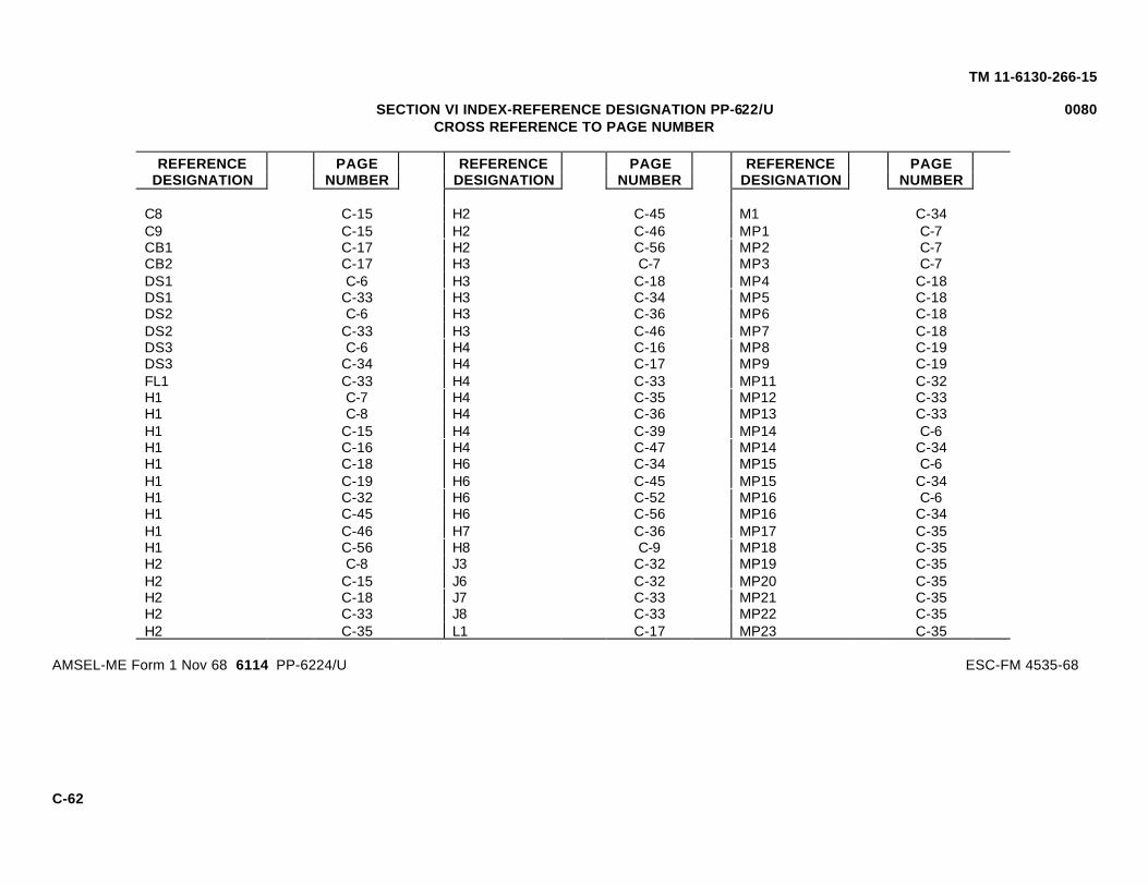
TM 11-6130-266-15
SECTION VI INDEX-REFERENCE DESIGNATION PP-622/U 0080CROSS REFERENCE TO PAGE NUMBER
REFERENCE PAGE REFERENCE PAGE REFERENCE PAGEDESIGNATION NUMBER DESIGNATION NUMBER DESIGNATION NUMBER
C8 C-15 H2 C-45 M1 C-34C9 C-15 H2 C-46 MP1 C-7CB1 C-17 H2 C-56 MP2 C-7CB2 C-17 H3 C-7 MP3 C-7DS1 C-6 H3 C-18 MP4 C-18DS1 C-33 H3 C-34 MP5 C-18DS2 C-6 H3 C-36 MP6 C-18DS2 C-33 H3 C-46 MP7 C-18DS3 C-6 H4 C-16 MP8 C-19DS3 C-34 H4 C-17 MP9 C-19FL1 C-33 H4 C-33 MP11 C-32H1 C-7 H4 C-35 MP12 C-33H1 C-8 H4 C-36 MP13 C-33H1 C-15 H4 C-39 MP14 C-6H1 C-16 H4 C-47 MP14 C-34H1 C-18 H6 C-34 MP15 C-6H1 C-19 H6 C-45 MP15 C-34H1 C-32 H6 C-52 MP16 C-6H1 C-45 H6 C-56 MP16 C-34H1 C-46 H7 C-36 MP17 C-35H1 C-56 H8 C-9 MP18 C-35H2 C-8 J3 C-32 MP19 C-35H2 C-15 J6 C-32 MP20 C-35H2 C-18 J7 C-33 MP21 C-35H2 C-33 J8 C-33 MP22 C-35H2 C-35 L1 C-17 MP23 C-35
AMSEL-ME Form 1 Nov 68 6114 PP-6224/U ESC-FM 4535-68
C-62

TM 11-6130-266-15
SECTION VI INDEX-REFERENCE DESIGNATION PP-622/U 0080CROSS REFERENCE TO PAGE NUMBER
REFERENCE PAGE REFERENCE PAGE REFERENCE PAGEDESIGNATION NUMBER DESIGNATION NUMBER DESIGNATION NUMBER
MP26 C-36 A1CR10 C-23 A1Q9 C-24MP26 C-45 A1CR11 C-23 A1R1 C-21R3 C-44 A1H2 C-20 A1R3 C-21S1 C-45 A1K1 C-21 A1R4 C-21
A1R5 C-21S1 C-46 A1K2 C-21 A1R6 C-21S2 C-45 A1MP1 C-21 A1R7 C-22T1 C-46 A1P2 C-20 A1R9 C-23W1 C-6 A1MP3 C-20 A1R10 C-22W1 C-36 A1MP4 C-20 A1R11 C-22W2 C-6 A1MP5 C-20 A1R12 C-22W2 C-36 A1MP6 C-20 A1R13 C-21XDS1 C-34 A1MP7 C-20 A1R14 C-22XDS2 C-34 A1MP8 C-21 A1R15 C-22XDS3 C-34 A1MP9 C-21 A1R16 C-22A1 C-19 A1MP10 C-21 A1R17 C-22A1C1 C-19 A1MP11 C-21 A1R18 C-22A1C2 C-20 A1R19 C-22A1C3 C-20 A1MP12 C-20 A1R21 C-22A1CR1 C-23 A1P1 C-20 A1R22 C-23A1CR11 C-24 A1Q1 C-24 A1R23 C-23A1CR10 C-24 A1Q2 C-24 A1TP1 C-24A1CR2 C-23 A1Q3 C-24 A1TP2 C-24A1CR3 C-23 A1Q4 C-24 A2 C-25A1CR4 C-23 A1Q5 C-24 A2C1 C-25A1CR5 C-23 A1Q6 C-24 A2C2 C-25A1CR7 C-23 A1Q7 C-24 A2C3 C-25A1CR8 C-23A1CR9 C-23 A1Q8 C-25 A2C4 C-25
AMSEL-ME Form 1 Nov 68 6114 PP-6224/U ESC-FM 4535-68
C-63

TM 11-6130-266-15
SECTION VI INDEX-REFERENCE DESIGNATION PP-622/U 0080CROSS REFERENCE TO PAGE NUMBER
REFERENCE PAGE REFERENCE PAGE REFERENCE PAGEDESIGNATION NUMBER DESIGNATION NUMBER DESIGNATION NUMBER
A2C5 C-25 A2R9 C-27 A3H1 C-51A2C7 C-25 A2R10 C-28 A3H1 C-52A2CR1 C-28 A2R11 C-27 A3H1 C-53A2CR2 C-28 A2R12 C-27 A3H1 C-54A2CR3 C-28 A2R13 C-27 A3H1 C-55A2CR4 C-28 A2R14 C-27 A3H1 C-56A2CR6 C-28 A2R15 C-28 A3H2 C-47A2CR7 C-28 A2R16 C-27 A3H2 C-49A2H2 C-25 A2R17 C-28 A3H2 C-53A2MP1 C-26 A2R18 C-27 A3H2 C-54A2MP2 C-26 A2R19 C-27 A3H2 C-55A2MP3 C-26 A2R20 C-27 A3H2 C-56A2MP4 C-26 A2R21 C-27 A3MP1 C-47A2P1 C-25 A2R22 C-27 A3MP2 C-47A2Q1 C-28 A2TP1 C-28 A3MP3 C-47A2Q2 C-29 A2A1 C-26 A3MP5 C-52A2Q3 C-29 A3 C-46 A3MP6 C-52A2Q4 C-28 A3CR1 C-50 A3MP7 C-52A2R1 C-26 A3CR2 C-50 A3MP8 C-52A2R2 C-26 A3CR3 C-50 A3MP9 C-52A2R3 C-26 A3CR4 C-51 A3MP10 C-53A2R4 C-26 A3CR5 C-51 A3Q1 C-53A2R5 C-26 A3CR6 C-52 A3Q2 C-55A2R6 C-26 A3H1 C-47 A3Q3 C-55A2R7 C-26 A3H1 C-48 A3Q4 C-53A2R8 C-27 A3H1 C-50 A3Q5 C-54
AMSEL-ME Form 1 Nov 68 6114 PP-6224/U ESC-FM 4535-68
C-64

TM 11-6130-266-15
SECTION VI INDEX-REFERENCE DESIGNATION PP-622/U 0080CROSS REFERENCE TO PAGE NUMBER
REFERENCE PAGE REFERENCE PAGE REFERENCE PAGEDESIGNATION NUMBER DESIGNATION NUMBER DESIGNATION NUMBER
A3Q6 C-54 A4H2 C-42 A4A2MP3 C-40A3R8 C-49 A4H2 C-43 A4A2P1 C-40A3R9 C-49 A4H2 C-44 A4A2Q1 C-42A3S1 C-53 A4H4 C-42 A4A2Q2 C-42A3A1 C-47 AJ1 C-42 A4A2R1 C-40A3A1E1 C-48 A4MP1 C-39 A4A2R2 C-40
A4A2R3 C-41A3A1E2 C-49 A4MP2 C-39 A4A2R4 C-41A3A1E3 C-49 A4MP3 C-43 A4A2R5 C-41A3A1E4 C-49 A4MP4 C-44 A4A2R6 C-41A3A1E5 C-49 A4Q1 C-43 A4A2R7 C-41A3A1E6 C-49 A4Q2 C-43 A4A2R8 C-41A3A1E7 C-48 A4A1 C-42 A4A2R9 C-41A3A1E8 C-49 A4A2 C-39 A4A2R10 C-41A3A1MP1 C-48 A4A2C1 C-39 A4A3 C-42A3A1R1 C-48 A4A2C2 C-40 A5 C-29A3A1R2 C-48 A4A2C3 C-40 A5C1 C-29A3A1R3 C-48 A4A2C4 C-40 A5C2 C-29A3A1R4 C-48 A4A2CR1 C-41 A5CR1 C-31A3A1R5 C-48 A4A2CR2 C-41 A5CR2 C-31A3A1R6 C-48 A4A2CR3 C-41 A5CR3 C-31A3A1R7 C-48 A4A2CR4 C-41 A5CR4 C-31A4 C-39 A4A2E1 C-41 A5H2 C-29A4H1 C-39 A4A2E2 C-42 A5H3 C-29A4H1 C-43 A4A2H2 C-40 A5J1 C-29A4H1 C-44 A4A2MP1 C-40 A5MP1 C-30A4H2 C-39 A4A2MP2 C-40 A5MP2 C-29
AMSEL-ME Form 1 Nov 68 6114 PP-6224/U ESC-FM 4535-68
C-65

TM 11-6130-266-15
SECTION VI INDEX-REFERENCE DESIGNATION PP-622/U 0080CROSS REFERENCE TO PAGE NUMBER
REFERENCE PAGE REFERENCE PAGE REFERENCE PAGEDESIGNATION NUMBER DESIGNATION NUMBER DESIGNATION NUMBER
A5MP3 C-29 A6A1C1 C-36 A8C1 C-9A5MP4 C-29 A6A1E1 C-37 A8C2 C-9A5MP1 C-30 A6A1E2 C-37 A8C3 C-10A5MP6 C-30 A6A1E4 C-37 A8C4 C-10A5Q1 C-31 A6A1E5 C-37 A8C5 C-10A5Q2 C-31 A6A1E6 C-36 A8C6 C-11A5Q3 C-31 A6A1E7 C-37 A8E1 C-14A5R1 C-30 A6A1E8 C-37 A8E2 C-15A5R2 C-30 A6A1E9 C-38 A8H1 C-9A5R3 C-30 A6A1E10 C-38 A8H1 C-10A5R5 C-30 A6A1E11 C-37 A8H1 C-11A5R6 C-30 A6A1E12 C-37 A8H1 C-15A5R7 C-30 A6A1H2 C-36 A8H3 C-13A5R8 C-30 A6A1MP1 C-36 A8H3 C-14A5R9 C-31 A6A1R2 C-37 A8H4 C-9A5R10 C-31 A6A1R3 C-37 A8MP1 C-9A5R12 C-30 A6A1R4 C-37 A8MP2 C-13A5R13 C-30 A6A1R5 C-37 A8MP3 C-13A5TP1 C-31 A7 C-8 A8MP4 C-13A6 C-36 A7C1 C-8 A8MP5 C-14A6H2 C-38 A7C2 C-8 A8MP6 C-14A6H4 C-38 A7E1 C-9 A8A1 C-11A6K1 C-38 A7E2 C-9 A8A1A1H2 C-11A6MP1 C-38 A7H1 C-8 A8A1A1MP2 C-11A6R1 C-38 A7MP1 C-8 A8A1A1MP3 C-11A6A1 C-36 A8 C-9 A8A1A1MP4 C-11
AMSEL-ME Form 1 Nov 68 6114 PP-6224/U ESC-FM 4535-68
C-66
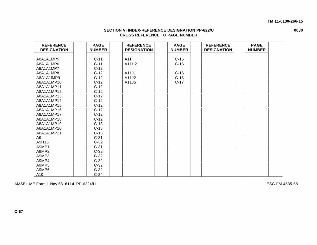
TM 11-6130-266-15
SECTION VI INDEX-REFERENCE DESIGNATION PP-622/U 0080CROSS REFERENCE TO PAGE NUMBER
REFERENCE PAGE REFERENCE PAGE REFERENCE PAGEDESIGNATION NUMBER DESIGNATION NUMBER DESIGNATION NUMBER
A8A1A1MP5 C-11 A11 C-16A8A1A1MP6 C-11 A11H2 C-16A8A1A1MP7 C-12A8A1A1MP8 C-12 A11J1 C-16A8A1A1lMP9 C-12 A11J2 C-16A8A1A1MP10 C-12 A11J5 C-17A8A1A1MP11 C-12A8A1A1MP12 C-12A8A1A1MP13 C-12A8A1A1MP14 C-12A8A1A1MP15 C-12A8A1A1MP16 C-12A8A1A1MP17 C-12A8A1A1MP18 C-12A8A1A1MP19 C-13A8A1A1MP20 C-13A8A1A1MP21 C-13A9 C-31A9H16 C-32A9MP1 C-31A9MP2 C-32A9MP3 C-32A9MP4 C-32A9MP5 C-32A9MP6 C-32A10 C-34
AMSEL-ME Form 1 Nov 68 6114 PP-6224/U ESC-FM 4535-68
C-67

TM 11-6130-266-15
Figure 8-1. Color code marking for resistors and capacitors.
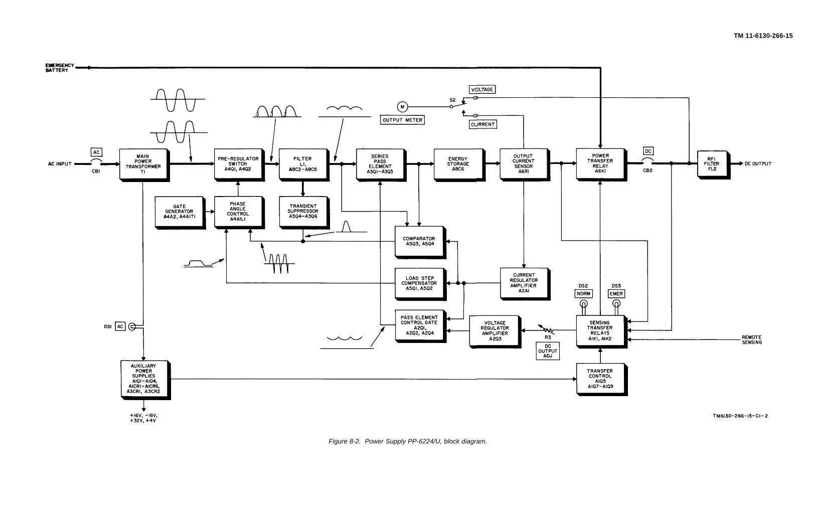
TM 6130-266-15-C1-2
TM 11-6130-266-15
Figure 8-2. Power Supply PP-6224/U, block diagram.
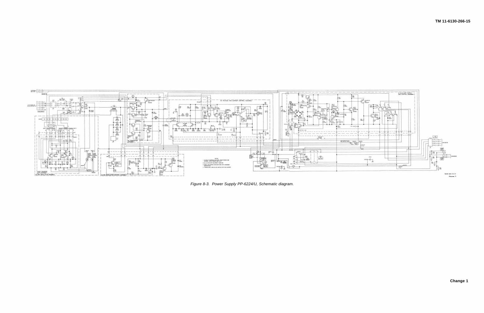
TM 6130-266-15-C1-3
TM 11-6130-266-15
Figure 8-3. Power Supply PP-6224/U, Schematic diagram.
Change 1
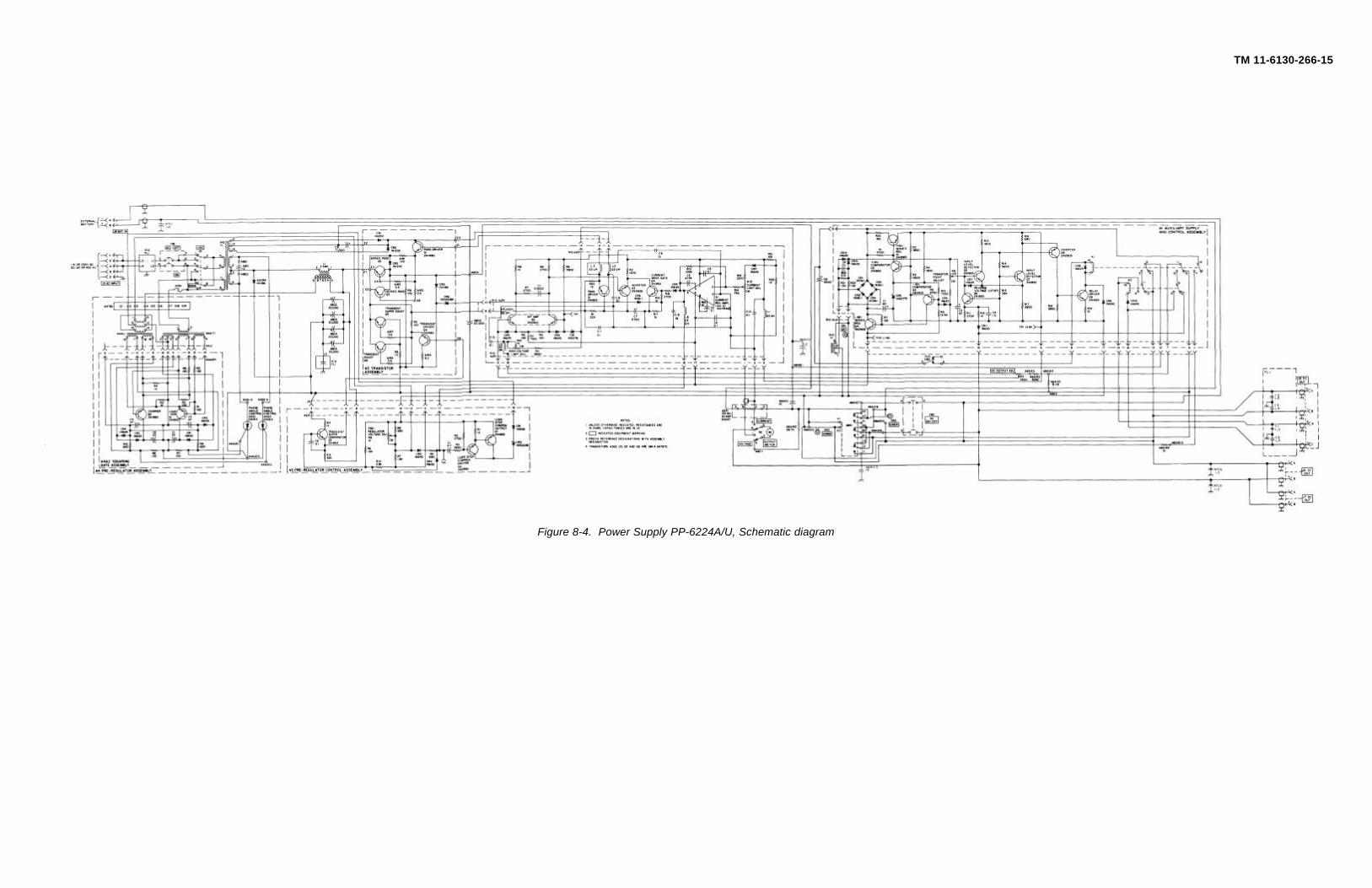
TM 11-6130-266-15
Figure 8-4. Power Supply PP-6224A/U, Schematic diagram

TM 11-6130-266-15
By Order of the Secretary of the Army:
W. C. WESTMORELAND,General, United States Army,
Official: Chief of Staff.
VERNE L. BOWERS,Major General, United States Army,The Adjutant General
Distribution:To be distributed in accordance with DA Form 12-51, operator maintenance requirements for the RT- 246/VRC and RT-524/VRC equipments.
¶U.S. GOVERNMENT PRINTING OFFICE: 1971-714-207/5038
FORMS-6
TEAR ALONG DOTTED LINE
REVERSE OF DA FORM 2028-2
FOLD BACK
OFFICIAL BUSINESS
DEPARTMENT OF THE ARMY
FILL IN YOURUNIT'S ADDRESS
CommanderU.S. Army Communications-Electronics Command and Fort MonmouthATTN: AMSEL-LC-LEO-D-CS-CFOFort Monmouth, New Jersey 07703-5000
PLEASEAFFIX
STAMPPOSTAGEREQUIRED
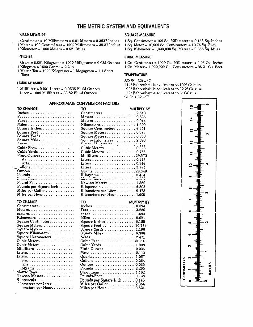
THE METRIC SYSTEM AND EQUIVALENTS

TM 11-6130-266-15
PIN: 020697-004

This fine document...
Was brought to you by me:
Liberated Manuals -- free army and government manuals
Why do I do it? I am tired of sleazy CD-ROM sellers, who take publicly available information, slap “watermarks” and other junk on it, and sell it. Those masters of search engine manipulation make sure that their sites that sell free information, come up first in search engines. They did not create it... They did not even scan it... Why should they get your money? Why are not letting you give those free manuals to your friends?
I am setting this document FREE. This document was made by the US Government and is NOT protected by Copyright. Feel free to share, republish, sell and so on.
I am not asking you for donations, fees or handouts. If you can, please provide a link to liberatedmanuals.com, so that free manuals come up first in search engines:
<A HREF=http://www.liberatedmanuals.com/>Free Military and Government Manuals</A>
– SincerelyIgor Chudovhttp://igor.chudov.com/
– Chicago Machinery Movers
Related Documents