TM 10-3930-665-13&P TECHNICAL MANUAL Operator’s, Unit and DS Maintenance Manual CONVEYOR, BELT, PORTABLE, ELECTRIC, CASTER MOUNTED NSN: 3910-01-376-0431 HIGHLAND ENGINEERING, INC. MODEL 9306 Approved for Public Release; Distribution is Unlimited HEADQUARTERS, DEPARTMENT OF THE ARMY SEPTEMBER 1994

Welcome message from author
This document is posted to help you gain knowledge. Please leave a comment to let me know what you think about it! Share it to your friends and learn new things together.
Transcript
TM 10-3930-665-13&P
TECHNICAL MANUAL
Operator’s, Unit and DS Maintenance Manual
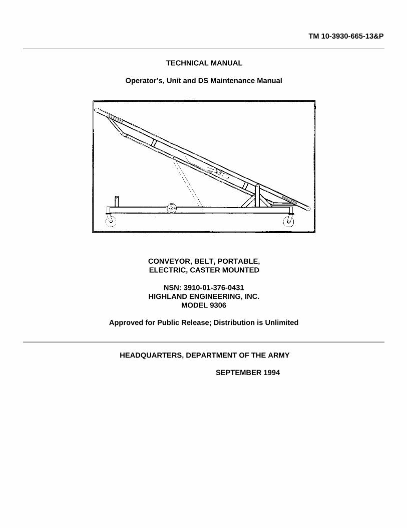
CONVEYOR, BELT, PORTABLE,ELECTRIC, CASTER MOUNTED
NSN: 3910-01-376-0431HIGHLAND ENGINEERING, INC.
MODEL 9306
Approved for Public Release; Distribution is Unlimited
HEADQUARTERS, DEPARTMENT OF THE ARMY
SEPTEMBER 1994
TM 10-3930-665-13&P
HEADQUARTERSTECHNICAL MANUAL DEPARTMENT OF THE ARMYNo. 10-3930665-13&P Washington D.C., 19 September 1994
Operator’s, Unit and DS Maintenance ManualFOR
CONVEYOR, BELT, PORTABLE,ELECTRIC, CASTER MOUNTED
REPORTING ERRORS AND RECOMMENDING IMPROVEMENTS
You can help improve this manual. If you find any mistakes or if you know of a way to improve the procedures, please lotus know. Mail your letter, DA Form 2028 (Recommended Changes to Publications and Blank Forms) or DA Form 2028-2located in the back of this manual, direct to: AMSTA-MB, Warren, MI 48397-5000. A reply will be furnished to you.
TABLE OF CONTENTSCHAPTER 1 INTRODUCTION
Section I General Information .................................................................................................................. 1-1Section II Equipment Description.............................................................................................................. 1-6Section III Technical Principles of Operation ............................................................................................. 1-10
CHAPTER 2 OPERATING INSTRUCTIONS
Section I Description and Use of Controls ............................................................................................... 2-1Section II Operator Preventive Maintenance (PMCS) .............................................................................. 2-3Section III Operation in usual conditions.................................................................................................... 2-4
CHAPTER 3 MAINTENANCE INSTRUCTIONS
Section I General Maintenance Procedures ............................................................................................ 3-1Section II Changing the Belt ..................................................................................................................... 3-4Section III Troubleshooting ........................................................................................................................ 3-5Section IV Controls..................................................................................................................................... 3-6Section V Repair Procedures.................................................................................................................... 3-7
Append. A List of Applicable PublicationsAppend. B RPSTLAppend. C SOMARPI
Approved for public release; distribution is unlimited.
i

TM 10-3930-665-13&P
CHAPTER 1INTRODUCTION
Section I GENERAL INFORMATION
1-1 SCOPE
This manual is an Operators Technical Manual which provides operation and maintenance information for the CasterMounted Electric Portable Belt Conveyor made by Highland Engineering, Inc., Howell, Michigan, USA. "0AK83" (firstcharacter is numeric zero) appears on the identification plate and is a code which represents Highland Engineering, Inc.as the manufacturer. The Caster Mounted Electric Portable Belt Conveyor is intended for use in environments with atemperature range of 0 deg. F to 120 deg. F and is adjustable and mobile to allow efficient positioning and use.
1-2 MAINTENANCE FORMS, RECORDS, and REPORTS
Department of the Army forms and procedures used for equipment maintenance will be those prescribed by DA Pam 738-750, The Army Maintenance Management System (TAMMS).
1-3 DESTRUCTION OF ARMY MATERIEL TO PREVENT ENEMY USE
Please refer to TM 750-244-6, Procedures for Destruction of Tank Automotive Equipment to Prevent Enemy Use (USArmy Tank-Automotive Command).
1-4 REPORTING EQUIPMENT IMPROVEMENT RECOMMENDATIONS (EIR)
If your Caster Mounted Electric Portable Belt Conveyor needs improvement, let us know. Send us an EIR. You, the user,are the only one who can tell us what you don’t like about your equipment. Let us know why you don’t like the design orperformance. Put it on an SF368 (Product Quality Deficiency Report). Mail it to us at US Army TACOM, AMSTA-QRD,Warren, MI 48397-5000. We’ll send you a reply.
1-1
TM 10-3930-665-13&P
1-5 PREPARATION FOR STORAGE OR SHIPMENT
a. Turn machine off.
b. Unplug machine, safely stow the power cord.
c. Place machine in horizontal position.
d. Insert pins to lock conveyor in down position.
e. Clean entire exterior of machine.
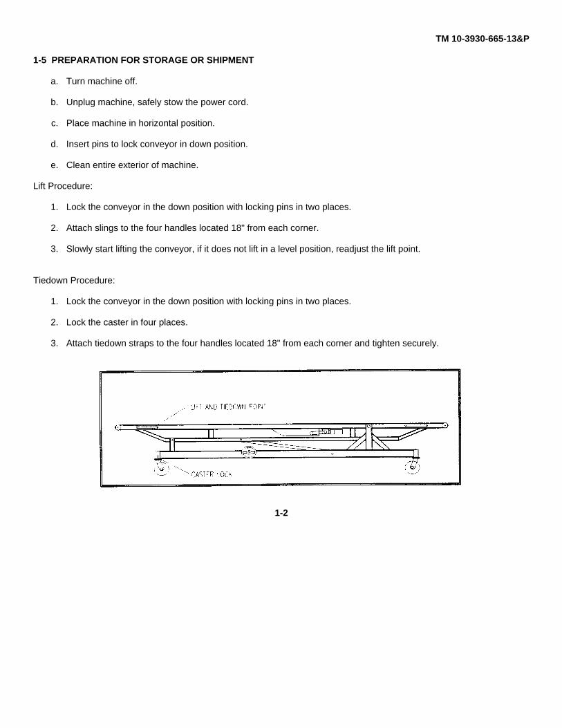
Lift Procedure:
1. Lock the conveyor in the down position with locking pins in two places.
2. Attach slings to the four handles located 18" from each corner.
3. Slowly start lifting the conveyor, if it does not lift in a level position, readjust the lift point.
Tiedown Procedure:
1. Lock the conveyor in the down position with locking pins in two places.
2. Lock the caster in four places.
3. Attach tiedown straps to the four handles located 18" from each corner and tighten securely.
1-2
TM 10-3930-665-13&P
Section II Equipment Description
1-6 EQUIPMENT CHARACTERISTICS, CAPABILITIES, AND FEATURES
a. Mobile
b. Adjustable inclination angle
c. Reversible belt motion
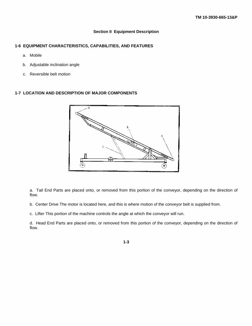
1-7 LOCATION AND DESCRIPTION OF MAJOR COMPONENTS
a. Tail End Parts are placed onto, or removed from this portion of the conveyor, depending on the direction offlow.
b. Center Drive The motor is located here, and this is where motion of the conveyor belt is supplied from.
c. Lifter This portion of the machine controls the angle at which the conveyor will run.
d. Head End Parts are placed onto, or removed from this portion of the conveyor, depending on the direction offlow.
1-3
TM 10-3930-665-13&P
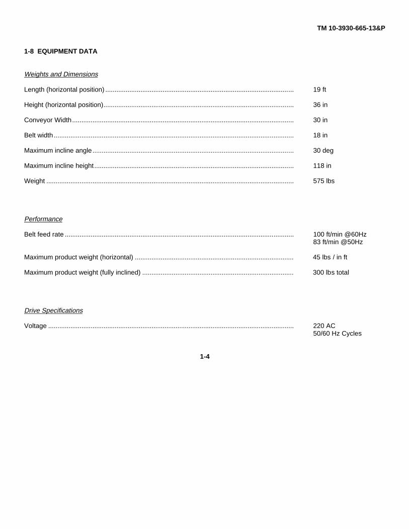
1-8 EQUIPMENT DATA
Weights and Dimensions
Length (horizontal position) ...................................................................................................... 19 ft
Height (horizontal position)....................................................................................................... 36 in
Conveyor Width........................................................................................................................ 30 in
Belt width.................................................................................................................................. 18 in
Maximum incline angle............................................................................................................. 30 deg
Maximum incline height............................................................................................................ 118 in
Weight ...................................................................................................................................... 575 lbs
Performance
Belt feed rate ............................................................................................................................ 100 ft/min @60Hz83 ft/min @50Hz
Maximum product weight (horizontal) ...................................................................................... 45 lbs / in ft
Maximum product weight (fully inclined) .................................................................................. 300 lbs total
Drive Specifications
Voltage ..................................................................................................................................... 220 AC50/60 Hz Cycles
1-4

TM 10-3930-665-13&P
1-9 SAFETY, CARE, AND HANDLING
a. Proper Operations and Daily Maintenance. Procedures are vital to safe, reliable use of this type of mechanicalequipment.
b. Notes, Cautions, and Warnings. The various procedures described in this manual, and the NOTES,CAUTIONS, and WARNINGS, should be followed to prevent the possibility of equipment damage, and or operatordanger.
c. Safety Guidelines:
1. Do not use this equipment for applications for which it is not intended.
2. Do not allow improperly trained personnel to operate this equipment.
3. Read and understand the operating procedures and safety precautions before operating the machine.
4. Always operate with all safety guards in place and in proper working order.
5. Do not leave machine unattended.
6. Be careful to ensure proper placement of the machine and lock all adjustment mechanisms.
7. Always keep hands, feet, and clothing free of moving parts.
8. Perform maintenance checks as required per the PMCS Schedule.
9. Always use extreme caution, and follow all safety procedures, as listed in this manual, when operating thismachine.
1-5
TM 10-3930-665-13&P
Section III Technical Principles of Operation
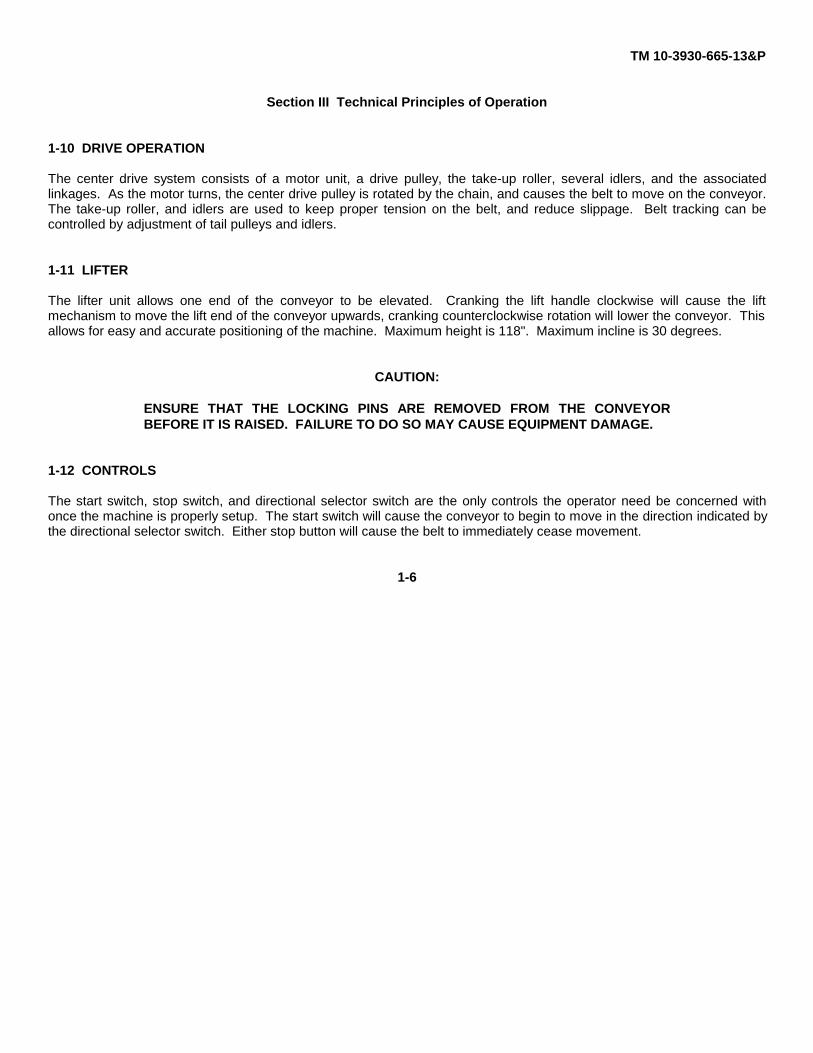
1-10 DRIVE OPERATION
The center drive system consists of a motor unit, a drive pulley, the take-up roller, several idlers, and the associatedlinkages. As the motor turns, the center drive pulley is rotated by the chain, and causes the belt to move on the conveyor.The take-up roller, and idlers are used to keep proper tension on the belt, and reduce slippage. Belt tracking can becontrolled by adjustment of tail pulleys and idlers.
1-11 LIFTER
The lifter unit allows one end of the conveyor to be elevated. Cranking the lift handle clockwise will cause the liftmechanism to move the lift end of the conveyor upwards, cranking counterclockwise rotation will lower the conveyor. Thisallows for easy and accurate positioning of the machine. Maximum height is 118". Maximum incline is 30 degrees.
CAUTION:
ENSURE THAT THE LOCKING PINS ARE REMOVED FROM THE CONVEYORBEFORE IT IS RAISED. FAILURE TO DO SO MAY CAUSE EQUIPMENT DAMAGE.
1-12 CONTROLS
The start switch, stop switch, and directional selector switch are the only controls the operator need be concerned withonce the machine is properly setup. The start switch will cause the conveyor to begin to move in the direction indicated bythe directional selector switch. Either stop button will cause the belt to immediately cease movement.
1-6

TM 10-3930-665-13&P
CHAPTER 2OPERATING INSTRUCTIONS
Section I Description and Use of Operator Controls
2-1 CONTROLS
Once the machine is in position, and all adjustment mechanisms are properly locked, the conveyor may be plugged in, andoperation may begin. The start switch (Figure 2-1) at either end of the unit can be used to start the conveyor, and theconveyor can be stopped by pressing either stop switch.
Figure 2-1. Figure 2-2.
Locking either stop button with the attached lock mechanism will make the conveyor inoperative.
The main operator control panel (Figure 2-2) contains the directional selector switch. This switch is used to change thedirection of the belt movement. It is a three position switch, forward, off, reverse.
CAUTION:
THE DIRECTION OF THE BELT CANNOT BE CHANGED WHILE THE CONVEYOR ISIN MOTION. FAILURE TO DO SO MAY CAUSE EQUIPMENT DAMAGE.
2-2 LIFTER
The incline of the belt conveyor is adjusted using a hand wheel which is mounted to the lower frame. Clockwise rotationraises the conveyor, and counter-clockwise rotation lowers it.
CAUTION:
ENSURE LOCKING PINS ARE REMOVED BEFORE RAISING OR LOWERING THECONVEYOR. FAILURE TO DO SO MAY CAUSE EQUIPMENT DAMAGE.
2-1

TM 10-3930-665-13&P
Section II OPERATOR PREVENTIVE MAINTENANCECHECKS AND SERVICES
2-3 PMCS CHART
OPERATOR / CREW PREVENTIVE MAINTENANCE CHECKS ANDSERVICES
B - BEFORE D - DURING A - AFTER W - WEEKLY M - MONTHLY
ITEM
INTERVALITEM TO BE INSPECTED INTERVAL
PROCEDURE: CHECK FOR AND HAVEREPAIRED. FILLED. OR ADJUSTED AS
NEEDED
EQUIPMENT IS NOTREADY/AVAILABLE IF
B D A W M1 * CONVEYOR FRAME
Check for cracks, bends, or broken weldsa. Frame welds are cracked or broken.
2 * ELECTRICAL SYSTEMCheck for frayed cable and broken plug,switches, or buttons.
a. Power cord is frayed, or plug is damaged.
b. Buttons or switches are cracked or broken3 * CASTERS
Check that all casters provide a positiveanti- motion lock
a. Any caster is broken, or the lockingmechanism for any caster is damaged.
4 * LIFTERCheck that the crank mechanism is free toturn and the locking pins are in place.
a. If the crank mechanism is jammed orbroken.
b. If the locking pins are missing, or broken.5 * LUBRICATION
Check that chain is properly oiled. and liftmechanism is properly greased
a. If either the chain or lift mechanism is dryor inadequately lubricated.
6 * LUBRICATIONCheck that the reducer oil level isadequate
a. If the reducer oil level is below normal.
2-2

TM 10-3930-665-13&P
Section III OPERATION IN USUAL CONDITIONS
2-4 SET-UP
Before using the conveyor, the operator should ensure that the area in which the conveyor will be used is separated frompersonnel traffic. It is also important to check that the materiel to be moved is within the weight and load restrictions of themachine. Once the above conditions are met, and the area has been cleared, setup may begin.
a. Roll the conveyor into position.
b. Lock casters.
c. Adjust the lifter to allow the correct angle.
CAUTION:
ENSURE LOCKING PINS ARE REMOVED BEFORE RAISING OR LOWERING THECONVEYOR. FAILURE TO DO SO MAY CAUSE EQUIPMENT DAMAGE.
d. Check that the movement of the belt is not restricted.
e. Plug conveyor in.
f. Adjust belt direction switch.
g. Press start switch.
CAUTION:
IF AT ANY TIME THE CONVEYOR BELT BECOMES JAMMED, OR OTHERWISEIMMOBILIZED, IMMEDIATELY STOP THE MACHINE AND FOLLOW THETROUBLESHOOTING PROCEDURES FOUND IN CHAPTER 3. FAILURE TO DO SOMAY CAUSE INJURY TO PERSONNEL OR INJURY TO EQUIPMENT.
2-3
TM 10-3930-665-13&P
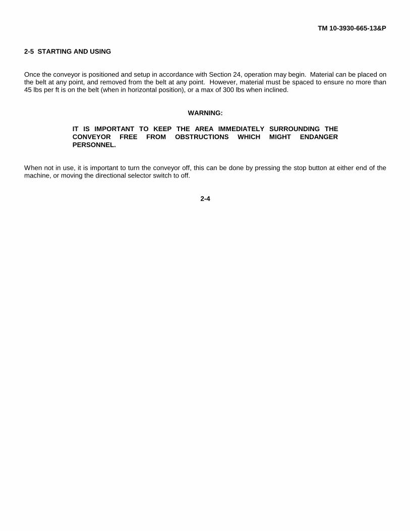
2-5 STARTING AND USING
Once the conveyor is positioned and setup in accordance with Section 24, operation may begin. Material can be placed onthe belt at any point, and removed from the belt at any point. However, material must be spaced to ensure no more than45 lbs per ft is on the belt (when in horizontal position), or a max of 300 lbs when inclined.
WARNING:
IT IS IMPORTANT TO KEEP THE AREA IMMEDIATELY SURROUNDING THECONVEYOR FREE FROM OBSTRUCTIONS WHICH MIGHT ENDANGERPERSONNEL.
When not in use, it is important to turn the conveyor off, this can be done by pressing the stop button at either end of themachine, or moving the directional selector switch to off.
2-4

TM 10-3930-665-13&P
CHAPTER 3Maintenance Instructions
Section I GENERAL MAINTENANCE PROCEDURES
3-1 GENERAL
All maintenance such as lubrication and adjustments shall be performed only by authorized personnel. It is important themachine longevity and operator safety that proper maintenance procedures be followed at all times. If any safety devicesare removed to facilitate adjustments, they must be replaced before power is applied to the conveyor.
3-2 DRIVE CHAIN ALIGNMENT AND TENSION
The drive chain and sprockets should be periodically checked for proper tension and alignment. Improperly adjusted drivecomponents will cause excess wear, and accelerated failure.
Adjustment Procedures:
a. Ensure machine is not powered.
b. Remove chain guard.
c. Check sprocket alignment by placing a straight edge across the face of both sprockets. (See Figure 3-1)Loosen set screws and adjust as needed. Re-tighten set screws.
FIGURE 3-1.
3-1
TM 10-3930-665-13&P
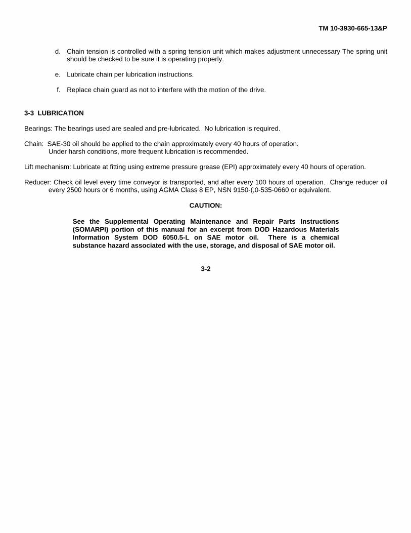
d. Chain tension is controlled with a spring tension unit which makes adjustment unnecessary The spring unitshould be checked to be sure it is operating properly.
e. Lubricate chain per lubrication instructions.
f. Replace chain guard as not to interfere with the motion of the drive.
3-3 LUBRICATION
Bearings: The bearings used are sealed and pre-lubricated. No lubrication is required.
Chain: SAE-30 oil should be applied to the chain approximately every 40 hours of operation.Under harsh conditions, more frequent lubrication is recommended.
Lift mechanism: Lubricate at fitting using extreme pressure grease (EPI) approximately every 40 hours of operation.
Reducer: Check oil level every time conveyor is transported, and after every 100 hours of operation. Change reducer oilevery 2500 hours or 6 months, using AGMA Class 8 EP, NSN 9150-(,0-535-0660 or equivalent.
CAUTION:
See the Supplemental Operating Maintenance and Repair Parts Instructions(SOMARPI) portion of this manual for an excerpt from DOD Hazardous MaterialsInformation System DOD 6050.5-L on SAE motor oil. There is a chemicalsubstance hazard associated with the use, storage, and disposal of SAE motor oil.
3-2

TM 10-3930-665-13&P
Section II CHANGING THE BELT
3-4 INSTALLING (REPLACING) THE BELT
If the replacement of the conveyor belt becomes necessary, run the conveyor until the splice is centered on the upper bedof the conveyor. Lockout power to the conveyor using the stop button. Remove tension from the belt by loosing the take-up pulley on both sides. Next remove the lacing pin. Next remove the lower belt guard and the chain guard Loosen thedrive chain by removing the lower tension sprocket and the master link. Remove the old belt by pulling through the headend. Once this is accomplished, the new belt can be threaded through the conveyor (See Figure 3-3). One side of the beltwill be smooth, thread the belt so that this side is facing down. Thread the belt from the tail end of the conveyor.
FIGURE 3-3.
Once the belt has been threaded through the conveyor,pull the ends together and insert lacing pin. (SeeFigure 3-4).
It is important to maintain the proper tension on the beltso that it will not slip when carrying the rated load. Belttension should be adjusted with the take-up pulley (SeeFigure 3-3). Make certain to keep pulleys square withbed by moving both take-up bolts an equal amount.Replace the drive chain, reinstall the master link, andreplace the tension sprocket. Replace all machineguards.
FIGURE 3-4
3-3

TM 10-3930-665-13&P
Section III TROUBLESHOOTING
3-5 TROUBLESHOOTING CHART
TROUBLE CAUSE SOLUTION
Conveyor will not start or motor 1. Motor is overloaded or drawing 1. Check for overloading ofquits frequently. to much current. conveyor.Drive chain and sprockets have 1. Lack of lubrication on chain may 1. Replace chain and sprocket.excessive ,wear. have caused chain stretch, which
created an improper chain tosprocket mesh.2. Sprockets are out of alignment. 2. Align sprockets. (See sect 3-2)3. Loose chain. 3. Tighten chain.
Loud popping or grinding noise. 1. Defective bearing. 1. Replace bearing.2. Loose set screws. 2. Tighten set screw.3. Loose drive chain. 3. Tighten chain.
Motor or reducer overheating. 1. Conveyor is overloaded. 1. Check2. Low voltage to motor. 2. Have an electrician check supply
voltage.3. Low lubricant level in reducer. 3. Relubricate. (See sect 3-3)
Belt doesn’t move. but drive runs. 1. Conveyor is overloaded. 1. Reduce load.2. Belt is loose. 2. Tighten belt.
Entire belt creeps off at one spot. 1. One or more idlers are out of 1. Adjust idlers.line.2. Material buildup on pulleys or 2. Remove residue from pulleys oridlers. idlers.
Belt creeps to one side at either tail 1. Tail pulley, return idler, or snub 1. Adjust as necessary.pulley. idler near tail pulley not properly
aligned or square with bed.Entire belt creeps to one side. 1. Conveyor not level. 1. Correct as necessary.
2. Material buildup on rollers, 2. Remove residue.pulleys. or idlers.
WARNING:
IT IS IMPORTANT THAT ONLY QUALIFIED PERSONNEL ENGAGE INTROUBLESHOOTING OR REPAIR OF THE CONVEYOR, OR INJURY TOPERSONNEL AND/OR DAMAGE TO EQUIPMENT MAY RESULT.
3-4

TM 10-3930-665-13&P
Section IV CONTROLS
3-6 CONTROL DIAGRAM
Controls for Belt Conveyor 9306
3-5

TM 10-3930-665-13&P
SECTION V REPAIR
3-7 REPLACING THE MOTOR
Removal:
a. Remove the cover on the motor case, remove (and discard) the wire nuts from the feed cables. Remove thecable from the motor.
b. Remove the four bolts securing the motor to the reducer while supporting the motor.
c. Remove the motor.
Replacement:
a. Insert the motor insuring that the key engages the reducer shaft correctly.
b. Replace the bolts and tighten.
c. Reconnect the cable with new wire nuts. Replace the wiring cover.
3-8 REPLACING IDLER ROLLERS
Removal:
a. Remove the four bolts securing the roller.
b. Remove the roller.
Replacement:
a. Insert the roller.
b. Replace the bolts and insure the roller is straight and turns freely.
3-6

TM 10-3930-665-13&P
3-9 REPLACING TAKE-UP ROLLERS
Removal:
a. Remove setscrews from the outer take-up blocks (2 places).
b. Remove attaching bolts from take-up blocks.
c. Loosen adjusting nuts (4 places).
d. Remove take-up blocks.
e. Remove shaft and roller assembly.
f. Remove shaft with drift tool while supporting roller.
Replacement:
a. Replace shaft in new take-up roller.
b. Replace shaft and roller assembly.
c. Replace take-up blocks and replace bolts.
d. Adjust take-up roller assembly.
e. Replace setscrews in the outer take-up blocks (2 places).
3-7

TM 10-3930-665-13&P
APPENDIX A
PUBLICATION REFERENCES
A-1. FORMS
The following forms pertain to this material. (Refer to DA Pamphlet 310-2 for index of blank forms.)
Standard Form 46, U.S. Government Motor Vehicle Operator’s Identification Card
Standard Form 91, Operator’s Report of Motor Vehicle Accident.
Recommended Changes to DA Publications and Blank Form, DA Form 2028.
DA PAM 738-750, The Army Maintenance Management System (TAMMS), for instructions on the use of maintenanceforms pertaining to this material.
A-2. OTHER PUBLICATIONS
The following publications contain information pertinent to the major item materiel and associatedequipment.
The Army Maintenance Management System (TAMMS) applies as follows:
(1) Army Equipment Log Book Binder, NSN 7510-00-889-3494.(2) Case, Maintenance and Operational Manuals, NSN 7520-00-559-5618.(3) DA Form 2407, Maintenance Request.(4) DA Form 2408, Equipment Log Book Assembly (Record).(5) DA Form 2408-1, Equipment Daily and Monthly Log.(6) DA Form 2408-5, Equipment Modification Record.(7) DA Form 2408-9, Equipment Control Record.(8) DA Form 2409, Equipment Maintenance Log (Consolidated).
A-1

TM 10-3930-665-13&P
The following publications contain information pertinent to the major item materiel and associated equipment.
a. Operating Vehicle.
Driver Selection and Training (Wheeled Vehicles) FM 55-30Manual for the Wheeled Vehicle Driver FM 21-305Prevention of Motor Vehicle Accidents AR 385-55Accident Reporting and Records AR 385-40
b. Maintenance and Repair.
The Army Maintenance Management Systems (TA..S) DA PAM 738-750Identification List for Fuels, Lubricants. Oils and Waxes C 9100-ILDescription. Use. Bonding Techniques. and Properties of Adhesives TB ORD 1032Materiels Used for Cleaning. Preserving. Abrading. and CementingOrdnance Material and Related Materials. Including Chemicals TM 9-247Metal Body Repair and Related Operations FM 43-2Welding Theory and Application TM 9-247Painting Instructions for Field Use TM 43-0139Inspection. Care. and Maintenance of Anti-Friction Bearings TM 9-214Operator’s. Organizational. Direct Support and General Mainten-ance Manual for Lead-Acid Storage Batteries. 4HN, 24 (NSN 6140-00-059-3528). MS 75047-1. 2HN. 12V (NSN 6140-00-057-2554);MS 35000-3. TM 9-6140-200-14
c. Cold Weather Operation and MaintenanceBasic Cold Weather Manual FM 31-70Northern Operations FM 31-71Operation and Maintenance of Ordnance Materiel in ExtremeCold Weather (0°F to -65°F) FM 9-207Winterization Kits for Army Tank-Automotive Materiel SB 9-16
d. Decontamination.
Chemical. Biological. and Radiological ICBRI Decontamination TM 3-220Chemical. Biological. Radiological. and Nuclear Defense (NBC) FM 21-40
General
Hand Portable Fire Extinguishers Approved for Army Users TB 5-4200-200-10Camouflage FM 5-20Procedures for Destruction o! Equipment to Prevent Enemy Use(Mobility Equipment Command) TM 750-244-3Administrative Storage of Equipment TM 740-90-1Preservation of USAMECOM Mechanical Equipment for Shipmentand Storage TM 740-97-2
A-2

TM 10-3930-665-13&P
APPENDIX B
REPAIR PARTS AND SPECIAL TOOLS LIST
CONVEYOR, BELT, PORTABLE,ELECTRIC, CASTER MOUNTED

TM 10-3930-665-13&P
TABLE OF CONTENTS
SECTION I INTRODUCTION ILLUS./FIGURESECTION II REPAIR PARTS LIST
MAIN ASSEMBLY....................................................................................... 1CASTERS AND LOCKING PINS ................................................................ 2DRIVE FRAME............................................................................................ 3MAIN LIFT ................................................................................................... 4LIFT ............................................................................................................. 5MOTOR AND REDUCER............................................................................ 6HEAD AND TAIL END................................................................................. 7CONTROLS ................................................................................................ 8
SECTION III CROSS REFERENCE INDEXES..................................................................... I-1
1

TM 10-3930-665-13&P
UNIT, DIRECT SUPPORT
REPAIR PARTS AND SPECIAL TOOLS LIST
Section I. INTRODUCTION
1. Scope.
This RPSTL lists and authorizes spares and repair parts; special tools; special test, measurement, and diagnosticequipment (TMDE); and other special support equipment required for performance of unit, direct support, It authorizes therequisitioning, issue, and disposition of spares, repair parts, and special tools as indicated by the source, maintenance,and recoverability (SMR) codes.
2. General.
In addition to Section I, Introduction, this Repair Parts and Special Tools List is divided into the following sections: a.Section II. Repair Parts List. A list of spares and repair parts authorized by this RPSTL for use in the performance ofmaintenance. The list also includes parts which must be removed for replacement of the authorized parts. Parts lists arecomposed of functional groups in ascending alphanumeric sequence, with the parts in each group listed in ascendingfigure and item number sequence. Bulk materials are listed in item name sequence. Repair parts kits are listedseparately in their own functional group within Section II. Repair parts for reparable special tools are also listed in thissection. Items listed are shown on the associated illustration(s)/figure(s).
b. Section III. Special Tools List. A list of special tools, special TMDE, and other special support equipmentauthorized by this RPSTL (as indicated by Basis of Issue (BOI) information in DESCRIPTION AND USABLE ON CODEcolumn) for the performance of maintenance.
c. Section IV. National Stock Number and Part Number Index. A list, in National item identification number (NIIN)sequence, of all National stock numbered items appearing in the listing, followed by a list in alphanumeric sequence of allpart numbers appearing in the listings. National stock numbers and part numbers are cross-referenced to each illustrationfigure and item number appearance.
1
TM 10-3930-665-13&P
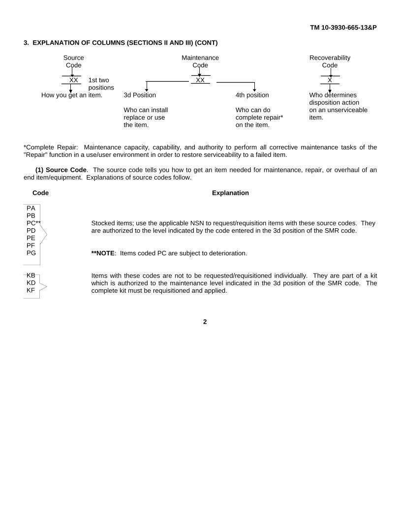
3. EXPLANATION OF COLUMNS (SECTIONS II AND III) (CONT)
Source Maintenance RecoverabilityCode Code Code
XX 1st two XX Xpositions
How you get an item. 3d Position 4th position Who determinesdisposition action
Who can install Who can do on an unserviceablereplace or use complete repair* item.the item. on the item.
*Complete Repair: Maintenance capacity, capability, and authority to perform all corrective maintenance tasks of the"Repair" function in a use/user environment in order to restore serviceability to a failed item.
(1) Source Code. The source code tells you how to get an item needed for maintenance, repair, or overhaul of anend item/equipment. Explanations of source codes follow.
Code Explanation
PAPBPC**PDPEPFPG
KBKDKF
Stocked items; use the applicable NSN to request/requisition items with these source codes. Theyare authorized to the level indicated by the code entered in the 3d position of the SMR code.
**NOTE: Items coded PC are subject to deterioration.
Items with these codes are not to be requested/requisitioned individually. They are part of a kitwhich is authorized to the maintenance level indicated in the 3d position of the SMR code. Thecomplete kit must be requisitioned and applied.
2

TM 10-3930-665-13&P
MO - Made at Org/AVUMcategory
MF - Made at DS/AVIMcategory
MH - Made at GS categoryML - Made at Specialized
Repair Activity (SRA)MD - Made at Depot
AO - Assembled by Org/AVUMcategory
AF - Assembled by DS/AVIMcategory
AH - Assembled by GS categoryAL - Assembled by SRAAD - Assembled by Depot
Items with these codes are not to be requested/requisitioned individually.They must be made from bulk material which is identified by the partnumber in the DESCRIPTION AND USABLE ON CODE (UOC) columnand listed in the Bulk Material group of the repair parts list in this RPSTL.If the item is authorized to you by the 3d position code of the SMR code,but the source code indicates it is made at a higher level, order the itemfrom the higher level of maintenance.
Items with these codes are not to be requested/requisitioned individually.The parts that make up the assembled item must be requisitioned orfabricated and assembled at the level of maintenance indicated by thesource code. If the 3d position code of the SMR code authorizes you toreplace the item, but the source code indicates the item is assembled at ahigher level, order the item from the higher level of maintenance.
XA - Do not requisition an "XA"-coded item. Order its next higher assembly. (Also, refer to the NOTE below.)XB - If an "XB" item is not available from salvage, order it using the CAGEC and part number given.XC - Installation drawing, diagram, instruction sheet, field service drawing, that is identified by manufacturer’s part
number.XD - Item is not stocked. Order an "XD"-coded item through normal supply channels using the CAGEC and part
number given, if no NSN is available.
NOTE
Cannibalization or controlled exchange, when authorized, may be used as a sourceof supply for items with the above source codes, except for those source coded"XA" or those aircraft support items restricted by requirements of AR 750-1.
3

TM 10-3930-665-13&P
(2) Maintenance Code. Maintenance codes tell you the level(s) of maintenance authorized to USE and REPAIRsupport items. The maintenance codes are entered in the third and fourth positions of the SMR code as follows:
(a) The maintenance code entered in the third position tells you the lowest maintenance level authorized to remove,replace, and use an item. The maintenance code entered in the third position will indicate authorization to one of thefollowing levels of maintenance:
CODE APPLICATION/EXPLANATION
C -Crew or operator maintenance done within unit or aviation unit maintenance.
O -Unit or aviation unit level can remove, replace, and use the item.
F -Direct support or aviation intermediate level can remove, replace, and use the item.
H -General support level can remove, replace, and use the item.
L -Specialized repair activity can remove, replace, and use the item.
D -Depot level can remove, replace, and use the item.
(b) The maintenance code entered in the fourth position tells whether or not the item is to be repaired and identifiesthe lowest maintenance level with the capability to do complete repair (i.e., perform all authorized repair functions). (NOTE: Some limited repair may be done on the item at a lower level of maintenance, if authorized by the Maintenance AllocationChart (MAC) and SMR codes.) This position will contain one of the following maintenance codes.
CODE APPLICATION/EXPLANATION
O -Unit or aviation unit is the lowest level that can do complete repair of the item.
F -Direct support or aviation intermediate is the lowest level that can do complete repair of the item.
H -General support is the lowest level that can do complete repair of the item.
L -Specialized repair activity is the lowest level that can do complete repair of the item.
D -Depot is the lowest level that can do complete repair of the item.
4
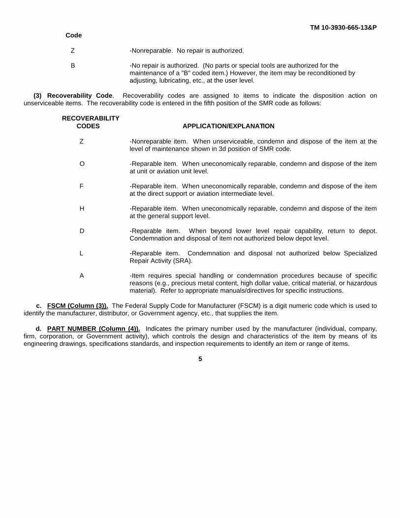
TM 10-3930-665-13&PCode
Z -Nonreparable. No repair is authorized.
B -No repair is authorized. (No parts or special tools are authorized for the maintenance of a "B" coded item.) However, the item may be reconditioned by adjusting, lubricating, etc., at the user level.
(3) Recoverability Code. Recoverability codes are assigned to items to indicate the disposition action onunserviceable items. The recoverability code is entered in the fifth position of the SMR code as follows:
RECOVERABILITYCODES APPLICATION/EXPLANATION
Z -Nonreparable item. When unserviceable, condemn and dispose of the item at thelevel of maintenance shown in 3d position of SMR code.
O -Reparable item. When uneconomically reparable, condemn and dispose of the itemat unit or aviation unit level.
F -Reparable item. When uneconomically reparable, condemn and dispose of the itemat the direct support or aviation intermediate level.
H -Reparable item. When uneconomically reparable, condemn and dispose of the itemat the general support level.
D -Reparable item. When beyond lower level repair capability, return to depot.Condemnation and disposal of item not authorized below depot level.
L -Reparable item. Condemnation and disposal not authorized below SpecializedRepair Activity (SRA).
A -Item requires special handling or condemnation procedures because of specificreasons (e.g., precious metal content, high dollar value, critical material, or hazardousmaterial). Refer to appropriate manuals/directives for specific instructions.
c. FSCM (Column (3)). The Federal Supply Code for Manufacturer (FSCM) is a digit numeric code which is used toidentify the manufacturer, distributor, or Government agency, etc., that supplies the item.
d. PART NUMBER (Column (4)). Indicates the primary number used by the manufacturer (individual, company,firm, corporation, or Government activity), which controls the design and characteristics of the item by means of itsengineering drawings, specifications standards, and inspection requirements to identify an item or range of items.
5

TM 10-3930-665-13&P
NOTE: When you use an NSN to requisition an item, the item you receive may have a different part number fromthe part ordered.
e. DESCRIPTION AND USABLE ON CODE (UOC) (Column (5)). This column includes the following information:
(1) The Federal item name and, when required, a minimum description to identify the item.(2) The physical security classification of the item is indicated by the parenthetical entry (insert applicable
physical security classified abbreviation, e.g., Phy Sec C1 (C)Confidential, Phy Sec C1 (S)-Secret, Phy Sec C1 (T)-TopSecret.
(3) Items that are included in kits and sets are listed below the name of the kit or set.(4) Spare/repair parts that make up an assembled item are listed immediately following the assembled item line
entry.(5) Part numbers for bulk materials are referenced in this column in the line item entry for the item to be
manufactured/ fabricated.(6) When the item is not used with all serial numbers of the same model, the effective serial numbers are
shown on the last line(s) of the description (before UOC).(7) The usable on code, when applicable (see paragraph 5, Special Information).(8) In the Special Tools List section, the basis of issue (BOI) appears as the last line(s) in the entry for each
special tool, special TMDE, and other special support equipment. When density of equipment supported exceeds densityspread indicated in the basis of issue, the total authorization is increased proportionately.
(9) The statement "END OF FIGURE" appears just below the last item description in Column 5 for a givenfigure in both Section II and Section III.
f. QTY (Column (6)). The QTY (quantity per figure column) indicates the quantity of the item used in the breakoutshown on the illustration figure, which is prepared for a functional group, subfunctional group, or anassembly. A "V" appearing in this column in lieu of a quantity indicates that the quantity is variable and the quantity mayvary from application to application.
4. EXPLANATION OF COLUMNS (SECTION IV)
a. National Stock Number (NSN) Index.
(1) STOCK NUMBER column. This column lists the NSN by National item identification number (NIIN)sequence. The NIIN consists of the last nine digits of the NSN
NSN(i.e., 5305-01-674-1467). When using this
NIINcolumn to locate an item, ignore the first 4 digits of the NSN. However, the complete NSN should be used when orderingitems by stock number.
(2) FIG. column. This column lists the number of the figure where the item is identified/located. The figuresare in numerical order in Section II and Section III.
6

TM 10-3930-665-13&P
(3) ITEM Column. The item number identifies the item associated with the figure listed in the adjacent FIG.column. This item is also identified by the NSN listed on the same line.
b. PART NUMBER INDEX Part numbers in this index are listed by part number in ascending alphanumeric sequence(i.e., vertical arrangement of letter and number combination which places the first letter or digit of each group in order Athrough Z, followed by the numbers 0 through 9, and each following letter or digit in like order).
(1) FSCM Column. The Federal Supply Code for Manufacturer (FSCM) is a 5-digit numeric code used toidentify the manufacturer, distributor, or Government agency, etc., that supplies the item.
(2) PART NUMBER Column. Indicates the primary number used by the manufacturer (individual, company,firm, corporation, or Government activity), which controls the design and characteristics of the item by means of itsengineering drawings, specifications, standards, and inspection requirements to identify an item or range of items.
(3) STOCK NUMBER Column. This column lists the NSN for the associated part number and manufactureridentified in the PART NUMBER and FSCM columns to the left
(4) FIG. Column. This column lists the number of the figure where the item is identified/located in Section IIand Section III.
(5) ITEM Column. The item number is that number assigned to the item as it appears in the figure referencedin the adjacent figure number column.
5. Special Information. Use the following subparagraphs as applicable:
a. USABLE ON CODE. The usable on code appears in the lower left corner of the Description column heading.Usable on codes are shown as “UOC: ...” in the Description Column (justified left) on the first line applicable itemdescription/nomenclature. Uncoded items are applicable to all models.
b. FABRICATION INSTRUCTIONS. Bulk materials required to manufacture items are listed in the Bulk MaterialFunctional Group of this RPSTL. Part numbers for bulk materials are also referenced in the description column of the lineitem entry for the item to be manufactured/fabricated. Detailed fabrication instructions for items source coded to bemanufactured or fabricated are found in the applicable maintenance level manual.
c. ASSEMBLY INSTRUCTIONS. Detailed assembly instructions for items source coded to be assembled fromcomponent spare/repair parts are found in the applicable maintenance level manual. Items that make up the assembly arelisted immediately following the assembly item entry or reference is made to an applicable figure.
d. KITS. Line item entries for repair parts kits appear in a group in Section II. See table of contents.
7

TM 10-3930-665-13&P
6. How to Locate Repair Parts.
a. When National Stock Number or Part Number is Not Known.
(1) First. Using the table of contents, determine the assembly group or subassembly group to which the itembelongs. This is necessary since figures are prepared for assembly groups and subassembly groups, and listings aredivided into the same groups.
(2) Second. Find the figure covering the assembly group or subassembly group to which the item belongs.
(3) Third. Identify item on the figure and note the item number.
(4) Fourth. Refer to the Repair Parts List for the figure to find the part number for the item number noted on thefigure.
(5) Fifth. Refer to the Part Number Index to find the NSN, if assigned.
b. When National Stock Number or Part Number is Known:
(1) First. Using the Index of National Stock Numbers and Part Numbers, find the pertinent National StockNumber or Part Number. The NSN index is in National Item Identification Number (NIIN) sequence. The part numbers inthe Part Number Index are listed in ascending alphanumeric sequence. Both indexes cross-reference you to theillustration figure and item number of the item you are looking for.
(2) Second. After finding the figure and item number, verify that the item is the one you are looking for, thenlocate the item number in the repair parts list for the figure.
7. Abbreviations.
Abbreviation Explanation
NIIN Acronym for National Item Identification Number (consists of the last 9 digits ofthe NSN)
RPSTL Acronym for Repair Parts and Special Tools List
SMR Acronym for Source, Maintenance and Recoverability Code
TMDE Acronym for Test, Measurement, and Diagnostic Equipment
8

TM 10-3930-665-13&P
FIGURE 1: MAIN ASSEMBLY.
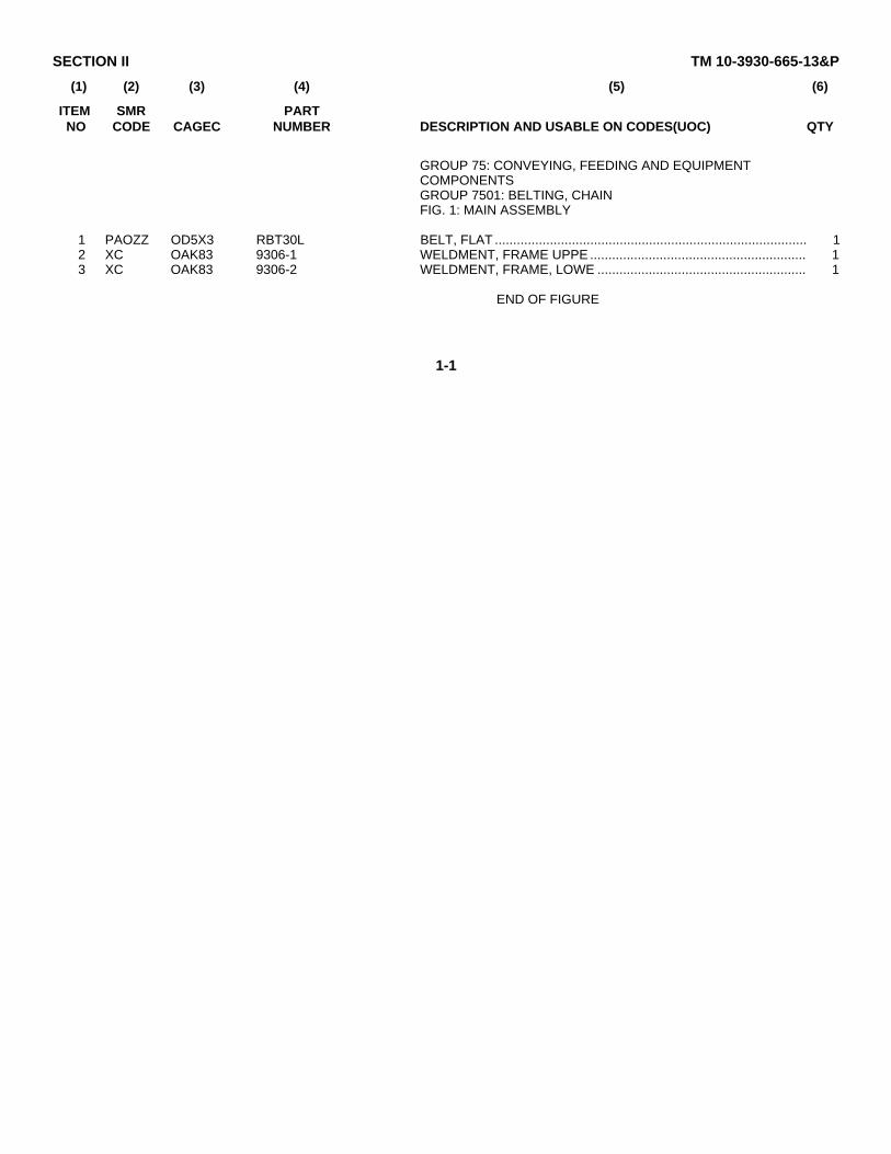
SECTION II TM 10-3930-665-13&P
(1) (2) (3) (4) (5) (6)
ITEM SMR PARTNO CODE CAGEC NUMBER DESCRIPTION AND USABLE ON CODES(UOC) QTY
GROUP 75: CONVEYING, FEEDING AND EQUIPMENTCOMPONENTSGROUP 7501: BELTING, CHAINFIG. 1: MAIN ASSEMBLY
1 PAOZZ OD5X3 RBT30L BELT, FLAT ..................................................................................... 12 XC OAK83 9306-1 WELDMENT, FRAME UPPE ........................................................... 13 XC OAK83 9306-2 WELDMENT, FRAME, LOWE ......................................................... 1
END OF FIGURE
1-1

TM 10-3930-665-13&P
FIGURE 2: CASTERS AND LOCKING PINS

SECTION II TM 10-3930-665-13&P
(1) (2) (3) (4) (5) (6)
ITEM SMR PARTNO CODE CAGEC NUMBER DESCRIPTION AND USABLE ON CODES(UOC) QTY
GROUP 7501: BELTING, CHAINFIG. 2: CASTERS AND LOCKING PINS
1 PAOZZ 69455 2888T62 CASTER, SWIVEL........................................................................... 42 PAOZZ 96906 MS-90728-66 SCREW, CAP, HEXAGON H........................................................... 43 PAOZZ 96906 MS17829-6C NUT, SELF-LOCKING, HE .............................................................. 44 PAOZZ 99862 CL-8-BLPT-2.5-C PIN, SHOULDER, HEADED ............................................................ 25 PAOZZ 96906 MS35207-261 SCREW, MACHINE......................................................................... 16 PAOZZ 02064 P-0.5000X3/4X1 BUSHING, MACHINE THR.............................................................. 27 PAOZZ 9G138 99862P-48-10 BUSHING, SLEEVE......................................................................... 28 PFOZZ OAK83 9306-19 PAD, CUSHIONING......................................................................... 1
END OF FIGURE
2-1

TM 10-3930-665-13&P
FIGURE 3: DRIVE FRAME

SECTION II TM 10-3930-665-13&P
(1) (2) (3) (4) (5) (6)
ITEM SMR PARTNO CODE CAGEC NUMBER DESCRIPTION AND USABLE ON CODES(UOC) QTY
GROUP 40: ELECTRIC MOTORSGROUP 4216: MISC. WIRING AND FITTINGSFIG. 3: DRIVE FRAME
1 PAOZZ 72547 SF-3/4 BEARING......................................................................................... 22 PAOZZ 96906 MS17829-6C NUT, SELF-LOCKING, HE .............................................................. 83 PAOZZ 30076 15529 SCREW, CAP, HEXAGON H........................................................... 84 PAOZZ OAK83 9306-93 KEY.................................................................................................. 35 PFOZZ OAK83 9306-21 SHAFT, STRAIGHT......................................................................... 16 PFOZZ 7K971 3.5PC20-D-.75RTL PULLEY........................................................................................... 47 PAOZZ 96906 MS18063-13 SETSCREW .................................................................................... 48 PFOZZ OAK83 9306-7 SHAFT, STRAIGHT......................................................................... 39 PAOZZ OAK83 9306-71 GUARD, MECHANICAL DR ............................................................ 1
10 PAOZZ OAK83 9306-5 SHAFT, STRAIGHT......................................................................... 711 PAOZZ 96906 M535207-263 SCREW, MACHINE......................................................................... 1012 PAOZZ OAK83 9306-4 PULLEY, FLAT ................................................................................ 313 PAOZZ OAK83 9306-62 SCREW, ASSEMBLED WAS .......................................................... 2814 PFOZZ OAK83 9306-14 PLATE, MOUNTING........................................................................ 1415 PFOZZ OAK83 9306-9 BEARING, ROLLER ROD .............................................................. 716 PAOZZ 96906 MS51977-43 SETSCREW .................................................................................... 617 PAOZZ 96906 MS16562-36 PIN, SPRING ................................................................................... 618 PFOZZ OAK83 9306-11 ROD, CONTINUOUS THRE ............................................................ 219 PAOZZ 96906 MS51967-14 NUT, PLAIN, HEXAGON ................................................................. 420 PFOZZ OAK83 9306-10 BLOCK, TAKEUP ............................................................................ 221 PAOZZ 76474 40B30 SPROCKET ..................................................................................... 122 PAOZZ 96906 M518063-13 SETSCREW .................................................................................... 223 XBFFF OAK83 9306-13 FRAME, DRIVE, ALUM.................................................................... 1
END OF FIGURE
3-1

TM 10-3930-665-13&P
FIGURE 4: MAIN PIVOT

SECTION II TM 10-3930-665-13&P
(1) (2) (3) (4) (5) (6)
ITEM SMR PARTNO CODE CAGEC NUMBER DESCRIPTION AND USABLE ON CODES(UOC) QTY
GROUP 7501: BELTING, CHAINFIG. 4: MAIN PIVOT
1 PFOZZ OAK83 1045 SHAFT, STRAIGHT......................................................................... 12 PAOZZ 96906 MS16562-69 PIN, SPRING ................................................................................... 23 PFOZZ 3A621 DRT-2448-4 BEARING, WASHER, THRU ........................................................... 24 PAOZZ 72547 EF-1 P2428-12 SPACER, SLEEVE .......................................................................... 2
END OF FIGURE
4-1

TM 10-3930-665-13&P
FIGURE 5: LIFT

SECTION II TM 10-3930-665-13&P
(1) (2) (3) (4) (5) (6)
ITEM SMR PARTNO CODE CAGEC NUMBER DESCRIPTION AND USABLE ON CODES(UOC) QTY
GROUP 7508: ELEVATING WHEELFIG. 5: LIFT
1 PFOZZ OAK83 9306-37 SPACER, SLEEVE .......................................................................... 12 PFOZZ OAK83 9306-41 SHAFT, STRAIGHT......................................................................... 13 PAOZZ 72547 EF-1 FP1216-12 SPACER, SLEEVE .......................................................................... 24 PAOZZ 72547 EF-1 2X3/4 WASHER, BEARING, THRU ........................................................... 25 PFOZZ OAK83 9306-38 SPACER, SLEEVE .......................................................................... 26 PFOZZ OAK83 9306-29 SHAFT, SHOULDERED .................................................................. 27 PAOZZ 96906 MS-90728-66 SCREW, CAP, HEXAGON H........................................................... 28 PAOZZ 96906 MS51967-8 NUT, PLAIN, HEXAGON ................................................................. 29 PFOZZ 72547 1.5X1.0X1/8GFT BEARING, WASHER, THRE ........................................................... 2
10 PFOZZ OAK83 9306-42 SHAFT, STRAIGHT......................................................................... 111 PAOZZ 72547 FR1620-12 BUSHING, MACHINE THR.............................................................. 212 PAOZZ 96906 MS16562-50 PIN, SPRING ................................................................................... 113 PFOZZ OAK83 9306-39 BLOCK, ALUM................................................................................. 114 PAOZZ 96906 MS17829-6C NUT, SELF-LOCKING, HE .............................................................. 215 PFOZZ OAK83 9306-43 PAD, CUSHIONING......................................................................... 416 PAOZZ 74445 HKA-640428 SCREW, MACHINE......................................................................... 2417 PFOZZ OAK83 9306-27 CONNECTING LINK, RIG................................................................ 218 PAOZZ 96906 MS20066-120 KEY, MACHINE ............................................................................... 119 PAOZZ 96906 MS16562-52 PIN, SPRING ................................................................................... 220 PFOZZ 99862 CL-8-HWSFA HANDWHEEL.................................................................................. 121 PAOZZ 96906 MS18154-59 SCREW, CAP, HEXAGON H........................................................... 222 PAOZZ 72547 FP1216-8 BUSHING, SLEEVE......................................................................... 123 PFOZZ OAK83 9306-40 TUBE, METALLIC............................................................................ 124 PFOZZ 18740 2500-THD-8-30 ACTUATOR ..................................................................................... 1
END OF FIGURE
5-1

TM 10-3930-665-13&P
FIGURE 6: MOTOR AND REDUCER

SECTION II TM 10-3930-665-13&P
(1) (2) (3) (4) (5) (6)
ITEM SMR PARTNO CODE CAGEC NUMBER DESCRIPTION AND USABLE ON CODES(UOC) QTY
GROUP 40: ELECTRIC MOTORSGROUP 4000: MAJOR ASSEMBLAGE-MOTORFIG. 6: MOTOR AND REDUCER
1 PAOZZ 96906 MS17829-6C NUT, SELF-LOCKING, HE .............................................................. 42 PAOZZ 80204 B1821BH038C088N SCREW, CAP, HEXAGON H........................................................... 43 PAOZZ 96906 MS20066-122 KEY, MACHINE ............................................................................... 14 PAOZZ OEXL7 V56C17D5310 MOTOR, DIRECT CURREN............................................................ 15 PFOZZ 72547 SRF721 GEAR ASSEMBLY, SPEED ............................................................ 16 PAOZZ OAK83 9306-95 KEY.................................................................................................. 17 PAOZZ 71176 40B17 SPROCKET WHEEL ....................................................................... 18 PAOZZ 96906 MS18063-13 SETSCREW .................................................................................... 29 PFOZZ 72547 40812T1 SPROCKET, IDLER......................................................................... 2
10 PAOZZ 72547 RC40X46 CHAIN, ROLLER ............................................................................. 111 PAOZZ OAK83 9306-45 GUARD, MECHANICAL................................................................... 112 PAOZZ 96906 M535207-261 SCREW, MACHINE......................................................................... 513 PAOZZ 30076 15529 SCREW, CAP, HEXAGON H........................................................... 214 PFOZZ 72547 61BG SPRING, TENSIONER .................................................................... 115 PAOZZ 96906 MS17829-6C NUT, SELF-LOCKING, HE .............................................................. 216 PAOZZ 96906 MS51967-8 NUT, PLAIN, HEXAGON ................................................................. 117 PAOZZ 96906 MS-90728-66 SCREW, CAP, HEXAGON H........................................................... 1
END OF FIGURE
6-1

TM 10-3930-665-13&P
FIGURE 7: HEAD AND TAIL END.

SECTION II TM 10-3930-665-13&P
(1) (2) (3) (4) (5) (6)
ITEM SMR PARTNO CODE CAGEC NUMBER DESCRIPTION AND USABLE ON CODES(UOC) QTY
GROUP 7504: ROLLSFIG. 7: HEAD AND TAIL END
1 PAOZZ 39428 97517A055 RIVET, BLIND.................................................................................. 502 PAOZZ OAK83 9306-72 BED, SLIDER .................................................................................. 53 PAOZZ OAK83 9306-4 PULLEY, FLAT ................................................................................ 34 PAOZZ 96906 MS17829-6C NUT, SELF-LOCKING, HE .............................................................. 85 PFOZZ OAK83 9306-6 BRACKET, MOUNTING................................................................... 46 PAOZZ 96906 MS51977-43 SETSCREW .................................................................................... 67 PAOZZ 74445 HKA-64074E SCREW, HEX, W/WASHER ............................................................ 88 PFOZZ OAK83 9306-7 SHAFT, STRAIGHT......................................................................... 39 PFOZZ OAK83 3/8-16X3.50 ROD, THREADED END................................................................... 4
10 PAOZZ 96906 MS51967-9 NUT, PLAIN, HEXAGON ................................................................. 811 PAOZZ 96906 MS27183-14 WASHER, FLAT .............................................................................. 8
END OF FIGURE
7-1

TM 10-3930-665-13&P
FIGURE 8: CONTROLS.

SECTION II TM 10-3930-665-13&P
(1) (2) (3) (4) (5) (6)
ITEM SMR PARTNO CODE CAGEC NUMBER DESCRIPTION AND USABLE ON CODES(UOC) QTY
GROUP 40: ELECTRIC MOTORSGROUP 4216: MISC. WIRES AND FITTINGSFIG. 8: CONTROLS
1 PAOZZ 08843 3865JFG SWITCH OX .................................................................................... 12 PAOZZ 96906 MS90725-1 SCREW, CAP, HEXAGON H........................................................... 103 PFOZZ 08843 E2PBSC SWITCH BOX .................................................................................. 13 PAOZZ 01121 800T-B6A SWITCH, PUSH............................................................................... 24 PAOZZ 01121 800T-X550 MARKER, IDENTIFICATI................................................................. 25 PFOZZ 01121 800T-N2 LOCK, FLUSH ................................................................................. 26 PAOZZ 01121 800-X550 MARKER, IDENTIFICATI................................................................. 27 PFOZZ 01121 BOOT-A1A SWITCH, PUSH............................................................................... 28 PAOZZ 03743 CG 1850 ADAPTER, CONNECTOR............................................................... 29 PFOZZ 69304 STO#12-2 CABLE, POWER, ELECTRI ............................................................ 2
10 PAOZZ 03743 CG90-25505 BOX CONNECTOR, ELECT............................................................ 211 PAOZA 01121 800T-J28 SWITCH, PUSH............................................................................... 112 PAOZZ 01121 800T-X507 MARKER, IDENTIFICATI................................................................. 113 PFOZZ 01121 W50 HEATER, THERMAL RELE............................................................. 114 PAOZZ 01121 509-T0XA STARTER, MOTOR......................................................................... 115 PAOZZ 01121 1492-CD2 TERMINAL BOARD......................................................................... 616 PAOZZ 01121 1492-N16 INSULATOR, PLATE....................................................................... 117 PAOZZ 01121 1492-N2 CLIP, SPRING TENSION ................................................................ 218 PAOZZ 01121 1492-N1 HOLDER, ELECTRICAL C .............................................................. 119 PAOZZ 00843 A6P6 PANEL, BLANK ............................................................................... 120 PAOZZ 08843 3865JFG SWITCH BOX .................................................................................. 121 PAOZZ 03743 CG90 3750 BOX CONNECTOR, ELECT............................................................ 222 PAOZZ 07759 STO#12-5 CABLE, POWER, ELECTRI ............................................................ 223 PFOZZ 69304 STO#12-3 CABLE, POWER, ELECTRI ............................................................ 224 PAOZZ OAK83 9306-86 CABLE ASSEMBLY, POWE............................................................ 2
END OF FIGURE
8-1

SECTION IV TM 10-3930-665-13&P
CROSS-REFERENCE INDEXES
NATIONAL STOCK NUMBER INDEXSTOCK NUMBER FIGURE ITEM STOCK NUMBER FIGURE ITEM
5305-00-058-9376 3 16 5365-01-384-0795 5 37 6 5365-01-384-1052 5 11
5305-00-068-0498 8 2 5365-01-384-2479 5 55310-00-080-6004 7 11 5365-01-384-2494 5 15305-00-269-3211 3 3 5307-01-384-2940 3 18
6 13 5340-01-384-3447 5 155315-00-298-9161 6 3 5340-01-384-3462 5 205930-00-331-2416 8 3 5340-01-384-3466 7 55970-00-407-0931 8 16 3120-01-384-3477 5 95310-00-483-8790 2 3 6105-01-384-5151 6 4
2 3 3020-01-384-6210 3 123 2 7 35 14 3040-01-384-6222 5 176 1 3040-01-384-6227 3 106 15 3040-01-384-6251 5 67 4 3040-01-384-6263 4 1
5340-00-499-1907 8 17 3040-01-384-6278 3 55310-00-732-0558 5 8 3040-01-384-6284 5 2
6 16 3040-01-384-6300 3 87 10 7 8
5310-00-768-0318 3 19 3910-01-384-6585 7 25305-00-782-9489 2 2 3910-01-384-6641 3 20
2 2 5340-01-384-7789 2 85 7 2 86 17 3020-01-384-8882 3 9
5315-00-810-3701 3 17 3020-01-384-9014 6 115315-00-814-3531 5 12 5340-01-385-0017 8 55930-00-836-2394 8 11 4710-01-385-1209 5 235315-00-836-9628 5 19 3030-01-385-1237 1 15305-00-842-1117 3 7 7690-01-385-3952 8 4
3 22 8 66 8 3120-01-385-4627 4 3
5930-00-843-0830 8 7 3010-01-385-6883 6 55315-00-844-5840 4 2 7690-01-386-5979 8 125935-00-947-6177 8 8 3910-01-386-6626 3 155320-00-962-4693 7 1 3040-01-387-3969 5 105975-00-988-3493 8 195305-00-989-7434 3 115315-00-990-2973 5 185305-00-990-6444 2 5
2 56 12
5305-01-010-2362 5 215305-01-140-9118 6 25998-01-192-9008 B 185999-01-241-8032 8 135940-01-316-0399 8 155975-01-344-4609 8 105340-01-383-9877 3 145365-01-384-0264 4 4
I-1

SECTION II TM 10-3930-665-13&P
CROSS-REFERENCE INDEXES
PART NUMBER INDEXCAGEC PART NUMBER STOCK NUMBER FIG. ITEM
00843 A6P6 5975-00-988-3493 8 1980204 B18218H038C088N 5305-01-140-9118 6 203743 CG 1850 593S-00-947-6177 8 803743 CG90 3750 8 2103743 CG90-2550S 5975-01-344-4609 8 1099862 CL-8-BLPT-2.5-C 2 4
2 499862 CL-9-HWSFA 5340-01-384-3462 5 203A621 DRT-2448-4 3120-01-385-4627 4 372547 EF-1 FP1216-12 5365-01-384-0795 5 372547 EF-1 P2428-12 5365-01-384-0264 4 472547 EF-1 2X3/4 5 408843 E2PBSC 8 372547 FP1216-8 5 2272547 FR1620-12 5365-01-384-1052 5 1174445 HKA-64042B 5 1674445 HKA-64074E 7 796906 MS-90728-66 5305-00-782-9489 2 2
2 25 76 17
96906 MS16562-36 5315-00-810-3701 3 1796906 MS16562-50 5315-00-814-3531 5 1296906 MS16562-52 5315-00-836-9628 5 1996906 MS16562-69 5315-00-844-5840 4 296906 MS17829-6C 5310-00-483-8790 2 3
2 33 25 146 16 157 4
96906 MS18063-13 5305-00-842-1117 3 73 226 8
96906 MS18154-59 5305-01-010-2362 5 2196906 MS20066-120 5315-00-990-2973 5 1896906 MS20066-122 5315-00-298-9161 6 396906 MS27183-14 5310-00-080-6004 7 1196906 MS35207-261 5305-00-990-6444 2 5
2 56 12
96906 MS35207-263 5305-00-989-7434 3 1196906 MS51967-14 5310-00-768-0318 3 1996906 MS51967-8 5310-00-732-0558 5 8
6 167 10
96906 M551977-43 5305-00-058-9376 3 167 6
96906 MS90725-1 5305-00-068-0498 8 202064 P-0.5000X3/4X1 2 6
I-2

SECTION II TM 10-3930-665-13&P
CROSS-REFERENCE INDEXES
PART NUMBER INDEXCAGEC PART NUMBER STOCK NUMBER FIG. ITEM
02064 P-0.5000X3/4X1 2 6005X3 RBT30L 3030-01-385-1237 1 172547 RC40X46 6 1072547 SF-3/4 3 172547 SRF721 3010-01-385-6883 6 569304 STO#12-2 8 969304 STO#12-3 8 2307759 STO#12-5 8 22OEXL7 V56C17D5310 6105-01-384-5151 6 401121 W50 5999-01-241-8032 8 1372547 1.5X1.0X1/8GFT 3120-01-384-3477 5 9OAK83 1045 3040-01-384-6263 4 101121 1492-C02 5940-01-316-0399 8 1501121 1492-N1 5998-01-192-9008 8 1801121 1492-N16 5970-00-407-0931 8 1601121 1492-N2 5340-00-499-1907 8 1730076 15529 5305-00-269-3211 3 3
6 1318740 2500-THD-B-30 5 2469455 2988T62 2 1
2 17K971 3.5PC20-D-.75RTL 3 6OAK83 3/8-16X3.50 7 908843 3965JFG 8 1
8 2072547 40812T1 6 971176 40817 6 776474 408B30 3 2101121 509-TOXA 8 1472547 61BG 6 1401121 800T-A1A 5930-00-843-0830 8 701121 800T-B6A 5930-00-331-2416 8 301121 800T-J28 5930-00-836-2394 8 1101121 800T-N2 5340-01-385-0017 8 501121 800T-X507 7690-01-386-5979 8 1201121 800T-X550 7690-01-395-3952 8 4
8 6OAK83 9306-1 1 2OAK83 9306-10 3910-01-384-6641 3 20OAK83 9306-11 5307-01-384-2940 3 18OAK83 9306-13 3 23OAK83 9406-14 5340-01-383-9877 3 14OAK83 9306-19 5340-01-384-7789 2 8
2 800K83 9306-2 1 3OAK83 9306-21 3040-01-384-6278 3 5OAK83 9306-27 3040-01-384-6222 5 17OAK83 9306-29 3040-01-384-6251 5 6OAK83 9306-37 5365-01-384-2494 5 1OAK83 9306-38 5365-01-384-2479 5 5OAK83 9306-39 5 13
I-3

SECTION II TM 10-3930-665-13&P
CROSS-REFERENCE INDEXES
PART NUMBER INDEXCAGEC PART NUMBER STOCK NUMBER FIG. ITEM
OAK83 9306-4 3020-01-384-6210 3 127 3
OAK83 9306-40 4710-01-385-1209 5 23OAK83 9306-41 3040-01-384-6284 5 2OAK83 9306-42 3040-01-387-3969 5 10OAK83 9306-43 5340-01-384-3447 5 15OAK83 9306-45 3020-01-384-9014 6 11OAK83 9306-5 3040-01-384-6227 3 10OAK83 9306-6 5340-01-384-3466 7 5OAK83 9306-62 3 13OAK83 9306-1 3040-01-384-6300 3 8
7 8OAK83 9306-71 3020-01-384-8882 3 9OAK83 9306-72 3910-01-384-6585 7 2OAK83 9306-86 8 24OAK83 9306-9 3910-01-386-6626 3 15OAK83 9306-93 3 4OAK83 9306-95 6 639428 97517A055 5320-00-962-4693 7 19G138 99862P-48-10 2 7
2 7
I-4

SECTION II TM 10-3930-665-13&P
CROSS-REFERENCE INDEXES
FIGURE AND ITEM NUMBER INDEXFIG ITEM STOCK NUMBER CAGEC PART NUMBER
1 1 3030-01-385-1237 005X3 RBT30L1 2 OAK83 9306-11 3 OAK83 9306-22 1 69455 2888T622 1 69455 2888T622 2 5305-00-782-9489 96906 MS-90728-662 2 5305-00-782-9489 96906 MS-90728-662 3 5310-00-483-8790 96906 MS17829-6C2 3 5310-00-483-8790 96906 MS17829-6C2 4 99862 CL-8-BLPT-2.5-C2 4 99862 CL-8-BLPT-2.5-C2 5 5305-00-990-6444 96906 M535207-2612 5 5305-00-990-6444 96906 M535207-2612 6 02064 P-0.5000X3/4X12 6 02064 P-0.5000X3/4X12 7 9G138 99862P-48-102 7 9G138 99862P-48-102 8 5340-01-384-7789 OAK83 9306-192 8 5340-01-384-7789 OAK83 9306-193 1 72547 SF-3/43 2 5310-00-483-8790 96906 M517829-6C3 3 5305-00-269-3211 30076 155293 4 OAK83 9306-933 5 3040-01-384-6278 OAK83 9306-213 6 7K971 3.5PC20-D-.75RTL3 7 5305-00-842-1117 96906 MS18063-133 8 3040-01-384-6300 OAK83 9306-73 9 3020-01-384-8882 OAK83 9306-713 10 3040-01-384-6227 OAK83 9306-53 11 5305-00-989-7434 96906 MS35207-2633 12 3020-01-384-6210 OAK83 9306-43 13 OAK83 9306-623 14 5340-01-383-9877 OAK83 9306-143 15 3910-01-386-6626 OAK83 9306-93 16 5305-00-058-9376 96906 M551977-433 17 5315-00-810-3701 96906 M516562-363 18 5307-01-384-2940 OAK83 9306-113 19 5310-00-768-0318 96906 MS51967-143 20 3910-01-384-6641 OAK83 9306-103 21 76474 408303 22 5305-00-842-1117 96906 MS518063-133 23 OAK83 9306-134 1 3040-01-384-6263 OAK83 10454 2 5315-00-844-5840 96906 M516562-694 3 3120-01-385-4627 3A621 DRT-2448-44 4 5365-01-384-0264 72547 EF-1 P2428-125 1 5365-01-384-2494 OAK83 9306-375 2 3040-01-384-6284 OAK83 9306-415 3 5365-01-384-0795 72547 EF-1 FP1216-125 4 72547 EF-1 2X3/45 5 5365-01-384-2479 OAK83 9306-38
I-5

SECTION II TM 10-3930-665-13&P
CROSS-REFERENCE INDEXES
FIGURE AND ITEM NUMBER INDEXFIG ITEM STOCK NUMBER CAGEC PART NUMBER
5 6 3040-01-384-6251 OAK83 9306-295 7 5305-00-782-9489 96906 MS-90728-665 8 5310-00-732-0558 96906 MS51967-85 9 3120-01-384-3477 72547 1.5X1.0X1/8GFT5 10 3040-01-387-3969 OAK83 9306-425 11 5365-01-384-1052 72547 FR1620-125 12 5315-00-814-3531 96906 MS16562-505 13 OAK83 9306-395 14 5310-00-483-8790 96906 MS17829-6C5 15 5340-01-384-3447 OAK83 9306-435 16 74445 HKA-64042B5 17 3040-01-384-6222 OAK83 9306-275 19 5315-00-990-29713 96906 MS20066-1205 19 5315-00-836-9628 96906 MS16562-525 20 5340-01-384-3462 99862 CL-8-HWSFA5 21 5305-01-010-2362 96906 MS18154-595 22 72547 FP1216-85 23 4710-01-385-1209 OAK83 9306-405 24 18740 2500-THD-B-306 1 5310-00-483-8790 96906 MS17829-6C6 2 5305-01-140-9118 80204 B1821BH038C088N6 3 5315-00-298-9161 96906 MS20066-1226 4 6105-01-384-5151 OEXL7 V56C17D53106 5 3010-01-395-6883 72547 SRF7216 6 OAK83 9306-956 7 71176 408176 8 5305-00-842-1117 96906 MS18063-136 9 72547 40B12T16 10 72547 RC40X466 11 3020-01-384-9014 OAK83 9306-456 12 5305-00-990-6444 96906 MS35207-2616 13 5305-00-269-3211 30076 155296 14 72547 61BG6 15 5310-00-483-8790 96906 MS17829-6C6 16 5310-00-732-0558 96906 MS51967-86 17 5305-00-782-9489 96906 MS-90728-667 1 5320-00-962-4693 39428 97511A0557 2 3910-01-384-6585 OAK83 9306-727 3 3020-01-384-6210 OAK83 9306-47 4 5310-00-483-8790 96906 MS17829-6C7 5 5340-01-384-3466 OAK83 9306-67 6 5305-00-058-9376 96906 MS51977-437 7 74445 HKA-64074E7 9 3040-01-384-6300 OAK83 9306-77 9 OAK83 3/8-16X3.507 10 5310-00-732-0558 96906 M551967-87 11 5310-00-080-6004 96906 M527183-148 1 08843 3865JFG8 2 5305-00-068-0498 96906 MS90725-18 3 08843 E2PBSC8 3 5930-00-331-2416 01121 800T-B6A
I-6

SECTION II TM 10-3930-665-13&P
CROSS-REFERENCE INDEXES
FIGURE AND ITEM NUMBER INDEXFIG ITEM STOCK NUMBER CAGEC PART NUMBER
8 4 7690-01-385-3952 01121 800T-X5508 5 5340-01-385-0017 01121 800T-N28 6 7690-01-385-3952 01121 800T-X5508 7 5930-00-843-0830 01121 800T-A1A8 8 5935-00-947-6177 03743 CG 18508 9 69304 STO#12-28 10 5975-01-344-4609 03743 CG90-2550S8 11 5930-00-836-2394 01121 800T-J2B8 12 7690-01-386-5979 01121 800T-X5078 13 5999-01-241-8032 01121 W508 14 01121 509-TOXA8 15 5940-01-316-0399 01121 1492-C028 16 5970-00-407-0931 01121 1492-N168 17 5340-00-499-1907 01121 1492-N28 18 5998-01-192-9008 01121 1492-N18 19 5975-00-988-3493 00843 A6P68 20 08843 3865JFG8 21 03743 CG90 37508 22 07759 STO#12-58 23 69304 STO#12-38 24 OAK83 9306-86
I-7

SUPPLEMENTAL OPERATING, MAINTENANCE
AND REPAIR PARTS INSTRUCTIONS
FOR
BELT, CONVEYOR, ELECTRIC MOTOR DRIVEN,
NSN 3910-01-376-0431
TABLE OF CONTENTS
SECTION I - GENERAL
1.1 PURPOSE I-11.2 SCOPE1.3 DESCRIPTION I-11.4 OPERATIONAL CONCEPT I-11.5 PROCUREMENT STATUS I-11.6 EQUIPMENT PUBLICATIONS I-1-21.7 PERSONNEL AND TRAINING I-2-31.8 LOGISTICS ASSISTANCE (AR 700-4) I-31.9 RECOMMENDING PUBLICATION CHANGES I-3
SECTION II - MAINTENANCE
2.1 MAINTENANCE CONCEPT II-1-22.2 RELIABILITY, AVAILABILITY AND MAINTAINABILITY II-22.3 MODIFICATION II-22.4 EQUIPMENT IMPROVEMENT RECOMMENDATION II-22.5 SHIPMENT AND STORAGE II-22.6 DESTRUCTION TO DENY ENEMY USE II-22.7 BASIC ISSUE ITEM LIST (BIIL) II-22.8 SPECIAL TOOLS , AND TEST EQUIPMENT II-32.9 MAINTENANCE FORMS AND RECORDS II-32.10 PREVENTIVE MAINTENANCE CHECKS & SERVICES II-32.11 EXPENDABLE ! DURABLE SUPPLIES & MATERIAL II-3
SECTION III
3.1 GENERAL III-13.2 REQUISITIONING REPAIR PARTS III-1-23.3 REPAIR PARTS SUPPLY III-23.4 SUBMITTING REPAIR PARTS REQUISITION III-3
C-1
APPENDICES
A - Warrants Guidelines
B - Maintenance Expenditure Limits (MEL)
C - Maintenance Allocation Chart (MAC)
D - Preventive Maintenance Checks and Services (PMCS) - Operator
E - Preventive Maintenance checks and Services (PMCS) - Unit
F - Expendable / Durable Supplies and Materials List
G - Recommended Common Tools
C-2
SECTION I
GENERAL
1.1. PURPOSE: To provide user and support personnel Supplemental Operating and Repair Parts Instructions(SOMARPI) applicable to the conveyor belt manufactured by Highland Engineering
1.2 SCOPE This SOMARPI applies to Department of the Army Units, Organizations and Activities that useand/or support the Belt, Conveyor, Electric, Castor Mounted NSN 3910-01-376-0431
1.3 DESCRIPTION: The portable conveyor is a continuous belt type with steel slider plates, electric motor driven, and is used in moving materials horizontally or up an incline. The conveyor is 19 feet long with a belt width of 18 inchesand weighs 575 pounds. The conveyor frame is aluminum , mounted on four swivel type caster wheels approximately sixinches in diameter and two inches wide. The casters have a foot operated brake. The controls are a push button startand stop switch at both ends and a emergency stop switch . The capacity is 45 pounds per linear foot when the conveyoris level and no more than 15 pounds per linear foot when the conveyor is operated at an angle of 30 degrees. The beltspeed is 100 feet per minute.
1.4. OPERATIONAL CONCEPT: This conveyor is used to move small packages and materials short distancesin military postal units or TDA activities . The conveyor can be used level or tilted at an angle up to 30 degrees. Theconveyor is transportable by air , rail , highway and marine transport modes.
1.5. PROCUREMENT STATUS : The Procurement Contract Number is DAAE07-93-C-0313.
1.6. EQUIPMENT PUBLICATIONS: TM 10-3930-665-1 3&P and SOMARPI 10-3930-665.
a. Equipment publications will be DA TM10-3930-665-13 & P, the TM contains operator, repair and repair partsinformation .
NOMENCLATURE PUBLICATION NUMBER DATE SOURCE OF SUPPLYOperation, MaintenanceRepair Parts & TM 10-3930-665-13&PSpecial Tools NONESOMARPI SOMARPI 10-3930-665 TACOM
C-3

b. Requests for additional copies of this SOMARPI should be made to:
CommanderU.S. Army Tank-Automotive CommandATTN: AMSTA-MCSWarren, MI 48397-5000
1.7 PERSONNEL AND TRAINING:
a. MOS Requirements: Qualitative and Quantitative Personnel Requirements Information (QQPRI) will bedisseminated IAW AR611-1. The following MOSs can operate and maintain the conveyor;
(1) Operator: 71L
(2) Unit Maintenance: 63J and 92Y
1.8 LOGISTICS ASSISTANCE (AR700-4): U.S. Army Tank-Automotive Command’s Logistic AssistanceRepresentative stationed at CONUS and OCONUS installations are available to furnish on-site training/technicalassistance. Assistance can be obtained by listed in AR700-4. contacting the appropriate Logistics Assistance Office (LAO)
1.9 RECOMMENDING PUBLICATION CHANGES: To recommend changes to this publication, complete and mailDA Form 2028 (recommended changes to publications and blank forms) to
COMMANDERU.S. ARMY TANK-AUTOMOTIVE COMMAND
Warren, MI 48397-5000
C4

SECTION II
MAINTENANCE
2.1 MAINTENANCE CONCEPT:
a. This conveyor will not require special or new maintenance considerations. Maintenance operations can beaccomplished within the current maintenance concept for Material Handling Equipment.
b. Nature and extent of maintenance
(1) Maintenance Allocation Chart (MAC): Maintenance will be performed as necessary by the category indicated in theMAC (Appendix B) to retain and/or restore serviceability. Units may exceed their authorized scope and functions in theMAC when approved by the appropriate commander.
(2) Maintenance:
(a) Unit Maintenance: Is performed by the operator, crew and/or unit maintenance personnel. It ischaracterized by quick turn-around based on repair by replacement and minor repairs. Inspections by sight and touch ofexternal and other easily accessible components. Lubrication, cleaning, preserving (to include painting), tightening, andminor adjustments to easily accessible mechanical, electrical, and hydraulic systems.
(b) Direct Support (DS) is characterized by one stop painting of skirts, fenders, body and hull sections.Receive, store and issue Class IX supplies. Evacuation of unserviceable end items and modules to designated repairfacilities.
(c) General Support (GS) is characterized by: commodity oriented platoons performing repair of componentsand end items in support of the theater supply system; back-up maintenance support to DS, Job Shop/bay or productionline operations: diagnosis and isolation of material, and module malfunctions to the internal part level; adjustment,alignment and repair of materiel and modules as necessary , when authorized; repair of module by replacement of externaland internal parts; replacement of defective modules beyond the authorized capability of lower maintenance levels;performance of heavy body, hull, turret, and frame repair; collection and classification of unserviceable or abandon ClassVII materiel for proper disposition; evacuation of unserviceable, unrepairable materiel through selected disposal channels;fabrication or manufacture of repair parts, assemblies, components, jigs, and fixtures as approved by MACOMS (referenceAR 750-1 Chapter 2, Section I, Para 2-1, K).
(d)Depot: There is no scheduled depot maintenance on the conveyor belt.
c. Maintenance Expenditure Limit (MEL): The MEL is based on a life expectancy of 15 years. Repair limits arebased on 5Opercent of replacement cost for the first 10 years and 25 percent for the remaining 5 years (Appendix D).
C-5

2.2 RELIABILITY, AVAILABILITY, AND MAINTAINABILITY: Reliability and maintainability will be assessed throughthe field evaluation of current users Specific numerical RAM requirements or bjectives are not established.
2.3 MODIFICATION: Modification will be accomplished by the end item manufacturer after Belvoir Research,Development, and Engineering Center (BREDC) acceptance and with TACOM approval.
2.4 EQUIPMENT INMPROVEMENT RECOMMENDATIONS (EIR): Equipment Improvement Recommendations willbe submitted IAW DA PAM 738-750
2.5 SHIPMENT AND STORAGE:
a. Refer to TB9-2300-28 1-35 for procedures covering preservation of equipment for shipment. General proceduresfor shipment are found in FM 55-15 with more specific information in TM 55-2200-001-12 for rail and TB 55-45 for airtransport .for instructions covering administrative storage of equipment.
b. Administrative Storage: Refer to TM 740-90-1
c. Weight Classification: The weight classification of the end item as delivered by the manufacturer is 575 pounds.
2.6 DESTRUCTION TO DENY ENEMY USE: Refer to TM 750-244-3 for instructions governing destruction ofequipment to prevent enemy use.
2.7 BASIC ISSUE ITEMS LIST (BIIL): N/A UNIT OF
SMR CODE NSN DESCRIPTION MEASURE QTYN/A
2.8 SPECIAL TOOLS AND TEST EQUIPMIENT: None
2.9 MAINTENANCE FORNIS AND RECORDS: Operational, maintenance and historical forms/records will be IAWthe current DA PAM 738-750
2.10. PREVENTIVE MAINTENANCE CHECKS AND SERVICES: See Appendicies D/E.
2.11 EXPENDABLE/DURABLE SUPPLIES AND MATERIALS LIST: See Appendix F for a list of maintenance andoperating supplies required for initial operation.
C-6
SECTION IIIREPAIR PARTS SUPPLY
3.1 GENERAL:
a. The basic policies and procedures in AR710-2 "Unit Supply Update" are generally applicable to repair partsmanagement for Material Handling Equipment (MHE) items.
b. The technical manual does cross-reference repair parts to National Stock Numbers (NSN). Use TM 10-3930-665-13&P for repair parts to NSN
3.2 REQUISITIONING REPAIR PARTS:
a. Preparation and Transmittal:
(1) Requisitions will be prepared in the normal MILSTRIP format.
(2) NSN Repair Parts. Requisitions transmitted by AUTODIN for NSN repair parts will be automatically routedby the Defense Automated Addressing Systems (DAAS) to the responsible federal supply class manager. Automatedprocessing (AUTODIN) of CAGE part number requisitions, without edit for matching NSNs is authorized.
(3) Non-NSN Repair Parts. Requisitions for non-NSN repair parts may be locally procured (CONUS only) orrequisitioned from the Defense Construction Supply Center (DCSC). When the manufacturer’s part number and theCAGE exceed columns 8-22, prepare AO5 (OCONUS)/AOE (CONUS) requisition.
(a) Project codes have been assigned to identify non-NSN repair parts requisitions placed on thewholesale supply system.
(b) For applicable codes and format to assist in requisitioning parts for materiel handling equipment mailrequisitions to:
CommanderDefense Construction Supply CenterATTN: DCSC-OSRColumbus, OH 43215
(4) Non-AMDF requests. All requests for NSN items not in the AMDF will be identified by an assignedDocument
C-7

Identifier Code (DIC). These requests will be edited for sufficient data to provide identification of higher supply levels.
b. MHE repair parts that cannot be locally procured will be routed to DCSC, OCONUSN activities are not required toattempt local purchase.
3.3 REPAIR PARTS SUPPLY:
General: The basic policies and procedures in AR710-2, DA PAM710-2-1 and DA PAM 710-2-2, as contained in the latestedition off Unit Supply Update", are generally applicable to repair parts, management for Material Handling Equipment(MHE) items
3.4 SUBMITTING REPAIR PARTS REQUISITION:
Unique or Specific Coding applicable to repair parts requisitions for this equipment is furnished in Tables 1 and 2 belowOther entries should conform to normal AR 725-50 MILSTRIP codes and formats
TABLE 1NON-NSN REQUISITION FORMAT
CARD COLUMN DESCRIPTION ENTRYCONUS OCONUS
1-3 Document Identifier AOB AO2Code
4-6 Route Identifier S9C S9CCode
8-22 Part Number Enter the FederalSupply Code for theManufacturer, followedby the Part Number.
54-56 Distribution Code:
54 Control Activity F AR 725-50
55-56 Weapon System to be provided
C-8

Designator Code in final MFP
57-59 Project Code JZM JZM
TABLE 2NSN FORMAT
CARD COLUMN DESCRIPTION ENTRYCONUS OCONUS
1-3 Document Identifier AOA AO1Code
8-22 National Stock Enter applicable 13Number digit NSN
54-56 Distribution Code Same as Table 1
57-59 Project Code Not required
C-9

APPENDIX A
WARRANTY GUIDELINES
There is no warranty on this piece of equipment.
C-10

APPENDIX - B
MAINTENANCE EXPENDITURE LIMITS (MEL)
NSN 3910-01-376-0431 BELT, CONVEYOR PRODUCTION YEAR 1995YEARS OF LIFE EXPECTANCY 15 MEL FROM 1995 to 2005 50%,
FROM 2005 to 2010 25%
MISCELLANEOUS
The yellow auxiliary power extension cord has a plug on one end that matches the power supply cord on theconveyor . Due to the difference in local electrical codes or field use the using unit will have to either wire the cord into apower supply or install an electrical connector that matches their power supply
C-11

APPENDIX C
MAINTENANCE ALLOCATION CHART
Section I - INTRODUCTION
1. General. This Maintenance Allocation Chart (MAC) designates responsibility for performance of maintenancefunctions to specific maintenance categories.
2. Maintenance Functions. Maintenance functions are as follows:
a. Inspect: To determine the serviceability of an item by comparing its physical, mechanical or electricalcharacteristics with established standards through examination.
b. Test: To verify serviceability and detect incipient failures by measuring the mechanical and/or electricalcharacteristics of an item and comparing those characteristics with prescribed standards.
c. Service: Operations required periodically to keep an item in proper operating condition; i.e., to clean(decontaminate), to preserve, to drain, to paint or to replenish fuel, lubricants, hydraulic fluids or compressed air (gas)supplies.
d. Adjust: To maintain, within prescribed limits, by bringing into proper or exact position or by setting theoperating characteristics to specified parameters.
e. Align: To adjust specified variable elements of an item to bring about optimum or desired performance.
f. Calibrate: To determine and cause corrections to be made or to be adjusted on instruments or test,measurement and diagnostic equipment used in precision measurement. Consists of comparisons of two instruments,one of which is a certified standard of known accuracy, to detect and adjust any discrepancy in the accuracy of theinstrument being compared.
g. Install: The act of emplacing, seating, or fixing into position, an item, part or module (component orassembly) in a manner to allow the proper functioning of an equipment or system.
h. Replace: The act of substituting a serviceable like type part, sub-assembly or module (component orassembly) for an unserviceable counterpart.
i. Repair: The application of maintenance services or other maintenance actions to restore serviceability to anitem by correcting specific damage, fault, malfunction or failure in a part, subassembly, module (component or assembly),end item or system.
C-12

(1) (2) (3) (4) (5) (6)Maintenance Level
Direct General ToolsGroup Component/ Maint. Unit Support Support Depot and
Number Assembly Function C O F H D Equipment Remarks
40 ELECTRIC MOTOR
4000 ELECTRIC MOTOR Replace 1.0
4007 DRIVECOMPONENTS
Drive Reducer. Replace 0.4Drive Pulley Replace 0.7Bearing & Replace 0.4Roller AssyIdler Replace 0.3Chain & Guard Replace 0.2
4009 CONTROL PANELSSwitch Start/ Replace 0.5StopSwitch Replace 0.5DirectionalControlSwitch Replace 0.5EmergencyStop
4216 MISCELLANEOUSWIRINGWiring Power Replace 0.2CordWiring Repair 0.2HarnessWiring Replace 0.1Supports
7501 CONVEYINGBelting Replace 0.8Frame Support Replace 0.1PinsCastors Replace 0.1
7508 LIFTHand Wheel & Replace 0.7ScrewPivot Shaft Replace 0.5
C-13

DOD HAZARDOUS MATERIALS INTORMATION SYSTEM (DOD 6050 5-L)MOTOR OIL SAE-30
HEALTH HAZARD DATAEYE: PRODUCT IS PRACTICALLY NON- IRRITATING TO EYES UPON DIRECT CONTACT BASED ON TESTING OF
SIMILAR PRODUCTS & ,OR COMPONENTS.
SKIN. AVOID CONTACT PRODUCT IS MINIMALLY IRRITATING TO SKIN UPON DIRECT CONTACT. BASED ONTESTING OF SIMILAR PRODUCTS &/ OR COMPONENTS, PROLONG/REPEATED CONTACT MAY RESULT IN
CONTACT DERMATITIS WHICH IS CHARACTERIZED BY THE EFFECTS OF OVEREXPOSURE AS PRESENTEDBELOW.
ACUTE: SWALLOWING MAY RESULT IN STOMACH CRAMPS AND DIARRHEA MAY CAUSE SKIN IRRITATIONUPON DIRECT CONTACT
CHRONIC: ON RARE OCCASIONS PROLONGED i REPEATED EXPOSURE TO OIL MIST POSES A RISK OFPULMONARY DISEASE SUCH AS CHRONIC LUNG INFLAMMATION. CONSTITUENTS OF THIS PRODUCT HAVE
BEEN ASSOCIATED WITH PHOTOSENSITIVITY.
SIGNS / SYMPTOMS OF OVEREXPOSURE: HEALTH HAZARD: DRYNESS, CHAPPING & REDDENING CONDITIONMAY MAKE SKIN MORE SUSCEPTIBLE TO OTHER IRRITANTS, SENSITIZER, & DISEASE. PROLONGED /
REPEATED CONTACT MAY RESULT IN ACNE WHICH IS CHARACTERIZED BY BLACKHEADS WITH POSSIBLESECONDARY INFECTION. CONSTITUENTS OF PRODUCTS HAVE BEEN ASSOCIATED WITH PHOTOSENSITIVITY.
EMERGENCY/FIRST AID PROC:
EYE: IMMEDIATELY FLUSH WITH LARGE AMOUNTS OF WATER FOR AT LEAST 15 MINUTES & CONTINUEFLUSHING UNTIL IRRITATION SUBSIDES. IF MATERIAL IS HOT, TREAT FOR THERMAL BURNS & TAKE VICTIM
TO HOSPITAL IMMEDIATELY
SKIN REMOVE CONTAMINATED CLOTHING WASH CONTAMINATED AREA THOROUGHLY WITH SOAP ANDWATER IF MATERIAL IS HOT, SUBMERGE INJURED AREA IN COLD WATER. IF VICTIM IS SEVERELY BURNED,
REMOVE TO HOSPITAL IMMEDIATELY
INHALATION: REMOVE TO FRESH AIR SUPPORT BREATHING. (GIVE OXYGEN/ARTIFICIAL RESPIRATION )
PRECAUTIONS FOR SAFE HANDLING AND USE
C-14

STEPS IF MATERIAL IS RELEASED / SPILL: NOTIFY APPROPRIATE AUTHORITY OF SPILL. CONTAIN SPILLIMMEDIATELY. DO NOT ALLOW SPILL TO ENTER SEWERS / WATERCOURSES . REMOVE ALL SOURCES OF
IGNITION. ABSORB WITH APPROPRIATE INERT MATERIAL SUCH AS SAND , CLAY, ETC. LARGE SPILLS MAY BEPICKED UP USING VACUUM PUMPS, SHOVELS, BUCKETS. NEUTRALIZING AGENT: NONE SPECIFIED BY
MANUFACTURER.
WASTE DISPOSAL METHOD: ALL DISPOSAL MUST COMPLY WITH FEDERAL /STATE / LOCAL REGULATIONS .MATERIAL IF SPILLED / DISCARDED, MAY BE REGULATED WASTE . REFER TO LOCAL / STATE REGULATIONS .
CAUTION ! IF REGULATED SOLVENTS ARE USED TO CLEAN UP SPILLED MATERIAL, RESULTING WASTEMIXTURE MAY BE REGULATED.
PRECAUTIONS-HANDLING / STORING: DO NOT TRANSFER TO UNMARKED CONTAINER. STORE IN CLOSEDCONTAINERS AWAY FROM HEAT, SPARKS, OPEN FLAME, OR OXIDIZING MATERIAL
OTHER PRECAUTIONS : PRODUCT IS NOT CLASSIFIED AS HAZARDOUS UNDER DOT REGULATIONS. FIREEXTINGUISHERS SHOULD BE KEPT READILY AVAILABLE. SEE NFPA AND OSHA 1910.106 - FLAMMABLE AND
COMBUSTIBLE LIQUIDS. CONTROL MEASURES
RESPIRATORY PROTECTION: RESPIRATORY PROTECTION IS NOT REQUIRED UNDER CONDITIONS OFNORMAL USE . IF VAPOR / MIST IS GENERATED WHEN MATERIAL IS HEATED / HANDLED USE A NIOSH / MSHAORGANIC VAPOR RESPIRATOR WITH DUST / MIST FILTER . ALL RESPIRATORS MUST BE NIOSH CERTIFIED .
DO NOT USE COMPRESSED OXYGEN IN HYDROCARBON ATMOSPHERES .
VENTILATION: IF VAPOR / MIST IS GENERATED WHEN MATERIAL IS HEATED / HANDLED, ADEQUATEVENTILATION IN ACCORDANCE WITH GOOD ENGINEERING PRACTICE MUST BE PROVIDED PROTECTIVE
GLOVES: IMPERVIOUS GLOVES
EYE PROTECTION: CHEMICAL WORK GOGGLES OR FULL LENGTH FACE SHIELD.
OTHER PROTECTIVE EQUIPMENT: IMPERVIOUS CLOTHING ( BOOTS, APRONS, ETC. ) OVER PARTS OF THEBODY SUBJECT TO EXPOSURE.
WORK HYGIENIC PRACTICES: CONSUMPTION OF FOOD & BEVERAGE SHOULD BE AVOIDED IN WORK AREASWHERE HYDROCARBONS ARE PRESENT. ALWAYS WASH HANDS.
Users and maintainers should consult the local medical authority and environmental coordinator forhealth and environmental support. The excerpt that follows is from the DOD Hazardous Materials InformationSystem (DOD 6050.-L) and addresses the use, storage, and disposal of the SAE-30 motor oil, cited in paragraph 3-3 under LUBRICATION in the technical manual portion.
C-15

APPENDIX D
OPERATOR/CREW PREVENTIVE MAINTENANCE CHECKSANDSERVICES(PMCS)
GENERAL
Your Preventive Maintenance Checks and Services Table lists the inspections and care of your equipment required tokeep it in good operating condition
Record all deficiencies and shortcomings along with corrective action taken on DA Form 2404
OPERATOR,ICREW PREVENTIVE MAINTENANCE CHECKS AND SERVICES
1. The number column of your PMCS is the source for the number used on the TM Number Column on DA Form2404
2. The inter al column of your PMCS Table tells your when to do a certain check of service
a. While you operate, perform your Before (B) PMCS Always keep in mind the WARNINGS and CAUTIONS.b. While you operate, perform your During (D) PMCS. Always keep in mind the WARNINGS and CAUTIONS.c. Right after you operate, perform your After (A) PNICS.
3. The procedure column of your PMCS Table tells you how to do the required checks and services Carefully followthese instructions If you do not have the tools, or if the procedure tells you to. have unit maintenance do the ,work
4. If your equipment does not perform as required, refer to the troubleshooting section in this manual for possibleproblems. Report any malfunctions or failures on the proper DA Form 2404 or refer to D.A Pamphlet 738-750
C-16

NOTE
The terms ready/available and mission capable referto the same status: Equipment is on hand and isable to perform listed combat missions (see DAPamphlet 738-750)
5. Equipment is not ready/available if column. This column tells you when and why your equipment cannot be used.
6. Always do your PMCS in the same order so it gets to be a habit. Once you’ve had some practice, you will spotanything wrong in a hurry.
7. When you do your PMCS, take along a rag or two.
8. While performing PMCS, observe WARNINGS and CAUTIONS preceding those operations which could endangeryour safety or could result in damage to equipment.
WARNING
Dry cleaning solvent, P-D-680 is toxic and flammable. Wear protective goggles and gloves anduse only in well ventilated area. Avoid allowing solvent to contact skin, eyes, and clothes, and do
not breathe vapors. Do not use near open flame or excessive heat. If you become dizzy whileusing cleaning solvent, get fresh air immediately and get medical aid. If solvent comes in contact
with skin or clothing, wash with water. If solvent gets in your eyes, flush with water and getmedical aid immediately. Flash point of solvent is 138 F (59 C).
a. Keep it clean Dirt, grease, oil and debris only get in the way and may cover up a serious problem. Clean asyou work and as needed. Use dry cleaning solvent (P-D-680) to clean metal surfaces Use soap and water when you cleanrubber or plastic material.
b. Bolts, nuts. and screws. Check that they are not loose, missing, bent or broken. You can’t try them all witha tool, or course, but look for chipped paint. bare metal or rust around bolt heads. Tighten any bolt, nut, or screw that youfind loose.
c. Welds. Look for loose or chipped paint. rust or gaps ,where parts are welded together. If you find a badreport to unit maintenance
C-17

d. Electric wires and connectors. Look for cracked or broken insulation, bare wires and loose or brokenconnectors. Report damaged or loose wiring to unit maintenance.
9. It is necessary for you to know how fluid leaks affect the status of your equipment. The following are definitions ofthe types/classes of leakage you need to know to be able to determine the status of your equipment . Learn and befamiliar with them and REME.MBER - when in doubt, notify your supervisor.
Class I Seepage of fluid (as indicated by wetness or discoloration) notgreat enough to form drops.
Class II Leakage of fluid great enough to form drops, but not enough tocause drops to drip from the item being checked/inspected.
Class III Leakage of fluid great enough to form drops and fall from theitem being checked/inspected.
CAUTION
Equipment operation is allowable with minor leakages (Class I or II) Of course,consideration must be given to the fluid capacity in the item/system being
checked/inspected When operating with Class I or II leaks, continue to check fluidlevels as required on your PMCS. Class III leaks should be reported to your
supervisor or unit maintenance. Equipment is not ready/available if any gasolineleak is present, whether Class I, 1I. or III (Reference AR 385-55).
C-18
SOMARPI 10-3930-665
APPENDIX E
UNIT MAINTENANCE
PREVENTIVE MAINTENANCE CHECKS AND SERVICES (PMCS) GENERAL
To make sure that your vehicle is ready for operation at all times, inspect it systematically so you can discover anydefect and have them corrected before they result in serious damage or failure. the item number indicates the sequenceof minimum inspection requirements. If you are operating the vehicle and notice something wrong which could damagethe equipment if you continue operation, stop operation immediately . Record all deficiencies and shortcomings, alongwith the corrective action taken, on DA Form 2404. The Item Number column is the source for the numbers used on theTM Number column on DA Form 2404.
UNIT MAINTENANCE PREVENTIVE MAINTENANCE CHECKS AND SERVICES
1. The item numbers of the table indicates the sequence of the PMCS. Perform at the intervals shown below.
a. Do your (H) PREVENTIVE MAINTENANCE at the hour interval listed.
b. Do your ( Q ) PREVENTIVE MAINTENANCE quarterly (once every 3 months).
2. If something does not work, troubleshoot it according to the instructions in this manual or notify your supervisor.
3. Always do your preventive maintenance in the same order, so it gets to be a habit. Once you have had somepractice, you will spot anything wrong in a hurry.
4. If anything looks wrong and you can’t fix it, write it down on your DA Form 2404 If you find something seriouslywrong report it to intermediate direct support as soon as possible.
C-19

5. It is necessary for you to know how fluid leaks affect the status of your equipment. The following are definitions ofthe types/classes of leakage you need to know to be able to determine the status of your equipment. Learn and befamiliar with them and REMIEMBER--when in doubt, notify your supervisor.
CAUTION
Equipment operation is allowable with minor leakages (Class I or II) Of course,consideration must be given to fluid capacity in the item/system beingchecked/inspected. When operating with Class I or II leaks, continue to check fluidlevels as required on your PMCS. Class III leaks should be reported to yoursupervisor or unit maintenance.
LEAKAGE DEFINITIONS FOR UNIT MAINTENANCE
CLASS I Seepage of fluid (as indicated by setness or discoloration) not great enough to formdrops.
CLASS II Leakage of fluid great enough to form drops, but not enough to cause drops to drip fromthe item being checked/inspected.
CLASS III Leakage of fluid great enough to form drops that fall from the item beingchecked/inspected.
C-20
WARNING
Dry cleaning solvent P-D-680 is toxic and flammable. Wear protective goggles and glovesand use only in well ventilated area. Avoid allowing solvent to contact you skin, eyes and clothesand don’t breath vapors. Do not use near open flame or excessive heat. If you become dizzywhile using cleaning solvent, get fresh air immediately and get medical aid. If solvent comes incontact with skin or clothing, wash with water. If solvent gets in your eyes, flush with water andget medical aid immediately.
WARNING
Compressed air, used for cleaning purposes will not exceed 30 psi. Use only with effectivechip guarding and personnel protective equipment (goggles/shield/gloves, etc.).
a. Keep it clean: Dirt, grease, oil and debris only get in the way and may cover up a serious problem. Clean asyou work and as needed Use dry cleaning solvent (P-D-680) to clean metal surfaces. Use soap and water when you cleanrubber or plastic material.
b. Bolts, nuts, and screws: Check that they are not loose, missing, bent or broken. You can’t try them all with atool, of course, but look for chipped paint, bare metal or rust around bolt heads Tighten any bolt, nut, or screw that you findloose.
c. Welds: Look for loose or chipped paint, rust or gaps where parts are welded together.If you find a bad weld, report it to direct support.
d. Electric wires and connectors: Look for cracked or broken insulation, bare wires and loose or brokenconnectors. Tighten loose connections and make sure the wires are in good condition.
e. Hoses and fluid lines: Look for wear, damage, and leaks. Make sure clamps and fittings are tight. Wespots show leaks but a stain around a fitting or connector can also mean a leak. If leakage comes from a loose fitting orconnector, tighten the fitting or connector. If something, is broken or worn out, either correct it or report it to intermediatedirect support (refer to Allocation Chart).
C-21

APPENDIX - F
EXPENDABLE / DURABLE SUPPLIES LIST
COMPONENT DESCRIPTION UNIT/MEASURE NSN
Various Dry Cleaning Solvent 1 Gal 6850-00-281-1985Oil Can Points OE/HDO 30,MIL-L-2104D 1 QT 9150-00-186-6681Levers /Bearings OE/HDO 30O,MIL-L-2104D 1 QT 9150-00-186-6681Gear Reducer AGMA Class 8 EP 9150-00-535-0660Lift Mechanism GAA (3516) none 9150-00-190-0907
C-22
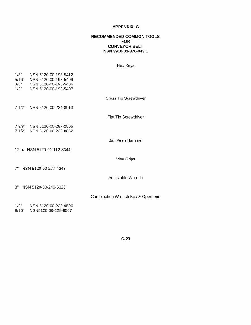
APPENDIX -G
RECOMMENDED COMMON TOOLSFOR
CONVEYOR BELTNSN 3910-01-376-043 1
Hex Keys
1/8" NSN 5120-00-198-54125/16" NSN 5120-00-198-54093/8" NSN 5120-00-198-54061/2" NSN 5120-00-198-5407
Cross Tip Screwdriver
7 1/2" NSN 5120-00-234-8913
Flat Tip Screwdriver
7 3/8" NSN 5120-00-287-25057 1/2" NSN 5120-00-222-8852
Ball Peen Hammer
12 oz NSN 5120-01-112-8344
Vise Grips
7" NSN 5120-00-277-4243
Adjustable Wrench
8" NSN 5120-00-240-5328
Combination Wrench Box & Open-end
1/2" NSN 5120-00-228-95069/16" NSN5120-00-228-9507
C-23

By Order of the Secretary of the Army:
GORDON R. SULLIVANGeneral, United States Army
Official: Chief of Staff
MITN H. HAMILTONAdministrative Assistant to the
Secretary of the Army07493
Distribution:To be distributed in accordance with DA Form 12-25E(Block No. 6218) maintenance requirements for TM 10-3930-
665-13&P.
�U.S. GOVERNMENT PRINTING OFFICE: 1994-546-017/00173


THE METRIC SYSTEM AND EQUIVALENTSLINEAR MEASURE
1 Centimeter = 10 Millimeters = 0.01 Meters = 0.3937 Inches1 Meter = 100 Centimeters = 1000 Millimeters = 39.37 Inches1 Kilometer = 1000 Meters = 0.621 Mile =
WEIGHTS
1 Gram = 0.001 Kilograms = 1000 Milligrams = 0.035 Ounces1 Kilogram = 1000 Grams = 2.2 Lb1 Metric Ton = 1000 Kilograms = 1 Megagram = 1.1 Short Tons
LIQUID MEASURE
1 Milliliter = 0.001 Liters = 0.0338 Fluid Ounces1 Liter = 1000 Milliliters = 33.82 Fluid Ounces
SQUARE MEASURE
1 Sq. Centimeter = 100 Sq. Millimeters = 0.155 Sq. Inch1 Sq. Meter = 10,000 Sq Centimiters = 10.76 Sq. Feet1 Sq. Kilometer = 1,000,000 Sq. Meters = 0.386 Sq. Mile
CUBIC MEASURE
1 Cu. Centimeter = 1000 Cu. Millimeters = 0.06 Cu. Inch1 Cu. Meter = 1,000,000 Cu. Centimeters = 35.31 Cu. Feet
TEMPERATURE
5/9 (°F - 32) = °C212° Fahrenheit is equivalent to 100° Celsius90° Fahrenheit is equivalent to 32.2° Celsius32°Fahrenheit is equivalent to 0° Celsius9/5 (°C + 32) = °F
APPROXIMATE CONVERSION FACTORS
TO CHANGE TO MULTIPLY BY
Inches ............................ Centimeters .............................. 2.540Feet ............................... Meters ...................................... 0.305Yards ............................. Meters ...................................... 0.914Miles .............................. Kilometers ................................ 1.609Square Inches................ Square Centimeters.................. 6.451Square Feet ................... Square Meters .......................... 0.093Square Yards ................. Square Meters .......................... 0.836Square Miles .................. Square Kilometers .................... 2.590Acres ............................. Square Hectometers................. 0.405Cubic Feet ..................... Cubic Meters ............................ 0.028Cubic Yards ................... Cubic Meters ............................ 0.765Fluid Ounces.................. Milliliters.................................. 29.573Pints............................... Liters......................................... 0.473Quarts ............................ Liters......................................... 0.946Gallons........................... Liters......................................... 3.785Ounces .......................... Grams..................................... 28.349Pounds........................... Kilograms ................................. 0.454Short Tons ..................... Metric Tons............................... 0.907Pound-Feet .................... Newton-Meters ......................... 1.356Pounds per Sq. Inch....... Kilopascals ............................... 6.895Miles per Gallon ............. Kilometers per Liter................... 0.425Miler per Hour ................ Kilometer per Hour.................... 1.609TO CHANGE.................. TO MULTIPLY BY
Centimeters ................... Inches....................................... 0.394Meters............................ Feet .......................................... 3.280Meters............................ Yards ........................................ 1.094Kilometers...................... Miles ......................................... 0.621Square Centimeters ....... Square Inches .......................... 0.155Square Meters ............... Square Feet............................ 10.764Square Meters ............... Square Yards............................ 1.196Square Kilometers ......... Square Miles............................. 0.386Square Hectometers ...... Acres ........................................ 2.471Cubic Meters.................. Cubic Feet .............................. 35.315Cubic Meters.................. Cubic Yards .............................. 1.308Milliliters ......................... Fluid Ounces ............................ 0.034Liters.............................. Pints ......................................... 2.113Liters.............................. Quarts....................................... 1.057Liters.............................. Gallons ..................................... 0.264Grams............................ Ounces ..................................... 0.035Kilograms....................... Pounds ..................................... 2.205Metric Tons .................... Short Tons................................ 1.102Newton-Meters............... Pound-Feet............................... 0.738Kilopascals..................... Pounds per Square Inch ........... 0.145Kilometers per Liter ........ Miles per Gallon........................ 2.354Kilometers per Hour ....... Miles per Hour .......................... 0.621

PIN: 073235-000

This fine document...
Was brought to you by me:
Liberated Manuals -- free army and government manuals
Why do I do it? I am tired of sleazy CD-ROM sellers, who take publicly available information, slap “watermarks” and other junk on it, and sell it. Those masters of search engine manipulation make sure that their sites that sell free information, come up first in search engines. They did not create it... They did not even scan it... Why should they get your money? Why are not letting you give those free manuals to your friends?
I am setting this document FREE. This document was made by the US Government and is NOT protected by Copyright. Feel free to share, republish, sell and so on.
I am not asking you for donations, fees or handouts. If you can, please provide a link to liberatedmanuals.com, so that free manuals come up first in search engines:
<A HREF=http://www.liberatedmanuals.com/>Free Military and Government Manuals</A>
– SincerelyIgor Chudovhttp://igor.chudov.com/
– Chicago Machinery Movers
Related Documents