OPERATOR MANUAL AUTO LENSMETER TL-3000A • Read this Operator Manual carefully before using this instrument in order to operate it properly and safely. • Do not use procedures other than those specified in this manual. • Keep this Operator Manual handy when operating this instrument. • For any questions about this instrument or about this manual, contact your Tomey representative or local distributor. TL-3000A

Welcome message from author
This document is posted to help you gain knowledge. Please leave a comment to let me know what you think about it! Share it to your friends and learn new things together.
Transcript
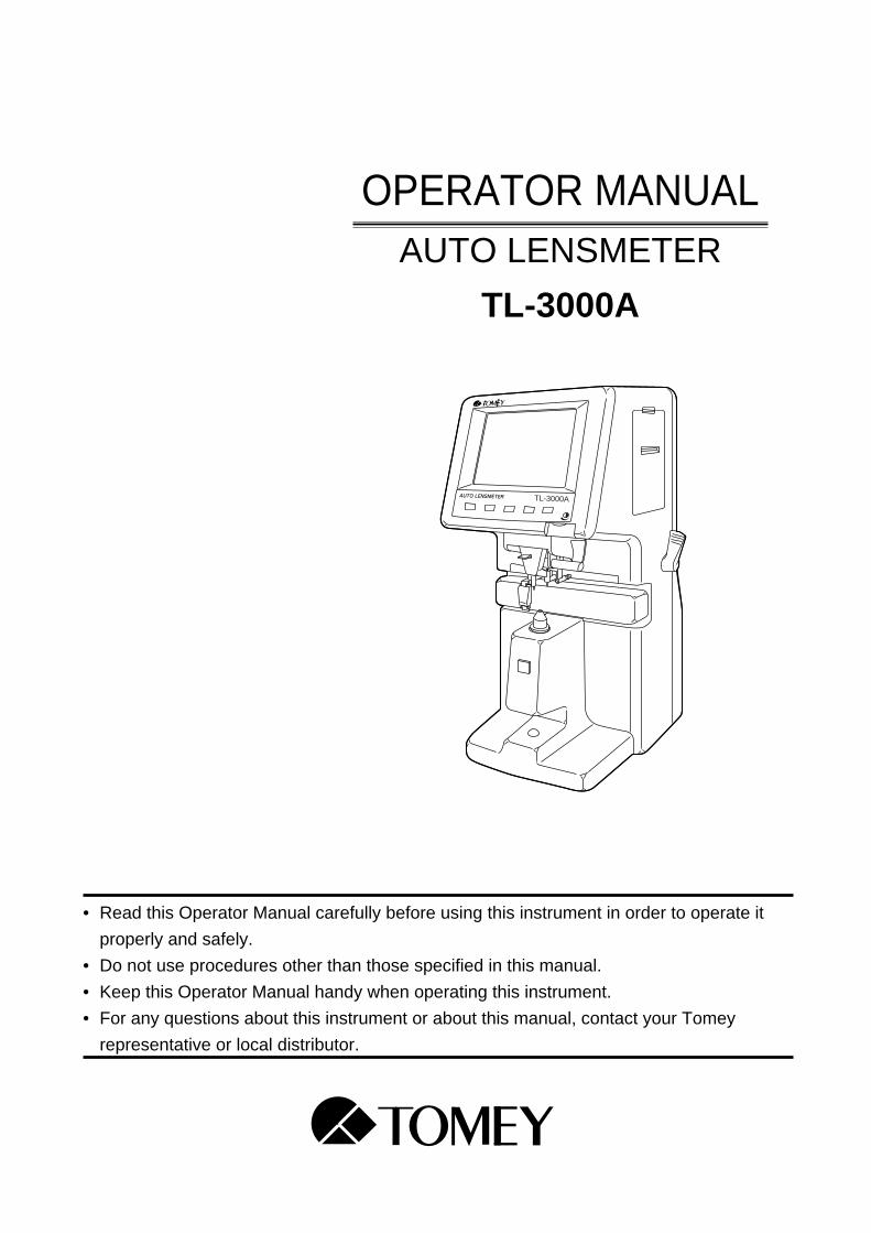
OPERATOR MANUALAUTO LENSMETER
TL-3000A
• Read this Operator Manual carefully before using this instrument in order to operate it
properly and safely.
• Do not use procedures other than those specified in this manual.
• Keep this Operator Manual handy when operating this instrument.
• For any questions about this instrument or about this manual, contact your Tomey
representative or local distributor.
TL-3000A

SYMBOLS USED IN THIS MANUALThe symbols used in this manual represent the following messages:
• This is a precaution that, if unheeded, will result in a hazardous
situation where there is an imminent danger of serious injury or
death.
• This is a precaution that, if unheeded, may result in a situation where
there is a possibility of minor or moderate injury or damage to prop-
erty.
• This is an additional instruction, which may contain a special precau-
tion on company policy related , either directly or indirectly, to the
safety of personnel or to the protection of property.
IMPORTANT PRECAUTION / SYMBOLS USED IN THIS MANUAL
IMPORTANT PRECAUTION
• Never install this instrument near locations where explosive or flam-
mable materials are used or stored. Such installation may result in a
fire or an explosion.
i
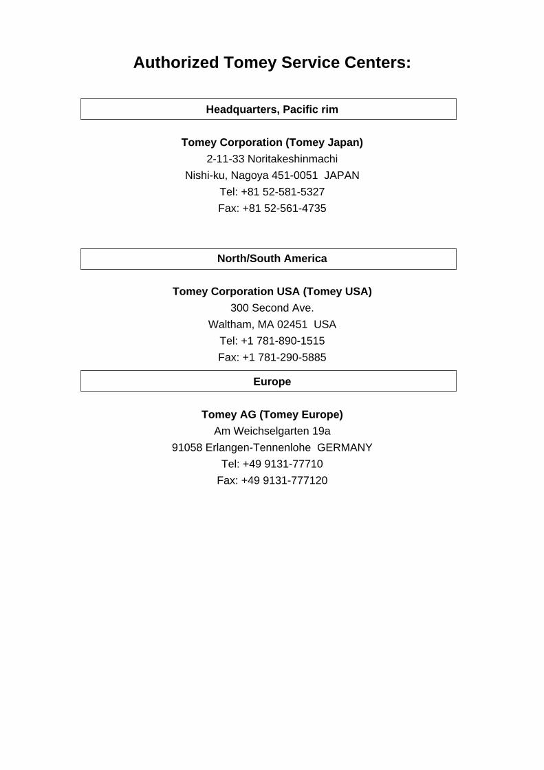
Authorized Tomey Service Centers:
Headquarters, Pacific rim
Tomey Corporation (Tomey Japan)
2-11-33 Noritakeshinmachi
Nishi-ku, Nagoya 451-0051 JAPAN
Tel: +81 52-581-5327
Fax: +81 52-561-4735
North/South America
Tomey Corporation USA (Tomey USA)
300 Second Ave.
Waltham, MA 02451 USA
Tel: +1 781-890-1515
Fax: +1 781-290-5885
Europe
Tomey AG (Tomey Europe)
Am Weichselgarten 19a
91058 Erlangen-Tennenlohe GERMANY
Tel: +49 9131-77710
Fax: +49 9131-777120

ID: 0110
iiCONTENTS
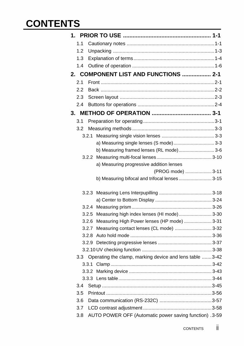
CONTENTS1. PRIOR TO USE ....................................................... 1-1
1.1 Cautionary notes ................................................................1-1
1.2 Unpacking ..........................................................................1-3
1.3 Explanation of terms...........................................................1-4
1.4 Outline of operation ............................................................1-6
2. COMPONENT LIST AND FUNCTIONS .................. 2-12.1 Front ...................................................................................2-1
2.2 Back ...................................................................................2-2
2.3 Screen layout .....................................................................2-3
2.4 Buttons for operations ........................................................2-4
3. METHOD OF OPERATION ..................................... 3-13.1 Preparation for operating....................................................3-1
3.2 Measuring methods ............................................................3-3
3.2.1 Measuring single vision lenses ........................................ 3-3
a) Measuring single lenses (S mode)............................... 3-3
b) Measuring framed lenses (RL mode)........................... 3-6
3.2.2 Measuring multi-focal lenses.......................................... 3-10
a) Measuring progressive addition lenses
(PROG mode) .................... 3-11
b) Measuring bifocal and trifocal lenses ......................... 3-15
3.2.3 Measuring Lens Interpupilling ........................................ 3-18
a) Center to Bottom Display ........................................... 3-24
3.2.4 Measuring prism............................................................. 3-26
3.2.5 Measuring high index lenses (HI mode)......................... 3-30
3.2.6 Measuring High Power lenses (HP mode) ..................... 3-31
3.2.7 Measuring contact lenses (CL mode) ............................ 3-32
3.2.8 Auto hold mode .............................................................. 3-36
3.2.9 Detecting progressive lenses ......................................... 3-37
3.2.10 UV checking function ..................................................... 3-38
3.3 Operating the clamp, marking device and lens table .......3-42
3.3.1 Clamp ............................................................................. 3-42
3.3.2 Marking device ............................................................... 3-43
3.3.3 Lens table....................................................................... 3-44
3.4 Setup ................................................................................3-45
3.5 Printout .............................................................................3-56
3.6 Data communication (RS-232C) ......................................3-57
3.7 LCD contrast adjustment ..................................................3-58
3.8 AUTO POWER OFF (Automatic power saving function) .3-59

CONTENTSiii
4. MAINTENANCE AND INSPECTION ....................... 4-14.1 Warranty .............................................................................4-1
4.2 Routine maintenance .........................................................4-2
4.2.1 Cleaning cover glass ........................................................ 4-2
4.3 Replacing spare parts ........................................................4-3
4.3.1 Fuse ................................................................................. 4-3
4.3.2 Ink cartridge ..................................................................... 4-4
4.3.3 Printer paper .................................................................... 4-6
4.4 Storage ...............................................................................4-7
4.5 Packing materials ...............................................................4-7
5. TROUBLESHOOTING............................................. 5-15.1 Troubleshooting guide ........................................................5-1
5.1.1 General operation .............................................................. 5-1
5.1.2 Progressive addition lens measurement ............................ 5-4
5.2 Error messages ..................................................................5-8
6. SPARE PARTS........................................................ 6-1
7. SPECIFICATIONS ................................................... 7-17.1 Measurement .....................................................................7-1
7.2 Data control ........................................................................7-1
7.3 Physical dimensions and electrical requirements ...............7-2
7.4 Environmental conditions ...................................................7-2
7.5 Approved international standards .......................................7-2
8. INDEX ...................................................................... 8-1

CAUTION MARKS
CAUTION MARKS
• There are caution marks on the side and rear of the main unit .
• Do not mutilate the caution marks.
• The external output terminal is not isolated from the internal circuit.
Before connecting any external devices, contact your Tomey repre-
sentative. Otherwise, the internal circuit may be damaged.
• Do not touch the edge of the paper cutter at the printer paper outlet.
iv

v
(This page is left intentionally blank.)

1-1
1. PRIOR TO USE
• Read this Operator Manual carefully before using this instrument in
order to operate it properly and safely.
• Do not use procedures other than those specified in this manual.
1.1 Cautionary notes
• Only well-trained personnel should operate this instrument.
• When installing this instrument, observe the following items.
- Do not install this instrument in a location where it might be exposed
to water or chemicals.
- Do not install this instrument in a location where it might be subject
to adverse influences, such as excessive atmospheric pressure, high
temperature, excessive humidity, poor ventilation, direct sunlight,
dust, salt or sulfur in the air.
- Ascertain that factors such as excessive slope, vibration and impact
will not endanger the instrument (including during transportation).
- Do not install this instrument near the storage of chemical substances
or in a location where gas may be generated.
- Adhere to the specified mains frequency, voltage and allowable
current (or allowable power consumption).
• During use of this instrument, observe the following:
- Do not move a coated lens when it is held with the clamp. This may
result in damage to the coating. The clamp should be used only for
marking.
- Clean the cover glass under the nose piece often with a soft cloth.
- Always keep the tip of the nose piece clean. Dust on it may result in
scratches on a lens.
1.1 Cautionary notes

1-2
• When cutting the printout, hold the paper against the edge of the
paper cutter, bend the paper upward and tear off the paper by pulling
in a lateral direction. Otherwise, a paper jam or malfunction of the
printer may result.
• When this instrument is not in use, keep the dust cover over it.
• When the instrument is not used for an extended period of time,
unplug the power cord.
• After using this instrument, observe the following:
- Do not apply excessive force when unplugging the cords.
- Refer to the Section 4.4 "Storage" for storage instructions.
• If you suspect that this instrument is not functioning properly, do
not attempt to repair it. Contact your Tomey representative or local
distributor.
• Do not modify this instrument.
• Maintenance:
- Inspect this instrument and its accessories periodically.
- If this instrument has been idle for a long period of time, make sure
that it is functioning properly and safely before using it again. For
this, TOMEY recommends using a trial lens set for checking
accuracy.
• Due to vibration during transport and/or environmental changes of
storage, the ink may leak out of the marking device cartridge. If you
find an ink stain and/or leakage of ink at the tip of the marking de-
vice, wipe it off and make sure it is functioning properly.
1.1 Cautionary notes

1-3
• Power Cord ................................................................. 1
• CL (Contact Lens) Nose Piece ................................... 1
• Hard Contact Lens Holder .......................................... 1
• Spare Fuse (250V, 2.0A) ............................................ 1
• Printer Paper (One roll is already in the unit) ............ 3
• Dust Cover .................................................................. 1
• Operator Manual (this book) ...................................... 1
1.2 UnpackingUpon unpacking , inspect that all the components are present and that
there is no visible damage to any of them.
If there are any missing or damaged items, immediately contact your
Tomey representative or local distributor.
• Be sure to retain all shipping and packing materials for reuse if the
instrument will be transported or shipped.
1.2 Unpacking
• Main unit of the AUTO LENSMETER TL-3000A ... 1
TL-3000A
COMPONENTS
1-4 1.3 Explanation of terms
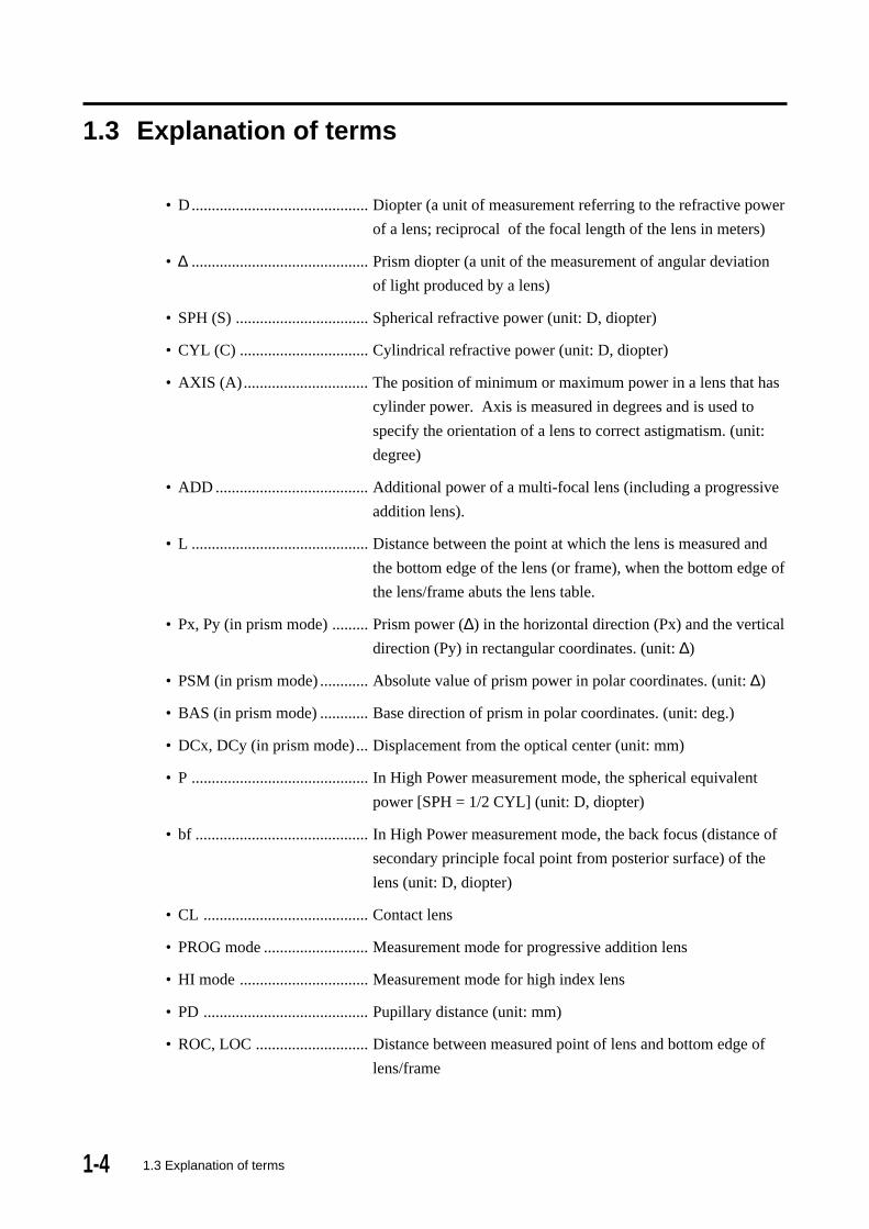
1.3 Explanation of terms
• D............................................ Diopter (a unit of measurement referring to the refractive power
of a lens; reciprocal of the focal length of the lens in meters)
• ∆ ............................................ Prism diopter (a unit of the measurement of angular deviation
of light produced by a lens)
• SPH (S) ................................. Spherical refractive power (unit: D, diopter)
• CYL (C) ................................ Cylindrical refractive power (unit: D, diopter)
• AXIS (A)............................... The position of minimum or maximum power in a lens that has
cylinder power. Axis is measured in degrees and is used to
specify the orientation of a lens to correct astigmatism. (unit:
degree)
• ADD ...................................... Additional power of a multi-focal lens (including a progressive
addition lens).
• L ............................................ Distance between the point at which the lens is measured and
the bottom edge of the lens (or frame), when the bottom edge of
the lens/frame abuts the lens table.
• Px, Py (in prism mode) ......... Prism power (∆) in the horizontal direction (Px) and the vertical
direction (Py) in rectangular coordinates. (unit: ∆)
• PSM (in prism mode) ............ Absolute value of prism power in polar coordinates. (unit: ∆)
• BAS (in prism mode) ............ Base direction of prism in polar coordinates. (unit: deg.)
• DCx, DCy (in prism mode) ... Displacement from the optical center (unit: mm)
• P ............................................ In High Power measurement mode, the spherical equivalent
power [SPH = 1/2 CYL] (unit: D, diopter)
• bf ........................................... In High Power measurement mode, the back focus (distance of
secondary principle focal point from posterior surface) of the
lens (unit: D, diopter)
• CL ......................................... Contact lens
• PROG mode .......................... Measurement mode for progressive addition lens
• HI mode ................................ Measurement mode for high index lens
• PD ......................................... Pupillary distance (unit: mm)
• ROC, LOC ............................ Distance between measured point of lens and bottom edge of
lens/frame
1-51.3 Explanation of terms
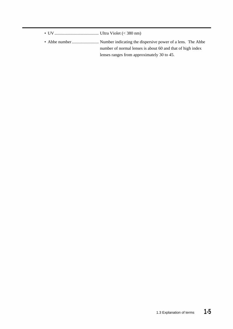
• UV ......................................... Ultra Violet (< 380 nm)
• Abbe number ......................... Number indicating the dispersive power of a lens. The Abbe
number of normal lenses is about 60 and that of high index
lenses ranges from approximately 30 to 45.
1-6
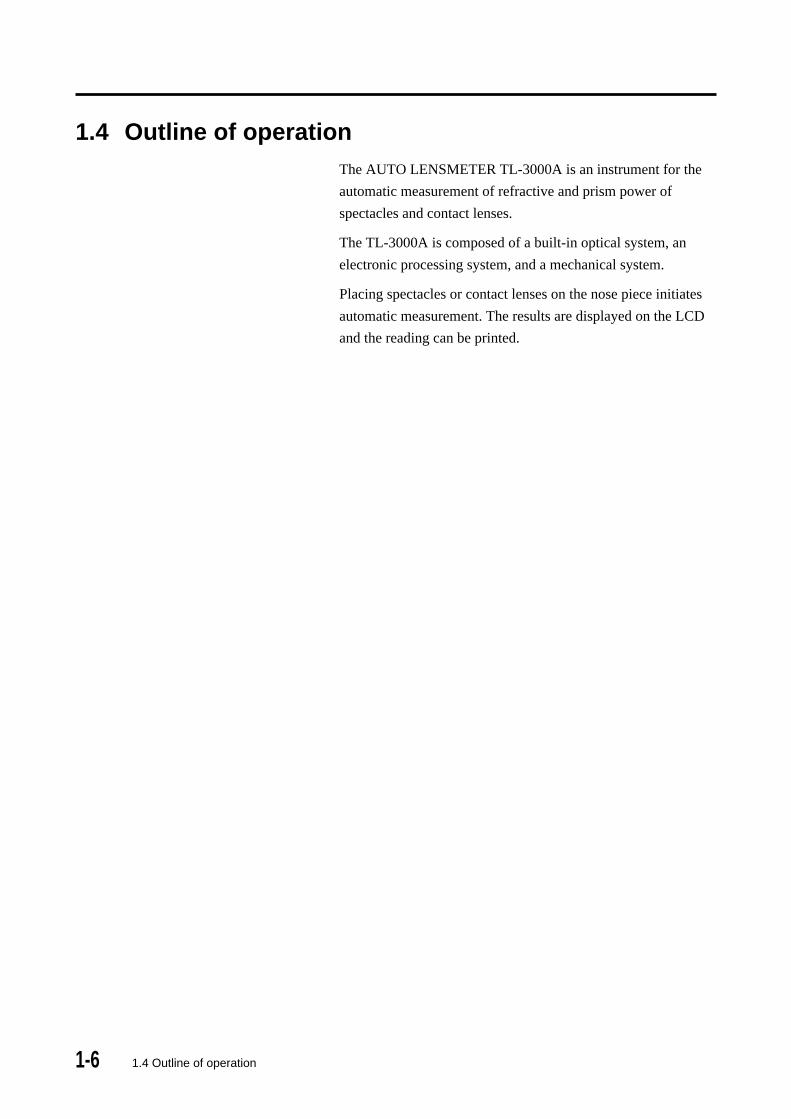
1.4 Outline of operationThe AUTO LENSMETER TL-3000A is an instrument for the
automatic measurement of refractive and prism power of
spectacles and contact lenses.
The TL-3000A is composed of a built-in optical system, an
electronic processing system, and a mechanical system.
Placing spectacles or contact lenses on the nose piece initiates
automatic measurement. The results are displayed on the LCD
and the reading can be printed.
1.4 Outline of operation

2-12.1 Front
2. COMPONENT LIST AND FUNCTIONS
2.1 FrontLCD
Liquid crystal display displays information such ascentering of lens, measurement conditions andresults.
Contrast adjusterAdjusts the contrast of the LCD.
Marking deviceMarks the center and axis orientation of thelens.
ClampStabilizes the lens when marking it.
LeverChanges the position of the lens table.
Lens tableUsed to standardize the orientation of spectaclesfor accurate cylinder axis measurement andverdical prism measurement.
Nose blockUsed for PD measurement.
Nose pieceLens is placed on the nose piece.
HOLD buttonUsed for holding and storing the data.
UV checkerUsed to measure transmission ratio of UltraViolet (UV) light.
Control panelFive buttons are located on this panel to controlthe unit. The function of each button is indicatedabove the button on the LCD display.
PrinterPrints out readings.

2-2 2.2 Back
2.2 Back
Name plateShows the serial number.
AC power terminalThe accompanying power cable is connected tothis terminal.
Fuse holderThe fuse is mounted in this holder.
Power switchTurns the power on or off.
External output terminal (RS-232C)Prints the data when connected to a printer, ortransmits the data when connected to a computer.
2-3
L=25
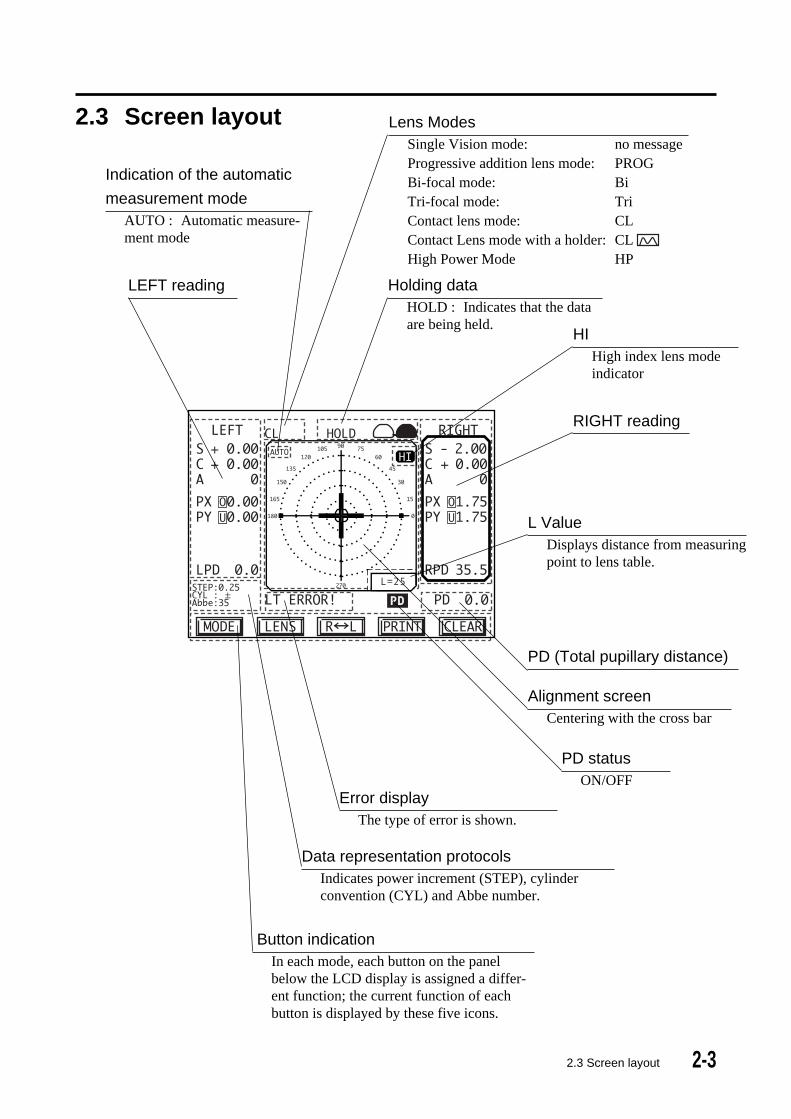
Alignment screenCentering with the cross bar
2.3 Screen layout
2.3 Screen layout
Lens ModesSingle Vision mode: no messageProgressive addition lens mode: PROGBi-focal mode: BiTri-focal mode: TriContact lens mode: CLContact Lens mode with a holder: CLHigh Power Mode HP
Holding dataHOLD : Indicates that the dataare being held.
Indication of the automatic
measurement modeAUTO : Automatic measure-ment mode
Data representation protocolsIndicates power increment (STEP), cylinderconvention (CYL) and Abbe number.
PD (Total pupillary distance)
RIGHT reading
LEFT reading
Button indicationIn each mode, each button on the panelbelow the LCD display is assigned a differ-ent function; the current function of eachbutton is displayed by these five icons.
Error displayThe type of error is shown.
HIHigh index lens modeindicator
PD statusON/OFF
L ValueDisplays distance from measuringpoint to lens table.

2-4
2.4 Buttons for operations
1) Display 1 ( )
MODE: for switching between Control Panel Display 1and Control Panel
Display 2.
for entering Setup mode (by pressing and holding for approximately
one second).
LENS: for switching between single vision, multi-focal lens, contact lens and
high power modes.
R L: for switching from S-mode (for measuring single lenses) to RL-mode
(for measuring lenses mounted in spectacle frames) and for
switching between the right and left lens.
PRINT: for recalling and printing readings.
CLEAR: for clearing stored readings (if any readings are in the memory).
for changing from RL-mode to S-mode (if no readings are in the
memory).
2) Display 2 ( )
MODE: for switching between Control Panel Display 1 and Control Panel
Display 2.
for entering Setup mode (by pressing and holding for approximately
one second).
+ - : for changing CYL reading (+, -) for the currently displayed lens(es)
If you go back to Display 1, the CYL reading (+, -) returns to the
default setting. It can be changed permanently in Setup Menu 1.
PD: for changing PD mode (ON/OFF)
If the PD mode is ON, is shown on the lower right of the screen.
UV: for using UV check function
PRISM: for changing prism mode (No display, Px/Py, PSM/BAS, DCx/DCy).
CAL: for calibration of UV check function (only appears in UV check
function).
3) HOLD buttonThe HOLD button is used for storing a reading manually.
2.4 Buttons for operations

3-1
• When the instrument is first turned on, the LCD (liquid crystal dis-
play) may appear dim. The brightness will increas as it warms up.
This may require extra time if the ambient temperature is low.
3.1 Preparation for operating
• Before turning on the power, check the following items:
- Make sure that the cover glass under the nose piece is clean.
- Make sure that a lens is not on the nose piece.
- Make sure that the nose piece is seated properly.
1) Connect the female end of the power cord into the power receptacle on
the back of the Autolensmeter and the male end in to a 3-prong power
outlet.
2) Press the power switch ON.
3) The initial screen will appear for approximately five seconds.
3.1 Preparation for operating
Nose piece
Cover glass
3. METHOD OF OPERATION
3-2
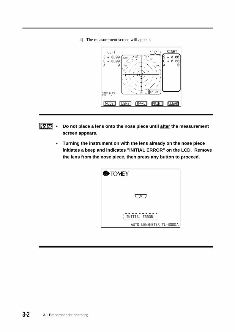
4) The measurement screen will appear.
• Do not place a lens onto the nose piece until after the measurement
screen appears.
• Turning the instrument on with the lens already on the nose piece
initiates a beep and indicates "INITIAL ERROR" on the LCD. Remove
the lens from the nose piece, then press any button to proceed.
3.1 Preparation for operating
L= 25
3-3
3.2 Measuring methods
3.2.1 Measuring single vision lenses
a) Measuring single lenses (lens blanks, S-mode)
• In Auto mode, the reading will be automatically held when appropri-
ate alignment is achieved. Change between AUTO mode and Manual
mode by continuously pressing the HOLD button located below the
nose piece for approximately one second.
• Do not push the lens against the nose piece with undue force or
move the lens abruptly, which may cause to damage the lens.
1) To measure a single lens, SINGLE mode must be set to ON in Setup
(see section 3.4, Menu 4). If the instrument is in the RL-mode, press
the CLEAR button to change to the S-mode. To change back to RL-
mode, press the R L button.
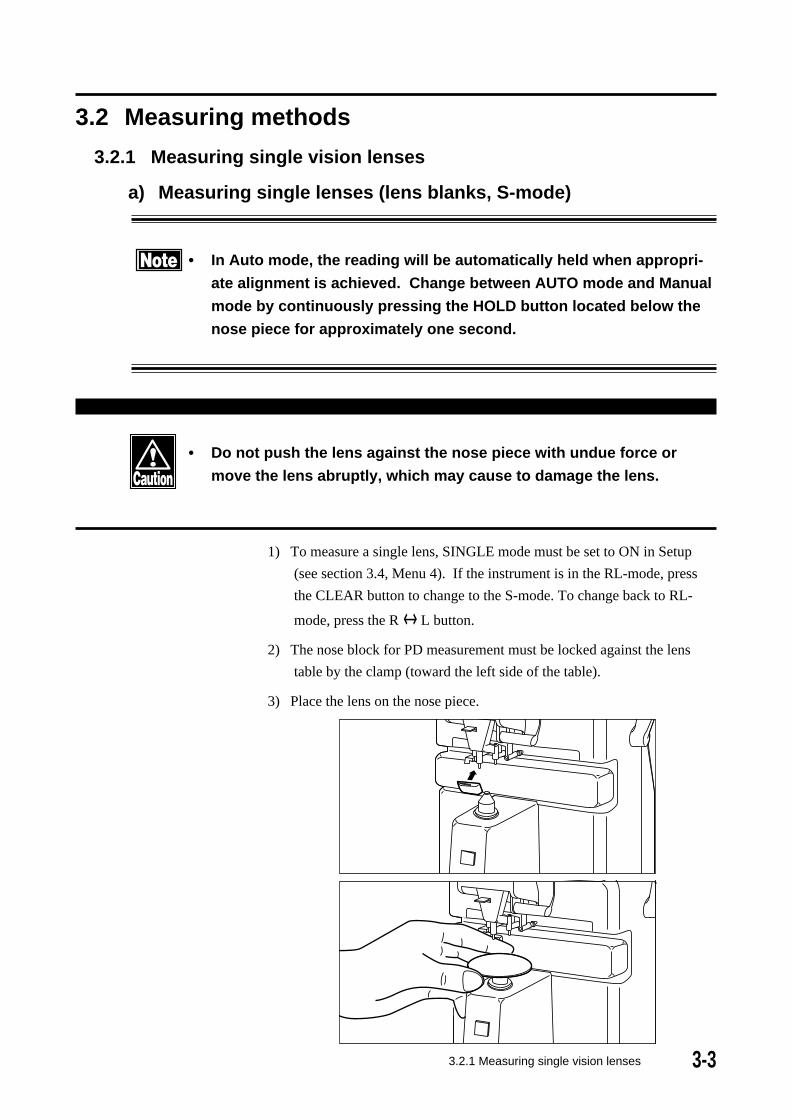
2) The nose block for PD measurement must be locked against the lens
table by the clamp (toward the left side of the table).
3) Place the lens on the nose piece.
3.2.1 Measuring single vision lenses

3-4
L= 25
4) Move the lens gently right and left, back and forth to center the cursor
(+) on the crosshair.
L= 25
5) Measured data are displayed in real time. If the lens table is used, "L"
(displayed at the bottom right of the alignment screen) indicates the
distance between the measured point (center of nose piece) and the
bottom edge of the lens.
6) In Auto mode, the reading will be automatically acquired and held. In
Manual mode, press the HOLD button when the lens is aligned to hold
the measured data. The memory display will show HOLD and the
stored data will be displayed. Up to 50 measurements can be stored
(S-mode only).
3.2.1 Measuring single vision lenses
L= 25
3-53.2.1 Measuring single vision lenses
7) After removing the lens from the nose piece, the target ("+" mark) will
disappear. It will reappear when another lens is placed on the nose
piece.
8) Press the PRINT button to print all the data that have been stored. Until
HOLD button is pressed next time, all data are retained.
• Pressing the HOLD button will allow the instrument to return to the
measuring mode for taking new readings. ALL data for previously
measured lenses are retained. However, if 50 measurements have
been stored and the HOLD button is pressed, the message "OVER
FLOW!" is displayed and indicates that there is no room to store
additional readings. To continue measurement, it is necessary to
either press the CLEAR button or print out the stored measurements
by pressing the PRINT button before taking another reading.
• Pressing the CLEAR button erases ALL data that have been stored,
i.e., data for all previously measured lenses are erased.
• If the SINGLE MODE menu setting is off, the S-mode cannot be acti-
vated. (See Section 3.4, Setup, Menu 4)
• Single lenses with power exceeding +/- 25D (up to +/- 80D) can be
measured using the High Power Lens Mode (see Section 3.2.7 and
Section 3.4, Setup Menu 2).
• If the PRINT menu setting is off, no printout can be made. (See Sec-
tion 3.4, Setup, Menu 1).

3-6
b) Measuring framed lenses (RL-mode)
• Do not push the lens against the nose piece with undue force or
move the lens abruptly, which may cause to damage to the lens.
• In Auto mode, the reading will be automatically held when appropri-
ate alignment is achieved. Change between Auto mode and Manual
mode by continuously pressing the HOLD button located below the
nose piece for approximately one second.
1) If the instrument is in S-mode, Press the R<->L button to change to RL
mode. The right lens is expected to be measured first and then the left
lens. If you wish to measure the left lens before the right lens, press the
R<->L-button again. A rectangle indicates the lens (R or L) to be
measured. (Auto R/L may be turned ON or OFF; see Section 3.4,
Setup Menu 3. The default setting is ON).
• If the nose block is not at the home position, the unit is in PD mea-
surement mode and the R<->L-button is not functional (i.e., pressing
it does not change between Right and Left).
2) Place the right lens on the nose piece with the bottom of the frame away
from you and the temples downward (as shown below).
3.2.1 Measuring single vision lenses
3-7
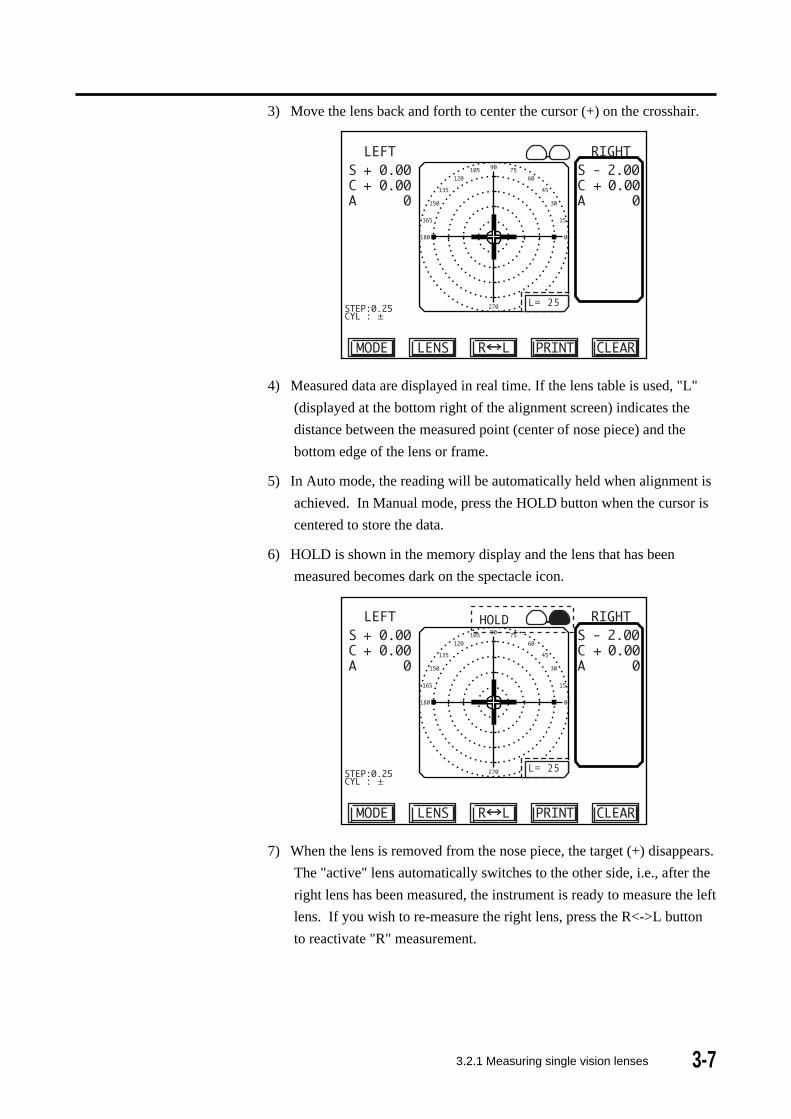
3) Move the lens back and forth to center the cursor (+) on the crosshair.
L= 25
4) Measured data are displayed in real time. If the lens table is used, "L"
(displayed at the bottom right of the alignment screen) indicates the
distance between the measured point (center of nose piece) and the
bottom edge of the lens or frame.
5) In Auto mode, the reading will be automatically held when alignment is
achieved. In Manual mode, press the HOLD button when the cursor is
centered to store the data.
6) HOLD is shown in the memory display and the lens that has been
measured becomes dark on the spectacle icon.
L= 25
7) When the lens is removed from the nose piece, the target (+) disappears.
The "active" lens automatically switches to the other side, i.e., after the
right lens has been measured, the instrument is ready to measure the left
lens. If you wish to re-measure the right lens, press the R<->L button
to reactivate "R" measurement.
3.2.1 Measuring single vision lenses

3-8 3.2.1 Measuring single vision lenses
8)When measurement of the right lens is completed, repeat the above steps
to measure the left lens.
L= 25
L= 25
9) After both lenses have been measured, press the PRINT button to print
the measurement.
10) The instrument is now ready to measure a right lens
• Pressing the HOLD button will allow the instrument to return to the
measuring mode for taking new readings. ALL data for previously
measured lenses are retained until you take the next reading. The
new reading will replace the old reading that was stored in memory.
• Pressing the CLEAR button erases ALL data that have been stored,
i.e., data for both the right and the left lens are erased.
• If a lens is placed on the nose piece without clearing the previous
measurements, the stored data are cleared and the new reading will
be displayed.
• If the PRINT menu setting is off, no printout can be made (See Sec-
tion 3.4, Setup, Menu 1).

3-9
(This page is left intentionally blank.)
3-10 3.2.2 Measuring Multi-Focal Lenses
3.2.2 Measuring Multi-Focal Lenses
There are four multi-focal options (see Section 3.4, Setup Menu 2):
1) Progressive: for measuring progressive lenses
2) Bi-focal: for measuring bifocal lenses
3) Tri-focal: for measuring trifocal lenses
4) Prog+Bi: for measuring progressive and bifocal lenses
(default setting)
(Note that the above options are for framed or single multi-focal lenses, not for multi-focal
contact lenses.)
To change from Single Vision mode to Multi-Focal mode on the measurement screen, press
the LENS button.
When the Single Vision option selected in Setup is Spectacle+CL, pressing the LENS
button displays the measurement screens in the following order: Single Vision Mode for
framed/single lenses, Multi-focal mode(s) for framed/single lenses and Contact lens
mode. For example, if the PROG+Bi Multi-focal option is selected, pressing the LENS
button changes the screen successively from Single Vision mode to Progressive mode to
Bifocal mode to Contact lens mode.
When the Single Vision option selected in Setup is Spectacle, if the selected Multi-focal
option is PROG+Bi, pressing the LENS button changes the screen successively from
Single Vision framed/single lens mode to Progressive mode to Bifocal mode. If the
selected Multi-focal option is Progressive or Bifocal or Trifocal, pressing the LENS
button alternately changes between Single Vision mode and the selected Multi-focal
mode.

3-113.2.2 Measuring Multi-Focal Lenses
a) Measuring progressive addition lenses (PROG mode)
• Do not apply the lens to the nose piece with undue force or move it
abruptly, which may cause to damage lens.
• When measuring in the Auto mode, the reading at the far area and
ADD data at the near print area are held automatically. Press the
HOLD button for approximately one second without a lens on the
nose piece to alternately change between the Auto and the Manual
mode.
• If you cannot make a proper measurement of progressive addition
lenses, see "5.1 TROUBLESHOOTING".
1) Select Progressive mode on the measurement screen by pressing the
LENS button. (If Progressive mode is not available, go to Setup Menu
2 and change the Multi-Focal mode setting; see Section 3.4.)
2) Determine the extent of the progressive addition area.
a. Place the lens on the nose piece with the bottom of the frame away
from you and the temples downward as illustrated on p.3-6 and, with
the progressive addition area, which is located slightly below the
center of the lens, above the nose piece.
L= 25

3-12 3.2.2 Measuring Multi-Focal Lenses
b. A bar graph indicating refractive power change at the point being
measured in the progressive area appears at the left lower part of the
target area.
L= 25
• If the add power is low, it may not be possible to center the target. In
this case, place the center of the lens above the nose piece and
press the HOLD button to proceed to far point measurement.
3) Measure the far point area.
a. Since the far point area is located in the top portion of the lens, move
the lens away from you so that the top portion is over the nose piece.
Move it back/forth and left/right to center the cursor (+) on the
crosshair.
L= 25
b. When centering of the target is achieved, if in the Auto mode, a beep
sounds and the far point power is automatically stored. If not in the
Auto mode, it is necessary to press the HOLD button when the target
is centered to store the data. (See 3.4 Setup, Menu 3.)
c. The display is next changed to that for measurement of the near point
3-133.2.2 Measuring Multi-Focal Lenses
• There are some lenses for which centering cannot be achieved. In
case of such a lens, move the lens back/forth and left/right with the
area approximately 6 to 10 mm above the center of the lens (in the
center of the frame in case of a framed lens) positioned above the
nose piece and measure the far point area in the position where there
is the least variation of SPH and CYL values. Then press the HOLD
button.
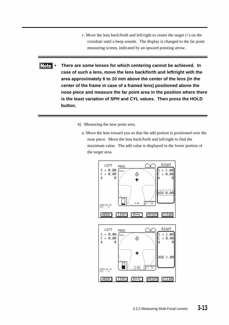
4) Measuring the near point area.
a. Move the lens toward you so that the add portion is positioned over the
nose piece. Move the lens back/forth and left/right to find the
maximum value. The add value is displayed in the lower portion of
the target area.
L= 25
L= 25
c. Move the lens back/forth and left/right to center the target (+) on the
crosshair until a beep sounds. The display is changed to the far point
measuring screen, indicated by an upward pointing arrow.
3-14 3.2.2 Measuring Multi-Focal Lenses
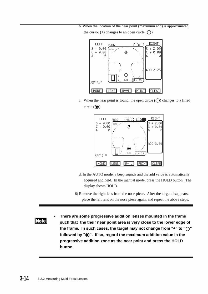
b. When the location of the near point (maximum add) is approximated,
the cursor (+) changes to an open circle ( ).
c. When the near point is found, the open circle ( ) changes to a filled
circle ( ).
STEP:0.25CYL : ±
PROG HOLD
MODE
S + 2.00C + 0.00A 0
LENS R←→L PRINT CLEAR
AUTO
3.00
ADD 3.00
L= 25
d. In the AUTO mode, a beep sounds and the add value is automatically
acquired and held. In the manual mode, press the HOLD button. The
display shows HOLD.
6) Remove the right lens from the nose piece. After the target disappears,
place the left lens on the nose piece again, and repeat the above steps.
• There are some progressive addition lenses mounted in the frame
such that the their near point area is very close to the lower edge of
the frame. In such cases, the target may not change from "+" to " "
followed by " ". If so, regard the maximum addition value in the
progressive addition zone as the near point and press the HOLD
button.
L= 25

3-15
b) Measuring bifocal and trifocal lenses
• Do not push the lens onto the nose piece with undue force or
abruptly move the lens, which may damage the lens.
• When measuring in the Auto mode, the reading at the far area and
the add values at the near point area are held automatically. Press-
ing the HOLD button continuously for approximately one second
alternately changes between Auto and Manual modes.
1) Select Bifocal or Trifocal mode on the measurement screen by pressing
the LENS button. (If the desired mode is not available, change the
Multi-Focal mode setting on Setup Menu 2; see Section 3.4). "Bi" or
"Tri" will be indicated above the measurement screen, depending on
which has been selected on Setup Menu 2.
STEP:0.25CYL : ±
Bi
MODE
S + 2.00C + 0.00A 0
LENS R←→L PRINT CLEAR
L= 25
STEP:0.25CYL : ±
TriS + 2.00C + 0.00A 0
MODE LENS R←→L PRINT CLEAR
L= 25
3.2.2 Measuring Multi-Focal Lenses

3-16 3.2.2 Measuring Multi-Focal Lenses
2) Place the right lens on the nose piece with the bottom of the frame away
from you and the temples downward (See illustration on p. 3-6)
3) Measure the far point area.
a. Move the lens back/forth and left/right to center the cursor (+) on the
crosshair.
b. When centering is achieved, if in the Auto mode, a beep sounds and
the reading in the far point area is held . If in the manual mode, it is
necessary to press the HOLD button when the target is centered to
store the reading. (See 3.4, Setup, Menu 3.)
4) Measure the near point area.
a. Move the lens toward you to position the near segment over the nose
piece. For a tri-focal lens, move the intermediate area over the nose
piece.
b. The "+" mark moves downward as you move the lens and changes to a
filled circle ( ) when the near (or intermediate) point is centered.
c. In AUTO mode, a beep sounds and the add (or intermediate) value is
automatically stored. In MANUAL mode, press the HOLD button to
store the value.
d. In case of a trifocal lens, after measuring the intermediate segment,
draw the lens closer to you to move the near point area over the nose
piece. Press the HOLD button to store the add value.
5) Remove the lens from the nose piece. After the target disappears, repeat
the above procedure for the next lens.
• Removing the lens while measuring the near point area automatically
returns the display to that for the far point area.

3-17
(This page is left intentionally blank.)

3-18 3.2.3 Measuring Interpupillary Distance (PD)
3.2.3 Measuring Interpupillary Distance (PD)
• In Auto mode, the reading will be automatically held when appropri-
ate alignment is achieved. Change between Auto mode and Manual
mode by pressing the HOLD button located below the nose piece
continuously for approximately one second.
• When the distance measurements are automatically held (Auto mode
for single vision lenses and for multi focal lenses), the lens PD is
measured from the optical centers of the right and left lens. When the
distance measurements are manually acquired by pressing the HOLD
button, the lens PD is measured from the location at which the read-
ings were taken.
• Monocular lens PDs (RPD and LPD) measured from the point at
which the distance reading was taken to the center of the nose block.
For measuring lens interpupillary distance (PD), PD measure must be
turned ON, as described in Section 3.4, Setup, Menu 1. If PD is ON,
"PD" appears at the lower right of the screen (above the PRINT button).
Beep
Setup Menu 4

3-19
• To obtain correct PD measurement, the nose block must rest securely
against the frame between the two spectacle lenses.
• To obtain PD measurement, the lens table must abut the lower end of
the frame. Correct PD measurement cannot be obtained if the frame is tilted.
• PD data are displayed in real time; they are displayed when the data
are stored.
• If you do not wish to measure PD, move the nose block up and to the
far left and lock it in place against the lens table.
1) If the instument is in Single mode, change to RL mode by pressing the
R<->L button.
2) Unlock the nose block by moving it slightly to the right and allowing it to
drop down.
Nose block
3.2.3 Measuring Interpupillary Distance (PD)
3-20 3.2.3 Measuring Interpupillary Distance (PD)
L= 25
32.5
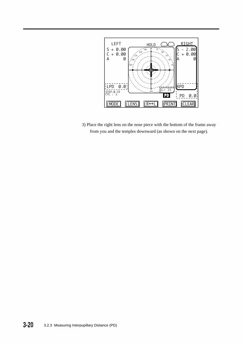
3) Place the right lens on the nose piece with the bottom of the frame away
from you and the temples downward (as shown on the next page).
3-213.2.3 Measuring Interpupillary Distance (PD)
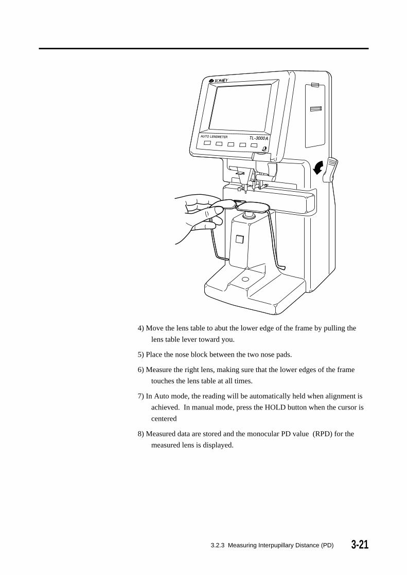
4) Move the lens table to abut the lower edge of the frame by pulling the
lens table lever toward you.
5) Place the nose block between the two nose pads.
6) Measure the right lens, making sure that the lower edges of the frame
touches the lens table at all times.
7) In Auto mode, the reading will be automatically held when alignment is
achieved. In manual mode, press the HOLD button when the cursor is
centered
8) Measured data are stored and the monocular PD value (RPD) for the
measured lens is displayed.

3-22 3.2.3 Measuring Interpupillary Distance (PD)
L= 25
9) Move the frame to the left lens with the nose block still resting on the
frame between the nose pads. (Lift the frame upward to clear the nose
piece.) Measurement is automatically changed for measurement of the
left lens.
L= 25
34.0
66.5
32.5
10) Measure the left lens using in the same procedure as for the right means.
L= 25
3-23
11) Measured data are stored, and the monocular PD value for the left lens
(LPD) and the total PD value (RPD + LPD) are displayed.
12) Press the PRINT button to print the measurement.
3.2.3 Measuring Interpupillary Distance (PD)
3-24
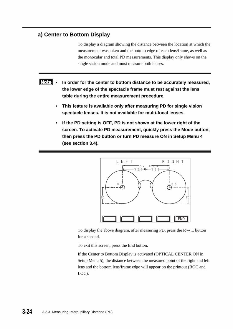
a) Center to Bottom Display
To display a diagram showing the distance between the location at which the
measurement was taken and the bottom edge of each lens/frame, as well as
the monocular and total PD measurements. This display only shows on the
single vision mode and must measure both lenses.
• In order for the center to bottom distance to be accurately measured,
the lower edge of the spectacle frame must rest against the lens
table during the entire measurement procedure.
• This feature is available only after measuring PD for single vision
spectacle lenses. It is not available for multi-focal lenses.
• If the PD setting is OFF, PD is not shown at the lower right of the
screen. To activate PD measurement, quickly press the Mode button,
then press the PD button or turn PD measure ON in Setup Menu 4
(see section 3.4).
To display the above diagram, after measuring PD, press the R L button
for a second.
To exit this screen, press the End button.
If the Center to Bottom Display is activated (OPTICAL CENTER ON in
Setup Menu 5), the distance between the measured point of the right and left
lens and the bottom lens/frame edge will appear on the printout (ROC and
LOC).
LEFT RIGHTPD 64.5
32.532.0
26 26
OC OC
3.2.3 Measuring Interpupillary Distance (PD)

3-25
(This page is left intentionally blank.)

3-26
3.2.4 Measuring prism
To measure prism, select one of the three prism measurement options (see
below) according to the instructions given in section 3.4, Setup Menu 1. If
you have already selected a prism option and wish to change it, press the
Mode button to enter Mode 2 and press the prism button to view / select a
different prism option. When the prism option is activated, prism values are
displayed below the sphere, cylinder and axis values.
Three prism display options are available:
• PX, PY ( ): Rectangular coordinates
• PSM, BAS( , deg.): Polar coordinates
• DCX, DCY (mm): Displacement from the optical center (mm)
• Rectangular coordinate
PX: horizontal base direction (in or out) and prism magnitude (prism
diopters).
PY: vertical base direction (up or down) and prism magnitude (prism
diopters).
Prism base direction is expressed as:
O : base out I : base in
U : base up D : base down
L= 25
3.2.4 Measuring Prism

3-27
• Polar coordinates
PSM: prism magnitude (prism diopter)
BAS: base orientation (angle in degrees)
L= 25
• Displacement from the optical center
DCX: Horizontal displacement (mm) from optical center
DCY: Vertical displacement (mm) from optical center
3.2.4 Measuring prism
L= 25
--

3-28 3.2.4 Measuring Prism
• Total Prism Display
If the TOTAL PRISM option is ON (see Section 3.4, Setup Menu 4), the
total (net) horizontal and vertical prism in a pair of spectacle lenses will be
displayed after both lenses have been measured. The value are expressed in
rectangular coordinates (BI/BO, BU/BD), regardless of which prism display
option you have selected. The total prism values are displayed below the
right lens data. The total vertical prism value is given for the right lens.

3-29
(This page is left intentionally blank.)

3-30 3.2.5 Measuring high index lenses (HI mode)
3.2.5 Measuring high index lenses (HI mode)
• It is recommended to use the High Index (HI) mode when measuring
high index lenses. In genaral, a lens with refractive index of 1.6 or
higher, is considered as a high index lens. The correct Abbe number
should be used to obtain the most accurate reading (see Section 3.4,
Setup Menu 1).
• The industrial standard wavelength used in measuring lenses is
slightly different from the wavelength used in TL-3000A. Because of
this, if the High Index mode is not used, the TL-3000A reading of high
index lenses may be different from the reading provided by the lens
manufacturer.
1) The default abbe number value for normal index mode is 60. The default
Abbe number for HI mode set at the factory is 35. To change the value
of the Abbe number for HI mode, see the instructions given in Setion
3.4 Setup, Menu 1. To obtain accurate Abbe number of the lens, please
read the lens data sheets provided by the manufacturer.
2) Hold the LENS button for approximately one second.
3) " " is displayed at the upper right of the target area.
L= 25
4) When is displayed, the measured values are automatically corrected
using the Abbe number set for high index.
5) To exit HI mode, press and hold the LENS button for approximately one
second.

3-31
3.2.6 Measuring high power lenses (HP mode)
• The HIGH POWER option is available only for measuring single
lenses (S-mode); It is not available for framed lenses (RL-mode).
• When the HIGH POWER option is ON (see Section 3.4, Setup Menu
2), the only available lens modes are single vision single (not framed)
lenses and HIGH POWER CONTACT LENS is use the CL nose piece
to measure the high power contact lens.
• The sperical equivalent power [SPH + 1/2 CYL] of the lens is dis-
played; cylinder values are not given.
1) To measure a lens with power exceeding +/- 25D, both SINGLE mode
(see Section 3.4, Setup Menu 4) and HIGH POWER single vision mode
(see Section 3.4, Setup Menu 2) must be ON. "HP" will appear at the
upper left of the alignment screen.
2) Measure the lens as described in Section 3.2.1a [Measuring single vision
lenses, Measuring single lenses (lens blanks, S-mode)].
3) In Auto mode, the reading will be automatically acquired and held. In
Manual mode, press the HOLD button when the lens is aligned to hold
the measured data. The memory display will show HOLD and the
spherical equivalent power (P=SPH + 1/2 CYL) in diopters and the
length of the back focus (bf) of the lens in millimeters will be
displayed. Up to 50 measurements can be stored.
3.2.6 Measuring high power lenses (HP mode)
L= 25
P
bf
HP

3-32
3.2.7 Measuring contact lenses (CL mode)
• Because the measurement conditions for contact lenses are different
from those for spectacles, be sure that the following requirements
are met:
- Be sure to use the Contact Lens nose piece when measuring contact
lenses. Using the standard nose piece may result in errors.
- Be sure to use the Contact Lens mode (CL mode) when measuring
contact lenses. Measuring in Spectacle mode may result in errors.
- Be sure that the appropriate Contact Lens mode is selected in Setup
(see Section 3.4, setup Menu 2). To measure soft or rigid contact
lenses without the contact lens holder, the Single Vision option
SPECTACLE + CL should be selected. To measure rigid contact
lenses using the contact lens holder, the Single Vision option
SPECTA + CL should be selected. Using the wrong CL mode may
result in errors.
• If the AUTO CL feature is turned ON (see Section 3.4, Setup Menu 3),
the Contact Lens mode will automatically be activated when the
contact lens holder is placed on the nose piece. When the contact
lens holder is removed, the mode will automatically change to Spec-
tacle mode.
1) Remove the standard nose piece and install the Contact Lens nose piece.
CL
3.2.7 Measuring contact lenses (CL mode)

3-333.2.7 Measuring contact lenses (CL mode)
L= 25
2) Change to Contact Lens mode, indicated by "CL" at the upper left of the
measurement screen.
• If either SPECTACLE + CL or SPECTA + CL is select in Setup Menu 2,
simply press the Lens button to select the Contact Lens mode.
• If neither Contact Lens option is selected in Setup Menu 2, follow the
instructions in section 3.4 to select SPECTACLE + CL if you do not
plan to use the CL holder and SPECTA + CL if you plan to measure
rigid lenses using the CL holder. When you return to the measurement
screen after making your selection, press the LENS button to select the
Contact Lens mode.
• If the AUTO CL feature is ON, the Contact Lens mode will automatically
be activated when a contact lens or nthe CL holder is placed on the
Contact Lens nose piece.
3) Measure soft or rigid contact lenses as described below.
a. Measuring Hard Contact Lenses
1) To measure rigid contact lenses without the CL holder:
- With the SPECTACLE + CL option selected on Setup Menu 2
and the instrument in Contact Lens mode, place the lens on the
contact lens nose piece with its front convex surface up.
b. Find the optical center of the lens by moving it back/forth and left/right,
following the procedure givin in Section 3.2.1a [Measuring single
vision lenses, Measuring single lenses (lens blanks, S-mode)].
3-34
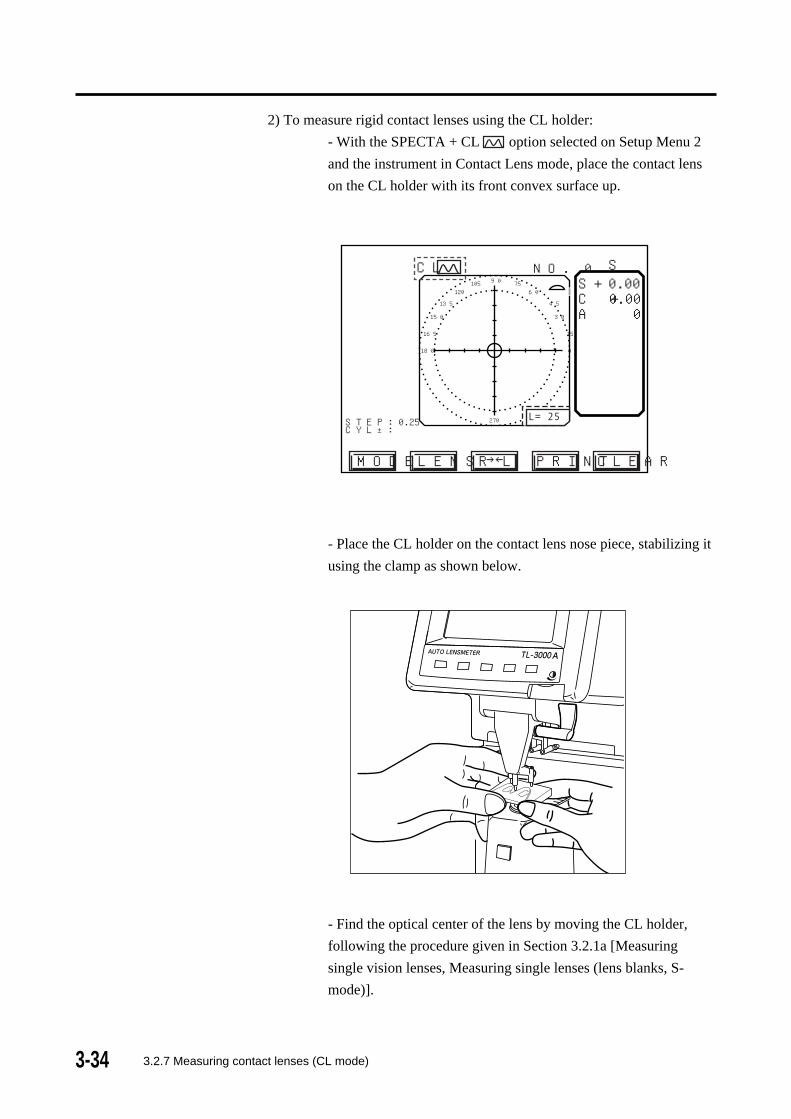
2) To measure rigid contact lenses using the CL holder:
- With the SPECTA + CL option selected on Setup Menu 2
and the instrument in Contact Lens mode, place the contact lens
on the CL holder with its front convex surface up.
- Place the CL holder on the contact lens nose piece, stabilizing it
using the clamp as shown below.
- Find the optical center of the lens by moving the CL holder,
following the procedure given in Section 3.2.1a [Measuring
single vision lenses, Measuring single lenses (lens blanks, S-
mode)].
STEP:0.25CYL : ±
180 0
165 15
150 30
135 45
120 60105 7590
270
HI
NO. 0 S
MODE
S + 0.00C + 0.00A 0
LENS R←→L PRINT CLEAR
L= 25
CL
3.2.7 Measuring contact lenses (CL mode)

3-35
Measurement error may increase for lenses that fall outside the
following ranges:
• Power: +/- 15D
• Base Curve: 7.35 to 8.35mm
• Diameter: 8.0 to 9.6mm
b) Measuring Soft Contact Lenses
• Due to the physical properties of soft contact lenses, the readings
may be inaccurate.
1) Wipe off the water from the soft contact lens.
2) With the SPECTACLE + CL option selected on setup Menu 2 and the
instrument in Contact Lens mode, place the lens with its front surface
up on the contact lens nose piece.
3) Find the optical center of the lens by moving it back/forth and left/right,
following the procedure given in Section 3.2.1a [Measuring single
vision lenses, Measuring single lenses (lens blanks, S-mode)].
3.2.7 Measuring contact lenses (CL mode)

3-36 3.2.8 Auto hold mode
3.2.8 Auto hold mode
When the instrument is in Automatic hold mode, "AUTO" is displayed on
the left side above the target area. When centering is achieved in Single
Vision mode, the distance data are automatically held and stored in the
memory.
In Multi-Focal mode, the reading at the far area and the add value is at the
near point area automatically held and stored. In order for the distance value
to be automatically held and stored, the Auto Far option must also be ON
(see Section 3.4, Setup Menu 3).
1. Setting of the Auto Hold mode:
The auto hold mode can be set by either of the following two procedures.
a) Set AUTO HOLD as discribed in Section 3.4, Setup, Menu 3.
b) Continuously press the HOLD button located below the nose piece for
approximately one second. When "AUTO" is displayed on the left
side above the target area, release the HOLD button. Return to
Manual mode by continuously pressing the HOLD button again for
approximately one second. Note that this method changes the Auto
Hold status temporarily. When the instrument is turned off and back
on, the status will revent to that set on Setup Menu 3.
L= 25
3-373.2.9 Detecting progressive lenses
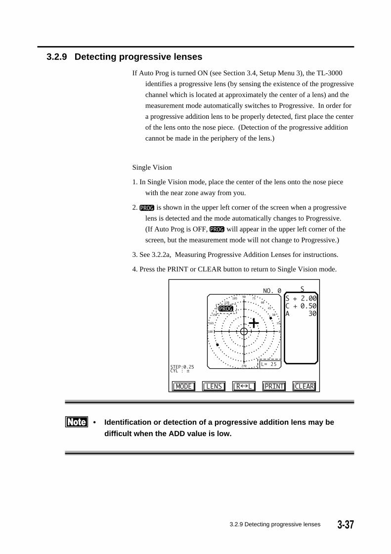
3.2.9 Detecting progressive lenses
If Auto Prog is turned ON (see Section 3.4, Setup Menu 3), the TL-3000
identifies a progressive lens (by sensing the existence of the progressive
channel which is located at approximately the center of a lens) and the
measurement mode automatically switches to Progressive. In order for
a progressive addition lens to be properly detected, first place the center
of the lens onto the nose piece. (Detection of the progressive addition
cannot be made in the periphery of the lens.)
Single Vision
1. In Single Vision mode, place the center of the lens onto the nose piece
with the near zone away from you.
2. is shown in the upper left corner of the screen when a progressive
lens is detected and the mode automatically changes to Progressive.
(If Auto Prog is OFF, will appear in the upper left corner of the
screen, but the measurement mode will not change to Progressive.)
3. See 3.2.2a, Measuring Progressive Addition Lenses for instructions.
4. Press the PRINT or CLEAR button to return to Single Vision mode.
L= 25
• Identification or detection of a progressive addition lens may be
difficult when the ADD value is low.

3-38
3.2.10 UV checking function
The percent transmittance of light in the ultraviolet portion of the spectrum
(wavelength=370nm) may be shown in a bar graph. (Note that the bar graph
does not cover transmittance in the entire UV zone. It indicates only the %
transmittance at 370 nm.)
1. Press the MODE button to enter Mode 2.
UVPD+ -MODE PRISM
L= 25
2. Press the UV button. A bar graph is shown in the target area.
UVPD+ -MODE CAL
3. When no lens is present, the bar graph should indicate 100%
transmittance (no blockage of the UV light). If this is not the case,
press the CAL button to calibrate the instrument.
3.2.10 UV checking function

3-393.2.10 UV checking function
UVPD+ -MODE CAL
4. Insert the lens in the UV checker at the bottom of the instrument, placing
the center of the lens over the UV detector. Measurement taken in the
surrounding area may be incorrect.
5. The bar graph shows the percent of UV light transmitted by the lens.
UVPD+ -MODE CAL

3-40
• Avoid direct sunlight when using UV check function, or the reading
may not be accurate.
• In UV checking mode, when the instrument is not used for more than
3 minutes, it automatically returns to Measurement mode.
3.2.10 UV checking function

3-41
(This page is left intentionally blank.)

3-42 3.3.1 Clamp
3.3 Operating the clamp, marking device and lens table
3.3.1 Clamp
• Lower the clamp slowly.
Quick lowering of the clamp may result in damage to the lens.
Use the lens clamp to stabilize the position of the lens when marking it. (See
Section 3.3.2, Marking device.)
1) Raise the lens clamp with your finger to release the lock.
2) Lower the clamp gently onto the lens.

3-433.3.2 Marking device
3.3.2 Marking device
The marking device places three marks on the lens, one in the center of the
lens and one approximately 16 mm lateral to the center on each side along
the lens axis.
1) Turn and press down on the marking lever, causing the pens to descend
and mark the lens surface.
2) Carefully release the marking lever, so it will return to its initial position
by its spring force.
The three (3) marking pens are self-contained cartridges. When the ink
supply becomes depleted, replace the cartridge. (See Section 4.3.2, Ink
cartridge.)
3-44 3.3.3 Lens table
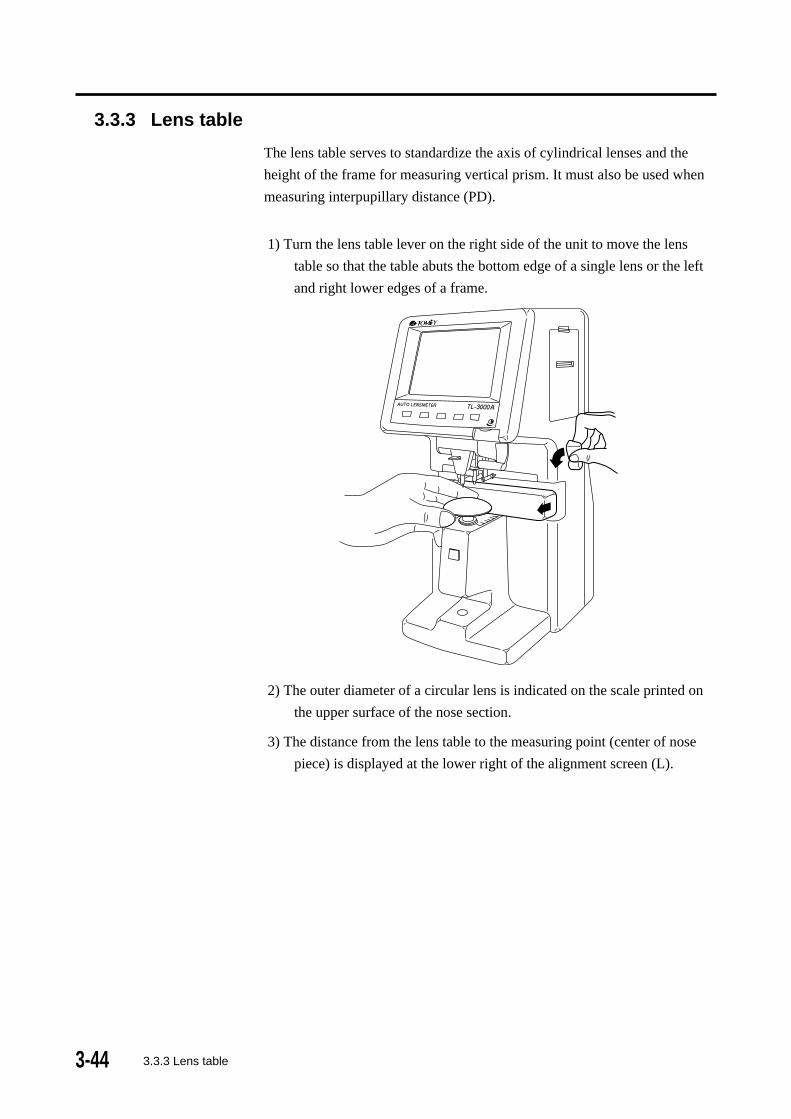
3.3.3 Lens table
The lens table serves to standardize the axis of cylindrical lenses and the
height of the frame for measuring vertical prism. It must also be used when
measuring interpupillary distance (PD).
1) Turn the lens table lever on the right side of the unit to move the lens
table so that the table abuts the bottom edge of a single lens or the left
and right lower edges of a frame.
2) The outer diameter of a circular lens is indicated on the scale printed on
the upper surface of the nose section.
3) The distance from the lens table to the measuring point (center of nose
piece) is displayed at the lower right of the alignment screen (L).
3-453.4 Setup
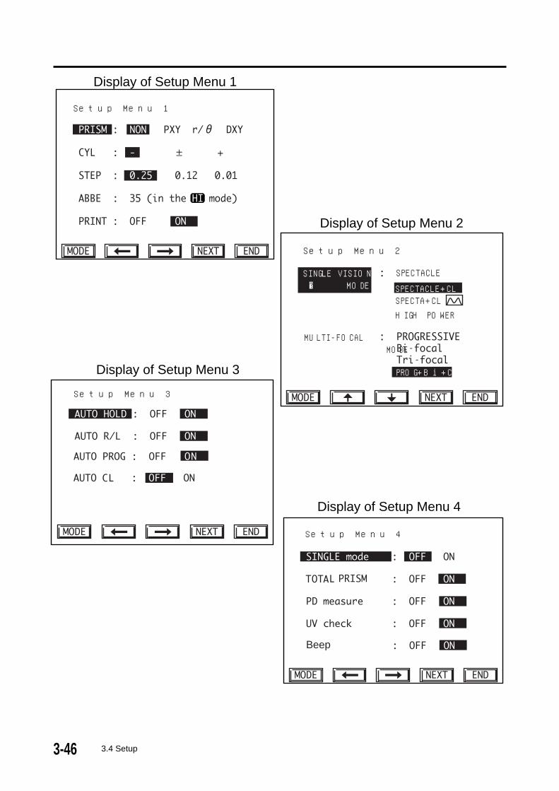
3.4 Setup
• Since the information which has been set is stored in the memory, it
need not be rest after the power has been turned off and back on.
• In Setup mode, if the instrument is not used for more than 3 minutes,
it automatically returns to the Measurement mode.
Indication units and measuring conditions are modified by menu selection.
1) Press and hold the MODE button for approximately one second until the
Setup Menu 1 display appears.
2) There are six Setup Menus.
3) To change from one item to the next in the menu, press the MODE
button.
4) To select the desired option for each item, press the horizontal or vertical
arrow buttons.
5) To change to the next menu, press the NEXT button.
6) To return to the measuring display after setup, press the END button.
3-46 3.4 Setup
Beep
Setup Menu 4
Setup Menu 3
Display of Setup Menu 3
Display of Setup Menu 4
Setup Menu 1
Display of Setup Menu 1
Display of Setup Menu 2
Setup Menu 2
SINGLE VISION� � MODE
MULTI-FOCAL MODE
SPECTACLE
PROG+Bi+CL
SPECTACLE+CL
HIGH POWERSPECTA+CL
--

3-473.4 Setup
0123456789-.ABCDEFGHIJKLMNOPQRSTUVWXYZabcdefghijklmnopqrstuvwxyz
TL-3000A
HOLD:decision
Setup Menu 6 (Title Layout)
PRINT DENSITY +0
PRINT TITLE
OPTICAL CENTER
Setup Menu 5 (Print Setting)
Display of Setup Menu 5
Display of Setup Menu 6
3-48 3.4 Setup
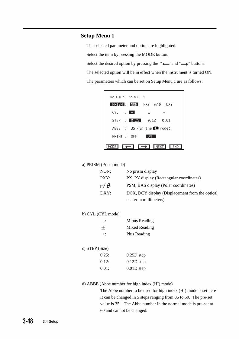
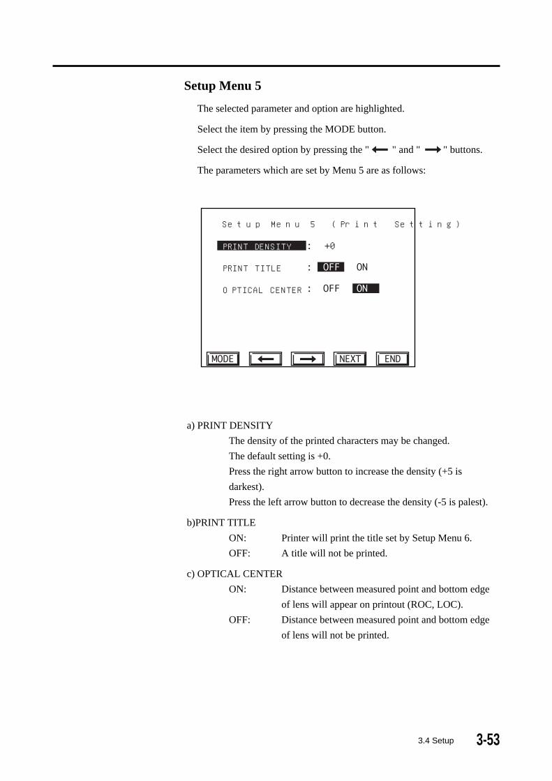
Setup Menu 1
The selected parameter and option are highlighted.
Select the item by pressing the MODE button.
Select the desired option by pressing the " "and " " buttons.
The selected option will be in effect when the instrument is turned ON.
The parameters which can be set on Setup Menu 1 are as follows:
Setup Menu 1
a) PRISM (Prism mode)
NON: No prism display
PXY: PX, PY display (Rectangular coordinates)
: PSM, BAS display (Polar coordinates)
DXY: DCX, DCY display (Displacement from the optical
center in millimeters)
b) CYL (CYL mode)
-: Minus Reading
: Mixed Reading
+: Plus Reading
c) STEP (Size)
0.25: 0.25D step
0.12: 0.12D step
0.01: 0.01D step
d) ABBE (Abbe number for high index (HI) mode)
The Abbe number to be used for high index (HI) mode is set here
It can be changed in 5 steps ranging from 35 to 60. The pre-set
value is 35. The Abbe number in the normal mode is pre-set at
60 and cannot be changed.
3-493.4 Setup
e) PRINT (Printout ON/OFF)
ON: Printout enabled
OFF: Printout disabled
Press the NEXT button to advance to Setup Menu 2.
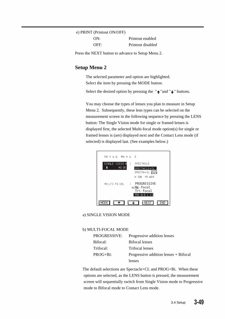
Setup Menu 2
The selected parameter and option are highlighted.
Select the item by pressing the MODE button.
Select the desired option by pressing the " "and " " buttons.
You may choose the types of lenses you plan to measure in Setup
Menu 2. Subsequently, these lens types can be selected on the
measurement screen in the following sequence by pressing the LENS
button: The Single Vision mode for single or framed lenses is
displayed first, the selected Multi-focal mode option(s) for single or
framed lenses is (are) displayed next and the Contact Lens mode (if
selected) is displayed last. (See examples below.)
Setup Menu 2
SINGLE VISION� � MODE
MULTI-FOCAL MODE
SPECTACLE
PROG+Bi+CL
SPECTACLE+CL
HIGH POWERSPECTA+CL
--
a) SINGLE VISION MODE
b) MULTI-FOCAL MODE
PROGRESSIVE: Progressive addition lenses
Bifocal: Bifocal lenses
Trifocal: Trifocal lenses
PROG+Bi: Progressive addition lenses + Bifocal
lenses
The default selections are Spectacle+CL and PROG+Bi. When these
options are selected, as the LENS button is pressed, the measurement
screen will sequentially switch from Single Vision mode to Progressive
mode to Bifocal mode to Contact Lens mode.

3-50 3.4 Setup
If SPECTACLE+CL and PROGRESSIVE or Bifocal or Trifocal are
selected, as the LENS button is pressed, the measurement screen will
sequentially switch from Single Vision mode to the selected Multi-
Focal mode to Contact Lens mode.
When SPECTACLE is selected in Single Vision mode, contact lenses
cannot be measured. When the LENS button is pressed, the
measurement screen will change from Single Vision framed/single lens
mode to the selected Multi-Focal mode(s). For example, if
SPECTACLE and PROG+Bi are selected, the measurement screen
changes successively from Single Vision framed/single lens mode to
Progressive mode to Bifocal mode as the LENS button is pressed. If
SPECTACLE and PROGRESSIVE (or Bifocal or Trifocal) are
selected, pressing the LENS button alternately changes between Single
Vision mode and Multi-focal mode (Progressive, Bifocal or Trifocal,
whichever is selected).
When HIGH POWER is selected in Single Vision mode, multi-focal
lenses cannot be measured. When the LENS button is pressed, the
measurement screen alternately changes between High Power mode
and High Power Contact Lens mode.
Press the NEXT button to advance to Setup Menu 3.
Setup Menu 3
The selected parameter and option are highlighted.
Select the item by pressing the MODE button.
Select the desired option by pressing the " "and " " buttons.
The parameters which are set by Menu 3 are as follows:
Setup Menu 3

3-513.4 Setup
a) AUTO HOLD
ON: Automatic hold mode. For Single Vision lenses, the
reading will be held and stored to the memory
automatically. For multi-focal lenses, the reading
at the far area and the add value at the near point
area will be held automatically.
(see AUTO FAR below).
OFF: Manual mode. The HOLD button must be pressed to
store data.
b) AUTO R/L
ON: Automatic RIGHT/LEFT change
(when not measuring PD)
OFF: No automatic RIGHT/LEFT change
(when not measuring PD)
When measuring PD, RIGHT/LEFT changes automatically even
if AUTO R/L is OFF. To change to the other eye when AUTO R/
L is OFF, press the R L button on the measurement screen.
c) AUTO PROG:
ON: Automatic change to the PROG mode when a
progressive addition is detected.
OFF: No automatic change to the PROG mode when a
progressive addition is present.
d) AUTO CL:
ON: Contact Lens mode automatically activated when
contact lens placed on CL nose piece. Mode
automatically changes to spectacle mode when CL
or CL holder removed.
OFF: No automatic changing of CL mode and spectacle
lens mode.
Press the NEXT button to advance to Setup Menu 4.
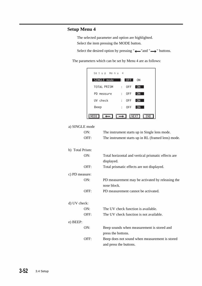
3-52 3.4 Setup
The parameters which can be set by Menu 4 are as follows:
Beep
Setup Menu 4
a) SINGLE mode
ON: The instrument starts up in Single lens mode.
OFF: The instrument starts up in RL (framed lens) mode.
b) Total Prism:
ON: Total horizontal and vertical prismatic effects are
displayed.
OFF: Total prismatic effects are not displayed.
c) PD measure:
ON: PD measurement may be activated by releasing the
nose block.
OFF: PD measurement cannot be activated.
d) UV check:
ON: The UV check function is available.
OFF: The UV check function is not available.
e) BEEP:
ON: Beep sounds when measurement is stored and
press the bottons.
OFF: Beep does not sound when measurement is stored
and press the buttons.
Setup Menu 4
The selected parameter and option are highlighted.
Select the item pressing the MODE button.
Select the desired option by pressing " "and " " buttons.
3-533.4 Setup
Setup Menu 5
The selected parameter and option are highlighted.
Select the item by pressing the MODE button.
Select the desired option by pressing the " " and " " buttons.
The parameters which are set by Menu 5 are as follows:
a) PRINT DENSITY
The density of the printed characters may be changed.
The default setting is +0.
Press the right arrow button to increase the density (+5 is
darkest).
Press the left arrow button to decrease the density (-5 is palest).
b)PRINT TITLE
ON: Printer will print the title set by Setup Menu 6.
OFF: A title will not be printed.
c) OPTICAL CENTER
ON: Distance between measured point and bottom edge
of lens will appear on printout (ROC, LOC).
OFF: Distance between measured point and bottom edge
of lens will not be printed.
PRINT DENSITY +0
PRINT TITLE
OPTICAL CENTER
Setup Menu 5 (Print Setting)

3-54 3.4 Setup
Setup Menu 6
Setup menu 6 allows you to create a title to appear at the top of each
printout.
This menu can be accessed only when the PRINT TITLE option is ON in
Setup Menu 5. If PRINT TITLE is OFF, this menu will be skipped.
A title consisting of up to 13 characters may be created as follows:
1) Select the first character by pressing the " " and " " buttons. The
selected character will be highlighted.
2) Press the HOLD button to enter the chracter, which will be displayed in
the title box.
3) Repeat steps 1 and 2 until the title is complete.
4) Press the NEXT button or the END button to save and exit.
To edit the title:
1) Press the MODE button. The double arrow ( ) will move down so
that it is adjacent to the title box.
2) Press the " " and " " buttons to select the character you wish to
change.
3) Press the MODE button again. The double arrow ( ) will move back
up to the character will be highlighted.
0123456789-.ABCDEFGHIJKLMNOPQRSTUVWXYZabcdefghijklmnopqrstuvwxyz
TL-3000A
HOLD:decisionTitle Block
Setup Menu 6 (Title Layout)

3-55
4) Select the replacement character by pressing the " " and " "
buttons. The selected character will be highlighted.
5) Press the HOLD button to enter the character, which will replace the
previous entry.
3.4 Setup
3-56
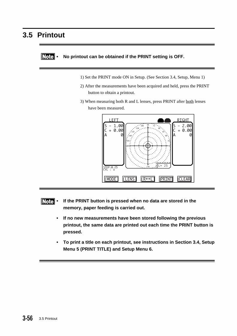
3.5 Printout
• No printout can be obtained if the PRINT setting is OFF.
1) Set the PRINT mode ON in Setup. (See Section 3.4, Setup, Menu 1)
2) After the measurements have been acquired and held, press the PRINT
button to obtain a printout.
3) When measuring both R and L lenses, press PRINT after both lenses
have been measured.
L= 25
• If the PRINT button is pressed when no data are stored in the
memory, paper feeding is carried out.
• If no new measurements have been stored following the previous
printout, the same data are printed out each time the PRINT button is
pressed.
• To print a title on each printout, see instructions in Section 3.4, Setup
Menu 5 (PRINT TITLE) and Setup Menu 6.
3.5 Printout

3-573.6 Data Communication (RS-232C)
3.6 Data communication (RS-232C)The RS-232C Data Communication feature allows measurement data to be
sent to an external device, such as a computer.
Whenever the PRINT button is pressed, data are sent to the RS-232C port
regardless of the PRINT mode setting. If you would like to disable the built-
in printer to use the RS-232C port only, turn the PRINT mode OFF (see
Section 3.4, Setup Menu 1).
• The data communication terminal is not isolated from the internal
circuits. Connecting inappropriate device(s) with TL-3000 which do
not follow RS-232C protocols, may damage the instrument. It is
recommended to contact a TOMEY representative or a local distribu-
tor before using the data communication terminal.

3-58 3.7 LCD contrast adjustment
3.7 LCD contrast adjustmentAdjust the LCD contrast by turning the contrast adjuster at the lower right of
the operation panel.

3-593.8 AUTO OFF (Automatic power saving function)
3.8 AUTO POWER OFF
(Automatic Power saving function)
1) When the instrument is not used for more than 10 minutes (i.e., no lens is
placed on the nose piece and no operation button is pressed), the back
light of the display screen, the internal motor and the light source are
automatically turned off. The following screenis displayed.
AUTO POWER OFFPUSH ANY BUTTON.
2) Press any of the operation buttons to reactive the instrument.
• Turn off the power switch when you do not intend to use this instru-
ment for a long period of time.

3-60
(This page is left intentionally blank.)

4-14.1 Warranty
4. MAINTENANCE AND INSPECTION
4.1 WarrantyOne-Year Limited Warranty
The Seller warrants this product to be free from defects in material and
workmanship under normal use for one year from the date of invoice issued
by Seller to the original purchaser.
This warranty shall apply only to the original purchaser and shall not, in any
way, be transferable or assignable to any party other than the original
purchaser.
Lamps, paper and other consumable items shall not be covered by this
warranty.
This warranty also shall NOT apply if the product has not been installed,
operated or maintained in accordance with the OPERATOR MANUAL of
Tomey Corporation (hereinafter called "Tomey"). Neither Seller nor Tomey
shall be liable for any damages caused by purchaser's failure to follow
instructions for proper installation, use and maintenance of the product.
This warranty is only applicable to the new product and DOES NOT cover
any damage resulting from or caused by accident or negligence, abuse,
misuse, mishandling, improper installation, improper repair or improper
modification of this product, by persons other than personnel duly authorized
by Tomey, nor to a product whose serial number or batch number is
removed, altered or effaced.
THIS WARRANTY IS EXPRESSLY IN LIEU OF ANY AND ALL
OTHER WARRANTIES, EXPRESS OR IMPLIED (INCLUDING
SPECIFICALLY, WITHOUT LIMITING THE GENERALITY OF THE
FOREGOING, ALL WARRANTIES OF MERCHANTABILITY AND
FITNESS FOR A PARTICULAR PURPOSE), AND ALL OTHER
OBLIGATION AND LIABILITY ON THE PART OF SELLER AND
TOMEY. NEITHER SELLER NOR TOMEY SHALL BE LIABLE FOR
INCIDENTAL, CONSEQUENTIAL OR SPECIAL DAMAGES UNDER
ANY CIRCUMSTANCES OR FOR MORE THAN REPAIR,
REPLACEMENT OR REFUND OF THE PURCHASE PRICE OF
DEFECTIVE GOODS.

4-2
4.2 Routine maintenance
• Do not touch the optical elements, such as the cover glass, with your
fingers. Keep them clean. Accuracy of the reading may be adversely
affected by dust or a dirt.
• Keep the dust cover over the instrument when the instrument is not in
immediate use.
• Use a dry cloth to clean the cover, screen and front panel. Use diluted
non-organic detergents for any heavy stains. Do not use organic
solvents, such as thinners, which may cause damage to the surface of
the instrument.
• Disconnect the power cord if you do not plan to use the instrument for a
long time.
4.2.1 Cleaning cover glass
Clean the cover glass periodically.
1) Remove the nose piece.
2) Clean the cover glass as follows:
Remove the dust on the cover glass by using blower (i.e., compressed
air). If dirt still remains, gently wipe it off using a soft cloth or other
lens cleaning accessories.
• Scratches on the cover glass may result in inaccurate readings.
4.2 Routine maintenance
4-3
4.3 Replacing spare parts
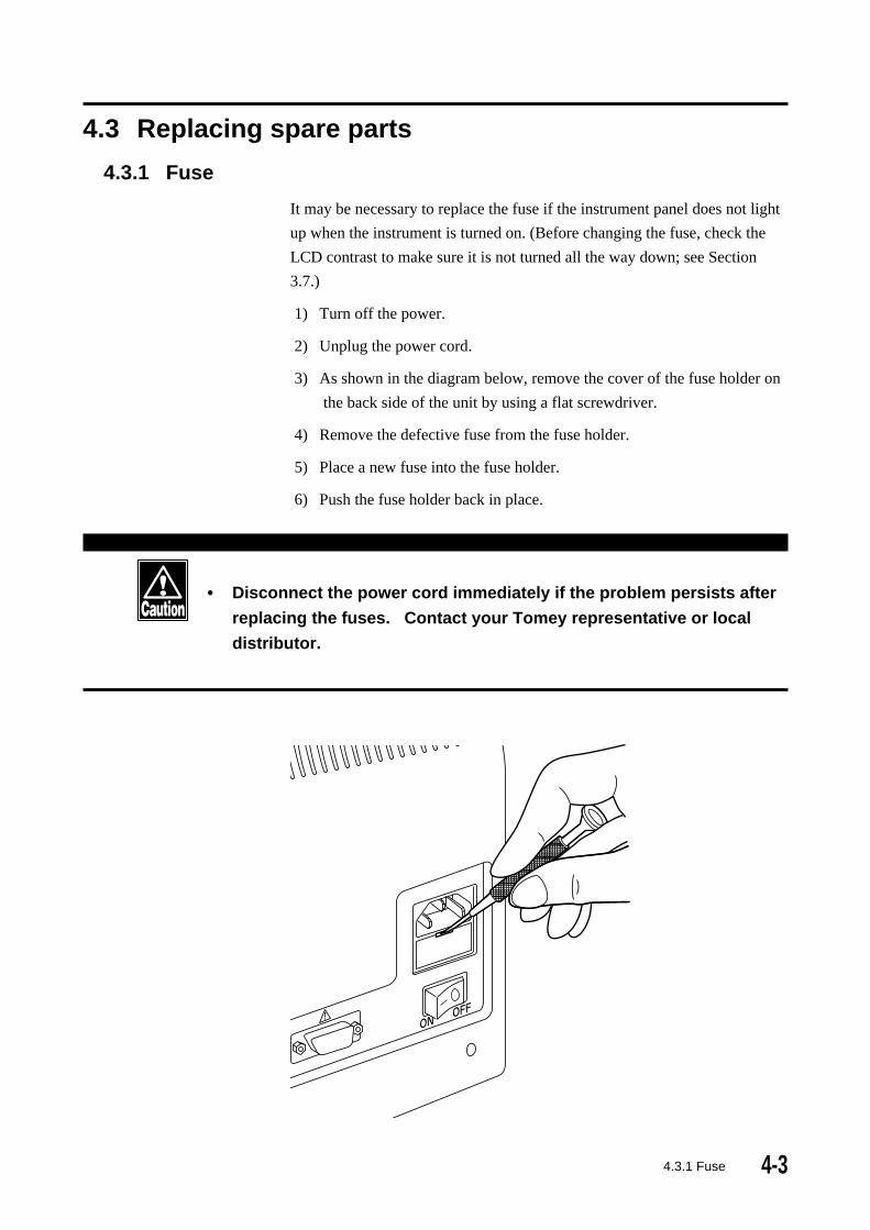
4.3.1 Fuse
It may be necessary to replace the fuse if the instrument panel does not light
up when the instrument is turned on. (Before changing the fuse, check the
LCD contrast to make sure it is not turned all the way down; see Section
3.7.)
1) Turn off the power.
2) Unplug the power cord.
3) As shown in the diagram below, remove the cover of the fuse holder on
the back side of the unit by using a flat screwdriver.
4) Remove the defective fuse from the fuse holder.
5) Place a new fuse into the fuse holder.
6) Push the fuse holder back in place.
• Disconnect the power cord immediately if the problem persists after
replacing the fuses. Contact your Tomey representative or local
distributor.
4.3.1 Fuse
������������������������������������������
������������������������������������������
������������������������������������������
������������������������������������������
������������������������������������������
������������������������������������������
������������������������������������������
������������������������������������������
������������������������������������������
������������������������������������������
������������������������������������������
������������������������������������������
������������������������������������������
������������������������������������������
������������������������������������������
������������������������������������������
������������������������������������������
������������������������������������������
������������������������������������������
������������������������������������������
������������������������������������������
������������������������������������������
������������������������������������������
������������������������������������������
������������������������������������������
������������������������������������������
������������������������������������������
������������������������������������������
������������������������������������������
4-4
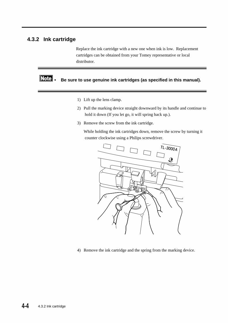
4.3.2 Ink cartridge
Replace the ink cartridge with a new one when ink is low. Replacement
cartridges can be obtained from your Tomey representative or local
distributor.
• Be sure to use genuine ink cartridges (as specified in this manual).
1) Lift up the lens clamp.
2) Pull the marking device straight downward by its handle and continue to
hold it down (If you let go, it will spring back up.).
3) Remove the screw from the ink cartridge.
While holding the ink cartridges down, remove the screw by turning it
counter clockwise using a Philips screwdriver.
4) Remove the ink cartridge and the spring from the marking device.
4.3.2 Ink cartridge
4-5
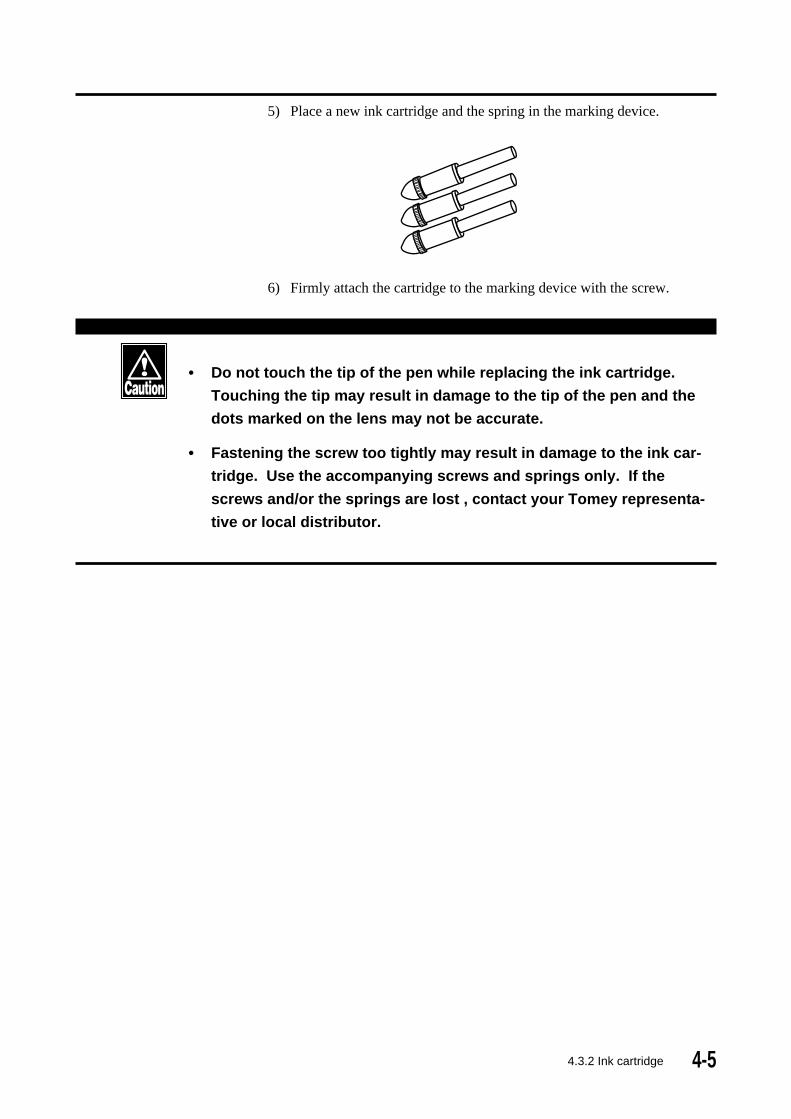
5) Place a new ink cartridge and the spring in the marking device.
6) Firmly attach the cartridge to the marking device with the screw.
• Do not touch the tip of the pen while replacing the ink cartridge.
Touching the tip may result in damage to the tip of the pen and the
dots marked on the lens may not be accurate.
• Fastening the screw too tightly may result in damage to the ink car-
tridge. Use the accompanying screws and springs only. If the
screws and/or the springs are lost , contact your Tomey representa-
tive or local distributor.
4.3.2 Ink cartridge

4-6
4.3.3 Replacing the printer paper
Replace the paper when red lines appear on both sides of the paper.
• Be sure to use the genuine printer paper (specified below).
Model : TP-102C-2
Manufacturer: Seiko Electric Co. Ltd. JAPAN
1) Open the printer cover by pressing down on the latch at the top of the
cover and pulling the cover outward.
2) To remove the printing paper that remains, advance the paper by
pressing the PRINT button.
3) Cut the edge of the new roll of paper straight using scissors.
4) Put the new roll into the resessed area of the printer unit as shown
below.
5) Insert the end of the paper through the paper outlet.
6) Press the PRINT button to advance the paper.
7) Close the printer cover.
4.3.3 Replacing the printer paper

4-7
4.4 Storage
• Do not store this instrument in a location where it might be exposed
to water.
• Avoid excessive atmospheric pressure, high temperature, excessive
humidity, poor ventilation, direct sunlight, dust, salt or sulfur in the
air.
• Ascertain that factors such as excessive slope, vibration and impact
will not endanger the instrument (including during transportation).
• Do not store this instrument near chemical substances or in a loca-
tion where the gas may be generated.
4.5 Packing materials
• Keep the containers and packing materials for future use.
• If you discard the packing materials, be sure to comply with local
ordinances and regulations.
4.4 Storage/4.5 Packing materials

4-8
(This page is left intentionally blank.)

5-1
5. TROUBLESHOOTINGBefore calling service personel, check the following and restart the unit
(turn power OFF, then ON).
• Do not attempt measures other than those described below.
• If the problems persist after checking the following, stop using the
unit and immediately contact your Tomey representative for inspec-
tion or repair.
5.1 Troubleshooting guide
5.1.1 General operation
1) The LCD does not light up after turning ON.
Cause 1: Failure in connecting the power cord.
Action: Insert the female end of the power cord securely into the
AC inlet terminal of the instrument.
Insert the male end of the power cord securely into an AC
outlet.
Cause 2: The fuse is blown.
Action: Replace with a new fuse (See Section 4.3.1, Fuse)
Cause 3: Improper adjustment of the screen contrast.
Action: Adjust the contrast of the screen properly by using the
contrast adjuster at the lower right of the operation panel
(see Section 3.7, Controlling the LCD contrast).
2) Freezes at the initial screen.
Cause 1: There was an object on the nose piece when the instrument was
turned ON.
Action: Remove the object from the nose piece and press any
button.
Cause 2: The nose piece is not seated properly.
Action: Seat the nose piece properly and press any button.
Cause 3: The cover glass under the nose piece is not clean.
Action: Turn off the power. Remove the nose piece and then
clean the cover glass. Replace the nose piece and turn
the power on again.
5.1.1 General operation

5-2 5.1.1 General operation
3) "INITIAL ERR!" is displayed.
Cause 1: A lens was on the nose piece when the power was turned on.
Action: Remove the lens and press any button.
Cause 2: The nose piece is not seated properly.
Action: Seat the nose piece properly and press any button.
Cause 3: The cover glass under the nose piece is not clean.
Action: Turn off the power. Remove the nose piece and clean the
cover glass. Replace the nose piece and turn the power
on again.
Cause 4: Turn on the power with the CL nose piece.
Action: Turn off the power and replace the CL nose piece to the
regular nose piece then turn on the power.
4) a) The S, C or A value is not ZERO (0.00) with no lens on the
nose piece.
b) The readings are inaccurate.
Cause 1: The nose piece is not seated properly.
Action: Seat the nose piece properly.
Cause 2: The cover glass under the nose piece is not clean.
Action: Turn off the power. Remove the nose piece and clean the
cover glass. Replace the nose piece and turn the power
on again.
Cause 3: When the measurement mode is not CL mode, the CL nose
piece is on the cover glass.
Action: Replace the nose piece to the regular nose piece.
5) Printer does not work when the PRINT button is pushed.
Cause 1: PRINT setting is OFF.
Action: Set PRINT setting ON. (See Section 3.4, Setup Menu 1.)
Cause 2: Printer paper has been installed incorrectly, with the wrong side
up.
Action: Install the paper correctly. (See to Section 4.3.4.)

5-35.1.1 General operation
6) Print density is too light or too dark.
Cause 3: Setting of the print density is not appropriate.
Action: Change the setting
(See 3.4 Setup, Setup Menu 5)
7) PD values are not displayed when moving the nose block.
Cause 1: The nose block has not been reset.
Action: Move the nose block all the way to the left end (stopper
5-4 5.1.2 Progressive addition lens measurement
position) before starting PD measurement.
Cause 2: "PD measure" setting is OFF.
Action: Set "PD measure" parameter ON. (See Section 3.4, Setup
Menu 4.)

5-55.1.2 Progressive addition lens measurement
5.1.2 Progressive addition lens measurement
1) The cursor cannot be centered in the progressive channel.
Cause 1: With progressive lenses which have a small power difference
between the far point area and the near point area, aligning the
cursor to the center may not be achievable.
Action : The beginning of the progressive channel is located in
approximately the center of the lens or the center in the
frame. Take measurement around that position and press
the HOLD button.
2) The cursor cannot be centered in the far point area.
Cause 1: Progressive lenses are sometimes dispensed for intermediate
and near correction only. In such lenses, the progressive area
extends into the far point area and it is difficult to accurately
measure the far point area.
Action: Take a reading near the top of lens.
Slightly move the lens back and forth, right and left, near
the central top portion of the lens. Regard the area where
the SPH value varies the least as the measurement of the
far point area. Press the HOLD button when this location
is found.
3) The near point area is not detected. (The cursor does not
change to " " or " " .)
Cause 1: The near point area is NOT automatically detected if the ADD
power is less than 1.0 diopter.
Action: Press the HOLD button when judging the highest
addition value when the cursor is in the progressive zone.
Cause 2: The near point area in frame lenses with a long progressive
zone may be positioned very near the edge of the frame or even
outside of the frame. It may not be possible to detect the near
point in such lenses.
Action: Press the HOLD button when judging the highest

5-6
addition value when the cursor is in the progressive zone.
Cause 3: The near point area in a small frame lens may be positioned
very near to the edge of the frame or even outside of the frame.
It may not be possible to detect the near point area in such lenses.
Action: Press HOLD button when judging the highest addition
value when the cursor is in the progressive zone.
4) The ADD readings are significantly lower (> 0.5 diopters) than
the nominal values.
Cause 1: The far point area was not measured properly.
Action : With some lenses, the far point area may not be measured
accurately if AUTO HOLD mode is used. Disable the
AUTO HOLD mode in the menu Setup (See Section 3.4,
Setup Menu 3), and measure the far point area manually.
5.1.2 Progressive addition lens measurement
ADD (nominal)
ADD (measurement)
ADD (measurement) < ADD (nominal)
-1.00 D
0.00 D
Tot
al r
efra
ctiv
e po
wer
(S
+AD
D)
Location in the progressive extent
Change of mark
Use this value as the ADD.
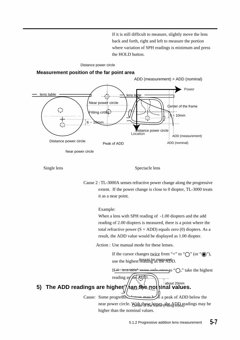
5-75.1.2 Progressive addition lens measurement
If it is still difficult to measure, slightly move the lens
back and forth, right and left to measure the portion
where variation of SPH readings is minimum and press
the HOLD button.
Measurement position of the far point area
6 ~ 10mm
Fitting cross
Near power circle
Distance power circle
lens table
6 ~ 10mm
Center of the frame
Distance power circle
lens table
Single lens Spectacle lens
Cause 2 : TL-3000A senses refractive power change along the progressive
extent. If the power change is close to 0 diopter, TL-3000 treats
it as a near point.
Example:
When a lens with SPH reading of -1.00 diopters and the add
reading of 2.00 diopters is measured, there is a point where the
total refractive power (S + ADD) equals zero (0) diopters. As a
result, the ADD value would be displayed as 1.00 diopter.
Action : Use manual mode for these lenses.
If the cursor changes twice from “+” to “ ” (or “ ”),
use the highest reading as the ADD.
If the cursor changes only once to “ ,” take the highest
reading as the ADD.
5) The ADD readings are higher than the nominal values.
Cause: Some progressive lenses may have a peak of ADD below the
near power circle. With these lenses, the ADD readings may be
higher than the nominal values.
Near power circle
Peak of ADD
Distance power circle
ADD (nominal)
ADD (measurement)
ADD (measurement) > ADD (nominal)
Power
Location
about 20mm
Center of the frame (Fitting cross)
Area to be measured
lens table
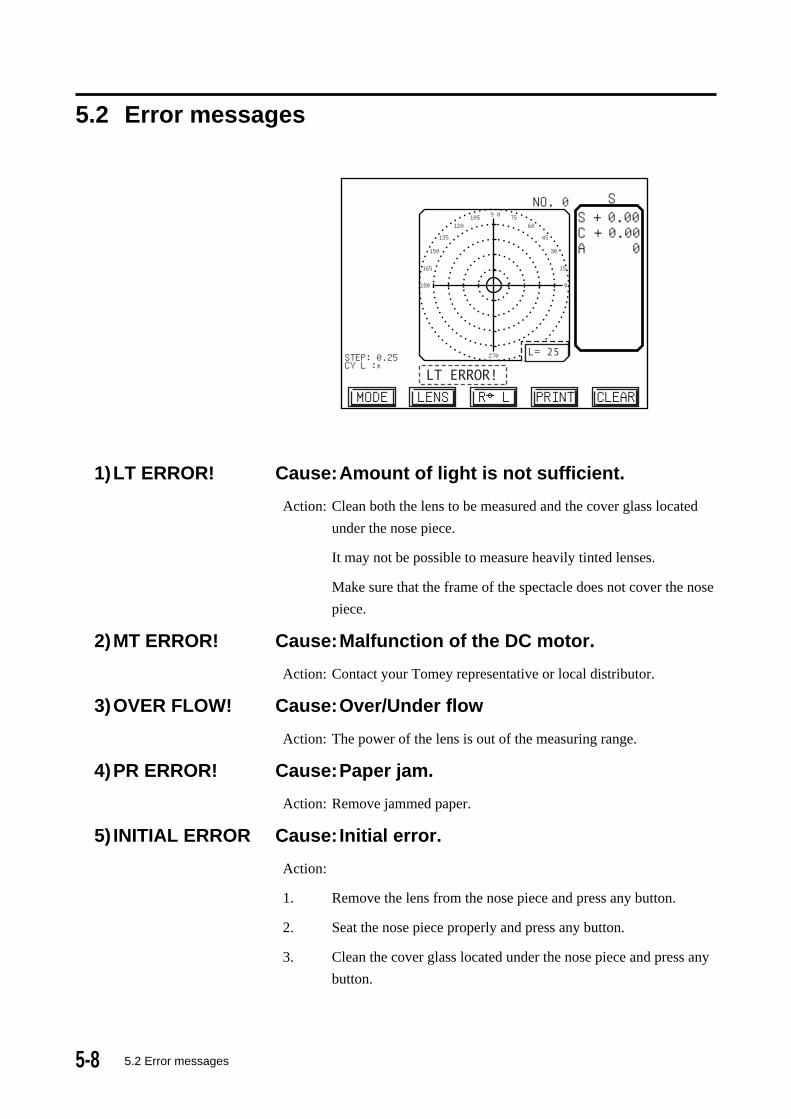
5-8
5.2 Error messages
STEP:0.25CYL : ±
180 0
165 15
150 30
135 45
120 60105 7590
270
HI
NO. 0 S
MODE
S + 0.00C + 0.00A 0
LENS R←→L PRINT CLEAR
L= 25
1)LT ERROR! Cause:Amount of light is not sufficient.
Action: Clean both the lens to be measured and the cover glass located
under the nose piece.
It may not be possible to measure heavily tinted lenses.
Make sure that the frame of the spectacle does not cover the nose
piece.
2)MT ERROR! Cause:Malfunction of the DC motor.
Action: Contact your Tomey representative or local distributor.
3)OVER FLOW! Cause:Over/Under flow
Action: The power of the lens is out of the measuring range.
4)PR ERROR! Cause:Paper jam.
Action: Remove jammed paper.
5) INITIAL ERROR Cause:Initial error.
Action:
1. Remove the lens from the nose piece and press any button.
2. Seat the nose piece properly and press any button.
3. Clean the cover glass located under the nose piece and press any
button.
5.2 Error messages

5-9
6)MODE ERROR! Cause:Mismatch of the measurement mode and
the nose piece.
Action: Check the measurement mode and the nose piece. Make sure the
measurement mode and the nose piece are match to measure the
lens.
5.2 Error messages
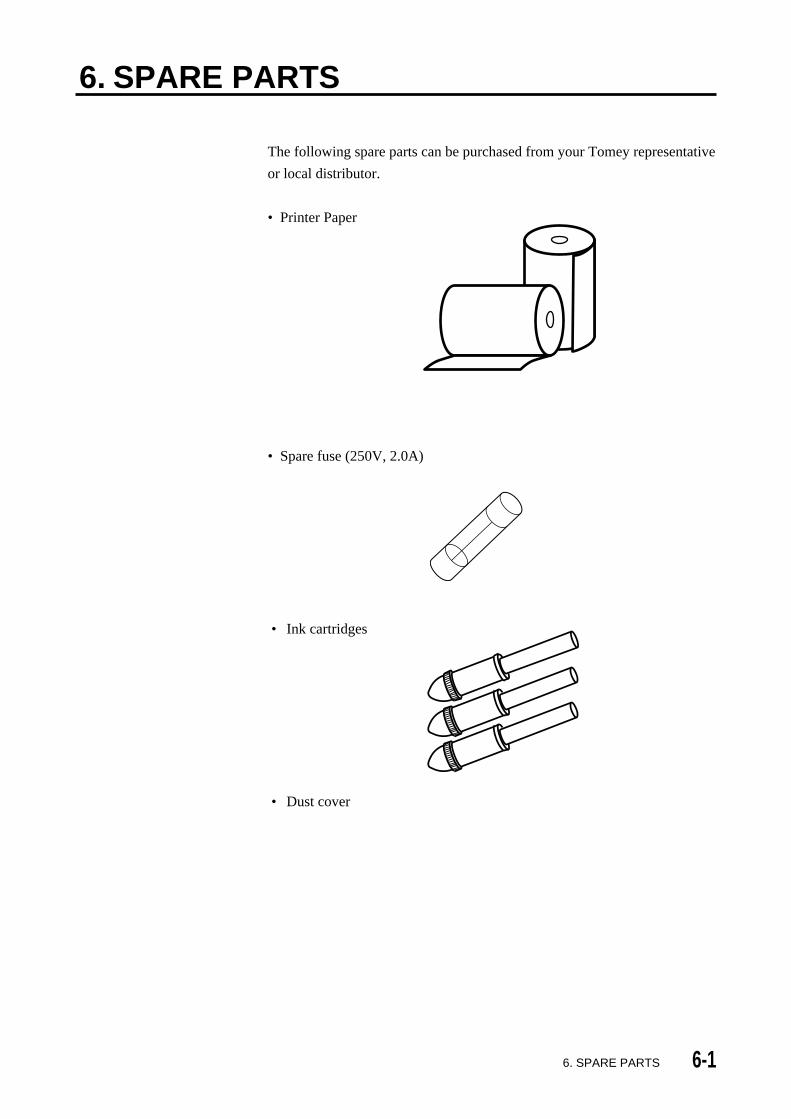
6-1
6. SPARE PARTS
The following spare parts can be purchased from your Tomey representative
or local distributor.
• Printer Paper
• Spare fuse (250V, 2.0A)
• Ink cartridges
• Dust cover
6. SPARE PARTS

6-2
(This page is left intentionally blank.)

7-17. SPECIFICATIONS
7. SPECIFICATIONS7.1 Measurement
• Range
Spherical power (S): ± 25D
High power : ± 80D
Cylindrical power (C): ±10D
Axis of cylindrical power (A): 0 to 180 degrees
Addition reading (ADD): 0 to 10 D
Prism power (P reading): 0 to 10 ƥ Units
Power: 0.01/0.12/0.25 D
Prism: 0.01/0.12/0.25 ƥ Modes
Cylinder: + / ± / –
Prism: Rectangular Coordinates
Polar coordinates
Displacement
• Lens types: Single vision lenses, Bi-focals,
Trifocals, and Progressives
• Sampling speed: 0.035 seconds
• Measurement wavelength: 660 nm
• Diameter of the beam: 2.5/5.0 mm
• Pupilary Distance (PD): 50 to 86 mm
• Lens diameter: 20 to 100 mm
• Abbe numbers: 30 to 60 (5-unit increment)
(30,35,40,45,50,55,60)
7.2 Data control• Display: Monochrome LCD display
(320 x 240 pixels)
• Alignment: Cross cursor
(Thickens when lens is aligned.)
• Printer: Thermal printer (MTP type)
• External communication port: RS-232C
7-2
7.3 Physical dimensions and electrical requirements• Dimensions: 220 (W) x 259.5 (D) x 437.5 (H) mm
[ 8.7 (W) x 10.2 (D) x 17.2 (H) in ]
• Weight: approx. 6.8 Kg (14.9 lbs)
• Main supply voltage: 100 to 240 V AC
(adjusts automatically)
• Power consumption: 35 VA
• Frequency: 50/60 Hz
7.4 Environmental conditions• Installation site: indoor
• Operating temperature range: +10°C to + 40°C (+ 50 °F +104 °F)
maximum relative humidity 80% for
temperatures up to 31°C decreasing
linearly to 50% relative humidity at
40°C
• Main supply voltage fluctuations: ±10% of the normal voltage
• Installation Category: II
• Pollution degree: 2 (based on IEC664)
7.5 Approved international standards• Electrical safety: IEC -1010-1; +A1; +A2
• Electromagnetic compatibility: EN61326EN61000-3-2EN61000-3-3
FCC (Part15 Class B)
7. SPECIFICATIONS

8-18. INDEX
8. INDEXA
Abbe number 1-5 3-30, 3-46
AC power terminal 2-2
ADD 1-4
Approved international standards 7-2
AXIS (A) 1-4
Auto CL 3-32, 3-46, 3-51
AUTO R/L 3-6, 3-46, 3-51
AUTO FAR 3-15, 3-16, 3-18, 3-46, 3-51
AUTO PROG 3-46, 3-51
BBAS (in prism mode) 1-4, 3-27
BEEP 3-46, 3-52
Bifocal lenses 3-10, 3-49
Buttons 2-4
CCL holder 3-34
Clamp 2-1, 3-42
Contrast adjustment 3-58
CYL (C) 1-4, 3-46
DD 1-4
Data communication 3-57
Data control 7-1
Detecting progressive lenses 3-37
Dimensions 7-2
EElectrical requirements 7-2
Environmental conditions 7-2
ERROR INIT ERR 5-8
ERROR LT 5-8
Error messages 5-8
ERROR MT 5-8
ERROR OV 5-8
ERROR PR 5-8
Explanation of terms 1-4
External output terminal (RS-232C) 2-2
FFar point area 3-12
Fuse 4-3
Fuse holder 2-2, 4-3
HHI 1-4
HI mode 1-4, 3-30
HOLD button 2-1, 2-4
High Power Mode (HP mode) 3-31
High Index 3-30, 3-48
IINITIAL ERR! 3-2, 5-2
Initial screen 3-1
Ink cartridge 4-4
International standards 7-2
Interpupillary distance 3-18
LLCD 2-1
LCD contrast adjustment 3-58
LENS button 3-10
Lens table 2-1, 3-44
Lever 2-1, 3-44
MMAINTENANCE 4-2
Marking device 2-1, 3-43
Measuring bifocal and trifocal lenses 3-15
Measuring contact lenses 3-32
Measuring framed lenses 3-6
Measuring high index lenses 3-30
Measuring interpupillary distance 3-18
Measuring methods 3-3
Measuring prism 3-26
Measuring progressive addition lenses 3-11, 5-4
Measuring single vision lenses 3-3
MODE button 2-4
MULTI-FOCAL MODE 3-10, 3-46, 3-49
NNear point area 3-13
Nose piece 2-1, 3-1
OOne-Year Limited Warranty 4-1
PPacking materials 4-7
Power Saving function 3-59
Printout 3-49, 3-56
Printer paper 4-6
PROG mode 3-11, 3-46
PSM 1-4, 3-26, 3-48
Px, Py (in prism mode) 1-4, 3-26, 3-48
PD measure 3-18, 3-52
8-2 8. INDEX
RReplacing spare parts 4-3
Routine maintenance 4-2
RS-232C 2-2, 3-57
SSafety precautions 1-1
Screen layout 2-3
Setup 3-45
Single lenses 3-3
SINGLE mode 3-3, 3-52
Single vision lenses 3-3
SINGLE VISION MODE 3-3, 3-49
Spare parts 4-3
SPECIFICATIONS 7-1
SPH (S) 1-4
STEP 3-48
Storage 4-7
TTrifocal lenses 3-15, 3-49
Troubleshooting guide 5-1
UUnpacking 1-3
UV check 3-38, 3-52
WWarranty 4-1
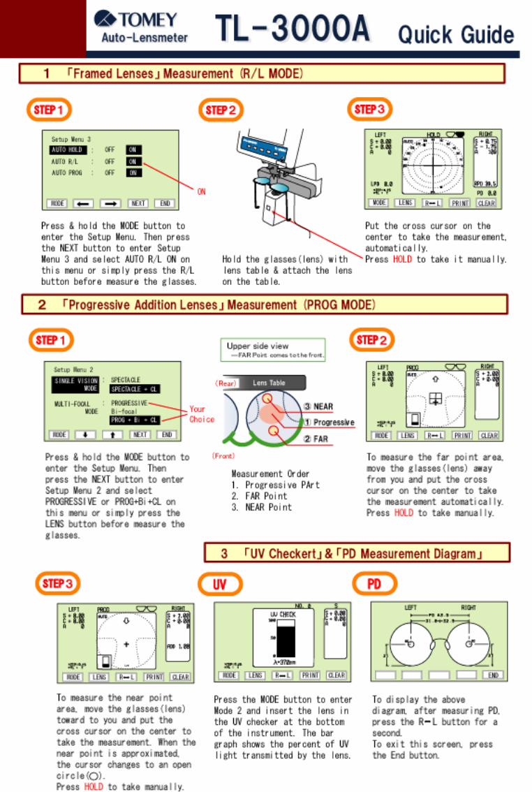
Related Documents