Featuring Trus Joist ® TJ ® Shear Braces for engineered and prescriptive applications #TJ-8620 SPECIFIER’S GUIDE WoodBYWY.Com 1.888.453.8358 TJ ® SHeaR BRaCe Field Trimmable ! •prefabricated Shear Wall engineered for performance, designed for Safety •Quick and Simple to install •perfect for narrow Wall Sections •Tall Shear Braces for Walls up to 20' •Complies with 2009 iBC/iRC •limited product Warranty

Welcome message from author
This document is posted to help you gain knowledge. Please leave a comment to let me know what you think about it! Share it to your friends and learn new things together.
Transcript

Featuring Trus Joist® TJ® Shear Braces for engineered and prescriptive applications
#TJ-8620 SPECIFIER’S GUIDE
WoodBYWY.Com 1.888.453.8358
TJ® SHeaR BRaCe
Field Trimmable !
• prefabricated Shear Wall engineered for performance, designed for Safety
• Quick and Simple to install
• perfect for narrow Wall Sections
• Tall Shear Braces for Walls up to 20'
• Complies with 2009 iBC/iRC
• limited product Warranty

available Kits (see page 4 for parts lists and descriptions)• anchor kit: Required for all braces except those in the second story.• portal kit: Required for brace-to-header connections. Portal kits are included with all braces that
are 100" or less in height. Order straps separately for braces taller than 100".• multistory kit (mSK): Required for stacked-brace applications.
Trus Joist® TJ® Shear Brace Specifier's Guide TJ-8620 | July 2012
2
Available Shear Braces and Kits 2Shear Brace Applications 3Kit and Accessory Descriptions 4engineered design information Engineered Design General Assumptions 5 Single Portal 8 Double Portal 9 Portal 9 Overturning Forces 13allowable loads Stand-Alone Brace 6–7 Allowable Out-of-Plane Lateral Loads 8 Double Portal Frames 10 Single Portal Frames 11 Stacked Shear Braces 12installation details Installation 14, 17–18 Trim Zones and Allowable Holes 14 Screw Spacing Options 15 Portals 16anchorage Anchor Bolt Installation 19 Anchorage Embedment Depths 20 Anchorage Details 21–23prescriptive design information Wall Bracing 24 Bracing Requirements 25 Brace Example – Wind 25 Brace Example – Seismic 26 Portals and Portal Header Sizing Table 27 TJ® Garage Portal System 28 Anchorage 29 Alternate Anchorage for 12"
and 18" Shear Braces 29
TaBle oF ConTenTS
The products in this guide are readily available through our nationwide network of distributors and dealers. For more information on other applications or other Trus Joist® products, contact your Weyerhaeuser representative.
available TJ® Shear Braces
TJ® Shear Brace Width Height(1)Weight
(lbs)
portal Kit (included with
Brace)Typical
applicationsTJSB 12x7 12" 78" 100 Yes
First story onlyTJSB 12x7.5 12" 85½" 110 YesTJSB 12x8 12" 93¼" 115 Yes
TJSB 12x9 12" 105¼" 125 First or second story(2)
TJSB 12x10 12" 117¼" 135First story onlyTJSB 12x11 12" 129¼" 150
TJSB 12x12 12" 141¼" 160TJSB 18x7 18" 78" 145 Yes
First story onlyTJSB 18x7.5 18" 85½" 155 YesTJSB 18x8 18" 93¼" 165 YesTJSB 18x9 18" 105¼" 180
First or second story(2)
TJSB 18x10 18" 117¼" 200TJSB 18x11 18" 129¼" 215TJSB 18x12 18" 141¼" 235TJSB 18x13 18" 153¼" 250
First story onlyTJSB 18x20 18" 240" 385TJSB 24x8 24" 93¼" 220 Yes First story onlyTJSB 24x9 24" 105¼" 240
First or second story(2)
TJSB 24x10 24" 117¼" 265TJSB 24x11 24" 129¼" 290TJSB 24x12 24" 141¼" 315TJSB 24x13 24" 153¼" 340
First story onlyTJSB 24x20 24" 240" 515
WHaT iS THe TRuS JoiST® TJ® SHeaR BRaCe?The TJ® Shear Brace (TJSB) is a specially designed, prefabricated, engineered-wood panel that helps structures resist lateral forces such as those created by earthquakes and high winds. The International Residential Code (IRC) and International Building Code (IBC) require wall bracing for lateral loads in all structures. The TJ® Shear Brace can help you meet those requirements efficiently and confidently with the following features:
• Field adjustable—can be trimmed and drilled
• Suitable for residential, multifamily, and light commercial construction
• Narrow panel widths have high allowable loads
• Works in tall wall and multistory applications
• 12" braces up to 9' tall and 18" and 24" braces up to 12' tall can be substituted for field-built, prescriptive wall bracing
(1) For heights not listed, order the next taller brace and trim to fit. minimum trimmed height is 74½".
(2) For stacked braces, see page 12 for requirements and limitations.• All braces come standard with two pre-attached holdowns, two slotted
nuts, two washers, 6¾" screws, and an installation guide.• All braces are 3½" thick.
Brace naming SystemTJSB 18x8
Nominal height (ft.) Width (in.) TJ® Shear Brace
Code evaluation: See iCC eS eSR-2652 and RR-25730
2

Trus Joist® TJ® Shear Brace Specifier's Guide TJ-8620 | July 2012
3
TJ® SHeaR BRaCe appliCaTionS
Stand-alone applications• Narrow wall spaces• Wall heights up to 20'
Stacked applications• Narrow wall spaces• Multistory installation kit
(MSK) required (order separately)
• Total assembled heights up to 24'
portal applications• Narrow wall spaces• Garages• Large windows and doors• Increased capacities when
used in a portal
Resists bowing, twisting, and shrinking
easy header connections mSK for stacked
applications, includes upper holdownsField drillable
and trimmable
Convenient chase for wiring
Simple connection to foundation for all applications
Portal Application
Tall Wall Application
Stacked Application
Stand-Alone Application
Stacked Application
TJ® Shear Braces may be trimmed in all applications. See pages 14,
16, and 18 for details.
Field drillable and trimmable
Field drillable and trimmable
Trus Joist® TJ® Shear Brace Specifier's Guide TJ-8620 | July 2012
4
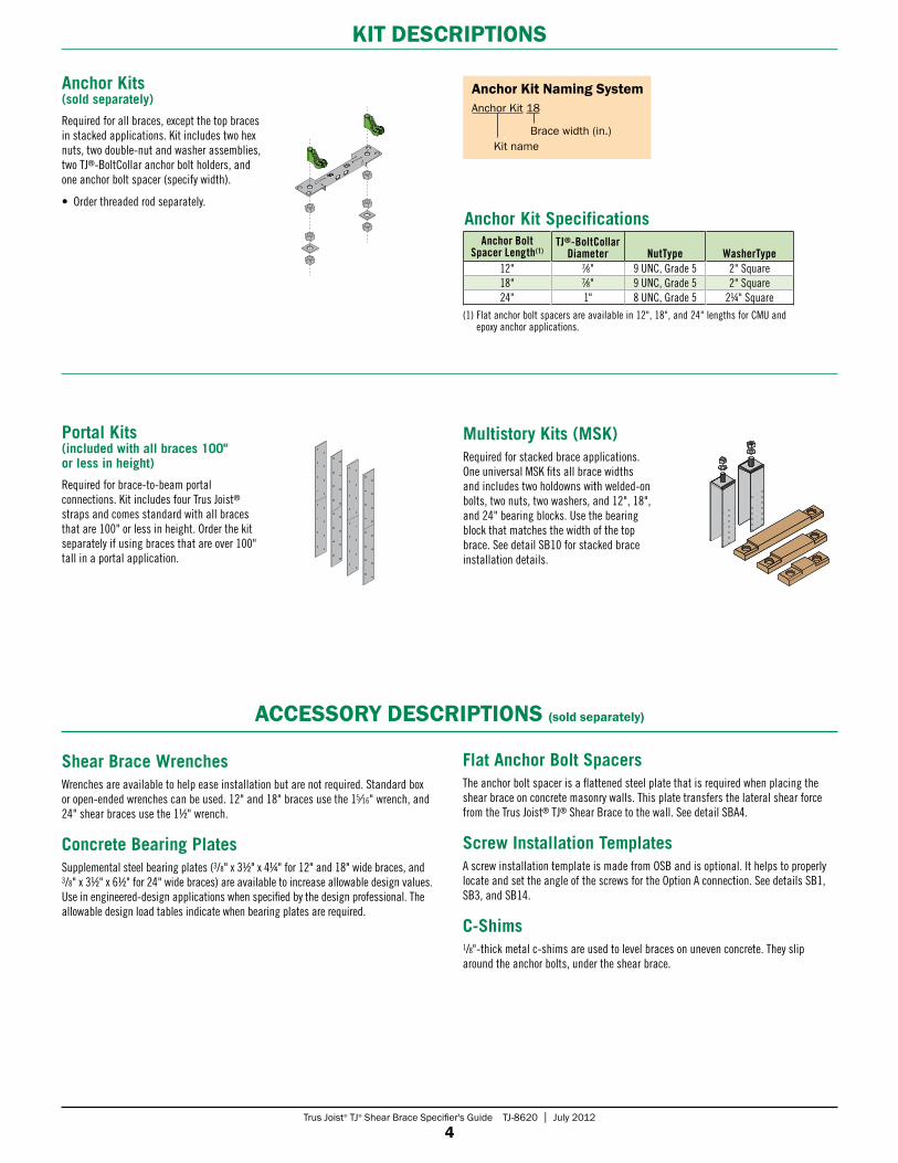
KiT deSCRipTionS
Portal Kits (included with all braces 100" or less in height)
Required for brace-to-beam portal connections. Kit includes four Trus Joist® straps and comes standard with all braces that are 100" or less in height. Order the kit separately if using braces that are over 100" tall in a portal application.
Multistory Kits (MSK)Required for stacked brace applications. One universal MSK fits all brace widths and includes two holdowns with welded-on bolts, two nuts, two washers, and 12", 18", and 24" bearing blocks. Use the bearing block that matches the width of the top brace. See detail SB10 for stacked brace installation details.
Anchor Kits (sold separately)
Required for all braces, except the top braces in stacked applications. Kit includes two hex nuts, two double-nut and washer assemblies, two TJ®-BoltCollar anchor bolt holders, and one anchor bolt spacer (specify width).
• Order threaded rod separately.
Anchor Bolt Spacer Length(1)
TJ®-BoltCollarDiameter NutType WasherType
12" 7⁄8" 9 UNC, Grade 5 2" Square18" 7⁄8" 9 UNC, Grade 5 2" Square24" 1" 8 UNC, Grade 5 2¼" Square
(1) Flat anchor bolt spacers are available in 12", 18", and 24" lengths for CMU and epoxy anchor applications.
anchor Kit naming SystemAnchor Kit 18
Brace width (in.) Kit name
Anchor Kit Specifications
Shear Brace WrenchesWrenches are available to help ease installation but are not required. Standard box or open-ended wrenches can be used. 12" and 18" braces use the 15⁄16" wrench, and 24" shear braces use the 11/2" wrench.
Concrete Bearing PlatesSupplemental steel bearing plates (3/8" x 31/2" x 4¼" for 12" and 18" wide braces, and 3/8" x 31/2" x 61/2" for 24" wide braces) are available to increase allowable design values. Use in engineered-design applications when specified by the design professional. The allowable design load tables indicate when bearing plates are required.
aCCeSSoRY deSCRipTionS (sold separately)
Flat Anchor Bolt SpacersThe anchor bolt spacer is a flattened steel plate that is required when placing the shear brace on concrete masonry walls. This plate transfers the lateral shear force from the Trus Joist® TJ® Shear Brace to the wall. See detail SBA4.
Screw Installation TemplatesA screw installation template is made from OSB and is optional. It helps to properly locate and set the angle of the screws for the Option A connection. See details SB1, SB3, and SB14.
C-Shims1/8"-thick metal c-shims are used to level braces on uneven concrete. They slip around the anchor bolts, under the shear brace.
Trus Joist® TJ® Shear Brace Specifier's Guide TJ-8620 | July 2012
5
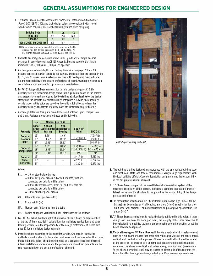
GeneRal aSSumpTionS FoR enGineeRed deSiGn
1. TJ® Shear Braces meet the Acceptance Criteria for Prefabricated Wood Shear Panels (ICC-ES AC 130), and their design values are consistent with typical wood-framed construction. Use the following values when designing:
Building Code R Ωo Cd
1997 UBC 5.5 2.8 N.A.2000 IBC 6 3(1) 4
2003, 2006, and 2009 IBC 6.5 3(1) 4
AC130 cyclic testing in the lab.
2. Concrete anchorage table values shown in this guide are for single anchors designed in accordance with ACI 318 Appendix D using concrete that has a minimum f'c of 2,500 psi or 3,000 psi, as specified.
3. Anchorage embedment depths and footing dimensions on pages 20 and 29 assume concrete breakout cones do not overlap. Breakout cones are defined by the C1, C2, and C3 dimensions. Analysis of anchors with overlapping breakout cones are the responsibility of the design professional of record. Overlapping cones can occur when braces are doubled up, wide-face to wide-face.
4. Per ACI 318 Appendix D requirements for seismic design categories C-E, the anchorage details for seismic design shown in this guide are based on the brace's anchorage attachment undergoing ductile yielding at a load level below the design strength of the concrete. For seismic design categories A-B/Wind, the anchorage details shown in this guide are based on the uplift at full allowable shear. For anchorage design, the effects of gravity loads are considered only for bearing.
5. Anchorage details in this guide consider factored holdown uplift, compression, and shear. Factored properties are based on the following:
Where:
F . . . . = 1.0 for stand-alone braces = 0.8 for 12" portal braces, 93¼" tall and less, that are connected per details in this guide = 0.9 for 18"portal braces, 93¼" tall and less, that are connected per details in this guide = 1.0 for all other portal braces
AS . . . Allowable shear per brace (lbs)
h . . . . Brace height (in.)
MA. . . Moment arm (in.); value from the table
OH . . . Portion of applied vertical load (lbs) distributed to the holdown
6. For SDC A–B/Wind, holdown uplift at allowable shear is based on loads applied at the top of the brace. Uplift calculations for multistory applications and other loading schemes are the responsibility of the design professional of record. See page 13 for a multistory design example.
7. Install products according to this specifier's guide. Changes in installation methods or modifications to the product and associated systems (other than those indicated in this guide) should only be made by a design professional of record. Altered installation procedures and the performance of modified products are the sole responsibility of the design professional of record.
8. The building shall be designed in accordance with the appropriate building code and meet local, state, and federal requirements. Verify design requirements with the local building official. Concrete foundation design remains the responsibility of the design professional of record.
9. TJ® Shear Braces are part of the overall lateral-force-resisting system of the structure. The design of this system, including a complete load path to transfer lateral forces from the structure to the ground, is the responsibility of the design professional of record.
10. In prescriptive specification, TJ® Shear Braces up to 141¼" high (105¼" for 12" braces) can be counted as 4' of bracing, and are a 1-for-1 substitution for site-built shear wall sections. For more information on prescriptive specification, see pages 24–27.
11. TJ® Shear Braces are designed to resist the loads published in this guide. If these design loads are exceeded during an event, the integrity of the shear brace should be evaluated by a qualified technical professional to determine whether or not the brace needs to be replaced.
12. Vertical Loading on TJ® Shear Braces: If there is a vertical-load transfer element, such as a rim board or beam that bears along the entire width of the brace, then a vertical load can be located anywhere. Otherwise, a vertical load must be located at the center of the brace or be a uniform load equaling a point load that does not exceed the allowable vertical load. Alternatively, a vertical load (maximum of 1/2 the allowable vertical load) may be located on either side of the center of the brace. For other loading conditions, contact your Weyerhaeuser representative.
(1) When shear braces are installed in structures with flexible diaphragms (as defined in Section 12.3.1 of the ASCE-7), Ωo may be reduced per ASCE-7, Table 12.2.1, footnote g.
Property
TJ®
Shear Brace Width
Moment Arm (MA)
SDC A-B/Wind SDC C-E
Without Supplemental
Bearing
With Supplemental
Bearing
Factored Holdown
Uplift
12" 8.69" 8.69" 17,357 lbs18" 14.56" 14.56" 32,400 lbs24" 19.31" 19.31" 39,867 lbs
Factored Compression
12" 8.69" 8.06"18" 14.56" 13.94"24" 19.31" 18.81"
Factored Shear
(per brace)
12" – – 2,417 lbs 2,417 lbs18" – – 4,928 lbs 6,722 lbs24" – – 8,320 lbs 9,871 lbs
F(1.6 x AS x h) MA
1.6(OH) + F(1.6 x AS x h)
MA
1.4(OH) + F(1.4 x AS x h)
MA
Trus Joist® TJ® Shear Brace Specifier's Guide TJ-8620 | July 2012
6
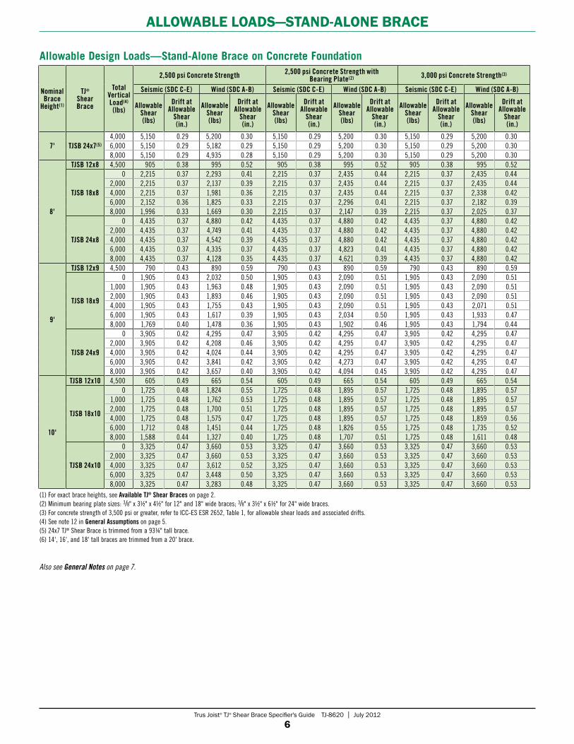
alloWaBle loadS—STand-alone BRaCe
Nominal Brace
Height(1)
TJ® Shear Brace
TotalVertical Load(4) (lbs)
2,500 psi Concrete Strength 2,500 psi Concrete Strength with Bearing Plate(2) 3,000 psi Concrete Strength(3)
Seismic (SDC C-E) Wind (SDC A-B) Seismic (SDC C-E) Wind (SDC A-B) Seismic (SDC C-E) Wind (SDC A-B)
Allowable Shear (lbs)
Drift at Allowable
Shear (in.)
Allowable Shear (lbs)
Drift at Allowable
Shear (in.)
Allowable Shear (lbs)
Drift at Allowable
Shear (in.)
Allowable Shear (lbs)
Drift at Allowable
Shear (in.)
Allowable Shear (lbs)
Drift at Allowable
Shear
(in.)
Allowable Shear (lbs)
Drift at Allowable
Shear (in.)
7' TJSB 24x7(5)
4,000 5,150 0.29 5,200 0.30 5,150 0.29 5,200 0.30 5,150 0.29 5,200 0.306,000 5,150 0.29 5,182 0.29 5,150 0.29 5,200 0.30 5,150 0.29 5,200 0.308,000 5,150 0.29 4,935 0.28 5,150 0.29 5,200 0.30 5,150 0.29 5,200 0.30
8'
TJSB 12x8 4,500 905 0.38 995 0.52 905 0.38 995 0.52 905 0.38 995 0.52
TJSB 18x8
0 2,215 0.37 2,293 0.41 2,215 0.37 2,435 0.44 2,215 0.37 2,435 0.442,000 2,215 0.37 2,137 0.39 2,215 0.37 2,435 0.44 2,215 0.37 2,435 0.444,000 2,215 0.37 1,981 0.36 2,215 0.37 2,435 0.44 2,215 0.37 2,338 0.426,000 2,152 0.36 1,825 0.33 2,215 0.37 2,296 0.41 2,215 0.37 2,182 0.398,000 1,996 0.33 1,669 0.30 2,215 0.37 2,147 0.39 2,215 0.37 2,025 0.37
TJSB 24x8
0 4,435 0.37 4,880 0.42 4,435 0.37 4,880 0.42 4,435 0.37 4,880 0.422,000 4,435 0.37 4,749 0.41 4,435 0.37 4,880 0.42 4,435 0.37 4,880 0.424,000 4,435 0.37 4,542 0.39 4,435 0.37 4,880 0.42 4,435 0.37 4,880 0.426,000 4,435 0.37 4,335 0.37 4,435 0.37 4,823 0.41 4,435 0.37 4,880 0.428,000 4,435 0.37 4,128 0.35 4,435 0.37 4,621 0.39 4,435 0.37 4,880 0.42
9'
TJSB 12x9 4,500 790 0.43 890 0.59 790 0.43 890 0.59 790 0.43 890 0.59
TJSB 18x9
0 1,905 0.43 2,032 0.50 1,905 0.43 2,090 0.51 1,905 0.43 2,090 0.511,000 1,905 0.43 1,963 0.48 1,905 0.43 2,090 0.51 1,905 0.43 2,090 0.512,000 1,905 0.43 1,893 0.46 1,905 0.43 2,090 0.51 1,905 0.43 2,090 0.514,000 1,905 0.43 1,755 0.43 1,905 0.43 2,090 0.51 1,905 0.43 2,071 0.516,000 1,905 0.43 1,617 0.39 1,905 0.43 2,034 0.50 1,905 0.43 1,933 0.478,000 1,769 0.40 1,478 0.36 1,905 0.43 1,902 0.46 1,905 0.43 1,794 0.44
TJSB 24x9
0 3,905 0.42 4,295 0.47 3,905 0.42 4,295 0.47 3,905 0.42 4,295 0.472,000 3,905 0.42 4,208 0.46 3,905 0.42 4,295 0.47 3,905 0.42 4,295 0.474,000 3,905 0.42 4,024 0.44 3,905 0.42 4,295 0.47 3,905 0.42 4,295 0.476,000 3,905 0.42 3,841 0.42 3,905 0.42 4,273 0.47 3,905 0.42 4,295 0.478,000 3,905 0.42 3,657 0.40 3,905 0.42 4,094 0.45 3,905 0.42 4,295 0.47
10'
TJSB 12x10 4,500 605 0.49 665 0.54 605 0.49 665 0.54 605 0.49 665 0.54
TJSB 18x10
0 1,725 0.48 1,824 0.55 1,725 0.48 1,895 0.57 1,725 0.48 1,895 0.571,000 1,725 0.48 1,762 0.53 1,725 0.48 1,895 0.57 1,725 0.48 1,895 0.572,000 1,725 0.48 1,700 0.51 1,725 0.48 1,895 0.57 1,725 0.48 1,895 0.574,000 1,725 0.48 1,575 0.47 1,725 0.48 1,895 0.57 1,725 0.48 1,859 0.566,000 1,712 0.48 1,451 0.44 1,725 0.48 1,826 0.55 1,725 0.48 1,735 0.528,000 1,588 0.44 1,327 0.40 1,725 0.48 1,707 0.51 1,725 0.48 1,611 0.48
TJSB 24x10
0 3,325 0.47 3,660 0.53 3,325 0.47 3,660 0.53 3,325 0.47 3,660 0.532,000 3,325 0.47 3,660 0.53 3,325 0.47 3,660 0.53 3,325 0.47 3,660 0.534,000 3,325 0.47 3,612 0.52 3,325 0.47 3,660 0.53 3,325 0.47 3,660 0.536,000 3,325 0.47 3,448 0.50 3,325 0.47 3,660 0.53 3,325 0.47 3,660 0.538,000 3,325 0.47 3,283 0.48 3,325 0.47 3,660 0.53 3,325 0.47 3,660 0.53
Allowable Design Loads—Stand-Alone Brace on Concrete Foundation
(1) For exact brace heights, see Available TJ® Shear Braces on page 2.(2) Minimum bearing plate sizes: 3/8" x 31/2" x 41/2" for 12" and 18" wide braces; 3/8" x 31/2" x 61/2" for 24" wide braces.(3) For concrete strength of 3,500 psi or greater, refer to ICC-ES ESR 2652, Table 1, for allowable shear loads and associated drifts.(4) See note 12 in General Assumptions on page 5.(5) 24x7 TJ® Shear Brace is trimmed from a 93¼" tall brace.(6) 14', 16', and 18' tall braces are trimmed from a 20' brace.
Also see General Notes on page 7.
Trus Joist® TJ® Shear Brace Specifier's Guide TJ-8620 | July 2012
7
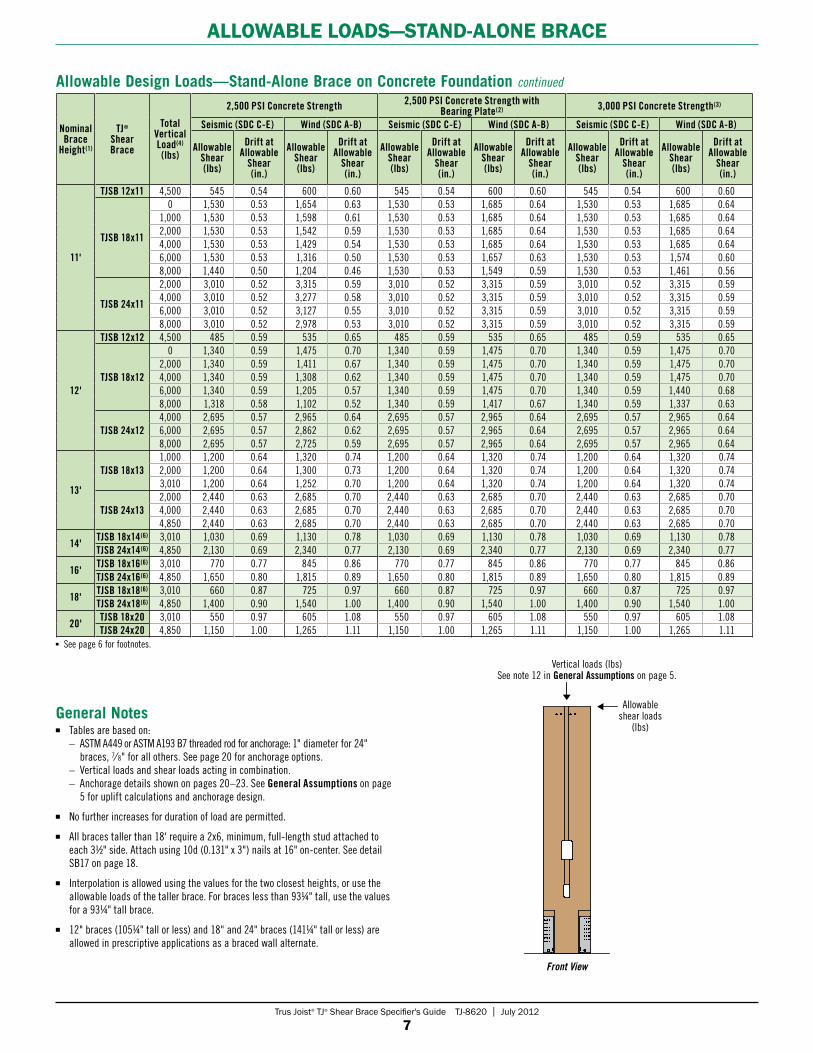
alloWaBle loadS—STand-alone BRaCe
Vertical loads (lbs) See note 12 in General Assumptions on page 5.
Allowable shear loads
(lbs)
Front View
Tables are based on: – ASTM A449 or ASTM A193 B7 threaded rod for anchorage: 1" diameter for 24"
braces, 7⁄ 8" for all others. See page 20 for anchorage options. – Vertical loads and shear loads acting in combination. – Anchorage details shown on pages 20–23. See General Assumptions on page
5 for uplift calculations and anchorage design.
No further increases for duration of load are permitted.
All braces taller than 18' require a 2x6, minimum, full-length stud attached to each 31/2" side. Attach using 10d (0.131" x 3") nails at 16" on-center. See detail SB17 on page 18.
Interpolation is allowed using the values for the two closest heights, or use the allowable loads of the taller brace. For braces less than 93¼" tall, use the values for a 93¼" tall brace.
12" braces (105¼" tall or less) and 18" and 24" braces (141¼" tall or less) are allowed in prescriptive applications as a braced wall alternate.
General Notes
Nominal Brace
Height(1)
TJ® Shear Brace
TotalVertical Load(4) (lbs)
2,500 PSI Concrete Strength 2,500 PSI Concrete Strength with Bearing Plate(2) 3,000 PSI Concrete Strength(3)
Seismic (SDC C-E) Wind (SDC A-B) Seismic (SDC C-E) Wind (SDC A-B) Seismic (SDC C-E) Wind (SDC A-B)
Allowable Shear (lbs)
Drift at Allowable
Shear (in.)
Allowable Shear (lbs)
Drift at Allowable
Shear (in.)
Allowable Shear (lbs)
Drift at Allowable
Shear
(in.)
Allowable Shear (lbs)
Drift at Allowable
Shear (in.)
Allowable Shear (lbs)
Drift at Allowable
Shear (in.)
Allowable Shear (lbs)
Drift at Allowable
Shear (in.)
11'
TJSB 12x11 4,500 545 0.54 600 0.60 545 0.54 600 0.60 545 0.54 600 0.60
TJSB 18x11
0 1,530 0.53 1,654 0.63 1,530 0.53 1,685 0.64 1,530 0.53 1,685 0.641,000 1,530 0.53 1,598 0.61 1,530 0.53 1,685 0.64 1,530 0.53 1,685 0.642,000 1,530 0.53 1,542 0.59 1,530 0.53 1,685 0.64 1,530 0.53 1,685 0.644,000 1,530 0.53 1,429 0.54 1,530 0.53 1,685 0.64 1,530 0.53 1,685 0.646,000 1,530 0.53 1,316 0.50 1,530 0.53 1,657 0.63 1,530 0.53 1,574 0.608,000 1,440 0.50 1,204 0.46 1,530 0.53 1,549 0.59 1,530 0.53 1,461 0.56
TJSB 24x11
2,000 3,010 0.52 3,315 0.59 3,010 0.52 3,315 0.59 3,010 0.52 3,315 0.594,000 3,010 0.52 3,277 0.58 3,010 0.52 3,315 0.59 3,010 0.52 3,315 0.596,000 3,010 0.52 3,127 0.55 3,010 0.52 3,315 0.59 3,010 0.52 3,315 0.598,000 3,010 0.52 2,978 0.53 3,010 0.52 3,315 0.59 3,010 0.52 3,315 0.59
12'
TJSB 12x12 4,500 485 0.59 535 0.65 485 0.59 535 0.65 485 0.59 535 0.65
TJSB 18x12
0 1,340 0.59 1,475 0.70 1,340 0.59 1,475 0.70 1,340 0.59 1,475 0.702,000 1,340 0.59 1,411 0.67 1,340 0.59 1,475 0.70 1,340 0.59 1,475 0.704,000 1,340 0.59 1,308 0.62 1,340 0.59 1,475 0.70 1,340 0.59 1,475 0.706,000 1,340 0.59 1,205 0.57 1,340 0.59 1,475 0.70 1,340 0.59 1,440 0.688,000 1,318 0.58 1,102 0.52 1,340 0.59 1,417 0.67 1,340 0.59 1,337 0.63
TJSB 24x124,000 2,695 0.57 2,965 0.64 2,695 0.57 2,965 0.64 2,695 0.57 2,965 0.646,000 2,695 0.57 2,862 0.62 2,695 0.57 2,965 0.64 2,695 0.57 2,965 0.648,000 2,695 0.57 2,725 0.59 2,695 0.57 2,965 0.64 2,695 0.57 2,965 0.64
13'
TJSB 18x131,000 1,200 0.64 1,320 0.74 1,200 0.64 1,320 0.74 1,200 0.64 1,320 0.742,000 1,200 0.64 1,300 0.73 1,200 0.64 1,320 0.74 1,200 0.64 1,320 0.743,010 1,200 0.64 1,252 0.70 1,200 0.64 1,320 0.74 1,200 0.64 1,320 0.74
TJSB 24x132,000 2,440 0.63 2,685 0.70 2,440 0.63 2,685 0.70 2,440 0.63 2,685 0.704,000 2,440 0.63 2,685 0.70 2,440 0.63 2,685 0.70 2,440 0.63 2,685 0.704,850 2,440 0.63 2,685 0.70 2,440 0.63 2,685 0.70 2,440 0.63 2,685 0.70
14'TJSB 18x14(6) 3,010 1,030 0.69 1,130 0.78 1,030 0.69 1,130 0.78 1,030 0.69 1,130 0.78TJSB 24x14(6) 4,850 2,130 0.69 2,340 0.77 2,130 0.69 2,340 0.77 2,130 0.69 2,340 0.77
16'TJSB 18x16(6) 3,010 770 0.77 845 0.86 770 0.77 845 0.86 770 0.77 845 0.86TJSB 24x16(6) 4,850 1,650 0.80 1,815 0.89 1,650 0.80 1,815 0.89 1,650 0.80 1,815 0.89
18'TJSB 18x18(6) 3,010 660 0.87 725 0.97 660 0.87 725 0.97 660 0.87 725 0.97TJSB 24x18(6) 4,850 1,400 0.90 1,540 1.00 1,400 0.90 1,540 1.00 1,400 0.90 1,540 1.00
20'TJSB 18x20 3,010 550 0.97 605 1.08 550 0.97 605 1.08 550 0.97 605 1.08TJSB 24x20 4,850 1,150 1.00 1,265 1.11 1,150 1.00 1,265 1.11 1,150 1.00 1,265 1.11
Allowable Design Loads—Stand-Alone Brace on Concrete Foundation continued
See page 6 for footnotes.

Trus Joist® TJ® Shear Brace Specifier's Guide TJ-8620 | July 2012
8
alloWaBle ouT-oF-plane laTeRal loadS—all BRaCeS
(1) Braces used in stand-alone applications (no portals) and installed according to the details in this guide.(2) Braces used in a portal application and installed according to the details in this guide.(3) Table values based on using Trus Joist® Portal Kit to resist header overturning.(4) Use a load reduction factor of 0.88 for 16" deep headers; 0.78 for 18" deep headers.
Allowable Out-of-Plane Lateral Loads (PSF)
Nominal Brace Height
Stand-Alone Brace on Concrete Foundation(1) Portal on Concrete Foundation(2)
Attached to Double Top Plate Attached to Header(3)(4) Attached to Header(3)(4)
Shear Brace Width Shear Brace Width Shear Brace Width12" 18" 24" 12" 18" 24" 12" 18" 24"
7' 275 185 14071/2' 255 170 1258' 305 300 300 230 155 115 230 155 1159' 210 210 210 205 135 105 205 135 10510' 150 150 150 150 125 90 150 125 9011' 110 110 110 110 110 85 110 110 8512' 85 85 85 85 85 75 85 85 7513' 65 6514' 50 5016' 35 3518' 25 2520' 15 15
Table is based on: – Wall deflection of L/240. – Header depth (where applicable) of 14".
No further increases for duration of load are permitted.
Out-of-plane lateral loads consider the total vertical load.
General Notes
Vertical loads (lbs)
Out-of-plane lateral loads (psf)
Side View
SinGle poRTal deSiGn
For allowable holes, see details SB2 and SB11
Use one strap on each side with a minimum uplift capacity of 500 lbs per strap
Column base with a minimum uplift
capacity of 1,000 lbsPre-cut wiring chase
Concrete design is the responsibility of the design professional of record
Header clear span
Portal straps 1/2" from edges on both sides of the brace (4 straps total per brace)
1/8" gap between brace and concrete

Trus Joist® TJ® Shear Brace Specifier's Guide TJ-8620 | July 2012
9
douBle poRTal deSiGn
Portal Header DesignBoth lateral and vertical allowable design loads shown in this guide for portal frames assume that the header size falls within the portal frame parameters listed below, and that the header and braces are connected per detail SB3, SB5, or SB12. When sizing a portal frame header for vertical load, refer to the Minimum Portal Header Size table on page 27 or the Trus Joist® Beam, Header and Column Specifier's Guide (reorder TJ-9000).
The TJ® Garage Portal system is a double portal frame consisting of two TJ® Shear Braces and a 1.55E TimberStrand® LSL header. When used in this system, a 1.55E TimberStrand® LSL header may be sized using 1.9E Microllam® LVL values only if it falls within the parameters below and meets the connection criteria stated above.
poRTal deSiGn inFoRmaTion
Using Shear Braces in Portal Frame AssembliesThe portal shear braces listed in the tables under Allowable Loads—Portal Frame on pages 10 and 11 require the brace-to-header connection details shown throughout this guide. Increased shear capacity due to the portal acting as a system has been accounted for in the Allowable Shear values, where applicable.
For portal installation details, see pages 16–18.
For drilling and trimming information, see page 14.
Induced ForcesA portal frame under lateral loads causes the portal header to experience internal stresses in addition to those created by the primary loads (like gravity and wind). These additional stresses are called induced forces and must be considered when designing portal headers.
For headers with typical residential uniform loads, the induced moment and shear forces from a portal frame system do not control the design. This is due to the 160% duration of load (DOL) factor used in design and the location of the induced stresses. See ICC ES ESR-2652 for more information.
For allowable holes, see details SB2 and SB11
Pre-cut wiring chase
Concrete design is the responsibility of the design professional of record
Portal straps 1/2" from edges on both sides of the brace (4 straps total per brace)
Header clear span
Trus Joist® TJ® Garage Portal System For increased economy in double portal frames, you can design
1.55E TimberStrand® LSL headers using 1.9E Microllam® LVL values. See Portal Header Design below.
Portal-Header Allowable Design Parameters
Header Parameter1.55E TimberStrand® LSL
in TJ® Garage Portal System (Double Portal)
All Other Headers and Applications
Width 31/2"(1) 31/8"– 51/2"Depth 9¼"–16" 9¼"–18"
Clear Span 9'–18'-6" 9'–18'-6"K(2) ≤ 265 lb/in. 90–4,000 lb/in.Fb 2,600(3) psi per TJ-9000
(1) 31/2" wide headers can be one-piece members or two 1¾" plies.(2) K = Ebd3/12L3, where E is modulus of elasticity (psi), and b, d, and L are the header width
(in.), depth (in.), and clear span (in.), respectively.(3) For 12" depths. For other depths, multiply by (12/d)0.136. Fb may be adjusted for duration of
load not to exceed a maximum value of [3,720(12/d)0.136] psi.
1/8" gap between brace and concrete, typical
Trus Joist® TJ® Shear Brace Specifier's Guide TJ-8620 | July 2012
10
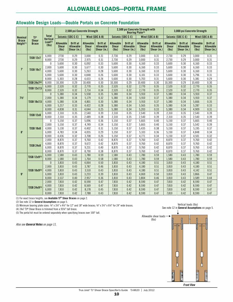
alloWaBle loadS—poRTal FRame
(1) For exact brace heights, see Available TJ® Shear Braces on page 2.(2) See note 12 in General Assumptions on page 5.(3) Minimum bearing plate sizes: 3/8" x 31/2" x 41/2" for 12" and 18" wide braces; 3/8" x 31/2" x 61/2" for 24" wide braces.(4) 24x7 TJ® Shear Brace is trimmed from a 93¼" tall brace.(5) The portal kit must be ordered separately when specifying braces over 100" tall.
Also see General Notes on page 11.
Front View
Vertical loads (lbs) See note 12 in General Assumptions on page 5.
Allowable shear loads (lbs)
Nominal Brace
Height(1)
TJ® Shear Brace
TotalVertical Load(2)
(lbs)
2,500 psi Concrete Strength 2,500 psi Concrete Strength with Bearing Plate(3) 3,000 psi Concrete Strength
Seismic (SDC C-E) Wind (SDC A-B) Seismic (SDC C-E) Wind (SDC A-B) Seismic (SDC C-E) Wind (SDC A-B)
Allowable Shear (lbs)
Drift at Allowable Shear (in.)
Allowable Shear (lbs)
Drift at Allowable Shear (in.)
Allowable Shear (lbs)
Drift at Allowable Shear (in.)
Allowable Shear (lbs)
Drift at Allowable Shear (in.)
Allowable Shear (lbs)
Drift at Allowable Shear (in.)
Allowable Shear (lbs)
Drift at Allowable Shear (in.)
7'
TJSB 12x76,000 2730 0.29 3,000 0.31 2,730 0.29 3,000 0.31 2,730 0.29 3,000 0.318,000 2730 0.29 2,975 0.31 2,730 0.29 3,000 0.31 2,730 0.29 3,000 0.31
TJSB 18x7
0 5,600 0.30 6,092 0.33 5,600 0.30 6,160 0.33 5,600 0.30 6,160 0.332,000 5,600 0.30 5,677 0.30 5,600 0.30 6,160 0.33 5,600 0.30 6,160 0.334,000 5,600 0.30 5,263 0.28 5,600 0.30 6,160 0.33 5,600 0.30 6,160 0.336,000 5,600 0.30 4,848 0.26 5,600 0.30 6,101 0.33 5,600 0.30 5,796 0.318,000 5,303 0.28 4,433 0.24 5,600 0.30 5,703 0.31 5,600 0.30 5,381 0.29
TJSB 24x7(4) 8,000 10,300 0.29 10,400 0.30 10,300 0.29 10,400 0.30 10,300 0.29 10,400 0.30
71/2'
TJSB 12x7.56,000 2,520 0.32 2,770 0.35 2,520 0.32 2,770 0.35 2,520 0.32 2,770 0.358,000 2,520 0.32 2,714 0.34 2,520 0.32 2,770 0.35 2,520 0.32 2,770 0.35
TJSB 18x7.5
0 5,380 0.34 5,558 0.35 5,380 0.34 5,910 0.37 5,380 0.34 5,910 0.372,000 5,380 0.34 5,179 0.32 5,380 0.34 5,910 0.37 5,380 0.34 5,910 0.374,000 5,380 0.34 4,801 0.30 5,380 0.34 5,910 0.37 5,380 0.34 5,666 0.356,000 5,217 0.33 4,422 0.28 5,380 0.34 5,565 0.35 5,380 0.34 5,287 0.338,000 4,838 0.31 4,044 0.25 5,380 0.34 5,203 0.33 5,380 0.34 4,909 0.31
8'
TJSB 12x86,000 2,310 0.35 2,540 0.39 2,310 0.35 2,540 0.39 2,310 0.35 2,540 0.398,000 2,310 0.35 2,489 0.38 2,310 0.35 2,540 0.39 2,310 0.35 2,540 0.39
TJSB 18x8
0 5,150 0.37 5,096 0.36 5,150 0.37 5,665 0.40 5,150 0.37 5,665 0.402,000 5,150 0.37 4,749 0.34 5,150 0.37 5,665 0.40 5,150 0.37 5,542 0.394,000 5,130 0.37 4,402 0.31 5,150 0.37 5,435 0.38 5,150 0.37 5,195 0.376,000 4,783 0.34 4,055 0.29 5,150 0.37 5,103 0.36 5,150 0.37 4,848 0.348,000 4,436 0.32 3,708 0.26 5,150 0.37 4,771 0.34 5,150 0.37 4,501 0.32
TJSB 24x8
2,000 8,870 0.37 9,760 0.42 8,870 0.37 9,760 0.42 8,870 0.37 9,760 0.424,000 8,870 0.37 9,672 0.42 8,870 0.37 9,760 0.42 8,870 0.37 9,760 0.426,000 8,870 0.37 9,231 0.40 8,870 0.37 9,760 0.42 8,870 0.37 9,760 0.428,000 8,870 0.37 8,790 0.38 8,870 0.37 9,760 0.42 8,870 0.37 9,760 0.42
9'
TJSB 12x9(5) 6,000 1,580 0.43 1,780 0.59 1,580 0.43 1,780 0.59 1,580 0.43 1,780 0.598,000 1,580 0.43 1,764 0.58 1,580 0.43 1,780 0.59 1,580 0.43 1,780 0.59
TJSB 18x9(5)
0 3,810 0.43 4,064 0.50 3,810 0.43 4,180 0.51 3,810 0.43 4,180 0.512,000 3,810 0.43 3,787 0.46 3,810 0.43 4,180 0.51 3,810 0.43 4,180 0.514,000 3,810 0.43 3,510 0.43 3,810 0.43 4,180 0.51 3,810 0.43 4,142 0.516,000 3,810 0.43 3,233 0.39 3,810 0.43 4,069 0.50 3,810 0.43 3,866 0.478,000 3,537 0.40 2,957 0.36 3,810 0.43 3,804 0.46 3,810 0.43 3,589 0.44
TJSB 24x9(5)
2,000 7,810 0.42 8,590 0.47 7,810 0.42 8,590 0.47 7,810 0.42 8,590 0.474,000 7,810 0.42 8,569 0.47 7,810 0.42 8,590 0.47 7,810 0.42 8,590 0.476,000 7,810 0.42 8,178 0.45 7,810 0.42 8,590 0.47 7,810 0.42 8,590 0.478,000 7,810 0.42 7,788 0.43 7,810 0.42 8,590 0.47 7,810 0.42 8,590 0.47
Allowable Design Loads—Double Portals on Concrete Foundation

Trus Joist® TJ® Shear Brace Specifier's Guide TJ-8620 | July 2012
11
alloWaBle loadS—poRTal FRame
Tables are based on: – ASTM A449 or ASTM A193-B7 threaded rod for anchorage; 1" diameter for 24"
wide braces, 7⁄8" for all others. See page 20 for anchorage options. – Portal header clear spans of 9' (minimum) to 18'-6" (maximum). – Vertical loads and shear loads acting in combination. – Anchorage details shown on pages 20–23. See General Assumptions on page 5
for uplift calculations and anchorage design. Allowable Shear and Drift at Allowable Shear are for the entire portal assembly.
No further increases for duration of load are permitted.
Interpolation is allowed; use the values for the two closest heights, or use the allowable loads of the taller brace. For braces less than 78" tall, use the values for a 78" tall brace.
Portal frame assemblies must be connected directly to a concrete foundation or footing.
Braces may be trimmed to a minimum height of 741/2 inches.
For shimming and furring requirements, see details on pages 16–18.
Portal braces may be used in 2x4 or 2x6 wall framing. See details SB5 and SB12 for header framing options.
12" braces (105¼" tall or less) and 18" and 24" braces (141¼" tall or less) are allowed in prescriptive applications as a braced wall alternate.
General Notes
Allowable Design Loads—Single Portals on Concrete Foundation
Nominal Brace
Height(1)
TJ® Shear Brace
TotalVertical Load(2) (lbs)
2,500 psi Concrete Strength 2,500 psi Concrete Strength with Bearing Plate(3) 3,000 psi Concrete Strength
Seismic (SDC C-E) Wind (SDC A-B) Seismic (SDC C-E) Wind (SDC A-B) Seismic (SDC C-E) Wind (SDC A-B)
Allowable Shear
(lbs)
Drift at Allowable
Shear
(in.)
Allowable Shear (lbs)
Drift at Allowable
Shear
(in.)
Allowable Shear (lbs)
Drift at Allowable
Shear (in.)
Allowable Shear (lbs)
Drift at Allowable
Shear (in.)
Allowable Shear (lbs)
Drift at Allowable
Shear (in.)
Allowable Shear (lbs)
Drift at Allowable
Shear (in.)
7'
TJSB 12x7 8,000 1,300 0.27 1,430 0.33 1,300 0.27 1,430 0.33 1,300 0.27 1,430 0.33
TJSB 18x7
0 2,800 0.31 3,046 0.36 2,800 0.31 3,080 0.36 2,800 0.31 3,080 0.362,000 2,800 0.31 2,839 0.33 2,800 0.31 3,080 0.36 2,800 0.31 3,080 0.364,000 2,800 0.31 2,631 0.31 2,800 0.31 3,080 0.36 2,800 0.31 3,080 0.366,000 2,800 0.31 2,424 0.28 2,800 0.31 3,050 0.36 2,800 0.31 2,898 0.348,000 2,652 0.29 2,216 0.26 2,800 0.31 2,852 0.33 2,800 0.31 2,690 0.31
TJSB 24x7(4)
4,000 5,150 0.29 5,200 0.30 5,150 0.29 5,200 0.30 5,150 0.29 5,200 0.306,000 5,150 0.29 5,182 0.30 5,150 0.29 5,200 0.30 5,150 0.29 5,200 0.308,000 5,150 0.29 4,935 0.28 5,150 0.29 5,200 0.30 5,150 0.29 5,200 0.30
71/2'
TJSB 12x7.5 8,000 1,200 0.31 1,320 0.38 1,200 0.31 1,320 0.38 1,200 0.31 1,320 0.38
TJSB 18x7.5
0 2,625 0.33 2,779 0.39 2,625 0.33 2,885 0.40 2,625 0.33 2,885 0.402,000 2,625 0.33 2,590 0.36 2,625 0.33 2,885 0.40 2,625 0.33 2,885 0.404,000 2,625 0.33 2,400 0.33 2,625 0.33 2,885 0.40 2,625 0.33 2,833 0.396,000 2,608 0.33 2,211 0.31 2,625 0.33 2,783 0.39 2,625 0.33 2,644 0.378,000 2,419 0.30 2,022 0.28 2,625 0.33 2,602 0.36 2,625 0.33 2,454 0.34
8'
TJSB 12x8 8,000 1,100 0.35 1,210 0.42 1,100 0.35 1,210 0.42 1,100 0.35 1,210 0.42
TJSB 18x8
0 2,450 0.36 2,548 0.41 2,450 0.36 2,695 0.43 2,450 0.36 2,695 0.432,000 2,450 0.36 2,375 0.38 2,450 0.36 2,695 0.43 2,450 0.36 2,695 0.434,000 2,450 0.36 2,201 0.35 2,450 0.36 2,695 0.43 2,450 0.36 2,597 0.416,000 2,392 0.35 2,027 0.32 2,450 0.36 2,551 0.41 2,450 0.36 2,424 0.398,000 2,218 0.33 1,854 0.30 2,450 0.36 2,385 0.38 2,450 0.36 2,250 0.36
TJSB 24x8
0 4,435 0.37 4,880 0.42 4,435 0.37 4,880 0.42 4,435 0.37 4,880 0.422,000 4,435 0.37 4,749 0.41 4,435 0.37 4,880 0.42 4,435 0.37 4,880 0.424,000 4,435 0.37 4,542 0.39 4,435 0.37 4,880 0.42 4,435 0.37 4,880 0.426,000 4,435 0.37 4,335 0.37 4,435 0.37 4,823 0.42 4,435 0.37 4,880 0.428,000 4,435 0.37 4,128 0.36 4,435 0.37 4,621 0.40 4,435 0.37 4,880 0.42
9'
TJSB 12x9(5) 8,000 790 0.43 882 0.58 790 0.43 890 0.59 790 0.43 890 0.59
TJSB 18x9(5)
0 1,905 0.43 2,032 0.50 1,905 0.43 2,090 0.51 1,905 0.43 2,090 0.512,000 1,905 0.43 1,893 0.46 1,905 0.43 2,090 0.51 1,905 0.43 2,090 0.514,000 1,905 0.43 1,755 0.43 1,905 0.43 2,090 0.51 1,905 0.43 2,071 0.516,000 1,905 0.43 1,617 0.39 1,905 0.43 2,034 0.50 1,905 0.43 1,933 0.478,000 1,769 0.40 1,478 0.36 1,905 0.43 1,902 0.46 1,905 0.43 1,794 0.44
TJSB 24x9(5)
0 3,905 0.42 4,295 0.47 3,905 0.42 4,295 0.47 3,905 0.42 4,295 0.472,000 3,905 0.42 4,208 0.46 3,905 0.42 4,295 0.47 3,905 0.42 4,295 0.474,000 3,905 0.42 4,024 0.44 3,905 0.42 4,295 0.47 3,905 0.42 4,295 0.476,000 3,905 0.42 3,841 0.42 3,905 0.42 4,273 0.47 3,905 0.42 4,295 0.478,000 3,905 0.42 3,657 0.40 3,905 0.42 4,094 0.45 3,905 0.42 4,295 0.47
See page 10 for footnotes.

Trus Joist® TJ® Shear Brace Specifier's Guide TJ-8620 | July 2012
12
allowable loads—STaCKed SHeaR BRaCeS
Allowable Design Loads for Brace in Second Floor, Stacked Application
TJ® Shear Brace
Width HeightTotal
Vertical Load (1)
(lbs)
Seismic Design Wind Design
Allowable Shear(2)
(lbs)
Drift at Allowable Shear(2)
(in.)
Allowable Shear(2)
(lbs)
Drift at Allowable Shear(2)
(in.)
TJSB 12x9(3) 12" 105¼" 2,000 500 0.44 550 0.50TJSB 18x9 18" 105¼" 2,000 1,225 0.42 1,345 0.48TJSB 24x9 24" 105¼" 2,000 2,165 0.41 2,380 0.46TJSB 18x10 18" 117¼" 2,000 1,125 0.47 1,235 0.53TJSB 24x10 24" 117¼" 2,000 1,990 0.46 2,190 0.52TJSB 18x11 18" 129¼" 2,000 1,020 0.52 1,120 0.59TJSB 24x11 24" 129¼" 2,000 1,815 0.51 1,995 0.59TJSB 18x12 18" 141¼" 2,000 920 0.57 1,010 0.64TJSB 24x12 24" 141¼" 2,000 1,640 0.57 1,805 0.65
Allowable Design Loads for Brace in First Floor, Stacked Application
TJ® Shear Brace
Width HeightTotal
Vertical Load(1)(2)
(lbs)
Kx109
(lb-in2)
Seismic Design Wind DesignAllowable Shear(3)(4)
(lbs)
Allowable Shear(3)(4)
(lbs)TJSB 18x8 18" 93¼" 4,000 9.7 2,215 2,435TJSB 24x8 24" 93¼" 4,000 19.4 4,435 4,880TJSB 18x9 18" 105¼" 4,000 10.3 1,905 2,090TJSB 24x9 24" 105¼" 4,000 21.5 3,905 4,295TJSB 18x10 18" 117¼" 4,000 11.6 1,725 1,895TJSB 24x10 24" 117¼" 4,000 22.6 3,325 3,660TJSB 18x11 18" 129¼" 4,000 12.5 1,530 1,685TJSB 24x11 24" 129¼" 4,000 24.8 3,010 3,315TJSB 18x12 18" 141¼" 4,000 12.8 1,340 1,475TJSB 24x12 24" 141¼" 4,000 26.5 2,695 2,965
(1) See note 12 in General Assumptions on page 5.(2) Maximum vertical load = second floor axial load (2,000 lbs) + first floor axial load (4,000 lbs)
= 6,000 lbs.(3) Interpolation of Allowable Shear values is allowed; use the values for the two closest
heights. Minimum brace height of 93¼" required.(4) Drift of first floor brace must comply with code drift limits. Calculate drift using the equa-
tion shown at right.
(1) See note 12 in General Assumptions on page 5.(2) Interpolation of Allowable Shear and Drift at Allowable Shear values is allowed; use the
values for the two closest heights. Minimum brace height of 105¼" required.(3) 12x9 brace does not qualify as a prescriptive braced unit in a second floor application.
Shear capacities shown are for individual braces only. To resist forces at both upper and lower floors in a two-story application, check the shear at each floor against the maximum capacity for EACH brace.
Check the overturning moment (OM) against the maximum capacity for the system. See page 13 for an example.
OM = (V2h2) + (V1h1)
V2
Vbase
h3
h1
h2
V1
h4
Maximum Allowable Base Overturning Moment(1) (in-lbs)
First Floor Brace Width
Total Vertical Load(2) (lbs)
Concrete Strength
2,500 psi 2,500 psi with Bearing Plate(3) 3,000 psi
Seismic SDC C-E
Wind SDC A-B
Seismic SDC C-E
Wind SDC A-B
Seismic SDC C-E
Wind SDC A-B
18"
0 216,115 213,845 216,115 237,740 216,115 237,7402,000 216,115 199,280 216,115 237,740 216,115 232,5554,000 215,270 184,715 216,115 228,065 216,115 217,9956,000 200,705 170,155 216,115 214,130 216,115 203,430
24"
0 413,590 455,015 413,590 455,015 413,590 455,0152,000 413,590 442,845 413,590 455,015 413,590 455,0154,000 413,590 423,535 413,590 455,015 413,590 455,0156,000 413,590 404,220 413,590 449,745 413,590 455,015
(1) Values in this table may not be interpolated.(2) See note 12 in General Assumptions on page 5.(3) Minimum bearing plate sizes: 3⁄8" x 31/2" x 4¼" for 18" wide braces and 3⁄8" x 31/2" x 61/2" for
24" wide braces.
No further increases for duration of load are permitted.
The maximum reactions for footings shown on this page are based on the information on page 20–23.
In a stacked application, use a TJ® Shear Brace on the first floor that will extend the height of the wall and the floor system. See detail SB9.
The second story brace must be the same width or narrower than the first floor brace.
When specifing the height of second floor braces, add the total floor height, including sheathing, to the wall height, then subtract 2"; see h3 at right. Maximum height for second floor braces is 141¼".
See page 17 for installation details.
See page 13 for design procedures and for allowable brace combinations for stacked shear braces in prescriptive applications.
Axial loads and shear loads are assumed to act in combination.
General Notes
Δ . . . . . . . . . . . deflection at the top of the first floor brace (in.)
h1 . . . . . . . . . . . first floor brace height: Top of concrete to the bottom of the second floor top plates (in.)
h2 . . . . . . . . . . . total assembly height: Top of concrete to the bottom of the second floor top plates (in.)
h3 . . . . . . . . . . . second floor brace height (h4 minus 2"): Top of the LSL bearing block to the bottom of the second floor top plates (in.)
h4 . . . . . . . . . . . top of first floor top plates to the bottom of the second floor top plates (in.)
V1 . . . . . . . . . . . applied shear load on first floor brace (lbs)
V2 . . . . . . . . . . . applied shear load on second floor brace (lbs)
Vbase . . . . . . . . . . V1 + V2 (lbs)
K . . . . . . . . . . .from table (lb-in2)
Δ = (3V2h3 + 2Vbaseh1)h12 K
Drift Equation for First Floor Braces
Trus Joist® TJ® Shear Brace Specifier's Guide TJ-8620 | July 2012
13
oveRTuRninG FoRCeS—STaCKed SHeaR BRaCeS
U C
h2
h1
OM =339,550in.-lb
17,639 lbs
U C
V2 =1,000 lbs
V =1,200 lbs
Vbase =2,200 lbs
24x9 TJ® Shear brace
18x9TJ® Shear brace
Given 2,500 psi, uncracked concrete
SDC D; Wind speed = 100 mph (seismic controls)
First floor wall height = 9'; shear brace choice = TJSB 24x9
Second floor wall height = 8'; joist height = 117/8"; shear brace choice = TJSB 18x9
Second floor brace shear, V2 = 1,000 lbs First floor brace shear, V1 = 1,200 lbs Shear at footing, Vbase = 2,200 lbs
Solution
1. From the Maximum Allowable Base Overturning Moment table on page 12, the maximum base overturning moment (OMmax) is: 413,590 in.-lb.
2. Compare the shear at each brace to the maximum allowable shear for each brace shown in the tables on page 12.
Second floor brace: Allowable shear for an TJSB 18x9 = 1,225 lbs > 1,000 lbs required. OK.
First floor brace: Allowable shear for an TJSB 24x9 = 3,905 lbs > 2,200 lbs (1,200 + 1,000 lbs) required. OK.
3. Calculate the required overturning moment (OM) using the shear at each floor and the floor heights:
OM = (V2h2) + (V1h1) OM = (1,000 x 213.25) + (1,200 x 105.25) = 339,550 in.-lb.
4. Compare the allowed maximum base overturning moment (from step 1) to the required overturning moment. If the capacity is exceeded, consider adding an additional brace to the first floor.
413,590 in.-lb > 339,550 in.-lb required. OK.
The stacked TJSB 18x9 and TJSB 24x9 are adequate to resist the overturning and shear forces in this example.
5. Verify the vertical load limits for each brace as shown in the tables on page 12.
6. Verify the footing requirements for the stacked shear braces. Using tables on page 20, a 40" footing and an of 13" for uncracked concrete is required.
7. Verify the drift requirements for the first floor brace. Calculate the drift from the equation on page 12, and compare it to the maximum allowable seismic drift limit. Maximum allowable drift = = 0.47" Δ = [3(1,000 x 105.25") + 2(2,200 x 105.25")] Δ = 0.41" < 0.47" OK
Elevation of stacked braces, and the structural forces developed
during lateral events.
Designing for Overturning ForcesWhen specifying stacked shear brace applications, it is important to consider overturning forces. Analysis should be performed by following these steps:
1. Analyze the structure to determine the shear forces at each floor. The detail at right illustrates the forces developed in a stacked shear brace.
2. Select a TJ® Shear Brace for each floor, and verify that the shear capacity of the brace meets or exceeds what is required. See below for more information.
3. Calculate the system’s overturning moment and shear.
4. Compare the required forces to the TJ® Shear Brace capacity.
Calculating the Overturning Resistance of a Stacked Shear BraceThe maximum overturning resistance provided by a TJ® Shear Brace depends on the footing capacity, the anchor bolt capacity, and the brace capacity. For all TJ® Shear Braces, the anchorage capacity controls. See page 12 for Maximum Allowable Base Overturning Moment. For definitions of the variables used on this page, see Drift Equation for First Floor Braces on page 12.
Design Example
V2
V1
U C
h2
h1
Vbase =OM OM =
339,550in.-lb
17,639 lbs
U C
V2 =1,000 lbs
V =1,200 lbs
Vbase =2,200 lbs
24x9 TJ® Shear brace
18x9TJ® Shear brace
h2 = 213¼"
h1 = 105¼"
(105.25")2 21.5 x 10⁹
105.25" x 2.5% 4 x 1.4
h1
Bottom TJ® Shear Brace
Top TJ® Shear BraceTJSB 18x9 TJSB 18x10 TJSB 18x11 TJSB 18x12 TJSB 24x9 TJSB 24x10 TJSB 24x11 TJSB 24x12
TJSB 18x8 W W/S W W – – – –TJSB 18x9 W W W W – – – –TJSB 18x10 W W W – – – – –TJSB 18x11 – – – – – – – –TJSB 18x12 – – – – – – – –TJSB 24x8 W/S W/S W/S W/S W/S W/S W/S W/STJSB 24x9 W/S W/S W/S W/S W/S W/S W/S W/STJSB 24x10 W/S W/S W/S W/S W/S W/S W/S W/STJSB 24x11 W/S W/S W/S W/S W/S W/S W/S W/STJSB 24x12 W/S W/S W/S W/S W/S W/S W/S W/S
Allowed Combinations for Stacked TJ® Shear Braces in Wind- or Seismic-Controlled Prescriptive Applications
W indicates allowed brace combination for SDC A-B; S indicates allowed combinations for SDC C-D2. See page 29 for prescriptive anchorage requirements. Maximum vertical load of 2,000 lbs. Bearing plates required, see page 4 for dimensions.
Trus Joist® TJ® Shear Brace Specifier's Guide TJ-8620 | July 2012
14
inSTallaTion deTailS, TRim zoneS, and alloWaBle HoleS
Stand-Alone TJ® Shear Brace Installation Allowable Small Holes—All Braces
Allowable Large Holes—All Braces (in addition to allowable small holes above)
Verify that brace is
plumb. Use metal shims
at base if required
For allowable trim, see
below
Two top plates or as specified
Threaded rod
Anchor bolt spacer (remains in
concrete)
Ensure concrete is level and smooth beneath brace. Grind or fill as necessary. DO NOT damage spacer when grinding.
Foundation system design is the responsibility of the design professional of record
Slotted nut
Washer
Holdown
sb1
sb2
sb11
Optional OSB shim, 7⁄8" maximum
Optional OSB shim, 7⁄8" maximum
OPTION B 6¾" screws (provided) installed from the top: 6 with 12" brace 8 with 18" brace 12 with 24" brace
OPTION A 6¾" screws (provided) installed from the front and back: 6 with 12" brace (3 front, 3 back) 8 with 18" brace (4 front, 4 back) 12 with 24" brace (6 front, 6 back)
Allowable Trim Trim height from the top of the brace only. Do not trim the sides or bottom. Braces may be trimmed down to a minimum height of 741/2".
No holes allowed in top 8"
12" above existing hole, minimum
FACE DRILL ZONE Center 45⁄8" of brace face as shown
No holes allowed in top 8" of brace
No edge holes allowed in lower
26" of brace
HOLES Maximum three
holes in face and three in edge
¾" diameter holes, maximum
6" o.c., minimum
HOLES 45⁄8" diameter
holes, maximum Maximum two 45⁄8"
holes or one 4¼" x 12" hole
No minimum on-center spacing required
EDGE DRILL ZONE Middle 1⁄3 of brace
thickness
FACE DRILL ZONE Maintain 11/2" min. edge distance from chase and outside edge, typical
For allowable trim, see below
Install nut finger-tight plus 1/8 turn, min.
No face holes allowed in lower 40" of brace
See detail SB14 for screw spacing information. An installation template is available from your Weyerhaeuser representative.
See detail SB14 for screw spacing information.
HOLES for 24x7 BRACE ONLY Maximum one
45⁄8" x 6" diameter hole
8" from top of brace, minimum
Visit woodbywy.com/walls/w_shear-brace.aspx for complete CAD details
Prior to placing adjacent studs or braces, tighten the slotted holdown nuts and washers. 1½" minimum clear space from the side is required to access nuts and washers.
16"
241∕8"
WARNING: Drilling, sawing, sanding or machining wood products generates wood dust, a substance known to the State of California to cause cancer.
For more information on Proposition 65, visit wy.com/inform.

Trus Joist® TJ® Shear Brace Specifier's Guide TJ-8620 | July 2012
15
SCReW SpaCinG opTionS FoR inSTallaTion deTailS
Stand-Alone Brace—Screw Option A
Multistory Brace—Screw Option A
1" min. at edge
Stand-Alone Brace—Screw Option B
Multistory Brace—Screw Option B
13/8" o.c. min.
Optional 7/8" max. OSB shim, as required
1/2" min. at chase
Offset screws between front and back to avoid interference
Section A-A
Start screw tip 31/2" (± 1/2") from bottom of double top plate or header
Install at an angle that prevents screws from exiting sides of top plates or headerDO NOT install screws in center electrical chase
Start screw at top inside edge of the countersink
Section A-A
Install at an angle that prevents screws from exiting sides of top plates or header
41/2" min. at edge 13/8" o.c. min.
Optional 7/8" max. OSB shim, as required
1/2" min. at chase
Offset screws between front and back to avoid interference
DO NOT install screws in center electrical chase
1" min. at edge
1/2" min. at chase
Section B-B1¼" min. row spacing
13/8" o.c. min.
1" min. at edge
1/2" min. at chase13/8" o.c. min.
1" min. at edge
Optional 7/8" max. OSB shim, as required
1/2" min. at chase
13/8" o.c. min.
Section B-B
Install screws before installing bearing block. Countersink (½" max.) screw heads into the top plate to allow bearing block to sit flat. If a code inspection is required for the connection, have it performed prior to installing the bearing block on top.
1/2" min. at chase
1" min. at edge
1¼" min. row spacing
13/8" o.c. min.
1" min. at edge
sb14
sb15
DO NOT install screws in center electrical chase
A
A
B
B
A
A
DO NOT install screws in center electrical chase. If a code inspection is required for the connection, have it performed prior to installing the bearing block on top.
B
B
Optional: 1" diameter countersink,
max. ¼" deep
Optional 7/8" max. OSB shim, as required
Plan View
Plan View
1" min. at edge
Optional: 1" diameter countersink,
max. ¼" deep
Start screw tip 31/2" (± 1/2") from bottom of double top plate or header
Locate center of countersink 31/2" (± 1/2") from bottom of double top plate or header
Start screw at top inside edge of the countersink
Locate center of countersink 31/2" (± 1/2") from bottom of double top plate or header
Trus Joist® TJ® Shear Brace Specifier's Guide TJ-8620 | July 2012
16
poRTal inSTallaTion deTailS
Portal Frame Shear Brace
Concentric Header Connection
Portal Frame Column
Header as specified. For 5¼" or 51/2" header, use furring as required. See detail SB5 or SB12.
Use a strap by others on each side with a minimum uplift capacity of 500 lbs per strap
TimberStrand® LSL portal column or solid sawn column (3" x 31/2" minimum) per the design professional of record. Trim as required.
Column base by others with a minimum uplift capacity of 1,000 lbs
Foundation system design is the responsibility of the design professional of record
SB3 SB4
SB5
(31⁄8"–51/2") wide x (9¼"–18") deep header as specified. Center over brace width.
Portal straps: Maintain 1/2" edge distance. Attach with sixteen nails, 10d (0.148" x 23∕8") min., 8 into header and 8 into brace. Straps are provided for braces under 100" tall. For taller braces, order straps separately.
For 5¼" or 51/2" wide headers, use a minimum 21/2" x 10" furring of 7⁄8" thick OSB. Attach furring to each side of brace with ten 8d (0.131" x 21/2") nails. With 31⁄8" wide headers, attach ¼" thick furring to one side of header.
Connect header to brace with 63⁄4" screws (provided): 6 with 12" brace (3 front, 3 back) 8 with 18" brace (4 front, 4 back) 12 with 24" brace (6 front, 6 back)
31/2" wide x 9¼"–18" deep header as specified. See details SB5 and SB12 for other header widths and allowable furring.
Portal straps: Maintain 1/2" edge distance. Attach with sixteen nails, 0.148" x 23∕8" minimum: 8 into header and 8 into brace. Straps are provided for braces under 100" tall. For taller braces, order straps separately.
Threaded rod
Anchor bolt spacer (remains in concrete)
Ensure concrete is level and smooth beneath brace. Grind or fill as necessary. DO NOT damage the spacer when grinding.
Slotted nut
Washer
Holdown
Foundation system design is the responsibility of the design professional of record
Optional OSB shim, 7⁄8" maximum
Portal Allowable Trim Trim height from the top of the brace only. Do not trim the sides or bottom. Braces may be trimmed down to a minimum height of 741/2".
Connect header to brace with 6¾" screws (provided), installed from the front and back: 6 with 12" brace (3 front, 3 back) 8 with 18" brace (4 front, 4 back) 12 with 24" brace (6 front, 6 back)
Verify brace is plumb. Use
metal shims at the base, if required.
Install nut finger-tight plus 1/8 turn, minimum
8 nails, 10d (0.148" x 23/8") min., into strap at header
6 screws for 12" brace 8 screws for 18" brace 12 screws for 24" brace
10 nails, 8d (0.131" x 21/2") min., into furring
8 nails, 10d (0.148" x 23/8") min., into strap at brace
OSB furring
Furring strips may also be attached as shown in detail SB12.
See detail SB16 for screw spacing information. An installation template is available from your Weyerhaeuser representative.
For trim zones, see below
Prior to placing adjacent studs or braces, tighten slotted holdown nuts and washers. 1½" minimum clear space from the side is required to access nuts and washers.
For multiple ply headers, connect plies using the Multiple-Member Connections for Side-Loaded Beams table in #TJ-9000, page 38.

Trus Joist® TJ® Shear Brace Specifier's Guide TJ-8620 | July 2012
17
Second floor brace height includes wall height plus total floor height; see General Notes on page 12.
inSTallaTion deTailS
Stacked Brace Installation
❷ Align 2" tall bearing block (provided) over first story brace. To help secure the block while installing the holdowns, attach block to plates with one nail in each recessed hole.
❸ Install holdowns over the bearing block and slide down the face of the TJ® Shear Brace(1). To ensure easy installation of second story brace, verify the following center-to-center bolt spacings:
81/8" for 12" braces 14" for 18" braces 20" for 24" braces
Nail holdowns to the first story brace using 10d nails, (0.148" x 21/2"). Fill all visible holes.
➍ Install second story brace using the nuts and washers provided in the multistory kit.
Ledgers and joist hangers may be attached directly to the brace. See detail SB9.
❶ Install first story brace and framing per detail SB15. If using Option B, countersink (1/2" maximum) screws into the top plate to avoid interference with the bearing block. DO NOT modify the bearing block. If a code inspection is required for the connection, have it performed prior to installing the bearing block on top.
sb 10
Portal Screw Detail
Start screw at top inside edge of the countersink
Section A-A
Install at an angle that prevents screws from exiting sides of top plates or header
3" min. at edge 13/8" o.c. min.
Optional 7/8" max. OSB shim, as required
1/2" min. at chase
Offset screws between front and back to avoid interference
DO NOT install screws in center electrical chase
A
A
DO NOT use Option B screw installation with portal applications
1/2"
sb 16
(1) With 2x6 framing, cut slots (¼" wide maximum) in the top plates to allow holdowns to pass through. DO NOT notch the double plate.
Optional: 1" diameter countersink,
max. ¼" deep
Portal straps: Maintain 1/2" edge distance. Attach with 16 nails, 10d (0.148" x 23∕8") min., 8 into header and 8 into shear brace. Straps are provided for braces under 100" tall. For taller braces, order straps separately.
Visit woodbywy.com/walls/w_shear-brace.aspx for complete CAD details
Start screw tip 31/2" (± 1/2") from bottom of double top plate or header
Locate center of countersink 31/2" (± 1/2") from bottom of double top plate or header
In-Line Shear Brace
SB9
Sill plate
TJI® joist
Joist hangerLedger
Sill plate anchor bolt (per code)
Foundation system design is the responsibility of the design professional of record
1¼" Trus Joist® TimberStrand® LSL or 11/8" Trus Joist® TJ® rim board
TJ® Shear Brace sized to include the floor system height and installed directly on the foundation
Specify brace height from the top of the foundation to the bottom of the top plate or beam. See dimension h1 on page 12.

Trus Joist® TJ® Shear Brace Specifier's Guide TJ-8620 | July 2012
18
inSTallaTion deTailS
Slope Distance a
Distance b
0:12 – 4:12 2" 3"5:12 – 8:12 11/2" 41/2"9:12 – 12:12 1/2" 51/2"
End Distance for Screws
sb 13
≥ w
w
ba
≥ w
w
Rake Wall
Maintain end distances to prevent screws from penetrating through the outer edges.
Install screws perpendicular to the top plate. End distances assume double top plate.General Notes
Actual cut length must be greater than or equal to the brace's width (w).
For slopes up to 12:12.
Walls taller than 12' must be designed for the application.
Four LTP4, MP4F, or A35 framing anchors (2 front, 2 back). Fill all nail holes.
Eight 6¾" screws provided with
the brace. Install in 2 rows of 4, and
countersink, as required. See Screw
Spacing details SB14 and SB15.
LTP4 or MP4F framing anchors
A35 framing anchors
Shear brace
Section View for 2x6 or Wider Wall
sb 12
Portal straps: Maintain 1/2" edge distance. Attach with 16 nails, 10d (0.148" x 23∕8") min.: 8 into header and 8 into shear brace. Straps are provided for braces under 100" tall. For taller braces, order straps separately.
1" edge distance for shim
nailing
2" end distance for shim nailing
Attach shim with 2 rows of 16d (0.162" x 31/2") nails at 6" on-center, staggered. Nail the full length of the shim, allowing 1" edge distance, 2" end distance, and 3" row spacing.
5¼" or 51/2" wide x 9¼"–18" deep header, as specified
Install TimberStrand® LSL shim to interior side of brace. Minimum shim size is 1¾" x 5¼" x half of the brace height.
3" row spacing for shim nailing
Offset Header
6 screws for 12" brace 8 screws for 18" brace 12 screws for 24" brace
8 nails, 10d (0.148" x 23/8") min., into strap at brace
Furring on interior face of brace
8 nails, 10d (0.148" x 23/8") min., into strap at header
2 rows of nails, 16d (0.162" x 31/2") min., at 6" on-center, staggered
Double top plates
4" minimum clear.
No holes in this area
Holes allowed below this line. Maintain 4" minimum clearance
from low end. See details
SB2 and SB11.
For multiple ply headers, connect plies using the Multiple-Member Connections for Side-Loaded Beams table in #TJ-9000, page 38.
End of brace to nearest screw (see table)
Tall Brace Framing (braces over 18' tall)
Shear brace may be flush to the interior or exterior of the wall or centered in the wall
2x6, minimum, full-length stud
required on each side for braces
over 18' tall.
Attach studs to brace with
10d (0.131" x 3") nails at 16" hon-center
sb 17
Fully install brace before
attaching studs
See detail SB14 for screw installation
Trus Joist® TJ® Shear Brace Specifier's Guide TJ-8620 | July 2012
19
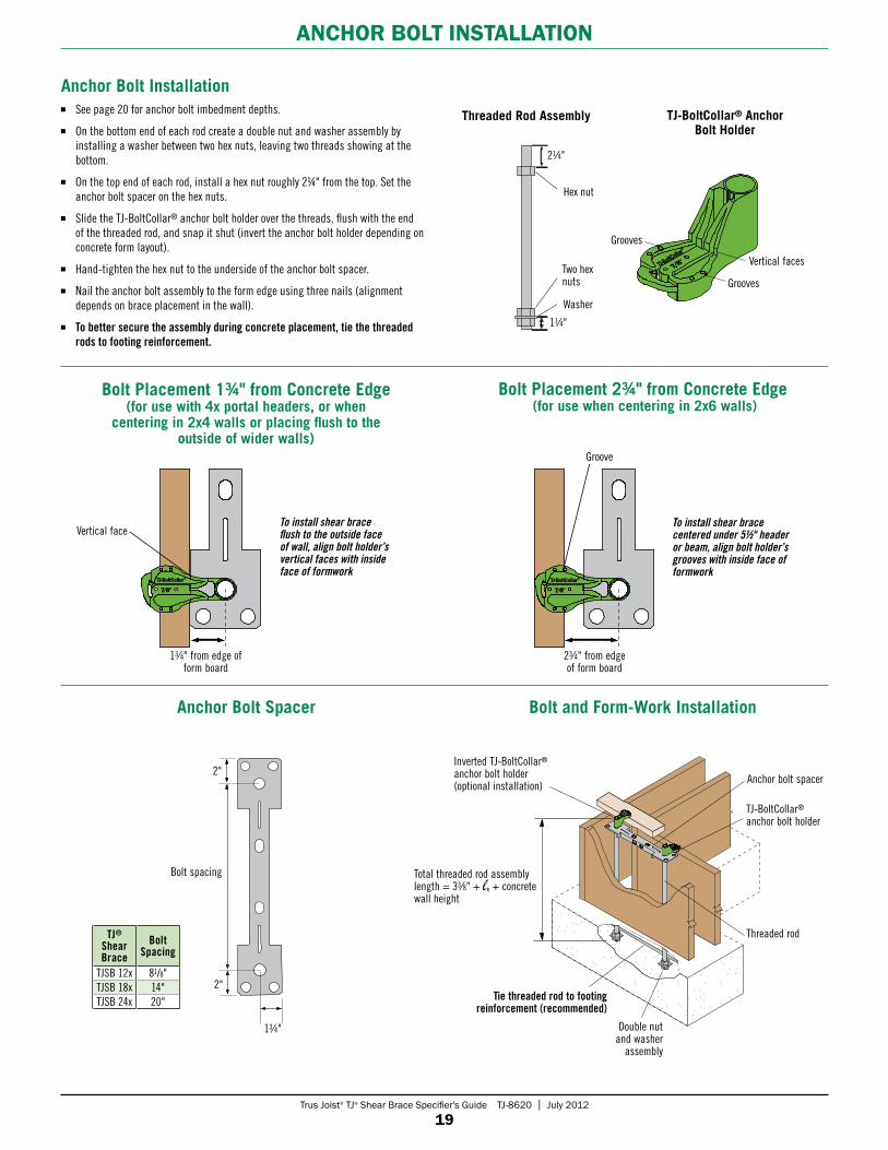
anCHoR BolT inSTallaTion
Bolt Placement 1¾" from Concrete Edge Bolt Placement 2¾" from Concrete Edge (for use when centering in 2x6 walls)
Anchor bolt spacer
TJ-BoltCollar®
anchor bolt holder
Threaded rod
Double nut and washer
assembly
Tie threaded rod to footing reinforcement (recommended)
To install shear brace flush to the outside face of wall, align bolt holder’s vertical faces with inside face of formwork
To install shear brace centered under 5½" header or beam, align bolt holder’s grooves with inside face of formwork
Total threaded rod assembly length = 33⁄8" + + concrete wall height
7/8″TJ-BoltCollar®
7/8″TJ-BoltCollar®
7/8″TJ-BoltCollar®
7/8″TJ-BoltCollar®
Anchor Bolt Installation See page 20 for anchor bolt imbedment depths.
On the bottom end of each rod create a double nut and washer assembly by installing a washer between two hex nuts, leaving two threads showing at the bottom.
On the top end of each rod, install a hex nut roughly 2¼" from the top. Set the anchor bolt spacer on the hex nuts.
Slide the TJ-BoltCollar® anchor bolt holder over the threads, flush with the end of the threaded rod, and snap it shut (invert the anchor bolt holder depending on concrete form layout).
Hand-tighten the hex nut to the underside of the anchor bolt spacer.
Nail the anchor bolt assembly to the form edge using three nails (alignment depends on brace placement in the wall).
To better secure the assembly during concrete placement, tie the threaded rods to footing reinforcement.
7/8″
Grooves
Grooves
Vertical faces
13⁄4" from edge of form board
23⁄4" from edge of form board
Vertical face
Groove
21⁄4"
11⁄4"
TJ-BoltCollar® Anchor Bolt Holder
Threaded Rod Assembly
Inverted TJ-BoltCollar®
anchor bolt holder (optional installation)
(for use with 4x portal headers, or when centering in 2x4 walls or placing flush to the
outside of wider walls)
Hex nut
Two hex nuts
Washer
Anchor Bolt Spacer Bolt and Form-Work Installation
13⁄4"
2"
Bolt spacing
2"
TJ®
Shear Brace
Bolt Spacing
TJSB 12x 81/8"TJSB 18x 14"TJSB 24x 20"
Trus Joist® TJ® Shear Brace Specifier's Guide TJ-8620 | July 2012
20
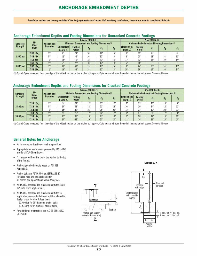
anCHoRaGe emBedmenT depTHS
General Notes for Anchorage No increases for duration of load are permitted.
Appropriate for use in areas governed by IBC or IRC and for all TJ® Shear braces.
is measured from the top of the washer to the top of the footing.
Anchorage embedment is based on ACI 318 Appendix D.
Anchor bolts are ASTM A449 or ASTM A193 B7 threaded rods and are applicable for all braces and applications within this guide.
ASTM A307 threaded rod may be substituted in all 12" wide brace applications.
ASTM A307 threaded rod may be substituted in applications where the holdown uplift at allowable design shear for wind is less than:
13,400 lbs for 7⁄8" diameter anchor bolts. 17,575 lbs for 1" diameter anchor bolts.
For additional information, see ICC ES ESR-2652, RR-25730.
Anchorage Embedment Depths and Footing Dimensions for Uncracked Concrete Footings
Concrete Strength
TJ® Shear Brace
Anchor Bolt Diameter
Seismic (SDC C-E) Wind (SDC A-B)Minimum Embedment and Footing Dimensions(1) Minimum Embedment and Footing Dimensions(1)
Embedment Depth,
Footing Width C1 C2 C3
Embedment Depth,
Footing Width C1 C2 C3
2,500 psiTJSB 12x_ 7⁄ 8" 8" 24" 10" 14" 10" 6" 19" 8" 11" 8"TJSB 18x_ 7⁄ 8" 12" 36" 16" 20" 16" 8" 25" 11" 14" 11"TJSB 24x_ 1" 13" 40" 18" 22" 18" 11" 33" 14" 19" 14"
3,000 psiTJSB 12x_ 7⁄ 8" 7" 22" 10" 12" 10" 6" 18" 7" 11" 7"TJSB 18x_ 7⁄ 8" 11" 33" 15" 18" 15" 8" 24" 10" 14" 10"TJSB 24x_ 1" 13" 38" 18" 20" 18" 10" 30" 14" 16" 14"
(1) C1 and C2 are measured from the edge of the widest section on the anchor bolt spacer. C3 is measured from the end of the anchor bolt spacer. See detail below.
Foundation systems are the responsibility of the design professional of record. Visit woodbywy.com/walls/w_shear-brace.aspx for complete CAD details
21⁄8"
Stem wallper code
Footing
C2
C1
C3
C2
Footing width
C1
C3
5" min. for 7/8" dia. rod; 6" min. for 1" dia. rod
Concretewall height
Total threaded rod assembly
length
A
A
Section A–A
Anchor bolt spacer (remains in concrete)
Anchorage Embedment Depths and Footing Dimensions for Cracked Concrete Footings
Concrete Strength
TJ® Shear Brace
Anchor Bolt Diameter
Seismic (SDC C-E) Wind (SDC A-B)Minimum Embedment and Footing Dimensions(1) Minimum Embedment and Footing Dimensions(1)
Embedment Depth,
Footing Width C1 C2 C3
Embedment Depth,
Footing Width C1 C2 C3
2,500 psiTJSB 12x_ 7⁄ 8" 9" 27" 12" 15" 12" 7" 23" 10" 13" 9"TJSB 18x_ 7⁄ 8" 14" 41" 18" 23" 18" 10" 30" 14" 16" 13"TJSB 24x_ 1" 15" 46" 21" 25" 21" 12" 37" 17" 20" 17"
3,000 psiTJSB 12x_ 7⁄ 8" 9" 26" 12" 14" 12" 7" 21" 9" 12" 9"TJSB 18x_ 7⁄ 8" 13" 39" 18" 21" 18" 9" 28" 12" 16" 12"TJSB 24x_ 1" 14" 43" 20" 23" 20" 12" 36" 16" 20" 15"
(1) C1 and C2 are measured from the edge of the widest section on the anchor bolt spacer. C3 is measured from the end of the anchor bolt spacer. See detail below.
Trus Joist® TJ® Shear Brace Specifier's Guide TJ-8620 | July 2012
21
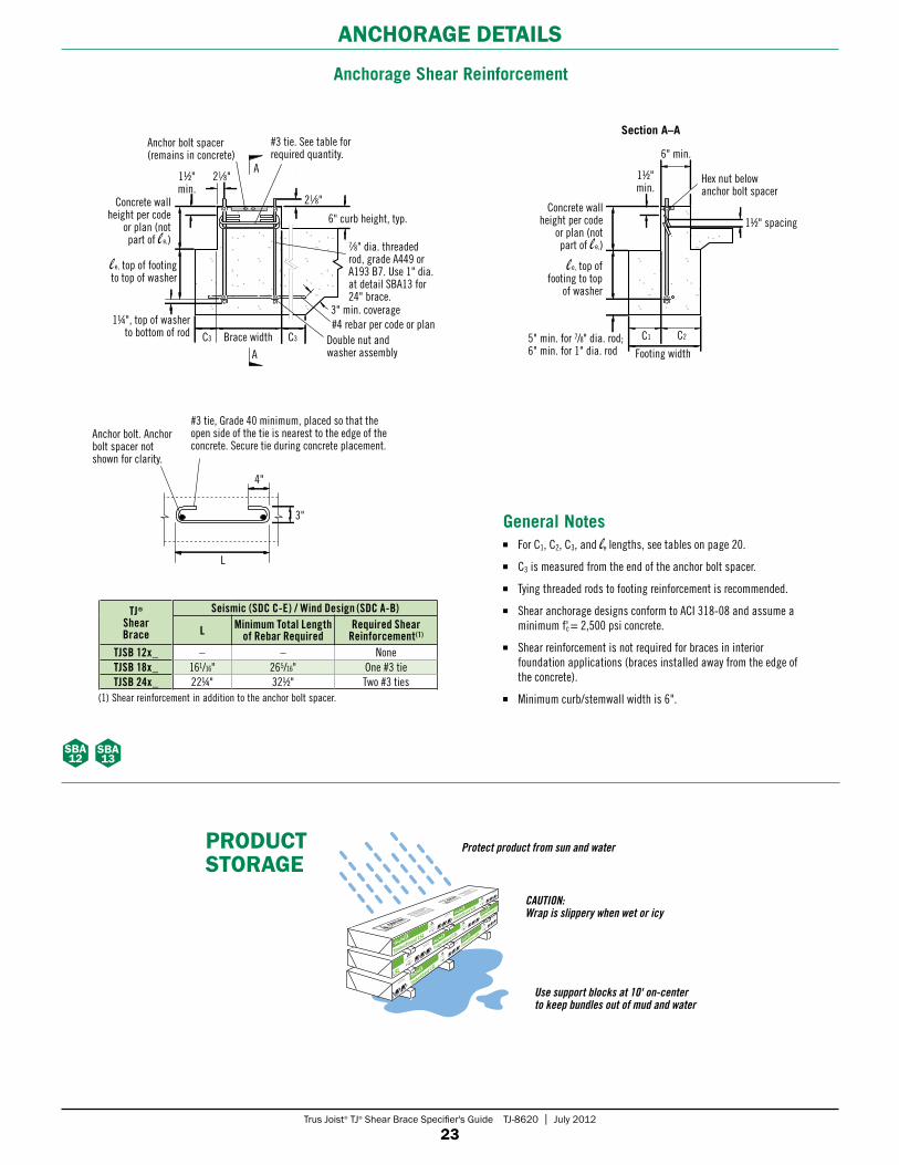
anCHoRaGe deTailS
Portal Anchorage at Garage Curb
Concrete Foundation—Slab on Grade
General Notes For C1, C2, C3, and lengths,
see tables on page 20.
C3 is measured from the end of the anchor bolt spacer.
Tying threaded rods to footing reinforcement is recommended.
Section B–B
Section A–A
General Notes For C1, C2, C3, and lengths,
see tables on page 20.
C3 is measured from the end of the anchor bolt spacer.
Tying threaded rods to footing reinforcement is recommended.sba
1sba
5
sba 2
sba 6
General Notes For C1, C2, C3, and lengths,
see tables on page 20.
For a two-stage pour, a second anchor bolt spacer is recommended. See detail.
C3 is measured from the end of the anchor bolt spacer.
Tying threaded rods to footing reinforcement is recommended.
Section C–C
Concrete Foundation with Stem Wall or Basement
sba 3
sba 7
Foundation systems are the responsibility of the design professional of record. Visit woodbywy.com/walls/w_shear-brace.aspx for complete CAD details
Anchor bolt spacer (remains in concrete)
21∕8"
6" curb height, typ.
7∕8" dia. threaded rod, grade A449 or A193 B7. Use 1" dia. at detail SBA5 for 24" brace.
3" min. coverage#4 rebar per code or planDouble nut and washer assembly
C3C3 Brace width
1¼" top of washer to bottom of rod
e, top of footing to top of washer
2" min.
A
A
Hex nut below anchor bolt spacer
6" curb height, typ.
Footing width
6" min. stem wall
e, top of footing to top of washer
Concrete wall height per code or plan (not part of e,)
C2C1
Anchor bolt spacer (remains in concrete)
21∕8"
7∕8" dia. threaded rod, grade A449 or A193 B7. Use 1" dia. at detail SBA6 for 24" brace.
Double nut and washer assembly
C3C3 Brace width
Concrete wall height per code or plan (not part of e,)
2" min.Hex nut below anchor bolt spacer
Footing width
e, top of footing to top of washer
Concrete wall height per code or plan (not part of e,)
C2C1
B
B
#4 rebar per code or plan1¼" top of washer
to bottom of rod
Hex nut below anchor bolt spacer
Hex nut below anchor bolt spacer
Footing width
e, top of footing to top
of washer
Concrete wall height per code
or plan (not part of e,)
C2C1
Second anchor bolt spacer recommended for two-stage pour
Anchor bolt spacer (remains in concrete)
7∕8" dia. threaded rod, grade A449 or A193 B7. Use 1" dia. at detail SBA7 for 24" brace.
Double nut and washer assemblyC3C3
Brace width
2" min.
C
C
1¼" top of washer to
bottom of rod
21∕8"
Stem wall per code
Monolithic or two-stage pour
Ported coupler, compatible with A193 B7 threaded rod, as required
Concrete wall height per code or plan (not
part of e,)
5" min. for 7/8" dia. rod; 6" min. for 1" dia. rod
5" min. for 7/8" dia. rod; 6" min. for 1" dia. rod
5" min. for 7/8" dia. rod; 6" min. for 1" dia. rod
Shear reinforcement per detail SBA12 when required
Shear reinforcement per detail SBA12 when required
Shear reinforcement per detail SBA12 when required
Concrete wall height per code or plan (not part of e,)
e, top of footing to top of washer
e, top of footing to top of washer
#4 rebar per code or plan
Trus Joist® TJ® Shear Brace Specifier's Guide TJ-8620 | July 2012
22
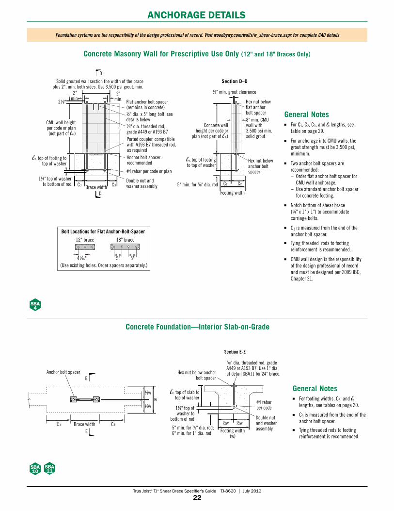
anCHoRaGe deTailS
Foundation systems are the responsibility of the design professional of record. Visit woodbywy.com/walls/w_shear-brace.aspx for complete CAD details
sba 10
E
E
C3
1/2w
1/2ww
Anchor bolt spacer Hex nut below anchor bolt spacer
Footing width (w)
1/2w 1/2w
1¼" top of washer to
bottom of rod
Concrete Foundation—Interior Slab-on-Grade
General Notes For footing widths, C3, and
lengths, see tables on page 20.
C3 is measured from the end of the anchor bolt spacer.
Tying threaded rods to footing reinforcement is recommended.
Section E-E
7/8" dia. threaded rod, grade A449 or A193 B7. Use 1" dia. at detail SBA11 for 24" brace.
#4 rebar per code
Double nut and washer assembly
sba 11
Brace width5" min. for 7/8" dia. rod; 6" min. for 1" dia. rod
Concrete Masonry Wall for Prescriptive Use Only (12" and 18" Braces Only)
General Notes For C1, C2, C3, and lengths, see
table on page 29.
For anchorage into CMU walls, the grout strength must be 3,500 psi, minimum.
Two anchor bolt spacers are recommended: – Order flat anchor bolt spacer for
CMU wall anchorage. – Use standard anchor bolt spacer
for concrete footing.
Notch bottom of shear brace (¼" x 1" x 1") to accommodate carriage bolts.
C3 is measured from the end of the anchor bolt spacer.
Tying threaded rods to footing reinforcement is recommended.
CMU wall design is the responsibility of the design professional of record and must be designed per 2009 IBC, Chapter 21.
le l
Section D–D
12" brace 18" brace
Bolt Locations for Flat Anchor-Bolt-Spacer
5"41⁄16" 5"(Use existing holes. Order spacers separately.)
Flat anchor bolt spacer (remains in concrete)
21∕8"
C3C3 Brace width
1¼" top of washer to bottom of rod
e, top of footing to top of washer
D
D
2" min.
Solid grouted wall section the width of the brace plus 2", min. both sides. Use 3,500 psi grout, min.
2" min.
CMU wall height per code or plan (not part of e,)
1/2" dia. x 5" long bolt, see details below7∕8" dia. threaded rod, grade A449 or A193 B7Ported coupler, compatible with A193 B7 threaded rod, as requiredAnchor bolt spacer recommended
#4 rebar per code or plan
Double nut and washer assembly
Hex nut below anchor bolt spacer
Footing width
1/2" min. grout clearance
e, top of footing to top of washer
C2C1
Hex nut below flat anchor bolt spacer8" min. CMU wall with 3,500 psi min. solid grout
Concrete wall height per code or
plan (not part of e,)
5" min. for 7/8" dia. rod
C3
sba 4
e, top of slab to top of washer
Trus Joist® TJ® Shear Brace Specifier's Guide TJ-8620 | July 2012
23
anCHoRaGe deTailS
Anchorage Shear Reinforcement
Section A–A
General Notes For C1, C2, C3, and lengths, see tables on page 20.
C3 is measured from the end of the anchor bolt spacer.
Tying threaded rods to footing reinforcement is recommended.
Shear anchorage designs conform to ACI 318-08 and assume a minimum f'c = 2,500 psi concrete.
Shear reinforcement is not required for braces in interior foundation applications (braces installed away from the edge of the concrete).
Minimum curb/stemwall width is 6".
Anchor bolt spacer (remains in concrete)
21∕8"
6" curb height, typ.
7∕8" dia. threaded rod, grade A449 or A193 B7. Use 1" dia. at detail SBA13 for 24" brace.
3" min. coverage#4 rebar per code or plan
Double nut and washer assembly
C3C3 Brace width
1¼", top of washer to bottom of rod
e, top of footing to top of washer
Concrete wall height per code
or plan (not part of e,)
11/2" min.
A
A
Hex nut below anchor bolt spacer
11/2" spacing
Footing width
6" min.
e, top of footing to top
of washer
Concrete wall height per code
or plan (not part of e,)
C2C15" min. for 7/8" dia. rod; 6" min. for 1" dia. rod
#3 tie. See table for required quantity.
sba 12
L
4"
3"
Anchor bolt. Anchor bolt spacer not shown for clarity.
#3 tie, Grade 40 minimum, placed so that the open side of the tie is nearest to the edge of the concrete. Secure tie during concrete placement.
TJ® Shear Brace
Seismic (SDC C-E) / Wind Design (SDC A-B)
L Minimum Total Length of Rebar Required
Required Shear Reinforcement(1)
TJSB 12x_ – – NoneTJSB 18x_ 161/16" 265/16" One #3 tieTJSB 24x_ 22¼" 321/2" Two #3 ties
11/2" min.
(1) Shear reinforcement in addition to the anchor bolt spacer.
TrusJoist.com
888.453.8358
TrusJoist.com
888.453.8358
TrusJoist.com
888.453.8358
TrusJoist.com
888.453.8358
TrusJoist.com
888.453.8358
TrusJoist.com
888.453.8358
TrusJoist.com
888.453.8358
Use support blocks at 10' on-center to keep bundles out of mud and water
Protect product from sun and water
CAUTION: Wrap is slippery when wet or icy
pRoduCT SToRaGe
21∕8"
sba 13
Trus Joist® TJ® Shear Brace Specifier's Guide TJ-8620 | July 2012
24
pReSCRipTive Wall BRaCinG
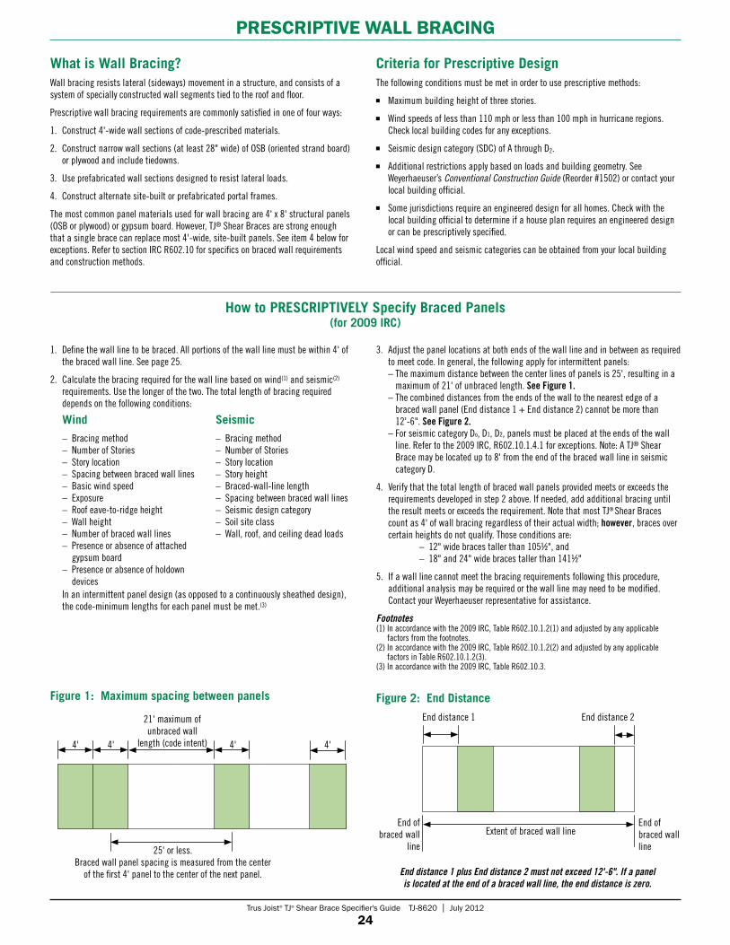
What is Wall Bracing?Wall bracing resists lateral (sideways) movement in a structure, and consists of a system of specially constructed wall segments tied to the roof and floor.
Prescriptive wall bracing requirements are commonly satisfied in one of four ways:
1. Construct 4'-wide wall sections of code-prescribed materials.
2. Construct narrow wall sections (at least 28" wide) of OSB (oriented strand board) or plywood and include tiedowns.
3. Use prefabricated wall sections designed to resist lateral loads.
4. Construct alternate site-built or prefabricated portal frames.
The most common panel materials used for wall bracing are 4' x 8' structural panels (OSB or plywood) or gypsum board. However, TJ® Shear Braces are strong enough that a single brace can replace most 4'-wide, site-built panels. See item 4 below for exceptions. Refer to section IRC R602.10 for specifics on braced wall requirements and construction methods.
Criteria for Prescriptive DesignThe following conditions must be met in order to use prescriptive methods:
Maximum building height of three stories.
Wind speeds of less than 110 mph or less than 100 mph in hurricane regions. Check local building codes for any exceptions.
Seismic design category (SDC) of A through D2.
Additional restrictions apply based on loads and building geometry. See Weyerhaeuser’s Conventional Construction Guide (Reorder #1502) or contact your local building official.
Some jurisdictions require an engineered design for all homes. Check with the local building official to determine if a house plan requires an engineered design or can be prescriptively specified.
Local wind speed and seismic categories can be obtained from your local building official.
1. Define the wall line to be braced. All portions of the wall line must be within 4' of the braced wall line. See page 25.
2. Calculate the bracing required for the wall line based on wind(1) and seismic(2) requirements. Use the longer of the two. The total length of bracing required depends on the following conditions:
In an intermittent panel design (as opposed to a continuously sheathed design), the code-minimum lengths for each panel must be met.(3)
Wind
– Bracing method– Number of Stories– Story location– Spacing between braced wall lines– Basic wind speed– Exposure– Roof eave-to-ridge height– Wall height– Number of braced wall lines– Presence or absence of attached
gypsum board– Presence or absence of holdown
devices
Seismic
– Bracing method– Number of Stories– Story location– Story height– Braced-wall-line length– Spacing between braced wall lines– Seismic design category– Soil site class– Wall, roof, and ceiling dead loads
How to PRESCRIPTIVELY Specify Braced Panels (for 2009 IRC)
3. Adjust the panel locations at both ends of the wall line and in between as required to meet code. In general, the following apply for intermittent panels: – The maximum distance between the center lines of panels is 25', resulting in a
maximum of 21' of unbraced length. See Figure 1. – The combined distances from the ends of the wall to the nearest edge of a
braced wall panel (End distance 1 + End distance 2) cannot be more than 12'-6". See Figure 2.
– For seismic category Do, D1, D2, panels must be placed at the ends of the wall line. Refer to the 2009 IRC, R602.10.1.4.1 for exceptions. Note: A TJ® Shear Brace may be located up to 8' from the end of the braced wall line in seismic category D.
4. Verify that the total length of braced wall panels provided meets or exceeds the requirements developed in step 2 above. If needed, add additional bracing until the result meets or exceeds the requirement. Note that most TJ® Shear Braces count as 4' of wall bracing regardless of their actual width; however, braces over certain heights do not qualify. Those conditions are:
– 12" wide braces taller than 1051/2", and – 18" and 24" wide braces taller than 1411/2"
5. If a wall line cannot meet the bracing requirements following this procedure, additional analysis may be required or the wall line may need to be modified. Contact your Weyerhaeuser representative for assistance.
Footnotes(1) In accordance with the 2009 IRC, Table R602.10.1.2(1) and adjusted by any applicable
factors from the footnotes.(2) In accordance with the 2009 IRC, Table R602.10.1.2(2) and adjusted by any applicable
factors in Table R602.10.1.2(3).(3) In accordance with the 2009 IRC, Table R602.10.3.
4' 4' 4' 4'
25' or less. Braced wall panel spacing is measured from the center
of the first 4' panel to the center of the next panel.
21' maximum of unbraced wall
length (code intent)
Figure 1: Maximum spacing between panels Figure 2: End Distance
End distance 1 End distance 2
Extent of braced wall lineEnd of
braced wall line
End distance 1 plus End distance 2 must not exceed 12'-6". If a panel is located at the end of a braced wall line, the end distance is zero.
End of braced wall line
Trus Joist® TJ® Shear Brace Specifier's Guide TJ-8620 | July 2012
25
pReSCRipTive BRaCinG ReQuiRemenTS
pReSCRipTive BRaCe eXample
A B C
19'
21'
55'
28'
3'
4'
2
1
3
Braced wall panels may be offset no more than 4'
from a braced wall line
Typically, site-built panels must be at least 4' long
Laying Out Braced Wall Lines and Panels in a Typical House
Braced wall panels must occur at least every 25' along the length of the braced wall line
Braced wall lines may be spaced up to 60' apart for wind-controlled
applications and up to 25' (may be increased up to 35') for most seismic-controlled applications.
Braced wall lines, typical
Wall or opening
Code-accepted braced wall panel
Identifies each braced wall line
for easier trackingCalculate the distance from each end of the
braced wall line to the start of the closest panel. The total combined end distances must
not exceed 12'-6", e.g. 4' + 0' = 4' < 12'-6". For seismic design category D, all braces must start at the end unless they meet the exception
requirements in the 2009 IRC, R602.10.1.4.1.
Legend
32'-0"
17'-6"1'-9"1'-9" 1'-9"
8'-6"
32'-0"
17'-6"1'-9"2'-6" 2'-6"
8'-6"
44'-4"
6'3'
9'4'
5'3'3' 2'2'2'2'8" 8"2'
3'
44'-4"
6'3'
9'4'
5'3'3' 2'2'2'2'8" 8"2'
3'
44'-4"
6'3'
9'4'
5'3'3' 2'2'2'2'8" 8"2'
3'
44'-4"
6'3'
9'4'
5'3'3' 2'2'2'2'8" 8"2'
3'
41'-10"
7'-4" 10'7' 8'4' 2'2' 1'-6"
3'
41'-10"
7' 8'4' 2'2' 1'-6"
3'
7'-4" 10'
Opening in wall Wall Shear Brace locations 4' site-built panel
Determine the required bracing for the wall line shown:
Example 1: Wind Controlled
41'-10"
7' 8'4' 2'2' 1'-6"
3'
7'-4" 10'
A B
C
First story of a two-story, single-family residence.
Dead loads: Wall = 10psf; roof/ceiling = 12psf
Wind speed = 100 mph
Exposure category B; soil site class D
Seismic category (SDC) A
Total exterior wall length = 41'-10"
Eave-to-ridge height = 9'-0"; wall height = 9'-0"
3 braced wall lines; spacing = 25'
Applied interior gypsum
Bracing method to be wood structural panels (WSP) and TJ® Shear Braces
1. Develop the adjustment factor according to the footnotes in table R602.10.1.2(1), 2009 IRC as follows:
2. Determine the total length of bracing required for a WSP-braced wall using table R602.10.1.2(1), and wind speed of 100 mph. Interpolating between a 20' and 30' braced-wall-line spacing gives a required bracing length of 11'.
3. Multiply the bracing length from step 2 by the final adjustment factor from step 1: 11' x 1.2 = 13.2' of required bracing length.
4. Choose brace types and locations. Since there are no 4' long wall sections available on the right side of the wall line for a WSP, use one 12x9 TJ® Shear Brace (equivalent to 4') in that area (brace C). In the longer wall section, choose WSPs for the 8' and 4' wall sections (braces A and B).
5. Checks:
Sufficient braced wall length(1) 8' + 4' + 4' = 16' > 13.2' OK Combined end distance to panels 9' + 0' = 9' < 12'-6" OK Unbraced wall length between panels : Length from brace A to B = 7'-4" < 21' OK Length from brace B to C = 12'-6" < 21' OK
The braced panel layout is complete.
Footnotes(1) The TJ® Shear Brace is equivalent to 4' of bracing regardless of its actual width.
Adjustment Factor Description Factor Value Exposure 1.0
Eave-to-ridge height 0.97Wall height 0.95
Number of braced wall lines 1.3Gypsum attachment 1.0
Final Adjustment Factor (product of all factors above) 1.20
Since this wall line is part of a detached single-family residence located in a SDC A zone, the building is exempt from seismic requirements.
Given:

Trus Joist® TJ® Shear Brace Specifier's Guide TJ-8620 | July 2012
26
Determine the required length of wall bracing based on wind design:
1. Adjustment factors will be the same as in Example 1, step 1. Final adjustment factor = 1.2.
2. Determine the total length of bracing required for a WSP-braced wall using table R602.10.1.2(1), wind speed 90 mph. Interpolating between a 20' and 30' braced-wall-line spacing gives a bracing length of 9'.
3. Required bracing length for wind is 9' x 1.2 = 10.80'
Determine the required length of wall bracing based on seismic design:
4. Develop the adjustment factor according to the footnotes in table R602.10.1.2(3), 2009 IRC as follows:
5. Determine the total length of bracing required for a WSP-braced wall using table R602.10.1.2(2). Interpolating between a 40' and 50' braced-wall-line spacing gives a bracing length of 18.83'.
6. Multiply the bracing length from step 5 by the final adjustment factor from step 4: 18.83' x 1.0 = 18.83' of bracing length required.
7. Compare the wind and seismic required bracing lengths and use the largest. 10.80' (wind) < 18.83' (seismic); therefore use 18.83'.
8. Choose brace types and locations. Place one 12x9 brace (equivalent to 4') at each end of the wall line (braces A and D). In the center, choose WSPs for the 8' and 4' wall sections (braces B and C).
9 Checks:
Sufficient braced wall length(1) 4' + 8' + 4' + 4' = 20' > 18.83' OK Unbraced wall length between panels (2): Length from brace A to B = 8'-0" < 21' OK Length from brace B to C = 7'-4" < 21' OK Length from brace C to D = 12'-6" < 21' OK
The braced panel layout is complete.
Footnotes(1) The TJ® Shear Brace is equivalent to 4' of bracing regardless of its actual width.
(2) Since the building is in SDC Do, a panel must be located at each end of the braced wall line for WSP-braced walls, or a maximum of 8' from the end for a TJ® Shear Brace. In this example the short walls and windows at each end of the wall line would not allow a WSP at each end. This is an ideal application for TJ® Shear Braces.
pReSCRipTive BRaCe eXample
Legend
32'-0"
17'-6"1'-9"1'-9" 1'-9"
8'-6"
32'-0"
17'-6"1'-9"2'-6" 2'-6"
8'-6"
44'-4"
6'3'
9'4'
5'3'3' 2'2'2'2'8" 8"2'
3'
44'-4"
6'3'
9'4'
5'3'3' 2'2'2'2'8" 8"2'
3'
44'-4"
6'3'
9'4'
5'3'3' 2'2'2'2'
8" 8"2'
3'
44'-4"
6'3'
9'4'
5'3'3' 2'2'2'2'8" 8"
2'
3'
41'-10"
7'-4" 10'7' 8'4' 2'2' 1'-6"
3'
41'-10"
7' 8'4' 2'2' 1'-6"
3'
7'-4" 10'
Opening in wall Wall Shear brace locations 4' site-built panel
Determine the required bracing for the wall line shown:
Example 2 : Seismic Controlled
Given: First story of a two-story, single-family residence.
Dead loads: wall = 10psf; roof/ceiling = 12psf
Wind speed = 90 mph
Eave-to-ridge height = 9'-0"; wall height = 9'-0"
Exposure category B; soil site class D
Seismic category (SDC) Do
Total exterior wall length = 41'-10"
3 braced wall lines; spacing = 25'
Applied interior gypsum
Bracing method to be wood structural panels (WSP) and TJ® Shear Braces
Adjustment Factor Description Factor Value Story height 1.0
Braced wall line spacing 1.0Wall dead load 1.0
Roof/ceiling dead load 1.0Final Adjustment Factor
(product of all factors above) 1.0
Since this wall line is part of a detached single-family residence located in a SDC Do zone, the required length of bracing will be the greater of the lengths calculated based on wind or seismic.
41'-10"
7' 8'4' 2'2' 1'-6"
3'
7'-4" 10'
A B C
D
Trus Joist® TJ® Shear Brace Specifier's Guide TJ-8620 | July 2012
27
pReSCRipTive poRTalS
pReSCRipTive poRTal HeadeR SizinG TaBle
Header must be single span. Do not run headers continuous over more than one portal.
A minimum of 1,000 lbs of uplift capacity is required at the top and bottom of a single, portal column.
To transfer shear across header joints in prescriptive applications, use one LSTA 24 strap, minimum. Place strap across the top with 91/2" deep headers. Strap is not required if the header is attached to a continuous double top plate.
One Single and One Double Portal Three Single Portals
One Double Portal Two Single Portals
8'-0" min. 18'-6" max.
8'-0" min. 18'-6" max.
8'-0" min. 18'-6" max.
8'-0" min. 18'-6" max.
24'-0" max.
8'-0" min. 18'-6" max.
Rough opening House
width
How to Use This Table1. Determine appropriate Roof Load and
House Width.
2. Locate Rough Opening.
3. Select header size and material.
Roof Load (PSF) House Width
Rough Opening9'-3" 16'-3" 18'-3"
Non-Snow Area 125%
20LL + 15DL24' 31/2" x 9¼" T M P 31/2" x 117/8" (1) M P 31/2" x 14" T M P30' 31/2" x 9¼" T M P 31/2" x 14" T M P 31/2" x 14" (1) M P36' 31/2" x 9¼" T M P 31/2" x 14" T M P 31/2" x 16" T M P
20LL + 20DL24' 31/2" x 9¼" T M P 31/2" x 117/8" (1) M P 31/2" x 14" (1) M P30' 31/2" x 9¼" T M P 31/2" x 14" T M P 31/2" x 16" T M P36' 31/2" x 9¼" T M P 31/2" x 14" (1) M P 31/2" x 16" (1) M P
Snow Area 115%
25LL + 15DL24' 31/2" x 9¼" T M P 31/2" x 117/8" (1) M P 31/2" x 14" (1) M P30' 31/2" x 9¼" T M P 31/2" x 14" T M P 31/2" x 16" T M P36' 31/2" x 9¼" T M P 31/2" x 14" (1) M P 31/2" x 16" (1) M P
30LL + 15DL24' 31/2" x 9¼" T M P 31/2" x 14" T M P 31/2" x 14" (1) M P30' 31/2" x 9¼" T M P 31/2" x 14" (1) M P 31/2" x 16" (1) M P36' 31/2" x 9¼" T M P 31/2" x 16" T M P 5¼" x 14" (1) M P
40LL + 15DL24' 31/2" x 9¼" T M P 31/2" x 14" (1) M P 31/2" x 16" (1) M P30' 31/2" x 9¼" T M P 31/2" x 16" (1) M P 5¼" x 14" (1) M P36' 31/2" x 9¼" (1) M P 5¼" x 14" (1) M P 5¼" x 16" T M P
Minimum Portal Header Size
T 1.55E TimberStrand® LSL M 1.9E Microllam® LVL P 2.0E Parallam® PSL
Quantity SizePanels 2 TJSB 12x7, 7.5, or 8
Headers 1 See table below
Quantity SizePanels 3 TJSB 12x7, 7.5, or 8
Columns 1 31/2" x 31/2" x brace heightHeaders 2 See table below
Quantity SizePanels 3 TJSB 12x7, 7.5, or 8
Columns 3 31/2" x 31/2" x brace heightHeaders 3 See table below
Quantity SizePanels 2 TJSB 12x7, 7.5, or 8
Columns 2 31/2" x 31/2" x brace heightHeaders 2 See table below
24'-0" max.
8'-0" min. 18'-6" max.
8'-0" min. 18'-6" max.
8'-0" min. 18'-6" max.
General Notes
(1) 1.55E TimberStrand® LSL may be substituted for 1.9E Microllam® LVL if the header is used as part of the TJ® Garage Portal system. See page 28 for other requirements.

Trus Joist® TJ® Shear Brace Specifier's Guide TJ-8620 | July 2012
28
TJ® GaRaGe poRTal SYSTem
For allowable holes, see
details SB2 and SB11 on
page 14
Pre-cut wiring chase
Concrete design is the responsibility of the design professional
of record
Portal straps 1/2" from edges on both sides of the brace (4 straps total per brace)
Header clear span
Double PortalWhat is the TJ® Garage Portal System?The Trus Joist® TJ® Garage Portal system is a double portal frame consisting of two TJ® Shear Braces and a 1.55E TimberStrand® LSL header. The header and shear braces must be connected according to details SB3, SB5, or SB12 in this guide and meet the parameters in the table below.
Using the TJ® Garage Double Portal system allows the advantage of designing a 1.55E TimberStrand® LSL portal header using 1.9E Microllam® LVL design properties, when installed as specified above. This allowed increase is due to the double portal acting together as a system.
Portal Header DesignLateral allowable design loads in this guide are applicable to portals with headers that fall within the parameters listed in the table below. Headers and braces must be connected per detail SB3, SB5, or SB12. When sizing a portal frame header vertical load, refer to the Minimum Portal Header Size table on page 27 or the Trus Joist Beams, Headers, and Columns Specifier's Guide (Reorder #TJ-9000), except for 1.55E TimberStrand® LSL as noted below.
For Portal Installation Details, see pages 16–18.
For drilling and trimming information, see pages 14.
TJ® Garage Portal System For increased economy in double portal frames, you can now design 1.55E TimberStrand LSL headers using 1.9E Microllam LVL values.
See Portal Header Allowable Design Parameters table below.
Portal Header Allowable Design Parameters
Header Parameter1.55E TimberStrand® LSL
in TJ® Garage Portal System (Double Portal)
All Other Headers and Applications
Width 31/2"(1) 31/8"– 51/2"Depth 9¼"–16" 9¼"–18"
Clear Span 9'–18'-6" 9'–18'-6"K(2) ≤ 265 lb/in. 90–4,000 lb/in.Fb 2,600(3) psi per TJ-9000
(1) 31/2" wide headers can be one-piece members or two 1¾" plies.(2) K = Ebd3/12L3, where E is modulus of elasticity (psi), and b, d, and L are the header width
(in.), depth (in.), and clear span (in.), respectively.(3) For 12" depths. For other depths, multiply by (12/d)0.136. Fb may be adjusted for duration of
load not to exceed a maximum value of [3,720(12/d)0.136] psi.
l16.1
For multiple-ply headers, connect plies using the Multiple-Member Connections for Side-Loaded Beams on page 38 of the Trus Joist® Beams, Headers, and Columns Specifier's Guide (Reorder #TJ-9000).
TJ® Shear Brace
Sheathing strength axis
One 8d (0.113" x 21/2") nail each side of joist or blocking. Blocking is required if joist framing is parallel to beam. Joist spacing must be 24" on-center or less.
4'-0" maximum height cripple wall. Wall studs at 24" on-center, maximum.
Fasten 2x_ plate to header below with 10d (0.131" x 3") nails at 8" on-center, staggered.
Nail continuous king studs to the end of the beam using:– Four 10d (0.131" x 3") nails for beams 117⁄8" deep or less– Six 10d (0.131" x 3") nails for beams 16" deep or less
Rated wall sheathing (7⁄16" nominal) continuous from bottom of beam to top of wall. Connect sheathing with 8d (0.113" x 21/2") nails at 6" on-center at panel edges and 12" on-center in panel field, or per plan.
When framed as shown above, the following dropped headers are considered fully braced under uniform-load, simple-span conditions:Single-ply: – 31/2" wide headers, 16" deep or less, with a maximum span of 18'-6"Multiple-ply: – Headers up to three 1¾" plies, 117⁄8" deep or less – Headers up to three 1¾" x 14" plies, with a maximum span of 8'-6"
Dropped Header with Acceptable Lateral Bracing

Trus Joist® TJ® Shear Brace Specifier's Guide TJ-8620 | July 2012
29
pReSCRipTive anCHoRaGe
General Notes Minimum concrete f'c of 2,500 psi.
Standard anchor bolts are ASTM A449 or ASTM A193-B7 threaded rods; 1" diameter for 24" wide braces and 7∕8" diameter for 12" and 18" wide braces.
For 12" braces, A307-grade threaded rod may be used with the embedment depths shown.
For 18" braces, A307-grade threaded rod may be used with the embedment depths shown, if the brace is used in an SDC A or B application (SDC C for detached houses) and in a non-stacked application.
Ties for anchorage shear reinforcement are not required.
C3 is measured from the end of the template.
Threaded Rod Installation With a two-stage concrete pour, use two anchor bolt
spacers (one at the footing and one at the stem wall) to ensure the proper on-center spacing of threaded rods or anchor bolts. See details on page 20.
TJ® Shear Brace Application
Minimum Footing Width
Embedment Depth, Minimum Footing DimensionsWind
SDC A-BSeismic
SDC C-D2(1)Minimum
C1
Minimum C2
Minimum C3
Uncracked Concrete
Standard or Portal Brace 16" 6" 7"(2) 6" 10" 10"Stacked Brace (18" bottom brace) 26" 8" 8"(2) 11" 15" 11"Stacked Brace (24" bottom brace) 33" 10" 11"(2) 14" 19" 14"
Cracked Concrete
Standard or Portal Brace 20" 6" 7" 9" 11" 10"Stacked Brace (18" bottom brace) 30" 9" 10" 14" 16" 14"Stacked Brace (24" bottom brace) 35" 11" 12" 16" 19" 16"
Prescriptive Embedment Depths and Footing Dimensions
(1) Applications in SDC C-D2 regions with stone or masonry veneer require special consideration. Contact your Weyerhaeuser representative for assistance. (2) In SDC C-D2 regions, the ACI 318-08 Appendix D and the 2009 IBC require anchorage to be designed with cracked concrete, unless it can be demonstrated that
the concrete remains uncracked.
alTeRnaTe pReSCRipTive anCHoRaGe
Anchor Manufacturer Embedment Depth,
Anchor Bolt Spacer Required
STB28 USP 27¾" YesSSTB28 Simpson 27¾" Yes
Alternate AnchorageFor 12"(1) and 18" TJ® Shear Braces
General Notes Check with manufacturer for capacities and installation
instructions. Exception: Leave 21⁄8" of anchor bolt above the anchor bolt spacer.
Not for use with masonry walls.
Minimum concrete f'c of 2,500 psi.
Place hex nut on anchor bolt 21⁄8" from the top of the bolt.
Not for use in stacked applications.
21⁄8"
Stem wallper code
Footing
C2
C1
C3
C2
Footing width
C1
Stem wallper codeStem wall
8" x 18" min.
#4 rebar
#4 rebar
5" min.
Footingwidth per code
Footing design by others
C3
5" min. for 7/8" dia. rod; 6" min. for 1" dia. rod
Concretewall height
Total threaded rod assembly
length
B
B
A
A
21⁄8"
21⁄8"
Stem wallper code
Footing
C2
C1
C3
C2
Footing width
C1
Stem wallper codeStem wall
8" x 18" min.
#4 rebar
#4 rebar
5" min.
Footingwidth per code
Footing design by others
C3
5" min. for 7/8" dia. rod; 6" min. for 1" dia. rod
Concretewall height
Total threaded rod assembly
length
B
B
A
A
21⁄8"
Section A–A
Section View of Concrete Wall and FootingSection B–B
Top View of Concrete Wall and Footing
Anchor bolt spacer (remains in concrete)
Anchor bolt spacer
(remains in concrete)
(1) Applicable for 12" braces in portal applications only.

Trus Joist® TJ® Shear Brace Specifier's Guide TJ-8620 | July 2012
30
noTeS

Trus Joist® TJ® Shear Brace Specifier's Guide TJ-8620 | July 2012
31
noTeS

July 2012 • Reorder TJ-8620 , Weyerhaeuser, Microllam, Parallam, TimberStrand, TJ-BoltCollar, TJ, TJI and Trus Joist are registered trademarks and Edge Gold and TJ-Pro are trademarks of Weyerhaeuser NR.
© 2012 Weyerhaeuser NR Company. All rights reserved. Printed in the USA.This document supersedes all previous versions. If this is more than one year old, contact your dealer or Weyerhaeuser rep.
You want to build solid and durable structures—we want to help. Weyerhaeuser provides high-quality building products and unparalleled technical and field assistance to support you and your project from start to finish.
Floors and Roofs: Start with the best framing components in the industry: our Trus Joist® TJI® joists; TimberStrand® LSL rim board; and TimberStrand® LSL, Microllam® LVL, and Parallam® PSL headers and beams. Pull them all together with our self-gapping and self-draining Weyerhaeuser Edge Gold™ floor panels and durable Weyerhaeuser roof sheathing.
Walls: Get the best value out of your framing package—use TimberStrand® LSL studs for tall walls, kitchens, and bathrooms, and our traditional, solid-sawn lumber everywhere else. Cut down installation time by using TimberStrand® LSL headers for doors and windows, and Weyerhaeuser wall sheathing with its handy two-way nail lines. Use our TJ® Shear Brace for extra support in walls with large openings or in high wind or seismic areas.
Software Solutions: Whether you are a design professional or lumber dealer, Weyerhaeuser offers an array of software packages to help you specify individual framing members, create cut lists, manage inventories—even help you design a complete structural frame. Contact your Weyerhaeuser representative to find out how to get the software you need.
Technical Support: Need technical help? Weyerhaeuser has one of the largest networks of engineers and sales representatives in the business. Call us for help, and a skilled member from our team of experts will answer your questions and work with you to develop solutions that meet all your structural framing needs.
We Can Help You Build SmaRTeR
Visit woodbywy.com/warranty for copies of this and other Trus Joist® Engineered Wood Product warranties.
ConTaCT uS
1.888.453.8358 • woodbywy.com/contact
Contact your local representative or dealer at:
Related Documents


