Copyright © 2013 Texas Instruments Incorporated UG-ROM-TM4C129x-797 SPMU363 ROM USER’S GUIDE Tiva™ C Series TM4C129x

Welcome message from author
This document is posted to help you gain knowledge. Please leave a comment to let me know what you think about it! Share it to your friends and learn new things together.
Transcript

Copyright © 2013Texas Instruments Incorporated
UG-ROM-TM4C129x-797SPMU363
ROM USER’S GUIDE
Tiva™ C Series TM4C129x
CopyrightCopyright © 2013 Texas Instruments Incorporated. All rights reserved. Tiva and TivaWare are trademarks of Texas Instruments Instruments. ARM andThumb are registered trademarks and Cortex is a trademark of ARM Limited. Other names and brands may be claimed as the property of others.
Please be aware that an important notice concerning availability, standard warranty, and use in critical applications of Texas Instruments semicon-ductor products and disclaimers thereto appears at the end of this document.
Texas Instruments108 Wild Basin, Suite 350Austin, TX 78746www.ti.com/tiva-c
Revision InformationThis is version 797 of this document, last updated on October 29, 2013.
2 October 29, 2013
Table of Contents
Table of ContentsCopyright . . . . . . . . . . . . . . . . . . . . . . . . . . . . . . . . . . . . . . . . . . . . . . . . . . . . . 2
Revision Information . . . . . . . . . . . . . . . . . . . . . . . . . . . . . . . . . . . . . . . . . . . . . . . 2
1 Introduction . . . . . . . . . . . . . . . . . . . . . . . . . . . . . . . . . . . . . . . . . . . . . . . . . 7
2 Analog Comparator . . . . . . . . . . . . . . . . . . . . . . . . . . . . . . . . . . . . . . . . . . . . 92.1 Introduction . . . . . . . . . . . . . . . . . . . . . . . . . . . . . . . . . . . . . . . . . . . . . . . . . . 92.2 Functions . . . . . . . . . . . . . . . . . . . . . . . . . . . . . . . . . . . . . . . . . . . . . . . . . . . 9
3 Analog to Digital Converter (ADC) . . . . . . . . . . . . . . . . . . . . . . . . . . . . . . . . . . . . 153.1 Introduction . . . . . . . . . . . . . . . . . . . . . . . . . . . . . . . . . . . . . . . . . . . . . . . . . . 153.2 Functions . . . . . . . . . . . . . . . . . . . . . . . . . . . . . . . . . . . . . . . . . . . . . . . . . . . 15
4 AES . . . . . . . . . . . . . . . . . . . . . . . . . . . . . . . . . . . . . . . . . . . . . . . . . . . . . . 374.1 Introduction . . . . . . . . . . . . . . . . . . . . . . . . . . . . . . . . . . . . . . . . . . . . . . . . . . 374.2 API Functions . . . . . . . . . . . . . . . . . . . . . . . . . . . . . . . . . . . . . . . . . . . . . . . . 37
5 Controller Area Network (CAN) . . . . . . . . . . . . . . . . . . . . . . . . . . . . . . . . . . . . . . 535.1 Introduction . . . . . . . . . . . . . . . . . . . . . . . . . . . . . . . . . . . . . . . . . . . . . . . . . . 535.2 Functions . . . . . . . . . . . . . . . . . . . . . . . . . . . . . . . . . . . . . . . . . . . . . . . . . . . 54
6 CRC . . . . . . . . . . . . . . . . . . . . . . . . . . . . . . . . . . . . . . . . . . . . . . . . . . . . . . 696.1 Introduction . . . . . . . . . . . . . . . . . . . . . . . . . . . . . . . . . . . . . . . . . . . . . . . . . . 696.2 API Functions . . . . . . . . . . . . . . . . . . . . . . . . . . . . . . . . . . . . . . . . . . . . . . . . 69
7 DES . . . . . . . . . . . . . . . . . . . . . . . . . . . . . . . . . . . . . . . . . . . . . . . . . . . . . . 737.1 Introduction . . . . . . . . . . . . . . . . . . . . . . . . . . . . . . . . . . . . . . . . . . . . . . . . . . 737.2 API Functions . . . . . . . . . . . . . . . . . . . . . . . . . . . . . . . . . . . . . . . . . . . . . . . . 73
8 EEPROM . . . . . . . . . . . . . . . . . . . . . . . . . . . . . . . . . . . . . . . . . . . . . . . . . . . 838.1 Introduction . . . . . . . . . . . . . . . . . . . . . . . . . . . . . . . . . . . . . . . . . . . . . . . . . . 838.2 API Functions . . . . . . . . . . . . . . . . . . . . . . . . . . . . . . . . . . . . . . . . . . . . . . . . 84
9 Ethernet Controller . . . . . . . . . . . . . . . . . . . . . . . . . . . . . . . . . . . . . . . . . . . . . 979.1 Introduction . . . . . . . . . . . . . . . . . . . . . . . . . . . . . . . . . . . . . . . . . . . . . . . . . . 979.2 API Functions . . . . . . . . . . . . . . . . . . . . . . . . . . . . . . . . . . . . . . . . . . . . . . . . 97
10 External Peripheral Interface (EPI) . . . . . . . . . . . . . . . . . . . . . . . . . . . . . . . . . . . . 16510.1 Introduction . . . . . . . . . . . . . . . . . . . . . . . . . . . . . . . . . . . . . . . . . . . . . . . . . . 16510.2 Functions . . . . . . . . . . . . . . . . . . . . . . . . . . . . . . . . . . . . . . . . . . . . . . . . . . . 166
11 Flash . . . . . . . . . . . . . . . . . . . . . . . . . . . . . . . . . . . . . . . . . . . . . . . . . . . . . 19511.1 Introduction . . . . . . . . . . . . . . . . . . . . . . . . . . . . . . . . . . . . . . . . . . . . . . . . . . 19511.2 Functions . . . . . . . . . . . . . . . . . . . . . . . . . . . . . . . . . . . . . . . . . . . . . . . . . . . 195
12 Floating-Point Unit (FPU) . . . . . . . . . . . . . . . . . . . . . . . . . . . . . . . . . . . . . . . . . 20312.1 Introduction . . . . . . . . . . . . . . . . . . . . . . . . . . . . . . . . . . . . . . . . . . . . . . . . . . 20312.2 API Functions . . . . . . . . . . . . . . . . . . . . . . . . . . . . . . . . . . . . . . . . . . . . . . . . 204
13 GPIO . . . . . . . . . . . . . . . . . . . . . . . . . . . . . . . . . . . . . . . . . . . . . . . . . . . . . 20913.1 Introduction . . . . . . . . . . . . . . . . . . . . . . . . . . . . . . . . . . . . . . . . . . . . . . . . . . 20913.2 Functions . . . . . . . . . . . . . . . . . . . . . . . . . . . . . . . . . . . . . . . . . . . . . . . . . . . 209
14 Hibernation Module . . . . . . . . . . . . . . . . . . . . . . . . . . . . . . . . . . . . . . . . . . . . 24514.1 Introduction . . . . . . . . . . . . . . . . . . . . . . . . . . . . . . . . . . . . . . . . . . . . . . . . . . 24514.2 Functions . . . . . . . . . . . . . . . . . . . . . . . . . . . . . . . . . . . . . . . . . . . . . . . . . . . 246
15 Inter-Integrated Circuit (I2C) . . . . . . . . . . . . . . . . . . . . . . . . . . . . . . . . . . . . . . . 27515.1 Introduction . . . . . . . . . . . . . . . . . . . . . . . . . . . . . . . . . . . . . . . . . . . . . . . . . . 275
October 29, 2013 3
Table of Contents
15.2 Functions . . . . . . . . . . . . . . . . . . . . . . . . . . . . . . . . . . . . . . . . . . . . . . . . . . . 276
16 Interrupt Controller (NVIC) . . . . . . . . . . . . . . . . . . . . . . . . . . . . . . . . . . . . . . . . 30716.1 Introduction . . . . . . . . . . . . . . . . . . . . . . . . . . . . . . . . . . . . . . . . . . . . . . . . . . 30716.2 Functions . . . . . . . . . . . . . . . . . . . . . . . . . . . . . . . . . . . . . . . . . . . . . . . . . . . 307
17 LCD Controller (LCD) . . . . . . . . . . . . . . . . . . . . . . . . . . . . . . . . . . . . . . . . . . . 31517.1 Introduction . . . . . . . . . . . . . . . . . . . . . . . . . . . . . . . . . . . . . . . . . . . . . . . . . . 31517.2 API Functions . . . . . . . . . . . . . . . . . . . . . . . . . . . . . . . . . . . . . . . . . . . . . . . . 315
18 Memory Protection Unit (MPU) . . . . . . . . . . . . . . . . . . . . . . . . . . . . . . . . . . . . . . 33918.1 Introduction . . . . . . . . . . . . . . . . . . . . . . . . . . . . . . . . . . . . . . . . . . . . . . . . . . 33918.2 Functions . . . . . . . . . . . . . . . . . . . . . . . . . . . . . . . . . . . . . . . . . . . . . . . . . . . 340
19 1-Wire Master Module . . . . . . . . . . . . . . . . . . . . . . . . . . . . . . . . . . . . . . . . . . . 34719.1 Introduction . . . . . . . . . . . . . . . . . . . . . . . . . . . . . . . . . . . . . . . . . . . . . . . . . . 34719.2 API Functions . . . . . . . . . . . . . . . . . . . . . . . . . . . . . . . . . . . . . . . . . . . . . . . . 347
20 Pulse Width Modulator (PWM) . . . . . . . . . . . . . . . . . . . . . . . . . . . . . . . . . . . . . . 35720.1 Introduction . . . . . . . . . . . . . . . . . . . . . . . . . . . . . . . . . . . . . . . . . . . . . . . . . . 35720.2 Functions . . . . . . . . . . . . . . . . . . . . . . . . . . . . . . . . . . . . . . . . . . . . . . . . . . . 357
21 Quadrature Encoder (QEI) . . . . . . . . . . . . . . . . . . . . . . . . . . . . . . . . . . . . . . . . 38121.1 Introduction . . . . . . . . . . . . . . . . . . . . . . . . . . . . . . . . . . . . . . . . . . . . . . . . . . 38121.2 Functions . . . . . . . . . . . . . . . . . . . . . . . . . . . . . . . . . . . . . . . . . . . . . . . . . . . 381
22 SMBus Stack . . . . . . . . . . . . . . . . . . . . . . . . . . . . . . . . . . . . . . . . . . . . . . . . 39122.1 Introduction . . . . . . . . . . . . . . . . . . . . . . . . . . . . . . . . . . . . . . . . . . . . . . . . . . 39122.2 API Functions . . . . . . . . . . . . . . . . . . . . . . . . . . . . . . . . . . . . . . . . . . . . . . . . 392
23 Software AES Data Tables . . . . . . . . . . . . . . . . . . . . . . . . . . . . . . . . . . . . . . . . 42523.1 Introduction . . . . . . . . . . . . . . . . . . . . . . . . . . . . . . . . . . . . . . . . . . . . . . . . . . 42523.2 Data Structures . . . . . . . . . . . . . . . . . . . . . . . . . . . . . . . . . . . . . . . . . . . . . . . 425
24 Software CRC . . . . . . . . . . . . . . . . . . . . . . . . . . . . . . . . . . . . . . . . . . . . . . . . 42724.1 Introduction . . . . . . . . . . . . . . . . . . . . . . . . . . . . . . . . . . . . . . . . . . . . . . . . . . 42724.2 Functions . . . . . . . . . . . . . . . . . . . . . . . . . . . . . . . . . . . . . . . . . . . . . . . . . . . 427
25 SPI Flash Module . . . . . . . . . . . . . . . . . . . . . . . . . . . . . . . . . . . . . . . . . . . . . . 43325.1 Introduction . . . . . . . . . . . . . . . . . . . . . . . . . . . . . . . . . . . . . . . . . . . . . . . . . . 43325.2 API Functions . . . . . . . . . . . . . . . . . . . . . . . . . . . . . . . . . . . . . . . . . . . . . . . . 433
26 Synchronous Serial Interface (SSI) . . . . . . . . . . . . . . . . . . . . . . . . . . . . . . . . . . . 44926.1 Introduction . . . . . . . . . . . . . . . . . . . . . . . . . . . . . . . . . . . . . . . . . . . . . . . . . . 44926.2 Functions . . . . . . . . . . . . . . . . . . . . . . . . . . . . . . . . . . . . . . . . . . . . . . . . . . . 451
27 System Control . . . . . . . . . . . . . . . . . . . . . . . . . . . . . . . . . . . . . . . . . . . . . . . 46527.1 Introduction . . . . . . . . . . . . . . . . . . . . . . . . . . . . . . . . . . . . . . . . . . . . . . . . . . 46527.2 Functions . . . . . . . . . . . . . . . . . . . . . . . . . . . . . . . . . . . . . . . . . . . . . . . . . . . 466
28 System Exception Module . . . . . . . . . . . . . . . . . . . . . . . . . . . . . . . . . . . . . . . . 49928.1 Introduction . . . . . . . . . . . . . . . . . . . . . . . . . . . . . . . . . . . . . . . . . . . . . . . . . . 49928.2 API Functions . . . . . . . . . . . . . . . . . . . . . . . . . . . . . . . . . . . . . . . . . . . . . . . . 499
29 System Tick (SysTick) . . . . . . . . . . . . . . . . . . . . . . . . . . . . . . . . . . . . . . . . . . . 50329.1 Introduction . . . . . . . . . . . . . . . . . . . . . . . . . . . . . . . . . . . . . . . . . . . . . . . . . . 50329.2 Functions . . . . . . . . . . . . . . . . . . . . . . . . . . . . . . . . . . . . . . . . . . . . . . . . . . . 503
30 Timer . . . . . . . . . . . . . . . . . . . . . . . . . . . . . . . . . . . . . . . . . . . . . . . . . . . . . 50730.1 Introduction . . . . . . . . . . . . . . . . . . . . . . . . . . . . . . . . . . . . . . . . . . . . . . . . . . 50730.2 Functions . . . . . . . . . . . . . . . . . . . . . . . . . . . . . . . . . . . . . . . . . . . . . . . . . . . 508
31 UART . . . . . . . . . . . . . . . . . . . . . . . . . . . . . . . . . . . . . . . . . . . . . . . . . . . . . 529
4 October 29, 2013
Table of Contents
31.1 Introduction . . . . . . . . . . . . . . . . . . . . . . . . . . . . . . . . . . . . . . . . . . . . . . . . . . 52931.2 Functions . . . . . . . . . . . . . . . . . . . . . . . . . . . . . . . . . . . . . . . . . . . . . . . . . . . 529
32 uDMA Controller . . . . . . . . . . . . . . . . . . . . . . . . . . . . . . . . . . . . . . . . . . . . . . 55732.1 Introduction . . . . . . . . . . . . . . . . . . . . . . . . . . . . . . . . . . . . . . . . . . . . . . . . . . 55732.2 Functions . . . . . . . . . . . . . . . . . . . . . . . . . . . . . . . . . . . . . . . . . . . . . . . . . . . 559
33 USB Controller . . . . . . . . . . . . . . . . . . . . . . . . . . . . . . . . . . . . . . . . . . . . . . . 57533.1 Introduction . . . . . . . . . . . . . . . . . . . . . . . . . . . . . . . . . . . . . . . . . . . . . . . . . . 57533.2 Functions . . . . . . . . . . . . . . . . . . . . . . . . . . . . . . . . . . . . . . . . . . . . . . . . . . . 576
34 Watchdog Timer . . . . . . . . . . . . . . . . . . . . . . . . . . . . . . . . . . . . . . . . . . . . . . 65134.1 Introduction . . . . . . . . . . . . . . . . . . . . . . . . . . . . . . . . . . . . . . . . . . . . . . . . . . 65134.2 Functions . . . . . . . . . . . . . . . . . . . . . . . . . . . . . . . . . . . . . . . . . . . . . . . . . . . 651
IMPORTANT NOTICE . . . . . . . . . . . . . . . . . . . . . . . . . . . . . . . . . . . . . . . . . . . . . . . 660
October 29, 2013 5

Table of Contents
6 October 29, 2013
Introduction
1 IntroductionThe TM4C129x ROM contains the TivaWare™ Peripheral Driver Library and the TivaWare BootLoader. The peripheral driver library can be used by applications to reduce their flash footprint,allowing more of the flash to be used by the application for other purposes. The boot loader is usedas an initial program loader (when the flash is empty) as well as an application-initiated firmwareupgrade mechanism (by calling back to the boot loader).
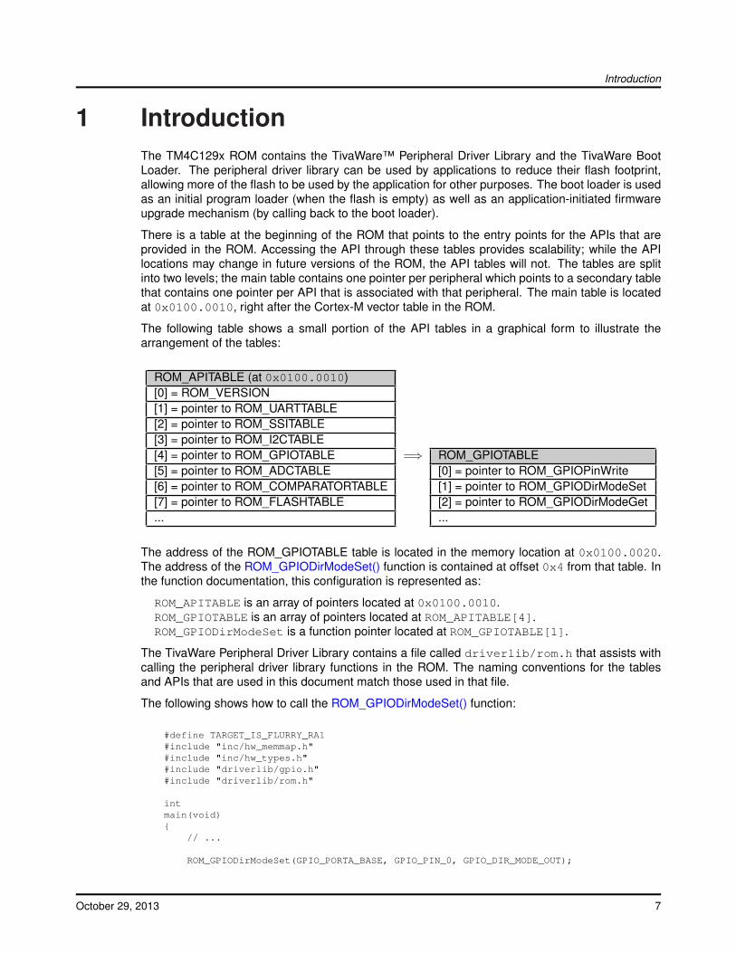
There is a table at the beginning of the ROM that points to the entry points for the APIs that areprovided in the ROM. Accessing the API through these tables provides scalability; while the APIlocations may change in future versions of the ROM, the API tables will not. The tables are splitinto two levels; the main table contains one pointer per peripheral which points to a secondary tablethat contains one pointer per API that is associated with that peripheral. The main table is locatedat 0x0100.0010, right after the Cortex-M vector table in the ROM.
The following table shows a small portion of the API tables in a graphical form to illustrate thearrangement of the tables:
ROM_APITABLE (at 0x0100.0010)[0] = ROM_VERSION[1] = pointer to ROM_UARTTABLE[2] = pointer to ROM_SSITABLE[3] = pointer to ROM_I2CTABLE[4] = pointer to ROM_GPIOTABLE =⇒ ROM_GPIOTABLE[5] = pointer to ROM_ADCTABLE [0] = pointer to ROM_GPIOPinWrite[6] = pointer to ROM_COMPARATORTABLE [1] = pointer to ROM_GPIODirModeSet[7] = pointer to ROM_FLASHTABLE [2] = pointer to ROM_GPIODirModeGet... ...
The address of the ROM_GPIOTABLE table is located in the memory location at 0x0100.0020.The address of the ROM_GPIODirModeSet() function is contained at offset 0x4 from that table. Inthe function documentation, this configuration is represented as:
ROM_APITABLE is an array of pointers located at 0x0100.0010.ROM_GPIOTABLE is an array of pointers located at ROM_APITABLE[4].ROM_GPIODirModeSet is a function pointer located at ROM_GPIOTABLE[1].
The TivaWare Peripheral Driver Library contains a file called driverlib/rom.h that assists withcalling the peripheral driver library functions in the ROM. The naming conventions for the tablesand APIs that are used in this document match those used in that file.
The following shows how to call the ROM_GPIODirModeSet() function:
#define TARGET_IS_FLURRY_RA1#include "inc/hw_memmap.h"#include "inc/hw_types.h"#include "driverlib/gpio.h"#include "driverlib/rom.h"
intmain(void){
// ...
ROM_GPIODirModeSet(GPIO_PORTA_BASE, GPIO_PIN_0, GPIO_DIR_MODE_OUT);
October 29, 2013 7
Introduction
// ....}
See the “Using the ROM” chapter of the TivaWare Peripheral Driver Library User’s Guide for moredetails on calling the ROM functions and using driverlib/rom.h.
The APIs provided by the ROM can be used by any compiler that complies with the EmbeddedApplications Binary Interface (EABI), including all recent compilers for the Tiva microcontroller.
8 October 29, 2013
Analog Comparator
2 Analog ComparatorIntroduction . . . . . . . . . . . . . . . . . . . . . . . . . . . . . . . . . . . . . . . . . . . . . . . . . . . . . . . . . . . . . . . . . . . . . . . . . . . . . . . . . . . . . . . . . . . . . . . 9Functions . . . . . . . . . . . . . . . . . . . . . . . . . . . . . . . . . . . . . . . . . . . . . . . . . . . . . . . . . . . . . . . . . . . . . . . . . . . . . . . . . . . . . . . . . . . . . . . . . 9
2.1 Introduction
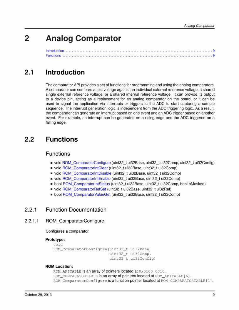
The comparator API provides a set of functions for programming and using the analog comparators.A comparator can compare a test voltage against an individual external reference voltage, a sharedsingle external reference voltage, or a shared internal reference voltage. It can provide its outputto a device pin, acting as a replacement for an analog comparator on the board, or it can beused to signal the application via interrupts or triggers to the ADC to start capturing a samplesequence. The interrupt generation logic is independent from the ADC triggering logic. As a result,the comparator can generate an interrupt based on one event and an ADC trigger based on anotherevent. For example, an interrupt can be generated on a rising edge and the ADC triggered on afalling edge.
2.2 Functions
Functionsvoid ROM_ComparatorConfigure (uint32_t ui32Base, uint32_t ui32Comp, uint32_t ui32Config)void ROM_ComparatorIntClear (uint32_t ui32Base, uint32_t ui32Comp)void ROM_ComparatorIntDisable (uint32_t ui32Base, uint32_t ui32Comp)void ROM_ComparatorIntEnable (uint32_t ui32Base, uint32_t ui32Comp)bool ROM_ComparatorIntStatus (uint32_t ui32Base, uint32_t ui32Comp, bool bMasked)void ROM_ComparatorRefSet (uint32_t ui32Base, uint32_t ui32Ref)bool ROM_ComparatorValueGet (uint32_t ui32Base, uint32_t ui32Comp)
2.2.1 Function Documentation
2.2.1.1 ROM_ComparatorConfigure
Configures a comparator.
Prototype:voidROM_ComparatorConfigure(uint32_t ui32Base,
uint32_t ui32Comp,uint32_t ui32Config)
ROM Location:ROM_APITABLE is an array of pointers located at 0x0100.0010.ROM_COMPARATORTABLE is an array of pointers located at ROM_APITABLE[6].ROM_ComparatorConfigure is a function pointer located at ROM_COMPARATORTABLE[1].
October 29, 2013 9
Analog Comparator
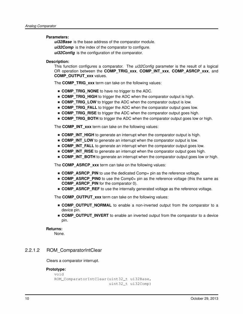
Parameters:ui32Base is the base address of the comparator module.ui32Comp is the index of the comparator to configure.ui32Config is the configuration of the comparator.
Description:This function configures a comparator. The ui32Config parameter is the result of a logicalOR operation between the COMP_TRIG_xxx, COMP_INT_xxx, COMP_ASRCP_xxx, andCOMP_OUTPUT_xxx values.
The COMP_TRIG_xxx term can take on the following values:
COMP_TRIG_NONE to have no trigger to the ADC.COMP_TRIG_HIGH to trigger the ADC when the comparator output is high.COMP_TRIG_LOW to trigger the ADC when the comparator output is low.COMP_TRIG_FALL to trigger the ADC when the comparator output goes low.COMP_TRIG_RISE to trigger the ADC when the comparator output goes high.COMP_TRIG_BOTH to trigger the ADC when the comparator output goes low or high.
The COMP_INT_xxx term can take on the following values:
COMP_INT_HIGH to generate an interrupt when the comparator output is high.COMP_INT_LOW to generate an interrupt when the comparator output is low.COMP_INT_FALL to generate an interrupt when the comparator output goes low.COMP_INT_RISE to generate an interrupt when the comparator output goes high.COMP_INT_BOTH to generate an interrupt when the comparator output goes low or high.
The COMP_ASRCP_xxx term can take on the following values:
COMP_ASRCP_PIN to use the dedicated Comp+ pin as the reference voltage.COMP_ASRCP_PIN0 to use the Comp0+ pin as the reference voltage (this the same asCOMP_ASRCP_PIN for the comparator 0).COMP_ASRCP_REF to use the internally generated voltage as the reference voltage.
The COMP_OUTPUT_xxx term can take on the following values:
COMP_OUTPUT_NORMAL to enable a non-inverted output from the comparator to adevice pin.COMP_OUTPUT_INVERT to enable an inverted output from the comparator to a devicepin.
Returns:None.
2.2.1.2 ROM_ComparatorIntClear
Clears a comparator interrupt.
Prototype:voidROM_ComparatorIntClear(uint32_t ui32Base,
uint32_t ui32Comp)
10 October 29, 2013
Analog Comparator
ROM Location:ROM_APITABLE is an array of pointers located at 0x0100.0010.ROM_COMPARATORTABLE is an array of pointers located at ROM_APITABLE[6].ROM_ComparatorIntClear is a function pointer located at ROM_COMPARATORTABLE[0].
Parameters:ui32Base is the base address of the comparator module.ui32Comp is the index of the comparator.
Description:The comparator interrupt is cleared, so that it no longer asserts. This function must be called inthe interrupt handler to keep the handler from being called again immediately upon exit. Notethat for a level-triggered interrupt, the interrupt cannot be cleared until it stops asserting.
Note:Because there is a write buffer in the Cortex-M processor, it may take several clock cyclesbefore the interrupt source is actually cleared. Therefore, it is recommended that the interruptsource be cleared early in the interrupt handler (as opposed to the very last action) to avoidreturning from the interrupt handler before the interrupt source is actually cleared. Failure todo so may result in the interrupt handler being immediately reentered (because the interruptcontroller still sees the interrupt source asserted).
Returns:None.
2.2.1.3 ROM_ComparatorIntDisable
Disables the comparator interrupt.
Prototype:voidROM_ComparatorIntDisable(uint32_t ui32Base,
uint32_t ui32Comp)
ROM Location:ROM_APITABLE is an array of pointers located at 0x0100.0010.ROM_COMPARATORTABLE is an array of pointers located at ROM_APITABLE[6].ROM_ComparatorIntDisable is a function pointer located at ROM_COMPARATORTABLE[5].
Parameters:ui32Base is the base address of the comparator module.ui32Comp is the index of the comparator.
Description:This function disables generation of an interrupt from the specified comparator. Only enabledcomparator interrupts can be reflected to the processor.
Returns:None.
October 29, 2013 11
Analog Comparator
2.2.1.4 ROM_ComparatorIntEnable
Enables the comparator interrupt.
Prototype:voidROM_ComparatorIntEnable(uint32_t ui32Base,
uint32_t ui32Comp)
ROM Location:ROM_APITABLE is an array of pointers located at 0x0100.0010.ROM_COMPARATORTABLE is an array of pointers located at ROM_APITABLE[6].ROM_ComparatorIntEnable is a function pointer located at ROM_COMPARATORTABLE[4].
Parameters:ui32Base is the base address of the comparator module.ui32Comp is the index of the comparator.
Description:This function enables generation of an interrupt from the specified comparator. Only enabledcomparator interrupts can be reflected to the processor.
Returns:None.
2.2.1.5 ROM_ComparatorIntStatus
Gets the current interrupt status.
Prototype:boolROM_ComparatorIntStatus(uint32_t ui32Base,
uint32_t ui32Comp,bool bMasked)
ROM Location:ROM_APITABLE is an array of pointers located at 0x0100.0010.ROM_COMPARATORTABLE is an array of pointers located at ROM_APITABLE[6].ROM_ComparatorIntStatus is a function pointer located at ROM_COMPARATORTABLE[6].
Parameters:ui32Base is the base address of the comparator module.ui32Comp is the index of the comparator.bMasked is false if the raw interrupt status is required and true if the masked interrupt status
is required.
Description:This function returns the interrupt status for the comparator. Either the raw or the maskedinterrupt status can be returned.
Returns:true if the interrupt is asserted and false if it is not asserted.
12 October 29, 2013
Analog Comparator
2.2.1.6 ROM_ComparatorRefSet
Sets the internal reference voltage.
Prototype:voidROM_ComparatorRefSet(uint32_t ui32Base,
uint32_t ui32Ref)
ROM Location:ROM_APITABLE is an array of pointers located at 0x0100.0010.ROM_COMPARATORTABLE is an array of pointers located at ROM_APITABLE[6].ROM_ComparatorRefSet is a function pointer located at ROM_COMPARATORTABLE[2].
Parameters:ui32Base is the base address of the comparator module.ui32Ref is the desired reference voltage.
Description:This function sets the internal reference voltage value. The voltage is specified as one of thefollowing values:
COMP_REF_OFF to turn off the reference voltageCOMP_REF_0V to set the reference voltage to 0 VCOMP_REF_0_1375V to set the reference voltage to 0.1375 VCOMP_REF_0_275V to set the reference voltage to 0.275 VCOMP_REF_0_4125V to set the reference voltage to 0.4125 VCOMP_REF_0_55V to set the reference voltage to 0.55 VCOMP_REF_0_6875V to set the reference voltage to 0.6875 VCOMP_REF_0_825V to set the reference voltage to 0.825 VCOMP_REF_0_928125V to set the reference voltage to 0.928125 VCOMP_REF_0_9625V to set the reference voltage to 0.9625 VCOMP_REF_1_03125V to set the reference voltage to 1.03125 VCOMP_REF_1_134375V to set the reference voltage to 1.134375 VCOMP_REF_1_1V to set the reference voltage to 1.1 VCOMP_REF_1_2375V to set the reference voltage to 1.2375 VCOMP_REF_1_340625V to set the reference voltage to 1.340625 VCOMP_REF_1_375V to set the reference voltage to 1.375 VCOMP_REF_1_44375V to set the reference voltage to 1.44375 VCOMP_REF_1_5125V to set the reference voltage to 1.5125 VCOMP_REF_1_546875V to set the reference voltage to 1.546875 VCOMP_REF_1_65V to set the reference voltage to 1.65 VCOMP_REF_1_753125V to set the reference voltage to 1.753125 VCOMP_REF_1_7875V to set the reference voltage to 1.7875 VCOMP_REF_1_85625V to set the reference voltage to 1.85625 VCOMP_REF_1_925V to set the reference voltage to 1.925 VCOMP_REF_1_959375V to set the reference voltage to 1.959375 VCOMP_REF_2_0625V to set the reference voltage to 2.0625 VCOMP_REF_2_165625V to set the reference voltage to 2.165625 V
October 29, 2013 13
Analog Comparator
COMP_REF_2_26875V to set the reference voltage to 2.26875 VCOMP_REF_2_371875V to set the reference voltage to 2.371875 V
Returns:None.
2.2.1.7 ROM_ComparatorValueGet
Gets the current comparator output value.
Prototype:boolROM_ComparatorValueGet(uint32_t ui32Base,
uint32_t ui32Comp)
ROM Location:ROM_APITABLE is an array of pointers located at 0x0100.0010.ROM_COMPARATORTABLE is an array of pointers located at ROM_APITABLE[6].ROM_ComparatorValueGet is a function pointer located at ROM_COMPARATORTABLE[3].
Parameters:ui32Base is the base address of the comparator module.ui32Comp is the index of the comparator.
Description:This function retrieves the current value of the comparator output.
Returns:Returns true if the comparator output is high and false if the comparator output is low.
14 October 29, 2013
Analog to Digital Converter (ADC)
3 Analog to Digital Converter (ADC)Introduction . . . . . . . . . . . . . . . . . . . . . . . . . . . . . . . . . . . . . . . . . . . . . . . . . . . . . . . . . . . . . . . . . . . . . . . . . . . . . . . . . . . . . . . . . . . . . . 15Functions . . . . . . . . . . . . . . . . . . . . . . . . . . . . . . . . . . . . . . . . . . . . . . . . . . . . . . . . . . . . . . . . . . . . . . . . . . . . . . . . . . . . . . . . . . . . . . . . 15
3.1 Introduction
The analog to digital converter (ADC) API provides a set of functions for programming and using theADC. Functions are provided to configure the sample sequencers, read the captured data, registera sample sequence interrupt handler, and handle interrupt masking/clearing.
The ADC supports up to twenty-four input channels plus an internal temperature sensor. Foursampling sequencers, each with configurable trigger events, can be captured. The first sequencercaptures up to eight samples, the second and third sequencers capture up to four samples, andthe fourth sequencer captures a single sample. Each sample can be the same channel, differentchannels, or any combination in any order.
The sample sequencers have configurable priorities that determine the order in which they arecaptured when multiple triggers occur simultaneously. The highest priority sequencer that is cur-rently triggered is sampled first. Care must be taken with triggers that occur frequently (such as the“always” trigger); if their priority is too high, it is possible to starve the lower priority sequencers.
Hardware oversampling of the ADC data is available for improved accuracy. An oversampling factorof 2x, 4x, 8x, 16x, 32x, or 64x is supported, but reduces the throughput of the ADC by a corre-sponding factor. Hardware oversampling is applied uniformly across all sample sequencers.
3.2 Functions
Functionsbool ROM_ADCBusy (uint32_t ui32Base)void ROM_ADCComparatorConfigure (uint32_t ui32Base, uint32_t ui32Comp, uint32_tui32Config)void ROM_ADCComparatorIntClear (uint32_t ui32Base, uint32_t ui32Status)void ROM_ADCComparatorIntDisable (uint32_t ui32Base, uint32_t ui32SequenceNum)void ROM_ADCComparatorIntEnable (uint32_t ui32Base, uint32_t ui32SequenceNum)uint32_t ROM_ADCComparatorIntStatus (uint32_t ui32Base)void ROM_ADCComparatorRegionSet (uint32_t ui32Base, uint32_t ui32Comp, uint32_tui32LowRef, uint32_t ui32HighRef)void ROM_ADCComparatorReset (uint32_t ui32Base, uint32_t ui32Comp, bool bTrigger, boolbInterrupt)void ROM_ADCHardwareOversampleConfigure (uint32_t ui32Base, uint32_t ui32Factor)void ROM_ADCIntClear (uint32_t ui32Base, uint32_t ui32SequenceNum)void ROM_ADCIntClearEx (uint32_t ui32Base, uint32_t ui32IntFlags)void ROM_ADCIntDisable (uint32_t ui32Base, uint32_t ui32SequenceNum)void ROM_ADCIntDisableEx (uint32_t ui32Base, uint32_t ui32IntFlags)
October 29, 2013 15
Analog to Digital Converter (ADC)
void ROM_ADCIntEnable (uint32_t ui32Base, uint32_t ui32SequenceNum)void ROM_ADCIntEnableEx (uint32_t ui32Base, uint32_t ui32IntFlags)uint32_t ROM_ADCIntStatus (uint32_t ui32Base, uint32_t ui32SequenceNum, bool bMasked)uint32_t ROM_ADCIntStatusEx (uint32_t ui32Base, bool bMasked)uint32_t ROM_ADCPhaseDelayGet (uint32_t ui32Base)void ROM_ADCPhaseDelaySet (uint32_t ui32Base, uint32_t ui32Phase)void ROM_ADCProcessorTrigger (uint32_t ui32Base, uint32_t ui32SequenceNum)uint32_t ROM_ADCReferenceGet (uint32_t ui32Base)void ROM_ADCReferenceSet (uint32_t ui32Base, uint32_t ui32Ref)void ROM_ADCSequenceConfigure (uint32_t ui32Base, uint32_t ui32SequenceNum, uint32_tui32Trigger, uint32_t ui32Priority)int32_t ROM_ADCSequenceDataGet (uint32_t ui32Base, uint32_t ui32SequenceNum,uint32_t ∗pui32Buffer)void ROM_ADCSequenceDisable (uint32_t ui32Base, uint32_t ui32SequenceNum)void ROM_ADCSequenceDMADisable (uint32_t ui32Base, uint32_t ui32SequenceNum)void ROM_ADCSequenceDMAEnable (uint32_t ui32Base, uint32_t ui32SequenceNum)void ROM_ADCSequenceEnable (uint32_t ui32Base, uint32_t ui32SequenceNum)int32_t ROM_ADCSequenceOverflow (uint32_t ui32Base, uint32_t ui32SequenceNum)void ROM_ADCSequenceOverflowClear (uint32_t ui32Base, uint32_t ui32SequenceNum)void ROM_ADCSequenceStepConfigure (uint32_t ui32Base, uint32_t ui32SequenceNum,uint32_t ui32Step, uint32_t ui32Config)int32_t ROM_ADCSequenceUnderflow (uint32_t ui32Base, uint32_t ui32SequenceNum)void ROM_ADCSequenceUnderflowClear (uint32_t ui32Base, uint32_t ui32SequenceNum)
3.2.1 Function Documentation
3.2.1.1 ROM_ADCBusy
Determines whether the ADC is busy or not.
Prototype:boolROM_ADCBusy(uint32_t ui32Base)
ROM Location:ROM_APITABLE is an array of pointers located at 0x0100.0010.ROM_ADCTABLE is an array of pointers located at ROM_APITABLE[5].ROM_ADCBusy is a function pointer located at ROM_ADCTABLE[34].
Parameters:ui32Base is the base address of the ADC.
Description:This function allows the caller to determine whether or not the ADC is currently sampling . Iffalse is returned, then the ADC is not sampling data.
Use this function to detect that the ADC is finished sampling data before putting the deviceinto deep sleep. Before using this function, it is highly recommended that the event triggeris changed to ADC_TRIGGER_NEVER on all enabled sequencers to prevent the ADC fromstarting after checking the busy status.
16 October 29, 2013
Analog to Digital Converter (ADC)
Returns:Returns true if the ADC is sampling or false if all samples are complete.
3.2.1.2 ROM_ADCComparatorConfigure
Configures an ADC digital comparator.
Prototype:voidROM_ADCComparatorConfigure(uint32_t ui32Base,
uint32_t ui32Comp,uint32_t ui32Config)
ROM Location:ROM_APITABLE is an array of pointers located at 0x0100.0010.ROM_ADCTABLE is an array of pointers located at ROM_APITABLE[5].ROM_ADCComparatorConfigure is a function pointer located at ROM_ADCTABLE[15].
Parameters:ui32Base is the base address of the ADC module.ui32Comp is the index of the comparator to configure.ui32Config is the configuration of the comparator.
Description:This function configures a comparator. The ui32Config parameter is the result of a logical ORoperation between the ADC_COMP_TRIG_xxx, and ADC_COMP_INT_xxx values.
The ADC_COMP_TRIG_xxx term can take on the following values:
ADC_COMP_TRIG_NONE to never trigger PWM fault condition.ADC_COMP_TRIG_LOW_ALWAYS to always trigger PWM fault condition when ADC out-put is in the low-band.ADC_COMP_TRIG_LOW_ONCE to trigger PWM fault condition once when ADC outputtransitions into the low-band.ADC_COMP_TRIG_LOW_HALWAYS to always trigger PWM fault condition when ADCoutput is in the low-band only if ADC output has been in the high-band since the lasttrigger output.ADC_COMP_TRIG_LOW_HONCE to trigger PWM fault condition once when ADC outputtransitions into low-band only if ADC output has been in the high-band since the last triggeroutput.ADC_COMP_TRIG_MID_ALWAYS to always trigger PWM fault condition when ADC out-put is in the mid-band.ADC_COMP_TRIG_MID_ONCE to trigger PWM fault condition once when ADC outputtransitions into the mid-band.ADC_COMP_TRIG_HIGH_ALWAYS to always trigger PWM fault condition when ADC out-put is in the high-band.ADC_COMP_TRIG_HIGH_ONCE to trigger PWM fault condition once when ADC outputtransitions into the high-band.ADC_COMP_TRIG_HIGH_HALWAYS to always trigger PWM fault condition when ADCoutput is in the high-band only if ADC output has been in the low-band since the lasttrigger output.
October 29, 2013 17
Analog to Digital Converter (ADC)
ADC_COMP_TRIG_HIGH_HONCE to trigger PWM fault condition once when ADC outputtransitions into high-band only if ADC output has been in the low-band since the last triggeroutput.
The ADC_COMP_INT_xxx term can take on the following values:
ADC_COMP_INT_NONE to never generate ADC interrupt.ADC_COMP_INT_LOW_ALWAYS to always generate ADC interrupt when ADC output isin the low-band.ADC_COMP_INT_LOW_ONCE to generate ADC interrupt once when ADC output transi-tions into the low-band.ADC_COMP_INT_LOW_HALWAYS to always generate ADC interrupt when ADC outputis in the low-band only if ADC output has been in the high-band since the last trigger output.ADC_COMP_INT_LOW_HONCE to generate ADC interrupt once when ADC output tran-sitions into low-band only if ADC output has been in the high-band since the last triggeroutput.ADC_COMP_INT_MID_ALWAYS to always generate ADC interrupt when ADC output isin the mid-band.ADC_COMP_INT_MID_ONCE to generate ADC interrupt once when ADC output transi-tions into the mid-band.ADC_COMP_INT_HIGH_ALWAYS to always generate ADC interrupt when ADC output isin the high-band.ADC_COMP_INT_HIGH_ONCE to generate ADC interrupt once when ADC output transi-tions into the high-band.ADC_COMP_INT_HIGH_HALWAYS to always generate ADC interrupt when ADC outputis in the high-band only if ADC output has been in the low-band since the last trigger output.ADC_COMP_INT_HIGH_HONCE to generate ADC interrupt once when ADC output tran-sitions into high-band only if ADC output has been in the low-band since the last triggeroutput.
Returns:None.
3.2.1.3 ROM_ADCComparatorIntClear
Clears sample sequence comparator interrupt source.
Prototype:voidROM_ADCComparatorIntClear(uint32_t ui32Base,
uint32_t ui32Status)
ROM Location:ROM_APITABLE is an array of pointers located at 0x0100.0010.ROM_ADCTABLE is an array of pointers located at ROM_APITABLE[5].ROM_ADCComparatorIntClear is a function pointer located at ROM_ADCTABLE[21].
Parameters:ui32Base is the base address of the ADC module.ui32Status is the bit-mapped interrupts status to clear.
18 October 29, 2013
Analog to Digital Converter (ADC)
Description:The specified interrupt status is cleared.
Returns:None.
3.2.1.4 ROM_ADCComparatorIntDisable
Disables a sample sequence comparator interrupt.
Prototype:voidROM_ADCComparatorIntDisable(uint32_t ui32Base,
uint32_t ui32SequenceNum)
ROM Location:ROM_APITABLE is an array of pointers located at 0x0100.0010.ROM_ADCTABLE is an array of pointers located at ROM_APITABLE[5].ROM_ADCComparatorIntDisable is a function pointer located at ROM_ADCTABLE[18].
Parameters:ui32Base is the base address of the ADC module.ui32SequenceNum is the sample sequence number.
Description:This function disables the requested sample sequence comparator interrupt.
Returns:None.
3.2.1.5 ROM_ADCComparatorIntEnable
Enables a sample sequence comparator interrupt.
Prototype:voidROM_ADCComparatorIntEnable(uint32_t ui32Base,
uint32_t ui32SequenceNum)
ROM Location:ROM_APITABLE is an array of pointers located at 0x0100.0010.ROM_ADCTABLE is an array of pointers located at ROM_APITABLE[5].ROM_ADCComparatorIntEnable is a function pointer located at ROM_ADCTABLE[19].
Parameters:ui32Base is the base address of the ADC module.ui32SequenceNum is the sample sequence number.
Description:This function enables the requested sample sequence comparator interrupt.
Returns:None.
October 29, 2013 19
Analog to Digital Converter (ADC)
3.2.1.6 ROM_ADCComparatorIntStatus
Gets the current comparator interrupt status.
Prototype:uint32_tROM_ADCComparatorIntStatus(uint32_t ui32Base)
ROM Location:ROM_APITABLE is an array of pointers located at 0x0100.0010.ROM_ADCTABLE is an array of pointers located at ROM_APITABLE[5].ROM_ADCComparatorIntStatus is a function pointer located at ROM_ADCTABLE[20].
Parameters:ui32Base is the base address of the ADC module.
Description:This function returns the digital comparator interrupt status bits. This status is sequence ag-nostic.
Returns:The current comparator interrupt status.
3.2.1.7 ROM_ADCComparatorRegionSet
Defines the ADC digital comparator regions.
Prototype:voidROM_ADCComparatorRegionSet(uint32_t ui32Base,
uint32_t ui32Comp,uint32_t ui32LowRef,uint32_t ui32HighRef)
ROM Location:ROM_APITABLE is an array of pointers located at 0x0100.0010.ROM_ADCTABLE is an array of pointers located at ROM_APITABLE[5].ROM_ADCComparatorRegionSet is a function pointer located at ROM_ADCTABLE[16].
Parameters:ui32Base is the base address of the ADC module.ui32Comp is the index of the comparator to configure.ui32LowRef is the reference point for the low/mid band threshold.ui32HighRef is the reference point for the mid/high band threshold.
Description:The ADC digital comparator operation is based on three ADC value regions:
low-band is defined as any ADC value less than or equal to the ui32LowRef value.mid-band is defined as any ADC value greater than the ui32LowRef value but less thanor equal to the ui32HighRef value.high-band is defined as any ADC value greater than the ui32HighRef value.
20 October 29, 2013
Analog to Digital Converter (ADC)
Returns:None.
3.2.1.8 ROM_ADCComparatorReset
Resets the current ADC digital comparator conditions.
Prototype:voidROM_ADCComparatorReset(uint32_t ui32Base,
uint32_t ui32Comp,bool bTrigger,bool bInterrupt)
ROM Location:ROM_APITABLE is an array of pointers located at 0x0100.0010.ROM_ADCTABLE is an array of pointers located at ROM_APITABLE[5].ROM_ADCComparatorReset is a function pointer located at ROM_ADCTABLE[17].
Parameters:ui32Base is the base address of the ADC module.ui32Comp is the index of the comparator.bTrigger is the flag to indicate reset of Trigger conditions.bInterrupt is the flag to indicate reset of Interrupt conditions.
Description:Because the digital comparator uses current and previous ADC values, this function allowsthe comparator to be reset to its initial value to prevent stale data from being used when asequence is enabled.
Returns:None.
3.2.1.9 ROM_ADCHardwareOversampleConfigure
Configures the hardware oversampling factor of the ADC.
Prototype:voidROM_ADCHardwareOversampleConfigure(uint32_t ui32Base,
uint32_t ui32Factor)
ROM Location:ROM_APITABLE is an array of pointers located at 0x0100.0010.ROM_ADCTABLE is an array of pointers located at ROM_APITABLE[5].ROM_ADCHardwareOversampleConfigure is a function pointer located atROM_ADCTABLE[14].
Parameters:ui32Base is the base address of the ADC module.
October 29, 2013 21
Analog to Digital Converter (ADC)
ui32Factor is the number of samples to be averaged.
Description:This function configures the hardware oversampling for the ADC, which can be used to providebetter resolution on the sampled data. Oversampling is accomplished by averaging multiplesamples from the same analog input. Six different oversampling rates are supported; 2x, 4x,8x, 16x, 32x, and 64x. Specifying an oversampling factor of zero disables hardware oversam-pling.
Hardware oversampling applies uniformly to all sample sequencers. It does not reduce thedepth of the sample sequencers like the software oversampling APIs; each sample written intothe sample sequencer FIFO is a fully oversampled analog input reading.
Enabling hardware averaging increases the precision of the ADC at the cost of throughput. Forexample, enabling 4x oversampling reduces the throughput of a 250 k samples/second ADCto 62.5 k samples/second.
Returns:None.
3.2.1.10 ROM_ADCIntClear
Clears sample sequence interrupt source.
Prototype:voidROM_ADCIntClear(uint32_t ui32Base,
uint32_t ui32SequenceNum)
ROM Location:ROM_APITABLE is an array of pointers located at 0x0100.0010.ROM_ADCTABLE is an array of pointers located at ROM_APITABLE[5].ROM_ADCIntClear is a function pointer located at ROM_ADCTABLE[4].
Parameters:ui32Base is the base address of the ADC module.ui32SequenceNum is the sample sequence number.
Description:The specified sample sequence interrupt is cleared, so that it no longer asserts. This func-tion must be called in the interrupt handler to keep the interrupt from being triggered againimmediately upon exit.
Note:Because there is a write buffer in the Cortex-M processor, it may take several clock cyclesbefore the interrupt source is actually cleared. Therefore, it is recommended that the interruptsource be cleared early in the interrupt handler (as opposed to the very last action) to avoidreturning from the interrupt handler before the interrupt source is actually cleared. Failure todo so may result in the interrupt handler being immediately reentered (because the interruptcontroller still sees the interrupt source asserted).
Returns:None.
22 October 29, 2013
Analog to Digital Converter (ADC)
3.2.1.11 ROM_ADCIntClearEx
Clears the specified ADC interrupt sources.
Prototype:voidROM_ADCIntClearEx(uint32_t ui32Base,
uint32_t ui32IntFlags)
ROM Location:ROM_APITABLE is an array of pointers located at 0x0100.0010.ROM_ADCTABLE is an array of pointers located at ROM_APITABLE[5].ROM_ADCIntClearEx is a function pointer located at ROM_ADCTABLE[28].
Parameters:ui32Base is the base address of the ADC port.ui32IntFlags is the bit mask of the interrupt sources to disable.
Description:Clears the interrupt for the specified interrupt source(s).
The ui32IntFlags parameter is the logical OR of the ADC_INT_∗ values. See theROM_ADCIntEnableEx() function for the list of possible ADC_INT∗ values.
Note:Because there is a write buffer in the Cortex-M processor, it may take several clock cyclesbefore the interrupt source is actually cleared. Therefore, it is recommended that the interruptsource be cleared early in the interrupt handler (as opposed to the very last action) to avoidreturning from the interrupt handler before the interrupt source is actually cleared. Failure todo so may result in the interrupt handler being immediately reentered (because the interruptcontroller still sees the interrupt source asserted).
Returns:None.
3.2.1.12 ROM_ADCIntDisable
Disables a sample sequence interrupt.
Prototype:voidROM_ADCIntDisable(uint32_t ui32Base,
uint32_t ui32SequenceNum)
ROM Location:ROM_APITABLE is an array of pointers located at 0x0100.0010.ROM_ADCTABLE is an array of pointers located at ROM_APITABLE[5].ROM_ADCIntDisable is a function pointer located at ROM_ADCTABLE[1].
Parameters:ui32Base is the base address of the ADC module.ui32SequenceNum is the sample sequence number.
October 29, 2013 23
Analog to Digital Converter (ADC)
Description:This function disables the requested sample sequence interrupt.
Returns:None.
3.2.1.13 ROM_ADCIntDisableEx
Disables ADC interrupt sources.
Prototype:voidROM_ADCIntDisableEx(uint32_t ui32Base,
uint32_t ui32IntFlags)
ROM Location:ROM_APITABLE is an array of pointers located at 0x0100.0010.ROM_ADCTABLE is an array of pointers located at ROM_APITABLE[5].ROM_ADCIntDisableEx is a function pointer located at ROM_ADCTABLE[29].
Parameters:ui32Base is the base address of the ADC module.ui32IntFlags is the bit mask of the interrupt sources to disable.
Description:This function disables the indicated ADC interrupt sources. Only the sources that are enabledcan be reflected to the processor interrupt; disabled sources have no effect on the processor.
The ui32IntFlags parameter is the logical OR of any of the following:
ADC_INT_SS0 - interrupt due to ADC sample sequence 0.ADC_INT_SS1 - interrupt due to ADC sample sequence 1.ADC_INT_SS2 - interrupt due to ADC sample sequence 2.ADC_INT_SS3 - interrupt due to ADC sample sequence 3.ADC_INT_DMA_SS0 - interrupt due to DMA on ADC sample sequence 0.ADC_INT_DMA_SS1 - interrupt due to DMA on ADC sample sequence 1.ADC_INT_DMA_SS2 - interrupt due to DMA on ADC sample sequence 2.ADC_INT_DMA_SS3 - interrupt due to DMA on ADC sample sequence 3.ADC_INT_DCON_SS0 - interrupt due to digital comparator on ADC sample sequence 0.ADC_INT_DCON_SS1 - interrupt due to digital comparator on ADC sample sequence 1.ADC_INT_DCON_SS2 - interrupt due to digital comparator on ADC sample sequence 2.ADC_INT_DCON_SS3 - interrupt due to digital comparator on ADC sample sequence 3.
Returns:None.
3.2.1.14 ROM_ADCIntEnable
Enables a sample sequence interrupt.
24 October 29, 2013
Analog to Digital Converter (ADC)
Prototype:voidROM_ADCIntEnable(uint32_t ui32Base,
uint32_t ui32SequenceNum)
ROM Location:ROM_APITABLE is an array of pointers located at 0x0100.0010.ROM_ADCTABLE is an array of pointers located at ROM_APITABLE[5].ROM_ADCIntEnable is a function pointer located at ROM_ADCTABLE[2].
Parameters:ui32Base is the base address of the ADC module.ui32SequenceNum is the sample sequence number.
Description:This function enables the requested sample sequence interrupt. Any outstanding interruptsare cleared before enabling the sample sequence interrupt.
Returns:None.
3.2.1.15 ROM_ADCIntEnableEx
Enables ADC interrupt sources.
Prototype:voidROM_ADCIntEnableEx(uint32_t ui32Base,
uint32_t ui32IntFlags)
ROM Location:ROM_APITABLE is an array of pointers located at 0x0100.0010.ROM_ADCTABLE is an array of pointers located at ROM_APITABLE[5].ROM_ADCIntEnableEx is a function pointer located at ROM_ADCTABLE[30].
Parameters:ui32Base is the base address of the ADC module.ui32IntFlags is the bit mask of the interrupt sources to disable.
Description:This function enables the indicated ADC interrupt sources. Only the sources that are enabledcan be reflected to the processor interrupt; disabled sources have no effect on the processor.
The ui32IntFlags parameter is the logical OR of any of the following:
ADC_INT_SS0 - interrupt due to ADC sample sequence 0.ADC_INT_SS1 - interrupt due to ADC sample sequence 1.ADC_INT_SS2 - interrupt due to ADC sample sequence 2.ADC_INT_SS3 - interrupt due to ADC sample sequence 3.ADC_INT_DMA_SS0 - interrupt due to DMA on ADC sample sequence 0.ADC_INT_DMA_SS1 - interrupt due to DMA on ADC sample sequence 1.ADC_INT_DMA_SS2 - interrupt due to DMA on ADC sample sequence 2.
October 29, 2013 25
Analog to Digital Converter (ADC)
ADC_INT_DMA_SS3 - interrupt due to DMA on ADC sample sequence 3.ADC_INT_DCON_SS0 - interrupt due to digital comparator on ADC sample sequence 0.ADC_INT_DCON_SS1 - interrupt due to digital comparator on ADC sample sequence 1.ADC_INT_DCON_SS2 - interrupt due to digital comparator on ADC sample sequence 2.ADC_INT_DCON_SS3 - interrupt due to digital comparator on ADC sample sequence 3.
Returns:None.
3.2.1.16 ROM_ADCIntStatus
Gets the current interrupt status.
Prototype:uint32_tROM_ADCIntStatus(uint32_t ui32Base,
uint32_t ui32SequenceNum,bool bMasked)
ROM Location:ROM_APITABLE is an array of pointers located at 0x0100.0010.ROM_ADCTABLE is an array of pointers located at ROM_APITABLE[5].ROM_ADCIntStatus is a function pointer located at ROM_ADCTABLE[3].
Parameters:ui32Base is the base address of the ADC module.ui32SequenceNum is the sample sequence number.bMasked is false if the raw interrupt status is required and true if the masked interrupt status
is required.
Description:This function returns the interrupt status for the specified sample sequence. Either the rawinterrupt status or the status of interrupts that are allowed to reflect to the processor can bereturned.
Returns:The current raw or masked interrupt status.
3.2.1.17 ROM_ADCIntStatusEx
Gets interrupt status for the specified ADC module.
Prototype:uint32_tROM_ADCIntStatusEx(uint32_t ui32Base,
bool bMasked)
ROM Location:ROM_APITABLE is an array of pointers located at 0x0100.0010.ROM_ADCTABLE is an array of pointers located at ROM_APITABLE[5].ROM_ADCIntStatusEx is a function pointer located at ROM_ADCTABLE[31].
26 October 29, 2013
Analog to Digital Converter (ADC)
Parameters:ui32Base is the base address of the ADC module.bMasked specifies whether masked or raw interrupt status is returned.
Description:If bMasked is set as true, then the masked interrupt status is returned; otherwise, the rawinterrupt status is returned.
Returns:Returns the current interrupt status for the specified ADC module. The value returned is thelogical OR of the ADC_INT_∗ values that are currently active.
3.2.1.18 ROM_ADCPhaseDelayGet
Gets the phase delay between a trigger and the start of a sequence.
Prototype:uint32_tROM_ADCPhaseDelayGet(uint32_t ui32Base)
ROM Location:ROM_APITABLE is an array of pointers located at 0x0100.0010.ROM_ADCTABLE is an array of pointers located at ROM_APITABLE[5].ROM_ADCPhaseDelayGet is a function pointer located at ROM_ADCTABLE[25].
Parameters:ui32Base is the base address of the ADC module.
Description:This function gets the current phase delay between the detection of an ADC trigger event andthe start of the sample sequence.
Returns:Returns the phase delay, specified as one of ADC_PHASE_0, ADC_PHASE_22_5,ADC_PHASE_45, ADC_PHASE_67_5, ADC_PHASE_90, ADC_PHASE_112_5,ADC_PHASE_135, ADC_PHASE_157_5, ADC_PHASE_180, ADC_PHASE_202_5,ADC_PHASE_225, ADC_PHASE_247_5, ADC_PHASE_270, ADC_PHASE_292_5,ADC_PHASE_315, or ADC_PHASE_337_5.
3.2.1.19 ROM_ADCPhaseDelaySet
Sets the phase delay between a trigger and the start of a sequence.
Prototype:voidROM_ADCPhaseDelaySet(uint32_t ui32Base,
uint32_t ui32Phase)
ROM Location:ROM_APITABLE is an array of pointers located at 0x0100.0010.ROM_ADCTABLE is an array of pointers located at ROM_APITABLE[5].ROM_ADCPhaseDelaySet is a function pointer located at ROM_ADCTABLE[24].
October 29, 2013 27
Analog to Digital Converter (ADC)
Parameters:ui32Base is the base address of the ADC module.ui32Phase is the phase delay, specified as one of ADC_PHASE_0, ADC_PHASE_22_5,
ADC_PHASE_45, ADC_PHASE_67_5, ADC_PHASE_90, ADC_PHASE_112_5,ADC_PHASE_135, ADC_PHASE_157_5, ADC_PHASE_180, ADC_PHASE_202_5,ADC_PHASE_225, ADC_PHASE_247_5, ADC_PHASE_270, ADC_PHASE_292_5,ADC_PHASE_315, or ADC_PHASE_337_5.
Description:This function sets the phase delay between the detection of an ADC trigger event and the startof the sample sequence. By selecting a different phase delay for a pair of ADC modules (suchas ADC_PHASE_0 and ADC_PHASE_180) and having each ADC module sample the sameanalog input, it is possible to increase the sampling rate of the analog input (with samples N,N+2, N+4, and so on, coming from the first ADC and samples N+1, N+3, N+5, and so on,coming from the second ADC). The ADC module has a single phase delay that is applied to allsample sequences within that module.
Returns:None.
3.2.1.20 ROM_ADCProcessorTrigger
Causes a processor trigger for a sample sequence.
Prototype:voidROM_ADCProcessorTrigger(uint32_t ui32Base,
uint32_t ui32SequenceNum)
ROM Location:ROM_APITABLE is an array of pointers located at 0x0100.0010.ROM_ADCTABLE is an array of pointers located at ROM_APITABLE[5].ROM_ADCProcessorTrigger is a function pointer located at ROM_ADCTABLE[13].
Parameters:ui32Base is the base address of the ADC module.ui32SequenceNum is the sample sequence number, with ADC_TRIGGER_WAIT or
ADC_TRIGGER_SIGNAL optionally ORed into it.
Description:This function triggers a processor-initiated sample sequence if the sample sequence triggeris configured to ADC_TRIGGER_PROCESSOR. If ADC_TRIGGER_WAIT is ORed into thesequence number, the processor-initiated trigger is delayed until a later processor-initiatedtrigger to a different ADC module that specifies ADC_TRIGGER_SIGNAL, allowing multipleADCs to start from a processor-initiated trigger in a synchronous manner.
Returns:None.
28 October 29, 2013
Analog to Digital Converter (ADC)
3.2.1.21 ROM_ADCReferenceGet
Returns the current setting of the ADC reference.
Prototype:uint32_tROM_ADCReferenceGet(uint32_t ui32Base)
ROM Location:ROM_APITABLE is an array of pointers located at 0x0100.0010.ROM_ADCTABLE is an array of pointers located at ROM_APITABLE[5].ROM_ADCReferenceGet is a function pointer located at ROM_ADCTABLE[23].
Parameters:ui32Base is the base address of the ADC module.
Description:Returns the value of the ADC reference setting. The returned value is one of ADC_REF_INTor ADC_REF_EXT_3V.
Returns:The current setting of the ADC reference.
3.2.1.22 ROM_ADCReferenceSet
Selects the ADC reference.
Prototype:voidROM_ADCReferenceSet(uint32_t ui32Base,
uint32_t ui32Ref)
ROM Location:ROM_APITABLE is an array of pointers located at 0x0100.0010.ROM_ADCTABLE is an array of pointers located at ROM_APITABLE[5].ROM_ADCReferenceSet is a function pointer located at ROM_ADCTABLE[22].
Parameters:ui32Base is the base address of the ADC module.ui32Ref is the reference to use.
Description:The ADC reference is set as specified by ui32Ref . It must be one of ADC_REF_INT orADC_REF_EXT_3V, for internal or external reference. If ADC_REF_INT is chosen, then aninternal 3V reference is used and no external reference is needed. If ADC_REF_EXT_3V ischosen, then a 3V reference must be supplied to the AVREF pin.
Returns:None.
October 29, 2013 29
Analog to Digital Converter (ADC)
3.2.1.23 ROM_ADCSequenceConfigure
Configures the trigger source and priority of a sample sequence.
Prototype:voidROM_ADCSequenceConfigure(uint32_t ui32Base,
uint32_t ui32SequenceNum,uint32_t ui32Trigger,uint32_t ui32Priority)
ROM Location:ROM_APITABLE is an array of pointers located at 0x0100.0010.ROM_ADCTABLE is an array of pointers located at ROM_APITABLE[5].ROM_ADCSequenceConfigure is a function pointer located at ROM_ADCTABLE[7].
Parameters:ui32Base is the base address of the ADC module.ui32SequenceNum is the sample sequence number.ui32Trigger is the trigger source that initiates the sample sequence; must be one of the
ADC_TRIGGER_∗ values.ui32Priority is the relative priority of the sample sequence with respect to the other sample
sequences.
Description:This function configures the initiation criteria for a sample sequence. Valid sample sequencersrange from zero to three; sequencer zero captures up to eight samples, sequencers one andtwo capture up to four samples, and sequencer three captures a single sample. The triggercondition and priority (with respect to other sample sequencer execution) are set.
The ui32Trigger parameter can take on the following values:
ADC_TRIGGER_PROCESSOR - A trigger generated by the processor, via theROM_ADCProcessorTrigger() function.
ADC_TRIGGER_COMP0 - A trigger generated by the first analog comparator; configuredwith ROM_ComparatorConfigure().ADC_TRIGGER_COMP1 - A trigger generated by the second analog comparator; config-ured with ROM_ComparatorConfigure().ADC_TRIGGER_COMP2 - A trigger generated by the third analog comparator; configuredwith ROM_ComparatorConfigure().
ADC_TRIGGER_EXTERNAL - A trigger generated by an input from the Port B4 pin, orthe GPIO selected using the ROM_GPIOADCTriggerEnable() function.ADC_TRIGGER_TIMER - A trigger generated by a timer; configured withROM_TimerControlTrigger().
ADC_TRIGGER_PWM0 - A trigger generated by the first PWM generator; configured withROM_PWMGenIntTrigEnable().ADC_TRIGGER_PWM1 - A trigger generated by the second PWM generator; configuredwith ROM_PWMGenIntTrigEnable().ADC_TRIGGER_PWM2 - A trigger generated by the third PWM generator; configured withROM_PWMGenIntTrigEnable().
30 October 29, 2013
Analog to Digital Converter (ADC)
ADC_TRIGGER_PWM3 - A trigger generated by the fourth PWM generator; configuredwith ROM_PWMGenIntTrigEnable().
ADC_TRIGGER_ALWAYS - A trigger that is always asserted, causing the sample se-quence to capture repeatedly (so long as there is not a higher priority source active).
The ui32Priority parameter is a value between 0 and 3, where 0 represents the highest priorityand 3 the lowest. Note that when programming the priority among a set of sample sequences,each must have unique priority; it is up to the caller to guarantee the uniqueness of the priori-ties.
Returns:None.
3.2.1.24 ROM_ADCSequenceDataGet
Gets the captured data for a sample sequence.
Prototype:int32_tROM_ADCSequenceDataGet(uint32_t ui32Base,
uint32_t ui32SequenceNum,uint32_t *pui32Buffer)
ROM Location:ROM_APITABLE is an array of pointers located at 0x0100.0010.ROM_ADCTABLE is an array of pointers located at ROM_APITABLE[5].ROM_ADCSequenceDataGet is a function pointer located at ROM_ADCTABLE[0].
Parameters:ui32Base is the base address of the ADC module.ui32SequenceNum is the sample sequence number.pui32Buffer is the address where the data is stored.
Description:This function copies data from the specified sample sequencer output FIFO to a memory resi-dent buffer. The number of samples available in the hardware FIFO are copied into the buffer,which is assumed to be large enough to hold that many samples. This function only returnsthe samples that are presently available, which may not be the entire sample sequence if it isin the process of being executed.
Returns:Returns the number of samples copied to the buffer.
3.2.1.25 ROM_ADCSequenceDisable
Disables a sample sequence.
Prototype:voidROM_ADCSequenceDisable(uint32_t ui32Base,
uint32_t ui32SequenceNum)
October 29, 2013 31
Analog to Digital Converter (ADC)
ROM Location:ROM_APITABLE is an array of pointers located at 0x0100.0010.ROM_ADCTABLE is an array of pointers located at ROM_APITABLE[5].ROM_ADCSequenceDisable is a function pointer located at ROM_ADCTABLE[6].
Parameters:ui32Base is the base address of the ADC module.ui32SequenceNum is the sample sequence number.
Description:Prevents the specified sample sequence from being captured when its trigger is detected. Asample sequence must be disabled before it is configured.
Returns:None.
3.2.1.26 ROM_ADCSequenceDMADisable
Disables DMA for sample sequencers.
Prototype:voidROM_ADCSequenceDMADisable(uint32_t ui32Base,
uint32_t ui32SequenceNum)
ROM Location:ROM_APITABLE is an array of pointers located at 0x0100.0010.ROM_ADCTABLE is an array of pointers located at ROM_APITABLE[5].ROM_ADCSequenceDMADisable is a function pointer located at ROM_ADCTABLE[33].
Parameters:ui32Base is the base address of the ADC module.ui32SequenceNum is the sample sequence number.
Description:Prevents the specified sample sequencer from generating DMA requests.
Returns:None.
3.2.1.27 ROM_ADCSequenceDMAEnable
Enables DMA for sample sequencers.
Prototype:voidROM_ADCSequenceDMAEnable(uint32_t ui32Base,
uint32_t ui32SequenceNum)
32 October 29, 2013
Analog to Digital Converter (ADC)
ROM Location:ROM_APITABLE is an array of pointers located at 0x0100.0010.ROM_ADCTABLE is an array of pointers located at ROM_APITABLE[5].ROM_ADCSequenceDMAEnable is a function pointer located at ROM_ADCTABLE[32].
Parameters:ui32Base is the base address of the ADC module.ui32SequenceNum is the sample sequence number.
Description:Allows DMA requests to be generated based on the FIFO level of the sample sequencer.
Returns:None.
3.2.1.28 ROM_ADCSequenceEnable
Enables a sample sequence.
Prototype:voidROM_ADCSequenceEnable(uint32_t ui32Base,
uint32_t ui32SequenceNum)
ROM Location:ROM_APITABLE is an array of pointers located at 0x0100.0010.ROM_ADCTABLE is an array of pointers located at ROM_APITABLE[5].ROM_ADCSequenceEnable is a function pointer located at ROM_ADCTABLE[5].
Parameters:ui32Base is the base address of the ADC module.ui32SequenceNum is the sample sequence number.
Description:Allows the specified sample sequence to be captured when its trigger is detected. A samplesequence must be configured before it is enabled.
Returns:None.
3.2.1.29 ROM_ADCSequenceOverflow
Determines if a sample sequence overflow occurred.
Prototype:int32_tROM_ADCSequenceOverflow(uint32_t ui32Base,
uint32_t ui32SequenceNum)
October 29, 2013 33
Analog to Digital Converter (ADC)
ROM Location:ROM_APITABLE is an array of pointers located at 0x0100.0010.ROM_ADCTABLE is an array of pointers located at ROM_APITABLE[5].ROM_ADCSequenceOverflow is a function pointer located at ROM_ADCTABLE[9].
Parameters:ui32Base is the base address of the ADC module.ui32SequenceNum is the sample sequence number.
Description:This function determines if a sample sequence overflow has occurred. Overflow happens if thecaptured samples are not read from the FIFO before the next trigger occurs.
Returns:Returns zero if there was not an overflow, and non-zero if there was.
3.2.1.30 ROM_ADCSequenceOverflowClear
Clears the overflow condition on a sample sequence.
Prototype:voidROM_ADCSequenceOverflowClear(uint32_t ui32Base,
uint32_t ui32SequenceNum)
ROM Location:ROM_APITABLE is an array of pointers located at 0x0100.0010.ROM_ADCTABLE is an array of pointers located at ROM_APITABLE[5].ROM_ADCSequenceOverflowClear is a function pointer located at ROM_ADCTABLE[10].
Parameters:ui32Base is the base address of the ADC module.ui32SequenceNum is the sample sequence number.
Description:This function clears an overflow condition on one of the sample sequences. The overflowcondition must be cleared in order to detect a subsequent overflow condition (it otherwisecauses no harm).
Returns:None.
3.2.1.31 ROM_ADCSequenceStepConfigure
Configure a step of the sample sequencer.
Prototype:voidROM_ADCSequenceStepConfigure(uint32_t ui32Base,
uint32_t ui32SequenceNum,uint32_t ui32Step,uint32_t ui32Config)
34 October 29, 2013
Analog to Digital Converter (ADC)
ROM Location:ROM_APITABLE is an array of pointers located at 0x0100.0010.ROM_ADCTABLE is an array of pointers located at ROM_APITABLE[5].ROM_ADCSequenceStepConfigure is a function pointer located at ROM_ADCTABLE[8].
Parameters:ui32Base is the base address of the ADC module.ui32SequenceNum is the sample sequence number.ui32Step is the step to be configured.ui32Config is the configuration of this step; must be a logical OR of ADC_CTL_TS,
ADC_CTL_IE, ADC_CTL_END, ADC_CTL_D, one of the input channel selects(ADC_CTL_CH0 through ADC_CTL_CH23), and one of the digital comparator selects(ADC_CTL_CMP0 through ADC_CTL_CMP7).
Description:This function configures the ADC for one step of a sample sequence. The ADC can beconfigured for single-ended or differential operation (the ADC_CTL_D bit selects differen-tial operation when set), the channel to be sampled can be chosen (the ADC_CTL_CH0through ADC_CTL_CH23 values), and the internal temperature sensor can be selected (theADC_CTL_TS bit). Additionally, this step can be defined as the last in the sequence (theADC_CTL_END bit) and it can be configured to cause an interrupt when the step is complete(the ADC_CTL_IE bit). If the digital comparators are present on the device, this step may alsobe configured to send the ADC sample to the selected comparator using ADC_CTL_CMP0through ADC_CTL_CMP7. The configuration is used by the ADC at the appropriate time whenthe trigger for this sequence occurs.
Note:If the Digital Comparator is present and enabled using the ADC_CTL_CMP0 throughADC_CTL_CMP7 selects, the ADC sample is NOT written into the ADC sequence data FIFO.
The ui32Step parameter determines the order in which the samples are captured by the ADC whenthe trigger occurs. It can range from zero to seven for the first sample sequencer, from zero to threefor the second and third sample sequencer, and can only be zero for the fourth sample sequencer.
Differential mode only works with adjacent channel pairs (for example, 0 and 1). The channel selectmust be the number of the channel pair to sample (for example, ADC_CTL_CH0 for 0 and 1, orADC_CTL_CH1 for 2 and 3) or undefined results are returned by the ADC. Additionally, if differentialmode is selected when the temperature sensor is being sampled, undefined results are returnedby the ADC.
It is the responsibility of the caller to ensure that a valid configuration is specified; this function doesnot check the validity of the specified configuration.
Returns:None.
3.2.1.32 ROM_ADCSequenceUnderflow
Determines if a sample sequence underflow occurred.
Prototype:int32_tROM_ADCSequenceUnderflow(uint32_t ui32Base,
uint32_t ui32SequenceNum)
October 29, 2013 35
Analog to Digital Converter (ADC)
ROM Location:ROM_APITABLE is an array of pointers located at 0x0100.0010.ROM_ADCTABLE is an array of pointers located at ROM_APITABLE[5].ROM_ADCSequenceUnderflow is a function pointer located at ROM_ADCTABLE[11].
Parameters:ui32Base is the base address of the ADC module.ui32SequenceNum is the sample sequence number.
Description:This function determines if a sample sequence underflow has occurred. Underflow happens iftoo many samples are read from the FIFO.
Returns:Returns zero if there was not an underflow, and non-zero if there was.
3.2.1.33 ROM_ADCSequenceUnderflowClear
Clears the underflow condition on a sample sequence.
Prototype:voidROM_ADCSequenceUnderflowClear(uint32_t ui32Base,
uint32_t ui32SequenceNum)
ROM Location:ROM_APITABLE is an array of pointers located at 0x0100.0010.ROM_ADCTABLE is an array of pointers located at ROM_APITABLE[5].ROM_ADCSequenceUnderflowClear is a function pointer located at ROM_ADCTABLE[12].
Parameters:ui32Base is the base address of the ADC module.ui32SequenceNum is the sample sequence number.
Description:This function clears an underflow condition on one of the sample sequencers. The underflowcondition must be cleared in order to detect a subsequent underflow condition (it otherwisecauses no harm).
Returns:None.
36 October 29, 2013
AES
4 AESIntroduction . . . . . . . . . . . . . . . . . . . . . . . . . . . . . . . . . . . . . . . . . . . . . . . . . . . . . . . . . . . . . . . . . . . . . . . . . . . . . . . . . . . . . . . . . . . . . . 37API Functions . . . . . . . . . . . . . . . . . . . . . . . . . . . . . . . . . . . . . . . . . . . . . . . . . . . . . . . . . . . . . . . . . . . . . . . . . . . . . . . . . . . . . . . . . . . .37
4.1 Introduction
The AES module driver provides a method for performing encryption and decryption operations onblocks of 128 bits of data. The configuration and feature highlights are:
Supports ECB, CBC, CTR, ICM, CFB, CBC-MAC, GCM, CCM, XTS, F8, and F9 operatingmodes.
The cipher block handles keys of 128 bits, 192 bits, and 256 bits.
In modes that require authentication, a hash tag is generated.
Controls uDMA triggers for context and data transfers.
4.2 API Functions
Functionsvoid ROM_AESAuthLengthSet (uint32_t ui32Base, uint32_t ui32Length)void ROM_AESConfigSet (uint32_t ui32Base, uint32_t ui32Config)bool ROM_AESDataAuth (uint32_t ui32Base, uint32_t ∗pui32Src, uint32_t ui32Length,uint32_t ∗pui32Tag)bool ROM_AESDataProcess (uint32_t ui32Base, uint32_t ∗pui32Src, uint32_t ∗pui32Dest,uint32_t ui32Length)bool ROM_AESDataProcessAuth (uint32_t ui32Base, uint32_t ∗pui32Src, uint32_t∗pui32Dest, uint32_t ui32Length, uint32_t ∗pui32AuthSrc, uint32_t ui32AuthLength, uint32_t∗pui32Tag)void ROM_AESDataRead (uint32_t ui32Base, uint32_t ∗pui32Dest)bool ROM_AESDataReadNonBlocking (uint32_t ui32Base, uint32_t ∗pui32Dest)void ROM_AESDataWrite (uint32_t ui32Base, uint32_t ∗pui32Src)bool ROM_AESDataWriteNonBlocking (uint32_t ui32Base, uint32_t ∗pui32Src)void ROM_AESDMADisable (uint32_t ui32Base, uint32_t ui32Flags)void ROM_AESDMAEnable (uint32_t ui32Base, uint32_t ui32Flags)void ROM_AESIntClear (uint32_t ui32Base, uint32_t ui32IntFlags)void ROM_AESIntDisable (uint32_t ui32Base, uint32_t ui32IntFlags)void ROM_AESIntEnable (uint32_t ui32Base, uint32_t ui32IntFlags)uint32_t ROM_AESIntStatus (uint32_t ui32Base, bool bMasked)void ROM_AESIVRead (uint32_t ui32Base, uint32_t ∗pui32IVData)void ROM_AESIVSet (uint32_t ui32Base, uint32_t ∗pui32IVdata)void ROM_AESKey1Set (uint32_t ui32Base, uint32_t ∗pui32Key, uint32_t ui32Keysize)void ROM_AESKey2Set (uint32_t ui32Base, uint32_t ∗pui32Key, uint32_t ui32Keysize)
October 29, 2013 37
AES
void ROM_AESKey3Set (uint32_t ui32Base, uint32_t ∗pui32Key)void ROM_AESLengthSet (uint32_t ui32Base, uint64_t ui64Length)void ROM_AESReset (uint32_t ui32Base)void ROM_AESTagRead (uint32_t ui32Base, uint32_t ∗pui32TagData)
4.2.1 Function Documentation
4.2.1.1 ROM_AESAuthLengthSet
Sets the authentication data length in the AES module.
Prototype:voidROM_AESAuthLengthSet(uint32_t ui32Base,
uint32_t ui32Length)
ROM Location:ROM_APITABLE is an array of pointers located at 0x0100.0010.ROM_AESTABLE is an array of pointers located at ROM_APITABLE[43].ROM_AESAuthLengthSet is a function pointer located at ROM_AESTABLE[1].
Parameters:ui32Base is the base address of the AES module.ui32Length is the length in bytes.
Description:This function is only used to write the authentication data length in the combined modes (GCMor CCM) and XTS mode. Supported AAD lengths for CCM are from 0 to (2∧16 - 28) bytes. ForGCM, any value up to (2∧32 - 1) can be used. For XTS mode, this register is used to load j.Loading of j is only required if j != 0. j represents the sequential number of the 128-bit blocksinside the data unit. Consequently, j must be multiplied by 16 when passed to this function,thereby placing the block number in bits [31:4] of the register.
When this function is called, the engine is triggered to start using this context for GCM andCCM.
Returns:None
4.2.1.2 ROM_AESConfigSet
Configures the AES module.
Prototype:voidROM_AESConfigSet(uint32_t ui32Base,
uint32_t ui32Config)
ROM Location:ROM_APITABLE is an array of pointers located at 0x0100.0010.ROM_AESTABLE is an array of pointers located at ROM_APITABLE[43].ROM_AESConfigSet is a function pointer located at ROM_AESTABLE[2].
38 October 29, 2013
AES
Parameters:ui32Base is the base address of the AES module.ui32Config is the configuration of the AES module.
Description:This function configures the AES module based on the specified parameters. It does notchange any DMA- or interrupt-related parameters.
The ui32Config parameter is a bit-wise OR of a number of configuration flags. The valid flagsare grouped based on their function.
The direction of the operation is specified with only of following flags:
AES_CFG_DIR_ENCRYPT - Encryption modeAES_CFG_DIR_DECRYPT - Decryption mode
The key size is specified with only one of the following flags:
AES_CFG_KEY_SIZE_128BIT - Key size of 128 bitsAES_CFG_KEY_SIZE_192BIT - Key size of 192 bitsAES_CFG_KEY_SIZE_256BIT - Key size of 256 bits
The mode of operation is specified with only one of the following flags.
AES_CFG_MODE_ECB - Electronic codebook modeAES_CFG_MODE_CBC - Cipher-block chaining modeAES_CFG_MODE_CFB - Cipher feedback modeAES_CFG_MODE_CTR - Counter modeAES_CFG_MODE_ICM - Integer counter modeAES_CFG_MODE_XTS - Ciphertext stealing modeAES_CFG_MODE_XTS_TWEAKJL - XEX-based tweaked-codebook mode with cipher-text stealing with previous/intermediate tweak value and j loadedAES_CFG_MODE_XTS_K2IJL - XEX-based tweaked-codebook mode with ciphertextstealing with key2, i and j loadedAES_CFG_MODE_XTS_K2ILJ0 - XEX-based tweaked-codebook mode with ciphertextstealing with key2 and i loaded, j = 0AES_CFG_MODE_F8 - F8 modeAES_CFG_MODE_F9 - F9 modeAES_CFG_MODE_CBCMAC - Cipher block chaining message authentication code modeAES_CFG_MODE_GCM_HLY0ZERO - Galois/counter mode with GHASH with H loaded,Y0-encrypted forced to zero and counter is not enabled.AES_CFG_MODE_GCM_HLY0CALC - Galois/counter mode with GHASH with H loaded,Y0-encrypted calculated internally and counter is enabled.AES_CFG_MODE_GCM_HY0CALC - Galois/Counter mode with autonomous GHASH(both H and Y0-encrypted calculated internally) and counter is enabled.AES_CFG_MODE_CCM - Counter with CBC-MAC mode
The following defines are used to specify the counter width. It is only required to be definedwhen using CTR, CCM, or GCM modes, only one of the following defines must be used tospecify the counter width length:
AES_CFG_CTR_WIDTH_32 - Counter is 32 bitsAES_CFG_CTR_WIDTH_64 - Counter is 64 bits
October 29, 2013 39
AES
AES_CFG_CTR_WIDTH_96 - Counter is 96 bitsAES_CFG_CTR_WIDTH_128 - Counter is 128 bits
Only one of the following defines must be used to specify the length field for CCM operations(L):
AES_CFG_CCM_L_2 - 2 bytesAES_CFG_CCM_L_4 - 4 bytesAES_CFG_CCM_L_8 - 8 bytes
Only one of the following defines must be used to specify the length of the authenticationfield for CCM operations (M) through the ui32Config argument in the ROM_AESConfigSet()function:
AES_CFG_CCM_M_4 - 4 bytesAES_CFG_CCM_M_6 - 6 bytesAES_CFG_CCM_M_8 - 8 bytesAES_CFG_CCM_M_10 - 10 bytesAES_CFG_CCM_M_12 - 12 bytesAES_CFG_CCM_M_14 - 14 bytesAES_CFG_CCM_M_16 - 16 bytes
Note:When performing a basic GHASH operation for used with GCM mode, use theAES_CFG_MODE_GCM_HLY0ZERO and do not specify a direction.
Returns:None.
4.2.1.3 ROM_AESDataAuth
Used to authenticate blocks of data by generating a hash tag.
Prototype:boolROM_AESDataAuth(uint32_t ui32Base,
uint32_t *pui32Src,uint32_t ui32Length,uint32_t *pui32Tag)
ROM Location:ROM_APITABLE is an array of pointers located at 0x0100.0010.ROM_AESTABLE is an array of pointers located at ROM_APITABLE[43].ROM_AESDataAuth is a function pointer located at ROM_AESTABLE[3].
Parameters:ui32Base is the base address of the AES module.pui32Src is a pointer to the memory location where the input data is stored. The data must
be padded to the 16-byte boundary.ui32Length is the length of the cryptographic data in bytes.pui32Tag is a pointer to a 4-word array where the hash tag is written.
40 October 29, 2013
AES
Description:This function processes data to produce a hash tag that can be used tor authentication. Beforecalling this function, ensure that the AES module is properly configured the key, data size,mode, etc. Only CBC-MAC and F9 modes should be used.
Returns:Returns true if data was processed successfully. Returns false if data processing failed.
4.2.1.4 ROM_AESDataProcess
Used to process(transform) blocks of data, either encrypt or decrypt it.
Prototype:boolROM_AESDataProcess(uint32_t ui32Base,
uint32_t *pui32Src,uint32_t *pui32Dest,uint32_t ui32Length)
ROM Location:ROM_APITABLE is an array of pointers located at 0x0100.0010.ROM_AESTABLE is an array of pointers located at ROM_APITABLE[43].ROM_AESDataProcess is a function pointer located at ROM_AESTABLE[4].
Parameters:ui32Base is the base address of the AES module.pui32Src is a pointer to the memory location where the input data is stored. The data must
be padded to the 16-byte boundary.pui32Dest is a pointer to the memory location output is written. The space for written data
must be rounded up to the 16-byte boundary.ui32Length is the length of the cryptographic data in bytes.
Description:This function iterates the encryption or decryption mechanism number over the data length.Before calling this function, ensure that the AES module is properly configured the key, datasize, mode, etc. Only ECB, CBC, CTR, ICM, CFB, XTS and F8 operating modes should beused. The data is processed in 4-word (16-byte) blocks.
Note:This function only supports values of ui32Length less than 2∧32, because the memory size isrestricted to between 0 to 2∧32 bytes.
Returns:Returns true if data was processed successfully. Returns false if data processing failed.
4.2.1.5 ROM_AESDataProcessAuth
Processes and authenticates blocks of data, either encrypt it or decrypts it.
October 29, 2013 41
AES
Prototype:boolROM_AESDataProcessAuth(uint32_t ui32Base,
uint32_t *pui32Src,uint32_t *pui32Dest,uint32_t ui32Length,uint32_t *pui32AuthSrc,uint32_t ui32AuthLength,uint32_t *pui32Tag)
ROM Location:ROM_APITABLE is an array of pointers located at 0x0100.0010.ROM_AESTABLE is an array of pointers located at ROM_APITABLE[43].ROM_AESDataProcessAuth is a function pointer located at ROM_AESTABLE[5].
Parameters:ui32Base is the base address of the AES module.pui32Src is a pointer to the memory location where the input data is stored. The data must
be padded to the 16-byte boundary.pui32Dest is a pointer to the memory location output is written. The space for written data
must be rounded up to the 16-byte boundary.ui32Length is the length of the cryptographic data in bytes.pui32AuthSrc is a pointer to the memory location where the additional authentication data is
stored. The data must be padded to the 16-byte boundary.ui32AuthLength is the length of the additional authentication data in bytes.pui32Tag is a pointer to a 4-word array where the hash tag is written.
Description:This function encrypts or decrypts blocks of data in addition to authentication data. A hashtag is also produced. Before calling this function, ensure that the AES module is properlyconfigured the key, data size, mode, etc. Only CCM and GCM modes should be used.
Returns:Returns true if data was processed successfully. Returns false if data processing failed.
4.2.1.6 ROM_AESDataRead
Reads plaintext/ciphertext from data registers with blocking.
Prototype:voidROM_AESDataRead(uint32_t ui32Base,
uint32_t *pui32Dest)
ROM Location:ROM_APITABLE is an array of pointers located at 0x0100.0010.ROM_AESTABLE is an array of pointers located at ROM_APITABLE[43].ROM_AESDataRead is a function pointer located at ROM_AESTABLE[6].
Parameters:ui32Base is the base address of the AES module.
42 October 29, 2013
AES
pui32Dest is a pointer to an array of words.
Description:This function reads a block of either plaintext or ciphertext out of the AES module. If the outputis not ready, the function waits until it is ready. A block is 16 bytes or 4 words.
Returns:None.
4.2.1.7 ROM_AESDataReadNonBlocking
Reads plaintext/ciphertext from data registers without blocking.
Prototype:boolROM_AESDataReadNonBlocking(uint32_t ui32Base,
uint32_t *pui32Dest)
ROM Location:ROM_APITABLE is an array of pointers located at 0x0100.0010.ROM_AESTABLE is an array of pointers located at ROM_APITABLE[43].ROM_AESDataReadNonBlocking is a function pointer located at ROM_AESTABLE[7].
Parameters:ui32Base is the base address of the AES module.pui32Dest is a pointer to an array of words of data.
Description:This function reads a block of either plaintext or ciphertext out of the AES module. If the outputdata is not ready, the function returns false. If the read completed successfully, the functionreturns true. A block is 16 bytes or 4 words.
Returns:true or false.
4.2.1.8 ROM_AESDataWrite
Writes plaintext/ciphertext to data registers with blocking.
Prototype:voidROM_AESDataWrite(uint32_t ui32Base,
uint32_t *pui32Src)
ROM Location:ROM_APITABLE is an array of pointers located at 0x0100.0010.ROM_AESTABLE is an array of pointers located at ROM_APITABLE[43].ROM_AESDataWrite is a function pointer located at ROM_AESTABLE[8].
Parameters:ui32Base is the base address of the AES module.
October 29, 2013 43
AES
pui32Src is a pointer to an array of bytes.
Description:This function writes a block of either plaintext or ciphertext into the AES module. If the input isnot ready, the function waits until it is ready before performing the write. A block is 16 bytes or4 words.
Returns:None.
4.2.1.9 ROM_AESDataWriteNonBlocking
Writes plaintext/ciphertext to data registers without blocking.
Prototype:boolROM_AESDataWriteNonBlocking(uint32_t ui32Base,
uint32_t *pui32Src)
ROM Location:ROM_APITABLE is an array of pointers located at 0x0100.0010.ROM_AESTABLE is an array of pointers located at ROM_APITABLE[43].ROM_AESDataWriteNonBlocking is a function pointer located at ROM_AESTABLE[9].
Parameters:ui32Base is the base address of the AES module.pui32Src is a pointer to an array of words of data.
Description:This function writes a block of either plaintext or ciphertext into the AES module. If the inputis not ready, the function returns false. If the write completed successfully, the function returnstrue. A block is 16 bytes or 4 words.
Returns:True or false.
4.2.1.10 ROM_AESDMADisable
Disables uDMA requests for the AES module.
Prototype:voidROM_AESDMADisable(uint32_t ui32Base,
uint32_t ui32Flags)
ROM Location:ROM_APITABLE is an array of pointers located at 0x0100.0010.ROM_AESTABLE is an array of pointers located at ROM_APITABLE[43].ROM_AESDMADisable is a function pointer located at ROM_AESTABLE[10].
44 October 29, 2013
AES
Parameters:ui32Base is the base address of the AES module.ui32Flags is a bit mask of the uDMA requests to be disabled.
Description:This function disables the uDMA request sources in the AES module. The ui32Flags parameteris the logical OR of any of the following:
AES_DMA_DATA_INAES_DMA_DATA_OUTAES_DMA_CONTEXT_INAES_DMA_CONTEXT_OUT
Returns:None.
4.2.1.11 ROM_AESDMAEnable
Enables uDMA requests for the AES module.
Prototype:voidROM_AESDMAEnable(uint32_t ui32Base,
uint32_t ui32Flags)
ROM Location:ROM_APITABLE is an array of pointers located at 0x0100.0010.ROM_AESTABLE is an array of pointers located at ROM_APITABLE[43].ROM_AESDMAEnable is a function pointer located at ROM_AESTABLE[11].
Parameters:ui32Base is the base address of the AES module.ui32Flags is a bit mask of the uDMA requests to be enabled.
Description:This function enables the uDMA request sources in the AES module. The ui32Flags parameteris the logical OR of any of the following:
AES_DMA_DATA_INAES_DMA_DATA_OUTAES_DMA_CONTEXT_INAES_DMA_CONTEXT_OUT
Returns:None.
4.2.1.12 ROM_AESIntClear
Clears AES module interrupts.
October 29, 2013 45
AES
Prototype:voidROM_AESIntClear(uint32_t ui32Base,
uint32_t ui32IntFlags)
ROM Location:ROM_APITABLE is an array of pointers located at 0x0100.0010.ROM_AESTABLE is an array of pointers located at ROM_APITABLE[43].ROM_AESIntClear is a function pointer located at ROM_AESTABLE[12].
Parameters:ui32Base is the base address of the AES module.ui32IntFlags is a bit mask of the interrupt sources to disable.
Description:This function clears the interrupt sources in the AES module. The ui32IntFlags parameter isthe logical OR of any of the following:
AES_INT_DMA_CONTEXT_IN - Context DMA done interruptAES_INT_DMA_CONTEXT_OUT - Authentication tag (and IV) DMA done interruptAES_INT_DMA_DATA_IN - Data input DMA done interruptAES_INT_DMA_DATA_OUT - Data output DMA done interrupt
Note:Only the DMA done interrupts can be cleared. The remaining interrupts should be disabledwith ROM_AESIntDisable().
Returns:None.
4.2.1.13 ROM_AESIntDisable
Disables AES module interrupts.
Prototype:voidROM_AESIntDisable(uint32_t ui32Base,
uint32_t ui32IntFlags)
ROM Location:ROM_APITABLE is an array of pointers located at 0x0100.0010.ROM_AESTABLE is an array of pointers located at ROM_APITABLE[43].ROM_AESIntDisable is a function pointer located at ROM_AESTABLE[13].
Parameters:ui32Base is the base address of the AES module.ui32IntFlags is a bit mask of the interrupt sources to disable.
Description:This function disables the interrupt sources in the AES module. The ui32IntFlags parameter isthe logical OR of any of the following:
AES_INT_CONTEXT_IN - Context interrupt
46 October 29, 2013
AES
AES_INT_CONTEXT_OUT - Authentication tag (and IV) interruptAES_INT_DATA_IN - Data input interruptAES_INT_DATA_OUT - Data output interruptAES_INT_DMA_CONTEXT_IN - Context DMA done interruptAES_INT_DMA_CONTEXT_OUT - Authentication tag (and IV) DMA done interruptAES_INT_DMA_DATA_IN - Data input DMA done interruptAES_INT_DMA_DATA_OUT - Data output DMA done interrupt
Note:The DMA done interrupts are the only interrupts that can be cleared. The remaining interruptscan be disabled instead using ROM_AESIntDisable().
Returns:None.
4.2.1.14 ROM_AESIntEnable
Enables AES module interrupts.
Prototype:voidROM_AESIntEnable(uint32_t ui32Base,
uint32_t ui32IntFlags)
ROM Location:ROM_APITABLE is an array of pointers located at 0x0100.0010.ROM_AESTABLE is an array of pointers located at ROM_APITABLE[43].ROM_AESIntEnable is a function pointer located at ROM_AESTABLE[14].
Parameters:ui32Base is the base address of the AES module.ui32IntFlags is a bit mask of the interrupt sources to enable.
Description:This function enables the interrupts in the AES module. The ui32IntFlags parameter is thelogical OR of any of the following:
AES_INT_CONTEXT_IN - Context interruptAES_INT_CONTEXT_OUT - Authentication tag (and IV) interruptAES_INT_DATA_IN - Data input interruptAES_INT_DATA_OUT - Data output interruptAES_INT_DMA_CONTEXT_IN - Context DMA done interruptAES_INT_DMA_CONTEXT_OUT - Authentication tag (and IV) DMA done interruptAES_INT_DMA_DATA_IN - Data input DMA done interruptAES_INT_DMA_DATA_OUT - Data output DMA done interrupt
Note:Interrupts that have been previously been enabled are not disabled when this function is called.
Returns:None.
October 29, 2013 47

AES
4.2.1.15 ROM_AESIntStatus
Returns the current AES module interrupt status.
Prototype:uint32_tROM_AESIntStatus(uint32_t ui32Base,
bool bMasked)
ROM Location:ROM_APITABLE is an array of pointers located at 0x0100.0010.ROM_AESTABLE is an array of pointers located at ROM_APITABLE[43].ROM_AESIntStatus is a function pointer located at ROM_AESTABLE[0].
Parameters:ui32Base is the base address of the AES module.bMasked is false if the raw interrupt status is required and true if the masked interrupt status
is required.
Returns:Returns a bit mask of the interrupt sources, which is a logical OR of any of the following:
AES_INT_CONTEXT_IN - Context interrupt
AES_INT_CONTEXT_OUT - Authentication tag (and IV) interrupt.
AES_INT_DATA_IN - Data input interrupt
AES_INT_DATA_OUT - Data output interrupt
AES_INT_DMA_CONTEXT_IN - Context DMA done interrupt
AES_INT_DMA_CONTEXT_OUT - Authentication tag (and IV) DMA done interrupt
AES_INT_DMA_DATA_IN - Data input DMA done interrupt
AES_INT_DMA_DATA_OUT - Data output DMA done interrupt
4.2.1.16 void ROM_AESIVRead (uint32_t ui32Base, uint32_t ∗ pui32IVData)
Saves the Initial Vector (IV) registers to a user-defined location.
Parameters:ui32Base is the base address of the AES module.pui32IVData is pointer to the location that stores the IV data.
Description:This function stores the IV for use with authenticated encryption and decryption operations. Itis assumed that the AES_CTRL_SAVE_CONTEXT bit is set in the AES_CTRL register.
Returns:None.
48 October 29, 2013
AES
4.2.1.17 ROM_AESIVSet
Writes the Initial Vector (IV) register, needed in some of the AES Modes.
Prototype:voidROM_AESIVSet(uint32_t ui32Base,
uint32_t *pui32IVdata)
ROM Location:ROM_APITABLE is an array of pointers located at 0x0100.0010.ROM_AESTABLE is an array of pointers located at ROM_APITABLE[43].ROM_AESIVSet is a function pointer located at ROM_AESTABLE[15].
Parameters:ui32Base is the base address of the AES module.pui32IVdata is an array of 4 words (128 bits), containing the IV value to be configured. The
least significant word is in the 0th index.
Description:This functions writes the initial vector registers in the AES module.
Returns:None.
4.2.1.18 ROM_AESKey1Set
Writes the key 1 configuration registers, which are used for encryption or decryption.
Prototype:voidROM_AESKey1Set(uint32_t ui32Base,
uint32_t *pui32Key,uint32_t ui32Keysize)
ROM Location:ROM_APITABLE is an array of pointers located at 0x0100.0010.ROM_AESTABLE is an array of pointers located at ROM_APITABLE[43].ROM_AESKey1Set is a function pointer located at ROM_AESTABLE[16].
Parameters:ui32Base is the base address for the AES module.pui32Key is an array of 32-bit words, containing the key to be configured. The least significant
word in the 0th index.ui32Keysize is the size of the key, which must be one of the following values:
AES_CFG_KEY_SIZE_128, AES_CFG_KEY_SIZE_192, or AES_CFG_KEY_SIZE_256.
Description:This function writes key 1 configuration registers based on the key size. This function is usedin all modes.
Returns:None.
October 29, 2013 49
AES
4.2.1.19 ROM_AESKey2Set
Writes the key 2 configuration registers, which are used for encryption or decryption.
Prototype:voidROM_AESKey2Set(uint32_t ui32Base,
uint32_t *pui32Key,uint32_t ui32Keysize)
ROM Location:ROM_APITABLE is an array of pointers located at 0x0100.0010.ROM_AESTABLE is an array of pointers located at ROM_APITABLE[43].ROM_AESKey2Set is a function pointer located at ROM_AESTABLE[17].
Parameters:ui32Base is the base address for the AES module.pui32Key is an array of 32-bit words, containing the key to be configured. The least significant
word in the 0th index.ui32Keysize is the size of the key, which must be one of the following values:
AES_CFG_KEY_SIZE_128, AES_CFG_KEY_SIZE_192, or AES_CFG_KEY_SIZE_256.
Description:This function writes the key 2 configuration registers based on the key size. This function isused in the F8, F9, XTS, CCM, and CBC-MAC modes.
Returns:None.
4.2.1.20 ROM_AESKey3Set
Writes key 3 configuration registers, which are used for encryption or decryption.
Prototype:voidROM_AESKey3Set(uint32_t ui32Base,
uint32_t *pui32Key)
ROM Location:ROM_APITABLE is an array of pointers located at 0x0100.0010.ROM_AESTABLE is an array of pointers located at ROM_APITABLE[43].ROM_AESKey3Set is a function pointer located at ROM_AESTABLE[18].
Parameters:ui32Base is the base address for the AES module.pui32Key is a pointer to an array of 4 words (128 bits), containing the key to be configured.
The least significant word is in the 0th index.
Description:This function writes the key 2 configuration registers with key 3 data used in CBC-MAC and F8modes. This key is always 128 bits.
50 October 29, 2013
AES
Returns:None.
4.2.1.21 ROM_AESLengthSet
Used to set the write crypto data length in the AES module.
Prototype:voidROM_AESLengthSet(uint32_t ui32Base,
uint64_t ui64Length)
ROM Location:ROM_APITABLE is an array of pointers located at 0x0100.0010.ROM_AESTABLE is an array of pointers located at ROM_APITABLE[43].ROM_AESLengthSet is a function pointer located at ROM_AESTABLE[19].
Parameters:ui32Base is the base address of the AES module.ui64Length is the crypto data length in bytes.
Description:This function stores the cryptographic data length in blocks for all modes. Data lengths up to(2∧61 - 1) bytes are allowed. For GCM, any value up to (2∧36 - 2) bytes are allowed becausea 32-bit block counter is used. For basic modes (ECB/CBC/CTR/ICM/CFB128), zero can beprogrammed into the length field, indicating that the length is infinite.
When this function is called, the engine is triggered to start using this context.
Note:This length does not include the authentication-only data used in some modes. Use theROM_AESAuthLengthSet() function to specify the authentication data length.
Returns:None
4.2.1.22 ROM_AESReset
Resets the AES module.
Prototype:voidROM_AESReset(uint32_t ui32Base)
ROM Location:ROM_APITABLE is an array of pointers located at 0x0100.0010.ROM_AESTABLE is an array of pointers located at ROM_APITABLE[43].ROM_AESReset is a function pointer located at ROM_AESTABLE[20].
Parameters:ui32Base is the base address of the AES module.
October 29, 2013 51
AES
Description:This function performs a softreset the AES module.
Returns:None.
4.2.1.23 ROM_AESTagRead
Saves the tag registers to a user-defined location.
Prototype:voidROM_AESTagRead(uint32_t ui32Base,
uint32_t *pui32TagData)
ROM Location:ROM_APITABLE is an array of pointers located at 0x0100.0010.ROM_AESTABLE is an array of pointers located at ROM_APITABLE[43].ROM_AESTagRead is a function pointer located at ROM_AESTABLE[21].
Parameters:ui32Base is the base address of the AES module.pui32TagData is pointer to the location that stores the tag data.
Description:This function stores the tag data for use authenticated encryption and decryption operations.It is assumed that the AES_CTRL_SAVE_CONTEXT bit is set in the AES_CTRL register.
Returns:None.
52 October 29, 2013
Controller Area Network (CAN)
5 Controller Area Network (CAN)Introduction . . . . . . . . . . . . . . . . . . . . . . . . . . . . . . . . . . . . . . . . . . . . . . . . . . . . . . . . . . . . . . . . . . . . . . . . . . . . . . . . . . . . . . . . . . . . . . 53Functions . . . . . . . . . . . . . . . . . . . . . . . . . . . . . . . . . . . . . . . . . . . . . . . . . . . . . . . . . . . . . . . . . . . . . . . . . . . . . . . . . . . . . . . . . . . . . . . . 54
5.1 Introduction
The Controller Area Network (CAN) APIs provide a set of functions for programming and using theTiva CAN modules. Functions are provided to configure the CAN controllers, configure messageobjects, and manage CAN interrupts.
The Tiva CAN module provides hardware processing of the CAN data link layer. It can be configuredwith message filters and preloaded message data so that it can autonomously send and receivemessages on the bus, and notify the application accordingly. It automatically handles generationand checking of CRCs, error processing, and retransmission of CAN messages.
The message objects are stored in the CAN controller and provide the main interface for the CANmodule on the CAN bus. There are 32 message objects that can each be programmed to handlea separate message ID, or can be chained together for a sequence of frames with the same ID.The message identifier filters provide masking that can be programmed to match any or all of themessage ID bits, and frame types.
The CAN module is disabled by default, so the ROM_CANInit() function must be called before anyother CAN functions are called. This call initializes the message objects to a safe state prior toenabling the controller on the CAN bus. Also, the bit timing values must be programmed prior toenabling the CAN controller. The ROM_CANBitTimingSet() function should be called with the ap-propriate bit timing values for the CAN bus. Once these two functions have been called, a CAN con-troller can be enabled using the ROM_CANEnable() and later disabled using ROM_CANDisable()if needed. Calling ROM_CANDisable() does not reinitialize a CAN controller, so it can be used totemporarily remove a CAN controller from the bus.
The CAN controller is highly configurable and can be programmed to automatically transmit andreceive CAN messages under certain conditions. Message objects allow the application to performsome actions automatically without interaction from the microcontroller. Some examples of theseactions are the following:
Send a data frame immediately
Send a data frame when a matching remote frame is seen on the CAN bus
Receive a specific data frame
Receive data frames that match a certain identifier pattern
To configure message objects to perform any of these actions, the application must first set up oneof the 32 message objects using ROM_CANMessageSet(). This function must be used to configurea message object to send data, or to configure a message object to receive data. Each messageobject can be configured to generate interrupts on transmission or reception of CAN messages.
When data is received from the CAN bus, the application can use the ROM_CANMessageGet()function to read the received message. This function can also be used to read a message objectthat is already configured in order to populate a message structure prior to making changes to theconfiguration of a message object. Reading the message object using this function also clears anypending interrupt on the message object.
October 29, 2013 53
Controller Area Network (CAN)
Once a message object has been configured using ROM_CANMessageSet(), the message objecthas been allocated and continues to perform its programmed function unless it is released by acall to ROM_CANMessageClear(). The application is not required to clear out a message objectbefore setting it with a new configuration, because each time ROM_CANMessageSet() is called, itoverwrites any previously programmed configuration.
The 32 message objects are identical except for priority. The lowest numbered message objectshave the highest priority. Priority affects operation in two ways. First, if multiple actions are readyat the same time, the one with the highest priority message object occurs first. And second, whenmultiple message objects have interrupts pending, the highest priority is presented first when read-ing the interrupt status. It is up to the application to manage the 32 message objects as a resourceand determine the best method for allocating and releasing them.
The CAN controller can generate interrupts on several conditions:
When any message object transmits a message
When any message object receives a message
On warning conditions such as an error counter reaching a limit or occurrence of various buserrors
On controller error conditions such as entering the bus-off state
Once CAN interrupts are enabled, the handler is invoked whenever a CAN interrupt is triggered.The handler can determine which condition caused the interrupt by using the ROM_CANIntStatus()function. Multiple conditions can be pending when an interrupt occurs, so the handler must bedesigned to process all pending interrupt conditions before exiting. Each interrupt condition mustbe cleared before exiting the handler. There are two ways to do this. The ROM_CANIntClear()function clears a specific interrupt condition without further action required by the handler. However,the handler can also clear the condition by performing certain actions. If the interrupt is a statusinterrupt, the interrupt can be cleared by reading the status register with ROM_CANStatusGet().If the interrupt is caused by one ofthe message objects, then it can be cleared by reading themessage object using ROM_CANMessageGet().
There are several status registers that can be used to help the application manage the controller.The status registers are read using the ROM_CANStatusGet() function. There is a controller statusregister that provides general status information such as error or warning conditions. There are alsoseveral status registers that provide information about all of the message objects at once using a32-bit bit map of the status, with one bit representing each message object. These status registerscan be used to determine:
Which message objects have unprocessed received data
Which message objects have pending transmission requests
Which message objects are allocated for use
5.2 Functions
Functionsuint32_t ROM_CANBitRateSet (uint32_t ui32Base, uint32_t ui32SourceClock, uint32_tui32BitRate)void ROM_CANBitTimingGet (uint32_t ui32Base, tCANBitClkParms ∗psClkParms)
54 October 29, 2013
Controller Area Network (CAN)
void ROM_CANBitTimingSet (uint32_t ui32Base, tCANBitClkParms ∗psClkParms)void ROM_CANDisable (uint32_t ui32Base)void ROM_CANEnable (uint32_t ui32Base)bool ROM_CANErrCntrGet (uint32_t ui32Base, uint32_t ∗pui32RxCount, uint32_t∗pui32TxCount)void ROM_CANInit (uint32_t ui32Base)void ROM_CANIntClear (uint32_t ui32Base, uint32_t ui32IntClr)void ROM_CANIntDisable (uint32_t ui32Base, uint32_t ui32IntFlags)void ROM_CANIntEnable (uint32_t ui32Base, uint32_t ui32IntFlags)uint32_t ROM_CANIntStatus (uint32_t ui32Base, tCANIntStsReg eIntStsReg)void ROM_CANMessageClear (uint32_t ui32Base, uint32_t ui32ObjID)void ROM_CANMessageGet (uint32_t ui32Base, uint32_t ui32ObjID, tCANMsgObject∗psMsgObject, bool bClrPendingInt)void ROM_CANMessageSet (uint32_t ui32Base, uint32_t ui32ObjID, tCANMsgObject∗psMsgObject, tMsgObjType eMsgType)bool ROM_CANRetryGet (uint32_t ui32Base)void ROM_CANRetrySet (uint32_t ui32Base, bool bAutoRetry)uint32_t ROM_CANStatusGet (uint32_t ui32Base, tCANStsReg eStatusReg)
5.2.1 Function Documentation
5.2.1.1 ROM_CANBitRateSet
Sets the CAN bit timing values to a nominal setting based on a desired bit rate.
Prototype:uint32_tROM_CANBitRateSet(uint32_t ui32Base,
uint32_t ui32SourceClock,uint32_t ui32BitRate)
ROM Location:ROM_APITABLE is an array of pointers located at 0x0100.0010.ROM_CANTABLE is an array of pointers located at ROM_APITABLE[18].ROM_CANBitRateSet is a function pointer located at ROM_CANTABLE[16].
Parameters:ui32Base is the base address of the CAN controller.ui32SourceClock is the system clock for the device in Hz.ui32BitRate is the desired bit rate.
Description:This function sets the CAN bit timing for the bit rate passed in the ui32BitRate parameterbased on the ui32SourceClock parameter. Because the CAN clock is based off of the sys-tem clock, the calling function must pass in the source clock rate either by retrieving it fromSysCtlClockGet() or using a specific value in Hz. The CAN bit timing is calculated assuminga minimal amount of propagation delay, which works for most cases where the network lengthis int16_t. If tighter timing requirements or longer network lengths are needed, then the CAN-BitTimingSet() function is available for full customization of all of the CAN bit timing values.
October 29, 2013 55
Controller Area Network (CAN)
Because not all bit rates can be matched exactly, the bit rate is set to the value closest to thedesired bit rate without being higher than the ui32BitRate value.
Note:On some devices the source clock is fixed at 8MHz so the ui32SourceClock must be set to8000000.
Returns:This function returns the bit rate that the CAN controller was configured to use or it returns 0to indicate that the bit rate was not changed because the requested bit rate was not valid.
5.2.1.2 ROM_CANBitTimingGet
Reads the current settings for the CAN controller bit timing.
Prototype:voidROM_CANBitTimingGet(uint32_t ui32Base,
tCANBitClkParms *psClkParms)
ROM Location:ROM_APITABLE is an array of pointers located at 0x0100.0010.ROM_CANTABLE is an array of pointers located at ROM_APITABLE[18].ROM_CANBitTimingGet is a function pointer located at ROM_CANTABLE[5].
Parameters:ui32Base is the base address of the CAN controller.psClkParms is a pointer to a structure to hold the timing parameters.
Description:This function reads the current configuration of the CAN controller bit clock timing and storesthe resulting information in the structure supplied by the caller. Refer to CANBitTimingSet() forthe meaning of the values that are returned in the structure pointed to by psClkParms.
Returns:None.
5.2.1.3 ROM_CANBitTimingSet
Configures the CAN controller bit timing.
Prototype:voidROM_CANBitTimingSet(uint32_t ui32Base,
tCANBitClkParms *psClkParms)
ROM Location:ROM_APITABLE is an array of pointers located at 0x0100.0010.ROM_CANTABLE is an array of pointers located at ROM_APITABLE[18].ROM_CANBitTimingSet is a function pointer located at ROM_CANTABLE[4].
56 October 29, 2013
Controller Area Network (CAN)
Parameters:ui32Base is the base address of the CAN controller.psClkParms points to the structure with the clock parameters.
Description:Configures the various timing parameters for the CAN bus bit timing: Propagation segment,Phase Buffer 1 segment, Phase Buffer 2 segment, and the Synchronization Jump Width.The values for Propagation and Phase Buffer 1 segments are derived from the combinationpsClkParms->ui32SyncPropPhase1Seg parameter. Phase Buffer 2 is determined from thepsClkParms->ui32Phase2Seg parameter. These two parameters, along with psClkParms->ui32SJW are based in units of bit time quanta. The actual quantum time is determined bythe psClkParms->ui32QuantumPrescaler value, which specifies the divisor for the CAN mod-ule clock.
The total bit time, in quanta, is the sum of the two Seg parameters, as follows:
bit_time_q = ui32SyncPropPhase1Seg + ui32Phase2Seg + 1
Note that the Sync_Seg is always one quantum in duration, and is added to derive the correctduration of Prop_Seg and Phase1_Seg.
The equation to determine the actual bit rate is as follows:
CAN Clock / ((ui32SyncPropPhase1Seg + ui32Phase2Seg + 1) ∗ (ui32QuantumPrescaler ))
Thus with ui32SyncPropPhase1Seg = 4, ui32Phase2Seg = 1, ui32QuantumPrescaler = 2 andan 8 MHz CAN clock, the bit rate is (8 MHz) / ((5 + 2 + 1) ∗ 2) or 500 Kbit/sec.
Returns:None.
5.2.1.4 ROM_CANDisable
Disables the CAN controller.
Prototype:voidROM_CANDisable(uint32_t ui32Base)
ROM Location:ROM_APITABLE is an array of pointers located at 0x0100.0010.ROM_CANTABLE is an array of pointers located at ROM_APITABLE[18].ROM_CANDisable is a function pointer located at ROM_CANTABLE[3].
Parameters:ui32Base is the base address of the CAN controller to disable.
Description:Disables the CAN controller for message processing. When disabled, the controller no longerautomatically processes data on the CAN bus. The controller can be restarted by callingROM_CANEnable(). The state of the CAN controller and the message objects in the controllerare left as they were before this call was made.
Returns:None.
October 29, 2013 57
Controller Area Network (CAN)
5.2.1.5 ROM_CANEnable
Enables the CAN controller.
Prototype:voidROM_CANEnable(uint32_t ui32Base)
ROM Location:ROM_APITABLE is an array of pointers located at 0x0100.0010.ROM_CANTABLE is an array of pointers located at ROM_APITABLE[18].ROM_CANEnable is a function pointer located at ROM_CANTABLE[2].
Parameters:ui32Base is the base address of the CAN controller to enable.
Description:Enables the CAN controller for message processing. Once enabled, the controller automati-cally transmits any pending frames, and processes any received frames. The controller can bestopped by calling ROM_CANDisable(). Prior to calling ROM_CANEnable(), ROM_CANInit()must have been called to initialize the controller and the CAN bus clock must be configured bycalling ROM_CANBitTimingSet().
Returns:None.
5.2.1.6 ROM_CANErrCntrGet
Reads the CAN controller error counter register.
Prototype:boolROM_CANErrCntrGet(uint32_t ui32Base,
uint32_t *pui32RxCount,uint32_t *pui32TxCount)
ROM Location:ROM_APITABLE is an array of pointers located at 0x0100.0010.ROM_CANTABLE is an array of pointers located at ROM_APITABLE[18].ROM_CANErrCntrGet is a function pointer located at ROM_CANTABLE[15].
Parameters:ui32Base is the base address of the CAN controller.pui32RxCount is a pointer to storage for the receive error counter.pui32TxCount is a pointer to storage for the transmit error counter.
Description:This function reads the error counter register and returns the transmit and receive error countsto the caller along with a flag indicating if the controller receive counter has reached the errorpassive limit. The values of the receive and transmit error counters are returned through thepointers provided as parameters.
After this call, ∗pui32RxCount holds the current receive error count and ∗pui32TxCount holdsthe current transmit error count.
58 October 29, 2013
Controller Area Network (CAN)
Returns:Returns true if the receive error count has reached the error passive limit, and false if the errorcount is below the error passive limit.
5.2.1.7 ROM_CANInit
Initializes the CAN controller after reset.
Prototype:voidROM_CANInit(uint32_t ui32Base)
ROM Location:ROM_APITABLE is an array of pointers located at 0x0100.0010.ROM_CANTABLE is an array of pointers located at ROM_APITABLE[18].ROM_CANInit is a function pointer located at ROM_CANTABLE[1].
Parameters:ui32Base is the base address of the CAN controller.
Description:After reset, the CAN controller is left in the disabled state. However, the memory used formessage objects contains undefined values and must be cleared prior to enabling the CANcontroller the first time. This prevents unwanted transmission or reception of data before themessage objects are configured. This function must be called before enabling the controllerthe first time.
Returns:None.
5.2.1.8 ROM_CANIntClear
Clears a CAN interrupt source.
Prototype:voidROM_CANIntClear(uint32_t ui32Base,
uint32_t ui32IntClr)
ROM Location:ROM_APITABLE is an array of pointers located at 0x0100.0010.ROM_CANTABLE is an array of pointers located at ROM_APITABLE[18].ROM_CANIntClear is a function pointer located at ROM_CANTABLE[0].
Parameters:ui32Base is the base address of the CAN controller.ui32IntClr is a value indicating which interrupt source to clear.
Description:This function can be used to clear a specific interrupt source. The ui32IntClr parameter mustbe one of the following values:
October 29, 2013 59
Controller Area Network (CAN)
CAN_INT_INTID_STATUS - Clears a status interrupt.1-32 - Clears the specified message object interrupt
It is not necessary to use this function to clear an interrupt. This function is only used if theapplication wants to clear an interrupt source without taking the normal interrupt action.
Normally, the status interrupt is cleared by reading the controller status using CANStatusGet().A specific message object interrupt is normally cleared by reading the message object usingCANMessageGet().
Note:Because there is a write buffer in the Cortex-M processor, it may take several clock cyclesbefore the interrupt source is actually cleared. Therefore, it is recommended that the interruptsource be cleared early in the interrupt handler (as opposed to the very last action) to avoidreturning from the interrupt handler before the interrupt source is actually cleared. Failure todo so may result in the interrupt handler being immediately reentered (because the interruptcontroller still sees the interrupt source asserted).
Returns:None.
5.2.1.9 ROM_CANIntDisable
Disables individual CAN controller interrupt sources.
Prototype:voidROM_CANIntDisable(uint32_t ui32Base,
uint32_t ui32IntFlags)
ROM Location:ROM_APITABLE is an array of pointers located at 0x0100.0010.ROM_CANTABLE is an array of pointers located at ROM_APITABLE[18].ROM_CANIntDisable is a function pointer located at ROM_CANTABLE[11].
Parameters:ui32Base is the base address of the CAN controller.ui32IntFlags is the bit mask of the interrupt sources to be disabled.
Description:Disables the specified CAN controller interrupt sources. Only enabled interrupt sources cancause a processor interrupt.
The ui32IntFlags parameter has the same definition as in the CANIntEnable() function.
Returns:None.
5.2.1.10 ROM_CANIntEnable
Enables individual CAN controller interrupt sources.
60 October 29, 2013
Controller Area Network (CAN)
Prototype:voidROM_CANIntEnable(uint32_t ui32Base,
uint32_t ui32IntFlags)
ROM Location:ROM_APITABLE is an array of pointers located at 0x0100.0010.ROM_CANTABLE is an array of pointers located at ROM_APITABLE[18].ROM_CANIntEnable is a function pointer located at ROM_CANTABLE[10].
Parameters:ui32Base is the base address of the CAN controller.ui32IntFlags is the bit mask of the interrupt sources to be enabled.
Description:This function enables specific interrupt sources of the CAN controller. Only enabled sourcescause a processor interrupt.
The ui32IntFlags parameter is the logical OR of any of the following:
CAN_INT_ERROR - a controller error condition has occurredCAN_INT_STATUS - a message transfer has completed, or a bus error has been detectedCAN_INT_MASTER - allow CAN controller to generate interrupts
In order to generate any interrupts, CAN_INT_MASTER must be enabled. Further, for anyparticular transaction from a message object to generate an interrupt, that message objectmust have interrupts enabled (see CANMessageSet()). CAN_INT_ERROR generates an in-terrupt if the controller enters the “bus off” condition, or if the error counters reach a limit.CAN_INT_STATUS generates an interrupt under quite a few status conditions and may pro-vide more interrupts than the application needs to handle. When an interrupt occurs, useCANIntStatus() to determine the cause.
Returns:None.
5.2.1.11 ROM_CANIntStatus
Returns the current CAN controller interrupt status.
Prototype:uint32_tROM_CANIntStatus(uint32_t ui32Base,
tCANIntStsReg eIntStsReg)
ROM Location:ROM_APITABLE is an array of pointers located at 0x0100.0010.ROM_CANTABLE is an array of pointers located at ROM_APITABLE[18].ROM_CANIntStatus is a function pointer located at ROM_CANTABLE[12].
Parameters:ui32Base is the base address of the CAN controller.eIntStsReg indicates which interrupt status register to read
October 29, 2013 61
Controller Area Network (CAN)
Description:This function returns the value of one of two interrupt status registers. The interrupt statusregister read is determined by the eIntStsReg parameter, which can have one of the followingvalues:
CAN_INT_STS_CAUSE - indicates the cause of the interruptCAN_INT_STS_OBJECT - indicates pending interrupts of all message objects
CAN_INT_STS_CAUSE returns the value of the controller interrupt register and indicates thecause of the interrupt. The value returned is CAN_INT_INTID_STATUS if the cause is a statusinterrupt. In this case, the status register is read with the CANStatusGet() function. Callingthis function to read the status also clears the status interrupt. If the value of the interruptregister is in the range 1-32, then this indicates the number of the highest priority messageobject that has an interrupt pending. The message object interrupt can be cleared by using theCANIntClear() function, or by reading the message using CANMessageGet() in the case of areceived message. The interrupt handler can read the interrupt status again to make sure allpending interrupts are cleared before returning from the interrupt.
CAN_INT_STS_OBJECT returns a bit mask indicating which message objects have pendinginterrupts. This value can be used to discover all of the pending interrupts at once, as opposedto repeatedly reading the interrupt register by using CAN_INT_STS_CAUSE.
Returns:Returns the value of one of the interrupt status registers.
5.2.1.12 ROM_CANMessageClear
Clears a message object so that it is no longer used.
Prototype:voidROM_CANMessageClear(uint32_t ui32Base,
uint32_t ui32ObjID)
ROM Location:ROM_APITABLE is an array of pointers located at 0x0100.0010.ROM_CANTABLE is an array of pointers located at ROM_APITABLE[18].ROM_CANMessageClear is a function pointer located at ROM_CANTABLE[9].
Parameters:ui32Base is the base address of the CAN controller.ui32ObjID is the message object number to disable (1-32).
Description:This function frees the specified message object from use. Once a message object has been“cleared,” it no longer automatically sends or receives messages, nor does it generate inter-rupts.
Returns:None.
62 October 29, 2013
Controller Area Network (CAN)
5.2.1.13 ROM_CANMessageGet
Reads a CAN message from one of the message object buffers.
Prototype:voidROM_CANMessageGet(uint32_t ui32Base,
uint32_t ui32ObjID,tCANMsgObject *psMsgObject,bool bClrPendingInt)
ROM Location:ROM_APITABLE is an array of pointers located at 0x0100.0010.ROM_CANTABLE is an array of pointers located at ROM_APITABLE[18].ROM_CANMessageGet is a function pointer located at ROM_CANTABLE[7].
Parameters:ui32Base is the base address of the CAN controller.ui32ObjID is the object number to read (1-32).psMsgObject points to a structure containing message object fields.bClrPendingInt indicates whether an associated interrupt should be cleared.
Description:This function is used to read the contents of one of the 32 message objects in the CAN con-troller and return it to the caller. The data returned is stored in the fields of the caller-suppliedstructure pointed to by psMsgObject . The data consists of all of the parts of a CAN message,plus some control and status information.
Normally, this function is used to read a message object that has received and stored a CANmessage with a certain identifier. However, this function could also be used to read the contentsof a message object in order to load the fields of the structure in case only part of the structuremust be changed from a previous setting.
When using CANMessageGet(), all of the same fields of the structure are populated in thesame way as when the CANMessageSet() function is used, with the following exceptions:
psMsgObject->ui32Flags:
MSG_OBJ_NEW_DATA indicates if this data is new since the last time it was readMSG_OBJ_DATA_LOST indicates that at least one message was received on this mes-sage object and not read by the host before being overwritten.
Returns:None.
5.2.1.14 ROM_CANMessageSet
Configures a message object in the CAN controller.
Prototype:voidROM_CANMessageSet(uint32_t ui32Base,
uint32_t ui32ObjID,
October 29, 2013 63
Controller Area Network (CAN)
tCANMsgObject *psMsgObject,tMsgObjType eMsgType)
ROM Location:ROM_APITABLE is an array of pointers located at 0x0100.0010.ROM_CANTABLE is an array of pointers located at ROM_APITABLE[18].ROM_CANMessageSet is a function pointer located at ROM_CANTABLE[6].
Parameters:ui32Base is the base address of the CAN controller.ui32ObjID is the object number to configure (1-32).psMsgObject is a pointer to a structure containing message object settings.eMsgType indicates the type of message for this object.
Description:This function is used to configure any one of the 32 message objects in the CAN controller. Amessage object can be configured to be any type of CAN message object as well as to use au-tomatic transmission and reception. This call also allows the message object to be configuredto generate interrupts on completion of message receipt or transmission. The message objectcan also be configured with a filter/mask so that actions are only taken when a message thatmeets certain parameters is seen on the CAN bus.
The eMsgType parameter must be one of the following values:
MSG_OBJ_TYPE_TX - CAN transmit message object.MSG_OBJ_TYPE_TX_REMOTE - CAN transmit remote request message object.MSG_OBJ_TYPE_RX - CAN receive message object.MSG_OBJ_TYPE_RX_REMOTE - CAN receive remote request message object.MSG_OBJ_TYPE_RXTX_REMOTE - CAN remote frame receive remote, then transmitmessage object.
The message object pointed to by psMsgObject must be populated by the caller, as follows:
ui32MsgID - contains the message ID, either 11 or 29 bits.ui32MsgIDMask - mask of bits from ui32MsgID that must match if identifier filtering isenabled.ui32Flags
• Set MSG_OBJ_TX_INT_ENABLE flag to enable interrupt on transmission.• Set MSG_OBJ_RX_INT_ENABLE flag to enable interrupt on receipt.• Set MSG_OBJ_USE_ID_FILTER flag to enable filtering based on the identifier mask
specified by ui32MsgIDMask .ui32MsgLen - the number of bytes in the message data. This parameter must be non-zeroeven for a remote frame; it must match the expected bytes of data in the responding dataframe.pui8MsgData - points to a buffer containing up to 8 bytes of data for a data frame.
Example: To send a data frame or remote frame (in response to a remote request), take thefollowing steps:
1. Set eMsgType to MSG_OBJ_TYPE_TX.2. Set psMsgObject->ui32MsgID to the message ID.3. Set psMsgObject->ui32Flags. Make sure to set MSG_OBJ_TX_INT_ENABLE to allow
an interrupt to be generated when the message is sent.
64 October 29, 2013
Controller Area Network (CAN)
4. Set psMsgObject->ui32MsgLen to the number of bytes in the data frame.5. Set psMsgObject->pui8MsgData to point to an array containing the bytes to send in the
message.6. Call this function with ui32ObjID set to one of the 32 object buffers.
Example: To receive a specific data frame, take the following steps:
1. Set eMsgObjType to MSG_OBJ_TYPE_RX.2. Set psMsgObject->ui32MsgID to the full message ID, or a partial mask to use partial ID
matching.3. Set psMsgObject->ui32MsgIDMask bits that are used for masking during comparison.4. Set psMsgObject->ui32Flags as follows:
Set MSG_OBJ_RX_INT_ENABLE flag to be interrupted when the data frame is re-ceived.Set MSG_OBJ_USE_ID_FILTER flag to enable identifier-based filtering.
5. Set psMsgObject->ui32MsgLen to the number of bytes in the expected data frame.6. The buffer pointed to by psMsgObject->pui8MsgData is not used by this call as no data is
present at the time of the call.7. Call this function with ui32ObjID set to one of the 32 object buffers.
If you specify a message object buffer that already contains a message definition, it is overwrit-ten.
Returns:None.
5.2.1.15 ROM_CANRetryGet
Returns the current setting for automatic retransmission.
Prototype:boolROM_CANRetryGet(uint32_t ui32Base)
ROM Location:ROM_APITABLE is an array of pointers located at 0x0100.0010.ROM_CANTABLE is an array of pointers located at ROM_APITABLE[18].ROM_CANRetryGet is a function pointer located at ROM_CANTABLE[13].
Parameters:ui32Base is the base address of the CAN controller.
Description:This function reads the current setting for automatic retransmission in the CAN controller andreturns it to the caller.
Returns:Returns true if automatic retransmission is enabled, false otherwise.
October 29, 2013 65
Controller Area Network (CAN)
5.2.1.16 ROM_CANRetrySet
Sets the CAN controller automatic retransmission behavior.
Prototype:voidROM_CANRetrySet(uint32_t ui32Base,
bool bAutoRetry)
ROM Location:ROM_APITABLE is an array of pointers located at 0x0100.0010.ROM_CANTABLE is an array of pointers located at ROM_APITABLE[18].ROM_CANRetrySet is a function pointer located at ROM_CANTABLE[14].
Parameters:ui32Base is the base address of the CAN controller.bAutoRetry enables automatic retransmission.
Description:This function enables or disables automatic retransmission of messages with detected errors.If bAutoRetry is true, then automatic retransmission is enabled, otherwise it is disabled.
Returns:None.
5.2.1.17 ROM_CANStatusGet
Reads one of the controller status registers.
Prototype:uint32_tROM_CANStatusGet(uint32_t ui32Base,
tCANStsReg eStatusReg)
ROM Location:ROM_APITABLE is an array of pointers located at 0x0100.0010.ROM_CANTABLE is an array of pointers located at ROM_APITABLE[18].ROM_CANStatusGet is a function pointer located at ROM_CANTABLE[8].
Parameters:ui32Base is the base address of the CAN controller.eStatusReg is the status register to read.
Description:This function reads a status register of the CAN controller and returns it to the caller. Thedifferent status registers are:
CAN_STS_CONTROL - the main controller statusCAN_STS_TXREQUEST - bit mask of objects pending transmissionCAN_STS_NEWDAT - bit mask of objects with new dataCAN_STS_MSGVAL - bit mask of objects with valid configuration
66 October 29, 2013
Controller Area Network (CAN)
When reading the main controller status register, a pending status interrupt is cleared. This pa-rameter is used in the interrupt handler for the CAN controller if the cause is a status interrupt.The controller status register fields are as follows:
CAN_STATUS_BUS_OFF - controller is in bus-off conditionCAN_STATUS_EWARN - an error counter has reached a limit of at least 96CAN_STATUS_EPASS - CAN controller is in the error passive stateCAN_STATUS_RXOK - a message was received successfully (independent of any mes-sage filtering).CAN_STATUS_TXOK - a message was successfully transmittedCAN_STATUS_LEC_MSK - mask of last error code bits (3 bits)CAN_STATUS_LEC_NONE - no errorCAN_STATUS_LEC_STUFF - stuffing error detectedCAN_STATUS_LEC_FORM - a format error occurred in the fixed format part of a messageCAN_STATUS_LEC_ACK - a transmitted message was not acknowledgedCAN_STATUS_LEC_BIT1 - dominant level detected when trying to send in recessivemodeCAN_STATUS_LEC_BIT0 - recessive level detected when trying to send in dominantmodeCAN_STATUS_LEC_CRC - CRC error in received message
The remaining status registers consist of 32-bit-wide bit maps to the message objects. Theycan be used to quickly obtain information about the status of all the message objects withoutneeding to query each one. They contain the following information:
CAN_STS_TXREQUEST - if a message object’s TXRQST bit is set, a transmission ispending on that object. The application can use this information to determine which objectsare still waiting to send a message.CAN_STS_NEWDAT - if a message object’s NEWDAT bit is set, a new message has beenreceived in that object, and has not yet been picked up by the host applicationCAN_STS_MSGVAL - if a message object’s MSGVAL bit is set, the object has a validconfiguration programmed. The host application can use this information to determinewhich message objects are empty/unused.
Returns:Returns the value of the status register.
October 29, 2013 67

Controller Area Network (CAN)
68 October 29, 2013
CRC
6 CRCIntroduction . . . . . . . . . . . . . . . . . . . . . . . . . . . . . . . . . . . . . . . . . . . . . . . . . . . . . . . . . . . . . . . . . . . . . . . . . . . . . . . . . . . . . . . . . . . . . . 69API Functions . . . . . . . . . . . . . . . . . . . . . . . . . . . . . . . . . . . . . . . . . . . . . . . . . . . . . . . . . . . . . . . . . . . . . . . . . . . . . . . . . . . . . . . . . . . .69
6.1 Introduction
The CRC module driver provides a method for generating CRC checksums of various types. Theconfiguration and feature highlights are:
Seed value for CRC operations is either all zeroes, all ones or a user-defined value.
Accepts data as bytes or 4-byte words.
Optionally performs pre- and post-processing on the input data and checksum.
6.2 API Functions
Functionsvoid ROM_CRCConfigSet (uint32_t ui32Base, uint32_t ui32CRCConfig)uint32_t ROM_CRCDataProcess (uint32_t ui32Base, uint32_t ∗pui32DataIn, uint32_tui32DataLength, bool bPPResult)void ROM_CRCDataWrite (uint32_t ui32Base, uint32_t ui32Data)uint32_t ROM_CRCResultRead (uint32_t ui32Base, bool bPPResult)void ROM_CRCSeedSet (uint32_t ui32Base, uint32_t ui32Seed)
6.2.1 Function Documentation
6.2.1.1 ROM_CRCConfigSet
Set the configuration of CRC functionality with the EC module.
Prototype:voidROM_CRCConfigSet(uint32_t ui32Base,
uint32_t ui32CRCConfig)
ROM Location:ROM_APITABLE is an array of pointers located at 0x0100.0010.ROM_CRCTABLE is an array of pointers located at ROM_APITABLE[44].ROM_CRCConfigSet is a function pointer located at ROM_CRCTABLE[0].
Parameters:ui32Base is the base address of the EC module.ui32CRCConfig is the configuration of the CRC engine.
October 29, 2013 69
CRC
Description:This function configures the operation of the CRC engine within the EC module. The configu-ration is specified with the ui32CRCConfig argument. It is the logical OR of any of the followingoptions:
CRC Initialization Value
CRC_CFG_INIT_SEED - Initialize with seed valueCRC_CFG_INIT_0 - Initialize to all ’0s’CRC_CFG_INIT_1 - Initialize to all ’1s’
Input Data Size
CRC_CFG_SIZE_8BIT - Input data size of 8 bitsCRC_CFG_SIZE_32BIT - Input data size of 32 bits
Post Process Reverse/Inverse
CRC_CFG_RESINV - Result inverse enableCRC_CFG_OBR - Output reverse enable
Input Bit Reverse
CRC_CFG_IBR - Bit reverse enable
Endian Control
CRC_CFG_ENDIAN_SBHW - Swap byte in half-wordCRC_CFG_ENDIAN_SHW - Swap half-word
Operation Type
CRC_CFG_TYPE_P8005 - Polynomial 0x8005CRC_CFG_TYPE_P1021 - Polynomial 0x1021CRC_CFG_TYPE_P4C11DB7 - Polynomial 0x4C11DB7CRC_CFG_TYPE_P1EDC6F41 - Polynomial 0x1EDC6F41CRC_CFG_TYPE_TCPCHKSUM - TCP checksum
Returns:None.
6.2.1.2 ROM_CRCDataProcess
Process data to generate a CRC with the EC module.
Prototype:uint32_tROM_CRCDataProcess(uint32_t ui32Base,
uint32_t *pui32DataIn,uint32_t ui32DataLength,bool bPPResult)
ROM Location:ROM_APITABLE is an array of pointers located at 0x0100.0010.ROM_CRCTABLE is an array of pointers located at ROM_APITABLE[44].ROM_CRCDataProcess is a function pointer located at ROM_CRCTABLE[1].
70 October 29, 2013
CRC
Parameters:ui32Base is the base address of the EC module.pui32DataIn is a pointer to an array of data that is processed.ui32DataLength is the number of data items that are processed to produce the CRC.bPPResult is true to read the post-processed result, or false to read the unmodified result.
Description:This function processes an array of data to produce a CRC result.
The data in the array pointed to be pui32DataIn is either an array of bytes or an array orwords depending on the selection of the input data size options CRC_CFG_SIZE_8BIT andCRC_CFG_SIZE_32BIT.
This function returns either the unmodified CRC result or the post- processed CRC result fromthe EC module. The post-processing options are selectable through CRC_CFG_RESINV andCRC_CFG_OBR parameters.
Returns:The CRC result.
6.2.1.3 ROM_CRCDataWrite
Write data into the EC module for CRC operations.
Prototype:voidROM_CRCDataWrite(uint32_t ui32Base,
uint32_t ui32Data)
ROM Location:ROM_APITABLE is an array of pointers located at 0x0100.0010.ROM_CRCTABLE is an array of pointers located at ROM_APITABLE[44].ROM_CRCDataWrite is a function pointer located at ROM_CRCTABLE[2].
Parameters:ui32Base is the base address of the EC module.ui32Data is the data to be written.
Description:This function writes either 8 or 32 bits of data into the EC module for CRC operations.The distinction between 8 and 32 bits of data is made when the CRC_CFG_SIZE_8BIT orCRC_CFG_SIZE_32BIT flag is set using the ROM_CRCConfigSet() function.
When writing 8 bits of data, ensure the data is in the least significant byte position. The re-maining bytes should be written with zero. For example, when writing 0xAB, ui32Data shouldbe 0x000000AB.
Returns:None
October 29, 2013 71
CRC
6.2.1.4 ROM_CRCResultRead
Reads the result of a CRC operation in the EC module.
Prototype:uint32_tROM_CRCResultRead(uint32_t ui32Base,
bool bPPResult)
ROM Location:ROM_APITABLE is an array of pointers located at 0x0100.0010.ROM_CRCTABLE is an array of pointers located at ROM_APITABLE[44].ROM_CRCResultRead is a function pointer located at ROM_CRCTABLE[3].
Parameters:ui32Base is the base address of the EC module.bPPResult is true to read the post-processed result, or false to read the unmodified result.
Description:This function reads either the unmodified CRC result or the post processed CRC result fromthe EC module. The post-processing options are selectable through CRC_CFG_RESINV andCRC_CFG_OBR parameters in the ROM_CRCConfigSet() function.
Returns:The CRC result.
6.2.1.5 ROM_CRCSeedSet
Write the seed value for CRC operations in the EC module.
Prototype:voidROM_CRCSeedSet(uint32_t ui32Base,
uint32_t ui32Seed)
ROM Location:ROM_APITABLE is an array of pointers located at 0x0100.0010.ROM_CRCTABLE is an array of pointers located at ROM_APITABLE[44].ROM_CRCSeedSet is a function pointer located at ROM_CRCTABLE[4].
Parameters:ui32Base is the base address of the EC module.ui32Seed is the seed value.
Description:This function writes the seed value for use with CRC operations in the EC module. This valueis the start value for CRC operations. If this value is not written, then the residual seed fromthe previous operation is used as the starting value.
Note:The seed must be written only if CRC_CFG_INIT_SEED is set with the ROM_CRCConfigSet()function.
72 October 29, 2013
DES
7 DESIntroduction . . . . . . . . . . . . . . . . . . . . . . . . . . . . . . . . . . . . . . . . . . . . . . . . . . . . . . . . . . . . . . . . . . . . . . . . . . . . . . . . . . . . . . . . . . . . . . 73API Functions . . . . . . . . . . . . . . . . . . . . . . . . . . . . . . . . . . . . . . . . . . . . . . . . . . . . . . . . . . . . . . . . . . . . . . . . . . . . . . . . . . . . . . . . . . . .73
7.1 Introduction
The DES module driver provides a method for performing encryption and decryption operations onblocks of 64-bits of data. The configuration and feature highlights are:
Supports ECB, CBC, and CFB operating modes.
Supports DES and TDES (3EDE) operating modes.
7.2 API Functions
Functionsvoid ROM_DESConfigSet (uint32_t ui32Base, uint32_t ui32Config)bool ROM_DESDataProcess (uint32_t ui32Base, uint32_t ∗pui32Src, uint32_t ∗pui32Dest,uint32_t ui32Length)void ROM_DESDataRead (uint32_t ui32Base, uint32_t ∗pui32Dest)bool ROM_DESDataReadNonBlocking (uint32_t ui32Base, uint32_t ∗pui32Dest)void ROM_DESDataWrite (uint32_t ui32Base, uint32_t ∗pui32Src)bool ROM_DESDataWriteNonBlocking (uint32_t ui32Base, uint32_t ∗pui32Src)void ROM_DESDMADisable (uint32_t ui32Base, uint32_t ui32Flags)void ROM_DESDMAEnable (uint32_t ui32Base, uint32_t ui32Flags)void ROM_DESIntClear (uint32_t ui32Base, uint32_t ui32IntFlags)void ROM_DESIntDisable (uint32_t ui32Base, uint32_t ui32IntFlags)void ROM_DESIntEnable (uint32_t ui32Base, uint32_t ui32IntFlags)uint32_t ROM_DESIntStatus (uint32_t ui32Base, bool bMasked)bool ROM_DESIVSet (uint32_t ui32Base, uint32_t ∗pui32IVdata)void ROM_DESKeySet (uint32_t ui32Base, uint32_t ∗pui32Key)void ROM_DESLengthSet (uint32_t ui32Base, uint32_t ui32Length)void ROM_DESReset (uint32_t ui32Base)
7.2.1 Function Documentation
7.2.1.1 ROM_DESConfigSet
Configures the DES module for operation.
October 29, 2013 73
DES
Prototype:voidROM_DESConfigSet(uint32_t ui32Base,
uint32_t ui32Config)
ROM Location:ROM_APITABLE is an array of pointers located at 0x0100.0010.ROM_DESTABLE is an array of pointers located at ROM_APITABLE[45].ROM_DESConfigSet is a function pointer located at ROM_DESTABLE[1].
Parameters:ui32Base is the base address of the DES module.ui32Config is the configuration of the DES module.
Description:This function configures the DES module for operation.
The ui32Config parameter is a bit-wise OR of a number of configuration flags. The valid flagsare grouped below based on their function.
The direction of the operation is specified with one of the following two flags. Only one ispermitted.
DES_CFG_DIR_ENCRYPT - EncryptionDES_CFG_DIR_DECRYPT - Decryption
The operational mode of the DES engine is specified with one of the following flags. Only oneis permitted.
DES_CFG_MODE_ECB - Electronic Codebook ModeDES_CFG_MODE_CBC - Cipher-Block Chaining ModeDES_CFG_MODE_CFB - Cipher Feedback Mode
The selection of single DES or triple DES is specified with one of the following two flags. Onlyone is permitted.
DES_CFG_SINGLE - Single DESDES_CFG_TRIPLE - Triple DES
Returns:None.
7.2.1.2 ROM_DESDataProcess
Processes blocks of data through the DES module.
Prototype:boolROM_DESDataProcess(uint32_t ui32Base,
uint32_t *pui32Src,uint32_t *pui32Dest,uint32_t ui32Length)
74 October 29, 2013
DES
ROM Location:ROM_APITABLE is an array of pointers located at 0x0100.0010.ROM_DESTABLE is an array of pointers located at ROM_APITABLE[45].ROM_DESDataProcess is a function pointer located at ROM_DESTABLE[4].
Parameters:ui32Base is the base address of the DES module.pui32Src is a pointer to an array of words that contains the source data for processing.pui32Dest is a pointer to an array of words consisting of the processed data.ui32Length is the length of the cryptographic data in bytes. It must be a multiple of eight.
Description:This function takes the data contained in the pui32Src array and processes it using the DESengine. The resulting data is stored in the pui32Dest array. The function blocks until all of thedata has been processed. If processing is successful, the function returns true.
Note:This functions assumes that the DES module has been configured, and initialization valuesand keys have been written.
Returns:true or false.
7.2.1.3 ROM_DESDataRead
Reads plaintext/ciphertext from data registers with blocking.
Prototype:voidROM_DESDataRead(uint32_t ui32Base,
uint32_t *pui32Dest)
ROM Location:ROM_APITABLE is an array of pointers located at 0x0100.0010.ROM_DESTABLE is an array of pointers located at ROM_APITABLE[45].ROM_DESDataRead is a function pointer located at ROM_DESTABLE[2].
Parameters:ui32Base is the base address of the DES module.pui32Dest is a pointer to an array of bytes.
Description:This function waits until the DES module is finished and encrypted or decrypted data is ready.The output data is then stored in the pui32Dest array.
Returns:None
October 29, 2013 75
DES
7.2.1.4 ROM_DESDataReadNonBlocking
Reads plaintext/ciphertext from data registers without blocking
Prototype:boolROM_DESDataReadNonBlocking(uint32_t ui32Base,
uint32_t *pui32Dest)
ROM Location:ROM_APITABLE is an array of pointers located at 0x0100.0010.ROM_DESTABLE is an array of pointers located at ROM_APITABLE[45].ROM_DESDataReadNonBlocking is a function pointer located at ROM_DESTABLE[3].
Parameters:ui32Base is the base address of the DES module.pui32Dest is a pointer to an array of 2 words.
Description:This function returns true if the data was ready when the function was called. If the data wasnot ready, false is returned.
Returns:True or false.
7.2.1.5 ROM_DESDataWrite
Writes plaintext/ciphertext to data registers without blocking
Prototype:voidROM_DESDataWrite(uint32_t ui32Base,
uint32_t *pui32Src)
ROM Location:ROM_APITABLE is an array of pointers located at 0x0100.0010.ROM_DESTABLE is an array of pointers located at ROM_APITABLE[45].ROM_DESDataWrite is a function pointer located at ROM_DESTABLE[5].
Parameters:ui32Base is the base address of the DES module.pui32Src is a pointer to an array of bytes.
Description:This function waits until the DES module is ready before writing the data contained in thepui32Src array.
Returns:None.
76 October 29, 2013
DES
7.2.1.6 ROM_DESDataWriteNonBlocking
Writes plaintext/ciphertext to data registers without blocking
Prototype:boolROM_DESDataWriteNonBlocking(uint32_t ui32Base,
uint32_t *pui32Src)
ROM Location:ROM_APITABLE is an array of pointers located at 0x0100.0010.ROM_DESTABLE is an array of pointers located at ROM_APITABLE[45].ROM_DESDataWriteNonBlocking is a function pointer located at ROM_DESTABLE[6].
Parameters:ui32Base is the base address of the DES module.pui32Src is a pointer to an array of 2 words.
Description:This function returns false if the DES module is not ready to accept data. It returns true if thedata was written successfully.
Returns:true or false.
7.2.1.7 ROM_DESDMADisable
Disables DMA request sources in the DES module.
Prototype:voidROM_DESDMADisable(uint32_t ui32Base,
uint32_t ui32Flags)
ROM Location:ROM_APITABLE is an array of pointers located at 0x0100.0010.ROM_DESTABLE is an array of pointers located at ROM_APITABLE[45].ROM_DESDMADisable is a function pointer located at ROM_DESTABLE[7].
Parameters:ui32Base is the base address of the DES module.ui32Flags is a bit mask of the DMA requests to be disabled.
Description:This function disables DMA request sources in the DES module. The ui32Flags parametershould be the logical OR of any of the following:
DES_DMA_CONTEXT_IN - Context InDES_DMA_DATA_OUT - Data OutDES_DMA_DATA_IN - Data In
Returns:None.
October 29, 2013 77
DES
7.2.1.8 ROM_DESDMAEnable
Enables DMA request sources in the DES module.
Prototype:voidROM_DESDMAEnable(uint32_t ui32Base,
uint32_t ui32Flags)
ROM Location:ROM_APITABLE is an array of pointers located at 0x0100.0010.ROM_DESTABLE is an array of pointers located at ROM_APITABLE[45].ROM_DESDMAEnable is a function pointer located at ROM_DESTABLE[8].
Parameters:ui32Base is the base address of the DES module.ui32Flags is a bit mask of the DMA requests to be enabled.
Description:This function enables DMA request sources in the DES module. The ui32Flags parametershould be the logical OR of any of the following:
DES_DMA_CONTEXT_IN - Context InDES_DMA_DATA_OUT - Data OutDES_DMA_DATA_IN - Data In
Returns:None.
7.2.1.9 ROM_DESIntClear
Clears interrupts in the DES module.
Prototype:voidROM_DESIntClear(uint32_t ui32Base,
uint32_t ui32IntFlags)
ROM Location:ROM_APITABLE is an array of pointers located at 0x0100.0010.ROM_DESTABLE is an array of pointers located at ROM_APITABLE[45].ROM_DESIntClear is a function pointer located at ROM_DESTABLE[9].
Parameters:ui32Base is the base address of the DES module.ui32IntFlags is a bit mask of the interrupts to be disabled.
Description:This function disables interrupt sources in the DES module. ui32IntFlags should be a logicalOR of one or more of the following values:
DES_INT_DMA_CONTEXT_IN - Context interrupt
78 October 29, 2013
DES
DES_INT_DMA_DATA_IN - Data input interruptDES_INT_DMA_DATA_OUT - Data output interrupt
Note:The DMA done interrupts are the only interrupts that can be cleared. The remaining interruptscan be disabled instead using ROM_DESIntDisable().
Returns:None.
7.2.1.10 ROM_DESIntDisable
Disables interrupts in the DES module.
Prototype:voidROM_DESIntDisable(uint32_t ui32Base,
uint32_t ui32IntFlags)
ROM Location:ROM_APITABLE is an array of pointers located at 0x0100.0010.ROM_DESTABLE is an array of pointers located at ROM_APITABLE[45].ROM_DESIntDisable is a function pointer located at ROM_DESTABLE[10].
Parameters:ui32Base is the base address of the DES module.ui32IntFlags is a bit mask of the interrupts to be disabled.
Description:This function disables interrupt sources in the DES module. ui32IntFlags should be a logicalOR of one or more of the following values:
DES_INT_CONTEXT_IN - Context interruptDES_INT_DATA_IN - Data input interruptDES_INT_DATA_OUT - Data output interruptDES_INT_DMA_CONTEXT_IN - Context DMA done interruptDES_INT_DMA_DATA_IN - Data input DMA done interruptDES_INT_DMA_DATA_OUT - Data output DMA done interrupt
Returns:None.
7.2.1.11 ROM_DESIntEnable
Enables interrupts in the DES module.
Prototype:voidROM_DESIntEnable(uint32_t ui32Base,
uint32_t ui32IntFlags)
October 29, 2013 79
DES
ROM Location:ROM_APITABLE is an array of pointers located at 0x0100.0010.ROM_DESTABLE is an array of pointers located at ROM_APITABLE[45].ROM_DESIntEnable is a function pointer located at ROM_DESTABLE[11].
Parameters:ui32Base is the base address of the DES module.ui32IntFlags is a bit mask of the interrupts to be enabled.
Description:ui32IntFlags should be a logical OR of one or more of the following values:
DES_INT_CONTEXT_IN - Context interruptDES_INT_DATA_IN - Data input interruptDES_INT_DATA_OUT - Data output interruptDES_INT_DMA_CONTEXT_IN - Context DMA done interruptDES_INT_DMA_DATA_IN - Data input DMA done interruptDES_INT_DMA_DATA_OUT - Data output DMA done interrupt
Returns:None.
7.2.1.12 ROM_DESIntStatus
Returns the current interrupt status of the DES module.
Prototype:uint32_tROM_DESIntStatus(uint32_t ui32Base,
bool bMasked)
ROM Location:ROM_APITABLE is an array of pointers located at 0x0100.0010.ROM_DESTABLE is an array of pointers located at ROM_APITABLE[45].ROM_DESIntStatus is a function pointer located at ROM_DESTABLE[0].
Parameters:ui32Base is the base address of the DES module.bMasked is false if the raw interrupt status is required and true if the masked interrupt status
is required.
Description:This function gets the current interrupt status of the DES module. The value returned is alogical OR of the following values:
DES_INT_CONTEXT_IN - Context interruptDES_INT_DATA_IN - Data input interruptDES_INT_DATA_OUT_INT - Data output interruptDES_INT_DMA_CONTEXT_IN - Context DMA done interruptDES_INT_DMA_DATA_IN - Data input DMA done interruptDES_INT_DMA_DATA_OUT - Data output DMA done interrupt
80 October 29, 2013
DES
Returns:A bit mask of the current interrupt status.
7.2.1.13 ROM_DESIVSet
Sets the initialization vector in the DES module.
Prototype:boolROM_DESIVSet(uint32_t ui32Base,
uint32_t *pui32IVdata)
ROM Location:ROM_APITABLE is an array of pointers located at 0x0100.0010.ROM_DESTABLE is an array of pointers located at ROM_APITABLE[45].ROM_DESIVSet is a function pointer located at ROM_DESTABLE[12].
Parameters:ui32Base is the base address of the DES module.pui32IVdata is a pointer to an array of 64 bits (2 words) of data to be written into the initializa-
tion vectors registers.
Description:This function sets the initialization vector in the DES module. It returns true if the registerswere successfully written. If the context registers cannot be written at the time the function wascalled, then false is returned.
Returns:True or false.
7.2.1.14 ROM_DESKeySet
Sets the key used for DES operations.
Prototype:voidROM_DESKeySet(uint32_t ui32Base,
uint32_t *pui32Key)
ROM Location:ROM_APITABLE is an array of pointers located at 0x0100.0010.ROM_DESTABLE is an array of pointers located at ROM_APITABLE[45].ROM_DESKeySet is a function pointer located at ROM_DESTABLE[13].
Parameters:ui32Base is the base address of the DES module.pui32Key is a pointer to an array that holds the key
Description:This function sets the key used for DES operations.
pui32Key should be 64 bits long (2 words) if single DES is being used or 192 bits (6 words) iftriple DES is being used.
October 29, 2013 81
DES
Returns:None.
7.2.1.15 ROM_DESLengthSet
Sets the crytographic data length in the DES module.
Prototype:voidROM_DESLengthSet(uint32_t ui32Base,
uint32_t ui32Length)
ROM Location:ROM_APITABLE is an array of pointers located at 0x0100.0010.ROM_DESTABLE is an array of pointers located at ROM_APITABLE[45].ROM_DESLengthSet is a function pointer located at ROM_DESTABLE[14].
Parameters:ui32Base is the base address of the DES module.ui32Length is the length of the data in bytes.
Description:This function writes the cryptographic data length into the DES module. When this register iswritten, the engine is triggered to start using this context.
Note:Data lengths up to (2∧32 - 1) bytes are allowed.
Returns:None.
7.2.1.16 ROM_DESReset
Resets the DES Module.
Prototype:voidROM_DESReset(uint32_t ui32Base)
ROM Location:ROM_APITABLE is an array of pointers located at 0x0100.0010.ROM_DESTABLE is an array of pointers located at ROM_APITABLE[45].ROM_DESReset is a function pointer located at ROM_DESTABLE[15].
Parameters:ui32Base is the base address of the DES module.
Description:This function performs a soft-reset sequence of the DES module.
Returns:None.
82 October 29, 2013
EEPROM
8 EEPROMIntroduction . . . . . . . . . . . . . . . . . . . . . . . . . . . . . . . . . . . . . . . . . . . . . . . . . . . . . . . . . . . . . . . . . . . . . . . . . . . . . . . . . . . . . . . . . . . . . . 83API Functions . . . . . . . . . . . . . . . . . . . . . . . . . . . . . . . . . . . . . . . . . . . . . . . . . . . . . . . . . . . . . . . . . . . . . . . . . . . . . . . . . . . . . . . . . . . .84
8.1 Introduction
The EEPROM API provides a set of functions for interacting with the on-chip EEPROM providingeasy-to-use non-volatile data storage. Functions are provided to program and erase the EEPROM,configure the EEPROM protection, and handle the EEPROM interrupt.
The EEPROM can be programmed on a word-by-word basis and, unlike flash, the application neednot explicitly erase a word or page before writing a new value to it.
The EEPROM controller has the ability to generate an interrupt when an invalid access is attempted(such as reading from a protected block). This interrupt can be used to validate the operation of aprogram; the interrupt prevents invalid accesses from being silently ignored, hiding potential bugs.An interrupt can also be generated when an erase or programming operation has completed.
The size of the EEPROM can be determined at runtime with ROM_EEPROMSizeGet() andROM_EEPROMBlockCountGet().
Data protection is supported at both the device and block levels with configurable passwords used tocontrol read and write access. Additionally, blocks may be configured to allow access only while theCPU is running in supervisor mode. A second protection mechanism allows one or more EEPROMblocks to be made completely inaccessible to software until the next system reset.
8.1.1 EEPROM Protection
The EEPROM device is organized into a number of blocks each of which may be configured withvarious protection options to control an application’s ability to read and/or write data. Additionally,protection options set on the first block of the device, block 0, affect access to the EEPROM as awhole, allowing global options to be set on block 0 and individual block protection to be layered ontop.
Each block may be configured for two protection states, one that is in effect when the block is lockedand a second that applies when the block is unlocked. Unlocking is performed by writing a 32- to96-bit password that has previously been set and committed by the user.
If a password is set on block 0, all other blocks in the device and the registers that control themare inaccessible until block 0 is unlocked. After block 0 is unlocked, the protection set on eachindividual block applies, with those blocks being individually lockable via their own passwords.
The EEPROM driver allows three specific protection modes to be set on each block. These modesare defined by the following labels from eeprom.h that define the protection provided if the blockhas no password set, if it has a password set and is locked and if it has a password set and isunlocked. Additionally, EEPROM_PROT_SUPERVISOR_ONLY may be ORed with each of theselabels when calling ROM_EEPROMBlockProtectSet() to prevent all accesses to the block when theCPU is executing in user mode.
October 29, 2013 83
EEPROM
8.1.1.1 EEPROM_PROT_RW_LRO_URW
If no password is set for the block, this protection level allows both read and write access to theblock data.
If a password is set for the block and the block is locked, this protection level allows only readaccess to the block data.
If a password is set for the block and the block is unlocked, this protection level allows both readand write access to the block data.
8.1.1.2 EEPROM_PROT_NA_LNA_URW
If no password is set for the block, this protection level prevents the block data from being read orwritten.
If a password is set for the block and the block is locked, this protection level prevents the blockdata from being read or written.
If a password is set for the block and the block is unlocked, this protection level allows both readand write access to the block data.
8.1.1.3 EEPROM_PROT_RO_LNA_URO
If no password is set for the block, this protection level allows only read access to the block data.
If a password is set for the block and the block is locked, this protection level prevents the blockdata from being read or written.
If a password is set for the block and the block is unlocked, this protection level allows only readaccess to the block data.
8.2 API Functions
Functionsuint32_t ROM_EEPROMBlockCountGet (void)void ROM_EEPROMBlockHide (uint32_t ui32Block)uint32_t ROM_EEPROMBlockLock (uint32_t ui32Block)uint32_t ROM_EEPROMBlockPasswordSet (uint32_t ui32Block, uint32_t ∗pui32Password,uint32_t ui32Count)uint32_t ROM_EEPROMBlockProtectGet (uint32_t ui32Block)uint32_t ROM_EEPROMBlockProtectSet (uint32_t ui32Block, uint32_t ui32Protect)uint32_t ROM_EEPROMBlockUnlock (uint32_t ui32Block, uint32_t ∗pui32Password, uint32_tui32Count)uint32_t ROM_EEPROMInit (void)void ROM_EEPROMIntClear (uint32_t ui32IntFlags)void ROM_EEPROMIntDisable (uint32_t ui32IntFlags)void ROM_EEPROMIntEnable (uint32_t ui32IntFlags)
84 October 29, 2013
EEPROM
uint32_t ROM_EEPROMIntStatus (bool bMasked)uint32_t ROM_EEPROMProgram (uint32_t ∗pui32Data, uint32_t ui32Address, uint32_tui32Count)uint32_t ROM_EEPROMProgramNonBlocking (uint32_t ui32Data, uint32_t ui32Address)void ROM_EEPROMRead (uint32_t ∗pui32Data, uint32_t ui32Address, uint32_t ui32Count)uint32_t ROM_EEPROMSizeGet (void)uint32_t ROM_EEPROMStatusGet (void)
8.2.1 Function Documentation
8.2.1.1 ROM_EEPROMBlockCountGet
Determines the number of blocks in the EEPROM.
Prototype:uint32_tROM_EEPROMBlockCountGet(void)
ROM Location:ROM_APITABLE is an array of pointers located at 0x0100.0010.ROM_EEPROMTABLE is an array of pointers located at ROM_APITABLE[24].ROM_EEPROMBlockCountGet is a function pointer located at ROM_EEPROMTABLE[1].
Description:This function may be called to determine the number of blocks in the EEPROM. Each block isthe same size, and the number of bytes of storage contained in a block may be determined bydividing the size of the device, obtained via a call to the ROM_EEPROMSizeGet() function, bythe number of blocks returned by this function.
Returns:Returns the total number of blocks in the device EEPROM.
8.2.1.2 ROM_EEPROMBlockHide
Hides an EEPROM block until the next reset.
Prototype:voidROM_EEPROMBlockHide(uint32_t ui32Block)
ROM Location:ROM_APITABLE is an array of pointers located at 0x0100.0010.ROM_EEPROMTABLE is an array of pointers located at ROM_APITABLE[24].ROM_EEPROMBlockHide is a function pointer located at ROM_EEPROMTABLE[2].
Parameters:ui32Block is the EEPROM block number that is to be hidden.
October 29, 2013 85
EEPROM
Description:This function hides an EEPROM block other than block 0. Once hidden, a block is completelyinaccessible until the next reset. This mechanism allows initialization code to have access todata that is to be hidden from the rest of the application. Unlike applications using passwords,an application making using of block hiding need not contain any embedded passwords thatcould be found through disassembly.
Returns:None.
8.2.1.3 ROM_EEPROMBlockLock
Locks a password-protected EEPROM block.
Prototype:uint32_tROM_EEPROMBlockLock(uint32_t ui32Block)
ROM Location:ROM_APITABLE is an array of pointers located at 0x0100.0010.ROM_EEPROMTABLE is an array of pointers located at ROM_APITABLE[24].ROM_EEPROMBlockLock is a function pointer located at ROM_EEPROMTABLE[3].
Parameters:ui32Block is the EEPROM block number that is to be locked.
Description:This function locks an EEPROM block that has previously been protected by writing a pass-word. Access to the block once it is locked is determined by the protection settings applied viaa previous call to the ROM_EEPROMBlockProtectSet() function. If no password has previouslybeen set for the block, this function has no effect.
Locking block 0 has the effect of making all other blocks in the EEPROM inaccessible.
Returns:Returns the lock state for the block on exit, 1 if unlocked (as would be the case if no passwordwas set) or 0 if locked.
8.2.1.4 ROM_EEPROMBlockPasswordSet
Sets the password used to protect an EEPROM block.
Prototype:uint32_tROM_EEPROMBlockPasswordSet(uint32_t ui32Block,
uint32_t *pui32Password,uint32_t ui32Count)
ROM Location:ROM_APITABLE is an array of pointers located at 0x0100.0010.ROM_EEPROMTABLE is an array of pointers located at ROM_APITABLE[24].ROM_EEPROMBlockPasswordSet is a function pointer located at ROM_EEPROMTABLE[4].
86 October 29, 2013
EEPROM
Parameters:ui32Block is the EEPROM block number for which the password is to be set.pui32Password points to an array of uint32_t values comprising the password to set. Each
element may be any 32-bit value other than 0xFFFFFFFF. This array must contain thenumber of elements given by the ui32Count parameter.
ui32Count provides the number of elements in the pui32Password array. Valid values are 1,2 and 3.
Description:This function allows the password used to unlock an EEPROM block to be set. Valid passwordsmay be either 32, 64 or 96 bits comprising words with any value other than 0xFFFFFFFF.The password may only be set once. Any further attempts to set the password result in anerror. Once the password is set, the block remains unlocked until ROM_EEPROMBlockLock()is called for that block or block 0, or a reset occurs.
Setting a password on block 0 affects locking of the peripheral as a whole. When block 0 islocked, all other EEPROM blocks are inaccessible until block 0 is unlocked. Once block 0 isunlocked, other blocks become accessible according to any passwords set on those blocks andthe protection set for that block via a call to ROM_EEPROMBlockProtectSet().
Returns:Returns a logical OR combination of EEPROM_RC_INVPL, EEPROM_RC_WRBUSY,EEPROM_RC_NOPERM, EEPROM_RC_WKCOPY, EEPROM_RC_WKERASE, and EEP-ROM_RC_WORKING to indicate status and error conditions.
8.2.1.5 ROM_EEPROMBlockProtectGet
Returns the current protection level for an EEPROM block.
Prototype:uint32_tROM_EEPROMBlockProtectGet(uint32_t ui32Block)
ROM Location:ROM_APITABLE is an array of pointers located at 0x0100.0010.ROM_EEPROMTABLE is an array of pointers located at ROM_APITABLE[24].ROM_EEPROMBlockProtectGet is a function pointer located at ROM_EEPROMTABLE[5].
Parameters:ui32Block is the block number for which the protection level is to be queried.
Description:This function returns the current protection settings for a given EEPROM block. If block 0 iscurrently locked, it must be unlocked prior to calling this function to query the protection settingfor other blocks.
Returns:Returns one of EEPROM_PROT_RW_LRO_URW, EEPROM_PROT_NA_LNA_URW or EEP-ROM_PROT_RO_LNA_URO optionally OR-ed with EEPROM_PROT_SUPERVISOR_ONLY.
October 29, 2013 87
EEPROM
8.2.1.6 ROM_EEPROMBlockProtectSet
Set the current protection options for an EEPROM block.
Prototype:uint32_tROM_EEPROMBlockProtectSet(uint32_t ui32Block,
uint32_t ui32Protect)
ROM Location:ROM_APITABLE is an array of pointers located at 0x0100.0010.ROM_EEPROMTABLE is an array of pointers located at ROM_APITABLE[24].ROM_EEPROMBlockProtectSet is a function pointer located at ROM_EEPROMTABLE[6].
Parameters:ui32Block is the block number for which the protection options are to be set.ui32Protect consists of one of the values EEPROM_PROT_RW_LRO_URW, EEP-
ROM_PROT_NA_LNA_URW or EEPROM_PROT_RO_LNA_URO optionally ORed withEEPROM_PROT_SUPERVISOR_ONLY.
Description:This function sets the protection settings for a given EEPROM block assuming no protectionsettings have previously been written. Note that protection settings applied to block 0 havespecial meaning and control access to the EEPROM peripheral as a whole. Protection settingsapplied to blocks numbered 1 and above are layered above any protection set on block 0 suchthat the effective protection on each block is the logical OR of the protection flags set for block0 and for the target block. This protocol allows global protection options to be set for the wholedevice via block 0 and more restrictive protection settings to be set on a block-by-block basis.
The protection flags indicate access permissions as follow:
EEPROM_PROT_SUPERVISOR_ONLY restricts access to the block to threads running in su-pervisor mode. If clear, both user and supervisor threads can access the block.
EEPROM_PROT_RW_LRO_URW provides read/write access to the block if no password isset or if a password is set and the block is unlocked. If the block is locked, only read access ispermitted.
EEPROM_PROT_NA_LNA_URW provides neither read nor write access unless a passwordis set and the block is unlocked. If the block is unlocked, both read and write access arepermitted.
EEPROM_PROT_RO_LNA_URO provides read access to the block if no password is set orif a password is set and the block is unlocked. If the block is password protected and locked,neither read nor write access is permitted.
Returns:Returns a logical OR combination of EEPROM_RC_INVPL, EEPROM_RC_WRBUSY,EEPROM_RC_NOPERM, EEPROM_RC_WKCOPY, EEPROM_RC_WKERASE, and EEP-ROM_RC_WORKING to indicate status and error conditions.
8.2.1.7 ROM_EEPROMBlockUnlock
Unlocks a password-protected EEPROM block.
88 October 29, 2013
EEPROM
Prototype:uint32_tROM_EEPROMBlockUnlock(uint32_t ui32Block,
uint32_t *pui32Password,uint32_t ui32Count)
ROM Location:ROM_APITABLE is an array of pointers located at 0x0100.0010.ROM_EEPROMTABLE is an array of pointers located at ROM_APITABLE[24].ROM_EEPROMBlockUnlock is a function pointer located at ROM_EEPROMTABLE[7].
Parameters:ui32Block is the EEPROM block number which is to be unlocked.pui32Password points to an array of uint32_t values containing the password for the
block. Each element must match the password originally set via a call toROM_EEPROMBlockPasswordSet().
ui32Count provides the number of elements in the pui32Password array and must match thevalue originally passed to ROM_EEPROMBlockPasswordSet(). Valid values are 1, 2 and3.
Description:This function unlocks an EEPROM block that has previously been protected by writing a pass-word. Access to the block once it is unlocked is determined by the protection settings appliedvia a previous call to the ROM_EEPROMBlockProtectSet() function.
To successfully unlock an EEPROM block, the password provided must match the passwordprovided on the original call to ROM_EEPROMBlockPasswordSet(). If an incorrect passwordis provided, the block remains locked.
Unlocking block 0 has the effect of making all other blocks in the device accessible accordingto their own access protection settings. When block 0 is locked, all other EEPROM blocks areinaccessible.
Returns:Returns the lock state for the block on exit, 1 if unlocked or 0 if locked.
8.2.1.8 ROM_EEPROMInit
Performs any necessary recovery in case of power failures during write.
Prototype:uint32_tROM_EEPROMInit(void)
ROM Location:ROM_APITABLE is an array of pointers located at 0x0100.0010.ROM_EEPROMTABLE is an array of pointers located at ROM_APITABLE[24].ROM_EEPROMInit is a function pointer located at ROM_EEPROMTABLE[17].
Description:This function must be called after ROM_SysCtlPeripheralEnable() and before the EEPROM isaccessed. It is used to check for errors in the EEPROM state such as from power fail during aprevious write operation. The function detects these errors and performs as much recovery as
October 29, 2013 89
EEPROM
possible before returning information to the caller on whether or not a previous data write waslost and must be retried.
In cases where EEPROM_INIT_RETRY is returned, the application is responsible for deter-mining which data write may have been lost and rewriting this data. If EEPROM_INIT_ERRORis returned, the EEPROM was unable to recover its state. This condition may or may not beresolved on future resets depending upon the cause of the fault. For example, if the supplyvoltage is unstable, retrying the operation once the voltage is stabilized may clear the error.
Failure to call this function after a reset may lead to incorrect operation or permanent data lossif the EEPROM is later written.
Returns:Returns EEPROM_INIT_OK if no errors were detected, EEPROM_INIT_RETRY if a pre-vious write operation may have been interrupted by a power or reset event or EEP-ROM_INIT_ERROR if the EEPROM peripheral cannot currently recover from an interruptedwrite or erase operation.
8.2.1.9 ROM_EEPROMIntClear
Clears the EEPROM interrupt.
Prototype:voidROM_EEPROMIntClear(uint32_t ui32IntFlags)
ROM Location:ROM_APITABLE is an array of pointers located at 0x0100.0010.ROM_EEPROMTABLE is an array of pointers located at ROM_APITABLE[24].ROM_EEPROMIntClear is a function pointer located at ROM_EEPROMTABLE[8].
Parameters:ui32IntFlags indicates which interrupt sources to clear. Currently, the only valid value is EEP-
ROM_INT_PROGRAM.
Description:This function allows an application to clear the EEPROM interrupt.
Note:Because there is a write buffer in the Cortex-M processor, it may take several clock cyclesbefore the interrupt source is actually cleared. Therefore, it is recommended that the interruptsource be cleared early in the interrupt handler (as opposed to the very last action) to avoidreturning from the interrupt handler before the interrupt source is actually cleared. Failure todo so may result in the interrupt handler being immediately reentered (because the interruptcontroller still sees the interrupt source asserted).
Returns:None.
8.2.1.10 ROM_EEPROMIntDisable
Disables the EEPROM interrupt.
90 October 29, 2013
EEPROM
Prototype:voidROM_EEPROMIntDisable(uint32_t ui32IntFlags)
ROM Location:ROM_APITABLE is an array of pointers located at 0x0100.0010.ROM_EEPROMTABLE is an array of pointers located at ROM_APITABLE[24].ROM_EEPROMIntDisable is a function pointer located at ROM_EEPROMTABLE[9].
Parameters:ui32IntFlags indicates which EEPROM interrupt source to disable. Currently, the only valid
value is EEPROM_INT_PROGRAM.
Description:This function disables the EEPROM interrupt and prevents calls to the interrupt vector whenany EEPROM write or erase operation completes. The EEPROM peripheral shares a sin-gle interrupt vector with the flash memory subsystem, INT_FLASH. This function is pro-vided as a convenience but the EEPROM interrupt can also be disabled using a call toROM_FlashIntDisable() passing FLASH_INT_EEPROM in the ui32IntFlags parameter.
Returns:None.
8.2.1.11 ROM_EEPROMIntEnable
Enables the EEPROM interrupt.
Prototype:voidROM_EEPROMIntEnable(uint32_t ui32IntFlags)
ROM Location:ROM_APITABLE is an array of pointers located at 0x0100.0010.ROM_EEPROMTABLE is an array of pointers located at ROM_APITABLE[24].ROM_EEPROMIntEnable is a function pointer located at ROM_EEPROMTABLE[10].
Parameters:ui32IntFlags indicates which EEPROM interrupt source to enable. Currently, the only valid
value is EEPROM_INT_PROGRAM.
Description:This function enables the EEPROM interrupt. When enabled, an interrupt is generated whenany EEPROM write or erase operation completes. The EEPROM peripheral shares a sin-gle interrupt vector with the flash memory subsystem, INT_FLASH. This function is pro-vided as a convenience but the EEPROM interrupt can also be enabled using a call toROM_FlashIntEnable() passing FLASH_INT_EEPROM in the ui32IntFlags parameter.
Returns:None.
October 29, 2013 91
EEPROM
8.2.1.12 ROM_EEPROMIntStatus
Reports the state of the EEPROM interrupt.
Prototype:uint32_tROM_EEPROMIntStatus(bool bMasked)
ROM Location:ROM_APITABLE is an array of pointers located at 0x0100.0010.ROM_EEPROMTABLE is an array of pointers located at ROM_APITABLE[24].ROM_EEPROMIntStatus is a function pointer located at ROM_EEPROMTABLE[11].
Parameters:bMasked determines whether the masked or unmasked state of the interrupt is to be returned.
If bMasked is true, the masked state is returned, otherwise the unmasked state is returned.
Description:This function allows an application to query the state of the EEPROM interrupt. If active, theinterrupt may be cleared by calling ROM_EEPROMIntClear().
Returns:Returns EEPROM_INT_PROGRAM if an interrupt is being signaled or 0 otherwise.
8.2.1.13 ROM_EEPROMProgram
Writes data to the EEPROM.
Prototype:uint32_tROM_EEPROMProgram(uint32_t *pui32Data,
uint32_t ui32Address,uint32_t ui32Count)
ROM Location:ROM_APITABLE is an array of pointers located at 0x0100.0010.ROM_EEPROMTABLE is an array of pointers located at ROM_APITABLE[24].ROM_EEPROMProgram is a function pointer located at ROM_EEPROMTABLE[13].
Parameters:pui32Data points to the first word of data to write to the EEPROM.ui32Address defines the byte address within the EEPROM that the data is to be written to.
This value must be a multiple of 4.ui32Count defines the number of bytes of data that is to be written. This value must be a
multiple of 4.
Description:This function may be called to write data into the EEPROM at a given word-aligned address.The call is synchronous and returns only after all data has been written or an error occurs.
Returns:Returns 0 on success or non-zero values on failure. Failure codes are logical OR combi-nations of EEPROM_RC_INVPL, EEPROM_RC_WRBUSY, EEPROM_RC_NOPERM, EEP-ROM_RC_WKCOPY, EEPROM_RC_WKERASE, and EEPROM_RC_WORKING.
92 October 29, 2013
EEPROM
8.2.1.14 ROM_EEPROMProgramNonBlocking
Writes a word to the EEPROM.
Prototype:uint32_tROM_EEPROMProgramNonBlocking(uint32_t ui32Data,
uint32_t ui32Address)
ROM Location:ROM_APITABLE is an array of pointers located at 0x0100.0010.ROM_EEPROMTABLE is an array of pointers located at ROM_APITABLE[24].ROM_EEPROMProgramNonBlocking is a function pointer located atROM_EEPROMTABLE[14].
Parameters:ui32Data is the word to write to the EEPROM.ui32Address defines the byte address within the EEPROM to which the data is to be written.
This value must be a multiple of 4.
Description:This function is intended to allow EEPROM programming under interrupt control. It may becalled to start the process of writing a single word of data into the EEPROM at a given word-aligned address. The call is asynchronous and returns immediately without waiting for thewrite to complete. Completion of the operation is signaled by means of an interrupt from theEEPROM module. The EEPROM peripheral shares a single interrupt vector with the flashmemory subsystem, INT_FLASH.
Returns:Returns status and error information in the form of a logical OR combinationsof EEPROM_RC_INVPL, EEPROM_RC_WRBUSY, EEPROM_RC_NOPERM, EEP-ROM_RC_WKCOPY, EEPROM_RC_WKERASE and EEPROM_RC_WORKING. FlagsEEPROM_RC_WKCOPY, EEPROM_RC_WKERASE, and EEPROM_RC_WORKING areexpected in normal operation and do not indicate an error.
8.2.1.15 ROM_EEPROMRead
Reads data from the EEPROM.
Prototype:voidROM_EEPROMRead(uint32_t *pui32Data,
uint32_t ui32Address,uint32_t ui32Count)
ROM Location:ROM_APITABLE is an array of pointers located at 0x0100.0010.ROM_EEPROMTABLE is an array of pointers located at ROM_APITABLE[24].ROM_EEPROMRead is a function pointer located at ROM_EEPROMTABLE[0].
Parameters:pui32Data is a pointer to storage for the data read from the EEPROM. This pointer must point
to at least ui32Count bytes of available memory.
October 29, 2013 93
EEPROM
ui32Address is the byte address within the EEPROM from which data is to be read. Thisvalue must be a multiple of 4.
ui32Count is the number of bytes of data to read from the EEPROM. This value must be amultiple of 4.
Description:This function may be called to read a number of words of data from a word-aligned addresswithin the EEPROM. Data read is copied into the buffer pointed to by the pui32Data parameter.
Returns:None.
8.2.1.16 ROM_EEPROMSizeGet
Determines the size of the EEPROM.
Prototype:uint32_tROM_EEPROMSizeGet(void)
ROM Location:ROM_APITABLE is an array of pointers located at 0x0100.0010.ROM_EEPROMTABLE is an array of pointers located at ROM_APITABLE[24].ROM_EEPROMSizeGet is a function pointer located at ROM_EEPROMTABLE[15].
Description:This function returns the size of the EEPROM in bytes.
Returns:Returns the total number of bytes in the EEPROM.
8.2.1.17 ROM_EEPROMStatusGet
Returns status on the last EEPROM program or erase operation.
Prototype:uint32_tROM_EEPROMStatusGet(void)
ROM Location:ROM_APITABLE is an array of pointers located at 0x0100.0010.ROM_EEPROMTABLE is an array of pointers located at ROM_APITABLE[24].ROM_EEPROMStatusGet is a function pointer located at ROM_EEPROMTABLE[16].
Description:This function returns the current status of the last program or erase operation performed bythe EEPROM. It is intended to provide error information to applications programming or settingEEPROM protection options under interrupt control.
94 October 29, 2013

EEPROM
Returns:Returns 0 if the last program or erase operation completed without any errors. If anoperation is ongoing or an error occurred, the return value is a logical OR combi-nation of EEPROM_RC_INVPL, EEPROM_RC_WRBUSY, EEPROM_RC_NOPERM, EEP-ROM_RC_WKCOPY, EEPROM_RC_WKERASE, and EEPROM_RC_WORKING.
October 29, 2013 95

EEPROM
96 October 29, 2013
Ethernet Controller
9 Ethernet ControllerIntroduction . . . . . . . . . . . . . . . . . . . . . . . . . . . . . . . . . . . . . . . . . . . . . . . . . . . . . . . . . . . . . . . . . . . . . . . . . . . . . . . . . . . . . . . . . . . . . . 97API Functions . . . . . . . . . . . . . . . . . . . . . . . . . . . . . . . . . . . . . . . . . . . . . . . . . . . . . . . . . . . . . . . . . . . . . . . . . . . . . . . . . . . . . . . . . . . .97
9.1 Introduction
The Tiva Ethernet controller consists of a fully integrated media access controller (MAC) and anetwork physical (PHY) interface device. The Ethernet controller conforms to IEEE 802.3 specifica-tions and fully supports 10BASE-T and 100BASE-TX standards. Additionally, external PHYs maybe connected via either MII or RMII interfaces.
The Ethernet MAC API provides the set of functions required to implement an interrupt-drivenEthernet driver for the Tiva Ethernet MAC. Functions are provided to configure and control the MAC,to access the register set on the PHY, to transmit and receive Ethernet packets using the MAC’sintegrated DMA engine, to control timestamp handling for IEEE1588, to configure and control lowpower operation, to configure and control VLAN tagging, and to configure and control the peripheralinterrupts.
9.2 API Functions
Functionsuint32_t ROM_EMACAddrFilterGet (uint32_t ui32Base, uint32_t ui32Index)void ROM_EMACAddrFilterSet (uint32_t ui32Base, uint32_t ui32Index, uint32_t ui32Config)void ROM_EMACAddrGet (uint32_t ui32Base, uint32_t ui32Index, uint8_t ∗pui8MACAddr)void ROM_EMACAddrSet (uint32_t ui32Base, uint32_t ui32Index, const uint8_t∗pui8MACAddr)void ROM_EMACConfigGet (uint32_t ui32Base, uint32_t ∗pui32Config, uint32_t ∗pui32Mode,uint32_t ∗pui32RxMaxFrameSize)void ROM_EMACConfigSet (uint32_t ui32Base, uint32_t ui32Config, uint32_t ui32ModeFlags,uint32_t ui32RxMaxFrameSize)uint32_t ROM_EMACDMAStateGet (uint32_t ui32Base)uint32_t ROM_EMACFrameFilterGet (uint32_t ui32Base)void ROM_EMACFrameFilterSet (uint32_t ui32Base, uint32_t ui32FilterOpts)uint32_t ROM_EMACHashFilterBitCalculate (uint8_t ∗pui8MACAddr)void ROM_EMACHashFilterGet (uint32_t ui32Base, uint32_t ∗pui32HashHi, uint32_t∗pui32HashLo)void ROM_EMACHashFilterSet (uint32_t ui32Base, uint32_t ui32HashHi, uint32_tui32HashLo)void ROM_EMACInit (uint32_t ui32Base, uint32_t ui32SysClk, uint32_t ui32BusConfig,uint32_t ui32RxBurst, uint32_t ui32TxBurst, uint32_t ui32DescSkipSize)void ROM_EMACIntClear (uint32_t ui32Base, uint32_t ui32IntFlags)void ROM_EMACIntDisable (uint32_t ui32Base, uint32_t ui32IntFlags)void ROM_EMACIntEnable (uint32_t ui32Base, uint32_t ui32IntFlags)
October 29, 2013 97
Ethernet Controller
uint32_t ROM_EMACIntStatus (uint32_t ui32Base, bool bMasked)uint32_t ROM_EMACNumAddrGet (uint32_t ui32Base)void ROM_EMACPHYConfigSet (uint32_t ui32Base, uint32_t ui32Config)uint16_t ROM_EMACPHYExtendedRead (uint32_t ui32Base, uint8_t ui8PhyAddr, uint16_tui16RegAddr)void ROM_EMACPHYExtendedWrite (uint32_t ui32Base, uint8_t ui8PhyAddr, uint16_tui16RegAddr, uint16_t ui16Value)void ROM_EMACPHYPowerOff (uint32_t ui32Base, uint8_t ui8PhyAddr)void ROM_EMACPHYPowerOn (uint32_t ui32Base, uint8_t ui8PhyAddr)uint16_t ROM_EMACPHYRead (uint32_t ui32Base, uint8_t ui8PhyAddr, uint8_t ui8RegAddr)void ROM_EMACPHYWrite (uint32_t ui32Base, uint8_t ui8PhyAddr, uint8_t ui8RegAddr,uint16_t ui16Data)uint32_t ROM_EMACPowerManagementControlGet (uint32_t ui32Base)void ROM_EMACPowerManagementControlSet (uint32_t ui32Base, uint32_t ui32Flags)uint32_t ROM_EMACPowerManagementStatusGet (uint32_t ui32Base)void ROM_EMACRemoteWakeUpFrameFilterGet (uint32_t ui32Base, tEMACWakeUpFrame-Filter ∗pFilter)void ROM_EMACRemoteWakeUpFrameFilterSet (uint32_t ui32Base, const tEMACWake-UpFrameFilter ∗pFilter)void ROM_EMACReset (uint32_t ui32Base)void ROM_EMACRxDisable (uint32_t ui32Base)uint8_t ∗ ROM_EMACRxDMACurrentBufferGet (uint32_t ui32Base)tEMACDMADescriptor ∗ ROM_EMACRxDMACurrentDescriptorGet (uint32_t ui32Base)tEMACDMADescriptor ∗ ROM_EMACRxDMADescriptorListGet (uint32_t ui32Base)void ROM_EMACRxDMADescriptorListSet (uint32_t ui32Base, tEMACDMADescriptor∗pDescriptor)void ROM_EMACRxDMAPollDemand (uint32_t ui32Base)void ROM_EMACRxEnable (uint32_t ui32Base)void ROM_EMACRxWatchdogTimerSet (uint32_t ui32Base, uint8_t ui8Timeout)uint32_t ROM_EMACStatusGet (uint32_t ui32Base)void ROM_EMACTimestampAddendSet (uint32_t ui32Base, uint32_t ui32Increment)uint32_t ROM_EMACTimestampConfigGet (uint32_t ui32Base, uint32_t∗pui32SubSecondInc)void ROM_EMACTimestampConfigSet (uint32_t ui32Base, uint32_t ui32Config, uint32_tui32SubSecondInc)void ROM_EMACTimestampDisable (uint32_t ui32Base)void ROM_EMACTimestampEnable (uint32_t ui32Base)uint32_t ROM_EMACTimestampIntStatus (uint32_t ui32Base)void ROM_EMACTimestampPPSCommand (uint32_t ui32Base, uint8_t ui8Cmd)void ROM_EMACTimestampPPSCommandModeSet (uint32_t ui32Base, uint32_tui32Config)void ROM_EMACTimestampPPSPeriodSet (uint32_t ui32Base, uint32_t ui32Period, uint32_tui32Width)void ROM_EMACTimestampPPSSimpleModeSet (uint32_t ui32Base, uint32_tui32FreqConfig)void ROM_EMACTimestampSysTimeGet (uint32_t ui32Base, uint32_t ∗pui32Seconds,uint32_t ∗pui32SubSeconds)
98 October 29, 2013
Ethernet Controller
void ROM_EMACTimestampSysTimeSet (uint32_t ui32Base, uint32_t ui32Seconds, uint32_tui32SubSeconds)void ROM_EMACTimestampSysTimeUpdate (uint32_t ui32Base, uint32_t ui32Seconds,uint32_t ui32SubSeconds, bool bInc)void ROM_EMACTimestampTargetIntDisable (uint32_t ui32Base)void ROM_EMACTimestampTargetIntEnable (uint32_t ui32Base)void ROM_EMACTimestampTargetSet (uint32_t ui32Base, uint32_t ui32Seconds, uint32_tui32SubSeconds)void ROM_EMACTxDisable (uint32_t ui32Base)uint8_t ∗ ROM_EMACTxDMACurrentBufferGet (uint32_t ui32Base)tEMACDMADescriptor ∗ ROM_EMACTxDMACurrentDescriptorGet (uint32_t ui32Base)tEMACDMADescriptor ∗ ROM_EMACTxDMADescriptorListGet (uint32_t ui32Base)void ROM_EMACTxDMADescriptorListSet (uint32_t ui32Base, tEMACDMADescriptor∗pDescriptor)void ROM_EMACTxDMAPollDemand (uint32_t ui32Base)void ROM_EMACTxEnable (uint32_t ui32Base)void ROM_EMACTxFlush (uint32_t ui32Base)uint32_t ROM_EMACVLANHashFilterBitCalculate (uint16_t ui16Tag)uint32_t ROM_EMACVLANHashFilterGet (uint32_t ui32Base)void ROM_EMACVLANHashFilterSet (uint32_t ui32Base, uint32_t ui32Hash)uint32_t ROM_EMACVLANRxConfigGet (uint32_t ui32Base, uint16_t ∗pui16Tag)void ROM_EMACVLANRxConfigSet (uint32_t ui32Base, uint16_t ui16Tag, uint32_tui32Config)uint32_t ROM_EMACVLANTxConfigGet (uint32_t ui32Base, uint16_t ∗pui16Tag)void ROM_EMACVLANTxConfigSet (uint32_t ui32Base, uint16_t ui16Tag, uint32_tui32Config)void ROM_UpdateEMAC (uint32_t ui32Clock)
9.2.1 Function Documentation
9.2.1.1 ROM_EMACAddrFilterGet
Gets filtering parameters associated with one of the configured MAC addresses.
Prototype:uint32_tROM_EMACAddrFilterGet(uint32_t ui32Base,
uint32_t ui32Index)
ROM Location:ROM_APITABLE is an array of pointers located at 0x0100.0010.ROM_EMACTABLE is an array of pointers located at ROM_APITABLE[42].ROM_EMACAddrFilterGet is a function pointer located at ROM_EMACTABLE[35].
Parameters:ui32Base is the base address of the controller.ui32Index is the index of the MAC address slot for which the filter is to be queried.
October 29, 2013 99
Ethernet Controller
Description:This function returns filtering parameters associated with one of the MAC address slots thatthe controller supports. This configuration is used when perfect filtering (rather than hash tablefiltering) is selected.
Valid values for ui32Index are from 1 to (number of MAC address slots – 1). The number ofsupported MAC address slots may be found by calling ROM_EMACNumAddrGet(). MAC index0 is the local MAC address and does not have filtering parameters associated with it.
Returns:Returns the filter configuration as the logical OR of the following labels:
EMAC_FILTER_ADDR_ENABLE indicates that this MAC address is enabled and is usedwhen performing perfect filtering. If this flag is absent, the MAC address at the given index isdisabled and is not used in filtering.
EMAC_FILTER_SOURCE_ADDR indicates that the MAC address at the given index is com-pared to the source address of incoming frames while performing perfect filtering. If absent,the MAC address is compared against the destination address.
EMAC_FILTER_MASK_BYTE_6 indicates that the MAC ignores the sixth byte of the sourceor destination address when filtering.
EMAC_FILTER_MASK_BYTE_5 indicates that the MAC ignores the fifth byte of the source ordestination address when filtering.
EMAC_FILTER_MASK_BYTE_4 indicates that the MAC ignores the fourth byte of the sourceor destination address when filtering.
EMAC_FILTER_MASK_BYTE_3 indicates that the MAC ignores the third byte of the sourceor destination address when filtering.
EMAC_FILTER_MASK_BYTE_2 indicates that the MAC ignores the second byte of thesource or destination address when filtering.
EMAC_FILTER_MASK_BYTE_1 indicates that the MAC ignores the first byte of the source ordestination address when filtering.
9.2.1.2 ROM_EMACAddrFilterSet
Sets filtering parameters associated with one of the configured MAC addresses.
Prototype:voidROM_EMACAddrFilterSet(uint32_t ui32Base,
uint32_t ui32Index,uint32_t ui32Config)
ROM Location:ROM_APITABLE is an array of pointers located at 0x0100.0010.ROM_EMACTABLE is an array of pointers located at ROM_APITABLE[42].ROM_EMACAddrFilterSet is a function pointer located at ROM_EMACTABLE[36].
Parameters:ui32Base is the base address of the controller.ui32Index is the index of the MAC address slot for which the filter is to be set.ui32Config sets the filter parameters for the given MAC address.
100 October 29, 2013
Ethernet Controller
Description:This function sets filtering parameters associated with one of the MAC address slots that thecontroller supports. This configuration is used when perfect filtering (rather than hash tablefiltering) is selected.
Valid values for ui32Index are from 1 to (number of MAC address slots – 1). The number ofsupported MAC address slots may be found by calling ROM_EMACNumAddrGet(). MAC index0 is the local MAC address and does not have filtering parameters associated with it.
The ui32Config parameter determines how the given MAC address is used when filtering in-coming Ethernet frames. It is comprised of a logical OR of the fields:
EMAC_FILTER_ADDR_ENABLE indicates that this MAC address is enabled and shouldbe used when performing perfect filtering. If this flag is absent, the MAC address at thegiven index is disabled and is not used in filtering.EMAC_FILTER_SOURCE_ADDR indicates that the MAC address at the given index iscompared to the source address of incoming frames while performing perfect filtering. Ifabsent, the MAC address is compared against the destination address.EMAC_FILTER_MASK_BYTE_6 indicates that the MAC should ignore the sixth byte ofthe source or destination address when filtering.EMAC_FILTER_MASK_BYTE_5 indicates that the MAC should ignore the fifth byte of thesource or destination address when filtering.EMAC_FILTER_MASK_BYTE_4 indicates that the MAC should ignore the fourth byte ofthe source or destination address when filtering.EMAC_FILTER_MASK_BYTE_3 indicates that the MAC should ignore the third byte ofthe source or destination address when filtering.EMAC_FILTER_MASK_BYTE_2 indicates that the MAC should ignore the second byte ofthe source or destination address when filtering.EMAC_FILTER_MASK_BYTE_1 indicates that the MAC should ignore the first byte of thesource or destination address when filtering.
Returns:None.
9.2.1.3 ROM_EMACAddrGet
Gets one of the MAC addresses stored in the Ethernet controller.
Prototype:voidROM_EMACAddrGet(uint32_t ui32Base,
uint32_t ui32Index,uint8_t *pui8MACAddr)
ROM Location:ROM_APITABLE is an array of pointers located at 0x0100.0010.ROM_EMACTABLE is an array of pointers located at ROM_APITABLE[42].ROM_EMACAddrGet is a function pointer located at ROM_EMACTABLE[1].
Parameters:ui32Base is the base address of the controller.ui32Index is the zero-based index of the MAC address to return.
October 29, 2013 101
Ethernet Controller
pui8MACAddr is the pointer to the location in which to store the array of MAC-48 addressoctets.
Description:This function reads the currently programmed MAC address into the pui8MACAddr buffer.The ui32Index parameter defines which of the hardware’s MAC addresses to return. Thenumber of MAC addresses supported by the controller may be queried using a call toROM_EMACNumAddrGet(). Index 0 refers to the MAC address of the local node. Other indicesare used to hold MAC addresses when filtering incoming packets.
The address is written to the pui8MACAddr array ordered with the first byte to be transmit-ted in the first array entry. For example, if the address is written in its usual form with theOrganizationally Unique Identifier (OUI) shown first as:
AC-DE-48-00-00-80
the data is returned with 0xAC in the first byte of the array, 0xDE in the second, 0x48 in thethird and so on.
Returns:None.
9.2.1.4 ROM_EMACAddrSet
Sets the MAC address of the Ethernet controller.
Prototype:voidROM_EMACAddrSet(uint32_t ui32Base,
uint32_t ui32Index,const uint8_t *pui8MACAddr)
ROM Location:ROM_APITABLE is an array of pointers located at 0x0100.0010.ROM_EMACTABLE is an array of pointers located at ROM_APITABLE[42].ROM_EMACAddrSet is a function pointer located at ROM_EMACTABLE[2].
Parameters:ui32Base is the base address of the Ethernet controller.ui32Index is the zero-based index of the MAC address to set.pui8MACAddr is the pointer to the array of MAC-48 address octets.
Description:This function programs the IEEE-defined MAC-48 address specified in pui8MACAddr into theEthernet controller. This address is used by the Ethernet controller for hardware-level filteringof incoming Ethernet packets (when promiscuous mode is not enabled). Index 0 is used tohold the local node’s MAC address which is inserted into all transmitted packets.
The controller may support several Ethernet MAC address slots, each of which may be pro-grammed independently and used to filter incoming packets. The number of MAC addressesthat the hardware supports may be queried using a call to ROM_EMACNumAddrGet(). Thevalue of the ui32Index parameter must lie in the range from 0 to (number of MAC addresses -1) inclusive.
102 October 29, 2013
Ethernet Controller
The MAC-48 address is defined as 6 octets, illustrated by the following example address. Thenumbers are shown in hexadecimal format.
AC-DE-48-00-00-80
In this representation, the first three octets (AC-DE-48) are the Organizationally Unique Iden-tifier (OUI). This is a number assigned by the IEEE to an organization that requests a block ofMAC addresses. The last three octets (00-00-80) are a 24-bit number managed by the OUIowner to uniquely identify a piece of hardware within that organization that is to be connectedto the Ethernet.
In this representation, the octets are transmitted from left to right, with the “AC” octet beingtransmitted first and the “80” octet being transmitted last. Within an octet, the bits are transmit-ted LSB to MSB. For this address, the first bit to be transmitted would be “0”, the LSB of “AC”,and the last bit to be transmitted would be “1”, the MSB of “80”.
The address passed to this function in the pui8MACAddr array is ordered with the first byteto be transmitted in the first array entry. For example, the address given above could berepresented using the following array:
uint8_t g_pui8MACAddr[] = { 0xAC, 0xDE, 0x48, 0x00, 0x00, 0x80 };
If the MAC address set by this function is currently enabled, it will remain enabled following thiscall. Similarly, any filter configured for the MAC address will remain unaffected by a change inthe address.
Returns:None.
9.2.1.5 ROM_EMACConfigGet
Returns the Ethernet MAC’s current basic configuration parameters.
Prototype:voidROM_EMACConfigGet(uint32_t ui32Base,
uint32_t *pui32Config,uint32_t *pui32Mode,uint32_t *pui32RxMaxFrameSize)
ROM Location:ROM_APITABLE is an array of pointers located at 0x0100.0010.ROM_EMACTABLE is an array of pointers located at ROM_APITABLE[42].ROM_EMACConfigGet is a function pointer located at ROM_EMACTABLE[3].
Parameters:ui32Base is the base address of the Ethernet controller.pui32Config points to storage that is written with Ethernet MAC configuration.pui32Mode points to storage that is written with Ethernet MAC mode information.pui32RxMaxFrameSize points to storage that is written with the maximum receive frame size.
Description:This function is called to query the basic operating parameters for the MAC and its DMA en-gines.
October 29, 2013 103
Ethernet Controller
The pui32Config parameter is written with the logical OR of various fields and flags. The firstfield describes which MAC address is used during insertion or replacement for all transmittedframes. Valid options are
EMAC_CONFIG_USE_MACADDR1EMAC_CONFIG_USE_MACADDR0
The interframe gap between transmitted frames is given using one of the following values:
EMAC_CONFIG_IF_GAP_96BITSEMAC_CONFIG_IF_GAP_88BITSEMAC_CONFIG_IF_GAP_80BITSEMAC_CONFIG_IF_GAP_72BITSEMAC_CONFIG_IF_GAP_64BITSEMAC_CONFIG_IF_GAP_56BITSEMAC_CONFIG_IF_GAP_48BITSEMAC_CONFIG_IF_GAP_40BITS
The number of bytes of preamble added to the beginning of every transmitted frame is de-scribed using one of the following values:
EMAC_CONFIG_7BYTE_PREAMBLEEMAC_CONFIG_5BYTE_PREAMBLEEMAC_CONFIG_3BYTE_PREAMBLE
The back-off limit determines the range of the random time that the MAC delays after a collisionand before attempting to retransmit a frame. One of the following values provides the currentlyselected limit. In each case the retransmission delay in terms of 512 bit time slots, is the lowerof (2 ∗∗ N) and a random number between 0 and the reported backoff-limit.
EMAC_CONFIG_BO_LIMIT_1024EMAC_CONFIG_BO_LIMIT_256EMAC_CONFIG_BO_LIMIT_16EMAC_CONFIG_BO_LIMIT_2
Handling of insertion or replacement of the source address in all transmitted frames is de-scribed by one of the following fields:
EMAC_CONFIG_SA_INSERT causes the MAC address (0 or 1 depending upon whetherEMAC_CONFIG_USE_MACADDR0 or EMAC_CONFIG_USE_MACADDR1 was speci-fied) to be inserted into all transmitted frames.EMAC_CONFIG_SA_REPLACE causes the MAC address to be replaced with the se-lected address in all transmitted frames.EMAC_CONFIG_SA_FROM_DESCRIPTOR causes control of source address insertionor deletion to be controlled by fields in the DMA transmit descriptor, allowing control on aframe-by-frame basis.
Whether the interface attempts to operate in full- or half-duplex mode is reported by one of thefollowing flags:
EMAC_CONFIG_FULL_DUPLEXEMAC_CONFIG_HALF_DUPLEX
The following additional flags may also be included:
104 October 29, 2013
Ethernet Controller
EMAC_CONFIG_2K_PACKETS indicates that IEEE802.3as support for 2K packets is en-abled. When present, the MAC considers all frames up to 2000 bytes in length as nor-mal packets. When EMAC_CONFIG_JUMBO_ENABLE is not reported, all frames largerthan 2000 bytes are treated as Giant frames. The value of this flag should be ignored ifEMAC_CONFIG_JUMBO_ENABLE is also reported.EMAC_CONFIG_STRIP_CRC indicates that the 4 byte CRC of all Ethernet type frames isbeing stripped and dropped before the frame is forwarded to the application.EMAC_CONFIG_JABBER_DISABLE indicates that the the jabber timer on the transmitteris disabled, allowing frames of up to 16384 bytes to be transmitted. If this flag is absent,the MAC does not allow more than 2048 (or 10240 if EMAC_CONFIG_JUMBO_ENABLEis reported) bytes to be sent in any one frame.EMAC_CONFIG_JUMBO_ENABLE indicates that Jumbo Frames of up to 9018 (or 9022if using VLAN tagging) are enabled.EMAC_CONFIG_CS_DISABLE indicates that Carrier Sense is disabled during transmis-sion when operating in half-duplex mode.EMAC_CONFIG_100MBPS indicates that the MAC is using 100Mbps signaling to com-municate with the PHY.EMAC_CONFIG_RX_OWN_DISABLE indicates that reception of transmitted frames isdisabled when operating in half-duplex mode.EMAC_CONFIG_LOOPBACK indicates that internal loopback is enabled.EMAC_CONFIG_CHECKSUM_OFFLOAD indicates that IPv4 header checksum checkingand IPv4 or IPv6 TCP, UPD or ICMP payload checksum checking is enabled. The resultsof the checksum calculations are reported via status fields in the DMA receive descriptors.EMAC_CONFIG_RETRY_DISABLE indicates that retransmission is disabled in caseswhere half-duplex mode is in use and a collision occurs. This causes the current frame tobe ignored and a frame abort to be reported in the transmit frame status.EMAC_CONFIG_AUTO_CRC_STRIPPING indicates that the last 4 bytes (frame checksequence) from all Ether type frames are being stripped before frames are forwarded tothe application.EMAC_CONFIG_DEFERRAL_CHK_ENABLE indicates that transmit deferral checking isdisabled in half-duplex mode. When enabled, the transmitter will report an error if it isunable to transmit a frame for more than 24288 bit times (or 155680 bit times in Jumboframe mode) due to an active carrier sense signal on the MII.EMAC_CONFIG_TX_ENABLED indicates that the MAC transmitter is currently enabled.EMAC_CONFIG_RX_ENABLED indicates that the MAC receiver is currently enabled.
The pui32ModeFlags parameter is written with operating parameters related to the internalMAC FIFOs. It comprises a logical OR of the following fields. The first reports the transmitFIFO threshold. Transmission of a frame begins when this amount of data or a full frame existsin the transmit FIFO. This field should be ignored if EMAC_MODE_TX_STORE_FORWARD isalso reported. One of the following values is reported:
EMAC_MODE_TX_THRESHOLD_16_BYTESEMAC_MODE_TX_THRESHOLD_24_BYTESEMAC_MODE_TX_THRESHOLD_32_BYTESEMAC_MODE_TX_THRESHOLD_40_BYTESEMAC_MODE_TX_THRESHOLD_64_BYTESEMAC_MODE_TX_THRESHOLD_128_BYTESEMAC_MODE_TX_THRESHOLD_192_BYTESEMAC_MODE_TX_THRESHOLD_256_BYTES
October 29, 2013 105
Ethernet Controller
The second field reports the receive FIFO threshold. DMA transfers of received data begineither when the receive FIFO contains a full frame or this number of bytes. This field should beignored if EMAC_MODE_RX_STORE_FORWARD is included. One of the following values isreported:
EMAC_MODE_RX_THRESHOLD_64_BYTESEMAC_MODE_RX_THRESHOLD_32_BYTESEMAC_MODE_RX_THRESHOLD_96_BYTESEMAC_MODE_RX_THRESHOLD_128_BYTES
The following additional flags may be included:
EMAC_MODE_KEEP_BAD_CRC indicates that frames with TCP/IP checksum errors arebeing forwarded to the application if those frames do not have any errors (including FCSerrors) in the Ethernet framing. In these cases, the frames have errors only in the pay-load. If this flag is not reported, all frames with any detected error are discarded unlessEMAC_MODE_RX_ERROR_FRAMES is also reported.EMAC_MODE_RX_STORE_FORWARD indicates that the receive DMA is configured toread frames from the FIFO only after the complete frame has been written to it. If thismode is enabled, the receive threshold is ignored.EMAC_MODE_RX_FLUSH_DISABLE indicates that the flushing of received frames isdisabled in cases where receive descriptors or buffers are unavailable.EMAC_MODE_TX_STORE_FORWARD indicates that the transmitter is configured totransmit a frame only after the whole frame has been written to the transmit FIFO. If thismode is enabled, the transmit threshold is ignored.EMAC_MODE_RX_ERROR_FRAMES indicates that all frames other than runt errorframes are being forwarded to the receive DMA regardless of any errors detected in theframes.EMAC_MODE_RX_UNDERSIZED_FRAMES indicates that undersized frames (framesshorter than 64 bytes but with no errors) are being forwarded to the application. If thisoption is not reported, all undersized frames are dropped by the receiver unless it hasalready started transferring them to the receive FIFO due to the receive threshold setting.EMAC_MODE_OPERATE_2ND_FRAME indicates that the transmit DMA is configuredto operate on a second frame while waiting for the previous frame to be transmitted andassociated status and timestamps to be reported. If absent, the transmit DMA works on asingle frame at any one time, waiting for that frame to be transmitted and its status to bereceived before moving on to the next frame.EMAC_MODE_TX_DMA_ENABLED indicates that the transmit DMA engine is currentlyenabled.EMAC_MODE_RX_DMA_ENABLED indicates that the receive DMA engine is currentlyenabled.
The pui32RxMaxFrameSize is written with the currently configured maximum receive packetsize. Packets larger than this will be flagged as being in error.
Returns:None.
9.2.1.6 ROM_EMACConfigSet
Configures basic Ethernet MAC operation parameters.
106 October 29, 2013
Ethernet Controller
Prototype:voidROM_EMACConfigSet(uint32_t ui32Base,
uint32_t ui32Config,uint32_t ui32ModeFlags,uint32_t ui32RxMaxFrameSize)
ROM Location:ROM_APITABLE is an array of pointers located at 0x0100.0010.ROM_EMACTABLE is an array of pointers located at ROM_APITABLE[42].ROM_EMACConfigSet is a function pointer located at ROM_EMACTABLE[4].
Parameters:ui32Base is the base address of the Ethernet controller.ui32Config provides various flags and values configuring the MAC.ui32ModeFlags provides configuration relating to the transmit and receive DMA engines.ui32RxMaxFrameSize sets the maximum receive frame size above which an error will be
reported.
Description:This function is called to configure basic operating parameters for the MAC and its DMA en-gines.
The ui32Config parameter is the logical OR of various fields and flags. The first field determineswhich MAC address is used during insertion or replacement for all transmitted frames. Validoptions are
EMAC_CONFIG_USE_MACADDR1 andEMAC_CONFIG_USE_MACADDR0
The interframe gap between transmitted frames is controlled using one of the following values:
EMAC_CONFIG_IF_GAP_96BITSEMAC_CONFIG_IF_GAP_88BITSEMAC_CONFIG_IF_GAP_80BITSEMAC_CONFIG_IF_GAP_72BITSEMAC_CONFIG_IF_GAP_64BITSEMAC_CONFIG_IF_GAP_56BITSEMAC_CONFIG_IF_GAP_48BITSEMAC_CONFIG_IF_GAP_40BITS
The number of bytes of preamble added to the beginning of every transmitted frame is selectedusing one of the following values:
EMAC_CONFIG_7BYTE_PREAMBLEEMAC_CONFIG_5BYTE_PREAMBLEEMAC_CONFIG_3BYTE_PREAMBLE
The back-off limit determines the range of the random time that the MAC delays after a collisionand before attempting to retransmit a frame. One of the following values must be used to selectthis limit. In each case, the retransmission delay in terms of 512 bit time slots, will be the lowerof (2 ∗∗ N) and a random number between 0 and the selected backoff-limit.
EMAC_CONFIG_BO_LIMIT_1024
October 29, 2013 107
Ethernet Controller
EMAC_CONFIG_BO_LIMIT_256EMAC_CONFIG_BO_LIMIT_16EMAC_CONFIG_BO_LIMIT_2
Control over insertion or replacement of the source address in all transmitted frames is providedby using one of the following fields:
EMAC_CONFIG_SA_INSERT causes the MAC address (0 or 1 depending upon whetherEMAC_CONFIG_USE_MACADDR0 or EMAC_CONFIG_USE_MACADDR1 was speci-fied) to be inserted into all transmitted frames.EMAC_CONFIG_SA_REPLACE causes the MAC address to be replaced with the se-lected address in all transmitted frames.EMAC_CONFIG_SA_FROM_DESCRIPTOR causes control of source address insertionor deletion to be controlled by fields in the DMA transmit descriptor, allowing control on aframe-by-frame basis.
Whether the interface attempts to operate in full- or half-duplex mode is controlled by one ofthe following flags:
EMAC_CONFIG_FULL_DUPLEXEMAC_CONFIG_HALF_DUPLEX
The following additional flags may also be specified:
EMAC_CONFIG_2K_PACKETS enables IEEE802.3as support for 2K packets. Whenspecified, the MAC considers all frames up to 2000 bytes in length as nor-mal packets. When EMAC_CONFIG_JUMBO_ENABLE is not specified, all frameslarger than 2000 bytes are treated as Giant frames. This flag is ignored ifEMAC_CONFIG_JUMBO_ENABLE is specified.EMAC_CONFIG_STRIP_CRC causes the 4 byte CRC of all Ethernet type frames to bestripped and dropped before the frame is forwarded to the application.EMAC_CONFIG_JABBER_DISABLE disables the jabber timer on the transmitter and en-ables frames of up to 16384 bytes to be transmitted. If this flag is absent, the MAC doesnot allow more than 2048 (or 10240 if EMAC_CONFIG_JUMBO_ENABLE is specified)bytes to be sent in any one frame.EMAC_CONFIG_JUMBO_ENABLE enables Jumbo Frames, allowing frames of up to9018 (or 9022 if using VLAN tagging) to be handled without reporting giant frame errors.EMAC_CONFIG_100MBPS forces the MAC to communicate with the PHY using 100Mbpssignaling. If this option is not specified, the MAC will use 10Mbps signaling. This speed set-ting is important when using an external RMII PHY where the selected rate must match thePHY’s setting which may have been made as a result of auto-negotiation. When using theinternal PHY or an external MII PHY, the signaling rate is controlled by the PHY-providedtransmit and receive clocks.EMAC_CONFIG_CS_DISABLE disables Carrier Sense during transmission when operat-ing in half-duplex mode.EMAC_CONFIG_RX_OWN_DISABLE disables reception of transmitted frames when op-erating in half-duplex mode.EMAC_CONFIG_LOOPBACK enables internal loopback.EMAC_CONFIG_CHECKSUM_OFFLOAD enables IPv4 header checksum checking andIPv4 or IPv6 TCP, UPD or ICMP payload checksum checking. The results of the checksumcalculations are reported via status fields in the DMA receive descriptors.
108 October 29, 2013
Ethernet Controller
EMAC_CONFIG_RETRY_DISABLE disables retransmission in cases where half-duplexmode is in use and a collision occurs. This causes the current frame to be ignored and aframe abort to be reported in the transmit frame status.EMAC_CONFIG_AUTO_CRC_STRIPPING strips the last 4 bytes (frame check sequence)from all Ether type frames before forwarding the frames to the application.EMAC_CONFIG_DEFERRAL_CHK_ENABLE enables transmit deferral checking in half-duplex mode. When enabled, the transmitter will report an error if it is unable to transmit aframe for more than 24288 bit times (or 155680 bit times in Jumbo frame mode) due to anactive carrier sense signal on the MII.
The ui32ModeFlags parameter sets operating parameters related to the internal MAC FIFOs.It comprises a logical OR of the following fields. The first selects the transmit FIFO threshold.Transmission of a frame begins when this amount of data or a full frame exists in the transmitFIFO. This field is ignored if EMAC_MODE_TX_STORE_FORWARD is included. One of thefollowing must be specified:
EMAC_MODE_TX_THRESHOLD_16_BYTESEMAC_MODE_TX_THRESHOLD_24_BYTESEMAC_MODE_TX_THRESHOLD_32_BYTESEMAC_MODE_TX_THRESHOLD_40_BYTESEMAC_MODE_TX_THRESHOLD_64_BYTESEMAC_MODE_TX_THRESHOLD_128_BYTESEMAC_MODE_TX_THRESHOLD_192_BYTESEMAC_MODE_TX_THRESHOLD_256_BYTES
The second field controls the receive FIFO threshold. DMA transfers of received data begineither when the receive FIFO contains a full frame or this number of bytes. This field is ignoredif EMAC_MODE_RX_STORE_FORWARD is included. One of the following must be specified:
EMAC_MODE_RX_THRESHOLD_64_BYTESEMAC_MODE_RX_THRESHOLD_32_BYTESEMAC_MODE_RX_THRESHOLD_96_BYTESEMAC_MODE_RX_THRESHOLD_128_BYTES
The following additional flags may be specified:
EMAC_MODE_KEEP_BAD_CRC causes frames with TCP/IP checksum errors to be for-warded to the application if those frames do not have any errors (including FCS er-rors) in the Ethernet framing. In these cases, the frames have errors only in the pay-load. If this flag is not specified, all frames with any detected error are discarded unlessEMAC_MODE_RX_ERROR_FRAMES is also specified.EMAC_MODE_RX_STORE_FORWARD causes the receive DMA to read frames from theFIFO only after the complete frame has been written to it. If this mode is enabled, thereceive threshold is ignored.EMAC_MODE_RX_FLUSH_DISABLE disables the flushing of received frames in caseswhere receive descriptors or buffers are unavailable.EMAC_MODE_TX_STORE_FORWARD causes the transmitter to start transmitting aframe only after the whole frame has been written to the transmit FIFO. If this mode isenabled, the transmit threshold is ignored.EMAC_MODE_RX_ERROR_FRAMES causes all frames other than runt error frames tobe forwarded to the receive DMA regardless of any errors detected in the frames.
October 29, 2013 109
Ethernet Controller
EMAC_MODE_RX_UNDERSIZED_FRAMES causes undersized frames (frames shorterthan 64 bytes but with no errors) to the application. If this option is not selected, all under-sized frames are dropped by the receiver unless it has already started transferring them tothe receive FIFO due to the receive threshold setting.EMAC_MODE_OPERATE_2ND_FRAME enables the transmit DMA to operate on a sec-ond frame while waiting for the previous frame to be transmitted and associated status andtimestamps to be reported. If absent, the transmit DMA works on a single frame at any onetime, waiting for that frame to be transmitted and its status to be received before movingon to the next frame.
The ui32RxMaxFrameSize parameter may be used to override the default setting for the maxi-mum number of bytes that can be received in a frame before that frame is flagged as being inerror. If the parameter is set to 0, the default hardware settings are applied. If non-zero, anyframe received which is longer than the ui32RxMaxFrameSize, regardless of whether the MACis configured for normal or Jumbo frame operation, will be flagged as an error.
Returns:None.
9.2.1.7 ROM_EMACDMAStateGet
Returns the current states of the Ethernet MAC transmit and receive DMA engines.
Prototype:uint32_tROM_EMACDMAStateGet(uint32_t ui32Base)
ROM Location:ROM_APITABLE is an array of pointers located at 0x0100.0010.ROM_EMACTABLE is an array of pointers located at ROM_APITABLE[42].ROM_EMACDMAStateGet is a function pointer located at ROM_EMACTABLE[5].
Parameters:ui32Base is the base address of the controller.
Description:This function may be used to query the current states of the transmit and receive DMA engines.The return value contains two fields, one providing the transmit state and the other the re-ceive state. Macros ROM_EMAC_TX_DMA_STATE() and ROM_EMAC_RX_DMA_STATE()may be used to extract these fields from the returned value. Alternatively, masksEMAC_DMA_TXSTAT_MASK and EMAC_DMA_RXSTAT_MASK may be used directly tomask out the individual states from the returned value.
Returns:Returns the states of the transmit and receive DMA engines. These states are ORed togetherinto a single word containing one of:
EMAC_DMA_TXSTAT_STOPPED indicating that the transmit engine is stopped.
EMAC_DMA_TXSTAT_RUN_FETCH_DESC indicating that the transmit engine is fetching thenext descriptor.
EMAC_DMA_TXSTAT_RUN_WAIT_STATUS indicating that the transmit engine is waiting forstatus from the MAC.
110 October 29, 2013
Ethernet Controller
EMAC_DMA_TXSTAT_RUN_READING indicating that the transmit engine is currently trans-ferring data from memory to the MAC transmit FIFO.
EMAC_DMA_TXSTAT_RUN_CLOSE_DESC indicating that the transmit engine is closing thedescriptor after transmission of the buffer data.
EMAC_DMA_TXSTAT_TS_WRITE indicating that the transmit engine is currently writingtimestamp information to the descriptor.
EMAC_DMA_TXSTAT_SUSPENDED indicating that the transmit engine is suspended due tothe next descriptor being unavailable (owned by the host) or a transmit buffer underflow.
and one of:
EMAC_DMA_RXSTAT_STOPPED indicating that the receive engine is stopped.
EMAC_DMA_RXSTAT_RUN_FETCH_DESC indicating that the receive engine is fetching thenext descriptor.
EMAC_DMA_RXSTAT_RUN_WAIT_PACKET indicating that the receive engine is waiting forthe next packet.
EMAC_DMA_RXSTAT_SUSPENDED indicating that the receive engine is suspended due tothe next descriptor being unavailable.
EMAC_DMA_RXSTAT_RUN_CLOSE_DESC indicating that the receive engine is closing thedescriptor after receiving a buffer of data.
EMAC_DMA_RXSTAT_TS_WRITE indicating that the transmit engine is currently writingtimestamp information to the descriptor.
EMAC_DMA_RXSTAT_RUN_RECEIVING indicating that the receive engine is currently trans-ferring data from the MAC receive FIFO to memory.
Additionally, a DMA bus error may be signaled using EMAC_DMA_ERROR. If this flag is present,the source of the error is identified using one of the following values which may be extracted fromthe return value using EMAC_DMA_ERR_MASK:
EMAC_DMA_ERR_RX_DATA_WRITE indicates that an error occurred when writing receiveddata to memory.
EMAC_DMA_ERR_TX_DATA_READ indicates that an error occurred when reading data frommemory for transmission.
EMAC_DMA_ERR_RX_DESC_WRITE indicates that an error occurred when writing to thereceive descriptor.
EMAC_DMA_ERR_TX_DESC_WRITE indicates that an error occurred when writing to thetransmit descriptor.
EMAC_DMA_ERR_RX_DESC_READ indicates that an error occurred when reading the re-ceive descriptor.
EMAC_DMA_ERR_TX_DESC_READ indicates that an error occurred when reading thetransmit descriptor.
9.2.1.8 ROM_EMACFrameFilterGet
Returns the current Ethernet frame filtering settings.
October 29, 2013 111

Ethernet Controller
Prototype:uint32_tROM_EMACFrameFilterGet(uint32_t ui32Base)
ROM Location:ROM_APITABLE is an array of pointers located at 0x0100.0010.ROM_EMACTABLE is an array of pointers located at ROM_APITABLE[42].ROM_EMACFrameFilterGet is a function pointer located at ROM_EMACTABLE[6].
Parameters:ui32Base is the base address of the controller.
Description:This function may be called to retrieve the frame filtering configuration set using a prior call toROM_EMACFrameFilterSet().
Returns:Returns a value comprising the logical OR of various flags indicating the frame filtering optionsin use. Possible flags are:
EMAC_FRMFILTER_RX_ALL indicates that the MAC to is configured to pass all receivedframes regardless of whether or not they pass any address filter that is configured. The receivestatus word in the relevant DMA descriptor is updated to indicate whether the configured filterpassed or failed for the frame.
EMAC_FRMFILTER_VLAN indicates that the MAC is configured to drop any frames which donot pass the VLAN tag comparison.
EMAC_FRMFILTER_HASH_AND_PERFECT indicates that the MAC is configured topass frames if they match either the hash filter or the perfect filter. If this flagis absent, frames passing based on the result of a single filter, the perfect filterif EMAC_FRMFILTER_HASH_MULTICAST or EMAC_FRMFILTER_HASH_UNICAST areclear or the hash filter otherwise.
EMAC_FRMFILTER_SADDR indicates that the MAC is configured to drop received frameswhen the source address field in the frame does not match the values programmed into theenabled SA registers.
EMAC_FRMFILTER_INV_SADDR enables inverse source address filtering. When this optionis specified, frames whose SA does not match the SA registers are marked as passing thesource address filter.
EMAC_FRMFILTER_BROADCAST indicates that the MAC is configured to discard all incom-ing broadcast frames.
EMAC_FRMFILTER_PASS_MULTICAST indicates that the MAC is configured to pass all in-coming frames with multicast destinations addresses.
EMAC_FRMFILTER_INV_DADDR indicates that the sense of the destination address filteringfor both unicast and multicast frames is inverted.
EMAC_FRMFILTER_HASH_MULTICAST indicates that destination address filtering of re-ceived multicast frames is enabled using the hash table. If absent, perfect destination addressfiltering is used. If used in conjunction with EMAC_FRMFILTER_HASH_AND_PERFECT, thisflag indicates that the hash filter should be used for incoming multicast packets along with theperfect filter.
EMAC_FRMFILTER_HASH_UNICAST indicates that destination address filtering of receivedunicast frames is enabled using the hash table. If absent, perfect destination address filteringis used. If used in conjunction with EMAC_FRMFILTER_HASH_AND_PERFECT, this flag
112 October 29, 2013
Ethernet Controller
indicates that the hash filter should be used for incoming unicast packets along with the perfectfilter.
EMAC_FRMFILTER_PROMISCUOUS indicates that the MAC is configured to operate inpromiscuous mode where all received frames are passed to the application and the SA andDA filter status bits of the descriptor receive status word are always cleared.
Control frame filtering configuration is indicated by one of the following values which may be ex-tracted from the returned value using the mask EMAC_FRMFILTER_PASS_MASK:
EMAC_FRMFILTER_PASS_NO_CTRL prevents any control frame from reaching the applica-tion.
EMAC_FRMFILTER_PASS_NO_PAUSE passes all control frames other than PAUSE even ifthey fail the configured address filter.
EMAC_FRMFILTER_PASS_ALL_CTRL passes all control frames, including PAUSE even ifthey fail the configured address filter.
EMAC_FRMFILTER_PASS_ADDR_CTRL passes all control frames only if they pass the con-figured address filter.
9.2.1.9 ROM_EMACFrameFilterSet
Sets options related to Ethernet frame filtering.
Prototype:voidROM_EMACFrameFilterSet(uint32_t ui32Base,
uint32_t ui32FilterOpts)
ROM Location:ROM_APITABLE is an array of pointers located at 0x0100.0010.ROM_EMACTABLE is an array of pointers located at ROM_APITABLE[42].ROM_EMACFrameFilterSet is a function pointer located at ROM_EMACTABLE[7].
Parameters:ui32Base is the base address of the controller.ui32FilterOpts is a logical OR of flags defining the required MAC address filtering options.
Description:This function allows various filtering options to be defined and allows an application to con-trol which frames are received based upon various criteria related to the frame source anddestination MAC addresses or VLAN tagging.
The ui32FilterOpts parameter is a logical OR of any of the following flags:
EMAC_FRMFILTER_RX_ALL configures the MAC to pass all received frames regardlessof whether or not they pass any address filter that is configured. The receive status wordin the relevant DMA descriptor is updated to indicate whether the configured filter passedor failed for the frame.EMAC_FRMFILTER_VLAN configures the MAC to drop any frames which do not pass theVLAN tag comparison.
October 29, 2013 113
Ethernet Controller
EMAC_FRMFILTER_HASH_AND_PERFECT configures the MAC to filter framesbased on both any perfect filters set and the hash filter if enabled usingEMAC_FRMFILTER_HASH_UNICAST or EMAC_FRMFILTER_HASH_MULTICAST. Inthis case, only of both filters fail will the packet be rejected. If this option is absent, onlyone of the filter types is used, as controlled by EMAC_FRMFILTER_HASH_UNICAST andEMAC_FRMFILTER_HASH_MULTICAST for unicast and multicast frames respectively.EMAC_FRMFILTER_SADDR configures the MAC to drop received frames when thesource address field in the frame does not match the values programmed into the enabledSA registers.EMAC_FRMFILTER_INV_SADDR enables inverse source address filtering. When thisoption is specified, frames whose SA does not match the SA registers are marked aspassing the source address filter.EMAC_FRMFILTER_BROADCAST configures the MAC to discard all incoming broadcastframes.EMAC_FRMFILTER_PASS_MULTICAST configures the MAC to pass all incoming frameswith multicast destinations addresses.EMAC_FRMFILTER_INV_DADDR inverts the sense of the destination address filtering forboth unicast and multicast frames.EMAC_FRMFILTER_HASH_MULTICAST enables destination address filtering of re-ceived multicast frames using the hash table. If absent, perfect destination address filteringis used. If used in conjunction with EMAC_FRMFILTER_HASH_AND_PERFECT, this flagindicates that the hash filter should be used for incoming multicast packets along with theperfect filter.EMAC_FRMFILTER_HASH_UNICAST enables destination address filtering of receivedunicast frames using the hash table. If absent, perfect destination address filtering isused. If used in conjunction with EMAC_FRMFILTER_HASH_AND_PERFECT, this flagindicates that the hash filter should be used for incoming unicast packets along with theperfect filter.EMAC_FRMFILTER_PROMISCUOUS configures the MAC to operate in promiscuousmode where all received frames are passed to the application and the SA and DA filterstatus bits of the descriptor receive status word are always cleared.
Control frame filtering may be configured by ORing one of the following values intoui32FilterOpts:
EMAC_FRMFILTER_PASS_NO_CTRL prevents any control frame from reaching the ap-plication.EMAC_FRMFILTER_PASS_NO_PAUSE passes all control frames other than PAUSEeven if they fail the configured address filter.EMAC_FRMFILTER_PASS_ALL_CTRL passes all control frames, including PAUSE evenif they fail the configured address filter.EMAC_FRMFILTER_PASS_ADDR_CTRL passes all control frames only if they pass theconfigured address filter.
Returns:None.
9.2.1.10 ROM_EMACHashFilterBitCalculate
Returns the bit number to set in the MAC hash filter corresponding to a given MAC address.
114 October 29, 2013
Ethernet Controller
Prototype:uint32_tROM_EMACHashFilterBitCalculate(uint8_t *pui8MACAddr)
ROM Location:ROM_APITABLE is an array of pointers located at 0x0100.0010.ROM_EMACTABLE is an array of pointers located at ROM_APITABLE[42].ROM_EMACHashFilterBitCalculate is a function pointer located atROM_EMACTABLE[37].
Parameters:pui8MACAddr points to a buffer containing the 6 byte MAC address whose hash filter bit is to
be determined.
Description:This function may be used to determine which bit in the MAC address hash filter to set todescribe a given 6 byte MAC address. The returned value is a 6 bit number where bit 5indicates which of the two hash table words is affected and the bottom 5 bits indicate the bitnumber to set within that word. For example, if 0x22 (100010b) is returned, this indicates thatbit 2 of word 1 (ui32HashHi as passed to ROM_EMACHashFilterSet()) must be set to describethe passed MAC address.
Returns:Returns the bit number to set in the MAC hash table to describe the passed MAC address.
9.2.1.11 ROM_EMACHashFilterGet
Returns the current MAC address hash filter table.
Prototype:voidROM_EMACHashFilterGet(uint32_t ui32Base,
uint32_t *pui32HashHi,uint32_t *pui32HashLo)
ROM Location:ROM_APITABLE is an array of pointers located at 0x0100.0010.ROM_EMACTABLE is an array of pointers located at ROM_APITABLE[42].ROM_EMACHashFilterGet is a function pointer located at ROM_EMACTABLE[38].
Parameters:ui32Base is the base address of the controller.pui32HashHi points to storage which will be written with the upper 32 bits of the current 64-bit
hash filter table.pui32HashLo points to storage which will be written with the lower 32 bits of the current 64-bit
hash filter table.
Description:This function may be used to retrieve the current 64-bit hash filter table from the MAC prior tomaking changes and setting the new hash filter via a call to ROM_EMACHashFilterSet().
Hash table filtering allows many different MAC addresses to be filtered simultaneously at thecost of some false-positive results in the form of packets passing the filter when their MAC
October 29, 2013 115
Ethernet Controller
address was not one of those required. A CRC of the packet source or destination MACaddress is calculated and the bottom 6 bits used as a bit index into the 64-bit hash filter table.If the bit in the hash table is set, the filter is considered to have passed. If the bit is clear, the filterfails and the packet is rejected (assuming normal rather than inverse filtering is configured).
Returns:None.
9.2.1.12 ROM_EMACHashFilterSet
Sets the MAC address hash filter table.
Prototype:voidROM_EMACHashFilterSet(uint32_t ui32Base,
uint32_t ui32HashHi,uint32_t ui32HashLo)
ROM Location:ROM_APITABLE is an array of pointers located at 0x0100.0010.ROM_EMACTABLE is an array of pointers located at ROM_APITABLE[42].ROM_EMACHashFilterSet is a function pointer located at ROM_EMACTABLE[39].
Parameters:ui32Base is the base address of the controller.ui32HashHi is the upper 32 bits of the current 64-bit hash filter table to set.ui32HashLo is the lower 32 bits of the current 64-bit hash filter table to set.
Description:This function may be used to set the current 64-bit hash filter table used by the MAC tofilter incoming packets when hash filtering is enabled. Hash filtering is enabled by pass-ing EMAC_FRMFILTER_HASH_UNICAST and/or EMAC_FRMFILTER_HASH_MULTICASTin the ui32FilterOpts parameter to ROM_EMACFrameFilterSet(). The current hash filter maybe retrieved by calling ROM_EMACHashFilterGet().
Hash table filtering allows many different MAC addresses to be filtered simultaneously at thecost of some false-positive results (in the form of packets passing the filter when their MACaddress was not one of those required). A CRC of the packet source or destination MACaddress is calculated and the bottom 6 bits used as a bit index into the 64-bit hash filter table.If the bit in the hash table is set, the filter is considered to have passed. If the bit is clear, the filterfails and the packet is rejected (assuming normal rather than inverse filtering is configured).
Returns:None.
9.2.1.13 ROM_EMACInit
Initializes the Ethernet MAC and sets bus-related DMA parameters.
116 October 29, 2013
Ethernet Controller
Prototype:voidROM_EMACInit(uint32_t ui32Base,
uint32_t ui32SysClk,uint32_t ui32BusConfig,uint32_t ui32RxBurst,uint32_t ui32TxBurst,uint32_t ui32DescSkipSize)
ROM Location:ROM_APITABLE is an array of pointers located at 0x0100.0010.ROM_EMACTABLE is an array of pointers located at ROM_APITABLE[42].ROM_EMACInit is a function pointer located at ROM_EMACTABLE[8].
Parameters:ui32Base is the base address of the Ethernet controller.ui32SysClk is the current system clock frequency in Hertz.ui32BusConfig defines the bus operating mode for the Ethernet MAC DMA controller.ui32RxBurst is the maximum receive burst size in words.ui32TxBurst is the maximum transmit burst size in words.ui32DescSkipSize is the number of 32-bit words to skip between two unchained DMA de-
scriptors. Values in the range 0 to 31 are valid.
Description:This function sets bus-related parameters for the Ethernet MAC DMA engines. It mustbe called after ROM_EMACPHYConfigSet() and called again after any subsequent call toROM_EMACPHYConfigSet().
The ui32BusConfig parameter is the logical OR of various fields. The first sets the DMA chan-nel priority weight:
EMAC_BCONFIG_DMA_PRIO_WEIGHT_1EMAC_BCONFIG_DMA_PRIO_WEIGHT_2EMAC_BCONFIG_DMA_PRIO_WEIGHT_3EMAC_BCONFIG_DMA_PRIO_WEIGHT_4
The second field sets the receive and transmit priorities used when arbitrating betweenthe Rx and Tx DMA. The priorities are Rx:Tx unless EMAC_BCONFIG_TX_PRIORITY isalso specified in which case they become Tx:Rx. The priority provided here is ignored ifEMAC_BCONFIG_PRIORITY_FIXED is specified.
EMAC_BCONFIG_PRIORITY_1_1EMAC_BCONFIG_PRIORITY_2_1EMAC_BCONFIG_PRIORITY_3_1EMAC_BCONFIG_PRIORITY_4_1
The following additional flags may also be defined:
EMAC_BCONFIG_TX_PRIORITY indicates that the transmit DMA should be higher prior-ity in all arbitration for the system-side bus. If this is not defined, the receive DMA will havehigher priority.EMAC_BCONFIG_ADDR_ALIGNED works in tandem withEMAC_BCONFIG_FIXED_BURST to control address alignment of AHB bursts. When
October 29, 2013 117
Ethernet Controller
both flags are specified, all bursts are aligned to the start address least significant bits.If EMAC_BCONFIG_FIXED_BURST is not specified, the first burst will be unaligned butsubsequent bursts are aligned to the address.EMAC_BCONFIG_ALT_DESCRIPTORS indicates that the DMA engine should use thealternate descriptor format as defined in type tEMACDMADescriptor. If absent, the ba-sic descriptor type is used. Alternate descriptors are required if using IEEE1588-2008advanced timestamping, VLAN or TCP/UDP/ICMP CRC insertion features. Note that, forclarity, emac.h does not contain type definitions for the basic descriptor type. Please seethe part datasheet for information on basic descriptor structures.EMAC_BCONFIG_PRIORITY_FIXED indicates that a fixed priority schemeshould be employed when arbitrating between the transmit and receive DMAfor system-side bus access. In this case, the receive channel always has pri-ority unless EMAC_BCONFIG_TX_PRIORITY is set in which case the trans-mit channel has priority. If EMAC_BCONFIG_PRIORITY_FIXED is not speci-fied, a weighted round-robin arbitration scheme is used with the weighting de-fined using EMAC_BCONFIG_PRIORITY_1_1, EMAC_BCONFIG_PRIORITY_2_1,EMAC_BCONFIG_PRIORITY_3_1 or EMAC_BCONFIG_PRIORITY_4_1, andEMAC_BCONFIG_TX_PRIORITY.EMAC_BCONFIG_FIXED_BURST indicates that fixed burst transfers should be used.EMAC_BCONFIG_MIXED_BURST indicates that the DMA engine should use mixed bursttypes depending upon the length of data to be transferred across the system bus.
The ui32RxBurst and ui32TxBurst parameters indicate the maximum number of words that therelevant DMA should transfer in a single transaction. Valid values are 1, 2, 4, 8, 16 and 32.Any other value will result in undefined behavior.
The ui32DescSkipSize parameter is used when the descriptor lists are using ring mode (wheredescriptors are contiguous in memory with the last descriptor marked with the END_OF_RINGflag) rather than chained mode (where each descriptor includes a field which points to the nextdescriptor in the list). In this case, the hardware uses the ui32DescSkipSize to skip past anyapplication-defined fields after the end the hardware-defined descriptor fields. The parametervalue indicates the number of 32-bit words to skip after the last field of the hardware-defined de-scriptor to get to the first field of the next descriptor. When using arrays of either the tEMACD-MADescriptor or tEMACAltDMADescriptor types defined for this driver, ui32DescSkipSizemust be set to 1 to skip the pvNext pointer added to the end of each of these structures. Ap-plications may modify these structure definitions to include their own application-specific dataand modify ui32DescSkipSize appropriately if desired.
Returns:None.
9.2.1.14 ROM_EMACIntClear
Clears individual Ethernet MAC interrupt sources.
Prototype:voidROM_EMACIntClear(uint32_t ui32Base,
uint32_t ui32IntFlags)
ROM Location:ROM_APITABLE is an array of pointers located at 0x0100.0010.
118 October 29, 2013
Ethernet Controller
ROM_EMACTABLE is an array of pointers located at ROM_APITABLE[42].ROM_EMACIntClear is a function pointer located at ROM_EMACTABLE[9].
Parameters:ui32Base is the base address of the Ethernet MAC.ui32IntFlags is the bit mask of the interrupt sources to be cleared.
Description:This function disables the indicated Ethernet MAC interrupt sources.
The ui32IntFlags parameter is the logical OR of any of the following:
EMAC_INT_PHY indicates that the PHY has signaled a change of state. Software mustread and write the appropriate PHY registers to enable, disable and clear particular notifi-cations.EMAC_INT_EARLY_RECEIVE indicates that the DMA engine has filled the first data bufferof a packet.EMAC_INT_BUS_ERROR indicates that a fatal bus error has occurred and that the DMAengine has been disabled.EMAC_INT_EARLY_TRANSMIT indicates that a frame to be transmitted has been fullywritten from memory into the MAC transmit FIFO.EMAC_INT_RX_WATCHDOG indicates that a frame with length greater than 2048 bytes(of 10240 bytes in Jumbo Frame mode) was received.EMAC_INT_RX_STOPPED indicates that the receive process has entered the stoppedstate.EMAC_INT_RX_NO_BUFFER indicates that the host owns the next buffer in the DMA’sreceive descriptor list and the DMA cannot, therefore, acquire a buffer. The receive pro-cess is suspended and can be resumed by changing the descriptor ownership and callingROM_EMACRxDMAPollDemand().EMAC_INT_RECEIVE indicates that reception of a frame has completed and all requestedstatus has been written to the appropriate DMA receive descriptor.EMAC_INT_TX_UNDERFLOW indicates that the transmitter experienced an underflowduring transmission. The transmit process is suspended.EMAC_INT_RX_OVERFLOW indicates that an overflow was experienced during recep-tion.EMAC_INT_TX_JABBER indicates that the transmit jabber timer expired. This happenswhen the frame size exceeds 2048 bytes (or 10240 bytes in Jumbo Frame mode) andcauses the transmit process to abort and enter the Stopped state.EMAC_INT_TX_NO_BUFFER indicates that the host owns the next buffer in the DMA’stransmit descriptor list and that the DMA cannot, therefore, acquire a buffer. Transmis-sion is suspended and can be resumed by changing the descriptor ownership and callingROM_EMACTxDMAPollDemand().EMAC_INT_TX_STOPPED indicates that the transmit process has stopped.EMAC_INT_TRANSMIT indicates that transmission of a frame has completed and that allrequested status has been updated in the descriptor.
Summary interrupt bits EMAC_INT_NORMAL_INT and EMAC_INT_ABNORMAL_INT arecleared automatically by the driver if any of their constituent sources are cleared. Applicationsdo not need to explicitly clear these bits.
Returns:None.
October 29, 2013 119
Ethernet Controller
9.2.1.15 ROM_EMACIntDisable
Disables individual Ethernet MAC interrupt sources.
Prototype:voidROM_EMACIntDisable(uint32_t ui32Base,
uint32_t ui32IntFlags)
ROM Location:ROM_APITABLE is an array of pointers located at 0x0100.0010.ROM_EMACTABLE is an array of pointers located at ROM_APITABLE[42].ROM_EMACIntDisable is a function pointer located at ROM_EMACTABLE[10].
Parameters:ui32Base is the base address of the Ethernet MAC.ui32IntFlags is the bit mask of the interrupt sources to be disabled.
Description:This function disables the indicated Ethernet MAC interrupt sources.
The ui32IntFlags parameter is the logical OR of any of the following:
EMAC_INT_PHY indicates that the PHY has signaled a change of state. Software mustread and write the appropriate PHY registers to enable and disable particular notifications.EMAC_INT_EARLY_RECEIVE indicates that the DMA engine has filled the first data bufferof a packet.EMAC_INT_BUS_ERROR indicates that a fatal bus error has occurred and that the DMAengine has been disabled.EMAC_INT_EARLY_TRANSMIT indicates that a frame to be transmitted has been fullywritten from memory into the MAC transmit FIFO.EMAC_INT_RX_WATCHDOG indicates that a frame with length greater than 2048 bytes(of 10240 bytes in Jumbo Frame mode) was received.EMAC_INT_RX_STOPPED indicates that the receive process has entered the stoppedstate.EMAC_INT_RX_NO_BUFFER indicates that the host owns the next buffer in the DMA’sreceive descriptor list and the DMA cannot, therefore, acquire a buffer. The receive pro-cess is suspended and can be resumed by changing the descriptor ownership and callingROM_EMACRxDMAPollDemand().EMAC_INT_RECEIVE indicates that reception of a frame has completed and all requestedstatus has been written to the appropriate DMA receive descriptor.EMAC_INT_TX_UNDERFLOW indicates that the transmitter experienced an underflowduring transmission. The transmit process is suspended.EMAC_INT_RX_OVERFLOW indicates that an overflow was experienced during recep-tion.EMAC_INT_TX_JABBER indicates that the transmit jabber timer expired. This happenswhen the frame size exceeds 2048 bytes (or 10240 bytes in Jumbo Frame mode) andcauses the transmit process to abort and enter the Stopped state.EMAC_INT_TX_NO_BUFFER indicates that the host owns the next buffer in the DMA’stransmit descriptor list and that the DMA cannot, therefore, acquire a buffer. Transmis-sion is suspended and can be resumed by changing the descriptor ownership and callingROM_EMACTxDMAPollDemand().
120 October 29, 2013
Ethernet Controller
EMAC_INT_TX_STOPPED indicates that the transmit process has stopped.EMAC_INT_TRANSMIT indicates that transmission of a frame has completed and that allrequested status has been updated in the descriptor.EMAC_INT_TIMESTAMP indicates that an interrupt from the timestamp module hasoccurred. This precise source of the interrupt can be determined by callingROM_EMACTimestampIntStatus() which will also clear this bit.
Summary interrupt bits EMAC_INT_NORMAL_INT and EMAC_INT_ABNORMAL_INT aredisabled automatically by the driver if none of their constituent sources are enabled. Appli-cations do not need to explicitly disable these bits.
Note:Timestamp-related interrupts from the IEEE-1588 module must be disabled independently byusing a call to ROM_EMACTimestampTargetIntDisable().
Returns:None.
9.2.1.16 ROM_EMACIntEnable
Enables individual Ethernet MAC interrupt sources.
Prototype:voidROM_EMACIntEnable(uint32_t ui32Base,
uint32_t ui32IntFlags)
ROM Location:ROM_APITABLE is an array of pointers located at 0x0100.0010.ROM_EMACTABLE is an array of pointers located at ROM_APITABLE[42].ROM_EMACIntEnable is a function pointer located at ROM_EMACTABLE[11].
Parameters:ui32Base is the base address of the Ethernet MAC.ui32IntFlags is the bit mask of the interrupt sources to be enabled.
Description:This function enables the indicated Ethernet MAC interrupt sources. Only the sources that areenabled can be reflected to the processor interrupt; disabled sources have no effect on theprocessor.
The ui32IntFlags parameter is the logical OR of any of the following:
EMAC_INT_PHY indicates that the PHY has signaled a change of state. Software mustread and write the appropriate PHY registers to enable and disable particular notifications.EMAC_INT_EARLY_RECEIVE indicates that the DMA engine has filled the first data bufferof a packet.EMAC_INT_BUS_ERROR indicates that a fatal bus error has occurred and that the DMAengine has been disabled.EMAC_INT_EARLY_TRANSMIT indicates that a frame to be transmitted has been fullywritten from memory into the MAC transmit FIFO.
October 29, 2013 121
Ethernet Controller
EMAC_INT_RX_WATCHDOG indicates that a frame with length greater than 2048 bytes(of 10240 bytes in Jumbo Frame mode) was received.EMAC_INT_RX_STOPPED indicates that the receive process has entered the stoppedstate.EMAC_INT_RX_NO_BUFFER indicates that the host owns the next buffer in the DMA’sreceive descriptor list and the DMA cannot, therefore, acquire a buffer. The receive pro-cess is suspended and can be resumed by changing the descriptor ownership and callingROM_EMACRxDMAPollDemand().EMAC_INT_RECEIVE indicates that reception of a frame has completed and all requestedstatus has been written to the appropriate DMA receive descriptor.EMAC_INT_TX_UNDERFLOW indicates that the transmitter experienced an underflowduring transmission. The transmit process is suspended.EMAC_INT_RX_OVERFLOW indicates that an overflow was experienced during recep-tion.EMAC_INT_TX_JABBER indicates that the transmit jabber timer expired. This happenswhen the frame size exceeds 2048 bytes (or 10240 bytes in Jumbo Frame mode) andcauses the transmit process to abort and enter the Stopped state.EMAC_INT_TX_NO_BUFFER indicates that the host owns the next buffer in the DMA’stransmit descriptor list and that the DMA cannot, therefore, acquire a buffer. Transmis-sion is suspended and can be resumed by changing the descriptor ownership and callingROM_EMACTxDMAPollDemand().EMAC_INT_TX_STOPPED indicates that the transmit process has stopped.EMAC_INT_TRANSMIT indicates that transmission of a frame has completed and that allrequested status has been updated in the descriptor.
Summary interrupt bits EMAC_INT_NORMAL_INT and EMAC_INT_ABNORMAL_INT are en-abled automatically by the driver if any of their constituent sources are enabled. Applicationsdo not need to explicitly enable these bits.
Note:Timestamp-related interrupts from the IEEE-1588 module must be enabled independently byusing a call to ROM_EMACTimestampTargetIntEnable().
Returns:None.
9.2.1.17 ROM_EMACIntStatus
Gets the current Ethernet MAC interrupt status.
Prototype:uint32_tROM_EMACIntStatus(uint32_t ui32Base,
bool bMasked)
ROM Location:ROM_APITABLE is an array of pointers located at 0x0100.0010.ROM_EMACTABLE is an array of pointers located at ROM_APITABLE[42].ROM_EMACIntStatus is a function pointer located at ROM_EMACTABLE[0].
122 October 29, 2013
Ethernet Controller
Parameters:ui32Base is the base address of the Ethernet MAC.bMasked is true to return the masked interrupt status or false to return the unmasked status.
Description:This function returns the interrupt status for the Ethernet MAC. Either the raw interrupt statusor the status of interrupts that are allowed to reflect to the processor can be returned.
Returns:Returns the current interrupt status as the logical OR of any of the following:
EMAC_INT_PHY indicates that the PHY interrupt has occurred. Software must read the rele-vant PHY interrupt status register to determine the cause.EMAC_INT_EARLY_RECEIVE indicates that the DMA engine has filled the first data buffer ofa packet.EMAC_INT_BUS_ERROR indicates that a fatal bus error has occurred and that theDMA engine has been disabled. The cause of the error can be determined by callingROM_EMACDMAStateGet().EMAC_INT_EARLY_TRANSMIT indicates that a frame to be transmitted has been fully writtenfrom memory into the MAC transmit FIFO.EMAC_INT_RX_WATCHDOG indicates that a frame with length greater than 2048 bytes (of10240 bytes in Jumbo Frame mode) was received.EMAC_INT_RX_STOPPED indicates that the receive process has entered the stopped state.EMAC_INT_RX_NO_BUFFER indicates that the host owns the next buffer in the DMA’sreceive descriptor list and the DMA cannot, therefore, acquire a buffer. The receive pro-cess is suspended and can be resumed by changing the descriptor ownership and callingROM_EMACRxDMAPollDemand().EMAC_INT_RECEIVE indicates that reception of a frame has completed and all requestedstatus has been written to the appropriate DMA receive descriptor.EMAC_INT_TX_UNDERFLOW indicates that the transmitter experienced an underflow duringtransmission. The transmit process is suspended.EMAC_INT_RX_OVERFLOW indicates that an overflow was experienced during reception.EMAC_INT_TX_JABBER indicates that the transmit jabber timer expired. This happens whenthe frame size exceeds 2048 bytes (or 10240 bytes in Jumbo Frame mode) and causes thetransmit process to abort and enter the Stopped state.EMAC_INT_TX_NO_BUFFER indicates that the host owns the next buffer in the DMA’stransmit descriptor list and that the DMA cannot, therefore, acquire a buffer. Transmis-sion is suspended and can be resumed by changing the descriptor ownership and callingROM_EMACTxDMAPollDemand().EMAC_INT_TX_STOPPED indicates that the transmit process has stopped.EMAC_INT_TRANSMIT indicates that transmission of a frame has completed and that allrequested status has been updated in the descriptor.EMAC_INT_NORMAL_INT is a summary interrupt comprising the logical OR of the maskedstate of EMAC_INT_TRANSMIT, EMAC_INT_RECEIVE, EMAC_INT_TX_NO_BUFFER andEMAC_INT_EARLY_RECEIVE.EMAC_INT_ABNORMAL_INT is a summary interrupt comprisingthe logical OR of the masked state of EMAC_INT_TX_STOPPED,EMAC_INT_TX_JABBER, EMAC_INT_RX_OVERFLOW, EMAC_INT_TX_UNDERFLOW,EMAC_INT_RX_NO_BUFFER, EMAC_INT_RX_STOPPED, EMAC_INT_RX_WATCHDOG,EMAC_INT_EARLY_TRANSMIT and EMAC_INT_BUS_ERROR.
October 29, 2013 123
Ethernet Controller
9.2.1.18 ROM_EMACNumAddrGet
Returns the number of MAC addresses supported by the Ethernet controller.
Prototype:uint32_tROM_EMACNumAddrGet(uint32_t ui32Base)
ROM Location:ROM_APITABLE is an array of pointers located at 0x0100.0010.ROM_EMACTABLE is an array of pointers located at ROM_APITABLE[42].ROM_EMACNumAddrGet is a function pointer located at ROM_EMACTABLE[40].
Parameters:ui32Base is the base address of the Ethernet controller.
Description:This function may be used to determine the number of MAC addresses that the given controllersupports. MAC address slots may be used when performing perfect (rather than hash table)filtering of packets.
Returns:Returns the number of supported MAC addresses.
9.2.1.19 ROM_EMACPHYConfigSet
Selects the Ethernet PHY in use.
Prototype:voidROM_EMACPHYConfigSet(uint32_t ui32Base,
uint32_t ui32Config)
ROM Location:ROM_APITABLE is an array of pointers located at 0x0100.0010.ROM_EMACTABLE is an array of pointers located at ROM_APITABLE[42].ROM_EMACPHYConfigSet is a function pointer located at ROM_EMACTABLE[12].
Parameters:ui32Base is the base address of the Ethernet controller.ui32Config selects the PHY in use and, when using the internal PHY, allows various various
PHY parameters to be configured.
Description:This function must be called prior to ROM_EMACInit() and ROM_EMACConfigSet() to selectthe Ethernet PHY to be used. If the internal PHY is selected, the function also allows config-uration of various PHY parameters. Note that the Ethernet MAC is reset during this functioncall since parameters set here are latched by the hardware only on a MAC reset. The callsequence to select and configure the PHY, therefore, must be as follows:
// Enable and reset the MAC.ROM_SysCtlPeripheralEnable(SYSCTL_PERIPH_EMAC0);ROM_SysCtlPeripheralReset(SYSCTL_PERIPH_EMAC0);
124 October 29, 2013
Ethernet Controller
if(<using internal PHY>){
// Enable and reset the internal PHY.ROM_SysCtlPeripheralEnable(SYSCTL_PERIPH_EPHY0);ROM_SysCtlPeripheralReset(SYSCTL_PERIPH_EPHY0);
}
// Ensure the MAC is completed its reset.while(!ROM_SysCtlPeripheralReady(SYSCTL_PERIPH_EMAC0)){}
// Set the PHY type and configuration options.ROM_EMACPHYConfigSet(EMAC0_BASE, <config>);
// Initialize and configure the MAC.ROM_EMACInit(EMAC0_BASE, <system clock rate>, <bus config>,
<Rx burst size>, <Tx burst size>, <desc skip>);ROM_EMACConfigSet(EMAC0_BASE, <parameters>);
The ui32Config parameter must specify one of the following values:
EMAC_PHY_TYPE_INTERNAL selects the internal Ethernet PHY.EMAC_PHY_TYPE_EXTERNAL_MII selects an external PHY connected via the MII inter-face.EMAC_PHY_TYPE_EXTERNAL_RMII selects an external PHY connected via the RMIIinterface.
If EMAC_PHY_TYPE_INTERNAL is selected, the following flags may be ORed into ui32Configto control various PHY features and modes. These are ignored if an external PHY is selected.
EMAC_PHY_INT_NIB_TXERR_DET_DIS disables odd nibble transmit error detection(sets the default value of PHY register 0x0A, bit 1).EMAC_PHY_INT_RX_ER_DURING_IDLE enables receive error detection during idle(sets the default value of PHY register 0x0A, bit 2).EMAC_PHY_INT_ISOLATE_MII_LLOSS ties the MII outputs low if no link is establishedin 100B-T and full duplex modes(sets the default value of PHY register 0x0A, bit 3).EMAC_PHY_INT_LINK_LOSS_RECOVERY enables link loss recovery (sets the defaultvalue of PHY register 0x09, bit 7).EMAC_PHY_INT_TDRRUN enables execution of the TDR procedure after a link downevent (sets the default value of PHY register 0x09, bit 8).EMAC_PHY_INT_LD_ON_RX_ERR_COUNT enables link down if the receiver error countreaches 32 within a 10uS interval (sets the default value of PHY register 0x0B bit 3).EMAC_PHY_INT_LD_ON_MTL3_ERR_COUNT enables link down if the MTL3 errorcount reaches 20 in a 10uS interval (sets the default value of PHY register 0x0B bit 2).EMAC_PHY_INT_LD_ON_LOW_SNR enables link down if the low SNR threshold iscrossed 20 times in a 10uS interval (sets the default value of PHY register 0x0B bit 1).EMAC_PHY_INT_LD_ON_SIGNAL_ENERGY enables link down if energy detector indi-cates Energy Loss (sets the default value of PHY register 0x0B bit 0).EMAC_PHY_INT_POLARITY_SWAP inverts the polarity on both TPTD and TPRD pairs(sets the default value of PHY register 0x0B bit 5).EMAC_PHY_INT_MDI_SWAP swaps the MDI pairs putting receive on the TPTD pair andtransmit on TPRD (sets the default value of PHY register 0x0B bit 6).EMAC_PHY_INT_ROBUST_MDIX enables robust auto MDI-X resolution (sets the defaultvalue of PHY register 0x09 bit 5).
October 29, 2013 125
Ethernet Controller
EMAC_PHY_INT_FAST_MDIX enables fast auto-MDI/MDIX resolution (sets the defaultvalue of PHY register 0x09 bit 6).EMAC_PHY_INT_MDIX_EN enables auto-MDI/MDIX crossover (sets the default value ofPHY register 0x09 bit 14).EMAC_PHY_INT_FAST_RXDV_DETECT enables fast RXDV detection (set the defaultvalue of PHY register 0x09 bit 1).EMAC_PHY_INT_FAST_L_UP_DETECT enables fast link-up time during parallel detec-tion (sets the default value of PHY register 0x0A bit 6)EMAC_PHY_INT_EXT_FULL_DUPLEX forces full-duplex while working with a link part-ner in forced 100B-TX (sets the default value of PHY register 0x0A bit 5).EMAC_PHY_INT_FAST_AN_80_50_35 enables fast auto-negotiation using break link,link fail inhibit and wait timers set to 80, 50 and 35 respectively (sets the default valueof PHY register 9 bits [4:2] to 3b100).EMAC_PHY_INT_FAST_AN_120_75_50 enables fast auto-negotiation using break link,link fail inhibit and wait timers set to 120, 75 and 50 respectively (sets the default value ofPHY register 9 bits [4:2] to 3b101).EMAC_PHY_INT_FAST_AN_140_150_100 enables fast auto-negotiation using breaklink, link fail inhibit and wait timers set to 140, 150 and 100 respectively (sets the defaultvalue of PHY register 9 bits [4:2] to 3b110).EMAC_PHY_FORCE_10B_T_HALF_DUPLEX disables auto-negotiation and forces op-eration in 10Base-T, half duplex mode (sets the default value of PHY register 9 bits [13:11]to 3b000).EMAC_PHY_FORCE_10B_T_FULL_DUPLEX disables auto-negotiation and forces oper-ation in 10Base-T, full duplex mode (sets the default value of PHY register 9 bits [13:11] to3b001).EMAC_PHY_FORCE_100B_T_HALF_DUPLEX disables auto-negotiation and forces op-eration in 100Base-T, half duplex mode (sets the default value of PHY register 9 bits [13:11]to 3b010).EMAC_PHY_FORCE_100B_T_FULL_DUPLEX disables auto-negotiation and forces op-eration in 100Base-T, full duplex mode (sets the default value of PHY register 9 bits [13:11]to 3b011).EMAC_PHY_AN_10B_T_HALF_DUPLEX enables auto-negotiation and advertises10Base-T, half duplex mode (sets the default value of PHY register 9 bits [13:11] to 3b100).EMAC_PHY_AN_10B_T_FULL_DUPLEX enables auto-negotiation and advertises10Base-T half or full duplex modes (sets the default value of PHY register 9 bits [13:11] to3b101).EMAC_PHY_AN_100B_T_HALF_DUPLEX enables auto-negotiation and advertises10Base-T half or full duplex, and 100Base-T half duplex modes (sets the default valueof PHY register 9 bits [13:11] to 3b110).EMAC_PHY_AN_100B_T_FULL_DUPLEX enables auto-negotiation and advertises10Base-T half or full duplex, and 100Base-T half or full duplex modes (sets the defaultvalue of PHY register 9 bits [13:11] to 3b111).EMAC_PHY_INT_HOLD prevents the PHY from transmitting energy on the line.
As a side-effect of this function, the Ethernet MAC is reset so any previous MAC configurationis lost.
Returns:None.
126 October 29, 2013
Ethernet Controller
9.2.1.20 ROM_EMACPHYExtendedRead
Reads from an extended PHY register.
Prototype:uint16_tROM_EMACPHYExtendedRead(uint32_t ui32Base,
uint8_t ui8PhyAddr,uint16_t ui16RegAddr)
ROM Location:ROM_APITABLE is an array of pointers located at 0x0100.0010.ROM_EMACTABLE is an array of pointers located at ROM_APITABLE[42].ROM_EMACPHYExtendedRead is a function pointer located at ROM_EMACTABLE[41].
Parameters:ui32Base is the base address of the controller.ui8PhyAddr is the physical address of the PHY to access.ui16RegAddr is the address of the PHY extended register to be accessed.
Description:When using the internal PHY or when connected to an external PHY supporting extendedregisters, this function returns the contents of the extended PHY register specified byui16RegAddr .
Returns:Returns the 16-bit value read from the PHY.
9.2.1.21 ROM_EMACPHYExtendedWrite
Writes a value to an extended PHY register.
Prototype:voidROM_EMACPHYExtendedWrite(uint32_t ui32Base,
uint8_t ui8PhyAddr,uint16_t ui16RegAddr,uint16_t ui16Value)
ROM Location:ROM_APITABLE is an array of pointers located at 0x0100.0010.ROM_EMACTABLE is an array of pointers located at ROM_APITABLE[42].ROM_EMACPHYExtendedWrite is a function pointer located at ROM_EMACTABLE[42].
Parameters:ui32Base is the base address of the controller.ui8PhyAddr is the physical address of the PHY to access.ui16RegAddr is the address of the PHY extended register to be accessed.ui16Value is the value to write to the register.
October 29, 2013 127
Ethernet Controller
Description:When using the internal PHY or when connected to an external PHY supporting extendedregisters, this function allows a value to be written to the extended PHY register specified byui16RegAddr .
Returns:None.
9.2.1.22 ROM_EMACPHYPowerOff
Powers off the Ethernet PHY.
Prototype:voidROM_EMACPHYPowerOff(uint32_t ui32Base,
uint8_t ui8PhyAddr)
ROM Location:ROM_APITABLE is an array of pointers located at 0x0100.0010.ROM_EMACTABLE is an array of pointers located at ROM_APITABLE[42].ROM_EMACPHYPowerOff is a function pointer located at ROM_EMACTABLE[13].
Parameters:ui32Base is the base address of the controller.ui8PhyAddr is the physical address of the PHY to power down.
Description:This function powers off the Ethernet PHY, reducing the current consumption of the device.While in the powered off state, the Ethernet controller is unable to connect to the Ethernet.
Returns:None.
9.2.1.23 ROM_EMACPHYPowerOn
Powers on the Ethernet PHY.
Prototype:voidROM_EMACPHYPowerOn(uint32_t ui32Base,
uint8_t ui8PhyAddr)
ROM Location:ROM_APITABLE is an array of pointers located at 0x0100.0010.ROM_EMACTABLE is an array of pointers located at ROM_APITABLE[42].ROM_EMACPHYPowerOn is a function pointer located at ROM_EMACTABLE[14].
Parameters:ui32Base is the base address of the controller.ui8PhyAddr is the physical address of the PHY to power up.
128 October 29, 2013
Ethernet Controller
Description:This function powers on the Ethernet PHY, enabling it return to normal operation. By default,the PHY is powered on, so this function is only called if ROM_EMACPHYPowerOff() has pre-viously been called.
Returns:None.
9.2.1.24 ROM_EMACPHYRead
Reads from a PHY register.
Prototype:uint16_tROM_EMACPHYRead(uint32_t ui32Base,
uint8_t ui8PhyAddr,uint8_t ui8RegAddr)
ROM Location:ROM_APITABLE is an array of pointers located at 0x0100.0010.ROM_EMACTABLE is an array of pointers located at ROM_APITABLE[42].ROM_EMACPHYRead is a function pointer located at ROM_EMACTABLE[15].
Parameters:ui32Base is the base address of the controller.ui8PhyAddr is the physical address of the PHY to access.ui8RegAddr is the address of the PHY register to be accessed.
Description:This function returns the contents of the PHY register specified by ui8RegAddr .
Returns:Returns the 16-bit value read from the PHY.
9.2.1.25 ROM_EMACPHYWrite
Writes to the PHY register.
Prototype:voidROM_EMACPHYWrite(uint32_t ui32Base,
uint8_t ui8PhyAddr,uint8_t ui8RegAddr,uint16_t ui16Data)
ROM Location:ROM_APITABLE is an array of pointers located at 0x0100.0010.ROM_EMACTABLE is an array of pointers located at ROM_APITABLE[42].ROM_EMACPHYWrite is a function pointer located at ROM_EMACTABLE[16].
October 29, 2013 129
Ethernet Controller
Parameters:ui32Base is the base address of the controller.ui8PhyAddr is the physical address of the PHY to access.ui8RegAddr is the address of the PHY register to be accessed.ui16Data is the data to be written to the PHY register.
Description:This function writes the ui16Data value to the PHY register specified by ui8RegAddr .
Returns:None.
9.2.1.26 ROM_EMACPowerManagementControlGet
Queries the current Ethernet MAC remote wake-up configuration.
Prototype:uint32_tROM_EMACPowerManagementControlGet(uint32_t ui32Base)
ROM Location:ROM_APITABLE is an array of pointers located at 0x0100.0010.ROM_EMACTABLE is an array of pointers located at ROM_APITABLE[42].ROM_EMACPowerManagementControlGet is a function pointer located atROM_EMACTABLE[43].
Parameters:ui32Base is the base address of the controller.
Description:This function allows the MAC’s remote wake-up settings to be queried. These settings deter-mine which types of frame should trigger a remote wake-up event
Returns:Returns a logical OR of the following flags:
EMAC_PMT_GLOBAL_UNICAST_ENABLE indicates that the MAC wakes up when any uni-cast frame matching the MAC destination address filter is received.
EMAC_PMT_WAKEUP_PACKET_ENABLE indicates that the MAC wakes up whenany received frame matches the remote wake-up filter configured via a call toROM_EMACRemoteWakeupFrameFilterSet().
EMAC_PMT_MAGIC_PACKET_ENABLE indicates that the MAC wakes up when a standardWake-on-LAN "magic packet" is received. The magic packet contains 6 bytes of 0xFF followedimmediately by 16 repetitions of the destination MAC address.
EMAC_PMT_POWER_DOWN indicates that the MAC is currently in power-down mode andis waiting for an incoming frame matching the remote wake-up frames as described by otherreturned flags and via the remote wake-up filter.
130 October 29, 2013
Ethernet Controller
9.2.1.27 ROM_EMACPowerManagementControlSet
Sets the Ethernet MAC remote wake-up configuration.
Prototype:voidROM_EMACPowerManagementControlSet(uint32_t ui32Base,
uint32_t ui32Flags)
ROM Location:ROM_APITABLE is an array of pointers located at 0x0100.0010.ROM_EMACTABLE is an array of pointers located at ROM_APITABLE[42].ROM_EMACPowerManagementControlSet is a function pointer located atROM_EMACTABLE[44].
Parameters:ui32Base is the base address of the controller.ui32Flags defines which types of frame should trigger a remote wake-up and allows the MAC
to be put into power-down mode.
Description:This function allows the MAC’s remote wake-up features to be configured, determining whichtypes of frame should trigger a wake-up event and allowing an application to place the MAC inpower-down mode. In this mode, the MAC will ignore all received frames until one matchinga configured remote wake-up frame is received, at which point the MAC will automatically exitpower-down mode and continue to receive frames.
The ui32Flags parameter is a logical OR of the following flags:
EMAC_PMT_GLOBAL_UNICAST_ENABLE instructs the MAC to wake up when any uni-cast frame matching the MAC destination address filter is received.EMAC_PMT_WAKEUP_PACKET_ENABLE instructs the MAC to wake up whenany received frame matches the remote wake-up filter configured via a call toROM_EMACRemoteWakeupFrameFilterSet().EMAC_PMT_MAGIC_PACKET_ENABLE instructs the MAC to wake up when a standardWake-on-LAN "magic packet" is received. The magic packet contains 6 bytes of 0xFFfollowed immediately by 16 repetitions of the destination MAC address.EMAC_PMT_POWER_DOWN instructs the MAC to enter power-down mode and wait foran incoming frame matching the remote wake-up frames as described by other flags andvia the remote wake-up filter. This flag should only set set if at least one other flag isspecified to configure a wake-up frame type.
When the MAC is in power-down mode, software may exit the mode by calling this func-tion with the EMAC_PMT_POWER_DOWN flag absent from ui32Flags. If a configuredwake-up frame is received while in power-down mode, the EMAC_INT_POWER_MGMNTinterrupt will be signaled and this may be cleared by reading the status usingROM_EMACPowerManagementStatusGet().
Note:While it is possible to gate the clock to the MAC while it is in power-down mode, doing sowill prevent the reading of the registers required to determine the interrupt status and will alsoprevent power-down mode from exiting via another call to this function.
Returns:None.
October 29, 2013 131
Ethernet Controller
9.2.1.28 ROM_EMACPowerManagementStatusGet
Queries the current Ethernet MAC remote wake-up status.
Prototype:uint32_tROM_EMACPowerManagementStatusGet(uint32_t ui32Base)
ROM Location:ROM_APITABLE is an array of pointers located at 0x0100.0010.ROM_EMACTABLE is an array of pointers located at ROM_APITABLE[42].ROM_EMACPowerManagementStatusGet is a function pointer located atROM_EMACTABLE[45].
Parameters:ui32Base is the base address of the controller.
Description:This function returns information on the remote wake-up state of the Ethernet MAC. If the MAChas been woken up since the last call, the returned value indicates the type of received framewhich caused the MAC to exit power-down state.
Returns:Returns a logical OR of the following flags:
EMAC_PMT_POWER_DOWN indicates that the MAC is currently in power-down mode.
EMAC_PMT_WAKEUP_PACKET_RECEIVED indicates that the MAC exited power-downmode due to a remote wake-up frame being received. This function call clears this flag.
EMAC_PMT_MAGIC_PACKET_RECEIVED indicates that the MAC exited power-down modedue to a wake-on-LAN magic packet being received. This function call clears this flag.
9.2.1.29 ROM_EMACRemoteWakeUpFrameFilterGet
Returns the current remote wake-up frame filter configuration.
Prototype:voidROM_EMACRemoteWakeUpFrameFilterGet(uint32_t ui32Base,
tEMACWakeUpFrameFilter *pFilter)
ROM Location:ROM_APITABLE is an array of pointers located at 0x0100.0010.ROM_EMACTABLE is an array of pointers located at ROM_APITABLE[42].ROM_EMACRemoteWakeUpFrameFilterGet is a function pointer located atROM_EMACTABLE[46].
Parameters:ui32Base is the base address of the controller.pFilter points to the structure which is written with the current remote wake-up frame filter
information.
132 October 29, 2013
Ethernet Controller
Description:This function may be used to read the current wake-up frame filter settings. The data returnedby the function describes wake-up frames in terms of a CRC calculated on up to 31 payloadbytes in the frame. The actual bytes used in the CRC calculation are defined by means of a bitmask where a “1” indicates that a byte in the frame should contribute to the CRC calculationand a “0” indicates that the byte should be skipped, and an offset from the start of the frame topayload byte which represents the first byte in the 31-byte CRC-checked sequence.
The pFilter parameter points to storage which is written with a structure containing the infor-mation defining the frame filters. This structure contains the following fields, each of which isreplicated 4 times, once for each possible wake-up frame:
pui32ByteMask defines whether a given byte in the chosen 31-byte sequence within theframe should contribute to the CRC calculation or not. A 1 indicates that the byte shouldcontribute to the calculation, a 0 causes the byte to be skipped.pui8Command contains flags defining whether this filter is enabled and, if so,whether it refers to unicast or multicast packets. Valid values are one ofEMAC_RWU_FILTER_MULTICAST or EMAC_RWU_FILTER_UNICAST ORed with oneof EMAC_RWU_FILTER_ENABLE or EMAC_RWU_FILTER_DISABLE.pui8Offset defines the zero-based index of the byte within the frame at which CRC check-ing defined by pui32ByteMask will begin. Alternatively, this value can be thought of as thenumber of bytes in the that the MAC will skip before accumulating the CRC based on thepattern in pui32ByteMask.pui16CRC provides the value of the calculated CRC for a valid remote wake-up frame. Ifthe incoming frame is processed according to the filter values provided and the final CRCcalculation equals this value, the frame is considered to be a valid remote wake-up frame.
Note that this filter uses CRC16 rather than CRC32 as used in frame checksums.
Returns:None.
9.2.1.30 ROM_EMACRemoteWakeUpFrameFilterSet
Sets values defining up to four frames use to trigger a remote wake-up.
Prototype:voidROM_EMACRemoteWakeUpFrameFilterSet(uint32_t ui32Base,
const tEMACWakeUpFrameFilter
*pFilter)
ROM Location:ROM_APITABLE is an array of pointers located at 0x0100.0010.ROM_EMACTABLE is an array of pointers located at ROM_APITABLE[42].ROM_EMACRemoteWakeUpFrameFilterSet is a function pointer located atROM_EMACTABLE[47].
Parameters:ui32Base is the base address of the controller.pFilter points to the structure containing remote wake-up frame filter information.
October 29, 2013 133
Ethernet Controller
Description:This function may be used to define up to four different frames which are considered by theEthernet MAC to be remote wake-up signals. The data passed to the function describes awake-up frame in terms of a CRC calculated on up to 31 payload bytes in the frame. Theactual bytes used in the CRC calculation are defined by means of a bit mask where a “1”indicates that a byte in the frame should contribute to the CRC calculation and a “0” indicatesthat the byte should be skipped, and an offset from the start of the frame to payload byte whichrepresents the first byte in the 31-byte CRC-checked sequence.
The pFilter parameter points to a structure containing the information necessary to set up thefilters. This structure contains the following fields, each of which is replicated 4 times, once foreach possible wake-up frame:
pui32ByteMask defines whether a given byte in the chosen 31-byte sequence within theframe should contribute to the CRC calculation or not. A 1 indicates that the byte shouldcontribute to the calculation, a 0 causes the byte to be skipped.pui8Command contains flags defining whether this filter is enabled and, if so,whether it refers to unicast or multicast packets. Valid values are one ofEMAC_RWU_FILTER_MULTICAST or EMAC_RWU_FILTER_UNICAST ORed with oneof EMAC_RWU_FILTER_ENABLE or EMAC_RWU_FILTER_DISABLE.pui8Offset defines the zero-based index of the byte within the frame at which CRC check-ing defined by pui32ByteMask will begin. Alternatively, this value can be thought of as thenumber of bytes in the that the MAC will skip before accumulating the CRC based on thepattern in pui32ByteMask.pui16CRC provides the value of the calculated CRC for a valid remote wake-up frame. Ifthe incoming frame is processed according to the filter values provided and the final CRCcalculation equals this value, the frame is considered to be a valid remote wake-up frame.
Note that this filter uses CRC16 rather than CRC32 as used in frame checksums. The requiredCRC uses a direct algorithm with polynomial 0x8005, initial seed value 0xFFFF, no final XORand reversed data order. CRCs for use in this function may be determined using the onlinecalculator found at http://www.zorc.breitbandkatze.de/crc.html.
Returns:None.
9.2.1.31 ROM_EMACReset
Resets the Ethernet MAC.
Prototype:voidROM_EMACReset(uint32_t ui32Base)
ROM Location:ROM_APITABLE is an array of pointers located at 0x0100.0010.ROM_EMACTABLE is an array of pointers located at ROM_APITABLE[42].ROM_EMACReset is a function pointer located at ROM_EMACTABLE[17].
Parameters:ui32Base is the base address of the Ethernet controller.
134 October 29, 2013
Ethernet Controller
Description:This function performs a reset of the Ethernet MAC, resets all logic and sets all registers totheir default values. The function returns only once the hardware indicates that the reset hascompleted.
Note:To ensure that the reset completes, the selected PHY clock must be enabled when this functionis called. If the PHY clock is absent, this function will hang.
Returns:None.
9.2.1.32 ROM_EMACRxDisable
Disables the Ethernet controller receiver.
Prototype:voidROM_EMACRxDisable(uint32_t ui32Base)
ROM Location:ROM_APITABLE is an array of pointers located at 0x0100.0010.ROM_EMACTABLE is an array of pointers located at ROM_APITABLE[42].ROM_EMACRxDisable is a function pointer located at ROM_EMACTABLE[18].
Parameters:ui32Base is the base address of the controller.
Description:When terminating operations on the Ethernet interface, this function should be called. Thisfunction disables the receiver.
Returns:None.
9.2.1.33 ROM_EMACRxDMACurrentBufferGet
Returns the current DMA receive buffer pointer.
Prototype:uint8_t *ROM_EMACRxDMACurrentBufferGet(uint32_t ui32Base)
ROM Location:ROM_APITABLE is an array of pointers located at 0x0100.0010.ROM_EMACTABLE is an array of pointers located at ROM_APITABLE[42].ROM_EMACRxDMACurrentBufferGet is a function pointer located at ROM_EMACTABLE[19].
Parameters:ui32Base is the base address of the controller.
October 29, 2013 135
Ethernet Controller
Description:This function may be called to determine which buffer the receive DMA engine is currentlywriting to.
Returns:Returns the receive buffer address currently being written by the DMA engine.
9.2.1.34 ROM_EMACRxDMACurrentDescriptorGet
Returns the current DMA receive descriptor pointer.
Prototype:tEMACDMADescriptor *ROM_EMACRxDMACurrentDescriptorGet(uint32_t ui32Base)
ROM Location:ROM_APITABLE is an array of pointers located at 0x0100.0010.ROM_EMACTABLE is an array of pointers located at ROM_APITABLE[42].ROM_EMACRxDMACurrentDescriptorGet is a function pointer located atROM_EMACTABLE[20].
Parameters:ui32Base is the base address of the controller.
Description:This function returns a pointer to the current Ethernet receive descriptor read by the DMA.
Returns:Returns a pointer to the start of the current receive DMA descriptor.
9.2.1.35 ROM_EMACRxDMADescriptorListGet
Returns a pointer to the start of the DMA receive descriptor list.
Prototype:tEMACDMADescriptor *ROM_EMACRxDMADescriptorListGet(uint32_t ui32Base)
ROM Location:ROM_APITABLE is an array of pointers located at 0x0100.0010.ROM_EMACTABLE is an array of pointers located at ROM_APITABLE[42].ROM_EMACRxDMADescriptorListGet is a function pointer located atROM_EMACTABLE[21].
Parameters:ui32Base is the base address of the controller.
Description:This function returns a pointer to the head of the Ethernet MAC’s receive DMA de-scriptor list. This value will correspond to the pointer originally set using a call toROM_EMACRxDMADescriptorListSet().
136 October 29, 2013
Ethernet Controller
Returns:Returns a pointer to the start of the DMA receive descriptor list.
9.2.1.36 ROM_EMACRxDMADescriptorListSet
Sets the DMA receive descriptor list pointer.
Prototype:voidROM_EMACRxDMADescriptorListSet(uint32_t ui32Base,
tEMACDMADescriptor *pDescriptor)
ROM Location:ROM_APITABLE is an array of pointers located at 0x0100.0010.ROM_EMACTABLE is an array of pointers located at ROM_APITABLE[42].ROM_EMACRxDMADescriptorListSet is a function pointer located atROM_EMACTABLE[22].
Parameters:ui32Base is the base address of the controller.pDescriptor points to the first DMA descriptor in the list to be passed to the receive DMA
engine.
Description:This function sets the Ethernet MAC’s receive DMA descriptor list pointer. The pDescriptorpointer must point to one or more descriptor structures.
When multiple descriptors are provided, they can be either chained or unchained.Chained descriptors are indicated by setting the flag DES0_TX_CTRL_CHAINED orDES1_RX_CTRL_CHAINED bits in the relevant word of the transmit or receive descriptor.If this bit is clear, unchained descriptors are assumed.
Chained descriptors use a link pointer in each descriptor to point to the next descriptor in thechain.
Unchained descriptors are assumed to be contiguous in memory with a consistent offset be-tween the start of one descriptor and the next. If unchained descriptors are used, the pvLinkfield in the descriptor becomes available to store a second buffer pointer, allowing each de-scriptor to point to two buffers rather than one. In this case, the ui32DescSkipSize parameterto ROM_EMACInit() must previously have been set to the number of words between the endof one descriptor and the start of the next. This value must be 0 in cases where a packed arrayof tEMACDMADescriptor structures is used. If the application wishes to add new state fieldsto the end of the descriptor structure, the skip size should be set to accommodate the newlysized structure.
Applications are responsible for initializing all descriptor fields appropriately before passing thedescriptor list to the hardware.
Returns:None.
October 29, 2013 137
Ethernet Controller
9.2.1.37 ROM_EMACRxDMAPollDemand
Orders the MAC DMA controller to attempt to acquire the next receive descriptor.
Prototype:voidROM_EMACRxDMAPollDemand(uint32_t ui32Base)
ROM Location:ROM_APITABLE is an array of pointers located at 0x0100.0010.ROM_EMACTABLE is an array of pointers located at ROM_APITABLE[42].ROM_EMACRxDMAPollDemand is a function pointer located at ROM_EMACTABLE[23].
Parameters:ui32Base is the base address of the Ethernet controller.
Description:This function must be called to restart the receiver if it has been suspended due to the currentreceive DMA descriptor being owned by the host. Once the application reads any data from thedescriptor and marks it as being owned by the MAC DMA, this function will cause the hardwareto attempt to acquire the descriptor before writing the next received packet into its buffer(s).
Returns:None.
9.2.1.38 ROM_EMACRxEnable
Enables the Ethernet controller receiver.
Prototype:voidROM_EMACRxEnable(uint32_t ui32Base)
ROM Location:ROM_APITABLE is an array of pointers located at 0x0100.0010.ROM_EMACTABLE is an array of pointers located at ROM_APITABLE[42].ROM_EMACRxEnable is a function pointer located at ROM_EMACTABLE[24].
Parameters:ui32Base is the base address of the controller.
Description:When starting operations on the Ethernet interface, this function should be called to enable thereceiver after all configuration has been completed.
Returns:None.
9.2.1.39 ROM_EMACRxWatchdogTimerSet
Sets the receive interrupt watchdog timer period.
138 October 29, 2013
Ethernet Controller
Prototype:voidROM_EMACRxWatchdogTimerSet(uint32_t ui32Base,
uint8_t ui8Timeout)
ROM Location:ROM_APITABLE is an array of pointers located at 0x0100.0010.ROM_EMACTABLE is an array of pointers located at ROM_APITABLE[42].ROM_EMACRxWatchdogTimerSet is a function pointer located at ROM_EMACTABLE[25].
Parameters:ui32Base is the base address of the Ethernet controller.ui8Timeout is the desired timeout expressed as a number of 256 system clock periods.
Description:This function configures the receive interrupt watchdog timer. The uiTimeout parameterspecifies the number of 256 system clock periods that will elapse before the timer ex-pires. In cases where the DMA has transferred a frame using a descriptor which hasDES1_RX_CTRL_DISABLE_INT set, the watchdog will cause a receive interrupt to be trig-gered when it times out. The watchdog timer is reset whenever a packet is transferred tomemory using a DMA descriptor which does not disable the receive interrupt.
To disable the receive interrupt watchdog function, set ui8Timeout to 0.
Returns:None.
9.2.1.40 ROM_EMACStatusGet
Returns the current Ethernet MAC status.
Prototype:uint32_tROM_EMACStatusGet(uint32_t ui32Base)
ROM Location:ROM_APITABLE is an array of pointers located at 0x0100.0010.ROM_EMACTABLE is an array of pointers located at ROM_APITABLE[42].ROM_EMACStatusGet is a function pointer located at ROM_EMACTABLE[26].
Parameters:ui32Base is the base address of the Ethernet controller.
Description:This function returns information on the current status of all the main modules in the MACtransmit and receive data paths.
Returns:Returns the current MAC status as a logical OR of any of the following flags:
EMAC_STATUS_TX_NOT_EMPTY
EMAC_STATUS_TX_WRITING_FIFO
EMAC_STATUS_TX_PAUSED
October 29, 2013 139
Ethernet Controller
EMAC_STATUS_MAC_NOT_IDLE
EMAC_STATUS_RWC_ACTIVE
EMAC_STATUS_RPE_ACTIVE
The transmit frame controller status will be one of the following. This can be extracted from thereturned value by ANDing with EMAC_STATUS_TFC_STATE_MASK:
EMAC_STATUS_TFC_STATE_IDLE
EMAC_STATUS_TFC_STATE_WAITING
EMAC_STATUS_TFC_STATE_PAUSING
EMAC_STATUS_TFC_STATE_WRITING
The transmit FIFO read controller status will be one of the following. This can be extracted from thereturned value by ANDing with EMAC_STATUS_TRC_STATE_MASK:
EMAC_STATUS_TRC_STATE_IDLE
EMAC_STATUS_TRC_STATE_READING
EMAC_STATUS_TRC_STATE_WAITING
EMAC_STATUS_TRC_STATE_STATUS
The current receive FIFO level will be one of the following. This can be extracted from the returnedvalue by ANDing with EMAC_STATUS_RX_FIFO_LEVEL_MASK:
EMAC_STATUS_RX_FIFO_EMPTY indicating that the FIFO is empty.
EMAC_STATUS_RX_FIFO_BELOW indicating that the FIFO fill level is below the flow-controldeactivate threshold.
EMAC_STATUS_RX_FIFO_ABOVE indicating that the FIFO fill level is above the flow=controlactivate threshold.
EMAC_STATUS_RX_FIFO_FULL indicating that the FIFO is full.
The current receive FIFO state will be one of the following. This can be extracted from the returnedvalue by ANDing with EMAC_STATUS_RX_FIFO_STATE_MASK:
EMAC_STATUS_RX_FIFO_IDLE
EMAC_STATUS_RX_FIFO_READING
EMAC_STATUS_RX_FIFO_STATUS
EMAC_STATUS_RX_FIFO_FLUSHING
9.2.1.41 ROM_EMACTimestampAddendSet
Adjusts the system time update rate when using the fine correction method.
Prototype:voidROM_EMACTimestampAddendSet(uint32_t ui32Base,
uint32_t ui32Increment)
140 October 29, 2013
Ethernet Controller
ROM Location:ROM_APITABLE is an array of pointers located at 0x0100.0010.ROM_EMACTABLE is an array of pointers located at ROM_APITABLE[42].ROM_EMACTimestampAddendSet is a function pointer located at ROM_EMACTABLE[48].
Parameters:ui32Base is the base address of the controller.ui32Increment is the number to add to the accumulator register on each tick of the 25MHz
main oscillator.
Description:This function is used to control the rate of update of the system time when in fine update mode.Fine correction mode is selected if EMAC_TS_UPDATE_FINE is supplied in the ui32Configparameter passed to a previous call to ROM_EMACTimestampConfigSet(). Fine update modeis typically used when synchronizing the local clock to the IEEE-1588 master clock. The sub-second counter is incremented by the number passed to ROM_EMACTimestampConfigSet()in teh ui32SubSecondInc parameter each time a 32-bit accumulator register generates a carry.The accumulator register is incremented by the "addend" value on each main oscillator tickand this addend value is modified to allow fine control over the rate of change of the timestampcounter. The addend value is calculated using the ratio of the main oscillator clock rate andthe desired IEEE-1588 clock rate and the ui32SubSecondInc value is set to correspond to thedesired IEEE-1588 clock rate.
As an example, using digital rollover mode and a 25MHz main oscillator clock witha desired IEEE-1588 clock accuracy of 12.5MHz, and having made a previous call toROM_EMACTimestampConfigSet() with ui32SubSecondInc set to the 12.5MHz clock periodof 80nS and, the initial ui32Increment value would be set to 0x80000000 to generate a carryon every second main oscillator tick. Because the system time updates each time the accu-mulator overflows, small changes in the ui32Increment value can be used to very finely controlthe system time rate.
Returns:None.
See also:ROM_EMACTimestampConfigSet()
9.2.1.42 ROM_EMACTimestampConfigGet
Returns the current IEEE1588 timestamping configuration.
Prototype:uint32_tROM_EMACTimestampConfigGet(uint32_t ui32Base,
uint32_t *pui32SubSecondInc)
ROM Location:ROM_APITABLE is an array of pointers located at 0x0100.0010.ROM_EMACTABLE is an array of pointers located at ROM_APITABLE[42].ROM_EMACTimestampConfigGet is a function pointer located at ROM_EMACTABLE[49].
Parameters:ui32Base is the base address of the controller.
October 29, 2013 141
Ethernet Controller
pui32SubSecondInc points to storage which is written with the current subsecond incrementvalue for the IEEE-1588 clock.
Description:This function may be used to retreive the current MAC timestamping configuration.
See also:ROM_EMACTimestampConfigSet()
Returns:Returns the current timestamping configuration as a logical OR of the following flags:
EMAC_TS_PTP_VERSION_2 indicates that the MAC is processing PTP version 2 messages.If this flag is absent, PTP version 1 messages are expected.EMAC_TS_DIGITAL_ROLLOVER causes the clock’s subsecond value to roll over at0x3BA9C9FF (999999999 decimal). In this mode, it can be considered as a nanosecondcounter with each digit representing 1nS. If this flag is absent, the subsecond value rolls overat 0x7FFFFFFF effectively counting increments of 0.465nS.EMAC_TS_MAC_FILTER_ENABLE indicates that incoming PTP messages are filtered usingany of the configured MAC addresses. Messages with a destination address that has beenprogrammed into the MAC address filter will be passed, others will be discarded. If this flag isabsent, the MAC address is ignoredEMAC_TS_UPDATE_FINE indicates that the fine update method which causes the IEEE-1588 clock to advance by the the value returned in the ∗pui32SubSecondInc parameter eachtime a carry is generated from the addend accumulator register. If this flag is absent, thecoarse update method is in use and the clock is advanced by the ∗pui32SubSecondInc valueon each system clock tick.EMAC_TS_SYNC_ONLY indicates that timestamps are only generated for SYNC messages.EMAC_TS_DELAYREQ_ONLY indicates that timestamps are only generated for Delay_Reqmessages.EMAC_TS_ALL indicates that timestamps are generated for all IEEE-1588 messages.EMAC_TS_SYNC_PDREQ_PDRESP timestamps only SYNC, Pdelay_Req and Pdelay_Respmessages.EMAC_TS_DREQ_PDREQ_PDRESP indicates that timestamps are only generated for De-lay_Req, Pdelay_Req and Pdelay_Resp messages.EMAC_TS_SYNC_DELAYREQ indicates that timestamps are only generated for Delay_Reqmessages.EMAC_TS_PDREQ_PDRESP indicates that timestamps are only generated for Pdelay_Reqand Pdelay_Resp messages.EMAC_TS_PROCESS_IPV4_UDP indicates that PTP packets encapsulated in UDP overIPv4 packets are being processed. If absent, the MAC ignores these frames.EMAC_TS_PROCESS_IPV6_UDP indicates that PTP packets encapsulated in UDP overIPv6 packets are being processed. If absent, the MAC ignores these frames.EMAC_TS_PROCESS_ETHERNET indicates that PTP packets encapsulated directly in Eth-ernet frames are being processd. If absent, the MAC ignores these frames.EMAC_TS_ALL_RX_FRAMES indicates that timestamping is enabled for all frames receivedby the MAC, regardless of type.
If EMAC_TS_ALL_RX_FRAMES and none of the options specifying subsets of PTP packets totimestamp are set, the MAC is configured to timestamp SYNC, Follow_Up, Delay_Req and De-lay_Resp messages only.
142 October 29, 2013
Ethernet Controller
9.2.1.43 ROM_EMACTimestampConfigSet
Configures the Ethernet MAC’s IEEE-1588 timestamping options.
Prototype:voidROM_EMACTimestampConfigSet(uint32_t ui32Base,
uint32_t ui32Config,uint32_t ui32SubSecondInc)
ROM Location:ROM_APITABLE is an array of pointers located at 0x0100.0010.ROM_EMACTABLE is an array of pointers located at ROM_APITABLE[42].ROM_EMACTimestampConfigSet is a function pointer located at ROM_EMACTABLE[50].
Parameters:ui32Base is the base address of the controller.ui32Config contains flags selecting particular configuration options.ui32SubSecondInc is the number that the IEEE-1588 subsecond clock should increment on
each tick.
Description:This function is used to configure the operation of the Ethernet MAC’s internal timestampingclock. This clock is used to timestamp incoming and outgoing packets and as an accuratesystem time reference when IEEE-1588 Precision Time Protocol is in use.
The ui32Config parameter contains a collection of flags selecting the desired options. Validflags are:
One of the following to determine whether IEEE-1588 version 1 or version 2 packet format isto be processed.
EMAC_TS_PTP_VERSION_2EMAC_TS_PTP_VERSION_1
One or other of the following to determine how the IEEE-1588 clock’s subsecond value shouldbe interpreted and handled.
EMAC_TS_DIGITAL_ROLLOVER causes the clock’s subsecond value to roll over at0x3BA9C9FF (999999999 decimal). In this mode, it can be considered as a nanosec-ond counter with each digit representing 1nS.EMAC_TS_BINARY_ROLLOVER causes the clock’s subsecond value to roll over at0x7FFFFFFF. In this mode, the subsecond value counts 0.465nS periods.
One of the following to enable or disable MAC address filtering. When enabled, PTP frames arefiltered unless the destination MAC address matches any of the currently programmed MACaddresses.
EMAC_TS_MAC_FILTER_ENABLEEMAC_TS_MAC_FILTER_DISABLE
One of the following to determine how the clock is updated.
EMAC_TS_UPDATE_COARSE causes the IEEE-1588 clock to advance by the value sup-plied in the ui32SubSecondInc parameter on each main oscillator clock cycle.
October 29, 2013 143
Ethernet Controller
EMAC_TS_UPDATE_FINE selects the fine update method which causes the IEEE-1588clock to advance by the the value supplied in the ui32SubSecondInc parameter each timea carry is generated from the addend accumulator register.
One of the following determines which IEEE-1588 messages are timestamped:
EMAC_TS_SYNC_FOLLOW_DREQ_DRESP timestamps SYNC, Follow_Up, Delay_Reqand Delay_Resp messages.EMAC_TS_SYNC_ONLY timestamps only SYNC messages.EMAC_TS_DELAYREQ_ONLY timestamps only Delay_Req messages.EMAC_TS_ALL timestamps all IEEE-1588 messages.EMAC_TS_SYNC_PDREQ_PDRESP timestamps only SYNC, Pdelay_Req and Pde-lay_Resp messages.EMAC_TS_DREQ_PDREQ_PDRESP timestamps only Delay_Req, Pdelay_Req andPdelay_Resp messages.EMAC_TS_SYNC_DELAYREQ timestamps only Delay_Req messages.EMAC_TS_PDREQ_PDRESP timestamps only Pdelay_Req and Pdelay_Resp mes-sages.
Optional, additional flags are:
EMAC_TS_PROCESS_IPV4_UDP processes PTP packets encapsulated in UDP overIPv4 packets. If absent, the MAC ignores these frames.EMAC_TS_PROCESS_IPV6_UDP processes PTP packets encapsulated in UDP overIPv6 packets. If absent, the MAC ignores these frames.EMAC_TS_PROCESS_ETHERNET processes PTP packets encapsulated directly in Eth-ernet frames. If absent, the MAC ignores these frames.EMAC_TS_ALL_RX_FRAMES enables timestamping for all frames received by the MAC,regardless of type.
The ui32SubSecondInc controls the rate at which the timestamp clock’s subsecond countincrements. Its meaning depends upon which of EMAC_TS_DIGITAL_ROLLOVERor EMAC_TS_BINARY_ROLLOVER and EMAC_TS_UPDATE_FINE orEMAC_TS_UPDATE_COARSE was included in ui32Config.
The timestamp second counter is incremented each time the subsecond counter rolls over. Indigital rollover mode, the subsecond counter acts as a simple 31-bit counter, rolling over to 0 af-ter reaching 0x7FFFFFFF. In this case, each lsb of the subsecond counter represents 0.465nS(assuming that we maintain the definition of 1 second resolution for the seconds counter).When binary rollover mode is selected, the subsecond counter acts as a nanosecond counterand rolls over to 0 after reaching 999,999,999 making each lsb represent 1 nanosecond.
In coarse update mode, the timestamp subsecond counter is incremented byui32SubSecondInc on each main oscillator clock tick. Setting ui32SubSecondInc to themain oscillator clock period in either 1nS or 0.465nS units will ensure that the time stamp,read as seconds and subseconds, increments at the same rate as the main oscillator clock.For example, if the main oscillator is 25MHz, ui32SubSecondInc would be set to 40 if digitalrollover mode was selected or (40 / 0.465) = 86 in binary rollover mode.
In fine update mode, the subsecond increment value must be set according to the desiredaccuracy of the recovered IEEE-1588 clock which must be lower than the system clock rate.Fine update mode is typically used when synchronizing the local clock to the IEEE-1588 masterclock. The subsecond counter is incremented by ui32SubSecondInc counts each time a 32-bit accumulator register generates a carry. The accumulator register is incremented by the
144 October 29, 2013
Ethernet Controller
"addend" value on each main oscillator tick and this addend value is modified to allow finecontrol over the rate of change of the timestamp counter. The addend value is calculatedusing the ratio of the main oscillator clock rate and the desired IEEE-1588 clock rate and theui32SubSecondInc value is set to correspond to the desired IEEE-1588 clock rate. As anexample, using digital rollover mode and a 25MHz main oscillator clock with a desired IEEE-1588 clock accuracy of 12.5MHz, we would set ui32SubSecondInc to the 12.5MHz clock periodof 80nS and set the initial addend value to 0x80000000 to generate a carry on every secondsystem clock.
See also:ROM_EMACTimestampAddendSet()
Returns:None.
9.2.1.44 ROM_EMACTimestampDisable
Disables packet timestamping and stops the system clock.
Prototype:voidROM_EMACTimestampDisable(uint32_t ui32Base)
ROM Location:ROM_APITABLE is an array of pointers located at 0x0100.0010.ROM_EMACTABLE is an array of pointers located at ROM_APITABLE[42].ROM_EMACTimestampDisable is a function pointer located at ROM_EMACTABLE[51].
Parameters:ui32Base is the base address of the controller.
Description:This function may be used to stop the system clock used to timestamp Ethernet frames and todisable timestamping.
Returns:None.
9.2.1.45 ROM_EMACTimestampEnable
Enables packet timestamping and starts the system clock running.
Prototype:voidROM_EMACTimestampEnable(uint32_t ui32Base)
ROM Location:ROM_APITABLE is an array of pointers located at 0x0100.0010.ROM_EMACTABLE is an array of pointers located at ROM_APITABLE[42].ROM_EMACTimestampEnable is a function pointer located at ROM_EMACTABLE[52].
October 29, 2013 145
Ethernet Controller
Parameters:ui32Base is the base address of the controller.
Description:This function may be used to enable the system clock used to timestamp Ethernet frames andto enable that timestamping.
Returns:None.
9.2.1.46 ROM_EMACTimestampIntStatus
Reads the status of the Ethernet system time interrupt.
Prototype:uint32_tROM_EMACTimestampIntStatus(uint32_t ui32Base)
ROM Location:ROM_APITABLE is an array of pointers located at 0x0100.0010.ROM_EMACTABLE is an array of pointers located at ROM_APITABLE[42].ROM_EMACTimestampIntStatus is a function pointer located at ROM_EMACTABLE[53].
Parameters:ui32Base is the base address of the controller.
Description:When an Ethernet interrupt occurs and EMAC_INT_TIMESTAMP is reported byROM_EMACIntStatus(), this function must be called to read and clear the timer interrupt status.
Returns:The return value is the logical OR of the values EMAC_TS_INT_TS_SEC_OVERFLOW andEMAC_TS_INT_TARGET_REACHED.
EMAC_TS_INT_TS_SEC_OVERFLOW indicates that the second counter in the hardwaretimer has rolled over.
EMAC_TS_INT_TARGET_REACHED indicates that the system time incremented pastthe value set in an earlier call to ROM_EMACTimestampTargetSet(). When this oc-curs, a new target time may be set and the interrupt re-enabled using calls toROM_EMACTimestampTargetSet() and ROM_EMACTimestampTargetIntEnable().
9.2.1.47 ROM_EMACTimestampPPSCommand
Sends a command to control the PPS output from the Ethernet MAC.
Prototype:voidROM_EMACTimestampPPSCommand(uint32_t ui32Base,
uint8_t ui8Cmd)
146 October 29, 2013
Ethernet Controller
ROM Location:ROM_APITABLE is an array of pointers located at 0x0100.0010.ROM_EMACTABLE is an array of pointers located at ROM_APITABLE[42].ROM_EMACTimestampPPSCommand is a function pointer located at ROM_EMACTABLE[54].
Parameters:ui32Base is the base address of the controller.ui8Cmd identifies the command to be sent.
Description:This function may be used to send a command to the MAC PPS (Pulse Per Second) con-troller when it is operating in command mode. Command mode is selected by callingROM_EMACTimestampPPSCommandModeSet(). Valid commands are as follow:
EMAC_PPS_COMMAND_NONE indicates no command.EMAC_PPS_COMMAND_START_SINGLE indicates that a single high pulse should begenerate when the system time reaches the current target time.EMAC_PPS_COMMAND_START_TRAIN indicates that a train of pulses should bestarted when the system time reaches the current target time.EMAC_PPS_COMMAND_CANCEL_START cancels any pending start command if thesystem time has not yet reached the programmed target time.EMAC_PPS_COMMAND_STOP_AT_TIME indicates that the current pulse train shouldbe stopped when the system time reaches the current target time.EMAC_PPS_COMMAND_STOP_NOW indicates that the current pulse train should bestopped immediately.EMAC_PPS_COMMAND_CANCEL_STOP cancels any pending stop command if thesystem time has not yet reached the programmed target time.
In all cases, the width of the pulses generated is governed by the ui32Width parameter passedto ROM_EMACTimestampPPSPeriodSet(). If a command starts a train of pulses, the period ofthe pulses is governed by the ui32Period parameter passed to the same function. Target timesassociated with PPS commands are set by calling ROM_EMACTimestampTargetSet().
Returns:None.
9.2.1.48 ROM_EMACTimestampPPSCommandModeSet
Configures the Ethernet MAC PPS output in command mode.
Prototype:voidROM_EMACTimestampPPSCommandModeSet(uint32_t ui32Base,
uint32_t ui32Config)
ROM Location:ROM_APITABLE is an array of pointers located at 0x0100.0010.ROM_EMACTABLE is an array of pointers located at ROM_APITABLE[42].ROM_EMACTimestampPPSCommandModeSet is a function pointer located atROM_EMACTABLE[55].
October 29, 2013 147
Ethernet Controller
Parameters:ui32Base is the base address of the controller.ui32Config determines how the system target time is used.
Description:The simple mode of operation offered by the PPS (Pulse Per Second) engine may be toorestrictive for some applications. The second mode, however, allows complex pulse trains tobe generated using commands that tell the engine to send individual pulses or start and stoptrains if pulses. In this mode, the pulse width and period may be set arbitrarily based upon ticksof the clock used to update the system time. Commands are triggered at specific times usingthe target time last set using a call to ROM_EMACTimestampTargetSet().
The ui32Config parameter may be used to control whether the target time is used to triggercommands only or can also generate an interrupt to the CPU. Valid values are:
EMAC_PPS_TARGET_INT configures the target time to only raise an interrupt and not totrigger any pending PPS command.EMAC_PPS_TARGET_PPS configures the target time to trigger a pending PPS commandbut not raise an interrupt.EMAC_PPS_TARGET_BOTH configures the target time to trigger any pending PPS com-mand and also raise an interrupt.
To use command mode, an application must call this function to enable the mode, then call:
ROM_EMACTimestampPPSPeriodSet() to set the desired pulse width and period thenROM_EMACTimestampTargetSet() to set the time at which the next command will be ex-ecuted, and finallyROM_EMACTimestampPPSCommand() to send a command to cause the pulse or pulsetrain to be started at the required time.
Returns:None.
9.2.1.49 ROM_EMACTimestampPPSPeriodSet
Sets the period and width of the pulses on the Ethernet MAC PPS output.
Prototype:voidROM_EMACTimestampPPSPeriodSet(uint32_t ui32Base,
uint32_t ui32Period,uint32_t ui32Width)
ROM Location:ROM_APITABLE is an array of pointers located at 0x0100.0010.ROM_EMACTABLE is an array of pointers located at ROM_APITABLE[42].ROM_EMACTimestampPPSPeriodSet is a function pointer located at ROM_EMACTABLE[56].
Parameters:ui32Base is the base address of the controller.ui32Period is the period of the PPS output expressed in terms of system time update ticks.ui32Width is the width of the high portion of the PPS output expressed in terms of system
time update ticks.
148 October 29, 2013
Ethernet Controller
Description:This function may be used to control the period and duty cycle of the signal output on theEthernet MAC PPS pin when the PPS generator is operating in command mode and a com-mand to send one or more pulses has been executed. Command mode is selected by callingROM_EMACTimestampPPSCommandModeSet().
In simple mode the PPS output signal frequency is controlled by the ui32FreqConfig parameterpassed to ROM_EMACTimestampPPSSimpleModeSet().
The ui32Period and ui32Width parameters are expressed in terms of system time updateticks. When the system time is operating in coarse update mode, each tick is equivalentto the system clock. In fine update mode, a tick occurs every time the 32-bit system timeaccumulator overflows and this, in turn, is determined by the value passed to the functionROM_EMACTimestampAddendSet(). Regardless of the tick source, each tick will incrementthe actual system time, queried using ROM_EMACTimestampSysTimeGet() by the subsecondincrement value passed in the ui32SubSecondInc to ROM_EMACTimestampConfigSet().
Returns:None.
9.2.1.50 ROM_EMACTimestampPPSSimpleModeSet
Configures the Ethernet MAC PPS output in simple mode.
Prototype:voidROM_EMACTimestampPPSSimpleModeSet(uint32_t ui32Base,
uint32_t ui32FreqConfig)
ROM Location:ROM_APITABLE is an array of pointers located at 0x0100.0010.ROM_EMACTABLE is an array of pointers located at ROM_APITABLE[42].ROM_EMACTimestampPPSSimpleModeSet is a function pointer located atROM_EMACTABLE[57].
Parameters:ui32Base is the base address of the controller.ui32FreqConfig determines the frequency of the output generated on the PPS pin.
Description:This function configures the Ethernet MAC PPS (Pulse Per Second) engine to operatein its simple mode which allows the generation of a few, fixed frequencies and pulsewidths on the PPS pin. If more complex pulse train generation is required, the MACalso provides a command-based PPS control mode which may be selected by callingROM_EMACTimestampPPSCommandModeSet().
The ui32FreqConfig parameter may take one of the following values:
EMAC_PPS_SINGLE_PULSE generates a single high pulse on the PPS output once persecond. The pulse width is the same as the system clock period.EMAC_PPS_1HZ generates a 1Hz signal on the PPS output. This option is not availableif the system time subsecond counter is currently configured to operate in binary rollovermode.
October 29, 2013 149
Ethernet Controller
EMAC_PPS_2HZ, EMAC_PPS_4HZ, EMAC_PPS_8HZ, EMAC_PPS_16HZ,EMAC_PPS_32HZ, EMAC_PPS_64HZ, EMAC_PPS_128HZ, EMAC_PPS_256HZ,EMAC_PPS_512HZ, EMAC_PPS_1024HZ, EMAC_PPS_2048HZ, EMAC_PPS_4096HZ,EMAC_PPS_8192HZ, EMAC_PPS_16384HZ generate the requested frequency on thePPS output in both binary and digital rollover modes.EMAC_PPS_32768HZ generates a 32KHz signal on the PPS output. This option is notavailable if the system time subsecond counter is currently configured to operate in digitalrollover mode.
Except when EMAC_PPS_SINGLE_PULSE is specified, the signal generated on PPS willhave a duty cycle of 50% when binary rollover mode is used for the system time subsecondcount. In digital mode, the output frequency averages the value requested and is resynchro-nized each second. For example, if EMAC_PPS_4HZ is selected in digital rollover mode, theoutput will generate three clocks with 50 percent duty cycle and 268ms period followed by afourth clock of 195mS period, 134mS low and 61mS high.
Returns:None.
9.2.1.51 ROM_EMACTimestampSysTimeGet
Gets the current system time.
Prototype:voidROM_EMACTimestampSysTimeGet(uint32_t ui32Base,
uint32_t *pui32Seconds,uint32_t *pui32SubSeconds)
ROM Location:ROM_APITABLE is an array of pointers located at 0x0100.0010.ROM_EMACTABLE is an array of pointers located at ROM_APITABLE[42].ROM_EMACTimestampSysTimeGet is a function pointer located at ROM_EMACTABLE[58].
Parameters:ui32Base is the base address of the controller.pui32Seconds points to storage for the current seconds value.pui32SubSeconds points to storage for the current subseconds value.
Description:This function may be used to get the current system time.
The meaning of ui32SubSeconds depends upon the current system time con-figuration. If ROM_EMACTimestampConfigSet() was previously called with theEMAC_TS_DIGITAL_ROLLOVER configuration option, each bit in the ui32SubSeconds valuerepresents 1nS. If EMAC_TS_BINARY_ROLLOVER was specified instead, a ui32SubSecondsbit represents 0.46nS.
Returns:None.
150 October 29, 2013
Ethernet Controller
9.2.1.52 ROM_EMACTimestampSysTimeSet
Sets the current system time.
Prototype:voidROM_EMACTimestampSysTimeSet(uint32_t ui32Base,
uint32_t ui32Seconds,uint32_t ui32SubSeconds)
ROM Location:ROM_APITABLE is an array of pointers located at 0x0100.0010.ROM_EMACTABLE is an array of pointers located at ROM_APITABLE[42].ROM_EMACTimestampSysTimeSet is a function pointer located at ROM_EMACTABLE[59].
Parameters:ui32Base is the base address of the controller.ui32Seconds is the seconds value of the new system clock setting.ui32SubSeconds is the subseconds value of the new system clock setting.
Description:This function may be used to set the current system time. The system clock us set to the valuepassed in the ui32Seconds and ui32SubSeconds parameters.
The meaning of ui32SubSeconds depends upon the current system time con-figuration. If ROM_EMACTimestampConfigSet() was previously called with theEMAC_TS_DIGITAL_ROLLOVER configuration option, each bit in the ui32SubSeconds valuerepresents 1nS. If EMAC_TS_BINARY_ROLLOVER was specified instead, a ui32SubSecondsbit represents 0.46nS.
Returns:None.
9.2.1.53 ROM_EMACTimestampSysTimeUpdate
Adjusts the current system time upwards or downwards by a given amount.
Prototype:voidROM_EMACTimestampSysTimeUpdate(uint32_t ui32Base,
uint32_t ui32Seconds,uint32_t ui32SubSeconds,bool bInc)
ROM Location:ROM_APITABLE is an array of pointers located at 0x0100.0010.ROM_EMACTABLE is an array of pointers located at ROM_APITABLE[42].ROM_EMACTimestampSysTimeUpdate is a function pointer located atROM_EMACTABLE[60].
Parameters:ui32Base is the base address of the controller.
October 29, 2013 151
Ethernet Controller
ui32Seconds is the seconds value of the time update to apply.ui32SubSeconds is the subseconds value of the time update to apply.bInc defines the direction of the update.
Description:This function may be used to adjust the current system time either upwards or downwards bya given amount. The size of the adjustment is given by the ui32Seconds and ui32SubSecondsparameter and the direction by the bInc parameter. When bInc is true, the system time isadvanced by the interval given. When it is false, the time is retarded by the interval.
The meaning of ui32SubSeconds depends upon the current system time con-figuration. If ROM_EMACTimestampConfigSet() was previously called with theEMAC_TS_DIGITAL_ROLLOVER configuration option, each bit in the subsecond valuerepresents 1nS. If EMAC_TS_BINARY_ROLLOVER was specified instead, a subsecond bitrepresents 0.46nS.
Returns:None.
9.2.1.54 ROM_EMACTimestampTargetIntDisable
Disables the Ethernet system time interrupt.
Prototype:voidROM_EMACTimestampTargetIntDisable(uint32_t ui32Base)
ROM Location:ROM_APITABLE is an array of pointers located at 0x0100.0010.ROM_EMACTABLE is an array of pointers located at ROM_APITABLE[42].ROM_EMACTimestampTargetIntDisable is a function pointer located atROM_EMACTABLE[61].
Parameters:ui32Base is the base address of the controller.
Description:This function may be used to disable any pending Ethernet system time in-terrupt previously scheduled using calls to ROM_EMACTimestampTargetSet() andROM_EMACTimestampTargetIntEnable().
Returns:None.
9.2.1.55 ROM_EMACTimestampTargetIntEnable
Enables the Ethernet system time interrupt.
Prototype:voidROM_EMACTimestampTargetIntEnable(uint32_t ui32Base)
152 October 29, 2013
Ethernet Controller
ROM Location:ROM_APITABLE is an array of pointers located at 0x0100.0010.ROM_EMACTABLE is an array of pointers located at ROM_APITABLE[42].ROM_EMACTimestampTargetIntEnable is a function pointer located atROM_EMACTABLE[62].
Parameters:ui32Base is the base address of the controller.
Description:This function may be used after ROM_EMACTimestampTargetSet() to schedule an interruptat some future time. The time reference for the function is the IEEE1588 time as returnedby ROM_EMACTimestampSysTimeGet(). To generate an interrupt when the system time ex-ceeds a given value, call this function to set the desired time then EMACTimestampTarget-IntEnable() to enable the interrupt. When the system time increments past the target time, anEthernet interrupt with status EMAC_INT_TIMESTAMP will be generated.
Returns:None.
9.2.1.56 ROM_EMACTimestampTargetSet
Sets the target system time at which the next Ethernet timer interrupt will fire.
Prototype:voidROM_EMACTimestampTargetSet(uint32_t ui32Base,
uint32_t ui32Seconds,uint32_t ui32SubSeconds)
ROM Location:ROM_APITABLE is an array of pointers located at 0x0100.0010.ROM_EMACTABLE is an array of pointers located at ROM_APITABLE[42].ROM_EMACTimestampTargetSet is a function pointer located at ROM_EMACTABLE[63].
Parameters:ui32Base is the base address of the controller.ui32Seconds is the second value of the desired target time.ui32SubSeconds is the subseconds value of the desired target time.
Description:This function may be used to schedule an interrupt at some future time. The time referencefor the function is the IEEE1588 time as returned by ROM_EMACTimestampSysTimeGet().To generate an interrupt when the system time exceeds a given value, call this function toset the desired time then ROM_EMACTimestampTargetIntEnable() to enable the interrupt.When the system time increments past the target time, an Ethernet interrupt with statusEMAC_INT_TIMESTAMP will be generated.
The accuracy of the interrupt timing depends upon the Ethernet timer update frequency andthe subsecond increment value currently in use. The interrupt is generated on the first timerincrement which causes the system time to be greater than or equal to the target time set.
Returns:None.
October 29, 2013 153
Ethernet Controller
9.2.1.57 ROM_EMACTxDisable
Disables the Ethernet controller transmitter.
Prototype:voidROM_EMACTxDisable(uint32_t ui32Base)
ROM Location:ROM_APITABLE is an array of pointers located at 0x0100.0010.ROM_EMACTABLE is an array of pointers located at ROM_APITABLE[42].ROM_EMACTxDisable is a function pointer located at ROM_EMACTABLE[27].
Parameters:ui32Base is the base address of the controller.
Description:When terminating operations on the Ethernet interface, this function should be called. Thisfunction disables the transmitter.
Returns:None.
9.2.1.58 ROM_EMACTxDMACurrentBufferGet
Returns the current DMA transmit buffer pointer.
Prototype:uint8_t *ROM_EMACTxDMACurrentBufferGet(uint32_t ui32Base)
ROM Location:ROM_APITABLE is an array of pointers located at 0x0100.0010.ROM_EMACTABLE is an array of pointers located at ROM_APITABLE[42].ROM_EMACTxDMACurrentBufferGet is a function pointer located at ROM_EMACTABLE[28].
Parameters:ui32Base is the base address of the controller.
Description:This function may be called to determine which buffer the transmit DMA engine is currentlyreading from.
Returns:Returns the transmit buffer address currently being read by the DMA engine.
9.2.1.59 ROM_EMACTxDMACurrentDescriptorGet
Returns the current DMA transmit descriptor pointer.
Prototype:tEMACDMADescriptor *ROM_EMACTxDMACurrentDescriptorGet(uint32_t ui32Base)
154 October 29, 2013
Ethernet Controller
ROM Location:ROM_APITABLE is an array of pointers located at 0x0100.0010.ROM_EMACTABLE is an array of pointers located at ROM_APITABLE[42].ROM_EMACTxDMACurrentDescriptorGet is a function pointer located atROM_EMACTABLE[29].
Parameters:ui32Base is the base address of the controller.
Description:This function returns a pointer to the current Ethernet transmit descriptor read by the DMA.
Returns:Returns a pointer to the start of the current transmit DMA descriptor.
9.2.1.60 ROM_EMACTxDMADescriptorListGet
Returns a pointer to the start of the DMA transmit descriptor list.
Prototype:tEMACDMADescriptor *ROM_EMACTxDMADescriptorListGet(uint32_t ui32Base)
ROM Location:ROM_APITABLE is an array of pointers located at 0x0100.0010.ROM_EMACTABLE is an array of pointers located at ROM_APITABLE[42].ROM_EMACTxDMADescriptorListGet is a function pointer located atROM_EMACTABLE[30].
Parameters:ui32Base is the base address of the controller.
Description:This function returns a pointer to the head of the Ethernet MAC’s transmit DMA de-scriptor list. This value will correspond to the pointer originally set using a call toROM_EMACTxDMADescriptorListSet().
Returns:Returns a pointer to the start of the DMA transmit descriptor list.
9.2.1.61 ROM_EMACTxDMADescriptorListSet
Sets the DMA transmit descriptor list pointer.
Prototype:voidROM_EMACTxDMADescriptorListSet(uint32_t ui32Base,
tEMACDMADescriptor *pDescriptor)
ROM Location:ROM_APITABLE is an array of pointers located at 0x0100.0010.ROM_EMACTABLE is an array of pointers located at ROM_APITABLE[42].
October 29, 2013 155
Ethernet Controller
ROM_EMACTxDMADescriptorListSet is a function pointer located atROM_EMACTABLE[31].
Parameters:ui32Base is the base address of the controller.pDescriptor points to the first DMA descriptor in the list to be passed to the transmit DMA
engine.
Description:This function sets the Ethernet MAC’s transmit DMA descriptor list pointer. The pDescriptorpointer must point to one or more descriptor structures.
When multiple descriptors are provided, they can be either chained or unchained.Chained descriptors are indicated by setting the flag DES0_TX_CTRL_CHAINED orDES1_RX_CTRL_CHAINED bits in the relevant word of the transmit or receive descriptor.If this bit is clear, unchained descriptors are assumed.
Chained descriptors use a link pointer in each descriptor to point to the next descriptor in thechain.
Unchained descriptors are assumed to be contiguous in memory with a consistent offset be-tween the start of one descriptor and the next. If unchained descriptors are used, the pvLinkfield in the descriptor becomes available to store a second buffer pointer, allowing each de-scriptor to point to two buffers rather than one. In this case, the ui32DescSkipSize parameterto ROM_EMACInit() must previously have been set to the number of words between the endof one descriptor and the start of the next. This value must be 0 in cases where a packed arrayof tEMACDMADescriptor structures is used. If the application wishes to add new state fieldsto the end of the descriptor structure, the skip size should be set to accommodate the newlysized structure.
Applications are responsible for initializing all descriptor fields appropriately before passing thedescriptor list to the hardware.
Returns:None.
9.2.1.62 ROM_EMACTxDMAPollDemand
Orders the MAC DMA controller to attempt to acquire the next transmit descriptor.
Prototype:voidROM_EMACTxDMAPollDemand(uint32_t ui32Base)
ROM Location:ROM_APITABLE is an array of pointers located at 0x0100.0010.ROM_EMACTABLE is an array of pointers located at ROM_APITABLE[42].ROM_EMACTxDMAPollDemand is a function pointer located at ROM_EMACTABLE[32].
Parameters:ui32Base is the base address of the Ethernet controller.
Description:This function must be called to restart the transmitter if it has been suspended due to thecurrent transmit DMA descriptor being owned by the host. Once the application writes new
156 October 29, 2013
Ethernet Controller
values to the descriptor and marks it as being owned by the MAC DMA, this function will causethe hardware to attempt to acquire the descriptor and start transmission of the new data.
Returns:None.
9.2.1.63 ROM_EMACTxEnable
Enables the Ethernet controller transmitter.
Prototype:voidROM_EMACTxEnable(uint32_t ui32Base)
ROM Location:ROM_APITABLE is an array of pointers located at 0x0100.0010.ROM_EMACTABLE is an array of pointers located at ROM_APITABLE[42].ROM_EMACTxEnable is a function pointer located at ROM_EMACTABLE[33].
Parameters:ui32Base is the base address of the controller.
Description:When starting operations on the Ethernet interface, this function should be called to enable thetransmitter after all configuration has been completed.
Returns:None.
9.2.1.64 ROM_EMACTxFlush
Flushes the Ethernet controller transmit FIFO.
Prototype:voidROM_EMACTxFlush(uint32_t ui32Base)
ROM Location:ROM_APITABLE is an array of pointers located at 0x0100.0010.ROM_EMACTABLE is an array of pointers located at ROM_APITABLE[42].ROM_EMACTxFlush is a function pointer located at ROM_EMACTABLE[34].
Parameters:ui32Base is the base address of the controller.
Description:This function will flush any data currently held in the Ethernet transmit FIFO. Data which hasalready been passed to the MAC for transmission will be transmitted possibly resulting in atransmit underflow or runt frame transmission.
Returns:None.
October 29, 2013 157
Ethernet Controller
9.2.1.65 ROM_EMACVLANHashFilterBitCalculate
Returns the bit number to set in the VLAN hash filter corresponding to a given tag.
Prototype:uint32_tROM_EMACVLANHashFilterBitCalculate(uint16_t ui16Tag)
ROM Location:ROM_APITABLE is an array of pointers located at 0x0100.0010.ROM_EMACTABLE is an array of pointers located at ROM_APITABLE[42].ROM_EMACVLANHashFilterBitCalculate is a function pointer located atROM_EMACTABLE[64].
Parameters:ui16Tag is the VLAN tag whose hash filter bit number is to be determined.
Description:This function may be used to determine which bit in the VLAN hash filter to set to describe agiven 12- or 16-bit VLAN tag. The returned value is a 4 bit value indicating the bit number toset within the 16-bit VLAN hash filter. For example, if 0x02 is returned, this indicates that bit 2of the hash filter must be set to pass the supplied VLAN tag.
Returns:Returns the bit number to set in the VLAN hash filter to describe the passed tag.
9.2.1.66 ROM_EMACVLANHashFilterGet
Returns the current value of the hash filter used to control reception of VLAN-tagged frames.
Prototype:uint32_tROM_EMACVLANHashFilterGet(uint32_t ui32Base)
ROM Location:ROM_APITABLE is an array of pointers located at 0x0100.0010.ROM_EMACTABLE is an array of pointers located at ROM_APITABLE[42].ROM_EMACVLANHashFilterGet is a function pointer located at ROM_EMACTABLE[65].
Parameters:ui32Base is the base address of the controller.
Description:This function allows the current VLAN tag hash filter value to be returned. Ad-ditional VLAN tags may be added to this filter by setting the appropriate bits,determined by calling ROM_EMACVLANHashFilterBitCalculate(), and then callingROM_EMACVLANHashFilterSet() to set the new filter value.
Returns:Returns the current value of the VLAN hash filter.
158 October 29, 2013
Ethernet Controller
9.2.1.67 ROM_EMACVLANHashFilterSet
Sets the hash filter used to control reception of VLAN-tagged frames.
Prototype:voidROM_EMACVLANHashFilterSet(uint32_t ui32Base,
uint32_t ui32Hash)
ROM Location:ROM_APITABLE is an array of pointers located at 0x0100.0010.ROM_EMACTABLE is an array of pointers located at ROM_APITABLE[42].ROM_EMACVLANHashFilterSet is a function pointer located at ROM_EMACTABLE[66].
Parameters:ui32Base is the base address of the controller.ui32Hash is the hash filter value to set.
Description:This function allows the VLAG tag hash filter to be set. By using hash filtering, several differentVLAN tags can be filtered very easily at the cost of some false positive results which must beremoved by software.
The hash filter value passed in ui32Hash may be built up by callingROM_EMACVLANHashFilterBitCalculate() for each VLAN tag which is to pass the filterand then setting each of the bits whose numbers are returned by that function. Care mustbe taken when clearing bits in the hash filter due to the fact that there is a many-to-onecorrespondence between VLAN tags and hash filter bits.
Returns:None
9.2.1.68 ROM_EMACVLANRxConfigGet
Returns the currently-set options related to reception of VLAN-tagged frames.
Prototype:uint32_tROM_EMACVLANRxConfigGet(uint32_t ui32Base,
uint16_t *pui16Tag)
ROM Location:ROM_APITABLE is an array of pointers located at 0x0100.0010.ROM_EMACTABLE is an array of pointers located at ROM_APITABLE[42].ROM_EMACVLANRxConfigGet is a function pointer located at ROM_EMACTABLE[67].
Parameters:ui32Base is the base address of the controller.pui16Tag points to storage which is written with the currently configured VLAN tag used for
perfect filtering.
Description:This function returns information on how the receiver is currently handling IEEE 802.1Q VLAN-tagged frames.
October 29, 2013 159
Ethernet Controller
See also:ROM_EMACVLANRxConfigSet()
Returns:Returns flags defining how VLAN-tagged frames are handled. The value will be a logical ORof the following flags:
EMAC_VLAN_RX_HASH_ENABLE indicates that hash filtering is enabled for VLAN tags. Ifthis flag is absent, perfect filtering using the tag returned in ∗pui16Tag is performed.
EMAC_VLAN_RX_SVLAN_ENABLE indicates that the receiver recognizes S-VLAN (Type =0x88A8) frames as valid VLAN-tagged frames. If absent, only frames with type 0x8100 areconsidered valid VLAN frames.
EMAC_VLAN_RX_INVERSE_MATCH indicates that the receiver passes all VLAN frameswhose tags do not match the ∗pui16Tag value. If this flag is absent, only tagged framesmatching ∗pui16Tag are passed.
EMAC_VLAN_RX_12BIT_TAG indicates that the receiver is comparing only the bottom 12bits of ∗pui16Tag when performing either perfect or hash filtering of VLAN frames. If thisflag is absent, all 16 bits of the frame tag are examined when filtering. If this flag is set and∗pui16Tag has all bottom 12 bits clear, the receiver will pass all frames with types 0x8100 or0x88A8 regardless of the tag values they contain.
9.2.1.69 ROM_EMACVLANRxConfigSet
Sets options related to reception of VLAN-tagged frames.
Prototype:voidROM_EMACVLANRxConfigSet(uint32_t ui32Base,
uint16_t ui16Tag,uint32_t ui32Config)
ROM Location:ROM_APITABLE is an array of pointers located at 0x0100.0010.ROM_EMACTABLE is an array of pointers located at ROM_APITABLE[42].ROM_EMACVLANRxConfigSet is a function pointer located at ROM_EMACTABLE[68].
Parameters:ui32Base is the base address of the controller.ui16Tag is the IEEE 802.1Q VLAN tag expected for incoming frames.ui32Config determines how the receiver handles VLAN-tagged frames.
Description:This function configures the receiver’s handling of IEEE 802.1Q VLAN tagged frames. Incom-ing tagged frames are filtered using either a perfect filter or a hash filter. When hash filteringis disabled, VLAN frames tagged with the value of ui16Tag pass the filter and all others arerejected. The tag comparison may involve all 16 bits or only the 12-bit VLAN ID portion of thetag.
The ui32Config parameter is a logical OR of the following values:
160 October 29, 2013
Ethernet Controller
EMAC_VLAN_RX_HASH_ENABLE enables hash filtering for VLAN tags. Ifthis flag is absent, perfect filtering using the tag supplied in ui16Tag is per-formed. The hash filter may be set using ROM_EMACVLANHashFilterSet() andROM_EMACVLANHashFilterBitCalculate() may be used to determine which bits to setin the filter for given VLAN tags.EMAC_VLAN_RX_SVLAN_ENABLE causes the receiver to recognize S-VLAN (Type =0x88A8) frames as valid VLAN-tagged frames. If absent, only frames with type 0x8100are considered valid VLAN frames.EMAC_VLAN_RX_INVERSE_MATCH causes the receiver to pass all VLAN frameswhose tags do not match the supplied ui16Tag value. If this flag is absent, only taggedframes matching ui16Tag are passed.EMAC_VLAN_RX_12BIT_TAG causes the receiver to compare only the bottom 12 bitsof ui16Tag when performing either perfect or hash filtering of VLAN frames. If this flagis absent, all 16 bits of the frame tag are examined when filtering. If this flag is set andui16Tag has all bottom 12 bits clear, the receiver will pass all frames with types 0x8100 or0x88A8 regardless of the tag values they contain.
Note:To ensure that VLAN frames which fail the tag filter are dropped by the MAC,ROM_EMACFrameFilterSet() must be called with the EMAC_FRMFILTER_VLAN flag set inthe ui32FilterOpts parameter. If this flag is not set, failing VLAN packets will be received by theapplication but bit 10 of RDES0 (EMAC_FRMFILTER_VLAN) will be clear indicating that thepacket did not match the current VLAG tag filter.
See also:ROM_EMACVLANRxConfigGet()
Returns:None
9.2.1.70 ROM_EMACVLANTxConfigGet
Returns currently-selected options related to transmission of VLAN-tagged frames.
Prototype:uint32_tROM_EMACVLANTxConfigGet(uint32_t ui32Base,
uint16_t *pui16Tag)
ROM Location:ROM_APITABLE is an array of pointers located at 0x0100.0010.ROM_EMACTABLE is an array of pointers located at ROM_APITABLE[42].ROM_EMACVLANTxConfigGet is a function pointer located at ROM_EMACTABLE[69].
Parameters:ui32Base is the base address of the controller.pui16Tag points to storage which is written with the VLAN tag currently being used for insertion
or replacement.
Description:This function returns information on the current settings related to VLAN tagging of transmittedframes.
October 29, 2013 161
Ethernet Controller
See also:ROM_EMACVLANTxConfigSet()
Returns:Returns flags describing the current VLAN configuration relating to frame transmission. Thereturn value is a logical OR of the following values:
EMAC_VLAN_TX_SVLAN indicates that the S-VLAN type (0x88A8) is being used when in-serting or replacing tags in transmitted frames. If this label is absent, C-VLAN type (0x8100)is being used.
EMAC_VLAN_TX_USE_VLC indicates that the transmitter is processing VLAN frames ac-cording to the VLAN control (VLC) value returned here. If this tag is absent, VLAN handling iscontrolled by fields in the transmit descriptor.
If EMAC_VLAN_TX_USE_VLC is returned, one of the following four labels is also included todefine the transmit VLAN tag handling. Note that this value may be extracted from the return valueusing the mask EMAC_VLAN_TX_VLC_MASK.
EMAC_VLAN_TX_VLC_NONE indicates that the transmitter is not performing VLAN tag in-sertion, deletion or replacement.
EMAC_VLAN_TX_VLC_DELETE indicates that the transmitter is removing VLAN tags fromall transmitted frames which contain them.
EMAC_VLAN_TX_VLC_INSERT indicates that the transmitter is inserting a VLAN type andtag into all outgoing frames regardless of whether or not they already contain a VLAN tag.
EMAC_VLAN_TX_VLC_REPLACE indicates that the transmitter is replacing the VLAN tag inall transmitted frames of type 0x8100 or 0x88A8 with the value returned in ∗pui16Tag.
9.2.1.71 ROM_EMACVLANTxConfigSet
Sets options related to transmission of VLAN-tagged frames.
Prototype:voidROM_EMACVLANTxConfigSet(uint32_t ui32Base,
uint16_t ui16Tag,uint32_t ui32Config)
ROM Location:ROM_APITABLE is an array of pointers located at 0x0100.0010.ROM_EMACTABLE is an array of pointers located at ROM_APITABLE[42].ROM_EMACVLANTxConfigSet is a function pointer located at ROM_EMACTABLE[70].
Parameters:ui32Base is the base address of the controller.ui16Tag is the VLAN tag to be used when inserting or replacing tags in transmitted frames.ui32Config determines the VLAN-related processing performed by the transmitter.
Description:This function is used to configure transmitter options relating to IEEE 802.1Q VLAN tagging.The transmitter may be set to insert tagging into untagged frames or replace existing tags withnew values.
162 October 29, 2013
Ethernet Controller
The ui16Tag parameter contains the VLAN tag that is to be used in outgoing tagged frames.The ui32Config parameter is a logical OR of the following labels:
EMAC_VLAN_TX_SVLAN uses the S-VLAN type (0x88A8) when inserting or replacingtags in transmitted frames. If this label is absent, C-VLAN type (0x8100) is used.EMAC_VLAN_TX_USE_VLC informs the transmitter that the VLAN tag handling shouldbe defined by the VLAN control (VLC) value provided in this function call. If this tag isabsent, VLAN handling is controlled by fields in the transmit descriptor.
If EMAC_VLAN_TX_USE_VLC is set, one of the following four labels must also be included todefine the transmit VLAN tag handling:
EMAC_VLAN_TX_VLC_NONE instructs the transmitter to perform no VLAN tag insertion,deletion or replacement.EMAC_VLAN_TX_VLC_DELETE instructs the transmitter to remove VLAN tags from alltransmitted frames which contain them. This removes bytes 13, 14, 15 and 16 from allframes with types 0x8100 or 0x88A8.EMAC_VLAN_TX_VLC_INSERT instructs the transmitter to insert a VLAN type and taginto all outgoing frames regardless of whether or not they already contain a VLAN tag.EMAC_VLAN_TX_VLC_REPLACE instructs the transmitter to replace the VLAN tag in allframes of type 0x8100 or 0x88A8 with the value provided to this function in the ui16Tagparameter.
Returns:None
9.2.1.72 ROM_UpdateEMAC
Starts an update over the Ethernet interface.
Prototype:voidROM_UpdateEMAC(uint32_t ui32Clock)
ROM Location:ROM_APITABLE is an array of pointers located at 0x0100.0010.ROM_EMACTABLE is an array of pointers located at ROM_APITABLE[42].ROM_UpdateEMAC is a function pointer located at ROM_EMACTABLE[71].
Parameters:ui32Clock is the current system clock frequency in Hertz.
Description:Calling this function commences an update of the firmware via the Ethernet interface. Thisfunction assumes that the Ethernet interface has already been configured and is currentlyoperational.
Returns:Never returns.
October 29, 2013 163

Ethernet Controller
164 October 29, 2013
External Peripheral Interface (EPI)
10 External Peripheral Interface (EPI)Introduction . . . . . . . . . . . . . . . . . . . . . . . . . . . . . . . . . . . . . . . . . . . . . . . . . . . . . . . . . . . . . . . . . . . . . . . . . . . . . . . . . . . . . . . . . . . . .165Functions . . . . . . . . . . . . . . . . . . . . . . . . . . . . . . . . . . . . . . . . . . . . . . . . . . . . . . . . . . . . . . . . . . . . . . . . . . . . . . . . . . . . . . . . . . . . . . . 166
10.1 Introduction
The EPI API provides functions to use the EPI module available in the Tiva microcontroller. TheEPI module provides a physical interface for external peripherals and memories. The EPI canbe configured to support several types of external interfaces and different sized address and databuses.
Some features of the EPI module are:
configurable interface modes including SDRAM, HostBus, and simple read/write protocolsconfigurable address and data sizesconfigurable bus cycle timingblocking and non-blocking reads and writesFIFO for streaming readsinterrupt and uDMA support
The function ROM_EPIModeSet() is used to select the interface mode. The clock divider isset with the ROM_EPIDividerSet() function which determines the speed of the external bus.The external device is mapped into the processor memory or peripheral space using theROM_EPIAddressMapSet() function.
Once the mode is selected, the interface is configured with one of the configuration functions. IfSDRAM mode is chosen, then the function ROM_EPIConfigSDRAMSet() is used to configure theSDRAM interface. If Host-Bus 8 mode is chosen, then ROM_EPIConfigHB8Set() is used. If Host-Bus 16 mode is chosen, then ROM_EPIConfigHB16Set() is used. If General-Purpose mode ischosen, then ROM_EPIConfigGPModeSet() is used.
After the mode has been selected and configured, then the device can be accessed byreading and writing to the memory or peripheral address space that was programmed withROM_EPIAddressMapSet().
There are more sophisticated ways to use the read/write interface. When an application is writingto the mapped memory or peripheral space, the writes stall the processor until the write to theexternal interface is completed. However, the EPI contains an internal transaction FIFO and canbuffer up to 4 pending writes without stalling the processor. Prior to writing, the application can testto see if the EPI can take more write operations without stalling the processor by using the functionROM_EPINonBlockingWriteCount() which returns the number of non-blocking writes that can bemade.
For efficient reads from the external device, the EPI contains a programmable read FIFO.After setting a starting address and a count, data from sequential reads from the de-vice can be stored in the FIFO. The application can then periodically drain the FIFOby polling or by interrupts, optionally using the uDMA controller. A non-blocking readis configured by using the function ROM_EPINonBlockingReadConfigure(). The read op-eration is started with ROM_EPINonBlockingReadStart() and can be stopped by call-ing ROM_EPINonBlockingReadStop(). The function ROM_EPINonBlockingReadCount() can
October 29, 2013 165
External Peripheral Interface (EPI)
be used to determine the number of items remaining to be read, while the functionROM_EPINonBlockingReadAvail() returns the number of items in the FIFO that can be read im-mediately without stalling. There are 3 functions available for reading data from the FIFO andinto a buffer provided by the application. These functions are ROM_EPINonBlockingReadGet32(),ROM_EPINonBlockingReadGet16(), ROM_EPINonBlockingReadGet8(), to read the data from theFIFO as 32-bit, 16-bit, or 8-bit data items.
The read FIFO and write transaction FIFO can be configured with the functionROM_EPIFIFOConfig(). This function is used to set the FIFO trigger levels and to enableerror interrupts to be generated when a read or write is stalled.
Interrupts are enabled or disabled with the functions ROM_EPIIntEnable() andROM_EPIIntDisable(). The interrupt status can be read by calling ROM_EPIIntStatus(). Ifthere is an error interrupt pending, the cause of the error can be determined with the functionROM_EPIIntErrorStatus(). The error can then be cleared with ROM_EPIIntErrorClear().
/∗!
10.2 Functions
Functionsvoid ROM_EPIAddressMapSet (uint32_t ui32Base, uint32_t ui32Map)void ROM_EPIConfigGPModeSet (uint32_t ui32Base, uint32_t ui32Config, uint32_tui32FrameCount, uint32_t ui32MaxWait)void ROM_EPIConfigHB16CSSet (uint32_t ui32Base, uint32_t ui32CS, uint32_t ui32Config)void ROM_EPIConfigHB16Set (uint32_t ui32Base, uint32_t ui32Config, uint32_tui32MaxWait)void ROM_EPIConfigHB16TimingSet (uint32_t ui32Base, uint32_t ui32CS, uint32_tui32Config)void ROM_EPIConfigHB8CSSet (uint32_t ui32Base, uint32_t ui32CS, uint32_t ui32Config)void ROM_EPIConfigHB8Set (uint32_t ui32Base, uint32_t ui32Config, uint32_t ui32MaxWait)void ROM_EPIConfigHB8TimingSet (uint32_t ui32Base, uint32_t ui32CS, uint32_tui32Config)void ROM_EPIConfigSDRAMSet (uint32_t ui32Base, uint32_t ui32Config, uint32_tui32Refresh)void ROM_EPIDividerCSSet (uint32_t ui32Base, uint32_t ui32CS, uint32_t ui32Divider)void ROM_EPIDividerSet (uint32_t ui32Base, uint32_t ui32Divider)void ROM_EPIDMATxCount (uint32_t ui32Base, uint32_t ui32Count)void ROM_EPIFIFOConfig (uint32_t ui32Base, uint32_t ui32Config)void ROM_EPIIntDisable (uint32_t ui32Base, uint32_t ui32IntFlags)void ROM_EPIIntEnable (uint32_t ui32Base, uint32_t ui32IntFlags)void ROM_EPIIntErrorClear (uint32_t ui32Base, uint32_t ui32ErrFlags)uint32_t ROM_EPIIntErrorStatus (uint32_t ui32Base)uint32_t ROM_EPIIntStatus (uint32_t ui32Base, bool bMasked)void ROM_EPIModeSet (uint32_t ui32Base, uint32_t ui32Mode)uint32_t ROM_EPINonBlockingReadAvail (uint32_t ui32Base)void ROM_EPINonBlockingReadConfigure (uint32_t ui32Base, uint32_t ui32Channel,uint32_t ui32DataSize, uint32_t ui32Address)
166 October 29, 2013
External Peripheral Interface (EPI)
uint32_t ROM_EPINonBlockingReadCount (uint32_t ui32Base, uint32_t ui32Channel)uint32_t ROM_EPINonBlockingReadGet16 (uint32_t ui32Base, uint32_t ui32Count, uint16_t∗pui16Buf)uint32_t ROM_EPINonBlockingReadGet32 (uint32_t ui32Base, uint32_t ui32Count, uint32_t∗pui32Buf)uint32_t ROM_EPINonBlockingReadGet8 (uint32_t ui32Base, uint32_t ui32Count, uint8_t∗pui8Buf)void ROM_EPINonBlockingReadStart (uint32_t ui32Base, uint32_t ui32Channel, uint32_tui32Count)void ROM_EPINonBlockingReadStop (uint32_t ui32Base, uint32_t ui32Channel)uint32_t ROM_EPIPSRAMConfigRegGet (uint32_t ui32Base, uint32_t ui32CS)bool ROM_EPIPSRAMConfigRegGetNonBlocking (uint32_t ui32Base, uint32_t ui32CS,uint32_t ∗pui32CR)void ROM_EPIPSRAMConfigRegRead (uint32_t ui32Base, uint32_t ui32CS)void ROM_EPIPSRAMConfigRegSet (uint32_t ui32Base, uint32_t ui32CS, uint32_t ui32CR)uint32_t ROM_EPIWriteFIFOCountGet (uint32_t ui32Base)
10.2.1 Function Documentation
10.2.1.1 ROM_EPIAddressMapSet
Configures the address map for the external interface.
Prototype:voidROM_EPIAddressMapSet(uint32_t ui32Base,
uint32_t ui32Map)
ROM Location:ROM_APITABLE is an array of pointers located at 0x0100.0010.ROM_EPITABLE is an array of pointers located at ROM_APITABLE[23].ROM_EPIAddressMapSet is a function pointer located at ROM_EPITABLE[7].
Parameters:ui32Base is the EPI module base address.ui32Map is the address mapping configuration.
Description:This function is used to configure the address mapping for the external interface, which thendetermines the base address of the external memory or device within the processor peripheraland/or memory space.
The parameter ui32Map is the logical OR of the following:
Peripheral address space size, select one of:• EPI_ADDR_PER_SIZE_256B sets the peripheral address space to 256 bytes.• EPI_ADDR_PER_SIZE_64KB sets the peripheral address space to 64 Kbytes.• EPI_ADDR_PER_SIZE_16MB sets the peripheral address space to 16 Mbytes.• EPI_ADDR_PER_SIZE_256MB sets the peripheral address space to 256 Mbytes.
Peripheral base address, select one of:
October 29, 2013 167
External Peripheral Interface (EPI)
• EPI_ADDR_PER_BASE_NONE sets the peripheral base address to none.• EPI_ADDR_PER_BASE_A sets the peripheral base address to 0xA0000000.• EPI_ADDR_PER_BASE_C sets the peripheral base address to 0xC0000000.
RAM address space, select one of:• EPI_ADDR_RAM_SIZE_256B sets the RAM address space to 256 bytes.• EPI_ADDR_RAM_SIZE_64KB sets the RAM address space to 64 Kbytes.• EPI_ADDR_RAM_SIZE_16MB sets the RAM address space to 16 Mbytes.• EPI_ADDR_RAM_SIZE_256MB sets the RAM address space to 256 Mbytes.
RAM base address, select one of:• EPI_ADDR_RAM_BASE_NONE sets the RAM space address to none.• EPI_ADDR_RAM_BASE_6 sets the RAM space address to 0x60000000.• EPI_ADDR_RAM_BASE_8 sets the RAM space address to 0x80000000.
EPI_ADDR_RAM_QUAD_MODE maps CS0n to 0x60000000, CS1n to 0x80000000,CS2n to 0xA0000000, and CS3n to 0xC0000000.EPI_ADDR_CODE_SIZE_256B sets an external code size of 256 bytes, range 0x00 to0xFF.EPI_ADDR_CODE_SIZE_64KB sets an external code size of 64 Kbytes, range 0x0000 to0xFFFF.EPI_ADDR_CODE_SIZE_16MB sets an external code size of 16 Mbytes, range 0x000000to 0xFFFFFF.EPI_ADDR_CODE_SIZE_256MB sets an external code size of 256 Mbytes, range0x0000000 to 0xFFFFFFF.EPI_ADDR_CODE_BASE_NONE sets external code base to not mapped.EPI_ADDR_CODE_BASE_1 sets external code base to 0x10000000.
Note:The availability of EPI_ADDR_RAM_QUAD_MODE and EPI_ADDR_CODE_∗ varies basedon the Tiva part in use. Please consult the data sheet to determine if these features areavailable.
Returns:None.
10.2.1.2 ROM_EPIConfigGPModeSet
Configures the interface for general-purpose mode operation.
Prototype:voidROM_EPIConfigGPModeSet(uint32_t ui32Base,
uint32_t ui32Config,uint32_t ui32FrameCount,uint32_t ui32MaxWait)
ROM Location:ROM_APITABLE is an array of pointers located at 0x0100.0010.ROM_EPITABLE is an array of pointers located at ROM_APITABLE[23].ROM_EPIConfigGPModeSet is a function pointer located at ROM_EPITABLE[4].
168 October 29, 2013
External Peripheral Interface (EPI)
Parameters:ui32Base is the EPI module base address.ui32Config is the interface configuration.ui32FrameCount is the frame size in clocks, if the frame signal is used (0-15).ui32MaxWait is the maximum number of external clocks to wait when the external clock enable
is holding off the transaction (0-255).
Description:This function is used to configure the interface when used in general-purpose operation aschosen with the function ROM_EPIModeSet(). The parameter ui32Config is the logical OR ofthe following:
EPI_GPMODE_CLKPIN interface clock as output on a pin.EPI_GPMODE_CLKGATE clock is stopped when there is no transaction, otherwise it isfree-running.EPI_GPMODE_FRAMEPIN framing signal is emitted on a pin.EPI_GPMODE_FRAME50 framing signal is 50/50 duty cycle, otherwise it is a pulse.EPI_GPMODE_WRITE2CYCLE a two-cycle write is used, otherwise a single-cycle writeis used.Address bus size, select one of:
• EPI_GPMODE_ASIZE_NONE sets no address bus.• EPI_GPMODE_ASIZE_4 sets an address bus size of 4 bits.• EPI_GPMODE_ASIZE_12 sets an address bus size of 12 bits.• EPI_GPMODE_ASIZE_20 sets an address bus size of 20 bits.
Data bus size, select one of:• EPI_GPMODE_DSIZE_8 sets a data bus size of 8 bits.• EPI_GPMODE_DSIZE_16 sets a data bus size of 16 bits.• EPI_GPMODE_DSIZE_24 sets a data bus size of 24 bits.• EPI_GPMODE_DSIZE_32 sets a data bus size of 32 bits.
The parameter ui32FrameCount is the number of clocks used to form the framing signal, ifthe framing signal is used. The behavior depends on whether the frame signal is a pulse ora 50/50 duty cycle. This value is not used if the framing signal is not enabled with the optionEPI_GPMODE_FRAMEPIN.
The parameter ui32MaxWait is used if the external clock enable is turned on with theEPI_GPMODE_CLKENA option is used. In the case that external clock enable is used, thisparameter determines the maximum number of clocks to wait when the external clock enablesignal is holding off a transaction. A value of 0 means to wait forever. If a non-zero value isused and exceeded, an interrupt occurs and the transaction aborted.
Returns:None.
10.2.1.3 ROM_EPIConfigHB16CSSet
Sets the individual chip select configuration for the Host-bus 16 interface.
Prototype:voidROM_EPIConfigHB16CSSet(uint32_t ui32Base,
October 29, 2013 169
External Peripheral Interface (EPI)
uint32_t ui32CS,uint32_t ui32Config)
ROM Location:ROM_APITABLE is an array of pointers located at 0x0100.0010.ROM_EPITABLE is an array of pointers located at ROM_APITABLE[23].ROM_EPIConfigHB16CSSet is a function pointer located at ROM_EPITABLE[25].
Parameters:ui32Base is the EPI module base address.ui32CS is the chip select value to configure.ui32Config is the configuration settings.
Description:This function is used to configure individual chip select settings for the Host-bus 16 interfacemode. ROM_EPIConfigHB16Set() must have been set up with the EPI_HB16_CSBAUD flagfor the individual chip select configuration option to be available.
The ui32Base parameter is the base address for the EPI hardware module. The ui32CS pa-rameter specifies the chip select to configure and has a valid range of 0-3. The parameterui32Config is the logical OR the following:
Host-bus 16 submode, select one of:• EPI_HB16_MODE_ADMUX sets data and address muxed, AD[15:0].• EPI_HB16_MODE_ADDEMUX sets up data and address separate, D[15:0].• EPI_HB16_MODE_SRAM same as EPI_HB8_MODE_ADDEMUX, but uses address
switch for multiple reads instead of OEn strobing, D[15:0].• EPI_HB16_MODE_FIFO adds XFIFO with sense of XFIFO full and XFIFO empty,
D[15:0]. This is only available on CS0n and CS1n.EPI_HB16_WRHIGH sets active high write strobe, otherwise it is active low.EPI_HB16_RDHIGH sets active high read strobe, otherwise it is active low.Write wait state when EPI_HB16_BAUD is used, select one of:
• EPI_HB16_WRWAIT_0 sets write wait state to 2 EPI clocks (default).• EPI_HB16_WRWAIT_1 sets write wait state to 4 EPI clocks.• EPI_HB16_WRWAIT_2 sets write wait state to 6 EPI clocks.• EPI_HB16_WRWAIT_3 sets write wait state to 8 EPI clocks.
Read wait state when EPI_HB16_BAUD is used, select one of:• EPI_HB16_RDWAIT_0 sets read wait state to 2 EPI clocks (default).• EPI_HB16_RDWAIT_1 sets read wait state to 4 EPI clocks.• EPI_HB16_RDWAIT_2 sets read wait state to 6 EPI clocks.• EPI_HB16_RDWAIT_3 sets read wait state to 8 EPI clocks.
EPI_HB16_ALE_HIGH sets the address latch active high (default).EPI_HB16_ALE_LOW sets address latch active low.EPI_HB16_BURST_TRAFFIC enables burst traffic. Only valid withEPI_HB16_MODE_ADMUX and a chip select configuration that utilizes an ALE.
Note:The availability of the unique chip select configuration within the Host-bus 16 interface modevaries based on the Tiva part in use. Please consult the data sheet to determine if this featureis available.
Returns:None.
170 October 29, 2013
External Peripheral Interface (EPI)
10.2.1.4 ROM_EPIConfigHB16Set
Configures the interface for Host-bus 16 operation.
Prototype:voidROM_EPIConfigHB16Set(uint32_t ui32Base,
uint32_t ui32Config,uint32_t ui32MaxWait)
ROM Location:ROM_APITABLE is an array of pointers located at 0x0100.0010.ROM_EPITABLE is an array of pointers located at ROM_APITABLE[23].ROM_EPIConfigHB16Set is a function pointer located at ROM_EPITABLE[6].
Parameters:ui32Base is the EPI module base address.ui32Config is the interface configuration.ui32MaxWait is the maximum number of external clocks to wait if a FIFO ready signal is
holding off the transaction.
Description:This function is used to configure the interface when used in Host-bus 16 operation as chosenwith the function ROM_EPIModeSet(). The parameter ui32Config is the logical OR of thefollowing:
Host-bus 16 submode, select one of:• EPI_HB16_MODE_ADMUX sets data and address muxed, AD[15:0].• EPI_HB16_MODE_ADDEMUX sets up data and address as separate, D[15:0].• EPI_HB16_MODE_SRAM sets as EPI_HB16_MODE_ADDEMUX but uses address
switch for multiple reads instead of OEn strobing, D[15:0].• EPI_HB16_MODE_FIFO addes XFIFO controls with sense of XFIFO full and XFIFO
empty, D[15:0]. This submode uses no address or ALE.
EPI_HB16_USE_TXEMPTY enables TXEMPTY signal with FIFO.EPI_HB16_USE_RXFULL enables RXFULL signal with FIFO.EPI_HB16_WRHIGH use active high write strobe, otherwise it is active low.EPI_HB16_RDHIGH use active high read strobe, otherwise it is active low.Write wait state, select one of:
• EPI_HB16_WRWAIT_0 sets write wait state to 2 EPI clocks.• EPI_HB16_WRWAIT_1 sets write wait state to 4 EPI clocks.• EPI_HB16_WRWAIT_2 sets write wait state to 6 EPI clocks.• EPI_HB16_WRWAIT_3 sets write wait state to 8 EPI clocks.
Read wait state, select one of:• EPI_HB16_RDWAIT_0 sets read wait state to 2 EPI clocks.• EPI_HB16_RDWAIT_1 sets read wait state to 4 EPI clocks.• EPI_HB16_RDWAIT_2 sets read wait state to 6 EPI clocks.• EPI_HB16_RDWAIT_3 sets read wait state to 8 EPI clocks.
EPI_HB16_WORD_ACCESS use Word Access mode to route bytes to the correct bytelanes allowing data to be stored in bits [31:16]. If absent, all data transfers use bits [15:0].
October 29, 2013 171
External Peripheral Interface (EPI)
Note:EPI_HB16_WORD_ACCESS is not available on all parts. Please consult the data sheet todetermine if this feature is available.
EPI_HB16_CLOCK_GATE_IDLE holds the EPI clock low when no data is available to read orwrite.
EPI_HB16_CLOCK_INVERT inverts the EPI clock.
EPI_HB16_IN_READY_EN sets EPIS032 as a ready/stall signal, active high.
EPI_HB16_IN_READY_EN_INVERTED sets EPIS032 as ready/stall signal, active low.
Address latch logic, select one of:
• EPI_HB16_ALE_HIGH sets the address latch active high (default).• EPI_HB16_ALE_LOW sets address latch active low.
EPI_HB16_BURST_TRAFFIC enables burst traffic. Only valid withEPI_HB16_MODE_ADMUX and a chip select configuration that utilizes an ALE.
EPI_HB16_BSEL enables byte selects. In this mode, two EPI signals operate as byte selectsallowing 8-bit transfers. If this flag is not specified, data must be read and written using only16-bit transfers.
EPI_HB16_CSBAUD use different baud rates when accessing devices on each chip se-lect. CS0n uses the baud rate specified by the lower 16 bits of the divider passed toROM_EPIDividerSet() and CS1n uses the divider passed in the upper 16 bits. If this op-tion is absent, both chip selects use the baud rate resulting from the divider in the lower 16bits of the parameter passed to ROM_EPIDividerSet().
In addition, CS2n and CS3n are supported for a total of 4 chip selects. If EPI_HB16_CSBAUD isconfigured, ROM_EPIDividerCSSet() should be used to to configure the divider for CS2n and CS3n.They both also use the lower 16 bits passed to ROM_EPIDividerSet() if this option is absent.
The use of EPI_HB16_CSBAUD also allows for unqiue chip select configurations. CS0n,CS1n, CS2n, and CS3n can each be configured by calling ROM_EPIConfigHB16CSSet() ifEPI_HB16_CSBAUD is used. Otherwise, the configuration provided in ui32Config is used for allchip selects.
Chip select configuration, select one of:
• EPI_HB16_CSCFG_CS sets EPIS030 to operate as a chip select signal.• EPI_HB16_CSCFG_ALE sets EPIS030 to operate as an address latch (ALE).• EPI_HB16_CSCFG_DUAL_CS sets EPIS030 to operate as CS0n and EPIS027 as CS1n
with the asserted chip select determined from the most significant address bit for therespective external address map.
• EPI_HB16_CSCFG_ALE_DUAL_CS sets EPIS030 as an address latch (ALE), EPIS027as CS0n and EPIS026 as CS1n with the asserted chip select determined from the mostsignificant address bit for the respective external address map.
• EPI_HB16_CSCFG_ALE_SINGLE_CS sets EPIS030 to operate as an address latch(ALE) and EPIS027 is used as a chip select.
• EPI_HB16_CSCFG_QUAD_CS sets EPIS030 as CS0n, EPIS027 as CS1n, EPIS034 asCS2n and EPIS033 as CS3n.
• EPI_HB16_CSCFG_ALE_QUAD_CS sets EPIS030 as an address latch (ALE), EPIS026as CS0n, EPIS027 as CS1n, EPIS034 as CS2n and EPIS033 as CS3n.
172 October 29, 2013
External Peripheral Interface (EPI)
Note:The availability of EPI_HB16_CSCFG_ALE_SINGLE_CS, EPI_HB16_CSCFG_QUAD_CS,and EPI_HB16_CSFCG_ALE_QUAD_CS functionality varies based on the Tiva part in use.Please consult the data sheet to determine if these! features are available.
The parameter ui32MaxWait is used if the FIFO mode is chosen. If a FIFO is used along withRXFULL or TXEMPTY ready signals, then this parameter determines the maximum number ofclocks to wait when the transaction is being held off by by the FIFO using one of these readysignals. A value of 0 means to wait forever.
Note:Availability of configuration options varies based on the Tiva part in use. Please consult thedata sheet to determine if the features desired are available.
Returns:None.
10.2.1.5 ROM_EPIConfigHB16TimingSet
Sets the individual chip select timing settings for the Host-bus 16 interface.
Prototype:voidROM_EPIConfigHB16TimingSet(uint32_t ui32Base,
uint32_t ui32CS,uint32_t ui32Config)
ROM Location:ROM_APITABLE is an array of pointers located at 0x0100.0010.ROM_EPITABLE is an array of pointers located at ROM_APITABLE[23].ROM_EPIConfigHB16TimingSet is a function pointer located at ROM_EPITABLE[27].
Parameters:ui32Base is the EPI module base address.ui32CS is the chip select value to configure.ui32Config is the configuration settings.
Description:This function is used to set individual chip select timings for the Host-bus 16 interface mode.
The ui32Base parameter is the base address for the EPI hardware module. The ui32CS pa-rameter specifies the chip select to configure and has a valid range of 0-3. The parameterui32Config is the logical OR of the following:
Input ready stall delay, select one of:• EPI_HB16_IN_READY_DELAY_1 sets the stall on input ready (EPIS032) to start 1
EPI clock after signaled.• EPI_HB16_IN_READY_DELAY_2 sets the stall on input ready (EPIS032) to start 2
EPI clocks after signaled.• EPI_HB16_IN_READY_DELAY_3 sets the stall on input ready (EPIS032) to start 3
EPI clocks after signaled.
PSRAM size limitation, select one of:
October 29, 2013 173
External Peripheral Interface (EPI)
• EPI_HB16_PSRAM_NO_LIMIT defines no row size limitation.• EPI_HB16_PSRAM_128 defines the PSRAM row size to 128 bytes.• EPI_HB16_PSRAM_256 defines the PSRAM row size to 256 bytes.• EPI_HB16_PSRAM_512 defines the PSRAM row size to 512 bytes.• EPI_HB16_PSRAM_1024 defines the PSRAM row size to 1024 bytes.• EPI_HB16_PSRAM_2048 defines the PSRAM row size to 2048 bytes.• EPI_HB16_PSRAM_4096 defines the PSRAM row size to 4096 bytes.• EPI_HB16_PSRAM_8192 defines the PSRAM row size to 8192 bytes.
Host bus transfer delay, select one of:• EPI_HB16_CAP_WIDTH_1 defines the inter-transfer capture width to create a delay
of 1 EPI clock.• EPI_HB16_CAP_WIDTH_2 defines the inter-transfer capture width to create a delay
of 2 EPI clocks.
Write wait state timing reduction, select one of:• EPI_HB16_WRWAIT_MINUS_DISABLE disables the additional write wait state reduc-
tion.• EPI_HB16_WRWAIT_MINUS_ENABLE enables a 1 EPI clock write wait state reduc-
tion.
Read wait state timing reduction, select one of:• EPI_HB16_RDWAIT_MINUS_DISABLE disables the additional read wait state reduc-
tion.• EPI_HB16_RDWAIT_MINUS_ENABLE enables a 1 EPI clock read wait state reduc-
tion.
Note:The availability of unique chip select timings within Host-bus 16 interface mode varies basedon the Tiva part in use. Please consult the data sheet to determine if this feature is available.
Returns:None.
10.2.1.6 ROM_EPIConfigHB8CSSet
Sets the individual chip select configuration for the Host-bus 8 interface.
Prototype:voidROM_EPIConfigHB8CSSet(uint32_t ui32Base,
uint32_t ui32CS,uint32_t ui32Config)
ROM Location:ROM_APITABLE is an array of pointers located at 0x0100.0010.ROM_EPITABLE is an array of pointers located at ROM_APITABLE[23].ROM_EPIConfigHB8CSSet is a function pointer located at ROM_EPITABLE[24].
Parameters:ui32Base is the EPI module base address.
174 October 29, 2013
External Peripheral Interface (EPI)
ui32CS is the chip select value to configure.ui32Config is the configuration settings.
Description:This function is used to configure individual chip select settings for the Host-bus 8 interfacemode. ROM_EPIConfigHB8Set() must have been set up with the EPI_HB8_CSBAUD flag forthe individual chip select configuration option to be available.
The ui32Base parameter is the base address for the EPI hardware module. The ui32CS pa-rameter specifies the chip select to configure and has a valid range of 0-3. The parameterui32Config is the logical OR of the following:
Host-bus 8 submode, select one of:• EPI_HB8_MODE_ADMUX sets data and address muxed, AD[7:0].• EPI_HB8_MODE_ADDEMUX sets up data and address separate, D[7:0].• EPI_HB8_MODE_SRAM as EPI_HB8_MODE_ADDEMUX, but uses address switch
for multiple reads instead of OEn strobing, D[7:0].• EPI_HB8_MODE_FIFO adds XFIFO with sense of XFIFO full and XFIFO empty,
D[7:0]. This is only available for CS0n and CS1n.
EPI_HB8_WRHIGH sets active high write strobe, otherwise it is active low.EPI_HB8_RDHIGH sets active high read strobe, otherwise it is active low.Write wait state when EPI_HB8_BAUD is used, select one of:
• EPI_HB8_WRWAIT_0 sets write wait state to 2 EPI clocks (default).• EPI_HB8_WRWAIT_1 sets write wait state to 4 EPI clocks.• EPI_HB8_WRWAIT_2 sets write wait state to 6 EPI clocks.• EPI_HB8_WRWAIT_3 sets write wait state to 8 EPI clocks.
Read wait state when EPI_HB8_BAUD is used, select one of:• EPI_HB8_RDWAIT_0 sets read wait state to 2 EPI clocks (default).• EPI_HB8_RDWAIT_1 sets read wait state to 4 EPI clocks.• EPI_HB8_RDWAIT_2 sets read wait state to 6 EPI clocks.• EPI_HB8_RDWAIT_3 sets read wait state to 8 EPI clocks.
EPI_HB8_ALE_HIGH sets the address latch active high (default).EPI_HB8_ALE_LOW sets address latch active low.
Note:The availability of a unique chip select configuration within Host-bus 8 interface mode variesbased on the Tiva part in use. Please consult the data sheet to determine if this feature isavailable.
Returns:None.
10.2.1.7 ROM_EPIConfigHB8Set
Configures the interface for Host-bus 8 operation.
Prototype:voidROM_EPIConfigHB8Set(uint32_t ui32Base,
uint32_t ui32Config,uint32_t ui32MaxWait)
October 29, 2013 175
External Peripheral Interface (EPI)
ROM Location:ROM_APITABLE is an array of pointers located at 0x0100.0010.ROM_EPITABLE is an array of pointers located at ROM_APITABLE[23].ROM_EPIConfigHB8Set is a function pointer located at ROM_EPITABLE[5].
Parameters:ui32Base is the EPI module base address.ui32Config is the interface configuration.ui32MaxWait is the maximum number of external clocks to wait if a FIFO ready signal is
holding off the transaction, 0-255.
Description:This function is used to configure the interface when used in host-bus 8 operation as chosenwith the function ROM_EPIModeSet(). The parameter ui32Config is the logical OR of thefollowing:
Host-bus 8 submode, select one of:• EPI_HB8_MODE_ADMUX sets data and address muxed, AD[7:0]• EPI_HB8_MODE_ADDEMUX sets up data and address separate, D[7:0]• EPI_HB8_MODE_SRAM as EPI_HB8_MODE_ADDEMUX, but uses address switch
for multiple reads instead of OEn strobing, D[7:0]• EPI_HB8_MODE_FIFO adds XFIFO with sense of XFIFO full and XFIFO empty, D[7:0]
EPI_HB8_USE_TXEMPTY enables TXEMPTY signal with FIFOEPI_HB8_USE_RXFULL enables RXFULL signal with FIFOEPI_HB8_WRHIGH sets active high write strobe, otherwise it is active lowEPI_HB8_RDHIGH sets active high read strobe, otherwise it is active low
Write wait state when EPI_HB8_BAUD is used, select one of:• EPI_HB8_WRWAIT_0 sets write wait state to 2 EPI clocks (default)• EPI_HB8_WRWAIT_1 sets write wait state to 4 EPI clocks• EPI_HB8_WRWAIT_2 sets write wait state to 6 EPI clocks• EPI_HB8_WRWAIT_3 sets write wait state to 8 EPI clocks
Read wait state when EPI_HB8_BAUD is used, select one of:• EPI_HB8_RDWAIT_0 sets read wait state to 2 EPI clocks (default)• EPI_HB8_RDWAIT_1 sets read wait state to 4 EPI clocks• EPI_HB8_RDWAIT_2 sets read wait state to 6 EPI clocks• EPI_HB8_RDWAIT_3 sets read wait state to 8 EPI clocks
EPI_HB8_CLOCK_GATE_IDLE sets the EPI clock to be held low when no data is avail-able to read or writeEPI_HB8_CLOCK_INVERT inverts the EPI clockEPI_HB8_IN_READY_EN sets EPIS032 as a ready/stall signal, active highEPI_HB8_IN_READY_EN_INVERT sets EPIS032 as ready/stall signal, active lowEPI_HB8_ALE_HIGH sets the address latch active high (default)EPI_HB8_ALE_LOW sets address latch active lowEPI_HB8_CSBAUD use different baud rates when accessing devices on each chip se-lect. CS0n uses the baud rate specified by the lower 16 bits of the divider passed toROM_EPIDividerSet() and CS1n uses the divider passed in the upper 16 bits. If this op-tion is absent, both chip selects use the baud rate resulting from the divider in the lower 16bits of the parameter passed to ROM_EPIDividerSet().
176 October 29, 2013
External Peripheral Interface (EPI)
In addition, CS2n and CS3n are supported for a total of 4 chip selects. If EPI_HB8_CSBAUDis configured, ROM_EPIDividerCSSet() should be used to to configure the divider for CS2nand CS3n. They both also use the lower 16 bits passed to ROM_EPIDividerSet() if this optionis absent.
The use of EPI_HB8_CSBAUD also allows for unique chip select configurations. CS0n,CS1n, CS2n, and CS3n can each be configured by calling ROM_EPIConfigHB8CSSet() ifEPI_HB8_CSBAUD is used. Otherwise, the configuration provided in ui32Config is used forall chip selects enabled.
Chip select configuration, select one of:• EPI_HB8_CSCFG_CS sets EPIS030 to operate as a chip select signal• EPI_HB8_CSCFG_ALE sets EPIS030 to operate as an address latch (ALE)• EPI_HB8_CSCFG_DUAL_CS sets EPIS030 to operate as CS0n and EPIS027 as
CS1n with the asserted chip select determined from the most significant address bitfor the respective external address map
• EPI_HB8_CSCFG_ALE_DUAL_CS sets EPIS030 as an address latch (ALE),EPIS027 as CS0n and EPIS026 as CS1n with the asserted chip select determinedfrom the most significant address bit for the respective external address map
• EPI_HB8_CSCFG_ALE_SINGLE_CS sets EPIS030 to operate as an address latch(ALE) and EPIS027 is used as a chip select
• EPI_HB8_CSCFG_QUAD_CS sets EPIS030 as CS0n, EPIS027 as CS1n, EPIS034as CS2n and EPIS033 as CS3n
• EPI_HB8_CSCFG_ALE_QUAD_CS sets EPIS030 as an address latch (ALE),EPIS026 as CS0n, EPIS027 as CS1n, EPIS034 as CS2n and EPIS033 as CS3n
The parameter ui32MaxWait is used if the FIFO mode is chosen. If a FIFO is used aint32_t withRXFULL or TXEMPTY ready signals, then this parameter determines the maximum number ofclocks to wait when the transaction is being held off by by the FIFO using one of these readysignals. A value of 0 means to wait forever.
Note:Availability of configuration options varies based on the Tiva part in use. Please consult thedata sheet to determine if the features desired are available.
Returns:None.
10.2.1.8 ROM_EPIConfigHB8TimingSet
Sets the individual chip select timing settings for the Host-bus 8 interface.
Prototype:voidROM_EPIConfigHB8TimingSet(uint32_t ui32Base,
uint32_t ui32CS,uint32_t ui32Config)
ROM Location:ROM_APITABLE is an array of pointers located at 0x0100.0010.ROM_EPITABLE is an array of pointers located at ROM_APITABLE[23].ROM_EPIConfigHB8TimingSet is a function pointer located at ROM_EPITABLE[26].
October 29, 2013 177
External Peripheral Interface (EPI)
Parameters:ui32Base is the EPI module base address.ui32CS is the chip select value to configure.ui32Config is the configuration settings.
Description:This function is used to set individual chip select timings for the Host-bus 8 interface mode.
The ui32Base parameter is the base address for the EPI hardware module. The ui32CS pa-rameter specifies the chip select to configure and has a valid range of 0-3. The parameterui32Config is the logical OR of the following:
Input ready stall delay, select one of:• EPI_HB8_IN_READY_DELAY_1 sets the stall on input ready (EPIS032) to start 1 EPI
clock after signaled.• EPI_HB8_IN_READY_DELAY_2 sets the stall on input ready (EPIS032) to start 2 EPI
clocks after signaled.• EPI_HB8_IN_READY_DELAY_3 sets the stall on input ready (EPIS032) to start 3 EPI
clocks after signaled.
Host bus transfer delay, select one of:• EPI_HB8_CAP_WIDTH_1 defines the inter-transfer capture width to create a delay of
1 EPI clock.• EPI_HB8_CAP_WIDTH_2 defines the inter-transfer capture width to create a delay of
2 EPI clocks.
EPI_HB8_WRWAIT_MINUS_DISABLE disables the additional write wait state reduction.EPI_HB8_WRWAIT_MINUS_ENABLE enables a 1 EPI clock write wait state reduction.EPI_HB8_RDWAIT_MINUS_DISABLE disables the additional read wait state reduction.EPI_HB8_RDWAIT_MINUS_ENABLE enables a 1 EPI clock read wait state reduction.
Note:The availability of unique chip select timings within Host-bus 8 interface mode varies based onthe Tiva part in use. Please consult the data sheet to determine if this feature is available.
Returns:None.
10.2.1.9 ROM_EPIConfigSDRAMSet
Configures the SDRAM mode of operation.
Prototype:voidROM_EPIConfigSDRAMSet(uint32_t ui32Base,
uint32_t ui32Config,uint32_t ui32Refresh)
ROM Location:ROM_APITABLE is an array of pointers located at 0x0100.0010.ROM_EPITABLE is an array of pointers located at ROM_APITABLE[23].ROM_EPIConfigSDRAMSet is a function pointer located at ROM_EPITABLE[3].
178 October 29, 2013
External Peripheral Interface (EPI)
Parameters:ui32Base is the EPI module base address.ui32Config is the SDRAM interface configuration.ui32Refresh is the refresh count in core clocks (0-2047).
Description:This function is used to configure the SDRAM interface, when the SDRAM mode is chosenwith the function ROM_EPIModeSet(). The parameter ui32Config is the logical OR of severalsets of choices:
The processor core frequency must be specified with one of the following:
EPI_SDRAM_CORE_FREQ_0_15 defines core clock as 0 MHz < clk <= 15 MHzEPI_SDRAM_CORE_FREQ_15_30 defines core clock as 15 MHz < clk <= 30 MHzEPI_SDRAM_CORE_FREQ_30_50 defines core clock as 30 MHz < clk <= 50 MHzEPI_SDRAM_CORE_FREQ_50_100 defines core clock as 50 MHz < clk <= 100 MHz
The low power mode is specified with one of the following:
EPI_SDRAM_LOW_POWER enter low power, self-refresh state.EPI_SDRAM_FULL_POWER normal operating state.
The SDRAM device size is specified with one of the following:
EPI_SDRAM_SIZE_64MBIT size is a 64 Mbit device (8 MB).EPI_SDRAM_SIZE_128MBIT size is a 128 Mbit device (16 MB).EPI_SDRAM_SIZE_256MBIT size is a 256 Mbit device (32 MB).EPI_SDRAM_SIZE_512MBIT size is a 512 Mbit device (64 MB).
The parameter ui16Refresh sets the refresh counter in units of core clock ticks. It is an 11-bitvalue with a range of 0 - 2047 counts.
Returns:None.
10.2.1.10 ROM_EPIDividerCSSet
Sets the clock divider for the specified CS in the EPI module.
Prototype:voidROM_EPIDividerCSSet(uint32_t ui32Base,
uint32_t ui32CS,uint32_t ui32Divider)
ROM Location:ROM_APITABLE is an array of pointers located at 0x0100.0010.ROM_EPITABLE is an array of pointers located at ROM_APITABLE[23].ROM_EPIDividerCSSet is a function pointer located at ROM_EPITABLE[22].
Parameters:ui32Base is the EPI module base address.ui32CS is the chip select to modify and has a valid range of 0-3.
October 29, 2013 179
External Peripheral Interface (EPI)
ui32Divider is the value of the clock divider to be applied to the external interface (0-65535).
Description:This function sets the clock divider(s) for the specified CS that is used to determine the clockrate of the external interface. The ui32Divider value is used to derive the EPI clock rate fromthe system clock based on the following formula.
EPIClk = (Divider == 0) ? SysClk : (SysClk / (((Divider / 2) + 1) ∗ 2))
For example, a divider value of 1 results in an EPI clock rate of half the system clock, value of2 or 3 yields one quarter of the system clock and a value of 4 results in one sixth of the systemclock rate.
Note:The availability of CS2n and CS3n varies based on the Tiva part in use. Please consult thedata sheet to determine if this feature is available.
Returns:None.
10.2.1.11 ROM_EPIDividerSet
Sets the clock divider for the EPI module’s CS0n/CS1n.
Prototype:voidROM_EPIDividerSet(uint32_t ui32Base,
uint32_t ui32Divider)
ROM Location:ROM_APITABLE is an array of pointers located at 0x0100.0010.ROM_EPITABLE is an array of pointers located at ROM_APITABLE[23].ROM_EPIDividerSet is a function pointer located at ROM_EPITABLE[2].
Parameters:ui32Base is the EPI module base address.ui32Divider is the value of the clock divider to be applied to the external interface (0-65535).
Description:This function sets the clock divider(s) that is used to determine the clock rate of the externalinterface. The ui32Divider value is used to derive the EPI clock rate from the system clockbased on the following formula.
EPIClk = (Divider == 0) ? SysClk : (SysClk / (((Divider / 2) + 1) ∗ 2))
For example, a divider value of 1 results in an EPI clock rate of half the system clock, value of2 or 3 yields one quarter of the system clock and a value of 4 results in one sixth of the systemclock rate.
In cases where a dual chip select mode is in use and different clock rates are required for eachchip select, the ui32Divider parameter must contain two dividers. The lower 16 bits define thedivider to be used with CS0n and the upper 16 bits define the divider for CS1n.
Returns:None.
180 October 29, 2013
External Peripheral Interface (EPI)
10.2.1.12 ROM_EPIDMATxCount
Sets the transfer count for uDMA transmit operations on EPI.
Prototype:voidROM_EPIDMATxCount(uint32_t ui32Base,
uint32_t ui32Count)
ROM Location:ROM_APITABLE is an array of pointers located at 0x0100.0010.ROM_EPITABLE is an array of pointers located at ROM_APITABLE[23].ROM_EPIDMATxCount is a function pointer located at ROM_EPITABLE[23].
Parameters:ui32Base is the EPI module base address.ui32Count is the number of units to transmit by uDMA to WRFIFO.
Description:This function is used to help configure the EPI uDMA transmit operations. A non-zero transmitcount in combination with a FIFO threshold trigger asserts an EPI uDMA transmit.
Note:The availability of the EPI DMA TX count varies based on the Tiva part in use. Please consultthe data sheet to determine if this feature is available.
Returns:None.
10.2.1.13 ROM_EPIFIFOConfig
Configures the read FIFO.
Prototype:voidROM_EPIFIFOConfig(uint32_t ui32Base,
uint32_t ui32Config)
ROM Location:ROM_APITABLE is an array of pointers located at 0x0100.0010.ROM_EPITABLE is an array of pointers located at ROM_APITABLE[23].ROM_EPIFIFOConfig is a function pointer located at ROM_EPITABLE[16].
Parameters:ui32Base is the EPI module base address.ui32Config is the FIFO configuration.
Description:This function configures the FIFO trigger levels and error generation. The parameterui32Config is the logical OR of the following:
EPI_FIFO_CONFIG_WTFULLERR enables an error interrupt when a write is attemptedand the write FIFO is full
October 29, 2013 181
External Peripheral Interface (EPI)
EPI_FIFO_CONFIG_RSTALLERR enables an error interrupt when a read is stalled dueto an interleaved write or other reasonFIFO TX trigger level, select one of:
• EPI_FIFO_CONFIG_TX_EMPTY sets the FIFO TX trigger level to empty.• EPI_FIFO_CONFIG_TX_1_4 sets the FIFO TX trigger level to 1/4.• EPI_FIFO_CONFIG_TX_1_2 sets the FIFO TX trigger level to 1/2.• EPI_FIFO_CONFIG_TX_3_4 sets the FIFO TX trigger level to 3/4.
FIFO RX trigger level, select one of:• EPI_FIFO_CONFIG_RX_1_8 sets the FIFO RX trigger level to 1/8.• EPI_FIFO_CONFIG_RX_1_4 sets the FIFO RX trigger level to 1/4.• EPI_FIFO_CONFIG_RX_1_2 sets the FIFO RX trigger level to 1/2.• EPI_FIFO_CONFIG_RX_3_4 sets the FIFO RX trigger level to 3/4.• EPI_FIFO_CONFIG_RX_7_8 sets the FIFO RX trigger level to 7/8.• EPI_FIFO_CONFIG_RX_FULL sets the FIFO RX trigger level to full.
Returns:None.
10.2.1.14 ROM_EPIIntDisable
Disables EPI interrupt sources.
Prototype:voidROM_EPIIntDisable(uint32_t ui32Base,
uint32_t ui32IntFlags)
ROM Location:ROM_APITABLE is an array of pointers located at 0x0100.0010.ROM_EPITABLE is an array of pointers located at ROM_APITABLE[23].ROM_EPIIntDisable is a function pointer located at ROM_EPITABLE[19].
Parameters:ui32Base is the EPI module base address.ui32IntFlags is a bit mask of the interrupt sources to be disabled.
Description:This function disables the specified EPI sources for interrupt generation. The ui32IntFlagsparameter can be the logical OR of any of the following values:
EPI_INT_TXREQ interrupt when transmit FIFO is below the trigger level.EPI_INT_RXREQ interrupt when read FIFO is above the trigger level.EPI_INT_ERR interrupt when an error condition occurrs.EPI_INT_DMA_TX_DONE interrupt when the transmit DMA completes.EPI_INT_DMA_RX_DONE interrupt when the read DMA completes.
Returns:Returns None.
182 October 29, 2013

External Peripheral Interface (EPI)
10.2.1.15 ROM_EPIIntEnable
Enables EPI interrupt sources.
Prototype:voidROM_EPIIntEnable(uint32_t ui32Base,
uint32_t ui32IntFlags)
ROM Location:ROM_APITABLE is an array of pointers located at 0x0100.0010.ROM_EPITABLE is an array of pointers located at ROM_APITABLE[23].ROM_EPIIntEnable is a function pointer located at ROM_EPITABLE[18].
Parameters:ui32Base is the EPI module base address.ui32IntFlags is a bit mask of the interrupt sources to be enabled.
Description:This function enables the specified EPI sources to generate interrupts. The ui32IntFlags pa-rameter can be the logical OR of any of the following values:
EPI_INT_TXREQ interrupt when transmit FIFO is below the trigger level.EPI_INT_RXREQ interrupt when read FIFO is above the trigger level.EPI_INT_ERR interrupt when an error condition occurs.EPI_INT_DMA_TX_DONE interrupt when the transmit DMA completes.EPI_INT_DMA_RX_DONE interrupt when the read DMA completes.
Returns:Returns None.
10.2.1.16 ROM_EPIIntErrorClear
Clears pending EPI error sources.
Prototype:voidROM_EPIIntErrorClear(uint32_t ui32Base,
uint32_t ui32ErrFlags)
ROM Location:ROM_APITABLE is an array of pointers located at 0x0100.0010.ROM_EPITABLE is an array of pointers located at ROM_APITABLE[23].ROM_EPIIntErrorClear is a function pointer located at ROM_EPITABLE[21].
Parameters:ui32Base is the EPI module base address.ui32ErrFlags is a bit mask of the error sources to be cleared.
Description:This function clears the specified pending EPI errors. The ui32ErrFlags parameter can be thelogical OR of any of the following values:
October 29, 2013 183
External Peripheral Interface (EPI)
EPI_INT_ERR_DMAWRIC clears the EPI_INT_DMA_TX_DONE as an interrupt sourceEPI_INT_ERR_DMARDIC clears the EPI_INT_DMA_RX_DONE as an interrupt sourceEPI_INT_ERR_WTFULL occurs when a write stalled when the transaction FIFO was fullEPI_INT_ERR_RSTALL occurs when a read stalledEPI_INT_ERR_TIMEOUT occurs when the external clock enable held off a transactionlonger than the configured maximum wait time
Returns:Returns None.
10.2.1.17 ROM_EPIIntErrorStatus
Gets the EPI error interrupt status.
Prototype:uint32_tROM_EPIIntErrorStatus(uint32_t ui32Base)
ROM Location:ROM_APITABLE is an array of pointers located at 0x0100.0010.ROM_EPITABLE is an array of pointers located at ROM_APITABLE[23].ROM_EPIIntErrorStatus is a function pointer located at ROM_EPITABLE[20].
Parameters:ui32Base is the EPI module base address.
Description:This function returns the error status of the EPI. If the return value of the functionROM_EPIIntStatus() has the flag EPI_INT_ERR set, then this function can be used to de-termine the cause of the error.
Returns:Returns a bit mask of error flags, which can be the logical OR of any of the following:
EPI_INT_ERR_WTFULL occurs when a write stalled when the transaction FIFO was full
EPI_INT_ERR_RSTALL occurs when a read stalled
EPI_INT_ERR_TIMEOUT occurs when the external clock enable held off a transaction longerthan the configured maximum wait time
10.2.1.18 ROM_EPIIntStatus
Gets the EPI interrupt status.
Prototype:uint32_tROM_EPIIntStatus(uint32_t ui32Base,
bool bMasked)
184 October 29, 2013
External Peripheral Interface (EPI)
ROM Location:ROM_APITABLE is an array of pointers located at 0x0100.0010.ROM_EPITABLE is an array of pointers located at ROM_APITABLE[23].ROM_EPIIntStatus is a function pointer located at ROM_EPITABLE[0].
Parameters:ui32Base is the EPI module base address.bMasked is set true to get the masked interrupt status, or false to get the raw interrupt status.
Description:This function returns the EPI interrupt status. It can return either the raw or masked interruptstatus.
Returns:Returns the masked or raw EPI interrupt status, as a bit field of any of the following values:
EPI_INT_TXREQ interrupt when transmit FIFO is below the trigger level.
EPI_INT_RXREQ interrupt when read FIFO is above the trigger level.
EPI_INT_ERR interrupt when an error condition occurrs.
EPI_INT_DMA_TX_DONE interrupt when the transmit DMA completes.
EPI_INT_DMA_RX_DONE interrupt when the read DMA completes.
10.2.1.19 ROM_EPIModeSet
Sets the usage mode of the EPI module.
Prototype:voidROM_EPIModeSet(uint32_t ui32Base,
uint32_t ui32Mode)
ROM Location:ROM_APITABLE is an array of pointers located at 0x0100.0010.ROM_EPITABLE is an array of pointers located at ROM_APITABLE[23].ROM_EPIModeSet is a function pointer located at ROM_EPITABLE[1].
Parameters:ui32Base is the EPI module base address.ui32Mode is the usage mode of the EPI module.
Description:This functions sets the operating mode of the EPI module. The parameter ui32Mode must beone of the following:
EPI_MODE_GENERAL - use for general-purpose mode operationEPI_MODE_SDRAM - use with SDRAM deviceEPI_MODE_HB8 - use with host-bus 8-bit interfaceEPI_MODE_HB16 - use with host-bus 16-bit interfaceEPI_MODE_DISABLE - disable the EPI module
October 29, 2013 185
External Peripheral Interface (EPI)
Selection of any of the above modes enables the EPI module, except for EPI_MODE_DISABLEwhich should be used to disable the module.
Returns:None.
10.2.1.20 ROM_EPINonBlockingReadAvail
Get the count of items available in the read FIFO.
Prototype:uint32_tROM_EPINonBlockingReadAvail(uint32_t ui32Base)
ROM Location:ROM_APITABLE is an array of pointers located at 0x0100.0010.ROM_EPITABLE is an array of pointers located at ROM_APITABLE[23].ROM_EPINonBlockingReadAvail is a function pointer located at ROM_EPITABLE[12].
Parameters:ui32Base is the EPI module base address.
Description:This function gets the number of items that are available to read in the read FIFO. Theread FIFO is filled by a non-blocking read transaction which is configured by the functionsROM_EPINonBlockingReadConfigure() and ROM_EPINonBlockingReadStart().
Returns:The number of items available to read in the read FIFO.
10.2.1.21 ROM_EPINonBlockingReadConfigure
Configures a non-blocking read transaction.
Prototype:voidROM_EPINonBlockingReadConfigure(uint32_t ui32Base,
uint32_t ui32Channel,uint32_t ui32DataSize,uint32_t ui32Address)
ROM Location:ROM_APITABLE is an array of pointers located at 0x0100.0010.ROM_EPITABLE is an array of pointers located at ROM_APITABLE[23].ROM_EPINonBlockingReadConfigure is a function pointer located at ROM_EPITABLE[8].
Parameters:ui32Base is the EPI module base address.ui32Channel is the read channel (0 or 1).ui32DataSize is the size of the data items to read.ui32Address is the starting address to read.
186 October 29, 2013
External Peripheral Interface (EPI)
Description:This function is used to configure a non-blocking read channel for a transaction. Two chan-nels are available which can be used in a ping-pong method for continuous reading. It is notnecessary to use both channels to perform a non-blocking read.
The parameter ui8DataSize is one of EPI_NBCONFIG_SIZE_8, EPI_NBCONFIG_SIZE_16,or EPI_NBCONFIG_SIZE_32 for 8-bit, 16-bit, or 32-bit sized data transfers.
The parameter ui32Address is the starting address for the read, relative to the external device.The start of the device is address 0.
Once configured, the non-blocking read is started by callingROM_EPINonBlockingReadStart(). If the addresses to be read from the device are in asequence, it is not necessary to call this function multiple times. Until it is changed, the EPImodule stores the last address that was used for a non-blocking read (per channel).
Returns:None.
10.2.1.22 ROM_EPINonBlockingReadCount
Get the count remaining for a non-blocking transaction.
Prototype:uint32_tROM_EPINonBlockingReadCount(uint32_t ui32Base,
uint32_t ui32Channel)
ROM Location:ROM_APITABLE is an array of pointers located at 0x0100.0010.ROM_EPITABLE is an array of pointers located at ROM_APITABLE[23].ROM_EPINonBlockingReadCount is a function pointer located at ROM_EPITABLE[11].
Parameters:ui32Base is the EPI module base address.ui32Channel is the read channel (0 or 1).
Description:This function gets the remaining count of items for a non-blocking read transaction.
Returns:The number of items remaining in the non-blocking read transaction.
10.2.1.23 ROM_EPINonBlockingReadGet16
Read available data from the read FIFO, as 16-bit data items.
Prototype:uint32_tROM_EPINonBlockingReadGet16(uint32_t ui32Base,
uint32_t ui32Count,uint16_t *pui16Buf)
October 29, 2013 187
External Peripheral Interface (EPI)
ROM Location:ROM_APITABLE is an array of pointers located at 0x0100.0010.ROM_EPITABLE is an array of pointers located at ROM_APITABLE[23].ROM_EPINonBlockingReadGet16 is a function pointer located at ROM_EPITABLE[14].
Parameters:ui32Base is the EPI module base address.ui32Count is the maximum count of items to read.pui16Buf is the caller-supplied buffer where the read data should be stored.
Description:This function reads 16-bit data items from the read FIFO and stores the values in a caller-supplied buffer. The function reads and stores data from the FIFO until there is no more datain the FIFO or the maximum count is reached as specified in the parameter ui32Count . Theactual count of items is returned.
Returns:The number of items read from the FIFO.
10.2.1.24 ROM_EPINonBlockingReadGet32
Read available data from the read FIFO, as 32-bit data items.
Prototype:uint32_tROM_EPINonBlockingReadGet32(uint32_t ui32Base,
uint32_t ui32Count,uint32_t *pui32Buf)
ROM Location:ROM_APITABLE is an array of pointers located at 0x0100.0010.ROM_EPITABLE is an array of pointers located at ROM_APITABLE[23].ROM_EPINonBlockingReadGet32 is a function pointer located at ROM_EPITABLE[13].
Parameters:ui32Base is the EPI module base address.ui32Count is the maximum count of items to read.pui32Buf is the caller supplied buffer where the read data should be stored.
Description:This function reads 32-bit data items from the read FIFO and stores the values in a caller-supplied buffer. The function reads and stores data from the FIFO until there is no more datain the FIFO or the maximum count is reached as specified in the parameter ui32Count . Theactual count of items is returned.
Returns:The number of items read from the FIFO.
10.2.1.25 ROM_EPINonBlockingReadGet8
Read available data from the read FIFO, as 8-bit data items.
188 October 29, 2013
External Peripheral Interface (EPI)
Prototype:uint32_tROM_EPINonBlockingReadGet8(uint32_t ui32Base,
uint32_t ui32Count,uint8_t *pui8Buf)
ROM Location:ROM_APITABLE is an array of pointers located at 0x0100.0010.ROM_EPITABLE is an array of pointers located at ROM_APITABLE[23].ROM_EPINonBlockingReadGet8 is a function pointer located at ROM_EPITABLE[15].
Parameters:ui32Base is the EPI module base address.ui32Count is the maximum count of items to read.pui8Buf is the caller-supplied buffer where the read data should be stored.
Description:This function reads 8-bit data items from the read FIFO and stores the values in a caller-supplied buffer. The function reads and stores data from the FIFO until there is no more datain the FIFO or the maximum count is reached as specified in the parameter ui32Count . Theactual count of items is returned.
Returns:The number of items read from the FIFO.
10.2.1.26 ROM_EPINonBlockingReadStart
Starts a non-blocking read transaction.
Prototype:voidROM_EPINonBlockingReadStart(uint32_t ui32Base,
uint32_t ui32Channel,uint32_t ui32Count)
ROM Location:ROM_APITABLE is an array of pointers located at 0x0100.0010.ROM_EPITABLE is an array of pointers located at ROM_APITABLE[23].ROM_EPINonBlockingReadStart is a function pointer located at ROM_EPITABLE[9].
Parameters:ui32Base is the EPI module base address.ui32Channel is the read channel (0 or 1).ui32Count is the number of items to read (1-4095).
Description:This function starts a non-blocking read that was previously configured with the functionROM_EPINonBlockingReadConfigure(). Once this function is called, the EPI module beginsreading data from the external device into the read FIFO. The EPI stops reading when the FIFOfills up and resumes reading when the application drains the FIFO, until the total specified countof data items has been read.
Once a read transaction is completed and the FIFO drained, another transaction can be startedfrom the next address by calling this function again.
October 29, 2013 189
External Peripheral Interface (EPI)
Returns:None.
10.2.1.27 ROM_EPINonBlockingReadStop
Stops a non-blocking read transaction.
Prototype:voidROM_EPINonBlockingReadStop(uint32_t ui32Base,
uint32_t ui32Channel)
ROM Location:ROM_APITABLE is an array of pointers located at 0x0100.0010.ROM_EPITABLE is an array of pointers located at ROM_APITABLE[23].ROM_EPINonBlockingReadStop is a function pointer located at ROM_EPITABLE[10].
Parameters:ui32Base is the EPI module base address.ui32Channel is the read channel (0 or 1).
Description:This function cancels a non-blocking read transaction that is already in progress.
Returns:None.
10.2.1.28 ROM_EPIPSRAMConfigRegGet
Retrieves the contents of the EPI PSRAM configuration register.
Prototype:uint32_tROM_EPIPSRAMConfigRegGet(uint32_t ui32Base,
uint32_t ui32CS)
ROM Location:ROM_APITABLE is an array of pointers located at 0x0100.0010.ROM_EPITABLE is an array of pointers located at ROM_APITABLE[23].ROM_EPIPSRAMConfigRegGet is a function pointer located at ROM_EPITABLE[31].
Parameters:ui32Base is the EPI module base address.ui32CS is the chip select target.
Description:This function retrieves the EPI PSRAM configuration register. The register is read once theEPI PSRAM configuration register read enable signal is de-asserted.
The Host-bus 16 interface mode should be setup and ROM_EPIPSRAMConfigRegRead()should be called prior to calling this function.
190 October 29, 2013
External Peripheral Interface (EPI)
The ui32Base parameter is the base address for the EPI hardware module. The ui32CS pa-rameter specifies the chip select to configure and has a valid range of 0-3.
Note:The availability of PSRAM support varies based on the Tiva part in use. Please consult thedata sheet to determine if this feature is available.
Returns:none.
10.2.1.29 ROM_EPIPSRAMConfigRegGetNonBlocking
Retrieves the contents of the EPI PSRAM configuration register.
Prototype:boolROM_EPIPSRAMConfigRegGetNonBlocking(uint32_t ui32Base,
uint32_t ui32CS,uint32_t *pui32CR)
ROM Location:ROM_APITABLE is an array of pointers located at 0x0100.0010.ROM_EPITABLE is an array of pointers located at ROM_APITABLE[23].ROM_EPIPSRAMConfigRegGetNonBlocking is a function pointer located atROM_EPITABLE[30].
Parameters:ui32Base is the EPI module base address.ui32CS is the chip select target.pui32CR is the provided storage used to hold the register value.
Description:This function copies the contents of the EPI PSRAM configuration register to the providedstorage if the PSRAM read configuration register enable is no longer asserted. Otherwise theprovided storage is not modified.
The Host-bus 16 interface mode should be setup and ROM_EPIPSRAMConfigRegRead()should be called prior to calling this function.
The ui32Base parameter is the base address for the EPI hardware module. The ui32CS pa-rameter specifies the chip select to configure and has a valid range of 0-3. The pui32CRparameter is a pointer to provided storage used to hold the register value.
Note:The availability of PSRAM support varies based on the Tiva part in use. Please consult thedata sheet to determine if this feature is available.
Returns:true if the value was copied to the provided storage and false if it was not.
October 29, 2013 191
External Peripheral Interface (EPI)
10.2.1.30 ROM_EPIPSRAMConfigRegRead
Requests a configuration register read from the PSRAM.
Prototype:voidROM_EPIPSRAMConfigRegRead(uint32_t ui32Base,
uint32_t ui32CS)
ROM Location:ROM_APITABLE is an array of pointers located at 0x0100.0010.ROM_EPITABLE is an array of pointers located at ROM_APITABLE[23].ROM_EPIPSRAMConfigRegRead is a function pointer located at ROM_EPITABLE[29].
Parameters:ui32Base is the EPI module base address.ui32CS is the chip select target.
Description:This function requests a read of the PSRAM’s configuration register. The Host-bus 16 interfacemode should be configured prior to calling this function. The ROM_EPIPSRAMConfigRegGet()and ROM_EPIPSRAMConfigRegGetNonBlocking() can be used to retrieve the configurationregister value.
The ui32Base parameter is the base address for the EPI hardware module. The ui32CS pa-rameter specifies the chip select to configure and has a valid range of 0-3.
Note:The availability of PSRAM support varies based on the Tiva part in use. Please consult thedata sheet to determine if this feature is available.
Returns:none.
10.2.1.31 ROM_EPIPSRAMConfigRegSet
Sets the PSRAM configuration register.
Prototype:voidROM_EPIPSRAMConfigRegSet(uint32_t ui32Base,
uint32_t ui32CS,uint32_t ui32CR)
ROM Location:ROM_APITABLE is an array of pointers located at 0x0100.0010.ROM_EPITABLE is an array of pointers located at ROM_APITABLE[23].ROM_EPIPSRAMConfigRegSet is a function pointer located at ROM_EPITABLE[28].
Parameters:ui32Base is the EPI module base address.ui32CS is the chip select target.ui32CR is the PSRAM configuration register value.
192 October 29, 2013
External Peripheral Interface (EPI)
Description:This function sets the PSRAM’s configuration register by using the PSRAM configuration reg-ister enable signal. The Host-bus 16 interface mode should be configured prior to calling thisfunction.
The ui32Base parameter is the base address for the EPI hardware module. The ui32CS pa-rameter specifies the chip select to configure and has a valid range of 0-3. The parameterui32CR value is determined by consulting the PSRAM’s data sheet.
Note:The availability of PSRAM support varies based on the Tiva part in use. Please consult thedata sheet to determine if this feature is available.
Returns:None.
10.2.1.32 ROM_EPIWriteFIFOCountGet
Reads the number of empty slots in the write transaction FIFO.
Prototype:uint32_tROM_EPIWriteFIFOCountGet(uint32_t ui32Base)
ROM Location:ROM_APITABLE is an array of pointers located at 0x0100.0010.ROM_EPITABLE is an array of pointers located at ROM_APITABLE[23].ROM_EPIWriteFIFOCountGet is a function pointer located at ROM_EPITABLE[17].
Parameters:ui32Base is the EPI module base address.
Description:This function returns the number of slots available in the transaction FIFO. It can be used in apolling method to avoid attempting a write that would stall.
Returns:The number of empty slots in the transaction FIFO.
October 29, 2013 193

External Peripheral Interface (EPI)
194 October 29, 2013
Flash
11 FlashIntroduction . . . . . . . . . . . . . . . . . . . . . . . . . . . . . . . . . . . . . . . . . . . . . . . . . . . . . . . . . . . . . . . . . . . . . . . . . . . . . . . . . . . . . . . . . . . . .195Functions . . . . . . . . . . . . . . . . . . . . . . . . . . . . . . . . . . . . . . . . . . . . . . . . . . . . . . . . . . . . . . . . . . . . . . . . . . . . . . . . . . . . . . . . . . . . . . . 195
11.1 Introduction
The flash API provides a set of functions for dealing with the on-chip flash. Functions are providedto program and erase the flash, configure the flash protection, and handle the flash interrupt.
The flash is organized as a set of 16 kB blocks that can be individually erased Erasing a blockcauses the entire contents of the block to be reset to all ones. The memory protection registersallow for 2-kB blocks to be marked as read-only. Additionally, 16-kB blocks can be marked asexecute-only, providing differing levels of code protection. Read-only blocks cannot be erased orprogrammed, protecting the contents of those blocks from being modified. Execute-only blocks can-not be erased or programmed, and can only be read by the processor instruction fetch mechanism,protecting the contents of those blocks from being read by either the processor or by debuggers.
The flash can be programmed on a word-by-word basis. Programming causes 1 bits to become 0bits (where appropriate); because of this, a word can be repeatedly programmed so long as eachprogramming operation only requires changing 1 bits to 0 bits.
The flash controller has the ability to generate an interrupt when an invalid access is attempted(such as reading from execute-only flash). This capability can be used to validate the operationof a program; the interrupt ensures that invalid accesses are not silently ignored, hiding potentialbugs. The flash protection can be applied without being permanently enabled; this, along with theinterrupt, allows the program to be debugged before the flash protection is permanently applied tothe device (which is a non-reversible operation). An interrupt can also be generated when an eraseor programming operation has completed.
11.2 Functions
Functionsint32_t ROM_FlashErase (uint32_t ui32Address)void ROM_FlashIntClear (uint32_t ui32IntFlags)void ROM_FlashIntDisable (uint32_t ui32IntFlags)void ROM_FlashIntEnable (uint32_t ui32IntFlags)uint32_t ROM_FlashIntStatus (bool bMasked)int32_t ROM_FlashProgram (uint32_t ∗pui32Data, uint32_t ui32Address, uint32_t ui32Count)tFlashProtection ROM_FlashProtectGet (uint32_t ui32Address)int32_t ROM_FlashProtectSave (void)int32_t ROM_FlashProtectSet (uint32_t ui32Address, tFlashProtection eProtect)int32_t ROM_FlashUserGet (uint32_t ∗pui32User0, uint32_t ∗pui32User1)int32_t ROM_FlashUserSave (void)int32_t ROM_FlashUserSet (uint32_t ui32User0, uint32_t ui32User1)
October 29, 2013 195
Flash
11.2.1 Function Documentation
11.2.1.1 ROM_FlashErase
Erases a block of flash.
Prototype:int32_tROM_FlashErase(uint32_t ui32Address)
ROM Location:ROM_APITABLE is an array of pointers located at 0x0100.0010.ROM_FLASHTABLE is an array of pointers located at ROM_APITABLE[7].ROM_FlashErase is a function pointer located at ROM_FLASHTABLE[3].
Parameters:ui32Address is the start address of the flash block to be erased.
Description:This function will erase a 16 kB block of the on-chip flash. After erasing the block is filled with0xFF bytes. Read-only and execute-only blocks cannot be erased.
This function does not return until the block has been erased.
Returns:Returns 0 on success, or -1 if an invalid block address was specified or the block is write-protected.
11.2.1.2 ROM_FlashIntClear
Clears flash controller interrupt sources.
Prototype:voidROM_FlashIntClear(uint32_t ui32IntFlags)
ROM Location:ROM_APITABLE is an array of pointers located at 0x0100.0010.ROM_FLASHTABLE is an array of pointers located at ROM_APITABLE[7].ROM_FlashIntClear is a function pointer located at ROM_FLASHTABLE[13].
Parameters:ui32IntFlags is the bit mask of the interrupt sources to be cleared. Can be any of the
FLASH_INT_PROGRAM or FLASH_INT_AMISC values.
Description:The specified flash controller interrupt sources are cleared, so that they no longer assert. Thisfunction must be called in the interrupt handler to keep the interrupt from being triggered againimmediately upon exit.
Note:Because there is a write buffer in the Cortex-M processor, it may take several clock cyclesbefore the interrupt source is actually cleared. Therefore, it is recommended that the interrupt
196 October 29, 2013
Flash
source be cleared early in the interrupt handler (as opposed to the very last action) to avoidreturning from the interrupt handler before the interrupt source is actually cleared. Failure todo so may result in the interrupt handler being immediately reentered (because the interruptcontroller still sees the interrupt source asserted).
Returns:None.
11.2.1.3 ROM_FlashIntDisable
Disables individual flash controller interrupt sources.
Prototype:voidROM_FlashIntDisable(uint32_t ui32IntFlags)
ROM Location:ROM_APITABLE is an array of pointers located at 0x0100.0010.ROM_FLASHTABLE is an array of pointers located at ROM_APITABLE[7].ROM_FlashIntDisable is a function pointer located at ROM_FLASHTABLE[11].
Parameters:ui32IntFlags is a bit mask of the interrupt sources to be disabled. Can be any of the
FLASH_INT_PROGRAM or FLASH_INT_ACCESS values.
Description:This function disables the indicated flash controller interrupt sources. Only the sources thatare enabled can be reflected to the processor interrupt; disabled sources have no effect on theprocessor.
Returns:None.
11.2.1.4 ROM_FlashIntEnable
Enables individual flash controller interrupt sources.
Prototype:voidROM_FlashIntEnable(uint32_t ui32IntFlags)
ROM Location:ROM_APITABLE is an array of pointers located at 0x0100.0010.ROM_FLASHTABLE is an array of pointers located at ROM_APITABLE[7].ROM_FlashIntEnable is a function pointer located at ROM_FLASHTABLE[10].
Parameters:ui32IntFlags is a bit mask of the interrupt sources to be enabled. Can be any of the
FLASH_INT_PROGRAM or FLASH_INT_ACCESS values.
October 29, 2013 197
Flash
Description:This function enables the indicated flash controller interrupt sources. Only the sources that areenabled can be reflected to the processor interrupt; disabled sources have no effect on theprocessor.
Returns:None.
11.2.1.5 ROM_FlashIntStatus
Gets the current interrupt status.
Prototype:uint32_tROM_FlashIntStatus(bool bMasked)
ROM Location:ROM_APITABLE is an array of pointers located at 0x0100.0010.ROM_FLASHTABLE is an array of pointers located at ROM_APITABLE[7].ROM_FlashIntStatus is a function pointer located at ROM_FLASHTABLE[12].
Parameters:bMasked is false if the raw interrupt status is required and true if the masked interrupt status
is required.
Description:This function returns the interrupt status for the flash controller. Either the raw interrupt statusor the status of interrupts that are allowed to reflect to the processor can be returned.
Returns:The current interrupt status, enumerated as a bit field of FLASH_INT_PROGRAM andFLASH_INT_ACCESS.
11.2.1.6 ROM_FlashProgram
Programs flash.
Prototype:int32_tROM_FlashProgram(uint32_t *pui32Data,
uint32_t ui32Address,uint32_t ui32Count)
ROM Location:ROM_APITABLE is an array of pointers located at 0x0100.0010.ROM_FLASHTABLE is an array of pointers located at ROM_APITABLE[7].ROM_FlashProgram is a function pointer located at ROM_FLASHTABLE[0].
Parameters:pui32Data is a pointer to the data to be programmed.ui32Address is the starting address in flash to be programmed. Must be a multiple of four.
198 October 29, 2013
Flash
ui32Count is the number of bytes to be programmed. Must be a multiple of four.
Description:This function programs a sequence of words into the on-chip flash. Because the flash is pro-grammed one word at a time, the starting address and byte count must both be multiples offour. It is up to the caller to verify the programmed contents, if such verification is required.
This function does not return until the data has been programmed.
Returns:Returns 0 on success, or -1 if a programming error is encountered.
11.2.1.7 ROM_FlashProtectGet
Gets the protection setting for a block of flash.
Prototype:tFlashProtectionROM_FlashProtectGet(uint32_t ui32Address)
ROM Location:ROM_APITABLE is an array of pointers located at 0x0100.0010.ROM_FLASHTABLE is an array of pointers located at ROM_APITABLE[7].ROM_FlashProtectGet is a function pointer located at ROM_FLASHTABLE[4].
Parameters:ui32Address is the start address of the flash block to be queried.
Description:This function gets the current protection for the specified 2 kB block of flash. Each block can beread/write, read-only, or execute-only. Read/write blocks can be read, executed, erased, andprogrammed. Read-only blocks can be read and executed. Execute-only blocks can only beexecuted; processor and debugger data reads are not allowed.
Returns:Returns the protection setting for this block. See ROM_FlashProtectSet() for possible values.
11.2.1.8 ROM_FlashProtectSave
Saves the flash protection settings.
Prototype:int32_tROM_FlashProtectSave(void)
ROM Location:ROM_APITABLE is an array of pointers located at 0x0100.0010.ROM_FLASHTABLE is an array of pointers located at ROM_APITABLE[7].ROM_FlashProtectSave is a function pointer located at ROM_FLASHTABLE[6].
October 29, 2013 199
Flash
Description:This function makes the currently programmed flash protection settings permanent. This is anon-reversible operation; a chip reset or power cycle does not change the flash protection.
This function does not return until the protection has been saved.
Returns:Returns 0 on success, or -1 if a hardware error is encountered.
11.2.1.9 ROM_FlashProtectSet
Sets the protection setting for a block of flash.
Prototype:int32_tROM_FlashProtectSet(uint32_t ui32Address,
tFlashProtection eProtect)
ROM Location:ROM_APITABLE is an array of pointers located at 0x0100.0010.ROM_FLASHTABLE is an array of pointers located at ROM_APITABLE[7].ROM_FlashProtectSet is a function pointer located at ROM_FLASHTABLE[5].
Parameters:ui32Address is the start address of the flash block to be protected.eProtect is the protection to be applied to the block. Can be one of FlashReadWrite,
FlashReadOnly, or FlashExecuteOnly.
Description:This function sets the protection for the specified 2 kB block of flash. Blocks that are read/writecan be made read-only or execute-only. Blocks that are read-only can be made execute-only.Blocks that are execute-only cannot have their protection modified. Attempts to make the blockprotection less stringent (that is, read-only to read/write) result in a failure (and are preventedby the hardware).
Note:FlashExecuteOnly applies to a 16-kB block. If this setting is used, an entire 16-kB block willbe affected, and not just a 2-kB block.
Changes to the flash protection are maintained only until the next reset. This protocol allowsthe application to be executed in the desired flash protection environment to check for inappro-priate flash access (via the flash interrupt). To make the flash protection permanent, use theROM_FlashProtectSave() function.
Returns:Returns 0 on success, or -1 if an invalid address or an invalid protection was specified.
11.2.1.10 ROM_FlashUserGet
Gets the user registers.
200 October 29, 2013
Flash
Prototype:int32_tROM_FlashUserGet(uint32_t *pui32User0,
uint32_t *pui32User1)
ROM Location:ROM_APITABLE is an array of pointers located at 0x0100.0010.ROM_FLASHTABLE is an array of pointers located at ROM_APITABLE[7].ROM_FlashUserGet is a function pointer located at ROM_FLASHTABLE[7].
Parameters:pui32User0 is a pointer to the location to store USER Register 0.pui32User1 is a pointer to the location to store USER Register 1.
Description:This function reads the contents of user registers (0 and 1), and stores them in the specifiedlocations.
Returns:Returns 0 on success, or -1 if a hardware error is encountered.
11.2.1.11 ROM_FlashUserSave
Saves the user registers.
Prototype:int32_tROM_FlashUserSave(void)
ROM Location:ROM_APITABLE is an array of pointers located at 0x0100.0010.ROM_FLASHTABLE is an array of pointers located at ROM_APITABLE[7].ROM_FlashUserSave is a function pointer located at ROM_FLASHTABLE[9].
Description:This function makes the currently programmed user register settings permanent. This is anon-reversible operation; a chip reset or power cycle does not change this setting.
This function does not return until the protection has been saved.
Returns:Returns 0 on success, or -1 if a hardware error is encountered.
11.2.1.12 ROM_FlashUserSet
Sets the user registers.
Prototype:int32_tROM_FlashUserSet(uint32_t ui32User0,
uint32_t ui32User1)
October 29, 2013 201
Flash
ROM Location:ROM_APITABLE is an array of pointers located at 0x0100.0010.ROM_FLASHTABLE is an array of pointers located at ROM_APITABLE[7].ROM_FlashUserSet is a function pointer located at ROM_FLASHTABLE[8].
Parameters:ui32User0 is the value to store in USER Register 0.ui32User1 is the value to store in USER Register 1.
Description:This function sets the contents of the user registers (0 and 1) to the specified values.
Returns:Returns 0 on success, or -1 if a hardware error is encountered.
202 October 29, 2013
Floating-Point Unit (FPU)
12 Floating-Point Unit (FPU)Introduction . . . . . . . . . . . . . . . . . . . . . . . . . . . . . . . . . . . . . . . . . . . . . . . . . . . . . . . . . . . . . . . . . . . . . . . . . . . . . . . . . . . . . . . . . . . . .203API Functions . . . . . . . . . . . . . . . . . . . . . . . . . . . . . . . . . . . . . . . . . . . . . . . . . . . . . . . . . . . . . . . . . . . . . . . . . . . . . . . . . . . . . . . . . . 204
12.1 Introduction
The floating-point unit (FPU) driver provides methods for manipulating the behavior of the floating-point unit in the Cortex-M processor. By default, the floating-point is disabled and must be enabledprior to the execution of any floating-point instructions. If a floating-point instruction is executedwhen the floating-point unit is disabled, a NOCP usage fault is generated. This feature can beused by an RTOS, for example, to keep track of which tasks actually use the floating-point unit, andtherefore only perform floating-point context save/restore on task switches that involve those tasks.
There are three methods of handling the floating-point context when the processor executes an in-terrupt handler: it can do nothing with the floating-point context, it can always save the floating-pointcontext, or it can perform a lazy save/restore of the floating-point context. If nothing is done withthe floating-point context, the interrupt stack frame is identical to a Cortex-M processor that doesnot have a floating-point unit, containing only the volatile registers of the integer unit. This methodis useful for applications where the floating-point unit is used by the main thread of execution, butnot in any of the interrupt handlers. By not saving the floating-point context, stack usage is reducedand interrupt latency is kept to a minimum.
Alternatively, the floating-point context can always be saved onto the stack. This method allowsfloating-point operations to be performed inside interrupt handlers without any special precautions,at the expense of increased stack usage (for the floating-point context) and increased interruptlatency (due to the additional writes to the stack). The advantage to this method is that the stackframe always contains the floating-point context when inside an interrupt handler.
The default handling of the floating-point context is to perform a lazy save/restore. When an in-terrupt is taken, space is reserved on the stack for the floating-point context but the context is notwritten. This method keeps the interrupt latency to a minimum because only the integer state iswritten to the stack. Then, if a floating-point instruction is executed from within the interrupt handler,the floating-point context is written to the stack prior to the execution of the floating-point instruction.Finally, upon return from the interrupt, the floating-point context is restored from the stack only ifit was written. Using lazy save/restore provides a blend between fast interrupt response and theability to use floating-point instructions in the interrupt handler.
The floating-point unit can generate an interrupt when one of several exceptions occur. The ex-ceptions are underflow, overflow, divide by zero, invalid operation, input denormal, and inexactexception. The application can optionally choose to enable one or more of these interrupts and usethe interrupt handler to decide upon a course of action to be taken in each case.
The behavior of the floating-point unit can also be adjusted, specifying the format of half-precisionfloating-point values, the handle of NaN values, the flush-to-zero mode (which sacrifices full IEEEcompliance for execution speed), and the rounding mode for results.
October 29, 2013 203
Floating-Point Unit (FPU)
12.2 API Functions
Functionsvoid ROM_FPUDisable (void)void ROM_FPUEnable (void)void ROM_FPUFlushToZeroModeSet (uint32_t ui32Mode)void ROM_FPUHalfPrecisionModeSet (uint32_t ui32Mode)void ROM_FPULazyStackingEnable (void)void ROM_FPUNaNModeSet (uint32_t ui32Mode)void ROM_FPURoundingModeSet (uint32_t ui32Mode)void ROM_FPUStackingDisable (void)void ROM_FPUStackingEnable (void)
12.2.1 Function Documentation
12.2.1.1 ROM_FPUDisable
Disables the floating-point unit.
Prototype:voidROM_FPUDisable(void)
ROM Location:ROM_APITABLE is an array of pointers located at 0x0100.0010.ROM_FPUTABLE is an array of pointers located at ROM_APITABLE[26].ROM_FPUDisable is a function pointer located at ROM_FPUTABLE[1].
Description:This function disables the floating-point unit, preventing floating-point instructions from execut-ing (generating a NOCP usage fault instead).
Returns:None.
12.2.1.2 ROM_FPUEnable
Enables the floating-point unit.
Prototype:voidROM_FPUEnable(void)
ROM Location:ROM_APITABLE is an array of pointers located at 0x0100.0010.ROM_FPUTABLE is an array of pointers located at ROM_APITABLE[26].ROM_FPUEnable is a function pointer located at ROM_FPUTABLE[0].
204 October 29, 2013
Floating-Point Unit (FPU)
Description:This function enables the floating-point unit, allowing the floating-point instructions to be exe-cuted. This function must be called prior to performing any hardware floating-point operations;failure to do so results in a NOCP usage fault.
Returns:None.
12.2.1.3 ROM_FPUFlushToZeroModeSet
Selects the flush-to-zero mode.
Prototype:voidROM_FPUFlushToZeroModeSet(uint32_t ui32Mode)
ROM Location:ROM_APITABLE is an array of pointers located at 0x0100.0010.ROM_FPUTABLE is an array of pointers located at ROM_APITABLE[26].ROM_FPUFlushToZeroModeSet is a function pointer located at ROM_FPUTABLE[2].
Parameters:ui32Mode is the flush-to-zero mode; which is either FPU_FLUSH_TO_ZERO_DIS or
FPU_FLUSH_TO_ZERO_EN.
Description:This function enables or disables the flush-to-zero mode of the floating-point unit. When dis-abled (the default), the floating-point unit is fully IEEE compliant. When enabled, values closeto zero are treated as zero, greatly improving the execution speed at the expense of someaccuracy (as well as IEEE compliance).
Note:Unless this function is called prior to executing any floating-point instructions, the default modeis used.
Returns:None.
12.2.1.4 ROM_FPUHalfPrecisionModeSet
Selects the format of half-precision floating-point values.
Prototype:voidROM_FPUHalfPrecisionModeSet(uint32_t ui32Mode)
ROM Location:ROM_APITABLE is an array of pointers located at 0x0100.0010.ROM_FPUTABLE is an array of pointers located at ROM_APITABLE[26].ROM_FPUHalfPrecisionModeSet is a function pointer located at ROM_FPUTABLE[3].
October 29, 2013 205
Floating-Point Unit (FPU)
Parameters:ui32Mode is the format for half-precision floating-point values, which is either
FPU_HALF_IEEE or FPU_HALF_ALTERNATE.
Description:This function selects between the IEEE half-precision floating-point representation and theCortex-M processor alternative representation. The alternative representation has a largerrange but does not have a way to encode infinity (positive or negative) or NaN (quiet or signal-ing). The default setting is the IEEE format.
Note:Unless this function is called prior to executing any floating-point instructions, the default modeis used.
Returns:None.
12.2.1.5 ROM_FPULazyStackingEnable
Enables the lazy stacking of floating-point registers.
Prototype:voidROM_FPULazyStackingEnable(void)
ROM Location:ROM_APITABLE is an array of pointers located at 0x0100.0010.ROM_FPUTABLE is an array of pointers located at ROM_APITABLE[26].ROM_FPULazyStackingEnable is a function pointer located at ROM_FPUTABLE[4].
Description:This function enables the lazy stacking of floating-point registers s0-s15 when an interrupt ishandled. When lazy stacking is enabled, space is reserved on the stack for the floating-pointcontext, but the floating-point state is not saved. If a floating-point instruction is executed fromwithin the interrupt context, the floating-point context is first saved into the space reserved onthe stack. On completion of the interrupt handler, the floating-point context is only restored if itwas saved (as the result of executing a floating-point instruction).
This method provides a compromise between fast interrupt response (because the floating-point state is not saved on interrupt entry) and the ability to use floating-point in interrupt han-dlers (because the floating-point state is saved if floating-point instructions are used).
Returns:None.
12.2.1.6 ROM_FPUNaNModeSet
Selects the NaN mode.
Prototype:voidROM_FPUNaNModeSet(uint32_t ui32Mode)
206 October 29, 2013
Floating-Point Unit (FPU)
ROM Location:ROM_APITABLE is an array of pointers located at 0x0100.0010.ROM_FPUTABLE is an array of pointers located at ROM_APITABLE[26].ROM_FPUNaNModeSet is a function pointer located at ROM_FPUTABLE[5].
Parameters:ui32Mode is the mode for NaN results; which is either FPU_NAN_PROPAGATE or
FPU_NAN_DEFAULT.
Description:This function selects the handling of NaN results during floating-point computations. NaNs caneither propagate (the default), or they can return the default NaN.
Note:Unless this function is called prior to executing any floating-point instructions, the default modeis used.
Returns:None.
12.2.1.7 ROM_FPURoundingModeSet
Selects the rounding mode for floating-point results.
Prototype:voidROM_FPURoundingModeSet(uint32_t ui32Mode)
ROM Location:ROM_APITABLE is an array of pointers located at 0x0100.0010.ROM_FPUTABLE is an array of pointers located at ROM_APITABLE[26].ROM_FPURoundingModeSet is a function pointer located at ROM_FPUTABLE[6].
Parameters:ui32Mode is the rounding mode.
Description:This function selects the rounding mode for floating-point results. After a floating-point operation, the result is rounded toward the specified value. The default mode isFPU_ROUND_NEAREST.
The following rounding modes are available (as specified by ui32Mode):
FPU_ROUND_NEAREST - round toward the nearest valueFPU_ROUND_POS_INF - round toward positive infinityFPU_ROUND_NEG_INF - round toward negative infinityFPU_ROUND_ZERO - round toward zero
Note:Unless this function is called prior to executing any floating-point instructions, the default modeis used.
Returns:None.
October 29, 2013 207
Floating-Point Unit (FPU)
12.2.1.8 ROM_FPUStackingDisable
Disables the stacking of floating-point registers.
Prototype:voidROM_FPUStackingDisable(void)
ROM Location:ROM_APITABLE is an array of pointers located at 0x0100.0010.ROM_FPUTABLE is an array of pointers located at ROM_APITABLE[26].ROM_FPUStackingDisable is a function pointer located at ROM_FPUTABLE[7].
Description:This function disables the stacking of floating-point registers s0-s15 when an interrupt is han-dled. When floating-point context stacking is disabled, floating-point operations performed inan interrupt handler destroy the floating-point context of the main thread of execution.
Returns:None.
12.2.1.9 ROM_FPUStackingEnable
Enables the stacking of floating-point registers.
Prototype:voidROM_FPUStackingEnable(void)
ROM Location:ROM_APITABLE is an array of pointers located at 0x0100.0010.ROM_FPUTABLE is an array of pointers located at ROM_APITABLE[26].ROM_FPUStackingEnable is a function pointer located at ROM_FPUTABLE[8].
Description:This function enables the stacking of floating-point registers s0-s15 when an interrupt is han-dled. When enabled, space is reserved on the stack for the floating-point context and thefloating-point state is saved into this stack space. Upon return from the interrupt, the floating-point context is restored.
If the floating-point registers are not stacked, floating-point instructions cannot be safely exe-cuted in an interrupt handler because the values of s0-s15 are not likely to be preserved forthe interrupted code. On the other hand, stacking the floating-point registers increases thestacking operation from 8 words to 26 words, also increasing the interrupt response latency.
Returns:None.
208 October 29, 2013
GPIO
13 GPIOIntroduction . . . . . . . . . . . . . . . . . . . . . . . . . . . . . . . . . . . . . . . . . . . . . . . . . . . . . . . . . . . . . . . . . . . . . . . . . . . . . . . . . . . . . . . . . . . . .209Functions . . . . . . . . . . . . . . . . . . . . . . . . . . . . . . . . . . . . . . . . . . . . . . . . . . . . . . . . . . . . . . . . . . . . . . . . . . . . . . . . . . . . . . . . . . . . . . . 209
13.1 Introduction
The GPIO module provides control for up to eight independent GPIO pins (the actual numberpresent depend upon the GPIO port and part number). Each pin has the following capabilities:
Can be configured as an input or an output. On reset, GPIOs default to being an input.
In input mode, can generate interrupts on high level, low level, rising edge, falling edge, orboth edges.
In output mode, can be configured for 2-mA, 4-mA, 6-mA, 8-mA, 10-mA, or 12-mA drivestrength. The 8-mA drive strength configuration has optional slew rate control to limit therise and fall times of the signal. On reset, GPIOs default to 2-mA drive strength.
Optional weak pull-up or pull-down resistors. On reset, GPIOS default to no pull-up or pull-down resistors.
Optional open-drain operation. On reset, GPIOs default to standard push/pull operation.
Can be configured to be a GPIO or a peripheral pin. On reset, the default is GPIOs. Notethat not all pins on all parts have peripheral functions, in which case the pin is only useful as aGPIO (that is, when configured for peripheral function the pin does not do anything useful).
Most of the GPIO functions can operate on more than one GPIO pin (within a single module) at atime. The ui8Pins parameter to these functions is used to specify the pins that are affected; onlythe GPIO pins corresponding to the bits in this parameter that are set are affected (where pin 0 isbit 0, pin 1 1 in bit 1, and so on). For example, if ui8Pins is 0x09, then pins 0 and 3 are affected bythe function.
This protocol is most useful for the ROM_GPIOPinRead() and ROM_GPIOPinWrite() functions; aread returns only the values of the requested pins (with the other pin values masked out) and awrite only affects the requested pins simultaneously (that is, the state of multiple GPIO pins canbe changed at the same time). This data masking for the GPIO pin state occurs in the hardware;a single read or write is issued to the hardware, which interprets some of the address bits as anindication of the GPIO pins to operate on (and therefore the ones to not affect). See the part datasheet for details of the GPIO data register address-based bit masking.
For functions that have a ui8Pin (singular) parameter, only a single pin is affected by the function.In this case, the value specifies the pin number (that is, 0 through 7).
13.2 Functions
Functionsvoid ROM_GPIOADCTriggerDisable (uint32_t ui32Port, uint8_t ui8Pins)void ROM_GPIOADCTriggerEnable (uint32_t ui32Port, uint8_t ui8Pins)
October 29, 2013 209
GPIO
uint32_t ROM_GPIODirModeGet (uint32_t ui32Port, uint8_t ui8Pin)void ROM_GPIODirModeSet (uint32_t ui32Port, uint8_t ui8Pins, uint32_t ui32PinIO)void ROM_GPIODMATriggerDisable (uint32_t ui32Port, uint8_t ui8Pins)void ROM_GPIODMATriggerEnable (uint32_t ui32Port, uint8_t ui8Pins)void ROM_GPIOIntClear (uint32_t ui32Port, uint32_t ui32IntFlags)void ROM_GPIOIntDisable (uint32_t ui32Port, uint32_t ui32IntFlags)void ROM_GPIOIntEnable (uint32_t ui32Port, uint32_t ui32IntFlags)uint32_t ROM_GPIOIntStatus (uint32_t ui32Port, bool bMasked)uint32_t ROM_GPIOIntTypeGet (uint32_t ui32Port, uint8_t ui8Pin)void ROM_GPIOIntTypeSet (uint32_t ui32Port, uint8_t ui8Pins, uint32_t ui32IntType)void ROM_GPIOPadConfigGet (uint32_t ui32Port, uint8_t ui8Pin, uint32_t ∗pui32Strength,uint32_t ∗pui32PinType)void ROM_GPIOPadConfigSet (uint32_t ui32Port, uint8_t ui8Pins, uint32_t ui32Strength,uint32_t ui32PinType)void ROM_GPIOPinConfigure (uint32_t ui32PinConfig)int32_t ROM_GPIOPinRead (uint32_t ui32Port, uint8_t ui8Pins)void ROM_GPIOPinTypeADC (uint32_t ui32Port, uint8_t ui8Pins)void ROM_GPIOPinTypeCAN (uint32_t ui32Port, uint8_t ui8Pins)endif if CIR void ROM_GPIOPinTypeCIR (uint32_t ui32Port, uint8_t ui8Pins)void ROM_GPIOPinTypeComparator (uint32_t ui32Port, uint8_t ui8Pins)void ROM_GPIOPinTypeEPI (uint32_t ui32Port, uint8_t ui8Pins)void ROM_GPIOPinTypeEthernetLED (uint32_t ui32Port, uint8_t ui8Pins)void ROM_GPIOPinTypeEthernetMII (uint32_t ui32Port, uint8_t ui8Pins)if FAN void ROM_GPIOPinTypeFan (uint32_t ui32Port, uint8_t ui8Pins)endif void ROM_GPIOPinTypeGPIOInput (uint32_t ui32Port, uint8_t ui8Pins)void ROM_GPIOPinTypeGPIOOutput (uint32_t ui32Port, uint8_t ui8Pins)void ROM_GPIOPinTypeGPIOOutputOD (uint32_t ui32Port, uint8_t ui8Pins)void ROM_GPIOPinTypeI2C (uint32_t ui32Port, uint8_t ui8Pins)void ROM_GPIOPinTypeI2CSCL (uint32_t ui32Port, uint8_t ui8Pins)void ROM_GPIOPinTypeKBColumn (uint32_t ui32Port, uint8_t ui8Pins)if KBSCAN void ROM_GPIOPinTypeKBRow (uint32_t ui32Port, uint8_t ui8Pins)void ROM_GPIOPinTypeLCD (uint32_t ui32Port, uint8_t ui8Pins)endif if LEDSEQ void ROM_GPIOPinTypeLEDSeq (uint32_t ui32Port, uint8_t ui8Pins)if LPC void ROM_GPIOPinTypeLPC (uint32_t ui32Port, uint8_t ui8Pins)endif void ROM_GPIOPinTypeOneWire (uint32_t ui32Port, uint8_t ui8Pins)if PECI void ROM_GPIOPinTypePECIAnalog (uint32_t ui32Port, uint8_t ui8Pins)void ROM_GPIOPinTypePECIRx (uint32_t ui32Port, uint8_t ui8Pins)void ROM_GPIOPinTypePECITx (uint32_t ui32Port, uint8_t ui8Pins)endif if PS2 void ROM_GPIOPinTypePS2 (uint32_t ui32Port, uint8_t ui8Pins)endif void ROM_GPIOPinTypePWM (uint32_t ui32Port, uint8_t ui8Pins)void ROM_GPIOPinTypeQEI (uint32_t ui32Port, uint8_t ui8Pins)void ROM_GPIOPinTypeSSI (uint32_t ui32Port, uint8_t ui8Pins)void ROM_GPIOPinTypeTimer (uint32_t ui32Port, uint8_t ui8Pins)void ROM_GPIOPinTypeUART (uint32_t ui32Port, uint8_t ui8Pins)void ROM_GPIOPinTypeUSBAnalog (uint32_t ui32Port, uint8_t ui8Pins)void ROM_GPIOPinTypeUSBDigital (uint32_t ui32Port, uint8_t ui8Pins)
210 October 29, 2013
GPIO
void ROM_GPIOPinTypeWakeHigh (uint32_t ui32Port, uint8_t ui8Pins)void ROM_GPIOPinTypeWakeLow (uint32_t ui32Port, uint8_t ui8Pins)endif uint32_t ROM_GPIOPinWakeStatus (uint32_t ui32Port)void ROM_GPIOPinWrite (uint32_t ui32Port, uint8_t ui8Pins, uint8_t ui8Val)
13.2.1 Function Documentation
13.2.1.1 ROM_GPIOADCTriggerDisable
Disable a GPIO pin as a trigger to start an ADC capture.
Prototype:voidROM_GPIOADCTriggerDisable(uint32_t ui32Port,
uint8_t ui8Pins)
ROM Location:ROM_APITABLE is an array of pointers located at 0x0100.0010.ROM_GPIOTABLE is an array of pointers located at ROM_APITABLE[4].ROM_GPIOADCTriggerDisable is a function pointer located at ROM_GPIOTABLE[34].
Parameters:ui32Port is the base address of the GPIO port.ui8Pins is the bit-packed representation of the pin(s).
Description:This function disables a GPIO pin to be used as a trigger to start an ADC se-quence. This function can be used to disable this feature if it was enabled via a call toROM_GPIOADCTriggerEnable().
Note:This function is not available on all devices, consult the data sheet to ensure that the deviceyou are using supports GPIO ADC Control.
Returns:None.
13.2.1.2 ROM_GPIOADCTriggerEnable
Enables a GPIO pin as a trigger to start an ADC capture.
Prototype:voidROM_GPIOADCTriggerEnable(uint32_t ui32Port,
uint8_t ui8Pins)
ROM Location:ROM_APITABLE is an array of pointers located at 0x0100.0010.ROM_GPIOTABLE is an array of pointers located at ROM_APITABLE[4].ROM_GPIOADCTriggerEnable is a function pointer located at ROM_GPIOTABLE[33].
October 29, 2013 211
GPIO
Parameters:ui32Port is the base address of the GPIO port.ui8Pins is the bit-packed representation of the pin(s).
Description:This function enables a GPIO pin to be used as a trigger to start an ADC sequence. AnyGPIO pin can be configured to be an external trigger for an ADC sequence. The GPIO pin stillgenerates interrupts if the interrupt is enabled for the selected pin. To enable the use of a GPIOpin to trigger the ADC module, the ADCSequenceConfigure() function must be called with theADC_TRIGGER_EXTERNAL parameter.
Note:This function is not available on all devices, consult the data sheet to ensure that the deviceyou are using supports GPIO ADC Control.
Returns:None.
13.2.1.3 ROM_GPIODirModeGet
Gets the direction and mode of a pin.
Prototype:uint32_tROM_GPIODirModeGet(uint32_t ui32Port,
uint8_t ui8Pin)
ROM Location:ROM_APITABLE is an array of pointers located at 0x0100.0010.ROM_GPIOTABLE is an array of pointers located at ROM_APITABLE[4].ROM_GPIODirModeGet is a function pointer located at ROM_GPIOTABLE[2].
Parameters:ui32Port is the base address of the GPIO port.ui8Pin is the pin number.
Description:This function gets the direction and control mode for a specified pin on the selected GPIO port.The pin can be configured as either an input or output under software control, or it can be underhardware control. The type of control and direction are returned as an enumerated data type.
Returns:Returns one of the enumerated data types described for ROM_GPIODirModeSet().
13.2.1.4 ROM_GPIODirModeSet
Sets the direction and mode of the specified pin(s).
Prototype:voidROM_GPIODirModeSet(uint32_t ui32Port,
212 October 29, 2013
GPIO
uint8_t ui8Pins,uint32_t ui32PinIO)
ROM Location:ROM_APITABLE is an array of pointers located at 0x0100.0010.ROM_GPIOTABLE is an array of pointers located at ROM_APITABLE[4].ROM_GPIODirModeSet is a function pointer located at ROM_GPIOTABLE[1].
Parameters:ui32Port is the base address of the GPIO portui8Pins is the bit-packed representation of the pin(s).ui32PinIO is the pin direction and/or mode.
Description:This function configures the specified pin(s) on the selected GPIO port as either input or outputunder software control, or it configures the pin to be under hardware control.
The parameter ui32PinIO is an enumerated data type that can be one of the following values:
GPIO_DIR_MODE_INGPIO_DIR_MODE_OUTGPIO_DIR_MODE_HW
where GPIO_DIR_MODE_IN specifies that the pin is programmed as a software controlledinput, GPIO_DIR_MODE_OUT specifies that the pin is programmed as a software controlledoutput, and GPIO_DIR_MODE_HW specifies that the pin is placed under hardware control.
The pin(s) are specified using a bit-packed byte, where each bit that is set identifies the pin tobe accessed, and where bit 0 of the byte represents GPIO port pin 0, bit 1 represents GPIOport pin 1, and so on.
Note:ROM_GPIOPadConfigSet() must also be used to configure the corresponding pad(s) in orderfor them to propagate the signal to/from the GPIO.
Returns:None.
13.2.1.5 ROM_GPIODMATriggerDisable
Disables a GPIO pin as a trigger to start a DMA transaction.
Prototype:voidROM_GPIODMATriggerDisable(uint32_t ui32Port,
uint8_t ui8Pins)
ROM Location:ROM_APITABLE is an array of pointers located at 0x0100.0010.ROM_GPIOTABLE is an array of pointers located at ROM_APITABLE[4].ROM_GPIODMATriggerDisable is a function pointer located at ROM_GPIOTABLE[32].
Parameters:ui32Port is the base address of the GPIO port.
October 29, 2013 213
GPIO
ui8Pins is the bit-packed representation of the pin(s).
Description:This function disables a GPIO pin from being used as a trigger to start a uDMA trans-action. This function can be used to disable this feature if it was enabled via a call toROM_GPIODMATriggerEnable().
Note:This function is not available on all devices, consult the data sheet to ensure that the deviceyou are using supports GPIO DMA Control.
Returns:None.
13.2.1.6 ROM_GPIODMATriggerEnable
Enables a GPIO pin as a trigger to start a DMA transaction.
Prototype:voidROM_GPIODMATriggerEnable(uint32_t ui32Port,
uint8_t ui8Pins)
ROM Location:ROM_APITABLE is an array of pointers located at 0x0100.0010.ROM_GPIOTABLE is an array of pointers located at ROM_APITABLE[4].ROM_GPIODMATriggerEnable is a function pointer located at ROM_GPIOTABLE[31].
Parameters:ui32Port is the base address of the GPIO port.ui8Pins is the bit-packed representation of the pin(s).
Description:This function enables a GPIO pin to be used as a trigger to start a uDMA transaction. Any GPIOpin can be configured to be an external trigger for the uDMA. The GPIO pin still generatesinterrupts if the interrupt is enabled for the selected pin.
Note:This function is not available on all devices, consult the data sheet to ensure that the deviceyou are using supports GPIO DMA Control.
Returns:None.
13.2.1.7 ROM_GPIOIntClear
Clears the specified interrupt sources.
Prototype:voidROM_GPIOIntClear(uint32_t ui32Port,
uint32_t ui32IntFlags)
214 October 29, 2013
GPIO
ROM Location:ROM_APITABLE is an array of pointers located at 0x0100.0010.ROM_GPIOTABLE is an array of pointers located at ROM_APITABLE[4].ROM_GPIOIntClear is a function pointer located at ROM_GPIOTABLE[51].
Parameters:ui32Port is the base address of the GPIO port.ui32IntFlags is the bit mask of the interrupt sources to disable.
Description:Clears the interrupt for the specified interrupt source(s).
The ui32IntFlags parameter is the logical OR of the GPIO_INT_∗ values.
Note:Because there is a write buffer in the Cortex-M processor, it may take several clock cyclesbefore the interrupt source is actually cleared. Therefore, it is recommended that the interruptsource be cleared early in the interrupt handler (as opposed to the very last action) to avoidreturning from the interrupt handler before the interrupt source is actually cleared. Failure todo so may result in the interrupt handler being immediately reentered (because the interruptcontroller still sees the interrupt source asserted).
Returns:None.
13.2.1.8 ROM_GPIOIntDisable
Disables the specified GPIO interrupts.
Prototype:voidROM_GPIOIntDisable(uint32_t ui32Port,
uint32_t ui32IntFlags)
ROM Location:ROM_APITABLE is an array of pointers located at 0x0100.0010.ROM_GPIOTABLE is an array of pointers located at ROM_APITABLE[4].ROM_GPIOIntDisable is a function pointer located at ROM_GPIOTABLE[52].
Parameters:ui32Port is the base address of the GPIO port.ui32IntFlags is the bit mask of the interrupt sources to disable.
Description:This function disables the indicated GPIO interrupt sources. Only the sources that are enabledcan be reflected to the processor interrupt; disabled sources have no effect on the processor.
The ui32IntFlags parameter is the logical OR of any of the following:
GPIO_INT_PIN_0 - interrupt due to activity on Pin 0.GPIO_INT_PIN_1 - interrupt due to activity on Pin 1.GPIO_INT_PIN_2 - interrupt due to activity on Pin 2.GPIO_INT_PIN_3 - interrupt due to activity on Pin 3.
October 29, 2013 215
GPIO
GPIO_INT_PIN_4 - interrupt due to activity on Pin 4.GPIO_INT_PIN_5 - interrupt due to activity on Pin 5.GPIO_INT_PIN_6 - interrupt due to activity on Pin 6.GPIO_INT_PIN_7 - interrupt due to activity on Pin 7.GPIO_INT_DMA - interrupt due to DMA activity on this GPIO module.
Returns:None.
13.2.1.9 ROM_GPIOIntEnable
Enables the specified GPIO interrupts.
Prototype:voidROM_GPIOIntEnable(uint32_t ui32Port,
uint32_t ui32IntFlags)
ROM Location:ROM_APITABLE is an array of pointers located at 0x0100.0010.ROM_GPIOTABLE is an array of pointers located at ROM_APITABLE[4].ROM_GPIOIntEnable is a function pointer located at ROM_GPIOTABLE[53].
Parameters:ui32Port is the base address of the GPIO port.ui32IntFlags is the bit mask of the interrupt sources to enable.
Description:This function enables the indicated GPIO interrupt sources. Only the sources that are enabledcan be reflected to the processor interrupt; disabled sources have no effect on the processor.
The ui32IntFlags parameter is the logical OR of any of the following:
GPIO_INT_PIN_0 - interrupt due to activity on Pin 0.GPIO_INT_PIN_1 - interrupt due to activity on Pin 1.GPIO_INT_PIN_2 - interrupt due to activity on Pin 2.GPIO_INT_PIN_3 - interrupt due to activity on Pin 3.GPIO_INT_PIN_4 - interrupt due to activity on Pin 4.GPIO_INT_PIN_5 - interrupt due to activity on Pin 5.GPIO_INT_PIN_6 - interrupt due to activity on Pin 6.GPIO_INT_PIN_7 - interrupt due to activity on Pin 7.GPIO_INT_DMA - interrupt due to DMA activity on this GPIO module.
Returns:None.
13.2.1.10 ROM_GPIOIntStatus
Gets interrupt status for the specified GPIO port.
216 October 29, 2013
GPIO
Prototype:uint32_tROM_GPIOIntStatus(uint32_t ui32Port,
bool bMasked)
ROM Location:ROM_APITABLE is an array of pointers located at 0x0100.0010.ROM_GPIOTABLE is an array of pointers located at ROM_APITABLE[4].ROM_GPIOIntStatus is a function pointer located at ROM_GPIOTABLE[54].
Parameters:ui32Port is the base address of the GPIO port.bMasked specifies whether masked or raw interrupt status is returned.
Description:If bMasked is set as true, then the masked interrupt status is returned; otherwise, the rawinterrupt status is returned.
Returns:Returns the current interrupt status for the specified GPIO module. The value returned is thelogical OR of the GPIO_INT_∗ values that are currently active.
13.2.1.11 ROM_GPIOIntTypeGet
Gets the interrupt type for a pin.
Prototype:uint32_tROM_GPIOIntTypeGet(uint32_t ui32Port,
uint8_t ui8Pin)
ROM Location:ROM_APITABLE is an array of pointers located at 0x0100.0010.ROM_GPIOTABLE is an array of pointers located at ROM_APITABLE[4].ROM_GPIOIntTypeGet is a function pointer located at ROM_GPIOTABLE[4].
Parameters:ui32Port is the base address of the GPIO port.ui8Pin is the pin number.
Description:This function gets the interrupt type for a specified pin on the selected GPIO port. The pincan be configured as a falling-edge, rising-edge, or both-edges detected interrupt, or it canbe configured as a low-level or high-level detected interrupt. The type of interrupt detectionmechanism is returned and can include the GPIO_DISCRETE_INT flag.
Returns:Returns one of the flags described for ROM_GPIOIntTypeSet().
October 29, 2013 217
GPIO
13.2.1.12 ROM_GPIOIntTypeSet
Sets the interrupt type for the specified pin(s).
Prototype:voidROM_GPIOIntTypeSet(uint32_t ui32Port,
uint8_t ui8Pins,uint32_t ui32IntType)
ROM Location:ROM_APITABLE is an array of pointers located at 0x0100.0010.ROM_GPIOTABLE is an array of pointers located at ROM_APITABLE[4].ROM_GPIOIntTypeSet is a function pointer located at ROM_GPIOTABLE[3].
Parameters:ui32Port is the base address of the GPIO port.ui8Pins is the bit-packed representation of the pin(s).ui32IntType specifies the type of interrupt trigger mechanism.
Description:This function sets up the various interrupt trigger mechanisms for the specified pin(s) on theselected GPIO port.
One of the following flags can be used to define the ui32IntType parameter:
GPIO_FALLING_EDGE sets detection to edge and trigger to fallingGPIO_RISING_EDGE sets detection to edge and trigger to risingGPIO_BOTH_EDGES sets detection to both edgesGPIO_LOW_LEVEL sets detection to low levelGPIO_HIGH_LEVEL sets detection to high level
In addition to the above flags, the following flag can be OR’d in to the ui32IntType parameter:
GPIO_DISCRETE_INT sets discrete interrupts for each pin on a GPIO port.
The GPIO_DISCRETE_INT is not available on all devices or all GPIO ports, consult the datasheet to ensure that the device and the GPIO port supports discrete interrupts.
The pin(s) are specified using a bit-packed byte, where each bit that is set identifies the pin tobe accessed, and where bit 0 of the byte represents GPIO port pin 0, bit 1 represents GPIOport pin 1, and so on.
Note:In order to avoid any spurious interrupts, the user must ensure that the GPIO inputs remainstable for the duration of this function.
Returns:None.
13.2.1.13 ROM_GPIOPadConfigGet
Gets the pad configuration for a pin.
218 October 29, 2013
GPIO
Prototype:voidROM_GPIOPadConfigGet(uint32_t ui32Port,
uint8_t ui8Pin,uint32_t *pui32Strength,uint32_t *pui32PinType)
ROM Location:ROM_APITABLE is an array of pointers located at 0x0100.0010.ROM_GPIOTABLE is an array of pointers located at ROM_APITABLE[4].ROM_GPIOPadConfigGet is a function pointer located at ROM_GPIOTABLE[6].
Parameters:ui32Port is the base address of the GPIO port.ui8Pin is the pin number.pui32Strength is a pointer to storage for the output drive strength.pui32PinType is a pointer to storage for the output drive type.
Description:This function gets the pad configuration for a specified pin on the selected GPIO port.The values returned in pui32Strength and pui32PinType correspond to the values used inROM_GPIOPadConfigSet(). This function also works for pin(s) configured as input pin(s);however, the only meaningful data returned is whether the pin is terminated with a pull-up ordown resistor.
Returns:None
13.2.1.14 ROM_GPIOPadConfigSet
Sets the pad configuration for the specified pin(s).
Prototype:voidROM_GPIOPadConfigSet(uint32_t ui32Port,
uint8_t ui8Pins,uint32_t ui32Strength,uint32_t ui32PinType)
ROM Location:ROM_APITABLE is an array of pointers located at 0x0100.0010.ROM_GPIOTABLE is an array of pointers located at ROM_APITABLE[4].ROM_GPIOPadConfigSet is a function pointer located at ROM_GPIOTABLE[5].
Parameters:ui32Port is the base address of the GPIO port.ui8Pins is the bit-packed representation of the pin(s).ui32Strength specifies the output drive strength.ui32PinType specifies the pin type.
October 29, 2013 219
GPIO
Description:This function sets the drive strength and type for the specified pin(s) on the selected GPIOport. For pin(s) configured as input ports, the pad is configured as requested, but the only realeffect on the input is the configuration of the pull-up or pull-down termination.
The parameter ui32Strength can be one of the following values:
GPIO_STRENGTH_2MAGPIO_STRENGTH_4MAGPIO_STRENGTH_8MAGPIO_STRENGTH_8MA_SCGPIO_STRENGTH_6MAGPIO_STRENGTH_10MAGPIO_STRENGTH_12MA
where GPIO_STRENGTH_xMA specifies either 2, 4, or 8 mA output drive strength, andGPIO_OUT_STRENGTH_8MA_SC specifies 8 mA output drive with slew control.
Some Tiva devices also support output drive strengths of 6, 10, and 12 mA.
The parameter ui32PinType can be one of the following values:
GPIO_PIN_TYPE_STDGPIO_PIN_TYPE_STD_WPUGPIO_PIN_TYPE_STD_WPDGPIO_PIN_TYPE_ODGPIO_PIN_TYPE_ANALOGGPIO_PIN_TYPE_WAKE_HIGHGPIO_PIN_TYPE_WAKE_LOW
where GPIO_PIN_TYPE_STD∗ specifies a push-pull pin, GPIO_PIN_TYPE_OD∗ specifies anopen-drain pin, ∗_WPU specifies a weak pull-up, ∗_WPD specifies a weak pull-down, andGPIO_PIN_TYPE_ANALOG specifies an analog input.
The GPIO_PIN_TYPE_WAKE_∗ settings specify the pin to be used as a hibernation wakesource. The pin sense level can be high or low. These settings are only available on some Tivadevices.
The pin(s) are specified using a bit-packed byte, where each bit that is set identifies the pin tobe accessed, and where bit 0 of the byte represents GPIO port pin 0, bit 1 represents GPIOport pin 1, and so on.
Returns:None.
13.2.1.15 ROM_GPIOPinConfigure
Configures the alternate function of a GPIO pin.
Prototype:voidROM_GPIOPinConfigure(uint32_t ui32PinConfig)
220 October 29, 2013
GPIO
ROM Location:ROM_APITABLE is an array of pointers located at 0x0100.0010.ROM_GPIOTABLE is an array of pointers located at ROM_APITABLE[4].ROM_GPIOPinConfigure is a function pointer located at ROM_GPIOTABLE[26].
Parameters:ui32PinConfig is the pin configuration value, specified as only one of the GPIO_P??_???
values.
Description:This function configures the pin mux that selects the peripheral function associated with aparticular GPIO pin. Only one peripheral function at a time can be associated with a GPIOpin, and each peripheral function should only be associated with a single GPIO pin at a time(despite the fact that many of them can be associated with more than one GPIO pin). To fullyconfigure a pin, a GPIOPinType∗() function should also be called.
The available mappings are supplied on a per-device basis in pin_map.h. ThePART_IS_<partno> define enables the appropriate set of defines for the device that is be-ing used.
Note:If the same signal is assigned to two different GPIO port pins, the signal is assigned to the portwith the lowest letter and the assignment to the higher letter port is ignored.
Returns:None.
13.2.1.16 ROM_GPIOPinRead
Reads the values present of the specified pin(s).
Prototype:int32_tROM_GPIOPinRead(uint32_t ui32Port,
uint8_t ui8Pins)
ROM Location:ROM_APITABLE is an array of pointers located at 0x0100.0010.ROM_GPIOTABLE is an array of pointers located at ROM_APITABLE[4].ROM_GPIOPinRead is a function pointer located at ROM_GPIOTABLE[11].
Parameters:ui32Port is the base address of the GPIO port.ui8Pins is the bit-packed representation of the pin(s).
Description:The values at the specified pin(s) are read, as specified by ui8Pins. Values are returned forboth input and output pin(s), and the value for pin(s) that are not specified by ui8Pins are setto 0.
The pin(s) are specified using a bit-packed byte, where each bit that is set identifies the pin tobe accessed, and where bit 0 of the byte represents GPIO port pin 0, bit 1 represents GPIOport pin 1, and so on.
October 29, 2013 221
GPIO
Returns:Returns a bit-packed byte providing the state of the specified pin, where bit 0 of the byterepresents GPIO port pin 0, bit 1 represents GPIO port pin 1, and so on. Any bit that is notspecified by ui8Pins is returned as a 0. Bits 31:8 should be ignored.
13.2.1.17 ROM_GPIOPinTypeADC
Configures pin(s) for use as analog-to-digital converter inputs.
Prototype:voidROM_GPIOPinTypeADC(uint32_t ui32Port,
uint8_t ui8Pins)
ROM Location:ROM_APITABLE is an array of pointers located at 0x0100.0010.ROM_GPIOTABLE is an array of pointers located at ROM_APITABLE[4].ROM_GPIOPinTypeADC is a function pointer located at ROM_GPIOTABLE[23].
Parameters:ui32Port is the base address of the GPIO port.ui8Pins is the bit-packed representation of the pin(s).
Description:The analog-to-digital converter input pins must be properly configured for the analog-to-digitalperipheral to function correctly. This function provides the proper configuration for those pin(s).
The pin(s) are specified using a bit-packed byte, where each bit that is set identifies the pin tobe accessed, and where bit 0 of the byte represents GPIO port pin 0, bit 1 represents GPIOport pin 1, and so on.
Note:This function cannot be used to turn any pin into an ADC input; it only configures an ADC inputpin for proper operation.
Returns:None.
13.2.1.18 ROM_GPIOPinTypeCAN
Configures pin(s) for use as a CAN device.
Prototype:voidROM_GPIOPinTypeCAN(uint32_t ui32Port,
uint8_t ui8Pins)
ROM Location:ROM_APITABLE is an array of pointers located at 0x0100.0010.ROM_GPIOTABLE is an array of pointers located at ROM_APITABLE[4].ROM_GPIOPinTypeCAN is a function pointer located at ROM_GPIOTABLE[12].
222 October 29, 2013
GPIO
Parameters:ui32Port is the base address of the GPIO port.ui8Pins is the bit-packed representation of the pin(s).
Description:The CAN pins must be properly configured for the CAN peripherals to function correctly. Thisfunction provides a typical configuration for those pin(s); other configurations may work as welldepending upon the board setup (for example, using the on-chip pull-ups).
The pin(s) are specified using a bit-packed byte, where each bit that is set identifies the pin tobe accessed, and where bit 0 of the byte represents GPIO port pin 0, bit 1 represents GPIOport pin 1, and so on.
Note:This function cannot be used to turn any pin into a CAN pin; it only configures a CAN pin forproper operation. Devices with flexible pin muxing also require a ROM_GPIOPinConfigure()function call.
Returns:None.
13.2.1.19 ROM_GPIOPinTypeCIR
Configures pin(s) for use as Consumer Infrared inputs or outputs.
Prototype:endif if CIR voidROM_GPIOPinTypeCIR(uint32_t ui32Port,
uint8_t ui8Pins)
ROM Location:ROM_APITABLE is an array of pointers located at 0x0100.0010.ROM_GPIOTABLE is an array of pointers located at ROM_APITABLE[4].ROM_GPIOPinTypeCIR is a function pointer located at ROM_GPIOTABLE[40].
Parameters:ui32Port is the base address of the GPIO port.ui8Pins is the bit-packed representation of the pin(s).
Description:The GPIO pins must be properly configured in order to function correctly as Consumer Infraredpins. This function provides the proper configuration for those pin(s).
The pin(s) are specified using a bit-packed byte, where each bit that is set identifies the pin tobe accessed, and where bit 0 of the byte represents GPIO port pin 0, bit 1 represents GPIOport pin 1, and so on.
Note:This function cannot be used to turn any pin into a CIR pin; it only configures a CIR pin forproper operation. Devices with flexible pin muxing also require a ROM_GPIOPinConfigure()function call.
Returns:None.
October 29, 2013 223
GPIO
13.2.1.20 ROM_GPIOPinTypeComparator
Configures pin(s) for use as an analog comparator input.
Prototype:voidROM_GPIOPinTypeComparator(uint32_t ui32Port,
uint8_t ui8Pins)
ROM Location:ROM_APITABLE is an array of pointers located at 0x0100.0010.ROM_GPIOTABLE is an array of pointers located at ROM_APITABLE[4].ROM_GPIOPinTypeComparator is a function pointer located at ROM_GPIOTABLE[13].
Parameters:ui32Port is the base address of the GPIO port.ui8Pins is the bit-packed representation of the pin(s).
Description:The analog comparator input pins must be properly configured for the analog comparator tofunction correctly. This function provides the proper configuration for those pin(s).
The pin(s) are specified using a bit-packed byte, where each bit that is set identifies the pin tobe accessed, and where bit 0 of the byte represents GPIO port pin 0, bit 1 represents GPIOport pin 1, and so on.
Note:This function cannot be used to turn any pin into an analog comparator input; it only configuresan analog comparator pin for proper operation. Devices with flexible pin muxing also require aROM_GPIOPinConfigure() function call.
Returns:None.
13.2.1.21 ROM_GPIOPinTypeEPI
Configures pin(s) for use by the external peripheral interface.
Prototype:voidROM_GPIOPinTypeEPI(uint32_t ui32Port,
uint8_t ui8Pins)
ROM Location:ROM_APITABLE is an array of pointers located at 0x0100.0010.ROM_GPIOTABLE is an array of pointers located at ROM_APITABLE[4].ROM_GPIOPinTypeEPI is a function pointer located at ROM_GPIOTABLE[29].
Parameters:ui32Port is the base address of the GPIO port.ui8Pins is the bit-packed representation of the pin(s).
224 October 29, 2013
GPIO
Description:The external peripheral interface pins must be properly configured for the external peripheralinterface to function correctly. This function provides a typical configuration for those pin(s);other configurations may work as well depending upon the board setup (for example, using theon-chip pull-ups).
The pin(s) are specified using a bit-packed byte, where each bit that is set identifies the pin tobe accessed, and where bit 0 of the byte represents GPIO port pin 0, bit 1 represents GPIOport pin 1, and so on.
Note:This function cannot be used to turn any pin into an external peripheral interface pin; it onlyconfigures an external peripheral interface pin for proper operation. Devices with flexible pinmuxing also require a ROM_GPIOPinConfigure() function call.
Returns:None.
13.2.1.22 ROM_GPIOPinTypeEthernetLED
Configures pin(s) for use by the Ethernet peripheral as LED signals.
Prototype:voidROM_GPIOPinTypeEthernetLED(uint32_t ui32Port,
uint8_t ui8Pins)
ROM Location:ROM_APITABLE is an array of pointers located at 0x0100.0010.ROM_GPIOTABLE is an array of pointers located at ROM_APITABLE[4].ROM_GPIOPinTypeEthernetLED is a function pointer located at ROM_GPIOTABLE[27].
Parameters:ui32Port is the base address of the GPIO port.ui8Pins is the bit-packed representation of the pin(s).
Description:The Ethernet peripheral provides two signals that can be used to drive an LED (for example,for link status/activity). This function provides a typical configuration for the pins.
The pin(s) are specified using a bit-packed byte, where each bit that is set identifies the pin tobe accessed, and where bit 0 of the byte represents GPIO port pin 0, bit 1 represents GPIOport pin 1, and so on.
Note:This function cannot be used to turn any pin into an Ethernet LED pin; it only configuresan Ethernet LED pin for proper operation. Devices with flexible pin muxing also require aROM_GPIOPinConfigure() function call.
Returns:None.
October 29, 2013 225
GPIO
13.2.1.23 ROM_GPIOPinTypeEthernetMII
Configures pin(s) for use by the Ethernet peripheral as MII signals.
Prototype:voidROM_GPIOPinTypeEthernetMII(uint32_t ui32Port,
uint8_t ui8Pins)
ROM Location:ROM_APITABLE is an array of pointers located at 0x0100.0010.ROM_GPIOTABLE is an array of pointers located at ROM_APITABLE[4].ROM_GPIOPinTypeEthernetMII is a function pointer located at ROM_GPIOTABLE[30].
Parameters:ui32Port is the base address of the GPIO port.ui8Pins is the bit-packed representation of the pin(s).
Description:The Ethernet peripheral on some parts provides a set of MII signals that are used to connectto an external PHY. This function provides a typical configuration for the pins.
The pin(s) are specified using a bit-packed byte, where each bit that is set identifies the pin tobe accessed, and where bit 0 of the byte represents GPIO port pin 0, bit 1 represents GPIOport pin 1, and so on.
Note:This function cannot be used to turn any pin into an Ethernet MII pin; it only configuresan Ethernet MII pin for proper operation. Devices with flexible pin muxing also require aROM_GPIOPinConfigure() function call.
Returns:None.
13.2.1.24 ROM_GPIOPinTypeFan
Configures pin(s) for use by the fan module.
Prototype:if FAN voidROM_GPIOPinTypeFan(uint32_t ui32Port,
uint8_t ui8Pins)
ROM Location:ROM_APITABLE is an array of pointers located at 0x0100.0010.ROM_GPIOTABLE is an array of pointers located at ROM_APITABLE[4].ROM_GPIOPinTypeFan is a function pointer located at ROM_GPIOTABLE[35].
Parameters:ui32Port is the base address of the GPIO port.ui8Pins is the bit-packed representation of the pin(s).
226 October 29, 2013
GPIO
Description:The fan pins must be properly configured for the fan controller to function correctly. This func-tion provides a typical configuration for those pin(s); other configurations may work as welldepending upon the board setup (for example, using the on-chip pull-ups).
The pin(s) are specified using a bit-packed byte, where each bit that is set identifies the pin tobe accessed, and where bit 0 of the byte represents GPIO port pin 0, bit 1 represents GPIOport pin 1, and so on.
Note:This function cannot be used to turn any pin into a fan pin; it only configures a fan pin for properoperation. Devices with flexible pin muxing also require a ROM_GPIOPinConfigure() functioncall.
Returns:None.
13.2.1.25 ROM_GPIOPinTypeGPIOInput
Configures pin(s) for use as GPIO inputs.
Prototype:endif voidROM_GPIOPinTypeGPIOInput(uint32_t ui32Port,
uint8_t ui8Pins)
ROM Location:ROM_APITABLE is an array of pointers located at 0x0100.0010.ROM_GPIOTABLE is an array of pointers located at ROM_APITABLE[4].ROM_GPIOPinTypeGPIOInput is a function pointer located at ROM_GPIOTABLE[14].
Parameters:ui32Port is the base address of the GPIO port.ui8Pins is the bit-packed representation of the pin(s).
Description:The GPIO pins must be properly configured in order to function correctly as GPIO inputs. Thisfunction provides the proper configuration for those pin(s).
The pin(s) are specified using a bit-packed byte, where each bit that is set identifies the pin tobe accessed, and where bit 0 of the byte represents GPIO port pin 0, bit 1 represents GPIOport pin 1, and so on.
Returns:None.
13.2.1.26 ROM_GPIOPinTypeGPIOOutput
Configures pin(s) for use as GPIO outputs.
October 29, 2013 227
GPIO
Prototype:voidROM_GPIOPinTypeGPIOOutput(uint32_t ui32Port,
uint8_t ui8Pins)
ROM Location:ROM_APITABLE is an array of pointers located at 0x0100.0010.ROM_GPIOTABLE is an array of pointers located at ROM_APITABLE[4].ROM_GPIOPinTypeGPIOOutput is a function pointer located at ROM_GPIOTABLE[15].
Parameters:ui32Port is the base address of the GPIO port.ui8Pins is the bit-packed representation of the pin(s).
Description:The GPIO pins must be properly configured in order to function correctly as GPIO outputs.This function provides the proper configuration for those pin(s).
The pin(s) are specified using a bit-packed byte, where each bit that is set identifies the pin tobe accessed, and where bit 0 of the byte represents GPIO port pin 0, bit 1 represents GPIOport pin 1, and so on.
Returns:None.
13.2.1.27 ROM_GPIOPinTypeGPIOOutputOD
Configures pin(s) for use as GPIO open drain outputs.
Prototype:voidROM_GPIOPinTypeGPIOOutputOD(uint32_t ui32Port,
uint8_t ui8Pins)
ROM Location:ROM_APITABLE is an array of pointers located at 0x0100.0010.ROM_GPIOTABLE is an array of pointers located at ROM_APITABLE[4].ROM_GPIOPinTypeGPIOOutputOD is a function pointer located at ROM_GPIOTABLE[22].
Parameters:ui32Port is the base address of the GPIO port.ui8Pins is the bit-packed representation of the pin(s).
Description:The GPIO pins must be properly configured in order to function correctly as GPIO outputs.This function provides the proper configuration for those pin(s).
The pin(s) are specified using a bit-packed byte, where each bit that is set identifies the pin tobe accessed, and where bit 0 of the byte represents GPIO port pin 0, bit 1 represents GPIOport pin 1, and so on.
Returns:None.
228 October 29, 2013
GPIO
13.2.1.28 ROM_GPIOPinTypeI2C
Configures pin(s) for use by the I2C peripheral.
Prototype:voidROM_GPIOPinTypeI2C(uint32_t ui32Port,
uint8_t ui8Pins)
ROM Location:ROM_APITABLE is an array of pointers located at 0x0100.0010.ROM_GPIOTABLE is an array of pointers located at ROM_APITABLE[4].ROM_GPIOPinTypeI2C is a function pointer located at ROM_GPIOTABLE[16].
Parameters:ui32Port is the base address of the GPIO port.ui8Pins is the bit-packed representation of the pin(s).
Description:The I2C pins must be properly configured for the I2C peripheral to function correctly. Thisfunction provides the proper configuration for those pin(s).
The pin(s) are specified using a bit-packed byte, where each bit that is set identifies the pin tobe accessed, and where bit 0 of the byte represents GPIO port pin 0, bit 1 represents GPIOport pin 1, and so on.
Note:This function cannot be used to turn any pin into an I2C pin; it only configures an I2C pin forproper operation. Devices with flexible pin muxing also require a ROM_GPIOPinConfigure()function call.
Returns:None.
13.2.1.29 ROM_GPIOPinTypeI2CSCL
Configures pin(s) for use as SCL by the I2C peripheral.
Prototype:voidROM_GPIOPinTypeI2CSCL(uint32_t ui32Port,
uint8_t ui8Pins)
ROM Location:ROM_APITABLE is an array of pointers located at 0x0100.0010.ROM_GPIOTABLE is an array of pointers located at ROM_APITABLE[4].ROM_GPIOPinTypeI2CSCL is a function pointer located at ROM_GPIOTABLE[39].
Parameters:ui32Port is the base address of the GPIO port.ui8Pins is the bit-packed representation of the pin(s).
October 29, 2013 229
GPIO
Description:The I2C pins must be properly configured for the I2C peripheral to function correctly. Thisfunction provides the proper configuration for the SCL pin(s).
The pin(s) are specified using a bit-packed byte, where each bit that is set identifies the pin tobe accessed, and where bit 0 of the byte represents GPIO port pin 0, bit 1 represents GPIOport pin 1, and so on.
Note:This function cannot be used to turn any pin into an I2C SCL pin; it only configuresan I2C SCL pin for proper operation. Devices with flexible pin muxing also require aROM_GPIOPinConfigure() function call.
Returns:None.
13.2.1.30 ROM_GPIOPinTypeKBColumn
Configures pin(s) for use as scan matrix keyboard columns (inputs).
Prototype:voidROM_GPIOPinTypeKBColumn(uint32_t ui32Port,
uint8_t ui8Pins)
ROM Location:ROM_APITABLE is an array of pointers located at 0x0100.0010.ROM_GPIOTABLE is an array of pointers located at ROM_APITABLE[4].ROM_GPIOPinTypeKBColumn is a function pointer located at ROM_GPIOTABLE[42].
Parameters:ui32Port is the base address of the GPIO port.ui8Pins is the bit-packed representation of the pin(s).
Description:The GPIO pins must be properly configured in order to function correctly as scan matrix key-board inputs. This function provides the proper configuration for those pin(s).
The pin(s) are specified using a bit-packed byte, where each bit that is set identifies the pin tobe accessed, and where bit 0 of the byte represents GPIO port pin 0, bit 1 represents GPIOport pin 1, and so on.
Note:This function cannot be used to turn any pin into a scan matrix keyboard column pin; it onlyconfigures a scan matrix keyboard column pin for proper operation. Devices with flexible pinmuxing also require a ROM_GPIOPinConfigure() function call.
Returns:None.
230 October 29, 2013
GPIO
13.2.1.31 ROM_GPIOPinTypeKBRow
Configures pin(s) for use as scan matrix keyboard rows (outputs).
Prototype:if KBSCAN voidROM_GPIOPinTypeKBRow(uint32_t ui32Port,
uint8_t ui8Pins)
ROM Location:ROM_APITABLE is an array of pointers located at 0x0100.0010.ROM_GPIOTABLE is an array of pointers located at ROM_APITABLE[4].ROM_GPIOPinTypeKBRow is a function pointer located at ROM_GPIOTABLE[41].
Parameters:ui32Port is the base address of the GPIO port.ui8Pins is the bit-packed representation of the pin(s).
Description:The GPIO pins must be properly configured in order to function correctly as scan matrix key-board outputs. This function provides the proper configuration for those pin(s).
The pin(s) are specified using a bit-packed byte, where each bit that is set identifies the pin tobe accessed, and where bit 0 of the byte represents GPIO port pin 0, bit 1 represents GPIOport pin 1, and so on.
Note:This function cannot be used to turn any pin into a scan matrix keyboard row pin; it only con-figures a scan matrix keyboard row pin for proper operation. Devices with flexible pin muxingalso require a ROM_GPIOPinConfigure() function call.
Returns:None.
13.2.1.32 ROM_GPIOPinTypeLCD
Configures pin(s) for use by the LCD Controller.
Prototype:voidROM_GPIOPinTypeLCD(uint32_t ui32Port,
uint8_t ui8Pins)
ROM Location:ROM_APITABLE is an array of pointers located at 0x0100.0010.ROM_GPIOTABLE is an array of pointers located at ROM_APITABLE[4].ROM_GPIOPinTypeLCD is a function pointer located at ROM_GPIOTABLE[56].
Parameters:ui32Port is the base address of the GPIO port.ui8Pins is the bit-packed representation of the pin(s).
October 29, 2013 231
GPIO
Description:The LCD controller pins must be properly configured for the LCD controller to function correctly.This function provides a typical configuration for those pin(s); other configurations may work aswell depending upon the board setup (for example, using the on-chip pull-ups).
The pin(s) are specified using a bit-packed byte, where each bit that is set identifies the pin tobe accessed, and where bit 0 of the byte represents GPIO port pin 0, bit 1 represents GPIOport pin 1, and so on.
Note:This function cannot be used to turn any pin into an LCD pin; it only configures an LCD pin forproper operation. Devices with flexible pin muxing also require a ROM_GPIOPinConfigure()function call.
Returns:None.
13.2.1.33 ROM_GPIOPinTypeLEDSeq
Configures pin(s) for use as an LED sequencer output.
Prototype:endif if LEDSEQ voidROM_GPIOPinTypeLEDSeq(uint32_t ui32Port,
uint8_t ui8Pins)
ROM Location:ROM_APITABLE is an array of pointers located at 0x0100.0010.ROM_GPIOTABLE is an array of pointers located at ROM_APITABLE[4].ROM_GPIOPinTypeLEDSeq is a function pointer located at ROM_GPIOTABLE[43].
Parameters:ui32Port is the base address of the GPIO port.ui8Pins is the bit-packed representation of the pin(s).
Description:The GPIO pins must be properly configured in order to function correctly as LED sequencers.This function provides the proper configuration for those pin(s).
The pin(s) are specified using a bit-packed byte, where each bit that is set identifies the pin tobe accessed, and where bit 0 of the byte represents GPIO port pin 0, bit 1 represents GPIOport pin 1, and so on.
Note:This function cannot be used to turn any pin into an LED sequencer output pin; it only config-ures an LED sequencer output pin for proper operation. Devices with flexible pin muxing alsorequire a ROM_GPIOPinConfigure() function call.
Returns:None.
232 October 29, 2013
GPIO
13.2.1.34 ROM_GPIOPinTypeLPC
Configures pin(s) for use by the LPC module.
Prototype:if LPC voidROM_GPIOPinTypeLPC(uint32_t ui32Port,
uint8_t ui8Pins)
ROM Location:ROM_APITABLE is an array of pointers located at 0x0100.0010.ROM_GPIOTABLE is an array of pointers located at ROM_APITABLE[4].ROM_GPIOPinTypeLPC is a function pointer located at ROM_GPIOTABLE[36].
Parameters:ui32Port is the base address of the GPIO port.ui8Pins is the bit-packed representation of the pin(s).
Description:The LPC pins must be properly configured for the LPC module to function correctly. Thisfunction provides a typical configuration for those pin(s); other configurations may work as welldepending upon the board setup (for example, using the on-chip pull-ups).
The pin(s) are specified using a bit-packed byte, where each bit that is set identifies the pin tobe accessed, and where bit 0 of the byte represents GPIO port pin 0, bit 1 represents GPIOport pin 1, and so on.
Note:This function cannot be used to turn any pin into an LPC pin; it only configures an LPC pin forproper operation. Devices with flexible pin muxing also require a ROM_GPIOPinConfigure()function call.
Returns:None.
13.2.1.35 ROM_GPIOPinTypeOneWire
Configures pin(s) for use by the 1-Wire module.
Prototype:endif voidROM_GPIOPinTypeOneWire(uint32_t ui32Port,
uint8_t ui8Pins)
ROM Location:ROM_APITABLE is an array of pointers located at 0x0100.0010.ROM_GPIOTABLE is an array of pointers located at ROM_APITABLE[4].ROM_GPIOPinTypeOneWire is a function pointer located at ROM_GPIOTABLE[44].
Parameters:ui32Port is the base address of the GPIO port.ui8Pins is the bit-packed representation of the pin(s).
October 29, 2013 233
GPIO
Description:The 1-Wire pin must be properly configured for the 1-Wire peripheral to function correctly. Thisfunction provides a typical configuration for those pin(s); other configurations may work as welldepending upon the board setup (for example, using the on-chip pull-ups).
The pin(s) are specified using a bit-packed byte, where each bit that is set identifies the pin tobe accessed, and where bit 0 of the byte represents GPIO port pin 0, bit 1 represents GPIOport pin 1, and so on.
Note:This function cannot be used to turn any pin into a 1-Wire pin; it only configures a 1-Wire pinfor proper operation. Devices with flexible pin muxing also require a ROM_GPIOPinConfigure()function call.
Returns:None.
13.2.1.36 ROM_GPIOPinTypePECIAnalog
Configures a pin for analog transmit and receive use by the PECI module.
Prototype:if PECI voidROM_GPIOPinTypePECIAnalog(uint32_t ui32Port,
uint8_t ui8Pins)
ROM Location:ROM_APITABLE is an array of pointers located at 0x0100.0010.ROM_GPIOTABLE is an array of pointers located at ROM_APITABLE[4].ROM_GPIOPinTypePECIAnalog is a function pointer located at ROM_GPIOTABLE[50].
Parameters:ui32Port is the base address of the GPIO port.ui8Pins is the bit-packed representation of the pin(s).
Description:The analog PECI pin must be properly configured for the PECI module to function correctly.This function provides a typical configuration for that pin.
The pin is specified using a bit-packed byte, where each bit that is set identifies the pin to beaccessed, and where bit 0 of the byte represents GPIO port pin 0, bit 1 represents GPIO portpin 1, and so on.
Note:This function cannot be used to turn any pin into an analog PECI pin; it only configures a PECIpin for proper operation. Analog PECI pins are only available on some Tiva parts. Pleaseconsult the datasheet for the part you are using to determine whether PECI pins are ana-log or digital. Digital PECI pins must be configured using ROM_GPIOPinTypePECIRx() andROM_GPIOPinTypePECITx().
Returns:None.
234 October 29, 2013
GPIO
13.2.1.37 ROM_GPIOPinTypePECIRx
Configures a pin for receive use by the PECI module.
Prototype:voidROM_GPIOPinTypePECIRx(uint32_t ui32Port,
uint8_t ui8Pins)
ROM Location:ROM_APITABLE is an array of pointers located at 0x0100.0010.ROM_GPIOTABLE is an array of pointers located at ROM_APITABLE[4].ROM_GPIOPinTypePECIRx is a function pointer located at ROM_GPIOTABLE[37].
Parameters:ui32Port is the base address of the GPIO port.ui8Pins is the bit-packed representation of the pin(s).
Description:The PECI receive pin must be properly configured for the PECI module to function correctly.This function provides a typical configuration for that pin.
The pin is specified using a bit-packed byte, where each bit that is set identifies the pin to beaccessed, and where bit 0 of the byte represents GPIO port pin 0, bit 1 represents GPIO portpin 1, and so on.
Note:This function cannot be used to turn any pin into a PECI receive pin; it only configuresa PECI receive pin for proper operation. Devices with flexible pin muxing also require aROM_GPIOPinConfigure() function call.
Returns:None.
13.2.1.38 ROM_GPIOPinTypePECITx
Configures a pin for transmit use by the PECI module.
Prototype:voidROM_GPIOPinTypePECITx(uint32_t ui32Port,
uint8_t ui8Pins)
ROM Location:ROM_APITABLE is an array of pointers located at 0x0100.0010.ROM_GPIOTABLE is an array of pointers located at ROM_APITABLE[4].ROM_GPIOPinTypePECITx is a function pointer located at ROM_GPIOTABLE[38].
Parameters:ui32Port is the base address of the GPIO port.ui8Pins is the bit-packed representation of the pin(s).
October 29, 2013 235
GPIO
Description:The PECI transmit pin must be properly configured for the PECI module to function correctly.This function provides a typical configuration for that pin.
The pin is specified using a bit-packed byte, where each bit that is set identifies the pin to beaccessed, and where bit 0 of the byte represents GPIO port pin 0, bit 1 represents GPIO portpin 1, and so on.
Note:This function cannot be used to turn any pin into a PECI transmit pin; it only configuresa PECI transmit pin for proper operation. Devices with flexible pin muxing also require aROM_GPIOPinConfigure() function call.
Returns:None.
13.2.1.39 ROM_GPIOPinTypePS2
Configures pin(s) for use by the HIM peripheral’s PS/2 module.
Prototype:endif if PS2 voidROM_GPIOPinTypePS2(uint32_t ui32Port,
uint8_t ui8Pins)
ROM Location:ROM_APITABLE is an array of pointers located at 0x0100.0010.ROM_GPIOTABLE is an array of pointers located at ROM_APITABLE[4].ROM_GPIOPinTypePS2 is a function pointer located at ROM_GPIOTABLE[46].
Parameters:ui32Port is the base address of the GPIO port.ui8Pins is the bit-packed representation of the pin(s).
Description:The PS/2 pins must be properly configured for the PS/2 peripheral to function correctly. Thisfunction provides a typical configuration for those pin(s); other configurations may work as welldepending upon the board setup (for example, using the on-chip pull-ups).
The pin(s) are specified using a bit-packed byte, where each bit that is set identifies the pin tobe accessed, and where bit 0 of the byte represents GPIO port pin 0, bit 1 represents GPIOport pin 1, and so on.
Note:This function cannot be used to turn any pin into a PS/2 pin; it only configures a PS/2 pin forproper operation. Devices with flexible pin muxing also require a ROM_GPIOPinConfigure()function call.
Returns:None.
236 October 29, 2013
GPIO
13.2.1.40 ROM_GPIOPinTypePWM
Configures pin(s) for use by the PWM peripheral.
Prototype:endif voidROM_GPIOPinTypePWM(uint32_t ui32Port,
uint8_t ui8Pins)
ROM Location:ROM_APITABLE is an array of pointers located at 0x0100.0010.ROM_GPIOTABLE is an array of pointers located at ROM_APITABLE[4].ROM_GPIOPinTypePWM is a function pointer located at ROM_GPIOTABLE[17].
Parameters:ui32Port is the base address of the GPIO port.ui8Pins is the bit-packed representation of the pin(s).
Description:The PWM pins must be properly configured for the PWM peripheral to function correctly. Thisfunction provides a typical configuration for those pin(s); other configurations may work as welldepending upon the board setup (for example, using the on-chip pull-ups).
The pin(s) are specified using a bit-packed byte, where each bit that is set identifies the pin tobe accessed, and where bit 0 of the byte represents GPIO port pin 0, bit 1 represents GPIOport pin 1, and so on.
Note:This function cannot be used to turn any pin into a PWM pin; it only configures a PWM pin forproper operation. Devices wtih flexible pin muxing also require a ROM_GPIOPinConfigure()function call.
Returns:None.
13.2.1.41 ROM_GPIOPinTypeQEI
Configures pin(s) for use by the QEI peripheral.
Prototype:voidROM_GPIOPinTypeQEI(uint32_t ui32Port,
uint8_t ui8Pins)
ROM Location:ROM_APITABLE is an array of pointers located at 0x0100.0010.ROM_GPIOTABLE is an array of pointers located at ROM_APITABLE[4].ROM_GPIOPinTypeQEI is a function pointer located at ROM_GPIOTABLE[18].
Parameters:ui32Port is the base address of the GPIO port.ui8Pins is the bit-packed representation of the pin(s).
October 29, 2013 237
GPIO
Description:The QEI pins must be properly configured for the QEI peripheral to function correctly. Thisfunction provides a typical configuration for those pin(s); other configurations may work as welldepending upon the board setup (for example, not using the on-chip pull-ups).
The pin(s) are specified using a bit-packed byte, where each bit that is set identifies the pin tobe accessed, and where bit 0 of the byte represents GPIO port pin 0, bit 1 represents GPIOport pin 1, and so on.
Note:This function cannot be used to turn any pin into a QEI pin; it only configures a QEI pin forproper operation. Devices with flexible pin muxing also require a ROM_GPIOPinConfigure()function call.
Returns:None.
13.2.1.42 ROM_GPIOPinTypeSSI
Configures pin(s) for use by the SSI peripheral.
Prototype:voidROM_GPIOPinTypeSSI(uint32_t ui32Port,
uint8_t ui8Pins)
ROM Location:ROM_APITABLE is an array of pointers located at 0x0100.0010.ROM_GPIOTABLE is an array of pointers located at ROM_APITABLE[4].ROM_GPIOPinTypeSSI is a function pointer located at ROM_GPIOTABLE[19].
Parameters:ui32Port is the base address of the GPIO port.ui8Pins is the bit-packed representation of the pin(s).
Description:The SSI pins must be properly configured for the SSI peripheral to function correctly. Thisfunction provides a typical configuration for those pin(s); other configurations may work as welldepending upon the board setup (for example, using the on-chip pull-ups).
The pin(s) are specified using a bit-packed byte, where each bit that is set identifies the pin tobe accessed, and where bit 0 of the byte represents GPIO port pin 0, bit 1 represents GPIOport pin 1, and so on.
Note:This function cannot be used to turn any pin into a SSI pin; it only configures a SSI pin forproper operation. Devices with flexible pin muxing also require a ROM_GPIOPinConfigure()function call.
Returns:None.
238 October 29, 2013
GPIO
13.2.1.43 ROM_GPIOPinTypeTimer
Configures pin(s) for use by the Timer peripheral.
Prototype:voidROM_GPIOPinTypeTimer(uint32_t ui32Port,
uint8_t ui8Pins)
ROM Location:ROM_APITABLE is an array of pointers located at 0x0100.0010.ROM_GPIOTABLE is an array of pointers located at ROM_APITABLE[4].ROM_GPIOPinTypeTimer is a function pointer located at ROM_GPIOTABLE[20].
Parameters:ui32Port is the base address of the GPIO port.ui8Pins is the bit-packed representation of the pin(s).
Description:The CCP pins must be properly configured for the timer peripheral to function correctly. Thisfunction provides a typical configuration for those pin(s); other configurations may work as welldepending upon the board setup (for example, using the on-chip pull-ups).
The pin(s) are specified using a bit-packed byte, where each bit that is set identifies the pin tobe accessed, and where bit 0 of the byte represents GPIO port pin 0, bit 1 represents GPIOport pin 1, and so on.
Note:This function cannot be used to turn any pin into a timer pin; it only configures a timer pin forproper operation. Devices with flexible pin muxing also require a ROM_GPIOPinConfigure()function call.
Returns:None.
13.2.1.44 ROM_GPIOPinTypeUART
Configures pin(s) for use by the UART peripheral.
Prototype:voidROM_GPIOPinTypeUART(uint32_t ui32Port,
uint8_t ui8Pins)
ROM Location:ROM_APITABLE is an array of pointers located at 0x0100.0010.ROM_GPIOTABLE is an array of pointers located at ROM_APITABLE[4].ROM_GPIOPinTypeUART is a function pointer located at ROM_GPIOTABLE[21].
Parameters:ui32Port is the base address of the GPIO port.ui8Pins is the bit-packed representation of the pin(s).
October 29, 2013 239
GPIO
Description:The UART pins must be properly configured for the UART peripheral to function correctly. Thisfunction provides a typical configuration for those pin(s); other configurations may work as welldepending upon the board setup (for example, using the on-chip pull-ups).
The pin(s) are specified using a bit-packed byte, where each bit that is set identifies the pin tobe accessed, and where bit 0 of the byte represents GPIO port pin 0, bit 1 represents GPIOport pin 1, and so on.
Note:This function cannot be used to turn any pin into a UART pin; it only configures a UART pin forproper operation. Devices with flexible pin muxing also require a ROM_GPIOPinConfigure()function call.
Returns:None.
13.2.1.45 ROM_GPIOPinTypeUSBAnalog
Configures pin(s) for use by the USB peripheral.
Prototype:voidROM_GPIOPinTypeUSBAnalog(uint32_t ui32Port,
uint8_t ui8Pins)
ROM Location:ROM_APITABLE is an array of pointers located at 0x0100.0010.ROM_GPIOTABLE is an array of pointers located at ROM_APITABLE[4].ROM_GPIOPinTypeUSBAnalog is a function pointer located at ROM_GPIOTABLE[28].
Parameters:ui32Port is the base address of the GPIO port.ui8Pins is the bit-packed representation of the pin(s).
Description:Some USB analog pins must be properly configured for the USB peripheral to function correctly.This function provides the proper configuration for any USB pin(s). This can also be used toconfigure the EPEN and PFAULT pins so that they are no longer used by the USB controller.
The pin(s) are specified using a bit-packed byte, where each bit that is set identifies the pin tobe accessed, and where bit 0 of the byte represents GPIO port pin 0, bit 1 represents GPIOport pin 1, and so on.
Note:This function cannot be used to turn any pin into a USB pin; it only configures a USB pin forproper operation. Devices with flexible pin muxing also require a ROM_GPIOPinConfigure()function call.
Returns:None.
240 October 29, 2013
GPIO
13.2.1.46 ROM_GPIOPinTypeUSBDigital
Configures pin(s) for use by the USB peripheral.
Prototype:voidROM_GPIOPinTypeUSBDigital(uint32_t ui32Port,
uint8_t ui8Pins)
ROM Location:ROM_APITABLE is an array of pointers located at 0x0100.0010.ROM_GPIOTABLE is an array of pointers located at ROM_APITABLE[4].ROM_GPIOPinTypeUSBDigital is a function pointer located at ROM_GPIOTABLE[24].
Parameters:ui32Port is the base address of the GPIO port.ui8Pins is the bit-packed representation of the pin(s).
Description:Some USB digital pins must be properly configured for the USB peripheral to function correctly.This function provides a typical configuration for the digital USB pin(s); other configurations maywork as well depending upon the board setup (for example, using the on-chip pull-ups).
This function should only be used with EPEN and PFAULT pins as all other USB pins areanalog in nature or are not used in devices without OTG functionality.
The pin(s) are specified using a bit-packed byte, where each bit that is set identifies the pin tobe accessed, and where bit 0 of the byte represents GPIO port pin 0, bit 1 represents GPIOport pin 1, and so on.
Note:This function cannot be used to turn any pin into a USB pin; it only configures a USB pin forproper operation. Devices with flexible pin muxing also require a ROM_GPIOPinConfigure()function call.
Returns:None.
13.2.1.47 ROM_GPIOPinTypeWakeHigh
Configures pin(s) for use as a hibernate wake-on-high source.
Prototype:voidROM_GPIOPinTypeWakeHigh(uint32_t ui32Port,
uint8_t ui8Pins)
ROM Location:ROM_APITABLE is an array of pointers located at 0x0100.0010.ROM_GPIOTABLE is an array of pointers located at ROM_APITABLE[4].ROM_GPIOPinTypeWakeHigh is a function pointer located at ROM_GPIOTABLE[48].
Parameters:ui32Port is the base address of the GPIO port.
October 29, 2013 241
GPIO
ui8Pins is the bit-packed representation of the pin(s).
Description:The GPIO pins must be properly configured in order to function correctly as hibernate wake-high inputs. This function provides the proper configuration for those pin(s).
The pin(s) are specified using a bit-packed byte, where each bit that is set identifies the pin tobe accessed, and where bit 0 of the byte represents GPIO port pin 0, bit 1 represents GPIOport pin 1, and so on.
Returns:None.
13.2.1.48 ROM_GPIOPinTypeWakeLow
Configures pin(s) for use as a hibernate wake-on-low source.
Prototype:voidROM_GPIOPinTypeWakeLow(uint32_t ui32Port,
uint8_t ui8Pins)
ROM Location:ROM_APITABLE is an array of pointers located at 0x0100.0010.ROM_GPIOTABLE is an array of pointers located at ROM_APITABLE[4].ROM_GPIOPinTypeWakeLow is a function pointer located at ROM_GPIOTABLE[49].
Parameters:ui32Port is the base address of the GPIO port.ui8Pins is the bit-packed representation of the pin(s).
Description:The GPIO pins must be properly configured in order to function correctly as hibernate wake-lowinputs. This function provides the proper configuration for those pin(s).
The pin(s) are specified using a bit-packed byte, where each bit that is set identifies the pin tobe accessed, and where bit 0 of the byte represents GPIO port pin 0, bit 1 represents GPIOport pin 1, and so on.
Returns:None.
13.2.1.49 ROM_GPIOPinWakeStatus
Retrieves the wake pins status.
Prototype:endif uint32_tROM_GPIOPinWakeStatus(uint32_t ui32Port)
242 October 29, 2013
GPIO
ROM Location:ROM_APITABLE is an array of pointers located at 0x0100.0010.ROM_GPIOTABLE is an array of pointers located at ROM_APITABLE[4].ROM_GPIOPinWakeStatus is a function pointer located at ROM_GPIOTABLE[55].
Parameters:ui32Port is the base address of the GPIO port.
Description:This function returns the GPIO wake pin status values. The returned bitfield shows low or highpin state via a value of 0 or 1.
Note:This function is not available on all devices, consult the data sheet to ensure that the deviceyou are using supports GPIO wake pins.
Returns:Returns the wake pin status.
13.2.1.50 ROM_GPIOPinWrite
Writes a value to the specified pin(s).
Prototype:voidROM_GPIOPinWrite(uint32_t ui32Port,
uint8_t ui8Pins,uint8_t ui8Val)
ROM Location:ROM_APITABLE is an array of pointers located at 0x0100.0010.ROM_GPIOTABLE is an array of pointers located at ROM_APITABLE[4].ROM_GPIOPinWrite is a function pointer located at ROM_GPIOTABLE[0].
Parameters:ui32Port is the base address of the GPIO port.ui8Pins is the bit-packed representation of the pin(s).ui8Val is the value to write to the pin(s).
Description:Writes the corresponding bit values to the output pin(s) specified by ui8Pins. Writing to a pinconfigured as an input pin has no effect.
The pin(s) are specified using a bit-packed byte, where each bit that is set identifies the pin tobe accessed, and where bit 0 of the byte represents GPIO port pin 0, bit 1 represents GPIOport pin 1, and so on.
Returns:None.
October 29, 2013 243

GPIO
244 October 29, 2013
Hibernation Module
14 Hibernation ModuleIntroduction . . . . . . . . . . . . . . . . . . . . . . . . . . . . . . . . . . . . . . . . . . . . . . . . . . . . . . . . . . . . . . . . . . . . . . . . . . . . . . . . . . . . . . . . . . . . .245Functions . . . . . . . . . . . . . . . . . . . . . . . . . . . . . . . . . . . . . . . . . . . . . . . . . . . . . . . . . . . . . . . . . . . . . . . . . . . . . . . . . . . . . . . . . . . . . . . 246
14.1 Introduction
The Hibernate API provides a set of functions for using the Hibernation module on the Tiva mi-crocontroller. The Hibernation module allows the software application to remove power from themicrocontroller, and then be powered on later based on specific time or when the external WAKEpin is asserted. The API provides functions to configure wake conditions, manage interrupts, readstatus, save and restore program state information, and request hibernation mode.
Some of the features of the Hibernation module are:
32-bit real time clock, with 15-bit subseconds counterInternal low frequency oscillatorCalendar mode for the hibernation counterTamper detection and responseTrim register for fine tuning the RTC rateOne RTC match register for generating RTC eventsExternal WAKE pin to initiate a wake-upExternal RST pin and/or four GPIO port pins as alternate wake-up sources.Maintain GPIO state during hibernation.Low-battery detection16 32-bit words of battery-backed memoryProgrammable interrupts for hibernation events
The Hibernation module must be enabled before it can be used. Use theROM_HibernateEnableExpClk() function to enable it. If a crystal is used for the clocksource, then the initializing code must allow time for the crystal to stabilize after calling theROM_HibernateEnableExpClk() function. Refer to the device data sheet for information aboutcrystal stabilization time. If an oscillator is used, then no delay is necessary. After the module isenabled, the clock source must be configured by calling ROM_HibernateClockSelect().
In order to use the RTC feature of the Hibernation module, the RTC must be enabled by callingROM_HibernateRTCEnable(). It can be later disabled by calling ROM_HibernateRTCDisable().These functions can be called at any time to start and stop the RTC. The RTC value canbe read or set by using the ROM_HibernateRTCGet() and ROM_HibernateRTCSet() functions.The match register can be read and set by using the ROM_HibernateRTCMatchGet() andROM_HibernateRTCMatchSet() functions. The real-time clock rate can be adjusted by us-ing the trim register. Use the ROM_HibernateRTCTrimGet() and ROM_HibernateRTCTrimSet()functions for this purpose. The value of the subseconds counter can be read usingROM_HibernateRTCSSGet(). The match value of the subseconds counter can be set and readusing the ROM_HibernateRTCSSMatchSet() and ROM_HibernateRTCSSMatchGet() functions.
The tamper feature provides mechanisms to detect, respond to, and log system tamper events. Atamper event is detected by state transitions on select GPIOs (see processor datasheet for a list ofGPIOs that support this function) or the failure of the external oscillator if used as a clock source.
October 29, 2013 245
Hibernation Module
The tamper GPIOs are configured to use with ROM_HibernateTamperIOEnable() andROM_HibernateTamperIODisable(). None of the GPIO API functions are needed to con-figure the tamper GPIOs. The tamper GPIOs configured by using these functions over-ride any configuration by GPIO APIs. The external oscillator state can be retrieved withROM_HibernateTamperExtOscValid(). If an external oscillator failure is detected, a recovery at-tempt can be triggered with ROM_HibernateTamperExtOscRecover().
The module always reponds to a tamper event by generating a tamper event signal to theSystem Control module. The tamper feature can be also be configured to respond to atamper event by clearing all or part of the hibernate memory and/or waking from hiber-nate via ROM_HibernateTamperEventsConfig(). The detected events are logged with a real-time clock time stamp to allow investigation. The logged events can be managed withROM_HibernateTamperEventsGet() and ROM_HibernateTamperEventsClear().
The overall status of tamper retrieved with ROM_HibernateTamperStatusGet(). Thetamper feature can be enabled and disabled with ROM_HibernateTamperEnable() andROM_HibernateTamperDisable().
Application state information can be stored in the battery-backed memory of the Hiberna-tion module when the processor is powered off. Use the ROM_HibernateDataSet() andROM_HibernateDataGet() functions to access the battery-backed memory area.
The module can be configured to wake when the external WAKE pin is asserted, when an RTCmatch occurs, when the battery has reached a set level, when a GPIO pin is asserted, when theRESET pin is asserted, when a tamper even is detected, or any combination of these events. Usethe ROM_HibernateWakeSet() function to configure the wake conditions. The present configurationcan be read by calling ROM_HibernateWakeGet().
The Hibernation module can detect a low battery and signal the processor. It can also be configuredto abort a hibernation request if the battery voltage is too low. Use the ROM_HibernateLowBatSet()and ROM_HibernateLowBatGet() functions to configure this feature. The battery level can be mea-sured using the ROM_HibernateBatCheckStart() and ROM_HibernateBatCheckDone() functions.
Several functions are provided for managing interrupts. Use the ROM_HibernateIntEnable() andROM_HibernateIntDisable() functions to enable and disable specific interrupt sources. The presentinterrupt status can be found by calling ROM_HibernateIntStatus(). In the interrupt handler, allpending interrupts must be be cleared. Use the ROM_HibernateIntClear() function to clear pendinginterrupts.
Finally, once the module is appropriately configured, the state saved, and the software applicationis ready to hibernate, call the ROM_HibernateRequest() function. This function initiates the se-quence to remove power from the processor. At a power-on reset, the software application canuse the ROM_HibernateIsActive() function to determine if the Hibernation module is already activeand therefore does not need to be enabled. This function can provide a hint to the software thatthe processor is waking from hibernation instead of a cold start. The software can then use theROM_HibernateIntStatus() and ROM_HibernateDataGet() functions to discover the cause of thewake and to get the saved system state.
14.2 Functions
Functionsuint32_t ROM_HibernateBatCheckDone (void)
246 October 29, 2013
Hibernation Module
void ROM_HibernateBatCheckStart (void)int ROM_HibernateCalendarGet (tTime ∗psTime)void ROM_HibernateCalendarMatchGet (uint32_t ui32Index, tTime ∗psTime)void ROM_HibernateCalendarMatchSet (uint32_t ui32Index, tTime ∗psTime)void ROM_HibernateCalendarSet (tTime ∗psTime)void ROM_HibernateClockConfig (uint32_t ui32Config)void ROM_HibernateCounterMode (uint32_t ui32Config)void ROM_HibernateDataGet (uint32_t ∗pui32Data, uint32_t ui32Count)void ROM_HibernateDataSet (uint32_t ∗pui32Data, uint32_t ui32Count)void ROM_HibernateDisable (void)void ROM_HibernateEnableExpClk (uint32_t ui32HibClk)void ROM_HibernateGPIORetentionDisable (void)void ROM_HibernateGPIORetentionEnable (void)bool ROM_HibernateGPIORetentionGet (void)void ROM_HibernateIntClear (uint32_t ui32IntFlags)void ROM_HibernateIntDisable (uint32_t ui32IntFlags)void ROM_HibernateIntEnable (uint32_t ui32IntFlags)uint32_t ROM_HibernateIntStatus (bool bMasked)uint32_t ROM_HibernateIsActive (void)uint32_t ROM_HibernateLowBatGet (void)void ROM_HibernateLowBatSet (uint32_t ui32LowBatFlags)void ROM_HibernateRequest (void)void ROM_HibernateRTCDisable (void)void ROM_HibernateRTCEnable (void)uint32_t ROM_HibernateRTCGet (void)uint32_t ROM_HibernateRTCMatchGet (uint32_t ui32Match)void ROM_HibernateRTCMatchSet (uint32_t ui32Match, uint32_t ui32Value)void ROM_HibernateRTCSet (uint32_t ui32RTCValue)uint32_t ROM_HibernateRTCSSGet (void)uint32_t ROM_HibernateRTCSSMatchGet (uint32_t ui32Match)void ROM_HibernateRTCSSMatchSet (uint32_t ui32Match, uint32_t ui32Value)uint32_t ROM_HibernateRTCTrimGet (void)void ROM_HibernateRTCTrimSet (uint32_t ui32Trim)void ROM_HibernateTamperDisable (void)void ROM_HibernateTamperEnable (void)void ROM_HibernateTamperEventsClear (void)void ROM_HibernateTamperEventsConfig (uint32_t ui32Config)bool ROM_HibernateTamperEventsGet (uint32_t ui32Index, uint32_t ∗pui32RTC, uint32_t∗pui32Event)void ROM_HibernateTamperExtOscRecover (void)bool ROM_HibernateTamperExtOscValid (void)void ROM_HibernateTamperIODisable (uint32_t ui32Input)void ROM_HibernateTamperIOEnable (uint32_t ui32Input, uint32_t ui32Config)uint32_t ROM_HibernateTamperStatusGet (void)uint32_t ROM_HibernateWakeGet (void)void ROM_HibernateWakeSet (uint32_t ui32WakeFlags)
October 29, 2013 247
Hibernation Module
14.2.1 Function Documentation
14.2.1.1 ROM_HibernateBatCheckDone
Returns if a forced battery check has completed.
Prototype:uint32_tROM_HibernateBatCheckDone(void)
ROM Location:ROM_APITABLE is an array of pointers located at 0x0100.0010.ROM_HIBERNATETABLE is an array of pointers located at ROM_APITABLE[19].ROM_HibernateBatCheckDone is a function pointer located atROM_HIBERNATETABLE[30].
Description:This function returns if the forced battery check initiated by a call to theROM_HibernateBatCheckStart() function has completed. This function returns a non-zerovalue until the battery level check has completed. Once this function returns a value of zero,the hibernation module has completed the battery check and the ROM_HibernateIntStatus()function can be used to check if the battery was low by checking if the value returned has theHIBERNATE_INT_LOW_BAT set.
Returns:The value is zero when the battery level check has completed or non-zero if the check is still inprocess.
14.2.1.2 ROM_HibernateBatCheckStart
Forces the Hibernation module to initiate a check of the battery voltage.
Prototype:voidROM_HibernateBatCheckStart(void)
ROM Location:ROM_APITABLE is an array of pointers located at 0x0100.0010.ROM_HIBERNATETABLE is an array of pointers located at ROM_APITABLE[19].ROM_HibernateBatCheckStart is a function pointer located atROM_HIBERNATETABLE[29].
Description:This function forces the Hibernation module to initiate a check of the battery voltage imme-diately rather than waiting for the next check interval to pass. After calling this function, theapplication should call the ROM_HibernateBatCheckDone() function and wait for the functionto return a zero value before calling the ROM_HibernateIntStatus() to check if the return codehas the HIBERNATE_INT_LOW_BAT set. If HIBERNATE_INT_LOW_BAT is set, the batterylevel is low. The application can also enable the HIBERNATE_INT_LOW_BAT interrupt andwait for an interrupt to indicate that the battery level is low.
Note:A hibernation request is held off if a battery check is in progress.
248 October 29, 2013
Hibernation Module
Returns:None.
14.2.1.3 ROM_HibernateCalendarGet
Returns the Hibernation module’s date and time in calendar mode.
Prototype:intROM_HibernateCalendarGet(tTime *psTime)
ROM Location:ROM_APITABLE is an array of pointers located at 0x0100.0010.ROM_HIBERNATETABLE is an array of pointers located at ROM_APITABLE[19].ROM_HibernateCalendarGet is a function pointer located at ROM_HIBERNATETABLE[36].
Parameters:psTime is the structure that is filled with the current date and time.
Description:This function returns the current date and time in the structure provided by the psTime parame-ter. Regardless of the calendar mode, the psTime parameter uses a 24-hour representation ofthe time. This function can only be called when the Hibernation module is configured in calen-dar mode using the ROM_HibernateCounterMode() function with one of the calendar modes.
The only case where this function fails and returns a non-zero value is when the functiondetects that the counter is passing from the last second of the day to the first second of thenext day. This exception must be handled in the application by waiting at least one secondbefore calling again to get the updated calendar information.
Returns:Returns zero if the time and date were read successfully and returns a non-zero value if thepsTime structure was not updated.
14.2.1.4 ROM_HibernateCalendarMatchGet
Returns the Hibernation module’s date and time match value in calendar mode.
Prototype:voidROM_HibernateCalendarMatchGet(uint32_t ui32Index,
tTime *psTime)
ROM Location:ROM_APITABLE is an array of pointers located at 0x0100.0010.ROM_HIBERNATETABLE is an array of pointers located at ROM_APITABLE[19].ROM_HibernateCalendarMatchGet is a function pointer located atROM_HIBERNATETABLE[38].
Parameters:ui32Index indicates which match register to access.psTime is the structure to fill with the current date and time match value.
October 29, 2013 249
Hibernation Module
Description:This function returns the current date and time match value in the structure provided by thepsTime parameter. Regardless of the mode, the psTime parameter uses a 24-hour clock rep-resentation of time. This function can only be called when the Hibernation module is configuredin calendar mode using the ROM_HibernateCounterMode() function. The ui32Index value isreserved for future use and should always be zero.
Returns:Returns zero if the time and date match value were read successfully and returns a non-zerovalue if the psTime structure was not updated.
14.2.1.5 ROM_HibernateCalendarMatchSet
Sets the Hibernation module’s date and time match value in calendar mode.
Prototype:voidROM_HibernateCalendarMatchSet(uint32_t ui32Index,
tTime *psTime)
ROM Location:ROM_APITABLE is an array of pointers located at 0x0100.0010.ROM_HIBERNATETABLE is an array of pointers located at ROM_APITABLE[19].ROM_HibernateCalendarMatchSet is a function pointer located atROM_HIBERNATETABLE[37].
Parameters:ui32Index indicates which match register to access.psTime is the structure that holds all of the information to set the current date and time match
values.
Description:This function uses the psTime parameter to set the current date and time match value in theHibernation module’s calendar. Regardless of the mode, the psTime parameter uses a 24-hourclock representation of time. This function can only be called when the Hibernation module isconfigured in calendar mode using the ROM_HibernateCounterMode() function. The ui32Indexvalue is reserved for future use and should always be zero.
Calendar match can be enabled for every day, every hour, every minute or every second,setting any of these fields to 0xFF causes a match for that field. For example, setting the dayof month field to 0xFF results in a calendar match daily at the same time.
Returns:None.
14.2.1.6 ROM_HibernateCalendarSet
Sets the Hibernation module’s date and time in calendar mode.
Prototype:voidROM_HibernateCalendarSet(tTime *psTime)
250 October 29, 2013
Hibernation Module
ROM Location:ROM_APITABLE is an array of pointers located at 0x0100.0010.ROM_HIBERNATETABLE is an array of pointers located at ROM_APITABLE[19].ROM_HibernateCalendarSet is a function pointer located at ROM_HIBERNATETABLE[35].
Parameters:psTime is the structure that holds the information for the current date and time.
Description:This function uses the psTime parameter to set the current date and time when the Hi-bernation module is in calendar mode. Regardless of whether 24-hour or 12-hour modeis in use, the psTime structure uses a 24-hour representation of the time. This functioncan only be called when the hibernate counter is configured in calendar mode using theROM_HibernateCounterMode() function with one of the calendar modes.
Returns:None.
14.2.1.7 ROM_HibernateClockConfig
Configures the clock input for the Hibernation module.
Prototype:voidROM_HibernateClockConfig(uint32_t ui32Config)
ROM Location:ROM_APITABLE is an array of pointers located at 0x0100.0010.ROM_HIBERNATETABLE is an array of pointers located at ROM_APITABLE[19].ROM_HibernateClockConfig is a function pointer located at ROM_HIBERNATETABLE[28].
Parameters:ui32Config is one of the possible configuration options for the clock input listed below.
Description:This function is used to configure the clock input for the Hibernation module. The ui32Configparameter can be one of the following values:
HIBERNATE_OSC_DISABLE specifies that the internal oscillator is powered off. This isused when an externally supplied oscillator is connected to the XOSC0 pin or to savepower when the LFIOSC is used.HIBERNATE_OSC_HIGHDRIVE specifies a higher drive strength when a 24 pF filter ca-pacitor is used with a crystal.HIBERNATE_OSC_LOWDRIVE specifies a lower drive strength when a 12 pF filter ca-pacitor is used with a crystal.HIBERNATE_OSC_LFIOSC will use the Hibernation module’s internal low precision oscil-lator. Because of the low accuracy of this oscillator, this option should not be used whenthe system requires a real time counter.
This ui32Config also configures how the clock output from the hibernation is used to clock otherperipherals in the system. The ALT clock settings allow clocking a subset of the peripherals.See the hibernate section in the datasheet to determine which peripherals can be clocked by
October 29, 2013 251
Hibernation Module
the ALT clock outputs from the hibernation module. The ui32Config parameter can have anycombination of the following values:
HIBERNATE_OUT_SYSCLK enables the hibernate clock output to the system clock.HIBERNATE_OUT_WRSTALL eanbles the automatic bus stall on writes to hibernate reg-isters.
The HIBERNATE_OSC_DISABLE option is used to disable and power down the internal os-cillator if an external clock source or no clock source is used instead of a 32.768-kHz crystal.In the case where an external crystal is used, either the HIBERNATE_OSC_HIGHDRIVE orHIBERNATE_OSC_LOWDRIVE is used. These settings optimize the oscillator drive strengthto match the size of the filter capacitor that is used with the external crystal circuit. The HIBER-NATE_OUT_WRSTALL is used when the application wants writes to the Hibernation moduleto stall the processor instead of waiting for the write to complete in software by polling the writecomplete or waiting on an interrupt.
Returns:None.
14.2.1.8 ROM_HibernateCounterMode
Configures the Hibernation module’s internal counter mode.
Prototype:voidROM_HibernateCounterMode(uint32_t ui32Config)
ROM Location:ROM_APITABLE is an array of pointers located at 0x0100.0010.ROM_HIBERNATETABLE is an array of pointers located at ROM_APITABLE[19].ROM_HibernateCounterMode is a function pointer located at ROM_HIBERNATETABLE[34].
Parameters:ui32Config is the configuration to use for the hibernation module’s counter.
Description:This function configures the Hibernate module’s counter mode to operate as a standard RTCcounter or to operate in a calendar mode. The ui32Config parameter is used to provide theconfiguration for the counter and must include only one of the following values:
HIBERNATE_COUNTER_24HR specifies 24-hour calendar mode.HIBERNATE_COUNTER_12HR specifies 12-hour AM/PM calendar mode.HIBERNATE_COUNTER_RTC specifies RTC counter mode.
The HibernateCalendar functions can only be called when either HIBER-NATE_COUNTER_24HR or HIBERNATE_COUNTER_12HR is specified.
Returns:None.
252 October 29, 2013
Hibernation Module
14.2.1.9 ROM_HibernateDataGet
Reads a set of data from the battery-backed memory of the Hibernation module.
Prototype:voidROM_HibernateDataGet(uint32_t *pui32Data,
uint32_t ui32Count)
ROM Location:ROM_APITABLE is an array of pointers located at 0x0100.0010.ROM_HIBERNATETABLE is an array of pointers located at ROM_APITABLE[19].ROM_HibernateDataGet is a function pointer located at ROM_HIBERNATETABLE[19].
Parameters:pui32Data points to a location where the data that is read from the Hibernation module is
stored.ui32Count is the count of 32-bit words to read.
Description:This function retrieves a set of data from the Hibernation module battery-backed memory thatwas previously stored with the ROM_HibernateDataSet() function. The caller must ensure thatpui32Data points to a large enough memory block to hold all the data that is read from thebattery-backed memory.
Returns:None.
14.2.1.10 ROM_HibernateDataSet
Stores data in the battery-backed memory of the Hibernation module.
Prototype:voidROM_HibernateDataSet(uint32_t *pui32Data,
uint32_t ui32Count)
ROM Location:ROM_APITABLE is an array of pointers located at 0x0100.0010.ROM_HIBERNATETABLE is an array of pointers located at ROM_APITABLE[19].ROM_HibernateDataSet is a function pointer located at ROM_HIBERNATETABLE[18].
Parameters:pui32Data points to the data that the caller wants to store in the memory of the Hibernation
module.ui32Count is the count of 32-bit words to store.
Description:Stores a set of data in the Hibernation module battery-backed memory. This memory is pre-served when the power to the processor is turned off and can be used to store application stateinformation that is needed when the processor wakes. Up to 16 32-bit words can be stored inthe battery-backed memory. The data can be restored by calling the ROM_HibernateDataGet()function.
October 29, 2013 253
Hibernation Module
Returns:None.
14.2.1.11 ROM_HibernateDisable
Disables the Hibernation module for operation.
Prototype:voidROM_HibernateDisable(void)
ROM Location:ROM_APITABLE is an array of pointers located at 0x0100.0010.ROM_HIBERNATETABLE is an array of pointers located at ROM_APITABLE[19].ROM_HibernateDisable is a function pointer located at ROM_HIBERNATETABLE[2].
Description:This function disables the Hibernation module. After this function is called, none of the Hiber-nation module features are available.
Returns:None.
14.2.1.12 ROM_HibernateEnableExpClk
Enables the Hibernation module for operation.
Prototype:voidROM_HibernateEnableExpClk(uint32_t ui32HibClk)
ROM Location:ROM_APITABLE is an array of pointers located at 0x0100.0010.ROM_HIBERNATETABLE is an array of pointers located at ROM_APITABLE[19].ROM_HibernateEnableExpClk is a function pointer located at ROM_HIBERNATETABLE[1].
Parameters:ui32HibClk is the rate of the clock supplied to the Hibernation module.
Description:This function enables the Hibernation module for operation. This function should be calledbefore any of the Hibernation module features are used.
The peripheral clock is the same as the processor clock. This value is returned byROM_SysCtlClockFreqSet(), or it can be explicitly hard-coded if it is constant and known.
Returns:None.
254 October 29, 2013
Hibernation Module
14.2.1.13 ROM_HibernateGPIORetentionDisable
Disables GPIO retention after wake from hibernation.
Prototype:voidROM_HibernateGPIORetentionDisable(void)
ROM Location:ROM_APITABLE is an array of pointers located at 0x0100.0010.ROM_HIBERNATETABLE is an array of pointers located at ROM_APITABLE[19].ROM_HibernateGPIORetentionDisable is a function pointer located atROM_HIBERNATETABLE[32].
Description:This function disables the retention of the GPIO pin state during hibernation and allows theGPIO pins to be controlled by the system. If the ROM_HibernateGPIORetentionEnable() func-tion is called before entering hibernation, this function must be called after returning from hi-bernation to allow the GPIO pins to be controlled by GPIO module.
Returns:None.
14.2.1.14 ROM_HibernateGPIORetentionEnable
Enables GPIO retention after wake from hibernation.
Prototype:voidROM_HibernateGPIORetentionEnable(void)
ROM Location:ROM_APITABLE is an array of pointers located at 0x0100.0010.ROM_HIBERNATETABLE is an array of pointers located at ROM_APITABLE[19].ROM_HibernateGPIORetentionEnable is a function pointer located atROM_HIBERNATETABLE[31].
Description:This function enables the GPIO pin state to be maintained during hibernation and remainactive even when waking from hibernation. The GPIO module itself is reset upon enter-ing hibernation and no longer controls the output pins. To maintain the current outputlevel after waking from hibernation, the GPIO module must be reconfigured and then theROM_HibernateGPIORetentionDisable() function must be called to return control of the GPIOpin to the GPIO module.
Returns:None.
14.2.1.15 ROM_HibernateGPIORetentionGet
Returns the current setting for GPIO retention.
October 29, 2013 255
Hibernation Module
Prototype:boolROM_HibernateGPIORetentionGet(void)
ROM Location:ROM_APITABLE is an array of pointers located at 0x0100.0010.ROM_HIBERNATETABLE is an array of pointers located at ROM_APITABLE[19].ROM_HibernateGPIORetentionGet is a function pointer located atROM_HIBERNATETABLE[33].
Description:This function returns the current setting for GPIO retention in the hibernate module.
Returns:Returns true if GPIO retention is enabled and false if GPIO retention is disabled.
14.2.1.16 ROM_HibernateIntClear
Clears pending interrupts from the Hibernation module.
Prototype:voidROM_HibernateIntClear(uint32_t ui32IntFlags)
ROM Location:ROM_APITABLE is an array of pointers located at 0x0100.0010.ROM_HIBERNATETABLE is an array of pointers located at ROM_APITABLE[19].ROM_HibernateIntClear is a function pointer located at ROM_HIBERNATETABLE[0].
Parameters:ui32IntFlags is the bit mask of the interrupts to be cleared.
Description:This function clears the specified interrupt sources. This function must be called from withinthe interrupt handler or else the handler is called again upon exit.
The ui32IntFlags parameter has the same definition as the ui32IntFlags parameter to theROM_HibernateIntEnable() function.
Note:Because there is a write buffer in the Cortex-M processor, it may take several clock cyclesbefore the interrupt source is actually cleared. Therefore, it is recommended that the interruptsource be cleared early in the interrupt handler (as opposed to the very last action) to avoidreturning from the interrupt handler before the interrupt source is actually cleared. Failure todo so may result in the interrupt handler being immediately reentered (because the interruptcontroller still sees the interrupt source asserted).
Returns:None.
256 October 29, 2013
Hibernation Module
14.2.1.17 ROM_HibernateIntDisable
Disables interrupts for the Hibernation module.
Prototype:voidROM_HibernateIntDisable(uint32_t ui32IntFlags)
ROM Location:ROM_APITABLE is an array of pointers located at 0x0100.0010.ROM_HIBERNATETABLE is an array of pointers located at ROM_APITABLE[19].ROM_HibernateIntDisable is a function pointer located at ROM_HIBERNATETABLE[22].
Parameters:ui32IntFlags is the bit mask of the interrupts to be disabled.
Description:This function disables the specified interrupt sources from the Hibernation module.
The ui32IntFlags parameter has the same definition as the ui32IntFlags parameter to theROM_HibernateIntEnable() function.
Returns:None.
14.2.1.18 ROM_HibernateIntEnable
Enables interrupts for the Hibernation module.
Prototype:voidROM_HibernateIntEnable(uint32_t ui32IntFlags)
ROM Location:ROM_APITABLE is an array of pointers located at 0x0100.0010.ROM_HIBERNATETABLE is an array of pointers located at ROM_APITABLE[19].ROM_HibernateIntEnable is a function pointer located at ROM_HIBERNATETABLE[21].
Parameters:ui32IntFlags is the bit mask of the interrupts to be enabled.
Description:This function enables the specified interrupt sources from the Hibernation module.
The ui32IntFlags parameter must be the logical OR of any combination of the following:
HIBERNATE_INT_WR_COMPLETE - write complete interruptHIBERNATE_INT_PIN_WAKE - wake from pin interruptHIBERNATE_INT_LOW_BAT - low-battery interruptHIBERNATE_INT_RTC_MATCH_0 - RTC match 0 interruptHIBERNATE_INT_VDDFAIL - supply failure interrupt.HIBERNATE_INT_RESET_WAKE - wake from reset pin interruptHIBERNATE_INT_GPIO_WAKE - wake from GPIO pin interrupt
October 29, 2013 257
Hibernation Module
Returns:None.
14.2.1.19 ROM_HibernateIntStatus
Gets the current interrupt status of the Hibernation module.
Prototype:uint32_tROM_HibernateIntStatus(bool bMasked)
ROM Location:ROM_APITABLE is an array of pointers located at 0x0100.0010.ROM_HIBERNATETABLE is an array of pointers located at ROM_APITABLE[19].ROM_HibernateIntStatus is a function pointer located at ROM_HIBERNATETABLE[23].
Parameters:bMasked is false to retrieve the raw interrupt status, and true to retrieve the masked interrupt
status.
Description:This function returns the interrupt status of the Hibernation module. The caller can use thisfunction to determine the cause of a hibernation interrupt. Either the masked or raw interruptstatus can be returned.
Returns:Returns the interrupt status as a bit field with the values as described in theROM_HibernateIntEnable() function.
14.2.1.20 ROM_HibernateIsActive
Checks to see if the Hibernation module is already powered up.
Prototype:uint32_tROM_HibernateIsActive(void)
ROM Location:ROM_APITABLE is an array of pointers located at 0x0100.0010.ROM_HIBERNATETABLE is an array of pointers located at ROM_APITABLE[19].ROM_HibernateIsActive is a function pointer located at ROM_HIBERNATETABLE[24].
Description:This function queries the control register to determine if the module is already active. Thisfunction can be called at a power-on reset to help determine if the reset is due to a wake fromhibernation or a cold start. If the Hibernation module is already active, then it does not need tobe re-enabled, and its status can be queried immediately.
The software application should also use the ROM_HibernateIntStatus() function to read theraw interrupt status to determine the cause of the wake. The ROM_HibernateDataGet() func-tion can be used to restore state. These combinations of functions can be used by the softwareto determine if the processor is waking from hibernation and the appropriate action to take asa result.
258 October 29, 2013
Hibernation Module
Returns:Returns true if the module is already active, and false if not.
14.2.1.21 ROM_HibernateLowBatGet
Gets the currently configured low-battery detection behavior.
Prototype:uint32_tROM_HibernateLowBatGet(void)
ROM Location:ROM_APITABLE is an array of pointers located at 0x0100.0010.ROM_HIBERNATETABLE is an array of pointers located at ROM_APITABLE[19].ROM_HibernateLowBatGet is a function pointer located at ROM_HIBERNATETABLE[9].
Description:This function returns a value representing the currently configured low battery detection be-havior.
The return value is a combination of the values described in the ROM_HibernateLowBatSet()function.
Returns:Returns a value indicating the configured low-battery detection.
14.2.1.22 ROM_HibernateLowBatSet
Configures the low-battery detection.
Prototype:voidROM_HibernateLowBatSet(uint32_t ui32LowBatFlags)
ROM Location:ROM_APITABLE is an array of pointers located at 0x0100.0010.ROM_HIBERNATETABLE is an array of pointers located at ROM_APITABLE[19].ROM_HibernateLowBatSet is a function pointer located at ROM_HIBERNATETABLE[8].
Parameters:ui32LowBatFlags specifies behavior of low-battery detection.
Description:This function enables the low-battery detection and whether hibernation is allowed if a lowbattery is detected. If low-battery detection is enabled, then a low-battery condition is indicatedin the raw interrupt status register, which can be enabled to trigger an interrupt. Optionally,hibernation can be aborted if a low battery condition is detected.
The ui32LowBatFlags parameter is one of the following values:
HIBERNATE_LOW_BAT_DETECT - detect a low-battery condition
October 29, 2013 259
Hibernation Module
HIBERNATE_LOW_BAT_ABORT - detect a low-battery condition and abort hibernation iflow-battery is detected
The other setting in the ui32LowBatFlags allows the caller to set one of the following voltagelevel trigger values :
HIBERNATE_LOW_BAT_1_9V - voltage low level is 1.9 VHIBERNATE_LOW_BAT_2_1V - voltage low level is 2.1 VHIBERNATE_LOW_BAT_2_3V - voltage low level is 2.3 VHIBERNATE_LOW_BAT_2_5V - voltage low level is 2.5 V
Returns:None.
14.2.1.23 ROM_HibernateRequest
Requests hibernation mode.
Prototype:voidROM_HibernateRequest(void)
ROM Location:ROM_APITABLE is an array of pointers located at 0x0100.0010.ROM_HIBERNATETABLE is an array of pointers located at ROM_APITABLE[19].ROM_HibernateRequest is a function pointer located at ROM_HIBERNATETABLE[20].
Description:This function requests the Hibernation module to disable the external regulator, thus removingpower from the processor and all peripherals. The Hibernation module remains powered fromthe battery or auxiliary power supply.
The Hibernation module re-enables the external regulator when one of the configured wakeconditions occurs (such as RTC match or external WAKE pin). When the power is restored, theprocessor goes through a power-on reset although the Hibernation module is not reset. Theprocessor can retrieve saved state information with the ROM_HibernateDataGet() function.Prior to calling the function to request hibernation mode, the conditions for waking must havealready been set by using the ROM_HibernateWakeSet() function.
Note that this function may return because some time may elapse before the power is actu-ally removed, or it may not be removed at all. For this reason, the processor continues toexecute instructions for some time, and the caller should be prepared for this function to re-turn. There are various reasons why the power may not be removed. For example, if theROM_HibernateLowBatSet() function was used to configure an abort if low battery is detected,then the power is not removed if the battery voltage is too low. There may be other reasonsrelated to the external circuit design, that a request for hibernation may not actually occur.
For all these reasons, the caller must be prepared for this function to return. The simplest wayto handle it is to just enter an infinite loop and wait for the power to be removed.
Returns:None.
260 October 29, 2013
Hibernation Module
14.2.1.24 ROM_HibernateRTCDisable
Disables the RTC feature of the Hibernation module.
Prototype:voidROM_HibernateRTCDisable(void)
ROM Location:ROM_APITABLE is an array of pointers located at 0x0100.0010.ROM_HIBERNATETABLE is an array of pointers located at ROM_APITABLE[19].ROM_HibernateRTCDisable is a function pointer located at ROM_HIBERNATETABLE[5].
Description:This function disables the RTC in the Hibernation module. After calling this function, the RTCfeatures of the Hibernation module are not available.
Returns:None.
14.2.1.25 ROM_HibernateRTCEnable
Enables the RTC feature of the Hibernation module.
Prototype:voidROM_HibernateRTCEnable(void)
ROM Location:ROM_APITABLE is an array of pointers located at 0x0100.0010.ROM_HIBERNATETABLE is an array of pointers located at ROM_APITABLE[19].ROM_HibernateRTCEnable is a function pointer located at ROM_HIBERNATETABLE[4].
Description:This function enables the RTC in the Hibernation module. The RTC can be used to wake theprocessor from hibernation at a certain time, or to generate interrupts at certain times. Thisfunction must be called before using any of the RTC features of the Hibernation module.
Returns:None.
14.2.1.26 ROM_HibernateRTCGet
Gets the value of the real time clock (RTC) counter.
Prototype:uint32_tROM_HibernateRTCGet(void)
ROM Location:ROM_APITABLE is an array of pointers located at 0x0100.0010.ROM_HIBERNATETABLE is an array of pointers located at ROM_APITABLE[19].ROM_HibernateRTCGet is a function pointer located at ROM_HIBERNATETABLE[11].
October 29, 2013 261
Hibernation Module
Description:This function gets the value of the RTC and returns it to the caller.
Returns:Returns the value of the RTC counter in seconds.
14.2.1.27 ROM_HibernateRTCMatchGet
Gets the value of the requested RTC match register.
Prototype:uint32_tROM_HibernateRTCMatchGet(uint32_t ui32Match)
ROM Location:ROM_APITABLE is an array of pointers located at 0x0100.0010.ROM_HIBERNATETABLE is an array of pointers located at ROM_APITABLE[19].ROM_HibernateRTCMatchGet is a function pointer located at ROM_HIBERNATETABLE[49].
Parameters:ui32Match is the index of the match register.
Description:This function gets the value of the match register for the RTC. The only value that can be usedwith the ui32Match parameter is zero, other values are reserved for future use.
Returns:Returns the value of the requested match register.
14.2.1.28 ROM_HibernateRTCMatchSet
Sets the value of the RTC match register.
Prototype:voidROM_HibernateRTCMatchSet(uint32_t ui32Match,
uint32_t ui32Value)
ROM Location:ROM_APITABLE is an array of pointers located at 0x0100.0010.ROM_HIBERNATETABLE is an array of pointers located at ROM_APITABLE[19].ROM_HibernateRTCMatchSet is a function pointer located at ROM_HIBERNATETABLE[50].
Parameters:ui32Match is the index of the match register.ui32Value is the value for the match register.
Description:This function sets a match register for the RTC. The Hibernation module can be configured towake from hibernation, and/or generate an interrupt when the value of the RTC counter is thesame as the match register.
262 October 29, 2013
Hibernation Module
Returns:None.
14.2.1.29 ROM_HibernateRTCSet
Sets the value of the real time clock (RTC) counter.
Prototype:voidROM_HibernateRTCSet(uint32_t ui32RTCValue)
ROM Location:ROM_APITABLE is an array of pointers located at 0x0100.0010.ROM_HIBERNATETABLE is an array of pointers located at ROM_APITABLE[19].ROM_HibernateRTCSet is a function pointer located at ROM_HIBERNATETABLE[10].
Parameters:ui32RTCValue is the new value for the RTC.
Description:This function sets the value of the RTC. The RTC counter contains the count in sec-onds when a 32.768kHz clock source is in use. The RTC must be enabled by callingROM_HibernateRTCEnable() before calling this function.
Returns:None.
14.2.1.30 ROM_HibernateRTCSSGet
Returns the current value of the RTC sub second count.
Prototype:uint32_tROM_HibernateRTCSSGet(void)
ROM Location:ROM_APITABLE is an array of pointers located at 0x0100.0010.ROM_HIBERNATETABLE is an array of pointers located at ROM_APITABLE[19].ROM_HibernateRTCSSGet is a function pointer located at ROM_HIBERNATETABLE[27].
Description:This function returns the current value of the sub second count for the RTC in 1/32768 of asecond increments.
Returns:The current RTC sub second count in 1/32768 seconds.
October 29, 2013 263
Hibernation Module
14.2.1.31 ROM_HibernateRTCSSMatchGet
Returns the value of the requested RTC sub second match register.
Prototype:uint32_tROM_HibernateRTCSSMatchGet(uint32_t ui32Match)
ROM Location:ROM_APITABLE is an array of pointers located at 0x0100.0010.ROM_HIBERNATETABLE is an array of pointers located at ROM_APITABLE[19].ROM_HibernateRTCSSMatchGet is a function pointer located atROM_HIBERNATETABLE[51].
Parameters:ui32Match is the index of the match register.
Description:This function returns the current value of the sub second match register for the RTC. The valuereturned is in 1/32768 second increments. The only value that can be used with the ui32Matchparameter is zero, other values are reserved for future use.
Returns:Returns the value of the requested sub section match register.
14.2.1.32 ROM_HibernateRTCSSMatchSet
Sets the value of the RTC sub second match register.
Prototype:voidROM_HibernateRTCSSMatchSet(uint32_t ui32Match,
uint32_t ui32Value)
ROM Location:ROM_APITABLE is an array of pointers located at 0x0100.0010.ROM_HIBERNATETABLE is an array of pointers located at ROM_APITABLE[19].ROM_HibernateRTCSSMatchSet is a function pointer located atROM_HIBERNATETABLE[52].
Parameters:ui32Match is the index of the match register.ui32Value is the value for the sub second match register.
Description:This function sets the sub second match register for the RTC in 1/32768 of a second incre-ments. The Hibernation module can be configured to wake from hibernation, and/or generatean interrupt when the value of the RTC counter is the same as the match combined with thesub second match register. The only value that can be used with the ui32Match parameter iszero, other values are reserved for future use.
Returns:None.
264 October 29, 2013
Hibernation Module
14.2.1.33 ROM_HibernateRTCTrimGet
Gets the value of the RTC pre-divider trim register.
Prototype:uint32_tROM_HibernateRTCTrimGet(void)
ROM Location:ROM_APITABLE is an array of pointers located at 0x0100.0010.ROM_HIBERNATETABLE is an array of pointers located at ROM_APITABLE[19].ROM_HibernateRTCTrimGet is a function pointer located at ROM_HIBERNATETABLE[17].
Description:This function gets the value of the pre-divider trim register. This function can be usedto get the current value of the trim register prior to making an adjustment by using theROM_HibernateRTCTrimSet() function.
Returns:None.
14.2.1.34 ROM_HibernateRTCTrimSet
Sets the value of the RTC pre-divider trim register.
Prototype:voidROM_HibernateRTCTrimSet(uint32_t ui32Trim)
ROM Location:ROM_APITABLE is an array of pointers located at 0x0100.0010.ROM_HIBERNATETABLE is an array of pointers located at ROM_APITABLE[19].ROM_HibernateRTCTrimSet is a function pointer located at ROM_HIBERNATETABLE[16].
Parameters:ui32Trim is the new value for the pre-divider trim register.
Description:This function sets the value of the pre-divider trim register. The input time source is dividedby the pre-divider to achieve a one-second clock rate. Once every 64 seconds, the value ofthe pre-divider trim register is applied to the pre-divider to allow fine-tuning of the RTC rate, inorder to make corrections to the rate. The software application can make adjustments to thepre-divider trim register to account for variations in the accuracy of the input time source. Thenominal value is 0x7FFF, and it can be adjusted up or down in order to fine-tune the RTC rate.
Returns:None.
14.2.1.35 ROM_HibernateTamperDisable
Disables the tamper feature.
October 29, 2013 265
Hibernation Module
Prototype:voidROM_HibernateTamperDisable(void)
ROM Location:ROM_APITABLE is an array of pointers located at 0x0100.0010.ROM_HIBERNATETABLE is an array of pointers located at ROM_APITABLE[19].ROM_HibernateTamperDisable is a function pointer located atROM_HIBERNATETABLE[39].
Description:This function is used to disable the tamper feature functionality. All other configuration settingsare left unmodified, allowing a call to ROM_HibernateTamperEnable() to quickly enable thetamper feature with its previous configuration.
Returns:None.
14.2.1.36 ROM_HibernateTamperEnable
Enables the tamper feature.
Prototype:voidROM_HibernateTamperEnable(void)
ROM Location:ROM_APITABLE is an array of pointers located at 0x0100.0010.ROM_HIBERNATETABLE is an array of pointers located at ROM_APITABLE[19].ROM_HibernateTamperEnable is a function pointer located atROM_HIBERNATETABLE[40].
Description:This function is used to enable the tamper feature functionality. This function should only becalled after the global configuration is set with a call to ROM_HibernateTamperEventsConfig()and the tamper inputs have been configured with a call to ROM_HibernateTamperIOEnable().
Returns:None.
14.2.1.37 ROM_HibernateTamperEventsClear
Clears the tamper feature events.
Prototype:voidROM_HibernateTamperEventsClear(void)
ROM Location:ROM_APITABLE is an array of pointers located at 0x0100.0010.ROM_HIBERNATETABLE is an array of pointers located at ROM_APITABLE[19].
266 October 29, 2013
Hibernation Module
ROM_HibernateTamperEventsClear is a function pointer located atROM_HIBERNATETABLE[41].
Description:This function is used to clear all tamper events. This function always clears the tamper featureevent state indicator along with all tamper log entries. Logged event data should be retrievedwith ROM_HibernateTamperEventsGet() prior to requesting a event clear.
ROM_HibernateTamperEventsClear() should be called prior to clearing the system control NMIthat resulted from the tamper event.
Returns:None.
14.2.1.38 ROM_HibernateTamperEventsConfig
Configures the tamper feature event response.
Prototype:voidROM_HibernateTamperEventsConfig(uint32_t ui32Config)
ROM Location:ROM_APITABLE is an array of pointers located at 0x0100.0010.ROM_HIBERNATETABLE is an array of pointers located at ROM_APITABLE[19].ROM_HibernateTamperEventsConfig is a function pointer located atROM_HIBERNATETABLE[42].
Parameters:ui32Config holds the configuration options for tamper events.
Description:This function is used to configure the event response options for the tamper feature. Theui32Config parameter provides a combination of the HIBERNATE_TAMPER_EVENTS_∗ fea-tures to set these options. The application should choose from the following set of defines todetermine what happens to the system when a tamper event occurs:
HIBERNATE_TAMPER_EVENTS_ERASE_ALL_HIB_MEM all of the Hibernation mod-ule’s battery-backed RAM is cleared due to a tamper eventHIBERNATE_TAMPER_EVENTS_ERASE_HIGH_HIB_MEM the upper half of the Hiber-nation module’s battery-backed RAM is cleared due to a tamper eventHIBERNATE_TAMPER_EVENTS_ERASE_LOW_HIB_MEM the lower half of the Hiber-nation module’s battery-backed RAM is cleared due to a tamper eventHIBERNATE_TAMPER_EVENTS_ERASE_NO_HIB_MEM the Hibernation module’sbattery-backed RAM is not changed due to a tamper eventHIBERNATE_TAMPER_EVENTS_HIB_WAKE a tamper event wakes the MCU from hi-bernationHIBERNATE_TAMPER_EVENTS_NO_HIB_WAKE a tamper event does not wake theMCU from hibernation
Returns:None.
October 29, 2013 267
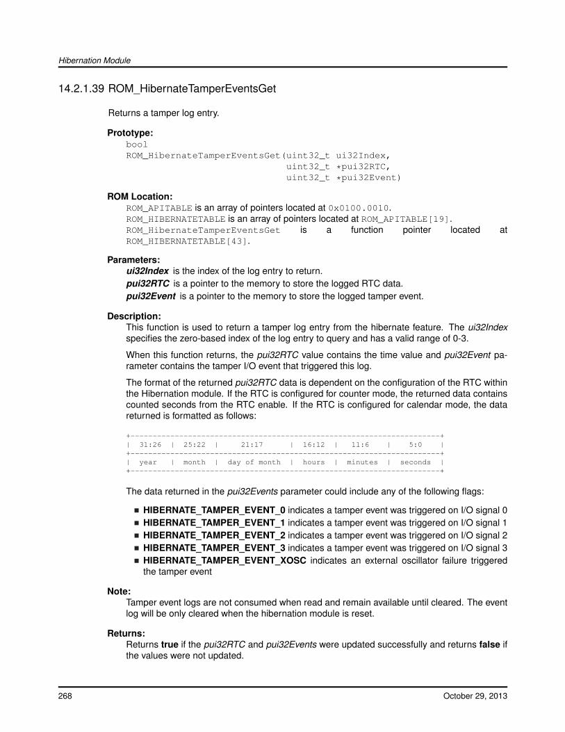
Hibernation Module
14.2.1.39 ROM_HibernateTamperEventsGet
Returns a tamper log entry.
Prototype:boolROM_HibernateTamperEventsGet(uint32_t ui32Index,
uint32_t *pui32RTC,uint32_t *pui32Event)
ROM Location:ROM_APITABLE is an array of pointers located at 0x0100.0010.ROM_HIBERNATETABLE is an array of pointers located at ROM_APITABLE[19].ROM_HibernateTamperEventsGet is a function pointer located atROM_HIBERNATETABLE[43].
Parameters:ui32Index is the index of the log entry to return.pui32RTC is a pointer to the memory to store the logged RTC data.pui32Event is a pointer to the memory to store the logged tamper event.
Description:This function is used to return a tamper log entry from the hibernate feature. The ui32Indexspecifies the zero-based index of the log entry to query and has a valid range of 0-3.
When this function returns, the pui32RTC value contains the time value and pui32Event pa-rameter contains the tamper I/O event that triggered this log.
The format of the returned pui32RTC data is dependent on the configuration of the RTC withinthe Hibernation module. If the RTC is configured for counter mode, the returned data containscounted seconds from the RTC enable. If the RTC is configured for calendar mode, the datareturned is formatted as follows:
+----------------------------------------------------------------------+| 31:26 | 25:22 | 21:17 | 16:12 | 11:6 | 5:0 |+----------------------------------------------------------------------+| year | month | day of month | hours | minutes | seconds |+----------------------------------------------------------------------+
The data returned in the pui32Events parameter could include any of the following flags:
HIBERNATE_TAMPER_EVENT_0 indicates a tamper event was triggered on I/O signal 0HIBERNATE_TAMPER_EVENT_1 indicates a tamper event was triggered on I/O signal 1HIBERNATE_TAMPER_EVENT_2 indicates a tamper event was triggered on I/O signal 2HIBERNATE_TAMPER_EVENT_3 indicates a tamper event was triggered on I/O signal 3HIBERNATE_TAMPER_EVENT_XOSC indicates an external oscillator failure triggeredthe tamper event
Note:Tamper event logs are not consumed when read and remain available until cleared. The eventlog will be only cleared when the hibernation module is reset.
Returns:Returns true if the pui32RTC and pui32Events were updated successfully and returns false ifthe values were not updated.
268 October 29, 2013
Hibernation Module
14.2.1.40 ROM_HibernateTamperExtOscRecover
Attempts to recover the external oscillator.
Prototype:voidROM_HibernateTamperExtOscRecover(void)
ROM Location:ROM_APITABLE is an array of pointers located at 0x0100.0010.ROM_HIBERNATETABLE is an array of pointers located at ROM_APITABLE[19].ROM_HibernateTamperExtOscRecover is a function pointer located atROM_HIBERNATETABLE[45].
Description:This function is used to attempt to recover the external oscillator after a HIBER-NATE_TAMPER_STATUS_EXT_OSC_FAILED status is reported. This function mustnot be called if the external oscillator is not used as the hibernation clock input.ROM_HibernateTamperExtOscValid() should be called before calling this function.
Returns:None.
14.2.1.41 ROM_HibernateTamperExtOscValid
Reports if the external oscillator signal is active and stable.
Prototype:boolROM_HibernateTamperExtOscValid(void)
ROM Location:ROM_APITABLE is an array of pointers located at 0x0100.0010.ROM_HIBERNATETABLE is an array of pointers located at ROM_APITABLE[19].ROM_HibernateTamperExtOscValid is a function pointer located atROM_HIBERNATETABLE[44].
Description:This function should be used to verify the external oscillator is active and valid before attempt-ing to recover from a HIBERNATE_TAMPER_STATUS_EXT_OSC_FAILED status by callingROM_HibernateTamperExtOscRecover().
Returns:Returns true if the external oscillator is both active and stable otherwise a false indicator isreturned.
14.2.1.42 ROM_HibernateTamperIODisable
Disables an input to the tamper feature.
October 29, 2013 269
Hibernation Module
Prototype:voidROM_HibernateTamperIODisable(uint32_t ui32Input)
ROM Location:ROM_APITABLE is an array of pointers located at 0x0100.0010.ROM_HIBERNATETABLE is an array of pointers located at ROM_APITABLE[19].ROM_HibernateTamperIODisable is a function pointer located atROM_HIBERNATETABLE[46].
Parameters:ui32Input is the tamper input to disable.
Description:This function is used to disable an input to the tamper feature. The ui32Input parameter spec-ifies the tamper signal to disable and has a valid range of 0-3.
Returns:None.
14.2.1.43 ROM_HibernateTamperIOEnable
Configures an input to the tamper feature.
Prototype:voidROM_HibernateTamperIOEnable(uint32_t ui32Input,
uint32_t ui32Config)
ROM Location:ROM_APITABLE is an array of pointers located at 0x0100.0010.ROM_HIBERNATETABLE is an array of pointers located at ROM_APITABLE[19].ROM_HibernateTamperIOEnable is a function pointer located atROM_HIBERNATETABLE[47].
Parameters:ui32Input is the tamper input to configure.ui32Config holds the configuration options for a given input to the tamper feature.
Description:This function is used to configure an input to the tamper feature. The ui32Input parameterspecifies the tamper signal to configure and has a valid range of 0-3. The ui32Config parameterprovides the set of tamper features in the HIBERNATE_TAMPER_IO_∗ values. The values thatare valid in the ui32Config parameter are:
HIBERNATE_TAMPER_IO_MATCH_SHORT configures the trigger to match after 2 hiber-nation clocksHIBERNATE_TAMPER_IO_MATCH_LONG configures the trigger to match after 3071 hi-bernation clocksHIBERNATE_TAMPER_IO_WPU_ENABLED turns on an internal weak pull upHIBERNATE_TAMPER_IO_WPU_DISABLED turns off an internal weak pull upHIBERNATE_TAMPER_IO_TRIGGER_HIGH sets the tamper event to active high
270 October 29, 2013
Hibernation Module
HIBERNATE_TAMPER_IO_TRIGGER_LOW sets the tamper event to active low
Returns:None.
14.2.1.44 ROM_HibernateTamperStatusGet
Returns the current tamper feature status.
Prototype:uint32_tROM_HibernateTamperStatusGet(void)
ROM Location:ROM_APITABLE is an array of pointers located at 0x0100.0010.ROM_HIBERNATETABLE is an array of pointers located at ROM_APITABLE[19].ROM_HibernateTamperStatusGet is a function pointer located atROM_HIBERNATETABLE[48].
Description:This function is used to return the tamper feature status. This function returns one of the valuesfrom this group of options:
HIBERNATE_TAMPER_STATUS_INACTIVE indicates tamper detection is disabledHIBERNATE_TAMPER_STATUS_ACTIVE indicates tamper detection is enabled andreadyHIBERNATE_TAMPER_STATUS_EVENT indicates tamper event was detected
In addition, one of the values is included from this group:
HIBERNATE_TAMPER_STATUS_EXT_OSC_INACTIVE indicates the external oscillatoris not activeHIBERNATE_TAMPER_STATUS_EXT_OSC_ACTIVE indicates the external oscillator isactive
And one of the values is included from this group:
HIBERNATE_TAMPER_STATUS_EXT_OSC_FAILED indicates the external oscillatorsignal has transitioned from valid to invalidHIBERNATE_TAMPER_STATUS_EXT_OSC_VALID indicates the external oscillator isproviding a valid signal
Returns:Returns a combination of the HIBERNATE_TAMPER_STATUS_∗ values.
14.2.1.45 ROM_HibernateWakeGet
Gets the currently configured wake conditions for the Hibernation module.
Prototype:uint32_tROM_HibernateWakeGet(void)
October 29, 2013 271
Hibernation Module
ROM Location:ROM_APITABLE is an array of pointers located at 0x0100.0010.ROM_HIBERNATETABLE is an array of pointers located at ROM_APITABLE[19].ROM_HibernateWakeGet is a function pointer located at ROM_HIBERNATETABLE[7].
Description:This function returns the flags representing the wake configuration for the Hibernation module.The return value is a combination of the following flags:
HIBERNATE_WAKE_PIN - wake when the external wake pin is assertedHIBERNATE_WAKE_RTC - wake when the RTC matches occursHIBERNATE_WAKE_LOW_BAT - wake from hibernation due to a low-battery level beingdetectedHIBERNATE_WAKE_GPIO - wake when a GPIO pin is assertedHIBERNATE_WAKE_RESET - wake when a reset pin is asserted
Note:Refer the function ROM_HibernateTamperEventsConfig() to wake from hibernation on a tam-per event.
Returns:Returns flags indicating the configured wake conditions.
14.2.1.46 ROM_HibernateWakeSet
Configures the wake conditions for the Hibernation module.
Prototype:voidROM_HibernateWakeSet(uint32_t ui32WakeFlags)
ROM Location:ROM_APITABLE is an array of pointers located at 0x0100.0010.ROM_HIBERNATETABLE is an array of pointers located at ROM_APITABLE[19].ROM_HibernateWakeSet is a function pointer located at ROM_HIBERNATETABLE[6].
Parameters:ui32WakeFlags specifies which conditions should be used for waking.
Description:This function enables the conditions under which the Hibernation module wakes. Theui32WakeFlags parameter is the logical OR of any combination of the following:
HIBERNATE_WAKE_PIN - wake when the external wake pin is asserted.HIBERNATE_WAKE_RTC - wake when the RTC match occurs.HIBERNATE_WAKE_LOW_BAT - wake from hibernate due to a low-battery level beingdetected.HIBERNATE_WAKE_GPIO - wake when a GPIO pin is asserted.HIBERNATE_WAKE_RESET - wake when a reset pin is asserted.
If the HIBERNATE_WAKE_GPIO flag is set, then one of the GPIO configuration functionsROM_GPIOPinTypeWakeHigh() or ROM_GPIOPinTypeWakeLow() must be called to properlyconfigure and enable a GPIO as a wake source for hibernation.
272 October 29, 2013

Hibernation Module
Note:Refer the function ROM_HibernateTamperEventsConfig() to wake from hibernation on a tam-per event.
Returns:None.
October 29, 2013 273

Hibernation Module
274 October 29, 2013
Inter-Integrated Circuit (I2C)
15 Inter-Integrated Circuit (I2C)Introduction . . . . . . . . . . . . . . . . . . . . . . . . . . . . . . . . . . . . . . . . . . . . . . . . . . . . . . . . . . . . . . . . . . . . . . . . . . . . . . . . . . . . . . . . . . . . .275Functions . . . . . . . . . . . . . . . . . . . . . . . . . . . . . . . . . . . . . . . . . . . . . . . . . . . . . . . . . . . . . . . . . . . . . . . . . . . . . . . . . . . . . . . . . . . . . . . 276
15.1 Introduction
The Inter-Integrated Circuit (I2C) API provides a set of functions for using the Tiva I2C master andslave modules. Functions are provided to initialize the I2C modules, to send and receive data,obtain status, and to manage interrupts for the I2C modules.
The I2C master and slave modules provide the ability to communicate to other IC devices over anI2C bus. The I2C bus is specified to support devices that can both transmit and receive (write andread) data. Also, devices on the I2C bus can be designated as either a master or a slave. TheTiva I2C modules support both sending and receiving data as either a master or a slave, and alsosupport the simultaneous operation as both a master and a slave. Finally, the Tiva I2C modulescan operate at four speeds: Standard (100 kbps), Fast (400 kbps), Fast Mode Plus (1 Mbps) andHigh Speed (3.33 Mbps).
Both the master and slave I2C modules can generate interrupts. The I2C master module generatesinterrupts when a transmit or receive operation is completed (or aborted due to an error); and onsome devices when a clock low timeout has occurred. The I2C slave module generates interruptswhen data has been sent or requested by a master; and on some devices, when a START or STOPcondition is present.
15.1.1 Master Operations
When using this API to drive the I2C master module, the user must first initialize the I2C mastermodule with a call to ROM_I2CMasterInitExpClk(). That function sets the bus speed and enablesthe master module.
The user may transmit or receive data after the successful initialization of the I2C master module.Data is transferred by first setting the slave address using ROM_I2CMasterSlaveAddrSet(). Thatfunction is also used to define whether the transfer is a send (a write to the slave from the master) ora receive (a read from the slave by the master). Then, if connected to an I2C bus that has multiplemasters, the Tiva I2C master must first call ROM_I2CMasterBusBusy() before attempting to initiatethe desired transaction. After determining that the bus is not busy, if trying to send data, the usermust call the ROM_I2CMasterDataPut() function. The transaction can then be initiated on the busby calling the I2CMasterControl() function with any of the following commands:
I2C_MASTER_CMD_SINGLE_SEND
I2C_MASTER_CMD_SINGLE_RECEIVE
I2C_MASTER_CMD_BURST_SEND_START
I2C_MASTER_CMD_BURST_RECEIVE_START
Any of those commands results in the master arbitrating for the bus, driving the start sequenceonto the bus, and sending the slave address and direction bit across the bus. The remainder of thetransaction can then be driven using either a polling or interrupt-driven method.
October 29, 2013 275
Inter-Integrated Circuit (I2C)
For the single send and receive cases, the polling method involves looping on the re-turn from ROM_I2CMasterBusy(). Once that function indicates that the I2C master isno longer busy, the bus transaction has been completed and can be checked for er-rors using ROM_I2CMasterErr(). If there are no errors, then the data has been sent oris ready to be read using I2CMasterDataGet(). For the burst send and receive cases,the polling method also involves calling the ROM_I2CMasterControl() function for eachbyte transmitted or received (using either the I2C_MASTER_CMD_BURST_SEND_CONTor I2C_MASTER_CMD_BURST_RECEIVE_CONT commands), and for the last bytesent or received (using either the I2C_MASTER_CMD_BURST_SEND_FINISH orI2C_MASTER_CMD_BURST_RECEIVE_FINISH commands). If any error is detectedduring the burst transfer, the ROM_I2CMasterControl() function should be called usingthe appropriate stop command (I2C_MASTER_CMD_BURST_SEND_ERROR_STOP orI2C_MASTER_CMD_BURST_RECEIVE_ERROR_STOP).
For the interrupt-driven transaction, the user must register an interrupt handler for the I2C devicesand enable the I2C master interrupt; the interrupt occurs when the master is no longer busy.
15.1.2 Slave Operations
When using this API to drive the I2C slave module, the user must first initialize the I2C slavemodule with a call to ROM_I2CSlaveInit(). This function enables the I2C slave module and ini-tializes the slave’s own address. After the initialization is complete, the user may poll the slavestatus using ROM_I2CSlaveStatus() to determine if a master requested a send or receive oper-ation. Depending on the type of operation requested, the user can call ROM_I2CSlaveDataPut()or ROM_I2CSlaveDataGet() to complete the transaction. Alternatively, the I2C slave can handletransactions using an interrupt handler.
15.2 Functions
Functionsuint32_t ROM_I2CFIFODataGet (uint32_t ui32Base)uint32_t ROM_I2CFIFODataGetNonBlocking (uint32_t ui32Base, uint8_t ∗pui8Data)void ROM_I2CFIFODataPut (uint32_t ui32Base, uint8_t ui8Data)uint32_t ROM_I2CFIFODataPutNonBlocking (uint32_t ui32Base, uint8_t ui8Data)uint32_t ROM_I2CFIFOStatus (uint32_t ui32Base)uint32_t ROM_I2CMasterBurstCountGet (uint32_t ui32Base)void ROM_I2CMasterBurstLengthSet (uint32_t ui32Base, uint8_t ui8Length)bool ROM_I2CMasterBusBusy (uint32_t ui32Base)bool ROM_I2CMasterBusy (uint32_t ui32Base)void ROM_I2CMasterControl (uint32_t ui32Base, uint32_t ui32Cmd)uint32_t ROM_I2CMasterDataGet (uint32_t ui32Base)void ROM_I2CMasterDataPut (uint32_t ui32Base, uint8_t ui8Data)void ROM_I2CMasterDisable (uint32_t ui32Base)void ROM_I2CMasterEnable (uint32_t ui32Base)uint32_t ROM_I2CMasterErr (uint32_t ui32Base)void ROM_I2CMasterGlitchFilterConfigSet (uint32_t ui32Base, uint32_t ui32Config)
276 October 29, 2013
Inter-Integrated Circuit (I2C)
void ROM_I2CMasterInitExpClk (uint32_t ui32Base, uint32_t ui32I2CClk, bool bFast)void ROM_I2CMasterIntClear (uint32_t ui32Base)void ROM_I2CMasterIntClearEx (uint32_t ui32Base, uint32_t ui32IntFlags)void ROM_I2CMasterIntDisable (uint32_t ui32Base)void ROM_I2CMasterIntDisableEx (uint32_t ui32Base, uint32_t ui32IntFlags)void ROM_I2CMasterIntEnable (uint32_t ui32Base)void ROM_I2CMasterIntEnableEx (uint32_t ui32Base, uint32_t ui32IntFlags)bool ROM_I2CMasterIntStatus (uint32_t ui32Base, bool bMasked)uint32_t ROM_I2CMasterIntStatusEx (uint32_t ui32Base, bool bMasked)uint32_t ROM_I2CMasterLineStateGet (uint32_t ui32Base)void ROM_I2CMasterSlaveAddrSet (uint32_t ui32Base, uint8_t ui8SlaveAddr, bool bReceive)void ROM_I2CMasterTimeoutSet (uint32_t ui32Base, uint32_t ui32Value)void ROM_I2CRxFIFOConfigSet (uint32_t ui32Base, uint32_t ui32Config)void ROM_I2CRxFIFOFlush (uint32_t ui32Base)void ROM_I2CSlaveACKOverride (uint32_t ui32Base, bool bEnable)void ROM_I2CSlaveACKValueSet (uint32_t ui32Base, bool bACK)void ROM_I2CSlaveAddressSet (uint32_t ui32Base, uint8_t ui8AddrNum, uint8_tui8SlaveAddr)uint32_t ROM_I2CSlaveDataGet (uint32_t ui32Base)void ROM_I2CSlaveDataPut (uint32_t ui32Base, uint8_t ui8Data)void ROM_I2CSlaveDisable (uint32_t ui32Base)void ROM_I2CSlaveEnable (uint32_t ui32Base)void ROM_I2CSlaveFIFODisable (uint32_t ui32Base)void ROM_I2CSlaveFIFOEnable (uint32_t ui32Base, uint32_t ui32Config)void ROM_I2CSlaveInit (uint32_t ui32Base, uint8_t ui8SlaveAddr)void ROM_I2CSlaveIntClear (uint32_t ui32Base)void ROM_I2CSlaveIntClearEx (uint32_t ui32Base, uint32_t ui32IntFlags)void ROM_I2CSlaveIntDisable (uint32_t ui32Base)void ROM_I2CSlaveIntDisableEx (uint32_t ui32Base, uint32_t ui32IntFlags)void ROM_I2CSlaveIntEnable (uint32_t ui32Base)void ROM_I2CSlaveIntEnableEx (uint32_t ui32Base, uint32_t ui32IntFlags)bool ROM_I2CSlaveIntStatus (uint32_t ui32Base, bool bMasked)uint32_t ROM_I2CSlaveIntStatusEx (uint32_t ui32Base, bool bMasked)uint32_t ROM_I2CSlaveStatus (uint32_t ui32Base)void ROM_I2CTxFIFOConfigSet (uint32_t ui32Base, uint32_t ui32Config)void ROM_I2CTxFIFOFlush (uint32_t ui32Base)void ROM_UpdateI2C (void)
15.2.1 Function Documentation
15.2.1.1 ROM_I2CFIFODataGet
Reads a byte from the I2C receive FIFO.
Prototype:uint32_tROM_I2CFIFODataGet(uint32_t ui32Base)
October 29, 2013 277
Inter-Integrated Circuit (I2C)
ROM Location:ROM_APITABLE is an array of pointers located at 0x0100.0010.ROM_I2CTABLE is an array of pointers located at ROM_APITABLE[3].ROM_I2CFIFODataGet is a function pointer located at ROM_I2CTABLE[46].
Parameters:ui32Base is the base address of the I2C module.
Description:This function reads a byte of data from I2C receive FIFO. If there is no data available, thisfunction waits until data is received before returning.
Returns:The data byte.
15.2.1.2 ROM_I2CFIFODataGetNonBlocking
Reads a byte from the I2C receive FIFO.
Prototype:uint32_tROM_I2CFIFODataGetNonBlocking(uint32_t ui32Base,
uint8_t *pui8Data)
ROM Location:ROM_APITABLE is an array of pointers located at 0x0100.0010.ROM_I2CTABLE is an array of pointers located at ROM_APITABLE[3].ROM_I2CFIFODataGetNonBlocking is a function pointer located at ROM_I2CTABLE[47].
Parameters:ui32Base is the base address of the I2C module.pui8Data is a pointer where the read data is stored.
Description:This function reads a byte of data from I2C receive FIFO and places it in the location specifiedby the pui8Data parameter. If there is no data available, this functions returns 0.
Returns:The number of elements read from the I2C receive FIFO.
15.2.1.3 ROM_I2CFIFODataPut
Writes a data byte to the I2C transmit FIFO.
Prototype:voidROM_I2CFIFODataPut(uint32_t ui32Base,
uint8_t ui8Data)
278 October 29, 2013
Inter-Integrated Circuit (I2C)
ROM Location:ROM_APITABLE is an array of pointers located at 0x0100.0010.ROM_I2CTABLE is an array of pointers located at ROM_APITABLE[3].ROM_I2CFIFODataPut is a function pointer located at ROM_I2CTABLE[44].
Parameters:ui32Base is the base address of the I2C module.ui8Data is the data to be placed into the transmit FIFO.
Description:This function adds a byte of data to the I2C transmit FIFO. If there is no space available in theFIFO, this function waits for space to become available before returning.
Returns:None.
15.2.1.4 ROM_I2CFIFODataPutNonBlocking
Writes a data byte to the I2C transmit FIFO.
Prototype:uint32_tROM_I2CFIFODataPutNonBlocking(uint32_t ui32Base,
uint8_t ui8Data)
ROM Location:ROM_APITABLE is an array of pointers located at 0x0100.0010.ROM_I2CTABLE is an array of pointers located at ROM_APITABLE[3].ROM_I2CFIFODataPutNonBlocking is a function pointer located at ROM_I2CTABLE[45].
Parameters:ui32Base is the base address of the I2C module.ui8Data is the data to be placed into the transmit FIFO.
Description:This function adds a byte of data to the I2C transmit FIFO. If there is no space available in theFIFO, this function returns a zero.
Returns:The number of elements added to the I2C transmit FIFO.
15.2.1.5 ROM_I2CFIFOStatus
Gets the current FIFO status.
Prototype:uint32_tROM_I2CFIFOStatus(uint32_t ui32Base)
October 29, 2013 279
Inter-Integrated Circuit (I2C)
ROM Location:ROM_APITABLE is an array of pointers located at 0x0100.0010.ROM_I2CTABLE is an array of pointers located at ROM_APITABLE[3].ROM_I2CFIFOStatus is a function pointer located at ROM_I2CTABLE[43].
Parameters:ui32Base is the base address of the I2C module.
Description:This function retrieves the status for both the transmit (TX) and receive (RX) FIFOs. The triggerlevel for the transmit FIFO is set using ROM_I2CTxFIFOConfigSet() and for the receive FIFOusing ROM_I2CTxFIFOConfigSet().
Returns:Returns the FIFO status, enumerated as a bit field containingI2C_FIFO_RX_BELOW_TRIG_LEVEL, I2C_FIFO_RX_FULL, I2C_FIFO_RX_EMPTY,I2C_FIFO_TX_BELOW_TRIG_LEVEL, I2C_FIFO_TX_FULL, and I2C_FIFO_TX_EMPTY.
15.2.1.6 ROM_I2CMasterBurstCountGet
Returns the current value of the burst transfer counter.
Prototype:uint32_tROM_I2CMasterBurstCountGet(uint32_t ui32Base)
ROM Location:ROM_APITABLE is an array of pointers located at 0x0100.0010.ROM_I2CTABLE is an array of pointers located at ROM_APITABLE[3].ROM_I2CMasterBurstCountGet is a function pointer located at ROM_I2CTABLE[49].
Parameters:ui32Base is the base address of the I2C module.
Description:This function returns the current value of the burst transfer counter that is used by the FIFOmechanism. Software can use this value to determine how many bytes remain in a transfer, orwhere in the transfer the burst operation was if an error has occurred.
Returns:None.
15.2.1.7 ROM_I2CMasterBurstLengthSet
Set the burst length for a I2C master FIFO operation.
Prototype:voidROM_I2CMasterBurstLengthSet(uint32_t ui32Base,
uint8_t ui8Length)
280 October 29, 2013
Inter-Integrated Circuit (I2C)
ROM Location:ROM_APITABLE is an array of pointers located at 0x0100.0010.ROM_I2CTABLE is an array of pointers located at ROM_APITABLE[3].ROM_I2CMasterBurstLengthSet is a function pointer located at ROM_I2CTABLE[48].
Parameters:ui32Base is the base address of the I2C module.ui8Length is the length of the burst transfer.
Description:This function configures the burst length for a I2C Master FIFO operation. The burst lengthis limited to 256 bytes. The burst length applies to a single I2CMCS BURST operation mean-ing that it specifies the burst length for only the current operation (can be TX or RX). Eachburst operation must configure the burst length prior to requesting a burst operation usingROM_I2CMasterControl().
Returns:None.
15.2.1.8 ROM_I2CMasterBusBusy
Indicates whether or not the I2C bus is busy.
Prototype:boolROM_I2CMasterBusBusy(uint32_t ui32Base)
ROM Location:ROM_APITABLE is an array of pointers located at 0x0100.0010.ROM_I2CTABLE is an array of pointers located at ROM_APITABLE[3].ROM_I2CMasterBusBusy is a function pointer located at ROM_I2CTABLE[17].
Parameters:ui32Base is the base address of the I2C module.
Description:This function returns an indication of whether or not the I2C bus is busy. This function can beused in a multi-master environment to determine if another master is currently using the bus.
Returns:Returns true if the I2C bus is busy; otherwise, returns false.
15.2.1.9 ROM_I2CMasterBusy
Indicates whether or not the I2C Master is busy.
Prototype:boolROM_I2CMasterBusy(uint32_t ui32Base)
October 29, 2013 281
Inter-Integrated Circuit (I2C)
ROM Location:ROM_APITABLE is an array of pointers located at 0x0100.0010.ROM_I2CTABLE is an array of pointers located at ROM_APITABLE[3].ROM_I2CMasterBusy is a function pointer located at ROM_I2CTABLE[16].
Parameters:ui32Base is the base address of the I2C module.
Description:This function returns an indication of whether or not the I2C Master is busy transmitting orreceiving data.
Returns:Returns true if the I2C Master is busy; otherwise, returns false.
15.2.1.10 ROM_I2CMasterControl
Controls the state of the I2C Master module.
Prototype:voidROM_I2CMasterControl(uint32_t ui32Base,
uint32_t ui32Cmd)
ROM Location:ROM_APITABLE is an array of pointers located at 0x0100.0010.ROM_I2CTABLE is an array of pointers located at ROM_APITABLE[3].ROM_I2CMasterControl is a function pointer located at ROM_I2CTABLE[18].
Parameters:ui32Base is the base address of the I2C module.ui32Cmd is the command to be issued to the I2C Master module.
Description:This function is used to control the state of the Master module send and receive operations.The ui32Cmd parameter can be one of the following values:
I2C_MASTER_CMD_SINGLE_SENDI2C_MASTER_CMD_SINGLE_RECEIVEI2C_MASTER_CMD_BURST_SEND_STARTI2C_MASTER_CMD_BURST_SEND_CONTI2C_MASTER_CMD_BURST_SEND_FINISHI2C_MASTER_CMD_BURST_SEND_ERROR_STOPI2C_MASTER_CMD_BURST_RECEIVE_STARTI2C_MASTER_CMD_BURST_RECEIVE_CONTI2C_MASTER_CMD_BURST_RECEIVE_FINISHI2C_MASTER_CMD_BURST_RECEIVE_ERROR_STOPI2C_MASTER_CMD_QUICK_COMMANDI2C_MASTER_CMD_HS_MASTER_CODE_SENDI2C_MASTER_CMD_FIFO_SINGLE_SENDI2C_MASTER_CMD_FIFO_SINGLE_RECEIVE
282 October 29, 2013
Inter-Integrated Circuit (I2C)
I2C_MASTER_CMD_FIFO_BURST_SEND_STARTI2C_MASTER_CMD_FIFO_BURST_SEND_CONTI2C_MASTER_CMD_FIFO_BURST_SEND_FINISHI2C_MASTER_CMD_FIFO_BURST_SEND_ERROR_STOPI2C_MASTER_CMD_FIFO_BURST_RECEIVE_STARTI2C_MASTER_CMD_FIFO_BURST_RECEIVE_CONTI2C_MASTER_CMD_FIFO_BURST_RECEIVE_FINISHI2C_MASTER_CMD_FIFO_BURST_RECEIVE_ERROR_STOP
Returns:None.
15.2.1.11 ROM_I2CMasterDataGet
Receives a byte that has been sent to the I2C Master.
Prototype:uint32_tROM_I2CMasterDataGet(uint32_t ui32Base)
ROM Location:ROM_APITABLE is an array of pointers located at 0x0100.0010.ROM_I2CTABLE is an array of pointers located at ROM_APITABLE[3].ROM_I2CMasterDataGet is a function pointer located at ROM_I2CTABLE[20].
Parameters:ui32Base is the base address of the I2C module.
Description:This function reads a byte of data from the I2C Master Data Register.
Returns:Returns the byte received from by the I2C Master, cast as an uint32_t.
15.2.1.12 ROM_I2CMasterDataPut
Transmits a byte from the I2C Master.
Prototype:voidROM_I2CMasterDataPut(uint32_t ui32Base,
uint8_t ui8Data)
ROM Location:ROM_APITABLE is an array of pointers located at 0x0100.0010.ROM_I2CTABLE is an array of pointers located at ROM_APITABLE[3].ROM_I2CMasterDataPut is a function pointer located at ROM_I2CTABLE[0].
Parameters:ui32Base is the base address of the I2C module.
October 29, 2013 283
Inter-Integrated Circuit (I2C)
ui8Data is the data to be transmitted from the I2C Master.
Description:This function places the supplied data into I2C Master Data Register.
Returns:None.
15.2.1.13 ROM_I2CMasterDisable
Disables the I2C master block.
Prototype:voidROM_I2CMasterDisable(uint32_t ui32Base)
ROM Location:ROM_APITABLE is an array of pointers located at 0x0100.0010.ROM_I2CTABLE is an array of pointers located at ROM_APITABLE[3].ROM_I2CMasterDisable is a function pointer located at ROM_I2CTABLE[5].
Parameters:ui32Base is the base address of the I2C module.
Description:This function disables operation of the I2C master block.
Returns:None.
15.2.1.14 ROM_I2CMasterEnable
Enables the I2C Master block.
Prototype:voidROM_I2CMasterEnable(uint32_t ui32Base)
ROM Location:ROM_APITABLE is an array of pointers located at 0x0100.0010.ROM_I2CTABLE is an array of pointers located at ROM_APITABLE[3].ROM_I2CMasterEnable is a function pointer located at ROM_I2CTABLE[3].
Parameters:ui32Base is the base address of the I2C module.
Description:This function enables operation of the I2C Master block.
Returns:None.
284 October 29, 2013
Inter-Integrated Circuit (I2C)
15.2.1.15 ROM_I2CMasterErr
Gets the error status of the I2C Master module.
Prototype:uint32_tROM_I2CMasterErr(uint32_t ui32Base)
ROM Location:ROM_APITABLE is an array of pointers located at 0x0100.0010.ROM_I2CTABLE is an array of pointers located at ROM_APITABLE[3].ROM_I2CMasterErr is a function pointer located at ROM_I2CTABLE[19].
Parameters:ui32Base is the base address of the I2C module.
Description:This function is used to obtain the error status of the Master module send and receive opera-tions.
Returns:Returns the error status, as one of I2C_MASTER_ERR_NONE,I2C_MASTER_ERR_ADDR_ACK, I2C_MASTER_ERR_DATA_ACK, orI2C_MASTER_ERR_ARB_LOST.
15.2.1.16 ROM_I2CMasterGlitchFilterConfigSet
Configures the I2C Master glitch filter.
Prototype:voidROM_I2CMasterGlitchFilterConfigSet(uint32_t ui32Base,
uint32_t ui32Config)
ROM Location:ROM_APITABLE is an array of pointers located at 0x0100.0010.ROM_I2CTABLE is an array of pointers located at ROM_APITABLE[3].ROM_I2CMasterGlitchFilterConfigSet is a function pointer located atROM_I2CTABLE[54].
Parameters:ui32Base is the base address of the I2C module.ui32Config is the glitch filter configuration.
Description:This function configures the I2C Master glitch filter. The value passed in to ui32Config deter-mines the sampling range of the glitch filter, which is configurable between 1 and 32 systemclock cycles. The default configuration of the glitch filter is 0 system clock cycles, which meansthat it’s disabled.
The ui32Config field should be any of the following values:
I2C_MASTER_GLITCH_FILTER_DISABLED
October 29, 2013 285
Inter-Integrated Circuit (I2C)
I2C_MASTER_GLITCH_FILTER_1I2C_MASTER_GLITCH_FILTER_2I2C_MASTER_GLITCH_FILTER_3I2C_MASTER_GLITCH_FILTER_4I2C_MASTER_GLITCH_FILTER_8I2C_MASTER_GLITCH_FILTER_16I2C_MASTER_GLITCH_FILTER_32
Returns:None.
15.2.1.17 ROM_I2CMasterInitExpClk
Initializes the I2C Master block.
Prototype:voidROM_I2CMasterInitExpClk(uint32_t ui32Base,
uint32_t ui32I2CClk,bool bFast)
ROM Location:ROM_APITABLE is an array of pointers located at 0x0100.0010.ROM_I2CTABLE is an array of pointers located at ROM_APITABLE[3].ROM_I2CMasterInitExpClk is a function pointer located at ROM_I2CTABLE[1].
Parameters:ui32Base is the base address of the I2C module.ui32I2CClk is the rate of the clock supplied to the I2C module.bFast set up for fast data transfers.
Description:This function initializes operation of the I2C Master block by configuring the bus speed for themaster and enabling the I2C Master block.
If the parameter bFast is true, then the master block is set up to transfer data at 400 Kbps;otherwise, it is set up to transfer data at 100 Kbps. If Fast Mode Plus (1 Mbps) is desired, soft-ware should manually write the I2CMTPR after calling this function. For High Speed (3.4 Mbps)mode, a specific command is used to switch to the faster clocks after the initial communicationwith the slave is done at either 100 Kbps or 400 Kbps.
The peripheral clock is the same as the processor clock. This value is returned byROM_SysCtlClockFreqSet(), or it can be explicitly hard-coded if it is constant and known.
Returns:None.
15.2.1.18 ROM_I2CMasterIntClear
Clears I2C Master interrupt sources.
286 October 29, 2013
Inter-Integrated Circuit (I2C)
Prototype:voidROM_I2CMasterIntClear(uint32_t ui32Base)
ROM Location:ROM_APITABLE is an array of pointers located at 0x0100.0010.ROM_I2CTABLE is an array of pointers located at ROM_APITABLE[3].ROM_I2CMasterIntClear is a function pointer located at ROM_I2CTABLE[13].
Parameters:ui32Base is the base address of the I2C module.
Description:The I2C Master interrupt source is cleared, so that it no longer asserts. This function mustbe called in the interrupt handler to keep the interrupt from being triggered again immediatelyupon exit.
Note:Because there is a write buffer in the Cortex-M processor, it may take several clock cyclesbefore the interrupt source is actually cleared. Therefore, it is recommended that the interruptsource be cleared early in the interrupt handler (as opposed to the very last action) to avoidreturning from the interrupt handler before the interrupt source is actually cleared. Failure todo so may result in the interrupt handler being immediately reentered (because the interruptcontroller still sees the interrupt source asserted).
Returns:None.
15.2.1.19 ROM_I2CMasterIntClearEx
Clears I2C Master interrupt sources.
Prototype:voidROM_I2CMasterIntClearEx(uint32_t ui32Base,
uint32_t ui32IntFlags)
ROM Location:ROM_APITABLE is an array of pointers located at 0x0100.0010.ROM_I2CTABLE is an array of pointers located at ROM_APITABLE[3].ROM_I2CMasterIntClearEx is a function pointer located at ROM_I2CTABLE[32].
Parameters:ui32Base is the base address of the I2C module.ui32IntFlags is a bit mask of the interrupt sources to be cleared.
Description:The specified I2C Master interrupt sources are cleared, so that they no longer assert. Thisfunction must be called in the interrupt handler to keep the interrupt from being triggered againimmediately upon exit.
The ui32IntFlags parameter has the same definition as the ui32IntFlags parameter toROM_I2CMasterIntEnableEx().
October 29, 2013 287
Inter-Integrated Circuit (I2C)
Note:Because there is a write buffer in the Cortex-M processor, it may take several clock cyclesbefore the interrupt source is actually cleared. Therefore, it is recommended that the interruptsource be cleared early in the interrupt handler (as opposed to the very last action) to avoidreturning from the interrupt handler before the interrupt source is actually cleared. Failure todo so may result in the interrupt handler being immediately reentered (because the interruptcontroller still sees the interrupt source asserted).
Returns:None.
15.2.1.20 ROM_I2CMasterIntDisable
Disables the I2C Master interrupt.
Prototype:voidROM_I2CMasterIntDisable(uint32_t ui32Base)
ROM Location:ROM_APITABLE is an array of pointers located at 0x0100.0010.ROM_I2CTABLE is an array of pointers located at ROM_APITABLE[3].ROM_I2CMasterIntDisable is a function pointer located at ROM_I2CTABLE[9].
Parameters:ui32Base is the base address of the I2C module.
Description:This function disables the I2C Master interrupt source.
Returns:None.
15.2.1.21 ROM_I2CMasterIntDisableEx
Disables individual I2C Master interrupt sources.
Prototype:voidROM_I2CMasterIntDisableEx(uint32_t ui32Base,
uint32_t ui32IntFlags)
ROM Location:ROM_APITABLE is an array of pointers located at 0x0100.0010.ROM_I2CTABLE is an array of pointers located at ROM_APITABLE[3].ROM_I2CMasterIntDisableEx is a function pointer located at ROM_I2CTABLE[30].
Parameters:ui32Base is the base address of the I2C module.ui32IntFlags is the bit mask of the interrupt sources to be disabled.
288 October 29, 2013
Inter-Integrated Circuit (I2C)
Description:This function disables the indicated I2C Master interrupt sources. Only the sources that areenabled can be reflected to the processor interrupt; disabled sources have no effect on theprocessor.
The ui32IntFlags parameter has the same definition as the ui32IntFlags parameter toROM_I2CMasterIntEnableEx().
Returns:None.
15.2.1.22 ROM_I2CMasterIntEnable
Enables the I2C Master interrupt.
Prototype:voidROM_I2CMasterIntEnable(uint32_t ui32Base)
ROM Location:ROM_APITABLE is an array of pointers located at 0x0100.0010.ROM_I2CTABLE is an array of pointers located at ROM_APITABLE[3].ROM_I2CMasterIntEnable is a function pointer located at ROM_I2CTABLE[7].
Parameters:ui32Base is the base address of the I2C module.
Description:This function enables the I2C Master interrupt source.
Returns:None.
15.2.1.23 ROM_I2CMasterIntEnableEx
Enables individual I2C Master interrupt sources.
Prototype:voidROM_I2CMasterIntEnableEx(uint32_t ui32Base,
uint32_t ui32IntFlags)
ROM Location:ROM_APITABLE is an array of pointers located at 0x0100.0010.ROM_I2CTABLE is an array of pointers located at ROM_APITABLE[3].ROM_I2CMasterIntEnableEx is a function pointer located at ROM_I2CTABLE[29].
Parameters:ui32Base is the base address of the I2C module.ui32IntFlags is the bit mask of the interrupt sources to be enabled.
October 29, 2013 289
Inter-Integrated Circuit (I2C)
Description:This function enables the indicated I2C Master interrupt sources. Only the sources that areenabled can be reflected to the processor interrupt; disabled sources have no effect on theprocessor.
The ui32IntFlags parameter is the logical OR of any of the following:
I2C_MASTER_INT_RX_FIFO_FULL - RX FIFO Full interruptI2C_MASTER_INT_TX_FIFO_EMPTY - TX FIFO Empty interruptI2C_MASTER_INT_RX_FIFO_REQ - RX FIFO Request interruptI2C_MASTER_INT_TX_FIFO_REQ - TX FIFO Request interruptI2C_MASTER_INT_ARB_LOST - Arbitration Lost interruptI2C_MASTER_INT_STOP - Stop Condition interruptI2C_MASTER_INT_START - Start Condition interruptI2C_MASTER_INT_NACK - Address/Data NACK interruptI2C_MASTER_INT_TX_DMA_DONE - TX DMA Complete interruptI2C_MASTER_INT_RX_DMA_DONE - RX DMA Complete interruptI2C_MASTER_INT_TIMEOUT - Clock Timeout interruptI2C_MASTER_INT_DATA - Data interrupt
Returns:None.
15.2.1.24 ROM_I2CMasterIntStatus
Gets the current I2C Master interrupt status.
Prototype:boolROM_I2CMasterIntStatus(uint32_t ui32Base,
bool bMasked)
ROM Location:ROM_APITABLE is an array of pointers located at 0x0100.0010.ROM_I2CTABLE is an array of pointers located at ROM_APITABLE[3].ROM_I2CMasterIntStatus is a function pointer located at ROM_I2CTABLE[11].
Parameters:ui32Base is the base address of the I2C module.bMasked is false if the raw interrupt status is requested and true if the masked interrupt status
is requested.
Description:This function returns the interrupt status for the I2C Master module. Either the raw interruptstatus or the status of interrupts that are allowed to reflect to the processor can be returned.
Returns:The current interrupt status, returned as true if active or false if not active.
290 October 29, 2013
Inter-Integrated Circuit (I2C)
15.2.1.25 ROM_I2CMasterIntStatusEx
Gets the current I2C Master interrupt status.
Prototype:uint32_tROM_I2CMasterIntStatusEx(uint32_t ui32Base,
bool bMasked)
ROM Location:ROM_APITABLE is an array of pointers located at 0x0100.0010.ROM_I2CTABLE is an array of pointers located at ROM_APITABLE[3].ROM_I2CMasterIntStatusEx is a function pointer located at ROM_I2CTABLE[31].
Parameters:ui32Base is the base address of the I2C module.bMasked is false if the raw interrupt status is requested and true if the masked interrupt status
is requested.
Description:This function returns the interrupt status for the I2C Master module. Either the raw interruptstatus or the status of interrupts that are allowed to reflect to the processor can be returned.
Returns:Returns the current interrupt status, enumerated as a bit field of values described inROM_I2CMasterIntEnableEx().
15.2.1.26 ROM_I2CMasterLineStateGet
Reads the state of the SDA and SCL pins.
Prototype:uint32_tROM_I2CMasterLineStateGet(uint32_t ui32Base)
ROM Location:ROM_APITABLE is an array of pointers located at 0x0100.0010.ROM_I2CTABLE is an array of pointers located at ROM_APITABLE[3].ROM_I2CMasterLineStateGet is a function pointer located at ROM_I2CTABLE[38].
Parameters:ui32Base is the base address of the I2C module.
Description:This function returns the state of the I2C bus by providing the real time values of the SDA andSCL pins.
Returns:Returns the state of the bus with SDA in bit position 1 and SCL in bit position 0.
October 29, 2013 291
Inter-Integrated Circuit (I2C)
15.2.1.27 ROM_I2CMasterSlaveAddrSet
Sets the address that the I2C Master will place on the bus.
Prototype:voidROM_I2CMasterSlaveAddrSet(uint32_t ui32Base,
uint8_t ui8SlaveAddr,bool bReceive)
ROM Location:ROM_APITABLE is an array of pointers located at 0x0100.0010.ROM_I2CTABLE is an array of pointers located at ROM_APITABLE[3].ROM_I2CMasterSlaveAddrSet is a function pointer located at ROM_I2CTABLE[15].
Parameters:ui32Base is the base address of the I2C module.ui8SlaveAddr 7-bit slave addressbReceive flag indicating the type of communication with the slave
Description:This function configures the address that the I2C Master places on the bus when initiating atransaction. When the bReceive parameter is set to true, the address indicates that the I2CMaster is initiating a read from the slave; otherwise the address indicates that the I2C Masteris initiating a write to the slave.
Returns:None.
15.2.1.28 ROM_I2CMasterTimeoutSet
Sets the Master clock timeout value.
Prototype:voidROM_I2CMasterTimeoutSet(uint32_t ui32Base,
uint32_t ui32Value)
ROM Location:ROM_APITABLE is an array of pointers located at 0x0100.0010.ROM_I2CTABLE is an array of pointers located at ROM_APITABLE[3].ROM_I2CMasterTimeoutSet is a function pointer located at ROM_I2CTABLE[33].
Parameters:ui32Base is the base address of the I2C module.ui32Value is the number of I2C clocks before the timeout is asserted.
Description:This function enables and configures the clock low timeout feature in the I2C peripheral. Thisfeature is implemented as a 12-bit counter, with the upper 8-bits being programmable. Forexample, to program a timeout of 20ms with a 100kHz SCL frequency, ui32Value would be0x7d.
292 October 29, 2013
Inter-Integrated Circuit (I2C)
Returns:None.
15.2.1.29 ROM_I2CRxFIFOConfigSet
Configures the I2C receive (RX) FIFO.
Prototype:voidROM_I2CRxFIFOConfigSet(uint32_t ui32Base,
uint32_t ui32Config)
ROM Location:ROM_APITABLE is an array of pointers located at 0x0100.0010.ROM_I2CTABLE is an array of pointers located at ROM_APITABLE[3].ROM_I2CRxFIFOConfigSet is a function pointer located at ROM_I2CTABLE[41].
Parameters:ui32Base is the base address of the I2C module.ui32Config is the configuration of the FIFO using specified macros.
Description:This function configures the I2C peripheral’s receive FIFO. The receive FIFO can be used bythe master or slave, but not both. The following macros are used to configure the RX FIFObehavior for master or slave, with or without DMA:
I2C_FIFO_CFG_RX_MASTERI2C_FIFO_CFG_RX_SLAVEI2C_FIFO_CFG_RX_MASTER_DMAI2C_FIFO_CFG_RX_SLAVE_DMA
To select the trigger level, one of the following macros should be used:
I2C_FIFO_CFG_RX_TRIG_1I2C_FIFO_CFG_RX_TRIG_2I2C_FIFO_CFG_RX_TRIG_3I2C_FIFO_CFG_RX_TRIG_4I2C_FIFO_CFG_RX_TRIG_5I2C_FIFO_CFG_RX_TRIG_6I2C_FIFO_CFG_RX_TRIG_7I2C_FIFO_CFG_RX_TRIG_8
Returns:None.
15.2.1.30 ROM_I2CRxFIFOFlush
Flushes the receive (RX) FIFO.
October 29, 2013 293
Inter-Integrated Circuit (I2C)
Prototype:voidROM_I2CRxFIFOFlush(uint32_t ui32Base)
ROM Location:ROM_APITABLE is an array of pointers located at 0x0100.0010.ROM_I2CTABLE is an array of pointers located at ROM_APITABLE[3].ROM_I2CRxFIFOFlush is a function pointer located at ROM_I2CTABLE[42].
Parameters:ui32Base is the base address of the I2C module.
Description:This function flushes the I2C receive FIFO.
Returns:None.
15.2.1.31 ROM_I2CSlaveACKOverride
Configures ACK override behavior of the I2C Slave.
Prototype:voidROM_I2CSlaveACKOverride(uint32_t ui32Base,
bool bEnable)
ROM Location:ROM_APITABLE is an array of pointers located at 0x0100.0010.ROM_I2CTABLE is an array of pointers located at ROM_APITABLE[3].ROM_I2CSlaveACKOverride is a function pointer located at ROM_I2CTABLE[34].
Parameters:ui32Base is the base address of the I2C module.bEnable enables or disables ACK override.
Description:This function enables or disables ACK override, allowing the user application to drive the valueon SDA during the ACK cycle.
Returns:None.
15.2.1.32 ROM_I2CSlaveACKValueSet
Writes the ACK value.
Prototype:voidROM_I2CSlaveACKValueSet(uint32_t ui32Base,
bool bACK)
294 October 29, 2013
Inter-Integrated Circuit (I2C)
ROM Location:ROM_APITABLE is an array of pointers located at 0x0100.0010.ROM_I2CTABLE is an array of pointers located at ROM_APITABLE[3].ROM_I2CSlaveACKValueSet is a function pointer located at ROM_I2CTABLE[35].
Parameters:ui32Base is the base address of the I2C module.bACK chooses whether to ACK (true) or NACK (false) the transfer.
Description:This function puts the desired ACK value on SDA during the ACK cycle. The value written isonly valid when ACK override is enabled using ROM_I2CSlaveACKOverride().
Returns:None.
15.2.1.33 ROM_I2CSlaveAddressSet
Sets the I2C slave address.
Prototype:voidROM_I2CSlaveAddressSet(uint32_t ui32Base,
uint8_t ui8AddrNum,uint8_t ui8SlaveAddr)
ROM Location:ROM_APITABLE is an array of pointers located at 0x0100.0010.ROM_I2CTABLE is an array of pointers located at ROM_APITABLE[3].ROM_I2CSlaveAddressSet is a function pointer located at ROM_I2CTABLE[37].
Parameters:ui32Base is the base address of the I2C module.ui8AddrNum determines which slave address is set.ui8SlaveAddr is the 7-bit slave address
Description:This function writes the specified slave address. The ui8AddrNum parameter dictates whichslave address is configured. For example, a value of 0 configures the primary address and avalue of 1 configures the secondary.
Returns:None.
15.2.1.34 ROM_I2CSlaveDataGet
Receives a byte that has been sent to the I2C Slave.
Prototype:uint32_tROM_I2CSlaveDataGet(uint32_t ui32Base)
October 29, 2013 295
Inter-Integrated Circuit (I2C)
ROM Location:ROM_APITABLE is an array of pointers located at 0x0100.0010.ROM_I2CTABLE is an array of pointers located at ROM_APITABLE[3].ROM_I2CSlaveDataGet is a function pointer located at ROM_I2CTABLE[23].
Parameters:ui32Base is the base address of the I2C module.
Description:This function reads a byte of data from the I2C Slave Data Register.
Returns:Returns the byte received from by the I2C Slave, cast as an uint32_t.
15.2.1.35 ROM_I2CSlaveDataPut
Transmits a byte from the I2C Slave.
Prototype:voidROM_I2CSlaveDataPut(uint32_t ui32Base,
uint8_t ui8Data)
ROM Location:ROM_APITABLE is an array of pointers located at 0x0100.0010.ROM_I2CTABLE is an array of pointers located at ROM_APITABLE[3].ROM_I2CSlaveDataPut is a function pointer located at ROM_I2CTABLE[22].
Parameters:ui32Base is the base address of the I2C module.ui8Data is the data to be transmitted from the I2C Slave.
Description:This function places the supplied data into I2C Slave Data Register.
Returns:None.
15.2.1.36 ROM_I2CSlaveDisable
Disables the I2C slave block.
Prototype:voidROM_I2CSlaveDisable(uint32_t ui32Base)
ROM Location:ROM_APITABLE is an array of pointers located at 0x0100.0010.ROM_I2CTABLE is an array of pointers located at ROM_APITABLE[3].ROM_I2CSlaveDisable is a function pointer located at ROM_I2CTABLE[6].
296 October 29, 2013
Inter-Integrated Circuit (I2C)
Parameters:ui32Base is the base address of the I2C module.
Description:This function disables operation of the I2C slave block.
Returns:None.
15.2.1.37 ROM_I2CSlaveEnable
Enables the I2C Slave block.
Prototype:voidROM_I2CSlaveEnable(uint32_t ui32Base)
ROM Location:ROM_APITABLE is an array of pointers located at 0x0100.0010.ROM_I2CTABLE is an array of pointers located at ROM_APITABLE[3].ROM_I2CSlaveEnable is a function pointer located at ROM_I2CTABLE[4].
Parameters:ui32Base is the base address of the I2C module.
Description:This function enables operation of the I2C Slave block.
Returns:None.
15.2.1.38 ROM_I2CSlaveFIFODisable
Disable FIFO usage for the I2C Slave module.
Prototype:voidROM_I2CSlaveFIFODisable(uint32_t ui32Base)
ROM Location:ROM_APITABLE is an array of pointers located at 0x0100.0010.ROM_I2CTABLE is an array of pointers located at ROM_APITABLE[3].ROM_I2CSlaveFIFODisable is a function pointer located at ROM_I2CTABLE[50].
Parameters:ui32Base is the base address of the I2C module.
Description:This function disables the FIFOs for the I2C Slave. After calling this this function, the FIFOsare disabled, but the Slave remains active.
Returns:None.
October 29, 2013 297
Inter-Integrated Circuit (I2C)
15.2.1.39 ROM_I2CSlaveFIFOEnable
Enables FIFO usage for the I2C Slave module.
Prototype:voidROM_I2CSlaveFIFOEnable(uint32_t ui32Base,
uint32_t ui32Config)
ROM Location:ROM_APITABLE is an array of pointers located at 0x0100.0010.ROM_I2CTABLE is an array of pointers located at ROM_APITABLE[3].ROM_I2CSlaveFIFOEnable is a function pointer located at ROM_I2CTABLE[51].
Parameters:ui32Base is the base address of the I2C module.ui32Config is the desired FIFO configuration of the I2C Slave.
Description:This function configures the I2C Slave module to use the FIFO(s). This function should be usedin combination with ROM_I2CTxFIFOConfigSet() and/or ROM_I2CRxFIFOConfigSet(), whichconfigure the FIFO trigger level and tell the FIFO hardware whether to interact with the I2CMaster or Slave. The application appropriate combination of I2C_SLAVE_TX_FIFO_ENABLEand I2C_SLAVE_RX_FIFO_ENABLE should be passed in to the ui32Config field.
Because the Slave I2CSCSR register is write-only, any call to ROM_I2CSlaveEnable(),ROM_I2CSlaveDisable() or ROM_I2CSlaveFIFOEnable() overwrites the slave configura-tion. Therefore, application software should call ROM_I2CSlaveEnable() followed byROM_I2CSlaveFIFOEnable() with the desired FIFO configuration.
Returns:None.
15.2.1.40 ROM_I2CSlaveInit
Initializes the I2C Slave block.
Prototype:voidROM_I2CSlaveInit(uint32_t ui32Base,
uint8_t ui8SlaveAddr)
ROM Location:ROM_APITABLE is an array of pointers located at 0x0100.0010.ROM_I2CTABLE is an array of pointers located at ROM_APITABLE[3].ROM_I2CSlaveInit is a function pointer located at ROM_I2CTABLE[2].
Parameters:ui32Base is the base address of the I2C module.ui8SlaveAddr 7-bit slave address
298 October 29, 2013
Inter-Integrated Circuit (I2C)
Description:This function initializes operation of the I2C Slave block by configuring the slave address andenabling the I2C Slave block.
The parameter ui8SlaveAddr is the value that is compared against the slave address sent byan I2C master.
Returns:None.
15.2.1.41 ROM_I2CSlaveIntClear
Clears I2C Slave interrupt sources.
Prototype:voidROM_I2CSlaveIntClear(uint32_t ui32Base)
ROM Location:ROM_APITABLE is an array of pointers located at 0x0100.0010.ROM_I2CTABLE is an array of pointers located at ROM_APITABLE[3].ROM_I2CSlaveIntClear is a function pointer located at ROM_I2CTABLE[14].
Parameters:ui32Base is the base address of the I2C module.
Description:The I2C Slave interrupt source is cleared, so that it no longer asserts. This function mustbe called in the interrupt handler to keep the interrupt from being triggered again immediatelyupon exit.
Note:Because there is a write buffer in the Cortex-M processor, it may take several clock cyclesbefore the interrupt source is actually cleared. Therefore, it is recommended that the interruptsource be cleared early in the interrupt handler (as opposed to the very last action) to avoidreturning from the interrupt handler before the interrupt source is actually cleared. Failure todo so may result in the interrupt handler being immediately reentered (because the interruptcontroller still sees the interrupt source asserted).
Returns:None.
15.2.1.42 ROM_I2CSlaveIntClearEx
Clears I2C Slave interrupt sources.
Prototype:voidROM_I2CSlaveIntClearEx(uint32_t ui32Base,
uint32_t ui32IntFlags)
October 29, 2013 299
Inter-Integrated Circuit (I2C)
ROM Location:ROM_APITABLE is an array of pointers located at 0x0100.0010.ROM_I2CTABLE is an array of pointers located at ROM_APITABLE[3].ROM_I2CSlaveIntClearEx is a function pointer located at ROM_I2CTABLE[28].
Parameters:ui32Base is the base address of the I2C module.ui32IntFlags is a bit mask of the interrupt sources to be cleared.
Description:The specified I2C Slave interrupt sources are cleared, so that they no longer assert. Thisfunction must be called in the interrupt handler to keep the interrupt from being triggered againimmediately upon exit.
The ui32IntFlags parameter has the same definition as the ui32IntFlags parameter toROM_I2CSlaveIntEnableEx().
Note:Because there is a write buffer in the Cortex-M processor, it may take several clock cyclesbefore the interrupt source is actually cleared. Therefore, it is recommended that the interruptsource be cleared early in the interrupt handler (as opposed to the very last action) to avoidreturning from the interrupt handler before the interrupt source is actually cleared. Failure todo so may result in the interrupt handler being immediately reentered (because the interruptcontroller still sees the interrupt source asserted).
Returns:None.
15.2.1.43 ROM_I2CSlaveIntDisable
Disables the I2C Slave interrupt.
Prototype:voidROM_I2CSlaveIntDisable(uint32_t ui32Base)
ROM Location:ROM_APITABLE is an array of pointers located at 0x0100.0010.ROM_I2CTABLE is an array of pointers located at ROM_APITABLE[3].ROM_I2CSlaveIntDisable is a function pointer located at ROM_I2CTABLE[10].
Parameters:ui32Base is the base address of the I2C module.
Description:This function disables the I2C Slave interrupt source.
Returns:None.
300 October 29, 2013
Inter-Integrated Circuit (I2C)
15.2.1.44 ROM_I2CSlaveIntDisableEx
Disables individual I2C Slave interrupt sources.
Prototype:voidROM_I2CSlaveIntDisableEx(uint32_t ui32Base,
uint32_t ui32IntFlags)
ROM Location:ROM_APITABLE is an array of pointers located at 0x0100.0010.ROM_I2CTABLE is an array of pointers located at ROM_APITABLE[3].ROM_I2CSlaveIntDisableEx is a function pointer located at ROM_I2CTABLE[26].
Parameters:ui32Base is the base address of the I2C module.ui32IntFlags is the bit mask of the interrupt sources to be disabled.
Description:This function disables the indicated I2C Slave interrupt sources. Only the sources that areenabled can be reflected to the processor interrupt; disabled sources have no effect on theprocessor.
The ui32IntFlags parameter has the same definition as the ui32IntFlags parameter toROM_I2CSlaveIntEnableEx().
Returns:None.
15.2.1.45 ROM_I2CSlaveIntEnable
Enables the I2C Slave interrupt.
Prototype:voidROM_I2CSlaveIntEnable(uint32_t ui32Base)
ROM Location:ROM_APITABLE is an array of pointers located at 0x0100.0010.ROM_I2CTABLE is an array of pointers located at ROM_APITABLE[3].ROM_I2CSlaveIntEnable is a function pointer located at ROM_I2CTABLE[8].
Parameters:ui32Base is the base address of the I2C module.
Description:This function enables the I2C Slave interrupt source.
Returns:None.
October 29, 2013 301
Inter-Integrated Circuit (I2C)
15.2.1.46 ROM_I2CSlaveIntEnableEx
Enables individual I2C Slave interrupt sources.
Prototype:voidROM_I2CSlaveIntEnableEx(uint32_t ui32Base,
uint32_t ui32IntFlags)
ROM Location:ROM_APITABLE is an array of pointers located at 0x0100.0010.ROM_I2CTABLE is an array of pointers located at ROM_APITABLE[3].ROM_I2CSlaveIntEnableEx is a function pointer located at ROM_I2CTABLE[25].
Parameters:ui32Base is the base address of the I2C module.ui32IntFlags is the bit mask of the interrupt sources to be enabled.
Description:This function enables the indicated I2C Slave interrupt sources. Only the sources that areenabled can be reflected to the processor interrupt; disabled sources have no effect on theprocessor.
The ui32IntFlags parameter is the logical OR of any of the following:
I2C_SLAVE_INT_RX_FIFO_FULL - RX FIFO Full interruptI2C_SLAVE_INT_TX_FIFO_EMPTY - TX FIFO Empty interruptI2C_SLAVE_INT_RX_FIFO_REQ - RX FIFO Request interruptI2C_SLAVE_INT_TX_FIFO_REQ - TX FIFO Request interruptI2C_SLAVE_INT_TX_DMA_DONE - TX DMA Complete interruptI2C_SLAVE_INT_RX_DMA_DONE - RX DMA Complete interruptI2C_SLAVE_INT_STOP - Stop condition detected interruptI2C_SLAVE_INT_START - Start condition detected interruptI2C_SLAVE_INT_DATA - Data interrupt
Returns:None.
15.2.1.47 ROM_I2CSlaveIntStatus
Gets the current I2C Slave interrupt status.
Prototype:boolROM_I2CSlaveIntStatus(uint32_t ui32Base,
bool bMasked)
ROM Location:ROM_APITABLE is an array of pointers located at 0x0100.0010.ROM_I2CTABLE is an array of pointers located at ROM_APITABLE[3].ROM_I2CSlaveIntStatus is a function pointer located at ROM_I2CTABLE[12].
302 October 29, 2013
Inter-Integrated Circuit (I2C)
Parameters:ui32Base is the base address of the I2C module.bMasked is false if the raw interrupt status is requested and true if the masked interrupt status
is requested.
Description:This function returns the interrupt status for the I2C Slave module. Either the raw interruptstatus or the status of interrupts that are allowed to reflect to the processor can be returned.
Returns:The current interrupt status, returned as true if active or false if not active.
15.2.1.48 ROM_I2CSlaveIntStatusEx
Gets the current I2C Slave interrupt status.
Prototype:uint32_tROM_I2CSlaveIntStatusEx(uint32_t ui32Base,
bool bMasked)
ROM Location:ROM_APITABLE is an array of pointers located at 0x0100.0010.ROM_I2CTABLE is an array of pointers located at ROM_APITABLE[3].ROM_I2CSlaveIntStatusEx is a function pointer located at ROM_I2CTABLE[27].
Parameters:ui32Base is the base address of the I2C module.bMasked is false if the raw interrupt status is requested and true if the masked interrupt status
is requested.
Description:This function returns the interrupt status for the I2C Slave module. Either the raw interruptstatus or the status of interrupts that are allowed to reflect to the processor can be returned.
Returns:Returns the current interrupt status, enumerated as a bit field of values described inROM_I2CSlaveIntEnableEx().
15.2.1.49 ROM_I2CSlaveStatus
Gets the I2C Slave module status
Prototype:uint32_tROM_I2CSlaveStatus(uint32_t ui32Base)
ROM Location:ROM_APITABLE is an array of pointers located at 0x0100.0010.ROM_I2CTABLE is an array of pointers located at ROM_APITABLE[3].ROM_I2CSlaveStatus is a function pointer located at ROM_I2CTABLE[21].
October 29, 2013 303
Inter-Integrated Circuit (I2C)
Parameters:ui32Base is the base address of the I2C module.
Description:This function returns the action requested from a master, if any. Possible values are:
I2C_SLAVE_ACT_NONEI2C_SLAVE_ACT_RREQI2C_SLAVE_ACT_TREQI2C_SLAVE_ACT_RREQ_FBRI2C_SLAVE_ACT_OWN2SELI2C_SLAVE_ACT_QCMDI2C_SLAVE_ACT_QCMD_DATA
Returns:Returns I2C_SLAVE_ACT_NONE to indicate that no action has been requested of the I2CSlave module, I2C_SLAVE_ACT_RREQ to indicate that an I2C master has sent data to theI2C Slave module, I2C_SLAVE_ACT_TREQ to indicate that an I2C master has requestedthat the I2C Slave module send data, I2C_SLAVE_ACT_RREQ_FBR to indicate that an I2Cmaster has sent data to the I2C slave and the first byte following the slave’s own address hasbeen received, I2C_SLAVE_ACT_OWN2SEL to indicate that the second I2C slave addresswas matched, I2C_SLAVE_ACT_QCMD to indicate that a quick command was received, andI2C_SLAVE_ACT_QCMD_DATA to indicate that the data bit was set when the quick commandwas received.
15.2.1.50 ROM_I2CTxFIFOConfigSet
Configures the I2C transmit (TX) FIFO.
Prototype:voidROM_I2CTxFIFOConfigSet(uint32_t ui32Base,
uint32_t ui32Config)
ROM Location:ROM_APITABLE is an array of pointers located at 0x0100.0010.ROM_I2CTABLE is an array of pointers located at ROM_APITABLE[3].ROM_I2CTxFIFOConfigSet is a function pointer located at ROM_I2CTABLE[39].
Parameters:ui32Base is the base address of the I2C module.ui32Config is the configuration of the FIFO using specified macros.
Description:This function configures the I2C peripheral’s transmit FIFO. The transmit FIFO can be used bythe master or slave, but not both. The following macros are used to configure the TX FIFObehavior for master or slave, with or without DMA:
I2C_FIFO_CFG_TX_MASTERI2C_FIFO_CFG_TX_SLAVEI2C_FIFO_CFG_TX_MASTER_DMA
304 October 29, 2013
Inter-Integrated Circuit (I2C)
I2C_FIFO_CFG_TX_SLAVE_DMA
To select the trigger level, one of the following macros should be used:
I2C_FIFO_CFG_TX_TRIG_1I2C_FIFO_CFG_TX_TRIG_2I2C_FIFO_CFG_TX_TRIG_3I2C_FIFO_CFG_TX_TRIG_4I2C_FIFO_CFG_TX_TRIG_5I2C_FIFO_CFG_TX_TRIG_6I2C_FIFO_CFG_TX_TRIG_7I2C_FIFO_CFG_TX_TRIG_8
Returns:None.
15.2.1.51 ROM_I2CTxFIFOFlush
Flushes the transmit (TX) FIFO.
Prototype:voidROM_I2CTxFIFOFlush(uint32_t ui32Base)
ROM Location:ROM_APITABLE is an array of pointers located at 0x0100.0010.ROM_I2CTABLE is an array of pointers located at ROM_APITABLE[3].ROM_I2CTxFIFOFlush is a function pointer located at ROM_I2CTABLE[40].
Parameters:ui32Base is the base address of the I2C module.
Description:This function flushes the I2C transmit FIFO.
Returns:None.
15.2.1.52 ROM_UpdateI2C
Starts an update over the I2C0 interface.
Prototype:voidROM_UpdateI2C(void)
ROM Location:ROM_APITABLE is an array of pointers located at 0x0100.0010.ROM_I2CTABLE is an array of pointers located at ROM_APITABLE[3].ROM_UpdateI2C is a function pointer located at ROM_I2CTABLE[24].
October 29, 2013 305

Inter-Integrated Circuit (I2C)
Description:Calling this function commences an update of the firmware via the I2C0 interface. This functionassumes that the I2C0 interface has already been configured and is currently operational. TheI2C0 slave is used for data transfer, and the I2C0 master is used to monitor bus busy conditions(therefore, both must be enabled).
Returns:Never returns.
306 October 29, 2013
Interrupt Controller (NVIC)
16 Interrupt Controller (NVIC)Introduction . . . . . . . . . . . . . . . . . . . . . . . . . . . . . . . . . . . . . . . . . . . . . . . . . . . . . . . . . . . . . . . . . . . . . . . . . . . . . . . . . . . . . . . . . . . . .307Functions . . . . . . . . . . . . . . . . . . . . . . . . . . . . . . . . . . . . . . . . . . . . . . . . . . . . . . . . . . . . . . . . . . . . . . . . . . . . . . . . . . . . . . . . . . . . . . . 307
16.1 Introduction
The interrupt controller API provides a set of functions for dealing with the Nested Vectored Inter-rupt Controller (NVIC). Functions are provided to enable and disable interrupts, register interrupthandlers, and set the priority of interrupts.
The NVIC provides global interrupt masking, prioritization, and handler dispatching. Devices withinthe Tiva TM4C129x family support up to 113 interrupt sources and eight priority levels. Individualinterrupt sources can be masked, and the processor interrupt can be globally masked as well(without affecting the individual source masks).
The NVIC is tightly coupled with the Cortex-M microprocessor. When the processor responds toan interrupt, the NVIC supplies the address of the function to handle the interrupt directly to theprocessor. This action eliminates the need for a global interrupt handler that queries the interruptcontroller to determine the cause of the interrupt and branch to the appropriate handler, reducinginterrupt response time.
The interrupt prioritization in the NVIC allows higher priority interrupts to be handled before lowerpriority interrupts, as well as allowing preemption of lower priority interrupt handlers by higher prior-ity interrupts. Again, this helps reduce interrupt response time (for example, a 1 ms system controlinterrupt is not held off by the execution of a lower priority 1 second housekeeping interrupt handler).
Sub-prioritization is also possible; instead of having N bits of preemptable prioritization, the NVICcan be configured (via software) for N - M bits of preemptable prioritization and M bits of sub-priority.In this scheme, two interrupts with the same preemptable prioritization but different sub-prioritiesdo not cause a preemption; tail chaining is used instead to process the two interrupts back-to-back.
If two interrupts with the same priority (and sub-priority if so configured) are asserted at the sametime, the one with the lower interrupt number is processed first. The NVIC keeps track of the nestingof interrupt handlers, allowing the processor to return from interrupt context only once all nestedand pending interrupts have been handled.
16.2 Functions
Functionsvoid ROM_IntDisable (uint32_t ui32Interrupt)void ROM_IntEnable (uint32_t ui32Interrupt)uint32_t ROM_IntIsEnabled (uint32_t ui32Interrupt)bool ROM_IntMasterDisable (void)bool ROM_IntMasterEnable (void)void ROM_IntPendClear (uint32_t ui32Interrupt)void ROM_IntPendSet (uint32_t ui32Interrupt)
October 29, 2013 307
Interrupt Controller (NVIC)
int32_t ROM_IntPriorityGet (uint32_t ui32Interrupt)uint32_t ROM_IntPriorityGroupingGet (void)void ROM_IntPriorityGroupingSet (uint32_t ui32Bits)uint32_t ROM_IntPriorityMaskGet (void)void ROM_IntPriorityMaskSet (uint32_t ui32PriorityMask)void ROM_IntPrioritySet (uint32_t ui32Interrupt, uint8_t ui8Priority)void ROM_IntTrigger (uint32_t ui32Interrupt)
16.2.1 Function Documentation
16.2.1.1 ROM_IntDisable
Disables an interrupt.
Prototype:voidROM_IntDisable(uint32_t ui32Interrupt)
ROM Location:ROM_APITABLE is an array of pointers located at 0x0100.0010.ROM_INTERRUPTTABLE is an array of pointers located at ROM_APITABLE[14].ROM_IntDisable is a function pointer located at ROM_INTERRUPTTABLE[3].
Parameters:ui32Interrupt specifies the interrupt to be disabled.
Description:The specified interrupt is disabled in the interrupt controller. Other enables for the interrupt(such as at the peripheral level) are unaffected by this function.
Returns:None.
16.2.1.2 ROM_IntEnable
Enables an interrupt.
Prototype:voidROM_IntEnable(uint32_t ui32Interrupt)
ROM Location:ROM_APITABLE is an array of pointers located at 0x0100.0010.ROM_INTERRUPTTABLE is an array of pointers located at ROM_APITABLE[14].ROM_IntEnable is a function pointer located at ROM_INTERRUPTTABLE[0].
Parameters:ui32Interrupt specifies the interrupt to be enabled.
308 October 29, 2013
Interrupt Controller (NVIC)
Description:The specified interrupt is enabled in the interrupt controller. Other enables for the interrupt(such as at the peripheral level) are unaffected by this function.
Returns:None.
16.2.1.3 ROM_IntIsEnabled
Returns if a peripheral interrupt is enabled.
Prototype:uint32_tROM_IntIsEnabled(uint32_t ui32Interrupt)
ROM Location:ROM_APITABLE is an array of pointers located at 0x0100.0010.ROM_INTERRUPTTABLE is an array of pointers located at ROM_APITABLE[14].ROM_IntIsEnabled is a function pointer located at ROM_INTERRUPTTABLE[12].
Parameters:ui32Interrupt specifies the interrupt to check.
Description:This function checks if the specified interrupt is enabled in the interrupt controller.
Returns:A non-zero value if the interrupt is enabled.
16.2.1.4 ROM_IntMasterDisable
Disables the processor interrupt.
Prototype:boolROM_IntMasterDisable(void)
ROM Location:ROM_APITABLE is an array of pointers located at 0x0100.0010.ROM_INTERRUPTTABLE is an array of pointers located at ROM_APITABLE[14].ROM_IntMasterDisable is a function pointer located at ROM_INTERRUPTTABLE[2].
Description:This function prevents the processor from receiving interrupts. This function does not affectthe set of interrupts enabled in the interrupt controller; it just gates the single interrupt from thecontroller to the processor.
Returns:Returns true if interrupts were already disabled when the function was called or false if theywere initially enabled.
October 29, 2013 309
Interrupt Controller (NVIC)
16.2.1.5 ROM_IntMasterEnable
Enables the processor interrupt.
Prototype:boolROM_IntMasterEnable(void)
ROM Location:ROM_APITABLE is an array of pointers located at 0x0100.0010.ROM_INTERRUPTTABLE is an array of pointers located at ROM_APITABLE[14].ROM_IntMasterEnable is a function pointer located at ROM_INTERRUPTTABLE[1].
Description:This function allows the processor to respond to interrupts. This function does not affect theset of interrupts enabled in the interrupt controller; it just gates the single interrupt from thecontroller to the processor.
Returns:Returns true if interrupts were disabled when the function was called or false if they wereinitially enabled.
16.2.1.6 ROM_IntPendClear
Un-pends an interrupt.
Prototype:voidROM_IntPendClear(uint32_t ui32Interrupt)
ROM Location:ROM_APITABLE is an array of pointers located at 0x0100.0010.ROM_INTERRUPTTABLE is an array of pointers located at ROM_APITABLE[14].ROM_IntPendClear is a function pointer located at ROM_INTERRUPTTABLE[9].
Parameters:ui32Interrupt specifies the interrupt to be un-pended.
Description:The specified interrupt is un-pended in the interrupt controller. This causes any previouslygenerated interrupts that have not been handled yet (due to higher priority interrupts or theinterrupt not having been enabled yet) to be discarded.
Returns:None.
16.2.1.7 ROM_IntPendSet
Pends an interrupt.
310 October 29, 2013
Interrupt Controller (NVIC)
Prototype:voidROM_IntPendSet(uint32_t ui32Interrupt)
ROM Location:ROM_APITABLE is an array of pointers located at 0x0100.0010.ROM_INTERRUPTTABLE is an array of pointers located at ROM_APITABLE[14].ROM_IntPendSet is a function pointer located at ROM_INTERRUPTTABLE[8].
Parameters:ui32Interrupt specifies the interrupt to be pended.
Description:The specified interrupt is pended in the interrupt controller. Pending an interrupt causes theinterrupt controller to execute the corresponding interrupt handler at the next available time,based on the current interrupt state priorities. For example, if called by a higher priority interrupthandler, the specified interrupt handler is not called until after the current interrupt handler hascompleted execution. The interrupt must have been enabled for it to be called.
Returns:None.
16.2.1.8 ROM_IntPriorityGet
Gets the priority of an interrupt.
Prototype:int32_tROM_IntPriorityGet(uint32_t ui32Interrupt)
ROM Location:ROM_APITABLE is an array of pointers located at 0x0100.0010.ROM_INTERRUPTTABLE is an array of pointers located at ROM_APITABLE[14].ROM_IntPriorityGet is a function pointer located at ROM_INTERRUPTTABLE[7].
Parameters:ui32Interrupt specifies the interrupt in question.
Description:This function gets the priority of an interrupt. See ROM_IntPrioritySet() for a definition of thepriority value.
Returns:Returns the interrupt priority, or -1 if an invalid interrupt was specified.
16.2.1.9 ROM_IntPriorityGroupingGet
Gets the priority grouping of the interrupt controller.
Prototype:uint32_tROM_IntPriorityGroupingGet(void)
October 29, 2013 311
Interrupt Controller (NVIC)
ROM Location:ROM_APITABLE is an array of pointers located at 0x0100.0010.ROM_INTERRUPTTABLE is an array of pointers located at ROM_APITABLE[14].ROM_IntPriorityGroupingGet is a function pointer located atROM_INTERRUPTTABLE[5].
Description:This function returns the split between preemptable priority levels and sub-priority levels in theinterrupt priority specification.
Returns:The number of bits of preemptable priority.
16.2.1.10 ROM_IntPriorityGroupingSet
Sets the priority grouping of the interrupt controller.
Prototype:voidROM_IntPriorityGroupingSet(uint32_t ui32Bits)
ROM Location:ROM_APITABLE is an array of pointers located at 0x0100.0010.ROM_INTERRUPTTABLE is an array of pointers located at ROM_APITABLE[14].ROM_IntPriorityGroupingSet is a function pointer located atROM_INTERRUPTTABLE[4].
Parameters:ui32Bits specifies the number of bits of preemptable priority.
Description:This function specifies the split between preemptable priority levels and sub-priority levels inthe interrupt priority specification. The range of the grouping values are dependent upon thehardware implementation; on this device, three bits are available for hardware interrupt priori-tization and therefore priority grouping values of three through seven have the same effect.
Returns:None.
16.2.1.11 ROM_IntPriorityMaskGet
Gets the priority masking level
Prototype:uint32_tROM_IntPriorityMaskGet(void)
ROM Location:ROM_APITABLE is an array of pointers located at 0x0100.0010.ROM_INTERRUPTTABLE is an array of pointers located at ROM_APITABLE[14].ROM_IntPriorityMaskGet is a function pointer located at ROM_INTERRUPTTABLE[11].
312 October 29, 2013
Interrupt Controller (NVIC)
Description:This function gets the current setting of the interrupt priority masking level. The value returnedis the priority level such that all interrupts of that and lesser priority are masked. A value of 0means that priority masking is disabled.
Smaller numbers correspond to higher interrupt priorities. So for example a priority level maskof 4 allows interrupts of priority level 0-3, and interrupts with a numerical priority of 4 and greaterare blocked.
The hardware priority mechanism only looks at the upper N bits of the priority level (where N is3 for this device), so any prioritization must be performed in those bits.
Returns:Returns the value of the interrupt priority level mask.
16.2.1.12 ROM_IntPriorityMaskSet
Sets the priority masking level
Prototype:voidROM_IntPriorityMaskSet(uint32_t ui32PriorityMask)
ROM Location:ROM_APITABLE is an array of pointers located at 0x0100.0010.ROM_INTERRUPTTABLE is an array of pointers located at ROM_APITABLE[14].ROM_IntPriorityMaskSet is a function pointer located at ROM_INTERRUPTTABLE[10].
Parameters:ui32PriorityMask is the priority level that is masked.
Description:This function sets the interrupt priority masking level so that all interrupts at the specified orlesser priority level are masked. Masking interrupts can be used to globally disable a set ofinterrupts with priority below a predetermined threshold. A value of 0 disables priority masking.
Smaller numbers correspond to higher interrupt priorities. So for example a priority level maskof 4 allows interrupts of priority level 0-3, and interrupts with a numerical priority of 4 and greaterare blocked.
The hardware priority mechanism only looks at the upper N bits of the priority level (where N is3 for this device), so any prioritization must be performed in those bits.
Returns:None.
16.2.1.13 ROM_IntPrioritySet
Sets the priority of an interrupt.
Prototype:voidROM_IntPrioritySet(uint32_t ui32Interrupt,
uint8_t ui8Priority)
October 29, 2013 313
Interrupt Controller (NVIC)
ROM Location:ROM_APITABLE is an array of pointers located at 0x0100.0010.ROM_INTERRUPTTABLE is an array of pointers located at ROM_APITABLE[14].ROM_IntPrioritySet is a function pointer located at ROM_INTERRUPTTABLE[6].
Parameters:ui32Interrupt specifies the interrupt in question.ui8Priority specifies the priority of the interrupt.
Description:This function is used to set the priority of an interrupt. When multiple interrupts are assertedsimultaneously, the ones with the highest priority are processed before the lower priority in-terrupts. Smaller numbers correspond to higher interrupt priorities; priority 0 is the highestinterrupt priority.
The hardware priority mechanism only looks at the upper N bits of the priority level (where Nis 3 for this device), so any prioritization must be performed in those bits. The remaining bitscan be used to sub-prioritize the interrupt sources, and may be used by the hardware prioritymechanism on a future part. This arrangement allows priorities to migrate to different NVICimplementations without changing the gross prioritization of the interrupts.
Returns:None.
16.2.1.14 ROM_IntTrigger
Triggers an interrupt.
Prototype:voidROM_IntTrigger(uint32_t ui32Interrupt)
ROM Location:ROM_APITABLE is an array of pointers located at 0x0100.0010.ROM_INTERRUPTTABLE is an array of pointers located at ROM_APITABLE[14].ROM_IntTrigger is a function pointer located at ROM_INTERRUPTTABLE[13].
Parameters:ui32Interrupt specifies the interrupt to be triggered.
Description:This function performs a software trigger of an interrupt. The interrupt controller behaves as ifthe corresponding interrupt line was asserted, and the interrupt is handled in the same manner(meaning that it must be enabled in order to be processed, and the processing is based on itspriority with respect to other unhandled interrupts).
Returns:None.
314 October 29, 2013
LCD Controller (LCD)
17 LCD Controller (LCD)Introduction . . . . . . . . . . . . . . . . . . . . . . . . . . . . . . . . . . . . . . . . . . . . . . . . . . . . . . . . . . . . . . . . . . . . . . . . . . . . . . . . . . . . . . . . . . . . .315API Functions . . . . . . . . . . . . . . . . . . . . . . . . . . . . . . . . . . . . . . . . . . . . . . . . . . . . . . . . . . . . . . . . . . . . . . . . . . . . . . . . . . . . . . . . . . 315
17.1 Introduction
The LCD Controller allows a variety of different character and graphic displays to be connectedto and driven by the microcontroller. The LCD module contains two independent controllers, onesupporting LCD Interface Display Driver (LIDD) mode command and data transactions to characterdisplays as well as displays containing an integrated controller with a packet-based interface, andthe other driving clock, syncs and data suitable for RGB raster displays. Up to two simultaneousLIDD displays or a single RGB raster mode display may be driven.
The LCD API provides functions to configure the interface type and timing for the attached displayor displays. For LIDD mode displays, functions allow an application to send commands or data tothe display or read back status or data. For raster displays, functions allow the pixel clock, HSYNC,VSYNC and ACTIVE timings to be set. Additional functions allow the frame buffer memory to beconfigured and the color palette to be set.
17.2 API Functions
Functionsvoid ROM_LCDClockReset (uint32_t ui32Base, uint32_t ui32Clocks)void ROM_LCDDMAConfigSet (uint32_t ui32Base, uint32_t ui32Config)void ROM_LCDIDDCommandWrite (uint32_t ui32Base, uint32_t ui32CS, uint16_t ui16Cmd)void ROM_LCDIDDConfigSet (uint32_t ui32Base, uint32_t ui32Config)uint16_t ROM_LCDIDDDataRead (uint32_t ui32Base, uint32_t ui32CS)void ROM_LCDIDDDataWrite (uint32_t ui32Base, uint32_t ui32CS, uint16_t ui16Data)void ROM_LCDIDDDMADisable (uint32_t ui32Base)void ROM_LCDIDDDMAWrite (uint32_t ui32Base, uint32_t ui32CS, const uint32_t∗pui32Data, uint32_t ui32Count)uint16_t ROM_LCDIDDIndexedRead (uint32_t ui32Base, uint32_t ui32CS, uint16_t ui16Addr)void ROM_LCDIDDIndexedWrite (uint32_t ui32Base, uint32_t ui32CS, uint16_t ui16Addr,uint16_t ui16Data)uint16_t ROM_LCDIDDStatusRead (uint32_t ui32Base, uint32_t ui32CS)void ROM_LCDIDDTimingSet (uint32_t ui32Base, uint32_t ui32CS, const tLCDIDDTiming∗psTiming)void ROM_LCDIntClear (uint32_t ui32Base, uint32_t ui32IntFlags)void ROM_LCDIntDisable (uint32_t ui32Base, uint32_t ui32IntFlags)void ROM_LCDIntEnable (uint32_t ui32Base, uint32_t ui32IntFlags)uint32_t ROM_LCDIntStatus (uint32_t ui32Base, bool bMasked)uint32_t ROM_LCDModeSet (uint32_t ui32Base, uint8_t ui8Mode, uint32_t ui32PixClk,uint32_t ui32SysClk)
October 29, 2013 315
LCD Controller (LCD)
void ROM_LCDRasterACBiasIntCountSet (uint32_t ui32Base, uint8_t ui8Count)void ROM_LCDRasterConfigSet (uint32_t ui32Base, uint32_t ui32Config, uint8_tui8PalLoadDelay)void ROM_LCDRasterDisable (uint32_t ui32Base)void ROM_LCDRasterEnable (uint32_t ui32Base)bool ROM_LCDRasterEnabled (uint32_t ui32Base)void ROM_LCDRasterFrameBufferSet (uint32_t ui32Base, uint8_t ui8Buffer, uint32_t∗pui32Addr, uint32_t ui32NumBytes)void ROM_LCDRasterPaletteSet (uint32_t ui32Base, uint32_t ui32Type, uint32_t ∗pui32Addr,const uint32_t ∗pui32SrcColors, uint32_t ui32Start, uint32_t ui32Count)void ROM_LCDRasterSubPanelConfigSet (uint32_t ui32Base, uint32_t ui32Flags, uint32_tui32BottomLines, uint32_t ui32DefaultPixel)void ROM_LCDRasterSubPanelDisable (uint32_t ui32Base)void ROM_LCDRasterSubPanelEnable (uint32_t ui32Base)void ROM_LCDRasterTimingSet (uint32_t ui32Base, const tLCDRasterTiming ∗psTiming)
17.2.1 Function Documentation
17.2.1.1 ROM_LCDClockReset
Resets one or more of the LCD controller clock domains.
Prototype:voidROM_LCDClockReset(uint32_t ui32Base,
uint32_t ui32Clocks)
ROM Location:ROM_APITABLE is an array of pointers located at 0x0100.0010.ROM_LCDTABLE is an array of pointers located at ROM_APITABLE[41].ROM_LCDClockReset is a function pointer located at ROM_LCDTABLE[1].
Parameters:ui32Base specifies the LCD controller module base address.ui32Clocks defines the subset of clock domains to be reset.
Description:This function allows sub-modules of the LCD controller to be reset under software control. Theui32Clocks parameter is the logical OR of the following clocks:
LCD_CLOCK_MAIN causes the entire LCD controller module to be reset.LCD_CLOCK_DMA causes the DMA controller submodule to be reset.LCD_CLOCK_LIDD causes the LIDD submodule to be reset.LCD_CLOCK_CORE causes the code module, including the raster logic to be reset.
In all cases, LCD controller register values are preserved across these resets.
Returns:None.
316 October 29, 2013
LCD Controller (LCD)
17.2.1.2 ROM_LCDDMAConfigSet
Configures the LCD controller DMA engine.
Prototype:voidROM_LCDDMAConfigSet(uint32_t ui32Base,
uint32_t ui32Config)
ROM Location:ROM_APITABLE is an array of pointers located at 0x0100.0010.ROM_LCDTABLE is an array of pointers located at ROM_APITABLE[41].ROM_LCDDMAConfigSet is a function pointer located at ROM_LCDTABLE[2].
Parameters:ui32Base is the base address of the controller.ui32Config provides flags defining the desired DMA parameters.
Description:This function is used to configure the DMA engine within the LCD controller. This engine is re-sponsible for performing bulk data transfers to the display when in LIDD mode or for transferringpalette and pixel data from SRAM to the display panel when in raster mode.
The ui32Config parameter is a logical OR of various flags. It must contain one value from eachof the following groups. The first group sets the DMA engine’s bus priority with higher numbersrepresenting higher priorities:
LCD_DMA_PRIORITY_0LCD_DMA_PRIORITY_1LCD_DMA_PRIORITY_2LCD_DMA_PRIORITY_3LCD_DMA_PRIORITY_4LCD_DMA_PRIORITY_5LCD_DMA_PRIORITY_6LCD_DMA_PRIORITY_7
The second group of flags set the number of words that have to be in the FIFO before it signalsthat it is ready:
LCD_DMA_FIFORDY_8_WORDSLCD_DMA_FIFORDY_16_WORDSLCD_DMA_FIFORDY_32_WORDSLCD_DMA_FIFORDY_64_WORDSLCD_DMA_FIFORDY_128_WORDSLCD_DMA_FIFORDY_256_WORDSLCD_DMA_FIFORDY_512_WORDS
The third group of flags set the number of 32-bit words in each DMA burst transfer:
LCD_DMA_BURST_1LCD_DMA_BURST_2LCD_DMA_BURST_4
October 29, 2013 317
LCD Controller (LCD)
LCD_DMA_BURST_8LCD_DMA_BURST_16
The final group of flags set internal byte lane controls and allows byte swapping within the DMAengine. The label represents the output byte order for an input 32-bit word ordered “0123”.
LCD_DMA_BYTE_ORDER_0123LCD_DMA_BYTE_ORDER_1023LCD_DMA_BYTE_ORDER_3210LCD_DMA_BYTE_ORDER_2301
Additionally, LCD_DMA_PING_PONG may be specified. This flag configures the controllerto operate in double-buffered mode. When data is scanned out from the first frame buffer, theDMA engine immediately moves to the second frame buffer and scan from there before movingback to the first. If this flag is clear, the DMA engine uses a single frame buffer, restarting thescan from the beginning of the buffer each time it completes a frame.
Note:DMA burst sizes LCD_DMA_BURST_1 and LCD_DMA_BURST_2 are only supported whenthe source data is in external, EPI-connected memory. If used when the source is internalSRAM, the DMA operation does not complete correctly.
Returns:None.
17.2.1.3 ROM_LCDIDDCommandWrite
Writes a command to the display when the LCD controller is in LIDD mode.
Prototype:voidROM_LCDIDDCommandWrite(uint32_t ui32Base,
uint32_t ui32CS,uint16_t ui16Cmd)
ROM Location:ROM_APITABLE is an array of pointers located at 0x0100.0010.ROM_LCDTABLE is an array of pointers located at ROM_APITABLE[41].ROM_LCDIDDCommandWrite is a function pointer located at ROM_LCDTABLE[3].
Parameters:ui32Base specifies the LCD controller module base address.ui32CS specifies the chip select to use. Valid values are 0 and 1.ui16Cmd is the 16 bit command word to write.
Description:This function writes a 16 bit command word to the display when the LCD controller is in LIDDmode. A command write occurs with the ALE signal active.
This function must not be called if the LIDD interface is currently configured to expect DMAtransactions. If DMA was previously used to write to the panel, ROM_LCDIDDDMADisable()must be called before this function can be used.
318 October 29, 2013
LCD Controller (LCD)
Note:CS1 is not available when operating in Sync MPU68 or Sync MPU80 modes.
Returns:None.
17.2.1.4 ROM_LCDIDDConfigSet
Sets the LCD controller communication parameters when in LIDD mode.
Prototype:voidROM_LCDIDDConfigSet(uint32_t ui32Base,
uint32_t ui32Config)
ROM Location:ROM_APITABLE is an array of pointers located at 0x0100.0010.ROM_LCDTABLE is an array of pointers located at ROM_APITABLE[41].ROM_LCDIDDConfigSet is a function pointer located at ROM_LCDTABLE[4].
Parameters:ui32Base specifies the LCD controller module base address.ui32Config defines the display interface configuration.
Description:This function is used when the LCD controller is configured in LIDD mode and specifies theconfiguration of the interface between the controller and the display panel. The ui32Configparameter is comprised of one of the following modes:
LIDD_CONFIG_SYNC_MPU68 selects Sync MPU68 mode. LCDCP = EN, LCDLP = DIR,LCDFP = ALE, LCDAC = CS0, LCDMCLK = MCLK.LIDD_CONFIG_ASYNC_MPU68 selects Async MPU68 mode. LCDCP = EN, LCDLP =DIR, LCDFP = ALE, LCDAC = CS0, LCDMCLK = CS1.LIDD_CONFIG_SYNC_MPU80 selects Sync MPU80 mode. LCDCP = RS, LCDLP = WS,LCDFP = ALE, LCDAC = CS0, LCDMCLK = MCLK.LIDD_CONFIG_ASYNC_MPU80 selects Async MPU80 mode. LCDCP = RS, LCDLP =WS, LCDFP = ALE, LCDAC = CS0, LCDMCLK = CS1.LIDD_CONFIG_ASYNC_HITACHI selects Hitachi (async) mode. LCDCP = N/C, LCDLP= DIR, LCDFP = ALE, LCDAC = E0, LCDMCLK = E1.
Additional flags may be ORed into ui32Config to control the polarities of various control signals:
LIDD_CONFIG_INVERT_ALE - Address Latch Enable (ALE) polarity control. By default,ALE is active low. If this flag is set, it becomes active high.LIDD_CONFIG_INVERT_RS_EN - Read Strobe/Enable polarity control. By default, RS isactive low and Enable is active high. If this flag is set, RS becomes active high and Enableactive low.LIDD_CONFIG_INVERT_WS_DIR - Write Strobe/Direction polarity control. By default,WS is active low and Direction write low/read high. If this flag is set, WS becomes activehigh and Direction becomes write high/read low.LIDD_CONFIG_INVERT_CS0 - Chip Select 0/Enable 0 polarity control. By default, CS0and E0 are active high. If this flag is set, they become active low.
October 29, 2013 319
LCD Controller (LCD)
LIDD_CONFIG_INVERT_CS1 - Chip Select 1/Enable 1 polarity control. By default, CS1and E1 are active high. If this flag is set, they become active low.
Returns:None.
17.2.1.5 ROM_LCDIDDDataRead
Reads a data word from the display when the LCD controller is in LIDD mode.
Prototype:uint16_tROM_LCDIDDDataRead(uint32_t ui32Base,
uint32_t ui32CS)
ROM Location:ROM_APITABLE is an array of pointers located at 0x0100.0010.ROM_LCDTABLE is an array of pointers located at ROM_APITABLE[41].ROM_LCDIDDDataRead is a function pointer located at ROM_LCDTABLE[5].
Parameters:ui32Base specifies the LCD controller module base address.ui32CS specifies the chip select to use. Valid values are 0 and 1.
Description:This function reads the 16 bit data word from the display when the LCD controller is in LIDDmode. A data read occurs with the ALE signal inactive.
This function must not be called if the LIDD interface is currently configured to expect DMAtransactions. If DMA was previously used to write to the panel, ROM_LCDIDDDMADisable()must be called before this function can be used.
Note:CS1 is not available when operating in Sync MPU68 or Sync MPU80 modes.
Returns:Returns the status word read from the display panel.
17.2.1.6 ROM_LCDIDDDataWrite
Writes a data value to the display when the LCD controller is in LIDD mode.
Prototype:voidROM_LCDIDDDataWrite(uint32_t ui32Base,
uint32_t ui32CS,uint16_t ui16Data)
ROM Location:ROM_APITABLE is an array of pointers located at 0x0100.0010.ROM_LCDTABLE is an array of pointers located at ROM_APITABLE[41].ROM_LCDIDDDataWrite is a function pointer located at ROM_LCDTABLE[6].
320 October 29, 2013
LCD Controller (LCD)
Parameters:ui32Base specifies the LCD controller module base address.ui32CS specifies the chip select to use. Valid values are 0 and 1.ui16Data is the 16 bit data word to write.
Description:This function writes a 16 bit data word to the display when the LCD controller is in LIDD mode.A data write occurs with the ALE signal inactive.
This function must not be called if the LIDD interface is currently configured to expect DMAtransactions. If DMA was previously used to write to the panel, ROM_LCDIDDDMADisable()must be called before this function can be used.
Note:CS1 is not available when operating in Sync MPU68 or Sync MPU80 modes.
Returns:None.
17.2.1.7 ROM_LCDIDDDMADisable
Disables DMA operation when the LCD controller is in LIDD mode.
Prototype:voidROM_LCDIDDDMADisable(uint32_t ui32Base)
ROM Location:ROM_APITABLE is an array of pointers located at 0x0100.0010.ROM_LCDTABLE is an array of pointers located at ROM_APITABLE[41].ROM_LCDIDDDMADisable is a function pointer located at ROM_LCDTABLE[7].
Parameters:ui32Base specifies the LCD controller module base address.
Description:When the LCD controller is operating in LCD Interface Display Driver mode, thisfunction must be called after completion of a DMA transaction and before call-ing ROM_LCDIDDCommandWrite(), ROM_LCDIDDDataWrite(), ROM_LCDIDDStatusRead(),ROM_LCDIDDIndexedWrite(), ROM_LCDIDDIndexedRead() or ROM_LCDIDDDataRead() todisable DMA mode and allow CPU-initiated transactions to the display.
Note:LIDD DMA mode is enabled automatically when ROM_LCDIDDDMAWrite() is called.
Returns:None.
17.2.1.8 ROM_LCDIDDDMAWrite
Writes a block of data to the display using DMA when the LCD controller is in LIDD mode.
October 29, 2013 321
LCD Controller (LCD)
Prototype:voidROM_LCDIDDDMAWrite(uint32_t ui32Base,
uint32_t ui32CS,const uint32_t *pui32Data,uint32_t ui32Count)
ROM Location:ROM_APITABLE is an array of pointers located at 0x0100.0010.ROM_LCDTABLE is an array of pointers located at ROM_APITABLE[41].ROM_LCDIDDDMAWrite is a function pointer located at ROM_LCDTABLE[8].
Parameters:ui32Base specifies the LCD controller module base address.ui32CS specifies the chip select to use. Valid values are 0 and 1.pui32Data is the address of the first 16-bit word to write. This address must be aligned on a
32-bit word boundary.ui32Count is the number of 16-bit words to write. This value must be a multiple of 2.
Description:This function writes a block of 16-bit data words to the display using DMA. It is only validwhen the LCD controller is in LIDD mode. Completion of the DMA transfer is signaled by theLCD_INT_DMA_DONE interrupt.
This function enables DMA mode prior to starting the transfer. The caller is responsible forensuring that any earlier DMA transfer has completed before initiating another transfer.
During the time that DMA is enabled, none of the other LCD LIDD data transfer functionsmay be called. When the DMA transfer is complete and the application wishes to use theCPU to communicate with the display, ROM_LCDIDDDMADisable() must be called to dis-able DMA access prior to calling ROM_LCDIDDCommandWrite(), ROM_LCDIDDDataWrite(),ROM_LCDIDDStatusRead(), ROM_LCDIDDIndexedWrite(), ROM_LCDIDDIndexedRead() orROM_LCDIDDDataRead().
Note:CS1 is not available when operating in Sync MPU68 or Sync MPU80 modes.
Returns:None.
17.2.1.9 ROM_LCDIDDIndexedRead
Reads a given display register when the LCD controller is in LIDD mode.
Prototype:uint16_tROM_LCDIDDIndexedRead(uint32_t ui32Base,
uint32_t ui32CS,uint16_t ui16Addr)
ROM Location:ROM_APITABLE is an array of pointers located at 0x0100.0010.ROM_LCDTABLE is an array of pointers located at ROM_APITABLE[41].ROM_LCDIDDIndexedRead is a function pointer located at ROM_LCDTABLE[9].
322 October 29, 2013
LCD Controller (LCD)
Parameters:ui32Base specifies the LCD controller module base address.ui32CS specifies the chip select to use. Valid values are 0 and 1.ui16Addr is the address of the display register to read.
Description:This function reads 16 bit word from a register in the display when the LCD controller is inLIDD mode and configured to use either the Motorola (LIDD_CONFIG_SYNC_MPU68or LIDD_CONFIG_ASYNC_MPU68) or Intel (LIDD_CONFIG_SYNC_MPU80 orLIDD_CONFIG_ASYNC_MPU80) modes which employ an external address latch.
When configured in Hitachi mode (LIDD_CONFIG_ASYNC_HITACHI), this function should notbe used. In this case the functions ROM_LCDIDDStatusRead() and ROM_LCDIDDDataRead()may be used to read status and data bytes from the panel.
This function must not be called if the LIDD interface is currently configured to expect DMAtransactions. If DMA was previously used to write to the panel, ROM_LCDIDDDMADisable()must be called before this function can be used.
Note:CS1 is not available when operating in Sync MPU68 or Sync MPU80 modes.
Returns:None.
17.2.1.10 ROM_LCDIDDIndexedWrite
Writes data to a given display register when the LCD controller is in LIDD mode.
Prototype:voidROM_LCDIDDIndexedWrite(uint32_t ui32Base,
uint32_t ui32CS,uint16_t ui16Addr,uint16_t ui16Data)
ROM Location:ROM_APITABLE is an array of pointers located at 0x0100.0010.ROM_LCDTABLE is an array of pointers located at ROM_APITABLE[41].ROM_LCDIDDIndexedWrite is a function pointer located at ROM_LCDTABLE[10].
Parameters:ui32Base specifies the LCD controller module base address.ui32CS specifies the chip select to use. Valid values are 0 and 1.ui16Addr is the address of the display register to write.ui16Data is the data to write.
Description:This function writes a 16 bit data word to a register in the display when the LCD controller is inLIDD mode and configured to use either the Motorola (LIDD_CONFIG_SYNC_MPU68or LIDD_CONFIG_ASYNC_MPU68) or Intel (LIDD_CONFIG_SYNC_MPU80 orLIDD_CONFIG_ASYNC_MPU80) modes which employ an external address latch.
October 29, 2013 323
LCD Controller (LCD)
When configured in Hitachi mode (LIDD_CONFIG_ASYNC_HITACHI), this functionshould not be used. In this case the functions ROM_LCDIDDCommandWrite() andROM_LCDIDDDataWrite() may be used to transfer command and data bytes to the panel.
This function must not be called if the LIDD interface is currently configured to expect DMAtransactions. If DMA was previously used to write to the panel, ROM_LCDIDDDMADisable()must be called before this function can be used.
Note:CS1 is not available when operating in Sync MPU68 or Sync MPU80 modes.
Returns:None.
17.2.1.11 ROM_LCDIDDStatusRead
Reads a status word from the display when the LCD controller is in LIDD mode.
Prototype:uint16_tROM_LCDIDDStatusRead(uint32_t ui32Base,
uint32_t ui32CS)
ROM Location:ROM_APITABLE is an array of pointers located at 0x0100.0010.ROM_LCDTABLE is an array of pointers located at ROM_APITABLE[41].ROM_LCDIDDStatusRead is a function pointer located at ROM_LCDTABLE[11].
Parameters:ui32Base specifies the LCD controller module base address.ui32CS specifies the chip select to use. Valid values are 0 and 1.
Description:This function reads the 16 bit status word from the display when the LCD controller is in LIDDmode. A status read occurs with the ALE signal active. If the interface is configured in Hitachimode (LIDD_CONFIG_ASYNC_HITACHI), this operation corresponds to a command moderead.
This function must not be called if the LIDD interface is currently configured to expect DMAtransactions. If DMA was previously used to write to the panel, ROM_LCDIDDDMADisable()must be called before this function can be used.
Note:CS1 is not available when operating in Sync MPU68 or Sync MPU80 modes.
Returns:Returns the status word read from the display panel.
17.2.1.12 ROM_LCDIDDTimingSet
Sets the LCD controller interface timing when in LIDD mode.
324 October 29, 2013
LCD Controller (LCD)
Prototype:voidROM_LCDIDDTimingSet(uint32_t ui32Base,
uint32_t ui32CS,const tLCDIDDTiming *psTiming)
ROM Location:ROM_APITABLE is an array of pointers located at 0x0100.0010.ROM_LCDTABLE is an array of pointers located at ROM_APITABLE[41].ROM_LCDIDDTimingSet is a function pointer located at ROM_LCDTABLE[12].
Parameters:ui32Base specifies the LCD controller module base address.ui32CS specifies the chip select whose timings are to be set.psTiming points to a structure containing the desired timing parameters.
Description:This function is used in LIDD mode to set the setup, strobe and hold times for the variousinterface control signals. Independent timings are stored for each of the two supported chipselects offered by the LCD controller.
For a definition of the timing parameters required, see the definition of tLCDIDDTiming.
Note:CS1 is not available when operating in Sync MPU68 or Sync MPU80 modes.
Returns:None
17.2.1.13 ROM_LCDIntClear
Clears LCD controller interrupt sources.
Prototype:voidROM_LCDIntClear(uint32_t ui32Base,
uint32_t ui32IntFlags)
ROM Location:ROM_APITABLE is an array of pointers located at 0x0100.0010.ROM_LCDTABLE is an array of pointers located at ROM_APITABLE[41].ROM_LCDIntClear is a function pointer located at ROM_LCDTABLE[13].
Parameters:ui32Base is the base address of the controller.ui32IntFlags is a bit mask of the interrupt sources to be cleared.
Description:The specified LCD controller interrupt sources are cleared so that they no longer assert. Thisfunction must be called in the interrupt handler to keep the interrupt from being triggered againimmediately upon exit.
The ui32IntFlags parameter is the logical OR of any of the following:
October 29, 2013 325
LCD Controller (LCD)
LCD_INT_DMA_DONE - This interrupt indicates that a LIDD DMA transfer is complete.LCD_INT_RASTER_FRAME_DONE - This interrupt indicates that a raster-mode frame iscomplete.LCD_INT_SYNC_LOST - This interrupt indicates that frame synchronization was lost.LCD_INT_AC_BIAS_CNT - This interrupt is valid for passive matrix panels only and indi-cates that that AC bias transition counter has decremented to zero. The counter, set bya call to ROM_LCDRasterACBiasIntCountSet(), is reloaded but remains disabled until thisinterrupt is cleared.LCD_INT_UNDERFLOW - This interrupt indicates that a data underflow occurred. Theinternal FIFO was empty when the output logic attempted to read data to send to thedisplay.LCD_INT_PAL_LOAD - This interrupt indicates that the color palette has been loaded.LCD_INT_EOF0 - This interrupt indicates that the raw End-of-Frame 0 has been signaled.LCD_INT_EOF2 - This interrupt indicates that the raw End-of-Frame 1 has been signaled.
Note:Because there is a write buffer in the Cortex-M processor, it may take several clock cyclesbefore the interrupt source is actually cleared. Therefore, it is recommended that the interruptsource be cleared early in the interrupt handler (as opposed to the very last action) to avoidreturning from the interrupt handler before the interrupt source is actually cleared. Failure todo so may result in the interrupt handler being immediately reentered (because the interruptcontroller still sees the interrupt source asserted).
Returns:None.
17.2.1.14 ROM_LCDIntDisable
Disables individual LCD controller interrupt sources.
Prototype:voidROM_LCDIntDisable(uint32_t ui32Base,
uint32_t ui32IntFlags)
ROM Location:ROM_APITABLE is an array of pointers located at 0x0100.0010.ROM_LCDTABLE is an array of pointers located at ROM_APITABLE[41].ROM_LCDIntDisable is a function pointer located at ROM_LCDTABLE[14].
Parameters:ui32Base is the base address of the controller.ui32IntFlags is the bit mask of the interrupt sources to be disabled.
Description:This function disables the indicated LCD controller interrupt sources. Only the sources thatare enabled can be reflected to the processor interrupt; disabled sources have no effect on theprocessor.
The ui32IntFlags parameter is the logical OR of any of the following:
LCD_INT_DMA_DONE - This interrupt indicates that a LIDD DMA transfer is complete.
326 October 29, 2013
LCD Controller (LCD)
LCD_INT_RASTER_FRAME_DONE - This interrupt indicates that a raster-mode frame iscomplete.LCD_INT_SYNC_LOST - This interrupt indicates that frame synchronization was lost.LCD_INT_AC_BIAS_CNT - This interrupt is valid for passive matrix panels only and indi-cates that that AC bias transition counter has decremented to zero. The counter, set bya call to ROM_LCDRasterACBiasIntCountSet(), is reloaded but remains disabled until thisinterrupt is cleared.LCD_INT_UNDERFLOW - This interrupt indicates that a data underflow occurred. Theinternal FIFO was empty when the output logic attempted to read data to send to thedisplay.LCD_INT_PAL_LOAD - This interrupt indicates that the color palette has been loaded.LCD_INT_EOF0 - This interrupt indicates that the raw End-of-Frame 0 has been signaled.LCD_INT_EOF2 - This interrupt indicates that the raw End-of-Frame 1 has been signaled.
Returns:None.
17.2.1.15 ROM_LCDIntEnable
Enables individual LCD controller interrupt sources.
Prototype:voidROM_LCDIntEnable(uint32_t ui32Base,
uint32_t ui32IntFlags)
ROM Location:ROM_APITABLE is an array of pointers located at 0x0100.0010.ROM_LCDTABLE is an array of pointers located at ROM_APITABLE[41].ROM_LCDIntEnable is a function pointer located at ROM_LCDTABLE[15].
Parameters:ui32Base is the base address of the controller.ui32IntFlags is the bit mask of the interrupt sources to be enabled.
Description:This function enables the indicated LCD controller interrupt sources. Only the sources that areenabled can be reflected to the processor interrupt; disabled sources have no effect on theprocessor.
The ui32IntFlags parameter is the logical OR of any of the following:
LCD_INT_DMA_DONE - This interrupt indicates that a LIDD DMA transfer is complete.LCD_INT_RASTER_FRAME_DONE - This interrupt indicates that a raster-mode frame iscomplete.LCD_INT_SYNC_LOST - This interrupt indicates that frame synchronization was lost.LCD_INT_AC_BIAS_CNT - This interrupt is valid for passive matrix panels only and indi-cates that that AC bias transition counter has decremented to zero. The counter, set bya call to ROM_LCDRasterACBiasIntCountSet(), is reloaded but remains disabled until thisinterrupt is cleared.
October 29, 2013 327
LCD Controller (LCD)
LCD_INT_UNDERFLOW - This interrupt indicates that a data underflow occurred. Theinternal FIFO was empty when the output logic attempted to read data to send to thedisplay.LCD_INT_PAL_LOAD - This interrupt indicates that the color palette has been loaded.LCD_INT_EOF0 - This interrupt indicates that the raw End-of-Frame 0 has been signaled.LCD_INT_EOF1 - This interrupt indicates that the raw End-of-Frame 1 has been signaled.
Returns:None.
17.2.1.16 ROM_LCDIntStatus
Gets the current LCD controller interrupt status.
Prototype:uint32_tROM_LCDIntStatus(uint32_t ui32Base,
bool bMasked)
ROM Location:ROM_APITABLE is an array of pointers located at 0x0100.0010.ROM_LCDTABLE is an array of pointers located at ROM_APITABLE[41].ROM_LCDIntStatus is a function pointer located at ROM_LCDTABLE[0].
Parameters:ui32Base is the base address of the controller.bMasked is false if the raw interrupt status is required and true if the masked interrupt status
is required.
Description:This function returns the interrupt status for the LCD controller. Either the raw interrupt statusor the status of interrupts that are allowed to reflect to the processor can be returned.
Returns:Returns the current interrupt status as the logical OR of any of the following:
LCD_INT_DMA_DONE - This interrupt indicates that a LIDD DMA transfer is complete.
LCD_INT_RASTER_FRAME_DONE - This interrupt indicates that a raster-mode frame iscomplete.
LCD_INT_SYNC_LOST - This interrupt indicates that frame synchronization was lost.
LCD_INT_AC_BIAS_CNT - This interrupt is valid for passive matrix panels only and indicatesthat that AC bias transition counter has decremented to zero. The counter, set by a call toROM_LCDRasterACBiasIntCountSet(), is reloaded but remains disabled until this interrupt iscleared.
LCD_INT_UNDERFLOW - This interrupt indicates that a data underflow occurred. The inter-nal FIFO was empty when the output logic attempted to read data to send to the display.
LCD_INT_PAL_LOAD - This interrupt indicates that the color palette has been loaded.
LCD_INT_EOF0 - This interrupt indicates that the raw End-of-Frame 0 has been signaled.
LCD_INT_EOF2 - This interrupt indicates that the raw End-of-Frame 1 has been signaled.
328 October 29, 2013
LCD Controller (LCD)
17.2.1.17 ROM_LCDModeSet
Configures the basic operating mode and clock rate for the LCD controller.
Prototype:uint32_tROM_LCDModeSet(uint32_t ui32Base,
uint8_t ui8Mode,uint32_t ui32PixClk,uint32_t ui32SysClk)
ROM Location:ROM_APITABLE is an array of pointers located at 0x0100.0010.ROM_LCDTABLE is an array of pointers located at ROM_APITABLE[41].ROM_LCDModeSet is a function pointer located at ROM_LCDTABLE[16].
Parameters:ui32Base specifies the LCD controller module base address.ui8Mode specifies the basic operating mode to be used.ui32PixClk specifies the desired LCD controller pixel or master clock rate in Hz.ui32SysClk specifies the current system clock rate in Hz.
Description:This function sets the basic operating mode of the LCD controller and also its master clock.The ui8Mode parameter may be set to either LCD_MODE_LIDD or LCD_MODE_RASTER.LCD_MODE_LIDD is used to select LCD Interface Display Driver mode for character panelsconnected via an asynchronous interface (CS, WE, OE, ALE, data) and LCD_MODE_RASTERis used to communicate with panels via a synchronous video interface using data and syncsignals. Additionally, LIDD_MODE_AUTO_UFLOW_RESTART may be ORed with either ofthese modes to indicate that the hardware should restart automatically if a data underflowoccurs.
The ui32PixClk parameter specifies the desired master clock for the the LCD controller. InLIDD mode, this value controls the MCLK used in communication with the display and validvalues are between ui32SysClk and ui32SysClk/255. In raster mode, ui32PixClk specifiesthe pixel clock rate for the raster interface and valid values are between ui32SysClk/2 andui32SysClk/255. The actual clock rate set may differ slightly from the desired rate due to thefact that only integer dividers are supported. The rate set will, however, be no higher than therequested value.
The ui32SysClk parameter provides the current system clock rate and is used to allow the LCDcontroller clock rate divisor to be correctly set to give the desired ui32PixClk rate.
Returns:Returns the actual LCD controller pixel clock or MCLK rate set.
17.2.1.18 ROM_LCDRasterACBiasIntCountSet
Sets the number of AC bias pin transitions per interrupt.
Prototype:void
October 29, 2013 329
LCD Controller (LCD)
ROM_LCDRasterACBiasIntCountSet(uint32_t ui32Base,uint8_t ui8Count)
ROM Location:ROM_APITABLE is an array of pointers located at 0x0100.0010.ROM_LCDTABLE is an array of pointers located at ROM_APITABLE[41].ROM_LCDRasterACBiasIntCountSet is a function pointer located at ROM_LCDTABLE[17].
Parameters:ui32Base is the base address of the controller.ui8Count is the number of AC bias pin transitions to count before the AC bias count interrupt
is asserted. Valid values are from 0 to 15.
Description:This function is used to set the number of AC bias transitions between each AC bias countinterrupt (LCD_INT_AC_BIAS_CNT). If ui8Count is 0, no AC bias count interrupt is generated.
Returns:None.
17.2.1.19 ROM_LCDRasterConfigSet
Sets the LCD controller interface timing when in raster mode.
Prototype:voidROM_LCDRasterConfigSet(uint32_t ui32Base,
uint32_t ui32Config,uint8_t ui8PalLoadDelay)
ROM Location:ROM_APITABLE is an array of pointers located at 0x0100.0010.ROM_LCDTABLE is an array of pointers located at ROM_APITABLE[41].ROM_LCDRasterConfigSet is a function pointer located at ROM_LCDTABLE[18].
Parameters:ui32Base specifies the LCD controller module base address.ui32Config specifies properties of the raster interface and the attached display panel.ui8PalLoadDelay specifies the number of system clocks to wait between each 16 halfword
(16-bit) burst when loading the palette from SRAM into the internal palette RAM of thecontroller.
Description:This function configures the basic operating mode of the raster interface and specifies the typeof panel that the controller is to drive.
The ui32Config parameter must defined one of the following to select the required target paneltype and output pixel format:
RASTER_FMT_ACTIVE_24BPP_PACKED selects an active matrix display and uses apacked 24-bit per pixel packet frame buffer where 4 pixels are described within 3 consec-utive 32-bit words.
330 October 29, 2013
LCD Controller (LCD)
RASTER_FMT_ACTIVE_24BPP_UNPACKED selects an active matrix display and usesan unpacked 24-bit per pixel packet frame buffer where each 32-bit word contains a singlepixel and 8 bits of padding.RASTER_FMT_ACTIVE_16BPP selects an active matrix display and uses a 16-bit perpixel frame buffer with 2 pixels in each 32-bit word.RASTER_FMT_ACTIVE_PALETTIZED_12BIT selects an active matrix display and usesa 1, 2, 4 or 8bpp frame buffer with palette lookup. Output color data is described in 12-bitformat using bits 11:0 of the data bus. The frame buffer pixel format is defined by the valuepassed in the ui32Type parameter to ROM_LCDRasterPaletteSet().RASTER_FMT_ACTIVE_PALETTIZED_16BIT selects an active matrix display and usesa 1, 2, 4 or 8bpp frame buffer with palette lookup. Output color data is described in 16-bit5:6:5 format. The frame buffer pixel format is defined by the value passed in the ui32Typeparameter to ROM_LCDRasterPaletteSet().RASTER_FMT_PASSIVE_MONO_4PIX selects a monochrome, passive matrix displaywhich outputs 4 pixels on each pixel clock.RASTER_FMT_PASSIVE_MONO_8PIX selects a monochrome, passive matrix displaywhich outputs 8 pixels on each pixel clock.RASTER_FMT_PASSIVE_COLOR_12BIT selects a passive matrix display and uses a12bpp frame buffer. The palette is bypassed and 12-bit pixel data is sent to the grayscalerfor the display.RASTER_FMT_PASSIVE_COLOR_16BIT selects a passive matrix display and uses a16bpp frame buffer with pixels in 5:6:5 format. Only the 4 most significant bits of eachcolor component are sent to the grayscaler for the display.
Additionally, the following flags may be ORed into ui32Config:
RASTER_ACTVID_DURING_BLANK sets Actvid to toggle during vertical blanking.RASTER_NIBBLE_MODE_ENABLED enables nibble mode. This works withRASTER_READ_ORDER_REVERSED to determine how 1, 2 and 4bpp pixels are ex-tracted from words read from the frame buffer. If specified, words read from the framebuffer are byte swapped prior to individual pixels being parsed from them.RASTER_LOAD_DATA_ONLY tells the controller to read only pixel data from the framebuffer and to use the last palette read. No palette load is performed.RASTER_LOAD_PALETTE_ONLY tells the controller to read only the palette data fromthe frame buffer.RASTER_READ_ORDER_REVERSED when using 1, 2, 4 and 8bpp frame buffers, thisoption reverses the order in which frame buffer words are parsed. When this option isspecified, the leftmost pixel in a word is taken from the most significant bits. When absent,the leftmost pixel is parsed from the least significant bits.
If the LCD controller’s raster engine is enabled when this function is called, it is disabled as aside effect of the call.
Returns:None.
17.2.1.20 ROM_LCDRasterDisable
Disables the raster output.
October 29, 2013 331
LCD Controller (LCD)
Prototype:voidROM_LCDRasterDisable(uint32_t ui32Base)
ROM Location:ROM_APITABLE is an array of pointers located at 0x0100.0010.ROM_LCDTABLE is an array of pointers located at ROM_APITABLE[41].ROM_LCDRasterDisable is a function pointer located at ROM_LCDTABLE[19].
Parameters:ui32Base is the base address of the controller.
Description:This function disables the LCD controller raster output and stops driving the attached display.
Note:Once disabled, the raster engine continues to scan data until the end of the currentframe. If the display is to be re-enabled, this must not be done until after the finalLCD_INT_RASTER_FRAME_DONE has been received, indicating that the raster engine hasstopped.
Returns:None.
17.2.1.21 ROM_LCDRasterEnable
Enables the raster output.
Prototype:voidROM_LCDRasterEnable(uint32_t ui32Base)
ROM Location:ROM_APITABLE is an array of pointers located at 0x0100.0010.ROM_LCDTABLE is an array of pointers located at ROM_APITABLE[41].ROM_LCDRasterEnable is a function pointer located at ROM_LCDTABLE[20].
Parameters:ui32Base is the base address of the controller.
Description:This function enables the LCD controller raster output and starts displayingthe content of the current frame buffer on the attached panel. Prior to en-abling the raster output, ROM_LCDModeSet(), ROM_LCDRasterConfigSet(),ROM_LCDDMAConfigSet(), ROM_LCDRasterTimingSet(), ROM_LCDRasterPaletteSet()and ROM_LCDRasterFrameBufferSet() must have been called.
Returns:None.
332 October 29, 2013
LCD Controller (LCD)
17.2.1.22 ROM_LCDRasterEnabled
Determines whether or not the raster output is currently enabled.
Prototype:boolROM_LCDRasterEnabled(uint32_t ui32Base)
ROM Location:ROM_APITABLE is an array of pointers located at 0x0100.0010.ROM_LCDTABLE is an array of pointers located at ROM_APITABLE[41].ROM_LCDRasterEnabled is a function pointer located at ROM_LCDTABLE[27].
Parameters:ui32Base is the base address of the controller.
Description:This function may be used to query whether or not the raster output is currently enabled.
Returns:Returns true if the raster is enabled or false if it is disabled.
17.2.1.23 ROM_LCDRasterFrameBufferSet
Sets the LCD controller frame buffer start address and size in raster mode.
Prototype:voidROM_LCDRasterFrameBufferSet(uint32_t ui32Base,
uint8_t ui8Buffer,uint32_t *pui32Addr,uint32_t ui32NumBytes)
ROM Location:ROM_APITABLE is an array of pointers located at 0x0100.0010.ROM_LCDTABLE is an array of pointers located at ROM_APITABLE[41].ROM_LCDRasterFrameBufferSet is a function pointer located at ROM_LCDTABLE[21].
Parameters:ui32Base is the base address of the controller.ui8Buffer specifies which frame buffer to configure. Valid values are 0 and 1.pui32Addr points to the first byte of the frame buffer. This pointer must be aligned on a 32-bit
(word) boundary.ui32NumBytes specifies the size of the frame buffer in bytes. This value must be a multiple
of 4.
Description:This function is used to configure the position and size of one of the two supported framebuffers while in raster mode. The second frame buffer (configured when ui8Buffer is setto 1) is only used if the controller is set to operate in ping-pong mode (by specifying theLCD_DMA_PING_PONG configuration flag on a call to ROM_LCDDMAConfigSet()).
October 29, 2013 333
LCD Controller (LCD)
The format of the frame buffer depends upon the image type in use and the current rasterconfiguration settings. If RASTER_LOAD_DATA_ONLY was specified in a previous call toROM_LCDRasterConfigSet(), the frame buffer contains only packed pixel data in the requiredbit depth and format. In other cases, the frame buffer comprises a palette of either 8 or 12832-bit words followed by the packed pixel data. The palette size is 8 words (16 16-bit entries)for all pixel formats other than 8bpp which uses a palette of 128 words (256 16-bit entries).Note that the 8 word palette is still present even for 12, 16 and 24-bit formats which do not usethe lookup table.
The frame buffer size, specified using the ui32NumBytes parameter, must be the palette size (ifany) plus the size of the image bitmap required for the currently configured display resolution.
ui32NumBytes = (Palette Size) + ((Width ∗ Height) ∗ BPP) / 8)
If RASTER_LOAD_DATA_ONLY is not specified, frame buffers passed to this function mustbe initialized using a call to ROM_LCDRasterPaletteSet() prior to enabling the raster output.If this is not done, the pixel format identifier and color table required by the hardware is notpresent and the results are unpredictable.
Returns:None.
17.2.1.24 ROM_LCDRasterPaletteSet
Initializes the color palette in a frame buffer.
Prototype:voidROM_LCDRasterPaletteSet(uint32_t ui32Base,
uint32_t ui32Type,uint32_t *pui32Addr,const uint32_t *pui32SrcColors,uint32_t ui32Start,uint32_t ui32Count)
ROM Location:ROM_APITABLE is an array of pointers located at 0x0100.0010.ROM_LCDTABLE is an array of pointers located at ROM_APITABLE[41].ROM_LCDRasterPaletteSet is a function pointer located at ROM_LCDTABLE[22].
Parameters:ui32Base is the base address of the controller.ui32Type specifies the type of pixel data to be held in the frame buffer and also the format of
the source color values passed.pui32Addr points to the start of the frame buffer into which the palette information is to be
written.pui32SrcColors points to the first color value which is to be written into the frame buffer
palette.ui32Start specifies the index of the first color in the palette to update.ui32Count specifies the number of source colors to be copied into the frame buffer palette.
334 October 29, 2013
LCD Controller (LCD)
Description:This function is used to initialize the color palette stored at the beginning of a frame buffer. Itwrites the relevant pixel type into the first entry of the frame buffer and copies the requestednumber of colors from a source buffer into the palette starting at the required index, optionallyconverting them from 24-bit color format into the 12-bit format used by the LCD controller.
ui32Type must be set to one of the following values to indicate the type of frame buffer whosepalette is being initialized:
LCD_PALETTE_TYPE_1BPP configures this as a 1 bit per pixel (monochrome) framebuffer. This format requires a 2 entry palette.LCD_PALETTE_TYPE_2BPP configures this as a 2 bit per pixel frame buffer. This formatrequires a 4 entry palette.LCD_PALETTE_TYPE_4BPP configures this as a 4 bit per pixel frame buffer. This formatrequires a 4 entry palette.LCD_PALETTE_TYPE_8BPP configures this as an 8 bit per pixel frame buffer. This formatrequires a 256 entry palette.LCD_PALETTE_TYPE_DIRECT configures this as a direct color (12, 16 or 24 bit perpixel). The color palette is not used in these modes but the frame buffer type must stillbe initialized to ensure that the hardware uses the correct pixel type. When this value isused, the format of the pixels in the frame buffer is defined by the ui32Config parameterpreviously passed to ROM_LCDRasterConfigSet().
Optionally, the LCD_PALETTE_SRC_24BIT flag may be ORed into ui32Type to indicate thatthe supplied colors in the pui32SrcColors array are in the 24-bit format as used by the TivaWareGraphics Library with one color stored in each 32-bit word. In this case, the colors read fromthe source array are converted to the 12-bit format used by the LCD controller before beingwritten into the frame buffer palette.
If LCD_PALETTE_SRC_24BIT is not present, it is assumed that the pui32SrcColors arraycontains 12-bit colors in the format required by the LCD controller with 2 colors stored in each32-bit word. In this case the values are copied directly into the frame buffer palette without anyreformatting.
Returns:None.
17.2.1.25 ROM_LCDRasterSubPanelConfigSet
Sets the position and size of the subpanel on the raster display.
Prototype:voidROM_LCDRasterSubPanelConfigSet(uint32_t ui32Base,
uint32_t ui32Flags,uint32_t ui32BottomLines,uint32_t ui32DefaultPixel)
ROM Location:ROM_APITABLE is an array of pointers located at 0x0100.0010.ROM_LCDTABLE is an array of pointers located at ROM_APITABLE[41].ROM_LCDRasterSubPanelConfigSet is a function pointer located at ROM_LCDTABLE[23].
October 29, 2013 335
LCD Controller (LCD)
Parameters:ui32Base is the base address of the controller.ui32Flags may be either LCD_SUBPANEL_AT_TOP to show frame buffer image data
in the top portion of the display and default color in the bottom portion, orLCD_SUBPANEL_AT_BOTTOM to show image data at the bottom of the display anddefault color at the top.
ui32BottomLines defines the number of lines comprising the bottom portion of the display. IfLCD_SUBPANEL_AT_TOP is set in ui32Flags, these lines contain the default pixel colorwhen the subpanel is enabled, otherwise they contain image data.
ui32DefaultPixel is the 24-bit RGB color to show in the portion of the display not configuredto show image data.
Description:The LCD controller provides a feature which allows a portion of the display to be filled with adefault color rather than image data from the frame buffer. This may be used to reduce SRAMbandwidth requirements since no data is fetched for lines containing the default color. Thisfeature is only available when the LCD controller is in raster mode and configured to drive anactive matrix display.
The subpanel area containing image data from the frame buffer may be positioned either at thetop or bottom of the display as controlled by the value of ui32Flags. The height of the bottomportion of the display is defined by ui32BottomLines.
When a subpanel is configured, the application must also reconfigure the frame buffer to ensurethat it contains the correct number of lines for the subpanel size in use. This can be achieved bycalling ROM_LCDRasterFrameBufferSet() with the ui32NumBytes parameter set appropriatelyto describe the required number of active video lines in the subpanel area.
The subpanel display mode is not enabled using this function. To enable the subpanel once ithas been configured, call ROM_LCDRasterSubPanelEnable().
Returns:None.
17.2.1.26 ROM_LCDRasterSubPanelDisable
Disables subpanel display mode.
Prototype:voidROM_LCDRasterSubPanelDisable(uint32_t ui32Base)
ROM Location:ROM_APITABLE is an array of pointers located at 0x0100.0010.ROM_LCDTABLE is an array of pointers located at ROM_APITABLE[41].ROM_LCDRasterSubPanelDisable is a function pointer located at ROM_LCDTABLE[24].
Parameters:ui32Base is the base address of the controller.
Description:This function disables subpanel display mode and reverts to showing the entire frame bufferimage on the display. After the subpanel is disabled, the frame buffer size must be reconfigured
336 October 29, 2013
LCD Controller (LCD)
to match the full dimensions of the display area by calling ROM_LCDRasterFrameBufferSet()with an appropriate value for the ui32NumBytes parameter.
Returns:None.
17.2.1.27 ROM_LCDRasterSubPanelEnable
Enables subpanel display mode.
Prototype:voidROM_LCDRasterSubPanelEnable(uint32_t ui32Base)
ROM Location:ROM_APITABLE is an array of pointers located at 0x0100.0010.ROM_LCDTABLE is an array of pointers located at ROM_APITABLE[41].ROM_LCDRasterSubPanelEnable is a function pointer located at ROM_LCDTABLE[25].
Parameters:ui32Base is the base address of the controller.
Description:This function enables subpanel display mode and displays a default color rather thanimage data in the number of lines and at the position specified by a previous call toROM_LCDRasterSubPanelConfigSet(). Prior to calling ROM_LCDRasterSubPanelEnable(),the frame buffer should have been reconfigured to match the desired subpanel size using acall to ROM_LCDRasterFrameBufferSet().
Subpanel display is only possible when the LCD controller is in raster mode and is configuredto drive an active matrix display.
Returns:None.
17.2.1.28 ROM_LCDRasterTimingSet
Sets the LCD controller interface timing when in raster mode.
Prototype:voidROM_LCDRasterTimingSet(uint32_t ui32Base,
const tLCDRasterTiming *psTiming)
ROM Location:ROM_APITABLE is an array of pointers located at 0x0100.0010.ROM_LCDTABLE is an array of pointers located at ROM_APITABLE[41].ROM_LCDRasterTimingSet is a function pointer located at ROM_LCDTABLE[26].
Parameters:ui32Base specifies the LCD controller module base address.
October 29, 2013 337
LCD Controller (LCD)
psTiming points to a structure containing the desired timing parameters.
Description:This function is used in raster mode to set the panel size and sync timing parameters.
For a definition of the timing parameters required, see the definition of tLCDRasterTiming.
Returns:None
338 October 29, 2013
Memory Protection Unit (MPU)
18 Memory Protection Unit (MPU)Introduction . . . . . . . . . . . . . . . . . . . . . . . . . . . . . . . . . . . . . . . . . . . . . . . . . . . . . . . . . . . . . . . . . . . . . . . . . . . . . . . . . . . . . . . . . . . . .339Functions . . . . . . . . . . . . . . . . . . . . . . . . . . . . . . . . . . . . . . . . . . . . . . . . . . . . . . . . . . . . . . . . . . . . . . . . . . . . . . . . . . . . . . . . . . . . . . . 340
18.1 Introduction
The Memory Protection Unit (MPU) API provides functions to configure the MPU. The MPU is tightlycoupled to the Cortex-M processor core and provides a means to establish access permissions onregions of memory.
Up to eight memory regions can be defined. Each region has a base address and a size. The sizeis specified as a power of 2 between 32 bytes and 4 GB, inclusive. The region’s base address mustbe aligned to the size of the region. Each region also has access permissions. Code execution canbe allowed or disallowed for a region. A region can be configured for read-only access, read/writeaccess, or no access for both privileged and user modes. Access permissions can be used tocreate an environment where only kernel or system code can access certain hardware registers orsections of code.
The MPU creates 8 sub-regions within each region. Any sub-region or combination of sub-regionscan be disabled, allowing creation of “holes” or complex overlaying regions with different permis-sions. The sub-regions can also be used to create an unaligned beginning or ending of a region bydisabling one or more of the leading or trailing sub-regions.
Once the regions are defined and the MPU is enabled, any access violation of a region causes amemory management fault, and the fault handler is activated.
Generally, the memory protection regions should be defined before enabling the MPU. The regionscan be configured by calling ROM_MPURegionSet() once for each region to be configured.
A region that is defined by ROM_MPURegionSet() can be initially enabled or disabled. If the regionis not initially enabled, it can be enabled later by calling ROM_MPURegionEnable(). An enabledregion can be disabled by calling ROM_MPURegionDisable(). When a region is disabled, its con-figuration is preserved as long as it is not overwritten. In this case, it can be enabled again withROM_MPURegionEnable() without the need to reconfigure the region.
Care must be taken when setting up a protection region using ROM_MPURegionSet(). The functionwrites to multiple registers and is not protected from interrupts. Therefore, it is possible that aninterrupt which accesses a region may occur while that region is in the process of being changed.The safest way to protect against this is to make sure that a region is always disabled before makingany changes. Otherwise, it is up to the caller to ensure that ROM_MPURegionSet() is always calledfrom within code that cannot be interrupted, or from code that is not affected if an interrupt occurswhile the region attributes are being changed.
The attributes of a region that have already been programmed can be retrieved and saved usingthe ROM_MPURegionGet() function. This function is intended to save the attributes in a formatthat can be used later to reload the regionusing the ROM_MPURegionSet() function. Note that theenable state of the region is saved with the attributes and takes effect when the region is reloaded.
When one or more regions are defined, the MPU can be enabled by calling ROM_MPUEnable().This function turns on the MPU and also defines the behavior in privileged mode and in the HardFault and NMI fault handlers. The MPU can be configured so that when in privileged mode andno regions are enabled, a default memory map is applied. If this feature is not enabled, then a
October 29, 2013 339
Memory Protection Unit (MPU)
memory management fault is generated if the MPU is enabled and no regions are configured andenabled. The MPU can also be set to use a default memory map when in the Hard Fault or NMIhandlers, instead of using the configured regions. All of these features are selected when callingROM_MPUEnable(). When the MPU is enabled, it can be disabled by calling ROM_MPUDisable().
18.2 Functions
Functionsvoid ROM_MPUDisable (void)void ROM_MPUEnable (uint32_t ui32MPUConfig)uint32_t ROM_MPURegionCountGet (void)void ROM_MPURegionDisable (uint32_t ui32Region)void ROM_MPURegionEnable (uint32_t ui32Region)void ROM_MPURegionGet (uint32_t ui32Region, uint32_t ∗pui32Addr, uint32_t ∗pui32Flags)void ROM_MPURegionSet (uint32_t ui32Region, uint32_t ui32Addr, uint32_t ui32Flags)
18.2.1 Function Documentation
18.2.1.1 ROM_MPUDisable
Disables the MPU for use.
Prototype:voidROM_MPUDisable(void)
ROM Location:ROM_APITABLE is an array of pointers located at 0x0100.0010.ROM_MPUTABLE is an array of pointers located at ROM_APITABLE[20].ROM_MPUDisable is a function pointer located at ROM_MPUTABLE[1].
Description:This function disables the Cortex-M memory protection unit. When the MPU is disabled, thedefault memory map is used and memory management faults are not generated.
Returns:None.
18.2.1.2 ROM_MPUEnable
Enables and configures the MPU for use.
Prototype:voidROM_MPUEnable(uint32_t ui32MPUConfig)
340 October 29, 2013
Memory Protection Unit (MPU)
ROM Location:ROM_APITABLE is an array of pointers located at 0x0100.0010.ROM_MPUTABLE is an array of pointers located at ROM_APITABLE[20].ROM_MPUEnable is a function pointer located at ROM_MPUTABLE[0].
Parameters:ui32MPUConfig is the logical OR of the possible configurations.
Description:This function enables the Cortex-M memory protection unit. It also configures the default be-havior when in privileged mode and while handling a hard fault or NMI. Prior to enabling theMPU, at least one region must be set by calling ROM_MPURegionSet() or else by enablingthe default region for privileged mode by passing the MPU_CONFIG_PRIV_DEFAULT flag toROM_MPUEnable(). Once the MPU is enabled, a memory management fault is generated formemory access violations.
The ui32MPUConfig parameter should be the logical OR of any of the following:
MPU_CONFIG_PRIV_DEFAULT enables the default memory map when in privilegedmode and when no other regions are defined. If this option is not enabled, then theremust be at least one valid region already defined when the MPU is enabled.MPU_CONFIG_HARDFLT_NMI enables the MPU while in a hard fault or NMI exceptionhandler. If this option is not enabled, then the MPU is disabled while in one of theseexception handlers and the default memory map is applied.MPU_CONFIG_NONE chooses none of the above options. In this case, no default mem-ory map is provided in privileged mode, and the MPU is not enabled in the fault handlers.
Returns:None.
18.2.1.3 ROM_MPURegionCountGet
Gets the count of regions supported by the MPU.
Prototype:uint32_tROM_MPURegionCountGet(void)
ROM Location:ROM_APITABLE is an array of pointers located at 0x0100.0010.ROM_MPUTABLE is an array of pointers located at ROM_APITABLE[20].ROM_MPURegionCountGet is a function pointer located at ROM_MPUTABLE[2].
Description:This function is used to get the total number of regions that are supported by the MPU, includingregions that are already programmed.
Returns:The number of memory protection regions that are available for programming usingROM_MPURegionSet().
October 29, 2013 341
Memory Protection Unit (MPU)
18.2.1.4 ROM_MPURegionDisable
Disables a specific region.
Prototype:voidROM_MPURegionDisable(uint32_t ui32Region)
ROM Location:ROM_APITABLE is an array of pointers located at 0x0100.0010.ROM_MPUTABLE is an array of pointers located at ROM_APITABLE[20].ROM_MPURegionDisable is a function pointer located at ROM_MPUTABLE[4].
Parameters:ui32Region is the region number to disable.
Description:This function is used to disable a previously enabled memory protection region. The regionremains configured if it is not overwritten with another call to ROM_MPURegionSet(), and canbe enabled again by calling ROM_MPURegionEnable().
Returns:None.
18.2.1.5 ROM_MPURegionEnable
Enables a specific region.
Prototype:voidROM_MPURegionEnable(uint32_t ui32Region)
ROM Location:ROM_APITABLE is an array of pointers located at 0x0100.0010.ROM_MPUTABLE is an array of pointers located at ROM_APITABLE[20].ROM_MPURegionEnable is a function pointer located at ROM_MPUTABLE[3].
Parameters:ui32Region is the region number to enable.
Description:This function is used to enable a memory protection region. The region should already beconfigured with the ROM_MPURegionSet() function. Once enabled, the memory protectionrules of the region are applied and access violations cause a memory management fault.
Returns:None.
18.2.1.6 ROM_MPURegionGet
Gets the current settings for a specific region.
342 October 29, 2013
Memory Protection Unit (MPU)
Prototype:voidROM_MPURegionGet(uint32_t ui32Region,
uint32_t *pui32Addr,uint32_t *pui32Flags)
ROM Location:ROM_APITABLE is an array of pointers located at 0x0100.0010.ROM_MPUTABLE is an array of pointers located at ROM_APITABLE[20].ROM_MPURegionGet is a function pointer located at ROM_MPUTABLE[6].
Parameters:ui32Region is the region number to get.pui32Addr points to storage for the base address of the region.pui32Flags points to the attribute flags for the region.
Description:This function retrieves the configuration of a specific region. The meanings and format of theparameters is the same as that of the ROM_MPURegionSet() function.
This function can be used to save the configuration of a region for later use with theROM_MPURegionSet() function. The region’s enable state is preserved in the attributes thatare saved.
Returns:None.
18.2.1.7 ROM_MPURegionSet
Sets up the access rules for a specific region.
Prototype:voidROM_MPURegionSet(uint32_t ui32Region,
uint32_t ui32Addr,uint32_t ui32Flags)
ROM Location:ROM_APITABLE is an array of pointers located at 0x0100.0010.ROM_MPUTABLE is an array of pointers located at ROM_APITABLE[20].ROM_MPURegionSet is a function pointer located at ROM_MPUTABLE[5].
Parameters:ui32Region is the region number to set up.ui32Addr is the base address of the region. It must be aligned according to the size of the
region specified in ui32Flags.ui32Flags is a set of flags to define the attributes of the region.
Description:This function sets up the protection rules for a region. The region has a base address and aset of attributes including the size. The base address parameter, ui32Addr , must be alignedaccording to the size, and the size must be a power of 2.
October 29, 2013 343
Memory Protection Unit (MPU)
The ui32Flags parameter is the logical OR of all of the attributes of the region. It is a com-bination of choices for region size, execute permission, read/write permissions, disabled sub-regions, and a flag to determine if the region is enabled.
The size flag determines the size of a region and must be one of the following:
MPU_RGN_SIZE_32BMPU_RGN_SIZE_64BMPU_RGN_SIZE_128BMPU_RGN_SIZE_256BMPU_RGN_SIZE_512BMPU_RGN_SIZE_1KMPU_RGN_SIZE_2KMPU_RGN_SIZE_4KMPU_RGN_SIZE_8KMPU_RGN_SIZE_16KMPU_RGN_SIZE_32KMPU_RGN_SIZE_64KMPU_RGN_SIZE_128KMPU_RGN_SIZE_256KMPU_RGN_SIZE_512KMPU_RGN_SIZE_1MMPU_RGN_SIZE_2MMPU_RGN_SIZE_4MMPU_RGN_SIZE_8MMPU_RGN_SIZE_16MMPU_RGN_SIZE_32MMPU_RGN_SIZE_64MMPU_RGN_SIZE_128MMPU_RGN_SIZE_256MMPU_RGN_SIZE_512MMPU_RGN_SIZE_1GMPU_RGN_SIZE_2GMPU_RGN_SIZE_4G
The execute permission flag must be one of the following:
MPU_RGN_PERM_EXEC enables the region for execution of codeMPU_RGN_PERM_NOEXEC disables the region for execution of code
The read/write access permissions are applied separately for the privileged and user modes.The read/write access flags must be one of the following:
MPU_RGN_PERM_PRV_NO_USR_NO - no access in privileged or user modeMPU_RGN_PERM_PRV_RW_USR_NO - privileged read/write, user no accessMPU_RGN_PERM_PRV_RW_USR_RO - privileged read/write, user read-onlyMPU_RGN_PERM_PRV_RW_USR_RW - privileged read/write, user read/writeMPU_RGN_PERM_PRV_RO_USR_NO - privileged read-only, user no accessMPU_RGN_PERM_PRV_RO_USR_RO - privileged read-only, user read-only
344 October 29, 2013
Memory Protection Unit (MPU)
The region is automatically divided into 8 equally-sized sub-regions by the MPU. Sub-regionscan only be used in regions of size 256 bytes or larger. Any of these 8 sub-regions can bedisabled, allowing for creation of “holes” in a region which can be left open, or overlaid byanother region with different attributes. Any of the 8 sub-regions can be disabled with a logicalOR of any of the following flags:
MPU_SUB_RGN_DISABLE_0MPU_SUB_RGN_DISABLE_1MPU_SUB_RGN_DISABLE_2MPU_SUB_RGN_DISABLE_3MPU_SUB_RGN_DISABLE_4MPU_SUB_RGN_DISABLE_5MPU_SUB_RGN_DISABLE_6MPU_SUB_RGN_DISABLE_7
Finally, the region can be initially enabled or disabled with one of the following flags:
MPU_RGN_ENABLEMPU_RGN_DISABLE
As an example, to set a region with the following attributes: size of 32 KB, execution en-abled, read-only for both privileged and user, one sub-region disabled, and initially enabled;the ui32Flags parameter would have the following value:
(MPU_RGN_SIZE_32K | MPU_RGN_PERM_EXEC | MPU_RGN_PERM_PRV_RO_USR_RO |MPU_SUB_RGN_DISABLE_2 | MPU_RGN_ENABLE)
Note:This function writes to multiple registers and is not protected from interrupts. It is possible thatan interrupt which accesses a region may occur while that region is in the process of beingchanged. The safest way to handle this is to disable a region before changing it. Refer to thediscussion of this in the introduction.
Returns:None.
October 29, 2013 345

Memory Protection Unit (MPU)
346 October 29, 2013
1-Wire Master Module
19 1-Wire Master ModuleIntroduction . . . . . . . . . . . . . . . . . . . . . . . . . . . . . . . . . . . . . . . . . . . . . . . . . . . . . . . . . . . . . . . . . . . . . . . . . . . . . . . . . . . . . . . . . . . . .347API Functions . . . . . . . . . . . . . . . . . . . . . . . . . . . . . . . . . . . . . . . . . . . . . . . . . . . . . . . . . . . . . . . . . . . . . . . . . . . . . . . . . . . . . . . . . . 347
19.1 Introduction
The 1-Wire API provides functions to use the 1-Wire Master module in the Tiva microcontroller.
The 1-Wire specification defines a bi-directional serial communication protocol that provides bothpower and data over a single wire. The 1-Wire Master module can interface with one or moreslave devices. Typical slave devices include thermometers, mixed-signal devices, memory, andauthentication devices.
Some features of the 1-Wire Master module include:
Support for standard and overdrive speeds, including a late-sample mechanism
Data size transfers of 1, 2, 3, or 4 bytes with sub-byte support
Interrupt capability for transaction pacing and line error
19.2 API Functions
Functionsvoid ROM_OneWireBusReset (uint32_t ui32Base)uint32_t ROM_OneWireBusStatus (uint32_t ui32Base)void ROM_OneWireDataGet (uint32_t ui32Base, uint32_t ∗pui32Data)bool ROM_OneWireDataGetNonBlocking (uint32_t ui32Base, uint32_t ∗pui32Data)void ROM_OneWireDMADisable (uint32_t ui32Base, uint32_t ui32DMAFlags)void ROM_OneWireDMAEnable (uint32_t ui32Base, uint32_t ui32DMAFlags)void ROM_OneWireInit (uint32_t ui32Base, uint32_t ui32InitFlags)void ROM_OneWireIntClear (uint32_t ui32Base, uint32_t ui32IntFlags)void ROM_OneWireIntDisable (uint32_t ui32Base, uint32_t ui32IntFlags)void ROM_OneWireIntEnable (uint32_t ui32Base, uint32_t ui32IntFlags)uint32_t ROM_OneWireIntStatus (uint32_t ui32Base, bool bMasked)void ROM_OneWireTransaction (uint32_t ui32Base, uint32_t ui32OpMode, uint32_t ui32Data,uint32_t ui32BitCnt)
19.2.1 Function Documentation
19.2.1.1 ROM_OneWireBusReset
Issues a reset on the 1-Wire bus.
October 29, 2013 347
1-Wire Master Module
Prototype:voidROM_OneWireBusReset(uint32_t ui32Base)
ROM Location:ROM_APITABLE is an array of pointers located at 0x0100.0010.ROM_ONEWIRETABLE is an array of pointers located at ROM_APITABLE[34].ROM_OneWireBusReset is a function pointer located at ROM_ONEWIRETABLE[1].
Parameters:ui32Base specifies the base address of the 1-Wire module.
Description:This function causes the 1-Wire module to generate a reset signal on the 1-Wire bus.
Returns:None.
19.2.1.2 ROM_OneWireBusStatus
Retrieves the 1-Wire bus condition status.
Prototype:uint32_tROM_OneWireBusStatus(uint32_t ui32Base)
ROM Location:ROM_APITABLE is an array of pointers located at 0x0100.0010.ROM_ONEWIRETABLE is an array of pointers located at ROM_APITABLE[34].ROM_OneWireBusStatus is a function pointer located at ROM_ONEWIRETABLE[2].
Parameters:ui32Base specifies the base address of the 1-Wire module.
Description:This function returns the 1-Wire bus conditions reported by the 1-Wire module. These condi-tions could be a logical OR of any of the following:
ONEWIRE_BUS_STATUS_BUSY - A read, write, or reset is active.ONEWIRE_BUS_STATUS_NO_SLAVE - No slave presence pulses detected.ONEWIRE_BUS_STATUS_STUCK - The bus is being held low by non-master.
Returns:Returns the 1-Wire bus conditions if detected else zero.
19.2.1.3 ROM_OneWireDataGet
Retrieves data from the 1-Wire interface.
Prototype:voidROM_OneWireDataGet(uint32_t ui32Base,
uint32_t *pui32Data)
348 October 29, 2013
1-Wire Master Module
ROM Location:ROM_APITABLE is an array of pointers located at 0x0100.0010.ROM_ONEWIRETABLE is an array of pointers located at ROM_APITABLE[34].ROM_OneWireDataGet is a function pointer located at ROM_ONEWIRETABLE[3].
Parameters:ui32Base specifies the base address of the 1-Wire module.pui32Data is a pointer to storage to hold the read data.
Description:This function reads data from the 1-Wire module once all active bus operations are completed.By protocol definition, bit data will default to a 1. Thus if a slave did not signal any 0 bit data,this read will return 0xffffffff.
Returns:None.
19.2.1.4 ROM_OneWireDataGetNonBlocking
Retrieves data from the 1-Wire interface.
Prototype:boolROM_OneWireDataGetNonBlocking(uint32_t ui32Base,
uint32_t *pui32Data)
ROM Location:ROM_APITABLE is an array of pointers located at 0x0100.0010.ROM_ONEWIRETABLE is an array of pointers located at ROM_APITABLE[34].ROM_OneWireDataGetNonBlocking is a function pointer located atROM_ONEWIRETABLE[4].
Parameters:ui32Base specifies the base address of the 1-Wire module.pui32Data is a pointer to storage to hold the read data.
Description:This function reads data from the 1-Wire module if there are no active operations on the bus.Otherwise it returns without reading the data from the module.
By protocol definition, bit data will default to a 1. Thus if a slave did not signal any 0 bit data,this read will return 0xffffffff.
Returns:Returns true if a data read was performed, or false if the bus was not idle and no data wasread.
19.2.1.5 ROM_OneWireDMADisable
Disables 1-Wire DMA operations.
October 29, 2013 349
1-Wire Master Module
Prototype:voidROM_OneWireDMADisable(uint32_t ui32Base,
uint32_t ui32DMAFlags)
ROM Location:ROM_APITABLE is an array of pointers located at 0x0100.0010.ROM_ONEWIRETABLE is an array of pointers located at ROM_APITABLE[34].ROM_OneWireDMADisable is a function pointer located at ROM_ONEWIRETABLE[10].
Parameters:ui32Base is the base address of the 1-Wire module.ui32DMAFlags is a bit mask of the DMA features to disable.
Description:This function is used to disable 1-Wire DMA features that were enabled byROM_OneWireDMAEnable(). The specified 1-Wire DMA features are disabled. Theui32DMAFlags parameter is a combination of the following:
ONEWIRE_DMA_BUS_RESET - Issue a 1-Wire bus reset before startingONEWIRE_DMA_OP_READ - Read after each module transactionONEWIRE_DMA_OP_MULTI_WRITE - Write after each previous writeONEWIRE_DMA_OP_MULTI_READ - Read after each previous readONEWIRE_DMA_MODE_SG - Start DMA on enable then repeat on each completionONEWIRE_DMA_OP_SZ_8 - Bus read/write of 8 bitsONEWIRE_DMA_OP_SZ_16 - Bus read/write of 16 bitsONEWIRE_DMA_OP_SZ_32 - Bus read/write of 32 bits
Returns:None.
19.2.1.6 ROM_OneWireDMAEnable
Enables 1-Wire DMA operations.
Prototype:voidROM_OneWireDMAEnable(uint32_t ui32Base,
uint32_t ui32DMAFlags)
ROM Location:ROM_APITABLE is an array of pointers located at 0x0100.0010.ROM_ONEWIRETABLE is an array of pointers located at ROM_APITABLE[34].ROM_OneWireDMAEnable is a function pointer located at ROM_ONEWIRETABLE[11].
Parameters:ui32Base is the base address of the 1-Wire module.ui32DMAFlags is a bit mask of the DMA features to enable.
Description:This function enables the specified 1-Wire DMA features. The 1-Wire module can be config-ured for write operations, read operations, small write and read operations, and scatter-gathersupport of mixed operations.
350 October 29, 2013
1-Wire Master Module
The ui32DMAFlags parameter is a combination of the following:
ONEWIRE_DMA_BUS_RESET - Issue a 1-Wire bus reset before startingONEWIRE_DMA_OP_READ - Read after each module transactionONEWIRE_DMA_OP_MULTI_WRITE - Write after each previous writeONEWIRE_DMA_OP_MULTI_READ - Read after each previous readONEWIRE_DMA_MODE_SG - Start DMA on enable then repeat on each completionONEWIRE_DMA_OP_SZ_8 - Bus read/write of 8 bitsONEWIRE_DMA_OP_SZ_16 - Bus read/write of 16 bitsONEWIRE_DMA_OP_SZ_32 - Bus read/write of 32 bits
Note:The uDMA controller must be properly configured before DMA can be used with the 1-Wiremodule.
Returns:None.
19.2.1.7 ROM_OneWireInit
Initializes the 1-Wire module.
Prototype:voidROM_OneWireInit(uint32_t ui32Base,
uint32_t ui32InitFlags)
ROM Location:ROM_APITABLE is an array of pointers located at 0x0100.0010.ROM_ONEWIRETABLE is an array of pointers located at ROM_APITABLE[34].ROM_OneWireInit is a function pointer located at ROM_ONEWIRETABLE[5].
Parameters:ui32Base specifies the base address of the 1-Wire module.ui32InitFlags provides the initialization flags.
Description:This function configures and initializes the 1-Wire interface for use.
The ui32InitFlags parameter is a combination of the following:
ONEWIRE_INIT_SPD_STD - standard speed bus timingsONEWIRE_INIT_SPD_OD - overdrive speed bus timingsONEWIRE_INIT_READ_STD - standard read sampling timingONEWIRE_INIT_READ_LATE - late read sampling timingONEWIRE_INIT_ATR - standard answer-to-reset presence detectONEWIRE_INIT_NO_ATR - no answer-to-reset presence detectONEWIRE_INIT_STD_POL - normal signal polarityONEWIRE_INIT_ALT_POL - alternate (reverse) signal polarityONEWIRE_INIT_1_WIRE_CFG - standard 1-Wire (1 data pin) setupONEWIRE_INIT_2_WIRE_CFG - alternate 2-Wire (2 data pin) setup
October 29, 2013 351
1-Wire Master Module
Returns:None.
19.2.1.8 ROM_OneWireIntClear
Clears the 1-Wire module interrupt sources.
Prototype:voidROM_OneWireIntClear(uint32_t ui32Base,
uint32_t ui32IntFlags)
ROM Location:ROM_APITABLE is an array of pointers located at 0x0100.0010.ROM_ONEWIRETABLE is an array of pointers located at ROM_APITABLE[34].ROM_OneWireIntClear is a function pointer located at ROM_ONEWIRETABLE[6].
Parameters:ui32Base specifies the base address of the 1-Wire module.ui32IntFlags is a bit mask of the interrupt sources to be cleared.
Description:This function clears the specified 1-Wire interrupt sources so that they no longer assert. Thisfunction must be called in the interrupt handler to keep the interrupts from being triggered againimmediately upon exit. The ui32IntFlags parameter can be a logical OR of any of the following:
ONEWIRE_INT_RESET_DONE - Bus reset has just completed.ONEWIRE_INT_OP_DONE - Read or write operation completed. If a combined write andread operation was setup, the interrupt signals the read is done.ONEWIRE_INT_NO_SLAVE - No presence detect was signaled by a slave.ONEWIRE_INT_STUCK - Bus is being held low by non-master.ONEWIRE_INT_DMA_DONE - DMA operation has completed.
Note:Because there is a write buffer in the Cortex-M processor, it may take several clock cyclesbefore the interrupt source is actually cleared. Therefore, it is recommended that the interruptsource be cleared early in the interrupt handler (as opposed to the very last action) to avoidreturning from the interrupt handler before the interrupt source is actually cleared. Failure todo so may result in the interrupt handler being immediately reentered (because the interruptcontroller still sees the interrupt source asserted).
Returns:None.
19.2.1.9 ROM_OneWireIntDisable
Disables individual 1-Wire module interrupt sources.
352 October 29, 2013
1-Wire Master Module
Prototype:voidROM_OneWireIntDisable(uint32_t ui32Base,
uint32_t ui32IntFlags)
ROM Location:ROM_APITABLE is an array of pointers located at 0x0100.0010.ROM_ONEWIRETABLE is an array of pointers located at ROM_APITABLE[34].ROM_OneWireIntDisable is a function pointer located at ROM_ONEWIRETABLE[7].
Parameters:ui32Base specifies the base address of the 1-Wire module.ui32IntFlags is a bit mask of the interrupt sources to be disabled.
Description:This function disables the indicated 1-Wire interrupt sources. The ui32IntFlags parameter canbe a logical OR of any of the following:
ONEWIRE_INT_RESET_DONE - Bus reset has just completed.ONEWIRE_INT_OP_DONE - Read or write operation completed. If a combined write andread operation was setup, the interrupt signals the read is done.ONEWIRE_INT_NO_SLAVE - No presence detect was signaled by a slave.ONEWIRE_INT_STUCK - Bus is being held low by non-master.ONEWIRE_INT_DMA_DONE - DMA operation has completed
Returns:None.
19.2.1.10 ROM_OneWireIntEnable
Enables individual 1-Wire module interrupt sources.
Prototype:voidROM_OneWireIntEnable(uint32_t ui32Base,
uint32_t ui32IntFlags)
ROM Location:ROM_APITABLE is an array of pointers located at 0x0100.0010.ROM_ONEWIRETABLE is an array of pointers located at ROM_APITABLE[34].ROM_OneWireIntEnable is a function pointer located at ROM_ONEWIRETABLE[8].
Parameters:ui32Base specifies the base address of the 1-Wire module.ui32IntFlags is a bit mask of the interrupt sources to be enabled.
Description:This function enables the indicated 1-Wire interrupt sources. Only the sources that are enabledcan be reflected to the processor interrupt; disabled sources have no effect on the processor.The ui32IntFlags parameter can be a logical OR of any of the following:
ONEWIRE_INT_RESET_DONE - Bus reset has just completed.
October 29, 2013 353
1-Wire Master Module
ONEWIRE_INT_OP_DONE - Read or write operation completed. If a combined write andread operation was setup, the interrupt signals the read is done.ONEWIRE_INT_NO_SLAVE - No presence detect was signaled by a slave.ONEWIRE_INT_STUCK - Bus is being held low by non-master.ONEWIRE_INT_DMA_DONE - DMA operation has completed
Returns:None.
19.2.1.11 ROM_OneWireIntStatus
Gets the current 1-Wire interrupt status.
Prototype:uint32_tROM_OneWireIntStatus(uint32_t ui32Base,
bool bMasked)
ROM Location:ROM_APITABLE is an array of pointers located at 0x0100.0010.ROM_ONEWIRETABLE is an array of pointers located at ROM_APITABLE[34].ROM_OneWireIntStatus is a function pointer located at ROM_ONEWIRETABLE[0].
Parameters:ui32Base specifies the base address of the 1-Wire module.bMasked is false if the raw interrupt status is required or true if the masked interrupt status is
required.
Description:This function returns the interrupt status for the 1-Wire module. Either the raw interrupt statusor the status of interrupts that are allowed to reflect to the processor can be returned.
Returns:Returns the masked or raw 1-Wire interrupt status, as a bit field of any of the following values:
ONEWIRE_INT_RESET_DONE - Bus reset has just completed.
ONEWIRE_INT_OP_DONE - Read or write operation completed.
ONEWIRE_INT_NO_SLAVE - No presence detect was signaled by a slave.
ONEWIRE_INT_STUCK - Bus is being held low by non-master.
ONEWIRE_INT_DMA_DONE - DMA operation has completed
19.2.1.12 ROM_OneWireTransaction
Performs a 1-Wire protocol transaction on the bus.
Prototype:voidROM_OneWireTransaction(uint32_t ui32Base,
354 October 29, 2013
1-Wire Master Module
uint32_t ui32OpMode,uint32_t ui32Data,uint32_t ui32BitCnt)
ROM Location:ROM_APITABLE is an array of pointers located at 0x0100.0010.ROM_ONEWIRETABLE is an array of pointers located at ROM_APITABLE[34].ROM_OneWireTransaction is a function pointer located at ROM_ONEWIRETABLE[9].
Parameters:ui32Base specifies the base address of the 1-Wire module.ui32OpMode sets the transaction type.ui32Data is the data for a write operation.ui32BitCnt specifies the number of valid bits (1-32) for the operation.
Description:This function performs a 1-Wire protocol transaction, read and/or write, on the bus. The appli-cation should confirm the bus is idle before starting a read or write transaction.
The ui32OpMode defines the activity for the bus operations and is a logical OR of the following:
ONEWIRE_OP_RESET - Indicates the operation should be started with a bus reset.ONEWIRE_OP_WRITE - A write operationONEWIRE_OP_READ - A read operation
Note:If both a read and write operation are requested, the write will be performed prior to the read.
Returns:None.
October 29, 2013 355

1-Wire Master Module
356 October 29, 2013

Pulse Width Modulator (PWM)
20 Pulse Width Modulator (PWM)Introduction . . . . . . . . . . . . . . . . . . . . . . . . . . . . . . . . . . . . . . . . . . . . . . . . . . . . . . . . . . . . . . . . . . . . . . . . . . . . . . . . . . . . . . . . . . . . .357Functions . . . . . . . . . . . . . . . . . . . . . . . . . . . . . . . . . . . . . . . . . . . . . . . . . . . . . . . . . . . . . . . . . . . . . . . . . . . . . . . . . . . . . . . . . . . . . . . 357
20.1 Introduction
The PWM module provides up to four instances of a PWM generator block, and an output controlblock. Each generator block has two PWM output signals, which can be operated independentlyor as a pair of signals with dead band delays inserted. Each generator block also has an interruptoutput and a trigger output. The control block determines the polarity of the PWM signals and whichsignals are passed through to the pins.
Some of the features of the Tiva PWM module are:
Up to four generator blocks, each containing:• One 16-bit down or up/down counter• Two comparators• PWM generator• Dead band generator• Control block• PWM output enable• Output polarity control• Synchronization• Fault handling• Interrupt status
When discussing the various components of the PWM module, the following conventions are used:
The generator blocks are called Gen0, Gen1, Gen2 and Gen3.The two PWM output signals associated with each generator block are called OutA and OutB.The output signals are called PWM0, PWM1, PWM2, PWM3, PWM4, PWM5, PWM6 andPWM7.PWM0 and PWM1 are associated with Gen0, PWM2 and PWM3 are associated with Gen1,PWM4 and PWM5 are associated with Gen2 and PWM6 and PWM7 are associated withGen3.
Also, as a simplifying assumption for this API, comparator A for each generator block is used ex-clusively to adjust the pulse width of the even numbered PWM outputs (PWM0, PWM2, PWM4 andPWM6). In addition, comparator B is used exclusively for the odd numbered PWM outputs (PWM1,PWM3, PWM5 and PWM7).
20.2 Functions
Functionsuint32_t ROM_PWMClockGet (uint32_t ui32Base)
October 29, 2013 357
Pulse Width Modulator (PWM)
void ROM_PWMClockSet (uint32_t ui32Base, uint32_t ui32Config)void ROM_PWMDeadBandDisable (uint32_t ui32Base, uint32_t ui32Gen)void ROM_PWMDeadBandEnable (uint32_t ui32Base, uint32_t ui32Gen, uint16_t ui16Rise,uint16_t ui16Fall)void ROM_PWMFaultIntClear (uint32_t ui32Base)void ROM_PWMFaultIntClearExt (uint32_t ui32Base, uint32_t ui32FaultInts)void ROM_PWMGenConfigure (uint32_t ui32Base, uint32_t ui32Gen, uint32_t ui32Config)void ROM_PWMGenDisable (uint32_t ui32Base, uint32_t ui32Gen)void ROM_PWMGenEnable (uint32_t ui32Base, uint32_t ui32Gen)void ROM_PWMGenFaultClear (uint32_t ui32Base, uint32_t ui32Gen, uint32_t ui32Group,uint32_t ui32FaultTriggers)void ROM_PWMGenFaultConfigure (uint32_t ui32Base, uint32_t ui32Gen, uint32_tui32MinFaultPeriod, uint32_t ui32FaultSenses)uint32_t ROM_PWMGenFaultStatus (uint32_t ui32Base, uint32_t ui32Gen, uint32_tui32Group)uint32_t ROM_PWMGenFaultTriggerGet (uint32_t ui32Base, uint32_t ui32Gen, uint32_tui32Group)void ROM_PWMGenFaultTriggerSet (uint32_t ui32Base, uint32_t ui32Gen, uint32_tui32Group, uint32_t ui32FaultTriggers)void ROM_PWMGenIntClear (uint32_t ui32Base, uint32_t ui32Gen, uint32_t ui32Ints)uint32_t ROM_PWMGenIntStatus (uint32_t ui32Base, uint32_t ui32Gen, bool bMasked)void ROM_PWMGenIntTrigDisable (uint32_t ui32Base, uint32_t ui32Gen, uint32_t ui32IntTrig)void ROM_PWMGenIntTrigEnable (uint32_t ui32Base, uint32_t ui32Gen, uint32_t ui32IntTrig)uint32_t ROM_PWMGenPeriodGet (uint32_t ui32Base, uint32_t ui32Gen)void ROM_PWMGenPeriodSet (uint32_t ui32Base, uint32_t ui32Gen, uint32_t ui32Period)void ROM_PWMIntDisable (uint32_t ui32Base, uint32_t ui32GenFault)void ROM_PWMIntEnable (uint32_t ui32Base, uint32_t ui32GenFault)uint32_t ROM_PWMIntStatus (uint32_t ui32Base, bool bMasked)void ROM_PWMOutputFault (uint32_t ui32Base, uint32_t ui32PWMOutBits, bool bFaultSup-press)void ROM_PWMOutputFaultLevel (uint32_t ui32Base, uint32_t ui32PWMOutBits, bool bDrive-High)void ROM_PWMOutputInvert (uint32_t ui32Base, uint32_t ui32PWMOutBits, bool bInvert)void ROM_PWMOutputState (uint32_t ui32Base, uint32_t ui32PWMOutBits, bool bEnable)void ROM_PWMOutputUpdateMode (uint32_t ui32Base, uint32_t ui32PWMOutBits, uint32_tui32Mode)uint32_t ROM_PWMPulseWidthGet (uint32_t ui32Base, uint32_t ui32PWMOut)void ROM_PWMPulseWidthSet (uint32_t ui32Base, uint32_t ui32PWMOut, uint32_tui32Width)void ROM_PWMSyncTimeBase (uint32_t ui32Base, uint32_t ui32GenBits)void ROM_PWMSyncUpdate (uint32_t ui32Base, uint32_t ui32GenBits)
20.2.1 Function Documentation
20.2.1.1 ROM_PWMClockGet
Gets the current PWM clock configuration.
358 October 29, 2013
Pulse Width Modulator (PWM)
Prototype:uint32_tROM_PWMClockGet(uint32_t ui32Base)
ROM Location:ROM_APITABLE is an array of pointers located at 0x0100.0010.ROM_PWMTABLE is an array of pointers located at ROM_APITABLE[8].ROM_PWMClockGet is a function pointer located at ROM_PWMTABLE[30].
Parameters:ui32Base is the base address of the PWM module.
Description:This function returns the current PWM clock configuration.
Returns:Returns the current PWM clock configuration; is one of PWM_SYSCLK_DIV_1,PWM_SYSCLK_DIV_2, PWM_SYSCLK_DIV_4, PWM_SYSCLK_DIV_8,PWM_SYSCLK_DIV_16, PWM_SYSCLK_DIV_32, or PWM_SYSCLK_DIV_64.
20.2.1.2 ROM_PWMClockSet
Sets the PWM clock configuration.
Prototype:voidROM_PWMClockSet(uint32_t ui32Base,
uint32_t ui32Config)
ROM Location:ROM_APITABLE is an array of pointers located at 0x0100.0010.ROM_PWMTABLE is an array of pointers located at ROM_APITABLE[8].ROM_PWMClockSet is a function pointer located at ROM_PWMTABLE[29].
Parameters:ui32Base is the base address of the PWM module.ui32Config is the configuration for the PWM clock; it must be one of PWM_SYSCLK_DIV_1,
PWM_SYSCLK_DIV_2, PWM_SYSCLK_DIV_4, PWM_SYSCLK_DIV_8,PWM_SYSCLK_DIV_16, PWM_SYSCLK_DIV_32, or PWM_SYSCLK_DIV_64.
Description:This function sets the PWM clock divider as the PWM clock source. It also configures the clockfrequency to the PWM module as a division of the system clock. This clock is used by thePWM module to generate PWM signals; its rate forms the basis for all PWM signals.
Note:The clocking of the PWM is dependent upon the system clock rate as configured byROM_SysCtlClockFreqSet().
Returns:None.
October 29, 2013 359
Pulse Width Modulator (PWM)
20.2.1.3 ROM_PWMDeadBandDisable
Disables the PWM dead band output.
Prototype:voidROM_PWMDeadBandDisable(uint32_t ui32Base,
uint32_t ui32Gen)
ROM Location:ROM_APITABLE is an array of pointers located at 0x0100.0010.ROM_PWMTABLE is an array of pointers located at ROM_APITABLE[8].ROM_PWMDeadBandDisable is a function pointer located at ROM_PWMTABLE[8].
Parameters:ui32Base is the base address of the PWM module.ui32Gen is the PWM generator to modify. This parameter must be one of PWM_GEN_0,
PWM_GEN_1, PWM_GEN_2, or PWM_GEN_3.
Description:This function disables the dead band mode for the specified PWM generator. Doing so decou-ples the OutA and OutB signals.
Returns:None.
20.2.1.4 ROM_PWMDeadBandEnable
Enables the PWM dead band output and sets the dead band delays.
Prototype:voidROM_PWMDeadBandEnable(uint32_t ui32Base,
uint32_t ui32Gen,uint16_t ui16Rise,uint16_t ui16Fall)
ROM Location:ROM_APITABLE is an array of pointers located at 0x0100.0010.ROM_PWMTABLE is an array of pointers located at ROM_APITABLE[8].ROM_PWMDeadBandEnable is a function pointer located at ROM_PWMTABLE[7].
Parameters:ui32Base is the base address of the PWM module.ui32Gen is the PWM generator to modify. This parameter must be one of PWM_GEN_0,
PWM_GEN_1, PWM_GEN_2, or PWM_GEN_3.ui16Rise specifies the width of delay from the rising edge.ui16Fall specifies the width of delay from the falling edge.
Description:This function sets the dead bands for the specified PWM generator, where the dead bandsare defined as the number of PWM clock ticks from the rising or falling edge of the generator’sOutA signal. Note that this function causes the coupling of OutB to OutA.
360 October 29, 2013
Pulse Width Modulator (PWM)
Returns:None.
20.2.1.5 ROM_PWMFaultIntClear
Clears the fault interrupt for a PWM module.
Prototype:voidROM_PWMFaultIntClear(uint32_t ui32Base)
ROM Location:ROM_APITABLE is an array of pointers located at 0x0100.0010.ROM_PWMTABLE is an array of pointers located at ROM_APITABLE[8].ROM_PWMFaultIntClear is a function pointer located at ROM_PWMTABLE[20].
Parameters:ui32Base is the base address of the PWM module.
Description:This function clears the fault interrupt by writing to the appropriate bit of the interrupt statusregister for the selected PWM module.
This function clears only the FAULT0 interrupt and is retained for backwards compatibility. It isrecommended that ROM_PWMFaultIntClearExt() be used instead because it supports all faultinterrupts supported on devices with and without extended PWM fault handling support.
Note:Because there is a write buffer in the Cortex-M processor, it may take several clock cyclesbefore the interrupt source is actually cleared. Therefore, it is recommended that the interruptsource be cleared early in the interrupt handler (as opposed to the very last action) to avoidreturning from the interrupt handler before the interrupt source is actually cleared. Failure todo so may result in the interrupt handler being immediately reentered (because the interruptcontroller still sees the interrupt source asserted).
Returns:None.
20.2.1.6 ROM_PWMFaultIntClearExt
Clears the fault interrupt for a PWM module.
Prototype:voidROM_PWMFaultIntClearExt(uint32_t ui32Base,
uint32_t ui32FaultInts)
ROM Location:ROM_APITABLE is an array of pointers located at 0x0100.0010.ROM_PWMTABLE is an array of pointers located at ROM_APITABLE[8].ROM_PWMFaultIntClearExt is a function pointer located at ROM_PWMTABLE[23].
October 29, 2013 361
Pulse Width Modulator (PWM)
Parameters:ui32Base is the base address of the PWM module.ui32FaultInts specifies the fault interrupts to clear.
Description:This function clears one or more fault interrupts by writing to the appropriate bit of the PWMinterrupt status register. The parameter ui32FaultInts must be the logical OR of any ofPWM_INT_FAULT0, PWM_INT_FAULT1, PWM_INT_FAULT2, or PWM_INT_FAULT3.
The fault interrupts are derived by performing a logical OR of each of the configured faulttrigger signals for a given generator. Therefore, these interrupts are not directly related to thefour possible FAULTn inputs to the device but indicate that a fault has been signaled to oneof the four possible PWM generators. On a device without extended PWM fault handling, theinterrupt is directly related to the state of the single FAULT pin.
Note:Because there is a write buffer in the Cortex-M processor, it may take several clock cyclesbefore the interrupt source is actually cleared. Therefore, it is recommended that the interruptsource be cleared early in the interrupt handler (as opposed to the very last action) to avoidreturning from the interrupt handler before the interrupt source is actually cleared. Failure todo so may result in the interrupt handler being immediately reentered (because the interruptcontroller still sees the interrupt source asserted).
Returns:None.
20.2.1.7 ROM_PWMGenConfigure
Configures a PWM generator.
Prototype:voidROM_PWMGenConfigure(uint32_t ui32Base,
uint32_t ui32Gen,uint32_t ui32Config)
ROM Location:ROM_APITABLE is an array of pointers located at 0x0100.0010.ROM_PWMTABLE is an array of pointers located at ROM_APITABLE[8].ROM_PWMGenConfigure is a function pointer located at ROM_PWMTABLE[1].
Parameters:ui32Base is the base address of the PWM module.ui32Gen is the PWM generator to configure. This parameter must be one of PWM_GEN_0,
PWM_GEN_1, PWM_GEN_2, or PWM_GEN_3.ui32Config is the configuration for the PWM generator.
Description:This function is used to set the mode of operation for a PWM generator. The counting mode,synchronization mode, and debug behavior are all configured. After configuration, the genera-tor is left in the disabled state.
362 October 29, 2013
Pulse Width Modulator (PWM)
A PWM generator can count in two different modes: count down mode or count up/down mode.In count down mode, it counts from a value down to zero, and then resets to the preset value,producing left-aligned PWM signals (that is, the rising edge of the two PWM signals producedby the generator occur at the same time). In count up/down mode, it counts up from zero tothe preset value, counts back down to zero, and then repeats the process, producing center-aligned PWM signals (that is, the middle of the high/low period of the PWM signals producedby the generator occurs at the same time).
When the PWM generator parameters (period and pulse width) are modified, their effect onthe output PWM signals can be delayed. In synchronous mode, the parameter updates arenot applied until a synchronization event occurs. This mode allows multiple parameters to bemodified and take effect simultaneously, instead of one at a time. Additionally, parameters tomultiple PWM generators in synchronous mode can be updated simultaneously, allowing themto be treated as if they were a unified generator. In non-synchronous mode, the parameterupdates are not delayed until a synchronization event. In either mode, the parameter updatesonly occur when the counter is at zero to help prevent oddly formed PWM signals during theupdate (that is, a PWM pulse that is too short or too long).
The PWM generator can either pause or continue running when the processor is stopped viathe debugger. If configured to pause, it continues to count until it reaches zero, at which pointit pauses until the processor is restarted. If configured to continue running, it keeps countingas if nothing had happened.
The ui32Config parameter contains the desired configuration. It is the logical OR of the follow-ing:
PWM_GEN_MODE_DOWN or PWM_GEN_MODE_UP_DOWN to specify the countingmodePWM_GEN_MODE_SYNC or PWM_GEN_MODE_NO_SYNC to specify the counter loadand comparator update synchronization modePWM_GEN_MODE_DBG_RUN or PWM_GEN_MODE_DBG_STOP to specify the debugbehaviorPWM_GEN_MODE_GEN_NO_SYNC, PWM_GEN_MODE_GEN_SYNC_LOCAL, orPWM_GEN_MODE_GEN_SYNC_GLOBAL to specify the update synchronization modefor generator counting mode changesPWM_GEN_MODE_DB_NO_SYNC, PWM_GEN_MODE_DB_SYNC_LOCAL, orPWM_GEN_MODE_DB_SYNC_GLOBAL to specify the deadband parameter syn-chronization modePWM_GEN_MODE_FAULT_LATCHED or PWM_GEN_MODE_FAULT_UNLATCHED tospecify whether fault conditions are latched or notPWM_GEN_MODE_FAULT_MINPER or PWM_GEN_MODE_FAULT_NO_MINPER tospecify whether minimum fault period support is requiredPWM_GEN_MODE_FAULT_EXT or PWM_GEN_MODE_FAULT_LEGACY to specifywhether extended fault source selection support is enabled or not
Setting PWM_GEN_MODE_FAULT_MINPER allows an application to set the minimum dura-tion of a PWM fault signal. Faults are signaled for at least this time even if the external faultpin deasserts earlier. Care should be taken when using this mode because during the faultsignal period, the fault interrupt from the PWM generator remains asserted. The fault interrupthandler may, therefore, reenter immediately if it exits prior to expiration of the fault timer.
Note:Changes to the counter mode affect the period of the PWM signals produced.ROM_PWMGenPeriodSet() and ROM_PWMPulseWidthSet() should be called after any
October 29, 2013 363
Pulse Width Modulator (PWM)
changes to the counter mode of a generator.
Returns:None.
20.2.1.8 ROM_PWMGenDisable
Disables the timer/counter for a PWM generator block.
Prototype:voidROM_PWMGenDisable(uint32_t ui32Base,
uint32_t ui32Gen)
ROM Location:ROM_APITABLE is an array of pointers located at 0x0100.0010.ROM_PWMTABLE is an array of pointers located at ROM_APITABLE[8].ROM_PWMGenDisable is a function pointer located at ROM_PWMTABLE[5].
Parameters:ui32Base is the base address of the PWM module.ui32Gen is the PWM generator to be disabled. This parameter must be one of PWM_GEN_0,
PWM_GEN_1, PWM_GEN_2, or PWM_GEN_3.
Description:This function blocks the PWM clock from driving the timer/counter for the specified generatorblock.
Returns:None.
20.2.1.9 ROM_PWMGenEnable
Enables the timer/counter for a PWM generator block.
Prototype:voidROM_PWMGenEnable(uint32_t ui32Base,
uint32_t ui32Gen)
ROM Location:ROM_APITABLE is an array of pointers located at 0x0100.0010.ROM_PWMTABLE is an array of pointers located at ROM_APITABLE[8].ROM_PWMGenEnable is a function pointer located at ROM_PWMTABLE[4].
Parameters:ui32Base is the base address of the PWM module.ui32Gen is the PWM generator to be enabled. This parameter must be one of PWM_GEN_0,
PWM_GEN_1, PWM_GEN_2, or PWM_GEN_3.
364 October 29, 2013
Pulse Width Modulator (PWM)
Description:This function allows the PWM clock to drive the timer/counter for the specified generator block.
Returns:None.
20.2.1.10 ROM_PWMGenFaultClear
Clears one or more latched fault triggers for a given PWM generator.
Prototype:voidROM_PWMGenFaultClear(uint32_t ui32Base,
uint32_t ui32Gen,uint32_t ui32Group,uint32_t ui32FaultTriggers)
ROM Location:ROM_APITABLE is an array of pointers located at 0x0100.0010.ROM_PWMTABLE is an array of pointers located at ROM_APITABLE[8].ROM_PWMGenFaultClear is a function pointer located at ROM_PWMTABLE[28].
Parameters:ui32Base is the base address of the PWM module.ui32Gen is the PWM generator for which fault trigger states are being queried. This parameter
must be one of PWM_GEN_0, PWM_GEN_1, PWM_GEN_2, or PWM_GEN_3.ui32Group indicates the subset of faults that are being queried. This parameter must be
PWM_FAULT_GROUP_0 or PWM_FAULT_GROUP_1.ui32FaultTriggers is the set of fault triggers which are to be cleared.
Description:This function allows an application to clear the fault triggers for a given PWM generator. Thisfunction is only required if ROM_PWMGenConfigure() has previously been called with flagPWM_GEN_MODE_FAULT_LATCHED in parameter ui32Config.
Returns:None.
20.2.1.11 ROM_PWMGenFaultConfigure
Configures the minimum fault period and fault pin senses for a given PWM generator.
Prototype:voidROM_PWMGenFaultConfigure(uint32_t ui32Base,
uint32_t ui32Gen,uint32_t ui32MinFaultPeriod,uint32_t ui32FaultSenses)
October 29, 2013 365
Pulse Width Modulator (PWM)
ROM Location:ROM_APITABLE is an array of pointers located at 0x0100.0010.ROM_PWMTABLE is an array of pointers located at ROM_APITABLE[8].ROM_PWMGenFaultConfigure is a function pointer located at ROM_PWMTABLE[24].
Parameters:ui32Base is the base address of the PWM module.ui32Gen is the PWM generator for which fault configuration is being set. This function must
be one of PWM_GEN_0, PWM_GEN_1, PWM_GEN_2, or PWM_GEN_3.ui32MinFaultPeriod is the minimum fault active period expressed in PWM clock cycles.ui32FaultSenses indicates which sense of each FAULT input should be considered the “as-
serted” state. Valid values are logical OR combinations of PWM_FAULTn_SENSE_HIGHand PWM_FAULTn_SENSE_LOW.
Description:This function configures the minimum fault period for a given generator along with thesense of each of the 4 possible fault inputs. The minimum fault period is expressed inPWM clock cycles and takes effect only if ROM_PWMGenConfigure() is called with flagPWM_GEN_MODE_FAULT_PER set in the ui32Config parameter. When a fault input is as-serted, the minimum fault period timer ensures that it remains asserted for at least the numberof clock cycles specified.
Returns:None.
20.2.1.12 ROM_PWMGenFaultStatus
Returns the current state of the fault triggers for a given PWM generator.
Prototype:uint32_tROM_PWMGenFaultStatus(uint32_t ui32Base,
uint32_t ui32Gen,uint32_t ui32Group)
ROM Location:ROM_APITABLE is an array of pointers located at 0x0100.0010.ROM_PWMTABLE is an array of pointers located at ROM_APITABLE[8].ROM_PWMGenFaultStatus is a function pointer located at ROM_PWMTABLE[27].
Parameters:ui32Base is the base address of the PWM module.ui32Gen is the PWM generator for which fault trigger states are being queried. This parameter
must be one of PWM_GEN_0, PWM_GEN_1, PWM_GEN_2, or PWM_GEN_3.ui32Group indicates the subset of faults that are being queried. This parameter must be
PWM_FAULT_GROUP_0 or PWM_FAULT_GROUP_1.
Description:This function allows an application to query the current state of each of the fault trig-ger inputs to a given PWM generator. The current state of each fault trigger in-put is returned unless ROM_PWMGenConfigure() has previously been called with flag
366 October 29, 2013
Pulse Width Modulator (PWM)
PWM_GEN_MODE_FAULT_LATCHED in the ui32Config parameter, in which case the re-turned status is the latched fault trigger status.
If latched faults are configured, the application must call ROM_PWMGenFaultClear() to cleareach trigger.
Returns:Returns the current state of the fault triggers for the given PWM generator. A set bit indicatesthat the associated trigger is active. For PWM_FAULT_GROUP_0, the returned value isa logical OR of PWM_FAULT_FAULT0, PWM_FAULT_FAULT1, PWM_FAULT_FAULT2,or PWM_FAULT_FAULT3. For PWM_FAULT_GROUP_1, the return value is the log-ical OR of PWM_FAULT_DCMP0, PWM_FAULT_DCMP1, PWM_FAULT_DCMP2,PWM_FAULT_DCMP3, PWM_FAULT_DCMP4, PWM_FAULT_DCMP5,PWM_FAULT_DCMP6, or PWM_FAULT_DCMP7.
20.2.1.13 ROM_PWMGenFaultTriggerGet
Returns the set of fault triggers currently configured for a given PWM generator.
Prototype:uint32_tROM_PWMGenFaultTriggerGet(uint32_t ui32Base,
uint32_t ui32Gen,uint32_t ui32Group)
ROM Location:ROM_APITABLE is an array of pointers located at 0x0100.0010.ROM_PWMTABLE is an array of pointers located at ROM_APITABLE[8].ROM_PWMGenFaultTriggerGet is a function pointer located at ROM_PWMTABLE[26].
Parameters:ui32Base is the base address of the PWM module.ui32Gen is the PWM generator for which fault triggers are being queried. This parameter must
be one of PWM_GEN_0, PWM_GEN_1, PWM_GEN_2, or PWM_GEN_3.ui32Group indicates the subset of faults that are being queried. This parameter must be
PWM_FAULT_GROUP_0 or PWM_FAULT_GROUP_1.
Description:This function allows an application to query the current set of inputs that contribute to thegeneration of a fault condition to a given PWM generator.
Returns:Returns the current fault triggers configured for the fault group provided. ForPWM_FAULT_GROUP_0, the returned value is a logical OR of PWM_FAULT_FAULT0,PWM_FAULT_FAULT1, PWM_FAULT_FAULT2, or PWM_FAULT_FAULT3. ForPWM_FAULT_GROUP_1, the return value is the logical OR of PWM_FAULT_DCMP0,PWM_FAULT_DCMP1, PWM_FAULT_DCMP2, PWM_FAULT_DCMP3,PWM_FAULT_DCMP4, PWM_FAULT_DCMP5, PWM_FAULT_DCMP6, orPWM_FAULT_DCMP7.
October 29, 2013 367
Pulse Width Modulator (PWM)
20.2.1.14 ROM_PWMGenFaultTriggerSet
Configures the set of fault triggers for a given PWM generator.
Prototype:voidROM_PWMGenFaultTriggerSet(uint32_t ui32Base,
uint32_t ui32Gen,uint32_t ui32Group,uint32_t ui32FaultTriggers)
ROM Location:ROM_APITABLE is an array of pointers located at 0x0100.0010.ROM_PWMTABLE is an array of pointers located at ROM_APITABLE[8].ROM_PWMGenFaultTriggerSet is a function pointer located at ROM_PWMTABLE[25].
Parameters:ui32Base is the base address of the PWM module.ui32Gen is the PWM generator for which fault triggers are being set. This parameter must be
one of PWM_GEN_0, PWM_GEN_1, PWM_GEN_2, or PWM_GEN_3.ui32Group indicates the subset of possible faults that are to be configured. This parameter
must be PWM_FAULT_GROUP_0 or PWM_FAULT_GROUP_1.ui32FaultTriggers defines the set of inputs that are to contribute towards generation of the
fault signal to the given PWM generator. For PWM_FAULT_GROUP_0, this is the log-ical OR of PWM_FAULT_FAULT0, PWM_FAULT_FAULT1, PWM_FAULT_FAULT2,or PWM_FAULT_FAULT3. For PWM_FAULT_GROUP_1, this is the logicalOR of PWM_FAULT_DCMP0, PWM_FAULT_DCMP1, PWM_FAULT_DCMP2,PWM_FAULT_DCMP3, PWM_FAULT_DCMP4, PWM_FAULT_DCMP5,PWM_FAULT_DCMP6, or PWM_FAULT_DCMP7.
Description:This function allows selection of the set of fault inputs that is combined to gener-ate a fault condition to a given PWM generator. By default, all generators use onlyFAULT0 (for backwards compatibility) but if ROM_PWMGenConfigure() is called with flagPWM_GEN_MODE_FAULT_SRC in the ui32Config parameter, extended fault handling is en-abled and this function must be called to configure the fault triggers.
The fault signal to the PWM generator is generated by ORing together each of the signalsspecified in the ui32FaultTriggers parameter after having adjusted the sense of each FAULTninput based on the configuration previously set using a call to ROM_PWMGenFaultConfigure().
Returns:None.
20.2.1.15 ROM_PWMGenIntClear
Clears the specified interrupt(s) for the specified PWM generator block.
Prototype:voidROM_PWMGenIntClear(uint32_t ui32Base,
uint32_t ui32Gen,uint32_t ui32Ints)
368 October 29, 2013
Pulse Width Modulator (PWM)
ROM Location:ROM_APITABLE is an array of pointers located at 0x0100.0010.ROM_PWMTABLE is an array of pointers located at ROM_APITABLE[8].ROM_PWMGenIntClear is a function pointer located at ROM_PWMTABLE[17].
Parameters:ui32Base is the base address of the PWM module.ui32Gen is the PWM generator to query. This parameter must be one of PWM_GEN_0,
PWM_GEN_1, PWM_GEN_2, or PWM_GEN_3.ui32Ints specifies the interrupts to be cleared.
Description:This function clears the specified interrupt(s) by writing a 1 to the specified bits of the interruptstatus register for the specified PWM generator. The ui32Ints parameter is the logical OR ofPWM_INT_CNT_ZERO, PWM_INT_CNT_LOAD, PWM_INT_CNT_AU, PWM_INT_CNT_AD,PWM_INT_CNT_BU, or PWM_INT_CNT_BD.
Note:Because there is a write buffer in the Cortex-M processor, it may take several clock cyclesbefore the interrupt source is actually cleared. Therefore, it is recommended that the interruptsource be cleared early in the interrupt handler (as opposed to the very last action) to avoidreturning from the interrupt handler before the interrupt source is actually cleared. Failure todo so may result in the interrupt handler being immediately reentered (because the interruptcontroller still sees the interrupt source asserted).
Returns:None.
20.2.1.16 ROM_PWMGenIntStatus
Gets interrupt status for the specified PWM generator block.
Prototype:uint32_tROM_PWMGenIntStatus(uint32_t ui32Base,
uint32_t ui32Gen,bool bMasked)
ROM Location:ROM_APITABLE is an array of pointers located at 0x0100.0010.ROM_PWMTABLE is an array of pointers located at ROM_APITABLE[8].ROM_PWMGenIntStatus is a function pointer located at ROM_PWMTABLE[16].
Parameters:ui32Base is the base address of the PWM module.ui32Gen is the PWM generator to query. This parameter must be one of PWM_GEN_0,
PWM_GEN_1, PWM_GEN_2, or PWM_GEN_3.bMasked specifies whether masked or raw interrupt status is returned.
Description:If bMasked is set as true, then the masked interrupt status is returned; otherwise, the rawinterrupt status is returned.
October 29, 2013 369
Pulse Width Modulator (PWM)
Returns:Returns the contents of the interrupt status register or the contents of the raw interrupt statusregister for the specified PWM generator.
20.2.1.17 ROM_PWMGenIntTrigDisable
Disables interrupts for the specified PWM generator block.
Prototype:voidROM_PWMGenIntTrigDisable(uint32_t ui32Base,
uint32_t ui32Gen,uint32_t ui32IntTrig)
ROM Location:ROM_APITABLE is an array of pointers located at 0x0100.0010.ROM_PWMTABLE is an array of pointers located at ROM_APITABLE[8].ROM_PWMGenIntTrigDisable is a function pointer located at ROM_PWMTABLE[15].
Parameters:ui32Base is the base address of the PWM module.ui32Gen is the PWM generator to have interrupts and triggers disabled. This parameter must
be one of PWM_GEN_0, PWM_GEN_1, PWM_GEN_2, or PWM_GEN_3.ui32IntTrig specifies the interrupts and triggers to be disabled.
Description:This function masks the specified interrupt(s) and trigger(s) by clearing the specified bits of theinterrupt/trigger enable register for the specified PWM generator. The ui32IntTrig parameteris the logical OR of PWM_INT_CNT_ZERO, PWM_INT_CNT_LOAD, PWM_INT_CNT_AU,PWM_INT_CNT_AD, PWM_INT_CNT_BU, PWM_INT_CNT_BD, PWM_TR_CNT_ZERO,PWM_TR_CNT_LOAD, PWM_TR_CNT_AU, PWM_TR_CNT_AD, PWM_TR_CNT_BU, orPWM_TR_CNT_BD.
Returns:None.
20.2.1.18 ROM_PWMGenIntTrigEnable
Enables interrupts and triggers for the specified PWM generator block.
Prototype:voidROM_PWMGenIntTrigEnable(uint32_t ui32Base,
uint32_t ui32Gen,uint32_t ui32IntTrig)
ROM Location:ROM_APITABLE is an array of pointers located at 0x0100.0010.ROM_PWMTABLE is an array of pointers located at ROM_APITABLE[8].ROM_PWMGenIntTrigEnable is a function pointer located at ROM_PWMTABLE[14].
370 October 29, 2013
Pulse Width Modulator (PWM)
Parameters:ui32Base is the base address of the PWM module.ui32Gen is the PWM generator to have interrupts and triggers enabled. This parameter must
be one of PWM_GEN_0, PWM_GEN_1, PWM_GEN_2, or PWM_GEN_3.ui32IntTrig specifies the interrupts and triggers to be enabled.
Description:This function unmasks the specified interrupt(s) and trigger(s) by setting the specified bits ofthe interrupt/trigger enable register for the specified PWM generator. The ui32IntTrig parame-ter is the logical OR of PWM_INT_CNT_ZERO, PWM_INT_CNT_LOAD, PWM_INT_CNT_AU,PWM_INT_CNT_AD, PWM_INT_CNT_BU, PWM_INT_CNT_BD, PWM_TR_CNT_ZERO,PWM_TR_CNT_LOAD, PWM_TR_CNT_AU, PWM_TR_CNT_AD, PWM_TR_CNT_BU, orPWM_TR_CNT_BD.
Returns:None.
20.2.1.19 ROM_PWMGenPeriodGet
Gets the period of a PWM generator block.
Prototype:uint32_tROM_PWMGenPeriodGet(uint32_t ui32Base,
uint32_t ui32Gen)
ROM Location:ROM_APITABLE is an array of pointers located at 0x0100.0010.ROM_PWMTABLE is an array of pointers located at ROM_APITABLE[8].ROM_PWMGenPeriodGet is a function pointer located at ROM_PWMTABLE[3].
Parameters:ui32Base is the base address of the PWM module.ui32Gen is the PWM generator to query. This parameter must be one of PWM_GEN_0,
PWM_GEN_1, PWM_GEN_2, or PWM_GEN_3.
Description:This function gets the period of the specified PWM generator block. The period of the generatorblock is defined as the number of PWM clock ticks between pulses on the generator block zerosignal.
If the update of the counter for the specified PWM generator has yet to be completed, thevalue returned may not be the active period. The value returned is the programmed period,measured in PWM clock ticks.
Returns:Returns the programmed period of the specified generator block in PWM clock ticks.
20.2.1.20 ROM_PWMGenPeriodSet
Sets the period of a PWM generator.
October 29, 2013 371
Pulse Width Modulator (PWM)
Prototype:voidROM_PWMGenPeriodSet(uint32_t ui32Base,
uint32_t ui32Gen,uint32_t ui32Period)
ROM Location:ROM_APITABLE is an array of pointers located at 0x0100.0010.ROM_PWMTABLE is an array of pointers located at ROM_APITABLE[8].ROM_PWMGenPeriodSet is a function pointer located at ROM_PWMTABLE[2].
Parameters:ui32Base is the base address of the PWM module.ui32Gen is the PWM generator to be modified. This parameter must be one of PWM_GEN_0,
PWM_GEN_1, PWM_GEN_2, or PWM_GEN_3.ui32Period specifies the period of PWM generator output, measured in clock ticks.
Description:This function sets the period of the specified PWM generator block, where the period of thegenerator block is defined as the number of PWM clock ticks between pulses on the generatorblock zero signal.
Note:Any subsequent calls made to this function before an update occurs cause the previous valuesto be overwritten.
Returns:None.
20.2.1.21 ROM_PWMIntDisable
Disables generator and fault interrupts for a PWM module.
Prototype:voidROM_PWMIntDisable(uint32_t ui32Base,
uint32_t ui32GenFault)
ROM Location:ROM_APITABLE is an array of pointers located at 0x0100.0010.ROM_PWMTABLE is an array of pointers located at ROM_APITABLE[8].ROM_PWMIntDisable is a function pointer located at ROM_PWMTABLE[19].
Parameters:ui32Base is the base address of the PWM module.ui32GenFault contains the interrupts to be disabled. This parameter must be a logical OR of
any of PWM_INT_GEN_0, PWM_INT_GEN_1, PWM_INT_GEN_2, PWM_INT_GEN_3,PWM_INT_FAULT0, PWM_INT_FAULT1, PWM_INT_FAULT2, or PWM_INT_FAULT3.
Description:This function masks the specified interrupt(s) by clearing the specified bits of the interruptenable register for the selected PWM module.
372 October 29, 2013
Pulse Width Modulator (PWM)
Returns:None.
20.2.1.22 ROM_PWMIntEnable
Enables generator and fault interrupts for a PWM module.
Prototype:voidROM_PWMIntEnable(uint32_t ui32Base,
uint32_t ui32GenFault)
ROM Location:ROM_APITABLE is an array of pointers located at 0x0100.0010.ROM_PWMTABLE is an array of pointers located at ROM_APITABLE[8].ROM_PWMIntEnable is a function pointer located at ROM_PWMTABLE[18].
Parameters:ui32Base is the base address of the PWM module.ui32GenFault contains the interrupts to be enabled. This parameter must be a logical OR of
any of PWM_INT_GEN_0, PWM_INT_GEN_1, PWM_INT_GEN_2, PWM_INT_GEN_3,PWM_INT_FAULT0, PWM_INT_FAULT1, PWM_INT_FAULT2, or PWM_INT_FAULT3.
Description:This function unmasks the specified interrupt(s) by setting the specified bits of the interruptenable register for the selected PWM module.
Returns:None.
20.2.1.23 ROM_PWMIntStatus
Gets the interrupt status for a PWM module.
Prototype:uint32_tROM_PWMIntStatus(uint32_t ui32Base,
bool bMasked)
ROM Location:ROM_APITABLE is an array of pointers located at 0x0100.0010.ROM_PWMTABLE is an array of pointers located at ROM_APITABLE[8].ROM_PWMIntStatus is a function pointer located at ROM_PWMTABLE[21].
Parameters:ui32Base is the base address of the PWM module.bMasked specifies whether masked or raw interrupt status is returned.
Description:If bMasked is set as true, then the masked interrupt status is returned; otherwise, the rawinterrupt status is returned.
October 29, 2013 373
Pulse Width Modulator (PWM)
Returns:The current interrupt status, enumerated as a bit field of PWM_INT_GEN_0,PWM_INT_GEN_1, PWM_INT_GEN_2, PWM_INT_GEN_3, PWM_INT_FAULT0,PWM_INT_FAULT1, PWM_INT_FAULT2, and PWM_INT_FAULT3.
20.2.1.24 ROM_PWMOutputFault
Specifies the state of PWM outputs in response to a fault condition.
Prototype:voidROM_PWMOutputFault(uint32_t ui32Base,
uint32_t ui32PWMOutBits,bool bFaultSuppress)
ROM Location:ROM_APITABLE is an array of pointers located at 0x0100.0010.ROM_PWMTABLE is an array of pointers located at ROM_APITABLE[8].ROM_PWMOutputFault is a function pointer located at ROM_PWMTABLE[13].
Parameters:ui32Base is the base address of the PWM module.ui32PWMOutBits are the PWM outputs to be modified. This parameter must be the logical OR
of any of PWM_OUT_0_BIT, PWM_OUT_1_BIT, PWM_OUT_2_BIT, PWM_OUT_3_BIT,PWM_OUT_4_BIT, PWM_OUT_5_BIT, PWM_OUT_6_BIT, or PWM_OUT_7_BIT.
bFaultSuppress determines if the signal is suppressed or passed through during an activefault condition.
Description:This function sets the fault handling characteristics of the selected PWM outputs. The outputsare selected using the parameter ui32PWMOutBits. The parameter bFaultSuppress deter-mines the fault handling characteristics for the selected outputs. If bFaultSuppress is true,then the selected outputs are made inactive. If bFaultSuppress is false, then the selectedoutputs are unaffected by the detected fault.
On devices supporting extended PWM fault handling, the state the affected output pins aredriven to can be configured with ROM_PWMOutputFaultLevel(). If not configured, affectedoutputs are driven low on a fault condition.
Returns:None.
20.2.1.25 ROM_PWMOutputFaultLevel
Specifies the level of PWM outputs suppressed in response to a fault condition.
Prototype:voidROM_PWMOutputFaultLevel(uint32_t ui32Base,
uint32_t ui32PWMOutBits,bool bDriveHigh)
374 October 29, 2013
Pulse Width Modulator (PWM)
ROM Location:ROM_APITABLE is an array of pointers located at 0x0100.0010.ROM_PWMTABLE is an array of pointers located at ROM_APITABLE[8].ROM_PWMOutputFaultLevel is a function pointer located at ROM_PWMTABLE[22].
Parameters:ui32Base is the base address of the PWM module.ui32PWMOutBits are the PWM outputs to be modified. This parameter must be the logical OR
of any of PWM_OUT_0_BIT, PWM_OUT_1_BIT, PWM_OUT_2_BIT, PWM_OUT_3_BIT,PWM_OUT_4_BIT, PWM_OUT_5_BIT, PWM_OUT_6_BIT, or PWM_OUT_7_BIT.
bDriveHigh determines if the signal is driven high or low during an active fault condition.
Description:This function determines whether a PWM output pin that is suppressed in response to afault condition is driven high or low. The affected outputs are selected using the parameterui32PWMOutBits. The parameter bDriveHigh determines the output level for the pins identi-fied by ui32PWMOutBits. If bDriveHigh is true then the selected outputs are driven high whena fault is detected. If it is false, the pins are driven low.
In a fault condition, pins which have not been configured to be suppressed via a call toROM_PWMOutputFault() are unaffected by this function.
Returns:None.
20.2.1.26 ROM_PWMOutputInvert
Selects the inversion mode for PWM outputs.
Prototype:voidROM_PWMOutputInvert(uint32_t ui32Base,
uint32_t ui32PWMOutBits,bool bInvert)
ROM Location:ROM_APITABLE is an array of pointers located at 0x0100.0010.ROM_PWMTABLE is an array of pointers located at ROM_APITABLE[8].ROM_PWMOutputInvert is a function pointer located at ROM_PWMTABLE[12].
Parameters:ui32Base is the base address of the PWM module.ui32PWMOutBits are the PWM outputs to be modified. This parameter must be the logical OR
of any of PWM_OUT_0_BIT, PWM_OUT_1_BIT, PWM_OUT_2_BIT, PWM_OUT_3_BIT,PWM_OUT_4_BIT, PWM_OUT_5_BIT, PWM_OUT_6_BIT, or PWM_OUT_7_BIT.
bInvert determines if the signal is inverted or passed through.
Description:This function is used to select the inversion mode for the selected PWM outputs. The outputsare selected using the parameter ui32PWMOutBits. The parameter bInvert determines theinversion mode for the selected outputs. If bInvert is true, this function causes the specifiedPWM output signals to be inverted or made active low. If bInvert is false, the specified outputsare passed through as is or made active high.
October 29, 2013 375
Pulse Width Modulator (PWM)
Returns:None.
20.2.1.27 ROM_PWMOutputState
Enables or disables PWM outputs.
Prototype:voidROM_PWMOutputState(uint32_t ui32Base,
uint32_t ui32PWMOutBits,bool bEnable)
ROM Location:ROM_APITABLE is an array of pointers located at 0x0100.0010.ROM_PWMTABLE is an array of pointers located at ROM_APITABLE[8].ROM_PWMOutputState is a function pointer located at ROM_PWMTABLE[11].
Parameters:ui32Base is the base address of the PWM module.ui32PWMOutBits are the PWM outputs to be modified. This parameter must be the logical OR
of any of PWM_OUT_0_BIT, PWM_OUT_1_BIT, PWM_OUT_2_BIT, PWM_OUT_3_BIT,PWM_OUT_4_BIT, PWM_OUT_5_BIT, PWM_OUT_6_BIT, or PWM_OUT_7_BIT.
bEnable determines if the signal is enabled or disabled.
Description:This function enables or disables the selected PWM outputs. The outputs are selected usingthe parameter ui32PWMOutBits. The parameter bEnable determines the state of the selectedoutputs. If bEnable is true, then the selected PWM outputs are enabled, or placed in the activestate. If bEnable is false, then the selected outputs are disabled or placed in the inactive state.
Returns:None.
20.2.1.28 ROM_PWMOutputUpdateMode
Sets the update mode or synchronization mode to the PWM outputs.
Prototype:voidROM_PWMOutputUpdateMode(uint32_t ui32Base,
uint32_t ui32PWMOutBits,uint32_t ui32Mode)
ROM Location:ROM_APITABLE is an array of pointers located at 0x0100.0010.ROM_PWMTABLE is an array of pointers located at ROM_APITABLE[8].ROM_PWMOutputUpdateMode is a function pointer located at ROM_PWMTABLE[31].
Parameters:ui32Base is the base address of the PWM module.
376 October 29, 2013
Pulse Width Modulator (PWM)
ui32PWMOutBits are the PWM outputs to be modified. This parameter must be the logical ORof any of PWM_OUT_0_BIT, PWM_OUT_1_BIT, PWM_OUT_2_BIT, PWM_OUT_3_BIT,PWM_OUT_4_BIT, PWM_OUT_5_BIT, PWM_OUT_6_BIT, or PWM_OUT_7_BIT.
ui32Mode specifies the enable update mode to use when enabling or disabling PWM outputs.
Description:This function sets one of three possible update modes to enable or disable the re-quested PWM outputs. The ui32Mode parameter controls when changes made via calls toROM_PWMOutputState() take effect. Possible values are:
PWM_OUTPUT_MODE_NO_SYNC, which enables/disables changes to take effect imme-diately.PWM_OUTPUT_MODE_SYNC_LOCAL, which causes changes to take effect when thelocal PWM generator’s count next reaches 0.PWM_OUTPUT_MODE_SYNC_GLOBAL, which causes changes to take effect when thelocal PWM generator’s count next reaches 0 following a call to ROM_PWMSyncUpdate()which specifies the same generator in its ui32GenBits parameter.
Returns:None.
20.2.1.29 ROM_PWMPulseWidthGet
Gets the pulse width of a PWM output.
Prototype:uint32_tROM_PWMPulseWidthGet(uint32_t ui32Base,
uint32_t ui32PWMOut)
ROM Location:ROM_APITABLE is an array of pointers located at 0x0100.0010.ROM_PWMTABLE is an array of pointers located at ROM_APITABLE[8].ROM_PWMPulseWidthGet is a function pointer located at ROM_PWMTABLE[6].
Parameters:ui32Base is the base address of the PWM module.ui32PWMOut is the PWM output to query. This parameter must be one of PWM_OUT_0,
PWM_OUT_1, PWM_OUT_2, PWM_OUT_3, PWM_OUT_4, PWM_OUT_5,PWM_OUT_6, or PWM_OUT_7.
Description:This function gets the currently programmed pulse width for the specified PWM output. If theupdate of the comparator for the specified output has yet to be completed, the value returnedmay not be the active pulse width. The value returned is the programmed pulse width, mea-sured in PWM clock ticks.
Returns:Returns the width of the pulse in PWM clock ticks.
October 29, 2013 377
Pulse Width Modulator (PWM)
20.2.1.30 ROM_PWMPulseWidthSet
Sets the pulse width for the specified PWM output.
Prototype:voidROM_PWMPulseWidthSet(uint32_t ui32Base,
uint32_t ui32PWMOut,uint32_t ui32Width)
ROM Location:ROM_APITABLE is an array of pointers located at 0x0100.0010.ROM_PWMTABLE is an array of pointers located at ROM_APITABLE[8].ROM_PWMPulseWidthSet is a function pointer located at ROM_PWMTABLE[0].
Parameters:ui32Base is the base address of the PWM module.ui32PWMOut is the PWM output to modify. This parameter must be one of PWM_OUT_0,
PWM_OUT_1, PWM_OUT_2, PWM_OUT_3, PWM_OUT_4, PWM_OUT_5,PWM_OUT_6, or PWM_OUT_7.
ui32Width specifies the width of the positive portion of the pulse.
Description:This function sets the pulse width for the specified PWM output, where the pulse width isdefined as the number of PWM clock ticks.
Note:Any subsequent calls made to this function before an update occurs cause the previous valuesto be overwritten.
Returns:None.
20.2.1.31 ROM_PWMSyncTimeBase
Synchronizes the counters in one or multiple PWM generator blocks.
Prototype:voidROM_PWMSyncTimeBase(uint32_t ui32Base,
uint32_t ui32GenBits)
ROM Location:ROM_APITABLE is an array of pointers located at 0x0100.0010.ROM_PWMTABLE is an array of pointers located at ROM_APITABLE[8].ROM_PWMSyncTimeBase is a function pointer located at ROM_PWMTABLE[10].
Parameters:ui32Base is the base address of the PWM module.ui32GenBits are the PWM generator blocks to be synchronized. This parameter must be
the logical OR of any of PWM_GEN_0_BIT, PWM_GEN_1_BIT, PWM_GEN_2_BIT, orPWM_GEN_3_BIT.
378 October 29, 2013
Pulse Width Modulator (PWM)
Description:For the selected PWM module, this function synchronizes the time base of the generator blocksby causing the specified generator counters to be reset to zero.
Returns:None.
20.2.1.32 ROM_PWMSyncUpdate
Synchronizes all pending updates.
Prototype:voidROM_PWMSyncUpdate(uint32_t ui32Base,
uint32_t ui32GenBits)
ROM Location:ROM_APITABLE is an array of pointers located at 0x0100.0010.ROM_PWMTABLE is an array of pointers located at ROM_APITABLE[8].ROM_PWMSyncUpdate is a function pointer located at ROM_PWMTABLE[9].
Parameters:ui32Base is the base address of the PWM module.ui32GenBits are the PWM generator blocks to be updated. This parameter must be
the logical OR of any of PWM_GEN_0_BIT, PWM_GEN_1_BIT, PWM_GEN_2_BIT, orPWM_GEN_3_BIT.
Description:For the selected PWM generators, this function causes all queued updates to the period orpulse width to be applied the next time the corresponding counter becomes zero.
Returns:None.
October 29, 2013 379

Pulse Width Modulator (PWM)
380 October 29, 2013
Quadrature Encoder (QEI)
21 Quadrature Encoder (QEI)Introduction . . . . . . . . . . . . . . . . . . . . . . . . . . . . . . . . . . . . . . . . . . . . . . . . . . . . . . . . . . . . . . . . . . . . . . . . . . . . . . . . . . . . . . . . . . . . .381Functions . . . . . . . . . . . . . . . . . . . . . . . . . . . . . . . . . . . . . . . . . . . . . . . . . . . . . . . . . . . . . . . . . . . . . . . . . . . . . . . . . . . . . . . . . . . . . . . 381
21.1 Introduction
The quadrature encoder API provides a set of functions for dealing with the Quadrature Encoderwith Index (QEI). Functions are provided to configure and read the position and velocity captures,register a QEI interrupt handler, and handle QEI interrupt masking/clearing.
The quadrature encoder module provides hardware encoding of the two channels and the indexsignal from a quadrature encoder device into an absolute or relative position. There is additionalhardware for capturing a measure of the encoder velocity, which is simply a count of encoder pulsesduring a fixed time period; the number of pulses is directly proportional to the encoder speed. Notethat the velocity capture can only operate when the position capture is enabled.
The QEI module supports two modes of operation: phase mode and clock/direction mode. In phasemode, the encoder produces two clocks that are 90 degrees out of phase; the edge relationship isused to determine the direction of rotation. In clock/direction mode, the encoder produces a clocksignal to indicate steps and a direction signal to indicate the direction of rotation.
When in phase mode, edges on the first channel or edges on both channels can be counted;counting edges on both channels provides higher encoder resolution if required. In either mode,the input signals can be swapped before being processed, allowing wiring mistakes to be correctedwithout modifying the circuit board.
The index pulse can be used to reset the position counter, allowing the position counter to maintainthe absolute encoder position. Otherwise, the position counter maintains the relative position andis never reset.
The velocity capture has a timer to measure equal periods of time. The number of encoder pulsesover each time period is accumulated as a measure of the encoder velocity. The running total forthe current time period and the final count for the previous time period are available to be read. Thefinal count for the previous time period is usually used as the velocity measure.
The QEI module generates interrupts when the index pulse is detected, when the velocity timerexpires, when the encoder direction changes, and when a phase signal error is detected. Theseinterrupt sources can be individually masked so that only the events of interest cause a processorinterrupt.
21.2 Functions
Functionsvoid ROM_QEIConfigure (uint32_t ui32Base, uint32_t ui32Config, uint32_t ui32MaxPosition)long ROM_QEIDirectionGet (uint32_t ui32Base)void ROM_QEIDisable (uint32_t ui32Base)void ROM_QEIEnable (uint32_t ui32Base)
October 29, 2013 381
Quadrature Encoder (QEI)
bool ROM_QEIErrorGet (uint32_t ui32Base)void ROM_QEIIntClear (uint32_t ui32Base, uint32_t ui32IntFlags)void ROM_QEIIntDisable (uint32_t ui32Base, uint32_t ui32IntFlags)void ROM_QEIIntEnable (uint32_t ui32Base, uint32_t ui32IntFlags)uint32_t ROM_QEIIntStatus (uint32_t ui32Base, bool bMasked)uint32_t ROM_QEIPositionGet (uint32_t ui32Base)void ROM_QEIPositionSet (uint32_t ui32Base, uint32_t ui32Position)void ROM_QEIVelocityConfigure (uint32_t ui32Base, uint32_t ui32PreDiv, uint32_tui32Period)void ROM_QEIVelocityDisable (uint32_t ui32Base)void ROM_QEIVelocityEnable (uint32_t ui32Base)uint32_t ROM_QEIVelocityGet (uint32_t ui32Base)
21.2.1 Function Documentation
21.2.1.1 ROM_QEIConfigure
Configures the quadrature encoder.
Prototype:voidROM_QEIConfigure(uint32_t ui32Base,
uint32_t ui32Config,uint32_t ui32MaxPosition)
ROM Location:ROM_APITABLE is an array of pointers located at 0x0100.0010.ROM_QEITABLE is an array of pointers located at ROM_APITABLE[9].ROM_QEIConfigure is a function pointer located at ROM_QEITABLE[3].
Parameters:ui32Base is the base address of the quadrature encoder module.ui32Config is the configuration for the quadrature encoder. See below for a description of this
parameter.ui32MaxPosition specifies the maximum position value.
Description:This function configures the operation of the quadrature encoder. The ui32Config parameterprovides the configuration of the encoder and is the logical OR of several values:
QEI_CONFIG_CAPTURE_A or QEI_CONFIG_CAPTURE_A_B specify if edges on chan-nel A or on both channels A and B should be counted by the position integrator and velocityaccumulator.QEI_CONFIG_NO_RESET or QEI_CONFIG_RESET_IDX specify if the position integratorshould be reset when the index pulse is detected.QEI_CONFIG_QUADRATURE or QEI_CONFIG_CLOCK_DIR specify if quadrature sig-nals are being provided on ChA and ChB, or if a direction signal and a clock are beingprovided instead.QEI_CONFIG_NO_SWAP or QEI_CONFIG_SWAP to specify if the signals provided onChA and ChB should be swapped before being processed.
382 October 29, 2013
Quadrature Encoder (QEI)
ui32MaxPosition is the maximum value of the position integrator and is the value used to resetthe position capture when in index reset mode and moving in the reverse (negative) direction.
Returns:None.
21.2.1.2 ROM_QEIDirectionGet
Gets the current direction of rotation.
Prototype:longROM_QEIDirectionGet(uint32_t ui32Base)
ROM Location:ROM_APITABLE is an array of pointers located at 0x0100.0010.ROM_QEITABLE is an array of pointers located at ROM_APITABLE[9].ROM_QEIDirectionGet is a function pointer located at ROM_QEITABLE[5].
Parameters:ui32Base is the base address of the quadrature encoder module.
Description:This function returns the current direction of rotation. In this case, current means the most re-cently detected direction of the encoder; it may not be presently moving but this is the directionit last moved before it stopped.
Returns:Returns 1 if moving in the forward direction or -1 if moving in the reverse direction.
21.2.1.3 ROM_QEIDisable
Disables the quadrature encoder.
Prototype:voidROM_QEIDisable(uint32_t ui32Base)
ROM Location:ROM_APITABLE is an array of pointers located at 0x0100.0010.ROM_QEITABLE is an array of pointers located at ROM_APITABLE[9].ROM_QEIDisable is a function pointer located at ROM_QEITABLE[2].
Parameters:ui32Base is the base address of the quadrature encoder module.
Description:This function disables operation of the quadrature encoder module.
Returns:None.
October 29, 2013 383
Quadrature Encoder (QEI)
21.2.1.4 ROM_QEIEnable
Enables the quadrature encoder.
Prototype:voidROM_QEIEnable(uint32_t ui32Base)
ROM Location:ROM_APITABLE is an array of pointers located at 0x0100.0010.ROM_QEITABLE is an array of pointers located at ROM_APITABLE[9].ROM_QEIEnable is a function pointer located at ROM_QEITABLE[1].
Parameters:ui32Base is the base address of the quadrature encoder module.
Description:This function enables operation of the quadrature encoder module. The module must be con-figured before it is enabled.
See also:ROM_QEIConfigure()
Returns:None.
21.2.1.5 ROM_QEIErrorGet
Gets the encoder error indicator.
Prototype:boolROM_QEIErrorGet(uint32_t ui32Base)
ROM Location:ROM_APITABLE is an array of pointers located at 0x0100.0010.ROM_QEITABLE is an array of pointers located at ROM_APITABLE[9].ROM_QEIErrorGet is a function pointer located at ROM_QEITABLE[6].
Parameters:ui32Base is the base address of the quadrature encoder module.
Description:This function returns the error indicator for the quadrature encoder. It is an error for both of thesignals of the quadrature input to change at the same time.
Returns:Returns true if an error has occurred and false otherwise.
384 October 29, 2013
Quadrature Encoder (QEI)
21.2.1.6 ROM_QEIIntClear
Clears quadrature encoder interrupt sources.
Prototype:voidROM_QEIIntClear(uint32_t ui32Base,
uint32_t ui32IntFlags)
ROM Location:ROM_APITABLE is an array of pointers located at 0x0100.0010.ROM_QEITABLE is an array of pointers located at ROM_APITABLE[9].ROM_QEIIntClear is a function pointer located at ROM_QEITABLE[14].
Parameters:ui32Base is the base address of the quadrature encoder module.ui32IntFlags is a bit mask of the interrupt sources to be cleared. This parameter can be any
of the QEI_INTERROR, QEI_INTDIR, QEI_INTTIMER, or QEI_INTINDEX values.
Description:The specified quadrature encoder interrupt sources are cleared, so that they no longer assert.This function must be called in the interrupt handler to keep the interrupt from being triggeredagain immediately upon exit.
Note:Because there is a write buffer in the Cortex-M processor, it may take several clock cyclesbefore the interrupt source is actually cleared. Therefore, it is recommended that the interruptsource be cleared early in the interrupt handler (as opposed to the very last action) to avoidreturning from the interrupt handler before the interrupt source is actually cleared. Failure todo so may result in the interrupt handler being immediately reentered (because the interruptcontroller still sees the interrupt source asserted).
Returns:None.
21.2.1.7 ROM_QEIIntDisable
Disables individual quadrature encoder interrupt sources.
Prototype:voidROM_QEIIntDisable(uint32_t ui32Base,
uint32_t ui32IntFlags)
ROM Location:ROM_APITABLE is an array of pointers located at 0x0100.0010.ROM_QEITABLE is an array of pointers located at ROM_APITABLE[9].ROM_QEIIntDisable is a function pointer located at ROM_QEITABLE[12].
Parameters:ui32Base is the base address of the quadrature encoder module.
October 29, 2013 385
Quadrature Encoder (QEI)
ui32IntFlags is a bit mask of the interrupt sources to be disabled. This parameter can be anyof the QEI_INTERROR, QEI_INTDIR, QEI_INTTIMER, or QEI_INTINDEX values.
Description:This function disables the indicated quadrature encoder interrupt sources. Only the sourcesthat are enabled can be reflected to the processor interrupt; disabled sources have no effecton the processor.
Returns:None.
21.2.1.8 ROM_QEIIntEnable
Enables individual quadrature encoder interrupt sources.
Prototype:voidROM_QEIIntEnable(uint32_t ui32Base,
uint32_t ui32IntFlags)
ROM Location:ROM_APITABLE is an array of pointers located at 0x0100.0010.ROM_QEITABLE is an array of pointers located at ROM_APITABLE[9].ROM_QEIIntEnable is a function pointer located at ROM_QEITABLE[11].
Parameters:ui32Base is the base address of the quadrature encoder module.ui32IntFlags is a bit mask of the interrupt sources to be enabled. Can be any of the
QEI_INTERROR, QEI_INTDIR, QEI_INTTIMER, or QEI_INTINDEX values.
Description:This function enables the indicated quadrature encoder interrupt sources. Only the sourcesthat are enabled can be reflected to the processor interrupt; disabled sources have no effecton the processor.
Returns:None.
21.2.1.9 ROM_QEIIntStatus
Gets the current interrupt status.
Prototype:uint32_tROM_QEIIntStatus(uint32_t ui32Base,
bool bMasked)
ROM Location:ROM_APITABLE is an array of pointers located at 0x0100.0010.ROM_QEITABLE is an array of pointers located at ROM_APITABLE[9].ROM_QEIIntStatus is a function pointer located at ROM_QEITABLE[13].
386 October 29, 2013
Quadrature Encoder (QEI)
Parameters:ui32Base is the base address of the quadrature encoder module.bMasked is false if the raw interrupt status is required and true if the masked interrupt status
is required.
Description:This function returns the interrupt status for the quadrature encoder module. Either the rawinterrupt status or the status of interrupts that are allowed to reflect to the processor can bereturned.
Returns:Returns the current interrupt status, enumerated as a bit field of QEI_INTERROR,QEI_INTDIR, QEI_INTTIMER, and QEI_INTINDEX.
21.2.1.10 ROM_QEIPositionGet
Gets the current encoder position.
Prototype:uint32_tROM_QEIPositionGet(uint32_t ui32Base)
ROM Location:ROM_APITABLE is an array of pointers located at 0x0100.0010.ROM_QEITABLE is an array of pointers located at ROM_APITABLE[9].ROM_QEIPositionGet is a function pointer located at ROM_QEITABLE[0].
Parameters:ui32Base is the base address of the quadrature encoder module.
Description:This function returns the current position of the encoder. Depending upon the configuration ofthe encoder, and the incident of an index pulse, this value may or may not contain the expecteddata (that is, if in reset on index mode, if an index pulse has not been encountered, the positioncounter is not yet aligned with the index pulse).
Returns:The current position of the encoder.
21.2.1.11 ROM_QEIPositionSet
Sets the current encoder position.
Prototype:voidROM_QEIPositionSet(uint32_t ui32Base,
uint32_t ui32Position)
ROM Location:ROM_APITABLE is an array of pointers located at 0x0100.0010.ROM_QEITABLE is an array of pointers located at ROM_APITABLE[9].ROM_QEIPositionSet is a function pointer located at ROM_QEITABLE[4].
October 29, 2013 387
Quadrature Encoder (QEI)
Parameters:ui32Base is the base address of the quadrature encoder module.ui32Position is the new position for the encoder.
Description:This function sets the current position of the encoder; the encoder position is then measuredrelative to this value.
Returns:None.
21.2.1.12 ROM_QEIVelocityConfigure
Configures the velocity capture.
Prototype:voidROM_QEIVelocityConfigure(uint32_t ui32Base,
uint32_t ui32PreDiv,uint32_t ui32Period)
ROM Location:ROM_APITABLE is an array of pointers located at 0x0100.0010.ROM_QEITABLE is an array of pointers located at ROM_APITABLE[9].ROM_QEIVelocityConfigure is a function pointer located at ROM_QEITABLE[9].
Parameters:ui32Base is the base address of the quadrature encoder module.ui32PreDiv specifies the predivider applied to the input quadrature signal before it is counted;
can be one of QEI_VELDIV_1, QEI_VELDIV_2, QEI_VELDIV_4, QEI_VELDIV_8,QEI_VELDIV_16, QEI_VELDIV_32, QEI_VELDIV_64, or QEI_VELDIV_128.
ui32Period specifies the number of clock ticks over which to measure the velocity; must benon-zero.
Description:This function configures the operation of the velocity capture portion of the quadrature encoder.The position increment signal is predivided as specified by ui32PreDiv before being accumu-lated by the velocity capture. The divided signal is accumulated over ui32Period system clockbefore being saved and resetting the accumulator.
Returns:None.
21.2.1.13 ROM_QEIVelocityDisable
Disables the velocity capture.
Prototype:voidROM_QEIVelocityDisable(uint32_t ui32Base)
388 October 29, 2013
Quadrature Encoder (QEI)
ROM Location:ROM_APITABLE is an array of pointers located at 0x0100.0010.ROM_QEITABLE is an array of pointers located at ROM_APITABLE[9].ROM_QEIVelocityDisable is a function pointer located at ROM_QEITABLE[8].
Parameters:ui32Base is the base address of the quadrature encoder module.
Description:This function disables operation of the velocity capture in the quadrature encoder module.
Returns:None.
21.2.1.14 ROM_QEIVelocityEnable
Enables the velocity capture.
Prototype:voidROM_QEIVelocityEnable(uint32_t ui32Base)
ROM Location:ROM_APITABLE is an array of pointers located at 0x0100.0010.ROM_QEITABLE is an array of pointers located at ROM_APITABLE[9].ROM_QEIVelocityEnable is a function pointer located at ROM_QEITABLE[7].
Parameters:ui32Base is the base address of the quadrature encoder module.
Description:This function enables operation of the velocity capture in the quadrature encoder module. Themodule must be configured before velocity capture is enabled.
See also:ROM_QEIVelocityConfigure() and ROM_QEIEnable()
Returns:None.
21.2.1.15 ROM_QEIVelocityGet
Gets the current encoder speed.
Prototype:uint32_tROM_QEIVelocityGet(uint32_t ui32Base)
ROM Location:ROM_APITABLE is an array of pointers located at 0x0100.0010.ROM_QEITABLE is an array of pointers located at ROM_APITABLE[9].ROM_QEIVelocityGet is a function pointer located at ROM_QEITABLE[10].
October 29, 2013 389
Quadrature Encoder (QEI)
Parameters:ui32Base is the base address of the quadrature encoder module.
Description:This function returns the current speed of the encoder. The value returned is the number ofpulses detected in the specified time period; this number can be multiplied by the numberof time periods per second and divided by the number of pulses per revolution to obtain thenumber of revolutions per second.
Returns:Returns the number of pulses captured in the given time period.
390 October 29, 2013
SMBus Stack
22 SMBus StackIntroduction . . . . . . . . . . . . . . . . . . . . . . . . . . . . . . . . . . . . . . . . . . . . . . . . . . . . . . . . . . . . . . . . . . . . . . . . . . . . . . . . . . . . . . . . . . . . .391API Functions . . . . . . . . . . . . . . . . . . . . . . . . . . . . . . . . . . . . . . . . . . . . . . . . . . . . . . . . . . . . . . . . . . . . . . . . . . . . . . . . . . . . . . . . . . 392
22.1 Introduction
The SMBus stack takes advantage of the SMBus extensions present on the I2C module. All stan-dard SMBus protocols are supported in the SMBus stack, including Packet Error Checking (PEC)and Address Resolution Protocol (ARP). PEC can be enabled or disabled on a per transfer basisby using the SMBusPECEnable() and SMBusPECDisable() functions.
The stack uses a per instance configuration data structure to define various settings for each bus.The data structure has both public and private members, and software should take care not tomodify members that it does not need to. For example, the interrupt state machine is trackedvia the configuration structure and can be adversely affected by modifications made by the userapplication. Public members include information such as the base address of the I2C peripheralbeing used, transmit/receive buffer pointers, transfer sizes, etc.
User application software is responsible for doing basic configuration of each I2C peripheral be-ing used for SMBus before attempting to do any bus transactions. For example, user code mustenable the GPIO ports, configure the pins, set up the functional IO mux, and enable the clock tothe I2C peripheral. Everything else, including initialization of the specific I2C peripheral and inter-rupts, is handled via SMBus stack calls such as ROM_SMBusMasterInit(), ROM_SMBusSlaveInit(),ROM_SMBusMasterIntEnable() and ROM_SMBusSlaveIntEnable(). When using ARP, softwarecan optionally define a Unique Device Identification (UDID) structure to be used by the slave duringthe configuration phase.
As mentioned above, the SMBus stack is based on an interrupt-driven state machine. When per-forming master operations, an application can choose to either poll the status of a transaction usingROM_SMBusStatusGet() or look at the return code from any of the SMBusMaster functions thatinitiate new transactions. If the SMBus instance is busy, it will return without impacting the ongoingtransfer. Slave operations can also use ROM_SMBusStatusGet() to query the status of an ongoingtransfer. This implementation is RTOS-friendly.
On the master side, things are very straightforward, with user code needing only a call toROM_SMBusMasterIntProcess() in the simplest case. Return codes can be tracked for eventssuch as slave NACK or other error conditions if desired. Once the stack is configured at initial-ization time, the user code makes calls to the various SMBusMaster functions to initiate transfersusing specific SMBus protocols.
The SMBus slave requires much more interaction from the user application. Since the slave is“dumb”, meaning that it doesn’t know which protocol to use until software tells it, the slave interruptservice routine requires much more code than the master case. The typical flow would be a call toROM_SMBusSlaveIntProcess() followed by code that analyses the return code and the first databyte received. The typical SMBus flow is to have the master send a command byte first. Once theISR analyzes the first data byte, it must set stack-specific flags for things such as process call orblock transfers so that the state machine functions correctly.
October 29, 2013 391
SMBus Stack
22.2 API Functions
Functionsvoid ROM_SMBusARPDisable (tSMBus ∗psSMBus)void ROM_SMBusARPEnable (tSMBus ∗psSMBus)void ROM_SMBusARPUDIDPacketDecode (tSMBusUDID ∗psUDID, uint8_t ∗pui8Address,uint8_t ∗pui8Data)void ROM_SMBusARPUDIDPacketEncode (tSMBusUDID ∗psUDID, uint8_t ui8Address,uint8_t ∗pui8Data)void ROM_SMBusDMADisable (tSMBus ∗psSMBus)void ROM_SMBusDMAEnable (tSMBus ∗psSMBus, uint8_t ui8TxChannel, uint8_tui8RxChannel)void ROM_SMBusFIFODisable (tSMBus ∗psSMBus)void ROM_SMBusFIFOEnable (tSMBus ∗psSMBus)tSMBusStatus ROM_SMBusMasterARPAssignAddress (tSMBus ∗psSMBus, uint8_t∗pui8Data)tSMBusStatus ROM_SMBusMasterARPNotifyMaster (tSMBus ∗psSMBus, uint8_t ∗pui8Data)tSMBusStatus ROM_SMBusMasterARPPrepareToARP (tSMBus ∗psSMBus)tSMBusStatus ROM_SMBusMasterBlockProcessCall (tSMBus ∗psSMBus, uint8_tui8TargetAddress, uint8_t ui8Command, uint8_t ∗pui8TxData, uint8_t ui8TxSize, uint8_t∗pui8RxData)tSMBusStatus ROM_SMBusMasterBlockRead (tSMBus ∗psSMBus, uint8_tui8TargetAddress, uint8_t ui8Command, uint8_t ∗pui8Data)tSMBusStatus ROM_SMBusMasterBlockWrite (tSMBus ∗psSMBus, uint8_tui8TargetAddress, uint8_t ui8Command, uint8_t ∗pui8Data, uint8_t ui8Size)tSMBusStatus ROM_SMBusMasterByteReceive (tSMBus ∗psSMBus, uint8_tui8TargetAddress, uint8_t ∗pui8Data)tSMBusStatus ROM_SMBusMasterByteSend (tSMBus ∗psSMBus, uint8_t ui8TargetAddress,uint8_t ui8Data)tSMBusStatus ROM_SMBusMasterByteWordRead (tSMBus ∗psSMBus, uint8_tui8TargetAddress, uint8_t ui8Command, uint8_t ∗pui8Data, uint8_t ui8Size)tSMBusStatus ROM_SMBusMasterByteWordWrite (tSMBus ∗psSMBus, uint8_tui8TargetAddress, uint8_t ui8Command, uint8_t ∗pui8Data, uint8_t ui8Size)tSMBusStatus ROM_SMBusMasterHostNotify (tSMBus ∗psSMBus, uint8_tui8OwnSlaveAddress, uint8_t ∗pui8Data)tSMBusStatus ROM_SMBusMasterI2CRead (tSMBus ∗psSMBus, uint8_t ui8TargetAddress,uint8_t ∗pui8Data, uint8_t ui8Size)tSMBusStatus ROM_SMBusMasterI2CWrite (tSMBus ∗psSMBus, uint8_t ui8TargetAddress,uint8_t ∗pui8Data, uint8_t ui8Size)tSMBusStatus ROM_SMBusMasterI2CWriteRead (tSMBus ∗psSMBus, uint8_tui8TargetAddress, uint8_t ∗pui8TxData, uint8_t ui8TxSize, uint8_t ∗pui8RxData, uint8_tui8RxSize)void ROM_SMBusMasterInit (tSMBus ∗psSMBus, uint32_t ui32I2CBase, uint32_tui32SMBusClock)void ROM_SMBusMasterIntEnable (tSMBus ∗psSMBus)tSMBusStatus ROM_SMBusMasterIntProcess (tSMBus ∗psSMBus)
392 October 29, 2013
SMBus Stack
tSMBusStatus ROM_SMBusMasterProcessCall (tSMBus ∗psSMBus, uint8_tui8TargetAddress, uint8_t ui8Command, uint8_t ∗pui8TxData, uint8_t ∗pui8RxData)tSMBusStatus ROM_SMBusMasterQuickCommand (tSMBus ∗psSMBus, uint8_tui8TargetAddress, bool bData)void ROM_SMBusPECDisable (tSMBus ∗psSMBus)void ROM_SMBusPECEnable (tSMBus ∗psSMBus)uint8_t ROM_SMBusRxPacketSizeGet (tSMBus ∗psSMBus)void ROM_SMBusSlaveACKSend (tSMBus ∗psSMBus, bool bACK)void ROM_SMBusSlaveAddressSet (tSMBus ∗psSMBus, uint8_t ui8AddressNum, uint8_tui8SlaveAddress)bool ROM_SMBusSlaveARPFlagARGet (tSMBus ∗psSMBus)void ROM_SMBusSlaveARPFlagARSet (tSMBus ∗psSMBus, bool bValue)bool ROM_SMBusSlaveARPFlagAVGet (tSMBus ∗psSMBus)void ROM_SMBusSlaveARPFlagAVSet (tSMBus ∗psSMBus, bool bValue)void ROM_SMBusSlaveBlockTransferDisable (tSMBus ∗psSMBus)void ROM_SMBusSlaveBlockTransferEnable (tSMBus ∗psSMBus)uint8_t ROM_SMBusSlaveCommandGet (tSMBus ∗psSMBus)tSMBusStatus ROM_SMBusSlaveDataSend (tSMBus ∗psSMBus)void ROM_SMBusSlaveI2CDisable (tSMBus ∗psSMBus)void ROM_SMBusSlaveI2CEnable (tSMBus ∗psSMBus)void ROM_SMBusSlaveInit (tSMBus ∗psSMBus, uint32_t ui32I2CBase)tSMBusStatus ROM_SMBusSlaveIntAddressGet (tSMBus ∗psSMBus)void ROM_SMBusSlaveIntEnable (tSMBus ∗psSMBus)tSMBusStatus ROM_SMBusSlaveIntProcess (tSMBus ∗psSMBus)void ROM_SMBusSlaveManualACKDisable (tSMBus ∗psSMBus)void ROM_SMBusSlaveManualACKEnable (tSMBus ∗psSMBus)bool ROM_SMBusSlaveManualACKStatusGet (tSMBus ∗psSMBus)void ROM_SMBusSlaveProcessCallDisable (tSMBus ∗psSMBus)void ROM_SMBusSlaveProcessCallEnable (tSMBus ∗psSMBus)void ROM_SMBusSlaveRxBufferSet (tSMBus ∗psSMBus, uint8_t ∗pui8Data, uint8_t ui8Size)void ROM_SMBusSlaveTransferInit (tSMBus ∗psSMBus)void ROM_SMBusSlaveTxBufferSet (tSMBus ∗psSMBus, uint8_t ∗pui8Data, uint8_t ui8Size)void ROM_SMBusSlaveUDIDSet (tSMBus ∗psSMBus, tSMBusUDID ∗psUDID)tSMBusStatus ROM_SMBusStatusGet (tSMBus ∗psSMBus)
22.2.1 Function Documentation
22.2.1.1 ROM_SMBusARPDisable
Clears the ARP flag in the configuration structure.
Prototype:voidROM_SMBusARPDisable(tSMBus *psSMBus)
October 29, 2013 393
SMBus Stack
ROM Location:ROM_APITABLE is an array of pointers located at 0x0100.0010.ROM_SMBUSTABLE is an array of pointers located at ROM_APITABLE[29].ROM_SMBusARPDisable is a function pointer located at ROM_SMBUSTABLE[1].
Parameters:psSMBus specifies the SMBus configuration structure.
Description:This function clears the Address Resolution Protocol (ARP) flag in the configuration structure.This flag can be used to track the state of a device during the ARP process.
Returns:None.
22.2.1.2 ROM_SMBusARPEnable
Sets the ARP flag in the configuration structure.
Prototype:voidROM_SMBusARPEnable(tSMBus *psSMBus)
ROM Location:ROM_APITABLE is an array of pointers located at 0x0100.0010.ROM_SMBUSTABLE is an array of pointers located at ROM_APITABLE[29].ROM_SMBusARPEnable is a function pointer located at ROM_SMBUSTABLE[2].
Parameters:psSMBus specifies the SMBus configuration structure.
Description:This function sets the Address Resolution Protocol (ARP) flag in the configuration structure.This flag can be used to track the state of a device during the ARP process.
Returns:None.
22.2.1.3 ROM_SMBusARPUDIDPacketDecode
Decodes an SMBus packet into a UDID structure and address.
Prototype:voidROM_SMBusARPUDIDPacketDecode(tSMBusUDID *psUDID,
uint8_t *pui8Address,uint8_t *pui8Data)
ROM Location:ROM_APITABLE is an array of pointers located at 0x0100.0010.ROM_SMBUSTABLE is an array of pointers located at ROM_APITABLE[29].ROM_SMBusARPUDIDPacketDecode is a function pointer located at ROM_SMBUSTABLE[3].
394 October 29, 2013
SMBus Stack
Parameters:psUDID specifies the structure that is updated with new data.pui8Address specifies the location of the variable that holds the the address sent with the
UDID (byte 17).pui8Data specifies the location of the source data.
Description:This function takes a data buffer and decodes it into a tSMBusUDID structure and an addressvariable. It is assumed that there are 17 bytes in the data buffer.
Returns:None.
22.2.1.4 ROM_SMBusARPUDIDPacketEncode
Encodes a UDID structure and address into SMBus-transferable byte order.
Prototype:voidROM_SMBusARPUDIDPacketEncode(tSMBusUDID *psUDID,
uint8_t ui8Address,uint8_t *pui8Data)
ROM Location:ROM_APITABLE is an array of pointers located at 0x0100.0010.ROM_SMBUSTABLE is an array of pointers located at ROM_APITABLE[29].ROM_SMBusARPUDIDPacketEncode is a function pointer located at ROM_SMBUSTABLE[4].
Parameters:psUDID specifies the structure to encode.ui8Address specifies the address to send with the UDID (byte 17).pui8Data specifies the location of the destination data buffer.
Description:This function takes a tSMBusUDID structure and re-orders the bytes so that it can be trans-ferred on the bus. The destination data buffer must contain at least 17 bytes.
Returns:None.
22.2.1.5 ROM_SMBusDMADisable
Disables use of the transmit and receive DMA and FIFOs.
Prototype:voidROM_SMBusDMADisable(tSMBus *psSMBus)
ROM Location:ROM_APITABLE is an array of pointers located at 0x0100.0010.ROM_SMBUSTABLE is an array of pointers located at ROM_APITABLE[29].ROM_SMBusDMADisable is a function pointer located at ROM_SMBUSTABLE[59].
October 29, 2013 395
SMBus Stack
Parameters:psSMBus specifies the SMBus configuration structure.
Description:This function disables the transmit and receive FIFOs and use of the DMA for the specifiedI2C/SMBus interface and disables the TX and RX FIFO request interrupts.
Returns:None.
22.2.1.6 ROM_SMBusDMAEnable
Enables use of the transmit and receive DMA.
Prototype:voidROM_SMBusDMAEnable(tSMBus *psSMBus,
uint8_t ui8TxChannel,uint8_t ui8RxChannel)
ROM Location:ROM_APITABLE is an array of pointers located at 0x0100.0010.ROM_SMBUSTABLE is an array of pointers located at ROM_APITABLE[29].ROM_SMBusDMAEnable is a function pointer located at ROM_SMBUSTABLE[58].
Parameters:psSMBus specifies the SMBus configuration structure.ui8TxChannel is the DMA channel number for I2C transmit.ui8RxChannel is the DMA channel number for I2C receive.
Description:This function enables the use of the on-chip DMA engine for the I2C/SMBus inter-face and enables the appropriate interrupts. The only SMBus APIs that support us-ing the DMA are ROM_SMBusMasterBlockWrite(), ROM_SMBusMasterBlockRead(),ROM_SMBusMasterBlockProcessCall(), ROM_SMBusMasterI2CWrite(),ROM_SMBusMasterI2CRead(), and ROM_SMBusMasterI2CWriteRead() due to the DMAconfiguration overhead. To maximize the efficiency of all other SMBus APIs that transfer fewerbytes, when this function is called, the FIFO flag is also set. This allows other APIs to benefitfrom the use of the FIFO without needing to call ROM_SMBusFIFOEnable(). Once the DMAflag is set (using this function), all SMBus transfers that support using the DMA will do so, andthose that don’t will not use the DMA. If DMA usage is no longer required, software should callROM_SMBusDMADisable().
Only the SMBus master interface is allowed to use DMA transfers. All slave operations withthe DMA flag set will use the FIFO interface only. If a I2C/SMBus peripheral is both master andslave, software must ensure that both master and slave are not both configured to use DMAor the FIFOs. The DMA utilizes the I2C peripheral’s FIFOs and there is a single transmit andsingle receive FIFO for each I2C interface (that includes a master and a slave). Each FIFOcan be used by the master or the slave, but not both. This function sets both the transmit andreceive FIFO for the specified I2C peripheral to the master or slave, depending on the baseaddress.
Returns:None.
396 October 29, 2013
SMBus Stack
22.2.1.7 ROM_SMBusFIFODisable
Disables use of the transmit and receive FIFO.
Prototype:voidROM_SMBusFIFODisable(tSMBus *psSMBus)
ROM Location:ROM_APITABLE is an array of pointers located at 0x0100.0010.ROM_SMBUSTABLE is an array of pointers located at ROM_APITABLE[29].ROM_SMBusFIFODisable is a function pointer located at ROM_SMBUSTABLE[57].
Parameters:psSMBus specifies the SMBus configuration structure.
Description:This function disables the transmit and receive FIFOs for the specified I2C/SMBus interfaceand disables the TX and RX FIFO request interrupts.
Returns:None.
22.2.1.8 ROM_SMBusFIFOEnable
Enables use of the transmit and receive FIFOs.
Prototype:voidROM_SMBusFIFOEnable(tSMBus *psSMBus)
ROM Location:ROM_APITABLE is an array of pointers located at 0x0100.0010.ROM_SMBUSTABLE is an array of pointers located at ROM_APITABLE[29].ROM_SMBusFIFOEnable is a function pointer located at ROM_SMBUSTABLE[56].
Parameters:psSMBus specifies the SMBus configuration structure.
Description:This function enables the transmit and receive FIFOs for the I2C/SMBus interface and enablesthe TX and RX FIFO request interrupts. Only SMBus APIs that send at least two bytes of datahave access to the FIFO. The FIFO trigger levels are fixed at a value of 4. Once the FIFO flagsare set (using this function), all SMBus transfers that support using the FIFOs will do so, andthose that don’t will not use the FIFO. If FIFO usage is no longer required, software should callROM_SMBusFIFODisable().
If a I2C/SMBus peripheral is both master and slave, software must ensure that both masterand slave are not configured to use the FIFOs. There is a single transmit and single receiveFIFO for each I2C interface (that includes a master and a slave). Each FIFO can be used bythe master or the slave, but not both. This function sets both the transmit and receive FIFO forthe specified I2C peripheral to the master or slave, depending on the base address.
October 29, 2013 397
SMBus Stack
Returns:None.
22.2.1.9 ROM_SMBusMasterARPAssignAddress
Sends an ARP Assign Address packet.
Prototype:tSMBusStatusROM_SMBusMasterARPAssignAddress(tSMBus *psSMBus,
uint8_t *pui8Data)
ROM Location:ROM_APITABLE is an array of pointers located at 0x0100.0010.ROM_SMBUSTABLE is an array of pointers located at ROM_APITABLE[29].ROM_SMBusMasterARPAssignAddress is a function pointer located atROM_SMBUSTABLE[5].
Parameters:psSMBus specifies the SMBus configuration structure.pui8Data is a pointer to the transmit data buffer. This buffer should be correctly formatted
using ROM_SMBusARPUDIDPacketEncode() and should contain the UDID data and theaddress for the slave.
Description:This function sends an Assign Address packet, used during Address ResolutionProtocol (ARP). Because SMBus requires data bytes be sent out MSB first, theUDID and target address should be formatted correctly by the application or usingROM_SMBusARPUDIDPacketEncode() and placed into a data buffer pointed to by pui8Data.
Returns:Returns SMBUS_PERIPHERAL_BUSY if the I2C peripheral is currently active, SM-BUS_BUS_BUSY if the bus is already in use, or SMBUS_OK if the transfer has successfullybeen initiated.
22.2.1.10 ROM_SMBusMasterARPNotifyMaster
Sends a Notify ARP Master packet.
Prototype:tSMBusStatusROM_SMBusMasterARPNotifyMaster(tSMBus *psSMBus,
uint8_t *pui8Data)
ROM Location:ROM_APITABLE is an array of pointers located at 0x0100.0010.ROM_SMBUSTABLE is an array of pointers located at ROM_APITABLE[29].ROM_SMBusMasterARPNotifyMaster is a function pointer located atROM_SMBUSTABLE[8].
398 October 29, 2013
SMBus Stack
Parameters:psSMBus specifies the SMBus configuration structure.pui8Data is a pointer to the transmit data buffer. The data payload should be 0x0000 for this
packet.
Description:This function sends a Notify ARP Master packet, used during Address Resolution Protocol(ARP). This packet is used by a slave to indicate to the ARP Master that it needs attention.
Returns:Returns SMBUS_PERIPHERAL_BUSY if the I2C peripheral is currently active, SM-BUS_BUS_BUSY if the bus is already in use, or SMBUS_OK if the transfer has successfullybeen initiated.
22.2.1.11 ROM_SMBusMasterARPPrepareToARP
Sends a Prepare to ARP packet.
Prototype:tSMBusStatusROM_SMBusMasterARPPrepareToARP(tSMBus *psSMBus)
ROM Location:ROM_APITABLE is an array of pointers located at 0x0100.0010.ROM_SMBUSTABLE is an array of pointers located at ROM_APITABLE[29].ROM_SMBusMasterARPPrepareToARP is a function pointer located atROM_SMBUSTABLE[9].
Parameters:psSMBus specifies the SMBus configuration structure.
Description:This function sends a Prepare to ARP packet, used during Address Resolution Protocol (ARP).This packet is used by an ARP Master to alert devices on the bus that ARP is about to begin.All ARP-capable devices must acknowledge all bytes in this packet and clear their AddressResolved (AR) flag.
Returns:Returns SMBUS_PERIPHERAL_BUSY if the I2C peripheral is currently active, SM-BUS_BUS_BUSY if the bus is already in use, or SMBUS_OK if the transfer has successfullybeen initiated.
22.2.1.12 ROM_SMBusMasterBlockProcessCall
Initiates a master Block Process Call transfer to an SMBus slave.
Prototype:tSMBusStatusROM_SMBusMasterBlockProcessCall(tSMBus *psSMBus,
uint8_t ui8TargetAddress,uint8_t ui8Command,
October 29, 2013 399
SMBus Stack
uint8_t *pui8TxData,uint8_t ui8TxSize,uint8_t *pui8RxData)
ROM Location:ROM_APITABLE is an array of pointers located at 0x0100.0010.ROM_SMBUSTABLE is an array of pointers located at ROM_APITABLE[29].ROM_SMBusMasterBlockProcessCall is a function pointer located atROM_SMBUSTABLE[12].
Parameters:psSMBus specifies the SMBus configuration structure.ui8TargetAddress specifies the slave address of the target device.ui8Command is the command byte sent before the data is requested.pui8TxData is a pointer to the transmit data buffer.ui8TxSize is the number of bytes to send to the slave.pui8RxData is a pointer to the receive data buffer.
Description:This function supports the Block Write/Block Read Process Call protocol. The amountof data sent to the slave is user defined but limited to 32 data bytes. The amount ofdata read is defined by the slave device, but should never exceed 32 bytes per the SM-Bus spec. The receive size is the first data byte returned by the slave, so the actualsize is populated in ROM_SMBusMasterIntProcess(). In the application interrupt handler,ROM_SMBusRxPacketSizeGet() can be used to obtain the amount of data sent by the slave.
This protocol supports the optional PEC byte for error checking. To use PEC,ROM_SMBusPECEnable() must be called before this function.
Returns:Returns SMBUS_PERIPHERAL_BUSY if the I2C peripheral is currently active, SM-BUS_BUS_BUSY if the bus is already in use, SMBUS_DATA_SIZE_ERROR if ui8TxSize isgreater than 32, or SMBUS_OK if the transfer has successfully been initiated.
22.2.1.13 ROM_SMBusMasterBlockRead
Initiates a master Block Read transfer to an SMBus slave.
Prototype:tSMBusStatusROM_SMBusMasterBlockRead(tSMBus *psSMBus,
uint8_t ui8TargetAddress,uint8_t ui8Command,uint8_t *pui8Data)
ROM Location:ROM_APITABLE is an array of pointers located at 0x0100.0010.ROM_SMBUSTABLE is an array of pointers located at ROM_APITABLE[29].ROM_SMBusMasterBlockRead is a function pointer located at ROM_SMBUSTABLE[13].
Parameters:psSMBus specifies the SMBus configuration structure.
400 October 29, 2013
SMBus Stack
ui8TargetAddress specifies the slave address of the target device.ui8Command is the command byte sent before the data is requested.pui8Data is a pointer to the receive data buffer.
Description:This function supports the Block Read protocol. The amount of data read is defined by theslave device, but should never exceed 32 bytes per the SMBus spec. The receive size is thefirst data byte returned by the slave, so this function assumes a size of 3 until the actual numberis sent by the slave. In the application interrupt handler, ROM_SMBusRxPacketSizeGet() canbe used to obtain the amount of data sent by the slave.
This protocol supports the optional PEC byte for error checking. To use PEC,ROM_SMBusPECEnable() must be called before this function.
Returns:Returns SMBUS_PERIPHERAL_BUSY if the I2C peripheral is currently active, SM-BUS_BUS_BUSY if the bus is already in use, or SMBUS_OK if the transfer has successfullybeen initiated.
22.2.1.14 ROM_SMBusMasterBlockWrite
Initiates a master Block Write transfer to an SMBus slave.
Prototype:tSMBusStatusROM_SMBusMasterBlockWrite(tSMBus *psSMBus,
uint8_t ui8TargetAddress,uint8_t ui8Command,uint8_t *pui8Data,uint8_t ui8Size)
ROM Location:ROM_APITABLE is an array of pointers located at 0x0100.0010.ROM_SMBUSTABLE is an array of pointers located at ROM_APITABLE[29].ROM_SMBusMasterBlockWrite is a function pointer located at ROM_SMBUSTABLE[14].
Parameters:psSMBus specifies the SMBus configuration structure.ui8TargetAddress specifies the slave address of the target device.ui8Command is the command byte sent before the data is requested.pui8Data is a pointer to the transmit data buffer.ui8Size is the number of bytes to send to the slave.
Description:This function supports the Block Write protocol. The amount of data sent to the slave is userdefined, but limited to 32 bytes per the SMBus spec.
This protocol supports the optional PEC byte for error checking. To use PEC,ROM_SMBusPECEnable() must be called before this function.
Returns:Returns SMBUS_PERIPHERAL_BUSY if the I2C peripheral is currently active, SM-BUS_BUS_BUSY if the bus is already in use, SMBUS_DATA_SIZE_ERROR if ui8Size isgreater than 32, or SMBUS_OK if the transfer has successfully been initiated.
October 29, 2013 401
SMBus Stack
22.2.1.15 ROM_SMBusMasterByteReceive
Initiates a master Receive Byte transfer to an SMBus slave.
Prototype:tSMBusStatusROM_SMBusMasterByteReceive(tSMBus *psSMBus,
uint8_t ui8TargetAddress,uint8_t *pui8Data)
ROM Location:ROM_APITABLE is an array of pointers located at 0x0100.0010.ROM_SMBUSTABLE is an array of pointers located at ROM_APITABLE[29].ROM_SMBusMasterByteReceive is a function pointer located at ROM_SMBUSTABLE[15].
Parameters:psSMBus specifies the SMBus configuration structure.ui8TargetAddress specifies the slave address of the target device.pui8Data is a pointer to the location to store the received data byte.
Description:The Receive Byte protocol is a basic SMBus protocol that receives a single data byte from theslave. Unlike most of the other SMBus protocols, Receive Byte does not send a “command”byte before the data payload and is intended for basic communication.
This protocol supports the optional PEC byte for error checking. To use PEC,ROM_SMBusPECEnable() must be called before this function.
Returns:Returns SMBUS_PERIPHERAL_BUSY if the I2C peripheral is currently active, SM-BUS_BUS_BUSY if the bus is already in use, or SMBUS_OK if the transfer has successfullybeen initiated.
22.2.1.16 ROM_SMBusMasterByteSend
Initiates a master Send Byte transfer to an SMBus slave.
Prototype:tSMBusStatusROM_SMBusMasterByteSend(tSMBus *psSMBus,
uint8_t ui8TargetAddress,uint8_t ui8Data)
ROM Location:ROM_APITABLE is an array of pointers located at 0x0100.0010.ROM_SMBUSTABLE is an array of pointers located at ROM_APITABLE[29].ROM_SMBusMasterByteSend is a function pointer located at ROM_SMBUSTABLE[16].
Parameters:psSMBus specifies the SMBus configuration structure.ui8TargetAddress specifies the slave address of the target device.ui8Data is the data byte to send to the slave.
402 October 29, 2013
SMBus Stack
Description:The Send Byte protocol is a basic SMBus protocol that sends a single data byte to the slave.Unlike most of the other SMBus protocols, Send Byte does not send a “command” byte beforethe data payload and is intended for basic communication.
This protocol supports the optional PEC byte for error checking. To use PEC,ROM_SMBusPECEnable() must be called before this function.
Returns:Returns SMBUS_PERIPHERAL_BUSY if the I2C peripheral is currently active, SM-BUS_BUS_BUSY if the bus is already in use, or SMBUS_OK if the transfer has successfullybeen initiated.
22.2.1.17 ROM_SMBusMasterByteWordRead
Initiates a master Read Byte or Read Word transfer to an SMBus slave.
Prototype:tSMBusStatusROM_SMBusMasterByteWordRead(tSMBus *psSMBus,
uint8_t ui8TargetAddress,uint8_t ui8Command,uint8_t *pui8Data,uint8_t ui8Size)
ROM Location:ROM_APITABLE is an array of pointers located at 0x0100.0010.ROM_SMBUSTABLE is an array of pointers located at ROM_APITABLE[29].ROM_SMBusMasterByteWordRead is a function pointer located at ROM_SMBUSTABLE[17].
Parameters:psSMBus specifies the SMBus configuration structure.ui8TargetAddress specifies the slave address of the target device.ui8Command is the command byte sent before the data is requested.pui8Data is a pointer to the receive data buffer.ui8Size is the number of bytes to receive from the slave.
Description:This function supports both the Read Byte and Read Word protocols. The amount of data toreceive is user defined, but limited to 1 or 2 bytes.
This protocol supports the optional PEC byte for error checking. To use PEC,ROM_SMBusPECEnable() must be called before this function.
Returns:Returns SMBUS_PERIPHERAL_BUSY if the I2C peripheral is currently active, SM-BUS_BUS_BUSY if the bus is already in use, SMBUS_DATA_SIZE_ERROR if ui8Size isgreater than 2, or SMBUS_OK if the transfer has successfully been initiated.
October 29, 2013 403
SMBus Stack
22.2.1.18 ROM_SMBusMasterByteWordWrite
Initiates a master Write Byte or Write Word transfer to an SMBus slave.
Prototype:tSMBusStatusROM_SMBusMasterByteWordWrite(tSMBus *psSMBus,
uint8_t ui8TargetAddress,uint8_t ui8Command,uint8_t *pui8Data,uint8_t ui8Size)
ROM Location:ROM_APITABLE is an array of pointers located at 0x0100.0010.ROM_SMBUSTABLE is an array of pointers located at ROM_APITABLE[29].ROM_SMBusMasterByteWordWrite is a function pointer located at ROM_SMBUSTABLE[18].
Parameters:psSMBus specifies the SMBus configuration structure.ui8TargetAddress specifies the slave address of the target device.ui8Command is the command byte sent before the data payload.pui8Data is a pointer to the transmit data buffer.ui8Size is the number of bytes to send to the slave.
Description:This function supports both the Write Byte and Write Word protocols. The amount of data tosend is user defined, but limited to 1 or 2 bytes.
This protocol supports the optional PEC byte for error checking. To use PEC,ROM_SMBusPECEnable() must be called before this function.
Returns:Returns SMBUS_PERIPHERAL_BUSY if the I2C peripheral is currently active, SM-BUS_BUS_BUSY if the bus is already in use, SMBUS_DATA_SIZE_ERROR if ui8Size isgreater than 2, or SMBUS_OK if the transfer has successfully been initiated.
22.2.1.19 ROM_SMBusMasterHostNotify
Initiates a master Host Notify transfer to the SMBus Host.
Prototype:tSMBusStatusROM_SMBusMasterHostNotify(tSMBus *psSMBus,
uint8_t ui8OwnSlaveAddress,uint8_t *pui8Data)
ROM Location:ROM_APITABLE is an array of pointers located at 0x0100.0010.ROM_SMBUSTABLE is an array of pointers located at ROM_APITABLE[29].ROM_SMBusMasterHostNotify is a function pointer located at ROM_SMBUSTABLE[19].
Parameters:psSMBus specifies the SMBus configuration structure.
404 October 29, 2013
SMBus Stack
ui8OwnSlaveAddress specifies the peripheral’s own slave address.pui8Data is a pointer to the two byte data payload.
Description:The Host Notify protocol is used by SMBus slaves to alert the bus Host about an event. Mostslave devices that operate in this environment only become a bus master when this packet typeis used. Host Notify always sends two data bytes to the host along with the peripheral’s ownslave address so that the Host knows which peripheral requested the Host’s attention.
This protocol does not support PEC. The PEC flag is explicitly cleared within this function, soif PEC is enabled prior to calling it, it must be re-enabled afterwards.
Returns:Returns SMBUS_PERIPHERAL_BUSY if the I2C peripheral is currently active, SM-BUS_BUS_BUSY if the bus is already in use, or SMBUS_OK if the transfer has successfullybeen initiated.
22.2.1.20 ROM_SMBusMasterI2CRead
Initiates a “raw” I2C read transfer to a slave device.
Prototype:tSMBusStatusROM_SMBusMasterI2CRead(tSMBus *psSMBus,
uint8_t ui8TargetAddress,uint8_t *pui8Data,uint8_t ui8Size)
ROM Location:ROM_APITABLE is an array of pointers located at 0x0100.0010.ROM_SMBUSTABLE is an array of pointers located at ROM_APITABLE[29].ROM_SMBusMasterI2CRead is a function pointer located at ROM_SMBUSTABLE[20].
Parameters:psSMBus specifies the SMBus configuration structure.ui8TargetAddress specifies the slave address of the target device.pui8Data is a pointer to the receive data buffer.ui8Size is the number of bytes to send to the slave.
Description:This function receives a user-defined number of bytes from an I2C slave without using anSMBus protocol. The data size is only limited to the size of the ui8Size parameter.
Because this function uses “raw” I2C, PEC is not supported.
Returns:Returns SMBUS_PERIPHERAL_BUSY if the I2C peripheral is currently active, SM-BUS_BUS_BUSY if the bus is already in use, or SMBUS_OK if the transfer has successfullybeen initiated.
October 29, 2013 405
SMBus Stack
22.2.1.21 ROM_SMBusMasterI2CWrite
Initiates a “raw” I2C write transfer to a slave device.
Prototype:tSMBusStatusROM_SMBusMasterI2CWrite(tSMBus *psSMBus,
uint8_t ui8TargetAddress,uint8_t *pui8Data,uint8_t ui8Size)
ROM Location:ROM_APITABLE is an array of pointers located at 0x0100.0010.ROM_SMBUSTABLE is an array of pointers located at ROM_APITABLE[29].ROM_SMBusMasterI2CWrite is a function pointer located at ROM_SMBUSTABLE[21].
Parameters:psSMBus specifies the SMBus configuration structure.ui8TargetAddress specifies the slave address of the target device.pui8Data is a pointer to the transmit data buffer.ui8Size is the number of bytes to send to the slave.
Description:This function sends a user-defined number of bytes to an I2C slave without using an SMBusprotocol. The data size is only limited to the size of the ui8Size parameter.
Because this function uses “raw” I2C, PEC is not supported.
Returns:Returns SMBUS_PERIPHERAL_BUSY if the I2C peripheral is currently active, SM-BUS_BUS_BUSY if the bus is already in use, or SMBUS_OK if the transfer has successfullybeen initiated.
22.2.1.22 ROM_SMBusMasterI2CWriteRead
Initiates a “raw” I2C write-read transfer to a slave device.
Prototype:tSMBusStatusROM_SMBusMasterI2CWriteRead(tSMBus *psSMBus,
uint8_t ui8TargetAddress,uint8_t *pui8TxData,uint8_t ui8TxSize,uint8_t *pui8RxData,uint8_t ui8RxSize)
ROM Location:ROM_APITABLE is an array of pointers located at 0x0100.0010.ROM_SMBUSTABLE is an array of pointers located at ROM_APITABLE[29].ROM_SMBusMasterI2CWriteRead is a function pointer located at ROM_SMBUSTABLE[22].
Parameters:psSMBus specifies the SMBus configuration structure.
406 October 29, 2013
SMBus Stack
ui8TargetAddress specifies the slave address of the target device.pui8TxData is a pointer to the transmit data buffer.ui8TxSize is the number of bytes to send to the slave.pui8RxData is a pointer to the receive data buffer.ui8RxSize is the number of bytes to receive from the slave.
Description:This function initiates a write-read transfer to an I2C slave without using an SMBus protocol.The user-defined number of bytes is written to the slave first, followed by the reception of theuser-defined number of bytes. The transmit and receive data sizes are only limited to the sizeof the ui8TxSize and ui8RxSize parameters.
Because this function uses “raw” I2C, PEC is not supported.
Returns:Returns SMBUS_PERIPHERAL_BUSY if the I2C peripheral is currently active, SM-BUS_BUS_BUSY if the bus is already in use, or SMBUS_OK if the transfer has successfullybeen initiated.
22.2.1.23 ROM_SMBusMasterInit
Initializes an I2C master peripheral for SMBus functionality.
Prototype:voidROM_SMBusMasterInit(tSMBus *psSMBus,
uint32_t ui32I2CBase,uint32_t ui32SMBusClock)
ROM Location:ROM_APITABLE is an array of pointers located at 0x0100.0010.ROM_SMBUSTABLE is an array of pointers located at ROM_APITABLE[29].ROM_SMBusMasterInit is a function pointer located at ROM_SMBUSTABLE[23].
Parameters:psSMBus specifies the SMBus configuration structure.ui32I2CBase specifies the base address of the I2C peripheral.ui32SMBusClock specifies the system clock speed of the MCU.
Description:This function initializes an I2C peripheral for SMBus master use. The instance-specific config-uration structure is initialized to a set of known values and the I2C peripheral is configured for100kHz use, which is required by the SMBus specification.
Returns:None.
22.2.1.24 ROM_SMBusMasterIntEnable
Enables the appropriate master interrupts for stack processing.
October 29, 2013 407
SMBus Stack
Prototype:voidROM_SMBusMasterIntEnable(tSMBus *psSMBus)
ROM Location:ROM_APITABLE is an array of pointers located at 0x0100.0010.ROM_SMBUSTABLE is an array of pointers located at ROM_APITABLE[29].ROM_SMBusMasterIntEnable is a function pointer located at ROM_SMBUSTABLE[24].
Parameters:psSMBus specifies the SMBus configuration structure.
Description:This function enables the I2C interrupts used by the SMBus master. Both the peripheral-leveland NVIC-level interrupts are enabled. ROM_SMBusMasterInit() must be called before thisfunction because this function relies on the I2C base address being defined.
Returns:None.
22.2.1.25 ROM_SMBusMasterIntProcess
Master ISR processing function for the SMBus application.
Prototype:tSMBusStatusROM_SMBusMasterIntProcess(tSMBus *psSMBus)
ROM Location:ROM_APITABLE is an array of pointers located at 0x0100.0010.ROM_SMBUSTABLE is an array of pointers located at ROM_APITABLE[29].ROM_SMBusMasterIntProcess is a function pointer located at ROM_SMBUSTABLE[0].
Parameters:psSMBus specifies the SMBus configuration structure.
Description:This function must be called in the application interrupt service routine (ISR) to process SMBusmaster interrupts.
Returns:Returns SMBUS_TIMEOUT if a bus timeout is detected, SMBUS_ARB_LOST if I2C bus ar-bitration lost is detected, SMBUS_ADDR_ACK_ERROR if the address phase of a transferresults in a NACK, SMBUS_DATA_ACK_ERROR if the data phase of a transfer results in aNACK, SMBUS_DATA_SIZE_ERROR if a receive buffer overrun is detected or if a transmitoperation tries to write more data than is allowed, SMBUS_MASTER_ERROR if an unknownerror occurs, SMBUS_PEC_ERROR if the received PEC byte does not match the locally cal-culated value, or SMBUS_OK if processing finished successfully.
408 October 29, 2013
SMBus Stack
22.2.1.26 ROM_SMBusMasterProcessCall
Initiates a master Process Call transfer to an SMBus slave.
Prototype:tSMBusStatusROM_SMBusMasterProcessCall(tSMBus *psSMBus,
uint8_t ui8TargetAddress,uint8_t ui8Command,uint8_t *pui8TxData,uint8_t *pui8RxData)
ROM Location:ROM_APITABLE is an array of pointers located at 0x0100.0010.ROM_SMBUSTABLE is an array of pointers located at ROM_APITABLE[29].ROM_SMBusMasterProcessCall is a function pointer located at ROM_SMBUSTABLE[25].
Parameters:psSMBus specifies the SMBus configuration structure.ui8TargetAddress specifies the slave address of the target device.ui8Command is the command byte sent before the data is requested.pui8TxData is a pointer to the transmit data buffer.pui8RxData is a pointer to the receive data buffer.
Description:This function supports the Process Call protocol. The amount of data sent to and receivedfrom the slave is fixed to 2 bytes per direction (2 sent, 2 received).
This protocol supports the optional PEC byte for error checking. To use PEC,ROM_SMBusPECEnable() must be called before this function.
Returns:Returns SMBUS_PERIPHERAL_BUSY if the I2C peripheral is currently active, SM-BUS_BUS_BUSY if the bus is already in use, or SMBUS_OK if the transfer has successfullybeen initiated.
22.2.1.27 ROM_SMBusMasterQuickCommand
Initiates a master Quick Command transfer to an SMBus slave.
Prototype:tSMBusStatusROM_SMBusMasterQuickCommand(tSMBus *psSMBus,
uint8_t ui8TargetAddress,bool bData)
ROM Location:ROM_APITABLE is an array of pointers located at 0x0100.0010.ROM_SMBUSTABLE is an array of pointers located at ROM_APITABLE[29].ROM_SMBusMasterQuickCommand is a function pointer located at ROM_SMBUSTABLE[26].
Parameters:psSMBus specifies the SMBus configuration structure.
October 29, 2013 409
SMBus Stack
ui8TargetAddress specifies the slave address of the target device.bData is the value of the single data bit sent to the slave.
Description:Quick Command is an SMBus protocol that sends a single data bit using the I2C R/S bit. Thisfunction issues a single I2C transfer with the slave address and data bit.
This protocol does not support PEC. The PEC flag is explicitly cleared within this function, soif PEC is enabled prior to calling it, it must be re-enabled afterwards.
Returns:Returns SMBUS_PERIPHERAL_BUSY if the I2C peripheral is currently active, SM-BUS_BUS_BUSY if the bus is already in use, or SMBUS_OK if the transfer has successfullybeen initiated.
22.2.1.28 ROM_SMBusPECDisable
Disables Packet Error Checking (PEC).
Prototype:voidROM_SMBusPECDisable(tSMBus *psSMBus)
ROM Location:ROM_APITABLE is an array of pointers located at 0x0100.0010.ROM_SMBUSTABLE is an array of pointers located at ROM_APITABLE[29].ROM_SMBusPECDisable is a function pointer located at ROM_SMBUSTABLE[27].
Parameters:psSMBus specifies the SMBus configuration structure.
Description:This function disables the transmission and checking of a PEC byte in SMBus transactions.
Returns:None.
22.2.1.29 ROM_SMBusPECEnable
Enables Packet Error Checking (PEC).
Prototype:voidROM_SMBusPECEnable(tSMBus *psSMBus)
ROM Location:ROM_APITABLE is an array of pointers located at 0x0100.0010.ROM_SMBUSTABLE is an array of pointers located at ROM_APITABLE[29].ROM_SMBusPECEnable is a function pointer located at ROM_SMBUSTABLE[28].
Parameters:psSMBus specifies the SMBus configuration structure.
410 October 29, 2013
SMBus Stack
Description:This function enables the transmission and checking of a PEC byte in SMBus transactions.
Returns:None.
22.2.1.30 ROM_SMBusRxPacketSizeGet
Returns the number of bytes in the receive buffer.
Prototype:uint8_tROM_SMBusRxPacketSizeGet(tSMBus *psSMBus)
ROM Location:ROM_APITABLE is an array of pointers located at 0x0100.0010.ROM_SMBUSTABLE is an array of pointers located at ROM_APITABLE[29].ROM_SMBusRxPacketSizeGet is a function pointer located at ROM_SMBUSTABLE[29].
Parameters:psSMBus specifies the SMBus configuration structure.
Description:This function returns the number of bytes in the active receive buffer. It can be used to deter-mine how many bytes have been received in the slave receive or master block read configura-tions.
Returns:Number of bytes in the buffer.
22.2.1.31 ROM_SMBusSlaveACKSend
Sets the value of the ACK bit when using manual acknowledgement.
Prototype:voidROM_SMBusSlaveACKSend(tSMBus *psSMBus,
bool bACK)
ROM Location:ROM_APITABLE is an array of pointers located at 0x0100.0010.ROM_SMBUSTABLE is an array of pointers located at ROM_APITABLE[29].ROM_SMBusSlaveACKSend is a function pointer located at ROM_SMBUSTABLE[30].
Parameters:psSMBus specifies the SMBus configuration structure.bACK specifies whether to ACK (true) or NACK (false).
Description:This function sets the value of the ACK bit. In order for the ACK bit to take effect, manual ac-knowledgement must be enabled on the slave using ROM_SMBusSlaveManualACKEnable().
October 29, 2013 411
SMBus Stack
Returns:None.
22.2.1.32 ROM_SMBusSlaveAddressSet
Sets the slave address for an SMBus slave peripheral.
Prototype:voidROM_SMBusSlaveAddressSet(tSMBus *psSMBus,
uint8_t ui8AddressNum,uint8_t ui8SlaveAddress)
ROM Location:ROM_APITABLE is an array of pointers located at 0x0100.0010.ROM_SMBUSTABLE is an array of pointers located at ROM_APITABLE[29].ROM_SMBusSlaveAddressSet is a function pointer located at ROM_SMBUSTABLE[31].
Parameters:psSMBus specifies the SMBus configuration structure.ui8AddressNum specifies which address (primary or secondary).ui8SlaveAddress is the address of the slave.
Description:This function sets the slave address. Both the primary and secondary addresses can be setusing this function. To set the primary address (stored in I2CSOAR), ui8AddressNum shouldbe ’0’. To set the secondary address (stored in I2CSOAR2), ui8AddressNum should be ’1’.
Returns:None.
22.2.1.33 ROM_SMBusSlaveARPFlagARGet
Returns the current value of the AR (Address Resolved) flag.
Prototype:boolROM_SMBusSlaveARPFlagARGet(tSMBus *psSMBus)
ROM Location:ROM_APITABLE is an array of pointers located at 0x0100.0010.ROM_SMBUSTABLE is an array of pointers located at ROM_APITABLE[29].ROM_SMBusSlaveARPFlagARGet is a function pointer located at ROM_SMBUSTABLE[32].
Parameters:psSMBus specifies the SMBus configuration structure.
Description:This returns the value of the AR (Address Resolved) flag.
Returns:Returns true if set, or false if cleared.
412 October 29, 2013
SMBus Stack
22.2.1.34 ROM_SMBusSlaveARPFlagARSet
Sets the value of the AR (Address Resolved) flag.
Prototype:voidROM_SMBusSlaveARPFlagARSet(tSMBus *psSMBus,
bool bValue)
ROM Location:ROM_APITABLE is an array of pointers located at 0x0100.0010.ROM_SMBUSTABLE is an array of pointers located at ROM_APITABLE[29].ROM_SMBusSlaveARPFlagARSet is a function pointer located at ROM_SMBUSTABLE[33].
Parameters:psSMBus specifies the SMBus configuration structure.bValue is the value to set the flag.
Description:This function allows the application to set the value of the AR flag. All SMBus slaves mustsupport the AR and AV flags. On POR, the AR flag is cleared. It is also cleared when a slavereceives the ARP Reset Device command.
Returns:None.
22.2.1.35 ROM_SMBusSlaveARPFlagAVGet
Returns the current value of the AV (Address Valid) flag.
Prototype:boolROM_SMBusSlaveARPFlagAVGet(tSMBus *psSMBus)
ROM Location:ROM_APITABLE is an array of pointers located at 0x0100.0010.ROM_SMBUSTABLE is an array of pointers located at ROM_APITABLE[29].ROM_SMBusSlaveARPFlagAVGet is a function pointer located at ROM_SMBUSTABLE[34].
Parameters:psSMBus specifies the SMBus configuration structure.
Description:This returns the value of the AV (Address Valid) flag.
Returns:Returns true if set, or false if cleared.
October 29, 2013 413
SMBus Stack
22.2.1.36 ROM_SMBusSlaveARPFlagAVSet
Sets the value of the AV (Address Valid) flag.
Prototype:voidROM_SMBusSlaveARPFlagAVSet(tSMBus *psSMBus,
bool bValue)
ROM Location:ROM_APITABLE is an array of pointers located at 0x0100.0010.ROM_SMBUSTABLE is an array of pointers located at ROM_APITABLE[29].ROM_SMBusSlaveARPFlagAVSet is a function pointer located at ROM_SMBUSTABLE[35].
Parameters:psSMBus specifies the SMBus configuration structure.bValue is the value to set the flag.
Description:This function allows the application to set the value of the AV flag. All SMBus slaves mustsupport the AR and AV flags. On POR, the AV flag is cleared. It is also cleared when a slavereceives the ARP Reset Device command.
Returns:None.
22.2.1.37 ROM_SMBusSlaveBlockTransferDisable
Clears the block transfer flag for an SMBus slave transfer.
Prototype:voidROM_SMBusSlaveBlockTransferDisable(tSMBus *psSMBus)
ROM Location:ROM_APITABLE is an array of pointers located at 0x0100.0010.ROM_SMBUSTABLE is an array of pointers located at ROM_APITABLE[29].ROM_SMBusSlaveBlockTransferDisable is a function pointer located atROM_SMBUSTABLE[36].
Parameters:psSMBus specifies the SMBus configuration structure.
Description:Clears the block transfer flag in the configuration structure. The user application can either callthis function to clear the flag, or use ROM_SMBusSlaveTransferInit() to clear out all transfer-specific flags.
Returns:None.
414 October 29, 2013
SMBus Stack
22.2.1.38 ROM_SMBusSlaveBlockTransferEnable
Sets the block transfer flag for an SMBus slave transfer.
Prototype:voidROM_SMBusSlaveBlockTransferEnable(tSMBus *psSMBus)
ROM Location:ROM_APITABLE is an array of pointers located at 0x0100.0010.ROM_SMBUSTABLE is an array of pointers located at ROM_APITABLE[29].ROM_SMBusSlaveBlockTransferEnable is a function pointer located atROM_SMBUSTABLE[37].
Parameters:psSMBus specifies the SMBus configuration structure.
Description:Sets the block transfer flag in the configuration structure so that the SMBus slave can respondcorrectly to a Block Write or Block Read request. This flag must be set prior to the data portionof the packet.
Returns:None.
22.2.1.39 ROM_SMBusSlaveCommandGet
Get the current command byte.
Prototype:uint8_tROM_SMBusSlaveCommandGet(tSMBus *psSMBus)
ROM Location:ROM_APITABLE is an array of pointers located at 0x0100.0010.ROM_SMBUSTABLE is an array of pointers located at ROM_APITABLE[29].ROM_SMBusSlaveCommandGet is a function pointer located at ROM_SMBUSTABLE[38].
Parameters:psSMBus specifies the SMBus configuration structure.
Description:Returns the current value of the ui8CurrentCommand variable in the SMBus configurationstructure. This can be used to help the user application set up the SMBus slave transmit andreceive buffers.
Returns:None.
October 29, 2013 415
SMBus Stack
22.2.1.40 ROM_SMBusSlaveDataSend
Sends data outside of the interrupt processing function.
Prototype:tSMBusStatusROM_SMBusSlaveDataSend(tSMBus *psSMBus)
ROM Location:ROM_APITABLE is an array of pointers located at 0x0100.0010.ROM_SMBUSTABLE is an array of pointers located at ROM_APITABLE[29].ROM_SMBusSlaveDataSend is a function pointer located at ROM_SMBUSTABLE[55].
Parameters:psSMBus specifies the SMBus configuration structure.
Description:This function sends data outside the interrupt processing function, and should only be usedwhen ROM_SMBusSlaveIntProcess() returns SMBUS_SLAVE_NOT_READY. At this point,the application should set up the transfer and call this function (it assumes that the transmitbuffer has already been populated when called). When called, this function updates the slavestate machine as if ROM_SMBusSlaveIntProcess() were called.
Returns:Returns SMBUS_SLAVE_NOT_READY if the slave’s transmit buffer is not yet initialized(ui8TxSize is 0), or SMBUS_OK if processing finished successfully.
22.2.1.41 ROM_SMBusSlaveI2CDisable
Clears the “raw” I2C flag for an SMBus slave transfer.
Prototype:voidROM_SMBusSlaveI2CDisable(tSMBus *psSMBus)
ROM Location:ROM_APITABLE is an array of pointers located at 0x0100.0010.ROM_SMBUSTABLE is an array of pointers located at ROM_APITABLE[29].ROM_SMBusSlaveI2CDisable is a function pointer located at ROM_SMBUSTABLE[39].
Parameters:psSMBus specifies the SMBus configuration structure.
Description:Clears the raw I2C flag in the configuration structure. This flag is a global setting similar to thePEC flag and cannot be cleared using ROM_SMBusSlaveTransferInit().
Returns:None.
416 October 29, 2013
SMBus Stack
22.2.1.42 ROM_SMBusSlaveI2CEnable
Sets the “raw” I2C flag for an SMBus slave transfer.
Prototype:voidROM_SMBusSlaveI2CEnable(tSMBus *psSMBus)
ROM Location:ROM_APITABLE is an array of pointers located at 0x0100.0010.ROM_SMBUSTABLE is an array of pointers located at ROM_APITABLE[29].ROM_SMBusSlaveI2CEnable is a function pointer located at ROM_SMBUSTABLE[40].
Parameters:psSMBus specifies the SMBus configuration structure.
Description:Sets the raw I2C flag in the configuration structure so that the SMBus slave can respondcorrectly to raw I2C (non-SMBus protocol) requests. This flag must be set prior to the transfer,and is a global setting.
Returns:None.
22.2.1.43 ROM_SMBusSlaveInit
Initializes an I2C slave peripheral for SMBus functionality.
Prototype:voidROM_SMBusSlaveInit(tSMBus *psSMBus,
uint32_t ui32I2CBase)
ROM Location:ROM_APITABLE is an array of pointers located at 0x0100.0010.ROM_SMBUSTABLE is an array of pointers located at ROM_APITABLE[29].ROM_SMBusSlaveInit is a function pointer located at ROM_SMBUSTABLE[41].
Parameters:psSMBus specifies the SMBus configuration structure.ui32I2CBase specifies the base address of the I2C peripheral.
Description:This function initializes an I2C peripheral for SMBus slave use. The instance-specific configu-ration structure is initialized to a set of known values and the I2C peripheral is configured basedon the input arguments.
The default configuration of the SMBus slave uses automatic acknowledgement. If manualacknowledgement is required, call ROM_SMBusSlaveManualACKEnable().
Returns:None.
October 29, 2013 417
SMBus Stack
22.2.1.44 ROM_SMBusSlaveIntAddressGet
Determine whether primary or secondary slave address has been requested by the master.
Prototype:tSMBusStatusROM_SMBusSlaveIntAddressGet(tSMBus *psSMBus)
ROM Location:ROM_APITABLE is an array of pointers located at 0x0100.0010.ROM_SMBUSTABLE is an array of pointers located at ROM_APITABLE[29].ROM_SMBusSlaveIntAddressGet is a function pointer located at ROM_SMBUSTABLE[42].
Parameters:psSMBus specifies the SMBus configuration structure.
Description:Tells the caller whether the I2C slave address requested by the master or SMBus Host isthe primary or secondary I2C slave address of the peripheral. The primary is defined asthe address programmed into I2CSOAR, and the secondary as the address programmed intoI2CSOAR2.
Returns:Returns SMBUS_SLAVE_ADDR_PRIMARY if the primary address is called out or SM-BUS_SLAVE_ADDR_SECONDARY if the secondary address is called out.
22.2.1.45 ROM_SMBusSlaveIntEnable
Enables the appropriate slave interrupts for stack processing.
Prototype:voidROM_SMBusSlaveIntEnable(tSMBus *psSMBus)
ROM Location:ROM_APITABLE is an array of pointers located at 0x0100.0010.ROM_SMBUSTABLE is an array of pointers located at ROM_APITABLE[29].ROM_SMBusSlaveIntEnable is a function pointer located at ROM_SMBUSTABLE[43].
Parameters:psSMBus specifies the SMBus configuration structure.
Description:This function enables the I2C interrupts used by the SMBus slave. Both the peripheral-level andNVIC-level interrupts are enabled. ROM_SMBusSlaveInit() must be called before this functionbecause this function relies on the I2C base address being defined.
Returns:None.
418 October 29, 2013
SMBus Stack
22.2.1.46 ROM_SMBusSlaveIntProcess
Slave ISR processing function for the SMBus application.
Prototype:tSMBusStatusROM_SMBusSlaveIntProcess(tSMBus *psSMBus)
ROM Location:ROM_APITABLE is an array of pointers located at 0x0100.0010.ROM_SMBUSTABLE is an array of pointers located at ROM_APITABLE[29].ROM_SMBusSlaveIntProcess is a function pointer located at ROM_SMBUSTABLE[44].
Parameters:psSMBus specifies the SMBus configuration structure.
Description:This function must be called in the application interrupt service routine (ISR) to process SMBusslave interrupts.
If manual acknowledge is enabled using ROM_SMBusSlaveManualACKEnable(), this functionprocesses the data byte, but does not send the ACK/NACK value. In this case, the userapplication is responsible for sending the acknowledge bit based on the return code of thisfunction.
When receiving a Quick Command from the master, the slave has some set-up requirements.When the master sends the R/S (data) bit as ’0’, nothing additional needs to be done in theslave and ROM_SMBusSlaveIntProcess() returns SMBUS_SLAVE_QCMD_0. However, whenthe master sends the R/S (data) bit as ’1’, the slave must write the data register with data con-taining a ’1’ in bit 7. This means that when receiving a Quick Command, the slave must set upthe TX buffer to either have 1 data byte with bit 7 set to ’1’ or set up the TX buffer to be zerolength. In the case where 1 data byte is put in the TX buffer, ROM_SMBusSlaveIntProcess()returns SMBUS_OK the first time its called and SMBUS_SLAVE_QCMD_0 the second. Inthe case where the TX buffer has no data, ROM_SMBusSlaveIntProcess() will return SM-BUS_SLAVE_ERROR the first time its called, and SMBUS_SLAVE_QCMD_1 the secondtime.
Returns:Returns SMBUS_SLAVE_FIRST_BYTE if the first byte (typically the SMBus command) hasbeen received; SMBUS_SLAVE_NOT_READY if the slave’s transmit buffer is not yet initial-ized when the master requests data from the slave; SMBUS_DATA_SIZE_ERROR if during amaster block write, the size sent by the master is greater than the amount of available space inthe receive buffer; SMBUS_SLAVE_ERROR if a buffer overrun is detected during a slave re-ceive operation or if data is sent and was not expected; SMBUS_SLAVE_QCMD_0 if a QuickCommand was received with data ’0’; SMBUS_SLAVE_QCMD_1 if a Quick Command wasreceived with data ’1’; SMBUS_TRANSFER_COMPLETE if a STOP is detected on the bus,marking the end of a transfer; SMBUS_PEC_ERROR if the received PEC byte does not matchthe locally calculated value; or SMBUS_OK if processing finished successfully.
22.2.1.47 ROM_SMBusSlaveManualACKDisable
Disables manual acknowledgement for the SMBus slave.
October 29, 2013 419
SMBus Stack
Prototype:voidROM_SMBusSlaveManualACKDisable(tSMBus *psSMBus)
ROM Location:ROM_APITABLE is an array of pointers located at 0x0100.0010.ROM_SMBUSTABLE is an array of pointers located at ROM_APITABLE[29].ROM_SMBusSlaveManualACKDisable is a function pointer located atROM_SMBUSTABLE[45].
Parameters:psSMBus specifies the SMBus configuration structure.
Description:This function disables manual acknowledge capability in the slave. When manual acknowl-edgement is disabled, the slave automatically ACKs every byte sent by the master.
Returns:None.
22.2.1.48 ROM_SMBusSlaveManualACKEnable
Enables manual acknowledgement for the SMBus slave.
Prototype:voidROM_SMBusSlaveManualACKEnable(tSMBus *psSMBus)
ROM Location:ROM_APITABLE is an array of pointers located at 0x0100.0010.ROM_SMBUSTABLE is an array of pointers located at ROM_APITABLE[29].ROM_SMBusSlaveManualACKEnable is a function pointer located atROM_SMBUSTABLE[46].
Parameters:psSMBus specifies the SMBus configuration structure.
Description:This function enables manual acknowledge capability in the slave. If the application requiresthat the slave NACK on a bad command or a bad PEC calculation, manual acknowledgementallows this to happen.
In the case of responding to a bad command with a NACK, the application should useROM_SMBusSlaveACKSend() to ACK/NACK the command. The slave ISR should checkfor the SMBUS_SLAVE_FIRST_BYTE return code from ROM_SMBusSlaveIntProcess() andACK/NACK accordingly. All other cases should be handled in the application based on thereturn code of ROM_SMBusSlaveIntProcess().
Returns:None.
420 October 29, 2013
SMBus Stack
22.2.1.49 ROM_SMBusSlaveManualACKStatusGet
Returns the manual acknowledgement status of the SMBus slave.
Prototype:boolROM_SMBusSlaveManualACKStatusGet(tSMBus *psSMBus)
ROM Location:ROM_APITABLE is an array of pointers located at 0x0100.0010.ROM_SMBUSTABLE is an array of pointers located at ROM_APITABLE[29].ROM_SMBusSlaveManualACKStatusGet is a function pointer located atROM_SMBUSTABLE[47].
Parameters:psSMBus specifies the SMBus configuration structure.
Description:This function returns the state of the I2C ACKOEN bit in the I2CSACKCTL register. This featureis disabled out of reset and must be enabled using ROM_SMBusSlaveManualACKEnable().
Returns:Returns true if manual acknowledge is enabled, or false if manual acknowledge is disabled.
22.2.1.50 ROM_SMBusSlaveProcessCallDisable
Clears the process call flag for an SMBus slave transfer.
Prototype:voidROM_SMBusSlaveProcessCallDisable(tSMBus *psSMBus)
ROM Location:ROM_APITABLE is an array of pointers located at 0x0100.0010.ROM_SMBUSTABLE is an array of pointers located at ROM_APITABLE[29].ROM_SMBusSlaveProcessCallDisable is a function pointer located atROM_SMBUSTABLE[48].
Parameters:psSMBus specifies the SMBus configuration structure.
Description:Clears the process call flag in the configuration structure. The user application can either callthis function to clear the flag, or use ROM_SMBusSlaveTransferInit() to clear out all transfer-specific flags.
Returns:None.
October 29, 2013 421
SMBus Stack
22.2.1.51 ROM_SMBusSlaveProcessCallEnable
Sets the process call flag for an SMBus slave transfer.
Prototype:voidROM_SMBusSlaveProcessCallEnable(tSMBus *psSMBus)
ROM Location:ROM_APITABLE is an array of pointers located at 0x0100.0010.ROM_SMBUSTABLE is an array of pointers located at ROM_APITABLE[29].ROM_SMBusSlaveProcessCallEnable is a function pointer located atROM_SMBUSTABLE[49].
Parameters:psSMBus specifies the SMBus configuration structure.
Description:Sets the process call flag in the configuration structure so that the SMBus slave can respondcorrectly to a Process Call request. This flag must be set prior to the data portion of the packet.
Returns:None.
22.2.1.52 ROM_SMBusSlaveRxBufferSet
Set the address and size of the slave receive buffer.
Prototype:voidROM_SMBusSlaveRxBufferSet(tSMBus *psSMBus,
uint8_t *pui8Data,uint8_t ui8Size)
ROM Location:ROM_APITABLE is an array of pointers located at 0x0100.0010.ROM_SMBUSTABLE is an array of pointers located at ROM_APITABLE[29].ROM_SMBusSlaveRxBufferSet is a function pointer located at ROM_SMBUSTABLE[50].
Parameters:psSMBus specifies the SMBus configuration structure.pui8Data is a pointer to the receive data buffer.ui8Size is the number of bytes in the buffer.
Description:This function sets the address and size of the slave receive buffer.
Returns:None.
422 October 29, 2013
SMBus Stack
22.2.1.53 ROM_SMBusSlaveTransferInit
Sets up the SMBus slave for a new transfer.
Prototype:voidROM_SMBusSlaveTransferInit(tSMBus *psSMBus)
ROM Location:ROM_APITABLE is an array of pointers located at 0x0100.0010.ROM_SMBUSTABLE is an array of pointers located at ROM_APITABLE[29].ROM_SMBusSlaveTransferInit is a function pointer located at ROM_SMBUSTABLE[51].
Parameters:psSMBus specifies the SMBus configuration structure.
Description:This function is used to re-initialize the configuration structure for a new transfer. Once atransfer is complete and the data has been processed, unused flags, states, the data buffersand buffer indexes should be reset to a known state before a new transfer.
Returns:None.
22.2.1.54 ROM_SMBusSlaveTxBufferSet
Set the address and size of the slave transmit buffer.
Prototype:voidROM_SMBusSlaveTxBufferSet(tSMBus *psSMBus,
uint8_t *pui8Data,uint8_t ui8Size)
ROM Location:ROM_APITABLE is an array of pointers located at 0x0100.0010.ROM_SMBUSTABLE is an array of pointers located at ROM_APITABLE[29].ROM_SMBusSlaveTxBufferSet is a function pointer located at ROM_SMBUSTABLE[52].
Parameters:psSMBus specifies the SMBus configuration structure.pui8Data is a pointer to the transmit data buffer.ui8Size is the number of bytes in the buffer.
Description:This function sets the address and size of the slave transmit buffer.
Returns:None.
October 29, 2013 423
SMBus Stack
22.2.1.55 ROM_SMBusSlaveUDIDSet
Sets a slave’s UDID structure.
Prototype:voidROM_SMBusSlaveUDIDSet(tSMBus *psSMBus,
tSMBusUDID *psUDID)
ROM Location:ROM_APITABLE is an array of pointers located at 0x0100.0010.ROM_SMBUSTABLE is an array of pointers located at ROM_APITABLE[29].ROM_SMBusSlaveUDIDSet is a function pointer located at ROM_SMBUSTABLE[53].
Parameters:psSMBus specifies the SMBus configuration structure.psUDID is a pointer to the UDID configuration for the slave. This is only needed if the slave is
on a bus that uses ARP.
Description:This function sets the UDID for a slave instance.
Returns:None.
22.2.1.56 ROM_SMBusStatusGet
Returns the state of an SMBus transfer.
Prototype:tSMBusStatusROM_SMBusStatusGet(tSMBus *psSMBus)
ROM Location:ROM_APITABLE is an array of pointers located at 0x0100.0010.ROM_SMBUSTABLE is an array of pointers located at ROM_APITABLE[29].ROM_SMBusStatusGet is a function pointer located at ROM_SMBUSTABLE[54].
Parameters:psSMBus specifies the SMBus configuration structure.
Description:This function returns the status of an SMBus transaction. It can be used to determine whethera transfer is ongoing or complete.
Returns:Returns SMBUS_TRANSFER_IN_PROGRESS if transfer is ongoing, or SM-BUS_TRANSFER_COMPLETE if transfer has completed.
424 October 29, 2013
Software AES Data Tables
23 Software AES Data TablesIntroduction . . . . . . . . . . . . . . . . . . . . . . . . . . . . . . . . . . . . . . . . . . . . . . . . . . . . . . . . . . . . . . . . . . . . . . . . . . . . . . . . . . . . . . . . . . . . .425Functions . . . . . . . . . . . . . . . . . . . . . . . . . . . . . . . . . . . . . . . . . . . . . . . . . . . . . . . . . . . . . . . . . . . . . . . . . . . . . . . . . . . . . . . . . . . . . . . 425
23.1 Introduction
The Advanced Encryption Standard (AES) is a publicly defined encryption standard used by theU.S. Government. It is a strong encryption method with reasonable performance and size. AESis fast in both hardware and software, is fairly easy to implement, and requires little memory. AESis ideal for applications that can use pre-arranged keys, such as setup during manufacturing orconfiguration.
Four data tables used by the XySSL AES implementation are provided in the ROM. The first isthe forward S-box substitution table, the second is the reverse S-box substitution table, the third isthe forward polynomial table, and the final is the reverse polynomial table. The meanings of thesetables and their use can be found in the XySSL AES code.
23.2 Data Structures
Data StructuresROM_pvAESTable
23.2.1 Data Structure Documentation
23.2.1.1 ROM_pvAESTable
This structure describes the AES tables that are available in the ROM.
ROM Location:ROM_APITABLE is an array of pointers located at 0x0100.0010.ROM_SOFTWARETABLE is an array of pointers located at ROM_APITABLE[21].ROM_pvAESTable is an array located at &ROM_SOFTWARETABLE[7].
Definition:typedef struct{
uint8_t ui8ForwardSBox[256];uint32_t ui32ForwardTable[256];uint8_t ui8ReverseSBox[256];uint32_t ui32ReverseTable[256];
}ROM_pvAESTable
Members:ui8ForwardSBox This table contains the forward S-Box, as defined by the AES standard.
October 29, 2013 425

Software AES Data Tables
ui32ForwardTable This table contains the forward polynomial table, as used by the XySSLAES implementation.
ui8ReverseSBox This table contains the reverse S-Box, as defined by the AES standard. Thisis simply the reverse of ui8ForwardSBox.
ui32ReverseTable This table contains the reverse polynomial table, as used by the XySSLAES implementation.
426 October 29, 2013
Software CRC
24 Software CRCIntroduction . . . . . . . . . . . . . . . . . . . . . . . . . . . . . . . . . . . . . . . . . . . . . . . . . . . . . . . . . . . . . . . . . . . . . . . . . . . . . . . . . . . . . . . . . . . . .427Functions . . . . . . . . . . . . . . . . . . . . . . . . . . . . . . . . . . . . . . . . . . . . . . . . . . . . . . . . . . . . . . . . . . . . . . . . . . . . . . . . . . . . . . . . . . . . . . . 427
24.1 Introduction
CRC (Cyclic Redundancy Check) is a technique to validate a span of data has the same contentsas when previously checked. This technique can be used to validate correct receipt of messages(nothing lost or modified in transit), to validate data after decompression, to validate that Flashmemory contents have not been changed, and for other cases where the data must be validated. ACRC is preferred over a simple checksum (for example, XOR all bits) because it catches changesmore readily.
The CRC API provides functions to compute the CRC-8-CCITT, CRC-16, and CRC-32 of a bufferof data. Support is provided for computing a running CRC, where a partial CRC is computed onone portion of the data, and then continued at a later time on another portion of the data. A runningCRC is useful when computing the CRC on a stream of data that is coming in via a serial link (forexample).
The CRC-32 API implements the standard CRC-32 polynomial:
x32 + x26 + x23 + x22 + x16 + x12 + x11 + x10 + x8 + x7 + x5 + x4 + x2 + x+ 1
The CRC-16 APIs implement the standard CRC-16 polynomial (also known as CRC-16-IBM):
x16 + x15 + x2 + 1
The CRC-8-CCITT API implements the standard CRC-8-CCITT polynomial:
x8 + x2 + x+ 1
The ROM_Crc16Array3() function performs three separate CRC-16 calculations; one across allbytes in the input data array, one across the even bytes, and one across the odd bytes. The abilityof a CRC to detect errors decreases as the size of the data array increases. The triple CRC-16function tries to slow this decrease in error detection rate as it is more difficult for a data error (orerrors) to result in all three CRC-16 calculations being correct.
24.2 Functions
Functionsuint16_t ROM_Crc16 (uint16_t ui16Crc, const uint8_t ∗pui8Data, uint32_t ui32Count)uint16_t ROM_Crc16Array (uint32_t ui32WordLen, uint32_t ∗pui32Data)void ROM_Crc16Array3 (uint32_t ui32WordLen, uint32_t ∗pui32Data, uint16_t ∗pui16Crc3)uint32_t ROM_Crc32 (uint32_t ui32Crc, const uint8_t ∗pui8Data, uint32_t ui32Count)uint8_t ROM_Crc8CCITT (uint8_t ui8Crc, const uint8_t ∗pui8Data, uint32_t ui32Count)
October 29, 2013 427
Software CRC
24.2.1 Function Documentation
24.2.1.1 ROM_Crc16
Calculates the CRC-16 of an array of bytes.
Prototype:uint16_tROM_Crc16(uint16_t ui16Crc,
const uint8_t *pui8Data,uint32_t ui32Count)
ROM Location:ROM_APITABLE is an array of pointers located at 0x0100.0010.ROM_SOFTWARETABLE is an array of pointers located at ROM_APITABLE[21].ROM_Crc16 is a function pointer located at ROM_SOFTWARETABLE[3].
Parameters:ui16Crc is the starting CRC-16 value.pui8Data is a pointer to the data buffer.ui32Count is the number of bytes in the data buffer.
Description:This function is used to calculate the CRC-16 of the input buffer. The CRC-16 is computed in arunning fashion, meaning that the entire data block that is to have its CRC-16 computed doesnot need to be supplied all at once. If the input buffer contains the entire block of data, thenui16Crc should be set to 0. If, however, the entire block of data is not available, then ui16Crcshould be set to 0 for the first portion of the data, and then the returned value should be passedback in as ui16Crc for the next portion of the data.
For example, to compute the CRC-16 of a block that has been split into three pieces, use thefollowing:
ui16Crc = ROM_Crc16(0, pui8Data1, ui32Len1);ui16Crc = ROM_Crc16(ui16Crc, pui8Data2, ui32Len2);ui16Crc = ROM_Crc16(ui16Crc, pui8Data3, ui32Len3);
Computing a CRC-16 in a running fashion is useful in cases where the data is arriving via aserial link (for example) and is therefore not all available at one time.
Returns:The CRC-16 of the input data.
24.2.1.2 ROM_Crc16Array
Calculates the CRC-16 of an array of words.
Prototype:uint16_tROM_Crc16Array(uint32_t ui32WordLen,
uint32_t *pui32Data)
428 October 29, 2013
Software CRC
ROM Location:ROM_APITABLE is an array of pointers located at 0x0100.0010.ROM_SOFTWARETABLE is an array of pointers located at ROM_APITABLE[21].ROM_Crc16Array is a function pointer located at ROM_SOFTWARETABLE[1].
Parameters:ui32WordLen is the length of the array in words (the number of bytes divided by 4).pui32Data is a pointer to the data buffer.
Description:This function is a wrapper around the running CRC-16 function, providing the CRC-16 for asingle block of data.
Returns:The CRC-16 of the input data.
24.2.1.3 ROM_Crc16Array3
Calculates three CRC-16s of an array of words.
Prototype:voidROM_Crc16Array3(uint32_t ui32WordLen,
uint32_t *pui32Data,uint16_t *pui16Crc3)
ROM Location:ROM_APITABLE is an array of pointers located at 0x0100.0010.ROM_SOFTWARETABLE is an array of pointers located at ROM_APITABLE[21].ROM_Crc16Array3 is a function pointer located at ROM_SOFTWARETABLE[2].
Parameters:ui32WordLen is the length of the array in words (the number of bytes divided by 4).pui32Data is a pointer to the data buffer.pui16Crc3 is a pointer to an array in which to place the three CRC-16 values.
Description:This function is used to calculate three CRC-16s of the input buffer; the first uses every bytefrom the array, the second uses only the even-index bytes from the array (in other words, bytes0, 2, 4, etc.), and the third uses only the odd-index bytes from the array (in other words, bytes1, 3, 5, etc.).
Returns:None
24.2.1.4 ROM_Crc32
Calculates the CRC-32 of an array of bytes.
October 29, 2013 429
Software CRC
Prototype:uint32_tROM_Crc32(uint32_t ui32Crc,
const uint8_t *pui8Data,uint32_t ui32Count)
ROM Location:ROM_APITABLE is an array of pointers located at 0x0100.0010.ROM_SOFTWARETABLE is an array of pointers located at ROM_APITABLE[21].ROM_Crc32 is a function pointer located at ROM_SOFTWARETABLE[5].
Parameters:ui32Crc is the starting CRC-32 value.pui8Data is a pointer to the data buffer.ui32Count is the number of bytes in the data buffer.
Description:This function is used to calculate the CRC-32 of the input buffer. The CRC-32 is computed in arunning fashion, meaning that the entire data block that is to have its CRC-32 computed doesnot need to be supplied all at once. If the input buffer contains the entire block of data, thenui32Crc should be set to 0xFFFFFFFF. If, however, the entire block of data is not available, thenui32Crc should be set to 0xFFFFFFFF for the first portion of the data, and then the returnedvalue should be passed back in as ui32Crc for the next portion of the data. Once all data hasbeen passed to the function, the final CRC-32 can be obtained by inverting the last returnedvalue.
For example, to compute the CRC-32 of a block that has been split into three pieces, use thefollowing:
ui32Crc = ROM_Crc32(0xffffffff, pui8Data1, ui32Len1);ui32Crc = ROM_Crc32(ui32Crc, pui8Data2, ui32Len2);ui32Crc = ROM_Crc32(ui32Crc, pui8Data3, ui32Len3);ui32Crc ^= 0xFFFFFFFF;
Computing a CRC-32 in a running fashion is useful in cases where the data is arriving via aserial link (for example) and is therefore not all available at one time.
Returns:The accumulated CRC-32 of the input data.
24.2.1.5 ROM_Crc8CCITT
Calculates the CRC-8-CCITT of an array of bytes.
Prototype:uint8_tROM_Crc8CCITT(uint8_t ui8Crc,
const uint8_t *pui8Data,uint32_t ui32Count)
ROM Location:ROM_APITABLE is an array of pointers located at 0x0100.0010.ROM_SOFTWARETABLE is an array of pointers located at ROM_APITABLE[21].ROM_Crc8CCITT is a function pointer located at ROM_SOFTWARETABLE[4].
430 October 29, 2013
Software CRC
Parameters:ui8Crc is the starting CRC-8-CCITT value.pui8Data is a pointer to the data buffer.ui32Count is the number of bytes in the data buffer.
Description:This function is used to calculate the CRC-8-CCITT of the input buffer. The CRC-8-CCITT iscomputed in a running fashion, meaning that the entire data block that is to have its CRC-8-CCITT computed does not need to be supplied all at once. If the input buffer contains theentire block of data, then ui8Crc should be set to 0. If, however, the entire block of data is notavailable, then ui8Crc should be set to 0 for the first portion of the data, and then the returnedvalue should be passed back in as ui8Crc for the next portion of the data.
For example, to compute the CRC-8-CCITT of a block that has been split into three pieces, usethe following:
ui8Crc = ROM_Crc8CCITT(0, pui8Data1, ui32Len1);ui8Crc = ROM_Crc8CCITT(ui8Crc, pui8Data2, ui32Len2);ui8Crc = ROM_Crc8CCITT(ui8Crc, pui8Data3, ui32Len3);
Computing a CRC-8-CCITT in a running fashion is useful in cases where the data is arrivingvia a serial link (for example) and is therefore not all available at one time.
Returns:The CRC-8-CCITT of the input data.
October 29, 2013 431

Software CRC
432 October 29, 2013
SPI Flash Module
25 SPI Flash ModuleIntroduction . . . . . . . . . . . . . . . . . . . . . . . . . . . . . . . . . . . . . . . . . . . . . . . . . . . . . . . . . . . . . . . . . . . . . . . . . . . . . . . . . . . . . . . . . . . . .433API Functions . . . . . . . . . . . . . . . . . . . . . . . . . . . . . . . . . . . . . . . . . . . . . . . . . . . . . . . . . . . . . . . . . . . . . . . . . . . . . . . . . . . . . . . . . . 433
25.1 Introduction
This module provides for configuring, reading and programming an external memory device that isconnected to an SSI port (SPI flash).
Prior to using the SPI Flash API, the application must enable the SSI peripheral and configure theappropriate GPIO pins for use by the SSI. Once that has been done, then the SSI peripheral isconfigured for use with external flash by calling ROM_SPIFlashInit(). The status of the externalmemory can be checked by calling ROM_SPIFlashReadStatus() and the ID of the device can beread with ROM_SPIFlashReadID().
ROM_SPIFlashRead(), ROM_SPIFlashFastRead(), ROM_SPIFlashDualRead() andROM_SPIFlashQuadRead() are used for reading flash using normal, fast, Bi-SPI and Quad-SPI modes, respectively.
The external flash can be erased using ROM_SPIFlashSectorErase(), ROM_SPIFlashChipErase(),ROM_SPIFlashBlockErase32() and ROM_SPIFlashBlockErase64().
The flash can be programmed using ROM_SPIFlashPageProgram().
The previous reading and programming functions mentioned are “blocking”, meaning that whenthe function is called it does not return until the operation is complete. These functions uti-lize polling loops during which no other processing takes place. Each of these functionshave a non-blocking form using the same name with “NonBlocking” appended. For exampleROM_SPIFlashReadNonBlocking() is used to perform reads in a non-blocking manner.
To perform non-blocking operation, the uDMA controller is used to perform transfers in the back-ground, with SSI interrupt occurring after each segment of data has been transferred. The applica-tion must implement an interrupt handler for the SSI peripheral, and whenever it is triggered, mustcall the SPI flash handler named ROM_SPIFlashIntHandler(). This function processes an ongoingnon-blocking transfer and then returns to the caller with an indication that the transfer is still ongoingor is complete. While a non-blocking transfer is taking place, other non-SSI related code can beexecuted.
25.2 API Functions
Functionsvoid ROM_SPIFlashBlockErase32 (uint32_t ui32Base, uint32_t ui32Addr)void ROM_SPIFlashBlockErase64 (uint32_t ui32Base, uint32_t ui32Addr)void ROM_SPIFlashChipErase (uint32_t ui32Base)void ROM_SPIFlashDualRead (uint32_t ui32Base, uint32_t ui32Addr, uint8_t ∗pui8Data,uint32_t ui32Count)
October 29, 2013 433
SPI Flash Module
void ROM_SPIFlashDualReadNonBlocking (tSPIFlashState ∗psState, uint32_t ui32Base,uint32_t ui32Addr, uint8_t ∗pui8Data, uint32_t ui32Count, bool bUseDMA, uint32_tui32TxChannel, uint32_t ui32RxChannel)void ROM_SPIFlashFastRead (uint32_t ui32Base, uint32_t ui32Addr, uint8_t ∗pui8Data,uint32_t ui32Count)void ROM_SPIFlashFastReadNonBlocking (tSPIFlashState ∗psState, uint32_t ui32Base,uint32_t ui32Addr, uint8_t ∗pui8Data, uint32_t ui32Count, bool bUseDMA, uint32_tui32TxChannel, uint32_t ui32RxChannel)void ROM_SPIFlashInit (uint32_t ui32Base, uint32_t ui32Clock, uint32_t ui32BitRate)uint32_t ROM_SPIFlashIntHandler (tSPIFlashState ∗psState)void ROM_SPIFlashPageProgram (uint32_t ui32Base, uint32_t ui32Addr, const uint8_t∗pui8Data, uint32_t ui32Count)void ROM_SPIFlashPageProgramNonBlocking (tSPIFlashState ∗psState, uint32_t ui32Base,uint32_t ui32Addr, const uint8_t ∗pui8Data, uint32_t ui32Count, bool bUseDMA, uint32_tui32TxChannel)void ROM_SPIFlashQuadRead (uint32_t ui32Base, uint32_t ui32Addr, uint8_t ∗pui8Data,uint32_t ui32Count)void ROM_SPIFlashQuadReadNonBlocking (tSPIFlashState ∗psState, uint32_t ui32Base,uint32_t ui32Addr, uint8_t ∗pui8Data, uint32_t ui32Count, bool bUseDMA, uint32_tui32TxChannel, uint32_t ui32RxChannel)void ROM_SPIFlashRead (uint32_t ui32Base, uint32_t ui32Addr, uint8_t ∗pui8Data, uint32_tui32Count)void ROM_SPIFlashReadID (uint32_t ui32Base, uint8_t ∗pui8ManufacturerID, uint16_t∗pui16DeviceID)void ROM_SPIFlashReadNonBlocking (tSPIFlashState ∗psState, uint32_t ui32Base, uint32_tui32Addr, uint8_t ∗pui8Data, uint32_t ui32Count, bool bUseDMA, uint32_t ui32TxChannel,uint32_t ui32RxChannel)uint8_t ROM_SPIFlashReadStatus (uint32_t ui32Base)void ROM_SPIFlashSectorErase (uint32_t ui32Base, uint32_t ui32Addr)void ROM_SPIFlashWriteDisable (uint32_t ui32Base)void ROM_SPIFlashWriteEnable (uint32_t ui32Base)void ROM_SPIFlashWriteStatus (uint32_t ui32Base, uint8_t ui8Status)
25.2.1 Function Documentation
25.2.1.1 ROM_SPIFlashBlockErase32
Erases a 32 KB block of the SPI flash.
Prototype:voidROM_SPIFlashBlockErase32(uint32_t ui32Base,
uint32_t ui32Addr)
ROM Location:ROM_APITABLE is an array of pointers located at 0x0100.0010.ROM_SPIFLASHTABLE is an array of pointers located at ROM_APITABLE[38].ROM_SPIFlashBlockErase32 is a function pointer located at ROM_SPIFLASHTABLE[15].
434 October 29, 2013
SPI Flash Module
Parameters:ui32Base is the SSI module base address.ui32Addr is the SPI flash address to erase.
Description:This function erases a 32 KB block of the SPI flash. Each 32 KB block has a 32 KB alignment;the SPI flash will ignore the lower 15 bits of the address provided. The 32 KB block erasecommand is issued by this function; ROM_SPIFlashReadStatus() must be used to query theSPI flash to determine when the 32 KB block erase operation has completed. This uses the0x52 SPI flash command.
Returns:None.
25.2.1.2 ROM_SPIFlashBlockErase64
Erases a 64 KB block of the SPI flash.
Prototype:voidROM_SPIFlashBlockErase64(uint32_t ui32Base,
uint32_t ui32Addr)
ROM Location:ROM_APITABLE is an array of pointers located at 0x0100.0010.ROM_SPIFLASHTABLE is an array of pointers located at ROM_APITABLE[38].ROM_SPIFlashBlockErase64 is a function pointer located at ROM_SPIFLASHTABLE[20].
Parameters:ui32Base is the SSI module base address.ui32Addr is the SPI flash address to erase.
Description:This function erases a 64 KB block of the SPI flash. Each 64 KB block has a 64 KB alignment;the SPI flash will ignore the lower 16 bits of the address provided. The 64 KB block erasecommand is issued by this function; ROM_SPIFlashReadStatus() must be used to query theSPI flash to determine when the 64 KB block erase operation has completed. This uses the0xd8 SPI flash command.
Returns:None.
25.2.1.3 ROM_SPIFlashChipErase
Erases the entire SPI flash.
Prototype:voidROM_SPIFlashChipErase(uint32_t ui32Base)
October 29, 2013 435
SPI Flash Module
ROM Location:ROM_APITABLE is an array of pointers located at 0x0100.0010.ROM_SPIFLASHTABLE is an array of pointers located at ROM_APITABLE[38].ROM_SPIFlashChipErase is a function pointer located at ROM_SPIFLASHTABLE[19].
Parameters:ui32Base is the SSI module base address.
Description:This command erase the entire SPI flash. The chip erase command is issued by this function;ROM_SPIFlashReadStatus() must be used to query the SPI flash to determine when the chiperase operation has completed. This uses the 0xc7 SPI flash command.
Returns:None.
25.2.1.4 ROM_SPIFlashDualRead
Reads data from the SPI flash using Bi-SPI.
Prototype:voidROM_SPIFlashDualRead(uint32_t ui32Base,
uint32_t ui32Addr,uint8_t *pui8Data,uint32_t ui32Count)
ROM Location:ROM_APITABLE is an array of pointers located at 0x0100.0010.ROM_SPIFLASHTABLE is an array of pointers located at ROM_APITABLE[38].ROM_SPIFlashDualRead is a function pointer located at ROM_SPIFLASHTABLE[13].
Parameters:ui32Base is the SSI module base address.ui32Addr is the SPI flash address to read.pui8Data is a pointer to the data buffer to into which to read the data.ui32Count is the number of bytes to read.
Description:This function reads data from the SPI flash with Bi-SPI, using PIO mode. This function will notreturn until the read has completed. This uses the 0x3b SPI flash command.
Returns:None.
25.2.1.5 ROM_SPIFlashDualReadNonBlocking
Reads data from the SPI flash using Bi-SPI in the background.
436 October 29, 2013
SPI Flash Module
Prototype:voidROM_SPIFlashDualReadNonBlocking(tSPIFlashState *psState,
uint32_t ui32Base,uint32_t ui32Addr,uint8_t *pui8Data,uint32_t ui32Count,bool bUseDMA,uint32_t ui32TxChannel,uint32_t ui32RxChannel)
ROM Location:ROM_APITABLE is an array of pointers located at 0x0100.0010.ROM_SPIFLASHTABLE is an array of pointers located at ROM_APITABLE[38].ROM_SPIFlashDualReadNonBlocking is a function pointer located atROM_SPIFLASHTABLE[14].
Parameters:psState is a pointer to the SPI flash state structure.ui32Base is the SSI module base address.ui32Addr is the SPI flash address to read.pui8Data is a pointer to the data buffer to into which to read the data.ui32Count is the number of bytes to read.bUseDMA is true if uDMA should be used and false otherwise.ui32TxChannel is the uDMA channel to be used for writing to the SSI module.ui32RxChannel is the uDMA channel to be used for reading from the SSI module.
Description:This function reads data from the SPI flash with Bi-SPI, using either interrupts or uDMA totransfer the data. This function will return immediately and read the data in the background. Inorder for this to complete successfully, several conditions must be satisfied:
Prior to calling this function:• The SSI module must be enabled in SysCtl.• The SSI pins must be configured for use by the SSI module.• The SSI module interrupt must be enabled in NVIC.• The uDMA module must be enabled in SysCtl and the control table set (if using uDMA).• The uDMA channels must be assigned to the SSI module.
After calling this function:• The interrupt handler for the SSI module must call ROM_SPIFlashIntHandler(), pass-
ing the same psState structure pointer that was supplied to this function.• No other SPI flash operation can be called until this operation has completed.
Completion of the read operation is indicated when ROM_SPIFlashIntHandler() returnsSPI_FLASH_DONE.
Like ROM_SPIFlashDualRead(), this uses the 0x3b SPI flash command.
Returns:None.
October 29, 2013 437
SPI Flash Module
25.2.1.6 ROM_SPIFlashFastRead
Reads data from the SPI flash using the fast read command.
Prototype:voidROM_SPIFlashFastRead(uint32_t ui32Base,
uint32_t ui32Addr,uint8_t *pui8Data,uint32_t ui32Count)
ROM Location:ROM_APITABLE is an array of pointers located at 0x0100.0010.ROM_SPIFLASHTABLE is an array of pointers located at ROM_APITABLE[38].ROM_SPIFlashFastRead is a function pointer located at ROM_SPIFLASHTABLE[10].
Parameters:ui32Base is the SSI module base address.ui32Addr is the SPI flash address to read.pui8Data is a pointer to the data buffer to into which to read the data.ui32Count is the number of bytes to read.
Description:This function reads data from the SPI flash with the fast read command, using PIO mode. Thefast read command allows the SPI flash to be read at a higher SPI clock rate because of theaddition of a dummy cycle during the command setup. This function will not return until theread has completed. This uses the 0x0b SPI flash command.
Returns:None.
25.2.1.7 ROM_SPIFlashFastReadNonBlocking
Reads data from the SPI flash using the fast read command in the background.
Prototype:voidROM_SPIFlashFastReadNonBlocking(tSPIFlashState *psState,
uint32_t ui32Base,uint32_t ui32Addr,uint8_t *pui8Data,uint32_t ui32Count,bool bUseDMA,uint32_t ui32TxChannel,uint32_t ui32RxChannel)
ROM Location:ROM_APITABLE is an array of pointers located at 0x0100.0010.ROM_SPIFLASHTABLE is an array of pointers located at ROM_APITABLE[38].ROM_SPIFlashFastReadNonBlocking is a function pointer located atROM_SPIFLASHTABLE[11].
438 October 29, 2013
SPI Flash Module
Parameters:psState is a pointer to the SPI flash state structure.ui32Base is the SSI module base address.ui32Addr is the SPI flash address to read.pui8Data is a pointer to the data buffer to into which to read the data.ui32Count is the number of bytes to read.bUseDMA is true if uDMA should be used and false otherwise.ui32TxChannel is the uDMA channel to be used for writing to the SSI module.ui32RxChannel is the uDMA channel to be used for reading from the SSI module.
Description:This function reads data from the SPI flash with the fast read command, using either interruptsor uDMA to transfer the data. The fast read command allows the SPI flash to be read at ahigher SPI clock rate because of the addition of a dummy cycle during the command setup.This function will return immediately and read the data in the background. In order for this tocomplete successfully, several conditions must be satisfied:
Prior to calling this function:• The SSI module must be enabled in SysCtl.• The SSI pins must be configured for use by the SSI module.• The SSI module interrupt must be enabled in NVIC.• The uDMA module must be enabled in SysCtl and the control table set (if using uDMA).• The uDMA channels must be assigned to the SSI module.
After calling this function:• The interrupt handler for the SSI module must call ROM_SPIFlashIntHandler(), pass-
ing the same psState structure pointer that was supplied to this function.• No other SPI flash operation can be called until this operation has completed.
Completion of the read operation is indicated when ROM_SPIFlashIntHandler() returnsSPI_FLASH_DONE.
Like ROM_SPIFlashFastRead(), this uses the 0x0b SPI flash command.
Returns:None.
25.2.1.8 ROM_SPIFlashInit
Initializes the SPI flash driver.
Prototype:voidROM_SPIFlashInit(uint32_t ui32Base,
uint32_t ui32Clock,uint32_t ui32BitRate)
ROM Location:ROM_APITABLE is an array of pointers located at 0x0100.0010.ROM_SPIFLASHTABLE is an array of pointers located at ROM_APITABLE[38].ROM_SPIFlashInit is a function pointer located at ROM_SPIFLASHTABLE[1].
October 29, 2013 439
SPI Flash Module
Parameters:ui32Base is the SSI module base address.ui32Clock is the rate of the clock supplied to the SSI module.ui32BitRate is the SPI clock rate.
Description:This function configures the SSI module for use by the SPI flash driver. The SSI module willbe placed into the correct mode of operation to allow communication with the SPI flash. Thisfunction must be called prior to calling the remaining SPI flash driver APIs. It can be called ata later point to reconfigure the SSI module, such as to increase the SPI clock rate once it hasbeen determined that it is safe to use a higher speed clock.
It is the responsibility of the caller to enable the SSI module and configure the pins that it willutilize.
Returns:None.
25.2.1.9 ROM_SPIFlashIntHandler
Handles SSI module interrupts for the SPI flash driver.
Prototype:uint32_tROM_SPIFlashIntHandler(tSPIFlashState *psState)
ROM Location:ROM_APITABLE is an array of pointers located at 0x0100.0010.ROM_SPIFLASHTABLE is an array of pointers located at ROM_APITABLE[38].ROM_SPIFlashIntHandler is a function pointer located at ROM_SPIFLASHTABLE[0].
Parameters:psState is a pointer to the SPI flash driver instance data.
Description:This function handles SSI module interrupts that are generated as a result of SPI flash driveroperations. This must be called by the application in response to the SSI module interruptwhen using the SPIFlashxxxNonBlocking APIs.
Returns:Returns SPI_FLASH_IDLE if there is no transfer in progress, SPI_FLASH_WORKING is therequested transfer is still in progress, or SPI_FLASH_DONE if the requested transfer has com-pleted.
25.2.1.10 ROM_SPIFlashPageProgram
Programs the SPI flash.
Prototype:voidROM_SPIFlashPageProgram(uint32_t ui32Base,
440 October 29, 2013
SPI Flash Module
uint32_t ui32Addr,const uint8_t *pui8Data,uint32_t ui32Count)
ROM Location:ROM_APITABLE is an array of pointers located at 0x0100.0010.ROM_SPIFLASHTABLE is an array of pointers located at ROM_APITABLE[38].ROM_SPIFlashPageProgram is a function pointer located at ROM_SPIFLASHTABLE[3].
Parameters:ui32Base is the SSI module base address.ui32Addr is the SPI flash address to be programmed.pui8Data is a pointer to the data to be programmed.ui32Count is the number of bytes to be programmed.
Description:This function programs data into the SPI flash, using PIO mode. This function will not returnuntil the entire program command has been written into the SSI transmit FIFO. This uses the0x02 SPI flash command.
Returns:None.
25.2.1.11 ROM_SPIFlashPageProgramNonBlocking
Programs the SPI flash in the background.
Prototype:voidROM_SPIFlashPageProgramNonBlocking(tSPIFlashState *psState,
uint32_t ui32Base,uint32_t ui32Addr,const uint8_t *pui8Data,uint32_t ui32Count,bool bUseDMA,uint32_t ui32TxChannel)
ROM Location:ROM_APITABLE is an array of pointers located at 0x0100.0010.ROM_SPIFLASHTABLE is an array of pointers located at ROM_APITABLE[38].ROM_SPIFlashPageProgramNonBlocking is a function pointer located atROM_SPIFLASHTABLE[4].
Parameters:psState is a pointer to the SPI flash state structure.ui32Base is the SSI module base address.ui32Addr is the SPI flash address to be programmed.pui8Data is a pointer to the data to be programmed.ui32Count is the number of bytes to be programmed.bUseDMA is true if uDMA should be used and false otherwise.ui32TxChannel is the uDMA channel to be used for writing to the SSI module.
October 29, 2013 441
SPI Flash Module
Description:This function programs data into the SPI flash, using either interrupts or uDMA to transfer thedata. This function will return immediately and send the data in the background. In order forthis to complete successfully, several conditions must be satisfied:
Prior to calling this function:• The SSI module must be enabled in SysCtl.• The SSI pins must be configured for use by the SSI module.• The SSI module interrupt must be enabled in NVIC.• The uDMA module must be enabled in SysCtl and the control table set (if using uDMA).• The uDMA channels must be assigned to the SSI module.
After calling this function:• The interrupt handler for the SSI module must call ROM_SPIFlashIntHandler(), pass-
ing the same psState structure pointer that was supplied to this function.• No other SPI flash operation can be called until this operation has completed.
Completion of the programming operation is indicated when ROM_SPIFlashIntHandler() re-turns SPI_FLASH_DONE.
Like ROM_SPIFlashPageProgram(), this uses the 0x02 SPI flash command.
Returns:None.
25.2.1.12 ROM_SPIFlashQuadRead
Reads data from the SPI flash using Quad-SPI.
Prototype:voidROM_SPIFlashQuadRead(uint32_t ui32Base,
uint32_t ui32Addr,uint8_t *pui8Data,uint32_t ui32Count)
ROM Location:ROM_APITABLE is an array of pointers located at 0x0100.0010.ROM_SPIFLASHTABLE is an array of pointers located at ROM_APITABLE[38].ROM_SPIFlashQuadRead is a function pointer located at ROM_SPIFLASHTABLE[16].
Parameters:ui32Base is the SSI module base address.ui32Addr is the SPI flash address to read.pui8Data is a pointer to the data buffer to into which to read the data.ui32Count is the number of bytes to read.
Description:This function reads data from the SPI flash with Quad-SPI, using PIO mode. This function willnot return until the read has completed. This uses the 0x6b SPI flash command.
Returns:None.
442 October 29, 2013
SPI Flash Module
25.2.1.13 ROM_SPIFlashQuadReadNonBlocking
Reads data from the SPI flash using Quad-SPI in the background.
Prototype:voidROM_SPIFlashQuadReadNonBlocking(tSPIFlashState *psState,
uint32_t ui32Base,uint32_t ui32Addr,uint8_t *pui8Data,uint32_t ui32Count,bool bUseDMA,uint32_t ui32TxChannel,uint32_t ui32RxChannel)
ROM Location:ROM_APITABLE is an array of pointers located at 0x0100.0010.ROM_SPIFLASHTABLE is an array of pointers located at ROM_APITABLE[38].ROM_SPIFlashQuadReadNonBlocking is a function pointer located atROM_SPIFLASHTABLE[17].
Parameters:psState is a pointer to the SPI flash state structure.ui32Base is the SSI module base address.ui32Addr is the SPI flash address to read.pui8Data is a pointer to the data buffer to into which to read the data.ui32Count is the number of bytes to read.bUseDMA is true if uDMA should be used and false otherwise.ui32TxChannel is the uDMA channel to be used for writing to the SSI module.ui32RxChannel is the uDMA channel to be used for reading from the SSI module.
Description:This function reads data from the SPI flash with Quad-SPI, using either interrupts or uDMA totransfer the data. This function will return immediately and read the data in the background. Inorder for this to complete successfully, several conditions must be satisfied:
Prior to calling this function:• The SSI module must be enabled in SysCtl.• The SSI pins must be configured for use by the SSI module.• The SSI module interrupt must be enabled in NVIC.• The uDMA module must be enabled in SysCtl and the control table set (if using uDMA).• The uDMA channels must be assigned to the SSI module.
After calling this function:• The interrupt handler for the SSI module must call ROM_SPIFlashIntHandler(), pass-
ing the same psState structure pointer that was supplied to this function.• No other SPI flash operation can be called until this operation has completed.
Completion of the read operation is indicated when ROM_SPIFlashIntHandler() returnsSPI_FLASH_DONE.
Like ROM_SPIFlashQuadRead(), this uses the 0x6b SPI flash command.
October 29, 2013 443
SPI Flash Module
Returns:None.
25.2.1.14 ROM_SPIFlashRead
Reads data from the SPI flash.
Prototype:voidROM_SPIFlashRead(uint32_t ui32Base,
uint32_t ui32Addr,uint8_t *pui8Data,uint32_t ui32Count)
ROM Location:ROM_APITABLE is an array of pointers located at 0x0100.0010.ROM_SPIFLASHTABLE is an array of pointers located at ROM_APITABLE[38].ROM_SPIFlashRead is a function pointer located at ROM_SPIFLASHTABLE[5].
Parameters:ui32Base is the SSI module base address.ui32Addr is the SPI flash address to read.pui8Data is a pointer to the data buffer to into which to read the data.ui32Count is the number of bytes to read.
Description:This function reads data from the SPI flash, using PIO mode. This function will not return untilthe read has completed. This uses the 0x03 SPI flash command.
Returns:None.
25.2.1.15 ROM_SPIFlashReadID
Reads the manufacturer and device IDs from the SPI flash.
Prototype:voidROM_SPIFlashReadID(uint32_t ui32Base,
uint8_t *pui8ManufacturerID,uint16_t *pui16DeviceID)
ROM Location:ROM_APITABLE is an array of pointers located at 0x0100.0010.ROM_SPIFLASHTABLE is an array of pointers located at ROM_APITABLE[38].ROM_SPIFlashReadID is a function pointer located at ROM_SPIFLASHTABLE[18].
Parameters:ui32Base is the SSI module base address.pui8ManufacturerID is a pointer to the location into which to store the manufacturer ID.
444 October 29, 2013
SPI Flash Module
pui16DeviceID is a pointer to the location into which to store the device ID.
Description:This function reads the manufacturer and device IDs from the SPI flash. These values can beused to identify the SPI flash that is attached, as well as determining if a SPI flash is attached(if the SSIRx pin is pulled up or down, either using the pad’s weak pull up/down or using anexternal resistor, which will cause the returned IDs to be either all zeros or all ones if the SPIflash is not attached). This uses the 0x9f SPI flash command.
Returns:None.
25.2.1.16 ROM_SPIFlashReadNonBlocking
Reads data from the SPI flash in the background.
Prototype:voidROM_SPIFlashReadNonBlocking(tSPIFlashState *psState,
uint32_t ui32Base,uint32_t ui32Addr,uint8_t *pui8Data,uint32_t ui32Count,bool bUseDMA,uint32_t ui32TxChannel,uint32_t ui32RxChannel)
ROM Location:ROM_APITABLE is an array of pointers located at 0x0100.0010.ROM_SPIFLASHTABLE is an array of pointers located at ROM_APITABLE[38].ROM_SPIFlashReadNonBlocking is a function pointer located atROM_SPIFLASHTABLE[6].
Parameters:psState is a pointer to the SPI flash state structure.ui32Base is the SSI module base address.ui32Addr is the SPI flash address to read.pui8Data is a pointer to the data buffer to into which to read the data.ui32Count is the number of bytes to read.bUseDMA is true if uDMA should be used and false otherwise.ui32TxChannel is the uDMA channel to be used for writing to the SSI module.ui32RxChannel is the uDMA channel to be used for reading from the SSI module.
Description:This function reads data from the SPI flash, using either interrupts or uDMA to transfer thedata. This function will return immediately and read the data in the background. In order forthis to complete successfully, several conditions must be satisfied:
Prior to calling this function:• The SSI module must be enabled in SysCtl.• The SSI pins must be configured for use by the SSI module.
October 29, 2013 445
SPI Flash Module
• The SSI module interrupt must be enabled in NVIC.• The uDMA module must be enabled in SysCtl and the control table set (if using uDMA).• The uDMA channels must be assigned to the SSI module.
After calling this function:• The interrupt handler for the SSI module must call ROM_SPIFlashIntHandler(), pass-
ing the same psState structure pointer that was supplied to this function.• No other SPI flash operation can be called until this operation has completed.
Completion of the read operation is indicated when ROM_SPIFlashIntHandler() returnsSPI_FLASH_DONE.
Like ROM_SPIFlashRead(), this uses the 0x03 SPI flash command.
Returns:None.
25.2.1.17 ROM_SPIFlashReadStatus
Reads the SPI flash status register.
Prototype:uint8_tROM_SPIFlashReadStatus(uint32_t ui32Base)
ROM Location:ROM_APITABLE is an array of pointers located at 0x0100.0010.ROM_SPIFLASHTABLE is an array of pointers located at ROM_APITABLE[38].ROM_SPIFlashReadStatus is a function pointer located at ROM_SPIFLASHTABLE[8].
Parameters:ui32Base is the SSI module base address.
Description:This function reads the SPI flash status register. This uses the 0x05 SPI flash command.
Returns:Returns the value of the SPI flash status register.
25.2.1.18 ROM_SPIFlashSectorErase
Erases a 4 KB sector of the SPI flash.
Prototype:voidROM_SPIFlashSectorErase(uint32_t ui32Base,
uint32_t ui32Addr)
ROM Location:ROM_APITABLE is an array of pointers located at 0x0100.0010.ROM_SPIFLASHTABLE is an array of pointers located at ROM_APITABLE[38].ROM_SPIFlashSectorErase is a function pointer located at ROM_SPIFLASHTABLE[12].
446 October 29, 2013
SPI Flash Module
Parameters:ui32Base is the SSI module base address.ui32Addr is the SPI flash address to erase.
Description:This function erases a sector of the SPI flash. Each sector is 4 KB with a 4 KB alignment; theSPI flash will ignore the lower ten bits of the address provided. The sector erase commandis issued by this function; ROM_SPIFlashReadStatus() must be used to query the SPI flashto determine when the sector erase operation has completed. This uses the 0x20 SPI flashcommand.
Returns:None.
25.2.1.19 ROM_SPIFlashWriteDisable
Disables SPI flash write operations.
Prototype:voidROM_SPIFlashWriteDisable(uint32_t ui32Base)
ROM Location:ROM_APITABLE is an array of pointers located at 0x0100.0010.ROM_SPIFLASHTABLE is an array of pointers located at ROM_APITABLE[38].ROM_SPIFlashWriteDisable is a function pointer located at ROM_SPIFLASHTABLE[7].
Parameters:ui32Base is the SSI module base address.
Description:This function sets the SPI flash to disallow program and erase operations. This uses the 0x04SPI flash command.
Returns:None.
25.2.1.20 ROM_SPIFlashWriteEnable
Enables SPI flash write operations.
Prototype:voidROM_SPIFlashWriteEnable(uint32_t ui32Base)
ROM Location:ROM_APITABLE is an array of pointers located at 0x0100.0010.ROM_SPIFLASHTABLE is an array of pointers located at ROM_APITABLE[38].ROM_SPIFlashWriteEnable is a function pointer located at ROM_SPIFLASHTABLE[9].
Parameters:ui32Base is the SSI module base address.
October 29, 2013 447
SPI Flash Module
Description:This function sets the SPI flash to allow program and erase operations. This must be done priorto each SPI flash program or erase operation; the SPI flash will automatically disable programand erase operations once a program or erase operation has completed. This uses the 0x06SPI flash command.
Returns:None.
25.2.1.21 ROM_SPIFlashWriteStatus
Writes the SPI flash status register.
Prototype:voidROM_SPIFlashWriteStatus(uint32_t ui32Base,
uint8_t ui8Status)
ROM Location:ROM_APITABLE is an array of pointers located at 0x0100.0010.ROM_SPIFLASHTABLE is an array of pointers located at ROM_APITABLE[38].ROM_SPIFlashWriteStatus is a function pointer located at ROM_SPIFLASHTABLE[2].
Parameters:ui32Base is the SSI module base address.ui8Status is the value to write to the status register.
Description:This function writes the SPI flash status register. This uses the 0x01 SPI flash command.
Returns:None.
448 October 29, 2013
Synchronous Serial Interface (SSI)
26 Synchronous Serial Interface (SSI)Introduction . . . . . . . . . . . . . . . . . . . . . . . . . . . . . . . . . . . . . . . . . . . . . . . . . . . . . . . . . . . . . . . . . . . . . . . . . . . . . . . . . . . . . . . . . . . . .449Functions . . . . . . . . . . . . . . . . . . . . . . . . . . . . . . . . . . . . . . . . . . . . . . . . . . . . . . . . . . . . . . . . . . . . . . . . . . . . . . . . . . . . . . . . . . . . . . . 451
26.1 Introduction
The Synchronous Serial Interface (SSI) module provides the functionality for synchronous se-rial communications with peripheral devices, and can be configured to use either the Mo-torola® SPI™or the Texas Instruments® synchronous serial interface frame formats. The sizeof the data frame is also configurable, and can be set to be between 4 and 16 bits, inclusive.
The SSI module performs serial-to-parallel data conversion on data received from a peripheraldevice, and parallel-to-serial conversion on data transmitted to a peripheral device. The TX and RXpaths are buffered with internal FIFOs, allowing up to eight 16-bit values to be stored independently.
The SSI module can be configured as either a master or a slave device. As a slave device, the SSImodule can also be configured to disable its output, which allows a master device to be coupledwith multiple slave devices.
The SSI module also includes a programmable bit rate clock divider and prescaler to generate theoutput serial clock derived from the SSI module’s input clock. Bit rates are generated based on theinput clock and the maximum bit rate supported by the connected peripheral.
For devices that include a DMA controller, the SSI module also provides a DMA interface to facilitatedata transfer via DMA.
Bi-SPI and Quad-SPI support
Bi-SPI and Quad-SPI allows two or four (respectively) data bits to be unidirectionally transferred oneach SSI clock pulse. In order to use these modes of operation, the SSI module must be configuredcorrectly and the appropriate advanced mode of operation selected.
The SSI module must be configured for 8 data bits and SSI_FRF_MOTO_MODE_0 data frameformat. For example:
ROM_SSIConfigSetExpClk(SSI0_BASE, ui32SystemClock, SSI_FRF_MOTO_MODE_0,SSI_MODE_MASTER, ui32BitRate, 8);
Bi-SPI or Quad-SPI transfers start with a normal bi-directional SPI transfer to send a command tothe slave, which also indicates that the Bi-SPI or Quad-SPI mode will be used for the remainder ofthe transfer (how this is negotiated is specific to the SPI device that is being used). For example,the following sequence uses two bytes to set up the command followed by four bytes of data thatare written via Bi-SPI:
ROM_SSIAdvModeSet(SSI0_BASE, SSI_ADV_MODE_WRITE);ROM_SSIDataPut(SSI0_BASE, <command byte 1>);ROM_SSIDataPut(SSI0_BASE, <command byte 2>);ROM_SSIAdvModeSet(SSI0_BASE, SSI_ADV_MODE_BI_WRITE)ROM_SSIDataPut(SSI0_BASE, <data byte 1>);ROM_SSIDataPut(SSI0_BASE, <data byte 2>);ROM_SSIDataPut(SSI0_BASE, <data byte 3>);ROM_SSIDataPut(SSI0_BASE, <data byte 4>);
October 29, 2013 449
Synchronous Serial Interface (SSI)
The following is an example using a two-byte command followed by four bytes of data that are readvia Bi-SPI:
ROM_SSIAdvModeSet(SSI0_BASE, SSI_ADV_MODE_WRITE);ROM_SSIDataPut(SSI0_BASE, <command byte 1>);ROM_SSIDataPut(SSI0_BASE, <command byte 2>);ROM_SSIAdvModeSet(SSI0_BASE, SSI_ADV_MODE_BI_READ)ROM_SSIDataPut(SSI0_BASE, 0);ROM_SSIDataPut(SSI0_BASE, 0);ROM_SSIDataPut(SSI0_BASE, 0);ROM_SSIDataPut(SSI0_BASE, 0);ROM_SSIDataGet(SSI0_BASE, <data byte 1>);ROM_SSIDataGet(SSI0_BASE, <data byte 2>);ROM_SSIDataGet(SSI0_BASE, <data byte 3>);ROM_SSIDataGet(SSI0_BASE, <data byte 4>);
The ROM_SSIDataPut() calls are necessary in the read case because they cause the transfer ofdata on the SPI bus; in this case the actual data in the transmit FIFO is thrown away because eachBi-SPI transaction is unidirectional and a read is being performed.
A similar sequence is used for Quad-SPI reads and writes. Note that the above sequences worksince the size of the associated data fits within the SSI module’s FIFOs; longer sequences requireproper management of the FIFOs.
There are also special provisions for controlling the SSIFss signal. Normally,SSI_FRF_MOTO_MODE_0 causes this signal to be deasserted for one clock between eachdata byte. By calling ROM_SSIAdvFrameHoldEnable(), this signal is asserted when the firstdata byte is written to the SSI transmit FIFO and remains asserted until a byte is encoun-tered in the FIFO that has been specifically marked as the last byte in a frame via a call toROM_SSIAdvDataPutFrameEnd(). After the last byte in a frame is transferred, the SSIFss signalis deasserted for at least one clock cycle; it asserts again prior to the next byte being transferred,which might be immediately if there is more data in the FIFO or it might be at some point in thefuture when new data is written into the FIFO. The following code modifies the previous examplefor a two-byte command followed by writing four bytes by placing two of the sequences into theFIFO:
ROM_SSIAdvFrameHoldEnable(SSI0_BASE);
ROM_SSIAdvModeSet(SSI0_BASE, SSI_ADV_MODE_WRITE);ROM_SSIDataPut(SSI0_BASE, <command byte 1>);ROM_SSIDataPut(SSI0_BASE, <command byte 2>);ROM_SSIAdvModeSet(SSI0_BASE, SSI_ADV_MODE_BI_WRITE)ROM_SSIDataPut(SSI0_BASE, <data byte 1>);ROM_SSIDataPut(SSI0_BASE, <data byte 2>);ROM_SSIDataPut(SSI0_BASE, <data byte 3>);ROM_SSIAdvDataPutFrameEnd(SSI0_BASE, <data byte 4>);
ROM_SSIAdvModeSet(SSI0_BASE, SSI_ADV_MODE_WRITE);ROM_SSIDataPut(SSI0_BASE, <command byte 1>);ROM_SSIDataPut(SSI0_BASE, <command byte 2>);ROM_SSIAdvModeSet(SSI0_BASE, SSI_ADV_MODE_BI_WRITE)ROM_SSIDataPut(SSI0_BASE, <data byte 1>);ROM_SSIDataPut(SSI0_BASE, <data byte 2>);ROM_SSIDataPut(SSI0_BASE, <data byte 3>);ROM_SSIAdvDataPutFrameEnd(SSI0_BASE, <data byte 4>);
450 October 29, 2013
Synchronous Serial Interface (SSI)
26.2 Functions
Functionsvoid ROM_SSIAdvDataPutFrameEnd (uint32_t ui32Base, uint32_t ui32Data)int32_t ROM_SSIAdvDataPutFrameEndNonBlocking (uint32_t ui32Base, uint32_t ui32Data)void ROM_SSIAdvFrameHoldDisable (uint32_t ui32Base)void ROM_SSIAdvFrameHoldEnable (uint32_t ui32Base)void ROM_SSIAdvModeSet (uint32_t ui32Base, uint32_t ui32Mode)bool ROM_SSIBusy (uint32_t ui32Base)uint32_t ROM_SSIClockSourceGet (uint32_t ui32Base)void ROM_SSIClockSourceSet (uint32_t ui32Base, uint32_t ui32Source)void ROM_SSIConfigSetExpClk (uint32_t ui32Base, uint32_t ui32SSIClk, uint32_tui32Protocol, uint32_t ui32Mode, uint32_t ui32BitRate, uint32_t ui32DataWidth)void ROM_SSIDataGet (uint32_t ui32Base, uint32_t ∗pui32Data)int32_t ROM_SSIDataGetNonBlocking (uint32_t ui32Base, uint32_t ∗pui32Data)void ROM_SSIDataPut (uint32_t ui32Base, uint32_t ui32Data)int32_t ROM_SSIDataPutNonBlocking (uint32_t ui32Base, uint32_t ui32Data)void ROM_SSIDisable (uint32_t ui32Base)void ROM_SSIDMADisable (uint32_t ui32Base, uint32_t ui32DMAFlags)void ROM_SSIDMAEnable (uint32_t ui32Base, uint32_t ui32DMAFlags)void ROM_SSIEnable (uint32_t ui32Base)void ROM_SSIIntClear (uint32_t ui32Base, uint32_t ui32IntFlags)void ROM_SSIIntDisable (uint32_t ui32Base, uint32_t ui32IntFlags)void ROM_SSIIntEnable (uint32_t ui32Base, uint32_t ui32IntFlags)uint32_t ROM_SSIIntStatus (uint32_t ui32Base, bool bMasked)void ROM_UpdateSSI (void)
26.2.1 Function Documentation
26.2.1.1 ROM_SSIAdvDataPutFrameEnd
Puts a data element into the SSI transmit FIFO as the end of a frame.
Prototype:voidROM_SSIAdvDataPutFrameEnd(uint32_t ui32Base,
uint32_t ui32Data)
ROM Location:ROM_APITABLE is an array of pointers located at 0x0100.0010.ROM_SSITABLE is an array of pointers located at ROM_APITABLE[2].ROM_SSIAdvDataPutFrameEnd is a function pointer located at ROM_SSITABLE[18].
Parameters:ui32Base specifies the SSI module base address.ui32Data is the data to be transmitted over the SSI interface.
October 29, 2013 451
Synchronous Serial Interface (SSI)
Description:This function places the supplied data into the transmit FIFO of the specified SSI module,marking it as the end of a frame. If there is no space available in the transmit FIFO, thisfunction waits until there is space available before returning. After this byte is transmitted bythe SSI module, the FSS signal de-asserts for at least one SSI clock.
Note:The upper 24 bits of ui32Data are discarded by the hardware.
Returns:None.
26.2.1.2 ROM_SSIAdvDataPutFrameEndNonBlocking
Puts a data element into the SSI transmit FIFO as the end of a frame.
Prototype:int32_tROM_SSIAdvDataPutFrameEndNonBlocking(uint32_t ui32Base,
uint32_t ui32Data)
ROM Location:ROM_APITABLE is an array of pointers located at 0x0100.0010.ROM_SSITABLE is an array of pointers located at ROM_APITABLE[2].ROM_SSIAdvDataPutFrameEndNonBlocking is a function pointer located atROM_SSITABLE[19].
Parameters:ui32Base specifies the SSI module base address.ui32Data is the data to be transmitted over the SSI interface.
Description:This function places the supplied data into the transmit FIFO of the specified SSI module,marking it as the end of a frame. After this byte is transmitted by the SSI module, the FSSsignal de-asserts for at least one SSI clock. If there is no space in the FIFO, then this functionreturns a zero.
Note:The upper 24 bits of ui32Data are discarded by the hardware.
Returns:Returns the number of elements written to the SSI transmit FIFO.
26.2.1.3 ROM_SSIAdvFrameHoldDisable
Configures the SSI advanced mode to de-assert SSIFss after every byte transfer.
Prototype:voidROM_SSIAdvFrameHoldDisable(uint32_t ui32Base)
452 October 29, 2013
Synchronous Serial Interface (SSI)
ROM Location:ROM_APITABLE is an array of pointers located at 0x0100.0010.ROM_SSITABLE is an array of pointers located at ROM_APITABLE[2].ROM_SSIAdvFrameHoldDisable is a function pointer located at ROM_SSITABLE[21].
Parameters:ui32Base is the base address of the SSI port.
Description:This function configures the SSI module to de-assert the SSIFss signal for one SSI clock cycleafter every byte is transferred using one of the advanced modes (instead of leaving it assertedfor the entire transfer). This mode is the default operation.
Returns:None.
26.2.1.4 ROM_SSIAdvFrameHoldEnable
Configures the SSI advanced mode to hold SSIFss during the full transfer.
Prototype:voidROM_SSIAdvFrameHoldEnable(uint32_t ui32Base)
ROM Location:ROM_APITABLE is an array of pointers located at 0x0100.0010.ROM_SSITABLE is an array of pointers located at ROM_APITABLE[2].ROM_SSIAdvFrameHoldEnable is a function pointer located at ROM_SSITABLE[20].
Parameters:ui32Base is the base address of the SSI port.
Description:This function configures the SSI module to de-assert the SSIFss signal during the en-tire data transfer when using one of the advanced modes (instead of briefly de-assertingit after every byte). When using this mode, SSIFss can be directly controlled viaROM_SSIAdvDataPutFrameEnd() and ROM_SSIAdvDataPutFrameEndNonBlocking().
Returns:None.
26.2.1.5 ROM_SSIAdvModeSet
Selects the advanced mode of operation for the SSI module.
Prototype:voidROM_SSIAdvModeSet(uint32_t ui32Base,
uint32_t ui32Mode)
October 29, 2013 453
Synchronous Serial Interface (SSI)
ROM Location:ROM_APITABLE is an array of pointers located at 0x0100.0010.ROM_SSITABLE is an array of pointers located at ROM_APITABLE[2].ROM_SSIAdvModeSet is a function pointer located at ROM_SSITABLE[17].
Parameters:ui32Base is the base address of the SSI port.ui32Mode is the mode of operation to use.
Description:This function selects the mode of operation for the SSI module, which is needed when usingthe advanced operation modes (Bi- or Quad-SPI). One of the following modes can be selected:
SSI_ADV_MODE_LEGACY - Disables the advanced modes of operation, resulting inlegacy, or backwards-compatible, operation. When this mode is selected, it is not validto switch to Bi- or Quad-SPI operation. This mode is the default.SSI_ADV_MODE_WRITE - The advanced mode of operation where data is only written tothe slave; any data clocked in via the SSIRx pin is thrown away (instead of being placedinto the SSI Rx FIFO).SSI_ADV_MODE_READ_WRITE - The advanced mode of operation where data is writtento and read from the slave; this mode is the same as SSI_ADV_MODE_LEGACY butallows transitions to Bi- or Quad-SPI operation.SSI_ADV_MODE_BI_READ - The advanced mode of operation where data is read fromthe slave in Bi-SPI mode, with two bits of data read on every SSI clock.SSI_ADV_MODE_BI_WRITE - The advanced mode of operation where data is written tothe slave in Bi-SPI mode, with two bits of data written on every SSI clock.SSI_ADV_MODE_QUAD_READ - The advanced mode of operation where data is readfrom the slave in Quad-SPI mode, with four bits of data read on every SSI clock.SSI_ADV_MODE_QUAD_WRITE - The advanced mode of operation where data is writtento the slave in Quad-SPI mode, with four bits of data written on every SSI clock.
The following mode transitions are valid (other transitions produce undefined results):
+----------+-------------------------------------------------------------+|FROM | TO || |Legacy|Write|Read Write|Bi Read|Bi Write|Quad Read|Quad Write|+----------+------+-----+----------+-------+--------+---------+----------+|Legacy | yes | yes | yes | | | | ||Write | yes | yes | yes | yes | yes | yes | yes ||Read/Write| yes | yes | yes | yes | yes | yes | yes ||Bi Read | | yes | yes | yes | yes | | ||Bi write | | yes | yes | yes | yes | | ||Quad read | | yes | yes | | | yes | yes ||Quad write| | yes | yes | | | yes | yes |+----------+------+-----+----------+-------+--------+---------+----------+
When using an advanced mode of operation, the SSI module must have been configured foreight data bits and the SSI_FRF_MOTO_MODE_0 protocol. The advanced mode operationthat is selected applies only to data newly written into the FIFO; the data that is already presentin the FIFO is handled using the advanced mode of operation in effect when that data waswritten.
Switching into and out of legacy mode should only occur when the FIFO is empty.
Returns:None.
454 October 29, 2013
Synchronous Serial Interface (SSI)
26.2.1.6 ROM_SSIBusy
Determines whether the SSI transmitter is busy or not.
Prototype:boolROM_SSIBusy(uint32_t ui32Base)
ROM Location:ROM_APITABLE is an array of pointers located at 0x0100.0010.ROM_SSITABLE is an array of pointers located at ROM_APITABLE[2].ROM_SSIBusy is a function pointer located at ROM_SSITABLE[14].
Parameters:ui32Base is the base address of the SSI port.
Description:This function allows the caller to determine whether all transmitted bytes have cleared thetransmitter hardware. If false is returned, then the transmit FIFO is empty and all bits of thelast transmitted word have left the hardware shift register.
Returns:Returns true if the SSI is transmitting or false if all transmissions are complete.
26.2.1.7 ROM_SSIClockSourceGet
Gets the data clock source for the specified SSI peripheral.
Prototype:uint32_tROM_SSIClockSourceGet(uint32_t ui32Base)
ROM Location:ROM_APITABLE is an array of pointers located at 0x0100.0010.ROM_SSITABLE is an array of pointers located at ROM_APITABLE[2].ROM_SSIClockSourceGet is a function pointer located at ROM_SSITABLE[15].
Parameters:ui32Base is the base address of the SSI port.
Description:This function returns the data clock source for the specified SSI.
Returns:Returns the current clock source, which will be either SSI_CLOCK_SYSTEM orSSI_CLOCK_PIOSC.
26.2.1.8 ROM_SSIClockSourceSet
Sets the data clock source for the specified SSI peripheral.
October 29, 2013 455
Synchronous Serial Interface (SSI)
Prototype:voidROM_SSIClockSourceSet(uint32_t ui32Base,
uint32_t ui32Source)
ROM Location:ROM_APITABLE is an array of pointers located at 0x0100.0010.ROM_SSITABLE is an array of pointers located at ROM_APITABLE[2].ROM_SSIClockSourceSet is a function pointer located at ROM_SSITABLE[16].
Parameters:ui32Base is the base address of the SSI port.ui32Source is the baud clock source for the SSI.
Description:This function allows the baud clock source for the SSI to be selected. The possible clocksource are the system clock (SSI_CLOCK_SYSTEM) or the precision internal oscillator(SSI_CLOCK_PIOSC).
Changing the baud clock source changes the data rate generated by the SSI. Therefore, thedata rate should be reconfigured after any change to the SSI clock source.
Returns:None.
26.2.1.9 ROM_SSIConfigSetExpClk
Configures the synchronous serial interface.
Prototype:voidROM_SSIConfigSetExpClk(uint32_t ui32Base,
uint32_t ui32SSIClk,uint32_t ui32Protocol,uint32_t ui32Mode,uint32_t ui32BitRate,uint32_t ui32DataWidth)
ROM Location:ROM_APITABLE is an array of pointers located at 0x0100.0010.ROM_SSITABLE is an array of pointers located at ROM_APITABLE[2].ROM_SSIConfigSetExpClk is a function pointer located at ROM_SSITABLE[1].
Parameters:ui32Base specifies the SSI module base address.ui32SSIClk is the rate of the clock supplied to the SSI module.ui32Protocol specifies the data transfer protocol.ui32Mode specifies the mode of operation.ui32BitRate specifies the clock rate.ui32DataWidth specifies number of bits transferred per frame.
456 October 29, 2013
Synchronous Serial Interface (SSI)
Description:This function configures the synchronous serial interface. It sets the SSI protocol, mode ofoperation, bit rate, and data width.
The ui32Protocol parameter defines the data frame format. The ui32Protocol parametercan be one of the following values: SSI_FRF_MOTO_MODE_0, SSI_FRF_MOTO_MODE_1,SSI_FRF_MOTO_MODE_2, SSI_FRF_MOTO_MODE_3, SSI_FRF_TI, or SSI_FRF_NMW.The Motorola frame formats encode the following polarity and phase configurations:
Polarity Phase Mode0 0 SSI_FRF_MOTO_MODE_00 1 SSI_FRF_MOTO_MODE_11 0 SSI_FRF_MOTO_MODE_21 1 SSI_FRF_MOTO_MODE_3
The ui32Mode parameter defines the operating mode of the SSI module. The SSI modulecan operate as a master or slave; if it is a slave, the SSI can be configured to disable out-put on its serial output line. The ui32Mode parameter can be one of the following values:SSI_MODE_MASTER, SSI_MODE_SLAVE, or SSI_MODE_SLAVE_OD.
The ui32BitRate parameter defines the bit rate for the SSI. This bit rate must satisfy the follow-ing clock ratio criteria:
FSSI >= 2 ∗ bit rate (master mode); this speed cannot exceed 25 MHz.FSSI >= 6 ∗ bit rate (slave modes)
where FSSI is the frequency of the clock supplied to the SSI module.
The ui32DataWidth parameter defines the width of the data transfers and can be a value be-tween 4 and 16, inclusive.
The peripheral clock is the same as the processor clock. This value is returned byROM_SysCtlClockFreqSet(), or it can be explicitly hard-coded if it is constant and known.
Returns:None.
26.2.1.10 ROM_SSIDataGet
Gets a data element from the SSI receive FIFO.
Prototype:voidROM_SSIDataGet(uint32_t ui32Base,
uint32_t *pui32Data)
ROM Location:ROM_APITABLE is an array of pointers located at 0x0100.0010.ROM_SSITABLE is an array of pointers located at ROM_APITABLE[2].ROM_SSIDataGet is a function pointer located at ROM_SSITABLE[9].
Parameters:ui32Base specifies the SSI module base address.pui32Data is a pointer to a storage location for data that was received over the SSI interface.
October 29, 2013 457
Synchronous Serial Interface (SSI)
Description:This function gets received data from the receive FIFO of the specified SSI module and placesthat data into the location specified by the pui32Data parameter. If there is no data available,this function waits until data is received before returning.
Note:Only the lower N bits of the value written to pui32Data contain valid data, where N is the datawidth as configured by ROM_SSIConfigSetExpClk(). For example, if the interface is configuredfor 8-bit data width, only the lower 8 bits of the value written to pui32Data contain valid data.
Returns:None.
26.2.1.11 ROM_SSIDataGetNonBlocking
Gets a data element from the SSI receive FIFO.
Prototype:int32_tROM_SSIDataGetNonBlocking(uint32_t ui32Base,
uint32_t *pui32Data)
ROM Location:ROM_APITABLE is an array of pointers located at 0x0100.0010.ROM_SSITABLE is an array of pointers located at ROM_APITABLE[2].ROM_SSIDataGetNonBlocking is a function pointer located at ROM_SSITABLE[10].
Parameters:ui32Base specifies the SSI module base address.pui32Data is a pointer to a storage location for data that was received over the SSI interface.
Description:This function gets received data from the receive FIFO of the specified SSI module and placesthat data into the location specified by the ui32Data parameter. If there is no data in the FIFO,then this function returns a zero.
Note:Only the lower N bits of the value written to pui32Data contain valid data, where N is the datawidth as configured by ROM_SSIConfigSetExpClk(). For example, if the interface is configuredfor 8-bit data width, only the lower 8 bits of the value written to pui32Data contain valid data.
Returns:Returns the number of elements read from the SSI receive FIFO.
26.2.1.12 ROM_SSIDataPut
Puts a data element into the SSI transmit FIFO.
Prototype:voidROM_SSIDataPut(uint32_t ui32Base,
uint32_t ui32Data)
458 October 29, 2013
Synchronous Serial Interface (SSI)
ROM Location:ROM_APITABLE is an array of pointers located at 0x0100.0010.ROM_SSITABLE is an array of pointers located at ROM_APITABLE[2].ROM_SSIDataPut is a function pointer located at ROM_SSITABLE[0].
Parameters:ui32Base specifies the SSI module base address.ui32Data is the data to be transmitted over the SSI interface.
Description:This function places the supplied data into the transmit FIFO of the specified SSI module. Ifthere is no space available in the transmit FIFO, this function waits until there is space availablebefore returning.
Note:The upper 32 - N bits of ui32Data are discarded by the hardware, where N is the data width asconfigured by ROM_SSIConfigSetExpClk(). For example, if the interface is configured for 8-bitdata width, the upper 24 bits of ui32Data are discarded.
Returns:None.
26.2.1.13 ROM_SSIDataPutNonBlocking
Puts a data element into the SSI transmit FIFO.
Prototype:int32_tROM_SSIDataPutNonBlocking(uint32_t ui32Base,
uint32_t ui32Data)
ROM Location:ROM_APITABLE is an array of pointers located at 0x0100.0010.ROM_SSITABLE is an array of pointers located at ROM_APITABLE[2].ROM_SSIDataPutNonBlocking is a function pointer located at ROM_SSITABLE[8].
Parameters:ui32Base specifies the SSI module base address.ui32Data is the data to be transmitted over the SSI interface.
Description:This function places the supplied data into the transmit FIFO of the specified SSI module. Ifthere is no space in the FIFO, then this function returns a zero.
Note:The upper 32 - N bits of ui32Data are discarded by the hardware, where N is the data width asconfigured by ROM_SSIConfigSetExpClk(). For example, if the interface is configured for 8-bitdata width, the upper 24 bits of ui32Data are discarded.
Returns:Returns the number of elements written to the SSI transmit FIFO.
October 29, 2013 459
Synchronous Serial Interface (SSI)
26.2.1.14 ROM_SSIDisable
Disables the synchronous serial interface.
Prototype:voidROM_SSIDisable(uint32_t ui32Base)
ROM Location:ROM_APITABLE is an array of pointers located at 0x0100.0010.ROM_SSITABLE is an array of pointers located at ROM_APITABLE[2].ROM_SSIDisable is a function pointer located at ROM_SSITABLE[3].
Parameters:ui32Base specifies the SSI module base address.
Description:This function disables operation of the synchronous serial interface.
Returns:None.
26.2.1.15 ROM_SSIDMADisable
Disables SSI DMA operation.
Prototype:voidROM_SSIDMADisable(uint32_t ui32Base,
uint32_t ui32DMAFlags)
ROM Location:ROM_APITABLE is an array of pointers located at 0x0100.0010.ROM_SSITABLE is an array of pointers located at ROM_APITABLE[2].ROM_SSIDMADisable is a function pointer located at ROM_SSITABLE[13].
Parameters:ui32Base is the base address of the SSI port.ui32DMAFlags is a bit mask of the DMA features to disable.
Description:This function is used to disable SSI DMA features that were enabled byROM_SSIDMAEnable(). The specified SSI DMA features are disabled. The ui32DMAFlagsparameter is the logical OR of any of the following values:
SSI_DMA_RX - disable DMA for receiveSSI_DMA_TX - disable DMA for transmit
Returns:None.
460 October 29, 2013
Synchronous Serial Interface (SSI)
26.2.1.16 ROM_SSIDMAEnable
Enables SSI DMA operation.
Prototype:voidROM_SSIDMAEnable(uint32_t ui32Base,
uint32_t ui32DMAFlags)
ROM Location:ROM_APITABLE is an array of pointers located at 0x0100.0010.ROM_SSITABLE is an array of pointers located at ROM_APITABLE[2].ROM_SSIDMAEnable is a function pointer located at ROM_SSITABLE[12].
Parameters:ui32Base is the base address of the SSI port.ui32DMAFlags is a bit mask of the DMA features to enable.
Description:This function enables the specified SSI DMA features. The SSI can be configured to use DMAfor transmit and/or receive data transfers. The ui32DMAFlags parameter is the logical OR ofany of the following values:
SSI_DMA_RX - enable DMA for receiveSSI_DMA_TX - enable DMA for transmit
Note:The uDMA controller must also be set up before DMA can be used with the SSI.
Returns:None.
26.2.1.17 ROM_SSIEnable
Enables the synchronous serial interface.
Prototype:voidROM_SSIEnable(uint32_t ui32Base)
ROM Location:ROM_APITABLE is an array of pointers located at 0x0100.0010.ROM_SSITABLE is an array of pointers located at ROM_APITABLE[2].ROM_SSIEnable is a function pointer located at ROM_SSITABLE[2].
Parameters:ui32Base specifies the SSI module base address.
Description:This function enables operation of the synchronous serial interface. The synchronous serialinterface must be configured before it is enabled.
Returns:None.
October 29, 2013 461
Synchronous Serial Interface (SSI)
26.2.1.18 ROM_SSIIntClear
Clears SSI interrupt sources.
Prototype:voidROM_SSIIntClear(uint32_t ui32Base,
uint32_t ui32IntFlags)
ROM Location:ROM_APITABLE is an array of pointers located at 0x0100.0010.ROM_SSITABLE is an array of pointers located at ROM_APITABLE[2].ROM_SSIIntClear is a function pointer located at ROM_SSITABLE[7].
Parameters:ui32Base specifies the SSI module base address.ui32IntFlags is a bit mask of the interrupt sources to be cleared.
Description:This function clears the specified SSI interrupt sources so that they no longer assert. This func-tion must be called in the interrupt handler to keep the interrupts from being recognized againimmediately upon exit. The ui32IntFlags parameter can be any of the SSI_RXTO, SSI_RXOR,SSI_TXEOT, SSI_DMATX, or SSI_DMARX values.
Note:Because there is a write buffer in the Cortex-M processor, it may take several clock cyclesbefore the interrupt source is actually cleared. Therefore, it is recommended that the interruptsource be cleared early in the interrupt handler (as opposed to the very last action) to avoidreturning from the interrupt handler before the interrupt source is actually cleared. Failure todo so may result in the interrupt handler being immediately reentered (because the interruptcontroller still sees the interrupt source asserted).
Returns:None.
26.2.1.19 ROM_SSIIntDisable
Disables individual SSI interrupt sources.
Prototype:voidROM_SSIIntDisable(uint32_t ui32Base,
uint32_t ui32IntFlags)
ROM Location:ROM_APITABLE is an array of pointers located at 0x0100.0010.ROM_SSITABLE is an array of pointers located at ROM_APITABLE[2].ROM_SSIIntDisable is a function pointer located at ROM_SSITABLE[5].
Parameters:ui32Base specifies the SSI module base address.ui32IntFlags is a bit mask of the interrupt sources to be disabled.
462 October 29, 2013
Synchronous Serial Interface (SSI)
Description:This function disables the indicated SSI interrupt sources. The ui32IntFlags parameter canbe any of the SSI_TXFF, SSI_RXFF, SSI_RXTO, SSI_RXOR, SSI_TXEOT, SSI_DMATX, orSSI_DMARX values.
Returns:None.
26.2.1.20 ROM_SSIIntEnable
Enables individual SSI interrupt sources.
Prototype:voidROM_SSIIntEnable(uint32_t ui32Base,
uint32_t ui32IntFlags)
ROM Location:ROM_APITABLE is an array of pointers located at 0x0100.0010.ROM_SSITABLE is an array of pointers located at ROM_APITABLE[2].ROM_SSIIntEnable is a function pointer located at ROM_SSITABLE[4].
Parameters:ui32Base specifies the SSI module base address.ui32IntFlags is a bit mask of the interrupt sources to be enabled.
Description:This function enables the indicated SSI interrupt sources. Only the sources that are enabledcan be reflected to the processor interrupt; disabled sources have no effect on the processor.The ui32IntFlags parameter can be any of the SSI_TXFF, SSI_RXFF, SSI_RXTO, SSI_RXOR,SSI_TXEOT, SSI_DMATX, or SSI_DMARX values.
Returns:None.
26.2.1.21 ROM_SSIIntStatus
Gets the current interrupt status.
Prototype:uint32_tROM_SSIIntStatus(uint32_t ui32Base,
bool bMasked)
ROM Location:ROM_APITABLE is an array of pointers located at 0x0100.0010.ROM_SSITABLE is an array of pointers located at ROM_APITABLE[2].ROM_SSIIntStatus is a function pointer located at ROM_SSITABLE[6].
Parameters:ui32Base specifies the SSI module base address.
October 29, 2013 463
Synchronous Serial Interface (SSI)
bMasked is false if the raw interrupt status is required or true if the masked interrupt status isrequired.
Description:This function returns the interrupt status for the SSI module. Either the raw interrupt status orthe status of interrupts that are allowed to reflect to the processor can be returned.
Returns:The current interrupt status, enumerated as a bit field of SSI_TXFF, SSI_RXFF, SSI_RXTO,SSI_RXOR, SSI_TXEOT, SSI_DMATX, and SSI_DMARX.
26.2.1.22 ROM_UpdateSSI
Starts an update over the SSI0 interface.
Prototype:voidROM_UpdateSSI(void)
ROM Location:ROM_APITABLE is an array of pointers located at 0x0100.0010.ROM_SSITABLE is an array of pointers located at ROM_APITABLE[2].ROM_UpdateSSI is a function pointer located at ROM_SSITABLE[11].
Description:Calling this function commences an update of the firmware via the SSI0 interface. This functionassumes that the SSI0 interface has already been configured and is currently operational.
Returns:Never returns.
464 October 29, 2013
System Control
27 System ControlIntroduction . . . . . . . . . . . . . . . . . . . . . . . . . . . . . . . . . . . . . . . . . . . . . . . . . . . . . . . . . . . . . . . . . . . . . . . . . . . . . . . . . . . . . . . . . . . . .465Functions . . . . . . . . . . . . . . . . . . . . . . . . . . . . . . . . . . . . . . . . . . . . . . . . . . . . . . . . . . . . . . . . . . . . . . . . . . . . . . . . . . . . . . . . . . . . . . . 466
27.1 Introduction
System control determines the overall operation of the device. It controls the clocking of the device,the set of peripherals that are enabled, configuration of the device and its resets, and providesinformation about the device.
The members of the Tiva family have a varying peripheral set and memory sizes. The device hasa set of read-only registers that indicate the size of the memories, the peripherals that are present,and the pins that are present for peripherals that have a varying number of pins. This informationcan be used to write adaptive software that can run on more than one member of the Tiva family.
The device can be clocked from the precision internal oscillator (PIOSC) or the PLL. The PIOSC is16 MHz, +/- 1%; its frequency will vary by device, with voltage, and with temperature.
Three modes of operation are supported by the Tiva family: run mode, sleep mode, and deep-sleep mode. In run mode, the processor is actively executing code. In sleep mode, the clockingof the device is unchanged but the processor no longer executes code (and is no longer clocked).In deep-sleep mode, the clocking of the device may change (depending upon the run mode clockconfiguration) and the processor no longer executes code (and is no longer clocked). An interruptreturns the device to run mode from one of the sleep modes; the sleep modes are entered uponrequest from the code.
There are several system events that, when detected, cause system control to reset the device.These events are the input voltage dropping too low, the LDO voltage dropping too low, an externalreset, a software reset request, a watchdog timeout, and a main oscillator failure. The properties ofsome of these events can be configured, and the reason for a reset can be determined from systemcontrol.
Each peripheral in the device can be individually enabled, disabled, or reset. Additionally, the setof peripherals that remain enabled during sleep mode and deep-sleep mode can be configured,allowing custom sleep and deep-sleep modes to be defined. Care must be taken with deep-sleepmode, though, because in this mode, the PLL is no longer used and the system is clocked by theinput crystal. Peripherals that depend upon a particular input clock rate (such as a UART) cannotoperate as expected in deep-sleep mode due to the clock rate change; these peripherals musteither be reconfigured upon entry to and exit from deep-sleep mode, or simply not enabled in deep-sleep mode. Some peripherals may be configured to use PIOSC, even while in deep-sleep modeso the peripheral clocking does not have to be reconfigured upon entry and exit.
There are various system events that, when detected, cause system control to generate a pro-cessor interrupt. These events are the PLL achieving lock, the internal LDO current limit beingexceeded, the internal oscillator failing, the main oscillator failing, the input voltage dropping toolow, the internal LDO voltage dropping too low, and the PLL failing. Each of these interrupts canbe individually enabled or disabled, and the sources must be cleared by the interrupt handler whenthey occur.
October 29, 2013 465
System Control
27.2 Functions
Functionsvoid ROM_SysCtlAltClkConfig (uint32_t ui32Config)uint32_t ROM_SysCtlClockFreqSet (uint32_t ui32Config, uint32_t ui32SysClock)void ROM_SysCtlClockOutConfig (uint32_t ui32Config, uint32_t ui32Div)void ROM_SysCtlDeepSleep (void)void ROM_SysCtlDeepSleepClockConfigSet (uint32_t ui32Div, uint32_t ui32Config)void ROM_SysCtlDelay (uint32_t ui32Count)uint32_t ROM_SysCtlFlashSectorSizeGet (void)uint32_t ROM_SysCtlFlashSizeGet (void)void ROM_SysCtlGPIOAHBDisable (uint32_t ui32GPIOPeripheral)void ROM_SysCtlGPIOAHBEnable (uint32_t ui32GPIOPeripheral)void ROM_SysCtlIntClear (uint32_t ui32Ints)void ROM_SysCtlIntDisable (uint32_t ui32Ints)void ROM_SysCtlIntEnable (uint32_t ui32Ints)uint32_t ROM_SysCtlIntStatus (bool bMasked)if TIVA_E void ROM_SysCtlLPCLowPowerConfigSet (uint32_t ui32Config)endif if TIVA_E if TIVA_E uint32_t ROM_SysCtlLPCLowPowerStatusGet (void)void ROM_SysCtlMOSCConfigSet (uint32_t ui32Config)void ROM_SysCtlNMIClear (uint32_t ui32Ints)uint32_t ROM_SysCtlNMIStatus (void)void ROM_SysCtlPeripheralClockGating (bool bEnable)void ROM_SysCtlPeripheralDeepSleepDisable (uint32_t ui32Peripheral)void ROM_SysCtlPeripheralDeepSleepEnable (uint32_t ui32Peripheral)void ROM_SysCtlPeripheralDisable (uint32_t ui32Peripheral)void ROM_SysCtlPeripheralEnable (uint32_t ui32Peripheral)void ROM_SysCtlPeripheralPowerOff (uint32_t ui32Peripheral)void ROM_SysCtlPeripheralPowerOn (uint32_t ui32Peripheral)bool ROM_SysCtlPeripheralPresent (uint32_t ui32Peripheral)bool ROM_SysCtlPeripheralReady (uint32_t ui32Peripheral)void ROM_SysCtlPeripheralReset (uint32_t ui32Peripheral)void ROM_SysCtlPeripheralSleepDisable (uint32_t ui32Peripheral)void ROM_SysCtlPeripheralSleepEnable (uint32_t ui32Peripheral)uint32_t ROM_SysCtlPIOSCCalibrate (uint32_t ui32Type)void ROM_SysCtlReset (void)uint32_t ROM_SysCtlResetBehaviorGet (void)void ROM_SysCtlResetBehaviorSet (uint32_t ui32Behavior)void ROM_SysCtlResetCauseClear (uint32_t ui32Causes)uint32_t ROM_SysCtlResetCauseGet (void)void ROM_SysCtlSleep (void)uint32_t ROM_SysCtlSRAMSizeGet (void)void ROM_SysCtlVoltageEventClear (uint32_t ui32Status)endif void ROM_SysCtlVoltageEventConfig (uint32_t ui32Config)uint32_t ROM_SysCtlVoltageEventStatus (void)
466 October 29, 2013
System Control
27.2.1 Function Documentation
27.2.1.1 ROM_SysCtlAltClkConfig
Configures the alternate peripheral clock source.
Prototype:voidROM_SysCtlAltClkConfig(uint32_t ui32Config)
ROM Location:ROM_APITABLE is an array of pointers located at 0x0100.0010.ROM_SYSCTLTABLE is an array of pointers located at ROM_APITABLE[13].ROM_SysCtlAltClkConfig is a function pointer located at ROM_SYSCTLTABLE[61].
Parameters:ui32Config holds the configuration options for the alternate peripheral clock.
Description:This function configures the alternate peripheral clock. The alternate peripheral clock is usedto provide a known clock in all operating modes to peripherals that support using the alternateperipheral clock as an input clock. The ui32Config parameter value provides the clock inputsource using one of the following values:
SYSCTL_ALTCLK_PIOSC - use the PIOSC as the alternate clock source(default).SYSCTL_ALTCLK_HIBRTC - use the Hibernate module RTC clock as the alternate clocksource.SYSCTL_ALTCLK_LFIOSC - use the LFIOSC as the alternate clock source.
Returns:None.
27.2.1.2 ROM_SysCtlClockFreqSet
Configures the system clock.
Prototype:uint32_tROM_SysCtlClockFreqSet(uint32_t ui32Config,
uint32_t ui32SysClock)
ROM Location:ROM_APITABLE is an array of pointers located at 0x0100.0010.ROM_SYSCTLTABLE is an array of pointers located at ROM_APITABLE[13].ROM_SysCtlClockFreqSet is a function pointer located at ROM_SYSCTLTABLE[48].
Parameters:ui32Config is the required configuration of the device clocking.ui32SysClock is the requested processor frequency.
October 29, 2013 467
System Control
Description:This function configures the main system clocking for the device. The input frequency, oscillatorsource, whether or not to enable the PLL, and the system clock divider are all configured withthis function. This function configures the system frequency to the closest available divisor ofone of the fixed PLL VCO settings provided in the ui32Config parameter. The caller sets theui32SysClock parameter to request the system clock frequency, and this function then attemptsto match this using the values provided in the ui32Config parameter. If this function cannotexactly match the requested frequency, it picks the closest frequency that is lower than therequested frequency. The ui32Config parameter provides the remaining configuration optionsusing a set of defines that are a logical OR of several different values, many of which aregrouped into sets where only one of the set can be chosen. This function returns the currentsystem frequency which may not match the requested frequency.
The oscillator source is chosen with one of the following values:
SYSCTL_OSC_INT to use the 16-MHz precision internal oscillator.SYSCTL_OSC_INT30 to use the internal low frequency oscillator.SYSCTL_OSC_EXT32 to use the hibernate modules 32.786-kHz oscillator. This option isonly available on devices that include the hibernation module.
The system clock source is chosen with one of the following values:
SYSCTL_USE_PLL is used to select the PLL output as the system clock.SYSCTL_USE_OSC is used to choose one of the oscillators as the system clock.
The PLL VCO frequency is chosen with one of the the following values:
SYSCTL_CFG_VCO_480 to set the PLL VCO output to 480-MHzSYSCTL_CFG_VCO_320 to set the PLL VCO output to 320-MHz
Example: Configure the system clocking to be 40 MHz with a 320-MHz PLL setting using the16-MHz internal oscillator.
ROM_SysCtlClockFreqSet(SYSCTL_OSC_INT | SYSCTL_USE_PLL | SYSCTL_CFG_VCO_320,40000000);
Returns:The actual configured system clock frequency in Hz or zero if the value could not be changeddue to a parameter error or PLL lock failure.
27.2.1.3 ROM_SysCtlClockOutConfig
Configures and enables or disables the clock output on the DIVSCLK pin.
Prototype:voidROM_SysCtlClockOutConfig(uint32_t ui32Config,
uint32_t ui32Div)
ROM Location:ROM_APITABLE is an array of pointers located at 0x0100.0010.ROM_SYSCTLTABLE is an array of pointers located at ROM_APITABLE[13].ROM_SysCtlClockOutConfig is a function pointer located at ROM_SYSCTLTABLE[60].
468 October 29, 2013
System Control
Parameters:ui32Config holds the configuration options including enabling or disabling the clock output the
DIVSCLK pin.ui32Div is the divisor for the clock selected in the ui32Config parameter.
Description:This function selects the source for the DIVSCLK, enables or disables the clock output, andprovides an output divider value as well. The ui32Div parameter specifies the divider for theselected clock source and has a valid range of 1-256. The ui32Config parameter configuresthe DIVSCLK output based on the following settings:
The first setting allows the output to be enabled or disabled.
SYSCTL_CLKOUT_EN - enable the DIVSCLK output.SYSCTL_CLKOUT_DIS - disable the DIVSCLK output(default).
The next group of settings selects the source for the DIVSCLK.
SYSCTL_CLKOUT_SYSCLK - use the current system clock as the source(default).SYSCTL_CLKOUT_PIOSC - use the PIOSC as the source.SYSCTL_CLKOUT_MOSC - use the MOSC as the source.
Example: Enable the PIOSC divided by 4 as the DIVSCLK output.
//// Enable the PIOSC divided by 4 as the DIVSCLK output.//SysCtlClockOutConfig(SYSCTL_DIVSCLK_EN | SYSCTL_DIVSCLK_SRC_PIOSC, 4);
Note:The availability of the DIVSCLK output varies with the Tiva part in use. Please consult the datasheet for the part you are using to determine which interrupt sources are available.
Returns:None.
27.2.1.4 ROM_SysCtlDeepSleep
Puts the processor into deep-sleep mode.
Prototype:voidROM_SysCtlDeepSleep(void)
ROM Location:ROM_APITABLE is an array of pointers located at 0x0100.0010.ROM_SYSCTLTABLE is an array of pointers located at ROM_APITABLE[13].ROM_SysCtlDeepSleep is a function pointer located at ROM_SYSCTLTABLE[20].
Description:This function places the processor into deep-sleep mode; it does not return un-til the processor returns to run mode. The peripherals that are enabled viaROM_SysCtlPeripheralDeepSleepEnable() continue to operate and can wake up the proces-sor (if automatic clock gating is enabled with ROM_SysCtlPeripheralClockGating(), otherwiseall peripherals continue to operate).
October 29, 2013 469

System Control
Returns:None.
27.2.1.5 ROM_SysCtlDeepSleepClockConfigSet
Sets the clock configuration of the device while in deep-sleep mode.
Prototype:voidROM_SysCtlDeepSleepClockConfigSet(uint32_t ui32Div,
uint32_t ui32Config)
ROM Location:ROM_APITABLE is an array of pointers located at 0x0100.0010.ROM_SYSCTLTABLE is an array of pointers located at ROM_APITABLE[13].ROM_SysCtlDeepSleepClockConfigSet is a function pointer located atROM_SYSCTLTABLE[47].
Parameters:ui32Div is the clock divider when in deep-sleep mode.ui32Config is the configuration of the device clocking while in deep-sleep mode.
Description:This function configures the clocking of the device while in deep-sleep mode. The ui32Configparameter selects the oscillator and the ui32Div parameter sets the clock divider usedin deep-sleep mode. The valid values for the ui32Div parameter range from 1 to 1024,however not all Tiva microcontrollers support this full range. This function replaces theROM_SysCtlDeepSleepClockSet() function and can be used on Tiva devices that supportdeep-sleep mode.
The oscillator source is chosen from one of the following values: SYSCTL_DSLP_OSC_MAIN,SYSCTL_DSLP_OSC_INT, SYSCTL_DSLP_OSC_INT30, or SYSCTL_DSLP_OSC_EXT32.The SYSCTL_DSLP_OSC_EXT32 option is only available on devices with the hibernationmodule, and then only when the hibernation module is enabled.
The precision internal oscillator can be powered down in deep-sleep mode by specifyingSYSCTL_DSLP_PIOSC_PD. The precision internal oscillator is not powered down if it is re-quired for operation while in deep-sleep (based on other configuration settings).
The main oscillator can be powered down in deep-sleep mode by specifyingSYSCTL_DSLP_MOSC_PD. The main oscillator is not powered down if it is required for oper-ation while in deep-sleep (based on other configuration settings).
Note:The availability of deep-sleep clocking configuration and the configuration values vary with theTiva device in use. Please consult the data sheet for the device you are using to determinewhether the desired configuration options are available and to determine the valid range for theclock divider.
Returns:None.
470 October 29, 2013
System Control
27.2.1.6 ROM_SysCtlDelay
Provides a small delay.
Prototype:voidROM_SysCtlDelay(uint32_t ui32Count)
ROM Location:ROM_APITABLE is an array of pointers located at 0x0100.0010.ROM_SYSCTLTABLE is an array of pointers located at ROM_APITABLE[13].ROM_SysCtlDelay is a function pointer located at ROM_SYSCTLTABLE[34].
Parameters:ui32Count is the number of delay loop iterations to perform.
Description:This function provides a means of generating a constant length delay. It is written in assemblyto keep the delay consistent across tool chains, avoiding the need to tune the delay based onthe tool chain in use.
The loop takes 3 cycles/loop.
Returns:None.
27.2.1.7 ROM_SysCtlFlashSectorSizeGet
Gets the size of a single eraseable sector of flash.
Prototype:uint32_tROM_SysCtlFlashSectorSizeGet(void)
ROM Location:ROM_APITABLE is an array of pointers located at 0x0100.0010.ROM_SYSCTLTABLE is an array of pointers located at ROM_APITABLE[13].ROM_SysCtlFlashSectorSizeGet is a function pointer located atROM_SYSCTLTABLE[54].
Description:This function determines the flash sector size on the Tiva device. This size determines theerase granularity of the device flash.
Returns:The number of bytes in a single flash sector.
27.2.1.8 ROM_SysCtlFlashSizeGet
Gets the size of the flash.
October 29, 2013 471
System Control
Prototype:uint32_tROM_SysCtlFlashSizeGet(void)
ROM Location:ROM_APITABLE is an array of pointers located at 0x0100.0010.ROM_SYSCTLTABLE is an array of pointers located at ROM_APITABLE[13].ROM_SysCtlFlashSizeGet is a function pointer located at ROM_SYSCTLTABLE[2].
Description:This function determines the size of the flash on the Tiva device.
Returns:The total number of bytes of flash.
27.2.1.9 ROM_SysCtlGPIOAHBDisable
Disables access to a GPIO peripheral via the AHB.
Prototype:voidROM_SysCtlGPIOAHBDisable(uint32_t ui32GPIOPeripheral)
ROM Location:ROM_APITABLE is an array of pointers located at 0x0100.0010.ROM_SYSCTLTABLE is an array of pointers located at ROM_APITABLE[13].ROM_SysCtlGPIOAHBDisable is a function pointer located at ROM_SYSCTLTABLE[30].
Parameters:ui32GPIOPeripheral is the GPIO peripheral to disable.
Description:This function disables the specified GPIO peripheral for access from the Advanced Host Bus(AHB). Once disabled, the GPIO peripheral is accessed from the legacy Advanced PeripheralBus (APB).
The ui32GPIOPeripheral argument must be only one of the following values:SYSCTL_PERIPH_GPIOA, SYSCTL_PERIPH_GPIOB, SYSCTL_PERIPH_GPIOC,SYSCTL_PERIPH_GPIOD, SYSCTL_PERIPH_GPIOE, SYSCTL_PERIPH_GPIOF,SYSCTL_PERIPH_GPIOG, SYSCTL_PERIPH_GPIOH, or SYSCTL_PERIPH_GPIOJ.
Note:Some devices allow disabling AHB access to GPIO ports that are only present on the AHB.Disabling AHB access to these ports will disable access to these GPIO ports.
Returns:None.
27.2.1.10 ROM_SysCtlGPIOAHBEnable
Enables access to a GPIO peripheral via the AHB.
472 October 29, 2013
System Control
Prototype:voidROM_SysCtlGPIOAHBEnable(uint32_t ui32GPIOPeripheral)
ROM Location:ROM_APITABLE is an array of pointers located at 0x0100.0010.ROM_SYSCTLTABLE is an array of pointers located at ROM_APITABLE[13].ROM_SysCtlGPIOAHBEnable is a function pointer located at ROM_SYSCTLTABLE[29].
Parameters:ui32GPIOPeripheral is the GPIO peripheral to enable.
Description:This function is used to enable the specified GPIO peripheral to be accessed from the Ad-vanced Host Bus (AHB) instead of the legacy Advanced Peripheral Bus (APB). When a GPIOperipheral is enabled for AHB access, the _AHB_BASE form of the base address should beused for GPIO functions. For example, instead of using GPIO_PORTA_BASE as the baseaddress for GPIO functions, use GPIO_PORTA_AHB_BASE instead.
The ui32GPIOPeripheral argument must be only one of the following values:SYSCTL_PERIPH_GPIOA, SYSCTL_PERIPH_GPIOB, SYSCTL_PERIPH_GPIOC,SYSCTL_PERIPH_GPIOD, SYSCTL_PERIPH_GPIOE, SYSCTL_PERIPH_GPIOF,SYSCTL_PERIPH_GPIOG, SYSCTL_PERIPH_GPIOH, or SYSCTL_PERIPH_GPIOJ.
Returns:None.
27.2.1.11 ROM_SysCtlIntClear
Clears system control interrupt sources.
Prototype:voidROM_SysCtlIntClear(uint32_t ui32Ints)
ROM Location:ROM_APITABLE is an array of pointers located at 0x0100.0010.ROM_SYSCTLTABLE is an array of pointers located at ROM_APITABLE[13].ROM_SysCtlIntClear is a function pointer located at ROM_SYSCTLTABLE[15].
Parameters:ui32Ints is a bit mask of the interrupt sources to be cleared. Must be a logical OR of
SYSCTL_INT_PLL_LOCK, SYSCTL_INT_CUR_LIMIT, SYSCTL_INT_IOSC_FAIL,SYSCTL_INT_MOSC_FAIL, SYSCTL_INT_POR, SYSCTL_INT_BOR, and/orSYSCTL_INT_PLL_FAIL.
Description:The specified system control interrupt sources are cleared, so that they no longer assert. Thisfunction must be called in the interrupt handler to keep it from being called again immediatelyupon exit.
Note:Because there is a write buffer in the Cortex-M processor, it may take several clock cyclesbefore the interrupt source is actually cleared. Therefore, it is recommended that the interrupt
October 29, 2013 473
System Control
source be cleared early in the interrupt handler (as opposed to the very last action) to avoidreturning from the interrupt handler before the interrupt source is actually cleared. Failure todo so may result in the interrupt handler being immediately reentered (because the interruptcontroller still sees the interrupt source asserted).
The interrupt sources vary based on the Tiva part in use. Please consult the data sheet for thepart you are using to determine which interrupt sources are available.
Returns:None.
27.2.1.12 ROM_SysCtlIntDisable
Disables individual system control interrupt sources.
Prototype:voidROM_SysCtlIntDisable(uint32_t ui32Ints)
ROM Location:ROM_APITABLE is an array of pointers located at 0x0100.0010.ROM_SYSCTLTABLE is an array of pointers located at ROM_APITABLE[13].ROM_SysCtlIntDisable is a function pointer located at ROM_SYSCTLTABLE[14].
Parameters:ui32Ints is a bit mask of the interrupt sources to be disabled. Must be a logical OR of
SYSCTL_INT_PLL_LOCK, SYSCTL_INT_CUR_LIMIT, SYSCTL_INT_IOSC_FAIL,SYSCTL_INT_MOSC_FAIL, SYSCTL_INT_POR, SYSCTL_INT_BOR, and/orSYSCTL_INT_PLL_FAIL.
Description:This function disables the indicated system control interrupt sources. Only the sources thatare enabled can be reflected to the processor interrupt; disabled sources have no effect on theprocessor.
Note:The interrupt sources vary based on the Tiva part in use. Please consult the data sheet for thepart you are using to determine which interrupt sources are available.
Returns:None.
27.2.1.13 ROM_SysCtlIntEnable
Enables individual system control interrupt sources.
Prototype:voidROM_SysCtlIntEnable(uint32_t ui32Ints)
474 October 29, 2013
System Control
ROM Location:ROM_APITABLE is an array of pointers located at 0x0100.0010.ROM_SYSCTLTABLE is an array of pointers located at ROM_APITABLE[13].ROM_SysCtlIntEnable is a function pointer located at ROM_SYSCTLTABLE[13].
Parameters:ui32Ints is a bit mask of the interrupt sources to be enabled. Must be a logical OR of
SYSCTL_INT_PLL_LOCK, SYSCTL_INT_CUR_LIMIT, SYSCTL_INT_IOSC_FAIL,SYSCTL_INT_MOSC_FAIL, SYSCTL_INT_POR, SYSCTL_INT_BOR, and/orSYSCTL_INT_PLL_FAIL.
Description:This function enables the indicated system control interrupt sources. Only the sources that areenabled can be reflected to the processor interrupt; disabled sources have no effect on theprocessor.
Note:The interrupt sources vary based on the Tiva part in use. Please consult the data sheet for thepart you are using to determine which interrupt sources are available.
Returns:None.
27.2.1.14 ROM_SysCtlIntStatus
Gets the current interrupt status.
Prototype:uint32_tROM_SysCtlIntStatus(bool bMasked)
ROM Location:ROM_APITABLE is an array of pointers located at 0x0100.0010.ROM_SYSCTLTABLE is an array of pointers located at ROM_APITABLE[13].ROM_SysCtlIntStatus is a function pointer located at ROM_SYSCTLTABLE[16].
Parameters:bMasked is false if the raw interrupt status is required and true if the masked interrupt status
is required.
Description:This function returns the interrupt status for the system controller. Either the raw interruptstatus or the status of interrupts that are allowed to reflect to the processor can be returned.
Note:The interrupt sources vary based on the Tiva part in use. Please consult the data sheet for thepart you are using to determine which interrupt sources are available.
Returns:The current interrupt status, enumerated as a bit field of SYSCTL_INT_PLL_LOCK,SYSCTL_INT_CUR_LIMIT, SYSCTL_INT_IOSC_FAIL, SYSCTL_INT_MOSC_FAIL,SYSCTL_INT_POR, SYSCTL_INT_BOR, and SYSCTL_INT_PLL_FAIL.
October 29, 2013 475
System Control
27.2.1.15 ROM_SysCtlLPCLowPowerConfigSet
Configures the low power mode settings for the LPC controller.
Prototype:if TIVA_E voidROM_SysCtlLPCLowPowerConfigSet(uint32_t ui32Config)
ROM Location:ROM_APITABLE is an array of pointers located at 0x0100.0010.ROM_SYSCTLTABLE is an array of pointers located at ROM_APITABLE[13].ROM_SysCtlLPCLowPowerConfigSet is a function pointer located atROM_SYSCTLTABLE[49].
Parameters:ui32Config is the low power configuration for the LPC controller.
Description:This function sets the low power configuration settings for the LPC controller. The ui32Configparameter should be one of the following values:
SYSCTL_LPCLPWR_SRAM_OFF disables the SRAM in the LPC controller on entering alow power mode.SYSCTL_LPCLPWR_SRAM_RETENTION puts the SRAM in the LPC controller into aSRAM retention mode on entering a low power mode.SYSCTL_LPCLPWR_SRAM_ON leaves the SRAM in the LPC controller fully poweredwhen entering a low power mode.
Note:The availability of this feature varies with the Tiva part in use. Please consult the data sheetfor the part you are using to determine whether this support is available.
Returns:None.
27.2.1.16 ROM_SysCtlLPCLowPowerStatusGet
Returns the low power status of the LPC controller.
Prototype:endif if TIVA_E if TIVA_E uint32_tROM_SysCtlLPCLowPowerStatusGet(void)
ROM Location:ROM_APITABLE is an array of pointers located at 0x0100.0010.ROM_SYSCTLTABLE is an array of pointers located at ROM_APITABLE[13].ROM_SysCtlLPCLowPowerStatusGet is a function pointer located atROM_SYSCTLTABLE[50].
Description:This function returns the system controller low power status of the LPC controller.
The value returned is one of the following SYSCTL_LPCLPWRS_ values:
476 October 29, 2013
System Control
SYSCTL_LPCLPWRS_PD_OFF indicates that the LPC SRAM power domain has beenpowered off.SYSCTL_LPCLPWRS_SRAM_OFF indicates that the LPC SRAM is powered off anddoes not retain any state. The power domain for the LPC SRAM is still enabled in thiscase.SYSCTL_LPCLPWRS_MEM_OFF indicates that the LPC SRAM is powered off.SYSCTL_LPCLPWRS_SRAM_RETENTION indicates that the LPC SRAM is in a lowpower. The power domain for the LPC SRAM is still enabled in this case.SYSCTL_LPCLPWRS_SRAM_ON indicates that the LPC SRAM has been set to a fullpower state. The power domain for the LPC SRAM is still enabled in this case.
Note:The availability of this feature varies with the Tiva part in use. Please consult the data sheetfor the part you are using to determine whether this support is available.
Returns:The current low power status for the LPC controller.
27.2.1.17 ROM_SysCtlMOSCConfigSet
Sets the configuration of the main oscillator (MOSC) control.
Prototype:voidROM_SysCtlMOSCConfigSet(uint32_t ui32Config)
ROM Location:ROM_APITABLE is an array of pointers located at 0x0100.0010.ROM_SYSCTLTABLE is an array of pointers located at ROM_APITABLE[13].ROM_SysCtlMOSCConfigSet is a function pointer located at ROM_SYSCTLTABLE[44].
Parameters:ui32Config is the required configuration of the MOSC control.
Description:This function configures the control of the main oscillator. The ui32Config is specified as thelogical OR of the following values:
SYSCTL_MOSC_VALIDATE enables the MOSC verification circuit that detects a failure ofthe main oscillator (such as a loss of the clock).SYSCTL_MOSC_INTERRUPT indicates that a MOSC failure should generate an interruptinstead of resetting the processor.SYSCTL_MOSC_NO_XTAL indicates that there is no crystal connected to theOSC0/OSC1 pins, allowing power consumption to be reduced.SYSCTL_MOSC_PWR_DIS disable power to the main oscillator. If this parameter is notspecified, the MOSC input remains powered.SYSCTL_MOSC_LOWFREQ MOSC is less than 10-MHz.SYSCTL_MOSC_HIGHFREQ MOSC is greater than 10-MHz.SYSCTL_MOSC_SESRC specifies that the MOSC is a singled ended oscillator connectedto OSC0. If this parameter is not specified, the input is assumed to be a crystal.
October 29, 2013 477
System Control
Note:The availability of MOSC control varies based on the Tiva part in use. Please consult the datasheet for the part you are using to determine whether this support is available. In addition, thecapability of MOSC control varies based on the Tiva part in use.
Returns:None.
27.2.1.18 ROM_SysCtlNMIClear
Clears NMI sources.
Prototype:voidROM_SysCtlNMIClear(uint32_t ui32Ints)
ROM Location:ROM_APITABLE is an array of pointers located at 0x0100.0010.ROM_SYSCTLTABLE is an array of pointers located at ROM_APITABLE[13].ROM_SysCtlNMIClear is a function pointer located at ROM_SYSCTLTABLE[59].
Parameters:ui32Ints is a bit mask of the non-maskable interrupt sources.
Description:This function clears the current NMI status specified in the ui32Ints parameter. The valid valuesfor the ui32Ints parameter are a logical OR of the following values:
SYSCTL_NMI_MOSCFAIL the main oscillator is not present or did not start.SYSCTL_NMI_TAMPER a tamper event has been detected.SYSCTL_NMI_WDT0 watchdog 0 generated a timeout.SYSCTL_NMI_WDT1 watchdog 1 generated a timeout.SYSCTL_NMI_POWER a power event occurred.SYSCTL_NMI_EXTERNAL an external NMI pin asserted.
Example: Clear all current NMI status flags.
//// Clear all the current NMI sources.//SysCtlNMIClear(SysCtlNMIStatus());
Note:The availability of the NMI status varies with the Tiva part in use. Please consult the data sheetfor the part you are using to determine which interrupt sources are available.
Returns:None.
478 October 29, 2013
System Control
27.2.1.19 ROM_SysCtlNMIStatus
Returns the current NMI status.
Prototype:uint32_tROM_SysCtlNMIStatus(void)
ROM Location:ROM_APITABLE is an array of pointers located at 0x0100.0010.ROM_SYSCTLTABLE is an array of pointers located at ROM_APITABLE[13].ROM_SysCtlNMIStatus is a function pointer located at ROM_SYSCTLTABLE[58].
Description:This function returns the NMI status for the system controller. The valid values for the ui32Intsparameter are a logical OR of the following values:
SYSCTL_NMI_MOSCFAIL the main oscillator is not present or did not start.SYSCTL_NMI_TAMPER a tamper event has been detected.SYSCTL_NMI_WDT0 watch dog 0 generated a timeout.SYSCTL_NMI_WDT1 watch dog 1 generated a timeout.SYSCTL_NMI_POWER a power event occurred.SYSCTL_NMI_EXTERNAL an external NMI pin asserted.
Example: Clear all current NMI status flags.
//// Clear all the current NMI sources.//SysCtlNMIClear(SysCtlNMIStatus());
Note:The availability of the NMI status varies with the Tiva part in use. Please consult the data sheetfor the part you are using to determine which interrupt sources are available.
Returns:The current NMI status.
27.2.1.20 ROM_SysCtlPeripheralClockGating
Controls peripheral clock gating in sleep and deep-sleep mode.
Prototype:voidROM_SysCtlPeripheralClockGating(bool bEnable)
ROM Location:ROM_APITABLE is an array of pointers located at 0x0100.0010.ROM_SYSCTLTABLE is an array of pointers located at ROM_APITABLE[13].ROM_SysCtlPeripheralClockGating is a function pointer located atROM_SYSCTLTABLE[12].
October 29, 2013 479
System Control
Parameters:bEnable is a boolean that is true if the sleep and deep-sleep peripheral configuration should
be used and false if not.
Description:This function controls how peripherals are clocked when the processor goes into sleepor deep-sleep mode. By default, the peripherals are clocked the same as in runmode; if peripheral clock gating is enabled, they are clocked according to the config-uration set by ROM_SysCtlPeripheralSleepEnable(), ROM_SysCtlPeripheralSleepDisable(),ROM_SysCtlPeripheralDeepSleepEnable(), and ROM_SysCtlPeripheralDeepSleepDisable().
Returns:None.
27.2.1.21 ROM_SysCtlPeripheralDeepSleepDisable
Disables a peripheral in deep-sleep mode.
Prototype:voidROM_SysCtlPeripheralDeepSleepDisable(uint32_t ui32Peripheral)
ROM Location:ROM_APITABLE is an array of pointers located at 0x0100.0010.ROM_SYSCTLTABLE is an array of pointers located at ROM_APITABLE[13].ROM_SysCtlPeripheralDeepSleepDisable is a function pointer located atROM_SYSCTLTABLE[11].
Parameters:ui32Peripheral is the peripheral to disable in deep-sleep mode.
Description:This function causes a peripheral to stop operating when the processor goes into deep-sleepmode. Disabling peripherals while in deep-sleep mode helps to lower the current draw ofthe device, and can keep peripherals that require a particular clock frequency from oper-ating when the clock changes as a result of entering deep-sleep mode. If enabled (viaROM_SysCtlPeripheralEnable()), the peripheral automatically resumes operation when theprocessor leaves deep-sleep mode, maintaining its entire state from before deep-sleep modewas entered.
Deep-sleep mode clocking of peripherals must be enabled viaROM_SysCtlPeripheralClockGating(); if disabled, the peripheral deep-sleep mode con-figuration is maintained but has no effect when deep-sleep mode is entered.
The ui32Peripheral parameter must be only one of the following values:SYSCTL_PERIPH_ADC0, SYSCTL_PERIPH_ADC1, SYSCTL_PERIPH_CAN0,SYSCTL_PERIPH_CAN1, SYSCTL_PERIPH_CAN2, SYSCTL_PERIPH_COMP0,SYSCTL_PERIPH_COMP1, SYSCTL_PERIPH_COMP2, SYSCTL_PERIPH_CRC,SYSCTL_PERIPH_EEPROM0, SYSCTL_PERIPH_EPI0, SYSCTL_PERIPH_ETH,SYSCTL_PERIPH_GPIOA, SYSCTL_PERIPH_GPIOB, SYSCTL_PERIPH_GPIOC,SYSCTL_PERIPH_GPIOD, SYSCTL_PERIPH_GPIOE, SYSCTL_PERIPH_GPIOF,SYSCTL_PERIPH_GPIOG, SYSCTL_PERIPH_GPIOH, SYSCTL_PERIPH_GPIOJ,SYSCTL_PERIPH_GPIOK, SYSCTL_PERIPH_GPIOL, SYSCTL_PERIPH_GPIOM,
480 October 29, 2013
System Control
SYSCTL_PERIPH_GPION, SYSCTL_PERIPH_GPIOP, SYSCTL_PERIPH_GPIOQ,SYSCTL_PERIPH_GPIOR, SYSCTL_PERIPH_GPIOS, SYSCTL_PERIPH_GPIOT,SYSCTL_PERIPH_HIBERNATE, SYSCTL_PERIPH_I2C0, SYSCTL_PERIPH_I2C1,SYSCTL_PERIPH_I2C2, SYSCTL_PERIPH_I2C3, SYSCTL_PERIPH_I2C4,SYSCTL_PERIPH_I2C5, SYSCTL_PERIPH_I2C6, SYSCTL_PERIPH_I2C7,SYSCTL_PERIPH_LCD, SYSCTL_PERIPH_ONEWIRE0, SYSCTL_PERIPH_PWM0,SYSCTL_PERIPH_PWM1, SYSCTL_PERIPH_QEI0, SYSCTL_PERIPH_QEI1,SYSCTL_PERIPH_SSI0, SYSCTL_PERIPH_SSI1, SYSCTL_PERIPH_SSI2,SYSCTL_PERIPH_SSI3, SYSCTL_PERIPH_TIMER0, SYSCTL_PERIPH_TIMER1,SYSCTL_PERIPH_TIMER2, SYSCTL_PERIPH_TIMER3, SYSCTL_PERIPH_TIMER4,SYSCTL_PERIPH_TIMER5, SYSCTL_PERIPH_UART0, SYSCTL_PERIPH_UART1,SYSCTL_PERIPH_UART2, SYSCTL_PERIPH_UDMA, SYSCTL_PERIPH_USB0,SYSCTL_PERIPH_WDOG0, or SYSCTL_PERIPH_WDOG1.
Returns:None.
27.2.1.22 ROM_SysCtlPeripheralDeepSleepEnable
Enables a peripheral in deep-sleep mode.
Prototype:voidROM_SysCtlPeripheralDeepSleepEnable(uint32_t ui32Peripheral)
ROM Location:ROM_APITABLE is an array of pointers located at 0x0100.0010.ROM_SYSCTLTABLE is an array of pointers located at ROM_APITABLE[13].ROM_SysCtlPeripheralDeepSleepEnable is a function pointer located atROM_SYSCTLTABLE[10].
Parameters:ui32Peripheral is the peripheral to enable in deep-sleep mode.
Description:This function allows a peripheral to continue operating when the processor goes into deep-sleep mode. Because the clocking configuration of the device may change, not all peripheralscan safely continue operating while the processor is in deep-sleep mode. Those that must runat a particular frequency (such as a UART) do not work as expected if the clock changes. It isthe responsibility of the caller to make sensible choices.
Deep-sleep mode clocking of peripherals must be enabled viaROM_SysCtlPeripheralClockGating(); if disabled, the peripheral deep-sleep mode con-figuration is maintained but has no effect when deep-sleep mode is entered.
The ui32Peripheral parameter must be only one of the following values:SYSCTL_PERIPH_ADC0, SYSCTL_PERIPH_ADC1, SYSCTL_PERIPH_CAN0,SYSCTL_PERIPH_CAN1, SYSCTL_PERIPH_CAN2, SYSCTL_PERIPH_COMP0,SYSCTL_PERIPH_COMP1, SYSCTL_PERIPH_COMP2, SYSCTL_PERIPH_CRC,SYSCTL_PERIPH_EEPROM0, SYSCTL_PERIPH_EPI0, SYSCTL_PERIPH_ETH,SYSCTL_PERIPH_GPIOA, SYSCTL_PERIPH_GPIOB, SYSCTL_PERIPH_GPIOC,SYSCTL_PERIPH_GPIOD, SYSCTL_PERIPH_GPIOE, SYSCTL_PERIPH_GPIOF,SYSCTL_PERIPH_GPIOG, SYSCTL_PERIPH_GPIOH, SYSCTL_PERIPH_GPIOJ,
October 29, 2013 481
System Control
SYSCTL_PERIPH_GPIOK, SYSCTL_PERIPH_GPIOL, SYSCTL_PERIPH_GPIOM,SYSCTL_PERIPH_GPION, SYSCTL_PERIPH_GPIOP, SYSCTL_PERIPH_GPIOQ,SYSCTL_PERIPH_GPIOR, SYSCTL_PERIPH_GPIOS, SYSCTL_PERIPH_GPIOT,SYSCTL_PERIPH_HIBERNATE, SYSCTL_PERIPH_I2C0, SYSCTL_PERIPH_I2C1,SYSCTL_PERIPH_I2C2, SYSCTL_PERIPH_I2C3, SYSCTL_PERIPH_I2C4,SYSCTL_PERIPH_I2C5, SYSCTL_PERIPH_I2C6, SYSCTL_PERIPH_I2C7,SYSCTL_PERIPH_LCD, SYSCTL_PERIPH_ONEWIRE0, SYSCTL_PERIPH_PWM0,SYSCTL_PERIPH_PWM1, SYSCTL_PERIPH_QEI0, SYSCTL_PERIPH_QEI1,SYSCTL_PERIPH_SSI0, SYSCTL_PERIPH_SSI1, SYSCTL_PERIPH_SSI2,SYSCTL_PERIPH_SSI3, SYSCTL_PERIPH_TIMER0, SYSCTL_PERIPH_TIMER1,SYSCTL_PERIPH_TIMER2, SYSCTL_PERIPH_TIMER3, SYSCTL_PERIPH_TIMER4,SYSCTL_PERIPH_TIMER5, SYSCTL_PERIPH_UART0, SYSCTL_PERIPH_UART1,SYSCTL_PERIPH_UART2, SYSCTL_PERIPH_UDMA, SYSCTL_PERIPH_USB0,SYSCTL_PERIPH_WDOG0, or SYSCTL_PERIPH_WDOG1. SYSCTL_PERIPH_ADC0,SYSCTL_PERIPH_ADC1, SYSCTL_PERIPH_CAN0, SYSCTL_PERIPH_CAN1,SYSCTL_PERIPH_CAN2, SYSCTL_PERIPH_COMP0, SYSCTL_PERIPH_COMP1,SYSCTL_PERIPH_COMP2, SYSCTL_PERIPH_CRC, SYSCTL_PERIPH_EEPROM0,SYSCTL_PERIPH_EPI0, SYSCTL_PERIPH_ETH, SYSCTL_PERIPH_GPIOA,SYSCTL_PERIPH_GPIOB, SYSCTL_PERIPH_GPIOC, SYSCTL_PERIPH_GPIOD,SYSCTL_PERIPH_GPIOE, SYSCTL_PERIPH_GPIOF, SYSCTL_PERIPH_GPIOG,SYSCTL_PERIPH_GPIOH, SYSCTL_PERIPH_GPIOJ, SYSCTL_PERIPH_GPIOK,SYSCTL_PERIPH_GPIOL, SYSCTL_PERIPH_GPIOM, SYSCTL_PERIPH_GPION,SYSCTL_PERIPH_GPIOP, SYSCTL_PERIPH_GPIOQ, SYSCTL_PERIPH_GPIOR,SYSCTL_PERIPH_GPIOS, SYSCTL_PERIPH_GPIOT, SYSCTL_PERIPH_HIBERNATE,SYSCTL_PERIPH_I2C0, SYSCTL_PERIPH_I2C1, SYSCTL_PERIPH_I2C2,SYSCTL_PERIPH_I2C3, SYSCTL_PERIPH_I2C4, SYSCTL_PERIPH_I2C5,SYSCTL_PERIPH_I2C6, SYSCTL_PERIPH_I2C7, SYSCTL_PERIPH_LCD,SYSCTL_PERIPH_ONEWIRE0, SYSCTL_PERIPH_PWM0, SYSCTL_PERIPH_PWM1,SYSCTL_PERIPH_QEI0, SYSCTL_PERIPH_QEI1, SYSCTL_PERIPH_SSI0,SYSCTL_PERIPH_SSI1, SYSCTL_PERIPH_SSI2, SYSCTL_PERIPH_SSI3,SYSCTL_PERIPH_TIMER0, SYSCTL_PERIPH_TIMER1, SYSCTL_PERIPH_TIMER2,SYSCTL_PERIPH_TIMER3, SYSCTL_PERIPH_TIMER4, SYSCTL_PERIPH_TIMER5,SYSCTL_PERIPH_UART0, SYSCTL_PERIPH_UART1, SYSCTL_PERIPH_UART2,SYSCTL_PERIPH_UDMA, SYSCTL_PERIPH_USB0, SYSCTL_PERIPH_WDOG0, orSYSCTL_PERIPH_WDOG1.
Returns:None.
27.2.1.23 ROM_SysCtlPeripheralDisable
Disables a peripheral.
Prototype:voidROM_SysCtlPeripheralDisable(uint32_t ui32Peripheral)
ROM Location:ROM_APITABLE is an array of pointers located at 0x0100.0010.ROM_SYSCTLTABLE is an array of pointers located at ROM_APITABLE[13].ROM_SysCtlPeripheralDisable is a function pointer located at ROM_SYSCTLTABLE[7].
482 October 29, 2013
System Control
Parameters:ui32Peripheral is the peripheral to disable.
Description:This function disables a peripheral. Once disabled, they do not operate or respond to registerreads/writes.
The ui32Peripheral parameter must be only one of the following values:SYSCTL_PERIPH_ADC0, SYSCTL_PERIPH_ADC1, SYSCTL_PERIPH_CAN0,SYSCTL_PERIPH_CAN1, SYSCTL_PERIPH_CAN2, SYSCTL_PERIPH_COMP0,SYSCTL_PERIPH_COMP1, SYSCTL_PERIPH_COMP2, SYSCTL_PERIPH_CRC,SYSCTL_PERIPH_EEPROM0, SYSCTL_PERIPH_EPI0, SYSCTL_PERIPH_ETH,SYSCTL_PERIPH_GPIOA, SYSCTL_PERIPH_GPIOB, SYSCTL_PERIPH_GPIOC,SYSCTL_PERIPH_GPIOD, SYSCTL_PERIPH_GPIOE, SYSCTL_PERIPH_GPIOF,SYSCTL_PERIPH_GPIOG, SYSCTL_PERIPH_GPIOH, SYSCTL_PERIPH_GPIOJ,SYSCTL_PERIPH_GPIOK, SYSCTL_PERIPH_GPIOL, SYSCTL_PERIPH_GPIOM,SYSCTL_PERIPH_GPION, SYSCTL_PERIPH_GPIOP, SYSCTL_PERIPH_GPIOQ,SYSCTL_PERIPH_GPIOR, SYSCTL_PERIPH_GPIOS, SYSCTL_PERIPH_GPIOT,SYSCTL_PERIPH_HIBERNATE, SYSCTL_PERIPH_I2C0, SYSCTL_PERIPH_I2C1,SYSCTL_PERIPH_I2C2, SYSCTL_PERIPH_I2C3, SYSCTL_PERIPH_I2C4,SYSCTL_PERIPH_I2C5, SYSCTL_PERIPH_I2C6, SYSCTL_PERIPH_I2C7,SYSCTL_PERIPH_LCD, SYSCTL_PERIPH_ONEWIRE0, SYSCTL_PERIPH_PWM0,SYSCTL_PERIPH_PWM1, SYSCTL_PERIPH_QEI0, SYSCTL_PERIPH_QEI1,SYSCTL_PERIPH_SSI0, SYSCTL_PERIPH_SSI1, SYSCTL_PERIPH_SSI2,SYSCTL_PERIPH_SSI3, SYSCTL_PERIPH_TIMER0, SYSCTL_PERIPH_TIMER1,SYSCTL_PERIPH_TIMER2, SYSCTL_PERIPH_TIMER3, SYSCTL_PERIPH_TIMER4,SYSCTL_PERIPH_TIMER5, SYSCTL_PERIPH_UART0, SYSCTL_PERIPH_UART1,SYSCTL_PERIPH_UART2, SYSCTL_PERIPH_UDMA, SYSCTL_PERIPH_USB0,SYSCTL_PERIPH_WDOG0, or SYSCTL_PERIPH_WDOG1.
Returns:None.
27.2.1.24 ROM_SysCtlPeripheralEnable
Enables a peripheral.
Prototype:voidROM_SysCtlPeripheralEnable(uint32_t ui32Peripheral)
ROM Location:ROM_APITABLE is an array of pointers located at 0x0100.0010.ROM_SYSCTLTABLE is an array of pointers located at ROM_APITABLE[13].ROM_SysCtlPeripheralEnable is a function pointer located at ROM_SYSCTLTABLE[6].
Parameters:ui32Peripheral is the peripheral to enable.
Description:This function enables a peripheral. At power-up, all peripherals are disabled; they must beenabled in order to operate or respond to register reads/writes.
October 29, 2013 483
System Control
The ui32Peripheral parameter must be only one of the following values:SYSCTL_PERIPH_ADC0, SYSCTL_PERIPH_ADC1, SYSCTL_PERIPH_CAN0,SYSCTL_PERIPH_CAN1, SYSCTL_PERIPH_CAN2, SYSCTL_PERIPH_COMP0,SYSCTL_PERIPH_COMP1, SYSCTL_PERIPH_COMP2, SYSCTL_PERIPH_CRC,SYSCTL_PERIPH_EEPROM0, SYSCTL_PERIPH_EPI0, SYSCTL_PERIPH_ETH,SYSCTL_PERIPH_GPIOA, SYSCTL_PERIPH_GPIOB, SYSCTL_PERIPH_GPIOC,SYSCTL_PERIPH_GPIOD, SYSCTL_PERIPH_GPIOE, SYSCTL_PERIPH_GPIOF,SYSCTL_PERIPH_GPIOG, SYSCTL_PERIPH_GPIOH, SYSCTL_PERIPH_GPIOJ,SYSCTL_PERIPH_GPIOK, SYSCTL_PERIPH_GPIOL, SYSCTL_PERIPH_GPIOM,SYSCTL_PERIPH_GPION, SYSCTL_PERIPH_GPIOP, SYSCTL_PERIPH_GPIOQ,SYSCTL_PERIPH_GPIOR, SYSCTL_PERIPH_GPIOS, SYSCTL_PERIPH_GPIOT,SYSCTL_PERIPH_HIBERNATE, SYSCTL_PERIPH_I2C0, SYSCTL_PERIPH_I2C1,SYSCTL_PERIPH_I2C2, SYSCTL_PERIPH_I2C3, SYSCTL_PERIPH_I2C4,SYSCTL_PERIPH_I2C5, SYSCTL_PERIPH_I2C6, SYSCTL_PERIPH_I2C7,SYSCTL_PERIPH_LCD, SYSCTL_PERIPH_ONEWIRE0, SYSCTL_PERIPH_PWM0,SYSCTL_PERIPH_PWM1, SYSCTL_PERIPH_QEI0, SYSCTL_PERIPH_QEI1,SYSCTL_PERIPH_SSI0, SYSCTL_PERIPH_SSI1, SYSCTL_PERIPH_SSI2,SYSCTL_PERIPH_SSI3, SYSCTL_PERIPH_TIMER0, SYSCTL_PERIPH_TIMER1,SYSCTL_PERIPH_TIMER2, SYSCTL_PERIPH_TIMER3, SYSCTL_PERIPH_TIMER4,SYSCTL_PERIPH_TIMER5, SYSCTL_PERIPH_UART0, SYSCTL_PERIPH_UART1,SYSCTL_PERIPH_UART2, SYSCTL_PERIPH_UDMA, SYSCTL_PERIPH_USB0,SYSCTL_PERIPH_WDOG0, or SYSCTL_PERIPH_WDOG1.
Note:It takes five clock cycles after the write to enable a peripheral before the the peripheral isactually enabled. During this time, attempts to access the peripheral result in a bus fault. Careshould be taken to ensure that the peripheral is not accessed during this brief time period.
Returns:None.
27.2.1.25 ROM_SysCtlPeripheralPowerOff
Powers off a peripheral.
Prototype:voidROM_SysCtlPeripheralPowerOff(uint32_t ui32Peripheral)
ROM Location:ROM_APITABLE is an array of pointers located at 0x0100.0010.ROM_SYSCTLTABLE is an array of pointers located at ROM_APITABLE[13].ROM_SysCtlPeripheralPowerOff is a function pointer located atROM_SYSCTLTABLE[37].
Parameters:ui32Peripheral is the peripheral to be powered off.
Description:This function allows the power to a peripheral to be turned off. The peripheral continues toreceive power when its clock is enabled, but the power is removed when its clock is disabled.
484 October 29, 2013
System Control
The ui32Peripheral parameter must be only one of the following values:SYSCTL_PERIPH_ADC0, SYSCTL_PERIPH_ADC1, SYSCTL_PERIPH_CAN0,SYSCTL_PERIPH_CAN1, SYSCTL_PERIPH_CAN2, SYSCTL_PERIPH_COMP0,SYSCTL_PERIPH_COMP1, SYSCTL_PERIPH_COMP2, SYSCTL_PERIPH_CRC,SYSCTL_PERIPH_EEPROM0, SYSCTL_PERIPH_EPI0, SYSCTL_PERIPH_ETH,SYSCTL_PERIPH_GPIOA, SYSCTL_PERIPH_GPIOB, SYSCTL_PERIPH_GPIOC,SYSCTL_PERIPH_GPIOD, SYSCTL_PERIPH_GPIOE, SYSCTL_PERIPH_GPIOF,SYSCTL_PERIPH_GPIOG, SYSCTL_PERIPH_GPIOH, SYSCTL_PERIPH_GPIOJ,SYSCTL_PERIPH_GPIOK, SYSCTL_PERIPH_GPIOL, SYSCTL_PERIPH_GPIOM,SYSCTL_PERIPH_GPION, SYSCTL_PERIPH_GPIOP, SYSCTL_PERIPH_GPIOQ,SYSCTL_PERIPH_GPIOR, SYSCTL_PERIPH_GPIOS, SYSCTL_PERIPH_GPIOT,SYSCTL_PERIPH_HIBERNATE, SYSCTL_PERIPH_I2C0, SYSCTL_PERIPH_I2C1,SYSCTL_PERIPH_I2C2, SYSCTL_PERIPH_I2C3, SYSCTL_PERIPH_I2C4,SYSCTL_PERIPH_I2C5, SYSCTL_PERIPH_I2C6, SYSCTL_PERIPH_I2C7,SYSCTL_PERIPH_LCD, SYSCTL_PERIPH_ONEWIRE0, SYSCTL_PERIPH_PWM0,SYSCTL_PERIPH_PWM1, SYSCTL_PERIPH_QEI0, SYSCTL_PERIPH_QEI1,SYSCTL_PERIPH_SSI0, SYSCTL_PERIPH_SSI1, SYSCTL_PERIPH_SSI2,SYSCTL_PERIPH_SSI3, SYSCTL_PERIPH_TIMER0, SYSCTL_PERIPH_TIMER1,SYSCTL_PERIPH_TIMER2, SYSCTL_PERIPH_TIMER3, SYSCTL_PERIPH_TIMER4,SYSCTL_PERIPH_TIMER5, SYSCTL_PERIPH_UART0, SYSCTL_PERIPH_UART1,SYSCTL_PERIPH_UART2, SYSCTL_PERIPH_UDMA, SYSCTL_PERIPH_USB0,SYSCTL_PERIPH_WDOG0, or SYSCTL_PERIPH_WDOG1.
Note:The ability to power off a peripheral varies based on the Tiva part in use. Please consult thedata sheet for the part you are using to determine if this feature is available.
Returns:None.
27.2.1.26 ROM_SysCtlPeripheralPowerOn
Powers on a peripheral.
Prototype:voidROM_SysCtlPeripheralPowerOn(uint32_t ui32Peripheral)
ROM Location:ROM_APITABLE is an array of pointers located at 0x0100.0010.ROM_SYSCTLTABLE is an array of pointers located at ROM_APITABLE[13].ROM_SysCtlPeripheralPowerOn is a function pointer located at ROM_SYSCTLTABLE[36].
Parameters:ui32Peripheral is the peripheral to be powered on.
Description:This function turns on the power to a peripheral. The peripheral continues to receive powereven when its clock is not enabled.
The ui32Peripheral parameter must be only one of the following values:SYSCTL_PERIPH_ADC0, SYSCTL_PERIPH_ADC1, SYSCTL_PERIPH_CAN0,
October 29, 2013 485
System Control
SYSCTL_PERIPH_CAN1, SYSCTL_PERIPH_CAN2, SYSCTL_PERIPH_COMP0,SYSCTL_PERIPH_COMP1, SYSCTL_PERIPH_COMP2, SYSCTL_PERIPH_CRC,SYSCTL_PERIPH_EEPROM0, SYSCTL_PERIPH_EPI0, SYSCTL_PERIPH_ETH,SYSCTL_PERIPH_GPIOA, SYSCTL_PERIPH_GPIOB, SYSCTL_PERIPH_GPIOC,SYSCTL_PERIPH_GPIOD, SYSCTL_PERIPH_GPIOE, SYSCTL_PERIPH_GPIOF,SYSCTL_PERIPH_GPIOG, SYSCTL_PERIPH_GPIOH, SYSCTL_PERIPH_GPIOJ,SYSCTL_PERIPH_GPIOK, SYSCTL_PERIPH_GPIOL, SYSCTL_PERIPH_GPIOM,SYSCTL_PERIPH_GPION, SYSCTL_PERIPH_GPIOP, SYSCTL_PERIPH_GPIOQ,SYSCTL_PERIPH_GPIOR, SYSCTL_PERIPH_GPIOS, SYSCTL_PERIPH_GPIOT,SYSCTL_PERIPH_HIBERNATE, SYSCTL_PERIPH_I2C0, SYSCTL_PERIPH_I2C1,SYSCTL_PERIPH_I2C2, SYSCTL_PERIPH_I2C3, SYSCTL_PERIPH_I2C4,SYSCTL_PERIPH_I2C5, SYSCTL_PERIPH_I2C6, SYSCTL_PERIPH_I2C7,SYSCTL_PERIPH_LCD, SYSCTL_PERIPH_ONEWIRE0, SYSCTL_PERIPH_PWM0,SYSCTL_PERIPH_PWM1, SYSCTL_PERIPH_QEI0, SYSCTL_PERIPH_QEI1,SYSCTL_PERIPH_SSI0, SYSCTL_PERIPH_SSI1, SYSCTL_PERIPH_SSI2,SYSCTL_PERIPH_SSI3, SYSCTL_PERIPH_TIMER0, SYSCTL_PERIPH_TIMER1,SYSCTL_PERIPH_TIMER2, SYSCTL_PERIPH_TIMER3, SYSCTL_PERIPH_TIMER4,SYSCTL_PERIPH_TIMER5, SYSCTL_PERIPH_UART0, SYSCTL_PERIPH_UART1,SYSCTL_PERIPH_UART2, SYSCTL_PERIPH_UDMA, SYSCTL_PERIPH_USB0,SYSCTL_PERIPH_WDOG0, or SYSCTL_PERIPH_WDOG1.
Note:The ability to power off a peripheral varies based on the Tiva part in use. Please consult thedata sheet for the part you are using to determine if this feature is available.
Returns:None.
27.2.1.27 ROM_SysCtlPeripheralPresent
Determines if a peripheral is present.
Prototype:boolROM_SysCtlPeripheralPresent(uint32_t ui32Peripheral)
ROM Location:ROM_APITABLE is an array of pointers located at 0x0100.0010.ROM_SYSCTLTABLE is an array of pointers located at ROM_APITABLE[13].ROM_SysCtlPeripheralPresent is a function pointer located at ROM_SYSCTLTABLE[4].
Parameters:ui32Peripheral is the peripheral in question.
Description:This function determines if a particular peripheral is present in the device. Each member ofthe Tiva family has a different peripheral set; this function determines which peripherals arepresent on this device.
The ui32Peripheral parameter must be only one of the following values:SYSCTL_PERIPH_ADC0, SYSCTL_PERIPH_ADC1, SYSCTL_PERIPH_CAN0,SYSCTL_PERIPH_CAN1, SYSCTL_PERIPH_CAN2, SYSCTL_PERIPH_COMP0,
486 October 29, 2013
System Control
SYSCTL_PERIPH_COMP1, SYSCTL_PERIPH_COMP2, SYSCTL_PERIPH_CRC,SYSCTL_PERIPH_EEPROM0, SYSCTL_PERIPH_EPI0, SYSCTL_PERIPH_ETH,SYSCTL_PERIPH_FAN0, SYSCTL_PERIPH_GPIOA, SYSCTL_PERIPH_GPIOB,SYSCTL_PERIPH_GPIOC, SYSCTL_PERIPH_GPIOD, SYSCTL_PERIPH_GPIOE,SYSCTL_PERIPH_GPIOF, SYSCTL_PERIPH_GPIOG, SYSCTL_PERIPH_GPIOH,SYSCTL_PERIPH_GPIOJ, SYSCTL_PERIPH_GPIOK, SYSCTL_PERIPH_GPIOL,SYSCTL_PERIPH_GPIOM, SYSCTL_PERIPH_GPION, SYSCTL_PERIPH_GPIOP,SYSCTL_PERIPH_GPIOQ, SYSCTL_PERIPH_GPIOR, SYSCTL_PERIPH_GPIOS,SYSCTL_PERIPH_GPIOT, SYSCTL_PERIPH_HIBERNATE, SYSCTL_PERIPH_HIM0,SYSCTL_PERIPH_I2C0, SYSCTL_PERIPH_I2C1, SYSCTL_PERIPH_I2C2,SYSCTL_PERIPH_I2C3, SYSCTL_PERIPH_I2C4, SYSCTL_PERIPH_I2C5,SYSCTL_PERIPH_I2C6, SYSCTL_PERIPH_I2C7, SYSCTL_PERIPH_I2S0,SYSCTL_PERIPH_IEEE1588, SYSCTL_PERIPH_LCD, SYSCTL_PERIPH_LPC0,SYSCTL_PERIPH_MPU, SYSCTL_PERIPH_ONEWIRE0, SYSCTL_PERIPH_PECI0,SYSCTL_PERIPH_PLL, SYSCTL_PERIPH_PWM0, SYSCTL_PERIPH_PWM1,SYSCTL_PERIPH_QEI0, SYSCTL_PERIPH_QEI1, SYSCTL_PERIPH_RTS0,SYSCTL_PERIPH_SSI0, SYSCTL_PERIPH_SSI1, SYSCTL_PERIPH_SSI2,SYSCTL_PERIPH_SSI3, SYSCTL_PERIPH_TEMP, SYSCTL_PERIPH_TIMER0,SYSCTL_PERIPH_TIMER1, SYSCTL_PERIPH_TIMER2, SYSCTL_PERIPH_TIMER3,SYSCTL_PERIPH_TIMER4, SYSCTL_PERIPH_TIMER5, SYSCTL_PERIPH_UART0,SYSCTL_PERIPH_UART1, SYSCTL_PERIPH_UART2, SYSCTL_PERIPH_UART3,SYSCTL_PERIPH_UART4, SYSCTL_PERIPH_UART5, SYSCTL_PERIPH_UART6,SYSCTL_PERIPH_UART7, SYSCTL_PERIPH_UDMA, SYSCTL_PERIPH_USB0,SYSCTL_PERIPH_WDOG0, SYSCTL_PERIPH_WDOG1,
Returns:Returns true if the specified peripheral is present and false if it is not.
27.2.1.28 ROM_SysCtlPeripheralReady
Determines if a peripheral is ready.
Prototype:boolROM_SysCtlPeripheralReady(uint32_t ui32Peripheral)
ROM Location:ROM_APITABLE is an array of pointers located at 0x0100.0010.ROM_SYSCTLTABLE is an array of pointers located at ROM_APITABLE[13].ROM_SysCtlPeripheralReady is a function pointer located at ROM_SYSCTLTABLE[35].
Parameters:ui32Peripheral is the peripheral in question.
Description:This function determines if a particular peripheral is ready to be accessed. The peripheralmay be in a non-ready state if it is not enabled, is being held in reset, or is in the process ofbecoming ready after being enabled or taken out of reset.
The ui32Peripheral parameter must be only one of the following values:SYSCTL_PERIPH_ADC0, SYSCTL_PERIPH_ADC1, SYSCTL_PERIPH_CAN0,SYSCTL_PERIPH_CAN1, SYSCTL_PERIPH_CAN2, SYSCTL_PERIPH_COMP0,
October 29, 2013 487
System Control
SYSCTL_PERIPH_COMP1, SYSCTL_PERIPH_COMP2, SYSCTL_PERIPH_CRC,SYSCTL_PERIPH_EEPROM0, SYSCTL_PERIPH_EPI0, SYSCTL_PERIPH_ETH,SYSCTL_PERIPH_GPIOA, SYSCTL_PERIPH_GPIOB, SYSCTL_PERIPH_GPIOC,SYSCTL_PERIPH_GPIOD, SYSCTL_PERIPH_GPIOE, SYSCTL_PERIPH_GPIOF,SYSCTL_PERIPH_GPIOG, SYSCTL_PERIPH_GPIOH, SYSCTL_PERIPH_GPIOJ,SYSCTL_PERIPH_GPIOK, SYSCTL_PERIPH_GPIOL, SYSCTL_PERIPH_GPIOM,SYSCTL_PERIPH_GPION, SYSCTL_PERIPH_GPIOP, SYSCTL_PERIPH_GPIOQ,SYSCTL_PERIPH_GPIOR, SYSCTL_PERIPH_GPIOS, SYSCTL_PERIPH_GPIOT,SYSCTL_PERIPH_HIBERNATE, SYSCTL_PERIPH_I2C0, SYSCTL_PERIPH_I2C1,SYSCTL_PERIPH_I2C2, SYSCTL_PERIPH_I2C3, SYSCTL_PERIPH_I2C4,SYSCTL_PERIPH_I2C5, SYSCTL_PERIPH_I2C6, SYSCTL_PERIPH_I2C7,SYSCTL_PERIPH_LCD, SYSCTL_PERIPH_ONEWIRE0, SYSCTL_PERIPH_PWM0,SYSCTL_PERIPH_PWM1, SYSCTL_PERIPH_QEI0, SYSCTL_PERIPH_QEI1,SYSCTL_PERIPH_SSI0, SYSCTL_PERIPH_SSI1, SYSCTL_PERIPH_SSI2,SYSCTL_PERIPH_SSI3, SYSCTL_PERIPH_TIMER0, SYSCTL_PERIPH_TIMER1,SYSCTL_PERIPH_TIMER2, SYSCTL_PERIPH_TIMER3, SYSCTL_PERIPH_TIMER4,SYSCTL_PERIPH_TIMER5, SYSCTL_PERIPH_UART0, SYSCTL_PERIPH_UART1,SYSCTL_PERIPH_UART2, SYSCTL_PERIPH_UDMA, SYSCTL_PERIPH_USB0,SYSCTL_PERIPH_WDOG0, or SYSCTL_PERIPH_WDOG1.
Note:The ability to check for a peripheral being ready varies based on the Tiva part in use. Pleaseconsult the data sheet for the part you are using to determine if this feature is available.
Returns:Returns true if the specified peripheral is ready and false if it is not.
27.2.1.29 ROM_SysCtlPeripheralReset
Performs a software reset of a peripheral.
Prototype:voidROM_SysCtlPeripheralReset(uint32_t ui32Peripheral)
ROM Location:ROM_APITABLE is an array of pointers located at 0x0100.0010.ROM_SYSCTLTABLE is an array of pointers located at ROM_APITABLE[13].ROM_SysCtlPeripheralReset is a function pointer located at ROM_SYSCTLTABLE[5].
Parameters:ui32Peripheral is the peripheral to reset.
Description:This function performs a software reset of the specified peripheral. An individual peripheralreset signal is asserted for a brief period and then de-asserted, returning the internal state ofthe peripheral to its reset condition.
The ui32Peripheral parameter must be only one of the following values:SYSCTL_PERIPH_ADC0, SYSCTL_PERIPH_ADC1, SYSCTL_PERIPH_CAN0,SYSCTL_PERIPH_CAN1, SYSCTL_PERIPH_CAN2, SYSCTL_PERIPH_COMP0,SYSCTL_PERIPH_COMP1, SYSCTL_PERIPH_COMP2, SYSCTL_PERIPH_CRC,
488 October 29, 2013
System Control
SYSCTL_PERIPH_EEPROM0, SYSCTL_PERIPH_EPI0, SYSCTL_PERIPH_ETH,SYSCTL_PERIPH_GPIOA, SYSCTL_PERIPH_GPIOB, SYSCTL_PERIPH_GPIOC,SYSCTL_PERIPH_GPIOD, SYSCTL_PERIPH_GPIOE, SYSCTL_PERIPH_GPIOF,SYSCTL_PERIPH_GPIOG, SYSCTL_PERIPH_GPIOH, SYSCTL_PERIPH_GPIOJ,SYSCTL_PERIPH_GPIOK, SYSCTL_PERIPH_GPIOL, SYSCTL_PERIPH_GPIOM,SYSCTL_PERIPH_GPION, SYSCTL_PERIPH_GPIOP, SYSCTL_PERIPH_GPIOQ,SYSCTL_PERIPH_GPIOR, SYSCTL_PERIPH_GPIOS, SYSCTL_PERIPH_GPIOT,SYSCTL_PERIPH_HIBERNATE, SYSCTL_PERIPH_I2C0, SYSCTL_PERIPH_I2C1,SYSCTL_PERIPH_I2C2, SYSCTL_PERIPH_I2C3, SYSCTL_PERIPH_I2C4,SYSCTL_PERIPH_I2C5, SYSCTL_PERIPH_I2C6, SYSCTL_PERIPH_I2C7,SYSCTL_PERIPH_LCD, SYSCTL_PERIPH_ONEWIRE0, SYSCTL_PERIPH_PWM0,SYSCTL_PERIPH_PWM1, SYSCTL_PERIPH_QEI0, SYSCTL_PERIPH_QEI1,SYSCTL_PERIPH_SSI0, SYSCTL_PERIPH_SSI1, SYSCTL_PERIPH_SSI2,SYSCTL_PERIPH_SSI3, SYSCTL_PERIPH_TIMER0, SYSCTL_PERIPH_TIMER1,SYSCTL_PERIPH_TIMER2, SYSCTL_PERIPH_TIMER3, SYSCTL_PERIPH_TIMER4,SYSCTL_PERIPH_TIMER5, SYSCTL_PERIPH_UART0, SYSCTL_PERIPH_UART1,SYSCTL_PERIPH_UART2, SYSCTL_PERIPH_UDMA, SYSCTL_PERIPH_USB0,SYSCTL_PERIPH_WDOG0, or SYSCTL_PERIPH_WDOG1.
Returns:None.
27.2.1.30 ROM_SysCtlPeripheralSleepDisable
Disables a peripheral in sleep mode.
Prototype:voidROM_SysCtlPeripheralSleepDisable(uint32_t ui32Peripheral)
ROM Location:ROM_APITABLE is an array of pointers located at 0x0100.0010.ROM_SYSCTLTABLE is an array of pointers located at ROM_APITABLE[13].ROM_SysCtlPeripheralSleepDisable is a function pointer located atROM_SYSCTLTABLE[9].
Parameters:ui32Peripheral is the peripheral to disable in sleep mode.
Description:This function causes a peripheral to stop operating when the processor goes into sleep mode.Disabling peripherals while in sleep mode helps to lower the current draw of the device. Ifenabled (via ROM_SysCtlPeripheralEnable()), the peripheral automatically resumes operationwhen the processor leaves sleep mode, maintaining its entire state from before sleep modewas entered.
Sleep mode clocking of peripherals must be enabled via ROM_SysCtlPeripheralClockGating();if disabled, the peripheral sleep mode configuration is maintained but has no effect when sleepmode is entered.
The ui32Peripheral parameter must be only one of the following values:SYSCTL_PERIPH_ADC0, SYSCTL_PERIPH_ADC1, SYSCTL_PERIPH_CAN0,SYSCTL_PERIPH_CAN1, SYSCTL_PERIPH_CAN2, SYSCTL_PERIPH_COMP0,
October 29, 2013 489
System Control
SYSCTL_PERIPH_COMP1, SYSCTL_PERIPH_COMP2, SYSCTL_PERIPH_CRC,SYSCTL_PERIPH_EEPROM0, SYSCTL_PERIPH_EPI0, SYSCTL_PERIPH_ETH,SYSCTL_PERIPH_GPIOA, SYSCTL_PERIPH_GPIOB, SYSCTL_PERIPH_GPIOC,SYSCTL_PERIPH_GPIOD, SYSCTL_PERIPH_GPIOE, SYSCTL_PERIPH_GPIOF,SYSCTL_PERIPH_GPIOG, SYSCTL_PERIPH_GPIOH, SYSCTL_PERIPH_GPIOJ,SYSCTL_PERIPH_GPIOK, SYSCTL_PERIPH_GPIOL, SYSCTL_PERIPH_GPIOM,SYSCTL_PERIPH_GPION, SYSCTL_PERIPH_GPIOP, SYSCTL_PERIPH_GPIOQ,SYSCTL_PERIPH_GPIOR, SYSCTL_PERIPH_GPIOS, SYSCTL_PERIPH_GPIOT,SYSCTL_PERIPH_HIBERNATE, SYSCTL_PERIPH_I2C0, SYSCTL_PERIPH_I2C1,SYSCTL_PERIPH_I2C2, SYSCTL_PERIPH_I2C3, SYSCTL_PERIPH_I2C4,SYSCTL_PERIPH_I2C5, SYSCTL_PERIPH_I2C6, SYSCTL_PERIPH_I2C7,SYSCTL_PERIPH_LCD, SYSCTL_PERIPH_ONEWIRE0, SYSCTL_PERIPH_PWM0,SYSCTL_PERIPH_PWM1, SYSCTL_PERIPH_QEI0, SYSCTL_PERIPH_QEI1,SYSCTL_PERIPH_SSI0, SYSCTL_PERIPH_SSI1, SYSCTL_PERIPH_SSI2,SYSCTL_PERIPH_SSI3, SYSCTL_PERIPH_TIMER0, SYSCTL_PERIPH_TIMER1,SYSCTL_PERIPH_TIMER2, SYSCTL_PERIPH_TIMER3, SYSCTL_PERIPH_TIMER4,SYSCTL_PERIPH_TIMER5, SYSCTL_PERIPH_UART0, SYSCTL_PERIPH_UART1,SYSCTL_PERIPH_UART2, SYSCTL_PERIPH_UDMA, SYSCTL_PERIPH_USB0,SYSCTL_PERIPH_WDOG0, or SYSCTL_PERIPH_WDOG1.
Returns:None.
27.2.1.31 ROM_SysCtlPeripheralSleepEnable
Enables a peripheral in sleep mode.
Prototype:voidROM_SysCtlPeripheralSleepEnable(uint32_t ui32Peripheral)
ROM Location:ROM_APITABLE is an array of pointers located at 0x0100.0010.ROM_SYSCTLTABLE is an array of pointers located at ROM_APITABLE[13].ROM_SysCtlPeripheralSleepEnable is a function pointer located atROM_SYSCTLTABLE[8].
Parameters:ui32Peripheral is the peripheral to enable in sleep mode.
Description:This function allows a peripheral to continue operating when the processor goes into sleepmode. Because the clocking configuration of the device does not change, any peripheral cansafely continue operating while the processor is in sleep mode and can therefore wake theprocessor from sleep mode.
Sleep mode clocking of peripherals must be enabled via ROM_SysCtlPeripheralClockGating();if disabled, the peripheral sleep mode configuration is maintained but has no effect when sleepmode is entered.
The ui32Peripheral parameter must be only one of the following values:SYSCTL_PERIPH_ADC0, SYSCTL_PERIPH_ADC1, SYSCTL_PERIPH_CAN0,SYSCTL_PERIPH_CAN1, SYSCTL_PERIPH_CAN2, SYSCTL_PERIPH_COMP0,
490 October 29, 2013
System Control
SYSCTL_PERIPH_COMP1, SYSCTL_PERIPH_COMP2, SYSCTL_PERIPH_CRC,SYSCTL_PERIPH_EEPROM0, SYSCTL_PERIPH_EPI0, SYSCTL_PERIPH_ETH,SYSCTL_PERIPH_GPIOA, SYSCTL_PERIPH_GPIOB, SYSCTL_PERIPH_GPIOC,SYSCTL_PERIPH_GPIOD, SYSCTL_PERIPH_GPIOE, SYSCTL_PERIPH_GPIOF,SYSCTL_PERIPH_GPIOG, SYSCTL_PERIPH_GPIOH, SYSCTL_PERIPH_GPIOJ,SYSCTL_PERIPH_GPIOK, SYSCTL_PERIPH_GPIOL, SYSCTL_PERIPH_GPIOM,SYSCTL_PERIPH_GPION, SYSCTL_PERIPH_GPIOP, SYSCTL_PERIPH_GPIOQ,SYSCTL_PERIPH_GPIOR, SYSCTL_PERIPH_GPIOS, SYSCTL_PERIPH_GPIOT,SYSCTL_PERIPH_HIBERNATE, SYSCTL_PERIPH_I2C0, SYSCTL_PERIPH_I2C1,SYSCTL_PERIPH_I2C2, SYSCTL_PERIPH_I2C3, SYSCTL_PERIPH_I2C4,SYSCTL_PERIPH_I2C5, SYSCTL_PERIPH_I2C6, SYSCTL_PERIPH_I2C7,SYSCTL_PERIPH_LCD, SYSCTL_PERIPH_ONEWIRE0, SYSCTL_PERIPH_PWM0,SYSCTL_PERIPH_PWM1, SYSCTL_PERIPH_QEI0, SYSCTL_PERIPH_QEI1,SYSCTL_PERIPH_SSI0, SYSCTL_PERIPH_SSI1, SYSCTL_PERIPH_SSI2,SYSCTL_PERIPH_SSI3, SYSCTL_PERIPH_TIMER0, SYSCTL_PERIPH_TIMER1,SYSCTL_PERIPH_TIMER2, SYSCTL_PERIPH_TIMER3, SYSCTL_PERIPH_TIMER4,SYSCTL_PERIPH_TIMER5, SYSCTL_PERIPH_UART0, SYSCTL_PERIPH_UART1,SYSCTL_PERIPH_UART2, SYSCTL_PERIPH_UDMA, SYSCTL_PERIPH_USB0,SYSCTL_PERIPH_WDOG0, or SYSCTL_PERIPH_WDOG1.
Returns:None.
27.2.1.32 ROM_SysCtlPIOSCCalibrate
Calibrates the precision internal oscillator.
Prototype:uint32_tROM_SysCtlPIOSCCalibrate(uint32_t ui32Type)
ROM Location:ROM_APITABLE is an array of pointers located at 0x0100.0010.ROM_SYSCTLTABLE is an array of pointers located at ROM_APITABLE[13].ROM_SysCtlPIOSCCalibrate is a function pointer located at ROM_SYSCTLTABLE[45].
Parameters:ui32Type is the type of calibration to perform.
Description:This function performs a calibration of the PIOSC. There are three types of calibration available;the desired calibration type as specified in ui32Type is one of:
SYSCTL_PIOSC_CAL_AUTO to perform automatic calibration using the 32-kHz clockfrom the hibernate module as a reference. This type is only possible on parts that have ahibernate module, and then only if it is enabled, a 32.768-kHz clock source is attached tothe XOSC0/1 pins and the hibernate module’s RTC is also enabled.
SYSCTL_PIOSC_CAL_FACT to reset the PIOSC calibration to the factory provided cali-bration.
SYSCTL_PIOSC_CAL_USER to set the PIOSC calibration to a user-supplied value. Thevalue to be used is ORed into the lower 7-bits of this value, with 0x40 being the “nominal”
October 29, 2013 491
System Control
value (in other words, if everything were perfect, 0x40 provides exactly 16 MHz). Valueslarger than 0x40 slow down PIOSC, and values smaller than 0x40 speed up PIOSC.
Returns:Returns 1 if the calibration was successful and 0 if it failed.
27.2.1.33 ROM_SysCtlReset
Resets the device.
Prototype:voidROM_SysCtlReset(void)
ROM Location:ROM_APITABLE is an array of pointers located at 0x0100.0010.ROM_SYSCTLTABLE is an array of pointers located at ROM_APITABLE[13].ROM_SysCtlReset is a function pointer located at ROM_SYSCTLTABLE[19].
Description:This function performs a software reset of the entire device. The processor and all peripheralsare reset and all device registers are returned to their default values (with the exception of thereset cause register, which maintains its current value but has the software reset bit set aswell).
Returns:This function does not return.
27.2.1.34 ROM_SysCtlResetBehaviorGet
Returns the current types of reset issued due to reset events.
Prototype:uint32_tROM_SysCtlResetBehaviorGet(void)
ROM Location:ROM_APITABLE is an array of pointers located at 0x0100.0010.ROM_SYSCTLTABLE is an array of pointers located at ROM_APITABLE[13].ROM_SysCtlResetBehaviorGet is a function pointer located at ROM_SYSCTLTABLE[52].
Description:This function returns the types of resets issued when a configurable reset occurs. The valuereturned is a logical OR combination of the valid values that are described in the documentationfor the ui32Behavior parameter of the ROM_SysCtlResetBehaviorSet() function.
Returns:The reset behaviors for all configurable resets.
492 October 29, 2013
System Control
27.2.1.35 ROM_SysCtlResetBehaviorSet
Sets the type of reset issued due to certain reset events.
Prototype:voidROM_SysCtlResetBehaviorSet(uint32_t ui32Behavior)
ROM Location:ROM_APITABLE is an array of pointers located at 0x0100.0010.ROM_SYSCTLTABLE is an array of pointers located at ROM_APITABLE[13].ROM_SysCtlResetBehaviorSet is a function pointer located at ROM_SYSCTLTABLE[51].
Parameters:ui32Behavior specifies the types of resets for each of the configurable reset events.
Description:This function sets the types of reset issued when a configurable reset event occurs. The resetevents that are configurable are: Watchdog 0 or 1, a brown out and the external RSTn pin. Seethe data sheet for more information on the differences between a full POR and a system reset.The valid actions are either a system reset or a full POR sequence. All reset behaviors can beconfigured with a single call using the logical OR of the values defined below. Any options thatare not specifically set leaves the type of reset for that reset to its default behavior. Either PORor system reset can be selected for each reset cause.
Valid values are logical combinations of the following:
SYSCTL_ONRST_WDOG0_POR configures a Watchdog 0 reset to perform a full POR.SYSCTL_ONRST_WDOG0_SYS configures a Watchdog 0 reset to perform a system re-set.SYSCTL_ONRST_WDOG1_POR configures a Watchdog 1 reset to perform a full POR.SYSCTL_ONRST_WDOG1_SYS configures a Watchdog 1 reset to perform a system re-set.SYSCTL_ONRST_BOR_POR configures a brown-out reset to perform a full POR.SYSCTL_ONRST_BOR_SYS configures a brown-out reset to perform a system reset.SYSCTL_ONRST_EXT_POR configures an external pin reset to perform a full POR.SYSCTL_ONRST_EXT_SYS configures an external pin reset to perform a system reset.
Example: Set Watchdog 0 reset to trigger a POR and a brown-out reset to trigger a systemreset while leaving the remaining resets with their default behaviors.
SysCtlResetBehaviorSet(SYSCTL_ONRST_WDOG0_POR | SYSCTL_ONRST_BOR_SYS);
Returns:None.
27.2.1.36 ROM_SysCtlResetCauseClear
Clears reset reasons.
Prototype:voidROM_SysCtlResetCauseClear(uint32_t ui32Causes)
October 29, 2013 493
System Control
ROM Location:ROM_APITABLE is an array of pointers located at 0x0100.0010.ROM_SYSCTLTABLE is an array of pointers located at ROM_APITABLE[13].ROM_SysCtlResetCauseClear is a function pointer located at ROM_SYSCTLTABLE[22].
Parameters:ui32Causes are the reset causes to be cleared; must be a logical OR of
SYSCTL_CAUSE_HSRVREQ, SYSCTL_CAUSE_HIB, SYSCTL_CAUSE_LDO,SYSCTL_CAUSE_WDOG1, SYSCTL_CAUSE_SW, SYSCTL_CAUSE_WDOG0,SYSCTL_CAUSE_WDOG, SYSCTL_CAUSE_BOR, SYSCTL_CAUSE_POR orSYSCTL_CAUSE_EXT.
Description:This function clears the specified sticky reset reasons. Once cleared, another reset for thesame reason can be detected, and a reset for a different reason can be distinguished (insteadof having two reset causes set). If the reset reason is used by an application, all reset causesshould be cleared after they are retrieved with ROM_SysCtlResetCauseGet().
Returns:None.
27.2.1.37 ROM_SysCtlResetCauseGet
Gets the reason for a reset.
Prototype:uint32_tROM_SysCtlResetCauseGet(void)
ROM Location:ROM_APITABLE is an array of pointers located at 0x0100.0010.ROM_SYSCTLTABLE is an array of pointers located at ROM_APITABLE[13].ROM_SysCtlResetCauseGet is a function pointer located at ROM_SYSCTLTABLE[21].
Description:This function returns the reason(s) for a reset. Because the reset reasons aresticky until either cleared by software or a power-on reset, multiple reset reasonsmay be returned if multiple resets have occurred. The reset reason is a log-ical OR of SYSCTL_CAUSE_LDO, SYSCTL_CAUSE_SW, SYSCTL_CAUSE_WDOG,SYSCTL_CAUSE_BOR, SYSCTL_CAUSE_POR, and/or SYSCTL_CAUSE_EXT.
Returns:Returns the reason(s) for a reset.
27.2.1.38 ROM_SysCtlSleep
Puts the processor into sleep mode.
Prototype:voidROM_SysCtlSleep(void)
494 October 29, 2013
System Control
ROM Location:ROM_APITABLE is an array of pointers located at 0x0100.0010.ROM_SYSCTLTABLE is an array of pointers located at ROM_APITABLE[13].ROM_SysCtlSleep is a function pointer located at ROM_SYSCTLTABLE[0].
Description:This function places the processor into sleep mode; it does not return until the processor re-turns to run mode. The peripherals that are enabled via ROM_SysCtlPeripheralSleepEnable()continue to operate and can wake up the processor (if automatic clock gating is enabled withROM_SysCtlPeripheralClockGating(), otherwise all peripherals continue to operate).
Returns:None.
27.2.1.39 ROM_SysCtlSRAMSizeGet
Gets the size of the SRAM.
Prototype:uint32_tROM_SysCtlSRAMSizeGet(void)
ROM Location:ROM_APITABLE is an array of pointers located at 0x0100.0010.ROM_SYSCTLTABLE is an array of pointers located at ROM_APITABLE[13].ROM_SysCtlSRAMSizeGet is a function pointer located at ROM_SYSCTLTABLE[1].
Description:This function determines the size of the SRAM on the Tiva device.
Returns:The total number of bytes of SRAM.
27.2.1.40 ROM_SysCtlVoltageEventClear
Clears the voltage event status.
Prototype:voidROM_SysCtlVoltageEventClear(uint32_t ui32Status)
ROM Location:ROM_APITABLE is an array of pointers located at 0x0100.0010.ROM_SYSCTLTABLE is an array of pointers located at ROM_APITABLE[13].ROM_SysCtlVoltageEventClear is a function pointer located at ROM_SYSCTLTABLE[57].
Parameters:ui32Status is a bit mask of the voltage events to clear.
Description:This function clears the current voltage events status for the values specified in the ui32Statusparameter. The ui32Status value must be a logical OR of the following values:
October 29, 2013 495
System Control
SYSCTL_VESTAT_VDDBOR a brown out event occurred on the VDD rail.SYSCTL_VESTAT_VDDABOR a brown out event occurred on the VDDA rail.SYSCTL_VESTAT_VDDCBOR a brown out event occurred on the VDDC rail.
Example: Clear the current voltage event status.
//// Clear all the current voltage events.//SysCtlVoltageEventClear(SysCtlVoltageEventStatus());
Note:The availability of voltage event status varies with the Tiva part in use. Please consult the datasheet for the part you are using to determine which interrupt sources are available.
Returns:None.
27.2.1.41 ROM_SysCtlVoltageEventConfig
Configures the response to system voltage events.
Prototype:endif voidROM_SysCtlVoltageEventConfig(uint32_t ui32Config)
ROM Location:ROM_APITABLE is an array of pointers located at 0x0100.0010.ROM_SYSCTLTABLE is an array of pointers located at ROM_APITABLE[13].ROM_SysCtlVoltageEventConfig is a function pointer located atROM_SYSCTLTABLE[55].
Parameters:ui32Config holds the configuration options for the voltage events.
Description:This function configures the response to voltage related events. These events are triggeredwhen the voltage rails drop below certain levels. The ui32Config parameter provides the con-figuration for the voltage events and is a combination of the SYSCTL_VEVENT_∗ values.
The response to a brown out on the VDDA rail is set by using one of the following values:
SYSCTL_VEVENT_VDDABO_NONE - There is no action taken on a VDDA brown out.SYSCTL_VEVENT_VDDABO_INT - A system interrupt is generated when a VDDA brownout occurs.SYSCTL_VEVENT_VDDABO_NMI - A NMI is generated when a VDDA brown out occurs.SYSCTL_VEVENT_VDDABO_RST - A reset is generated when a VDDA brown out oc-curs. The type of reset that is generated is controller by the SYSCTL_ONRST_BOR_∗setting passed into the ROM_SysCtlResetBehaviorSet() function.
The response to a brown out on the VDD rail is set by using one of the following values:
SYSCTL_VEVENT_VDDBO_NONE - There is no action taken on a VDD brown out.
496 October 29, 2013
System Control
SYSCTL_VEVENT_VDDBO_INT - A system interrupt is generated when a VDD brownout occurs.SYSCTL_VEVENT_VDDBO_NMI - A NMI is generated when a VDD brown out occurs.SYSCTL_VEVENT_VDDBO_RST - A reset is generated when a VDD brown out occurs.The type of reset that is generated is controller by the SYSCTL_ONRST_BOR_∗ settingpassed into the ROM_SysCtlResetBehaviorSet() function.
Example: Configure the voltage events to trigger an interrupt on a VDDA brown out, a NMI ora VDDC brown out and a reset on a VDD brown out.
//// Configure the BOR rest to trigger a full POR. This is needed because// the ROM_SysCtlVoltageEventConfig() call is triggering a reset so the type// of reset is specified by this call.//SysCtlResetBehaviorSet(SYSCTL_ONRST_BOR_POR);
//// Trigger an interrupt on a VDDA brown out, an NMI on a VDDC brown out and// a reset on a VDD brown out.//SysCtlVoltageEventConfig(SYSCTL_VEVENT_VDDCBO_NMI |
SYSCTL_VEVENT_VDDABO_INT |SYSCTL_VEVENT_VDDBO_RST);
Returns:None.
27.2.1.42 ROM_SysCtlVoltageEventStatus
Returns the voltage event status.
Prototype:uint32_tROM_SysCtlVoltageEventStatus(void)
ROM Location:ROM_APITABLE is an array of pointers located at 0x0100.0010.ROM_SYSCTLTABLE is an array of pointers located at ROM_APITABLE[13].ROM_SysCtlVoltageEventStatus is a function pointer located atROM_SYSCTLTABLE[56].
Description:This function returns the voltage event status for the system controller. The value returned is alogical OR of the following values:
SYSCTL_VESTAT_VDDBOR a brown out event occurred on the VDD rail.SYSCTL_VESTAT_VDDABOR a brown out event occurred on the VDDA rail.
The values returned from this function can be passed to the ROM_SysCtlVoltageEventClear()to clear the current voltage event status. Because voltage events are not cleared due to areset, the voltage event status must be cleared by calling ROM_SysCtlVoltageEventClear().
Example: Clear the current voltage event status.
October 29, 2013 497

System Control
uint32_t ui32VoltageEvents;
//// Read the current voltage event status.//ui32VoltageEvents = ROM_SysCtlVoltageEventStatus();
//// Clear all the current voltage events.//SysCtlVoltageEventClear(ui32VoltageEvents);
Returns:The current voltage event status.
Note:The availability of voltage events varies with the Tiva part in use. Please consult the data sheetfor the part you are using to determine which interrupt sources are available.
498 October 29, 2013
System Exception Module
28 System Exception ModuleIntroduction . . . . . . . . . . . . . . . . . . . . . . . . . . . . . . . . . . . . . . . . . . . . . . . . . . . . . . . . . . . . . . . . . . . . . . . . . . . . . . . . . . . . . . . . . . . . .499API Functions . . . . . . . . . . . . . . . . . . . . . . . . . . . . . . . . . . . . . . . . . . . . . . . . . . . . . . . . . . . . . . . . . . . . . . . . . . . . . . . . . . . . . . . . . . 499
28.1 Introduction
The system exception module driver provides methods for manipulating the behavior of the sys-tem exception module that handles system-level Cortex-M4 FPU exceptions. The exceptions areunderflow, overflow, divide by zero, invalid operation, input denormal, and inexact exception. Theapplication can optionally choose to enable one or more of these interrupts and use the interrupthandler to decide upon a course of action to be taken in each case. All the interrupt events areORed together before being sent to the interrupt controller, so the System Exception module canonly generate a single interrupt request to the controller at any given time.
28.2 API Functions
Functionsvoid ROM_SysExcIntClear (uint32_t ui32IntFlags)void ROM_SysExcIntDisable (uint32_t ui32IntFlags)void ROM_SysExcIntEnable (uint32_t ui32IntFlags)uint32_t ROM_SysExcIntStatus (bool bMasked)
28.2.1 Function Documentation
28.2.1.1 ROM_SysExcIntClear
Clears system exception interrupt sources.
Prototype:voidROM_SysExcIntClear(uint32_t ui32IntFlags)
ROM Location:ROM_APITABLE is an array of pointers located at 0x0100.0010.ROM_SYSEXCTABLE is an array of pointers located at ROM_APITABLE[30].ROM_SysExcIntClear is a function pointer located at ROM_SYSEXCTABLE[1].
Parameters:ui32IntFlags is a bit mask of the interrupt sources to be cleared.
Description:This function clears the specified system exception interrupt sources, so that they no longerassert. This function must be called in the interrupt handler to keep the interrupt from beingrecognized again immediately upon exit.
October 29, 2013 499
System Exception Module
The ui32IntFlags parameter is the logical OR of any of the following:
SYSEXC_INT_FP_IXC - Floating-point inexact exception interruptSYSEXC_INT_FP_OFC - Floating-point overflow exception interruptSYSEXC_INT_FP_UFC - Floating-point underflow exception interruptSYSEXC_INT_FP_IOC - Floating-point invalid operation interruptSYSEXC_INT_FP_DZC - Floating-point divide by zero exception interruptSYSEXC_INT_FP_IDC - Floating-point input denormal exception interrupt
Note:Because there is a write buffer in the Cortex-M processor, it may take several clock cyclesbefore the interrupt source is actually cleared. Therefore, it is recommended that the interruptsource be cleared early in the interrupt handler (as opposed to the very last action) to avoidreturning from the interrupt handler before the interrupt source is actually cleared. Failure todo so may result in the interrupt handler being immediately reentered (because the interruptcontroller still sees the interrupt source asserted).
Returns:None.
28.2.1.2 ROM_SysExcIntDisable
Disables individual system exception interrupt sources.
Prototype:voidROM_SysExcIntDisable(uint32_t ui32IntFlags)
ROM Location:ROM_APITABLE is an array of pointers located at 0x0100.0010.ROM_SYSEXCTABLE is an array of pointers located at ROM_APITABLE[30].ROM_SysExcIntDisable is a function pointer located at ROM_SYSEXCTABLE[2].
Parameters:ui32IntFlags is the bit mask of the interrupt sources to be disabled.
Description:This function disables the indicated system exception interrupt sources. Only sources that areenabled can be reflected to the processor interrupt; disabled sources have no effect on theprocessor.
The ui32IntFlags parameter is the logical OR of any of the following:
SYSEXC_INT_FP_IXC - Floating-point inexact exception interruptSYSEXC_INT_FP_OFC - Floating-point overflow exception interruptSYSEXC_INT_FP_UFC - Floating-point underflow exception interruptSYSEXC_INT_FP_IOC - Floating-point invalid operation interruptSYSEXC_INT_FP_DZC - Floating-point divide by zero exception interruptSYSEXC_INT_FP_IDC - Floating-point input denormal exception interrupt
Returns:None.
500 October 29, 2013
System Exception Module
28.2.1.3 ROM_SysExcIntEnable
Enables individual system exception interrupt sources.
Prototype:voidROM_SysExcIntEnable(uint32_t ui32IntFlags)
ROM Location:ROM_APITABLE is an array of pointers located at 0x0100.0010.ROM_SYSEXCTABLE is an array of pointers located at ROM_APITABLE[30].ROM_SysExcIntEnable is a function pointer located at ROM_SYSEXCTABLE[3].
Parameters:ui32IntFlags is the bit mask of the interrupt sources to be enabled.
Description:This function enables the indicated system exception interrupt sources. Only the sources thatare enabled can be reflected to the processor interrupt; disabled sources have no effect on theprocessor.
The ui32IntFlags parameter is the logical OR of any of the following:
SYSEXC_INT_FP_IXC - Floating-point inexact exception interruptSYSEXC_INT_FP_OFC - Floating-point overflow exception interruptSYSEXC_INT_FP_UFC - Floating-point underflow exception interruptSYSEXC_INT_FP_IOC - Floating-point invalid operation interruptSYSEXC_INT_FP_DZC - Floating-point divide by zero exception interruptSYSEXC_INT_FP_IDC - Floating-point input denormal exception interrupt
Returns:None.
28.2.1.4 ROM_SysExcIntStatus
Gets the current system exception interrupt status.
Prototype:uint32_tROM_SysExcIntStatus(bool bMasked)
ROM Location:ROM_APITABLE is an array of pointers located at 0x0100.0010.ROM_SYSEXCTABLE is an array of pointers located at ROM_APITABLE[30].ROM_SysExcIntStatus is a function pointer located at ROM_SYSEXCTABLE[0].
Parameters:bMasked is false if the raw interrupt status is required and true if the masked interrupt status
is required.
Description:This function returns the system exception interrupt status. Either the raw interrupt status orthe status of interrupts that are allowed to reflect to the processor can be returned.
October 29, 2013 501

System Exception Module
Returns:Returns the current system exception interrupt status, enumerated as the logi-cal OR of SYSEXC_INT_FP_IXC, SYSEXC_INT_FP_OFC, SYSEXC_INT_FP_UFC, SY-SEXC_INT_FP_IOC, SYSEXC_INT_FP_DZC, and SYSEXC_INT_FP_IDC.
502 October 29, 2013
System Tick (SysTick)
29 System Tick (SysTick)Introduction . . . . . . . . . . . . . . . . . . . . . . . . . . . . . . . . . . . . . . . . . . . . . . . . . . . . . . . . . . . . . . . . . . . . . . . . . . . . . . . . . . . . . . . . . . . . .503Functions . . . . . . . . . . . . . . . . . . . . . . . . . . . . . . . . . . . . . . . . . . . . . . . . . . . . . . . . . . . . . . . . . . . . . . . . . . . . . . . . . . . . . . . . . . . . . . . 503
29.1 Introduction
SysTick is a simple timer that is part of the NVIC controller in the Cortex-M microprocessor. Itsintended purpose is to provide a periodic interrupt for an RTOS, but it can be used for other simpletiming purposes.
The SysTick interrupt handler does not need to clear the SysTick interrupt source as it is clearedautomatically by the NVIC when the SysTick interrupt handler is called.
29.2 Functions
Functionsvoid ROM_SysTickDisable (void)void ROM_SysTickEnable (void)void ROM_SysTickIntDisable (void)void ROM_SysTickIntEnable (void)uint32_t ROM_SysTickPeriodGet (void)void ROM_SysTickPeriodSet (uint32_t ui32Period)uint32_t ROM_SysTickValueGet (void)
29.2.1 Function Documentation
29.2.1.1 ROM_SysTickDisable
Disables the SysTick counter.
Prototype:voidROM_SysTickDisable(void)
ROM Location:ROM_APITABLE is an array of pointers located at 0x0100.0010.ROM_SYSTICKTABLE is an array of pointers located at ROM_APITABLE[10].ROM_SysTickDisable is a function pointer located at ROM_SYSTICKTABLE[2].
Description:This function stops the SysTick counter. If an interrupt handler has been registered, it is notcalled until SysTick is restarted.
October 29, 2013 503
System Tick (SysTick)
Returns:None.
29.2.1.2 ROM_SysTickEnable
Enables the SysTick counter.
Prototype:voidROM_SysTickEnable(void)
ROM Location:ROM_APITABLE is an array of pointers located at 0x0100.0010.ROM_SYSTICKTABLE is an array of pointers located at ROM_APITABLE[10].ROM_SysTickEnable is a function pointer located at ROM_SYSTICKTABLE[1].
Description:This function starts the SysTick counter. If an interrupt handler has been registered, it is calledwhen the SysTick counter rolls over.
Note:Calling this function causes the SysTick counter to (re)commence counting from its currentvalue. The counter is not automatically reloaded with the period as specified in a previouscall to ROM_SysTickPeriodSet(). If an immediate reload is required, the NVIC_ST_CURRENTregister must be written to force the reload. Any write to this register clears the SysTick counterto 0 and causes a reload with the supplied period on the next clock.
Returns:None.
29.2.1.3 ROM_SysTickIntDisable
Disables the SysTick interrupt.
Prototype:voidROM_SysTickIntDisable(void)
ROM Location:ROM_APITABLE is an array of pointers located at 0x0100.0010.ROM_SYSTICKTABLE is an array of pointers located at ROM_APITABLE[10].ROM_SysTickIntDisable is a function pointer located at ROM_SYSTICKTABLE[4].
Description:This function disables the SysTick interrupt, preventing it from being reflected to the processor.
Returns:None.
504 October 29, 2013
System Tick (SysTick)
29.2.1.4 ROM_SysTickIntEnable
Enables the SysTick interrupt.
Prototype:voidROM_SysTickIntEnable(void)
ROM Location:ROM_APITABLE is an array of pointers located at 0x0100.0010.ROM_SYSTICKTABLE is an array of pointers located at ROM_APITABLE[10].ROM_SysTickIntEnable is a function pointer located at ROM_SYSTICKTABLE[3].
Description:This function enables the SysTick interrupt, allowing it to be reflected to the processor.
Note:The SysTick interrupt handler is not required to clear the SysTick interrupt source because it iscleared automatically by the NVIC when the interrupt handler is called.
Returns:None.
29.2.1.5 ROM_SysTickPeriodGet
Gets the period of the SysTick counter.
Prototype:uint32_tROM_SysTickPeriodGet(void)
ROM Location:ROM_APITABLE is an array of pointers located at 0x0100.0010.ROM_SYSTICKTABLE is an array of pointers located at ROM_APITABLE[10].ROM_SysTickPeriodGet is a function pointer located at ROM_SYSTICKTABLE[6].
Description:This function returns the rate at which the SysTick counter wraps, which equates to the numberof processor clocks between interrupts.
Returns:Returns the period of the SysTick counter.
29.2.1.6 ROM_SysTickPeriodSet
Sets the period of the SysTick counter.
Prototype:voidROM_SysTickPeriodSet(uint32_t ui32Period)
October 29, 2013 505
System Tick (SysTick)
ROM Location:ROM_APITABLE is an array of pointers located at 0x0100.0010.ROM_SYSTICKTABLE is an array of pointers located at ROM_APITABLE[10].ROM_SysTickPeriodSet is a function pointer located at ROM_SYSTICKTABLE[5].
Parameters:ui32Period is the number of clock ticks in each period of the SysTick counter and must be
between 1 and 16,777,216, inclusive.
Description:This function sets the rate at which the SysTick counter wraps, which equates to the numberof processor clocks between interrupts.
Note:Calling this function does not cause the SysTick counter to reload immediately. If an immediatereload is required, the NVIC_ST_CURRENT register must be written. Any write to this registerclears the SysTick counter to 0 and causes a reload with the ui32Period supplied here on thenext clock after SysTick is enabled.
Returns:None.
29.2.1.7 ROM_SysTickValueGet
Gets the current value of the SysTick counter.
Prototype:uint32_tROM_SysTickValueGet(void)
ROM Location:ROM_APITABLE is an array of pointers located at 0x0100.0010.ROM_SYSTICKTABLE is an array of pointers located at ROM_APITABLE[10].ROM_SysTickValueGet is a function pointer located at ROM_SYSTICKTABLE[0].
Description:This function returns the current value of the SysTick counter, which is a value between theperiod - 1 and zero, inclusive.
Returns:Returns the current value of the SysTick counter.
506 October 29, 2013
Timer
30 TimerIntroduction . . . . . . . . . . . . . . . . . . . . . . . . . . . . . . . . . . . . . . . . . . . . . . . . . . . . . . . . . . . . . . . . . . . . . . . . . . . . . . . . . . . . . . . . . . . . .507Functions . . . . . . . . . . . . . . . . . . . . . . . . . . . . . . . . . . . . . . . . . . . . . . . . . . . . . . . . . . . . . . . . . . . . . . . . . . . . . . . . . . . . . . . . . . . . . . . 508
30.1 Introduction
The timer API provides a set of functions for using the timer module. Functions are provided toconfigure and control the timer, modify timer/counter values, and manage timer interrupt handling.
The timer module provides two half-width timers/counters that can be configured to operate inde-pendently as timers or event counters or to operate as a combined full-width timer or Real TimeClock (RTC). The timers provide 16-bit half-width timers and a 32-bit full-width timer. For the pur-pose of this API, the two half-width timers provided by a timer module are referred to as TimerAand TimerB, and the full-width timer is referred to as TimerA.
When configured as either a full-width or half-width timer, a timer can be set up to run as a one-shottimer or a continuous timer. If configured in one-shot mode, the timer ceases counting when itreaches zero when counting down or the load value when counting up. If configured in continuousmode, the timer counts to zero (counting down) or the load value (counting up), then reloads andcontinues counting. When configured as a full-width timer, the timer can also be configured tooperate as an RTC. In this mode, the timer expects to be driven by a 32.768 KHz external clock,which is divided down to produce 1 second clock ticks.
When in half-width mode, the timer can also be configured for event capture or as a Pulse WidthModulation (PWM) generator. When configured for event capture, the timer acts as a counter. Itcan be configured to either count the time between events or the events themselves. The type ofevent being counted can be configured as a positive edge, a negative edge, or both edges. Whena timer is configured as a PWM generator, the input signal used to capture events becomes anoutput signal, and the timer drives an edge-aligned pulse onto that signal.
The timer module also provides the ability to control other functional parameters, such as outputinversion, output triggers, and timer behavior during stalls.
Control is also provided over interrupt sources and events. Interrupts can be generated to indicatethat an event has been captured, or that a certain number of events have been captured. Interruptscan also be generated when the timer has counted down to zero or when the timer matches acertain value.
The counters from multiple timer modules can be synchronized. Synchronized counters are usefulin PWM and edge time capture modes. In PWM mode, the PWM outputs from multiple timers canbe in lock-step by having the same load value and synchronizing the counters (meaning that thecounters always have the same value). Similarly, by using the same load value and synchronizedcounters in edge time capture mode, the absolute time between two input edges can be easilymeasured.
October 29, 2013 507
Timer
30.2 Functions
Functionsuint32_t ROM_TimerADCEventGet (uint32_t ui32Base)void ROM_TimerADCEventSet (uint32_t ui32Base, uint32_t ui32ADCEvent)uint32_t ROM_TimerClockSourceGet (uint32_t ui32Base)void ROM_TimerClockSourceSet (uint32_t ui32Base, uint32_t ui32Source)void ROM_TimerConfigure (uint32_t ui32Base, uint32_t ui32Config)void ROM_TimerControlEvent (uint32_t ui32Base, uint32_t ui32Timer, uint32_t ui32Event)void ROM_TimerControlLevel (uint32_t ui32Base, uint32_t ui32Timer, bool bInvert)void ROM_TimerControlStall (uint32_t ui32Base, uint32_t ui32Timer, bool bStall)void ROM_TimerControlTrigger (uint32_t ui32Base, uint32_t ui32Timer, bool bEnable)void ROM_TimerControlWaitOnTrigger (uint32_t ui32Base, uint32_t ui32Timer, bool bWait)void ROM_TimerDisable (uint32_t ui32Base, uint32_t ui32Timer)uint32_t ROM_TimerDMAEventGet (uint32_t ui32Base)void ROM_TimerDMAEventSet (uint32_t ui32Base, uint32_t ui32DMAEvent)void ROM_TimerEnable (uint32_t ui32Base, uint32_t ui32Timer)void ROM_TimerIntClear (uint32_t ui32Base, uint32_t ui32IntFlags)void ROM_TimerIntDisable (uint32_t ui32Base, uint32_t ui32IntFlags)void ROM_TimerIntEnable (uint32_t ui32Base, uint32_t ui32IntFlags)uint32_t ROM_TimerIntStatus (uint32_t ui32Base, bool bMasked)uint32_t ROM_TimerLoadGet (uint32_t ui32Base, uint32_t ui32Timer)void ROM_TimerLoadSet (uint32_t ui32Base, uint32_t ui32Timer, uint32_t ui32Value)uint32_t ROM_TimerMatchGet (uint32_t ui32Base, uint32_t ui32Timer)void ROM_TimerMatchSet (uint32_t ui32Base, uint32_t ui32Timer, uint32_t ui32Value)uint32_t ROM_TimerPrescaleGet (uint32_t ui32Base, uint32_t ui32Timer)uint32_t ROM_TimerPrescaleMatchGet (uint32_t ui32Base, uint32_t ui32Timer)void ROM_TimerPrescaleMatchSet (uint32_t ui32Base, uint32_t ui32Timer, uint32_tui32Value)void ROM_TimerPrescaleSet (uint32_t ui32Base, uint32_t ui32Timer, uint32_t ui32Value)void ROM_TimerRTCDisable (uint32_t ui32Base)void ROM_TimerRTCEnable (uint32_t ui32Base)void ROM_TimerSynchronize (uint32_t ui32Base, uint32_t ui32Timers)uint32_t ROM_TimerValueGet (uint32_t ui32Base, uint32_t ui32Timer)
30.2.1 Function Documentation
30.2.1.1 ROM_TimerADCEventGet
Returns the events that can cause an ADC trigger event.
Prototype:uint32_tROM_TimerADCEventGet(uint32_t ui32Base)
508 October 29, 2013
Timer
ROM Location:ROM_APITABLE is an array of pointers located at 0x0100.0010.ROM_TIMERTABLE is an array of pointers located at ROM_APITABLE[11].ROM_TimerADCEventGet is a function pointer located at ROM_TIMERTABLE[30].
Parameters:ui32Base is the base address of the timer module.
Description:This function returns the timer events that can cause an ADC trigger event. The ADC triggerevents are the logical OR of any of the following values:
TIMER_ADC_MODEMATCH_B - The mode match ADC trigger for timer B is enabled.TIMER_ADC_CAPEVENT_B - The capture event ADC trigger for timer B is enabled.TIMER_ADC_CAPMATCH_B - The capture match ADC trigger for timer B is enabled.TIMER_ADC_TIMEOUT_B - The timeout ADC trigger for timer B is enabled.TIMER_ADC_MODEMATCH_A - The mode match ADC trigger for timer A is enabled.TIMER_ADC_RTC_A - The RTC ADC trigger for timer A is enabled.TIMER_ADC_CAPEVENT_A - The capture event ADC trigger for timer A is enabled.TIMER_ADC_CAPMATCH_A - The capture match ADC trigger for timer A is enabled.TIMER_ADC_TIMEOUT_A - The timeout ADC trigger for timer A is enabled.
Returns:The timer events that trigger the ADC.
30.2.1.2 ROM_TimerADCEventSet
Enables the events that can cause an ADC trigger event.
Prototype:voidROM_TimerADCEventSet(uint32_t ui32Base,
uint32_t ui32ADCEvent)
ROM Location:ROM_APITABLE is an array of pointers located at 0x0100.0010.ROM_TIMERTABLE is an array of pointers located at ROM_APITABLE[11].ROM_TimerADCEventSet is a function pointer located at ROM_TIMERTABLE[31].
Parameters:ui32Base is the base address of the timer module.ui32ADCEvent is a bit mask of the events that can cause an ADC trigger event.
Description:This function enables the timer events that can cause an ADC trigger event. The ADC triggerevents are specified in the ui32ADCEvent parameter by passing in the logical OR of any of thefollowing values:
TIMER_ADC_MODEMATCH_B - Enables the mode match ADC trigger for timer B.TIMER_ADC_CAPEVENT_B - Enables the capture event ADC trigger for timer B.TIMER_ADC_CAPMATCH_B - Enables the capture match ADC trigger for timer B.
October 29, 2013 509
Timer
TIMER_ADC_TIMEOUT_B - Enables the timeout ADC trigger for timer B.TIMER_ADC_MODEMATCH_A - Enables the mode match ADC trigger for timer A.TIMER_ADC_RTC_A - Enables the RTC ADC trigger for timer A.TIMER_ADC_CAPEVENT_A - Enables the capture event ADC trigger for timer A.TIMER_ADC_CAPMATCH_A - Enables the capture match ADC trigger for timer A.TIMER_ADC_TIMEOUT_A - Enables the timeout ADC trigger for timer A.
Returns:None.
30.2.1.3 ROM_TimerClockSourceGet
Returns the clock source for the specified timer module.
Prototype:uint32_tROM_TimerClockSourceGet(uint32_t ui32Base)
ROM Location:ROM_APITABLE is an array of pointers located at 0x0100.0010.ROM_TIMERTABLE is an array of pointers located at ROM_APITABLE[11].ROM_TimerClockSourceGet is a function pointer located at ROM_TIMERTABLE[28].
Parameters:ui32Base is the base address of the timer module.
Description:This function returns the clock source for the specified timer module. The possible clocksources are the system clock (TIMER_CLOCK_SYSTEM) or the precision internal oscillator(TIMER_CLOCK_PIOSC).
Returns:Returns either TIMER_CLOCK_SYSTEM or TIMER_CLOCK_PIOSC.
30.2.1.4 ROM_TimerClockSourceSet
Sets the clock source for the specified timer module.
Prototype:voidROM_TimerClockSourceSet(uint32_t ui32Base,
uint32_t ui32Source)
ROM Location:ROM_APITABLE is an array of pointers located at 0x0100.0010.ROM_TIMERTABLE is an array of pointers located at ROM_APITABLE[11].ROM_TimerClockSourceSet is a function pointer located at ROM_TIMERTABLE[29].
Parameters:ui32Base is the base address of the timer module.
510 October 29, 2013
Timer
ui32Source is the clock source for the timer module.
Description:This function sets the clock source for both timer A and timer B for the given timer module.The possible clock sources are the system clock (TIMER_CLOCK_SYSTEM) or the precisioninternal oscillator (TIMER_CLOCK_PIOSC).
Returns:None.
30.2.1.5 ROM_TimerConfigure
Configures the timer(s).
Prototype:voidROM_TimerConfigure(uint32_t ui32Base,
uint32_t ui32Config)
ROM Location:ROM_APITABLE is an array of pointers located at 0x0100.0010.ROM_TIMERTABLE is an array of pointers located at ROM_APITABLE[11].ROM_TimerConfigure is a function pointer located at ROM_TIMERTABLE[3].
Parameters:ui32Base is the base address of the timer module.ui32Config is the configuration for the timer.
Description:This function configures the operating mode of the timer(s). The timer module is disabledbefore being configured and is left in the disabled state. The timer can be configured to be asingle full-width timer by using the TIMER_CFG_∗ values or a pair of half-width timers usingthe TIMER_CFG_A_∗ and TIMER_CFG_B_∗ values passed in the ui32Config parameter.
The configuration is specified in ui32Config as one of the following values:
TIMER_CFG_ONE_SHOT - Full-width one-shot timerTIMER_CFG_ONE_SHOT_UP - Full-width one-shot timer that counts up instead of down(not available on all parts)TIMER_CFG_PERIODIC - Full-width periodic timerTIMER_CFG_PERIODIC_UP - Full-width periodic timer that counts up instead of down(not available on all parts)TIMER_CFG_RTC - Full-width real time clock timerTIMER_CFG_SPLIT_PAIR - Two half-width timers
When configured for a pair of half-width timers, each timer is separately configured. The firsttimer is configured by setting ui32Config to the result of a logical OR operation between one ofthe following values and ui32Config:
TIMER_CFG_A_ONE_SHOT - Half-width one-shot timerTIMER_CFG_A_ONE_SHOT_UP - Half-width one-shot timer that counts up instead ofdown (not available on all parts)
October 29, 2013 511
Timer
TIMER_CFG_A_PERIODIC - Half-width periodic timerTIMER_CFG_A_PERIODIC_UP - Half-width periodic timer that counts up instead of down(not available on all parts)TIMER_CFG_A_CAP_COUNT - Half-width edge count captureTIMER_CFG_A_CAP_COUNT_UP - Half-width edge count capture that counts up insteadof down (not available on all parts)TIMER_CFG_A_CAP_TIME - Half-width edge time captureTIMER_CFG_A_CAP_TIME_UP - Half-width edge time capture that counts up instead ofdown (not available on all parts)TIMER_CFG_A_PWM - Half-width PWM output
One of the following can be combined with the TIMER_CFG_∗ values to enable an action ontimer A:
TIMER_CFG_A_ACT_TOINTD - masks the timeout interrupt of timer A.TIMER_CFG_A_ACT_NONE - no additional action on timeout of timer A.TIMER_CFG_A_ACT_TOGGLE - toggle CCP on timeout of timer A.TIMER_CFG_A_ACT_SETTO - set CCP on timeout of timer A.TIMER_CFG_A_ACT_CLRTO - clear CCP on timeout of timer A.TIMER_CFG_A_ACT_SETTOGTO - set CCP immediately and then toggle it on timeout oftimer A.TIMER_CFG_A_ACT_CLRTOGTO - clear CCP immediately and then toggle it on timeoutof timer A.TIMER_CFG_A_ACT_SETCLRTO - set CCP immediately and then clear it on timeout oftimer A.TIMER_CFG_A_ACT_CLRSETTO - clear CCP immediately and then set it on timeout oftimer A.
One of the following can be combined with the TIMER_CFG_∗ values to enable an action ontimer B:
TIMER_CFG_B_ACT_TOINTD - masks the timeout interrupt of timer B.TIMER_CFG_B_ACT_NONE - no additional action on timeout of timer B.TIMER_CFG_B_ACT_TOGGLE - toggle CCP on timeout of timer B.TIMER_CFG_B_ACT_SETTO - set CCP on timeout of timer B.TIMER_CFG_B_ACT_CLRTO - clear CCP on timeout of timer B.TIMER_CFG_B_ACT_SETTOGTO - set CCP immediately and then toggle it on timeout oftimer B.TIMER_CFG_B_ACT_CLRTOGTO - clear CCP immediately and then toggle it on timeoutof timer B.TIMER_CFG_B_ACT_SETCLRTO - set CCP immediately and then clear it on timeout oftimer B.TIMER_CFG_B_ACT_CLRSETTO - clear CCP immediately and then set it on timeout oftimer B.
Similarly, the second timer is configured by setting ui32Config to the result of a logical ORoperation between one of the corresponding TIMER_CFG_B_∗ values and ui32Config.
Returns:None.
512 October 29, 2013
Timer
30.2.1.6 ROM_TimerControlEvent
Controls the event type.
Prototype:voidROM_TimerControlEvent(uint32_t ui32Base,
uint32_t ui32Timer,uint32_t ui32Event)
ROM Location:ROM_APITABLE is an array of pointers located at 0x0100.0010.ROM_TIMERTABLE is an array of pointers located at ROM_APITABLE[11].ROM_TimerControlEvent is a function pointer located at ROM_TIMERTABLE[6].
Parameters:ui32Base is the base address of the timer module.ui32Timer specifies the timer(s) to be adjusted; must be one of TIMER_A, TIMER_B, or
TIMER_BOTH.ui32Event specifies the type of event; must be one of TIMER_EVENT_POS_EDGE,
TIMER_EVENT_NEG_EDGE, or TIMER_EVENT_BOTH_EDGES.
Description:This function configures the signal edge(s) that triggers the timer when in capture mode.
Returns:None.
30.2.1.7 ROM_TimerControlLevel
Controls the output level.
Prototype:voidROM_TimerControlLevel(uint32_t ui32Base,
uint32_t ui32Timer,bool bInvert)
ROM Location:ROM_APITABLE is an array of pointers located at 0x0100.0010.ROM_TIMERTABLE is an array of pointers located at ROM_APITABLE[11].ROM_TimerControlLevel is a function pointer located at ROM_TIMERTABLE[4].
Parameters:ui32Base is the base address of the timer module.ui32Timer specifies the timer(s) to adjust; must be one of TIMER_A, TIMER_B, or
TIMER_BOTH.bInvert specifies the output level.
Description:This function configures the PWM output level for the specified timer. If the bInvert parameteris true, then the timer’s output is made active low; otherwise, it is made active high.
October 29, 2013 513
Timer
Returns:None.
30.2.1.8 ROM_TimerControlStall
Controls the stall handling.
Prototype:voidROM_TimerControlStall(uint32_t ui32Base,
uint32_t ui32Timer,bool bStall)
ROM Location:ROM_APITABLE is an array of pointers located at 0x0100.0010.ROM_TIMERTABLE is an array of pointers located at ROM_APITABLE[11].ROM_TimerControlStall is a function pointer located at ROM_TIMERTABLE[7].
Parameters:ui32Base is the base address of the timer module.ui32Timer specifies the timer(s) to be adjusted; must be one of TIMER_A, TIMER_B, or
TIMER_BOTH.bStall specifies the response to a stall signal.
Description:This function controls the stall response for the specified timer. If the bStall parameter is true,then the timer stops counting if the processor enters debug mode; otherwise the timer keepsrunning while in debug mode.
Returns:None.
30.2.1.9 ROM_TimerControlTrigger
Enables or disables the ADC trigger output.
Prototype:voidROM_TimerControlTrigger(uint32_t ui32Base,
uint32_t ui32Timer,bool bEnable)
ROM Location:ROM_APITABLE is an array of pointers located at 0x0100.0010.ROM_TIMERTABLE is an array of pointers located at ROM_APITABLE[11].ROM_TimerControlTrigger is a function pointer located at ROM_TIMERTABLE[5].
Parameters:ui32Base is the base address of the timer module.ui32Timer specifies the timer to adjust; must be one of TIMER_A, TIMER_B, or
TIMER_BOTH.
514 October 29, 2013
Timer
bEnable specifies the desired ADC trigger state.
Description:This function controls the ADC trigger output for the specified timer. If the bEnable parameteris true, then the timer’s ADC output trigger is enabled; otherwise it is disabled.
Returns:None.
30.2.1.10 ROM_TimerControlWaitOnTrigger
Controls the wait on trigger handling.
Prototype:voidROM_TimerControlWaitOnTrigger(uint32_t ui32Base,
uint32_t ui32Timer,bool bWait)
ROM Location:ROM_APITABLE is an array of pointers located at 0x0100.0010.ROM_TIMERTABLE is an array of pointers located at ROM_APITABLE[11].ROM_TimerControlWaitOnTrigger is a function pointer located atROM_TIMERTABLE[22].
Parameters:ui32Base is the base address of the timer module.ui32Timer specifies the timer(s) to be adjusted; must be one of TIMER_A, TIMER_B, or
TIMER_BOTH.bWait specifies if the timer should wait for a trigger input.
Description:This function controls whether or not a timer waits for a trigger input to start counting. Whenenabled, the previous timer in the trigger chain must count to its timeout in order for this timerto start counting. Refer to the part’s data sheet for a description of the trigger chain.
Note:This function should not be used for Timer 0A.
Returns:None.
30.2.1.11 ROM_TimerDisable
Disables the timer(s).
Prototype:voidROM_TimerDisable(uint32_t ui32Base,
uint32_t ui32Timer)
October 29, 2013 515
Timer
ROM Location:ROM_APITABLE is an array of pointers located at 0x0100.0010.ROM_TIMERTABLE is an array of pointers located at ROM_APITABLE[11].ROM_TimerDisable is a function pointer located at ROM_TIMERTABLE[2].
Parameters:ui32Base is the base address of the timer module.ui32Timer specifies the timer(s) to disable; must be one of TIMER_A, TIMER_B, or
TIMER_BOTH.
Description:This function disables operation of the timer module.
Returns:None.
30.2.1.12 ROM_TimerDMAEventGet
Returns the events that can trigger a DMA request.
Prototype:uint32_tROM_TimerDMAEventGet(uint32_t ui32Base)
ROM Location:ROM_APITABLE is an array of pointers located at 0x0100.0010.ROM_TIMERTABLE is an array of pointers located at ROM_APITABLE[11].ROM_TimerDMAEventGet is a function pointer located at ROM_TIMERTABLE[32].
Parameters:ui32Base is the base address of the timer module.
Description:This function returns the timer events that can trigger the start of a DMA sequence. The DMAtrigger events are the logical OR of the following values:
TIMER_DMA_MODEMATCH_B - Enables the mode match DMA trigger for timer B.TIMER_DMA_CAPEVENT_B - Enables the capture event DMA trigger for timer B.TIMER_DMA_CAPMATCH_B - Enables the capture match DMA trigger for timer B.TIMER_DMA_TIMEOUT_B - Enables the timeout DMA trigger for timer B.TIMER_DMA_MODEMATCH_A - Enables the mode match DMA trigger for timer A.TIMER_DMA_RTC_A - Enables the RTC DMA trigger for timer A.TIMER_DMA_CAPEVENT_A - Enables the capture event DMA trigger for timer A.TIMER_DMA_CAPMATCH_A - Enables the capture match DMA trigger for timer A.TIMER_DMA_TIMEOUT_A - Enables the timeout DMA trigger for timer A.
Returns:The timer events that trigger the uDMA.
516 October 29, 2013
Timer
30.2.1.13 ROM_TimerDMAEventSet
Enables the events that can trigger a DMA request.
Prototype:voidROM_TimerDMAEventSet(uint32_t ui32Base,
uint32_t ui32DMAEvent)
ROM Location:ROM_APITABLE is an array of pointers located at 0x0100.0010.ROM_TIMERTABLE is an array of pointers located at ROM_APITABLE[11].ROM_TimerDMAEventSet is a function pointer located at ROM_TIMERTABLE[33].
Parameters:ui32Base is the base address of the timer module.ui32DMAEvent is a bit mask of the events that can trigger DMA.
Description:This function enables the timer events that can trigger the start of a DMA sequence. The DMAtrigger events are specified in the ui32DMAEvent parameter by passing in the logical OR ofthe following values:
TIMER_DMA_MODEMATCH_B - The mode match DMA trigger for timer B is enabled.TIMER_DMA_CAPEVENT_B - The capture event DMA trigger for timer B is enabled.TIMER_DMA_CAPMATCH_B - The capture match DMA trigger for timer B is enabled.TIMER_DMA_TIMEOUT_B - The timeout DMA trigger for timer B is enabled.TIMER_DMA_MODEMATCH_A - The mode match DMA trigger for timer A is enabled.TIMER_DMA_RTC_A - The RTC DMA trigger for timer A is enabled.TIMER_DMA_CAPEVENT_A - The capture event DMA trigger for timer A is enabled.TIMER_DMA_CAPMATCH_A - The capture match DMA trigger for timer A is enabled.TIMER_DMA_TIMEOUT_A - The timeout DMA trigger for timer A is enabled.
Returns:None.
30.2.1.14 ROM_TimerEnable
Enables the timer(s).
Prototype:voidROM_TimerEnable(uint32_t ui32Base,
uint32_t ui32Timer)
ROM Location:ROM_APITABLE is an array of pointers located at 0x0100.0010.ROM_TIMERTABLE is an array of pointers located at ROM_APITABLE[11].ROM_TimerEnable is a function pointer located at ROM_TIMERTABLE[1].
Parameters:ui32Base is the base address of the timer module.
October 29, 2013 517
Timer
ui32Timer specifies the timer(s) to enable; must be one of TIMER_A, TIMER_B, orTIMER_BOTH.
Description:This function enables operation of the timer module. The timer must be configured before it isenabled.
Returns:None.
30.2.1.15 ROM_TimerIntClear
Clears timer interrupt sources.
Prototype:voidROM_TimerIntClear(uint32_t ui32Base,
uint32_t ui32IntFlags)
ROM Location:ROM_APITABLE is an array of pointers located at 0x0100.0010.ROM_TIMERTABLE is an array of pointers located at ROM_APITABLE[11].ROM_TimerIntClear is a function pointer located at ROM_TIMERTABLE[0].
Parameters:ui32Base is the base address of the timer module.ui32IntFlags is a bit mask of the interrupt sources to be cleared.
Description:The specified timer interrupt sources are cleared, so that they no longer assert. This func-tion must be called in the interrupt handler to keep the interrupt from being triggered againimmediately upon exit.
The ui32IntFlags parameter has the same definition as the ui32IntFlags parameter toROM_TimerIntEnable().
Note:Because there is a write buffer in the Cortex-M processor, it may take several clock cyclesbefore the interrupt source is actually cleared. Therefore, it is recommended that the interruptsource be cleared early in the interrupt handler (as opposed to the very last action) to avoidreturning from the interrupt handler before the interrupt source is actually cleared. Failure todo so may result in the interrupt handler being immediately reentered (because the interruptcontroller still sees the interrupt source asserted).
Returns:None.
30.2.1.16 ROM_TimerIntDisable
Disables individual timer interrupt sources.
518 October 29, 2013
Timer
Prototype:voidROM_TimerIntDisable(uint32_t ui32Base,
uint32_t ui32IntFlags)
ROM Location:ROM_APITABLE is an array of pointers located at 0x0100.0010.ROM_TIMERTABLE is an array of pointers located at ROM_APITABLE[11].ROM_TimerIntDisable is a function pointer located at ROM_TIMERTABLE[20].
Parameters:ui32Base is the base address of the timer module.ui32IntFlags is the bit mask of the interrupt sources to be disabled.
Description:This function disables the indicated timer interrupt sources. Only the sources that are enabledcan be reflected to the processor interrupt; disabled sources have no effect on the processor.
The ui32IntFlags parameter has the same definition as the ui32IntFlags parameter toROM_TimerIntEnable().
Returns:None.
30.2.1.17 ROM_TimerIntEnable
Enables individual timer interrupt sources.
Prototype:voidROM_TimerIntEnable(uint32_t ui32Base,
uint32_t ui32IntFlags)
ROM Location:ROM_APITABLE is an array of pointers located at 0x0100.0010.ROM_TIMERTABLE is an array of pointers located at ROM_APITABLE[11].ROM_TimerIntEnable is a function pointer located at ROM_TIMERTABLE[19].
Parameters:ui32Base is the base address of the timer module.ui32IntFlags is the bit mask of the interrupt sources to be enabled.
Description:This function enables the indicated timer interrupt sources. Only the sources that are enabledcan be reflected to the processor interrupt; disabled sources have no effect on the processor.
The ui32IntFlags parameter must be the logical OR of any combination of the following:
TIMER_TIMB_DMA - Timer B DMA completeTIMER_TIMA_DMA - Timer A DMA completeTIMER_CAPB_EVENT - Capture B event interruptTIMER_CAPB_MATCH - Capture B match interruptTIMER_TIMB_TIMEOUT - Timer B timeout interrupt
October 29, 2013 519
Timer
TIMER_RTC_MATCH - RTC interrupt maskTIMER_CAPA_EVENT - Capture A event interruptTIMER_CAPA_MATCH - Capture A match interruptTIMER_TIMA_TIMEOUT - Timer A timeout interrupt
Returns:None.
30.2.1.18 ROM_TimerIntStatus
Gets the current interrupt status.
Prototype:uint32_tROM_TimerIntStatus(uint32_t ui32Base,
bool bMasked)
ROM Location:ROM_APITABLE is an array of pointers located at 0x0100.0010.ROM_TIMERTABLE is an array of pointers located at ROM_APITABLE[11].ROM_TimerIntStatus is a function pointer located at ROM_TIMERTABLE[21].
Parameters:ui32Base is the base address of the timer module.bMasked is false if the raw interrupt status is required and true if the masked interrupt status
is required.
Description:This function returns the interrupt status for the timer module. Either the raw interrupt status orthe status of interrupts that are allowed to reflect to the processor can be returned.
Returns:The current interrupt status, enumerated as a bit field of values described inROM_TimerIntEnable().
30.2.1.19 ROM_TimerLoadGet
Gets the timer load value.
Prototype:uint32_tROM_TimerLoadGet(uint32_t ui32Base,
uint32_t ui32Timer)
ROM Location:ROM_APITABLE is an array of pointers located at 0x0100.0010.ROM_TIMERTABLE is an array of pointers located at ROM_APITABLE[11].ROM_TimerLoadGet is a function pointer located at ROM_TIMERTABLE[15].
Parameters:ui32Base is the base address of the timer module.
520 October 29, 2013
Timer
ui32Timer specifies the timer; must be one of TIMER_A or TIMER_B. Only TIMER_A shouldbe used when the timer is configured for full-width operation.
Description:This function gets the currently programmed interval load value for the specified timer.
Returns:Returns the load value for the timer.
30.2.1.20 ROM_TimerLoadSet
Sets the timer load value.
Prototype:voidROM_TimerLoadSet(uint32_t ui32Base,
uint32_t ui32Timer,uint32_t ui32Value)
ROM Location:ROM_APITABLE is an array of pointers located at 0x0100.0010.ROM_TIMERTABLE is an array of pointers located at ROM_APITABLE[11].ROM_TimerLoadSet is a function pointer located at ROM_TIMERTABLE[14].
Parameters:ui32Base is the base address of the timer module.ui32Timer specifies the timer(s) to adjust; must be one of TIMER_A, TIMER_B, or
TIMER_BOTH. Only TIMER_A should be used when the timer is configured for full-widthoperation.
ui32Value is the load value.
Description:This function configures the timer load value; if the timer is running then the value is immedi-ately loaded into the timer.
Returns:None.
30.2.1.21 ROM_TimerMatchGet
Gets the timer match value.
Prototype:uint32_tROM_TimerMatchGet(uint32_t ui32Base,
uint32_t ui32Timer)
ROM Location:ROM_APITABLE is an array of pointers located at 0x0100.0010.ROM_TIMERTABLE is an array of pointers located at ROM_APITABLE[11].ROM_TimerMatchGet is a function pointer located at ROM_TIMERTABLE[18].
October 29, 2013 521
Timer
Parameters:ui32Base is the base address of the timer module.ui32Timer specifies the timer; must be one of TIMER_A or TIMER_B. Only TIMER_A should
be used when the timer is configured for full-width operation.
Description:This function gets the match value for the specified timer.
Returns:Returns the match value for the timer.
30.2.1.22 ROM_TimerMatchSet
Sets the timer match value.
Prototype:voidROM_TimerMatchSet(uint32_t ui32Base,
uint32_t ui32Timer,uint32_t ui32Value)
ROM Location:ROM_APITABLE is an array of pointers located at 0x0100.0010.ROM_TIMERTABLE is an array of pointers located at ROM_APITABLE[11].ROM_TimerMatchSet is a function pointer located at ROM_TIMERTABLE[17].
Parameters:ui32Base is the base address of the timer module.ui32Timer specifies the timer(s) to adjust; must be one of TIMER_A, TIMER_B, or
TIMER_BOTH. Only TIMER_A should be used when the timer is configured for full-widthoperation.
ui32Value is the match value.
Description:This function configures the match value for a timer. This value is used in capture count modeto determine when to interrupt the processor and in PWM mode to determine the duty cycle ofthe output signal. Match interrupts can also be generated in periodic and one-shot modes.
Returns:None.
30.2.1.23 ROM_TimerPrescaleGet
Get the timer prescale value.
Prototype:uint32_tROM_TimerPrescaleGet(uint32_t ui32Base,
uint32_t ui32Timer)
522 October 29, 2013
Timer
ROM Location:ROM_APITABLE is an array of pointers located at 0x0100.0010.ROM_TIMERTABLE is an array of pointers located at ROM_APITABLE[11].ROM_TimerPrescaleGet is a function pointer located at ROM_TIMERTABLE[11].
Parameters:ui32Base is the base address of the timer module.ui32Timer specifies the timer; must be one of TIMER_A or TIMER_B.
Description:This function gets the value of the input clock prescaler. The prescaler is only operational whenin half-width mode and is used to extend the range of the half-width timer modes. The prescalerprovides the least significant bits when counting down in periodic and one-shot modes; in allother modes, the prescaler provides the most significant bits.
Returns:The value of the timer prescaler.
30.2.1.24 ROM_TimerPrescaleMatchGet
Get the timer prescale match value.
Prototype:uint32_tROM_TimerPrescaleMatchGet(uint32_t ui32Base,
uint32_t ui32Timer)
ROM Location:ROM_APITABLE is an array of pointers located at 0x0100.0010.ROM_TIMERTABLE is an array of pointers located at ROM_APITABLE[11].ROM_TimerPrescaleMatchGet is a function pointer located at ROM_TIMERTABLE[13].
Parameters:ui32Base is the base address of the timer module.ui32Timer specifies the timer; must be one of TIMER_A or TIMER_B.
Description:This function gets the value of the input clock prescaler match value. When in a half-widthmode that uses the counter match and prescaler, the prescale match effectively extends therange of the match. The prescaler provides the least significant bits when counting down inperiodic and one-shot modes; in all other modes, the prescaler provides the most significantbits.
Returns:The value of the timer prescale match.
30.2.1.25 ROM_TimerPrescaleMatchSet
Set the timer prescale match value.
October 29, 2013 523
Timer
Prototype:voidROM_TimerPrescaleMatchSet(uint32_t ui32Base,
uint32_t ui32Timer,uint32_t ui32Value)
ROM Location:ROM_APITABLE is an array of pointers located at 0x0100.0010.ROM_TIMERTABLE is an array of pointers located at ROM_APITABLE[11].ROM_TimerPrescaleMatchSet is a function pointer located at ROM_TIMERTABLE[12].
Parameters:ui32Base is the base address of the timer module.ui32Timer specifies the timer(s) to adjust; must be one of TIMER_A, TIMER_B, or
TIMER_BOTH.ui32Value is the timer prescale match value which must be between 0 and 255 (inclusive).
Description:This function configures the value of the input clock prescaler match value. When in a half-widthmode that uses the counter match and the prescaler, the prescale match effectively extendsthe range of the match. The prescaler provides the least significant bits when counting downin periodic and one-shot modes; in all other modes, the prescaler provides the most significantbits.
Returns:None.
30.2.1.26 ROM_TimerPrescaleSet
Set the timer prescale value.
Prototype:voidROM_TimerPrescaleSet(uint32_t ui32Base,
uint32_t ui32Timer,uint32_t ui32Value)
ROM Location:ROM_APITABLE is an array of pointers located at 0x0100.0010.ROM_TIMERTABLE is an array of pointers located at ROM_APITABLE[11].ROM_TimerPrescaleSet is a function pointer located at ROM_TIMERTABLE[10].
Parameters:ui32Base is the base address of the timer module.ui32Timer specifies the timer(s) to adjust; must be one of TIMER_A, TIMER_B, or
TIMER_BOTH.ui32Value is the timer prescale value which must be between 0 and 255 (inclusive).
Description:This function configures the value of the input clock prescaler. The prescaler is only opera-tional when in half-width mode and is used to extend the range of the half-width timer modes.The prescaler provides the least significant bits when counting down in periodic and one-shotmodes; in all other modes, the prescaler provides the most significant bits.
524 October 29, 2013
Timer
Returns:None.
30.2.1.27 ROM_TimerRTCDisable
Disable RTC counting.
Prototype:voidROM_TimerRTCDisable(uint32_t ui32Base)
ROM Location:ROM_APITABLE is an array of pointers located at 0x0100.0010.ROM_TIMERTABLE is an array of pointers located at ROM_APITABLE[11].ROM_TimerRTCDisable is a function pointer located at ROM_TIMERTABLE[9].
Parameters:ui32Base is the base address of the timer module.
Description:This function causes the timer to stop counting when in RTC mode.
Returns:None.
30.2.1.28 ROM_TimerRTCEnable
Enable RTC counting.
Prototype:voidROM_TimerRTCEnable(uint32_t ui32Base)
ROM Location:ROM_APITABLE is an array of pointers located at 0x0100.0010.ROM_TIMERTABLE is an array of pointers located at ROM_APITABLE[11].ROM_TimerRTCEnable is a function pointer located at ROM_TIMERTABLE[8].
Parameters:ui32Base is the base address of the timer module.
Description:This function causes the timer to start counting when in RTC mode. If not configured for RTCmode, this function does nothing.
Returns:None.
October 29, 2013 525
Timer
30.2.1.29 ROM_TimerSynchronize
Synchronizes the counters in a set of timers.
Prototype:voidROM_TimerSynchronize(uint32_t ui32Base,
uint32_t ui32Timers)
ROM Location:ROM_APITABLE is an array of pointers located at 0x0100.0010.ROM_TIMERTABLE is an array of pointers located at ROM_APITABLE[11].ROM_TimerSynchronize is a function pointer located at ROM_TIMERTABLE[34].
Parameters:ui32Base is the base address of the timer module. This parameter must be the base address
of Timer0 (in other words, TIMER0_BASE).ui32Timers is the set of timers to synchronize.
Description:This function synchronizes the counters in a specified set of timers. When a timer is runningin half-width mode, each half can be included or excluded in the synchronization event. Whena timer is running in full-width mode, only the A timer can be synchronized (specifying the Btimer has no effect).
The ui32Timers parameter is the logical OR of any of the following defines:
TIMER_0A_SYNCTIMER_0B_SYNCTIMER_1A_SYNCTIMER_1B_SYNCTIMER_2A_SYNCTIMER_2B_SYNCTIMER_3A_SYNCTIMER_3B_SYNCTIMER_4A_SYNCTIMER_4B_SYNCTIMER_5A_SYNCTIMER_5B_SYNC
Returns:None.
30.2.1.30 ROM_TimerValueGet
Gets the current timer value.
Prototype:uint32_tROM_TimerValueGet(uint32_t ui32Base,
uint32_t ui32Timer)
526 October 29, 2013
Timer
ROM Location:ROM_APITABLE is an array of pointers located at 0x0100.0010.ROM_TIMERTABLE is an array of pointers located at ROM_APITABLE[11].ROM_TimerValueGet is a function pointer located at ROM_TIMERTABLE[16].
Parameters:ui32Base is the base address of the timer module.ui32Timer specifies the timer; must be one of TIMER_A or TIMER_B. Only TIMER_A should
be used when the timer is configured for full-width operation.
Description:This function reads the current value of the specified timer.
Returns:Returns the current value of the timer.
October 29, 2013 527

Timer
528 October 29, 2013
UART
31 UARTIntroduction . . . . . . . . . . . . . . . . . . . . . . . . . . . . . . . . . . . . . . . . . . . . . . . . . . . . . . . . . . . . . . . . . . . . . . . . . . . . . . . . . . . . . . . . . . . . .529Functions . . . . . . . . . . . . . . . . . . . . . . . . . . . . . . . . . . . . . . . . . . . . . . . . . . . . . . . . . . . . . . . . . . . . . . . . . . . . . . . . . . . . . . . . . . . . . . . 529
31.1 Introduction
The Universal Asynchronous Receiver/Transmitter (UART) API provides a set of functions for usingthe Tiva UART modules. Functions are provided to configure and control the UART modules, tosend and receive data, and to manage interrupts for the UART modules.
The Tiva UART performs the functions of parallel-to-serial and serial-to-parallel conversions. It isvery similar in functionality to a 16C550 UART, but is not register-compatible.
Some of the features of the Tiva UART are:
A 16x12 bit receive FIFO and a 16x8 bit transmit FIFO.
Programmable baud rate generator.
Automatic generation and stripping of start, stop, and parity bits.
Line break generation and detection.
Programmable serial interface
• 5, 6, 7, or 8 data bits• even, odd, stick, or no parity bit generation and detection• 1 or 2 stop bit generation• baud rate generation, from DC to processor clock/16• Modem control/flow control• IrDA serial-IR (SIR) encoder/decoder.• uDMA interface• 9-bit operation
31.2 Functions
Functionsvoid ROM_UART9BitAddrSend (uint32_t ui32Base, uint8_t ui8Addr)void ROM_UART9BitAddrSet (uint32_t ui32Base, uint8_t ui8Addr, uint8_t ui8Mask)void ROM_UART9BitDisable (uint32_t ui32Base)void ROM_UART9BitEnable (uint32_t ui32Base)void ROM_UARTBreakCtl (uint32_t ui32Base, bool bBreakState)bool ROM_UARTBusy (uint32_t ui32Base)int32_t ROM_UARTCharGet (uint32_t ui32Base)int32_t ROM_UARTCharGetNonBlocking (uint32_t ui32Base)void ROM_UARTCharPut (uint32_t ui32Base, unsigned char ucData)bool ROM_UARTCharPutNonBlocking (uint32_t ui32Base, unsigned char ucData)
October 29, 2013 529
UART
bool ROM_UARTCharsAvail (uint32_t ui32Base)uint32_t ROM_UARTClockSourceGet (uint32_t ui32Base)void ROM_UARTClockSourceSet (uint32_t ui32Base, uint32_t ui32Source)void ROM_UARTConfigGetExpClk (uint32_t ui32Base, uint32_t ui32UARTClk, uint32_t∗pui32Baud, uint32_t ∗pui32Config)void ROM_UARTConfigSetExpClk (uint32_t ui32Base, uint32_t ui32UARTClk, uint32_tui32Baud, uint32_t ui32Config)void ROM_UARTDisable (uint32_t ui32Base)void ROM_UARTDisableSIR (uint32_t ui32Base)void ROM_UARTDMADisable (uint32_t ui32Base, uint32_t ui32DMAFlags)void ROM_UARTDMAEnable (uint32_t ui32Base, uint32_t ui32DMAFlags)void ROM_UARTEnable (uint32_t ui32Base)void ROM_UARTEnableSIR (uint32_t ui32Base, bool bLowPower)void ROM_UARTFIFODisable (uint32_t ui32Base)void ROM_UARTFIFOEnable (uint32_t ui32Base)void ROM_UARTFIFOLevelGet (uint32_t ui32Base, uint32_t ∗pui32TxLevel, uint32_t∗pui32RxLevel)void ROM_UARTFIFOLevelSet (uint32_t ui32Base, uint32_t ui32TxLevel, uint32_tui32RxLevel)uint32_t ROM_UARTFlowControlGet (uint32_t ui32Base)void ROM_UARTFlowControlSet (uint32_t ui32Base, uint32_t ui32Mode)void ROM_UARTIntClear (uint32_t ui32Base, uint32_t ui32IntFlags)void ROM_UARTIntDisable (uint32_t ui32Base, uint32_t ui32IntFlags)void ROM_UARTIntEnable (uint32_t ui32Base, uint32_t ui32IntFlags)uint32_t ROM_UARTIntStatus (uint32_t ui32Base, bool bMasked)void ROM_UARTModemControlClear (uint32_t ui32Base, uint32_t ui32Control)uint32_t ROM_UARTModemControlGet (uint32_t ui32Base)void ROM_UARTModemControlSet (uint32_t ui32Base, uint32_t ui32Control)uint32_t ROM_UARTModemStatusGet (uint32_t ui32Base)uint32_t ROM_UARTParityModeGet (uint32_t ui32Base)void ROM_UARTParityModeSet (uint32_t ui32Base, uint32_t ui32Parity)void ROM_UARTRxErrorClear (uint32_t ui32Base)uint32_t ROM_UARTRxErrorGet (uint32_t ui32Base)void ROM_UARTSmartCardDisable (uint32_t ui32Base)void ROM_UARTSmartCardEnable (uint32_t ui32Base)bool ROM_UARTSpaceAvail (uint32_t ui32Base)uint32_t ROM_UARTTxIntModeGet (uint32_t ui32Base)void ROM_UARTTxIntModeSet (uint32_t ui32Base, uint32_t ui32Mode)void ROM_UpdateUART (void)
31.2.1 Function Documentation
31.2.1.1 ROM_UART9BitAddrSend
Sends an address character from the specified port when operating in 9-bit mode.
530 October 29, 2013
UART
Prototype:voidROM_UART9BitAddrSend(uint32_t ui32Base,
uint8_t ui8Addr)
ROM Location:ROM_APITABLE is an array of pointers located at 0x0100.0010.ROM_UARTTABLE is an array of pointers located at ROM_APITABLE[1].ROM_UART9BitAddrSend is a function pointer located at ROM_UARTTABLE[36].
Parameters:ui32Base is the base address of the UART port.ui8Addr is the address to be transmitted.
Description:This function waits until all data has been sent from the specified port and then sends the givenaddress as an address byte. It then waits until the address byte has been transmitted beforereturning.
The normal data functions (ROM_UARTCharPut(), ROM_UARTCharPutNonBlocking(),ROM_UARTCharGet(), and ROM_UARTCharGetNonBlocking()) are used to send and receivedata characters in 9-bit mode.
Returns:None.
31.2.1.2 ROM_UART9BitAddrSet
Sets the device address(es) for 9-bit mode.
Prototype:voidROM_UART9BitAddrSet(uint32_t ui32Base,
uint8_t ui8Addr,uint8_t ui8Mask)
ROM Location:ROM_APITABLE is an array of pointers located at 0x0100.0010.ROM_UARTTABLE is an array of pointers located at ROM_APITABLE[1].ROM_UART9BitAddrSet is a function pointer located at ROM_UARTTABLE[35].
Parameters:ui32Base is the base address of the UART port.ui8Addr is the device address.ui8Mask is the device address mask.
Description:This function configures the device address or range of device addresses that respond torequests on the 9-bit UART port. The received address is masked with the mask and thencompared against the given address, allowing either a single address (if ui8Mask is 0xff) or aset of addresses to be matched.
Returns:None.
October 29, 2013 531
UART
31.2.1.3 ROM_UART9BitDisable
Disables 9-bit mode on the specified UART.
Prototype:voidROM_UART9BitDisable(uint32_t ui32Base)
ROM Location:ROM_APITABLE is an array of pointers located at 0x0100.0010.ROM_UARTTABLE is an array of pointers located at ROM_APITABLE[1].ROM_UART9BitDisable is a function pointer located at ROM_UARTTABLE[34].
Parameters:ui32Base is the base address of the UART port.
Description:This function disables the 9-bit operational mode of the UART.
Returns:None.
31.2.1.4 ROM_UART9BitEnable
Enables 9-bit mode on the specified UART.
Prototype:voidROM_UART9BitEnable(uint32_t ui32Base)
ROM Location:ROM_APITABLE is an array of pointers located at 0x0100.0010.ROM_UARTTABLE is an array of pointers located at ROM_APITABLE[1].ROM_UART9BitEnable is a function pointer located at ROM_UARTTABLE[33].
Parameters:ui32Base is the base address of the UART port.
Description:This function enables the 9-bit operational mode of the UART.
Returns:None.
31.2.1.5 ROM_UARTBreakCtl
Causes a BREAK to be sent.
Prototype:voidROM_UARTBreakCtl(uint32_t ui32Base,
bool bBreakState)
532 October 29, 2013
UART
ROM Location:ROM_APITABLE is an array of pointers located at 0x0100.0010.ROM_UARTTABLE is an array of pointers located at ROM_APITABLE[1].ROM_UARTBreakCtl is a function pointer located at ROM_UARTTABLE[16].
Parameters:ui32Base is the base address of the UART port.bBreakState controls the output level.
Description:Calling this function with bBreakState set to true asserts a break condition on the UART. Callingthis function with bBreakState set to false removes the break condition. For proper transmis-sion of a break command, the break must be asserted for at least two complete frames.
Returns:None.
31.2.1.6 ROM_UARTBusy
Determines whether the UART transmitter is busy or not.
Prototype:boolROM_UARTBusy(uint32_t ui32Base)
ROM Location:ROM_APITABLE is an array of pointers located at 0x0100.0010.ROM_UARTTABLE is an array of pointers located at ROM_APITABLE[1].ROM_UARTBusy is a function pointer located at ROM_UARTTABLE[26].
Parameters:ui32Base is the base address of the UART port.
Description:This function allows the caller to determine whether all transmitted bytes have cleared thetransmitter hardware. If false is returned, the transmit FIFO is empty and all bits of the lasttransmitted character, including all stop bits, have left the hardware shift register.
Returns:Returns true if the UART is transmitting or false if all transmissions are complete.
31.2.1.7 ROM_UARTCharGet
Waits for a character from the specified port.
Prototype:int32_tROM_UARTCharGet(uint32_t ui32Base)
October 29, 2013 533
UART
ROM Location:ROM_APITABLE is an array of pointers located at 0x0100.0010.ROM_UARTTABLE is an array of pointers located at ROM_APITABLE[1].ROM_UARTCharGet is a function pointer located at ROM_UARTTABLE[14].
Parameters:ui32Base is the base address of the UART port.
Description:This function gets a character from the receive FIFO for the specified port. If there are nocharacters available, this function waits until a character is received before returning.
Returns:Returns the character read from the specified port, cast as a int32_t .
31.2.1.8 ROM_UARTCharGetNonBlocking
Receives a character from the specified port.
Prototype:int32_tROM_UARTCharGetNonBlocking(uint32_t ui32Base)
ROM Location:ROM_APITABLE is an array of pointers located at 0x0100.0010.ROM_UARTTABLE is an array of pointers located at ROM_APITABLE[1].ROM_UARTCharGetNonBlocking is a function pointer located at ROM_UARTTABLE[13].
Parameters:ui32Base is the base address of the UART port.
Description:This function gets a character from the receive FIFO for the specified port.
Returns:Returns the character read from the specified port, cast as a int32_t . A -1 is returned if thereare no characters present in the receive FIFO. The ROM_UARTCharsAvail() function shouldbe called before attempting to call this function.
31.2.1.9 ROM_UARTCharPut
Waits to send a character from the specified port.
Prototype:voidROM_UARTCharPut(uint32_t ui32Base,
unsigned char ucData)
ROM Location:ROM_APITABLE is an array of pointers located at 0x0100.0010.ROM_UARTTABLE is an array of pointers located at ROM_APITABLE[1].ROM_UARTCharPut is a function pointer located at ROM_UARTTABLE[0].
534 October 29, 2013
UART
Parameters:ui32Base is the base address of the UART port.ucData is the character to be transmitted.
Description:This function sends the character ucData to the transmit FIFO for the specified port. If there isno space available in the transmit FIFO, this function waits until there is space available beforereturning.
Returns:None.
31.2.1.10 ROM_UARTCharPutNonBlocking
Sends a character to the specified port.
Prototype:boolROM_UARTCharPutNonBlocking(uint32_t ui32Base,
unsigned char ucData)
ROM Location:ROM_APITABLE is an array of pointers located at 0x0100.0010.ROM_UARTTABLE is an array of pointers located at ROM_APITABLE[1].ROM_UARTCharPutNonBlocking is a function pointer located at ROM_UARTTABLE[15].
Parameters:ui32Base is the base address of the UART port.ucData is the character to be transmitted.
Description:This function writes the character ucData to the transmit FIFO for the specified port. Thisfunction does not block, so if there is no space available, then a false is returned and theapplication must retry the function later.
Returns:Returns true if the character was successfully placed in the transmit FIFO or false if there wasno space available in the transmit FIFO.
31.2.1.11 ROM_UARTCharsAvail
Determines if there are any characters in the receive FIFO.
Prototype:boolROM_UARTCharsAvail(uint32_t ui32Base)
ROM Location:ROM_APITABLE is an array of pointers located at 0x0100.0010.ROM_UARTTABLE is an array of pointers located at ROM_APITABLE[1].ROM_UARTCharsAvail is a function pointer located at ROM_UARTTABLE[11].
October 29, 2013 535
UART
Parameters:ui32Base is the base address of the UART port.
Description:This function returns a flag indicating whether or not there is data available in the receive FIFO.
Returns:Returns true if there is data in the receive FIFO or false if there is no data in the receive FIFO.
31.2.1.12 ROM_UARTClockSourceGet
Gets the baud clock source for the specified UART.
Prototype:uint32_tROM_UARTClockSourceGet(uint32_t ui32Base)
ROM Location:ROM_APITABLE is an array of pointers located at 0x0100.0010.ROM_UARTTABLE is an array of pointers located at ROM_APITABLE[1].ROM_UARTClockSourceGet is a function pointer located at ROM_UARTTABLE[32].
Parameters:ui32Base is the base address of the UART port.
Description:This function returns the baud clock source for the specified UART. The possible baud clocksource are the system clock (UART_CLOCK_SYSTEM) or the precision internal oscillator(UART_CLOCK_PIOSC).
Returns:None.
31.2.1.13 ROM_UARTClockSourceSet
Sets the baud clock source for the specified UART.
Prototype:voidROM_UARTClockSourceSet(uint32_t ui32Base,
uint32_t ui32Source)
ROM Location:ROM_APITABLE is an array of pointers located at 0x0100.0010.ROM_UARTTABLE is an array of pointers located at ROM_APITABLE[1].ROM_UARTClockSourceSet is a function pointer located at ROM_UARTTABLE[31].
Parameters:ui32Base is the base address of the UART port.ui32Source is the baud clock source for the UART.
536 October 29, 2013
UART
Description:This function allows the baud clock source for the UART to be selected. The possible clocksource are the system clock (UART_CLOCK_SYSTEM) or the precision internal oscillator(UART_CLOCK_PIOSC).
Changing the baud clock source changes the baud rate generated by the UART. Therefore, thebaud rate should be reconfigured after any change to the baud clock source.
Returns:None.
31.2.1.14 ROM_UARTConfigGetExpClk
Gets the current configuration of a UART.
Prototype:voidROM_UARTConfigGetExpClk(uint32_t ui32Base,
uint32_t ui32UARTClk,uint32_t *pui32Baud,uint32_t *pui32Config)
ROM Location:ROM_APITABLE is an array of pointers located at 0x0100.0010.ROM_UARTTABLE is an array of pointers located at ROM_APITABLE[1].ROM_UARTConfigGetExpClk is a function pointer located at ROM_UARTTABLE[6].
Parameters:ui32Base is the base address of the UART port.ui32UARTClk is the rate of the clock supplied to the UART module.pui32Baud is a pointer to storage for the baud rate.pui32Config is a pointer to storage for the data format.
Description:This function determines the baud rate and data format for the UART, given an explicitlyprovided peripheral clock (hence the ExpClk suffix). The returned baud rate is the actualbaud rate; it may not be the exact baud rate requested or an “official” baud rate. Thedata format returned in pui32Config is enumerated the same as the ui32Config parameterof ROM_UARTConfigSetExpClk().
The peripheral clock is the same as the processor clock. This value is returned byROM_SysCtlClockFreqSet(), or it can be explicitly hard-coded if it is constant and known.
If the peripheral clock has been changed to PIOSC (via ROM_UARTClockSourceSet()), theperipheral clock should be specified as 16,000,000 (the nominal rate of PIOSC).
Returns:None.
31.2.1.15 ROM_UARTConfigSetExpClk
Sets the configuration of a UART.
October 29, 2013 537
UART
Prototype:voidROM_UARTConfigSetExpClk(uint32_t ui32Base,
uint32_t ui32UARTClk,uint32_t ui32Baud,uint32_t ui32Config)
ROM Location:ROM_APITABLE is an array of pointers located at 0x0100.0010.ROM_UARTTABLE is an array of pointers located at ROM_APITABLE[1].ROM_UARTConfigSetExpClk is a function pointer located at ROM_UARTTABLE[5].
Parameters:ui32Base is the base address of the UART port.ui32UARTClk is the rate of the clock supplied to the UART module.ui32Baud is the desired baud rate.ui32Config is the data format for the port (number of data bits, number of stop bits, and parity).
Description:This function configures the UART for operation in the specified data format. The baud rate isprovided in the ui32Baud parameter and the data format in the ui32Config parameter.
The ui32Config parameter is the logical OR of three values: the number ofdata bits, the number of stop bits, and the parity. UART_CONFIG_WLEN_8,UART_CONFIG_WLEN_7, UART_CONFIG_WLEN_6, and UART_CONFIG_WLEN_5select from eight to five data bits per byte (respectively). UART_CONFIG_STOP_ONEand UART_CONFIG_STOP_TWO select one or two stop bits (respectively).UART_CONFIG_PAR_NONE, UART_CONFIG_PAR_EVEN, UART_CONFIG_PAR_ODD,UART_CONFIG_PAR_ONE, and UART_CONFIG_PAR_ZERO select the parity mode (noparity bit, even parity bit, odd parity bit, parity bit always one, and parity bit always zero,respectively).
The peripheral clock is the same as the processor clock. This value is returned byROM_SysCtlClockFreqSet(), or it can be explicitly hard-coded if it is constant and known.
If the peripheral clock has been changed to PIOSC (via ROM_UARTClockSourceSet()), theperipheral clock should be specified as 16,000,000 (the nominal rate of PIOSC).
Returns:None.
31.2.1.16 ROM_UARTDisable
Disables transmitting and receiving.
Prototype:voidROM_UARTDisable(uint32_t ui32Base)
ROM Location:ROM_APITABLE is an array of pointers located at 0x0100.0010.ROM_UARTTABLE is an array of pointers located at ROM_APITABLE[1].ROM_UARTDisable is a function pointer located at ROM_UARTTABLE[8].
538 October 29, 2013
UART
Parameters:ui32Base is the base address of the UART port.
Description:This function disables the UART, waits for the end of transmission of the current character, andflushes the transmit FIFO.
Returns:None.
31.2.1.17 ROM_UARTDisableSIR
Disables SIR (IrDA) mode on the specified UART.
Prototype:voidROM_UARTDisableSIR(uint32_t ui32Base)
ROM Location:ROM_APITABLE is an array of pointers located at 0x0100.0010.ROM_UARTTABLE is an array of pointers located at ROM_APITABLE[1].ROM_UARTDisableSIR is a function pointer located at ROM_UARTTABLE[10].
Parameters:ui32Base is the base address of the UART port.
Description:This function disables SIR(IrDA) mode on the UART. This function only has an ef-fect if the UART has not been enabled by a call to ROM_UARTEnable(). The callROM_UARTEnableSIR() must be made before a call to ROM_UARTConfigSetExpClk() be-cause the ROM_UARTConfigSetExpClk() function calls the ROM_UARTEnable() function. An-other option is to call ROM_UARTDisable() followed by ROM_UARTEnableSIR() and then en-able the UART by calling ROM_UARTEnable().
Returns:None.
31.2.1.18 ROM_UARTDMADisable
Disable UART uDMA operation.
Prototype:voidROM_UARTDMADisable(uint32_t ui32Base,
uint32_t ui32DMAFlags)
ROM Location:ROM_APITABLE is an array of pointers located at 0x0100.0010.ROM_UARTTABLE is an array of pointers located at ROM_APITABLE[1].ROM_UARTDMADisable is a function pointer located at ROM_UARTTABLE[23].
October 29, 2013 539
UART
Parameters:ui32Base is the base address of the UART port.ui32DMAFlags is a bit mask of the uDMA features to disable.
Description:This function is used to disable UART uDMA features that were enabled byROM_UARTDMAEnable(). The specified UART uDMA features are disabled. Theui32DMAFlags parameter is the logical OR of any of the following values:
UART_DMA_RX - disable uDMA for receiveUART_DMA_TX - disable uDMA for transmitUART_DMA_ERR_RXSTOP - do not disable uDMA receive on UART error
Returns:None.
31.2.1.19 ROM_UARTDMAEnable
Enable UART uDMA operation.
Prototype:voidROM_UARTDMAEnable(uint32_t ui32Base,
uint32_t ui32DMAFlags)
ROM Location:ROM_APITABLE is an array of pointers located at 0x0100.0010.ROM_UARTTABLE is an array of pointers located at ROM_APITABLE[1].ROM_UARTDMAEnable is a function pointer located at ROM_UARTTABLE[22].
Parameters:ui32Base is the base address of the UART port.ui32DMAFlags is a bit mask of the uDMA features to enable.
Description:The specified UART uDMA features are enabled. The UART can be configured to use uDMAfor transmit or receive and to disable receive if an error occurs. The ui32DMAFlags parameteris the logical OR of any of the following values:
UART_DMA_RX - enable uDMA for receiveUART_DMA_TX - enable uDMA for transmitUART_DMA_ERR_RXSTOP - disable uDMA receive on UART error
Note:The uDMA controller must also be set up before uDMA can be used with the UART.
Returns:None.
540 October 29, 2013
UART
31.2.1.20 ROM_UARTEnable
Enables transmitting and receiving.
Prototype:voidROM_UARTEnable(uint32_t ui32Base)
ROM Location:ROM_APITABLE is an array of pointers located at 0x0100.0010.ROM_UARTTABLE is an array of pointers located at ROM_APITABLE[1].ROM_UARTEnable is a function pointer located at ROM_UARTTABLE[7].
Parameters:ui32Base is the base address of the UART port.
Description:This function enables the UART and its transmit and receive FIFOs.
Returns:None.
31.2.1.21 ROM_UARTEnableSIR
Enables SIR (IrDA) mode on the specified UART.
Prototype:voidROM_UARTEnableSIR(uint32_t ui32Base,
bool bLowPower)
ROM Location:ROM_APITABLE is an array of pointers located at 0x0100.0010.ROM_UARTTABLE is an array of pointers located at ROM_APITABLE[1].ROM_UARTEnableSIR is a function pointer located at ROM_UARTTABLE[9].
Parameters:ui32Base is the base address of the UART port.bLowPower indicates if SIR Low Power Mode is to be used.
Description:This function enables SIR (IrDA) mode on the UART. If the bLowPower flag is true, then SIR lowpower mode will be selected as well. This function only has an effect if the UART has not beenenabled by a call to ROM_UARTEnable(). The call ROM_UARTEnableSIR() must be made be-fore a call to ROM_UARTConfigSetExpClk() because the ROM_UARTConfigSetExpClk() func-tions calls the ROM_UARTEnable() function. Another option is to call ROM_UARTDisable() fol-lowed by ROM_UARTEnableSIR() and then enable the UART by calling ROM_UARTEnable().
Returns:None.
October 29, 2013 541
UART
31.2.1.22 ROM_UARTFIFODisable
Disables the transmit and receive FIFOs.
Prototype:voidROM_UARTFIFODisable(uint32_t ui32Base)
ROM Location:ROM_APITABLE is an array of pointers located at 0x0100.0010.ROM_UARTTABLE is an array of pointers located at ROM_APITABLE[1].ROM_UARTFIFODisable is a function pointer located at ROM_UARTTABLE[25].
Parameters:ui32Base is the base address of the UART port.
Description:This function disables the transmit and receive FIFOs in the UART.
Returns:None.
31.2.1.23 ROM_UARTFIFOEnable
Enables the transmit and receive FIFOs.
Prototype:voidROM_UARTFIFOEnable(uint32_t ui32Base)
ROM Location:ROM_APITABLE is an array of pointers located at 0x0100.0010.ROM_UARTTABLE is an array of pointers located at ROM_APITABLE[1].ROM_UARTFIFOEnable is a function pointer located at ROM_UARTTABLE[24].
Parameters:ui32Base is the base address of the UART port.
Description:This functions enables the transmit and receive FIFOs in the UART.
Returns:None.
31.2.1.24 ROM_UARTFIFOLevelGet
Gets the FIFO level at which interrupts are generated.
Prototype:voidROM_UARTFIFOLevelGet(uint32_t ui32Base,
uint32_t *pui32TxLevel,uint32_t *pui32RxLevel)
542 October 29, 2013
UART
ROM Location:ROM_APITABLE is an array of pointers located at 0x0100.0010.ROM_UARTTABLE is an array of pointers located at ROM_APITABLE[1].ROM_UARTFIFOLevelGet is a function pointer located at ROM_UARTTABLE[4].
Parameters:ui32Base is the base address of the UART port.pui32TxLevel is a pointer to storage for the transmit FIFO level, returned as one of
UART_FIFO_TX1_8, UART_FIFO_TX2_8, UART_FIFO_TX4_8, UART_FIFO_TX6_8, orUART_FIFO_TX7_8.
pui32RxLevel is a pointer to storage for the receive FIFO level, returned as one ofUART_FIFO_RX1_8, UART_FIFO_RX2_8, UART_FIFO_RX4_8, UART_FIFO_RX6_8, orUART_FIFO_RX7_8.
Description:This function gets the FIFO level at which transmit and receive interrupts are generated.
Returns:None.
31.2.1.25 ROM_UARTFIFOLevelSet
Sets the FIFO level at which interrupts are generated.
Prototype:voidROM_UARTFIFOLevelSet(uint32_t ui32Base,
uint32_t ui32TxLevel,uint32_t ui32RxLevel)
ROM Location:ROM_APITABLE is an array of pointers located at 0x0100.0010.ROM_UARTTABLE is an array of pointers located at ROM_APITABLE[1].ROM_UARTFIFOLevelSet is a function pointer located at ROM_UARTTABLE[3].
Parameters:ui32Base is the base address of the UART port.ui32TxLevel is the transmit FIFO interrupt level, specified as one of UART_FIFO_TX1_8,
UART_FIFO_TX2_8, UART_FIFO_TX4_8, UART_FIFO_TX6_8, or UART_FIFO_TX7_8.ui32RxLevel is the receive FIFO interrupt level, specified as one of UART_FIFO_RX1_8,
UART_FIFO_RX2_8, UART_FIFO_RX4_8, UART_FIFO_RX6_8, or UART_FIFO_RX7_8.
Description:This function configures the FIFO level at which transmit and receive interrupts are generated.
Returns:None.
October 29, 2013 543
UART
31.2.1.26 ROM_UARTFlowControlGet
Returns the UART hardware flow control mode currently in use.
Prototype:uint32_tROM_UARTFlowControlGet(uint32_t ui32Base)
ROM Location:ROM_APITABLE is an array of pointers located at 0x0100.0010.ROM_UARTTABLE is an array of pointers located at ROM_APITABLE[1].ROM_UARTFlowControlGet is a function pointer located at ROM_UARTTABLE[43].
Parameters:ui32Base is the base address of the UART port.
Description:This function returns the current hardware flow control mode.
Note:The availability of hardware flow control varies with the UART in use. Please consult thedatasheet for the part you are using to determine whether this support is available.
Returns:Returns the current flow control mode in use. This value is a logical OR combina-tion of values UART_FLOWCONTROL_TX if transmit (CTS) flow control is enabled andUART_FLOWCONTROL_RX if receive (RTS) flow control is in use. If hardware flow control isdisabled, UART_FLOWCONTROL_NONE is returned.
31.2.1.27 ROM_UARTFlowControlSet
Sets the UART hardware flow control mode to be used.
Prototype:voidROM_UARTFlowControlSet(uint32_t ui32Base,
uint32_t ui32Mode)
ROM Location:ROM_APITABLE is an array of pointers located at 0x0100.0010.ROM_UARTTABLE is an array of pointers located at ROM_APITABLE[1].ROM_UARTFlowControlSet is a function pointer located at ROM_UARTTABLE[44].
Parameters:ui32Base is the base address of the UART port.ui32Mode indicates the flow control modes to be used. This parameter is a logical OR com-
bination of values UART_FLOWCONTROL_TX and UART_FLOWCONTROL_RXto enable hardware transmit (CTS) and receive (RTS) flow control orUART_FLOWCONTROL_NONE to disable hardware flow control.
Description:This function configures the required hardware flow control modes. If ui32Mode contains flagUART_FLOWCONTROL_TX, data is only transmitted if the incoming CTS signal is asserted.
544 October 29, 2013
UART
If ui32Mode contains flag UART_FLOWCONTROL_RX, the RTS output is controlled by thehardware and is asserted only when there is space available in the receive FIFO. If no hardwareflow control is required, UART_FLOWCONTROL_NONE should be passed.
Note:The availability of hardware flow control varies with the UART in use. Please consult thedatasheet for the part you are using to determine whether this support is available.
Returns:None.
31.2.1.28 ROM_UARTIntClear
Clears UART interrupt sources.
Prototype:voidROM_UARTIntClear(uint32_t ui32Base,
uint32_t ui32IntFlags)
ROM Location:ROM_APITABLE is an array of pointers located at 0x0100.0010.ROM_UARTTABLE is an array of pointers located at ROM_APITABLE[1].ROM_UARTIntClear is a function pointer located at ROM_UARTTABLE[20].
Parameters:ui32Base is the base address of the UART port.ui32IntFlags is a bit mask of the interrupt sources to be cleared.
Description:The specified UART interrupt sources are cleared, so that they no longer assert. This func-tion must be called in the interrupt handler to keep the interrupt from being triggered againimmediately upon exit.
The ui32IntFlags parameter has the same definition as the ui32IntFlags parameter toROM_UARTIntEnable().
Note:Because there is a write buffer in the Cortex-M processor, it may take several clock cyclesbefore the interrupt source is actually cleared. Therefore, it is recommended that the interruptsource be cleared early in the interrupt handler (as opposed to the very last action) to avoidreturning from the interrupt handler before the interrupt source is actually cleared. Failure todo so may result in the interrupt handler being immediately reentered (because the interruptcontroller still sees the interrupt source asserted).
Returns:None.
31.2.1.29 ROM_UARTIntDisable
Disables individual UART interrupt sources.
October 29, 2013 545
UART
Prototype:voidROM_UARTIntDisable(uint32_t ui32Base,
uint32_t ui32IntFlags)
ROM Location:ROM_APITABLE is an array of pointers located at 0x0100.0010.ROM_UARTTABLE is an array of pointers located at ROM_APITABLE[1].ROM_UARTIntDisable is a function pointer located at ROM_UARTTABLE[18].
Parameters:ui32Base is the base address of the UART port.ui32IntFlags is the bit mask of the interrupt sources to be disabled.
Description:This function disables the indicated UART interrupt sources. Only the sources that are enabledcan be reflected to the processor interrupt; disabled sources have no effect on the processor.
The ui32IntFlags parameter has the same definition as the ui32IntFlags parameter toROM_UARTIntEnable().
Returns:None.
31.2.1.30 ROM_UARTIntEnable
Enables individual UART interrupt sources.
Prototype:voidROM_UARTIntEnable(uint32_t ui32Base,
uint32_t ui32IntFlags)
ROM Location:ROM_APITABLE is an array of pointers located at 0x0100.0010.ROM_UARTTABLE is an array of pointers located at ROM_APITABLE[1].ROM_UARTIntEnable is a function pointer located at ROM_UARTTABLE[17].
Parameters:ui32Base is the base address of the UART port.ui32IntFlags is the bit mask of the interrupt sources to be enabled.
Description:This function enables the indicated UART interrupt sources. Only the sources that are enabledcan be reflected to the processor interrupt; disabled sources have no effect on the processor.
The ui32IntFlags parameter is the logical OR of any of the following:
UART_INT_9BIT - 9-bit Address Match interruptUART_INT_OE - Overrun Error interruptUART_INT_BE - Break Error interruptUART_INT_PE - Parity Error interruptUART_INT_FE - Framing Error interrupt
546 October 29, 2013
UART
UART_INT_RT - Receive Timeout interruptUART_INT_TX - Transmit interruptUART_INT_RX - Receive interruptUART_INT_DSR - DSR interruptUART_INT_DCD - DCD interruptUART_INT_CTS - CTS interruptUART_INT_RI - RI interrupt
Returns:None.
31.2.1.31 ROM_UARTIntStatus
Gets the current interrupt status.
Prototype:uint32_tROM_UARTIntStatus(uint32_t ui32Base,
bool bMasked)
ROM Location:ROM_APITABLE is an array of pointers located at 0x0100.0010.ROM_UARTTABLE is an array of pointers located at ROM_APITABLE[1].ROM_UARTIntStatus is a function pointer located at ROM_UARTTABLE[19].
Parameters:ui32Base is the base address of the UART port.bMasked is false if the raw interrupt status is required and true if the masked interrupt status
is required.
Description:This function returns the interrupt status for the specified UART. Either the raw interrupt statusor the status of interrupts that are allowed to reflect to the processor can be returned.
Returns:Returns the current interrupt status, enumerated as a bit field of values described inROM_UARTIntEnable().
31.2.1.32 ROM_UARTModemControlClear
Clears the states of the DTR and/or RTS modem control signals.
Prototype:voidROM_UARTModemControlClear(uint32_t ui32Base,
uint32_t ui32Control)
ROM Location:ROM_APITABLE is an array of pointers located at 0x0100.0010.ROM_UARTTABLE is an array of pointers located at ROM_APITABLE[1].ROM_UARTModemControlClear is a function pointer located at ROM_UARTTABLE[39].
October 29, 2013 547
UART
Parameters:ui32Base is the base address of the UART port.ui32Control is a bit-mapped flag indicating which modem control bits should be set.
Description:This function clears the states of the DTR or RTS modem handshake outputs from the UART.
The ui32Control parameter is the logical OR of any of the following:
UART_OUTPUT_DTR - The Modem Control DTR signalUART_OUTPUT_RTS - The Modem Control RTS signal
Note:The availability of hardware modem handshake signals varies with the UART in use. Pleaseconsult the datasheet for the part you are using to determine whether this support is available.
Returns:None.
31.2.1.33 ROM_UARTModemControlGet
Gets the states of the DTR and RTS modem control signals.
Prototype:uint32_tROM_UARTModemControlGet(uint32_t ui32Base)
ROM Location:ROM_APITABLE is an array of pointers located at 0x0100.0010.ROM_UARTTABLE is an array of pointers located at ROM_APITABLE[1].ROM_UARTModemControlGet is a function pointer located at ROM_UARTTABLE[40].
Parameters:ui32Base is the base address of the UART port.
Description:This function returns the current states of each of the two UART modem control signals, DTRand RTS.
Note:The availability of hardware modem handshake signals varies with the UART in use. Pleaseconsult the datasheet for the part you are using to determine whether this support is available.
Returns:Returns the states of the handshake output signals. This value is a logical OR combinationof values UART_OUTPUT_RTS and UART_OUTPUT_DTR where the presence of each flagindicates that the associated signal is asserted.
31.2.1.34 ROM_UARTModemControlSet
Sets the states of the DTR and/or RTS modem control signals.
548 October 29, 2013
UART
Prototype:voidROM_UARTModemControlSet(uint32_t ui32Base,
uint32_t ui32Control)
ROM Location:ROM_APITABLE is an array of pointers located at 0x0100.0010.ROM_UARTTABLE is an array of pointers located at ROM_APITABLE[1].ROM_UARTModemControlSet is a function pointer located at ROM_UARTTABLE[41].
Parameters:ui32Base is the base address of the UART port.ui32Control is a bit-mapped flag indicating which modem control bits should be set.
Description:This function configures the states of the DTR or RTS modem handshake outputs from theUART.
The ui32Control parameter is the logical OR of any of the following:
UART_OUTPUT_DTR - The Modem Control DTR signalUART_OUTPUT_RTS - The Modem Control RTS signal
Note:The availability of hardware modem handshake signals varies with the UART in use. Pleaseconsult the datasheet for the part you are using to determine whether this support is available.
Returns:None.
31.2.1.35 ROM_UARTModemStatusGet
Gets the states of the RI, DCD, DSR and CTS modem status signals.
Prototype:uint32_tROM_UARTModemStatusGet(uint32_t ui32Base)
ROM Location:ROM_APITABLE is an array of pointers located at 0x0100.0010.ROM_UARTTABLE is an array of pointers located at ROM_APITABLE[1].ROM_UARTModemStatusGet is a function pointer located at ROM_UARTTABLE[42].
Parameters:ui32Base is the base address of the UART port.
Description:This function returns the current states of each of the four UART modem status signals, RI,DCD, DSR and CTS.
Note:The availability of hardware modem handshake signals varies with the UART in use. Pleaseconsult the datasheet for the part you are using to determine whether this support is available.
October 29, 2013 549
UART
Returns:Returns the states of the handshake output signals. This value is a logical OR combination ofvalues UART_INPUT_RI, UART_INPUT_DCD, UART_INPUT_CTS and UART_INPUT_DSRwhere the presence of each flag indicates that the associated signal is asserted.
31.2.1.36 ROM_UARTParityModeGet
Gets the type of parity currently being used.
Prototype:uint32_tROM_UARTParityModeGet(uint32_t ui32Base)
ROM Location:ROM_APITABLE is an array of pointers located at 0x0100.0010.ROM_UARTTABLE is an array of pointers located at ROM_APITABLE[1].ROM_UARTParityModeGet is a function pointer located at ROM_UARTTABLE[2].
Parameters:ui32Base is the base address of the UART port.
Description:This function gets the type of parity used for transmitting data and expected when receivingdata.
Returns:Returns the current parity settings, specified as one of UART_CONFIG_PAR_NONE,UART_CONFIG_PAR_EVEN, UART_CONFIG_PAR_ODD, UART_CONFIG_PAR_ONE, orUART_CONFIG_PAR_ZERO.
31.2.1.37 ROM_UARTParityModeSet
Sets the type of parity.
Prototype:voidROM_UARTParityModeSet(uint32_t ui32Base,
uint32_t ui32Parity)
ROM Location:ROM_APITABLE is an array of pointers located at 0x0100.0010.ROM_UARTTABLE is an array of pointers located at ROM_APITABLE[1].ROM_UARTParityModeSet is a function pointer located at ROM_UARTTABLE[1].
Parameters:ui32Base is the base address of the UART port.ui32Parity specifies the type of parity to use.
Description:This function configures the type of parity to use for transmitting and expect whenreceiving. The ui32Parity parameter must be one of UART_CONFIG_PAR_NONE,
550 October 29, 2013
UART
UART_CONFIG_PAR_EVEN, UART_CONFIG_PAR_ODD, UART_CONFIG_PAR_ONE, orUART_CONFIG_PAR_ZERO. The last two parameters allow direct control of the parity bit;it is always either one or zero based on the mode.
Returns:None.
31.2.1.38 ROM_UARTRxErrorClear
Clears all reported receiver errors.
Prototype:voidROM_UARTRxErrorClear(uint32_t ui32Base)
ROM Location:ROM_APITABLE is an array of pointers located at 0x0100.0010.ROM_UARTTABLE is an array of pointers located at ROM_APITABLE[1].ROM_UARTRxErrorClear is a function pointer located at ROM_UARTTABLE[30].
Parameters:ui32Base is the base address of the UART port.
Description:This function is used to clear all receiver error conditions reported viaROM_UARTRxErrorGet(). If using the overrun, framing error, parity error or break inter-rupts, this function must be called after clearing the interrupt to ensure that later errors of thesame type trigger another interrupt.
Returns:None.
31.2.1.39 ROM_UARTRxErrorGet
Gets current receiver errors.
Prototype:uint32_tROM_UARTRxErrorGet(uint32_t ui32Base)
ROM Location:ROM_APITABLE is an array of pointers located at 0x0100.0010.ROM_UARTTABLE is an array of pointers located at ROM_APITABLE[1].ROM_UARTRxErrorGet is a function pointer located at ROM_UARTTABLE[29].
Parameters:ui32Base is the base address of the UART port.
Description:This function returns the current state of each of the 4 receiver error sources. The returned er-rors are equivalent to the four error bits returned via the previous call to ROM_UARTCharGet()
October 29, 2013 551
UART
or ROM_UARTCharGetNonBlocking() with the exception that the overrun error is set immedi-ately when the overrun occurs rather than when a character is next read.
Returns:Returns a logical OR combination of the receiver error flags, UART_RXERROR_FRAMING,UART_RXERROR_PARITY, UART_RXERROR_BREAK and UART_RXERROR_OVERRUN.
31.2.1.40 ROM_UARTSmartCardDisable
Disables ISO7816 smart card mode on the specified UART.
Prototype:voidROM_UARTSmartCardDisable(uint32_t ui32Base)
ROM Location:ROM_APITABLE is an array of pointers located at 0x0100.0010.ROM_UARTTABLE is an array of pointers located at ROM_APITABLE[1].ROM_UARTSmartCardDisable is a function pointer located at ROM_UARTTABLE[37].
Parameters:ui32Base is the base address of the UART port.
Description:This function clears the SMART (ISO7816 smart card) bit in the UART control register.
Note:The availability of ISO7816 smart card mode varies with the UART in use. Please consult thedatasheet for the part you are using to determine whether this support is available.
Returns:None.
31.2.1.41 ROM_UARTSmartCardEnable
Enables ISO7816 smart card mode on the specified UART.
Prototype:voidROM_UARTSmartCardEnable(uint32_t ui32Base)
ROM Location:ROM_APITABLE is an array of pointers located at 0x0100.0010.ROM_UARTTABLE is an array of pointers located at ROM_APITABLE[1].ROM_UARTSmartCardEnable is a function pointer located at ROM_UARTTABLE[38].
Parameters:ui32Base is the base address of the UART port.
Description:This function enables the SMART control bit for the ISO7816 smart card mode on the UART.This call also sets 8-bit word length and even parity as required by ISO7816.
552 October 29, 2013
UART
Note:The availability of ISO7816 smart card mode varies with the UART in use. Please consult thedatasheet for the part you are using to determine whether this support is available.
Returns:None.
31.2.1.42 ROM_UARTSpaceAvail
Determines if there is any space in the transmit FIFO.
Prototype:boolROM_UARTSpaceAvail(uint32_t ui32Base)
ROM Location:ROM_APITABLE is an array of pointers located at 0x0100.0010.ROM_UARTTABLE is an array of pointers located at ROM_APITABLE[1].ROM_UARTSpaceAvail is a function pointer located at ROM_UARTTABLE[12].
Parameters:ui32Base is the base address of the UART port.
Description:This function returns a flag indicating whether or not there is space available in the transmitFIFO.
Returns:Returns true if there is space available in the transmit FIFO or false if there is no spaceavailable in the transmit FIFO.
31.2.1.43 ROM_UARTTxIntModeGet
Returns the current operating mode for the UART transmit interrupt.
Prototype:uint32_tROM_UARTTxIntModeGet(uint32_t ui32Base)
ROM Location:ROM_APITABLE is an array of pointers located at 0x0100.0010.ROM_UARTTABLE is an array of pointers located at ROM_APITABLE[1].ROM_UARTTxIntModeGet is a function pointer located at ROM_UARTTABLE[28].
Parameters:ui32Base is the base address of the UART port.
Description:This function returns the current operating mode for the UART transmit interrupt. The returnvalue is UART_TXINT_MODE_EOT if the transmit interrupt is currently configured to be as-serted once the transmitter is completely idle - the transmit FIFO is empty and all bits, includingany stop bits, have cleared the transmitter. The return value is UART_TXINT_MODE_FIFO ifthe interrupt is configured to be asserted based on the level of the transmit FIFO.
October 29, 2013 553
UART
Returns:Returns UART_TXINT_MODE_FIFO or UART_TXINT_MODE_EOT.
31.2.1.44 ROM_UARTTxIntModeSet
Sets the operating mode for the UART transmit interrupt.
Prototype:voidROM_UARTTxIntModeSet(uint32_t ui32Base,
uint32_t ui32Mode)
ROM Location:ROM_APITABLE is an array of pointers located at 0x0100.0010.ROM_UARTTABLE is an array of pointers located at ROM_APITABLE[1].ROM_UARTTxIntModeSet is a function pointer located at ROM_UARTTABLE[27].
Parameters:ui32Base is the base address of the UART port.ui32Mode is the operating mode for the transmit interrupt. It may be
UART_TXINT_MODE_EOT to trigger interrupts when the transmitter is idle orUART_TXINT_MODE_FIFO to trigger based on the current transmit FIFO level.
Description:This function allows the mode of the UART transmit interrupt to be set. By default, thetransmit interrupt is asserted when the FIFO level falls past a threshold set via a call toROM_UARTFIFOLevelSet(). Alternatively, if this function is called with ui32Mode set toUART_TXINT_MODE_EOT, the transmit interrupt is asserted once the transmitter is com-pletely idle - the transmit FIFO is empty and all bits, including any stop bits, have cleared thetransmitter.
Returns:None.
31.2.1.45 ROM_UpdateUART
Starts an update over the UART0 interface.
Prototype:voidROM_UpdateUART(void)
ROM Location:ROM_APITABLE is an array of pointers located at 0x0100.0010.ROM_UARTTABLE is an array of pointers located at ROM_APITABLE[1].ROM_UpdateUART is a function pointer located at ROM_UARTTABLE[21].
Description:Calling this function commences an update of the firmware via the UART0 interface. Thisfunction assumes that the UART0 interface has already been configured and is currently oper-ational.
554 October 29, 2013

UART
Returns:Never returns.
October 29, 2013 555

UART
556 October 29, 2013
uDMA Controller
32 uDMA ControllerIntroduction . . . . . . . . . . . . . . . . . . . . . . . . . . . . . . . . . . . . . . . . . . . . . . . . . . . . . . . . . . . . . . . . . . . . . . . . . . . . . . . . . . . . . . . . . . . . .557Functions . . . . . . . . . . . . . . . . . . . . . . . . . . . . . . . . . . . . . . . . . . . . . . . . . . . . . . . . . . . . . . . . . . . . . . . . . . . . . . . . . . . . . . . . . . . . . . . 559
32.1 Introduction
The Micro Direct Memory Access (uDMA) API provides functions to configure the Tiva uDMA con-troller. The uDMA controller is designed to work with the ARM Cortex-M processor and providesan efficient and low-overhead means of transferring blocks of data in the system.
The uDMA controller has the following features:
dedicated channels for supported peripherals
one channel each for receive and transmit for devices with receive and transmit paths
dedicated channel for software initiated data transfers
channels can be independently configured and operated
an arbitration scheme that is configurable per channel
two levels of priority
subordinate to Cortex-M processor bus usage
data sizes of 8, 16, or 32 bits
address increment of byte, half-word, word, or none
maskable device requests
optional software initiated transfers on any channel
interrupt on transfer completion
The uDMA controller supports several different transfer modes, allowing for complex transferschemes. The following transfer modes are provided:
Basic mode performs a simple transfer when a request is asserted by a device. This mode isappropriate to use with peripherals where the peripheral asserts the request signal wheneverdata should be transferred. The transfer pauses if the request is de-asserted, even if thetransfer is not complete.
Auto-request mode performs a simple transfer that is started by a request, but always com-pletes the entire transfer, even if the request is de-asserted. This mode is appropriate to usewith software-initiated transfers.
Ping-Pong mode is used to transfer data to or from two buffers, switching from one buffer tothe other as each buffer fills. This mode is appropriate to use with peripherals as a way toensure a continuous flow of data to or from the peripheral. However, it is more complex to setup and requires code to manage the ping-pong buffers in the interrupt handler.
Memory scatter-gather mode is a complex mode that provides a way to set up a list oftransfer “tasks” for the uDMA controller. Blocks of data can be transferred to and from arbitrarylocations in memory.
October 29, 2013 557
uDMA Controller
Peripheral scatter-gather mode is similar to memory scatter-gather mode except that it iscontrolled by a peripheral request.
Detailed explanation of the various transfer modes is beyond the scope of this document. Pleaserefer to the device data sheet for more information on the operation of the uDMA controller.
The naming convention for the microDMA controller is to use the Greek letter “mu” to represent“micro”. For the purposes of this document, and in the software library function names, a lowercase “u” will be used in place of “mu” when the controller is referred to as “uDMA”.
The general order of function calls to set up and perform a uDMA transfer is the following:
ROM_uDMAEnable() is called once to enable the controller.ROM_uDMAControlBaseSet() is called once to set the channel control table.ROM_uDMAChannelAttributeEnable() is called once or infrequently to configure the behaviorof the channel.ROM_uDMAChannelControlSet() is used to set up characteristics of the data transfer. It isonly called once if the nature of the data transfer does not change.ROM_uDMAChannelTransferSet() is used to set the buffer pointers and size for a transfer. Itis called before each new transfer.ROM_uDMAChannelEnable() enables a channel to perform data transfers.ROM_uDMAChannelRequest() is used to initiate a software based transfer. This is normallynot used for peripheral based transfers.
In order to use the uDMA controller, you must first enable it by calling ROM_uDMAEnable(). Youcan later disable it, if no longer needed, by calling ROM_uDMADisable().
Once the uDMA controller is enabled, you must tell it where to find the channel control structures insystem memory by using the function ROM_uDMAControlBaseSet() and passing a pointer to thebase of the channel control structure. The control structure must be allocated by the application.One way to allocate the control structure is to declare an array of data type int8_t or uint8_t.In order to support all channels and transfer modes, the control table array should be 1024 bytes,but it can be fewer depending on transfer modes used and number of channels actually used.
Note:The control table must be aligned on a 1024-byte boundary.
The uDMA controller supports multiple channels. Each channel has a set of at-tribute flags to control certain uDMA features and channel behavior. The attributeflags are configured with the function ROM_uDMAChannelAttributeEnable() and cleared withROM_uDMAChannelAttributeDisable(). The setting of the channel attribute flags can be queriedusing the function ROM_uDMAChannelAttributeGet().
Next, the control parameters of the DMA transfer must be configured. These parameterscontrol the size and address increment of the data items to be transferred. The functionROM_uDMAChannelControlSet() is used to set up these control parameters.
All of the functions mentioned so far are used only once or infrequently to set up the uDMA channeland transfer. In order to configure the transfer addresses, transfer size, and transfer mode, usethe function ROM_uDMAChannelTransferSet(). This function must be called for each new trans-fer. Once everything is set up, the channel is enabled by calling ROM_uDMAChannelEnable(),which must be done before each new transfer. The uDMA controller automatically disablesthe channel at the completion of a transfer. A channel can be manually disabled by usingROM_uDMAChannelDisable().
558 October 29, 2013
uDMA Controller
There are additional functions that can be used to query the status of a channel, either froman interrupt handler or in polling fashion. The function ROM_uDMAChannelSizeGet() is used tofind the amount of data remaining to transfer on a channel. This value is zero when a trans-fer is complete. The function ROM_uDMAChannelModeGet() can be used to find the transfermode of a uDMA channel. This function is usually used to see if the mode indicates stopped,meaning that a transfer has completed on a channel that was previously running. The functionROM_uDMAChannelIsEnabled() can be used to determine if a particular channel is enabled.
The uDMA interrupt handler is only for software-initiated transfers or errors. uDMA interrupts fora peripheral occur on the peripheral’s dedicated interrupt channel and should be handled by theperipheral interrupt handler. It is not necessary to acknowledge or clear uDMA interrupt sources.They are cleared automatically when they are serviced.
The uDMA interrupt handler should use the function ROM_uDMAErrorStatusGet() to test if a uDMAerror occurred. If so, the interrupt must be cleared by calling ROM_uDMAErrorStatusClear().
Note:Many of the API functions take a channel parameter that includes the logical OR of one ofthe values UDMA_PRI_SELECT or UDMA_ALT_SELECT to choose the primary or alternatecontrol structure. For Basic and Auto transfer modes, only the primary control structure isneeded. The alternate control structure is only needed for complex transfer modes of Ping-pong or Scatter-gather. Refer to the device data sheet for detailed information about transfermodes.
32.2 Functions
Functionsvoid ROM_uDMAChannelAssign (uint32_t ui32Mapping)void ROM_uDMAChannelAttributeDisable (uint32_t ui32ChannelNum, uint32_t ui32Attr)void ROM_uDMAChannelAttributeEnable (uint32_t ui32ChannelNum, uint32_t ui32Attr)uint32_t ROM_uDMAChannelAttributeGet (uint32_t ui32ChannelNum)void ROM_uDMAChannelControlSet (uint32_t ui32ChannelStructIndex, uint32_t ui32Control)void ROM_uDMAChannelDisable (uint32_t ui32ChannelNum)void ROM_uDMAChannelEnable (uint32_t ui32ChannelNum)bool ROM_uDMAChannelIsEnabled (uint32_t ui32ChannelNum)uint32_t ROM_uDMAChannelModeGet (uint32_t ui32ChannelStructIndex)void ROM_uDMAChannelRequest (uint32_t ui32ChannelNum)void ROM_uDMAChannelScatterGatherSet (uint32_t ui32ChannelNum, uint32_tui32TaskCount, void ∗pvTaskList, uint32_t ui32IsPeriphSG)void ROM_uDMAChannelSelectDefault (uint32_t ui32DefPeriphs)void ROM_uDMAChannelSelectSecondary (uint32_t ui32SecPeriphs)uint32_t ROM_uDMAChannelSizeGet (uint32_t ui32ChannelStructIndex)void ROM_uDMAChannelTransferSet (uint32_t ui32ChannelStructIndex, uint32_t ui32Mode,void ∗pvSrcAddr, void ∗pvDstAddr, uint32_t ui32TransferSize)void ∗ ROM_uDMAControlAlternateBaseGet (void)void ∗ ROM_uDMAControlBaseGet (void)void ROM_uDMAControlBaseSet (void ∗psControlTable)
October 29, 2013 559
uDMA Controller
void ROM_uDMADisable (void)void ROM_uDMAEnable (void)void ROM_uDMAErrorStatusClear (void)uint32_t ROM_uDMAErrorStatusGet (void)void ROM_uDMAIntClear (uint32_t ui32ChanMask)uint32_t ROM_uDMAIntStatus (void)
32.2.1 Function Documentation
32.2.1.1 ROM_uDMAChannelAssign
Assigns a peripheral mapping for a uDMA channel.
Prototype:voidROM_uDMAChannelAssign(uint32_t ui32Mapping)
ROM Location:ROM_APITABLE is an array of pointers located at 0x0100.0010.ROM_UDMATABLE is an array of pointers located at ROM_APITABLE[17].ROM_uDMAChannelAssign is a function pointer located at ROM_UDMATABLE[23].
Parameters:ui32Mapping is a macro specifying the peripheral assignment for a channel.
Description:This function assigns a peripheral mapping to a uDMA channel. It is used to select which pe-ripheral is used for a uDMA channel. The parameter ui32Mapping should be one of the macrosnamed UDMA_CHn_tttt from the header file udma.h. For example, to assign uDMA channel0 to the UART2 RX channel, the parameter should be the macro UDMA_CH0_UART2RX.
Returns:None.
32.2.1.2 ROM_uDMAChannelAttributeDisable
Disables attributes of a uDMA channel.
Prototype:voidROM_uDMAChannelAttributeDisable(uint32_t ui32ChannelNum,
uint32_t ui32Attr)
ROM Location:ROM_APITABLE is an array of pointers located at 0x0100.0010.ROM_UDMATABLE is an array of pointers located at ROM_APITABLE[17].ROM_uDMAChannelAttributeDisable is a function pointer located atROM_UDMATABLE[12].
560 October 29, 2013
uDMA Controller
Parameters:ui32ChannelNum is the channel to configure.ui32Attr is a combination of attributes for the channel.
Description:This function is used to disable attributes of a uDMA channel.
The ui32Attr parameter is the logical OR of any of the following:
UDMA_ATTR_USEBURST is used to restrict transfers to use only burst mode.UDMA_ATTR_ALTSELECT is used to select the alternate control structure for this chan-nel.UDMA_ATTR_HIGH_PRIORITY is used to set this channel to high priority.UDMA_ATTR_REQMASK is used to mask the hardware request signal from the periph-eral for this channel.
Returns:None.
32.2.1.3 ROM_uDMAChannelAttributeEnable
Enables attributes of a uDMA channel.
Prototype:voidROM_uDMAChannelAttributeEnable(uint32_t ui32ChannelNum,
uint32_t ui32Attr)
ROM Location:ROM_APITABLE is an array of pointers located at 0x0100.0010.ROM_UDMATABLE is an array of pointers located at ROM_APITABLE[17].ROM_uDMAChannelAttributeEnable is a function pointer located atROM_UDMATABLE[11].
Parameters:ui32ChannelNum is the channel to configure.ui32Attr is a combination of attributes for the channel.
Description:This function is used to enable attributes of a uDMA channel.
The ui32Attr parameter is the logical OR of any of the following:
UDMA_ATTR_USEBURST is used to restrict transfers to use only burst mode.UDMA_ATTR_ALTSELECT is used to select the alternate control structure for this chan-nel (it is very unlikely that this flag should be used).UDMA_ATTR_HIGH_PRIORITY is used to set this channel to high priority.UDMA_ATTR_REQMASK is used to mask the hardware request signal from the periph-eral for this channel.
Returns:None.
October 29, 2013 561
uDMA Controller
32.2.1.4 ROM_uDMAChannelAttributeGet
Gets the enabled attributes of a uDMA channel.
Prototype:uint32_tROM_uDMAChannelAttributeGet(uint32_t ui32ChannelNum)
ROM Location:ROM_APITABLE is an array of pointers located at 0x0100.0010.ROM_UDMATABLE is an array of pointers located at ROM_APITABLE[17].ROM_uDMAChannelAttributeGet is a function pointer located at ROM_UDMATABLE[13].
Parameters:ui32ChannelNum is the channel to configure.
Description:This function returns a combination of flags representing the attributes of the uDMA channel.
Returns:Returns the logical OR of the attributes of the uDMA channel, which can be any of the following:
UDMA_ATTR_USEBURST is used to restrict transfers to use only burst mode.UDMA_ATTR_ALTSELECT is used to select the alternate control structure for this chan-nel.UDMA_ATTR_HIGH_PRIORITY is used to set this channel to high priority.UDMA_ATTR_REQMASK is used to mask the hardware request signal from the periph-eral for this channel.
32.2.1.5 ROM_uDMAChannelControlSet
Sets the control parameters for a uDMA channel control structure.
Prototype:voidROM_uDMAChannelControlSet(uint32_t ui32ChannelStructIndex,
uint32_t ui32Control)
ROM Location:ROM_APITABLE is an array of pointers located at 0x0100.0010.ROM_UDMATABLE is an array of pointers located at ROM_APITABLE[17].ROM_uDMAChannelControlSet is a function pointer located at ROM_UDMATABLE[14].
Parameters:ui32ChannelStructIndex is the logical OR of the uDMA channel number with
UDMA_PRI_SELECT or UDMA_ALT_SELECT.ui32Control is logical OR of several control values to set the control parameters for the chan-
nel.
Description:This function is used to set control parameters for a uDMA transfer. These parameters aretypically not changed often.
562 October 29, 2013
uDMA Controller
The ui32ChannelStructIndex parameter should be the logical OR of the channel number withone of UDMA_PRI_SELECT or UDMA_ALT_SELECT to choose whether the primary or alter-nate data structure is used.
The ui32Control parameter is the logical OR of five values: the data size, the source addressincrement, the destination address increment, the arbitration size, and the use burst flag. Thechoices available for each of these values is described below.
Choose the data size from one of UDMA_SIZE_8, UDMA_SIZE_16, or UDMA_SIZE_32 toselect a data size of 8, 16, or 32 bits.
Choose the source address increment from one of UDMA_SRC_INC_8,UDMA_SRC_INC_16, UDMA_SRC_INC_32, or UDMA_SRC_INC_NONE to select anaddress increment of 8-bit bytes, 16-bit half-words, 32-bit words, or to select non-incrementing.
Choose the destination address increment from one of UDMA_DST_INC_8,UDMA_DST_INC_16, UDMA_DST_INC_32, or UDMA_DST_INC_NONE to select an addressincrement of 8-bit bytes, 16-bit half-words, 32-bit words, or to select non-incrementing.
The arbitration size determines how many items are transferred before the uDMA controller re-arbitrates for the bus. Choose the arbitration size from one of UDMA_ARB_1, UDMA_ARB_2,UDMA_ARB_4, UDMA_ARB_8, through UDMA_ARB_1024 to select the arbitration size from1 to 1024 items, in powers of 2.
The value UDMA_NEXT_USEBURST is used to force the channel to only respond to burstrequests at the tail end of a scatter-gather transfer.
Note:The address increment cannot be smaller than the data size.
Returns:None.
32.2.1.6 ROM_uDMAChannelDisable
Disables a uDMA channel for operation.
Prototype:voidROM_uDMAChannelDisable(uint32_t ui32ChannelNum)
ROM Location:ROM_APITABLE is an array of pointers located at 0x0100.0010.ROM_UDMATABLE is an array of pointers located at ROM_APITABLE[17].ROM_uDMAChannelDisable is a function pointer located at ROM_UDMATABLE[6].
Parameters:ui32ChannelNum is the channel number to disable.
Description:This function disables a specific uDMA channel. Once disabled, a channel cannot respond touDMA transfer requests until re-enabled via ROM_uDMAChannelEnable().
Returns:None.
October 29, 2013 563
uDMA Controller
32.2.1.7 ROM_uDMAChannelEnable
Enables a uDMA channel for operation.
Prototype:voidROM_uDMAChannelEnable(uint32_t ui32ChannelNum)
ROM Location:ROM_APITABLE is an array of pointers located at 0x0100.0010.ROM_UDMATABLE is an array of pointers located at ROM_APITABLE[17].ROM_uDMAChannelEnable is a function pointer located at ROM_UDMATABLE[5].
Parameters:ui32ChannelNum is the channel number to enable.
Description:This function enables a specific uDMA channel for use. This function must be used to enablea channel before it can be used to perform a uDMA transfer.
When a uDMA transfer is completed, the channel is automatically disabled by the uDMA con-troller. Therefore, this function should be called prior to starting up any new transfer.
Returns:None.
32.2.1.8 ROM_uDMAChannelIsEnabled
Checks if a uDMA channel is enabled for operation.
Prototype:boolROM_uDMAChannelIsEnabled(uint32_t ui32ChannelNum)
ROM Location:ROM_APITABLE is an array of pointers located at 0x0100.0010.ROM_UDMATABLE is an array of pointers located at ROM_APITABLE[17].ROM_uDMAChannelIsEnabled is a function pointer located at ROM_UDMATABLE[7].
Parameters:ui32ChannelNum is the channel number to check.
Description:This function checks to see if a specific uDMA channel is enabled. This function can be used tocheck the status of a transfer, as the channel is automatically disabled at the end of a transfer.
Returns:Returns true if the channel is enabled, false if disabled.
564 October 29, 2013
uDMA Controller
32.2.1.9 ROM_uDMAChannelModeGet
Gets the transfer mode for a uDMA channel control structure.
Prototype:uint32_tROM_uDMAChannelModeGet(uint32_t ui32ChannelStructIndex)
ROM Location:ROM_APITABLE is an array of pointers located at 0x0100.0010.ROM_UDMATABLE is an array of pointers located at ROM_APITABLE[17].ROM_uDMAChannelModeGet is a function pointer located at ROM_UDMATABLE[16].
Parameters:ui32ChannelStructIndex is the logical OR of the uDMA channel number with either
UDMA_PRI_SELECT or UDMA_ALT_SELECT.
Description:This function is used to get the transfer mode for the uDMA channel and to query the status ofa transfer on a channel. When the transfer is complete the mode is UDMA_MODE_STOP.
Returns:Returns the transfer mode of the specified channel and control structure, which is one of thefollowing values: UDMA_MODE_STOP, UDMA_MODE_BASIC, UDMA_MODE_AUTO,UDMA_MODE_PINGPONG, UDMA_MODE_MEM_SCATTER_GATHER, orUDMA_MODE_PER_SCATTER_GATHER.
32.2.1.10 ROM_uDMAChannelRequest
Requests a uDMA channel to start a transfer.
Prototype:voidROM_uDMAChannelRequest(uint32_t ui32ChannelNum)
ROM Location:ROM_APITABLE is an array of pointers located at 0x0100.0010.ROM_UDMATABLE is an array of pointers located at ROM_APITABLE[17].ROM_uDMAChannelRequest is a function pointer located at ROM_UDMATABLE[10].
Parameters:ui32ChannelNum is the channel number on which to request a uDMA transfer.
Description:This function allows software to request a uDMA channel to begin a transfer. This functioncould be used for performing a memory-to-memory transfer, or if for some reason a transferneeds to be initiated by software instead of the peripheral associated with that channel.
Note:If the channel is UDMA_CHANNEL_SW and interrupts are used, then the completion is sig-naled on the uDMA dedicated interrupt. If a peripheral channel is used, then the completion issignaled on the peripheral’s interrupt.
October 29, 2013 565
uDMA Controller
Returns:None.
32.2.1.11 ROM_uDMAChannelScatterGatherSet
Configures a uDMA channel for scatter-gather mode.
Prototype:voidROM_uDMAChannelScatterGatherSet(uint32_t ui32ChannelNum,
uint32_t ui32TaskCount,void *pvTaskList,uint32_t ui32IsPeriphSG)
ROM Location:ROM_APITABLE is an array of pointers located at 0x0100.0010.ROM_UDMATABLE is an array of pointers located at ROM_APITABLE[17].ROM_uDMAChannelScatterGatherSet is a function pointer located atROM_UDMATABLE[22].
Parameters:ui32ChannelNum is the uDMA channel number.ui32TaskCount is the number of scatter-gather tasks to execute.pvTaskList is a pointer to the beginning of the scatter-gather task list.ui32IsPeriphSG is a flag to indicate it is a peripheral scatter-gather transfer (else it is memory
scatter-gather transfer)
Description:This function is used to configure a channel for scatter-gather mode. The caller must havealready set up a task list and must pass a pointer to the start of the task list as the pvTaskListparameter. The ui32TaskCount parameter is the count of tasks in the task list, not the sizeof the task list. The ui32IsPeriphSG parameter is used to indicate if scatter-gather should beconfigured for a peripheral or memory operation.
Returns:None.
32.2.1.12 ROM_uDMAChannelSelectDefault
Selects the default peripheral for a set of uDMA channels.
Prototype:voidROM_uDMAChannelSelectDefault(uint32_t ui32DefPeriphs)
ROM Location:ROM_APITABLE is an array of pointers located at 0x0100.0010.ROM_UDMATABLE is an array of pointers located at ROM_APITABLE[17].ROM_uDMAChannelSelectDefault is a function pointer located at ROM_UDMATABLE[18].
566 October 29, 2013
uDMA Controller
Parameters:ui32DefPeriphs is the logical OR of the uDMA channels for which to use the default peripheral,
instead of the secondary peripheral.
Description:This function is used to select the default peripheral assignment for a set of uDMA channels.
The parameter ui32DefPeriphs can be the logical OR of any of the following macros. If one ofthe macros below is in the list passed to this function, then the default peripheral (marked as_DEF_) is selected.
UDMA_DEF_USBEP1RX_SEC_UART2RXUDMA_DEF_USBEP1TX_SEC_UART2TXUDMA_DEF_USBEP2RX_SEC_TMR3AUDMA_DEF_USBEP2TX_SEC_TMR3BUDMA_DEF_USBEP3RX_SEC_TMR2AUDMA_DEF_USBEP3TX_SEC_TMR2BUDMA_DEF_ETH0RX_SEC_TMR2AUDMA_DEF_ETH0TX_SEC_TMR2BUDMA_DEF_UART0RX_SEC_UART1RXUDMA_DEF_UART0TX_SEC_UART1TXUDMA_DEF_SSI0RX_SEC_SSI1RXUDMA_DEF_SSI0TX_SEC_SSI1TXUDMA_DEF_ADC00_SEC_TMR2AUDMA_DEF_ADC01_SEC_TMR2BUDMA_DEF_ADC02_SEC_RESERVEDUDMA_DEF_ADC03_SEC_RESERVEDUDMA_DEF_TMR0A_SEC_TMR1AUDMA_DEF_TMR0B_SEC_TMR1BUDMA_DEF_TMR1A_SEC_EPI0RXUDMA_DEF_TMR1B_SEC_EPI0TXUDMA_DEF_UART1RX_SEC_RESERVEDUDMA_DEF_UART1TX_SEC_RESERVEDUDMA_DEF_SSI1RX_SEC_ADC10UDMA_DEF_SSI1TX_SEC_ADC11
Returns:None.
32.2.1.13 ROM_uDMAChannelSelectSecondary
Selects the secondary peripheral for a set of uDMA channels.
Prototype:voidROM_uDMAChannelSelectSecondary(uint32_t ui32SecPeriphs)
October 29, 2013 567
uDMA Controller
ROM Location:ROM_APITABLE is an array of pointers located at 0x0100.0010.ROM_UDMATABLE is an array of pointers located at ROM_APITABLE[17].ROM_uDMAChannelSelectSecondary is a function pointer located atROM_UDMATABLE[17].
Parameters:ui32SecPeriphs is the logical OR of the uDMA channels for which to use the secondary pe-
ripheral, instead of the default peripheral.
Description:This function is used to select the secondary peripheral assignment for a set of uDMA chan-nels. By selecting the secondary peripheral assignment for a channel, the default peripheralassignment is no longer available for that channel.
The parameter ui32SecPeriphs can be the logical OR of any of the following macros. If one ofthe macros below is in the list passed to this function, then the secondary peripheral (markedas _SEC_) is selected.
UDMA_DEF_USBEP1RX_SEC_UART2RXUDMA_DEF_USBEP1TX_SEC_UART2TXUDMA_DEF_USBEP2RX_SEC_TMR3AUDMA_DEF_USBEP2TX_SEC_TMR3BUDMA_DEF_USBEP3RX_SEC_TMR2AUDMA_DEF_USBEP3TX_SEC_TMR2BUDMA_DEF_ETH0RX_SEC_TMR2AUDMA_DEF_ETH0TX_SEC_TMR2BUDMA_DEF_UART0RX_SEC_UART1RXUDMA_DEF_UART0TX_SEC_UART1TXUDMA_DEF_SSI0RX_SEC_SSI1RXUDMA_DEF_SSI0TX_SEC_SSI1TXUDMA_DEF_RESERVED_SEC_UART2RXUDMA_DEF_RESERVED_SEC_UART2TXUDMA_DEF_ADC00_SEC_TMR2AUDMA_DEF_ADC01_SEC_TMR2BUDMA_DEF_TMR0A_SEC_TMR1AUDMA_DEF_TMR0B_SEC_TMR1BUDMA_DEF_TMR1A_SEC_EPI0RXUDMA_DEF_TMR1B_SEC_EPI0TXUDMA_DEF_SSI1RX_SEC_ADC10UDMA_DEF_SSI1TX_SEC_ADC11UDMA_DEF_RESERVED_SEC_ADC12UDMA_DEF_RESERVED_SEC_ADC13
Returns:None.
568 October 29, 2013
uDMA Controller
32.2.1.14 ROM_uDMAChannelSizeGet
Gets the current transfer size for a uDMA channel control structure.
Prototype:uint32_tROM_uDMAChannelSizeGet(uint32_t ui32ChannelStructIndex)
ROM Location:ROM_APITABLE is an array of pointers located at 0x0100.0010.ROM_UDMATABLE is an array of pointers located at ROM_APITABLE[17].ROM_uDMAChannelSizeGet is a function pointer located at ROM_UDMATABLE[15].
Parameters:ui32ChannelStructIndex is the logical OR of the uDMA channel number with either
UDMA_PRI_SELECT or UDMA_ALT_SELECT.
Description:This function is used to get the uDMA transfer size for a channel. The transfer size is thenumber of items to transfer, where the size of an item might be 8, 16, or 32 bits. If a partialtransfer has already occurred, then the number of remaining items is returned. If the transferis complete, then 0 is returned.
Returns:Returns the number of items remaining to transfer.
32.2.1.15 ROM_uDMAChannelTransferSet
Sets the transfer parameters for a uDMA channel control structure.
Prototype:voidROM_uDMAChannelTransferSet(uint32_t ui32ChannelStructIndex,
uint32_t ui32Mode,void *pvSrcAddr,void *pvDstAddr,uint32_t ui32TransferSize)
ROM Location:ROM_APITABLE is an array of pointers located at 0x0100.0010.ROM_UDMATABLE is an array of pointers located at ROM_APITABLE[17].ROM_uDMAChannelTransferSet is a function pointer located at ROM_UDMATABLE[0].
Parameters:ui32ChannelStructIndex is the logical OR of the uDMA channel number with either
UDMA_PRI_SELECT or UDMA_ALT_SELECT.ui32Mode is the type of uDMA transfer.pvSrcAddr is the source address for the transfer.pvDstAddr is the destination address for the transfer.ui32TransferSize is the number of data items to transfer.
October 29, 2013 569
uDMA Controller
Description:This function is used to configure the parameters for a uDMA transfer. These parameters aretypically changed often. The function ROM_uDMAChannelControlSet() MUST be called atleast once for this channel prior to calling this function.
The ui32ChannelStructIndex parameter should be the logical OR of the channel number withone of UDMA_PRI_SELECT or UDMA_ALT_SELECT to choose whether the primary or alter-nate data structure is used.
The ui32Mode parameter should be one of the following values:
UDMA_MODE_STOP stops the uDMA transfer. The controller sets the mode to this valueat the end of a transfer.UDMA_MODE_BASIC to perform a basic transfer based on request.UDMA_MODE_AUTO to perform a transfer that always completes once started even if therequest is removed.UDMA_MODE_PINGPONG to set up a transfer that switches between the primary andalternate control structures for the channel. This mode allows use of ping-pong bufferingfor uDMA transfers.UDMA_MODE_MEM_SCATTER_GATHER to set up a memory scatter-gather transfer.UDMA_MODE_PER_SCATTER_GATHER to set up a peripheral scatter-gather transfer.
The pvSrcAddr and pvDstAddr parameters are pointers to the first location of the data to betransferred. These addresses should be aligned according to the item size. The compiler takescare of this alignment if the pointers are pointing to storage of the appropriate data type.
The ui32TransferSize parameter is the number of data items, not the number of bytes.
The two scatter-gather modes, memory and peripheral, are actually different depending onwhether the primary or alternate control structure is selected. This function looks for theUDMA_PRI_SELECT and UDMA_ALT_SELECT flag along with the channel number and setsthe scatter-gather mode as appropriate for the primary or alternate control structure.
The channel must also be enabled using ROM_uDMAChannelEnable() after calling this func-tion. The transfer does not begin until the channel has been configured and enabled.Note that the channel is automatically disabled after the transfer is completed, meaning thatROM_uDMAChannelEnable() must be called again after setting up the next transfer.
Note:Great care must be taken to not modify a channel control structure that is in use or else theresults are unpredictable, including the possibility of undesired data transfers to or from mem-ory or peripherals. For BASIC and AUTO modes, it is safe to make changes when the channelis disabled, or the ROM_uDMAChannelModeGet() returns UDMA_MODE_STOP. For PING-PONG or one of the SCATTER_GATHER modes, it is safe to modify the primary or alternatecontrol structure only when the other is being used. The ROM_uDMAChannelModeGet() func-tion returns UDMA_MODE_STOP when a channel control structure is inactive and safe tomodify.
Returns:None.
32.2.1.16 ROM_uDMAControlAlternateBaseGet
Gets the base address for the channel control table alternate structures.
570 October 29, 2013
uDMA Controller
Prototype:void *ROM_uDMAControlAlternateBaseGet(void)
ROM Location:ROM_APITABLE is an array of pointers located at 0x0100.0010.ROM_UDMATABLE is an array of pointers located at ROM_APITABLE[17].ROM_uDMAControlAlternateBaseGet is a function pointer located atROM_UDMATABLE[21].
Description:This function gets the base address of the second half of the channel control table that holdsthe alternate control structures for each channel.
Returns:Returns a pointer to the base address of the second half of the channel control table.
32.2.1.17 ROM_uDMAControlBaseGet
Gets the base address for the channel control table.
Prototype:void *ROM_uDMAControlBaseGet(void)
ROM Location:ROM_APITABLE is an array of pointers located at 0x0100.0010.ROM_UDMATABLE is an array of pointers located at ROM_APITABLE[17].ROM_uDMAControlBaseGet is a function pointer located at ROM_UDMATABLE[9].
Description:This function gets the base address of the channel control table. This table resides in systemmemory and holds control information for each uDMA channel.
Returns:Returns a pointer to the base address of the channel control table.
32.2.1.18 ROM_uDMAControlBaseSet
Sets the base address for the channel control table.
Prototype:voidROM_uDMAControlBaseSet(void *psControlTable)
ROM Location:ROM_APITABLE is an array of pointers located at 0x0100.0010.ROM_UDMATABLE is an array of pointers located at ROM_APITABLE[17].ROM_uDMAControlBaseSet is a function pointer located at ROM_UDMATABLE[8].
Parameters:psControlTable is a pointer to the 1024-byte-aligned base address of the uDMA channel con-
trol table.
October 29, 2013 571
uDMA Controller
Description:This function configures the base address of the channel control table. This table resides insystem memory and holds control information for each uDMA channel. The table must bealigned on a 1024-byte boundary. The base address must be configured before any of thechannel functions can be used.
The size of the channel control table depends on the number of uDMA channels and thetransfer modes that are used. Refer to the introductory text and the microcontroller datasheetfor more information about the channel control table.
Returns:None.
32.2.1.19 ROM_uDMADisable
Disables the uDMA controller for use.
Prototype:voidROM_uDMADisable(void)
ROM Location:ROM_APITABLE is an array of pointers located at 0x0100.0010.ROM_UDMATABLE is an array of pointers located at ROM_APITABLE[17].ROM_uDMADisable is a function pointer located at ROM_UDMATABLE[2].
Description:This function disables the uDMA controller. Once disabled, the uDMA controller cannot operateuntil re-enabled with ROM_uDMAEnable().
Returns:None.
32.2.1.20 ROM_uDMAEnable
Enables the uDMA controller for use.
Prototype:voidROM_uDMAEnable(void)
ROM Location:ROM_APITABLE is an array of pointers located at 0x0100.0010.ROM_UDMATABLE is an array of pointers located at ROM_APITABLE[17].ROM_uDMAEnable is a function pointer located at ROM_UDMATABLE[1].
Description:This function enables the uDMA controller. The uDMA controller must be enabled before it canbe configured and used.
Returns:None.
572 October 29, 2013
uDMA Controller
32.2.1.21 ROM_uDMAErrorStatusClear
Clears the uDMA error interrupt.
Prototype:voidROM_uDMAErrorStatusClear(void)
ROM Location:ROM_APITABLE is an array of pointers located at 0x0100.0010.ROM_UDMATABLE is an array of pointers located at ROM_APITABLE[17].ROM_uDMAErrorStatusClear is a function pointer located at ROM_UDMATABLE[4].
Description:This function clears a pending uDMA error interrupt. This function should be called from withinthe uDMA error interrupt handler to clear the interrupt.
Returns:None.
32.2.1.22 ROM_uDMAErrorStatusGet
Gets the uDMA error status.
Prototype:uint32_tROM_uDMAErrorStatusGet(void)
ROM Location:ROM_APITABLE is an array of pointers located at 0x0100.0010.ROM_UDMATABLE is an array of pointers located at ROM_APITABLE[17].ROM_uDMAErrorStatusGet is a function pointer located at ROM_UDMATABLE[3].
Description:This function returns the uDMA error status. It should be called from within the uDMA errorinterrupt handler to determine if a uDMA error occurred.
Returns:Returns non-zero if a uDMA error is pending.
32.2.1.23 ROM_uDMAIntClear
Clears uDMA interrupt status.
Prototype:voidROM_uDMAIntClear(uint32_t ui32ChanMask)
ROM Location:ROM_APITABLE is an array of pointers located at 0x0100.0010.ROM_UDMATABLE is an array of pointers located at ROM_APITABLE[17].ROM_uDMAIntClear is a function pointer located at ROM_UDMATABLE[20].
October 29, 2013 573
uDMA Controller
Parameters:ui32ChanMask is a 32-bit mask with one bit for each uDMA channel.
Description:This function clears bits in the uDMA interrupt status register according to which bits are set inui32ChanMask . There is one bit for each channel. If a a bit is set in ui32ChanMask , then thatcorresponding channel’s interrupt status is cleared (if it was set).
Returns:None.
32.2.1.24 ROM_uDMAIntStatus
Gets the uDMA controller channel interrupt status.
Prototype:uint32_tROM_uDMAIntStatus(void)
ROM Location:ROM_APITABLE is an array of pointers located at 0x0100.0010.ROM_UDMATABLE is an array of pointers located at ROM_APITABLE[17].ROM_uDMAIntStatus is a function pointer located at ROM_UDMATABLE[19].
Description:This function is used to get the interrupt status of the uDMA controller. The returned valueis a 32-bit bit mask that indicates which channels are requesting an interrupt. This functioncan be used from within an interrupt handler to determine or confirm which uDMA channel hasrequested an interrupt.
Returns:Returns a 32-bit mask which indicates requesting uDMA channels. There is a bit for eachchannel and a 1 indicates that the channel is requesting an interrupt. Multiple bits can be set.
574 October 29, 2013
USB Controller
33 USB ControllerIntroduction . . . . . . . . . . . . . . . . . . . . . . . . . . . . . . . . . . . . . . . . . . . . . . . . . . . . . . . . . . . . . . . . . . . . . . . . . . . . . . . . . . . . . . . . . . . . .575Functions . . . . . . . . . . . . . . . . . . . . . . . . . . . . . . . . . . . . . . . . . . . . . . . . . . . . . . . . . . . . . . . . . . . . . . . . . . . . . . . . . . . . . . . . . . . . . . . 576
33.1 Introduction
The USB APIs provide a set of functions that are used to access the Tiva USB device, host and/ordevice, or OTG controllers. The APIs are split into groups according to the functionality provided bythe USB controller present in the microcontroller. The groups are the following: USBDev, USBHost,USBOTG, USBEndpoint, USBFIFO and USBDMA. The APIs in the USBDev group are only usedwith microcontrollers when the controller is operating in Device mode. The APIs in the USBHostgroup can only be used with microcontrollers when the device is operating in Host mode. TheUSBOTG APIs are used by microcontrollers with an OTG interface. With USB OTG controllers,once the mode of the USB controller is configured, the device or host APIs is used. The remainderof the APIs are used for both USB host and USB device controllers. The USBEndpoint APIs areused to configure and access the endpoints while the USBFIFO APIs are used to configure the sizeand location of the FIFOs.
The USB APIs provide all of the functions needed by an application to implement a USB deviceor USB host stack. The APIs abstract the IN/OUT nature of endpoints based on the type of USBcontroller that is in use. Any API that uses the IN/OUT terminology complies with the standard USBinterpretation of these terms. For example, an OUT endpoint on a microcontroller that has onlya device interface actually receives data on this endpoint, while a microcontroller that has a hostinterface actually transmits data on an OUT endpoint.
Another important fact to understand is that all endpoints in the USB controller, whether host ordevice, have two "sides" to them, allowing each endpoint to both transmit and receive data. Anapplication can use a single endpoint for both and IN and OUT transactions. For example: Indevice mode, endpoint 1 can be configured to have BULK IN and BULK OUT handled by endpoint1. It is important to note that the endpoint number used is the endpoint number reported to the host.For microcontrollers with host controllers, the application can use an endpoint to communicate withboth IN and OUT endpoints of different types as well. For example: Endpoint 2 can be used tocommunicate with one device’s interrupt IN endpoint and another device’s bulk OUT endpoint atthe same time. This configuration effectively gives the application one dedicated control endpointfor IN or OUT control transactions on endpoint 0, and seven IN endpoints and seven OUT endpoints.
The USB controller has a configurable FIFOs in devices that have a USB device controller as well asthose that have a host controller. The overall size of the FIFO RAM is 4096 bytes. It is important tonote that the first 64 bytes of this memory are dedicated to endpoint 0 for control transactions. Theremaining 4032 bytes are configurable however the application desires. The FIFO configuration isusually set at the beginning of the application and not modified once the USB controller is in use.The FIFO configuration uses the ROM_USBFIFOConfigSet() API to set the starting address andthe size of the FIFOs that are dedicated to each endpoint.
Example: FIFO Configuration
//// 0-64 - endpoint 0 IN/OUT (64 bytes).//// 64-576 - endpoint 1 IN (512 bytes).//
October 29, 2013 575
USB Controller
// 576-1088 - endpoint 1 OUT (512 bytes).//// 1088-1600 - endpoint 2 IN (512 bytes).//
//// FIFO for endpoint 1 IN starts at address 64 and is 512 bytes in size.//ROM_USBFIFOConfigSet(USB0_BASE, USB_EP_1, 64, USB_FIFO_SZ_512, USB_EP_DEV_IN);
//// FIFO for endpoint 1 OUT starts at address 576 and is 512 bytes in size.//ROM_USBFIFOConfigSet(USB0_BASE, USB_EP_1, 576, USB_FIFO_SZ_512, USB_EP_DEV_OUT);
//// FIFO for endpoint 2 IN starts at address 1088 and is 512 bytes in size.//ROM_USBFIFOConfigSet(USB0_BASE, USB_EP_2, 1088, USB_FIFO_SZ_512, USB_EP_DEV_IN);
33.2 Functions
Functionsvoid ROM_UpdateUSB (uint8_t ∗pui8USBBootROMInfo)void ROM_USBClockDisable (uint32_t ui32Base)void ROM_USBClockEnable (uint32_t ui32Base, uint32_t ui32Div, uint32_t ui32Flags)uint32_t ROM_USBControllerVersion (uint32_t ui32Base)uint32_t ROM_USBDevAddrGet (uint32_t ui32Base)void ROM_USBDevAddrSet (uint32_t ui32Base, uint32_t ui32Address)void ROM_USBDevConnect (uint32_t ui32Base)void ROM_USBDevDisconnect (uint32_t ui32Base)void ROM_USBDevEndpointConfigGet (uint32_t ui32Base, uint32_t ui32Endpoint, uint32_t∗pui32MaxPacketSize, uint32_t ∗pui32Flags)void ROM_USBDevEndpointConfigSet (uint32_t ui32Base, uint32_t ui32Endpoint, uint32_tui32MaxPacketSize, uint32_t ui32Flags)void ROM_USBDevEndpointDataAck (uint32_t ui32Base, uint32_t ui32Endpoint, bool bIsLast-Packet)void ROM_USBDevEndpointStall (uint32_t ui32Base, uint32_t ui32Endpoint, uint32_tui32Flags)void ROM_USBDevEndpointStallClear (uint32_t ui32Base, uint32_t ui32Endpoint, uint32_tui32Flags)void ROM_USBDevEndpointStatusClear (uint32_t ui32Base, uint32_t ui32Endpoint, uint32_tui32Flags)void ROM_USBDevLPMConfig (uint32_t ui32Base, uint32_t ui32Config)void ROM_USBDevLPMDisable (uint32_t ui32Base)void ROM_USBDevLPMEnable (uint32_t ui32Base)void ROM_USBDevLPMRemoteWake (uint32_t ui32Base)void ROM_USBDevMode (uint32_t ui32Base)uint32_t ROM_USBDevSpeedGet (uint32_t ui32Base)void ∗ ROM_USBDMAChannelAddressGet (uint32_t ui32Base, uint32_t ui32Channel)
576 October 29, 2013
USB Controller
void ROM_USBDMAChannelAddressSet (uint32_t ui32Base, uint32_t ui32Channel, void∗pvAddress)void ROM_USBDMAChannelConfigSet (uint32_t ui32Base, uint32_t ui32Channel, uint32_tui32Endpoint, uint32_t ui32Config)uint32_t ROM_USBDMAChannelCountGet (uint32_t ui32Base, uint32_t ui32Channel)void ROM_USBDMAChannelCountSet (uint32_t ui32Base, uint32_t ui32Channel, uint32_tui32Count)void ROM_USBDMAChannelDisable (uint32_t ui32Base, uint32_t ui32Channel)void ROM_USBDMAChannelEnable (uint32_t ui32Base, uint32_t ui32Channel)void ROM_USBDMAChannelIntDisable (uint32_t ui32Base, uint32_t ui32Channel)void ROM_USBDMAChannelIntEnable (uint32_t ui32Base, uint32_t ui32Channel)uint32_t ROM_USBDMAChannelIntStatus (uint32_t ui32Base)uint32_t ROM_USBDMAChannelStatus (uint32_t ui32Base, uint32_t ui32Channel)void ROM_USBDMAChannelStatusClear (uint32_t ui32Base, uint32_t ui32Channel, uint32_tui32Status)uint32_t ROM_USBDMANumChannels (uint32_t ui32Base)endif uint32_t ROM_USBEndpointDataAvail (uint32_t ui32Base, uint32_t ui32Endpoint)int32_t ROM_USBEndpointDataGet (uint32_t ui32Base, uint32_t ui32Endpoint, uint8_t∗pui8Data, uint32_t ∗pui32Size)int32_t ROM_USBEndpointDataPut (uint32_t ui32Base, uint32_t ui32Endpoint, uint8_t∗pui8Data, uint32_t ui32Size)int32_t ROM_USBEndpointDataSend (uint32_t ui32Base, uint32_t ui32Endpoint, uint32_tui32TransType)void ROM_USBEndpointDataToggleClear (uint32_t ui32Base, uint32_t ui32Endpoint, uint32_tui32Flags)if void ROM_USBEndpointDMAChannel (uint32_t ui32Base, uint32_t ui32Endpoint, uint32_tui32Channel)if void ROM_USBEndpointDMAConfigSet (uint32_t ui32Base, uint32_t ui32Endpoint, uint32_tui32Config)void ROM_USBEndpointDMADisable (uint32_t ui32Base, uint32_t ui32Endpoint, uint32_tui32Flags)void ROM_USBEndpointDMAEnable (uint32_t ui32Base, uint32_t ui32Endpoint, uint32_tui32Flags)void ROM_USBEndpointPacketCountSet (uint32_t ui32Base, uint32_t ui32Endpoint, uint32_tui32Count)uint32_t ROM_USBEndpointStatus (uint32_t ui32Base, uint32_t ui32Endpoint)uint32_t ROM_USBFIFOAddrGet (uint32_t ui32Base, uint32_t ui32Endpoint)void ROM_USBFIFOConfigGet (uint32_t ui32Base, uint32_t ui32Endpoint, uint32_t∗pui32FIFOAddress, uint32_t ∗pui32FIFOSize, uint32_t ui32Flags)void ROM_USBFIFOConfigSet (uint32_t ui32Base, uint32_t ui32Endpoint, uint32_tui32FIFOAddress, uint32_t ui32FIFOSize, uint32_t ui32Flags)void ROM_USBFIFOFlush (uint32_t ui32Base, uint32_t ui32Endpoint, uint32_t ui32Flags)uint32_t ROM_USBFrameNumberGet (uint32_t ui32Base)void ROM_USBHighSpeed (uint32_t ui32Base, bool bEnable)uint32_t ROM_USBHostAddrGet (uint32_t ui32Base, uint32_t ui32Endpoint, uint32_tui32Flags)void ROM_USBHostAddrSet (uint32_t ui32Base, uint32_t ui32Endpoint, uint32_t ui32Addr,uint32_t ui32Flags)
October 29, 2013 577
USB Controller
void ROM_USBHostEndpointConfig (uint32_t ui32Base, uint32_t ui32Endpoint, uint32_tui32MaxPayload, uint32_t ui32NAKPollInterval, uint32_t ui32TargetEndpoint, uint32_tui32Flags)void ROM_USBHostEndpointDataAck (uint32_t ui32Base, uint32_t ui32Endpoint)void ROM_USBHostEndpointDataToggle (uint32_t ui32Base, uint32_t ui32Endpoint, boolbDataToggle, uint32_t ui32Flags)void ROM_USBHostEndpointPing (uint32_t ui32Base, uint32_t ui32Endpoint, bool bEnable)void ROM_USBHostEndpointSpeed (uint32_t ui32Base, uint32_t ui32Endpoint, uint32_tui32Flags)void ROM_USBHostEndpointStatusClear (uint32_t ui32Base, uint32_t ui32Endpoint, uint32_tui32Flags)uint32_t ROM_USBHostHubAddrGet (uint32_t ui32Base, uint32_t ui32Endpoint, uint32_tui32Flags)void ROM_USBHostHubAddrSet (uint32_t ui32Base, uint32_t ui32Endpoint, uint32_tui32Addr, uint32_t ui32Flags)void ROM_USBHostLPMConfig (uint32_t ui32Base, uint32_t ui32ResumeTime, uint32_tui32Config)void ROM_USBHostLPMResume (uint32_t ui32Base)void ROM_USBHostLPMSend (uint32_t ui32Base, uint32_t ui32Address, uint32_tui32Endpoint)endif void ROM_USBHostMode (uint32_t ui32Base)void ROM_USBHostPwrConfig (uint32_t ui32Base, uint32_t ui32Flags)void ROM_USBHostPwrDisable (uint32_t ui32Base)void ROM_USBHostPwrEnable (uint32_t ui32Base)void ROM_USBHostPwrFaultDisable (uint32_t ui32Base)void ROM_USBHostPwrFaultEnable (uint32_t ui32Base)void ROM_USBHostRequestIN (uint32_t ui32Base, uint32_t ui32Endpoint)void ROM_USBHostRequestINClear (uint32_t ui32Base, uint32_t ui32Endpoint)void ROM_USBHostRequestStatus (uint32_t ui32Base)void ROM_USBHostReset (uint32_t ui32Base, bool bStart)void ROM_USBHostResume (uint32_t ui32Base, bool bStart)uint32_t ROM_USBHostSpeedGet (uint32_t ui32Base)void ROM_USBHostSuspend (uint32_t ui32Base)void ROM_USBIntDisableControl (uint32_t ui32Base, uint32_t ui32Flags)void ROM_USBIntDisableEndpoint (uint32_t ui32Base, uint32_t ui32Flags)void ROM_USBIntEnableControl (uint32_t ui32Base, uint32_t ui32Flags)void ROM_USBIntEnableEndpoint (uint32_t ui32Base, uint32_t ui32Flags)uint32_t ROM_USBIntStatusControl (uint32_t ui32Base)uint32_t ROM_USBIntStatusEndpoint (uint32_t ui32Base)uint32_t ROM_USBLPMEndpointGet (uint32_t ui32Base)void ROM_USBLPMIntDisable (uint32_t ui32Base, uint32_t ui32Ints)void ROM_USBLPMIntEnable (uint32_t ui32Base, uint32_t ui32Ints)uint32_t ROM_USBLPMIntStatus (uint32_t ui32Base)uint32_t ROM_USBLPMLinkStateGet (uint32_t ui32Base)bool ROM_USBLPMRemoteWakeEnabled (uint32_t ui32Base)void ROM_USBModeConfig (uint32_t ui32Base, uint32_t ui32Mode)uint32_t ROM_USBModeGet (uint32_t ui32Base)
578 October 29, 2013
USB Controller
uint32_t ROM_USBNumEndpointsGet (uint32_t ui32Base)void ROM_USBOTGHostRequest (uint32_t ui32Base, bool bStart)void ROM_USBOTGMode (uint32_t ui32Base)void ROM_USBOTGSessionRequest (uint32_t ui32Base, bool bStart)void ROM_USBPHYPowerOff (uint32_t ui32Base)void ROM_USBPHYPowerOn (uint32_t ui32Base)void ROM_USBULPIConfig (uint32_t ui32Base, uint32_t ui32Config)void ROM_USBULPIDisable (uint32_t ui32Base)void ROM_USBULPIEnable (uint32_t ui32Base)uint8_t ROM_USBULPIRegRead (uint32_t ui32Base, uint8_t ui8Reg)void ROM_USBULPIRegWrite (uint32_t ui32Base, uint8_t ui8Reg, uint8_t ui8Data)
33.2.1 Function Documentation
33.2.1.1 ROM_UpdateUSB
Starts an update over the USB interface.
Prototype:voidROM_UpdateUSB(uint8_t *pui8USBBootROMInfo)
ROM Location:ROM_APITABLE is an array of pointers located at 0x0100.0010.ROM_USBTABLE is an array of pointers located at ROM_APITABLE[16].ROM_UpdateUSB is a function pointer located at ROM_USBTABLE[58].
Parameters:pui8USBBootROMInfo is a pointer to an array containing the values that are used to cus-
tomize the USB interface.
Description:Calling this function commences an update of the firmware via the USB interface. This functionassumes that the USB interface has already been configured and the device is being clockedby the PLL. By using the pui8USBBootROMInfo, the vendor ID, product ID, bus- versus self-powered, maximum power, device version, and USB strings can be customized.
Returns:Never returns.
33.2.1.2 ROM_USBClockDisable
Disables the clocking of the USB controller’s PHY.
Prototype:voidROM_USBClockDisable(uint32_t ui32Base)
October 29, 2013 579
USB Controller
ROM Location:ROM_APITABLE is an array of pointers located at 0x0100.0010.ROM_USBTABLE is an array of pointers located at ROM_APITABLE[16].ROM_USBClockDisable is a function pointer located at ROM_USBTABLE[62].
Parameters:ui32Base specifies the USB module base address.
Description:This function disables the USB PHY clock input or output.
Example: Disable the USB PHY clock input.
//// Disable clocking of the USB controller’s PHY.//USBClockDisable(USB0_BASE);
Note:The ability to configure the USB PHY clock is not available on all Tiva devices. Please consultthe data sheet for the Tiva device that you are using to determine if this feature is available.
Returns:None.
33.2.1.3 ROM_USBClockEnable
Configures and enables the clocking to the USB controller’s PHY.
Prototype:voidROM_USBClockEnable(uint32_t ui32Base,
uint32_t ui32Div,uint32_t ui32Flags)
ROM Location:ROM_APITABLE is an array of pointers located at 0x0100.0010.ROM_USBTABLE is an array of pointers located at ROM_APITABLE[16].ROM_USBClockEnable is a function pointer located at ROM_USBTABLE[63].
Parameters:ui32Base specifies the USB module base address.ui32Div specifies the divider for the input clockui32Flags specifies which clock to use for the USB clock.
Description:This function configures and enables the USB PHY clock as an input to the USB controller oras and output to an externally connect USB PHY. The ui32Flags parameter specifies the clocksource with the following values:
USB_CLOCK_INTERNAL uses the internal clock for the USB PHY clock source.USB_CLOCK_EXTERNAL specifies that the USB0CLK input pin is used as the USB PHYclock source.
580 October 29, 2013
USB Controller
The ui32Div parameter is used to specify a divider for the internal clock if theUSB_CLOCK_INTERNAL is specified and is ignored if USB_CLOCK_EXTERNAL is spec-ified. When the USB_CLOCK_INTERNAL is specified, the ui32Div value must be set so thatthe PLL_VCO/ui32Div results in a 60-MHz clock.
Example: Enable the USB clock with a 480-MHz PLL setting.
//// Enable the USB clock using a 480-MHz PLL.// (480-MHz/8 = 60-MHz)//USBClockEnable(USB0_BASE, 8, USB_CLOCK_INTERNAL);
Note:The ability to configure the USB PHY clock input is not available on all Tiva devices. Pleaseconsult the data sheet for the Tiva device that you are using to determine if this feature isavailable.
Returns:None.
33.2.1.4 ROM_USBControllerVersion
Returns the version of the USB controller.
Prototype:uint32_tROM_USBControllerVersion(uint32_t ui32Base)
ROM Location:ROM_APITABLE is an array of pointers located at 0x0100.0010.ROM_USBTABLE is an array of pointers located at ROM_APITABLE[16].ROM_USBControllerVersion is a function pointer located at ROM_USBTABLE[64].
Parameters:ui32Base specifies the USB module base address.
Description:This function returns the version number of the USB controller, which can be be used to ad-just for slight differences between the USB controllers in the Tiva family. The values that arereturned are USB_CONTROLLER_VER_0 and USB_CONTROLLER_VER_1.
Note:The most significant difference between USB_CONTROLLER_VER_0 andUSB_CONTROLLER_VER_1 is that USB_CONTROLLER_VER_1 supports the USBcontroller’s own bus master DMA controller, while the USB_CONTROLLER_VER_0 onlysupports using the uDMA controller with the USB module.
Example: Get the version of the Tiva USB controller.
uint32_t ui32Version;
//// Retrieve the version of the Tiva USB controller.//ui32Version = USBControllerVersion(USB0_BASE);
October 29, 2013 581
USB Controller
Returns:This function returns one of the USB_CONTROLLER_VER_ values.
33.2.1.5 ROM_USBDevAddrGet
Returns the current device address in device mode.
Prototype:uint32_tROM_USBDevAddrGet(uint32_t ui32Base)
ROM Location:ROM_APITABLE is an array of pointers located at 0x0100.0010.ROM_USBTABLE is an array of pointers located at ROM_APITABLE[16].ROM_USBDevAddrGet is a function pointer located at ROM_USBTABLE[1].
Parameters:ui32Base specifies the USB module base address.
Description:This function returns the current device address. This address was set by a call toROM_USBDevAddrSet().
Note:This function must only be called in device mode.
Returns:The current device address.
33.2.1.6 ROM_USBDevAddrSet
Sets the address in device mode.
Prototype:voidROM_USBDevAddrSet(uint32_t ui32Base,
uint32_t ui32Address)
ROM Location:ROM_APITABLE is an array of pointers located at 0x0100.0010.ROM_USBTABLE is an array of pointers located at ROM_APITABLE[16].ROM_USBDevAddrSet is a function pointer located at ROM_USBTABLE[2].
Parameters:ui32Base specifies the USB module base address.ui32Address is the address to use for a device.
Description:This function configures the device address on the USB bus. This address was likely receivedvia a SET ADDRESS command from the host controller.
582 October 29, 2013
USB Controller
Note:This function must only be called in device mode.
Returns:None.
33.2.1.7 ROM_USBDevConnect
Connects the USB controller to the bus in device mode.
Prototype:voidROM_USBDevConnect(uint32_t ui32Base)
ROM Location:ROM_APITABLE is an array of pointers located at 0x0100.0010.ROM_USBTABLE is an array of pointers located at ROM_APITABLE[16].ROM_USBDevConnect is a function pointer located at ROM_USBTABLE[3].
Parameters:ui32Base specifies the USB module base address.
Description:This function causes the soft connect feature of the USB controller to be enabled. CallROM_USBDevDisconnect() to remove the USB device from the bus.
Note:This function must only be called in device mode.
Returns:None.
33.2.1.8 ROM_USBDevDisconnect
Removes the USB controller from the bus in device mode.
Prototype:voidROM_USBDevDisconnect(uint32_t ui32Base)
ROM Location:ROM_APITABLE is an array of pointers located at 0x0100.0010.ROM_USBTABLE is an array of pointers located at ROM_APITABLE[16].ROM_USBDevDisconnect is a function pointer located at ROM_USBTABLE[4].
Parameters:ui32Base specifies the USB module base address.
Description:This function causes the soft connect feature of the USB controller to remove the device fromthe USB bus. A call to ROM_USBDevConnect() is needed to reconnect to the bus.
October 29, 2013 583
USB Controller
Note:This function must only be called in device mode.
Returns:None.
33.2.1.9 ROM_USBDevEndpointConfigGet
Gets the current configuration for an endpoint.
Prototype:voidROM_USBDevEndpointConfigGet(uint32_t ui32Base,
uint32_t ui32Endpoint,uint32_t *pui32MaxPacketSize,uint32_t *pui32Flags)
ROM Location:ROM_APITABLE is an array of pointers located at 0x0100.0010.ROM_USBTABLE is an array of pointers located at ROM_APITABLE[16].ROM_USBDevEndpointConfigGet is a function pointer located at ROM_USBTABLE[41].
Parameters:ui32Base specifies the USB module base address.ui32Endpoint is the endpoint to access.pui32MaxPacketSize is a pointer which is written with the maximum packet size for this end-
point.pui32Flags is a pointer which is written with the current endpoint settings. On entry to the
function, this pointer must contain either USB_EP_DEV_IN or USB_EP_DEV_OUT to in-dicate whether the IN or OUT endpoint is to be queried.
Description:This function returns the basic configuration for an endpoint in device mode. The values re-turned in ∗pui32MaxPacketSize and ∗pui32Flags are equivalent to the ui32MaxPacketSize andui32Flags previously passed to ROM_USBDevEndpointConfigSet() for this endpoint.
Note:This function must only be called in device mode.
Returns:None.
33.2.1.10 ROM_USBDevEndpointConfigSet
Sets the configuration for an endpoint.
Prototype:voidROM_USBDevEndpointConfigSet(uint32_t ui32Base,
uint32_t ui32Endpoint,uint32_t ui32MaxPacketSize,uint32_t ui32Flags)
584 October 29, 2013
USB Controller
ROM Location:ROM_APITABLE is an array of pointers located at 0x0100.0010.ROM_USBTABLE is an array of pointers located at ROM_APITABLE[16].ROM_USBDevEndpointConfigSet is a function pointer located at ROM_USBTABLE[5].
Parameters:ui32Base specifies the USB module base address.ui32Endpoint is the endpoint to access.ui32MaxPacketSize is the maximum packet size for this endpoint.ui32Flags are used to configure other endpoint settings.
Description:This function sets the basic configuration for an endpoint in device mode. Endpoint zero doesnot have a dynamic configuration, so this function must not be called for endpoint zero. Theui32Flags parameter determines some of the configuration while the other parameters providethe rest.
The USB_EP_MODE_ flags define what the type is for the given endpoint.
USB_EP_MODE_CTRL is a control endpoint.USB_EP_MODE_ISOC is an isochronous endpoint.USB_EP_MODE_BULK is a bulk endpoint.USB_EP_MODE_INT is an interrupt endpoint.
When configuring an IN endpoint, the USB_EP_AUTO_SET bit can be specified to cause theautomatic transmission of data on the USB bus as soon as ui32MaxPacketSize bytes of dataare written into the FIFO for this endpoint.
When configuring an OUT endpoint, the USB_EP_AUTO_REQUEST bit is specified totrigger the request for more data once the FIFO has been drained enough to receiveui32MaxPacketSize more bytes of data. Also for OUT endpoints, the USB_EP_AUTO_CLEARbit can be used to clear the data packet ready flag automatically once the data has beenread from the FIFO. If this option is not used, this flag must be manually cleared via a call toROM_USBDevEndpointStatusClear(). Both of these settings can be used to remove the needfor extra calls when using the controller in DMA mode.
Note:This function must only be called in device mode.
Returns:None.
33.2.1.11 ROM_USBDevEndpointDataAck
Acknowledge that data was read from the given endpoint’s FIFO in device mode.
Prototype:voidROM_USBDevEndpointDataAck(uint32_t ui32Base,
uint32_t ui32Endpoint,bool bIsLastPacket)
October 29, 2013 585
USB Controller
ROM Location:ROM_APITABLE is an array of pointers located at 0x0100.0010.ROM_USBTABLE is an array of pointers located at ROM_APITABLE[16].ROM_USBDevEndpointDataAck is a function pointer located at ROM_USBTABLE[6].
Parameters:ui32Base specifies the USB module base address.ui32Endpoint is the endpoint to access.bIsLastPacket indicates if this packet is the last one.
Description:This function acknowledges that the data was read from the endpoint’s FIFO. The bIsLast-Packet parameter is set to a true value if this is the last in a series of data packets on endpointzero. The bIsLastPacket parameter is not used for endpoints other than endpoint zero. Thiscall can be used if processing is required between reading the data and acknowledging thatthe data has been read.
Note:This function must only be called in device mode.
Returns:None.
33.2.1.12 ROM_USBDevEndpointStall
Stalls the specified endpoint in device mode.
Prototype:voidROM_USBDevEndpointStall(uint32_t ui32Base,
uint32_t ui32Endpoint,uint32_t ui32Flags)
ROM Location:ROM_APITABLE is an array of pointers located at 0x0100.0010.ROM_USBTABLE is an array of pointers located at ROM_APITABLE[16].ROM_USBDevEndpointStall is a function pointer located at ROM_USBTABLE[7].
Parameters:ui32Base specifies the USB module base address.ui32Endpoint specifies the endpoint to stall.ui32Flags specifies whether to stall the IN or OUT endpoint.
Description:This function causes the endpoint number passed in to go into a stall condition. If the ui32Flagsparameter is USB_EP_DEV_IN, then the stall is issued on the IN portion of this endpoint. Ifthe ui32Flags parameter is USB_EP_DEV_OUT, then the stall is issued on the OUT portion ofthis endpoint.
Note:This function must only be called in device mode.
Returns:None.
586 October 29, 2013
USB Controller
33.2.1.13 ROM_USBDevEndpointStallClear
Clears the stall condition on the specified endpoint in device mode.
Prototype:voidROM_USBDevEndpointStallClear(uint32_t ui32Base,
uint32_t ui32Endpoint,uint32_t ui32Flags)
ROM Location:ROM_APITABLE is an array of pointers located at 0x0100.0010.ROM_USBTABLE is an array of pointers located at ROM_APITABLE[16].ROM_USBDevEndpointStallClear is a function pointer located at ROM_USBTABLE[8].
Parameters:ui32Base specifies the USB module base address.ui32Endpoint specifies which endpoint to remove the stall condition.ui32Flags specifies whether to remove the stall condition from the IN or the OUT portion of
this endpoint.
Description:This function causes the endpoint number passed in to exit the stall condition. If the ui32Flagsparameter is USB_EP_DEV_IN, then the stall is cleared on the IN portion of this endpoint. Ifthe ui32Flags parameter is USB_EP_DEV_OUT, then the stall is cleared on the OUT portionof this endpoint.
Note:This function must only be called in device mode.
Returns:None.
33.2.1.14 ROM_USBDevEndpointStatusClear
Clears the status bits in this endpoint in device mode.
Prototype:voidROM_USBDevEndpointStatusClear(uint32_t ui32Base,
uint32_t ui32Endpoint,uint32_t ui32Flags)
ROM Location:ROM_APITABLE is an array of pointers located at 0x0100.0010.ROM_USBTABLE is an array of pointers located at ROM_APITABLE[16].ROM_USBDevEndpointStatusClear is a function pointer located at ROM_USBTABLE[9].
Parameters:ui32Base specifies the USB module base address.ui32Endpoint is the endpoint to access.ui32Flags are the status bits that are cleared.
October 29, 2013 587
USB Controller
Description:This function clears the status of any bits that are passed in the ui32Flags parameter. Theui32Flags parameter can take the value returned from the ROM_USBEndpointStatus() call.
Note:This function must only be called in device mode.
Returns:None.
33.2.1.15 ROM_USBDevLPMConfig
Configures the USB device mode response to LPM requests.
Prototype:voidROM_USBDevLPMConfig(uint32_t ui32Base,
uint32_t ui32Config)
ROM Location:ROM_APITABLE is an array of pointers located at 0x0100.0010.ROM_USBTABLE is an array of pointers located at ROM_APITABLE[16].ROM_USBDevLPMConfig is a function pointer located at ROM_USBTABLE[65].
Parameters:ui32Base specifies the USB module base address.ui32Config is the combination of configuration options for LPM transactions in device mode.
Description:This function sets the global configuration options for LPM transactions in device mode andmust be called before ever calling ROM_USBDevLPMEnable(). The configuration options indevice mode are specified in the ui32Config parameter and include one of the following:
USB_DEV_LPM_NONE disables the USB controller from responding to LPM transactions.USB_DEV_LPM_EN enables the USB controller to respond to LPM and extended trans-actions.USB_DEV_LPM_EXTONLY enables the USB controller to respond to extended transac-tions, but not LPM transactions.
The ui32Config option can also optionally include the USB_DEV_LPM_NAK value to causethe USB controller to NAK all transactions other than an LPM transaction once the USB con-troller is in LPM suspend mode. If this value is not included in the ui32Config parameter, theUSB controller does not respond in suspend mode.
The USB controller does not enter LPM suspend mode until the application calls theROM_USBDevLPMEnable() function.
Example: Enable LPM transactions and NAK while in LPM suspend mode.
//// Enable LPM transactions and NAK while in LPM suspend mode.//USBDevLPMConfig(USB0_BASE, USB_DEV_LPM_NAK | USB_DEV_LPM_EN);
588 October 29, 2013
USB Controller
Note:The USB LPM feature is not available on all Tiva devices. Please consult the data sheet for theTiva device that you are using to determine if this feature is available.
Returns:None.
33.2.1.16 ROM_USBDevLPMDisable
Disables the USB controller from responding to LPM suspend requests.
Prototype:voidROM_USBDevLPMDisable(uint32_t ui32Base)
ROM Location:ROM_APITABLE is an array of pointers located at 0x0100.0010.ROM_USBTABLE is an array of pointers located at ROM_APITABLE[16].ROM_USBDevLPMDisable is a function pointer located at ROM_USBTABLE[66].
Parameters:ui32Base specifies the USB module base address.
Description:This function disables the USB controller from responding to LPM transactions. When thedevice enters LPM L1 mode, the USB controller automatically disables responding to furtherLPM transactions.
Note:If LPM transactions were enabled before calling this function, then an LPM request can stilloccur before this function returns. As a result, the application must continue to handle LPMrequests until this function returns.
Example: Disable LPM suspend mode.
//// Disable LPM suspend mode.//USBDevLPMDisable(USB0_BASE);
Note:The USB LPM feature is not available on all Tiva devices. Please consult the data sheet for theTiva device that you are using to determine if this feature is available.
Returns:None.
33.2.1.17 ROM_USBDevLPMEnable
Enables the USB controller to respond to LPM suspend requests.
October 29, 2013 589
USB Controller
Prototype:voidROM_USBDevLPMEnable(uint32_t ui32Base)
ROM Location:ROM_APITABLE is an array of pointers located at 0x0100.0010.ROM_USBTABLE is an array of pointers located at ROM_APITABLE[16].ROM_USBDevLPMEnable is a function pointer located at ROM_USBTABLE[67].
Parameters:ui32Base specifies the USB module base address.
Description:This function is used to automatically respond to an LPM sleep request from the USB hostcontroller. If there is no data pending in any transmit FIFOs, then the USB controller acknowl-edges the packet and enters the LPM L1 state and generate the USB_INTLPM_ACK interrupt.If the USB controller has pending transmit data in at least one FIFO, then the USB controller re-sponds with NYET and signals the USB_INTLPM_INCOMPLETE or USB_INTLPM_NYET de-pending on if data is pending in receive or transmit FIFOs. A call to ROM_USBDevLPMEnable()is required after every LPM resume event to re-enable LPM mode.
Example: Enable LPM suspend mode.
//// Enable LPM suspend mode.//USBDevLPMEnable(USB0_BASE);
Note:The USB LPM feature is not available on all Tiva devices. Please consult the data sheet for theTiva device that you are using to determine if this feature is available.
Returns:None.
33.2.1.18 ROM_USBDevLPMRemoteWake
Initiates remote wake signaling to request the device to leave LPM suspend mode.
Prototype:voidROM_USBDevLPMRemoteWake(uint32_t ui32Base)
ROM Location:ROM_APITABLE is an array of pointers located at 0x0100.0010.ROM_USBTABLE is an array of pointers located at ROM_APITABLE[16].ROM_USBDevLPMRemoteWake is a function pointer located at ROM_USBTABLE[68].
Parameters:ui32Base specifies the USB module base address.
Description:This function initiates remote wake signaling to request that the host wake a device that hasentered an LPM-triggered low power mode.
Example: Initiate remote wake signaling.
590 October 29, 2013
USB Controller
//// Initiate remote wake signaling.//USBDevLPMRemoteWake(USB0_BASE);
Note:This function must only be called in device mode.
The USB LPM feature is not available on all Tiva devices. Please consult the data sheet for theTiva device that you are using to determine if this feature is available.
Returns:None.
33.2.1.19 ROM_USBDevMode
Change the mode of the USB controller to device.
Prototype:voidROM_USBDevMode(uint32_t ui32Base)
ROM Location:ROM_APITABLE is an array of pointers located at 0x0100.0010.ROM_USBTABLE is an array of pointers located at ROM_APITABLE[16].ROM_USBDevMode is a function pointer located at ROM_USBTABLE[55].
Parameters:ui32Base specifies the USB module base address.
Description:This function changes the mode of the USB controller to device mode.
Note:This function must only be called on microcontrollers that support OTG operation and have theDEVMODOTG bit in the USBGPCS register.
Returns:None.
33.2.1.20 ROM_USBDevSpeedGet
Returns the current speed of the USB controller in device mode.
Prototype:uint32_tROM_USBDevSpeedGet(uint32_t ui32Base)
ROM Location:ROM_APITABLE is an array of pointers located at 0x0100.0010.ROM_USBTABLE is an array of pointers located at ROM_APITABLE[16].ROM_USBDevSpeedGet is a function pointer located at ROM_USBTABLE[69].
October 29, 2013 591
USB Controller
Parameters:ui32Base specifies the USB module base address.
Description:This function returns the operating speed of the connection to the USB host controller. Thisfunction returns either USB_HIGH_SPEED or USB_FULL_SPEED to indicate the connectionspeed in device mode.
Example: Get the USB connection speed.
//// Get the connection speed of the USB controller.//USBDevSpeedGet(USB0_BASE);
Note:This function must only be called in device mode.
Returns:Returns either USB_HIGH_SPEED or USB_FULL_SPEED.
33.2.1.21 ROM_USBDMAChannelAddressGet
Returns the source or destination address for a given USB controller’s DMA channel.
Prototype:void *ROM_USBDMAChannelAddressGet(uint32_t ui32Base,
uint32_t ui32Channel)
ROM Location:ROM_APITABLE is an array of pointers located at 0x0100.0010.ROM_USBTABLE is an array of pointers located at ROM_APITABLE[16].ROM_USBDMAChannelAddressGet is a function pointer located at ROM_USBTABLE[70].
Parameters:ui32Base specifies the USB module base address.ui32Channel specifies the USB DMA channel.
Description:This function returns the DMA address for the channel number specified in the ui32Channelparameter. The ui32Channel value is a zero-based index of the DMA channel to query.This function must not be used on devices that return USB_CONTROLLER_VER_0 from theROM_USBControllerVersion() function.
Example: Get the transfer address for USB DMA channel 1.
void *pvBuffer;
//// Retrieve the current DMA address for channel 1.//pvBuffer = USBDMAChannelAddressGet(USB0_BASE, 1);
Note:This feature is not available on all Tiva devices. Please check the data sheet to determine if theUSB controller has a DMA controller or if it must use the uDMA controller for DMA transfers.
592 October 29, 2013
USB Controller
Returns:The current DMA address for a USB DMA channel.
33.2.1.22 ROM_USBDMAChannelAddressSet
Sets the source or destination address for a USB DMA transfer on a given channel.
Prototype:voidROM_USBDMAChannelAddressSet(uint32_t ui32Base,
uint32_t ui32Channel,void *pvAddress)
ROM Location:ROM_APITABLE is an array of pointers located at 0x0100.0010.ROM_USBTABLE is an array of pointers located at ROM_APITABLE[16].ROM_USBDMAChannelAddressSet is a function pointer located at ROM_USBTABLE[71].
Parameters:ui32Base specifies the USB module base address.ui32Channel specifies which DMA channel to configure.pvAddress specifies the source or destination address for the USB DMA transfer.
Description:This function sets the source or destination address for the USB DMA channel number speci-fied in the ui32Channel parameter. The ui32Channel value is a zero-based index of the USBDMA channel. The pvAddress parameter is a source address if the transfer type for the DMAchannel is transmit and a destination address if the transfer type is receive.
Example: Set the transfer address for USB DMA channel 1.
void *pvBuffer;
//// Set the address for USB DMA channel 1.//USBDMAChannelAddressSet(USB0_BASE, 1, pvBuffer);
Note:This feature is not available on all Tiva devices. Please check the data sheet to determine if theUSB controller has a DMA controller or if it must use the uDMA controller for DMA transfers.
Returns:None.
33.2.1.23 ROM_USBDMAChannelConfigSet
Assigns and configures an endpoint to a given USB DMA channel.
Prototype:voidROM_USBDMAChannelConfigSet(uint32_t ui32Base,
October 29, 2013 593
USB Controller
uint32_t ui32Channel,uint32_t ui32Endpoint,uint32_t ui32Config)
ROM Location:ROM_APITABLE is an array of pointers located at 0x0100.0010.ROM_USBTABLE is an array of pointers located at ROM_APITABLE[16].ROM_USBDMAChannelConfigSet is a function pointer located at ROM_USBTABLE[72].
Parameters:ui32Base specifies the USB module base address.ui32Channel specifies which DMA channel to access.ui32Endpoint is the endpoint to assign to the USB DMA channel.ui32Config is used to specify the configuration of the USB DMA channel.
Description:This function assigns an endpoint and configures the settings for a USB DMA channel. Theui32Endpoint parameter is one of the USB_EP_∗ values and the ui32Channel value is a zero-based index of the DMA channel to configure. The ui32Config parameter is a combination ofthe USB_DMA_CFG_∗ values using the following guidelines.
Use one of the following to set the DMA burst mode:
USB_DMA_CFG_BURST_NONE disables bursting.USB_DMA_CFG_BURST_4 sets the DMA burst size to 4 words.USB_DMA_CFG_BURST_8 sets the DMA burst size to 8 words.USB_DMA_CFG_BURST_16 sets the DMA burst size to 16 words.
Use one of the following to set the DMA mode:
USB_DMA_CFG_MODE_0 is typically used when only a single packet is being sent viaDMA and triggers one completion interrupt per packet.USB_DMA_CFG_MODE_1 is typically used when multiple packets are being sent viaDMA and triggers one completion interrupt per transfer.
Use one of the following to set the direction of the transfer:
USB_DMA_CFG_DIR_RX selects a DMA transfer from the endpoint to a memory location.USB_DMA_CFG_DIR_TX selects a DMA transfer to the endpoint from a memory location.
The following two optional settings allow an application to immediately enable the DMA transferand/or DMA interrupts when configuring the DMA channel:
USB_DMA_CFG_INT_EN enables interrupts for this channel immediately so that anadded call to ROM_USBDMAChannelIntEnable() is not necessary.USB_DMA_CFG_EN enables the DMA channel immediately so that an added call toROM_USBDMAChannelEnable() is not necessary.
Example: Assign channel 0 to endpoint 1 in DMA mode 0, 4 word burst, enable interrupts andimmediately enable the transfer.
//// Assign channel 0 to endpoint 1 in DMA mode 0, 4 word bursts,// enable interrupts and immediately enable the transfer.//USBDMAChannelConfigSet(USB0_BASE, 0, USB_EP_1,
594 October 29, 2013

USB Controller
(USB_DMA_CFG_BURST_4 | USB_DMA_CFG_MODE0 |USB_DMA_CFG_DIR_RX | USB_DMA_CFG_INT_EN |USB_DMA_CFG_EN));
Note:This feature is not available on all Tiva devices. Please check the data sheet to determine if theUSB controller has a DMA controller or if it must use the uDMA controller for DMA transfers.
Returns:None.
33.2.1.24 ROM_USBDMAChannelCountGet
Returns the transfer count for a USB DMA channel.
Prototype:uint32_tROM_USBDMAChannelCountGet(uint32_t ui32Base,
uint32_t ui32Channel)
ROM Location:ROM_APITABLE is an array of pointers located at 0x0100.0010.ROM_USBTABLE is an array of pointers located at ROM_APITABLE[16].ROM_USBDMAChannelCountGet is a function pointer located at ROM_USBTABLE[77].
Parameters:ui32Base specifies the USB module base address.ui32Channel specifies which DMA channel to access.
Description:This function returns the USB DMA transfer count in bytes for the channel number specified inthe ui32Channel parameter. The ui32Channel value is a zero-based index of the DMA channelto query.
Example: Get the transfer count for USB DMA channel 1.
uint32_t ui32Count;
//// Get the transfer count for USB DMA channel 1.//ui32Count = USBDMAChannelCountGet(USB0_BASE, 1);
Note:This feature is not available on all Tiva devices. Please check the data sheet to determine if theUSB controller has a DMA controller or if it must use the uDMA controller for DMA transfers.
Returns:The current count for a USB DMA channel.
33.2.1.25 ROM_USBDMAChannelCountSet
Sets the transfer count for a USB DMA channel.
October 29, 2013 595
USB Controller
Prototype:voidROM_USBDMAChannelCountSet(uint32_t ui32Base,
uint32_t ui32Channel,uint32_t ui32Count)
ROM Location:ROM_APITABLE is an array of pointers located at 0x0100.0010.ROM_USBTABLE is an array of pointers located at ROM_APITABLE[16].ROM_USBDMAChannelCountSet is a function pointer located at ROM_USBTABLE[78].
Parameters:ui32Base specifies the USB module base address.ui32Channel specifies which DMA channel to access.ui32Count specifies the number of bytes to transfer.
Description:This function sets the USB DMA transfer count in bytes for the channel number specified in theui32Channel parameter. The ui32Channel value is a zero-based index of the DMA channel.
Example: Set the transfer count to 512 bytes for USB DMA channel 1.
//// Set the transfer count to 512 bytes for USB DMA channel 1.//USBDMAChannelCountSet(USB0_BASE, 1, 512);
Note:This feature is not available on all Tiva devices. Please check the data sheet to determine if theUSB controller has a DMA controller or if it must use the uDMA controller for DMA transfers.
Returns:None.
33.2.1.26 ROM_USBDMAChannelDisable
Disables USB DMA for a given channel.
Prototype:voidROM_USBDMAChannelDisable(uint32_t ui32Base,
uint32_t ui32Channel)
ROM Location:ROM_APITABLE is an array of pointers located at 0x0100.0010.ROM_USBTABLE is an array of pointers located at ROM_APITABLE[16].ROM_USBDMAChannelDisable is a function pointer located at ROM_USBTABLE[73].
Parameters:ui32Base specifies the USB module base address.ui32Channel specifies the USB DMA channel to disable.
596 October 29, 2013
USB Controller
Description:This function disables the USB DMA channel passed in the ui32Channel parameter. Theui32Channel parameter is a zero-based index of the DMA channel.
Example: Disable USB DMA channel 2.
//// Disable USB DMA channel 2.//USBDMAChannelDisable(2);
Note:This feature is not available on all Tiva devices. Please check the data sheet to determine if theUSB controller has a DMA controller or if it must use the uDMA controller for DMA transfers.
Returns:None.
33.2.1.27 ROM_USBDMAChannelEnable
Enables USB DMA for a given channel.
Prototype:voidROM_USBDMAChannelEnable(uint32_t ui32Base,
uint32_t ui32Channel)
ROM Location:ROM_APITABLE is an array of pointers located at 0x0100.0010.ROM_USBTABLE is an array of pointers located at ROM_APITABLE[16].ROM_USBDMAChannelEnable is a function pointer located at ROM_USBTABLE[74].
Parameters:ui32Base specifies the USB module base address.ui32Channel specifies the USB DMA channel to enable.
Description:This function enables the USB DMA channel passed in the ui32Channel parameter. Theui32Channel value is a zero-based index of the USB DMA channel.
Example: Enable USB DMA channel 2.
//// Enable USB DMA channel 2.//USBDMAChannelEnable(2);
Note:This feature is not available on all Tiva devices. Please check the data sheet to determine if theUSB controller has a DMA controller or if it must use the uDMA controller for DMA transfers.
Returns:None.
October 29, 2013 597
USB Controller
33.2.1.28 ROM_USBDMAChannelIntDisable
Disable interrupts for a given USB DMA channel.
Prototype:voidROM_USBDMAChannelIntDisable(uint32_t ui32Base,
uint32_t ui32Channel)
ROM Location:ROM_APITABLE is an array of pointers located at 0x0100.0010.ROM_USBTABLE is an array of pointers located at ROM_APITABLE[16].ROM_USBDMAChannelIntDisable is a function pointer located at ROM_USBTABLE[75].
Parameters:ui32Base specifies the USB module base address.ui32Channel specifies which USB DMA channel interrupt to disable.
Description:This function disables the USB DMA channel interrupt based on the ui32Channel parameter.The ui32Channel value is a zero-based index of the USB DMA channel.
Example: Disable the USB DMA channel 3 interrupt.
//// Disable the USB DMA channel 3 interrupt//USBDMAChannelIntDisable(USB0_BASE, 3);
Note:This feature is not available on all Tiva devices. Please check the data sheet to determine if theUSB controller has a DMA controller or if it must use the uDMA controller for DMA transfers.
Returns:None.
33.2.1.29 ROM_USBDMAChannelIntEnable
Enable interrupts for a given USB DMA channel.
Prototype:voidROM_USBDMAChannelIntEnable(uint32_t ui32Base,
uint32_t ui32Channel)
ROM Location:ROM_APITABLE is an array of pointers located at 0x0100.0010.ROM_USBTABLE is an array of pointers located at ROM_APITABLE[16].ROM_USBDMAChannelIntEnable is a function pointer located at ROM_USBTABLE[76].
Parameters:ui32Base specifies the USB module base address.ui32Channel specifies which DMA channel interrupt to enable.
598 October 29, 2013
USB Controller
Description:This function enables the USB DMA channel interrupt based on the ui32Channel parameter.The ui32Channel value is a zero-based index of the USB DMA channel. Once enabled, theROM_USBDMAChannelIntStatus() function returns if a DMA channel has generated an inter-rupt.
Example: Enable the USB DMA channel 3 interrupt.
//// Enable the USB DMA channel 3 interrupt//USBDMAChannelIntEnable(USB0_BASE, 3);
Note:This feature is not available on all Tiva devices. Please check the data sheet to determine if theUSB controller has a DMA controller or if it must use the uDMA controller for DMA transfers.
Returns:None.
33.2.1.30 ROM_USBDMAChannelIntStatus
Return the current status of the USB DMA interrupts.
Prototype:uint32_tROM_USBDMAChannelIntStatus(uint32_t ui32Base)
ROM Location:ROM_APITABLE is an array of pointers located at 0x0100.0010.ROM_USBTABLE is an array of pointers located at ROM_APITABLE[16].ROM_USBDMAChannelIntStatus is a function pointer located at ROM_USBTABLE[79].
Parameters:ui32Base specifies the USB module base address.
Description:This function returns the current bit-mapped interrupt status for all USB DMA channel interruptsources. Calling this function automatically clears all currently pending USB DMA interrupts.
Note:This feature is not available on all Tiva devices. Please check the data sheet to determine if theUSB controller has a DMA controller or if it must use the uDMA controller for DMA transfers.
Example: Get the pending USB DMA interrupts.
uint32_t ui32Ints;
//// Get the pending USB DMA interrupts.//ui32Ints = USBDMAChannelIntStatus(USB0_BASE);
Returns:The bit-mapped interrupts for the DMA channels.
October 29, 2013 599
USB Controller
33.2.1.31 ROM_USBDMAChannelStatus
Returns the current status for a USB DMA channel.
Prototype:uint32_tROM_USBDMAChannelStatus(uint32_t ui32Base,
uint32_t ui32Channel)
ROM Location:ROM_APITABLE is an array of pointers located at 0x0100.0010.ROM_USBTABLE is an array of pointers located at ROM_APITABLE[16].ROM_USBDMAChannelStatus is a function pointer located at ROM_USBTABLE[80].
Parameters:ui32Base specifies the USB module base address.ui32Channel specifies which DMA channel to query.
Description:This function returns the current status for the USB DMA channel specified by the ui32Channelparameter. The ui32Channel value is a zero-based index of the USB DMA channel to query.
Example: Get the current USB DMA status for channel 2.
uint32_t ui32Status;
//// Get the current USB DMA status for channel 2.//ui32Status = USBDMAChannelStatus(USB0_BASE, 2);
Note:This feature is not available on all Tiva devices. Please check the data sheet to determine if theUSB controller has a DMA controller or if it must use the uDMA controller for DMA transfers.
Returns:Returns zero or USB_DMACTL0_ERR if there is a pending error condition on a DMA channel.
33.2.1.32 ROM_USBDMAChannelStatusClear
Clears the USB DMA status for a given channel.
Prototype:voidROM_USBDMAChannelStatusClear(uint32_t ui32Base,
uint32_t ui32Channel,uint32_t ui32Status)
ROM Location:ROM_APITABLE is an array of pointers located at 0x0100.0010.ROM_USBTABLE is an array of pointers located at ROM_APITABLE[16].ROM_USBDMAChannelStatusClear is a function pointer located at ROM_USBTABLE[81].
Parameters:ui32Base specifies the USB module base address.
600 October 29, 2013
USB Controller
ui32Channel specifies which DMA channel to clear.ui32Status holds the status bits to clear.
Description:This function clears the USB DMA channel status for the channel specified by the ui32Channelparameter. The ui32Channel value is a zero-based index of the USB DMA channel to query.The ui32Status parameter specifies the status bits to clear and must be the valid values thatare returned from a call to the ROM_USBDMAChannelStatus() function.
Example: Clear the current USB DMA status for channel 2.
//// Clear the any pending USB DMA status for channel 2.//USBDMAChannelStatusClear(USB0_BASE, 2, USBDMAChannelStatus(USB0_BASE, 2));
Note:This feature is not available on all Tiva devices. Please check the data sheet to determine if theUSB controller has a DMA controller or if it must use the uDMA controller for DMA transfers.
Returns:None.
33.2.1.33 ROM_USBDMANumChannels
Returns the available number of integrated USB DMA channels.
Prototype:uint32_tROM_USBDMANumChannels(uint32_t ui32Base)
ROM Location:ROM_APITABLE is an array of pointers located at 0x0100.0010.ROM_USBTABLE is an array of pointers located at ROM_APITABLE[16].ROM_USBDMANumChannels is a function pointer located at ROM_USBTABLE[99].
Parameters:ui32Base specifies the USB module base address.
Description:This function returns the total number of DMA channels available when using the integratedUSB DMA controller. This function returns 0 if the integrated controller is not present.
Example: Get the number of integrated DMA channels.
uint32_t ui32Count;
//// Get the number of integrated DMA channels.//ui32Count = USBDMANumChannels(USB0_BASE);
Returns:The number of integrated USB DMA channels or zero if the integrated USB DMA controller isnot present.
October 29, 2013 601
USB Controller
33.2.1.34 ROM_USBEndpointDataAvail
Determine the number of bytes of data available in a given endpoint’s FIFO.
Prototype:endif uint32_tROM_USBEndpointDataAvail(uint32_t ui32Base,
uint32_t ui32Endpoint)
ROM Location:ROM_APITABLE is an array of pointers located at 0x0100.0010.ROM_USBTABLE is an array of pointers located at ROM_APITABLE[16].ROM_USBEndpointDataAvail is a function pointer located at ROM_USBTABLE[44].
Parameters:ui32Base specifies the USB module base address.ui32Endpoint is the endpoint to access.
Description:This function returns the number of bytes of data currently available in the FIFO for the givenreceive (OUT) endpoint. It may be used prior to calling ROM_USBEndpointDataGet() to deter-mine the size of buffer required to hold the newly-received packet.
Returns:This call returns the number of bytes available in a given endpoint FIFO.
33.2.1.35 ROM_USBEndpointDataGet
Retrieves data from the given endpoint’s FIFO.
Prototype:int32_tROM_USBEndpointDataGet(uint32_t ui32Base,
uint32_t ui32Endpoint,uint8_t *pui8Data,uint32_t *pui32Size)
ROM Location:ROM_APITABLE is an array of pointers located at 0x0100.0010.ROM_USBTABLE is an array of pointers located at ROM_APITABLE[16].ROM_USBEndpointDataGet is a function pointer located at ROM_USBTABLE[10].
Parameters:ui32Base specifies the USB module base address.ui32Endpoint is the endpoint to access.pui8Data is a pointer to the data area used to return the data from the FIFO.pui32Size is initially the size of the buffer passed into this call via the pui8Data parameter. It
is set to the amount of data returned in the buffer.
Description:This function returns the data from the FIFO for the given endpoint. The pui32Size parameterindicates the size of the buffer passed in the pui32Data parameter. The data in the pui32Size
602 October 29, 2013
USB Controller
parameter is changed to match the amount of data returned in the pui8Data parameter. If azero-byte packet is received, this call does not return an error but instead just returns a zero inthe pui32Size parameter. The only error case occurs when there is no data packet available.
Returns:This call returns 0, or -1 if no packet was received.
33.2.1.36 ROM_USBEndpointDataPut
Puts data into the given endpoint’s FIFO.
Prototype:int32_tROM_USBEndpointDataPut(uint32_t ui32Base,
uint32_t ui32Endpoint,uint8_t *pui8Data,uint32_t ui32Size)
ROM Location:ROM_APITABLE is an array of pointers located at 0x0100.0010.ROM_USBTABLE is an array of pointers located at ROM_APITABLE[16].ROM_USBEndpointDataPut is a function pointer located at ROM_USBTABLE[11].
Parameters:ui32Base specifies the USB module base address.ui32Endpoint is the endpoint to access.pui8Data is a pointer to the data area used as the source for the data to put into the FIFO.ui32Size is the amount of data to put into the FIFO.
Description:This function puts the data from the pui8Data parameter into the FIFO for this endpoint. If apacket is already pending for transmission, then this call does not put any of the data into theFIFO and returns -1. Care must be taken to not write more data than can fit into the FIFOallocated by the call to ROM_USBFIFOConfigSet().
Returns:This call returns 0 on success, or -1 to indicate that the FIFO is in use and cannot be written.
33.2.1.37 ROM_USBEndpointDataSend
Starts the transfer of data from an endpoint’s FIFO.
Prototype:int32_tROM_USBEndpointDataSend(uint32_t ui32Base,
uint32_t ui32Endpoint,uint32_t ui32TransType)
October 29, 2013 603
USB Controller
ROM Location:ROM_APITABLE is an array of pointers located at 0x0100.0010.ROM_USBTABLE is an array of pointers located at ROM_APITABLE[16].ROM_USBEndpointDataSend is a function pointer located at ROM_USBTABLE[12].
Parameters:ui32Base specifies the USB module base address.ui32Endpoint is the endpoint to access.ui32TransType is set to indicate what type of data is being sent.
Description:This function starts the transfer of data from the FIFO for a given endpoint. This func-tion is called if the USB_EP_AUTO_SET bit was not enabled for the endpoint. Setting theui32TransType parameter allows the appropriate signaling on the USB bus for the type of trans-action being requested. The ui32TransType parameter must be one of the following:
USB_TRANS_OUT for OUT transaction on any endpoint in host mode.USB_TRANS_IN for IN transaction on any endpoint in device mode.USB_TRANS_IN_LAST for the last IN transaction on endpoint zero in a sequence of INtransactions.USB_TRANS_SETUP for setup transactions on endpoint zero.USB_TRANS_STATUS for status results on endpoint zero.
Returns:This call returns 0 on success, or -1 if a transmission is already in progress.
33.2.1.38 ROM_USBEndpointDataToggleClear
Sets the data toggle on an endpoint to zero.
Prototype:voidROM_USBEndpointDataToggleClear(uint32_t ui32Base,
uint32_t ui32Endpoint,uint32_t ui32Flags)
ROM Location:ROM_APITABLE is an array of pointers located at 0x0100.0010.ROM_USBTABLE is an array of pointers located at ROM_APITABLE[16].ROM_USBEndpointDataToggleClear is a function pointer located at ROM_USBTABLE[13].
Parameters:ui32Base specifies the USB module base address.ui32Endpoint specifies the endpoint to reset the data toggle.ui32Flags specifies whether to access the IN or OUT endpoint.
Description:This function causes the USB controller to clear the data toggle for an endpoint. This call is notvalid for endpoint zero and can be made with host or device controllers.
The ui32Flags parameter must be one of USB_EP_HOST_OUT, USB_EP_HOST_IN,USB_EP_DEV_OUT, or USB_EP_DEV_IN.
604 October 29, 2013
USB Controller
Returns:None.
33.2.1.39 ROM_USBEndpointDMAChannel
Sets the DMA channel to use for a given endpoint.
Prototype:if voidROM_USBEndpointDMAChannel(uint32_t ui32Base,
uint32_t ui32Endpoint,uint32_t ui32Channel)
ROM Location:ROM_APITABLE is an array of pointers located at 0x0100.0010.ROM_USBTABLE is an array of pointers located at ROM_APITABLE[16].ROM_USBEndpointDMAChannel is a function pointer located at ROM_USBTABLE[47].
Parameters:ui32Base specifies the USB module base address.ui32Endpoint specifies which endpoint’s FIFO address to return.ui32Channel specifies which DMA channel to use for which endpoint.
Description:This function is used to configure which DMA channel to use with a given endpoint. ReceiveDMA channels can only be used with receive endpoints and transmit DMA channels can onlybe used with transmit endpoints. As a result, the 3 receive and 3 transmit DMA channels canbe mapped to any endpoint other than 0. The values that are passed into the ui32Channelvalue are the UDMA_CHANNEL_USBEP∗ values defined in udma.h.
Note:This function only has an effect on microcontrollers that have the ability to change the DMAchannel for an endpoint. Calling this function on other devices has no effect.
Returns:None.
33.2.1.40 ROM_USBEndpointDMAConfigSet
Configure the DMA settings for an endpoint.
Prototype:if voidROM_USBEndpointDMAConfigSet(uint32_t ui32Base,
uint32_t ui32Endpoint,uint32_t ui32Config)
ROM Location:ROM_APITABLE is an array of pointers located at 0x0100.0010.ROM_USBTABLE is an array of pointers located at ROM_APITABLE[16].ROM_USBEndpointDMAConfigSet is a function pointer located at ROM_USBTABLE[100].
October 29, 2013 605
USB Controller
Parameters:ui32Base specifies the USB module base address.ui32Endpoint is the endpoint to access.ui32Config specifies the configuration options for an endpoint.
Description:This function configures the DMA settings for a given endpoint without changing other op-tions that may already be configured. In order for the DMA transfer to be enabled, theROM_USBEndpointDMAEnable() function must be called before starting the DMA transfer.The configuration options are passed in the ui32Config parameter and can have the valuesdescribed below.
One of the following values to specify direction:
USB_EP_HOST_OUT or USB_EP_DEV_IN - This setting is used with DMA transfers frommemory to the USB controller.USB_EP_HOST_IN or USB_EP_DEV_OUT - This setting is used with DMA transfers fromthe USB controller to memory.
One of the following values:
USB_EP_DMA_MODE_0(default) - This setting is typically used for transfers that do notspan multiple packets or when interrupts are required for each packet.USB_EP_DMA_MODE_1 - This setting is typically used for transfers that span multiplepackets and do not require interrupts between packets.
Values only used with USB_EP_HOST_OUT or USB_EP_DEV_IN:
USB_EP_AUTO_SET - This setting is used to allow transmit DMA transfers to au-tomatically be sent when a full packet is loaded into a FIFO. This is needed withUSB_EP_DMA_MODE_1 to ensure that packets go out when the FIFO becomes full andthe DMA has more data to send.
Values only used with USB_EP_HOST_IN or USB_EP_DEV_OUT:
USB_EP_AUTO_CLEAR - This setting is used to allow receive DMA transfers to automati-cally be acknowledged as they are received. This is needed with USB_EP_DMA_MODE_1to ensure that packets continue to be received and acknowledged when the FIFO is emp-tied by the DMA transfer.
Values only used with USB_EP_HOST_IN:
USB_EP_AUTO_REQUEST - This setting is used to allow receive DMA transfers to auto-matically request a new IN transaction when the previous transfer has emptied the FIFO.This is typically used in conjunction with USB_EP_AUTO_CLEAR so that receive DMAtransfers can continue without interrupting the main processor.
Example: Set endpoint 1 receive endpoint to automatically acknowledge request and auto-matically generate a new IN request in host mode.
//// Configure endpoint 1 for receiving multiple packets using DMA.//USBEndpointDMAConfigSet(USB0_BASE, USB_EP_1, USB_EP_HOST_IN |
USB_EP_DMA_MODE_1 |USB_EP_AUTO_CLEAR |USB_EP_AUTO_REQUEST);
606 October 29, 2013
USB Controller
Example: Set endpoint 2 transmit endpoint to automatically send each packet in host modewhen spanning multiple packets.
//// Configure endpoint 1 for transmitting multiple packets using DMA.//USBEndpointDMAConfigSet(USB0_BASE, USB_EP_2, USB_EP_HOST_OUT |
USB_EP_DMA_MODE_1 |USB_EP_AUTO_SET);
Returns:None.
33.2.1.41 ROM_USBEndpointDMADisable
Disable DMA on a given endpoint.
Prototype:voidROM_USBEndpointDMADisable(uint32_t ui32Base,
uint32_t ui32Endpoint,uint32_t ui32Flags)
ROM Location:ROM_APITABLE is an array of pointers located at 0x0100.0010.ROM_USBTABLE is an array of pointers located at ROM_APITABLE[16].ROM_USBEndpointDMADisable is a function pointer located at ROM_USBTABLE[43].
Parameters:ui32Base specifies the USB module base address.ui32Endpoint is the endpoint to access.ui32Flags specifies which direction to disable.
Description:This function disables DMA on a given endpoint to allow non-DMA USB transactions togenerate interrupts normally. The ui32Flags parameter must be USB_EP_DEV_IN orUSB_EP_DEV_OUT; all other bits are ignored.
Returns:None.
33.2.1.42 ROM_USBEndpointDMAEnable
Enable DMA on a given endpoint.
Prototype:voidROM_USBEndpointDMAEnable(uint32_t ui32Base,
uint32_t ui32Endpoint,uint32_t ui32Flags)
October 29, 2013 607
USB Controller
ROM Location:ROM_APITABLE is an array of pointers located at 0x0100.0010.ROM_USBTABLE is an array of pointers located at ROM_APITABLE[16].ROM_USBEndpointDMAEnable is a function pointer located at ROM_USBTABLE[42].
Parameters:ui32Base specifies the USB module base address.ui32Endpoint is the endpoint to access.ui32Flags specifies which direction and what mode to use when enabling DMA.
Description:This function enables DMA on a given endpoint and configures the mode according to thevalues in the ui32Flags parameter. The ui32Flags parameter must have USB_EP_DEV_INor USB_EP_DEV_OUT set. Once this function is called the only DMA or error interrupts aregenerated by the USB controller.
Note:If this function is called when an endpoint is configured in DMA mode 0 the USB controllerdoes not generate an interrupt.
Returns:None.
33.2.1.43 ROM_USBEndpointPacketCountSet
Sets the number of packets to request when transferring multiple bulk packets.
Prototype:voidROM_USBEndpointPacketCountSet(uint32_t ui32Base,
uint32_t ui32Endpoint,uint32_t ui32Count)
ROM Location:ROM_APITABLE is an array of pointers located at 0x0100.0010.ROM_USBTABLE is an array of pointers located at ROM_APITABLE[16].ROM_USBEndpointPacketCountSet is a function pointer located at ROM_USBTABLE[92].
Parameters:ui32Base specifies the USB module base address.ui32Endpoint is the endpoint index to target for this write.ui32Count is the number of packets to request.
Description:This function sets the number of consecutive bulk packets to request when transferring multiplebulk packets with DMA.
Note:This feature is not available on all Tiva devices. Please check the data sheet to determine if theUSB controller has a DMA controller or if it must use the uDMA controller for DMA transfers.
Returns:None.
608 October 29, 2013
USB Controller
33.2.1.44 ROM_USBEndpointStatus
Returns the current status of an endpoint.
Prototype:uint32_tROM_USBEndpointStatus(uint32_t ui32Base,
uint32_t ui32Endpoint)
ROM Location:ROM_APITABLE is an array of pointers located at 0x0100.0010.ROM_USBTABLE is an array of pointers located at ROM_APITABLE[16].ROM_USBEndpointStatus is a function pointer located at ROM_USBTABLE[14].
Parameters:ui32Base specifies the USB module base address.ui32Endpoint is the endpoint to access.
Description:This function returns the status of a given endpoint. If any of these status bits must be cleared,then the ROM_USBDevEndpointStatusClear() or the ROM_USBHostEndpointStatusClear()functions must be called.
The following are the status flags for host mode:
USB_HOST_IN_PID_ERROR - PID error on the given endpoint.USB_HOST_IN_NOT_COMP - The device failed to respond to an IN request.USB_HOST_IN_STALL - A stall was received on an IN endpoint.USB_HOST_IN_DATA_ERROR - There was a CRC or bit-stuff error on an IN endpoint inIsochronous mode.USB_HOST_IN_NAK_TO - NAKs received on this IN endpoint for more than the specifiedtimeout period.USB_HOST_IN_ERROR - Failed to communicate with a device using this IN endpoint.USB_HOST_IN_FIFO_FULL - This IN endpoint’s FIFO is full.USB_HOST_IN_PKTRDY - Data packet ready on this IN endpoint.USB_HOST_OUT_NAK_TO - NAKs received on this OUT endpoint for more than thespecified timeout period.USB_HOST_OUT_NOT_COMP - The device failed to respond to an OUT request.USB_HOST_OUT_STALL - A stall was received on this OUT endpoint.USB_HOST_OUT_ERROR - Failed to communicate with a device using this OUT end-point.USB_HOST_OUT_FIFO_NE - This endpoint’s OUT FIFO is not empty.USB_HOST_OUT_PKTPEND - The data transfer on this OUT endpoint has not com-pleted.USB_HOST_EP0_NAK_TO - NAKs received on endpoint zero for more than the specifiedtimeout period.USB_HOST_EP0_ERROR - The device failed to respond to a request on endpoint zero.USB_HOST_EP0_IN_STALL - A stall was received on endpoint zero for an IN transaction.USB_HOST_EP0_IN_PKTRDY - Data packet ready on endpoint zero for an IN transaction.
The following are the status flags for device mode:
October 29, 2013 609
USB Controller
USB_DEV_OUT_SENT_STALL - A stall was sent on this OUT endpoint.USB_DEV_OUT_DATA_ERROR - There was a CRC or bit-stuff error on an OUT endpoint.USB_DEV_OUT_OVERRUN - An OUT packet was not loaded due to a full FIFO.USB_DEV_OUT_FIFO_FULL - The OUT endpoint’s FIFO is full.USB_DEV_OUT_PKTRDY - There is a data packet ready in the OUT endpoint’s FIFO.USB_DEV_IN_NOT_COMP - A larger packet was split up, more data to come.USB_DEV_IN_SENT_STALL - A stall was sent on this IN endpoint.USB_DEV_IN_UNDERRUN - Data was requested on the IN endpoint and no data wasready.USB_DEV_IN_FIFO_NE - The IN endpoint’s FIFO is not empty.USB_DEV_IN_PKTPEND - The data transfer on this IN endpoint has not completed.USB_DEV_EP0_SETUP_END - A control transaction ended before Data End conditionwas sent.USB_DEV_EP0_SENT_STALL - A stall was sent on endpoint zero.USB_DEV_EP0_IN_PKTPEND - The data transfer on endpoint zero has not completed.USB_DEV_EP0_OUT_PKTRDY - There is a data packet ready in endpoint zero’s OUTFIFO.
Returns:The current status flags for the endpoint depending on mode.
33.2.1.45 ROM_USBFIFOAddrGet
Returns the absolute FIFO address for a given endpoint.
Prototype:uint32_tROM_USBFIFOAddrGet(uint32_t ui32Base,
uint32_t ui32Endpoint)
ROM Location:ROM_APITABLE is an array of pointers located at 0x0100.0010.ROM_USBTABLE is an array of pointers located at ROM_APITABLE[16].ROM_USBFIFOAddrGet is a function pointer located at ROM_USBTABLE[15].
Parameters:ui32Base specifies the USB module base address.ui32Endpoint specifies which endpoint’s FIFO address to return.
Description:This function returns the actual physical address of the FIFO. This address is needed when theUSB is going to be used with the uDMA controller and the source or destination address mustbe set to the physical FIFO address for a given endpoint.
Returns:None.
610 October 29, 2013
USB Controller
33.2.1.46 ROM_USBFIFOConfigGet
Returns the FIFO configuration for an endpoint.
Prototype:voidROM_USBFIFOConfigGet(uint32_t ui32Base,
uint32_t ui32Endpoint,uint32_t *pui32FIFOAddress,uint32_t *pui32FIFOSize,uint32_t ui32Flags)
ROM Location:ROM_APITABLE is an array of pointers located at 0x0100.0010.ROM_USBTABLE is an array of pointers located at ROM_APITABLE[16].ROM_USBFIFOConfigGet is a function pointer located at ROM_USBTABLE[16].
Parameters:ui32Base specifies the USB module base address.ui32Endpoint is the endpoint to access.pui32FIFOAddress is the starting address for the FIFO.pui32FIFOSize is the size of the FIFO as specified by one of the USB_FIFO_SZ_ values.ui32Flags specifies what information to retrieve from the FIFO configuration.
Description:This function returns the starting address and size of the FIFO for a given endpoint. Endpointzero does not have a dynamically configurable FIFO, so this function must not be called forendpoint zero. The ui32Flags parameter specifies whether the endpoint’s OUT or IN FIFOmust be read. If in host mode, the ui32Flags parameter must be USB_EP_HOST_OUTor USB_EP_HOST_IN, and if in device mode, the ui32Flags parameter must be eitherUSB_EP_DEV_OUT or USB_EP_DEV_IN.
Returns:None.
33.2.1.47 ROM_USBFIFOConfigSet
Sets the FIFO configuration for an endpoint.
Prototype:voidROM_USBFIFOConfigSet(uint32_t ui32Base,
uint32_t ui32Endpoint,uint32_t ui32FIFOAddress,uint32_t ui32FIFOSize,uint32_t ui32Flags)
ROM Location:ROM_APITABLE is an array of pointers located at 0x0100.0010.ROM_USBTABLE is an array of pointers located at ROM_APITABLE[16].ROM_USBFIFOConfigSet is a function pointer located at ROM_USBTABLE[17].
October 29, 2013 611
USB Controller
Parameters:ui32Base specifies the USB module base address.ui32Endpoint is the endpoint to access.ui32FIFOAddress is the starting address for the FIFO.ui32FIFOSize is the size of the FIFO specified by one of the USB_FIFO_SZ_ values.ui32Flags specifies what information to set in the FIFO configuration.
Description:This function configures the starting FIFO RAM address and size of the FIFO for a givenendpoint. Endpoint zero does not have a dynamically configurable FIFO, so this function mustnot be called for endpoint zero. The ui32FIFOSize parameter must be one of the values in theUSB_FIFO_SZ_ values.
The ui32FIFOAddress value must be a multiple of 8 bytes and directly indicates the startingaddress in the USB controller’s FIFO RAM. For example, a value of 64 indicates that the FIFOstarts 64 bytes into the USB controller’s FIFO memory. The ui32Flags value specifies whetherthe endpoint’s OUT or IN FIFO must be configured. If in host mode, use USB_EP_HOST_OUTor USB_EP_HOST_IN, and if in device mode, use USB_EP_DEV_OUT or USB_EP_DEV_IN.
Returns:None.
33.2.1.48 ROM_USBFIFOFlush
Forces a flush of an endpoint’s FIFO.
Prototype:voidROM_USBFIFOFlush(uint32_t ui32Base,
uint32_t ui32Endpoint,uint32_t ui32Flags)
ROM Location:ROM_APITABLE is an array of pointers located at 0x0100.0010.ROM_USBTABLE is an array of pointers located at ROM_APITABLE[16].ROM_USBFIFOFlush is a function pointer located at ROM_USBTABLE[18].
Parameters:ui32Base specifies the USB module base address.ui32Endpoint is the endpoint to access.ui32Flags specifies if the IN or OUT endpoint is accessed.
Description:This function forces the USB controller to flush out the data in the FIFO. The function can becalled with either host or device controllers and requires the ui32Flags parameter be one ofUSB_EP_HOST_OUT, USB_EP_HOST_IN, USB_EP_DEV_OUT, or USB_EP_DEV_IN.
Returns:None.
612 October 29, 2013
USB Controller
33.2.1.49 ROM_USBFrameNumberGet
Get the current frame number.
Prototype:uint32_tROM_USBFrameNumberGet(uint32_t ui32Base)
ROM Location:ROM_APITABLE is an array of pointers located at 0x0100.0010.ROM_USBTABLE is an array of pointers located at ROM_APITABLE[16].ROM_USBFrameNumberGet is a function pointer located at ROM_USBTABLE[19].
Parameters:ui32Base specifies the USB module base address.
Description:This function returns the last frame number received.
Returns:The last frame number received.
33.2.1.50 ROM_USBHighSpeed
Enable or disable USB high-speed negotiation.
Prototype:voidROM_USBHighSpeed(uint32_t ui32Base,
bool bEnable)
ROM Location:ROM_APITABLE is an array of pointers located at 0x0100.0010.ROM_USBTABLE is an array of pointers located at ROM_APITABLE[16].ROM_USBHighSpeed is a function pointer located at ROM_USBTABLE[82].
Parameters:ui32Base specifies the USB module base address.bEnable specifies whether to enable or disable high-speed negotiation.
Description:High-speed negotiations for both host and device mode are enabled when this function is calledwith the bEnable parameter set to true. In device mode this causes the device to negotiate forhigh speed when the USB controller receives a reset from the host. In host mode, the USBhost enables high-speed negotiations when resetting the connected device. If bEnable is setto false the controller only operates only in full-speed or low-speed.
Example: Enable USB high-speed mode.
//// Enable USB high-speed mode.//USBHighSpeed(USB0_BASE, true);
October 29, 2013 613
USB Controller
Returns:None.
33.2.1.51 ROM_USBHostAddrGet
Gets the current functional device address for an endpoint.
Prototype:uint32_tROM_USBHostAddrGet(uint32_t ui32Base,
uint32_t ui32Endpoint,uint32_t ui32Flags)
ROM Location:ROM_APITABLE is an array of pointers located at 0x0100.0010.ROM_USBTABLE is an array of pointers located at ROM_APITABLE[16].ROM_USBHostAddrGet is a function pointer located at ROM_USBTABLE[20].
Parameters:ui32Base specifies the USB module base address.ui32Endpoint is the endpoint to access.ui32Flags determines if this is an IN or an OUT endpoint.
Description:This function returns the current functional address that an endpoint is using to communicatewith a device. The ui32Flags parameter determines if the IN or OUT endpoint’s device addressis returned.
Note:This function must only be called in host mode.
Returns:Returns the current function address being used by an endpoint.
33.2.1.52 ROM_USBHostAddrSet
Sets the functional address for the device that is connected to an endpoint in host mode.
Prototype:voidROM_USBHostAddrSet(uint32_t ui32Base,
uint32_t ui32Endpoint,uint32_t ui32Addr,uint32_t ui32Flags)
ROM Location:ROM_APITABLE is an array of pointers located at 0x0100.0010.ROM_USBTABLE is an array of pointers located at ROM_APITABLE[16].ROM_USBHostAddrSet is a function pointer located at ROM_USBTABLE[21].
614 October 29, 2013
USB Controller
Parameters:ui32Base specifies the USB module base address.ui32Endpoint is the endpoint to access.ui32Addr is the functional address for the controller to use for this endpoint.ui32Flags determines if this is an IN or an OUT endpoint.
Description:This function configures the functional address for a device that is using this endpoint for com-munication. This ui32Addr parameter is the address of the target device that this endpoint iscommunicating with. The ui32Flags parameter indicates if the IN or OUT endpoint is set.
Note:This function must only be called in host mode.
Returns:None.
33.2.1.53 ROM_USBHostEndpointConfig
Sets the base configuration for a host endpoint.
Prototype:voidROM_USBHostEndpointConfig(uint32_t ui32Base,
uint32_t ui32Endpoint,uint32_t ui32MaxPayload,uint32_t ui32NAKPollInterval,uint32_t ui32TargetEndpoint,uint32_t ui32Flags)
ROM Location:ROM_APITABLE is an array of pointers located at 0x0100.0010.ROM_USBTABLE is an array of pointers located at ROM_APITABLE[16].ROM_USBHostEndpointConfig is a function pointer located at ROM_USBTABLE[22].
Parameters:ui32Base specifies the USB module base address.ui32Endpoint is the endpoint to access.ui32MaxPayload is the maximum payload for this endpoint.ui32NAKPollInterval is the either the NAK timeout limit or the polling interval, depending on
the type of endpoint.ui32TargetEndpoint is the endpoint that the host endpoint is targeting.ui32Flags are used to configure other endpoint settings.
Description:This function sets the basic configuration for the transmit or receive portion of an endpoint inhost mode. The ui32Flags parameter determines some of the configuration while the otherparameters provide the rest. The ui32Flags parameter determines whether this is an IN end-point (USB_EP_HOST_IN or USB_EP_DEV_IN) or an OUT endpoint (USB_EP_HOST_OUTor USB_EP_DEV_OUT), whether this is a Full speed endpoint (USB_EP_SPEED_FULL) or aLow speed endpoint (USB_EP_SPEED_LOW).
The USB_EP_MODE_ flags control the type of the endpoint.
October 29, 2013 615
USB Controller
USB_EP_MODE_CTRL is a control endpoint.USB_EP_MODE_ISOC is an isochronous endpoint.USB_EP_MODE_BULK is a bulk endpoint.USB_EP_MODE_INT is an interrupt endpoint.
The ui32NAKPollInterval parameter has different meanings based on the USB_EP_MODEvalue and whether or not this call is being made for endpoint zero or another endpoint. Forendpoint zero or any Bulk endpoints, this value always indicates the number of frames to allowa device to NAK before considering it a timeout. If this endpoint is an isochronous or interruptendpoint, this value is the polling interval for this endpoint.
For interrupt endpoints, the polling interval is the number of frames between interrupt IN re-quests to an endpoint and has a range of 1 to 255. For isochronous endpoints this valuerepresents a polling interval of 2 ∧ (ui32NAKPollInterval - 1) frames. When used as a NAKtimeout, the ui32NAKPollInterval value specifies 2 ∧ (ui32NAKPollInterval - 1) frames beforeissuing a time out.
There are two special time out values that can be specified when setting theui32NAKPollInterval value. The first is MAX_NAK_LIMIT, which is the maximum value thatcan be passed in this variable. The other is DISABLE_NAK_LIMIT, which indicates that thereis no limit on the number of NAKs.
When configuring the OUT portion of an endpoint, the USB_EP_AUTO_SET bit is specifiedto cause the transmission of data on the USB bus to start as soon as the number of bytesspecified by ui32MaxPayload has been written into the OUT FIFO for this endpoint.
When configuring the IN portion of an endpoint, the USB_EP_AUTO_REQUEST bit can bespecified to trigger the request for more data once the FIFO has been drained enough tofit ui32MaxPayload bytes. The USB_EP_AUTO_CLEAR bit can be used to clear the datapacket ready flag automatically once the data has been read from the FIFO. If this option is notused, this flag must be manually cleared via a call to ROM_USBDevEndpointStatusClear() orROM_USBHostEndpointStatusClear().
Note:This function must only be called in host mode.
Returns:None.
33.2.1.54 ROM_USBHostEndpointDataAck
Acknowledge that data was read from the given endpoint’s FIFO in host mode.
Prototype:voidROM_USBHostEndpointDataAck(uint32_t ui32Base,
uint32_t ui32Endpoint)
ROM Location:ROM_APITABLE is an array of pointers located at 0x0100.0010.ROM_USBTABLE is an array of pointers located at ROM_APITABLE[16].ROM_USBHostEndpointDataAck is a function pointer located at ROM_USBTABLE[23].
616 October 29, 2013
USB Controller
Parameters:ui32Base specifies the USB module base address.ui32Endpoint is the endpoint to access.
Description:This function acknowledges that the data was read from the endpoint’s FIFO. This call is usedif processing is required between reading the data and acknowledging that the data has beenread.
Note:This function must only be called in host mode.
Returns:None.
33.2.1.55 ROM_USBHostEndpointDataToggle
Sets the value data toggle on an endpoint in host mode.
Prototype:voidROM_USBHostEndpointDataToggle(uint32_t ui32Base,
uint32_t ui32Endpoint,bool bDataToggle,uint32_t ui32Flags)
ROM Location:ROM_APITABLE is an array of pointers located at 0x0100.0010.ROM_USBTABLE is an array of pointers located at ROM_APITABLE[16].ROM_USBHostEndpointDataToggle is a function pointer located at ROM_USBTABLE[24].
Parameters:ui32Base specifies the USB module base address.ui32Endpoint specifies the endpoint to reset the data toggle.bDataToggle specifies whether to set the state to DATA0 or DATA1.ui32Flags specifies whether to set the IN or OUT endpoint.
Description:This function is used to force the state of the data toggle in host mode. If the value passedin the bDataToggle parameter is false, then the data toggle is set to the DATA0 state, and ifit is true it is set to the DATA1 state. The ui32Flags parameter can be USB_EP_HOST_IN orUSB_EP_HOST_OUT to access the desired portion of this endpoint. The ui32Flags parameteris ignored for endpoint zero.
Note:This function must only be called in host mode.
Returns:None.
October 29, 2013 617
USB Controller
33.2.1.56 ROM_USBHostEndpointPing
Enables or disables ping tokens for an endpoint using high-speed control transfers in host mode.
Prototype:voidROM_USBHostEndpointPing(uint32_t ui32Base,
uint32_t ui32Endpoint,bool bEnable)
ROM Location:ROM_APITABLE is an array of pointers located at 0x0100.0010.ROM_USBTABLE is an array of pointers located at ROM_APITABLE[16].ROM_USBHostEndpointPing is a function pointer located at ROM_USBTABLE[83].
Parameters:ui32Base specifies the USB module base address.ui32Endpoint specifies the endpoint to enable/disable ping tokens.bEnable specifies whether enable or disable ping tokens.
Description:This function configures the USB controller to either send or not send ping tokens duringthe data and status phase of high speed control transfers. The only supported value forui32Endpoint is USB_EP_0 because all control transfers are handled using this endpoint. Ifthe bEnable is true then ping tokens are enabled, if false then ping tokens are disabled. Thismust be used if the controller must support communications with devices that do not supportping tokens in high speed mode.
Example: Disable ping transactions in host mode on endpoint 0.
//// Disable ping transaction on endpoint 0.//USBHostEndpointPing(USB0_BASE, USB_EP_0, false);
Note:This function must only be called in host mode.
Returns:None.
33.2.1.57 ROM_USBHostEndpointSpeed
Changes the speed of the connection for a host endpoint.
Prototype:voidROM_USBHostEndpointSpeed(uint32_t ui32Base,
uint32_t ui32Endpoint,uint32_t ui32Flags)
ROM Location:ROM_APITABLE is an array of pointers located at 0x0100.0010.ROM_USBTABLE is an array of pointers located at ROM_APITABLE[16].ROM_USBHostEndpointSpeed is a function pointer located at ROM_USBTABLE[84].
618 October 29, 2013
USB Controller
Parameters:ui32Base specifies the USB module base address.ui32Endpoint is the endpoint to access.ui32Flags are used to configure other endpoint settings.
Description:This function sets the USB speed for an IN or OUT endpoint in host mode. The ui32Flagsparameter specifies the speed using one of the following values: USB_EP_SPEED_LOW,USB_EP_SPEED_FULL, or USB_EP_SPEED_HIGH. The ui32Flags parameter also spec-ifies which direction is set by adding the logical OR in either USB_EP_HOST_IN orUSB_EP_HOST_OUT. All other flags are ignored. This is typically only used for endpoint0, but could be used with other endpoints as well.
Example: Set host transactions on endpoint 0 to full speed..
//// Set host endpoint 0 transactions to full speed.//USBHostEndpointSpeed(USB0_BASE, USB_EP_0, USB_EP_SPEED_FULL);
Note:This function must only be called in host mode.
Returns:None.
33.2.1.58 ROM_USBHostEndpointStatusClear
Clears the status bits in this endpoint in host mode.
Prototype:voidROM_USBHostEndpointStatusClear(uint32_t ui32Base,
uint32_t ui32Endpoint,uint32_t ui32Flags)
ROM Location:ROM_APITABLE is an array of pointers located at 0x0100.0010.ROM_USBTABLE is an array of pointers located at ROM_APITABLE[16].ROM_USBHostEndpointStatusClear is a function pointer located at ROM_USBTABLE[25].
Parameters:ui32Base specifies the USB module base address.ui32Endpoint is the endpoint to access.ui32Flags are the status bits that are cleared.
Description:This function clears the status of any bits that are passed in the ui32Flags parameter. Theui32Flags parameter can take the value returned from the ROM_USBEndpointStatus() call.
Note:This function must only be called in host mode.
Returns:None.
October 29, 2013 619
USB Controller
33.2.1.59 ROM_USBHostHubAddrGet
Gets the current device hub address for this endpoint.
Prototype:uint32_tROM_USBHostHubAddrGet(uint32_t ui32Base,
uint32_t ui32Endpoint,uint32_t ui32Flags)
ROM Location:ROM_APITABLE is an array of pointers located at 0x0100.0010.ROM_USBTABLE is an array of pointers located at ROM_APITABLE[16].ROM_USBHostHubAddrGet is a function pointer located at ROM_USBTABLE[26].
Parameters:ui32Base specifies the USB module base address.ui32Endpoint is the endpoint to access.ui32Flags determines if this is an IN or an OUT endpoint.
Description:This function returns the current hub address that an endpoint is using to communicate with adevice. The ui32Flags parameter determines if the device address for the IN or OUT endpointis returned.
Note:This function must only be called in host mode.
Returns:This function returns the current hub address being used by an endpoint.
33.2.1.60 ROM_USBHostHubAddrSet
Sets the hub address for the device that is connected to an endpoint.
Prototype:voidROM_USBHostHubAddrSet(uint32_t ui32Base,
uint32_t ui32Endpoint,uint32_t ui32Addr,uint32_t ui32Flags)
ROM Location:ROM_APITABLE is an array of pointers located at 0x0100.0010.ROM_USBTABLE is an array of pointers located at ROM_APITABLE[16].ROM_USBHostHubAddrSet is a function pointer located at ROM_USBTABLE[27].
Parameters:ui32Base specifies the USB module base address.ui32Endpoint is the endpoint to access.ui32Addr is the hub address and port for the device using this endpoint. The hub address
must be defined in bits 0 through 6 with the port number in bits 8 through 14.
620 October 29, 2013
USB Controller
ui32Flags determines if this is an IN or an OUT endpoint.
Description:This function configures the hub address for a device that is using this endpoint for communica-tion. The ui32Flags parameter determines if the device address for the IN or the OUT endpointis configured by this call and sets the speed of the downstream device. Valid values are one ofUSB_EP_HOST_OUT or USB_EP_HOST_IN optionally ORed with USB_EP_SPEED_LOW.
Note:This function must only be called in host mode.
Returns:None.
33.2.1.61 ROM_USBHostLPMConfig
Sets the global configuration for all LPM requests.
Prototype:voidROM_USBHostLPMConfig(uint32_t ui32Base,
uint32_t ui32ResumeTime,uint32_t ui32Config)
ROM Location:ROM_APITABLE is an array of pointers located at 0x0100.0010.ROM_USBTABLE is an array of pointers located at ROM_APITABLE[16].ROM_USBHostLPMConfig is a function pointer located at ROM_USBTABLE[85].
Parameters:ui32Base specifies the USB module base address.ui32ResumeTime specifies the resume signaling duration in 75us increments.ui32Config specifies the combination of configuration options for LPM transactions.
Description:This function sets the global configuration options for LPM transactions and must be called atleast once before ever calling ROM_USBHostLPMSend() to set the configuration parametersfor LPM transactions. The ui32ResumeTime specifies the length of time that the host drivesresume signaling on the bus in microseconds. The valid values for ui32ResumeTime are from50us to 1175us in 75us increments. The remaining configuration is specified by the ui32Configparameter and includes the following options:
USB_HOST_LPM_RMTWAKE allows the device to signal a remote wake from the LPMstate.USB_HOST_LPM_L1 is the LPM mode to enter and must always be included in the con-figuration.
Example: Set the LPM configuration to allow remote wake with a resume duration of 500us.
//// Set the LPM configuration to allow remote wake with a resume// duration of 500us.//USBHostLPMConfig(USB0_BASE, 500, USB_HOST_LPM_RMTWAKE | USB_HOST_LPM_L1);
October 29, 2013 621
USB Controller
Note:The USB LPM feature is not available on all Tiva devices. Please consult the data sheet for theTiva device that you are using to determine if this feature is available.
Returns:None.
33.2.1.62 ROM_USBHostLPMResume
Initiates resume signaling to wake a device from LPM suspend mode.
Prototype:voidROM_USBHostLPMResume(uint32_t ui32Base)
ROM Location:ROM_APITABLE is an array of pointers located at 0x0100.0010.ROM_USBTABLE is an array of pointers located at ROM_APITABLE[16].ROM_USBHostLPMResume is a function pointer located at ROM_USBTABLE[86].
Parameters:ui32Base specifies the USB module base address.
Description:In host mode, this function initiates resume signaling to wake a device that has entered anLPM-triggered low power mode. This LPM-triggered low power mode is entered when theROM_USBHostLPMSend() is called to put a specific device into a low power state.
Example: Initiate resume signaling.
//// Initiate resume signaling.//USBHostLPMResume(USB0_BASE);
Note:This function must only be called in host mode.
The USB LPM feature is not available on all Tiva devices. Please consult the data sheet for theTiva device that you are using to determine if this feature is available.
Returns:None.
33.2.1.63 ROM_USBHostLPMSend
Sends an LPM request to a device at a given address and endpoint number.
Prototype:voidROM_USBHostLPMSend(uint32_t ui32Base,
uint32_t ui32Address,uint32_t ui32Endpoint)
622 October 29, 2013
USB Controller
ROM Location:ROM_APITABLE is an array of pointers located at 0x0100.0010.ROM_USBTABLE is an array of pointers located at ROM_APITABLE[16].ROM_USBHostLPMSend is a function pointer located at ROM_USBTABLE[87].
Parameters:ui32Base specifies the USB module base address.ui32Address is the target device address for the LPM request.ui32Endpoint is the target endpoint for the LPM request.
Description:This function sends an LPM request to a connected device in host mode. The ui32Addressparameter specifies the device address and has a range of values from 1 to 127. Theui32Endpoint parameter specifies the endpoint on the device to which to send the LPM re-quest and must be one of the USB_EP_∗ values. The function returns before the LPM requestis sent, requiring the caller to poll the ROM_USBLPMIntStatus() function or wait for an inter-rupt to signal completion of the LPM transaction. This function must only be called after theROM_USBHostLPMConfig() has configured the LPM transaction settings.
Example: Send an LPM request to the device at address 1 on endpoint 0.
//// Send an LPM request to the device at address 1 on endpoint 0.//USBHostLPMSend(USB0_BASE, 1, USB_EP_0);
Note:The USB LPM feature is not available on all Tiva devices. Please consult the data sheet for theTiva device that you are using to determine if this feature is available.
Returns:None.
33.2.1.64 ROM_USBHostMode
Change the mode of the USB controller to host.
Prototype:endif voidROM_USBHostMode(uint32_t ui32Base)
ROM Location:ROM_APITABLE is an array of pointers located at 0x0100.0010.ROM_USBTABLE is an array of pointers located at ROM_APITABLE[16].ROM_USBHostMode is a function pointer located at ROM_USBTABLE[54].
Parameters:ui32Base specifies the USB module base address.
Description:This function changes the mode of the USB controller to host mode.
Note:This function must only be called on microcontrollers that support OTG operation and have theDEVMODOTG bit in the USBGPCS register.
October 29, 2013 623
USB Controller
Returns:None.
33.2.1.65 ROM_USBHostPwrConfig
Sets the configuration for USB power fault.
Prototype:voidROM_USBHostPwrConfig(uint32_t ui32Base,
uint32_t ui32Flags)
ROM Location:ROM_APITABLE is an array of pointers located at 0x0100.0010.ROM_USBTABLE is an array of pointers located at ROM_APITABLE[16].ROM_USBHostPwrConfig is a function pointer located at ROM_USBTABLE[30].
Parameters:ui32Base specifies the USB module base address.ui32Flags specifies the configuration of the power fault.
Description:This function controls how the USB controller uses its external power control pins (USBnPFLTand USBnEPEN). The flags specify the power fault level sensitivity, the power fault action, andthe power enable level and source.
One of the following can be selected as the power fault level sensitivity:
USB_HOST_PWRFLT_LOW - An external power fault is indicated by the pin being drivenlow.USB_HOST_PWRFLT_HIGH - An external power fault is indicated by the pin being drivenhigh.
One of the following can be selected as the power fault action:
USB_HOST_PWRFLT_EP_NONE - No automatic action when power fault detected.USB_HOST_PWRFLT_EP_TRI - Automatically tri-state the USBnEPEN pin on a powerfault.USB_HOST_PWRFLT_EP_LOW - Automatically drive USBnEPEN pin low on a powerfault.USB_HOST_PWRFLT_EP_HIGH - Automatically drive USBnEPEN pin high on a powerfault.
One of the following can be selected as the power enable level and source:
USB_HOST_PWREN_MAN_LOW - USBnEPEN is driven low by the USB controller whenROM_USBHostPwrEnable() is called.USB_HOST_PWREN_MAN_HIGH - USBnEPEN is driven high by the USB controllerwhen ROM_USBHostPwrEnable() is called.USB_HOST_PWREN_AUTOLOW - USBnEPEN is driven low by the USB controller auto-matically if ROM_USBOTGSessionRequest() has enabled a session.USB_HOST_PWREN_AUTOHIGH - USBnEPEN is driven high by the USB controller au-tomatically if ROM_USBOTGSessionRequest() has enabled a session.
624 October 29, 2013
USB Controller
On devices that support the VBUS glitch filter, the USB_HOST_PWREN_FILTER can beadded to ignore small, short drops in VBUS level caused by high power consumption. Thisfeature is mainly used to avoid causing VBUS errors caused by devices with high in-rush cur-rent.
Note:This function must only be called on microcontrollers that support host mode or OTG operation.
Returns:None.
33.2.1.66 ROM_USBHostPwrDisable
Disables the external power pin.
Prototype:voidROM_USBHostPwrDisable(uint32_t ui32Base)
ROM Location:ROM_APITABLE is an array of pointers located at 0x0100.0010.ROM_USBTABLE is an array of pointers located at ROM_APITABLE[16].ROM_USBHostPwrDisable is a function pointer located at ROM_USBTABLE[28].
Parameters:ui32Base specifies the USB module base address.
Description:This function disables the USBnEPEN signal, which disables an external power supply in hostmode operation.
Note:This function must only be called in host mode.
Returns:None.
33.2.1.67 ROM_USBHostPwrEnable
Enables the external power pin.
Prototype:voidROM_USBHostPwrEnable(uint32_t ui32Base)
ROM Location:ROM_APITABLE is an array of pointers located at 0x0100.0010.ROM_USBTABLE is an array of pointers located at ROM_APITABLE[16].ROM_USBHostPwrEnable is a function pointer located at ROM_USBTABLE[29].
Parameters:ui32Base specifies the USB module base address.
October 29, 2013 625
USB Controller
Description:This function enables the USBnEPEN signal, which enables an external power supply in hostmode operation.
Note:This function must only be called in host mode.
Returns:None.
33.2.1.68 ROM_USBHostPwrFaultDisable
Disables power fault detection.
Prototype:voidROM_USBHostPwrFaultDisable(uint32_t ui32Base)
ROM Location:ROM_APITABLE is an array of pointers located at 0x0100.0010.ROM_USBTABLE is an array of pointers located at ROM_APITABLE[16].ROM_USBHostPwrFaultDisable is a function pointer located at ROM_USBTABLE[31].
Parameters:ui32Base specifies the USB module base address.
Description:This function disables power fault detection in the USB controller.
Note:This function must only be called in host mode.
Returns:None.
33.2.1.69 ROM_USBHostPwrFaultEnable
Enables power fault detection.
Prototype:voidROM_USBHostPwrFaultEnable(uint32_t ui32Base)
ROM Location:ROM_APITABLE is an array of pointers located at 0x0100.0010.ROM_USBTABLE is an array of pointers located at ROM_APITABLE[16].ROM_USBHostPwrFaultEnable is a function pointer located at ROM_USBTABLE[32].
Parameters:ui32Base specifies the USB module base address.
626 October 29, 2013
USB Controller
Description:This function enables power fault detection in the USB controller. If the USBnPFLT pin is not inuse, this function must not be used.
Note:This function must only be called in host mode.
Returns:None.
33.2.1.70 ROM_USBHostRequestIN
Schedules a request for an IN transaction on an endpoint in host mode.
Prototype:voidROM_USBHostRequestIN(uint32_t ui32Base,
uint32_t ui32Endpoint)
ROM Location:ROM_APITABLE is an array of pointers located at 0x0100.0010.ROM_USBTABLE is an array of pointers located at ROM_APITABLE[16].ROM_USBHostRequestIN is a function pointer located at ROM_USBTABLE[33].
Parameters:ui32Base specifies the USB module base address.ui32Endpoint is the endpoint to access.
Description:This function schedules a request for an IN transaction. When the USB device be-ing communicated with responds with the data, the data can be retrieved by callingROM_USBEndpointDataGet() or via a DMA transfer.
Note:This function must only be called in host mode and only for IN endpoints.
Returns:None.
33.2.1.71 ROM_USBHostRequestINClear
Clears a scheduled IN transaction for an endpoint in host mode.
Prototype:voidROM_USBHostRequestINClear(uint32_t ui32Base,
uint32_t ui32Endpoint)
ROM Location:ROM_APITABLE is an array of pointers located at 0x0100.0010.ROM_USBTABLE is an array of pointers located at ROM_APITABLE[16].ROM_USBHostRequestINClear is a function pointer located at ROM_USBTABLE[60].
October 29, 2013 627
USB Controller
Parameters:ui32Base specifies the USB module base address.ui32Endpoint is the endpoint to access.
Description:This function clears a previously scheduled IN transaction if it is still pending. This function isused to safely disable any scheduled IN transactions if the endpoint specified by ui32Endpointis reconfigured for communications with other devices.
Note:This function must only be called in host mode and only for IN endpoints.
Returns:None.
33.2.1.72 ROM_USBHostRequestStatus
Issues a request for a status IN transaction on endpoint zero.
Prototype:voidROM_USBHostRequestStatus(uint32_t ui32Base)
ROM Location:ROM_APITABLE is an array of pointers located at 0x0100.0010.ROM_USBTABLE is an array of pointers located at ROM_APITABLE[16].ROM_USBHostRequestStatus is a function pointer located at ROM_USBTABLE[34].
Parameters:ui32Base specifies the USB module base address.
Description:This function is used to cause a request for a status IN transaction from a device on endpointzero. This function can only be used with endpoint zero as that is the only control endpoint thatsupports this ability. This function is used to complete the last phase of a control transaction toa device and an interrupt is signaled when the status packet has been received.
Returns:None.
33.2.1.73 ROM_USBHostReset
Handles the USB bus reset condition.
Prototype:voidROM_USBHostReset(uint32_t ui32Base,
bool bStart)
628 October 29, 2013
USB Controller
ROM Location:ROM_APITABLE is an array of pointers located at 0x0100.0010.ROM_USBTABLE is an array of pointers located at ROM_APITABLE[16].ROM_USBHostReset is a function pointer located at ROM_USBTABLE[35].
Parameters:ui32Base specifies the USB module base address.bStart specifies whether to start or stop signaling reset on the USB bus.
Description:When this function is called with the bStart parameter set to true, this function causes the startof a reset condition on the USB bus. The caller must then delay at least 20ms before callingthis function again with the bStart parameter set to false.
Note:This function must only be called in host mode.
Returns:None.
33.2.1.74 ROM_USBHostResume
Handles the USB bus resume condition.
Prototype:voidROM_USBHostResume(uint32_t ui32Base,
bool bStart)
ROM Location:ROM_APITABLE is an array of pointers located at 0x0100.0010.ROM_USBTABLE is an array of pointers located at ROM_APITABLE[16].ROM_USBHostResume is a function pointer located at ROM_USBTABLE[36].
Parameters:ui32Base specifies the USB module base address.bStart specifies if the USB controller is entering or leaving the resume signaling state.
Description:When in device mode, this function brings the USB controller out of the suspend state. Thiscall must first be made with the bStart parameter set to true to start resume signaling. Thedevice application must then delay at least 10ms but not more than 15ms before calling thisfunction with the bStart parameter set to false.
When in host mode, this function signals devices to leave the suspend state. This call must firstbe made with the bStart parameter set to true to start resume signaling. The host applicationmust then delay at least 20ms before calling this function with the bStart parameter set to false.This action causes the controller to complete the resume signaling on the USB bus.
Returns:None.
October 29, 2013 629
USB Controller
33.2.1.75 ROM_USBHostSpeedGet
Returns the current speed of the USB device connected.
Prototype:uint32_tROM_USBHostSpeedGet(uint32_t ui32Base)
ROM Location:ROM_APITABLE is an array of pointers located at 0x0100.0010.ROM_USBTABLE is an array of pointers located at ROM_APITABLE[16].ROM_USBHostSpeedGet is a function pointer located at ROM_USBTABLE[37].
Parameters:ui32Base specifies the USB module base address.
Description:This function returns the current speed of the USB bus in host mode.
Example: Get the USB connection speed.
//// Get the connection speed of the device connected to the USB controller.//USBHostSpeedGet(USB0_BASE);
Note:This function must only be called in host mode.
Returns:Returns one of the following: USB_LOW_SPEED, USB_FULL_SPEED, USB_HIGH_SPEED,or USB_UNDEF_SPEED.
33.2.1.76 ROM_USBHostSuspend
Puts the USB bus in a suspended state.
Prototype:voidROM_USBHostSuspend(uint32_t ui32Base)
ROM Location:ROM_APITABLE is an array of pointers located at 0x0100.0010.ROM_USBTABLE is an array of pointers located at ROM_APITABLE[16].ROM_USBHostSuspend is a function pointer located at ROM_USBTABLE[38].
Parameters:ui32Base specifies the USB module base address.
Description:When used in host mode, this function puts the USB bus in the suspended state.
Note:This function must only be called in host mode.
630 October 29, 2013
USB Controller
Returns:None.
33.2.1.77 ROM_USBIntDisableControl
Disables control interrupts on a given USB controller.
Prototype:voidROM_USBIntDisableControl(uint32_t ui32Base,
uint32_t ui32Flags)
ROM Location:ROM_APITABLE is an array of pointers located at 0x0100.0010.ROM_USBTABLE is an array of pointers located at ROM_APITABLE[16].ROM_USBIntDisableControl is a function pointer located at ROM_USBTABLE[48].
Parameters:ui32Base specifies the USB module base address.ui32Flags specifies which control interrupts to disable.
Description:This function disables the control interrupts for the USB controller specified by the ui32Baseparameter. The ui32Flags parameter specifies which control interrupts to disable. The flagspassed in the ui32Flags parameters must be the definitions that start with USB_INTCTRL_∗and not any other USB_INT flags.
Returns:None.
33.2.1.78 ROM_USBIntDisableEndpoint
Disables endpoint interrupts on a given USB controller.
Prototype:voidROM_USBIntDisableEndpoint(uint32_t ui32Base,
uint32_t ui32Flags)
ROM Location:ROM_APITABLE is an array of pointers located at 0x0100.0010.ROM_USBTABLE is an array of pointers located at ROM_APITABLE[16].ROM_USBIntDisableEndpoint is a function pointer located at ROM_USBTABLE[51].
Parameters:ui32Base specifies the USB module base address.ui32Flags specifies which endpoint interrupts to disable.
Description:This function disables endpoint interrupts for the USB controller specified by the ui32Baseparameter. The ui32Flags parameter specifies which endpoint interrupts to disable. The flags
October 29, 2013 631
USB Controller
passed in the ui32Flags parameters must be the definitions that start with USB_INTEP_∗ andnot any other USB_INT flags.
Returns:None.
33.2.1.79 ROM_USBIntEnableControl
Enables control interrupts on a given USB controller.
Prototype:voidROM_USBIntEnableControl(uint32_t ui32Base,
uint32_t ui32Flags)
ROM Location:ROM_APITABLE is an array of pointers located at 0x0100.0010.ROM_USBTABLE is an array of pointers located at ROM_APITABLE[16].ROM_USBIntEnableControl is a function pointer located at ROM_USBTABLE[49].
Parameters:ui32Base specifies the USB module base address.ui32Flags specifies which control interrupts to enable.
Description:This function enables the control interrupts for the USB controller specified by the ui32Baseparameter. The ui32Flags parameter specifies which control interrupts to enable. The flagspassed in the ui32Flags parameters must be the definitions that start with USB_INTCTRL_∗and not any other USB_INT flags.
Returns:None.
33.2.1.80 ROM_USBIntEnableEndpoint
Enables endpoint interrupts on a given USB controller.
Prototype:voidROM_USBIntEnableEndpoint(uint32_t ui32Base,
uint32_t ui32Flags)
ROM Location:ROM_APITABLE is an array of pointers located at 0x0100.0010.ROM_USBTABLE is an array of pointers located at ROM_APITABLE[16].ROM_USBIntEnableEndpoint is a function pointer located at ROM_USBTABLE[52].
Parameters:ui32Base specifies the USB module base address.ui32Flags specifies which endpoint interrupts to enable.
632 October 29, 2013
USB Controller
Description:This function enables endpoint interrupts for the USB controller specified by the ui32Baseparameter. The ui32Flags parameter specifies which endpoint interrupts to enable. The flagspassed in the ui32Flags parameters must be the definitions that start with USB_INTEP_∗ andnot any other USB_INT flags.
Returns:None.
33.2.1.81 ROM_USBIntStatusControl
Returns the control interrupt status on a given USB controller.
Prototype:uint32_tROM_USBIntStatusControl(uint32_t ui32Base)
ROM Location:ROM_APITABLE is an array of pointers located at 0x0100.0010.ROM_USBTABLE is an array of pointers located at ROM_APITABLE[16].ROM_USBIntStatusControl is a function pointer located at ROM_USBTABLE[50].
Parameters:ui32Base specifies the USB module base address.
Description:This function reads control interrupt status for a USB controller. This call returns thecurrent status for control interrupts only, the endpoint interrupt status is retrieved by call-ing ROM_USBIntStatusEndpoint(). The bit values returned are compared against theUSB_INTCTRL_∗ values.
The following are the meanings of all USB_INCTRL_ flags and the modes for whichthey are valid. These values apply to any calls to ROM_USBIntStatusControl(),ROM_USBIntEnableControl(), and ROM_USBIntDisableControl(). Some of these flags areonly valid in the following modes as indicated in the parentheses: Host, Device, and OTG.
USB_INTCTRL_ALL - A full mask of all control interrupt sources.USB_INTCTRL_VBUS_ERR - A VBUS error has occurred (Host Only).USB_INTCTRL_SESSION - Session Start Detected on A-side of cable (OTG Only).USB_INTCTRL_SESSION_END - Session End Detected (Device Only)USB_INTCTRL_DISCONNECT - Device Disconnect Detected (Host Only)USB_INTCTRL_CONNECT - Device Connect Detected (Host Only)USB_INTCTRL_SOF - Start of Frame Detected.USB_INTCTRL_BABBLE - USB controller detected a device signaling past the end of aframe (Host Only)USB_INTCTRL_RESET - Reset signaling detected by device (Device Only)USB_INTCTRL_RESUME - Resume signaling detected.USB_INTCTRL_SUSPEND - Suspend signaling detected by device (Device Only)USB_INTCTRL_MODE_DETECT - OTG cable mode detection has completed (OTG Only)USB_INTCTRL_POWER_FAULT - Power Fault detected (Host Only)
October 29, 2013 633
USB Controller
Note:This call clears the source of all of the control status interrupts.
Returns:Returns the status of the control interrupts for a USB controller.
33.2.1.82 ROM_USBIntStatusEndpoint
Returns the endpoint interrupt status on a given USB controller.
Prototype:uint32_tROM_USBIntStatusEndpoint(uint32_t ui32Base)
ROM Location:ROM_APITABLE is an array of pointers located at 0x0100.0010.ROM_USBTABLE is an array of pointers located at ROM_APITABLE[16].ROM_USBIntStatusEndpoint is a function pointer located at ROM_USBTABLE[53].
Parameters:ui32Base specifies the USB module base address.
Description:This function reads endpoint interrupt status for a USB controller. This call returnsthe current status for endpoint interrupts only, the control interrupt status is retrieved bycalling ROM_USBIntStatusControl(). The bit values returned are compared against theUSB_INTEP_∗ values. These values are grouped into classes for USB_INTEP_HOST_∗ andUSB_INTEP_DEV_∗ values to handle both host and device modes with all endpoints.
Note:This call clears the source of all of the endpoint interrupts.
Returns:Returns the status of the endpoint interrupts for a USB controller.
33.2.1.83 ROM_USBLPMEndpointGet
Returns the current link state setting.
Prototype:uint32_tROM_USBLPMEndpointGet(uint32_t ui32Base)
ROM Location:ROM_APITABLE is an array of pointers located at 0x0100.0010.ROM_USBTABLE is an array of pointers located at ROM_APITABLE[16].ROM_USBLPMEndpointGet is a function pointer located at ROM_USBTABLE[101].
Parameters:ui32Base specifies the USB module base address.
634 October 29, 2013
USB Controller
Description:This function returns the current link state setting for the USB controller. When the controller isoperating as a host, this link state is sent with an LPM request. When the controller is acting asa device, this link state was received by the last LPM transaction whether it was acknowledgedor stalled because the requested LPM mode is not supported.
Example: Get the link state for the last LPM transaction.
uint32_t ui32LinkState;
//// Get the endpoint number that received the LPM request.//ui32LinkState = USBLPMLinkStateGet(USB0_BASE);
//// Check if this was a supported link state.//if(ui32LinkState == USB_HOST_LPM_L1){
//// Handle the supported L1 link state.//
}else{
//// Handle the unsupported link state.//
}
Note:The USB LPM feature is not available on all Tiva devices. Please consult the data sheet for theTiva device that you are using to determine if this feature is available.
Returns:The last endpoint to receive an LPM request.
33.2.1.84 ROM_USBLPMIntDisable
Disables LPM interrupts.
Prototype:voidROM_USBLPMIntDisable(uint32_t ui32Base,
uint32_t ui32Ints)
ROM Location:ROM_APITABLE is an array of pointers located at 0x0100.0010.ROM_USBTABLE is an array of pointers located at ROM_APITABLE[16].ROM_USBLPMIntDisable is a function pointer located at ROM_USBTABLE[88].
Parameters:ui32Base specifies the USB module base address.ui32Ints specifies which LPM interrupts to disable.
October 29, 2013 635
USB Controller
Description:This function disables the LPM interrupts specified in the ui32Ints parameter, preventing themfrom triggering a USB interrupt.
The valid interrupt status bits when the USB controller is acting as a host are the following:
USB_INTLPM_ERROR a bus error occurred in the transmission of an LPM transaction.USB_INTLPM_RESUME the USB controller has resumed from LPM low power state.USB_INTLPM_INCOMPLETE the LPM transaction failed because a timeout occurred orthere were bit errors in the response for three attempts.USB_INTLPM_ACK the device has acknowledged an LPM transaction.USB_INTLPM_NYET the device has responded with a NYET to an LPM transaction.USB_INTLPM_STALL the device has stalled an LPM transaction.
The valid interrupt status bits when the USB controller is acting as a device are the following:
USB_INTLPM_ERROR an LPM transaction was received that has an unsupported linkstate field. The transaction was stalled, but the requested link state can still be read usingthe ROM_USBLPMLinkStateGet() function.USB_INTLPM_RESUME the USB controller has resumed from the LPM low power state.USB_INTLPM_INCOMPLETE the USB controller responded to an LPM transaction with aNYET because data was still in the transmit FIFOs.USB_INTLPM_ACK the USB controller acknowledged an LPM transaction and is now inthe LPM suspend mode.USB_INTLPM_NYET the USB controller responded to an LPM transaction with a NYETbecause LPM transactions are not yet enabled by a call to ROM_USBDevLPMEnable().USB_INTLPM_STALL the USB controller has stalled an incoming LPM transaction.
Example: Disable all LPM interrupt sources.
//// Disable all LPM interrupt sources.//USBLPMIntDisable(USB0_BASE, USB_INTLPM_ERROR | USB_INTLPM_RESUME |
USB_INTLPM_INCOMPLETE | USB_INTLPM_ACK |USB_INTLPM_NYET | USB_INTLPM_STALL);
Note:The USB LPM feature is not available on all Tiva devices. Please consult the data sheet for theTiva device that you are using to determine if this feature is available.
Returns:None.
33.2.1.85 ROM_USBLPMIntEnable
Enables LPM interrupts.
Prototype:voidROM_USBLPMIntEnable(uint32_t ui32Base,
uint32_t ui32Ints)
636 October 29, 2013
USB Controller
ROM Location:ROM_APITABLE is an array of pointers located at 0x0100.0010.ROM_USBTABLE is an array of pointers located at ROM_APITABLE[16].ROM_USBLPMIntEnable is a function pointer located at ROM_USBTABLE[89].
Parameters:ui32Base specifies the USB module base address.ui32Ints specifies which LPM interrupts to enable.
Description:This function enables a set of LPM interrupts so that they can trigger a USB interrupt. Theui32Ints parameter specifies which of the USB_INTLPM_∗ to enable.
The valid interrupt status bits when the USB controller is acting as a host are the following:
USB_INTLPM_ERROR a bus error occurred in the transmission of an LPM transaction.USB_INTLPM_RESUME the USB controller has resumed from LPM low power state.USB_INTLPM_INCOMPLETE the LPM transaction failed because a timeout occurred orthere were bit errors in the response for three attempts.USB_INTLPM_ACK the device has acknowledged an LPM transaction.USB_INTLPM_NYET the device has responded with a NYET to an LPM transaction.USB_INTLPM_STALL the device has stalled an LPM transaction.
The valid interrupt status bits when the USB controller is acting as a device are the following:
USB_INTLPM_ERROR an LPM transaction was received that has an unsupported linkstate field. The transaction was stalled, but the requested link state can still be read usingthe ROM_USBLPMLinkStateGet() function.USB_INTLPM_RESUME the USB controller has resumed from the LPM low power state.USB_INTLPM_INCOMPLETE the USB controller responded to an LPM transaction with aNYET because data was still in the transmit FIFOs.USB_INTLPM_ACK the USB controller acknowledged an LPM transaction and is now inthe LPM suspend mode.USB_INTLPM_NYET the USB controller responded to an LPM transaction with a NYETbecause LPM transactions are not yet enabled by a call to ROM_USBDevLPMEnable().USB_INTLPM_STALL the USB controller has stalled an incoming LPM transaction.
Example: Enable all LPM interrupt sources.
//// Enable all LPM interrupt sources.//USBLPMIntEnable(USB0_BASE, USB_INTLPM_ERROR | USB_INTLPM_RESUME |
USB_INTLPM_INCOMPLETE | USB_INTLPM_ACK |USB_INTLPM_NYET | USB_INTLPM_STALL);
Note:The USB LPM feature is not available on all Tiva devices. Please consult the data sheet for theTiva device that you are using to determine if this feature is available.
Returns:None.
October 29, 2013 637
USB Controller
33.2.1.86 ROM_USBLPMIntStatus
Returns the current LPM interrupt status.
Prototype:uint32_tROM_USBLPMIntStatus(uint32_t ui32Base)
ROM Location:ROM_APITABLE is an array of pointers located at 0x0100.0010.ROM_USBTABLE is an array of pointers located at ROM_APITABLE[16].ROM_USBLPMIntStatus is a function pointer located at ROM_USBTABLE[90].
Parameters:ui32Base specifies the USB module base address.
Description:This function returns the current LPM interrupt status for the USB controller.
The valid interrupt status bits when the USB controller is acting as a host are the following:
USB_INTLPM_ERROR a bus error occurred in the transmission of an LPM transaction.USB_INTLPM_RESUME the USB controller has resumed from the LPM low power state.USB_INTLPM_INCOMPLETE the LPM transaction failed because a timeout occurred orthere were bit errors in the response for three attempts.USB_INTLPM_ACK the device has acknowledged an LPM transaction.USB_INTLPM_NYET the device has responded with a NYET to an LPM transaction.USB_INTLPM_STALL the device has stalled an LPM transaction.
The valid interrupt status bits when the USB controller is acting as a device are the following:
USB_INTLPM_ERROR an LPM transaction was received that has an unsupported linkstate field. The transaction was stalled, but the requested link state can still be read usingthe ROM_USBLPMLinkStateGet() function.USB_INTLPM_RESUME the USB controller has resumed from the LPM low power state.USB_INTLPM_INCOMPLETE the USB controller responded to an LPM transaction with aNYET because data was still in the transmit FIFOs.USB_INTLPM_ACK the USB controller acknowledged an LPM transaction and is now inthe LPM suspend mode.USB_INTLPM_NYET the USB controller responded to an LPM transaction with a NYETbecause LPM transactions are not yet enabled by a call to ROM_USBDevLPMEnable().USB_INTLPM_STALL the USB controller has stalled an incoming LPM transaction.
Note:This call clears the source of all LPM status interrupts, so the caller must take care to save thevalue returned because a subsequent call to ROM_USBLPMIntStatus() does not return theprevious value.
Example: Get the current LPM interrupt status.
uint32_t ui32LPMIntStatus;
//// Get the current LPM interrupt status.
638 October 29, 2013
USB Controller
//ui32LPMIntStatus = USBLPMIntStatus(USB0_BASE);
//// Check if an LPM transaction was acknowledged.//if(ui32LPMIntStatus & USB_INTLPM_ACK){
//// Handle entering LPM suspend mode.//...
}
Note:The USB LPM feature is not available on all Tiva devices. Please consult the data sheet for theTiva device that you are using to determine if this feature is available.
Returns:The current LPM interrupt status.
33.2.1.87 ROM_USBLPMLinkStateGet
Returns the current link state setting.
Prototype:uint32_tROM_USBLPMLinkStateGet(uint32_t ui32Base)
ROM Location:ROM_APITABLE is an array of pointers located at 0x0100.0010.ROM_USBTABLE is an array of pointers located at ROM_APITABLE[16].ROM_USBLPMLinkStateGet is a function pointer located at ROM_USBTABLE[91].
Parameters:ui32Base specifies the USB module base address.
Description:This function returns the current link state setting for the USB controller. When the controller isoperating as a host, this link state is sent with an LPM request. When the controller is acting asa device, this link state was received by the last LPM transaction whether it was acknowledgedor stalled because the requested LPM mode is not supported.
Example: Get the link state for the last LPM transaction.
uint32_t ui32LinkState;
//// Get the endpoint number that received the LPM request.//ui32LinkState = USBLPMLinkStateGet(USB0_BASE);
//// Check if this was a supported link state.//if(ui32LinkState == USB_HOST_LPM_L1){
//
October 29, 2013 639
USB Controller
// Handle the supported L1 link state.//
}else{
//// Handle the unsupported link state.//
}
Note:The USB LPM feature is not available on all Tiva devices. Please consult the data sheet for theTiva device that you are using to determine if this feature is available.
Returns:The current LPM link state.
33.2.1.88 ROM_USBLPMRemoteWakeEnabled
Returns if remote wake is currently enabled.
Prototype:boolROM_USBLPMRemoteWakeEnabled(uint32_t ui32Base)
ROM Location:ROM_APITABLE is an array of pointers located at 0x0100.0010.ROM_USBTABLE is an array of pointers located at ROM_APITABLE[16].ROM_USBLPMRemoteWakeEnabled is a function pointer located at ROM_USBTABLE[102].
Parameters:ui32Base specifies the USB module base address.
Description:This function returns the current state of the remote wake setting for host or device modeoperation. If the controller is acting as a host this returns the current setting that is sent todevices when LPM requests are sent to a device. If the controller is in device mode, thisreturns the state of the last LPM request sent from the host and indicates if the host enabledremote wakeup.
Example: Issue remote wake if remote wake is enabled.
if(USBLPMRemoteWakeEnabled(USB0_BASE)){
USBDevLPMRemoteWake(USB0_BASE);}
Note:The USB LPM feature is not available on all Tiva devices. Please consult the data sheet for theTiva device that you are using to determine if this feature is available.
Returns:The true if remote wake is enabled or false if it is not.
640 October 29, 2013
USB Controller
33.2.1.89 ROM_USBModeConfig
Change the operating mode of the USB controller.
Prototype:voidROM_USBModeConfig(uint32_t ui32Base,
uint32_t ui32Mode)
ROM Location:ROM_APITABLE is an array of pointers located at 0x0100.0010.ROM_USBTABLE is an array of pointers located at ROM_APITABLE[16].ROM_USBModeConfig is a function pointer located at ROM_USBTABLE[103].
Parameters:ui32Base specifies the USB module base address.ui32Mode specifies the operating mode of the USB OTG pins.
Description:This function changes the operating modes of the USB controller. When operating in full OTGmode, the USB controller uses the VBUS and ID pins to detect mode and voltage changes.While these pins are primarily used in OTG mode, they can also affect the operation of hostand device modes. In device mode the USB controller can configured monitor or ignoreVBUS. Monitoring VBUS allows the controller to determine if it has been disconnected fromthe host. In host mode, the USB controller uses the VBUS pin to detect loss of VBUS dueto excessive power draw due to a drop in the VBUS voltage. This call takes the place ofROM_USBHostMode(), ROM_USBDevMode(), and ROM_USBOTGMode(). The ui32Modevalue should be one of the following values:
USB_MODE_OTG enables operating in full OTG mode, VBUS and ID are used by thecontroller.USB_MODE_HOST enables operating only as a host with no monitoring of VBUS or IDpins.USB_MODE_HOST_VBUS enables operating only as a host with monitoring of VBUS pin.This enables detection of VBUS droop while still forcing host mode.USB_MODE_DEVICE enables operating only as a device with no monitoring of VBUS orID pins.USB_MODE_DEVICE_VBUS enables operating only as a device with monitoring of VBUSpin. This enables disconnect detection while still forcing device mode.
Note:This feature is not available on all Tiva devices. Please check the data sheet to determine ifthe USB controller has the ability to control monitoring VBUS while forcing the ID state.
Example: Force device mode but allow monitoring of the USB VBUS pin.
//// Force device mode but allow monitoring of VBUS for disconnect.//USBModeConfig(USB_MODE_DEVICE_VBUS);
Returns:None.
October 29, 2013 641
USB Controller
33.2.1.90 ROM_USBModeGet
Returns the current operating mode of the controller.
Prototype:uint32_tROM_USBModeGet(uint32_t ui32Base)
ROM Location:ROM_APITABLE is an array of pointers located at 0x0100.0010.ROM_USBTABLE is an array of pointers located at ROM_APITABLE[16].ROM_USBModeGet is a function pointer located at ROM_USBTABLE[46].
Parameters:ui32Base specifies the USB module base address.
Description:This function returns the current operating mode on USB controllers with OTG or Dual modefunctionality.
For OTG controllers:
The function returns one of the following values on OTG con-trollers: USB_OTG_MODE_ASIDE_HOST, USB_OTG_MODE_ASIDE_DEV,USB_OTG_MODE_BSIDE_HOST, USB_OTG_MODE_BSIDE_DEV,USB_OTG_MODE_NONE.
USB_OTG_MODE_ASIDE_HOST indicates that the controller is in host mode on the A-sideof the cable.
USB_OTG_MODE_ASIDE_DEV indicates that the controller is in device mode on the A-sideof the cable.
USB_OTG_MODE_BSIDE_HOST indicates that the controller is in host mode on the B-sideof the cable.
USB_OTG_MODE_BSIDE_DEV indicates that the controller is in device mode on the B-sideof the cable. If an OTG session request is started with no cable in place, this mode is thedefault.
USB_OTG_MODE_NONE indicates that the controller is not attempting to determine its rolein the system.
For Dual Mode controllers:
The function returns one of the following values: USB_DUAL_MODE_HOST,USB_DUAL_MODE_DEVICE, or USB_DUAL_MODE_NONE.
USB_DUAL_MODE_HOST indicates that the controller is acting as a host.
USB_DUAL_MODE_DEVICE indicates that the controller acting as a device.
USB_DUAL_MODE_NONE indicates that the controller is not active as either a host or device.
Returns:Returns USB_OTG_MODE_ASIDE_HOST, USB_OTG_MODE_ASIDE_DEV,USB_OTG_MODE_BSIDE_HOST, USB_OTG_MODE_BSIDE_DEV,USB_OTG_MODE_NONE, USB_DUAL_MODE_HOST, USB_DUAL_MODE_DEVICE,or USB_DUAL_MODE_NONE.
642 October 29, 2013
USB Controller
33.2.1.91 ROM_USBNumEndpointsGet
Returns the number of USB endpoint pairs on the device.
Prototype:uint32_tROM_USBNumEndpointsGet(uint32_t ui32Base)
ROM Location:ROM_APITABLE is an array of pointers located at 0x0100.0010.ROM_USBTABLE is an array of pointers located at ROM_APITABLE[16].ROM_USBNumEndpointsGet is a function pointer located at ROM_USBTABLE[61].
Parameters:ui32Base specifies the USB module base address.
Description:This function returns the number of endpoint pairs supported by the USB controller corre-sponding to the passed base address. The value returned is the number of IN or OUT end-points available and does not include endpoint 0 (the control endpoint). For example, if 15 isreturned, there are 15 IN and 15 OUT endpoints available in addition to endpoint 0.
Returns:Returns the number of IN or OUT endpoints available.
33.2.1.92 ROM_USBOTGHostRequest
Enables host negotiation protocol when in device mode.
Prototype:voidROM_USBOTGHostRequest(uint32_t ui32Base,
bool bStart)
ROM Location:ROM_APITABLE is an array of pointers located at 0x0100.0010.ROM_USBTABLE is an array of pointers located at ROM_APITABLE[16].ROM_USBOTGHostRequest is a function pointer located at ROM_USBTABLE[45].
Parameters:ui32Base specifies the USB module base address.bStart specifies if this call starts or ends a session.
Description:This function is used in OTG mode when the USB controller is on the B-Side of the cable andit must become the host during a session. If the bHNP parameter is set to true, then the USBcontroller is enabled to initiate the Host Negotiation Protocol (HNP) and if it is set to false,the USB controller is not enabled to initiate HNP. Enabling the HNP sequence allows the HNPprotocol to start the next time the USB controller sees a suspend condition on the bus. If thesequence is successful, the USB controller generates a USB_INTCTRL_CONNECT interrupt.The USB controller also automatically generates a reset condition on the bus.
October 29, 2013 643
USB Controller
Note:The application code must wait at least 20ms after receiving theUSB_INTCTRL_CONNECT interrupt before clearing the reset condition with a call toROM_USBHostReset(). In order to leave host mode due to a successful HNP sequence,the USB controller must put the bus into suspend via a call to ROM_USBHostSuspend().This call signals the A-Side of the cable to resume host operation.
Returns:None.
33.2.1.93 ROM_USBOTGMode
Change the mode of the USB controller to OTG.
Prototype:voidROM_USBOTGMode(uint32_t ui32Base)
ROM Location:ROM_APITABLE is an array of pointers located at 0x0100.0010.ROM_USBTABLE is an array of pointers located at ROM_APITABLE[16].ROM_USBOTGMode is a function pointer located at ROM_USBTABLE[59].
Parameters:ui32Base specifies the USB module base address.
Description:This function changes the mode of the USB controller to OTG mode. This function is only validon microcontrollers that have the OTG capabilities.
Returns:None.
33.2.1.94 ROM_USBOTGSessionRequest
Starts or ends a session.
Prototype:voidROM_USBOTGSessionRequest(uint32_t ui32Base,
bool bStart)
ROM Location:ROM_APITABLE is an array of pointers located at 0x0100.0010.ROM_USBTABLE is an array of pointers located at ROM_APITABLE[16].ROM_USBOTGSessionRequest is a function pointer located at ROM_USBTABLE[98].
Parameters:ui32Base specifies the USB module base address.bStart specifies if this call starts or ends a session.
644 October 29, 2013
USB Controller
Description:This function is used in OTG mode to start a session request or end a session. If the bStartparameter is set to true, then this function starts a session and if it is false it ends a session.
Returns:None.
33.2.1.95 ROM_USBPHYPowerOff
Powers off the USB PHY.
Prototype:voidROM_USBPHYPowerOff(uint32_t ui32Base)
ROM Location:ROM_APITABLE is an array of pointers located at 0x0100.0010.ROM_USBTABLE is an array of pointers located at ROM_APITABLE[16].ROM_USBPHYPowerOff is a function pointer located at ROM_USBTABLE[56].
Parameters:ui32Base specifies the USB module base address.
Description:This function powers off the USB PHY, reducing the current consuption of the device. While inthe powered-off state, the USB controller is unable to operate.
Returns:None.
33.2.1.96 ROM_USBPHYPowerOn
Powers on the USB PHY.
Prototype:voidROM_USBPHYPowerOn(uint32_t ui32Base)
ROM Location:ROM_APITABLE is an array of pointers located at 0x0100.0010.ROM_USBTABLE is an array of pointers located at ROM_APITABLE[16].ROM_USBPHYPowerOn is a function pointer located at ROM_USBTABLE[57].
Parameters:ui32Base specifies the USB module base address.
Description:This function powers on the USB PHY, enabling it return to normal operation. By default,the PHY is powered on, so this function must only be called if ROM_USBPHYPowerOff() haspreviously been called.
Returns:None.
October 29, 2013 645
USB Controller
33.2.1.97 ROM_USBULPIConfig
Configures the USB controller’s ULPI interface.
Prototype:voidROM_USBULPIConfig(uint32_t ui32Base,
uint32_t ui32Config)
ROM Location:ROM_APITABLE is an array of pointers located at 0x0100.0010.ROM_USBTABLE is an array of pointers located at ROM_APITABLE[16].ROM_USBULPIConfig is a function pointer located at ROM_USBTABLE[93].
Parameters:ui32Base specifies the USB module base address.ui32Config contains the configuration options.
Description:This function is used to configure the USB controller’s ULPI interface. The configuration optionsare set in the ui32Config parameter and are a logical OR of the following values:
USB_ULPI_EXTVBUS enables the external ULPI PHY as the source for VBUS signaling.USB_ULPI_EXTVBUS_IND enables the external ULPI PHY to detect external VBUS over-current condition.
Example: Enable ULPI PHY with full VBUS control.
//// Enable ULPI PHY with full VBUS control.//USBULPIConfig(USB0_BASE, USB_ULPI_EXTVBUS | USB_ULPI_EXTVBUS_IND);
Note:The USB ULPI feature is not available on all Tiva devices. Please consult the data sheet forthe Tiva device that you are using to determine if this feature is available.
Returns:None.
33.2.1.98 ROM_USBULPIDisable
Disables the USB controller’s ULPI interface.
Prototype:voidROM_USBULPIDisable(uint32_t ui32Base)
ROM Location:ROM_APITABLE is an array of pointers located at 0x0100.0010.ROM_USBTABLE is an array of pointers located at ROM_APITABLE[16].ROM_USBULPIDisable is a function pointer located at ROM_USBTABLE[94].
646 October 29, 2013
USB Controller
Parameters:ui32Base specifies the USB module base address.
Description:This function disables the USB controller’s ULPI interface. Accesses to the ULPI-connectedPHY do not succeed after this function has been called.
Example: Disable ULPI interface.
//// Disable ULPI interface.//USBULPIDisable(USB0_BASE);
Note:The USB ULPI feature is not available on all Tiva devices. Please consult the data sheet forthe Tiva device that you are using to determine if this feature is available.
Returns:None.
33.2.1.99 ROM_USBULPIEnable
Enables the USB controller’s ULPI interface.
Prototype:voidROM_USBULPIEnable(uint32_t ui32Base)
ROM Location:ROM_APITABLE is an array of pointers located at 0x0100.0010.ROM_USBTABLE is an array of pointers located at ROM_APITABLE[16].ROM_USBULPIEnable is a function pointer located at ROM_USBTABLE[95].
Parameters:ui32Base specifies the USB module base address.
Description:This function enables the USB controller’s ULPI interface and must be called before attemptingto access the ULPI-connected USB PHY.
Example: Enable ULPI interface.
//// Enable ULPI interface.//USBULPIEnable(USB0_BASE);
Note:The USB ULPI feature is not available on all Tiva devices. Please consult the data sheet forthe Tiva device that you are using to determine if this feature is available.
Returns:None.
October 29, 2013 647
USB Controller
33.2.1.100ROM_USBULPIRegRead
Reads a register from a ULPI-connected USB PHY.
Prototype:uint8_tROM_USBULPIRegRead(uint32_t ui32Base,
uint8_t ui8Reg)
ROM Location:ROM_APITABLE is an array of pointers located at 0x0100.0010.ROM_USBTABLE is an array of pointers located at ROM_APITABLE[16].ROM_USBULPIRegRead is a function pointer located at ROM_USBTABLE[96].
Parameters:ui32Base specifies the USB module base address.ui8Reg specifies the register address to read.
Description:This function reads the register address specified in the ui8Reg parameter using the ULPIinterface. This function is blocking and only returns when the read access completes. Thefunction does not return if there is not a ULPI-connected USB PHY present.
Example: Read a register from the ULPI PHY.
uint8_t ui8Value;
//// Read a register from the ULPI PHY register at 0x10.//ui8Value = USBULPIRegRead(USB0_BASE, 0x10);
Note:The USB ULPI feature is not available on all Tiva devices. Please consult the data sheet forthe Tiva device that you are using to determine if this feature is available.
Returns:The value of the requested ULPI register.
33.2.1.101ROM_USBULPIRegWrite
Writes a value to a register on a ULPI-connected USB PHY.
Prototype:voidROM_USBULPIRegWrite(uint32_t ui32Base,
uint8_t ui8Reg,uint8_t ui8Data)
ROM Location:ROM_APITABLE is an array of pointers located at 0x0100.0010.ROM_USBTABLE is an array of pointers located at ROM_APITABLE[16].ROM_USBULPIRegWrite is a function pointer located at ROM_USBTABLE[97].
648 October 29, 2013
USB Controller
Parameters:ui32Base specifies the USB module base address.ui8Reg specifies the register address to write.ui8Data specifies the data to write.
Description:This function writes the register address specified in the ui8Reg parameter with the valuespecified in the ui8Data parameter using the ULPI interface. This function is blocking andonly returns when the write access completes. The function does not return if there is not aULPI-connected USB PHY present.
Example: Write a register from the ULPI PHY.
//// Write the ULPI PHY register at 0x10 with 0x20.//USBULPIRegWrite(USB0_BASE, 0x10, 0x20);
Note:The USB ULPI feature is not available on all Tiva devices. Please consult the data sheet forthe Tiva device that you are using to determine if this feature is available.
Returns:None.
October 29, 2013 649

USB Controller
650 October 29, 2013
Watchdog Timer
34 Watchdog TimerIntroduction . . . . . . . . . . . . . . . . . . . . . . . . . . . . . . . . . . . . . . . . . . . . . . . . . . . . . . . . . . . . . . . . . . . . . . . . . . . . . . . . . . . . . . . . . . . . .651Functions . . . . . . . . . . . . . . . . . . . . . . . . . . . . . . . . . . . . . . . . . . . . . . . . . . . . . . . . . . . . . . . . . . . . . . . . . . . . . . . . . . . . . . . . . . . . . . . 651
34.1 Introduction
The Watchdog Timer API provides a set of functions for using the Tiva watchdog timer modules.Functions are provided to deal with the watchdog timer interrupts, and to handle status and config-uration of the watchdog timer.
A watchdog timer module’s function is to prevent system hangs. The watchdog timer module con-sists of a 32-bit down counter, a programmable load register, interrupt generation logic, and alocking register. Once the watchdog timer has been configured, the lock register can be written toprevent the timer configuration from being inadvertently altered.
The watchdog timer can be configured to generate an interrupt to the processor after its first timeout,and to generate a reset signal after its second timeout. The watchdog timer module generates thefirst timeout signal when the 32-bit counter reaches the zero state after being enabled; enabling thecounter also enables the watchdog timer interrupt. After the first timeout event, the 32-bit counter isreloaded with the value of the watchdog timer load register, and the timer resumes counting downfrom that value. If the timer counts down to its zero state again before the first timeout interrupt iscleared, and the reset signal has been enabled, the watchdog timer asserts its reset signal to thesystem. If the interrupt is cleared before the 32-bit counter reaches its second timeout, the 32-bitcounter is loaded with the value in the load register, and counting resumes from that value. If theload register is written with a new value while the watchdog timer counter is counting, then thecounter is loaded with the new value and continues counting.
The watchdog timer can be configured to generate an NMI instead of a standard interrupt. If thewatchdog timer has been configured to generate an NMI, the interrupt is still treated the same asif it were a standard interrupt; it must be enabled in order to be triggered, and it must be clearedinside the NMI handler.
34.2 Functions
Functionsvoid ROM_WatchdogEnable (uint32_t ui32Base)void ROM_WatchdogIntClear (uint32_t ui32Base)void ROM_WatchdogIntEnable (uint32_t ui32Base)uint32_t ROM_WatchdogIntStatus (uint32_t ui32Base, bool bMasked)void ROM_WatchdogIntTypeSet (uint32_t ui32Base, uint32_t ui32Type)void ROM_WatchdogLock (uint32_t ui32Base)bool ROM_WatchdogLockState (uint32_t ui32Base)uint32_t ROM_WatchdogReloadGet (uint32_t ui32Base)void ROM_WatchdogReloadSet (uint32_t ui32Base, uint32_t ui32LoadVal)void ROM_WatchdogResetDisable (uint32_t ui32Base)
October 29, 2013 651
Watchdog Timer
void ROM_WatchdogResetEnable (uint32_t ui32Base)bool ROM_WatchdogRunning (uint32_t ui32Base)void ROM_WatchdogStallDisable (uint32_t ui32Base)void ROM_WatchdogStallEnable (uint32_t ui32Base)void ROM_WatchdogUnlock (uint32_t ui32Base)uint32_t ROM_WatchdogValueGet (uint32_t ui32Base)
34.2.1 Function Documentation
34.2.1.1 ROM_WatchdogEnable
Enables the watchdog timer.
Prototype:voidROM_WatchdogEnable(uint32_t ui32Base)
ROM Location:ROM_APITABLE is an array of pointers located at 0x0100.0010.ROM_WATCHDOGTABLE is an array of pointers located at ROM_APITABLE[12].ROM_WatchdogEnable is a function pointer located at ROM_WATCHDOGTABLE[2].
Parameters:ui32Base is the base address of the watchdog timer module.
Description:This function enables the watchdog timer counter and interrupt.
Note:This function has no effect if the watchdog timer has been locked.
Returns:None.
34.2.1.2 ROM_WatchdogIntClear
Clears the watchdog timer interrupt.
Prototype:voidROM_WatchdogIntClear(uint32_t ui32Base)
ROM Location:ROM_APITABLE is an array of pointers located at 0x0100.0010.ROM_WATCHDOGTABLE is an array of pointers located at ROM_APITABLE[12].ROM_WatchdogIntClear is a function pointer located at ROM_WATCHDOGTABLE[0].
Parameters:ui32Base is the base address of the watchdog timer module.
652 October 29, 2013
Watchdog Timer
Description:The watchdog timer interrupt source is cleared, so that it no longer asserts.
Note:Because there is a write buffer in the Cortex-M processor, it may take several clock cyclesbefore the interrupt source is actually cleared. Therefore, it is recommended that the interruptsource be cleared early in the interrupt handler (as opposed to the very last action) to avoidreturning from the interrupt handler before the interrupt source is actually cleared. Failure todo so may result in the interrupt handler being immediately reentered (because the interruptcontroller still sees the interrupt source asserted).
Returns:None.
34.2.1.3 ROM_WatchdogIntEnable
Enables the watchdog timer interrupt.
Prototype:voidROM_WatchdogIntEnable(uint32_t ui32Base)
ROM Location:ROM_APITABLE is an array of pointers located at 0x0100.0010.ROM_WATCHDOGTABLE is an array of pointers located at ROM_APITABLE[12].ROM_WatchdogIntEnable is a function pointer located at ROM_WATCHDOGTABLE[11].
Parameters:ui32Base is the base address of the watchdog timer module.
Description:This function enables the watchdog timer interrupt.
Note:This function has no effect if the watchdog timer has been locked.
Returns:None.
34.2.1.4 ROM_WatchdogIntStatus
Gets the current watchdog timer interrupt status.
Prototype:uint32_tROM_WatchdogIntStatus(uint32_t ui32Base,
bool bMasked)
ROM Location:ROM_APITABLE is an array of pointers located at 0x0100.0010.ROM_WATCHDOGTABLE is an array of pointers located at ROM_APITABLE[12].ROM_WatchdogIntStatus is a function pointer located at ROM_WATCHDOGTABLE[12].
October 29, 2013 653
Watchdog Timer
Parameters:ui32Base is the base address of the watchdog timer module.bMasked is false if the raw interrupt status is required and true if the masked interrupt status
is required.
Description:This function returns the interrupt status for the watchdog timer module. Either the raw interruptstatus or the status of interrupt that is allowed to reflect to the processor can be returned.
Returns:Returns the current interrupt status, where a 1 indicates that the watchdog interrupt is active,and a 0 indicates that it is not active.
34.2.1.5 ROM_WatchdogIntTypeSet
Sets the type of interrupt generated by the watchdog.
Prototype:voidROM_WatchdogIntTypeSet(uint32_t ui32Base,
uint32_t ui32Type)
ROM Location:ROM_APITABLE is an array of pointers located at 0x0100.0010.ROM_WATCHDOGTABLE is an array of pointers located at ROM_APITABLE[12].ROM_WatchdogIntTypeSet is a function pointer located at ROM_WATCHDOGTABLE[15].
Parameters:ui32Base is the base address of the watchdog timer module.ui32Type is the type of interrupt to generate.
Description:This function sets the type of interrupt that is generated if the watchdog timer expires. ui32Typecan be either WATCHDOG_INT_TYPE_INT to generate a standard interrupt (the default) orWATCHDOG_INT_TYPE_NMI to generate a non-maskable interrupt (NMI).
When configured to generate an NMI, the watchdog interrupt must still be enabled withROM_WatchdogIntEnable(), and it must still be cleared inside the NMI handler withROM_WatchdogIntClear().
Returns:None.
34.2.1.6 ROM_WatchdogLock
Enables the watchdog timer lock mechanism.
Prototype:voidROM_WatchdogLock(uint32_t ui32Base)
654 October 29, 2013
Watchdog Timer
ROM Location:ROM_APITABLE is an array of pointers located at 0x0100.0010.ROM_WATCHDOGTABLE is an array of pointers located at ROM_APITABLE[12].ROM_WatchdogLock is a function pointer located at ROM_WATCHDOGTABLE[5].
Parameters:ui32Base is the base address of the watchdog timer module.
Description:This function locks out write access to the watchdog timer registers.
Returns:None.
34.2.1.7 ROM_WatchdogLockState
Gets the state of the watchdog timer lock mechanism.
Prototype:boolROM_WatchdogLockState(uint32_t ui32Base)
ROM Location:ROM_APITABLE is an array of pointers located at 0x0100.0010.ROM_WATCHDOGTABLE is an array of pointers located at ROM_APITABLE[12].ROM_WatchdogLockState is a function pointer located at ROM_WATCHDOGTABLE[7].
Parameters:ui32Base is the base address of the watchdog timer module.
Description:This function returns the lock state of the watchdog timer registers.
Returns:Returns true if the watchdog timer registers are locked, and false if they are not locked.
34.2.1.8 ROM_WatchdogReloadGet
Gets the watchdog timer reload value.
Prototype:uint32_tROM_WatchdogReloadGet(uint32_t ui32Base)
ROM Location:ROM_APITABLE is an array of pointers located at 0x0100.0010.ROM_WATCHDOGTABLE is an array of pointers located at ROM_APITABLE[12].ROM_WatchdogReloadGet is a function pointer located at ROM_WATCHDOGTABLE[9].
Parameters:ui32Base is the base address of the watchdog timer module.
October 29, 2013 655
Watchdog Timer
Description:This function gets the value that is loaded into the watchdog timer when the count reacheszero for the first time.
Returns:None.
34.2.1.9 ROM_WatchdogReloadSet
Sets the watchdog timer reload value.
Prototype:voidROM_WatchdogReloadSet(uint32_t ui32Base,
uint32_t ui32LoadVal)
ROM Location:ROM_APITABLE is an array of pointers located at 0x0100.0010.ROM_WATCHDOGTABLE is an array of pointers located at ROM_APITABLE[12].ROM_WatchdogReloadSet is a function pointer located at ROM_WATCHDOGTABLE[8].
Parameters:ui32Base is the base address of the watchdog timer module.ui32LoadVal is the load value for the watchdog timer.
Description:This function configures the value to load into the watchdog timer when the count reaches zerofor the first time; if the watchdog timer is running when this function is called, then the value isimmediately loaded into the watchdog timer counter. If the ui32LoadVal parameter is 0, thenan interrupt is immediately generated.
Note:This function has no effect if the watchdog timer has been locked.
Returns:None.
34.2.1.10 ROM_WatchdogResetDisable
Disables the watchdog timer reset.
Prototype:voidROM_WatchdogResetDisable(uint32_t ui32Base)
ROM Location:ROM_APITABLE is an array of pointers located at 0x0100.0010.ROM_WATCHDOGTABLE is an array of pointers located at ROM_APITABLE[12].ROM_WatchdogResetDisable is a function pointer located at ROM_WATCHDOGTABLE[4].
Parameters:ui32Base is the base address of the watchdog timer module.
656 October 29, 2013
Watchdog Timer
Description:This function disables the capability of the watchdog timer to issue a reset to the processorafter a second timeout condition.
Note:This function has no effect if the watchdog timer has been locked.
Returns:None.
34.2.1.11 ROM_WatchdogResetEnable
Enables the watchdog timer reset.
Prototype:voidROM_WatchdogResetEnable(uint32_t ui32Base)
ROM Location:ROM_APITABLE is an array of pointers located at 0x0100.0010.ROM_WATCHDOGTABLE is an array of pointers located at ROM_APITABLE[12].ROM_WatchdogResetEnable is a function pointer located at ROM_WATCHDOGTABLE[3].
Parameters:ui32Base is the base address of the watchdog timer module.
Description:This function enables the capability of the watchdog timer to issue a reset to the processorafter a second timeout condition.
Note:This function has no effect if the watchdog timer has been locked.
Returns:None.
34.2.1.12 ROM_WatchdogRunning
Determines if the watchdog timer is enabled.
Prototype:boolROM_WatchdogRunning(uint32_t ui32Base)
ROM Location:ROM_APITABLE is an array of pointers located at 0x0100.0010.ROM_WATCHDOGTABLE is an array of pointers located at ROM_APITABLE[12].ROM_WatchdogRunning is a function pointer located at ROM_WATCHDOGTABLE[1].
Parameters:ui32Base is the base address of the watchdog timer module.
October 29, 2013 657
Watchdog Timer
Description:This function checks to see if the watchdog timer is enabled.
Returns:Returns true if the watchdog timer is enabled and false if it is not.
34.2.1.13 ROM_WatchdogStallDisable
Disables stalling of the watchdog timer during debug events.
Prototype:voidROM_WatchdogStallDisable(uint32_t ui32Base)
ROM Location:ROM_APITABLE is an array of pointers located at 0x0100.0010.ROM_WATCHDOGTABLE is an array of pointers located at ROM_APITABLE[12].ROM_WatchdogStallDisable is a function pointer located at ROM_WATCHDOGTABLE[14].
Parameters:ui32Base is the base address of the watchdog timer module.
Description:This function disables the debug mode stall of the watchdog timer. By doing so, the watchdogtimer continues to count regardless of the processor debug state.
Returns:None.
34.2.1.14 ROM_WatchdogStallEnable
Enables stalling of the watchdog timer during debug events.
Prototype:voidROM_WatchdogStallEnable(uint32_t ui32Base)
ROM Location:ROM_APITABLE is an array of pointers located at 0x0100.0010.ROM_WATCHDOGTABLE is an array of pointers located at ROM_APITABLE[12].ROM_WatchdogStallEnable is a function pointer located at ROM_WATCHDOGTABLE[13].
Parameters:ui32Base is the base address of the watchdog timer module.
Description:This function allows the watchdog timer to stop counting when the processor is stopped by thedebugger. By doing so, the watchdog is prevented from expiring (typically almost immediatelyfrom a human time perspective) and resetting the system (if reset is enabled). The watchdoginstead expires after the appropriate number of processor cycles have been executed whiledebugging (or at the appropriate time after the processor has been restarted).
658 October 29, 2013
Watchdog Timer
Returns:None.
34.2.1.15 ROM_WatchdogUnlock
Disables the watchdog timer lock mechanism.
Prototype:voidROM_WatchdogUnlock(uint32_t ui32Base)
ROM Location:ROM_APITABLE is an array of pointers located at 0x0100.0010.ROM_WATCHDOGTABLE is an array of pointers located at ROM_APITABLE[12].ROM_WatchdogUnlock is a function pointer located at ROM_WATCHDOGTABLE[6].
Parameters:ui32Base is the base address of the watchdog timer module.
Description:This function enables write access to the watchdog timer registers.
Returns:None.
34.2.1.16 ROM_WatchdogValueGet
Gets the current watchdog timer value.
Prototype:uint32_tROM_WatchdogValueGet(uint32_t ui32Base)
ROM Location:ROM_APITABLE is an array of pointers located at 0x0100.0010.ROM_WATCHDOGTABLE is an array of pointers located at ROM_APITABLE[12].ROM_WatchdogValueGet is a function pointer located at ROM_WATCHDOGTABLE[10].
Parameters:ui32Base is the base address of the watchdog timer module.
Description:This function reads the current value of the watchdog timer.
Returns:Returns the current value of the watchdog timer.
October 29, 2013 659

IMPORTANT NOTICETexas Instruments Incorporated and its subsidiaries (TI) reserve the right to make corrections, enhancements, improvements and otherchanges to its semiconductor products and services per JESD46, latest issue, and to discontinue any product or service per JESD48,latest issue. Buyers should obtain the latest relevant information before placing orders and should verify that such information is currentand complete. All semiconductor products (also referred to herein as “components”) are sold subject to TI’s terms and conditions of salesupplied at the time of order acknowledgment.
TI warrants performance of its components to the specifications applicable at the time of sale, in accordance with the warranty in TI’s termsand conditions of sale of semiconductor products. Testing and other quality control techniques are used to the extent TI deems necessary tosupport this warranty. Except where mandated by applicable law, testing of all parameters of each component is not necessarily performed.
TI assumes no liability for applications assistance or the design of Buyers’ products. Buyers are responsible for their products and appli-cations using TI components. To minimize the risks associated with Buyers’ products and applications, Buyers should provide adequatedesign and operating safeguards.
TI does not warrant or represent that any license, either express or implied, is granted under any patent right, copyright, mask work right, orother intellectual property right relating to any combination, machine, or process in which TI components or services are used. Informationpublished by TI regarding third-party products or services does not constitute a license to use such products or services or a warranty orendorsement thereof. Use of such information may require a license from a third party under the patents or other intellectual property ofthe third party, or a license from TI under the patents or other intellectual property of TI.
Reproduction of significant portions of TI information in TI data books or data sheets is permissible only if reproduction is without alterationand is accompanied by all associated warranties, conditions, limitations, and notices. TI is not responsible or liable for such altereddocumentation. Information of third parties may be subject to additional restrictions.
Resale of TI components or services with statements different from or beyond the parameters stated by TI for that component or servicevoids all express and any implied warranties for the associated TI component or service and is an unfair and deceptive business practice.TI is not responsible or liable for any such statements.
Buyer acknowledges and agrees that it is solely responsible for compliance with all legal, regulatory and safety-related requirementsconcerning its products, and any use of TI components in its applications, notwithstanding any applications-related information or supportthat may be provided by TI. Buyer represents and agrees that it has all the necessary expertise to create and implement safeguards whichanticipate dangerous consequences of failures, monitor failures and their consequences, lessen the likelihood of failures that might causeharm and take appropriate remedial actions. Buyer will fully indemnify TI and its representatives against any damages arising out of theuse of any TI components in safety-critical applications.
In some cases, TI components may be promoted specifically to facilitate safety-related applications. With such components, TI’s goalis to help enable customers to design and create their own end-product solutions that meet applicable functional safety standards andrequirements. Nonetheless, such components are subject to these terms.
No TI components are authorized for use in FDA Class III (or similar life-critical medical equipment) unless authorized officers of the partieshave executed a special agreement specifically governing such use.
Only those TI components which TI has specifically designated as military grade or “enhanced plastic” are designed and intended for usein military/aerospace applications or environments. Buyer acknowledges and agrees that any military or aerospace use of TI componentswhich have not been so designated is solely at the Buyer’s risk, and that Buyer is solely responsible for compliance with all legal andregulatory requirements in connection with such use.
TI has specifically designated certain components as meeting ISO/TS16949 requirements, mainly for automotive use. In any case of useof non-designated products, TI will not be responsible for any failure to meet ISO/TS16949.
Products ApplicationsAudio www.ti.com/audio Automotive and Transportation www.ti.com/automotiveAmplifiers amplifier.ti.com Communications and Telecom www.ti.com/communicationsData Converters dataconverter.ti.com Computers and Peripherals www.ti.com/computersDLP® Products www.dlp.com Consumer Electronics www.ti.com/consumer-appsDSP dsp.ti.com Energy and Lighting www.ti.com/energyClocks and Timers www.ti.com/clocks Industrial www.ti.com/industrialInterface interface.ti.com Medical www.ti.com/medicalLogic logic.ti.com Security www.ti.com/securityPower Mgmt power.ti.com Space, Avionics and Defense www.ti.com/space-avionics-defenseMicrocontrollers microcontroller.ti.com Video and Imaging www.ti.com/videoRFID www.ti-rfid.comOMAP Applications Processors www.ti.com/omap TI E2E Community e2e.ti.comWireless Connectivity www.ti.com/wirelessconnectivity
Mailing Address: Texas Instruments, Post Office Box 655303, Dallas, Texas 75265Copyright © 2013, Texas Instruments Incorporated
660 October 29, 2013
Related Documents