Millimeter Wave Identification: Concept, Applications and Demonstrations Tauno Vähä-Heikkilä 1* , Pekka Pursula 1 , Alexandru Müller 2 , Dan Neculoiu 2 , George Konstantinidis 3 , and Jussi Tuovinen 1 1 VTT-MilliLab, P.O.BOX 1000, 02044 VTT, Finland, [email protected] 2 IMT-Bucharest 32 B, Erou Iancu Nicolae str., 077190 Bucharest, Romania 3 FORTH-IESL-MRG Heraklion, P.O.Box 1527, Crete, Greece ABSTRACT This paper presents millimeter wave identification (MMID) concept, which extends the Radio frequency identification (RFID) systems to millimeter wave frequencies. The MMID system is described as well as experimental demonstrations are presented both at 60 GHz and 77 GHz. Keywords: MMID, RFID, millimeter wave, back scattering 1. INTRODUCTION Radio frequency identification (RFID) systems have already been transferred from research laboratories to industrial applications successfully and RFID has several types of applications which are widely used [1]. The RFID systems operate typically in frequency bands between 125 KHz and 2.4 GHz. We propose a new concept in this work, which uses millimeter wave frequencies instead of below 3 GHz frequencies typical for RFID. The millimeter wave RFID can is called millimeter wave identification (MMID) [2]. MMID concept, potential applications and experimental results are presented in this paper. There are several advantages in MMID system compared to traditional RFID systems 1) High data rate (higher than gigabit) communication can be realized. Several unlicensed frequency bands are available at millimeter wave frequencies having several gigahertz bandwidths available. Examples of interesting applications include wireless mass memories which can be red within a few seconds in a short distance. 2) Wavelength is much shorter compared to RFID frequencies also making antenna elements and antenna arrays small. An MMID reader can have a small directive antenna array with capability to select between different transponders (tags) by pointing. As an example, 60 GHz 4 x 4 antenna array can have size of around 15 mm x 15 mm [3] being small enough to be integrated to portable handsets. Small antenna arrays can also be made electrically steerable. In addition to the benefits in MMID readers due to the small antenna arrays, miniature tags can also be realized. A patch antenna size can be in the range of 1 mm x 1 mm [3], which is significantly smaller than RFID tags. Pointing functionality is important, for example, bio sensor networks. Micro scale biosensor can be integrated to miniaturized tags and they can be separated by directive reader. 3) There are millimeter wave products already available, which can be adopted to be used as MMID readers. For example, automotive radars can be, in principle, to be used as readers. Automotive applications are very interesting by increasing public safety. As an example, millimeter wave transponders can be included to the clothing of children, where the transponders can give warnings to oncoming cars. Nanosensors and Microsensors for Bio-Systems 2008, edited by Vijay K. Varadan, Proc. of SPIE Vol. 6931, 69310M, (2008) · 0277-786X/08/$18 · doi: 10.1117/12.776354 Proc. of SPIE Vol. 6931 69310M-1 2008 SPIE Digital Library -- Subscriber Archive Copy

Welcome message from author
This document is posted to help you gain knowledge. Please leave a comment to let me know what you think about it! Share it to your friends and learn new things together.
Transcript
Millimeter Wave Identification: Concept, Applications and Demonstrations
Tauno Vähä-Heikkilä1*, Pekka Pursula1, Alexandru Müller2, Dan Neculoiu2, George Konstantinidis3,
and Jussi Tuovinen1 1VTT-MilliLab, P.O.BOX 1000, 02044 VTT, Finland, [email protected]
2IMT-Bucharest 32 B, Erou Iancu Nicolae str., 077190 Bucharest, Romania 3FORTH-IESL-MRG Heraklion, P.O.Box 1527, Crete, Greece
ABSTRACT
This paper presents millimeter wave identification (MMID) concept, which extends the Radio frequency identification (RFID) systems to millimeter wave frequencies. The MMID system is described as well as experimental demonstrations are presented both at 60 GHz and 77 GHz.
Keywords: MMID, RFID, millimeter wave, back scattering
1. INTRODUCTION Radio frequency identification (RFID) systems have already been transferred from research laboratories to industrial applications successfully and RFID has several types of applications which are widely used [1]. The RFID systems operate typically in frequency bands between 125 KHz and 2.4 GHz. We propose a new concept in this work, which uses millimeter wave frequencies instead of below 3 GHz frequencies typical for RFID. The millimeter wave RFID can is called millimeter wave identification (MMID) [2]. MMID concept, potential applications and experimental results are presented in this paper.
There are several advantages in MMID system compared to traditional RFID systems
1) High data rate (higher than gigabit) communication can be realized. Several unlicensed frequency bands are available at millimeter wave frequencies having several gigahertz bandwidths available. Examples of interesting applications include wireless mass memories which can be red within a few seconds in a short distance.
2) Wavelength is much shorter compared to RFID frequencies also making antenna elements and antenna arrays small. An MMID reader can have a small directive antenna array with capability to select between different transponders (tags) by pointing. As an example, 60 GHz 4 x 4 antenna array can have size of around 15 mm x 15 mm [3] being small enough to be integrated to portable handsets. Small antenna arrays can also be made electrically steerable. In addition to the benefits in MMID readers due to the small antenna arrays, miniature tags can also be realized. A patch antenna size can be in the range of 1 mm x 1 mm [3], which is significantly smaller than RFID tags. Pointing functionality is important, for example, bio sensor networks. Micro scale biosensor can be integrated to miniaturized tags and they can be separated by directive reader.
3) There are millimeter wave products already available, which can be adopted to be used as MMID readers. For example, automotive radars can be, in principle, to be used as readers. Automotive applications are very interesting by increasing public safety. As an example, millimeter wave transponders can be included to the clothing of children, where the transponders can give warnings to oncoming cars.
Nanosensors and Microsensors for Bio-Systems 2008, edited by Vijay K. Varadan,Proc. of SPIE Vol. 6931, 69310M, (2008) · 0277-786X/08/$18 · doi: 10.1117/12.776354
Proc. of SPIE Vol. 6931 69310M-12008 SPIE Digital Library -- Subscriber Archive Copy
power
Comm &fl d
Transponder
data
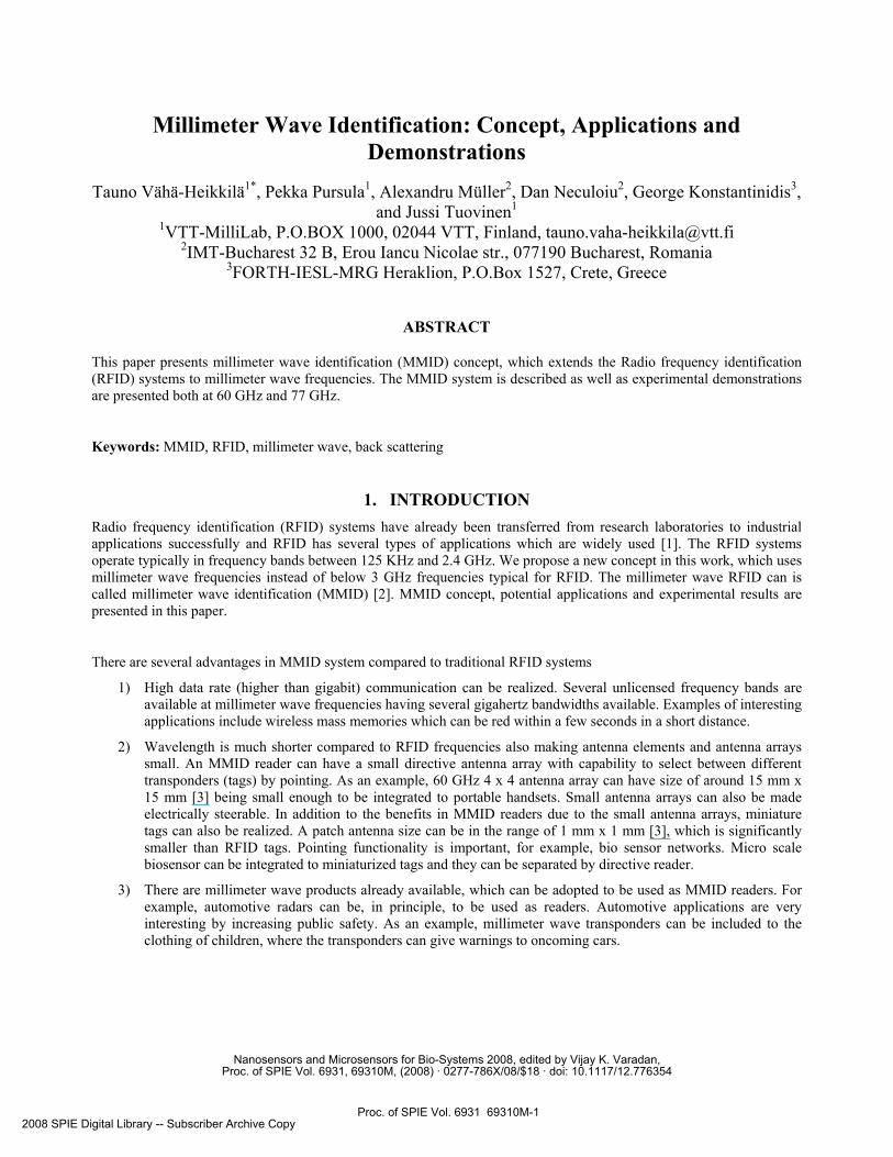
2. MMID SYSTEM In general, an MMID system consists of a reader device and transponder (or a tag) as presented schematically in Fig. 1 [2]. The principle of operation is similar to an RFID system. The transmitter in the reader sends out a signal of modulated continuous wave (downlink). The tag receives the signal, operates according to detected command and returns an answer to the reader device (uplink). The answer is detected in the reader device receiver. This description applies almost to every radio link, but what makes the RFID as well as MMID systems unique, are the transponder powering and uplink realization. A transponder can be powered up in three ways: A passive transponder receives power from the reader transmission. For this, the transponder includes a rectifier in parallel with the detector to generate DC power from the carrier send by the reader. A semipassive transponder uses a DC power source, such as a battery, but still uses backscattering for communication. This enables longer operation distances than with a passive transponder, still providing a long battery lifetime, because no, or very small, current is drawn from the battery when reader is not present. An active transponder is similar to an active radio: It uses a battery for biasing an active detector, and has an active radio for uplink, too. In RFID or MMID, usually the uplink is realized by modulating backscattering. However, lately also active radios are mentioned as active RFID, if the link is used for identification applications. So, as ever, drawing limits between different kinds of radios, is neither self-evident or established. The backscattering modulation is achieved by modulating the load of the transponder antenna. Thus reader receiver and transmitter must be operating simultaneously at the same frequency. The reader device can also be deciphered as a radar: The uplink signal is a faint echo of the reader transmission. The dynamic range requirement for the reader is very high.
Fig. 1. Schematical description of an MMID system containing a reader device and a transponder (or tag).
3. EXPERIMENTAL RESULTS To demonstrate the MMID concept at millimetre waves, both downlink and backscattering measurements are needed. The downlink experiment shows that data can be sent from a reader to transponder. This is needed for example in pointing functions. The backscattering measurement demonstrates the MMID concept itself showing that signal transmitted by the reader is modulated by a transponder and modulated signal is received by the reader. As basic elements, both a reader and transponder are needed in an MMID system demonstration. In this work, the MMID systems have been developed for 60 GHz and 77 GHz frequency bands.
3.1 Reader
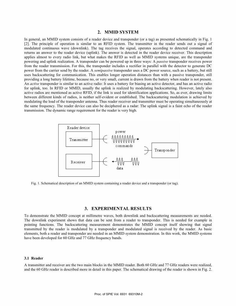
A transmitter and receiver are the two main blocks in the MMID reader. Both 60 GHz and 77 GHz readers were realized, and the 60 GHz reader is described more in detail in this paper. The schematical drawing of the reader is shown in Fig. 2.
Proc. of SPIE Vol. 6931 69310M-2
EXPERIMENTAL READER DEVICE
I
RECEIVER
HORN
MIXER
I TRANSMITTER
DATE: 05/17/06 2 nnDevice: VG2920673R0
VegaDigital Microscopy lnaging __DIgIIt MIcoo_py gi,g
The transmitter consisted of a modulated signal generator, multiplier and a horn antenna. The transmitted power at 60 GHz was 25 dBm eirp. The receiver consisted of signal generator, multiplier, mixer, isolators and a horn antenna, respectively. Both 60 GHz and 77 GHz readers were similar in principle except that V-band (50-75 GHz) components were used at 60 GHz and W-band (75-110 GHz) at 77 GHz.
Fig. 2. Schematical drawing of an MMID reader.
3.2 Transponder
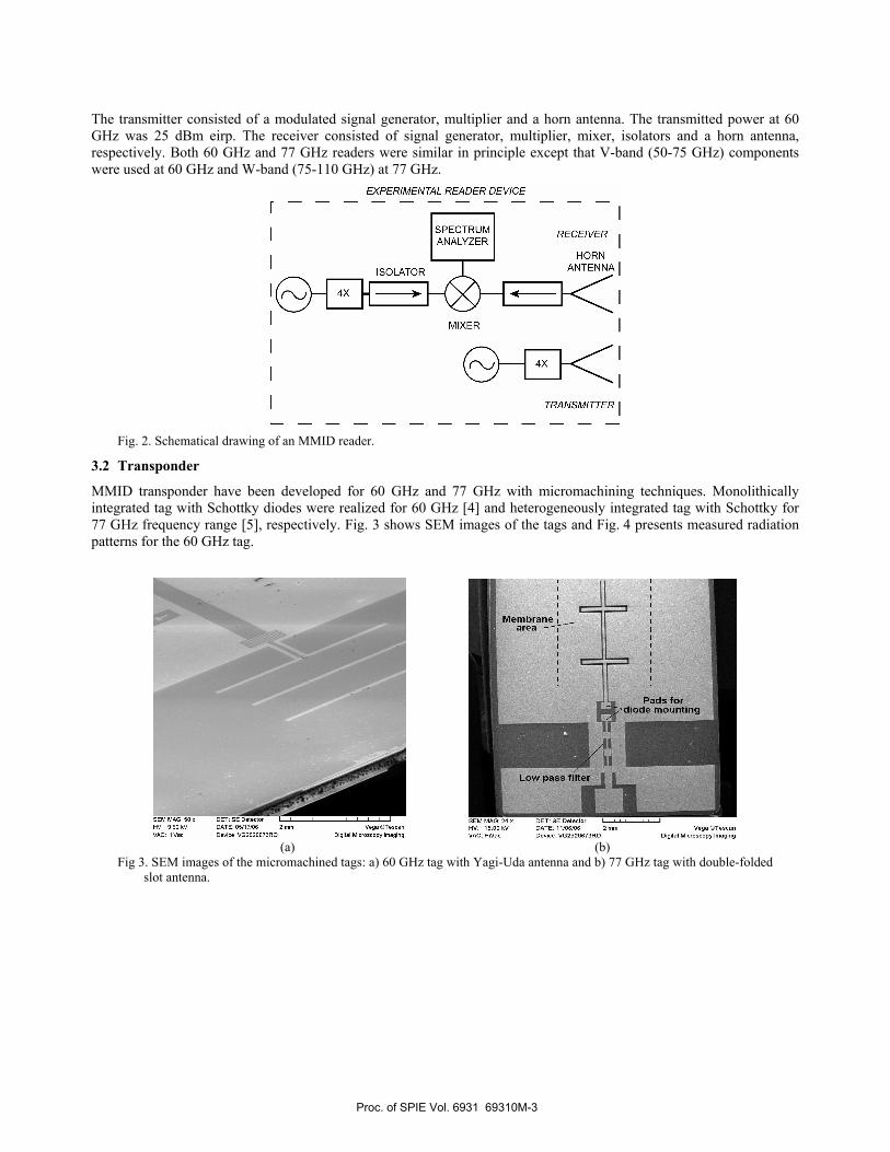
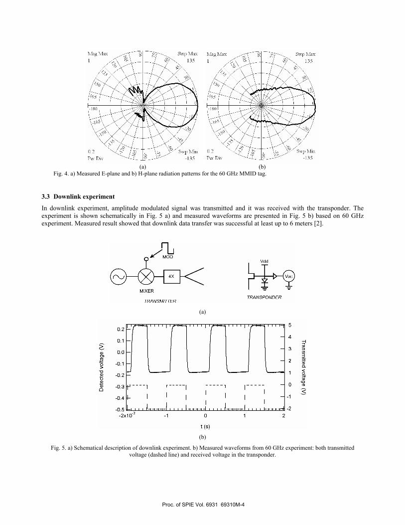
MMID transponder have been developed for 60 GHz and 77 GHz with micromachining techniques. Monolithically integrated tag with Schottky diodes were realized for 60 GHz [4] and heterogeneously integrated tag with Schottky for 77 GHz frequency range [5], respectively. Fig. 3 shows SEM images of the tags and Fig. 4 presents measured radiation patterns for the 60 GHz tag.
(a) (b)
Fig 3. SEM images of the micromachined tags: a) 60 GHz tag with Yagi-Uda antenna and b) 77 GHz tag with double-folded slot antenna.
Proc. of SPIE Vol. 6931 69310M-3
Swp Max135
Swp Mn-135
Swp Max135
Swp Mmn
-135
MIXER
TRANSMITTERTRANSPONDER
-0.411—I
I'
I H-I—0.5 L1 —i—I I I I I —I—I— I I I I —2
-2x10³ -I 0 1 2
t (s)
(a) (b)
Fig. 4. a) Measured E-plane and b) H-plane radiation patterns for the 60 GHz MMID tag.
3.3 Downlink experiment
In downlink experiment, amplitude modulated signal was transmitted and it was received with the transponder. The experiment is shown schematically in Fig. 5 a) and measured waveforms are presented in Fig. 5 b) based on 60 GHz experiment. Measured result showed that downlink data transfer was successful at least up to 6 meters [2].
(a)
(b)
Fig. 5. a) Schematical description of downlink experiment. b) Measured waveforms from 60 GHz experiment: both transmitted voltage (dashed line) and received voltage in the transponder.
Proc. of SPIE Vol. 6931 69310M-4
I SPECTRUM IRECEIVER
ANALYZER
__________ HORN
ISOLATOR ANTENNA-E1--IIIkçMIXER MOD
TRANSPONDER
TRANSMITTER
A •pBwlOImz Delta2 En]*VBw100Hz —29.20cm
Psf-3OdBm Att 10dB SWI — 33€00Idiz
EEF E EEE
Date: 5.SEP.2006 08:18:26
A40
—50
70
-90
-fi130
Center 1GHz 200Idlz/ Span 2fllz
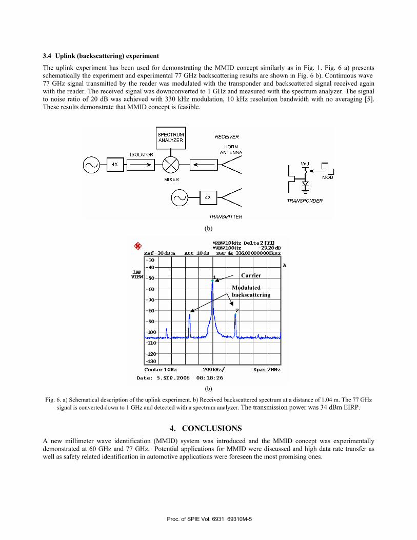
3.4 Uplink (backscattering) experiment
The uplink experiment has been used for demonstrating the MMID concept similarly as in Fig. 1. Fig. 6 a) presents schematically the experiment and experimental 77 GHz backscattering results are shown in Fig. 6 b). Continuous wave 77 GHz signal transmitted by the reader was modulated with the transponder and backscattered signal received again with the reader. The received signal was downconverted to 1 GHz and measured with the spectrum analyzer. The signal to noise ratio of 20 dB was achieved with 330 kHz modulation, 10 kHz resolution bandwidth with no averaging [5]. These results demonstrate that MMID concept is feasible.
(b)
(b)
Fig. 6. a) Schematical description of the uplink experiment. b) Received backscattered spectrum at a distance of 1.04 m. The 77 GHz signal is converted down to 1 GHz and detected with a spectrum analyzer. The transmission power was 34 dBm EIRP.
4. CONCLUSIONS A new millimeter wave identification (MMID) system was introduced and the MMID concept was experimentally demonstrated at 60 GHz and 77 GHz. Potential applications for MMID were discussed and high data rate transfer as well as safety related identification in automotive applications were foreseen the most promising ones.
Modulated backscattering
Carrier
Proc. of SPIE Vol. 6931 69310M-5
REFERENCES
[1] K. Finkenzeller, RFID Handbook, 2nd edition, John Wiley & Sons, 2003. [2] P.Pursula, T. Vähä-Heikkilä, A. Muller, G.Konstantinidis, D. Neculoiu, A. Oja and J. Tuovinen, "Millimetre Wave
Identification — new radio system for low power, high data rate and short range," accepted to the IEEE Transactions on Microwave Theory and Techniques, Feb. 2008.
[3] A. Lamminen, J. Säily and A. Vimpari, "60 GHz patch antennas and arrays on LTCC with embedded-cavity substrates," accepted to IEEE Transactions on Antennas and Propagation, Jan. 2008.
[4] D.Neculoiu, A.Müller, D.Vasilache, M.Dragoman, I.Petrini, C.Buiculescu, G.Konstantinidis, A.Stavinidris, Z. Hazoupulos, N.Kornilios, T. Vähä-Heikkilä, P.Pursula, L.Bary, and R.Plana, "GaAs membrane-supported 60 GHz receiver with Yagi-Uda antenna," Proceedings of the MEMSWAVE 2006 the 7th International Conference on RF MEMS and RF Microsystems, Barcelona, Spain, June 2007.
[5] A.Müller, D. Neculoiu, P. Pursula, T. Vähä-Heikkilä, F. Giacomozzi, and J. Tuovinen, "Hybrid Integrated Micromachined Receiver for 77 GHz Millimeter Wave Identification Systems," Proceedings of the 37th European Microwave Conference 2007, Munich, Germany, Oct. 2007, pp. 1034-1037.
Proc. of SPIE Vol. 6931 69310M-6
Related Documents