*[email protected]; phone 1 937 255 6427 x4331; AFRL/SNRR, Building 620, 2241 Avionics Circle, Wright-Patterson AFB, OH 45433; Integrated RF Modules for Cooperative UGV/UAV Tandems Atindra K. Mitra, Ph.D.* a , Lamar Westbrook a , Johnathan Corgan b , Sean Young a , Jogender Nagar a , Tedros Bariagaber c a Air Force Research Laboratory; b Corgan Enterprises, c Tennessee State University ABSTRACT This paper addresses a number of design issues that are associated with integrating lightweight and low-cost RF (Radio Frequency) sensors onto small UGV’s (Unmanned Ground Vehicles) and UAV’s (Unmanned Aerial Vehicles). Modular\integrated RF sub-systems functions that are discussed include lightweight software programmable radar (or software radar) using COTS software radio components and compact microstrip antenna design concepts for low- frequency surface penetration radars. A discussion on the potential for implementing lightweight multi-function RF systems as well as a discussion on novel futuristic concepts that explore the limits of sensor/platform integration is included. Keywords: Cooperative UAV Tandems, Low-Cost RF Sensors, Lightweight RF Sensors, Software Radar, Wi-Fi Radar, Micro-Impulse Radar Antennas 1. INTRODUCTION Within the past few years, a number of research and development organizations and sponsoring agencies have committed to the development and implementation of cooperative robotic platforms for the surveillance of remote regions-of-interest. For example, Figure 1 [1] is a picture of a developmental system from the Center for Robot- Assisted Search and Rescue at the University of South Florida. This is a two-platform system where a UGV works in tandem with a UAV (Unmanned Aerial Vehicle) to characterize threats due to surface-level explosives. Both of the UGV and UAV platforms in Figure 1 are fitted with different types of advanced electro-optic technologies. Alternatively, Figure 2 depicts a UGV with a lightweight and short-range impulse radar system. This type of radar system [2] can be designed to fit on a small UGV robot to detect shallow-buried objects-of-interest and allows for the application of the autonomous robotic systems architecture of Figure 2 over a larger variety of environments. Also, a variety of different RF systems that can adjust to different applications can also be integrated into multiplatform sensor architectures for tandems of small UAVs and UGVs. The following sections of this paper discuss issues and challenges related to designing compact and integrated RF sensors for small autonomous/robotic UAV’s and UGV’s. Section 2 discusses the design of a software radar system using COTS (Commercial Off-the-Shelf) USRP (Universal Software Radio Peripheral) modules. This section provides insights into similarities and differences between state-of-the-art communications and radar waveforms and provides a set of sample specifications for using programmable software radio waveforms to generate radar waveforms. An outline of diagnostics and testing procedures for this type of system is also provided. Section 3 outlines an approach to UWB (ultra-wideband) antenna design based on the exploitation of low-permittivity substrate materials and also discusses another novel new approach to integrated UWB (Ultra-wideband) antenna design via the excitation of multiple radiation modes. Section 4 provides a summary and a short discussion on scope for future research in this area. Some novel concepts that explore the limits of sensor/platform integration are also presented. Unmanned Systems Technology X, edited by Grant R. Gerhart, Douglas W. Gage, Charles M. Shoemaker Proc. of SPIE Vol. 6962, 69621Y, (2008) · 0277-786X/08/$18 · doi: 10.1117/12.785258 Proc. of SPIE Vol. 6962 69621Y-1 2008 SPIE Digital Library -- Subscriber Archive Copy

Welcome message from author
This document is posted to help you gain knowledge. Please leave a comment to let me know what you think about it! Share it to your friends and learn new things together.
Transcript
*[email protected]; phone 1 937 255 6427 x4331; AFRL/SNRR, Building 620, 2241 Avionics Circle, Wright-Patterson AFB, OH 45433;
Integrated RF Modules for Cooperative UGV/UAV Tandems
Atindra K. Mitra, Ph.D.*a , Lamar Westbrooka , Johnathan Corganb , Sean Younga , Jogender Nagara , Tedros Bariagaberc
aAir Force Research Laboratory; bCorgan Enterprises, cTennessee State University
ABSTRACT This paper addresses a number of design issues that are associated with integrating lightweight and low-cost RF (Radio Frequency) sensors onto small UGV’s (Unmanned Ground Vehicles) and UAV’s (Unmanned Aerial Vehicles). Modular\integrated RF sub-systems functions that are discussed include lightweight software programmable radar (or software radar) using COTS software radio components and compact microstrip antenna design concepts for low-frequency surface penetration radars. A discussion on the potential for implementing lightweight multi-function RF systems as well as a discussion on novel futuristic concepts that explore the limits of sensor/platform integration is included. Keywords: Cooperative UAV Tandems, Low-Cost RF Sensors, Lightweight RF Sensors, Software Radar, Wi-Fi Radar, Micro-Impulse Radar Antennas
1. INTRODUCTION Within the past few years, a number of research and development organizations and sponsoring agencies have committed to the development and implementation of cooperative robotic platforms for the surveillance of remote regions-of-interest. For example, Figure 1 [1] is a picture of a developmental system from the Center for Robot-Assisted Search and Rescue at the University of South Florida. This is a two-platform system where a UGV works in tandem with a UAV (Unmanned Aerial Vehicle) to characterize threats due to surface-level explosives. Both of the UGV and UAV platforms in Figure 1 are fitted with different types of advanced electro-optic technologies. Alternatively, Figure 2 depicts a UGV with a lightweight and short-range impulse radar system. This type of radar system [2] can be designed to fit on a small UGV robot to detect shallow-buried objects-of-interest and allows for the application of the autonomous robotic systems architecture of Figure 2 over a larger variety of environments. Also, a variety of different RF systems that can adjust to different applications can also be integrated into multiplatform sensor architectures for tandems of small UAVs and UGVs. The following sections of this paper discuss issues and challenges related to designing compact and integrated RF sensors for small autonomous/robotic UAV’s and UGV’s. Section 2 discusses the design of a software radar system using COTS (Commercial Off-the-Shelf) USRP (Universal Software Radio Peripheral) modules. This section provides insights into similarities and differences between state-of-the-art communications and radar waveforms and provides a set of sample specifications for using programmable software radio waveforms to generate radar waveforms. An outline of diagnostics and testing procedures for this type of system is also provided. Section 3 outlines an approach to UWB (ultra-wideband) antenna design based on the exploitation of low-permittivity substrate materials and also discusses another novel new approach to integrated UWB (Ultra-wideband) antenna design via the excitation of multiple radiation modes. Section 4 provides a summary and a short discussion on scope for future research in this area. Some novel concepts that explore the limits of sensor/platform integration are also presented.
Unmanned Systems Technology X, edited by Grant R. Gerhart, Douglas W. Gage, Charles M. ShoemakerProc. of SPIE Vol. 6962, 69621Y, (2008) · 0277-786X/08/$18 · doi: 10.1117/12.785258
Proc. of SPIE Vol. 6962 69621Y-12008 SPIE Digital Library -- Subscriber Archive Copy

-.
v•-
UAV1
/
Figure 1: Team of UAV And UGV Robot Pairs Each Fitted With Electro-Optic Cameras
To Detect Explosives on Surface [1]
Figure 2: Autonomous UGV Design With Small Impulse Radar To Detect Shallow Buried Explosives
Proc. of SPIE Vol. 6962 69621Y-2

Miniature
Log-PeriodicAntenna
(SingleBoard
Computer)
USRP
With DaughterCardFront End
SBC3W
Bi-DirectionalWi-Fi Amplifier
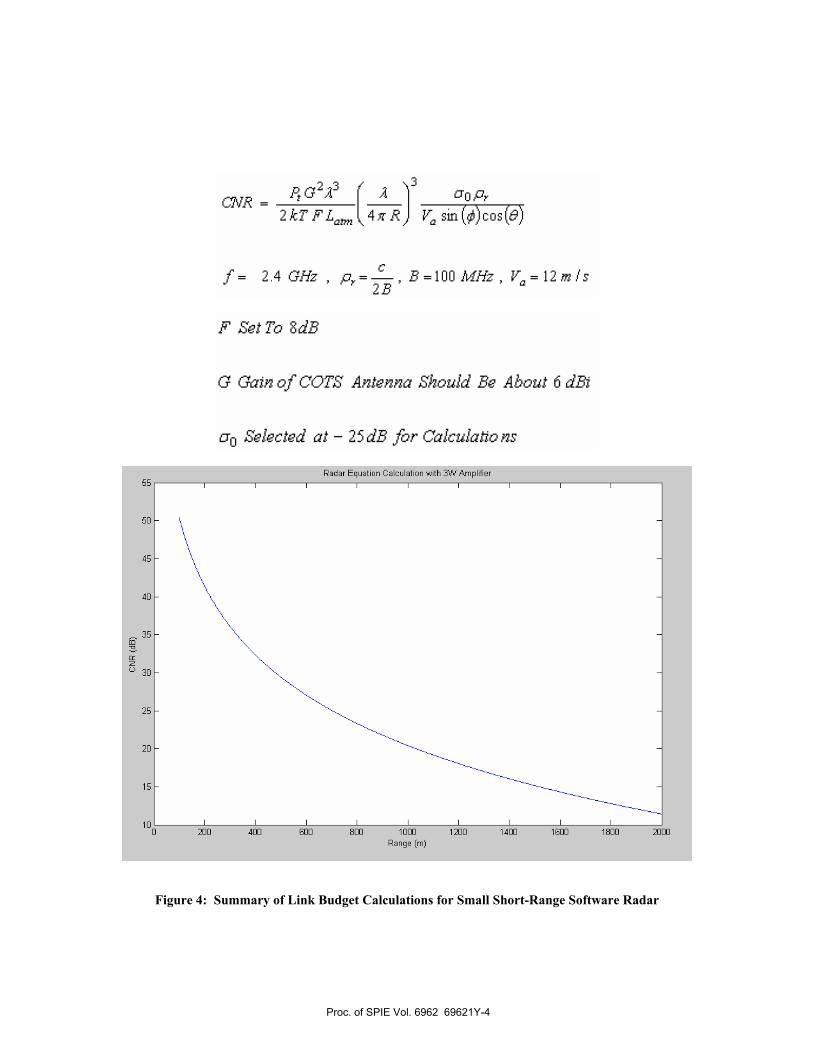
2. SOFTWARE RADAR DESIGN WITH PROGRAMMABLE COTS SW RADIO MODULES Figure 3 is a block diagram of the basic software radar design that is developed for this investigation. This design is based on programmable COTS software radio components that conform to a published standard denoted as USRP. These particular USRP-based components are obtained from Ettus Research for a cost of less than $1000. The total hardware cost of this initial software radar prototype is roughly $2000. While the USRP board in Figure 3 shows two daughtercards that function as receiver RF frontends and two daughtercards that function as transmitter RF frontends, the final design for this software radar has one transceiver card that occupies the space of two of the daughtercards. This transceiver card is denoted as a RFX2400 card which can be programmed to operate in the neighborhood of the 2.4 GHz Wi-Fi frequency band. Before directly addressing the complex software and firmware issues related to generating pulsed radar waveforms from a wide variety of communications signals that are available on the USRP, a basic radar link budget analysis is conducted. This is accomplished via an iterative procedure where tradeoffs between a number of different antennas and amplifiers are considered in order to optimize the size and weight of the design. Figure 4 is intended to serve as a summary of this link budget analysis where the parameters are selected for a potential SAR (Synthetic Aperture Radar) imaging application on a relatively slow-moving small UAV. Using a CNR (Clutter-to-Noise Ratio) threshold of about 15 dB, the resulting plot of CNR versus range indicates that the range limit of this design is about 1.5 Km. The estimated weight of this design is about 10 lbs including the weight of a battery pack and chassis. This figure meets the payload requirements of many small UAV’s including some RC aircraft such as a Sig-110.
Figure 3: Block Diagram of Software Radar Design
Proc. of SPIE Vol. 6962 69621Y-3
3PtG2A3 ( A uop,CNR
2 kT FL 4g R) V sin (Ø)cos(8)
f 2.4 rift BlOO MHz, Vl2m/s
F S&tTo 8dB
G Gain of COTS Ant&nna Should B& About 6 dTh
ao S&l&ct&d at — 25dB for Calculaho ns
Radar Equation Calculation wfth 3W Amplifiar
0 200 400 800 800 1000
Range (m)
1200 1400 1800 1800 2000
Figure 4: Summary of Link Budget Calculations for Small Short-Range Software Radar
Proc. of SPIE Vol. 6962 69621Y-4
In' ml ml0-32 M H 32-64 M H 64-Q6 M H
LFM LFM
ChirpIiiiiiii
Chirp
5igI BiC Nt
— transmater on time-= receive turn-around time (8x
- look time (range gate
— LO step/settling time hSU us) DATA = tIth x 4 bytes sample x B4Msps
tpuIe tsw tIcd<
record
send over USB
Hd Oñ
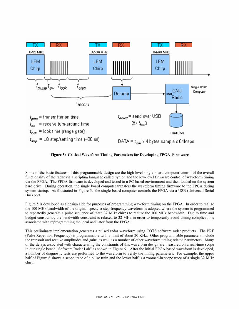
Figure 5: Critical Waveform Timing Parameters for Developing FPGA Firmware Some of the basic features of this programmable design are the high-level single-board computer control of the overall functionality of the radar via a scripting language called python and the low-level firmware control of waveform timing via the FPGA. The FPGA firmware is developed and tested in a PC-based environment and then loaded on the system hard drive. During operation, the single board computer transfers the waveform timing firmware to the FPGA during system startup. As illustrated in Figure 5, the single-board computer controls the FPGA via a USB (Universal Serial Bus) port. Figure 5 is developed as a design aide for purposes of programming waveform timing on the FPGA. In order to realize the 100 MHz bandwidth of the original specs, a step frequency waveform is adopted where the system is programmed to repeatedly generate a pulse sequence of three 32 MHz chirps to realize the 100 MHz bandwidth. Due to time and budget constraints, the bandwidth constraint is relaxed to 32 MHz in order to temporarily avoid timing complications associated with reprogramming the local oscillator from the FPGA. This preliminary implementation generates a pulsed radar waveform using COTS software radar products. The PRF (Pulse Repetition Frequency) is programmable with a limit of about 20 KHz. Other programmable parameters include the transmit and receive amplitudes and gains as well as a number of other waveform timing related parameters. Many of the delays associated with characterizing the constraints of this waveform design are measured on a real-time scope in our single bench “Software Radar Lab” as shown in Figure 6. After the initial FPGA based waveform is developed, a number of diagnostic tests are performed to the waveform to verify the timing parameters. For example, the upper half of Figure 6 shows a scope trace of a pulse train and the lower half is a zoomed-in scope trace of a single 32 MHz chirp.
Proc. of SPIE Vol. 6962 69621Y-5

— — £ — £ —IjL1 I=II MI.J -_�±±_IJe —:
-I".ISII IthLjI
Figure 6: Critical Waveform Timing Parameters for Developing FPGA Firmware
Proc. of SPIE Vol. 6962 69621Y-6
I 1-i a -. rn..:.-lj ;i.as1.:.a
_ o ___—-
I F
,L W'liii
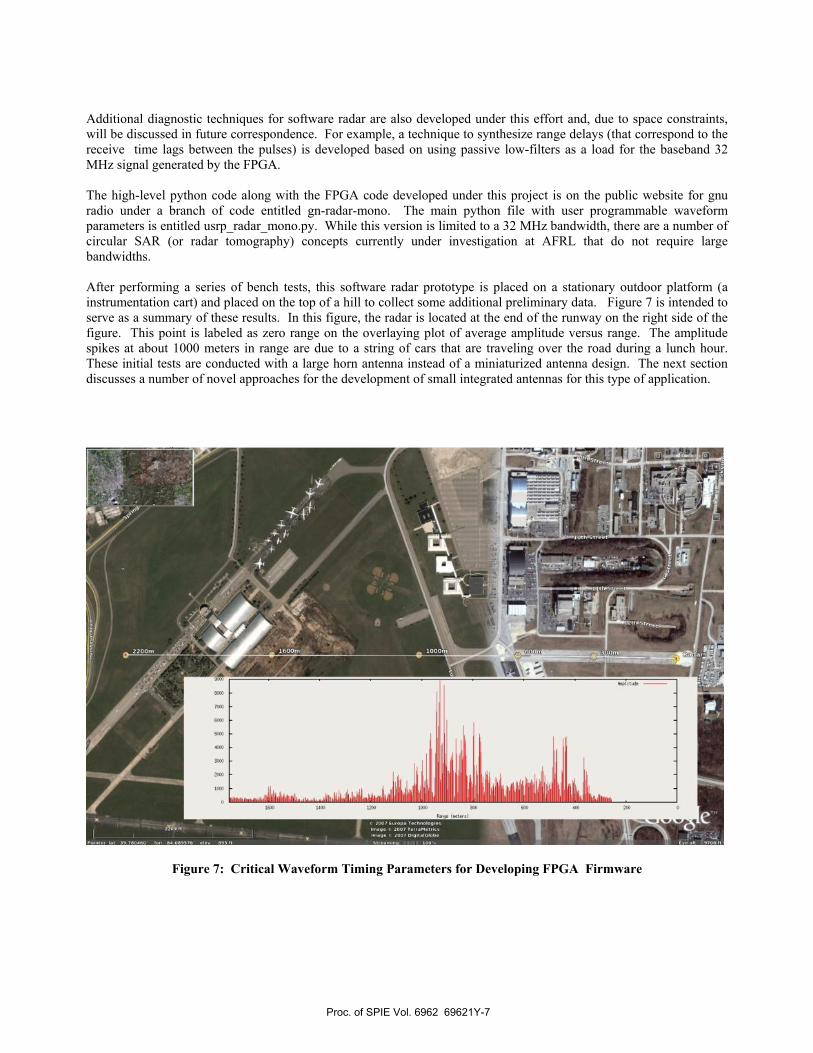
Additional diagnostic techniques for software radar are also developed under this effort and, due to space constraints, will be discussed in future correspondence. For example, a technique to synthesize range delays (that correspond to the receive time lags between the pulses) is developed based on using passive low-filters as a load for the baseband 32 MHz signal generated by the FPGA. The high-level python code along with the FPGA code developed under this project is on the public website for gnu radio under a branch of code entitled gn-radar-mono. The main python file with user programmable waveform parameters is entitled usrp_radar_mono.py. While this version is limited to a 32 MHz bandwidth, there are a number of circular SAR (or radar tomography) concepts currently under investigation at AFRL that do not require large bandwidths. After performing a series of bench tests, this software radar prototype is placed on a stationary outdoor platform (a instrumentation cart) and placed on the top of a hill to collect some additional preliminary data. Figure 7 is intended to serve as a summary of these results. In this figure, the radar is located at the end of the runway on the right side of the figure. This point is labeled as zero range on the overlaying plot of average amplitude versus range. The amplitude spikes at about 1000 meters in range are due to a string of cars that are traveling over the road during a lunch hour. These initial tests are conducted with a large horn antenna instead of a miniaturized antenna design. The next section discusses a number of novel approaches for the development of small integrated antennas for this type of application.
Figure 7: Critical Waveform Timing Parameters for Developing FPGA Firmware
Proc. of SPIE Vol. 6962 69621Y-7

3. DESIGN CONCEPTS FOR ANTENNA MINIATURIZATION
Methodologies for designing and fabricating compact low-profile antennas for small lightweight software radars and impulse radars are presented in this section. The design frequency range for the sample results in this section is selected at 1 – 2 GHz. Selection of this frequency range is considered a good compromise between resolution, material penetration, and antenna size. The resulting antenna geometries are compact and can be mounted or integrated on mobile robot arms and other sub-structures on the front of autonomous UGV’s (Unmanned Ground Vehicles). The focus of the discussion is on two novel approaches a) Integrated microstrip antenna design with low-permittivity substrate materials and b) A new mixed-mode antenna geometry denoted as a Broken-Comb Slot Antenna Figure 8 illustrates a patch antenna geometry [3] fabricated on a substrate. Potential ultra-wideband antenna designs using this geometry via introduction of air gaps into low-permittivity substrate materials are investigated in the first half of this section. The patch antenna structure in Figure 8 is a resonant structure where the design center frequency can be expressed as follows:
effreff
cL
cf,2 ε
= (1)
where Leff is the effective length of the patch and εr,eff is the effective permittivity of the substrate. The variation of the bandwidth and directivity of this patch geometry as a function of the effective permittivity of the substrate can be observed in the approximate expressions of equations 2 and 3:
L
WhBWeffrc ,
180%ελ
≈ (2)
dB6.1log106.62.,
⎟⎟
⎠
⎞
⎜⎜
⎝
⎛++≈
effr
WDε
(3)
Equations 2 and 3 indicate that one approach towards the development of compact patch antennas for ultra-wideband frequency ranges is to design and implement the antenna on a low-permittivity substrate. Additional gains in bandwidth and directivity can be observed by fabricating an air gap in the substrate to further reduce the effective permittivity, as illustrated in Figure 8.
Figure 8: Geometry for Rectangular Patch Antenna
Proc. of SPIE Vol. 6962 69621Y-8
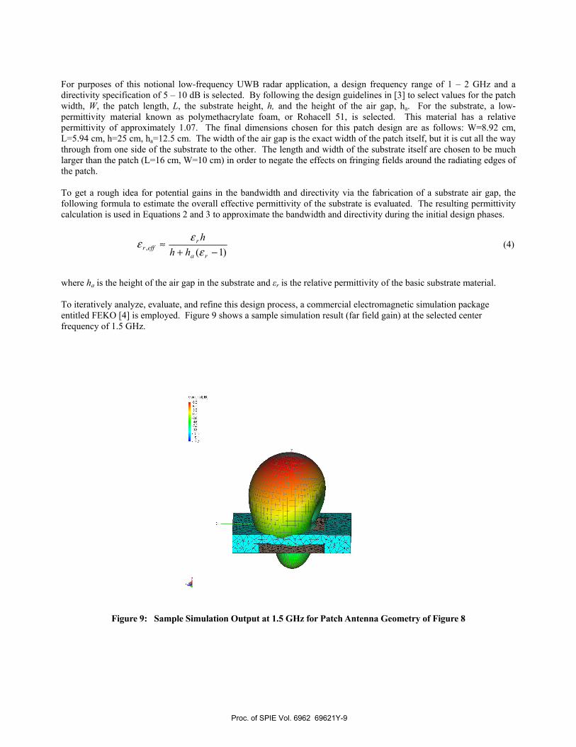
For purposes of this notional low-frequency UWB radar application, a design frequency range of 1 – 2 GHz and a directivity specification of 5 – 10 dB is selected. By following the design guidelines in [3] to select values for the patch width, W, the patch length, L, the substrate height, h, and the height of the air gap, ha. For the substrate, a low-permittivity material known as polymethacrylate foam, or Rohacell 51, is selected. This material has a relative permittivity of approximately 1.07. The final dimensions chosen for this patch design are as follows: W=8.92 cm, L=5.94 cm, h=25 cm, ha=12.5 cm. The width of the air gap is the exact width of the patch itself, but it is cut all the way through from one side of the substrate to the other. The length and width of the substrate itself are chosen to be much larger than the patch (L=16 cm, W=10 cm) in order to negate the effects on fringing fields around the radiating edges of the patch. To get a rough idea for potential gains in the bandwidth and directivity via the fabrication of a substrate air gap, the following formula to estimate the overall effective permittivity of the substrate is evaluated. The resulting permittivity calculation is used in Equations 2 and 3 to approximate the bandwidth and directivity during the initial design phases.
)1(, −+
≈ra
reffr hh
hε
εε (4)
where ha is the height of the air gap in the substrate and εr is the relative permittivity of the basic substrate material. To iteratively analyze, evaluate, and refine this design process, a commercial electromagnetic simulation package entitled FEKO [4] is employed. Figure 9 shows a sample simulation result (far field gain) at the selected center frequency of 1.5 GHz.
Figure 9: Sample Simulation Output at 1.5 GHz for Patch Antenna Geometry of Figure 8
Proc. of SPIE Vol. 6962 69621Y-9

Gi
As part of the procedure for introducing the air gap within the FEKO CAD model, a very thin metal piece is added to one of the radiating edges of the patch. Through simulation, we have verified that this metal piece has very little effect on the performance of the antenna, and therefore any improvements in directivity and bandwidth can be attributed to the introduction of the air gap. Initial evaluation of this UWB antenna design indicates reasonable VSWR (voltage standing wave ratio) and directivity over the entire frequency range of 1 – 2 GHz. As shown in Figure 10, the introduction of the air gap significantly increases the broadside gain of the antenna over the frequency range. Further inspection of this figure indicates a drop in gain at the high end of the frequency spectrum; further research and simulations will be conducted to investigate this effect in detail. Additional simulation outputs (including VSWR and S-Parameters) will be included with future correspondence.
Figure 10: Broadside Gain in Decibels Comparing the Patches With and Without an Air Gap A number of elaborate techniques exist and are documented in the antennas and propagation literature that address challenges related to the design of compact broadband antennas [3]. These techniques include stacked-patch designs, C-shaped MSA (microstrip antenna), H-Shaped MSA, rectangular MSA’s with U-slots, along with a number of additional notable designs. Many of these techniques are for consumer electronics applications such as cell phones, laptops, and other mobile communications. Most of these applications do not have specific directivity requirements at this point. In addition, many of the contemporary UWB integrated/mircostrip antenna designs address future UWB communications requirements in the 3 – 10 GHz range. For purposes of addressing our unique ultrawideband antenna design challenges for developing a very small and lightweight antenna with large bandwidth and reasonable directivity over the 1 – 2 GHz frequency range, the compact structure in Figure 11 is specially formulated as part of this in-house effort at AFRL (Air Force Research Laboratory) . The brown areas in the model represent metal (which is modeled as a perfect electric conductor). The brown color coding on the periphery of the substrate indicates a metallic casing around the side faces of the substrate. This casing has the effect of directing more energy into the desired direction, and allows us to shrink the size of our patch without affecting its operating frequency [5]. The blue areas of the model are the top face of the polymethacrylate substrate. Inspection of the internal design geometry of this patch shows the structure of slots (modeled as being infinitesimally small) that are cut into the surface of the patch. This novel design is denoted as a Broken-Comb Structure and is intended to simultaneously excite multiple elements that are integrated into a small area in an effort to obtain good directivity and bandwidth over the frequency range of interest. A more detailed theoretical analysis and development of this new geometry will be reported in future correspondence.
Proc. of SPIE Vol. 6962 69621Y-10
Gi
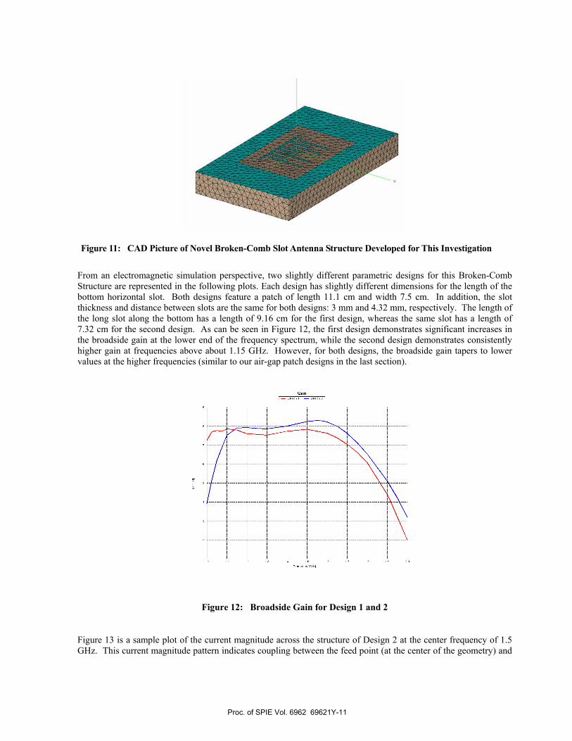
Figure 11: CAD Picture of Novel Broken-Comb Slot Antenna Structure Developed for This Investigation
From an electromagnetic simulation perspective, two slightly different parametric designs for this Broken-Comb Structure are represented in the following plots. Each design has slightly different dimensions for the length of the bottom horizontal slot. Both designs feature a patch of length 11.1 cm and width 7.5 cm. In addition, the slot thickness and distance between slots are the same for both designs: 3 mm and 4.32 mm, respectively. The length of the long slot along the bottom has a length of 9.16 cm for the first design, whereas the same slot has a length of 7.32 cm for the second design. As can be seen in Figure 12, the first design demonstrates significant increases in the broadside gain at the lower end of the frequency spectrum, while the second design demonstrates consistently higher gain at frequencies above about 1.15 GHz. However, for both designs, the broadside gain tapers to lower values at the higher frequencies (similar to our air-gap patch designs in the last section).
Figure 12: Broadside Gain for Design 1 and 2
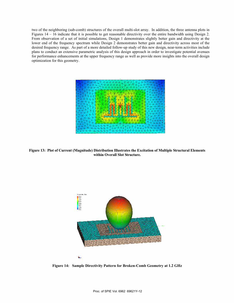
Figure 13 is a sample plot of the current magnitude across the structure of Design 2 at the center frequency of 1.5 GHz. This current magnitude pattern indicates coupling between the feed point (at the center of the geometry) and
Proc. of SPIE Vol. 6962 69621Y-11
U
two of the neighboring (sub-comb) structures of the overall multi-slot array. In addition, the three antenna plots in Figures 14 – 16 indicate that it is possible to get reasonable directivity over the entire bandwidth using Design 2. From observation of a set of initial simulations, Design 1 demonstrates slightly better gain and directivity at the lower end of the frequency spectrum while Design 2 demonstrates better gain and directivity across most of the desired frequency range. As part of a more detailed follow-up study of this new design, near-term activities include plans to conduct an extensive parametric analysis of this design approach in order to investigate potential avenues for performance enhancements at the upper frequency range as well as provide more insights into the overall design optimization for this geometry.
Figure 13: Plot of Current (Magnitude) Distribution Illustrates the Excitation of Multiple Structural Elements within Overall Slot Structure.
Figure 14: Sample Directivity Pattern for Broken-Comb Geometry at 1.2 GHz
Proc. of SPIE Vol. 6962 69621Y-12

Figure 15: Sample Directivity Pattern for Broken-Comb Geometry at 1.5 GHz
Figure 16: Sample Directivity Pattern for Broken-Comb Geometry at 1.8 GHz
A few potential approaches to designing small, lightweight, and integrated UWB antennas for small lightweight radar applications have been investigated in this section. These approaches include a microstrip patch design with air gaps fabricated into the substrate as well as a novel design denoted as a Broken-Comb slotted antenna. One near-term application, or focus area, is for small UVG robot radar systems that will survey remote regions-of-interest for important targets such as shallow-buried explosives. The resulting radar data can be used in tandem with other autonomous UAV/UGV’s to develop autonomous multi-robot surveillance and security systems. With regard to potential for more future research in this area, some of the many options include the incorporation of more advanced substrate materials resulting from present and future developments in nanotechnology. Some of these advanced materials may allow for further reductions in size while maintaining overall performance. There are many avenues for future research in the general area of small integrated antenna designs. In addition, theoretical modeling and further development of the novel Broken-Comb Slot Antenna structure will be pursued. Also, due to the enhanced performance trends with the addition of the air gap into the rectangular microstrip patch design, follow-up activities
Proc. of SPIE Vol. 6962 69621Y-13

include the investigation of the effects of air gaps in the Broken-Comb design. Theoretically, we can predict an increase in bandwidth and directivity. Simulations with parametric trends will be conducted to further quantify this effect . In general, the advancement of this type of integrated antenna technology should, in turn, enhance the development of, for example, future distributed multi-node radar systems.
4. SUMMARY AND FUTURISTIC SYSTEMS CONCEPTS A number of issues related to the development of small, lightweight, and low-cost RF modules for purposes of integration into cooperative tandems of small UAVs and UGVs are discussed in this paper. Many avenues for further pursuit and maturation of these concepts exist from a basic research point of view. In addition, a number critical interference challenges , due for example to the inadvertent propagation of stray substrate modes, must be addressed before final implementation of these types of small-scale RF systems can commence with reliability and precision over a mass scale.
With regard to formulating new sensor concepts for future applications, it is possible to envision futuristic sensor concepts for cooperative tandems of small UGV/UAV micro-platforms that incorporate many varying degrees of sensor integration. For example, new Micro-UAV-Based Integrated Sensor Concepts have been formulated for potentially relatively near-term applications via the generalization of a patented Position-Adaptive Radar [6] concept depicted in Figure 17 on this page. The portion of this figure that is marked in dark font illustrates a position-adaptive radar concept that was originally formulated for thru-wall sensing applications. When employed as a radar concept, the hovering platforms within this architecture spatially-adapt to a environment (in this case the building structure) to collect information on objects-of-interest that are embedded within the environment.
Figure 17: Notional Multi-platform Sensor Geometry That Depicts Many Levels of Sensor Integration and
Miniaturization Concepts That Can Be Developed In the Near-Term and Long-Term Future
Proc. of SPIE Vol. 6962 69621Y-14

This novel radar concept can be generalized to investigate applications for the detection of Chem/Bio materials including embedded explosives. For example, if the depiction of the building in this figure is replaced with a wooden cart or a truckbed that contains explosives, we can formulate systems concepts for a swarm of micro-UAV’s in an effort to detect whether or not a given cart or truckbed contains explosives. Under this new concept, some of the members of the UAV swarm can serve as “transmitters” by ,for example, blowing air over the cart and some of the members of the UAV swarm can serve as “receivers” that are equipped with chem/bio sensors that function as, for example, “electronic noses”. The objective can be defined as improving the particle count for the explosives in the external air that surrounds a cart in order to improve the detection and false-alarm statistics.
As an extreme case of the development of envisonible sensor integration technology for potential far term applications, the sensor architecture in Figure 17 can be further generalized by, for example, denoting the hovercraft on the left as a Encompassing Structure that emits sensor-coated balloons. Under this new (imaginary) concept, the Encompassing Structure will contain unfilled balloons (that are “coated” with integrated sensors) while traversing to a region-of-interest. Then, the Encompassing Structure will generate and emit air-filled sensor-coated balloons in a number of desired directions in the vicinity of the region-of-interest. Options for investigating integrated sensor-coatings for the balloons include RFID circuits and micro-scale Chem/Bio Devices. For example, Figure 17 can be interpreted/envisioned as a new integrated sensor structure that contains one Robotic Micro-UAV Hovercraft and a series of UAV Balloons (encircled in orange font in the figure) that are fitted with small integrated sensor devices. Options for developing transmitter/excitation functions of the Encompassing Structure include RF, Vibrational, Acoustic, and Seismic modules, as well as modules that induce fluid, chemical spray, and air flow. At this point, this futuristic sensor integration concept is denoted as “Self-Incarnating Micro-UAV Swarms via the Ejection of Sensor-Coated Balloons/Films.” It seems to be possible to explore the additional limits of sensor integration technology concepts via the formulation of many other types of emerging technologies such as for example nanotechnologies.
ACKNOWLEDGEMENTS
The authors would like to thank Jackie Toussaint, Nivia Colon-Diaz, Ed Culpepper, Tom Morton, Captain Shawn Corey, Kevin Sickles, Phil Mumford, Keith Loree, and Bill Moore in the RF Sensor Technology Division at the Air Force Research Laboratory, Dr. Amir Shirkhodaie in the Center of Excellence for Battlefield Sensor Fusion at Tennessee State University, and Dr. Paul McManamon, the Chief Scientist at the AFRL Sensors Directorate, for support.
REFERENCES
1. M. Long, A. Gage, R. Murphy and K. Valavanis, “Application of the Distributed Field Robot Architecture to a
Simulated Demining Task”, 2005 IEEE International Conference on Robotics and Automation, Barcelona, Spain 2. A. Mitra and K. Pasala, “Low-Cost Position-Adaptive UAV Radar Design with State-of-the-Art COTS
Technology”, Radar Technology X, 2004 SPIE Defense and Security Symposium, Orlando, Florida 3. G. Kumar and K. Ray, Broadband Microstrip Antennas, Artech House, 2003 4. Dr. Rensheng Sun, private consultation, EM Software and and Systems Inc, June 2007 5. G. Chen, “GPR Propagation Simulation and Fat Dipole Antenna Design”, Cape Town, March 2006. 6. A. K. Mitra, “Position-Adaptive UAV Radar for Urban Environments,” United States Patent 6727841
Proc. of SPIE Vol. 6962 69621Y-15
Related Documents


