Closed-loop synchronization scheme of resonant MOEMS-Mirrors with two axes A. Tortschanoff* a , A. Frank a , M. Lenzhofer a , M. Wildenhain b , T. Sandner b , A. Kenda a a Carinthian Tech Research AG, Villach, Austria; b Fraunhofer Institute for Photonic Microsystems, Dresden, Germany ABSTRACT We have developed compact devices comprising optical position sensing and driver electronics, with closed loop control, capable of driving resonant 1D- and 2D-MOEMS scanner mirrors. Position encoding is realized by measuring a laser beam reflected from the backside of the mirror. In the 2D-device we use cylindrical mirrors, in order to suppress the deflection of the orthogonal dimension. This reduces the problem to the control of two independent 1D-oscillations and allows accurate position sensing and closed loop control. In this device the phase between the oscillations of the two orthogonal axes is actively controlled to achieve a stable Lissajous figure. In this contribution we also demonstrate that this approach is scalable for synchronization of separate MEMS mirrors. Keywords: MOEMS, electrostatically driven scanners, synchronization, closed loop control 1. INTRODUCTION Resonantly driven oscillating MOEMS mirrors feature high mirror deflection angles at relatively low driving voltages and minimal energy consumption. Due to their small weight they are shock and vibration resistant and can provide scanning rates of up to 30 kHz. Finally the small device dimensions and possible low production costs are important features with regard to mass production. On the other hand, often there is no inherent position feedback of the movement of the mirror, which is crucial for most applications. For this reason, we have developed compact devices comprising optical position sensing and driver electronics, with closed loop control, capable of driving resonant 1D- and 2D- MOEMS scanner mirrors. Position encoding is realized by measuring a laser beam reflected from the backside of the mirror. The angular position of the mirror is encoded by an optical trigger signal combined with a harmonic extrapolation function. The approach is very flexible and especially applicable for high frequency devices, where synchronized excitation 1 is difficult. It was successfully implemented for 1D-device in the past 2,3 . For 2D MOEMS mirrors, we use cylindrical mirrors, in order to suppress the deflection of the orthogonal dimension. The backside of the mirror now is hit by two crossed orthogonal laser beams, whose reflections pass a cylindrical mirror before being sent onto the photo-diodes for the timing signals. This reduces the problem to the control of two independent 1D-oscillations and allows accurate position sensing and closed loop control. In this contribution we present in much detail the position encoding and feedback scheme of the novel 2D device, and in addition, demonstrate that this approach is scalable for synchronization of separate MEMS modules. 2. PRINCIPLE AND CONTROL SYSTEM 2.1 MEMS devices Micromechanical scanner mirrors are fabricated at the Fraunhofer IPMS using CMOS compatible technology 4 , 5 . Figure 1 shows a picture of the 2-dimensional Micro Scanning Mirror used in this work. Key feature of these Micro Scanning Mirrors is the patented electrostatic driving principle 6 . Electrodes are placed adjacent to the sides of the mirror. In this way the electrode gap is minimized, capacitance is high and driving voltage can be low. The trade-off is that only resonant oscillation is possible, but at high deflection angles. *[email protected]; phone +43 4242 56300 250; fax +43 4242 56300 400

Welcome message from author
This document is posted to help you gain knowledge. Please leave a comment to let me know what you think about it! Share it to your friends and learn new things together.
Transcript

Closed-loop synchronization scheme of resonant MOEMS-Mirrors with two axes
A. Tortschanoff*a, A. Franka, M. Lenzhofera, M. Wildenhainb, T. Sandnerb, A. Kendaa
a Carinthian Tech Research AG, Villach, Austria; b Fraunhofer Institute for Photonic Microsystems, Dresden, Germany
ABSTRACT
We have developed compact devices comprising optical position sensing and driver electronics, with closed loop control, capable of driving resonant 1D- and 2D-MOEMS scanner mirrors. Position encoding is realized by measuring a laser beam reflected from the backside of the mirror. In the 2D-device we use cylindrical mirrors, in order to suppress the deflection of the orthogonal dimension. This reduces the problem to the control of two independent 1D-oscillations and allows accurate position sensing and closed loop control. In this device the phase between the oscillations of the two orthogonal axes is actively controlled to achieve a stable Lissajous figure. In this contribution we also demonstrate that this approach is scalable for synchronization of separate MEMS mirrors.
Keywords: MOEMS, electrostatically driven scanners, synchronization, closed loop control
1. INTRODUCTION Resonantly driven oscillating MOEMS mirrors feature high mirror deflection angles at relatively low driving voltages and minimal energy consumption. Due to their small weight they are shock and vibration resistant and can provide scanning rates of up to 30 kHz. Finally the small device dimensions and possible low production costs are important features with regard to mass production. On the other hand, often there is no inherent position feedback of the movement of the mirror, which is crucial for most applications.
For this reason, we have developed compact devices comprising optical position sensing and driver electronics, with closed loop control, capable of driving resonant 1D- and 2D- MOEMS scanner mirrors. Position encoding is realized by measuring a laser beam reflected from the backside of the mirror. The angular position of the mirror is encoded by an optical trigger signal combined with a harmonic extrapolation function. The approach is very flexible and especially applicable for high frequency devices, where synchronized excitation1 is difficult.
It was successfully implemented for 1D-device in the past2,3. For 2D MOEMS mirrors, we use cylindrical mirrors, in order to suppress the deflection of the orthogonal dimension. The backside of the mirror now is hit by two crossed orthogonal laser beams, whose reflections pass a cylindrical mirror before being sent onto the photo-diodes for the timing signals. This reduces the problem to the control of two independent 1D-oscillations and allows accurate position sensing and closed loop control.
In this contribution we present in much detail the position encoding and feedback scheme of the novel 2D device, and in addition, demonstrate that this approach is scalable for synchronization of separate MEMS modules.
2. PRINCIPLE AND CONTROL SYSTEM 2.1 MEMS devices
Micromechanical scanner mirrors are fabricated at the Fraunhofer IPMS using CMOS compatible technology 4,5. Figure 1 shows a picture of the 2-dimensional Micro Scanning Mirror used in this work. Key feature of these Micro Scanning Mirrors is the patented electrostatic driving principle6. Electrodes are placed adjacent to the sides of the mirror. In this way the electrode gap is minimized, capacitance is high and driving voltage can be low. The trade-off is that only resonant oscillation is possible, but at high deflection angles.
*[email protected]; phone +43 4242 56300 250; fax +43 4242 56300 400

Fig. 1: 2D-Micro Scanning Mirror
A deflectable mirror plate is suspended via two torsional springs in a frame. Electrode fingers at the edge of the mirror plate and in the frame intertwine to form an electrostatic comb drive. The frame is suspended in the same way in a fixed frame and is thus deflectable enabling 2-dimensional deflection. Mirror plate, deflectable frame, fixed frame as well as the torsional springs, and the comb drives are fabricated monolithically from the same crystal silicon layer (SOI-layer, see below). This guaranties excellent mechanical properties.
Actuation is done by a pulsed voltage of twice the oscillation frequency of the mirror plate. The deflected mirror plate is forced back towards rest position by the voltage across the comb drive and by the torsional springs. In the moment of crossover driving voltage is switched off, and the mirror plate moves on to deflect in the opposite direction, controlled only by inertia and the moment of the torsional springs. At maximum deflection the next pulse of driving voltage is started.
The Micro Scanning Mirror is fabricated by bulk-micromachining in crystalline silicon as described in [7]. The process is based on parts of a CMOS-technology, taking advantage of the high level of development.
The substrates are BSOI-wafers (bonded silicon on insulator) with 30 µm of crystalline silicon over 1 µm of buried oxide (BOX). The first process module produces filled insulation trenches by etching deep trenches in an anisotropic plasma etch, growing a thermal oxide, refilling the trenches with LP-poly-silicon, and removing excess poly-silicon by chemical mechanical polishing (CMP). Then the interconnects and bondpads are realized in a CMOS-metal layer. Next backside grinding and deposition of an oxide/nitride hard mask prepare the anisotropic wet etch of the backside openings in TMAH. Before the etch the mirror metalization of aluminum is deposited and structured on the front side. When the backside openings are etch in TMAH, the front sides are protected by etch boxes that expose only the backside. The result is a wafer with silicon membranes formed by the SOI-layer. In the last process module open trenches are etched in the silicon membranes in order to set the mechanical elements free.
When driven with a fixed driving frequency the mirror will oscillate with half this frequency. Depending on the frequency, there will be an offset in the timing of the zero-deflection point with regard to the switching off of the driving voltage, which is exactly zero, if the mirror is driven exactly at its resonance frequency. Changes in the resonance frequency, which might occur due to environmental influences, can lead to suboptimal performance or the break-down of the oscillation. A possibility to overcome this problem is to measure the phase and actively adjust the driving frequency, which is the approach we implemented in our devices2,3.
2.2 Position encoding scheme
Position encoding of the mirror movement is an important aspect for many applications. The capacitance variance can be used to detect the zero-transition and estimate the speed and amplitude of resonant MOEMS mirrors1. This was demonstrated using an especially designed integrated circuit and a 250 Hz mirror. However the capacitance signal is very weak and optical detection techniques promise higher accuracy. Another interesting approach consists in fabrication of piezoresistive areas and measurement of the piezoresistive signal8. While both approaches feature the advantage of direct integration on the MEMS component and thus a high potential for miniaturization, at the current stage, they do not provide accuracy for high demand applications. Thus in our devices an optical position encoding was included.
For a single axis this can be implemented by measuring a laser beam reflected from the backside of the mirror with precisely positioned fast photodetectors as indicated in Fig. 2(a). In this way the position sensing unit is placed behind

the MOEMS mirror and the front-side still is freely accessible for the optical applications. The angular position of the mirror is encoded by an optical trigger signal combined with a harmonic extrapolation function [9]. A fast photodiode at zero deflection angle allows accurate timing of the zero transition, which is crucial for a precise measurement of the phasedelay between the excitation signal and the mirror oscillation. This phase difference is a sensitive measure for the resonance frequency. Another diode, positioned at a well-defined deflection angle can be used to determine the oscillation amplitude.
Fig. 2. (a) Scheme of the optical position sensing principle: The beam from a red laser diode module (LM) is reflected at the
backside of the MOEMS mirror. Two fast photodetectors Det0 and Det1 measure the timing of the passage at the zero position and at a fixed angular deflection, respectively, which completely determines the angular movement within the harmonic approximation. Inset shows the line projected by a 1D device. (see text for details)
Two differential photodiodes (Hamamtsu, S9684) were used as photodetectors. These devices are especially designed to generate accurate timing signals with a low dependence on fluctuations in laser power or ambient temperature. This was found to be very helpful for our application.
2.2.1 2D-MEMS
This approach was successfully implemented for the case of 1D scanner mirrors2,3. In the 1D device, which has a size of only ~1cm3, the timing is measured and controlled with a precision of <10 ns (corresponding to a phase difference of 0.01°).
Extending the same approach to 2D MOEMS devices implies a significant increase in complexity, because we have to characterize a 2D Lissajous figure instead of a straight line. For each axis we use a cylindrical mirror, in order to suppress the deflection of the orthogonal dimension. The principle is illustrated in Fig. 3. Mirror deflection around one axis, in this case, is compensated at the plane of the detection diodes while deflection around the other axis leads to a vertical deflection. This reduces the problem to the measurement of individual 1D-oscillations and allows accurate position sensing and closed loop control for this axis.
Strictly speaking the compensation of the oscillation with cylindrical optics is not perfect. Elliptical mirrors would be more exact, since they project light from one focus to another one. However, they are more difficult to fabricate and in simulations it was shown, that they cannot provide a large improvement for the deflection angles under consideration. Furthermore, exact compensation of the deflection of one axis is only provided at zero deflection of the other, because of the projection of the beam onto a planar surface. Without going into to much detail, this results in a small variation of the timing of the amplitude diode as a function of the deflection around the orthogonal axis, as can be seen in Fig. 3. It could be compensated by placing the two diodes on a curved surface, which, however, was not realizable in our small module, where we have to keep complexity at an acceptable level. In our device this problem is reduced by averaging over a large number of measurements, which provides enough accuracy for amplitude control. There is no problem for the zero
LM
Det0 Det1
z
yx
deflection diodes, which are necessary for the phase information, since it is hit at zero deflection and thus provides an accurate timing signal independent on the other axis.
The configuration in our device is schematically depicted in Fig. 3. The backside of the mirror is hit by two crossed orthogonal laser beams, and each reflected beam passes a cylindrical mirror before being sent onto the photo-diodes for the timing signals. Thus, with the help of 2 cylindrical mirrors and 4 photodiodes the problem is reduced to the control of two 1D-oscillations.
Fig. 3: Basic scheme of the optical layout in the 2D device, which consists of the MEMS mirror (red) and two crossed
cylindrical mirrors (large grey surfaces), which steer the beams to the corresponding detectors (blue rectangles) (Some beam-steering mirrors are not shown).
2.3 Synchronization
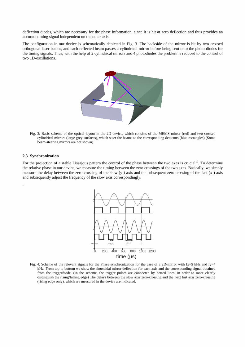
For the projection of a stable Lissajous pattern the control of the phase between the two axes is crucial10. To determine the relative phase in our device, we measure the timing between the zero crossings of the two axes. Basically, we simply measure the delay between the zero crossing of the slow (y-) axis and the subsequent zero crossing of the fast (x-) axis and subsequently adjust the frequency of the slow axis correspondingly.
.
∆t=0µs 66,6 133,3 0
0 200 400 600 800 1000 1200
time (µs) Fig. 4: Scheme of the relevant signals for the Phase synchronization for the case of a 2D-mirror with fx=5 kHz and fy=4
kHz: From top to bottom we show the sinusoidal mirror deflection for each axis and the corresponding signal obtained from the triggerdiode. (In the scheme, the trigger pulses are connected by dotted lines, in order to more clearly distinguish the rising/falling edge) The delays between the slow axis zero-crossing and the next fast axis zero-crossing (rising edge only), which are measured in the device are indicated.

The situation is somewhat complicated by the fact, that (except for the situation where the frequency of the fast axis fx is an integer multiple of the slow axis frequency fy) we have multiple zero crossings of the slow axis, before the Lissajous-figure repeats itself, as is outlined in Fig. 4 for the simple case of a frequency ratio of fx/fy=5/3. A more detailed mathematical description is presented elsewhere11 and for this experimental article we just state, that these delays are measured and analyzed in order to keep the relative phase between the two oscillations at a constant well defined value
In closed loop operation, the phase in our device is controlled continuously and, if necessary adjusted by adapting the frequency of the slow axis. In this way, the fast axis, which is more critical, can still be operated at resonance in all cases, while the slow axis now is controlled with goal of achieving a stable relative phase, instead of operation at resonance.
In this scheme, we treat and analyse each axis independently. As such it is straight forward to apply it to independent mirrors, which should be driven synchronously. The same electronics can be used with slight reprogramming of the firmware in order to synchronize two mirrors to an external reference signal. In fact it would also be possible to synchronize mirrors with different frequency, which shows the flexibility of this approach.
2.4 System integration
Note that, while the concept and basic properties apply to any kind of electrostatically driven MEMS scanner, the actual design always targets the MEMS devices described in chapter 2.1. The whole position-detection is integrated in a detector head with a size of 20x15x15 mm² as shown in Fig. 5(a). Details are described in [12]. We implemented a hemispheric front-optic in order to avoid the reflection of the incoming beam, which can be a nuisance in projection applications. Hermetic vacuum packaging could be implemented using a ceramic board and soldering processed, but at the current stage is not used.
(a) (b)
Fig. 5: (a) Detector head, (b) complete electronics
Fig. 5(b) shows the electronics capable of driving a large range of electrostatically driven 2D MEMS mirrors with resonance frequencies in the range from 100Hz to 30 kHz. As described in detail in [13] it includes all the logic for independently starting and driving the mirrors under closed loop control. It communicates via an SPI interface. A graphical user interface was developed in order to set all relevant parameters and read out all information provided by the position sensing unit. All mirror related parameters are stored on an EPROM included on the detector head.
Fig. 6 shows the demonstrator setup where the beam from a laser pointer is reflected from the 2D module projecting a Lissajous figure onto a screen.

Fig. 6: Demonstrator setup
3. RESULTS The 2D-MOEMS mirrors have a resonance frequency of fx=1,3 kHz and fy=200 Hz and typically are driven in the range of 20-50 V. Mechanicals amplitudes in the range of 10° can be obtained with these mirrors. The front side of the mirror is coated with aluminum to enhance the reflectivity. The backside, which is used for the position detection in our device, is a silicon surface. The mirror area was 1 mm2.
3.1 Timing signals
The following figures (Fig. 7,Fig. 8) show the trigger signals from the photodiodes together with the driving signal of the mirror and the reference signal. The differential photodiodes we used (Hamamtsu, S9684) supply negative pulses with a jitter of less than 8ns.
The reference signal corresponding to the mirror frequency and has half the driving frequency. It is directly generated by dividing the driving frequency. With the help of the signals from the amplitude diode the ambiguity of the mirror´s driving direction is resolved, meaning that it is ensured that the reference signal is not out 180° of phase with the mirror motion. Note that, without position feedback there is no way to ensure that this is the case for this kind of mirrors, since they are driven with twice the resonance frequency and the initial direction, with which the mirror starts up is arbitrary.
There is a small time delay between the trigger pulse from the zero transition and the rising edge of the reference signal indicates that the mirror was not driven exactly at resonance but at a slightly higher frequency. (In addition there is a minor delay between the trigger signals and the high-voltage driving signal caused by the electronics, which is less than 2 µs.) We typically set the mirror frequency slightly above the resonance frequency, in a regime where the amplitude is still high (typically more than 95% of the maximum value) and where more stable operation is ensured. Remember that at frequency below resonance the mirror very quickly stalls completely [2,3,11].
The corresponding phase delay of the slow axis is significantly higher, since, in closed loop operation, the slow axis is adjusted for a stable phase relation towards the fast axis (c.f. Fig. 9) (for a stable Lissajous-pattern protection) rather than for operation close to resonance.

When analysing the signal of the amplitude diode in more detail a jitter in the time delay between the two pulses can be observed, which results from the crosstalk between the two axes due the geometry with cylindrical mirrors. As mentioned above, this is not an issue for the zero-crossing diode. Currently we avoid instabilities in the amplitude measurement by simply averaging over a large number of samples. Time is not critical to avoid the slow drifts in the mirror behaviour and it turned out, that this approach is sufficient for stable operation with constant amplitude. On the other hand problems still might arise in some special situations and parameter sets and in particular if not only stable amplitude but also the absolute amplitude is of importance. This topic will be analysed in more detail elsewhere.
(a) (b)
Fig. 7: Timing signals corresponding to the fast axis on two different timescales as measured on the oscilloscope. From top to bottom the following curves are displayed: reference signal (3), driving signal (1), trigger signal from zero-position diode (4), and the trigger signal from the amplitude diode (2)
(a) (b) Fig. 8: Timing signals from the y-axis. Signals are the same as in Fig. 8. Note the different time scales due to the lower
frequency of this axis.
Fig. 9(a) shows the reference signals from the fast and the slow axis for the situation of a frequency ration of 6:1. In this case every 6th rising edge of the two signals coincides. This situation is maintained by the control loop electronics by continuously adjusting the frequency of the slow axis. Fig. 9(b) demonstrates that a precision of better than 0.01 mrad can be obtained. At a fast axis frequency of about 1.25 kHz this corresponds to a timing precision of about 1.2 ns, which was obtained by averaging over 100 periods.
The same concept can be used for synchronization of individual mirrors. In a separate experiment the same main electronics were used to synchronize two 1D mirrors to an external reference signal. For this experiment, we did not use the detector head shown in Fig. 5(a), but rather used a breadboard set-up with position sensitive diodes for the position feedback.
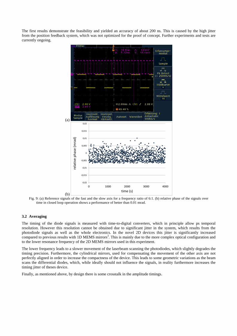
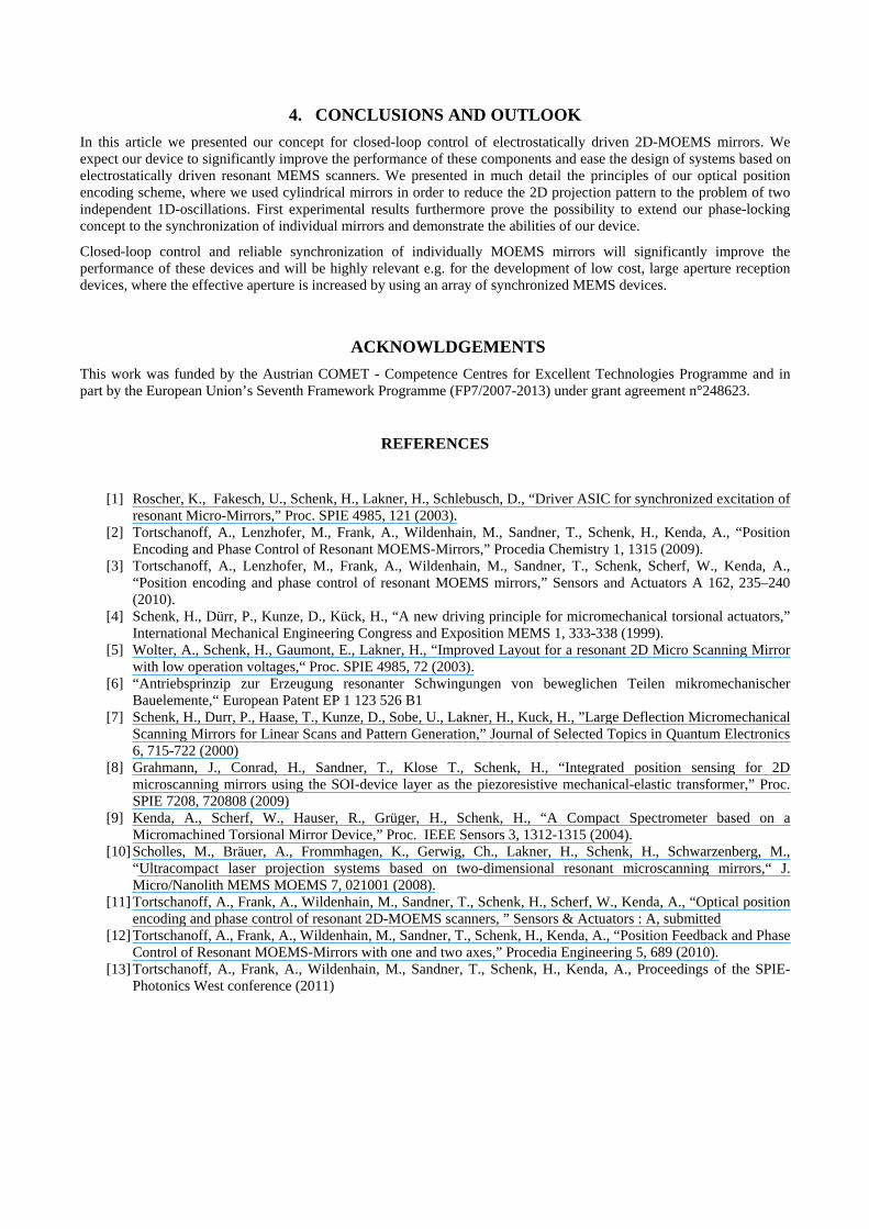
The first results demonstrate the feasibility and yielded an accuracy of about 200 ns. This is caused by the high jitter from the position feedback system, which was not optimized for the proof of concept. Further experiments and tests are currently ongoing.
(a)
(b)
‐0,02
‐0,015
‐0,01
‐0,005
0
0,005
0,01
0,015
0,02
0 1000 2000 3000 4000
relative ph
ase (m
rad)
time (s) Fig. 9: (a) Reference signals of the fast and the slow axis for a frequency ratio of 6:1. (b) relative phase of the signals over
time in closed loop operation shows a performance of better than 0.01 mrad.
3.2 Averaging
The timing of the diode signals is measured with time-to-digital converters, which in principle allow ps temporal resolution. However this resolution cannot be obtained due to significant jitter in the system, which results from the photodiode signals as well as the whole electronics. In the novel 2D devices this jitter is significantly increased compared to previous results with 1D MEMS mirrors3. This is mainly due to the more complex optical configuration and to the lower resonance frequency of the 2D MEMS mirrors used in this experiment.
The lower frequency leads to a slower movement of the laserbeam scanning the photodiodes, which slightly degrades the timing precision. Furthermore, the cylindrical mirrors, used for compensating the movement of the other axis are not perfectly aligned in order to increase the compactness of the device. This leads to some geometric variations as the beam scans the differential diodes, which, while ideally should not influence the signals, in reality furthermore increases the timing jitter of theses device.
Finally, as mentioned above, by design there is some crosstalk in the amplitude timings.

To reduce the noise and improve the stability of the closed loop control, we average the timing results before calculating phase and amplitude and adjusting driving voltages and frequencies. Results from averaging over different amounts of sample points are displayed below.
(a)
0 50 100 150
11500
12000
12500
11500
12000
12500
11500
12000
12500
11500
12000
12500
11500
12000
12500
phas
edel
ay (n
s)
time (s)
1 sample
phas
edel
ay (n
s) 4 samples
phas
edel
ay (n
s) 9 samples
phas
edel
ay (n
s)
100 samples
phas
edel
ay (n
s)
1000 samples
(b)
0 50 100 1508.15
8.20
8.25
8.30
8.35
8.40
8.15
8.20
8.25
8.30
8.35
8.40
8.15
8.20
8.25
8.30
8.35
8.40
8.15
8.20
8.25
8.30
8.35
8.40
8.15
8.20
8.25
8.30
8.35
8.40
ampl
itude
(°)
time (s)
1 sample
ampl
itude
(°) 4 samples
ampl
itude
(°) 9 samples
ampl
itude
(°) 100 samples
ampl
itude
(°) 1000 samples
Fig. 10: (a) phasedleay and (b) amplitude of the fast axis measured after averaging of different amounts of samplepoints.
Averaging significantly increases signal to noise and we find, very roughly, the square-root dependance on the number of samples, which is expected. However, taking very large numbers of samples does not improve the precision any more because in this case, due to the increase in measurement time, we start to sample the drift of the mirror parameters, which actually we want to compensate for, by the closed loop control.
Table 1: average amplitude and phasedelay and the corresponding standard deviation for different averaging
Samples Amplitude Phase delay
# Mean (°) StdDev. (°) Mean (ns) StdDev. (ns)
1 8,28 0,085 11934 345
4 8,28 0,032 11944 140
9 8,29 0,017 11943 76
100 8,29 0,0019 11960 12
1000 8,29 0,0012 11994 13
4. CONCLUSIONS AND OUTLOOK In this article we presented our concept for closed-loop control of electrostatically driven 2D-MOEMS mirrors. We expect our device to significantly improve the performance of these components and ease the design of systems based on electrostatically driven resonant MEMS scanners. We presented in much detail the principles of our optical position encoding scheme, where we used cylindrical mirrors in order to reduce the 2D projection pattern to the problem of two independent 1D-oscillations. First experimental results furthermore prove the possibility to extend our phase-locking concept to the synchronization of individual mirrors and demonstrate the abilities of our device.
Closed-loop control and reliable synchronization of individually MOEMS mirrors will significantly improve the performance of these devices and will be highly relevant e.g. for the development of low cost, large aperture reception devices, where the effective aperture is increased by using an array of synchronized MEMS devices.
ACKNOWLDGEMENTS This work was funded by the Austrian COMET - Competence Centres for Excellent Technologies Programme and in part by the European Union’s Seventh Framework Programme (FP7/2007-2013) under grant agreement n°248623.
REFERENCES
[1] Roscher, K., Fakesch, U., Schenk, H., Lakner, H., Schlebusch, D., “Driver ASIC for synchronized excitation of
resonant Micro-Mirrors,” Proc. SPIE 4985, 121 (2003). [2] Tortschanoff, A., Lenzhofer, M., Frank, A., Wildenhain, M., Sandner, T., Schenk, H., Kenda, A., “Position
Encoding and Phase Control of Resonant MOEMS-Mirrors,” Procedia Chemistry 1, 1315 (2009). [3] Tortschanoff, A., Lenzhofer, M., Frank, A., Wildenhain, M., Sandner, T., Schenk, Scherf, W., Kenda, A.,
“Position encoding and phase control of resonant MOEMS mirrors,” Sensors and Actuators A 162, 235–240 (2010).
[4] Schenk, H., Dürr, P., Kunze, D., Kück, H., “A new driving principle for micromechanical torsional actuators,” International Mechanical Engineering Congress and Exposition MEMS 1, 333-338 (1999).
[5] Wolter, A., Schenk, H., Gaumont, E., Lakner, H., “Improved Layout for a resonant 2D Micro Scanning Mirror with low operation voltages,“ Proc. SPIE 4985, 72 (2003).
[6] “Antriebsprinzip zur Erzeugung resonanter Schwingungen von beweglichen Teilen mikromechanischer Bauelemente,“ European Patent EP 1 123 526 B1
[7] Schenk, H., Durr, P., Haase, T., Kunze, D., Sobe, U., Lakner, H., Kuck, H., ”Large Deflection Micromechanical Scanning Mirrors for Linear Scans and Pattern Generation,” Journal of Selected Topics in Quantum Electronics 6, 715-722 (2000)
[8] Grahmann, J., Conrad, H., Sandner, T., Klose T., Schenk, H., “Integrated position sensing for 2D microscanning mirrors using the SOI-device layer as the piezoresistive mechanical-elastic transformer,” Proc. SPIE 7208, 720808 (2009)
[9] Kenda, A., Scherf, W., Hauser, R., Grüger, H., Schenk, H., “A Compact Spectrometer based on a Micromachined Torsional Mirror Device,” Proc. IEEE Sensors 3, 1312-1315 (2004).
[10] Scholles, M., Bräuer, A., Frommhagen, K., Gerwig, Ch., Lakner, H., Schenk, H., Schwarzenberg, M., “Ultracompact laser projection systems based on two-dimensional resonant microscanning mirrors,“ J. Micro/Nanolith MEMS MOEMS 7, 021001 (2008).
[11] Tortschanoff, A., Frank, A., Wildenhain, M., Sandner, T., Schenk, H., Scherf, W., Kenda, A., “Optical position encoding and phase control of resonant 2D-MOEMS scanners, ” Sensors & Actuators : A, submitted
[12] Tortschanoff, A., Frank, A., Wildenhain, M., Sandner, T., Schenk, H., Kenda, A., “Position Feedback and Phase Control of Resonant MOEMS-Mirrors with one and two axes,” Procedia Engineering 5, 689 (2010).
[13] Tortschanoff, A., Frank, A., Wildenhain, M., Sandner, T., Schenk, H., Kenda, A., Proceedings of the SPIE-Photonics West conference (2011)
Related Documents